safety challenges in construction of kochi metro rail project
TRANSCRIPT
1
Safety Challenges in Construction of Kochi
Metro Rail Project & Its Control
and
Studies on Safety Engineering Aspects of
Nisargruna Biogas Technology
Arin Manna
Department of Chemical Engineering
National Institute of Technology Rourkela
2
Safety Challenges in Construction of
Kochi Metro Rail project & Its Control
and
Studies on Safety Engineering Aspects of
Nisargruna Biogas Technology
Dissertation submitted in partial fulfillment
of the requirements of the degree of
Master of Technology
in
Safety Engineering
by
Arin Manna
(Roll Number: 214CH2471)
based on research carried out
under the supervision of
Dr. P. Balasubramanian
May, 2016
Department of Chemical Engineering
National Institute of Technology Rourkela
iii
Department of Chemical Engineering
National Institute of Technology Rourkela
May 13, 2016
Certificate of Examination
Roll Number: 214CH2471 Name: Arin Manna Title of Dissertation: Safety Challenges in Construction of Kochi Metro Rail
Project & Its Control
and
Studies on Safety Engineering Aspects of Nisargruna Biogas Technology
We the below signed, after checking the dissertation mentioned above and the
official record book (s) of the student, hereby state our approval of the dissertation
submitted in partial fulfillment of the requirements of the degree of Master of
Technology in Safety Engineering at National Institute of Technology Rourkela. We
are satisfied with the volume, quality, correctness, and originality of the work.
P. Balasubramanian Assistant Professor
Arvind Kumar
Assistant Professor
iv
Department of Chemical Engineering
National Institute of Technology Rourkela Dr. P. Balasubramanian Assistant Professor
May 13, 2016
Supervisor’s Certificate
This is to certify that the work presented in the dissertation entitled Safety
Challenges in Construction of Kochi Metro Rail Project & Its Control and Studies
on Safety Engineering Aspects of Nisargruna Biogas Technology submitted by Arin
Manna, Roll Number 214CH2471, is a record of original research carried out by
him under my supervision and guidance in partial fulfillment of the requirements of
the degree of Master of Technology in Safety Engineering. Neither this dissertation
nor any part of it has been submitted earlier for any degree or diploma to any
institute or university in India or abroad.
P. Balasubramanian
Assistant Professor
v
Declaration of originality
This is to certify that the work presented in the dissertation entitled Guidelines for
Formatting Dissertation submitted by Arin Manna, Roll Number 214CH2471, is a record
of original research carried out by him under our supervision and guidance in partial
fulfillment of the requirements of the degree of Masters in Technology in Safety
Engineering. Neither this dissertation nor any part of it has been submitted earlier for any
degree or diploma to any institute or university in India or abroad.
I am fully aware that in case of any non-compliance detected in future, the Senate of NIT
Rourkela may withdraw the degree awarded to me on the basis of the present dissertation.
May 13, 2016 Arin Manna
NIT Rourkela

vi
Acknowledgement
The satisfaction on successful completion of any task would be incomplete without the
mention of the people who made it possible whose constant guidance and encouragement
crowned out effort with success. I would like to express my heartfelt gratitude to my
esteemed supervisor, Prof P. Balasubramanian for her technical guidance, valuable
suggestions, and encouragement throughout the experimental and theoretical study and in
preparing this report.
I would also like to express my heartfelt gratitude to my esteemed in charge Mr. Jeevagan
R., Mr. Sarang N. and the entire team of L&T associated with Kochi Metro Rail Project
for his technical guidance and to give me opportunity to complete my project work in their
site and use their resources.
It has been an honor to work under Prof P. Balasubramanian, whose expertise and
discernment were key in the completion of this project. I am grateful to the Dept. of
Chemical Engineering, NIT Rourkela, for giving me the opportunity to execute this
project, which is an integral part of the curriculum in M.Tech. program at the National
Institute of Technology, Rourkela.
Many thanks to my friends who are directly or indirectly helped me in my project work for
their generous contribution towards enriching the quality of the work.
This acknowledgement would not be complete without expressing my sincere gratitude to
my parents for their love, patience, encouragement, and understanding which are the
source of my motivation and inspiration throughout my work..
Arin Manna

vii
Nomenclature
Definitions:
i. The use of ‘shall’ indicates a mandatory requirement.
ii. The use of ‘should’ indicates a guideline that is strongly recommended.
iii. The use of ‘may’ indicates a guideline that is to be considered.
iv. SHE means Safety, Health & Environment.
v. NIOSH means National Institute Of Occupational Safety And Health
vi. OHSAS means Occupational Health & Safety Advisory Systems: 18001, 2007.
vii. OHSMS means Occupational health & Safety Management Systems: 18001,
2007.
viii. OHSM means Occupational Health & Safety Management.
ix. Direct Employee: Employees who are on Company’s pay role.
x. Indirect Personnel: Personnel who may be engaged for and/or in connection
with the operation/activity of the Company but are not on Company’s pay role
xi. Hazardous waste: Any waste by means of its characteristics may cause danger
to health or environment. Example: used oil, waste oil, oily soaked jutes,
filters, paint sludge, paint/oil contaminated barrels, sludge from wet scrubber.
xii. Biological egents:-microorganisms that can cause infections or have sensitizing
or toxic effects in humans.
xiii. ISO means International Standards Organisation
xiv. OSH means Occupational Safety Health
xv. Policy means a statement of Intent, and is implemented as a procedure or
protocol.
xvi. Safety Policy means a written statement by an employer stating the company’s
commitment for the protection of the health and safety of employees and to the
public.
xvii. BARC means Bhaba Atomic Research Center.
viii
Safety Challenges in Construction of
Kochi Metro Rail Project & Its
Control
Arin Manna
ix
Abstract Rapid transportation system becomes a significant factor for the developing country.
Apart from that it is very essential to control the traffic in the high dense and populated
country like India. So this where the need of metro rail is generated. A metro project is
carried out in kochi, kerla under Delhi Metro Rail Project. L&T is one of the client of
DMRC in that project. This thesis work is carried out for a part of kochi metro project. In
the present scenario, in India maximum accident occurs in construction industry as the
Indian construction company is lacking a huge with updated safety instrument and lack of
knowledge about safety. Lersen and toubro is a big multinational Indian construction
company. This studies is deals with the safety policies, there work environment,
responsibilities of a safety personnel in L&T company. L&t company has a very strict and
well defined safety rules which follows BIS standard, OSAH standard and BOCW. The
duty of safety engineer is to look after whether any activity, in the site or out of the site,
related to the project is going safely or not. It has to be checked by safety personnel as
well as the engineer whether any work is following the safety integral management system
of the company.
Key word: Kochi metro rail project, OSAH, BOCW
x
Index
Certificate of Examination iii
Supervisors’ Certificate iv
Declaration of Originality v
Acknowledgment vi
Nomenclature vii
Title page viii
Abstract ix
List of table xii
List of figure xiii
1 Introduction 1
1.1 Aim of the project ………………………………… ………………………….. 1
1.2 Objective ………………………………………………………………………. 2
1.3 Need of metro ………………………………………………………………….. 2
1.4 Advantage of metro …………………………………………………………….. 2
2 literature review 3
2.1 Introduction …………………………………………………………………… 3
2.2 Construction consequence ……………………………………………………… 3
2.3 Work permit system …………………………………………………………… 5
2.4 House-keeping ……………………………………………………………….... 6
3 EHS policy 7
3.1 Introduction ……………………………………………………………………. 7
3.2 Visibility ……………………………………………………………………… 7
3.3 Proactive target settings ………………………………………………………. 8
3.4 Company culture ………………………………………………………………. 9
3.5 Legal and other requirements …………………………………………………… 10
3.6 General EHS rule ………………………………………………………………. 10
xi
3.7 EHS policy 12
3.8 Responsibilities of EHSO …………………………………………………….. 12
3.9 EHS risk assessment …………………………………………………………. 15
4 EHS challenges and initiatives to control 16
4.1 Introduction ……..…………………………………………………………….. 16
4.2 EHS challenges ………………………………………………………………… 16
4.3 Control measures ………………………………………………………………. 16
5 Reports 19
6 Conclusion 32

xii
List of table
3.1, 3.3 Responsibilities of personnel 7, 10
3.2 Target setting 8
3.4 list of legal requirement 10
3.5 responsibilities of EHSO 12

xiii
List of figure
1.1 Road map 1
2.1 Piling machine 3
2.2 Pier 4
2.3 Girder erection 5
1
Chapter 1
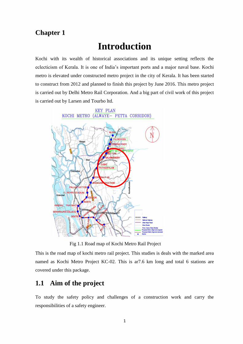
Introduction Kochi with its wealth of historical associations and its unique setting reflects the
eclecticism of Kerala. It is one of India’s important ports and a major naval base. Kochi
metro is elevated under constructed metro project in the city of Kerala. It has been started
to construct from 2012 and planned to finish this project by June 2016. This metro project
is carried out by Delhi Metro Rail Corporation. And a big part of civil work of this project
is carried out by Larsen and Tourbo ltd.
Fig 1.1 Road map of Kochi Metro Rail Project
This is the road map of kochi metro rail project. This studies is deals with the marked area
named as Kochi Metro Project KC-02. This is ar7.6 km long and total 6 stations are
covered under this package.
1.1 Aim of the project
To study the safety policy and challenges of a construction work and carry the
responsibilities of a safety engineer.
2
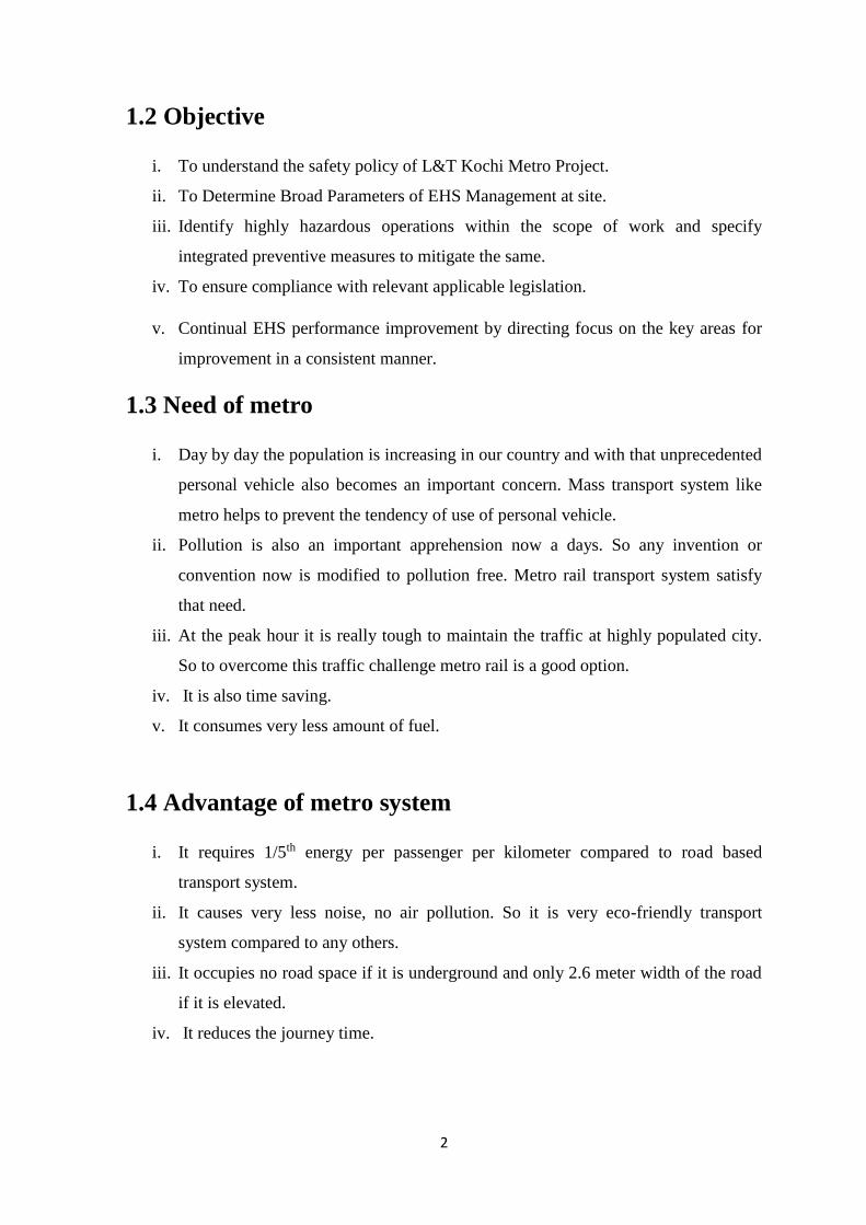
1.2 Objective
i. To understand the safety policy of L&T Kochi Metro Project.
ii. To Determine Broad Parameters of EHS Management at site.
iii. Identify highly hazardous operations within the scope of work and specify
integrated preventive measures to mitigate the same.
iv. To ensure compliance with relevant applicable legislation.
v. Continual EHS performance improvement by directing focus on the key areas for
improvement in a consistent manner.
1.3 Need of metro
i. Day by day the population is increasing in our country and with that unprecedented
personal vehicle also becomes an important concern. Mass transport system like
metro helps to prevent the tendency of use of personal vehicle.
ii. Pollution is also an important apprehension now a days. So any invention or
convention now is modified to pollution free. Metro rail transport system satisfy
that need.
iii. At the peak hour it is really tough to maintain the traffic at highly populated city.
So to overcome this traffic challenge metro rail is a good option.
iv. It is also time saving.
v. It consumes very less amount of fuel.
1.4 Advantage of metro system
i. It requires 1/5th energy per passenger per kilometer compared to road based
transport system.
ii. It causes very less noise, no air pollution. So it is very eco-friendly transport
system compared to any others.
iii. It occupies no road space if it is underground and only 2.6 meter width of the road
if it is elevated.
iv. It reduces the journey time.
3
Chapter 2
Literature review
2.1 Introduction
As the population of India is increasing day by day traffic control becomes a significant
challenge for the government. In fact the space is limited, so the traffic accident rate is
also increased day by day. This challenge is confronting the administration of india is the
search of proper solution for trffic management. If we see the developed country, most of
the people even who has ability to effort personal vehicle, is using public transport or mass
transport system. Due to various advantages metro is considered as the best rapid mass
transport system.
2.2 Construction sequence
2.2.1 Road diversion and barricading
First a regulation is implemented for the traffic for 1 lane movement in each side for a
length of 200 meter between two stations. Mark the road both side at 4 meter distance
from the divider. Barricade the area properly with caution board and restrict the
unauthorized entry. All the light post is removed then from divider and dismantle the
median. Before excavating the lane or area is to be checked for any underground obstracle.
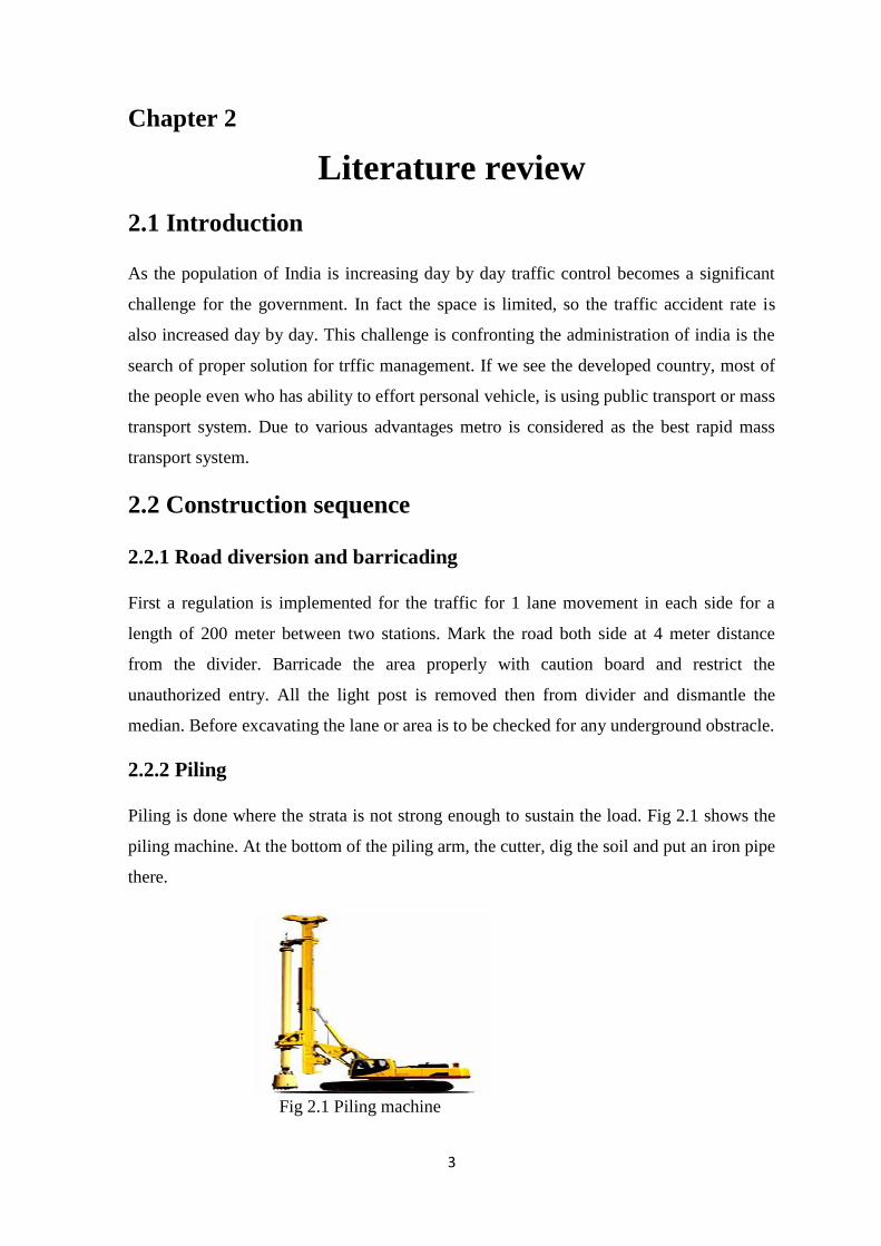
2.2.2 Piling
Piling is done where the strata is not strong enough to sustain the load. Fig 2.1 shows the
piling machine. At the bottom of the piling arm, the cutter, dig the soil and put an iron pipe
there.
Fig 2.1 Piling machine

4
This pipe act as mold box. The desired reinforcement is done before the concreting. After
concreting is left for 4-5 days putting a load on the piling to make it more stronger. When
the desired strength is achieved a pile cap is constracted to make a base on the ground for
further construction.
2.2.3 Pier construction
Above the pile cap reinforcement is carried out for pier. Cross section of the pier can be
round of 5 ft. dia and 5*4 ft. cross section if it is rectangular. Round pier is generally used
for the single pier and rectangular cross-section is used for the extended pier and in station
beam. At the bottom of the pier a protector is provided for the sock resistance.
Fig 2.2 Pier
So that it protect the base of the pier. A pier cap is mounted then on the pier. Pier cap is
pre casted in the casting yard. Fig 2.2 is showing the completed pier along with pier cap.
Weight of the normal pier cap is around 70 ton.
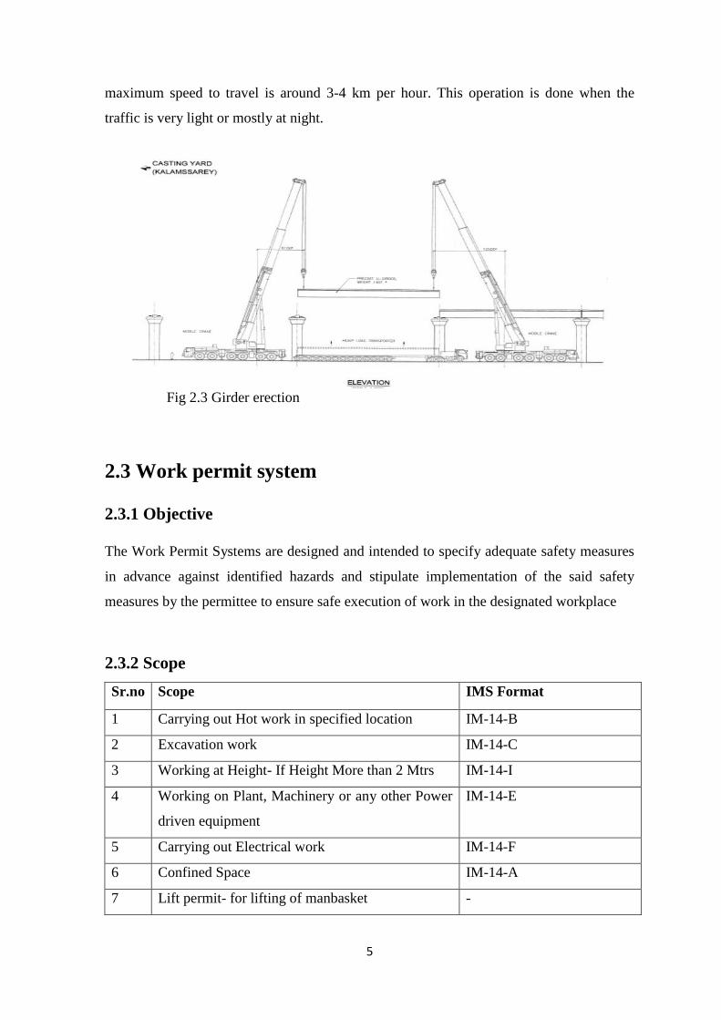
2.2.4 Girder erection
This is the final stage of civil construction of elevated metro rail. Two type of girder is
used there in order to the limitation of space for the crane. The girder length is also vary
like 25 meter, 23 meter and 22 meter. As shown in fig 2.3 the cross section can be ‘U’ or
‘I’. Weight of each girder is around 140 ton. Erection of girder is the most critical
movement of whole construction. Two crane of 150 ton capacity is engaged for one girder
erection. Fig.. shows the elevation sketch how the girder is erected. The trailer to convey
the girder from casting yard to the erection site, is having around 36 meter long. And the
5
maximum speed to travel is around 3-4 km per hour. This operation is done when the
traffic is very light or mostly at night.
Fig 2.3 Girder erection
2.3 Work permit system
2.3.1 Objective
The Work Permit Systems are designed and intended to specify adequate safety measures
in advance against identified hazards and stipulate implementation of the said safety
measures by the permittee to ensure safe execution of work in the designated workplace
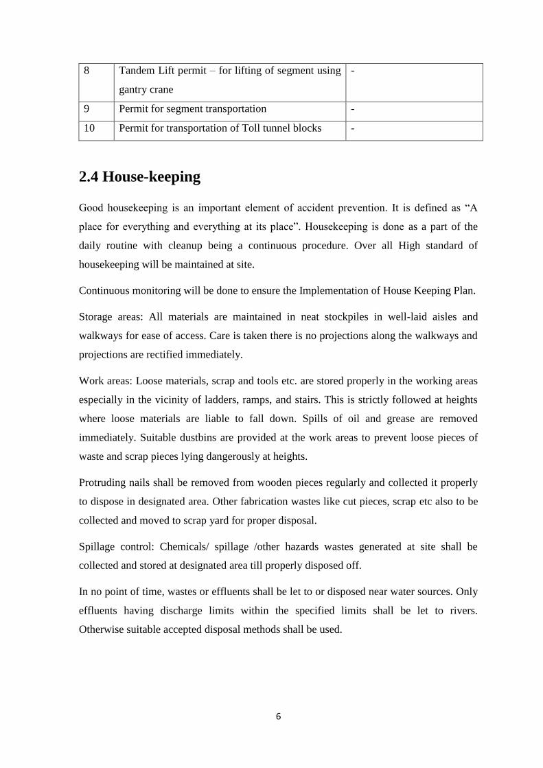
2.3.2 Scope
Sr.no Scope IMS Format
1 Carrying out Hot work in specified location IM-14-B
2 Excavation work IM-14-C
3 Working at Height- If Height More than 2 Mtrs IM-14-I
4 Working on Plant, Machinery or any other Power
driven equipment
IM-14-E
5 Carrying out Electrical work IM-14-F
6 Confined Space IM-14-A
7 Lift permit- for lifting of manbasket -
6
8 Tandem Lift permit – for lifting of segment using
gantry crane
-
9 Permit for segment transportation -
10 Permit for transportation of Toll tunnel blocks -
2.4 House-keeping
Good housekeeping is an important element of accident prevention. It is defined as “A
place for everything and everything at its place”. Housekeeping is done as a part of the
daily routine with cleanup being a continuous procedure. Over all High standard of
housekeeping will be maintained at site.
Continuous monitoring will be done to ensure the Implementation of House Keeping Plan.
Storage areas: All materials are maintained in neat stockpiles in well-laid aisles and
walkways for ease of access. Care is taken there is no projections along the walkways and
projections are rectified immediately.
Work areas: Loose materials, scrap and tools etc. are stored properly in the working areas
especially in the vicinity of ladders, ramps, and stairs. This is strictly followed at heights
where loose materials are liable to fall down. Spills of oil and grease are removed
immediately. Suitable dustbins are provided at the work areas to prevent loose pieces of
waste and scrap pieces lying dangerously at heights.
Protruding nails shall be removed from wooden pieces regularly and collected it properly
to dispose in designated area. Other fabrication wastes like cut pieces, scrap etc also to be
collected and moved to scrap yard for proper disposal.
Spillage control: Chemicals/ spillage /other hazards wastes generated at site shall be
collected and stored at designated area till properly disposed off.
In no point of time, wastes or effluents shall be let to or disposed near water sources. Only
effluents having discharge limits within the specified limits shall be let to rivers.
Otherwise suitable accepted disposal methods shall be used.
7
Chapter 3
EHS policy:
3.1 Introduction:
L&T ECCD Infrastructure IC Senior Management provides demonstrable management
leadership and commitment through active participation in EHS activities.
Their leadership and commitments translate into necessary resources to develop, operate
and maintain L&T ECCD Infrastructure OC EHS Management System and to attain EHS
Policy and legal requirements.
We are committed to manage all its activities, risks to ‘As Low As Reasonably
Practicable’ (ALARP).
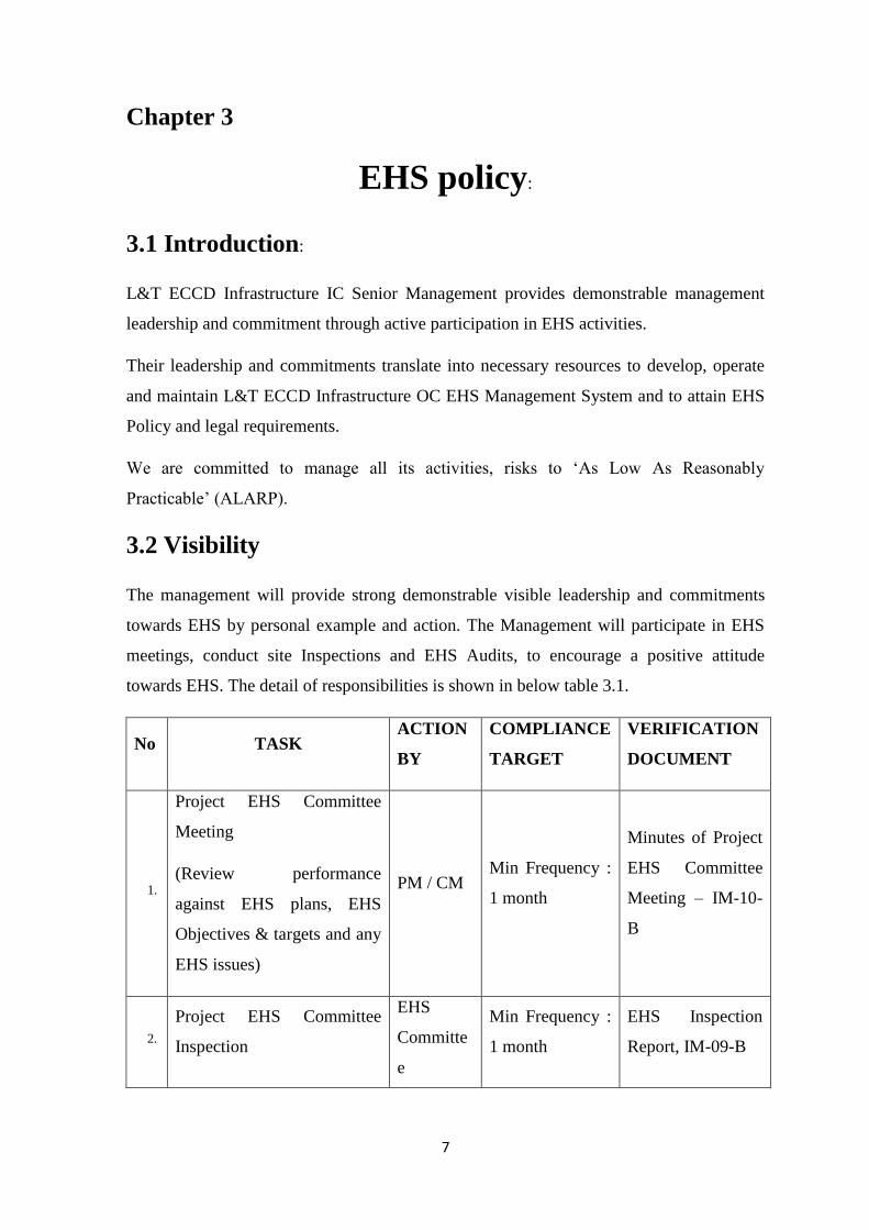
3.2 Visibility
The management will provide strong demonstrable visible leadership and commitments
towards EHS by personal example and action. The Management will participate in EHS
meetings, conduct site Inspections and EHS Audits, to encourage a positive attitude
towards EHS. The detail of responsibilities is shown in below table 3.1.
No TASK ACTION
BY
COMPLIANCE
TARGET
VERIFICATION
DOCUMENT
1.
Project EHS Committee
Meeting
(Review performance
against EHS plans, EHS
Objectives & targets and any
EHS issues)
PM / CM Min Frequency :
1 month
Minutes of Project
EHS Committee
Meeting – IM-10-
B
2.
Project EHS Committee
Inspection
EHS
Committe
e
Min Frequency :
1 month
EHS Inspection
Report, IM-09-B

8
Members
3. EHS Review Cluster
Heads
During their Site
Visit
Minutes of Project
EHS Committee
Meeting – IM-10-
B
4. Internal EHS Audit MR Once in Six
Months
Audit Report
including NCRs,
& Site Observation
5.
Motivation
Giving Safety Certificates,
with token gift to the “Best
safety conscious personnel”
of the month to recognise
good EHS practices.
PM / CM Monthly Copies of
Certificates
Table 3.1
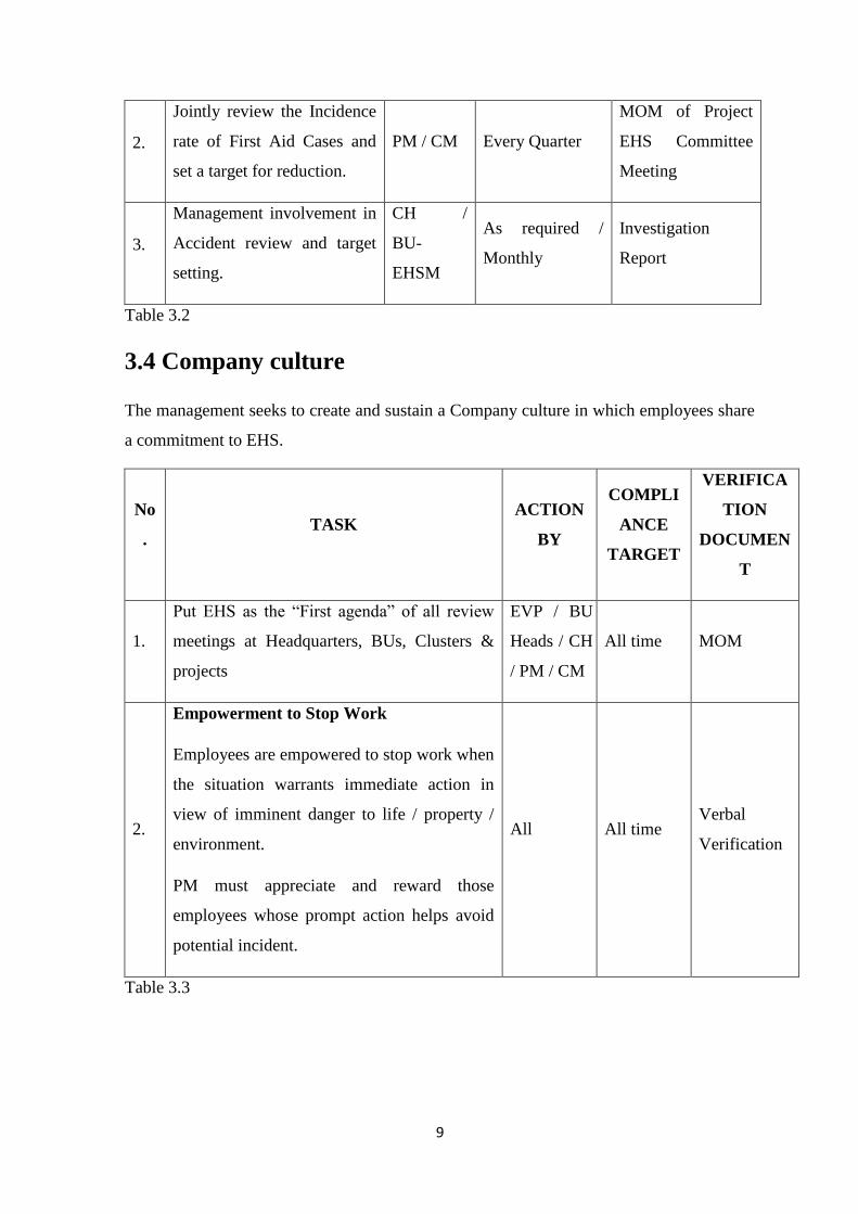
3.3 Proactive target settings
The project management demonstrates pro-activeness in target setting, which is shown in
detail in following table 3.2.
No. TASK ACTION
BY
COMPLIANCE
TARGET
VERIFICATION
DOCUMENT
1.
Jointly develop and discuss
improvement targets and
indicators for each location
with Construction Managers
& EHSO. (eg. Training of
Workmen – Coverage,
Inspection Compliance etc.)
PM / CM Every Quarter
MOM of Project
EHS Committee
Meeting
9
2.
Jointly review the Incidence
rate of First Aid Cases and
set a target for reduction.
PM / CM Every Quarter
MOM of Project
EHS Committee
Meeting
3.
Management involvement in
Accident review and target
setting.
CH /
BU-
EHSM
As required /
Monthly
Investigation
Report
Table 3.2
3.4 Company culture
The management seeks to create and sustain a Company culture in which employees share
a commitment to EHS.
No
. TASK
ACTION
BY
COMPLI
ANCE
TARGET
VERIFICA
TION
DOCUMEN
T
1.
Put EHS as the “First agenda” of all review
meetings at Headquarters, BUs, Clusters &
projects
EVP / BU
Heads / CH
/ PM / CM
All time MOM
2.
Empowerment to Stop Work
Employees are empowered to stop work when
the situation warrants immediate action in
view of imminent danger to life / property /
environment.
PM must appreciate and reward those
employees whose prompt action helps avoid
potential incident.
All All time Verbal
Verification
Table 3.3
10
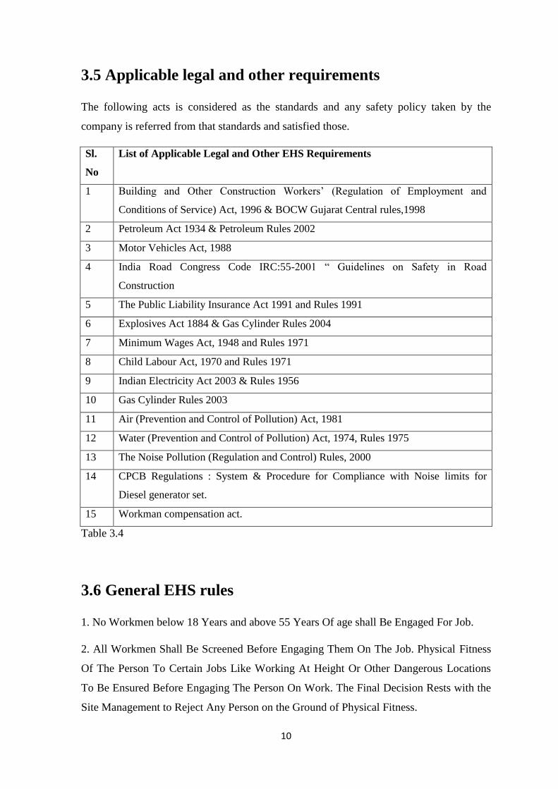
3.5 Applicable legal and other requirements
The following acts is considered as the standards and any safety policy taken by the
company is referred from that standards and satisfied those.
Sl.
No
List of Applicable Legal and Other EHS Requirements
1 Building and Other Construction Workers’ (Regulation of Employment and
Conditions of Service) Act, 1996 & BOCW Gujarat Central rules,1998
2 Petroleum Act 1934 & Petroleum Rules 2002
3 Motor Vehicles Act, 1988
4 India Road Congress Code IRC:55-2001 “ Guidelines on Safety in Road
Construction
5 The Public Liability Insurance Act 1991 and Rules 1991
6 Explosives Act 1884 & Gas Cylinder Rules 2004
7 Minimum Wages Act, 1948 and Rules 1971
8 Child Labour Act, 1970 and Rules 1971
9 Indian Electricity Act 2003 & Rules 1956
10 Gas Cylinder Rules 2003
11 Air (Prevention and Control of Pollution) Act, 1981
12 Water (Prevention and Control of Pollution) Act, 1974, Rules 1975
13 The Noise Pollution (Regulation and Control) Rules, 2000
14 CPCB Regulations : System & Procedure for Compliance with Noise limits for
Diesel generator set.
15 Workman compensation act.
Table 3.4
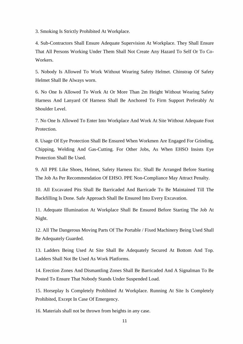
3.6 General EHS rules
1. No Workmen below 18 Years and above 55 Years Of age shall Be Engaged For Job.
2. All Workmen Shall Be Screened Before Engaging Them On The Job. Physical Fitness
Of The Person To Certain Jobs Like Working At Height Or Other Dangerous Locations
To Be Ensured Before Engaging The Person On Work. The Final Decision Rests with the
Site Management to Reject Any Person on the Ground of Physical Fitness.
11
3. Smoking Is Strictly Prohibited At Workplace.
4. Sub-Contractors Shall Ensure Adequate Supervision At Workplace. They Shall Ensure
That All Persons Working Under Them Shall Not Create Any Hazard To Self Or To Co-
Workers.
5. Nobody Is Allowed To Work Without Wearing Safety Helmet. Chinstrap Of Safety
Helmet Shall Be Always worn.
6. No One Is Allowed To Work At Or More Than 2m Height Without Wearing Safety
Harness And Lanyard Of Harness Shall Be Anchored To Firm Support Preferably At
Shoulder Level.
7. No One Is Allowed To Enter Into Workplace And Work At Site Without Adequate Foot
Protection.
8. Usage Of Eye Protection Shall Be Ensured When Workmen Are Engaged For Grinding,
Chipping, Welding And Gas-Cutting. For Other Jobs, As When EHSO Insists Eye
Protection Shall Be Used.
9. All PPE Like Shoes, Helmet, Safety Harness Etc. Shall Be Arranged Before Starting
The Job As Per Recommendation Of EHSO. PPE Non-Compliance May Attract Penalty.
10. All Excavated Pits Shall Be Barricaded And Barricade To Be Maintained Till The
Backfilling Is Done. Safe Approach Shall Be Ensured Into Every Excavation.
11. Adequate Illumination At Workplace Shall Be Ensured Before Starting The Job At
Night.
12. All The Dangerous Moving Parts Of The Portable / Fixed Machinery Being Used Shall
Be Adequately Guarded.
13. Ladders Being Used At Site Shall Be Adequately Secured At Bottom And Top.
Ladders Shall Not Be Used As Work Platforms.
14. Erection Zones And Dismantling Zones Shall Be Barricaded And A Signalman To Be
Posted To Ensure That Nobody Stands Under Suspended Load.
15. Horseplay Is Completely Prohibited At Workplace. Running At Site Is Completely
Prohibited, Except In Case Of Emergency.
16. Materials shall not be thrown from heights in any case.

12
17. Only authorized person are allowed for Welding and Gas cutting work.
3.7 EHS policy
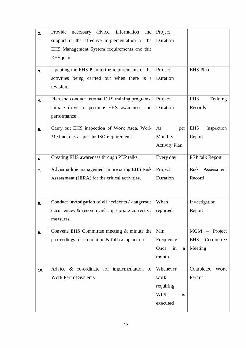
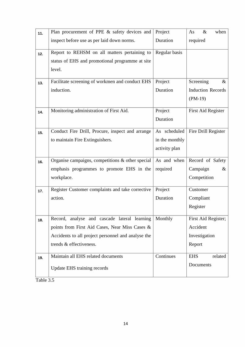
3.8 Responsibilities of EHSO
NO. TASK TARGET VERIFICATION
DOCUMENT
1. Disseminate and Communicate L&T ECCD EHS
Policy, EHS Management System requirements to
site personnel.
Project
Duration
-
13
2. Provide necessary advice, information and
support in the effective implementation of the
EHS Management System requirements and this
EHS plan.
Project
Duration
-
3. Updating the EHS Plan to the requirements of the
activities being carried out when there is a
revision.
Project
Duration
EHS Plan
4. Plan and conduct Internal EHS training programs,
initiate drive to promote EHS awareness and
performance
Project
Duration
EHS Training
Records
5. Carry out EHS inspection of Work Area, Work
Method, etc. as per the ISO requirement.
As per
Monthly
Activity Plan
EHS Inspection
Report
6. Creating EHS awareness through PEP talks. Every day PEP talk Report
7. Advising line management in preparing EHS Risk
Assessment (HIRA) for the critical activities.
Project
Duration
Risk Assessment
Record
8. Conduct investigation of all accidents / dangerous
occurrences & recommend appropriate corrective
measures.
When
reported
Investigation
Report
9. Convene EHS Committee meeting & minute the
proceedings for circulation & follow-up action.
Min
Frequency –
Once in a
month
MOM – Project
EHS Committee
Meeting
10. Advice & co-ordinate for implementation of
Work Permit Systems.
Whenever
work
requiring
WPS is
executed
Completed Work
Permit
14
11. Plan procurement of PPE & safety devices and
inspect before use as per laid down norms.
Project
Duration
As & when
required
12. Report to REHSM on all matters pertaining to
status of EHS and promotional programme at site
level.
Regular basis
13. Facilitate screening of workmen and conduct EHS
induction.
Project
Duration
Screening &
Induction Records
(PM-19)
14. Monitoring administration of First Aid. Project
Duration
First Aid Register
15. Conduct Fire Drill, Procure, inspect and arrange
to maintain Fire Extinguishers.
As scheduled
in the monthly
activity plan
Fire Drill Register
16. Organise campaigns, competitions & other special
emphasis programmes to promote EHS in the
workplace.
As and when
required
Record of Safety
Campaign &
Competition
17. Register Customer complaints and take corrective
action.
Project
Duration
Customer
Compliant
Register
18. Record, analyse and cascade lateral learning
points from First Aid Cases, Near Miss Cases &
Accidents to all project personnel and analyse the
trends & effectiveness.
Monthly First Aid Register;
Accident
Investigation
Report
19. Maintain all EHS related documents
Update EHS training records
Continues EHS related
Documents
Table 3.5
15
3.9 EHS risk assessment
3.9.1 Scope
This procedure is applicable for all offices, project sites and operations globally. EHS Risk
Management shall cover:
i. All routine and non-routine activities
ii. Activities of all personnel having access to the workplace (including contractors,
visitors)
iii. Facilities at the workplace (eg. office, canteen, workmen facilities etc)
3.9.2 Purpose
L&T’s Risk management process is applied through the five steps to risk management and
is the key driver for risk control in business:
i. All relevant parties including construction & EHS teams must be involved in risk
assessments and the risk management process;
ii. Risk assessments & Safe Work Method statement must be developed and approved
prior to any work activity starting;
iii. All Identified risks and risk mitigation plans must be documented, approved and
simply communicated to all parties.
16
Chapter 4
EHS challenges and initiatives to control
4.1 Introduction
The metro project work is constructed on the busy road. So safety precaution of the
worker and the engineer along with the public is significant concern of the project. Due to
the heavy traffic during the pick hour as the road where is it being constructed, is
connected to national highway, so many limitations come during the construction. This
challenge confronting all the safety personnel along with all the employees to adopt a
safety policy and to apply the control measures to minimize the probability of risk or the
impact of undesirable EHS consequences. Risk control measures that have been
implemented and are still effective in controlling the hazard.
4.2 EHS challenges
i. Traffic Management i.e working on live traffic while Barricading boards
Installation & Cleaning.
ii. Space constraint.
iii. Work at height including, Station work, Pier cap erection & U-Girder erection.
iv. High Workmen Rotation.
v. Managing Union workmen
4.3 control measures
Following the safety policies the initiatives taken by the company to overcome the above
challenges are
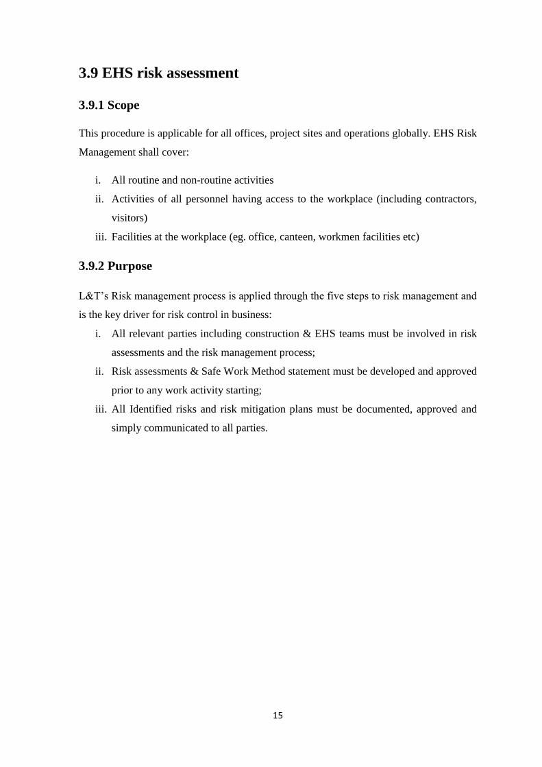
i. To manage the traffic control, at every 200 meter a traffic marshal is employed. Apart
from that to avoid the accident a stong barricading is provided at the both side of work
place. The proper deviation and caution board is also provided. For the night all the
deviation sign and the caution board are written with light reflective materials as
shown in fig 4.1
17
fig 4.1 barricading and diversion.
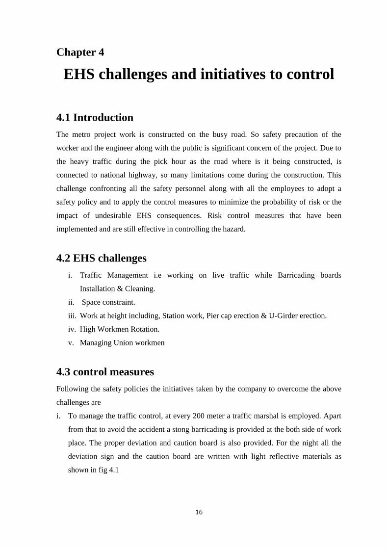
ii. Project EHS Department in co-ordination with assigned trainer will conduct Safety
training programs on different topics. Project Manager, Section in charge, Site
engineers, supervisors & workmen attend the program to enhance their technical
knowledge with respect to safety and learn how to integrate safety into the work-
practices. It is compulsory for all staff members to attend this programme at least once
as early as possible from the date when they joined in company service. Apart from
training program everyday morning toolbox talk is given at the site by the engineer in
presence of safety officer as shown in fig 4.2
Fig. 4.2 tool box talk.
iii. All the excavated area generated due to piling work is barricaded with the caution
board.
iv. Prper housekeeping is carried out every time to main the the workplace clean.
v. To prevent fall from height and the materials falling two layer of safety net is to
provided. Apart from that if anywhere any work is carried out at hight a caution board
is given to make aware from the material fallings. As per the regulations all the
workers are working at height must be provided the required ppes.
18
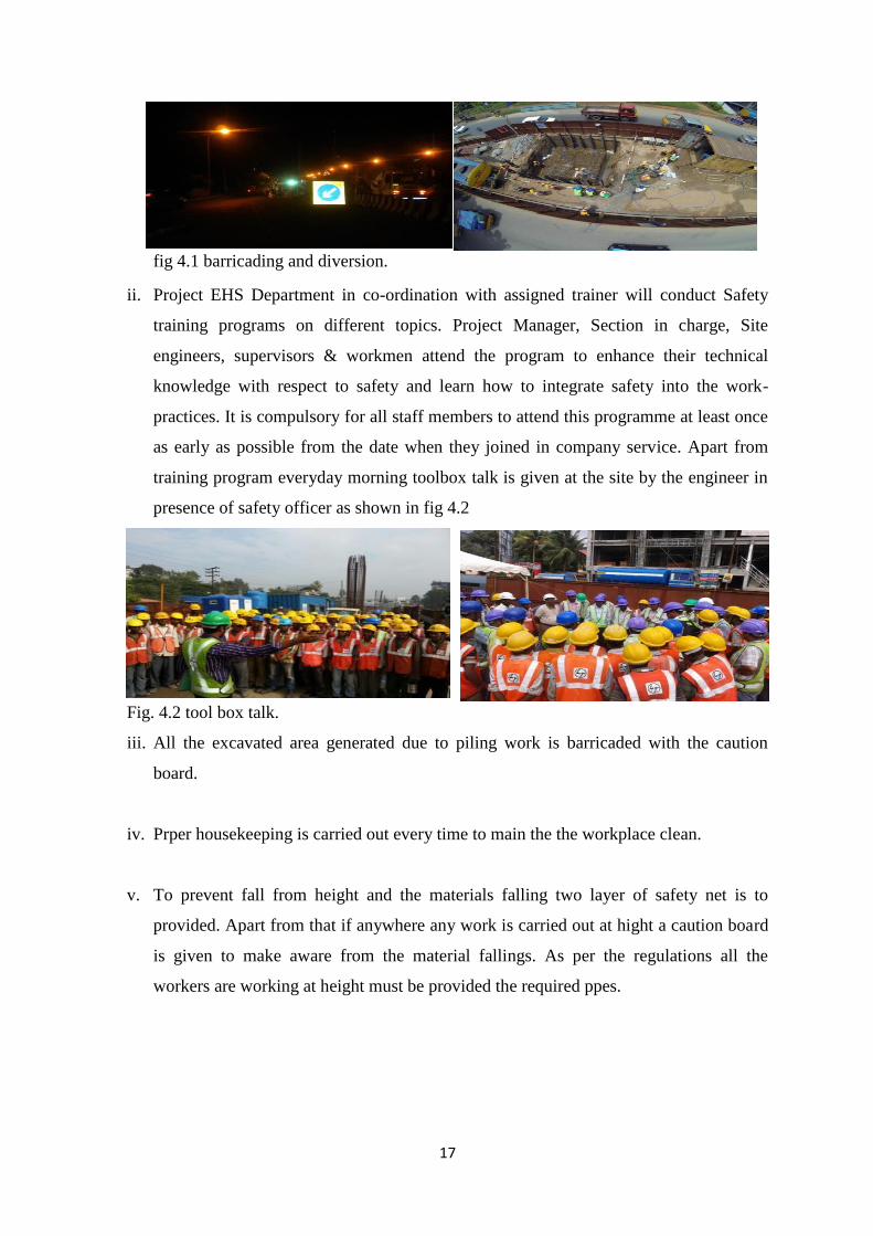
vi. In every month noise, dust particle at the work premises, illumination, air contaminant
is checked whether it exceeds the standards or not. To prevent the dust water sprinkler
is spread to the road nd the working place as shown in fig…
Fig 4.3 Water sprinkler.
vii. Various types of colorful posters are provided beside the road to increase the safety
awareness. Apart from that the every year some award is given to the worker or
engineers for proper motivation.

19
Chapter 5
Reports
I have been working there as a trainee safety engineer for 5 months. In this stipulated
duration my work plan detail is given bellow.
Some sample reports prepared by me:
Project EHS inspection report between muttom to kalmassery station.
LARSEN & TOUBRO LIMITED
INFRASTRUCTURE INDEPENDENT COMPANY
PROJECT EHS INSPECTION REPORT
Name of Project: KMRL KC-02
Business Unit : Metros & Defence Area / Location Inspected : MUTTOM P
TO: PROJECT
INCHARGE
Date-14/8/2015 INSPECTED BY: RJ,SN
Sl
no
EHS observation Action
required
Action
by
Target
date
Remark
s
1.
2.
material storage is improper
Inspection data is not written
Do Proper
housekeepin
g and stack
materials in
designated
place.
Fill up the
JP
19/08/
15

20
3.
4.
improper placement of ladder P177
Access blocked to the staircase and
improper storage of materials
green card
properly
with
permanent
marker
The ladder
should be
extended at
least 1 meter
above the
landing
platform.
NR
Bhanska
r
W.I.E
W.I.E
Closed
21
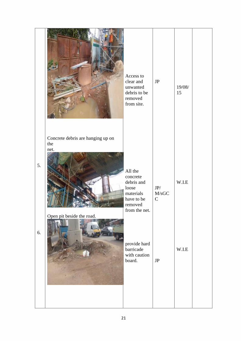
5.
6.
Concrete debris are hanging up on
the
net.
Open pit beside the road.
Access to
clear and
unwanted
debris to be
removed
from site.
All the
concrete
debris and
loose
materials
have to be
removed
from the net.
provide hard
barricade
with caution
board.
JP
JP/
M/sGC
C
JP
19/08/
15
W.I.E
W.I.E

22
7.
8.
9.
10
misuse fire extinguisher.
No safety net P
Improper base of scaffolding.
Stagnant water, unhealthy condition.
Keep the
fire
extinguisher
properly at
proper
place.
Wrap safety
net properly.
Provide
proper base
JP
PK
JP
18/08/
15
W.I.E
W.I.E
complie
d

23
.
11
.
12
.
accessto p.d.b box is blocked.
No protection from public vehicle
Stagnant
water has to
be drained
from the pit.
Provide
prope access
to pd.b box.
JP
JP
20/08/
15
19/08/
15
24
EHS inspection report of a inspection in casting yard.
LARSEN & TOUBRO LIMITED
INFRASTRUCTURE INDEPENDENT COMPANY
PROJECT EHS INSPECTION REPORT
Name of Project: KMRL KC-02
Business Unit : Metros & Defence Area / Location Inspected : MUTTOM P
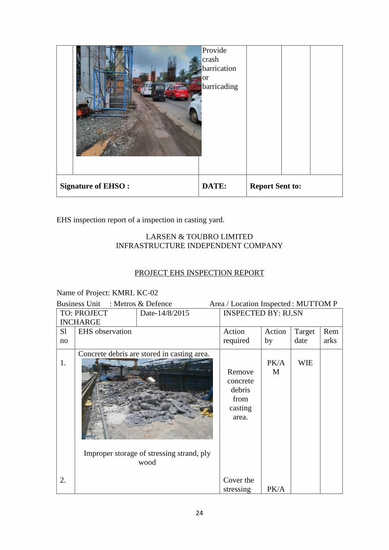
Provide
crash
barrication
or
barricading
Signature of EHSO : DATE: Report Sent to:
TO: PROJECT
INCHARGE
Date-14/8/2015 INSPECTED BY: RJ,SN
Sl
no
EHS observation Action
required
Action
by
Target
date
Rem
arks
1.
2.
Concrete debris are stored in casting area.
Improper storage of stressing strand, ply
wood
Remove
concrete
debris
from
casting
area.
Cover the
stressing
PK/A
M
PK/A
WIE

25
3.
4.
Poor housekeeping used/damaged metal
scrubs are thrown.
Sparks flown on flammable material &
cloths
Drinking watertank cleaning not done
strand and
store it
properly.
Keep
clean walk
way.
Proper
housekeep
ing to be
done.
Remove
cloths and
other
flammable
materials.
Tank to be
cleaned
M
PK/A
M
PK/A
M
SRA
15/10/
15
15/10/
15
WIE
WIE
Clos
ed
26
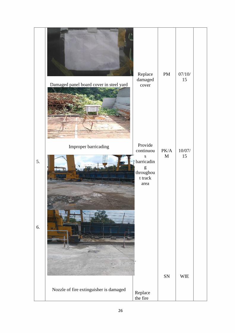
5.
6.
Damaged panel board cover in steel yard
Improper barricading
Nozzle of fire extinguisher is damaged
Replace
damaged
cover
Provide
continuou
s
barricadin
g
throughou
t track
area
.
Replace
the fire
PM
PK/A
M
SN
07/10/
15
10/07/
15
WIE
27
Compliance report of a casting yard:
Compliance report for
EHS inspection report dated 19/09/2015
1. Hand protection not provided
while handling grease & Petrol
Complied
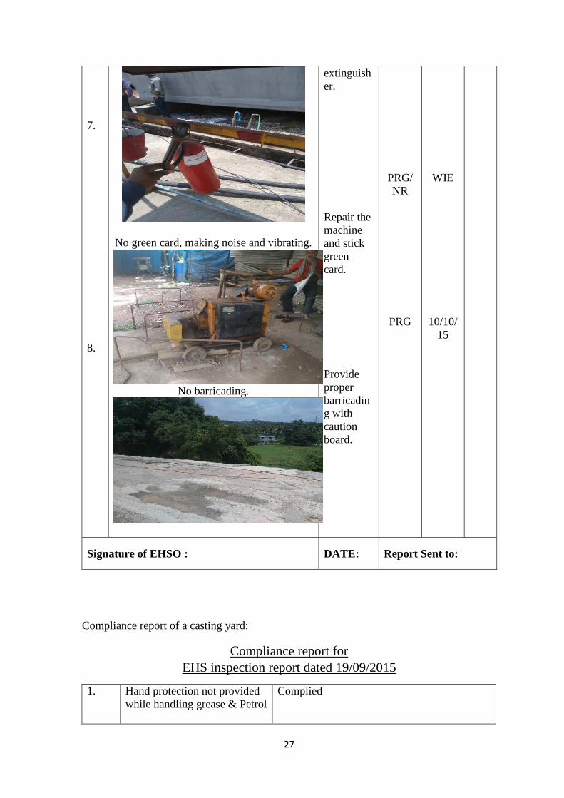
7.
8.
No green card, making noise and vibrating.
No barricading.
extinguish
er.
Repair the
machine
and stick
green
card.
Provide
proper
barricadin
g with
caution
board.
PRG/
NR
PRG
WIE
10/10/
15
Signature of EHSO : DATE: Report Sent to:
28
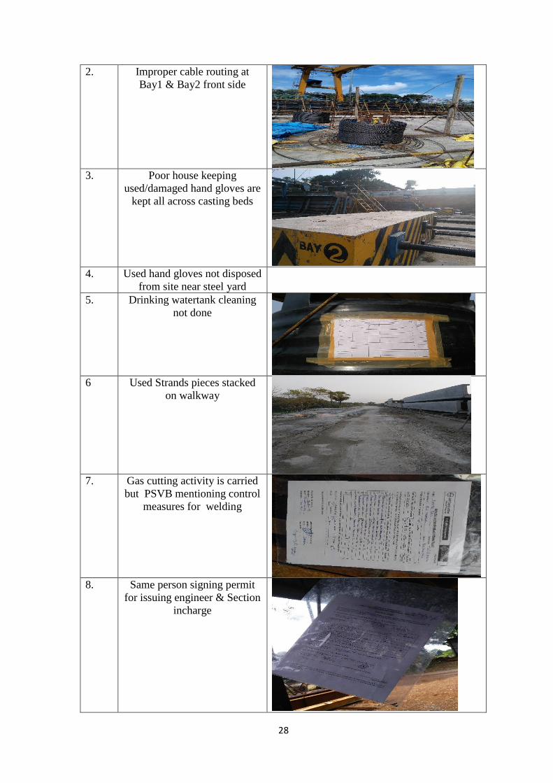
2. Improper cable routing at
Bay1 & Bay2 front side
3. Poor house keeping
used/damaged hand gloves are
kept all across casting beds
4. Used hand gloves not disposed
from site near steel yard
5. Drinking watertank cleaning
not done
6 Used Strands pieces stacked
on walkway
7. Gas cutting activity is carried
but PSVB mentioning control
measures for welding
8. Same person signing permit
for issuing engineer & Section
incharge
29
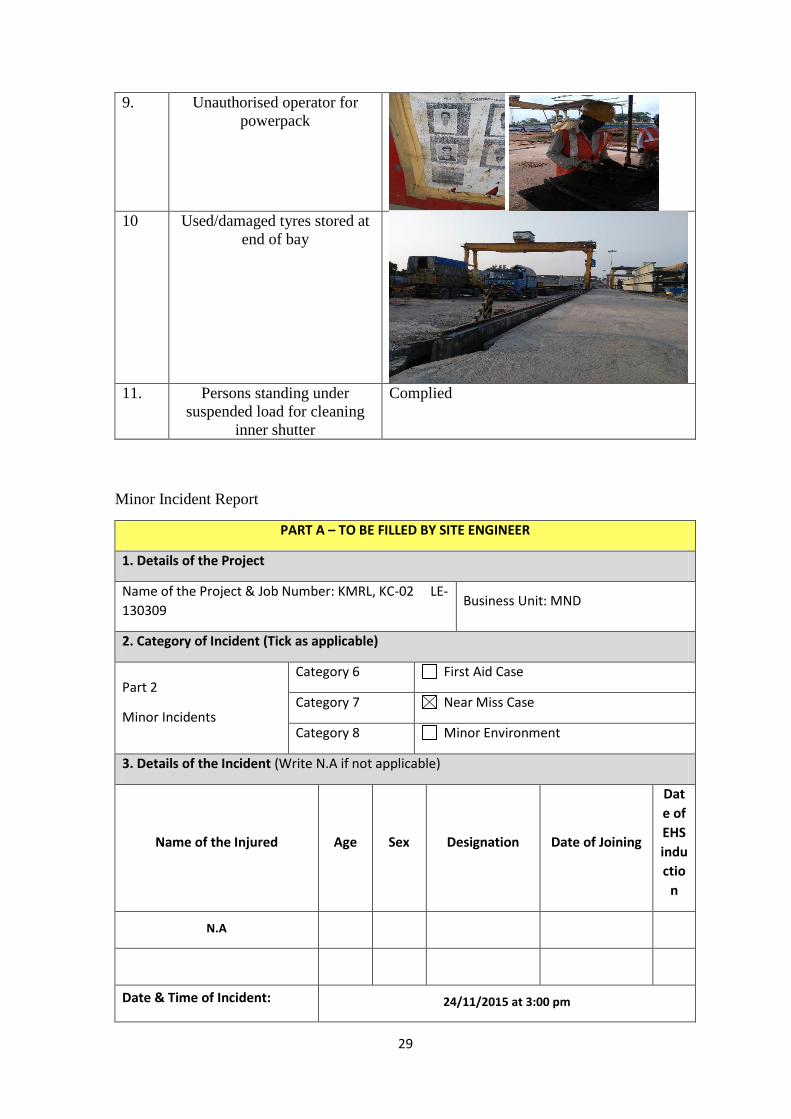
9. Unauthorised operator for
powerpack
10 Used/damaged tyres stored at
end of bay
11. Persons standing under
suspended load for cleaning
inner shutter
Complied
Minor Incident Report
PART A – TO BE FILLED BY SITE ENGINEER
1. Details of the Project
Name of the Project & Job Number: KMRL, KC-02 LE-
130309 Business Unit: MND
2. Category of Incident (Tick as applicable)
Part 2
Minor Incidents
Category 6 First Aid Case
Category 7 Near Miss Case
Category 8 Minor Environment
3. Details of the Incident (Write N.A if not applicable)
Name of the Injured Age Sex Designation Date of Joining
Dat
e of
EHS
indu
ctio
n
N.A
Date & Time of Incident: 24/11/2015 at 3:00 pm
30
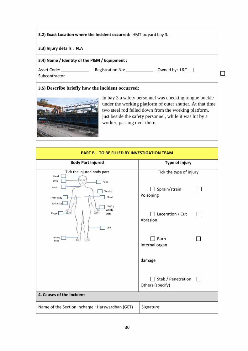
3.2) Exact Location where the Incident occurred: HMT pc yard bay 3.
3.3) Injury details : N.A
3.4) Name / Identity of the P&M / Equipment :
Asset Code: ____________ Registration No: ____________ Owned by: L&T
Subcontractor
3.5) Describe briefly how the incident occurred:
In bay 3 a safety personnel was checking tongue buckle
under the working platform of outer shutter. At that time
two steel rod felled down from the working platform,
just beside the safety personnel, while it was hit by a
worker, passing over there.
Name of the Section Incharge : Harswardhan (GET) Signature:
PART B – TO BE FILLED BY INVESTIGATION TEAM
Body Part Injured Type of Injury
Tick the injured body part
Tick the type of injury
Sprain/strain
Poisoning
Laceration / Cut
Abrasion
Burn
Internal organ
damage
Stab / Penetration
Others (specify)
4. Causes of the Incident
31
4.1) Direct Causes: 1. Worker hit the bars. 2. Rebar fell down from walk way.
4.2) Root Causes: (Tick the root cause)
1. Human factors
2. Physical condition 3. Managemen
t System
1.1 Inexperienced/
Unauthorised/ untrained
worker
2.1 Wrong selection of
equipment / tools.
3.1 Hazard &
controls not
identified previously
1.2 Medically or physically
unfit
2.2 Faulty equipment / tools
(not safety inspected)
3.2 Unsafe work
method / Generic
1.3 Poor task behaviour/
shortcuts
2.3 Unsafe operation /
Safety devices not working
3.3 Design safety
issues
3.4 Risk control
measures not
implemented
1.4 PPE not used / worn 2.4 Poor housekeeping
1.5 Unsafe behaviour of
worker (horseplay/ mobile
phone usage etc.)
2.5 Poor storage of
materials 3.5 Not enough
training or
instruction
2.6 Unsuitable work area
(inadequate space)
3.6 Poor compliance
to safety inspection
1.6 Golden Safety rules
violated
2.7 Unsafe Work
environment (light / noise /
dust / smoke/ weather condition)
3.7 Lack /
incompetent
supervision
1.7 Standing & operating
in unsafe position
2.8 Hazards originated due
to external factors
3.8 Poor
selection/quality/ no
issue of PPE
1.8 others 2.9 others 3.9 others
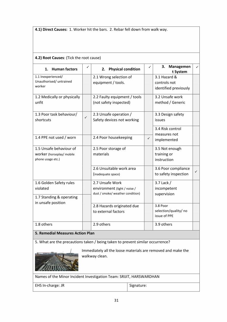
5. Remedial Measures Action Plan
5. What are the precautions taken / being taken to prevent similar occurrence?
Immediately all the loose materials are removed and make the
walkway clean.
Names of the Minor Incident Investigation Team: SRIJIT, HARSWARDHAN
EHS In-charge: JR Signature:
32
Chapter 6
Conclusion
Though the Lersen and Toubro is a multinational construction company due lack of
modern technology still there are some accident take place. During the stipulated time of
project there was no any fatal case but some minor injuries is taking place. Even everyday
some people are injured at first aid level. Safety is not a responsibility of any particular
person or only the safety engineers. From the very first day when a employee employed,
he is advised to take care of own safety himself. This is really tough to make a site totally
injury free but not impossible.
L&T is updating its safety policy or EHS management system to make a project totally
accident free. Safety become their first concern and they provide more layer of protection
to prevent the risk at the workplace.
In this project the main challenges were height work, and traffic management. L&T is
successfully takle those challenge by implementing new technologies and established
fluent communication system. Through different report and punishment for in-compliance
of unsafe work the accident rate becomes under controlled.
i
Safety Engineering Aspects of Nisargruna
Biogas Technology
Arin Manna
ii
Abstract
Though dumping of solid waste is very unsafe, as it misbalance the element of
environment, it is very common way in the cities due to lack of technical and financial
recourse to reuse the waste properly. Segregation of organic waste from the municipal
solid waste stream line represents an open scope to reduce the quantity of waste using for
landfills by up to 50% by weight. Nisargruna technology is developed by Bhabha Atomic
Research center of India that deals with bioprocessing of any type of biodegradable solid
waste in a very efficient and environment friendly way. Since National Institute of
Technology Rourkela is being a home to around 6000 students per year, the disposal of
hostel kitchen waste is one of the key environmental concern to be addressed. This study
aimed to analyze the safety engineering aspects of Nisargruna technology for the biogas
generation from hostel kitchen wastes. Any leakage of waste manure from biogas tank
could affect the environment very much instantly. In addition, it might have fire, physical,
and mechanical hazards etc. This biogas plant doesn’t have high possibility of occurring
accident. But as it is producing high flammable gas like methane and very harmful gas to
human health, like hydrogen sulfide, we need to adopt a safe and proper safety policies to
overcome the explosions and the health effect. Apart from that a hazop study is done to
eliminate another small hazards, involved in this process. The plant is planned to construct
near hostel premises. So it is necessary to evaluate the risk area and risk volume to locate
the plant at a proper place so that the student will not be effected by the consequence of
any accident. Another main purpose is to generate electricity using biogas. So this is need
to evaluate the economic advantage by adopting this project.
Key word: Segregation, Nisargruna Technology, Biogas plant.
iii
Index
Title page .. i
Abstract ii
List of table v
List of figure vi
1 Introduction 33
1.1 Aim of the project ………………………………………………………………. 33
1.2 Objective …………………………………………………………………………. 34
1.3 Purpose ………………………………………………………………………….. 34
2 literature review 35
2.1 Introduction ………………………………………………………………….... 35
2.2 Technical detail ………………………………………………………………….. 36
3. Case study 38
3.1 Discussion ………………………………………………………………………. 38
3.2 Outcome and specification ……………………………………………………... 40
4. Questionnaires and survey 42
4.1 Introduction …………………………………………………………………….. 42
4.2 Responses and feedback ………………………………………………………… 42
4.3 Discussion ………………………………………………………………………. 45
5 Design aspects 47
5.1 Size of component ……………………………………………………………… 47
5.2 Energy yield ……………………………………………………………………. 49
5.3 Project at a glance ……………………………………………………………… 51
6. HAZOP study 53
6.1 Processing hall …………………………………………………………………. 53
6.2 Digester ………………………………………………………………………… 54
6.3 Risk area ……………………………………………………………………….. 55
6.4 Emergency plan ………………………………………………………………… 56
iv
7. Safety aspect 57
7.1 Risk and hazard …………………………………………………………………. 57
7.2 Explosion range of methane ……………………………………………………. 59
7.3 Occupational health aspects ……………………………………………………. 60
7.4 Conveying food waste and another waste ……………………………………… 61
7.5 Safety measure for segregation ………………………………………………… 61
7.6 Checklist ………………………………………………………………………… 62
7.7 Threat zone ……………………………………………………………………… 63
8 Advantage and disadvantage 68
9 Conclusion 69
Reference 70

v
List of table
3.1 Description of OPGC biogas plant 40
3.2 Cost analysis 40
5.1 Project specification of nit biogas plant 51
6.1 Recommendation of processing room 53
7.1 Element of biogas 59
vi
List of image
2.1 Layout of nisargruna biogas plant 35
3.1 Processing room 39
3.2 Solar panel 39
3.3 Maintenance work 39
3.4 Digester 39
3.5 Manure by product 40
3.6 Membrane of digester. 40
7.1 Threat zone due to jet fire 65
7.2 Flammability area of vapor cloud 65
7.3 Over pressure blast threat zone 66
7.4 Threat zone due to jet fire at night 66
7.5 Over pressure blast threat zone at night 67
33
Chapter 1
Introduction
Waste disposal and its handling is a big concern of the developed and developing
countries nowadays. Generally the waste is disposed by means of landfill, incineration,
and dumping etc. Yet, all the processes have their own pros and cons. However, the
improper disposal of waste affects human health and environmental balance. Concurrently
the world energy demand is also increasing day by day. This alarming situation presses the
demand for sustainable solutions to address both energy and environmental sectors. So the
most efficient way to waste management is utilizing biomass energy from biodegradable
waste. So the government of different countries are making their legislation regarding the
waste disposal, its proper management and using the biomass energy. Likewise NIT
Rourkela, a prestigious educational institution, situated in odisha, is also taking the
challenge of appropriate solution of the waste disposal by producing electricity from
biogas energy. A biogas plant of 2MT input capacity is planned to install in the premises
with a motto of using renewable energy. As an outcome from the brief survey at the hostel
discloses that around 1000 kg of food waste are being generated in the campus daily.
Apart from that there are also a few amount of dry leaves and grasses are coming out as
waste. All this wastes are sent outside for the landfill purpose or food supply to the
animals. So basically there are two main objectives behind this project. One is proper
management of waste and another one is supplying electricity for own use, which
motivates the use of renewable energy. As it is a large scale plant going to install at the
hostel premises, safety is also a non-negotiable factor here. Though biogas plant is not
very much vulnerable we have to adopt a good safety policy to prevent any type of
accident which can cause any harm to the students and the workers of the plant. A little
mistake can cause a big loss. So by implementing proper safety policy according to the
norms and regulation of OSHA and BIS regarding bio mass handling this project will be a
successful one to fulfill its objective.
1.1 Aim of the project
To evaluate the safety engineering aspects of biogas plant using nisargruna technology in a
large scale
34
1.2 Objective
1. Develop proper solid waste management in NIT Rourkela campus
2. Explore the safety aspects of Nisaragruna technology
1.3 Purpose of the project
The main purpose of the biogas plant following nisargruna technology is as follows:-
1 The whole process is environment friendly in order to disposal of waste, the need of the
hour.
2 To generate a rich amount of biogas fuel, which will definitely support the declining
energy resources. As well as the gas can be used for as fuel in power generation and in
kitchen purpose also.
3 Generation of rich quality, weed free manure, which is enrich the soil conditioner for
fertilization. This is significantly important for replenishing organic carbon in the
undernourished soil after years of agriculture.
35
Chapter 2
Literature review
2.1 Introduction
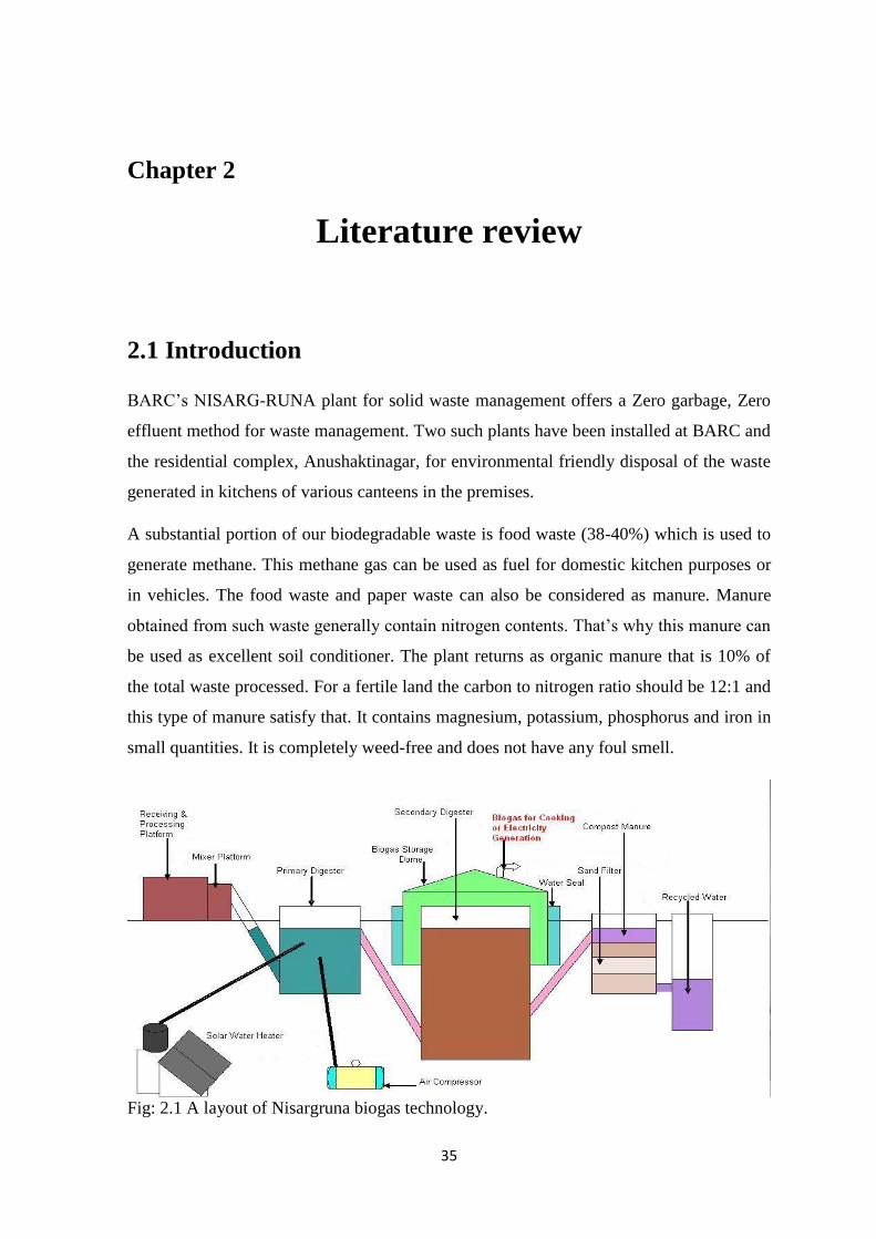
BARC’s NISARG-RUNA plant for solid waste management offers a Zero garbage, Zero
effluent method for waste management. Two such plants have been installed at BARC and
the residential complex, Anushaktinagar, for environmental friendly disposal of the waste
generated in kitchens of various canteens in the premises.
A substantial portion of our biodegradable waste is food waste (38-40%) which is used to
generate methane. This methane gas can be used as fuel for domestic kitchen purposes or
in vehicles. The food waste and paper waste can also be considered as manure. Manure
obtained from such waste generally contain nitrogen contents. That’s why this manure can
be used as excellent soil conditioner. The plant returns as organic manure that is 10% of
the total waste processed. For a fertile land the carbon to nitrogen ratio should be 12:1 and
this type of manure satisfy that. It contains magnesium, potassium, phosphorus and iron in
small quantities. It is completely weed-free and does not have any foul smell.
Fig: 2.1 A layout of Nisargruna biogas technology.

36
2.2 Technical details of the plant
Major components of BARC’s a Nisargruna plant include a mixture/pulper with motor(s)
for crushing solid waste, a pre-mix tank, a pre-digester tank, an air compressor, a slow
water heater or solar panels, a main digestion tank, a gas delivery system, manure pits, a
tank for recycling water, a water pump, slurry pump and a gas utilization system. The
waste is homogenized in a mixer using water. This slurry enters the pre-digester tank
where aerobic thermophilic bacteria proliferate and convert part of this waste into organic
acids like acetic acid, butyric acid, propionic acid and formic acid (Dr S Kale, 2005).
2.2.1 The three steps of Nisargjyoti (biogas) production
Nisargjyoti microbes, which is consist of a large group of complex and differently acting
microbe species, mainly methane-producing bacteria. The entire Nisargjyoti formation
process is followed by three steps: hydrolysis, acidification, and methane formation.
Different types of bacteria are accordingly involved in these processes.
Hydrolysis
This is the first step (hydrolysis) where the organic matter is enzymolyzed externally by
extra cellular enzymes (cellulase, amylase, protease and lipase) of microorganisms. This
step is being carried out in pre-digester tank. In this step the solid waste is converted in to
the semi liquid through a mixer. Bacteria decomposes the long chains of the protein,
complex hydrocarbon and lipids and make it in shorter parts. Proteins are split into amino
acids and peptide. The protein and the simple hydrocarbonate are degraded entirely.
Acidification
In the second step the acidifying bacteria involved, convert the intermediates of
fermenting bacteria and it produces acetic acid (CH3COOH), hydrogen (H2) and carbon
dioxide (CO2) in the same pre-digester. These type of bacteria, like genus bacillus, are
aerobic and facultative anaerobic, and can function under acidic conditions. An air
compressor is provided to maintain aerobic conditions in the pre-digester. To produce
acetic acid, the bacteria use the dissolved oxygen in the slurry solution or bonded-oxygen.
Therefore, the acidifying bacteria reduce the compounds with a low molecular weight into
alcohols, organic acids, amino acids, carbon dioxide, hydrogen sulphide and traces of
methane.
37
Methane formation
In the third step, the methane-producing bacteria, decompose the compounds, produced
after acidifying, with a low molecular weight. Under normal conditions, methanogenic
microorganisms take place to the extent that anaerobic conditions are provided, for
instance under water, in marshes and ruminant stomachs. These bacteria are anaerobic and
very sensitive to environmental changes. In contrast to acidogenic and acetogenic bacteria,
methanogenic bacteria belong to the archae bacteria group. Archae bacteria is a group of
bacteria with a very heterogeneous morphology and a number of common biochemical
and molecular-biological properties that distinguish them from all other bacterial genera. It
is worthwhile to circulate the generated biogas back into the system using a small
compressor. This would provide a rich quality of methane and enhance the reduction of
CO2 to methane.
38
Chapter 3
Case studies
3.1 Discussion
A case study is done in Odisha Power Grid Corporation for the purpose of better
understanding about the nisargruna technology. In OPGC, Odisha a biogas plant of 50 kg
input capacity, is running successfully following Nisargruna technology. The installation
in addition to dairy cow dung manure, uses residential biodegradable waste and co-
digester materials. This biogas plant, following Nisargruna technology, encompassing
feedstock resources and transport. This plant is established 2004. The cow dung is
imported from nearby cow stables by means of scraper system. It is left for sometimes and
then collected from the cow dung pit and send to processing room for proper mixing with
another raw material. Other manure like food waste dry leaves are collected from
residential area every day. These collected waste are segregated in biodegradable and non-
biodegradable. Though they are having a good policy for the segregation, where the
segregation of biodegradable waste is done at the source. Every residence are given two
different dustbin with different color code. Apart from that the drainage system is also
designed in such a way that the separation of waste is one at the source. So all
biodegradable waste are collected automatically in a particular place. All the collected
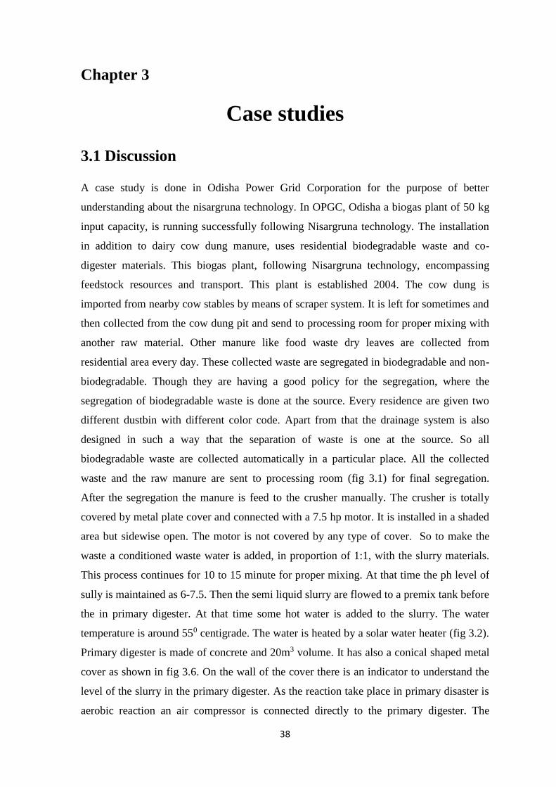
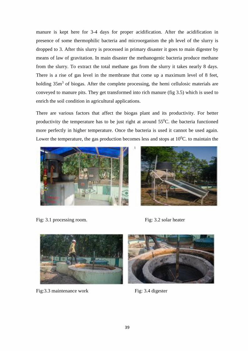
waste and the raw manure are sent to processing room (fig 3.1) for final segregation.
After the segregation the manure is feed to the crusher manually. The crusher is totally
covered by metal plate cover and connected with a 7.5 hp motor. It is installed in a shaded
area but sidewise open. The motor is not covered by any type of cover. So to make the
waste a conditioned waste water is added, in proportion of 1:1, with the slurry materials.
This process continues for 10 to 15 minute for proper mixing. At that time the ph level of
sully is maintained as 6-7.5. Then the semi liquid slurry are flowed to a premix tank before
the in primary digester. At that time some hot water is added to the slurry. The water
temperature is around 550 centigrade. The water is heated by a solar water heater (fig 3.2).
Primary digester is made of concrete and 20m3 volume. It has also a conical shaped metal
cover as shown in fig 3.6. On the wall of the cover there is an indicator to understand the
level of the slurry in the primary digester. As the reaction take place in primary disaster is
aerobic reaction an air compressor is connected directly to the primary digester. The
39
manure is kept here for 3-4 days for proper acidification. After the acidification in
presence of some thermophilic bacteria and microorganism the ph level of the slurry is
dropped to 3. After this slurry is processed in primary disaster it goes to main digester by
means of law of gravitation. In main disaster the methanogenic bacteria produce methane
from the slurry. To extract the total methane gas from the slurry it takes nearly 8 days.
There is a rise of gas level in the membrane that come up a maximum level of 8 feet,
holding 35m3 of biogas. After the complete processing, the hemi cellulosic materials are
conveyed to manure pits. They get transformed into rich manure (fig 3.5) which is used to
enrich the soil condition in agricultural applications.
There are various factors that affect the biogas plant and its productivity. For better
productivity the temperature has to be just right at around 550C. the bacteria functioned
more perfectly in higher temperature. Once the bacteria is used it cannot be used again.
Lower the temperature, the gas production becomes less and stops at 100C. to maintain the
optimum number of methane-producing bacteria the Ph level in the digester tank should be
6.5-7.5.
Fig: 3.1 processing room. Fig: 3.2 solar heater
Fig:3.3 maintenance work Fig: 3.4 digester

40
Fig: 3.5 manure by product Fig 3.6 membrane of two digester.
3.2 Outcome and specification
The quantity and description of the subtract
Amount of biomass (per day) 250 kg
Amount of water use (per day) 250 liter
Electricity (3.7 Kw for 30 min per day) 1.87 units
Lighting (400 watt for 12 hours) 4.8 units
Biogas from 200 kg waste 16 m3 per day
Equivalent lpg gas produced 7.75 kg per day
Digested slurry 75 kg per day
Table: 3.1
Cost analysis:
Project cost 5,81,000
Labour cost 73000
Maintenance cost 30,000
Electricity cost for 6.67 unit 7000 per year
Water cost 1000 per year
Total 1,11,000 per year
Cost of biogas produced (compared to lpg) 1,64,000 per year
Cost of manure produced (@ rs 2/kg) 55000
Total 2,19000
Table 3.2

41
There are several benefits constructed the biogas plant in the premises. Solid waste
management is being carried out smoothly. Apart from that the waste are also used to
produce biomass energy. It is clearly seen from the table that the produced biomass energy
is saving Rs 1,64,000 cost of natural resources by means of LPG gas. Apart from that a
rich manure is also produced which can be applied to enrich the productivity of the soil.
As well as the whole process is also eco-friendly as it is not releasing any type of pollutant
gasses. So the total savings, OPGC can save from this production of rich manure and high
quality biogas is about Rs 1,08,000 per annum.
42
Chapter 4
Questionnaires and survey
4.1 Introduction
A survey work is carried out to know the approach for the handling of waste. It is
necessary to know how much the food department and the hostel cleaning persons know
about the waste handling and disposal. By that means it is easy to figure out the
segregation plan at the source. Segregation of wet waste is essential in order to process the
solid waste management.
Some questions are asked to the head of the mess caterer, hostel warden, canteen owner
and some students also to know their awareness and approaches regarding solid waste
management. We have got very active interesting responses from them.it has been very
easy to us todo the survey work as they are very spontaneous and enthusiasm for this solid
waste management program.
4.2 Response and feedback
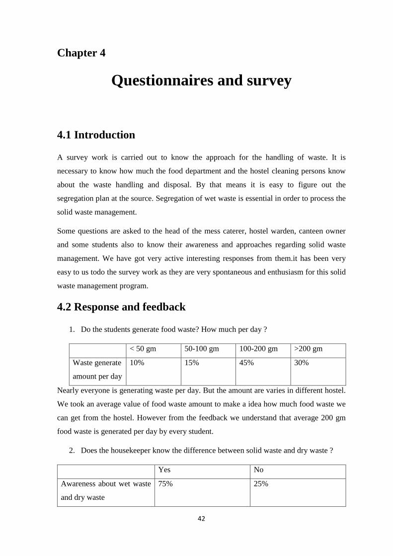
1. Do the students generate food waste? How much per day ?
< 50 gm 50-100 gm 100-200 gm >200 gm
Waste generate
amount per day
10% 15% 45% 30%
Nearly everyone is generating waste per day. But the amount are varies in different hostel.
We took an average value of food waste amount to make a idea how much food waste we
can get from the hostel. However from the feedback we understand that average 200 gm
food waste is generated per day by every student.
2. Does the housekeeper know the difference between solid waste and dry waste ?
Yes No
Awareness about wet waste
and dry waste
75% 25%

43
The hostel warden, kitchen stuffs they are almost know about the wet waste and dry waste.
But it is necessary to know whether the housekeepers know or not. Because they clean the
hostel collect the wasted from the hostel dustbin. In case of canteen also the owner can
separate wet waste and dry waste.
3. Where do the students through their waste. ?
Hostel dustbin Road side Anywhere else
Disposal habit 80% 20% 0
This is very glad to know that the almost students throw their waste at proper place. There
are several dustbin in every hostel at every floor. Apart from that at the campus road side
also there are some bust-bins. So most of the people throw their waste at proper place. So
it is very helpful to collect the waste. But during the night the students take some food
from night canteen or the food shop in campus. That time mostely they through the paper
of waste beside the road.
4. How is the waste collected?
Sweepers are employed to sweep the hostel premises daily. They collect the waste from
the hostel dust bin at every morning. In the dining hall some dustbins are kept. The
students put their food waste by themselves. There are also dustbin at every canteen and
the food restaurant. All the waste including kithen waste, generated in hostel are stored in
a big dustbin constructed before every hostel building. Municipality car comes to collect
the waste. Apart from that there are many workers, sweep dry leaves maintain the grass,
and store all this type of waste at the garbage bins situated in different pace of nit purpose.
5. Is the plastic bag used to disposed the waste ?
Yes No
Use of plastic bag 45% 55%
Generally non degradable plastic bags are used to dispose the waste. The wet waste are
collected in plastic bag to throw it in to the dustbin. But in every hostel a good culture is
adopted. They have some big bucket to use as a dustbin. All the food waste and the
44
kitchen waste are first thrown there. At the end of the day all the all the wasted stored in
the bucket are thrown in the garbage bin at in-front of the hostel. But in canteen or other
restaurant plastic bags are used to dispose any waste. Apart from that the different food
product also available in plastic bag. So from there also plastic packets are generate.
Recently biodegradable plastic packet is also invented and government take necessary
steps to remove the use of hard plastic bags. But here still now biodegradable plastic bag is
not introduced properly.
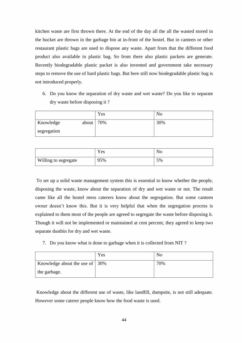
6. Do you know the separation of dry waste and wet waste? Do you like to separate
dry waste before disposing it ?
Yes No
Knowledge about
segregation
70% 30%
Yes No
Willing to segregate 95% 5%
To set up a solid waste management system this is essential to know whether the people,
disposing the waste, know about the separation of dry and wet waste or not. The result
came like all the hostel mess caterers know about the segregation. But some canteen
owner doesn’t know this. But it is very helpful that when the segregation process is
explained to them most of the people are agreed to segregate the waste before disposing it.
Though it will not be implemented or maintained at cent percent, they agreed to keep two
separate dustbin for dry and wet waste.
7. Do you know what is done to garbage when it is collected from NIT ?
Yes No
Knowledge about the use of
the garbage.
30% 70%
Knowledge about the different use of waste, like landfill, dumpsite, is not still adequate.
However some caterer people know how the food waste is used.
45
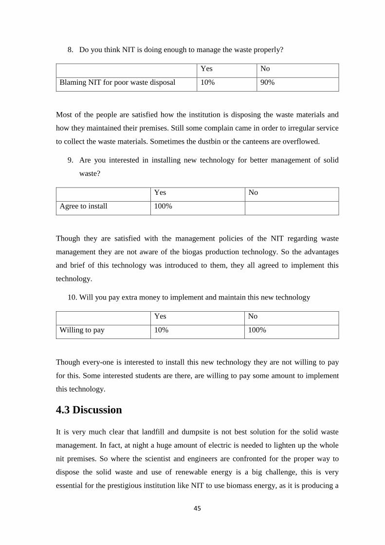
8. Do you think NIT is doing enough to manage the waste properly?
Yes No
Blaming NIT for poor waste disposal 10% 90%
Most of the people are satisfied how the institution is disposing the waste materials and
how they maintained their premises. Still some complain came in order to irregular service
to collect the waste materials. Sometimes the dustbin or the canteens are overflowed.
9. Are you interested in installing new technology for better management of solid
waste?
Yes No
Agree to install 100%
Though they are satisfied with the management policies of the NIT regarding waste
management they are not aware of the biogas production technology. So the advantages
and brief of this technology was introduced to them, they all agreed to implement this
technology.
10. Will you pay extra money to implement and maintain this new technology
Yes No
Willing to pay 10% 100%
Though every-one is interested to install this new technology they are not willing to pay
for this. Some interested students are there, are willing to pay some amount to implement
this technology.
4.3 Discussion
It is very much clear that landfill and dumpsite is not best solution for the solid waste
management. In fact, at night a huge amount of electric is needed to lighten up the whole
nit premises. So where the scientist and engineers are confronted for the proper way to
dispose the solid waste and use of renewable energy is a big challenge, this is very
essential for the prestigious institution like NIT to use biomass energy, as it is producing a

46
huge amount of biodegradable waste. Apart from that this institute can be motivational
icon for the other developing cities and countries, where the waste material handling is a
significant issue. Education is the best way to solve any problem. So it will be very fruitful
for the society if this type of initiatives can be taken by the institution.
47
Chapter 5
Design aspects
5.1 Size of component
The main components of a biogas plant is a motor pump, crusher, two digester, piping
arrangement, insulator, segregation system, air compressor and a solar water heater. On
basis of the installation cost of this main component, the plant installation cost is
evaluated. The following formula can be used to determine the required volume of of the
primary digester.
VD = (Mmanure + Mcs) * HRT/365
Where, VD- digester volume
Mmanure- mass of manure
Mcs – mass of additional material.
HRT – hydraulic retention time
Hydraulic retention time is defined as the time period during which the input manure stays
in digester and the desired reaction is not done properly.
HRT for acidification is around 4 days and the same for methanogenic reaction is around 9
days.
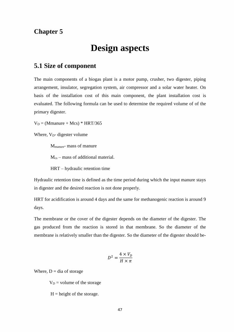
The membrane or the cover of the digester depends on the diameter of the digester. The
gas produced from the reaction is stored in that membrane. So the diameter of the
membrane is relatively smaller than the digester. So the diameter of the digester should be-
𝐷2 =4 × 𝑉𝐷
𝐻 × 𝜋
Where, D = dia of storage
VD = volume of the storage
H = height of the storage.

48
Same equations also go for the secondary digestion. But HRT of methanogenic is more
than the acidification. Apart from that the final product i.e. methane is stored at the upper
membrane of the digester. So the total size of the secondary disaster is greater than the
primary digester.
The biogas, is produce after methanogenic, is stored in the membranes which cover the
secondary digester. So the volume of the dome is
𝑉𝐵𝑆 =𝑉𝑏𝑖𝑜
365× 0.2
Where,
VBS= biomass storage volume
Vbio = daily biogas gas production
Total area of the insulation
For wall
𝐴 = 𝐻 × 𝐷 × 𝜋
For ground
𝐴 = 𝐷2 × 0.785
Suppose we feed 500 kg at a time for crushing and mixing. So the capacity of the motor
and pump is required to mix the slurry is-
Biogas yield:
No of student in the hostel(nos) = 5000
Food waste generated per day(fwg) = 0.2 kg per day
Total food waste amount, generated per day(Tfwg) = nos×fwg
= 1×10³ kg/day
= 365.242 T/year
Making slurry out of food waste for feeding in the digester for efficient digester
Specific gravity of water(spw) = 1
Density of water(pw) = 1000 kg/m3
49
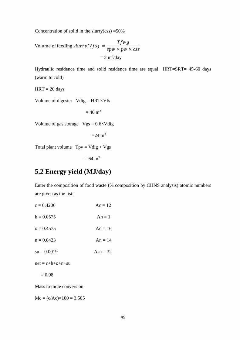
Concentration of solid in the slurry(css) =50%
Volume of feeding 𝑠𝑙𝑢𝑟𝑟𝑦(𝑉𝑓𝑠) =𝑇𝑓𝑤𝑔
𝑠𝑝𝑤 × 𝑝𝑤 × 𝑐𝑠𝑠
= 2 m3/day
Hydraulic residence time and solid residence time are equal HRT=SRT= 45-60 days
(warm to cold)
HRT = 20 days
Volume of digester Vdig = HRT×Vfs
= 40 m3
Volume of gas storage Vgs = 0.6×Vdig
=24 m3
Total plant volume Tpv = Vdig + Vgs
= 64 m3
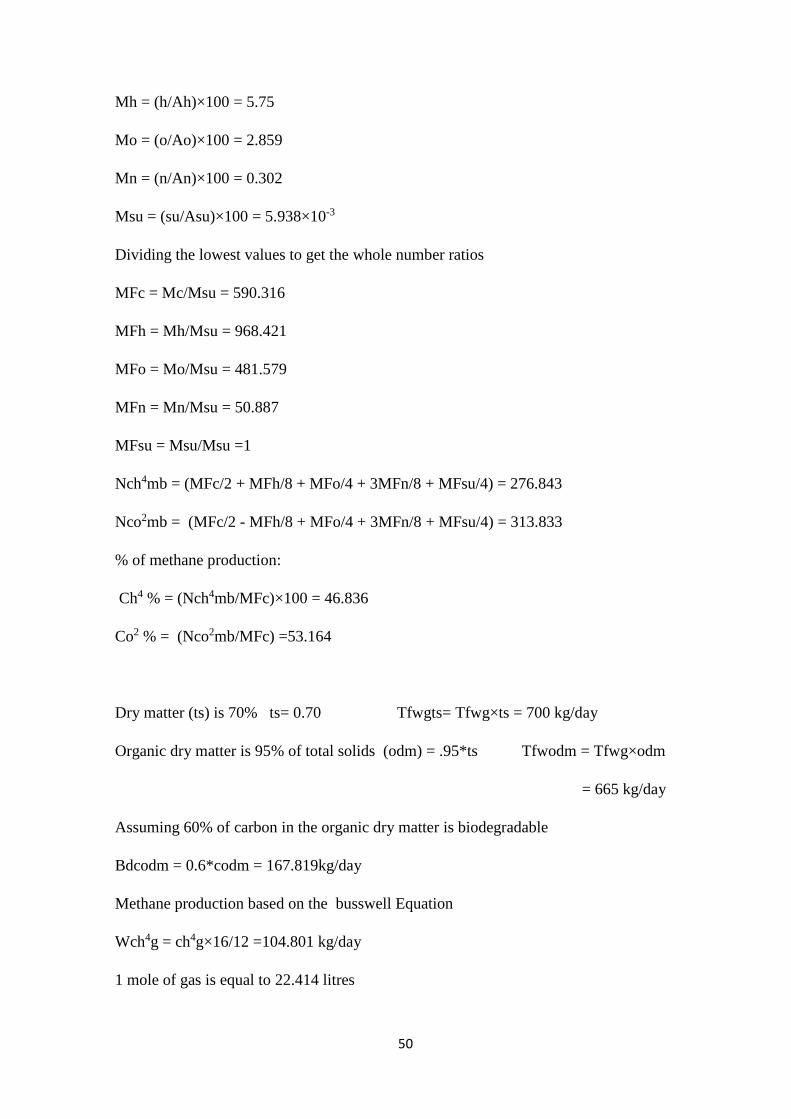
5.2 Energy yield (MJ/day)
Enter the composition of food waste (% composition by CHNS analysis) atomic numbers
are given as the list:
c = 0.4206 Ac = 12
h = 0.0575 Ah = 1
o = 0.4575 Ao = 16
n = 0.0423 An = 14
su = 0.0019 Asn = 32
net = c+h+o+n+su
= 0.98
Mass to mole conversion
Mc = (c/Ac)×100 = 3.505
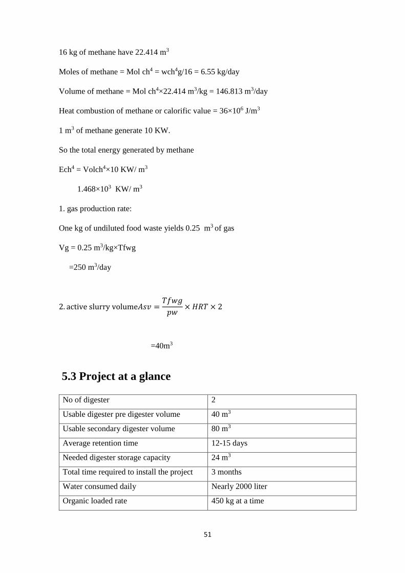
50
Mh = (h/Ah)×100 = 5.75
Mo = (o/Ao)×100 = 2.859
Mn = (n/An)×100 = 0.302
Msu = (su/Asu)×100 = 5.938×10⁻³
Dividing the lowest values to get the whole number ratios
MFc = Mc/Msu = 590.316
MFh = Mh/Msu = 968.421
MFo = Mo/Msu = 481.579
MFn = Mn/Msu = 50.887
MFsu = Msu/Msu =1
Nch4mb = (MFc/2 + MFh/8 + MFo/4 + 3MFn/8 + MFsu/4) = 276.843
Nco2mb = (MFc/2 - MFh/8 + MFo/4 + 3MFn/8 + MFsu/4) = 313.833
% of methane production:
Ch4 % = (Nch4mb/MFc)×100 = 46.836
Co2 % = (Nco2mb/MFc) =53.164
Dry matter (ts) is 70% ts= 0.70 Tfwgts= Tfwg×ts = 700 kg/day
Organic dry matter is 95% of total solids (odm) = .95*ts Tfwodm = Tfwg×odm
= 665 kg/day
Assuming 60% of carbon in the organic dry matter is biodegradable
Bdcodm = 0.6*codm = 167.819kg/day
Methane production based on the busswell Equation
Wch4g = ch4g×16/12 =104.801 kg/day
1 mole of gas is equal to 22.414 litres
51
16 kg of methane have 22.414 m3
Moles of methane = Mol ch4 = wch4g/16 = 6.55 kg/day
Volume of methane = Mol ch4×22.414 m3/kg = 146.813 m3/day
Heat combustion of methane or calorific value = 36×106 J/m3
1 m3 of methane generate 10 KW.
So the total energy generated by methane
Ech4 = Volch4×10 KW/ m3
1.468×10³ KW/ m3
1. gas production rate:
One kg of undiluted food waste yields 0.25 m3 of gas
Vg = 0.25 m3/kg×Tfwg
=250 m3/day
2. active slurry volume𝐴𝑠𝑣 =𝑇𝑓𝑤𝑔
𝑝𝑤× 𝐻𝑅𝑇 × 2
=40m3
5.3 Project at a glance
No of digester 2
Usable digester pre digester volume 40 m3
Usable secondary digester volume 80 m3
Average retention time 12-15 days
Needed digester storage capacity 24 m3
Total time required to install the project 3 months
Water consumed daily Nearly 2000 liter
Organic loaded rate 450 kg at a time
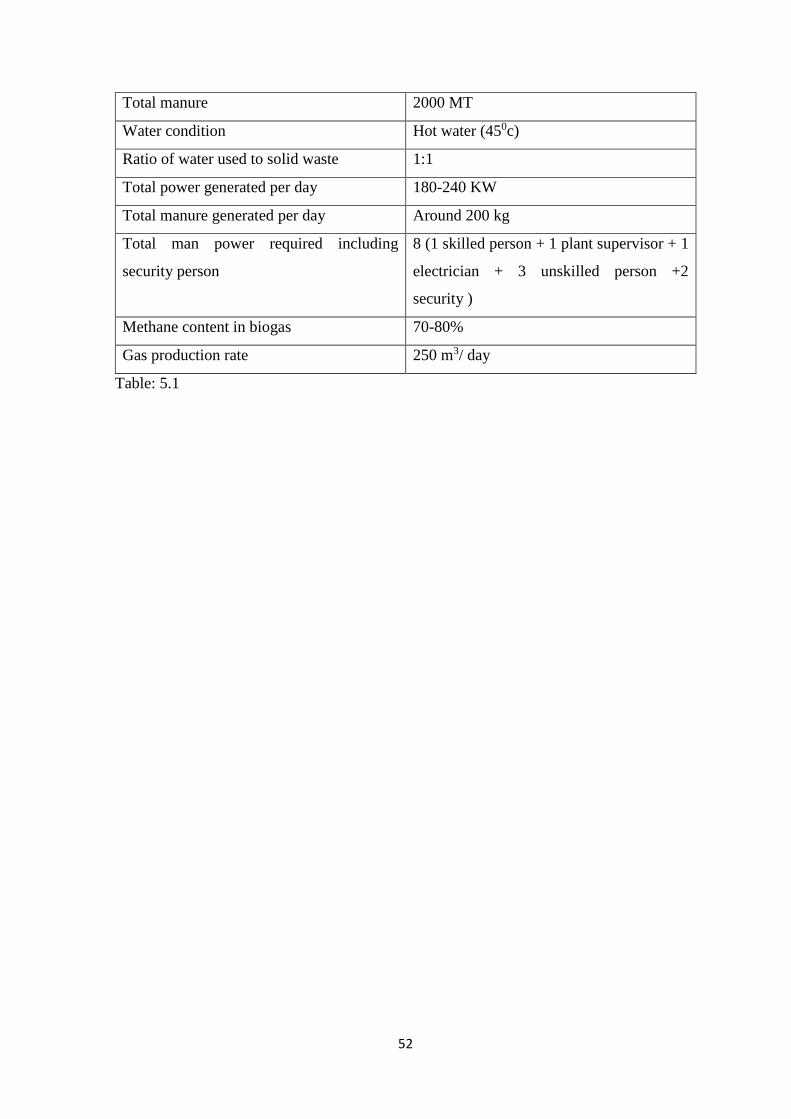
52
Total manure 2000 MT
Water condition Hot water (450c)
Ratio of water used to solid waste 1:1
Total power generated per day 180-240 KW
Total manure generated per day Around 200 kg
Total man power required including
security person
8 (1 skilled person + 1 plant supervisor + 1
electrician + 3 unskilled person +2
security )
Methane content in biogas 70-80%
Gas production rate 250 m3/ day
Table: 5.1
53
Chapter-6
HAZOP study
Biomass is currently an emerging source of renewable energy. This helps a lot to reduce
the use of nonrenewable energy. NIT Rourkela is planned to install a biogas plant to
produce the electricity for hostel purpose. The plant is using cow dung and food waste and
another biodegradable waste of the campus and it is having a good capacity of 2000 kg
feedstock and designed to produce 180-240 KW power. So the role of safety is important
here.
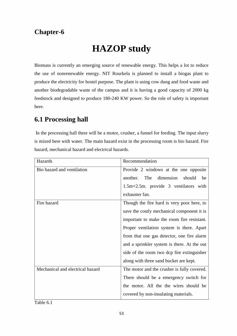
6.1 Processing hall
In the processing hall there will be a motor, crusher, a funnel for feeding. The input slurry
is mixed here with water. The main hazard exist in the processing room is bio hazard. Fire
hazard, mechanical hazard and electrical hazards.
Hazards Recommendation
Bio hazard and ventilation Provide 2 windows at the one opposite
another. The dimension should be
1.5m×2.5m. provide 3 ventilators with
exhauster fan.
Fire hazard Though the fire hard is very poor here, to
save the costly mechanical component it is
important to make the room fire resistant.
Proper ventilation system is there. Apart
from that one gas detector, one fire alarm
and a sprinkler system is there. At the out
side of the room two dcp fire extinguisher
along with three sand bucket are kept.
Mechanical and electrical hazard The motor and the crusher is fully covered.
There should be a emergency switch for
the motor. All the the wires should be
covered by non-insulating materials.
Table 6.1
54
6.2 Digester
It should have a volume of 10 m3each with a center wall having 3’ opening at the bottom
for free slurry movement (excavation, 9” rubbing soiling, P.C.C:- 1:3:6, brick work:- 1:5,
plastering :- 1:4) and aeration grid (using 0.75” GI pipes of tata class) in both the
compartments to provide aeration at three levels of equal intervals starting at 1’ above the
bottom level. The pre digester will be covered by the slab of 4’’ thickness RCC with two
manholes (3’ * 3’) cast in 5mm MS plate.
So as per the design total volume of the primary digester is 10 m3.
As it is an aerobic reaction 10 % space should be given to digester.
So the liquid volume should be 9 m3.
Density of the slurry is 50 kg/m3.
So the maximum input material will be (50*9) kg
= 450 kg
The pressure at the bottom of is developed= 50 * 9.81 * 3
= 1471.5 kg/s
So the wall thickness should be resist this amount of pressure.
To prevent the fire hazard a fire point should be given at 10 m distance from the digester.
The fire point must be equipped with 2 DCP fire extinguisher and three sand buckets.
Secondary digester:
The inlet mass to the main digester is 8 m3.
Hydraulic retention time for the methanogenic reaction 10 day
So the minimum volume of the main digester should be 80m3.
The joint of the slurry conveyer pipe between secondary to main digester should be air
tight properly. And an ignition protection device should be given.
This is most vulnerable area of the plant as the fire hazard is very high here. So a fire point
is provided equipped with 3 water fire extinguisher and four sand bucket.
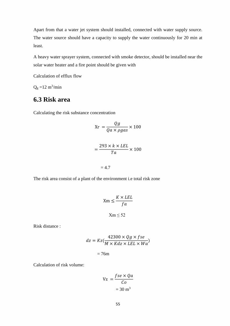
55
Apart from that a water jet system should installed, connected with water supply source.
The water source should have a capacity to supply the water continuously for 20 min at
least.
A heavy water sprayer system, connected with smoke detector, should be installed near the
solar water heater and a fire point should be given with
Calculation of efflux flow
Qg =12 m3/min
6.3 Risk area
Calculating the risk substance concentration
Xr =𝑄𝑔
𝑄𝑎 × 𝜌𝑔𝑎𝑠× 100
=293 × 𝑘 × 𝐿𝐸𝐿
𝑇𝑎× 100
= 4.7
The risk area consist of a plant of the environment i.e total risk zone
Xm ≤𝐾 × 𝐿𝐸𝐿
𝑓𝑎
Xm ≤ 52
Risk distance :
𝑑𝑧 = 𝐾𝑧(42300 × 𝑄𝑔 × 𝑓𝑠𝑒
𝑀 × 𝐾𝑑𝑧 × 𝐿𝐸𝐿 × 𝑊𝑎)
= 76m
Calculation of risk volume:
Vz =𝑓𝑠𝑒 × 𝑄𝑎
𝐶𝑜
= 30 m3
56
6.4 Emergency plan
The Main Objective of the Emergency Response Plan shall be preserving the life, property
& Environment from the consequence of the emergencies arising within the site.
Systematic coordination of emergency control action to arrest escalation of emergency to
evacuate personal within or outside the site where necessary & to rehabilitate them.
Restoring normalcy in site operation with minimum loss of time
So form the above calculation it is recommended an emergency shelter should be there 76
m away from the main digester. In general case the flame can come up to 52 m. so there
should be a water hose connected with at least 250 liter water source. Most importantly
there must not be any hostel or busy road in 52 to 60 meter radius from the main digester.
All the workers have to be trained for fire-fighting so that they can have a basic idea about
how to operate fire extinguisher.
57
Chapter 7
Safety aspects
7.1 Risk and hazard
Production plants present three main risks:
- The hazard of explosion is the most concerned topic as it is associated to the use and
production of a highly flammable gas which is composed with methane.
- The next foremost risk is toxicity due to the presence of H2S. It is a very toxic gas that is
produced in anaerobic digestion.
- The microbial risk is also to be considered, however chronic risk of inhaling pathogens
and minor elements when using biogas is overshadowed by the two previous risks.
To fulfill the aim to construct a bio gas plant, following Nisargruna Technology, the
process of installing and the maintenance should be well monitored in order to the
prevention the hazards, managing the risk and prevent the exposure to that risk.
The biogas plant generally encountered by two main type of hazards:
i. Biological hazard
ii. Fire hazard
7.1.1 Biological hazard:
Bio-chemical-hazard related to biogas plant technology may be encountered by the
feedstock and the digestive. Slurry of animals and human origin encompass various
pathogenic bacteria (e.g Salmonella, Enterobacter, Clostridia, Listeria ecc), parasites (e.g.
Ascaris, Trichostrangylidae, Coccidae), fungi, viruses (Ritari et al. 2012, Sahlstrom 2003).
These bacteria could cause an occupational and environmental biohazard. Biogas
generation from co-digestion of animal manure and biodegradable wastes should not result
in new routes of pathogens and diseases transmission among animals, humans. It can be
controlled by standardized sanitary and veterinary controls.
58
The hazardous substances, are produced in this technology are-
Processing aids (essential nutrients), compounds for desulfurization= hazard of
carcinogenic substances, toxic hazard, In the Ordinance on Bio-substances, biological
agents.
7.1.2 Fire hazard
Biogas plants process in large scale deals with highly combustible and toxic gases. So any
big accident regarding fire and explosion can take place in order to any fault in design,
material or control. Methane, the main product of this process, is highly flammable and
cause explosive mixtures while it composed with the oxygen in the air in proper portion.
Therefore explosion protection is noteworthy factor in biogas plants. Apart from methane
H2S is also a by-product of this plant which is also same flammable. So proper safety
control and policies must be implemented during construction, maintenance and operation
of biogas plants.
Apart from that there are also some another type of hazard may encountered.
7.1.3 Electrical hazards
The main electrical hazards present in the whole system are
Defective electrical equipment or electrical lines; defective lightning protection, defective
electrical installations.
Recommendation
i. All the electrical wire must be covered by non-insulator material coding.
ii. The generator area should be barricaded. No authorised person is allowed to enter
that area.
7.1.4 Mechanical hazards
There are not so much mechanical hazard. In processing room there are some mechanical
components. Apart from that during the construction, maintenance mechanical hazard can
take place. Falling from in to tanks, construction area, silo, ladder.
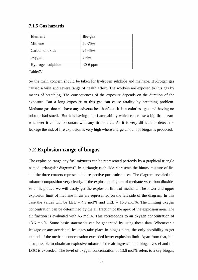
59
7.1.5 Gas hazards
Element Bio-gas
Mithene 50-75%
Carbon di oxide 25-45%
oxygen 2-4%
Hydrogen sulphide <0-6 ppm
Table:7.1
So the main concern should be taken for hydrogen sulphide and methane. Hydrogen gas
caused a wise and severe range of health effect. The workers are exposed to this gas by
means of breathing. The consequences of the exposure depends on the duration of the
exposure. But a long exposure to this gas can cause fatality by breathing problem.
Methane gas doesn’t have any adverse health effect. It is a colorless gas and having no
odor or bad smell. But it is having high flammability which can cause a big fire hazard
whenever it comes to contact with any fire source. As it is very difficult to detect the
leakage the risk of fire explosion is very high where a large amount of biogas is produced.
7.2 Explosion range of biogas
The explosion range any fuel mixtures can be represented perfectly by a graphical triangle
named “triangular diagrams”. In a triangle each side represents the binary mixture of fire
and the three corners represents the respective pure substances. The diagram revealed the
mixture composition very clearly. If the explosion diagram of methane-vs-carbon dioxide-
vs-air is plotted we will easily get the explosion limit of methane. The lower and upper
explosion limit of methane in air are represented on the left side of the diagram. In this
case the values will be LEL = 4.3 mol% and UEL = 16.3 mol%. The limiting oxygen
concentration can be determined by the air fraction of the apex of the explosion area. The
air fraction is evaluated with 65 mol%. This corresponds to an oxygen concentration of
13.6 mol%. Some basic statements can be generated by using these data. Whenever a
leakage or any accidental leakages take place in biogas plant, the only possibility to get
explode if the methane concentration exceeded lower explosion limit. Apart from that, it is
also possible to obtain an explosive mixture if the air ingress into a biogas vessel and the
LOC is exceeded. The level of oxygen concentration of 13.6 mol% refers to a dry biogas,
60
in which the water vapor portion is negligible. For the secondary digesters, where the
biogas contains major portion of water vapor at temperatures up to 50 °C, the LOC drops
down to 12.4 mol%.
Calculation of explosion limit:
The lower explosion limit
LEL = (1 +𝑋𝑐𝑜2
𝑋𝑐ℎ4) × 𝐿𝐸𝐿𝑐ℎ4𝑐𝑜2
So the lower explosion limit from the equation LEL(30/70) = 6.3 mol%
LEL (50/50) = 9.2 mol%
The upper explosion limit
UEL = (1 +𝑋𝑐𝑜2
𝑋𝑐ℎ4) × 𝑈𝐸𝐿𝑐ℎ4𝑐𝑜2
So the upper explosion limit from the equation UEL(30/70) = 19.7 mol%
UEL (50/50) = 23.2 mol%
7.3 Occupational health aspects
Though according to the Italian Decree 81/2008 no special protection devices are required
badly, but the observance of hygiene regulations is critically significant during work and
maintenance in biogas plants. If the quantified hygiene measures and other protective
controls are properly taken, any hazards are not normally encountered. However if
employees suffer any occupational health problems like headaches, dizziness, diarrhoea or
skin irritation, the workers and efficacy of the protective control must be immediately
tested. Any personal hygiene measures include the disinfection or washing of hands before
breaks. The work-place (plant area) must be non-smoking zone and eating and drinking is
not allowed near the processing room or when the segregation is carried out. The apron for
working must be separately stored from private clothing in accordance with good practice
for preventing the propagation of pathogens. A skincare plan is also important. It includes
the provision of facilities for washing and disinfection, and of skin protection and care
products. Furthermore employees must receive instructions on hazards and protective
measures before assuming their tasks and subsequently at regular intervals. In biogas
61
plants, during the different operations (biomass storage, loading and unloading) workers
could be exposed to bacterial endotoxins. Acute lung function changes, which are
associated with endotoxin levels, have been measured in different occupational
environments: pigs farming, animal feed, grain processing, waste and compost industry,
and agricultural seeds (grass, cereal, or vegetable). The source of endotoxins is the
lipopolysaccharides (LPS) in the cell walls of Gram-negative bacteria derived from
decaying wastes. At low concentrations i.e. less than 200 Endotoxin Units (EU)/m3),
endotoxins can induce fever, and at high concentrations (>200 EU/m3) a stimulation of the
mucous membrane; respiratory diseases up to chronic inflammations of the respiratory
system can be evoked. Relatively low endotoxin levels of 50-500 EU/m3 over 8 h may
cause a decline in lung function. An exposure limit of 50 EU/m3 has been recommended
(ICOH 1997).
7.4 Conveying food waste and another waste
According to Nisargruna Technology food waste, another kitchen waste and biodegradable
waste like dry leaves, are considered as input material. So every day food waste will be
collected from all hostels and canteens. The waste from the hostel will be collected by
mini truck to the processing room. To make the segregation easier the hostel caterer will
be provided two different dustbin for biodegradable and non-biodegradable waste. And it
is ordered strictly to throw the waste to the dustbin accordingly. There will be a separate
road for truck to convey the waste and which will be generally avoid to use for general
transportation purpose. The transportation time should be when the road was not too busy.
7.5 Safety measures for segregation
The quality of the methane produced is significantly depended on the segregation process
and the proper input materials. So the segregation of biodegradable material should very
proper in order to produce a high quality biogas. At the time of segregation the bio hazard
is the big concern. As it is segregated manually the workers are directly exposed to the
bacteria. So the effective control measures are-
i. Livestock health control- No animal manure and slurries should be supplied from
any livestock with health problem.
62
ii. Feedstock control- Biomass types with high risk of pathogen contamination must
be excluded from aerobic digester.
iii. All the workers including segregation plant maintenance work, manure collectors
must be provided proper ppe.
Generally three PPEs are require for the whole process
i. Hand gloves: there are no such vulnerable contaminant reacts with rubber. So the
light weight rubber, plastic or simple cotton gloves can be suggested for the whole
process. But as any electric difficulties can come it is better to afford rubber gloves
(IS4770).
ii. Full body apron: simple light weighted cotton apron (HS63079090 is suggested for
the segregation operation.
iii. Nose mask: simple nose mask can be used for the segregation. But at the time of
maintenance of digester tank proper respiratory protection has to be taken.
According to the ICOH 1997 no worker will be exposed in segregation work continuously
for 1 hour.
7.6 Checklist
7.6.1 Checklist for daily work
Conditions yes No
All electrical connections and equipment are checked by the
electrician
Illumination of the processing room is greater the 60
The workers are provided all the recommended ppes
Toolbox talk is given
By product waste manure are cleared out.
The cover of the crusher is locked.
The sensor in AD and SD is working properly.
Solar panel, manure pits are barricaded.
All the fire fighting equipment are inn workable condition
63
7.6.2 Monthly checklist
Parameter Yes No
Maintenance of digester is done
The condition of electric connection are checked
Maintenance the sand filter
Check sprinkler and gas detectors.
Clean the crusher and pipes.
7.6.3 Checklist for maintenance work
Parameter Yes No
All the electrical connection is closed
Environment in the digester is not flammable under normal
condition
No ignition source is present near the digester
Adequate oxygen level is present in the digester
The workers are provided all the PPEs required
All the fire fighting equipment are in workable condition
An ambulance with a medical team is present for the medical
emergency.
7.7 Threat zone
Site data
Location: Rourkela, India
Building Air Exchanges Per Hour: 1.32 (unsheltered single storied)
Time: May 22, 2016 0124 hours ST (using computer's clock)
Chemical data
Chemical Name: METHANE
CAS Number: 74-82-8 Molecular Weight: 16.04 g/mol
64
PAC-1: 65000 ppm PAC-2: 230000 ppm PAC-3: 400000 ppm
LEL: 50000 ppm UEL: 150000 ppm
Ambient Boiling Point: -259.0° F
Vapor Pressure at Ambient Temperature: greater than 1 atm
Ambient Saturation Concentration: 1,000,000 ppm or 100.0%
Atmospheric data: (manual input of data)
Wind: 6 meters/second from SE at 3 meters
Ground Roughness: open country Cloud Cover: 5 tenths
Air Temperature: 38° C Stability Class: D
No Inversion Height Relative Humidity: 36%
Source strength:
Leak from hole in vertical cylindrical tank
Flammable chemical is burning as it escapes from tank
Tank Diameter: 3.57 meters Tank Length: 3 meters
Tank Volume: 30 cubic meters
Tank contains gas only Internal Temperature: 50° C
Amount of Chemical in Tank: 35 cubic meters
Circular Opening Diameter: 5 inches
Flame Length: 11 yards Burn Duration: 20 seconds
Burn Rate: 3.62 pounds/sec
Total Amount Burned: 13.7 pounds

65
Jet fire:
Fig 7.1 Threat zone due to jet fire
Flammable Area of Vapor Cloud
Fig 7.2 Flammable area due to vapor cloud.
66
Over pressure blast-force threat zone:
Fig 7.3 Over pressure blast force threat zone
Night condition:
Atmospheric data changed: wind speed 8 m/sec and humidity 56%
fig 7.4 threat zone due to jet fire at night.
67
over pressure blast force from vapor cloud explosion
Fig: 7.5 Threat zone of over pressure blast force at night
68
Chapter 8
Advantages and disadvantages
Advantage of nisargruna technology
1. Easy to maintain the plant.
2. System is designed indigenously in India; and does not consist of any expensive
imported components, thus ensuring easy availability of spares.
3. Most sub-operations does not require high skill. Workers can be trained for plant
operation in 3 months.
4. Can be more efficient when waste input is good quality of segregated waste.
Disadvantage of the technology
1. Most of the operations are manual and no mechanical operations involved in the
system, pre-digester system needs manual operation of feeding the slurry further to
the pre-digester from the inlet channel. Aesthetically it may not look good.
2. Hot water in the pre-digester needs to be poured manually.
3. There was bad odour at the plant. It might disturb neighbours and dwellers as well
as other visitors too.
4. Sludge holding tanks showed bubbles, which indicates that there might be some
anaerobic conditions, which is due to incomplete digestion of the slurry.
5. There is no proper shredding or cutting of the waste in the mixer, it only
homogenizes with water but doesn’t get crushed by the blades. Digestion will be
faster with properly crushed waste.
69
Chapter 9
Conclusion
Where the pollution is a big concern of the modern world and solid waste management is
part of that aspect, this type of initiatives taken by NIT Rourkela is a motivational
approach to overcome the environmental challenges as well as it is also generating
electrical energy from biomass energy.
It will take around 3 months to install the complete set up. The total expenditure of the
project goes up to maximum 32 lakh including commissioning. And as the biogas is
converted into electricity power it needs a gas generator and a scrubber. So for the
generator and its accessories the budget will be 10 lakh. So the total cost will be around 40
lakh initially. Now every day it will generate 180-250 KW power and around 200 Kg rich
manure. That means rs 900 for electricity (unit@ rs 5) and the manure worth is rs 400 (@
rs 2 per kg). Total we can earn around 1300 per day.
If we see from the environmental aspects, then also the total process is echo friendly. If
any accidental leakage does not take place then this process can run very safely for long
day. From the graph of risk zone it is clearly understood that the main risk zone is around
30 m3. And if the gas leaks for one min without burning it can covered above 70m
distance.

70
Reference
1. www.barc.gov.in/technologies/kitchen/Kitchen.html
2. www.barc.gov.in/publications/nl/2004/200408-8.pdf
3. www.barc.gov.in/akruti-tp/atp_nisar.html
4. www.cdc.gov/niosh/npg/
5. Saha thesis on nisargruna technology, A Diploma Project in Implementation of
Sustainable Technology,
6. Bio-gas plant safety aspects, science direct.
7. Techno-economic analysis of electricity and heat generation from farm-scale biogas
plant: Çiçekdagı case study by Abdullah Akbulut (Mechanical Engineering
Department, Engineering Faculty, Dumlupinar University, 43270 Kutahya, Turkey)