Σ series sgm /sgd user's manual ac servodrives sgm
TRANSCRIPT
YASKAWA
YASKAWA MANUAL NO. SIE-S800-26.3B
!
!
Safety Information
iii
Safety Information
The following conventions are used to indicate precautions in this manual. Failure to heed precau-
tions provided in this manual can result in serious or possibly even fatal injury or damage to the prod-
ucts or to related equipment and systems.
WARNING Indicates precautions that, if not heeded, could possibly result in loss of life orserious injury.
CAUTION Indicates precautions that, if not heeded, could result in relatively serious or minorinjury, damage to the product, or faulty operation.
Yaskawa, 1998
All rights reserved. No part of this publicationmay be reproduced, stored in a retrieval system, or transmitted, in any form,or by any means, mechanical, electronic, photocopying, recording, or otherwise, without the prior written permission ofYaskawa. No patent liability is assumed with respect to the use of the information contained herein. Moreover, becauseYaskawa is constantly striving to improve its high-quality products, the information contained in this manual is subject tochange without notice. Every precaution has been taken in the preparation of this manual. Nevertheless, Yaskawa as-sumes no responsibility for errors or omissions. Neither is any liability assumed for damages resulting from the use of theinformation contained in this publication.
OVERVIEW
v
OVERVIEW
Safety Information iii. . . . . . . . . . . . . . . . . . . . . . . . . . . . . . . . . . . . . . . . . .
TABLE OF CONTENTS vii. . . . . . . . . . . . . . . . . . . . . . . . . . . . . . . . . . . . .
Preface xiii. . . . . . . . . . . . . . . . . . . . . . . . . . . . . . . . . . . . . . . . . . . . . . . . . . .
Features xiii. . . . . . . . . . . . . . . . . . . . . . . . . . . . . . . . . . . . . . . . . . . . . . . . . .
Related Manuals xiii. . . . . . . . . . . . . . . . . . . . . . . . . . . . . . . . . . . . . . . . . . .
Safety Precautions xiv. . . . . . . . . . . . . . . . . . . . . . . . . . . . . . . . . . . . . . . . .
1 Configuration and Model Numbers1.1 Configuration 1 -2. . . . . . . . . . . . . . . . . . . . . . . . . . . . . . . . . . . . . . . . . .
1.2 Models 1 -3. . . . . . . . . . . . . . . . . . . . . . . . . . . . . . . . . . . . . . . . . . . . . . . .
2 Ratings and Characteristics2.1 Ratings/Specifications for 200-VAC SGM Servomotors 2 -2. . . . . . .
2.2 Ratings/Specifications for 100-VAC SGM Servomotors 2 -5. . . . . . .
2.3 Ratings/Specifications for 200-VAC SGMP Servomotors 2 -8. . . . .
2.4 Ratings/Specifications for 100-VAC SGMP Servomotors 2 -10. . . . .
2.5 SERVOPACK Ratings and Specifications 2 -12. . . . . . . . . . . . . . . . . .
2.6 Standard Peripheral Device Combinations 2 -14. . . . . . . . . . . . . . . . .
3 Servodrive Characteristics3.1 Overload Characteristics 3 -2. . . . . . . . . . . . . . . . . . . . . . . . . . . . . . . .
3.2 Starting and Stopping Time 3 -3. . . . . . . . . . . . . . . . . . . . . . . . . . . . . .
3.3 Allowable Repeatability 3 -4. . . . . . . . . . . . . . . . . . . . . . . . . . . . . . . . . .
3.4 Large-amplitude Frequency Characteristics 3 -6. . . . . . . . . . . . . . . .
3.5 Mechanical Characteristics 3 -7. . . . . . . . . . . . . . . . . . . . . . . . . . . . . .
4 Configuration and Connections4.1 Internal Connection Diagram 4 -3. . . . . . . . . . . . . . . . . . . . . . . . . . . . .
4.2 Main Circuit Terminals 4 -4. . . . . . . . . . . . . . . . . . . . . . . . . . . . . . . . . . .
4.3 Applicable Receptacles 4 -4. . . . . . . . . . . . . . . . . . . . . . . . . . . . . . . . . .
4.4 Connecting an Incremental Encoder 4 -5. . . . . . . . . . . . . . . . . . . . . . .
4.5 Connecting an Absolute Encoder 4 -9. . . . . . . . . . . . . . . . . . . . . . . . .
4.6 Output Circuits 4 -13. . . . . . . . . . . . . . . . . . . . . . . . . . . . . . . . . . . . . . . . .
4.7 Connector Terminal Block Converter Unit for 1CN 4 -13. . . . . . . . . . .
4.8 2CN Encoder Connector Terminals 4 -16. . . . . . . . . . . . . . . . . . . . . . . .
4.9 3CN Connector for MECHATROLINK Communication 4 -20. . . . . . .
5 Application5.1 Turning Power ON/OFF 5 -3. . . . . . . . . . . . . . . . . . . . . . . . . . . . . . . . .
5.2 Position Control 5 -4. . . . . . . . . . . . . . . . . . . . . . . . . . . . . . . . . . . . . . . .
5.3 Setting Up an Absolute Encoder 5 -6. . . . . . . . . . . . . . . . . . . . . . . . . .
5.4 Protection Functions 5 -7. . . . . . . . . . . . . . . . . . . . . . . . . . . . . . . . . . . .
5.5 Indications 5 -8. . . . . . . . . . . . . . . . . . . . . . . . . . . . . . . . . . . . . . . . . . . . .
5.6 Precautions 5 -9. . . . . . . . . . . . . . . . . . . . . . . . . . . . . . . . . . . . . . . . . . . .
5.7 Application Precautions 5 -14. . . . . . . . . . . . . . . . . . . . . . . . . . . . . . . . . .
vi
5.8 Appropriate Applications 5 -19. . . . . . . . . . . . . . . . . . . . . . . . . . . . . . . . .
5.9 Adjustments 5 -20. . . . . . . . . . . . . . . . . . . . . . . . . . . . . . . . . . . . . . . . . . .
6 MECHATROLINK Communication6.1 Specifications and Configuration 6 -2. . . . . . . . . . . . . . . . . . . . . . . . . .
6.2 1SW Rotary Switch for MECHATROLINK StationAddress Settings 6 -3. . . . . . . . . . . . . . . . . . . . . . . . . . . . . . . . . . . . .
6.3 MECHATROLINK Command List 6 -4. . . . . . . . . . . . . . . . . . . . . . . . .
6.4 Special Descriptions 6 -7. . . . . . . . . . . . . . . . . . . . . . . . . . . . . . . . . . . .
6.5 Power ON Sequence (Communication Sequence) 6 -16. . . . . . . . . . .
6.6 List of Alarm and Warning Codes 6 -19. . . . . . . . . . . . . . . . . . . . . . . . .
7 User Constants7.1 Setting User Constants 7 -2. . . . . . . . . . . . . . . . . . . . . . . . . . . . . . . . . .
7.2 List of User Constants 7 -13. . . . . . . . . . . . . . . . . . . . . . . . . . . . . . . . . . .
7.3 Memory Switch Bit Details 7 -16. . . . . . . . . . . . . . . . . . . . . . . . . . . . . . .
7.4 Limits to User Constant Changes 7 -21. . . . . . . . . . . . . . . . . . . . . . . . .
7.5 Procedure for Transferring User Constants 7 -21. . . . . . . . . . . . . . . . .
8 Installation and Wiring8.1 Checking on Delivery 8 -2. . . . . . . . . . . . . . . . . . . . . . . . . . . . . . . . . . .
8.2 Installation 8 -2. . . . . . . . . . . . . . . . . . . . . . . . . . . . . . . . . . . . . . . . . . . . .
8.3 Wiring Specifications 8 -6. . . . . . . . . . . . . . . . . . . . . . . . . . . . . . . . . . . .
9 Servodrives Dimensional Drawings9.1 Servomotor Dimensional Drawings 9 -2. . . . . . . . . . . . . . . . . . . . . . . .
9.2 SERVOPACK Dimensional Drawings 9 -34. . . . . . . . . . . . . . . . . . . . . .
9.3 Regenerative Resistor Unit Dimensional Drawings 9 -37. . . . . . . . . .
9.4 Cable Specifications 9 -38. . . . . . . . . . . . . . . . . . . . . . . . . . . . . . . . . . . .
9.5 Connector Kits 9 -44. . . . . . . . . . . . . . . . . . . . . . . . . . . . . . . . . . . . . . . . .
9.6 Noise Filters 9 -47. . . . . . . . . . . . . . . . . . . . . . . . . . . . . . . . . . . . . . . . . . .
9.7 Peripheral Devices 9 -48. . . . . . . . . . . . . . . . . . . . . . . . . . . . . . . . . . . . . .
10 Trial Operation10.1 Check Items before Trial Operation 10 -2. . . . . . . . . . . . . . . . . . . . . .
10.2 Trial Operation Procedure 10 -3. . . . . . . . . . . . . . . . . . . . . . . . . . . . . .
11 Settings11.1 Characteristics at the Factory 11 -2. . . . . . . . . . . . . . . . . . . . . . . . . . .
11.2 Resetting 11 -2. . . . . . . . . . . . . . . . . . . . . . . . . . . . . . . . . . . . . . . . . . . . .
11.3 Adjusting Servo Performance 11 -3. . . . . . . . . . . . . . . . . . . . . . . . . . . .
12 Maintenance and Inspection12.1 Servodrive Maintenance and Inspection of Servodrives 12 -2. . . . .
12.2 Troubleshooting 12 -4. . . . . . . . . . . . . . . . . . . . . . . . . . . . . . . . . . . . . . .
TABLE OF CONTENTS
vii
TABLE OF CONTENTS
Safety Information iii. . . . . . . . . . . . . . . . . . . . . . . . . . . . . . . . . . . . . . . . . . . . . . .TABLE OF CONTENTS vii. . . . . . . . . . . . . . . . . . . . . . . . . . . . . . . . . . . . . . . . .Preface xiii. . . . . . . . . . . . . . . . . . . . . . . . . . . . . . . . . . . . . . . . . . . . . . . . . . . . . . . .Features xiii. . . . . . . . . . . . . . . . . . . . . . . . . . . . . . . . . . . . . . . . . . . . . . . . . . . . . . .Related Manuals xiii. . . . . . . . . . . . . . . . . . . . . . . . . . . . . . . . . . . . . . . . . . . . . . . .Safety Precautions xiv. . . . . . . . . . . . . . . . . . . . . . . . . . . . . . . . . . . . . . . . . . . . . .
1 Configuration and Model Numbers
1.1 Configuration 1 −2. . . . . . . . . . . . . . . . . . . . . . . . . . . . . . . . . . . . . . . . . . . . . .
1.2 Models 1 −3. . . . . . . . . . . . . . . . . . . . . . . . . . . . . . . . . . . . . . . . . . . . . . . . . . . .1.2.1 Servomotor Model Numbers 1 −3. . . . . . . . . . . . . . . . . . . . . . . . . . . . . . . . . . . . . . . . . . .1.2.2 SERVOPACK Model Numbers 1 −3. . . . . . . . . . . . . . . . . . . . . . . . . . . . . . . . . . . . . . . . .
2 Ratings and Characteristics
2.1 Ratings/Specifications for 200-VAC SGM Servomotors 2 −2. . . . . . . .2.1.1 Ratings and Specifications 2 −2. . . . . . . . . . . . . . . . . . . . . . . . . . . . . . . . . . . . . . . . . . . .
2.2 Ratings/Specifications for 100-VAC SGM Servomotors 2 −5. . . . . . . .2.2.1 Ratings and Specifications 2 −5. . . . . . . . . . . . . . . . . . . . . . . . . . . . . . . . . . . . . . . . . . . .
2.3 Ratings/Specifications for 200-VAC SGMP Servomotors 2 −8. . . . . .2.3.1 Ratings and Specifications 2 −8. . . . . . . . . . . . . . . . . . . . . . . . . . . . . . . . . . . . . . . . . . . .
2.4 Ratings/Specifications for 100-VAC SGMP Servomotors 2 −10. . . . . .2.4.1 Ratings and Specifications 2 −10. . . . . . . . . . . . . . . . . . . . . . . . . . . . . . . . . . . . . . . . . . . .
2.5 SERVOPACK Ratings and Specifications 2 −12. . . . . . . . . . . . . . . . . . . . .
2.6 Standard Peripheral Device Combinations 2 −14. . . . . . . . . . . . . . . . . . .
3 Servodrive Characteristics
3.1 Overload Characteristics 3 −2. . . . . . . . . . . . . . . . . . . . . . . . . . . . . . . . . . .
3.2 Starting and Stopping Time 3 −3. . . . . . . . . . . . . . . . . . . . . . . . . . . . . . . . .
3.3 Allowable Repeatability 3 −4. . . . . . . . . . . . . . . . . . . . . . . . . . . . . . . . . . . . .3.3.1 Allowable Repeatability as Limited by the Servomotor 3 −4. . . . . . . . . . . . . . . . . . . . .
3.4 Large-amplitude Frequency Characteristics 3 −6. . . . . . . . . . . . . . . . . .
viii
3.5 Mechanical Characteristics 3 −7. . . . . . . . . . . . . . . . . . . . . . . . . . . . . . . . .3.5.1 Mechanical Strength 3 −7. . . . . . . . . . . . . . . . . . . . . . . . . . . . . . . . . . . . . . . . . . . . . . . . . .3.5.2 Allowable Radial Load and Allowable Thrust Load 3 −7. . . . . . . . . . . . . . . . . . . . . . . .3.5.3 Mechanical Tolerances 3 −7. . . . . . . . . . . . . . . . . . . . . . . . . . . . . . . . . . . . . . . . . . . . . . .3.5.4 Direction of Motor Rotation 3 −8. . . . . . . . . . . . . . . . . . . . . . . . . . . . . . . . . . . . . . . . . . . .3.5.5 Impact Resistance 3 −9. . . . . . . . . . . . . . . . . . . . . . . . . . . . . . . . . . . . . . . . . . . . . . . . . . .3.5.6 Vibration Resistance 3 −9. . . . . . . . . . . . . . . . . . . . . . . . . . . . . . . . . . . . . . . . . . . . . . . . .3.5.7 Vibration Class 3 −9. . . . . . . . . . . . . . . . . . . . . . . . . . . . . . . . . . . . . . . . . . . . . . . . . . . . . .
4 Configuration and Connections
4.1 Internal Connection Diagram 4 −3. . . . . . . . . . . . . . . . . . . . . . . . . . . . . . . .
4.2 Main Circuit Terminals 4 −4. . . . . . . . . . . . . . . . . . . . . . . . . . . . . . . . . . . . . .
4.3 Applicable Receptacles 4 −4. . . . . . . . . . . . . . . . . . . . . . . . . . . . . . . . . . . . .4.3.1 1CN Connector for I/O Signals 4 −4. . . . . . . . . . . . . . . . . . . . . . . . . . . . . . . . . . . . . . . . .4.3.2 2CN Connector for Encoder 4 −4. . . . . . . . . . . . . . . . . . . . . . . . . . . . . . . . . . . . . . . . . . .4.3.3 3CN Connector for MECHATROLINK Communication 4 −4. . . . . . . . . . . . . . . . . . . . .
4.4 Connecting an Incremental Encoder 4 −5. . . . . . . . . . . . . . . . . . . . . . . . .4.4.1 Typical Example 4 −5. . . . . . . . . . . . . . . . . . . . . . . . . . . . . . . . . . . . . . . . . . . . . . . . . . . . .4.4.2 1CN I/O Connector Terminals 4 −6. . . . . . . . . . . . . . . . . . . . . . . . . . . . . . . . . . . . . . . . . .
4.5 Connecting an Absolute Encoder 4 −9. . . . . . . . . . . . . . . . . . . . . . . . . . . .4.5.1 Typical Example 4 −9. . . . . . . . . . . . . . . . . . . . . . . . . . . . . . . . . . . . . . . . . . . . . . . . . . . . .4.5.2 1CN I/O Connector Terminals 4 −10. . . . . . . . . . . . . . . . . . . . . . . . . . . . . . . . . . . . . . . . . .
4.6 Output Circuits 4 −13. . . . . . . . . . . . . . . . . . . . . . . . . . . . . . . . . . . . . . . . . . . . .
4.7 Connector Terminal Block Converter Unit for 1CN 4 −13. . . . . . . . . . . .4.7.1 Application 4 −13. . . . . . . . . . . . . . . . . . . . . . . . . . . . . . . . . . . . . . . . . . . . . . . . . . . . . . . . . .4.7.2 Connection Specifications 4 −14. . . . . . . . . . . . . . . . . . . . . . . . . . . . . . . . . . . . . . . . . . . . .4.7.3 Cable Specifications (Accessory for Connector Terminal Block Converter Unit) 4 −15
4.8 2CN Encoder Connector Terminals 4 −16. . . . . . . . . . . . . . . . . . . . . . . . . .4.8.1 2CN Terminal Layout 4 −16. . . . . . . . . . . . . . . . . . . . . . . . . . . . . . . . . . . . . . . . . . . . . . . . .4.8.2 Applicable Cables 4 −17. . . . . . . . . . . . . . . . . . . . . . . . . . . . . . . . . . . . . . . . . . . . . . . . . . . .4.8.3 2CN Connection Method 4 −18. . . . . . . . . . . . . . . . . . . . . . . . . . . . . . . . . . . . . . . . . . . . . .
4.9 3CN Connector for MECHATROLINK Communication 4 −20. . . . . . . . .4.9.1 3CN Terminal Layout 4 −20. . . . . . . . . . . . . . . . . . . . . . . . . . . . . . . . . . . . . . . . . . . . . . . . .4.9.2 3CN Connection Method 4 −20. . . . . . . . . . . . . . . . . . . . . . . . . . . . . . . . . . . . . . . . . . . . . .
5 Application
5.1 Turning Power ON/OFF 5 −3. . . . . . . . . . . . . . . . . . . . . . . . . . . . . . . . . . . . .
TABLE OF CONTENTS
ix
5.2 Position Control 5 −4. . . . . . . . . . . . . . . . . . . . . . . . . . . . . . . . . . . . . . . . . . . .5.2.1 Electronic Gear Function 5 −4. . . . . . . . . . . . . . . . . . . . . . . . . . . . . . . . . . . . . . . . . . . . . .5.2.2 Feed-forward Control Function 5 −5. . . . . . . . . . . . . . . . . . . . . . . . . . . . . . . . . . . . . . . . .
5.3 Setting Up an Absolute Encoder 5 −6. . . . . . . . . . . . . . . . . . . . . . . . . . . . .5.3.1 Battery 5 −6. . . . . . . . . . . . . . . . . . . . . . . . . . . . . . . . . . . . . . . . . . . . . . . . . . . . . . . . . . . . .5.3.2 Setup Procedure 5 −6. . . . . . . . . . . . . . . . . . . . . . . . . . . . . . . . . . . . . . . . . . . . . . . . . . . . .
5.4 Protection Functions 5 −7. . . . . . . . . . . . . . . . . . . . . . . . . . . . . . . . . . . . . . .5.4.1 Dynamic Brake Function 5 −7. . . . . . . . . . . . . . . . . . . . . . . . . . . . . . . . . . . . . . . . . . . . . .5.4.2 Error Detection Function 5 −7. . . . . . . . . . . . . . . . . . . . . . . . . . . . . . . . . . . . . . . . . . . . . .5.4.3 Servo Alarm Output (ALM, ALM-SG) 5 −8. . . . . . . . . . . . . . . . . . . . . . . . . . . . . . . . . . . .5.4.4 Handling Protection Circuit Operation 5 −8. . . . . . . . . . . . . . . . . . . . . . . . . . . . . . . . . . .5.4.5 Servo Alarm Reset 5 −8. . . . . . . . . . . . . . . . . . . . . . . . . . . . . . . . . . . . . . . . . . . . . . . . . . .
5.5 Indications 5 −8. . . . . . . . . . . . . . . . . . . . . . . . . . . . . . . . . . . . . . . . . . . . . . . . .
5.6 Precautions 5 −9. . . . . . . . . . . . . . . . . . . . . . . . . . . . . . . . . . . . . . . . . . . . . . . .5.6.1 Overhanging Load 5 −9. . . . . . . . . . . . . . . . . . . . . . . . . . . . . . . . . . . . . . . . . . . . . . . . . . .5.6.2 Load Moment of Inertia JL 5 −9. . . . . . . . . . . . . . . . . . . . . . . . . . . . . . . . . . . . . . . . . . . . .5.6.3 Regenerative Unit 5 −11. . . . . . . . . . . . . . . . . . . . . . . . . . . . . . . . . . . . . . . . . . . . . . . . . . . .5.6.4 High Voltage Lines 5 −13. . . . . . . . . . . . . . . . . . . . . . . . . . . . . . . . . . . . . . . . . . . . . . . . . . .
5.7 Application Precautions 5 −14. . . . . . . . . . . . . . . . . . . . . . . . . . . . . . . . . . . .5.7.1 Noise Control 5 −14. . . . . . . . . . . . . . . . . . . . . . . . . . . . . . . . . . . . . . . . . . . . . . . . . . . . . . . .5.7.2 Power Supply Line Protection 5 −17. . . . . . . . . . . . . . . . . . . . . . . . . . . . . . . . . . . . . . . . . .
5.8 Appropriate Applications 5 −19. . . . . . . . . . . . . . . . . . . . . . . . . . . . . . . . . . .5.8.1 Holding Brake Interlock Signal 5 −19. . . . . . . . . . . . . . . . . . . . . . . . . . . . . . . . . . . . . . . . .
5.9 Adjustments 5 −20. . . . . . . . . . . . . . . . . . . . . . . . . . . . . . . . . . . . . . . . . . . . . . .5.9.1 Servo System Adjustments 5 −20. . . . . . . . . . . . . . . . . . . . . . . . . . . . . . . . . . . . . . . . . . . .5.9.2 User Constants 5 −21. . . . . . . . . . . . . . . . . . . . . . . . . . . . . . . . . . . . . . . . . . . . . . . . . . . . . .5.9.3 Functions that Improve Response 5 −24. . . . . . . . . . . . . . . . . . . . . . . . . . . . . . . . . . . . . .5.9.4 Guidelines for Setting the Load Inertia Ratio 5 −25. . . . . . . . . . . . . . . . . . . . . . . . . . . . .
6 MECHATROLINK Communication
6.1 Specifications and Configuration 6 −2. . . . . . . . . . . . . . . . . . . . . . . . . . . .6.1.1 Specifications 6 −2. . . . . . . . . . . . . . . . . . . . . . . . . . . . . . . . . . . . . . . . . . . . . . . . . . . . . . .6.1.2 Control Structure 6 −2. . . . . . . . . . . . . . . . . . . . . . . . . . . . . . . . . . . . . . . . . . . . . . . . . . . . .
6.2 1SW Rotary Switch for MECHATROLINK StationAddress Settings 6 −3. . . . . . . . . . . . . . . . . . . . . . . . . . . . . . . . . . . . . . . . .
6.3 MECHATROLINK Command List 6 −4. . . . . . . . . . . . . . . . . . . . . . . . . . . . .
x
6.4 Special Descriptions 6 −7. . . . . . . . . . . . . . . . . . . . . . . . . . . . . . . . . . . . . . .6.4.1 Option Field Specifications 6 −7. . . . . . . . . . . . . . . . . . . . . . . . . . . . . . . . . . . . . . . . . . . .6.4.2 I/O Monitor Specifications 6 −9. . . . . . . . . . . . . . . . . . . . . . . . . . . . . . . . . . . . . . . . . . . . .6.4.3 Monitor 1/2 Type Field Specifications 6 −10. . . . . . . . . . . . . . . . . . . . . . . . . . . . . . . . . . .6.4.4 CONFIG Specifications 6 −11. . . . . . . . . . . . . . . . . . . . . . . . . . . . . . . . . . . . . . . . . . . . . . .6.4.5 ALM_RD Specifications 6 −11. . . . . . . . . . . . . . . . . . . . . . . . . . . . . . . . . . . . . . . . . . . . . . .6.4.6 ALM_CLR Specifications 6 −12. . . . . . . . . . . . . . . . . . . . . . . . . . . . . . . . . . . . . . . . . . . . . .6.4.7 CONNECT Specifications 6 −12. . . . . . . . . . . . . . . . . . . . . . . . . . . . . . . . . . . . . . . . . . . . .6.4.8 INTERPOLATE Specifications 6 −13. . . . . . . . . . . . . . . . . . . . . . . . . . . . . . . . . . . . . . . . .6.4.9 LATCH Specifications 6 −13. . . . . . . . . . . . . . . . . . . . . . . . . . . . . . . . . . . . . . . . . . . . . . . .6.4.10 POSING Command Specifications 6 −14. . . . . . . . . . . . . . . . . . . . . . . . . . . . . . . . . . . .6.4.11 INTERPOLATE Command Specifications 6 −14. . . . . . . . . . . . . . . . . . . . . . . . . . . . . . .6.4.12 ID_RD Specifications 6 −14. . . . . . . . . . . . . . . . . . . . . . . . . . . . . . . . . . . . . . . . . . . . . . . .6.4.13 Unsupported Commands 6 −15. . . . . . . . . . . . . . . . . . . . . . . . . . . . . . . . . . . . . . . . . . . .
6.5 Power ON Sequence (Communication Sequence) 6 −16. . . . . . . . . . . . .
6.6 List of Alarm and Warning Codes 6 −19. . . . . . . . . . . . . . . . . . . . . . . . . . . .
7 User Constants
7.1 Setting User Constants 7 −2. . . . . . . . . . . . . . . . . . . . . . . . . . . . . . . . . . . . .7.1.1 Gain-related Constants 7 −2. . . . . . . . . . . . . . . . . . . . . . . . . . . . . . . . . . . . . . . . . . . . . . .7.1.2 Torque-related Constants 7 −3. . . . . . . . . . . . . . . . . . . . . . . . . . . . . . . . . . . . . . . . . . . . .7.1.3 Sequence-related Constants 7 −3. . . . . . . . . . . . . . . . . . . . . . . . . . . . . . . . . . . . . . . . . .7.1.4 Motion-related Constants 7 −5. . . . . . . . . . . . . . . . . . . . . . . . . . . . . . . . . . . . . . . . . . . . .7.1.5 Pulse-related Constants 7 −7. . . . . . . . . . . . . . . . . . . . . . . . . . . . . . . . . . . . . . . . . . . . . .7.1.6 Other Constants 7 −8. . . . . . . . . . . . . . . . . . . . . . . . . . . . . . . . . . . . . . . . . . . . . . . . . . . . .7.1.7 Memory Switches 7 −9. . . . . . . . . . . . . . . . . . . . . . . . . . . . . . . . . . . . . . . . . . . . . . . . . . . .
7.2 List of User Constants 7 −13. . . . . . . . . . . . . . . . . . . . . . . . . . . . . . . . . . . . . .
7.3 Memory Switch Bit Details 7 −16. . . . . . . . . . . . . . . . . . . . . . . . . . . . . . . . . .7.3.1 Cn-0001: Memory Switches 1 7 −16. . . . . . . . . . . . . . . . . . . . . . . . . . . . . . . . . . . . . . . . . .7.3.2 Cn-0002: Memory Switches 2 7 −18. . . . . . . . . . . . . . . . . . . . . . . . . . . . . . . . . . . . . . . . . .7.3.3 Cn-0013: Memory Switches 3 7 −19. . . . . . . . . . . . . . . . . . . . . . . . . . . . . . . . . . . . . . . . . .7.3.4 Cn-0014: Memory Switches 4 7 −20. . . . . . . . . . . . . . . . . . . . . . . . . . . . . . . . . . . . . . . . . .
7.4 Limits to User Constant Changes 7 −21. . . . . . . . . . . . . . . . . . . . . . . . . . . .
7.5 Procedure for Transferring User Constants 7 −21. . . . . . . . . . . . . . . . . .
8 Installation and Wiring
8.1 Checking on Delivery 8 −2. . . . . . . . . . . . . . . . . . . . . . . . . . . . . . . . . . . . . . .
8.2 Installation 8 −2. . . . . . . . . . . . . . . . . . . . . . . . . . . . . . . . . . . . . . . . . . . . . . . . .8.2.1 Installing Servomotors 8 −2. . . . . . . . . . . . . . . . . . . . . . . . . . . . . . . . . . . . . . . . . . . . . . . .8.2.2 Installing SERVOPACKS 8 −4. . . . . . . . . . . . . . . . . . . . . . . . . . . . . . . . . . . . . . . . . . . . . .
TABLE OF CONTENTS
xi
8.3 Wiring Specifications 8 −6. . . . . . . . . . . . . . . . . . . . . . . . . . . . . . . . . . . . . . .8.3.1 Rated Current and Cable Specifications 8 −6. . . . . . . . . . . . . . . . . . . . . . . . . . . . . . . . .8.3.2 Wiring Instructions 8 −7. . . . . . . . . . . . . . . . . . . . . . . . . . . . . . . . . . . . . . . . . . . . . . . . . . .8.3.3 Power Loss 8 −8. . . . . . . . . . . . . . . . . . . . . . . . . . . . . . . . . . . . . . . . . . . . . . . . . . . . . . . . .8.3.4 Leakage Current 8 −9. . . . . . . . . . . . . . . . . . . . . . . . . . . . . . . . . . . . . . . . . . . . . . . . . . . . .
9 Servodrives Dimensional Drawings
9.1 Servomotor Dimensional Drawings 9 −2. . . . . . . . . . . . . . . . . . . . . . . . . .9.1.1 SGM Servomotors 9 −2. . . . . . . . . . . . . . . . . . . . . . . . . . . . . . . . . . . . . . . . . . . . . . . . . . .9.1.2 SGMP Servomotors 9 −18. . . . . . . . . . . . . . . . . . . . . . . . . . . . . . . . . . . . . . . . . . . . . . . . . .
9.2 SERVOPACK Dimensional Drawings 9 −34. . . . . . . . . . . . . . . . . . . . . . . . .9.2.1 SGD-A3AN to 02AN, SGD-A3BN to 01BN 9 −34. . . . . . . . . . . . . . . . . . . . . . . . . . . . . . .9.2.2 SGD-04AN, SGD-02BN 9 −35. . . . . . . . . . . . . . . . . . . . . . . . . . . . . . . . . . . . . . . . . . . . .9.2.3 SGD-08AN, SGD-03BN 9 −36. . . . . . . . . . . . . . . . . . . . . . . . . . . . . . . . . . . . . . . . . . . . .
9.3 Regenerative Resistor Unit Dimensional Drawings 9 −37. . . . . . . . . . . .
9.4 Cable Specifications 9 −38. . . . . . . . . . . . . . . . . . . . . . . . . . . . . . . . . . . . . . . .9.4.1 Cables from Yaskawa 9 −38. . . . . . . . . . . . . . . . . . . . . . . . . . . . . . . . . . . . . . . . . . . . . . . .9.4.2 Cables without SERVOPACK Connectors (PG Cables Only) 9 −40. . . . . . . . . . . . . . .9.4.3 Cables Only 9 −42. . . . . . . . . . . . . . . . . . . . . . . . . . . . . . . . . . . . . . . . . . . . . . . . . . . . . . . . .
9.5 Connector Kits 9 −44. . . . . . . . . . . . . . . . . . . . . . . . . . . . . . . . . . . . . . . . . . . . .9.5.1 Encoder Cable Connectors 9 −44. . . . . . . . . . . . . . . . . . . . . . . . . . . . . . . . . . . . . . . . . . . .9.5.2 Motor Cable Connectors 9 −44. . . . . . . . . . . . . . . . . . . . . . . . . . . . . . . . . . . . . . . . . . . . . .9.5.3 SERVOPACK Connectors 9 −44. . . . . . . . . . . . . . . . . . . . . . . . . . . . . . . . . . . . . . . . . . . . .
9.6 Noise Filters 9 −47. . . . . . . . . . . . . . . . . . . . . . . . . . . . . . . . . . . . . . . . . . . . . . .9.6.1 Dimensional Diagram 9 −47. . . . . . . . . . . . . . . . . . . . . . . . . . . . . . . . . . . . . . . . . . . . . . . . .
9.7 Peripheral Devices 9 −48. . . . . . . . . . . . . . . . . . . . . . . . . . . . . . . . . . . . . . . . .9.7.1 Connector Terminal Block Converter Unit 9 −48. . . . . . . . . . . . . . . . . . . . . . . . . . . . . . . .9.7.2 Brake Power Supply 9 −48. . . . . . . . . . . . . . . . . . . . . . . . . . . . . . . . . . . . . . . . . . . . . . . . . .9.7.3 Analog Monitor Cables 9 −49. . . . . . . . . . . . . . . . . . . . . . . . . . . . . . . . . . . . . . . . . . . . . . . .
10 Trial Operation
10.1 Check Items before Trial Operation 10 −2. . . . . . . . . . . . . . . . . . . . . . . . .10.1.1 Servomotors 10 −2. . . . . . . . . . . . . . . . . . . . . . . . . . . . . . . . . . . . . . . . . . . . . . . . . . . . . . .10.1.2 SERVOPACKS 10 −2. . . . . . . . . . . . . . . . . . . . . . . . . . . . . . . . . . . . . . . . . . . . . . . . . . . . .
10.2 Trial Operation Procedure 10 −3. . . . . . . . . . . . . . . . . . . . . . . . . . . . . . . . .10.2.1 Preparation for Trial Operation 10 −3. . . . . . . . . . . . . . . . . . . . . . . . . . . . . . . . . . . . . . . .10.2.2 Operation 10 −3. . . . . . . . . . . . . . . . . . . . . . . . . . . . . . . . . . . . . . . . . . . . . . . . . . . . . . . . . .10.2.3 Trial Operation Inspection 10 −4. . . . . . . . . . . . . . . . . . . . . . . . . . . . . . . . . . . . . . . . . . . .
xii
11 Settings
11.1 Characteristics at the Factory 11 −2. . . . . . . . . . . . . . . . . . . . . . . . . . . . . .
11.2 Resetting 11 −2. . . . . . . . . . . . . . . . . . . . . . . . . . . . . . . . . . . . . . . . . . . . . . . . .
11.3 Adjusting Servo Performance 11 −3. . . . . . . . . . . . . . . . . . . . . . . . . . . . . .11.3.1 Setting User Constants 11 −3. . . . . . . . . . . . . . . . . . . . . . . . . . . . . . . . . . . . . . . . . . . . . .11.3.2 Setting Optimum Position and Speed Loop Gain 11 −3. . . . . . . . . . . . . . . . . . . . . . . .
12 Maintenance and Inspection
12.1 Servodrive Maintenance and Inspection of Servodrives 12 −2. . . . . .12.1.1 Servomotor 12 −2. . . . . . . . . . . . . . . . . . . . . . . . . . . . . . . . . . . . . . . . . . . . . . . . . . . . . . . .12.1.2 SERVOPACK Inspection 12 −3. . . . . . . . . . . . . . . . . . . . . . . . . . . . . . . . . . . . . . . . . . . . .12.1.3 Replacing Battery for Absolute Encoder 12 −3. . . . . . . . . . . . . . . . . . . . . . . . . . . . . . . .
12.2 Troubleshooting 12 −4. . . . . . . . . . . . . . . . . . . . . . . . . . . . . . . . . . . . . . . . . .12.2.1 Servomotor 12 −4. . . . . . . . . . . . . . . . . . . . . . . . . . . . . . . . . . . . . . . . . . . . . . . . . . . . . . . .12.2.2 SERVOPACK 12 −5. . . . . . . . . . . . . . . . . . . . . . . . . . . . . . . . . . . . . . . . . . . . . . . . . . . . . .
Preface
xiii
Preface
Based on Yaskawa servo manufacturing technology and servo application technology accumulated
over the last half a century, Yaskawa has launched the AC Servo Series that, together with its rich line
of products, meets the needs of the modern needs of FA and FMS in their application to machining
tools and robots.
AC Servos not only provide stable, highly accurate, and high-speed response control even under ad-
verse environments, but also provide such features as easy application, flexibility, and easy maintain.
The new Yaskawa AC Servos can be used in various servo fields, including machining tools and ro-
bots.
Features
D The highest available power rates and response in this class of servo.
D Compared with conventional products, these servomotors are approximately 1/3 both in volume
and weight and SERVOPACKS are approximately 1/4 in volume.
D Thebook-shapeSERVOPACKScanbeusedwith either incremental encodersor absoluteencoders.
D Positioning is performed using the MECHATROLINK High-speed Field Network.
D Electronic gear function provided.
D For incremental encoders, there are now only 9 lines to wire between the encoder and the SERVO-
PACK (previously: 15 lines).
D There are now only 6 I/O points to wire (previously: 15 I/O points).
D Improved environmental resistance by using varnish coating.
D Improved dispersion with command cable length up to 50 m (previously: 3 m).
Related Manuals
Refer to the following manuals as required
Read this manual carefully to ensure the proper use of the SERVOPACKS. Also, keep this manual in
a safe place so that it can be referred to whenever necessary.
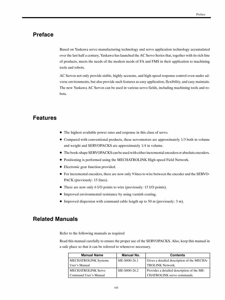
Manual Name Manual No. Contents
MECHATROLINK SystemsUser’s Manual
SIE-S800-26.1 Gives a detailed description of the MECHA-TROLINK Network.
MECHATROLINK ServoCommand User’s Manual
SIE-S800-26.2 Provides a detailed description of the ME-CHATROLINK servo commands.
xiv
Safety Precautions
The following precautions are for checking products upon delivery, installation, wiring, operation,
maintenance and inspections.
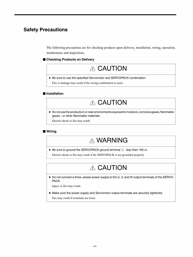
JChecking Products on Delivery
CAUTION!
D Be sure to use the specified Servomotor and SERVOPACK combination.
Fire or damage may result if the wrong combination is used..
J Installation
CAUTION!
D Donotuse theproducts inor nearenvironmentsexposed tomoisture, corrosivegases, flammablegases , or other flammable materials.
Electric shock or fire may result.
JWiring
WARNING!
D Be sure to ground the SERVOPACK ground terminal less than 100 Ω.
Electric shock or fire may result if the SERVOPACK is not grounded properly.
CAUTION!
D Do not connect a three−phase power supply to the U, V, and W output terminals of the SERVO-PACK.
Injury or fire may result.
D Make sure the power supply and Servomotor output terminals are securely tightened.
Fire may result if terminals are loose.
Safety Precautions
xv
JOperation
WARNING!
D Do not touch rotating parts of the Servomotor during operation.
Injury may result.
CAUTION!
D In order to avoid accidents, do not connect the Servomotor shaft to the controlled equipment dur-ing the trial operation.
Injury may result.
D Be sure to set the proper user constants for the controlled equipment prior to starting operationwith the Servomotor connected to the equipment.
Equipment overrun or damage may result without proper settings prior to the start of operation.
D Always set up an emergency stop prior to starting operationwith the Servomotor connected to theequipment.
Injury may result if an emergency stop is not readily available.
D Do not touch the heat sink area during operation.
Severe burns due to high temperatures may result.
JMaintenance and Inspection
WARNING!
D Do not touch areas inside the SERVOPACK.
Electric shock may result.
D Make sure the panel cover is attached when power is ON.
Electric shock may result if the panel cover is left open.
D Turn OFF power and wait 5 minutes before touching terminals.
Electric shock from residual voltage may result if terminals are touched within 5 minutes of turning OFFpower.
CAUTION!
D Do not disassemble the Servomotor.
Electric shock or injury may result.
D Do not change wiring with the power turned ON.
Electric shock or injury may result.
xvi
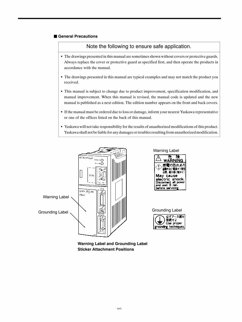
JGeneral Precautions
Note the following to ensure safe application.
S The drawings presented in thismanual are sometimes shownwithout covers or protective guards.Always replace the cover or protective guard as specified first, and then operate the products inaccordance with the manual.
S The drawings presented in this manual are typical examples and may not match the product youreceived.
S This manual is subject to change due to product improvement, specification modification, andmanual improvement. When this manual is revised, the manual code is updated and the newmanual is published as a next edition. The edition number appears on the front and back covers.
S If themanualmust be ordered due to loss or damage, inform your nearest Yaskawa representativeor one of the offices listed on the back of this manual.
S Yaskawawill not take responsibility for the results of unauthorizedmodifications of this product.Yaskawa shall not be liable for anydamagesor troubles resulting fromunauthorizedmodification.
Warning Label and Grounding LabelSticker Attachment Positions
Warning Label
Grounding Label
Warning Label
Grounding Label
1 -1
1Configuration and Model Numbers
This chapter describes the configuration and model numbers for Servo-
drives.
1.1 Configuration 1 -2. . . . . . . . . . . . . . . . . . . . . . . . . . . . .1.2 Models 1 -3. . . . . . . . . . . . . . . . . . . . . . . . . . . . . . . . . .
1.2.1 Servomotor Model Numbers 1 -3. . . . . . . . . . . . . . . . . .
1.2.2 SERVOPACK Model Numbers 1 -3. . . . . . . . . . . . . . . .
1
Configuration and Model Numbers
1 -2
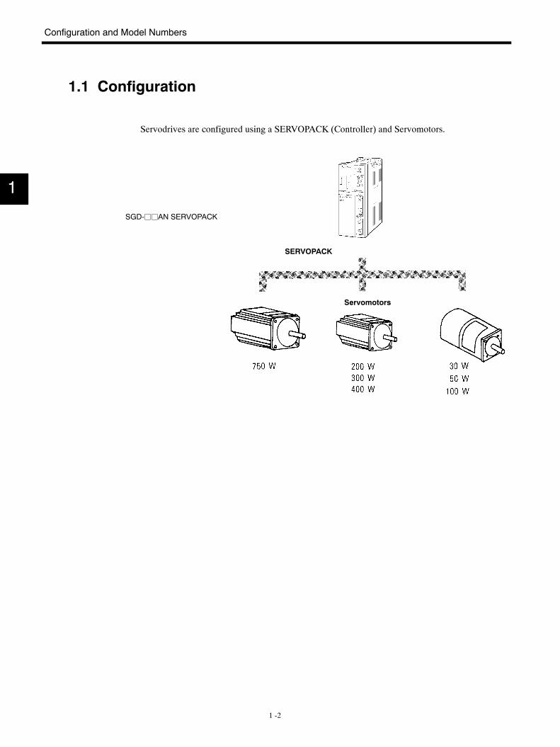
1.1 Configuration
Servodrives are configured using a SERVOPACK (Controller) and Servomotors.
SGD-jjAN SERVOPACK
SERVOPACK
Servomotors
1
1.2 Models
1 -3
1.2 Models
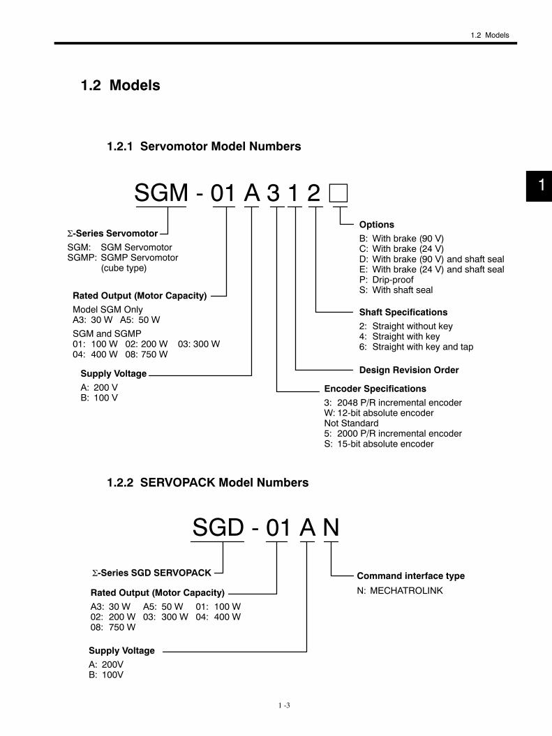
1.2.1 Servomotor Model Numbers
SGM - 01 A 3 1 2 jΣ-Series ServomotorSGM: SGM ServomotorSGMP: SGMP Servomotor
(cube type)
Rated Output (Motor Capacity)Model SGM OnlyA3: 30 W A5: 50 WSGM and SGMP01: 100 W 02: 200 W 03: 300 W04: 400 W 08: 750 W
Supply VoltageA: 200 VB: 100 V
OptionsB: With brake (90 V)C: With brake (24 V)D: With brake (90 V) and shaft sealE: With brake (24 V) and shaft sealP: Drip-proofS: With shaft seal
Shaft Specifications2: Straight without key4: Straight with key6: Straight with key and tap
Design Revision Order
Encoder Specifications3: 2048 P/R incremental encoderW: 12-bit absolute encoderNot Standard5: 2000 P/R incremental encoderS: 15-bit absolute encoder
1.2.2 SERVOPACK Model Numbers
SGD - 01 A N
Command interface type
N: MECHATROLINK
Σ-Series SGD SERVOPACK
Rated Output (Motor Capacity)A3: 30 W A5: 50 W 01: 100 W02: 200 W 03: 300 W 04: 400 W08: 750 W
Supply VoltageA: 200VB: 100V
1
2 -1
2Ratings and Characteristics
This chapter provides Servomotor ratings, specifications, and torque-
speed characteristics, as well as SERVOPACK ratings and specifications.
2.1 Ratings/Specifications for 200-VAC SGMServomotors 2 -2. . . . . . . . . . . . . . . . . . . . . . . . . . . . . .2.1.1 Ratings and Specifications 2 -2. . . . . . . . . . . . . . . . . . . .
2.2 Ratings/Specifications for 100-VAC SGMServomotors 2 -5. . . . . . . . . . . . . . . . . . . . . . . . . . . . . .2.2.1 Ratings and Specifications 2 -5. . . . . . . . . . . . . . . . . . . .
2.3 Ratings/Specifications for 200-VAC SGMPServomotors 2 -8. . . . . . . . . . . . . . . . . . . . . . . . . . . . . .2.3.1 Ratings and Specifications 2 -8. . . . . . . . . . . . . . . . . . . .
2.4 Ratings/Specifications for 100-VAC SGMPServomotors 2 -10. . . . . . . . . . . . . . . . . . . . . . . . . . . . . .2.4.1 Ratings and Specifications 2 -10. . . . . . . . . . . . . . . . . . . .
2.5 SERVOPACK Ratings and Specifications 2 -12. . . .2.6 Standard Peripheral Device Combinations 2 -14. . . .
2
Ratings and Characteristics
2.1.1 Ratings and Specifications
2 -2
2.1 Ratings/Specifications for 200-VAC SGM Servomotors
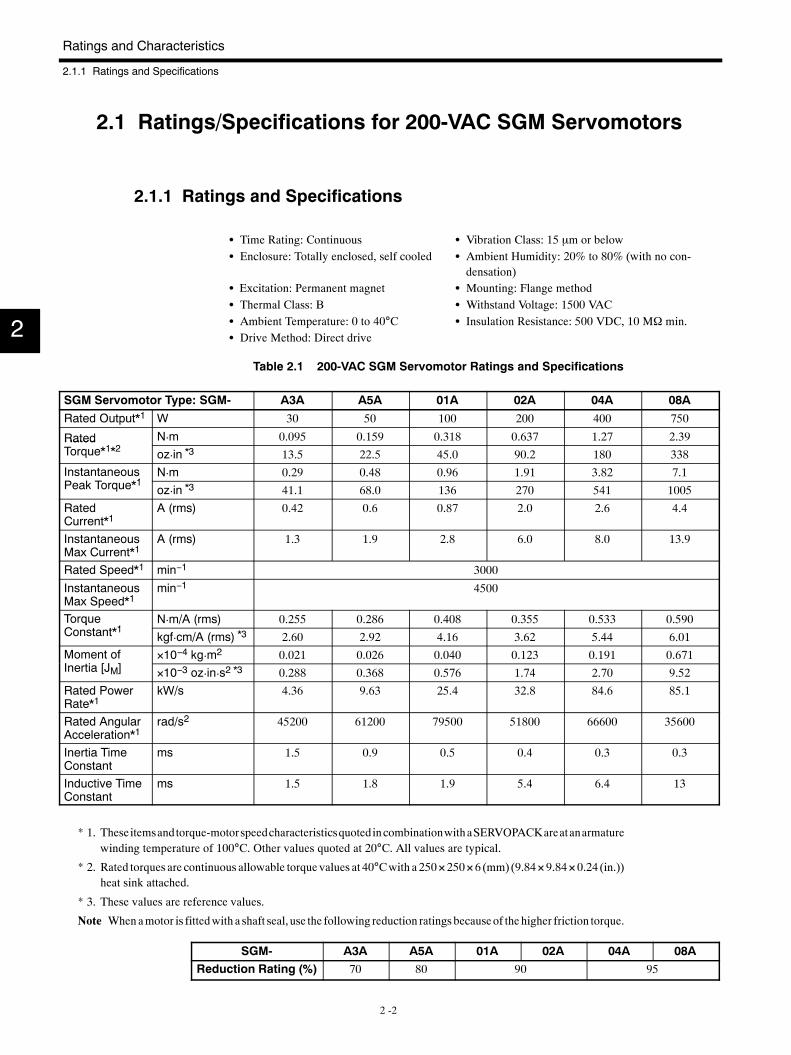
2.1.1 Ratings and Specifications
S Time Rating: Continuous S Vibration Class: 15 µm or belowS Enclosure: Totally enclosed, self cooled S Ambient Humidity: 20% to 80% (with no con-
densation)S Excitation: Permanent magnet S Mounting: Flange methodS Thermal Class: B S Withstand Voltage: 1500 VACS Ambient Temperature: 0 to 40°C S Insulation Resistance: 500 VDC, 10 MΩ min.S Drive Method: Direct drive
Table 2.1 200-VAC SGM Servomotor Ratings and Specifications
SGM Servomotor Type: SGM- A3A A5A 01A 02A 04A 08A
Rated Output*1 W 30 50 100 200 400 750
Rated N¡m 0.095 0.159 0.318 0.637 1.27 2.39RatedTorque*1*2 oz¡in *3 13.5 22.5 45.0 90.2 180 338InstantaneousP k T *1
N¡m 0.29 0.48 0.96 1.91 3.82 7.1Peak Torque*1 oz¡in *3 41.1 68.0 136 270 541 1005
RatedCurrent*1
A (rms) 0.42 0.6 0.87 2.0 2.6 4.4
InstantaneousMax Current*1
A (rms) 1.3 1.9 2.8 6.0 8.0 13.9
Rated Speed*1 min−1 3000
InstantaneousMax Speed*1
min−1 4500
TorqueC *1
N¡m/A (rms) 0.255 0.286 0.408 0.355 0.533 0.590qConstant*1 kgf¡cm/A (rms) *3 2.60 2.92 4.16 3.62 5.44 6.01Moment ofI i [J ]
×10−4 kg¡m2 0.021 0.026 0.040 0.123 0.191 0.671Inertia [JM] ×10−3 oz¡in¡s2 *3 0.288 0.368 0.576 1.74 2.70 9.52
Rated PowerRate*1
kW/s 4.36 9.63 25.4 32.8 84.6 85.1
Rated AngularAcceleration*1
rad/s2 45200 61200 79500 51800 66600 35600
Inertia TimeConstant
ms 1.5 0.9 0.5 0.4 0.3 0.3
Inductive TimeConstant
ms 1.5 1.8 1.9 5.4 6.4 13
* 1. Theseitemsandtorque-motorspeedcharacteristicsquotedincombinationwithaSERVOPACKareatanarmaturewinding temperature of 100°C. Other values quoted at 20°C. All values are typical.
* 2. Rated torques are continuous allowable torque values at 40°Cwith a 250×250×6 (mm) (9.84×9.84×0.24 (in.))heat sink attached.
* 3. These values are reference values.
Note Whenamotor is fittedwith a shaft seal, use the following reduction ratings becauseof thehigher friction torque.
SGM- A3A A5A 01A 02A 04A 08AReduction Rating (%) 70 80 90 95
2
2.1 Ratings/Specifications for 200-VAC SGM Servomotors
2 -3
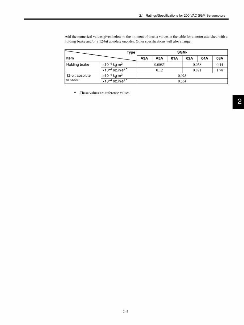
Add the numerical values given below to the moment of inertia values in the table for a motor attatched with aholding brake and/or a 12-bit absolute encoder. Other specifications will also change.
Type SGM-yp
Item A3A A5A 01A 02A 04A 08A
Holding brake ×10−4 kg¡m2 0.0085 0.058 0.14g
×10−4 oz.in¡s2 * 0.12 0.821 1.9812-bit absolute
d×10−4 kg¡m2 0.025
encoder ×10−4 oz.in¡s2 * 0.354
* These values are reference values.
2
Ratings and Characteristics
2.1.1 Ratings and Specifications
2 -4
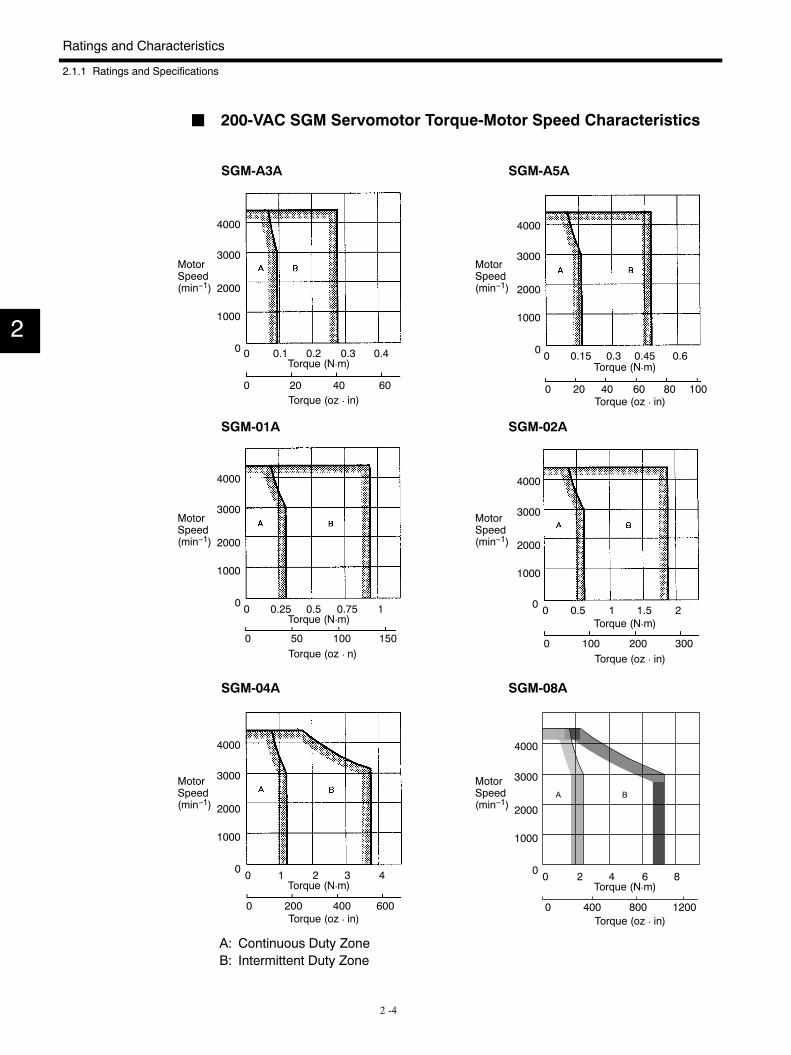
J 200-VAC SGM Servomotor Torque-Motor Speed Characteristics
SGM-A3A SGM-A5A
SGM-01A SGM-02A
SGM-04A SGM-08A
A: Continuous Duty ZoneB: Intermittent Duty Zone
MotorSpeed(min−1)
4000
3000
2000
1000
0 0 0.1 0.2 0.3 0.4
0 20 40 60
4000
3000
2000
1000
0 0 0.15 0.3 0.45 0.6
0 20 40 60 80 100
4000
3000
2000
1000
0 0 0.25 0.5 0.75 1
0 50 100 150
4000
3000
2000
1000
0 0 0.5 1 1.5 2
0 100 200 300
4000
3000
2000
1000
0 0 1 2 3 4
0 200 400 600
4000
3000
2000
1000
0 0 2 4 6 8
0 400 800 1200
Torque (oz ¡ in)
Torque (N¡m)
Torque (oz ¡ n)
Torque (N¡m)
Torque (oz ¡ in)
Torque (N¡m)
Torque (oz ¡ in)
Torque (N¡m)
Torque (oz ¡ in)
Torque (N¡m)
Torque (oz ¡ in)
Torque (N¡m)
A B
MotorSpeed(min−1)
MotorSpeed(min−1)
MotorSpeed(min−1)
MotorSpeed(min−1)
MotorSpeed(min−1)
2
2.2 Ratings/Specifications for 100-VAC SGM Servomotors
2 -5
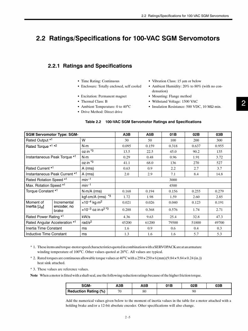
2.2 Ratings/Specifications for 100-VAC SGM Servomotors
2.2.1 Ratings and Specifications
S Time Rating: Continuous S Vibration Class: 15 µm or belowS Enclosure: Totally enclosed, self cooled S Ambient Humidity: 20% to 80% (with no con-
densation)S Excitation: Permanent magnet S Mounting: Flange methodS Thermal Class: B S Withstand Voltage: 1500 VACS Ambient Temperature: 0 to 40°C S Insulation Resistance: 500 VDC, 10 MΩ min.S Drive Method: Direct drive
Table 2.2 100-VAC SGM Servomotor Ratings and Specifications
SGM Servomotor Type: SGM- A3B A5B 01B 02B 03B
Rated Output *1 W 30 50 100 200 300
Rated Torque *1 *2 N¡m 0.095 0.159 0.318 0.637 0.955Rated Torqueoz¡in *3 13.5 22.5 45.0 90.2 135
Instantaneous Peak Torque *1 N¡m 0.29 0.48 0.96 1.91 3.72q
oz¡in *3 41.1 68.0 136 270 527
Rated Current *1 A (rms) 0.63 0.9 2.2 2.7 3.7
Instantaneous Peak Current *1 A (rms) 2.0 2.9 7.1 8.4 14.8
Rated Rotation Speed *1 min−1 3000
Max. Rotation Speed *1 min−1 4500
Torque Constant *1 N¡m/A (rms) 0.168 0.194 0.156 0.255 0.279q
kgf¡cm/A (rms) *3 1.72 1.98 1.59 2.60 2.85Moment ofInertia [JM]
Incrementalencoder no
×10−4 kg¡m2 0.021 0.026 0.040 0.123 0.191Inertia [JM] encoder, no
brake ×10−3 oz¡in¡s2 *3 0.288 0.368 0.576 1.74 2.71
Rated Power Rating *1 kW/s 4.36 9.63 25.4 32.8 47.3
Rated Angular Acceleration *1 rad/s2 45200 61200 79500 51800 49700
Inertia Time Constant ms 1.6 0.9 0.6 0.4 0.3
Inductive Time Constant ms 1.3 1.6 1.6 5.7 5.3
* 1. Theseitemsandtorque-motorspeedcharacteristicsquotedincombinationwithaSERVOPACKareatanarmaturewinding temperature of 100°C. Other values quoted at 20°C. All values are typical.
* 2. Rated torques are continuous allowable torque values at 40°Cwith a 250×250×6 (mm) (9.84×9.84×0.24 (in.))heat sink attached.
* 3. These values are reference values.
Note Whenamotor is fittedwith a shaft seal, use the following reduction ratings becauseof thehigher friction torque.
SGM- A3B A5B 01B 02B 03BReduction Rating (%) 70 80 90
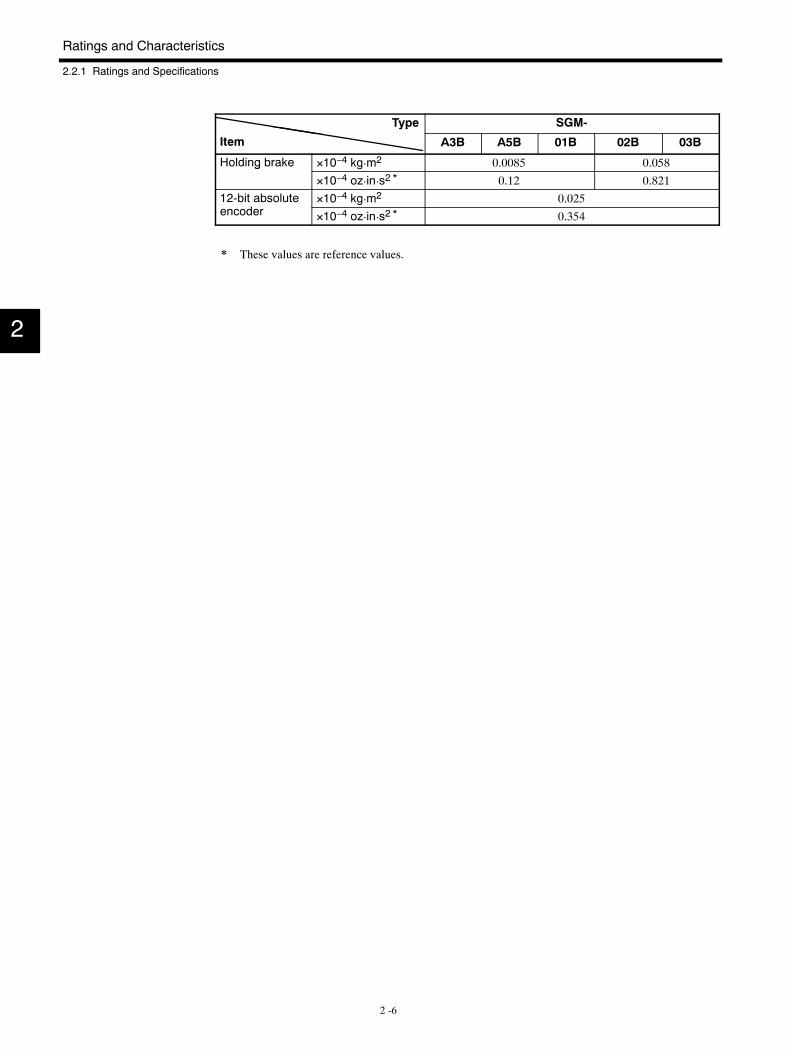
Add the numerical values given below to the moment of inertia values in the table for a motor attached with aholding brake and/or a 12-bit absolute encoder. Other specifications will also change.
2
Ratings and Characteristics
2.2.1 Ratings and Specifications
2 -6
Type SGM-yp
Item A3B A5B 01B 02B 03B
Holding brake ×10−4 kg¡m2 0.0085 0.058g
×10−4 oz¡in¡s2 * 0.12 0.82112-bit absolute
d×10−4 kg¡m2 0.025
encoder ×10−4 oz¡in¡s2 * 0.354
* These values are reference values.
2
2.2 Ratings/Specifications for 100-VAC SGM Servomotors
2 -7
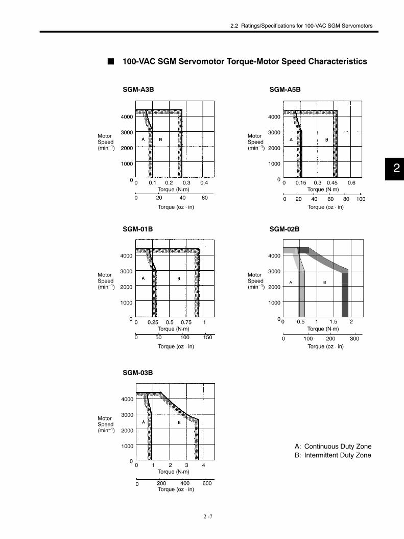
J 100-VAC SGM Servomotor Torque-Motor Speed Characteristics
Torque (N¡m)
SGM-A3B SGM-A5B
SGM-01B SGM-02B
SGM-03B
A: Continuous Duty ZoneB: Intermittent Duty Zone
Torque (oz ¡ in)
Torque (N¡m)
4000
3000
2000
1000
0 0 0.1 0.2 0.3 0.4
0 20 40 60
4000
3000
2000
1000
0 0 0.15 0.3 0.45 0.6
0 20 40 60 80 100
4000
3000
2000
1000
0 0 0.25 0.5 0.75 1
0 50 100 150
4000
3000
2000
1000
00 0.5 1 1.5 2
0 100 200 300
4000
3000
2000
1000
00 1 2 3 4
0 200 400 600
Torque (oz ¡ in)
Torque (N¡m)
Torque (oz ¡ in)
Torque (oz ¡ in)
Torque (N¡m)
Torque (oz ¡ in)
Torque (N¡m)
A B
MotorSpeed(min−1)
MotorSpeed(min−1)
MotorSpeed(min−1)
MotorSpeed(min−1)
MotorSpeed(min−1)
2
Ratings and Characteristics
2.3.1 Ratings and Specifications
2 -8
2.3 Ratings/Specifications for 200-VAC SGMP Servomotors
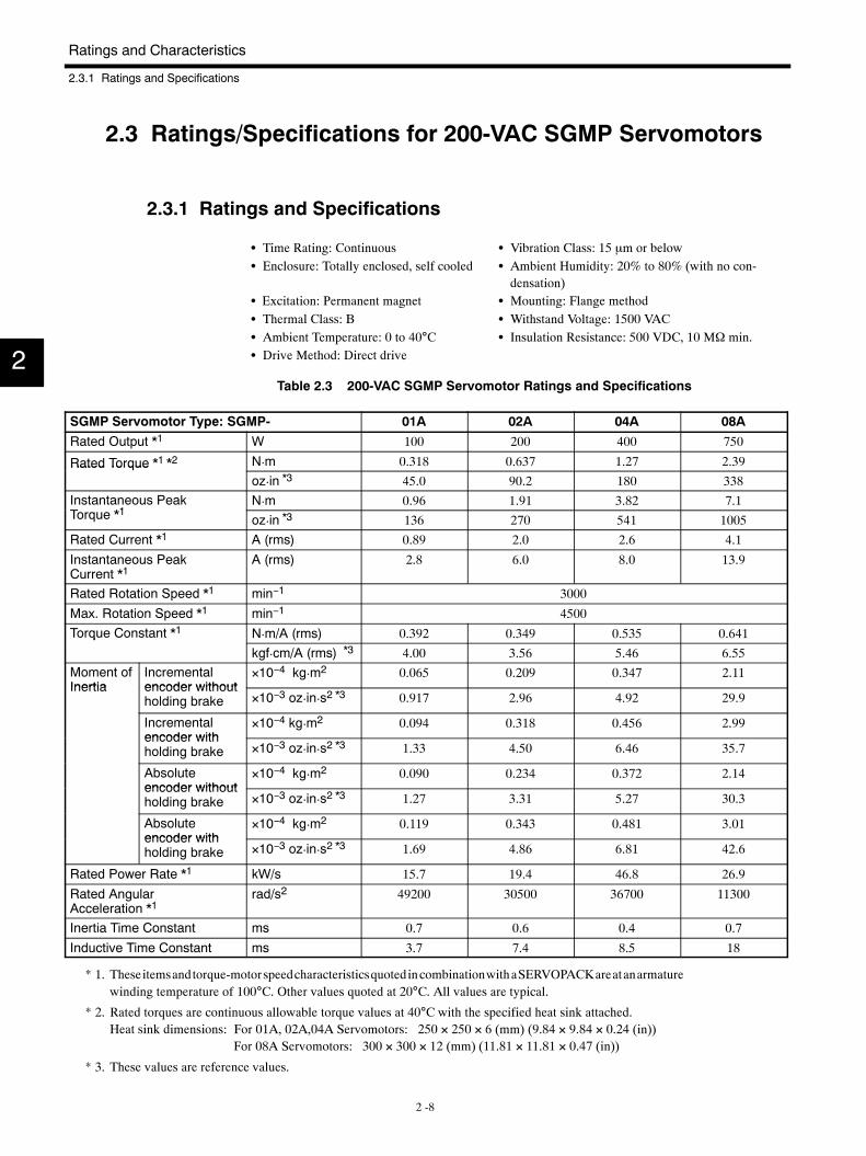
2.3.1 Ratings and Specifications
S Time Rating: Continuous S Vibration Class: 15 µm or belowS Enclosure: Totally enclosed, self cooled S Ambient Humidity: 20% to 80% (with no con-
densation)S Excitation: Permanent magnet S Mounting: Flange methodS Thermal Class: B S Withstand Voltage: 1500 VACS Ambient Temperature: 0 to 40°C S Insulation Resistance: 500 VDC, 10 MΩ min.S Drive Method: Direct drive
Table 2.3 200-VAC SGMP Servomotor Ratings and Specifications
SGMP Servomotor Type: SGMP- 01A 02A 04A 08A
Rated Output *1 W 100 200 400 750
Rated Torque *1 *2 N¡m 0.318 0.637 1.27 2.39Rated Torqueoz¡in *3 45.0 90.2 180 338
Instantaneous PeakT *1
N¡m 0.96 1.91 3.82 7.1Torque *1 oz¡in *3 136 270 541 1005
Rated Current *1 A (rms) 0.89 2.0 2.6 4.1
Instantaneous PeakCurrent *1
A (rms) 2.8 6.0 8.0 13.9
Rated Rotation Speed *1 min−1 3000
Max. Rotation Speed *1 min−1 4500
Torque Constant *1 N¡m/A (rms) 0.392 0.349 0.535 0.641q
kgf¡cm/A (rms) *3 4.00 3.56 5.46 6.55Moment ofInertia
Incrementalencoder without
×10−4 kg¡m2 0.065 0.209 0.347 2.11Inertia encoder without
holding brake ×10−3 oz¡in¡s2 *3 0.917 2.96 4.92 29.9
Incrementalencoder with
×10−4 kg¡m2 0.094 0.318 0.456 2.99encoder withholding brake ×10−3 oz¡in¡s2 *3 1.33 4.50 6.46 35.7
Absoluteencoder without
×10−4 kg¡m2 0.090 0.234 0.372 2.14encoder withoutholding brake ×10−3 oz¡in¡s2 *3 1.27 3.31 5.27 30.3
Absoluteencoder with
×10−4 kg¡m2 0.119 0.343 0.481 3.01encoder withholding brake ×10−3 oz¡in¡s2 *3 1.69 4.86 6.81 42.6
Rated Power Rate *1 kW/s 15.7 19.4 46.8 26.9
Rated AngularAcceleration *1
rad/s2 49200 30500 36700 11300
Inertia Time Constant ms 0.7 0.6 0.4 0.7
Inductive Time Constant ms 3.7 7.4 8.5 18
* 1. Theseitemsandtorque-motorspeedcharacteristicsquotedincombinationwithaSERVOPACKareatanarmaturewinding temperature of 100°C. Other values quoted at 20°C. All values are typical.
* 2. Rated torques are continuous allowable torque values at 40°C with the specified heat sink attached.Heat sink dimensions: For 01A, 02A,04A Servomotors: 250 × 250 × 6 (mm) (9.84 × 9.84 × 0.24 (in))
For 08A Servomotors: 300 × 300 × 12 (mm) (11.81 × 11.81 × 0.47 (in))
* 3. These values are reference values.
2
2.3 Ratings/Specifications for 200-VAC SGMP Servomotors
2 -9
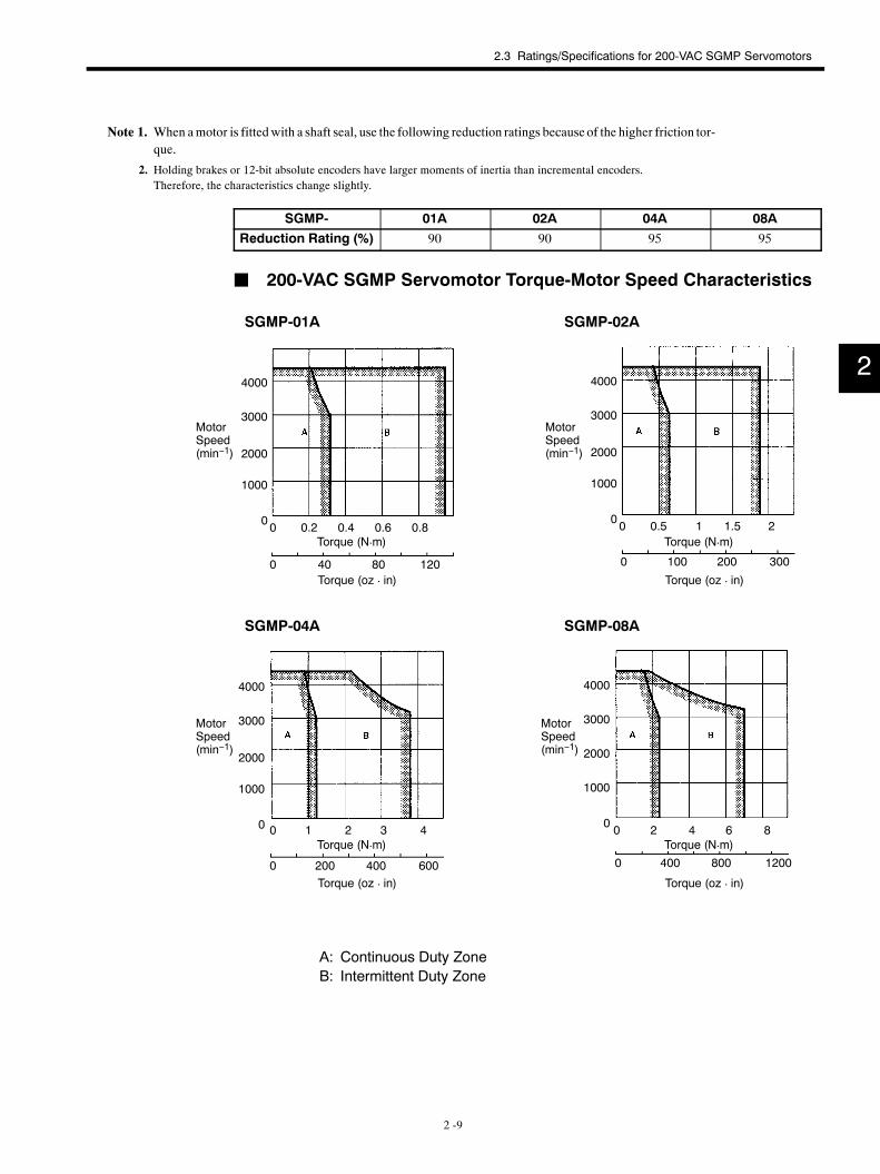
Note 1. When amotor is fittedwith a shaft seal, use the following reduction ratings because of the higher friction tor-que.
2. Holding brakes or 12-bit absolute encoders have larger moments of inertia than incremental encoders.Therefore, the characteristics change slightly.
SGMP- 01A 02A 04A 08AReduction Rating (%) 90 90 95 95
J 200-VAC SGMP Servomotor Torque-Motor Speed Characteristics
SGMP-01A SGMP-02A
SGMP-04A SGMP-08A
A: Continuous Duty ZoneB: Intermittent Duty Zone
4000
3000
2000
1000
00 0.2 0.4 0.6 0.8
0 40 80 120
4000
3000
2000
1000
00 0.5 1 1.5 2
0 100 200 300
4000
3000
2000
1000
0 0 1 2 3 4
0 200 400 600
4000
3000
2000
1000
0 0 2 4 6 8
0 400 800 1200
Torque (oz ¡ in)
Torque (N¡m)
Torque (oz ¡ in)
Torque (N¡m)
Torque (oz ¡ in)
Torque (N¡m)
Torque (oz ¡ in)
Torque (N¡m)
MotorSpeed(min−1)
MotorSpeed(min−1)
MotorSpeed(min−1)
MotorSpeed(min−1)
2
Ratings and Characteristics
2.4.1 Ratings and Specifications
2 -10
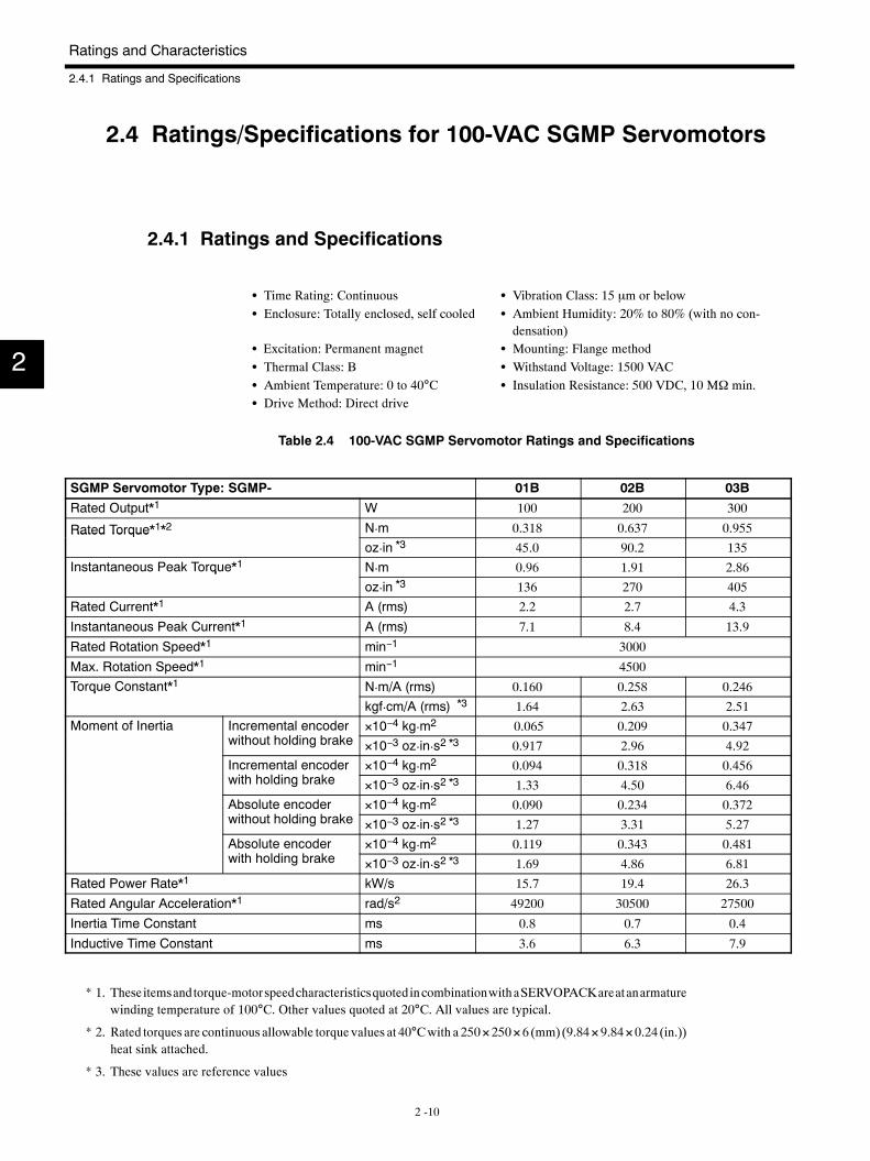
2.4 Ratings/Specifications for 100-VAC SGMP Servomotors
2.4.1 Ratings and Specifications
S Time Rating: Continuous S Vibration Class: 15 µm or belowS Enclosure: Totally enclosed, self cooled S Ambient Humidity: 20% to 80% (with no con-
densation)S Excitation: Permanent magnet S Mounting: Flange methodS Thermal Class: B S Withstand Voltage: 1500 VACS Ambient Temperature: 0 to 40°C S Insulation Resistance: 500 VDC, 10 MΩ min.S Drive Method: Direct drive
Table 2.4 100-VAC SGMP Servomotor Ratings and Specifications
SGMP Servomotor Type: SGMP- 01B 02B 03B
Rated Output*1 W 100 200 300
Rated Torque*1*2 N¡m 0.318 0.637 0.955Rated Torqueoz¡in *3 45.0 90.2 135
Instantaneous Peak Torque*1 N¡m 0.96 1.91 2.86q
oz¡in *3 136 270 405
Rated Current*1 A (rms) 2.2 2.7 4.3
Instantaneous Peak Current*1 A (rms) 7.1 8.4 13.9
Rated Rotation Speed*1 min−1 3000
Max. Rotation Speed*1 min−1 4500
Torque Constant*1 N¡m/A (rms) 0.160 0.258 0.246q
kgf¡cm/A (rms) *3 1.64 2.63 2.51Moment of Inertia Incremental encoder
i h h ldi b k×10−4 kg¡m2 0.065 0.209 0.347
without holding brake ×10−3 oz¡in¡s2 *3 0.917 2.96 4.92Incremental encoderi h h ldi b k
×10−4 kg¡m2 0.094 0.318 0.456with holding brake ×10−3 oz¡in¡s2 *3 1.33 4.50 6.46Absolute encoderi h h ldi b k
×10−4 kg¡m2 0.090 0.234 0.372without holding brake ×10−3 oz¡in¡s2 *3 1.27 3.31 5.27Absolute encoderi h h ldi b k
×10−4 kg¡m2 0.119 0.343 0.481with holding brake ×10−3 oz¡in¡s2 *3 1.69 4.86 6.81
Rated Power Rate*1 kW/s 15.7 19.4 26.3
Rated Angular Acceleration*1 rad/s2 49200 30500 27500
Inertia Time Constant ms 0.8 0.7 0.4
Inductive Time Constant ms 3.6 6.3 7.9
* 1. Theseitemsandtorque-motorspeedcharacteristicsquotedincombinationwithaSERVOPACKareatanarmaturewinding temperature of 100°C. Other values quoted at 20°C. All values are typical.
* 2. Rated torques are continuous allowable torque values at 40°Cwith a 250×250×6 (mm) (9.84×9.84×0.24 (in.))heat sink attached.
* 3. These values are reference values
2
2.4 Ratings/Specifications for 100-VAC SGMP Servomotors
2 -11
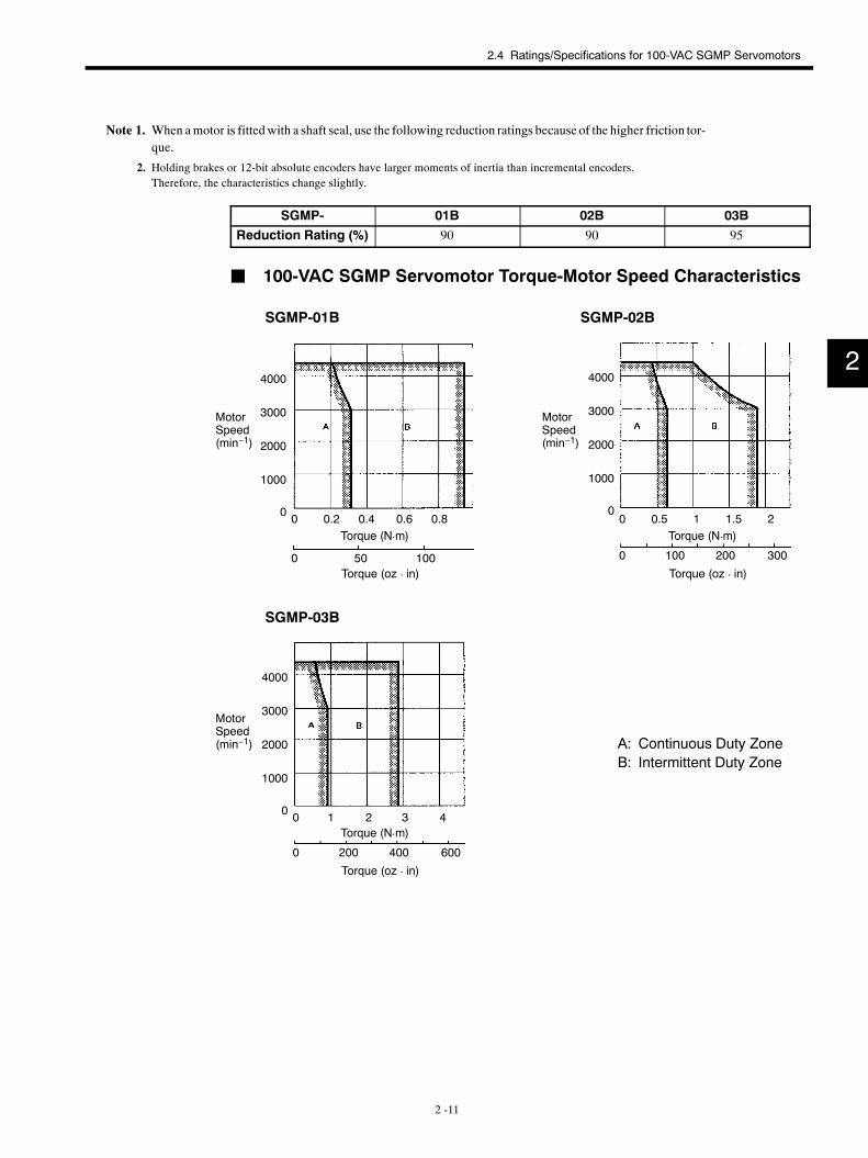
Note 1. When amotor is fittedwith a shaft seal, use the following reduction ratings because of the higher friction tor-que.
2. Holding brakes or 12-bit absolute encoders have larger moments of inertia than incremental encoders.Therefore, the characteristics change slightly.
SGMP- 01B 02B 03BReduction Rating (%) 90 90 95
J 100-VAC SGMP Servomotor Torque-Motor Speed Characteristics
SGMP-01B SGMP-02B
SGMP-03B
A: Continuous Duty ZoneB: Intermittent Duty Zone
4000
3000
2000
1000
0 0 0.2 0.4 0.6 0.8
0 50 100
4000
3000
2000
1000
00 0.5 1 1.5 2
0 100 200 300
4000
3000
2000
1000
0 0 1 2 3 4
0 200 400 600
Torque (oz ¡ in)
Torque (N¡m)
Torque (oz ¡ in)
Torque (N¡m)
Torque (oz ¡ in)
Torque (N¡m)
MotorSpeed(min−1)
MotorSpeed(min−1)
MotorSpeed(min−1)
2
Configuration and Model Numbers
2 -12
2.5 SERVOPACK Ratings and Specifications
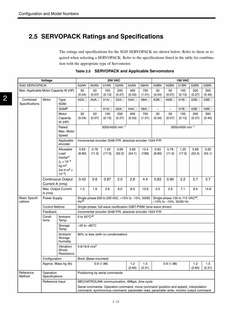
The ratings and specifications for the SGD SERVOPACK are shown below. Refer to them as re-
quired when selecting a SERVOPACK. Refer to the specifications listed in the table for combina-
tion with the appropriate type of Servomotor.
Table 2.5 SERVOPACK and Applicable Servomotors
Voltage 200 VAC 100 VAC
SGD SERVOPACK A3AN A5AN 01AN 02AN 04AN 08AN A3BN A5BN 01BN 02BN 03BN
Max. Applicable Motor Capacity W (HP) 30(0.04)
50(0.07)
100(0.13)
200(0.27)
400(0.53)
750(1.01)
30(0.04)
50(0.07)
100(0.13)
200(0.27)
300(0.40)
CombinedSpecifications
Motor Type:SGM-
A3Aj A5Aj 01Aj 02Aj 04Aj 08Aj A3Bj A5Bj 01Bj 02Bj 03Bjp
SGMP − − 01Aj 02Aj 04Aj 08Aj − − 01Bj 02Bj 03Bj
MotorCapacityW (HP)
30(0.04)
50(0.07)
100(0.13)
200(0.27)
400(0.53)
750(1.01)
30(0.04)
50(0.07)
100(0.13)
200(0.27)
300(0.40)
Rated/Max. MotorSpeed
3000/4500 min−1 3000/4500 min−1
Applicableencoder
Incremental encoder 2048 P/R, absolute encoder 1024 P/R
AllowableLoadInertia*1
JL¢10−4
kg¡m2
(oz¡in¡s2¢10−3)
0.63(8.80)
0.78(11.0)
1.20(17.0)
3.69(52.2)
3.82(54.1)
13.4(189)
0.63(8.80)
0.78(11.0)
1.20(17.0)
3.69(52.2)
3.82(54.1)
Continuous OutputCurrent A (rms)
0.42 0.6 0.87 2.0 2.6 4.4 0.63 0.90 2.2 2.7 3.7
Max. Output CurrentA (rms)
1.3 1.9 2.8 6.0 8.0 13.9 2.0 2.9 7.1 8.4 14.8
Basic Specifi-cations
Power Supply Single-phase 200 to 230 VAC, +10% to −15%, 50/60Hz*2
Single-phase 100 to 115 VAC*2,+10% to −15%, 50/60 Hz
Control Method Single-phase, full-wave rectification IGBT-PWM (sine-wave driven)
Feedback Incremental encoder 2048 P/R, absolute encoder 1024 P/R
Condi-tions
AmbientTemp.
0 to 55°C*3
StorageTemp.
−20 to +85°C
Ambient/StorageHumidity
90% or less (with no condensation)
Vibration/ShockResistance
4.9/19.6 m/s2
Configuration Book (Base-mounted)
Approx. Mass kg (lb) 0.9 (1.98) 1.2(2.65)
1.5(3.31)
0.9 (1.98) 1.2(2.65)
1.5(3.31)
ReferenceMethod
OperationSpecifications
Positioning by serial commands
Reference Input MECHATROLINK communication, 4Mbps, 2ms cycle
Serial commands: Operation command, move command (position and speed), interpolationcommand, synchronous command, parameter read, parameter write, monitor output command
2
2.5 SERVOPACK Ratings and Specifications
2 -13
Voltage 100 VAC200 VAC
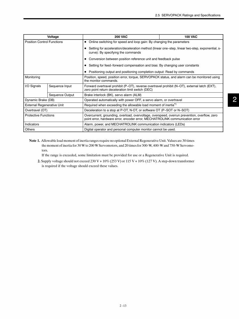
Position Control Functions D Online switching for speed and loop gain: By changing the parameters
D Setting for acceleration/deceleration method (linear one−step, linear two-step, exponential, s-curve): By specifying the commands
D Conversion between position reference unit and feedback pulse
D Setting for feed−forward compensation and bias: By changing user constants
D Positioning output and positioning completion output: Read by commands
Monitoring Position, speed, position error, torque, SERVOPACK status, and alarm can be monitored usingthe monitor commands.
I/O Signals Sequence Input Forward overtravel prohibit (P−OT), reverse overtravel prohibit (N−OT), external latch (EXT),zero point return deceleration limit switch (DEC)
Sequence Output Brake interlock (BK), servo alarm (ALM)
Dynamic Brake (DB) Operated automatically with power OFF, a servo alarm, or overtravel
External Regenerative Unit Required when exceeding the allowable load moment of inertia*1
Overtravel (OT) Deceleration to a stop at P-OT, N-OT, or software OT (P−SOT or N−SOT)
Protective Functions Overcurrent, grounding, overload, overvoltage, overspeed, overrun prevention, overflow, zeropoint error, hardware error, encoder error, MECHATROLINK communication error
Indicators Alarm, power, and MECHATROLINK communication indicators (LEDs)
Others Digital operator and personal computer monitor cannot be used.
Note 1. Allowable loadmoment of inertia ranges require no optional External RegenerativeUnit. Values are 30 timesthemoment of inertia for 30W to 200WServomotors, and 20 times for 300-W, 400-Wand 750-WServomo-tors.If the range is exceeded, some limitation must be provided for use or a Regenerative Unit is required.
2. Supply voltage should not exceed 230 V + 10% (253 V) or 115 V + 10% (127 V). A step-down transformeris required if the voltage should exceed these values.
2
Configuration and Model Numbers
2 -14
2.6 Standard Peripheral Device Combinations
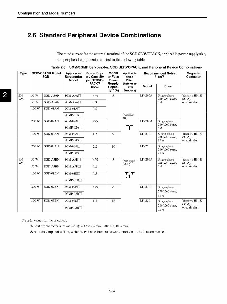
The rated current for the external terminal of the SGDSERVOPACK, applicable power supply size,
and peripheral equipment are listed in the following table.
Table 2.6 SGM/SGMP Servomotor, SGD SERVOPACK, and Peripheral Device Combinations
Type SERVOPACK ModelSGD-
ApplicableServomotor
Model
Power Sup-ply Capacityper SERVO-PACK*1
MCCBor FusePowerSupply
ApplicableNoiseFilter
(Reference
Recommended NoiseFilter*3
MagneticContactor
PACK*1(kVA)
SupplyCapac-ity*2 (A)
(ReferenceFilter
Structure)
Model Spec.
200VAC
30 W SGD-A3AN SGM-A3Aj 0.25 5 LF- 205A Single-phase200 VAC class,
Yaskawa HI-11J(20 A),VAC
50 W SGD-A5AN SGM-A5Aj 0.3200 VAC class,5 A
(20 A),or equivalent
100 W SGD-01AN SGM-01Aj 0.5
SGMP-01Aj (Applica-ble)
200 W SGD-02AN SGM-02Aj 0.75ble)
LF- 205A Single-phase200 VAC class
SGMP-02Aj200 VAC class,5 A
400 W SGD-04AN SGM-04Aj 1.2 9 LF- 210 Single-phase200 VAC class
Yaskawa HI-15J(35 A)
SGMP-04Aj200 VAC class,10 A
(35 A),or equivalent
750 W SGD-08AN SGM-08Aj 2.2 16 LF- 220 Single-phase200 VAC class,
SGMP-08Aj200 VAC class,20 A
100VAC
30 W SGD-A3BN SGM-A3Bj 0.25 5 (Not appli-cable)
LF- 205A Single-phase200 VAC class,
Yaskawa HI-11J(20 A),VAC
50 W SGD-A5BN SGM-A5Bj 0.3cable) 200 VAC class,
5 A(20 A),or equivalent
100 W SGD-01BN SGM-01Bj 0.5
SGMP-01Bj
200 W SGD-02BN SGM-02Bj 0.75 8 LF- 210 Single-phase200 VAC class
SGMP-02Bj200 VAC class,10 A
300 W SGD-03BN SGM-03Bj 1.4 15 LF- 220 Single-phase200 VAC class
Yaskawa HI-15J(35 A),
SGMP-03Bj200 VAC class,20 A
(35 A),or equivalent
Note 1. Values for the rated load
2. Shut off characteristics (at 25°C): 200%: 2 s min., 700%: 0.01 s min.
3.A Tokin Corp. noise filter, which is available from Yaskawa Control Co., Ltd., is recommended.
2
3 -1
3Servodrive Characteristics
This chapter provides characteristics of SERVOPACKS and Servomotors.
3.1 Overload Characteristics 3 -2. . . . . . . . . . . . . . . . . . .3.2 Starting and Stopping Time 3 -3. . . . . . . . . . . . . . . . .3.3 Allowable Repeatability 3 -4. . . . . . . . . . . . . . . . . . . .
3.3.1 Allowable Repeatability as Limited by theServomotor 3 -4. . . . . . . . . . . . . . . . . . . . . . . . . . . . . . .
3.4 Large-amplitude Frequency Characteristics 3 -6. . .3.5 Mechanical Characteristics 3 -7. . . . . . . . . . . . . . . . .
3.5.1 Mechanical Strength 3 -7. . . . . . . . . . . . . . . . . . . . . . . . .
3.5.2 Allowable Radial Load and Allowable ThrustLoad 3 -7. . . . . . . . . . . . . . . . . . . . . . . . . . . . . . . . . . . . .
3.5.3 Mechanical Tolerances 3 -7. . . . . . . . . . . . . . . . . . . . . . .
3.5.4 Direction of Motor Rotation 3 -8. . . . . . . . . . . . . . . . . . .
3.5.5 Impact Resistance 3 -9. . . . . . . . . . . . . . . . . . . . . . . . . . .
3.5.6 Vibration Resistance 3 -9. . . . . . . . . . . . . . . . . . . . . . . . .
3.5.7 Vibration Class 3 -9. . . . . . . . . . . . . . . . . . . . . . . . . . . . . .
3
Servodrive Characteristics
3 -2
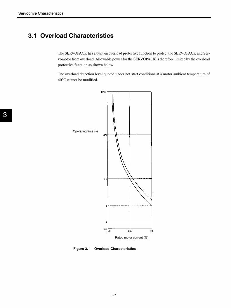
3.1 Overload Characteristics
The SERVOPACK has a built-in overload protective function to protect the SERVOPACK and Ser-
vomotor from overload. Allowable power for the SERVOPACK is therefore limited by the overload
protective function as shown below.
The overload detection level quoted under hot start conditions at a motor ambient temperature of
40°C cannot be modified.
Operating time (s)
Rated motor current (%)
Figure 3.1 Overload Characteristics
3
3.2 Starting and Stopping Time
3 -3
3.2 Starting and Stopping Time
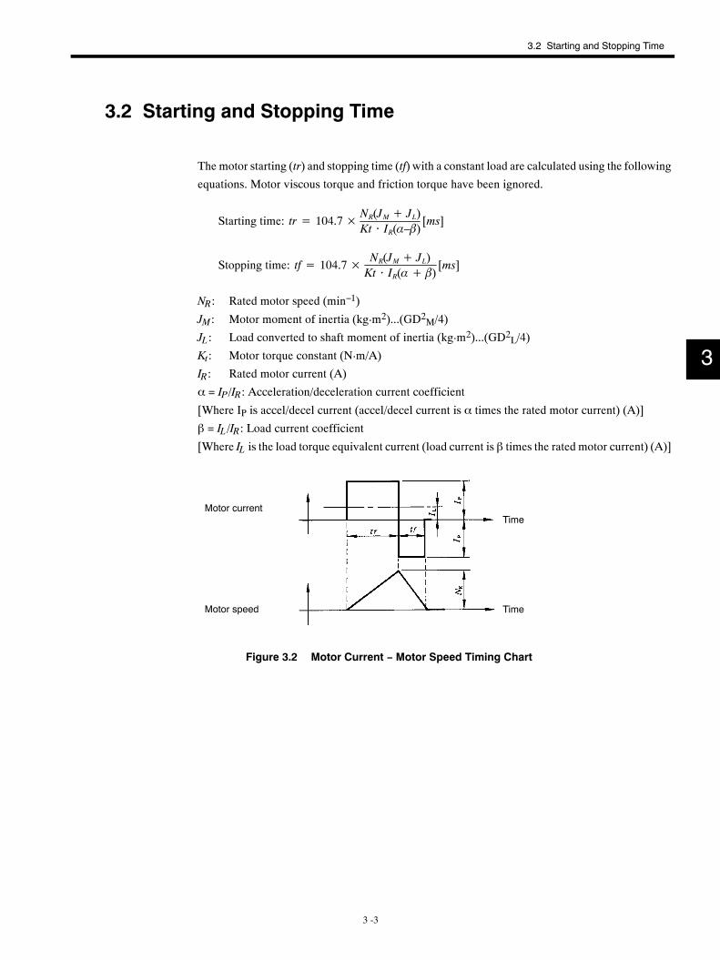
The motor starting (tr) and stopping time (tf) with a constant load are calculated using the following
equations. Motor viscous torque and friction torque have been ignored.
Starting time: tr= 104.7× NR(JM+ JL)Kt ⋅ IR(α–β)
[ms]
Stopping time: tf= 104.7× NR(JM+ JL)Kt ⋅ IR(α+ β)
[ms]
NR: Rated motor speed (min−1)
JM: Motor moment of inertia (kg¡m2)...(GD2M/4)
JL: Load converted to shaft moment of inertia (kg¡m2)...(GD2L/4)
Kt: Motor torque constant (N¡m/A)
IR: Rated motor current (A)
α = IP/IR: Acceleration/deceleration current coefficient
[Where IP is accel/decel current (accel/decel current is α times the rated motor current) (A)]
β = IL/IR: Load current coefficient
[Where IL is the load torque equivalent current (load current is β times the rated motor current) (A)]
Motor currentTime
Motor speed Time
Figure 3.2 Motor Current − Motor Speed Timing Chart
3
Servodrive Characteristics
3.3.1 Allowable Repeatability as Limited by the Servomotor
3 -4
3.3 Allowable Repeatability
The running and stopping frequency is limited by the Servomotor. It is important to ensure that the
Servomotor is not started and stopped too frequently.
3.3.1 Allowable Repeatability as Limited by the Servomotor
Running and stopping repeatability vary with motor conditions, such as the load conditions and
running time. A typical example is given below (SeeChapter 3.2 “Starting and Stopping Time”
for details on symbols.).
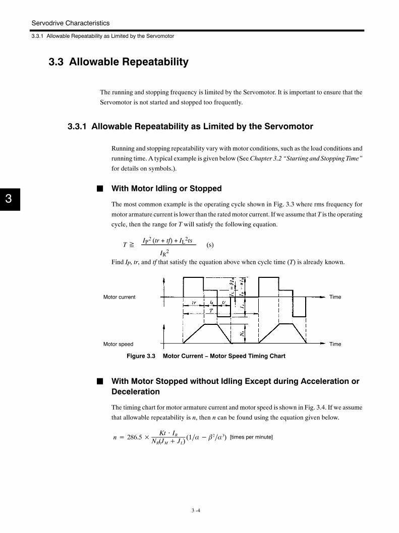
J With Motor Idling or Stopped
The most common example is the operating cycle shown in Fig. 3.3 where rms frequency for
motor armature current is lower than the ratedmotor current. If we assume that T is the operating
cycle, then the range for T will satisfy the following equation.
T≧ (s)IP2 (tr + tf) + IL2ts
IR2
Find IP, tr, and tf that satisfy the equation above when cycle time (T) is already known.
Motor current Time
Motor speed Time
Figure 3.3 Motor Current − Motor Speed Timing Chart
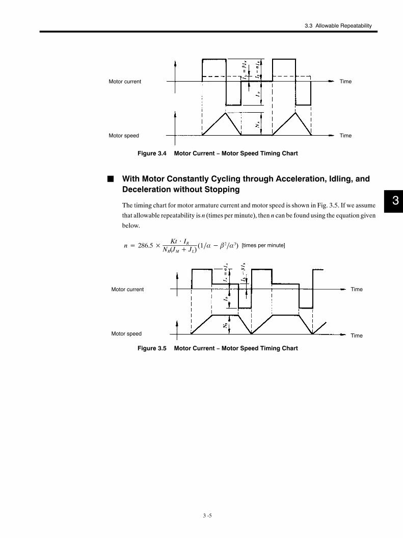
J With Motor Stopped without Idling Except during Acceleration orDeceleration
The timing chart for motor armature current and motor speed is shown in Fig. 3.4. If we assume
that allowable repeatability is n, then n can be found using the equation given below.
n= 286.5× Kt ⋅ IRNR(JM+ JL)
(1∕α− β2∕α3) [times per minute]
3
3.3 Allowable Repeatability
3 -5
Motor current Time
Motor speed Time
Figure 3.4 Motor Current − Motor Speed Timing Chart
J With Motor Constantly Cycling through Acceleration, Idling, andDeceleration without Stopping
The timing chart for motor armature current and motor speed is shown in Fig. 3.5. If we assume
that allowable repeatability is n (times perminute), then n can be found using the equation given
below.
n= 286.5× Kt ⋅ IRNR(JM+ JL)
(1∕α− β2∕α3) [times per minute]
Motor current Time
Motor speed Time
Figure 3.5 Motor Current − Motor Speed Timing Chart
3
Servodrive Characteristics
3 -6
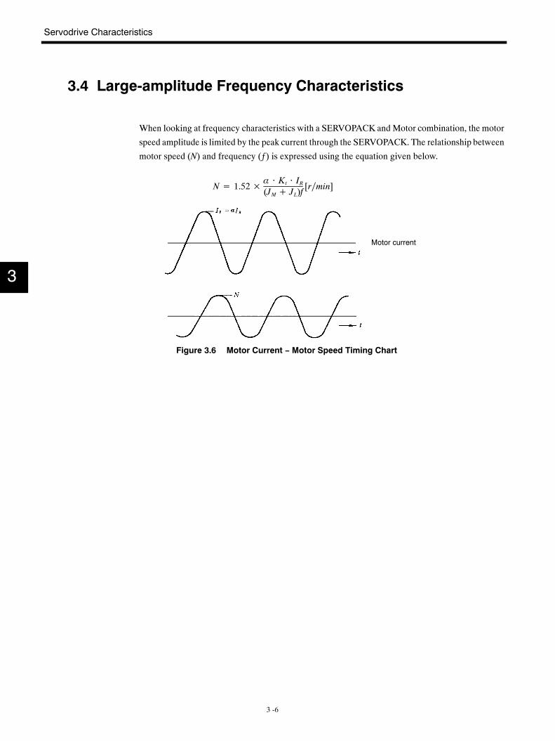
3.4 Large-amplitude Frequency Characteristics
When looking at frequency characteristics with a SERVOPACK andMotor combination, the motor
speed amplitude is limited by the peak current through the SERVOPACK. The relationship between
motor speed (N) and frequency (ƒ) is expressed using the equation given below.
N= 1.52× α ⋅ Kt ⋅ IR(JM+ JL)f
[r∕min]
Motor current
Figure 3.6 Motor Current − Motor Speed Timing Chart
3
3.5 Mechanical Characteristics
3 -7
3.5 Mechanical Characteristics
3.5.1 Mechanical Strength
A Servomotor can withstand instantaneous peak torque on the output shaft of up to 300% of the
motor rating.
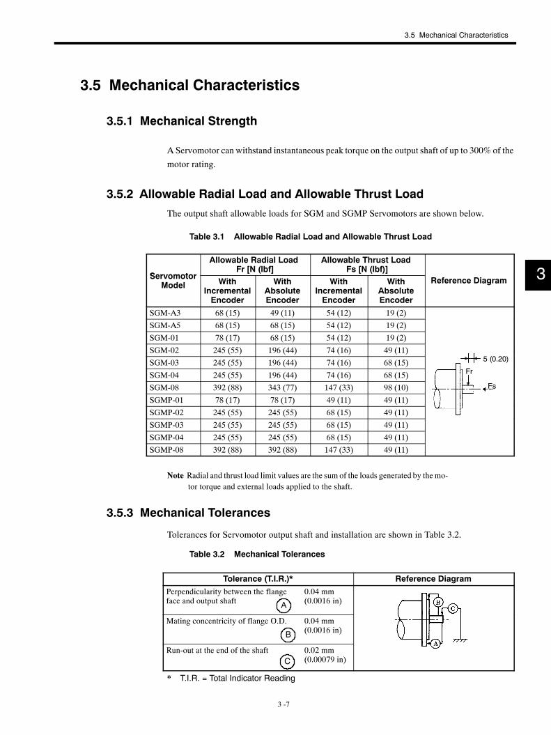
3.5.2 Allowable Radial Load and Allowable Thrust Load
The output shaft allowable loads for SGM and SGMP Servomotors are shown below.
Table 3.1 Allowable Radial Load and Allowable Thrust Load
Servomotor
Allowable Radial LoadFr [N (lbf]
Allowable Thrust LoadFs [N (lbf)]
ServomotorModel With
IncrementalEncoder
WithAbsoluteEncoder
WithIncrementalEncoder
WithAbsoluteEncoder
Reference Diagram
SGM-A3 68 (15) 49 (11) 54 (12) 19 (2)
SGM-A5 68 (15) 68 (15) 54 (12) 19 (2)
SGM-01 78 (17) 68 (15) 54 (12) 19 (2)
SGM-02 245 (55) 196 (44) 74 (16) 49 (11)(0 20)SGM-03 245 (55) 196 (44) 74 (16) 68 (15) 5 (0.20)
FSGM-04 245 (55) 196 (44) 74 (16) 68 (15) Fr
SGM-08 392 (88) 343 (77) 147 (33) 98 (10) Fs
SGMP-01 78 (17) 78 (17) 49 (11) 49 (11)
SGMP-02 245 (55) 245 (55) 68 (15) 49 (11)
SGMP-03 245 (55) 245 (55) 68 (15) 49 (11)
SGMP-04 245 (55) 245 (55) 68 (15) 49 (11)
SGMP-08 392 (88) 392 (88) 147 (33) 49 (11)
Note Radial and thrust load limit values are the sum of the loads generated by themo-tor torque and external loads applied to the shaft.
3.5.3 Mechanical Tolerances
Tolerances for Servomotor output shaft and installation are shown in Table 3.2.
Table 3.2 Mechanical Tolerances
Tolerance (T.I.R.)* Reference Diagram
Perpendicularity between the flangeface and output shaft A
0.04 mm(0.0016 in)
Mating concentricity of flange O.D.
B
0.04 mm(0.0016 in)
Run-out at the end of the shaftC
0.02 mm(0.00079 in)
* T.I.R. = Total Indicator Reading
3
Servodrive Characteristics
3.5.4 Direction of Motor Rotation
3 -8
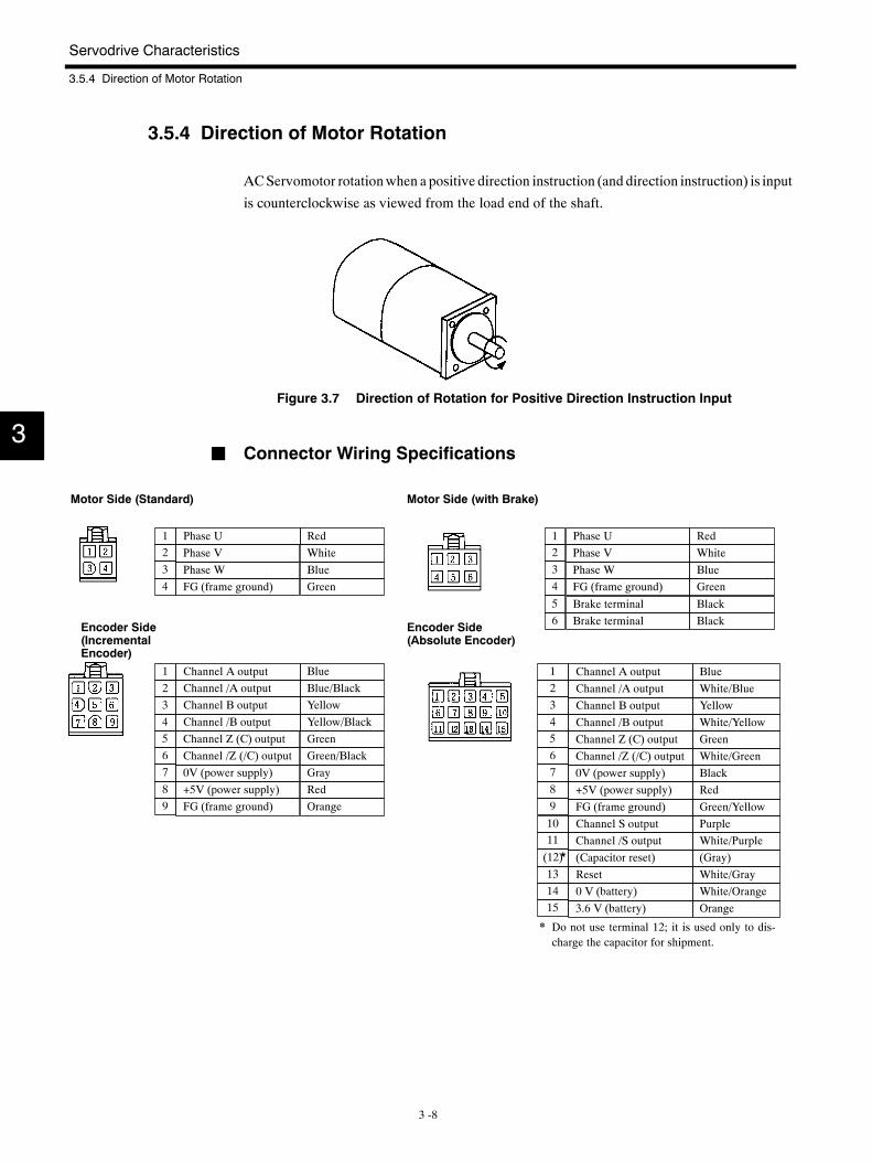
3.5.4 Direction of Motor Rotation
ACServomotor rotationwhen a positive direction instruction (and direction instruction) is input
is counterclockwise as viewed from the load end of the shaft.
Figure 3.7 Direction of Rotation for Positive Direction Instruction Input
J Connector Wiring Specifications
Channel /Z (/C) output
Phase U RedPhase V WhitePhase W BlueFG (frame ground) Green
Channel A output BlueChannel /A output Blue/BlackChannel B output YellowChannel /B output Yellow/Black
GreenGreen/BlackGrayRed
FG (frame ground) Orange
1234
123456789
Channel Z (C) output
+5V (power supply)0V (power supply)
Motor Side (Standard)
Encoder Side(IncrementalEncoder)
Channel /Z (/C) output
Phase U RedPhase V WhitePhase W BlueFG (frame ground) Green
Channel A output BlueChannel /A output White/BlueChannel B output YellowChannel /B output White/Yellow
GreenWhite/GreenBlackRed
FG (frame ground) Green/Yellow
1234
123456789
Channel Z (C) output
+5V (power supply)0V (power supply)
Channel /S outputChannel S output Purple
(Capacitor reset) (Gray)Reset White/Gray0 V (battery) White/Orange
Orange
White/Purple10
(12)131415
11
3.6 V (battery)
Motor Side (with Brake)
Encoder Side(Absolute Encoder)
Brake terminal BlackBrake terminal Black
56
* Do not use terminal 12; it is used only to dis-charge the capacitor for shipment.
*
3
3.5 Mechanical Characteristics
3 -9
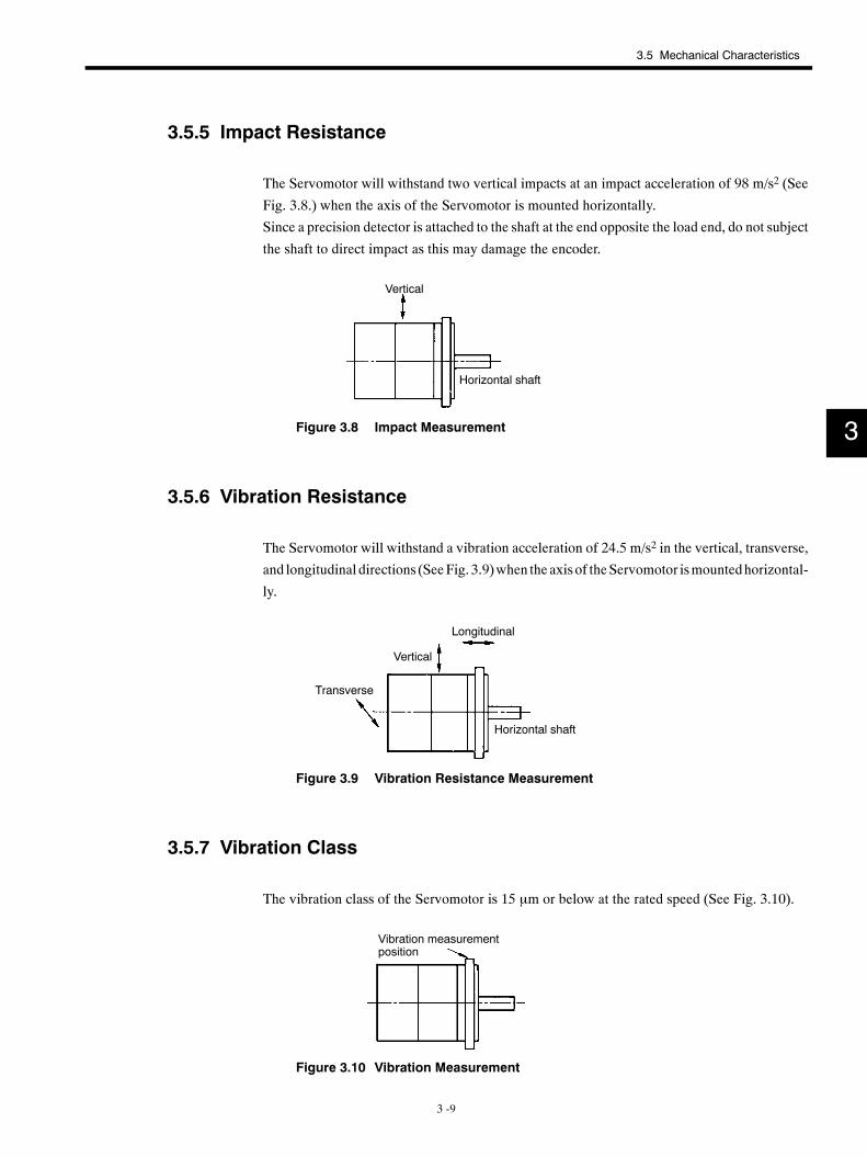
3.5.5 Impact Resistance
The Servomotor will withstand two vertical impacts at an impact acceleration of 98 m/s2 (See
Fig. 3.8.) when the axis of the Servomotor is mounted horizontally.
Since a precision detector is attached to the shaft at the end opposite the load end, do not subject
the shaft to direct impact as this may damage the encoder.
Vertical
Horizontal shaft
Figure 3.8 Impact Measurement
3.5.6 Vibration Resistance
The Servomotor will withstand a vibration acceleration of 24.5 m/s2 in the vertical, transverse,
and longitudinal directions (SeeFig. 3.9)when the axis of theServomotor ismountedhorizontal-
ly.
Longitudinal
Transverse
Vertical
Horizontal shaft
Figure 3.9 Vibration Resistance Measurement
3.5.7 Vibration Class
The vibration class of the Servomotor is 15 µm or below at the rated speed (See Fig. 3.10).
Vibration measurementposition
Figure 3.10 Vibration Measurement
3
4 -1
4Configuration and Connections
This chapter provides information on the Servodrives configuration and
connections.
4.1 Internal Connection Diagram 4 -3. . . . . . . . . . . . . . .4.2 Main Circuit Terminals 4 -4. . . . . . . . . . . . . . . . . . . . .4.3 Applicable Receptacles 4 -4. . . . . . . . . . . . . . . . . . . .
4.3.1 1CN Connector for I/O Signals 4 -4. . . . . . . . . . . . . . . .
4.3.2 2CN Connector for Encoder 4 -4. . . . . . . . . . . . . . . . . . .
4.3.3 3CN Connector for MECHATROLINKCommunication 4 -4. . . . . . . . . . . . . . . . . . . . . . . . . . .
4.4 Connecting an Incremental Encoder 4 -5. . . . . . . . .4.4.1 Typical Example 4 -5. . . . . . . . . . . . . . . . . . . . . . . . . . . . .
4.4.2 1CN I/O Connector Terminals 4 -6. . . . . . . . . . . . . . . . .
4.5 Connecting an Absolute Encoder 4 -9. . . . . . . . . . . .4.5.1 Typical Example 4 -9. . . . . . . . . . . . . . . . . . . . . . . . . . . . .
4.5.2 1CN I/O Connector Terminals 4 -10. . . . . . . . . . . . . . . . .
4.6 Output Circuits 4 -13. . . . . . . . . . . . . . . . . . . . . . . . . . . .4.7 Connector Terminal Block Converter Unit
for 1CN 4 -13. . . . . . . . . . . . . . . . . . . . . . . . . . . . . . . .4.7.1 Application 4 -13. . . . . . . . . . . . . . . . . . . . . . . . . . . . . . . . .
4.7.2 Connection Specifications 4 -14. . . . . . . . . . . . . . . . . . . .
4.7.3 Cable Specifications (Accessory for ConnectorTerminal Block Converter Unit) 4 -15. . . . . . . . . . . . . .
4
Configuration and Connections
4 -2
4.8 2CN Encoder Connector Terminals 4 -16. . . . . . . . . .4.8.1 2CN Terminal Layout 4 -16. . . . . . . . . . . . . . . . . . . . . . . . .
4.8.2 Applicable Cables 4 17. . . . . . . . . . . . . . . . . . . . . . . . . . .
4.8.3 2CN Connection Method 4 -18. . . . . . . . . . . . . . . . . . . . .
4.9 3CN Connector for MECHATROLINKCommunication 4 -20. . . . . . . . . . . . . . . . . . . . . . . . . .4.9.1 3CN Terminal Layout 4 -20. . . . . . . . . . . . . . . . . . . . . . . . .
4.9.2 3CN Connection Method 4 -20. . . . . . . . . . . . . . . . . . . . .
4
4.1 Internal Connection Diagram
4 -3
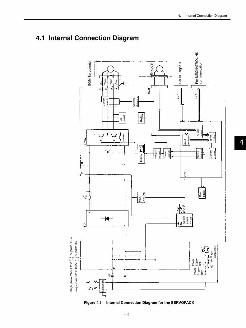
4.1 Internal Connection Diagram
Noise
filter
Singlephase200to230V
%(50/60
Hz),or
singlephase100to115V
%(50/60
Hz)
Fault
detection
Control
power
supply
Alarm
display
Pow
erSupply
OFF
Pow
erSupply
ON
Surge
suppressor
Isolator
Current
controller
Current
reference
Current
control
Position
control
Speed
calculation
Speed
control
Relay
DB
circuit
Current
detection
Current
detector
SGMServomotor
Red
White
Yellow
Green
ForI/O
signals
ForMECHAT
ROLINK
communication
PWMgener-
atorcircuit
1MC
1Ry
Encoder
+10
-15
+10
-15
Figure 4.1 Internal Connection Diagram for the SERVOPACK
4
Configuration and Connections
4.3.3 3CN Connector for MECHATROLINK Communication
4 -4
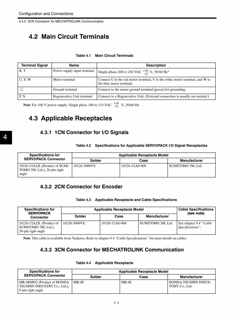
4.2 Main Circuit Terminals
Table 4.1 Main Circuit Terminals
Terminal Signal Name DescriptionR, T Power supply input terminal Single-phase 200 to 230 VAC %, 50/60 Hz*+10
-15
U, V, W Motor terminal Connect U to the red motor terminal, V to the white motor terminal, and W tothe blue motor terminal.
Ground terminal Connect to the motor ground terminal (green) for grounding.
P, N Regenerative Unit terminal Connect to a Regenerative Unit. (External connection is usually not needed.)
Note For 100 V power supply: Single phase 100 to 115 VAC +10-15 %, 50/60 Hz
4.3 Applicable Receptacles
4.3.1 1CN Connector for I/O Signals
Table 4.2 Specifications for Applicable SERVOPACK I/O Signal Receptacles
Specifications forSERVOPACK C
Applicable Receptacle ModelpSERVOPACK Connector Solder Case Manufacturer
10226-52A2JL (Product of SUMI-TOMO 3M, Ltd.), 26-pin rightangle
10126-3000VE 10326-52A0-008 SUMITOMO 3M, Ltd.
4.3.2 2CN Connector for Encoder
Table 4.3 Applicable Receptacle and Cable Specifications
Specifications forSERVOPACK
Applicable Receptacle Model Cable Specifications(see note)SERVOPACK
Connector Solder Case Manufacturer(see note)
10220-52A2JL (Product ofSUMITOMO 3M, Ltd.),20-pin right angle
10120-3000VE 10320-52A0-008 SUMITOMO 3M, Ltd. See chapter 9.4 “CableSpecifications”.
Note This cable is available from Yaskawa. Refer to chapter 9.4 “Cable Specifications” for more details on cables.
4.3.3 3CN Connector for MECHATROLINK Communication
Table 4.4 Applicable Receptacle
Specifications forSERVOPACK C
Applicable Receptacle ModelpSERVOPACK Connector Solder Case Manufacturer
MR-8RMD2 (Product of HONDATSUSHIN INDUSTRY Co., Ltd.),8-pin right angle
MR-8F MR-8L HONDA TSUSHIN INDUS-TORY Co., Ltd.
4
4.4 Connecting an Incremental Encoder
4 -5
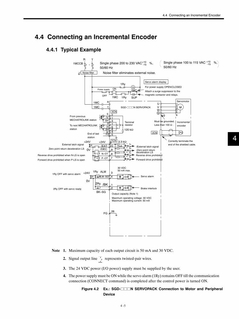
4.4 Connecting an Incremental Encoder
4.4.1 Typical Example
2/S 1
R T1MCCB
PL
1MC 1Ry SUP
1Ry
1MC
1MC R
1MC
S
120 kΩ
3CN
6
1
7
R
SH
4
S/SSH
FG 5
8
3
U
PG2CN
VW
1234
M
+24VP
0VN−LS
P−LS
/DECN−OT
P−OT
+24V/EXT
3.3 kΩ7mA
78
910
1CN6
FG26
/BK
BK−SG
2Ry 12
1Ry ALM
ALM−SG
34
+24V
0VP
T
P
P
Single phase 200 to 230 VAC %,50/60 Hz
Single phase 100 to 115 VAC %,50/60 Hz
Noise filter Noise filter eliminates external noise.
Servo alarm display
Power supply ON
OFF
For power supply OPEN/CLOSED
Attach a surge suppressor to themagnetic contactor and relays.
Servomotor
Must be grounded.Less than 100 Ω .
Incrementalencoder
Correctly terminate theend of the shielded cable.
From previousMECHATROLINK station
To next MECHATROLINKstation
SGD-jjjN SERVOPACK
End of laststation
External latch signal
Zero point return deceleration LS
Reverse drive prohibited
Forward drive prohibited
/Zero point return/External latch signal
30 VDC50 mA max.
1Ry OFF with servo alarm
2Ry OFF with servo ready
Servo alarm
Brake interlock
Output capacity (Note 1)
Maximum operating voltage: 30 VDCMaximum operating current: 50 mA
+10-15
+10-15
Terminalresistor
Reverse drive prohibited when N-LS is open
Forward drive prohibited when P-LS is open
deceleration LS
Note 1. Maximum capacity of each output circuit is 50 mA and 30 VDC.
2. Signal output line P represents twisted-pair wires.
3. The 24 VDC power (I/O power) supply must be supplied by the user.
4. The power supplymust be ONwhile the servo alarm (1Ry) remains OFF till the communicationconnection (CONNECT command) is completed after the control power is turned ON.
Figure 4.2 Ex.: SGD-jjjN SERVOPACK Connection to Motor and PeripheralDevice
4
Configuration and Connections
4.4.2 1CN I/O Connector Terminals
4 -6
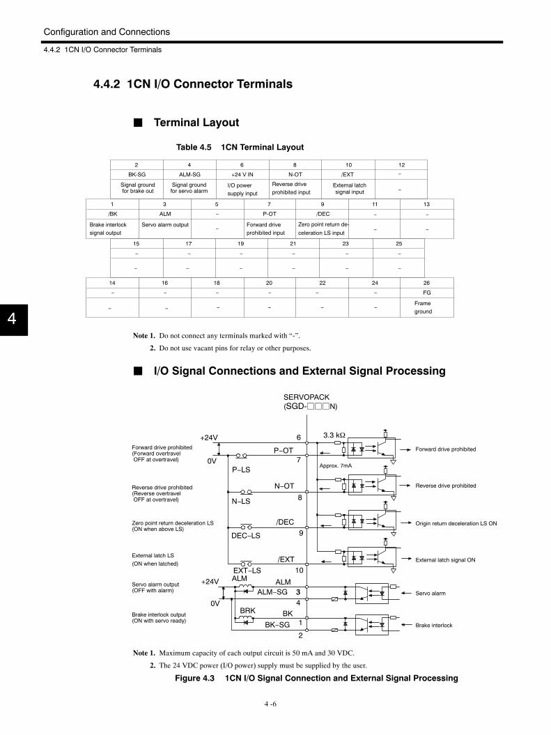
4.4.2 1CN I/O Connector Terminals
J Terminal Layout
Table 4.5 1CN Terminal Layout
1 3 5 7 9 11 13
/BK ALM − P-OT /DEC
14 16 18 20 22 24 26
− − − − − − FG
2 4 6 8 10 12
BK-SG ALM-SG +24 V IN N-OT /EXT
15 17 19 21 23 25
− − − − − −
− −− −−
− −−−
− −
−
−
Signal groundfor brake out
Signal groundfor servo alarm
External latchsignal input
Brake interlocksignal output
Servo alarm output Forward driveprohibited input
Zero point return de-
celeration LS input
I/O powersupply input
Reverse driveprohibited input
Frameground−
−
−
−
− −
Note 1. Do not connect any terminals marked with “-”.
2. Do not use vacant pins for relay or other purposes.
J I/O Signal Connections and External Signal Processing
0VP−LS
6
P−OT7
3.3 kΩ
N−LS
N−OT
8
DEC−LS
/DEC9
EXT−LS/EXT
10
+24V
0V
ALM ALMALM−SG 33
4BRK BK
BK−SG 1
2
+24VForward drive prohibited(Forward overtravelOFF at overtravel)
Reverse drive prohibited(Reverse overtravelOFF at overtravel)
Zero point return deceleration LS(ON when above LS)
External latch LS(ON when latched)
Servo alarm output(OFF with alarm)
Brake interlock output(ON with servo ready)
Approx. 7mA
Origin return deceleration LS ON
External latch signal ON
Reverse drive prohibited
Forward drive prohibited
Servo alarm
Brake interlock
SERVOPACK(SGD-jjjN)
Note 1. Maximum capacity of each output circuit is 50 mA and 30 VDC.
2. The 24 VDC power (I/O power) supply must be supplied by the user.
Figure 4.3 1CN I/O Signal Connection and External Signal Processing
4
4.4 Connecting an Incremental Encoder
4 -7
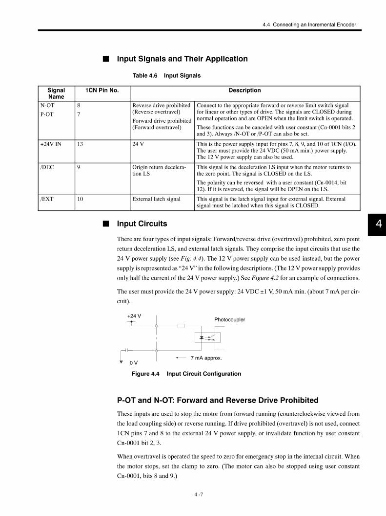
J Input Signals and Their Application
Table 4.6 Input Signals
SignalName
1CN Pin No. Description
N-OT
P-OT
8
7
Reverse drive prohibited(Reverse overtravel)
Forward drive prohibited(Forward overtravel)
Connect to the appropriate forward or reverse limit switch signalfor linear or other types of drive. The signals are CLOSED duringnormal operation and are OPEN when the limit switch is operated.
These functions can be canceled with user constant (Cn-0001 bits 2and 3). Always /N-OT or /P-OT can also be set.
+24V IN 13 24 V This is the power supply input for pins 7, 8, 9, and 10 of 1CN (I/O).The user must provide the 24 VDC (50 mA min.) power supply.The 12 V power supply can also be used.
/DEC 9 Origin return decelera-tion LS
This signal is the deceleration LS input when the motor returns tothe zero point. The signal is CLOSED on the LS.
The polarity can be reversed with a user constant (Cn-0014, bit12). If it is reversed, the signal will be OPEN on the LS.
/EXT 10 External latch signal This signal is the latch signal input for external signal. Externalsignal must be latched when this signal is CLOSED.
J Input Circuits
There are four types of input signals: Forward/reverse drive (overtravel) prohibited, zero point
return deceleration LS, and external latch signals. They comprise the input circuits that use the
24 V power supply (see Fig. 4.4). The 12 V power supply can be used instead, but the power
supply is represented as “24 V” in the following descriptions. (The 12 V power supply provides
only half the current of the 24 V power supply.) See Figure 4.2 for an example of connections.
The user must provide the 24 V power supply: 24 VDC ±1 V, 50 mA min. (about 7 mA per cir-
cuit).
+24 V
0 V7 mA approx.
Photocoupler
Figure 4.4 Input Circuit Configuration
P-OT and N-OT: Forward and Reverse Drive Prohibited
These inputs are used to stop the motor from forward running (counterclockwise viewed from
the load coupling side) or reverse running. If drive prohibited (overtravel) is not used, connect
1CN pins 7 and 8 to the external 24 V power supply, or invalidate function by user constant
Cn-0001 bit 2, 3.
When overtravel is operated the speed to zero for emergency stop in the internal circuit. When
the motor stops, set the clamp to zero. (The motor can also be stopped using user constant
Cn-0001, bits 8 and 9.)
4
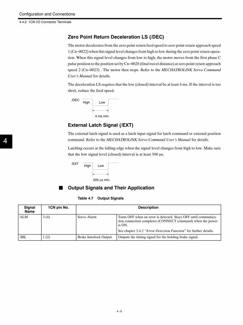
Configuration and Connections
4.4.2 1CN I/O Connector Terminals
4 -8
Zero Point Return Deceleration LS (/DEC)
The motor decelerates from the zero point return feed speed to zero point return approach speed
1 (Cn−0022) when this signal level changes from high to low during the zero point return opera-
tion. When this signal level changes from low to high, the motor moves from the first phase C
pulse position to the position set byCn−0028 (final travel distance) at zero point return approach
speed 2 (Cn−0023) . The motor then stops. Refer to the MECHATROLINK Servo Command
User’s Manual for details.
The deceleration LS requires that the low (closed) interval be at least 4 ms. If the interval is too
short, reduce the feed speed.
4 ms min.
/DECHigh Low
External Latch Signal (/EXT)
The external latch signal is used as a latch input signal for latch command or external position
command. Refer to the MECHATROLINK Servo Command User’s Manual for details.
Latching occurs at the falling edge when the signal level changes from high to low. Make sure
that the low signal level (closed) interval is at least 500 µs.
500 µs min.
/EXT High Low
J Output Signals and Their Application
Table 4.7 Output Signals
SignalName
1CN pin No. Description
ALM 3 (4) Servo Alarm Turns OFF when an error is detected. Stays OFF until communica-tion connection completes (CONNECT command) when the poweris ON.
See chapter 5.4.2 “Error Detection Function” for further details.
/BK 1 (2) Brake Interlock Output Outputs the timing signal for the holding brake signal.
4
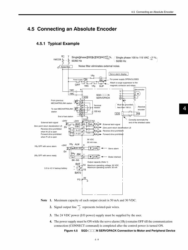
4.5 Connecting an Absolute Encoder
4 -9
4.5 Connecting an Absolute Encoder
4.5.1 Typical Example
1
R T1MCCB
PL
1MC 1Ry SUP
1Ry
1MC
1MC R
1MC
S
120 kΩ
3CN
6
1
7
2
R
/SSH
4
S/SSH
FG 5
8
3
U
PG2CN
VW
1234
M
+24VP
0VN−LS
P−LS
/DECN−OT
P−OT
+24V/EXT
3.3 kΩ7mA
78910
1CN6
FG26
/BK
BK−SG
2Ry 12
1Ry ALM
ALM−SG
34
+24V
0VP
BAT+
P−BAT0
14
15
P
P
Single phase 200 to 230 VAC %,50/60 Hz
Single phase 100 to 115 VAC %,50/60 Hz
Noise filter Noise filter eliminates external noise.
Servo alarm display
Power supply ON
OFF
For power supply OPEN/CLOSED
Attach a surge suppressor to themagnetic contactor and relays.
Servomotor
SGD-jjjNSERVOPACK
From previousMECHATROLINK station
To next MECHATROLINKstation
End of last station
External latch signal
Zero point return deceleration LS
Reverse drive prohibitedwhen N-LS is openForward drive prohibitedwhen P-LS is open
Must be grounded.less than 100 Ω . Absolute
encoder
Correctly terminate theend of the shielded cable.
/External latch signal
/Zero point return deceleration LS
Reverse drive prohibited
Forward drive prohibited
1Ry OFF with servo alarm
2Ry OFF with servo ready
3.3 to 4.5 V backup battery
30 VDC50 mA max.
Servo alarm
Brake interlock
Output capacity (Note 1)
Maximum operating voltage: 30 VDCMaximum operating current: 50 mA
+10-15
+10-15
Terminalresistor
Note 1. Maximum capacity of each output circuit is 50 mA and 30 VDC.
2. Signal output line P represents twisted-pair wires.
3. The 24 VDC power (I/O power) supply must be supplied by the user.
4. The power supplymust be ONwhile the servo alarm (1Ry) remains OFF till the communicationconnection (CONNECT command) is completed after the control power is turned ON.
Figure 4.5 SGD-jjjN SERVOPACK Connection to Motor and Peripheral Device
4
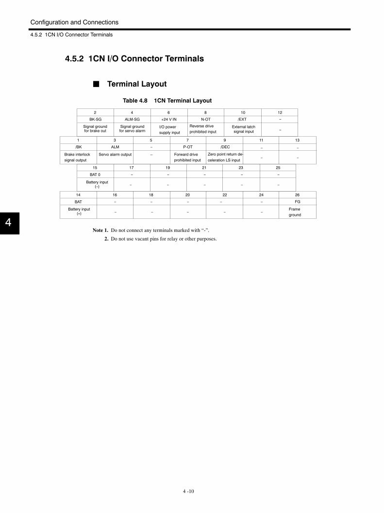
Configuration and Connections
4.5.2 1CN I/O Connector Terminals
4 -10
4.5.2 1CN I/O Connector Terminals
J Terminal Layout
Table 4.8 1CN Terminal Layout
1 3 5 7 9 11 13
/BK ALM − P-OT /DEC
14 16 18 20 22 24 26
− − − − − FG
2 4 6 8 10 12
BK-SG ALM-SG +24 V IN N-OT /EXT
15 17 19 21 23 25
− − − − −
− −− −
− −−−
− −
−
−
Signal groundfor brake out
Signal groundfor servo alarm
External latchsignal input
Brake interlocksignal output
Servo alarm output Forward driveprohibited input
Zero point return de-
celeration LS input
I/O powersupply input
Reverse driveprohibited input
Frameground
BAT
BAT 0
Battery input(+)
Battery input(−)
−
−
−
− −
Note 1. Do not connect any terminals marked with “-”.
2. Do not use vacant pins for relay or other purposes.
4
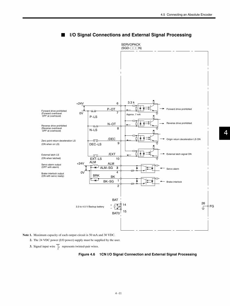
4.5 Connecting an Absolute Encoder
4 -11
J I/O Signal Connections and External Signal Processing
26FG
0VP−LS
6
P−OT7
3.3 k
N−LS
N−OT8
DEC−LS
/DEC9
EXT−LS/EXT
10
+24V
0V
ALM ALMALM−SG 33
4BRK BK
BK−SG 1
2
+24V
BAT
+P−
BAT0
14
15
SERVOPACK(SGD-jjjN)
Forward drive prohibited(Forward overtravelOFF at overtravel)
Reverse drive prohibited(Reverse overtravelOFF at overtravel)
Zero point return deceleration LS(ON when on LS)
External latch LS(ON when latched)
Servo alarm output(OFF with alarm)
Brake interlock output(ON with servo ready)
Approx. 7 mA
3.3 to 4.5 V Backup battery
Origin return deceleration LS ON
External latch signal ON
Servo alarm
Brake interlock
Reverse drive prohibited
Forward drive prohibited
Note 1. Maximum capacity of each output circuit is 50 mA and 30 VDC.
2. The 24 VDC power (I/O power) supply must be supplied by the user.
3. Signal input wire P represents twisted-pair wires.
Figure 4.6 1CN I/O Signal Connection and External Signal Processing
4
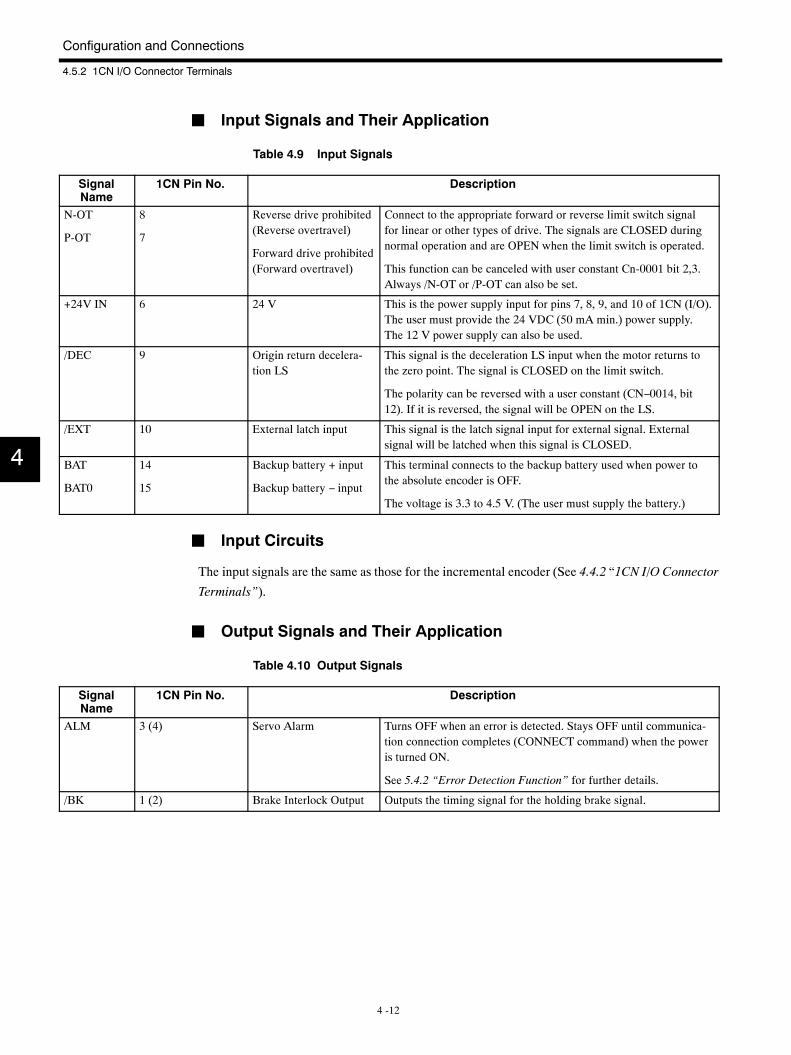
Configuration and Connections
4.5.2 1CN I/O Connector Terminals
4 -12
J Input Signals and Their Application
Table 4.9 Input Signals
SignalName
1CN Pin No. Description
N-OT
P-OT
8
7
Reverse drive prohibited(Reverse overtravel)
Forward drive prohibited(Forward overtravel)
Connect to the appropriate forward or reverse limit switch signalfor linear or other types of drive. The signals are CLOSED duringnormal operation and are OPEN when the limit switch is operated.
This function can be canceled with user constant Cn-0001 bit 2,3.Always /N-OT or /P-OT can also be set.
+24V IN 6 24 V This is the power supply input for pins 7, 8, 9, and 10 of 1CN (I/O).The user must provide the 24 VDC (50 mA min.) power supply.The 12 V power supply can also be used.
/DEC 9 Origin return decelera-tion LS
This signal is the deceleration LS input when the motor returns tothe zero point. The signal is CLOSED on the limit switch.
The polarity can be reversed with a user constant (CN−0014, bit12). If it is reversed, the signal will be OPEN on the LS.
/EXT 10 External latch input This signal is the latch signal input for external signal. Externalsignal will be latched when this signal is CLOSED.
BAT
BAT0
14
15
Backup battery + input
Backup battery − input
This terminal connects to the backup battery used when power tothe absolute encoder is OFF.
The voltage is 3.3 to 4.5 V. (The user must supply the battery.)
J Input Circuits
The input signals are the same as those for the incremental encoder (See 4.4.2 “1CN I/O Connector
Terminals”).
J Output Signals and Their Application
Table 4.10 Output Signals
SignalName
1CN Pin No. Description
ALM 3 (4) Servo Alarm Turns OFF when an error is detected. Stays OFF until communica-tion connection completes (CONNECT command) when the poweris turned ON.
See 5.4.2 “Error Detection Function” for further details.
/BK 1 (2) Brake Interlock Output Outputs the timing signal for the holding brake signal.
4
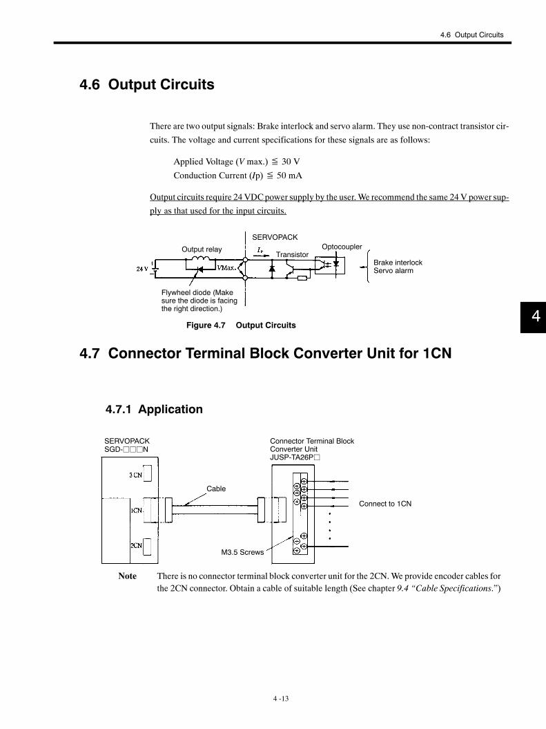
4.6 Output Circuits
4 -13
4.6 Output Circuits
There are two output signals: Brake interlock and servo alarm. They use non-contract transistor cir-
cuits. The voltage and current specifications for these signals are as follows:
Applied Voltage (V max.)≦ 30 V
Conduction Current (Ip)≦ 50 mA
Output circuits require 24VDCpower supply by the user.We recommend the same 24V power sup-
ply as that used for the input circuits.
Output relay
Flywheel diode (Makesure the diode is facingthe right direction.)
TransistorOptocoupler
Brake interlockServo alarm
SERVOPACK
Figure 4.7 Output Circuits
4.7 Connector Terminal Block Converter Unit for 1CN
4.7.1 Application
Connector Terminal BlockConverter UnitJUSP-TA26Pj
Cable
M3.5 Screws
Connect to 1CN
SERVOPACKSGD-jjjN
Note There is no connector terminal block converter unit for the 2CN.We provide encoder cables forthe 2CN connector. Obtain a cable of suitable length (See chapter 9.4 “Cable Specifications.”)
4
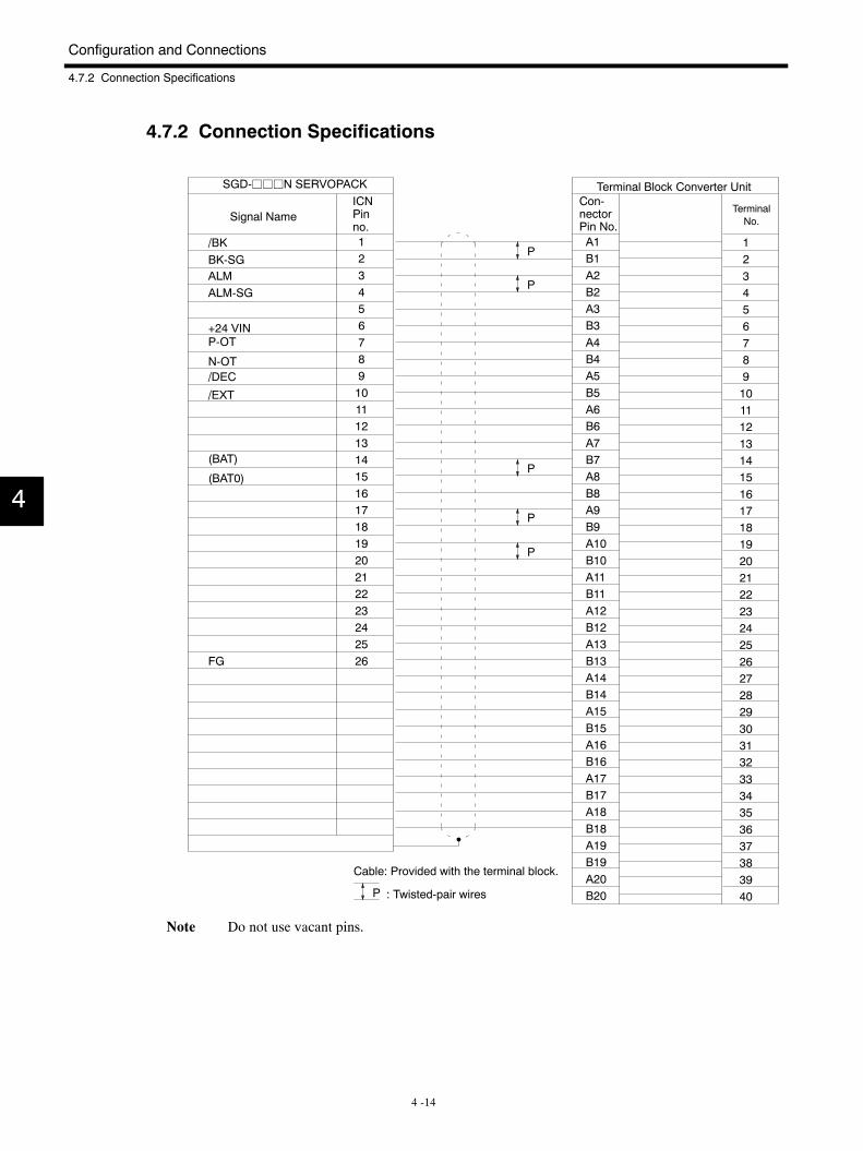
Configuration and Connections
4.7.2 Connection Specifications
4 -14
4.7.2 Connection Specifications
1234567891011121314151617181920212223242526
12345678910111213141516171819202122232425262728293031323334353637383940
A1B1A2B2A3B3A4B4A5B5A6B6A7B7A8B8A9B9A10B10A11B11A12B12A13B13A14B14A15B15A16B16A17B17A18B18A19B19A20B20
/BK
N-OT
(BAT)
(BAT0)
P
P
P
P
P
/EXT
P-OT+24 VIN
ALM-SGALMBK-SG
FG
/DEC
SGD-jjjN SERVOPACK
Signal NameICNPinno.
Terminal Block Converter UnitCon-nectorPin No.
TerminalNo.
Cable: Provided with the terminal block.
: Twisted-pair wiresP
Note Do not use vacant pins.
4
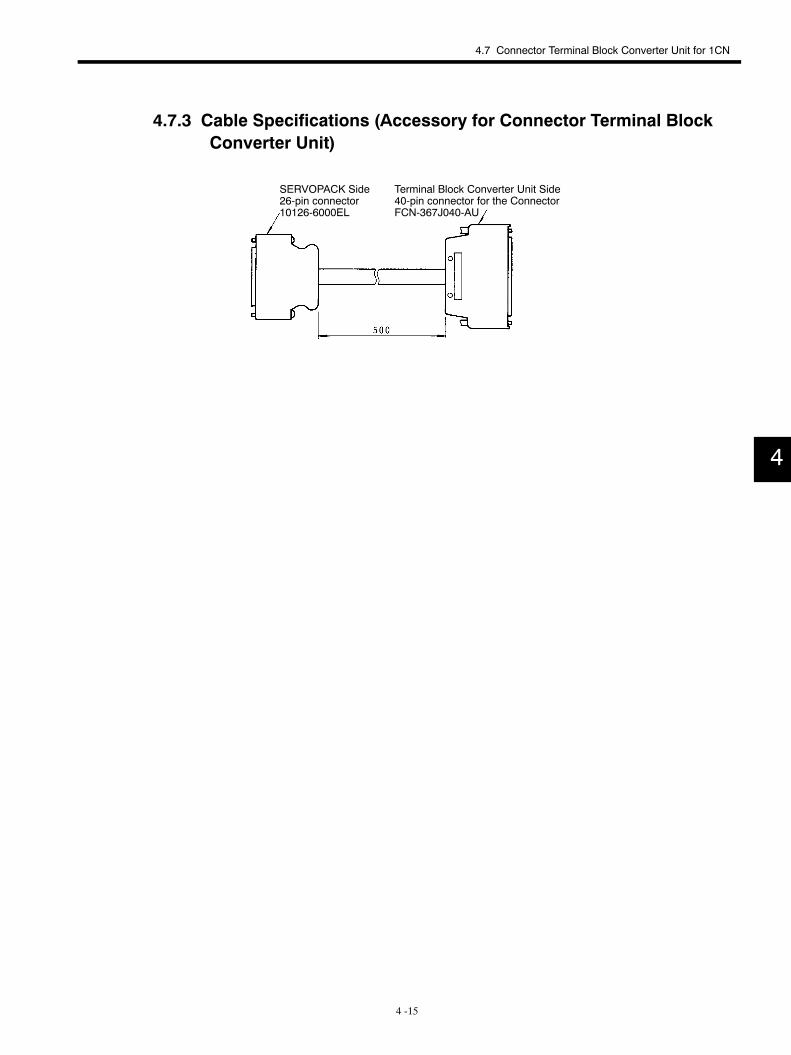
4.7 Connector Terminal Block Converter Unit for 1CN
4 -15
4.7.3 Cable Specifications (Accessory for Connector Terminal BlockConverter Unit)
SERVOPACK Side26-pin connector10126-6000EL
Terminal Block Converter Unit Side40-pin connector for the ConnectorFCN-367J040-AU
4
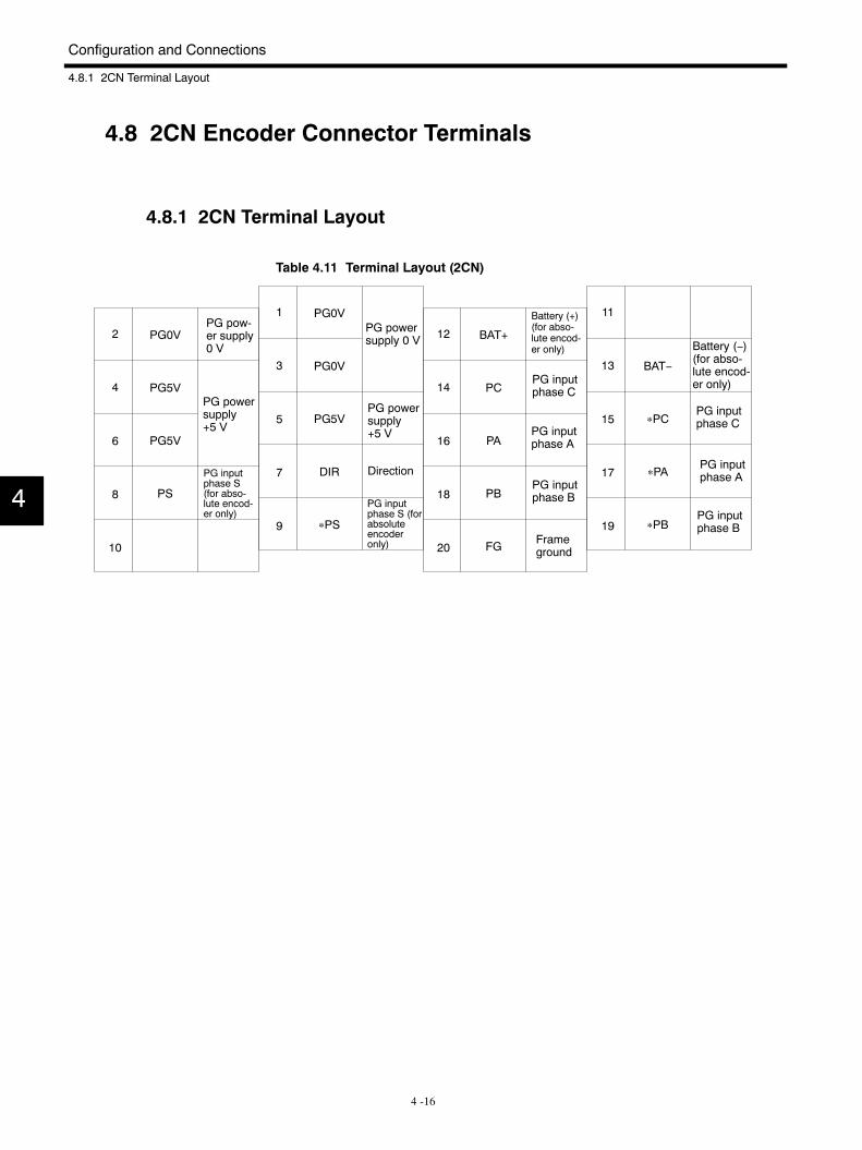
Configuration and Connections
4.8.1 2CN Terminal Layout
4 -16
4.8 2CN Encoder Connector Terminals
4.8.1 2CN Terminal Layout
Table 4.11 Terminal Layout (2CN)
PG0V
PG5V
PG5V
PS
2
4
6
8
10
PG0V
PG0V
PG5V
DIR
∗PS
1
3
5
7
9
BAT+
PC
PA
PB
FG
12
14
16
18
20
BAT−
∗PC
∗PA
∗PB
11
13
15
17
19
Direction
PG pow-er supply0 V
PG powersupply+5 V
PG inputphase S(for abso-lute encod-er only)
PG inputphase S (forabsoluteencoderonly)
PG powersupply+5 V
PG powersupply 0 V
Frameground
PG inputphase B
PG inputphase A
PG inputphase C
Battery (+)(for abso-lute encod-er only) Battery (−)
(for abso-lute encod-er only)
PG inputphase C
PG inputphase A
PG inputphase B
4
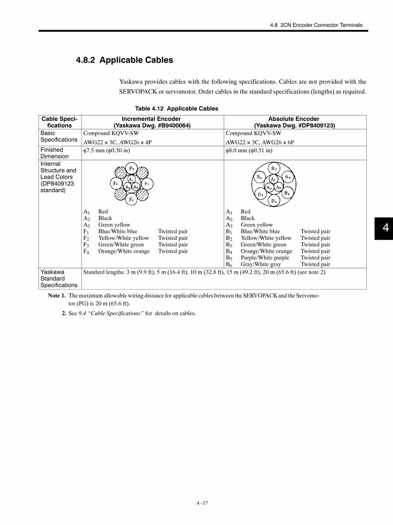
4.8 2CN Encoder Connector Terminals
4 -17
4.8.2 Applicable Cables
Yaskawa provides cables with the following specifications. Cables are not provided with the
SERVOPACK or servomotor. Order cables in the standard specifications (lengths) as required.
Table 4.12 Applicable Cables
Cable Speci-fications
Incremental Encoder(Yaskawa Dwg. #B9400064)
Absolute Encoder(Yaskawa Dwg. #DP8409123)
BasicSpecifications
Compound KQVV-SW
AWG22 × 3C, AWG26 × 4P
Compound KQVV-SW
AWG22 × 3C, AWG26 × 6PFinishedDimension
φ7.5 mm (φ0.30 in) φ8.0 mm (φ0.31 in)
InternalStructure andLead Colors(DP8409123standard)
A1 RedA2 BlackA3 Green yellowF1 Blue/White blue Twisted pairF2 Yellow/White yellow Twisted pairF3 Green/White green Twisted pairF4 Orange/White orange Twisted pair
A1 RedA2 BlackA3 Green yellowB1 Blue/White blue Twisted pairB2 Yellow/White yellow Twisted pairB3 Green/White green Twisted pairB4 Orange/White orange Twisted pairB5 Purple/White purple Twisted pairB6 Gray/White gray Twisted pair
YaskawaStandardSpecifications
Standard lengths: 3 m (9.9 ft), 5 m (16.4 ft), 10 m (32.8 ft), 15 m (49.2 ft), 20 m (65.6 ft) (see note 2)
Note 1. Themaximumallowablewiring distance for applicable cables between the SERVOPACKand the Servomo-tor (PG) is 20 m (65.6 ft).
2. See 9.4 “Cable Specifications” for details on cables.
4
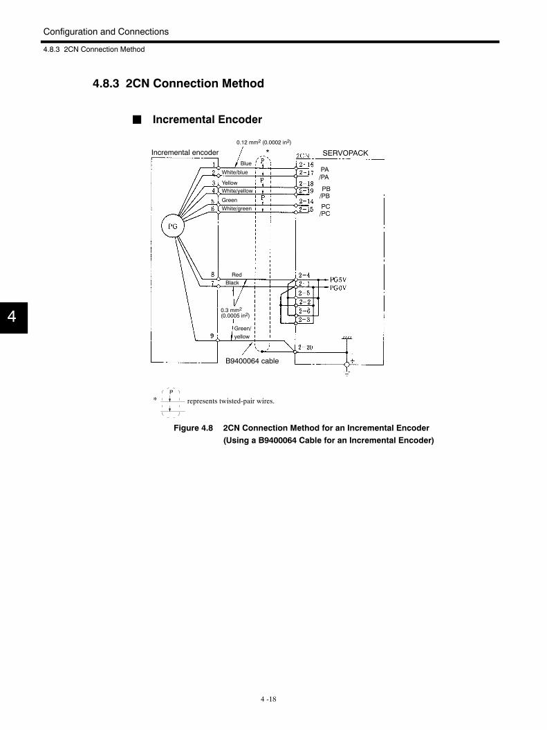
Configuration and Connections
4.8.3 2CN Connection Method
4 -18
4.8.3 2CN Connection Method
J Incremental Encoder
Incremental encoder
B9400064 cable
*
White/blue
Blue
YellowWhite/yellow
White/green
Green
Green/yellow
RedBlack
0.12 mm2 (0.0002 in2)
0.3 mm2(0.0005 in2)
SERVOPACK
/PA
/PB
/PC
PA
PB
PC
*P
represents twisted-pair wires.
Figure 4.8 2CN Connection Method for an Incremental Encoder(Using a B9400064 Cable for an Incremental Encoder)
4
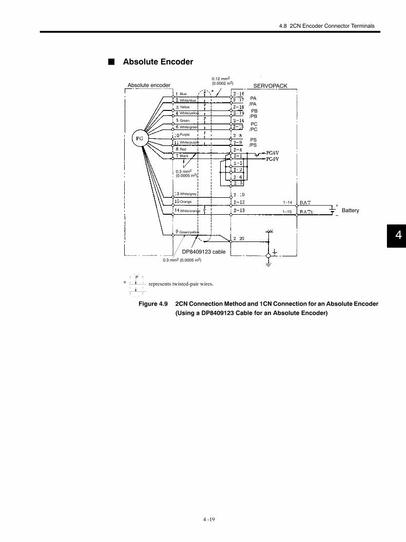
4.8 2CN Encoder Connector Terminals
4 -19
J Absolute Encoder
Absolute encoder
DP8409123 cable
Blue
White/blue
Yellow
Green
White/yellow
White/green
Purple
Red
Black
White/purple
White/grey
Orange
White/orange
Green/yellow
Battery
1−14
1−15
*
0.12 mm2
(0.0002 in2)
0.3 mm2 (0.0005 in2)
0.3 mm2(0.0005 in2)
SERVOPACK
/PA
/PB
/PC
PA
PB
PC
/PSPS
*P
represents twisted-pair wires.
Figure 4.9 2CN Connection Method and 1CNConnection for an Absolute Encoder(Using a DP8409123 Cable for an Absolute Encoder)
4
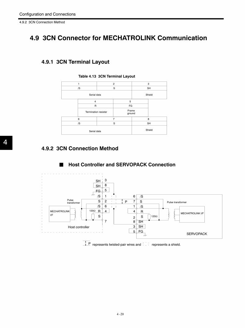
Configuration and Connections
4.9.2 3CN Connection Method
4 -20
4.9 3CN Connector for MECHATROLINK Communication
4.9.1 3CN Terminal Layout
Table 4.13 3CN Terminal Layout
1 2 3
/S S SH
4 5
R FG
6 7 8
/S S SH
Serial data Shield
Termination resister Frameground
Serial data Shield
4.9.2 3CN Connection Method
J Host Controller and SERVOPACK Connection
385
SHSH
FG
/S
S/SRS
MECHATROLINK I/F
SERVOPACK
120Ω
120Ω
6714
835
/S
S
/SR
SSHSHFG
Pulse transformerPulsetransformer
Host controller
MECHATROLINKI/F
P
represents twisted-pair wires and represents a shield.P
1264
72
4
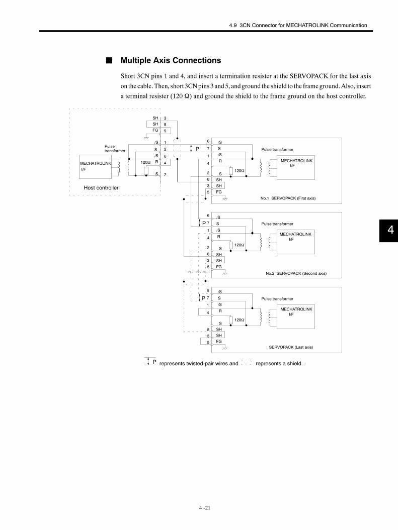
4.9 3CN Connector for MECHATROLINK Communication
4 -21
J Multiple Axis Connections
Short 3CN pins 1 and 4, and insert a termination resister at the SERVOPACK for the last axis
on the cable.Then, short 3CNpins 3 and5, andground the shield to the frameground.Also, insert
a terminal resister (120 Ω) and ground the shield to the frame ground on the host controller.
3
8
5
SHSH
FG
/S
No.1 SERVOPACK (First axis)
120Ω
120Ω
6
7
1
4
/S
S
/S
R
SSHSHFG
Pulse transformerPulsetransformer
I/FMECHATROLINK
120Ω
6
7
1
4
/S
S
/S
R
SSHSHFG
Pulse transformer
I/FMECHATROLINK
120Ω
6
7
1
4
S
SH
SH
FG
Pulse transformer
S
/S
R
S
/S
S
/S
R
No.2 SERVOPACK (Second axis)
SERVOPACK (Last axis)
Host controller
MECHATROLINKI/F
P
P
P
represents twisted-pair wires and represents a shield.P
1
8
5
3
2
2
2
6
4
7
8
5
3
8
5
3
MECHATROLINKI/F
4
5 -1
5Application
This chapter describes how to use the Servodrives.
5.1 Turning Power ON/OFF 5 -3. . . . . . . . . . . . . . . . . . . .5.2 Position Control 5 -4. . . . . . . . . . . . . . . . . . . . . . . . . . .
5.2.1 Electronic Gear Function 5 -4. . . . . . . . . . . . . . . . . . . . .
5.2.2 Feed-forward Control Function 5 -5. . . . . . . . . . . . . . . .
5.3 Setting Up an Absolute Encoder 5 -6. . . . . . . . . . . .5.3.1 Battery 5 -6. . . . . . . . . . . . . . . . . . . . . . . . . . . . . . . . . . . . .
5.3.2 Setup Procedure 5 -6. . . . . . . . . . . . . . . . . . . . . . . . . . . .
5.4 Protection Functions 5 -7. . . . . . . . . . . . . . . . . . . . . . .5.4.1 Dynamic Brake Function 5 -7. . . . . . . . . . . . . . . . . . . . .
5.4.2 Error Detection Function 5 -7. . . . . . . . . . . . . . . . . . . . . .
5.4.3 Servo Alarm Output (ALM, ALM-SG) 5 -8. . . . . . . . . . .
5.4.4 Handling Protection Circuit Operation 5 -8. . . . . . . . . .
5.4.5 Servo Alarm Reset 5 -8. . . . . . . . . . . . . . . . . . . . . . . . . .
5.5 Indications 5 -8. . . . . . . . . . . . . . . . . . . . . . . . . . . . . . .5.6 Precautions 5 -9. . . . . . . . . . . . . . . . . . . . . . . . . . . . . .
5.6.1 Overhanging Load 5 -9. . . . . . . . . . . . . . . . . . . . . . . . . . .
5.6.2 Load Moment of Inertia JL 5 -9. . . . . . . . . . . . . . . . . . . .
5.6.3 Regenerative Unit 5 -11. . . . . . . . . . . . . . . . . . . . . . . . . . .
5.6.4 High Voltage Lines 5 -13. . . . . . . . . . . . . . . . . . . . . . . . . .
5.7 Application Precautions 5 -14. . . . . . . . . . . . . . . . . . . .5.7.1 Noise Control 5 -14. . . . . . . . . . . . . . . . . . . . . . . . . . . . . . .
5.7.2 Power Supply Line Protection 5 -17. . . . . . . . . . . . . . . . .
5.8 Appropriate Applications 5 -19. . . . . . . . . . . . . . . . . . .5.8.1 Holding Brake Interlock Signal 5 -19. . . . . . . . . . . . . . . .
5
Application
5 -2
5.9 Adjustments 5 -20. . . . . . . . . . . . . . . . . . . . . . . . . . . . . .5.9.1 Servo System Adjustments 5 -20. . . . . . . . . . . . . . . . . . .
5.9.2 User Constants 5 -21. . . . . . . . . . . . . . . . . . . . . . . . . . . . .
5.9.3 Functions that Improve Response 5 -24. . . . . . . . . . . . .
5.9.4 Guidelines for Setting the Load Inertia Ratio 5 -25. . . .
5
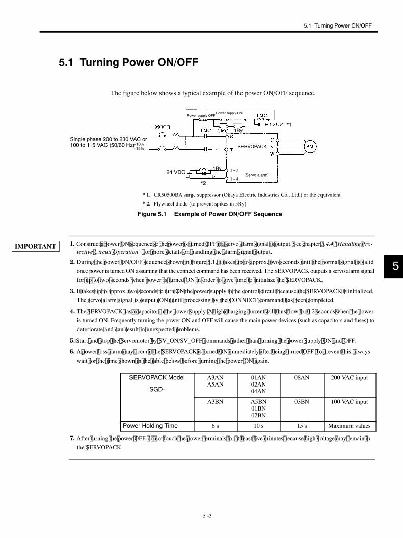
5.1 Turning Power ON/OFF
5 -3
5.1 Turning Power ON/OFF
The figure below shows a typical example of the power ON/OFF sequence.
24 VDC
Single phase 200 to 230 VAC or100 to 115 VAC (50/60 Hz)
Power supply OFFPower supply ON
(Servo alarm)
*1
*2
* 1. CR50500BA surge suppressor (Okaya Electric Industries Co., Ltd.) or the equivalent
* 2. Flywheel diode (to prevent spikes in 5Ry)
1 − 3
1 − 4
+10%−15% SERVOPACK
1Ry
1Ry
Figure 5.1 Example of Power ON/OFF Sequence
1. Construct a power ON sequence so the power is turned OFF if a servo alarm signal is output. See chapter 5.4.4 “Handling Pro-tective Circuit Operation” for more details on handling the alarm signal output.
2. During the power ON/OFF sequence shown in Figure 5.1, it takes up to approx. two seconds until the normal signal is validonce power is turned ON assuming that the connect command has been received. The SERVOPACK outputs a servo alarm signal
for u p to two seconds when power is turned ON in order to give time to initialize the SERVOPACK.
3. It takes up to approx. two seconds to turn ON the power supply to the control circuit because the SERVOPACK is initialized.The servo alarm signal is output (ON) until processing by the CONNECT command has been completed.
4. The SERVOPACK has a capacitor in the power supply. A high charging current will thus flow for 0.2 seconds when the poweris turned ON. Frequently turning the power ON and OFF will cause the main power devices (such as capacitors and fuses) to
deteriorate and can result in unexpected problems.
5. Start and stop the Servomotor by SV_ON/SV_OFF commands rather than turning the power supply ON and OFF.
6. A power loss alarm may occur if the SERVOPACK is turned ON immediately after being turned OFF. To prevent this, alwayswait for the time shown in the table below before turning the power ON again.
SERVOPACK Model
SGD-
A3ANA5AN
01AN02AN04AN
08AN 200 VAC input
A3BN A5BN01BN02BN
03BN 100 VAC input
Power Holding Time 6 s 10 s 15 s Maximum values
7. After turning the power OFF, d o not touch the power terminals for at least five minutes because high voltage may remain inthe SERVOPACK.
5
IMPORTANT
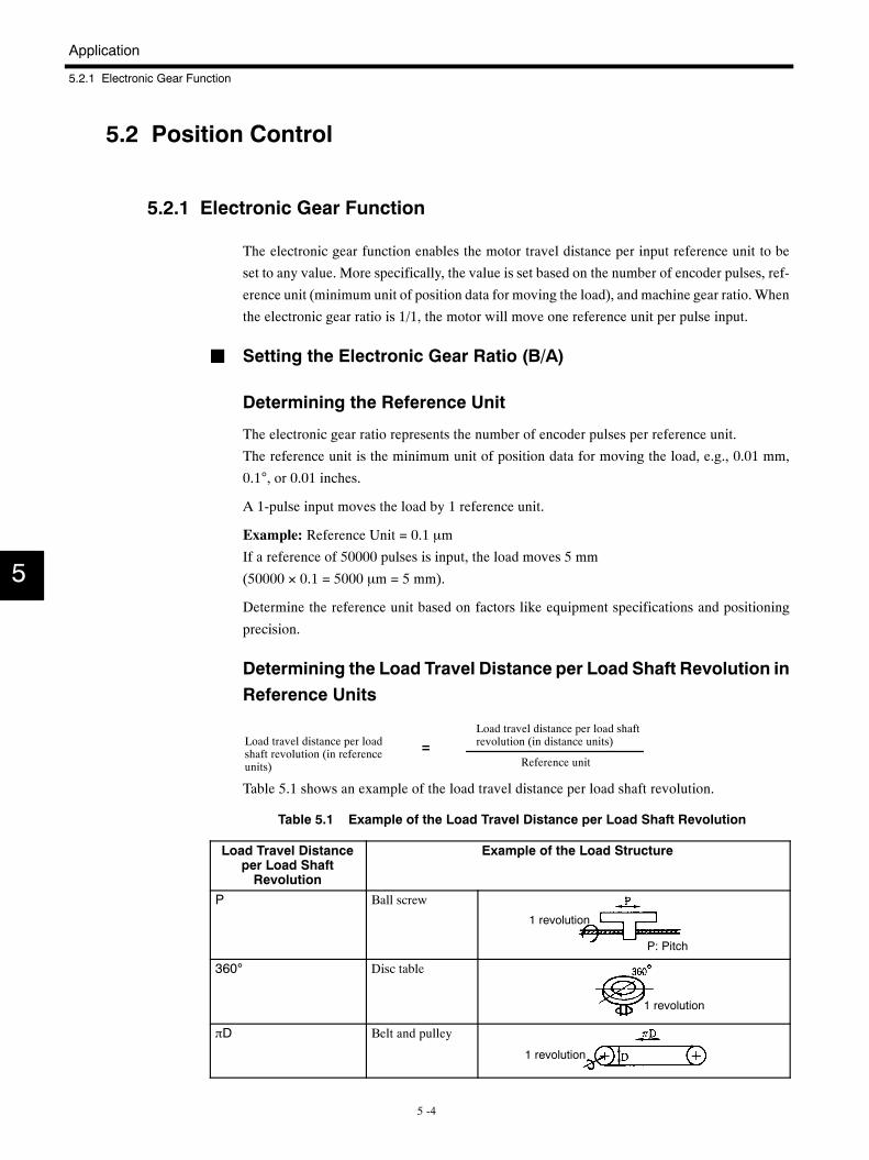
Application
5.2.1 Electronic Gear Function
5 -4
5.2 Position Control
5.2.1 Electronic Gear Function
The electronic gear function enables the motor travel distance per input reference unit to be
set to any value. More specifically, the value is set based on the number of encoder pulses, ref-
erence unit (minimum unit of position data for moving the load), and machine gear ratio.When
the electronic gear ratio is 1/1, the motor will move one reference unit per pulse input.
J Setting the Electronic Gear Ratio (B/A)
Determining the Reference Unit
The electronic gear ratio represents the number of encoder pulses per reference unit.
The reference unit is the minimum unit of position data for moving the load, e.g., 0.01 mm,
0.1°, or 0.01 inches.
A 1-pulse input moves the load by 1 reference unit.
Example: Reference Unit = 0.1 µm
If a reference of 50000 pulses is input, the load moves 5 mm
(50000 × 0.1 = 5000 µm = 5 mm).
Determine the reference unit based on factors like equipment specifications and positioning
precision.
Determining the Load Travel Distance per Load Shaft Revolution inReference Units
Load travel distance per loadshaft revolution (in referenceunits)
Load travel distance per load shaftrevolution (in distance units)
Reference unit=
Table 5.1 shows an example of the load travel distance per load shaft revolution.
Table 5.1 Example of the Load Travel Distance per Load Shaft Revolution
Load Travel Distanceper Load ShaftRevolution
Example of the Load Structure
P Ball screw
1 revolution
P: Pitch
360° Disc table
1 revolution
πD Belt and pulley
1 revolution
5
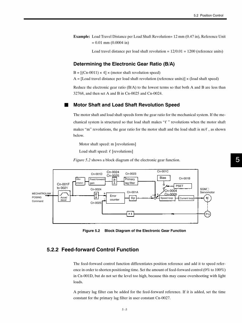
5.2 Position Control
5 -5
Example: Load Travel Distance per Load Shaft Revolution= 12 mm (0.47 in), Reference Unit
= 0.01 mm (0.0004 in)
Load travel distance per load shaft revolution = 12/0.01 = 1200 (reference units)
Determining the Electronic Gear Ratio (B/A)
B = [(Cn-0011) × 4] × (motor shaft revolution speed)
A = [Load travel distance per load shaft revolution (reference units)] × (load shaft speed)
Reduce the electronic gear ratio (B/A) to the lowest terms so that both A and B are less than
32768, and then set A and B in Cn-0025 and Cn-0024.
J Motor Shaft and Load Shaft Revolution Speed
The motor shaft and load shaft speeds form the gear ratio for the mechanical system. If the me-
chanical system is structured so that load shaft makes “ℓ ” revolutions when the motor shaft
makes “m” revolutions, the gear ratio for the motor shaft and the load shaft is m/ℓ , as shownbelow.
Motor shaft speed: m [revolutions]
Load shaft speed: ℓ [revolutions]
Figure 5.2 shows a block diagram of the electronic gear function.
MECHATROLINK
POSING
CommandAccel/decel
Differ-
entiation
Feed-forward
gain
Errorcounter
Primarylag filter
Bias
PSET
Speed loop Current loop
Cn-001Fto 0021
Cn-001DCn-0024Cn-0025
Cn-0023Cn-001C
Cn-001B
Cn-0004Cn-0005
Cn-001ACn-0024
Cn-0025
SGMjServomotor
Figure 5.2 Block Diagram of the Electronic Gear Function
5.2.2 Feed-forward Control Function
The feed-forward control function differentiates position reference and add it to speed refer-
ence in order to shorten positioning time. Set the amount of feed-forward control (0% to 100%)
in Cn-001D, but do not set the level too high, because this may cause overshooting with light
loads.
A primary lag filter can be added for the feed-forward reference. If it is added, set the time
constant for the primary lag filter in user constant Cn-0027.
5
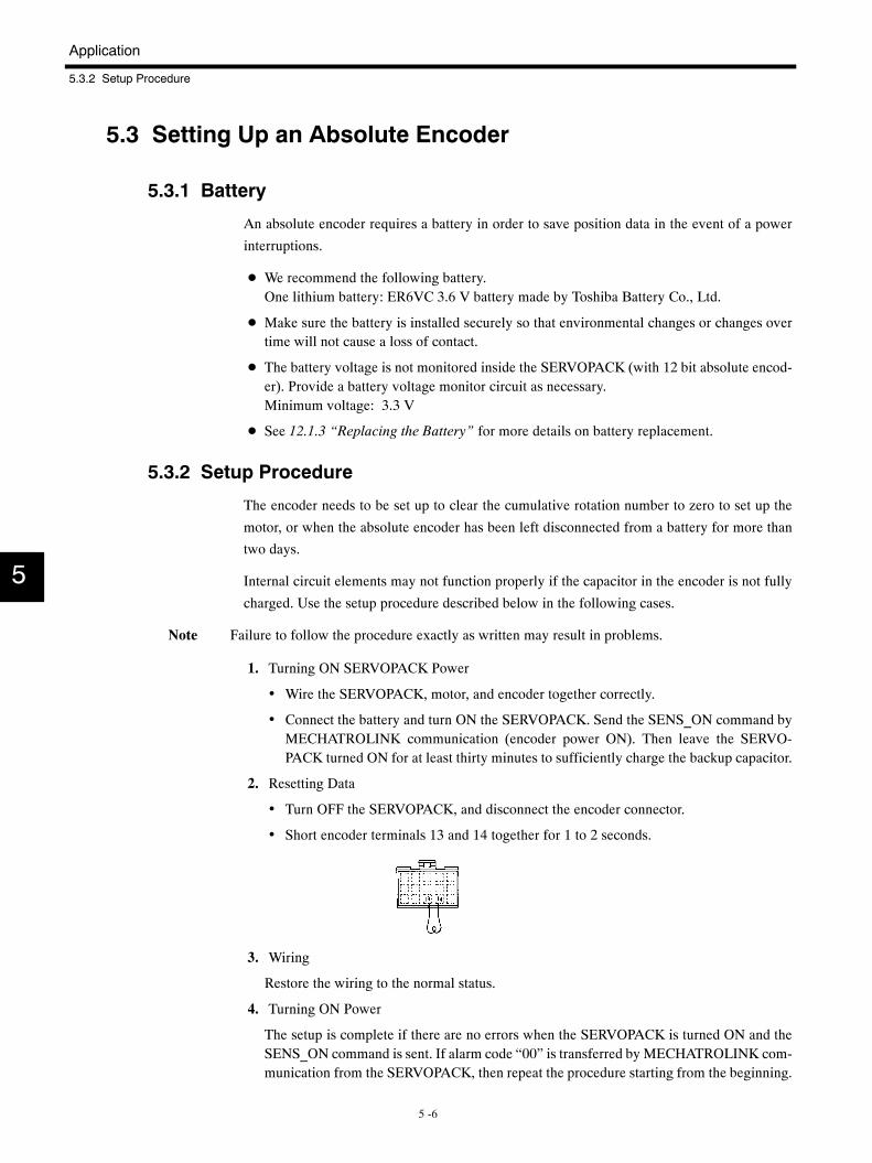
Application
5.3.2 Setup Procedure
5 -6
5.3 Setting Up an Absolute Encoder
5.3.1 Battery
An absolute encoder requires a battery in order to save position data in the event of a power
interruptions.
D We recommend the following battery.One lithium battery: ER6VC 3.6 V battery made by Toshiba Battery Co., Ltd.
D Make sure the battery is installed securely so that environmental changes or changes overtime will not cause a loss of contact.
D The battery voltage is not monitored inside the SERVOPACK (with 12 bit absolute encod-er). Provide a battery voltage monitor circuit as necessary.Minimum voltage: 3.3 V
D See 12.1.3 “Replacing the Battery” for more details on battery replacement.
5.3.2 Setup Procedure
The encoder needs to be set up to clear the cumulative rotation number to zero to set up the
motor, or when the absolute encoder has been left disconnected from a battery for more than
two days.
Internal circuit elements may not function properly if the capacitor in the encoder is not fully
charged. Use the setup procedure described below in the following cases.
Note Failure to follow the procedure exactly as written may result in problems.
1. Turning ON SERVOPACK Power
• Wire the SERVOPACK, motor, and encoder together correctly.
• Connect the battery and turn ON the SERVOPACK. Send the SENS_ON command byMECHATROLINK communication (encoder power ON). Then leave the SERVO-PACK turned ON for at least thirty minutes to sufficiently charge the backup capacitor.
2. Resetting Data
• Turn OFF the SERVOPACK, and disconnect the encoder connector.
• Short encoder terminals 13 and 14 together for 1 to 2 seconds.
3. Wiring
Restore the wiring to the normal status.
4. Turning ON Power
The setup is complete if there are no errors when the SERVOPACK is turned ON and theSENS_ON command is sent. If alarm code “00” is transferred by MECHATROLINK com-munication from the SERVOPACK, then repeat the procedure starting from the beginning.
5
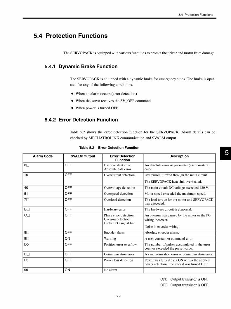
5.4 Protection Functions
5 -7
5.4 Protection Functions
The SERVOPACK is equipped with various functions to protect the driver andmotor from damage.
5.4.1 Dynamic Brake Function
The SERVOPACK is equipped with a dynamic brake for emergency stops. The brake is oper-
ated for any of the following conditions.
D When an alarm occurs (error detection)
D When the servo receives the SV_OFF command
D When power is turned OFF
5.4.2 Error Detection Function
Table 5.2 shows the error detection function for the SERVOPACK. Alarm details can be
checked by MECHATROLINK communication and SVALM output.
Table 5.2 Error Detection Function
Alarm Code SVALM Output Error Detection DescriptionAlarm Code SVALM Output Error DetectionFunction
DescriptionFunction
0j OFF User constant errorAbsolute data error
An absolute error or parameter (user constant)error.
10 OFF Overcurrent detection Overcurrent flowed through the main circuit.
The SERVOPACK heat sink overheated.
40 OFF Overvoltage detection The main circuit DC voltage exceeded 420 V.
51 OFF Overspeed detection Motor speed exceeded the maximum speed.
7j OFF Overload detection The load torque for the motor and SERVOPACKwas exceeded.
Bj OFF Hardware error The hardware circuit is abnormal.
Cj OFF Phase error detectionOverrun detectionBroken PG signal line
An overrun was caused by the motor or the PGwiring incorrect.
Noise in encoder wiring.
8j OFF Encoder alarm Absolute encoder alarm.
9j ON Warning A user constant or command error.
D0 OFF Position error overflow The number of pulses accumulated in the errorcounter exceeded the preset value.
Ej OFF Communication error A synchronization error or communication error.
F3 OFF Power loss detection Power was turned back ON within the allottedpower retention time after it was turned OFF.
99 ON No alarm −
ON: Output transistor is ON.
OFF: Output transistor is OFF.
5
Application
5.4.5 Servo Alarm Reset
5 -8
5.4.3 Servo Alarm Output (ALM, ALM-SG)
The power drive circuit in the SERVOPACK will turn OFF and the alarm status will be dis-
played if any error detection function shown in Table 5.2 operates. Details of the alarm will
be sent by a MECHATROLINK response message, the red indicator on the SERVOPACK will
light, and the alarm output (ALM, ALM-SG) will turn OFF. See Table 5.2 for more details on
alarm codes.
5.4.4 Handling Protection Circuit Operation
An alarm signal output indicates some kind of error. Determine the cause, take appropriate ac-
tion, and then resume operation.
Check the error data for past occurrences using the alarm-warning history (traceback) of the
MECHATROLINK communication, and implement the remedy listed in Table 12.6.
5.4.5 Servo Alarm Reset
To reset the SERVOPACK when a servo alarm occurs, send the MECHATROLINK ALM-CLR
command, or turn OFF the power and then ON.
5.5 Indications
The following indications are made on the front panel of the SERVOPACK.
D Power ON: Green LED lights.
D Alarm occurred: Red LED lights.
D During MECHATROLINK communication: Green LED lights.
5
5.6 Precautions
5 -9
5.6 Precautions
5.6.1 Overhanging Load
Do not allow the motor to be continuously rotated by the load while the regenerative brake is
being applied.
Example: Tension control drive
Do not use the motor for lowering objects without a counterweight.
Rated specifications for the regenerative braking capacity of the SERVOPACK is only for brief
periods while the motor is stopped. Contact your Yaskawa representative about applications
with overhanging load.
5.6.2 Load Moment of Inertia JL
Make sure the allowable load moment of inertia JL calculated for the motor shaft falls within
the range given in Figure 5.3. (when using Servomotors with incremental encoders for 200
VAC) An overvoltage alarm will occur during deceleration if the load moment of inertia ex-
ceeds the values in the figure. If this occurs, take one of the following actions. For further de-
tails, contact your Yaskawa representative.
D Reduce the torque limit.
D Reduce the deceleration rate.
D Reduce the maximum rotation speed.
D Add a Regenerative Unit.
5
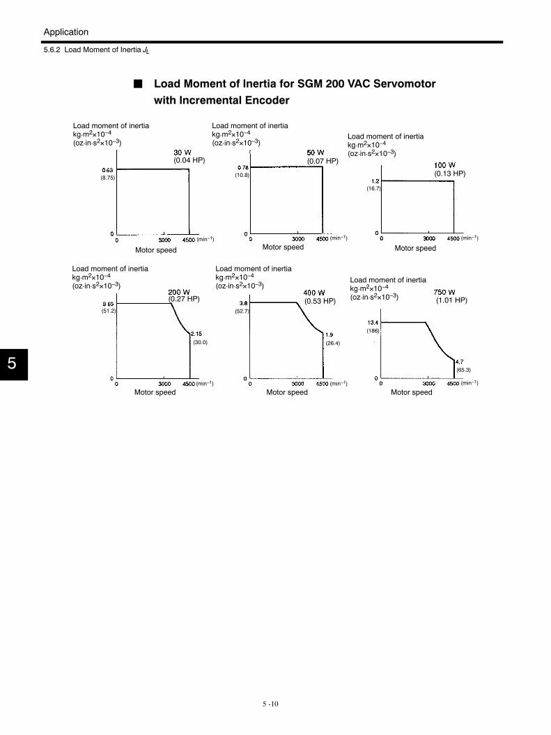
Application
5.6.2 Load Moment of Inertia JL
5 -10
J Load Moment of Inertia for SGM 200 VAC Servomotorwith Incremental Encoder
Load moment of inertiakg¡m2×10−4(oz¡in¡s2×10−3)
Motor speed Motor speed Motor speed
Motor speed Motor speed Motor speed
(51.2)
(30.0)
(52.7)
(26.4)
(186)
(65.3)
(8.75) (10.8)
(16.7)
(0.04 HP) (0.07 HP)
(0.13 HP)
(0.53 HP) (1.01 HP)(0.27 HP)
Load moment of inertiakg¡m2×10−4(oz¡in¡s2×10−3)
Load moment of inertiakg¡m2×10−4(oz¡in¡s2×10−3)
Load moment of inertiakg¡m2×10−4(oz¡in¡s2×10−3)
Load moment of inertiakg¡m2×10−4(oz¡in¡s2×10−3)
Load moment of inertiakg¡m2×10−4(oz¡in¡s2×10−3)
(min−1) (min−1) (min−1)
(min−1) (min−1) (min−1)
5
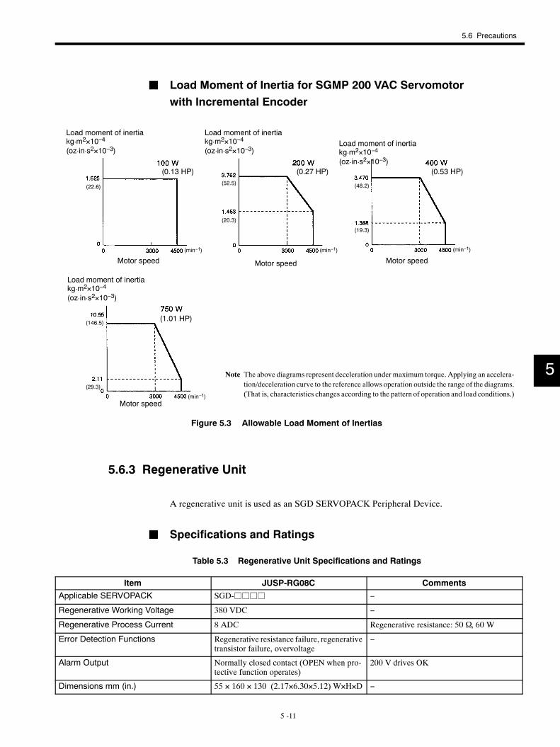
5.6 Precautions
5 -11
J Load Moment of Inertia for SGMP 200 VAC Servomotorwith Incremental Encoder
Motor speedMotor speedMotor speed
Motor speed
Note The above diagrams represent deceleration under maximum torque. Applying an accelera-tion/deceleration curve to the reference allows operation outside the range of the diagrams.(That is, characteristics changes according to the pattern of operation and load conditions.)
(22.6)(52.5)
(20.3)
(48.2)
(19.3)
(0.13 HP) (0.27 HP) (0.53 HP)
(1.01 HP)(146.5)
(29.3)
Load moment of inertiakg¡m2×10−4
(oz¡in¡s2×10−3)
Load moment of inertiakg¡m2×10−4
(oz¡in¡s2×10−3)Load moment of inertiakg¡m2×10−4
(oz¡in¡s2×10−3)
Load moment of inertiakg¡m2×10−4
(oz¡in¡s2×10−3)
(min−1) (min−1) (min−1)
(min−1)
Figure 5.3 Allowable Load Moment of Inertias
5.6.3 Regenerative Unit
A regenerative unit is used as an SGD SERVOPACK Peripheral Device.
J Specifications and Ratings
Table 5.3 Regenerative Unit Specifications and Ratings
Item JUSP-RG08C CommentsApplicable SERVOPACK SGD-jjjj −
Regenerative Working Voltage 380 VDC −
Regenerative Process Current 8 ADC Regenerative resistance: 50 Ω, 60 W
Error Detection Functions Regenerative resistance failure, regenerativetransistor failure, overvoltage
−
Alarm Output Normally closed contact (OPEN when pro-tective function operates)
200 V drives OK
Dimensions mm (in.) 55 × 160 × 130 (2.17×6.30×5.12) W×H×D −
5
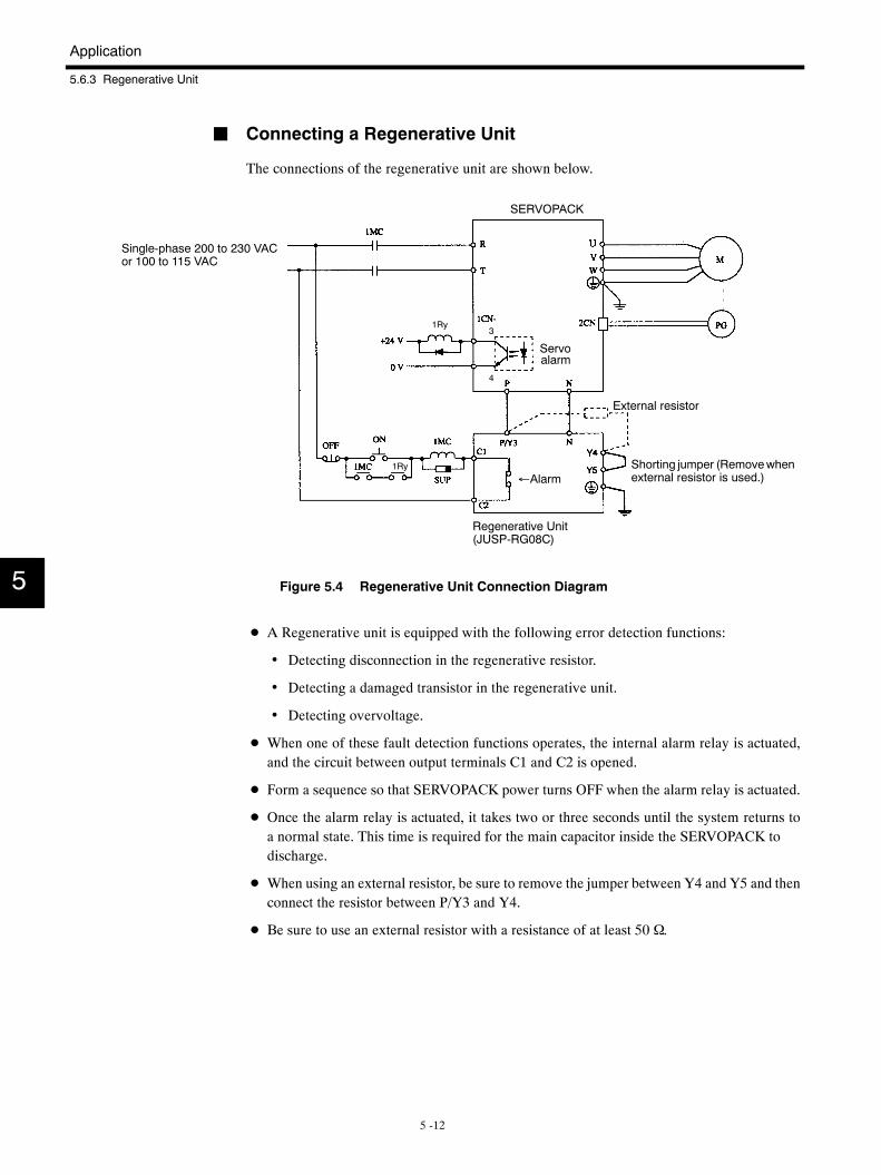
Application
5.6.3 Regenerative Unit
5 -12
J Connecting a Regenerative Unit
The connections of the regenerative unit are shown below.
Single-phase 200 to 230 VACor 100 to 115 VAC
External resistor
Shorting jumper (Removewhenexternal resistor is used.)
Regenerative Unit(JUSP-RG08C)
SERVOPACK
3
4
1Ry
1Ry
←Alarm
Servoalarm
Figure 5.4 Regenerative Unit Connection Diagram
D A Regenerative unit is equipped with the following error detection functions:
• Detecting disconnection in the regenerative resistor.
• Detecting a damaged transistor in the regenerative unit.
• Detecting overvoltage.
D When one of these fault detection functions operates, the internal alarm relay is actuated,and the circuit between output terminals C1 and C2 is opened.
D Form a sequence so that SERVOPACK power turns OFF when the alarm relay is actuated.
D Once the alarm relay is actuated, it takes two or three seconds until the system returns toa normal state. This time is required for the main capacitor inside the SERVOPACK todischarge.
D When using an external resistor, be sure to remove the jumper between Y4 and Y5 and thenconnect the resistor between P/Y3 and Y4.
D Be sure to use an external resistor with a resistance of at least 50 Ω.
5
5.6 Precautions
5 -13
5.6.4 High Voltage Lines
A transformer that will step down three-phase 400/440 V to single-phase 200 V or single-phase
100 V is required when using a 400 V class (400 V, 440 V) power supply. Select an appropriate
power transformer using Table 5.5 MCCB or Fuse for the Power Capacity.
5
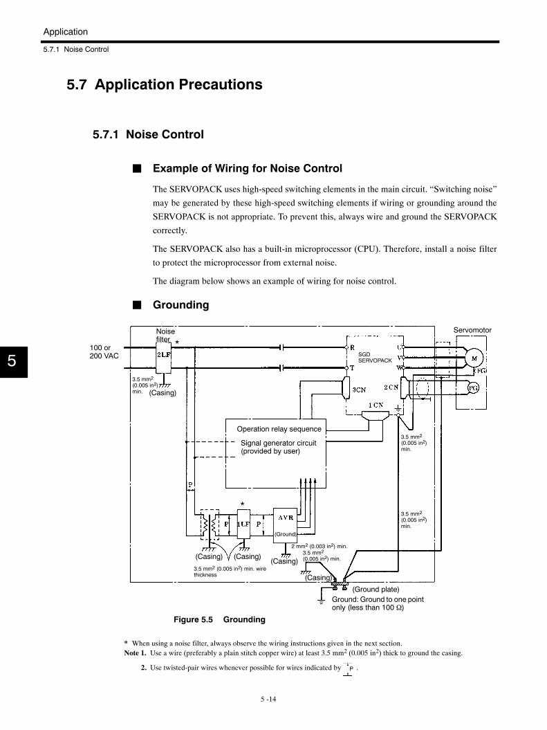
Application
5.7.1 Noise Control
5 -14
5.7 Application Precautions
5.7.1 Noise Control
J Example of Wiring for Noise Control
The SERVOPACK uses high-speed switching elements in the main circuit. “Switching noise”
may be generated by these high-speed switching elements if wiring or grounding around the
SERVOPACK is not appropriate. To prevent this, always wire and ground the SERVOPACK
correctly.
The SERVOPACK also has a built-in microprocessor (CPU). Therefore, install a noise filter
to protect the microprocessor from external noise.
The diagram below shows an example of wiring for noise control.
J Grounding
100 or200 VAC
Noisefilter
(Casing)
Operation relay sequence
Signal generator circuit(provided by user)
Servomotor
(Ground)
3.5 mm2 (0.005 in2) min. wirethickness
(Ground plate)Ground: Ground to one pointonly (less than 100 Ω)
(Casing) (Casing)(Casing)
(Casing)
2 mm2 (0.003 in2) min.
3.5 mm2
(0.005 in2)min.
SGDSERVOPACK
*
3.5 mm2
(0.005 in2)min.
3.5 mm2
(0.005 in2)min.
3.5 mm2
(0.005 in2) min.
*
Figure 5.5 Grounding
* When using a noise filter, always observe the wiring instructions given in the next section.Note 1. Use a wire (preferably a plain stitch copper wire) at least 3.5 mm2 (0.005 in2) thick to ground the casing.
2. Use twisted-pair wires whenever possible for wires indicated by P .
5
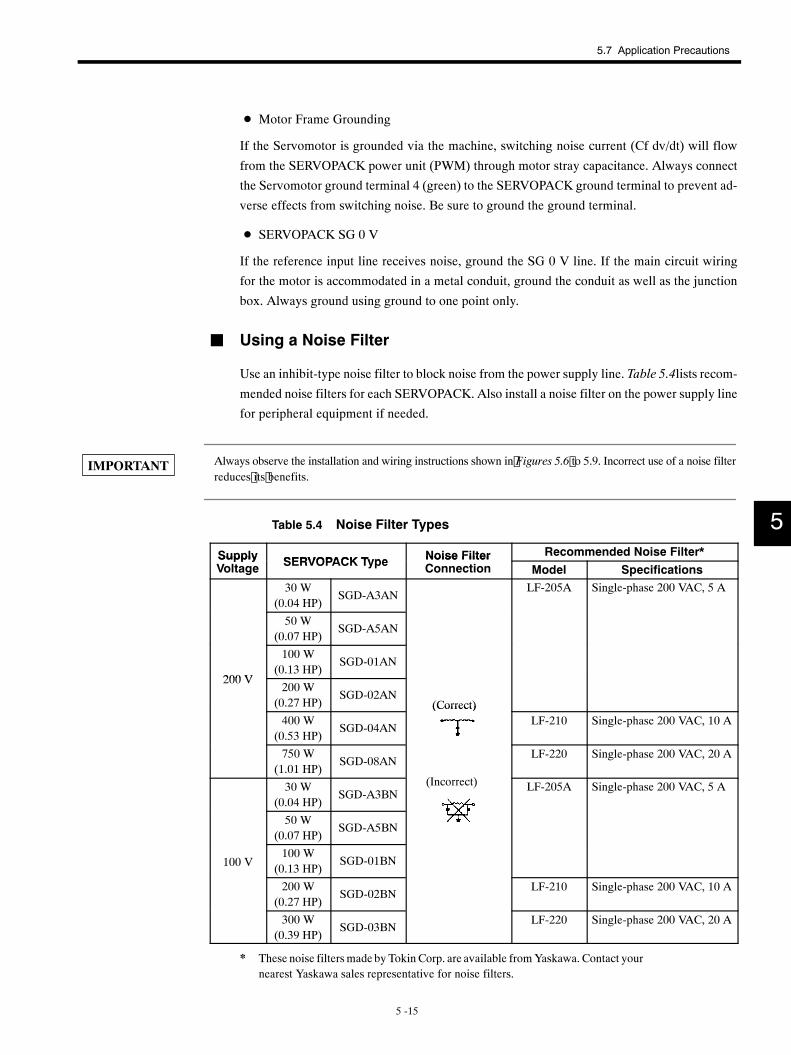
5.7 Application Precautions
5 -15
D Motor Frame Grounding
If the Servomotor is grounded via the machine, switching noise current (Cf dv/dt) will flow
from the SERVOPACK power unit (PWM) through motor stray capacitance. Always connect
the Servomotor ground terminal 4 (green) to the SERVOPACK ground terminal to prevent ad-
verse effects from switching noise. Be sure to ground the ground terminal.
D SERVOPACK SG 0 V
If the reference input line receives noise, ground the SG 0 V line. If the main circuit wiring
for the motor is accommodated in a metal conduit, ground the conduit as well as the junction
box. Always ground using ground to one point only.
J Using a Noise Filter
Use an inhibit-type noise filter to block noise from the power supply line. Table 5.4lists recom-
mended noise filters for each SERVOPACK. Also install a noise filter on the power supply line
for peripheral equipment if needed.
Always observe the installation and wiring instructions shown in Figures 5.6 to 5.9. Incorrect use of a noise filterreduces its benefits.
Table 5.4 Noise Filter Types
Supply SERVOPACK Type Noise Filter Recommended Noise Filter*SupplyVoltage SERVOPACK Type Noise Filter
Connection Model Specifications30 W
(0.04 HP)SGD-A3AN
LF-205A Single-phase 200 VAC, 5 A
50 W(0.07 HP)
SGD-A5AN
200 V
100 W(0.13 HP)
SGD-01AN
200 V200 W
(0.27 HP)SGD-02AN
(Correct)400 W
(0.53 HP)SGD-04AN
(Correct)LF-210 Single-phase 200 VAC, 10 A
750 W(1.01 HP)
SGD-08AN
( )
LF-220 Single-phase 200 VAC, 20 A
30 W(0.04 HP)
SGD-A3BN(Incorrect) LF-205A Single-phase 200 VAC, 5 A
50 W(0.07 HP)
SGD-A5BN
100 V100 W
(0.13 HP)SGD-01BN
200 W(0.27 HP)
SGD-02BNLF-210 Single-phase 200 VAC, 10 A
300 W(0.39 HP)
SGD-03BNLF-220 Single-phase 200 VAC, 20 A
* These noise filtersmade by TokinCorp. are available fromYaskawa. Contact yournearest Yaskawa sales representative for noise filters.
5
IMPORTANT
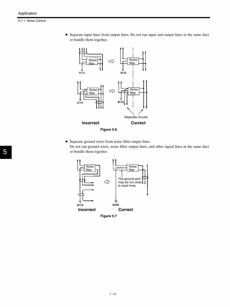
Application
5.7.1 Noise Control
5 -16
D Separate input lines from output lines. Do not run input and output lines in the same ductor bundle them together.
Noisefilter
Noisefilter
Noisefilter
Noisefilter
Separate circuits.
Incorrect Correct
Figure 5.6
D Separate ground wires from noise filter output lines.Do not run ground wires, noise filter output lines, and other signal lines in the same ductor bundle them together.
Noisefilter
Noisefilter
The ground wiremay be run closeto input lines.
Incorrect Correct
Figure 5.7
5
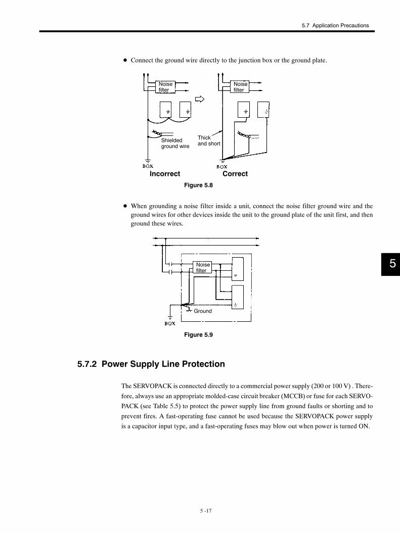
5.7 Application Precautions
5 -17
D Connect the ground wire directly to the junction box or the ground plate.
Noisefilter
Noisefilter
Shieldedground wire
Thickand short
Incorrect Correct
Figure 5.8
D When grounding a noise filter inside a unit, connect the noise filter ground wire and theground wires for other devices inside the unit to the ground plate of the unit first, and thenground these wires.
Noisefilter
Ground
Figure 5.9
5.7.2 Power Supply Line Protection
The SERVOPACK is connected directly to a commercial power supply (200 or 100 V) . There-
fore, always use an appropriate molded-case circuit breaker (MCCB) or fuse for each SERVO-
PACK (see Table 5.5) to protect the power supply line from ground faults or shorting and to
prevent fires. A fast-operating fuse cannot be used because the SERVOPACK power supply
is a capacitor input type, and a fast-operating fuses may blow out when power is turned ON.
5
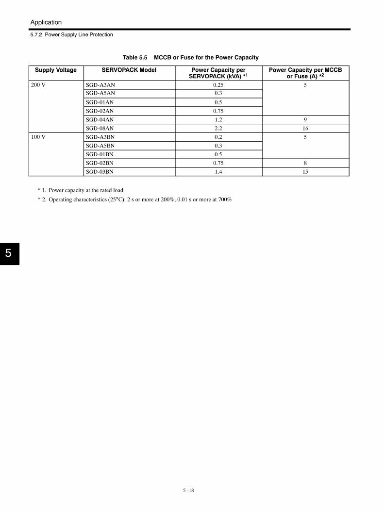
Application
5.7.2 Power Supply Line Protection
5 -18
Table 5.5 MCCB or Fuse for the Power Capacity
Supply Voltage SERVOPACK Model Power Capacity per Power Capacity per MCCBSupply Voltage SERVOPACK Model Power Capacity perSERVOPACK (kVA) *1
Power Capacity per MCCBor Fuse (A) *2
200 V SGD-A3AN 0.25 5SGD-A5AN 0.3
SGD-01AN 0.5
SGD-02AN 0.75
SGD-04AN 1.2 9
SGD-08AN 2.2 16100 V SGD-A3BN 0.2 5
SGD-A5BN 0.3
SGD-01BN 0.5
SGD-02BN 0.75 8
SGD-03BN 1.4 15
* 1. Power capacity at the rated load
* 2. Operating characteristics (25°C): 2 s or more at 200%, 0.01 s or more at 700%
5
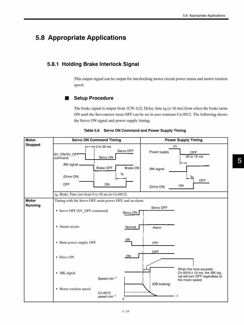
5.8 Appropriate Applications
5 -19
5.8 Appropriate Applications
5.8.1 Holding Brake Interlock Signal
This output signal can be output for interlocking motor circuit power status and motor rotation
speed.
J Setup Procedure
The brake signal is output from 1CN-1(2). Delay time tB (× 10 ms) from when the brake turns
ON until the Servomotor turns OFF can be set in user constant Cn-0012. The following shows
the Servo ON signal and power supply timing.
Table 5.6 Servo ON Command and Power Supply Timing
MotorS d
Servo ON Command Timing Power Supply TimingStopped 0 to 35 ms
Servo ON
Servo OFF
/BK signal
(Drive ON)
OFF ON
SV_ON/SV_OFFcommand
Brake OFF Brake ON
tB
55 to 75 ms
(Drive ON) ON
OFF
/BK signal
Power supply
tB
tB: Brake Time (set from 0 to 50 ms in Cn-0012)
MotorRunning
Timing with the Servo OFF, main power OFF, and an alarm
S Servo OFF (SV_OFF command)
S Alarm occurs
S Main power supply OFF
S Drive ON
S /BK signal
S Motor rotation speed
Servo ONServo OFF
OFFON
Normal Alarm
When this time exceedsCn-0016 x 10 ms, the /BK sig-nal will turn OFF regardless ofthe motor speed.Speed min−1
(DB braking)
Cn-0015speed min−1
5
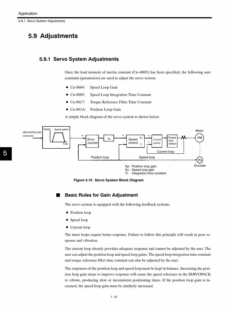
Application
5.9.1 Servo System Adjustments
5 -20
5.9 Adjustments
5.9.1 Servo System Adjustments
Once the load moment of inertia constant (Cn−0003) has been specified, the following user
constants (parameters) are used to adjust the servo system.
D Cn-0004: Speed Loop Gain
D Cn-0005: Speed Loop Integration Time Constant
D Cn-0017: Torque Reference Filter Time Constant
D Cn-001A: Position Loop Gain
A simple block diagram of the servo system is shown below.
MECHATROLINKcommand
Speed Speed pattern
Time
Errorcounter
Speedcontrol
Position loop Speed loop
Currentcontrol
PowerCon-vertion
Motor
Current loop
EncoderKp: Position loop gainKv: Speed loop gainTi: Integration time constant
KVKP
Ti
Figure 5.10 Servo System Block Diagram
J Basic Rules for Gain Adjustment
The servo system is equipped with the following feedback systems.
D Position loop
D Speed loop
D Current loop
The inner loops require better response. Failure to follow this principle will result in poor re-
sponse and vibration.
The current loop already provides adequate response and cannot be adjusted by the user. The
user can adjust the position loop and speed loop gains. The speed loop integration time constant
and torque reference filter time constant can also be adjusted by the user.
The responses of the position loop and speed loop must be kept in balance. Increasing the posi-
tion loop gain alone to improve response will cause the speed reference in the SERVOPACK
to vibrate, producing slow or inconsistent positioning times. If the position loop gain is in-
creased, the speed loop gain must be similarly increased.
5
5.9 Adjustments
5 -21
The mechanical system will start to vibrate at the upper limits for the position and speed loop
gain. Do not exceed these limits. Generally position loop gain cannot be increased beyond the
characteristic frequency of the mechanical system.
Example:Articulated Robots
Using harmonic gears produces a mechanism with extremely low rigidity.
Characteristic frequency of the mechanical system: 10 to 20 Hz
Allowable position loop gain: 10 to 20 (1/s)
Example:Chip Mounters, IC Bonders, Precision Machine Tools
Characteristic frequency: 70 Hz or more.
Position loop gain: 70 (1/s) or more.
The response of the servo system (Controller, Servodriver, Servomotor, detector, etc.) is cru-
cial to the response requirements, but a highly rigid system is also needed as well.
5.9.2 User Constants
J Cn−0003: Load Moment of Inertia
The load moment of inertia specifies motor axis converted load moment of inertia.
Specify the load moment of inertia as a percentage of the motor’s rotor moment of inertia (mo-
tor moment of inertia = 100%).
J Cn-0004: Speed Loop Gain
The Speed Loop Gain sets the speed loop response. The response is improved by setting this
user constant to the maximum value in a range that does not cause vibrations in the mechanical
system.
J Cn-0005: Speed Loop Integration Time Constant
The speed loop has an integration element that enables response to micro-inputs. Because this
integration element can produce a delay in the servo system, positioning set time increases and
response slows as the time constants increase. The integration time constant must be increased,
however, to prevent machine vibration if the load moment of inertia is large or the mechanical
system includes an element prone to vibration. The following equation can be used to calculate
a guideline value.
12π× Kv
Ti ≧ 2.3 ×
Ti: Integration time constant [s]
Kv:Speed loop gain [Hz]
J Cn-0017, 0018: Torque Reference Filter Time Constant
When a ball screw is used, torsional resonance may occur that increases the pitch of the vibrat-
ing noise. This oscillation can sometimes be overcome by increasing the torque reference filter
5
Application
5.9.2 User Constants
5 -22
time constant. The filter, however, will produce a delay in the servo system, just like the in-
tegration time constant, and its value should not be increased any more than necessary.
If the secondary torque reference filter time constant (Cn−0018) is set to 0, the torque reference
filter switch to the primary filter.
If the vibration cannot be overcome by the torque reference filter time constant (Cn−0017),
use the secondary torque reference filter time constant (Cn−0018) to switch the filter to the
secondary filter and overcome the vibration.
J Cn-001A: Position Loop Gain
The position loop gain determines the response of the servo system. The higher it is set, the
higher the response and the less time it takes for positioning. As such, the equipment must have
higher rigidity and a higher characteristic frequency.
The entire servo system is more susceptible to vibration if position loop gain alone is increased
to improve response, and the speed reference output from the position loop will cause vibra-
tion. Always increase speed loop gain while checking the response.
Position loop gain KP is calculated as shown below.
KP=VSÁ
KP (1/s): Position loop gain
VS (PPS): Steady speed reference
ε (Pulse): Steady error (The number of pulses in the error counter at constant speed)
J Adjustment
1. Calculate and set the motor axis converted load moment of inertia.
2. Set the loop gain to a low value and increase speed loop gain within a range that does notcause noise or vibration to occur.
3. Slightly reduce the speed loop gain from the value in step 1, and increase position loopgain within a range that does not cause overshooting or vibration to occur.
4. Determine the speed loop integration time constant by observing the positioning time andvibration in the mechanical system. Positioning time may be increased if the speed loopintegration time constant is too large.
5. It is not necessary to change the torque reference filter time constant unless torsional reso-nance occurs in the equipment shafts. Torsion resonance may be present if there high-fre-quency vibration noise. In this case, adjust the torque reference filter time constant to re-duce the noise.
6. Finally, it is necessary to determine the optimum value for acceleration/deceleration to ad-just finely the position and speed loop gain as well as the integration time constant.
J Monitoring
The MECHATROLINK communications monitoring function can be used to read various
monitor items, display the monitor status at the host controller, and make any necessary adjust-
5
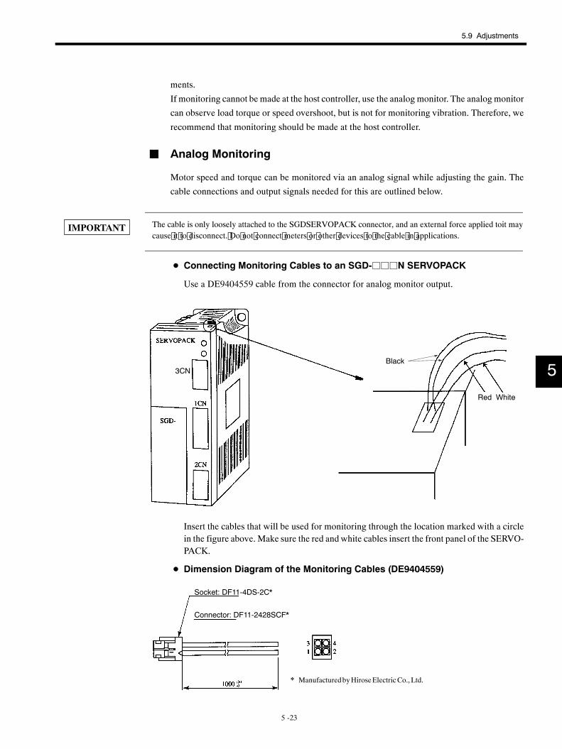
5.9 Adjustments
5 -23
ments.
If monitoring cannot be made at the host controller, use the analog monitor. The analogmonitor
can observe load torque or speed overshoot, but is not for monitoring vibration. Therefore, we
recommend that monitoring should be made at the host controller.
J Analog Monitoring
Motor speed and torque can be monitored via an analog signal while adjusting the gain. The
cable connections and output signals needed for this are outlined below.
The cable is only loosely attached to the SGDSERVOPACK connector, and an external force applied toit maycause it to disconnect. Do not connect meters or other devices to the cable in applications.
D Connecting Monitoring Cables to an SGD-jjjN SERVOPACK
Use a DE9404559 cable from the connector for analog monitor output.
Red White
Black3CN
Insert the cables that will be used for monitoring through the location marked with a circlein the figure above. Make sure the red and white cables insert the front panel of the SERVO-PACK.
D Dimension Diagram of the Monitoring Cables (DE9404559)
Socket: DF11-4DS-2C*
Connector: DF11-2428SCF*
* ManufacturedbyHiroseElectricCo.,Ltd.
5
IMPORTANT
Application
5.9.3 Functions that Improve Response
5 -24
D Cable Colors and Monitor Signals
Cable Color Signal Name DescriptionRed VTG-M Speed monitor (0.5 V, 1,000 min−1)
White TRQ-M Torque monitor (0.5 V, 100% torque)
Black (2 wires) GND GND
5.9.3 Functions that Improve Response
The following functions are provided to improve response.
D Mode switching
D Feed-forward control
D Bias
These functions will not necessarily improve characteristics, and they can even have the oppo-
site effect. Be sure to observe the precautions given below, and monitor the actual response
of the characteristics while making adjustments.
J Mode Switching
Mode switching is used to improve transient characteristics if the torque reference saturates
during acceleration and deceleration. In other words, mode switching is a function that auto-
matically switches the speed control mode inside the SERVOPACK from PI (proportional/in-
tegral) to P (proportional) control above a certain setting.
J Feed-forward Control
Feed-forward control generally shortens positioning time, but has no effect on systems where
the position loop gain is at its maximum. Adjust the amount of feed-forward control using
Cn-001D as outlined below.
1. Adjust the speed and position loop.
2. Gradually increase the amount of feed-forward control set in Cn-001D until the position-ing complete status (PSET) is output as quickly possible.
Make sure during adjustment that the position complete status (PSET) is not intermittent (re-
peatedly turning ON and OFF) and that the speed is not overshoot. Setting the amount of feed-
forward control too high will cause a intermittent positioning complete status as well as speed
overshooting.
A primary lag filter may be added to the feed-forward line to improve characteristics when the
positioning complete signal is intermittent or when speed overshooting occurs due to excessive
feed-forward control.
J Bias Control
When the number of pulses in the error counter exceeds the positioning complete width
(Cn-001B), bias (Cn-001C) is added to the error counter output (speed reference) until the
5
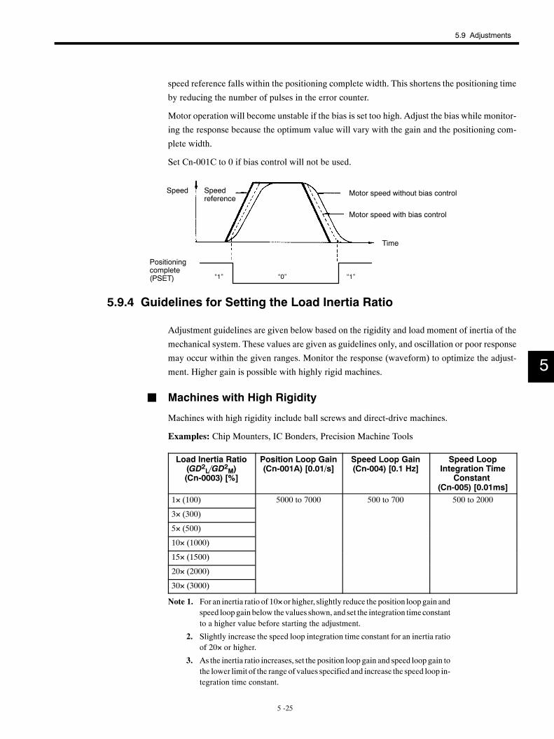
5.9 Adjustments
5 -25
speed reference falls within the positioning complete width. This shortens the positioning time
by reducing the number of pulses in the error counter.
Motor operation will become unstable if the bias is set too high. Adjust the bias while monitor-
ing the response because the optimum value will vary with the gain and the positioning com-
plete width.
Set Cn-001C to 0 if bias control will not be used.
“1” “1”“0”
Speed Speedreference
Positioningcomplete(PSET)
Motor speed without bias control
Motor speed with bias control
Time
5.9.4 Guidelines for Setting the Load Inertia Ratio
Adjustment guidelines are given below based on the rigidity and load moment of inertia of the
mechanical system. These values are given as guidelines only, and oscillation or poor response
may occur within the given ranges. Monitor the response (waveform) to optimize the adjust-
ment. Higher gain is possible with highly rigid machines.
J Machines with High Rigidity
Machines with high rigidity include ball screws and direct-drive machines.
Examples: Chip Mounters, IC Bonders, Precision Machine Tools
Load Inertia Ratio(GD2L/GD2M)(Cn-0003) [%]
Position Loop Gain(Cn-001A) [0.01/s]
Speed Loop Gain(Cn-004) [0.1 Hz]
Speed LoopIntegration Time
Constant(Cn-005) [0.01ms]
1× (100) 5000 to 7000 500 to 700 500 to 2000
3× (300)
5× (500)
10× (1000)
15× (1500)
20× (2000)
30× (3000)
Note 1. For an inertia ratio of 10×or higher, slightly reduce the position loop gain andspeed loop gain below the values shown, and set the integration timeconstantto a higher value before starting the adjustment.
2. Slightly increase the speed loop integration time constant for an inertia ratioof 20× or higher.
3. As the inertia ratio increases, set the position loop gain and speed loop gain tothe lower limit of the range of values specified and increase the speed loop in-tegration time constant.
5
Application
5.9.4 Guidelines for Setting the Load Inertia Ratio
5 -26
J Machines with Medium Rigidity
Machines with medium rigidity include machines driven by ball screws through reduction
gears. or machines driven directly by long ball screws.
Examples: General Machine Tools, Orthogonal Robots, Conveyors
Load Inertia Ratio(GD2L/GD2M)(Cn-0003) [%]
Position Loop Gain(Cn-001A) [0.01/s]
Speed Loop Gain(Cn-0004) [0.1 Hz]
Speed LoopIntegration Time
Constant(Cn-0005) [0.01 ms]
1× (100) 3000 to 5000 300 to 500 1000 to 4000
3× (300)
5× (500)
10× (1000)
15× (1500)
20× (2000)
30× (3000)
Note 1. For an inertia ratio of 10×or higher, slightly reduce the position loop gain andspeed loop gain below the values shown, and set the integration timeconstantto a higher value before starting the adjustment.
2. Slightly increase the speed loop integration time constant for an inertia ratioof 20× or higher.
3. As the inertia ratio increases, set the position loop gain and speed loop gain tothe lower limit of the rangeof values specified, and increase the speed loop in-tegration time constant.
J Machines with Low Rigidity
Machines with low rigidity includemachines driven by timing belts, chains, or harmonic gears.
Example: Conveyors, Articulated Robots
Load Inertia Ratio(GD2L/GD2M)(Cn-0003) [%]
Position Loop Gain(Cn-001A) [0.01/s]
Speed Loop Gain(Cn-0004) [0.1 Hz]
Speed LoopIntegration Time
Constant(Cn-0005) [0.01 ms]
1× (100) 1000 to 2000 100 to 200 5000 to 10000
3× (300)
5× (500)
10× (1000)
15× (1500)
20× (2000)
30× (3000)
Note 1. For an inertia ratio of 10×or higher, slightly reduce the position loop gain andspeed loop gain below the values shown, and set the integration timeconstantto a higher value before starting the adjustment.
2. Slightly increase the speed loop integration time constant for an inertia ratioof 20× or higher.
3. As the inertia ratio increases, set the position loop gain and speed loop gain tothe lower limit of the rangeof values specified, and increase the speed loop in-tegration time constant.
5
6 -1
6MECHATROLINK Communication
This chapter describes MECHATROLINK communication specifications,
commands and communication sequence and provides a list of alarms/
warning.
6.1 Specifications and Configuration 6 -2. . . . . . . . . . . .6.1.1 Specifications 6 -2. . . . . . . . . . . . . . . . . . . . . . . . . . . . . . .
6.1.2 Control Structure 6 -2. . . . . . . . . . . . . . . . . . . . . . . . . . . .
6.2 1SW Rotary Switch for MECHATROLINK StationAddress Settings 6 -3. . . . . . . . . . . . . . . . . . . . . . . .
6.3 MECHATROLINK Command List 6 -4. . . . . . . . . . . .6.4 Special Descriptions 6 -7. . . . . . . . . . . . . . . . . . . . . . .
6.4.1 Option Field Specifications 6 -7. . . . . . . . . . . . . . . . . . .
6.4.2 I/O Monitor Specifications 6 -9. . . . . . . . . . . . . . . . . . . .
6.4.3 Monitor 1/2 Type Field Specifications 6 -10. . . . . . . . . . .
6.4.4 CONFIG Specifications 6 -11. . . . . . . . . . . . . . . . . . . . . . .
6.4.5 ALM_RD Specifications 6 -11. . . . . . . . . . . . . . . . . . . . . .
6.4.6 ALM_CLR Specifications 6 -12. . . . . . . . . . . . . . . . . . . . .
6.4.7 CONNECT Specifications 6 -12. . . . . . . . . . . . . . . . . . . .
6.4.8 INTERPOLATE Specifications 6 -13. . . . . . . . . . . . . . . . .
6.4.9 LATCH Specifications 6 -13. . . . . . . . . . . . . . . . . . . . . . . .
6.4.10 POSING Command Specifications 6 -14. . . . . . . . . . . .
6.4.11 INTERPOLATE Command Specifications 6 -14. . . . . .
6.4.12 ID_RD Specifications 6 -14. . . . . . . . . . . . . . . . . . . . . . .
6.4.13 Unsupported Commands 6 -15. . . . . . . . . . . . . . . . . . . .
6.5 Power ON Sequence(Communication Sequence) 6 -16. . . . . . . . . . . . . . .
6.6 List of Alarm and Warning Codes 6 -19. . . . . . . . . . .
6
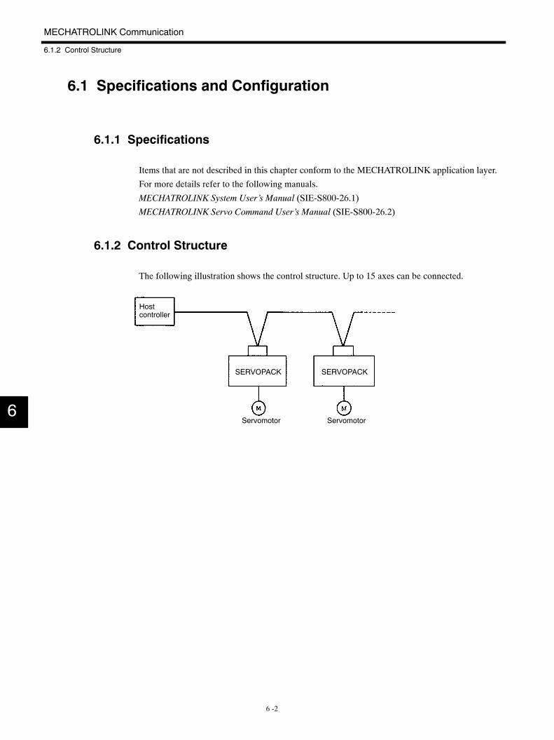
MECHATROLINK Communication
6.1.2 Control Structure
6 -2
6.1 Specifications and Configuration
6.1.1 Specifications
Items that are not described in this chapter conform to the MECHATROLINK application layer.
For more details refer to the following manuals.
MECHATROLINK System User’s Manual (SIE-S800-26.1)
MECHATROLINK Servo Command User’s Manual (SIE-S800-26.2)
6.1.2 Control Structure
The following illustration shows the control structure. Up to 15 axes can be connected.
Hostcontroller
Servomotor Servomotor
SERVOPACK SERVOPACK
6
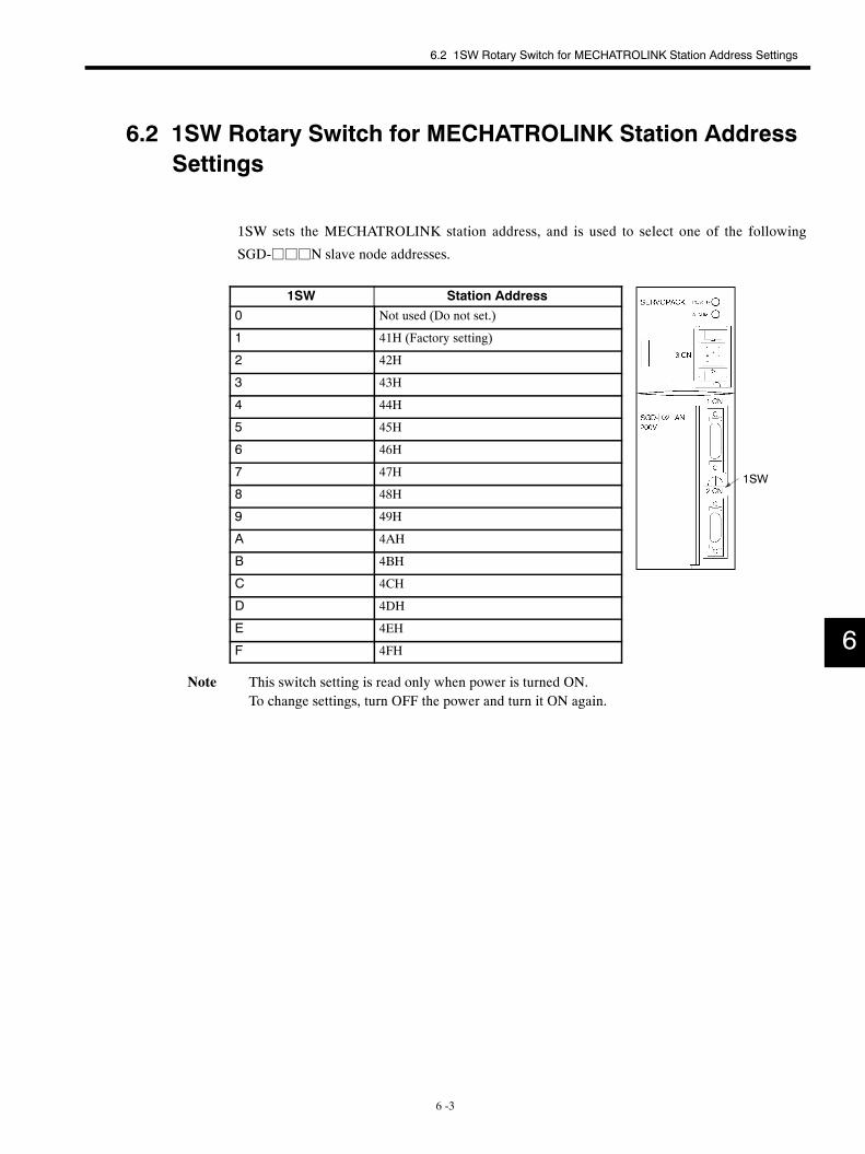
1SW
6.2 1SW Rotary Switch for MECHATROLINK Station Address Settings
6 -3
6.2 1SW Rotary Switch for MECHATROLINK Station AddressSettings
1SW sets the MECHATROLINK station address, and is used to select one of the following
SGD-jjjN slave node addresses.
1SW Station Address0 Not used (Do not set.)
1 41H (Factory setting)
2 42H
3 43H
4 44H
5 45H
6 46H
7 47H
8 48H
9 49H
A 4AH
B 4BH
C 4CH
D 4DH
E 4EH
F 4FH
Note This switch setting is read only when power is turned ON.To change settings, turn OFF the power and turn it ON again.
6
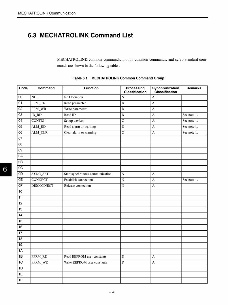
MECHATROLINK Communication
6 -4
6.3 MECHATROLINK Command List
MECHATROLINK common commands, motion common commands, and servo standard com-
mands are shown in the following tables.
Table 6.1 MECHATROLINK Common Command Group
Code Command Function ProcessingClassification
SynchronizationClassification
Remarks
00 NOP No Operation N A
01 PRM_RD Read parameter D A
02 PRM_WR Write parameter D A
03 ID_RD Read ID D A See note 1.
04 CONFIG Set up devices C A See note 1.
05 ALM_RD Read alarm or warning D A See note 1.
06 ALM_CLR Clear alarm or warning C A See note 1.
07
08
09
0A
0B
0C
0D SYNC_SET Start synchronous communication N A
0E CONNECT Establish connection N A See note 1.
0F DISCONNECT Release connection N A
10
11
12
13
14
15
16
17
18
19
1A
1B PPRM_RD Read EEPROM user constants D A
1C PPRM_WR Write EEPROM user constants D A
1D
1E
1F
6
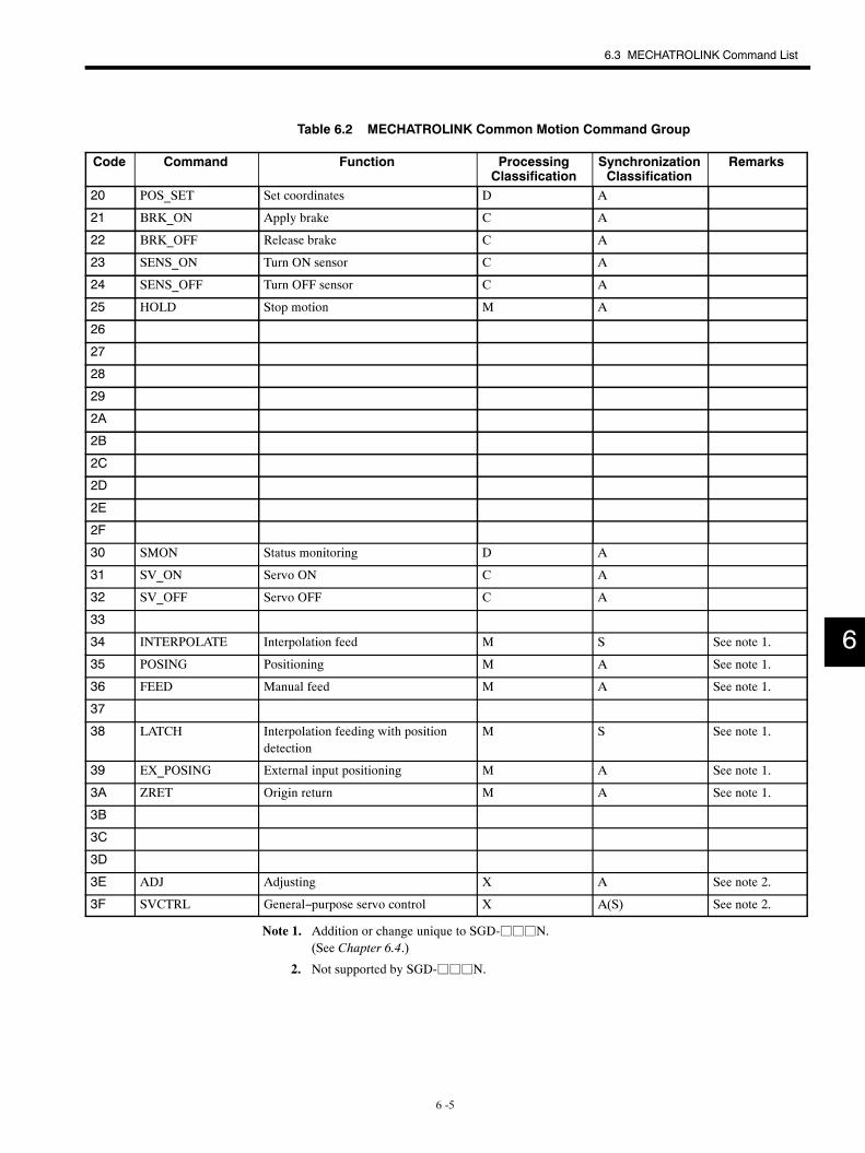
6.3 MECHATROLINK Command List
6 -5
Table 6.2 MECHATROLINK Common Motion Command Group
Code Command Function ProcessingClassification
SynchronizationClassification
Remarks
20 POS_SET Set coordinates D A
21 BRK_ON Apply brake C A
22 BRK_OFF Release brake C A
23 SENS_ON Turn ON sensor C A
24 SENS_OFF Turn OFF sensor C A
25 HOLD Stop motion M A
26
27
28
29
2A
2B
2C
2D
2E
2F
30 SMON Status monitoring D A
31 SV_ON Servo ON C A
32 SV_OFF Servo OFF C A
33
34 INTERPOLATE Interpolation feed M S See note 1.
35 POSING Positioning M A See note 1.
36 FEED Manual feed M A See note 1.
37
38 LATCH Interpolation feeding with positiondetection
M S See note 1.
39 EX_POSING External input positioning M A See note 1.
3A ZRET Origin return M A See note 1.
3B
3C
3D
3E ADJ Adjusting X A See note 2.
3F SVCTRL General−purpose servo control X A(S) See note 2.
Note 1. Addition or change unique to SGD-jjjN.(See Chapter 6.4.)
2. Not supported by SGD-jjjN.
6
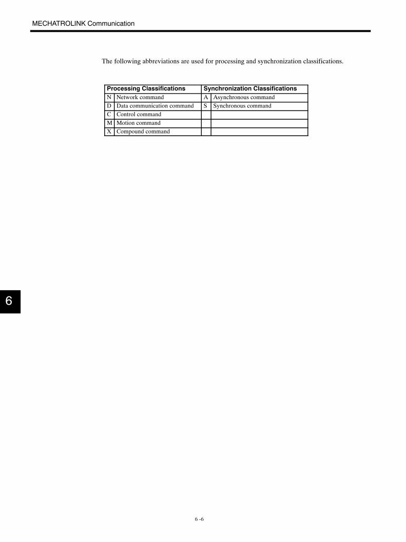
MECHATROLINK Communication
6 -6
The following abbreviations are used for processing and synchronization classifications.
Processing Classifications Synchronization ClassificationsN Network command A Asynchronous commandD Data communication command S Synchronous commandC Control commandM Motion commandX Compound command
6
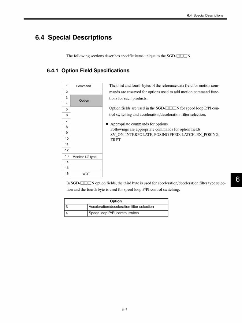
6.4 Special Descriptions
6 -7
6.4 Special Descriptions
The following sections describes specific items unique to the SGD-jjjN.
6.4.1 Option Field Specifications
The third and fourth bytes of the reference data field for motion com-
mands are reserved for options used to add motion command func-
tions for each products.
Option fields are used in the SGD-jjjN for speed loop P/PI con-
trol switching and acceleration/deceleration filter selection.
D Appropriate commands for options.Followings are appropriate commands for option fields.SV_ON, INTERPOLATE, POSING FEED, LATCH, EX_POSING,ZRET
WDT
1
2
3
4
5
6
7
8
9
10
11
12
13
14
15
16
Command
Option
Monitor 1/2 type
In SGD-jjjN option fields, the third byte is used for acceleration/deceleration filter type selec-
tion and the fourth byte is used for speed loop P/PI control switching.
Option3 Acceleration/deceleration filter selection
4 Speed loop P/PI control switch
6
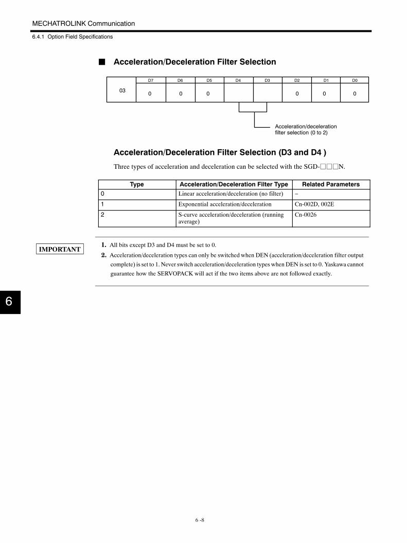
MECHATROLINK Communication
6.4.1 Option Field Specifications
6 -8
J Acceleration/Deceleration Filter Selection
D6 D5 D4 D3 D2 D1 D0D7
Acceleration/decelerationfilter selection (0 to 2)
03 0 0 0 0 0 0
Acceleration/Deceleration Filter Selection (D3 and D4 )
Three types of acceleration and deceleration can be selected with the SGD-jjjN.
Type Acceleration/Deceleration Filter Type Related Parameters0 Linear acceleration/deceleration (no filter) −
1 Exponential acceleration/deceleration Cn-002D, 002E
2 S-curve acceleration/deceleration (runningaverage)
Cn-0026
1. All bits except D3 and D4 must be set to 0.
2. Acceleration/deceleration types can only be switched when DEN (acceleration/deceleration filter output
complete) is set to 1. Never switch acceleration/deceleration types whenDEN is set to 0. Yaskawa cannot
guarantee how the SERVOPACK will act if the two items above are not followed exactly.
6
IMPORTANT
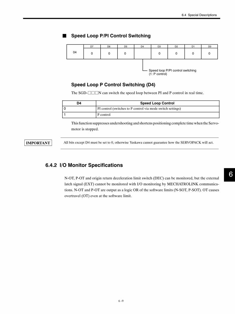
6.4 Special Descriptions
6 -9
J Speed Loop P/PI Control Switching
D6 D5 D4 D3 D2 D1 D0D7
0 0 0 0 0 004 0
Speed loop P/PI control switching(1: P control)
Speed Loop P Control Switching (D4)
The SGD-jjjN can switch the speed loop between PI and P control in real time.
D4 Speed Loop Control0 PI control (switches to P control via mode switch settings)
1 P control
This function suppresses undershooting and shortenspositioningcomplete timewhen theServo-
motor is stopped.
All bits except D4 must be set to 0, otherwise Yaskawa cannot guarantee how the SERVOPACK will act.
6.4.2 I/O Monitor Specifications
N-OT, P-OT and origin return deceleration limit switch (DEC) can be monitored, but the external
latch signal (EXT) cannot be monitored with I/O monitoring by MECHATROLINK communica-
tions. N-OT and P-OT are output as a logic OR of the software limits (N-SOT, P-SOT). OT causes
overtravel (OT) even at the software limit.
6
IMPORTANT
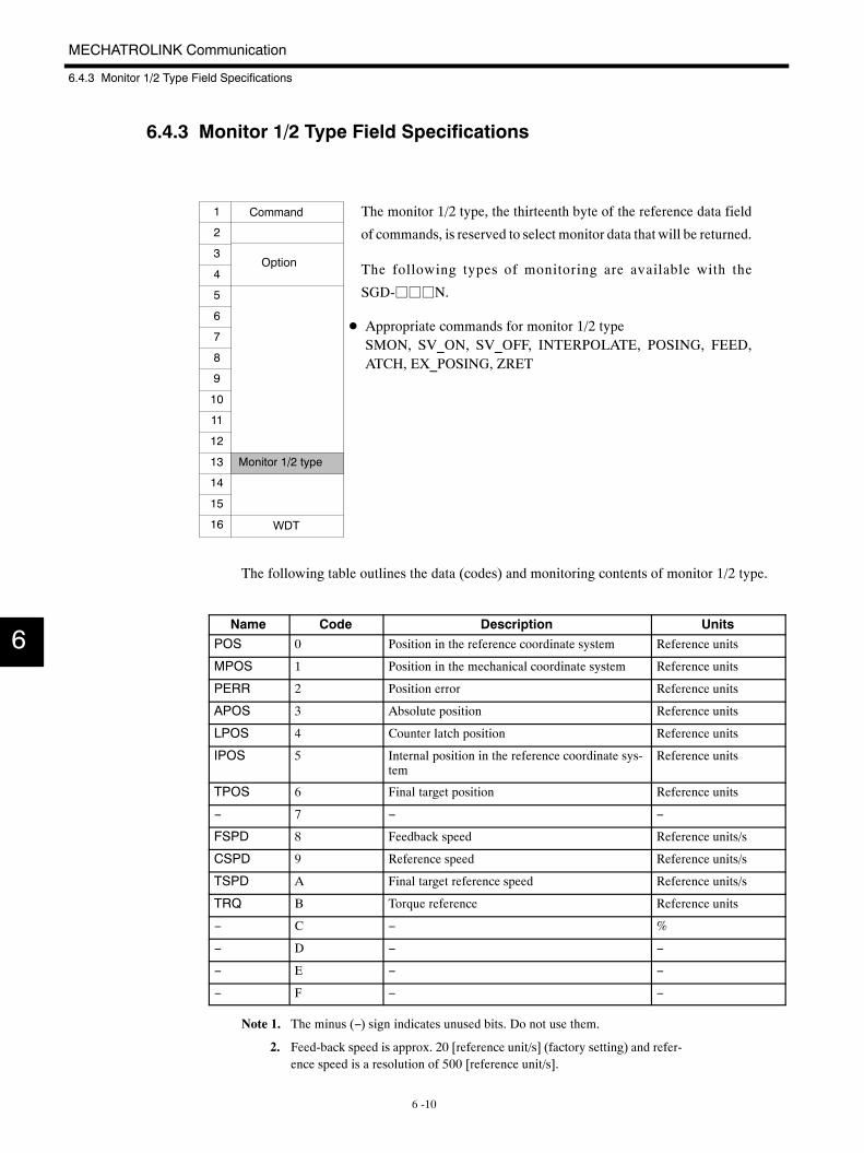
MECHATROLINK Communication
6.4.3 Monitor 1/2 Type Field Specifications
6 -10
6.4.3 Monitor 1/2 Type Field Specifications
The monitor 1/2 type, the thirteenth byte of the reference data field
of commands, is reserved to select monitor data that will be returned.
The following types of monitoring are available with the
SGD-jjjN.
D Appropriate commands for monitor 1/2 typeSMON, SV_ON, SV_OFF, INTERPOLATE, POSING, FEED,ATCH, EX_POSING, ZRET
WDT
1
2
3
4
5
6
7
8
9
10
11
12
13
14
15
16
Command
Option
Monitor 1/2 type
The following table outlines the data (codes) and monitoring contents of monitor 1/2 type.
Name Code Description UnitsPOS 0 Position in the reference coordinate system Reference units
MPOS 1 Position in the mechanical coordinate system Reference units
PERR 2 Position error Reference units
APOS 3 Absolute position Reference units
LPOS 4 Counter latch position Reference units
IPOS 5 Internal position in the reference coordinate sys-tem
Reference units
TPOS 6 Final target position Reference units
− 7 − −
FSPD 8 Feedback speed Reference units/s
CSPD 9 Reference speed Reference units/s
TSPD A Final target reference speed Reference units/s
TRQ B Torque reference Reference units
− C − %
− D − −
− E − −
− F − −
Note 1. The minus (−) sign indicates unused bits. Do not use them.
2. Feed-back speed is approx. 20 [reference unit/s] (factory setting) and refer-ence speed is a resolution of 500 [reference unit/s].
6
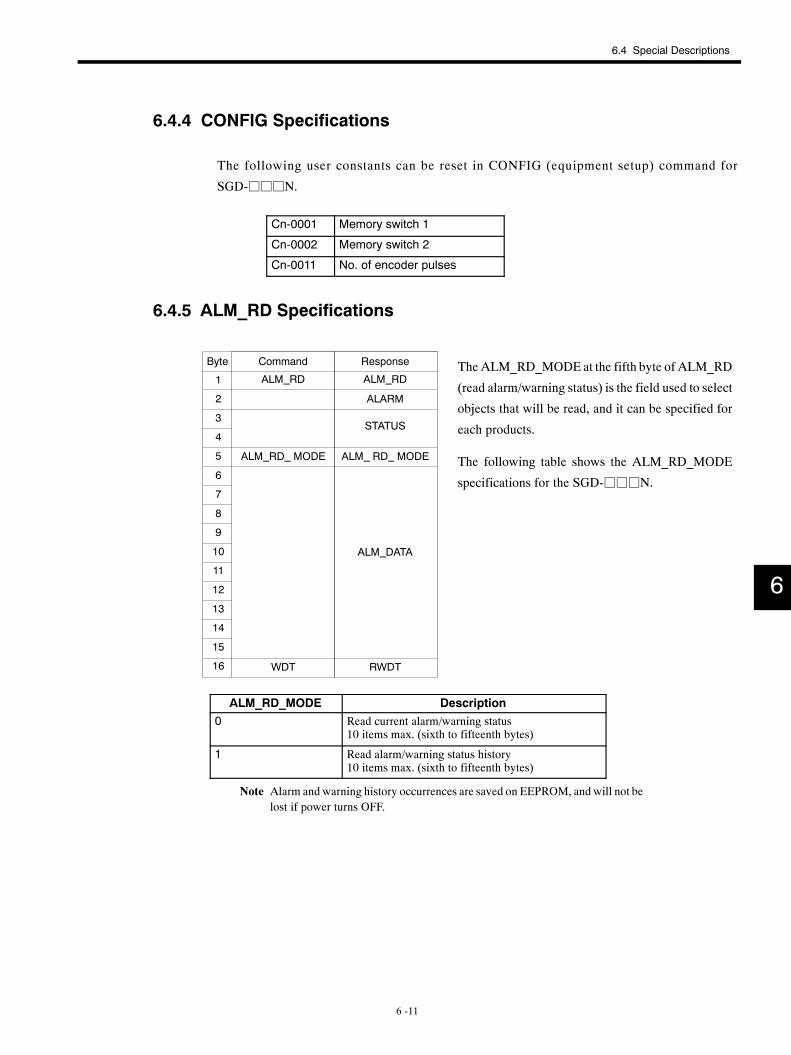
6.4 Special Descriptions
6 -11
6.4.4 CONFIG Specifications
The following user constants can be reset in CONFIG (equipment setup) command for
SGD-jjjN.
Cn-0001 Memory switch 1
Cn-0002 Memory switch 2
Cn-0011 No. of encoder pulses
6.4.5 ALM_RD Specifications
TheALM_RD_MODE at the fifth byte of ALM_RD
(read alarm/warning status) is the field used to select
objects that will be read, and it can be specified for
each products.
The following table shows the ALM_RD_MODE
specifications for the SGD-jjjN.
ALM RD
ALARM
STATUS
ALM DATA
WDT
1
2
3
4
5
6
7
8
9
10
11
12
13
14
15
16 RWDT
ALM RD
ALM RD MODE ALM RD MODE
Command ResponseByte
ALM_RD_MODE Description0 Read current alarm/warning status
10 items max. (sixth to fifteenth bytes)
1 Read alarm/warning status history10 items max. (sixth to fifteenth bytes)
Note Alarm and warning history occurrences are saved on EEPROM, and will not belost if power turns OFF.
6
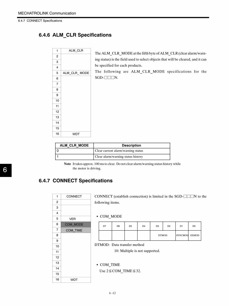
MECHATROLINK Communication
6.4.7 CONNECT Specifications
6 -12
6.4.6 ALM_CLR Specifications
TheALM_CLR_MODEat the fifthbyte ofALM_CLR (clear alarm/warn-
ing status) is the field used to select objects that will be cleared, and it can
be specified for each products.
The following are ALM_CLR_MODE specifications for the
SGD-jjjN.
ALM CLR
WDT
1
2
3
4
5
6
7
8
9
10
11
12
13
14
15
16
ALM CLR MODE
ALM_CLR_MODE Description0 Clear current alarm/warning status
1 Clear alarm/warning status history
Note It takes approx. 100ms to clear. Do not clear alarm/warning status historywhilethe motor is driving.
6.4.7 CONNECT Specifications
CONNECT (establish connection) is limited in the SGD-jjjN to the
following items.
S COM_MODE
DTMOD: Data transfer method
10: Multiple is not supported.
S COM_TIME
Use 2≦COM_TIME≦32.
CONNECT
WDT
1
2
3
4
5
6
7
8
9
10
11
12
13
14
15
16
COM MODE
COM TIME
VER
D7 D6 D5 D4 D3 D2 D1 D0
DTMOD SYNCMOD EXMOD
6
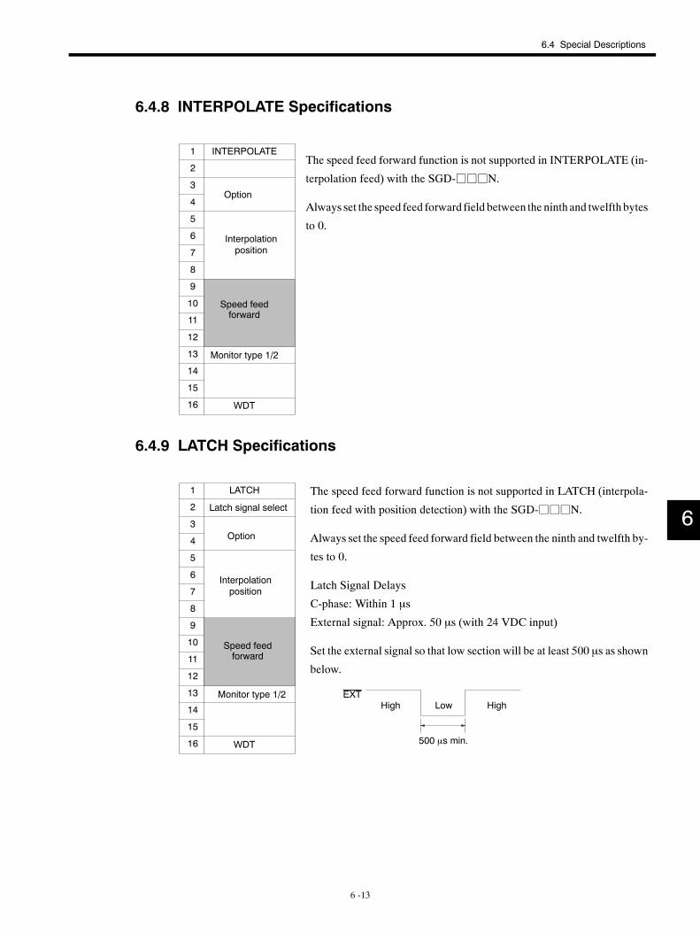
6.4 Special Descriptions
6 -13
6.4.8 INTERPOLATE Specifications
The speed feed forward function is not supported in INTERPOLATE (in-
terpolation feed) with the SGD-jjjN.
Always set the speed feed forward field between the ninth and twelfth bytes
to 0.
INTERPOLATE
WDT
1
2
3
4
5
6
7
8
9
10
11
12
13
14
15
16
Option
Interpolationposition
Speed feedforward
Monitor type 1/2
6.4.9 LATCH Specifications
The speed feed forward function is not supported in LATCH (interpola-
tion feed with position detection) with the SGD-jjjN.
Always set the speed feed forward field between the ninth and twelfth by-
tes to 0.
Latch Signal Delays
C-phase: Within 1 µs
External signal: Approx. 50 µs (with 24 VDC input)
Set the external signal so that low section will be at least 500 µs as shown
below.
LATCH
WDT
1
2
3
4
5
6
7
8
9
10
11
12
13
14
15
16
Option
Interpolationposition
Speed feedforward
Monitor type 1/2
Latch signal select
EXTHigh HighLow
500 µs min.
6
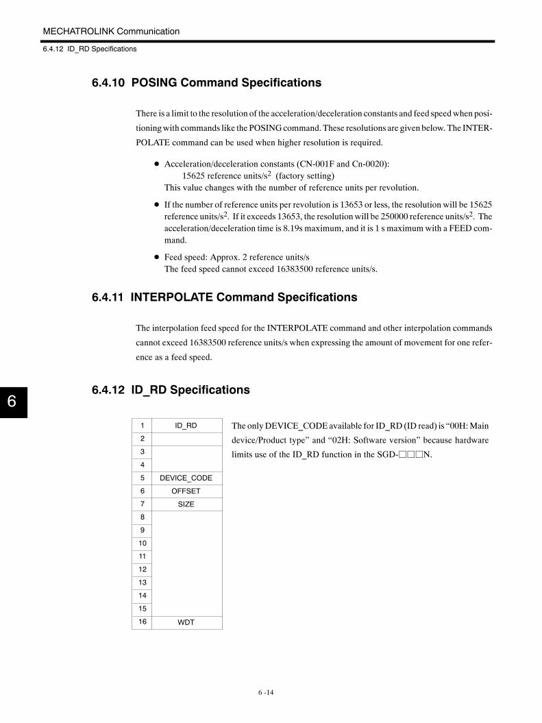
MECHATROLINK Communication
6.4.12 ID_RD Specifications
6 -14
6.4.10 POSING Command Specifications
There is a limit to the resolution of the acceleration/deceleration constants and feed speedwhen posi-
tioningwith commands like the POSINGcommand.These resolutions are given below. The INTER-
POLATE command can be used when higher resolution is required.
D Acceleration/deceleration constants (CN-001F and Cn-0020):15625 reference units/s2 (factory setting)
This value changes with the number of reference units per revolution.
D If the number of reference units per revolution is 13653 or less, the resolution will be 15625reference units/s2. If it exceeds 13653, the resolutionwill be 250000 reference units/s2. Theacceleration/deceleration time is 8.19s maximum, and it is 1 s maximumwith a FEED com-mand.
D Feed speed: Approx. 2 reference units/sThe feed speed cannot exceed 16383500 reference units/s.
6.4.11 INTERPOLATE Command Specifications
The interpolation feed speed for the INTERPOLATE command and other interpolation commands
cannot exceed 16383500 reference units/s when expressing the amount of movement for one refer-
ence as a feed speed.
6.4.12 ID_RD Specifications
The onlyDEVICE_CODEavailable for ID_RD (ID read) is “00H:Main
device/Product type” and “02H: Software version” because hardware
limits use of the ID_RD function in the SGD-jjjN.
ID_RD
DEVICE_CODE
OFFSET
SIZE
WDT
1
2
3
4
5
6
7
8
9
10
11
12
13
14
15
16
6
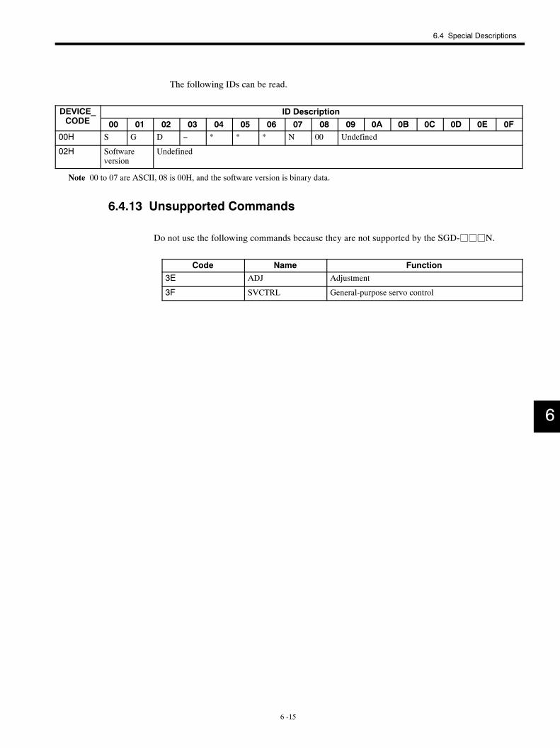
6.4 Special Descriptions
6 -15
The following IDs can be read.
DEVICE_CODE
ID Description_CODE 00 01 02 03 04 05 06 07 08 09 0A 0B 0C 0D 0E 0F
00H S G D − * * * N 00 Undefined
02H Softwareversion
Undefined
Note 00 to 07 are ASCII, 08 is 00H, and the software version is binary data.
6.4.13 Unsupported Commands
Do not use the following commands because they are not supported by the SGD-jjjN.
Code Name Function3E ADJ Adjustment
3F SVCTRL General-purpose servo control
6
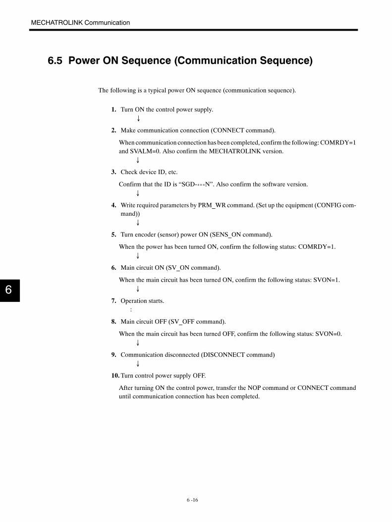
MECHATROLINK Communication
6 -16
6.5 Power ON Sequence (Communication Sequence)
The following is a typical power ON sequence (communication sequence).
1. Turn ON the control power supply.→↓
2. Make communication connection (CONNECT command).
When communication connection has been completed, confirm the following:COMRDY=1and SVALM=0. Also confirm the MECHATROLINK version.
↓
3. Check device ID, etc.
Confirm that the ID is “SGD-***N”. Also confirm the software version.↓
4. Write required parameters by PRM_WR command. (Set up the equipment (CONFIG com-mand))
↓
5. Turn encoder (sensor) power ON (SENS_ON command).
When the power has been turned ON, confirm the following status: COMRDY=1.↓
6. Main circuit ON (SV_ON command).
When the main circuit has been turned ON, confirm the following status: SVON=1.↓
7. Operation starts.:
8. Main circuit OFF (SV_OFF command).
When the main circuit has been turned OFF, confirm the following status: SVON=0.↓
9. Communication disconnected (DISCONNECT command)↓
10.Turn control power supply OFF.
After turning ON the control power, transfer the NOP command or CONNECT commanduntil communication connection has been completed.
6
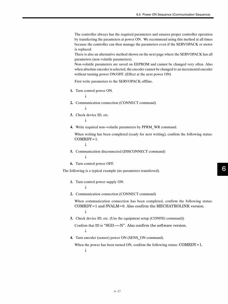
6.5 Power ON Sequence (Communication Sequence)
6 -17
The controller always has the required parameters and ensures proper controller operationby transferring the parameters at power ON. We recommend using this method at all timesbecause the controller can then manage the parameters even if the SERVOPACK or motoris replaced.There is also an alternative method shown on the next page where the SERVOPACK has allparameters (non-volatile parameters).Non-volatile parameters are saved on EEPROM and cannot be changed very often. Alsowhen absolute encoder is selected, the encoder cannot be changed to an incremental encoderwithout turning power ON/OFF. (Effect at the next power ON)
First write parameters to the SERVOPACK offline.
1. Turn control power ON.↓
2. Communication connection (CONNECT command)↓
3. Check device ID, etc.↓
4. Write required non−volatile parameters by PPRM_WR command.
When writing has been completed (ready for next writing), confirm the following status:COMRDY=1.
↓
5. Communication disconnected (DISCONNECT command)↓
6. Turn control power OFF.
The following is a typical example (no parameters transferred).
1. Turn control power supply ON.↓
2. Communication connection (CONNECT command)
When communication connection has been completed, confirm the following status:COMRDY=1 and SVALM=0. Also confirm the MECHATROLINK version.
↓
3. Check device ID, etc. (Use the equipment setup (CONFIG command))
Confirm that ID is “SGD-***N”. Also confirm the software version.↓
4. Turn encoder (sensor) power ON (SENS_ON command).
When the power has been turned ON, confirm the following status: COMRDY=1.↓
6
MECHATROLINK Communication
6 -18
5. Main circuits ON (SV_ON command).
When the main circuit has been turned ON, confirm the following status: SVON=1.↓
6. Operation starts.:
7. Main circuit OFF and turn OFF the main power supply.↓
8. Communication disconnected (DISCONNECT command)↓
9. Turn control power supply OFF.
6
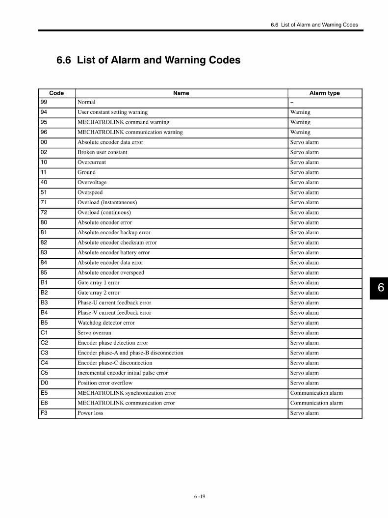
6.6 List of Alarm and Warning Codes
6 -19
6.6 List of Alarm and Warning Codes
Code Name Alarm type99 Normal −
94 User constant setting warning Warning
95 MECHATROLINK command warning Warning
96 MECHATROLINK communication warning Warning
00 Absolute encoder data error Servo alarm
02 Broken user constant Servo alarm
10 Overcurrent Servo alarm
11 Ground Servo alarm
40 Overvoltage Servo alarm
51 Overspeed Servo alarm
71 Overload (instantaneous) Servo alarm
72 Overload (continuous) Servo alarm
80 Absolute encoder error Servo alarm
81 Absolute encoder backup error Servo alarm
82 Absolute encoder checksum error Servo alarm
83 Absolute encoder battery error Servo alarm
84 Absolute encoder data error Servo alarm
85 Absolute encoder overspeed Servo alarm
B1 Gate array 1 error Servo alarm
B2 Gate array 2 error Servo alarm
B3 Phase-U current feedback error Servo alarm
B4 Phase-V current feedback error Servo alarm
B5 Watchdog detector error Servo alarm
C1 Servo overrun Servo alarm
C2 Encoder phase detection error Servo alarm
C3 Encoder phase-A and phase-B disconnection Servo alarm
C4 Encoder phase-C disconnection Servo alarm
C5 Incremental encoder initial pulse error Servo alarm
D0 Position error overflow Servo alarm
E5 MECHATROLINK synchronization error Communication alarm
E6 MECHATROLINK communication error Communication alarm
F3 Power loss Servo alarm
6
7 -1
7User Constants
This chapter describes the contents and settings of user constants (parame-
ters) and memory switches.
7.1 Setting User Constants 7 -2. . . . . . . . . . . . . . . . . . . .7.1.1 Gain-related Constants 7 -2. . . . . . . . . . . . . . . . . . . . . . .
7.1.2 Torque-related Constants 7 -3. . . . . . . . . . . . . . . . . . . . .
7.1.3 Sequence-related Constants 7 -3. . . . . . . . . . . . . . . . . .
7.1.4 Motion-related Constants 7 -5. . . . . . . . . . . . . . . . . . . . .
7.1.5 Pulse-related Constants 7 -7. . . . . . . . . . . . . . . . . . . . . .
7.1.6 Other Constants 7 -8. . . . . . . . . . . . . . . . . . . . . . . . . . . . .
7.1.7 Memory Switches 7 -9. . . . . . . . . . . . . . . . . . . . . . . . . . .
7.2 List of User Constants 7 -13. . . . . . . . . . . . . . . . . . . . .7.3 Memory Switch Bit Details 7 -16. . . . . . . . . . . . . . . . . .
7.3.1 Cn-0001: Memory Switches 1 7 -16. . . . . . . . . . . . . . . . .
7.3.2 Cn-0002: Memory Switches 2 7 -18. . . . . . . . . . . . . . . . .
7.3.3 Cn-0013: Memory Switches 3 7 -19. . . . . . . . . . . . . . . . .
7.3.4 Cn-0014: Memory Switches 4 7 -20. . . . . . . . . . . . . . . . .
7.4 Limits to User Constant Changes 7 -21. . . . . . . . . . .7.5 Procedure for Transferring User Constants 7 -21. . .
7
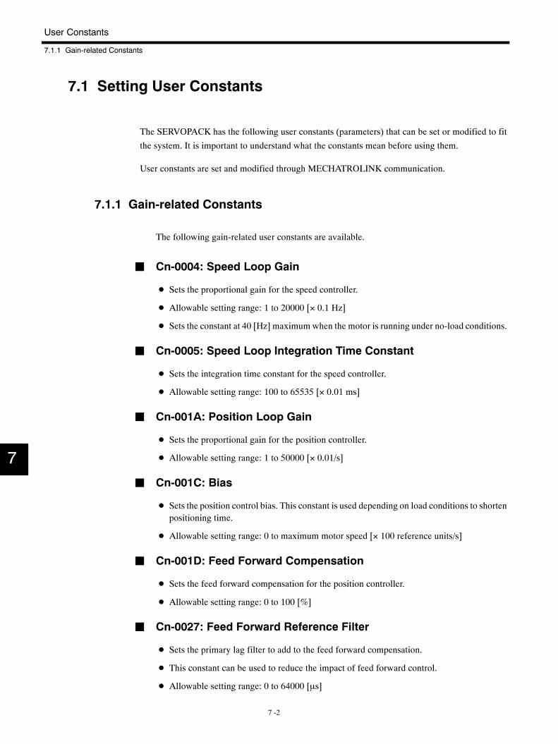
User Constants
7.1.1 Gain-related Constants
7 -2
7.1 Setting User Constants
The SERVOPACK has the following user constants (parameters) that can be set or modified to fit
the system. It is important to understand what the constants mean before using them.
User constants are set and modified through MECHATROLINK communication.
7.1.1 Gain-related Constants
The following gain-related user constants are available.
J Cn-0004: Speed Loop Gain
D Sets the proportional gain for the speed controller.
D Allowable setting range: 1 to 20000 [× 0.1 Hz]
D Sets the constant at 40 [Hz] maximum when the motor is running under no-load conditions.
J Cn-0005: Speed Loop Integration Time Constant
D Sets the integration time constant for the speed controller.
D Allowable setting range: 100 to 65535 [× 0.01 ms]
J Cn-001A: Position Loop Gain
D Sets the proportional gain for the position controller.
D Allowable setting range: 1 to 50000 [× 0.01/s]
J Cn-001C: Bias
D Sets the position control bias. This constant is used depending on load conditions to shortenpositioning time.
D Allowable setting range: 0 to maximum motor speed [× 100 reference units/s]
J Cn-001D: Feed Forward Compensation
D Sets the feed forward compensation for the position controller.
D Allowable setting range: 0 to 100 [%]
J Cn-0027: Feed Forward Reference Filter
D Sets the primary lag filter to add to the feed forward compensation.
D This constant can be used to reduce the impact of feed forward control.
D Allowable setting range: 0 to 64000 [µs]
7
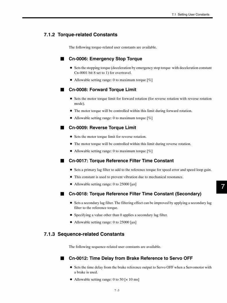
7.1 Setting User Constants
7 -3
7.1.2 Torque-related Constants
The following torque-related user constants are available.
J Cn-0006: Emergency Stop Torque
D Sets the stopping torque (deceleration by emergency stop torque with deceleration constantCn-0001 bit 8 set to 1) for overtravel.
D Allowable setting range: 0 to maximum torque [%]
J Cn-0008: Forward Torque Limit
D Sets the motor torque limit for forward rotation (for reverse rotation with reverse rotationmode).
D The motor torque will be controlled within this limit during forward rotation.
D Allowable setting range: 0 to maximum torque [%]
J Cn-0009: Reverse Torque Limit
D Sets the motor torque limit for reverse rotation.
D The motor torque will be controlled within this limit during reverse rotation.
D Allowable setting range: 0 to maximum torque [%]
J Cn-0017: Torque Reference Filter Time Constant
D Sets a primary lag filter to add to the reference torque for speed error and speed loop gain.
D This constant is used to prevent vibration due to mechanical resonance.
D Allowable setting range: 0 to 25000 [µs]
J Cn-0018: Torque Reference Filter Time Constant (Secondary)
D Sets a secondary lag filter. The filtering effect can be improved by applying a secondary lagfilter to the reference torque.
D Specifying a value other than 0 applies a secondary lag filter.
D Allowable setting range: 0 to 25000 [µs]
7.1.3 Sequence-related Constants
The following sequence-related user constants are available.
J Cn-0012: Time Delay from Brake Reference to Servo OFF
D Sets the time delay from the brake reference output to Servo OFF when a Servomotor witha brake is used.
D Allowable setting range: 0 to 50 [× 10 ms]
7
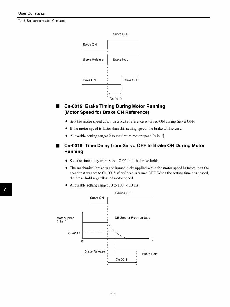
User Constants
7.1.3 Sequence-related Constants
7 -4
Cn-0012
Servo OFF
Servo ON
Brake Release Brake Hold
Drive ON Drive OFF
J Cn-0015: Brake Timing During Motor Running(Motor Speed for Brake ON Reference)
D Sets the motor speed at which a brake reference is turned ON during Servo OFF.
D If the motor speed is faster than this setting speed, the brake will release.
D Allowable setting range: 0 to maximum motor speed [min−1]
J Cn-0016: Time Delay from Servo OFF to Brake ON During MotorRunning
D Sets the time delay from Servo OFF until the brake holds.
D The mechanical brake is not immediately applied while the motor speed is faster than thespeed that was set to Cn-0015 after Servo is turned OFF. When the setting time has passed,the brake hold regardless of motor speed.
D Allowable setting range: 10 to 100 [× 10 ms]
Cn-0015
0 t
Cn-0016
Servo OFF
Servo ON
DB Stop or Free-run StopMotor Speed(min−1)
Brake ReleaseBrake Hold
7
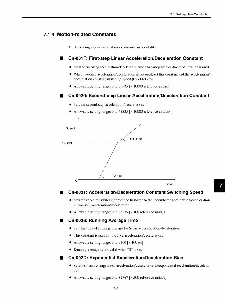
7.1 Setting User Constants
7 -5
7.1.4 Motion-related Constants
The following motion-related user constants are available.
J Cn-001F: First-step Linear Acceleration/Deceleration Constant
D Sets the first-step acceleration/decelerationwhen two-step acceleration/deceleration is used.
D When two-step acceleration/deceleration is not used, set this constant and the acceleration/deceleration constant switching speed (Cn-0021) to 0.
D Allowable setting range: 0 to 65535 [× 10000 reference units/s2]
J Cn-0020: Second-step Linear Acceleration/Deceleration Constant
D Sets the second-step acceleration/deceleration.
D Allowable setting range: 0 to 65535 [× 10000 reference units/s2]
Cn-0020
Cn-001F
Cn-0021
Speed
Time0
J Cn-0021: Acceleration/Deceleration Constant Switching Speed
D Sets the speed for switching from the first-step to the second-step acceleration/decelerationin two-step acceleration/deceleration.
D Allowable setting range: 0 to 65535 [× 100 reference units/s]
J Cn-0026: Running Average Time
D Sets the time of running average for S-curve acceleration/deceleration.
D This constant is used for S-curve acceleration/deceleration.
D Allowable setting range: 0 to 5100 [× 100 µs]
D Running average is not valid when “0” is set.
J Cn-002D: Exponential Acceleration/Deceleration Bias
D Sets the bias to change linear acceleration/deceleration to exponential acceleration/decelera-tion.
D Allowable setting range: 0 to 32767 [× 500 reference units/s]
7
User Constants
7.1.4 Motion-related Constants
7 -6
J Cn-002E: Exponential Acceleration/Deceleration Time Constant
D Sets the time constant to change linear acceleration/deceleration to exponential acceleration/deceleration.
D Allowable setting range: 0 to 5100 [× 100 µs]
D Exponential acceleration/deceleration is not valid when “0” is set.
J Cn-0022: Zero point Return Approach Speed 1
D Sets the approach speed for returning to the zero point after the deceleration limit switch sig-nal turns ON.
D Allowable setting range: 0 to 65535 [× 100 reference units/s]
J Cn-0023: Zero point Return Approach Speed 2
D Sets the search speed for the zero point after the deceleration limit switch signal turns ONor OFF.
D Allowable setting range: 0 to 65535 [× 100 reference units/s]
J Cn-0028: Final Travel Distance To Return To Zero Point
D Sets the distance from the encoder zero point pulse (phase-C pulse) to the zero point whenreturning to the zero point.
D Allowable setting range: −2147483648 to +2147483647 [reference units]
D If the setting distance is reverse direction or a short travel distance, the motor will decelerateto a stop and then return to reverse direction.
J Cn-002A: Zero Point Width
D Sets the zero point (ZPOINT) detection width.
D Allowable setting range: 0 to 65535 [reference units]
J Cn-0033: Absolute Encoder Zero Point Offset
D Sets the difference between the encoder zero point (position 0) and the machine zero pointif an absolute encoder is used. For example, set the amount of offset so that the machine zeropoint is position 0.
D Allowable setting range: −2147483648 to +2147483647 [reference units]
J Cn-002B: Final Travel Distance for External Positioning
D Sets the distance from the external signal input during external positioning.
D Allowable setting range: −2147483648 to +2147483647 [reference units]
D If the setting distance is reverse direction or a short travel distance, the motor will decelerateto a stop and then return to reverse direction.
J Cn-002F: Forward Software Limit
D Sets the forward software position limit.
7
7.1 Setting User Constants
7 -7
D Allowable setting range: −2147483648 to +2147483647 [reference units]
D Thepositive software limitmust be set in combinationwith the reverse software limit to spec-ify the range of motion. Make sure that the forward software limit is greater than the reversesoftware limit.
J Cn-0031: Reverse Software Limit
D Sets the reverse software position limit.
D Allowable setting range: −2147483648 to +2147483647 [reference units]
J Cn-001B: Positioning Completed Width
D Sets the positioning completed width (PSET).
D Allowable setting range: 0 to 250 [reference units]
J Cn-0007: Positioning Near Detection Width
D Sets the detection width for positioning completed nearly (NEAR).
D When the motor position moves within the this range for the target position, NEAR is set to1 regardless of whether command distribution is completed.
D Allowable setting range: 0 to 10000 [reference units]
J Cn-001E: Position Error Overflow Range
D Sets the overflow detection level of the position error counter.
D Allowable setting range: 1 to 65535 [reference units]
D If the number of reference units per motor revolution (no. of encoder pulses × 4 × A/B) is8193 or more, the range is the setting × 128. Therefore, the allowable setting range is 1 to65535 [× 128 reference units].
7.1.5 Pulse-related Constants
The following pulse-related constants are available.
J Cn-0011: Number of Encoder Pulses
D Sets the number of pulses per encoder revolution.
D The setting can be changed only once after power is turned ON; do not change the settingduring operation.
D Sets Cn-0011 to 2048 P/R (SGM-VVV312) or 2000 P/R (SGM-VVV512) for an incremen-tal encoder and to 1024 P/R for an absolute encoder.
J Cn-0024 (B) and Cn-0025 (A): Electronic Gear Ratio
D The electronic gear ratio AB
Cn-0025Cn-0024
represents the number of encoder pulses per refer-
ence unit.
7
User Constants
7.1.6 Other Constants
7 -8
For example, consider a system where the reference unit is micrometers in equipment thatdrives a ball screw with a 5-mm (0.20-in) pitch using a Servomotor with an incremental en-coder (8192 pulses). Since 8192 encoder pulses are generated 4 times (unconditionally 4times) in one motor revolution, the number of pulses generated is 2048¢ 4 or 8192 pulses.Here, the Servomotor moves 5 mm (0.20 in) above the 5-mm (0.20-in) pitch ball screw, andthis distance expressed as micrometers is 5000 µm. Therefore, set Cn-0024 to 8192 andCn-0025 to 5000.
D Makes sure that the electronic gear ratio falls within the range 0.01≦ B/A≦ 100.
D Be sure to recalculate and correct user constants set in reference and speed reference units.Do not change this setting during operation.
7.1.6 Other Constants
The following user constants are available.
J Cn-0003: Load Moment of Inertia
D Sets the load moment of inertia for the moment of inertia ratio on the motor shaft.
D Allowable setting range: 0 to 65535 [%]
D If the loadmoment of inertia exceeds the allowable range, regenerative brakes and other fac-tors must be reviewed. See Section 6.6.2.
J Cn-000C: Torque Reference Mode Switch Level
D Sets the torque reference mode switch level.
D This constant is valid only when torque reference mode switch is selected at Cn-0001 bits12 and 13.
D Allowable setting range: 0 to maximum motor torque [%]
J Cn-000E: Acceleration Mode Switch Level
D Sets the acceleration mode switch level.
D This constant is valid onlywhen accelerationmode switch is selected at Cn-0001 bits 12 and13.
D Allowable setting range: 0 to 3000 [× 0.167 r/s2]
J Cn-000F: Error Pulse Mode Switch Level
D Sets the mode switch level for switching the mode by error pulses.
D This constant is valid only when error pulse mode switch is selected at Cn-0001 bits 12 and13.
D Unit: Encoder pulses
D Allowable setting range: 0 to 10000 [pulses]
J Cn-0035: Speed Loop Compensation Constant
D The speed loop compensation function compensates for a phase shift resulting from speeddetection in digital control and is effective in reducing vibration.
7
7.1 Setting User Constants
7 -9
D When using this function, set Cn-0035within a range that does not cause vibration in the ser-vo system or abnormal noise in the mechanical system.
D The speed loop compensation functionmay not be effective in some cases and vibrationmayincrease as a result. In that case, do not use the function (set Cn-0035 to 0).
D Allowable setting range: 0 to 100 (0: no compensation)
7.1.7 Memory Switches
The settings and functions of the memory switches are described below.
J Cn-0001 Bit 0: SV_ON Command Mask
D The SV_ON command is disabled when this bit is set to 1 (main circuit operating status).
J Cn-0001 Bit 0: SENS_ON Command Mask
D The SENS_ON command is disabled when this bit is set to 1 (encoder power ON status).
J Cn-0001 Bit 2: P-OT Mask
D The P-OT signal is disabled when this bit is set to 1 (P-OT input OFF status).
J Cn-0001 Bit 3: N-OT Mask
D The N-OT signal is disabled when this bit is set to 1 (N-OT input OFF status).
J Cn-0001 Bit 5: Power Loss Mask
D Power loss alarm is not detected when this bit is set to 1. (No servo alarm at power loss.)
J Cn-0001 Bit 6: Base Block Stopping Method
D Sets whether to use the dynamic brake or coasting to stop the motor when the main circuitis not operating (base block).
D Motor coasts to a stop when this bit is set to 1.
J Cn-0001 Bit 7: Operation After Dynamic Brake (DB) Stop
D Sets whether to continue the dynamic brake after a dynamic brake stops.
D The brake is not continued when this bit is set to 1.
J Cn-0001 Bit 8: Overtravel (OT) Stoping Method
D Sets how to stop a motor when overtravel occurs.Occurs at OT forward/reverse drive prohibit (overtravel) input and software limit.
D The motor will decelerate to a stop with the torque specified in the emergency stop torqueconstant (Cn-0006) when Cn-0001 bit 8 is set to 1.
J Cn-0001 Bit 9: Holding Method After An Emergency TorqueDeceleration Stop at Overtravel
D Sets the holdingmethodafter an emergency torquedeceleration stopwhenovertravel occurs.
7
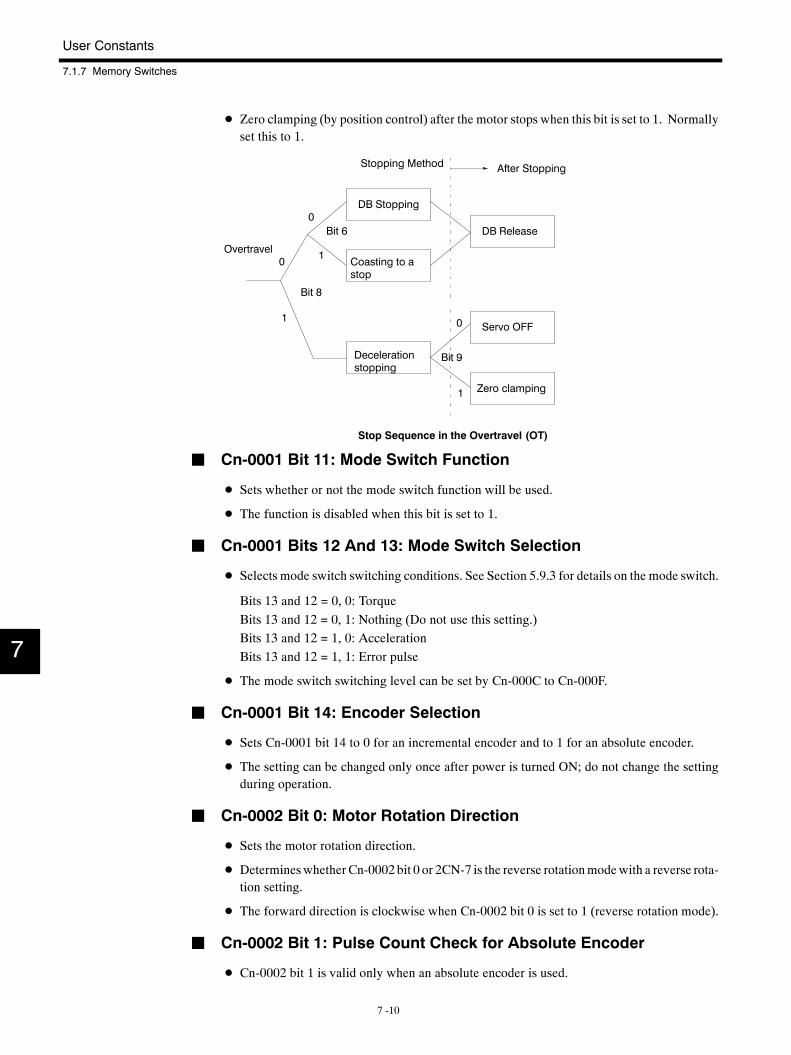
User Constants
7.1.7 Memory Switches
7 -10
D Zero clamping (by position control) after the motor stops when this bit is set to 1. Normallyset this to 1.
Overtravel
DB Stopping
Coasting to astop
0
0
1
Bit 6
Decelerationstopping
Servo OFF
Zero clamping
0
1
Bit 9
1
Bit 8
DB Release
Stopping Method After Stopping
Stop Sequence in the Overtravel (OT)
J Cn-0001 Bit 11: Mode Switch Function
D Sets whether or not the mode switch function will be used.
D The function is disabled when this bit is set to 1.
J Cn-0001 Bits 12 And 13: Mode Switch Selection
D Selects mode switch switching conditions. See Section 5.9.3 for details on the mode switch.
Bits 13 and 12 = 0, 0: TorqueBits 13 and 12 = 0, 1: Nothing (Do not use this setting.)Bits 13 and 12 = 1, 0: AccelerationBits 13 and 12 = 1, 1: Error pulse
D The mode switch switching level can be set by Cn-000C to Cn-000F.
J Cn-0001 Bit 14: Encoder Selection
D Sets Cn-0001 bit 14 to 0 for an incremental encoder and to 1 for an absolute encoder.
D The setting can be changed only once after power is turned ON; do not change the settingduring operation.
J Cn-0002 Bit 0: Motor Rotation Direction
D Sets the motor rotation direction.
D Determineswhether Cn-0002 bit 0 or 2CN-7 is the reverse rotationmodewith a reverse rota-tion setting.
D The forward direction is clockwise when Cn-0002 bit 0 is set to 1 (reverse rotation mode).
J Cn-0002 Bit 1: Pulse Count Check for Absolute Encoder
D Cn-0002 bit 1 is valid only when an absolute encoder is used.
7
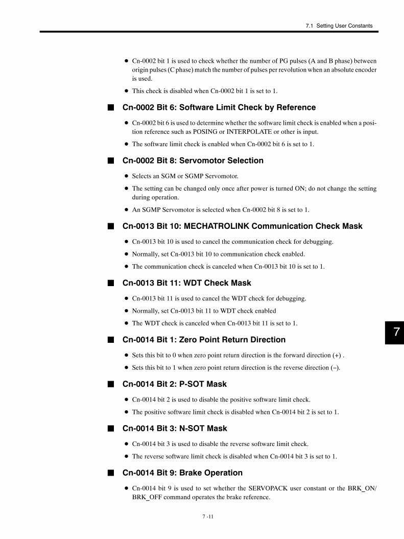
7.1 Setting User Constants
7 -11
D Cn-0002 bit 1 is used to check whether the number of PG pulses (A and B phase) betweenorigin pulses (C phase)match the number of pulses per revolutionwhen an absolute encoderis used.
D This check is disabled when Cn-0002 bit 1 is set to 1.
J Cn-0002 Bit 6: Software Limit Check by Reference
D Cn-0002 bit 6 is used to determine whether the software limit check is enabled when a posi-tion reference such as POSING or INTERPOLATE or other is input.
D The software limit check is enabled when Cn-0002 bit 6 is set to 1.
J Cn-0002 Bit 8: Servomotor Selection
D Selects an SGM or SGMP Servomotor.
D The setting can be changed only once after power is turned ON; do not change the settingduring operation.
D An SGMP Servomotor is selected when Cn-0002 bit 8 is set to 1.
J Cn-0013 Bit 10: MECHATROLINK Communication Check Mask
D Cn-0013 bit 10 is used to cancel the communication check for debugging.
D Normally, set Cn-0013 bit 10 to communication check enabled.
D The communication check is canceled when Cn-0013 bit 10 is set to 1.
J Cn-0013 Bit 11: WDT Check Mask
D Cn-0013 bit 11 is used to cancel the WDT check for debugging.
D Normally, set Cn-0013 bit 11 to WDT check enabled
D The WDT check is canceled when Cn-0013 bit 11 is set to 1.
J Cn-0014 Bit 1: Zero Point Return Direction
D Sets this bit to 0 when zero point return direction is the forward direction (+) .
D Sets this bit to 1 when zero point return direction is the reverse direction (−).
J Cn-0014 Bit 2: P-SOT Mask
D Cn-0014 bit 2 is used to disable the positive software limit check.
D The positive software limit check is disabled when Cn-0014 bit 2 is set to 1.
J Cn-0014 Bit 3: N-SOT Mask
D Cn-0014 bit 3 is used to disable the reverse software limit check.
D The reverse software limit check is disabled when Cn-0014 bit 3 is set to 1.
J Cn-0014 Bit 9: Brake Operation
D Cn-0014 bit 9 is used to set whether the SERVOPACK user constant or the BRK_ON/BRK_OFF command operates the brake reference.
7
User Constants
7.1.7 Memory Switches
7 -12
D The brake reference is operated by the SERVOPACK user constant when Cn-0014 bit 9 isset to 1.
J Cn-0014 Bit 10: P-OT Signal Logic
D TheP-OTsignal logic is reversedwhenCn-0014bit 10 is set to 1. Forwarddrive isprohibitedwhen the P-OT signal is turned OFF (Signal is CLOSED).
J Cn-0014 Bit 11: N-OT Signal Logic
D TheN-OT signal logic is reversedwhenCn-0014bit 11 is set to 1. Reverse drive isprohibitedwhen the N-OT signal is turned OFF (Signal is CLOSED).
J Cn-0014 Bit 12: DEC Signal Logic
D The DEC signal logic is reversed when Cn-0014 bit 12 is set to 1.
D The motor moves at zero point return approach speed 1 when the DEC signal is turned OFF(Signal is OPEN).
D The motor searches for the origin pulse at zero point return approach speed 2 when the DECsignal is turned ON (Signal is CLOSED).
7
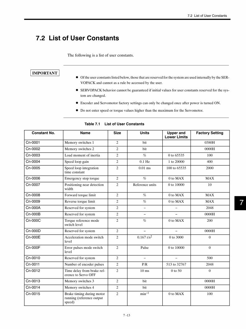
7.2 List of User Constants
7 -13
7.2 List of User Constants
The following is a list of user constants.
D Of the user constants listed below, those that are reserved for the system areused internally by the SER-VOPACK and cannot as a rule be accessed by the user.
D SERVOPACK behavior cannot be guaranteed if initial values for user constants reserved for the sys-tem are changed.
D Encoder and Servomotor factory settings can only be changed once after power is turned ON.
D Do not enter speed or torque values higher than the maximum for the Servomotor.
Table 7.1 List of User Constants
Constant No. Name Size Units Upper andLower LImits
Factory Setting
Cn-0001 Memory switches 1 2 bit 0380H
Cn-0002 Memory switches 2 2 bit 0000H
Cn-0003 Load moment of inertia 2 % 0 to 65535 100
Cn-0004 Speed loop gain 2 0.1 Hz 1 to 20000 400
Cn-0005 Speed loop integrationtime constant
2 0.01 ms 100 to 65535 2000
Cn-0006 Emergency stop torque 2 % 0 to MAX MAX
Cn-0007 Positioning near detectionwidth
2 Reference units 0 to 10000 10
Cn-0008 Forward torque limit 2 % 0 to MAX MAX
Cn-0009 Reverse torque limit 2 % 0 to MAX MAX
Cn-000A Reserved for system 2 − − 2048
Cn-000B Reserved for system 2 − − 0000H
Cn-000C Torque reference modeswitch level
2 % 0 to MAX 200
Cn-000D Reserved for system 2 − − 0000H
Cn-000E Acceleration mode switchlevel
2 0.167 r/s2 0 to 3000 0
Cn-000F Error pulses mode switchlevel
2 Pulse 0 to 10000 0
Cn-0010 Reserved for system 2 − − 500
Cn-0011 Number of encoder pulses 2 P/R 513 to 32767 2048
Cn-0012 Time delay from brake ref-erence to Servo OFF
2 10 ms 0 to 50 0
Cn-0013 Memory switches 3 2 bit 0000H
Cn-0014 Memory switches 4 2 bit 0000H
Cn-0015 Brake timing during motorrunning (reference outputspeed)
2 min−1 0 to MAX 100
7
IMPORTANT
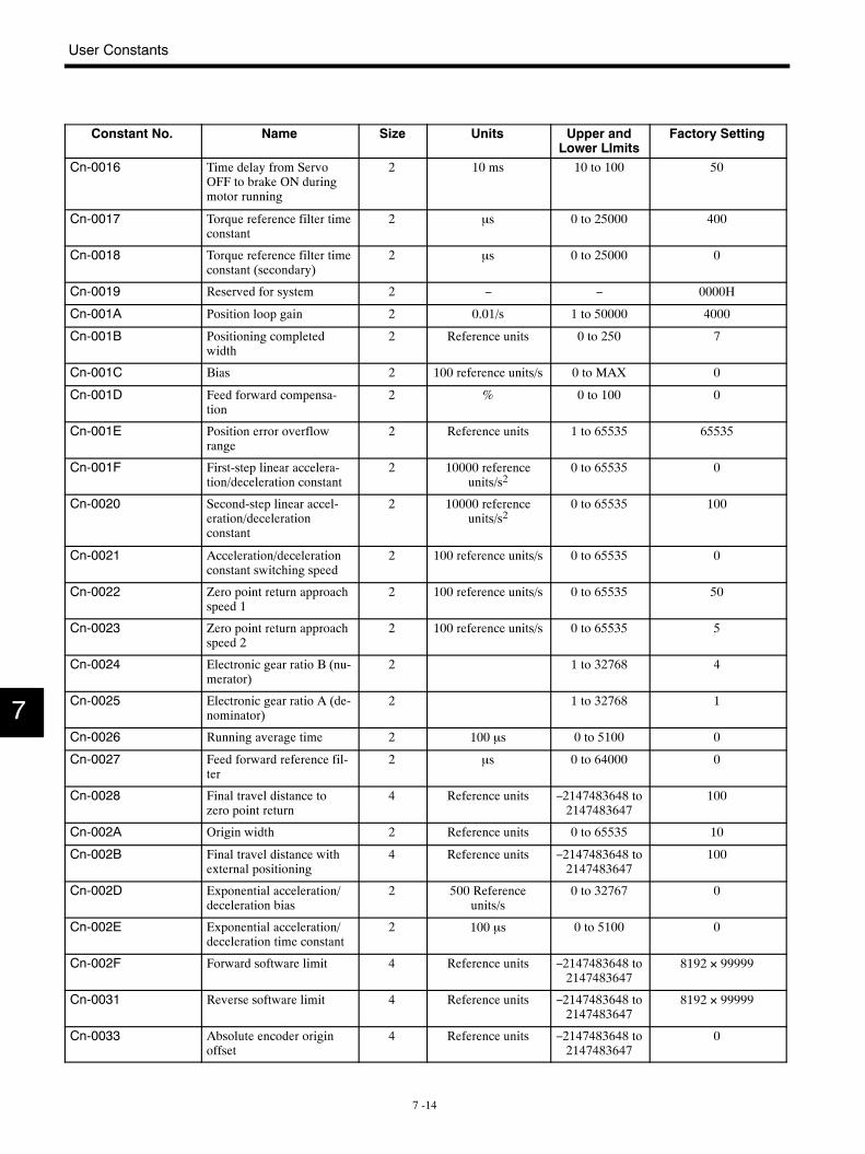
User Constants
7 -14
Constant No. Factory SettingUpper andLower LImits
UnitsSizeName
Cn-0016 Time delay from ServoOFF to brake ON duringmotor running
2 10 ms 10 to 100 50
Cn-0017 Torque reference filter timeconstant
2 µs 0 to 25000 400
Cn-0018 Torque reference filter timeconstant (secondary)
2 µs 0 to 25000 0
Cn-0019 Reserved for system 2 − − 0000H
Cn-001A Position loop gain 2 0.01/s 1 to 50000 4000
Cn-001B Positioning completedwidth
2 Reference units 0 to 250 7
Cn-001C Bias 2 100 reference units/s 0 to MAX 0
Cn-001D Feed forward compensa-tion
2 % 0 to 100 0
Cn-001E Position error overflowrange
2 Reference units 1 to 65535 65535
Cn-001F First-step linear accelera-tion/deceleration constant
2 10000 referenceunits/s2
0 to 65535 0
Cn-0020 Second-step linear accel-eration/decelerationconstant
2 10000 referenceunits/s2
0 to 65535 100
Cn-0021 Acceleration/decelerationconstant switching speed
2 100 reference units/s 0 to 65535 0
Cn-0022 Zero point return approachspeed 1
2 100 reference units/s 0 to 65535 50
Cn-0023 Zero point return approachspeed 2
2 100 reference units/s 0 to 65535 5
Cn-0024 Electronic gear ratio B (nu-merator)
2 1 to 32768 4
Cn-0025 Electronic gear ratio A (de-nominator)
2 1 to 32768 1
Cn-0026 Running average time 2 100 µs 0 to 5100 0
Cn-0027 Feed forward reference fil-ter
2 µs 0 to 64000 0
Cn-0028 Final travel distance tozero point return
4 Reference units −2147483648 to2147483647
100
Cn-002A Origin width 2 Reference units 0 to 65535 10
Cn-002B Final travel distance withexternal positioning
4 Reference units −2147483648 to2147483647
100
Cn-002D Exponential acceleration/deceleration bias
2 500 Referenceunits/s
0 to 32767 0
Cn-002E Exponential acceleration/deceleration time constant
2 100 µs 0 to 5100 0
Cn-002F Forward software limit 4 Reference units −2147483648 to2147483647
8192 × 99999
Cn-0031 Reverse software limit 4 Reference units −2147483648 to2147483647
8192 × 99999
Cn-0033 Absolute encoder originoffset
4 Reference units −2147483648 to2147483647
0
7
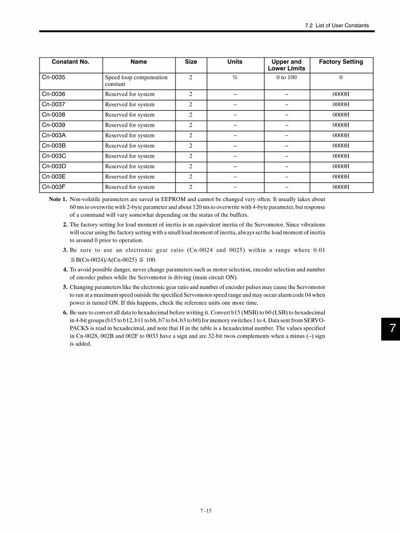
7.2 List of User Constants
7 -15
Constant No. Factory SettingUpper andLower LImits
UnitsSizeName
Cn-0035 Speed loop compensationconstant
2 % 0 to 100 0
Cn-0036 Reserved for system 2 − − 0000H
Cn-0037 Reserved for system 2 − − 0000H
Cn-0038 Reserved for system 2 − − 0000H
Cn-0039 Reserved for system 2 − − 0000H
Cn-003A Reserved for system 2 − − 0000H
Cn-003B Reserved for system 2 − − 0000H
Cn-003C Reserved for system 2 − − 0000H
Cn-003D Reserved for system 2 − − 0000H
Cn-003E Reserved for system 2 − − 0000H
Cn-003F Reserved for system 2 − − 0000H
Note 1. Non-volatile parameters are saved in EEPROM and cannot be changed very often. It usually takes about60ms to overwrite with 2-byte parameter and about 120ms to overwrite with 4-byte parameter, but responseof a command will vary somewhat depending on the status of the buffers.
2. The factory setting for load moment of inertia is an equivalent inertia of the Servomotor. Since vibrationswill occur using the factory settingwith a small loadmoment of inertia, always set the loadmoment of inertiato around 0 prior to operation.
3. Be sure to use an electronic gear ratio (Cn-0024 and 0025) within a range where 0.01
≦B(Cn-0024)/A(Cn-0025)≦ 100.
4. To avoid possible danger, never change parameters such as motor selection, encoder selection and numberof encoder pulses while the Servomotor is driving (main circuit ON).
5. Changing parameters like the electronic gear ratio and number of encoder pulses may cause the Servomotorto run at amaximum speed outside the specified Servomotor speed range andmayoccur alarmcode 04whenpower is turned ON. If this happens, check the reference units one more time.
6. Be sure to convert all data to hexadecimal before writing it. Convert b15 (MSB) to b0 (LSB) to hexadecimalin 4-bit groups (b15 to b12, b11 to b8, b7 to b4, b3 to b0) formemory switches 1 to 4. Data sent fromSERVO-PACKS is read in hexadecimal, and note that H in the table is a hexadecimal number. The values specifiedin Cn-0028, 002B and 002F to 0033 have a sign and are 32-bit twos complements when a minus (−) signis added.
7

User Constants
7.3.1 Cn-0001: Memory Switches 1
7 -16
7.3 Memory Switch Bit Details
The following describes each bit of memory switch (bit-type user constant).
7.3.1 Cn-0001: Memory Switches 1
J Bits b0 to b7
Bits b0 to b7 are described in the following table.
Bit Description FactorySetting
b0 SV_ON command mask0: Enable SV_ON/SV_OFF command.1: Always send SV_ON command (Servo ON).
0
b1 SENS_ON command mask0: Enable SENS_ON/SENS_OFF command.1: Always send SENS_ON command (Encoder power ON).
0
b2 P-OT mask0: Enable the P-OT signal.1: Mask (always disable) P-OT signal
0
b3 N-OT mask0: Enable N-OT signal.1: Mask (always disable) N-OT signal
0
b4 − 0
b5 Power loss mask0: Servo alarm at power loss recovery (momentary power loss
alarm)1: Power loss mask (no servo alarm at power loss recovery)
0
b6 Base block stopping method0: Dynamic brake (DB) stop1: Coasting to a stop
0
b7 Operation after dynamic brake stop0: Release dynamic brake.1: Do not release dynamic brake.
1
Note Never change the factory setting of the bit marked with “−”.
7
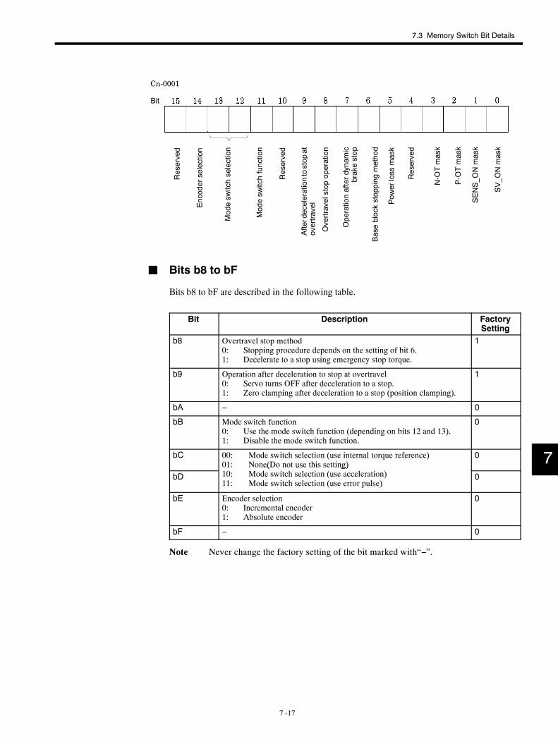
7.3 Memory Switch Bit Details
7 -17
Cn-0001
Bit
Reserved
Encoderselection
Afterdecelerationtostop
atovertravel
Reserved
SENS_O
Nmask
SV_O
Nmask
P-OTmask
N-OTmask
Modesw
itchselection
Modesw
itchfunction
Overtravelstopoperation
Operationafterdynamic
brakestop
Baseblockstopping
method
Pow
erloss
mask
Reserved
J Bits b8 to bF
Bits b8 to bF are described in the following table.
Bit Description FactorySetting
b8 Overtravel stop method0: Stopping procedure depends on the setting of bit 6.1: Decelerate to a stop using emergency stop torque.
1
b9 Operation after deceleration to stop at overtravel0: Servo turns OFF after deceleration to a stop.1: Zero clamping after deceleration to a stop (position clamping).
1
bA − 0
bB Mode switch function0: Use the mode switch function (depending on bits 12 and 13).1: Disable the mode switch function.
0
bC 00: Mode switch selection (use internal torque reference)01: None(Do not use this setting)
0
bD( u g)
10: Mode switch selection (use acceleration)11: Mode switch selection (use error pulse)
0
bE Encoder selection0: Incremental encoder1: Absolute encoder
0
bF − 0
Note Never change the factory setting of the bit marked with“−”.
7
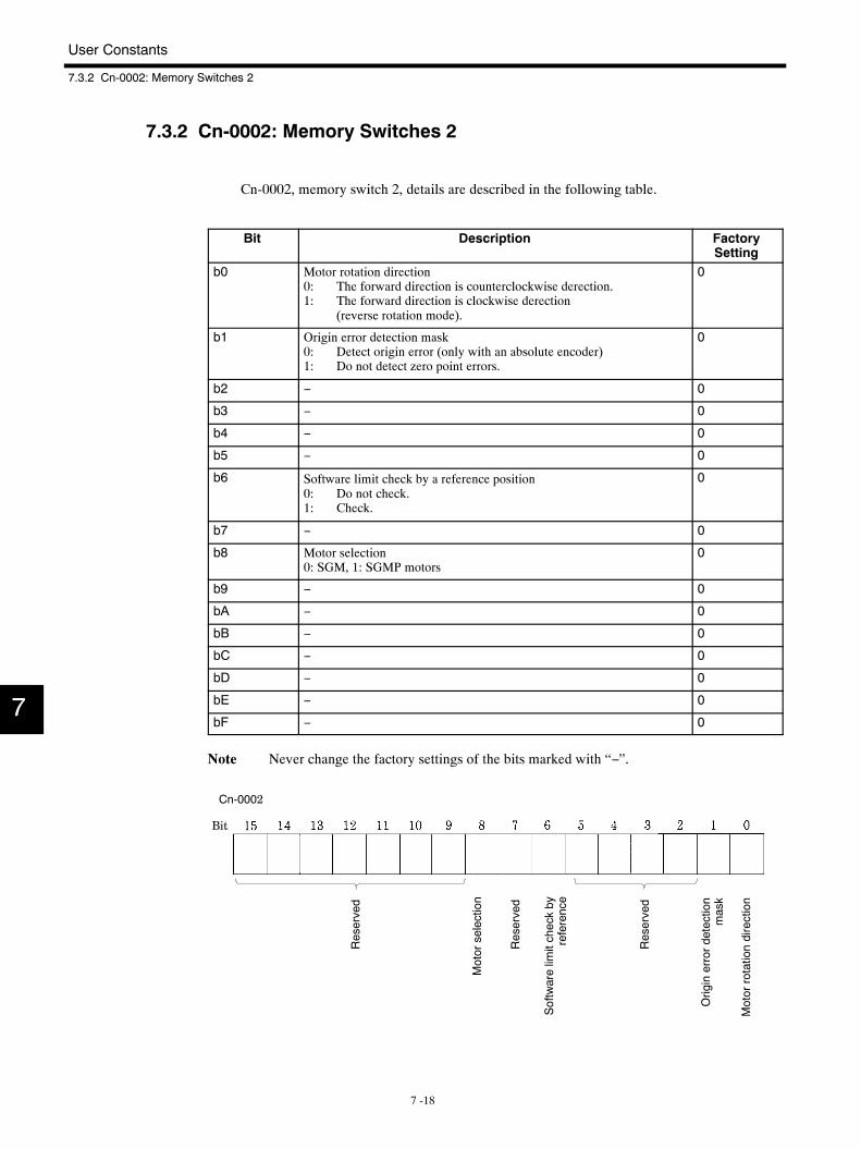
User Constants
7.3.2 Cn-0002: Memory Switches 2
7 -18
7.3.2 Cn-0002: Memory Switches 2
Cn-0002, memory switch 2, details are described in the following table.
Bit Description FactorySetting
b0 Motor rotation direction0: The forward direction is counterclockwise derection.1: The forward direction is clockwise derection
(reverse rotation mode).
0
b1 Origin error detection mask0: Detect origin error (only with an absolute encoder)1: Do not detect zero point errors.
0
b2 − 0
b3 − 0
b4 − 0
b5 − 0
b6 Software limit check by a reference position0: Do not check.1: Check.
0
b7 − 0
b8 Motor selection0: SGM, 1: SGMP motors
0
b9 − 0
bA − 0
bB − 0
bC − 0
bD − 0
bE − 0
bF − 0
Note Never change the factory settings of the bits marked with “−”.
Cn-0002
Bit
Reserved
Reserved
Reserved
Motorselection
Softwarelim
itcheckby
reference
Originerrordetection
mask
Motorrotationdirection
7
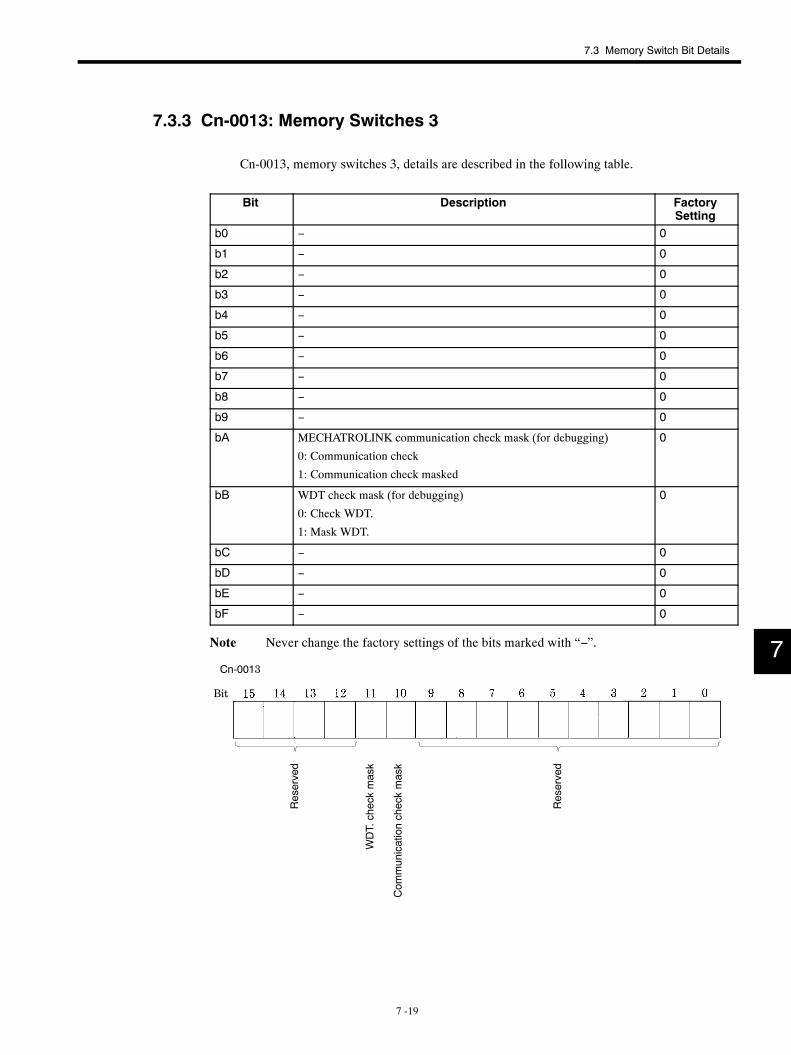
7.3 Memory Switch Bit Details
7 -19
7.3.3 Cn-0013: Memory Switches 3
Cn-0013, memory switches 3, details are described in the following table.
Bit Description FactorySetting
b0 − 0
b1 − 0
b2 − 0
b3 − 0
b4 − 0
b5 − 0
b6 − 0
b7 − 0
b8 − 0
b9 − 0
bA MECHATROLINK communication check mask (for debugging)
0: Communication check
1: Communication check masked
0
bB WDT check mask (for debugging)
0: Check WDT.
1: Mask WDT.
0
bC − 0
bD − 0
bE − 0
bF − 0
Note Never change the factory settings of the bits marked with “−”.
Cn-0013
Bit
Reserved
Reserved
Com
municationcheckmask
WDT.checkmask
7
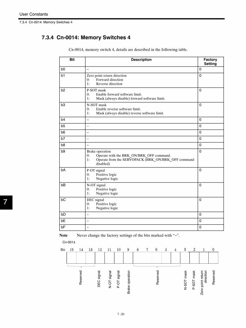
User Constants
7.3.4 Cn-0014: Memory Switches 4
7 -20
7.3.4 Cn-0014: Memory Switches 4
Cn-0014, memory switch 4, details are described in the following table.
Bit Description FactorySetting
b0 − 0
b1 Zero point return direction0: Forward direction1: Reverse direction
0
b2 P-SOT mask0: Enable forward software limit.1: Mask (always disable) forward software limit.
0
b3 N-SOT mask0: Enable reverse software limit.1: Mask (always disable) reverse software limit.
0
b4 − 0
b5 − 0
b6 − 0
b7 − 0
b8 − 0
b9 Brake operation0: Operate with the BRK_ON/BRK_OFF command.1: Operate from the SERVOPACK (BRK_ON/BRK_OFF command
disabled)
0
bA P-OT signal0: Positive logic1: Negative logic
0
bB N-OT signal0: Positive logic1: Negative logic
0
bC DEC signal0: Positive logic1: Negative logic
0
bD − 0
bE − 0
bF − 0
Note Never change the factory settings of the bits marked with “−”.
Cn-0014
Bit
Reserved
Reserved
Reserved
DECsignal
N-OTsignal
P-OTsignal
Brake
operation
N-SOTmask
P-SOTmask
Zeropointreturn
direction
7
7.4 Limits to User Constant Changes
7 -21
7.4 Limits to User Constant Changes
The only user constants that can be changed during motor running are those listed below. Never
change any other user constants during motor running.
Number NameCn-0004 Speed loop gain
Cn-0005 Speed loop integration time constant
Cn-0008 Positive torque limit
Cn-0009 Negative torque limit
Cn-0017 Torque reference filter time constant
Cn-0018 Torque reference filter time constant (secondary)
Cn-001A Position loop gain
Cn-001C Bias
Cn-001D Feed forward compensation
7.5 Procedure for Transferring User Constants
The procedure for changing (transferring) user constants (parameters) after power is turned ON is
to transfer the Servomotor selection, encoder selection (encoder type and number of pulses), elec-
tronic gear ratio, and other user constants in order only. Randomly transferring user constants can
cause a user constant setting warning and they may not be received.
Motor selection, encoder selection, and electronic gear ratio parameters can be changed only once
after power is turned ON. This must be done prior to executing the SENS_ON command and the
motor running.
7

8 -1
8Installation and Wiring
This chapter describes procedures for checking to be performed when the
Servomotors and SERVOPACKS are delivered as well as installation and
wiring specifications.
8.1 Checking on Delivery 8 -2. . . . . . . . . . . . . . . . . . . . . .8.2 Installation 8 -2. . . . . . . . . . . . . . . . . . . . . . . . . . . . . . .
8.2.1 Installing Servomotors 8 -2. . . . . . . . . . . . . . . . . . . . . . .
8.2.2 Installing SERVOPACKS 8 -4. . . . . . . . . . . . . . . . . . . . .
8.3 Wiring Specifications 8 -6. . . . . . . . . . . . . . . . . . . . . .8.3.1 Rated Current and Cable Specifications 8 -6. . . . . . . .
8.3.2 Wiring Instructions 8 -7. . . . . . . . . . . . . . . . . . . . . . . . . . .
8.3.3 Power Loss 8 -8. . . . . . . . . . . . . . . . . . . . . . . . . . . . . . . . .
8.3.4 Leakage Current 8 -9. . . . . . . . . . . . . . . . . . . . . . . . . . . .
8
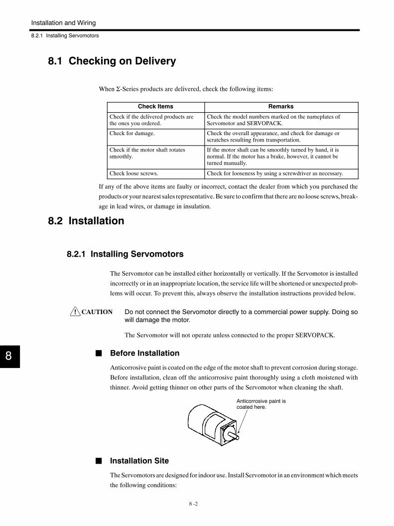
!
Installation and Wiring
8.2.1 Installing Servomotors
8 -2
8.1 Checking on Delivery
When Σ-Series products are delivered, check the following items:
Check Items Remarks
Check if the delivered products arethe ones you ordered.
Check the model numbers marked on the nameplates ofServomotor and SERVOPACK.
Check for damage. Check the overall appearance, and check for damage orscratches resulting from transportation.
Check if the motor shaft rotatessmoothly.
If the motor shaft can be smoothly turned by hand, it isnormal. If the motor has a brake, however, it cannot beturned manually.
Check loose screws. Check for looseness by using a screwdriver as necessary.
If any of the above items are faulty or incorrect, contact the dealer from which you purchased the
products or your nearest sales representative.Be sure to confirm that there are no loose screws, break-
age in lead wires, or damage in insulation.
8.2 Installation
8.2.1 Installing Servomotors
The Servomotor can be installed either horizontally or vertically. If the Servomotor is installed
incorrectly or in an inappropriate location, the service life will be shortened or unexpected prob-
lems will occur. To prevent this, always observe the installation instructions provided below.
CAUTION Do not connect the Servomotor directly to a commercial power supply. Doing sowill damage the motor.
The Servomotor will not operate unless connected to the proper SERVOPACK.
J Before Installation
Anticorrosive paint is coated on the edge of the motor shaft to prevent corrosion during storage.
Before installation, clean off the anticorrosive paint thoroughly using a cloth moistened with
thinner. Avoid getting thinner on other parts of the Servomotor when cleaning the shaft.
Anticorrosive paint iscoated here.
J Installation Site
TheServomotors are designed for indoor use. Install Servomotor in an environmentwhichmeets
the following conditions:
8
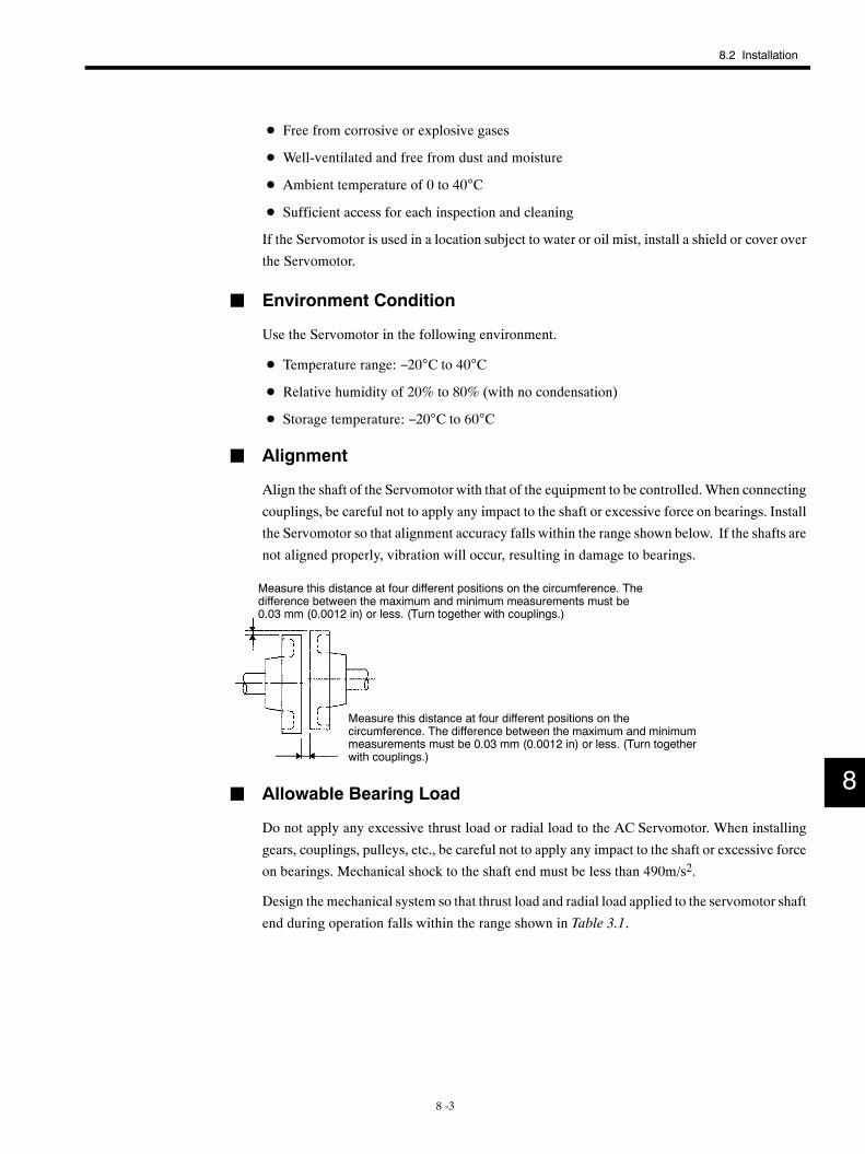
8.2 Installation
8 -3
D Free from corrosive or explosive gases
D Well-ventilated and free from dust and moisture
D Ambient temperature of 0 to 40°C
D Sufficient access for each inspection and cleaning
If the Servomotor is used in a location subject to water or oil mist, install a shield or cover over
the Servomotor.
J Environment Condition
Use the Servomotor in the following environment.
D Temperature range: −20°C to 40°C
D Relative humidity of 20% to 80% (with no condensation)
D Storage temperature: −20°C to 60°C
J Alignment
Align the shaft of the Servomotor with that of the equipment to be controlled. When connecting
couplings, be careful not to apply any impact to the shaft or excessive force on bearings. Install
the Servomotor so that alignment accuracy falls within the range shown below. If the shafts are
not aligned properly, vibration will occur, resulting in damage to bearings.
Measure this distance at four different positions on the circumference. Thedifference between the maximum and minimum measurements must be0.03 mm (0.0012 in) or less. (Turn together with couplings.)
Measure this distance at four different positions on thecircumference. The difference between the maximum and minimummeasurements must be 0.03 mm (0.0012 in) or less. (Turn togetherwith couplings.)
J Allowable Bearing Load
Do not apply any excessive thrust load or radial load to the AC Servomotor. When installing
gears, couplings, pulleys, etc., be careful not to apply any impact to the shaft or excessive force
on bearings. Mechanical shock to the shaft end must be less than 490m/s2.
Design the mechanical system so that thrust load and radial load applied to the servomotor shaft
end during operation falls within the range shown in Table 3.1.
8
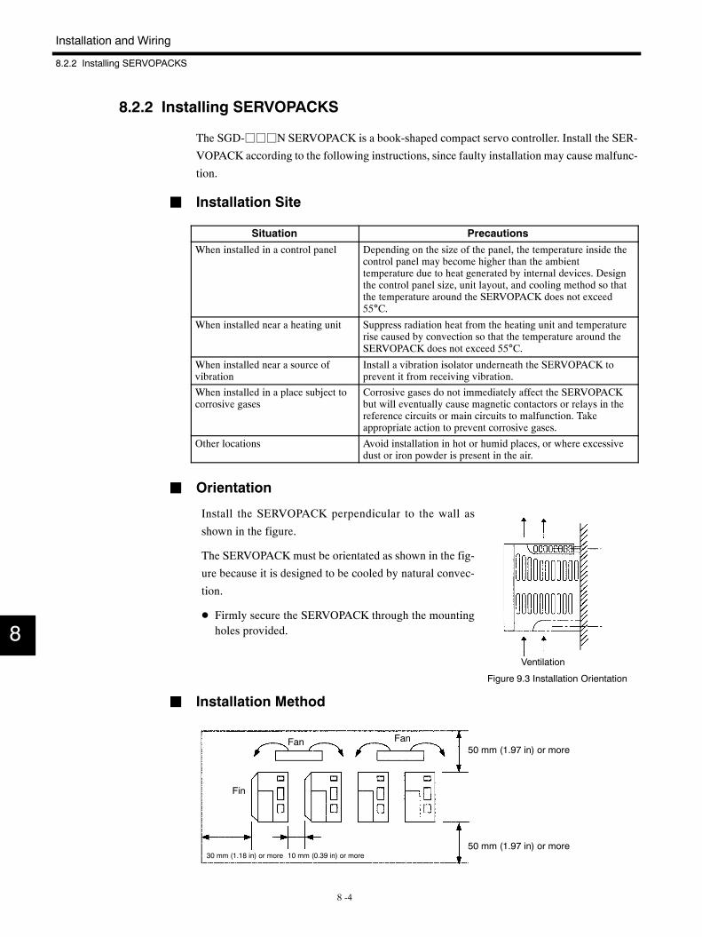
Installation and Wiring
8.2.2 Installing SERVOPACKS
8 -4
8.2.2 Installing SERVOPACKS
The SGD-jjjN SERVOPACK is a book-shaped compact servo controller. Install the SER-
VOPACK according to the following instructions, since faulty installation may cause malfunc-
tion.
J Installation Site
Situation Precautions
When installed in a control panel Depending on the size of the panel, the temperature inside thecontrol panel may become higher than the ambienttemperature due to heat generated by internal devices. Designthe control panel size, unit layout, and cooling method so thatthe temperature around the SERVOPACK does not exceed55°C.
When installed near a heating unit Suppress radiation heat from the heating unit and temperaturerise caused by convection so that the temperature around theSERVOPACK does not exceed 55°C.
When installed near a source ofvibration
Install a vibration isolator underneath the SERVOPACK toprevent it from receiving vibration.
When installed in a place subject tocorrosive gases
Corrosive gases do not immediately affect the SERVOPACKbut will eventually cause magnetic contactors or relays in thereference circuits or main circuits to malfunction. Takeappropriate action to prevent corrosive gases.
Other locations Avoid installation in hot or humid places, or where excessivedust or iron powder is present in the air.
J Orientation
Ventilation
Figure 9.3 Installation Orientation
Install the SERVOPACK perpendicular to the wall as
shown in the figure.
The SERVOPACK must be orientated as shown in the fig-
ure because it is designed to be cooled by natural convec-
tion.
D Firmly secure the SERVOPACK through the mountingholes provided.
J Installation Method
Fan50 mm (1.97 in) or more
Fin
30 mm (1.18 in) or more 10 mm (0.39 in) or more
Fan
50 mm (1.97 in) or more
8
8.2 Installation
8 -5
D Install the SERVOPACK perpendicular to the wall so that the front panel faces outward.
D Provide sufficient space around each SERVOPACK to allow cooling by natural convection.
D When installing SERVOPACKS side by side, install cooling fans above the SERVOPACKSto prevent the temperature around each SERVOPACK from increasing excessively and alsoto maintain an even temperature inside the control panel.
D When installing multiple SERVOPACKS side by side in a control panel, provide at least 10mm (0.39 in) space between them and at least 50 mm (1.97 in) space above and below themas shown in the figure on the buttom of the previous page and observe the following installa-tion conditions:
• Ambient temperature for SERVOPACKS: 0 to 55°C
• Humidity: 90% RH or less
• Vibration: 4.9 m/s2
• Condensation and freezing: None
• Ambient temperature (or in-panel temperature) to ensure long-term reliability: 45°C orless
8
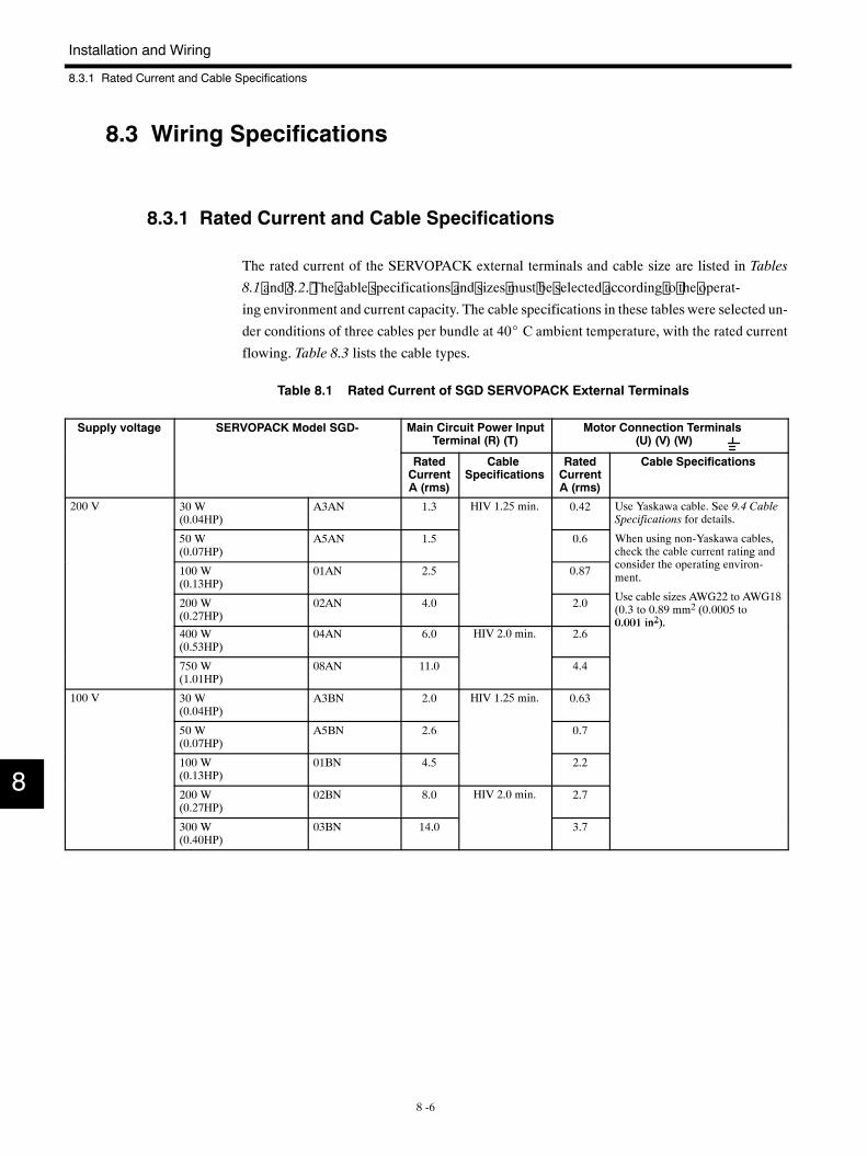
Installation and Wiring
8.3.1 Rated Current and Cable Specifications
8 -6
8.3 Wiring Specifications
8.3.1 Rated Current and Cable Specifications
The rated current of the SERVOPACK external terminals and cable size are listed in Tables
8.1 and 8.2. The cable specifications and sizes must be selected according to the operat-
ing environment and current capacity. The cable specifications in these tables were selected un-
der conditions of three cables per bundle at 40_ C ambient temperature, with the rated current
flowing. Table 8.3 lists the cable types.
Table 8.1 Rated Current of SGD SERVOPACK External Terminals
Supply voltage SERVOPACK Model SGD- Main Circuit Power InputTerminal (R) (T)
Motor Connection Terminals(U) (V) (W)
RatedCurrentA (rms)
CableSpecifications
RatedCurrentA (rms)
Cable Specifications
200 V 30 W(0.04HP)
A3AN 1.3 HIV 1.25 min. 0.42 Use Yaskawa cable. See 9.4 CableSpecifications for details.
50 W(0.07HP)
A5AN 1.5 0.6
p f
When using non-Yaskawa cables,check the cable current rating and
id th ti i100 W(0.13HP)
01AN 2.5 0.87
gconsider the operating environ-ment.
U bl i AWG22 AWG18200 W(0.27HP)
02AN 4.0 2.0 Use cable sizes AWG22 to AWG18(0.3 to 0.89 mm2 (0.0005 to0.001 in2).
400 W(0.53HP)
04AN 6.0 HIV 2.0 min. 2.60.001 in2).
750 W(1.01HP)
08AN 11.0 4.4
100 V 30 W(0.04HP)
A3BN 2.0 HIV 1.25 min. 0.63
50 W(0.07HP)
A5BN 2.6 0.7
100 W(0.13HP)
01BN 4.5 2.2
200 W(0.27HP)
02BN 8.0 HIV 2.0 min. 2.7
300 W(0.40HP)
03BN 14.0 3.7
8
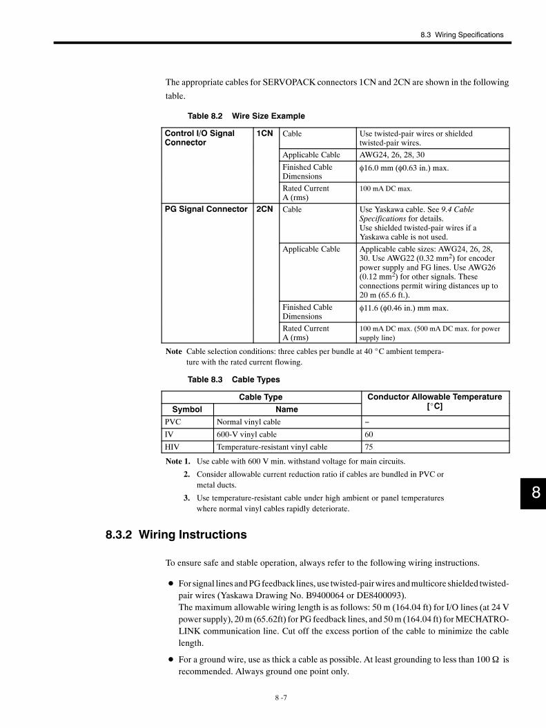
8.3 Wiring Specifications
8 -7
The appropriate cables for SERVOPACK connectors 1CN and 2CN are shown in the following
table.
Table 8.2 Wire Size Example
Control I/O SignalConnector
1CN Cable Use twisted-pair wires or shieldedtwisted-pair wires.Co ec o
Applicable Cable AWG24, 26, 28, 30
Finished CableDimensions
φ16.0 mm (φ0.63 in.) max.
Rated CurrentA (rms)
100 mA DC max.
PG Signal Connector 2CN Cable Use Yaskawa cable. See 9.4 CableSpecifications for details.Use shielded twisted-pair wires if aYaskawa cable is not used.
Applicable Cable Applicable cable sizes: AWG24, 26, 28,30. Use AWG22 (0.32 mm2) for encoderpower supply and FG lines. Use AWG26(0.12 mm2) for other signals. Theseconnections permit wiring distances up to20 m (65.6 ft.).
Finished CableDimensions
φ11.6 (φ0.46 in.) mm max.
Rated CurrentA (rms)
100 mA DC max. (500 mA DC max. for powersupply line)
Note Cable selection conditions: three cables per bundle at 40 _C ambient tempera-ture with the rated current flowing.
Table 8.3 Cable Types
Cable Type Conductor Allowable Temperature[ C]Symbol Name
p[_C]
PVC Normal vinyl cable −
IV 600-V vinyl cable 60
HIV Temperature-resistant vinyl cable 75
Note 1. Use cable with 600 V min. withstand voltage for main circuits.
2. Consider allowable current reduction ratio if cables are bundled in PVC ormetal ducts.
3. Use temperature-resistant cable under high ambient or panel temperatureswhere normal vinyl cables rapidly deteriorate.
8.3.2 Wiring Instructions
To ensure safe and stable operation, always refer to the following wiring instructions.
D For signal lines andPGfeedback lines, use twisted-pairwires andmulticore shielded twisted-pair wires (Yaskawa Drawing No. B9400064 or DE8400093).The maximum allowable wiring length is as follows: 50 m (164.04 ft) for I/O lines (at 24 Vpower supply), 20m (65.62ft) for PG feedback lines, and 50m (164.04 ft) forMECHATRO-LINK communication line. Cut off the excess portion of the cable to minimize the cablelength.
D For a ground wire, use as thick a cable as possible. At least grounding to less than 100Ω isrecommended. Always ground one point only.
8
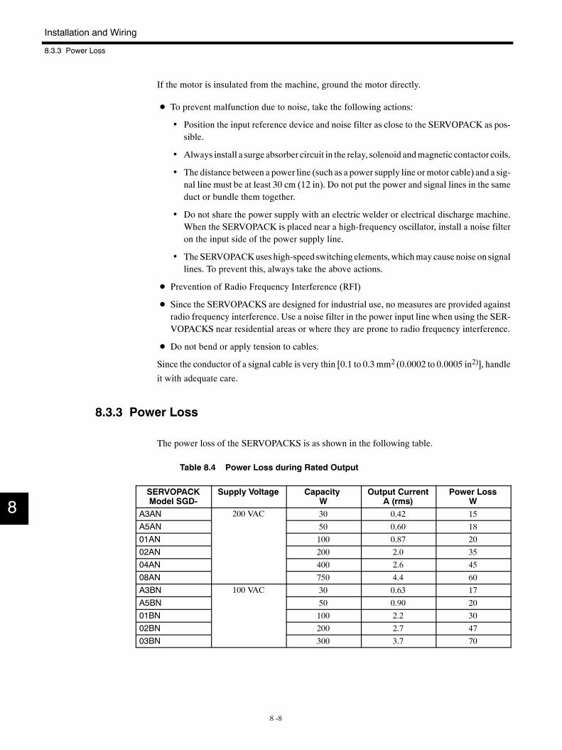
Installation and Wiring
8.3.3 Power Loss
8 -8
If the motor is insulated from the machine, ground the motor directly.
D To prevent malfunction due to noise, take the following actions:
• Position the input reference device and noise filter as close to the SERVOPACK as pos-sible.
• Always install a surge absorber circuit in the relay, solenoid andmagnetic contactor coils.
• The distance between a power line (such as a power supply line ormotor cable) and a sig-nal line must be at least 30 cm (12 in). Do not put the power and signal lines in the sameduct or bundle them together.
• Do not share the power supply with an electric welder or electrical discharge machine.When the SERVOPACK is placed near a high-frequency oscillator, install a noise filteron the input side of the power supply line.
• TheSERVOPACKuses high-speed switching elements,whichmay cause noise on signallines. To prevent this, always take the above actions.
D Prevention of Radio Frequency Interference (RFI)
D Since the SERVOPACKS are designed for industrial use, no measures are provided againstradio frequency interference. Use a noise filter in the power input line when using the SER-VOPACKS near residential areas or where they are prone to radio frequency interference.
D Do not bend or apply tension to cables.
Since the conductor of a signal cable is very thin [0.1 to 0.3 mm2 (0.0002 to 0.0005 in2)], handle
it with adequate care.
8.3.3 Power Loss
The power loss of the SERVOPACKS is as shown in the following table.
Table 8.4 Power Loss during Rated Output
SERVOPACKModel SGD-
Supply Voltage CapacityW
Output CurrentA (rms)
Power LossW
A3AN 200 VAC 30 0.42 15
A5AN 50 0.60 18
01AN 100 0.87 20
02AN 200 2.0 35
04AN 400 2.6 45
08AN 750 4.4 60
A3BN 100 VAC 30 0.63 17
A5BN 50 0.90 20
01BN 100 2.2 30
02BN 200 2.7 47
03BN 300 3.7 70
8
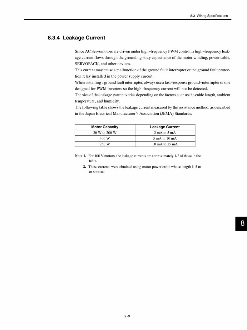
8.3 Wiring Specifications
8 -9
8.3.4 Leakage Current
Since AC Servomotors are driven under high−frequency PWM control, a high−frequency leak-
age current flows through the grounding stray capacitance of the motor winding, power cable,
SERVOPACK, and other devices.
This current may cause a malfunction of the ground fault interrupter or the ground fault protec-
tion relay installed in the power supply curcuit.
When installing a ground fault interrupter, always use a fast−response ground−interrupter or one
designed for PWM inverters so the high−frequency current will not be detected.
The size of the leakage current varies depending on the factors such as the cable length, ambient
temperature, and humidity.
The following table shows the leakage current measured by the resistance method, as described
in the Japan Electrical Manufacturer’s Association (JEMA) Standards.
Motor Capacity Leakage Current
30 W to 200 W 2 mA to 5 mA
400 W 5 mA to 10 mA
750 W 10 mA to 15 mA
Note 1. For 100 Vmotors, the leakage currents are approximately 1/2 of those in thetable.
2. These currents were obtained using motor power cable whose length is 5 mor shorter.
8
9 -1
9Servodrives Dimensional Drawings
This chapter presents dimensional drawings of the Servomotors, SERVO-
PACKS, and peripheral devices.
9.1 Servomotor Dimensional Drawings 9 -2. . . . . . . . . .9.1.1 SGM Servomotors 9 -2. . . . . . . . . . . . . . . . . . . . . . . . . . .
9.1.2 SGMP Servomotors 9 -18. . . . . . . . . . . . . . . . . . . . . . . . .
9.2 SERVOPACK Dimensional Drawings 9 -34. . . . . . . .9.2.1 SGD-A3AN to 02AN, SGD-A3BN to 01BN 9 -34. . . . . .
9.2.2 SGD-04AN, SGD-02BN 9 -35. . . . . . . . . . . . . . . . . . . . .
9.2.3 SGD-08AN, SGD-03BN 9 -36. . . . . . . . . . . . . . . . . . . . .
9.3 Regenerative Resistor Unit DimensionalDrawings 9 -37. . . . . . . . . . . . . . . . . . . . . . . . . . . . . . .
9.4 Cable Specifications 9 -38. . . . . . . . . . . . . . . . . . . . . . .9.4.1 Cables from Yaskawa 9 -38. . . . . . . . . . . . . . . . . . . . . . . .
9.4.2 Cables without SERVOPACK Connectors(PG Cables Only) 9 -40. . . . . . . . . . . . . . . . . . . . . . . . . .
9.4.3 Cables Only 9 -42. . . . . . . . . . . . . . . . . . . . . . . . . . . . . . . .
9.5 Connector Kits 9 -44. . . . . . . . . . . . . . . . . . . . . . . . . . . .9.5.1 Encoder Cable Connectors 9 -44. . . . . . . . . . . . . . . . . . .
9.5.2 Motor Cable Connectors 9 -44. . . . . . . . . . . . . . . . . . . . . .
9.5.3 SERVOPACK Connectors 9 -44. . . . . . . . . . . . . . . . . . . .
9.6 Noise Filters 9 -47. . . . . . . . . . . . . . . . . . . . . . . . . . . . . .9.6.1 Dimensional Diagram 9 -47. . . . . . . . . . . . . . . . . . . . . . . .
9.7 Peripheral Devices 9 -48. . . . . . . . . . . . . . . . . . . . . . . .9.7.1 Connector Terminal Block Converter Unit 9 -48. . . . . . .
9.7.2 Brake Power Supply 9 -48. . . . . . . . . . . . . . . . . . . . . . . . .
9.7.3 Analog Monitor Cables 9 -49. . . . . . . . . . . . . . . . . . . . . . .
9
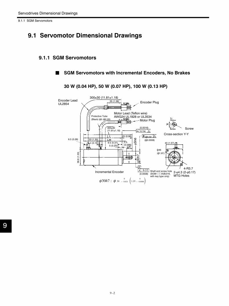
Servodrives Dimensional Drawings
9.1.1 SGM Servomotors
9 -2
9.1 Servomotor Dimensional Drawings
9.1.1 SGM Servomotors
J SGM Servomotors with Incremental Encoders, No Brakes
30 W (0.04 HP), 50 W (0.07 HP), 100 W (0.13 HP)
4-R3.72-φ4.3 (2-φ0.17)MTG Holes
φ46(φ1.81)
Encoder Plug
Motor Plug
Screw
Cross-section Y-Y
Incremental Encoder
Protective Tube(Black) φ5 (φ0.20)
Motor Lead (Teflon wire)AWG24 UL1828 or UL3534
Encoder LeadUL2854
φ0.02
Shaft end screw hole(SGM-jjA(B)316,with key type only)
φSh6
φ30h7
300±30 (11.81±1.18)35 (1.38)
300±30(11.81±1.18)
33 (1.30)6.5 (0.26)
38.8(1.53)
4 (0.16) 9.5 (0.37)5 (0.20)
25 (0.98)
2.5(0.098)
(0.0016)
(φ0.0008)
(0.0008)
φ30h7 : φ 300
− 0.021 1.19 0
− 0.0008
40 (1.57)
9
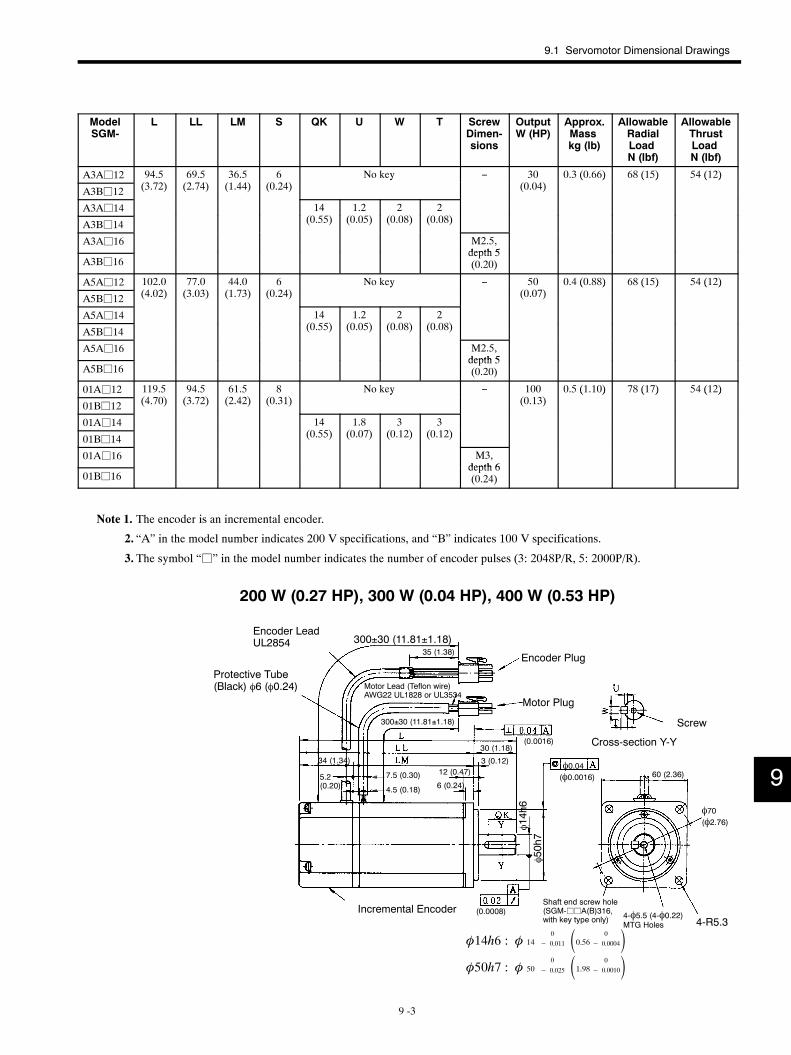
9.1 Servomotor Dimensional Drawings
9 -3
ModelSGM-
L LL LM S QK U W T ScrewDimen-sions
OutputW (HP)
Approx.Masskg (lb)
AllowableRadialLoadN (lbf)
AllowableThrustLoadN (lbf)
A3Aj12 94.5(3 2)
69.5(2 4)
36.5(1 44)
6(0 24)
No key − 30(0 04)
0.3 (0.66) 68 (15) 54 (12)
A3Bj12 (3.72) (2.74) (1.44) (0.24)y
(0.04)( ) ( ) ( )
A3Aj14 14(0 55)
1.2(0 05)
2(0 08)
2(0 08)A3Bj14 (0.55) (0.05) (0.08) (0.08)
A3Aj16 M2.5,depth 5
A3Bj16depth 5(0.20)
A5Aj12 102.0(4 02)
77.0(3 03)
44.0(1 3)
6(0 24)
No key − 50(0 0 )
0.4 (0.88) 68 (15) 54 (12)
A5Bj12 (4.02) (3.03) (1.73) (0.24)y
(0.07)( ) ( ) ( )
A5Aj14 14(0 55)
1.2(0 05)
2(0 08)
2(0 08)A5Bj14 (0.55) (0.05) (0.08) (0.08)
A5Aj16 M2.5,depth 5
A5Bj16depth 5(0.20)
01Aj12 119.5(4 0)
94.5(3 2)
61.5(2 42)
8(0 31)
No key − 100(0 13)
0.5 (1.10) 78 (17) 54 (12)
01Bj12 (4.70) (3.72) (2.42) (0.31)y
(0.13)( ) ( ) ( )
01Aj14 14(0 55)
1.8(0 0 )
3(0 12)
3(0 12)01Bj14 (0.55) (0.07) (0.12) (0.12)
01Aj16 M3,depth 6
01Bj16depth 6(0.24)
Note 1. The encoder is an incremental encoder.
2. “A” in the model number indicates 200 V specifications, and “B” indicates 100 V specifications.
3. The symbol “j” in the model number indicates the number of encoder pulses (3: 2048P/R, 5: 2000P/R).
200 W (0.27 HP), 300 W (0.04 HP), 400 W (0.53 HP)
4-R5.34-φ5.5 (4-φ0.22)MTG Holes
φ70(φ2.76)
Encoder LeadUL2854
Protective Tube(Black) φ6 (φ0.24) Motor Lead (Teflon wire)
AWG22 UL1828 or UL3534
Encoder Plug
Motor Plug
Screw
Cross-section Y-Y
Incremental Encoder
φ0.04
Shaft end screw hole(SGM-jjA(B)316,with key type only)
φ14h6
φ50h7
300±30 (11.81±1.18)35 (1.38)
300±30 (11.81±1.18)
(0.0016)
(0.0008)
(φ0.0016)
34 (1.34)
5.2(0.20)
7.5 (0.30)
4.5 (0.18)
30 (1.18)
3 (0.12)12 (0.47)
6 (0.24)60 (2.36)
φ14h6 : φ 140
− 0.011 0.56 0
− 0.0004φ50h7 : φ 50
0
− 0.025 1.98 0
− 0.0010
9
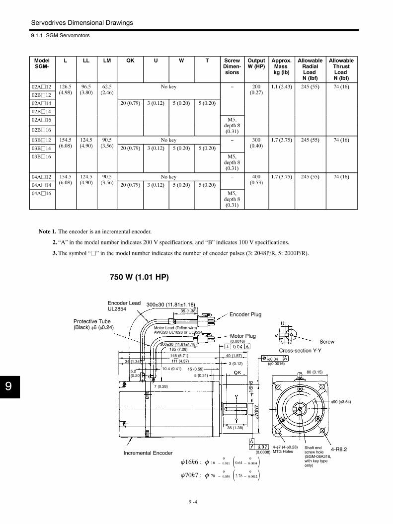
Servodrives Dimensional Drawings
9.1.1 SGM Servomotors
9 -4
ModelSGM-
L LL LM QK U W T ScrewDimen-sions
OutputW (HP)
Approx.Masskg (lb)
AllowableRadialLoadN (lbf)
AllowableThrustLoadN (lbf)
02Aj12 126.5(4 98)
96.5(3 80)
62.5(2 46)
No key − 200(0 2 )
1.1 (2.43) 245 (55) 74 (16)
02Bj12 (4.98) (3.80) (2.46)y
(0.27)( ) ( ) ( )
02Aj14 20 (0.79) 3 (0.12) 5 (0.20) 5 (0.20)
02Bj14
( ) ( ) ( ) ( )
02Aj16 M5,depth 8
02Bj16depth 8(0.31)
03Bj12 154.5(6 08)
124.5(4 90)
90.5(3 56)
No key − 300(0 40)
1.7 (3.75) 245 (55) 74 (16)
03Bj14 (6.08) (4.90) (3.56) 20 (0.79) 3 (0.12) 5 (0.20) 5 (0.20) (0.40)( ) ( ) ( )
03Bj16
( ) ( ) ( ) ( )
M5,depth 8(0.31)
04Aj12 154.5(6 08)
124.5(4 90)
90.5(3 56)
No key − 400(0 53)
1.7 (3.75) 245 (55) 74 (16)
04Aj14 (6.08) (4.90) (3.56) 20 (0.79) 3 (0.12) 5 (0.20) 5 (0.20) (0.53)( ) ( ) ( )
04Aj16
( ) ( ) ( ) ( )
M5,depth 8(0.31)
Note 1. The encoder is an incremental encoder.
2. “A” in the model number indicates 200 V specifications, and “B” indicates 100 V specifications.
3. The symbol “j” in the model number indicates the number of encoder pulses (3: 2048P/R, 5: 2000P/R).
750 W (1.01 HP)
4-R8.24-φ7 (4-φ0.28)MTG Holes
φ90 (φ3.54)
Incremental Encoder
Protective Tube(Black) φ6 (φ0.24)
Encoder LeadUL2854
Encoder Plug
Motor PlugScrew
Cross-section Y-Y
Motor Lead (Teflon wire)AWG20 UL1828 or UL3534
φ0.04
Shaft endscrew hole(SGM-08A316,with key typeonly)
φ16h6
φ70h7
300±30 (11.81±1.18)35 (1.38)
(0.0008)
(φ0.0016)34 (1.34)
5.2(0.20)
300±30 (11.81±1.18)(0.0016)
185 (7.28)
145 (5.71)111 (4.37)
10.4 (0.41)
7 (0.28)
15 (0.59)
8 (0.31)
3 (0.12)
40 (1.57)
80 (3.15)
35 (1.38)
φ16h6 : φ 160
− 0.011 0.64 0
− 0.0004φ70h7 : φ 70
0
− 0.030 2.78 0
− 0.0012
9
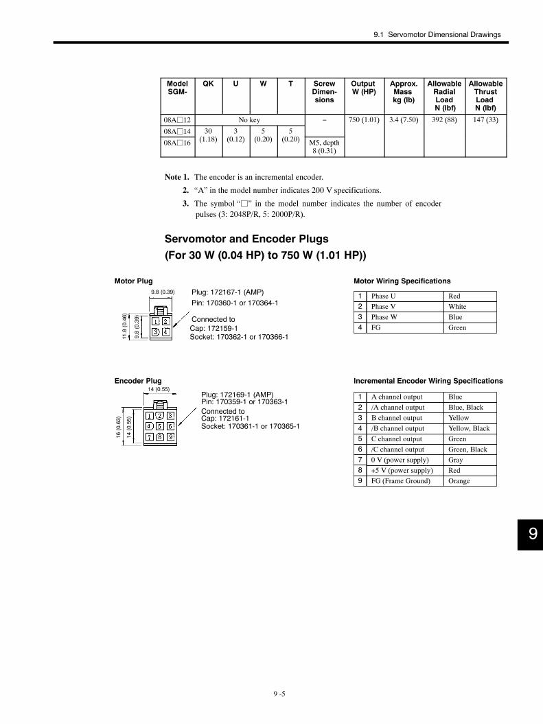
9.1 Servomotor Dimensional Drawings
9 -5
ModelSGM-
QK U W T ScrewDimen-sions
OutputW (HP)
Approx.Masskg (lb)
AllowableRadialLoadN (lbf)
AllowableThrustLoadN (lbf)
08Aj12 No key − 750 (1.01) 3.4 (7.50) 392 (88) 147 (33)
08Aj14 30(1 18)
3(0 12)
5(0 20)
5(0 20)
( ) ( ) ( ) ( )
08Aj16 (1.18) (0.12) (0.20) (0.20) M5, depth8 (0.31)
Note 1. The encoder is an incremental encoder.
2. “A” in the model number indicates 200 V specifications.
3. The symbol “j” in the model number indicates the number of encoderpulses (3: 2048P/R, 5: 2000P/R).
Servomotor and Encoder Plugs(For 30 W (0.04 HP) to 750 W (1.01 HP))
/C channel output
Phase U RedPhase V WhitePhase W BlueFG Green
Motor Wiring Specifications
Incremental Encoder Wiring Specifications
A channel output Blue/A channel output Blue, BlackB channel output Yellow/B channel output Yellow, Black
GreenGreen, BlackGrayRed
FG (Frame Ground) Orange
1234
123456789
C channel output
+5 V (power supply)0 V (power supply)
Pin: 170360-1 or 170364-1Plug: 172167-1 (AMP)
Motor Plug
Cap: 172159-1Connected to
Plug: 172169-1 (AMP)Pin: 170359-1 or 170363-1Connected toCap: 172161-1Socket: 170361-1 or 170365-1
Encoder Plug
Socket: 170362-1 or 170366-1
9.8 (0.39)
9.8(0.39)
11.8(0.46)
14 (0.55)
14(0.55)
16(0.63)
9
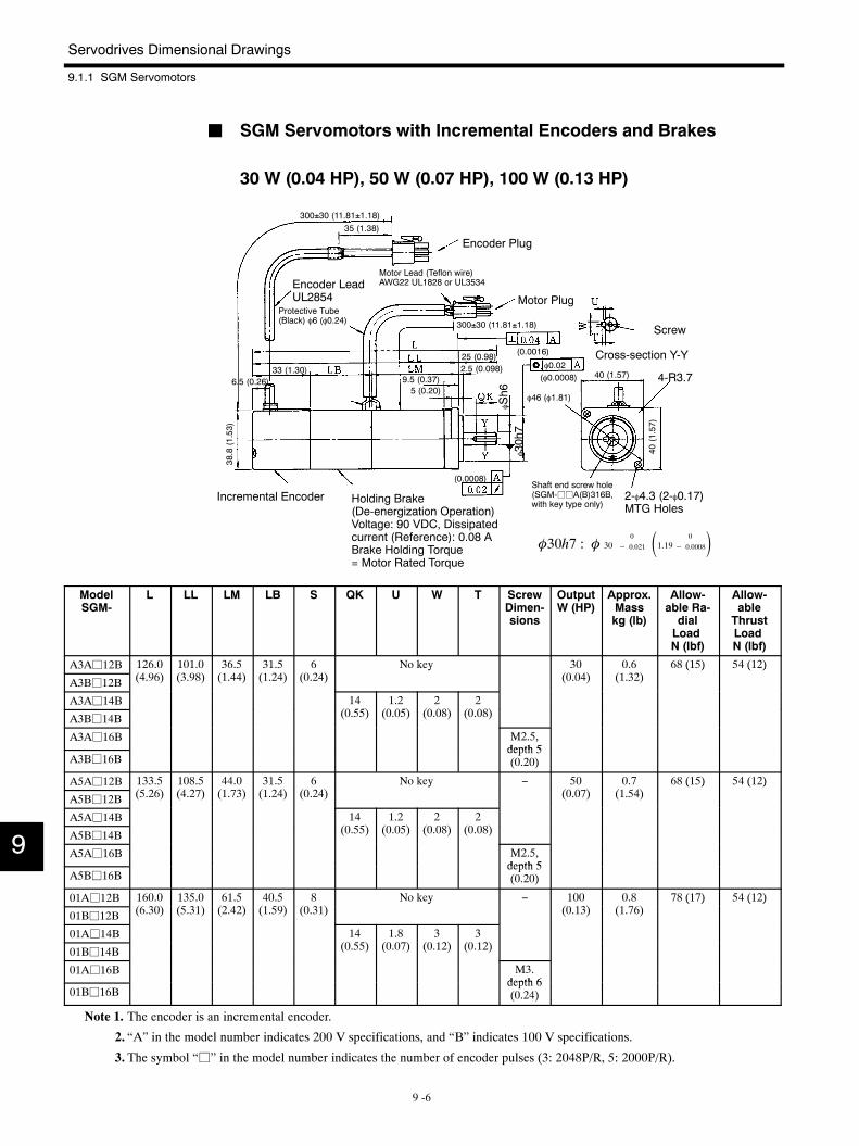
Servodrives Dimensional Drawings
9.1.1 SGM Servomotors
9 -6
J SGM Servomotors with Incremental Encoders and Brakes
30 W (0.04 HP), 50 W (0.07 HP), 100 W (0.13 HP)
4-R3.7
φ46 (φ1.81)
Encoder Plug
Encoder LeadUL2854
Motor Lead (Teflon wire)AWG22 UL1828 or UL3534
Motor Plug
Screw
Cross-section Y-Y
2-φ4.3 (2-φ0.17)MTG Holes
Incremental Encoder Holding Brake(De-energization Operation)Voltage: 90 VDC, Dissipatedcurrent (Reference): 0.08 ABrake Holding Torque= Motor Rated Torque
Protective Tube(Black) φ6 (φ0.24)
φ0.02
Shaft end screw hole(SGM-jjA(B)316B,with key type only)
φSh6
φ30h7
(0.0008)
(0.0016)
300±30 (11.81±1.18)
(φ0.0008)
300±30 (11.81±1.18)
35 (1.38)
6.5 (0.26)33 (1.30)
38.8(1.53)
9.5 (0.37)5 (0.20)
25 (0.98)2.5 (0.098)
40 (1.57)
40(1.57)
φ30h7 : φ 300
− 0.021 1.19 0
− 0.0008
ModelSGM-
L LL LM LB S QK U W T ScrewDimen-sions
OutputW (HP)
Approx.Masskg (lb)
Allow-able Ra-dialLoadN (lbf)
Allow-ableThrustLoadN (lbf)
A3Aj12B 126.0(4 96)
101.0(3 98)
36.5(1 44)
31.5(1 24)
6(0 24)
No key 30(0 04)
0.6(1 32)
68 (15) 54 (12)
A3Bj12B (4.96) (3.98) (1.44) (1.24) (0.24)y
(0.04) (1.32)( ) ( )
A3Aj14B 14(0 55)
1.2(0 05)
2(0 08)
2(0 08)A3Bj14B (0.55) (0.05) (0.08) (0.08)
A3Aj16B M2.5,depth 5
A3Bj16Bdepth 5(0.20)
A5Aj12B 133.5(5 26)
108.5(4 2 )
44.0(1 3)
31.5(1 24)
6(0 24)
No key − 50(0 0 )
0.7(1 54)
68 (15) 54 (12)
A5Bj12B (5.26) (4.27) (1.73) (1.24) (0.24)y
(0.07) (1.54)( ) ( )
A5Aj14B 14(0 55)
1.2(0 05)
2(0 08)
2(0 08)A5Bj14B (0.55) (0.05) (0.08) (0.08)
A5Aj16B M2.5,depth 5
A5Bj16Bdepth 5(0.20)
01Aj12B 160.0(6 30)
135.0(5 31)
61.5(2 42)
40.5(1 59)
8(0 31)
No key − 100(0 13)
0.8(1 6)
78 (17) 54 (12)
01Bj12B (6.30) (5.31) (2.42) (1.59) (0.31)y
(0.13) (1.76)( ) ( )
01Aj14B 14(0 55)
1.8(0 0 )
3(0 12)
3(0 12)01Bj14B (0.55) (0.07) (0.12) (0.12)
01Aj16B M3.depth 6
01Bj16Bdepth 6(0.24)
Note 1. The encoder is an incremental encoder.
2. “A” in the model number indicates 200 V specifications, and “B” indicates 100 V specifications.
3. The symbol “j” in the model number indicates the number of encoder pulses (3: 2048P/R, 5: 2000P/R).
9
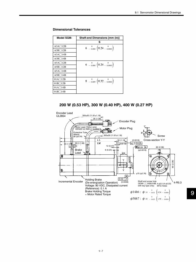
9.1 Servomotor Dimensional Drawings
9 -7
Dimensional Tolerances
Model SGM- Shaft-end Dimensions [mm (in)]
S
A3Aj12B6
0 0 24 0 A3Bj12B
6 − 0.008 0.24− 0.0003A3Aj14B
A3Bj14B
A5Aj12B6
0 0 24 0 A5Bj12B
6 − 0.008 0.24− 0.0003A5Aj14B
A5Bj14B
01Aj12B8
0 0 32 0 01Bj12B
8 − 0.009 0.32− 0.000401Aj14B
01Bj14B
200 W (0.53 HP), 300 W (0.40 HP), 400 W (0.27 HP)
4-R5.3
φ70 (φ2.76)
Encoder Plug
Motor Plug
Screw
Cross-section Y-Y
Protective Tube(Black)φ6 (φ0.24)
Encoder LeadUL2854
Motor Lead (Teflon wire)AWG22 UL1828 or UL3534
BrakeLead
Incremental EncoderHolding Brake(De-energization Operation)Voltage: 90 VDC, Dissipated current(Reference): 0.1 ABrake Holding Torque= Motor Rated Torque
4-φ5.5 (4-φ0.22)MTG Holes
φ0.04
Shaft end screw hole(SGM-jjA(B)316B,with key type only)
φ14h6
φ50h7
(0.0016)
300±30 (11.81±1.18)
(0.0008)
(φ0.0016)
35 (1.38)
300±30 (11.81±1.18)
39.5 (1.56)34 (1.34)5.2 (0.20)
30 (1.18)
3 (0.12)12 (0.47)
6 (0.24)60 (2.36)
60(2.36)
φ50h7 : φ 500
− 0.025 1.98 0
− 0.0010φ14h6 : φ 14
0
− 0.011 0.56 0
− 0.0004 9
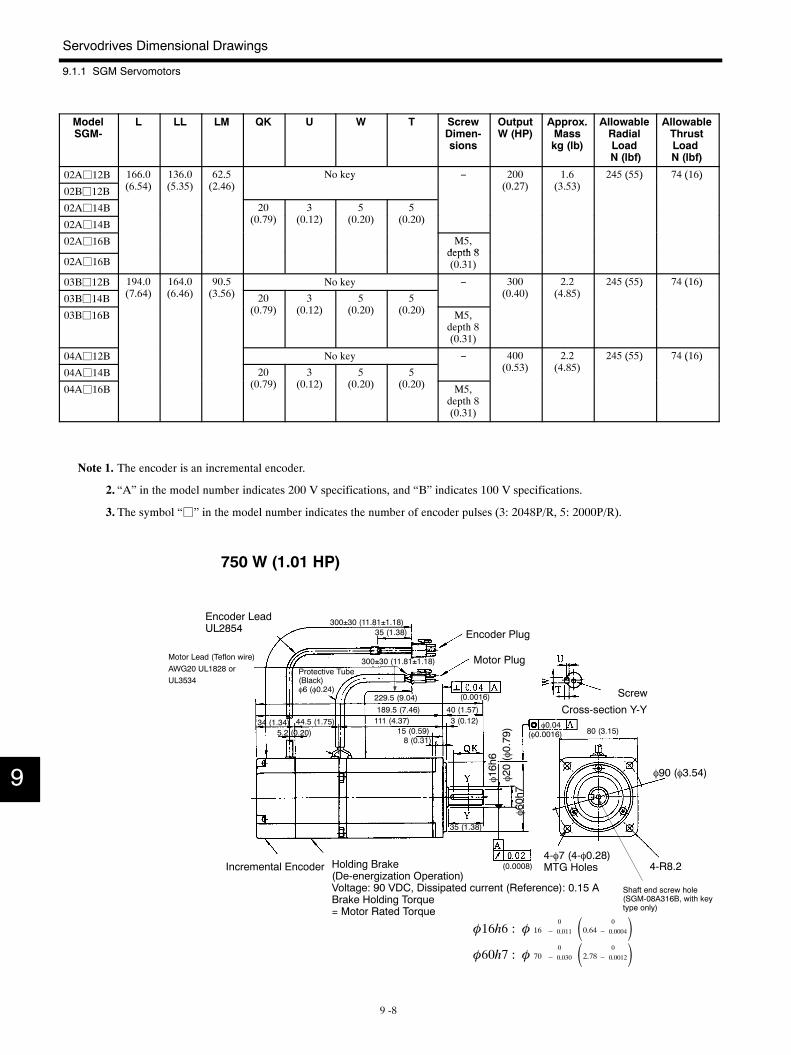
Servodrives Dimensional Drawings
9.1.1 SGM Servomotors
9 -8
ModelSGM-
L LL LM QK U W T ScrewDimen-sions
OutputW (HP)
Approx.Masskg (lb)
AllowableRadialLoadN (lbf)
AllowableThrustLoadN (lbf)
02Aj12B 166.0(6 54)
136.0(5 35)
62.5(2 46)
No key − 200(0 2 )
1.6(3 53)
245 (55) 74 (16)
02Bj12B (6.54) (5.35) (2.46)y
(0.27) (3.53)( ) ( )
02Aj14B 20(0 9)
3(0 12)
5(0 20)
5(0 20)02Aj14B (0.79) (0.12) (0.20) (0.20)
02Aj16B M5,depth 8
02Aj16Bdepth 8(0.31)
03Bj12B 194.0( 64)
164.0(6 46)
90.5(3 56)
No key − 300(0 40)
2.2(4 85)
245 (55) 74 (16)
03Bj14B (7.64) (6.46) (3.56) 20(0 9)
3(0 12)
5(0 20)
5(0 20)
(0.40) (4.85)( ) ( )
03Bj16B (0.79) (0.12) (0.20) (0.20) M5,depth 8(0.31)
04Aj12B No key − 400(0 53)
2.2(4 85)
245 (55) 74 (16)
04Aj14B 20(0 9)
3(0 12)
5(0 20)
5(0 20)
(0.53) (4.85)( ) ( )
04Aj16B (0.79) (0.12) (0.20) (0.20) M5,depth 8(0.31)
Note 1. The encoder is an incremental encoder.
2. “A” in the model number indicates 200 V specifications, and “B” indicates 100 V specifications.
3. The symbol “j” in the model number indicates the number of encoder pulses (3: 2048P/R, 5: 2000P/R).
750 W (1.01 HP)
φ90 (φ3.54)
4-R8.2
Encoder LeadUL2854
Motor Lead (Teflon wire)AWG20 UL1828 orUL3534
Protective Tube(Black)φ6 (φ0.24)
Encoder Plug
Motor Plug
Screw
Cross-section Y-Y
4-φ7 (4-φ0.28)MTG HolesIncremental Encoder Holding Brake
(De-energization Operation)Voltage: 90 VDC, Dissipated current (Reference): 0.15 ABrake Holding Torque= Motor Rated Torque
φ0.04
Shaft end screw hole(SGM-08A316B, with keytype only)
φ16h6
φ20(φ0.79)
φ60h7
300±30 (11.81±1.18)
(0.0008)
(φ0.0016)
(0.0016)
35 (1.38)
300±30 (11.81±1.18)
229.5 (9.04)189.5 (7.46)111 (4.37)34 (1.34)
5.2 (0.20)44.5 (1.75)
40 (1.57)3 (0.12)
15 (0.59)8 (0.31)
35 (1.38)
80 (3.15)
φ16h6 : φ 160
− 0.011 0.64 0
− 0.0004φ60h7 : φ 70
0
− 0.030 2.78 0
− 0.0012
9
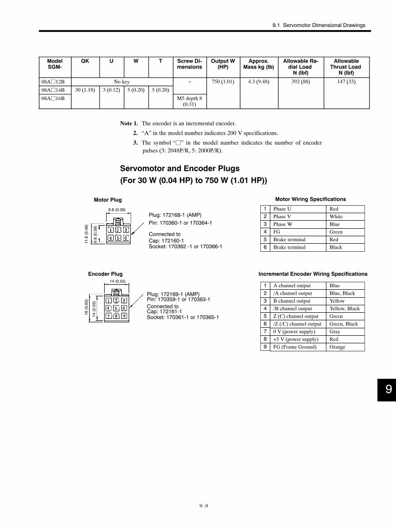
9.1 Servomotor Dimensional Drawings
9 -9
ModelSGM-
QK U W T Screw Di-mensions
Output W(HP)
Approx.Mass kg (lb)
Allowable Ra-dial LoadN (lbf)
AllowableThrust Load
N (lbf)
08Aj12B No key − 750 (1.01) 4.3 (9.48) 392 (88) 147 (33)
08Aj14B 30 (1.18) 3 (0.12) 5 (0.20) 5 (0.20)
( ) ( ) ( ) ( )
08Aj16B
( ) ( ) ( ) ( )
M5 depth 8(0.31)
Note 1. The encoder is an incremental encoder.
2. “A” in the model number indicates 200 V specifications.
3. The symbol “j” in the model number indicates the number of encoderpulses (3: 2048P/R, 5: 2000P/R).
Servomotor and Encoder Plugs(For 30 W (0.04 HP) to 750 W (1.01 HP))
/Z (/C) channel output
Phase U RedPhase V WhitePhase W BlueFG Green
Incremental Encoder Wiring Specifications
A channel output Blue/A channel output Blue, BlackB channel output Yellow/B channel output Yellow, Black
GreenGreen, BlackGrayRed
FG (Frame Ground) Orange
1234
123456789
Z (C) channel output
+5 V (power supply)0 V (power supply)
Motor Wiring Specifications
Brake terminal Red5Brake terminal Black6Socket: 170362 -1 or 170366-1
Motor Plug
Pin: 170360-1 or 170364-1
Cap: 172160-1
Plug: 172168-1 (AMP)
Connected to
Encoder Plug
Plug: 172169-1 (AMP)Pin: 170359-1 or 170363-1Connected toCap: 172161-1Socket: 170361-1 or 170365-1
9.8 (0.39)
9.8(0.39)
11.8(0.46)
14 (0.55)
14(0.55)
16(0.63)
9
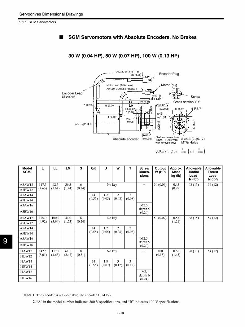
Servodrives Dimensional Drawings
9.1.1 SGM Servomotors
9 -10
J SGM Servomotors with Absolute Encoders, No Brakes
30 W (0.04 HP), 50 W (0.07 HP), 100 W (0.13 HP)
φ46(φ1.81)
4-R3.7
φ53 (φ2.09)
Encoder LeadUL20276
Motor Lead (Teflon wire)AWG24 UL1828 or UL3534
Encoder Plug
Motor Plug
Screw
Cross-section Y-Y
2-φ4.3 (2-φ0.17)MTG Holes
Absolute encoder
φ0.02
Shaft end screw hole(SGM-jjA(B)W16,with key type only)
φSh6
φ30h7
300±30 (11.81±1.18)
(0.0008)
(0.0016)
(φ0.0008)
35 (1.38)
56 (2.20)7 (0.28)
9.5 (0.37)
4 (0.16)
5 (0.20)
25 (0.98)
2.5(0.098)
40 (1.57)
40(1.57)
φ30h7 : φ 300
− 0.021 1.19 0
− 0.0008
ModelSGM-
L LL LM S QK U W T ScrewDimen-sions
OutputW (HP)
Approx.Masskg (lb)
AllowableRadialLoadN (lbf)
AllowableThrustLoadN (lbf)
A3AW12 117.5(4 63)
92.5(3 64)
36.5(1 44)
6(0 24)
No key − 30 (0.04) 0.45(0 99)
68 (15) 54 (12)
A3BW12 (4.63) (3.64) (1.44) (0.24)y ( )
(0.99)( ) ( )
A3AW14 14(0 55)
1.2(0 05)
2(0 08)
2(0 08)A3BW14 (0.55) (0.05) (0.08) (0.08)
A3AW16 M2.5,depth 5
A3BW16depth 5(0.20)
A5AW12 125.0(4 92)
100.0(3 94)
44.0(1 73)
6(0 24)
No key − 50 (0.07) 0.55(1 21)
68 (15) 54 (12)
A5BW12 (4.92) (3.94) (1.73) (0.24)y ( )
(1.21)( ) ( )
A5AW14 14(0 55)
1.2(0 05)
2(0 08)
2(0 08)A5BW14 (0.55) (0.05) (0.08) (0.08)
A5AW16 M2.5,depth 5
A5BW16depth 5(0.20)
01AW12 142.5(5 61)
117.5(4 63)
61.5(2 42)
8(0 31)
No key − 100(0 13)
0.65(1 43)
78 (17) 54 (12)
01BW12 (5.61) (4.63) (2.42) (0.31)y
(0.13) (1.43)( ) ( )
01AW14 14(0 55)
1.8(0 07)
3(0 12)
3(0 12)01BW14 (0.55) (0.07) (0.12) (0.12)
01AW16 M3,depth 6
01BW16depth 6(0.24)
Note 1. The encoder is a 12-bit absolute encoder 1024 P/R.
2. “A” in the model number indicates 200 V-specifications, and “B” indicates 100 V-specifications.
9
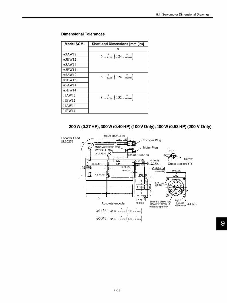
9.1 Servomotor Dimensional Drawings
9 -11
Dimensional Tolerances
Model SGM- Shaft-end Dimensions [mm (in)]
SA3AW12
600 008 0 24 0
0 0003A3BW12
6 − 0.008 0.24− 0.0003A3AW14A3BW14A5AW12
600 008 0 24 0
0 0003A5BW12
6 − 0.008 0.24− 0.0003A5AW14A5BW1401AW12
800 009 0 32 0
0 000401BW12
8 − 0.009 0.32− 0.000401AW1401BW14
200W (0.27HP), 300W (0.40HP) (100VOnly), 400W (0.53HP) (200 V Only)
4-R5.3
φ70(φ2.76)
Screw
Cross-section Y-Y
Encoder Plug
Motor Plug
Encoder LeadUL20276
Motor Lead (Teflon wire)AWG24 UL1828or UL3534
Absolute encoder4-φ5.5(4-φ0.22)MTG Holes
φ0.04
Shaft end screw hole(SGM-jjA(B)W16,with key type only)
φ14h6
φ50h7
300±30 (11.81±1.18)
(0.0016)
(0.0008)
(φ0.0016)
300±30 (11.81±1.18)
35 (1.38)
8.5 (0.33)
7.5 (0.30)
12 (0.47)
6 (0.24)
30 (1.18)
3 (0.12)
60 (2.36)
φ14h6 : φ 140
− 0.011 0.56 0
− 0.0004φ50h7 : φ 50
0
− 0.025 1.98 0
− 0.0010
55 (2.17)
9
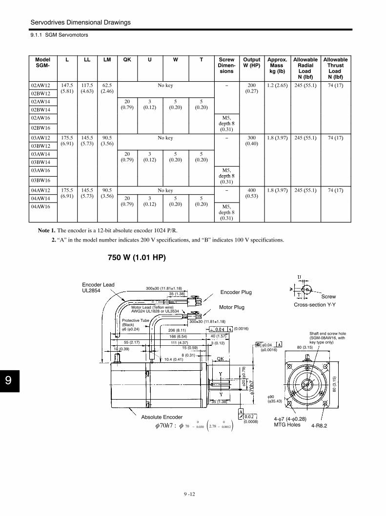
Servodrives Dimensional Drawings
9.1.1 SGM Servomotors
9 -12
ModelSGM-
L LL LM QK U W T ScrewDimen-sions
OutputW (HP)
Approx.Masskg (lb)
AllowableRadialLoadN (lbf)
AllowableThrustLoadN (lbf)
02AW12 147.5(5 81)
117.5(4 63)
62.5(2 46)
No key − 200(0 2 )
1.2 (2.65) 245 (55.1) 74 (17)
02BW12 (5.81) (4.63) (2.46)y
(0.27)( ) ( ) ( )
02AW14 20(0 9)
3(0 12)
5(0 20)
5(0 20)02BW14 (0.79) (0.12) (0.20) (0.20)
02AW16 M5,depth 8
02BW16depth 8(0.31)
03AW12 175.5(6 91)
145.5(5 3)
90.5(3 56)
No key − 300(0 40)
1.8 (3.97) 245 (55.1) 74 (17)
03BW12 (6.91) (5.73) (3.56)y
(0.40)( ) ( ) ( )
03AW14 20(0 9)
3(0 12)
5(0 20)
5(0 20)03BW14 (0.79) (0.12) (0.20) (0.20)
03AW16 M5,depth 8
03BW16depth 8(0.31)
04AW12 175.5(6 91)
145.5(5 3)
90.5(3 56)
No key − 400(0 53)
1.8 (3.97) 245 (55.1) 74 (17)
04AW14 (6.91) (5.73) (3.56) 20(0 9)
3(0 12)
5(0 20)
5(0 20)
(0.53)( ) ( ) ( )
04AW16 (0.79) (0.12) (0.20) (0.20) M5,depth 8(0.31)
Note 1. The encoder is a 12-bit absolute encoder 1024 P/R.
2. “A” in the model number indicates 200 V specifications, and “B” indicates 100 V specifications.
750 W (1.01 HP)
4-R8.2
φ90(φ35.43)
Encoder LeadUL2854
Motor Lead (Teflon wire)AWG24 UL1828 or UL3534
Protective Tube(Black)φ6 (φ0.24)
Motor Plug
Encoder Plug
Absolute Encoder 4-φ7 (4-φ0.28)MTG Holes
Screw
Cross-section Y-Y
φ0.04
Shaft end screw hole(SGM-08AW16, withkey type only)
φ20(φ0.79)
φ70h7
300±30 (11.81±1.18)
(0.0008)
(φ0.0016)
(0.0016)
35 (1.38)
300±30 (11.81±1.18)
206 (8.11)
166 (6.54)
111 (4.37)55 (2.17)
10 (0.39)
10.4 (0.41)
15 (0.59)
8 (0.31)
40 (1.57)
3 (0.12)
35 (1.38)
80 (3.15)
80(3.15)
φ70h7 : φ 700
− 0.030 2.78 0
− 0.0012
9
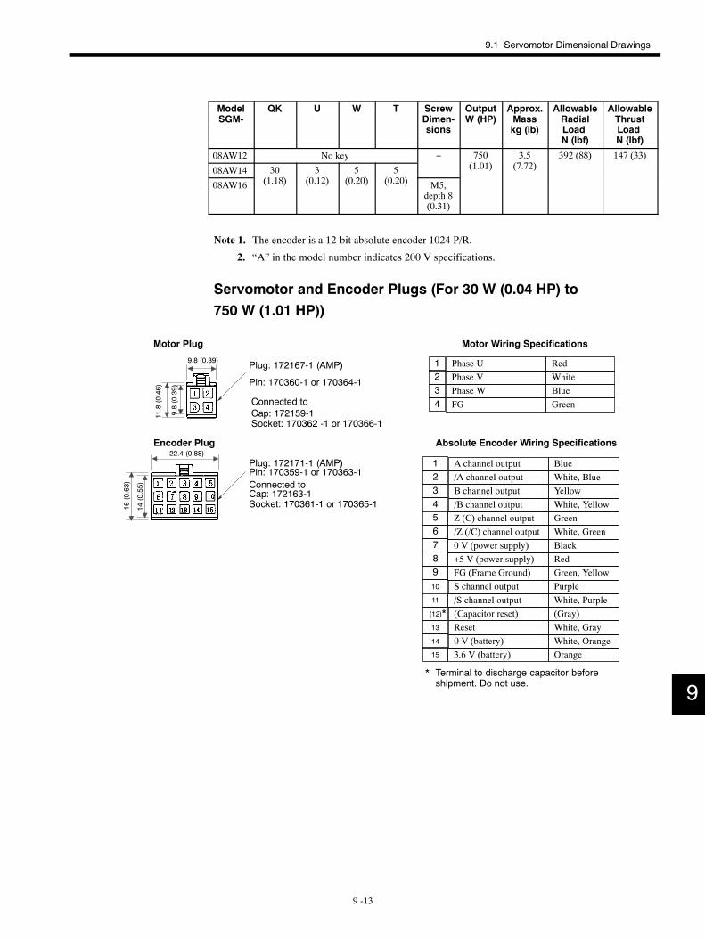
9.1 Servomotor Dimensional Drawings
9 -13
ModelSGM-
QK U W T ScrewDimen-sions
OutputW (HP)
Approx.Masskg (lb)
AllowableRadialLoadN (lbf)
AllowableThrustLoadN (lbf)
08AW12 No key − 750(1 01)
3.5( 2)
392 (88) 147 (33)
08AW14 30(1 18)
3(0 12)
5(0 20)
5(0 20)
(1.01) (7.72)( ) ( )
08AW16 (1.18) (0.12) (0.20) (0.20) M5,depth 8(0.31)
Note 1. The encoder is a 12-bit absolute encoder 1024 P/R.
2. “A” in the model number indicates 200 V specifications.
Servomotor and Encoder Plugs (For 30 W (0.04 HP) to750 W (1.01 HP))
/Z (/C) channel output
Phase U RedPhase V WhitePhase W BlueFG Green
Motor Wiring Specifications
Absolute Encoder Wiring Specifications
A channel output Blue/A channel output White, BlueB channel output Yellow/B channel output White, Yellow
GreenWhite, GreenBlackRed
FG (Frame Ground) Green, Yellow
1234
123456789
Z (C) channel output
+5 V (power supply)0 V (power supply)
/S channel outputS channel output Purple
(Capacitor reset) (Gray)Reset White, Gray0 V (battery) White, Orange
Orange
White, Purple10
(12)*13
14
15
11
3.6 V (battery)
* Terminal to discharge capacitor beforeshipment. Do not use.
Socket: 170362 -1 or 170366-1
Motor Plug
Cap: 172159-1
Plug: 172167-1 (AMP)
Connected to
Encoder Plug
Plug: 172171-1 (AMP)Pin: 170359-1 or 170363-1Connected toCap: 172163-1Socket: 170361-1 or 170365-1
Pin: 170360-1 or 170364-1
9.8 (0.39)
9.8(0.39)
11.8(0.46)
14(0.55)
16(0.63)
22.4 (0.88)
9
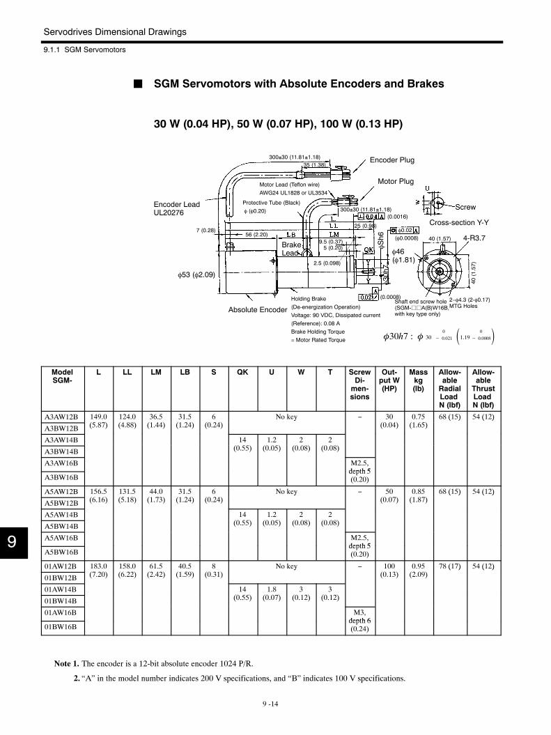
Servodrives Dimensional Drawings
9.1.1 SGM Servomotors
9 -14
J SGM Servomotors with Absolute Encoders and Brakes
30 W (0.04 HP), 50 W (0.07 HP), 100 W (0.13 HP)
φ46(φ1.81)
4-R3.7
φ53 (φ2.09)
Encoder LeadUL20276
Motor Lead (Teflon wire)AWG24 UL1828 or UL3534
Protective Tube (Black)φ (φ0.20)
Encoder Plug
Motor Plug
Screw
Cross-section Y-Y
2−φ4.3 (2-φ0.17)MTG Holes
BrakeLead
Absolute Encoder
Holding Brake(De-energization Operation)Voltage: 90 VDC, Dissipated current(Reference): 0.08 ABrake Holding Torque= Motor Rated Torque
φ0.02
Shaft end screw hole(SGM-jjA(B)W16B,with key type only)
φSh6
φ30h7
300±30 (11.81±1.18)
(0.0008)
(0.0016)
(φ0.0008)
35 (1.38)
300±30 (11.81±1.18)
7 (0.28)56 (2.20)
25 (0.98)
2.5 (0.098)
9.5 (0.37)5 (0.20)
40 (1.57)
φ30h7 : φ 300
− 0.021 1.19 0
− 0.0008
40(1.57)
ModelSGM-
L LL LM LB S QK U W T ScrewDi-men-sions
Out-put W(HP)
Masskg(lb)
Allow-ableRadialLoadN (lbf)
Allow-ableThrustLoadN (lbf)
A3AW12B 149.0(5 8 )
124.0(4 88)
36.5(1 44)
31.5(1 24)
6(0 24)
No key − 30(0 04)
0.75(1 65)
68 (15) 54 (12)
A3BW12B (5.87) (4.88) (1.44) (1.24) (0.24)y
(0.04) (1.65)( ) ( )
A3AW14B 14(0 55)
1.2(0 05)
2(0 08)
2(0 08)A3BW14B (0.55) (0.05) (0.08) (0.08)
A3AW16B M2.5,depth 5
A3BW16Bdepth 5(0.20)
A5AW12B 156.5(6 16)
131.5(5 18)
44.0(1 3)
31.5(1 24)
6(0 24)
No key − 50(0 0 )
0.85(1 8 )
68 (15) 54 (12)
A5BW12B (6.16) (5.18) (1.73) (1.24) (0.24)y
(0.07) (1.87)( ) ( )
A5AW14B 14(0 55)
1.2(0 05)
2(0 08)
2(0 08)A5BW14B (0.55) (0.05) (0.08) (0.08)
A5AW16B M2.5,depth 5
A5BW16Bdepth 5(0.20)
01AW12B 183.0( 20)
158.0(6 22)
61.5(2 42)
40.5(1 59)
8(0 31)
No key − 100(0 13)
0.95(2 09)
78 (17) 54 (12)
01BW12B (7.20) (6.22) (2.42) (1.59) (0.31)y
(0.13) (2.09)( ) ( )
01AW14B 14(0 55)
1.8(0 0 )
3(0 12)
3(0 12)01BW14B (0.55) (0.07) (0.12) (0.12)
01AW16B M3,depth 6
01BW16Bdepth 6(0.24)
Note 1. The encoder is a 12-bit absolute encoder 1024 P/R.
2. “A” in the model number indicates 200 V specifications, and “B” indicates 100 V specifications.
9
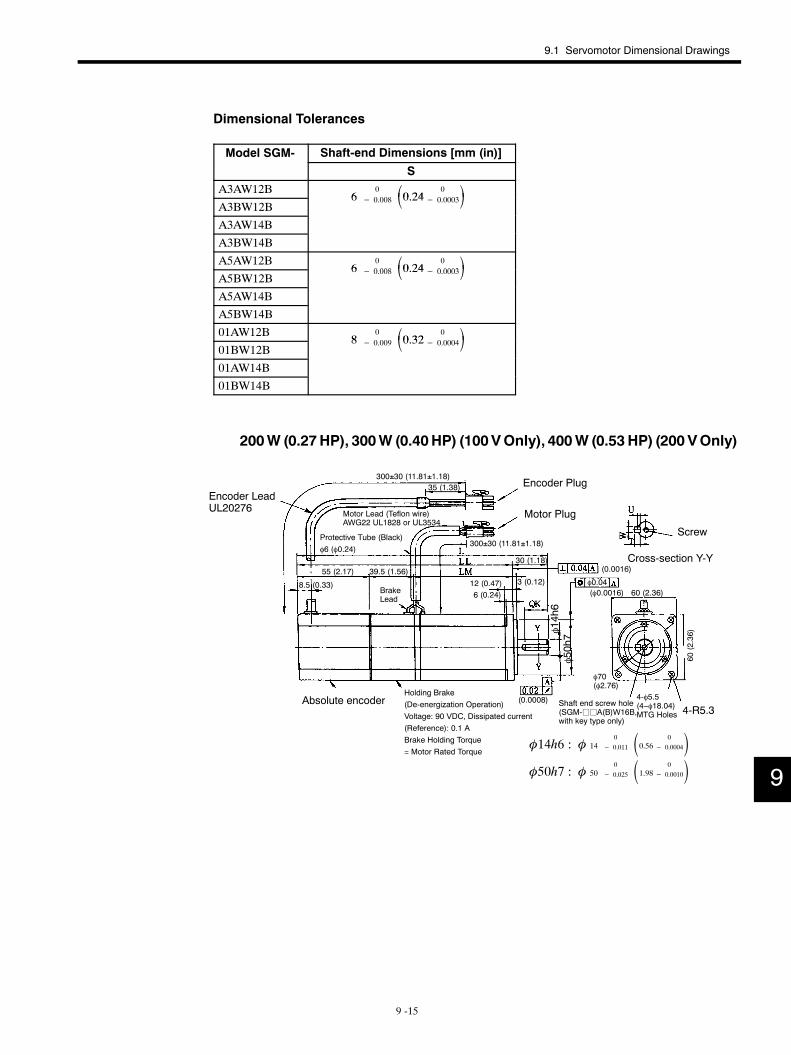
9.1 Servomotor Dimensional Drawings
9 -15
Dimensional Tolerances
Model SGM- Shaft-end Dimensions [mm (in)]
SA3AW12B
600 008 0 24 0
0 0003A3BW12B
6 − 0.008 0.24− 0.0003A3AW14B
A3BW14B
A5AW12B6
00 008 0 24 0
0 0003A5BW12B
6 − 0.008 0.24− 0.0003A5AW14B
A5BW14B
01AW12B8
00 009 0 32 0
0 000401BW12B
8 − 0.009 0.32− 0.000401AW14B
01BW14B
200W (0.27HP), 300W (0.40HP) (100VOnly), 400W (0.53 HP) (200 VOnly)
4-R5.3
φ70(φ2.76)
Encoder LeadUL20276
Motor Lead (Teflon wire)AWG22 UL1828 or UL3534
Protective Tube (Black)φ6 (φ0.24)
Encoder Plug
Motor Plug
Screw
Cross-section Y-Y
4-φ5.5(4−φ18.04)MTG Holes
Absolute encoderHolding Brake(De-energization Operation)Voltage: 90 VDC, Dissipated current(Reference): 0.1 ABrake Holding Torque= Motor Rated Torque
BrakeLead
φ0.04
Shaft end screw hole(SGM-jjA(B)W16B,with key type only)
φ14h6
φ50h7
300±30 (11.81±1.18)
(0.0016)
(0.0008)
(φ0.0016)
35 (1.38)
300±30 (11.81±1.18)
55 (2.17) 39.5 (1.56)
8.5 (0.33) 12 (0.47)6 (0.24)
30 (1.18)
3 (0.12)60 (2.36)
60(2.36)
φ14h6 : φ 140
− 0.011 0.56 0
− 0.0004φ50h7 : φ 50
0
− 0.025 1.98 0
− 0.0010 9
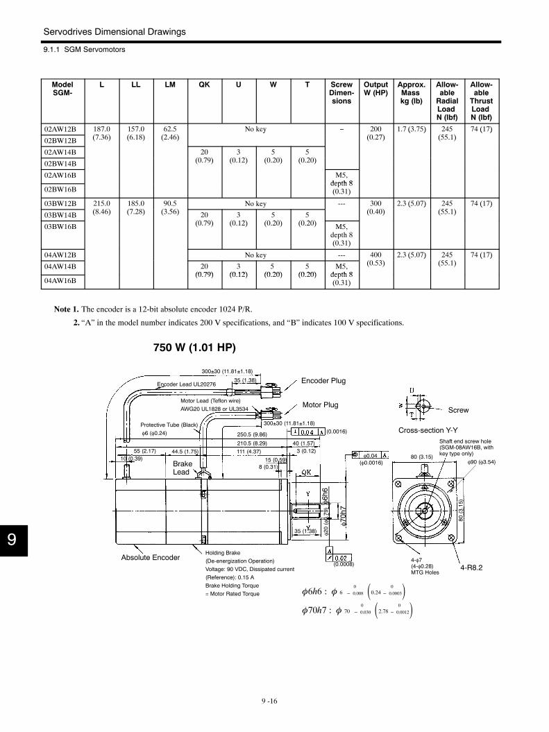
Servodrives Dimensional Drawings
9.1.1 SGM Servomotors
9 -16
ModelSGM-
L LL LM QK U W T ScrewDimen-sions
OutputW (HP)
Approx.Masskg (lb)
Allow-ableRadialLoadN (lbf)
Allow-ableThrustLoadN (lbf)
02AW12B 187.0( 36)
157.0(6 18)
62.5(2 46)
No key − 200(0 2 )
1.7 (3.75) 245(55 1)
74 (17)
02BW12B (7.36) (6.18) (2.46)y
(0.27)( )
(55.1)( )
02AW14B 20(0 9)
3(0 12)
5(0 20)
5(0 20)02BW14B (0.79) (0.12) (0.20) (0.20)
02AW16B M5,depth 8
02BW16Bdepth 8(0.31)
03BW12B 215.0(8 46)
185.0( 28)
90.5(3 56)
No key --- 300(0 40)
2.3 (5.07) 245(55 1)
74 (17)
03BW14B (8.46) (7.28) (3.56) 20(0 9)
3(0 12)
5(0 20)
5(0 20)
(0.40)( )
(55.1)( )
03BW16B (0.79) (0.12) (0.20) (0.20) M5,depth 8(0.31)
04AW12B No key --- 400(0 53)
2.3 (5.07) 245(55 1)
74 (17)
04AW14B 20(0 79)
3(0 12)
5(0 20)
5(0 20)
M5,depth 8
(0.53)( )
(55.1)( )
04AW16B(0.79) (0.12) (0.20) (0.20) depth 8
(0.31)
Note 1. The encoder is a 12-bit absolute encoder 1024 P/R.
2. “A” in the model number indicates 200 V specifications, and “B” indicates 100 V specifications.
750 W (1.01 HP)
4-R8.2
φ90 (φ3.54)
Encoder Lead UL20276
Motor Lead (Teflon wire)AWG20 UL1828 or UL3534
Protective Tube (Black)φ6 (φ0.24)
Encoder Plug
Motor PlugScrew
Cross-section Y-Y
4-φ7(4-φ0.28)MTG Holes
BrakeLead
Absolute EncoderHolding Brake(De-energization Operation)Voltage: 90 VDC, Dissipated current(Reference): 0.15 ABrake Holding Torque= Motor Rated Torque
φ0.04
Shaft end screw hole(SGM-08AW16B, withkey type only)
φ6h6
φ20(φ0.79)
φ70h7
300±30 (11.81±1.18)
(0.0008)
(φ0.0016)
(0.0016)
35 (1.38)
300±30 (11.81±1.18)
250.5 (9.86)
210.5 (8.29)111 (4.37)55 (2.17) 44.5 (1.75)
10 (0.39)
40 (1.57)3 (0.12)
15 (0.59)8 (0.31)
35 (1.38)
80 (3.15)80
(3.15)
φ70h7 : φ 700
− 0.030 2.78 0
− 0.0012φ6h6 : φ 6
0
− 0.008 0.24 0
− 0.0003
9
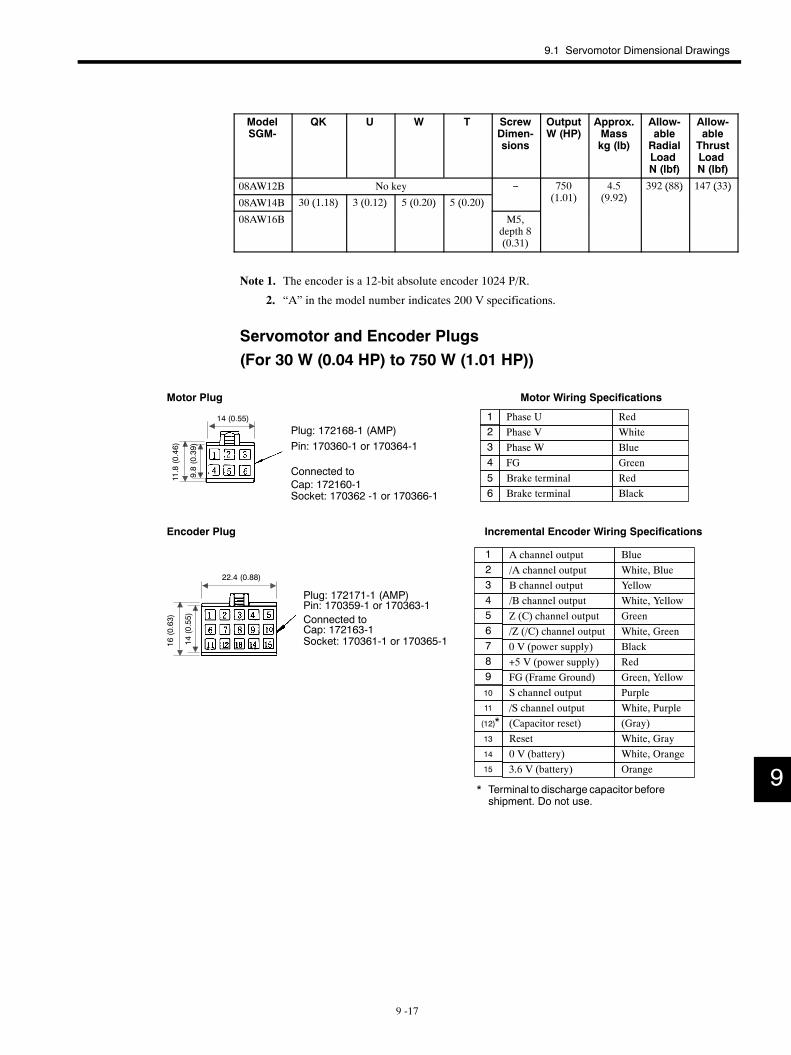
9.1 Servomotor Dimensional Drawings
9 -17
ModelSGM-
QK U W T ScrewDimen-sions
OutputW (HP)
Approx.Masskg (lb)
Allow-ableRadialLoadN (lbf)
Allow-ableThrustLoadN (lbf)
08AW12B No key − 750(1 01)
4.5(9 92)
392 (88) 147 (33)
08AW14B 30 (1.18) 3 (0.12) 5 (0.20) 5 (0.20) (1.01) (9.92)( ) ( )
08AW16B
( ) ( ) ( ) ( )
M5,depth 8(0.31)
Note 1. The encoder is a 12-bit absolute encoder 1024 P/R.
2. “A” in the model number indicates 200 V specifications.
Servomotor and Encoder Plugs(For 30 W (0.04 HP) to 750 W (1.01 HP))
/Z (/C) channel output
Motor Wiring Specifications
Incremental Encoder Wiring Specifications
A channel output Blue/A channel output White, BlueB channel output Yellow/B channel output White, Yellow
GreenWhite, GreenBlackRed
FG (Frame Ground) Green, Yellow
123456789
Z (C) channel output
+5 V (power supply)0 V (power supply)
/S channel outputS channel output Purple
(Capacitor reset) (Gray)Reset White, Gray0 V (battery) White, Orange
Orange
White, Purple10
(12)
13
14
15
11
3.6 V (battery)
*
* Terminal to discharge capacitor beforeshipment. Do not use.
Phase U RedPhase V WhitePhase W BlueFG Green
1234
Brake terminal Red5Brake terminal Black6Socket: 170362 -1 or 170366-1
Motor Plug
Pin: 170360-1 or 170364-1
Cap: 172160-1
Plug: 172168-1 (AMP)
Connected to
Encoder Plug
Plug: 172171-1 (AMP)Pin: 170359-1 or 170363-1Connected toCap: 172163-1Socket: 170361-1 or 170365-1
14 (0.55)
9.8(0.39)
11.8(0.46)
22.4 (0.88)
14(0.55)
16(0.63)
9
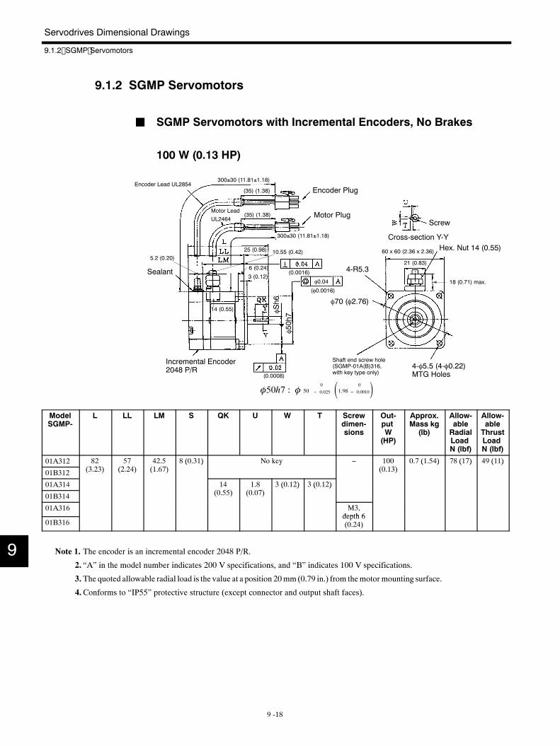
Servodrives Dimensional Drawings
9.1.2 SGMP Servomotors
9 -18
9.1.2 SGMP Servomotors
J SGMP Servomotors with Incremental Encoders, No Brakes
100 W (0.13 HP)
4-R5.3
φ70 (φ2.76)
60 x 60 (2.36 x 2.36)
Encoder Lead UL2854
Motor LeadUL2464
Encoder Plug
Motor PlugScrew
Cross-section Y-Y
Incremental Encoder2048 P/R 4-φ5.5 (4-φ0.22)
MTG Holes
Sealant
Hex. Nut 14 (0.55)
φ0.04
Shaft end screw hole(SGMP-01A(B)316,with key type only)
φSh6
φ50h7
300±30 (11.81±1.18)
(0.0008)
(φ0.0016)
(0.0016)
300±30 (11.81±1.18)
(35) (1.38)
(35) (1.38)
25 (0.98)
3 (0.12)
6 (0.24)
10.55 (0.42)5.2 (0.20)
14 (0.55)
21 (0.83)
18 (0.71) max.
φ50h7 : φ 500
− 0.025 1.98 0
− 0.0010
ModelSGMP-
L LL LM S QK U W T Screwdimen-sions
Out-putW(HP)
Approx.Mass kg(lb)
Allow-ableRadialLoadN (lbf)
Allow-ableThrustLoadN (lbf)
01A312 82(3 23)
57(2 24)
42.5(1 6 )
8 (0.31) No key − 100(0 13)
0.7 (1.54) 78 (17) 49 (11)
01B312 (3.23) (2.24) (1.67)( ) y
(0.13)( ) ( ) ( )
01A314 14(0 55)
1.8(0 0 )
3 (0.12) 3 (0.12)
01B314 (0.55) (0.07)( ) ( )
01A316 M3,depth 6
01B316depth 6(0.24)
Note 1. The encoder is an incremental encoder 2048 P/R.
2. “A” in the model number indicates 200 V specifications, and “B” indicates 100 V specifications.
3. The quoted allowable radial load is the value at a position 20mm(0.79 in.) from themotor mounting surface.
4.Conforms to “IP55” protective structure (except connector and output shaft faces).
9
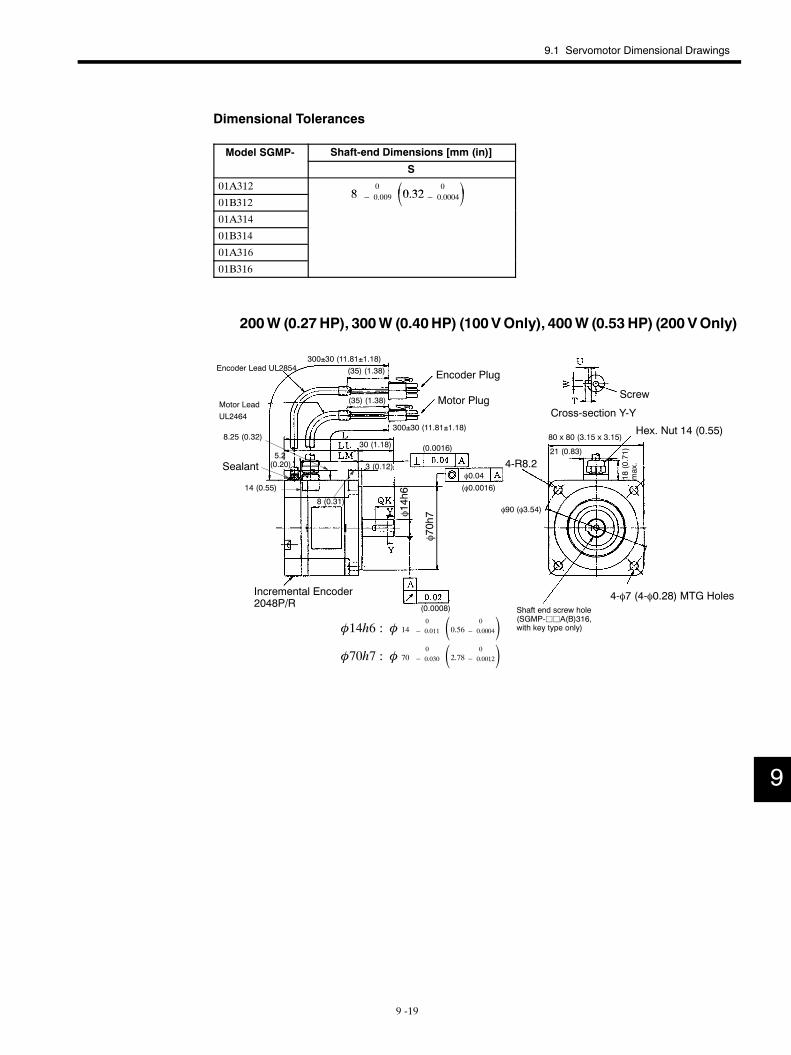
9.1 Servomotor Dimensional Drawings
9 -19
Dimensional Tolerances
Model SGMP- Shaft-end Dimensions [mm (in)]
S
01A3128
0 0 32 0 01B312
8 − 0.009 0.32− 0.000401A314
01B314
01A316
01B316
200W (0.27HP), 300W (0.40HP) (100VOnly), 400W (0.53 HP) (200 VOnly)
4-R8.2
φ90 (φ3.54)
80 x 80 (3.15 x 3.15)
Encoder Lead UL2854
Motor LeadUL2464
Encoder Plug
Motor Plug Screw
Cross-section Y-Y
Incremental Encoder2048P/R
4-φ7 (4-φ0.28) MTG Holes
Sealant
Hex. Nut 14 (0.55)
φ0.04
Shaft end screw hole(SGMP-jjA(B)316,with key type only)
φ70h7φ14h6
300±30 (11.81±1.18)
(0.0008)
(φ0.0016)
(0.0016)
300±30 (11.81±1.18)
(35) (1.38)
(35) (1.38)
30 (1.18)
3 (0.12)
8 (0.31)
8.25 (0.32)
5.2(0.20)
21 (0.83)
φ14h6 : φ 140
− 0.011 0.56 0
− 0.0004φ70h7 : φ 70
0
− 0.030 2.78 0
− 0.0012
14 (0.55)
18(0.71)
max.
9
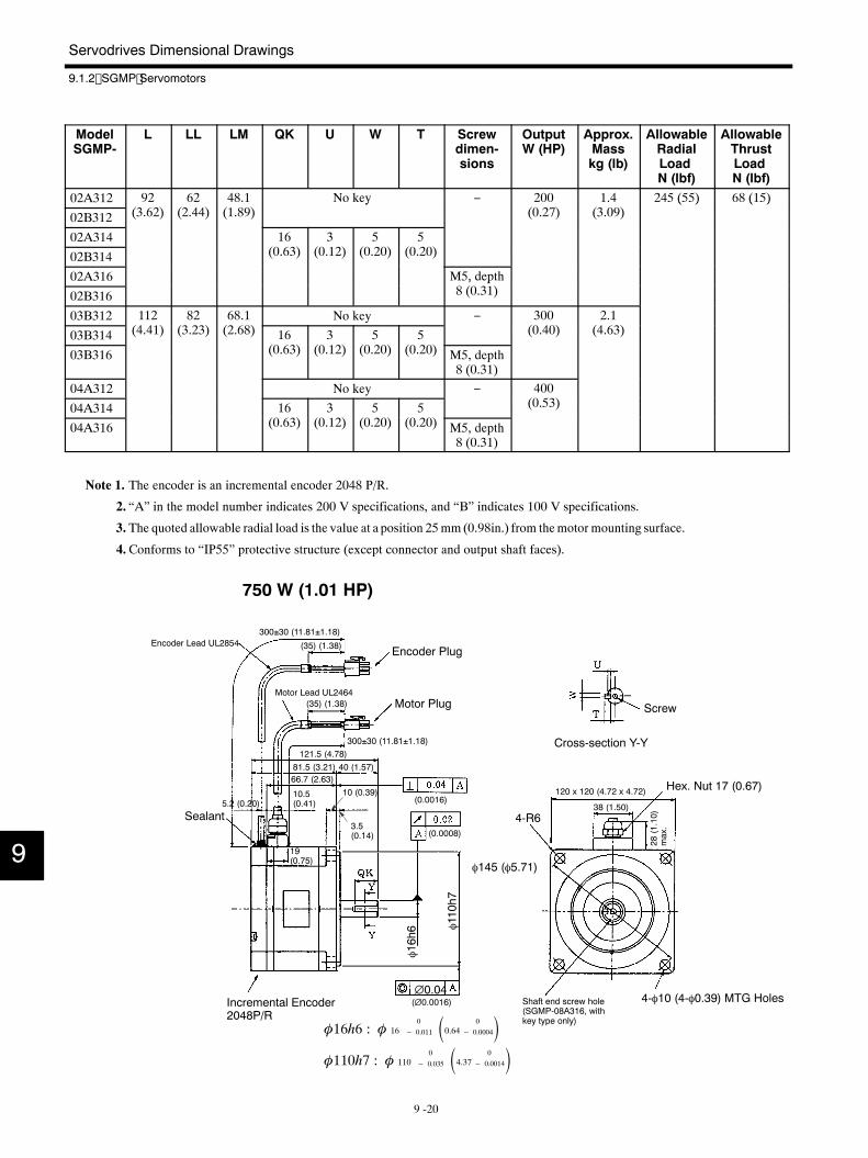
Servodrives Dimensional Drawings
9.1.2 SGMP Servomotors
9 -20
ModelSGMP-
L LL LM QK U W T Screwdimen-sions
OutputW (HP)
Approx.Masskg (lb)
AllowableRadialLoadN (lbf)
AllowableThrustLoadN (lbf)
02A312 92( )
62( )
48.1( )
No key − 200( )
1.4( )
245 (55) 68 (15)
02B312 (3.62) (2.44) (1.89)y
(0.27) (3.09)( ) ( )
02A314 16( )
3( )
5( )
5( )02B314 (0.63) (0.12) (0.20) (0.20)
02A316 M5, depth( )02B316
, p8 (0.31)
03B312 112( )
82( )
68.1( )
No key − 300( )
2.1( )03B314 (4.41) (3.23) (2.68) 16
( )3
( )5
( )5
( )
(0.40) (4.63)
03B316 (0.63) (0.12) (0.20) (0.20) M5, depth8 (0.31)
04A312 No key − 400( )04A314 16
( )3
( )5
( )5
( )
(0.53)
04A316 (0.63) (0.12) (0.20) (0.20) M5, depth8 (0.31)
Note 1. The encoder is an incremental encoder 2048 P/R.
2. “A” in the model number indicates 200 V specifications, and “B” indicates 100 V specifications.
3. The quoted allowable radial load is the value at a position 25mm (0.98in.) from themotor mounting surface.
4.Conforms to “IP55” protective structure (except connector and output shaft faces).
750 W (1.01 HP)
4-R6
φ145 (φ5.71)
120 x 120 (4.72 x 4.72)
Encoder Lead UL2854
Motor Lead UL2464
Encoder Plug
Motor Plug Screw
Cross-section Y-Y
Incremental Encoder2048P/R
4-φ10 (4-φ0.39) MTG Holes
Hex. Nut 17 (0.67)
Sealant
∅0.04Shaft end screw hole(SGMP-08A316, withkey type only)
φ110h7
φ16h6
300±30 (11.81±1.18)
(0.0008)
(∅0.0016)
(0.0016)
300±30 (11.81±1.18)
(35) (1.38)
(35) (1.38)
121.5 (4.78)81.5 (3.21) 40 (1.57)66.7 (2.63)
3.5(0.14)
10 (0.39)10.5(0.41)5.2 (0.20)
19(0.75)
38 (1.50)
28(1.10)
max.
φ110h7 : φ 1100
− 0.035 4.37 0
− 0.0014φ16h6 : φ 16
0
− 0.011 0.64 0
− 0.0004
9
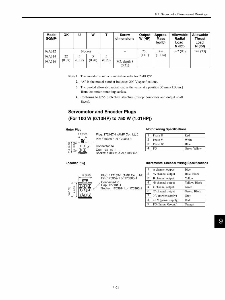
9.1 Servomotor Dimensional Drawings
9 -21
ModelSGMP-
QK U W T Screwdimensions
OutputW (HP)
Approx.Masskg(lb)
AllowableRadialLoadN (lbf)
AllowableThrustLoadN (lbf)
08A312 No key − 750 4.6 392 (80) 147 (33)
08A314 22 3 5 5 (1.01) (10.14)( ) ( )
08A316 (0.87) (0.12) (0.20) (0.20) M5, depth 8(0.31)
Note 1. The encoder is an incremental encoder for 2048 P/R.
2. “A” in the model number indicates 200 V specifications.
3. The quoted allowable radial load is the value at a position 35 mm (1.38 in.)from the motor mounting surface.
4. Conforms to IP55 protective structure (except connector and output shaftfaces).
Servomotor and Encoder Plugs(For 100 W (0.13HP) to 750 W (1.01HP))
/C channel output
Phase U RedPhase V WhitePhase W BlueFG Green Yellow
Motor Wiring Specifications
Incremental Encoder Wiring Specifications
A channel output Blue/A channel output Blue, BlackB channel output Yellow/B channel output Yellow, Black
GreenGreen, BlackGrayRed
FG (Frame Ground) Orange
1234
123456789
C channel output
+5 V (power supply)0 V (power supply)
Socket: 170362 -1 or 170366-1
Motor Plug
Pin: 170360-1 or 170364-1
Cap: 172159-1
Plug: 172167-1 (AMP Co., Ltd.)
Connected to
Encoder Plug
Plug: 172169-1 (AMP Co., Ltd.)Pin: 170359-1 or 170363-1Connected toCap: 172161-1Socket: 170361-1 or 170365-1
9.8 (0.39)
9.8(0.39)
11.8(0.46)
14(0.55)
16(0.63)
14 (0.55)
9
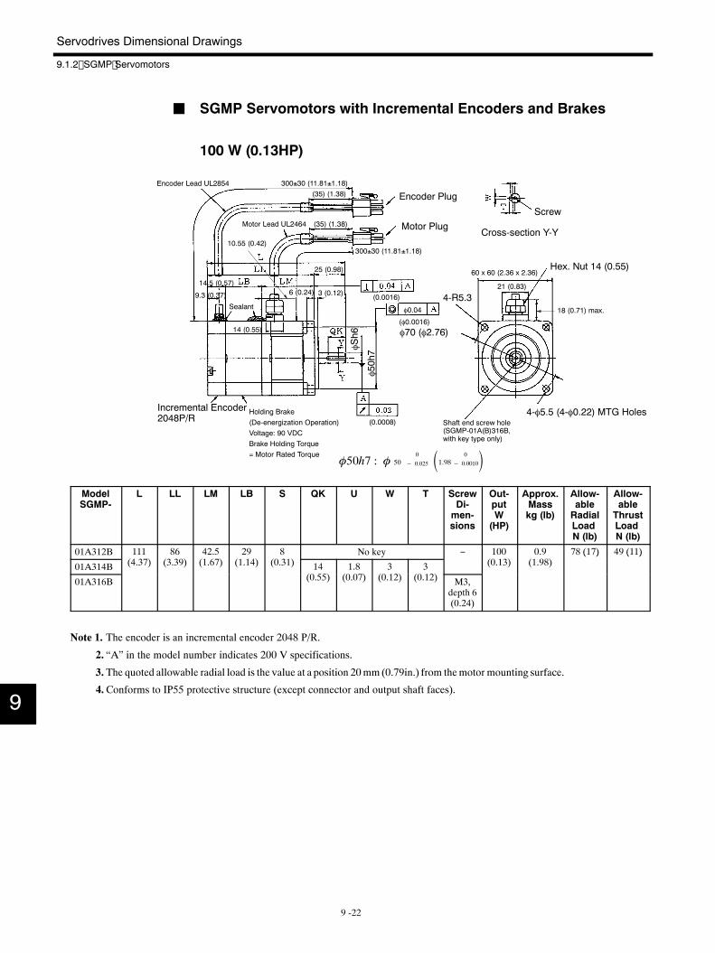
Servodrives Dimensional Drawings
9.1.2 SGMP Servomotors
9 -22
J SGMP Servomotors with Incremental Encoders and Brakes
100 W (0.13HP)
4-R5.3
φ70 (φ2.76)
60 x 60 (2.36 x 2.36)
Encoder Lead UL2854
Motor Lead UL2464
Encoder Plug
Motor PlugScrew
Cross-section Y-Y
Incremental Encoder2048P/R
4-φ5.5 (4-φ0.22) MTG Holes
Sealant
Hex. Nut 14 (0.55)
Holding Brake(De-energization Operation)Voltage: 90 VDCBrake Holding Torque= Motor Rated Torque
φ0.04
Shaft end screw hole(SGMP-01A(B)316B,with key type only)
φ50h7φS
h6
300±30 (11.81±1.18)
(0.0008)
(φ0.0016)
(0.0016)
300±30 (11.81±1.18)
(35) (1.38)
(35) (1.38)
25 (0.98)
14.5 (0.57)
9.3 (0.37)
10.55 (0.42)
6 (0.24) 3 (0.12)
14 (0.55)
21 (0.83)
18 (0.71) max.
φ50h7 : φ 500
− 0.025 1.98 0
− 0.0010
ModelSGMP-
L LL LM LB S QK U W T ScrewDi-men-sions
Out-putW(HP)
Approx.Masskg (lb)
Allow-ableRadialLoadN (lb)
Allow-ableThrustLoadN (lb)
01A312B 111(4 3 )
86(3 39)
42.5(1 6 )
29(1 14)
8(0 31)
No key − 100(0 13)
0.9(1 98)
78 (17) 49 (11)
01A314B (4.37) (3.39) (1.67) (1.14) (0.31) 14(0 55)
1.8(0 0 )
3(0 12)
3(0 12)
(0.13) (1.98)( ) ( )
01A316B (0.55) (0.07) (0.12) (0.12) M3,depth 6(0.24)
Note 1. The encoder is an incremental encoder 2048 P/R.
2. “A” in the model number indicates 200 V specifications.
3. The quoted allowable radial load is the value at a position 20mm (0.79in.) from themotor mounting surface.
4.Conforms to IP55 protective structure (except connector and output shaft faces).
9
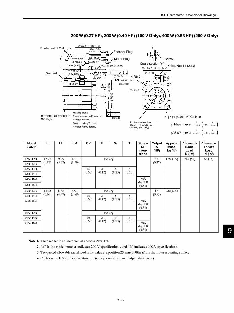
9.1 Servomotor Dimensional Drawings
9 -23
200W (0.27HP), 300W (0.40HP) (100VOnly), 400W (0.53 HP) (200 VOnly)
4-R8.2
φ90 (φ3.54)
80 x 80 (3.15 x 3.15)
Encoder Lead UL2854
Motor LeadUL2464
Encoder Plug
Motor Plug ScrewCross-section Y-Y
Incremental Encoder2048P/R
4-φ7 (4-φ0.28) MTG Holes
Sealant
Hex. Nut 14 (0.55)
Holding Brake(De-energization Operation)Voltage: 90 VDCBrake Holding Torque= Motor Rated Torque
φ0.04
Shaft end screw hole(SGMP-jjA(B)316B,with key type only)
φ70h7φ14h6
300±30 (11.81±1.18)
(0.0008)
(φ0.0016)
(0.0016)
300±30 (11.81±1.18)
(35) (1.38)
(35) (1.38)
31.5 (1.24)30 (1.18)5.2 (0.20)
8.25 (0.32)
14 (0.55)
8 (0.31)
3 (0.12)
21 (0.83)
18(0.71)
max.
φ14h6 : φ 140
− 0.011 0.56 0
− 0.0004φ70h7 : φ 70
0
− 0.030 2.78 0
− 0.0012
ModelSGMP-
L LL LM QK U W T ScrewDi-men-sions
OutputW(HP)
Approx.Masskg (lb)
AllowableRadialLoadN (lbf)
AllowableThrustLoadN (lbf)
02A312B 123.5(4 86)
93.5(3 68)
48.1(1 89)
No key − 200(0 2 )
1.9 (4.19) 245 (55) 68 (15)
02B312B (4.86) (3.68) (1.89)y
(0.27)( ) ( ) ( )
02A314B 16(0 63)
3(0 12)
5(0 20)
5(0 20)02B314B (0.63) (0.12) (0.20) (0.20)
02A316B M5,depth 8
02B316Bdepth 8(0.31)
03B312B 143.5(5 65)
113.5(4 4 )
68.1(2 68)
No key − 400(0 53)
2.6 (0.10)
03B314B (5.65) (4.47) (2.68) 16(0 63)
3(0 12)
5(0 20)
5(0 20)
(0.53)( )
03B316B (0.63) (0.12) (0.20) (0.20) M5,depth 8(0.31)
04A312B No key −
04A314B 16(0 63)
3(0 12)
5(0 20)
5(0 20)04A316B (0.63) (0.12) (0.20) (0.20) M5,
depth 8(0.31)
Note 1. The encoder is an incremental encoder 2048 P/R.
2. “A” in the model number indicates 200 V specifications, and “B” indicates 100 V specifications.
3. The quoted allowable radial load is the value at a position 25mm (0.98in.) from themotor mounting surface.
4.Conforms to IP55 protective structure (except connector and output shaft faces).
9

Servodrives Dimensional Drawings
9.1.2 SGMP Servomotors
9 -24
750 W (1.01HP)
4-R6
φ145 (φ5.71)
120 x 120 (4.72 x 4.72)
Encoder Lead UL2854
Motor LeadUL2464
Encoder Plug
Motor Plug Screw
Cross-section Y-Y
Incremental Encoder2048P/R
4-φ10 (4-φ0.39) MTG Holes
SealantHex. Nut 17 (0.67)
Holding Brake(De-energization Operation)Voltage: 90 VDCBrake Holding Torque= Motor Rated Torque
φ0.04 Shaft end screw hole(SGMP-08A316B,with key type only)
φ110h7
φ16h6
300±30 (11.81±1.18)
(0.0008)
(φ0.0016)
(0.0016)
300±30 (11.81±1.18)
(35) (1.38)
(35) (1.38)
158 (6.22) max.118 (4.65) max. 40 (1.57)66.7 (2.63)9.6 (0.38)
10.5(0.41)
10 (0.39)
3.5 (0.14)
19 (0.75)
38 (1.50)
28(1.10)
max.
φ16h6 : φ 160
− 0.011 0.64 0
− 0.0004φ110h7 : φ 110
0
− 0.035 4.37 0
− 0.0014
ModelSGMP-
QK U W T ScrewDimen-sions
OutputW(HP)
Approx.Masskg (lb)
AllowableRadialLoad N(lbf)
AllowableThrustLoad N(lbf)
08A312B No key − 750(1 01)
5.7(12 566)
392 (88) 147 (33)
08A314B 22 (0.87) 3 (0.12) 5 (0.20) 5 (0.20) (1.01) (12.566)( ) ( )
08A316B
( ) ( ) ( ) ( )
M5,depth 8(0.31)
Note 1. The encoder is an incremental encoder 2048 P/R.
2. “A” in the model number indicates 200 V specifications.
3. The quoted allowable radial load is the value at a position 35 mm (1.38 in.)from the motor mounting surface.
4. Conforms to IP55 protective structure (except connector and output shaftfaces).
9
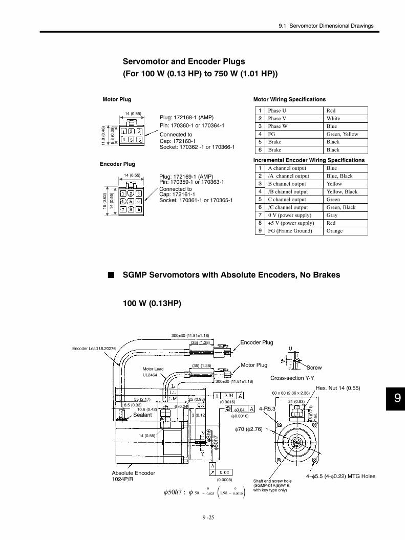
9.1 Servomotor Dimensional Drawings
9 -25
Servomotor and Encoder Plugs(For 100 W (0.13 HP) to 750 W (1.01 HP))
Phase U RedPhase V WhitePhase W BlueFG Green, Yellow
Motor Wiring Specifications
Incremental Encoder Wiring SpecificationsA channel output Blue/A channel output Blue, BlackB channel output Yellow
Yellow, BlackGreenGreen, BlackGrayRed
FG (Frame Ground) Orange
1234
123
56789
Brake BlackBrake Black
56
/B channel output4C channel output/C channel output0 V (power supply)+5 V (power supply)
Socket: 170362 -1 or 170366-1
Motor Plug
Pin: 170360-1 or 170364-1
Cap: 172160-1
Plug: 172168-1 (AMP)
Connected to
Encoder Plug
Plug: 172169-1 (AMP)Pin: 170359-1 or 170363-1Connected toCap: 172161-1Socket: 170361-1 or 170365-1
14 (0.55)9.8(0.39)
11.8(0.46)
14 (0.55)
14(0.55)
16(0.63)
J SGMP Servomotors with Absolute Encoders, No Brakes
100 W (0.13HP)
4-R5.3
φ70 (φ2.76)
60 x 60 (2.36 x 2.36)
Encoder Lead UL20276
Motor LeadUL2464
Encoder Plug
Motor Plug Screw
Cross-section Y-Y
Sealant
Hex. Nut 14 (0.55)
4−φ5.5 (4-φ0.22) MTG HolesAbsolute Encoder1024P/R
φ0.04
Shaft end screw hole(SGMP-01A(B)W16,with key type only)
φ50h7
φSh6
300±30 (11.81±1.18)
(0.0008)
(φ0.0016)
(0.0016)
300±30 (11.81±1.18)
(35) (1.38)
(35) (1.38)
25 (0.98)55 (2.17)8.5 (0.33)
10.6 (0.42)
14 (0.55)
6 (0.24)
3 (0.12)
21 (0.83)
18(0.71)
max.
φ50h7 : φ 500
− 0.025 1.98 0
− 0.0010
9
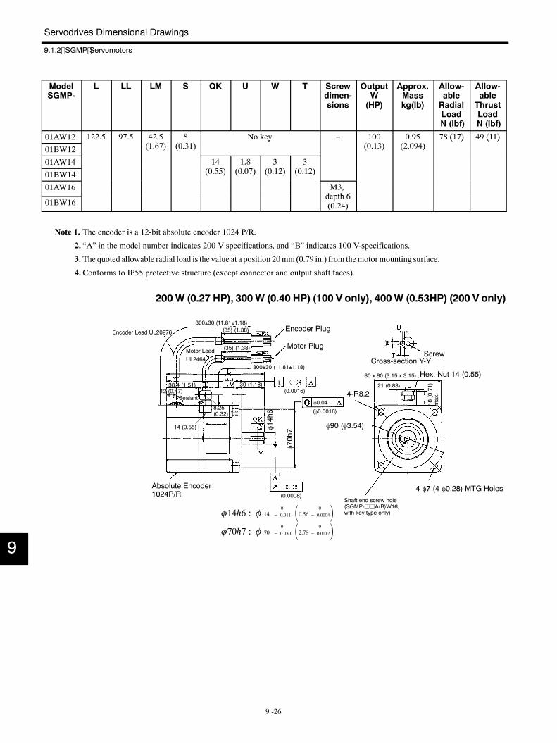
Servodrives Dimensional Drawings
9.1.2 SGMP Servomotors
9 -26
ModelSGMP-
L LL LM S QK U W T Screwdimen-sions
OutputW(HP)
Approx.Masskg(lb)
Allow-ableRadialLoadN (lbf)
Allow-ableThrustLoadN (lbf)
01AW12 122.5 97.5 42.5( )
8( )
No key − 100( )
0.95( )
78 (17) 49 (11)
01BW12 (1.67) (0.31)y
(0.13) (2.094)( ) ( )
01AW14 14( )
1.8( )
3( )
3( )01BW14 (0.55) (0.07) (0.12) (0.12)
01AW16 M3,depth 6
01BW16depth 6(0.24)
Note 1. The encoder is a 12-bit absolute encoder 1024 P/R.
2. “A” in the model number indicates 200 V specifications, and “B” indicates 100 V-specifications.
3. The quoted allowable radial load is the value at a position 20mm(0.79 in.) from themotor mounting surface.
4.Conforms to IP55 protective structure (except connector and output shaft faces).
200W (0.27 HP), 300W (0.40 HP) (100 V only), 400W (0.53HP) (200 V only)
4-R8.2
φ90 (φ3.54)
80 x 80 (3.15 x 3.15)
Encoder Lead UL20276
Motor LeadUL2464
Encoder Plug
Motor PlugScrew
Cross-section Y-Y
Sealant
Hex. Nut 14 (0.55)
4-φ7 (4-φ0.28) MTG HolesAbsolute Encoder1024P/R
φ0.04
Shaft end screw hole(SGMP-jjA(B)W16,with key type only)
φ70h7φ1
4h6
300±30 (11.81±1.18)
(0.0008)
(φ0.0016)
(0.0016)
300±30 (11.81±1.18)
(35) (1.38)
(35) (1.38)
30 (1.18)38.4 (1.51)12 (0.47)
8.25(0.32)
14 (0.55)
21 (0.83)
18(0.71)
max.
φ14h6 : φ 140
− 0.011 0.56 0
− 0.0004φ70h7 : φ 70
0
− 0.030 2.78 0
− 0.00129
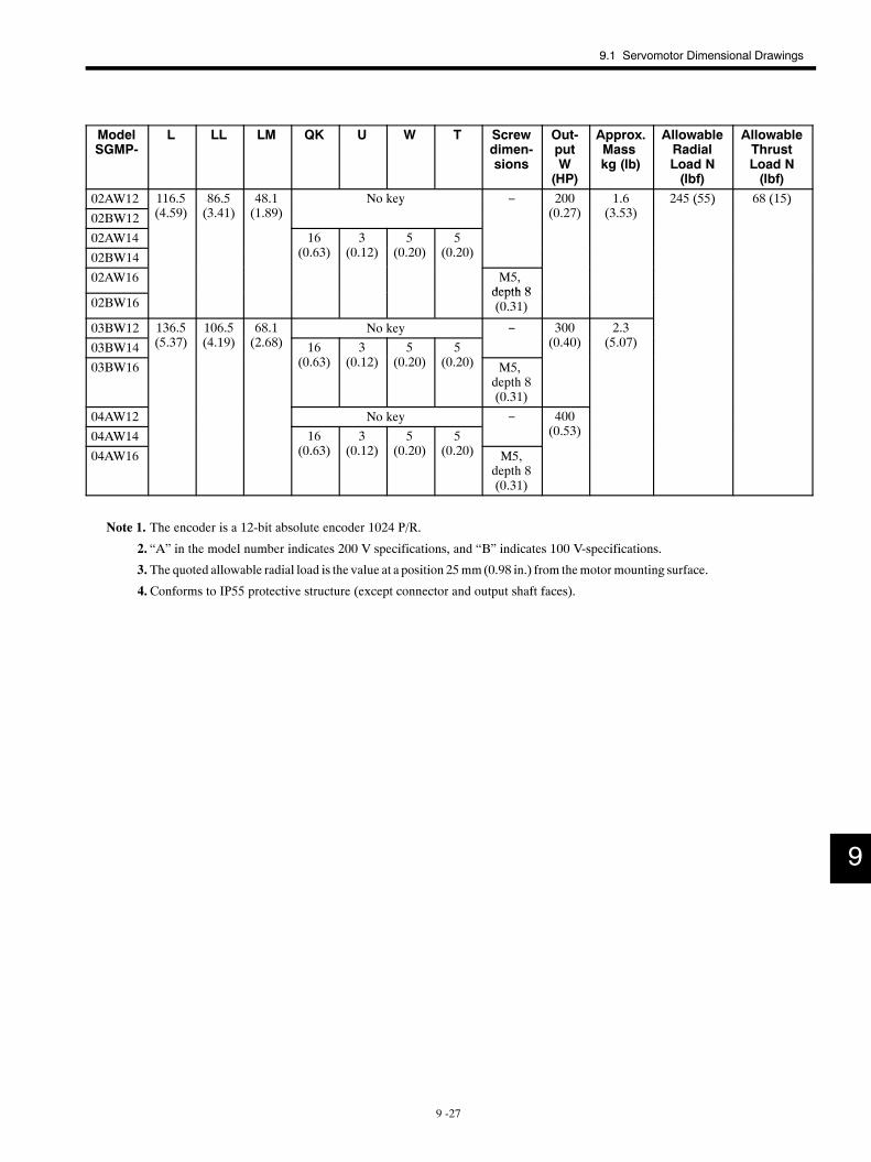
9.1 Servomotor Dimensional Drawings
9 -27
ModelSGMP-
L LL LM QK U W T Screwdimen-sions
Out-putW(HP)
Approx.Masskg (lb)
AllowableRadialLoad N(lbf)
AllowableThrustLoad N(lbf)
02AW12 116.5( )
86.5( )
48.1( )
No key − 200( )
1.6( )
245 (55) 68 (15)
02BW12 (4.59) (3.41) (1.89)y
(0.27) (3.53)( ) ( )
02AW14 16( )
3( )
5( )
5( )02BW14 (0.63) (0.12) (0.20) (0.20)
02AW16 M5,depth 8
02BW16depth 8(0.31)
03BW12 136.5( )
106.5( )
68.1( )
No key − 300( )
2.3( )03BW14 (5.37) (4.19) (2.68) 16
( )3
( )5
( )5
( )
(0.40) (5.07)
03BW16 (0.63) (0.12) (0.20) (0.20) M5,depth 8(0.31)
04AW12 No key − 400( )04AW14 16
( )3
( )5
( )5
( )
(0.53)
04AW16 (0.63) (0.12) (0.20) (0.20) M5,depth 8(0.31)
Note 1. The encoder is a 12-bit absolute encoder 1024 P/R.
2. “A” in the model number indicates 200 V specifications, and “B” indicates 100 V-specifications.
3. The quoted allowable radial load is the value at a position 25mm(0.98 in.) from themotor mounting surface.
4.Conforms to IP55 protective structure (except connector and output shaft faces).
9
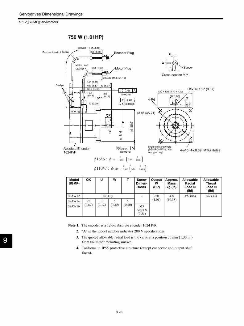
Servodrives Dimensional Drawings
9.1.2 SGMP Servomotors
9 -28
750 W (1.01HP)
4-R6
φ145 (φ5.71)
120 x 120 (4.72 x 4.72)
Encoder Lead UL20276
Motor LeadUL2464
Encoder Plug
Motor Plug Screw
Cross-section Y-Y
Sealant
Hex. Nut 17 (0.67)
4-φ10 (4-φ0.39) MTG HolesAbsolute Encoder1024P/R
φ0.04Shaft end screw hole(SGMP-08AW16, withkey type only)
φ110h7
φ16h6
300±30 (11.81±1.18)
(0.0008)
(φ0.0016)
(0.0016)
300±30 (11.81±1.18)
(35) (1.38)
(35) (1.38)
146 (5.75)106 (4.17) 40 (1.57)66.7 (2.63)
12 (0.47) 10.5(0.41)
10 (0.39)
3.5(0.14)
19 (0.75)
38 (1.50)
28(1.10)
max.
φ110h7 : φ 1100
− 0.035 4.37 0
− 0.0014φ16h6 : φ 16
0
− 0.011 0.64 0
− 0.0004
ModelSGMP-
QK U W T ScrewDimen-sions
OutputW(HP)
Approx.Masskg (lb)
AllowableRadialLoad N(lbf)
AllowableThrustLoad N(lbf)
08AW12 No key − 750(1 01)
4.8(10 58)
392 (88) 147 (33)
08AW14 22(0 8 )
3(0 12)
5(0 20)
5(0 20)
(1.01) (10.58)( ) ( )
08AW16 (0.87) (0.12) (0.20) (0.20) M5depth 8(0.31)
Note 1. The encoder is a 12-bit absolute encoder 1024 P/R.
2. “A” in the model number indicates 200 V specifications.
3. The quoted allowable radial load is the value at a position 35 mm (1.38 in.)from the motor mounting surface.
4. Conforms to IP55 protective structure (except connector and output shaftfaces).
9
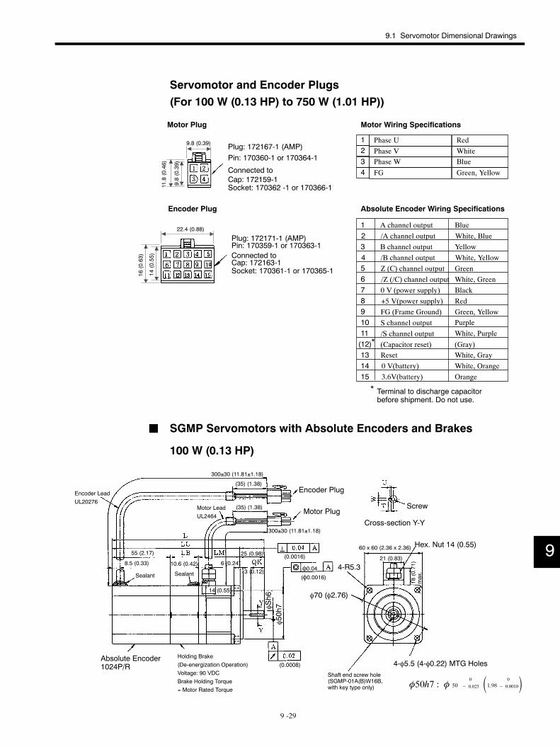
9.1 Servomotor Dimensional Drawings
9 -29
Servomotor and Encoder Plugs(For 100 W (0.13 HP) to 750 W (1.01 HP))
Phase U RedPhase V WhitePhase W BlueFG Green, Yellow
Motor Wiring Specifications
Absolute Encoder Wiring Specifications
A channel output Blue/A channel output White, BlueB channel output Yellow/B channel output White, Yellow
GreenWhite, GreenBlackRed
FG (Frame Ground) Green, Yellow
1234
12345678
131415
S channel output/S channel output
PurpleWhite, Purple
(Capacitor reset) (Gray)Reset White, Gray0 V(battery)3.6V(battery)
White, OrangeOrange
Terminal to discharge capacitorbefore shipment. Do not use.
*
*
Z (C) channel output/Z (/C) channel output0 V (power supply)+5 V(power supply)
91011(12)
Socket: 170362 -1 or 170366-1
Motor Plug
Pin: 170360-1 or 170364-1
Cap: 172159-1
Plug: 172167-1 (AMP)
Connected to
Encoder Plug
Plug: 172171-1 (AMP)Pin: 170359-1 or 170363-1Connected toCap: 172163-1Socket: 170361-1 or 170365-1
9.8 (0.39)
9.8(0.39)
11.8(0.46)
22.4 (0.88)
14(0.55)
16(0.63)
J SGMP Servomotors with Absolute Encoders and Brakes
100 W (0.13 HP)
4-R5.3
φ70 (φ2.76)
60 x 60 (2.36 x 2.36)
Encoder LeadUL20276
Motor LeadUL2464
Encoder Plug
Motor PlugScrew
Cross-section Y-Y
Sealant
Hex. Nut 14 (0.55)
4-φ5.5 (4-φ0.22) MTG HolesAbsolute Encoder1024P/R
Sealant
Holding Brake(De-energization Operation)Voltage: 90 VDCBrake Holding Torque= Motor Rated Torque
φ0.04
Shaft end screw hole(SGMP-01A(B)W16B,with key type only)
φ50h7φSh6
300±30 (11.81±1.18)
(0.0008)
(φ0.0016)
(0.0016)
300±30 (11.81±1.18)
(35) (1.38)
(35) (1.38)
25 (0.98)55 (2.17)
8.5 (0.33) 10.6 (0.42) 6 (0.24)3 (0.12)
14 (0.55)
21 (0.83)
18(0.71)
max.
φ50h7 : φ 500
− 0.025 1.98 0
− 0.0010
9
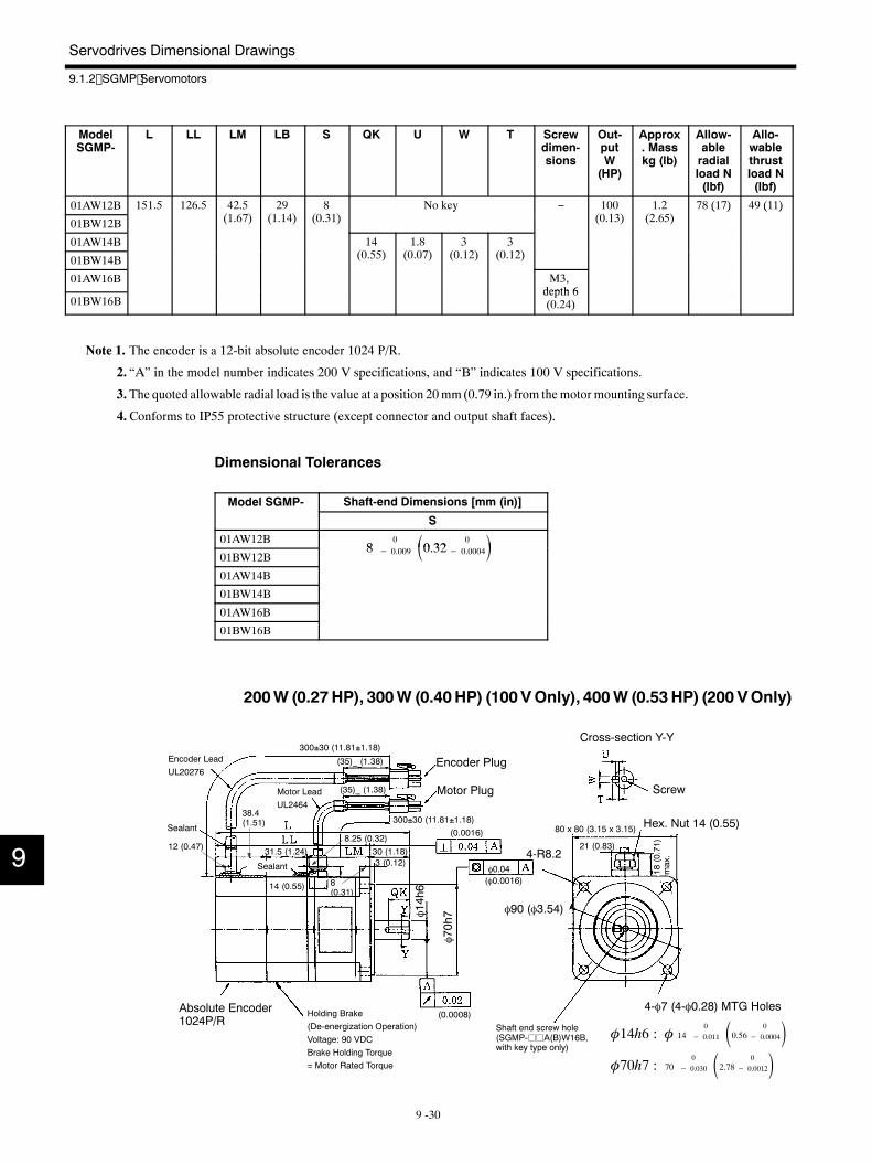
Servodrives Dimensional Drawings
9.1.2 SGMP Servomotors
9 -30
ModelSGMP-
L LL LM LB S QK U W T Screwdimen-sions
Out-putW(HP)
Approx. Masskg (lb)
Allow-ableradialload N(lbf)
Allo-wablethrustload N(lbf)
01AW12B 151.5 126.5 42.5(1 6 )
29(1 14)
8(0 31)
No key − 100(0 13)
1.2(2 65)
78 (17) 49 (11)
01BW12B (1.67) (1.14) (0.31)y
(0.13) (2.65)( ) ( )
01AW14B 14(0 55)
1.8(0 0 )
3(0 12)
3(0 12)01BW14B (0.55) (0.07) (0.12) (0.12)
01AW16B M3,depth 6
01BW16Bdepth 6(0.24)
Note 1. The encoder is a 12-bit absolute encoder 1024 P/R.
2. “A” in the model number indicates 200 V specifications, and “B” indicates 100 V specifications.
3. The quoted allowable radial load is the value at a position 20mm(0.79 in.) from themotor mounting surface.
4.Conforms to IP55 protective structure (except connector and output shaft faces).
Dimensional Tolerances
Model SGMP- Shaft-end Dimensions [mm (in)]
S
01AW12B8
0 0 32 0 01BW12B
8 − 0.009 0.32− 0.000401AW14B
01BW14B
01AW16B
01BW16B
200W (0.27HP), 300W (0.40HP) (100VOnly), 400W (0.53 HP) (200 VOnly)
4-R8.2
80 x 80 (3.15 x 3.15)
φ90 (φ3.54)
Encoder LeadUL20276
Encoder Plug
Motor Plug Screw
Cross-section Y-Y
Sealant Hex. Nut 14 (0.55)
4-φ7 (4-φ0.28) MTG HolesAbsolute Encoder1024P/R
Holding Brake(De-energization Operation)Voltage: 90 VDCBrake Holding Torque= Motor Rated Torque
Sealant
Motor LeadUL2464
φ0.04
Shaft end screw hole(SGMP-jjA(B)W16B,with key type only)
φ70h7φ14h6
300±30 (11.81±1.18)
(0.0008)
(φ0.0016)
(0.0016)300±30 (11.81±1.18)
(35)_ (1.38)
(35)_ (1.38)
30 (1.18)31.5 (1.24)
38.4(1.51)
12 (0.47)8.25 (0.32)
8(0.31)
14 (0.55)
3 (0.12)
21 (0.83)
18(0.71)
max.
φ70h7 : 700
− 0.030 2.78 0
− 0.0012φ14h6 : φ 14
0
− 0.011 0.56 0
− 0.0004
9
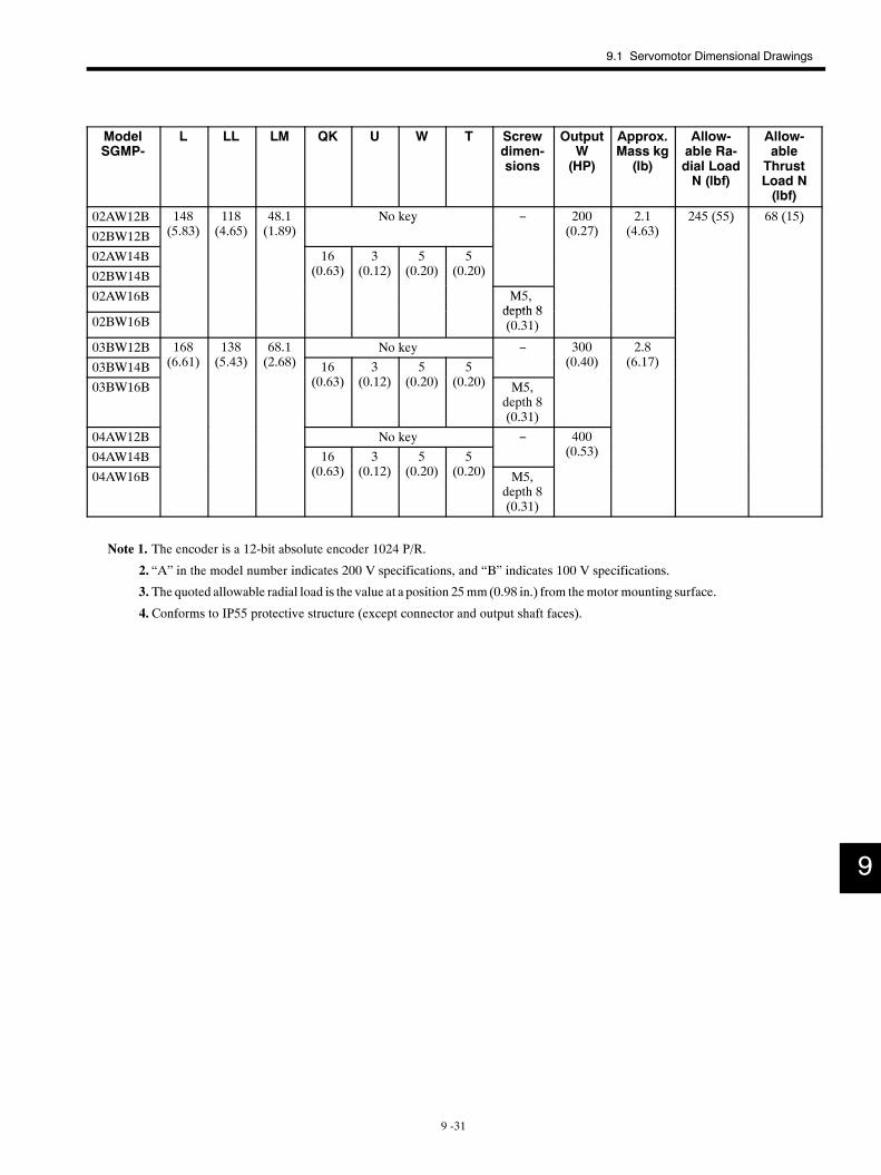
9.1 Servomotor Dimensional Drawings
9 -31
ModelSGMP-
L LL LM QK U W T Screwdimen-sions
OutputW(HP)
Approx.Mass kg(lb)
Allow-able Ra-dial LoadN (lbf)
Allow-ableThrustLoad N(lbf)
02AW12B 148( )
118( )
48.1( )
No key − 200( )
2.1( )
245 (55) 68 (15)
02BW12B (5.83) (4.65) (1.89)y
(0.27) (4.63)( ) ( )
02AW14B 16( )
3( )
5( )
5( )02BW14B (0.63) (0.12) (0.20) (0.20)
02AW16B M5,depth 8
02BW16Bdepth 8(0.31)
03BW12B 168( )
138( )
68.1( )
No key − 300( )
2.8( )03BW14B (6.61) (5.43) (2.68) 16
( )3
( )5
( )5
( )
(0.40) (6.17)
03BW16B (0.63) (0.12) (0.20) (0.20) M5,depth 8(0.31)
04AW12B No key − 400( )04AW14B 16
( )3
( )5
( )5
( )
(0.53)
04AW16B (0.63) (0.12) (0.20) (0.20) M5,depth 8(0.31)
Note 1. The encoder is a 12-bit absolute encoder 1024 P/R.
2. “A” in the model number indicates 200 V specifications, and “B” indicates 100 V specifications.
3. The quoted allowable radial load is the value at a position 25mm(0.98 in.) from themotor mounting surface.
4.Conforms to IP55 protective structure (except connector and output shaft faces).
9
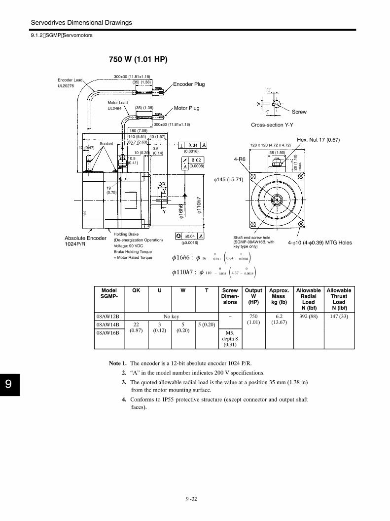
Servodrives Dimensional Drawings
9.1.2 SGMP Servomotors
9 -32
750 W (1.01 HP)
4-R6
φ145 (φ5.71)
120 x 120 (4.72 x 4.72)
Encoder LeadUL20276 Encoder Plug
Motor PlugScrew
Cross-section Y-Y
SealantHex. Nut 17 (0.67)
4-φ10 (4-φ0.39) MTG HolesAbsolute Encoder1024P/R
Holding Brake(De-energization Operation)Voltage: 90 VDCBrake Holding Torque= Motor Rated Torque
Motor LeadUL2464
φ0.04 Shaft end screw hole(SGMP-08AW16B, withkey type only)
φ110h7
φ16h6
300±30 (11.81±1.18)
(0.0008)
(φ0.0016)
(0.0016)
300±30 (11.81±1.18)
(35) (1.38)
(35) (1.38)
180 (7.09)140 (5.51) 40 (1.57)66.7 (2.63)
3.5(0.14)
10.5(0.41)
10 (0.39)12 (0.47)
19(0.75)
38 (1.50)
28(1.10)
max.
φ16h6 : φ 160
− 0.011 0.64 0
− 0.0004φ110h7 : φ 110
0
− 0.035 4.37 0
− 0.0014
ModelSGMP-
QK U W T ScrewDimen-sions
OutputW(HP)
Approx.Masskg (lb)
AllowableRadialLoadN (lbf)
AllowableThrustLoadN (lbf)
08AW12B No key − 750(1 01)
6.2(13 6 )
392 (88) 147 (33)
08AW14B 22(0 8 )
3(0 12)
5(0 20)
5 (0.20) (1.01) (13.67)( ) ( )
08AW16B (0.87) (0.12) (0.20)( )
M5,depth 8(0.31)
Note 1. The encoder is a 12-bit absolute encoder 1024 P/R.
2. “A” in the model number indicates 200 V specifications.
3. The quoted allowable radial load is the value at a position 35 mm (1.38 in)from the motor mounting surface.
4. Conforms to IP55 protective structure (except connector and output shaftfaces).
9
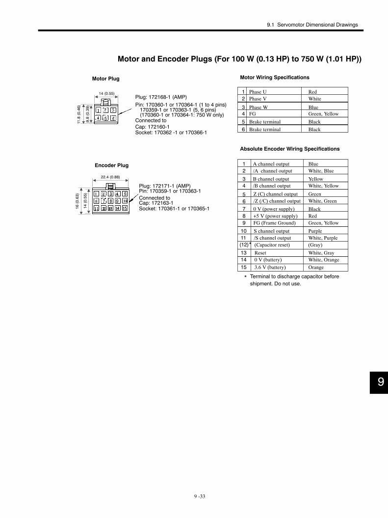
9.1 Servomotor Dimensional Drawings
9 -33
Motor and Encoder Plugs (For 100 W (0.13 HP) to 750 W (1.01 HP))
A channel output Blue/A channel output White, Blue
B channel output Yellow/B channel output White, Yellow
GreenWhite, Green
BlackRed
FG (Frame Ground) Green, Yellow
/Z (/C) channel outputZ (C) channel output
0 V (power supply)+5 V (power supply)
12
34
56789
1011(12)
131415
S channel output/S channel output
PurpleWhite, Purple
(Capacitor reset) (Gray)
Reset White, Gray0 V (battery)3.6 V (battery)
White, OrangeOrange
Phase U RedPhase V White
Phase W BlueFG Green, Yellow
Motor Wiring Specifications
Absolute Encoder Wiring Specifications
12
34
56
Brake terminalBrake terminal
BlackBlack
Terminal to discharge capacitor beforeshipment. Do not use.
*
*
Socket: 170362 -1 or 170366-1
Motor Plug
Pin: 170360-1 or 170364-1 (1 to 4 pins)
Cap: 172160-1
Plug: 172168-1 (AMP)
Connected to
170359-1 or 170363-1 (5, 6 pins)(170360-1 or 170364-1: 750 W only)
Encoder Plug
Plug: 172171-1 (AMP)Pin: 170359-1 or 170363-1Connected toCap: 172163-1Socket: 170361-1 or 170365-1
14 (0.55)
9.8(0.39)
11.8(0.46)
22.4 (0.88)
14(0.55)
16(0.63)
9
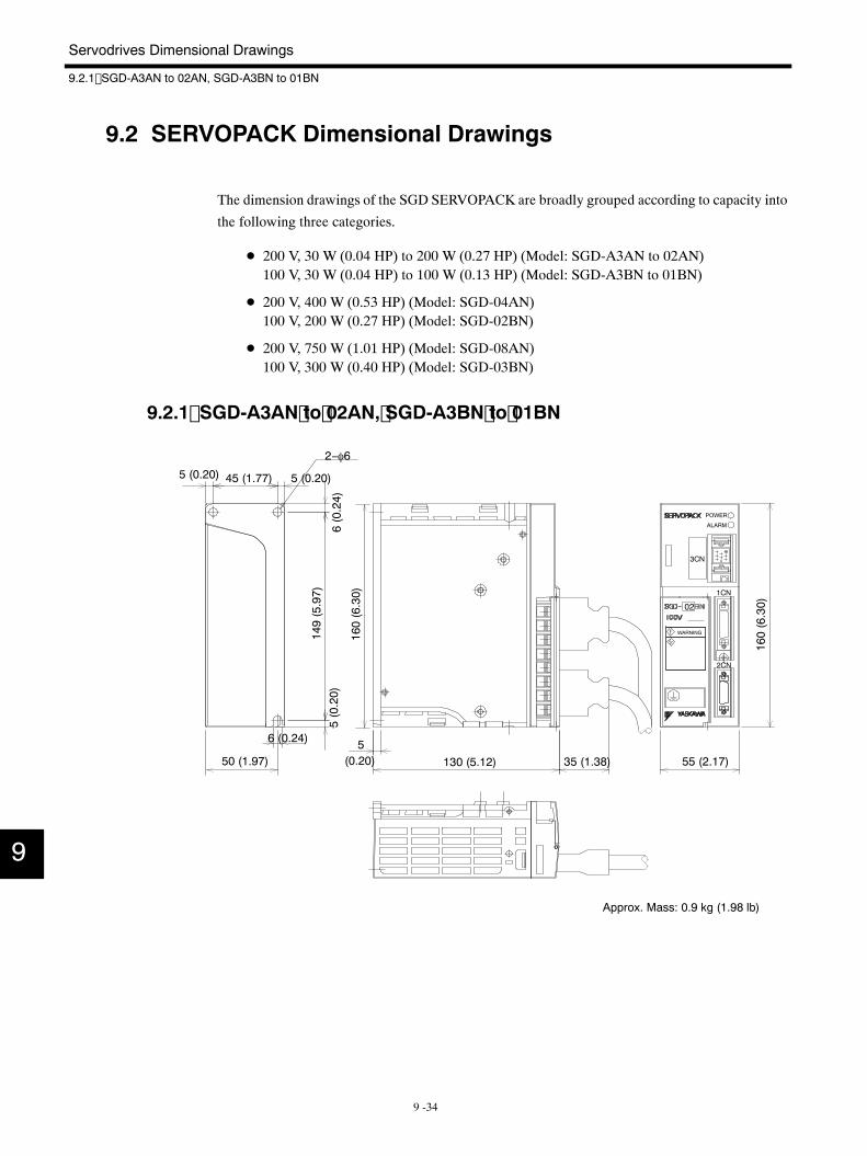
Servodrives Dimensional Drawings
9.2.1 SGD-A3AN to 02AN, SGD-A3BN to 01BN
9 -34
9.2 SERVOPACK Dimensional Drawings
The dimension drawings of the SGD SERVOPACK are broadly grouped according to capacity into
the following three categories.
D 200 V, 30 W (0.04 HP) to 200 W (0.27 HP) (Model: SGD-A3AN to 02AN)100 V, 30 W (0.04 HP) to 100 W (0.13 HP) (Model: SGD-A3BN to 01BN)
D 200 V, 400 W (0.53 HP) (Model: SGD-04AN)100 V, 200 W (0.27 HP) (Model: SGD-02BN)
D 200 V, 750 W (1.01 HP) (Model: SGD-08AN)100 V, 300 W (0.40 HP) (Model: SGD-03BN)
9.2.1 SGD-A3AN to 02AN, SGD-A3BN to 01BN
!
55 (2.17)130 (5.12)56 (0.24)
50 (1.97)
2−φ6
149(5.97)
35 (1.38)
WARNING
1CN
POWER
ALARM
3CN
2CN
160(6.30)
02
45 (1.77)5 (0.20) 5 (0.20)
6(0.24)
5(0.20)
(0.20)160(6.30)
Approx. Mass: 0.9 kg (1.98 lb)
9
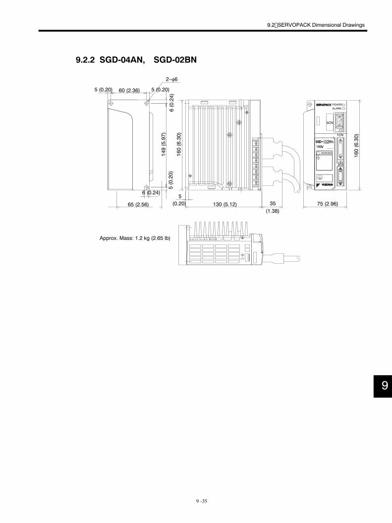
9.2 SERVOPACK Dimensional Drawings
9 -35
9.2.2 SGD-04AN, SGD-02BN
6 (0.24)
149(5.97)
160(6.30)
75 (2.96)130 (5.12)
5
65 (2.56)
60 (2.36)5 (0.20)
2−φ6
35
3CN
POWERALARM
1CN
2CN
160(6.30)
02
WARNING
Approx. Mass: 1.2 kg (2.65 lb)
5 (0.20)
6(0.24)
5(0.20)
(1.38)(0.20)
9
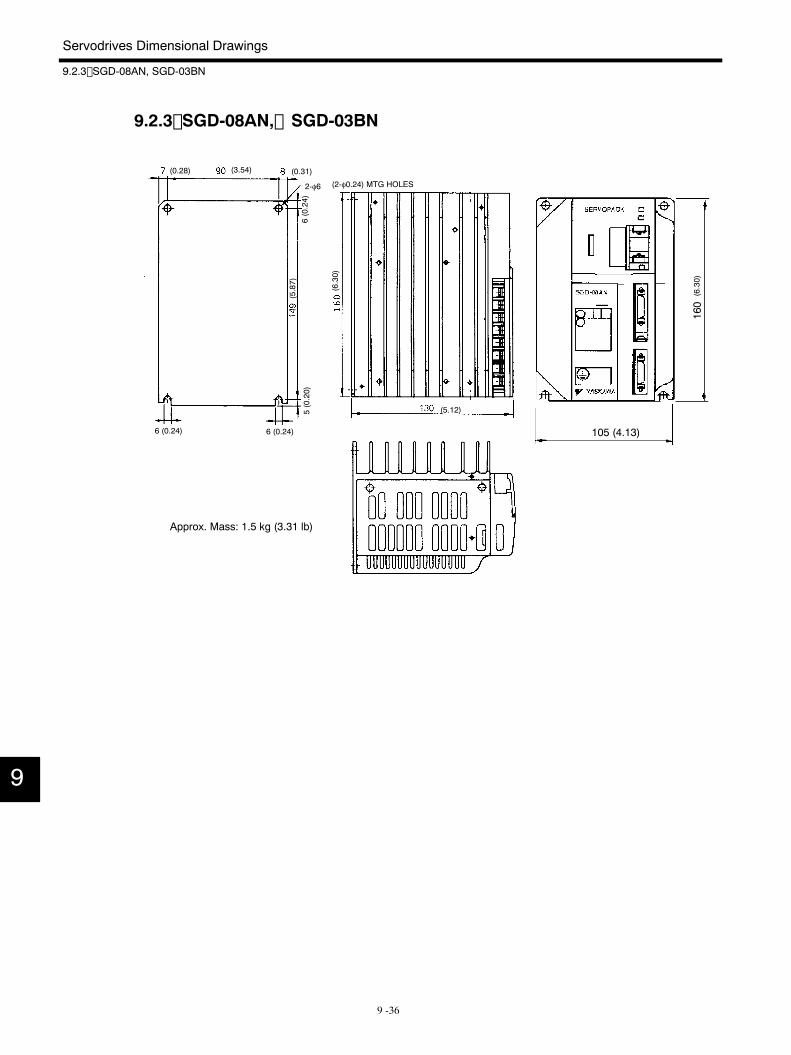
Servodrives Dimensional Drawings
9.2.3 SGD-08AN, SGD-03BN
9 -36
9.2.3 SGD-08AN, SGD-03BN
160
105 (4.13)
Approx. Mass: 1.5 kg (3.31 lb)
(2-φ0.24) MTG HOLES
(0.28) (3.54) (0.31)
(5.87)
6 (0.24)6 (0.24)
(6.30)
(5.12)
(6.30)
2-φ6
6(0.24)
5(0.20)
9
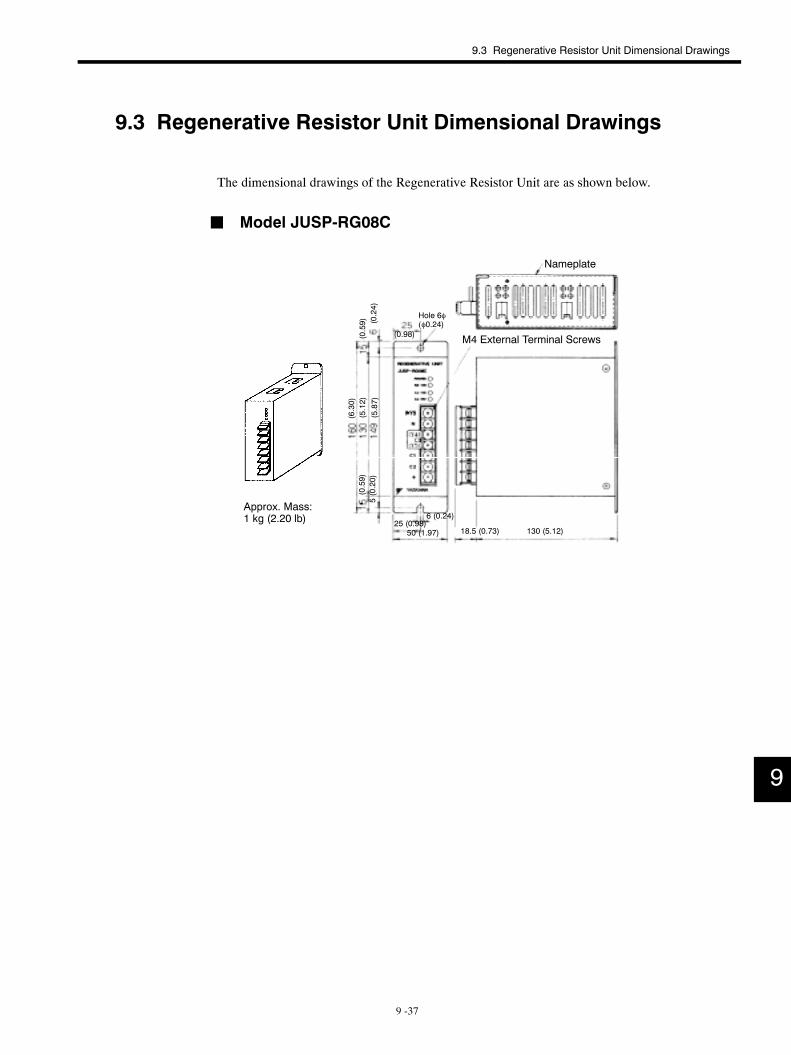
9.3 Regenerative Resistor Unit Dimensional Drawings
9 -37
9.3 Regenerative Resistor Unit Dimensional Drawings
The dimensional drawings of the Regenerative Resistor Unit are as shown below.
J Model JUSP-RG08C
M4 External Terminal Screws
Approx. Mass:1 kg (2.20 lb)
Hole 6φ(φ0.24)
50 (1.97)25 (0.98)
18.5 (0.73) 130 (5.12)
(6.30)
(5.12)
(5.87)
(0.59) (0.24)
6 (0.24)
(0.98)
(0.59)
Nameplate
5(0.20)
9
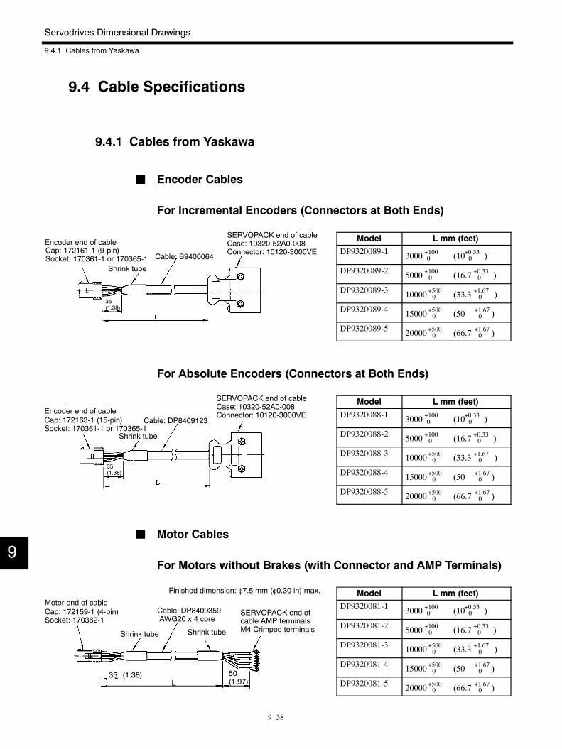
SERVOPACK end of cableCase: 10320-52A0-008Connector: 10120-3000VE
Cable: DP8409123
Shrink tube
Cap: 172163-1 (15-pin)Socket: 170361-1 or 170365-1
Encoder end of cable
35(1.38)
SERVOPACK end ofcable AMP terminalsM4 Crimped terminals
Shrink tube Shrink tube
Cable: DP8409359AWG20 x 4 core
Cap: 172159-1 (4-pin)Socket: 170362-1
Finished dimension: φ7.5 mm (φ0.30 in) max.
Motor end of cable
50(1.97)
35 (1.38)L
Servodrives Dimensional Drawings
9.4.1 Cables from Yaskawa
9 -38
9.4 Cable Specifications
9.4.1 Cables from Yaskawa
J Encoder Cables
For Incremental Encoders (Connectors at Both Ends)
Model L mm (feet)
DP9320089-1 3000 +1000 (10+0.330 )
DP9320089-2 5000 +1000 (16.7 +0.330 )
DP9320089-3 10000+5000 (33.3 +1.670 )
DP9320089-4 15000+5000 (50 +1.670 )
DP9320089-5 20000+5000 (66.7 +1.670 )
For Absolute Encoders (Connectors at Both Ends)
Model L mm (feet)
DP9320088-1 3000 +1000 (10+0.330 )
DP9320088-2 5000 +1000 (16.7 +0.330 )
DP9320088-3 10000+5000 (33.3 +1.670 )
DP9320088-4 15000+5000 (50 +1.670 )
DP9320088-5 20000+5000 (66.7 +1.670 )
J Motor Cables
For Motors without Brakes (with Connector and AMP Terminals)
Model L mm (feet)
DP9320081-1 3000 +1000 (10+0.330 )
DP9320081-2 5000 +1000 (16.7 +0.330 )
DP9320081-3 10000+5000 (33.3 +1.670 )
DP9320081-4 15000+5000 (50 +1.670 )
DP9320081-5 20000+5000 (66.7 +1.670 )
9
SERVOPACK end of cableCase: 10320-52A0-008Connector: 10120-3000VE
Cable: B9400064
Shrink tube
Cap: 172161-1 (9-pin)Socket: 170361-1 or 170365-1
Encoder end of cable
35(1.38)
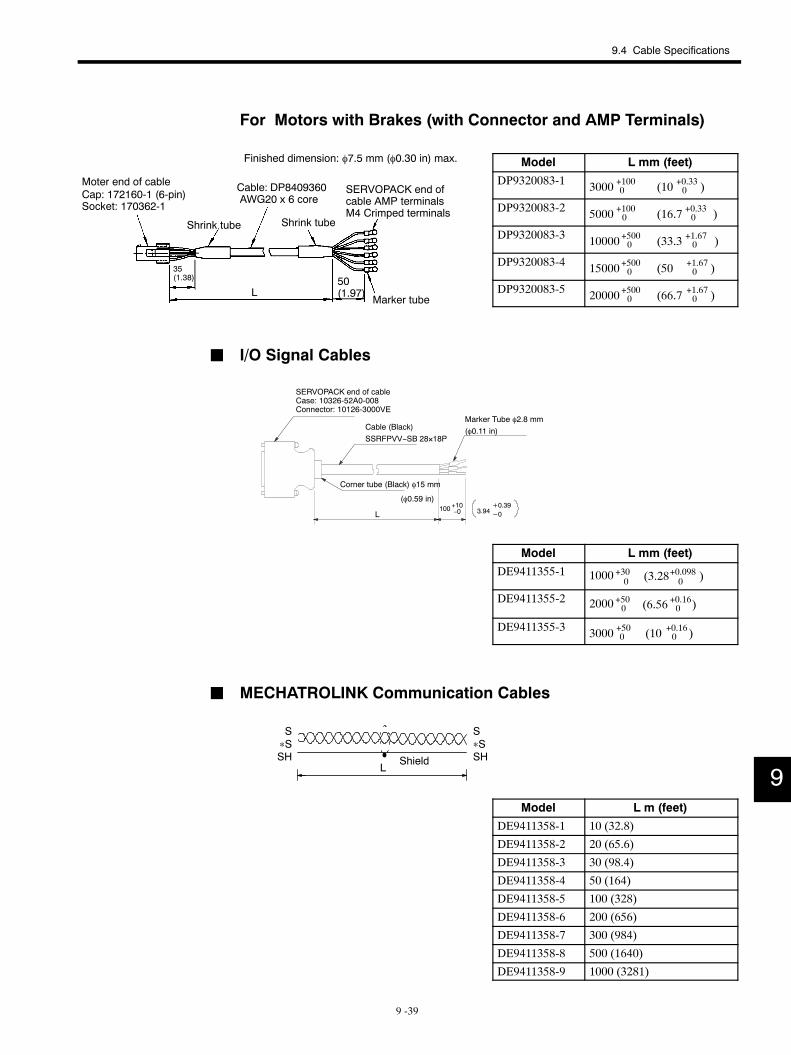
SERVOPACK end ofcable AMP terminalsM4 Crimped terminals
Shrink tube Shrink tube
Cable: DP8409360AWG20 x 6 coreCap: 172160-1 (6-pin)
Socket: 170362-1
Finished dimension: φ7.5 mm (φ0.30 in) max.
Marker tube
Moter end of cable
35(1.38) 50
(1.97)L
9.4 Cable Specifications
9 -39
For Motors with Brakes (with Connector and AMP Terminals)
Model L mm (feet)
DP9320083-1 3000 +1000 (10 +0.330 )
DP9320083-2 5000 +1000 (16.7 +0.330 )
DP9320083-3 10000+5000 (33.3 +1.670 )
DP9320083-4 15000+5000 (50 +1.670 )
DP9320083-5 20000+5000 (66.7 +1.670 )
J I/O Signal Cables
SERVOPACK end of cableCase: 10326-52A0-008Connector: 10126-3000VE
Cable (Black)SSRFPVV−SB 28×18P
Marker Tube φ2.8 mm(φ0.11 in)
Corner tube (Black) φ15 mm
L100+10−0
(φ0.59 in)3.94
+0.39−0
Model L mm (feet)
DE9411355-1 +3001000 (3.28 )+0.098
0
DE9411355-2 2000 +500 (6.56 )+0.160
DE9411355-3 3000 +500 (10 +0.160 )
J MECHATROLINK Communication Cables
S∗SSH
S∗SSHShield
L
Model L m (feet)
DE9411358-1 10 (32.8)
DE9411358-2 20 (65.6)
DE9411358-3 30 (98.4)
DE9411358-4 50 (164)
DE9411358-5 100 (328)
DE9411358-6 200 (656)
DE9411358-7 300 (984)
DE9411358-8 500 (1640)
DE9411358-9 1000 (3281)
9
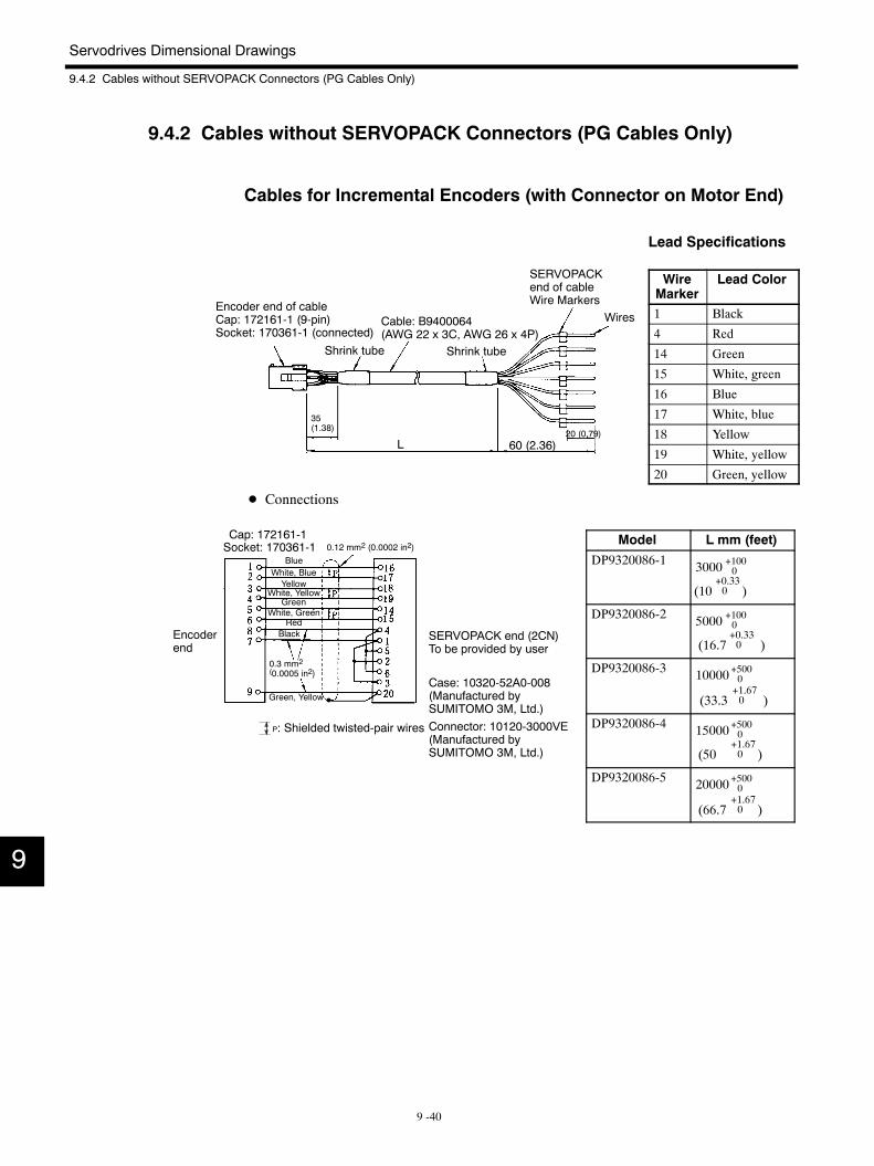
Encoder end of cableCap: 172161-1 (9-pin)Socket: 170361-1 (connected)
Shrink tube
Cable: B9400064(AWG 22 x 3C, AWG 26 x 4P)
Shrink tube
SERVOPACKend of cableWire Markers
Wires
35(1.38)
60 (2.36)20 (0.79)
L
BlueWhite, BlueYellow
White, YellowGreen
White, GreenRed
Black
Green, Yellow
Cap: 172161-1Socket: 170361-1
Case: 10320-52A0-008(Manufactured bySUMITOMO 3M, Ltd.)Connector: 10120-3000VE(Manufactured bySUMITOMO 3M, Ltd.)
P: Shielded twisted-pair wires
SERVOPACK end (2CN)To be provided by user
0.12 mm2 (0.0002 in2)
0.3 mm2(0.0005 in2)
Encoderend
Servodrives Dimensional Drawings
9.4.2 Cables without SERVOPACK Connectors (PG Cables Only)
9 -40
9.4.2 Cables without SERVOPACK Connectors (PG Cables Only)
Cables for Incremental Encoders (with Connector on Motor End)
Lead Specifications
WireMarker
Lead Color
1 Black
4 Red
14 Green
15 White, green
16 Blue
17 White, blue
18 Yellow
19 White, yellow
20 Green, yellow
D Connections
Model L mm (feet)
DP9320086-1 3000 +1000
(10+0.330 )
DP9320086-2 5000 +1000
(16.7+0.330 )
DP9320086-3 10000+5000
(33.3+1.670 )
DP9320086-4 15000+5000
(50+1.670 )
DP9320086-5 20000+5000
(66.7+1.670 )
9
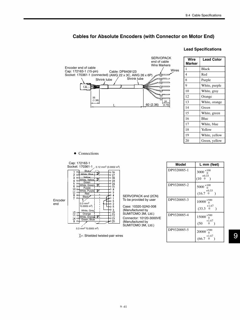
Encoder end of cableCap: 172163-1 (15-pin)Socket: 170361-1 (connected)
Shrink tube
Cable: DP8409123(AWG 22 x 3C, AWG 26 x 6P)
Shrink tube
SERVOPACKend of cableWire Markers
Wires
35(1.38)
60 (2.36)20(0.79)
BlueWhite, BlueYellow
White, YellowGreen
White, Green
RedBlack
Cap: 172163-1Socket: 170361-1
Case: 10320-52A0-008(Manufactured bySUMITOMO 3M, Ltd.)Connector: 10120-3000VE(Manufactured bySUMITOMO 3M, Ltd.)
P: Shielded twisted-pair wires
Purple
White, GreyOrange
White, OrangeGreen, Blue
SERVOPACK end (2CN)To be provided by user
White, Purple
0.12 mm2 (0.0002 in2)
0.3 mm2(0.0005 in2)
0.3 mm2 (0.0005 in2)
Encoderend
9.4 Cable Specifications
9 -41
Cables for Absolute Encoders (with Connector on Motor End)
Lead Specifications
WireMarker
Lead Color
1 Black
4 Red
8 Purple
9 White, purple
10 White, gray
12 Orange
13 White, orange
14 Green
15 White, green
16 Blue
17 White, blue
18 Yellow
19 White, yellow
20 Green, yellow
D Connections
Model L mm (feet)
DP9320085-1 3000 +1000
(10+0.330 )
DP9320085-2 5000 +1000
(16.7+0.330 )
DP9320085-3 10000+5000
(33.3+1.670 )
DP9320085-4 15000+5000
(50+1.670 )
DP9320085-5 20000+5000
(66.7+1.670 ) 9
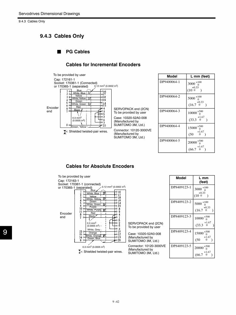
BlueWhite, BlueYellow
White,YellowGreen
White, GreenRed
Black
Green, Yellow
Case: 10320-52A0-008(Manufactured bySUMITOMO 3M, Ltd.)
Connector: 10120-3000VE(Manufactured bySUMITOMO 3M, Ltd.)
Cap: 172161-1Socket: 170361-1 (Connected)or 170365-1 (separated)
SERVOPACK end (2CN)To be provided by user
To be provided by user
P: Shielded twisted-pair wires.
0.12 mm2 (0.0002 in2)
0.3 mm2
(0.0005 in2)
Encoderend
BlueWhite, BlueYellow
White, YellowGreen
White, Green
RedBlack
Purple
White, GreyOrange
White, OrangeGreen, Blue
White, Purple
Case: 10320-52A0-008(Manufactured bySUMITOMO 3M, Ltd.)
Connector: 10120-3000VE(Manufactured bySUMITOMO 3M, Ltd.)
Cap: 172163-1Socket: 170361-1 (connected)or 170365-1 (separated)
To be provided by user
SERVOPACK end (2CN)To be provided by user
0.12 mm2 (0.0002 in2)
0.3 mm2
(0.0005 in2)
0.3 mm2 (0.0005 in2)
Encoderend
P: Shielded twisted-pair wires.
Servodrives Dimensional Drawings
9.4.3 Cables Only
9 -42
9.4.3 Cables Only
J PG Cables
Cables for Incremental Encoders
Model L mm (feet)
DP9400064-1 3000 +1000
(10+0.330 )
DP9400064-2 5000 +1000
(16.7+0.330 )
DP9400064-3 10000+5000
(33.3+1.670 )
DP9400064-4 15000+5000
(50+1.670 )
DP9400064-5 20000+5000
(66.7+1.670 )
Cables for Absolute Encoders
Model L mm(feet)
DP8409123-1 3000 +1000
(10+0.330 )
DP8409123-2 5000 +1000
(16.7+0.330 )
DP8409123-3 10000+5000
(33.3+1.670 )
DP8409123-4 15000+5000
(50+1.670 )
DP8409123-5 20000+5000
(66.7+1.670 )
9
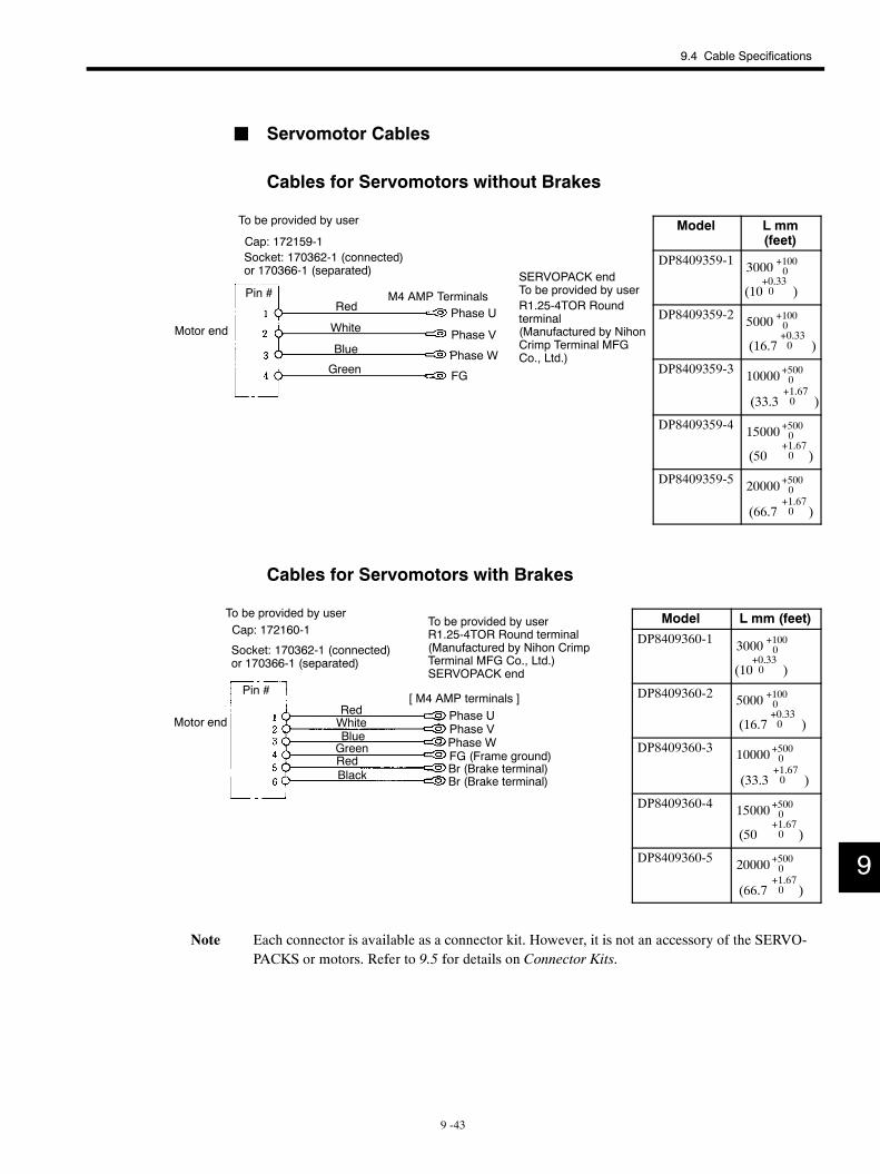
Pin #Red
White
Blue
Green
M4 AMP TerminalsPhase U
Phase V
Phase W
FG
Cap: 172159-1Socket: 170362-1 (connected)or 170366-1 (separated) SERVOPACK end
To be provided by userR1.25-4TOR Roundterminal(Manufactured by NihonCrimp Terminal MFGCo., Ltd.)
To be provided by user
Motor end
RedWhiteBlueGreenRedBlack
Pin #
Phase UPhase VPhase WFG (Frame ground)Br (Brake terminal)Br (Brake terminal)
Cap: 172160-1
Socket: 170362-1 (connected)or 170366-1 (separated)
To be provided by userTo be provided by userR1.25-4TOR Round terminal(Manufactured by Nihon CrimpTerminal MFG Co., Ltd.)SERVOPACK end
[ M4 AMP terminals ]
Motor end
9.4 Cable Specifications
9 -43
J Servomotor Cables
Cables for Servomotors without Brakes
Model L mm(feet)
DP8409359-1 3000 +1000
(10+0.330 )
DP8409359-2 5000 +1000
(16.7+0.330 )
DP8409359-3 10000+5000
(33.3+1.670 )
DP8409359-4 15000+5000
(50+1.670 )
DP8409359-5 20000+5000
(66.7+1.670 )
Cables for Servomotors with Brakes
Model L mm (feet)
DP8409360-1 3000 +1000
(10+0.330 )
DP8409360-2 5000 +1000
(16.7+0.330 )
DP8409360-3 10000+5000
(33.3+1.670 )
DP8409360-4 15000+5000
(50+1.670 )
DP8409360-5 20000+5000
(66.7+1.670 )
Note Each connector is available as a connector kit. However, it is not an accessory of the SERVO-PACKS or motors. Refer to 9.5 for details on Connector Kits.
9
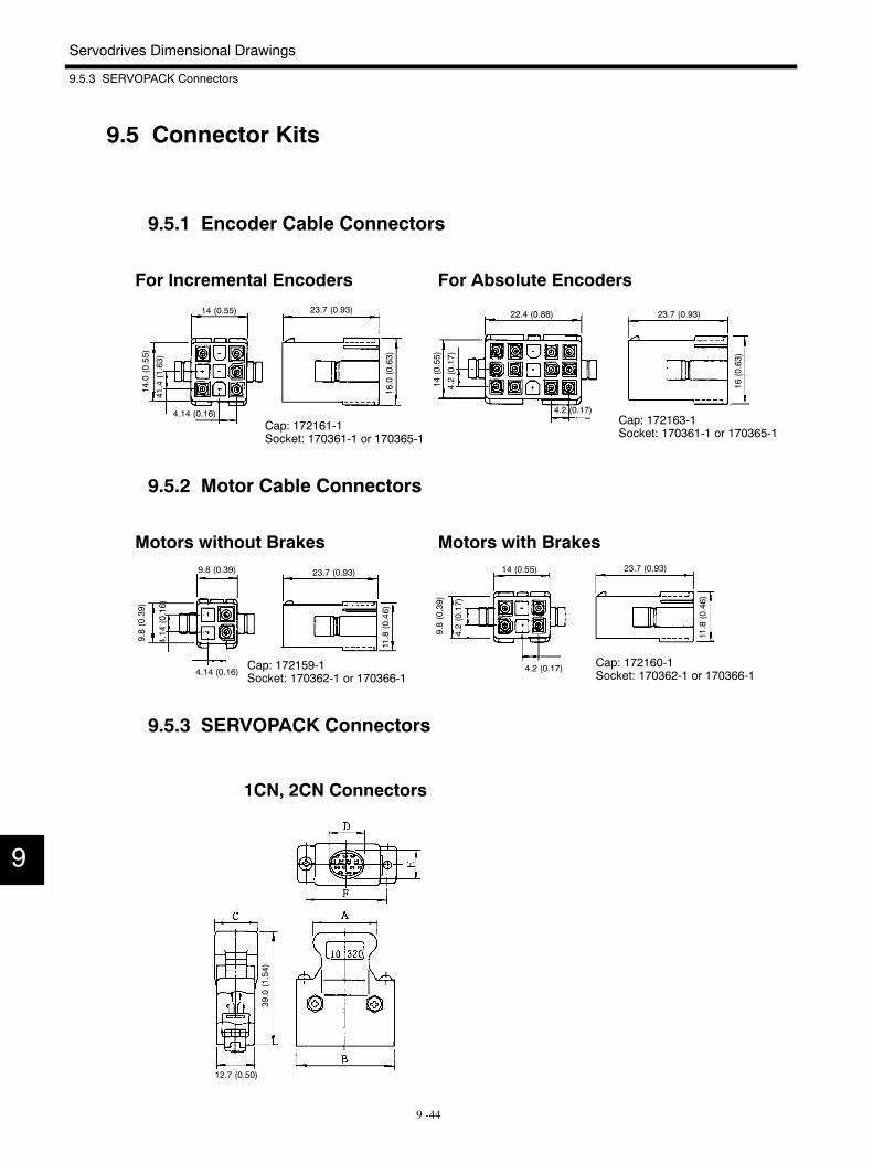
Servodrives Dimensional Drawings
9.5.3 SERVOPACK Connectors
9 -44
9.5 Connector Kits
9.5.1 Encoder Cable Connectors
Cap: 172161-1Socket: 170361-1 or 170365-1
14 (0.55) 23.7 (0.93)
14.0(0.55)
41.4(1.63)
4.14 (0.16)
16.0(0.63)
For Incremental Encoders For Absolute Encoders
Cap: 172163-1Socket: 170361-1 or 170365-1
22.4 (0.88)
14(0.55)
4.2(0.17)
4.2 (0.17)
23.7 (0.93)
16(0.63)
9.5.2 Motor Cable Connectors
Motors without Brakes Motors with Brakes
Cap: 172159-1Socket: 170362-1 or 170366-1
9.8 (0.39)
9.8(0.39)
4.14 (0.16)
4.14
(0.16)
23.7 (0.93)
11.8(0.46)
Cap: 172160-1Socket: 170362-1 or 170366-1
9.8(0.39)
14 (0.55)
4.2(0.17)
4.2 (0.17)
23.7 (0.93)
11.8(0.46)
9.5.3 SERVOPACK Connectors
1CN, 2CN Connectors
39.0(1.54)
12.7 (0.50)
9
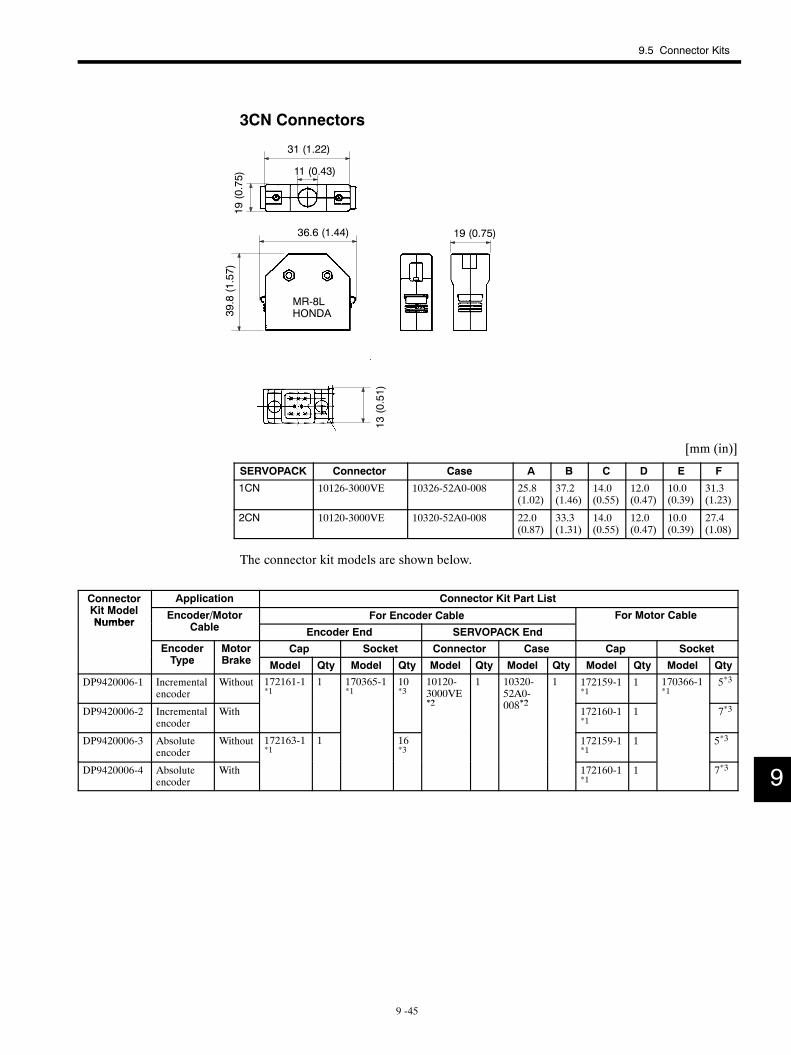
9.5 Connector Kits
9 -45
3CN Connectors
31 (1.22)
36.6 (1.44)
11 (0.43)
19 (0.75)19
(0.75)
39.8(1.57)
MR-8LHONDA
13(0.51)
[mm (in)]
SERVOPACK Connector Case A B C D E F
1CN 10126-3000VE 10326-52A0-008 25.8(1.02)
37.2(1.46)
14.0(0.55)
12.0(0.47)
10.0(0.39)
31.3(1.23)
2CN 10120-3000VE 10320-52A0-008 22.0(0.87)
33.3(1.31)
14.0(0.55)
12.0(0.47)
10.0(0.39)
27.4(1.08)
The connector kit models are shown below.
ConnectorKit M d l
Application Connector Kit Part ListKit ModelNumber
Encoder/MotorC bl
For Encoder Cable For Motor CableNumber
/Cable Encoder End SERVOPACK End
EncoderT
MotorB k
Cap Socket Connector Case Cap SocketType Brake Model Qty Model Qty Model Qty Model Qty Model Qty Model Qty
DP9420006-1 Incrementalencoder
Without 172161-1*1
1 170365-1*1
10*3
10120-3000VE*2
1 10320-52A0-008*2
1 172159-1*1
1 170366-1*1
5*3
DP9420006-2 Incrementalencoder
With*2 008*2 172160-1
*11 7*3
DP9420006-3 Absoluteencoder
Without 172163-1*1
1 16*3
172159-1*1
1 5*3
DP9420006-4 Absoluteencoder
With 172160-1*1
1 7*3 9
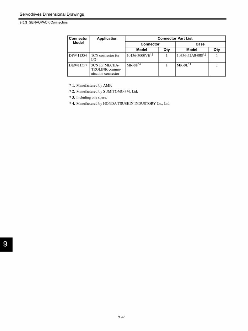
Servodrives Dimensional Drawings
9.5.3 SERVOPACK Connectors
9 -46
ConnectorM d l
Application Connector Part ListModel
pp
Connector CaseModel Qty Model Qty
DP9411354 1CN connector forI/O
10136-3000VE*2 1 10336-52A0-008*2 1
DE9411357 3CN for MECHA-TROLINK commu-nication connector
MR-8F*4 1 MR-8L*4 1
* 1. Manufactured by AMP.
* 2. Manufactured by SUMITOMO 3M, Ltd.
* 3. Including one spare.
* 4. Manufactured by HONDA TSUSHIN INDUSTORY Co., Ltd.
9
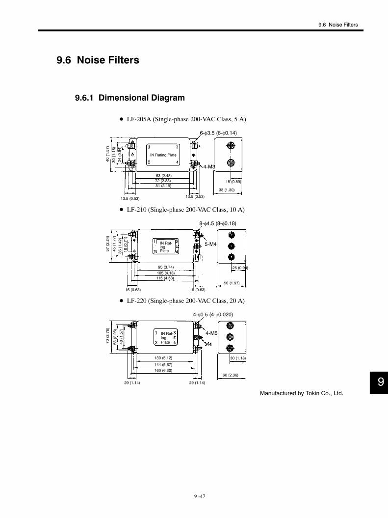
9.6 Noise Filters
9 -47
9.6 Noise Filters
9.6.1 Dimensional Diagram
D LF-205A (Single-phase 200-VAC Class, 5 A)
4-M3
IN Rating Plate
6-φ3.5 (6-φ0.14)
40(1.57)
30(1.18)
24(0.94)
13.5 (0.53)
63 (2.48)72 (2.83)81 (3.19)
13.5 (0.53)
33 (1.30)
15 (0.59)
D LF-210 (Single-phase 200-VAC Class, 10 A)
IN Rat-ingPlate
8-φ4.5 (8-φ0.18)
5-M4
57(2.24)
45(1.77)
36(1.42)
18(0.71)
16 (0.63)
95 (3.74)105 (4.13)115 (4.53)
25 (0.98)
50 (1.97)
16 (0.63)
D LF-220 (Single-phase 200-VAC Class, 20 A)
4-φ0.5 (4-φ0.020)
4-M5IN Rat-ingPlate70
(2.76)
58(2.28)
40(1.57)
130 (5.12)
144 (5.67)160 (6.30)
29 (1.14) 29 (1.14)
30 (1.18)
60 (2.36)
Manufactured by Tokin Co., Ltd.
9
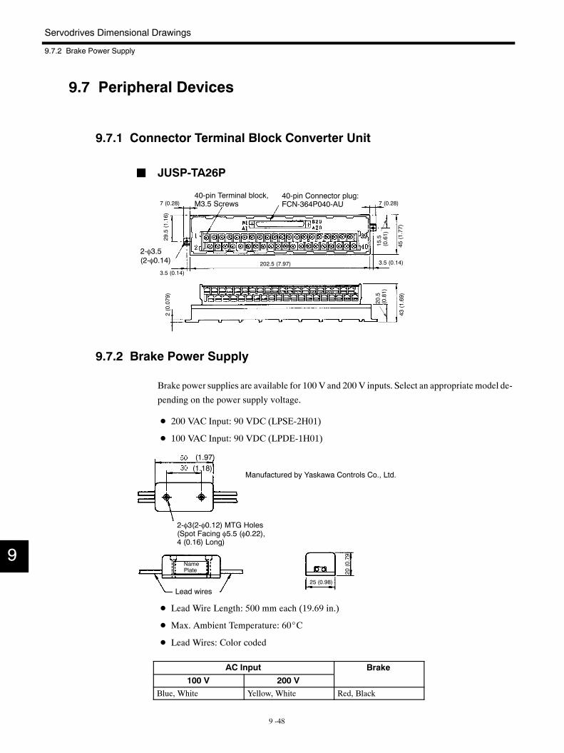
Servodrives Dimensional Drawings
9.7.2 Brake Power Supply
9 -48
9.7 Peripheral Devices
9.7.1 Connector Terminal Block Converter Unit
J JUSP-TA26P
2-φ3.5(2-φ0.14)
40-pin Connector plug:FCN-364P040-AU
40-pin Terminal block,M3.5 Screws7 (0.28)
29.5(1.16)
3.5 (0.14)
202.5 (7.97)
7 (0.28)
15.5
(0.61)
45(1.77)
3.5 (0.14)
2(0.079)
20.5
(0.81)
43(1.69)
9.7.2 Brake Power Supply
Brake power supplies are available for 100 V and 200 V inputs. Select an appropriate model de-
pending on the power supply voltage.
D 200 VAC Input: 90 VDC (LPSE-2H01)
D 100 VAC Input: 90 VDC (LPDE-1H01)
Manufactured by Yaskawa Controls Co., Ltd.
NamePlate
Lead wires
(1.97)(1.18)
25 (0.98)
2-φ3(2-φ0.12) MTG Holes(Spot Facing φ5.5 (φ0.22),4 (0.16) Long)
20(0.79)
D Lead Wire Length: 500 mm each (19.69 in.)
D Max. Ambient Temperature: 60_C
D Lead Wires: Color coded
AC Input Brake
100 V 200 VBlue, White Yellow, White Red, Black
9
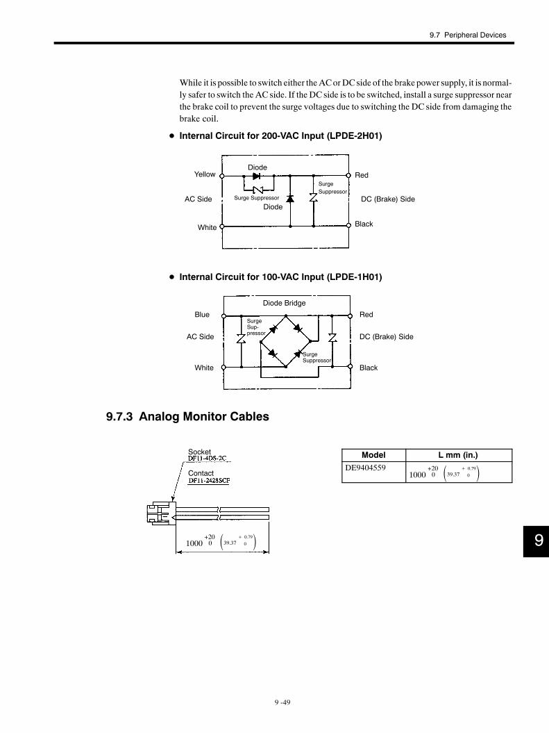
Socket
Contact
1000+200 39.37 + 0.79
0
9.7 Peripheral Devices
9 -49
While it is possible to switch either theACorDC side of the brake power supply, it is normal-ly safer to switch the AC side. If the DC side is to be switched, install a surge suppressor nearthe brake coil to prevent the surge voltages due to switching the DC side from damaging thebrake coil.
D Internal Circuit for 200-VAC Input (LPDE-2H01)
Yellow
AC Side
White
SurgeSuppressor
Diode
Red
DC (Brake) Side
Black
Diode
Surge Suppressor
D Internal Circuit for 100-VAC Input (LPDE-1H01)
Blue
AC Side
White
Diode Bridge
SurgeSup-pressor
SurgeSuppressor
Red
DC (Brake) Side
Black
9.7.3 Analog Monitor Cables
Model L mm (in.)
DE94045591000
+200 39.37 + 0.79
0
9
10 -1
10Trial Operation
This chapter describes how to conduct a full trial operation.
10.1 Check Items before Trial Operation 10 -2. . . . . . . . .10.1.1 Servomotors 10 -2. . . . . . . . . . . . . . . . . . . . . . . . . . . . . . .
10.1.2 SERVOPACKS 10 -2. . . . . . . . . . . . . . . . . . . . . . . . . . . . .
10.2 Trial Operation Procedure 10 -3. . . . . . . . . . . . . . . . .10.2.1 Preparation for Trial Operation 10 -3. . . . . . . . . . . . . . .
10.2.2 Operation 10 -3. . . . . . . . . . . . . . . . . . . . . . . . . . . . . . . . .
10.2.3 Trial Operation Inspection 10 -4. . . . . . . . . . . . . . . . . . .
10
Trial Operation
10.1.2 SERVOPACKS
10 -2
10.1 Check Items before Trial Operation
Inspect the following items before conducting trial operation. Also conduct the inspections accord-
ing to Chapter 12 “Maintenance and Inspection” if conducting trial operation on Servomotors that
have been stored for a long period of time.
10.1.1 Servomotors
D Connection to machines or devices, wiring and grounding are correct.
D Bolts and nuts are tightened.
D For motors with oil seals, the seals are not damaged and motor is properly lubricated.
10.1.2 SERVOPACKS
D User constants are properly set for the applicable Servomotor and specifications.
D Terminal connections and wiring leads are tightened securely. Connectors are inserted se-curely.
D The power supply is turned OFF if a servo alarm occurs.
D Voltage supplied to SGD SERVOPACK is 200 to 230 V +10−15 % (100 to 115 V +10
−15 %).
(When using a power supply that is not 200 V (100 V), a transformer that steps down to200 V (100 V) must be installed separately.)
Take appropriate action immediately if an alarm occurs or one of the items above is incorrect.
10
10.2 Trial Operation Procedure
10 -3
10.2 Trial Operation Procedure
10.2.1 Preparation for Trial Operation
To prevent accidents, initially conduct trial operation with no load connected to the Servomotor. If the trial op-eration must be conducted while connected to equipment, confirm that the driven system is ready for an emer-gency stop at any time.
Prepare operation according to the following procedure.
1. Turn the power ON.If the power supply ON sequence is correct as shown in Chapter 5, press the ON switchto turn ON power. Press and hold the switch for about two seconds in Figure 5.1 ofChapter5.
2. If the power is supplied normally, the power-ON indicator LED (green) will light. Afterthe CONNECT (establish connection) command is transferred, the alarm LED (red) willgo OFF. Use the SMON (status monitoring) command to check SERVOPACK status. Thedata returned from the SERVOPACK is alarm code 99.
3. Use the ID_RD (read ID) command to check the SERVOPACK type. The SERVOPACKreturns “SGD−***N.”
4. Transfer the parameters required for trial operation (such as motor selection, encoder type,and encoder pulses) by PRM_WR (write parameter) command.
5. Transfer a SENS_ON (encoder power ON) command and verify that no alarm has oc-curred. Position data is also received with an absolute encoder.
6. When the SV_ON (Servo ON) command transfer, the power circuit in the SERVOPACKis activated and the Servomotor is ready to drive. If the SMON command is transfer, statusSVON = 1 (base driving) will be returned.
* As factory settings the motor is set to an SGMmotor and the encoder is set to an incremen-tal encoder (2048 P/R). When using any other motors, the parameters must be changed.
10.2.2 Operation
Driving a Servomotor is possible only when the main circuit is in active base driving. Run the
Servomotor at low speed.
J Command Transmission Example
POSING (rapid traverse positioning) command
Option = 0
Positioning setting = 10000 (current position + 10000 with absolute encoder)
Rapid traverse speed = 400
Make sure the Servomotor is running in the proper direction according to the reference.
10IMPORTANT
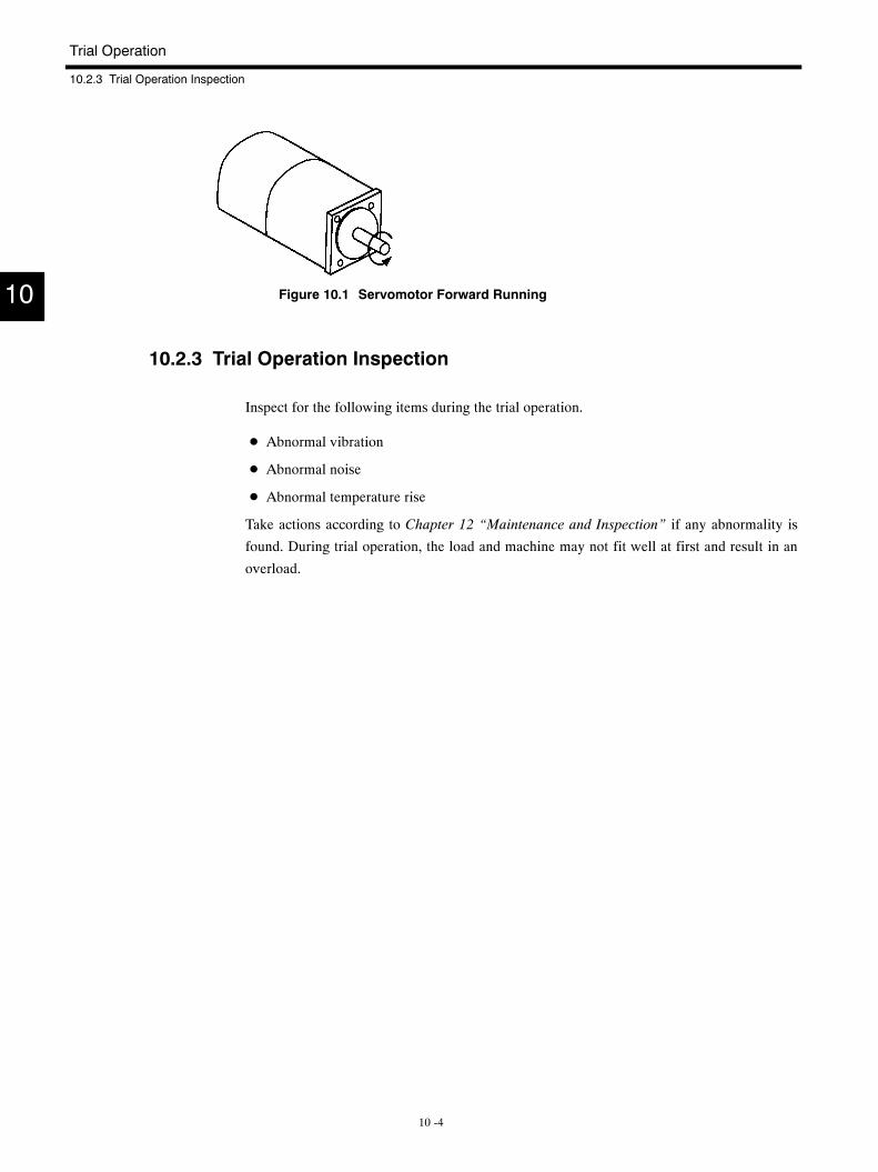
Trial Operation
10.2.3 Trial Operation Inspection
10 -4
Figure 10.1 Servomotor Forward Running
10.2.3 Trial Operation Inspection
Inspect for the following items during the trial operation.
D Abnormal vibration
D Abnormal noise
D Abnormal temperature rise
Take actions according to Chapter 12 “Maintenance and Inspection” if any abnormality is
found. During trial operation, the load and machine may not fit well at first and result in an
overload.
10
11 -1
11Settings
This chapter describes characteristics at the factory before shipping and
Servo performance adjustment.
11.1 Characteristics at the Factory 11 -2. . . . . . . . . . . . . .11.2 Resetting 11 -2. . . . . . . . . . . . . . . . . . . . . . . . . . . . . . .11.3 Adjusting Servo Performance 11 -3. . . . . . . . . . . . . .
11.3.1 Setting User Constants 11 -3. . . . . . . . . . . . . . . . . . . . . .
11.3.2 Setting Optimum Position and Speed Loop Gain 11 -3
11
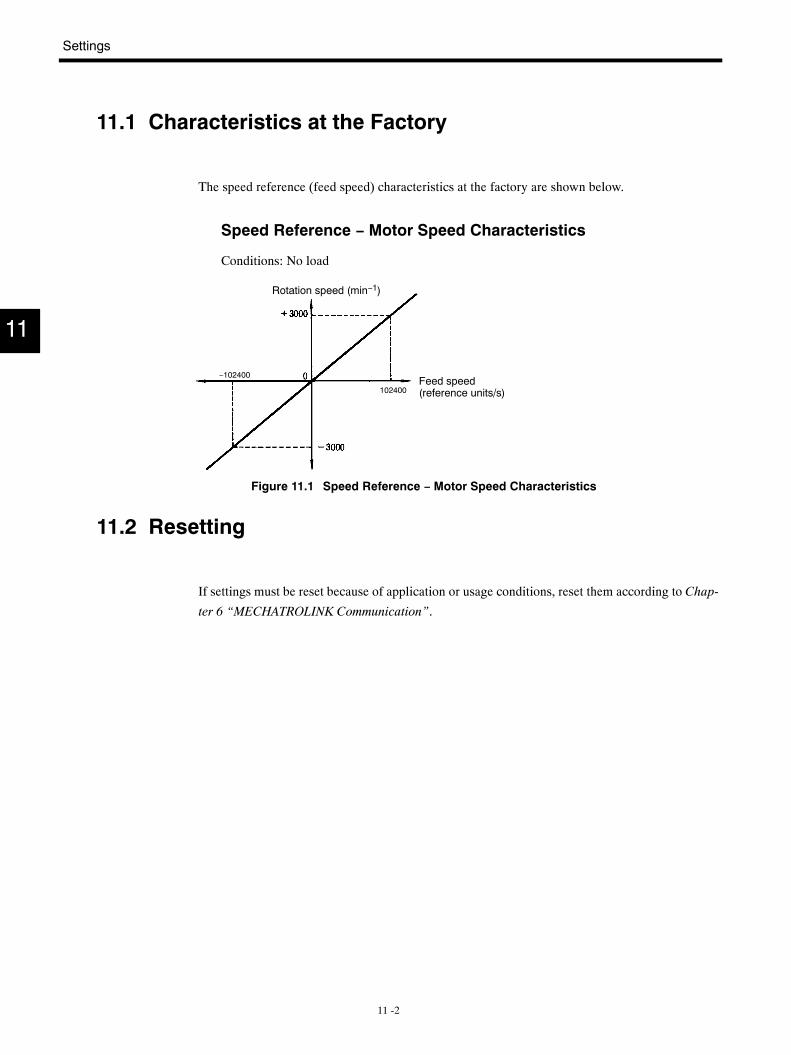
Settings
11 -2
11.1 Characteristics at the Factory
The speed reference (feed speed) characteristics at the factory are shown below.
Speed Reference − Motor Speed Characteristics
Conditions: No load
Rotation speed (min−1)
Feed speed(reference units/s)
−102400
102400
Figure 11.1 Speed Reference − Motor Speed Characteristics
11.2 Resetting
If settings must be reset because of application or usage conditions, reset them according to Chap-
ter 6 “MECHATROLINK Communication”.
11
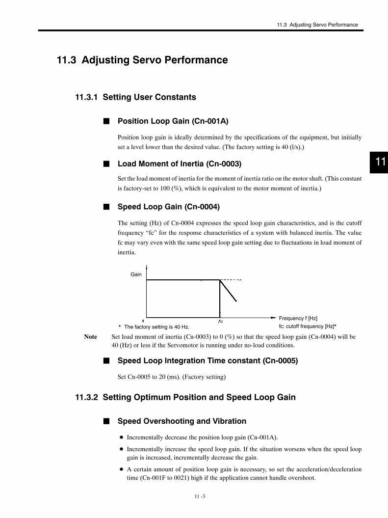
11.3 Adjusting Servo Performance
11 -3
11.3 Adjusting Servo Performance
11.3.1 Setting User Constants
J Position Loop Gain (Cn-001A)
Position loop gain is ideally determined by the specifications of the equipment, but initially
set a level lower than the desired value. (The factory setting is 40 (l/s).)
J Load Moment of Inertia (Cn-0003)
Set the load moment of inertia for the moment of inertia ratio on the motor shaft. (This constant
is factory-set to 100 (%), which is equivalent to the motor moment of inertia.)
J Speed Loop Gain (Cn-0004)
The setting (Hz) of Cn-0004 expresses the speed loop gain characteristics, and is the cutoff
frequency “fc” for the response characteristics of a system with balanced inertia. The value
fc may vary even with the same speed loop gain setting due to fluctuations in load moment of
inertia.
Gain
Frequency f [Hz]
* The factory setting is 40 Hz. fc: cutoff frequency [Hz]*
Note Set load moment of inertia (Cn-0003) to 0 (%) so that the speed loop gain (Cn-0004) will be40 (Hz) or less if the Servomotor is running under no-load conditions.
J Speed Loop Integration Time constant (Cn-0005)
Set Cn-0005 to 20 (ms). (Factory setting)
11.3.2 Setting Optimum Position and Speed Loop Gain
J Speed Overshooting and Vibration
D Incrementally decrease the position loop gain (Cn-001A).
D Incrementally increase the speed loop gain. If the situation worsens when the speed loopgain is increased, incrementally decrease the gain.
D A certain amount of position loop gain is necessary, so set the acceleration/decelerationtime (Cn-001F to 0021) high if the application cannot handle overshoot.
11

Settings
11.3.2 Setting Optimum Position and Speed Loop Gain
11 -4
J When Response Tracking Worsens
D Incrementally increase the position loop gain (Cn-0001A).
D If the position loop gain cannot be increased any higher because of vibration, incrementallyincrease the speed loop gain (Cn-0004). If increasing the speed loop gain causes vibration,then tracking performance including that for the mechanical system is at its limit.
11

12 -1
12Maintenance and Inspection
This chapter describes Servodrive maintenance, inspection, and trouble-
shooting.
12.1 Servodrive Maintenance and Inspection ofServodrives 12 -2. . . . . . . . . . . . . . . . . . . . . . . . . . . . .12.1.1 Servomotor 12 -2. . . . . . . . . . . . . . . . . . . . . . . . . . . . . . . .
12.1.2 SERVOPACK Inspection 12 -3. . . . . . . . . . . . . . . . . . . .
12.1.3 Replacing Battery for Absolute Encoder 12 -3. . . . . . .
12.2 Troubleshooting 12 -4. . . . . . . . . . . . . . . . . . . . . . . . .12.2.1 Servomotor 12 -4. . . . . . . . . . . . . . . . . . . . . . . . . . . . . . . .
12.2.2 SERVOPACK 12 -5. . . . . . . . . . . . . . . . . . . . . . . . . . . . . .
12
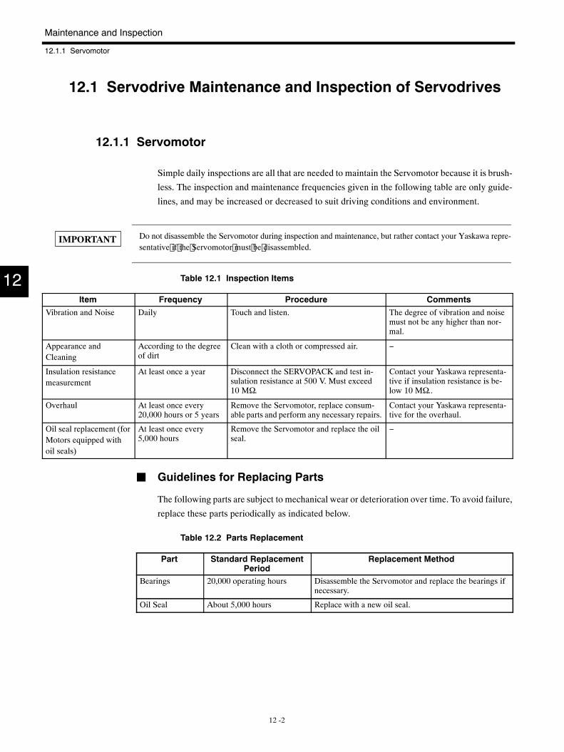
Maintenance and Inspection
12.1.1 Servomotor
12 -2
12.1 Servodrive Maintenance and Inspection of Servodrives
12.1.1 Servomotor
Simple daily inspections are all that are needed to maintain the Servomotor because it is brush-
less. The inspection and maintenance frequencies given in the following table are only guide-
lines, and may be increased or decreased to suit driving conditions and environment.
Do not disassemble the Servomotor during inspection and maintenance, but rather contact your Yaskawa repre-sentative if the Servomotor must be disassembled.
Table 12.1 Inspection Items
Item Frequency Procedure CommentsVibration and Noise Daily Touch and listen. The degree of vibration and noise
must not be any higher than nor-mal.
Appearance andCleaning
According to the degreeof dirt
Clean with a cloth or compressed air. −
Insulation resistancemeasurement
At least once a year Disconnect the SERVOPACK and test in-sulation resistance at 500 V. Must exceed10 MΩ.
Contact your Yaskawa representa-tive if insulation resistance is be-low 10 MΩ..
Overhaul At least once every20,000 hours or 5 years
Remove the Servomotor, replace consum-able parts and perform any necessary repairs.
Contact your Yaskawa representa-tive for the overhaul.
Oil seal replacement (forMotors equipped withoil seals)
At least once every5,000 hours
Remove the Servomotor and replace the oilseal.
−
J Guidelines for Replacing Parts
The following parts are subject to mechanical wear or deterioration over time. To avoid failure,
replace these parts periodically as indicated below.
Table 12.2 Parts Replacement
Part Standard ReplacementPeriod
Replacement Method
Bearings 20,000 operating hours Disassemble the Servomotor and replace the bearings ifnecessary.
Oil Seal About 5,000 hours Replace with a new oil seal.
12
IMPORTANT
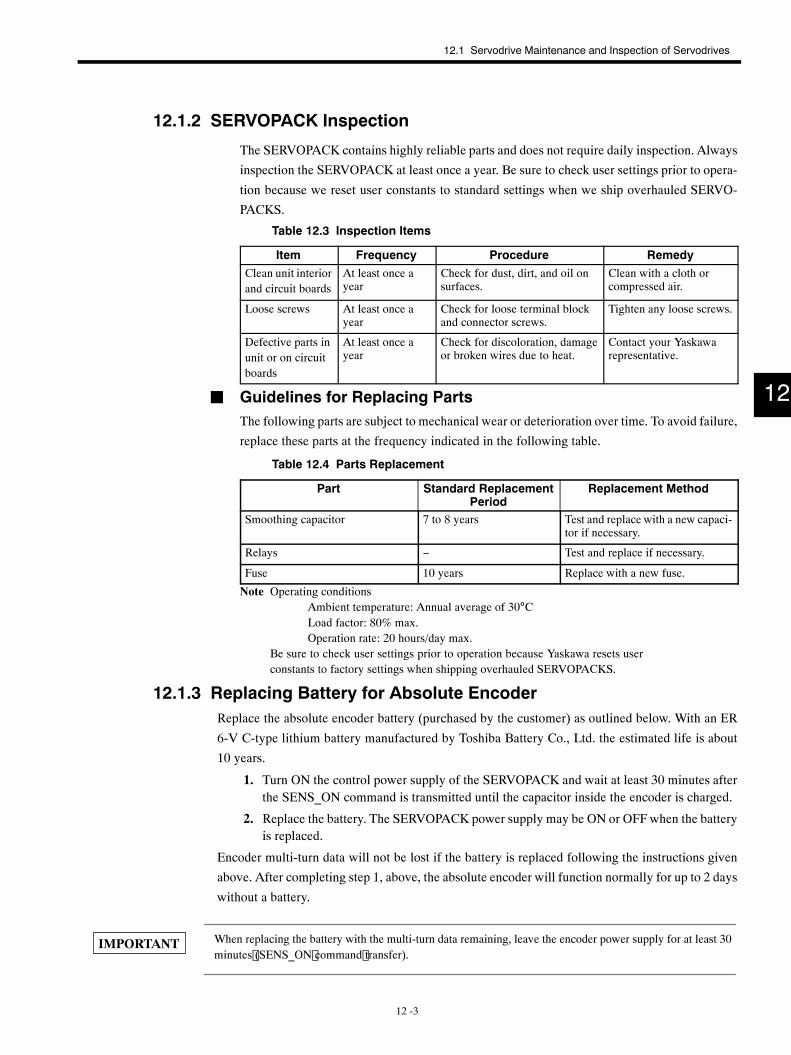
12.1 Servodrive Maintenance and Inspection of Servodrives
12 -3
12.1.2 SERVOPACK Inspection
The SERVOPACK contains highly reliable parts and does not require daily inspection. Always
inspection the SERVOPACK at least once a year. Be sure to check user settings prior to opera-
tion because we reset user constants to standard settings when we ship overhauled SERVO-
PACKS.
Table 12.3 Inspection Items
Item Frequency Procedure RemedyClean unit interiorand circuit boards
At least once ayear
Check for dust, dirt, and oil onsurfaces.
Clean with a cloth orcompressed air.
Loose screws At least once ayear
Check for loose terminal blockand connector screws.
Tighten any loose screws.
Defective parts inunit or on circuitboards
At least once ayear
Check for discoloration, damageor broken wires due to heat.
Contact your Yaskawarepresentative.
J Guidelines for Replacing PartsThe following parts are subject to mechanical wear or deterioration over time. To avoid failure,
replace these parts at the frequency indicated in the following table.
Table 12.4 Parts Replacement
Part Standard ReplacementPeriod
Replacement Method
Smoothing capacitor 7 to 8 years Test and replace with a new capaci-tor if necessary.
Relays − Test and replace if necessary.
Fuse 10 years Replace with a new fuse.
Note Operating conditionsAmbient temperature: Annual average of 30°CLoad factor: 80% max.Operation rate: 20 hours/day max.
Be sure to check user settings prior to operation because Yaskawa resets userconstants to factory settings when shipping overhauled SERVOPACKS.
12.1.3 Replacing Battery for Absolute EncoderReplace the absolute encoder battery (purchased by the customer) as outlined below. With an ER
6-V C-type lithium battery manufactured by Toshiba Battery Co., Ltd. the estimated life is about
10 years.
1. Turn ON the control power supply of the SERVOPACK and wait at least 30 minutes afterthe SENS_ON command is transmitted until the capacitor inside the encoder is charged.
2. Replace the battery. The SERVOPACK power supply may be ON or OFF when the batteryis replaced.
Encoder multi-turn data will not be lost if the battery is replaced following the instructions given
above. After completing step 1, above, the absolute encoder will function normally for up to 2 days
without a battery.
When replacing the battery with the multi-turn data remaining, leave the encoder power supply for at least 30minutes (SENS_ON command transfer).
12
IMPORTANT
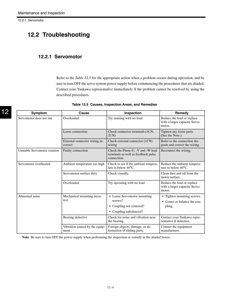
Maintenance and Inspection
12.2.1 Servomotor
12 -4
12.2 Troubleshooting
12.2.1 Servomotor
Refer to the Table 12.5 for the appropriate action when a problem occurs during operation, and be
sure to turn OFF the servo system power supply before commencing the procedures that are shaded.
Contact your Yaskawa representative immediately if the problem cannot be resolved by using the
described procedures.
Table 12.5 Causes, Inspection Areas, and Remedies
Symptom Cause Inspection RemedyServomotor does not run Overloaded Try running with no load Reduce the load or replace
with a larger capacity Servo-motor.
Loose connection Check connector terminals (1CN,2CN)
Tighten any loose parts.(See the Note.)
External connector wiring in-correct
Check external connector (1CN)wiring
Refer to the connection dia-gram and correct the wiring.
Unstable Servomotor rotation Faulty connection Check the Phase-U, -V and -W leadterminals as well as feedback pulseconnection.
Reconnect the wiring.
Servomotor overheated Ambient temperature too high Check to see if the ambient tempera-ture is below 40°C.
Reduce the ambient tempera-ture to below 40°C.
Servomotor surface dirty Check visually. Clean dust and oil from themotor surface.
Overloaded Try operating with no load Reduce the load or replacewith a larger capacity Servo-motor.
Abnormal noise Mechanical mounting incor-rect
S Loose Servomotor mountingscrews?
S Coupling not centered?
S Coupling unbalanced?
S Tighten mounting screws.
S Center or balance the cou-pling.
Bearing defective Check for noise and vibration nearthe bearing.
Contact your Yaskawa repre-sentative if defective.
Vibration caused by the equip-ment
Foreign objects, damage, or de-formation of sliding parts.
Contact the equipmentmanufacturer.
Note Be sure to turn OFF the power supply when performing the inspection or remedy in the shaded boxes.
12
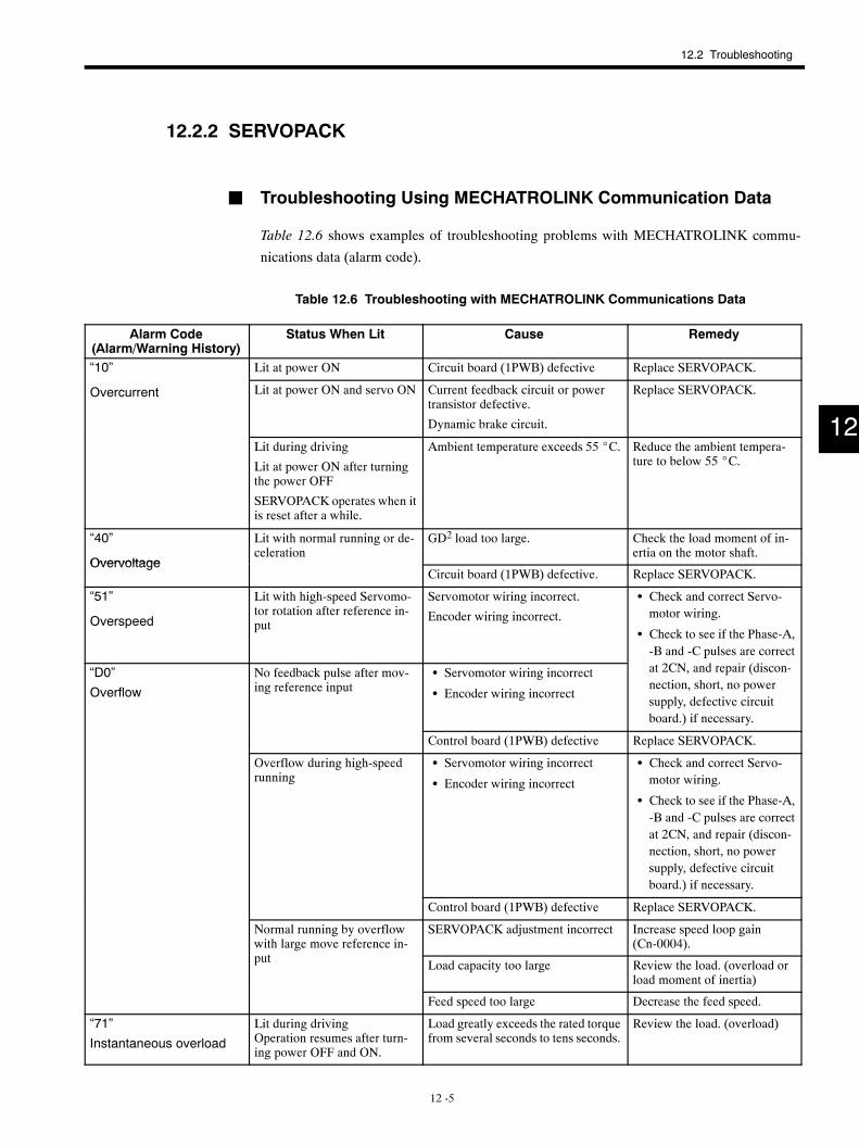
12.2 Troubleshooting
12 -5
12.2.2 SERVOPACK
J Troubleshooting Using MECHATROLINK Communication Data
Table 12.6 shows examples of troubleshooting problems with MECHATROLINK commu-
nications data (alarm code).
Table 12.6 Troubleshooting with MECHATROLINK Communications Data
Alarm Code(Alarm/Warning History)
Status When Lit Cause Remedy
“10” Lit at power ON Circuit board (1PWB) defective Replace SERVOPACK.
Overcurrent Lit at power ON and servo ON Current feedback circuit or powertransistor defective.
Dynamic brake circuit.
Replace SERVOPACK.
Lit during driving
Lit at power ON after turningthe power OFF
SERVOPACK operates when itis reset after a while.
Ambient temperature exceeds 55 _C. Reduce the ambient tempera-ture to below 55 _C.
“40”
Overvoltage
Lit with normal running or de-celeration
GD2 load too large. Check the load moment of in-ertia on the motor shaft.
OvervoltageCircuit board (1PWB) defective. Replace SERVOPACK.
“51”
Overspeed
Lit with high-speed Servomo-tor rotation after reference in-put
Servomotor wiring incorrect.
Encoder wiring incorrect.
S Check and correct Servo-motor wiring.
S Check to see if the Phase-A,-B and -C pulses are correct
“D0”
Overflow
No feedback pulse after mov-ing reference input
S Servomotor wiring incorrect
S Encoder wiring incorrect
pat 2CN, and repair (discon-nection, short, no powersupply, defective circuitboard.) if necessary.
Control board (1PWB) defective Replace SERVOPACK.
Overflow during high-speedrunning
S Servomotor wiring incorrect
S Encoder wiring incorrect
S Check and correct Servo-motor wiring.
S Check to see if the Phase-A,-B and -C pulses are correctat 2CN, and repair (discon-nection, short, no powersupply, defective circuitboard.) if necessary.
Control board (1PWB) defective Replace SERVOPACK.
Normal running by overflowwith large move reference in-t
SERVOPACK adjustment incorrect Increase speed loop gain(Cn-0004).g
put Load capacity too large Review the load. (overload orload moment of inertia)
Feed speed too large Decrease the feed speed.
“71”
Instantaneous overload
Lit during drivingOperation resumes after turn-ing power OFF and ON.
Load greatly exceeds the rated torquefrom several seconds to tens seconds.
Review the load. (overload)
12
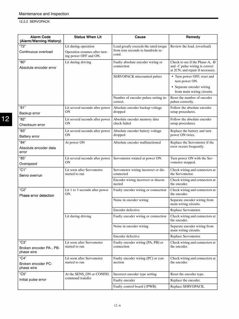
Maintenance and Inspection
12.2.2 SERVOPACK
12 -6
Alarm Code(Alarm/Warning History)
RemedyCauseStatus When Lit
“72”
Continuous overload
Lit during operation
Operation resumes after turn-ing power OFF and ON.
Load greatly exceeds the rated torquefrom tens seconds to hundreds se-cond.
Review the load. (overload)
“80”
Absolute encoder error
Lit during driving Faulty absolute encoder wiring orconnection
Check to see if the Phase-A, -Band -C pulse wiring is correctat 2CN, and repair if necessary.
SERVOPACK miscounted pulses S Turn power OFF, reset andturn power ON.
S Separate encoder wiringfrom main wiring circuits.
Number of encoder pulses setting in-correct.
Reset the number of encoderpulses correctly.
“81”
Backup error
Lit several seconds after powerON
Absolute encoder backup voltagedropped
Follow the absolute encodersetup procedures.
“82”
Checksum error
Lit several seconds after powerON
Absolute encoder memory datacheck failed
Follow the absolute encodersetup procedures.
“83”
Battery error
Lit several seconds after powerON
Absolute encoder battery voltagedropped
Replace the battery and turnpower ON twice.
“84”
Absolute encoder dataerror
At power ON Absolute encoder malfunctioned Replace the Servomotor if theerror occurs frequently.
“85”
Overspeed
Lit several seconds after powerON
Servomotor rotated at power ON. Turn power ON with the Ser-vomotor stopped.
“C1”
Servo overrun
Lit soon after Servomotorstarted to run
Servomotor wiring incorrect or dis-connected
Check wiring and connectors atthe Servomotor.Servo overrun
Encoder wiring incorrect or discon-nected
Check wiring and connectors atthe encoder.
“C2”
Phase error detection
Lit 1 to 3 seconds after powerON.
Faulty encoder wiring or connection Check wiring and connectors atthe encoder.Phase error detection
Noise in encoder wiring Separate encoder wiring frommain wiring circuits.
Encoder defective Replace Servomotor.
Lit during driving Faulty encoder wiring or connection Check wiring and connectors atthe encoder.
Noise in encoder wiring Separate encoder wiring frommain wiring circuits.
Encoder defective Replace Servomotor.
“C3”
Broken encoder PA-, PB-phase wire
Lit soon after Servomotorstarted to run
Faulty encoder wiring (PA, PB) orconnection
Check wiring and connectors atthe encoder.
“C4”
Broken encoder PC-phase wire
Lit soon after Servomotorstarted to run
Faulty encoder wiring (PC) or con-nection
Check wiring and connectors atthe encoder.
“C5” At the SENS_ON or CONFIGd t f
Incorrect encoder type setting Reset the encoder type.
Initial pulse error command transferFaulty encoder Replace the encoder.
Faulty control board (1PWB) Replace SERVOPACK.
12
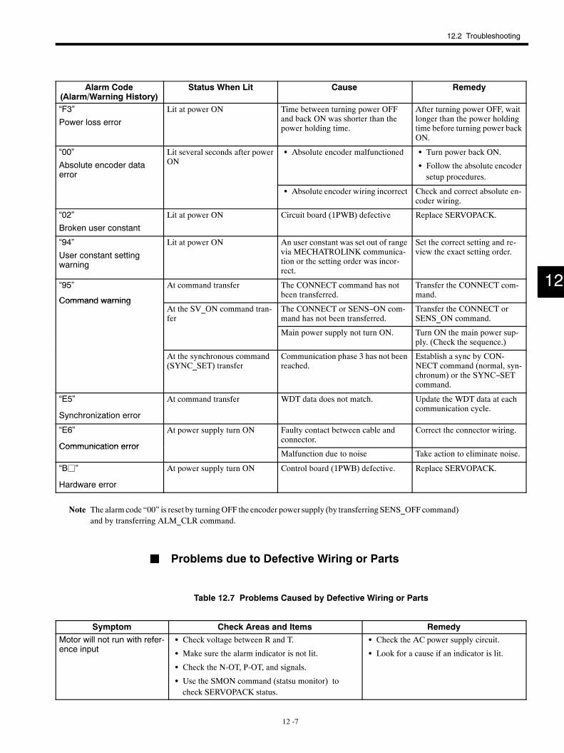
12.2 Troubleshooting
12 -7
Alarm Code(Alarm/Warning History)
RemedyCauseStatus When Lit
“F3”
Power loss error
Lit at power ON Time between turning power OFFand back ON was shorter than thepower holding time.
After turning power OFF, waitlonger than the power holdingtime before turning power backON.
“00”
Absolute encoder dataerror
Lit several seconds after powerON
S Absolute encoder malfunctioned S Turn power back ON.
S Follow the absolute encodersetup procedures.
S Absolute encoder wiring incorrect Check and correct absolute en-coder wiring.
“02”
Broken user constant
Lit at power ON Circuit board (1PWB) defective Replace SERVOPACK.
“94”
User constant settingwarning
Lit at power ON An user constant was set out of rangevia MECHATROLINK communica-tion or the setting order was incor-rect.
Set the correct setting and re-view the exact setting order.
“95”
Command warning
At command transfer The CONNECT command has notbeen transferred.
Transfer the CONNECT com-mand.
Command warningAt the SV_ON command tran-fer
The CONNECT or SENS−ON com-mand has not been transferred.
Transfer the CONNECT orSENS_ON command.
Main power supply not turn ON. Turn ON the main power sup-ply. (Check the sequence.)
At the synchronous command(SYNC_SET) transfer
Communication phase 3 has not beenreached.
Establish a sync by CON-NECT command (normal, syn-chronum) or the SYNC−SETcommand.
“E5”
Synchronization error
At command transfer WDT data does not match. Update the WDT data at eachcommunication cycle.
“E6”
Communication error
At power supply turn ON Faulty contact between cable andconnector.
Correct the connector wiring.
Communication errorMalfunction due to noise Take action to eliminate noise.
“Bj”
Hardware error
At power supply turn ON Control board (1PWB) defective. Replace SERVOPACK.
Note The alarmcode “00” is reset by turningOFF the encoder power supply (by transferring SENS_OFFcommand)and by transferring ALM_CLR command.
J Problems due to Defective Wiring or Parts
Table 12.7 Problems Caused by Defective Wiring or Parts
Symptom Check Areas and Items RemedyMotor will not run with refer-ence input
S Check voltage between R and T.
S Make sure the alarm indicator is not lit.
S Check the N-OT, P-OT, and signals.
S Use the SMON command (statsu monitor) tocheck SERVOPACK status.
S Check the AC power supply circuit.
S Look for a cause if an indicator is lit.
12
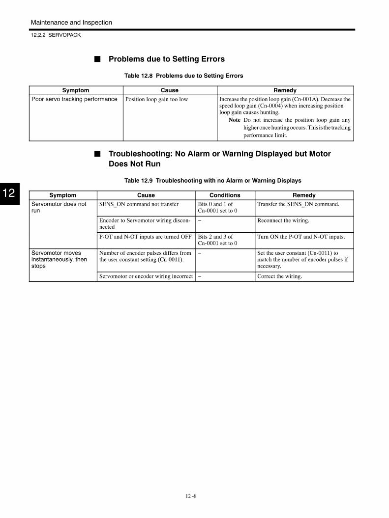
Maintenance and Inspection
12.2.2 SERVOPACK
12 -8
J Problems due to Setting Errors
Table 12.8 Problems due to Setting Errors
Symptom Cause RemedyPoor servo tracking performance Position loop gain too low Increase the position loop gain (Cn-001A). Decrease the
speed loop gain (Cn-0004) when increasing positionloop gain causes hunting.
Note Do not increase the position loop gain anyhigheroncehuntingoccurs.This is the trackingperformance limit.
J Troubleshooting: No Alarm or Warning Displayed but MotorDoes Not Run
Table 12.9 Troubleshooting with no Alarm or Warning Displays
Symptom Cause Conditions RemedyServomotor does notrun
SENS_ON command not transfer Bits 0 and 1 ofCn-0001 set to 0
Transfer the SENS_ON command.
Encoder to Servomotor wiring discon-nected
− Reconnect the wiring.
P-OT and N-OT inputs are turned OFF Bits 2 and 3 ofCn-0001 set to 0
Turn ON the P-OT and N-OT inputs.
Servomotor movesinstantaneously, thenstops
Number of encoder pulses differs fromthe user constant setting (Cn-0011).
− Set the user constant (Cn-0011) tomatch the number of encoder pulses ifnecessary.
Servomotor or encoder wiring incorrect − Correct the wiring.
12
IRUMA BUSINESS CENTER480, Kamifujisawa, Iruma, Saitama 358-8555, JapanPhone 81-42-962-5696 Fax 81-42-962-6138
YASKAWA ELECTRIC AMERICA, INC.2121 Norman Drive South, Waukegan, IL 60085, U.S.A.Phone 1-847-887-7000 Fax 1-847-887-7370
MOTOMAN INC. HEADQUARTERS805 Liberty Lane West Carrollton, OH 45449, U.S.A.Phone 1-937-847-6200 Fax 1-937-847-6277
YASKAWA ELETRICO DO BRASIL COMERCIO LTD.A.Avenida Fagundes Filho, 620 Bairro Saude-Sao Paulo-SP, Brazil CEP: 04304-000Phone 55-11-5071-2552 Fax 55-11-5581-8795
YASKAWA ELECTRIC EUROPE GmbHAm Kronberger Hang 2, 65824 Schwalbach, GermanyPhone 49-6196-569-300 Fax 49-6196-569-398
Motoman Robotics Europe ABBox 504 S38525 Torsas, SwedenPhone 46-486-48800 Fax 46-486-41410
Motoman Robotec GmbHKammerfeldstra e 1, 85391 Allershausen, GermanyPhone 49-8166-90-100 Fax 49-8166-90-103
YASKAWA ELECTRIC UK LTD.1 Hunt Hill Orchardton Woods Cumbernauld, G68 9LF, United KingdomPhone 44-1236-735000 Fax 44-1236-458182
YASKAWA ELECTRIC KOREA CORPORATIONKfpa Bldg #1201, 35-4 Youido-dong, Yeongdungpo-Ku, Seoul 150-010, KoreaPhone 82-2-784-7844 Fax 82-2-784-8495
YASKAWA ELECTRIC (SINGAPORE) PTE. LTD.151 Lorong Chuan, #04-01, New Tech Park Singapore 556741, SingaporePhone 65-6282-3003 Fax 65-6289-3003
YASKAWA ELECTRIC (SHANGHAI) CO., LTD.4F No.18 Aona Road, Waigaoqiao Free Trade Zone, Pudong New Area, Shanghai 200131, ChinaPhone 86-21-5866-3470 Fax 86-21-5866-3869
YATEC ENGINEERING CORPORATION4F., No.49 Wu Kong 6 Rd, Wu-Ku Industrial Park, Taipei, TaiwanPhone 886-2-2298-3676 Fax 886-2-2298-3677
YASKAWA ELECTRIC (HK) COMPANY LIMITEDRm. 2909-10, Hong Kong Plaza, 186-191 Connaught Road West, Hong KongPhone 852-2803-2385 Fax 852-2547-5773
BEIJING OFFICERoom No. 301 Office Building of Beijing International Club, 21Jianguomenwai Avenue, Beijing 100020, ChinaPhone 86-10-6532-1850 Fax 86-10-6532-1851
TAIPEI OFFICE9F, 16, Nanking E. Rd., Sec. 3, Taipei, TaiwanPhone 886-2-2502-5003 Fax 886-2-2505-1280
SHANGHAI YASKAWA-TONGJI M & E CO., LTD.27 Hui He Road Shanghai China 200437Phone 86-21-6553-6060 Fax 86-21-5588-1190
BEIJING YASKAWA BEIKE AUTOMATION ENGINEERING CO., LTD.30 Xue Yuan Road, Haidian, Beijing P.R. China Post Code: 100083Phone 86-10-6233-2782 Fax 86-10-6232-1536
SHOUGANG MOTOMAN ROBOT CO., LTD.7, Yongchang-North Street, Beijing Economic Technological Investment & Development Area, Beijing 100076, P.R. ChinaPhone 86-10-6788-0551 Fax 86-10-6788-2878
YASKAWA
YASKAWA ELECTRIC CORPORATION
Specifications are subject to change without notice for ongoing product modifications and improvements.
Printed in Japan April 2001 98-3
MANUAL NO. SIE-S800-26.3B
99-73©