s & angela m. ellis - suffolk, va
TRANSCRIPT
1"=10'
1"=10'
PLAN
B-1
AND GENERAL NOTES
PLAN, PROFILE, DESIGN EXCEPTIONS
oN29 -56'-44"W
Elev. 39.20
39'-
8"
LB
39.36
Elev.
100'-0"
Sta. 12+45.00
End of slab
End of bridge
L
Span a
-0.69%+0.36%
V.C. = 160.00'
C.G. EL = 39.57
C.G. Sta. = 11+95.00
Sta. 11+45.00
Abutment A
End of slab
Sta. 12+45.00
Abutment B
End of slab
state line
To North Carolina
To Rte. 13
Const.
Carolina Road90 typ.
o
DEVELOPED SECTION ALONG CAROLINA ROAD CONSTR. B
Ordinary high water elev. 31.0
Face of rail
Face of rail
Existing overhead power line
Proposed retaining wall typ.
sheet B-2
See detail on
26" deep, typ.
Dry riprap Class I,
100'-0"
Span a
Edge of stream
Approach slab
10"
19'-
10"
19'-
10"
10"
Approach slab
Sta. 11+45.00
End of slab
Beginning of bridge
Finished grade
ABUTMENT B
Finished grade
21
21
Constr.
along Carolina Road
Exist. profile
LB
Cypress S
wa
mp
Sleeper pad
Sleeper pad
Edge of stream25'-0" 25'-0"
100-year water surface elev. 35.7
ABUTMENT A
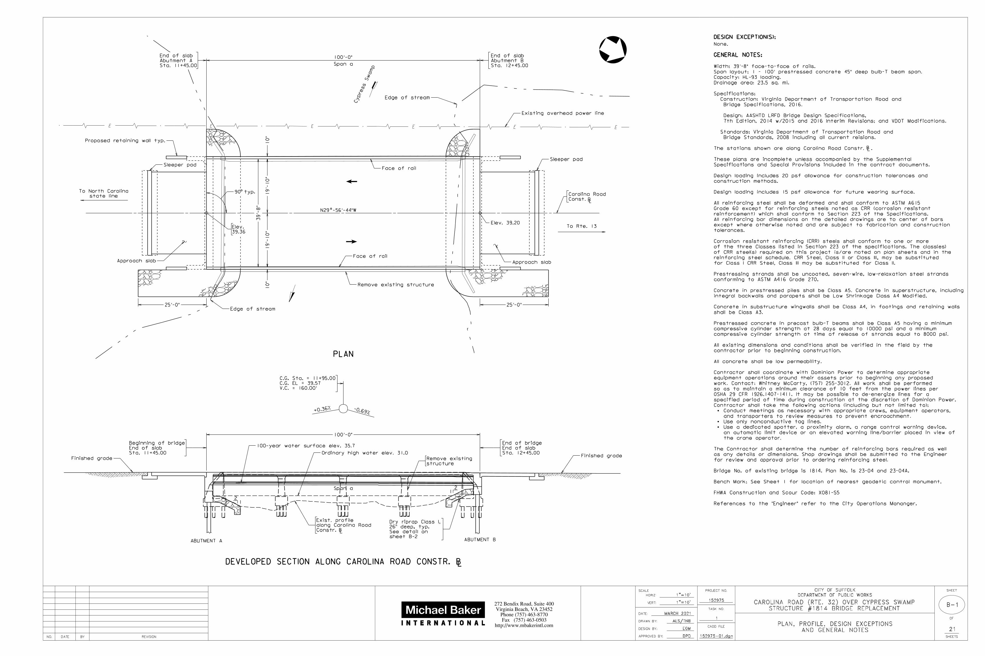
GENERAL NOTES:
DESIGN EXCEPTION(S):
None.
References to the "Engineer" refer to the City Operations Mananger.
FHWA Construction and Scour Code: X081-S5
Bench Mark: See Sheet 1 for location of nearest geodetic control monument.
Bridge No. of existing bridge is 1814. Plan No. is 23-04 and 23-04A.
for review and approval prior to ordering reinforcing steel.
as any details or dimensions. Shop drawings shall be submitted to the Engineer
The Contractor shall determine the number of reinforcing bars required as well
the crane operator.
an automatic limit device or an elevated warning line/barrier placed in view of
Use a dedicated spotter, a proximity alarm, a range control warning device,
Use only nonconductive tag lines.
and transporters to review measures to prevent encroachment.
Conduct meetings as necessary with appropriate crews, equipment operators,
Contractor shall take the following actions (including but not limited to):
specified period of time during construction at the discretion of Dominion Power.
OSHA 29 CFR 1926.1407-1411. It may be possible to de-energize lines for a
so as to maintain a minimum clearance of 10 feet from the power lines per
work. Contact: Whitney McCarty, (757) 255-3012. All work shall be performed
equipment operations around their assets prior to beginning any proposed
Contractor shall coordinate with Dominion Power to determine appropriate
All concrete shall be low permeability.
contractor prior to beginning construction.
All existing dimensions and conditions shall be verified in the field by the
compressive cylinder strength at time of release of strands equal to 8000 psi.
compressive cylinder strength at 28 days equal to 10000 psi and a minimum
Prestressed concrete in precast bulb-T beams shall be Class A5 having a minimum
shall be Class A3.
Concrete in substructure wingwalls shall be Class A4, in footings and retaining walls
integral backwalls and parapets shall be Low Shrinkage Class A4 Modified.
Concrete in prestressed piles shall be Class A5. Concrete in superstructure, including
conforming to ASTM A416 Grade 270.
Prestressing strands shall be uncoated, seven-wire, low-relaxation steel strands
for Class I CRR Steel, Class III may be substituted for Class II.
reinforcing steel schedule. CRR Steel, Class II or Class III, may be substituted
of CRR steel(s) required on this project is/are noted on plan sheets and in the
of the three Classes listed in Section 223 of the specifications. The class(es)
Corrosion resistant reinforcing (CRR) steels shall conform to one or more
tolerances.
except where otherwise noted and are subject to fabrication and construction
All reinforcing bar dimensions on the detailed drawings are to center of bars
reinforcement) which shall conform to Section 223 of the Specifications.
Grade 60 except for reinforcing steels noted as CRR (corrosion resistant
All reinforcing steel shall be deformed and shall conform to ASTM A615
Design loading includes 15 psf allowance for future wearing surface.
construction methods.
Design loading includes 20 psf allowance for construction tolerances and
Specifications and Special Provisions included in the contract documents.
These plans are incomplete unless accompanied by the Supplemental
The stations shown are along Carolina Road Constr. .
Bridge Standards, 2008 including all current reisions.
Standards: Virginia Department of Transportation Road and
7th Edition, 2014 w/2015 and 2016 Interim Revisions; and VDOT Modifications.
Design: AASHTO LRFD Bridge Design Specifications,
Bridge Specifications, 2016.
Construction: Virginia Department of Transportation Road and
Specifications:
Drainage area: 23.5 sq. mi.
Capacity: HL-93 loading.
Span layout: 1 - 100' prestressed concrete 45" deep bulb-T beam span.
Width: 39'-8" face-to-face of rails.
LB
152975-01.dgn
Remove existing structure
structure
Remove existing
TAX ID: 66*4
INST. #20100414000038810
JAMES C. ELLIS & ANGELA M. ELLIS
NOW OR FORMERLYSEE NOTE #8
NO. REVISIONBYDATE
SCALE
HORIZ:
VERT:
DRAWN BY:
DESIGN BY:
APPROVED BY:
DATE:
CADD FILE
PROJECT NO.
TASK NO.
SHEET
OF
21
SHEETSDPD
EGM
152975
1
http://www.mbakerintl.com
Fax (757) 463-0503
Phone (757) 463-8770
Virginia Beach, VA 23452
272 Bendix Road, Suite 400
DEPARTMENT OF PUBLIC WORKS
CITY OF SUFFOLK
MARCH 2021
152975- .dgn
ALS/TNB
STRUCTURE #1814 BRIDGE REPLACEMENT
CAROLINA ROAD (RTE. 32) OVER CYPRESS SWAMP

Sheet No.
INDEX OF SHEETS
Description
NTS
NTSB-2
INDEX OF SHEETS
ESTIMATED QUANTITIES AND
Construction Surveying
LS
LS
LS
Neat
Abutment A
17.4
Abutment B
Footing
Neat
Total
12.8
48.0
Piles
Concrete
Prestressed
531
177
482
289
ESTIMATED QUANTITIES - SUBSTRUCTURE ONLY
550
Units Quantity
200
Item
575
77.0
Bridge Deck Grooving
Corrosion Resistant Reinforcing Steel, Class II
Concrete Class A4 Bridge Approach Slab
Reinforcing Steel Bridge Approach Slab
Preformed Elastomeric Joint Sealer 3"
EA
LF
CY
SY
LB
CY
LB
LF
16"
LF TON
Excav.
Struct.
CY
Wall Drain
Geocomposite
SY
6"
Underdrain
Pipe
LF
Structure Number 1814
Dismantle and Remove Existing
3.3
3.1
6.4
Class A4
Concrete
953
953
261
depth +90'-100'
Prestressed Concrete Beam, Bulb-T 45"
866
866
LF
1 Rail
BR27C
Railing,
26"
Class I
Dry Riprap
Concrete Low Shrinkage Class A4 Modified
Railing, BR27C 1 Rail
LF
12:1
TYPICAL SLOPE PROTECTION DETAIL
3'-
0"
3'-0"
Toe of slope
Edge of riprap
dry riprap Class I (26")
2'-2" slope protection
7'-0"3'-0"
B-6 and B-7
Varies, see sheets
Class A3
Concrete
Footing
Class I
Reinf. Steel,
Resistant
Corrosion
LUMP SUM BID ITEMS
Mobilization
aggregate bedding4" no. 25 or 26
fabricGeotextile filter
2:1
Edge of berm
AbutmentBridge
Testing
Pile
Dynamic
EA EA
Cofferdams
SY
Zone)
(Abutment
Backfill
Select
SY 441Cover Depth Survey
9.3
8.5
10
10
20
1
1
2
17
12
29
92
85
15
15
30
1
1
2
4
166.3
34,350
13,010
60
LBCYCY
Bid price for Concrete Class A3 shall include ƒ" expanded rubber joint filler and 1" expanded rubber joint filler.
Bid item Corrosion Resistant Reinf. Steel, Class I shall include the quantity for retaining walls.
Bid item Concrete Class A3 shall include the quantity for retaining walls.
Denotes items to be paid for on the basis of plan quantities in accordance with current VDOT Road and Bridge Specifications.
Corrosion Resistant Reinforcing Steel, Class II includes integral backwalls.
Concrete Low Shrinkage Class A4 Modified includes integral backwalls.
slabs.
Bid Item Bridge Deck Grooving includes the quantity for approach
accordance with current VDOT Road and Bridge Specifications.
Denotes items to be paid for on the basis of plan quantities in
Concrete Pile
Prestressed
16"
NS Preboring
1,270
1,640
1,130
1,460
ESTIMATED QUANTITIES - SUPERSTRUCTURE ONLY
5,500 1,906 1,013 1,732
Approach slab
Prestressed concrete piles
Reinforcing steel schedule and bending diagram
BR27C rail connections and notes
42" - BR27C steel railing
Deck slab elevations
Deck slab plan
details
Prestressed concrete beam intermediate diaphragm
details
Prestressed concrete bulb-T miscellaneous beam
Prestressed concrete bulb-T PCBT-45
Erection diagram and top of slab elevations
Transverse section
Abutment A and B retaining wall details
Abutment A and B wingwall details
Abutment B sections & details
Abutment A sections & details
Abutment B plan, elevation and footing
Abutment A plan, elevation and footing
Substructure layout
Estimated quantities and index of sheets
and general notes
Title sheet; Plan, profile, design exceptions
B-21
B-20
B-19
B-18
B-17
B-16
B-15
B-14
B-13
B-12
B-11
B-10
B-9
B-8
B-7
B-6
B-5
B-4
B-3
B-2
B-1
152975-02.dgnNO. REVISIONBYDATE
SCALE
HORIZ:
VERT:
DRAWN BY:
DESIGN BY:
APPROVED BY:
DATE:
CADD FILE
PROJECT NO.
TASK NO.
SHEET
OF
21
SHEETSDPD
EGM
152975
1
http://www.mbakerintl.com
Fax (757) 463-0503
Phone (757) 463-8770
Virginia Beach, VA 23452
272 Bendix Road, Suite 400
DEPARTMENT OF PUBLIC WORKS
CITY OF SUFFOLK
MARCH 2021
152975- .dgn
ALS/TNB
STRUCTURE #1814 BRIDGE REPLACEMENT
CAROLINA ROAD (RTE. 32) OVER CYPRESS SWAMP

B-3
SUBSTRUCTURE LAYOUT
1"=5'
1"=5'
20'-
8"
20'-
8"
41'-
4"
20'-
8"
20'-
8"
41'-
4"
3'-0"3'-0"
Span a
LB
Abut. B
End of slab
12+45.00
Sta.
Const.
Carolina Road90 typ.o
typ.
7'-6"
3'-
0"
typ.
100'-0"
oN29 -56'-44"W
11+45.00
Sta.
7'-6" 7'-6"
7'-6"
3'-
0"
2'-5" typ.
7'-3ƒ" 7'-3ƒ"
2'-5" typ.
3'-
0"
3'-
0"
Abut. A
End of slab
SUBSTRUCTURE LAYOUT
Existing substructure
1'-
2" ty
p.
1'-
2" ty
p.
Pile Size
Resistance
Factored Axial
16" 86132
13216" 86
16" 12
16" 12
19
19
PILE DATA TABLE
Abutment A
Abutment B
Abutment A
Retaining walls -
Abutment B
Retaining walls -
During Driving
Measured
Resistance
Nominal Axial
(Tons/pile) (Tons/pile)
Unit
Substructure
Elevation
Estimated Tip
Elevation
Minimum Tip
-53.52
-52.21
2.93
4.24
-12.00
-16.00
2.93
4.24 additional preboring is required, it will be paid for at the unit price bid.
Estimated quantities include a pay item for preboring (20 LF). If
City and the independent testing agency performing pile testing.
will also require preboring. Determination shall be confirmed by the
10' below bottom of footings to determine if the production piles
18' below existing grade. Test piles shall be prebored to a depth of
A relatively hard layer is noted at Boring B-2 roughly between 10' to
in conflict shall be removed a minimum of 2' below the mudline.
foundation shall be removed full depth. Existing substructures not
All existing piles and/or substructures in conflict with proposed
For boring locations, see sheets 1C(1) and 1C(2).
For details of neat work, see abutment and retaining wall details.
of locating footings of abutments and retaining walls.
The substructure layout is to be used only for the purpose
NOTES:
152975-03.dgnNO. REVISIONBYDATE
SCALE
HORIZ:
VERT:
DRAWN BY:
DESIGN BY:
APPROVED BY:
DATE:
CADD FILE
PROJECT NO.
TASK NO.
SHEET
OF
21
SHEETSDPD
EGM
152975
1
http://www.mbakerintl.com
Fax (757) 463-0503
Phone (757) 463-8770
Virginia Beach, VA 23452
272 Bendix Road, Suite 400
DEPARTMENT OF PUBLIC WORKS
CITY OF SUFFOLK
MARCH 2021
ALS/TNB
STRUCTURE #1814 BRIDGE REPLACEMENT
CAROLINA ROAD (RTE. 32) OVER CYPRESS SWAMP
B-4
1/4"=1'-0"
1/4"=1'-0"
AND FOOTING
ABUTMENT A PLAN, ELEVATION
LC
thru center of piles
abutment and line
drain from to surface of fill.
with geotextile fabric. Slope to
6" dia. perforated pipe wrapped
LC
EPS material
End of slab
3'-
0"
1'-
6" abutment
integral
Face of
DETAIL A
Beam A Beam B Beam C Beam D
Table of bottom of Beam Elevations
2'-1‚"
Carolina Road Constr. LB
LC
End of slab
support, typ.
Temporary
Elev. 28.48 ELEVATION
11'-0"
Elev. 38.95
Elev. 38.95
PLAN
Elev. 39.36
Sta. 11+45.00
abutment
integral
Back of
7"
LC
filler, typ.
rubber joint
ƒ" expanded
B64
A64
B64
A64
LB
4"
12" = 2'-0"
2 spa. @
1'-0" typ.
C84
C84
18 spa. @ 5"
beams
typ. between @ 5" typ.
5 spa.
4'-2"
Carolina Road Constr.LB
Back of integral abutment
concrete piles, typ.
16" sq. prestressed
abutment
integral
Face of
centers of bearings
abutment and line thru
joint, typ.
Constr.
Elev. 38.95
7" typ.
5 spa. @
7" typ.
2 spa. @
12 spa. @ 7"
beams
typ. between1'-6" typ.
Elev. 38.95
1'-0" typ.
‡" steel dowel, typ.
LC Beam D LC Beam C LC Beam B LC Beam A
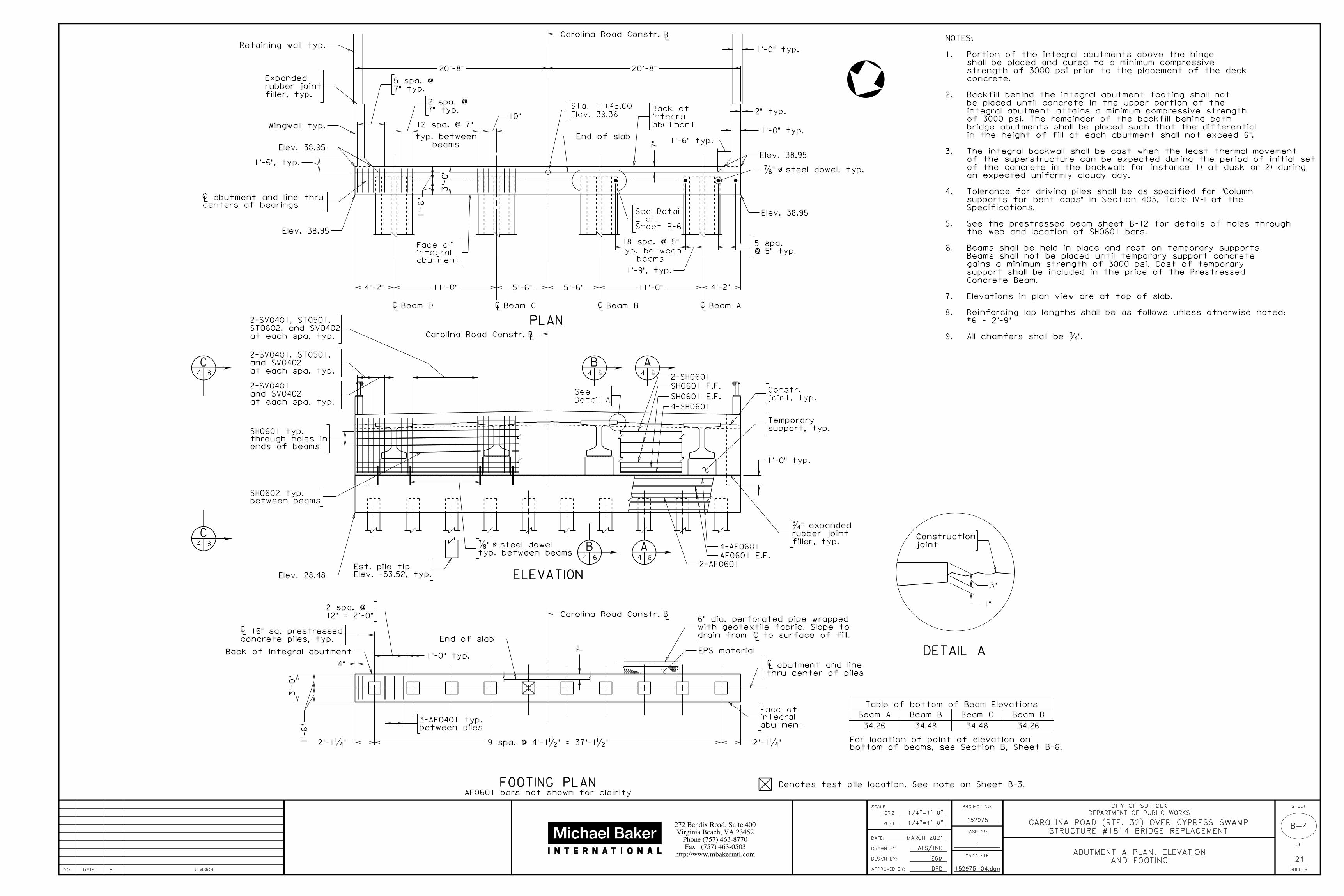
34.26 34.48 34.48 34.26
Detail A
SeeSH0601 F.F.
SH0601 E.F.
2-SH0601
4-SH0601
4-AF0601
2-AF0601
AF0601 E.F.
Elev. -53.52, typ.
Est. pile tip
typ. between beams
‡" steel dowelo/
1'-0" typ.
between beams
SH0602 typ.
ends of beams
through holes in
SH0601 typ.
Carolina Road Constr.
at each spa. typ.
and SV0402
2-SV0401, ST0501,
at each spa. typ.
and SV0402
2-SV0401
between piles
3-AF0401 typ.
10"
4'-2" 11'-0" 5'-6" 5'-6"
20'-8" 20'-8"
o/
2'-1‚" 9 spa. @ 4'-1•" = 37'-1•"
7"
1'-6", typ.
1'-9", typ.
at each spa. typ.
ST0602, and SV0402
2-SV0401, ST0501,
Sheet B-6
E on
See Detail 1'-
6"
3'-
0"
2" typ.
bottom of beams, see Section B, Sheet B-6.
For location of point of elevation on
Retaining wall typ.
Wingwall typ.1'-0" typ.
filler, typ.
rubber joint
Expanded
FOOTING PLANAF0601 bars not shown for clairity
3"
1"
joint
Construction
Denotes test pile location. See note on Sheet B-3.
152975-04.dgn
All chamfers shall be ƒ".9.
#6 - 2'-9"
Reinforcing lap lengths shall be as follows unless otherwise noted:8.
Elevations in plan view are at top of slab. 7.
Concrete Beam.
support shall be included in the price of the Prestressed
gains a minimum strength of 3000 psi. Cost of temporary
Beams shall not be placed until temporary support concrete
Beams shall be held in place and rest on temporary supports. 6.
the web and location of SH0601 bars.
See the prestressed beam sheet B-12 for details of holes through 5.
Specifications.
supports for bent caps" in Section 403, Table IV-I of the
Tolerance for driving piles shall be as specified for "Column 4.
an expected uniformly cloudy day.
of the concrete in the backwall: for instance 1) at dusk or 2) during
of the superstructure can be expected during the period of initial set
The integral backwall shall be cast when the least thermal movement3.
in the height of fill at each abutment shall not exceed 6".
bridge abutments shall be placed such that the differential
of 3000 psi. The remainder of the backfill behind both
integral abutment attains a minimum compressive strength
be placed until concrete in the upper portion of the
Backfill behind the integral abutment footing shall not 2.
concrete.
strength of 3000 psi prior to the placement of the deck
shall be placed and cured to a minimum compressive
Portion of the integral abutments above the hinge 1.
NOTES:
NO. REVISIONBYDATE
SCALE
HORIZ:
VERT:
DRAWN BY:
DESIGN BY:
APPROVED BY:
DATE:
CADD FILE
PROJECT NO.
TASK NO.
SHEET
OF
21
SHEETSDPD
EGM
152975
1
http://www.mbakerintl.com
Fax (757) 463-0503
Phone (757) 463-8770
Virginia Beach, VA 23452
272 Bendix Road, Suite 400
DEPARTMENT OF PUBLIC WORKS
CITY OF SUFFOLK
MARCH 2021
ALS/TNB
STRUCTURE #1814 BRIDGE REPLACEMENT
CAROLINA ROAD (RTE. 32) OVER CYPRESS SWAMP

B-5
1/4"=1'-0"
1/4"=1'-0"
AND FOOTING
ABUTMENT B PLAN, ELEVATION
7"
Back of integral abutment
concrete piles, typ.
16" sq. prestressedLC
End of slab
LC
thru center of piles
abutment and line
LC
EPS material
1'-
0" ty
p.
Elev. 29.79
ELEVATION
11'-0"5'-6"5'-6"11'-0"
Elev. 38.79
Elev. 38.79
PLAN
4'-2"
Beam A Beam B Beam C Beam D
Table of bottom of Beam Elevations
3'-
0"
1'-
6" abutment
integral
Face of
20'-8"20'-8"
Elev. 39.20
Sta. 12+45.00
abutment
integral
Back of
7"
centers of bearings
abutment and line thruLC
LC Beam A LC Beam B LC Beam C Beam DLC
abutment
integral
Face of
B5 7
A5 7
B5 7
A5 7
Carolina Road Constr. LB
2'-1‚"
Carolina Road Constr.LB
4"
12" = 2'-0"
2 spa. @
1'-0" typ.
D5 8
D5 8
18 spa. @ 5"
beams
typ. between@ 5" typ.
5 spa.
4'-2"
Carolina Road Constr.LB
Elev. 38.78
7" typ.
5 spa. @
7" typ.
2 spa. @
beams
typ. between
12 spa. @ 7"10" typ.
End of slab
Elev. 38.78
1'-0"
1'-0" typ.
drain from to surface of fill.
with geotextile fabric. Slope to
6" dia. perforated pipe wrapped
34.11 34.33 34.33 34.11
Elev. -52.21 typ.
Est. pile tip
filler, typ.
rubber joint
ƒ" expanded
Detail A
See
at each spa. typ.
ST0602, and SV0402
2-SV0403, ST0501,
at each spa. typ.
and SV0402
2-SV0403, ST0501,
at each spa. typ.
and SV0402
2-SV0403, ST0501,
at each spa. typ.
and SV0402
2-SV0403
‡" steel dowel, typ.o/
2-SH0601
support, typ.
Temporary
E.F.
SH0601
F.F.
SH0601
4-SH0601
4-AF0601AF0601 E.F.
2-AF0601
ends of beams
through holes in
SH0601 typ.
between beams
SH0602 typ.
2'-1‚"
1'-9", typ.
3'-
0"
1'-
6"
Sheet B-7
E on
See Detail
2" typ.
bottom of beams, see Section B, Sheet B-7.
For location of point of elevation on
Retaining wall typ.
Wingwall typ.
1'-0" typ.
filler, typ.
rubber joint
Expanded
AF0601 bars not shown for clairity
FOOTING PLAN
DETAIL A
3"
1"
joint
Construction
Denotes test pile location. See note on Sheet B-3.
All chamfers shall be ƒ"9.
#6 - 2'-9"
Reinforcement lap lengths shall be as follows unless otherwise noted:8.
Elevations in plan view are at top of slab. 7.
Concrete Beam.
support shall be included in the price of the Prestressed
gains a minimum strength of 3000 psi. Cost of temporary
Beams shall not be placed until temporary support concrete
Beams shall be held in place and rest on temporary supports. 6.
the web and location of SH0601 bars.
See the prestressed beam sheet B-12 for details of holes through 5.
Specifications.
supports for bent caps" in Section 403, Table IV-I of the
Tolerance for driving piles shall be as specified for "Column 4.
1) at dusk or 2) during an expected uniformly cloudy day.
period of initial set of the concrete in the backwall: for instance
movement of the superstructure can be expected during the
The integral backwall shall be cast when the least thermal 3.
in the height of fill at each abutment shall not exceed 6".
bridge abutments shall be placed such that the differential
of 3000 psi. The remainder of the backfill behind both
integral abutment attains a minimum compressive strength
be placed until concrete in the upper portion of the
Backfill behind the integral abutment footing shall not 2.
concrete.
strength of 3000 psi prior to the placement of the deck
shall be placed and cured to a minimum compressive
Portion of the integral abutments above the hinge 1.
NOTES:
152975-05.dgn
9 spa. @ 4'-1•" = 37'-1•"
NO. REVISIONBYDATE
SCALE
HORIZ:
VERT:
DRAWN BY:
DESIGN BY:
APPROVED BY:
DATE:
CADD FILE
PROJECT NO.
TASK NO.
SHEET
OF
21
SHEETSDPD
EGM
152975
1
http://www.mbakerintl.com
Fax (757) 463-0503
Phone (757) 463-8770
Virginia Beach, VA 23452
272 Bendix Road, Suite 400
DEPARTMENT OF PUBLIC WORKS
CITY OF SUFFOLK
MARCH 2021
ALS/TNB
STRUCTURE #1814 BRIDGE REPLACEMENT
CAROLINA ROAD (RTE. 32) OVER CYPRESS SWAMP

B-6
1/2"=1'-0"
1/2"=1'-0"
VIEW F-F
SECTION D-D
TEMPORARY SUPPORT DETAIL
(STAY IN-PLACE)
(For details not shown, see Section A-A)
AT BEAMS
EPS material
enclosing it, typ.
EPS material fully
wrapped around ends of
Geotextile fabric shall be
Not to scale
10"
Varie
s
Class A4 concrete
joint filler, typ.
ƒ" expanded rubber
Top of footing
Interpolated if 9" < h < 2'-0"
12" - if h = 2'-0"
3" - if h = 9"**
12" min.
**
1'-
6"
See note 2.modified concreteClass A4Low shrinkage
See note 4
Top of beam
Bottom of slab
6"
4'-
0"
1'-
6"
7"
concrete piles, typ.
16" sq. prestressed
End of slab
Hot poured joint sealerApproach slab
Construction joint
abutment
integral
Face of
See hinge detail
filter fabric
Geotextile
abutment
integral
Back of
EPS material
at hinge
fabric centered
waterproofing
12" wide
FF
F
HINGE DETAILNot to scale
Top of footing
taped to dowel
rubber cap securely
ƒ" thick expanded ‡" x 2'-0" steels dowels
integral abutment and
3 layers of roofing
felt around dowels
ƒ" expanded
rubber joint filler
12"
LC
LC o/
durometer typ.
3" x •", 70
Neoprene strip
D
D
Approach slab seat
Not to scale
5"5"detail
See hinge
12"12"
steel dowel, typ.
7/8" dia. x 2'-0"
SECTIONA
6
SECTIONB
6
15"
3'-0"
wall drain
Geocomposite
1
1
6" 6"
h
See note 3.Class A3 concrete
ty
p.
min. la
p,
Point of elevation
PCBT-45
Detail E
7"
11" 6
"
Back of integral abutment
End of slab
integral abutment
Face of
6"
hole in webLC
2:1
12:1
support detail
See temporary
3'-0"
Edge of berm
ABUTMENT A SECTIONS AND DETAILS
1'-6" typ.
2'-
4"
4
4
G
G
Limits
of ro
ad
way
Approach slab
SECTION G-G
EPS material
1'-3" 20'-0"
End of slab
7"
VTM-10 test method.
with Table II of the
95% or in accordance
Minimum density
backfill material.
Zone of select
LC integral abutment
END DETAIL
PIPE UNDERDRAIN
12" min.
3"Slope
o/
Pipe Underdrain 6".
included in the bid price for
of hardware cloth shall be
galvanized steel wire. Cost
outlet end and secure with
hardware cloth. Crimp around
(galvanized after weaving)
ƒ" x ƒ" mesh. min. 17 ga.
6"
min.
surface of fill.
Extend to
underdrain.
6" dia. pipe
SV0402
ST0501
ST0602
SH0601
SH0602
SV0401
AF0401
AF0601
SH0601
1'-
9"
6" pipe underdrain
6"
of the Specifications
as per Section 305.03(a)
Minimum density for top 6"
Subgrade
Bolster
2 spa. @ 8"
1'-3ƒ"
LC
appro
ach cut
structure excavation
To be paid for as
70 durometer hardness
pad 10" x 2'-6" x ƒ"
Plain elastomeric bearing
durometer, typ.
3" x •", 70
Neoprene strip
LC beam
1'-3"
hardness
70 durometer
10" x 2'-6" x ƒ"
bearing pad
Plain elastomeric
7"
AP0402
2-AP0401
AP0402
AP0401
necessary
Field cut as
10'-7"18'-11"
steel dowels
and ‡" X 2'-0"
integral abutmentLC
LC o/
10'-
11"
Deck reinforcement
SH0602holes in web and of 1•" dia.
152975-06.dgn
AT BACKWALL
BETWEEN GIRDERS AND
considered incidental.
Cost of neoprene and roofing felt shall be
the bid price for prestressed concrete beams.
and temporary supports shall be included in
Cost of dowels, anchor bolts, plates, washers, 5.
beam flanges.
concrete, to eliminate any voids under
Extreme care must be taken, when placing 4.
included with substructure quantities.
Class A3 concrete and CRR steel, Class I are 3.
superstructure quantities.
same Class as deck, are included with
Corrosion Resistant Reinforcing (CRR) steel,
Low Shrinkage Class A4 Modified concrete and2.
All chamfers shall be 3/4"1.
NOTES:
NO. REVISIONBYDATE
SCALE
HORIZ:
VERT:
DRAWN BY:
DESIGN BY:
APPROVED BY:
DATE:
CADD FILE
PROJECT NO.
TASK NO.
SHEET
OF
21
SHEETSDPD
EGM
152975
1
http://www.mbakerintl.com
Fax (757) 463-0503
Phone (757) 463-8770
Virginia Beach, VA 23452
272 Bendix Road, Suite 400
DEPARTMENT OF PUBLIC WORKS
CITY OF SUFFOLK
MARCH 2021
ALS/TNB
STRUCTURE #1814 BRIDGE REPLACEMENT
CAROLINA ROAD (RTE. 32) OVER CYPRESS SWAMP

B-7
1/2"=1'-0"
1/2"=1'-0"
VIEW F-F
SECTION D-D
TEMPORARY SUPPORT DETAIL
(STAY IN-PLACE)
(For details not shown, see Section A-A)
AT BEAMS
EPS material
enclosing it, typ.
EPS material fully
wrapped around ends of
Geotextile fabric shall be
Not to scale
10"
Varie
s
Class A4 concrete
joint filler, typ.
ƒ" expanded rubber
Top of footing
Interpolated if 9" < h < 2'-0"
12" - if h = 2'-0"
3" - if h = 9"**
12" min.
**
1'-
6"
See note 2.modified concreteClass A4Low shrinkage
Top of beam
Bottom of slab
6"
6"
3'-
0"
7"
concrete piles, typ.
16" sq. prestressed
End of slab
Hot poured joint sealerApproach slab
Construction joint
abutment
integral
Face of
See hinge detail
filter fabric
Geotextile
abutment
integral
Back of
EPS material
at hinge
fabric centered
waterproofing
12" wide
FF
F
HINGE DETAILNot to scale
Top of footing
taped to dowel
rubber cap securely
ƒ" thick expanded ‡" x 2'-0" steels dowels
integral abutment and
3 layers of roofing
felt around dowels
ƒ" expanded
rubber joint filler
12"
LC
LC o/
durometer typ.
3" x •", 70
Neoprene strip
D
D
Approach slab seat
Not to scale
5"5"detail
See hinge
12"12"
steel dowel, typ.
7/8" dia. x 2'-0"
SECTIONA
7SECTION
B7
15"
3'-0"
wall drain
Geocomposite
1
1
6" 6"
h
See note 3.Class A3 concrete
1'-
9"
ty
p.
min. la
p,
PCBT-45
Detail E
7"
11" 6
"
Back of integral abutment
integral abutmentLC
End of slab
integral abutment
Face of
6"
hole in webLC
2:1
12:1
support detail
See temporary
3'-0"
Edge of berm
ABUTMENT B SECTIONS AND DETAILS
1'-6" typ.
5
5
9ƒ
"
G
G
Limits
of ro
ad
way
Approach slabSubgrade
of the Specifications
as per Section 305.03(a)
Minimum density for top 6"
EPS material
1'-3" 20'-0"
End of slab
7"
VTM-10 test method.
with Table II of the
95% or in accordance
Minimum density
backfill material.
Zone of select
SECTION G-G
END DETAIL
PIPE UNDERDRAIN
12" min.
3"Slope
6" pipe underdraino/
Pipe Underdrain 6".
included in the bid price for
of hardware cloth shall be
galvanized steel wire. Cost
outlet end and secure with
hardware cloth. Crimp around
(galvanized after weaving)
ƒ" x ƒ" mesh. min. 17 ga.
6"
min.
surface of fill.
Extend to
underdrain.
6" dia. pipe
SV0402
ST0501
SH0601
SH0602
SV0403
SH0601
AF0601
AF0402
ST0602
Bolster
1'-3ƒ"
1'-
6" 7"
1'-3"
hardness
70 durometer
10" x 2'-6" x ƒ"
bearing pad
Plain elastomeric
AP0401
AP0402
beamLC
2-AP0401
AP0402
70 durometer hardness
pad 10" x 2'-6" x ƒ"
Plain elastomeric bearing
durometer, typ.
3" x •", 70
Neoprene strip
structure excavation
To be paid for as
appro
ach cut
2 spa. @ 8"
See note 4
Point of elevation
necessary
Field cut as
15'-10" 13'-7"
steel dowels
and ‡" X 2'-0"
integral abutmentLC
LC o/
9'-
5"
Deck reinforcement LC
SH0602holes in web and of 1•" dia.
152975-07.dgn
considered incidental.
Cost of neoprene and roofing felt shall be
the bid price for prestressed concrete beams.
and temporary supports shall be included in
Cost of dowels, anchor bolts, plates, washers, 5.
beam flanges.
concrete, to eliminate any voids under
Extreme care must be taken, when placing 4.
included with substructure quantities.
Class A3 concrete and CRR steel, Class I are 3.
superstructure quantities.
same Class as deck, are included with
Corrosion Resistant Reinforcing (CRR) steel,
Low Shrinkage Class A4 Modified concrete and2.
All chamfers shall be 3/4"1.
NOTES:
AT BACKWALL
BETWEEN GIRDERS AND
NO. REVISIONBYDATE
SCALE
HORIZ:
VERT:
DRAWN BY:
DESIGN BY:
APPROVED BY:
DATE:
CADD FILE
PROJECT NO.
TASK NO.
SHEET
OF
21
SHEETSDPD
EGM
152975
1
http://www.mbakerintl.com
Fax (757) 463-0503
Phone (757) 463-8770
Virginia Beach, VA 23452
272 Bendix Road, Suite 400
DEPARTMENT OF PUBLIC WORKS
CITY OF SUFFOLK
MARCH 2021
ALS/TNB
STRUCTURE #1814 BRIDGE REPLACEMENT
CAROLINA ROAD (RTE. 32) OVER CYPRESS SWAMP
B-8
1/2"=1'-0"
1/2"=1'-0"
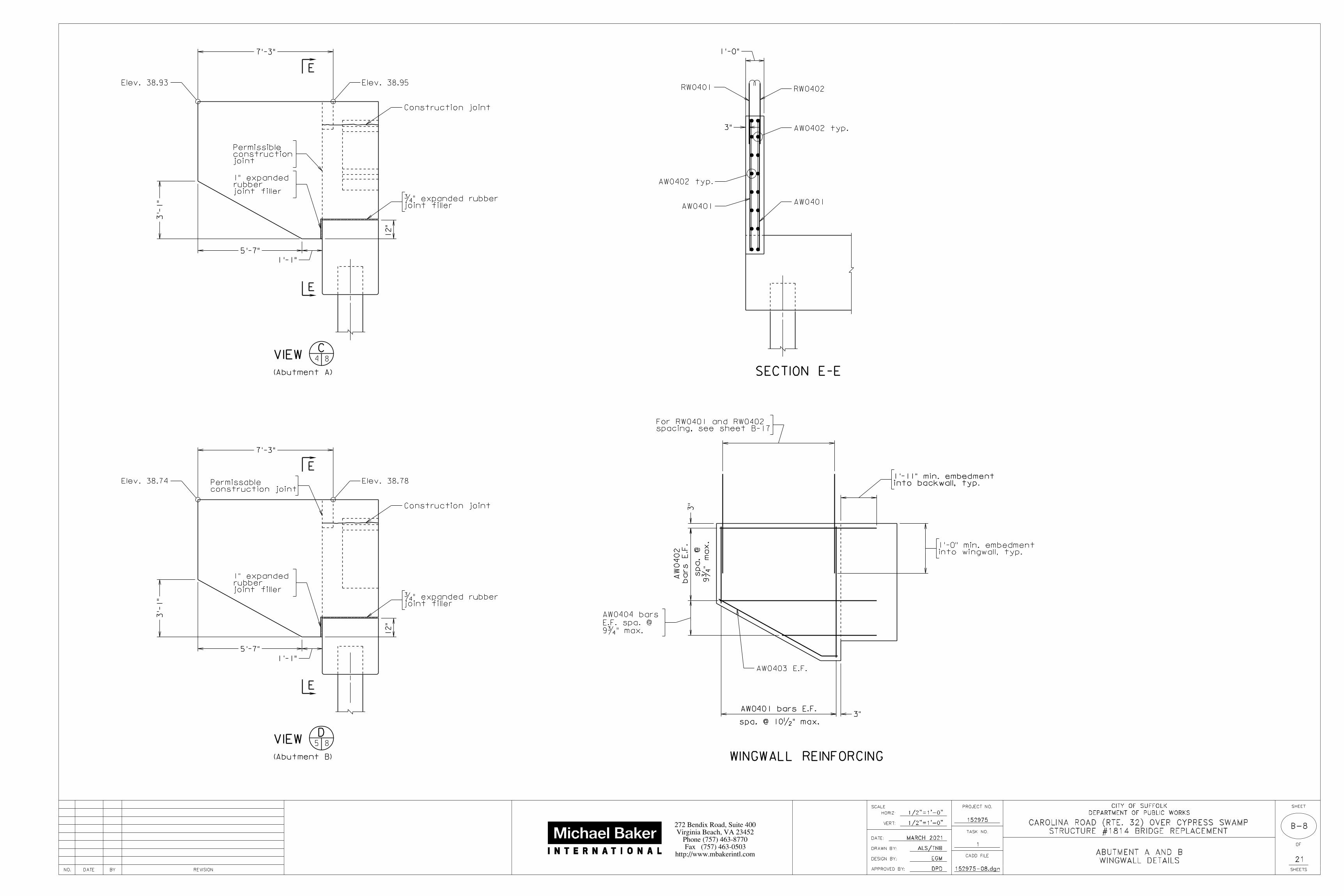
WINGWALL DETAILS
ABUTMENT A AND B
VIEW
(Abutment A)
(Abutment B)
VIEW
E
E
jointconstructionPermissible
joint fillerƒ" expanded rubber
7'-3"
E
joint fillerƒ" expanded rubber
E
1'-0"
3"
WINGWALL REINFORCING
3'-
1"
AW0401AW0401
AW0402 typ.
AW0402 typ.
RW0402Elev. 38.93 Elev. 38.95
Elev. 38.74 Elev. 38.78
AW0401 bars E.F.
SECTION E-E
C84
D85
spa. @ 10•" max.
7'-3"
3'-
1"
1'-1"
5'-7"
12"
1'-1"
5'-7"
12"
3"
joint fillerrubber1" expanded
joint fillerrubber1" expanded
AW0403 E.F.
into backwall, typ.1'-11" min. embedment
Construction joint
Construction joint
construction jointPermissable
RW0401
3"
spacing, see sheet B-17For RW0401 and RW0402
into wingwall, typ.1'-0" min. embedment
9ƒ
" m
ax.
spa.
@
bars
E.F.
AW
0402
9ƒ" max.
E.F. spa. @
AW0404 bars
152975-08.dgnNO. REVISIONBYDATE
SCALE
HORIZ:
VERT:
DRAWN BY:
DESIGN BY:
APPROVED BY:
DATE:
CADD FILE
PROJECT NO.
TASK NO.
SHEET
OF
21
SHEETSDPD
EGM
152975
1
http://www.mbakerintl.com
Fax (757) 463-0503
Phone (757) 463-8770
Virginia Beach, VA 23452
272 Bendix Road, Suite 400
DEPARTMENT OF PUBLIC WORKS
CITY OF SUFFOLK
MARCH 2021
ALS/TNB
STRUCTURE #1814 BRIDGE REPLACEMENT
CAROLINA ROAD (RTE. 32) OVER CYPRESS SWAMP

B-9
1/2"=1'-0"
1/2"=1'-0"
RETAINING WALL DETAILS
ABUTMENT A AND B
VIEW
(Abutment A)1'-
6"
3"
3'-
0"
VIEW
(Abutment B)
G
G
1'-
6"
Wingwall
3"
1'-0"
3'-
0"
(Abutment A)
(Abutment B)
RETAINING WALL REINFORCING
RETAINING WALL REINFORCING
4" typ.
2 - AF0403
spa. @ 12" max = 6'-10"
3"
= 8'-
0"
4" typ.
2 - AF0403
spa. @ 12" max = 6'-10"
3"
= 7'-0"
SECTION F-F
SECTION G-G
C94
D95
AH0401 spa.
@ 7"
max.
E.F.
AF-0406
2-AF0406
4-AF0406
E.F.
AF-0406
2-AF0406
4-AF0406
AV0504
AH0401
AF0406
AF0403
AF0406
AF0403
AV0505
AH0401
3'-
0"
4'-0"1'-9"
7'-6"
6'-
4"
3'-
0"
4'-0"1'-9"
1'-0"
3'-0"
3'-0"
F
Elev. 30.93
ty
p.
3" ty
p.
Elev. 32.24
1'-9"
3" ty
p.
Elev. 2.93 typ.
Est. pile tip
Elev. 4.24 typ.
Est. pile tip
AV0505 spa. @ 6" max.
1'-6"
8"
1'-9"
Wingwall7'-6"
7'-
10"
8"
F
VIEW A-A
3•
"
3•
"
1•
"
1•
"
9"
3'-
6"
1'-
9ƒ
" min.
1'-
10ƒ
" m
ax.
LC
LC
++
+
LC
see notes
bolts
1'-6"
3'-7"
3"
2'-3ƒ"
4"
++
+
2'-3ƒ"
4"3"
3'-7"
see notes.
holes,
see notes.
bolts,
Not to scale
A
A
LC
see notes
holes
1'-
3" ty
p.
11'-
6"
grade
Finished
LC
see notes
bolts
A
A
ty
p.
1'-
3" ty
p.
10'-
0"
AH0401 spa.
@
7"
max.
= 6'-
6"
Bend in field
+
LC
see notes
holes
++
+
++
+
= 7'-0"
AV0504 spa. @ 6" max.1'-0"1'-0"
1'-0"1'-0"
12"
guardrail attachment GR-FOA-1.Retaining walls are detailed to take
to clear holes for guardrail attachments.shifted with the approval of the Engineer AV0504, AV0505, and AH0401 may be
rub rail is attached.and shall be drilled and installed whenexpansion anchor bolts, 6" long shown, shall be †" diameterBolts for guardrail attachment, where
nominal pipe.with sleeves of 1•" diameterHoles, where shown, shall be formed
All bevels for concrete shall be ƒ".
NOTES:
fillerrubber jointExpanded
fillerrubber jointExpanded
5'-
0"
constr. joint
Permissible
constr. joint
Permissible
3'-
6"
constr. joint
Permissible
Bend in fieldElev. 42.43
Elev. 42.42
Elev. 42.21Elev. 42.24
152975-09.dgnNO. REVISIONBYDATE
SCALE
HORIZ:
VERT:
DRAWN BY:
DESIGN BY:
APPROVED BY:
DATE:
CADD FILE
PROJECT NO.
TASK NO.
SHEET
OF
21
SHEETSDPD
EGM
152975
1
http://www.mbakerintl.com
Fax (757) 463-0503
Phone (757) 463-8770
Virginia Beach, VA 23452
272 Bendix Road, Suite 400
DEPARTMENT OF PUBLIC WORKS
CITY OF SUFFOLK
MARCH 2021
ALS/TNB
STRUCTURE #1814 BRIDGE REPLACEMENT
CAROLINA ROAD (RTE. 32) OVER CYPRESS SWAMP
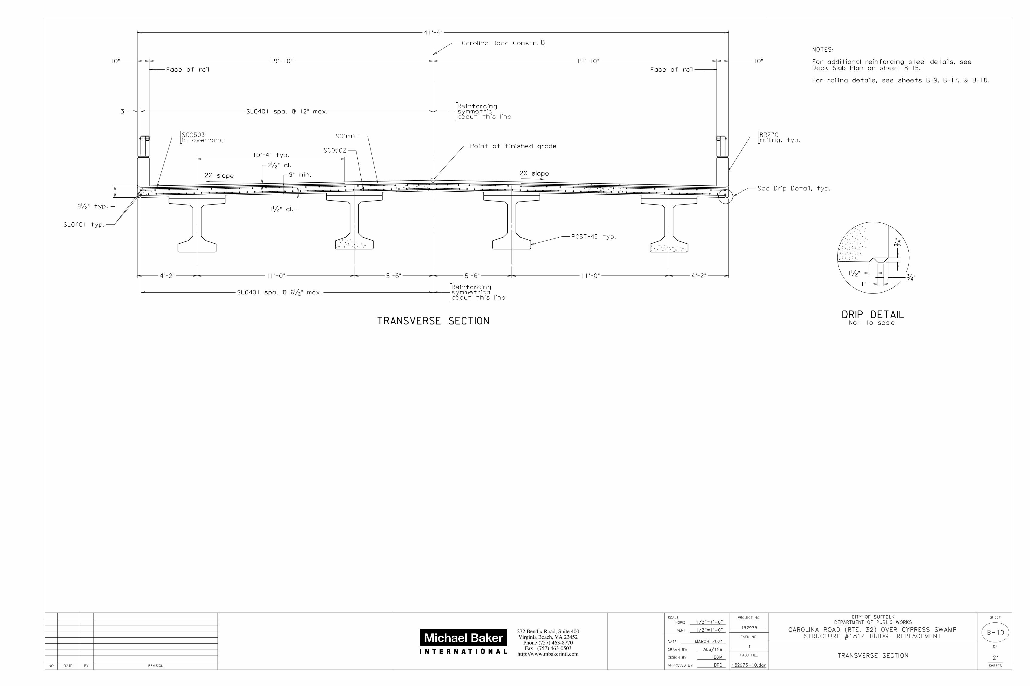
TRANSVERSE SECTION
B-10
1/2"=1'-0"
1/2"=1'-0"
9" min.
9•" typ.
DRIP DETAIL
1•"
1"
ƒ"
See Drip Detail, typ.
2% slope2% slope
TRANSVERSE SECTION
ƒ"
Not to scale
Carolina Road Constr. LB
41'-4"
Point of finished grade
Face of rail Face of rail
2•" cl.
3"
1‚" cl.
PCBT-45 typ.
in overhangSC0503
SC0502
4'-2"11'-0"5'-6"5'-6"11'-0"4'-2"
SL0401 typ.
10"19'-10"19'-10"10"
SL0401 spa. @ 12" max.
SC0501
about this linesymmetrical Reinforcing
SL0401 spa. @ 6•" max.
railing, typ.BR27C
10'-4" typ.
about this linesymmetricReinforcing
152975-10.dgn
For railing details, see sheets B-9, B-17, & B-18.
Deck Slab Plan on sheet B-15.
For additional reinforcing steel details, see
NOTES:
NO. REVISIONBYDATE
SCALE
HORIZ:
VERT:
DRAWN BY:
DESIGN BY:
APPROVED BY:
DATE:
CADD FILE
PROJECT NO.
TASK NO.
SHEET
OF
21
SHEETSDPD
EGM
152975
1
http://www.mbakerintl.com
Fax (757) 463-0503
Phone (757) 463-8770
Virginia Beach, VA 23452
272 Bendix Road, Suite 400
DEPARTMENT OF PUBLIC WORKS
CITY OF SUFFOLK
MARCH 2021
ALS/TNB
STRUCTURE #1814 BRIDGE REPLACEMENT
CAROLINA ROAD (RTE. 32) OVER CYPRESS SWAMP

B-11
OF SLAB ELEVATIONS
ERECTION DIAGRAM AND TOP
1"=5'
1"=5'
2'-5" 2'-5"
abutment
Face of integral
Abutment A
End of slabAbutment B
End of slab
abutment
Face of integral
ERECTION DIAGRAM
PLAN
Beam A
Beam B
Beam C
Beam D
steel diaphragms
for intermediate
of inserts or bolts
Line through centers
steel diaphragms
for intermediate
of inserts or bolts
Line through centers
1 2 3 4 5 6 7 8 9 10 11
integral abutment
End of slab at
LC
LCor bearing
Abutment10 equal spaces
LCor bearing
Abutment
integral abutment
End of slab at
girderLC
LC
Carolina Road Constr. LB
100'-0"
Span a
90 typ.o
11'-
0"
5'-
6"
5'-
6"
11'-
0"
34'-5" 26'-4" 34'-5"
For intermediate diaphragm details, see sheet B-14.
For prestressed concrete beam details, see sheets B-12 and B-13.
NOTES:
of slab elevations
showing points of top
TOP OF SLAB ELEVATIONS ALONG CL OF BEAMS
GIRDER 1 2 3 4 5 6 7 8 9 10 11
STATION 11+45.92 11+55.00 11+65.00 11+75.00 11+85.00 11+95.00 12+05.00 12+15.00 12+25.00 12+35.00 12+44.08
BEAM A 39.03 39.04 39.05 39.05 39.04 39.03 39.01 38.98 38.95 38.91 38.87
BEAM B 39.25 39.26 39.27 39.27 39.26 39.25 39.23 39.20 39.17 39.13 39.09
BEAM C 39.25 39.26 39.27 39.27 39.26 39.25 39.23 39.20 39.17 39.13 39.09
BEAM D 39.03 39.04 39.05 39.05 39.04 39.03 39.01 38.98 38.95 38.91 38.87
152975-11.dgnNO. REVISIONBYDATE
SCALE
HORIZ:
VERT:
DRAWN BY:
DESIGN BY:
APPROVED BY:
DATE:
CADD FILE
PROJECT NO.
TASK NO.
SHEET
OF
21
SHEETSDPD
EGM
152975
1
http://www.mbakerintl.com
Fax (757) 463-0503
Phone (757) 463-8770
Virginia Beach, VA 23452
272 Bendix Road, Suite 400
DEPARTMENT OF PUBLIC WORKS
CITY OF SUFFOLK
MARCH 2021
ALS/TNB
STRUCTURE #1814 BRIDGE REPLACEMENT
CAROLINA ROAD (RTE. 32) OVER CYPRESS SWAMP

Scale: ƒ" = 1'-0" unless otherwise noted
/
/
/
NTS
NTSB-12
PCBT-45
PRESTRESSED CONCRETE BULB-T
END VIEW
At integral backwall
LC beam
BC0504
BC0603
3‡" typ.
3ƒ" typ.
2…
"
TYPICAL BOTTOM FLANGE EDGE DETAILNot to scale
Midspan
CAMBER DIAGRAMNot to scale
L storage supportsC
is made = N
when stress transfer
Expected net camber
L
BL0501
/C
C
B
1'-
3"
AC.G. of prestressing strands
L/2
A
PLAN
SECTION ON CENTERLINE
L/2
C
End of beam
dowels spaced to clear strands
flange with 4 - #4 x 1'-6" long
the full width of bottom
Provide L 1‚ x 1‚ x ‰for
1'-6"
2"
3'-
9"
2'-
0"
1•"
3'-11"
4"
1•
"7"
2'-8"
C
TYPICAL BEAM SECTION
3•
"
3"
2"
9"3•"
7"
BS0402
END VIEW
2'-8"
3" typ.
C/
2"
BS0401
3" typ.
BS04 or BS05 series
SECTION A-A
2'-8"
3" min.2‚" typ.
2"
For dimensions not shown, see Typical Beam Section.
See Note 6.
BL0501.
G
BS0401
BS0403
Midspan
D
2"BS0402
See Note 7.
BS04 or BS05 series.
J
with BL0501
min. lap 2'-4"
4 - BC0504
10"
2"
See Note 1See Note 1
backwall
Face of integral
min. lap 2'-4"
4 - BL0501
Span Beam
lb. per strand
at Release
Prestr. force
strands / beam
of
No. and size
in.
N
Net Camber
ft.-in.
A
in
B
ft.-in.
C
ft.-in.
D
ft.-in.
E
in.
G
in.
J
ft.-in.
L
DATA AND DIMENSION TABLE
A
E
10"
2"
abutment
Face of integral
2"
J
See Note 4
with BL0501
min. lap 2'-4"
4 - BC0504
See Note 7.
series.
BS04 or BS05
4 - BCO603
3"
BS0401 and BS0403
3"
4 - BC0603
5•"16 spa. @ 8"
= 10'-8" = 16'-0"
16 spa. @ 12"
= 19'-7"
10 spa. @ 1'-11•"
L beamC
See Note 1
at integral abutment
Typical beam endbackwall
Face of integral
a A thru D 43,942 50 - 0.6" o/ 3 ‹" 9‡" 5‹" 1'-11" 1'-11" 7ƒ" 95'-2"
13 spa. @ 2"
= 2'-2"
6 spa. @ 2" = 1'-0"
13 spa. @ 2"
= 2'-2"
2‚"
@ 2" = 6"
3 spa.
See Note 6.
BL0501.
3"
@ 2" = 6"
3 spa.
abutment
end at integral
Typical beam
Beam details symmetrical between these lines about midspan
See Note 2.
L 2" o open hole.
For dimensions not shown, see Typical Beam Section.
19-BS0402
19'-1"
See Note 4.
diaphragm.
L intermediate
See Note 4
See Notes 3 and 4.
L threaded inserts.
See Note 4.
L 1•" o open holes.
9'-9Ž"
see sheet B-13.
reinforcing steel schedule and miscellaneous details,
For beam end reinforcing details, dead load deflection diagram7.
to the flange edge may be increased from 3" to no more than 4".
4 - BL05 series bars. Maximum distance from the outside strands
4 - 0.6" o strands stressed to 8,000 lbs. may be substituted for6.
prestressing force and c.g. are the same as shown on the plans.
different prestressing strand arrangement provided that the total
The Contractor, after written approval from the Engineer, may use5.
B-6, B-7 and B-14.
for intermediate diaphragms and at integral abutments, see sheets
sheet B-11. For location and number of holes or inserts required
tion of intermediate diaphragms, see Erection Diagram on
1•" o open holes shall be formed with non-rigid tubing. For loca-4.
a minimum ultimate mechanical tensile strength of 8,000 pounds.
ferrule inserts suitable for thin precast concrete elements having
rior beam. Threaded inserts shall be ‡" - 9 NC threaded plain
terior beams where line of diaphragms is discontinued at an inte-
Threaded inserts shall be provided at all exterior beams and at in-3.
Holes may be slightly shifted to clear reinforcing bars and strands.
Beams shall have 2" o open holes formed with nonrigid tubing 2.
of beam shall be covered with epoxy type EP-3T.
tar is applied. After mortar is allowed to cure, the entire end
may be used as an alternate. Strands should be cool before mor-
tar covering the ends of strands with a minimum thickness of „"
mortar immediately after clipping strands. An approved epoxy mor-
with 2" minimum edge clearances and fill with pneumatically applied
At beam ends use 1" deep recesses around local strand groups 1.
NOTES:
17"
152975-12.dgnNO. REVISIONBYDATE
SCALE
HORIZ:
VERT:
DRAWN BY:
DESIGN BY:
APPROVED BY:
DATE:
CADD FILE
PROJECT NO.
TASK NO.
SHEET
OF
21
SHEETSDPD
EGM
152975
1
http://www.mbakerintl.com
Fax (757) 463-0503
Phone (757) 463-8770
Virginia Beach, VA 23452
272 Bendix Road, Suite 400
DEPARTMENT OF PUBLIC WORKS
CITY OF SUFFOLK
MARCH 2021
ALS/TNB
STRUCTURE #1814 BRIDGE REPLACEMENT
CAROLINA ROAD (RTE. 32) OVER CYPRESS SWAMP

b
L/4 L/4
a
L/4
b
L/4
C
L bearingL bearing
slab thickness
minimum
dead load.
total concrete deck
after deflection from
(bottom of deck slab)
Shape of top of form
C2
C2
C1
DEAD LOAD DEFLECTION DIAGRAM
BeamAt a At b
C2 C1 C1 C2
ANTICIPATED DEAD LOAD DEFLECTION
= + C1 C2 C
load deflection.
grade after full dead
Computed finished
CC
where above this line
Top of form to be no
concrete is placed.
before any deck slab
Shape of top of form
4ƒ
"
2'-5"
5•
" 1'-4…"
1'-5‚"
BC0603
4•"
Mark No.Size Length
BS0401
BS0402
BS0403
#4
#4
#4
Pin o/
5'-9ƒ"
#5
BC0603 #6
BC0504 #5
3•"
3•"BS04 series
BS05 series 3ƒ"
BS04 series
BS05 series 5†"
BL0501
3ƒ"
2•"
BS0505 #5
2"
2•"
REINFORCING STEEL SCHEDULE
BS0404
BS0505
2•"
Location
Stirrup outside anchorage zone
Bottom flange - confinement
Anchorage zone stirrup
Top flange longitudinal
Top flange transverse3'-7"
BC0504
BC0603
5†
"
7„
"
4'-
2ƒ
"
NTS
NTSB-13
2"
BS0403
BS0401 BS0401
2"
15 spa. @ 4"
typ.
3" typ.
10"
BS0505
3 spa. @ 3" 5 spa. @ 4•"
3 spa. @ 3" 5 spa. @ 4•"
= 5'-0"
2'-7•"
5•"
BC0504
BS0505
2 bundled
AT INTEGRAL ABUTMENT
AT INTEGRAL ABUTMENT
MISCELLANEOUS BEAM DETAILS
PRESTRESSED CONCRETE BULB-T
A and D
B and C
= 9"
= 9"
= 1'-10•"
= 1'-10•"
3"= 9"
3 spa. @
„"
„" 2"
„"
„"
(e.g. parapet and curb added after deck is cast).
= Deflection of composite section from dead load
its own weight.
not include the deflection of the beam from
deck slab, bolsters and diaphragms and does
= Deflection of beam from dead load of concrete
be set above final finished grade by amounts =
alteration of slab thickness. Longitudinal screed should
of concrete bolster between slab and beam without
load deflections shall be made by varying thickness
Adjustment of deck slab forms to correct for dead
BOTTOM FLANGE REINFORCEMENT END DETAILS
TOP FLANGE AND WEB REINFORCEMENT END DETAILS
19-BS0402
BS0402
BS0403
4'-0†"
3'-5†"
BC0504
BC0603 and BC0504
4'-
1…
"
4'-
1‹
"
4'-5"
BC0603
BS0505
Bottom flange
Top flange
2…"
2ƒ"
1ƒ"
Class I.
Denotes reinforcing bars that shall be corrosion resistant reinforcing steel,
may be fabricated as a two piece bar with a minimum 1'-4" lap.
At the Contractor's option and at no additional cost, bar BS0402
sheet B-12.
Reinforcing bars shown in the above schedule are for all beams shown on
Dimensions in bending diagram are out-to-out of bars.
**
**
*
shifted to clear inserts and open holes.
BS0401, BS0402, BS0403, or BS0505 may be
For beam details and notes, see sheet B-12.
NOTES:
152975-13.dgnNO. REVISIONBYDATE
SCALE
HORIZ:
VERT:
DRAWN BY:
DESIGN BY:
APPROVED BY:
DATE:
CADD FILE
PROJECT NO.
TASK NO.
SHEET
OF
21
SHEETSDPD
EGM
152975
1
http://www.mbakerintl.com
Fax (757) 463-0503
Phone (757) 463-8770
Virginia Beach, VA 23452
272 Bendix Road, Suite 400
DEPARTMENT OF PUBLIC WORKS
CITY OF SUFFOLK
MARCH 2021
ALS/TNB
STRUCTURE #1814 BRIDGE REPLACEMENT
CAROLINA ROAD (RTE. 32) OVER CYPRESS SWAMP

C
PCBT-29
PCBT-37
PCBT-45
PCBT-53
A B
12"
C
MC8x22.8
C12x20.7
PART TRANSVERSE SECTION
CHANNEL DETAIL
1'-3"
1'-5"
1'-7•"
1'-11•"
1'-1•"
1'-5•"
8"
1'-3"
1'-3"
C15x33.9
C15x33.9
Detail A Channel
Detail B
2"
4•"
DIMENSION TABLE
CHANNEL SIZE
90
/
/
/
L beam
slotted holes
1" x 2‚"
DETAIL A DETAIL B
o
L beam
L threaded insert90
o
C CD D
/
/
SECTION C-C SECTION D-D
Skew angle
20 90 - skew angleo
90o 20
o
o
L 6 x 6 x •
L 6 x 6 x •
2•
"2•
"
/
channel size
See table for
9"
11"
ty
p.
A
B
ty
p.
C
C
C
in channel
L 1ˆ" o holesC
‡" o bolts with hex nut,
two 2‚" o washers and
two hardened washers.
‡" o bolts with hex nut,
two 2‚" o washers and
two hardened washers.
/
slotted holes
1" x 2‚"
ALTERNATE DETAIL B
/
/
‡" o bolts with hex nut,
two 2‚" o washers and
two hardened washers.
/
/
Threaded insert for
/
Threaded insert for
one hardened washer
one 2‚" o washer and
‡" o x 2‚" bolt with
L beam
90o
L 6 x 6 x •
C
E E
SECTION E-E
/
/
Threaded insert for
/
Threaded insert for
one hardened washer
one 2‚" o washer and
‡" o x 2‚" bolt with
C
diaphragms
of inserts for
thru centers
L beam and line
Work point at
C
diaphragms
of bolts for
thru centers
L beam and line
Work point at
C
diaphragms
of inserts for
thru centers
L beam and line
Work point at
6" 6"
2•
"
C
1•
"
3"
L 6 x 6 x •
BEAM FACE
/
DIAPHRAGM FACE
CONNECTOR PLATE DETAIL
1" x 2‚" slotted hole
for ‡" o bolt
1•
"
2•
"
2„"
/
/
‡" o bolts with hex nut,
two 2‚" o washers and
two hardened washers.
See erection diagram.
for diaphragms.
of inserts or bolts
Line thru centers
See erection diagram.
for diaphragms.
of inserts or bolts
Line thru centers See erection diagram.
for diaphragms.
of inserts or bolts
Line thru centers
crete members.
shall be included in the contract unit price for prestressed con-
Payment for furnishing and installing steel intermediate diaphragms
plate shall be shop bent to conform with the line of diaphragms.
plate shown for skew angles less than or equal to 20 degrees. The •"
A •" bent plate may be used in lieu of the L 6 x 6 x • connector
mechanical tensile strength of 8,000 pounds.
suitable for thin precast concrete elements having a minimum ultimate
All threaded inserts shall be ‡" - 9 NC threaded plain ferrule inserts
galvanized.
All diaphragm materials including bolts, nuts and washers shall be
snug tight condition. Rotational capacity test is not required.
All H.S. bolts installed in threaded inserts shall be tightened to a
by turn-of-nut method. Rotational capacity test will be required.
All H.S. bolts used for steel-to-steel connections shall be tightened
All bolts shall be ‡" o H.S. bolts, ASTM A325.
All structural steel shall be ASTM A36.
NOTES:
NTS
NTSB-14
DIAPHRAGM DETAILS
PRESTRESSED CONCRETE BEAM INTERMEDIATE
structure.
of diaphragms is continuous across the
Detail B at interior beams where line
is discontinued at interior beam. Use
interior beams where line of diaphragms
Use Detail A at exterior beams and
BEAM TYPE
with non-rigid tubing
Form 1•" o holes in web
10"
152975-14.dgnNO. REVISIONBYDATE
SCALE
HORIZ:
VERT:
DRAWN BY:
DESIGN BY:
APPROVED BY:
DATE:
CADD FILE
PROJECT NO.
TASK NO.
SHEET
OF
21
SHEETSDPD
EGM
152975
1
http://www.mbakerintl.com
Fax (757) 463-0503
Phone (757) 463-8770
Virginia Beach, VA 23452
272 Bendix Road, Suite 400
DEPARTMENT OF PUBLIC WORKS
CITY OF SUFFOLK
MARCH 2021
ALS/TNB
STRUCTURE #1814 BRIDGE REPLACEMENT
CAROLINA ROAD (RTE. 32) OVER CYPRESS SWAMP

B-15
1"=5'
1"=5'
DECK SLAB PLAN
100'-0"
Span aAbutment A
End of slab
Abutment B
End of slab
LB
10"
DECK SLAB PLAN
Constr.
Carolina Road
90 typ.o
1'-9" min. lap
2'-2" min. lap typ.
SC0502 spa. @ 7" max (bottom)
SL0401 bars spa.
@ 12"
max. (t
op)
SL0401 bars spa.
@ 6•
" m
ax (b
otto
m)
SL0401 top and bottom
SL0401 top and bottom
Face of rail
Face of rail
19'-
10"
19'-
10"
41'-
4"
39'-
8"
10" SC0501 spa. @ 7" max. (top)
All deck reinforcing shall be CRR-low carbon/chromium, Class II.3.
For rail details and reinforcing see sheets B-9, B-17, and B-18.2.
See sheets B-4 through B-7 for integral backwall details.1.
NOTES:
1-SC0503 Top - centered between SC0501 (typ. each overhang)
152975-15.dgnNO. REVISIONBYDATE
SCALE
HORIZ:
VERT:
DRAWN BY:
DESIGN BY:
APPROVED BY:
DATE:
CADD FILE
PROJECT NO.
TASK NO.
SHEET
OF
21
SHEETSDPD
EGM
152975
1
http://www.mbakerintl.com
Fax (757) 463-0503
Phone (757) 463-8770
Virginia Beach, VA 23452
272 Bendix Road, Suite 400
DEPARTMENT OF PUBLIC WORKS
CITY OF SUFFOLK
MARCH 2021
ALS/TNB
STRUCTURE #1814 BRIDGE REPLACEMENT
CAROLINA ROAD (RTE. 32) OVER CYPRESS SWAMP
B-16
1/4"=1'-0"
1/4"=1'-0"
DECK SLAB ELEVATIONS
1/4"=1'-0"
1/4"=1'-0"
DECK SLAB ELEVATIONS
1/4"=1'-0"
1/4"=1'-0"
DECK SLAB ELEVATIONS
LB
End of slab
End of slab
Span a
1 2 3 4 5 6 7 8 9 10 11
12 13 14 15 16 17 18 19 20 21 22
23 24 25 26 27 28 29 30 31 32 33
DECK SLAB ELEVATIONS
Constr.
Carolina Road
Right curb line
Left curb line
10 eq. spa. = 100'-0"
L
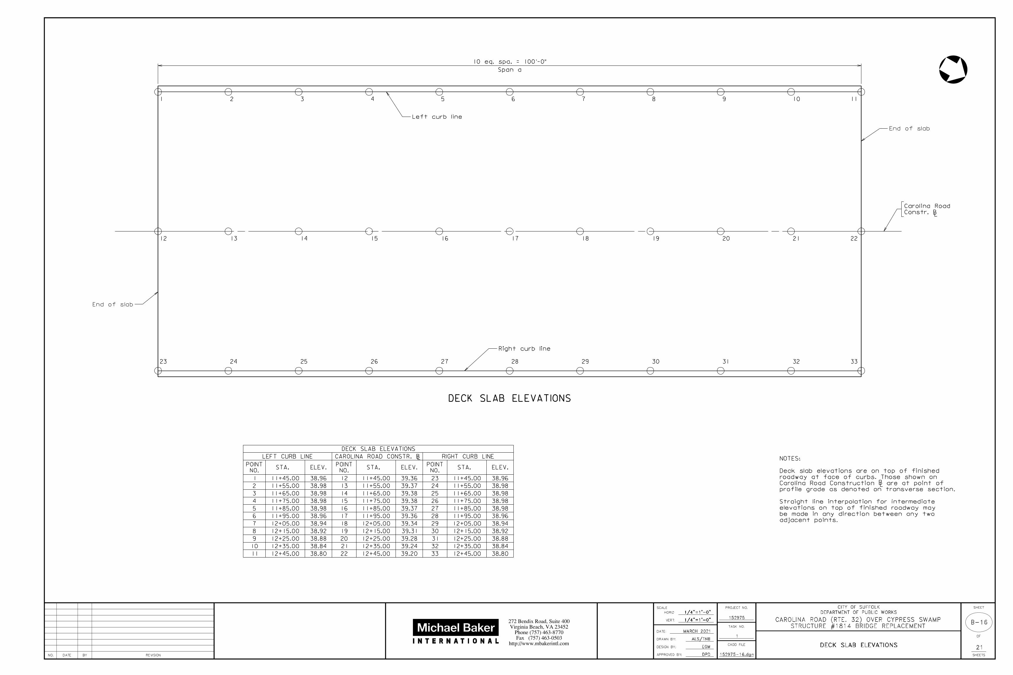
adjacent points.
be made in any direction between any two
elevations on top of finished roadway may
Straight line interpolation for intermediate
profile grade as denoted on transverse section.
Carolina Road Construction are at point of
roadway at face of curbs. Those shown on
Deck slab elevations are on top of finished
NOTES:
LB
DECK SLAB ELEVATIONS
LEFT CURB LINE CAROLINA ROAD CONSTR. B RIGHT CURB LINE
NO.
POINTSTA. ELEV.
NO.
POINTSTA. ELEV.
NO.
POINTSTA. ELEV.
1 11+45.00 38.96 12 11+45.00 39.36 23 11+45.00 38.96
2 11+55.00 38.98 13 11+55.00 39.37 24 11+55.00 38.98
3 11+65.00 38.98 14 11+65.00 39.38 25 11+65.00 38.98
4 11+75.00 38.98 15 11+75.00 39.38 26 11+75.00 38.98
5 11+85.00 38.98 16 11+85.00 39.37 27 11+85.00 38.98
6 11+95.00 38.96 17 11+95.00 39.36 28 11+95.00 38.96
7 12+05.00 38.94 18 12+05.00 39.34 29 12+05.00 38.94
8 12+15.00 38.92 19 12+15.00 39.31 30 12+15.00 38.92
9 12+25.00 38.88 20 12+25.00 39.28 31 12+25.00 38.88
10 12+35.00 38.84 21 12+35.00 39.24 32 12+35.00 38.84
11 12+45.00 38.80 22 12+45.00 39.20 33 12+45.00 38.80
152975-16.dgnNO. REVISIONBYDATE
SCALE
HORIZ:
VERT:
DRAWN BY:
DESIGN BY:
APPROVED BY:
DATE:
CADD FILE
PROJECT NO.
TASK NO.
SHEET
OF
21
SHEETSDPD
EGM
152975
1
http://www.mbakerintl.com
Fax (757) 463-0503
Phone (757) 463-8770
Virginia Beach, VA 23452
272 Bendix Road, Suite 400
DEPARTMENT OF PUBLIC WORKS
CITY OF SUFFOLK
MARCH 2021
ALS/TNB
STRUCTURE #1814 BRIDGE REPLACEMENT
CAROLINA ROAD (RTE. 32) OVER CYPRESS SWAMP

NTS
NTSB-17
Scale: ƒ" = 1'-0" unless otherwise noted.
Max. spa.
1'-8"
= 3'-0" @ posts
2"
= 8"
= 8"
C
2'-
0"
3"
2"
Face of rail2'-
0"
3'-
6"
„
7"
„" elastomeric pad
1'-
4"
4"
1'-
6"
Limit f
or railin
g pay
me
nt
PL 3ƒ x 3ƒ x ‚
PL 8• x 9• x ƒ
1"
C
SECTION A-A
C
A
B
steel tubing
HSS 4 x 3 x ‚
C C
C C
10"
10"
Full scale
•"
ƒ"
1•" cl.
10"
/
SECTION B-B
**
**
BASE PLATE DETAIL8•
"
4‚
"
ƒ"
1•" 1•"3‚"
1" o hole/
C
‚
/
**
REINFORCING STEEL SCHEDULE
Mark No.Size Length Location
RL04
/
#4
#4
3"
RG0401
RG0402
RG0402
#4
4•
"
4•
"
1'-6"
4"
delineator
Barrier
42"-BR27C STEEL RAILING
Min. lap
1'-10" typ. 2" typ.
8" minimum
2'-0" maximum
weld all around typ.
with „" seal
‚" closure plate
ABUTMENT
steel railing
L groove and end of
in pedestal
L groove
typ.
slotted hole
‡" o x 1„"
SECTION C-C
PART ELEVATION Not to scale
steel tubing
HSS 4 x 4 x ‰
bars not shown.
Transverse slab
Note:
Top of deck slab
1•" cl.
RG0401
RL04 series
RG0402
Face of rail
1•" cl.
washers typ.
hex nuts and flat
A449 bolts with
†" o x 13" H.S.
deck slab
Top of
= 8"
C
C
Min. lap
1'-10" typ. 2" typ.
in pedestal
L groove
Limit of payment for railing on superstructure
End of slabEnd of wingwall
Limit of payment for railing on substructure
=7'-3"
wingwall
Top of
2'-0" maximum
8" minimum
weld all around typ.
with „" seal
‚" closure plate
1'-6" 1'-6" 1'-6"
3 spa. @
6" = 1'-6"= 6"
Max. spa.
RW0401 and RW0402 at each space
ABUTMENTS
6 spa. @ 6"
RL04 seriesMax. spa.
A
L rail spliceB
1'-8"
L rail splice
deck slab
Top of
Max. spa.RL04 series
Retaining wall
RL04 series Face of rail L post
PL 8• x 9• x ƒ
2ˆ
"4
…"
2ˆ
"
9•"
3‚"
R = •" typ.
4‚
"
Groove detail for
both sides of rail
ƒ"
slab bars
Longitudinal
Scale: 1" = 1'-0"
contained inside rebar cage
Bolts through base plate shall be
Scale: 1" = 1'-0"
10"
Parapet
Parapet
Parapet3"
Pin o
RG0401
Dimensions in bending diagram are out-to-out of bars.
1'-6"
placement of the RG04 series bars.
Specifications as -0" to +•" is shifted to -‚" to +‚" for
The cover tolerance referenced in the VDOT Road and Bridge
ELEVATION
Max. spa. = 8"
RG0401 and RG0402 at each space
D
D
Face of rail
10"
SECTION D-D
**
4"
1•" cl.
RW0401
RL04 series
wingwall
Top of
RW0402
for details not shown
See Section A-A and B-B
contained inside rebar cage
Bolts through base plate shall be
Scale: 1" = 1'-0"
4•
"
2'-
10•
"
RW0401 RW0402
RW0401 #4 3"
RW0402 #4 3"
Parapet and u-back wing
Parapet and u-back wing
2'-
10•
"
4•
"
2'-
2…
"
2'-
6•
"
Retaining wall
Retaining Wall
Retaining wall
Retaining Wall
152975-17.dgn
For additional notes, see sheets B-9, and B-18.
Rails to be continuous over a minimum of 3 posts before splicing.
ground down.
Where more tilting of the post is required, the concrete shall be
alignment, maximum thickness of shim build-up not to exceed „".
posts will be vertical. Steel shims may be used to adjust post
Cut bottom of posts to match cross slope before welding so that
dimensions.
a nominal durometer hardness of 60. Pads shall conform to post base
Posts shall be seated on neoprene pads „" minimum thickness, having
Minimum spacing is 6'-6"
Posts shall be equally spaced within a span. Maximum spacing is 7'-0".
All steel shall be hot dip galvanized.
shall be applied to damaged galvanized areas.
the bolt end ground so that no sharp edges remain. Cold galvanizing
the extension is longer, excess shall be cut off and the edges of
be limited to the smaller of one and a half finishing turns or ‚". If
For bolts attaching rails to posts, bolt extensions beyond nut shall
or ASTM A194 Grade 2H. Washers shall be ASTM F436.
otherwise indicated in the details. Nuts shall be ASTM A563 Grade DH
slot in head), ASTM A449. All other bolts shall be ASTM A325 unless
Bolts for attaching rails to post are ƒ" diameter round head (with
be ASTM A36 steel. Steel pipe sleeves shall be ASTM A53.
Posts and rail members shall be ASTM A500 Grade B steel. Plates shall
see sheet B-9.
For details and reinforcing steel schedule of retaining wall,
Steel, Class II.
All reinforcing steel shall be Corrosion Resistant Reinforcing
and slab depths.
shall adjust the reinforcing steel as required for other cross slopes
‚" per foot cross slope and for an 8•" slab depth. The Contractor
The reinforcing steel shown has been detailed based on a standard
All bevels for concrete shall be ƒ".
All concrete shall be Low Shrinkage Class A4 Modified.
for installation.
The Contractor shall determine all dimensions and details necessary
vertical planes.
Plan dimensions shown are measured in the respective horizontal and
NOTES:
NO. REVISIONBYDATE
SCALE
HORIZ:
VERT:
DRAWN BY:
DESIGN BY:
APPROVED BY:
DATE:
CADD FILE
PROJECT NO.
TASK NO.
SHEET
OF
21
SHEETSDPD
EGM
152975
1
http://www.mbakerintl.com
Fax (757) 463-0503
Phone (757) 463-8770
Virginia Beach, VA 23452
272 Bendix Road, Suite 400
DEPARTMENT OF PUBLIC WORKS
CITY OF SUFFOLK
MARCH 2021
ALS/TNB
STRUCTURE #1814 BRIDGE REPLACEMENT
CAROLINA ROAD (RTE. 32) OVER CYPRESS SWAMP
NTS
NTSB-18
‰
Locknut
SECTION A-A
SECTION C-C
‰
3‚
"SECTION AT RAIL SPLICE
Steel tubing
Locknut
3"
typ.
2"
1•
"
2"2" 2"
‰
Typ.
SECTION B-B
RAIL SPLICE DETAILS
ELEVATION VIEW
BB
A
•"
4" 4"1"
L rail spliceC
Œ" x 1•" slot in outer tube
Œ" o hole in inner sleeve
2"2"
SECTION D-D
ELEVATION VIEW
DD
A
A
4"A
A/2
RAIL EXPANSION JOINT DETAILS
L rail expansion joint
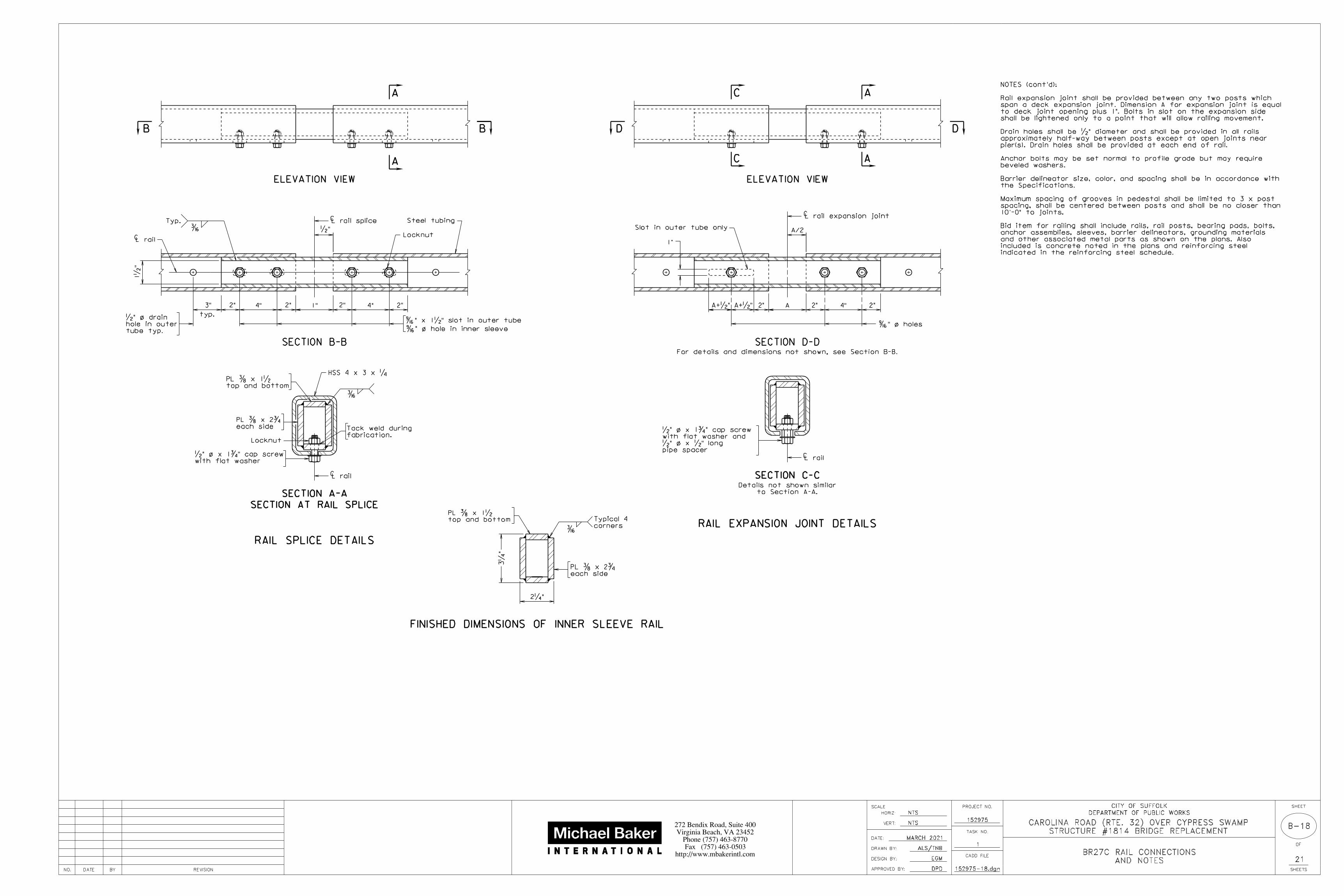
For details and dimensions not shown, see Section B-B.
2"A+•" A+•"
1"
Slot in outer tube only
CL rail
CL rail
2‚"
/
/
C
Œ" o holes/
A
/
/
FINISHED DIMENSIONS OF INNER SLEEVE RAIL
/
corners
Typical 4
top and bottom
PL … x 1•
each side
PL … x 2ƒ
top and bottom
PL … x 1•
each side
PL … x 2ƒ
HSS 4 x 3 x ‚
L railC
tube typ.
hole in outer
•" o drain
to Section A-A.
Details not shown similar
fabrication.
Tack weld during
with flat washer
•" o x 1ƒ" cap screwpipe spacer
•" o x •" long
with flat washer and
•" o x 1ƒ" cap screw
C
C
AND NOTES
BR27C RAIL CONNECTIONS
indicated in the reinforcing steel schedule.
included is concrete noted in the plans and reinforcing steel
and other associated metal parts as shown on the plans. Also
anchor assemblies, sleeves, barrier delineators, grounding materials
Bid item for railing shall include rails, rail posts, bearing pads, bolts,
10'-0" to joints.
spacing, shall be centered between posts and shall be no closer than
Maximum spacing of grooves in pedestal shall be limited to 3 x post
the Specifications.
Barrier delineator size, color, and spacing shall be in accordance with
beveled washers.
Anchor bolts may be set normal to profile grade but may require
pier(s). Drain holes shall be provided at each end of rail.
approximately half-way between posts except at open joints near
Drain holes shall be •" diameter and shall be provided in all rails
shall be lightened only to a point that will allow railing movement.
to deck joint opening plus 1". Bolts in slot on the expansion side
span a deck expansion joint. Dimension A for expansion joint is equal
Rail expansion joint shall be provided between any two posts which
NOTES (cont'd):
152975-18.dgnNO. REVISIONBYDATE
SCALE
HORIZ:
VERT:
DRAWN BY:
DESIGN BY:
APPROVED BY:
DATE:
CADD FILE
PROJECT NO.
TASK NO.
SHEET
OF
21
SHEETSDPD
EGM
152975
1
http://www.mbakerintl.com
Fax (757) 463-0503
Phone (757) 463-8770
Virginia Beach, VA 23452
272 Bendix Road, Suite 400
DEPARTMENT OF PUBLIC WORKS
CITY OF SUFFOLK
MARCH 2021
ALS/TNB
STRUCTURE #1814 BRIDGE REPLACEMENT
CAROLINA ROAD (RTE. 32) OVER CYPRESS SWAMP
NTS
NTSB-19
AND BENDING DIAGRAM
REINFORCING STEEL SCHEDULE
Type 1
A
Type 5
A
Q D
P
R
Type 6
C
B
Type 7
B
C
D
Type 27
Q
H
P
A
R
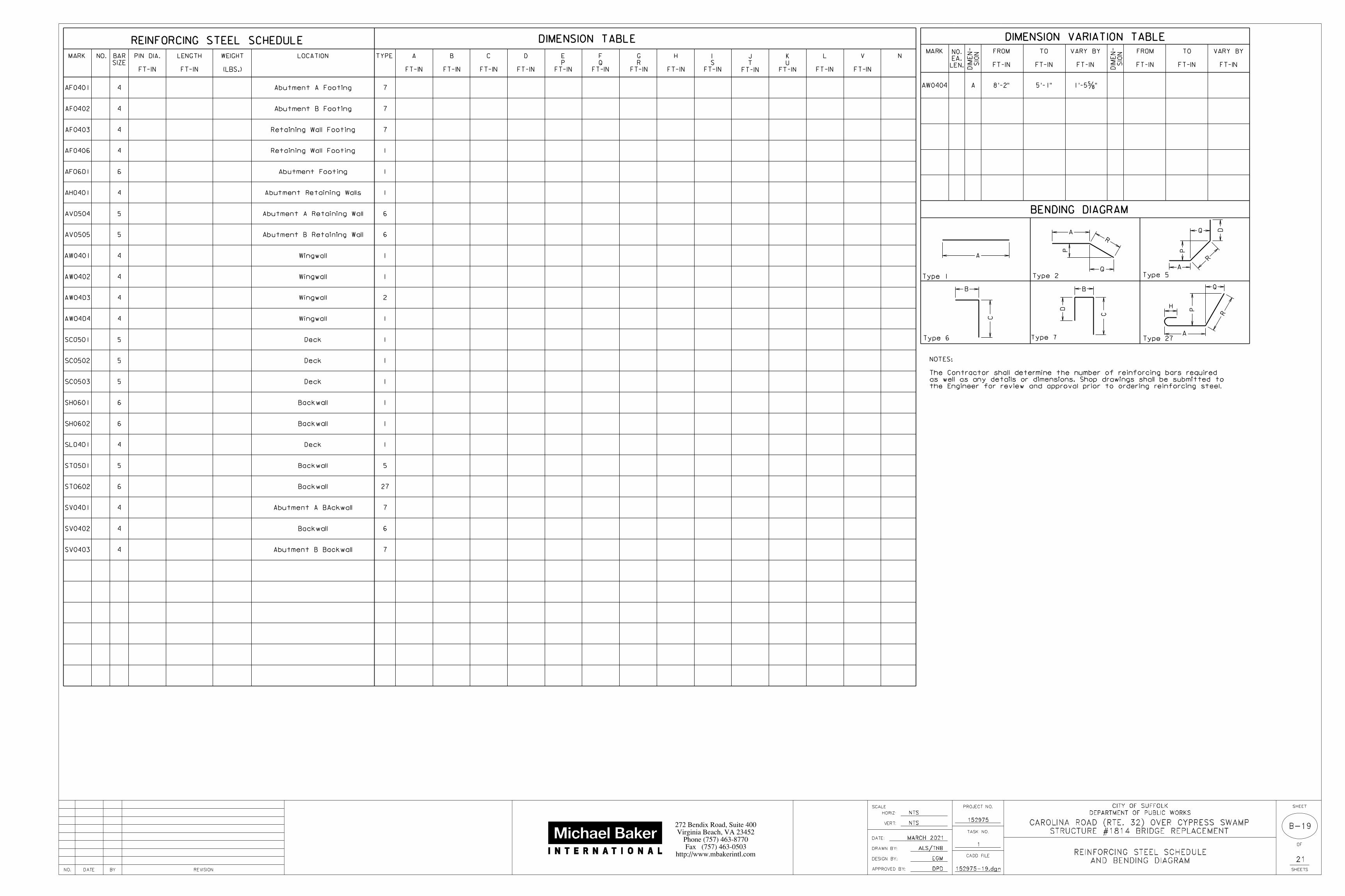
REINFORCING STEEL SCHEDULE DIMENSION TABLE
MARK NO.
SIZE
BAR LOCATION TYPE N
FT-IN
PIN DIA.
FT-IN
A
FT-IN
B
FT-IN
C
FT-IN
D
FT-IN
P
E
FT-IN
Q
F
FT-IN
R
G
FT-IN
H
FT-IN
S
I
FT-IN
T
J
FT-IN
U
K
FT-IN
L
FT-IN
V
BENDING DIAGRAM
AF0401 4 Abutment A Footing 7
(LBS.)
WEIGHT
FT-IN
LENGTH
AF0402 4 Abutment B Footing 7
AF0403 4 7
AF0406 4 1
AF0601 6 1
AH0401 4 1
AV0504 5 6
AV0505 5 6
AW0401 4 1
AW0402 4 1
AW0403 4 2
SC0501 5 1
SC0502 5 1
SC0503 5 1
SH0601 6 1
SH0602 6 1
SL0401 4 1
ST0501 5 5
ST0602 6 27
SV0401 4 7
4 6
SV0403 4 7
SV0402
Retaining Wall Footing
Retaining Wall Footing
Abutment Footing
Abutment A Retaining Wall
Abutment B Retaining Wall
Wingwall
Wingwall
Wingwall
Deck
Deck
Deck
Backwall
Backwall
Deck
Backwall
Backwall
Abutment A BAckwall
Backwall
Abutment B Backwall
Abutment Retaining Walls
AW0404 4 Wingwall 1
DIMENSION VARIATION TABLE
MARK
LEN.
EA.
NO.
SIO
N
DIM
EN-
SIO
N
DIM
EN-
FT-IN
FROM
FT-IN
TO
FT-IN
VARY BY
FT-IN
FROM
FT-IN
TO
FT-IN
VARY BY
AAW0404 8'-2" 5'-1" 1'-5†"
Type 2
Q
A
P
R
the Engineer for review and approval prior to ordering reinforcing steel.
as well as any details or dimensions. Shop drawings shall be submitted to
The Contractor shall determine the number of reinforcing bars required
NOTES:
152975-19.dgnNO. REVISIONBYDATE
SCALE
HORIZ:
VERT:
DRAWN BY:
DESIGN BY:
APPROVED BY:
DATE:
CADD FILE
PROJECT NO.
TASK NO.
SHEET
OF
21
SHEETSDPD
EGM
152975
1
http://www.mbakerintl.com
Fax (757) 463-0503
Phone (757) 463-8770
Virginia Beach, VA 23452
272 Bendix Road, Suite 400
DEPARTMENT OF PUBLIC WORKS
CITY OF SUFFOLK
MARCH 2021
ALS/TNB
STRUCTURE #1814 BRIDGE REPLACEMENT
CAROLINA ROAD (RTE. 32) OVER CYPRESS SWAMP

B-20
PRESTRESSED CONCRETE PILES
NTS
NTS
2'-
6"
Build-up
3"
2'-
6"
A A
6"
pit
ch
See Note B
6"
pit
ch (S
ee
Note
C)
2
3
4
1
POINTS
0.292L
0.207L
0.145L 0.355L
0.107L 0.262L 0.262L
0.586L
L
L
L
L
0.262L
0.207L
0.145L
0.107L
0.355L
0.708L
PICK UP POINTS
Unless special lifting devices are attached for pick-up, pick-up
points shall be plainly marked on all piles after removal of the
forms. The pile shall be supported only at the indicated pick-up
points remain in a straight line during lifting and when position-
ing the pile for driving.
points while in storage or while being handled.
1-Point 2-Point 3-Point 4-Point
LLLL
PILE PICK-UP DATA
150
204
338
12"
14"
18"
20"
24"
417
600
W
size
Pile
SQUARE CIRCULAR
SECTION A-A: STRAND PATTERN FOR PILE
eq.
spa.
N
eq. spa.W
W
L strands
Strands equally spaced
See Note B
SECTION B-B: PILE HEAD
The use of special embedded or attached lifting devices, the em-
ployment of other pick-up points or any other method of pick-up
shall be subject to approval by the Engineer.
than 5000 psi, the maximum pick-up length shall be the tabulated
length reduced by 1% for every 250 psi below 5000 psi.
Lbs.
LF
Wt. per
Approx. for various pick-up systems
Maximum lengths
C
3" typ. for 18" thru 24" piles
12"
14"
18"
20"
24"
psi(in.)
Circular
Square
Circular
Circular
Circular
Circular
Square
Square
Square
Square 4
4
12
12
16
16
•
•
•
•
•
•
•
•
•
•
1
2
3
3
4
751
751
820
751
751
poundsin.
Maximum lengths are determined from impact loads. L is the maxi-
/
/
W
16 turns
16 turns
3"
pit
ch
3"
pit
ch
1"
pile tip.
with pile head and
Cut strands flush
1"
5 turns
1"
pit
ch
5 turns
1"
pit
ch
mum pick-up length based on a concrete compressive strength of
5000 psi. If piles are picked up when concrete strength is less
2016, Commonwealth of Virginiac
PILE BUILD-UP ELEVATIONPILE ELEVATION
feather edges
hammered to prevent
pile head shall be bush-
Concrete around top of head
Top of pile
B B
Permissible mechanical splice
2'-
6"
5'-
0"
DETAIL
PILE HEAD PROJECTING BAR
Section B-B.
see Pile Data Table and
number of reinforcing bars,
For size, location and
See Note A
#8 bars for 24" piles
#7 bars for 14", 18" and 20" piles
#6 bars for 12" piles
2•" typ. for 12" and 14" piles
12" and 14" PILES
(W-6") for piles 18" thru 24"
(W-5") for piles 12" and 14"
B B
or cap
Bottom of footing
or cap
Top of footing
PILE HEAD CONNECTION DETAILStrands and ties not shown
3" min.
2'-
6"
min.
minimum embedment
bars if needed to achieve the required
Use a 90 bend at top of projectingo
W
Pile size
per strand
force
Prestressing
strands
of
Diameter
in pile
strands
no. of
Total
pattern
Strand
spacings
Strand
after losses
prestress
Effective6"
min.
The use of proper rigging is required to ensure that the pick-up
8
6
12
10
30,980
30,980
24,790
26,850
30,980
30,980
30,980
30,980
30,980
30,980
18", 20" and 24" piles
W5 wire spiral ties for
for 12" and 14" piles;
W3.5 wire spiral ties
N
N
shown).
wire spiral ties not
Pile head (strands and
in Section A-A.
are the same as
Wire spiral ties
3•" typ.
4-#7 for 14" piles
4-#6 for 12" piles
3•" typ.
Strands and wire spiral ties not shown
18", 20" and 24" piles
W5 wire spiral ties for
for 12" and 14" piles;
W3.5 wire spiral ties
PILE DATA TABLE
8-#8 for 24" piles
8-#7 for 18" and 20" piles
and Note C.
Section A-A
ties, See
Wire spiral
#3 bars shall be used and the pitch shall be 3".
For Seismic Performance Zone 2 bridges (structures), W12 wire or
Note C:
be placed to fit.
If alternate circular strand arrangement is used, bar extension must
Note B:
ASTM C939.
a flow time between 10 to 30 seconds tested in accordance with
reinforcing bars shall be installed immediately. The grout shall have
strength grout shall be placed in the holes and the #6, #7 or #8
driving the pile and cleaning out the holes, an approved high
shall be a single section and shall be capped at the bottom. After
2" o holes formed with galvanized corrugated metal duct. The duct
(the holes shall be serrated to provide a mechanical bond) or
2. The top of the pile shall be cast with 1…" o preformed holes
undamaged before casting the footing or cap; or
expose the strands. The strands must be thoroughly cleaned and
the concrete pile, remove the concrete from the added length to
1. The pile may be cast 2'-6" longer than required. After driving
In lieu of the reinforcing bars projecting from the head:
Note A:
hot dip galvanized.
the spiral ties and all other reinforcing bars in the pile shall be
bents and in footings constructed above Mean High Tide elevation,
Where piles are exposed in bridges over tidal water such as in pile
strands shall project into the cap or footing to serve for anchorage.
When pile cut-off is greater than 2'-6" at least 30 inches of all the
the pile is driven and the bars are spliced.
adequate shielding to protect the ends of the reinforcing bars until
Section 406.03(e) of the Specifications. The Contractor shall provide
Mechanical splices for reinforcing bars shall be in accordance with
and then only after driving is complete.
Build-ups shall be used only with written permission by the Engineer
Splicing is not permitted, unless authorized by the Engineer.
Wire spiral ties shall conform to ASTM A82.
Deformed reinforcing bars shall conform to ASTM A615, Grade 60.
of 270 ksi.
All strands shall be low relaxation and shall have an ultimate strength
cylinder strength at time of release of strands equal to 3500 psi.
strength at 28 days equal to 5000 psi and a minimum compressive
All concrete shall be Class A5 having a minimum compressive cylinder
Note:
CONNECTION DETAIL
See PILE HEAD CONNECTION DETAIL
See PILE HEAD
834
835
2'-
6"
5'-
0"
B B
See Note A
PROJECTING BAR DETAIL
ALTERNATE PILE HEAD
Strands and spirals not shown
#8 bars for 24" piles
and 20" piles
#7 bars for 14", 18"
#6 bars for 12" piles
Galvanized corrugated metal duct
827
806
806
49'
54'
62'
65'
69'
69'
77'
88'
91'
97'
98'
110'
125'
131'
139'
133'
149'
170'
177'
189'
16" 267 62' 88' 126' 171'
16"Circular
Square •
•
28
8
30,970
30,970
836
836
16", 18", 20" and 24" PILES
152975-20.dgnNO. REVISIONBYDATE
SCALE
HORIZ:
VERT:
DRAWN BY:
DESIGN BY:
APPROVED BY:
DATE:
CADD FILE
PROJECT NO.
TASK NO.
SHEET
OF
21
SHEETSDPD
EGM
152975
1
http://www.mbakerintl.com
Fax (757) 463-0503
Phone (757) 463-8770
Virginia Beach, VA 23452
272 Bendix Road, Suite 400
DEPARTMENT OF PUBLIC WORKS
CITY OF SUFFOLK
MARCH 2021
ALS/TNB
STRUCTURE #1814 BRIDGE REPLACEMENT
CAROLINA ROAD (RTE. 32) OVER CYPRESS SWAMP

B-21
APPROACH SLAB
NTS
NTS
SECTION A-A
AS0701
AS0503 AS0502
4"
1'-
3"
PLAN
20'-0"
3'-
0"
4"
3"9" 9"
3"
Face of backwall
A
BB
A
CC
3'-
0"
4"
Slope to match bridge slab
AS0502 to
p
AS0701 botto
m
AS0503 @ 1'-6" c-c top
AS0503 @ 9" c-c bottom
Spaces
@ 12"
c-c to
p
Spaces
@ 6"
c-c botto
m
7•
"
Scale: ƒ" = 1'-0"
3•
"
L
Mark
AS0701
AS0502
AS0503
No. Length
19'-8"
Location
REINFORCING STEEL SCHEDULE
Bottom longitudinal
Top longitudinal
Size Pin o/
Top and bottom transverse
#7
#5
#5
Scale: …" = 1'-0"
botto
m
8
@ 4"
to
p
4
@ 8"
to
p
4
@ 8"
AS0503 top and bottom
30'-
0"
Bolster as necessary
3"
4"
1'-
3"
7•
"
7"AS0510
2'-0" 2'-0"1'-6"
AS0414
3•
"3"
1'-
3"
pavement
Approach
AS0509
9"
10"
End of slab
abutment
integral
Face of
2•
" clr. ty
p.
10 mil plastic moisture barrier, typ.
Detail F
filler
Joint
Joint filler
Molykote 321 by Dow Corning or Mantek Dri-guard.
Between the pads, use either a powdered graphite lubricant,
Specifications, for full length of approach slab seat.
Section 237 of the current VDOT Road and Bridge
2 -„" preformed bedding material pads conforming to
PREFORMED ELASTOMERIC JOINT SEALER
3"
In uncompressed state
this line
Do not cut above
DETAIL F
L joint
Lubricant adhesive
Preformed sealer
Max. R = ‚" typ.
…"
C
typ.
•"
Not to scale
Hot poured joint sealer
Approach slab
Bond breaker
‚" radius typ.
•"
•"
„"
End of slab
SECTION B-BScale: ƒ" = 1'-0"
SECTION C-CNot to scale
AS0503 top and bottom
AS0502
AS0701
AS0414
AS0510
AS0509
#4
#5
#5 Sleeper pad
Sleeper pad
Sleeper pad
botto
m
8
@ 4"
3"
12"
ty
p.
1‡"
sheets B-6 & B-7
ST0602 see
Top of slab
Carolina Road Constr. B
1•
"
and bottomAS0503 top
3•
"A
S0509
&
AS0510
@ 12"
max.
3•
"
Sleeper pad
20'-4•"
#5 - 2'-2"
#4 - 1'-9"
Reinforcing lap lengths shall be as follows unless otherwise noted:
Payment for grooving is included in bridge deck grooving quantities.
Specifications, Section 404.07 (f), Class 6, Bridge Deck Finish.
Grooving shall be in accordance with VDOT Road and Bridge
for more than two weeks.
Material Type RC-70, RC-250 or MC-250 if aggregate base is exposed
Prime aggregate base material with 0.35 gal. per sq. yd. Liquid Asphalt
between approach slab and concrete pavement.
See VDOT Road and Bridge Standards, Section 300 for dowels in joint
centers of bars.
All reinforcing bar dimensions except for bending diagram are to
Deformed reinforcing bars shall conform to ASTM A615, Grade 60.
the joint shall be blown out with oil-free compressed air.
brushed with a mechanical rotary wire brush. Just prior to sealing,
compound, oils, greases and dirt. All faces must be sandblasted or
areas and their faces shall be free of all foreign matter, curing
All joints that are to be sealed shall be free of cracked and spalled
NOTES:
152975-21.dgnNO. REVISIONBYDATE
SCALE
HORIZ:
VERT:
DRAWN BY:
DESIGN BY:
APPROVED BY:
DATE:
CADD FILE
PROJECT NO.
TASK NO.
SHEET
OF
21
SHEETSDPD
EGM
152975
1
http://www.mbakerintl.com
Fax (757) 463-0503
Phone (757) 463-8770
Virginia Beach, VA 23452
272 Bendix Road, Suite 400
DEPARTMENT OF PUBLIC WORKS
CITY OF SUFFOLK
MARCH 2021
ALS/TNB
STRUCTURE #1814 BRIDGE REPLACEMENT
CAROLINA ROAD (RTE. 32) OVER CYPRESS SWAMP