rotary, kelly, swivel, tongs, and top drive - petroleum
TRANSCRIPT
Petrole
um Exte
nsion
-The U
nivers
ity of
Texas
at Aus
tin
ROTARY DRILLING SERIES
Unit I: The Rig and Its Maintenance
Lesson1: TheRotaryRigandItsComponentsLesson2: TheBitLesson3: DrillStringandDrillCollarsLesson4: Rotary,Kelly,Swivel,Tongs,andTopDriveLesson5: TheBlocksandDrillingLineLesson6: TheDrawworksandtheCompoundLesson7: DrillingFluids,MudPumps,andConditioningEquipmentLesson8: DieselEnginesandElectricPowerLesson9: TheAuxiliariesLesson10: SafetyontheRig
Unit II: Normal Drilling Operations
Lesson1: MakingHoleLesson2: DrillingFluidsLesson3: DrillingaStraightHoleLesson4: CasingandCementingLesson5: TestingandCompleting
Unit III: Nonroutine Operations
Lesson1: ControlledDirectionalDrillingLesson2: Open-HoleFishingLesson3: BlowoutPrevention
Unit IV: Man Management and Rig Management
Unit V: Offshore Technology
Lesson1: Wind,Waves,andWeatherLesson2: SpreadMooringSystemsLesson3: Buoyancy,Stability,andTrimLesson4: JackingSystemsandRigMovingProceduresLesson5: DivingandEquipmentLesson6: VesselInspectionandMaintenanceLesson7: HelicopterSafetyLesson8: OrientationforOffshoreCraneOperationsLesson9: LifeOffshoreLesson10: MarineRiserSystemsandSubseaBlowoutPreventers
Petrole
um Exte
nsion
-The U
nivers
ity of
Texas
at Aus
tin
iii
Figures and Table vi
Foreword ix
Acknowledgments xi
Units of Measurement xii
Introduction 1
Conventional Rotating System 3
Top-Drive System 7To summarize 8
Rotary Table Assembly 9Definition 9Functions 10
During Drilling 10When Drilling Stops 10
How the Rotary Table Assembly Works 12Size 13Components 13
Base 13Rotary Table 15Drive-Shaft Assembly 16Sprockets 18Locking Devices 18
Maintenance 20Installation 20Lubrication ` 24
To summarize 26
Master Bushing, Kelly Bushing, and Slips 27Master Bushing 27
Definition 27Functions 29Construction 30Design 30Drives 33Size 34Additional Equipment 34Maintenance 36
Kelly Bushing 38Definition 38Functions 39How the Kelly Bushing Works 40Design 43Maintenance 46
Contents
Petrole
um Exte
nsion
-The U
nivers
ity of
Texas
at Aus
tin
iv
Slips 48Definition 48Function 49How Slips Work 49Design 52Size 54Handling 55Repair 57Maintenance and Inspection 58
Power Slips 61To summarize 62
Kelly 63Definition 63Functions 64Design 64How the Kelly Works 66Kelly Accessories 67
Kelly Saver Sub 67Upper Kelly Cock 68Lower Kelly Cock 69
To summarize 70
Swivel 71Definition 71Function 72Design 72How the Swivel Works 76Maintenance 77
Replacing Oil Seals and Wear Sleeves 77Replacing Worn Washpipe Packing 78
Lubrication 79To summarize 80
Spinning and Torquing Devices 81Spinning Devices 82 Spinning Chain 82
Kelly Spinner 84Spinning Wrenches 85
Torquing Devices 86 Conventional Tongs 86
Power Tongs 91Hydraulic Torque Wrench 92
Combination Power-and-Spinning Wrenches 93Tong Safety 94Maintenance 95To summarize 96
Petrole
um Exte
nsion
-The U
nivers
ity of
Texas
at Aus
tin
v
Top Drives 97Definition 97Functions 98Design 100How a Top Drive Works 103Maintenance 104 Visual Inspection 104 Lubrication 105To summarize 106
Conclusion 107
Appendix AMaintenance Checklist for One Brand of Rotary Table Assembly 108
Appendix BRotary Table Assembly Troubleshooting Guide 110
Appendix CLubrication and Maintenance Checklist for One Brand of Swivel 112
Appendix DSwivel Troubleshooting Guide 115
Appendix EHydraulic Spinning Wrench Lubrication 116
Appendix FTorque Wrench Lubrication 118
Appendix GTorque Wrench Troubleshooting Guide 120
Appendix HTop-Drive Maintenance and Lubrication 122
Appendix ITop-Drive Torque Wrench Toubleshooting Guide 124
Glossary 127
Review Questions 141
Answers to Review Questions 147
Petrole
um Exte
nsion
-The U
nivers
ity of
Texas
at Aus
tin
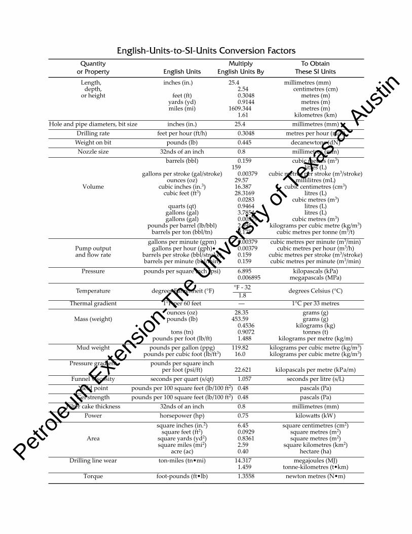
Quantity Multiply ToObtain orProperty EnglishUnits EnglishUnitsBy TheseSIUnits
Length, inches(in.) 25.4 millimetres(mm) depth, 2.54 centimetres(cm) orheight feet(ft) 0.3048 metres(m) yards(yd) 0.9144 metres(m) miles(mi) 1609.344 metres(m) 1.61 kilometres(km)Holeandpipediameters,bitsize inches(in.) 25.4 millimetres(mm) Drillingrate feetperhour(ft/h) 0.3048 metresperhour(m/h) Weightonbit pounds(lb) 0.445 decanewtons(dN) Nozzlesize 32ndsofaninch 0.8 millimetres(mm) barrels(bbl) 0.159 cubicmetres(m3) 159 litres(L) gallonsperstroke(gal/stroke) 0.00379 cubicmetresperstroke(m3/stroke) ounces(oz) 29.57 millilitres(mL) Volume cubicinches(in.3) 16.387 cubiccentimetres(cm3) cubicfeet(ft3) 28.3169 litres(L) 0.0283 cubicmetres(m3) quarts(qt) 0.9464 litres(L) gallons(gal) 3.7854 litres(L) gallons(gal) 0.00379 cubicmetres(m3) poundsperbarrel(lb/bbl) 2.895 kilogramspercubicmetre(kg/m3) barrelsperton(bbl/tn) 0.175 cubicmetrespertonne(m3/t) gallonsperminute(gpm) 0.00379 cubicmetresperminute(m3/min) Pumpoutput gallonsperhour(gph) 0.00379 cubicmetresperhour(m3/h) andflowrate barrelsperstroke(bbl/stroke) 0.159 cubicmetresperstroke(m3/stroke) barrelsperminute(bbl/min) 0.159 cubicmetresperminute(m3/min) Pressure poundspersquareinch(psi) 6.895 kilopascals(kPa) 0.006895 megapascals(MPa)
Temperature degreesFahrenheit(°F) degreesCelsius(°C)
Thermalgradient 1°Fper60feet –– 1°Cper33metres ounces(oz) 28.35 grams(g) Mass(weight) pounds(lb) 453.59 grams(g) 0.4536 kilograms(kg) tons(tn) 0.9072 tonnes(t) poundsperfoot(lb/ft) 1.488 kilogramspermetre(kg/m) Mudweight poundspergallon(ppg) 119.82 kilogramspercubicmetre(kg/m3) poundspercubicfoot(lb/ft3) 16.0 kilogramspercubicmetre(kg/m3) Pressuregradient poundspersquareinch perfoot(psi/ft) 22.621 kilopascalspermetre(kPa/m) Funnelviscosity secondsperquart(s/qt) 1.057 secondsperlitre(s/L) Yieldpoint poundsper100squarefeet(lb/100ft2) 0.48 pascals(Pa) Gelstrength poundsper100squarefeet(lb/100ft2) 0.48 pascals(Pa) Filtercakethickness 32ndsofaninch 0.8 millimetres(mm) Power horsepower(hp) 0.75 kilowatts(kW) squareinches(in.2) 6.45 squarecentimetres(cm2) squarefeet(ft2) 0.0929 squaremetres(m2) Area squareyards(yd2) 0.8361 squaremetres(m2) squaremiles(mi2) 2.59 squarekilometres(km2) acre(ac) 0.40 hectare(ha) Drillinglinewear ton-miles(tn•mi) 14.317 megajoules(MJ) 1.459 tonne-kilometres(t•km) Torque foot-pounds(ft•lb) 1.3558 newtonmetres(N•m)
°F-321.8
English-Units-to-SI-UnitsConversionFactors
Petrole
um Exte
nsion
-The U
nivers
ity of
Texas
at Aus
tin
1
Drillers ready to drill ahead sometimes say, “Let’s put the bit on bottom and turn it to the right.” This oil patch expression
is a nod to a special technology called rotary drilling. Rotary drilling bores through underground formations by rotating (turning) the drill stem and the bit.
Today, rotary drilling is the industry standard, but it was not always so. Before rotary drilling started to flourish in Texas in the 1900s, oil people drilled most wells with cable drilling tools. With this method, rig crewmembers attach a sharp tool—a bit—to a cable. The cable, along with other rig equipment, repeat edly picks up and drops the heavily weighted bit, which punches a hole into the ground.
Cable tool drilling has two big drawbacks. Chips of rock (cuttings) that the bit gouges from the formation stay in the hole. The cabletool system has no way of gett ing them out of the way as the bit drills. Eventually, the cuttings build up to the point that the bit starts punching into old cuttings instead of into fresh, uncut rock. At this point, the bit no longer deepens the hole. Crewmembers therefore have to stop the operation and bail (re move) the cuttings. Even worse, however, is that some soft formations cave in around the bit and keep it from drilling at all.
Rotary drilling solves the problems of having to stop drilling to bail, and of caveins in soft forma tions. The beauty of the rotary method is that it not only rotates the bit to drill ahead (make hole), it also re moves cuttings from the hole at the same time. Removing cuttings at the same time the bit drills keeps the hole clean, regardless of how soft the formations are. Unlike cabletool drilling, rotary drilling uses hollow pipe (the drill stem) to put the bit on the bottom of the hole. The diameter of the bit is larger than the diameter of the drill stem, so it drills a hole whose diameter is larger than the drill stem’s. Thus, there is space between the drill stem and the wall of the hole. This space is the an nular space, or the annulus.
Introduction
Petrole
um Exte
nsion
-The U
nivers
ity of
Texas
at Aus
tin
3
ConventionalRotatingSystem
Figure 1 shows a conventional rotary system. From top to bottom, it consists of a hook, a swivel, and a rotary (kelly)
hose. It also has an upper kelly cock (valve), a kelly, and a lower kelly cock (valve), which is screwed into the bottom of the kelly and cannot be seen on the figure. Not shown in the figure, but an important part (you will see why later), is a kelly saver sub.
The conventional rotating system also has a kelly bushing, a master bushing, and a rotary table assembly. The rotating system allows part of the drill stem’s weight to press down on the bit to make it drill. The system also provides the rotat ing force to turn the bit. Finally, it provides a passageway for the pump to send drilling fluid downhole to lift cuttings.
Let’s take a closer look at how a conventional rotary rig accomplishes these three jobs (fig. 2). The drilling crew attaches a drill bit studded with metal or diamond cutters to the bottom of the drill stem. Crewmembers then lower the drill stem into the hole until the bit is very near the bottom. At this point, the driller engages the ro tary table assembly on the rig floor to turn the drill stem and bit. The mud pump is also started to circulate drilling fluid. The driller then lowers the rotating bit the rest of the way to bottom and allows part of the drill stem’s weight to push down on the bit. Weight causes the bit’s cutters to bite into the formation and drill ahead.
Petrole
um Exte
nsion
-The U
nivers
ity of
Texas
at Aus
tin
7
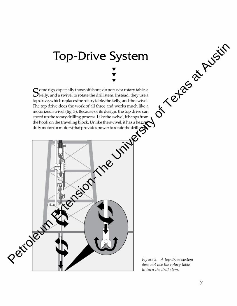
Figure 3. A top-drive system does not use the rotary table to turn the drill stem.
Top-DriveSystem
Some rigs, especially those offshore, do not use a rotary table, a kelly, and a swivel to rotate the drill stem. Instead, they use a
top drive, which replaces the rotary table, the kelly, and the swivel. The top drive does the work of all three and works much like a mo torized swivel (fig. 3). Because of its de sign, the top drive can speed up the rotary drilling process. Like the swivel, it hangs from the hook on the traveling block. Unlike the swivel, it has a heavyduty motor (or motors) that provides power to ro tate the drill stem.
Petrole
um Exte
nsion
-The U
nivers
ity of
Texas
at Aus
tin
9
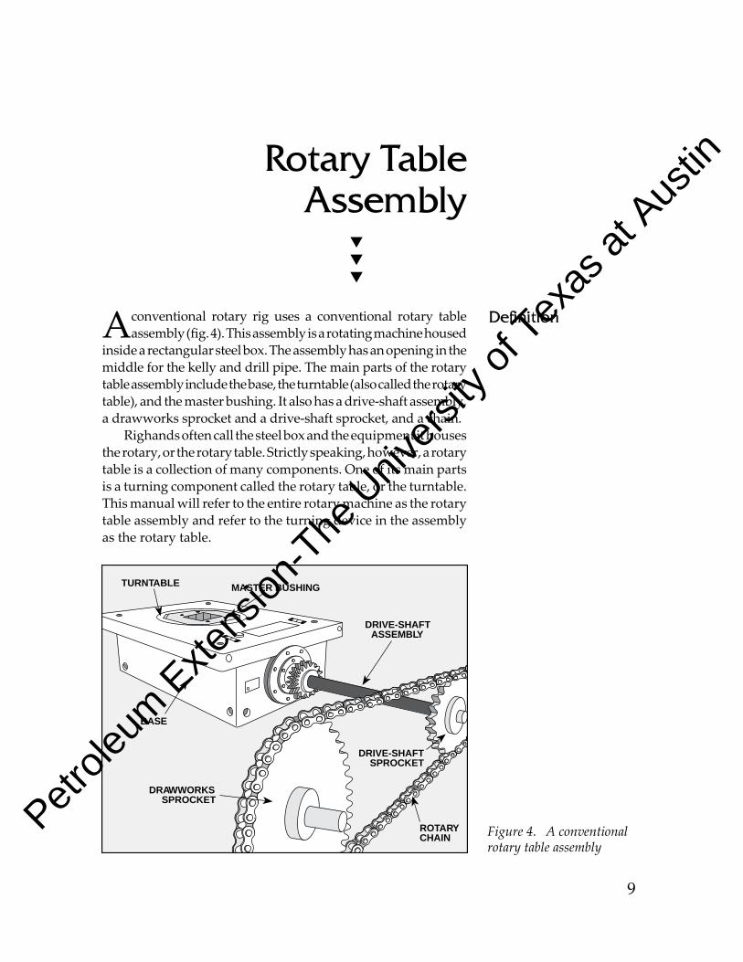
DRIVE-SHAFTSPROCKET
DRAWWORKSSPROCKET
ROTARYCHAIN
MASTER BUSHINGTURNTABLE
DRIVE-SHAFTASSEMBLY
BASE
A conventional rotary rig uses a conventional rotary table assembly (fig. 4). This assembly is a rotating ma chine housed
inside a rectangu lar steel box. The assembly has an opening in the middle for the kelly and drill pipe. The main parts of the ro tary table assembly include the base, the turntable (also called the ro tary table), and the master bushing. It also has a drive-shaft assembly, a drawworks sprocket and a drive-shaft sprocket, and a chain.
Righands often call the steel box and the equipment it houses the rotary, or the rotary table. Strictly speaking, however, a rotary table is a collection of many components. One of its main parts is a turning component called the rotary table, or the turntable. This manual will refer to the entire ro tary machine as the rotary table assembly and refer to the turning device in the assembly as the rotary table.
Definition
RotaryTableAssembly
Figure 4. A conventional rotary table assembly
Petrole
um Exte
nsion
-The U
nivers
ity of
Texas
at Aus
tin
27
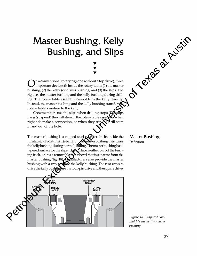
Figure 18. Tapered bowl that fits inside the master bushing
DRIVEHOLE
MASTERBUSHING
TAPEREDBOWL
DRIVEHOLE
ROTARYTABLE
MasterBushing,KellyBushing,andSlips
On a conventional rotary rig (one without a top drive), three important devices fit inside the rotary table: (1) the master
bushing, (2) the kelly (or drive) bushing, and (3) the slips. The rig uses the master bushing and the kelly bushing during drill-ing. The rotary table assembly cannot turn the kelly di rectly. Instead, the master bushing and the kelly bushing transfer the ro tary table’s motion to the kelly.
Crewmembers use the slips when drilling stops. The slips hang (suspend) the drill stem in the rotary table assembly when righands make a connection, or when they trip the drill stem in and out of the hole.
The master bushing is a rugged steel cylinder. It sits inside the turntable, which turns it (see fig. 5). The master bushing then turns the kelly bushing during normal drilling. The master bushing has a tapered surface for the slips. This surface is either part of the bush-ing itself, or it is a removable inner bowl that is separate from the master bushing (fig. 18). Manufacturers also provide the master bushing with a way to drive the kelly bushing. The two ways to drive the kelly bushing are the four-pin drive and the square drive.
MasterBushingDefinition
Petrole
um Exte
nsion
-The U
nivers
ity of
Texas
at Aus
tin
63
Kelly
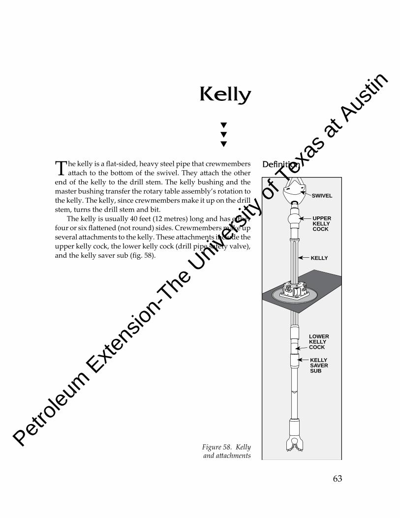
The kelly is a flat-sided, heavy steel pipe that crewmembers attach to the bottom of the swivel. They attach the other
end of the kelly to the drill stem. The kelly bushing and the master bushing transfer the rotary table assembly’s rotation to the kelly. The kelly, since crewmembers make it up on the drill stem, turns the drill stem and bit.
The kelly is usually 40 feet (12 metres) long and has either four or six flattened (not round) sides. Crewmembers make up several attachments to the kelly. These attachments include the upper kelly cock, the lower kelly cock (drill pipe safety valve), and the kelly saver sub (fig. 58).
Definition
KELLYSAVERSUB
LOWERKELLYCOCK
KELLY
UPPERKELLYCOCK
SWIVEL
Figure 58. Kelly and attachments
Petrole
um Exte
nsion
-The U
nivers
ity of
Texas
at Aus
tin
71
Swivel
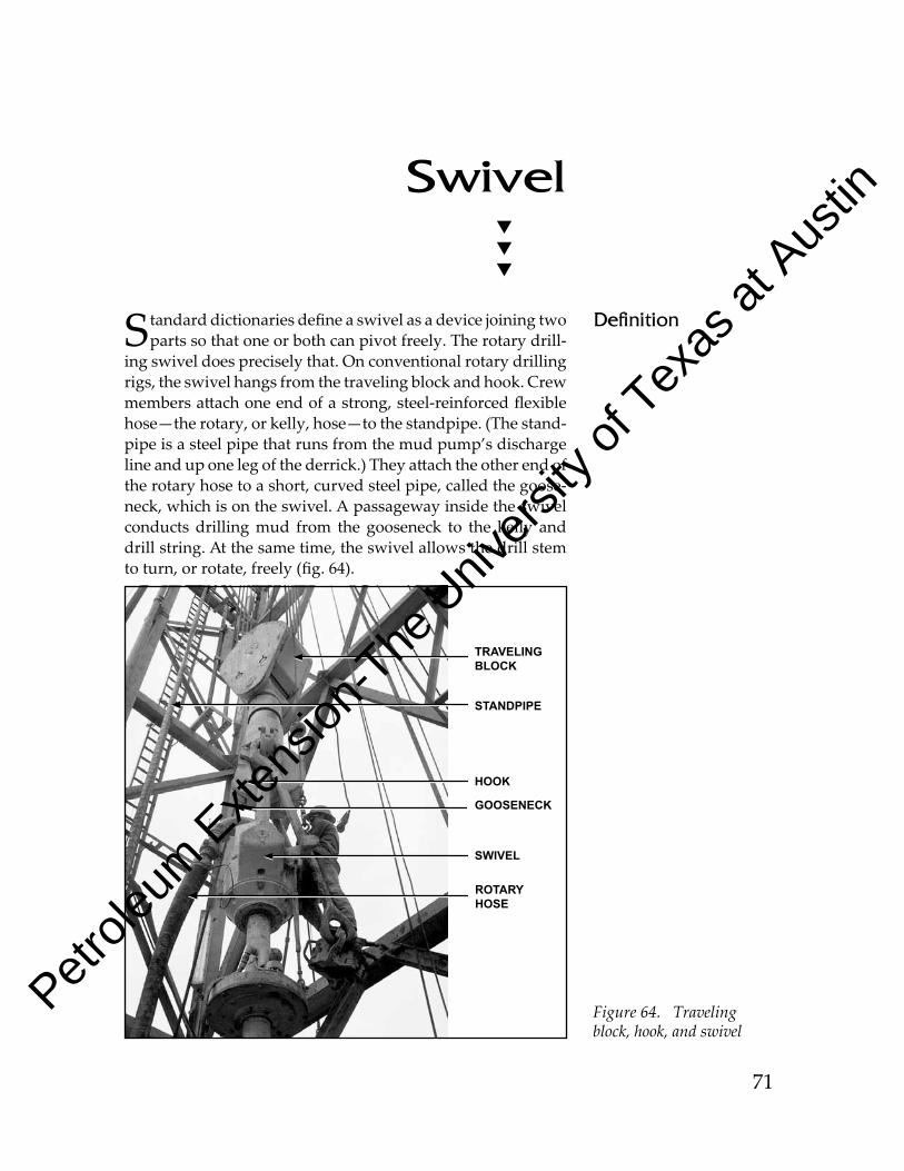
Standard dictionaries define a swivel as a device joining two parts so that one or both can pivot freely. The rotary drill-
ing swivel does precisely that. On conventional rotary drilling rigs, the swivel hangs from the traveling block and hook. Crew members at ach one end of a strong, steel-reinforced flexible hose—the rotary, or kelly, hose—to the standpipe. (The stand-pipe is a steel pipe that runs from the mud pump’s discharge line and up one leg of the derrick.) They atach the other end of the rotary hose to a short, curved steel pipe, called the goose-neck, which is on the swivel. A passageway inside the swivel conducts drilling mud from the gooseneck to the kelly and drill string. At the same time, the swivel allows the drill stem to turn, or rotate, freely (fig. 64).
TRAVELING BLOCK
SWIVEL
Figure 64. Traveling block, hook, and swivel
ROTARYHOSE
GOOSENECK
HOOK
Definition
STANDPIPE
Petrole
um Exte
nsion
-The U
nivers
ity of
Texas
at Aus
tin
81
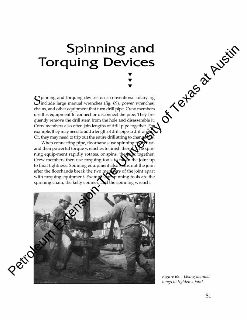
SpinningandTorquingDevices
Spinning and torquing devices on a conventional rotary rig include large manual wrenches (fig. 69), power wrenches,
chains, and other equipment that turn drill pipe. Crew members use this equip ment to connect or disconnect the pipe. They fre-quently remove the drill stem from the hole and disas semble it. Crew members also often join lengths of drill pipe together. For example, they may need to add a length of drill pipe to drill ahead. Or, they may need to trip out the en tire drill string to change bits.
When connecting pipe, floorhands use spinning tools first, and then powerful torque wrenches to finish the job. The spin-ning equip -ment rapidly rotates, or spins, the joint together. Crew members then use torquing tools to make the joint up to final tightness. Spinning equipment also spins out the joint after the floorhands break the two members of the joint apart with torquing equip ment. Examples of spinning tools are the spinning chain, the kelly spinner, and the spin ning wrench.
Figure 69. Using manual tongs to tighten a joint
Petrole
um Exte
nsion
-The U
nivers
ity of
Texas
at Aus
tin
97
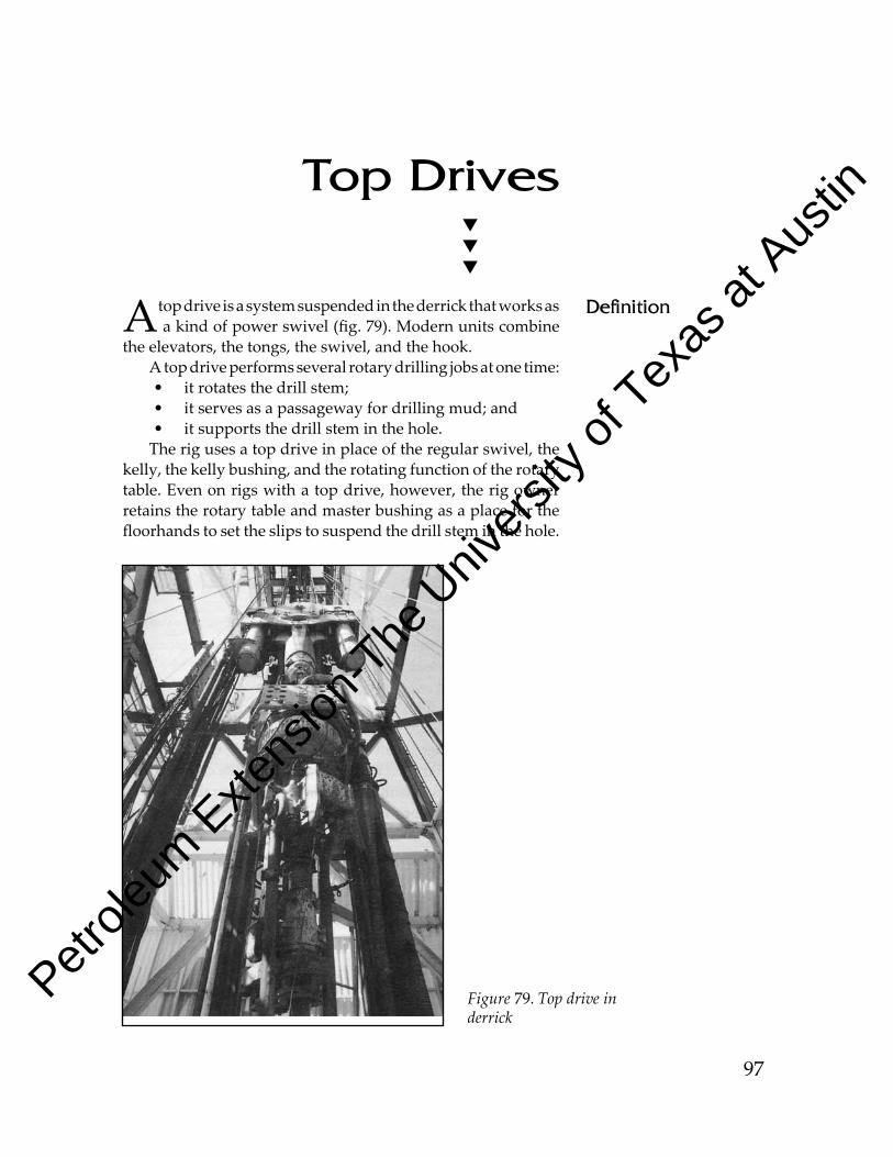
TopDrives
A top drive is a system suspended in the derrick that works as a kind of power swivel (fig. 79). Modern units combine
the elevators, the tongs, the swivel, and the hook. A top drive per forms several rotary drilling jobs at one time:• it rotates the drill stem;• it serves as a passageway for drilling mud; and • it supports the drill stem in the hole.
The rig uses a top drive in place of the regular swivel, the kelly, the kelly bush ing, and the rotating function of the rotary table. Even on rigs with a top drive, however, the rig owner retains the rotary table and master bushing as a place for the floorhands to set the slips to suspend the drill stem in the hole.
Figure 79. Top drive in derrick
Definition
Petrole
um Exte
nsion
-The U
nivers
ity of
Texas
at Aus
tin
107
Conclusion
The early days of rotary drilling overlapped the fading era of cable tool drilling. For a time, the rival technologies waged
a battle across the oilfields of the United States. Rotary workers called cable tool crew members rope chokers, jar heads, and mail pouchers (after a brand of chewing tobacco). Cable tool workers branded rotary hands auger men, chain breakers, clutch stompers, twisters, and swivel necks. Feelings were so fierce in Electra, Texas, for example, that boardinghouses segregated the workers to keep fights from breaking out. One house was for swivel necks only; the other was reserved for mail pouch ers.
Nearly a century later, the oilfield remains just as colorful, and drilling methods are still advanc ing. Rotary drilling even-tually took its place as the in dustry standard. Now, top-drive technology is changing rotary drilling itself. The old debate over drilling gear continues as top-drive equipment improves and challenges the conventional rotary method. But the news media have not reported any instances of separate boardinghouses for top-drive hands and for rotary table hands—at least, not yet.
Petrole
um Exte
nsion
-The U
nivers
ity of
Texas
at Aus
tin
To obtain additional training materials, contact:
PETEXThe University of Texas at Austin
Petroleum extension service10100 Burnet Road, Bldg. 2
Austin, TX 78758
Telephone: 512-471-5940or 800-687-4132
FAX: 512-471-9410or 800-687-7839
E-mail: [email protected] visit our Web site: www.utexas.edu/ce/petex
To obtain information about training courses, contact:
PETEXlearning and assessment center
The University of Texas4702 N. Sam Houston Parkway West, Suite 800
Houston, TX 77086
Telephone: 281-397-2440or 800-687-7052
FAX: 281-397-2441E-mail: [email protected]
or visit our Web site: www.utexas.edu/ce/petex
Petrole
um Exte
nsion
-The U
nivers
ity of
Texas
at Aus
tin

Petrole
um Exte
nsion
-The U
nivers
ity of
Texas
at Aus
tin