rolling friction of a rugby wheelchair
TRANSCRIPT
Available online at www.sciencedirect.com
Procedia Engineering 00 (2009) 000–000
Procedia Engineering
www.elsevier.com/locate/procedia
8th
Conference of the International Sports Engineering Association (ISEA)
Rolling friction of a rugby wheelchair
Julian J. C. Chua, Franz Konstantin Fuss*, Aleksandar Subic
School of Aerospace, Mechanical and Manufacturing Engineering, RMIT University, Melbourne VIC 3083, Australia
Elsevier use only: Received date here; revised date here; accepted date here
Abstract
The rolling friction coefficient is treated either as a constant, or a constant plus a parabolic velocity-dependent component.
According to mathematical models, the rolling friction coefficient of visco-elastic objects increases first and drops at higher
speeds. The aim of this paper was to analyse the non-linear rolling friction of a rugby wheelchair as a function of speed. Non-
linear velocity-dependent drag and lift coefficients were determined in the wind tunnel. In order to obtain the friction coefficient,
we applied the coast down method on three different floors (wood, linoleum, and short-pile carpet) by instrumenting the
wheelchair with an accelerometer. The rolling friction coefficient was calculated from the ratio of the difference between inertial
force and drag force to the difference between weight and upward lift force (where all forces are absolute values). The friction
coefficient µ of the carpet floor was the highest (µ = 0.0143; mean weighted to velocity), followed by the linoleum floor (µ =
0.0061) and the wooden one (µ = 0.0042). µ of carpet and linoleum showed no clear trend in the velocity range of 0-4 m s–1 and
can be treated as a constant. µ of the wooden gym floor increased, then dropped and increased again with speed. A fit function
based on a combined Bateman and parabolic function was applied to the wood data in order to separate the initial peak from the
velocity dependency at higher speeds.
© 2010 Published by Elsevier Ltd.
Keywords: wheelchair rugby; wheelchair; drag; lift; rolling friction; non-linearity
* Corresponding author. Tel.: +61 3 9925 6123; fax: +61 3 9925 6108.
E-mail address: [email protected].
2 Author name / Procedia Engineering 00 (2010) 000–000
1. Introduction
At low speeds, rolling resistance is the major source of energy loss in balls and vehicles, depending on the rolling
friction coefficient of balls and tyres on different surfaces, and also on the mass of the vehicle. Several methods for
measuring and analysing rolling friction are available, e.g.
- coast down methods:
- - distance of roll [1-3] by applying ramp methods,
- - timing gate method, which measures the velocity in discrete steps between the gates, and estimates the
velocity decreasing with time [4,5],
- - velocity method, which directly measures the velocity with time; e.g. [6,7];
- conveyor belt method, which uses large diameter rotating drums and flat conveyor belts to directly measure the
rolling resistance [8],
- pulling method, where a rolling object is pulled on a flat level surface, the reaction force is measured and the
rolling resistance calculated based on the mass of the object, and
- oscillation method, where an eccentric mass is attached in between two tyres which are allowed to rock back
and forth until they come to a stop; the rate of angular decay represents the friction resistance [9,10].
The disadvantage of all these methods is that the coefficient of rolling friction is considered constant and thus
velocity independent:
mgF RR µ= (1)
where FR is the friction force, µR is the coefficient of rolling friction, and the product of mass and gravitational
acceleration, m g, is the weight of the object.
Petrushov [11] introduced a coast down method which allows extracting the velocity dependent rolling friction as
a parabolic function of the velocity v
2
mgvkmgF fRR += µ (2)
where kf is the coefficient of speed influence on the rolling resistance [11]. In the case of car tyres, µR = 0.009 –
0.014, and kf = 1x10⁻⁶
– 1x10⁻⁵
s2 m
–2 [11], which are functions of tyre inflation pressure and temperature (data from
indoor vehicle coast-down tests on a wooden floor).
During coasting down, the inertial force, rolling resistance and aerodynamic drag force are in equilibrium,
resulting in the following non-linear ordinary differential equation
05.0d
d 22=+++ mgmgvkAvc
t
vm RfD µρ (3)
or
0d
d2
2
1 =++ cvct
vm (4)
where ρ is the density of air, cD is the drag coefficient, A is the frontal area, and c1 and c2 combine the constants
of Eq. (3). Solving Eq. (4) for v yields
−
= −
m
cct
c
cv
c
cvt
21
2
10
1
1
2 tantan (5)
where vt is the instantaneous velocity decreasing with time when coasting-down, and v0 is the initial condition at
impending deceleration [11]. The constant c2 combines the lumped drag coefficient, 0.5ρcDA, and the velocity

Author name / Procedia Engineering 00 (2010) 000–000 3
dependent rolling friction coefficient times the weight, kfmg. Separating both values is only possible if the lumped
drag coefficient is known from wind tunnel experiments.
Mathematical analyses of spheres or cylinders rolling on a flat surface, where one object is visco-elastic and the
other rigid, show that rolling resistance increases initially with speed before decreasing at higher speeds [12,13].
This behaviour would add another component to the velocity dependent rolling friction coefficient kf known from
car tyres [11].
Wheelchair rugby was developed for quadriplegic athletes as an alternative to wheelchair basketball. It is a
combination of both rugby and basketball and the main aim of the game is to carry the ball across the opponent’s
goal line, and likewise to prevent the other team from getting the ball or scoring. Like the game of rugby, wheelchair
rugby requires the athletes to turn and accelerate quickly to avoid their opponents and score. Therefore a rugby
wheelchair needs to be highly manoeuvrable and be able to accelerate quickly from standstill. The ability to
accelerate a rugby wheelchair from standstill is determined by three major characteristics: a) those related to
wheelchair configuration such as the overall rolling resistance and internal friction; b) those related to the athlete
such as explosive strength and propulsion technique and c) those related to the adjustment of the wheelchair
characteristics to the functional abilities of the player or wheelchair-user interface [14]. Rugby wheelchairs (as well
as most designs of basketball and some tennis chairs) are six-wheeled in contrast to other wheelchair types. Two of
the six wheels are large diameter inflatable spoke or disc tyres, and the other four are small size plastic casters with
either the front or the rear pair in contact with the ground.
Hoffman et al. [6] determined the rolling friction coefficients of several wheelchair types (folding, rigid ultra
light and racing) on linoleum and carpet. Their friction coefficient data range from 0.0150-0.0212 on carpet and
from 0.0013-0.0099 on linoleum. Fuss [7] investigated the rolling friction coefficients in racing wheelchairs on
rubber tracks which amounted to 0.01-0.012.
The aim of this study was to analyse the non-linearity of the rolling friction coefficient of a rugby wheelchair, by
- determining its non-linear lumped drag and lift coefficients as functions of speed,
- determining the coast-down deceleration and speed on three different surfaces, and
- presenting the rolling friction coefficient as a function of speed.
2. Experimental
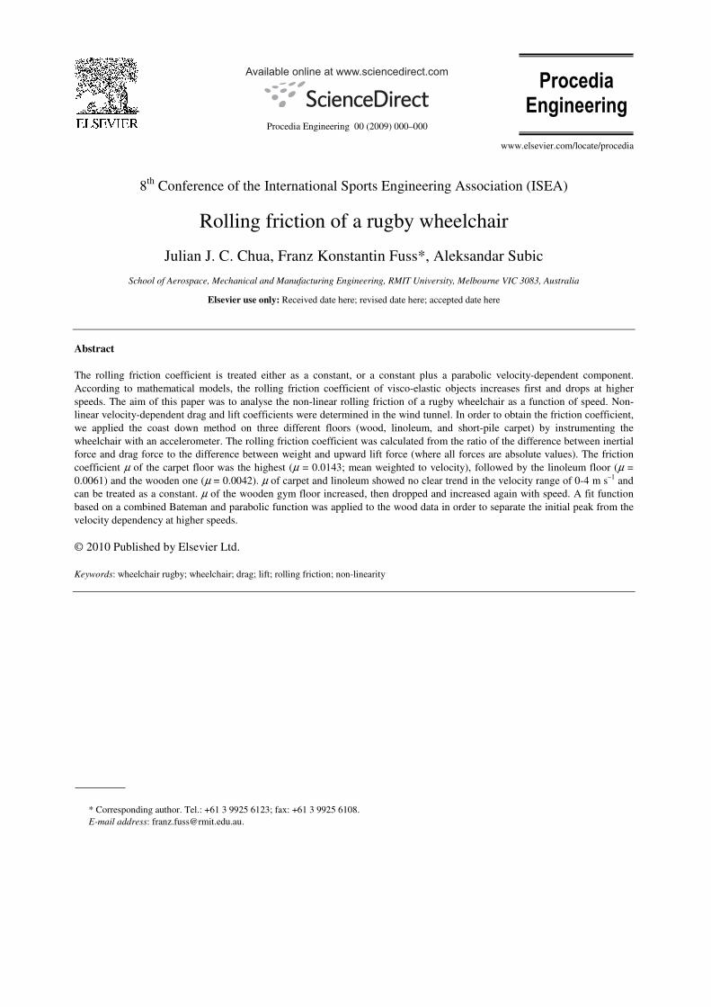
1) Rugby wheelchair: all experiments were carried out with a rugby wheelchair custom built by Melrose
(Christchurch, New Zealand; Figure 1). The weight of the chair was 169 N.
2) Wind tunnel experiments: drag and lift were measured using a Type 9260AA6 Kistler force plate (Kistler,
Winterthur, Switzerland). The force plate was mounted in an industrial wind tunnel, the test section of which is 3 m
wide, 2 m high and 9 m long. The maximum attainable wind speed is up to 40 m s–1
, but required test speed for this
experiment was only up to 11.11 m s–1
(40 kph). As the support area of the rugby wheelchair is larger than the force
plate, a wooden board (1.8 x 0.85 x 0.03 m) was secured onto the force plate before the wheelchair was placed on
top (Figure 1). The drag and lift force was obtained from the force plate plus the wooden board first, at increments
of 5 kph. Subsequently, the wheelchair was placed on the board and the procedure was repeated. Drag and lift forces
were recorded using the Kistler Bioware (Kistler, Winterthur, Switzerland) software. The drag and lift forces of the
force plate plus board were subtracted from the wheelchair drag and lift forces, and divided by the velocity squared.
A reciprocal function of the structure
DBv
ACC LD +
+=, (6)
where CD and CL are the lumped drag and lift coefficients (0.5ρcDA, 0.5ρcLA), respectively, and A, B and D are
the parameters of this function (D is the asymptotic value), was fitted to the lumped drag and lift coefficients to
account for the increased drag and lift at small velocities.
3) Coast down experiments: the experiments were carried out on three different indoor surfaces, a short pile
carpet floor, a linoleum floor, and a standard area-elastic wooden gym floor. The axles of the small front wheels
were aligned such that their vectors are parallel with zero distance in between, and the wheels were locked in this
4 Author name / Procedia Engineering 00 (2010) 000–000
position. This served to ensure a straight cost down path and avoid caster shimmy. The wheelchair was accelerated
manually and allowed to coast down until standstill or manual deceleration. The latter enabled higher coast-down
speeds. The experiments were carried out at different initial speeds (“high”, “medium”, “slow”) and repeated three
times. For “slow” speeds, the wheelchair reached a standstill, and for higher velocities it was decelerated manually.
Overlapping of the velocity ranges of “high”, “medium”, “slow” speeds at free coast down (without manual
deceleration) was essential and thus aimed at. The acceleration data were collected with an accelerometer
(minimaxX, Catapult Innovations Pty Ltd, Scoresby, Australia; resolution 0.037 m s–2
), attached to the frame of the
wheelchair, at 100 Hz.
3. Data analysis
The acceleration a was numerically integrated with time in order to obtain the velocity. The slight offset of the
data at zero acceleration was corrected such that the velocity after integration equals zero when the wheelchair is not
moving. As the rolling friction coefficient µ is the ratio of tangential friction force to weight, µ was obtained from
LG
DI
FF
FF
+
+−=µ (7)
where FI, FD, FG and FL are inertial, drag, gravitational and lift forces, respectively, or
2
2
vCgm
vCam
L
D
+
+−−=µ (8)
Note that inertial and drag forces are opposite, as are gravitational and lift forces. FG and FD are negative in Eqs.
(7) and (8).
The rolling friction coefficient µ was expressed as a function of velocity. The noise was removed with a 2nd
order
Savitzky-Golay filter of a window width of 1/33 of all data, applied five times.
As the non-linear rolling friction at slow velocities (c.f. Figure 3 of [12], and Figure 4 of [13]) resembles a
Bateman function, a combined Bateman and parabolic function of the form
( ) 2ee DvA CvBv +−= −−µ (9)
was fitted to the friction coefficients of the three different surfaces, where A, B, C, and D are the coefficients of
this function (D = kfmg).
4. Results
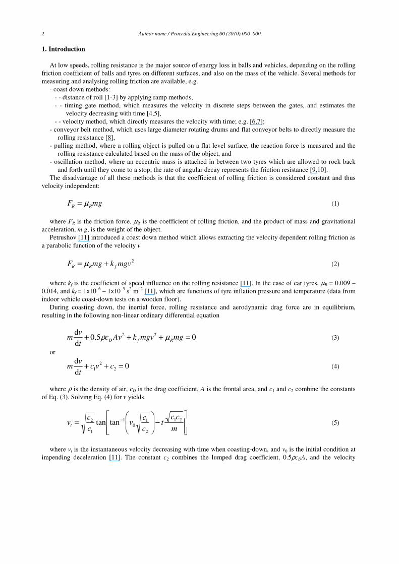
The lumped drag and lift coefficients, CD and CL, against velocity v are shown in Figure 2. The corresponding
equations are:
0.1608 0.0762
0.2955+
+=
vCD (10)
and
0.1666 0.1218
0.2099+
+=
vCL (11)
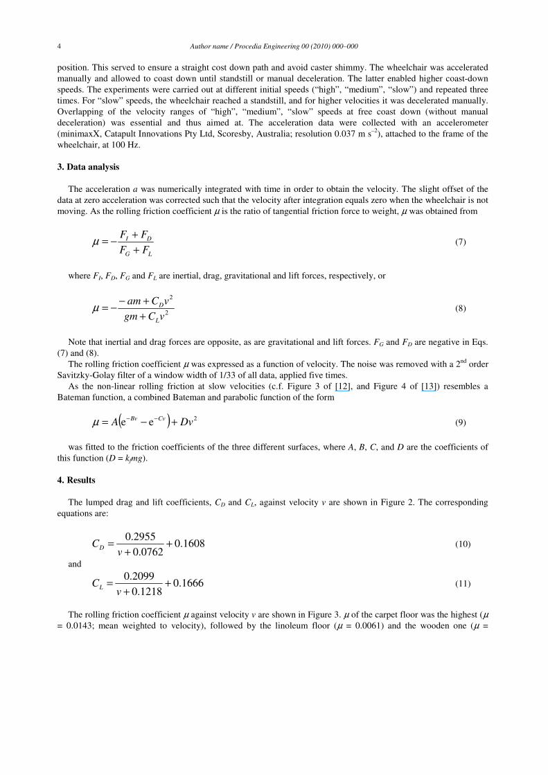
The rolling friction coefficient µ against velocity v are shown in Figure 3. µ of the carpet floor was the highest (µ
= 0.0143; mean weighted to velocity), followed by the linoleum floor (µ = 0.0061) and the wooden one (µ =
Author name / Procedia Engineering 00 (2010) 000–000 5
0.0042). The fluctuations of µ in Figure 3 indicate a range where the actual µ is located, and should not be
interpreted e.g. that µ of the carpet floor at v = 1.9 m s–1
is exactly 0.01567. The combined Bateman and parabolic
function of Eq. (9) was fitted in the data of the wooden floor only; the data of the other floors did not return all
positive coefficients. Only the data of the wooden floor showed a clear initial increase in µ, followed by a decrease
and another increase. The corresponding fit function (Figure 3) is
( ) 245.288707.0 00051.0ee00808.0 vvv +−= −−µ (12)
As kfmg equals 0.00051 in Eq. (12), kf amounts to 3x10⁻⁶
s2 m
–2.
Figure 1: rugby wheelchair mounted on the force plate in the wind tunnel.
Figure 2: lumped drag and lift coefficients against velocity; dashed lines: curve fit according to Eq. (6).
Figure 3: rolling friction coefficient against velocity; dashed lines: curve fit according to Eq. (9).

6 Author name / Procedia Engineering 00 (2010) 000–000
5. Discussion
The method used for determining the non-linear friction coefficient µ as a function of velocity, applied in this
study, was successful. Expressing µ non-linearly, however, makes sense only if the data follow roughly a combined
Bateman and parabolic function. This was not the case in the data of carpet and linoleum floors and thus a single,
constant µ is recommended. kf of the wheelchair on the wooden floor, which was 3x10⁻⁶
s2 m
–2 in this study, lies
well within the range of Petrushov’s results, which is between 1x10⁻⁶
and 1x10⁻⁵
s2 m
–2 [11].
The initial peak of µ occurs at v = 0.1264 m s–1
. Considering that the main wheels have a diameter of 0.61 m a
linear speed of 0.1264 m s–1
corresponds to an angular one of 0.4144 rad s–1
. According to [12] and [13], the
velocity at the peak µ depends on the radius and weight of the rolling object, and on the elastic, viscous and inertial
parameters as well as the Poisson ratio of the visco-elastic object (rolling or surface).
The data of Hoffman et al. [6] indicate that the drag area (cDA) of the same wheelchair is larger on carpet than on
linoleum. As this is impossible, their result suggests that kf on carpet is larger than kf on linoleum and that both
surfaces have a velocity dependent component. Hoffman et al. [6] did not consider that c1 in Eq. (4) is not just
0.5ρcDA but rather 0.5ρcDA + kfmg. The carpet data of Hoffman et al. (µ = 0.0150-0.0212) are comparable to ours (µ
= 0.0143). Their linoleum data range from 0.0013-0.0099. It has to be noted that Hoffman et al. [6] did not
investigate rugby wheelchairs, which are of a different construction (two large wheels, two plastic casters in contact
with the ground) than their folding, rigid ultra light and racing wheelchairs.
References
[1] Van der Plas R. Rolling resistance of bicycle tires. Bike Tech 1983;2:8-12.
[2] Fehlau G. The recumbent bicycle. Ann Arbor MI: Out Your Backdoor Press; 2000.
[3] FIFA Quality Concept for Football Turf. Available:
http://www.fifa.com/mm/document/afdeveloping/pitchequip/fqc_football_turf_folder_342.pdf.
[4] British Standard BS7044. Artificial sports surfaces, Part 2 Section 2.1. London: British Standards Institution; 1991.
[5] Kolitzus HJ. Ball Roll Behavior: The Functional Relationship of the Ball Roll Distance and the Timing Gate Method; How to Calculate the
Ball Roll Distance from Timing Gate Measurements. ISSS - International Association for Sports Surface Sciences, Eschenz / Switzerland,
2003. Available: http://www.isss-sportsurfacescience.org/downloads/documents/ZPKPAJJUWY_Ball_Roll_BehaviorKS.pdf.
[6] Hoffman MD, Millet GY, Hoch AZ, Candau RB. Assessment of wheelchair drag resistance using a coasting deceleration technique. Am J
Phys Med Rehabil 2003;82:880-889.
[7] Fuss FK. Influence of mass on the speed of wheelchair racing. Sports Engineering 2009;12:41–53.
[8] Milliken WF, Milliken DF. Race Car Vehicle Dynamics. Warrendale PA: SAE International; 1995.
[9] Hill B. Measurement of rolling resistance using an eccentrically weighted oscillating wheel. In: Meyer WE, and Reichert J, editors. Surface
characteristics of roadways. Philadelphia PA: ASTM; 1990, p. 497-504.
[10] Wang E, Macedo V, Reid J. A method for quantifying the rolling resistance of bicycle tires. In: Hubbard M, Mehta RD, Pallis JM, editors.
The Engineering of Sport 5, Vol. 2. Sheffield: International Sports Engineering Assocation; 2004, p. 132-138.
[11] Petrushov VA. Improvement in vehicle aerodynamic drag and rolling resistance determination from coast-down tests. Proc Instn Mech
Engrs Part D, J Automobile Engng 1998;212:369-380.
[12] Pöschel T, Schwager T, Brilliantov NV. Rolling friction of a hard cylinder on a viscous plane. Eur Phys J 1999;B10:169-174.
[13] Yung KL, Xu Y. Non-linear expressions for rolling friction of a soft ball on a hard plane. Nonlin Dyn 2003;33:33-41.
[14] Vanlandewijck Y, Theisen D, Thaly D. Wheelchair Propulsion Biomechanics. Sports Med 2001;31: 339-367.