roller guide assembly machine user's manual
TRANSCRIPT
ELSCO Roller Guide Assembly
Machine
User’s Manual
Page | 1
Table of Contents Table of Photos ............................................................................................................... 4
INTRODUCTION ............................................................................................................. 5
Common terminology ................................................................................................... 5 Safety circuits: ............................................................................................................. 5
Bearing Stations .......................................................................................................... 6
Spacer Stations ........................................................................................................... 6 Indexing table .............................................................................................................. 7
Normal Operation: ....................................................................................................... 7
ROBOT Operation: ................................................................................................... 8 HMI SCREEN DESCRIPTIONS ...................................................................................... 9
HOME Screen ............................................................................................................. 9
WHEEL SELECTOR Screen ..................................................................................... 11 SETTINGS Screen .................................................................................................... 12
ALARM LIST Screen ................................................................................................. 13
ALARM LIST DISPLAY .......................................................................................... 14 Alarms 1-8 – Bearing andSpacer Station Alarms ................................................... 16
POSSIBLE CAUSES .......................................................................................... 17
CORRECTIVE ACTIONS ................................................................................... 17 Alarms 9-10 – Press Actuator Alarms .................................................................... 17
POSSIBLE CAUSES .......................................................................................... 17
CORRECTIVE ACTIONS ................................................................................... 18 Alarms 11-18 – Press Station Alarms .................................................................... 18
POSSIBLE CAUSES .......................................................................................... 18
CORRECTIVE ACTIONS ................................................................................... 18 Alarms 19-22 – No Parts Available Alarms ............................................................ 19
POSSIBLE CAUSES .......................................................................................... 19
CORRECTIVE ACTIONS ................................................................................... 19 Alarms 23-42 – Robot Alarms ................................................................................ 19
Alarm 43 Keyence Safety Monitor Fault ................................................................. 19 Alarms 43-47 – Bearing and Spacer Actuators Can’t Retract Alarms .................... 20
Alarm 48 – Robot Fault Alarm ................................................................................ 20
Alarm 49 – Too Many Indexes Alarm ..................................................................... 20
Page | 2
Alarm 50 – Low Air Pressure Alarm ....................................................................... 20
Alarm 51 -Robot collision Fault Alarm .................................................................... 20 Alarm 52 -Indexer VFD Fault Alarm ....................................................................... 20
Alarm 53 -Press Extended Too Long Alarm ........................................................... 20
Alarm 55-57 -Too Many Wheels in Fixture ............................................................. 21 POSSIBLE CAUSES .......................................................................................... 21
CORRECTIVE ACTIONS ................................................................................... 21
ROBOT MESSAGES ................................................................................................. 21 Message #1: .......................................................................................................... 21
Message #2: .......................................................................................................... 21
Message #3: .......................................................................................................... 21 Message #4: .......................................................................................................... 22
Message #5: .......................................................................................................... 22
Message #6: .......................................................................................................... 22 Message #7: .......................................................................................................... 22
Message #8: .......................................................................................................... 22
Message #9: .......................................................................................................... 22 Message #10:......................................................................................................... 23
Message #11:......................................................................................................... 23 PROCESSING Screen .............................................................................................. 24
Other Screens .......................................................................................................... 25
Totalizer Screen ..................................................................................................... 25 Manual Ops Screens .............................................................................................. 25
ManualOps ......................................................................................................... 25
Manual Ops2 ...................................................................................................... 26 DOORS Screens .................................................................................................... 26
E-STOP Screens .................................................................................................... 27
Accessing the MAINTENANCE POSITION ................................................................... 28 CHANGE-OVER PROCESS ......................................................................................... 30
Indexing table ............................................................................................................ 30
obot End-of-Arm Tooling (EOAT)............................................................................... 30 Press station .............................................................................................................. 31
DEVICE STATUS SENSORS ....................................................................................... 32
Bearing and Spacer Actuators ................................................................................... 32
Page | 3
Lift Table Actuators .................................................................................................... 33
Push-off Actuators ..................................................................................................... 34 PRESS Actuator ........................................................................................................ 35
Other sensors ............................................................................................................ 36
Keyence LZ-R Laser sensor .................................................................................. 36 Keyence LR-TB5000 Analog Laser sensor ............................................................ 36
Keyence Locking Door Switch................................................................................ 37
Pneumatic supply components .............................................................................. 37 INDEXER CAM Switch ........................................................................................... 38
............................................................................................................................... 38
MECHANICAL DRAWINGS .......................................................................................... 39 ELECTRICAL DRAWINGS ........................................................................................... 63
INDEX ........................................................................................................................... 74
APPENDICES ............................................................................................................... 75 Keyence LR-ZH Series Instruction Manual Keyence LR-TB5000 Series Instruction Manual Keyence G L-R Series -Safety Light Curtain Instruction Manual Keyence GS (Lock) Safety Interlocking Switch Instruction Manual Keyence PR-M/F Instruction Manual
Page | 4
Table of Photos
PHOTO 1 - Robot in Maintenance position ................................................................... 28 PHOTO 2 - Robot in HOME position ............................................................................. 29 PHOTO 3 - CORRECT Orientation ............................................................................... 30 PHOTO 4 - INCORRECT Orientation ............................................................................ 30 PHOTO 5 - BEARING/SPACER ACTUATOR ............................................................... 32 PHOTO 6 – BEARING STATION – BEARING PRESENT SENSOR ............................ 33 PHOTO 7 - LIFT TABLE ACTUATOR ........................................................................... 33 PHOTO 8 - PUSH-OFF ACTUATOR ............................................................................ 34 PHOTO 9 - PRESS ACTUATOR................................................................................... 35 PHOTO 10 – Keyence Self contained LR-Z Laser Sensor ............................................ 36 PHOTO 11 - Keyence LR-TB5000 Analog Laser Sensor .............................................. 36 PHOTO 12 - Door locking limit switch ........................................................................... 37 PHOTO 13- Primary Air Prep ........................................................................................ 37 PHOTO 14 - Air Supply ................................................................................................. 37 PHOTO 15 - SMC Pneumatic manifold and Ethernet IO modules ................................ 37 PHOTO 16 - INDEXER CAM Switch ............................................................................. 38

Page | 5
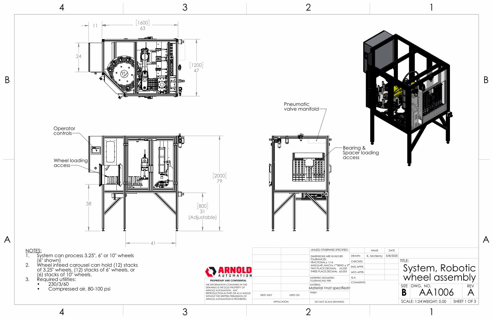
INTRODUCTION This machine is a robot assisted assembly unit designed to present pre-loaded wheels, bearings, and spacers in a pre-determined sequence to the press unit and provide press operations at the correct time to provide and discharge a completely finished wheel assembly. PLC (programmable logic controller) programming monitors pre-loading conditions, including providing the operator with fixture positions for loading the wheels and assuring that bearings and spacers of the correct size are available for robotic transport. Additionally, measuring and transmitting the wheel position for robot selection, and initiating the press operation are controlled by the PLC. Robot controller programming determines the exact positioning for each of the components, and operates end effectors to secure and place each of the necessary components on the press station. The robot controller programming is set up to respond to PLC communications and will operate only when the appropriate data has been provided to allow correct operation. To correctly process the components, the operator must assure that necessary components are available, and must select the correct size of the wheel assembly to be processed (3-1/4”, 6”, 10”) from the HMI (human machine interface) prior to beginning processing. Additionally, each wheel assembly will require specific end effectors to be installed on the robotic arm, and appropriate table fixture posts to be installed at correct locations on the indexer table. Details on these topics are provided later in this manual. Common terminology Certain terms, abbreviations are used throughout this manual: PLC – programmable logic controller HMI – human machine interface LBS – large bearing station SBS – small bearing station LSS – large spacer station SSS – small spacer station WS – wheel station PS – press station Safety circuits: The machine is equipped with several safety circuits. These circuits are monitored by the Keyence safety controller. Two e-stop buttons are located at: 1) the main panel and 2) at the bearing load area. A light curtain is provided at the wheel load station. Both access doors are equipped with locking safety switches. All of these provide two channel monitoring of the safety inputs.
Page | 6
The e-stop pushbuttons will provide a stop category 0 to the table indexer by opening series safety contractors feeding the indexer VFD. These will also provide a stop category 0 to the Fanuc SCARA robot through a pair of force guided safety relays to the robot controller E-stop safety circuit. The light curtain provides a stop category 1 to the indexer variable frequency drive by initiating an instant stop signal to the VFD control, followed by a timed interruption of the two channel STO (safe torque off) safety circuit of the VFD. The locking door safety switches create a stop category 1 to the robot controller through a pair of force guided control relays, and a stop category 1 to the indexer by initiating an instant stop signal to the VFD control, followed by a timed interruption of the two channel STO (safe torque off) safety circuit of the VFD. Bearing Stations Bearing stations are equipped with a pneumatic actuator. A photoelectric sensor also forms part of the bearing station. When the sensor determines there are no bearings available for the robot to pick, the pneumatic actuator will retract to load four new bearings the into pick position. Once loaded, the actuator will return to the normal, extended position. The status of the actuator is monitored by two magnetic switches (one for retracted, one for extended) located on the actuator housing. A fault condition will occur if the actuator is commanded to a position and does not achieve the position within several seconds. Additionally, if the actuator attempts to load bearings for three successive attempts and is not successful, a fault will be triggered indicating no bearings available. The operator will need to correct the condition and reset the fault to continue processing Both the large and small bearing stations operate similarly. Spacer Stations Spacer stations are equipped with a pneumatic actuator. A photoelectric sensor also forms part of the spacer station. When the sensor determines there is no spacer available for the robot to pick, the pneumatic actuator will extend to reach a new spacer and then retract to load that spacer the into pick position. Once loaded, the actuator will remain retracted to prevent the spacer from moving due to vibration. It will then return to the normal, extended position shortly before the robot moves to pick the spacer. The status of the actuator is monitored by two magnetic switches (one for retracted, one for extended) located on the actuator housing. A fault condition will occur if the actuator is commanded to a position and does not achieve the position in several seconds. Additionally, if the actuator attempts to load bearings for three successive attempts and is not successful, a fault will be triggered indicating no bearings available.
Page | 7
Both the large and small spacer stations operate similarly. Indexing table The indexing table supports 12 fixture positions. The 3.25” wheels and the 6” wheels will occupy 1 fixture position each, filling all 12 positions; the 10” wheels will occupy 2 fixture positions so that 6 actual fill positions will be occupied by 10” wheels. The table will rotate a fixed amount each movement (index). Several different triggers can initiate an index: 1) when the robot has picked all of the wheels within a given fixture, an index will be triggered; 2) when the operator has filled a fixture to its full capacity - ( (7) 3.25” wheels or (6) 6” wheels) and the fixture reaches position #1(left-most from the operator’s point of view), an index will be triggered so that the operator will always have access to as many minimally loaded fixtures as possible; finally, 3) the operator may manually request an index of the table from the manual operation screens. Normal Operation: Once the operator presses the “Start Processing” button, the system will cycle through the following operations: The indexer will move, one position at time, until there is a stack of 1 or more wheels present at the robot pick position. If the cycle was started with 1 or more wheels in the pick position, the indexer will not move at that time.
The robot will travel to the bearing station and pick up a bearing using the smaller gripper. If the bearing station needs to cycle in order to make a bearing available, the robot will wait while the actuator is in motion
The robot will then return to a position near the wheel indexer. If the indexer is in motion, or the pick position is empty, the robot will wait until there is a wheel available. Using the larger gripper, the robot will pick the top wheel from the stack in the pick position and transport that wheel to the press. The robot will place the wheel on the press, retract from the press position, and place the bearing on the press. As the robot retracts from the press area, the press will actuate and press the first bearing in to position. While the press actuates, the robot will travel to the spacer station and pick up 1 spacer using the smaller gripper.
Page | 8
The robot will return to the press area and place the spacer on the press station. The robot will travel to the bearing station and pick up a second bearing. The robot will return to the press area and place the bearing on the press station. As the robot retracts from the press area, the press will actuate and press the second bearing in to position, completing the wheel assembly. While the robot travels to the bearing station to start the next cycle, the platform on the press station will lift the completed wheel up so that it is clear of the lower tooling. The pusher mechanism will push the completed wheel away from the press so that the wheel slides down the roller ramp and out of the system enclosure. The pusher mechanism and lift platform will retract to allow for the next wheel to be placed. ROBOT Operation: The ROBOT ( robot controller) typically operates in three states: 1) RUNNING, 2) PAUSED, or 3)ABORTED. When the robot is running, the controller is actively executing the program in the robot controller. When the robot is paused, the program execution has been temporarily halted, but can continue from the point in the program at which it was halted. When the robot is aborted, processing in the PLC is stopped, and the robot it is no longer running any program, and is not paused. Once an ABORT command has been issued, the next time processing is started from the HMI, the robot will execute an abort routine, which is a different set of logic from the normal running condition: the robot will move to a predetermined unload position at which any product presently held by either end of arm tooling will be dropped. Then the robot will progress back to the HOME position, and be return to the paused state – ready to begin executing the normal logic steps.
Page | 9
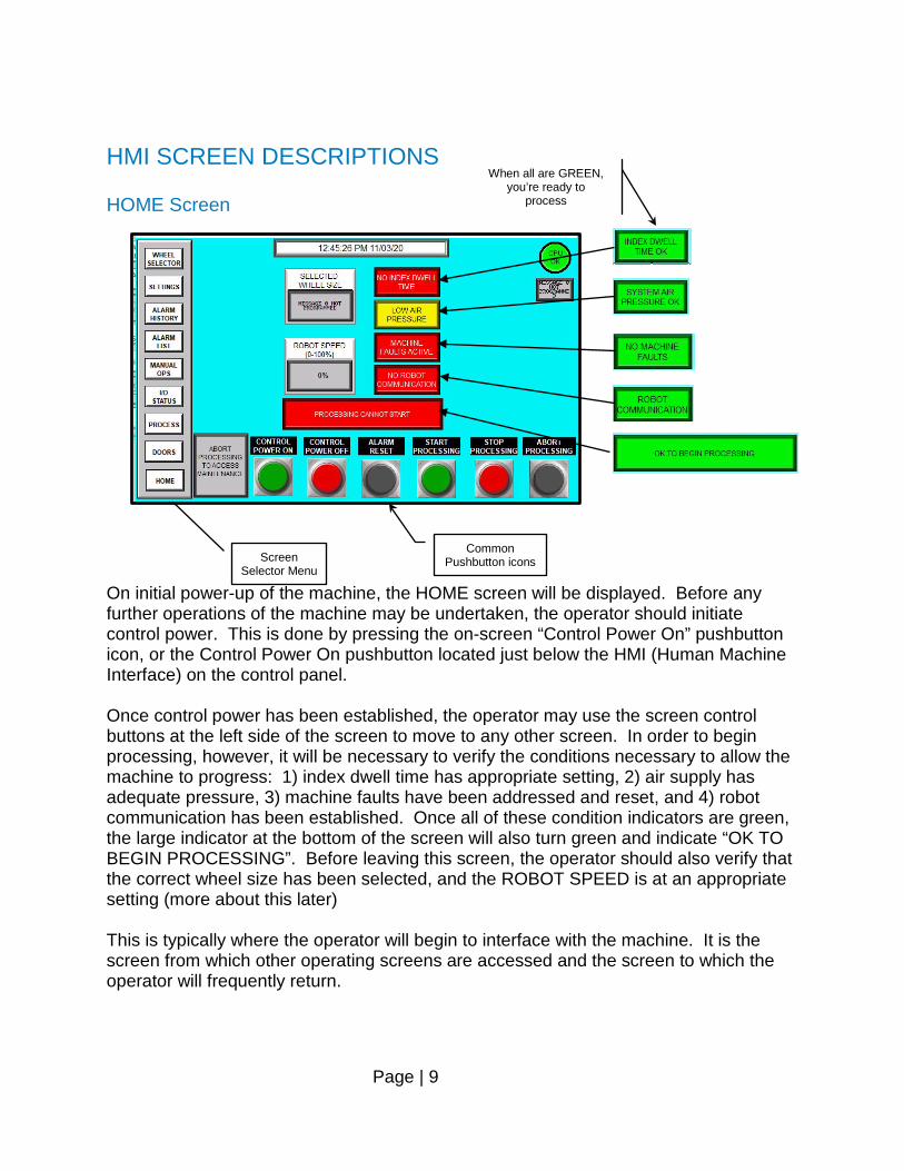
HMI SCREEN DESCRIPTIONS HOME Screen On initial power-up of the machine, the HOME screen will be displayed. Before any further operations of the machine may be undertaken, the operator should initiate control power. This is done by pressing the on-screen “Control Power On” pushbutton icon, or the Control Power On pushbutton located just below the HMI (Human Machine Interface) on the control panel. Once control power has been established, the operator may use the screen control buttons at the left side of the screen to move to any other screen. In order to begin processing, however, it will be necessary to verify the conditions necessary to allow the machine to progress: 1) index dwell time has appropriate setting, 2) air supply has adequate pressure, 3) machine faults have been addressed and reset, and 4) robot communication has been established. Once all of these condition indicators are green, the large indicator at the bottom of the screen will also turn green and indicate “OK TO BEGIN PROCESSING”. Before leaving this screen, the operator should also verify that the correct wheel size has been selected, and the ROBOT SPEED is at an appropriate setting (more about this later) This is typically where the operator will begin to interface with the machine. It is the screen from which other operating screens are accessed and the screen to which the operator will frequently return.
Screen Selector Menu
Common Pushbutton icons
When all are GREEN, you’re ready to
process
Page | 10
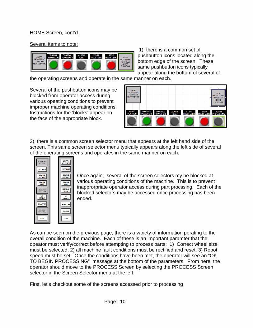
HOME Screen, cont’d Several items to note:
1) there is a common set of pushbutton icons located along the bottom edge of the screen. These same pushbutton icons typically appear along the bottom of several of
the operating screens and operate in the same manner on each. Several of the pushbutton icons may be blocked from operator access during various opeating conditions to prevent improper machine operating conditions. Instructions for the ‘blocks’ appear on the face of the appropriate block. 2) there is a common screen selector menu that appears at the left hand side of the screen. This same screen selector menu typically appears along the left side of several of the operating screens and operates in the same manner on each.
Once again, several of the screen selectors my be blocked at various operating conditions of the machine. This is to prevent inapprorpriate operator access during part procssing. Each of the blocked selectors may be accessed once processing has been ended.
As can be seen on the previous page, there is a variety of information perating to the overall condition of the machine. Each of these is an important paramter that the opeator must verify/correct before attempting to process parts: 1) Correct wheel size must be selected, 2) all machine fault conditions must be rectified and reset, 3) Robot speed must be set. Once the conditions have been met, the operator will see an “OK TO BEGIN PROCESSING” message at the bottom of the parameters. From here, the operator should move to the PROCESS Screen by selecting the PROCESS Screen selector in the Screen Selector menu at the left. First, let’s checkout some of the screens accessed prior to processing
Page | 11
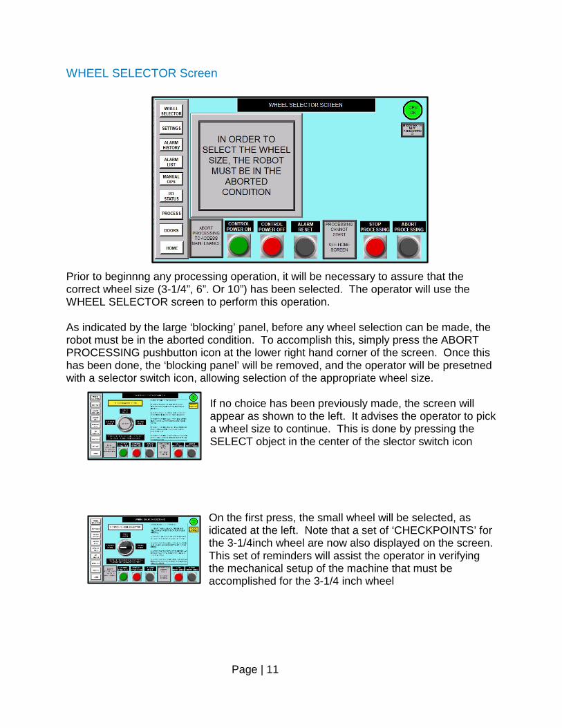
WHEEL SELECTOR Screen Prior to beginnng any processing operation, it will be necessary to assure that the correct wheel size (3-1/4”, 6”. Or 10”) has been selected. The operator will use the WHEEL SELECTOR screen to perform this operation. As indicated by the large ‘blocking’ panel, before any wheel selection can be made, the robot must be in the aborted condition. To accomplish this, simply press the ABORT PROCESSING pushbutton icon at the lower right hand corner of the screen. Once this has been done, the ‘blocking panel’ will be removed, and the operator will be presetned with a selector switch icon, allowing selection of the appropriate wheel size.
If no choice has been previously made, the screen will appear as shown to the left. It advises the operator to pick a wheel size to continue. This is done by pressing the SELECT object in the center of the slector switch icon
On the first press, the small wheel will be selected, as idicated at the left. Note that a set of ‘CHECKPOINTS’ for the 3-1/4inch wheel are now also displayed on the screen. This set of reminders will assist the operator in verifying the mechanical setup of the machine that must be accomplished for the 3-1/4 inch wheel
Page | 12
WHEEL SELECTOR Screen, cont’d
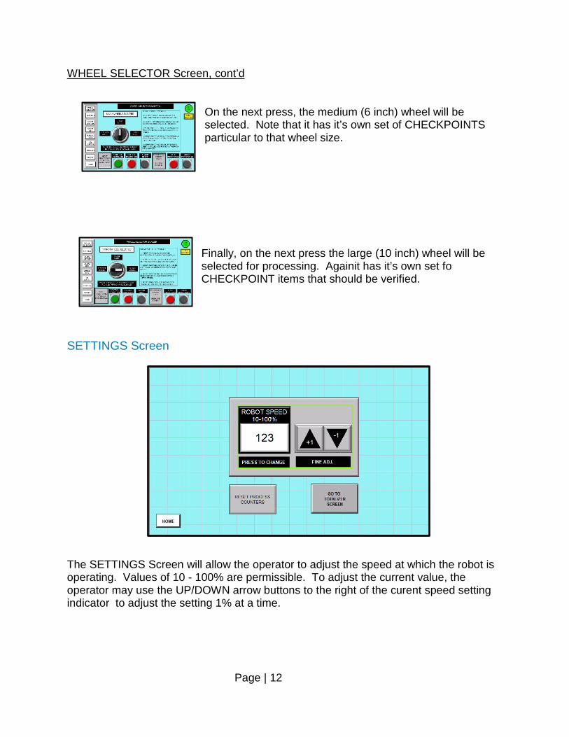
On the next press, the medium (6 inch) wheel will be selected. Note that it has it’s own set of CHECKPOINTS particular to that wheel size.
Finally, on the next press the large (10 inch) wheel will be selected for processing. Againit has it’s own set fo CHECKPOINT items that should be verified.
SETTINGS Screen The SETTINGS Screen will allow the operator to adjust the speed at which the robot is operating. Values of 10 - 100% are permissible. To adjust the current value, the operator may use the UP/DOWN arrow buttons to the right of the curent speed setting indicator to adjust the setting 1% at a time.
Page | 13
SETTINGS Screen, cont’d
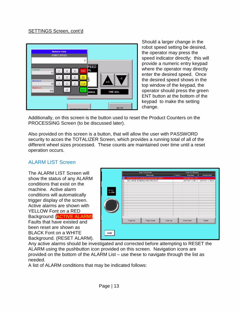
Should a larger change in the robot speed setting be desired, the operator may press the speed indicator directly; this will provide a numeric entry keypad where the operator may directly enter the desired speed. Once the desired speed shows in the top window of the keypad, the operator should press the green ENT button at the bottom of the keypad to make the setting change.
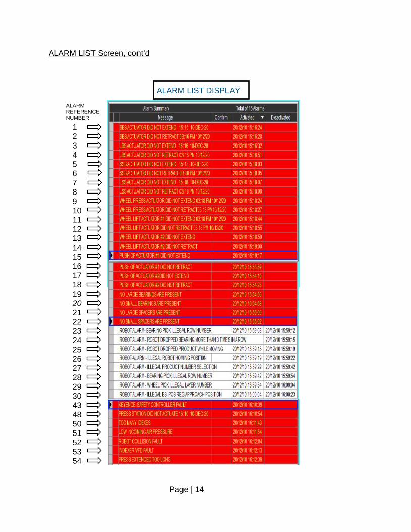
Additionally, on this screen is the button used to reset the Product Counters on the PROCESSING Screen (to be discussed later). Also provided on this screen is a button, that will allow the user with PASSWORD security to acces the TOTALIZER Screen, which provides a running total of all of the different wheel sizes processed. These counts are maintained over time until a reset operation occurs. ALARM LIST Screen The ALARM LIST Screen will show the status of any ALARM conditions that exist on the machine. Active alarm conditions will automatically trigger display of the screen. Active alarms are shown with YELLOW Font on a RED Background (ACTIVE ALARM). Faults that have existed and been reset are shown as BLACK Font on a WHITE Background. (RESET ALARM). Any active alarms should be investigated and corrected before attempting to RESET the ALARM using the pushbutton icon provided on this screen. Navigation icons are provided on the bottom of the ALARM List – use these to navigate through the list as needed. A list of ALARM conditions that may be indicated follows:
Page | 14
ALARM LIST Screen, cont’d 1 2 3 4 5 6 7 8 9 10 11 12 13 14 15 16 17 18 19 20 21 22 23 24 25 26 27 28 29 30 43 48 50 51 52 53 54
ALARM REFERENCE NUMBER
ALARM LIST DISPLAY

Page | 15
ALARM LIST Screen, cont’d
ALARM CONDITIONS
Alarm Reference Number
Alarm Condition
1 SBS ACTUATOR DID NOT EXTEND <!<24H:MM>!> <!<dd-mmm-yy>!> 2 SBS ACTUATOR DID NOT RETRACT <!<12H:MM>!> <!<dd/mm/yy>!> 3 LBS ACTUATOR DID NOT EXTEND <!<24H:MM>!> <!<dd-mmm-yy>!> 4 LBS ACTUATOR DID NOT RETRACT <!<12H:MM>!> <!<dd/mm/yy>!> 5 SSS ACTUATOR DID NOT EXTEND <!<24H:MM>!> <!<dd-mmm-yy>!> 6 SSS ACTUATOR DID NOT RETRACT <!<12H:MM>!> <!<dd/mm/yy>!> 7 LSS ACTUATOR DID NOT EXTEND <!<24H:MM>!> <!<dd-mmm-yy>!> 8 LSS ACTUATOR DID NOT RETRACT <!<12H:MM>!> <!<dd/mm/yy>!> 9 WHEEL PRESS ACTUATOR DID NOT EXTEND <!<12H:MM>!> <!<dd/mm/yy>!> 10 WHEEL PRESS ACTUATOR DID NOT RETRACT<!<12H:MM>!><!<dd/mm/yy>!> 11 WHEEL LIFT ACTUATOR #1 DID NOT EXTEND <!<12H:MM>!> <!<dd/mm/yy>!> 12 WHEEL LIFT ACTUATOR DID NOT RETRACT <!<12H:MM>!> <!<dd/mm/yy>!> 13 WHEEL LIFT ACTUATOR #2 DID NOT EXTEND 14 WHEEL LIFT ACTUATOR #2 DID NOT RETRACT 15 PUSH OF ACTUATOR #1 DID NOT EXTEND 16 PUSH OF ACTUATOR #1 DID NOT RETRACT 17 PUSH OF ACTUATOR #2DID NOT EXTEND 18 PUSH OF ACTUATOR #2 DID NOT RETRACT 19 NO LARGE BEARINGS ARE PRESENT 20 NO SMALL BEARINGS ARE PRESENT 21 NO LARGE SPACERS ARE PRESENT 22 NO SMALL SPACERS ARE PRESENT 23 ROBOT ALARM- BEARING PICK ILLEGAL ROW NUMBER 24 ROBOT ALARM - ROBOT DROPPED BEARING MORE THAN 3 TIMES IN A
ROW 25 ROBOT ALARM - ROBOT DROPPED PRODUCT WHILE MOVING 26 ROBOT-ALARM - ILLEGAL ROBOT HOMING POSITI0N 27 ROBOT ALARM - ILLEGAL PRODUCT NUMBER SELECTION 28 ROBOT ALARM - BEARING PICK ILLEGAL ROW NUMBER 29 ROBOT ALARM - WHEEL PICK ILLEGAL LAYER NUMBER 30 ROBOT ALARM - ILLEGAL BS POS REG APPROACH POSITION 31 ROBOT WAITING FOR PLC TO PICK AT BEARING STATION 32 RROBOT WAITING FOR BEARING GRIPPER CLOSED EOT SENSOR SIGNAL
Page | 16
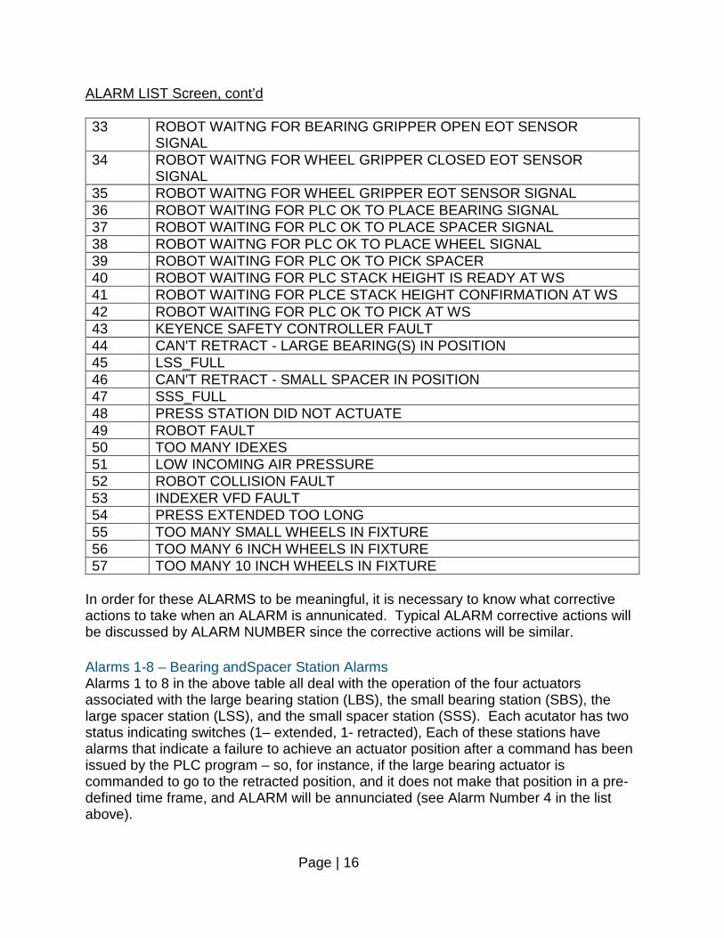
ALARM LIST Screen, cont’d 33 ROBOT WAITNG FOR BEARING GRIPPER OPEN EOT SENSOR
SIGNAL 34 ROBOT WAITNG FOR WHEEL GRIPPER CLOSED EOT SENSOR
SIGNAL 35 ROBOT WAITNG FOR WHEEL GRIPPER EOT SENSOR SIGNAL 36 ROBOT WAITING FOR PLC OK TO PLACE BEARING SIGNAL 37 ROBOT WAITING FOR PLC OK TO PLACE SPACER SIGNAL 38 ROBOT WAITNG FOR PLC OK TO PLACE WHEEL SIGNAL 39 ROBOT WAITING FOR PLC OK TO PICK SPACER 40 ROBOT WAITING FOR PLC STACK HEIGHT IS READY AT WS 41 ROBOT WAITING FOR PLCE STACK HEIGHT CONFIRMATION AT WS 42 ROBOT WAITING FOR PLC OK TO PICK AT WS 43 KEYENCE SAFETY CONTROLLER FAULT 44 CAN'T RETRACT - LARGE BEARING(S) IN POSITION 45 LSS_FULL 46 CAN'T RETRACT - SMALL SPACER IN POSITION 47 SSS_FULL 48 PRESS STATION DID NOT ACTUATE 49 ROBOT FAULT 50 TOO MANY IDEXES 51 LOW INCOMING AIR PRESSURE 52 ROBOT COLLISION FAULT 53 INDEXER VFD FAULT 54 PRESS EXTENDED TOO LONG 55 TOO MANY SMALL WHEELS IN FIXTURE 56 TOO MANY 6 INCH WHEELS IN FIXTURE 57 TOO MANY 10 INCH WHEELS IN FIXTURE
In order for these ALARMS to be meaningful, it is necessary to know what corrective actions to take when an ALARM is annunicated. Typical ALARM corrective actions will be discussed by ALARM NUMBER since the corrective actions will be similar. Alarms 1-8 – Bearing andSpacer Station Alarms Alarms 1 to 8 in the above table all deal with the operation of the four actuators associated with the large bearing station (LBS), the small bearing station (SBS), the large spacer station (LSS), and the small spacer station (SSS). Each acutator has two status indicating switches (1– extended, 1- retracted), Each of these stations have alarms that indicate a failure to achieve an actuator position after a command has been issued by the PLC program – so, for instance, if the large bearing actuator is commanded to go to the retracted position, and it does not make that position in a pre-defined time frame, and ALARM will be annunciated (see Alarm Number 4 in the list above).
Page | 17
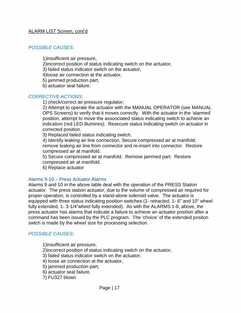
ALARM LIST Screen, cont’d POSSIBLE CAUSES:
1)insufficient air pressure, 2)incorrect position of status indicating switch on the actuator, 3) failed status indicator switch on the actuator, 4)loose air connection at the actuator, 5) jammed production part, 6) actuator seal failure.
CORRECTIVE ACTIONS:
1) check/correct air pressure regulator; 2) Attempt to operate the actuator with the MANUAL OPERATOR (see MANUAL OPS Screens) to verify that it moves correctly. With the actuator in the ‘alarmed’ position, attempt to move the assoociated status indicating switch to achieve an indication (red LED illumines). Resecure status indicating switch on actuator in corrected position. 3) Replaced failed status indicating switch, 4) Identify leaking air line connection. Secure compressed air at manifold; remove leaking air line from connector and re-insert into connector. Restore compressed air at manifold. 5) Secure compressed air at manifold. Remove jammed part. Restore compressed air at manifold. 6) Replace actuator
Alarms 9-10 – Press Actuator Alarms Alarms 9 and 10 in the above table deal with the operation of the PRESS Station actuator. The press station actuator, due to the volume of compressed air required for proper operation, is controlled by a stand-alone solenoid valve. The actuator is equipped with three status indicating position switches (1- retracted, 1- 6” and 10” wheel fully extended, 1- 3-1/4”wheel fully extended). As with the ALARMS 1-8, above, the press actuator has alarms that indicate a failure to achieve an actuator position after a command has been issued by the PLC program. The ‘choice’ of the extended positon swtch is made by the wheel size for processing selection. POSSIBLE CAUSES:
1)insufficient air pressure, 2)incorrect position of status indicating switch on the actuator, 3) failed status indicator switch on the actuator, 4) loose air connection at the actuator, 5) jammed production part, 6) actuator seal failure. 7) FU327 blown

Page | 18
ALARM LIST Screen, cont’d CORRECTIVE ACTIONS:
1) check/correct air pressure regulator; 2) Attempt to operate the actuator with the MANUAL OPERATOR (see MANUAL OPS Screens) to verify that it moves correctly. With the actuator in the ‘alarmed’ position (if one of the ‘extended alarms is annunciated,this will require a second person to operate the actuator to keep it in the extended condition), attempt to move the assoociated status indicating switch to achieve an indication (red LED illumines). Resecure status indicating switch on actuator in corrected position. 3) Replaced failed status indicating switch, 4) Identify leaking air line connection. Secure compressed air at manifold; remove leaking air line from connector and re-insert into connector. Restore compressed air at manifold. 5) Using MANUAL Operator, remove jammed part form press. 6) see manufacturers’ bulletin for corrective procedures 7) Check solenoid coil; replace FU327.
Alarms 11-18 – Press Station Alarms Alarms 11 to 18 in the above table deal with the operation of the two lift table actuators and the two pushoff actuatros associated with press station. Each acutator has two status indicating switches (1– extended, 1- retracted), Each of these actuators have alarms that indicate a failure to achieve an actuator position after a command has been issued by the PLC program. These four actuators (unlike the press actuator) are controlled through the compressed air manifold). POSSIBLE CAUSES:
1) insufficient air pressure, 2) incorrect position of status indicating switch on the actuator, 3) failed status indicator switch on the actuator, 4) loose air connection at the actuator, 5) jammed production part, 6) actuator seal failure.
CORRECTIVE ACTIONS:
1) check/correct air pressure regulator; 2) Attempt to operate the actuator with the MANUAL OPERATOR (see MANUAL OPS Screens) to verify that it moves correctly. With the actuator in the ‘alarmed’ position, attempt to move the assoociated status indicating switch to achieve an indication (red LED illuminates). Resecure status indicating switch on actuator in corrected position. 3) Replaced failed status indicating switch.
Page | 19
ALARM LIST Screen, cont’d
4) Identify leaking air line connection. Secure compressed air at manifold; remove leaking air line from connector and re-insert into connector. Restore compressed air at manifold. 5) Secure compressed air at manifold. Remove jammed part. Restore compressed air at manifold. 6) Replace actuator
Alarms 19-22 – No Parts Available Alarms Alarms 19-22 alert the operator to a lack of production parts (bearings and spacers). Each of the 4 part stations are equipped with photosensors that detect the presence of parts. These sensors are the same sensors that trigger the loading of new production parts for robot pick. When an acutator attempts to load parts 3 times, without a part being sensed, an out of part alarm will be annunciated. POSSIBLE CAUSES:
1) Part supply has been exhausted 2) Part sensor failure 3) Part jammed in stack
CORRECTIVE ACTIONS:
1) Load part into station receiver 2) Replace sensor 3) Carefully remove jammed part from stack and reload with spacers or bearings
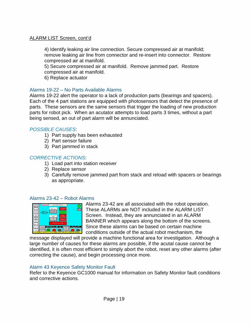
as appropriate. Alarms 23-42 – Robot Alarms
Alarms 23-42 are all associated with the robot operation. These ALARMs are NOT included in the ALARM LIST Screen. Instead, they are annunciated in an ALARM BANNER which appears along the bottom of the screens. Since these alarms can be based on certain machine conditions outside of the actual robot mechanism, the
message displayed will provide a machine functional area for investigation. Although a large number of causes for these alarms are possible, if the acutal cause cannot be identified, it is often most efficient to simply abort the robot, reset any other alarms (after correcting the cause), and begin processing once more. Alarm 43 Keyence Safety Monitor Fault Refer to the Keyence GC1000 manual for information on Safety Monitor fault conditions and corrective actions.
Page | 20
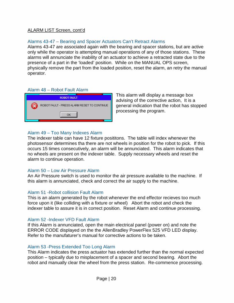
ALARM LIST Screen, cont’d Alarms 43-47 – Bearing and Spacer Actuators Can’t Retract Alarms Alarms 43-47 are associated again with the bearing and spacer stations, but are active only while the operator is attempting manual operations of any of those stations. These alarms will annunciate the inability of an actuator to achieve a retracted state due to the presence of a part in the ‘loaded’ position. While on the MANUAL OPS screen, physically remove the part from the loaded position, reset the alarm, an retry the manual operator. Alarm 48 – Robot Fault Alarm
This alarm will display a message box advising of the corrective action, It is a general indication that the robot has stopped processing the program.
Alarm 49 – Too Many Indexes Alarm The indexer table can have 12 fixture posititons. The table will index whenever the photosensor determines tha there are not wheels in position for the robot to pick. If this occurs 15 times consecutively, an alarm will be annunciated. This alarm indicates that no wheels are present on the indexer table. Supply necessary wheels and reset the alarm to continue operation. Alarm 50 – Low Air Pressure Alarm An Air Pressure switch is used to monitor the air pressure available to the machine. If this alarm is annunciated, check and correct the air supply to the machine. Alarm 51 -Robot collision Fault Alarm This is an alarm generated by the robot whenever the end effector recieves too much force upon it (like colliding with a fixture or wheel) Abort the robot and check the indexer table to assure it is in correct position. Reset Alarm and continue processing. Alarm 52 -Indexer VFD Fault Alarm If this Alarm is annunciated, open the main electrical panel (power on) and note the ERROR CODE displayed on the the AllenBradley PowerFlex 525 VFD LED display. Refer to the manufaturer’s manual for corrective actions to be taken. Alarm 53 -Press Extended Too Long Alarm This Alarm indicates the press actuator has extended further than the normal expected position – typically due to misplacement of a spacer and second bearing. Abort the robot and manually clear the wheel from the press station. Re-commence processing.
Page | 21
ALARM LIST Screen, cont’d Alarm 55-57 -Too Many Wheels in Fixture POSSIBLE CAUSES:
Too many parts hve been loaded into a fixture CORRECTIVE ACTIONS:
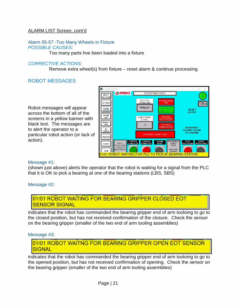
Remove extra wheel(s) from fixture – reset alarm & continue processing ROBOT MESSAGES Robot messages will appear across the bottom of all of the screens in a yellow banner with black text. The messages are to alert the operator to a particular robot action (or lack of action). Message #1: (shown just above) alerts the operator that the robot is waiting for a signal from the PLC that it is OK to pick a bearing at one of the bearing stations (LBS, SBS) Message #2:
indicates that the robot has commanded the bearing gripper end of arm tooloing to go to the closed position, but has not received confirmation of the closure. Check the sensor on the bearing gripper (smaller of the two end of arm tooling assemblies) Message #3:
indicates that the robot has commanded the bearing gripper end of arm tooloing to go to the opened position, but has not received confirmation of opening. Check the sensor on the bearing gripper (smaller of the two end of arm tooling assemblies)
Page | 22
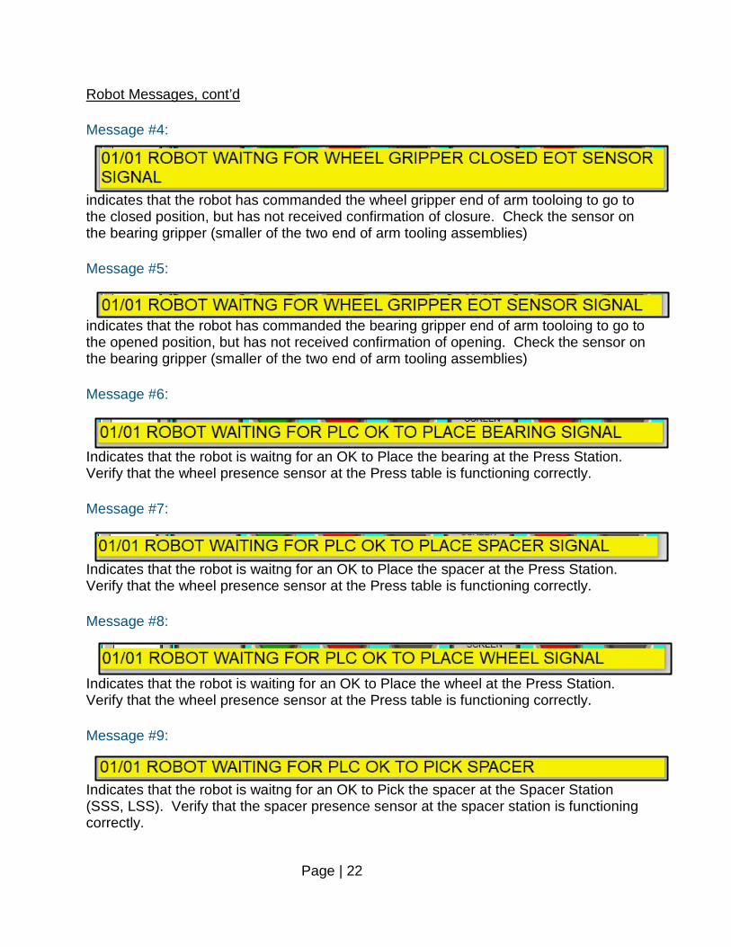
Robot Messages, cont’d Message #4:
indicates that the robot has commanded the wheel gripper end of arm tooloing to go to the closed position, but has not received confirmation of closure. Check the sensor on the bearing gripper (smaller of the two end of arm tooling assemblies) Message #5:
indicates that the robot has commanded the bearing gripper end of arm tooloing to go to the opened position, but has not received confirmation of opening. Check the sensor on the bearing gripper (smaller of the two end of arm tooling assemblies) Message #6:
Indicates that the robot is waitng for an OK to Place the bearing at the Press Station. Verify that the wheel presence sensor at the Press table is functioning correctly. Message #7:
Indicates that the robot is waitng for an OK to Place the spacer at the Press Station. Verify that the wheel presence sensor at the Press table is functioning correctly. Message #8:
Indicates that the robot is waiting for an OK to Place the wheel at the Press Station. Verify that the wheel presence sensor at the Press table is functioning correctly. Message #9:
Indicates that the robot is waitng for an OK to Pick the spacer at the Spacer Station (SSS, LSS). Verify that the spacer presence sensor at the spacer station is functioning correctly.
Page | 23
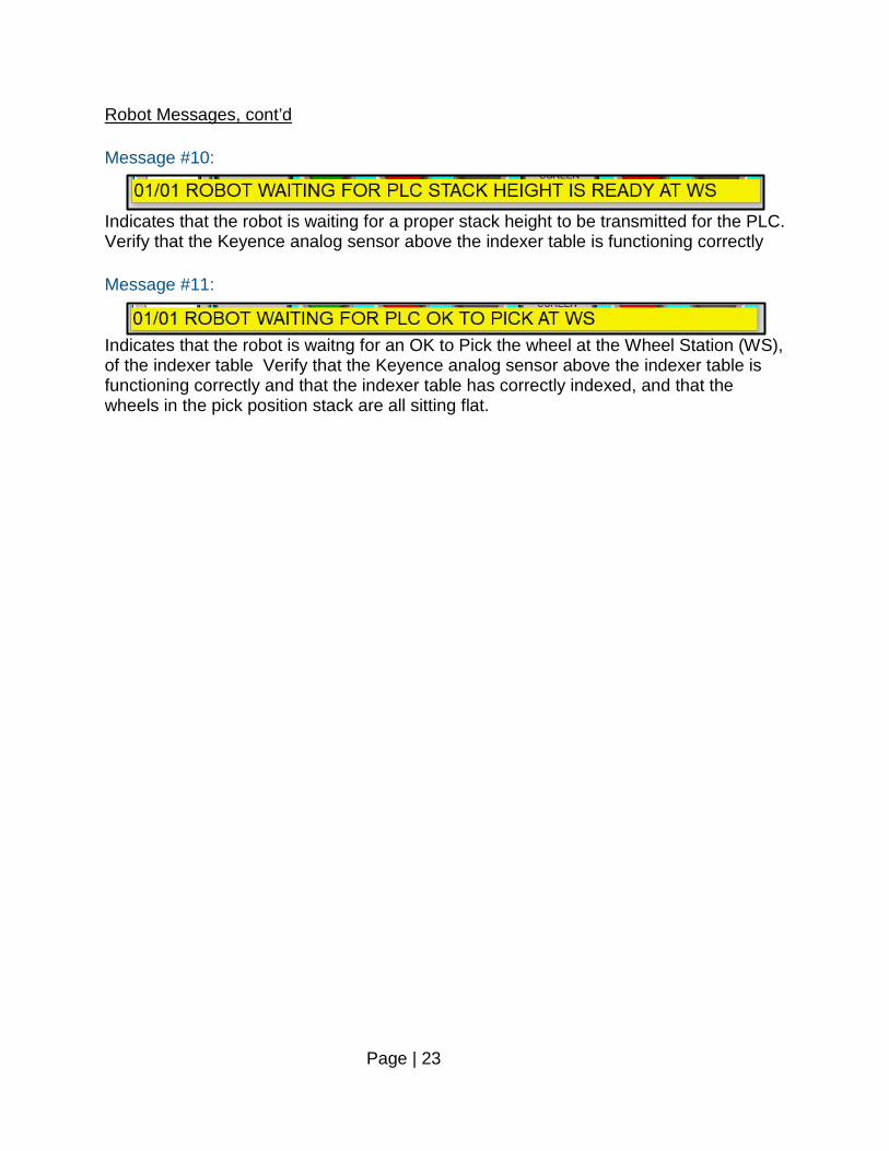
Robot Messages, cont’d Message #10:
Indicates that the robot is waiting for a proper stack height to be transmitted for the PLC. Verify that the Keyence analog sensor above the indexer table is functioning correctly Message #11:
Indicates that the robot is waitng for an OK to Pick the wheel at the Wheel Station (WS), of the indexer table Verify that the Keyence analog sensor above the indexer table is functioning correctly and that the indexer table has correctly indexed, and that the wheels in the pick position stack are all sitting flat.
Page | 24
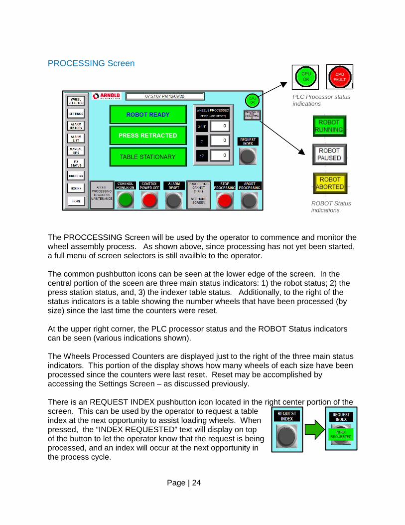
PROCESSING Screen The PROCCESSING Screen will be used by the operator to commence and monitor the wheel assembly process. As shown above, since processing has not yet been started, a full menu of screen selectors is still availble to the operator. The common pushbutton icons can be seen at the lower edge of the screen. In the central portion of the sceen are three main status indicators: 1) the robot status; 2) the press station status, and, 3) the indexer table status. Additionally, to the right of the status indicators is a table showing the number wheels that have been processed (by size) since the last time the counters were reset. At the upper right corner, the PLC processor status and the ROBOT Status indicators can be seen (various indications shown). The Wheels Processed Counters are displayed just to the right of the three main status indicators. This portion of the display shows how many wheels of each size have been processed since the counters were last reset. Reset may be accomplished by accessing the Settings Screen – as discussed previously. There is an REQUEST INDEX pushbutton icon located in the right center portion of the screen. This can be used by the operator to request a table index at the next opportunity to assist loading wheels. When pressed, the “INDEX REQUESTED” text will display on top of the button to let the operator know that the request is being processed, and an index will occur at the next opportunity in the process cycle.
PLC Processor status indications
ROBOT Status indications
Page | 25
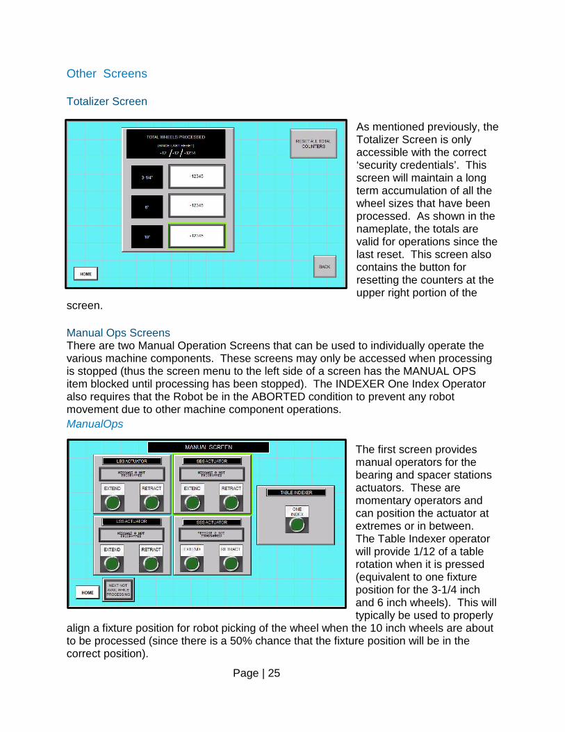
Other Screens Totalizer Screen
As mentioned previously, the Totalizer Screen is only accessible with the correct ‘security credentials’. This screen will maintain a long term accumulation of all the wheel sizes that have been processed. As shown in the nameplate, the totals are valid for operations since the last reset. This screen also contains the button for resetting the counters at the upper right portion of the
screen. Manual Ops Screens There are two Manual Operation Screens that can be used to individually operate the various machine components. These screens may only be accessed when processing is stopped (thus the screen menu to the left side of a screen has the MANUAL OPS item blocked until processing has been stopped). The INDEXER One Index Operator also requires that the Robot be in the ABORTED condition to prevent any robot movement due to other machine component operations. ManualOps
The first screen provides manual operators for the bearing and spacer stations actuators. These are momentary operators and can position the actuator at extremes or in between. The Table Indexer operator will provide 1/12 of a table rotation when it is pressed (equivalent to one fixture position for the 3-1/4 inch and 6 inch wheels). This will typically be used to properly
align a fixture position for robot picking of the wheel when the 10 inch wheels are about to be processed (since there is a 50% chance that the fixture position will be in the correct position).
Page | 26
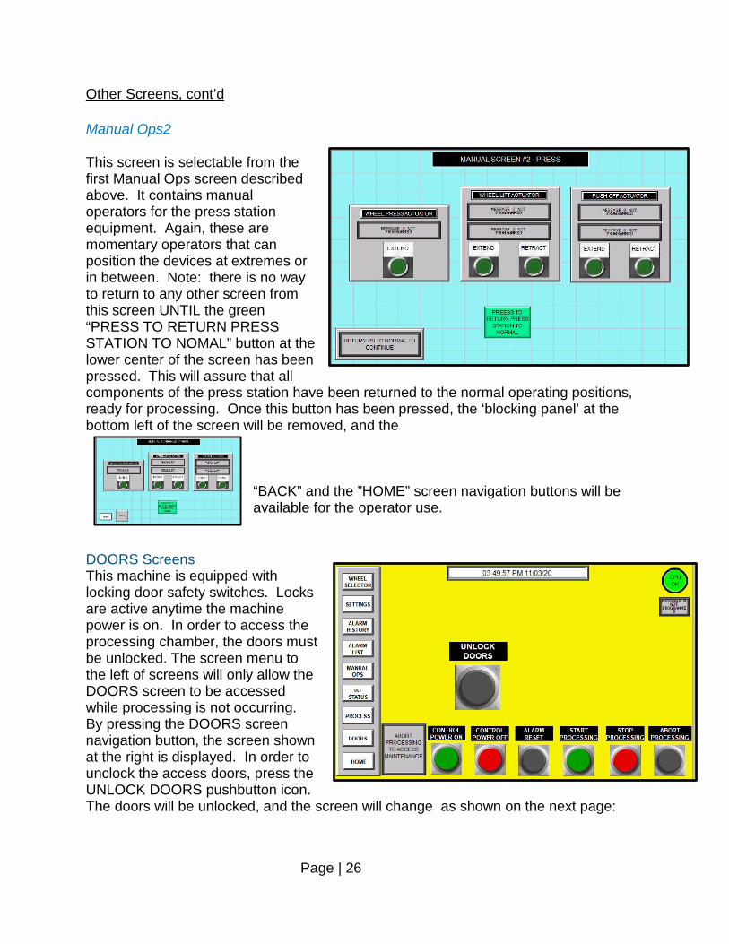
Other Screens, cont’d Manual Ops2 This screen is selectable from the first Manual Ops screen described above. It contains manual operators for the press station equipment. Again, these are momentary operators that can position the devices at extremes or in between. Note: there is no way to return to any other screen from this screen UNTIL the green “PRESS TO RETURN PRESS STATION TO NOMAL” button at the lower center of the screen has been pressed. This will assure that all components of the press station have been returned to the normal operating positions, ready for processing. Once this button has been pressed, the ‘blocking panel’ at the bottom left of the screen will be removed, and the
“BACK” and the ”HOME” screen navigation buttons will be available for the operator use.
DOORS Screens This machine is equipped with locking door safety switches. Locks are active anytime the machine power is on. In order to access the processing chamber, the doors must be unlocked. The screen menu to the left of screens will only allow the DOORS screen to be accessed while processing is not occurring. By pressing the DOORS screen navigation button, the screen shown at the right is displayed. In order to unclock the access doors, press the UNLOCK DOORS pushbutton icon. The doors will be unlocked, and the screen will change as shown on the next page:
Page | 27
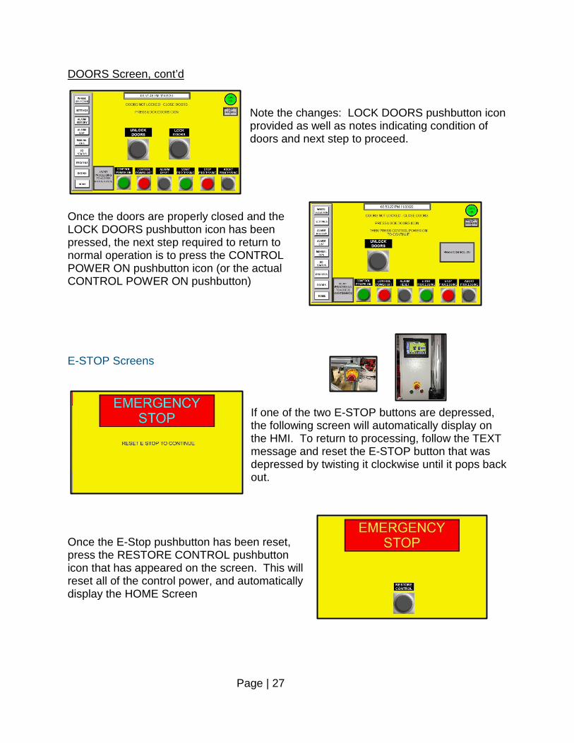
DOORS Screen, cont’d Note the changes: LOCK DOORS pushbutton icon provided as well as notes indicating condition of doors and next step to proceed.
Once the doors are properly closed and the LOCK DOORS pushbutton icon has been pressed, the next step required to return to normal operation is to press the CONTROL POWER ON pushbutton icon (or the actual CONTROL POWER ON pushbutton) E-STOP Screens
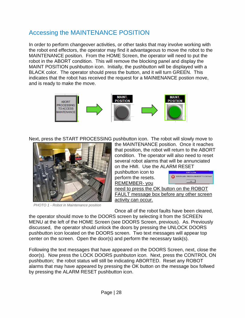
If one of the two E-STOP buttons are depressed, the following screen will automatically display on the HMI. To return to processing, follow the TEXT message and reset the E-STOP button that was depressed by twisting it clockwise until it pops back out.
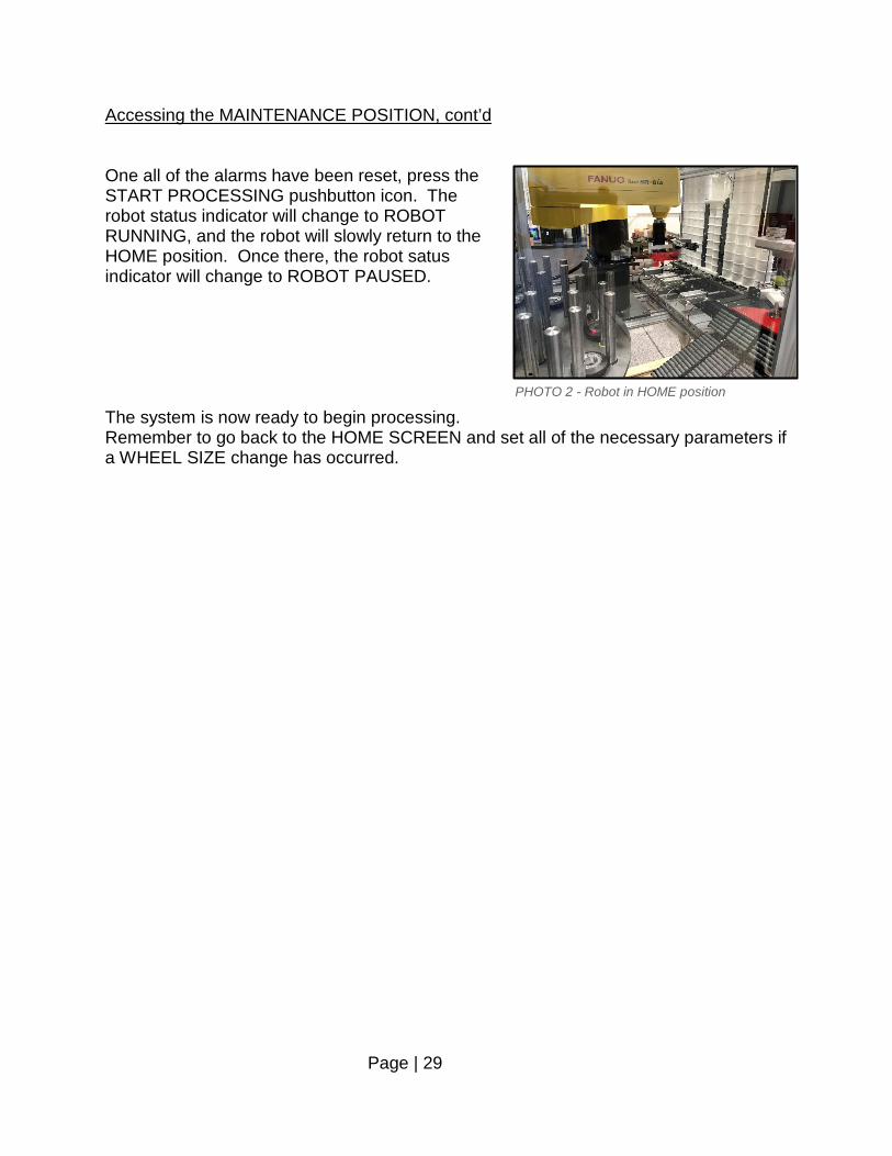
Once the E-Stop pushbutton has been reset, press the RESTORE CONTROL pushbutton icon that has appeared on the screen. This will reset all of the control power, and automatically display the HOME Screen
Page | 28
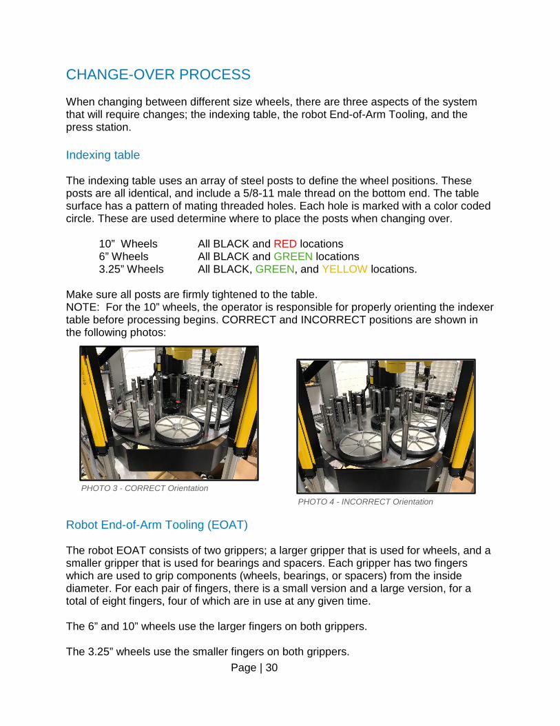
Accessing the MAINTENANCE POSITION In order to perform changeover activities, or other tasks that may involve working with the robot end effectors, the operator may find it advantageous to move the robot to the MAINTENANCE position. From the HOME Screen, the operator will need to put the robot in the ABORT condition. This will remove the blocking panel and display the MAINT POSITION pushbutton icon. Initially, the pushbutton will be displayed with a BLACK color. The operator should press the button, and it will turn GREEN. This indicates that the robot has received the request for a MAINtENANCE postion move, and is ready to make the move. Next, press the START PROCESSING pushbutton icon. The robot will slowly move to
the MAINTENANCE position. Once it reaches that position, the robot will return to the ABORT condition. The operator will also need to reset several robot alarms that will be annunciated on the HMI. Use the ALARM RESET pushbutton icon to perform the resets. REMEMBER- you need to press the OK button on the ROBOT FAULT message box before any other screen activity can occur. Once all of the robot faults have been cleared,
the operator should move to the DOORS screen by selecting it from the SCREEN MENU at the left of the HOME Screen (see DOORS Screen, previous). As. Previously discussed, the operator should unlock the doors by pressing the UNLOCK DOORS pushbutton icon located on the DOORS screen. Two text messages will appear top center on the screen. Open the door(s) and perform the necessary task(s). Following the text messages that have appeared on the DOORS Screen, next, close the door(s). Now press the LOCK DOORS pushbuton icon. Next, press the CONTROL ON pushbutton; the robot status will still be indicating ABORTED. Reset any ROBOT alarms that may have appeared by pressing the OK button on the message box follwed by pressing the ALARM RESET pushbutton icon.
PHOTO 1 - Robot in Maintenance position
Page | 29
Accessing the MAINTENANCE POSITION, cont’d One all of the alarms have been reset, press the START PROCESSING pushbutton icon. The robot status indicator will change to ROBOT RUNNING, and the robot will slowly return to the HOME position. Once there, the robot satus indicator will change to ROBOT PAUSED. The system is now ready to begin processing. Remember to go back to the HOME SCREEN and set all of the necessary parameters if a WHEEL SIZE change has occurred.
PHOTO 2 - Robot in HOME position
Page | 30
CHANGE-OVER PROCESS When changing between different size wheels, there are three aspects of the system that will require changes; the indexing table, the robot End-of-Arm Tooling, and the press station. Indexing table The indexing table uses an array of steel posts to define the wheel positions. These posts are all identical, and include a 5/8-11 male thread on the bottom end. The table surface has a pattern of mating threaded holes. Each hole is marked with a color coded circle. These are used determine where to place the posts when changing over. 10” Wheels All BLACK and RED locations 6” Wheels All BLACK and GREEN locations 3.25” Wheels All BLACK, GREEN, and YELLOW locations. Make sure all posts are firmly tightened to the table. NOTE: For the 10” wheels, the operator is responsible for properly orienting the indexer table before processing begins. CORRECT and INCORRECT positions are shown in the following photos:
Robot End-of-Arm Tooling (EOAT) The robot EOAT consists of two grippers; a larger gripper that is used for wheels, and a smaller gripper that is used for bearings and spacers. Each gripper has two fingers which are used to grip components (wheels, bearings, or spacers) from the inside diameter. For each pair of fingers, there is a small version and a large version, for a total of eight fingers, four of which are in use at any given time. The 6” and 10” wheels use the larger fingers on both grippers. The 3.25” wheels use the smaller fingers on both grippers.
PHOTO 3 - CORRECT Orientation PHOTO 4 - INCORRECT Orientation
Page | 31
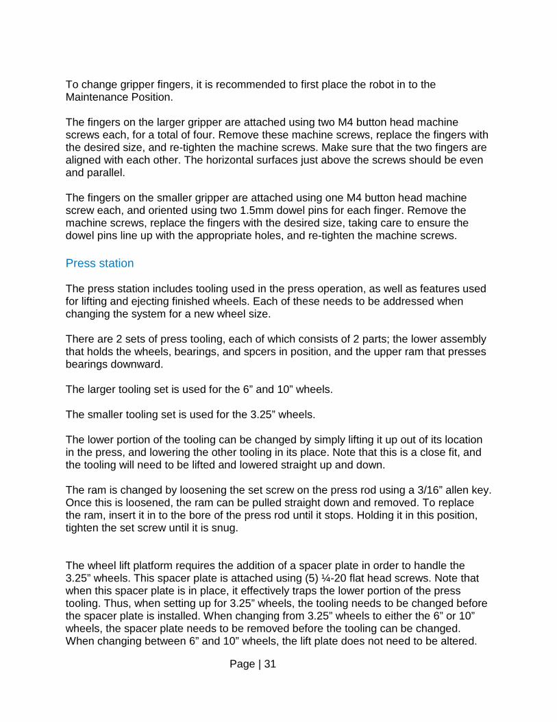
To change gripper fingers, it is recommended to first place the robot in to the Maintenance Position. The fingers on the larger gripper are attached using two M4 button head machine screws each, for a total of four. Remove these machine screws, replace the fingers with the desired size, and re-tighten the machine screws. Make sure that the two fingers are aligned with each other. The horizontal surfaces just above the screws should be even and parallel. The fingers on the smaller gripper are attached using one M4 button head machine screw each, and oriented using two 1.5mm dowel pins for each finger. Remove the machine screws, replace the fingers with the desired size, taking care to ensure the dowel pins line up with the appropriate holes, and re-tighten the machine screws. Press station The press station includes tooling used in the press operation, as well as features used for lifting and ejecting finished wheels. Each of these needs to be addressed when changing the system for a new wheel size. There are 2 sets of press tooling, each of which consists of 2 parts; the lower assembly that holds the wheels, bearings, and spcers in position, and the upper ram that presses bearings downward. The larger tooling set is used for the 6” and 10” wheels. The smaller tooling set is used for the 3.25” wheels. The lower portion of the tooling can be changed by simply lifting it up out of its location in the press, and lowering the other tooling in its place. Note that this is a close fit, and the tooling will need to be lifted and lowered straight up and down. The ram is changed by loosening the set screw on the press rod using a 3/16” allen key. Once this is loosened, the ram can be pulled straight down and removed. To replace the ram, insert it in to the bore of the press rod until it stops. Holding it in this position, tighten the set screw until it is snug. The wheel lift platform requires the addition of a spacer plate in order to handle the 3.25” wheels. This spacer plate is attached using (5) ¼-20 flat head screws. Note that when this spacer plate is in place, it effectively traps the lower portion of the press tooling. Thus, when setting up for 3.25” wheels, the tooling needs to be changed before the spacer plate is installed. When changing from 3.25” wheels to either the 6” or 10” wheels, the spacer plate needs to be removed before the tooling can be changed. When changing between 6” and 10” wheels, the lift plate does not need to be altered.
Page | 32
The wheel ejection mechanism will need to be addressed anytime the system is changing from one wheel size to another. This system consists of 2 pneumatic cylinders mounted to the lift plate, and plastic pushers that are specific to the wheel sizes. The 10” wheels are pushed by the 2 plastic blocks that are permanently attached to the cylinders. No other components are needed for the 10” wheels, and these blocks do not need to be removed for any size wheel. In each of these blocks is a quick-release pin which can be used to attach the plastic blocks for the other wheel sizes. The 3.25” and 6” wheels each have their own plastic pusher block that bridges between the two permanent blocks, and attaches to them using the quick-release pins. The two size-specific pusher blocks can be differentiated by paying attention to the curvature of the pushing surface, which closely matches the radius of the appropriate wheel size. To install these pusher blocks, remove the quick-release pins from the permanent blocks, place the pusher block so that its mounting holes line up with the holes in the permanent blocks, and re-insert the quick-release pins.
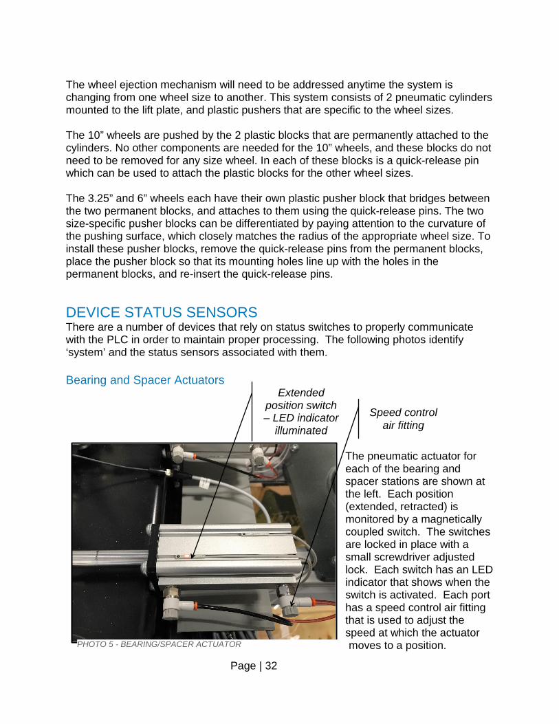
DEVICE STATUS SENSORS There are a number of devices that rely on status switches to properly communicate with the PLC in order to maintain proper processing. The following photos identify ‘system’ and the status sensors associated with them. Bearing and Spacer Actuators
The pneumatic actuator for each of the bearing and spacer stations are shown at the left. Each position (extended, retracted) is monitored by a magnetically coupled switch. The switches are locked in place with a small screwdriver adjusted lock. Each switch has an LED indicator that shows when the switch is activated. Each port has a speed control air fitting that is used to adjust the speed at which the actuator moves to a position. PHOTO 5 - BEARING/SPACER ACTUATOR
Speed control air fitting
Extended position switch – LED indicator
illuminated
Page | 33
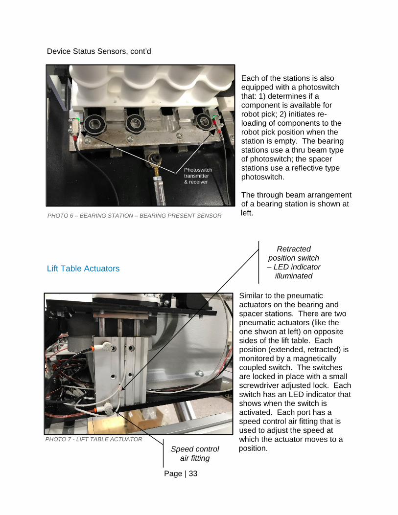
Device Status Sensors, cont’d Each of the stations is also equipped with a photoswitch that: 1) determines if a component is available for robot pick; 2) initiates re-loading of components to the robot pick position when the station is empty. The bearing stations use a thru beam type of photoswitch; the spacer stations use a reflective type photoswitch. The through beam arrangement of a bearing station is shown at left.
Lift Table Actuators
Similar to the pneumatic actuators on the bearing and spacer stations. There are two pneumatic actuators (like the one shwon at left) on opposite sides of the lift table. Each position (extended, retracted) is monitored by a magnetically coupled switch. The switches are locked in place with a small screwdriver adjusted lock. Each switch has an LED indicator that shows when the switch is activated. Each port has a speed control air fitting that is used to adjust the speed at which the actuator moves to a position.
PHOTO 6 – BEARING STATION – BEARING PRESENT SENSOR
PHOTO 7 - LIFT TABLE ACTUATOR
Retracted position switch – LED indicator
illuminated
Speed control air fitting
Photoswitch transmitter & receiver
Page | 34
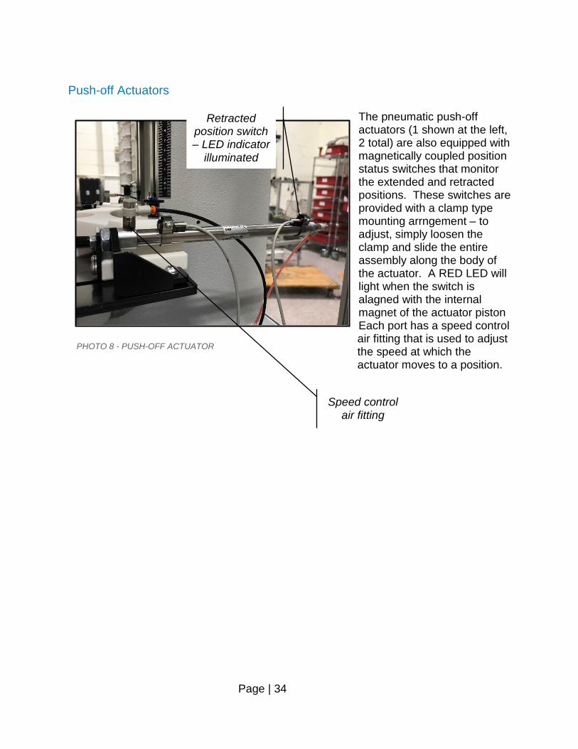
Push-off Actuators
The pneumatic push-off actuators (1 shown at the left, 2 total) are also equipped with magnetically coupled position status switches that monitor the extended and retracted positions. These switches are provided with a clamp type mounting arrngement – to adjust, simply loosen the clamp and slide the entire assembly along the body of the actuator. A RED LED will light when the switch is alagned with the internal magnet of the actuator piston Each port has a speed control air fitting that is used to adjust the speed at which the actuator moves to a position.
PHOTO 8 - PUSH-OFF ACTUATOR
Retracted position switch – LED indicator
illuminated
Speed control air fitting
Page | 35
PRESS Actuator
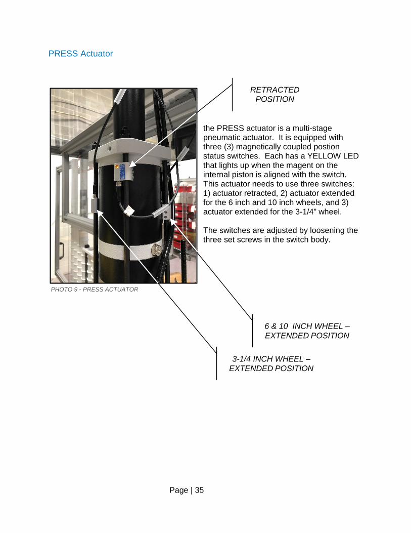
the PRESS actuator is a multi-stage pneumatic actuator. It is equipped with three (3) magnetically coupled postion status switches. Each has a YELLOW LED that lights up when the magent on the internal piston is aligned with the switch. This actuator needs to use three switches: 1) actuator retracted, 2) actuator extended for the 6 inch and 10 inch wheels, and 3) actuator extended for the 3-1/4” wheel. The switches are adjusted by loosening the three set screws in the switch body.
PHOTO 9 - PRESS ACTUATOR
3-1/4 INCH WHEEL – EXTENDED POSITION
6 & 10 INCH WHEEL – EXTENDED POSITION
RETRACTED POSITION
Page | 36
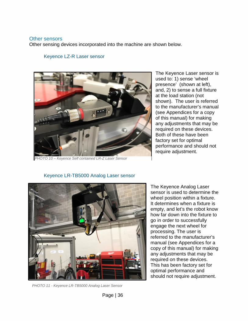
Other sensors Other sensing devices incorporated into the machine are shown below.
Keyence LZ-R Laser sensor
The Keyence Laser sensor is used to: 1) sense ‘wheel presence’ (shown at left), and, 2) to sense a full fixture at the load station (not shown). The user is referred to the manufacturer’s manual (see Appendices for a copy of this manual) for making any adjustments that may be required on these devices. Both of these have been factory set for optimal performance and should not require adjustment.
Keyence LR-TB5000 Analog Laser sensor The Keyence Analog Laser sensor is used to determine the wheel position within a fixture. It determines when a fixture is empty, and let’s the robot know how far down into the fixture to go in order to successfully engage the next wheel for processing. The user is referred to the manufacturer’s manual (see Appendices for a copy of this manual) for making any adjustments that may be required on these devices. This has been factory set for optimal performance and should not require adjustment.
PHOTO 10 – Keyence Self contained LR-Z Laser Sensor
PHOTO 11 - Keyence LR-TB5000 Analog Laser Sensor
Page | 37
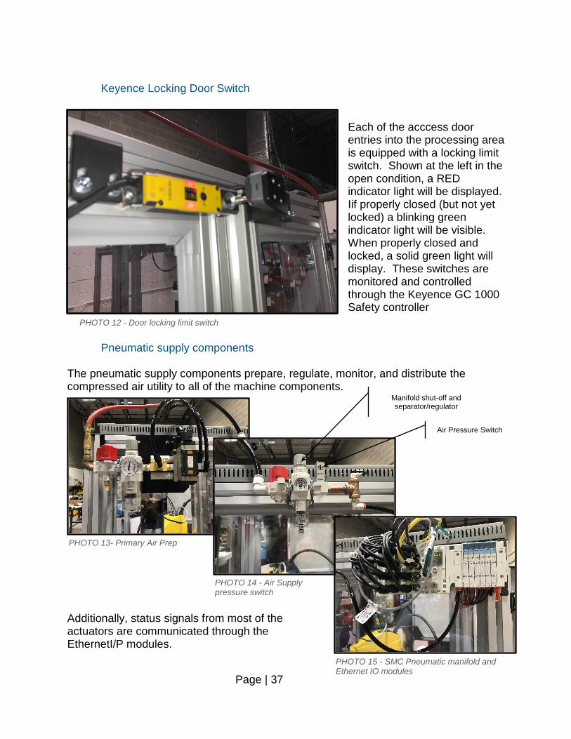
Keyence Locking Door Switch
Each of the acccess door entries into the processing area is equipped with a locking limit switch. Shown at the left in the open condition, a RED indicator light will be displayed. Iif properly closed (but not yet locked) a blinking green indicator light will be visible. When properly closed and locked, a solid green light will display. These switches are monitored and controlled through the Keyence GC 1000 Safety controller
Pneumatic supply components The pneumatic supply components prepare, regulate, monitor, and distribute the compressed air utility to all of the machine components.
Additionally, status signals from most of the actuators are communicated through the EthernetI/P modules.
PHOTO 12 - Door locking limit switch
PHOTO 13- Primary Air Prep
PHOTO 14 - Air Supply pressure switch
PHOTO 15 - SMC Pneumatic manifold and Ethernet IO modules
Air Pressure Switch
Manifold shut-off and separator/regulator
Page | 38
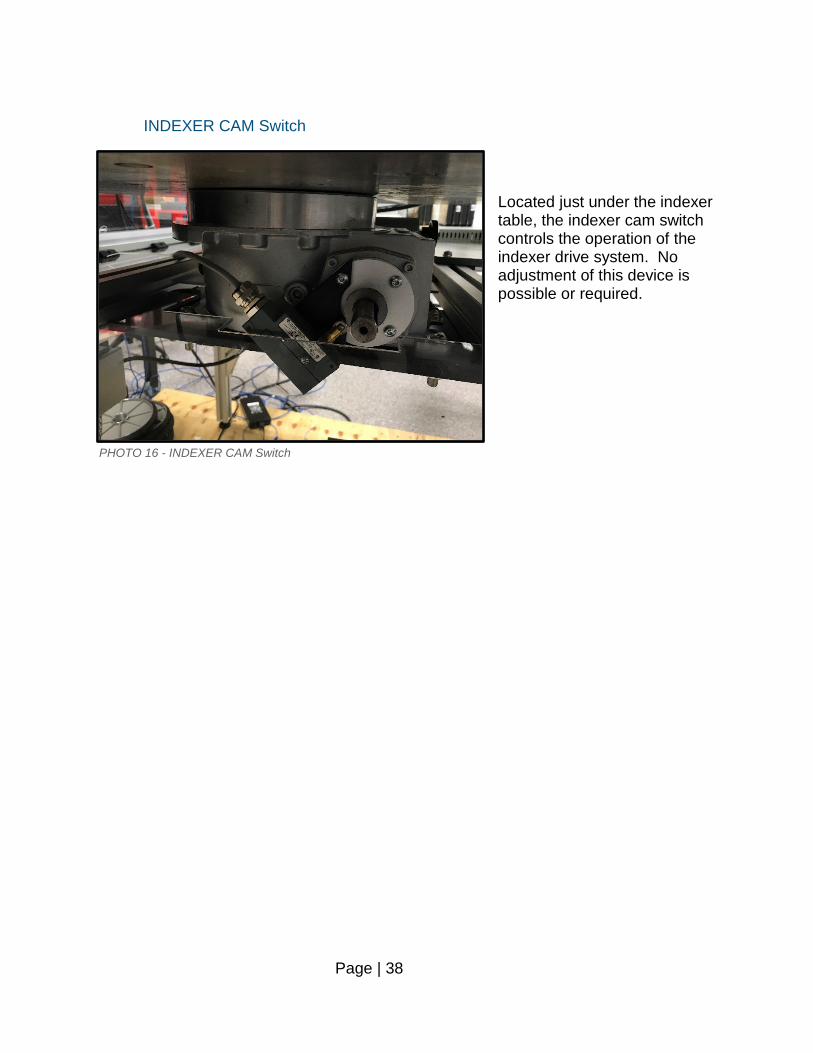
INDEXER CAM Switch
Located just under the indexer table, the indexer cam switch controls the operation of the indexer drive system. No adjustment of this device is possible or required.
PHOTO 16 - INDEXER CAM Switch

Page | 39
MECHANICAL DRAWINGS
80031
(Adjustable)
200079
38
41
Wheel loadingaccess
Operatorcontrols
Bearing &Spacer loadingaccess
Pneumaticvalve manifold
120047
160063
24
11
NOTES:System can process 3.25", 6" or 10" wheels 1.(6" shown)Wheel infeed carousel can hold (12) stacks 2.of 3.25" wheels, (12) stacks of 6" wheels, or (6) stacks of 10" wheels.Required utilities:3.
230/3/60•Compressed air, 80-100 psi• Material <not specified>
System, Robotic wheel assembly
ADO NOT SCALE DRAWING
AA1006SHEET 1 OF 3
5/8/2020K. McHenry
UNLESS OTHERWISE SPECIFIED:
SCALE: 1:24 WEIGHT: 0.00
REVDWG. NO.
BSIZE
TITLE:
NAME DATE
COMMENTS:
Q.A.
MFG APPR.
ENG APPR.
CHECKED
DRAWN
FINISH
MATERIAL
INTERPRET GEOMETRICTOLERANCING PER:
DIMENSIONS ARE IN INCHESTOLERANCES:FRACTIONAL 1/16ANGULAR: MACH 1 BEND 3TWO PLACE DECIMAL 0.030THREE PLACE DECIMAL 0.005
APPLICATION
USED ONNEXT ASSY
PROPRIETARY AND CONFIDENTIALTHE INFORMATION CONTAINED IN THISDRAWING IS THE SOLE PROPERTY OFARNOLD AUTOMATION. ANY REPRODUCTION IN PART OR AS A WHOLEWITHOUT THE WRITTEN PERMISSION OFARNOLD AUTOMATION IS PROHIBITED.
A A
B B
4
4
3
3
2
2
1
1
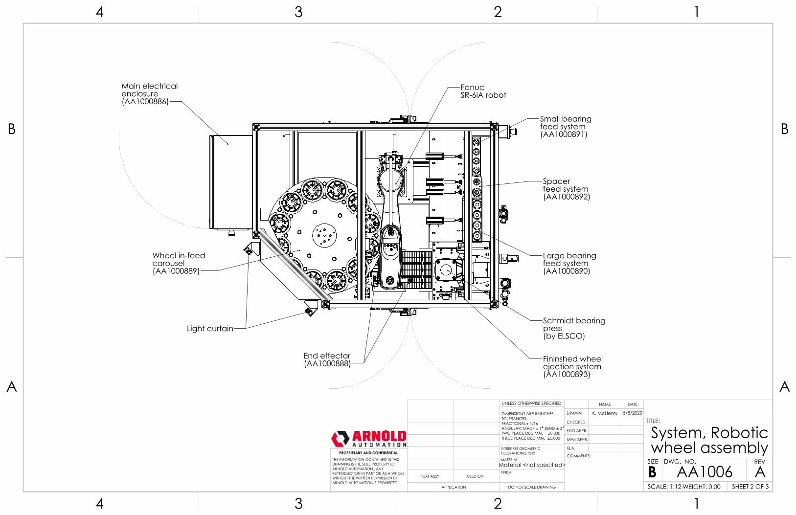
Large bearingfeed system(AA1000890)
Small bearingfeed system(AA1000891)
Spacerfeed system(AA1000892)
FanucSR-6iA robot
Wheel in-feedcarousel(AA1000889)
Light curtainSchmidt bearingpress(by ELSCO)
Fininshed wheelejection system(AA1000893)
Main electricalenclosure(AA1000886)
End effector(AA1000888)
Material <not specified>
System, Robotic wheel assembly
ADO NOT SCALE DRAWING
AA1006SHEET 2 OF 3
5/8/2020K. McHenry
UNLESS OTHERWISE SPECIFIED:
SCALE: 1:12 WEIGHT: 0.00
REVDWG. NO.
BSIZE
TITLE:
NAME DATE
COMMENTS:
Q.A.
MFG APPR.
ENG APPR.
CHECKED
DRAWN
FINISH
MATERIAL
INTERPRET GEOMETRICTOLERANCING PER:
DIMENSIONS ARE IN INCHESTOLERANCES:FRACTIONAL 1/16ANGULAR: MACH 1 BEND 3TWO PLACE DECIMAL 0.030THREE PLACE DECIMAL 0.005
APPLICATION
USED ONNEXT ASSY
PROPRIETARY AND CONFIDENTIALTHE INFORMATION CONTAINED IN THISDRAWING IS THE SOLE PROPERTY OFARNOLD AUTOMATION. ANY REPRODUCTION IN PART OR AS A WHOLEWITHOUT THE WRITTEN PERMISSION OFARNOLD AUTOMATION IS PROHIBITED.
A A
B B
4
4
3
3
2
2
1
1
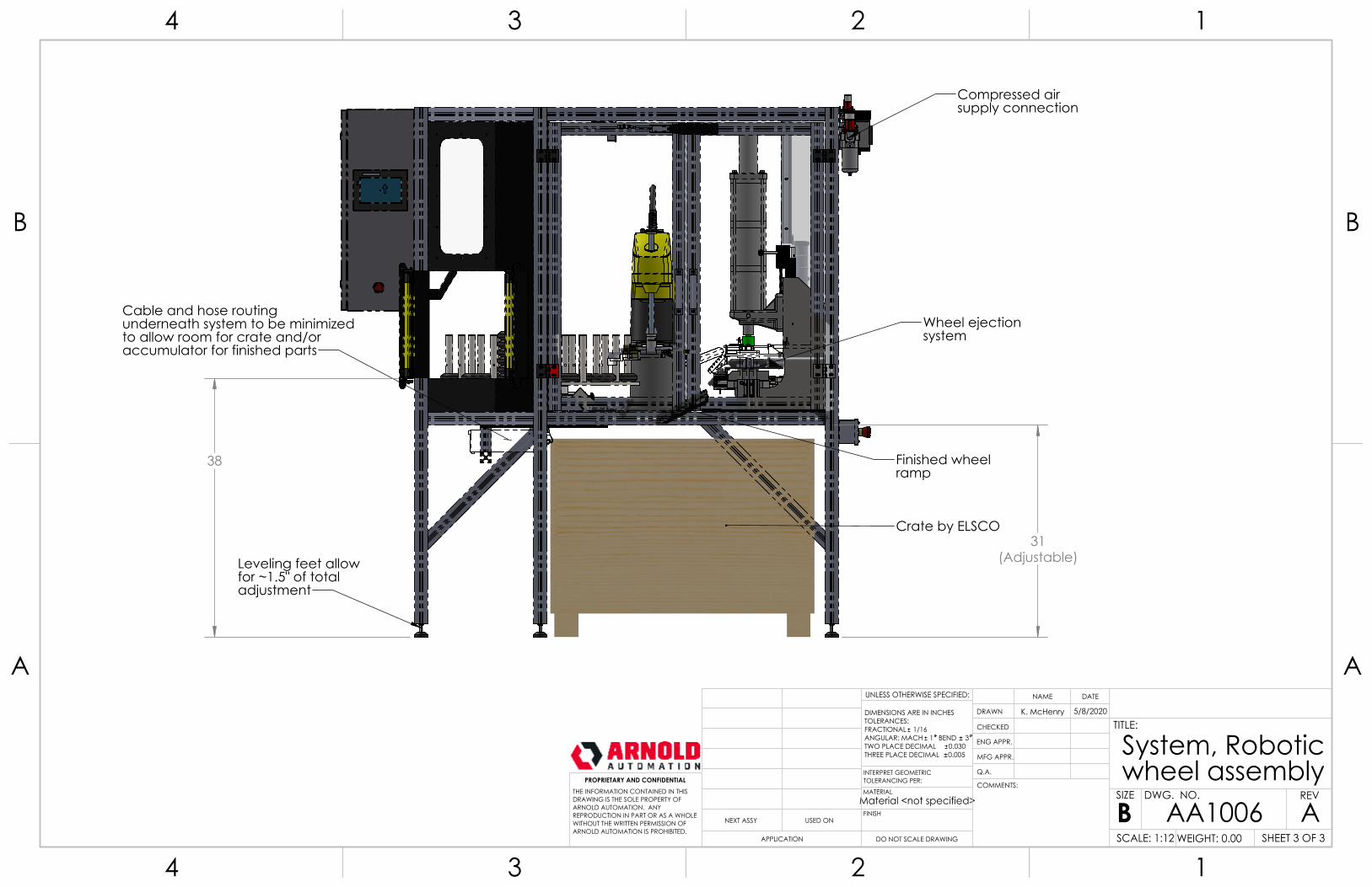
38
31(Adjustable)
Wheel ejectionsystem
Finished wheelramp
Leveling feet allowfor ~1.5" of totaladjustment
Crate by ELSCO
Compressed airsupply connection
Cable and hose routing underneath system to be minimized to allow room for crate and/or accumulator for finished parts
Material <not specified>
System, Robotic wheel assembly
ADO NOT SCALE DRAWING
AA1006SHEET 3 OF 3
5/8/2020K. McHenry
UNLESS OTHERWISE SPECIFIED:
SCALE: 1:12 WEIGHT: 0.00
REVDWG. NO.
BSIZE
TITLE:
NAME DATE
COMMENTS:
Q.A.
MFG APPR.
ENG APPR.
CHECKED
DRAWN
FINISH
MATERIAL
INTERPRET GEOMETRICTOLERANCING PER:
DIMENSIONS ARE IN INCHESTOLERANCES:FRACTIONAL 1/16ANGULAR: MACH 1 BEND 3TWO PLACE DECIMAL 0.030THREE PLACE DECIMAL 0.005
APPLICATION
USED ONNEXT ASSY
PROPRIETARY AND CONFIDENTIALTHE INFORMATION CONTAINED IN THISDRAWING IS THE SOLE PROPERTY OFARNOLD AUTOMATION. ANY REPRODUCTION IN PART OR AS A WHOLEWITHOUT THE WRITTEN PERMISSION OFARNOLD AUTOMATION IS PROHIBITED.
A A
B B
4
4
3
3
2
2
1
1
10
6
5
11
1 2 4
8
7
912
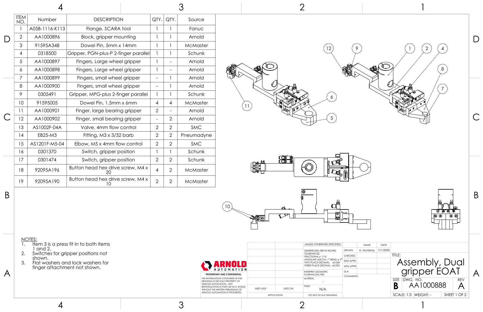
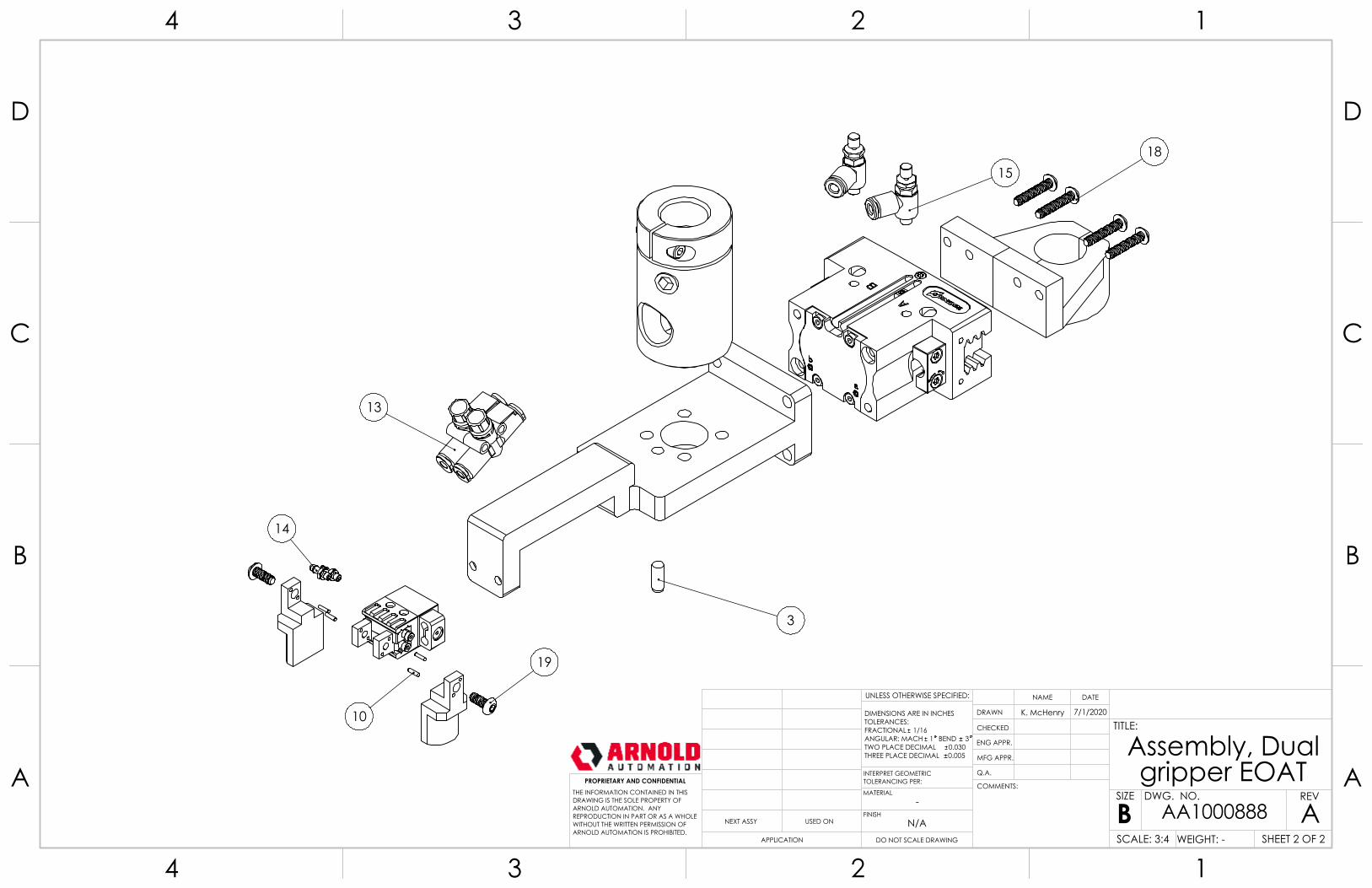
NOTES:Item 3 is a press fit in to both items 1.1 and 2.Switches for gripper positions not 2.shown.Flat washers and lock washers for 3.finger attachment not shown.
ITEM NO. Number DESCRIPTION QTY. QTY. Source
1 A05B-1116-K113 Flange, SCARA tool 1 1 Fanuc
2 AA1000896 Block, gripper mounting 1 1 Arnold
3 91595A348 Dowel Pin, 5mm x 14mm 1 1 McMaster4 0318500 Gripper, PGN-plus-P 2-finger parallel 1 1 Schunk
5 AA1000897 Fingers, Large wheel gripper 1 - Arnold
6 AA1000898 Fingers, Large wheel gripper 1 - Arnold
7 AA1000899 Fingers, small wheel gripper - 1 Arnold
8 AA1000900 Fingers, small wheel gripper - 1 Arnold
9 0305491 Gripper, MPG-plus 2-finger parallel 1 1 Schunk
10 91595005 Dowel Pin, 1.5mm x 6mm 4 4 McMaster11 AA1000901 Finger, large bearing gripper 2 - Arnold
12 AA1000902 Finger, small bearing gripper - 2 Arnold
13 AS1002F-04A Valve, 4mm flow control 2 2 SMC14 EB25-M3 Fitting, M3 x 3/32 barb 2 2 Pneumadyne
15 AS1201F-M5-04 Elbow, M5 x 4mm flow control 2 2 SMC16 0301370 Switch, gripper position 1 1 Schunk
17 0301474 Switch, gripper position 2 2 Schunk
18 92095A196 Button head hex drive screw, M4 x 20 4 2 McMaster
19 92095A190 Button head hex drive screw, M4 x 10 2 2 McMaster
-
Assembly, Dual gripper EOAT
ADO NOT SCALE DRAWING
AA1000888SHEET 1 OF 2
7/1/2020K. McHenry
UNLESS OTHERWISE SPECIFIED:
SCALE: 1:3 WEIGHT: -
REVDWG. NO.
BSIZE
TITLE:
NAME DATE
COMMENTS:
Q.A.
MFG APPR.
ENG APPR.
CHECKED
DRAWN
N/AFINISH
MATERIAL
INTERPRET GEOMETRICTOLERANCING PER:
DIMENSIONS ARE IN INCHESTOLERANCES:FRACTIONAL 1/16ANGULAR: MACH 1 BEND 3TWO PLACE DECIMAL 0.030THREE PLACE DECIMAL 0.005
APPLICATION
USED ONNEXT ASSY
PROPRIETARY AND CONFIDENTIALTHE INFORMATION CONTAINED IN THISDRAWING IS THE SOLE PROPERTY OFARNOLD AUTOMATION. ANY REPRODUCTION IN PART OR AS A WHOLEWITHOUT THE WRITTEN PERMISSION OFARNOLD AUTOMATION IS PROHIBITED.
A A
B B
C C
D D
4
4
3
3
2
2
1
1
3
10
13
14
1518
19
-
Assembly, Dual gripper EOAT
ADO NOT SCALE DRAWING
AA1000888SHEET 2 OF 2
7/1/2020K. McHenry
UNLESS OTHERWISE SPECIFIED:
SCALE: 3:4 WEIGHT: -
REVDWG. NO.
BSIZE
TITLE:
NAME DATE
COMMENTS:
Q.A.
MFG APPR.
ENG APPR.
CHECKED
DRAWN
N/AFINISH
MATERIAL
INTERPRET GEOMETRICTOLERANCING PER:
DIMENSIONS ARE IN INCHESTOLERANCES:FRACTIONAL 1/16ANGULAR: MACH 1 BEND 3TWO PLACE DECIMAL 0.030THREE PLACE DECIMAL 0.005
APPLICATION
USED ONNEXT ASSY
PROPRIETARY AND CONFIDENTIALTHE INFORMATION CONTAINED IN THISDRAWING IS THE SOLE PROPERTY OFARNOLD AUTOMATION. ANY REPRODUCTION IN PART OR AS A WHOLEWITHOUT THE WRITTEN PERMISSION OFARNOLD AUTOMATION IS PROHIBITED.
A A
B B
C C
D D
4
4
3
3
2
2
1
1
5
1
2 4
3
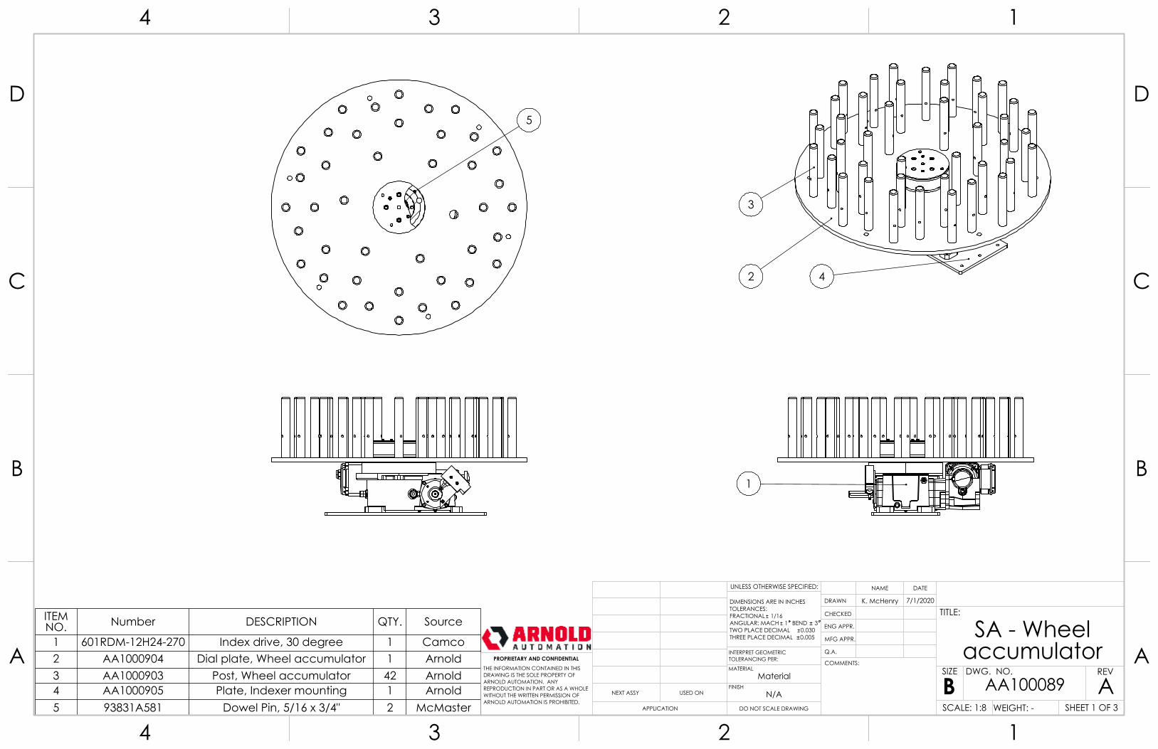
NOTES:Blah.1.Blah.2.
ITEM NO. Number DESCRIPTION QTY. Source
1 601RDM-12H24-270 Index drive, 30 degree 1 Camco2 AA1000904 Dial plate, Wheel accumulator 1 Arnold3 AA1000903 Post, Wheel accumulator 42 Arnold4 AA1000905 Plate, Indexer mounting 1 Arnold5 93831A581 Dowel Pin, 5/16 x 3/4" 2 McMaster
Material
SA - Wheel accumulator
ADO NOT SCALE DRAWING
AA100089SHEET 1 OF 3
7/1/2020K. McHenry
UNLESS OTHERWISE SPECIFIED:
SCALE: 1:8 WEIGHT: -
REVDWG. NO.
BSIZE
TITLE:
NAME DATE
COMMENTS:
Q.A.
MFG APPR.
ENG APPR.
CHECKED
DRAWN
N/AFINISH
MATERIAL
INTERPRET GEOMETRICTOLERANCING PER:
DIMENSIONS ARE IN INCHESTOLERANCES:FRACTIONAL 1/16ANGULAR: MACH 1 BEND 3TWO PLACE DECIMAL 0.030THREE PLACE DECIMAL 0.005
APPLICATION
USED ONNEXT ASSY
PROPRIETARY AND CONFIDENTIALTHE INFORMATION CONTAINED IN THISDRAWING IS THE SOLE PROPERTY OFARNOLD AUTOMATION. ANY REPRODUCTION IN PART OR AS A WHOLEWITHOUT THE WRITTEN PERMISSION OFARNOLD AUTOMATION IS PROHIBITED.
A A
B B
C C
D D
4
4
3
3
2
2
1
1
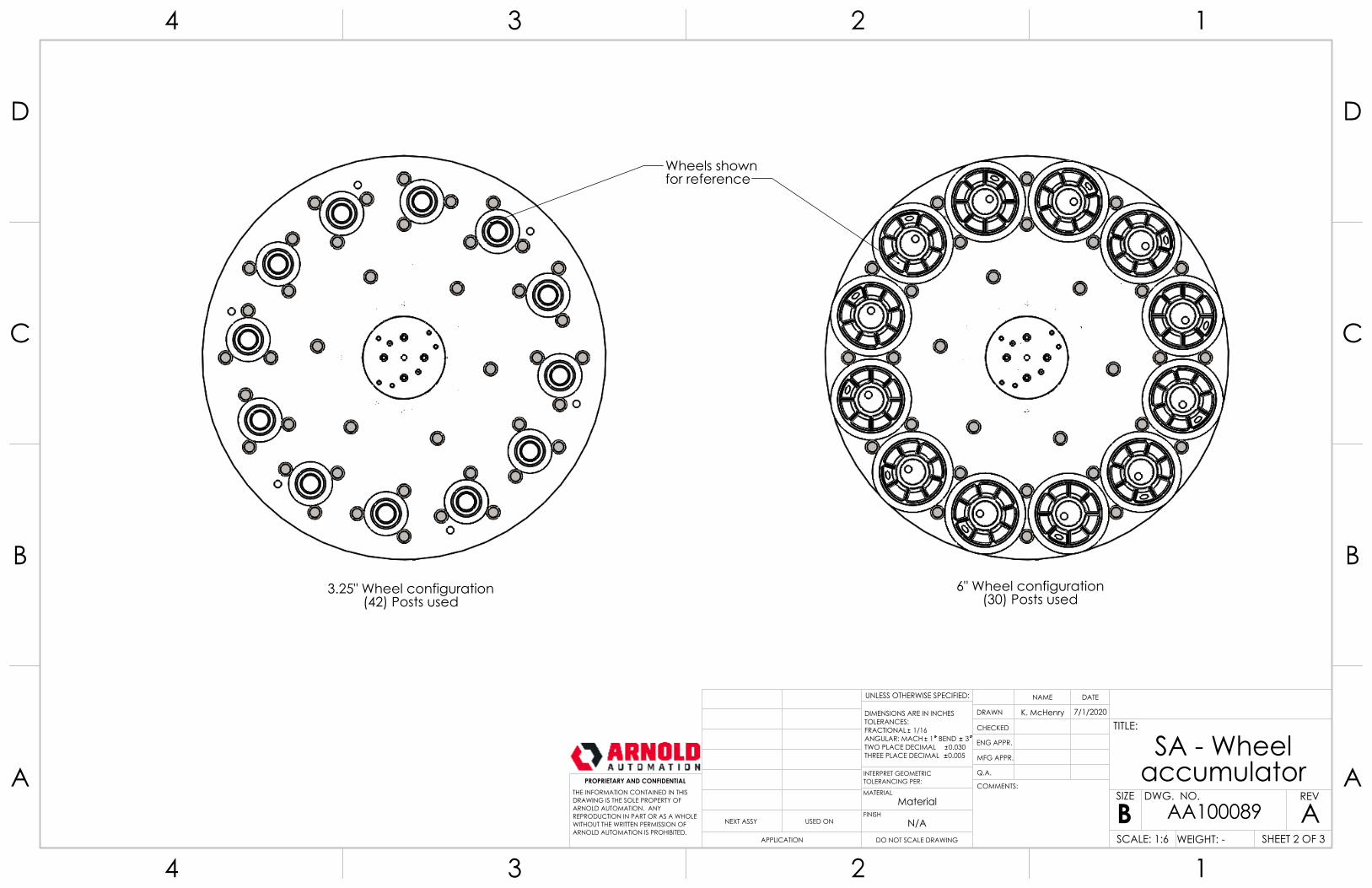
3.25" Wheel configuration(42) Posts used
6" Wheel configuration(30) Posts used
Wheels shownfor reference
Material
SA - Wheel accumulator
ADO NOT SCALE DRAWING
AA100089SHEET 2 OF 3
7/1/2020K. McHenry
UNLESS OTHERWISE SPECIFIED:
SCALE: 1:6 WEIGHT: -
REVDWG. NO.
BSIZE
TITLE:
NAME DATE
COMMENTS:
Q.A.
MFG APPR.
ENG APPR.
CHECKED
DRAWN
N/AFINISH
MATERIAL
INTERPRET GEOMETRICTOLERANCING PER:
DIMENSIONS ARE IN INCHESTOLERANCES:FRACTIONAL 1/16ANGULAR: MACH 1 BEND 3TWO PLACE DECIMAL 0.030THREE PLACE DECIMAL 0.005
APPLICATION
USED ONNEXT ASSY
PROPRIETARY AND CONFIDENTIALTHE INFORMATION CONTAINED IN THISDRAWING IS THE SOLE PROPERTY OFARNOLD AUTOMATION. ANY REPRODUCTION IN PART OR AS A WHOLEWITHOUT THE WRITTEN PERMISSION OFARNOLD AUTOMATION IS PROHIBITED.
A A
B B
C C
D D
4
4
3
3
2
2
1
1
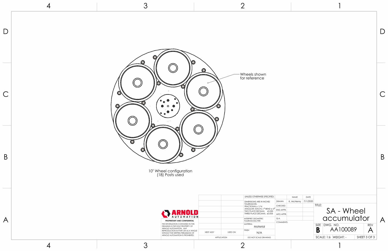
10" Wheel configuration(18) Posts used
Wheels shownfor reference
Material
SA - Wheel accumulator
ADO NOT SCALE DRAWING
AA100089SHEET 3 OF 3
7/1/2020K. McHenry
UNLESS OTHERWISE SPECIFIED:
SCALE: 1:6 WEIGHT: -
REVDWG. NO.
BSIZE
TITLE:
NAME DATE
COMMENTS:
Q.A.
MFG APPR.
ENG APPR.
CHECKED
DRAWN
N/AFINISH
MATERIAL
INTERPRET GEOMETRICTOLERANCING PER:
DIMENSIONS ARE IN INCHESTOLERANCES:FRACTIONAL 1/16ANGULAR: MACH 1 BEND 3TWO PLACE DECIMAL 0.030THREE PLACE DECIMAL 0.005
APPLICATION
USED ONNEXT ASSY
PROPRIETARY AND CONFIDENTIALTHE INFORMATION CONTAINED IN THISDRAWING IS THE SOLE PROPERTY OFARNOLD AUTOMATION. ANY REPRODUCTION IN PART OR AS A WHOLEWITHOUT THE WRITTEN PERMISSION OFARNOLD AUTOMATION IS PROHIBITED.
A A
B B
C C
D D
4
4
3
3
2
2
1
1
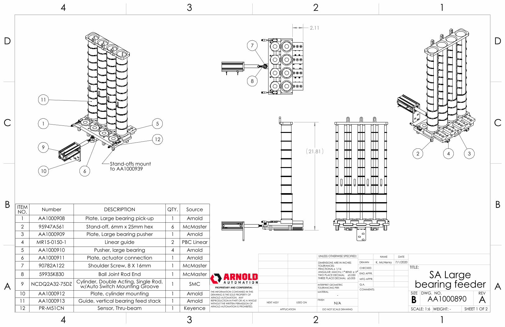
21.81
2.11
7
8
2 4 3
Stand-offs mountto AA1000939
1
11
9
5
12
610
NOTES:Blah.1.Blah.2.
ITEM NO. Number DESCRIPTION QTY. Source
1 AA1000908 Plate, Large bearing pick-up 1 Arnold2 95947A561 Stand-off, 6mm x 25mm hex 6 McMaster3 AA1000909 Plate, Large bearing pusher 1 Arnold4 MR15-0150-1 Linear guide 2 PBC Linear5 AA1000910 Pusher, large bearing 4 Arnold6 AA1000911 Plate, actuator connection 1 Arnold7 90782A122 Shoulder Screw, 8 X 16mm 1 McMaster
8 59935K830 Ball Joint Rod End 1 McMaster
9 NCDQ2A32-75DZ Cylinder, Double Acting, Single Rod, w/Auto Switch Mounting Groove 1 SMC
10 AA1000912 Plate, cylinder mounting 1 Arnold11 AA1000913 Guide, vertical bearing feed stack 1 Arnold12 PR-M51CN Sensor, Thru-beam 1 Keyence
-
SA Large bearing feeder
ADO NOT SCALE DRAWING
AA1000890SHEET 1 OF 2
7/1/2020K. McHenry
UNLESS OTHERWISE SPECIFIED:
SCALE: 1:6 WEIGHT: -
REVDWG. NO.
BSIZE
TITLE:
NAME DATE
COMMENTS:
Q.A.
MFG APPR.
ENG APPR.
CHECKED
DRAWN
N/AFINISH
MATERIAL
INTERPRET GEOMETRICTOLERANCING PER:
DIMENSIONS ARE IN INCHESTOLERANCES:FRACTIONAL 1/16ANGULAR: MACH 1 BEND 3TWO PLACE DECIMAL 0.030THREE PLACE DECIMAL 0.005
APPLICATION
USED ONNEXT ASSY
PROPRIETARY AND CONFIDENTIALTHE INFORMATION CONTAINED IN THISDRAWING IS THE SOLE PROPERTY OFARNOLD AUTOMATION. ANY REPRODUCTION IN PART OR AS A WHOLEWITHOUT THE WRITTEN PERMISSION OFARNOLD AUTOMATION IS PROHIBITED.
A A
B B
C C
D D
4
4
3
3
2
2
1
1
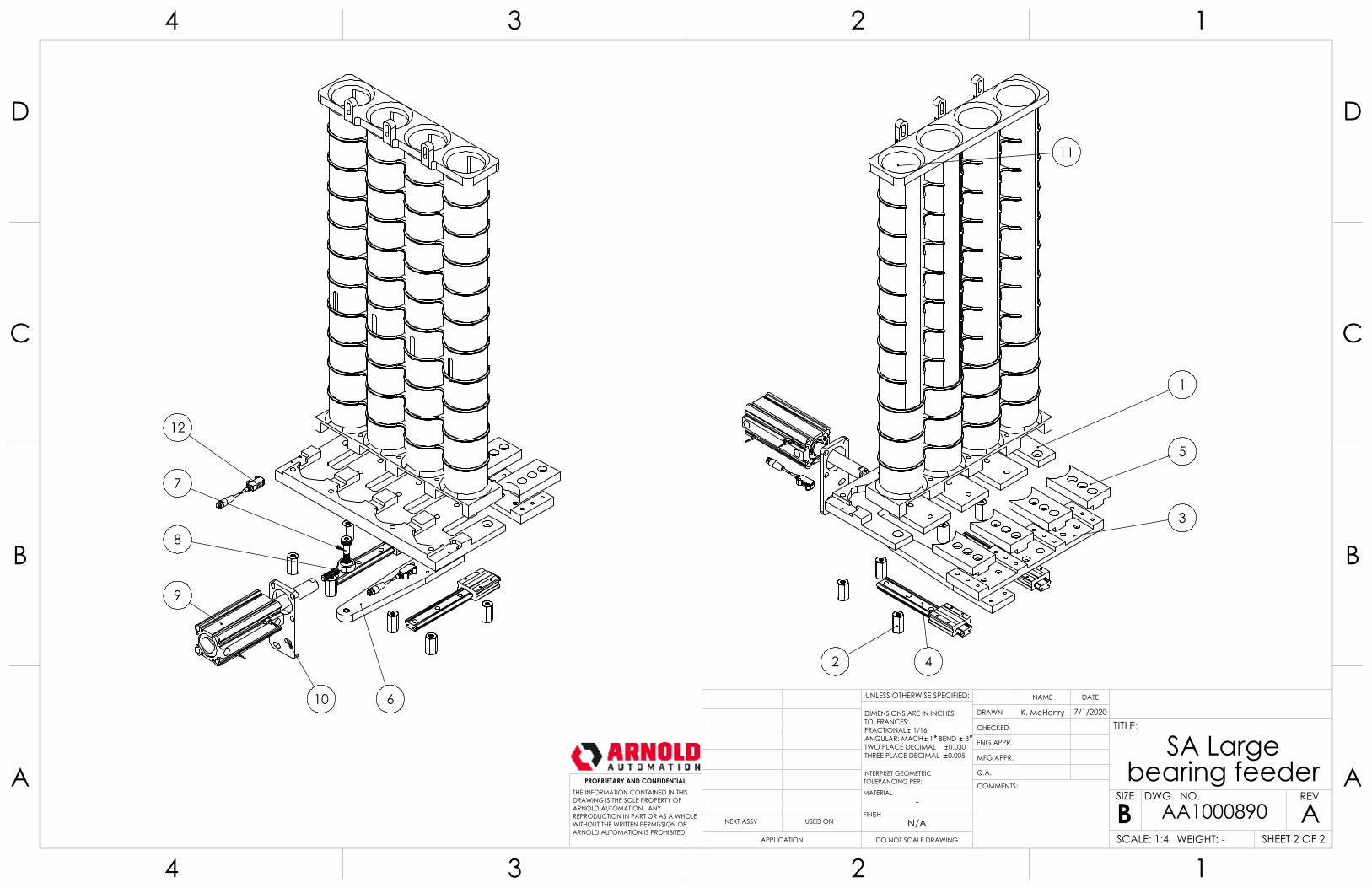
11
1
5
3
42
12
610
9
7
8
-
SA Large bearing feeder
ADO NOT SCALE DRAWING
AA1000890SHEET 2 OF 2
7/1/2020K. McHenry
UNLESS OTHERWISE SPECIFIED:
SCALE: 1:4 WEIGHT: -
REVDWG. NO.
BSIZE
TITLE:
NAME DATE
COMMENTS:
Q.A.
MFG APPR.
ENG APPR.
CHECKED
DRAWN
N/AFINISH
MATERIAL
INTERPRET GEOMETRICTOLERANCING PER:
DIMENSIONS ARE IN INCHESTOLERANCES:FRACTIONAL 1/16ANGULAR: MACH 1 BEND 3TWO PLACE DECIMAL 0.030THREE PLACE DECIMAL 0.005
APPLICATION
USED ONNEXT ASSY
PROPRIETARY AND CONFIDENTIALTHE INFORMATION CONTAINED IN THISDRAWING IS THE SOLE PROPERTY OFARNOLD AUTOMATION. ANY REPRODUCTION IN PART OR AS A WHOLEWITHOUT THE WRITTEN PERMISSION OFARNOLD AUTOMATION IS PROHIBITED.
A A
B B
C C
D D
4
4
3
3
2
2
1
1
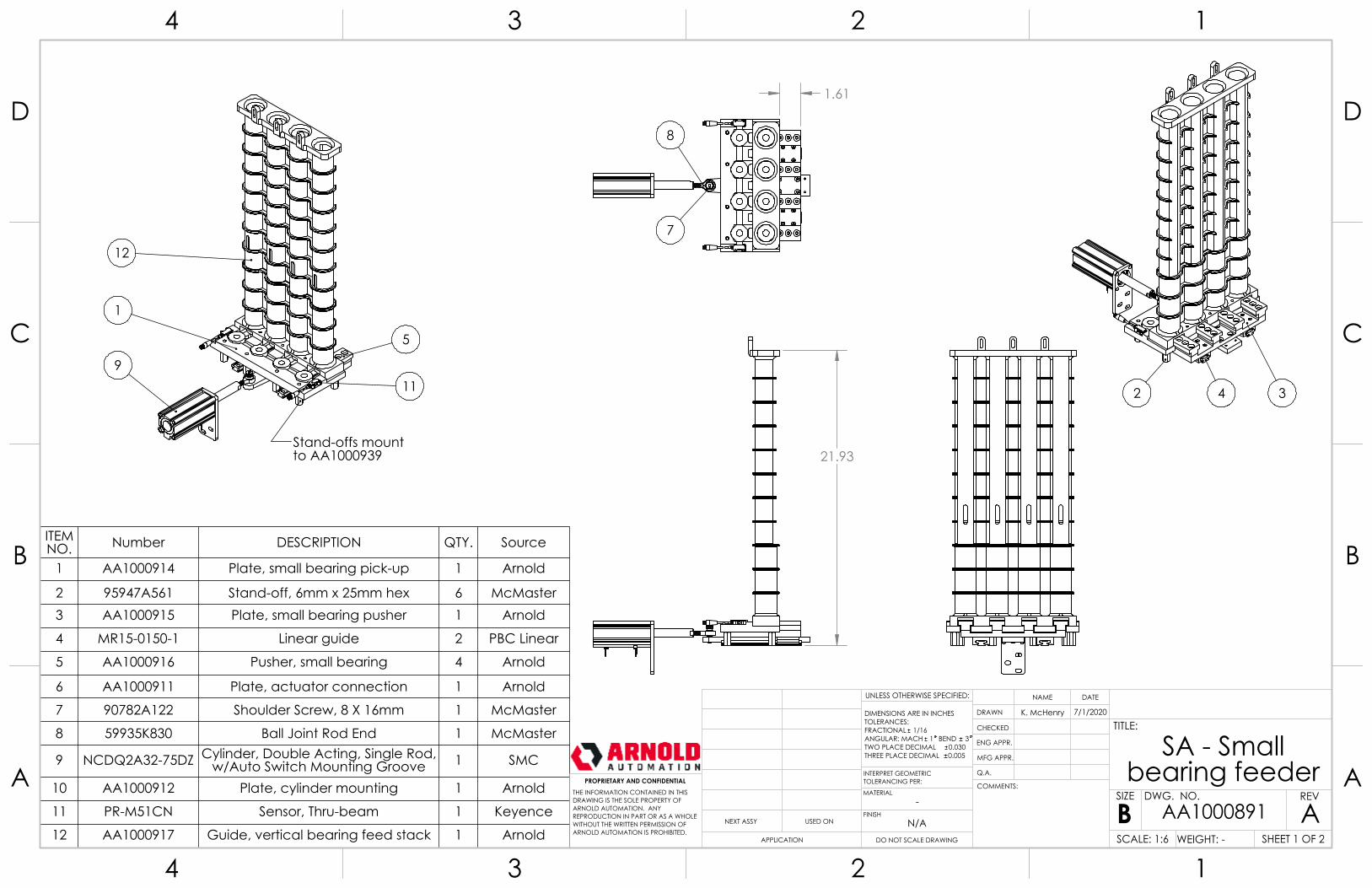
21.93
1.61
8
7
2 4 3
Stand-offs mountto AA1000939
9
1
12
5
11
NOTES:Blah.1.Blah.2.
ITEM NO. Number DESCRIPTION QTY. Source
1 AA1000914 Plate, small bearing pick-up 1 Arnold
2 95947A561 Stand-off, 6mm x 25mm hex 6 McMaster3 AA1000915 Plate, small bearing pusher 1 Arnold
4 MR15-0150-1 Linear guide 2 PBC Linear
5 AA1000916 Pusher, small bearing 4 Arnold
6 AA1000911 Plate, actuator connection 1 Arnold
7 90782A122 Shoulder Screw, 8 X 16mm 1 McMaster
8 59935K830 Ball Joint Rod End 1 McMaster
9 NCDQ2A32-75DZ Cylinder, Double Acting, Single Rod, w/Auto Switch Mounting Groove 1 SMC
10 AA1000912 Plate, cylinder mounting 1 Arnold
11 PR-M51CN Sensor, Thru-beam 1 Keyence
12 AA1000917 Guide, vertical bearing feed stack 1 Arnold
-
SA - Small bearing feeder
ADO NOT SCALE DRAWING
AA1000891SHEET 1 OF 2
7/1/2020K. McHenry
UNLESS OTHERWISE SPECIFIED:
SCALE: 1:6 WEIGHT: -
REVDWG. NO.
BSIZE
TITLE:
NAME DATE
COMMENTS:
Q.A.
MFG APPR.
ENG APPR.
CHECKED
DRAWN
N/AFINISH
MATERIAL
INTERPRET GEOMETRICTOLERANCING PER:
DIMENSIONS ARE IN INCHESTOLERANCES:FRACTIONAL 1/16ANGULAR: MACH 1 BEND 3TWO PLACE DECIMAL 0.030THREE PLACE DECIMAL 0.005
APPLICATION
USED ONNEXT ASSY
PROPRIETARY AND CONFIDENTIALTHE INFORMATION CONTAINED IN THISDRAWING IS THE SOLE PROPERTY OFARNOLD AUTOMATION. ANY REPRODUCTION IN PART OR AS A WHOLEWITHOUT THE WRITTEN PERMISSION OFARNOLD AUTOMATION IS PROHIBITED.
A A
B B
C C
D D
4
4
3
3
2
2
1
1
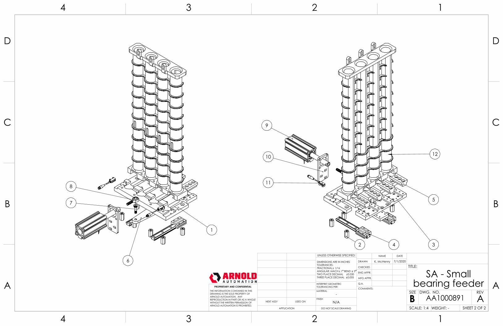
4 32
5
12
9
10
118
7
6
1
-
SA - Small bearing feeder
ADO NOT SCALE DRAWING
AA1000891SHEET 2 OF 2
7/1/2020K. McHenry
UNLESS OTHERWISE SPECIFIED:
SCALE: 1:4 WEIGHT: -
REVDWG. NO.
BSIZE
TITLE:
NAME DATE
COMMENTS:
Q.A.
MFG APPR.
ENG APPR.
CHECKED
DRAWN
N/AFINISH
MATERIAL
INTERPRET GEOMETRICTOLERANCING PER:
DIMENSIONS ARE IN INCHESTOLERANCES:FRACTIONAL 1/16ANGULAR: MACH 1 BEND 3TWO PLACE DECIMAL 0.030THREE PLACE DECIMAL 0.005
APPLICATION
USED ONNEXT ASSY
PROPRIETARY AND CONFIDENTIALTHE INFORMATION CONTAINED IN THISDRAWING IS THE SOLE PROPERTY OFARNOLD AUTOMATION. ANY REPRODUCTION IN PART OR AS A WHOLEWITHOUT THE WRITTEN PERMISSION OFARNOLD AUTOMATION IS PROHIBITED.
A A
B B
C C
D D
4
4
3
3
2
2
1
1
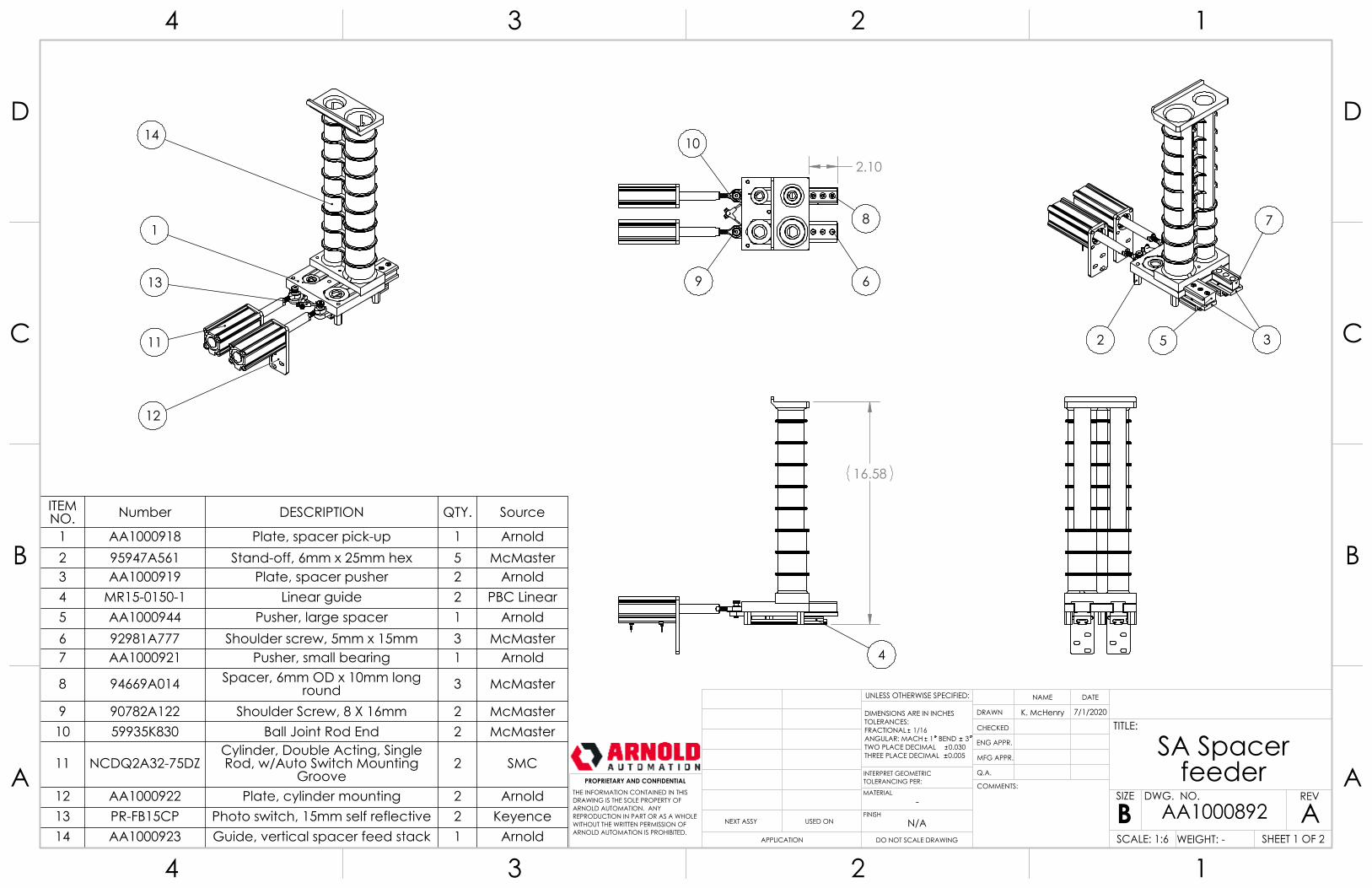
16.58
4
2.10
10
9 6
8 7
352
14
11
12
1
13
NOTES:Blah.1.Blah.2.
ITEM NO. Number DESCRIPTION QTY. Source
1 AA1000918 Plate, spacer pick-up 1 Arnold2 95947A561 Stand-off, 6mm x 25mm hex 5 McMaster3 AA1000919 Plate, spacer pusher 2 Arnold4 MR15-0150-1 Linear guide 2 PBC Linear5 AA1000944 Pusher, large spacer 1 Arnold6 92981A777 Shoulder screw, 5mm x 15mm 3 McMaster7 AA1000921 Pusher, small bearing 1 Arnold
8 94669A014 Spacer, 6mm OD x 10mm long round 3 McMaster
9 90782A122 Shoulder Screw, 8 X 16mm 2 McMaster10 59935K830 Ball Joint Rod End 2 McMaster
11 NCDQ2A32-75DZCylinder, Double Acting, Single Rod, w/Auto Switch Mounting
Groove 2 SMC
12 AA1000922 Plate, cylinder mounting 2 Arnold13 PR-FB15CP Photo switch, 15mm self reflective 2 Keyence14 AA1000923 Guide, vertical spacer feed stack 1 Arnold
-
SA Spacer feeder
ADO NOT SCALE DRAWING
AA1000892SHEET 1 OF 2
7/1/2020K. McHenry
UNLESS OTHERWISE SPECIFIED:
SCALE: 1:6 WEIGHT: -
REVDWG. NO.
BSIZE
TITLE:
NAME DATE
COMMENTS:
Q.A.
MFG APPR.
ENG APPR.
CHECKED
DRAWN
N/AFINISH
MATERIAL
INTERPRET GEOMETRICTOLERANCING PER:
DIMENSIONS ARE IN INCHESTOLERANCES:FRACTIONAL 1/16ANGULAR: MACH 1 BEND 3TWO PLACE DECIMAL 0.030THREE PLACE DECIMAL 0.005
APPLICATION
USED ONNEXT ASSY
PROPRIETARY AND CONFIDENTIALTHE INFORMATION CONTAINED IN THISDRAWING IS THE SOLE PROPERTY OFARNOLD AUTOMATION. ANY REPRODUCTION IN PART OR AS A WHOLEWITHOUT THE WRITTEN PERMISSION OFARNOLD AUTOMATION IS PROHIBITED.
A A
B B
C C
D D
4
4
3
3
2
2
1
1
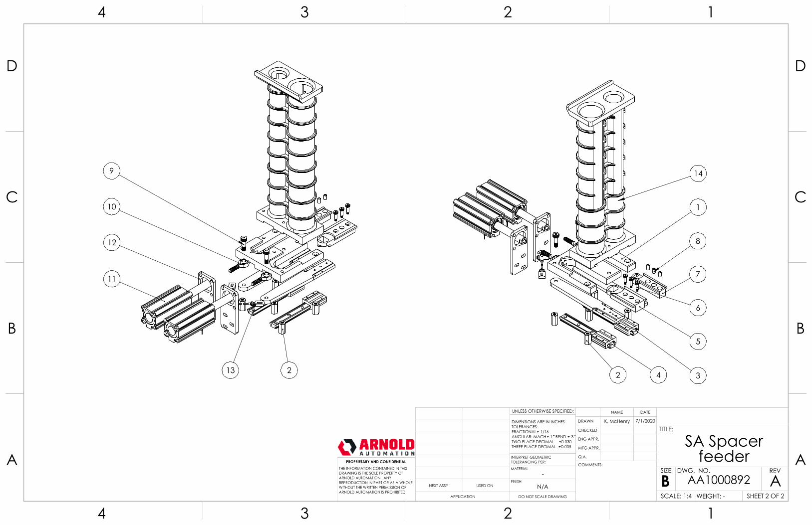
14
1
8
7
6
5
4 32
9
10
12
11
13 2
-
SA Spacer feeder
ADO NOT SCALE DRAWING
AA1000892SHEET 2 OF 2
7/1/2020K. McHenry
UNLESS OTHERWISE SPECIFIED:
SCALE: 1:4 WEIGHT: -
REVDWG. NO.
BSIZE
TITLE:
NAME DATE
COMMENTS:
Q.A.
MFG APPR.
ENG APPR.
CHECKED
DRAWN
N/AFINISH
MATERIAL
INTERPRET GEOMETRICTOLERANCING PER:
DIMENSIONS ARE IN INCHESTOLERANCES:FRACTIONAL 1/16ANGULAR: MACH 1 BEND 3TWO PLACE DECIMAL 0.030THREE PLACE DECIMAL 0.005
APPLICATION
USED ONNEXT ASSY
PROPRIETARY AND CONFIDENTIALTHE INFORMATION CONTAINED IN THISDRAWING IS THE SOLE PROPERTY OFARNOLD AUTOMATION. ANY REPRODUCTION IN PART OR AS A WHOLEWITHOUT THE WRITTEN PERMISSION OFARNOLD AUTOMATION IS PROHIBITED.
A A
B B
C C
D D
4
4
3
3
2
2
1
1
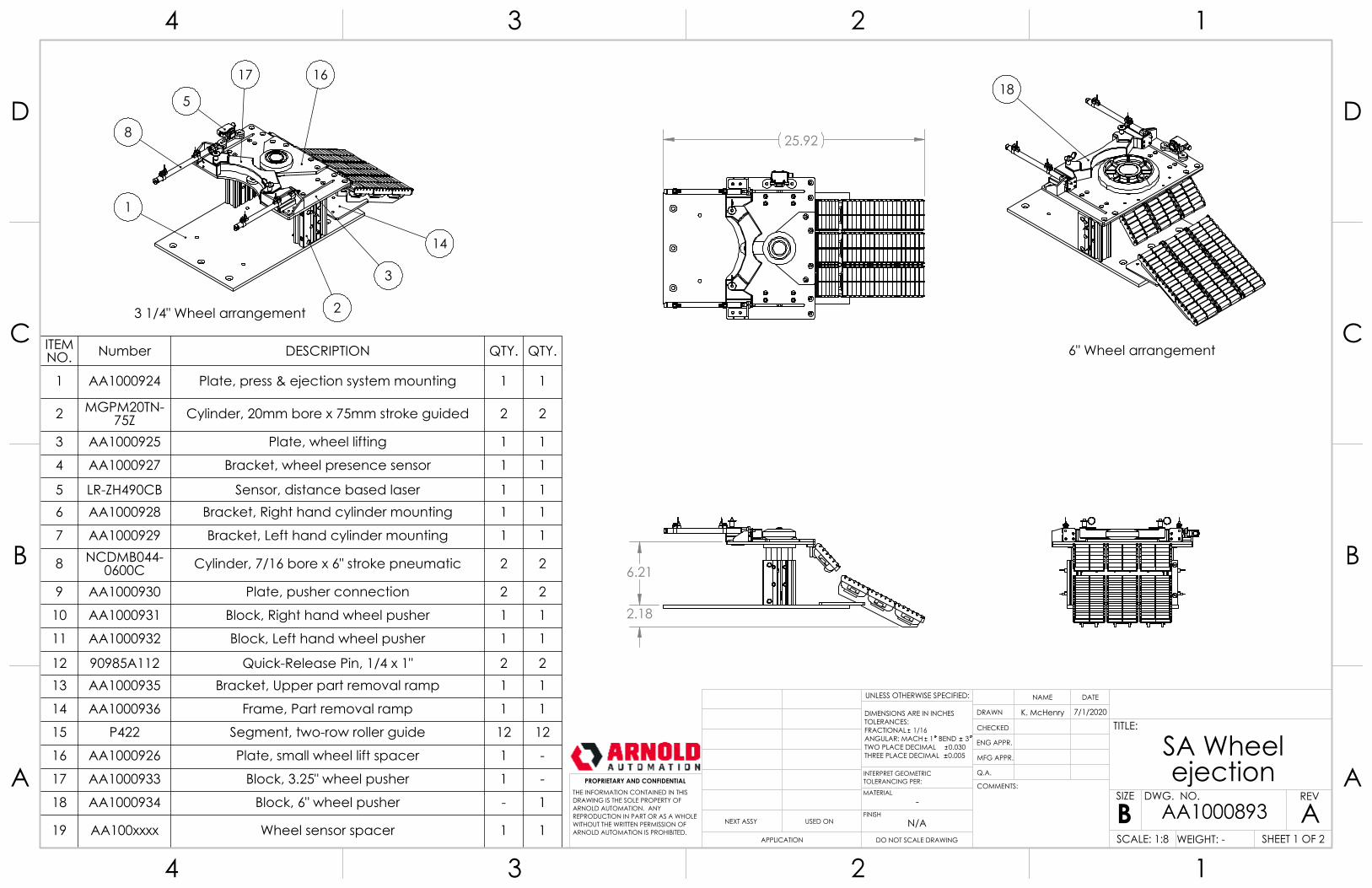
6.21
2.18
25.92
18
6" Wheel arrangement
8
17 16
1
14
3
2
5
NOTES:Blah.1.Blah.2.
3 1/4" Wheel arrangement
ITEM NO. Number DESCRIPTION QTY. QTY.
1 AA1000924 Plate, press & ejection system mounting 1 1
2 MGPM20TN-75Z Cylinder, 20mm bore x 75mm stroke guided 2 2
3 AA1000925 Plate, wheel lifting 1 1
4 AA1000927 Bracket, wheel presence sensor 1 1
5 LR-ZH490CB Sensor, distance based laser 1 16 AA1000928 Bracket, Right hand cylinder mounting 1 1
7 AA1000929 Bracket, Left hand cylinder mounting 1 1
8 NCDMB044-0600C Cylinder, 7/16 bore x 6" stroke pneumatic 2 2
9 AA1000930 Plate, pusher connection 2 2
10 AA1000931 Block, Right hand wheel pusher 1 1
11 AA1000932 Block, Left hand wheel pusher 1 1
12 90985A112 Quick-Release Pin, 1/4 x 1" 2 213 AA1000935 Bracket, Upper part removal ramp 1 1
14 AA1000936 Frame, Part removal ramp 1 1
15 P422 Segment, two-row roller guide 12 12
16 AA1000926 Plate, small wheel lift spacer 1 -
17 AA1000933 Block, 3.25" wheel pusher 1 -
18 AA1000934 Block, 6" wheel pusher - 1
19 AA100xxxx Wheel sensor spacer 1 1
-
SA Wheel ejection
ADO NOT SCALE DRAWING
AA1000893SHEET 1 OF 2
7/1/2020K. McHenry
UNLESS OTHERWISE SPECIFIED:
SCALE: 1:8 WEIGHT: -
REVDWG. NO.
BSIZE
TITLE:
NAME DATE
COMMENTS:
Q.A.
MFG APPR.
ENG APPR.
CHECKED
DRAWN
N/AFINISH
MATERIAL
INTERPRET GEOMETRICTOLERANCING PER:
DIMENSIONS ARE IN INCHESTOLERANCES:FRACTIONAL 1/16ANGULAR: MACH 1 BEND 3TWO PLACE DECIMAL 0.030THREE PLACE DECIMAL 0.005
APPLICATION
USED ONNEXT ASSY
PROPRIETARY AND CONFIDENTIALTHE INFORMATION CONTAINED IN THISDRAWING IS THE SOLE PROPERTY OFARNOLD AUTOMATION. ANY REPRODUCTION IN PART OR AS A WHOLEWITHOUT THE WRITTEN PERMISSION OFARNOLD AUTOMATION IS PROHIBITED.
A A
B B
C C
D D
4
4
3
3
2
2
1
1
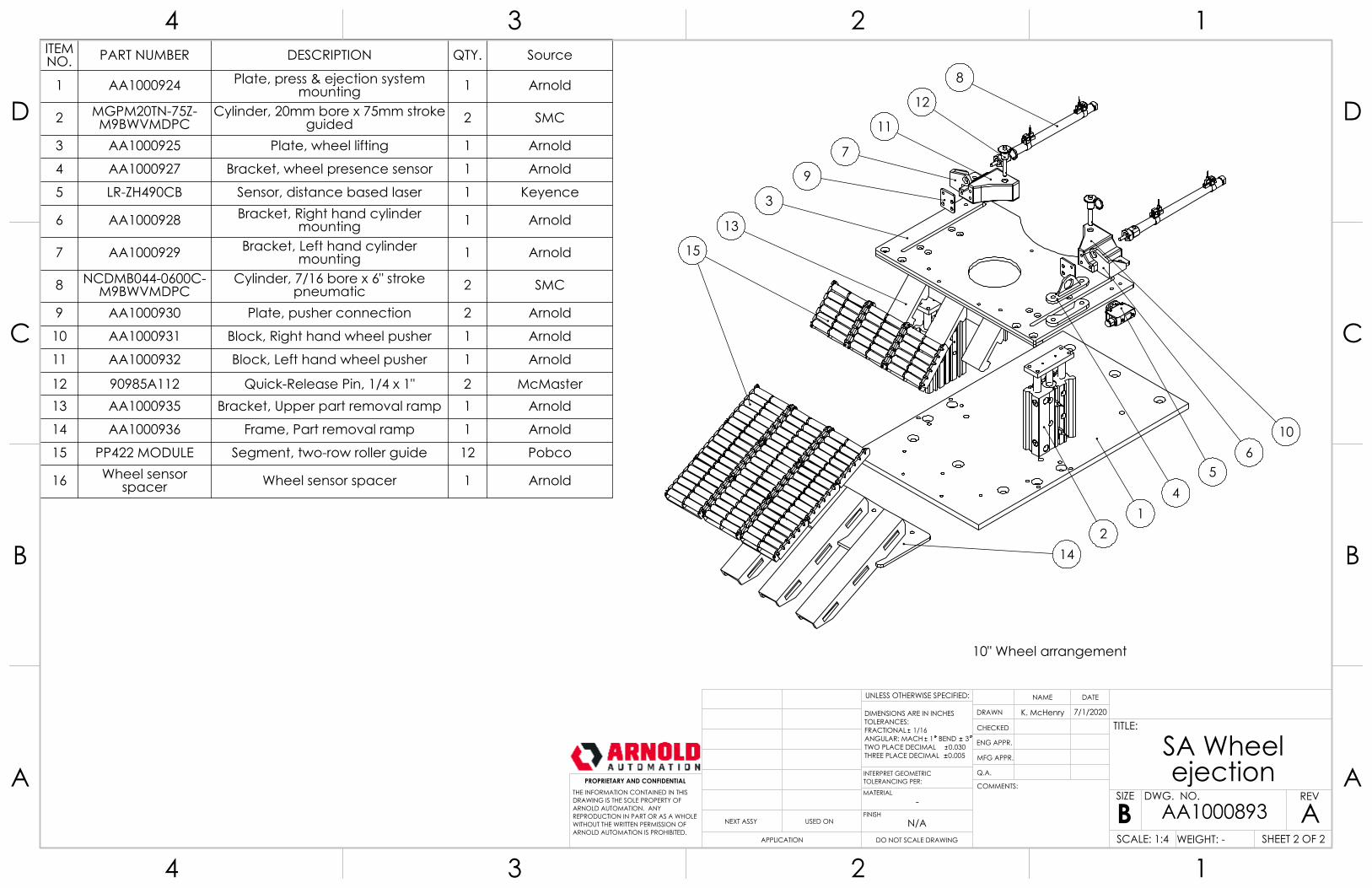
8
12
11
7
9
3
1
54
2
15
13
6
14
10
10" Wheel arrangement
ITEM NO. PART NUMBER DESCRIPTION QTY. Source
1 AA1000924 Plate, press & ejection system mounting 1 Arnold
2 MGPM20TN-75Z-M9BWVMDPC
Cylinder, 20mm bore x 75mm stroke guided 2 SMC
3 AA1000925 Plate, wheel lifting 1 Arnold
4 AA1000927 Bracket, wheel presence sensor 1 Arnold
5 LR-ZH490CB Sensor, distance based laser 1 Keyence
6 AA1000928 Bracket, Right hand cylinder mounting 1 Arnold
7 AA1000929 Bracket, Left hand cylinder mounting 1 Arnold
8 NCDMB044-0600C-M9BWVMDPC
Cylinder, 7/16 bore x 6" stroke pneumatic 2 SMC
9 AA1000930 Plate, pusher connection 2 Arnold
10 AA1000931 Block, Right hand wheel pusher 1 Arnold
11 AA1000932 Block, Left hand wheel pusher 1 Arnold
12 90985A112 Quick-Release Pin, 1/4 x 1" 2 McMaster13 AA1000935 Bracket, Upper part removal ramp 1 Arnold
14 AA1000936 Frame, Part removal ramp 1 Arnold
15 PP422 MODULE Segment, two-row roller guide 12 Pobco
16 Wheel sensor spacer Wheel sensor spacer 1 Arnold
-
SA Wheel ejection
ADO NOT SCALE DRAWING
AA1000893SHEET 2 OF 2
7/1/2020K. McHenry
UNLESS OTHERWISE SPECIFIED:
SCALE: 1:4 WEIGHT: -
REVDWG. NO.
BSIZE
TITLE:
NAME DATE
COMMENTS:
Q.A.
MFG APPR.
ENG APPR.
CHECKED
DRAWN
N/AFINISH
MATERIAL
INTERPRET GEOMETRICTOLERANCING PER:
DIMENSIONS ARE IN INCHESTOLERANCES:FRACTIONAL 1/16ANGULAR: MACH 1 BEND 3TWO PLACE DECIMAL 0.030THREE PLACE DECIMAL 0.005
APPLICATION
USED ONNEXT ASSY
PROPRIETARY AND CONFIDENTIALTHE INFORMATION CONTAINED IN THISDRAWING IS THE SOLE PROPERTY OFARNOLD AUTOMATION. ANY REPRODUCTION IN PART OR AS A WHOLEWITHOUT THE WRITTEN PERMISSION OFARNOLD AUTOMATION IS PROHIBITED.
A A
B B
C C
D D
4
4
3
3
2
2
1
1
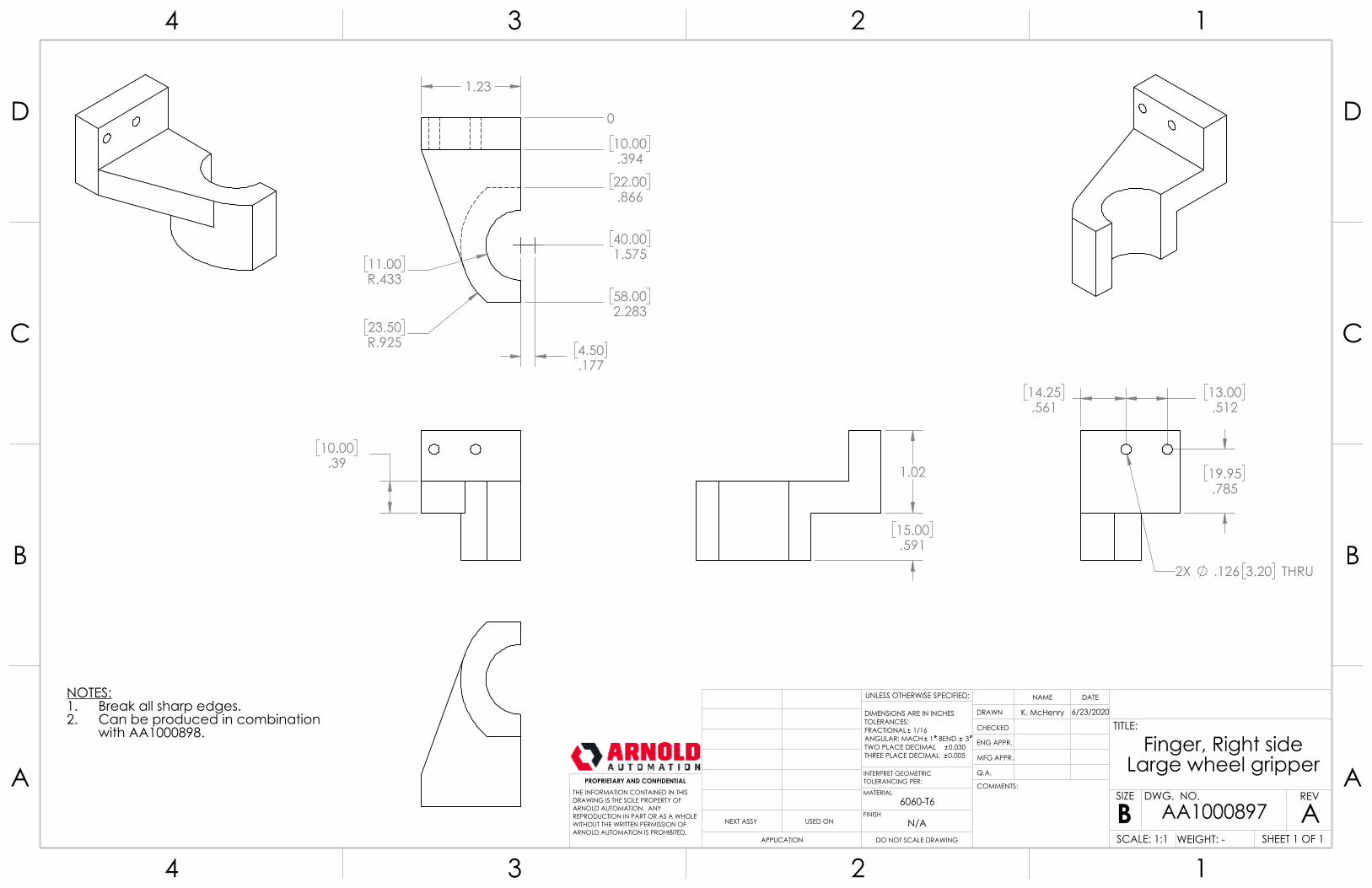
10.00.39
11.00R.433
23.50R.925
1.23
4.50.177
0
10.00.394
40.001.575
58.002.283
22.00.866
1.02
15.00.591
19.95.785
13.00.512
14.25.561
2X .126 3.20 THRU
NOTES:Break all sharp edges.1.Can be produced in combination2.with AA1000898.
6060-T6
Finger, Right side Large wheel gripper
ADO NOT SCALE DRAWING
AA1000897SHEET 1 OF 1
6/23/2020K. McHenry
UNLESS OTHERWISE SPECIFIED:
SCALE: 1:1 WEIGHT: -
REVDWG. NO.
BSIZE
TITLE:
NAME DATE
COMMENTS:
Q.A.
MFG APPR.
ENG APPR.
CHECKED
DRAWN
N/AFINISH
MATERIAL
INTERPRET GEOMETRICTOLERANCING PER:
DIMENSIONS ARE IN INCHESTOLERANCES:FRACTIONAL 1/16ANGULAR: MACH 1 BEND 3TWO PLACE DECIMAL 0.030THREE PLACE DECIMAL 0.005
APPLICATION
USED ONNEXT ASSY
PROPRIETARY AND CONFIDENTIALTHE INFORMATION CONTAINED IN THISDRAWING IS THE SOLE PROPERTY OFARNOLD AUTOMATION. ANY REPRODUCTION IN PART OR AS A WHOLEWITHOUT THE WRITTEN PERMISSION OFARNOLD AUTOMATION IS PROHIBITED.
A A
B B
C C
D D
4
4
3
3
2
2
1
1
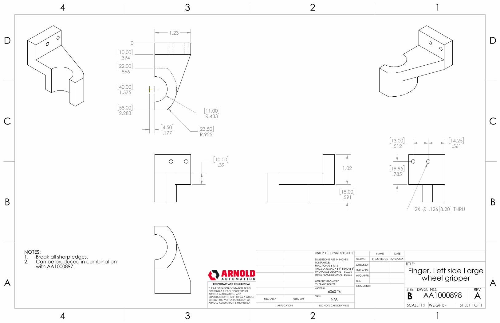
10.00.39
23.50R.925
11.00R.433
4.50.177
1.23
0
10.00.394
22.00.866
40.001.575
58.002.283
1.02
15.00.591
13.00.512
19.95.785
14.25.561
2X .126 3.20 THRU
NOTES:Break all sharp edges.1.Can be produced in combination2.with AA1000897.
6060-T6
Finger, Left side Large wheel gripper
ADO NOT SCALE DRAWING
AA1000898SHEET 1 OF 1
6/24/2020K. McHenry
UNLESS OTHERWISE SPECIFIED:
SCALE: 1:1 WEIGHT: -
REVDWG. NO.
BSIZE
TITLE:
NAME DATE
COMMENTS:
Q.A.
MFG APPR.
ENG APPR.
CHECKED
DRAWN
N/AFINISH
MATERIAL
INTERPRET GEOMETRICTOLERANCING PER:
DIMENSIONS ARE IN INCHESTOLERANCES:FRACTIONAL 1/16ANGULAR: MACH 1 BEND 3TWO PLACE DECIMAL 0.030THREE PLACE DECIMAL 0.005
APPLICATION
USED ONNEXT ASSY
PROPRIETARY AND CONFIDENTIALTHE INFORMATION CONTAINED IN THISDRAWING IS THE SOLE PROPERTY OFARNOLD AUTOMATION. ANY REPRODUCTION IN PART OR AS A WHOLEWITHOUT THE WRITTEN PERMISSION OFARNOLD AUTOMATION IS PROHIBITED.
A A
B B
C C
D D
4
4
3
3
2
2
1
1
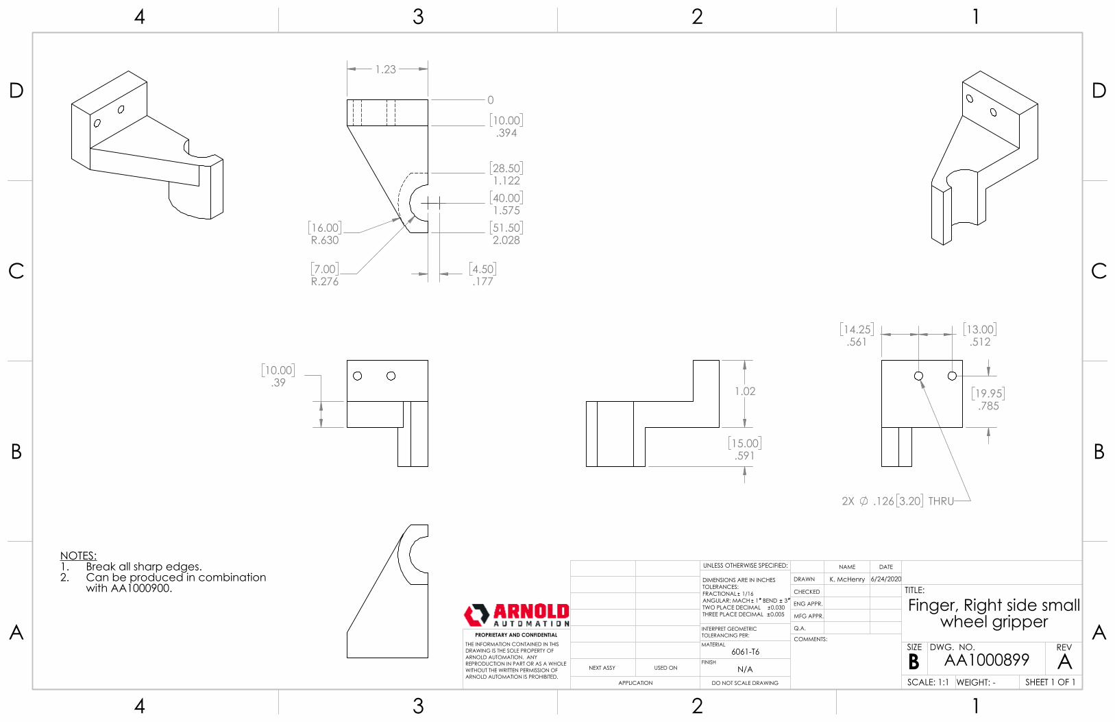
10.00.39
1.23
7.00R.276
16.00R.630
4.50.177
0
10.00.394
28.501.12240.001.57551.502.028
1.02
15.00.591
14.25.561
13.00.512
19.95.785
2X .126 3.20 THRU
NOTES:Break all sharp edges.1.Can be produced in combination2.with AA1000900.
6061-T6
Finger, Right side small wheel gripper
ADO NOT SCALE DRAWING
AA1000899SHEET 1 OF 1
6/24/2020K. McHenry
UNLESS OTHERWISE SPECIFIED:
SCALE: 1:1 WEIGHT: -
REVDWG. NO.
BSIZE
TITLE:
NAME DATE
COMMENTS:
Q.A.
MFG APPR.
ENG APPR.
CHECKED
DRAWN
N/AFINISH
MATERIAL
INTERPRET GEOMETRICTOLERANCING PER:
DIMENSIONS ARE IN INCHESTOLERANCES:FRACTIONAL 1/16ANGULAR: MACH 1 BEND 3TWO PLACE DECIMAL 0.030THREE PLACE DECIMAL 0.005
APPLICATION
USED ONNEXT ASSY
PROPRIETARY AND CONFIDENTIALTHE INFORMATION CONTAINED IN THISDRAWING IS THE SOLE PROPERTY OFARNOLD AUTOMATION. ANY REPRODUCTION IN PART OR AS A WHOLEWITHOUT THE WRITTEN PERMISSION OFARNOLD AUTOMATION IS PROHIBITED.
A A
B B
C C
D D
4
4
3
3
2
2
1
1
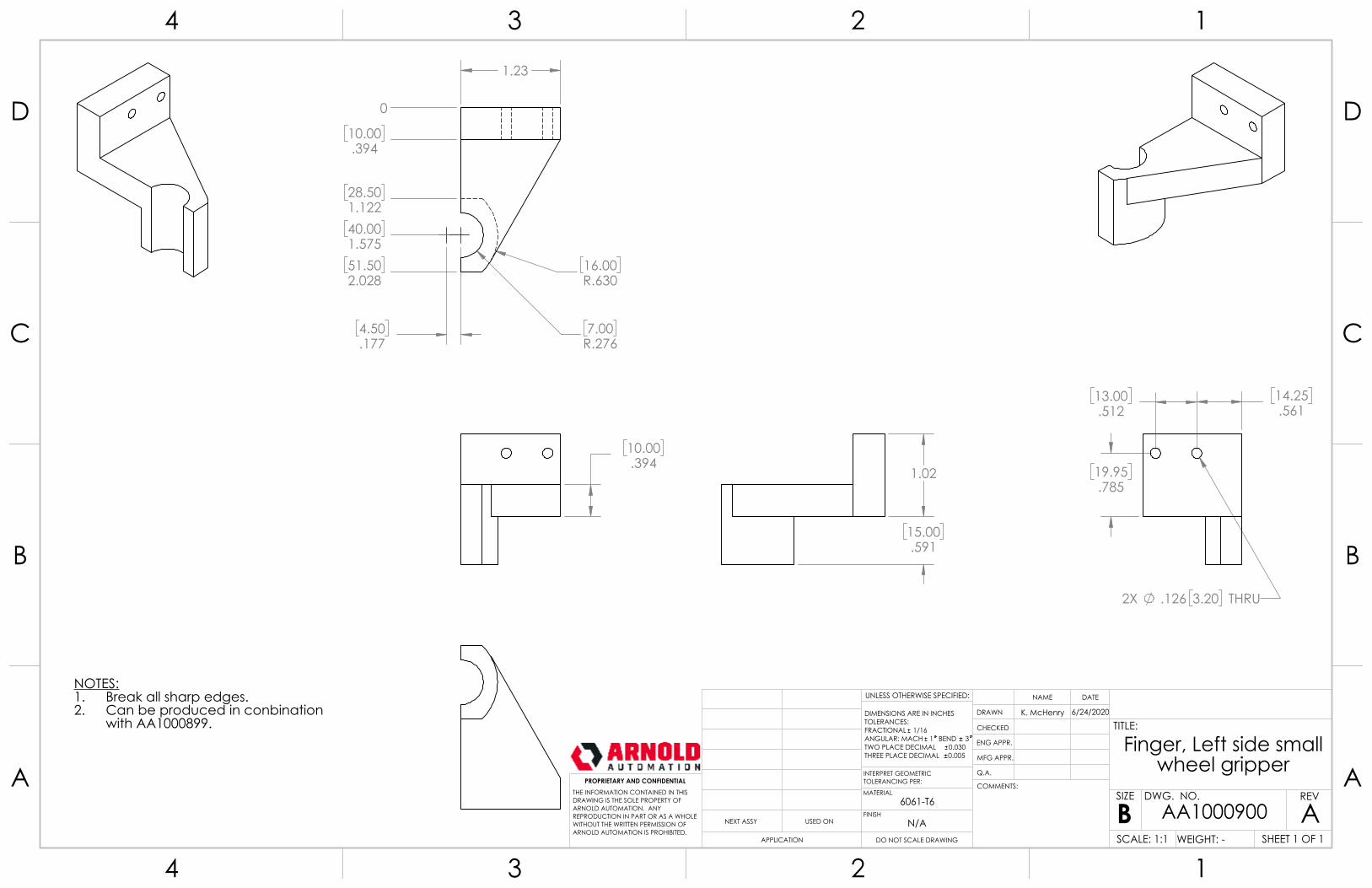
10.00.394
1.23
4.50.177
7.00R.276
16.00R.630
0
10.00.394
28.501.122
40.001.575
51.502.028
1.02
15.00.591
13.00.512
14.25.561
19.95.785
2X .126 3.20 THRU
NOTES:Break all sharp edges.1.Can be produced in conbination 2.with AA1000899.
6061-T6
Finger, Left side small wheel gripper
ADO NOT SCALE DRAWING
AA1000900SHEET 1 OF 1
6/24/2020K. McHenry
UNLESS OTHERWISE SPECIFIED:
SCALE: 1:1 WEIGHT: -
REVDWG. NO.
BSIZE
TITLE:
NAME DATE
COMMENTS:
Q.A.
MFG APPR.
ENG APPR.
CHECKED
DRAWN
N/AFINISH
MATERIAL
INTERPRET GEOMETRICTOLERANCING PER:
DIMENSIONS ARE IN INCHESTOLERANCES:FRACTIONAL 1/16ANGULAR: MACH 1 BEND 3TWO PLACE DECIMAL 0.030THREE PLACE DECIMAL 0.005
APPLICATION
USED ONNEXT ASSY
PROPRIETARY AND CONFIDENTIALTHE INFORMATION CONTAINED IN THISDRAWING IS THE SOLE PROPERTY OFARNOLD AUTOMATION. ANY REPRODUCTION IN PART OR AS A WHOLEWITHOUT THE WRITTEN PERMISSION OFARNOLD AUTOMATION IS PROHIBITED.
A A
B B
C C
D D
4
4
3
3
2
2
1
1

18.00.709
9.00.354
0
10.00.39414.00.551
29.001.142
4.50.18
A
.12 3.00 X 45°2 PL's
8.00.315
10.00.394
12.00.472
10.00R.394
1.00.039
.169 4.30 THRU
2X .0607.0597 THRU
0
3.00.118
3.00.118
0 2.
00.0
79
2.00
.079
3.80
.150
3.80
.150
DETAIL ASCALE 4 : 1
NOTES:Break all sharp edges.1.
6061-T6
Finger, large bearing gripper
ADO NOT SCALE DRAWING
AA1000901SHEET 1 OF 1
6/24/2020K. McHenry
UNLESS OTHERWISE SPECIFIED:
SCALE: 2:1 WEIGHT: -
REVDWG. NO.
BSIZE
TITLE:
NAME DATE
COMMENTS:
Q.A.
MFG APPR.
ENG APPR.
CHECKED
DRAWN
N/AFINISH
MATERIAL
INTERPRET GEOMETRICTOLERANCING PER:
DIMENSIONS ARE IN INCHESTOLERANCES:FRACTIONAL 1/16ANGULAR: MACH 1 BEND 3TWO PLACE DECIMAL 0.030THREE PLACE DECIMAL 0.005
APPLICATION
USED ONNEXT ASSY
PROPRIETARY AND CONFIDENTIALTHE INFORMATION CONTAINED IN THISDRAWING IS THE SOLE PROPERTY OFARNOLD AUTOMATION. ANY REPRODUCTION IN PART OR AS A WHOLEWITHOUT THE WRITTEN PERMISSION OFARNOLD AUTOMATION IS PROHIBITED.
A A
B B
C C
D D
4
4
3
3
2
2
1
1
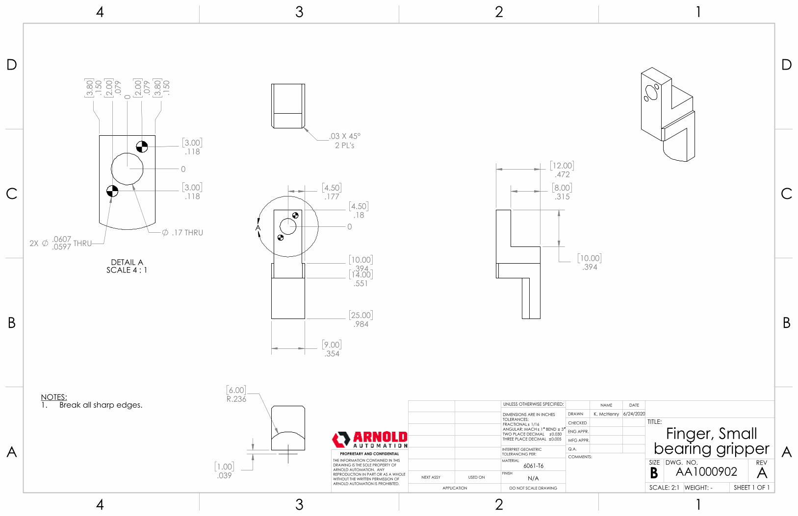
9.00.354
4.50.177
0
4.50.18
10.00.39414.00.551
25.00.984
A
8.00.315
10.00.394
12.00.472
.03 X 45°2 PL's
1.00.039
6.00R.236
.17 THRU2X .0607
.0597 THRU
0
3.00.118
3.00.118
0 2.
00.0
793.
80.1
50
2.00
.079
3.80
.150
DETAIL ASCALE 4 : 1
NOTES:Break all sharp edges.1.
6061-T6
Finger, Small bearing gripper
ADO NOT SCALE DRAWING
AA1000902SHEET 1 OF 1
6/24/2020K. McHenry
UNLESS OTHERWISE SPECIFIED:
SCALE: 2:1 WEIGHT: -
REVDWG. NO.
BSIZE
TITLE:
NAME DATE
COMMENTS:
Q.A.
MFG APPR.
ENG APPR.
CHECKED
DRAWN
N/AFINISH
MATERIAL
INTERPRET GEOMETRICTOLERANCING PER:
DIMENSIONS ARE IN INCHESTOLERANCES:FRACTIONAL 1/16ANGULAR: MACH 1 BEND 3TWO PLACE DECIMAL 0.030THREE PLACE DECIMAL 0.005
APPLICATION
USED ONNEXT ASSY
PROPRIETARY AND CONFIDENTIALTHE INFORMATION CONTAINED IN THISDRAWING IS THE SOLE PROPERTY OFARNOLD AUTOMATION. ANY REPRODUCTION IN PART OR AS A WHOLEWITHOUT THE WRITTEN PERMISSION OFARNOLD AUTOMATION IS PROHIBITED.
A A
B B
C C
D D
4
4
3
3
2
2
1
1

Page | 40
ELECTRICAL DRAWINGS
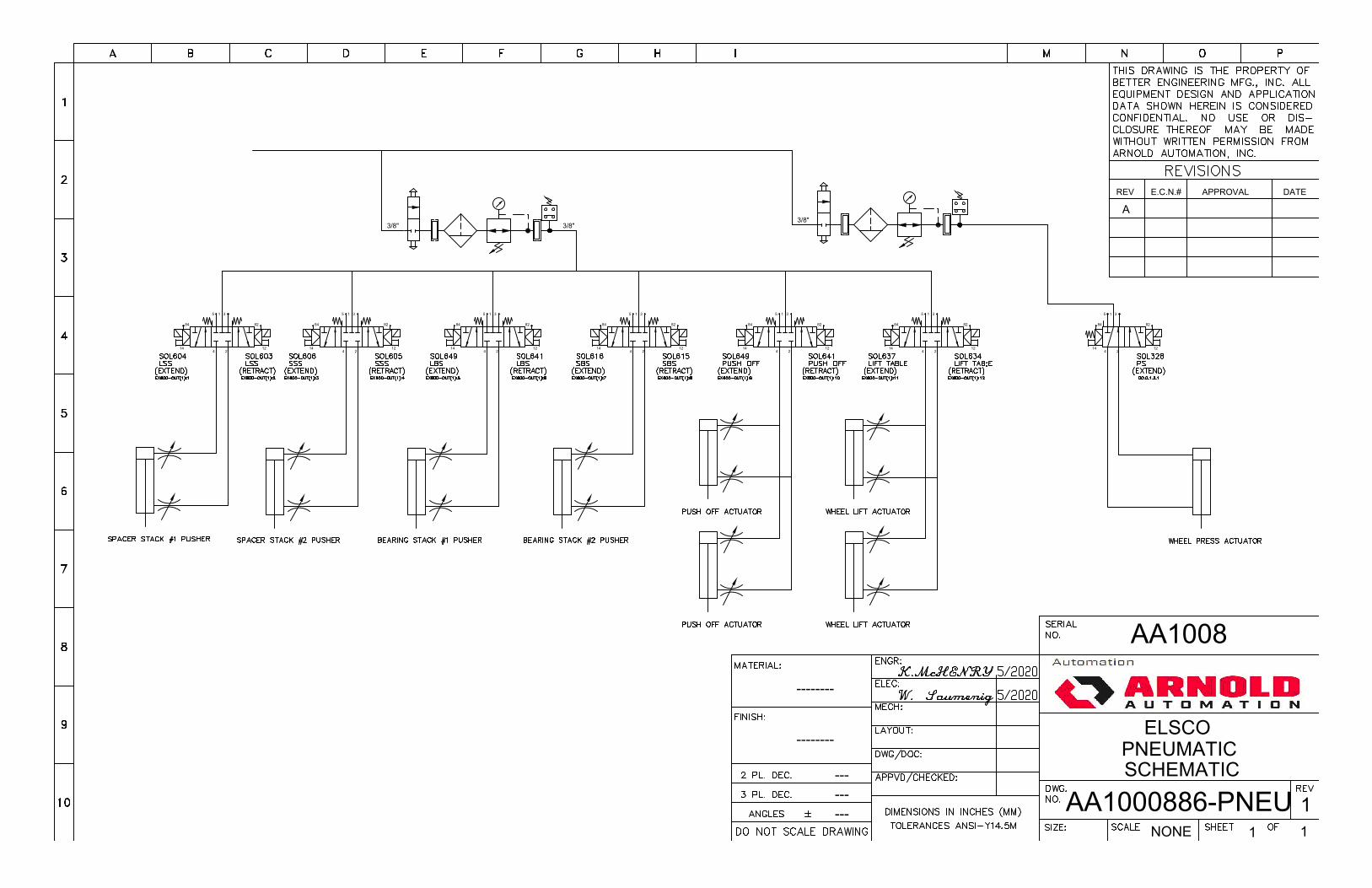
3/8"3/8"
82
122
3
14
84
5
4
1
82
122
3
14
84
5
4
1
82
122
3
14
84
5
4
1
82
122
3
14
84
5
4
1
82
122
3
14
84
5
4
1
82
122
3
14
84
5
4
1
APPROVALE.C.N.#REV DATE
AA1008
ELSCOPNEUMATIC SCHEMATIC
AA1000886-PNEU 11 1NONE
--------
--------
---------
A3/8"
82
122
3
14
84
5
4
1
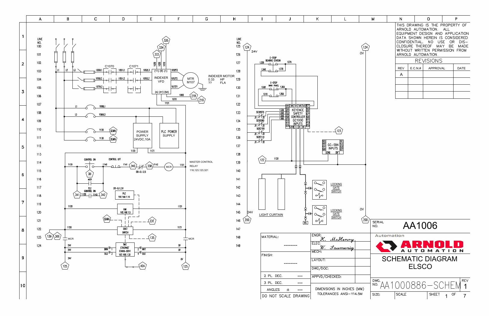
APPROVALE.C.N.#REV DATE
AA1006
SCHEMATIC DIAGRAMELSCO
11 7
--------
--------
---------
A
C1070
INDEXERVFD
MTR HPFLAM107
INDEXER MOTOR0.33??
C1071
POWERSUPPLY
24VDC,10ASUPPLY
RELAYMCR
MASTER CONTROL
116,123,123,321
MCRMCR
LOCKINGGATE
SWITCH
LOCKINGGATE
SWITCHLIGHT CURTAIN
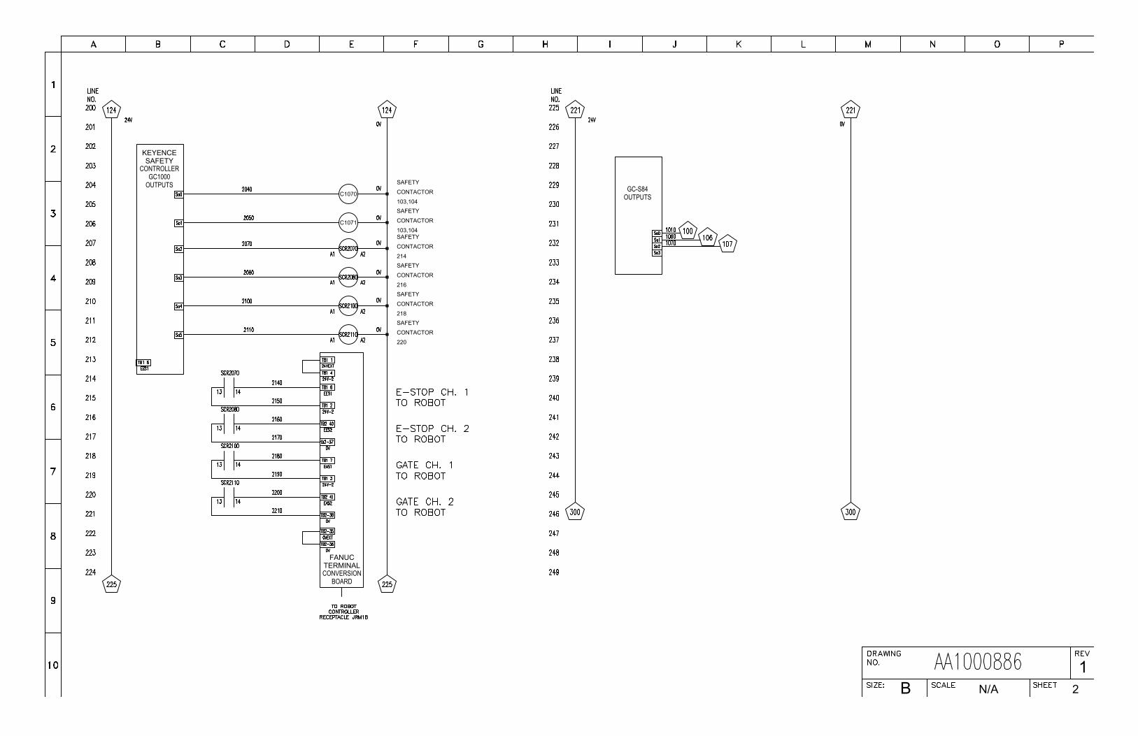
B 2N/A
1
KEYENCESAFETY
CONTROLLERGC1000
CONTACTORSAFETY
C1070103,104
CONTACTORSAFETY
C1071103,104
FANUCTERMINALCONVERSION
BOARD
OUTPUTS GC-S84OUTPUTS
CONTACTORSAFETY
214
CONTACTORSAFETY
216
CONTACTORSAFETY
218
CONTACTORSAFETY
220
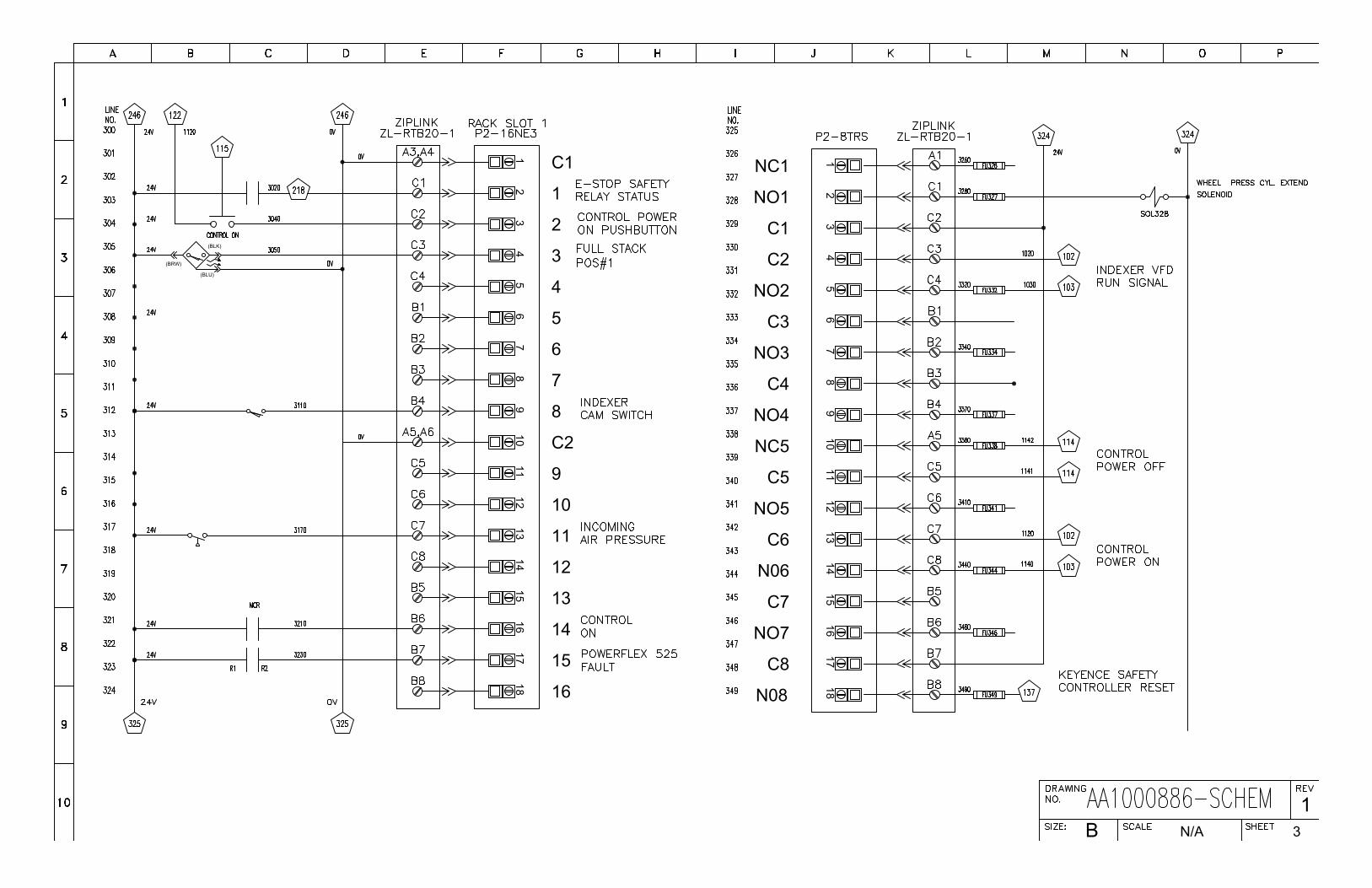
(BLK)
(BLU)
(BRW)
1817
1615
1413
1211
109
87
65
43
21 C1
1
2
3
4
5
6
7
8
C2
9
10
11
12
13
14
15
16
B 3N/A
1
1817
1615
1413
1211
109
87
65
43
21NC1
NO1
C1
C2
NO2
C3
NO3
C4
NO4
NC5
C5
NO5
C6
N06
C7
NO7
C8
N08
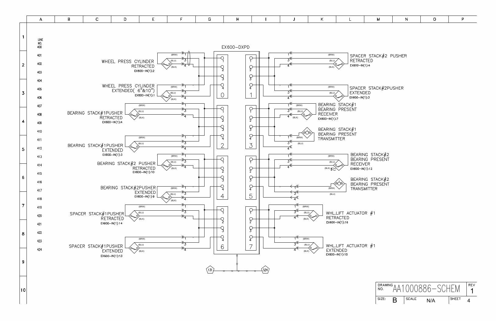
(BLK)
(BLU)
(BRW)
(BLK)
(BLU)
(BRW)
(BLK)
(BLU)
(BRW)
(BLU)
(BRW)
(BLK)
(BLU)
(BRW)
(BLK)
(BLU)
(BRW)
(BLK)
(BLU)
(BRW)
(BLU)
(BRW)
(BLK)
(BLU)
(BRW)
(BLU)
(BRW)
(BLK)
(BLK)
(BLU)
(BRW)
(BLU)
(BRW)
(BLU)
(BRW)
(BLK)
(BLU)
(BRW)
(BLK)
(BLU)
(BRW)
(BLK)
(BLU)
(BRW)
B 4N/A
1
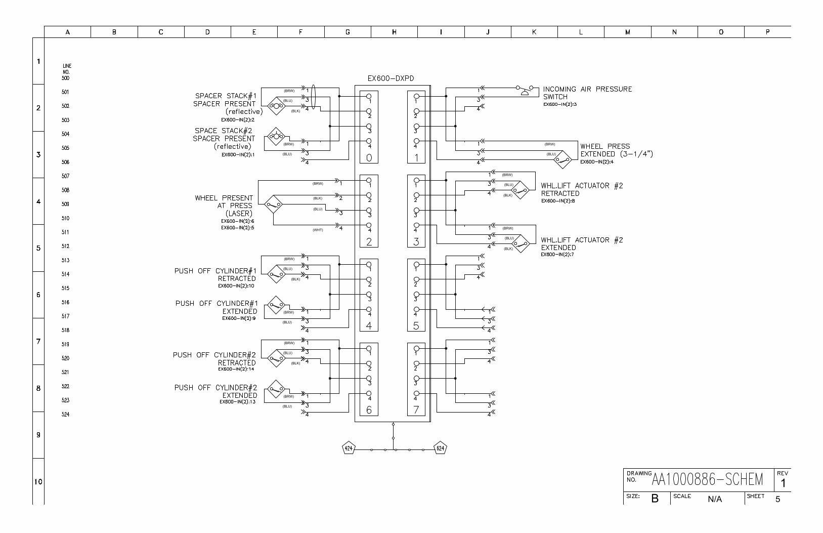
B 5N/A
1
(BLK)
(BLU)
(BRW)
(BLU)
(BRW)
(BLK)
(BLU)
(BRW)
(WHT)
(BLK)
(BLU)
(BRW)
(BLU)
(BRW)
(BLK)
(BLU)
(BRW)
(BLU)
(BRW)
(BLK)
(BLU)
(BRW)
(BLK)
(BLU)
(BRW)
(BLU)
(BRW)
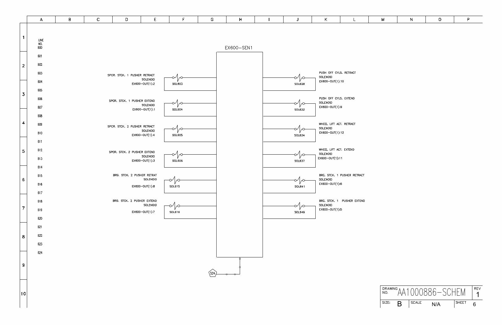
B 6N/A
1
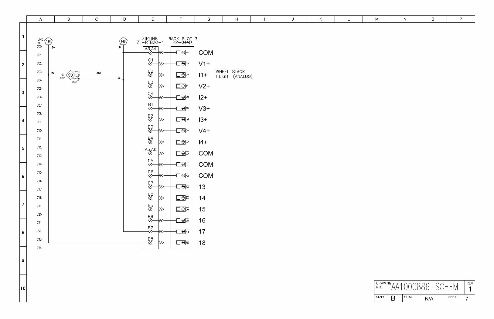
B 7N/A
1
1817
1615
1413
1211
109
87
65
43
21 COM
V1+
I1+
V2+
I2+
V3+
I3+
V4+
I4+
COM
COM
COM
13
14
15
16
17
18
(WHT)
(BLU)
(BRW)
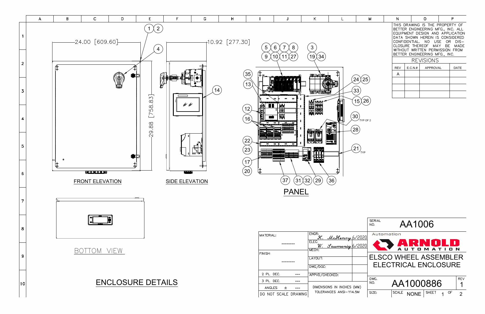
ENCLOSURE DETAILS
FRONT ELEVATION SIDE ELEVATION
PANEL
++ -
-
Adjust
DC OK
24V 10A
100-240V~ 5A 50-60Hz
L N
2.30
1 2
3419
14
5 6 7 8
9 10 11
12
13
15 26
16
17
20
21TYP
22
23
24 25
APPROVALE.C.N.#REV DATE
AA1006
ELSCO WHEEL ASSEMBLERELECTRICAL ENCLOSURE
AA1000886 11 2NONE
--------
--------
---------
A
27
28
29
30TYP OF 2
31 32
33
34
35
3637
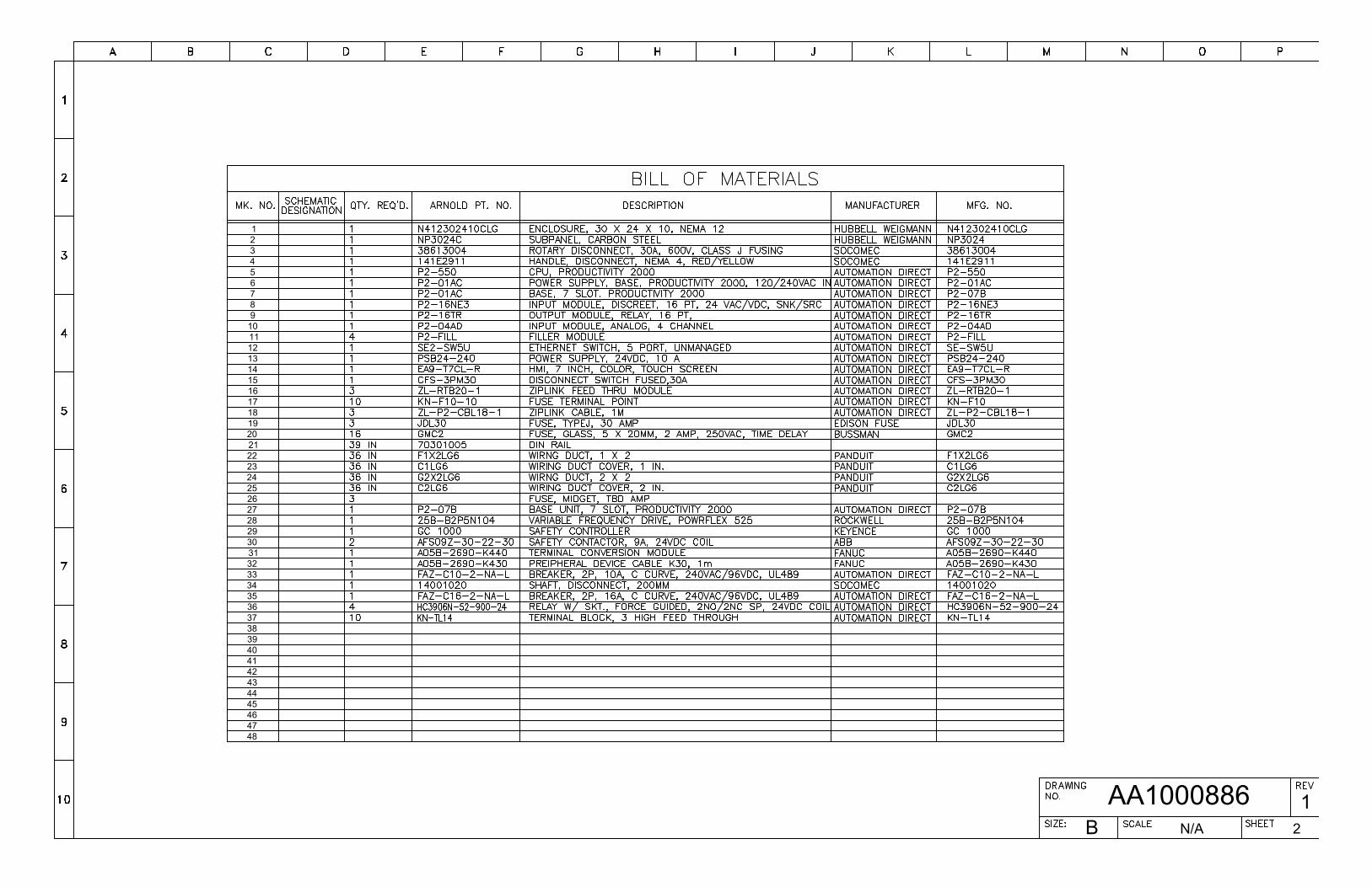
45
4748
46
9
27
41
36
3940
3738
4344
42
32
3435
33
3031
2829
18
23
262524
19
2122
20
10
1213
11
17
1516
14
876
1
5432
B 2N/A
1AA1000886
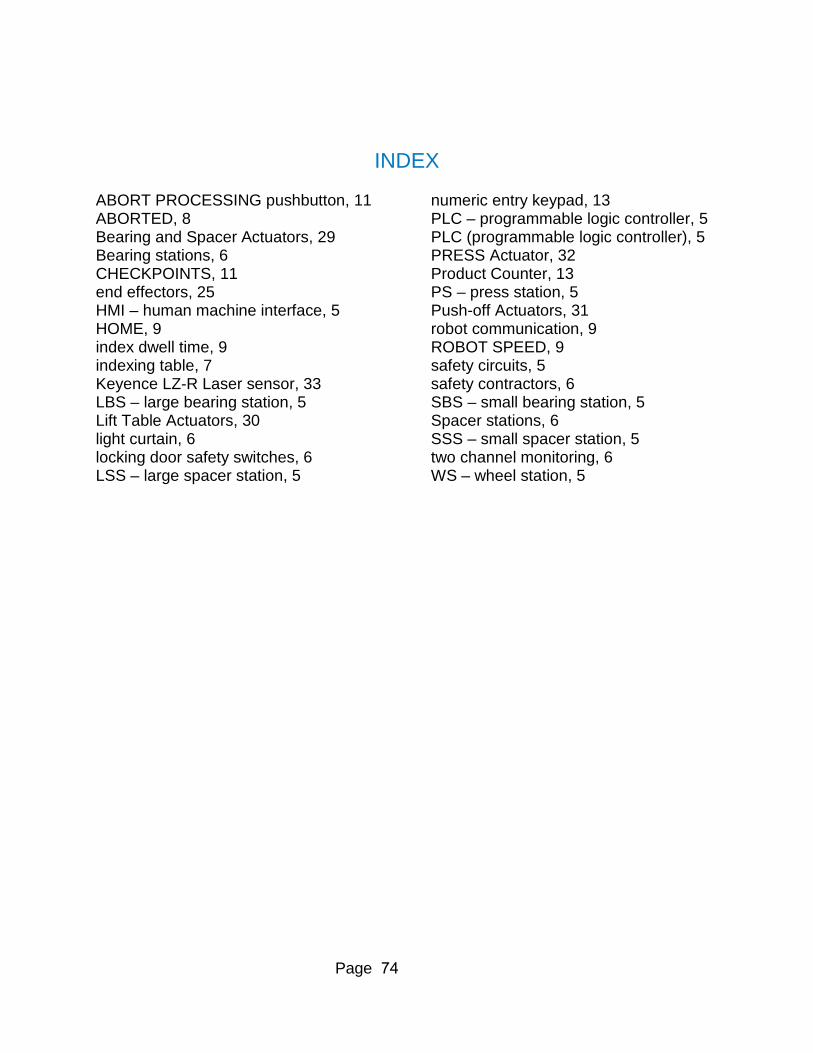
Page 74
INDEX
ABORT PROCESSING pushbutton, 11 ABORTED, 8 Bearing and Spacer Actuators, 29 Bearing stations, 6 CHECKPOINTS, 11 end effectors, 25 HMI – human machine interface, 5 HOME, 9 index dwell time, 9 indexing table, 7 Keyence LZ-R Laser sensor, 33 LBS – large bearing station, 5 Lift Table Actuators, 30 light curtain, 6 locking door safety switches, 6 LSS – large spacer station, 5
numeric entry keypad, 13 PLC – programmable logic controller, 5 PLC (programmable logic controller), 5 PRESS Actuator, 32 Product Counter, 13 PS – press station, 5 Push-off Actuators, 31 robot communication, 9 ROBOT SPEED, 9 safety circuits, 5 safety contractors, 6 SBS – small bearing station, 5 Spacer stations, 6 SSS – small spacer station, 5 two channel monitoring, 6 WS – wheel station, 5

Page 75
APPENDICES
Keyence LR-ZH Series Instruction Manual Keyence LR-TB5000 Series Instruction Manual Keyence G L-R Series -Safety Light Curtain Instruction Manual Keyence GS (Lock) Safety Interlocking Switch Instruction Manual Keyence PR-M/F Instruction Manual
