roland jv-90 owner's manual - synth db
TRANSCRIPT
Roland
EXPANDABLE SYNTHESIZER
jv-aaOWNER'S MANUAL

A CAUTIONHBK OF ELECTRIC SHOCK
DO ^0T OPEN AATTENTION; RiSOUE DE choc ELECmiQUE NE PAS QUUHIR
CAUTION: TO REDUCE THE RISK OF ELECTRIC SHOCK,
DO NOT REMOVE COVER (OR BACK).
NO USER-SERVICEABLE PARTS INSIDE.
REFER SERViCING TO QUALIFIED SERVICE PERSONNEL
AA
The lightning flash with arrowhead symbol, within an equiiat*
erai triangle, is intended to aiert the user to the presence of
uninsulated "dangemus voltage" within the product's enclo-
sure thai nnay be of sufficient magnitude to constitute a risk of
electric shock to persons.
The Bxciamation point within an equilateral triangle is intended
to alert the user to the presence of important operating andmaintenance (servicing) instructions In the literatute accompa-
nying the product.
JNSTRUCTIONS PERTAINING TO A RISK OF FIRE, ELECTRIC SHOCK, OR INJURY TO PERSONS.
IMPORTANT SAFETY INSTRUCTIONS
WARNING - When using eiectric products, basic precautions should always be fotlowed, including the following:
1
.
Read all the instructions before using the product.
2. Do not use this product near water — for example, near a
bathtub, washbowl, kitchen sink, in a wet basement, or near a
swimming pooi, or the like.
3. This product should be used only with a cart or stand that is
recommended by the manufacturer.
4. This product, either alone or in combination with an amplifier
and headphones or spealters, may be capable of producing
sound levels that could cause permanent hearing loss. Do not
operate for a long period of time at a high volume level or at alevel that is uncomfortable. If you experience any hearing loss
or ringing in the ears, you should consult an audioiogist.
5. The product should be located so that its location or position
does not interfere with its proper ventilation.
6. The product should be located away from heat sources such as
radiators, heat registers, or other products that produce heat.
7. The product should be connected to a power supply only of the
type described in the operating instructions or as marked on the
product.
8. The power-supply cord of the product should be unplugged
from the outlet when left unused for a long period of time.
9. Care should be taken so that objects do not fall and liquids are
not spilled into the enclosure through openings.
1 0. The product should be serviced by qualified service personnel
when:
A. The power-suppiy cord or the plug has been damaged; or
B. Objects have fallen, or liquid has been spilled onto the
product; or
C. The product has been exposed to rain; or
D. The product does not appear to operate normally or
exhibits a marked change in perfomiance; or
E. The product has been dropped, or the enclosure dam-aged.
1 1
.
Do not attempt to service the product beyond that described in
the user-maintenance instructions. All other servicing should
be referred to qualified service personnel.
For the USA
This product may be equipped with a polarized line plug (one blade wider than the other) . This is a safety feature, If you are
unable to insert the plug into the outlet, contact an electrician to replace your obsolete outlet. Do not defeat the safety purposeof the plug.
For Canada
For Polarized Line Plug
CAUTION: TO PREVENT ELECTRIC SHOCK, MATCH WIDE BLADE OF PLUG TO WIDE SLOT, FULLY INSERT.
ATENTION: POUR EVITER LES CHOCS ELECTRIQUES, INTRODUIRE LA LAME U PLUS LARGE DE LAFICHE DANS LA BORNE CORRESPONDANTE DE LA PRISE ET POUSSER JUSQU' AU FOND.
For the U.K.
IMPORTANT: THE WIRES IN THIS MAINS LEAD ARE COLOURED IN ACCORDANCE WITH THE FOLLOWING CODE.
BLUEBROWN
: NEUTRAL:LtVE
As the colours of the wires in the mains lead of this apparatus may not coirespond with the coloured maritings identifying the
terminals in your plug, proceed as follows:
The wire which Is coloured BLUE must be connected to the terminal which is marked with the letter N or coloured BLACK.The wire which is coloured BROWN must be connected to the terminal which is marked with the letter L or coloured RED.
^

Roland ly-gPEXPANnABLE SYNTHESIZER
Copyright © 1993 ROLAND CORPORATIONAll rights reserved. No part of this publication may be reproduced in any form without the written pemiissionof ROLAND CORPORATION.

INTRODUCTIONThank you for purchasing the Roland JV-90 Expandable Synthesizer. The JV-90 allows you to create a wide
variety of sonic textures by digitally manipulating the high-quality on-board sounds. By installing an optional
Voice Expansion Board, you can increase the number of sounds available and the instrument's maximum
polyphony. When fully expanded, theJV-90 is a versatile instrument that can be used forhve performances, studio
recordings and desk-top music applications.
To take full advantage of the JV-90's features and functions, please take the time to read this operation manual.
FEATURES
• Several Performance ModesThe Patch Play mode (Page 26) allows you to control different sounds m real-time, and the Performance Play
mode (Page 3 1 ) allows you to spontaneously control 8 Parts and MIDI channels. In addition, a number of Key
Modes can enhance any performance.
• Voice Expandability
If an optional Voice Expansion Board is installed, 28 voices and more sounds (Parts) are added to the 28 voices
abeady provided by the JV-90. (Page 102)
• A Selection of Several Waveforms
Not only will you find basic waveforms (sawtooth, square wave, pulse waves etc.), but a wide variety of unusual
waveforms are provided as well. (Page 55) By modifying these waveforms with FXM (Frequency Cross
Modulation) (Page 55), even more sophisticated sounds can be achieved. And by using optional PCM cards or
Wave Expansion Boards (Page 55), new waveforms can be added.
• Realtime Parameter Control
The JV-90's sliders and optional footswitches and pedals can be used to change the instrument's parameters in
realtime.
• Veloclty/Aftertouch Sensitive Keyboard
The JV-90's 76-note keyboard features Velocity sensitivity (Page 62) and Aftertouch sensitivity (Page 54); two
features which enhance any performance.

IMPORTANTNOTESIn addition to the items listed under Safety Precautions inside
the front cover, please read and observe liie following:
[Power Supply]
• Before connecting this unit to other devices, turn off the
powerto all units; thiswillhelppreventdamageormalfunction.
• Do not use this unit on the same power circuit with anydevice that will generate line noise; an electric motor orvariahle lighting system for example.
[Placement]
• Using the unit near power amplifier (or other equipmentcontaining large power transformers) may induce hum.
1 This devicemay interfere withradio and televisionreception.
Do not use this device in the vicinity of such receivers.
• Do not expose the tmit to temperature extremes or install it
near devices that radiate heat. Direct sunlight in an enclosedvehicle can defonn or discolor the unit.
[Maintenance]
• For everyday cleaiung wipe the unit with a soft, dry cloth or
one that has been shghtiy dampened with water. To removestubborn dirt, use a mild, non-abrasive detergent. Afterwards,
be sure to wipe the unit thoroughly with a soft, dry clotii.
• Never use benzene, thinners, alcohol or solvents of anykind, to avoid the possibility of discoloration and/or
deformation.
•When the batterybecomes weakthe following inessage will
appear in the display: "Internal Battery Low". Please changethe battery as soon as possible to avoid the loss of memorydata.
• Please be aware that the contents of memory may at times
be lost; when tiie unit is sent for repairs or when by somechance a malfunction has occurred. Important data should bestored on aRAM card, or written down on paper (ifpossible).
During repairs, due care is taken to avoid tiie loss of data.
However, in certain cases (such as when circuitry related to
memory itself is out of order), we regret tiiat it may not bepossible to restore die data.
About this owner's manualParameter names are often abbreviated in the instrument's
display. For example. Key Mode is abbreviate as 'Mode,' andChomsRateas 'ChoRate.' The ftillname ofdieparameter will
be used in the manual to avoid any confiasion.
If a parameter's value is continuously variable, it will beshown as being a number from —127. If, on the otiier hand,
a parameter value is selectable in discrete steps, those steps
will be shown as -100/-50/0/50/1O0 (for example).
Panel buttons are indicated within square brackets [ ]. such as
ECHORUSJ.
[Additional Precautions]
• Protect the unit from strong unpacL
• Never strike or apply snrong pressure to the display.
• A small amount of heat will radiate from the unit during
normal operation.
• Before using the unit in a foreign countiy, consult with
qualified service peraoimel.
• A small amount of noise may be heard from the display
during normal operation.
[Memory Backup]
• This imit contains a battery whichpowers ±e unit' s memorycircuits while ±e main (AC) power is off. The expected life ofthis battery is 5 years or more. However, to avoid the untimelyloss of memory data, it is strongly recommended tiiat youchange the battery every 5 years. Please be aware that the
acmal life of die battery will depend upon the physical
environment — especially the temperature— in which the
unit is used. When it is time to change the battery, consult with
qualified service personnel.
Regarding Screen DisplaysWhere possible, we will use the acmal screen displays for
explanations. Keep in mind, however, that the displays of
yourJV-90 may vary shghtiy depending on your inscruraeni" s

CONTENTSINTRODUCTION
FEATURES
IMPORTANT NOTES
CONTENTS
Chapter 1: Quick Start
Setup 12
Power On/Off 14
Playing the demonstration songs 15
Changing Patches (PATCH Play Mode) 16
Altering the sound on the JV-90 17
Playing Rhythm sounds (RHYTHM Play Mode) 18
Mixing different sounds
(PERFORMANCE Play Mode) 18
Using the three Key Modes
(Layer, Zone and Single) 19
Creating original sounds (EDIT PALETTE) 20
Write Procedure 21
Note on transmitting MIDI messages from the JV-90 (INT
ZONE, TX ZONE) 22
If stuck notes occur ... (PANIC) 22
Chapter 2: Performance and Realtime-Edit in
The Play Mode1. Patch Play mode 26
About the Palch Play mode 26
Operation guide 27
• How to use the TONE SWITCH buttons 27
• Use the edit assign buttons to select parameters 27
• Parameters you can adjust while in Patch Play mode 28
2. Perfonnance Play mode 31
About the Performance Play mode 31
Operation guide 32
• How to use the PART SWITCH buttons 32
• The Part Information function 32
Parameters accessible from Performance Play mode 33
• Performance play mode parameter list 35
3. Rhythm Play mode 37
About the Rhythm Play mode 37
How to select and modify parameters 37
4. Play mode 38
System Common parameters 38
• When Pressing [TUNE] 38
• When Pressing [CONTROL] 41
• When Pressing [MIDI] 42
• RX PART SWITCH 44
Effect parameters 45
• When Pressing [EFFECT] 45
Transmit a Program Change message 46
• When Pressing [PGM CHANGE] 46
Chapter 3: Details of the Edit Operations
1.Patch Edit mode 48
About the Patch Edit mode 48
Operation guide 48
• Patch editing procedure 48
• How to use the TONE SELECT buttons 49
About the parameters 50
• Parameters accessed by pressing [COMMON] 50
• Parameters accessed by pressing [EFFECT] 51
• Parameters accessed by pressing [CONTROL] 53
• Parameters accessed by pressing [WAVE/LFO] 55
• Parameters accessed by pressing [PITCH] 57
• Parameters accessed by pressing [TVF] 59
• Parameters accessed by pressing [TVA] 62
2. Performance Edit mode 65
About the Performance Edit mode 65
Operation guide - .-65
• Performance Edit procedure 65
Explanation of parameters 67
• Parameters accessed by pressing [COMMON] 67
• Parameters accessed by pressing [EFFECT] 68
• Parameter accessed by pressing [TX ZONE] 70
• Parameters accessed by pressing [ENT ZONE] 73
• Parameters accessed by pressing [PART] 75

3. Rhythm Edit mode 78
About the Rhythm Edit mode 78
Procedure, 7g
• Rhythm editing procedure 78
Explanation of parameters go
• Parameters accessed by pressing [EFFECT] 80
• Parameters accessed by pressing [CONTROL] 81
• Parameters accessed by pressing [WAVE/LFO] 82
• Parameters accessed by pressing [PITCH] 83
• Parameters accessed by pressing [TVFj 84
• Parameters accessed by pressing [TVA] 85
4. Commands 87
Write mode 87
Operation guide 87
Write, 88
•Copy 91
• Initialize 94
• Card 95
• Bulk (bulk dump) 96
• Protect 99
Chapter 4: Using a Voice Expansion Board1
.
Using a Voice Expansion Board
Using a Voice Expansion Board 102
• Modes 102
• Two Types of Voice Expansion Boards 102
• StiTJctureoftheVE-GSl 102
• Structure of die VE-A^l 103
• VE-GSl Maximum Polyphony 103
• The VE-GSl's Sound Parameters are Part Parameters 103
• When the value in die screen differs from that on the Voice
Expansion Board 103
• V-EXP MIDI IN Selector Switch 104
2. Using tiie VE-JV1 Voice Expansion Board
• Select the Voice Expansion Play Mode 105
• How to select the Part to be played from the keyboard .... 105
• How to change sounds in a Part 105
• How to edit the Sound Parameters of the VE-JV! 105
3. Using the VE-GSl Voice Expansion Board
• Select the Voice Expansion Play Mode 106
• How to select the Part to be played from the keyboard .... 1 06
• Part On/Off(play/mute) 1O6
• How to change sounds in a Part 1O6
• How to edit the sound parameters of the VE-GSI 108
• Other Editing Procedures ] 13
Chapters: REFERENCE1. Error Messages us
2. Troubleshooting 120
3. Waveform List 126
4. Preset Data 127
Internal, ^ 127
Preset A 127
Preset B ]28
Preset C 128
Preset D 129
JV-80 Compatible Preset a 130
JV-80 Compatible Preset b 130
Rhythm Set 131
JV-80 Compatible Rhythm Set 133
5. MID! Reference
Roland Exclusive Messages 134
MIDI Implementation I36
MIDI Implementation Chart 148
6. Index 150
7. Specifications 154

PANEL DESCRIPTIONS
The buttons on the JV-90's front panel function differently
depending on which mode {Patch/Performance/Rhythm/
Expansion) is currently selected. Therefore, always determine
which mode is selected before using the buttons. (See ModeButtons G)
Front Pane!
ED!T PALETTEA. Chorus Button, Reverb Button
These buttons turn the digital effects on and off.
B. TX Button, RX Button : Octave Buttons :
Part Select Buttons
Patch Mode : These buttons shift the pitch of the sounds being
played from the keyboard one octave up or down.
Performance Mode : These buttons determine how the Part Switch
Buttons (F) should function. You can transmit or receive MIDI data
and turn the Local Conu-ol setting on or off. (See page 32.)
Voice Expansion Mode : These buttons select Parts 1 - 8 and 9 - 1 6.
(Seepage 106.)
C. Edit Assign Buttons
In the Play mode of a Patch or Performance, or in Voice Expansion
mode, these buttons are used for selecting the parameter to be edited
and assigning it to a slider. The selected parameter can then be edited
by moving the slider.
D. Parameter Slider
Using this slider, you can continuously change the value of the
parameter currently selected when editing a sound or controlling an
externalMIDI device. Ifyoumove the slider while holding [ENTER]
(J) down, the cursor will move without the value being changed.
E. LCD (Liquid Crystal Display)
The display shows the currently selected sound, waveform, name or
value of the parameter being used, etc.
F.
Tone Switches 1 - 4
In the Patch Play or Patch Edit mode, you can turn Tones on and off
independently with the relevant button. When a Tone is on, the
corresponding indicator will light.
Tore Select Switches 1 - 4
In the Patch Edit mode, you can select the Tone to be edited using
these buttons.
Part Switches 1 - 8
In the Performance Play or Performance Edit mode, you can turn
specific Parts on and off, or determine whether or not to transmit/
receive MIDI messages. These buttons will function differently
depending on the settings. (See page 32.)
MODEG. Mode Buttons
These buttons are used to select the following modes:
Patch Mode ; This mode allows you to monitor or edit sounds. (See
page 26.)
Performance Mode : This mode allows you to play more than one
sound at a time, and therefore may be selected for desk top music
(DTM) applications. (See page 31.)
Rhythm Mode : This mode allows you to play percussion sounds.
(See page 37.)
Voice Expansion Mode : This mode should be used for playing (or
editing) the sounds on the optional Voice Expansion Board. The
parameters of a Roland GS sound module (connected via MIDI) can
also be edited on the JV-90's screen in this mode. (See page 106.)

TONE SWITCH
MODE
TONE SELECT
PERFOflMANCE PATCH HHYTHM ['"V^ExF
ErvfTEH
PEHFOFIMN-I
H
H.
INC/DEC Buttons
Using these buttons, you can change the value of the parameter
currently selected. Pressing [DEC] decreases the value while pressing
PNC] increases it. Ifyou press and hold [DEC], the value will changecondnually. Ifyou press [INC] while holding [DEC] down, the value
will change more rapidly.
Page Buttons ([A]/[T])
Use these buttons to change displays pages.
Cursor Buttons (N]/[^|)Use these buttons to move the cursor in the screen or select a
command.
I. EXIT Button
Press this button to cancel a procedure before it is completed.
Pressing the button will retrieve the previous display.
J. ENTER Button
Press this button to execute the selected command or function.
FUNCTIONK. FUNCTION Button
Use these buttons to select a function or parameter. The parameter
shown in the screen wiU depend on the mode cuirently selected.
FUNCTION PATCH GROUP
PATCH/V^EXP-PEflFORM»-
.* PEHTOHM
^ NUMBERPEWFORM
TUNE EFFECT CCWmrau PGM CHANGE
PATCH GROUPL. Patch Group Buttons
You can use these buttons together with the Bank and Numberbuttons (M) to select a sound. The sound group that can be selected
with the Patch Group buttons depends on the selected mode.
M. Bank/Number Buttons
Use these buttons to select a sound or name a Performance or Patch.

-PECia; HOLDTHRU OUT nv
!—A—"!* w t^ D •-E L.pJ G
Rear Panel
A.
Pedal Jacks 1 and 2
Connect an optional footswitch (e.g. FS- 1 , DP-2) or expression pedal
(EV-5 orEV-10) to these jacks. By assigning the specified function
to the connected footswitch or pedal, you can sustain a sound or alter
the tone, etc. (See page 54.)
Hold Pedal Jack
Connect an optional footswitch (e.g. FS- 1 , DP-2) to this jack and you
can use it as a hold (sustain) pedal. (See page 54.)
B. MIDI Connectors (IN/OUT/THRU)
These sockets are for establishing MIDI connections with external
devices. (See page 42.)
C. V-EXP MIDI !N Selector Switch (INT/EXT)
When using the MIDI IN of the V-EXP, set this switch to the EXTposition. When it is set to EXT, however, you cannot play the sounds
on the Voice Expansion Board (optional) from the JV-90' s keyboard.
Normally this switch should be set to INT. (See page 104.
)
D. V-EXP MIDI IN Connector
Use this socket forplaying the sounds on the Voice Expansion Board
(optional) via MIDI. When the V-EXP MIDI IN connector is being
used, be sure to set the V-EXP MIDI IN Selector switch to the EXTposition. (See page 104.)
E. V-EXP Output Jack (V-EXP OUTPUT)
Sound ofthe Voice Expansion Board (optional) is outputthrough this
jack. When the Voice Expansion Board is not connected to this jack,
no sound is output.
F. Output Jacks (MIX(INT) OUT)
Through these jacks, sounds can be output to an amplifier or mixer.
When the V-EXP Outputjack is not being used, the sound of the JV-
90 and that of the Voice Expansion Board (optional) are mixed and
sent through the MIX{1NT) OUT jack.
G. Headphone Jack
Connect headphones to this jack (Roland RH~20/80/120 (optional)).
Even when headphones are used, audio signals are output through the
Output Jacks.
H. Power Switch
This switch turns the JV-90 on and off.
I. AC Inlet
Connect the power cable to this inlet.
Versions of this product designed for use with 1 17V current do not
have an AC inlet.
They are instead equipped with a power cord that is permanently
attached to the unit.
J. DATA Card Slot
Insert an optional DATA card (e.g. M-256E) into this slot.
K. PCM Card Slot
Insert an optional PCM card (SO-PCMl Series) into this slot.

Side Panel
VOLUME PRESENCE CI
ABCMODULATION
A. Master Volume Slider
This slider controls the overall volume ofthe JV-90. When the VoiceExpansion Board (optional) is used, the volume of the sound output
through the V-EXP OUTPUT (L7R)jacks cannot be controlled withthis slider.
B. Presence Control
This controls the overall 'brightness' of the sound. Raising the slider
wiE brighten the sound. When the Voice Expansion Board (optional)
is used, the sound output from theV-EXPOUTPUT (L/R)jacks is not
affected by this control.
C. CI Slider
You can assign various parameters or functions to diis slider andchange the way the internal sound module will respond. (See page41.)
D. Bender/Modulation Lever
Using this lever you can obtain realtime pitch bend or vibrato effects.

10

Chapter 1
QUICKSTART

i.uuicKbiari
Setup
.PEDAL mXDTHfltJ OUT
I O O] [O } lo O
INT EXT _I i
MIDI Sound Source
CZl-I t 1
IMIIIIflllllPfllllllllffl
MIDI Keyboard
1
©i i
cana o C3c:C3C3Ca
ana
MIDI Sequencer
* Either padal switches or
expression pedals can beconnected to pedal jacfcs 1
and 2
Connection cable
{Optional : PJ-1M etc.)
Pedal switch
{FS-1, DP~2, etc.)
Pedal switch
(FS-1. DP-2, etc.)
Expression pedal
(EV-5, etc.)
OUTPUT
Stereo headphones{Roland RH-20, RH-80, RH-1 20, etc.)
To the AUX, LINE IN terminals
O
©n 1
o
©U|=
'i
^ffifl= =
= ll^J Hin!-hoa OOQD SJODOODnO
Stereo amp Stereo set, radio cassette player, ate.
12

Connect the MDCCINT) OUT jack on the rear of the JV - 90 to an amplifier/speaker setup (stereo set). You can also
connect stereo headphones to the PHONES jack.
To achieve the best results, use a stereo output when possible. For stereo use, cormeci two cables (L and R) to the
amplifier. For monaural use, use the JV - 90's L(MONO) jack only.
* You can use the V - EXP OUTPUT jack on the rear of the JV - 90 when a Voice Expansion Board (optional) is
Instailed.
If you connect a pedal switch or expression pedal to the HOLD or PEDAL jack on the rear of the unit, you can
sustain (hold) sounds, or control volume and tone using the foot pedal.
* You can connect a pedal switch (switch type) and e)qDresslon pedal (volume type) to the HOLD and PEDAL jack at
the same time.
Be sure to connect the pedal switch (switch type) to the HOLD jack.
13

Power On / Off
Switching on the JV - 90
1 . Check the following points before switching on theW - 90:
The external units (such as an amplifier) are correctly set up.
The volumes of the JV - 90 and the amplifier are set to minimum.
2. Switch on the JV - 90.
The LCD on the JV - 90 responds with :
EKPflNDRBLE SVNTHESIZERRoland J U - 9 9
3
.
Switch on the amplifier and raise the volume to an appropriate level.
4. Raise the volume of the JV - 90 with the VOLUME knob as you play the keyboard. Then press the [PRESET] and
NUMBER buttons in PATCH GROUP to check that the Patch selection function is working properly.
3t: The JV - 90 is equipped with a protection circuit. A brief interval (a few seconds) after power up is required before tiie
unit will operate normally.
* Tal<e care when setting volume levels; excessive levels can damage equipment and your hearing!
Switching off the JV - 90
1
.
Check the following points before switching off the JV - 90:
The volumes of the JV - 90 and the amplifier are set to minimum.
* Turning off the unit will instantly erase any sounds you have created. To retain this data, save it into memory as shown
in "Saving data" on page 88.
2. Switch off the JV - 90.
14

Playing the demonstration songs
1. Press [PATCH] while holding [LEVEL] in the EDIT PALETTE to select the Demo Song mode.
The screen will respond with :
ROMPLflV [Press ENTER/EXIT]
2. Press [ENTER], and the JV - 90 starts playing the demonstration songs. To stop playing, press [EXIT].
No. Title Song name Music / Copyright
1 Eldiablo W/EX 1 .Eldiablo Mitsuru Sakaue © 1993, Roland Corporation
2 Ada's Raveola 2.Ada's Raveola Adrian Scott© 1993, Adrian Scott
3 JV Demo 3.JV Demo Marvin Sandei^ © 1 993, Marvster Music
3. To exit the Demo Song mode and return to the normal mode, press [EXIT] while no demo song is playing.
* When the JV - 90 is in the Demo Song mode, tiie keyboard or panel buttons will not work.
* No perfomiance data of the demonstration songs is output from MIDI OUT.
Biographies of Composers
Mitsuru Sakaue
Mitsuru Sakaue began composing and doing arrangements for commercials and videos while still in school.
In particular, his studio work earned for him a solid reputation. Currently, he produces commercial musics and
jingles for FM stations.
Adrian Scott
Adrian Scott formerly handled the vocals and keyboards for the popular Australian group, "Air Supply." Since
following the solo path, he won the Silver Prize at the "World Song Festival Tokyo '84." Currently, he is involved
as a producer of commercial music and music for films. In addition, as a session player, he has performed along with
a number of Australia's top musicians, including John Famham and Kylie Minogue. He lives in Melbourne,
Australia.
Marvin Sanders
Marvin Sanders is a somewhat wacky Los Angeles composer whose work can be heard on projects for Toyota,
Acura, Max Factor, Alpine, Thomas Brothers, Theater for Young Audiences, and Michael Jackson. He has also
worked extensively with Roland, conducting clinics and writing music for numerous product videos and demos
including ROM - plays m the SC - 155 and JV - 880.
15

Changing Patches (PATCH Play Mode)
Many different Patches (sounds) have been preprogrammed into the JV - 90. Each Patch is created by setting
different values for the various parameters.
1. Press [PATCH] in MODE. The indicator will light and the Patch Play mode has been selected. It is from this
point that you select the various Patches.
2. Use die [PRESET], [A], [B], [C] and [D] buttons, and buttons [1]— [8] in PATCH GROUP to select the desired
Patch. The screen shows the name of tbe Patch you have selected. (See the Patch Table on page 127.)
PATCH GROUP
PRESET- j—
jW-E»P"
"21 C»"P~~1
1* - PCM CAHD - B
(IJ-EXPRHVT-
A B^~
i LQ-BANK-W
To select a Patch on a card or Expansion Board:
When you use any of the Roland PN - TVSO series cards, insert the card into the DATA CARD slot and press
[USER] and [CARD] in the PATCH GROUP (the indicators wiU light). Press BANK and NUMBER buttons to
select a Patch.
When you use any of the Roland SO - PCM series cards, insert the card into the PCM CARD slot and press [USER]
and [PCM CARD A] or [PCM CARD B] (the indicators will Ught). Press BANK and NUMBER to select a Patch.
When you are using any of die Roland Wave Expansion Boards (SR - JV80 series), press [W - EXP], [A], [B], [C],
or [D] in PATCH GROUP (the indicators will light). Select the Patch you like using the BANK and NUMBER
buttons.
When you are using a Roland Wave Expansion Board (VE - GSl or VE - JVl), press [V - EXP] in MODE, [V -
EXP] in PATCH GROUP (the indicators will light). Select the Patch you like using the BANK and NUMBER
buttons. K, however, the INT/ EXT switch on the rear of the unit has been set to the EXT position, no Patch on the
Voice Expansion Board can be played from the JV - 90's keyboard. Please read "How to change sounds in a Part"
(VE - GSl P.106 VE - JVl P.105) in detail of Patch selection.
* Before inserting a card or installing an Expansion Board, be sure that the JV - 90 is switched off.
16

Altering the sound on the JV - 90
Velocity and Aftertouch
The volume, pitch or timbre (tone quality) of a sound can be altered with the use of keyboard aftertouch. Aftertouch
effects are created by applying pressure to the keys after they have been played initially. (See Aftertouch on
page 54.)
Play softly Play strongly ^ Press down
Bender and Modulation Lever
Moving the lever to the left will lower the pitch of the sound, while moving it to the right will raise the pitch. This is
called the Pitch Bend effect. Pushing the lever forward (away from you) will create the Pitch Modulation effect. (See
page 54.) By moving the lever to the far left or right position and then pushing it forward, you will create both pitch
bend and modulation effects at the same time.
Modulation
Bend pitch down Bend pitch up
BENDER
CI Slider
By raising or lowering this slider, you can change the volume or the quality of the sound. How the sound changes
depends on the parameter settings. (See page 41.)
VQUIUE PP^ENCE Ct
— ji^^B —
Presence Control
By moving this slider you can change the brilliance of the sound. Raising the slider will brighten ti)e sound.
17

Playing Rhythm sounds (RHYTHM Play Mode)
1. Press [RHYTHM] in MODE (the indicator will light). This selects the Rhythm Play mode that allows you to play
various percussion sounds. A different instrument is assigned to each key of the keyboard, (page 131)
* Some keys do not have sounds assigned to them.
2. Press [PRESET] in PATCH GROUP (the indicator will light), then select a Rhythm Set by pressing [A], [B], [C]
or [D]. Sound assignment to the keyboard differs with each Rhythm Set.
Mixing different sounds (PERFORMANCE Play Mode)
In the Patch Play mode, you select and play one of die Patches. The Performance Play mode, however, allows you to
play more than one Patch at the same time. This combination of Patches is called a Performance. Many different
Performances are preprogranmied in the JV - 90.
1. Press [PERFORMANCE] in MODE (the indicator will light). This selects the Performance Play mode that
allows you to select any Performance you like.
2. Select a Performance using [PRESET], [A], [B], [C] or [D] and [1]— [16] in PATCH GROUP. The screen
shows the name of the Performance you have selected, (page 127)
3. Press [PRESET], [A] and [1] (the indicators will light), and the Performance named "Jazz Split" is selected. This
Performance contains a bass sound in the lefE section of the keyboard and a piano sound in the right section. That
is, it simultaneously uses a bass Patch and a piano Patch. You can even find Performances where two Patches are
played at the same time by pressing one key.
4. Press [PRESET], [A] and [16] (the indicators will light). The Performance named "PopOrchestra" is selected.
P E R F R M I P o p r c h e £ i r- a : P a r t L e m 9 1
Hi 6 fl 12 ! 127 1 127 1 i 17 1 12? ! 127 I 12? i 127
5. Pressing [ -^ ]/[ ] will move the cursor and change Patches. You can select 7 Patches and one Rhythm Set.
* The flashing underline in the display is called the "Cursor".
Using MIDI (page 42), you can automatically play the JV - 90 from a sequencer or computer. This may be usefiil
for ensemble performances with many different sounds.
* A sequencer is a device which records and plays MIDI data.
IR

Piay data
MIDI IN
Patch
Patch
Patch
Patch
Patch
Patch
Patch
Rhythm Sol ch.lO
ch.l
ch^
chj
ch^
Chi
ch.E
ch.7
"jPBjm
'MBH_ OUTPUT
As shown in the figure above, one Patch is assigned to each Part of the ensemble Performance. By changing Patches,
yon can make an ensemble Performance with the ideal sounds for each Part.
* By installing a Voice Expansion Board, you can increase the number of Parts available. {See page 1 02.)
6. When the indicator of the [LEVEL] button in EDIT PALETTE is lit. the screen shows the same display as in
step 4 above. Pressing PERFORM [PATCH] in EDIT PALETTE will then select the foUowing screen.
Patch name "1
PERFORM I Patch Select Pl=warr--i Uib^1=116 #fl4i IB14IB31 lfl35IB48iE;58!B73i fi
I t„ t—t—t
—
i
—\—
t
Pan 1 Part Z Part 3 Part 4 Part 5 Pan 6 Part 7 Part 8
Patch numbers — '
This screen shows the numbers and names of the Patches assigned to the 8 Pans. Move the cursor using [ -^ j/[ ] to
assign a Patch to each Part.
Using the three Key Modes (Layer, Zone and Single)
We have referred to three different Play Modes so far; Patch Play, Perfoiraance Play and Rhythm Play. The
Performance Play mode includes three different Key Modes. The two Performances (Jazz Split and PopOrchestra)
introduced on the previous page are played in different ways. This is because Jazz Split is set to the Zone Key mode
while PopOrchestra is set to the Single Key mode. The third Key Mode, Layer, can mix two different Patches.
* For a detarted explanation about the Key Modes, see page 67.
19

Creating original sounds (EDIT PALETTE)
A Patch is made from various parameters and consists of some Tones. A Patch on the JV - 90 can include up to 4
Tones, A Tone is made by modifying a Waveform.
'— I'p tci
1
1
Tone 1
WAVEFORM \ TVF M TVA
1
Tone 2
1Tone 3
1
Tone 4
-
Changing the values of sound parameters of a Patch is called "editing". The following shows a simple editing
method.
1. Press [PATCH] in MODE (the indicator will light). The Patch Play mode is selected.
2. Press [PRESET], [A], BANK [2] and NUMBER [2] (the indicators will light). The Patch named "Stack
Major" is selected. This Patch contains 4 Tones.
3. Press buttons [1]— 14] in TONE SWITCH to turn the 4 Tones on or off. Be sure to listen to each of the Tones.
The Patch will sound differently by turning the Tones on or off.
4. Make sure to confirm that the indicator on the EDIT PALETTE's [LEVEL] button is lighted. If it is not, press
[LEVEL] to turn it on. The screen at this time will show the volume level for each of the Tones. By altering the
level for each of rhe Tones, you can control their relative prominence within mixture. The resulting mixture of
differing volume levels will affect the timbre obtained with the Patch.
PATCH tStack MaJor s
fl22 4 127! 9€-TU!=l Leuel
113! 12?
5. Lighten 4 all TONE SWITCH indicators. Then move the cursor to the desired Tone using [ ^ ]/[ ], then
change the volume (TVA Level) of each Tone wiUi [DEC]/[INC]. Pressing [DEC] decreases the value while
pressing [INC] increases it. If you hold [DEC] down, the value will change continuously. If you press [INC]
while holding [DEC] down, the value will change more rapidly.

6. The volume of each Tone can also be edited by moving the sliders (PARAMETER SLIDERS) 1, 2, 3 and 4 in
EDIT PALETTE. If you move the slider while holding [ENTER] down, the cursor will move without the value
being changed.
7. Press PATCH [WAVE] in EDIT PALETTE (the indicator will light). The screen shows the waveform used in
each Tone. Move the cursor and try changing the waveform using the [DEC]/[INC] buttons or Parameter Sliders,
(page 126)
P fi T C H t b t a c k Major : < fl c P i a ft o 1 > U a mfl22 * ii 7 1 9 1
Pressing [ ] in this screen will select a sequence of different displays for editing other parameter values. You can
experiment with various sound changes by editing the values.
8. Similarly, you can select a different sound parameter display by pressing the relevant button in EDIT PALETTE,
and then editing the value. For a detailed explanation about how each parameter affects the sound, below
page 55.
* Sound data you have created here will be erased when the unit is switched off. if you wish to retain this data, save it
into memory using the Write procedure described beiow.
Write Procedure
To retain a sound you have made, store it into memory as explained below.
1. Press [WRITE]/[COMPARE] in FUNCTION.
2. Make sure that the cursor is positioned at Write, then press [ENTER]. If the cursor is not at the Write position,
move it using [ ^ ]/[ ].
3. Press [WRITE/COMPARE] agam while playing the keyboard. You can hear the new data and the old data that
exists at that place and compare them (Compare function). Writing new data will automatically erase the existing
sound data. Press [WRITE/COMPARE] again, new data sounds.
4. Specify the number where the data should be written using the BANK and NUMBER buttons. You can also
specify the number with the [DEC]/[INC3 buttons. We call the place where data is written the "User Area" or
"User Bank".
5. Press [ENTER], If the screen responds as follows, press [DEC] to turn OFF the Write Protect function, then
press [ENTER] again. Once more press [ENTER], the screen wiU respond with the message "Complete" showing
that the data has been saved.
W RITE i I n t e r n a 1 i E x c 1 u s i y ePROTECT I ONI OFF
* Write Protect is a function that prevents the accidental erasure of data.
* To cancel wri^ng, press [EXIT].
51

Note on transmitting MIDI messages from the JV - 90
(INT ZONE, TX ZONE)
Parameters of the JV - 90' s keyboard belong to either the Transmit Zone or the Internal Zone.
Some parameters in the Transmit and Internal Zone have the same names so you must be careful not to confiise
them.
To control an external MIDI device from the JV - 90's keyboard, you must edit the parameters (see page 70) in the
Transmit Zone, such as when you set a transmit channel or specify the range of note numbers to be transmitted.
To control the internal sound module of the JV - 90 with die JV - 90's keyboard, you must edit the parameters in the
Internal Zone (see page 73). Parameters in the Internal Zone include the Local Control Switch (see page 75) that can
be set separately for each Part. The Part for which this switch is set to OFF will not be played on the JV - 90's
keyboard (when die Key Mode (page 67) is set to the Zone or Layer). The internal Zone also includes Master Local
Control (page 43). Even when the Local Control is set to ON for a Part, it cannot be played on the JV - 90's
keyboard unless the Master Local Control is also set to ON.
When the JV - 90 is set to the Patch mode (page 26). you must set a MIDI transmit or receive channel using the
parameters in a Patch. (See page 42.) Setting a MIDI channel here will automatically cancel the previously specified
value of the parameter in the Performance (page 43) or Transmit Zone (page 72).
If Stuck notes occur „. (PANIC)
The following procedure will reset die entire system (including MIDI). Use this procedure to stop "stuck" or
"hanging" notes.
Procedure
While pressing [CUTOFF/TX VOLUME], press [RELEASE/INT TRANS].
CHORUS flEVEaaI
TX-UaCAL-nX l^reRFORM

If you press the buttons only for a short time (less than one second), the internal sound source will be muted, and
Key Off / Hold Off messages will be transmitted to each channel for which there is a Key On / Hold On. If you press
the buttons for more than one second, the following messages will be transmitted to all channels.
All Note Off (note off velocity 127)
Pitcfi Bender = center
Channel Aftertouch =
Modulation =
How = 10
Volume = 127
23


Chapter 2
PERFORMANCEAND REALTIMEEDIT
THEPLAYMODE

1. Patch Play mode
About the Patch Play mode
Patch Play mode is when just a single Patch is called into the temporary area and played. A Patch may consist of up to four Tones,
and you can use the parameter sliders and the TONE SWITCH buttons to adjust each Tone in realtime as you play.
By adjusting parameters in realtime you can add expression to your playing, or create effects that are not possible with convendonal
controller. This mode allows you maximum expressiveness with a single sound, and is suitable for playing solos, etc.
* Changes you make with the parameter sliders etc. will affect only the data that has bean read into ttie temporary area.
The originai Patch data in interna! memory {or the DATA card) will not change, if you wish, you can store the modified
settings from the temporary area as a Patch in th6 user memory. (See p.87, Write mode.]
Preset A
Preset Bnn
Preset C
Preset D
o-
Wave expansion board
PCM card
Operation
Internal
DATA cardu
r* TeiTiDorarv Area
Writing the data
Play data
MIDI IN
llo o]h 1—^RX CHi
Pjta
wis
I..
^LF01|
B><
iLFOaj
^WAVEFORM TVF — TVA
t-
PH
E
ch
JV
TVFENV J
0€I£OdHCHUZL
i.
EDTPAlfTTE
1(9 2/10 3ni Aim Sua 6/i4 7m Bjie
System commonparameter
Effector
CChoms
9 Reverb «\h
*
OUTPUT
TX CHo9 MIDI OUT
Operation guide
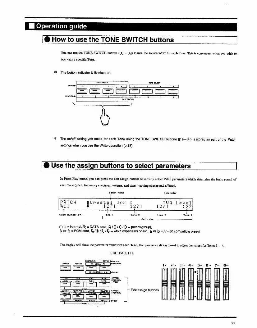
How to use the TONE SWITCH buttons
You can use the TONE SWITCH buttons ([1] — [4]) to turn the sound 00/08" for each Tone. This is convenient when you wish to
hear only a specific Tone.
* The button indicator is iit wlien on.
V
TONEBWnCK TONE SELECT
PATCHY1 ' - 1 1 . ^ 1
^n r^f^i l'=1 j=',r^-, f^npEiiranu^
! 1 ^ . 1
PART Switch
^rJ
* Ttie on/off setting you make for each Tone using the TONE SWITCH buttons ([1]— [4]) is stored as part of the Patch
settings when you use the Write operation {p.87).
Use the assign buttons to select parameters
In Patch Play mode, you can press the edit assign buttons to directly select Patch parameters which determine the basic sound of
each Tone (pitch, frequency spectrum, volume, and time - varying change and effects).
Patch name Parameter
PRTCH tCr-ystal y^ox :
"ill * 12?i 127! 127! 127
Patch number {*) Tone 1 Tone 2 Tone 3
Sot value
Tone 4
I
{•) U, = internal, It = DATA card, fl / B / C / D = preset(group).
Pft or % = PCM card, ^ / % / E^ / % = wave expansion board, a or b =JV - 80 compatibie preset
The display will show the parameter values for each Tone. Use parameter sliders 1—4 to adjust the values for Tones 1 —4.
EDIT PALETTE
OtORUS REreiffiI
TX-LOCJM,-HX I^PERFOnU
[^l^^AflT BEL - B-i^^ ^ tf-EXP
1 13 Sno 3l1 4"3 5"3 5"* 7"^ 8nB
££^- /V-iXP
JAMCi.i.i.— .ii. ....I —J
- Edit assign buttons
1
JL "

Parameters you can adjust while in Patch Play mode
In Ihe JV - 90, display screens in which you can modify parameters are called Pages. Each of the assign buttons has several pages
assigned to it, and by changing pages you can adjust various parameters in realtime.
When the assign buttons have been pressed, you can use [ A ]/[ ] to select the each parameters. You can modify these settings
while you play. For details on each parameter, refer to chapter 3 - 1 . (p.48)
Edtt
assign
button
Parameter selected
by[A]/[x]
Corresponding parameter of
Patch Edit mode See
PageFunction seiect
button
Parameter selected
byH/S
LEVEL
[AJTURLF0 2 DepthWAVE/LFO LFO DEPTH
A1 P.57
BTUflLFO 1 Depth A2 P.57
HTUflU-Ct-y
TVA
TVA
Crv P.62
B T U fl U e 1 S e n s e VbI P.62
TUfiLeMel Lev P.62
STUfi Key Fol low L-KF P.62
1 1 T n e Delay T i r-i eDELAY
Time P.63
1 1 T n e Delay M o d e Mode P.63
PAN
IaJ R e V e r- b S e n d
EFFECT FXSEND
Reverb P.51
[aJ C h r u = b e n d Chorus P.51
1 A 1 D r y L e 'v^ e 1 Dry P.51
PanTVA TVA
Pan P.62
1 I P a n Key F o 1 1 o w P-KF P.62
TUNE
HP itch LF0 2 DepthWAVE/LFO LFO DEPTH
P2 P.57
HP itch LFO 1 Depth P1 P.57
|a|P i tch Enye 1 ope
PITCH P!TCH
Env P.58
Coarse Tune Crs P.57
1 1 F i n e Tune Fin P.57
1 1 R a n d d v\ P i t c h Rnd P.57
H P i t c h f=. e y F U o w P-KF P.58
WAVE
l',l a ^' e
WAVE/LFO
WAVENo P.55
1 1 U a K> e G r- o u p Group P.55
HFXM SwitchFXM
Switch P.55
HFKM Depth Depth P.55

Edit
assign
button
Parameter selected
by)A|/jv|
Corresponding parameter of
Patcii Edit mode See
PageFunction select
button
Parameter selected
byH/H
CUTOFF
[AlTUFLFC!2DepthWAVE/LFO LFO DEPTH
F2 P.57
arUFLFO 1 Depth F1 P.57
L^ T U F - E n yU e 1 oS e n s e
TVF
TVF - ENV * Vel P.61
IaJTUF Enyelope
TVF
Env P.60
Cutoff Cut P.60
[iFi Iter Type Typ P.59
HCutof f Key Fol low F-KF P.60
RESO-
NANCE
R © s n a n c eTVF TVF
Res P.60
[JR e s- n a n G e M d e Mode P.60
ATTACK
H T U F - E n mK e y F 1 1 w
TVF TVF - ENV *
T-KF P.61
S T U F E n M e 1 p e T 4 T4 P.61
STUF Envelope L3 L3 P.61
HTUF Envelope T2 T2 P.61
HTUF Envelope Tl TI P.61
TUREnvelopeTi
TVA TVA - ENV *
TI P.64
STUfi Envelope 72 T2 P.64
STUfl Envelope L3 L3 P.64
HTUfl Envelope 14 T4 P.64
HTUfi-EnvKeyFol low Trme - KF P.64
RELEASE
H T U F - E n vK e yF o 1 1 o w
TVF TVF - ENV *
T-KF P.61
HTUF Envelope Ti TI P.61
IaJTUF Envelope T2 T2 P.61
[a]TUF Envelope L3 L3 P.61
HTUF Envelope T4 T4 P.61
T U fl E n V e 1 p e T 4
TVA TVA - ENV *
T4 P.64
STUfi Envelope L3 L3 P.64
STUfl Envelope T2 T2 P.64
STUfl Envelope Tl TI P.64
® T U fl - E r\ M K e y F 1 1 o w Time - KF P.64
Parameler setting displays marked by * occupy two screens in Patch Edit Mode,
29

* In Patch Play mode, MID! channels lor fe^nsmlssion and reception can be set independently. However, these settings
are detamined not by the Patch parameters, but rather by the System Common parameters. Thus, the MIDI channels
will not change when you select a different Patch. If you wish to change the MIDI channels, modify the System
Common parameters {p.42).
In Patch Play mode, it is possible to adjust the same parameter simultaneously for all four Tones.
In Patch Edit mode (p.48), which is explained later in this manual, the screen will show several
parameters for one Tone, so it may be difficult to keep track of the overall Patch.
For this reason, it is effective to use Patch Play mode for Patch editing when you wish to adjust the
balance between Tones, since this helps you to remain aware of the overall structure of the Patch.
^n
.nc;i luiiiiciiiuc? ridiy moae
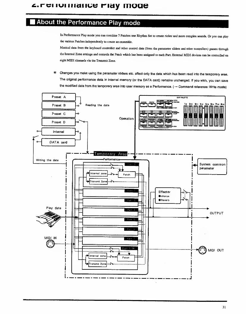
About the Performance Play mode
In Perfonnance Play mode you can combine 7 Patches one Rhythm Set to create richer and more complex somids. Or you can play
the various Patches independently to create an ensemble.
Musical data from the keyboard controUcr and other control data (from the parameter sUdci^ and other conU-ollera) passes through
the Internal Zone settings and controls die Patch which has been assigned to each Part External MIDI devices can be controlled on
eight MIDI channels via the Transmit Zone.
* Changes you make using the parameter sliders etc. affect only the data which has been read into the temporary area.
The original perfonnance data in Internal memory (or the DATA card) remains unchanged. If you wish, you can save
the modified data from the temporary area into user memory as a Perfonnance. (^ Command reference: Write mode)
OUTPUT
o o3 MID! OUT
31

Operation guide
How to use the PART SWITCH buttons
TONE SWITCH TONESElfCT
In perfonnance play mode, the PART SWITCH buttons C[l]— [8]) can be used to turn sequencer muting, or the transmit / receive /
local switches on / off for each Part. The function of the PART SWITCH buttons depends on the state of the EDIT PALETTE's
[TX]/iRX3 buttons:
When [TX] is lit MIDI transmit switch
Parts which are turned on will transmit musical data from the keyboard etc. from MIDI OUT to externa! MIDI devices, and Parts
which are turned off will not transmit data.
^When [RX] is lit MIDI receive switch
Parts which are mmed on will receive musical data from cxtemai MIDI devices connected to MIDI IN, and Parts which arc turned
off will not receive data.
When both [TX] and [RX] are lit ucai switch
Parts which are turned on will play their Patch in response to musical data from the keyboard etc., and Parts which are mmed off
will not play.
* Settings made using the PART SWITCH ([1]— [8]) and [TXl/ERX] buttons are stored as part of the Performance data
when you use the Write operation {p.87).
* When the Key Mode (p.67) is at SINGLE, settings tor the Transmit Switch and Local Switch will be Ignored. Only the
Transmit Switch and Local Switch tor the Part to which the cursor currently points will be turned ON.
The Part Information function
In performance play mode you can press the INFO ftinclion select button to see each type of MIDI data which is being received by
each Part from MIDI IN. To specify which type of MIDI messages will be displayed, use [ A ]/[ ]. The following types of data
can be displayed.
PERFORM i [PART INFORMATION] NpDdu I at i on11,61 * 8i 1 0t 81 SI 0i 0i S
Modulation Modulation 0—127
Messages that conu-ol vibrato (pitch modulation) or tremolo (volume modulation)
32

Volume Volume 0—127
Messages thai conirol Ihe volume level
Pan Pan l63—0—64r
Messages that control stereo positiDn
ExpressionI Expression 0—127
Messages that affect the character of the sound
Hold-1 Hold 1 ON/OFF
Hold pedal messages
Aftertouch Aftertouch 0—127
Aftertouch messages
Bender! Pitch bend change -64—+63
Messages that control c9ntmuous change in pitch
Voice the number of voices used 0—28The number of currently - sounding voices in the internal sound source (included voices used by paying the JV - 90 keyboard.)
* The number of voices will vary depending on the number of tones used to form a patch.For ever four voices used, " "
will appear in the display. " = " will appear when the total number of voices being used has exceeded 24.
* The display wiii show the actual data value of the fUiiDI message received. The actual result of the message may differ
from the displayed data value.
* The internal synthesizer sound source will not receive the type of fullDI message for which the Receive switch (p.43)
has been turned off. Also, Parts whose fwliDi Receive switch (p.32) has been turned off will not receive any MID!
messages from MIDI IN.
Parameters accessable from Performance Play modeEach edit assign button has several parameter pages assigned to it. This section explains the parameter settings for the page that
appears when you first press an edit assign button.
WAVE I
^P*TCH
/V-EXP
When pressing [LEVEL]PART LEVEL Part level 0-127
This parameter sets the level of each Part (relative to the value ofthe Patch parameter Level). If you do not need to adjust the volume
balance between Parts, it is best to set this to the maximum value (127).
When pressing [PAN]PART PAN Partpan L64 - o - 63R
This parameter sets the stereo position of each Pan.
33

When pressing [TUNE]Part Coarse Tune Part coarse tune -48—+48
This parameter adjusts the pitch of each Part in semitone steps. Positive (+) values will raise the pitch, and negative (~) values will
lower it.
PERFORM I M i 1 h: y 10 a y : Part Coarse TuneUl0i * 0! 1 0! 01 1 1 1
When pressing [PATCH]Patch Select Patch select
Thi s parameter selects the Patch (or Rhythm Set for Part 8) assigned to each Part.
PERFORM I Patch Select Pl^Cr-ystal Uoxu,01 iLi,n i"t62 11^.21 iiii36iUi3 6!iii36 1"il?! UI
* Use PATCH GROUP to select the Patch group and BANK^UMBER to select tiie bank/number. When you select a
Patch, ttie Patch name will appear in the upper right of the display.
* It is not possible to select PA/PB or EA -— ED Patch groups unless a PCM card is inserted or a wave expansion board
is installed.
For some t^es of boards or cards, not all Patch groups / bank numbers can be selected.
When pressing [TX VOLUME]Transmit Volume Transmit volume o— 127/oFF
These parameters adjust the volume of external MIDI devices.
PERFORM tMilky Way : Transmit Uolur-ieu>0i *OFFIOFF!OFFIOFFIOFF!OFF!OFF10FF
When pressing [TX PAN]Transmit Pan Transmitpan L64—0— bsr/off
These parameters adjust the pan of external MIDI devices.
PERFORM tMx Iky Way : Transmit Panti|01 tOFF I OFF 1 OFF lOFFI OFF I OFF! OFF 1 OFF
* If you have selected a Perfonnance whose Transmit Volume or Transmit Pan settings are OFF, the display will show
"OFF when you press [TX VOLUME] or \TX PAN]. However, H you then use the parameter sliders or [DEC]/[INC]
buttons to modify the setting, you will not be able to re - select "OFF. (P.72)
When pressing [TX TRANS]Transmit Transpose
ITransmit transpose -36~+36
This parameter transposes the Transmit Zone in semitone steps.
PERFORM tMilky Way : Tx
.
TransposeUiOl * 0! Si 1 01 0i 0! 0!
* if the Key Mode is Single (p.67), this setting has no effect.
34

^ When pressing [INT TRANS]lnt.Transpose
Iinternal transpose -36—+36
This parameter transposes the Internal Zone in semitone steps.
We recommend that you use the Part parameter "Coarae Tune' to adjust the character of the sound, and use this Transpose
parameter to make adjustments for playabiliiy.
PERFORM tMilky W-ay : Int , Tr-anspose^rSl # ! SI i Si ! 1 1
* The internal Zone processes the musica! data anci passes it on to the Part. The sound that actually results wi!t depend
on the Patch settings.
* if the Key Mode is Single {p.67), this setting has no eflect.
Performance play mode parameter list
When the assign buttons have been pressed, you can use [ A ]/[ ] to select the pages contammg the key range or velocity
parameters for the Transmit Zone and Internal Zone. You can modify these settings while you play. For details on each parameter,
refer to chapter 3 2, Perfonnance Edit Mode, (p.65)
Edit
assign
button
Parameter seiected
Corresponding parameter of
Patch! Edit mode See
PageFunction
seiect button
Parameter
seiected
Part Leyel Level P.751 PARTI
[J R e G e i u e C h a n n © 1 ( *
)
Receive Channel P.76
["lUo i G e Reser-Me (*) Voice Reserve P.76
S C h r u s S w i t c h { *
)
Chorus Switch P.76
1 LEVEL 1 [J R e y e r b S w i t g h ( *
)
ReveriD Switch P.76IPART!
l^lReGei ve P. C(*)Receive Program
ChangeP.76
[jReGeiMe Uolune(*) Receive Volume P.77
SReGei ve Hold-1 {*) Receive Hold -
1
P.77
|PAN| Part Pari 1 PARTI Pan P.75
ITUNEIP a r t C a r s- e T u n e Coarse Tune P.76
[(Part F i ne Tune1 PARTI
Fine Tune P.76
1 PATCH 1 P a t G h !i' e I e g t- 1 PARTI Patch Select P.75
35

Edit
assign
button
Parameter selected
byH/H
Corresponding parameter of
Patch Edit mode See
PageFunction
select button
Parameter
selected
I A 1 T r a n s fj i t P r o 9 r a nChangeTransmit Program
ChangeP.72
Tx
VOLUME T r a n s m i t U o 1 u p'i eITXZONEl
Transmit Volume P.72
!] T r- a n s m i t C h a n n e 1 Transmit Channel P.71
jA
j T r a n s n i tP r o 9 1- a rrC h a n 9 eTransmit Program
ChangeP.72
ITXPANIT r a n s rn i t P a n
ITXZONEITransmit pan P.72
[J T r a n s m i t C h a n ri e I Transmit Channel P.71
HTx.MaxUeloGity Max Velocity P.71
HTx.U-Crv Velocity Curve P.71
ITXZONEIIa{ T X . U e 1 b e n £ e Velocity Sense P.71TX
TRANS T X . T r a n s p o s e Transpose P.70
tzJ T X . R a ri 9 e L o w e r Key Range Lower P.70
ITXZONEI
[J T X . R a n 9 e Upper Key Range Upper P.70
Hint. Max Uelocity Max Velocity P.74
Hlnt.U-Cr-u Velocity Cun/e P.74
L*J I n t , t..t e 1 b e n s e Velocity Sense P.74INT
TRANS1 tNT ZONE
!
Int. T r a n s p o s e Transpose P.74
!! I n t . R a n 9 e L w e
r
Key Range Lower P.73
!! I n t .Range U p p e
r
Key Range Upper P.73
( * ) This parameter can also be accessed by the [PAN] in the Edit assign button.
* In addition to the parameters listed above, the JV - 90 has other parameters which are common to the entire
synthesizer sound source (System Common parameters) and are not specific to an individual Performance. Settings of
these parameters will not change even when you select a different Performance or enter a different mode, (p.38)

o.nnyinm nay moae
About the Rhythm Play mode
The JV - 90 synthesizer sound source has a Rhytiim Set (a set of rhythm sounds) for each memory; internal, preset A B C and D.
When you press [RHYTHM] you can play one of these Rhythm Sets from the keyboard controller.
If you are in Perfonnance Play mode when you press [RHYTHM], the Rhythm Set assigned to Part 8 of the Performance wiU be
selected. If you are in Patch Play mode when you press [RHYTHM], the Rhythm Set assigned to Part 8 of the last - selected
Perfonnance will be selected.
If you wish to play a different Rhythm Set, use the Patch group buttons to select the desired memory.
When you play the keyboard, the rhythm sound (Rhythm Tone) assigned to that key will sound. The 76 keys from El to G7 can be
assigned as key numbers.
* Page 131 lists the Rhythm Tones which were assigned to each key at the factory.
* Rhythm Sets cannot be played when the Local Switch for PERFORM MIDI (p.43) Is OFF.
* The transmit/receive channels for the Rhythm Play mode will be the same as the transmit/receive channels for Part 8 in
the Performance mode.
How to select and modify parameters
in Rhythm Play mode, the display of the synthesizer section will be as follows. The left side of the display will show the note name
and key number (Note Number) of the key that was pressed.
UI iSUitc-h I Group ! No i
6#2( 44) I OH! INT I 95<Clos.ed HflT 2)
At this time you can use the parameter sHders. [•<]/[ ]and [INC]/[DEC] to modify the values of the following parameters.
Switch Tone switch on/off
This parameter mms the currently selected Rhythm Tone ON (it will sound) or OFF (it will not sound).
Group! Wave group iNT/EXp/CARO
This parameter selects the memory from which the waveform of the Rhythm Tone will be taken: internal (INT), wave expansion
board (EXP), or PCM card (CARD).
No Wave number
This parameter selects a waveform from the specified wave group. The wave name of the selected number will be displayed in
parentheses ( ).
37

4. Play mode
System Common parameters
Press [TUNE], [CONTROLl, or [MIDI] to access the System Common parameters (parameters cormnon to the entire JV - 90).
Here we will explain the System Common parameters relevant to Patch Play mode and Performance Play mode. However, be aware
that modifications you make to these parameters will remain even if you select a difTerent Performance or Patch.
When Pressing [TUNE]
TUNES ! Tune I Transpose I LCD ! JU-LEUEL-E^-"^FUNCTIOH4440.0! OFFi 91 51 1271 12?
Tune Mastertune 427.4—452.6
This determines the overall mning of the JV - 90. The displayed value is the pitch frequency of the A4 key.
Transpose|Transpose on/off -36—+36
This transposes the entire JV - 90 in semitone steps. The setting to the left of the "|
" determines whether transpose will be used
(ON) or not (OFF). The setting to the right of the "j
" specifies the amount of transposition.
LCD LCD contrast o— 10
Tlus adjusts the contrast (brightness) of the display.
JV- LEVEL JV Level 0-127
This adjusts the output level of the internal sound source.
EX -LEVEL EXP Level 0-127
This adjusts the output level of the Voice Expansion Board. The value you set here will be invalid if the V - EXP MIDI IN Selector
on the rear of the JV - 90 is set to EXT.
TUNES: tScaie Tune i PowerUp i I
FUNCTION* OFF i DEFAULT i I
Scale Tune Scale Tune Switch on/off
Tunc it ON to use the scale tune feaWre, and OFF when it is not to be used.
PowerUpIPower up mode lastset/default
This specifics the condition the JV - 90 will be in when power is turned on.
LASTSET : The Patch or Performance last selected when the power was turned off will be
selected.
DEFAULT : Patch UI11 or Performance UI01 will be selected.
The pages telow are used for making the setting for Scale Tunc. The particular page that appears will be different depending on the
mode.

[From the Patch Play Mode]
TUHES t Hotel Tune!FUNCTIONI C! 61
Note Note c-B
Provides for selection of the note for which a Scale Tune setting is to be made. The note can be specified by simply pressing
keyboard key.
Tune Scale Tune -64 to +63
Sets the pitch of the specified note in steps of 1/100 of a semitone.
[From the Performance Play Mode]
TUHE& tFUHCTIOHI Si 91
Scale Tune C1 1 !
Scale Tune Scale Tune -64 to +63
The note for which a Scale Tune setting is to be made is specified by pressing a keyboard key. The pilch of the specified note can be
set in steps of 1/100 of a semitone, for each Part
39

• The Scale Tune Feature
The scale Tune feature allows you to finely adjust the individual pitch of the notes from C through B. Through the settings
are made while working with one octave, the fine adjustments will affect all octaves. By making the appropriate Scale Tune
settings, you can obtain a complete variety of tuning methods other than equal temperament.
O Equal Temperament
This method of tuning divides the octave into 1 2 equal parts. It is currently the most widely used form of tuning, especially
in occidental music. On the JV - 90, equal temperament is used whenever Scale Tune is OFF.
O Just Temperament (Keytone C)
The three main chords resound much more beautifully than with equal temperament, but this benefit can only be obtained in
one key. If transposed, the chords tend to become ambiguous. The example given involves settings for a key in which C is
the keynote.
O Arabian Scale
E and B are a half of a semitone lower than equal temperament, whereas C#, F#, and G# are a half of a semitone higher in
this method of mning. The intervals G-B, C-E, F-G#, A#-C#, E)#-F# arc a neutral third (interval between a major third and a
minor third). On the JV - 90, the Arabian Scale can be enjoyed with the three keys of G, C, and F.
[Example Setttings]
Note Equal TemperamentJust Temperament
(Keytone C)Arabian Scale
C -6
C# -8 +45
D +4 _2
D# +16 -12
E -14 -51
F -2 -8
F# -10 +43
G +2 -4
G# +14 +47
A -16
A# +14 -10
B -12 -49
40

When Pressing [CONTROL]
These sellings detenninc the parameters which will be controlled by foot pedals connected to pedal jacks 1 and 2 and by the CI
slider.
PEDHLlfiSSISN
ModelI + MI CC?.
fissign KUal : 0>UOLUME! I
Model Output mode off/int/mid!/i+m
This setting determines the destination of the control messages sent by the pedals or the CI slider. When INT is selected, the
messages will be sent only to the internal sound source. When MIDI is selected, the messages will be sent only to MIDI OUT. When
I+M is selected, the messages will be sent to both the internal sound source and to MIDI OUT. When OFF is selected, the pedals
and the CI slider will not transmit any messages.
ffl
IFoot Pedal 1 CI slider
Foot Pedal 2
INT_ Internal
sound
source
I+M
MIDI OUT
MIDI
Assign|Assign CC0-CC95/AFTERTOUCH/BEND-UP/BEND-DOWNff'ROG-UP/PROG-DOWN
These settings detennine Ihe parameters which will be controlled by the pedal or CI slider. CCO—CC95 are control change
numbers - 95. BEND - UP / BEND - DOWN indicates pitch bend up and down. PROG - UP / PROG - DOWN will select the next
highcrorlowerPerformanceorPatch. The value in parentheses ( ) indicates the current position of the pedal or CI slider.
PEDAL POLARITY pages
PEDAL t Pedal 1 i Pedal 2 I Hold I
POLflRI TV*STflNDflRD i STflNDflRD i STflNDFlRD I~
PEDAL1 PEDAL2 HOLD STANDARD/REVERSE
These settings allow the polarity of pedal switches connected to the pedal jacks 1/2 or the hold pedal jack to be reversed so as to be
compatible with the JV - 90. When using a Roland pedal switch (DP • 2) set this to STANDARD.
If you are using a reverse - polarity pedal switch made by another manufacturer (e.g., if the sound is held even when the pedal
switch connected to the Hold Pedal jack is not pressed), set this to REVERSE.
41

AFTER TOUCH page
AFTER t Thresh I
TOUCH 1 101
Thresh Threshold 0—127
This sets the level (threshold level) al which afteitouch will begin to function. If the afteitouch value does not reach this level,
aftertouch will have no effect. If this Threshold setting is set to 127, aftertouch will not function at all.
Volume 127
A 127*" ^^^ touch strength
Aftertouch threshold
When Pressing [MIDI]
For some types of board or card, not all Patch groups / bank numbers can be selected.
[ When in Patch Play mode ]
PfiTCH i Local!MIDI * ONI
Rx-Chl1 1
Tx-Ch
1
Rx-Chl
Local Local switch on/off
The internal sound source will produce sound in response to musical data from the JV - 90 itself when this is ON, and will ignore
such data when this is OFF. This setting does not affect MIDI transmission or reception.
Rx-Ch Patch receive channel 1~16
This sets the receive channel for Patch Play mode.
Tx-Ch Patch transmit channel i — 1 6/Rx - Ch/OFF
This sets the transmit channel for Patch Play mode. When this parameter is set to "Rx - Ch", the transmit channel will be the same
as the receive channel. When this is set OFF, data will not be transmitted.

[ When in Performance Play mode ]
PERFORM I
M I D
I
*Local iCtf-i"Chi
ONI 16 1
Local Local switch on/off
The internal sound source will produce sound in responBC to musical data from the 3V - 90 itself when this is ON, and will ignore
such data when this is OFF. This setting does not affect MIDI transmission or reception.
Ctrl-Ch Control channel 1— leraFF
This setting specifies the chaimel on which Petfonnances will be selected. (This is separate from (and in addition to) the
transinit/i«ceive channels for each Part in the Performance.) If this setting is the same as the receive channel setting for one of the
Parts in the Performance, Performance selection will take priority. When this is set OFF, transmissionAeception wiU take place.
* The MIDI transmit/receive channels tor each Part are detemiined by the Perfomnance parameters.
TRANSMIT MIDI, RECEIVE MIDI pages
RECEIUE tP. CiBnk ICC iUol IBend I Mod I flft I
MIDI * ONI ONI ONI ON! ONI ONI ON!--
P.C Bnk C.C Vol Bend Mod Aft ON/OFF
These settings specify whether each type of MIDI message will (ON) or will not (OFF) be transmitted/received. The various types
of message arc abbreviated as follows.
P.C Program change Bend Pitch bender
Bnk Bank select Mod Modulation
C.C Control change Aft Aftertouch
Vol Volume
43

SYS -EX MIDI page
SVS-EX tReceiveiDey. IDiMIDI I ONi 17!
Receive Exclusive receive switch on/off
This setting turns on/off reception of MIDI data specific to the JV - 90 (such as Performance or Patch data).
Dev. ID Device ID number 17—32
When you wish to transmit or receive exclusive messages, set this parameter to match the device ID number of the other MIDI
device.
RX PART SWITCH
This selects whether or not to recognize the MIDI messages received through MIDI EN for each Part in JV - 90's internal sound
module or Voice Expansion Board. Move the cursor with [ ^ ]/[ ] to select a Part, then select 1 or with [INC]/[DEC| (1 is to
recognize and is to ignore). The Part where is set will be muted.
^ When the JV - 90 is set to the Performance Mode, changing the value also changes the MIDI Receive Switch (Page 32)
automatically.
^ When the JV - 90 is set to the Patch mode, the Part of the Voice Expansion Board (Page 106) that has the same
receive channel as ^e receive channel (Page 42) of the Patch is shown with an arrow " i".
* When the V - EXP MIDI IN Selector Switch is set to EXT, the Voice Expansion Board will be played with the MID!
messages received on the V - EXP MIDI IN. The MIDI messages received through MIDI IN, however, will be ignored by
the Voice Expansion Board. (Page 104)
4-4

Effect parameters
These parameter determine effect imit settings (choniaA^verb) for the currently selected Patch or Performance.
* In Rhythm Play mode, the following operations are not possible.
When Pressing [EFFECT]
In Patch Play mode, these settings modiiy Patch effect parameters. In Performance Play mode, these settings modify Performance
effect parameters.
PATCH IChorate ! Depth I Rev-Leu I TineEFFECTS I 201 29 1 199! 89
ChoRate Chorus rate 0—127
This parameter sets the modulation speed for the chorus effect
DepthIChorus depth 0—127
This parameter sets the modulation depth for the chorus effect
Rev -Lev Reverb level 0—127
This parameter sets the volume of the reverb.
Time Reverb time 0—127
This parameter sets the reverberation time.
* When using chorus/reverb, press [CHORUS]/[REVERB} to turn the effect on.
45

Transmit a Program Change message
Here you can speciiy a program change message to be transmitted directly.
When Pressing [PGM CHANGE]
TRANSMIT P.C page
TRflNSMITI Tx-ChI P.C-No I Bnk -MSB i Bnk -LSBP.C I 1 ! 081 /fill I 1
Tx-Ch Transmit channel 1— 16
This parameter determines the MIDI channel on which Program Change messages will be transmitted.
P.C -No Program change number ooi/Aii — 128/B88
specify the program change that will be transmitted on the Tx - Ch.
The display will show the number in the format of "program change number / group - bank - number.
The PATCH GROUP / BANK / NUMBER indicators will light to show the selected program change number.
Press [ENTER] to transmit the program change message.
* When the cursor is located at the program change number display, you can directly enter a number from 001 — 1 28.
The BANK [1]— [8] buttons will enter the numerals 1 —8, and the NUMBER [\y[2] buttons will enter the numerals 9/0.
Input the desired program change number, and press [ENTER] to transmit the program change message.
1l -«a*NK-4 PEflFdRM
'i' ""K HUuaEB4PERF0IUI
/*! SPACE , .
When the cursor is located at the group/bank/number display, you can use the PATCH GROUP / BANK / NUMBER buttons to
specify the program change number.
Bnk-MSB/Bnk-LSB Bank select number eacho— 127
specify the MSB (control change #0) and LSB (control change #32) of the Bank Select message to be transmitted from the Tx - Ch.
* The Bank Select message will be transmitted at the same time that the Program Change message is transmitted.
* For information on the correspondence between the JV - 90's Patch Groups (Media) and Program Change and Bank
Select numbers, refer to the "MIDI lmplementation''(p.136).
46

Chapter 3
OF THEEDITOPERATIONS

1. Patch Edit mode
About the Patch Edit mode
Each Patch is made up of four Tones. Each Tone has various Tone parameters which determine the character of the
sound (pitch, frequency spectrum, loudness, and how these factors change). Tone parameters for the four Tones, a
Patch name, and effect unit settings used in Patch Play mode are collectively called "Patch parameters". The process
of modifying Patch parameter settings is called "Patch editing".
The sound produced by each Tone passes through several stages to create the final result, and function select buttons
have been assigned to access the parameters for each of these stages.
Operation guide
Patch editing procedure
In Patch Play mode, select the Patch you wish to edit Then press [EDIT] to enter Patch Edit mode. Then press one
of the function select buttons to select the desired Patch parameter.
EFFECT COMTHOL PBU »«UQE
- Function select buttons
In Patch Edit mode, the following type of pages will appear in the display.
[Example]
PATCH t T y p e i L e V 1 R a t I D e p ! F b k i u t i
CHORUS *CH02!127 1 1111251 99 1 REU
i
i i 4 i i 4
1/s 2na 3ni 4n? Sna fi/n 7/ib B/ie
Parameter slider
The values from left to right correspond to parameter sliders 1— 8. Move the parameter slider (or [DECJ/flNC])
corresponding to the parameter you wish to modify (p.6).
For pages in which " f " or " |- " is displayed, you can use [A ]/[ ] to select other pages (p.7).

How to use the TONE SELECT buttons
The TONE SELECT buttons are used in Patch Edit mode. For parameters which can be set individually for each
Tone (1 - 4), the display will indicate (for example) "1 ". This display indicates the number of the Tone
which is currently selected. Use the TONE SELECT ([1] - [4]) buttons to select die Tone to display and edit.
PATCH1 T
PERFDHU^[
You can also press two or more TONE SELECT buttons simultaneously. The display wiU indicate the number of die
last - selected Tone, and other selected Tones will be indicated by " * ". In diis condition, ftmher adjustments you
make to a parameter will set the same value for all selected Tones.
49

About the parameters
In this section we will explain the main parameters for each button, and how the parameters work. Press a function
select button, and then use [A ]/[ ] to select pages.
Parameters accessed by pressing [COMMON]
Here you can make settings for parameters that are common to the entire Patch.
PATCH NAME page
Patch nameIspace.A—2.a—z,i— 9,o, + -'/#i,.
You can give a 12 - character name to the Patch you are editing. Use parameter slider 2 or [ ^ ]/[ ] to move the
cursor, and use parameter slider 1 or [INC]/[DEC] to select a character at the cursor location.
Characters can also be selected using the BANK/NUMBER buttons. (Characters and symbols are printed in grey on
the lower right of the buttons.)
The three characters or symbols will alternate each time you press the button.
CAPS : This button switches between uppercase and lowercase ietters. When the indicator is
lit, uppercase ietters will be selected.
SPACE: This button enters a space.
PATCH COMMON page
Level Patch level 0—127
This parameter sets the level (volume) of the Patch.
PanIPatch pan L64—0— 63R
This parameter sets the pan position.
Velo -Sw Velocity range switch on/off
The velocity range setting will be valid when this is ON.
VELOCITY RANGE page
Tone 1 Tone 2 Tone 3 Tone 4 each 0—127
These parameters set the velocity range (lower/upper) for each Tone. Lower range is displayed at left, and die upper
range at right. The velocity values surrounded by the lower and upper settings are the Velocity Range,
The velocities in its specified range is valid.
* It is not possible to set the Lower value above the Upper.
50

Parameters accessed by pressing [EFFECT]
These parameters determine the settings of the built-in effects unit when a Patch is selected in Patch Play mode.
The effect settings apply to the entire Patch. The effects unit provides a wide range of possibilities, from deepening
and enriching the sound, to radical transformations of the tonal character.
* In Performance Ray mode, the effecte unit will use the settings of the Perfoimance.
FX SEND (effect send) page
DryIDrylevel 0—127
This parameter sets the level of the dry (unprocessed) sound.
Chorus Chorus send level 0—127
This parameter sets the level of the signal sent to the chorus.
Reverb Reverb send level — 1 27
This parameter sets the level of the signal sent to the reverb.
PATCH CHORUS page
Type! Chorus type choi— 3
This parameter selects the type of chorus effect.
CHOI
CH02
CH03
A conventional chorus.
A chorus with slower rate. You can also apply feedback to use this as a danger.
A chorus with greater depth. An effect of extreme detuning can be produced.
Lev Chorus level 0—127
This parameter sets the level of the chorused sound.
Rat Chorus rate o~ 1 27
This parameter sets the modulation speed of the chorus effect.
Depl Chorus depth 0—127
This parameter sets the modulation depth of the chorus effect.
Fbk Chorus feedback 0—127
This parameter sets the level at which sound is fed back into the chorus effect.
* Excessively high settings of Fbk can distort the sound.
51

OutIOutput switch MiX/REv
This parameter determines the output destination of the chorused sound. When MIX is selected, the chorus sound
and the reverb sound will be mixed with the dry signal. When REV is selected, the chorus sound will be sent through
the reverb and then mixed with the dry signal.
MIX REV
IN
Reverb
Chorus ^ OUT IN
Chorus
e- Reverb ^ OUT
PATCH REVERB page
TypeIReverb type roomi —2/stagei—2/halli— 2/delay/pan - dly
This parameter selects the type of reverb.
R00M1 short reverb with dense reverberation
R00M2 short reverb with sparse reverberation
STAGE1 reverb with more late reverberation
STAGE2 reverb with strong early reflections
HALL1 clear reverb
HALL2 rich reverb
DELAY conventional delay
PAN - DLY delay with echoes panned left/right
Level Reverb level 0—127
This parameter sets the level of the reverb sound. Higher values will result in a louder level.
Time Reverb time 0—127
If Reverb Type has been set to ROOM! — HALL2, this parameter determines the length of the reverb. If Reverb
Type has been set to DELAY/PAN - DLY. this parameter determines the delay time.
F-Back Delay feedback o~i27
If Reverb Type has been set to DELAY, this parameter determines the level at which the delayed sound will be fed
back into the delay.
ANALOG FEEL page
DepthIDepth 0—127
This parameter sets the depth of the Analog Feel effect, which applies "1/f modulation" to level and pitch to give
greater "naturalness" to the sound (ie., make it sound less digital). Higher settings will result in more modulation.

Parameters accessed by pressing [CONTROL]
Here you can make settings for the JV - 90 keyboard and controllers.
KEY ASGN & BEND RANGE (Key Assign & Bend Range) page
Assign|Assign mode poly/solo
This parameter determines whether the Patch will be polyphonic (POLY) or monophonic (SOLO). If POLY is
selected you can play chords, and if SOLO is selected, only the last - played note will sound.
Legato I Legato on/off
This parameter determines whether the Legato function will be applied (ON) or not (OFF). Even if Legato is ON, it
will not function if the Assign Mode is POLY.
Legato : The envelopes and LFO of the previous note continue. This allows you to simulate the
hammer - on/pull - offplaying technique ofa guitarist.
Bender -RangeIBenderrange -48~o(down)/o— i2(up)
Bend Range Down determines how far (In semitone steps) the pitch will fall when the bender lever is moved to the
left. Bend Range Up determines how far the pitch will rise when the bender lever is moved to the right.
PORTAMEIUITOpage
Portamento: Portamento is as effect in which the pitch changes smoothly between notes. In
Solo mode, it is appropriate to apply Portamento to guitar and wind instrument
sounds.
Switcli Portamento switch on/off
This determines whether portamento will be applied (ON) or not (OFF).
Wlodel Portamento mode legato/normal
This determines how the portamento effect will be applied. When NORMAL is selected, portamento will always be
applied. When LEGATO is selected, portamento will be applied only to notes played in legato style (i.e., when you
play a note before releasing the previous note).
Type! Portamento time time/rate
This determines the type of the portamento effect. When TIME is selected, the pitch will move to the new pitch over
a specific time regardless of how far apart the two pitches are. When RATE is selected, the pitch wiU move to the
new pitch at a specific rate, so that it will take longer to reach a more distant pitch.
Time Portamento time 0—127
This determines the lime over which the pitch will move to the new pitch.
PEDALS page
Voiume Volume control switch on/off
This determines whether MIDI Volume messages will be received by the Tone (ON) or not (OFF),
53

Hold - 1 Hold 1 Control Switch on/off
This parameter determines whether Hold 1 (sustain) messages from HOLD / PEDAL 1 / PEDAL2 / CI slider will
(ON) or will not (OFF) affect the Tone.
Re -DampIRe -damp switch on/off
If a Hold 1 message is received after key - off while notes are still sounding, this parameter determines whether the
sound at that time will be held (ON) or not (OFF).
* if Hold - 1 is OFF, Re - Damp wili have no effect even if it is turned ON.
* The MIDI specification defines control change #7 as volume and control change #64 as Hoid 1
.
CONTROL page
Modulation Modulation control
You can specij^ up to 4 Tone parameters to be controlled by modulation messages.
Aftertouch Aftertouch control
You can specify up to 4 Tone parameters to be controlled by aftertouch.
Expression|Expression control
You can specify up to 4 Tone parameters to be controlled by an expression pedal.
The Tone parameters that can be controlled and the ranges of control are given below.
Destination (parameter to be contralled)Depth
(setting range)Remarlcs
Display Meanins
PCH pitch (semitone) _63— +63
The parameter will increase (rise) for positive
(+) values, and decrease (fall) for negafive
(— ) values
CUT cutoff frequency -63— + 63
RES resonance -63 h63
LEU level (volume) -63 h63
PL! depth of LFO 1 applied to pitch ~63~+63
Positive (+} and negative ( — ) values invert
the phase of the LFO. In either case, values
diverging from wili have an increasingly
greater effect.
PL2 depth of LFO 2 applied to pitch -63— +63
FLi depth of LFO 1 applied to cutoff -63— +63
FL2 depth of LFO 2 applied to cutoff -63— + 63
RLi depth of LFO 1 applied to volume -63 h63
RL2 depth of LFO 2 applied to volume -63 !-63
LIR rate of LFO 1 -63— + 63 With positive (+) values the LFO cycle will be
shortened, and with negative ( — ) values the
cycle will be lengthened. (See diagramL2R rate of LFO 2 -63 h63
* The MIDI specification defines Expression as control change #11 and Modulation as control change #1. The JV-90
transmits Modulation messages when you move the bender/modulation lever away from you. Pedal 1 ,pedal 2 and the
CI slider will each transmit the MIDI message that has been assigned to them. For details refer to the MIDI
Implementation chart.

Parameters accessed by pressing [WAVE/LF01
These parameters select the waveform (the basic element of sound) and determine the LFO settings.
WAVE page
Switch Tone switch on/off
This parameter determines whether the currently selected Tone will be used (OP^ or not used (OFF). Voices will be
used only by Tones for which this parameter is turned ON.
GroupIWave group int/exp/card
This parameter determines which memory the waveform will be taken from. The JV - 90 has 152 wavefonns in
internal memory (INT). In addition, you can also use waveforms from optional wave expansion boards (EXP) or
PCM cards (PCM).
• Inserting a PCM card
When you wish to use PCM card waveforms,
insert ttie PCM card into tfie PCM card slot on
the rear panel. Make sure the product name
printed on the card is facing upward. Push the
card carefuiiy all the way into the slot.
* The actual design of the card will differ from
the illustration.
No Wave number
This parameter determines the waveform number.
* The display will show only the memory numbers which can be read.
FXM page
FXM modulates the waveform by a different waveform (i.e., applies cross - modulation) to create a new waveform.
SwitchIFXM (FrequencyX - Modulation) switch on/off
This parameter determines whether FXM (Frequency Cross Modulation) will be used (ON) or not used (OFF).
DepthIFXMdepth i-ie
This parameter determines the depth of FXM.
55

LFO 1/2 page
The following four pages contain the settings for LFO I and 2. (The parameters are the same for both LFOs.)
Form LFO waveform tri/sin/saw/sqr/rndi— 2
You can select from the following LFO waveforms: triangle, sine, sawtooth, square, random 1, and random 2.
Synchro|LFO synchronization on/off
When this parameter is turned ON, the LFO phase will be synchronized with the key - on timing, so that the phase of
each LFO will be independent for each note. When this is turned OFF, the LFO phase will be the same for all
sounding Patches.
Rate LFO rate o~i27
This parameter determines the speed of the LFO.
Offset Offset -100/-50/0/+50/+100
This parameter offsets the waveform of the LFO in a positive (+) or negative (-) durection. If a positive (negative)
offset is applied to pitch (volume) modulation, the center pitch (volume) of the modulation will be above (below) the
normal pitch (volume).
Delay|LFO delay time 0— 127/key-off
This parameter sets the length of the delay after The tone begins sounding (key - on) until when the LFO begins to
take effect. If this parameter is set to KEY - OFF, the LFO will begin to take effect when the key is released (key -
off).
Fade LFO fade mode in/out
This parameter determines how the LFO will be applied over time. When IN is selected, the LFO will gradually
increase after key - on, according to the LFO fade time parameter (see below). When OUT is selected, the LFO will
be applied from key - on until the LFO delay time elapses, and will then gradually diminish in effect according to the
LFO fade time.
Fade = IN
Higher (increase)
Pitch
TVF Cutoff
TVA Level
Lower (decrease)
Time LFO fade time 0—127
This parameter sets the fade in or fade out time of the LFO.
Fade ^ OUT
Higher (increase.
Delay
time Fade time
DepthPitch
TVF Cutoff
TVA Level
Fade time
Depth
Lower (decrease)

LFO DEPTH page
PI llP2| Pitch LFO 1 depth, Pitch LFO2 depth -63~+63
These parameters determine how deeply LFO 1 and 2 will affect the pitch of the Tone.
F1 II F2 IFiiter LFO 1 depth. Filter LFO 2 depth -63-+63
These parameters determine how deeply LFO 1 and 2 will affect the cutoff frequency of the Tone.
A1 HA2i Level LFO 1 depth, Levei LFO 2 depth -63-+63
These parameters determine how deeply LFO 1 and 2 wiU affect the level of the Tone.
The change in pitch or volume will be opposite depending on whether Depth is positive (+} or
negative {-) f^or example, if Depth is set to a positive (+) value for one Tone and to a negative {-)
but equal value for another Tone, the two Tones will be modulated with opposite phase. This could
be used to cyclically interchange two Tones, or could be used in conjunction with the Pan parameter
(explained later) to create cyclic changes in stereo position.
Parameters accessed by pressing [PITCH]
These parameters determine the pitch of the Tone.
PITCH page
Crs Pitch shift coarse -48— +48
This parameter shifts the pitch of the Tone in semitome steps.
Fin Pitch shift fine -so— +50
This parameter shifts the pitch of the Tone in steps of one "cent" (1/100 of a semitome step).
* The pitch will change but the key number of the keyboard will not be affected. This means that the Pitch Coarse/Fine
settings will not affect the range settings or the note numbers of the note messages transmitted from MIDI OUT.
Rnd| Random pitch depth
0/5/1 0/20/30/40/50/70/1 00/200/300/400/500/600/800/1 200
This parameter randomly shifts the pitch of the Tone. The parameter value is displayed in units of 1/100 of a
semitome step.
57

P-KF Pitch key follow
- 1 00/-70/-50/- 30/- 1 0/0/+1 0/+20/+30/+40/+50/+70/+1 00/+1 20/+1 50/+200
This parameter determines how the pitch of the Tone will change relative to the keyboard position. This setting is
relative to the pitch of the C4 key. For positive (+) settings, the pitch will rise as the note number increases (i.e., as
you play towards the right of the keyboard), and higher settings will result in a more rapid rise in pitch. For negative
(-) settings, the pitch will fall as the note number increases. For standard - pitch keyboard response, the Pitch Key
Follow parameter should be set at 100. If Pitch Key Follow is set at 0, all keys will produce the same pitch.
+!DD +150
Pitch ^MJ +1JD
^^ +1DD
+?0
^ +S0
.-^^ +40-^^_ +30^^ +S0_
+10
^^^^^^^i'^^-^^———— -10
^^^^^^^^^ 1
^^\^^^^^^~^*~-30
^"""^y/y/ ' ^x^ -SO
y/// 1^^ ^^ -70
// / 1 \. -!D0
C2 C3 C4 C5 C6
Kev numbera
Env Pitch envelope depth -12— +12
This parameter determines how the Tone's pitch will change in response to the the pitch envelope level settings.
When this parameter is set to a positive (+) value, the pitch will rise as the pitch envelope levels rise. When this
parameter is set to a negative {-) value, the pitch will fall as the pitch envelope levels rise.
* If increasing the envelope levels does not provide enough change, increase the Depth setting.
When the pitch envelope depth is
positive (+)
When the pitch envelope depth is
negative (-f)
-12'
Vel Veiocity envelope level sensitivity -63— +63
This parameter determines how the pitch envelope levels will change in response to velocity.
P - ENV (pitch envelope) page
The parameters of the following 2 pages determine how the pitch will change over time (the pitch envelope).
Veio-T1 Velocity attack time sensitivity
-ia0/-70/-50/-40/~30/-20/-10/0/+10/+20/+30/+40/+50/+70/+100
This parameter determines how velocity will affect the Tl parameter of the pitch envelope.
Velo-T4 Velocity release time sensitivity
- 1 00/-70/-50/-40/-30/-20/- 1 0/0/+1 0/+20/+30/+40/+50/+70/4-100
This parameter determines how velocity will affect the T4 parameter of the pitch envelope.

Time-KFl Envelope time key follow
-100/-70/-50/-40/-30/-20/-10/0/+10/+20/+30/-f40/+50/+70/+100
This parameter detemiines how keyboard position (key number) will affect the pitch envelope time. At the C4 key
the envelope times will be as specified by the envelope settings. With positive (+) settings of the Time - KF
parameter, the T2— T4 times will become shorter as the key number increases. With negative (-) settings, the T2—T4 times will become longer. With a setting of 0, keyboard position will not affect pitch envelope times.
T1 T2 T3 T4
+L1
A/ L
/3
Pitch \Ii \i/ * \i
Key -on V' K BY -off \!
- L2 U
* For negative (— ) values of
Envelope Depth, the polarity
(+/— ) Time of the pitch
change will be inverted.
Time
T1 T2 T3 T4 — 127
These parameters set the pitch envelope times Tl, T2, T3 and T4. These determine the tune over which the pitch
will change to the next pitch (for example, T2 is the time over which the pitch will move from LI to L2). Higher
values will result in longer times.
L1 L2 L3 L4 63—+63
These parameters set the pitch envelope levels LI, L2. L3 and L4. These determine the pitch (change) at each point.
These pitch changes are in relation to the pitch specified by the Pitch Shift and Coarse/Fine parameters. With
positive (+) settings, the pitch will be raised. With negative (~) settings, the pitch will be lowered.
Parameters accessed by pressing [TVF]
These parameters determine how the TVF will function.
TVF (filter) page
TypI Filter type off/lpf/hpf
This parameter selects tiie TVF type. LPF is a low - pass filter and HPF is a high - pass filter. When OFF is selected
the filter will have no effect.
LPFLbv^
HPFLevel
-Frequency
Cutoff frequency Cutoff frequency
-Frequency
59

Cut! Cutoff frequency 0—127
This parameter sels the frequency (cutoff frequency) at which the TVF will begin affecting the spectral content of
the wavefonn.
Filter Type and Cutoff Frequency
The conventional way to use the TVF is to set the Filter Type to LPF and use the TVF to reduce the
upper portion of the frequency spectrum. As the cutoff frequency is raised, more of the upper
frequencies will be allowed to pass and the sound will become brighter. Conversely, as the cutoff
frequency is lowered, the upper frequencies will be cut and the sound will become softer. !f the Filter
Type is set to HPF, raising the cutoff frequency will increasingly cut the lower frequencies, leaving
only the bright portion of the sound.
Res Resonance — 1 27
This parameter determmes the amount of emphasis applied to the spectral area around the cutoff frequency.
LPF HPFLevel
High
Resonance
Cutoff frequoncy""Frequency J
% H
Low L_ n
Mode Resonance mode soft/hard
This parameter selects the type of resonance.
* If the Tone is played with a high level or if the cutoff frequency is high, the effect of resonance may be less noticeable.
F-KF| Cutoff key follow
-100/-70/-50/-30/-10/0/+10/+20/+30/+40/+50/+70/+100/+120/+150/+200
This parameter determines how cutoff frequency will be affected by keyboard position. With a Cutoff Key Follow
setting of +100, the cutoff frequency will have the same relation to note pitch for all notes. When this parameter has
a positive (+) value, higher note numbers will have an increasingly higher cutoff frequency (relative to the C4 key).
As this parameter is increased, the cutoff frequency will rise more quickly. With negative (-) values, higher note
numbers will have an increasingly lower cutoff frequency.
Env TVF envelope depth - 63— +63
This parameter determines the maximum range over which the TVF envelope will affect the cutoff frequency.
60

TVF - ENV (TVF envelope) page
The parameters of the following two pages determine how the cutoff frequency will change over time (the TVF
envelope).
CryI
Velocity curve type i — 7
This parameter determines the way in which velocity will affect the cutoff frequency. A graphic indication of the
curve shape will be displayed for the selected curve type.
Veil Velocity envelope level sensitivity -b3~+63
This parameter determines how velocity will affect TVF envelope levels.
V-T1I
Velocity a ttacl< time sensitivity
~100/-70/-50/-40/-30/-20/-10/0/+10/+20/+30/+40/+50/+70/+100
This parameter determines how velocity will affect the TVF envelope Tl parameter.
V-T4| Velocity release time sensitivity
-100/-70/-50/-40/-30/~20/-10/0/+10/-f20/+30/+40/+50/-F70/+100
This parameter determines how key - off velocity will affect the TVF envelope T4 parameter.
T-KF Envelope time l<ey follow
-100/-70/-50A-40/-30/-20/-10/0/+10/4-20/+30/+40/+50/+70/+100
This parameter determines how keyboard position (relative to the C4 key) will affect the TVF envelope. With
positive {+) settings, T2— T4 times will become shorter as the key number increases. With negative (~) settings,
T2—T4 times will become longer as the key number increases.
_j.
Cutoff
frequency
Tl T2 T3 T4
LI
/\"5-^
L 3^ \ L4
Ji A
Kay -on Kev -off
* For negative {— ) values of
Envelope Depth, the polarity
{-!-/—) of the cutoff frequency
change will be inverted.
•Time
T1 T2 T3 T4 0—127
These parameters set the TVF envelope times Tl. T2, T3 and T4.
L1 L2 L3 L4 0—127
These parameters set the TVF envelope levels LI, L2, L3 and L4.
61

Parameters accessed by pressing rrVA]
This is where you make TVA settings.
TVA page
Lev Tone level o~i27
This parameter determines the level of the Tone.
L-KF| Level key follow
-100/-70/-50/-40/-30/-20/-10/0/+10/+20/+30/+40/+50/+70/+100
This parameter determines how keyboard position (key number) will affect the Tone level.
Level
C2 CA C5Key number
CryI
Velocity curve type i —7
This parameter determines the way in which velocity will affect the level. A graphic indication of the curve shape
will be displayed for the selected curve type.
Vel Velocity level sensitivity -63—+63
This parameter determines how greatly velocity will affect the level. With positive (+) settings, the level will
increase as velocity increases. With negative (-) settings, the level will increase as velocity decreases. It is also
possible to give Velocity Level Sensitivity settings of -32 and +32 to different Tones, so that your playing dynamics
will shift between two different sounds (velocity switch).
Pan Pan L64— —63R/RND
This parameter sets the stereo location of the Tone. A setting of L64 is far left, is center, and 63R is far right. With
a setting of RND, the stereo location will change randomly.
P-KF Panning key follow
-100/-70/-50/-40/-30/-20/-10/0/+10/+20/+30/+40/+50/+70/+100
This parameter determines how keyboard position will affect the stereo location. Relative to the stereo location at the
C4 key, positive (+) values will move the stereo location to the right as you play higher notes, and negative (--)
values will move the stereo location to the right as you play lower notes. In either case, the movement will be greater
as this Panning Key Follow is set further away from a value of 0. With a value of 0, all notes will have the same
stereo location.
62

NORMNote on
DELAY (tone delay) page
Tone delay mode normal/hold/playmateModeThis parameter selects the type of Tone delay. With a setting of NORMAL, Tone delay will still be valid even after
the key is released. In contrast, HOLD makes Tone delay valid only while the key is held, so that if you release the
key before the delay time elapses, the delayed Tone will not sound. With a settmg of PLAYMATE, the delay time
will be set equal to the interval between the previous note - on and the most recent note - on (only if this interval is
two seconds or less, however).
Note off Note off
PLAYMATE
The Tona dossnot Sounds
The delay time changes depending onthe time difference between the first
note on and the second note on.
TimeITone delay time o~ 1 27/key - off
This parameter sets the time delay after key - on until the Tone begins to sound. Higher values will result in a longer
delay.
If the Mode parameter has been set to PLAYMATE, a Tone Delay Time setting of 64 will set the delay time to the
interval between the previous note - on and the current note - on. A Tone Delay Time setting of 127 will result in a
delay approximately twice as long as a setting of 64.
If the Tone Delay Time parameter is set to KEY - OFF, the delayed Tone will begin sounding when the key is
released, regardless of the Mode setting. Unlike the delay produced by the effect unit, this method allows the delayed
sound to have a different tonal character, or a different pitch so as to create arpeggio effects played by a single key.
* Unlike the delay produced by the effect unit, tfie Tone Delay allows you to change the tonal color of the delayed note, or
modify the pitch for each Tone to create aipeggios piayed by a single key.
TVA - ENV (TVA envelope) page
1 tUelo»Tl IUelo-T4!Time-KF!TUfi-ENU * -30 i 6! 1
Velo-T1 Velocity attack time sensitivity
-1 00/-70/-50/-40/-30/~20/- 1 0/0/+1 0/+20/+30/+40/+50/+70/+1 00
This parameter determines how velocity will affect the TVA envelope Tl parameter.
Velo - T41
Velocity release time sensitivity
-100/-70/-50/-40/-30/-20/-10/0/+10/+20/+30/440/+50/+70/+100
This parameter determines how key - off velocity will affect the TVA envelope T4 parameter.
63

Time-KF] Envelope time key follow
- 1 00/-70/-50/~40/-30/-20/- 1 0/0/+1 0/+20/+30/+40/+50/+70/+ 1 00
This parameter determines how keyboard position (key number) will affect the TVA envelope. With positive (+)
settings, T2—T4 times will become shorter as the key number increases. With negative (-) settings, T2— T4 times
win become longer as the key number increases.
1 t Tl ! T2ITUfl-EHU 1 42 1 77 1
T3 !
95 !
T4I Lll L2I L3!881 1271 U7 1 1201
+
Cutoff
frequency
T1 T2 T3 T4
LI
/\-2/L3/ \ L4
1 I i
K ey-on Ke\ -off
For nagative (— ) values of
Envelope Depth, the polarity
(+/— ) of the cutoff frequency
change will be inverted.
•-Time
T1 T2 T3 T4 0—127
These parameters set the TVA envelope times Tl, T2, T3 and T4.
0—127
These parameters set the TVA envelope levels LI, L2 and L3.
L1 L2 L3
64

z. rerTormance tan moae
About the Performance Edit mode
The JV - 90 allows you to create a "Performance" that assigns seven Patches and one Rhythm Set each to their own
"Part", to create an ensemble in which more than one Patch can be played simultaneously. Performance Edit mode is
the mode in which you make these settings.
Operation guide
Performance Edit procedure
In Perfonnance Play mode, select a Performance and then press EDIT. You will enter Performance Edit mode. Nowpress one of the function select buttons to select the desired Performance parameter.
IgPUJDI RXPAnrSW MFO
toMUftN mm tmi^ -msr,fc<yfl,({>^3 c=
II
= csa
TIME EFFECT COKTROt. POM l>UUQE\ /
When you press [COMMON] or [EFFECT], a display like the following will appear.
[Example] when I EFFECT I is pressed
page name (parameter)
1
reiated
1
parameters
1 1 1
PERFOnCHORUS
tTyp'elLev IRat IDeplFbk 1 Out ! !
I-CHOI ! 100 ! 60 i 201 6iNIXi--|111111
I 1 1 11
parameter
When you press [TX ZONE], [INT ZONE] or [PART], a display like the following will appear.
[Example] when ITX ZONEl is pressed
page name (parameter)Parameter
TRfiNSMITtZONE tC.
K e y R a n 9 e L o u e rC2 I C2 i C2 I C2 I C2 I C2
Pan 1 Part 2 Part 3 Part 4 Part 5 Part 6 Part 7 Part
parameter value
In either case, the values from left to right correspond to parameter sliders 1— 8. Use the parameter sliders to
modify the desired value.
65

[Example]
TRflNSniTIZONE *C2 IC2 iC2 ! C:
4 4 i 4-
K e y R a n 9 e LowerIC2 1C2 !C2 IC2—
4
4 4 4—
Im 2/10 3fli Am Sm Bn* 7nB 0/ie
Parameter Sliders
For pages in which " t " or "-I
" are displayed, you can press [ A. ]/[ ]to select other pages Cp.7).
You can use the PART SWITCH ([1]— [8]) buttons to switch various functions for each Part, such as
turning MIDI reception/transmission on or off, or specifying whether or not a Part will sound. The
function switched on/off by the PART SWITCH buttons will depend on the function select button you
press, as follows (p.6).
Function select button The setting controlled by the PART
COMMON Receive Switch
EFFECT Chorus/Reverb Switch
TX ZONE Transmit Switch
INT ZONE Local Switch
PART Receive Switch
* To select the Part that the cursor currently points to when in the Performance mode, hold down [ENTER] while you
press [PATCH]. Thereafter, you can edit that Part by pressing [EDIT!. To return to the Performance mode, press
[PERFORMANCE].
66

Explanation of parameters
We will explain the parameters in the following order: Common, Transmit Zone, Internal Zone, and Part
Parameters accessed by pressing [COMMON]
These parameters aie common to ail Parts. These settings determine the Performance Name, Key Mode, and Effect
(chorus/reverb) settings.
When this button has been pressed, the PART SWITCH ([1]— [8]) buttons will act as MIDI Receive
switches to turn on/off MtDi message reception for each Part.
PERFORM NAME page
Performance Name space, a— z, a— z, i —9, o, + - • / # i ,
.
You can give a 12 - character name to the Performance being edited. Use parameter slider 2 or [ -^ ]/[ ] to move
the cursor, and use parameter slider 1 or [INC]/|T>EC] to select characters. Create the Performance name using the
same procedure as when entering a Patch name.
KEY MODE page
Mode Key mode layer/zone/single
How to send the performance data Data transmitted by MIDI
LAYER
The settings of the key range of the
internal/transmit zone become invalid;
76 keys data is sent to the eight Parts
and via MIDI OUT.
• When the Performance is changed,
program change data, as well as
volume data and pan data, which
are set In the transmit zone, are
transmitted.ZONE
The performance data within the key
range set in the intemal/tranmit zone is
sent to the eight Parts and via MIDI
OUT.
SINGLE
The settings of the internal/transmit
zone are ignored, and only the Part at
the cursor position can be controlled.
Playing the keyboard sounds the Patch
of the Part at the cursor position.
• The receiving channel numbers
which are assigned to the Parts are
also used for the transmission
channels.
• When the Patch is changed, bank
select and program change
messages, which correspond to the
Patch number, are transmitted.
• When the Performance is changed,
bank select and program change
messages, which correspond to the
Patch number that is assigned to the
Part, are transmitted.
67

Parameters accessed by pressing [EFFECT]
These parameters are the chorus and reverb settings. Chorus and reverb can be used to give depth or spacious stereo
width to the sound.
The settings of the built - in effect unit will apply to all Parts. The effect dep± for each Part is determined by the
Patch parameter Send Level, but the Patch parameter effect settings for use in Patch Play mode will be ignored.
PERFORM CHORUS page
When this page is selected, the PART SWITCH ([1]— [8]) buttons will turn on/off the chorus for each
Part.
TypeIChorus type choi— 3
This parameter selects the type of chorus effect.
CHOI
CH02
CH03
A conventional chorus.
A chorus w^ith slower rate. You can also apply feedback to use this as a flanger.
A chorus with greater depth. An effect of extreme detuning can be produced.
Lev Chorus level 0—127
This parameter sets the level of the chorused sound.
Rat Chorus rate 0—127
This parameter sets the modulation speed of the chorus.
PepIChorus depth 0—127
This parameter sets the depth of the chorus.
Fbk Chorus feedback 0—127
This parameter sets the level at which the chorused sound will be fed back mto the chorus effect.
Out Output switch MIX/REV
This parameter specifies the output destination of the chorus sound. When MIX is selected, the chorus sound and the
reverb sound will be mixed with the dry signal. When REV is selected, the chorus sound will be sent through the
reverb, and then mixed with the dry signal.

PERFORM REVERB page
When this page is selected, the PART SWITCH ([1]— [8]) buttons will turn on/off the reverb for each
Part.
Type! Reverb type roomi — 2/stagei — 2/halli —2/delay/pan - dly
This parameter selects the reverb type.
ROOMI
ROOM2
STAGE1
STAGE2
HALL1
HALL2
DELAY
PAN - DLY
short reverb with dense reverberation
short reverb wHh sparee reverberation
reverb wWi more late reverberation
reverb with strong early reflections
clear reverb
rich reverb
conventional delay
delay with echoes panned left/right
Level Reverb level o~i27
This parameter sets the level of the reverb sound.
Time Reverb time o— 1 27
If the Reverb Type has been set to ROOMI— HALL2, this parameter sets the length of the reverberation. If the
Reverb Type has been set to DELAY/PAN - DELAY, this parameter sets the delay time.
F - Back Delay feedback 0—127
If the Reverb Type has been set to DELAY, this parameter sets the level at which the delayed sound will be fed back
into the delay. This can be used to create echo effects that repeat two or more times.
69

Parameters accessed by pressing [TX ZONE]
When this button has been pressed, the PART SWITCH ([1]— [8]) buttons will act as MIDI Transmit Switches to
turn on/off MIDI transmission.
Key Range Lower/Upper page
TRflNSniTI Key Range LowerZONE *C-1 !C-1 !C-1 IC-1 I C-t I C-1 I C-1 I C-1
TRfiNSMITt Key Rari9e UpperZONE »i39 189 I G9 189 I G9 169 I G9 I S9
Key Range Lower! Key range lower c-i— G9
Key Range Upper! Key range upper c-i—G9
The parameters of these two pages determine the lower and upper limits of the key range of the Transmit Zone for
each part. Musical data from the keyboard will be transmitted only for notes within the specified key range.
Musical data wit! b&
transmitted only from
this range.
mfflDiiKey Range Lower' I Key Range Upper
* For the Key Range settings to have an effect, ttie Key Mode (p.67) must be set to ZONE.
* It is not possible to set the Key Range Lower parameter above the Key Range Upper parameter.
* The Key Range setting is specified as a range of keys on the JV - 90 keyboard itseif, and is not affected by parametera
such as Transpose, or parameters which affect the pitch of the sound. Thus, whether or not a note is in a certain Key
Range depends on the physical location of the note which you press, and not on the pitch that is produced.
Transpose page
Transpose Transpose -36— +36
This parameter determines how notes from the keyboard will be transposed by the Transmit Zone for each Part
before being transmitted from MIDI OUT.
The parameters of these three pages determine how velocity from the JV - 90's keyboard will be processed by the
Transmit Zone of each Part.

Max Velocity page
Max VelocityI Max velocity 0—127
Velocity will be limited to the Max Velocity.
Set value of Max VeloGity
Velocity Sense page
Velocity SenseI
Velocity sensitivity -63—+63
Velocity Sensitivity will determine how playing dynamics affect the resulting velocity value. For positive (+) values
of sensitivity, velocity will increase more rapidly as you play more strongly. For negative (-) values of sensitivity,
velocity will increase more gradually as you play more strongly. In either case, the effect will be more pronounced
as the parameter value is modified away from 0.
Velocity Curve page
Velocity CurveI
Velocity curve 1—7
In this case, the dynamics of the original velocity will be adjusted by the Velocity Cmve. A graphic indication of the
curve shape for the edited part will be shown in the upper right comer of the display.
[Example]
Max Velocity
Velocity Curve
Velocity Sensitivity
The following settings will result in a velocity
response curve like that shown in the graph to the
right.
100
6
+32
Transmit Channal page
Transmit CJiannei Transmit channel 1— le
This parameter sets the MIDI transmit channel for the Transmit Zone of each Part.
However, if the Key Mode is set to SINGLE (p.67), the transmit channel will be the same as the receive channel of
the Part, and the settings in this page will be ignored.

Transmit Program Change page
Transmit Program ChangeITransmitprogram change ai i —A88/bi i — bsb/off
This parameter specifies the Program Change number that will be transmitted by the Transmit Zone for each Part.
The program change number of the edited Part is shown in the upper right comer of the display. If this parameter is
set OFF, a Program Change message will not be transmitted.
* In the Edit mode, a Program Change message wiilnot be transmitted- The specified program change message will be
transmitted wiien the performance is selected.
Transmit Volume page
Transmit Volume|Transmit volume o— 127/oFF
This parameter specifies the Volume message that will be transmitted by the Transmit Zone for each Part. The
maximum volume is 127. If this parameter is set OFF, a Volume message will not be transmitted.
^ The specified volume message will be ^ansmltted wlien the Performance is selected.
Transmit Pan page
Transmit Pan|Transmitpan L64—o— 63R/off
This parameter specifies the Pan message that will be dransmitted by the Transmit Zone for each Part. A value of
L64 is far left, is center, and 63R is far right. If this parameter is set OFF, a Pan message will not be transmitted.
* The specified Pan message will be transmitted when the Perfomiance is selected.
Transmit Switch page
Transmit Switch|MIDi transmit switch on/off
This parameter determines whether data will be transmitted (ON) or will not be transmitted (OFF) to MIDI OUT by
the Transmit Zone for each Part. If this parameter is set OFF, the Program Change, Volume and Pan messages will
not be transmitted when the Performance is selected.
* If you use Oie fTX] or PART SWITCH buttons to turn on/off the MIDI transmit switches, the settings of this page will also
change automatically.
* When the Key Mode Is SINGLE (p.67) ttiese settings will have no effect.
79

Parameters accessed by pressing [INT ZONE]
These parameters determine how musical data from the JV - 90 keyboard will be processed by each Internal Zone
and sent to each Part.
When this button has been pressed, the PART SWITCH ([1]— J8]) buttons will act as Local switches
to turn on/off reception of data from the JV - 90 keyboard for each Part.
Key Range Lower/Upper page
IHTERNFlLI Key Ran9e LowerZONE *C-1 IC-1 IC-1 iC-1 IC-1 IC-1 I C-1 i C-1
Key Range Lower! Key range lower c - 1 —G9
INTERHflLt Key Range UpperZOHE -169 lij9 IS9 iG9 169 IG9 IG9 189
Key Range UpperIKey range upper c-i—g9
The parameters of these two pages detennine the lower and upper limits of the key range for the Internal Zone of
each Part. Musical data from the keyboard will be sent to each Part only for notes within the specified key range.
Musical data will besounded only fromthis range.
!flMm0agKey Range Lowerl 'Key Range Upper
* For tiie Key Range settings to have an effect, the Key Mode (p.67) must be set to ZONE.
* tt is not possible to set the Key Range Lower parameter above ttie Key Range Upper parameter.
* Some commercially available ROM DATA cards contain Zone mode Performances In which the key range has been set
as C2 to C7, so that notes outside this range will not sound. In such cases, copy the Perfomriance to user memory and
modify the key range.
* Some commercially available ROM DATA cards contain Zone mode Performances in which the key range has been set
as C2 to C7, so that notes outside this range will not sound. In such cases, copy the Performance to user memory and
modify the key range.
73

Transpose page
TransposeITranspose -36—+36
This parameter determines how notes from the keyboard will be transposed by the Internal Zone for each Part before
being sent to the Patch.
Max Velocity/Sense/Curve page
The parameters of these three pages determine how the Internal Zone will process velocities from the JV - 90
keyboard.
Max Velocity|Max velocity 0—127
Velocity will be restricted to the value of the Max Velocity.
127
the Max Velocttv setting
Velocity Sense|
Velocity sensitivity -63—63
Velocity Sensitivity will determine how playing dynamics affect the resulting velocity value.
for positive {+) vatuM of Velocity Swise for negative (— ) values of Velocity Sense
velocity after
processingvelocfty after
t .y^processing
^^v^cT/y'^^^
64
^playing127 strength
^ playing
127 Strength
INTERNflLt UeloGity CurMS Pi =2.-/ZONE # 3i 31 3! 31 3! 31 31 3
Velocity Curvej
Velocity curve 1—7
The dynamics of the original velocity will be adjusted by the Velocity Curve. A graphic indication of the curve
shape for the edited Part will be shown in the upper right comer of the display.
^
[Example] '"no
\ N\ "^^
Velocity Sensitivity -32 B-i\ V
The following settings will result in a velocity\ N
response curve like that shovm In the graph to the \v ^v^
right.Q
^"^-^.^^ ^^64 127

Local Switch page
Local Switch Local switch on/off
This parameter detennines whether or not to send musical data to the Part. When this is set OFF, musical data will
not be sent to the Part. Therefore, the Part is not sound by JV - 90 keyboard.
* If you use the [TXMBX] and PART SWrTCH buttons to turn the Local switch on/off, the settings of this page will also
change automatically.
* If the Key Mode is SINGLE (p.67), the internal Zone settings are ignored.
Parameters accessed by pressing [PART]
When this button has been pressed, the PART SWITCH ([1]~-[8]} buttons will act as MIDI Receive switches to
turn MIDI reception on/off for each Part.
Patch Select page
Patch Select Patch select
This parameter specifies the Patch assigned to each Part (the Rhythm Set in the case of Part 8).
* If a PCf^ card has not been inserted or a Wave Expansion Board has not been installed, you will not be able to select
PCM CARD orW - EXP Patch groups.
Level page
Level Part level 0—127
This parameter sets the level of each Part (relative to the value of the Patch parameter Level). If you do not need to
adjust the voliune balance between Parts, it is best to set this to the maximum value (127).
Pan page
Pan Partpan L64—0— 63R
This parameter sets the stereo position of each Part.
7<;

Coarse Tune/Fine Tune page
Coarse Tune Coarse tune -48—+48
Fine Tune Fine tune -50—+50
The parameters of these two pages detennine the pitch of the Patch assigned to each Part. Coarse Tune adjusts the
pitch in semitones. Fine Tune adjusts the pilch in steps of 1/100 of a semitone.
* These pitch adjustments are relative to the pitch of the Patch itself. The pitch that actually resutts will also depend on
the Patch parameters.
Receive Channel page
Receive Channel Receive channel 1-~16
This parameter sets the receive channel for each Part.
* tf you set this parameter to the same channel as the System Common parameter Control Channel (p.43), the control
channel setting will take priority so Uiai when a Program Change message is received a Performance will be selected.
Voice Reserve page
Voice Reserve Voice reserve o~-28
This parameter determines the number of voices that wiU be reserved for each Part. Since each note played by a
Patch will require as many voices as the Patch has Tones, you should set this parameter to the number of notes you
wish to reserve, multiplied by the number of Tones used by the Patch. It is not possible to make Voice Reserve
settings that would total more than 28 for all Parts.
The maximum number of voices (notes) that can be played simultaneously will depend on how many Tones are used
in a Patch. If, for example, a Patch uses only one Tone, then up to 28 notes can be played simultaneously. If,
however, a Patch uses two Tones, then only 14 notes can be played at the same time. (Refer to page 33 "the number
of voices used".)
Chorus Switch page
Chorus Switch Chorus switch on/off
This parameter determines whether the signal will be sent to the chorus (ON) or not (OFF).
Reverb Switch page
Reverb Switch Reverb switch ON/OFF
This parameter determines whether the signal will be sent to the reverb (ON) or not (OFF).
Receive Program Change page
Receive Program Change Program change receive switch on/off
This parameter determines whether each Part will receive Program Change messages (ON) or not (OFF).
76

Receive Volume page
Receive Volume Volume receive switch on/off
This parameter determines whether each Part will receive Volume messages (ON) or not (OFF).
Receive Hold - 1 page
Receive Hold - 1 l-lold 1 receive switcti on/off
This parameter determines whether each Part will receive Hold 1 messages (ON) or not (OFF).
Receive Switch page
Receive Switch I^IDi receive switch on/off
This parameter detennines wheUier each Part will receive MIDI data (ON) or not (OFF).
* If you use the [RX] or PART SWITCH buttons to turn the MIDI Receive Switch on/off, the settings in this page will also
change automatically.
77

s.Knytnm tait moae
This section explains how to edit a Rhythm Tone, and the role of each parameter.
About the Rhythm Edit mode
In Rhythm Edit mode you can edit the rhythm sounds (rhythm instraments) assigned to a Rhythm Set.
Each rhythm instrument is assigned to a key, and a set of instruments for each key is stored as a Rhythm Set. One
Rhythm Set can be stored in internal memory (INT), and another can be stored in a DATA card (CARD).
* In Rhythm mode, the effect unit will use the settings of the Perfomiance which is currently In the temporary area.
* Page 131 lists the Rhythm Tones assigned to each key at the factory.
Procedure
Rhythm editing procedure
(1 ) Press [RHYTHM] and you will enter Rhythm Play mode. The Rhythm Set selected for Part 8 of the current
Performance will be selected. If you wish to edit another Rhythm Set, use the PATCH GROUP SWITCH to select
the memory of the desired Rhythm Set.
(2 ) Press [EDIT] to enter Rhythm Edit mode.
78

(3 ) In Rhythm Edit mode, screens like tine following will be displayed.
[Exam pie] r- Memory name to which presently selected Rhythm Set is stored
Ir~ Key name currently selected
PITCHCrsIFini Rnd
I
EnvlUel lU-Tnl I
#C:4—t- i'81
-*-
8191 e
t» 2na 3ni 4m 6ns 8iJ4 7/ib Bn>
Parameter sliders
The values from the left correspond to parameter sliders 1— 8. Move the appropriate parameter slider to modify the
desired value.
For pages in which "-f
" or " |- " are displayed, you can press [ A. ]/[ ] to select other screens.
(A ) The upper left of the display will show a symbol indicating the memory of the Rhythm Set of the currently selected
Rhythm Tone, and tiae key name to which the Rhythm Tone is assigned. To select a Rhythm Tone to edit, you can
either press the key to which that Rhythm Tone is assigned, or press TONE SELECT [1]~[4]. The key name
display will change to indicate the selected key.
TONE SELECT 1
Each time you press this button, the currently displayed key name wili go down one octave.
TONE SELECT 2
Each time you press this button, the key name will go down a semitone.
TONE SELECT 3
Each time you press this button, the key name will go up a semitone.
TONE SELECT 4
Each time you press this button, the currently displayed key name will go up one octave.
PATCHYI 1
PERRWM^ r
TONEBWTTCH
J L.
TDNESEliCT
[= I j
=SI I
<=>I I
=.'I I
c=>I
pSiS"'I
79

Explanation of parameters
Here we will explain the parameters you can set in Rhythm Tone Edit mode, and how to use the buttons.
Parameters accessed by pressing [EFFECT]
FX SEND (effect send) page
DryIDry level 0—127
This parameter sets the level of the dry sound (not processed by the effect).
Chorus Chorus send level 0—127
This parameter sets the level of the sound sent to the choras.
Reverb Reverb send level — 1 27
This parameter sets the level of the sound sent to the reverb.
PERFORM CHORUS/REVERB (Performance chorus/reverb) page
The following two pages contain parameters for chorus and reverb. Be aware that these are Perfonnance parameters
which have been read into the temporary area. This means that effect unit settings you make here for a Rhythm Set
need to be stored as Performance data. However, if this Rhythm Set is selected from a different Performance, the
effect settings of that Performance will be used.
TypeIChorus type choi— 3
This parameter selects the type of chorus effect.
CH01 A conventional chorus.
CH02 A chorus with slower rate. You can also apply feedback to use this as a fianger.
CH03 A chorus with greater depth. An effect of extreme detuning can be produced.
Lev Chorus level — 1 27
This parameter sets the level of the chorused sound.
Rat Chorus rate 0—127
This parameter sets the modulation speed of the chorus.
PepIChorus depth 0—127
This parameter sets the modulation depth of the chorus.
Fbk Chorus feedback 0—127
This parameter sets the level of the chorused sound that is fed back into the chorus. This allows more complex
chorus effects to be produced.

OutIOutput switch MIX/REV
This parameter specifies the output destination of the chorus. When MIX is selected, the chorus sound and reverb
sound wiU be mixed with the dry sound. When REV is selected, the chorus sound will be sent through the reverb and
then mixed with the dry sound.
Type! Reverb type roomi—2/stagei—2/halli~2/delay/pan-dryThis parameter selects the type of reverb.
R00M1 short reverb with dense reverberation
R00M2 short reverb with sparse reverberation
STAGE1 reverb with more late reverteration
STAGE2 reverb with strong eariy reflections
HALL1 clear reverb
HALL2 rich reverb
DELAY conventional delay
PAN - DLY delay with echoes panned left/right
Level Reverb level 0—127
This parameter sets the level of the reverb sound.
Time Reverb time 0—127
If the Reverb Type has been set to ROOM 1—HALL2, this parameter sets the length of reverberation. If die Reverb
Type has been set to DELAY/PAN - DLY, this parameter sets the delay time.
F - Back Delay feedback o— 1 27
If the Reverb Type has been set to DELAY, this parameter sets the level of the delayed sound diat is fed back into
the delay.
Parameters accessed by pressing [CONTROL]
CONTROL page
Bender Bend range 0—12
This parameter determines the range of pitch change Uiat results when the bender/modulation lever is moved to right
or left.
Env^Modej Envelope mode no-sus/sus
This parameter determines how the Rhythm Tone will be sounded. When NO - SUS is selected, the time between the
sustain level (L3) and the key - off will be ignored, and the decay will begin immediately. This means that the sound
will always end after the same length of time (T1+T2+T3+T4). When SUS is selected, the sustain level will be
maintained until key - off. This allows you to use key - off to mute the Rhythm Tone.

sus
Volume
Volume
NO - SUS
sound ends
1 T1 'T2' T3 T4
key -on key -off
•Time
•Time
Mute-Grpi Mute group off/i— 31
This parameter assigns the Rhythm Tone to a Mute Group. When a Rhythm Tone is sounded, any other currently -
sounding Rhythm Tone in the same mute group will be muted. 31 separate mute groups can be used. When OFF is
selected, that Rhythm Tone will not mute any other Rhythm Tone, nor will it be muted by any other Rhythm Tone.
Parameters accessed by pressing [WAVE/LFO]
WAVE page
iji-c:km ME
S w i t c h 1 S r o L4 p I No 1
OHl INT ! 87afl Snare
Switch Tone switch on/off
This parameter specifies whether the currently selected Rhythm Tone wiU be sounded (ON) or not (OFF).
GroupIWave group int/exp/card
In the same way as for a standard Tone, you can select the waveform that will be the basis of the Rhythm Tone. The
Wave Group parameter specifies the memory from which the waveform will be read: Internal (INT), Wave
Expansion Board (EXP) or PCM card (PCM).
No Wave number
This parameter specifies a waveform from the selected wave group. The wave name of the selected number will be
displayed in parentheses ( ).
82

Parameters accessed by pressing [PITCH]
PITCH page
Crs Pitch coarse c - 1 —G9
This parameter selects the key pitch within the wavefonn to be sounded.
* Some waveforms have an upper pitch limit. If you set Pitch Coarse above this iimit, the waveform will sound at its upper
pitch limit.
FinIPitch shift fine -50—+5o
This parameter adjusts the pitch of the Rhythm Tone in steps of 1/100 of a semitone.
Rndj Random pitch depth
0/5/1 0/20/30/40/50/70/1 00/200/300/400/500/600/800/1 200
This parameter adds random variation to the pitch of the Rhythm Tone within die specified range. The setting value
is in units of 1/100 of a semitone.
Envj Pitch envelope depth -12— +12
This parameter determines the maximum pitch change produced by the pitch envelope.
Vel Velocity envelope level sensitivity -63— +63
This parameter determines how velocity will affect the pitch envelope levels.
V-Tm| Velocity envelope time sensitivity
-100/-70/-50/-40/-30/-20/~10/0/+10/+20/+30/+40/+50/+70/+100
This parameter determines how velocity will affect the overall pitch envelope time.
P-ENV (pitc
T1
h ei
T2
iveiop
T3
6) page
T4
+L
/1
\L3
Pitch / \
~,
key -on 1
I/2
key -off \L4
T1 T2 T3 T4 — 127
* For negative (— ) values of EnvelopeDepth, the poiarity (+/'—} of thepitch change will be inverted.
•-Time
These parameters set the pitch envelope times Tl. T2, T3 and T4. These deteiraine the time over which one pitch
will change to the next (for example, from LI to L2).
L1 L2 L3 L4 -63— +63
These parameters set the pitch envelope levels LI, L2, L3 and L4. These determme the pitch (change) at each point.
83

Parameters accessed by pressing [TVF|
These parameters determine how the TVF will function.
TVF page
Typi Filter type lpf/hpf/off
This parameter selects the TVF type. LPF is a low - pass filter and HPF is a high - pass filter. When OFF is selected
the filter will have no effect.
CutI
Cutoff frequency 0—127
This parameter sets the fi-equency (cutoff frequency) at which the TVF will begin affecting the fi-equencies of the
waveform.
Res Resonance 0—127
This parameter determines the amount of emphasis applied to the frequencies around the cutoff frequency.
Mode Resonance mode soft/hard
This parameter selects the type of resonance. When SOFT is selected the resonance will be soft, and when HARD is
selected, the resonance will be sharp.
* If the Tone is played with a high level, or if the cutoff frequency Is high, the effect of resonance may be less noticeable.
Env TVF envelope depth -63— +63
This parameter determines the maximum range over which the TVF envelope will affect the cutoff frequency.
Cutoff frequency
When the TVF envelope depth is positive (+)
5^ Time
When the TVF envelope depth is negative {—
)
Vel Velocity envelope level sensitivity -83~+63
This parameter determines how velocity will affect TVF envelope levels.
V-Tm Velocity time sensitivity
~ 1 00/- 70/- 50/- 40/-30/-20/- 1 0/0/+ 1 0/+20/+30/+4O/+5O/+7O/+1 00
This parameter determines how velocity will affect the overall TVF envelope times.
Ri

TVF - ENV (TVF envelope) page
The parameters in this page detennine how the cutoff frequency will change over time (TVF envelope).
* For negative {— ) values of Envelope
+
Cutoff
frequency
T1 ,'^, T3 14
L1
tZ
*
\i
key -on
k Ukey -off
Depth, the polarity {-{/—) of the
cutoff frequency change will beinverted.
Time
T1 T2 T3 T4 0-127
These parameters set the TVF envelope times Tl, T2, T3 and T4. These will determine the time over which the
cutoff frequency will move from one level to the next (for example from LI to L2).
LI L2 L3 L4 0—127
These parameters set the TVF envelope levels LI, L2, L3 and L4. These will determine the cutoff frequency at each
point The values you set here are adjusted by the TVF Envelope Depth parameter before they are applied to the
cutoff frequency.
Parameters accessed by pressing [TVA]
These parameters determine how the TVA will function.
TVA page
Level Tone level 0—127
This parameter determines the level of the Rhythm Tone.
Velo Velocity level sensitivity -63— +63
This parameter determines how greatly velocity will affect the level
V- TimeI
Velocity time sensitivity
- 1 00/-70/-50/-40/-30/-20/-1 0/O/+1 0/+20/+30/+40/+50/+70/+1 00
This parameter determines how velocity will affect the overall time of the TVA envelope.
Pan Pan L64— —63R/RND
This parameter determines the stereo position of the Rhythm Tone. With a setting of RND, the stereo position will
change randomly.
85

TVA-ENVpage
This page contains parameters which determine how the level will change over time (TVA envelope).
UI-C2 t Tl ! T2ITUfi-ENU 1 1 10 1
T3I30i
T4i Lli L2i?6! 127 ! 1001
L3I851
Level Tl _,_T2^*
T4»
iKey -off
Time
Tl T2 T3 T4 0-127
These parameters set the TVA envelope times Tl, T2, T3 and T4. These will determine the time over which the
volume will change from one level to the next (for example from LI to L2)
LI L2 L3 0—127
These parameters set the TVA envelope levels LI, L2 and L3. These will determine the volume at each point.
Higher levels result in higher levels. For the TVA envelope, the envelope level following key - off will be 0.

4.Commands
Write mode
Write mode is the mode in which yoa perform data management operations such as writing edited data into memory,
or copying or transmitting data.
* Data management operations are called "commands", and to use a command to perform an operation is to "execute"
the command.
Operation guide
(1 ) in Patch Piay mode or any other mode, press EWRITE]. You will enter Write mode and the foiiowing will appear in the
display of the synthesizer sound source section.
TUfffi EFraCT COMTBOL N»ICMAMQS
i
UIRITE MODEWrite I Copy! I n i t i a 1 i ze I Card! Bulk I Protect
(2 ) Use E-^ J4 ] or parameter slider 1 to select the command you wish to execute. The selected command will blink.
(3 ) Press [ENTER] and the command setting display will appear.
(4 )When you are expected to execute ttie command, the synthesizer sound source display will read Press [ENTER]. After
you finish maidng all necessary settings, press [ENTER] to execute the command. When complete, the following
display will appear.
Complete
TThe display which appears before pressing I WRITE
[.
The display will show "Complete", and you will then be returned to the display (mode) before you pressed [WRITE]
and the mode before you entered command mode.
* If you wish to quit without executing, press [EXIT]. Each time you press the button you will return to the immediately
previous display.
* If " t " or " f " appears in the command setting display, you can use [A ]/l ] to select other displays.
The settings for step (4) will be explained in the sections covering each command.

Write
The Write command writes edited data into user memory (such as internal memory or a DATA card).
The display that appears will depend on the mode from which you pressed [WRITE].
* When writing data into internal user memory, protect (p.99) must be turned off. If you attempt to write data while protect
is on, B warning message wili appear, and then the protect on/off setting display will appear. Use [ -^ ]/[ ^ ] to get ttie
word "intemar to blink, and then press [DEC] to turn protect off.
* When writing data into a DATA card, turn the protect switch of the DATA card off while It Is inserted Into the DATA card
slot. After writing the data, turn the protect switch on to protect the data.
Performance Play/Performance Edit Mode -^ Write
PERFORM WRITE Perform write
By pressing [WRTTE] from Performance Play mode or Performance Edit mode, you can write the data of the
temporary area into a Performance.
PERFORM ifrori TEMP tPr-ess ENTER]WRITE lio Uieiaiilky Way >
PBrformance namn of writing dastination
PerfDrmence number of writing destination (I ™ iniarnal, C ™ DATA card)
[Procedure]
Use the Patch group switches and BANK/NUMBER (or [!NC]^DEC] and parameter slider 1) to select the Performance
number Into which you wish to write the data. The name of the selected Performance will be displayed in parentiieses
PERFORM Ifrofi TEMP [Press ENTER]WRITE lio UieUMilky Way )
Pressing [PATCH] in the above display will mm the JV - 90 to the mode that allows you to write the Performance
data and the Patch used in the Performance all at once.
The display shows the destination Patch of each Part.

PERFORM I with these patches i: Press ENTER]WRITE mil ! mi3l I I15iC16! I17IUI
Here, the TV - 90 compares the data on the Temporary and Patch in each Media. Since it is unnecessary to write the
same data, " "is shown instead of the Patch Number.
Now, you can change the destmation Patch Numbers using the Parameter Slider, Cursor or IINC]/[DEC1. The same
Patch Number, however, cannot be selected.
When "^ — " is selected, the Patch in that Part is not written.
Performance data will be written into the new Patch Number selected here.
If you wish to compare the Temporary Patch at the cursor position with the destination Patch, press [WRITEJ here.
To leave the Compare mode, simply press [WRITE] again.
Pressing [ENTER] causes the screen to show the following message.
PERFORM I to UI91 CSure? Press ENTER]WRITE ! I
!I 1 115 1116 1117! IJ I
Here, the Parts that used to have the destination Media that could not be written, such as Preset, in the previous
display are shown as" ", and therefore will not be written. To write data, select UI or UC.
Press [ENTER], and the specified Part will be written, then the screen will be returned to the previous display before
the unit being turned to the WRITE mode.
* If you write the new Patch into the Patch used for the other Performance, the Performance will sound different.
89

Patch Play/Patch Edit Mode-*- Write
PATCH WRITE Patch write
By pressing PA^RTTE] from Patch Play mode or Patch Edit mode, you can write the data of the temporary area into a
Patch.
PATCH ifropi TEMP [Press EHTER/COMPflRElyPITE Ito UIlKCrystal Uox >
Patch name of writa dBStinition
Patch number of wrilB destination (I " internal. C ™ DATA card)
[Procedure]
Use the Patch group switches and BANK/NUMBER (or [INC]/[DEC] and parameter slider 1) to select the Patch number
into which you wish to write the data. The name of the selected Patch will be displayed in parentheses ( ).
Next, press [WRITE (COMPARE)] and the Patch Compare display will appear, allowing you to check the sound of the
writing destination Patch.
PRTCHCOMPARE
CPress COMPARE]UliUCr-ystal Uox >
i
IPatch name of write deBtination
Patch numbar of write deBtinBtion (I « internat, C ^ DATA card)
In this display you can still change Patch numbers. After checking the sound of the Patch to make sure of the writing
destination, press [WRITE (COMPARE)]. (You will return to the Patch Write display.)
Rhythm Play/Rhythm Edit Mode -Write
RHYTHM WRITEIRhythm set write
By pressing [WRITE] from Rhythm Play mode or Rhythm Edit mode, you can write the data of the temporary area
into a Rhythm Set.
RHVTHM Ifr-on TEMPWRITE Ito UI
[Press ENTER]
Memory number af write destinBlion = internBl. C = DATA card)
[Procedure]
Use the Patch group switches (or [INC]/[DEC], BANK/NUMBER, and parameter slider 1) to select the Rhythm Set into
which you wish to write the data.

• Copy
These commands copy Performance, Patch, or Tone data into the temporary area.
Performance Play/Performance Edit Mode -•Copy
Performance part copyThis command copies a specified Part of a Performance into a Part of the Performance in the temporary area.
Part to
IPerformance to be cDpied
I — internal. Part to be copiedC-DATA cardA or B"ProBel PerformancB name
PERFORM IfroM fi 91 PlCJazz Split /")
COPV *to TEMP P2 [Press ENTER]
Destination Part
[Procedure]
Use the Patch group switches and BANK/NUMBER (or [INC]/[DEC] and parameter slider 1) to seiect the Performance
number from which you wish to copy the data. The name of the selected Performance will be displayed in parentheses
{ ).
Select the Part from which you wish to copy using parameter sifder 2, or use M >I ] to move the cursor and
[INC3/[DEC] to make the selection.
Use PART SWITCH ([1]— [8]) to select the copy destination part.
If the Part to be copied is TEMP", it will be the temporary area of perfonnamce.
Press [WRITE] to choose TEMP".
Performance common copyThis command copies the Performance name, key mode, and effect unit settings from a selected Performance in
memory into the Performance in the temporary area.
PERFORM tfrori fi Ol COMMON (Jazz Split />COPV Ito TEMP [Press ENTER]
Number of Performance to be copiedl = lniornal, C--DATA card, A orB — Prasat)
1 Name of Performance to be copied
PERFORM tfropi UlOl COMMONaiilky iJayCOP Ito TEMP [Press ENTER]
[Procedure]
Select the copy source Performance number using the Patch group switches and BANK/NUMBER (or [INCMDEC] and
parameter slider 1 ). The name of the selected Performance will be displayed in parentheses( ).

Patch Play/Patch Edit Mode -Copy
Patch tone copy
This command copies data from a selected Tone of a Patch into the specified Tone of the Patch in the temporary
PATCHCOPV
[Procedure]
Pertormence to be copiedt = Internal,
C = DATA cardA or B^Preae! Tone to be copied Patch name
I f r- o fi fill T i < fl . P i a n i )
to TEMP T2 tPress ENTER]
Destination Tone tor copviriQ
Select the copy source Patch number using tiie Patch group switehes and BANK/NUMBER (or [!NC]/[DEC] and
parameter slider 1 ). The name of the selected Patch will be displayed in parentheses ( ).
Select the copy source Tone using parameter slider 2, or use [ -^ ]/[ ] to move the cursor and use [INCMDEC] to
make the selection.
If the tone to be copied is "TCMP", It will be the temporary area of patch.Press jWRITE] to choose TEMP".
Specify the copy destination Tone using TONE SELECT([1J~t4]).
Patch common copy
This conmiand copies parameters common to all Tones from a selected Patch into the Patch in the temporary area.
Numbar of Pertormanca tc be copied
I — Internal, C — DATA card, A DrB — Praaet)
I Name of the Patch to be copied
PRTCH tfroh UIll COMtlON C fi . P i ano 1 )
COPV lio TEMP [Press ENTER3
* This wiJi copy data such as effect unit settings, key assign (POLY/SOLO), etc. ( -* Patch Edit mode, p.48)
[Procedure]
Select ttie copy source Patah number using the Patch group switches and BANK/NUMBER (or [INC]/[DEC] and
parameter slider 1 ). The name of the selected Patch will be displayed in parentheses ( ).

Rhythm Play/Rhythm Edit Mode -Copy
Rhythm key copy
This command copies the Rhythm Tone data of a key in a specified Rhythm Set into a key of the Rhythm Set in the
temporary area.
Memory lype at ths Rhylhin 5ei la be copied
Key number to be copied
RHVTHM Ifrom TEMP C2COPV Ito TEMP C3
[Press ENTER]
Key number of copy destination
[Procedure]
Select the copy source memory using the Patch group switches and BANK/NUMBER (or IiNC]/IDEC] and parameter
slider 1).
Select the copy source key number using parameter slider 2, or use [ ^ ]/[ ] to move the cursor and use {INC]/[DEq
to make the selection.
Specify the copy destination key number by pressing the desired key of ttie keyboard.
If the Rhythm Set to be copied is TEMP", it will be the temporary area of rtiyttim setPress [WRITC] to choose TEMP".
93

Initialize
Initialization is an operation which erases tiie data currentiy in tiie Temporary Area and restores flie unit's internal
factory settings (the current Bank No.) on the iateraal area.
^ Initialization automatically erases any data you have created in the Temporary Area.
* To initialize all the data in the JV - 90, switch off the unit, then switch It on again while holding down
[16] in PATCH GROUP.
Performance Play/Performance Edit Mode -* Initialize
Performance Initialize
This operation erases the Performance data currentiy in the Temporary Area and restores the internal factory setting
on the internal area CP.127) for that Performance Number.
Patch Play/Patch Edit Mode -^ Initialize
Patch Initialize
This operation initializes the Patch data currently in the Temporary Area and restores the internal factory setting
(P.127) for that Patch Number.
* If you want to select the patch, "INITIAL DATA" in JV - 1000/80, please select JV - 80 compatible preset bSB. (P.130)
Rhythm Play/Rhythm Edit Mode -^ Initialize
Rhythm Key Initialize
This operation does not initialize the entire Rhythm Set currentiy in the Temporary Area, but initializes only the
Rhythm Tone data assigned to a specified key.
* You can specify the key to be initialized by pressing it.
Rhythm Set Initialize
This operation initializes the Rhythm Set currentiy in the Temporary Area.
94

Card
These commands transfer data between die JV - 90 and a DATA card. When you select this command, a display will
appear allowing you to select the type of operation.
Dfllfl CARDInt-^Card I Card-^Int I Int^H^Card
[Procedure]
UseI-^ M ] or parameter slider 1 to select the desired item (the selected item will blink) and press [ENTER].
Note
The JV - 90 allows you to create Performances which use both internal and DATA card Patches. If
you copy such a Performance from internal memory to a DATA card, or from a DATA card to internal
memory, you should be aware that the following situation wiil occur.
Example : Suppose that there is a Perfomiance UI01 {User Internal 01) which assigns a Patch
UI12 to Part 1 and UC11 to Part 2. When this Performance is copied from intemal
memory to DATA card, this Performance will be stored in the DATA card as
"UCOr(User card 01). The Patch assignment for Part 1 will be stored as ''UC12" and
the Patch assignment for Part 2 will remain UC1 1
.
If you later copy the data from the DATA card back to internal memory, the Performance
will be stored in intemal memory as "UIQ1" with Part 1 as "U!12", but Part 2 will be
stored as "Ulir, meaning that even though the Performance number is the same, the
Patch number specified by Part 2 has now changed.
Performance Performance PerformanceUIOl UC01 UI01
1 UI12
2 UCll.
copy to
DATA card
1 UC12
2 UCll copy to
Internal
the Patch number specified for Part 2 has changed
If you wish to save intemal data just as it is, use the Bulk Dump command (p.96).
95

COPY INTERNAL-* DATA CARD
CRRD lINTERNflL^DflTfi CRRDCOPV I [Press EHTER3
This command copies all the Performance, Patch, and Rhythm Set data in internal memory to a DATA card.
* When this command is executed using a new DATA card (or a DATA card tiiat has been used by another device), the
DATA card wiil be formatted (initialized) for the JV - 90.
COPY DATA CARD — INTERNAL
CARDCOPV I
DflTP CfiRD^INTERNflL[Press ENTER]
This command copies all the Performance, Patch, and Rhythm Set data in a DATA card to internal memory.
COPY INTERNAL -^-^ DATA CARD
CARDCOPV I
INTERNfiL^->DflTl^ CARD[Press ENTER]
This command exchanges all the Performance, Patch, and Rhythm Set data in a DATA card with the data in mtemal
memory.
Bulk (bulk dump)
These commands transmit Patch or Tone data from internal memory or the temporary area via MIDI to the
sequencer section, or to a MIDI device that is able to store bulk data. In this case, the MIDI channels and device ID
number (P.44) of the transmitting and receiving devices must match. (To set the device ID number (P.44), press
MIDI and make settings in the SYS - EX MIDI page.)
* Data is transmitted using ttie "one way" protocol.
When tiiis command is selected, a display will appear allowing you to select the memory from which data is to be
transmitted.
BULK DUMPInternal i C a r d ! T e pi p o r a r y

[Procedure]
Select the desired item using 1 -^ M ] or parameter slider 1 {the selected item will blink), and press [ENTER].
If you have selected Temporary", another display will appear allowing you to specify the type of data to be transmitted.
BULK DUMP TEMPORPIRVPerf orriancel Patchl RhythnI fll 1
Here, too, use [ -^ }/[ ] or parameter slider 1 to select the desired item (the selected Item will blink), and press
[ENTER].
When you have specified the data to be transmitted, press [ENTER]. The display will read "Now Sending", and
transmission will begin.
After a while the display will read "Complete", indicating that data transmission has ended.
INTERNAL DATAInternal data
This command bransmits all data from the JV - 90 internal memory; Performance, Patch, and Rhythm Set data.
CARD DATACard data
This command transmits all data from a DATA card; Performance, Patch, and Rhythm Set data.
PERFORMANCE TEMPPerformance temporary
This command transmits the Performance data from the temporary area.
PATCH TEMPPatch temporary
This command transmits the Patch data from the temporary area.
RHYTHM TEMPRhythm temporary
This command transmits the Rhythm Set data from the temporary area.
ALL TEMPAll temporary
This command transmits the Patch and Rhythm Set data for the Performance in the temporary area.
97

If the Voice Expansion Board is connected to the JV - 90, the following commands can be used.
INT-^ V - EXP (Internal -*• Voice Expansion)
This function can be used to set the VE - GS 1 to the actual panel settings. (This may be necessary when the panel
settings in the Voice Expansion mode differ from the VE - GSl's actual settings because the V - EXP MIDI IN
Selector Switch was set to EXT.)
If, however, the A' - 90 was in the Performance mode before entering the Write mode, this command transfers the
Temporary Area in the Perfonnance mode to the VE - TVl. By executing this command, you can play the loaded
Performance using the VB - JVl (rather than the JV - 90's internal sound module).
If the JV - 90 was in the Voice Expansion mode before entering the Write mode, this command transfers the
Temporary Area settings in the Voice Expansion mode to the VE - JVl.
You can also use this fiinction to match the VE - JVl to the settings of the Temporary Area in the Voice Expansion
mode when the settings differ because the V - EXP MIDI IN Selector Switch was set to EXT.
V - EXP — INT (Voice Expansion -* Internal)
This command transfers the parameter data on the VE - GSl to the JV - 90. This can be used to match the panel
settings to the VE - GS 1' s settings when the panel settings in the Voice Expansion mode differ (because the V - EXP
MIDI IN Selector Switch is set to EXT).
If the JV - 90 was in the Performance mode before entering the Write mode, this command transfers the settings of
the VE - JVl to the Temporary Area in the Performance mode. By executing this command, you can play the loaded
Performance on the JV - 90's sound module (rather than on the VE - JVl).
If the JV - 90 was in the Voice Expansion mode before entering the Write mode, this command transfers the
Parameter data of the VE - JVl to the Temporary Area in the Voice Expansion mode. You can use this operation to
match the VE - JVl to the setting of the Temporary Area in the Voice Expansion mode when the setting of the VE -
JVl differs from that of the Temporary Area in the Voice Expansion mode.
V - EXP — MIDI (Voice Expansion— MIDI)
Transfer the Parameter data on the Voice Expansion Board to a sequencer or a MIDI device that can record bulk
data.
98

Protect
The Internal Protect setting prevents internal memory from accidentally being overwritten.
The Exclusive Protect setting prevents user memory (internal / DATA card) from being overwritten by exclusive
data from MIDI IN.
WRITE PROTECT
WRITE 1 1 n i e r n a 1 1 E X c 1 u s i y e
I
PROTECT I ONI OFFI
Internal internal protect on/off
When this is ON, internal memory protect is enabled. If you wish to write Patch or Tone data from the temporary
area or from a card into internal memory, this must be set to OFF. When the power is turned on, this setting will be
ON.
ExclusiveIExclusive protect on/off
When this is ON, exclusive protect is enabled. If you wish to overwrite the contents of user memory (internal /
DATA card) with exclusive data from MIDI IN. this must be set to OFF. If user memory contains important data,
you should set this to ON. When the power is turned on, this setting will be OFF.
* When Exclusive Protect is OFF, exclusive messages will overwrite internal memory even if Internal Protect is ON.
[Procedure]
Use tlNC]/[DEC] or parameter sliders 1 or 2 to turn each protect setting ON or OFF.
99


Chapter 4
USINGA VOICE
EXPANSIONBOARD

1. Using a Voice Expansion Board
Using a Voice Expansion Board
Modes
Voice Expansion Play Mode (P.105, 106)
To select the Voice Expansion Play mode, press the Mode Selection button [V - EXP] and make sure that the
indicator is lit. This mode allows you to play the Voice Expansion Board from the JV - 90's keyboard (when the
V - EXP MIDI IN Selector Switch is set to INT). The TV - 90 retains the previous mode in memory, which can be
determined by the in^cator of the relevant Mode Selector button; [PERFORMANCE], [PATCH] or [RHYTHM],
The JV - 90's sound module is played in this mode with the MIDI messages received through MIDI IN.
Voice Expansion Edit Mode (P.1 13)
To select the Voice Expansion Edit mode, press [EDIT] in the Voice Expansion Play mode. This mode allows you to
edit various parameters on the Voice Expansion Board.
Tvyo Types of Voice Expansion Boards
There are two types of Voice Expansion Boards; the VE - GSl and VE - JVl. JV - 90 operation will depend on
which you install.
Structure of the VE - GSl
The VE - GSl has 16 Parts and one Tone can be assigned to each Part. Part MIDI channels 1— 16 are available
(Page 108).
* When you play the Voice Expansion Board with MIDI, change the position of the V - EXP MIDI !N Selector switch on
the rear panel of the JV - 90 (depending on the type of performance you want). (See page 1 04.)
When a Voice Expansion Board is not installed, pressing [V - EXP] in MODE will cause the screen to show the
following display.
Bank Select MSB Number
jPragram Change Number Parameter Natne
SS-CTRL IS-KRll) Pari Level1100 ! 100 I 106 ! 100! 100 i 100 ! 100 i 100
Vaiue of the each part
If SO, the parameters of a Roland OS sound module connected via MIDI can be edited on the JV - 90's screen.

structure of the VE - JV1
The VE - JVl consists of exactly the same structure as the JV - 90's internal sound module when the Perfonnance
Mode is set to the factory defaults. It has 7 Parts and 1 Rhythm Part, and a Patch can be assigned to each Part (1-7)
and a Rhythm Set to the Rhythm Part-
Exactly the same Performance Parameters, Patch Parameters, Rhythm Sets and Waveforms as the JV - 90 are
provided in the VE - JVl, and the control channel of the VE - JVl is set to 16.
The VE- JVl can also receive/transmit bulk data as System Exclusive messages. Therefore, the performance data
edited on the JV - 90 can be transferred to the VE - JVl as bulk data. (See page 98.)
VE - GS1 Maximum Polyphony
The VE - GSl can play up to 28 notes simultaneously. However, depending on the number of voices ( * ) used for
the Tone assigned to the Part, the number of notes to- be played simultaneously may be reduced. (Some Tones in
VE - GSI use two voices to create the most realistic result. This, however, reduces the maximum polyphony to 14
notes.)
* To find the number of voices used for the Tones of the VE - GS1 , refer to the Tone Lisf supplied with the VE - GSI . AH
the Tones of the JV - 90 use one voice only.
The VE - GSrs Sound Parameters are Part Parameters
The sound parameters of the VE - GSI should all be set for a Part None of them apply to a Tone. That is, if you
change the values of a parameter Uien change Tones assigned to the Part, the edited parameter value will be applied
to the new Tone.
When the value in the screen differs from that on the
Voice Expansion Board
If it applies to the following cases, you can change the values indicated in the screen using the buttons or sliders on
the JV - 90. This, however, does not change the actual value set on the Voice Expansion Board.
If you set a parameter when the V - EXP MID! IN Selector Switch on the rear of the unit is set to EXT
Change it to the INT position.
If you set the parameter in the Part where the Local Control Switch is set to OFF
Set the Local Control Switch to ON. (See page 1 06.)
Either send the data to the Voice Expansion Board using the bu!l< command in the Write mode, or send the data of the
Voice Expansion Board to the JV - 90. (Page 98)
103

When the GM System On messages are sent to the VE - GSl (such as when you play the VE - GSl with GM score
data), the VE-GSl works as a GM sound module. The VE-GSl, however, does not recognize NRPN or
Baiik(CCO) messages. This may cause some parameters to be unavailable for editing.
If this happens, follow "Resetting the VE - GS 1" procedure.
When a Bank Select message whose value is other than is sent to the VE - GSl, the Part that receives the Bank
Select message may be muted. If this happens, set an appropriate Bank Select number (or a Program Change
number) using the [BANK] and [NUMBER] buttons in a PATCH GROUP.
Resetting the VE - GSl
Press [COMMON] in the Voice Expansion Edit mode, then press [ENTER]. This will reset the VE-GSl to the
original factory settings.
V - EXP MIDI IN Selector Switch
Ordinarily, set the V - EXP MIDI IN Selector Switch to INT.
When the V - EXP MIDI IN Selector Switch is set to INT, the MIDI messages received at the V - EXP MIDI IN will
be ignored.
When the Part on the JV - 90, and that on die Voice Expansion Board are set to the same MIDI receive channel
number, two sounds will be mixed. If so, parameters in the JV - 90's sound module and in the Voice Expansion
Board may be altered by messages received through MIDI IN.
When should I set the V - EXP MIDI IN Selector Switch to EXT ?
If you wish to use more than 16 Parts in ensemble performances, set the V - EXP MIDI IN Selector Switch to EXT
and use both the V - EXP MIDI IN and MIDI IN sockets. Then the Voice Expansion Board ignores any messages
received through the MIDI IN Selector Switch and is played with the messages received through the V - EXP MIDI
IN Selector Switch to the EXT position, the Voice Expansion Board can be used as a sound module completely
separate from the TV - 90.
* When the V - EXP MID! IN Selector Switch is set to EXT, no sound on the Voice Expansion Board can be played from
the JV - 90's Iteyboard (so, It should be nomiaily set to INT).
* When the V - EXP MIDI IN Selector Switch is set to EXT, pressing V - EXP in the Mode Selector buttons will show the
following message in the screen:
y a r- ri i n 9 !!
Then it will change to the normal screen of the Voice Expansion Play Mode. Here, no message from the JV - 90 will
be transmitted to the Voice Expansion Board and therefore the values edited in the Voice Expansion Edit Mode will
not affect the Voice Expansion Board.

2. Using the VE - JV1 Voice Expansion Board
Select the Voice Expansion Play Mode
Press [V - EXP] in the Mode buttons, and the following display appears showing that the Voice Expansion mode is
selected.
U-EKPIfl. Piano 1 : Part Levelfill 41271 1271 127! 1271 1271 1271 1271 12?
How to select the Part to be played from the keyboard
In the Voice Expansion Play mode, the Part indicated with the cursor can be played from the keyboard. To change
Parts to be played, move the cursor with [ -^ ]/[ ].
How to change sounds In a Part
The upper line of the screen shows Uie name of the Patch assigned to the Part currently selected. To select a new
sound to be assigned to the Part, use tiie PATCH GROUP button.
DisplayCombination of
buttonsPatch to be selected Display
Combination of
buttonsPatch to be selected
A PRESET -A JV- 90 PRESET A E USER -INTFactory preset data of the
JV- 90 USER INTERNAL
B PRESET -B JV - 90 PRESET B F USER - CARD Data of PN - JV80 - 04
C PRESET -
C
JV- 90 PRESET
C
G USER - PCM - ACompatible data of JV - 80
PRESET A
D PRESET -
D
JV - 90 PRESET D H USER- PCM -BCompatible data of JV - 80
PRESET B
* No data can be stored in the USER INTERNAL or USER CARD area on the VE - JV1
,
* PN - JVBO - 04 "RICH SOUND COLLECTION 2".
How to edit the Sound Parameters of the VE - JV1
Select the sound parameter to be edited by pressing die relevant button in the EDIT PALETTE, then change the
value on the screen of the JV - 90. You can change values in the same way as with the VE - GSl explained on
page 108. The contents of the parameters are exactly the same as the JV - 90's sound module. (Page 48)
* If you wish to set all the parameters on the VE - JV1 to the same values as the JV - 90, select the Write Mode, then
transfer all the data to the VE - JV1 . (Page 98)
* You can change the envelope of the Tone on the VE - JV1 by pressing [TVF/TVA] in the Voice Expansion mode. The
envelopes of ail four Tones, however, will be changed relatively.
105

3. Using the VE - GS1 Voice Expansion Board
Select the Voice Expansion Play Mode
Press [V - EXP] in Mode buttons, and the following display appears showing that the Voice Expansion Play mode is
selected.
U-EXPIfi. Piano 1 : Part Leuel9-1 #1001 168! 1001 1 681 i 09! 1001 1001 160
How to select the Part to be played from the keyboard
In the Voice Expansion Play mode, the Part indicated with the cursor can be played from the keyboard. To change
Parts to be played, move the cursor with [ -^ ]/[ ] to the relevant Part. The screen shows the name of the sound of
the Part as well as the GS Bank Number and the Program Number.
To play a Part 1— 8, press [PART SEL(1— 8)] in the EDIT PALETTE and make sure that the indicator is lit. To
play a Part from 9—16, press [PART SEL(9— 16)].
Part On/Off(play/mute)
When you play a Part with messages received through MIDI IN, you can turn on (play) or turn off (mute) each Part.
When the indicator of the PART SWITCH buttons is lit, the corresponding Part is turned on and therefore will
sound. If die indicator is dark, the Part is muted. Pressing the PART SWITCH bunons turns on or off the Part. To
turn Parts 9—16 on/off, press [PART SEL(9— 16)] and turn on the indicator. To set a Part of 1—8, press [PART
SEL(1— 8)].
How to change sounds in a Part
To change the sound assigned to a Part, press [PATCH] in die EDIT PALETTE and call the following display.
U-EXP i 0! 6 1 0! 01 1 0! 6 1 9Bnk/Pci 11 11 1! 11 II 11 11 1
The upper line of the display shows the GS Bank Number and the lower line shows the Program Number. To select a
sound onthe VE-GSl,use the GS BankNumber and Program Number. When the indicator of [PART SEL(1— 8)]
in the EDIT PALETTE is lit, the screen shows the Bank Numbers and Program Numbers of Parts 1— 8 from left to
right. When the indicator of [PART SEL(9— 16)] is lit, the screen shows the Bank Numbers and Program Numbers
of Parts 9— 16.

How to set the Program Numbers
There are three different methods for setting Program Numbers:
1. Move the cursor to the Part where you wish to change sounds using [PART SEL] in the EDIT PALETTE and
[ -4 ]/[ ], then set the number with the Parameter Slider that corresponds to the Part number.
2. Move the cursor to the relevant Part with [ -^ ]/[ ], then set the number with [INC]/[DEC].
3. Move the cursor to the relevant Part with [ -^ ]/[ ], then specify the Patch Number using V - EXP - [A][B] in
the PATCH GROUP buttons and BANK/NUMBER buttons. When you use V - EXP - [A], you can set a Patch
Number of 1— 64 with BANK/NUMBER buttons, and when you use V - EXP - [B], you can set numbers 65
—
128.
* Setting a Patch Number with the Paramster Sliders or {INC]/[DEC] will affect the indicators of BANK and NUMBER
buttons in the PATCH GROUP.
How to set the GS Bank NumberTo specify a Bank number, move die cursor to the Part where you wish to change Bank numbers using [ -^ ]/[ ].
Then press V-EXP- [BANK LOJ in the PATCH GROUP buttons to set a GS Bank number of 0—63, and
V - EXP - [BANK HI] to set a GS Bank number of 64—128.
Specify the Bank nmnber as described in "How to set the Program Numbers" (step 1, 2 or 3).
How to set the Rhythm Set
To assign a Rhythm Set to a Part, move the cursor to the Part where you wish to set the Rhythm Set using [ -^ }/[ ].
Press tV - EXP RHY] in die PATCH GROUP buttons. Select Uie Rhydim Set to be assigned with BANK and
NUMBER buttons. The screen now shows the Program Number of the selected Rhythm Set. At die Part where die
Rhythm Set is assigned, "R" is shown instead of the Bank Number.
* You can assign Rhythm Sets to a maximum of 2 Parts.
* Part 1 has been factory - designated as the Rhythm Part.
107

How to edit the sound parameters of the VE - GS 1
Press the relevant buttons in the EDIT PALETTE to select a sound parameter to be edited, then edit the value on the
JV - 90's screen. Press [PART SEL(9— 16)] and make sure that the indicator is lit, and you can edit the parameters
in Parts 9—16. To edit the parameters in Parts 1—8, press [PART SEL (1—8)]. You can change the values of a
parameter using the Parameter Slider that corresponds to the Part Number. You can also edit a parameter using the
buttons in FUNCTION.
* Pressing [A }/[ ] in the screen of " t" or " 1 " will select pages of otfier parameters.
The following shows the parameters that can be edited
Parameters that can be edited by using buttons in EDiT PALETTE.
Parameters that can be selected by pressing [LEVEL]:
— 127Part Levei
This adjusts the volume balance of each Part.
Press [LEVEL], then the following parameters can be selected with [].
Voice Reserve 0—28 (Page 76)
This sets the minimum number of voices that should be retained for each Part
* TfiB maximum number of voices played on ttie VE - GS1 is 28. Be sure Vnai frie total number of voices for all Parts is
less than 28.
Part lUIIDI Channel
This sets the receive channel of a Part and die MIDI transmit channel of the JV ~ 90's keyboard (in the Voice
Expansion Mode).
Parameter that can be selected by pressing [PAN]:
L64—0—63R/RNDPart Pan
This adjusts the sound position (within the stereo positioning) of each Part.
* in some Patches, a small amount of sound may be heard from the opposite speaker even w'rth pan settings of full left
(or right).
* In the Rfiythm Set, the Pan is set for each Riiythm Tone. That is, if you change the pan setting of a Part where the
Rhythm Set is assigned, the sound position of the entire Rhythm Set will move.
* When the Par! Pan Is set to 63R, pressing [INC] will select "RND" that moves the sound positions to the right and left at
random.

Parameter that can be selected by pressing [TUNE]:
-24—+24Part Coarse Tune
This adjusts the pitch of each Part in semi - tone steps.
When [TUNE] is pressed, the following parameter can be selected with [DOWN].
Part Fine Tune -so—+50
This adjusts the pitch of each Part in steps of 1/100 of a semi - tone.
Parameter that can be called by pressing [PATCH]:
Patch Select
This specifies the Tone and Rhythm Set assigned to each Part. The upper line of the screen shows the Bank Number
of the Tone and the lower line shows the Program Number.
Parameters that can be selected by pressing [TVF/TVA]:
-50—+50TVF Cutoff Freq.
This controls the cutoff frequencies of the TVF.
When [TVF/TVA] is pressed, the following parameters can be selected with [A, ]/[].
TVF Resonance -50—+50
This controls how the harmonics around the cutoff frequency will be emphasized.
TVF - TVA Env Attack -50~+50
This controls the time needed for the volume and cutoff frequency to reach a certain level.
TVF -TVA Env Decay! -so—+50
This determines the time needed for the sound to reach the sustain level after the attack time has elapsed.
TVF-TVA Env Release -50—+50
This determines the time needed for the sound to fall to the minimum level.
Parameter that can be selected by pressing [REVERB]:
0—127Reverb Send Level
This adjusts the depth of the reverb effect.
Parameter that can be selected by pressing [CHORUS]:
0—127Chorus Send Level
This adjusts the depth of the chorus effect.
Parameters that can be called by pressing [VIBRATO]:
-50—+50Vibrato Rate
This controls the rate of the vibrato effect.
When [VIBRATO] is pressed, the following parameters can be selected with [ A. ]/[ ].
109

Vibrato DepthI -so—+50
This controls the depth of the vibrato effect.
Vibrato DelayI-so—+50
This determines the time needed for the vibrato effect to start working.
Parameters that can be edited by pressing buttons in FUNCTION:
* What you set here will be common to a!! the Parte.
Parameters that can be selected by pressing [EFFECT]:
Reverb Type
Chorus Type
These allow you to select a reverb and a chorus you like from 8 different types for each.
<Reverb Types>
Rooms 1-3 Sharp and spacious reverberations are obtained.
Halls 1 and 2 Longer and deeper reverbs than those provided by the Room settings.
Plate This simulates a plate echo (the reverb that uses the vibratons on a metal plate).
Delay A conventional delay effect.
Panning DelaySpecial delay where the sound moves to the right and left. Especially effective with
a stereo output.
<Chorus Types>
Choruses 1 - 4 These are standard chorus effects.
Feedback Chorus A chorus that creates a flanger - like effect. This makes the sound softer.
Flanger Creates the sonic iliusion of a jet plane ascending and descending.
Short Delay A delay with a short delay time.
Short Delay (FB) Short delays repeated many times.
Parameters that can be selected by pressing [PGM CHANGE]:
Tx-Ch (Transmit Channel) i— 1
6
This sets the ME)I channel on which the Program Change messages are transmitted.
P.C - No (Program Number) ooi/aii~-128/B88
This selects the Program Number to be transmitted on the Tx - Ch.
The screen shows the Program Change number in the form of "Program Number/Group - Bank -Number". The
indicators of PATCH GROUP BANK and NUMBER button will light according to the selected Program Number.
no

* When the cursor is at the position of a PnDgram Number, you can set ttie Number directly using numbers {1— 128).
BANK t1]~[8] corresponds to 1—8, and NUMBER [1] and [2] correspond to 9 and 0. Simply enter the Program
Number you wish then press [ENTER] and rt will be transmitted.
TRflNSMITI Tx-ChI P. C-Ho ! Bnk -MSB I Bnk -LSBP. C I 1 i @01/flll i 01 9
When the cursor is at the position of Group/Banlc/Number, you can specify the Program Change Number using
PATCH GROUP/BANK^gHMBER.
Bnk-MSB/Bnk"LSB| (GS Bank Number) 000-127 each
These set the MSB (the value of Control Change 0) and LSB (the value of Control Change 32) of the GS Bank
Number to be transmitted on the Tx - Ch.
* The Bank Number will be sent together with ttie Program Number when [ENTER] is pressed.
Parameters that can be selected by pressing [TUNE]:
Tune (Master Tune) 415.3--466^hz
This controls the pitch of the Voice Expansion Board. The values are the frequencies of the A4 key.
Transposejon/off -36™+36
This transposes the performance information (in semi - tone steps) sent from the keyboard controller to the Voice
Expansion Board. The left side of "j" determines whether to use the Transpose function (ON) or not (OFF), while
the right side of "1
" sets the amount of transposition.
LCD (LCD Contrast) 0-10
This adjusts the contrast of the display.
JV- LEVELI (JV Master Level) 0-127
This adjusts the overall output level of the internal sound module.
EX -LEVELI(V- EXP Master Level) 0-127
This adjusts the volume level of the Voice Expansion Board. The value you set here will be invalid if the V - EXP
MQDDI IN Selector on tiie rear of theW - 90 is set to EXT.
Key -ShiftI(Master Key Shift) -24—+24
This shifts the pilch of the Voice Expansion Board in semi - tone steps.
PanI(Master Pan) Lea—0— R63
This adjusts the overall pan setting (sound position) for the output of the Voice Expansion Board.
in

Parameters that can be selected by pressing [CONTROL]:
You can control the parameters assigned to foot pedals 1 and 2 connected to the Pedal Jacks I and 2, and the CI
slider.
Model (Output Mode) off/int/midi/i+m
This determines which sound module (MIDI device) should be controlled with the pedals orlhe CI slider. The INT
mode sends the messages only to the VE - GSl. The MIDI mode sends messages to only the MIDI OtFT on the rear
of the unit. In the I+M mode, messages are sent to both the VE - GSl and MIDI OUT. When it is set to OFF, neither
the VE - GS 1 or external MIDI device can be controlled using the slider or pedals.
Assign|ceo—ccds/aftertouch/bend - up/bend - down/prog - up/prog - down
This determines the parameter to be controlled with the pedal or CI slider. When CCO—CC95 is selected, the value
of MIDI Control Change number 0—95 is affected. When AFTERTOUCH is selected, the value of Aftertouch is
affected. When BEND - UP/BEND - DOWN is selected, the up and down value of the Pitch Bend is affected. When
PROG - UP/PROG - DOWN is selected, the value of the Program Number increases or decreases. The value shown
in the screen ( ) represents the current value of the pedal/Cl slider.
STANDARD/REVERSE for Pedal 1, Pedal 2 and Hold
This selects Standard or Reverse polarity for tbe JV - 90 in accordance with the polarity of the pedal switch
connected to the Pedal Jack 1/2 or Hold Pedal Jack. When you use a Roland Pedal Switch (e.g. DP - 2), set polarity
to STANDARD.
When you use a pedal switch that has opposite polarity ( * ), set to REVERSE.
* Switch polarity may be the problem when ttie sound is sustained, even wWiout pressing the pedal, when a pedai is
connected to the Hold Pedal Jack.
Tiiresh|(Threshold Level) 0-127
This sets the threshold level where the aftertouch effect starts working. That is, the aftertouch effect does not work
unless the aftertouch value exceeds the threshold level. When the Threshold is set to 127, no aftertouch effect can be
obtained.
Parameters that can be selected by pressing [MIDI]:
Move the cursor to any Part you like then press MIDI, and you can select the parameter setting display for MIDI in
that Part.
This selects whether to send each MIDI message (ON) or not (OFF).
The MIDI messages are:
P.C, : Program Change
C.C. : Control Change
Vol : Volume
112

Bend : Pitch Bender
Mod : Modulation
Aft Aftertoucti
When [RX PART SWITCH] is pressed :
This selects whether or not to recognize the MIDI messages received through MIDI IN for each Part in IV - 90's
internal sound module or Voice Expansion Board. Move the cursor with [ -^ ]/[ ] to select a Part, then select 1 or
with [INC]/[DEC] (1 is to recognize and is to ignore). The Part where is set will be muted.
* When me JV - 90 is set to the Performance Mode, changing the value also changes the MID! Receive Switch (Page 32)
automatically.
* When the JV - 90 is set to the Patch mode, the Part of the Voice Eiqaansion Board (Page 42) that has the same receive
channel as the receive channel (Page 1 08) of the Patch Is shown witi an an-ow " I".
* When the V - EXP MiDt IN Selector Switch is set to EXT. the Voice Expansion Board will be played with the MIDI
messages received on the V - EXP MIDI IN. The MIDI messages received through MIDI IN, however, will be ignored by
the Voice E)q3ansion Board. {Page 104)
Parameters that can be edited by pressing [EDIT] in FUNCTION:To edit parameters in a specified Part, move the cursor to the relevant Part in the Voice Expansion Play mode, then
press [EDIT] in FUNCTION (Voice Expansion Edit Mode). In the Voice Expansion Edit mode, you can select the
desired parameter by pressing the corresponding FUNCTION button.
Other Editing Procedures
Parameters that can be selected by pressing [CONTROL]Assign
|(Key Assign) poly/mono
This selects whether to play each Part polyphonically (POLY) or monophonically (MONO).
Bend Range|(Bender Range) 0—24
This sets the maximum level of the pitch change caused by the pitch bend lever. It can be set up to 2 octaves in semi
tone steps.
Mod - DepthI(Modulation Deptli) 0—127
This sets the depth of the modulation (e.g. vibrato effect) caused by the modulation lever.
DEPTHI
Velocity sensitivity depth — 1 27
As the Velocity Sensitivity Depth is increased, changes in playing dynamics will have a greater effect on volume.
With a setting of 0. playing dynamics will have no effect on volume.
OFFSETI
Velocity sensitivity offset 0—127
This parameter determines the velocity at which volume changes will result. As this setting is increased above 64,
the volume will change for softly played notes. As this sening is decreased below 64. the volume will change for
strongly played notes.
113

Parameters that can be selected by pressing [TVA/TVF]
TVF Cutoff Freq. (TVF Cutoff Frequency) -so—+50
This determines the cutoff frequency (that cuts off the harmonics in a sound).
TVF Resonance -so—+50
This sets how much the harmonics around the cutoff frequency will be emphasized.
TVF - TVA Attack (Envelope Attack) -50—+50
This determines the time needed for the volume and cutoff frequency to reach a certain level.
TVF - TVA Decay|(Envelope Decay) -so—+50
This determines the time needed for the sound to reach the sustain level.
TVF - TVA Reiease[(Envelope Reiease) -50—+50
This determines the time needed for the sound to fade away.
Parameters that can be selected by pressing [PITCH]:
Coarse Tune (Part Coarse Tune) -24—+24
This adjusts the pitch of each Part in semi - tone steps.
Fine Tune|
(Part Fine Tune) -100—+100
This adjusts the pitch of each Part in steps of 1/100 of a semi - tone.
Parameters accessed by [EFFECT]
These are the parameters related to chorus and reverb. Chorus and reverb give depth to the sound or create a
spacious stereo effect.
* The effect unit settings of VE - GS1 are common to all Parts. The depth of the effect for each Part will depend on the
Chorus/Revert) Send Level parameters (P.109), which are set independently for each Part.
IN — OUT
U-EXP ICHR i LPF I LUL 1 TIM J FB
!
SENREUERB I- 4 1 SI 40 i 40 1 1 8
CHR Reverb character o—
7
This parameter detennines the type of reverb.
1 lA

LPFI Reverb pre LPF o~7
This parameter sets the LPF (low pass filter) placed before the reverb.
LVL Reverb level 0—127
This parameter sets the level (volume) of the reverberant sound.
TIMIReverb time 0—127
When the reverb type is ROOM 1— PLATE, this parameter sets the reverb time. When the reverb type is
DELAYi^AN - DELAY, this parameter sets the delay time.
FBI Delay feedback 0—127
When the reverb type is DELAY, this parameter sets the level at which the delayed sound is fed back into the delay.
SEN Reverb sendlevel 0—127
This parameter sets the level at which the reverb output is sent to the chorus.
U-EKP tLPF i LUL I FB 1 DEL i RRT I DEP i SEN i
CHORUS I 1 48i S! 56 1 3! 13 1 B\
LPFI Chorus pre LPF 0—7
This parameter sets the LPF (low pass filter) placed before the chorus.
LVL Chorus level 0—127
This parameter sets the level (volume) of the chorused sound.
FB Chorus feedback 0—127
This parameter sets the level at which the chorused sound is fed back into the chorus.
DELIChorus delay 0—127
This parameter sets the delay time.
RAT Chorus rate 0—127
This parameter sets the modulation speed of the chorus.
DEP Chorus depth — 1 27
This parameter sets the modulation depth of the chorus.
SEN Chorus send level — 1 27
This parameter sets the level at which the chorus output is sent to the reverb.


1. Error Messages
When operations have been incorrectly executed, or when some unexpected condition arises, an error message will be
displayed. Check the displayed error message and implement the suggested solution (or solutions) in this section.
All the messages listed below are displayed for about 1 .5 seconds, after which the screen returns to the previous display.
Internal RAM Write Protect DATA Card Read Error
Problem: The internal memory write-protect function is on
and data cannot be written or stored.
Solution: After this message is displayed, the screen auto-
matically switches to the write-protect display. Set
the Internal protect function to OFF from this
display.
• Internal RAM Read Error
Problem: The data of the internal memory has somehow
been destroyed.
Solution: Consult with your nearest Roland Service Station.
• Internal Battery Low
Problem: The internal backup battery has run down.
Solution: Consult with your nearest Roland Service Station.
• DATA Card Not Ready
Problem: The DATA card has not been inserted into the
DATA card slot or has not been inserted
correctly.
Solution: Insert the DATA card correctly and securely.
• DATA Card Not Properly Formatted
Problem: The DATA card inserted has not been properly
formatted for use with the JV-SO or JV-80 series.
Solution: Format the card from the Write mode (P.95).
• DATA Card Write Protect
Problem: The protect switch of the DATA card is on and
data cannot be stored on the card.
Solution: Set the protect switch of the DATA card to off
(P.88), then perform the desired operation again.
Problem: The data of the DATA card has somehow been
destroyed.
Solution; Consult with your nearest Roland Service Station.
•DATA Card Battery Low
Problem: The DATA card backup battery has run down.
Solution: Transfer the data to another DATA card, then
replace the battery in the original card.
•PCM Card Not Ready
Problem: The PCM card has not been inserted into the
PCM card slot or has not been inserted correctly.
Solution: Insert the PCM card correctly and securely.
• PCM Card Not Properly Formatted
Problem: A PCM card not designed for use with the JV-90
has been inserted into the PCM card slot.
Solution: Use only a proper PCM card.
• MIDI Communication Error
Problem: Either an excessive amount of data was received
at once, or the active sensing function was cut
off.
Solution: Do not attempt to continuously transmit large
amounts of data (like program change
messages) that require processing on reception
and, hence, take more time than usual. Also
make sure that all MIDI cables are connected
correctly.
BULK DUMP: MIDI Buffer Full Please Set V-EXP MIDI EM Selector INT.
Probiem: Excessive data has been transmitted at once by
the bulk dump function.
Solution: Make adjustments to the exclusive data so that it
is sent in several "packets" of smaller amounts.
•bulk DUMP: Check Sum Error
Problem: You cannot transfer data between the JV-90 and
the Voice Expansion Board because V-EXP MIDI
IN Selector Switch is set to the EXT position.
Solution: Set the V-EXP MIDI IN Selector Switch to the INT
position.
Problem: The checksum value of the bulk dump is
incorrect.
Solution: Correct the exclusive data.
•bulk DUMP: DATA Card Not Ready
Problem: A DATA card has not been inserted and the data
received by the bulk dump function cannot be
written or stored.
Solution: Insert a DATA card correctly and securely into
the DATA card slot.
• bulk DUMP: Improper DATA Card
Problem: A DATA card not properly formatted for use with
the JV-90 or JV-80 senes has been inserted and
the data received by bulk dump cannot be written
or stored.
Solution: After formatting the DATA card from the Write
mode (P.95), perform the operation again.
•BULK DUMP: DATA Card Write Protect
Problem: The protect switch of the DATA card is on and
data received during execution of the bulk dump
function could not be written or stored.
Solution: Set the protect switch of the DATA card to off
(P.88), then perform the operation again.
• Warning !
!
V-EXP Parameters Would Be Ignored.
Problem: You cannot play or edit the Voice Expansion
Board in the V-EXP mode because the V-EXP
Selector Switch is set to the EXT position.
Solution: If you wish to play or edit in the V-EXP mode,
change the V-EXP MIDI IN Selector Switch to the
INT position.

2.Troubleshooting
Check through the following situations and conditions when
your JV-90 fails to operate properly.
Svnthesizer Sound Module
I No sound
Check that the JV-90, amplifier and mixer are all turned
on.
Checft that all the devices are connected correctly and
securely.
Check that the connecting cables are not defective.
Check whether the sound is output through a connected
set of headphones. If you can hear the sound normally
through the headphones, the connected device or cable
are probably the cause of the problem.
Check that the volume of the amplifier, mixer or external
MIDI sound source are set to suitable levels.
• Check that the receive switch which is set for the Part of
a Performance is on.
• Check that the transmit switch which is set for the
transmit zone of a Performance is on.
• Check that the Patch transmit channel of the system
parameters is on.
• Check that the Tone switch which is set for the Tone of a
Patch is on.
• Check that the range of the zone has been properly set:
O The key range value which is set for the transmit or interna!
zone, when the key mode of the Performance is set to zone
O Some Data Goard on the market have the Keyboard
range varying from C2 to C7.
• Check that the MIDI channel has been set properly:
• Check that the volume of JV-90 is set to a suitable level.
For the internal sound source, check the following:
O The position of ^e master volume
O The internal level value which isee for each part of a
Performance
O The Part level value which is set for the Part of a Perfonnance
O The Patch level value which is set for a Patch
O TVA level value which is set for the Tone of a Patch or a Rhythm
Tone
O The position of the pedal or slider when CC7A/0LUME is
assigned to Peda! 1/2 or 01
O The value of the volume data received via MIDI IN
For connected Sythesizer MIDI devices, check the following:
O The transmit volume setting which is made for the transmit zone
of a Performance
O The position of the pedal or slider when CC7A/OLUME is
assigned to Pedal 1/2 or 01
# Check that the local switch is OFF:
O The setting of the local switch In the system common parameters
O The setting of the local switch which is set for the internal zone of
a Performance
O When the Key Mode is set to Single, only the Part
indicated with the cursor wiill be played. That is, no other
Part cannot be played by the Keyboard even if the Local
Switch is set to ON.
O The Patch transmit/receive channel value which is set in the
system commom parameters
O Transmit channel value which is set by the transmit zone of the
Performance
O Receive channel value which is set for the Part of a Performance
• Sound may not be produced If: 1) the cutoff is set to
and the TVF filter type for the Tone of a Patch or a
Rhythm Tone is set to LPF, or 2) the cutoff is set to 127
and the filter type is set to HPF.
Check the following:
O TVF cutoff value
O TVF envelope depth
O The velocity sensitivity value and the key follow setting of the
TVF envelope
O The level setting of TVF envelope
O The depth setting and the controller position when the
modulation/aftertouch/expression control parameter is set to
cutoff
O The value of Velocity Range when the Velocity Switch of
the Patch is set to ON.

• Check that the TVA level of the Patch Tone or Rhythm
Tone is set to 0.
Check the following:
O Dry level value which is set by the effect send
O TVA ievel value
O The velocity senslHvity value and the key follow setting of the
TVA envelope
O The level setting of TVA envelope
O The depth setting and the controller position when the
moduiatlon/aftertouch/expression control parameter Is set to
level
O The Tone delay time value
O The value of Velocity Range when the Velocity Switch of
the Patch is set to ON.
• The sound range may be limited depending on the wave
selected.
Check the following:
O Transpose value of the system common parameters
O Transpose value which is set for the intemal zone of a
Performance
O Coarse tune vaiue which is set for the Part of a Performance
O Coarse Ujne value which is set for the Tone of a Patch
O Coarse tune value which is set for the RhyUim Tone
I Volume cannot be controlled
Check that either pedal 1/2 or C1 is assigned to
CC7/V0LU[VIE.
Check that the receiving switch for the volume is not off.
O The value of ^e TVA velocity cunfe/sensHivity, which are set for
the Rhythm Tone of a Patch.
The sound is distorted
• Check the levels of the amplifier and mixer and the
master volume of the JV-90 are set properly.
• When the Part level parameter of a Performance is set
too high, the sound sometimes may be distorted.
• When the TVA level or the resonance value set for a
Patch Tone or Rhythm Tone is set too high, the sound
sometimes may be distorted.
The pitch is wrong or does notchange
• Check that the tune settings are correct:
O The master tune/transpose values of the system parameters
O The transpose value set for the intemal zone of a Perfomiance
O The coarse tune/fine tune values set for the Part of a
Perfomiance
O The coaree tune/fine tune/random pitch values set for the Tone
of a Patch or a Rhythm Tone
O The pitch key follow value set for &ie Tone of a Patch
O The pitch envelope value set for the Tone of a Patch or a
Rhythm Tone
O The tuning value of the external MIDI sound source
O The setting of the Scale Tune.
• Check that the pitch bender has not been moved
Check the following:
O The receive volume setting which is set by MIDI receive in the
system common parameters
O "^le receive volume setting which is set for the Part of a
Performance
O The volume setting which is set for the pedal of the Patch Tone
• The volume is not transmitted even though the value of
the transmit volume of the transmit zone is changed in
the Performance Edit mode.
Dynamic changes in the sound donot respond correctly or as youexpect tnem to
• Check the velocity sensitivity settings:
O The value of the velocity curve/sensitivity and maximum velocity,
which are set in transmit/intemal zone of the Perfomiance
Check the following:
O The position of the bender lever
O The position of pedals 1/2 and 01 when ^e assignment of pedal
1/2 and 01 are set to BEND-UP/BEND-DOWN
O The pitch bend value received via MIDI IN
O The bender range value which Is set for the Patch
O The bender range value which is set for the Rhythm Tone
O The bender range value of the external MIDI sound source
• Check that the receiving switch of the pitch bender is
OFF.
Check the following:
O The bender setUng which Is set by the transmit/receive MIDI
functions of the system common parameters
O The bender range value which is set for the Patch
O The bender range value which is set for the Rhythm Tone
O The bender range value/receiving switch of the external MIDI
sound source
121

• Check that the effects and LFO are correctly set
Check the foilowing:
O The chorus value which is set tor the Performance/Patch
O The analog feel value which is set for the Patch
O The switch/depth value of FXM which is set for the Tone of a
Patch
O The pitch LFO depth value which is set for the Tone of a Patch
O The depth value and the controller position of the modulation/
aftertouch/expression control which Is set for the Tone of a
Patch, when the parameter is set to pitch LFO
# It may happen that the sounding pitch range is limited, or
that a Tone doesn't deviate from a certain pitch range, or
that the tuning sounds off, depending on the selected
wave.
The controllers do not work
• Check the mode/assign settings of pedals 1/2 and CI,
which are set in the system common parameters.
• Check the transmission/receiving switch of the controller.
Check the following:
O The MIDI transmit/receive settings made in the system common
parameters
O The receive volume/hold 1 settings made for the Part of a
Performance
O The voiumeAiold 1 settings made for the pedal of the Tone of a
Patch
• Check the modulation/aftertouch/expression control
settings made for the Tone of a Patch. The effect is not
applied when the parameter is set to off or the depth is
set to 0.
O The program change setting for MIDI transmit/receive which is
set in the system common parameters
O The transmit program change value which is set for the transmit
zone of a Performance
O The receive program change value which is set for the Part of a
Performance
• Check that the f^fllDI channel settings are correct;
O The control channel value which is set in the s^tem common
parameters
O The Patch transmit/receive channel value which is set in the
system common parameters
O TTie transmit channel value which is set for the transmit zone of
a Performance
O The receive channel value which is set for the Part of a
Performance
• The layer/zone key mode and the single key mode of a
Performance may have different settings for the program
change to be transmitted and the MIDI channel.
• When the Patch select display is selected in the
Performance Piay mode, the Perfonnance cannot be
changed.
• Check that the Edit mode has not been selected:
O Changing Performances or receiving program changes is not
possible in the Perfonnance Edit mode.
O Changing Patches or receiving program changes is not possible
in the Patch Edit mode.
O Changing Rhythms or receiving program changes is not possible
in the Rhythm Edit mode.
O From the Performance Edit mode, program change messages
cannot be transmitted even though the value of ttie transmit
program change of the transmit zone has been changed.
• The Theshold Level of the Aftertouch should be set to an
appropriate value. If it is set to 127 no aftertouch effect
can be obtained.
iThe sound color does not changeor program change messages arenot sent
The effects do not work
• Check that the effect switch is on:
OThe chonjs/reverb switch on the front panel
OThe chorus/reverb switch setting which is made for the Part of a
Perfonnance
Check that the switches which allow sending and
receiving of program change messages are not set to
OFF:
Check that the setting of the Performance and the effect
of a Patch have been made correctly. The effect is not
applied when the chorus/reverb level is set to 0.

Check that the setting of the Patch and Rhythm Tone
have been made correctly. The effect is not applied
when the chorus/reverb send, which is set by the effect
send parameter, is set to 0.
I Portamento does not work
Check that the portamento switch, which is set for the
Patch, is on.
When the portamento mode for the Patch is set to
legato, portamento is not applied unless you actually play
the keyboard with legato technique; that is, holding down
one key and not releasing it until after the next key has
been pressed.
Portamento is not applied to Rhythm Tones.
I The sound is muted
The maximum Polyphony of the JV-90 is twenty-eight.
Decrease the number of Tones you are using or adjust
the Partial reserve.
When the key assign parameter of the Patch is set to
solo, only a single Tone sounds even when several keys
are played.
If the mute group of a Rhythm Tone is on, the sound
which has been sounding is muted when another sound
from the same group Is played.
iThe Tone of a Patch cannot beedited as intended
Check that the condition of the Tone select and the Tone
number to be edited match.
The sound doesn't change when editing a Tone whose
Tone switch has been turned off.
iThe Rhythm cannot be edited asintended
Check that the key which is being edited and the
sounding key match. The key to be edited isn't affected
by the note data received via MIDI IN.
• No sound results when editing a Tone whose Tone
switch has been turned off.
Card cannot be used
• Cards which have not been formatted for use with the
JV-90 or JV-80 series cannot be used. Format the
DATA card by transferring the internal data to the card
(the card will automatically be formatted).
• PCM cards which have not been designed for use with
the JV-90 or JV - 80 series cannot be used.
Data cannot be transferred byMIDI exclusive messages
• Check that the receive exclusive switch, which is set in
the system common parameters, is OFF.
• Check that the unit number, which is set in the system
common parameters, is correct. IViatch it to the unit
number of the connected device.
• The temporary data will not be changed, even though the
data is transferred by exclusive messages to internal
memory or DATA card. Transfer to the temporary area or
switch the Performance/Patch by program change after
transferring the data by exclusive message.
• Check that a DATA card has been inserted. Data cannot
be stored on the DATA card if it has not been properiy
inserted.
• Check that the DATA card has been fonnatted for use
with the JV-90 or JV - 80 series. Data cannot be stored
on the DATA card if it has not been properiy formatted
for the JV-90 or JV - 80 series.
• Check that the write-protect switch is ON. Whentransferring data to either the internal memory or DATAcard, the data cannot be written unless the
corresponding write-protect switch is set to off.
123

Voice Exoansion Board
No sound is heard
Check if the volume is set too low.
Pitch is strange/Pitch does notchange
Check if the Tune is correctly set.
O Check the position of the Master Volume.
O Check the value of the Part Level.
O Check the posittons of the pedal and siider when CC7A/0LUIUIE
are assigned to Pedal 1/2 and C1.
O Check the value of the Volume infomiation from the MID! IN.
O Check if the level of the V-EXP system common parameter is set
too low.
• Check if the MIDI Receive switch is turned to OFF.
O Check the values of the Master Tune/Transpose of the V-EXP
system common parameters.
O Check the values of Coaree Tune/Fine Tune.
• Check if the Pitch Bender has been operated.
O Check the positions of the Pedal 1/2 and 01 when the Pedal 1/2
and CI assignment is BEND-UP/BEND-DOWN.
O Check the value of the Bender Range.
Check if the Receive Volume set with the Receive MIDI
is turned OFF.
Check if the Receive Switch of the Pitch Bender is set to
OFF.
• When the Cutoff is set to —50, no sound may be heard.
• Check the setting of the Velocity Sens.
O Check the vaiue of the Velocity Sens Depth.
O Check the value of the Velocity Sens Offset.
• Some Patches or Rhythm Sets have limited sound range
to be played.
O Check the Transpose value of the V-EXP system common
parameter.
O CheckyiBvatueof the Coarse Tune.
• Check if you have selected the Bank where no Patch is
assigned.
O Check if the Bander's receive switch set with the Receive MIDI Is
tumed OFF.
• Check if the Effect or Vibrato is correctly set.
O Check the value of the ChonjsDeptti.
O Check the value of the Vibrato Depth.
O Check the value of the Modulation Depth.
• Owing to the nature of the Wave, It may happen that the
pitch is strange or does not change at. all in a certain
sound range.
You cannot call a Patch to beassigned to a Part.
• Check if the MIDI Receive switch is set to OFF.
• Check if the receive switch of the Program Change set
with the Receive MIDI is tumed to OFF.
• Check if you have selected the Bank where no Patch is
assigned.
The Voice Expansion Edit mode does not allow you to
change Patches.

No effect is obtained
• Check if the Choms/Reveit Switch on the front panel of
the unit is turned ON.
• Checit if the effect is correctly set.
O Check the value of the Chorus/Reverb Send Deptti.
O Check the value of the Chorus/Reverb Level.
I Missing sounds
The maximum number of voices to be simultaneously
played on the expansion sound module is 28. If It
exceeds 28 voices, adjust the settings of the Voice
Reserve.
When the Key Assign is set to MONO, only a single note
will be played even with more than one Key On.
I You cannot edit data properly
When the unit receives the GM System On from MIDI
after it is being switched on, some parameters can no
longer be edited. If this happens, reset the expansion
sound module.
You cannot edit the Part where the MIDi Receive Switch
is set to OFF.
Check if the Receive Switch of the Control Change or
Volume on the Receive MIDI page is set to OFF.
If the value set with the switches on the panel differs
from the value set on the expansion sound module, send
the value set on the panel to the sound module again.
125

3.Waveform List
No. Wave Name No. Wave Name No. Wave Name No. Wave Name
1 Ac Piano 1 41 SYN VOX 1 81 Rattles 121 REV SN 4
2 SA Rhodes 1 42 SYN VOX 2 82 Tin Wave 122 REV Kick 1
3 SA Rhodes 2 43 Male Ooh 83 Spectrum 1 123 REV Cup
4 E.Piano 1 44 ORG VOX 84 808 SNR 1 124 REV Tom
5 E.Piano 2 45 VOX Noise 85 90's Snare 125 REV Cow Bell
6 Ciavl 46 Soft Pad 86 Piccolo SN 126 REVTAMB
7 Organ 1 47 JP Strings 87 LA Snare 127 REV Conga
B Jazz Organ 48 Pop Voice 88 Whack Snare 128 REV Maracas
9 Pipe Organ 49 Fine Wine 89 Rim Shot 129 REV Crash 1
10 Nylon GTR 50 Fantasynth 90 Bright Kick 130 REV Brush 1
11 6STR GTR 51 Fanta Bell 91 Verb Kick 131 REV Brush 2
12 GTR HARM 52 ORG Beil 92 Round Kick 132 REV Brush 3
13 Mute GTR 1 53 Agogo 93 808 Kick 133 REV Tom Hi
14 Pop Strat 54 Bottle Hit 94 Closed HAT 1 134 REV Tom Lo
15 Stratus 55 Vibes 95 Closed HAT 2 135 REV Ride
16 SYN GTR 56 Marimba Wave 96 Open HAT 1 136 REV Ped Hat
17 Harpi 57 Log Drum 97 Crash 1 137 Brush Slap
18 SYN Bass 58 DIGI Bell 1 98 Ridel 138 Brush Swish
19 Pick Bass 59 DIGI Chime 99 Ride Bell 1 139 Brush Roll
20 E.Bass 60 Steel Drums 100 Power Tom Hi 140 Tom Hi
21 Fretiess 1 61 MMM VOX 101 Power Tom Lo 141 Tom Lo
22 Upright BS 62 Spark VOX 102 Cross Stickl 142 Ride 2
23 Slap Bass 1 63 Wave Scan 103 808 Claps 143 Pedal HAT 1
24 Slap & Pop 64 Wire String 104 Cowbell 1 144 Open Triangl
25 Slap Bass 2 65 Lead Wave 105 Tambourine 145 Ac Piano2 pA
26 Slap Bass 3 66 Synth Saw 1 106 Timbate 146 Ac Piano2 pB
27 Flute 1 67 Synth Saw 2 107 CGA Mute Hi 147 Ac Piano2 pC
28 Trumpet 1 68 Synth Saw 3 106 CGA Mute Lo 148 Ac Piano2 fA
29 Trombone 1 69 Synth Square 109 CGA Slap 149 Ac Piano2 fB
30 Harmon Mutel 70 Synth Pulsel 110 Conga Hi 150 Ac Piano2 fC
31 Alto Sax 1 71 Synth Putse2 111 Conga Lo 151 AcP2Thump
32 Tenor Sax 1 72 Triangle 112 Maracas 152 AcP 2 Up TH
33 French 1 73 Sine 113 Cabasa Cut
34 Blow Pipe 74 ORG Click 114 Cabasa Up
35 Bottle 75 White Noise 115 Cabasa Down
36 Trumpet SECT 76 Wind Agogo 116 REV Steel DR
37 ST.Strings-R 77 Metal Wind 117 REV Tin Wave
38 ST.Strings-L 78 Feedbackwave lie REV SN 1
39 Mono Strings 79 Anklungs 119 REV SN 2
40 Pizz 80 Wind Chimes 120 REV SN 3
Numbers 130— 135 and 137— 142 use the waveforms of the commercially available "POP" (SR-JV- SO- 01) expansion board. Also,
numbers 145-152 were redesigned based on the waveforms of ttiecommerciaiiy available "Grand Piano 1" (SO- PCM1 -04)
.

4. Preset Data
Internal Preset A
Performance Patch Performance Patch
No Name No Name No Name
moi Milky Way rail Crystal Vox U151 Sea Shore
UU2 MIDI Ripper UI52 Clean Strat
uioz Black Hallrai3 Soundtrack 0153 Mighty Pad
l}103 Afto Brass rai4 Poly Brass UI54 Peso Brass
UI04 Movie StrU115 Nice Piano UI55 JImmee Dee 1
UII6 Blow Lead UI56 Sax Lead
UIOS Analog Pad urn Ultima Bass UI57 Untamed Bass
mu Analog Bs/Ld rais Amazon Moon ms8 Morning
ra2i Von Greece UI61 JV HeavenUI07 Pipe
W22 BrightGuiter ra62 Gtr Strings
UIOS Mad Station ra23 Octava Stmg m63 Wavox
UII)9 Bell PadUI24 Brass Sect. ra64 Afro Horn
vus BiissfuE m65 West Coast
mio Analog Swell UJ26 Square Lead mm Doctor Bob
UUl Ripper Pad UI27 Rubber Bs 3 UI67 5 - Stmg Bass
ra28 XfY/Z UI68 House Huntercm Anatog Brass
rasi Pulsynswell UI71 Utakata
um Analog Orch ra32 Nylon Chorus m72 Classical Gt
UU4 Melancholyra33 Orch Power UI73 ChuChu Vox
UI34 Mistress Brs m74 Brass Attack
UIIS Hamming Gtr UI35 Stackoid 13175 Mr.MellowJ
UU6 Chaos UI36 Sawteeth UI76 Belly Lead
ra37 Slap li! UI77 Mondo Bass
ra38 Kolor m78 Ice Hall
m4i Shakusphere rasi Ebb Tide
ra42 Rhythmatic m82 Gtr Fantasia
U143 Vocal Oohz ra83 Reso Swell
U144 Hybrid Bones ra84 Jam Brass
ra45 Fantasia JV 11X85 JV Rhodes
UI46 Doo Lead UI86 Key Power !!
ra47 Super JX Bs m87 Radio Bass
U148 Echo Riser rasa Arctic Winds
No Name
AOl Jazz Split
A02 Softly
A03 Bossa nova
A04 Uazzygroove
A05 OLD Bar
AOti FUNKY
A07 Pop Fusion
A08 Fusion Set
A09 Heavy
AlO Rokin Split
All Brass Rock
A12 Hard Wire
A13 Perc Harmntx
A14 Classy Piano
AIS Perc Strings
A16 Pop Orchestic
No Name No Name
AU A.Piano 1 A51 Tria Bells
A12 A.Piano 2 A52 Wave Bells
A13 A.Piano 3 A53 Vibrobetl
A14 A.Piano 4 •A54 Chime Inn
A15 A.Piano 1Tx4 A5S E.Organ
*A16 Rock Grand AS6 Jazz Organ 1
A17 MIDIed Grand AS7 Jazz Organ 2
A18 Pop Piano 1 *A58 Rock Organe
A21 Country Bar •A6i Jazz Rattler
*A22 Stack Major A62 Rne Organ
A23 Pop Piano 2 A63 Metal Organ
A24 RD Rhodes 1 A64 Organarimba
A25 Dig Rhodes 1 A65 Pipe Organ 1
A26 Dig Rhodes 2 A66 Pipe Organ 2
A27 Stiky Rhodes A67 Church Organ
A28 Guitr Rhodes *A68 Weddin Time
A31 Pop Piano 3 A71 Nylon Gtr 1
A32 FM.Piano A72 Nylon Gtr 2
*A33 Hi — CutEp A73 Flanged Nyln
A34 MIDI EPiano A74 SteelGuitan
A35 Clav1 A75 SteelGuitar2
*A36 Puise Klav A76 Velo Hannnix
*A37 Wire Klav A77 12 strings
*A38 Flange Ciav •A78 Fake1 2string
A41 Warm Vibe A81 JC Strat
A42 Vibe A82 Clean Strat
A43 Marimba *A83 Strata
A44 Lumber Jacow A84 Stratus
A45 Toy Box A85 SwitchOnMute
A46 Steel Dmm A86 Syn Strat
*A47 Islands A87 Syn Guitar
*A48 AfricaMetals A88 Overdrive
Patches indicated with a { * ) are identical to those contained in the Roland Sound Library. "Contemporary COMPOSER by ANDREWSHLESINGER" (PN - JV80 - 05).
• To restore the JV - 90's Internal memory to the factory default settings, first turn Its power OFF. Then while holding down the NUMBER[8] button, turn power back ON again. You can then follow the messages that appear in the display and press [ENTER] then [WRITE]. Tocancel the procedure, press [EXIT].
127

Preset B Preset C
Perfornnance Patch Performance Patch
No Name
BOl GTR Players
B02 Synth Pius
B03 PlanoEnsembI
B04 Church Choir
BOS YMBA Choir
B06 THE MALLEI
S
B07 South Shore
BOS Guitar Club
B09 for CranpuMIx
BIO Introduction
Bll House Sounds
B12 Cosmo Space
B13 Acoustics
B14 Finaiell
B15 Perseverance
B16 New Listening
No Name No Name
Bll Woody Bass 1 B51 Brass Sect 1
B12 Woody Bass 2 BS2 Brass Sect 2
B13 Hip Bass BS3 Brass Combo
B14 Rock Bass B54 Fake Brass
*B15 Plcl< Bass *B55 Stab Brass
B16 TTiumpin Bass B56 Brass Swell
B17 Fretless 1 *B57 Sax Section
B18 Fretless 2 B58 Horn Brass
B21 Analog Bs B61 Trumpet 1
B22 House Bass B62 Trumpet 2
B23 Wonder Bass B63 Trombone
B24 Yowza Bass B64 Harmon Mutel
B25 Rubber Bs 1 B65 Harmon Mute2
B26 Rubber Bs 2 B6fi French Horn
*BZ7 Asid Base B67 Alto Sax 1
*B28 Doom Bass B68 Alto Sax 2
B31 St Strings B71 Tenor Sax 1
B32 Warm Strings B72 Tenor Sax 2
B33 Slow Strings B73 Flute mod
B34 SoarinString B74 Piccolo
B35 Marcato B75 Air Lead
*B36 Big Stringer B76 Pan Pipe 1
*B37 Score String B77 Pan Pipe 2
B38 TremoioStmg B78 OveriDlownPan
B41 JP Strings 1 B81 Ocarina
B42 JP Strings 2 B82 Blow Square
*B43 Synstringer B83 Saku Pipe
B44 String Synth B84 Whistle 1
B45 Pizzicato B85 Whistle 2
B46 Real Pizz B86 Orch Stab 1
*B47 Ptci< it B87 Brite Stab
B48 Harp B88 Orch Stab 2
No Name
COl Pik - A - Dee
€02 ProgresSpllt
C03 Space Travel
C04 Mondo Monoll
COS Stringers
C06 Wash Comp
C07 Tinkle Wish
COS World?
C09 Dune
CIO Braz Bande
Cll Ethnotick
012 LiteJV
C13 Rim Cue
C14 Bio Hiss
CIS Organic
C16 SoLo
No Name No Name
Cll Saw Lead CSl Poly MG
C12 Syn SAX Lead CS2 Dist Une
C13 Soft Lead 1 C53 Julia Pad
C14 Soft Lead 2 CS4 Analog Horn
CIS Hamio Lead CSS Wamn Brass
C16 Reso Lead C56 Brass Pad
C17 Pulse Lead C57 SoulfulBrass
CIS MMM Lead CSS Ana Brass
C21 Clav Lead C6I Pizeza Hutt
C22 Square *C62 JV Pizzottle
C23 OB Lead *C63 Bio East
•C24 High Lyle *C64 Spook Metal
C2S VOX Lead 1 C6S Journey East
C26 VOX Lead 2 *C66 Lite Delay
C27 WhistiinAtom C67 Veloclfex
*C28 Russiastan •C68 Rezitan
C31 Touch Lead *C71 Like Dee
*C32 Diglrez Lead C72 Huff N Stuff
C33 Another Lead *C73 Bit World
C34 AT DCO Lead •C74 Meta Compa
*C3S Feed Leed C75 Stratosphere
C36 Real Pulse C76 Les Rhythmo
C37 Box Lead C77 Heavens Door
C38 Chu Ning ! C78 World Peace
*C41 Lorise *C81 Lovley Worid
C42 Old man *C82 Willlamsong
*C43 Duo Saw C83 Son Of Atmos
*C44 Wa - saw PhazB C84 Autumn Breez
*C45 Big Saw *C85 On The Wire
C46 Old Saw *C86 Easternai
C47 Pollyanna *C87 Snake Up
C48 Poly Portame C88 Brassy VOX
Patches indicated with a ( * ) are identical to those contained in the Roland Sound Library, "Contemporary COMPOSER by ANDREWSHLESINGER" (PN - JV80 - 05).

Preset D
Performance Patch
No Name No Name No Name
DOl Space Vox Dll Beauty Vox D51 Ebb tide Pad
D12 New Age Vox •D52 TangerineD02 Ethnic Bomb
D13 Vento Voxx D53 MillenniumJV
D03 Fanta Brass D14 PvDx Oooze D54 Fantacy Vox
D04 Retro StrD15 Vocal Oohz 2 *DS5 Wisp Rush
D16 JVVox •D56 Neurise
DOS LittleWorld D17 Arasian Mom D57 Mouse Pad
D06 SFX *D18 Love Trans D58 Nature Pad
D21 Cosmo Vox 2 *D61 Slo SlaggD07 Wistle Lead
D22 Aurora D62 Stai^earch
DOS Oriental Brs D23 Press - Cooker •D63 Atlantis
D09 Wire KeysD24 YASURAGi D64 Vortex CAfe
D25 Space Ahh D65 4th0imension
DIO Cosmic Pad *D26 Pidt-a-Doodi *D66 Hy Entropy
Dll lUlaturation D27 DooWah Diddy D67 Metlowtron
D28 Pop Voice D68 Power SawDi2 Poly Synth
D31 Analog Pad 1 D71 Big n Beefy
D13 Hyper Sonic D32 JP-BPad D72 Canal Zone
D14 Stack StmgsD33 Analog Pad 2 •D73 Hie Cue
D34 Analog Str D74 TalWng Pad
ms BellAtlantis D35 Analog Orch D75 MMM Pad
D16 Reverse Fx D36 SpaciosSweep *D76 Low Wind1
*D37 Story Pad •D77 SuspendTrump
•D38 The Pad *D78 Andromtda
D41 Wire Strings •D81 The Scope
*D42 Rimms D82 Hammer Beli
*D43 SloEp •D83 Flue Taloo
D44 Glasswaves 1 *D84 BeezleBreath
D45 Giasswaves 2 D85 DistanceCall
D46 Glass IT D86 Analog Seq
D47 Glass Pad D87 Reverse Mad
D48 Hardy Winery D88 RevCymBend
Patches indicated with a ( * ) are Identical to those contained in the
Roland Sound Library, "Contemporary COMPOSER by ANDREWSHLESINGER" (PN - JV80 - 05).
129

JV-80Compatible Preset a
JV-80Compatible Preset b
Performance Patch Performance Patch
No Name No Name No Name
aOl Jazz Splitall A.Piano 1 aSl Nylon Gtr 1
al2 A.PIano 2 a52 Flanged Nyin
a02 Softlyal3 Mellow Piano a53 Steet Guitar
a03 Bossa nova al4 Pop Piano 1 a54 PickedGuitar
a04 Jazzygrooveal5 Pop Piano 2 aSS 12 strings
al6 Pop Piano 3 a56 Velo Hannnix
a05 OLD Bar al7 MIDIed Grand a57 Nylon+Steel
b06 FUNKY al8 Country Bar a58 SwltchOnMute
a21 Glist El Pno a61 JC Strat
a07 Pop Fusiona22 MID! EPiano a62 Stratus
a08 Fusion Set a23 SA Rhodes a63 Syn Strat
a24 Dig Rhodes 1 a64 Pop Strat
a09 Heavya25 Dig Rhodes 2 a65 Clean Strat
alO Rokin Split a26 Stiky Rhodes a66 Funk Gtr
all Brass Rock a27 Guitr Rhodes a67 Syn Guitar
a28 Nylon Rhodes a68 Overdrive
al2 Hard Wirea31 Clav1 a71 Fretless
al3 Perc Harmnix a32 Ciav2 a72 St Fretless
a33 Marimba a73 Woody Bass 1
al4 Classy Pianoa34 Marimba SW a74 Woody Bass 2
al5 Perc Strings a35 Warm Vibe a75 Analog Bs 1
al6 PopOrchestra a36 Vibe a76 House Bass
a37 Wave Bells a77 Hip Bass
a38 Vibrobell a78 RockOut Bass
a41 Pipe Organ 1 aSl Slap Bass
a42 Pipe Organ 2 a82 Thumpin Bass
a43 Pipe Organ 3 a83 Pick Bass
a44 E.Organ 1 a84 Wonder Bass
a45 E.Organ 2 a85 Yowfza Bass
a46 Jazz Organ 1 a86 Rubber Bs 1
a47 Jazz Organ 2 a87 Rubber Bs 2
a48 Meta! Organ a88 Stereoviw Bs j
No Name No Name No Name
boi GTR Players bll Pizzicato bSl Brass Combo
bl2 Real Pizz bS2 Stab Brass
b02 Synth Plusbl3 Harp b53 Soft Brass
b03 PlanoEnembl bl4 SoarinString b54 Hom Brass
li04 Church Choirbis Wann Strings bSS French Hom
bl6 Marcato bS6 AltoLead Sax
bOS YMBA Choir bl7 St Strings b57 Alto Sax
b06 THE MALLETS bl8 Orch Strings bS8 Tenor Sax 1
b21 Slow/ Strings b61 Tenor Sax 2
b07 South Shoreb22 Velo Strings b62 Sax Section
b08 Guitar Club b23 BrightStmgs b63 SaxTpTb
b09 for CompuMIxb24 TremoloStmg b64 FiutePiccolo
b2S Orch Stab 1 b65 Flute mod
blO Introduction b26 Brite Stab b66 Ocarina
bll House Sounds b27 jp „ 8 Strings b67 OverbiownPan
b28 String Synth b68 Air Lead
bl2 Cosmo Spaceb31 Wire Strings b71 Steel Drum
bl3 Acoustics b32 New Age Vox b72 Log Drum
b33 Arasian Mom b73 Box Leadbl4 Flnaiell
b34 Beauty Vox b74 Soft Lead
bis Perseverance b35 Vento Voxx b7S Whistle
bl6 NewLlstentng b36 Pvox Oooze b76 Square Lead
b37 GiassVoices b77 Touch Lead
b38 Space Ahh b78 Nightshade
b41 Trumpet b81 Pizza Hutt
b42 Trombone b82 EP+Exp Pad
b43 Harmon Mute1 b83 JP - 8 Pad
b44 Hannon Mute2 b84 Puff
b45 TeaJay Brass b8S SpaciosSweep
b46 Brass Sect 1 bS6 Big n Beefy
b47 Brass Sect 2 b87 RevCymBend
b48 Brass Swell b88 INITIAL DATA
* To select the JV - 80 compatible Presets a/b, hold down [PCM CARD (A/B)] while you press [USER].
* Within the Patches, Performances, and Rhythm Sets at the JV - 80 compatible preset memory (a/b), there are some which are identical to
those stored in Preset Memory (A/B/C/D).
* If you need "Analog Seq", select the preset patch D86 (P.129). The patch b88 is the initial data of the JV - 80.

n
o
n
n
n
o
Rhythm Set
Internal
Tone Name
Bright Kick
38Cross Stick 1
90's Snare
40806 ClapsLA Snare
43
Power Tom LoClosed HAT 1
Power Tom LoClosed HAT 2Power Tom Hi
48
Open HAT 1
Power Tom HI
Power Tom Hi
Crash 1
Power Tom Hi
Ridel
53
Ride Bell 1
REV SN 1
TambourineREVSN2Cowbell 1
REV SN 3Cowbell 1
60
REV SN 4CGA Mute Hi
CGA Mute LoCGA Slap
65
Conga Hi
Conga Lo
69
TlmbaleTimbaleAgbgoAqoqoCabasa UpMaracas
72
Cabasa DownMaracas CutBOS Kick
808 SNR 1
DIGI Bell 1
77
808 SNR 1
B08 Kick
Spectrum 1
808 Kick
Spectrum 1
808 Kick
84
Spectrum 1
808 Kick
808 Kick
Feedbackwave808 Kick
FeedbackwavePop VoicePop VoiceWind AgofloPop Voice
Wind AqogoOpen HAT 1
96
AnklunqsOpen HAT 1
Open HAT 1
Preset A
Tone Name
Bright KickCross Stick 1
go's Snare808 Claps90's SnarePower Tom LoClosed HAT 1
Power Tom LoClosed HAT 2Power Tom Hi
Open HAT 1
Power Tom Hi
Power Tom HI
Crash 1
Power Tom Hi
RidelTin WaveRide Bell 1
TambourineSpBctnjm 1
Cowbell 1
Crash 1
Crash 1
Piccolo SNCGA Mute Hi
CGA Mute LoCGA SlapConga Hi
Conga LoTlmbaleTimbalePower Tom LoLA SnareCabara UpMaracasCabasa DownCabasa CutWhack SnareVerb Kick
Rim ShotRound Kick808 KickCabasa DownREV Steet DRREV Tin WaveREV SN 1
REV SN 2REV SN 3Wind ChimesREV KickAnkiungsRattles
REV Cow Bell
REVTAMBREV ConaaREV MaracasREV Crash 1
Steel DrumsWind AqoqoWirid Aqoqo
808 SNR 1
Preset B
Tone Name
Bright Kick
Cross Stick 1
Piccolo SN808 ClapsLA SnarePower Tom LoCtoaed HAT 1
Power Tom LoClosed HAT 2Power Tom LoOpen HAT 1
Power Tom LoPower Tom Hi
Crash 1
PowerTom Hi
RidetCrash 1
Ride Bell 1
Crash 1
Crash 1
Cowbell 1
Crash 1
Cowtoell 1
Crash 1
CGA Mute Hi
Conga Hi
CGA Slap
Conga LoCGA Mute LoTimbaleTimbaleJlmbaleTimbaleAqoqoAgogoC^asa UpCabasa DownMamcasCabasa CutTambourineLog DmmDIGI Bell 1
DIGI ChimeSteel DrumsAnkiungsWind ChimesRattles
Ronund Kick
808 Kick
808 Kick808 SNR 1
REV TAMB90's SnareClosed HAT 1
fin WaveSpectrum 1
REV Steel DRREV Tin WaveREVSN1REV Crash 1
REV Cow Bell
On the JV-90, 808 SNR (switched off) is assigned to Key Numbers 28-35 and 97-103. You can use them by editing data. Edited datacan be written in Ul and UC. (P.90)
131

o
o
n
o
o
o
36
38
40
41
43
45
47
4B
50
52
53
55
57
59
60
62
64
65
67
69
71
72
74
76
77
79
83
84
86
89
91
93
95
96
Preset C
Tone Name
Bright Kick
Cross Stick 1
90's Snare808 Clapsgo's SnarePower Tom LoClosed HAT 1
Power Tom LoClosed HAT 2Power Tom Hi
Open HAT 1
Power Tom Hi
Power Tom Hi
Crash 1
Power Tom Hi
RidelRide Bell 1
Ride Bell 1
TambourineSpectrum 1
Cowbell 1
Crash 1
Crash 1
Piccolo SNCGA Mute Hi
CGA Mute LoCGA SiapConga Hi
Conga LoTtmbaleTimbaleCross Stick 1
LA SnareCabasa UpMaracasCabasa DownCabasa Cut808 Kick
BOB Kick
808 SNR 1
808 SNR 1
Wind ChimesCabasa DownREV SN 1
REV SN 3REV TomREV SN 2REV Cow Bell
Wind ChimesWhite NoiseAnklunqsRattles
Rattles
REV Crash 1
Cowbell 1
REV MaracasREV Crash 1
90's SnareWind AgogoClosed HAT 1
808 SNR 1
Preset D
Tone Name
Verb Kick
Cross Stick 1
90's Snare808 ClapsPiccolo SNTom LoClosed HAT 1
Power Tom LoClosed HAT 2Tom Hi
Open HAT 1
Power Tom LoTom HiCrash 1
Power Tom Hi
RidelRide 2Ride Bell 1
TambourineREV SN 2Cowbell 1
Crash 1
LA SnareREV SN 4CGA Mute Hi
CGA Mute LoCGA Slap
Conga Hi
Conga LoTimbaleTimbaleApoqoAgogoCabasa UpMaracasCabasa DownCabasa GutRattles
Wind ChimesDtGi Bail 1
REV SN 3808 KickSpectrum 1
808 SNR 1
SpBctaim 1
806 KickSpectrum 1
Bright Kick
BOB KickRound Kick
Whack SnareRim ShotLA SnareBrush Slap
Pedal HAT 1
Brush SwishOpen Triangl
Brush Roll
Open Triangl
Conga Lo
Open HAT 1
On the JV-90, BOB SNR (switched off) Is assigned to Key Numbere 28-35 and 97-1 03. You can use them by editing data. Edited data
can be written in Ul and UC. (P.90)
132

JV - 80 Compatible Rhythm Set
nno
n
n
o
45
50
57
62
74
Preset a
Tone Name
Bright Kick
Cross Stick 1
90's Snare
89
808 Claps90's SnarePower Tom LoClosed HAT 1
Power Tom LoClosed HAT 2Power Tom Hi
Open HAT 1
Power Tom Hi
Power Tom Hi
Crash 1
Power Tom Hi
RidelTin WaveRide Bell 1
TambourineSpectrum 1
Cowbell 1
Crash 1
Crash 1
Piccolo SNCGA Mute Hi
CGA Mute LoCGA SlapConga Hi
Conga LoTimbale"nmbaiePower Tom LoLA SnareCafaasa UpMaracasCabasa DownMaracas CutWhack SnareVerb Kick
Rim ShotRound Kick
BOB KickCabasa DownREV Steel DRREV Tin WaveREV SN 1
REVSN2REV SN 3Wind ChimesREV Kick
AnklunqsRattles
REV Cow Bell
REV TAMBREV ConoaREV MaracasREV CrashSteel DrumWind AgogoWind Aqoqo
BOB SNR 1
Preset b
Tone Name
Bright Kick
Cross Stick 1
Piccolo SNSOB ClapsLA SnarePower Tom LoClosed HAT 1
Power Tom LoClosed HAT 2Power Tom LoOpen HAT 1
Power Tom LoPower Tom Hi
Crash 1
Power Tom Hi
RidelCrash 1
Ride Bell 1
Crash 1
Crash 1
Cowbell 1
Crash 1
Cowbell 1
Crash 1
CGA Mute HI
Conga Hi
CGA SlapConga LoCGA Mute LoTtmbaleTfmbale"HmbaleTimbaleAgogoAqoqoCabasa UpCabasa DownMaracasMaracas CutTambourinetog DrumDIGI Bell 1
DIGI ChimeSteel DrumsAnkiunqsWind ChimesRattles
Ronund Kick
BOB Kick
808 Kick
BOB SNR 1
REV TAMB90's SnareClosed HAT 1
Tin WaveSpectrum 1
REV Steel DRREV Tin WaveREV SN 1
REV Crash 1
REV Cow Bell
To select the JV - BO compatible Presets a/b, hold down [PCM CARD (A/B)] while you press [USER].Within the Patches, Periormances, and Rhythm Sets at the JV - BO compatible preset memory (ayb). there are some which areidentical to those stored in Preset Memory (A/B/C/D).
On the JV-90, BOB SNR (switched off) is assigned to Key Numbers 28-35 and 97-103. You can use them by editing data. Edited datacan be written in Ul and UC. (P.90)
133

5.MIDI Reference
Roland Exclusive Messages
Data Format for Exclusive Messages
Roland's MIDI implemcntHlian uies ihc foUowinE data formal for all enclusivc mcisagci
(type IV):
Byte Description
FDH ExclusrVB staius
41H Manufacturer ID (Roland)
DEV Device ID
MDL Model 10
CMD Command ID
[BODY] Main data
F7H End of exclusivB
#MIDI Status: FOH, F7HAn exclusive mtBsaE= m"*' ^^ Hanked by a pair of status codeB, siartinB wilh a
Mamifacmnsr-ID iinmEdialely after FOH {MIDI versionl.O).
#Manufacturer-ID : 41
H
The Manufacturer-ID identifies the manufacturer of a MIDI mstrument Ihal triggers an
exclusive message. Value 41H represents Roland's Manufacturtr-tt).
#Devlce-ID: DEVThe Device-ID contains a unique valoc that ideniifics the individual device in the muldplc
implemenialion of MIDI instnimenls. Ii is usually set to OOH - OFH. a value smallci by
one than thai of a basic channel, bul value OOH - IFH may be used for a device with
multiple basic channels.
#ModeMD : MDLThe Modet'ID contains a value that uniquely identifies one model from another.
Differcnl models, however, may share an identical Model-ID if ihey handle similar data.
The Model-ID fomial may conisin MH in one or more pUces to provide an extended data
field. The following are examples of valid Model-IDs. each representing a unique model:
OIH02HD3H
OOH. OIHO0H.O2HOOH. OOH. OIH
#Command-ID : CMDThe Command-ID indicates the function of an exclusive message. The Command-ID
formal may contain OOH in one or more places to provide an extended data field. The
following are examples of valid Command-IDs, each representing a uniqae hmctian:
OIH02H
03H
OOH. OIHOOH. 02HOOH. OOH. OiH
#Main data : BODYThis field conains a message to be exchanged across an inlcrface. The exact data siie and
conienis will vary wiih die Model-ID and Command-ID.
^Address-mapped Date Transfer
Address mapping is a technique for transfening messages conforming lo the data format
given in Section 1. 11 assigns a series of memory -leaident records-waveform and tone
data, switch status, and parameters, for exampie-to specific locations in a
machine-dependent address space, ihcreby allowing access la data residing at Ihe address
a message specifics.
Address-mapped data transfer is therefore independent of models and data categoties. This
technique allows use of two different transfer procedures; one-way transfer and
handshake transfer.
# One-way transfer procedure (See Section 3 for details.)
This procedure is suited for the nansfer of a small amount of data. It sends out an
exclusive message completely independent of a receiving device sutus.
ContiecUon DiaBram
DbvIcb (A) DBvice EB)
MIDI OUT
MiDt a
Miot m
MIDI OUT
Connection at point 2 is essential for "Request data" procedures. (See Section 3.)
#Handshak&-transfBr procedure(This device does not cover this procedure)
This procedure initiaies a prcdcttrmined transfer sequence (handshaking) across the
inurface before data transfer takes place. Handshaking ensures that reliability and timnsfer
speed are high enough to handle a large amount of data.
Connection Diagram
Device (A) DevicB (B)
MIDI OUT
MIDI »l
MIDI IN
MIDI OUT
Connection at points 1 and 2 is essential.
Notes on the above two procedures• There are Beparaie Coromand-IDB for aHerani nanifer procedures.
• Devices A and B cannot exchange data unless Ihey use ttie same transfer procedure,
share identical Device-ID and Model ID, and are ready for commDnicition.
One-way Transfer Procedure
This procedure sends out data all Ihe way until it stops and is used when Ihe messages are
so short that answerbacks need not be checked.
For long messages, however, flie receiving device must acquire each message in time with
the transfer sequence, which inserts inmrvals of at least 20 miUireconds in between.
Types of HesBagas
Massage Command ID
Request data 1
Data set 1
HQl (llH)
DTI (12H)
#Requestdata#1 : RQ1 (11H)This message is sent out when there is a need to acquire data from s device at the other end
of the inlcrface. It contains data for the address and aiie that specify designation and
lenglh, rtspeciivBly. of daia required,
On receiving an RQl message, the remote device diecks its memory for the data address
and size Ihat suisfy the request.
If it finds them and is ready for communication, the device will transmit a "Data set 1
(DTI)" message, which contains the requested data. Olhcrwise. the device will send out
noihing.
Byte Description
FOH Exclusive status
-llH Manufacturer ID (Roland)
DEV Device ID
MDL Model ID
llH Command ID
aaH Address MSB
LSB
ESH Si« MSB
LSB
sum Check sum
F7H End ot exciuslve

* The lisx of the lequcttcd dan doet noi indicaie ihc nuinbEr of byies thsi will make up a
DTI meiEagE, but tEpresenu ihc address fields where the requeficd data resides.
* Somt models ai^ subject to liminitions in daia format used for a single trausBctian.
Requested data, for example, may have a limii in length or must be divided into
pcEdciermined address fields befoic it is exchanged across ihc iMcrface.
* The same number of bytes comprises addieis and size data, which, however, vary with
the Model-ro,
* The error checking process uses a checksum that provides s bit paoem where the leasi
lignificanl 7 bits are zero when values for an address, size, and thai checksum are
lumtned.
#Dataset1 : DT1 (12H)This message coirespondi to the actual data transfer process.
Because every bytt in Ihc data is assigned a unique address, a DTI message can convey
the starting address of one or more data as well as a secies of dau fbnnatBd in an address-
dependent order.
The MIDI standards inhibit non^real lime messages &om inieirupting en exclusive one.
This fact is inconvenient for Ihc devices thai support a "sofl-througb" mechanism. To
mamtain compaUbiiily with such devices. Roland has limited the DTI lo 2S6 byies so thai
an excessively long message is scnl out in separate segments.
S Device B reqaeiting data from Device ADevice B sends an RQl message to Device A. Checking the message. Device Asends a DTI message back lo Device B.
Dovice (A) DawiCB (B)
[Data set 1] -*
[Data sel 1] ^-
<* More than 20m sac time internal.
[Data set 1];
^-
[Data set 1] ^-
-{Request daia]
Byte Description
FOH Exclusive
41H Manufacturer ID (Roland)
DEV Device ID
MDL Model ID
12H Commend ID
aE H Address MSB
L5B
dc H Data
SL m Check sum
F7H End of exclusive
A DTI message is capable of providing only the valid data among diose specified by an
RQl message.
* Some models arc subject to limilalions in data formal used for a single Dansaction.
KequcsiEd data, for example, may have a limit in length or must be divided into
prcdeiEimincd address fields before ii is excfasnged across the inlccfacc.
The number of bytes comprising address daia varies from one Model-ID to anoUicr,
' The error checldng process uses a checksum thai provides a bit pattern where the least
signiricant 7 bits are zero when values for an address, me, and that checksum ace
summed.
#Exampie of Message Transactions
#DeviceA sending data to Devices
Transfer of a DTI message is all that takes place.
Device (A) DavicB (B)
[Data set 1] ^«Mo[e than 2Dm sec time Interna!.
[Data set 1] ^
[Data sat 1]
135

[EXPANDABLE SYNTHESIZER]
Model jv-90 MIDI Implementation
Date : Oct. 13, 1993
Version : 1.00
1. RECEIVE DATA
Channel Voice Mbsssbe
• Notaoff
Status Second Third
anH kkH vvH
9nH kkH OOH
= MIDI channel numbK : OH -
kk = Note number :ODH
w = Velocity ;00H
FH (ch.l - ch.l6)
- 7FH (0 - 127)
- 7FH (D - 127)
* In the performance mode, ifinorad when the MIDI receive switch is OFF at
each part.
* In the rhythm part (partB), ignored when "ENV mode" is "NO - SUSTAIN"
at each rhythm tone.
Note on
gtatuB
9nH
Second
kkH
n = MIDI channel number
kk =Note number
vv = Velocity
Third
vvH
: OH - FH (ch.l ~ ch.l6)
:00H - 7FH (0 - 127)
:01H - 7FH a - 127)
* In the perfannance mode, ifinored when the MIDI receive switch is OFF at
each pan.
V Control change
O Bank aelBct MSB/LSB
BnHBnH
OOH
20H
Third
mmHIIH
:0H " FH Ich.l -- ch.l6)
: 50H - S4H (80 - 84)
: OOH - 7FH (0 - 127)
n = ME)I channel number
ran:=MSB of bank number
U=LSB of bank number
* The bank select is suspended until rEceiving a proeram change.
* Ignored when "Program bank sel" of the system common is OFF.
* In the patch mode, selected a bank of the patch memory. In the performance
mode, selected a bank of the performance part memory.
And specified the control channel, selected a hank of the performance itself,
* The hank number specified as follow.
Bank 5e ect Proeram Change IHedia (Patdi Number)
USB ISB !
BO I - 64 i Internal { SI - #64)
BO 65 - 128 i Data Card ( 81 - 864)
EI 1 - 64 ! JV-BD Preset A ( itl - 864)
Bl 65 - 128 1 JV^-BO Preset B ( «1 - 864)
BI 1 i - 64 ! Preset A ( fll - 864)
Bl 1 65 - 128 i Preset B ( #1 - -'864)
Bl 2 i - 64 ! Preset .C ( «1 r 864)
81 2 65 - 128 ! Preset D ( U - 864)
82 D 1 - 64 1 Data Card [ u - 864)
E3 1 - 128 1 PCU Card ( 81 - 8128)
g4 1 - 128 1 Expansion Board ( #1 - 812B)
84 I I - 128 1 Expansion Boanl (JI12S - 8256)
O Modulation
Status
BnH OIH
n = MIDI channel number
vv = Modulation depth
ThirS
vvH
: OH - FH (ch.l - ch.l6)
: OOH - 7FH {0 - 127)
* The effect of the modulation depends on the value of "Modi— 4" of the
patch tone.
* Ignored when "Receive Modulation" of the system common is OFF.
O Portamento time
Status
BnHSecond
OSH
n = MIDI channel number
w = Portamento bme
Tliird
vvH
:DH - FH {ch.l - ch.l6)
: OOH - 7FH {0 - 127)
* You can adjust the portamento time of the patch common.
* Igaored when "Receive Control change' of the system common is OFF.
Ovoiii
BnH 07H
n = MIDI channel number
vv = Volume
Third
vvH
:0H - FH (ch.l - ch.l 6)
: OOH - 7FH (0 - 127)
* You can adjust the volume of specified channel.
* Ignored when "Receive Volume' of the system common is OFF.
* In the performance mode, ignored when tlie volume receive switch is OFFat each part.
* Ignored when "Volume switch" of the patch tone is OFF.
OPan
Status
BnH OAH
n = MIDI channel number
vv = Pan
TMr4vvH
:0H - FH (ch.l - ch.l6)
: OOH " 7FH (0 - 127)
* "0" represents left end, "64" represents the center, and "127" represents
rizht end.
* Ignored when "Receive Control change" of the system commoa is OFF.
O ExpresBfon
BnH OBH
n^MIDI channel number
vv = Expression
Thjfd
vvH
: OH - FH (ch.l - ch.l6)
:O0H - 7FH (0 - 127)
* The effect of the expression depends on the value of "Eipl— 4" of the patch
tone.
* Ignored when "Receive Control change" of the system common is OFF.
OHoldl
BnH 40H
11 = MIDI channel number
vv = Control value
Third
vvH
:0H - FH (ch.l - ch.l6)
:00H-7FH (0-127) 0-63 = OFF 64-lZ7 = ON
* Notes played can be sustained for as long as the time that elapses between
turnins bold on and turning hold off.
* Ignored when "Receive Control change" of the system common is OFF.
* In the performance mode, ignored when the holdl receive switch is OFF at
each part.
* In the rhythm part (partS), ignored when "ENV mode" is "NO- SUSTAIN"
at each rhythm tone.
* Ignored when "Hold — 1 switch" of patch tone is OFF.
O Portamento
BnH 41H
n = MIDI channel number
vv = Control value
Third
vvH
: OH - FH (ch.l - ch.l6)
:00H-7FH (0-127) 0-63=OFF 64-127 = ON
* Switched over "Portamento sw" of patch common,
* Ignore when "Receive Control change" of the system common is OFF.
I-^fi

OEItacti clopth(RBvarb send toval)
BnHSecond
3BHThjrcj
vvH
n = MIDI channel number : OH - FH ich.l - ch.l6}
vv = Control value : DOH - 7FH (0 - 127) - 63 = OFF 64 - 127 = ON
* In the patch mode, switched over the reverfa switch of the system common.* In the performance mod E, switehed over the reverb switch of the perfonnance
part.
And specified the control chance!, switched over the reverb switch of the systemcommon.
* Ignore when "Receive Control change"' of the system common is OFF.
OEttect3 depth(Chorus send lavet)
BnH 5DHThird
vvH
n = MIDI channel number : OH - FH (0 - IS) {ch.l - ch.l6)
vv=Control value :0DH-7FH (0-127) 0-63 = OFF 54-127 = ON
* In the patch mode, switched over the chorus switch of the system common.* In the perfonnance mode, switched over the chorus switch of the performance
part.
And specified the conlroi channel, switched over the chorus switch of the
system common.* lenored when "Receive Control chanee" of the system common is OFF.
Orpnmsb/lsb
BnHBnH
65H
64H
Third
mmHIIH
n = MlDI channel number : OH - FH (ch.l - ch.l6)
mm = MSB of the specified parameter by RPN11 = LSB of the specified parameter by RPN
O Data entry MSB/LSa
BnHBnH
06H
25HmmHIIH
n = MIDI channel number : OH - FH (ch.l — ch.lfi)
mm = MSB of the value of the parameter specified with RPN11 = LSB of the value of the parameter specified with RPN
* Ignored wiien "Receive Control change" of the system common is OFF.
* * RPN * *
RPN {reBistered parameter number) is a parameter number of tone color ormusical expression defined in MIDI specification.
With the JV-90 as the receiver, RPN #0 (pitch bend sensitivity). RPN #3 (fine
tuning) and RPN #2 (coarse tuaing) are effective. When sending an RPNto the JV-90. first specify the MSB and LSB of the RPN to be used to control
a parameter and then set the value in the data entry field.
mi Data entry Description
USB LSB USE LSB
DM! ODH
TO OIH mK 1!H
OCH 02H ini^ ~
7FH 7FH
V Program change
Pitch bend sensitivity
BE : OCH - ODi {0 - 12 BCBitone)
il : Ignored
(Up to 1 octave)
*Vou can adjust "Bend range up" and "Bend
range doni" at same tiae,
* In the riiytha part(partS), this aessaage is
not recognized.
Fine tuning
on. I i ; 20H. DOH - im, OCH - 6QH. OOH
(-50 - - +50 cent)* In the patch mode, adjusted the aaster tune.* In the performance mode, adjusted fine tune
at each part.
* In the performance mode, specified control
channel, changed the aaster tune.
l^arse tuning
m : m- iUH- 70H
(-48 - - +48 semitone)
U : Ignored* In the patch mode, this message is not
recognized,
' In the performance mode, adjusted coarse
tune at each part.
HH) reset
am, U : Ignored
'Return to no specified paraneter of RPN.
Current setting value is no change.
CnH PPH
n = MIDI channel number
pp = Program number; OH - FH (ch.l - ch.l6)
: DDH - 7FH {prog.l - prog.128)
* Ignored when "Receive Program change" of the system common is OFF.* When the JV-90 receives a program change on a part receive channel while
in the performance mode, it changes the patches of that part : the new patchvalue being the program number plus 1. If the JV-90 receives the programchange on the control channel, it changes the performance.
* Channel pressure
Second
wHDnH
n = MIDI channel number : OH - FH (ch.l - ch.l6)
w = Pressure value : OOH - 7FH (0 - 127)
The effect of the Channel pressure depends on the value of "Afterl--4''
of the patch tone.
* Ignored when "Receive Aftertouch" of the system common is OFF.
# Pilch bend change
UH
Third
mmH
n=MIDI channel number : OH - FH (ch.l - ch.16)
mm, 11 = Pitch bend change : OOH, OOH - 7FH, 7FH (-B192 - - +B191)
* Ignored when "Receive Pitch bend" of the system common is OFF.

;}.iviiL/i neitnaiiwo
Channel Moda MBSsage
• Reut All ControllBra
System naattime meaeaga
V Active aenaing
BnH
Second
79H
Third
OOH
n = Mm! channel number : OH - FH (cb.l - ch.i6)
* Received this messaEe, The contro!lers is set the following.
£iantr.B,U,er. Value
Modulation
Voluae
Pan
Eipreasiod
Holdl
Channel pressure
Pitch bend change
RPH
O(off)
IZliKStiam)
64 (center)
O(off)
O(off)
O(off)
±0 (center)
No specified paraaeier, value is no change.
# Local control
BnH 7BH vvH
n = MIDI channel number : OH - FH (cb.l - ch.i6)
w=Value :00H,7H3 (0.127) = OFF 127=ON
FEH
* When JV ~ 90 receive 'active sensing", it measures time intervals between
incoming messages. If the subaequecl message will not come within about
300 ms after previous one, JV-90 turn off all MIDI -on notes as if it receive
"reset all controllers', and stop measuring messagE interval.
Syatam Exclualve Maaaage
Smm J>jta„,
FOH iH ddH eeH
F7H
FOH System exclusive
ii = Manufacturer ID 41H (65)
dd ee = Data OOH - 7FH (0 - 127)
F7H EOX (End of eicluaive)
Ignored when "Receive Exclusive" of the system common is OFF.
Refer to section 3. 4.
•am notes off
Status
BnH 7BHUiirdOOH
n = MID! channel number : OH - FH (ch.l - ch.l6)
* When this message is recognized, al! the notes which have been turned on
by MIDI note on message are turned off.
tOKNtOFF
BnH
Second
7CH OOH
n = MID! channel number : OH - FH (ch.l - ch.ie)
• Recognized as all notes off.
• OMNI ON
Status
BnH 7DHThird
OOH
n = MID! channel number : OH - FH (ch.l - ch.l6)
• Recognized as all notes off, OV - 90 doesn't recognize OMNI ON.)
• mono
Status
BnH££S.P,?t,e
7EH
Third
mmH
n = MIDI channel number : OH - FH (ch.l ~ ch.l6)
mm = Number of mono : OH - FH (0 - 16)
* Switched over 'Assign mode" of patch common.
* Recognized as all notes off. and set M0DE4 !M = 1) at each' pan.
• poly
BnH 7FH
Third
OOH
11 = MIDI channel number : OH - FH (ch.l - ch.l6)
* Switched over "Assign mode" nf patch common.
* Recognized al! notes off. and set M0DE3 at each part.
2. TRANSMIT DATA
I Channel Voice Data
'Note off
Status
BnH kkH
n = MIDI channel number
kk =KQte number
vv = Velocity
vvH
; OH - FH (ch.l - ch.l6)
: OOH - 7FH (0 - 127)
: OOH - 7FH (0 - 127)
* In the performance mode, not transmit when the MIDI transmit switch is OFT
at each part.
Status
9nH kkH
n=MIDI channel number
kk=Note number
w = Velocity
vvH
:0H - FH (ch.l - ch.16)
:00H - 7FH (0 - 127)
:OiH - 7FH (1 - 127)
* In the performance mode, not transmit when the MIDI transmit switch is OFF
at each part.
* Control change
* The function of the Modualtion lever is determined by control number 1
(modulation).
* The function of the Hold pedal is determined by control number 64 (holdl).
* Conti^)! numbers — 95 can be assigned co Pedail, Pedal2 and CI.
Third
vvH
:0H - FH (ch.l ~ ch.16)
: OH - 3FH, 46H - 5FH (0 - 63, 70 - 95)
:ODH - 7FH (0 - 127)
Ttijrd
vvH
BnH ccH
n = MIDI channel number
cc = Control number
vv = Control value
ccHBnH
n=MIDI channel number
cc = Control number
vv = Control value
:0H - FH (ch.l - ch.16)
:40H - 4SH (64 - 69)
:00H, 7FH (0, 127)
* Control change messages will not be transmitted when the following parameter
are set I

TRAffiUmnDT
0, 32(Bank Select) Bnk-(ffF
1. 33(yDdulation) Uod-CFF
7, 39(Vo1um) Vol-CFF
2-6. B - 31, 34 - 38. 40 - 95 C.C"(ffF
# Program Changs
Status Second
CnH ppH
n = MIDI channel number :0H - FH (ch.l - ch.l6)
pp = Prggram number :ODH ~ 7FH CproB.l - proB.l
3. Exctusive communications
The JV~90 can send and receive patch paranieter, etc using the system exclusive
message.
The model ID code ai Ebe rV-9D iB 46H. The device ID code is to be detennined
by the unit number setting of MIDI function.
The JV — 90 ignores GS eiclusive messages other than scale tune parameter.
The model ID of the GS Is 42H.
I One wiy coniinunlcation
* Not transmit when "Transmit Program change" of the system common is
OFF.
9 Chsniwl pniaaure
DnH wH
n=MIDI channel nunaber
vv = Value
: OH - FH (ch.l - ch.l6)
: OOH - 7FH (0 - 127)
* Not transmit when "Transmit Aftertouch" of the system common is OFF.
9 fttch band change
Status
EnH IIH
n=MIDI channel number
mm ,11 = Value
Third
mmH
: OH - FH (ch.l - cb.16)
: 0OH.OOH - 7FH,7FH (-8192
# Requast dBtal RQ1 (tlH)
Hvtp
FOH Exclusive status
41H Manufscturer ID [Roland)
Dev Device ID (Dev = UNIT # - 1)
46H Model ID aV-90)UK Command ID (RODaaH Address MSBbbH Address
ccH Address
ddH Address LSB
ssH Size MSBitH Size
uuH Size
wH Size LSBsum Check mmF7H EOX (End of exclusive)
+ 8191)
* Hat transmit when "Transmit Pitch bend" of the system common is OFF.
* Receive only : the JV — 90 does not Bend this mesaage.
• Dataaetl DTI (12H}
l.JV-90 (MODEL ID = 46H)
Syatam Real Time Meaaaga
# AcUve aamlnB
Status
FEH
* This niEssaBe traoBroil at about 300 milli — seconds interval.
M Syatom Exclualve MeasBge
Sims EataFOHF7H
FOHii = Manufacturer ID
dd ee = Data
F7H
Refer to section 3, 4.
iiH ddH eeH
Bvtp
FOH Exclusive status
41H Manufacturer ID (Roland)
Dev Device ID (Dev = UNIT* ~ 1)
46H Model ID UV-90)12H Command ID (DTDaaH Address MSBbhH Address
ccH Address
ddH Address LSB
eeH Data
ffH Data
sum Check sum
F7H EOX (End of eiclusive)
System exclusive
41H (65)
OOH - 7FH (0 - 127)
EOX (End of exclusive)
2.GS (MODEL 1D = 42H}
Bvte
FOH Exclusive status
41H Manufacturer ID (Roland)
Dev Device ID (Dev = UNIT* - 1)
42H Model ID (GS)
i2H Command ID (DTI)
aaH Address MSBbbH Address
ccH Address LSB
eeH Data
ffH Data
sum Check sum
F7H EOX (End of Exclusive)
Note : When the device ID is 7FH, JV — 90 can receive the GS exclusive message
even if the unit number is anything.

4. Parameter address map
Address and size are configured in 7 bits, and expiessed in hexadecimal.
f^ie^B J£LBioarT Oaaa aaaa Obbb bbbb Occc cccc Dddd dddd
7-bit hei M BB CC DD
Size JJ^ IMBinary Osss esss Ottt tttt Ouuu uuuu Ovw ww7-hit hei SS TT W W
pBramster bate addrssB
All data sent in exclusive meBsaee are given particular addresses to identify
parameters. These addresses are the sum of the base address and offset address.
Some parameters are defined using multiple offsets.
The address included in the messaee of a data set or a data request must be
witkin the value shown in the table below.
Note : A pair of two addresses preceded by the symbol # represents a divided
- by - two data. eg. the data ABH (hei) is divided into OAH and OBHand sent in that order.
Note : Parameters associated with address following the symbol % are for JV-880 and invalid with the JV-90.
Eiample of exclusive data
Td set the reverb type of the temporary perfonnance common to
send the following data to the JV-90."DELAY"
FOK ilH lOH 46H 12H OOH ODH lOH 06H 5DH F7H
Exclusive status
Manufacturer!): Roland = 41H.
Device K) : the unit number of the system common parameter minus
1. In tiuB example, the unit number is 17 : 17 ~ 1 = 16 which is eipreased
as IDH in hexadecimal notation.
Model ro of the JV-90 is 46H.
Command ID: data set I=12H.Addresses : by referring to Table 1. the start address of the temporary
performance = OOH ODH lOH OOH ; from Table 1-2, offset address of
performance common = OOH OOH; from Table 1 — 2 — 1, offset address
of reverb type = ODH. These addresses are added together :
OOH OOH lOH OOH
OOH OOH
OOH OOH IW am » tarjet address
The number of "DELAY" is 6 : 06H in hexadecimal
Check sum
The error checking process uses a checksum and provides a bit pattern
where the last significant 7 bits are zero, when values for an address,
data (or size) and the checksum are summed.
<£iample>
BOH - !( OOH + OOH + lOH + ODH - 06H ) fi 7fH I- 5DH
Address Data
End of exclusive
1 JV-90
< MODEL ID = 46H >
1 Start
1 address Description
{ 00 00 00 00 Systea Coiraon •1-11
1 00 00 10 00 Teaporary Performance 1-21
1 00 00 20 00 Petformance Mode Twparary Patch (Part 1) •1-31
1 00 01 20 00 Performance Hode To^nrary Patch (Part 2)
1 00 06 20 00 Performance Node Te^arary Patch (Part T)
j 00 07 40 00 Temporary Hhythm Setup -1-4 1
1 00 08 20 DO Patch Uode TetDporary Patch •1-3t
1 00 20 00 00 Taqjorary Ehytbn Setup 2 •1-4i
1 01 00 10 00 Internal Performance 101 •1-21
! 01 01 10 00 Internal Performance 102
1 01 OF 10 00 Internal Performance 116
j 01 20 00 00 Internal Hhythai Setup 2 •1-51
1 01 40 20 00 Interna! Patch 111 •1-3i
1 01 41 20 00 Internal Patch 112
} 01 7F 20 00 Internal Patch IBB
t 01 7F 40 00 Internal Hhythm Setup •1-41
t 02 00 10 00 Card Performance COl 1-21
\ 02 01 10 DO Card Performance C02
1 02 OF 10 Wl Card Perfonnance CI6
1 02 20 00 00 Card Khythm Setup 2 •1-51
1 02 40 20 00 Card Patch CU •1-31
1 02 41 20 00 Card Patch C12
1 02 7F 20 00 Card Patch CBB
t 02 7F 40 00 Card Ebythn Seti^ 1-41
*1 —1 System Common
[ Offset 1
[ address Description 1
i 00 DOOD OOOa Panel mode 0-1 1
(PESKIRIWICE. PATCH) 1
i 01 Oaaa aaaa Uaster tune 1-1271
(427,4 - 452.6} 1
i 02 Oaas asea Key transpose 28 - 100 1
1 03 0000 OOOa Transpose Switch - I 1
1 04 0000 OOOa Reverb svitch 0-1 i
(OFF. ON) 1
1 05 DOOO OOOa Chorus switch 0-1i
(OFF. ON) i
f 06 0000 OOOa Hold polarity 0-1 1
1 07 0000 OOOa Pedal 1 polarity - I 1
1 08 OODO DOaa Pedal 1 mode 0-3 !
t 09 Oaaa aaaa Pedal 1 assign - 100 i
t OA DOOO OOOa Pedal 2 polarity 0-1 1
1 OB OCfflO OOaa Pedal 2 mode 0-3 i
1 DC Oaaa aaaa Pedal 2 assign 0-100 1
1 OB DODO OOaa CI node 0-31
1 OE Oaaa aaaa CI assign - 100 1
1 OF Oaaa aaaa Aftertouch threshold 0-127 !
UIDI receive switch
! 10 DOOD OOOa VoluDe 0-1 1
(OFF. ON) 1
1 11 0000 OOOa Control change 0-1 1
(OFF, ON) ]
j 12 DOOO OOOa Channel pressure 0-1 i
(OFF, ON) !
1 13 DOOD DDOa Uodulation 0-1 1
(OFF, ON) !
1 14 0000 OOOa Pitch bend 0-1 t
(OFT, ON) f
1 15 DODO OOOa Program change - i t
(OFT, ON) t
i 16 DODO DDOa Bank select
UIDI transgit switch
0-1 i
(OFF, ON) f

37 0000 000a Voluae 0- II
38 0000 000a 1 Control chanee 0-1 1
19 0000 000a 1 Qiaimel pressure 0-1 |
U 0000 000a 1 litadulation 0-1 !
IB 0000 DOOa 1 Bender 0-1 !
IC 0000 000a 1 Progran change 0-1 !
ID 0000 000a 1 Bank Belect 0-1 1
IE 0000 aaaa 1 Patch receive channel 0-151
(1 - 36) [
IF 000a aaaa : Patch transait channel 0-37i
20 000a aaaa : Control channel 0-16!
(1 - 16, OFF) j
IX 23 0000 000a Output Dode 0-1i
{(OT2. 0UT4) !
IK . 22 ODOD DOOa Bhythn edit key 0-1i
ClffTUilDI, INT) i
23 0000 0000 Scale tune svitch 0-1i
(OFF, ON) t
24 Oaaa aasa Scale Tune Parti C 0-1271
{-64 - +63) !
25 Ct
26 D
27 D#
28 E
29 F
2A FS
2B G
2C GS
2D A
2E At!
2F B
30 Oaaa aaaa Scale Tune Part2 C 0-127. i
(-64 - *63) i
31 CI
32 D
33 OS
34 E
35 F
36 F#
37 G
38 G8
39 A
3A At;
3B B
3C Oaaa aaaa Scale Tune Part3 C 0-127I
(-54 - +63) 1
3D C#
3E D
3F U40 I
41 F
42 i FS
43 i G
44 1 Qf
45 1 A
46 1 All
47 1
1
B
1
48 1
1
Oasa BBsa Scale Tune Part4 C 0-1271
(-64 - +63) i
4S 1 CS
4A 1 D
4B i D«
4C ] E
4D 1 F
4£ 1 Fit
4F 1 G
50 1 Gtt
51 1 A
52 1 At
33 1
1
B
1
54 I
1
Oaaa aaaa Scale Tune PartS C 0-127!
(-64 - +63) 1
55 1 C8
56 1 D
57 i D8
58 1 E
59 1 F
5A 1 FS
5B [ G
5C \ GS
1 5D 1 A
1 5E ! At
1 5F 1 B
\ 60 Oaaa aaaa \ Scale Tune Part6 C
1
- 127
(-64 - +63)
1 61 C#
1 62 D
1 63 D8
1 64 E
1 65 F
1 66 Fi!
1 67 G
1 68 GS
1 69 A
1 6A A8
1 6B B
! fiC Oaaa aaaa 1 Scale Tune Part7 C
i
0-127(-64 - +63)
! 6D C«
1 6E D
1 6F D*t
t 70 E
( 71 F
i 72 nJ 73 G
! 74 GS
j 75 A
1 76 At
i 77 B
1 78
1
Oaaa aaaa 1 Scale Tune PartB C
!
- 127
(-64 - +63)
1 79 CS
1 7A D
I 7B D8
1 7C E
1 7D F
1 7E FI
f 7F G
t 01 00 GS
I 01 01 A
1 01 02 AS
1 01 03 B
1 01 04 Oaaa aaaa 1 Scale Tune Patch C
1
0-127(-64 - +63)
1 01 05 CS
1 01 06 D
1 01 07 D8
1 01 08 E
! 01 09 F
1 01 OA FI
] 01 OB G
1 01 OC GS
1 01 OD A
1 03 OE AS
1 01 OF B
1 01 10 1 (Dusmy)
I 01 11
[b- - ,
Oaaa aaaa 1 Master VDlune - 127
1 Total Size 00 DO 01 12
1-2 Performance
~-+
1 Offset
1 address Description
1 00 00 Perfonaance Cocmon 1-2-1 1-
! 08 00 Perforaance Part 1 1-2-21
[ 09 00 Performance Part 2
( OA 00 Perforaance Part 3
I OB 00 Performance Part 4
1 DC DO Performance Part 5
1 OD 00 Perfonnance Pan 6
1 OE 00 Perfomance Part 7
1 OF 00 PerfDrmance Part B
141

1-2-1 Performance Common
! Offset 1
i address Description 1
} 00 Daaa aaaB Ferfomance nane 1 32 - 127 !
1 01 Oaaa aaaa Ferforsance naae 2 32 - 127 i
1 OB Osaa 3ana PerfomancE naae 12 32 - 127 f
f OC DOOD OOaa Ker node 0-2 !
i OD 0000 Oaaa Rfiveib type
(ROW
0-7 i
. R00K2, STAffil. SrAGE2.
I
HAILl. HALL2. SEUV. PAN-DLY) 1
) OE Osaa saaa Reverb level 0-127 1
1 OF Oaaa aaaa Reverb tiae 0-127 1
i 10 Oaaa aaaa Reverb feedback 0-127 1
i 11 0000 OOaa Diorus type 0-2 1
(CHORIKI. CH(HH2. (HKUS3) 1
1 12 Oaaa aaaa Qiorus level 0-127 1
1 13 Oaaa aaaa Qiorus depth 0-127 1
1 14 Oaaa aaaa Chorus rate 0-127 1
! 15 Oaaa aaaa Oiorus feedback 0-127 1
! 16 0000 OOOa Chorus output 0-1I
(Ittl REV) !
1 17 ODOa aaaa Pari 1 Voice reserve - 2S 1
1 18 OOOa aaaa Part 2 Voice reserve 0-28 !
1 IE OOOa aaaa Part B Voice reserve 0-28 !
1 Total Size DO 00 00 I! 1
im. an) i
1 21 0000 ODOa 1 Receive hold-l 0-1 1
((ffF, m) 1
t% 22 0000 OOaa ! thitput select 0-2 1
(UN. SB. PAT) 1
t 23 OODO OOaa ! Patch nedia 0-3 1
(EilSIC. PKEifr. EIP. KH)\
) 24 0000 OOOa 1 Sequencer switch 0-1 1
(CK. (ST) 1
I Total Siie 00 00 00 25
Note : The values of the transmit key ranse upper must be greater than or
equal to the values of the tranamit key range lower.
Note : The values of the internal key range upper must be greater than or
equal to the values of the internal key range lower.
*1 Patdi
Offset
address Description
00 00 \ Patch Cannon
OS 00 I Patch Tone 1
09 00 I Patch Tone 2
OA 00 I Patch Tone 3
OB 00 I Patch Tone 4
1-3-1
1-3-2
*1 Patch Common
Note : The sum of voice receives must be less than or equal 28,
1—2—2 Performance Part
1 Offset
1 address Description
1 DO 0000 OOOa Transnit switch - 1
1 01 0000 aaaa Transnit channel 0-15
It 02 0000 aaaa
0000 btAb
Transmit program change - 12B
IS 04 0000 aaaa
0000 bt^b
Transmit volume - 12B
\t 06 0000 aaaa
0000 bbbb
Transmit pan - 12B
1 08 Oaaa aaaa Transmit key range lower - 127
! 09 Oaaa aaaa r Transit key range upper - 127
1 OA Oaaa aaaa Transmit key transpose 28 - 100
1 OB Oaaa aaaa Transmit velocity sense I - 127
1 X Oaaa aaaa Transmit velocity max - 127
1 OD 0000 Oaaa Transmit velocity curve 0-6
1 OE DOOD ODOa Internal swi tch - I
1 OF Oaaa aaaa Internal key range lower - 127
1 10 Oaaa aaaa Internal key range upper - 127
t 11 Oaaa aaaa Internal key transpose 28 - 100
} 12 Oaaa aaaa Internal velocity sense 1 - 127
i 13 Oaaa aaaa Internal velocity max - 127
t 14 0000 Oaaa Internal velocity curve 0-6
t 15 0000 OOOa Receive switch - 1
(OFT. ON)
i 16 0000 aaaa Receive channel 0-15(1 - 16)
IS 17 0000 asaa Patch number - 255
0000 bbbb (101 - 164, COl - C64. AOl - A64, BOI - B64)l
1 19 Oaaa aaaa Part level - 127
1 U Oaaa aaaa Part pan - 127
(L64 - 63R)
iIB Oaaa aaaa Part coarse tune 16 - 112
(-4B - 448)
1 ic Oaaa aaaa Par! fine tune 14 - 114
(-50 - 450)
1 ID 0000 OOOa Reverb switch - 1
{£ffF. ON)
1 IE OODD OOOa Chorus switch - 1
(OFF. ON)
1 IF OODO OOOa Receive progr^ change - 1
(OFF. ON)
1 20 0000 OOOa Receive volume - 1
1 Offset
1 address Descriptior !
1 00 Oaaa aaaa Patch name 1 32 - 127 1
1 01 Oaaa aaaa Patch naae 2 32 - 127 1
1 OB Oaaa aaaa Patch name 12 32 - 127 1
! OC 0000 OOOa Velocity switch 0-11
((ffF. m 1
1 OD DDOO Oaaa iieverb type
(ROOU
HALL
0-7 1
. R0fflI2, STA(E1. STA(E.!
. HALL2. DEUY. PAN-DLY)!
1 DE Oaaa aaaa Reverb level ^ 127 1
1 OF Oaaa aaaa Reverb tiae 0-127 i
1 10 Oaaa aaaa Delay feedback 0-127 !
1 11 0000 OOaa CSiorus type 0-2 i
(CHQRUSl. CH081B2. CH0RIB3) 1
J 12 Daaa aaaa Chorus level 0-127 1
1 13 Oaaa aaaa Chorus depth 0-127 1
i 14 Oaaa aaaa CSiorus rate 0-127 1
1 15 Oaaa aaaa Chorus feedback 0-127 1
1 16 0000 OOOa Chnrus output 0-1 !
(UII. REV} !
1 17 Oaaa aaaa Analog feel 0-127 1
\ 18 i Oaaa aaaa Patch level 0-127 t
1 19 ' Oaaa aaaa Patch pan 0-127 t
(164 - 63E) 1
1 U 1 Oaaa aaaa Bender range down 16-64 1
(-48 - 0) 1
1 IB 1 0000 aaaa Bender range up 0-12 1
1 IC 1 DDOO ODOa Key assign 0-1 1
(POLY. SOLO) 1
1 ID 1 DDOO ODOa Solo legato 0-1 1
((ST. ON) 1
1 IE 1 0000 OOOa Portamento switch 0-1 1
(tffP. ON) 1
1 IF 1 DOOD OOOa Portasento node D - 1 i
(LEfUTO. NCRMAL) !
i 20 1 DDOO OOOa Portamento type D - 1 1
(TIME, RATE) 1
1 21 1 Oaaa aaaa Portamento time - 127 1
1 Total Size 1 00 DO 00 22

* 1-3-2 Patch Tone
Offset 1
addrcES i Qescriptton
00 I ODDO OOaa
I
01 I 0000 aaaa
! 0000 bbhb
03 I OOOO ODOa
i
04 ) 0000 000a
f
05 I 0000 aaaa
05 I Oaaa aaaa
DT { Oaaa aaaa
08 I 0000 000a
I
09 ! OOOO DOOa
I
OA t OOOO aasa
Oaaa aaaa
K ! OOOO aaaa
I
OD \ Oaaa aaaa
!
OE I OOOO aaaa
i
I
1
!
or i Oaaa aaaa
I
10 I DODO aaaa
11 I Oaaa aaaa
i
32 I OOOO aaaa
13 I Oaaa aaaa
I
14 I OODD aaaa
!
t
I
I
15 I Oaaa aaaa
I
16 t OOOO aaaa
17 ! Oaaa aaaa
J
IB I OOOO aaaa
I
I
!
t
19 i Oaaa aaaa
i
lA I OOOO aaaa
Wave group
lave niaiber
Tone switch
mt switch
FU depth
0-2{im, ESP. KH)
- £M(1 - 355)
- 1
((FT. ON)
- 1
(car, OH)
0-15(1 - 16)
Velocity range lower
Velocity range uRier
- 127
~ 127
VoiiMe switch
Hold-1 switch
0-1!
(OFF. ON)I
0-1j
(CffF. ON)I
Uoduiation 1 destination 0-12|
(OFF. PITCH. CUTOFF, EESONAKCE.I
LEVEL. PITOl LPOl. PITCH 1K12. I
TVF LFOI. TVF LF02. TVA IFD!. )
TVA mi2, IFOl RATE. IF02 RATE) 1
Uoduiation 1 depth 1-127|
(-63 - +63)I
Uoduiation 2 destination 0-12|
im. PITCH. CUTOTF. RESONANCE.I
LEVEL. PITCH 1K)1. PITCH IKK, )
TVF IPC!, TVF LF02. TVA LFOI. !
TVA ISOZ. LFOI RATE. LK)2 RATI) I
Uoduiation 2 depth 1-1271
(-63 - +63)I
Uoduiation 3 destination 0-12|
(OFF. PITCa CimffF, RESONANCE,j
LEVEL, PITCH UX)1, PITCH LF02, )
TVF LFOI, TVF LF02. TVA LFOI. I
TVA IFOZ, IFOl RATE. IJ02 RATE) I
Modulation 3 depth 1-127|
(-63 ~ +63)I
Uoduiation 4 destination 0-12!
((FF, PITCH, CUTOFF. RESONANCE, i
LEVEL. PITOi UOl. PITCH IF02, i
TVF LFOI. TVF LF02, TVA LFOI, I
TVA IF02, IFOl HATE. LF02 RATE)i
Uoduiation 4 depth 1-127i
(-63 - +63)I
Aftertouch 1 destination 0-12(
(tffF. PITCH. CUItffF, HEffiNANCE. I
LEVEL. PITCH IFOl, PITtH LF02. 1
TVF LFOI, TVF LFOZ. TVA IFOl. I
TVA LF02. LFOI RATE, IF02 RATE)
I
Aftertouch I depth 1-127|
(-63 - +63) I
Aftertouch 2 destination 0-12j
(CFF. PITCH. CITTOFF. RESONANCE. I
LEVEL, PITCH IFOl, PITCH LF02, I
TVF LFOI. TVF LF02, TVA LFOI. !
TVA LF02. LFOI RATE, LF02 RAH) I
Aftertouch 2 depth 1-127[
(-63 - +63) f
Aftertouch 3 destination 0-12|
(OFF, PITCH. OntffF, REONAKCE, I
LEVEL, PITCH LFOI, PITCH IF02, i
TVF LFOI. TVF LF02, TVA IFOl. I
TVA IF02, LfOl RATE. LF02 RATE)
)
Aftertouch 3 depth 1-127[
(-63 - +63)I
Aftertouch 4 destination 0-12|
iOFF. PITCH. CUTOFF, RESONANCE, I
LEVEL. PITCH IJOl. PlttU 1P02, !
TVF IFOl. TVF LF02, TVA LFOI. i
TVA IF02, IFOl RATE. LF02 RATE)
I
Aftertouch 4 depth 1-127|
(-63 - +63)I
Expression 1 destination 0-12|
(OFF. PITCH. CUTfflT. BEStMNCE, !
LEVEL. PITCH LFOI, PITCH LF02. !
TVF Lft)l. TVF IF02. TVA IFOl.I
TVA LF02, IFOl RATE, LF02 RATE) I
Oaaa aaaa
OOOO aaaa
Oaaa aaaa
OOOO aaaa
Oaaa aaaa
OOOO aaaa
Oaaa aaaa
OOOO Oaaa
OOOO Oaaa
OOOO OOOa
Oaaa aaaa
OOOO aaaa
OOOO bbbb
OOOO OOOa
Oaaa aaaa
Daaa aaaa
Oaaa aaaa
Oaaa aaaa
DODO Oaaa
ODDO Oaaa
OOOO OOOa
Daaa aaaa
OOOO aaaa
OOOO bbbb
OOOO OOOa
Oaaa aaaa
Oaaa aaaa
Oaaa aaaa
Oaaa aaaa
Oaaa aaaa
Oaaa aaaa
OOOO aaaa
OOOO aaaa
Oaaa aaaa
OOOO aaaa
OOOO aaaa
OOOO aaaa
Oaaa aaaa
Eipression 1 depth 1 - 127
(-63 - +63)
Expression 2 destination 0-12(tffF. PITCH. amSF. REStfflAKCE.
LEVEL, PITCH IFOl. PITOl LF02.
TVF IFOl. TVF LF02. TVA LFOI,
TVA IF02, LFOI RATE. IF02 SATE)
Expression 2 depth 1 - 127
(-63 - +63)
Eipression 3 destination 0-12(OFF. PITCH, CUTOFF, RiSHttHCE.
LEVEL, PITCH iFOl. PITCH IJ02,
TVF IFOl. TVF LF02. TVA LFOI.
TVA LF02, IFOl RATE. LF02 RATE)
Eipression 3 depth 1-127(-63 - +63)
Expression 4 destination 0-12(OFF, pntH. amwF. res(mkce,
LEVEL. PITCH LFOI. PITO! IJ02,
TVF IFOl. TVF ISQZ. TVA LFOI,
TVA iF02. LFtll RATE. LF02 RATE)
Exptessinn 4 depth 1 - 127
(-63 - +63)
Cnu.
lFO-1 fora
LH)-1 offset
lFO-1 synchro
LFO-1 rate
IFO-I delay
IfO-1 fade polarity
IFO-1 fade tiae
LFO-I pitch depth
IFO-l TVF depth
LFO-1 TVA depth
IFO-2 fora
[FO-2 offset
LFO-2 synchro
LFO-2 rate
IFO-2 delay
IfO-2 fade polarity
LFO-2 fade tine
LFO-2 pitch depth
LFO-2 TVF depth
LFO-2 TVA depth
(TSI.
0-5I
SIN. SA«, SCR, RNDl. RND2)I
0-4I
(-100, -SO, 0. +50, +100)1
0-1!
(EfF, OH) i
0-127I
0-1281
(0 - 127. KPf-CffF) I
0- II
(IN. im)I
0-1271
1-1271
(-63 - +63) 1
1-127I
(-63 - +63) I
1-1271
(-63 - +63)j
0-5I
SIN, SAI, StK. RHll. RM)2)1
0-4!
(-100. -bO, 0, +50, +100)1
- 1
(OFF, ON)
- 127
- 128
(0 - 127. KEY-C5T)
- 1
(IN, OUT)
- 127
1 - ra(-63 - +63)
1 - 127
(-63 - +63)
1 - 127
(-63 - +63)
Pitch coarse 16 - 112 {
(-48 - +48) 1
Pitch fine 14 - 114 I
(-50 - +50) I
Randoa pitch 0-15I
(0, 5. 10. 20. 30, 40. 50, 70. 100,
1
200, 300. 400, 500, 600. BOO, 1200)1
Pitch key follow 0-15I
(-100, -70. -50. -30. -10, 0, +10. +20. +30. i
+40. +50, +70, +100, +120. +150. +200)1
P-ENV velocity sense 1-127j
(-63 - +63) !
P-ENV Tl velocity - U j
(-100, -70, -50, -4Q. -30, -20, -10. 0,
1
+10. +20, +30. +40. +50, +70. +100)1
P-ENV T4 velocity - U'
|
(-100. -70. -50, -40. -30. -20. -ID. 0.!
+10. +20. +30. +40, +50. +70, +100)!
P-ENV time key follow 0-14I
(-100. -70. -50, -40, -30. -20. -10. 0.
I
+10. +20. +30, +40. +50, +70, +100)1
P-ENV depth 52-75i
(-12 - +12) I
143

4! 1 Oe3E &3Ea 1P-EKV tine i 0-127 1
42 1
1
Oaaa aaaa 1 P-ENV level 1 1-127 1
(-63 - +63) 1
43 1 Oaaa zZBH 1 P-ENV tine 2 0-127 1
44 1
1
Oaaa aaaa ! P-ENV level 2 1-127 1
(-63 - +63) J
45 1 Offlaa aaaa 1 P-ENV tine 3 0-127 !
46 !
1
Oaaa aaaa 1P-^ENV level 3 1-127 1
(-63 - +63} !
47 1 Oaaa aaaa j P-ENV time 4 0-127 [
4B 1
1
Oasa saaa 1 P-ENV level 4 1-127 1
(-63 - +63} 1
49 i
i
0000 OOaa I TVF wade 0-2 j
(m. LPF. HPF) 1
4A Oaaa aaaa • Cutoff frequency 0-127 1
4B Oaaa aaaa i Resonance 0-127 1
4C 0000 000a 1 ResonaDce mode 0-1 1
(SCffT. HARD) 1
4D 0000 apan i TVF key follot
(-100. -70, - 50. -
0-15 !
30. -10. 0, +10. +20. +30.1
440. +50. +70, +100. +120. +150, +200)
i
4E 0000 Oaaa TVF-ENV velocity curve 0-6 !
(1-7} 1
4F Oaaa aaaa TVF-ENV velocity sense 1-127 1
(-63 - +63) 1
50 0000 aaaa TVF-afV Tl velocity
(-100, -70, -
+10, +20.
0-14 1
50, -40. -30. -20. -10, 0.1
+30. +40. +50. +70, +100)1
51 OOOO aaaa TVF-Em T4 velocity
(-100. -70. -
0-14 1
50. -40, -30, -20. -10, 0.1
+10 +20, +30. +40. +50, +70. +100)1
52 0000 aaaa TVF-HJV Cine key folic™
(-100. -70. -
0-14 1
50. -40. -30. -20. -10. 0,1
+10 +20. +30. +40. +50. +70. +100)!
53 Oaaa aaaa TVF-ENV d^th 1-127 1
(-63 - +63) 1
54 Oaaa aaaa TVF-ENV time 1 0-127 1
55 Daaa aaaa TVF-ENV level 1 0-127 !
56 Oaaa aaaa TVF-ENV time 2 0-127 1
57 Oaaa aaaa TVF-0ff level 2 0-127 !
58 Oaaa aaaa TVF-ENV time 3 0-127 1
59 Oaaa aaaa TVF-ENV levEi 3 0-127 1
5A Oaaa aaaa TVF-ENV time 4 0-127 1
5B Oaaa aaaa TVF-ENV level 4 0-127 i
5C
—"—
—
Oaaa aaaa Level 0-127 i
5D OOOO aaaa TVA key folltw
(-100,
+10
-70. -
+20
0-14 1
50, -40, -30. -20, -ID, 0,
1
+30. +40, +50. +70, +100)1
iS 5E OOOO aaaa
OOOO bhbb
Pan - 12B 1
(L64 - 63R. m» 1
60 OOOO aaaa Panning key follon
(-100, -70.
+10. +20
0-14 !
50. -40, -30. -20. -10. 0.
1
+30, +40, +50, +70, +100)1
61 ODDD OOaa TVA delay mode 0-2 1
(NORMAL. mH. PLAY-MATE) 1
Itt 62 OOOO aaaa
OOOO bbbb
TVA delay tioe - 12B 1
(0 - 127, KEV-(ffT) 1
64 OOOO Oaaa TVA-ENV VElDcity curve 0-6 1
(1-7) 1
65 Daaa aaaa TVA-EKV velocity sense 1-127 1
(-63 - +63) [
66 OOOO aaaa TVA-ESV Tl velocity
(-100. -70.
+10, +20
0-14 1
-50. -40, -30. -20, -10, 0. i
+30. +40. +50. +70. +100)1
67 OOOO aaaa TVA-EfJV T4 velocity
(-100. -70.
+10. +20
0-14 1
-50. -40. -30. -20. '10. 0.
)
+30, +40. +50, +70, +100)1
6B 1 DDOO aaaa
(
TVA-ENV tine key follow 0-14 1
(-100. -70. -50, -40. -30, -20. -10. 0.
1
[+10 , +20 +30. +40, +50. +70, +100)1
69 1 Oaaa aaaa I TVA-ENV time 1 0-127 1
6A 1 Oaaa aaaa 1 TVA-ENV level I 0-127 1
eB I Oaaa aaaa ! TVA-HJV time 2 0-127 1
6C 1 Oaaa aaaa 1 Vlk-m' level 2 0-127 1
6D 1 Oaaa aaaa 1 TVA-ENV time 3 0-127 1
6E ! Oaaa aaaa 1 TVA-EKV level 3 0-127 1
6F ! Oaaa aaaa 1 TVA-ENV time 4 0-127 1
70 1 Oaaa aaaa 1 Dry level 0-127 t
71 1 Oaaa aaaa ! Reverb send leve 0-127 1
72 1 Daaa aaaa 1 Chorus send leve 0-127 1
IK 73 1 DDOO OODa 1 Output select 0-1 1
1 I(MAIN. SIB)
74 1 OOOO 000a t Kedaiiper switch - 1
1 t{(fff. W)
Total Size I 00 00 00 75
Note : The values of the velocity range upper must he greater than or equal
to the values of tiie velocity range lower.
*1 -4 Rhythm Setup 1
1 Offset 1
1 address tDescription
j—,__—~— .'--4———
'
-""---' '
1 00 00 ! Btaythm Note for Key4t 36 (C 2) 1-4-1
i 01 00 1 : 37 (CS2)
1 02 00 1 : 38 (D2)
1 03 00 1 : 39 (082)
i 04 00 t : 40 (E2)
1 05 OD 1 41 (F2)
i 06 00 142 (Ft2)
1 07 DO 143 (G 2)
1 OS 00 144 (GS2)
1 09 00 145 U2)
1 OA 00 146 (A82)
! OB 00 1 47 (B 2)
1 DC 00 148 (C 3)
I DO DO 149 (a3)
1 DE 00 150 (D 3)
1 OF DO I51 (D83)
1 10 00 152 (E3)
1 n 00 i 53 (F3)
1 12 00 1 54 (FS3}
t 13 00 155 (G 3}
1 14 00 1 56 (Ct3)
1 15 00 157 {A3)
1 16 00 158 iAS3)
1 17 00 1 59 (B 3)
1 IS 00 ) 60 (C 4)
1 19 00 161 (CM)
1 UOO 162 (D 4)
1 IB 00 163 {D#4)
1 IC DO ! 64 (E4)
1 ID 00 1 65 (F4)
j IE OQ 1 66 (FM)
f IF 00 167 (G4)
t 20 00 168 (Git4)
1 21 DO 169 U 4)
1 22 DO 170 {AS4)
1 23 DO j71 (B 4)
j 24 00 172 (C 5)
1 25 00 173 (CtB)
) 26 00 174 (D 5)
1 27 00 175 (DS5)
1 2S DO 176 (E 5)
1 29 DO 177 (F 5)
i 2A 00 1 7a (FflS)
1 2B OD 1 79 (G 5)
1 2C 00 180 (G85}
I 2D 00 1Bl (A 5)
1 2EO0 1: B2 (Ait5)
1 2F00 1S3 (B 5)
\ 3D DO 184 (C 6)
1 31 00 {: 85 (CI6)
1 32 00 1: 86 (D 6)
1 33 00 1: 87 (DS6)
1 34 00 1 : 88 (E 6)
i 35 00 1 : 89 (F 6)
! 36 00 190 (Ftt6)
1 37 00 1: 91 (G 6)
1 3B DO 1: 92 (G86)
1 39 DO 1 : 93 (A 6}
! 3A 00 1 : 94 (A*6)
1 3B 00 i : 95 (B 6)
1 3C 00 1 : 96 (C 7)
*1
Offset
address
Rhythm Note 1
Description
I OOOO DOaa I Have group 0-2(IKT. EF. PCK)
1d4

0000 aaaa
0000 hbbb
0000 000a
Oaaa aaaa
DDQa aaaa
0000 000a
0000 aaaa
0000 aaaa
OaaE aaaa
0000 aaaa
Oaaa aaaa
Daaa aaaa
Oaaa aaaa
Oaaa aaaa
Oaaa aaaa
Oaaa aaaa
Oaaa aaaa
Oaoa aaaa
Oaaa aaaa
DOOO OOaa
Oaaa aaaa
'Oaaa aaaa
0000 000a
Oaaa aaaa
0000 aaaa
Oaaa aaaa
Qaaa aaaa
Oaaa aaaa
Oaaa aaaa
Oaaa aaaa
Oaaa aaaa
Oaaa aaaa
Oaaa aaaa
Oaaa aaaa
Oaaa aaaa
0000 aaaa
0000 bhbb
Oaaa aaaa
Oaaa aaaa
Oaaa aaaa
Oaaa aaaa
Oaaa aaaa
Oaaa aaaa
Oaaa aaaa
Oaaa aaaa
Oaaa aaaa
Oaaa aaaa
Oaaa aaaa
0000 OOOa
Rave nundier
Tone s»itch
Coarse tune
Uute group
Envelope aode
0-254
(1 - 255)
- 1
(car. ON}
- 127
(C-l - G9)
0-31(CffF. I - 31)
0-1(NO-SUSTAIN. SUSTAIN)
Pitch fine 14 - U4(-50 - +50}
RandDiD pitch 0-15(0, 5. 10, 20. 30. 40. SO, 70, 100.
200. 300. 400, 500. 600. 800, 1200)
Bender range 0-12P-ENV velocity aenae 1 - 127
(-63 - +63)
P-ENV timE velocity sense 0-14f-100. -70. -50, ^0, -30, -20, -10. 0,
+10. +20. +30. +40. +50, +70. +100)
P-ENV depth
P-ENV time I
P-ENV level 1
P-ENV tioe 2
P-ENV level 2
P-ENV time 3
P-ENV level 3
P-ENV tiae i
P-ENV level 4
52 - 76
(-12 - +12)
- 127
1 - 127
(-63 - +63}
- 127
1 - 127
(-63 - +63)
- 127
1 - 127
(-63 - +63)
- 127
1 - 127
(-63 - +63)
TVF node 0-2ICFF. LPF. W?)- 127
- 127
- 1
(SOFT, HARD)
1 - 127
(-63 - +63)
TVF-ENV tiae velocity Bense 0-14(-100. -70. "50, -40. -30, -20. -10, 0.
+10. +20, +30, +40, +50. +70. +100}
Cutoff frequency
Resonance
KsEonance mode
TVF-ENV velocity sense
TVF-EtfV depth
TVF-ENV time 1
TVF-ENV level 1
TVF-ENV time 2
TVF-HJV level 2
TVF-ENV tine 3
TVF-EHV ievel 3
TVF-ENV time 4
m-m/ level 4
1 - 127
(-63 - +63)
- 127
- 127
- 127
- 127
- 127
- 127
- 127
- 127
Level - 127
Pan - 12a
(L64 - 63R. Rffi})
TVA-ENV velocity sense I - 127
{-63 - +63)
TVA-ENV time velocity sense 0-14(-iOD, -70. -50, -40. -30. -20. -ID. 0.
+10. +20, +30, +40. +50, +70, +100)
TVA-ENV time 1 0-127TVA-ENV level 1 0-127TVA-ENV t iaffi 2 0-127TVA-ENV level 2 0-127TVA-eiV time 3 0-127TVA-ENV level 3 0-127TVA-HJV time 4 0-127
Dry level
Reverb send level
Chorus send level
Output select
- 127
- 127
- 127
- 1
(MAIN, SUB)
Total Size I 00 00 00 34
*1 -5 Rhythm Setup 2
1 Offset 1i
1 address j Description
[ 38 00 1 fihythm Note for Key* 28 (E 1) 1-5-1 1
1 39 00 1 29 (F 1)
[ 3A 00 1 30 (Fill)
1 3B OO 1 31 (G 1)
I 3C OO 1 32 mi)1 3D 00 1 33 (A 1)
1 3E 00 i 34 (A81)
1 3F00 1 35 (B 1)
1 40 00 1 97 (C87)
i 41 00 1 9B (D 7)
! 42 00 1 99 (DS7)
1 43 00 1 lOO (E 7)
! 44 00 1 101 (F 7)
! 45 00 ( 102 (F87)
1 46 OO ! 103 (G 7)
*1 -5-1
Same as 1 — 4 — U
Address Block
00 00 00 00 +
Rhythm Note 2
Address Map
Sub Block
System Ctmmia I
00 00 10 00
00 00 20 00
Ferfomance Uodel
Teii?iDrary Patch !
00 07 40 00 +-
Temporary 1
Ehytha Setup
00 08 20 00 +-
Patch Uode I
Temporary Patch I
00 20 38 00
TuBporary 1
Rhythm Setup 2 I
01 00 10 00 +-
Internal Memory I
Performance [
Tei^orary I i CooaiDn I
Performance I n +.
Part 1
Part 8
Part 11 1
-* . I Tone 1 I
Part 7
. I
Tone 4
Notes 36 I
Notett 96
Tone 1
Tone 4
Notett 28
HoteS 35
Noteti 97
Notelt 103
101
116
Part 1
. I Part 8
Reference
I I-l
1-2-1
1-2-2
I1-3-1
1-3-2
1-4-1
I1-3-1
1-3-2
I1-5-1
I1-2-1
I
1-2-2

01 20 3B 00 +-
I Internal Uenory
I Rhytha Secup 2
01 40 20 00 *-
Internal Uenory
Patch
01 7F 40 00 +-
Internal Maaory
Rhytbn Setup 2
02 00 10 00
i Card Uenory
I -Perfonuance
02 20 38 00 *-
Card Ifenory I
Ehytha Setup 2 I
02 40 20 00 -Card UeDiory I
Patch I
02 7F 40 00 +-
I Card_ Uenory I
I Rhythm Setw 1 I
Note{t 2S
Notet 35
Natett B7
Natett 103
111
NoteS 36
NoieJt 96
-+ * 1.
CDl I
Notet 2B
Notes 35
Kotett 97
Note« 103
Cll I
NoteH 36
+. +-
: I .*-
-+ . i Tone 1
IBS I . +-
-+ - I :
. ! Tone 4
Notes 96 I
. { Part 8 I
I Camon !
-+. *-
+ . I Tone 1
C8B I . '
Tone 4
I1-5-1
I
, -I +
I CosBDOn I I1-3-1
.A 1.
.+ ^
i 1-3-2 1
I3-4-1
t
.I —
t
1 H +
Conmon ! I1-2-1
1
: I. -t
*,.".....+ s
e . I Part 1 ! I1-2-2
I
C16 I . + + + i
+ . i :I
1-5-1I
1 1-3-1 t
11-3-1
i
I1-4-1
I
. + ^
2 GS
< MODEL ID = 42H >
Start
address Description
40 10 40 I Scale Tune PartS 2-1
40 11 40
40 12 40
40 13 40
40 14 40
40 15 40
40 16 40
40 17 40
Parti
Part2
Part3
PBrt4
Parts
Parte
Part?
2 — 1 Scale Tune
! Offset
t address lescription
t 00 Oaaa aaaa ! Scale Tune C
1
00 - 127 [
(-64 - +63) [
1 01 CS
1 02 D
1 03 Dft
I 04 E
1 05 F
1 06 F9
1 07 G
1 OB Git
1 09 A
1 OA At
1 OB B
J Total Size 00 00 00 K
Note I If you seud the scale tune data, must send from "C" to "B" (1 oct)
per pBckeL
/ EiamptB of DTI application /
To set the scale tune (C~B) of the performance part 1 Arabia, send the data
as follows :
FOH 41H lOH 42H 12H 40H IIH 40H 3AH 6DH 3EH 34H ODH 38H 6BH 3CH
6FH 40H 36H OFH 50H F7H

'Table A - 1 : Dactmal to HexadacliriBl • tabte A - 2 : ASCn code
The MEII messages are eJtpraBaed in hexadecimal configured in 7 bits.
This table is usefull when you read or write MIDI mesBaseB.
Patch Name and Perfonnance Name of MIDI data ate described the ASCII code
in the table below.
(D) = decimal
(H) = hexadecimal
1 (D)! (H)H ! D)l (H)ll [ D )l (H)ll (D)l (H )l
1 1 OOH M 32 1 2CH 11 64 1 4m 11 96 1 60H t
i I 1 OIH [| 33 1 2IH 11 65 1 41H II 97 i 61H 1
1 2 ! 02H 11 34 i 22) n 66 1 42H il 98 ! 62H 1
1 3 i 03H II 35 1 23H II 67 1 4aH il 99 1 63H 1
1 4 1 04H 11 36 1 24H il 68 { 44H M 100 1 64H 1
1 5 1 (m II 37 1 25H II 69 j 45H II 101 1 65H 1
1 6 1 06H !l 38 1 26H II 70 ( 46H If 102 1 66H 1
1 7 1 07H M 39 1 27H II 71 I 47K 11 103 1 671!1
1 g 1 OEH M 40 1 28H II 72 1 4ffli II 104 1 68H t
1 9 1 ogH II 41 1 29K 11 73 1 49H II 105 1 69H f
1 10 1 tUH II 42 1 2A1! II 74 1 4^ II 106 1 6AH 1
1 11 1 (m II 43 1 2mi [| 75 1 tm !l 107 ! 6BH 1
1 12 1 OQi 11 44 1 20! II 76 1 4CH il 108 1 6CH 1
f 13 1 ODH II 45 1 2DH II 77 i 4DH !! 109 1 6DH 1
1 14 1 OEH !l 46 i 2EH II 78 1 4EH If 110 1 6EH 1
1 15 ) OFH !l 47 ( 2FH II 79 1 4fH M HI 1 6PH 1
1 16 1 Iffi 11 4B 1 30H II BD 1 5(81 II 112 1 7H! 1
1 17 1 IIH II 49 1 31H 11 ai 1 51H II 113 1 71i! 1
1 IB 1 IZH 1) 50 1 3W n 82 1 52K II 114 1 72H t
1 19 1 I3H li 51 1 33H if 83 1 53H II 115 i 73H f
1 20 1 14H 11 52 j 34H II 84 1 S4H !1 116 j 74H t
1 21 1 15H !l 53 i 35H M 85 1 S5H n 117 1 75H 1
1 22 i IGH II 54 1 36H II 86 ! 56H n 118 f 76H 1
1 23 t 17H II 55 1 37H II 87 ! 57H II 119 t 77H 1
1 24 ( laa M 56 1 38H II 66 1 58H li IZO 1 lEH 1
1 25 1 I9H 11 57 1 39H il 89 1 59H II 121 1 79K 1
! 26 i m 11 58 1 3AH !j 90 1 5AIi II 122 1 7AH 1
1 271 m 11 69 I mi li 91 1 5BK II 123 1 7BH 1
1 2S 1 ICH il 601 3CH 11 92 1 &! II 124 1 7CH i
1 29 1 im li 61 i SDH H 93 1 5EB! n 125 1 TIM t
] 30 j lEH M 62 1 3£H II 94 ! sm U 126 1 TEH 1
i 31 1 IFH 11 63 1 3FH 1! 95 i 5FH II 127 1 7FH 1
(H) = hexadecimal
Note : IE space.
* The decimal value of MIDI channel, bank select, program change, etc is the
decimal number in the table plus 1.
I' In the hexadecimal notation in configured 7 bits, the maximum data of 1 byte
is 128. If the data is mode than 128, used plural bytes.
* The signed value is ODH = -64, 40H = ±0, 7FH = -f63. In decimal notetion,
the value is the decimal number in the table minus 64.
The signed value of dual bytes is 00 O0H = -8192, 40 40H = ±0, 7F 7FH =6191. For example, converted aaH bbH (hex) to decimal to the foliowing :
aa bbR-40H OOH^aa x 128 + bb - 64 i 128.
147

LCArMINUMDLC; OTIN 1 RCOI/LCnj
Model jv-90 MIDI Implementation Chart
units • WL.L. I O, I 3S^
Version : 1.00
Transmitted Recognized RemarksFunction •••
Basic Default 1 -16 1 -16
Channel Changed 1 -16 1 -16 Memorized
Default Mode 3 Mode 3
Mode Messages
Altered
X Mode 3. 4 (m = 1
)
Note 0-127 0-127
Number True Voice D:^'^:^^:^:^:^^: 0-127
Note ON o oVelocity
Note OFF o o
After Key's X XTouch Ch's o o
Pitch Bender o o Resolution : 9 bit
0-95 O* 1
o*i Bank select
1 o*i Modulation5 o*i Portamento time
6, 38 o*i Data entry
7 o*i Volume10 0*1 Panpot
11 0*1 ExpressionChange 64 o*i Holdl
65 o*i Portamento91 o*i Reverb93 0*1 Chorus
100, 101 X o RPN LSB, MSB121 X o Reset all controllers
Prog O* 1 O* 1
Change True # 4:^^3|:4::):4:^>k 0-127
System Exclusive o o
Song Pes X XSystem
Song Sel X XCommon
Tune X X
System Clock X X
Real Time Commands X X
Local ON/OFF X oAux All Notes OFF X O (123-127)
Messages Active Sense o OReset X X
* 1 O, X can be select able.Notes
Mode 1 : OMNi ON, POLY
Mode 3 : OMNI OFF, POLY
Mode 2 : OMNI ON, MONOMode 4 : OMNI OFF, MONO
O : Yes
X : No

How to read a MIDI Implementation Chart
O : MIDf messages that can be transmitted or received.
X : MIDI messages that cannot be transmitted or received.
• Basic Channe!The MIDI channel for transmitting(or receiving) MIDI messages can be specified over this range. The MIDI channel setting is
remembered even when the power is turned off.
#ModeMost recent keyboard use mode 3{omni off, poly).
Reception : MIDI messages are received only on the specified channels, and played polyphonically.
Transmission ; All MIDI messages are transmitted on the specified MIDI channel.
Wi "Mode" refers to MIDI Mode messages.
• Note NumberThis is the range of note numbera that can be tt^nsmitted(or received). Note number 60 is middle C(C4).
Velocity
This is the range over which velocity can be transmitted(or received) by Note On and Note Off messages.
• Aftertouch
Key's : Polyphonic Key Pressure
Ch's : Channel Pressure
• Pitch BendThe bender range setting of each Tone detennines the range of pitch change caused by Pitch Bender messages. When set to
0, Pitch Bender messages will be Ignored.
• Controi ChangeThis Indicates the control numbers that can be transmitted{or received), and what they will control. For details, refer to the MIDI
implementation.
• Program ChangeThe program numbers in the chart indicate the actual data.(This is one less than the Pitch and Tone program numbers.)
• Exclusive
Exclusive message reception can be turned On/Off.
• Common, Real time
These MIDI messages are used to synchronize sequencers and rhythm machines. The JV-90 does not use these messages.
• Aux messagesThese messages are mainly used to keep a MIDI system running correctly. Active sensing transmission can be turned on /off.
149

6. Index
[A] [E]
Aftertouch 17,41,43,54,112,113
Aftertouch Controi 54
Attertouch Threshold 42,112
Anaiog feel 52
Assign mode 53,113
[B]
Bank/number 7
Bender range 53,113
Bender/modulation lever 9,17,43,113
Bulk dump 96
[c]
CI slider - 9,17,41,112
Chorus 6,51,80,115
Chorus depth 45,51,80,115
Chorus feedback 51,80,115
Chorus level 51,80,115
Chorus rate 45,51,80,115
Chorus send depth 115
Chorus send level 51,80,109,115
Chorus svtfitch (button) 6,76
Chorus type 51,68,80,110
Coarse tune 34,57,76,83,109,114
Command B7
Corhmon 50,66,67
Compare 90
Controi 41,53,81,113
Controi change -41,54,81
Control channel 43,103
Copy 91,96
Cursor 18
Cutoff 60,84,109,114
Cutoff key foiiow 60
C.C -^Control change
[D]
DATA card 8,27,88,95
Delay 52,69,81,110,115
Delay feedback 52,69,81,115
Device ID number 44,96
Dry level 51,80
Edit 48,65,78,113
Effect 6,45,51,68,80,110,114
Envelope mode 81
Envelope time key follow 59,61,64
Exclusive message 44,96,99
Exclusive protect 99
Exclusive receive switch 44
Expansion board -•Voice expansion board
-•Wave expansion board
Expression control 54
Expression pedal 8,12,54
[F]
Factory setting 127
Filter LFO depth 57
Filter type 59,84
Fine tune 57,76,83,109,114
Foot pedal —Pedal 1/2
Function button 7
FXM(Frequency X — modulation) 55
[G]
GS reset 104
[H]
Hold 13,23,54.77,112
Holdl 33,54,77
Hoid1 control switch 54
Holdl receive switch 77
[I]
Initialize 94,130
Internal max velocity 74
Internal memory 26,31,95,97,99
Intemal protect 99
Internal transpose 35,74
Internal velocity curve 74
internal velocity sensitivity 74
Internal zone 22,31,73
Internal zone key range 73
Int. -+ Internal
150

[J]
JV — 80 compatible preset 130
[K]
Key assign 53,113
Key mode 67
Key number 37,79
Key range 70,73
[L]
Layer mode 67
LCD Contrast 38,111
Legato 53
Levei 33.38,50.52,69,75,81,85,108.111
Level key follow 62
Lave! LFO depth 57
LFO • 56,57
LFO delay time 56
LFO depth 57
LFO fade mode 56
LFO fade time 56
LFO offset 56
LFO rate 56
LFO synchro 56
LFO waveform 56
Local switch 42,43,66,75
LSB 46,111
[M]
IVlaster key shift Ill
Master level 111
Master pan Ill
Master tune 38,111
Max velocity 71,74
MIDI 8,22,32,42,55,96,104,112
MIDI receive channel 42,76,108,113
MIDI receive switch 32,44,66,77,106,113
MIDI transmit channel 42,71,108,110
MIDI transmit switch 32,66,72
Mode button 6
Modulation 32,43,113
Modulation control 54
Modulation depth 113
Modulation lever 9,17
MSB 46,111
Mute group 82
[o]
Offset 56,113
Output mode 41,112
Output switch 52,68,81
[Pl
Page 7
Pan 33,34,50,62,72.75,85,108,111
Panic 22
Panning key follow 62
Parameter slider 6,48,66
Part 31,65,75,105,106
Part coarse tune 34,76,109,114
Part fine tune 76,109,114
Part information 32
Part level 75,108
Part pan 75,108
Part switch 6,66
Patch 6,16.26,105.107
Patch chorus 51
Patch common copy 92
Patch common parameter - 50
Patch edit mode 48
Patch effects 51
Patch group (buttons) 7,16
Patch initialize 94
Patch level 50
Patch MIDI 42
Patch name 50
Patch pan 50
Patch play mode 16
Patch receive channel 42
Patch reverb 52
Patch select 34,90,106
Patch tone copy 92
Patch write 90
PCM card 8,16,27,55.82
Pedal 1/2 8,12,41,54,112
Performance 18,31.65
Performance chorus 68,80
Performance common copy 92
Performance common parameter 67
Performance edit mode 65
Performance effects 45.80
151

Performance initialize 94
Performance MIDI 43
Performance name 67
Performance part copy 91
Performance play mode 18,31
Performance reverb • 69,80
Perfomiance write 88
Pitch 57,83
Pitch bender 9,17,41,43,53,81,113
Pitch envelope 59,83
Pitch envelope depth 58,83
Pitch envelope time Itey follow 59
Pitch Itey follow 58
Pitch LFO depth 57
Pitch shift coarse 57,83
Pitch shift fine 57,83
Pitch velocity attack time sensitivity 58
Pitch velocity envelope level sensitivity 58,83
Pitch velocity envelope time sensitivity 83
Pitch velocity release time sensitivity 58
Poly 53,113
Portamento 53
Power up mode 38
Presence Control 9
Program change number '' 46,110
Program change receive switch 76
Program change 43,46,72,76,110,112
Protect 88,99
P.C -*Program change
[R]
Random pitch depth 57,83
Receive channel 42,76,108
Receive MIDI 43
Receive switch 32,44,77,106
Resonance 60,84,109,114
Resonance mode 60,84
Reverb 6,51,80,109,115
Reverb level 45,52,81,115
Reverb send level 51,80,109,115
Reverb switch (button) •— 6,76
Reverb time 45,52,69,81,115
Reverb type 52,69,81,110
Re — damp switch 54
Rhythm 18,37,78
Rhythm edit mode 78
Rhythm i<ey copy 93
Rhythm key initialize 94
Rhythm play mode 37
Rhythm set 37,78,108
Rhythm set initialize 94
Rhythm set write 90
Rhythm tone 37,79
RX PARTSWITCH 44,113
RX switch * 32
Rx. -* Receive
[s]
Scale tune 40
Single mode 67
Soto 53
System common parameter 38
[Tl
Temporary area 26,31
Threshold 42,112
Tone 20,49
Tone delay 63
Tone level 62,85
Tone select switch 49,79
Tone switch 6,27,37,50,82
Transmit channel 42,71,110
Transmit max velocity 71
Transmit MIDI 43,112
Transmit pan 34,72
Transmit program change(P.C) 43,72,112
Transmit switch 32,34,66,72
Transmit transpose 34,70
Transmit velocity curve 71
Transmit velocity sensitivity 71
Transmit volume 34,72
Transmit zone 70
Transmit zone key range 70
Transpose 34,35,38,70,74,111
Tune 34,38,39,109,111,114
TVA 62,85
TVA envelope 63,86
TVA envelope time key follow 64
TVA level key follow 62
TVA velocity attack time sensitivity 63
TVA velocity curve type 62
TVA velocity level sensitivity 62,85
TVA velocity release time sensitivity 63
TVF 20,84,114
TVF cutoff frequency 60,84,109,114
TVF cutoff key follow 60
152

TVF envelope 61,84
TVF envelope depth 60,84
TVF envelope time key follow 61
TVF resonance 60,84,109,114
TVF velocity attack time sensittvity 61
TVF velocity curve type 61
TVF velocity envelope level sensitivity ••• 61,84
TVF velocity release time sensitivity 61
TVF TVA envelope attack 1 09,1 14
TVF TVA envelope decay 109,114
TVF TVA envelope release 109,114
TX switch 32
T^- --Transmit
lu]
User memory gg
[V]
Velocity 17
Velocity attack time sensitivity 58,61,63
Velocity cun/e type gl ,62,71 ,74
Velocity envelope level sensitivity 58,61,83,84
Velocity envelope time sensitivity 83
Velocity range 50
Velocity release time sensitivity 58,61,63
Velocity sense depth 113
Velocity sense offset 113
Velocity sensitivity 71,74
Velocity switch 62
Velocity time sensitivity 84,85
Vibrato 109,110
Voice expansion board . 6,102
Voice expansion edit mode 102,113
Voice expansion mode 6
Voice expansion play mode 102,105,106
Voice reserve 76,108
Volume 9,13,23,33,34,72,112
Volume control switch 53
Volume receive switch 43,77
V — EXP -•Voice expansion
V -EXP MIDI iN Selector Switch 98,102-104
[wl
Wave expansion board 2,37,55,82
Wave group 37,55,82
Wave number 37,55,82,126
Wavefomi 20,37,55,82,126
Write 88
Write mode 87
Write protect gg
W — EXP -* Wave expansion

7. Specifications
JV-90 : Expandable Synthesizer
• Keyboard
76 keys(with Velocity and Channei Aftertouch)
• Power Consumption
21W (117V), 21W (230V), 21W {240V)
I Maximum Polyphony :28voices
# Memory
Factory
Patcfi 256
Performance 64
Rhythm Set 4
Internal
Patch 64
Performance 16
Rhythm Set 1
DATA Card(option)
Patch 64
Performance 16
Rhythm Set 1
• Effects
Chorus 3types
Reverb atypes
• Display
40 characters, 2 lines (B.jcklit LCD)
• Accessories
Owner's Manual
Power cord (230V, 240V only)
• Options
DATA card
PGM card
DATA(ROM)card
Wave expansion board
Voice expansion board
M - 256E
S0-PCM1 series
PN - JV80 series
SR - JV80 series
VE series
* In the interest of product development, the specifications
and/or appearance of this unit are subject to change
without prior notice.
# Connectors
Output jacks : Mix L{Mono)/R, V- Exp L/R
Stereo headphone jack
Hold jack
Pedal jacks (1,2)
MIDI Connectors (IN, OUT, THRU, V - EXP IN)
Card Slots (PCM Card, DATA Card)
• Dimensions
1200X305X85 mm47- 1/4X12X3-3/8 inches
• Weight
9.9kg(21lbs 13oz)

155


For Nordic Countries
Apparatus containing Lithium batteries
ADVARSEL!Uthlumbatteri - Eksplosionsiare vedfejlagtig hfindtering.
Udsklftning mS kun ske med batteri af
samme fabrikat og t^e.Lev6r det brugte batteri tilbage til
leverandaren.
YARNING!Expiosionsiara vid felaktigt batteribyte.
Anvand samma batterit>T3 eller enBkvivalent typ sam rekommenderas av
apparattiliverkaren.
Kassera anv&nt batteri enligt
Jabrikantens inslruktion.
ADVARSEL!Uthiumbatteri - Ekspiosjonsfare,
Ved utskifting benyttes kun baltsri somanbetalt av apparatfabrikanten.
Bmkt batleri refumBres
apparatieverandBren.
VAROITUS!Paristo voi rSjahtSS, jos se onvittieelllsesti asennetlu.
Valhda paristo ainoastaan
laitevalmlstafan suosittefemaan
tyyppiin. HfivitS kSytetty paristo
valmistajan ohjeiden mukaisesti.
Bescheinigung des Herstellers/lmporteurs
For Germany
HIermit wird bescheinigt, daR der/die/das
ROLAND EXPANDABLE SYNTHESIZER JV-90
(GerSt, Typ, Bezeichnung)
Dem Zenlralamt fur Zulassungen Im Fernmeldewesen wurdedas Inverkehrbringen dieses GerStes angezeigt und die
Berectitigung zur Oberpriifung der Serie auf die Einhaitung der
Bsstimmungen eingeraumt.
Roland Corporationin Obereinstimmung mit den Bestimmungen der BMPT-AmtsbiVfg 243/1991 funk-entstflrt ist. Der vorschriftsmaBige
Betrieb mancher GerSte (z. B. MeBsender) kann ailerdings 4-16 Dojimahama 1-Chome Kita-ku Osaka 530 JapangewissenEinschrankungenunteriiegen.BeachtenSiedeshalb
die Hinweise in der Bedienungsanleitung. (Name und Anschrift des Hersteliers/lmporteurs)
For tlie USA
FEDERAL COMMUNICATIONS COMMISSIONRADIO FREQUENCY INTERFERENCE STATEMENT
Tiiis equipment has been tested and found to comply with the limits for a Class B digital device, pursuant to Part 15 of the FCCRules. These limits are designed to provide reasonable protection against hannfu! interference in a residential installation. Thisequipment generates, uses, and can radiate radio frequency energy and, if not installed and used in accordance with theInstnjctions, may cause harmful interference to radio communications, However, there is no guarantee that interference will notoccur in a particular installation. If this equipment does cause harmful interference to radio or television reception, which can bedetemilned by turning the equipment off and on, the user is encouraged to try to correct the interference by one or more of thefollowing measures:
- Reorient or relocate the receiving antenna.- Increase the separation between the equipment and receiver.- Connect the equipment into an outlet on a circuit different from that to which the receiver is connected.- Consult the dealer or an experienced radio/TV technician for help.
Unauthorized changes or modification to this system can void Ihe users authority to operate this equipment.This equipment requires shielded interface cables in order to meet FCC class B Limit.
For Canada
CLASS B NOTICEThis digital apparatus does not exceed the Class B limits for radio noise emissions set out in the Radio InterferenceRegulations of the Canadian Department of Communications.
CLASSE B AVISGet appareil numerique ne depasse pas les limites de la classe B au niveau des emissions de bruits radioelectriques frxesdans le Reglement des signaux parasites par )e mintslere.canadien des Communications.

[^Roland10954
UF>C 10064
Roland Corporation 00129489