rim20 rotor insertion flowmeter - spirax sarco
TRANSCRIPT
Local regulations may restrict the use of this product to below the conditions quoted. In the interests of development and improvement of the product, we reserve the right to change the specification without notice. © Copyright 2018
Page 1 of 13
TRANSLATION RUN OVER
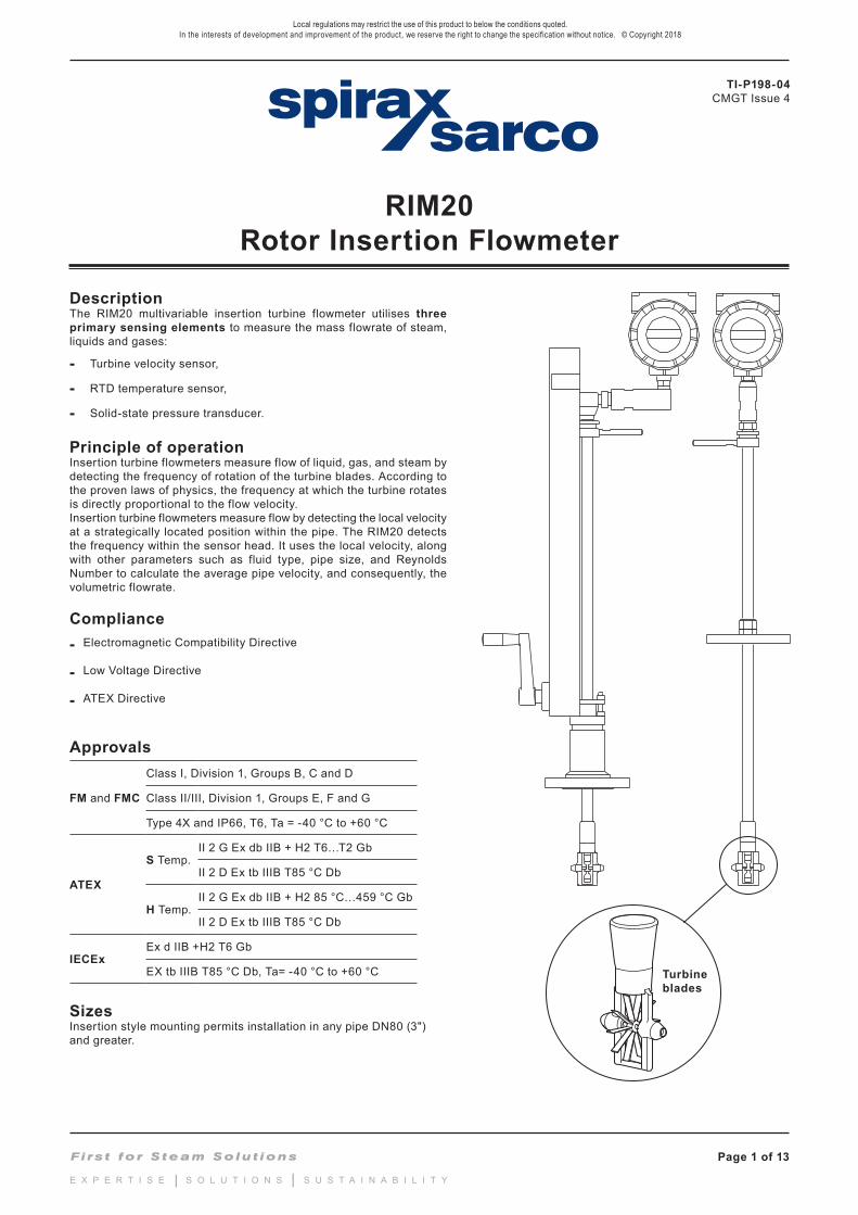
DescriptionThe RIM20 multivariable insertion turbine flowmeter utilises three primary sensing elements to measure the mass flowrate of steam, liquids and gases:
- Turbine velocity sensor,
- RTD temperature sensor,
- Solid-state pressure transducer.
Principle of operationInsertion turbine flowmeters measure flow of liquid, gas, and steam by detecting the frequency of rotation of the turbine blades. According to the proven laws of physics, the frequency at which the turbine rotates is directly proportional to the flow velocity.Insertion turbine flowmeters measure flow by detecting the local velocity at a strategically located position within the pipe. The RIM20 detects the frequency within the sensor head. It uses the local velocity, along with other parameters such as fluid type, pipe size, and Reynolds Number to calculate the average pipe velocity, and consequently, the volumetric flowrate.
Compliance- Electromagnetic Compatibility Directive
- Low Voltage Directive
- ATEX Directive
Approvals
FM and FMC
Class I, Division 1, Groups B, C and D
Class II/III, Division 1, Groups E, F and G
Type 4X and IP66, T6, Ta = -40 °C to +60 °C
ATEX
S Temp.II 2 G Ex db IIB + H2 T6…T2 Gb
II 2 D Ex tb IIIB T85 °C Db
H Temp.II 2 G Ex db IIB + H2 85 °C…459 °C Gb
II 2 D Ex tb IIIB T85 °C Db
IECExEx d IIB +H2 T6 Gb
EX tb IIIB T85 °C Db, Ta= -40 °C to +60 °C
SizesInsertion style mounting permits installation in any pipe DN80 (3") and greater.
Turbine blades
RIM20Rotor Insertion Flowmeter
TI-P198-04CMGT Issue 4
TI-P198-04CMGT Issue 4
Page 2 of 13
RIM20 Rotor Insertion Flowmeter
RIM20 range and benefits
The RIM20-V delivers a direct reading of volumetric flowrate, generally the most cost-effective solution for liquid flow monitoring, in applications ranging from general water flows to hydrocarbon fuel flow measurement.
The RIM20-VT integrates a precision 1 000 Ω platinum RTD temperature sensor that can be used to calculate and output a compensated mass reading. This device is typically used to measure flowrates of saturated steam.
The RIM20-VTP offers you flow computer functionality in a compact field device. This multivariable instrument incorporates temperature and pressure sensors to provide an instantaneous reading of the compensated mass flowrate of gases, liquids and steam. In addition to outputs for totalized mass and alarm settings, the field-configurable electronics deliver up to three analogue 4 - 20 mA outputs of five process measurements, including volumetric flowrate, mass flowrate, pressure, temperature and density.
The RIM20-EM Energy Monitoring option permits real-time calculation of energy consumption for a facility or process. The flowmeter can be programmed to measure steam, hot water or chilled water. The RIM20-VTP flowmeter monitors one side of the process, either sent or returned, and uses the input from a second separate temperature sensor on the opposite leg of the process to calculate the change in energy. Selectable energy units include BTUs, joules, calories, Watt-hours, Megawatt-hours and Horsepower-hours. The local or remote electronics indicate two temperatures, delta T, mass total and energy total.
Technical data
Wetted materials
316L, 302, and 17-4PH, and 18-8 stainless steel, tungsten carbide, sapphire, plus:• DuPont Teflon ® based thread sealant on models with pressure transducer• DuPont Teflon ® packing on standard temperature models with packing gland• Graphite based packing on high temperature models with packing gland
Application Any gas, liquid or steam compatible with 316L stainless steel and other listed wetted materials. Not recommended for multi-phase fluids
Temperature Process
S option - Standard -55 °C to +238 °C (-67 °F to +460 °F)*Where ATEX is required the lower temperature is further limited to -40 °C (-40 °F).
H option - High -267 °C to +454 °C (-448 °F to +850 °F)*Where ATEX is required the lower temperature is further limited to -40 °C (-40 °F).
Environmental
Temperature AmbientOperating -40 °C to +60 °C (-40 °F to +140 °F)
Storage -40 °C to +85 °C (-40 °F to +185 °F)
LVD
Electrical Safety EN61010-1:2010
Overvoltage Category II
Pollution Degree 2
EMCEmissions Group 1, Class A (Suitable for Industrial Environments only)
Immunity Suitable for Industrial Environments
Enclosure NEMA 4X, IP66
Pressure transducerratings
Full-scale operating pressure Maximum over-range pressure
2 bar a 30 psi a 4 bar a 60 psi a
7 bar a 100 psi a 14 bar a 200 psi a
20 bar a 300 psi a 41 bar a 600 psi a
34 bar a 500 psi a 69 bar a 1 000 psi a
100 bar a 1 500 psi a 175 bar a 2 500 psi a
Page 3 of 13
RIM20 Rotor Insertion Flowmeter
TI-P198-04CMGT Issue 4
TRANSLATION RUN OVER
Pressure ratings
Style connection Connection/Rating
Compression fitting
2" Male NPT ASME Class 600
2" ASME B16.5 Class 150 or DN50 EN1092-1 PN16
2" ASME B16.5 Class 300 or DN50 EN1092-1 PN40
2" ASME B16.5 Class 600 or DN50 EN1092-1 PN63
Packing gland
2" Male NPT ASME Class 300
2" ASME B16.5 Class 150 or DN50 EN1092-1 PN16
2" ASME B16.5 Class 300 or DN50 EN1092-1 PN40
Packing gland andPermanent retractor
2" Male NPT ASME Class 600
2" ASME B16.5 Class 150 or DN50 EN1092-1 PN16
2" ASME B16.5 Class 300 or DN50 EN1092-1 PN40
2" ASME B16.5 Class 600 or DN50 EN1092-1 PN63
Power requirements
DL option - 12 to 36 Vdc, 25 mA, 1 W maximum, Loop powered (single output)
DH option - 12 to 36 Vdc, 300 mA, 9 W maximum, (multiple outputs)
AC option - 100 to 240 Vac, 50/60 Hz line power, 5 W maximum (multiple outputs)
Display
Alphanumeric 2 line x 16 character LCD digital display
Six pushbuttons for full field configuration
Pushbuttons can be operated with magnetic wand without removal of the enclosure covers
Display can be mounted in 90° intervals for better viewing
Output signals
Analogue 4 - 20 mA
Alarm Solid state relay, 40 Vdc
Totalizer pulse 50 millisecond pulse, 40 Vdc
Volumetric or Loop powered mass
One analogue, one totalizer pulse, HART®, scaled frequncy output
Multivariable option 1 Up to three analogue signals, three alarms, one totalizer pulse, HART®, scaled frequency output
Multivariable option 2 Modus RTU or BACnet MS/TP compatible process monitoring
Performance specificationsAccuracy Mass flowrate accuracy for gas and steam based on 50 - 100% of pressure range
Process variables Liquids Gas and steam Repeatability Stability over 12 months
Volumetric flowrate ± 1.2% of rate ± 1.5% of rate ± 0.1% of rate ± Negligible
Mass flowrate ± 1.5% of rate ± 2.0% of rate ± 0.2% of rate ± 0.2% of rate
Temperature ± 1.0 °C (± 2.0 °F) ± 1.0 °C (± 2.0 °F) ± 1.0 °C (± 2.0 °F) ± 0.5 °C (± 0.9 °F)
Pressure ± 0.3% of full-scale ± 0.3% of full-scale ± 0.05% of full-scale ± 0.1% of full-scale
Density ± 0.3% of reading ± 0.5% of reading ± 0.1% of reading ± 0.1% of reading
Response time Adjustable from 1 to 100 seconds
Technical data (continued)
TI-P198-04CMGT Issue 4
Page 4 of 13
RIM20 Rotor Insertion Flowmeter
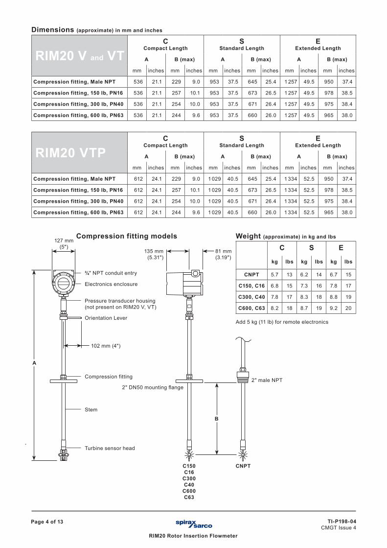
Weight (approximate) in kg and lbs
C S E
kg lbs kg lbs kg lbs
CNPT 5.7 13 6.2 14 6.7 15
C150, C16 6.8 15 7.3 16 7.8 17
C300, C40 7.8 17 8.3 18 8.8 19
C600, C63 8.2 18 8.7 19 9.2 20
Add 5 kg (11 lb) for remote electronics
B
135 mm (5.31")
81 mm (3.19")
2" male NPT2" DN50 mounting flange
A
127 mm (5")
Pressure transducer housing (not present on RIM20 V, VT)
Orientation Lever
102 mm (4")
¾" NPT conduit entry
Electronics enclosure
Compression fitting
Stem
Turbine sensor head
C150C16
C300C40
C600C63
CNPT
Compression fitting models
Dimensions (approximate) in mm and inches
RIM20 V and VTC
Compact Length S
Standard LengthE
Extended Length
A B (max) A B (max) A B (max)
mm inches mm inches mm inches mm inches mm inches mm inches
Compression fitting, Male NPT 536 21.1 229 9.0 953 37.5 645 25.4 1 257 49.5 950 37.4
Compression fitting, 150 Ib, PN16 536 21.1 257 10.1 953 37.5 673 26.5 1 257 49.5 978 38.5
Compression fitting, 300 Ib, PN40 536 21.1 254 10.0 953 37.5 671 26.4 1 257 49.5 975 38.4
Compression fitting, 600 Ib, PN63 536 21.1 244 9.6 953 37.5 660 26.0 1 257 49.5 965 38.0
RIM20 VTPC
Compact Length S
Standard LengthE
Extended Length
A B (max) A B (max) A B (max)
mm inches mm inches mm inches mm inches mm inches mm inches
Compression fitting, Male NPT 612 24.1 229 9.0 1 029 40.5 645 25.4 1 334 52.5 950 37.4
Compression fitting, 150 Ib, PN16 612 24.1 257 10.1 1 029 40.5 673 26.5 1 334 52.5 978 38.5
Compression fitting, 300 Ib, PN40 612 24.1 254 10.0 1 029 40.5 671 26.4 1 334 52.5 975 38.4
Compression fitting, 600 Ib, PN63 612 24.1 244 9.6 1 029 40.5 660 26.0 1 334 52.5 965 38.0
Page 5 of 13
RIM20 Rotor Insertion Flowmeter
TI-P198-04CMGT Issue 4
TRANSLATION RUN OVER
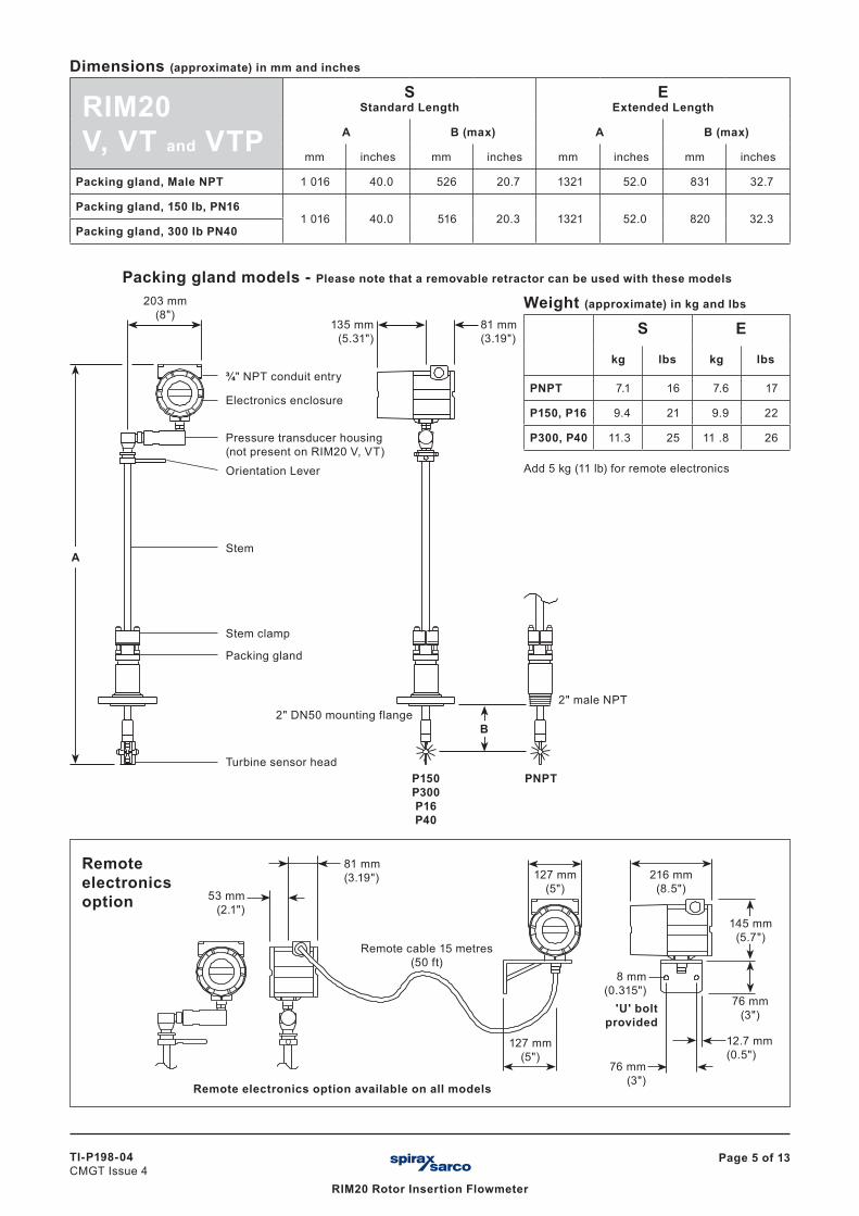
Weight (approximate) in kg and lbs
S E
kg lbs kg lbs
PNPT 7.1 16 7.6 17
P150, P16 9.4 21 9.9 22
P300, P40 11.3 25 11 .8 26
Add 5 kg (11 lb) for remote electronics
A
B
203 mm (8")
135 mm (5.31")
81 mm (3.19")
Pressure transducer housing (not present on RIM20 V, VT)Orientation Lever
2" male NPT2" DN50 mounting flange
¾" NPT conduit entry
Electronics enclosure
Stem
Turbine sensor headP150P300P16P40
PNPT
Stem clamp
Packing gland
Packing gland models - Please note that a removable retractor can be used with these models
Dimensions (approximate) in mm and inches
RIM20V, VT and VTP
S Standard Length
EExtended Length
A B (max) A B (max)
mm inches mm inches mm inches mm inches
Packing gland, Male NPT 1 016 40.0 526 20.7 1321 52.0 831 32.7
Packing gland, 150 Ib, PN16 1 016 40.0 516 20.3 1321 52.0 820 32.3
Packing gland, 300 Ib PN40
Remote electronics option 53 mm
(2.1")
81 mm (3.19") 216 mm
(8.5")127 mm
(5")
145 mm (5.7")
76 mm (3")
76 mm (3")
12.7 mm (0.5")
127 mm (5")
8 mm (0.315")
'U' bolt provided
Remote electronics option available on all models
Remote cable 15 metres (50 ft)
TI-P198-04CMGT Issue 4
Page 6 of 13
RIM20 Rotor Insertion Flowmeter
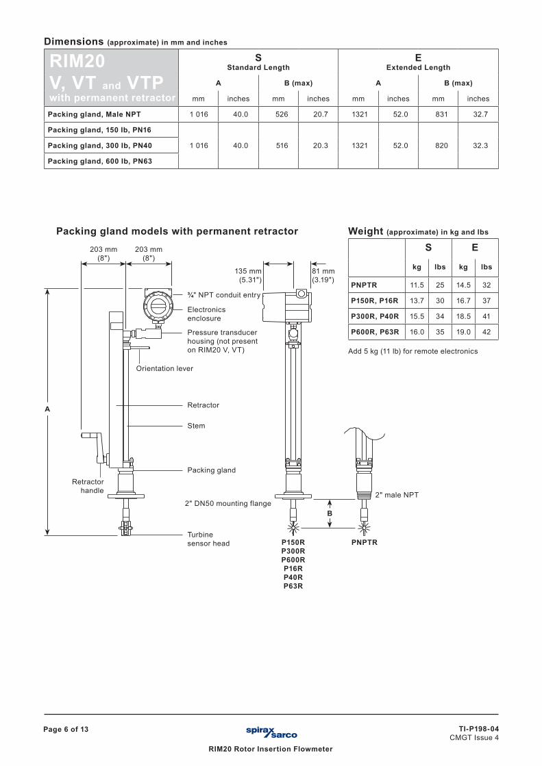
Dimensions (approximate) in mm and inches
RIM20V, VT and VTPwith permanent retractor
S Standard Length
EExtended Length
A B (max) A B (max)
mm inches mm inches mm inches mm inches
Packing gland, Male NPT 1 016 40.0 526 20.7 1321 52.0 831 32.7
Packing gland, 150 Ib, PN16
1 016 40.0 516 20.3 1321 52.0 820 32.3Packing gland, 300 Ib, PN40
Packing gland, 600 Ib, PN63
Weight (approximate) in kg and lbs
S E
kg lbs kg lbs
PNPTR 11.5 25 14.5 32
P150R, P16R 13.7 30 16.7 37
P300R, P40R 15.5 34 18.5 41
P600R, P63R 16.0 35 19.0 42
Add 5 kg (11 lb) for remote electronics
Packing gland models with permanent retractor203 mm
(8")
A
B
135 mm (5.31")
81 mm (3.19")
Pressure transducer housing (not present on RIM20 V, VT)
Orientation lever
2" male NPT2" DN50 mounting flange
¾" NPT conduit entry
Electronics enclosure
Stem
Turbine sensor head P150R
P300RP600RP16RP40RP63R
PNPTR
Packing glandRetractor
handle
203 mm (8")
Retractor
Page 7 of 13
RIM20 Rotor Insertion Flowmeter
TI-P198-04CMGT Issue 4
TRANSLATION RUN OVER
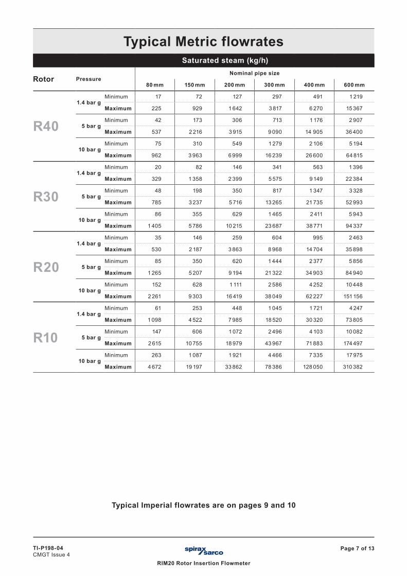
Typical Metric flowratesSaturated steam (kg/h)
Rotor PressureNominal pipe size
80 mm 150 mm 200 mm 300 mm 400 mm 600 mm
R40
1.4 bar gMinimum 17 72 127 297 491 1 219
Maximum 225 929 1 642 3 817 6 270 15 367
5 bar gMinimum 42 173 306 713 1 176 2 907
Maximum 537 2 216 3 915 9 090 14 905 36 400
10 bar gMinimum 75 310 549 1 279 2 106 5 194
Maximum 962 3 963 6 999 16 239 26 600 64 815
R30
1.4 bar gMinimum 20 82 146 341 563 1 396
Maximum 329 1 358 2 399 5 575 9 149 22 384
5 bar gMinimum 48 198 350 817 1 347 3 328
Maximum 785 3 237 5 716 13 265 21 735 52 993
10 bar gMinimum 86 355 629 1 465 2 411 5 943
Maximum 1 405 5 786 10 215 23 687 38 771 94 337
R20
1.4 bar gMinimum 35 146 259 604 995 2 463
Maximum 530 2 187 3 863 8 968 14 704 35 898
5 bar gMinimum 85 350 620 1 444 2 377 5 856
Maximum 1 265 5 207 9 194 21 322 34 903 84 940
10 bar gMinimum 152 628 1 111 2 586 4 252 10 448
Maximum 2 261 9 303 16 419 38 049 62 227 151 156
R10
1.4 bar gMinimum 61 253 448 1 045 1 721 4 247
Maximum 1 098 4 522 7 985 18 520 30 320 73 805
5 bar gMinimum 147 606 1 072 2 496 4 103 10 082
Maximum 2 615 10 755 18 979 43 967 71 883 174 497
10 bar gMinimum 263 1 087 1 921 4 466 7 335 17 975
Maximum 4 672 19 197 33 862 78 386 128 050 310 382
Typical Imperial flowrates are on pages 9 and 10
TI-P198-04CMGT Issue 4
Page 8 of 13
RIM20 Rotor Insertion Flowmeter
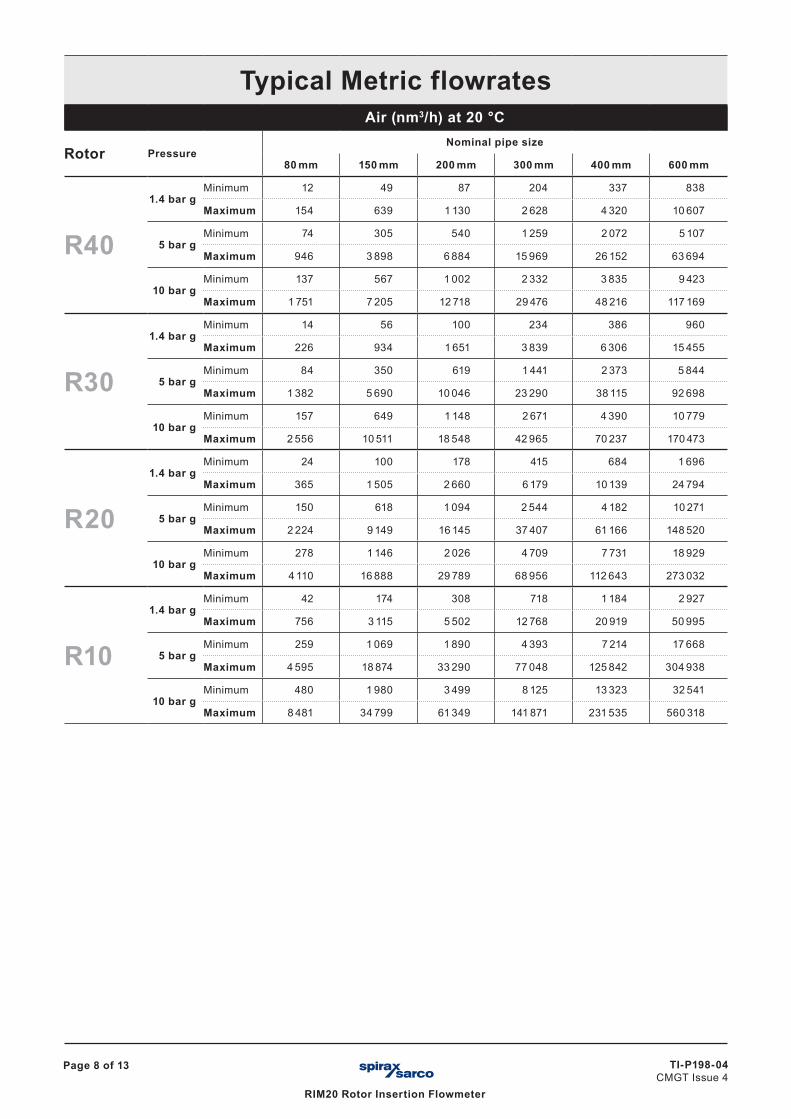
Typical Metric flowratesAir (nm3/h) at 20 °C
Rotor PressureNominal pipe size
80 mm 150 mm 200 mm 300 mm 400 mm 600 mm
R40
1.4 bar gMinimum 12 49 87 204 337 838
Maximum 154 639 1 130 2 628 4 320 10 607
5 bar gMinimum 74 305 540 1 259 2 072 5 107
Maximum 946 3 898 6 884 15 969 26 152 63 694
10 bar gMinimum 137 567 1 002 2 332 3 835 9 423
Maximum 1 751 7 205 12 718 29 476 48 216 117 169
R30
1.4 bar gMinimum 14 56 100 234 386 960
Maximum 226 934 1 651 3 839 6 306 15 455
5 bar gMinimum 84 350 619 1 441 2 373 5 844
Maximum 1 382 5 690 10 046 23 290 38 115 92 698
10 bar gMinimum 157 649 1 148 2 671 4 390 10 779
Maximum 2 556 10 511 18 548 42 965 70 237 170 473
R20
1.4 bar gMinimum 24 100 178 415 684 1 696
Maximum 365 1 505 2 660 6 179 10 139 24 794
5 bar gMinimum 150 618 1 094 2 544 4 182 10 271
Maximum 2 224 9 149 16 145 37 407 61 166 148 520
10 bar gMinimum 278 1 146 2 026 4 709 7 731 18 929
Maximum 4 110 16 888 29 789 68 956 112 643 273 032
R10
1.4 bar gMinimum 42 174 308 718 1 184 2 927
Maximum 756 3 115 5 502 12 768 20 919 50 995
5 bar gMinimum 259 1 069 1 890 4 393 7 214 17 668
Maximum 4 595 18 874 33 290 77 048 125 842 304 938
10 bar gMinimum 480 1 980 3 499 8 125 13 323 32 541
Maximum 8 481 34 799 61 349 141 871 231 535 560 318
Page 9 of 13
RIM20 Rotor Insertion Flowmeter
TI-P198-04CMGT Issue 4
TRANSLATION RUN OVER
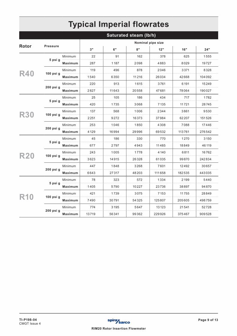
Typical Imperial flowratesSaturated steam (lb/h)
Rotor PressureNominal pipe size
3" 6" 8" 12" 16" 24"
R40
5 psi gMinimum 22 91 162 378 625 1 555
Maximum 287 1 187 2 098 4 883 8 029 19 727
100 psi gMinimum 119 496 878 2 046 3 371 8 328
Maximum 1 540 6 350 11 216 26 034 42 668 104 092
200 psi gMinimum 220 913 1 615 3 761 6 191 15 249
Maximum 2 827 11 643 20 558 47 681 78 064 190 027
R30
5 psi gMinimum 25 105 186 434 717 1 782
Maximum 420 1 735 3 068 7 135 11 721 28 745
100 psi gMinimum 137 568 1 006 2 344 3 861 9 530
Maximum 2 251 9 272 16 373 37 984 62 207 151 526
200 psi gMinimum 253 1 046 1 850 4 308 7 088 17 446
Maximum 4 129 16 994 29 996 69 532 113 761 276 542
R20
5 psi gMinimum 45 186 330 770 1 270 3 150
Maximum 677 2 797 4 943 11 485 18 849 46 119
100 psi gMinimum 243 1 005 1 778 4 140 6 811 16 762
Maximum 3 623 14 915 26 328 61 035 99 870 242 834
200 psi gMinimum 447 1 848 3 268 7 601 12 492 30 657
Maximum 6 643 27 317 48 203 111 658 182 535 443 035
R10
5 psi gMinimum 78 323 572 1 334 2 199 5 440
Maximum 1 405 5 790 10 227 23 736 38 897 94 870
100 psi gMinimum 421 1 739 3 075 7 153 11 755 28 849
Maximum 7 490 30 791 54 325 125 807 205 605 498 759
200 psi gMinimum 774 3 195 5 647 13 123 21 541 52 728
Maximum 13 719 56 341 99 362 229 926 375 467 909 528
TI-P198-04CMGT Issue 4
Page 10 of 13
RIM20 Rotor Insertion Flowmeter
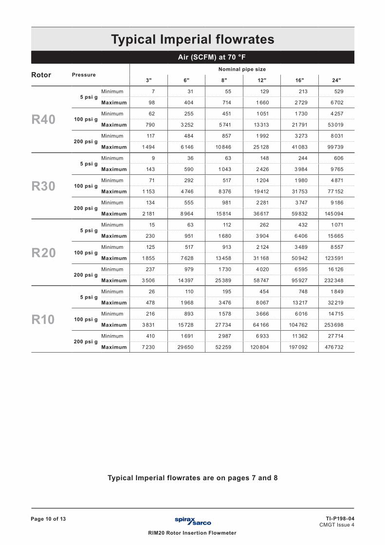
Typical Imperial flowratesAir (SCFM) at 70 °F
Rotor PressureNominal pipe size
3" 6" 8" 12" 16" 24"
R40
5 psi gMinimum 7 31 55 129 213 529
Maximum 98 404 714 1 660 2 729 6 702
100 psi gMinimum 62 255 451 1 051 1 730 4 257
Maximum 790 3 252 5 741 13 313 21 791 53 019
200 psi gMinimum 117 484 857 1 992 3 273 8 031
Maximum 1 494 6 146 10 846 25 128 41 083 99 739
R30
5 psi gMinimum 9 36 63 148 244 606
Maximum 143 590 1 043 2 426 3 984 9 765
100 psi gMinimum 71 292 517 1 204 1 980 4 871
Maximum 1 153 4 746 8 376 19 412 31 753 77 152
200 psi gMinimum 134 555 981 2 281 3 747 9 186
Maximum 2 181 8 964 15 814 36 617 59 832 145 094
R20
5 psi gMinimum 15 63 112 262 432 1 071
Maximum 230 951 1 680 3 904 6 406 15 665
100 psi gMinimum 125 517 913 2 124 3 489 8 557
Maximum 1 855 7 628 13 458 31 168 50 942 123 591
200 psi gMinimum 237 979 1 730 4 020 6 595 16 126
Maximum 3 506 14 397 25 389 58 747 95 927 232 348
R10
5 psi gMinimum 26 110 195 454 748 1 849
Maximum 478 1 968 3 476 8 067 13 217 32 219
100 psi gMinimum 216 893 1 578 3 666 6 016 14 715
Maximum 3 831 15 728 27 734 64 166 104 762 253 698
200 psi gMinimum 410 1 691 2 987 6 933 11 362 27 714
Maximum 7 230 29 650 52 259 120 804 197 092 476 732
Typical Imperial flowrates are on pages 7 and 8
Page 11 of 13
RIM20 Rotor Insertion Flowmeter
TI-P198-04CMGT Issue 4
TRANSLATION RUN OVER
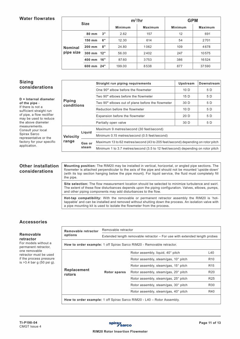
Water flowratesSize
m3/hr GPMMinimum Maximum Minimum Maximum
Nominal pipe size
80 mm 3" 2.62 157.0 12 691
150 mm 6" 12.30 614.0 54 2 701
200 mm 8" 24.80 1 062.0 109 4 678
300 mm 12" 56.00 2 402.0 247 10 575
400 mm 16" 87.60 3 753.0 386 16 524
600 mm 24" 199.00 8 538.0 877 37 590
Sizing considerations
D = Internal diameter of the pipe - If there is not a sufficient straight run of pipe, a flow rectifier may be used to reduce the above diameter measurements.Consult your local Spirax Sarco representative or the factory for your specific application.
Piping conditions
Straight run piping requirements Upstream Downstream
One 90° elbow before the flowmeter 10 D 5 D
Two 90° elbows before the flowmeter 15 D 5 D
Two 90° elbows out of plane before the flowmeter 30 D 5 D
Reduction before the flowmeter 10 D 5 D
Expansion before the flowmeter 20 D 5 D
Partially open valve 30 D 5 D
Velocity range
LiquidMaximum 9 metres/second (30 feet/second)
Minimum 0.15 metres/second (0.5 feet/second)
Gas or steam
Maximum 13 to 62 metres/second (43 to 205 feet/second) depending on rotor pitch
Minimum 1 to 3.7 metres/second (3.5 to 12 feet/second) depending on rotor pitch
Other installation considerations
Mounting position: The RIM20 may be installed in vertical, horizontal, or angled pipe sections. The flowmeter is attached perpendicular to the axis of the pipe and should not be mounted 'upside-down' (with its top section hanging below the pipe mount). For liquid service, the fluid must completely fill the pipe.
Site selection: The flow measurement location should be selected to minimize turbulence and swirl. The extent of these flow disturbances depends upon the piping configuration. Valves, elbows, pumps, and other piping components may add disturbances to the flow.
Hot-tap compatibility: With the removable or permanent retractor assembly the RIM20 is ‘hot-tappable’ and can be installed and removed without shutting down the process. An isolation valve with a pipe mounting kit is used to isolate the flowmeter from the process.
Accessories
Removable retractorFor models without a permanent retractor, one removable retractor must be used if the process pressure is >3.4 bar g (50 psi g).
Removable retractor options
Removable retractor
Extended length removable retractor – For use with extended length probes
How to order example: 1 off Spirax Sarco RIM20 - Removable retractor.
Replacement rotors Rotor spares
Rotor assembly, liquid, 40° pitch L40
Rotor assembly, steam/gas, 10° pitch R10
Rotor assembly, steam/gas, 15° pitch R15
Rotor assembly, steam/gas, 20° pitch R20
Rotor assembly, steam/gas, 25° pitch R25
Rotor assembly, steam/gas, 30° pitch R30
Rotor assembly, steam/gas, 40° pitch R40
How to order example: 1 off Spirax Sarco RIM20 - L40 – Rotor Assembly.
TI-P198-04CMGT Issue 4
Page 12 of 13
RIM20 Rotor Insertion Flowmeter
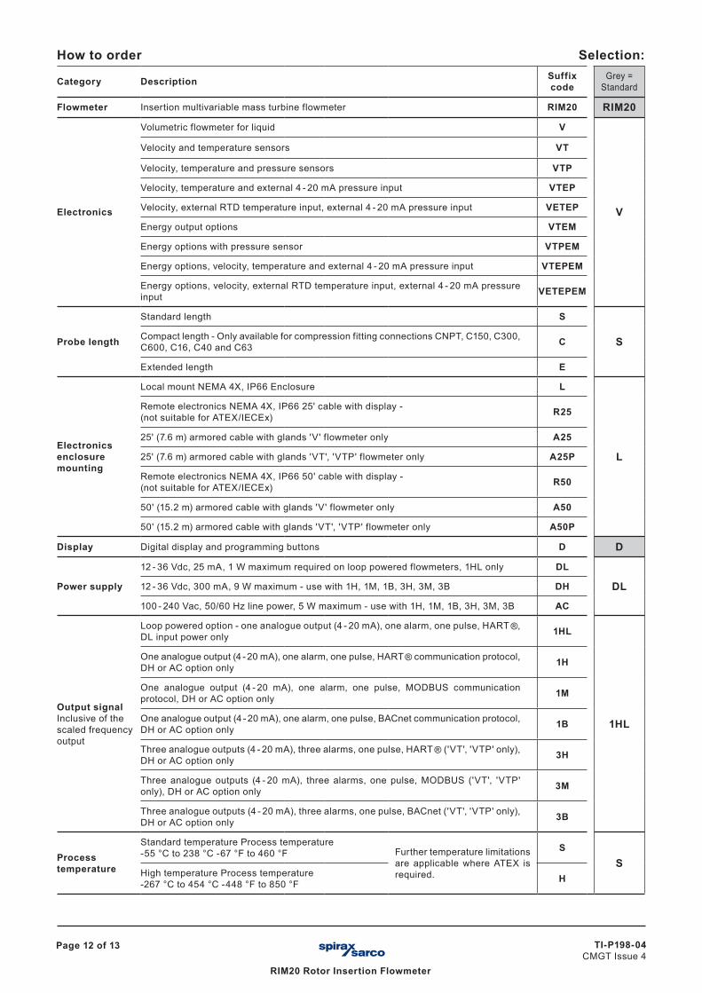
How to order Selection:
Category Description Suffix code
Grey = Standard
Flowmeter Insertion multivariable mass turbine flowmeter RIM20 RIM20
Electronics
Volumetric flowmeter for liquid V
V
Velocity and temperature sensors VT
Velocity, temperature and pressure sensors VTP
Velocity, temperature and external 4 - 20 mA pressure input VTEP
Velocity, external RTD temperature input, external 4 - 20 mA pressure input VETEP
Energy output options VTEM
Energy options with pressure sensor VTPEM
Energy options, velocity, temperature and external 4 - 20 mA pressure input VTEPEM
Energy options, velocity, external RTD temperature input, external 4 - 20 mA pressure input VETEPEM
Probe length
Standard length S
SCompact length - Only available for compression fitting connections CNPT, C150, C300, C600, C16, C40 and C63 C
Extended length E
Electronics enclosure mounting
Local mount NEMA 4X, IP66 Enclosure L
L
Remote electronics NEMA 4X, IP66 25' cable with display - (not suitable for ATEX/IECEx) R25
25' (7.6 m) armored cable with glands 'V' flowmeter only A25
25' (7.6 m) armored cable with glands 'VT', 'VTP' flowmeter only A25P
Remote electronics NEMA 4X, IP66 50' cable with display - (not suitable for ATEX/IECEx) R50
50' (15.2 m) armored cable with glands 'V' flowmeter only A50
50' (15.2 m) armored cable with glands 'VT', 'VTP' flowmeter only A50P
Display Digital display and programming buttons D D
Power supply
12 - 36 Vdc, 25 mA, 1 W maximum required on loop powered flowmeters, 1HL only DL
DL12 - 36 Vdc, 300 mA, 9 W maximum - use with 1H, 1M, 1B, 3H, 3M, 3B DH
100 - 240 Vac, 50/60 Hz line power, 5 W maximum - use with 1H, 1M, 1B, 3H, 3M, 3B AC
Output signalInclusive of the scaled frequency output
Loop powered option - one analogue output (4 - 20 mA), one alarm, one pulse, HART ®, DL input power only 1HL
1HL
One analogue output (4 - 20 mA), one alarm, one pulse, HART ® communication protocol, DH or AC option only 1H
One analogue output (4 - 20 mA), one alarm, one pulse, MODBUS communication protocol, DH or AC option only 1M
One analogue output (4 - 20 mA), one alarm, one pulse, BACnet communication protocol, DH or AC option only 1B
Three analogue outputs (4 - 20 mA), three alarms, one pulse, HART ® ('VT', 'VTP' only), DH or AC option only 3H
Three analogue outputs (4 - 20 mA), three alarms, one pulse, MODBUS ('VT', 'VTP' only), DH or AC option only 3M
Three analogue outputs (4 - 20 mA), three alarms, one pulse, BACnet ('VT', 'VTP' only), DH or AC option only 3B
Process temperature
Standard temperature Process temperature -55 °C to 238 °C -67 °F to 460 °F Further temperature limitations
are applicable where ATEX is required.
SS
High temperature Process temperature -267 °C to 454 °C -448 °F to 850 °F H
Page 13 of 13
RIM20 Rotor Insertion Flowmeter
TI-P198-04CMGT Issue 4
TRANSLATION RUN OVER
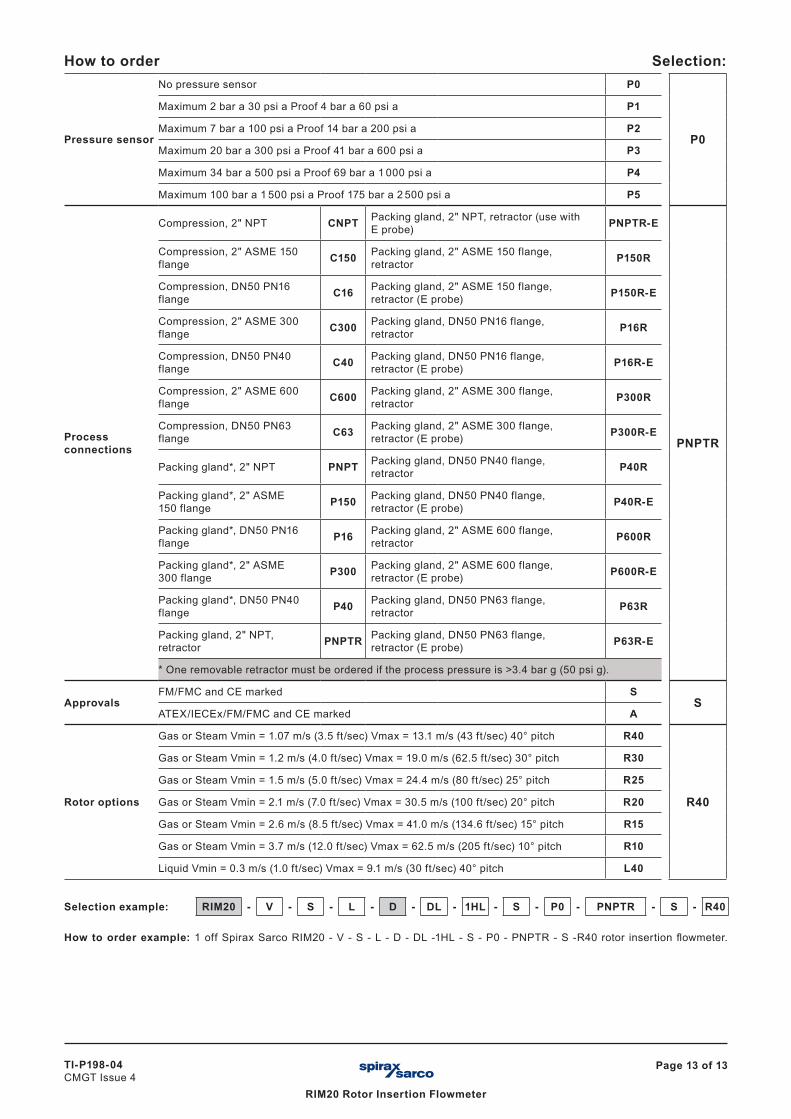
How to order Selection:
Pressure sensor
No pressure sensor P0
P0
Maximum 2 bar a 30 psi a Proof 4 bar a 60 psi a P1
Maximum 7 bar a 100 psi a Proof 14 bar a 200 psi a P2
Maximum 20 bar a 300 psi a Proof 41 bar a 600 psi a P3
Maximum 34 bar a 500 psi a Proof 69 bar a 1 000 psi a P4
Maximum 100 bar a 1 500 psi a Proof 175 bar a 2 500 psi a P5
Process connections
Compression, 2" NPT CNPT Packing gland, 2" NPT, retractor (use with E probe) PNPTR-E
PNPTR
Compression, 2" ASME 150 flange C150 Packing gland, 2" ASME 150 flange,
retractor P150R
Compression, DN50 PN16 flange C16 Packing gland, 2" ASME 150 flange,
retractor (E probe) P150R-E
Compression, 2" ASME 300 flange C300 Packing gland, DN50 PN16 flange,
retractor P16R
Compression, DN50 PN40 flange C40 Packing gland, DN50 PN16 flange,
retractor (E probe) P16R-E
Compression, 2" ASME 600 flange C600 Packing gland, 2" ASME 300 flange,
retractor P300R
Compression, DN50 PN63 flange C63 Packing gland, 2" ASME 300 flange,
retractor (E probe) P300R-E
Packing gland*, 2" NPT PNPT Packing gland, DN50 PN40 flange, retractor P40R
Packing gland*, 2" ASME 150 flange P150 Packing gland, DN50 PN40 flange,
retractor (E probe) P40R-E
Packing gland*, DN50 PN16 flange P16 Packing gland, 2" ASME 600 flange,
retractor P600R
Packing gland*, 2" ASME 300 flange P300 Packing gland, 2" ASME 600 flange,
retractor (E probe) P600R-E
Packing gland*, DN50 PN40 flange P40 Packing gland, DN50 PN63 flange,
retractor P63R
Packing gland, 2" NPT, retractor PNPTR Packing gland, DN50 PN63 flange,
retractor (E probe) P63R-E
* One removable retractor must be ordered if the process pressure is >3.4 bar g (50 psi g).
ApprovalsFM/FMC and CE marked S
SATEX/IECEx/FM/FMC and CE marked A
Rotor options
Gas or Steam Vmin = 1.07 m/s (3.5 ft/sec) Vmax = 13.1 m/s (43 ft/sec) 40° pitch R40
R40
Gas or Steam Vmin = 1.2 m/s (4.0 ft/sec) Vmax = 19.0 m/s (62.5 ft/sec) 30° pitch R30
Gas or Steam Vmin = 1.5 m/s (5.0 ft/sec) Vmax = 24.4 m/s (80 ft/sec) 25° pitch R25
Gas or Steam Vmin = 2.1 m/s (7.0 ft/sec) Vmax = 30.5 m/s (100 ft/sec) 20° pitch R20
Gas or Steam Vmin = 2.6 m/s (8.5 ft/sec) Vmax = 41.0 m/s (134.6 ft/sec) 15° pitch R15
Gas or Steam Vmin = 3.7 m/s (12.0 ft/sec) Vmax = 62.5 m/s (205 ft/sec) 10° pitch R10
Liquid Vmin = 0.3 m/s (1.0 ft/sec) Vmax = 9.1 m/s (30 ft/sec) 40° pitch L40
Selection example: RIM20 - V - S - L - D - DL - 1HL - S - P0 - PNPTR - S - R40
How to order example: 1 off Spirax Sarco RIM20 - V - S - L - D - DL -1HL - S - P0 - PNPTR - S -R40 rotor insertion flowmeter.