rf-dna: radio-frequency certificates of authenticity
TRANSCRIPT

RF-DNA: Radio-Frequency Certificates of Authenticity
Gerald DeJean and Darko Kirovski
Microsoft Research, Redmond, WA 98052, USA
Abstract
A certificate of authenticity (COA) is an inexpensive physical object that has a random andunique multidimensional structure S which is hard to near-exactly replicate. An inexpensivedevice should be able to scan object’s physical “fingerprint,” i.e., obtain a set of features in theform of a multidimensional signal x that pseudo-uniquely represents S. For a given “fingerprint”x and without access to S, it should be computationally difficult to construct an object offixed dimensions with a “fingerprint” y which is at a bounded proximity from x according to astandardized distance metric. We introduce objects that behave as COAs in the electromagneticfield. The objective is to complement RFIDs so that they are physically, not only digitally,unique and hard to replicate. By enabling this feature, we introduce a tag whose informationabout the product can be read within a relative far-field, and also whose authenticity can bereliably verified within its near-field. In order to counterfeit a tag, the adversary faces twodifficulties – a computational and a manufacturing one. The computational difficulty stemsfrom the hardness of solving linear inverse problems in the electromagnetic field. In order tocreate an actual tag, the adversary must also manufacture a multidimensional object with aspecific three-dimensional topology, dielectric properties, and conductivity.
1 Introduction
Between 7-8% of world trade,1 10% of the pharmaceuticals market,2 and 36% of the softwaremarket3 is counterfeit. We cluster all piracy efforts into two groups:
• piracy – where the buyer is confident that the purchased object is not genuine due to anuncharacteristically low price – however, she willingly executes the trade. Such transactionsdo not gain substantial revenues to the pirate, hence, it is arguable whether losses due tosuch events could be accounted as lost revenue for the legal copyright owner. The benefit of“free” marketing, brand popularization, and/or platform adoption could outweigh the realisticrevenue loss due to piracy.
• counterfeits – where the seller fools the buyer into believing that the merchandise isauthentic and collects the full “legal-market” price on the product. In this case, the piratecollects substantial revenue with profit margins typically higher than that of the originalmanufacturer due to lack of development and marketing costs.
To the best of our knowledge there does not exist a study which breaks down piracy estimatesinto the above categories, however for certain markets such as pharmaceuticals nearly all illegal
1According to Interpol, World Customs Organization and International Chamber of Commerce estimates thatroughly 7-8% of world trade every year is in counterfeit goods.
2Glaxo-Smith-Kline in a study with the US Food and Drug Administration estimated that counterfeit drugsaccount for 10% of the global pharmaceuticals market.
3The Business Software Alliance estimates that 36% of software sales worldwide are counterfeit.

trade can be claimed to be counterfeits. With hundreds of billions of dollars lost to counterfeitseach year, we are the first to develop RF-DNA – unique RFIDs with an aim to address this problem.Note that traditional RFIDs with encoded digital information could be easily replicated and thus,are not capable of resolving the problem or tag authenticity.
1.1 Certificate of Authenticity
A certificate of authenticity (COA) is a digitally signed physical object of fixed dimensions thathas a random unique structure which satisfies the following requirements:
R1 the cost of creating and signing original COAs is small, relative to a desired level of security,
R2 the cost of manufacturing a COA instance is several orders of magnitude lower than the costof near-exact replication of the unique and random physical structure of this instance, and
R3 the cost of verifying the authenticity of a signed COA is small, again relative to a desiredlevel of security.
The key to the analysis of COA instances is the extraction of its “fingerprint,” i.e., a set offeatures that reliably represents its multi-dimensional structure. This process is typically based ona specific physical phenomenon and produces a cardinality-N vector of complex numbers x ∈ C
N .This imposes that:
R4 it should be computationally difficult to construct an object of fixed dimensions with a “fin-gerprint” y such that ||x − y|| < δ, where x is a given “fingerprint” of an unknown COAinstance and δ bounds the proximity of x and y with respect to a standardized distancemetric || · ||.
An additional requirement, mainly impacted by a desired level of usability, is that a COAmust be robust to ordinary wear and tear. COA instances can be created in numerous ways. Forexample, when covering a surface with an epoxy substrate, its particles form a low-rise but random3D landscape which uniquely reflects light directed from a certain angle – COAs based upon thisidea were first proposed by Bauder and Simmons from the Sandia National Labs and used forweapons control during The Cold War [1].
1.2 Radio Frequency COAs
We investigate which objects behave as COAs in the electromagnetic (EM) field and the kind ofproperties they offer as counterfeit deterrents. Radio frequency (RF) COAs are built based uponseveral near-field phenomena that EM waves exhibit when interacting with complex, random, anddense objects:
• Arbitrary dielectric or conductive objects with topologies proportional in size to wave’s wave-length behave as significant EM scatterers [2], i.e., they reradiate large amount of EM energyinto free space.
• The refraction and reflection of EM waves at the boundary of two media can produce hard-to-predict near-field effects; the phenomenon can be modeled using the Maxwell equations orthe generalized Ewald-Oseen extinction theorem [3, 4, 5].
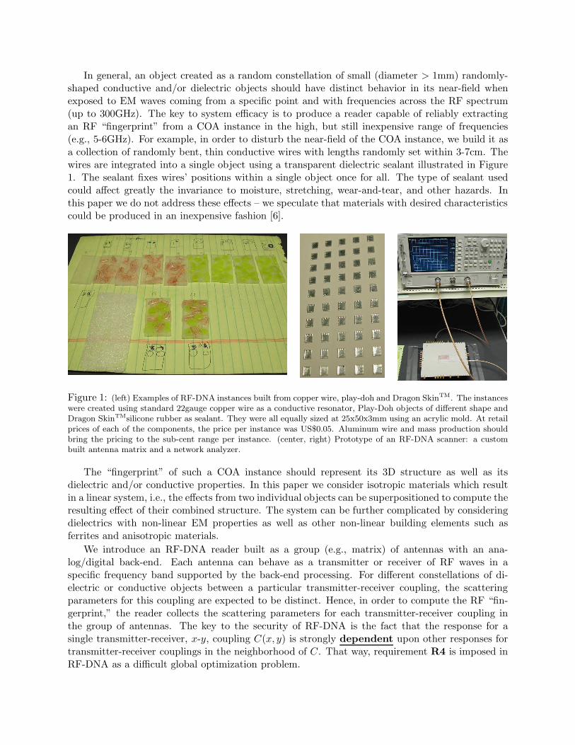
In general, an object created as a random constellation of small (diameter > 1mm) randomly-shaped conductive and/or dielectric objects should have distinct behavior in its near-field whenexposed to EM waves coming from a specific point and with frequencies across the RF spectrum(up to 300GHz). The key to system efficacy is to produce a reader capable of reliably extractingan RF “fingerprint” from a COA instance in the high, but still inexpensive range of frequencies(e.g., 5-6GHz). For example, in order to disturb the near-field of the COA instance, we build it asa collection of randomly bent, thin conductive wires with lengths randomly set within 3-7cm. Thewires are integrated into a single object using a transparent dielectric sealant illustrated in Figure1. The sealant fixes wires’ positions within a single object once for all. The type of sealant usedcould affect greatly the invariance to moisture, stretching, wear-and-tear, and other hazards. Inthis paper we do not address these effects – we speculate that materials with desired characteristicscould be produced in an inexpensive fashion [6].
Figure 1: (left) Examples of RF-DNA instances built from copper wire, play-doh and Dragon SkinTM. The instanceswere created using standard 22gauge copper wire as a conductive resonator, Play-Doh objects of different shape andDragon SkinTMsilicone rubber as sealant. They were all equally sized at 25x50x3mm using an acrylic mold. At retailprices of each of the components, the price per instance was US$0.05. Aluminum wire and mass production shouldbring the pricing to the sub-cent range per instance. (center, right) Prototype of an RF-DNA scanner: a custombuilt antenna matrix and a network analyzer.
The “fingerprint” of such a COA instance should represent its 3D structure as well as itsdielectric and/or conductive properties. In this paper we consider isotropic materials which resultin a linear system, i.e., the effects from two individual objects can be superpositioned to compute theresulting effect of their combined structure. The system can be further complicated by consideringdielectrics with non-linear EM properties as well as other non-linear building elements such asferrites and anisotropic materials.
We introduce an RF-DNA reader built as a group (e.g., matrix) of antennas with an ana-log/digital back-end. Each antenna can behave as a transmitter or receiver of RF waves in aspecific frequency band supported by the back-end processing. For different constellations of di-electric or conductive objects between a particular transmitter-receiver coupling, the scatteringparameters for this coupling are expected to be distinct. Hence, in order to compute the RF “fin-gerprint,” the reader collects the scattering parameters for each transmitter-receiver coupling inthe group of antennas. The key to the security of RF-DNA is the fact that the response for asingle transmitter-receiver, x-y, coupling C(x, y) is strongly dependent upon other responses fortransmitter-receiver couplings in the neighborhood of C. That way, requirement R4 is imposed inRF-DNA as a difficult global optimization problem.

We stress that reader’s measurements represent EM effects that occur in the near-field of thetransmitter, the COA instance, and the receiver; distances between any two objects are proportionalto the wavelengths of interest. We observe EM effects in the near-field for several reasons:
• It is difficult to maliciously jam near-field communication.
• The reader can operate with extreme low-power, low-efficiency antenna designs.
• The variance of the EM field is relatively high in the near-field, causing better distinguishingcharacteristics. Far-field responses typically represent certain average characteristics of ran-dom discrete scatterers ([7], Chapter §6), thus, such responses lose the ability to representthe scatterer’s random structure.
• Computing the actual EM responses numerically is a difficult task. We consider two differentcomputing tasks: the forward and the inverse design process. In the case of a forward designtask, the geometry of the reader and the RF-DNA instance is known – the objective is tocompute the resulting RF response, i.e., “fingerprint.” In the inverse design problem, for agiven “fingerprint” x and a known geometry of the reader, the goal is to construct a COAinstance whose fingerprint is in the close proximity of x. In general, while all EM phenomenaare analytically explained using the Maxwell equations, even fundamental problems such ascomputing responses from simple antennas with regular geometries, are notoriously intensivecomputational tasks with arguable accuracy [2, 8].
We built a prototype RF-DNA scanner as a matrix of 5x10 antennas that measure the uniqueresponse “fingerprint” of an RF-DNA instance as a collection of transmission (e.g., s2,1-parameter)responses in the 5-6GHz frequency range for each transmitter-receiver coupling on the reader. RF-DNA instances were placed at about 0.5mm from the antenna matrix, i.e., in the near-field ofthe scanner. While the analog/digital back-end in our testbed was resolved using an expensiveoff-the-shelf network analyzer, we speculate that a custom reader could cost less than US$100 ifmanufactured en masse. Figure 1 illustrates the proposed RF-DNA scanner prototype.
1.3 Logistics
When creating an RF-DNA instance, the issuer digitally signs instance’s EM response using tradi-tional public-key cryptography. First, the “fingerprint” is scanned, digitized, and compressed intoa fixed-length bit string f . Next, f is concatenated to the information t associated with the tag(e.g., product ID, expiration date, assigned value) to form a combined bit string w = f ||t. Oneway to sign the resulting message w is to use the Bellare-Rogaway recipe, PSS-R [9], for signingmessages using RSA [10] with message recovery. The resulting signature s as well as w are encodeddirectly onto the COA instance using existing technologies such as an RFID. Each COA instance isassociated with an object whose authenticity the issuer wants to vouch. Once issued, an RF-DNAinstance can be verified off-line by anyone using a reader that contains the corresponding publickey of the issuer. In case the integrity test is successful, the original response “fingerprint” f andassociated data g are extracted from w. The verifier proceeds to scan in-field the actual RF “fin-gerprint” f ′ of the attached instance, i.e., obtain a new reading of the instance’s EM properties,and compare them with f . If the level of similarity between f and f ′ exceeds a pre-defined andstatistically validated threshold δ, the verifier declares the instance to be authentic and displays t.In all other cases, the reader concludes that the instance is not authentic. In order to counterfeitprotected objects, the adversary needs to:

(i) compute the private key of the issuer – a task which can be made arbitrarily difficult byadjusting the key length of the used public-key crypto-system [10, 11, 12], or
(ii) devise a manufacturing process that can exactly replicate an already signed COA instance – atask which is not infeasible but requires certain expense by the malicious party – the forgingcost dictates the value that a single COA instance can protect [13], or
(iii) misappropriate signed COA instances – a responsibility of the organization that issues COAinstances.
COA instances are generic “objects of value.” They have a fully horizontal perspective ofpossible applications. The value that one COA instance represents, approximately equals the costto forge this instance [13]. Inexpensive verification makes COAs particularly attractive for severaltraditional applications as well as for a myriad of new ones. Currency, checks, money orders, creditcards, license and product tags, warranties, receipts, endorsements, ownership documents, proofs ofpurchase/return, proof of repair, coupons, tickets, identity documents, visas, seals, tamper-evidenthardware can all be produced using COAs. Note that the RF-DNA must be firmly attached tothe associated object as an adversary may remove, substitute, or attach valid RF-DNAs at will.Most of these problems can be rectified by devaluing RF-DNAs at point of sales or by recordingtransactions on the RF-DNA itself. For example, a license tag may consist of two independentlyidentifiable RF-DNA instances, where one is destroyed at purchase time to signal a sold product.The same procedure can be used to signal and/or value product’s “N th owner.”
One of the key features of RF-DNAs is that their “fingerprints” do not reveal their physi-cal structure in a straightforward fashion. Practically, assume the application where credit cardsare protected using RF-DNAs. Then, by accessing full credit card information from a merchantdatabase (e.g., holder’s name, card’s number and expiration date, PIN code, and COA’s “finger-print”), it would be still difficult for the adversary to create a physical copy of the original creditcard produced by the issuing bank. To complete the operation, the adversary would have to gainphysical access to the original credit card and accurately scan its 3D structure (e.g., using X-raysor other 3D imaging systems). Finally, the adversary still faces the task of actually building the3D object, a task that, we speculate, requires significant costs.
1.4 Related Work
In the 1970s Bauder and Simmons were the first to propose COAs created as sprayed epoxy on atwo dimensional substrate for weapons verification purposes during The Cold War [1]. Several yearslater they proposed to use a collection of fibers randomly positioned in an object using a transparentgluing material which permanently fixes fibers’ positioning [14]. Readout of the random structureof a fiber-based COA could be performed in numerous ways using the following fact: if one endof a fiber is illuminated, the other end will also glow. Bauder proposed fiber-based COAs forbanknote protection - fibers in that proposal were fixed using a semi-transparent material suchas paper [14]. To the best of our knowledge, only few efforts have followed the pioneering workby Bauder and Simmons. Church and Littman have worked on extraction of random optical-fiber patterns in the context of currency anti-counterfeiting [15, 16]. Pappu has created a classof physical one-way functions via speckle scattering [17, 18]. He has focused on Gabor waveletsto produce short digests of the natural randomness collected from an optical phenomenon. HisPh.D. thesis has a solid survey of the related but scarce work [17]. Recently, Kirovski evaluateda system for automatic verification of fiber-based COAs [13]. Finally, COAs in the EM domainhave been proposed by several companies [19, 20, 21, 22, 23], all of them aiming to detect COA’s

random structure in the far-field. Such detection is prone to spoofing; in addition, such COAs canbe relatively easily near-exactly replicated. Because the detection is taking place in the far-field,many of these systems operate in the “expensive” 60GHz frequency range.
The motivation for the research focus presented in this manuscript is complex. First, our RF-DNA designs force the counterfeiter to manufacture a given complex 3D structure and embed itin a soft or hard encapsulating sealant. The structures could be made from homogeneous liquidsin certain scenarios. In both cases, the cost of near-exact replication of such COA instances isgreatly raised. Second, since the readout of their random structure does not require a reader-object contact, RF-DNAs may be built with superior wear-and-tear properties. Next, as shownlater in this manuscript, for a credit-card sized RF-DNA instance and a reader that operates in the5-6GHz frequency subband, the entropy of the readout response from RF-DNAs easily tops severalthousand bits making the likelihood of accidental collusion negligent. Finally, RF-DNAs are thefirst type of COA that satisfies the requirement R4 from Section 1.
2 The RF-DNA Scanner
In order to scan the EM features of an RF-DNA instance, we proposed a scanner designed to exposethe subtle variances of near-field responses of these objects to RF waves in [24]. We introduced ascanner that consisted of a single antenna matrix, where each antenna was capable of operating bothas a transmitter and a receiver. While scanning a COA instance, it is aligned to a fixed position withrespect to the antenna matrix. The RF-DNA instance should have an absorbent and/or reflectivebackground so that the environment behind the tag does not affect its RF response. When anRF wave initiated by one of the antennas hits the COA instance, its reflection and refraction isdependant upon the 3D positioning of the scatterers embedded in the RF-DNA. This creates adistinct RF response, in particular in the near-field, that can be received by any of the remainingantennas on the panel. Each receiver obtains a view of the RF-DNA from its own perspective.The total voltage Vn of a device or port equals the sum of the voltage input into a device V +
n andthe voltage received from a device V −
n : Vn = V +n + V −
n . For two antennas under test, four specifics-parameters can be obtained for the two-port network. A matrix representation of the relationshipbetween the voltage and the s-parameters is shown in Eqn.1:
[
V −1
V −2
]
=
[
s1,1 s1,2
s2,1 s2,2
] [
V +1
V +2
]
. (1)
For example, for a system with M antennas, one can measure M s1,1 and(
M2
)
s2,1 parameters.In order to enable this, each antenna is multiplexed to an analog/digital back-end capable ofextracting the s2,1 parameter (i.e., insertion loss) for a particular antenna coupling. The actualdesign of the proposed RF-DNA scanner is identified in [24]. In mass production, we estimate thatthe price for this reader should be well below US$100 [25]. Figure 1 illustrates the manufacturedprototype and the simulation setup.
3 Empirical Evaluation of “Fingerprint’s” Uniqueness
Experimentally, we quantified system’s sensitivity to slight misalignment and estimated the re-sponse entropy as perceived by the verifier. Fig.2 illustrates the set of antenna couplings activeduring each experiment. We considered (⋆) eight RF-DNAs with copper wire embedded in Dragon
5 5.1 5.2 5.3 5.4 5.5 5.6 5.7 5.8 5.9 6
-40
-20
0
20
40
Frequency [GHz]
m{1
...8}
(x,y
) [dB
]
5 5.1 5.2 5.3 5.4 5.5 5.6 5.7 5.8 5.9 60
2
4
6
8
std(
m{1
...8}
)(x,
y) [d
B]
5 5.1 5.2 5.3 5.4 5.5 5.6 5.7 5.8 5.9 6-70
-60
-50
-40
-30
Frequency [GHz]
m1,
2 [dB
]
5 5.1 5.2 5.3 5.4 5.5 5.6 5.7 5.8 5.9 60
1
2
3
4
std(
m1,
2) [d
B]
Sensitivity to Manual Alignment in 10 Scans
�����
�����
����������
���������
����������
���������
����������
���������
����������
���������
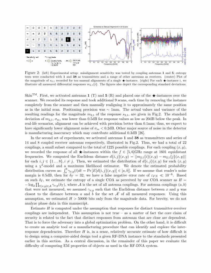
�� ���� ��� �� �� � ������� �� � � ���������������������������������� �� ��������������������Figure 2: (left) Experimental setup: misalignment sensitivity was tested by coupling antennas 1 and 5; entropytests were conducted with 1 and 38 as transmitters and a range of other antennas as receivers. (center) Plot ofthe magnitude of s2,1 recorded for ten manual alignments of a single ⋆-instance. (right) For each ⋆-instance i, weillustrate all measured differential responses m2,1{i}. The figures also depict the corresponding standard deviations.
SkinTM. First, we activated antennas 1 (T) and 5 (R) and placed one of the ⋆-instances over thescanner. We recorded its response and took additional 9 scans, each time by removing the instancecompletely from the scanner and then manually realigning it to approximately the same positionas in the initial scan. Positioning precision was ∼ 1mm. The actual values and variance of theresulting readings for the magnitude m2,1 of the response s2,1, are given in Fig.2. The standarddeviation of m2,1, σm, was lower than 0.5dB for response values as low as 20dB below the peak. Inreal-life scenarios, alignment can be achieved with precision better than 0.1mm; thus, we expect tohave significantly lower alignment noise of σm < 0.2dB. Other major source of noise in the detectoris manufacturing inaccuracy which may contribute additional 0.3dB [26].
In the second set of experiments, we activated antennas 1 and 38 as transmitters and series of14 and 8 coupled receiver antennas respectively, illustrated in Fig.2. Thus, we had a total of 22couplings, a small subset compared to the total of 1225 possible couplings. For each coupling (x, y),we recorded the response of all ⋆-instances within the f ∈ [5, 6]GHz range at 1601 equidistantfrequencies. We computed the Euclidean distance d{i, j}(x, y) = ||m2,1{i}(x, y) − m2,1{j}(x, y)||for each i, j ∈ {1 . . . 8}, i 6= j. Then, we estimated the distribution of d{i, j}(x, y) for each (x, y)using a χ2-model and a maximum likelihood estimator. We denote the estimated probabilitydistribution curves as:
∫ b
aγx,y(t)dt = Pr [E[d{i, j}(x, y)] ∈ [a, b]]. If we assume that reader’s noise
margin is 0.5dB, then for δT = 32, we have a false negative error rate of εFN ≪ 10−6. Basedon such δT , we estimate the entropy of a single COA as perceived by our COA scanner as H =− log2
∏
∀(x,y)∈A γx,y(δT ), where A is the set of all antenna couplings. For antenna couplings (a, b)that were not measured, we assumed γx,y such that the Euclidean distance between x and y wasclosest to the distance between a and b for the set A′ of all measured responses. Using thisassumption, we estimated H > 50000 bits only from the magnitude data. For brevity, we do notanalyze phase data in this manuscript.
Estimate H is computed under the assumption that responses for distinct transmitter-receivercouplings are independent. This assumption is not true – as a matter of fact the core claim ofsecurity is related to the fact that distinct responses from antennas that are close are dependent.That is to force the adversary into a global optimization problem. On the other hand, it is difficultto create an analytic tool or a manufacturing procedure that can identify and explore the inter-response dependencies. Therefore H is, in a sense, relatively accurate estimate of how difficult isto design using a computer-aided design tool a given RF-DNA instance to the standards presentedearlier in this section. As a central discussion, in the remainder of this paper we evaluate thedifficulty of computing EM properties of objects as used in the RF-DNA system.
Definition 1 An RF “fingerprint” x ∈ CF(M
2) of an RF-DNA consists of a set of complex
s2,1-parameters observed over a specific frequency band and collected for (a subset of or) all possible(
M2
)
antenna couplings using a reader with M antennas. Each analog s2,1-parameter is sampled atF arbitrary frequencies and individually quantized using an arbitrary quantizer.
4 Attack Scenarios
In this section, we evaluate the difficulty of counterfeiting RF-DNA instances. By assuming thatthe RF “fingerprint” is a complex vector f ∈ C
N , we formulate the key problems as follows.
Problem 1 Blind Analysis. Given an RF “fingerprint” x of an authentic RF-DNA instanceextracted using a known RF-DNA scanner, find a three-dimensional object S capable of producingan RF response x′ such that ||x′ − x|| < δT , where the detection threshold δT is a small scalar.
Problem 2 Known-S Manufacturing. An additional requirement is to develop a manufactur-ing process that can produce S in large quantities at a relatively low price.
There are two layers of difficulty imposed upon the counterfeiter: a computational one (Pr.1)and a manufacturing one (Pr.2). RF-DNAs can be used in scenarios where either one or bothchallenges are used to protect a physical object. We approach the two problems separately. Underthe assumption that manufacturing in 3D is a prohibitively expensive process, in this paper wefocus on formalizing Pr.1 and establishing its difficulty. We start this discussion by reminding thereader that the likelihood of a false positive εFP is negligible (as seen from a simple prototype andthe analysis in Section 3) and that an elaborate search process is required to produce S.
4.1 Forward Design
In this subsection, we review the process of simulating the effect of an RF-DNA in the presence ofEM waves. This procedure is important as it represents a direct step in the inverse design process.We refer the reader to review the basic concepts in EM theory in Appendix A. To the best of theknowledge of the authors, providing analytical or numerical solutions to Maxwell’s equations isnot a simple task in particular when field values are computed in the near-field of the scatterers.Within the scope of the application (most research in the field targets radar, medical imaging,communication, and geophysics applications), the existing techniques focus on either analyticallysimplifying the Maxwell equations via approximations for a particular constrained application andthen solving the approximations numerically or numerically solving the generic Maxwell equationsfor isotropic materials [27]. Analytical approximation techniques are typically used in constrainedscenarios with relatively poor results for general cases. For example one of the focuses is onapproximating rough surfaces with a Gaussian distribution and computing the first and secondorder statistics of the exerted EM far-field [28, 29, 2, 7, 30]. For an arbitrary field setup, one likelymust revert to a numerical EM field solver. In the remainder of this subsection, we review thespeed and accuracy of the most efficient numerical approaches.
Here, the objective is to compute the Maxwell equations for isotropic dielectric materials:
∇× H =1
c
∂D
∂t+
4π
cj, ∇× E +
1
c
∂B
∂t= 0, B = µH, D = εE (2)
in free space/time, where E and H represent the electric and magnetic field density, respectively, cis speed of light in vacuum, j denotes electric current density, and ε and µ are dielectric permittivity

and magnetic permeability, respectively. In material media, the response to the excitation producedby these fields is described by the electric displacement D and the magnetic flux density B.
Traditional approach to fast and accurate simulation of Eqns.2 is to: first, convert Eqns.2into the frequency domain, discretize the free space into K = Kx × Ky × Kz small volumetricunits, and rewrite Eqns.2 in the form of partial differential equations to create a system of linearequations Aq = b, where q is a vector of 3K elements that represent the values of the EM fieldsin each unit per dimension, vector b represents the source of EM activity, and matrix A representsthe field equations for each cell. This matrix is large and sparse. The solution to the system oflinear equations fulfills the objective of the simulation. EM solvers usually are chosen for a specificperformance feature-set: speed, accuracy, stability, and memory.
Speed. There are numerous methodologies used for finding solutions to partial differentialequations such as: Finite-Difference Time-Domain (FDTD) [27, 31], Finite Element Method (FEM)[32, 33], Method of Moments (MOM) [34], and the Finite Integration Technique (FIT) [35]. Com-mercial simulators typically offer several solvers as they usually offer distinct advantages for cer-tain problem specifications [36]. In general, the computational complexity for most techniques islinked to their accuracy; accurate methodologies are typically superlinear: O(K log K) for improvedMOM, FIT, and FEM [37] and O(K1.33) for FDTD [38], where K equals the number of unknownvariables, i.e., discrete elements (typically, simple volumetric unit cubes or other polyhedrons) usedto model the simulated EM environment. Due to the overall simplicity of programming FDTDapproaches, they are preferred in certain cases over the other asymptotically more efficient tech-niques. Although most of the pareto-point solvers offer advantages, their performance as genericfield solvers is often within one order of magnitude for equivalent level of accuracy [8]. Modernmethods is a result of several decades of research in electromagnetism and numerical analysis.
Accuracy. Besides speed, another important feature of EM solvers is their accuracy versusmeasurements on systems manufactured according to simulated specifications. Here it is importantto notice that there exists vast amount of literature as all published designs are typically supportedwith characteristics obtained via simulation and manufacturing/measurement. An example of thesubstantial discrepancy in accuracy and performance of modern field solvers can be observed in arecent comparison study of six state-of-the-art solvers [8]. For a relatively simple semi-2D structure,a vivaldi antenna with an operating frequency at f0 = 4.5GHz, modeled with approximately K ≈105 discrete elements, individual simulation results for the s2,1-parameter in the 3-7GHz band,differed up to 12dB with additional substantial differences with respect to actual measurementsof the physical implementation of the structure. Interestingly, the results among different solversfor the same antenna specification differed on the average for 3dB in the neighborhood of f0. Thefastest program in the suite returned its results after approximately one hour on a 800MHz Pentiumprocessor. We expect to see noise of about 0.5dB in the RF-DNA scanner when reading the sameRF-DNA instance using different instances of the same scanner design.
Let’s consider one of the fastest practical methodologies that solve E and H fields via systemsof partial differential equations, the FDTD [27]. The equations are solved in a leap-frog manner;the electric field is solved at a given instant in time, then the magnetic field is solved at the nextinstant, and the process is iterated. In FDTD, unknowns represent small volumetric cells. As we areinterested in sub-wavelength effects, in order to achieve a desired level of accuracy of 1dB, we meshthe space using cubic cells (∆x)3 with sides of at most ∆x ≤ λ/2000 [27, 39], where wavelengthλ > 0.05m for the considered range of 5-6GHz. Hence, the model of an RF-DNA object sized at50mm×25mm×2mm and placed on our reader, should result in a mesh of K > 108 unknowns.In order to achieve numerical stability of simulation, most variants must choose the time step ∆tduring the numerical analysis according to the Courant-Friedrich-Levy condition ∆t ≤ ∆x
√3/c,

where c is the fastest speed of light across all considered media and ∆x√
3 is the longest straightpath in the considered cell unit. In order to achieve relative accuracy, the basic step of the numericanalysis is repeated C times where typically 106 > C > 104 for the frequency range of interest(5-6GHz). Note that there exist certain variants of FDTD that are unconditionally stable (3DADI-FDTD, [40]), however require more processing to achieve the same level of accuracy [39].
In summary, the memory requirements of current computing systems as well as their processingpower have impacted that some of the largest EM simulations today are on the order of K = 107
unknowns providing results that typically are several dB off from the same parameters obtained viahigh-precision manufacturing and measurements. It is difficult to formally analyze simulation errorsfor most solvers in the generic case, thus, we do not evaluate the computational complexity (in thetraditional sense) for the task to simulate a scanning of an RF-DNA instance for a desired levelof accuracy (≪0.5dB) – from most modern studies, we speculate that accurate forward simulation(better than 0.5dB per sample of the “fingerprint”) of proposed RF-DNAs is not feasible.
The key to the efficacy of our system is to build RF-DNA objects such that they are relativelysmall but exhibit distinct and strong variance of transmission parameters when placed betweentwo antennas (one in transmitting mode and one in receiving mode). In this paper, we exploreresonators; however other phenomena could significantly and profoundly affect transmission suchas randomly shaped and positioned metamaterials4 [41, 42] or discrete dielectric and ferromagneticscatterers [7]. Ultimately, by combining scatterers with different properties, it is more difficult tofind accurate approximations that can accelerate a field solver.
4.2 Inverse Design
Even if the adversary could accurately solve the forward design process, she would still have tosearch within the solution space H (see Section 3) in order to solve Pr.1. One naıve strategy isthat the adversary must launch a localized search process for an RF-DNA instance which visuallycorresponds to authentic instances (three-dimensional object of fixed dimensions such as a creditcard) and which satisfies the constraints posed in Pr.1.
This inverse problem is actually well known in several research fields, in particular medicalimaging (electroencephalography – EEG) and geophysics research. In general, the problem isconsidered to be ill-posed (term introduced by Hadamard in 1902 – a problem whose solutiondoes not exist or it is not unique or it is not stable under perturbations on data). In general,the objective in this problem is to detect scatterers given a particular dataset obtained via EMprobing. In EEG research, substantial efforts have been targeted towards identifying the numberof probes that are required to identify the unique solution (electrical activity in the brain) thatproduces the observed EM signals [43]. From that perspective, it is important in our system thatthe number of antenna couplings is sufficient to represent the 3D structure of an RF-DNA instance.Techniques that succeed in relatively inaccurate solutions to inverse problems combine the forwardand inverse design step and iterate it numerous times. A survey of such schemes is presented in[44, 45] – in summary, best known systems achieve to solve some ill-defined inverse problems withprior knowledge of solution structure for K ≈ 103 in substantial amount of time. As formal analysisof such methodologies is not provided, we conjecture that solving Pr.1 is a task which is well beyondreach of modern inverse design tools. A topic of further research is to understand the ill-posednessof Pr.1.
4Materials that exhibit negative index of refraction.

4.3 Superpositioning
The adversary can use the fact that the system is linear [26] and try to obtain a desired “fingerprint”x by combining atomic objects with known, simulated “fingerprints.” A simple RF-DNA instanceX that consists of two separate non-overlapping atomic objects X1 and X2, satisfies the followingproperty: f(X) = f(X1)+f(X2), where function f returns the “fingerprint” of its argument. Notethat two different atomic objects can have the same geometric shape; however, their responseswill be different with high likelihood if these shapes are positioned at distinct locations relativeto the RF-DNA scanner. The goal of the adversary is to design a large set of m atomic objectsX = {X1, . . . ,Xm} and simulate f(X1), . . . , f(Xm). Then, the adversary would launch a searchover X in order to find a subset Y ⊂ X of non-overlapping shapes such that:
∣
∣
∣
∣
∣
∣
∣
∣
∣
∣
∣
∣
∑
Xi∈Y
f(Xi) − f
∣
∣
∣
∣
∣
∣
∣
∣
∣
∣
∣
∣
< δT (3)
and that the composition of all objects in Y is contained in the volume of a single RF-DNA instance.
Although seemingly attractive, this approach has several associated difficulties. First, whileperforming the summation in Eqn.3, the error accumulates. Thus, a necessary condition for theattack is that the average simulation-manufacturing error is smaller than 0.5dB/|Y|. Next, assumingthat such an error can be achieved, it is questionable whether a solution to Eqn.3 can be foundbased upon X only. While at least one solution to this problem certainly exists (e.g., the authenticRF-DNA), searching over non-overlapping shapes in X may not yield necessarily a viable solution.
Superpositioning is likely to be effective only using a non-overlapping set of parametric canonicalatomic objects. We define a parametric canonical atomic object as an atomic object such that itarbitrarily affects (based upon a set of parameters) only a narrow frequency band of the response fora single antenna coupling and has negligible effect on all other bands of this coupling as well as anyother antenna coupling. An additional requirement is that all considered canonical atomic objectsare non-overlapping. The design of such objects is not straightforward, however, if successful, itwould significantly simplify this attack.
4.4 Dimensionality Reduction
One trivial simplification of Pr.1 is to search for X that has reduced dimensionality. As manufac-turing of 2D or layered 2D objects is typically inexpensive, by solving the reduced problem, onecan achieve the overall goal using constrained resources. Here we stress that the sealant used increating COA instances should be transparent. Thus, the person verifying an RF-DNA instancecan always visually inspect its structure. Existence of a metallic 3D structure and absence of a 2Dobject with dimensions similar to instance’s dimensions, signals a potentially authentic instance. Inorder to fool such a simple verifier, the adversary must construct the 2D object using transparentmaterial with the same optical refraction properties as the sealant and conductor-like RF proper-ties. Also the adversary must find a way to mimic the visuals of metallic 3D structures withoutintroducing significant additional RF effects. To the best of our knowledge, we believe that such atask is difficult with modern materials but do not exclude its importance both computationally andfrom the perspective of manufacturing. Needless to mention, improved hardware verifiers could bedeployed to detect a 2D COA instance in case such attacks become viable.
In summary, all mentioned attacks rely on the accuracy of field solvers – a feature that isdifficult to achieve with modern numerical analysis methods in timely manner. While the problem

is easily defined (Pr.1), as opposed to traditional cryptographic procedures [46], its computationalcomplexity is difficult to address in formalities standard to computer science (e.g., O()) because ofthe result accuracy required from the EM solver. For most modern EM solvers these complexitiesare known to be exceptionally high however they have never been formalized to a level that couldstate a current formal computational bound O() on Pr.1. Thus, here we conjecture the inherentdifficulty to solve Pr.1, and pose an open problem to all related research communities.
5 Summary
In this paper, we have proposed the first system for manufacturing and verification of certificatesof authenticity which exhibit their random behavior in the EM near-field. A peculiar feature ofour system, not exhibited in previous proposals, is the conjectured difficulty of creating a COAinstance that produces a specific response. We demonstrated a working prototype of the systemthat has helped us estimate system performance from the perspective of response repetitivenessand entropy. Finally, we pointed out to several important attack scenarios that are difficult toundertake with modern simulation and manufacturing capabilities.
References
[1] D.W. Bauder. Personal Communication.
[2] L. Tsang, et al. Scattering of Electromagnetic Waves. Wiley Interscience, 2000 & 2001.
[3] P.P. Ewald. Ann. der Physik, Vol.49, 1-56, 1915.
[4] C.W. Oseen. Uber die Wechrelwirkung zwischen zwei elektrischen Dipolen und uber die Drehung der Polarisa-tionsebene in Kristallen und Flussigkeiten. Ann. der Physik, Vol.48; pp.1-56, 1915.
[5] E. Wolf. A generalized extinction theorem and its role in scattering theory. Coherence and Quantum Optics, L.Mandel and E. Wolf (eds.), Plenum, New York, 1973.
[6] P.S. Neelakanta. Handbook of Electromagnetic Materials. CRC Press, Boca Raton, FL, USA, 1995.
[7] L. Tsang, et al. Theory of Microwave Remote Sensing. Wiley-Interscience, New York, 1985.
[8] Microwave Engineering Europe. CAD benchmark. October 2000 – February 2001. Available on-line at:http://i.cmpnet.com/edtn/europe/mwee/pdf/CAD.pdf
[9] M. Bellare and P. Rogaway. The exact security of digital signatures how to sign with RSA and Rabin. EURO-CRYPT, pp.399–414, 1996.
[10] R.L. Rivest, et al. A method for obtaining digital signatures and public-key cryptosystems. Communications
of the ACM, vol.21, no.2, pp.120–126, 1978.
[11] ANSI X9.62-1998. Public Key Cryptography for the Financial Services Industry: The Elliptic Curve DigitalSignature Algorithm (ECDSA), 1998.
[12] IEEE 1363-2000: Standard Specifications For Public Key Cryptography, 2000.
[13] D. Kirovski. Toward An Automated Verification of Certificates of Authenticity. ACM Electronic Commerce,pp.160–9, 2004.
[14] D.W. Bauder. An Anti-Counterfeiting Concept for Currency Systems. Research report PTK-11990. SandiaNational Labs. Albuquerque, NM, 1983.
[15] S. Church and D. Littman. Machine reading of Visual Counterfeit Deterrent Features and Summary of USResearch, 1980-90. Four Nation Group on Advanced Counterfeit Deterrence, Canada, 1991.
[16] Commission on Engineering and Technical Systems (CETS). Counterfeit Deterrent Features for the Next-Generation Currency Design. The National Academic Press, 1993.
[17] R. Pappu. Physical One-Way Functions. Ph.D. Thesis, MIT, 2001.
[18] R. Pappu, et al. Physical One-Way Functions. Science, Vol.297, no.5589, pp.2026–30, 2002.

[19] J. Collins. RFID Fibers for Secure Applications. RFID Journal, 2004. Available on-line at:http://www.rfidjournal.com/ article/articleview/845/1/14.
[20] CrossID, Inc. Firewall Protection for Paper Documents. Available on-line at:http://www.rfidjournal.com/article/ articleview/790/1/44.
[21] Inkode, Inc. Available on-line at: http://www.inkode.com.
[22] Creo, Inc. Available on-line at: http://www.creo.com.
[23] RF SAW, Inc. Available on-line at: http://www.rfsaw.com/ tech.html
[24] G. DeJean and D. Kirovski. Radio Frequency Certificates of Authenticity. IEEE Antenna and PropagationSymposium, 2006.
[25] MetaGeek, Inc. WiSpy. Available on-line at: http://www.metageek.net.
[26] M. Tentzeris. Personal communication, 2006.
[27] K. Yee. Numerical solution of inital boundary value problems involving maxwell’s equations in isotropic media.IEEE Transactions on Antennas and Propagation, Vol.14, no.3, pp.302–307, 1966.
[28] M. Born and E. Wolf. Principles of Optics: Electromagnetic Theory of Propagation, Interference and Diffractionof Light. Pergamon Press, Oxford, 1975.
[29] M. Nieto-Vesperinas. Scattering and Diffraction in Physical Optics. John Wiley & Sons, Inc., New York, 1991.
[30] S.K. Cho. Electromagnetic scattering. Springer-Verlag, New York, 1990.
[31] A. Taflove and S.C. Hagness. Computational Electrodynamics: The Finite-Difference Time-Domain Method.Artech House Publishers, 2005.
[32] P. Monk. Finite Element Methods for Maxwell’s Equations. Clarendon Press, 2003.
[33] Ansoft Corp. HFSS: 3D EM Solver. Available on-line at: http://www.ansoft.com/products/hf/hfss/new.cfm.
[34] R.F. Harrington. Field Computation by Moment Methods. Wiley-IEEE Press, 1990.
[35] M. Clemens and T. Weiland. Discrete electromagnetism with the finite integration technique. ElectromagneticsResearch, pp.65-87, 2001.
[36] CST Corp. Microwave Studio. Available on-line at: http://www.cst.de/Content/Products/MWS/Solvers.aspx.
[37] P. Xu and L. Tsang. Scattering by rough surface using a hybrid technique combining the multilevel UV methodwith the sparse matrix canonical grid method. Radio Science, Vol.40, 2005.
[38] W.C. Chew. Waves and Fields in Inhomogenous Media. Wiley-IEEE Press, 1999.
[39] S.G. Garcia, et al. On the Accuracy of the ADI-FDTD Method. IEEE Antennas and Wireless PropagationLetters, Vol.1, No.1, pp.31–4, 2002.
[40] T. Namiki. 3-D ADIFDTD MethodUnconditionally Stable Time-Domain Algorithm for Solving Full VectorMaxwells Equations. IEEE Transactions on Microwave Theory and Techniques, Vol.48, no.10, pp.1743–47,2000.
[41] G. Veselago, Sov. Phys. Usp. 10, 509, 1968.
[42] R.A. Shelby, et al., Science 292, 77 (2001).
[43] C.M. Michel, et al. EEG source imaging. Clinical Neurophysiology, Vol.115, (no.10), pp.2195–222, 2004.
[44] E. Haber, et al. Inversion of 3D electromagnetic data in frequency and time domain using an inexact all-at-onceapproach. Geophysics, Vol.69, (no.5), pp.1216–1228, 2004.
[45] D.B. Avdeev. Three-dimensional electromagnetic modelling and inversion: from theory to application. Surveysin Geophysics, Vol.26, pp.767–799, 2005.
[46] A.J. Menezes, et al. Handbook of Applied Cryptography. CRC Press, 1996.

Appendix A
In general, electromagnetic fields are characterized by their electric and magnetic field intensity: E
and H, respectively. In material media, the response to the excitation produced by these fields isdescribed by the electric displacement D and the magnetic flux density B. The interaction betweenthese variables is described using the Maxwell’s equations:
∇× H =1
c
∂D
∂t+
4π
cj (4)
∇× E +1
c
∂B
∂t= 0
∇ ·D = 4πρ
∇ · B = 0,
where c is speed of light in vacuum, and j and ρ denote electric current density and charge density,respectively. For most media, we have linear relationships:
!"# "$"%"$"&'!( ! ) ! *
Figure 3: Illustration of the main variables in Eqn.10-13.
D = E + 4πP = εE,B = H + 4πM = µH, j = σE, (5)
where ε, µ, and σ are dielectric permittivity, magnetic permeability, and material’s specific conduc-tivity, respectively, and P and M are the polarization and magnetization vectors respectively. Fromthe curls in Eqns.4 and 5, one can derive the equations that model propagation of a monochromatic(time-dependency factor exp(iωt)) electromagnetic wave:
Fe = ∇×∇× E − k2E
= −4π
[
ik
cj + k2P + ik∇× M
]
(6)
Fm = ∇×∇× H − k2H
= 4π
[
1
c∇× j − ik∇× P + k2M
]
, (7)
where k = ωc
is the wavenumber. Eqns.6 and 7 fully describe electromagnetic waves in 3D space– however, commonly another form is used for simulation of scattering based upon the Ewald-Oseen extinction theorem5 [3, 4]. We consider a material medium occupying a volume V limited
5This theorem was derived later from the Maxwell equations in [5].

by a surface S and use r> and r< to denote vectors to an arbitrary point outside and inside Vrespectively. The variables are illustrated in Figure 3. The dyadic form G(r, r′) of the scalar Greenfunction G(r, r′):
G(r, r′) = (G +1
k2∇∇)G(r, r′), (8)
G(r, r′) =exp(ik|r − r′|)
|r − r′| (9)
where G is a unit dyadic, describes a spherical wave at point r sourced from point r′. Now, thegeneralized extinction theorem [5] states:
E(r<) =1
4π
∫
V
Fe(r′) · G(r<, r′)d3r′ − 1
4π
(−)∑
e
(r<) (10)
E(i)(r<) +1
4πSe(r<) = 0 (11)
E(r>) = E(i)(r>) +1
4πSe(r>) (12)
0 =1
4π
∫
V
Fe(r′) · G(r>, r′)d3r′ − 1
4π
(−)∑
e
(r>), (13)
where points r and r′ are both inside V (Eqn.10), inside and outside of V (Eqn.11), both outsideof V (Eqn.12), and outside and inside V (Eqn.13) respectively. E(i) is the incident field upon Vand:
Se =
∫
S−
[(
n× (∇× E − 4πikM) +4πik
cj
)
· G(r, r′)
+(n× E) · ∇ × G(r, r′)]
dS (14)
(−)∑
e
=
∫
S−
[
(n ×∇× E) · G(r, r′)+
(n × E) · ∇ × G(r, r′)]
dS, (15)
where S− signifies integration approaching the surface S from the inside of V and n is a unit vectoroutward normal to dS. An analogous set of equations can be derived for the magnetic field [5].Here, of particular importance, are Eqns.11 and 12 and their magnetic analogues as they govern thebehavior of the electromagnetic field inside and outside of V when the source is outside of V . Theycan be restated in different famous forms which can be adjusted to alternate material conditions(non-magnetic, non-conductor, linear, isotropic, spatially dispersive, etc.) (see [29] for survey).