return cycle mapping after entrainment of ventricular tachycardia
TRANSCRIPT

Return Cycle Mapping After Entrainment ofVentricular Tachycardia
Takashi Nitta, MD; Richard B. Schuessler, PhD; Masataka Mitsuno, MD; Chris K. Rokkas, MD;Fumitaka Isobe, MD; Christopher S. Cronin, MD; James L. Cox, MD; John P. Boineau, MD
Background—The central common pathway, which is the target for ablation in reentrant ventricular tachycardia, can belocalized by entrainment mapping techniques. However, localization of the pathway is not always possible because ofthe elevated pacing threshold and the low voltage and fractionated potentials at the pathway. We examined whetherreturn cycle mapping after entrainment localizes the pathway without pacing at the pathway or recording the potentialsfrom the pathway and determined the required electrode resolution to localize the pathway.
Methods and Results—Epicardial mapping was performed with 253 unipolar electrodes during and after entrainment of13 morphologies of ventricular tachycardia that were induced in dogs 4 days after infarction. The return cycle wascalculated by subtracting the first activation time from the second activation time after the last stimulus and the returncycle distribution map was constructed for each stimulation site. The return cycle isochrones equal to the ventriculartachycardia cycle length converged on the lines of conduction block irrespective of the stimulation site, and the centralcommon pathway was localized at the region between the intersections of the return cycle isochrones after entrainmentfrom different stimulation sites. The potentials from the central common pathway were not required to localize thepathway, and the mapping accuracy did not change with or without analysis of the potentials from the pathway.According to the correlation between the electrode resolution and the mapping accuracy, an interelectrode distance of8.5 mm was estimated as sufficient resolution for successful tachycardia termination during radiofrequency ablationguided by return cycle mapping.
Conclusions—Return cycle mapping after entrainment localizes the central common pathway without pacing at thepathway or recording the potentials from the pathway. This new mapping technique could improve the success rate ofthe ablative procedures.(Circulation. 1998;97:1164-1175.)
Key Words: tachycardian reentryn entrainmentn mappingn ventricles
Ablation or resection of tissue by the catheter technique orsurgery can abolish ventricular tachycardia (VT).1,2 Suc-
cessful elimination of VT by these techniques largely dependson localizing the critical region of the VT reentrant circuit.Clinical and experimental studies have revealed that the criticalregion for the sustenance of VT is the central common pathway(CCP) or the slow conduction zone of the reentrant circuit,3,4
because the CCP is the region where the activation wave frontsare confined to a narrow isthmus and it is only necessary toablate a small amount of myocardium at the CCP to eliminateVT. During surgery, high-resolution mapping with hundreds ofelectrodes can record potentials from the CCP and localize thepathway.5–8 However, the potentials at the CCP are frequentlylow voltage and fractionated; thus construction of activationmaps of the reentrant circuit requires careful analysis andextensive editing. The entrainment mapping technique has beenwidely used in localizing the CCP during catheter ablation.9–12
Demonstration of concealed entrainment combined with othercriteria has been shown topredict VT termination during
radiofrequency application.11,12 However, concealed en-trainment is not always demonstrable in patients withsustained VT, and the success rate for VT ablation is lowin cases in which concealed entrainment or other criteriaare not demonstrable. This is because that the presenttechnique is basically a site-by-site mapping method andrequires pacing at the CCP and recording potentials fromthe pathway to demonstrate that the electrode is located atthe pathway. The pacing threshold is frequently elevatedand the potentials are complex and fractionated at thepathway. Therefore if one cannot demonstrate the abovecriteria, the pathway is never localized even if the elec-trode is positioned at the pathway. A new mappingtechnique is required in catheter ablation or surgery forreentrant VT, a technique capable of localizing the CCPwithout placing electrodes at the pathway. Such a tech-nique would provide rapid and accurate mapping of thecritical region of VT, consequently improving the successrate of the ablative procedures.
Received July 14, 1997; revision received October 9, 1997; accepted October 21, 1997.From the Division of Cardiothoracic Surgery, Washington University School of Medicine, St Louis, Mo.Correspondence to Richard B. Schuessler, PhD, Division of Cardiothoracic Surgery, Box 8234–3308 CSRB, Washington University School of
Medicine, 660 S Euclid Ave, St Louis, MO 63110.E-mail [email protected]© 1998 American Heart Association, Inc.
1164
Basic Science Reports
by guest on February 29, 2016http://circ.ahajournals.org/Downloaded from

The return cycle after entrainment, which is the timeinterval between the first and second activation times aftercessation of pacing, is specific to the recording site in thereentrant circuit.13,14 We have previously demonstrated thatreturn cycle mapping after entrainment demonstrates a char-acteristic pattern that depends on the pacing rate and thespatial correlation between the stimulation site and thereentrant circuit and that the return cycle isochrones equal tothe VT cycle length converge on the lines of conductionblock of the reentrant circuit irrespective of the stimulationsite.15,16 The hypothesis of this study is that the return cycleisochrones equal to the VT cycle length localize the lines ofblock. The objective of this study was to demonstrate thatreturn cycle mapping after entrainment localizes the CCPwithout pacing at the pathway or recording potentials fromthe pathway. Specifically, the goals of this study were (1) todetermine if the potential from the CCP was essential inlocalizing the lines of block by return cycle mapping and (2)to determine the required electrode resolution to localize thepathway by this mapping technique.
MethodsIn 18 adult mongrel dogs of either sex, weighing 23 to 37 kg,anesthesia was induced with intravenous sodium thiopental (20mg/kg) and was maintained with inhaled halothane (1% to 3%). Theanimals were intubated and ventilated with the use of a volume-limited ventilator (Harvard Apparatus Co). The heart was exposedthrough a left thoracotomy at the fourth intercostal space with sterilesurgical technique and was suspended in a pericardial cradle. The leftanterior descending coronary artery (LAD) was carefully dissected atthe portion proximal to the branching of the first diagonal artery andwas occluded for 2 hours. A bolus injection of intravenous lidocaine(2 mg/kg) was given 5 minutes before the coronary occlusion, and acontinuous infusion of lidocaine (1 mg/kg per hour) was adminis-tered for 5 hours after the coronary occlusion. Another bolusinjection of lidocaine (1 mg/kg) was given 5 minutes before thereperfusion. The chest was closed in layers, and the animals wereallowed recover.
Four days after the surgery, the animals were reanesthetized withintravenous sodium pentobarbital (30 mg/kg). Supplemental doses ofthiopental (10 mg/kg) were given as needed to maintain the surgicalplane of anesthesia. The animals were intubated and ventilated asdescribed above. A femoral arterial line was inserted to monitorsystemic arterial pressure continuously. Arterial blood samples weredrawn every 30 minutes to determine PAO2, acid-base balance, andelectrolyte levels. Ringer’s lactate solution was continuously infused,and sodium bicarbonate, potassium chloride, and calcium chloride weresupplemented as indicated to maintain pH and electrolyte within normalvalues. The heart was exposed through a median sternotomy and wassuspended in a pericardial cradle. After systemic heparinization (3mg/kg), the right atrium and femoral artery were cannulated, andnormothermic cardiopulmonary bypass was instituted to maintain stablehemodynamics during sustained VT.
An electrode patch containing 253 unipolar electrodes and 16bipolar pacing electrodes was sutured on the epicardium of the leftventricle to cover the infarct and surrounding area. The electrodepatch was made of a silicon sheet molded to fit the convexity of theleft ventricular free wall. Both unipolar and bipolar electrodes wereconstructed from silver balls (diameter, 1 mm) and from Teflon-insulated silver wires (diameter, 125mm). The interelectrode dis-tance between the unipolar electrodes was 3 to 5 mm, with higherresolution over the infarcted area and lower resolution over theremaining areas. The intraelectrode distance of the bipolar electrodeswas 1 mm. The location of each unipolar and bipolar electrode isshown in the left panel of Fig 1.
Programmed electrical stimulation (DTU-101, Bloom AssociatesLtd) was performed to induce VT. Each stimulation was performedthrough the bipolar pacing electrodes mounted on the electrodepatch. A pacing threshold was determined, and all stimulation wasperformed at a pulse width of 2 ms and at twice the diastolicthreshold. After a train of eight paced beats (S1) at a paced cyclelength of 300 ms, single or double extrastimuli (S2 and S3) weredelivered at varying coupling intervals until VT was induced. Oncea stable sustained VT was induced, continuous pacing was per-formed to entrain the VT from various epicardial sites through thebipolar electrodes. The pacing cycle length was set 5 to 10 ms lessthan the VT cycle length. Surface ECGs, pacing artifacts, andreference electrograms from the unipolar electrodes were continu-ously monitored, and the VT cycle length was displayed digitally ina beat-by-beat fashion. After constant fusion beats in the surfaceECG and constant capture of the reference electrogram at the pacingrate were demonstrated, the pacing was abruptly terminated. Severalattempts to entrain the VT were repeated from different bipolarelectrode locations. Entrainment of the tachycardia was directlyverified by the activation maps during pacing.
A 256-channel computerized data acquisition and analysis systemwas used to collect, process, and display data. The mapping systemwas based on a VaxStation II/GPX graphics workstation connectedto two 128-channel PDP 11/231 based data acquisition subsystems.Unipolar electrograms were recorded at a gain of 250, with afrequency response of 0.05 to 500 Hz. Each channel was digitized at1000 Hz with a 12-bit resolution. Two-hundred fifty-three unipolarelectrograms, as well as surface ECGs, pacing artifacts, and refer-ence electrograms, were recorded during and after entrainment ofeach VT. The data were stored on the hard disk of the VaxStationand on an optical disk. The optical disks from each experiment werereplayed afterward for off-line data analysis. Local activation timeswere determined at the time of the maximum negative derivative ineach unipolar electrogram. All electrograms were edited visually toverify accuracy of the computer-picked activation times. Activationmaps of the first and second cardiac cycle after entrainment wereconstructed. A site of conduction block was defined as the sitebetween any two adjacent electrodes having an activation timegradient of .10 ms/mm, associated with a different activationsequence on opposite sites of the putative block and a differentmorphology of the electrograms. The return cycle after entrainmentwas calculated by subtracting the first activation time from thesecond activation time after the last stimulus at each unipolarelectrode location. The return cycle map was constructed as anisotemporal map for each stimulation site. The region where theisochrones equal to the VT cycle length converged and intersectedwas identified from the return cycle maps in each VT.
To determine if analysis of the potentials from the CCP is essentialfor localizing the pathway by return cycle mapping after entrain-ment, the potentials from the electrodes located adjacent to the linesof block and the electrodes located between the lines were notanalyzed (Fig 6). In addition, to determine the required electroderesolution for the mapping technique, the number of the recordingelectrodes was decreased from 253 to 127, 64, and 32 (Fig 7).Analysis of the potentials from every other electrode provided127-electrode analysis. Analysis of the potentials from every fourthand every eighth electrode provided 64 and 32-electrode analyses,respectively. The accuracy of the mapping technique with andwithout analyzing the potentials from the CCP and with variouselectrode resolutions was evaluated by the distance between themapped site demonstrated by the return cycle mapping with eachtechnique and the lines of block during VT defined by the activationmaps with 253 electrodes. The distances were measured on theelectrode patch and were expressed as mean61 SD. The accuracy ofthe mapping technique with and without analyzing the potentialsfrom the CCP was compared by Student’s pairedt test. Mappingaccuracy with various electrode resolutions was compared withmapping accuracy using 253 electrodes by Student’s pairedt test. Inaddition, the effect of average interelectrode distance on the mappingaccuracy was examined by linear regression analysis and analysis ofvariance. A value ofP,.05 was considered statistically significant.
Nitta et al March 31, 1998 1165
by guest on February 29, 2016http://circ.ahajournals.org/Downloaded from

All animals received humane care in compliance with the “Prin-ciples of Laboratory Animal Care” formulated by the NationalSociety of Medical Research and the “Guide for the Care and Use ofLaboratory Animals” prepared by the National Academy of Scienceand published by the National Institutes of Health (NIH publicationNo. 86–23, revised 1985). In addition, the study protocol wasapproved by the Washington University Animal Studies Committee.
ResultsVT CharacteristicsA total of 41 morphologies of sustained monomorphic VTwere induced in 18 animals. In 7 animals, the reentrant circuitwas mapped on the epicardial surface in 13 morphologies ofVT, and the return cycle distribution after entrainment wasexamined. The VT cycle lengths ranged from 127 to 241 ms(170637 ms). The reentrant circuits demonstrated a doubleloop circuit with lines of conduction block and a CCPbetween the lines. The lines of block were perpendicular tothe LAD in 11 of 13 morphologies of VT and parallel to theLAD in 2 morphologies. The lines of block were longer andthe CCP was narrower in the VTs in which the lines wereperpendicular to the LAD, compared with the VTs in whichthe lines were parallel to the LAD. The width of the CCPranged from 6 to 30 mm and the length of the line of blockranged from 9 to 44 mm. To evaluate conduction over theinfarct, activation maps were constructed during continuous
pacing from the bipolar electrode located at the anterior leftventricle, before the induction of VT in all animals. Anexample is shown in Fig 1. The lines of conduction blockseen during VT were not evident during pacing, suggestingthat the conduction block during VT was functional. Thesecharacteristics of the reentrant circuit were present also in theother VTs in this study. In the histological examination of theexcised heart, extensive infarction of the anterior left ventri-cle was seen. The number of surviving subepicardial musclelayers varied from one third of the total ventricular wallthickness to very thin layers of muscle. A transmural extent ofinfarction was also found.
Return Cycle DistributionThe VTs were entrained from three to five different epicardialsites and the effects of the stimulation site on the return cycledistribution were studied. Sample data are illustrated in Figs2, 3, and 4. The return cycle distribution was divided into tworegions: longer than the pacing cycle length and equal to thepacing cycle length. In the region where the last stimuluscaused the first activation after the cessation of pacing, thereturn cycle was greater than the pacing cycle length. In theregion where the second to last stimulus caused the firstactivation after the cessation of pacing, the return cycleequaled the pacing cycle length. These return cycle distribu-
Figure 1. Activation maps during pacing and sustained ventricular tachycardia (VT). Left, ECG and activation map during continuouspacing at a paced cycle length of 300 ms from the bipolar electrodes located at the anterior free wall of the left ventricle in a dog 4days after infarction. The boxed area on the ECG is the data window analyzed to construct the activation map. The electrode patchcovered the anterior free wall of the left ventricle from the basal left ventricle 1 to 2 cm away from the left atrioventricular groove to theinferior apex of the left ventricle. The left margin of the electrode array was adjacent to the left anterior descending coronary artery(LAD). A total of 253 unipolar electrodes were distributed over the infarcted anterior left ventricle. Interelectrode distance of the elec-trodes was 3 to 5 mm, with higher resolution over the infarcted area and lower resolution over the remaining areas. The stimulation sitein this map is denoted as a rectangle. The locations of the other 15 bipolar electrodes used for stimulation are shown as asterisks.Numbers in the map represent the activation times in milliseconds at each electrode location. Isochrones are drawn in 10-ms incre-ments. The location of each electrode in the following figures is the same as in this figure. Right, the ECG and the activation map dur-ing sustained VT induced in the same infarcted heart as shown on the left. The VT was induced by double extrastimuli from a pair ofthe bipolar electrodes. The cycle length of the VT was 147 ms. The activation wave fronts are denoted as arrows and lines of block ofthe reentrant circuit are denoted as bold lines. RV indicates right ventricle; LAA, left atrial appendage.
1166 Return Cycle Mapping of VT
by guest on February 29, 2016http://circ.ahajournals.org/Downloaded from

tions shifted and rotated around the lines of block as thespatial correlation between the stimulation site and CCPchanged. Two different patterns of transition were observedbetween these return cycle distributions. The transition was
precipitous at the region where the orthodromic activationwas transposed from the last stimulated activation to theactivation of the preceding stimulation (sites E and F in Fig 2,sites E and F in Fig 3, and sites G and H in Fig 4), while it
Figure 2. Activation sequence and return cycle after entrainment from a site proximal to the central common pathway (CCP). The VT shownin Fig 1 was entrained at a paced cycle length of 140 ms. ECG is shown, with pacing artifacts and electrograms from selected sites (A-J) inthe maps. The vertical line indicates the time of the last paced stimulation. After cessation of pacing, the tachycardia resumed at a cyclelength of 143 to 144 ms. The time intervals between each activation are shown as numbers in milliseconds. Arrows indicate the activationsequence. The activation map of the last stimulation is shown on the lower left and the return cycle map is shown on the lower right. Thestimulation site is denoted by a rectangle in both maps. In the activation map, time zero indicates the time of the last stimulation. Closedarrows indicate the stimulated wave fronts; open arrows indicate the wave fronts of the preceding stimulation. The return cycle isochronesare constructed at 10-ms increments from the pacing cycle length plus 5 ms. Broken bold lines denote the lines of conduction block duringVT. Note that the return cycle isochrone of 145 ms coincides with the lines of block. The configuration of the figure and the map symbols inthe following figures are the same as those used in this figure. Also see abbreviations in Fig 1.
Nitta et al March 31, 1998 1167
by guest on February 29, 2016http://circ.ahajournals.org/Downloaded from

was gradual at the collision region of the antidromic andorthodromic wave fronts (sites G and H in Fig 2, sites G andH in Fig 3, and sites C through J in Fig 4). Adjacent to thecollision region, there was a return cycle isochrone equal tothe VT cycle length, and this isochrone represented a uniquespatial correlation with the lines of conduction block. Anexample is shown in Fig 5. Although the isochrone shiftedand changed the shape as the stimulation site changed, the
isochrone always converged on the lines of block irrespectiveof the stimulation site. As a result, the intersections of thereturn cycle isochrones equal to the VT cycle length afterentrainment from different pacing sites coincided with thelines of conduction block in the reentrant circuit during VT.Therefore, the CCP was localized at the region between theintersections of the return cycle isochrones equal to the VTcycle length.
Figure 3. Activation sequence and return cycle after entrainment from the site in the CCP. The VT is the same VT as shown in Fig 1.The pacing cycle length was 140 ms, and the return tachycardia cycle length ranged from 146 to 148 ms. The ECG and electrogramsfrom selected sites (A-J) are shown. The activation map of the last stimulation and the return cycle map are shown on the lower leftand right. Note that the antidromic activation is confined to a limited region within the CCP and that the activation sequence outsidethe CCP is similar to the sequence during VT (Fig 1). Also see Fig 2.
1168 Return Cycle Mapping of VT
by guest on February 29, 2016http://circ.ahajournals.org/Downloaded from

Potentials From the CCP and the Accuracyof MappingThe effect of recording the CCP potentials on localizing thepathway by return cycle mapping was examined. An exampleis shown in Fig 6. In the activation map during VT withanalysis of all the potentials recorded, two lines of block anda CCP between them are evident. The return cycle mapdemonstrated the characteristic pattern as described aboveand the return cycle isochrone equal to the VT cycle length
(153 ms) converged on the line of conduction block duringVT. In the activation map in which the potentials from theCCP were not analyzed, a time gap of approximately 30 mswas seen between the latest activation and the earliestactivation, and the lines of block and the CCP were notlocalized. However, the return cycle isochrones converged ona region that coincided with the line of block nearest theentrance of the CCP even when the potentials from the CCPwere not analyzed.
Figure 4. Activation sequence and return cycle after entrainment from a site distal to the CCP. The VT is the same VT as shown in Fig1. The pacing cycle length was 140 ms, and the return tachycardia cycle length was 145 to 146 ms. The ECG and electrograms fromselected sites (A-J) are shown. The activation map of the last stimulation and the return cycle map are shown on the lower left andright. Also see Figs 1 and 2.
Nitta et al March 31, 1998 1169
by guest on February 29, 2016http://circ.ahajournals.org/Downloaded from

The number of electrodes not analyzed was 56624(2269.5% of 253 electrodes), and the corresponding area was7.063.5 cm2 (1969.5% of the total mapped area). Theaccuracy of mapping with and without analysis of thepotentials from the CCP was evaluated by the distancebetween the intersection of the return cycle isochrones equalto the VT cycle length and the line of block localized by theactivation map during VT. The distance was 1.061.4 mmwith analysis of the potentials from the CCP and 1.561.3 mmwithout analysis of the potentials. No statistical differenceswere found between the two analyses with or without analysisof the potentials from the CCP.
Mapping Resolution and Accuracy of Localizingthe CCPThe effect of electrode resolution on return cycle mapping wasexamined. Fig 7 illustrates how the mapping resolution affectedthe activation maps during VT and the localization of the lines ofblock by return cycle mapping. In the activation map with 253electrodes (left map of panel A), almost all of the entire sequenceof activation during VT was elucidated. As the number ofelectrodes decreased, the isochrones of activation becamesmooth and simple, and the location, shape, and length of thelines of block changed. As a result, the location and extent of theCCP became ambiguous with fewer electrodes (left maps ofpanels B, C, and D). In the right map of panel A, the return cycleisochrones equal to the VT cycle length converged on the linesof block. As the number of electrodes decreased, the return cycleisochrones became smooth and simple. However, the region
where the return cycle isochrones intersected remained nearby(right maps of panels B, C, and D).
The effect of the interelectrode distance on the mappingaccuracy of this technique is shown in Fig 8. The mappingaccuracy was evaluated by the distance between the lines ofblock localized by the activation maps with 253 electrodesand the intersections of the return cycle isochrones equal tothe VT cycle length in each mapping resolution. The distancewas 1.061.4, 1.961.5, 4.062.6, and 6.863.0 mm for eachanalysis group of 253, 127, 64, and 32 electrodes, respec-tively. The average interelectrode distance was 4.3, 6.0, 8.5,and 12.0 mm for each analysis group of 253, 127, 64, and 32electrodes. As the interelectrode distance increased, the map-ping accuracy decreased. However, there was no statisticaldifference in the mapping accuracy between the 127- or64-electrode analysis groups and the baseline analysis (253-electrode analysis). The mapping accuracy with 32 electrodeswas significantly lower than the mapping accuracy with 253electrodes. There was a significant linear correlation betweenthe average interelectrode distance and the mapping accuracy(r5.72, P,.001).
Discussion
Mapping During VT AblationThe most important finding in the present study is that returncycle mapping localizes the CCP without pacing at thepathway or recording potentials from the pathway. The CCPis the region where the activation wave fronts are confined toa narrow isthmus.13,17 This causes the diastolic phase in the
Figure 5. The spatial correlation of the return cycle isochrones equal to the ventricular tachycardia (VT) cycle length and the lines ofconduction block during VT. ECG during VT is shown. The VT cycle length was 136 ms. The activation map during VT is shown on thelower left. The boxed area on the ECG represents the data window analyzed to construct the activation map. The VT was entrainedfrom three different epicardial sites (A, B, and C on lower right) at the same paced cycle length of 130 ms. The return cycle map afterentrainment from site A is shown in the lower middle. The stimulation site is denoted as a rectangle. The lines of conduction block dur-ing VT are shown as bold lines. The right lower panel demonstrates the spatial correlation of the return cycle isochrones equal to theVT cycle length and the lines of block during VT. The sites of stimulation (A, B, and C) are shown as rectangles. The return cycle iso-chrones equal to the VT cycle length (136 ms), corresponding to each stimulation site (A, B, and C), are illustrated as broken, dotted,and solid lines, respectively. The return cycle isochrones equal to the VT cycle length converge on the lines of block irrespective of thestimulation site.
1170 Return Cycle Mapping of VT
by guest on February 29, 2016http://circ.ahajournals.org/Downloaded from
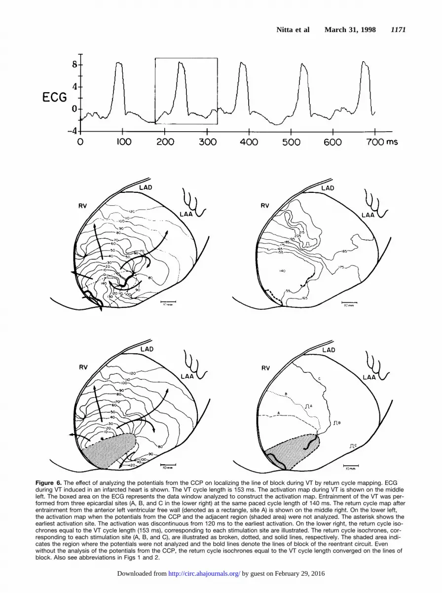
Figure 6. The effect of analyzing the potentials from the CCP on localizing the line of block during VT by return cycle mapping. ECGduring VT induced in an infarcted heart is shown. The VT cycle length is 153 ms. The activation map during VT is shown on the middleleft. The boxed area on the ECG represents the data window analyzed to construct the activation map. Entrainment of the VT was per-formed from three epicardial sites (A, B, and C in the lower right) at the same paced cycle length of 140 ms. The return cycle map afterentrainment from the anterior left ventricular free wall (denoted as a rectangle, site A) is shown on the middle right. On the lower left,the activation map when the potentials from the CCP and the adjacent region (shaded area) were not analyzed. The asterisk shows theearliest activation site. The activation was discontinuous from 120 ms to the earliest activation. On the lower right, the return cycle iso-chrones equal to the VT cycle length (153 ms), corresponding to each stimulation site are illustrated. The return cycle isochrones, cor-responding to each stimulation site (A, B, and C), are illustrated as broken, dotted, and solid lines, respectively. The shaded area indi-cates the region where the potentials were not analyzed and the bold lines denote the lines of block of the reentrant circuit. Evenwithout the analysis of the potentials from the CCP, the return cycle isochrones equal to the VT cycle length converged on the lines ofblock. Also see abbreviations in Figs 1 and 2.
Nitta et al March 31, 1998 1171
by guest on February 29, 2016http://circ.ahajournals.org/Downloaded from

Figure 7. Effects of the mapping res-olution on the activation maps and onthe localization of the lines of blockby return cycle mapping. The activa-tion times during a ventriculartachycardia (VT) were analyzed withfour degrees of mapping resolution.The VT cycle length was 140 ms. TheVT was entrained from three differentepicardial sites (A, B, and C) at apaced cycle length of 130 ms. Eachstimulation site is denoted as a rect-angle. The activation map in eachmapping resolution is illustrated in theleft maps and the return cycle iso-chrones equal to the VT cycle length(140 ms) are illustrated on the right.The numbers of channels analyzedwere 253, 127, 64, and 32 for themaps in each row of A through D.The numbers in the activation mapsdenote the activation times during VTat each electrode location. The boldlines show the lines of block and theisochrones are drawn in 10-ms incre-ments. On the right maps, the returncycle isochrones equal to the VTcycle length (140 ms), correspondingto each stimulation site (A, B, and C),are illustrated as broken, dotted, andsolid lines, respectively. Overlap ofmore than two lines is expressed asa solid line.
1172 Return Cycle Mapping of VT
by guest on February 29, 2016http://circ.ahajournals.org/Downloaded from

tachycardia cycle, because of the small volume of tissue thatis activated as the wave front traverses the CCP. Thereforeablation of a small amount of myocardium at the CCP isnecessary to eradicate reentry and successful elimination ofthe VT largely depends on mapping the pathway. Unfortu-nately, mapping the CCP is not always feasible duringsurgery or catheter ablation. Therefore this new mappingtechnique would help in localizing the CCP and improve thesuccess rate of the ablative procedures. During surgery forVT, high-resolution mapping with hundreds of electrodes canexhibit the entire reentrant circuit and localize the CCP.Although computers are used to process multiple simulta-neous recordings, determination of the activation times at theCCP frequently requires careful analysis and extensive man-ual editing of the complex and fractionated electrograms.This process significantly lengthens the duration of mapping.During catheter ablation of VT, precise localization of theCCP is essential because the ablation lesion created by thedelivered energy through a catheter is small.18 The entrain-ment mapping technique is helpful for localizing the CCPwith fewer electrodes. As demonstrated in Fig 3, duringentrainment from a site in the CCP, the antidromic activationis confined to a limited area and the activation sequenceoutside the CCP is similar to the sequence during VT. As aresult, the QRS morphology during entrainment is identical tothe QRS morphology during VT (concealed entrainment).Unfortunately, the predictive value of concealed entrainmentalone for localizing the successful ablation site is'50%,10
because the concealed entrainment can be demonstrableduring pacing from a bystander pathway or inner loop of thereentrant circuit. The other criteria, such as the presence ofisolated mid-diastolic potentials or electrogram2QRSinterval5stimulus2QRS interval, have been shown to en-hance the predictive value of the concealed entrainment forsuccessful ablation.12 The postpacing interval (the time inter-val from the last stimulus to the return cycle potential) hasalso been shown to predict VT termination during radiofre-quency current application.11 Combining these criteria with
the demonstration of concealed entrainment has been shownto correlate with a high likelihood of VT termination byradiofrequency energy.11,12 On the other hand, in the case inwhich concealed entrainment or other criteria are not dem-onstrated, the success rate for VT ablation is low. The presenttechnique is a site-by-site mapping method, yet requirespacing at the CCP or recording potentials from the pathway todemonstrate that the electrode is positioned at the pathway.The pacing threshold is frequently elevated and the potentialsare complex and fractionated at the CCP because the pathwayusually consists of islets of surviving myocardium in the scartissue. Return cycle mapping localizes the CCP by intersect-ing the return cycle isochrones equal to the VT cycle lengthafter entrainment from the sites outside the CCP. Moreover,this technique does not necessarily require the potentials fromthe CCP to localize the pathway. Therefore return cyclemapping after entrainment localizes the CCP even when noelectrodes are positioned at the pathway.
Return Cycle After EntrainmentThe return cycle was defined in the present study as the timeinterval between the first and second activation times aftercessation of pacing. As shown in Figs 2 to 4, the return cycleequals the pacing cycle length at the region activated by thepreceding stimulation orthodromically, because the returncycle is the time interval between the last two stimulatedactivation times in this region. In the rest of the region, thereturn cycle is the time interval between the last stimulatedactivation and the first tachycardia activation. This definitionof the return cycle helps the distribution map of the returncycle to localize the lines of conduction block, because thecomputer can automatically measure and calculate the returncycle, which is merely the first time interval after the lastpacing artifact. In contrast, determination of the time intervalbetween the last stimulated activation and the firsttachycardia activation after entrainment can be ambiguous atthe region where the antidromic and orthodromic wave frontscollide (site H in Fig 2, site G in Fig 3, and site J in Fig 4).This is because the first tachycardia activation after entrain-ment is the continuation of the last paced stimulation, and itis extremely difficult to determine by the potential morphol-ogy whether the activation is caused by the last pacedstimulation or the preceding stimulation at the region.
The primary mechanism for localizing the CCP by returncycle mapping is in that the return cycle isochrones equal tothe VT cycle length converge on the lines of conductionblock of the reentrant circuit. This is because the revolutiontime around the line of block after cessation of pacing is thecycle length of the tachycardia as long as an excitable gapexists along the lines of block. The present study also showedthat the potentials from the CCP were not necessarily re-quired to have the return cycle isochrones converge on thelines of block, and that the mapping accuracy did not changewith or without analysis of the potentials from the CCP. Thereason for this is that the return cycle isochrones equal to theVT cycle length radiate from the CCP. In addition, as shownin Figs 5 to 7, the return cycle isochrone was inclined toconverge at the line of block nearest the entrance of the CCP.The mechanism for this is illustrated in Fig 9. As the
Figure 8. The effect of the interelectrode distance on the accu-racy of the return cycle mapping. The mapping accuracy wasevaluated as the distance between the intersection of the returncycle isochrones equal to the ventricular tachycardia (VT) cyclelength and the lines of block during VT defined by the activationmaps with 253 electrodes. Mapping accuracy using variouselectrode resolutions was compared with mapping accuracyusing 253 electrodes. There was a significant linear correlationbetween the average interelectrode distance and the mappingaccuracy (r5.72, P,.001). A regression line is shown.
Nitta et al March 31, 1998 1173
by guest on February 29, 2016http://circ.ahajournals.org/Downloaded from

stimulation site shifts from site A to site B, the collisionregion of the antidromic and orthodromic wave fronts shifts,the return cycle isochrone equal to the VT cycle length alsoshifts. The degree of shift of the return cycle isochronesdepends on the conduction time difference from each stimu-lation site to the reentry circuit and to the collision region.The presence of slow conduction at the edge of the lines ofblock and in the CCP allows the collision region to rotateslowly at the region around the end of the lines as thestimulation site shifts. As a result, the degree of shift of thereturn cycle isochrone is more gradual at the region close tothe reentrant circuit than at the region distant from thereentrant circuit. This allows the return cycle isochronesconverge at the lines of block nearest the entrance of the CCPeven without the potentials from the pathway.
LimitationsLocalization of the CCP by entrainment mapping is based onthe assumption that the reentrant circuit has a fully excitablegap that allows a pacing impulse to reset the tachycardiawithout decremental conduction in the circuit.19,20 Almendraland colleagues21 and Gottlieb et al22 demonstrated, in humanischemic VT using the resetting response pattern, that therewere some patients whose VT showed an increasing patternin the resetting response that suggested decremental conduc-tion in the reentrant circuit or in the region between thestimulation site and the reentrant circuit. Decremental con-duction in the reentrant circuit as a response to rapid pacingmay impair the accuracy of the entrainment mapping tech-nique. The return cycle mapping shares the same limitation.In this study, we examined the return cycle distribution afterentrainment at a paced cycle length close to the VT cyclelength, therefore the decremental conduction was not signif-icant. Entrainment at a shorter pacing cycle length can causea change in the location and shape of functional block orresult in its acceleration or termination. Therefore pacingshould be performed with a cycle length long enough tocapture all the myocardium and avoid decremental conduc-tion in the reentrant circuit in this mapping technique.
In the present study, the reentrant circuit of the induced VTwas located in the thin epicardial tissue overlying a suben-docardial infarct, so that it was only necessary to map theepicardium. However, intramural reentry may be the mecha-nism of the VT in patients.23,24 Although this mappingtechnique does not require the potentials from the CCP tolocalize the pathway and could be easily extended forthree-dimensional return cycle mapping, further studies arenecessary to determine whether a CCP located intramurallycan be also localized by interpreting return cycles mappedendocardially or epicardially.
Clinical ImplicationsThis new mapping technique can be easily applied intraop-eratively during surgery for VT.25 Determination of theactivation times and calculation of the return cycle can beperformed using currently available mapping systems. Ourmapping system takes,3 minutes to display the return cyclemap for 253 electrode locations. To obtain the intersections ofthe return cycle isochrones equal to the VT cycle length, VTshould be entrained from more than two different ventricularsites. As shown in the present study, the pattern of the returncycle distribution depended on the spatial correlation betweenthe stimulation site and the CCP. Entrainment from sitesoutside and distant from the CCP may demonstrate anexpedient distribution of the return cycle to localize the CCP,because the antidromic and orthodromic wave fronts collideoutside the CCP. In consequence, the return cycle isochronesequal to the VT cycle length also distribute outside the CCP.When the diastolic potentials are recorded from the CCP, thereturn cycle isochrones equal to the VT cycle length intersectat two regions that coincide with the ends of the lines of blocknearest the entrance of the CCP. The distance between thetwo intersections gives the width of the pathway; thusablation of the tissue between the intersections would inter-rupt the CCP completely. When no potentials are recordedfrom the CCP, the return cycle isochrones equal to the VTcycle length intersect at a single region at the entrance of theCCP. Ablation between the earliest activation site and theintersection of the return cycle isochrones would interruptthe CCP. Demonstration of a return cycle equal or close to theVT cycle length at most areas except for the region around thestimulation site suggests that the VT is entrained from insideor close to the CCP. The location of the return cycleisochrone equal to the VT cycle length can be ambiguous,because the isochrone forms a small circle in the CCP and thedifference in return cycles between the neighboring electrodepositions is small. The stimulation site should be changeduntil the return cycle map demonstrates the proper distribu-tion pattern as described above.
Application of this mapping technique for catheter map-ping requires simultaneous recording of multipoint potentials.Recently, a basket-shaped mapping catheter carrying 64electrodes was developed, tested, and applied in patients withrecurrent sustained VT.26,27 There is a limit to the number ofelectrodes that a catheter can carry. In the present study, weestimated the sufficient interelectrode distance for catheterablation guided by this mapping method. The size of thelesion created by radiofrequency energy is determined by the
Figure 9. Mechanism for converging the return cycle isoch-rones equal to the ventricular tachycardia (VT) cycle length onthe lines of functional block. Schematic illustrates the shift ofthe return cycle isochrones equal to the VT cycle length corre-sponding to each stimulation site (A and B). Each arrow indi-cates the shift of the isochrone for each stimulation site. CCPindicates central common pathway; N, the region activated bythe last stimulus; and N-1, the region activated by the precedingstimulus.
1174 Return Cycle Mapping of VT
by guest on February 29, 2016http://circ.ahajournals.org/Downloaded from

power and exposure duration of the energy and can be largeas 8 mm in diameter.18 If mapping error is less than half of thediameter of the ablation lesion, the delivered energy canterminate the tachycardia. According to the correlation be-tween the interelectrode distance and the mapping accuracyshown in Fig 8, the required interelectrode distance isestimated to be 8.5 mm for the radiofrequency energy toterminate VT guided by return cycle mapping. The basket-shaped catheter described above provides enough mappingresolution. Specifically, the whole endocardial surface ofright and left ventricles will be mapped with the basket-shaped catheters, and the CCP will be localized by returncycle mapping. A radiofrequency catheter then will bedirected to the mapped site to ablate the VT, or the mappingelectrodes will be replaced with a different type of multielec-trode catheter to localize the CCP more precisely. Combiningthe multichannel catheter mapping technique with returncycle mapping would provide a rapid and systematic meansof localizing the CCP during catheter ablation of VT.
AcknowledgmentsThis study was supported in part by National Institutes of HealthGrant R01-HL-32257. The authors would like to acknowledge theexcellent technical assistance of Donna Hand, Steven Labarbera,Timothy Morris, Duane Probst, and Dennis Gordon. We also thankBarry Branham and John Platt for computer programming and DawnSchuessler for preparation of the manuscript.
References1. Morady F, Scheinman MM, Di Carlo LA Jr, Davis JC, Herre JM, Griffin
JC, Winston SA, de Buitleir M, Hantler CB, Wahr JA, Kou WH, NelsonSD. Catheter ablation of ventricular tachycardia with intracardiac shocks:results in 33 patients.Circulation. 1987;75:1037–1049.
2. Josephson ME, Harken AH, Horowitz LN. Endocardial excision: a newsurgical technique for the treatment of recurrent ventricular tachycardia.Circulation. 1979;60:1430–1439.
3. El-Sherif N, Mehra R, Gough WB, Zeiler RH. Reentrant ventriculararrhythmias in the late myocardial infarction period: interruption ofreentrant circuits by cryothermal techniques.Circulation. 1983;68:644–656.
4. Trappe HJ, Klein H, Auricchio A, Wenzlaff P, Lichtlen PR. Catheterablation of ventricular tachycardia: role of the underlying etiology and thesite of energy delivery.PACE. 1992;15:411–424.
5. de Bakker JM, van Capelle FJ, Janse MJ, van Hemel NM, Hauer RN,Defauw JJ, Vermeulen FE, Bakker de Wekker PF. Macroreentry in theinfarcted human heart: the mechanism of ventricular tachycardias with a‘focal’ activation pattern.J Am Coll Cardiol. 1991;18:1005–1014.
6. Downar E, Kimber S, Harris L, Mickleborough L, Sevaptsidis E, MasseS, Chen TCK, Genga A. Endocardial mapping of ventricular tachycardiain the intact human heart, II: evidence for multiuse reentry in a functionalsheet of surviving myocardium.J Am Coll Cardiol. 1992;20:869–878.
7. Downar E, Saito J, Doig JC, Chen TC, Sevaptsidis E, Masse S, KimberS, Mickleborough L, Harris L. Endocardial mapping of ventriculartachycardia in the intact human ventricle, III: evidence of multiuse reentrywith spontaneous and induced block in portions of reentrant pathcomplex.J Am Coll Cardiol. 1995;5:1591–1600.
8. Kaltenbrunner W, Cardinal R, Dubuc M, Shenasa M, Nadeau R,Tremblay G, Vermeulen M, Savard P, Page PL. Epicardial and endo-cardial mapping of ventricular tachycardia in patients with myocardialinfarction: is the origin of the tachycardia always subendocardiallylocalized?Circulation. 1991;84:1058–1071.
9. Waldo AL, Henthorn RW. Use of transient entrainment during ventriculartachycardia to localize a critical area in the reentry circuit for ablation.PACE. 1989;12:231–244.
10. Morady F, Kadish A, Rosenheck S, Calkins H, Kou WH, deBuitleir M,Sousa J. Concealed entrainment as a guide for catheter ablation of ven-tricular tachycardia in patients with prior myocardial infarction.J Am CollCardiol. 1991;17:678–689.
11. Stevenson WG, Khan H, Sager P, Saxon LA, Middlekauff HR, NattersonPD, Wiener I. Identification of reentry circuit sites during cathetermapping and radiofrequency ablation of ventricular tachycardia late aftermyocardial infarction.Circulation. 1993;88:1647–1670.
12. Bogun F, Bahu M, Knight BP, Weiss R, Paladino W, Harvey M, GoyalR, Daoud E, Man KC, Strickberger SA, Morady F. Comparison ofeffective and ineffective target sites that demonstrate concealedentrainment in patients with coronary artery disease undergoing radiofre-quency ablation of ventricular tachycardia.Circulation. 1997;95:183–190.
13. Waldecker B, Coromilas J, Saltman AE, Dillon SM, Wit AL. Overdrivestimulation of functional reentrant circuits causing ventricular tachycardiain the infarcted canine heart: resetting and entrainment.Circulation.1993;87:1286–1305.
14. Mann DE, Lawrie GM, Luck JC, Griffin JC, Magro SA, Wyndham RC.Importance of pacing site in entrainment of ventricular tachycardia.J AmColl Cardiol. 1985;5:781–787.
15. Nitta T, Mitsuno M, Rokkas CK, Isobe F, Cronin CS, Schuessler RB,Boineau JP, Cox JL. Distribution mapping of the time intervals afterentrainment of ventricular tachycardia.PACE. 1993;16:935. Abstract.
16. Nitta T, Mitsuno M, Cronin CS, Isobe F, Rokkas CK, Schuessler RB,Boineau JP, Cox JL. Distribution mapping of the time intervals afterentrainment of ventricular tachycardia: a new method for localization ofthe CCP.Circulation. 1993;88(suppl I):434. Abstract.
17. Dillon SM, Allessie MA, Ursell PC, Wit AL. Influences of anisotropictissue structure on reentrant circuits in the epicardial border zone ofsubacute canine infarcts.Circ Res. 1988;63:182–206.
18. Nath S, DiMarco JP, Haines DE. Basic aspects of radiofrequency catheterablation.J Cardiovasc Electrophysiol. 1994;5:863–876.
19. El-Sherif N, Gough WB, Restivo M. Reentrant ventricular arrhythmias inthe late myocardial infarction period, XIV: mechanisms of resetting,entrainment, acceleration, or termination of reentrant tachycardia by pro-grammed electrical stimulation.PACE. 1987;10:341–371.
20. Boersma L, Brugada J, Kirchhof C, Allessie M. Entrainment of reentrantventricular tachycardia in anisotropic rings of rabbit myocardium: mech-anisms of termination, changes in morphology, and acceleration.Circu-lation. 1993;88:1852–1865.
21. Almendral JM, Stamato NJ, Rosenthal ME, Marchlinski FE, Miller JM,Josephson ME. Resetting response patterns during sustained ventriculartachycardia: relationship to the excitable gap.Circulation. 1986;74:722–730.
22. Gottlieb CD, Rosenthal ME, Stamato NJ, Frame LH, Lesh MD, MillerJM, Josephson ME. A quantitative evaluation of refractoriness within areentrant circuit during ventricular tachycardia: relation to termination.Circulation. 1990;82:1289–1295.
23. Pogwizd SM, Hoyt RH, Saffitz JE, Corr PB, Cox JL, Cain ME. Reentrantand focal mechanisms underlying ventricular tachycardia in the humanheart.Circulation. 1992;86:1872–1887.
24. Svenson RH, Littmann L, Gallagher JJ, Selle JG, Zimmern SH, Fedor JM,Colavita PG. Termination of ventricular tachycardia with epicardial laserphotocoagulation: a clinical comparison with patients undergoing suc-cessful endocardial photocoagulation.J Am Coll Cardiol. 1990;15:163–170.
25. Nitta T, Yamauchi S, Yajima T, Hosaka H, Imura H, Bessho R, TanakaS. Distribution mapping of the time intervals after entrainment: a newmapping method in ventricular tachycardia surgery.PACE. 1996;19:627.Abstract.
26. Eldar M, Fitzpatrick AP, Ohad D, Smith MF, Hsu S, Whayne JG, VeredZ, Rotstein Z, Kordis T, Swanson DK, Chin M, Scheinman MM, LeshMD, Greenspon AJ. Percutaneous multielectrode endocardial mappingduring ventricular tachycardia in the swine model.Circulation. 1996;94:1125–1130.
27. Schalij MJ, Van der Velde ET, Savalle LH, Van Rugge P, BruschkeAVG. Percutaneous endocardial mapping of ventricular tachycardia: firstapplications of a high density mapping electrode catheter in humans.Circulation. 1996;94(suppl I):736. Abstract.
Nitta et al March 31, 1998 1175
by guest on February 29, 2016http://circ.ahajournals.org/Downloaded from

Christopher S. Cronin, James L. Cox and John P. BoineauTakashi Nitta, Richard B. Schuessler, Masataka Mitsuno, Chris K. Rokkas, Fumitaka Isobe,
Return Cycle Mapping After Entrainment of Ventricular Tachycardia
Print ISSN: 0009-7322. Online ISSN: 1524-4539 Copyright © 1998 American Heart Association, Inc. All rights reserved.
is published by the American Heart Association, 7272 Greenville Avenue, Dallas, TX 75231Circulation doi: 10.1161/01.CIR.97.12.1164
1998;97:1164-1175Circulation.
http://circ.ahajournals.org/content/97/12/1164World Wide Web at:
The online version of this article, along with updated information and services, is located on the
http://circ.ahajournals.org//subscriptions/
is online at: Circulation Information about subscribing to Subscriptions:
http://www.lww.com/reprints Information about reprints can be found online at: Reprints:
document. Permissions and Rights Question and Answer this process is available in the
click Request Permissions in the middle column of the Web page under Services. Further information aboutOffice. Once the online version of the published article for which permission is being requested is located,
can be obtained via RightsLink, a service of the Copyright Clearance Center, not the EditorialCirculationin Requests for permissions to reproduce figures, tables, or portions of articles originally publishedPermissions:
by guest on February 29, 2016http://circ.ahajournals.org/Downloaded from