report of the national screw thread commission
TRANSCRIPT
DEPARTMENT OF COMMERCEBUREAU OF STANDARDSGeorge K. Burgess, Director
REPORT OF THENATIONAL SCREW THREAD
COMMISSION
(REVISED, 1924)
MISCELLANEOUS PUBLICATIONS, BUREAU OF STANDARDS, No. 61

DEPARTMENT OF COMMERCEBUREAU OF STANDARDSGEORGE K. BURGESS, Director
REPORTOF THE
NATIONAL SCREW THREAD COMMISSION(REVISED, 1924)
(AUTHORIZED BY CONGRESS, JULY 18, 1918, H. R. 10852)
AS APPROVED AUGUST 19, 1924
FEBRUARY 11, 1925
MISCELLANEOUS PUBLICATIONSOF THE
BUREAU OF STANDARDS
No. 61
PRICE 35 CENTSSold only by the Superintendent of Documents, Government Printing Office
Washington, D. C.
WASHINGTONGOVERNMENT PRINTING OFFICE
1925
PREFACE
This report is the first revision of the progress report of the Na-tional Screw Thread Commission published in 1921. The material
has been generally rearranged and subdivided into sections, all
specifications relating to a given class of product being included in a
single section. Among the more important changes made in the
specifications as previously published are the following: The classes
of fit have been renamed and renumbered; the tolerance on major
diameter of screws of classes 3 and 4 has been made the same as for
class 2; specifications for gages have been extensively revised, and
the allowances and tolerances on fire-hose coupling threads have been
revised to decrease the maximum permissible looseness. In general,
any screw thread product which met the previous specifications will
meet the revised specifications. New material added includes speci-
fications for threading tools, recommended tool shapes, tap dimen-
sions, and tap drill sizes; specifications for screw threads of special
diameters, pitches and lengths of engagement; specifications for
gages for fire-hose coupling threads; specifications for wood screws;
and the appendixes, which embody information supplementing the
specifications.
Acknowledgment is made to the many individuals, firms, and. other
organizations, whose cooperation and assistance have made possible
the completion of this report. The thanks of the commission are
especially due the manufacturers and users of screw-thread products,
tools, and gages; the American Society of Mechanical Engineers;
the Society of Automotive Engineers; the American Engineering
Standards Committee and its sectional committees on screw threads
and plain limit gages; The Federal Specifications Board; the National
Board of Fire Underwriters; the United States Army; the United
States Navy; and the Bureau of Standards.
Attention is directed to the fact that in so far as the same ground
is covered by this revised report of the commission and by report
(B la—1924) of the American Engineering Standards Committee
(Sec. II, Sec. Ill— 1, 2, 3, and 4, and Appendix 1, herein), the tworeports are in substantial agreement.
Criticisms and suggestions for the improvement of the report are
invited and should be addressed to the National Screw Thread Com-mission, Bureau of Standards, Washington, D. C.
ii
APPROVAL BY THE COMMISSION AND TRANSMITTAL TOTHE SECRETARIES OF WAR, NAVY, AND COMMERCE
Hon. John W. Weeks,Secretary of War.
Hon. Curtis D. Wilbur,Secretary of the Navy.
Hon. Herbert Hoover,Secretary of Commerce.
August 19, 1924.
To the honorables the Secretary of War, the Secretary of theNavy, the Secretary of Commerce.The National Screw Thread Commission, having revised its
Progress Report, dated January 4, 1921, herewith submits its report
revised 1924, for your acceptance and approval, in accordance with
Public Act No. 201 (H. R. 10852, 65th Cong.), approved July 18,
1918; as amended by Public Act No. 324 (H. R. 15495, 65th Cong.),
approved March 3, 1919; Public Resolution No. 34 (H. J. 299, 66th
Cong.), approved March 23, 1920; and Public Resolution No. 43
(H. J. 227, 67th Cong.), approved March 21, 1922.
George K. Burgess,
Chairman.
E. C. Peck, Lieut. Colonel, U. S. A.,
J. 0. Johnson, Major, U. S. A.,
Appointed by the Secretary of War.
M. A. Libbey, Commander, U. S. N.,
John B. Rhodes, Commander, U. S. N.,
Appointed by the Secretary of the Navy.
F. O. Wells,'
Ralph E. Flanders,
Appointed by the Secretary of Commerce from nominations
by the American Society of Mechanical Engineers.
Earle Buckingham,George S. Case,
Appointed by the Secretary of Commerce from nominations
by the Society of Automotive Engineers.
in
IV NATIONAL SCREW THREAD COMMISSION
APPROVAL BY THE SECRETARIES OF WAR, NAVY, AND COMMERCE
October 2, 1924.
The attached report prepared by the National Screw Thread
Commission, in accordance with the law establishing the commis-
sion, Public Act No. 201 (H. R. 10852, 65th Cong.), amended by Pub-
lic Act No. 324 (H. R. 15495, 65th Cong.), is hereby accepted and
approved.
John W. Weeks,Secretary of War.
Curtis D. Wilbur,Secretary of the Navy.
Herbert Hoover,Secretary of Commerce.
1924 REPORT OF THE NATIONAL SCREW THREADCOMMISSION
(Authorized by Congress, July 18, 1918, H. R. 10852)
AS APPROVED AUGUST 19, 1924
CONTENTSPage
Preface nSection I. Introduction 4
1. Historical 4
2. Authorization 5
(a) Commission authorized by Congress 5
(b) Life of commission extended by Congress 6
3. Organization of the commission 6
(a) Preliminary meeting 6
(6) Members 7
(c) Officers 8
(d) Committees 8
(e) Later committees 1 8
(/) Personnel on European trip 1 9
(g) Present organization 1 9
(/i) General procedure 10
4. Arrangement of report 1 11
5. General 12
(a) Strict interchangeability 12
(b) Need of definite specifications 12
Section II. Terminology 13
1. Definitions 13
(a) Terms relating to screw threads 13
(b) Terms relating to classification and toler-
ances 14
2. Symbols 16
3. Illustrations showing terminology 18
Section III. Screw threads for bolts, nuts, commercial tapped holes, etc.. 18
1. National form of thread 18
(a) Specifications 18
(b) Illustration 18
2. Thread series 19
(a) National coarse-thread series 19
(b) National fine-thread series 20
3. Classification and tolerances 21
(a) General specifications 22
(b) Classification of fits 23
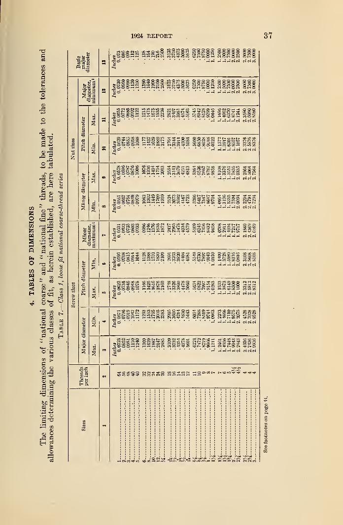
4. Tables of dimensions 37
1 New material not included in the progress report of Jan. 4, 1921.
1
2 NATIONAL SCREW THREAD COMMISSION
Section III. Screw threads for bolts, etc.—Continued. Page
5. Specifications for threading tools 1 53
(a) Form of tools for producing screws 53
(b) Taps 58
(c) Tap-drill sizes 63
6. Gages 1 67
(a) Fundamentals 67
(b) Gaging practices and types of gages 69
(c) Specifications for gages 73
Section IV. Screw threads of special diameters, pitches, and lengths of
engagement 1 88
1. Form of thread 88
2. Thread series 88
3. Classification and tolerances 88
(a) General specifications 88
(6) Classification of fits 90
4. Specifications for threading tools 101
(a) Form of tools for producing screws 101
(b) Taps 101
(c) TapdriUs 102
5. Gages 103
(a) Specifications for gages 103
Section V. National hose-coupling and fire-hose coupling threads 106
1. Form of thread 108
2. Thread series 108
(a) National hose-coupling threads 108
(b) National fire-hose coupling threads 109
3. Allowances and tolerances 109
4. Tables of dimensions 112
5. Gages 1 113
(a) Gages for national fire-hose coupling threads. 1 13
Section VI. National pipe threads 114
1. Form of thread 115
(a) Specifications 115
(6) Illustration 115
2. Symbols ... 116
3. Thread series 116
(a) National (American Briggs') taper pipe
threads 116
(b) National straight pipe threads 120
(c) National locknut threads 122
4. Tables of pipe dimensions 124
5. Threading tools 1 126
(a) Taps 126
lb) Tap driUs 126
6. Gages 128
(a) Classification of gages 128
(b) Gaging practices 130
(c) Specifications for gages 130
Section VII. Wood screws 1 139
1. General specifications 139
2. Thread series 141
1 New material not included in the progress report of Jan. 4, 1921.
1924 REPORT 3
Section VII. Wood screws—Continued. Page
3. Tolerances on length 141
(a) Flat and oval-head screws 141
(&) Round-head screws 141
4. Standard sizes of wood screws 142
(a) Steel screws 142
(6) Brass screws 142
Appendix 1. Derivation of tolerances 1 145
1. Pitch diameter tolerances 145
(a) Tolerances for fastening screws 145
(6) Tolerances for screw threads of special diam-
eters, pitches, and lengths of engage-
ment 145
2. Relation of lead and angle errors to pitch diameter
tolerances 146
(a) Diameter equivalent of lead error 146
(6) Diameter equivalent of angle error 146
Appendix 2. Wire methods of measurement of pitch diameter 1 147
1. Size of wires 147
2. Specification for wires 149
3. Methods of measuring and using wires 149
4. Measurement of pitch diameter of national straight
threads 150
5. Measurement of pitch diameter of national taper
threads 151
6. Measurement of pitch diameter of thread ring gages_ 153
Appendix 3. Control of accuracy of thread elements in the production of
threaded product 1 156
1. Fundamental factors 156
(a) Tool controlled by lead screw 156
(b) Self-leading threading tool 157
2. Cutting of screw threads 157
(a) Single-point tool 157
(b) Thread chaser 158
(c) Tap or die 158
(d) MiUing cutter 159
(e) Threading hob 159
3. Rolling of screw threads 160
(a) Threading roll 160
(b) Thread rolling dies 160
4. Finishing of screw threads 161
(a) Grinding 162
(6) Lapping 162
Appendix 4. Design and construction of gages 163
1. Material 168
2. Plug thread gages 163(a) Type 163
(6) Design of "go" thread plug gages 163
(c) Design of " not go " thread plug gages 164
3. Ring thread gages 164
(a) Type 164
(&) Design of "go" thread ring gages 164
(c) Design of "not go" thread ring gages 164
1 New material not included in the progress report of Jan. 4, 1921.
4 NATIONAL SCREW THREAD COMMISSION
Appendix 4. Design and construction of gages—Continued. p3ge4. Plain plug gages 164
5. Plain ring gages 164
6. Plain snap gages 164
Appendix 5. Future work of the commission 1 165
1. Screw threads used in electrical industry 165
2. Bolt and nut proportions and wrench openings 165
3. Machine-screw and stove-bolt proportions 166
4. Oil-well casing threads 166
5. Wrench fit of threaded studs 167
6. Wire gages, and stock sizes of wire, metal sheet, andplate 167
7. Acme threads 168
8. Other standardization projects 169
(a) Tolerance specifications for pipe threads
subject to high pressures 169
(6) Instrument-tubing threads 169
(c) Threads on instrument screws 169
(d) Form of thread for valve stems 169
(e) Threads on condenser-tube ferrules 169
(J) Plumbers' fine threads 169
(g) Special threads 169
Index 171
SECTION I. INTRODUCTION
1. HISTORICAL
The initial accomplishment in the standardization of screw threads
in the United States was the report under date of December 15, 1864,
of the special committee appointed by the Franklin Institute on April
21, 1861, for the investigation of a proper system of screw threads,
bolt heads, and nuts to be recommended by the institute for adop-
tion and general use by American engineers.
In its report this committee recommended a thread system designed
by William Sellers. This thread system specified a single series of
pitches for certain diameters from one-fourth inch to 6 inches, in-
clusive. The threads had an included angle of 60° and a flat at the
crest and root equal to one-eighth of the pitch. This system cameinto general use and was known as the Franklin Institute thread,
the Sellers thread, and commonly as the United States thread.
The accomplishments realized in the adoption of the Franklin In-
stitute, or United States standard thread, in 1864 were brought
about largely by the great need of standard threads by Americanrailroads for the development of their lines and equipment. In May,1868, this thread was adopted by the United States Navy.In recent years numerous organizations have carried forward the
standardization of screw threads. The American Society of Mechani-
1 New material not included in the progress report of Jan. 4, 1921.
1924 REPORT 5
cal Engineers, the Society of Automotive Engineers, the Bureau of
Standards, and prominent manufacturers of specialized threaded
products have been the chief influences in standardization of screw
threads in this country. In England the standardization of screw
threads began with the efforts of Sir Joseph Whitworth in ascertain-
ing shop practice in the manufacture of screw threads resulting in
the standardization and adoption of the Whitworth thread system,
which found extensive use in England. This work has been carried
forward by the British Engineering Standards Association, an organi-
zation formed in 1901.
While the United States standard thread system fulfilled a great
need in the period of the development of our great railway systems,
it did not fully meet the requirements of modern manufacture be-
cause of the need for additional standard sizes and pitches developed
in other industries, and especially because of the need for definitely
specified limiting sizes of threaded parts. To fulfill the first of these
needs, a thread system having finer pitches than the United States
standard system was recommended by the Society of Automotive
Engineers, and a machine-screw thread series which provided smaller
sizes of screws than the United States standard threads was recom-
mended by the American Society of Mechanical Engineers. Theprogress of machine design and manufacture has established an ex-
tensive use of these fine thread series.
With the great extension of quantity production in this and other
countries, particularly during the World War, the need for national
standard limiting dimensions was emphasized, as one of the pre-
requisites of quantity production is standardization of form and di-
mensions of parts, in order that interchangeability may be established.
This is especially important in the matter of screw-thread parts, since
there are two mating parts that must fit and these parts in manycases are made in different places. Standardization of screw threads
is important to both the manufacturer and the user of a machine, as
the user should be able to buy locally a screw or nut for replacement
in case of breakage or wear.
2. AUTHORIZATION
Through the efforts of several of the engineering societies, the
Bureau of Standards, and prominent manufacturers of screw-thread
products, a petition was presented to Congress requesting the appoint-
ment of a commission to investigate and promulgate standards of
screw threads to be adopted by manufacturing plants under the
control of the Army and Navy and for adoption and use by the public.
(a) Commission Authorized by Congress.—As a result of this
action the National Screw Thread Commission was authorized by
6 NATIONAL SCREW THREAD COMMISSION
the following act of Congress, approved July 18, 1918 (Public Act
No. 201, H. R. 10852, 65th Cong.):
AN ACT To provide for the appointment of a commission to standardize screw threads.
Be it enacted by the Senate and House of Representatives of the United States of
America in Congress assembled, That a commission is hereby created, to beknown as the Commission for the Standardization of Screw Threads, hereinafter-
referred to as the commission, which shall be composed of nine commissioners,
one of whom shall be the Director of the Bureau of Standards, who shall be chair-
man of the commission; two commissioned officers of the Army, to be appointed
by the Secretary of War; two commissioned officers of the Navy, to be appointed
by the Secretary of the Navy; and four to be appointed by the Secretary of Com-merce, two of whom shall be chosen from nominations made by the American
Society of Mechanical Engineers and two from nominations made by the Society
of Automotive Engineers.
Sec. 2. That it shall be the duty of said commission to ascertain and establish
standards for screw threads, which shall be' submitted to the Secretary of War,the Secretary of the Navy, and the Secretary of Commerce for their acceptance
and approval. Such standards, when thus accepted and approved, shall be
adopted and used in the several manufacturing plants under the control of the
War and Navy Departments, and, so far as practicable, in all specifications for
screw threads in proposals for manufactured articles, parts, or materials to be
used under the direction of these departments.
Sec. 3. That the Secretary of Commerce shall promulgate such standards for
use by the public and cause the same to be published as a public document.
Sec. 4. That the commission shall serve without compensation, but nothing
herein shall be held to affect the pay of the commissioners appointed from the
Army and Navy or of the Director of the Bureau of Standards.
Sec. 5. That the commission may adopt rules and regulations in regard to
its procedure and the conduct of its business.
Sec. 6. That the commission shall cease and terminate at the end of six
months from date of its appointment.
Approved, July 18, 1918.
(b) Life of Commission Extended by Congress.—Prior to the
expiration of the original term of six months for which the commis-
sion was appointed, it became apparent that it would be impossible
to complete in a satisfactory manner the work outlined by the com-mission. Extensions of time were, therefore, asked- by the com-mission and granted by Congress in accordance with the following
acts: Public Act No. 324 (H. R. 15495), 65th Cong.; Public Resolu-
tion No. 34 (H. J. Res. 299), 66th Cong. ; and Joint Public Resolution
No. 43 (H. J. Res. 227), 67th Cong. The term of the commission,
as last extended, expires March 21, 1927.
3. ORGANIZATION OF THE COMMISSION
(a) Preliminary Meeting.—As soon as nominees were selected
by the various organizations to be represented in the commission
a preliminary meeting was called at Washington, D. C, on Septem-ber 12, 1918, by Dr. S. W. Stratton, Director of the Bureau of
Standards and chairman of the commission. At this meeting the
1924 REPORT 7
organization of the commission was planned in order that workcould be started as soon as formal appointments of the various
members of the commission were made. The various commissioners
were formally appointed under date of September 21, 191S.
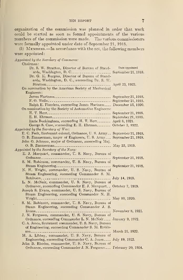
(&) Members.—In accordance with the act, the following memberswere appointed:
Appointed by the Secretary of Commerce:
Chairman
:
Dr. S. W. Stratton, Director of Bureau of Stand- Date appointed
ards, Washington, D. C September 21, 1918.
Dr. G. K. Burgess, Director of Bureau of Stand-
ards, Washington, D. C, succeeding Dr. S. W.Stratton April 23, 1923.
On nomination by the American Society of Mechanical
Engineers:
James Hartness September 21, 1918.
F. O. Wells September 21, 1918.
Ralph E. Flanders, succeeding James Hartness December 15, 1920.
On nomination by the Society of Automotive Engineers
:
H. T. Herr 1 September 21, 1918.
E. H. Ehrman September 21, 1918.
Earle Buckingham, succeeding H. T. Herr April 8, 1921.
George S. Case, succeeding E. H. Ehrman October 3, 1922.
Appointed by the Secretary of War:E. C. Peck, lieutenant colonel, Ordnance, U. S. Army-. September 21, 1918.
O. B. Zimmerman, major of Engineers, U. S. Army September 21, 1918.
John O. Johnson, major of Ordnance, succeeding Maj.
0. B. Zimmerman May 23, 1919.
Appointed by the Secretary of the Navy:
E. J. Marquart, commander, U. S. Navy, Bureau of
Ordnance September 21, 1918.
S. M. Robinson, commander, U. S. Navy, Bureau of
Steam Engineering September 21, 1918.
N. H. Wright, commander, U. S. Navy, Bureau of
Steam Engineering, succeeding Commander S. M.Robinson July 14, 1919.
L. N. McNair, commander, U. S. Navy, Bureau of
Ordnance, succeeding Commander E. J. Marquart, . October 7, 1919.
Joseph S. Evans, commander, U. S. Navy, Bureau of
Steam Engineering, succeeding Commander N. H.Wright r May 10, 1920.
S. M. Robinson, commander, U. S. Navy, Bureau of
Steam Engineering, succeeding Commander J. S.
Evans November 8, 1921.
J. N. Ferguson, commander, U. S. Navy, Bureau of
Ordnance, succeeding Commander L. N. McNair January 9, 1922.
C. A. Jones, lieutenant commander, U. S. Navy, Bureau
of Engineering, succeeding Commander S. M. Robin-
son March 21, 1922.
M. A. Libbey, commander, U. S. Navy, Bureau of
Engineering, succeeding Commander C. A. Jones July 19, 1922.
John B. Rhodes, commander, U. S. Navy, Bureau of
Ordnance, succeeding Commander J. N. Ferguson— February 20, 1924.
8 NATIONAll SCREW THREAD COMMISSION
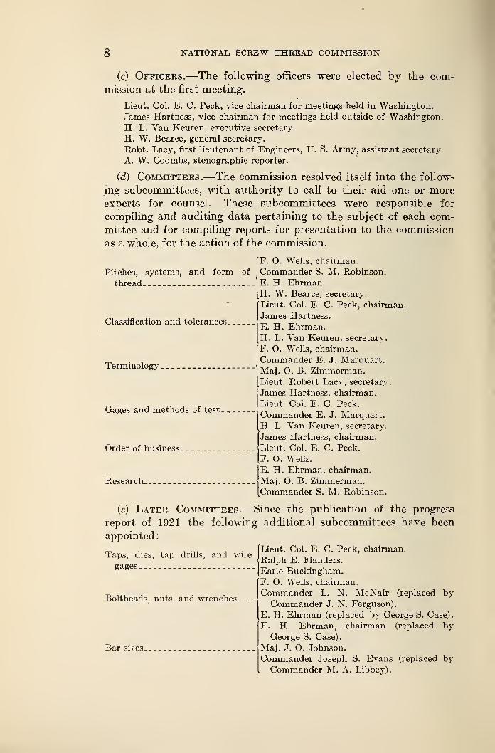
(c) Officers.—The following officers were elected by the com-mission at the first meeting.
Lieut. Col. E. C. Peck, vice chairman for meetings held in Washington.
James Hartness, vice chairman for meetings held outside of Washington.
H. L. Van Keuren, executive secretary.
H. W. Bearce, general secretary.
Robt. Lacy, first lieutenant of Engineers, U. S. Army, assistant secretary.
A. W. Coombs, stenographic reporter.
(<Z) Committees.—The commission resolved itself into the follow-
ing subcommittees, with authority to call to their aid one or moreexperts for counsel. These subcommittees were responsible for
compiling and auditing data pertaining to the subject of each com-
mittee and for compiling reports for presentation to the commission
as a whole, for the action of the commission.
Pitches, systems, and form of
thread
Classification and tolerances
Terminology
Gages and methods of test
Order of business
Research
F. O. Wells, chairman.
Commander S. M. Robinson.
E. H. Ehrman.H. W. Bearce, secretary.
Lieut. Col. E. C. Peck, chairman.
James Hartness.
E. H. Ehrman.H. L. Van Keuren, secretary.
F. O. Wells, chairman.
Commander E. J. Marquart.
Maj. O. B. Zimmerman.Lieut. Robert Lacy, secretary.
James Hartness, chairman.
Lieut. Col. E. C. Peck.
Commander E. J. Marquart.
H. L. Van Keuren, secretary.
James Hartness, chairman.
Lieut. Col. E. C. Peck.
F. O. Wells.
E. H. Ehrman, chairman.
Maj. O. B. Zimmerman.Commander S. M. Robinson.
Taps, dies, tap drills, and wire
gages
(e) Later Committees.—Since the publication of the progress
report of 1921 the following additional subcommittees have been
appointed
:
Lieut. Col. E. C. Peck, chairman.
Ralph E. Flanders.
Earle Buckingham.F. O. Wells, chairman.
Commander L. N. McNair (replaced byCommander J. N. Ferguson).
E. H. Ehrman (replaced by George S. Case).
E. H. Ehrman, chairman (replaced byGeorge S. Case).
Maj. J. O. Johnson.
Commander Joseph S. Evans (replaced byCommander M. A. Libbey).
Boltheads, nuts, and wrenches.
Bar sizes.
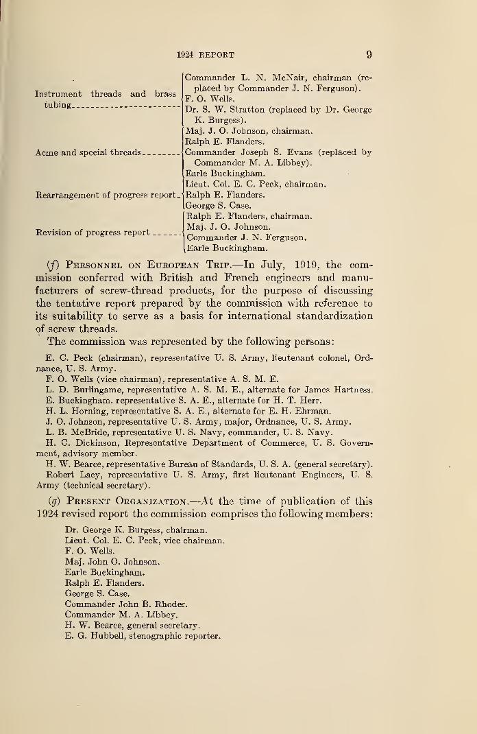
1924 REPORT 9
Instrument threads and brass
tubing
Acme and special threads.
Rearrangement of progress report.
Commander L. N. McNair, chairman (re-
placed by Commander J. N. Ferguson).
F. O. Wells.
Dr. S. W. Stratton (replaced by Dr. George
K. Burgess).
Maj. J. O. Johnson, chairman.
Ralph E. Flanders.
Commander Joseph S. Evans (replaced byCommander M. A. Libbey).
Earle Buckingham.Lieut. Col. E. C. Peck, chairman.
Ralph E. Flanders.
George S. Case.
Ralph E. Flanders, chairman.
. , Mai. J. O. Johnson.Revision of progress report „ ,Commander J. N. Ferguson.
[Earle Buckingham.
(/) Personnel on European Trip.—In July, 1919, the com-
mission conferred with British and French engineers and manu-facturers of screw-thread products, for the purpose of discussing
the tentative report prepared by the commission with reference to
its suitability to serve as a basis for international standardization
of screw threads.
The commission was represented by the following persons
:
E. C. Peck (chairman), representative U. S. Army, lieutenant colonel, Ord-
nance, U. S. Army.F. O. Wells (vice chairman), representative A. S. M. E.
L. D. Burlingame, representative A. S. M. E., alternate for James Hartness.
E. Buckingham, representative S. A. E., alternate for H. T. Herr.
H. L. Horning, representative S. A. E., alternate for E. H. Ehrman.J. 0. Johnson, representative U. S. Army, major, Ordnance, U. S. Army.L. B. McBride, representative U. S. Navy, commander, U. S. Navy.H. C. Dickinson, Representative Department of Commerce, U. S. Govern-
ment, advisory member.H. W. Bearce, representative Bureau of Standards, U. S. A. (general secretary).
Robert Lacy, representative U. S. Army, first lieutenant Engineers, U. S.
Army (technical secretary)
.
(g) Present Organization.—At the time of publication of this
1924 revised report the commission comprises the following members
:
Dr. George K. Burgess, chairman.
Lieut. Col. E. C. Peck, vice chairman.
F. O. Wells.
Maj. John O. Johnson.
Earle Buckingham.Ralph E. Flanders.
George S. Case.
Commander John B. Rhodes.
Commander M. A. Libbey.
H. W. Bearce, general secretary.
E. G. Hubbell, stenographic reporter.
10 RATIONAL, SCREW THREAD COMMISSION
(70 General Procedure.—In its work of establishing standards
for screw threads, the commission has made particular efforts to
secure actual facts concerning the need of standardization and the
economic conditions to be provided for in the production and use
of screw threads.
The work of the commission has proceeded rapidly, inasmuch as,
in recent years, the accomplishments of the American Society of
Mechanical Engineers, the Society of Automotive Engineers, andthe British Engineering Standards Association have paved the waytoward the adoption of necessary screw-thread standards. Further-
more, the commission has availed itself of the opportunity to se-
cure from the Tap Makers Association and representatives of prom-
inent manufacturing concerns valuable information and data regard-
ing the production of tools and appliances for making threaded prod-
ucts, as well as information and data regarding the application and
use of screw-thread products.
Steps were taken to secure from various screw-thread authorities,
and representative manufacturers and users, testimony as to the
nature of the standards to be adopted for the use of the Governmentand for American manufacturers. To secure this information public
hearings were conducted in various industrial centers throughout the
country; and Government officials, authorities on screw threads,
manufacturers, and users of screw-thread products, as well as manu-facturers of taps, dies, gages, and other tools required for producing
screw-thread products, were invited to attend these hearings andpresent their views on various phases of the subject. In addition,
announcements of the meetings, extending invitations to all interested
to be present, were published in the technical magazines. Topic
sheets were distributed in advance of the hearings in order that wit-
nesses could prepare their views on the subjects of the meeting in
a definite, concise, and authentic form.
A large amount of evidence was collected in this way and the op-
portunity was available for the various members of the commission
to bring out by cross-examination information which could have been
secured in no other way. This evidence was tabulated for the con-
sideration of the commission in formulating its report.
A large number of experiments and tests were made by the Bureauof Standards to verify the results obtained at the various hearings
and also in connection with the development of tolerances and of
other technical subjects considered by the commission. In addition
to the experiments conducted by the Bureau of Standards, the mem-bers of the commission individually conducted experiments and re-
search work at their ovm expense.
With regard to the possibilities of international standardization
of screw threads, it is the opinion of the commission that not only
1924 REPORT 11
is such international standardization very desirable, but that the
present time is most opportune for accomplishments in this direction.
Furthermore, international standardization is of great importance in
connection with the development of foreign trade.
In July, 1919, the commission visited Europe to confer with
British and French engineering standards organizations, and while
no definite agreements were reached in regard to international
standardization of screw threads, it was apparent in both France
and England that the engineers and manufacturers in these coun-
tries were anxious to cooperate with the United States in this work.
The time is very opportune for accomplishments along this line,
and it is the opinion of the commission that, as a result of the war,
it should be possible to reach an agreement on an international
standard thread. Such an international standard should be estab-
lished by giving consideration to the predominating sizes andstandards used in manufactured products, as well as to the possi-
bilities of providing a means for producing this international screw
thread by the use of either the English or the metric system of
measurement.
The advances made by the commission up to date will facilitate
manufacture in case of war, make the best use of labor in our indus-
tries in time of peace, increase the safety of travel by rail, steam-
ship, and airplane, and, in general, will increase the dependability
of all mechanisms. Every step toward standardization will result
in increased production with a minimum expenditure of materials,
energies, and other resources.
The commission, in formulating this report, has acted largely
in a judicial capacity, basing its decisions upon evidence received
from authorities on screw-thread subjects and upon the conclusions
drawn by other organizations having to do with standardization of
screw threads. In addition, the various subjects dealt with have
been considered with a knowledge of present manufacturing con-
ditions and with anticipation of further development in the pro-
duction of screw-thread products. Above all, it is the intention of
the commission to facilitate and promote progress in manufacture.
4. ARRANGEMENT OF REPORT
There are included in the body of the report matters of particular
importance and of general interest, while in the appendixes there is
arranged supplementary information of both a general and a tech-
nical nature. There is included in the body of the report sufficient
information to permit the writing of definite and complete speci-
fications for the purchase of screw-thread products.
The specifications in the report have been arranged, as far as
possible, by products. For example, one section deals with threads
12 NATIONAL. SCREW THREAD COMMISSION
for bolts and nuts, etc., another with hose-coupling threads, anotherwith pipe threads, etc. As far as practicable, each section is arrangedin the following order:
1. Form of thread.
2. Thread series.
3. Classification and tolerances.
4. Tables of dimensions.
5. Specifications of threading tools.
6. Gages.
5. GENERAL
One of the most important phases of standardization of screw-
thread products is that of interchangeability. The direct result of
establishing a national thread system will be the elimination of
many unnecessary sizes. Of even more importance are the
advantages to be gained in the manufacture of interchangeable
screw-thread parts, especially when made in different manufacturing
plants located at a distance from each other, which will assemble
without difficulty and in a dependable manner.
(a) Strict Interchangeability.—Many manufacturers, previ-
ous to the war, were making interchangeable machine parts in
their own shops where there was but one master gage or reference
standard, but one individual who had authority to pass on parts in
dispute, and where it was possible to secure assembly and satis-
factory operation by fitting the parts.
The experience gained by manufacturers producing war material
has demonstrated the economic advantage of producing inter-
changeable parts, especially where large quantities of parts are
manufactured. In addition to the direct saving in the cost of
manufacture, the numerous advantages to be gained make it manda-tory that a definite procedure for producing interchangeable workto specified tolerances be explicitly followed, if we, as manufacturers,
are to keep pace with or lead in the world's progress.
A screw-thread fit can not be accurately made with the samefacility as the fit of a plain hole and shaft. In the fit of a plain hole
and shaft only three elements are taken into account in securing a
given class of fit, namely, rotundity, diameter, and length; whereas
in a screw-thread fit it is necessary to consider rotundity, length,
major diameter, pitch diameter, minor diameter, angle of thread,
and pitch or lead. A variation in any one of these elements of a
screw thread will prevent a perfect fit, so that it is much more diffi-
cult to make a perfect screw-thread fit than it is to make a plain
bearing fit.
(&) Need of Definite Specifications.—The difficulties en-
countered in obtaining enormous quantities of war material needed
1924 REPORT 13
by the United States Government during the recent World Warpointed out to Government authorities, as well as manufacturers,
the need of writing definite and complete specifications for material
required. All specifications should be so written that the qualities
in the product desired are stated in definite terms of known measur-
able standards and correctly defined by the largest tolerance limits
compatible with the satisfactory operation or performance of the
articles or material for the purpose intended. To this end every
factor involved in the acceptability of the manufactured product
required should be comparable within specified limits with a knownmeasurable standard. Every specification should be so definite
that no dispute regarding the limiting lines of acceptance can arise.
SECTION II. TERMINOLOGY
In this report there are utilized, as far as possible, nontechnical
words and terms which best convey alike to the producer and user of
screw threads the information presented.
1. DEFINITIONS
The following definitions are given of the more important terms
used in the report. Definitions of terms which are obviously ele-
mentary in character are intentionally omitted.
(a) Terms Relating to Screw Threads.—1. Screw thread.—A ridge of uniform section in the form of a helix on the surface of a
cylinder or cone.
2. External and internal threads.—An external thread is a thread
on the outside of a member. Example: A threaded plug.
An internal thread is a thread on the inside of a member. Ex-ample: A threaded hole.
(These terms are here defined because of possible confusion arising
from the fact that an "internal member" has an "external thread,"
and vice versa.)
3. Major diameter {formerly Tcnown as "outside diameter").—-The
largest diameter of the thread of the screw or nut. The term "majordiameter" replaces the term "outside diameter" as applied to the
thread of a screw and also the term "full diameter" as applied to
the thread of a nut.
4. Minor diameter (formerly Tcnown as "core diameter").—Thesmallest diameter of the thread of the screw or nut. The term"minor diameter" replaces the term "core diameter" as applied to
the thread of a screw and also the term "inside diameter" as applied
to the thread of a nut.
5. Pitch diameter.—On a straight screw thread, the diameter of
an imaginary cylinder, the surface of which would pass through the
16802°—25t 2
14 NATIONAL SCREW THREAD COMMISSION
threads at such points as to make equal the width of the threads
and the width of the spaces cut by the surface of the cylinder. On a
taper screw thread, the diameter, at a given distance from a refer-
ence plane, of an imaginary cone, the surface of which would pass
through the threads at such points as to make equal the width of
the threads and the width of the spaces cut by the surface of the cone.
6. Pitch.—The distance from a point on a screw thread to a cor-
responding point on the next thread measured parallel to the axis.
The pitch in inches=c^ , t-t, ; :
—
rJN umber of threads per men
7. Lead.—-The distance a screw thread advances axially in one
turn. On a single-thread screw, the lead and pitch are identical;
on a double-thread screw the lead is twice the pitch; on a triple-
thread screw, the lead is three times the pitch, etc.
8. Angle of thread.—-The angle included between the sides of the
thread measured in an axial plane.
9. Helix angle.—The angle made by the helix of the thread at
the pitch diameter with a plane perpendicular to the axis.
10. Crest.—The top surface joining the two sides of a thread.
11. Root.—The bottom surface joining the sides of two adjacent
threads.
12. Side.—The surface of the thread which connects the crest
with the root.
13. Axis of a screw.—The longitudinal central line through the
screw.
14. Base of thread.—The bottom section of the thread; the greatest
section between the two adjacent roots.
15. Depth of thread.—The distance between the crest and the base
of thread measured normal to the axis.
16. Number of threads.—Number of threads in 1 inch of length.
17. Length of engagement.—The length of contact between twomating parts, measured axially.
18. Depth of engagement.—-The depth of thread contact of two
mating parts, measured radially.
(&) Terms Relating to Classification and Tolerances.—1. Allowance.—An intentional difference in the dimensions of mating
parts. It is the minimum clearance or the maximum interference
which is intended between mating parts. It represents the condition
of the tightest permissible fit, or the largest internal member matedwith the smallest external member. It is to provide for different
classes of fit. Examples
:
One-half inch, class 1, loose fit, national coarse thread:
Minimum pitch diameter of nut 0. 4500Maximum pitch diameter of screw . 4478
Allowance (positive) . 0022
1924 REPORT 15
One-half inch, class 4, close fit, national coarse thread
:
Minimum pitch diameter of nut 0. 4500
Maximum pitch diameter of screw . 4504
Allowance (negative) . 0004
2. Tolerance.—The amount of variation permitted in the size of a
part. Example
:
One-half inch screw, class 1, loose fit, national coarse thread:
Maximum pitch diameter 0. 4478
Minimum pitch diameter . 4404
Tolerance . 0074
3. Basic size.—The theoretical or nominal standard size from
which all variations are made.4. Crest clearance.—Defined on a screw form as the space between
the crest of a thread and the root of its mating thread.
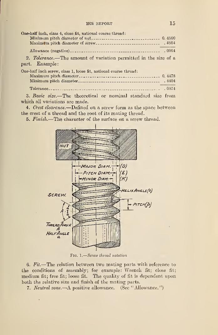
5. Finish.—The character of the surface on a screw thread.
Fig. 1.
—
Screw thread notation
6. Fit.—The relation between two mating parts with reference to
the conditions of assembly; for example: Wrench fit; close fit;
medium fit; free fit; loose fit. The quality of fit is dependent upon
both the relative size and finish of the mating parts.
7. Neutral zone.—A positive allowance. (See " Allowance. ")
16 NATIONAL SCREW THREAD COMMISSION
8. Limits.—The extreme permissible dimensions of a part. Ex-
ample :
One-half inch screw, class 1, loose fit, national coarse thread:
Maximum pitch diameter 0. 44781 These are
Minimum pitch diameter . 4404Jthe limits.
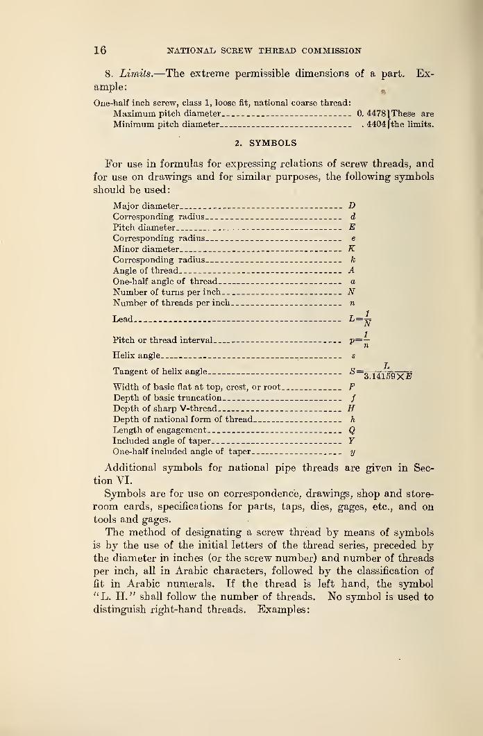
2. SYMBOLS
For use in formulas for expressing relations of screw threads, and
for use on drawings and for similar purposes, the following symbols
should be used
:
Major diameter DCorresponding radius d
Pitch diameter ECorresponding radius e
Minor diameter KCorresponding radius A;
Angle of thread AOne-half angle of thread a
Number of turns per inch NNumber of threads per inch n
Lead
Pitch or thread interval V=~nHelix angle s
Tangent of helix angle S==zHIE9XEWidth of basic flat at top, crest, or root FDepth of basic truncation /
Depth of sharp V-thread HDepth of national form of thread h
Length of engagement QIncluded angle of taper YOne-half included angle of taper y
Additional symbols for national pipe threads are given in Sec-
tion VI.
Symbols are for use on correspondence, drawings, shop and store-
room cards, specifications for parts, taps, dies, gages, etc., and on
tools and gages.
The method of designating a screw thread by means of symbols
is by the use of the initial letters of the thread series, preceded bythe diameter in inches (or the screw number) and number of threads
per inch, all in Arabic characters, followed by the classification of
fit in Arabic numerals. If the thread is left hand, the symbol
"L. H. " sball follow the number of threads. No symbol is used to
distinguish right-hand threads. Examples:
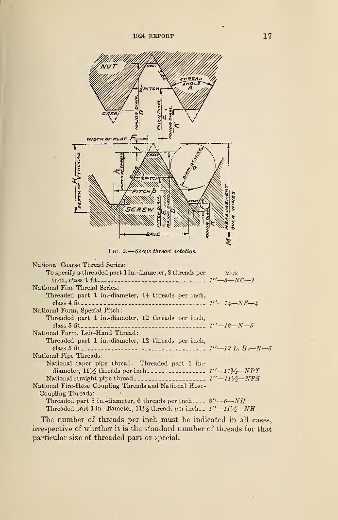
1924 KEPOET 17
Fig. 2.
—
Screw thread notation
National Coarse Thread Series:
To specify a threaded part 1 in.-diameter, 8 threads per Markinch, class 1 fit , l"—8—NC—l
National Fine Thread Series:
Threaded part 1 in.-diameter, 14 threads per inch,
class 4 fit 1"— 1J+—NF—4National Form, Special Pitch:
Threaded part 1 in.-diameter, 12 threads per inch,
class 5 fit l"—12—N—5National Form, Left-Hand Thread:
Threaded part 1 in.-diameter, 12 threads per inch,
class 5 fit 1"—12L. H.—N—5National Pipe Threads:
National taper pipe thread. Threaded part 1 in.-
diameter, 113^ threads per inch 1"—lty2—NPTNational straight pipe thread 1"—
—
NPSNational Fire-Hose Coupling Threads and National Hose-
Coupling Threads:
Threaded part 3 in.-diameter, 6 threads per inch 8"—6—NHThreaded part 1 in.-diameter, llj^ threads per inch.. 1"—11}/^—NH
The number of threads per inch must be indicated in all cases,
irrespective of whether it is the standard number of threads for that
particular size of threaded part or special.
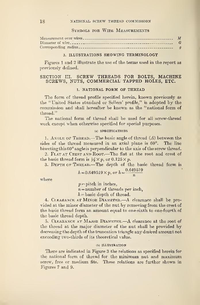
18 NATIONAL SCREW THREAD COMMISSION
Symbols for Wire Measurements
Measurement over wires MDiameter of wire GCorresponding radius g
3. ILLUSTRATIONS SHOWING TERMINOLOGY
Figures 1 and 2 illustrate the use of the terms used in the report as
previously denned.
SECTION III. SCREW THREADS FOR BOLTS, MACHINESCREWS, NUTS, COMMERCIAL TAPPED HOLES, ETC.
1. NATIONAL FORM OF THREAD
The form of thread profile specified herein, known previously as
the "United States standard or Sellers' profile," is adopted by the
commission and shall hereafter be known as the "national form of
thread."
The national form of thread shall be used for all screw-thread
work except when otherwise specified for special purposes.
(a) SPECIFICATIONS
1. Angle op Thread.—The basic angle of thread (A) between the
sides of the thread measured in an axial plane is 60°. The line
bisecting this 60° angle is perpendicular to the axis of the screw thread.
2. Flat at Crest and Root.—The flat at the root and crest of
the basic thread form is X p, or 0.125 X p.
3. Depth of Thread.—The depth of the basic thread form is
X X 0.649519A = 0.649519 Xp, or h =
wherep = pitch in inches,
?i =number of threads per inch,
h = basic depth of thread.
4. Clearance at Minor Diameter.—A clearance shall be pro-
vided at the minor diameter of the nut by removing from the crest of
the basic thread form an amount equal to one-sixth to one-fourth of
the basic thread depth.
5. Clearance at Major Diameter.—A clearance at the root of
the thread at the major diameter of the nut shall be provided bydecreasing the depth of the truncation triangle any desired amount not
exceeding two-thirds of its theoretical value.
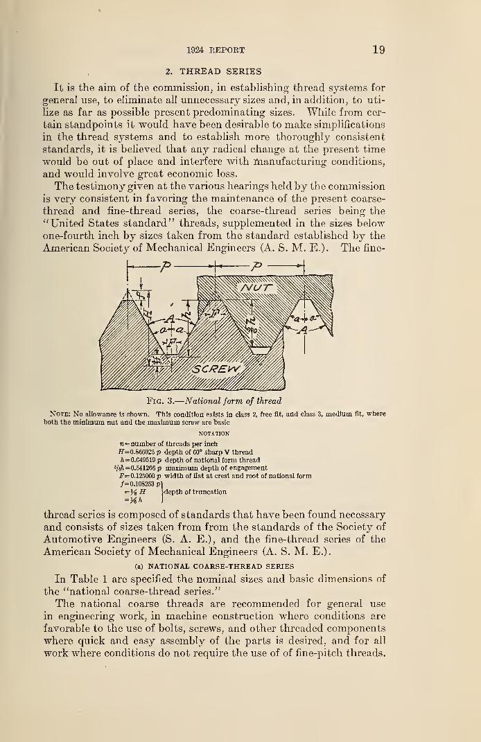
(b) ILLUSTRATION
There are indicated in Figure 3 the relations as specified herein for
the national form of thread for the minimum nut and maximumscrew, free or medium fits. These relations are further shown in
Figures 7 and 9.
4
1924 REPORT 19
2. THREAD SERIES
It is the aim of the commission, in establishing thread systems for
general use, to eliminate all unnecessary sizes and, in addition, to uti-
lize as far as possible present predominating sizes. While from cer-
tain standpoints it would have been desirable to make simplifications
in the thread systems and to establish more thoroughly consistent
standards, it is believed that any radical change at the present time
would be out of place and interfere with manufacturing conditions,
and would involve great economic loss.
The testimony given at the various hearings held by the commission
is very consistent in favoring the maintenance of the present coarse-
thread and fine-thread series, the coarse-thread series being the" United States standard" threads, supplemented in the sizes belowone-fourth inch by sizes taken from the standard established by the
American Society of Mechanical Engineers (A. S. M. E.). The fine-
P H- p
Fig. 3.
—
National form of thread
Note: No allowance is shown. This condition exists in class 2, free fit, and class 3, medium fit, where
both the minimum nut and the maximum screw are basic
NOTATION
n=number of threads per inch
H=0.866025 p depth of 60° sharp V thread
ft =0.649519 p depth of national form thread
•/«ft =0.541266 p maximum depth of engagementF= 0.125000 p width of flat at crest and root of national form/=0.108253 pi
=Y% H Idepth of truncation
=KA J
thread series is composed of standards that have been found necessary
and consists of sizes taken from from the standards of the Society of
Automotive Engineers (S. A. E.), and the fine-thread series of the
American Society of Mechanical Engineers (A. S. M. E.).
(a) RATIONAL COARSE-THREAD SERIES
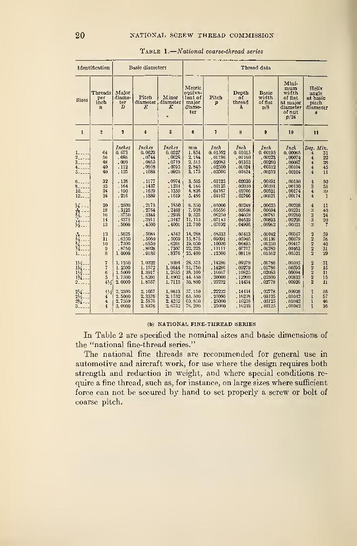
In Table 1 are specified the nominal sizes and basic dimensions of
the "national coarse-thread series."
The national coarse threads are recommended for general use
in engineering work, in machine construction where conditions are
favorable to the use of bolts, screws, and other threaded componentswhere quick and easy assembly of the parts is desired, and for all
work where conditions do not require the use of of fine-pitch threads.
20 NATIONAL, SCREW THREAD COMMISSION
Table 1.
—
National coarse-thread series
Identification Basic diameters Thread data
„. .
JVLini*
IVJ. CL11L mum HelixM a]orPitch
onn i i7o „'
1
i ii J v a T>pr»thJ-'opcu Basic width angleper diame- Minor lent of Pitch Of width of flat at basic
Sizesinch ter diameter diameter major V thread of flat at major pitchn j) E (\ iam p-
v_Alame ft PI a diameterter s
VI"
1 2 3 4 5 6 7 8 9 10 11
Inches Inches Inches 771771 Inch Inch Inch Inch Deo. Min.\ 64 0. 073 0. 0629 0. 0527 1. 854 0. 01562 0. 01015 V. UwUJ 4 312 56 !o86 !0744 !0628 2. 184 '. 01786 ! 01160 .00223 .00074 4 223 48 .099 .0855 .0719 2. 515 .02083 . 01353 .00260 .00087 4 264 40 . 112 .0958 .0795 2. 845 . 02500 . 01624 .00312 .00104 4 455 40 . 125 .1088 .0925 3. 175 .02500 . 01624 .00312 . 00104 4 11
g 32 . 138 . 1177 . 0974 3. 505 . 03125 . 02030 . 00391 . 00130 4 .50
8 32 ! 164 !l437 '. 1234 i. 166 '. 03125 '. 02030 ! 00391 ! 00130 3 5810_„__ 24 . 190 . 1629 .1359 4.826 .04167 .02706 .00521 .00174 4 3912 24 .216 .1889 .1619 5.486 . 04167 .02706 . 00521 .00174 4 1
M— 20 .2500 .2175 .1850 6.350 .05000 . 03248 .00625 .00208 4 11-5,lS
%— 18 . 3125 . 2764 . 2403 7. 938 . 00694 . 00231 3 4016 !3750 !3344 !2938 9] 525 .06250 .04059 ! 00781 ! 00260 3 24
7TS 14 .4375 .3911 .3447 11. 113 . 07143 .04639 .00893 .00298 3 20
Vi—
-
13 .5000 .4500 .4001 12.700 . 07692 .04996 .00962 .00321 3 7
A—
-
12 . 5625 .5084 .4542 14.288 .08333 . 05413 . 01042 .00347 2 59
%— 11 . 6250 . 5660 . 5069 15. 875 . 09091 . 05905 . 01136 . 00379 2 56
24—- 10 .7500 .6850 .6201 19. 050 . 10000 .06495 . 01250 .00417 2 40
Vs.— 9 .8750 .8028 .7307 22. 225 . 11111 . 07217 . 01389 .00463 2 31
l 8 1.0000 .9188 .8376 25. 400 . 12500 . 08119 . 01562 .00521 2 29
m— 7 1. 1250 1. 0322 .9394 28. 575 . 14286 .09279 .01786 . 00595 2 31M— 7 1.2500 1. 1572 1. 0644 31. 750 . 14286 . 09279 . 01786 . 00595 2 15M— 6 1. 5000 1. 3917 1.2835 38. 100 . 16667 . 10825 .02083 .00694 2 11
m~. 5 1. 7500 1. 6201 1. 4902 44. 450 .20000 . 12990 .02500 .00833 2 152 2.0000 1. 8557 1. 7113 50.800 . 22222 . 14434 . 02778 .00926 2 11
2X— 2. 2500 2. 1057 1. 9613 57. 150 . 22222 . 14434 . 02778 .00926 1 55
2V2-- 4 2.5000 2. 3376 2. 1752 63. 500 .25000 . 16238 .03125 . 01042 1 57
2M-- 4 2. 7500 2. 5876 2. 4252 69. 850 .25000 . 16238 .03125 . 01042 1 46
3 4 3. 0000 2. 8376 2. 6752 76. 200 . 25000 . 16238 . 03125 .01042 1 36
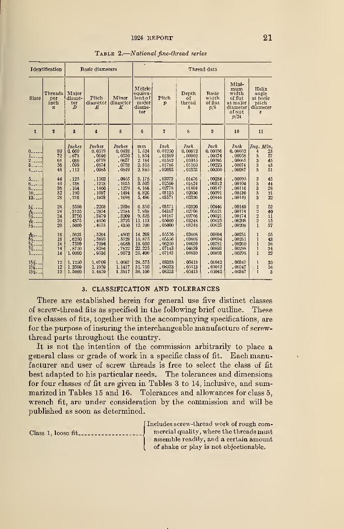
(b) NATIONAL FINE-THREAD SERIES
In Table 2 are specified the nominal sizes and basic dimensions of
the "national fine-thread series."
The national fine threads are recommended for general use in
automotive and aircraft work, for Use where the design requires both
strength and reduction in weight, and where special conditions re-
quire a fine thread, such as, for instance, on large sizes where sufficient
force can not be secured by hand to set properly a screw or bolt of
coarse pitch.
1924 REPORT 21
Table 2.
—
National fine-thread series
Identification Basic diameters Thread data
Mini-Metric mum Helix
Threads Major equiva- Depth Basic width angleSizes per diame- Pitch Minor lent of Pitch of width of flat at basic
inch ter diameter diameter major V thread of flat at major pitchn D E K diame- ft p/8 diameter diameter
ter of nut s
p/24
1 2 $ 4 g g 1 g 9 10 11
Inches Inches Inches mm Inch Inch Inch Inch Deg. Min.80 0.060 0. 0519 0.0438 1. 524 0. 01250 0.00812 0. 00156 0. 00052 4 23
1 72 .073 .0640 .0550 1. 854 . 01389 . 00902 . 00174 .00058 3 572 64 . 086 . 0759 . 0657 2. 184 . 01562 . 01015 . 00195 . 00065 3 453 56 . 099 . 0874 . 0758 2. 515 . 01786 . 01160 . 00223 . 00074 3 434 48 . 112 .0985 . 0849 2. 845 . 02083 . 01353 . 00260 . 00087 3 51
5 44 .125 .1102 .0955 3. 175 .02273 . 01476 .00284 .00095 3 456 40 .138 . 1218 . 1055 3. 505 .02500 .01624 . 00312 .00104 3 448 36 . 164 . 1460 . 1279 4. 166 . 02778 . 01804 . 00347 . 00116 3 2810 32 . 190 . 1697 . 1494 4. 826 . 03125 . 02030 . 00391 . 00130 3 2112.... 28 .216 .1928 .1696 5. 486 . 03571 . 02320 .00446 .00149 3 22
H— - 28 .2500 .2268 .2036 6. 350 . 03571 . 02320 .00446 .00149 2 52
ft—
-
24 .3125 .2854 .2584 7. 938 .04167 .02706 .00521 .00174 2 40
k~~ 24 .3750 .3479 .3209 9. 525 .04167 .02706 .00521 .00174 2 11
ft—
.
20 .4375 .4050 .3725 11. 113 .05000 .03248 .00625 . 00208 2 15
Vi— 20 .5000 .4075 .4350 12.700 .05000 .03248 .00625 .00208 1 57
ft
—
18 . 5625 .5264 .4903 14.288 . 05556 .03608 .00694 .00231 55
Vs 18 .6250 .5889 .5528 15. 875 .05556 . 03608 .00694 .00231 43
K—
-
Vs.—16 .7500 .7094 .6688 19.050 .06250 .04059 .00781 .00260 3614 .8750 .8286 .7822 22. 225 . 07143 .04639 .00893 .00298 34
1 14 1.0000 .9536 .9072 25.400 . 07143 .04639 .00893 .00298 22
1H— 12 1. 1250 1.0709 1. 0167 28. 575 .08333 .05413 .01042 .00347 2512 1.2500 1. 1959 1. 1417 31. 750 .08333 .05413 . 01042 .00347 16
1H— 12 1.5000 1. 4459 1. 3917 38. 100 .08333 .05413 .01042 . 00347 3
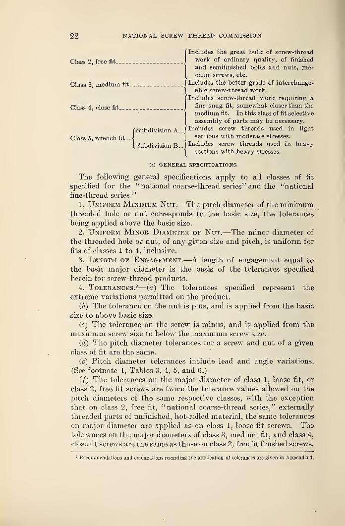
3. CLASSIFICATION AND TOLERANCES
There are established herein for general use five distinct classes
of screw-thread fits as specified in the following brief outline. These
five classes of fits, together with the accompanying specifications, are
for the purpose of insuring the interchangeable manufacture of screw-
thread parts throughout the country.
It is not the intention of the commission arbitrarily to place a
general class or grade of work in a specific class of fit. Each manu-facturer and user of screw threads is free to select the class of fit
best adapted to his particular needs. The tolerances and dimensions
for four classes of fit are given in Tables 3 to 14, inclusive, and sum-marized in Tables 15 and 16. Tolerances and allowances for class 5,
wrench fit, are under consideration by the commission and will be
published as soon as determined.
Class 1, loose fit.
Includes screw-thread work of rough com-mercial quality, where the threads mustassemble readily, and a certain amountof shake or play is not objectionable.
22 NATIONAL SCREW THREAD COMMISSION
Class 2, free fit
Class 3, medium fit
Includes the great bulk of screw-thread
work of ordinary quality, of finished
and semifinished bolts and nuts, ma-chine screws, etc.
Includes the better grade of interchange-
able screw-thread work.
CIncludes screw-thread work requiring a
Class 4 close fit J^ne snuS n% somewhat closer than the
|medium fit. In this class of fit selective
assembly of parts may be necessary.
{Subdivision A _f Includes screw threads used in light
1 sections with moderate stresses.
Subdivision B [Includes screw threads used in heavy
1 sections with heavy stresses.
(a) GENERAL SPECIFICATIONS
The following general specifications apply to all classes of fit
specified for the "national coarse-thread series" and the "national
fine-thread series."
1. Uniform Minimum Nut.—The pitch diameter of the minimumthreaded hole or nut corresponds to the basic size, the tolerances
being applied above the basic size.
2. Uniform Minor Diameter of Nut.—The minor diameter of
the threaded hole or nut, of any given size and pitch, is uniform for
fits of classes 1 to 4, inclusive.
3. Length of Engagement.—A length of engagement equal to
the basic major diameter is the basis of the tolerances specified
herein for screw-thread products.
4. Tolerances.2— (a) The tolerances specified represent the
extreme variations permitted on the product.
(b) The tolerance on the nut is plus, and is applied from the basic
size to above basic size.
(c) The tolerance on the screw is minus, and is applied from the
maximum screw size to below the maximum screw size.
(d) The pitch diameter tolerances for a screw and nut of a given
class of fit are the same.
(e) Pitch diameter tolerances include lead and angle variations.
(See footnote 1, Tables 3, 4, 5, and 6.)
(/) The tolerances on the major diameter of class 1, loose fit, or
class 2, free fit screws are twice the tolerance values allowed on the
pitch diameters of the same respective classes, with the exception
that on class 2, free fit, "national coarse-thread series," externally
threaded parts of unfinished, hot-rolled material, the same tolerances
on major diameter are applied as on class 1, loose fit screws. Thetolerances on the major diameters of class 3, medium fit, and class 4,
close fit screws are the same as those on class 2, free fit finished screws.
2 Recommendations and explanations regarding the application of tolerances are given in Appendix 1.
1924 REPORT 23
(g) The minimum minor diameter of a screw of a given pitch is
such as to result in a basic flat Q/% Xp) at the root when the pitch
diameter of the screw is at its minimum value. When the maximumscrew is basic, the minimum minor diameter of the screw will be below
the basic minor diameter by the amount of the specified pitch diameter
tolerance.
(h) The maximum minor diameter of a screw of a given pitch maybe such as results from the use of a worn or rounded threading tool,
when the pitch diameter is at its maximum value. In no case, how-ever, should the form of a thread, as results from tool wear, be such
as to cause the screw to be rejected on the maximum minor diameter
by a "go" ring gage, the minor diameter of which is equal to the
minimum minor diameter of the nut.
(i) The maximum major diameter of the nut of a given pitch is
such as to result in a flat equal to one-third of the basic flat X p)
when the pitch diameter of the nut is at its maximum value. Whenthe minimum nut is basic, its maximum major diameter will be above
the basic major diameter by the amount of the specified pitch diam-
eter tolerance plus two-ninths of the basic thread depth.
(j) The nominal minimum major diameter of a nut is the basic
major diameter. In no case, however, should the minimum majordiameter of the nut, as results from a worn tap or cutting tool, be
such as to cause the nut to be rejected on the minimum major diam-
eter by a "go" plug gage made to the standard form at the crest.
(k) The tolerance on the minoi diameter of a nut of a given pitch
is one-sixth of the basic thread depth regardless of the class of fit
being produced.(b) CLASSIFICATION OF FITS
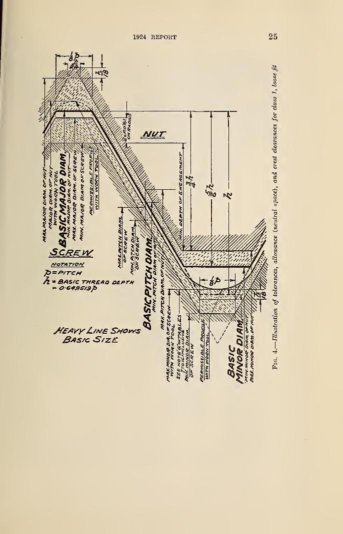
1. Class 1, Loose Fit.— (a) Definition.—The loose-fit class is
intended to cover the manufacture of threaded parts where quick
and easy assembly is necessary and a considerable amount of shake
or play is not objectionable.
This class has an allowance on the screw to permit ready assembly .
even when the threads are slightly bruised or dirty.
(b) Minimum nut basic.—The pitch diameter of the minimum nut
of a given diameter and pitch corresponds to the basic pitch diameter,
as specified in the tables of thread series given herein, which is com-puted from the basic major diameter of the thread. The pitch
diameter of the minimum nut is the theoretical pitch diameter for
that size.
(c) Maximum screw below basic. 3—The dimensions of the maximumscrew of a given pitch and diameter are below the basic dimensions
as specified in the tables of thread series given herein, which are
3 The maximum minor diameter of the screw is above the basic minor diameter, as shown in Figure 4.
24 NATIONAL SCREW THREAD COMMISSION
computed from the basic major diameter of the threads, by the
amount of the allowance given in Table 3.
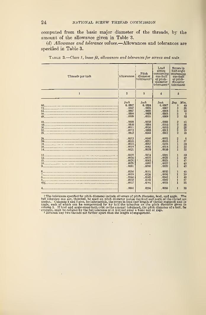
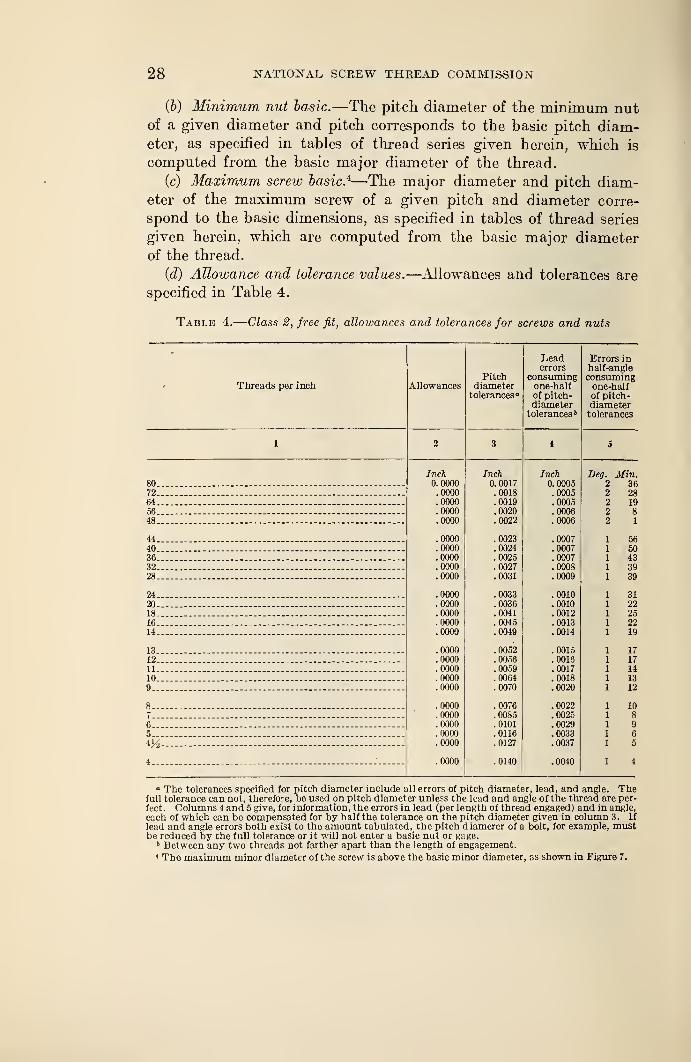
(d) Allowance and tolerance values.—Allowances and tolerances are
specified in Table 3.
Table 3.
—
Class 1, loose fit, allowances and tolerances for screws and nuts
Threads per inch AllowancesPitch
diametertolerances i
Leaderrors
consumingone-halfof pitch-diameter
tolerances 1
SO.
72-64.56.48..
44.,
40..
36.32.28.
24.20.
18.
16.
14.
13.12.11.
10.9-
8__7__6..5-.
4H
4_.
Inch0. 0007.0007.0007.0008.0009
.0009
.0010
.0011
.0011
.0012
.0013
.0015
.0016
.0018
.0021
.0022
.0024
.0026
.0028
.0031
.0034
.0039
.0044
.0052
.0057
.0064
Inch0.0024.0025.0026.0028.0031
.0032
.0034
.0036
.0038
.0043
.0046
.0051
.0057
.0063
.0070
.0074
.0079
.0085
.0092
.0100
.0111
.0124
.0145
.0169
.0184
.0204
Inch0.0007.0007.0008.0008.0009
.0009
.0010
.0010
.0011
.0012
.0013
.0015
.0016
.0018
.0020
.0021
.0023
.0025
.0027
.0029
.0032
.0036
.0042
.0049
.0053
.0059
1 The tolerances specified for pitch diameter include all errors of pitch diameter, lead, and angle. Thefull tolerance can not, therefore, be used on pitch diameter unless the lead and angle of the thread areperfect. Columns 4 and 5 give, for information, the errors in lead (per length of thread engaged) and inangle, each of which can be compensated for by half the tolerance on the pitch diameter given incolumn 3. If lead and angle errors both exist to the amount tabulated, the pitch diameter of a bolt, for
example, must be reduced by the full tolerance or it will not enter a basic nut or gage.2 Between any two threads not farther apart than the length of engagement.
1924 EEPOKT 25
J**SCREW
~fb=P/TCH• BAS/C TM#£AQ o£prn» -643S/3p
//EAvyJL/Ma ShowsBassc S/Z.E.
o
auJ-
<£>
<a
Ia
b
Sa
ua
oea2o
£
so
a
? ft*
oH
26 NATIONAL SCREW THREAD COMMISSION
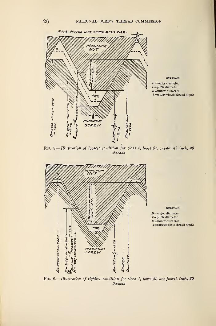
NOTATION
Z)=major diameter
iS=pitch diameter
j5T=minor diameter
ft =0.0325= basic thread depth
Fig. 5.
—
Illustration of loosest condition for class 1, loose fit, one-fourth inch, 20
threads
NOTATION
D= major diameter
2?= pitch diameter
K= minor diameter
ft =0.032S= basic thread depth
Fig. 6.
—
Illustration of tightest condition for class 1, loose fit, one-fourth inch, SO
threads
1924 REPORT 27
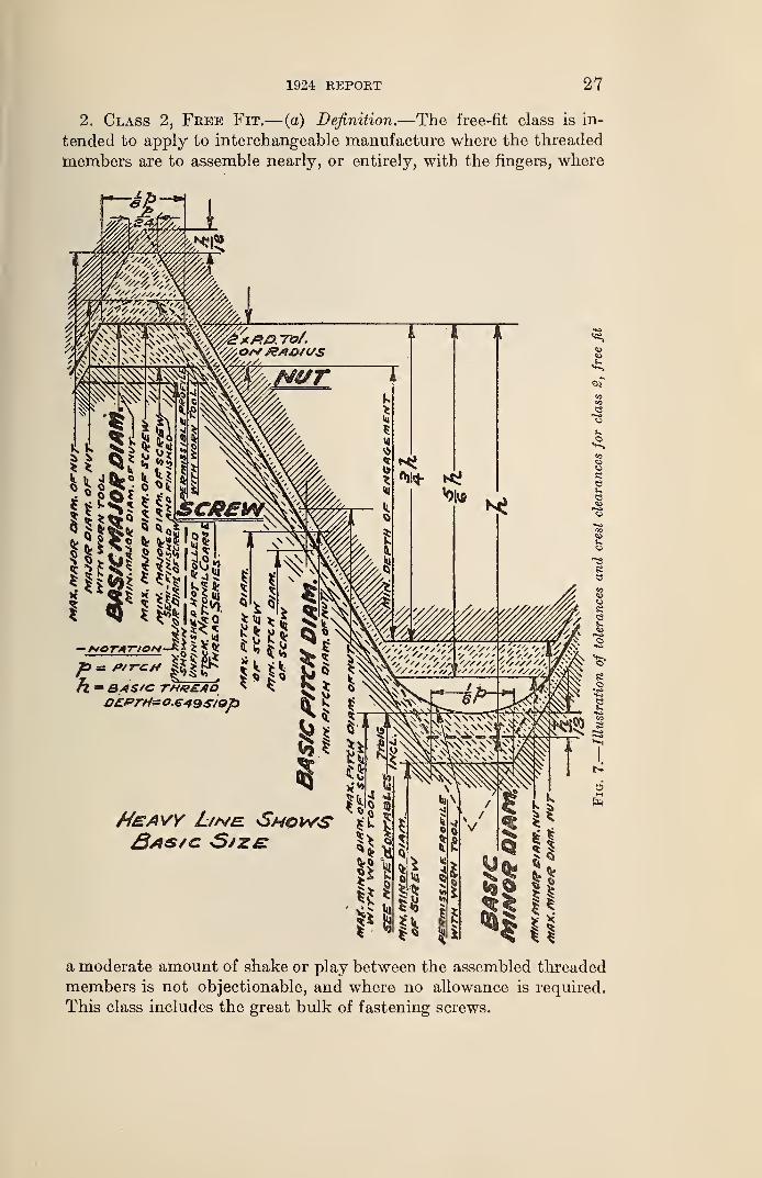
2. Class 2, Free Fit.— (a) Definition.—The free-fit class is in-
tended to apply to interchangeable manufacture where the threaded
members are to assemble nearly, or entirely, with the fingers, where
fl - B.AS/C THKEAO
Hsavy Ltne. Shows'
a moderate amount of shake or play between the assembled threaded
members is not objectionable, and where no allowance is required.
This class includes the great bulk of fastening screws.
28 NATIONAL SCREW THREAD COMMISSION
(6) Minimum nut basic.—The pitch diameter of the minimum nutof a given diameter and pitch corresponds to the basic pitch diam-eter, as specified in tables of thread series given herein, which is
computed from the basic major diameter of the thread.
(c) Maximum screw basic. 4—The major diameter and pitch diam-eter of the maximum screw of a given pitch and diameter corre-
spond to the basic dimensions, as specified in tables of thread series
given herein, which are computed from the basic major diameter
of the thread.
(d) Allowance and tolerance values.—Allowances and tolerances are
specified in Table 4.
Table 4.
—
Class 2, free fit, allowances and tolerances for screws and nuts
Threads per inch
80.
72.
64.56.48.
44.
40.36.
32.
28.
24.20.
18.
16.
14.
13-
12.
11.
10.
9..
8-7„6-a_.
4._
Allowances
Inch0.0000.0000.0000.0000.0000
.0000
. 0000
.0000
.0000
.0000
.0000
.0000
.0000
.0000
.0000
.0000
.0000
.0000
.0000
.0000
.0000
.0000
.0000
.0000
.0000
.0000
Pitchdiameter
tolerances
Inch0. 0017.0018.0019.0020.0022
.0023
.0024
.0025
.0027
.0031
.0033
.0036
.0041
.0045
.0049
.0052
.0056
.0059
.0064
.0070
.0076
.0085
.0101
.0116
.0127
.0140
Leaderrors
consumingone-halfof pitch-diameter
tolerances b
Inch0. 0005.0005.0005.0006.0006
.0007
.0007
.0007
.0008
.0009
.0010
.0010
.0012
.0013
.0014
.0015
.0016
.0017
.0018
.0020
.0022
.0025
.0029
.0033
.0037
.0040
Errors inhalf-angleconsumingone-halfof pitch-diametertolerances
Deg. Min.362819
5650433939
3122252219
17
171113
12
1089
6
5
4
» The tolerances specified for pitch diameter include all errors of pitch diameter, lead, and angle. Thefull tolerance can not, therefore, be used on pitch diameter unless the lead and angle of the thread are per-
fect. Columns 4 and 5 give, for information, the errors in lead (per length of thread engaged) and in angle,
each of which can be compensated for by half the tolerance on the pitch diameter given in column 3. If
lead and angle errors both exist to the amount tabulated, the pitch diamerer of a bolt, for example, mustbe reduced by the full tolerance or it will not enter a basic nut or gage.
b Between any two threads not farther apart than the length of engagement.1 The maximum minor diameter of the screw is above the basic minor diameter, ns shown in Figure 7.
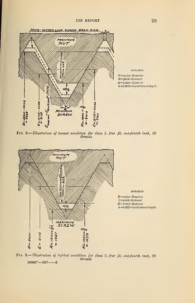
1924 REPORT 29
NOTATION
2>= major diameter
E= pitch diameter
K=minor diameter
A =0.0325= basic thread depth
Fig. 8.
—
Illustration of loosest condition for class 2, free fit, one-fourth inch, 20threads
30 NATIONAL SCREW THREAD COMMISSION
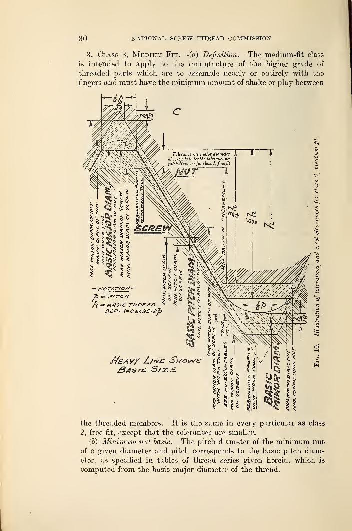
3. Class 3, Medium Fit.— (a) Definition.—The medium-fit class
is intended to apply to the manufacture of the higher grade of
threaded parts which are to assemble nearly or entirely with the
fingers and must have the minimum amount of shake or play between
0£FTH= O.£495 /£>h
MeAY/ Z//v£" Shows3as/c S/z. £.
the threaded members. It is the same in every particular as class
2, free fit, except that the tolerances are smaller.
(b) Minimum nut basic.—The pitch diameter of the minimum nut
of a given diameter and pitch corresponds to the basic pitch diam-
eter, as specified in tables of thread series given herein, which is
computed from the basic major diameter of the thread.
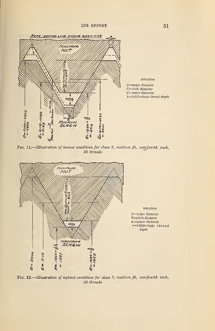
1924 REPORT 31
NOTATION
Z> = major diameter
E= pitch diameter
K=minor diameter
A =0.0325 = basic thread depth
Fig. 11.
—
Illustration of loosest condition for class 3, medium fit, one-fourth inch,
20 threads
NOTATION
D= major diameter
-E=piteh diameter
K=minor diameter
/i=0.0325=basic threaddepth
Fig. 12.
—
Illustration of tightest condition for class 3, medium fit, one-fourth inch,
20 threads
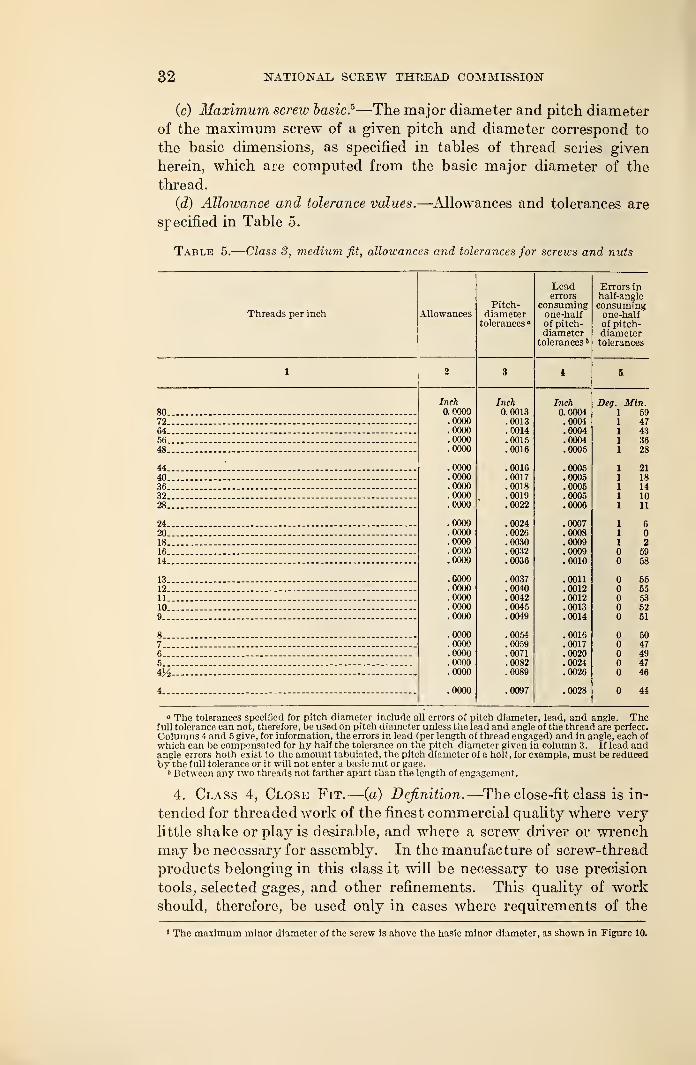
32 NATIONAL, SCREW THREAD COMMISSION
(c) Maximum screv: basic.5—The major diameter and pitch diameter
of the maximum screw of a given pitch and diameter correspond to
the basic dimensions, as specified in tables of thread series given
herein, which are computed from the basic major diameter of the
thread.
(d) Allowance and tolerance values.—Allowances and tolerances are
specified in Table 5.
Table 5.
—
Class S, medium fit, allowances and tolerances for screws and nuts
Threads Der inch AllowancesPitch-
diametertolerances
Leaderrors
consumingone-halfof pitch-diameter
tolerances b
Errors inhalf-angleconsumingone-halfof pitch-diametertolerances
80.72.
64.56.48.
44.40.36.32.28.
24.
20.
18.
16.
14.
13.
12.
11.
10.
9..
8..
7..6..5..
4..
Inch0.0000.0000.0000.0000.0000
.0000
.0000
.0000
.0000
.0000
.0000
.0000
.0000
.0000
.0000
.0000
.0000
.0000
.0000
.0000
.0000
.0000
.0000
.0000
.0000
.0000
Inch0.0013.0013.0014.0015.0016
.0016
.0017
.0018
.0019
.0022
.0024
.0026
.0030
.0032
.0036
.0037
.0040
.0042
.0045
.0049
.0054
.0059
.0071
.0082
.0089
.0097
Inch0.0004.0004.0004.0004.0005
.0005
.0005
.0005
.0005
.0006
.0007
.0008
.0009
.0009
.0010
.0011
.0012
.0012
.0013
.0014
.0016
.0017
.0020
.0024
.0026
.0028
Deg. Min.5947433628
2118141011
6
259
58
5555535251
6047494746
44
° The tolerances specified for pitch diameter include all errors of pitch diameter, lead, and angle. Thefull tolerance can not, therefore, be used on pitch diameter unless the lead and angle of the thread are perfect.
Columns 4 and 5 give, for information, the errors in lead (per length of thread engaged) and in angle, each of
which can be compensated for by half the tolerance on the pitch diameter given in column 3. If lead andangle errors both exist to the amount tabulated, the pitch diameter of a bolt, for example, must be reducedby the full tolerance or it will not enter a basic nut or gage.
* Between any two threads not farther apart than the length of engagement.
4. Class 4, Close Fit.—(a) Definition.—The close-fit class is in-
tended for threaded work of the finest commercial quality where very
little shake or play is desirable, and where a screw driver or wrench
may be necessary for assembly. In the manufacture of screw-thread
products belonging in this class it will be necessary to use precision
tools, selected gages, and other refinements. This quality of workshould, therefore, be used only in cases where requirements of the
1 The maximum minor diameter of the screw is above the basic minor diameter, as shown in Figure 10.
1924 EEPOET 33
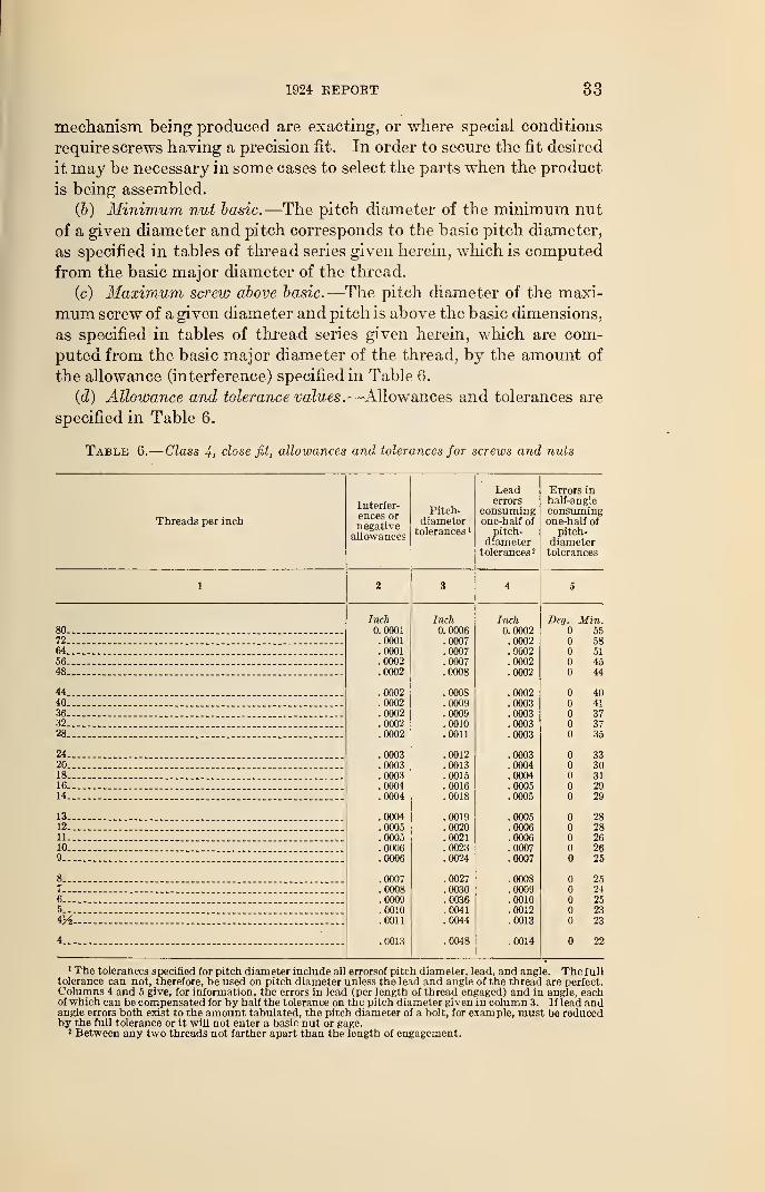
mechanism being produced are exacting, or where special conditions
require screws having a precision fit. In order to secure the fit desired
it may be necessary in some cases to select the parts when the product
is being assembled.
(b) Minimum nut basic.—The pitch diameter of the minimum nut
of a given diameter and pitch corresponds to the basic pitch diameter,
as specified in tables of thread series given herein, which is computed
from the basic major diameter of the thread.
(c) Maximum screw above basic.—The pitch diameter of the maxi-
mum screw of a given diameter and pitch is above the basic dimensions,
as specified in tables of thread series given herein, which are com-
puted from the basic major diameter of the thread, by the amount of
the allowance (interference) specified in Table 6.
(d) Allowance and tolerance values.—Allowances and tolerances are
specified in Table 6.
Table 6.
—
Class 4, close fit, allowances and tolerances for screws and nuts
Threads per inch
80..
72..
64..
56..
48..
44..
40..
36..
32..
28..
24..
20..
18..
16..
14..
13..
12..
11..
10..
9..
8...
7...
6...
5...
iy2
4..
Interfer-ences ornegativeallowances
Inch0.0001.0001.0001.0002.0002
.0002
.0002
.0002
.0002
.0002
.0003
.0003
.0003
.0004
.0004
.0004
.0005
.0005
.0006
.0006
.0007
.0008
.0009
.0010
.0011
.0013
Pitch-diameter
tolerances 1
Inch0. 0006.0007.0007.0007.0008
.0008
.0009
.0009
.0010
.0011
.0012
.0013
.0015
.0016
.0018
.0019
.0020
.0021
.0023
.0024
.0027
.0030
.0036
.0041
.0044
.0048
Leaderrors
consumingone-half of
pitch-diametertolerances 2
Inch0.0002.0002.0002.0002.0002
.0002
.0003
.0003
.0003
.0003
.0003
.0004
.0004
.0005
.0005
.0005
.0006
.0006
.0007
.0007
.0008
.0009
.0010
.0012
.0013
.0014
Errors inhalf-angleconsumingone-half of
pitch-diametertolerances
Beg. Min.55
58514544
40•11
373735
3330312929
2828262625
2524252323
22
1 The tolerances specified for pitch diameter include all errorsof pitch diameter, lead, and angle. The fulltolerance can not, therefore, be used on pitch diameter unless the lead and angle of the thread are perfect.Columns 4 and 5 give, for information, the errors in lead (per length of thread engaged) and in angle, eachof which can be compensated for by half the tolerance on the pitch diameter given in column 3. If lead andangle errors both exist to the amount tabulated, the pitch diameter of a bolt, for example, must be reducedby the full tolerance or it will not enter a basic nut or gage.
2 Between any two threads not farther apart than the length of engagement.
34 NATIONAL SCREW THREAD COMMISSION
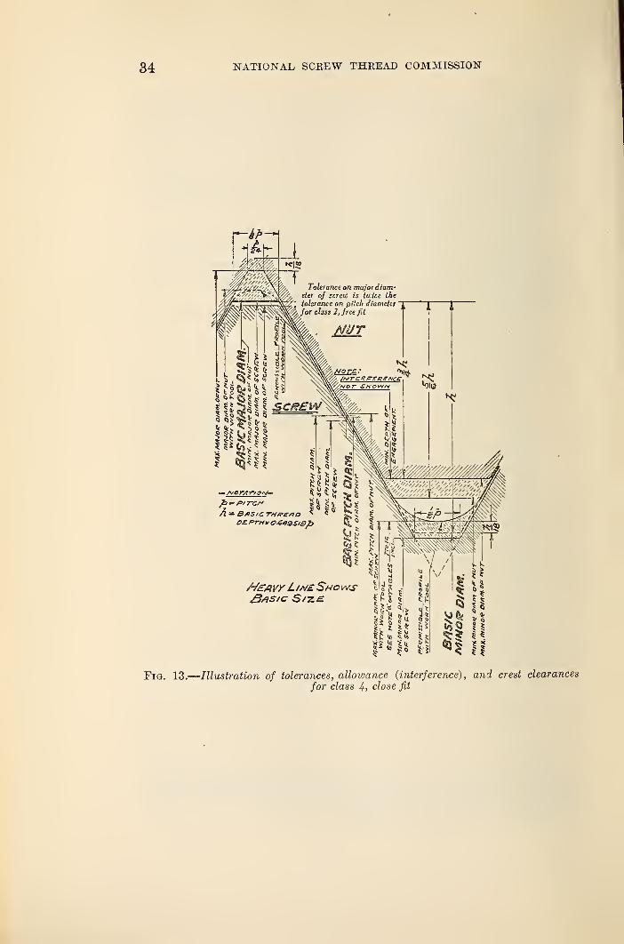
Fig. 13.
—
Illustration of tolerances, allowance (interference) , and crest clearances
for class 4, close fit
1924 EEPOET 35
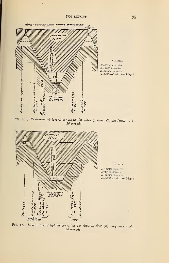
—Illustration of loosest condition for class 4, close fit, one-fourth inch,20 threads
Fig. 15.—Illustration of lightest condition for class 4, close fit, one-fourth inch,20 threads
36 NATIONAL SCREW THREAD COMMISSION
Pitch-InchJQ
.J,2
,J4 . 16
iUk&Zt « 2016 fG 14 13 12 II IO 3 & 7 G 3&XUX Number or Threads per /nch.
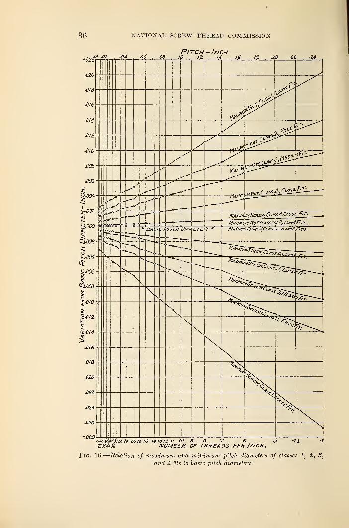
Fig. 16.
—
Relation of maximum and minimum pitch diameters of classes 1, 2, 3,
and 4 fits to basic pilch diameters
1924 REPORT 37
a
s
e- e
- '53 s° -2 ® ^« S-^ I
CD ~"£ o3 »
CD ^to so
i «d eO
—
m<!
H
a?? a
u <n a
'c? a a
all«1
SO Q n
h-gOO>HCN n©Ol H iO — COC£ O © © --> T HHHtNtN cert-*'
JE
« CM' CN CN cm" CO
En^ioP^©©© ©©©Q© OOC
- - - . _ _ _ .. _j »C © o © © O © © © © c?» r~ go © -h cn mo© —« o Ht^noco cN«ot^5iN i?5c5floii: 5 «3 cJSQOOHH T-H —' CS !M eO CO tP -O iO !Ot«OOOH N^NOCN O t-
C
HtNtN N N CO
iflr~CO©CN Hr>h.cOC1 CNOCOf-cONXOH <N tP to © CN ~"*>CPNCOO)h CN tP to © CN CO-#©iO.-i r-© —< CN tP o co t"» cn ioom!^0©©©—< H t-1 i-< i-t CN CNCOCOTpiO ^f(D*H CO O CO
tp 3; cn © tp ? ? 't ^ ^^ CN CN CN
© tP to CO C© t— © © iO nj* 1—< O tP 0O»»cN Nh.nt-r» O © ©cN-*-io»nco co cn co (O^hocc © o cn co cn t^HQioic r- t -^ 55 Cr 39 2? -1 © co ncoojoo oxo^m iqonioo co :o coJ © © © © hhhhIN CN CO CO tP o CD -X Ol O HMOXH CO GO
H i-I H H CNCNCN
xor- coto © © tp tp co h h co tp © cn co x a ri ^ ^ -»p -p tph>xxt>g r- co cd 10 1—1 co-^MOi-1 cd cn cdx o 1— o go co © © ©JiCCDNxO OCO-^NO mncOcNX CO »d CO r- GO HCOOXOT O O iO^ © © © © .-h »-( 1—( t-i r-< cn cn co co tp tp 10 © r~ co © r-Miot»o won
—t i—< i—( ^ CN CNCNCN
HN^OOi CN^OiC?*"© ^ CO CN CO Oh-I^N^ tCCOiCI'-* tP© © CO TP r- ^O^OiO <N t— © © CN COHTj'TfO iO © CO © © © © ©*5iOCDNXOi O^'l't-O) OOOHh CN Tp iO CO r- © •—I CO O O CN r-» CN^ © O © © © 1-1 »-» i-H i-H i-H CN CO CO tP >OCNXQ OMiflt^O N tP I-
^ CD i-3 i-I f-! i-J CN CN CN CN
r—1 CO CO CO CO CO CO CO CN NiCX^Cl © "O © CN CO CO —i TUfh- © © ©co co CN o co co -<p co cn co t— co r— o^iowic o »h © —i .-< co co co
5? 10 © r— co © ©CNcooao ^c6-too <—< cn co tp tj © © cn t— 00 co ao
i o © o 00 )tNco-f ^ iccor-coc<hhh CN CN CN
CXiO-f Tf XXOOC3 HtCO-f H OOh-MOJ OlXOCOcO CO CO CO0>0--'rHTti CN CO t— CO O © O CN O CO ^rtc7>1"iO O CN CO i-I f-t 000"iflNXOlO »h iC X H OCNCO-^OS iflt-XOH CO CO «-t O : fl^OOOOrH HHHHN CN CO CO Tf -^f OOr-OO HC"" - -'COiOXO CO O CO
HH HHtN CNCNCN
CNOCOCOCO OOOOQ CO O O CO O "*P CN CO CO CO O O © CM CN CNtNcC^-^P* O CN i—< t- CO •*J*CN0">I-~O CO CM CD lO CO CO Tp O O i—1-—-t-H
»>cOI>XC7iO H^OCO W COX-*0 O GO C» —> CN iOXhiOO CO GO CO5f O © O © ^ HHHHCN CN CO CO iO iOOt^-©© rimtOCCr-l CO iO CO
^ © r-t r-l CN CN CN CN
HCOOCNtN COCOiOmcO lOCO'l'OcO CO © CO CO O O tO m CO CO GO© •—< tp aia o> 10 ao © © —< co ^p »o '3D —» o > co —h t-~ r— cncncnas©[-^©©<-< (NiCt— ©CO © CO CN CO ^ ONiChCj) CNO-hiCO iO ©- CM CN CN CO - Ot-XOO CN Tf r- © CN Tp t-- ©
«-i H-ihhcN CNCNCN
cj
E-1 P*
MWHOO © © r- t— iO © CN GO t~* Tp CN © O —< O CO CO CO 000
CNiOcOi-htP O CN CO tP CO OrtOt- © NNhOh COff CO CO CO*• t*« CO © •—1 CN «tOXHU< >—1 1^- CO © O CN -rP r— © CN -*p © © tP OJ-*CS5^ O © © i-h «-t HH^tNtN COCO-ct-Tt iO OfX*H CNTPt^.©CN tP r-
©
rGHO i-» r-l H H H CNCNCN
i-h CN CO TP iO O CO 22s: hs^hs^hs xisss-S S5^c$^
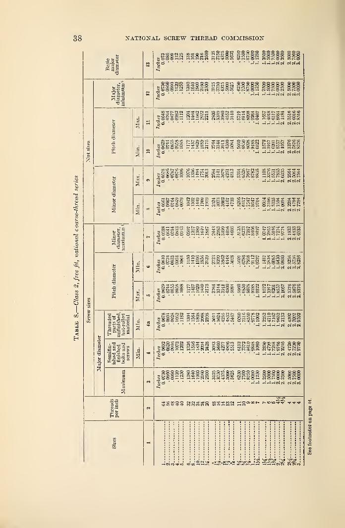
38 NATIONAL SCREW THREAD COMMISSION
•55-2,2Cj 03 Mn a.l
Swoicoo 00000 P Q p p p opeNiONQW <0 O iO O 10 OQOpO QOCN CO O 'd MOOHiO h N M O NiCNON lOOiOQiO OUC^OOOi-«i-H rtrHHCSN CO CO io iO ONXOH CN -O N O CN 1ONC•so'
a
*i4.
eg
_ CO CO O IM 'O co t o o CSOt^OlM 10000*0 00000 000°= 00 OS --h CS N!0 0)-0 >-< CO O O W iO W O iO O "O O >0 OBOO O O rH H rHr-lrHlNtN MMfOfl tONOOOn P1"OI-OLN i0f-0
"53
53
53
©
COCO
'—
i
c_>
06
w3m<
CO N CN CN ^ t}< (N W rH mOOMO O^00-*Cr NOONt^^ ©CO©tC © NX H O © © C"l H OCO©iO^ hhoscDO iO-hihQOCO 1-* 1— t t—
1
?J'ON'XCh CM "rt4 © O CN COMO)»OH ©OK©h iOOiO^OOOOrH rHe-C.—Ir-lCN N {O M lC IO © X C» O r-l -f © 00 CO CO 00
S O *~I rH t-5 i—I i-h CN CN CN CN
O *-t" "O 00 00 SN05 0>0 H« -h o O O CO CO CI CN N -h N N OOOcNT^ir^iooo r-eocNoor— © ~- o co © > ~ cn go cn ni-iooio n n n
P ©NODOO ^h © CO ~H N N © -O O OCOOhcO lOOiN lOO CO QO CO^ O O O O r-H i-h 1—( t—( CN CN CO CO **< 10 10500000 -hcq©OOH CO »o GO
« ©" 1—H 1—Hi—I1-H1—IcN CN CN CN
COON©© ©©rf Tfco .-h O CO ^ ©NiNCO CO O H iO iONOOCONO N CO Q m H OO N »0 -—1 O CN CO 00 ONOMM © CO COuO © N CO O OCOVNO iC-H©CNCO CO O © N CO i-i CO iO CO CO 1000^©OOO—< i-h 1—H i—i CN CN CO CO hh IC©NCOO> hM>ONO CN O N© rH^Hi—ii—!CN CNCNCN
HN-f 05 CN CN O O O -#cONNCO © N N N hh © 10 hh tJ< t}< -e<© © © T< N O O -Ci (MI- O © CN cdhh.^6 1CJC5COO5 0) OOO?"0©NXS) OCO-^ NC5 lO O (O h N CN O © N CT « CO *0 CN N CN~j © O © O © i-H.-H.-Hr-t.-H CN CO CO tH iO©NCOC6 OCO-ONO CN N^ © H H H th N CN* CM CN
sis
00 1—(hh 70 CO NN O N CO CO O © CO iOCCN©N N iO © CO CO CO
CO ^ CO <—1 CT i-O QO CO -^OOOlCO CO N 00 © © Tf iO r)< N N CO CO CO<-0 i-O © N 00 O O CN CO © CO ^CTVO© -niMCO-f N CT O CN N CT^CT
- - - ~ iHHH cn:---\ o o o o o ICNCO^xfl IO © N CO O O CN O NCR 1—1 tT ©
T3
TJ_ T3 -h
p3 w .22 o -S® k 3 V*
1 "d—Vd
i-H i—l i-h 1—11—1 ON CNCNCN
CCTf iCCCOO NNOO-iO tJ- i-h O -h OOOOOOCN CNN-NN © © ©CN h- lO iO CjO N CO CN CO N (D"f hOM ©-OCN00CN N f- O O iO N N N
^ © N CO CT O i-( ^ © CO >-t N CO CT -O O © X O >h CO iO CT CN "-O O CO CO CO^ O O © O i-h —ihhhCN CN CO CO "O "0©C0CTO »—1 CO © 00 >—^ CO »0 00
Jbj O H HMrtHCN CNCNCN*
...... _. 1 © CO CO CT CT CT?©XCTOrH CO lO 00O CO O © CN 00 TT OcO-ONO CN N h © h lOO-Cr ;000--«i-f i-h fH i-h CN CN CO CO tJ* Tf »C ©NXCTH CN NCTiCN NCTjo H HHHHCN CNCNCN
CN © © CN CN ©©M-^X CO O N © CO CNCNOoOO O CO OO © © OOOCT CN NO CN CO CO CT CT) ifONCJH CO N h tf CO CO CT © Tfi -*f CNCNCN^©COCTOCN CO lo OO O -f O © CN CO lO i-h CO © CO O CO N CN N CN N CN N^©©©.-Hi-h H-hhCNCN COCO-*^^ ©N WCT H CN t}h N OS CN M<NQI O tH h h h h CN CNCNCN
OOOOO OOOOO lOOiOQiO OOOOO QOOOO OOQCO © CT CN O XtC©0 CN 'O N p CN iO © KO © O OOOOO OOO
<^ N CO <CT --h CN CO © CD -h 11O i-hNcOO© CN iO N O CN 10OOOUO O iO O^ O O O — —I -hmihCNCN CO CO ij- iO iO ©NCOO--H CNuONOCN »-~ N O
h CN CN CN CN CO
E-1 p.
CC©tJ<C0CN HOC7)00N t- © IO ^ tJ*^^
8
DQ
i—( CN CO Tf *0 w h i-h 1 CN CN CN CN CO
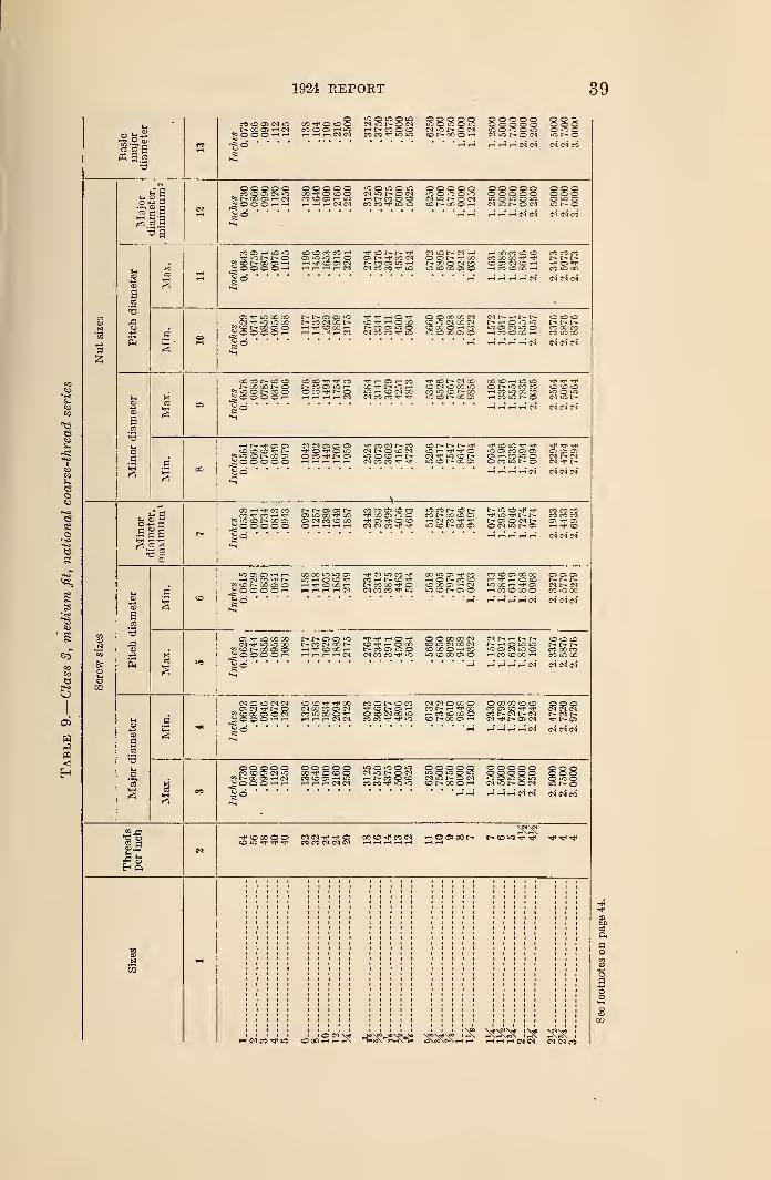
1924 REPORT 39
« 03 fl
C OS IM W CO^PO©© NiOr-OINr-ccosHN co © © r-t «o i—• r— co © ©*OOOHH hhhNN CO CO t iC oO O O © OiO O O © tOfl N O flco r— cc © r—i
©©©©© o © fto©©©© ©©©lO O "5 O W O lC ONiOt-ON tO I* O
rH H H H H N N
3
53
e
t3
SO
KCO
Bc_>
OS
Hn<
o 4-S 3«-. cu <hocas gig
© © © o ©CO tD OS CN iOt— CO as h CN
^ © ©© f-i i-t
So
© © © © ©CO r» O CD OCOOC5HChhhN(M
tO © tO © tO
HNCOOOCO CO »o iO
© © © © oiQO lOO O © © o © o© © © © ©
iO © iO © to
o © ©© © ©© io 5
COC5 rH lO>Cic N r- o« © r- oo © i-H
J" © ©© ©
w
© © CO CO i-H
HHHr-CNCn> t— co (NNCOOJiO HCM CO CO rp iO
© ~ r- cor-~ co © cm coto © co os ©
i-i oo co © ©co x no thCO OS C4 CD r-\i—< CO © 00 i—
t
CO CO COr- r- t-
OS "HH
CO tO CO
H i-i H CN
CM Tf W m 00?> © r- oo © ©§ © © O © rH
t— r— © © toIs- CO CM 00 t—
tp i-i ©CO w o OOKCOO>«SOci ro co io
© © co co cm© to CM CO CN© 00 © -i COtO © CO © ©
CM t— r~ t-N h O i-O iOtO © CN tO ©i—l CO © CO H
© © ©t~-CO GO COCO tO CO
rH HHHr-N
co © r- © ©r- oo oo r~ o
giiO CDN QC Og © O © © -h
© © **< COCO OS iOHO CO H t- ©
r-( rH rH r- CIto r—< © CM 00CM CO CO
-rj- © r- cm co© CM © 00 IOCO C N COto © oo ©
co © i-i to iOON OCOcOt- CO iO CO COi—i co to r— ©ihhhN
rH r- -^t* © os© © © H-£9 <IO CO t"~ CO ©^ o © © © ©
CM CM © © ©© CO t— ©
CO CM t— COCM r- O © (MIOO'«OHN(NCOCOrJiil*
© r- r- t-© -H "tf ©cm to © r-tO © t* 00 ©
T* © lO Tf *tH H- H^to © CO © © OS OS OS© i-1 CO iO © CM I— CM© CO iO t~— © CN -*NHi-IHHN
.s§a
52•3
c
s
a
in *-*
CO H ^1 CO COCO CO
«S to © r- co ©©© © © ©r— r~ © © r—OS iO 00 Hj- 00© CM CO © CO
CO CO © © COTT- 00 © tO ©© -n* © CDCM CM CO ^ ^
iO CO I> © t—co r- oo co o>i-i CM CO -h<to © r— co ©
iO © ^ -rf co co coto tj* r- r- co co cor-©©cMt— ©^©© CM tO t— © rH^CO
^H^-t,-,^,-! CM CM CM
iO © © i—i i—<
HNCOfllNfp © oo © ©SOOOOH
CO 00 tO tO ©tO i-« © © t**
i—1 if © GO —
1
i— t i—t i— t i-H CM
Tt" CM tO COco i—i r~ ©N CO CO Tt1 OCM CO CO trj
00 tO © Tf COt-h © r- co ©© 3C © —
• tMto © r— © ©
CO © © CO 00 © © ©i-'-rr^H©© r- r-~ r—tO CO i—i ^i © CM r-» CMi->CO©00© CO to CO
r-i i—l i—l i—l i—H CM
© tJ< tO 00 OOCM tO lO X'
g? co ao os o_^OOOOHr— r— © © toJ>- CO CM CO t-HTfCOCOHi—i »-i i—1 i—' CM
i-H ©co © to ©
CM CO CO tO
© © CO CO CM© IO CM X T 4© CO © i-i COtO © oo © ©
r- i—i © to totO OS CM tO C
© © ©I- t- I-CO 00 CO
' CO © CO »—» CO tO CO
HHHHCN
CM © © CM CM© CM ©5p © 00 © © CM5;© ©© rH h
C C ^ rjl CO CO © t— © CO-* © r- © rH© © CM CO tOCO CO to
CM CM © CC ©CO N t-i 'J' COi—l CO © CO ©CDNCCOiH
© 00 CO ©© © © ©CO © © TP rfi CM CM CMCO r— CN F- CM t— CM t—CM r- © CN Tf F-
©
<-H HHHHCN
© © © © ©CO CO Oi CM tO
«p oc © cm© O © 1-1 rH
© c © © ©CO ^ © © ©CO ©© rH IOi—< i—i H CM CM
tO © tO O tOCM to r- © CNi-t t— CO © ©CO CO tO tO
© © © © ©iO o tO © tOCN tO r~- © CN© t— 00 O <-!
© © © © © © o ©©©©©© QCOtO © tO © tO ©tO©CN tO © CN tOt*©
H H rH i—( i—< CN CN
OOO^coCN rH O © 00 C* t* © O 'Jl Tjl
rH CM CO TP lO ©OOrHrH
ft
a
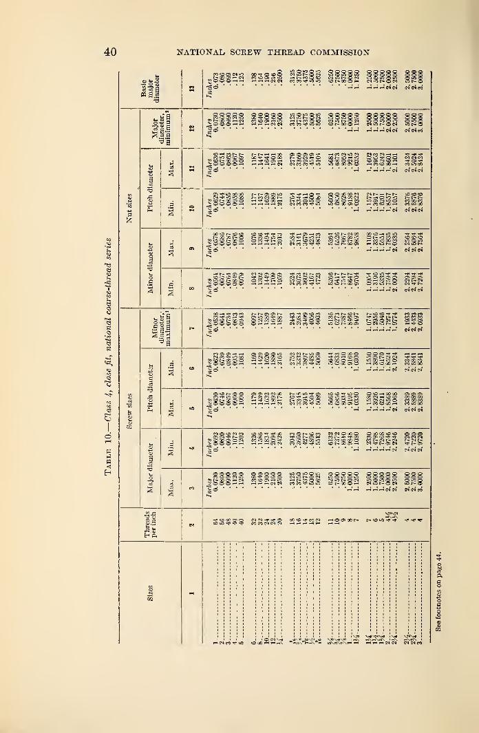
40 NATIONAL SCREW THREAD COMMISSION
« 9.2•a
m so a> tfi
•OO O -« « hhhww co co u
«6
3
13<3
eou
Bso
o
6
H
m
t. te §
-eg
a
3J3
C3
_ eo co os cm in
^OOOH HH W rH H H CN CM. CM CM CO
M ifl O CD CB»s CO t- X OS o5;© © oo h
t^. ^ CO00 -^J* ^J* O GOh h< co Os -h_< rH r- r- CM
OS O OS OSr- CO CM *-< oCM CO CO H« O
CO CM O CMCO t— in h inCO 00 O CM COm co go os o
CM CO CM —< -H
»-< CO SO 00 r-«
1-4 Hr-.rHr-lN
OS O CO GOCM m m 30
?5 CDN 00 3- O^ o© o © h
t— t— OS OS int- CO CM CO t-
CO XHHHH(NH- TP —I © "^P © © X X CM
CO O CM 30 CMO O h c3m co x os ©Mr i r-- t— co co sor~ >—i o o o r-i—r-m3)INOO CO CO CO- CO CO 0D H COiOGO
T-H HH^rtCI
00 CD h- CO COi- og x o
? i-O o r- » o^ o oo o -<
O CO -*v ©^ O -i CO CM COCM CO CO
rf CD CM COCO CM CO CO mco co oolq co r— go os
O C- iO CO COi—" CO iO GO CO . l .
rM i—° rH* r-1 CN CM" CM* CM*
a
t— --p os os© cO cD -P?s iO co t- X os^ © © © © ©
CI CM 0> OS OS
o co ^p r— os
co r-i coCH» O CD CMOOOnNCM CO CO -"P
co t- r-
cj m co r-m co r- co os
^OiC^-cH -»P -<P *P"OOcOQOS OS OS ©OS —t CO m O tNt^-CMOCOOt-O CNTN
g 2 g
c
gs
3
I
CO w co COCO tP CO r-< Tp« in co x oo o o o o
r~ t— cs osOS O CO COOS CM CO CO COOr-tHHH
CO CO OS CD CO•J- 'X OS i-O o-r os f o coCM CM CO ^ -3*
m co i— co r-CO F"- GO CO OS—
i CM co»0 CD OO Os
Nmco^"* co co coH-m^r^r- co co coh-CSQiNt- OS OSOCMiSt-OS »—< 'p CO
CO OS OS r-» —
t
CM CO 'M" l-O CO5? co r» x © ©i o o o o i-H
OS OS o o oCO 7 i Mi-< -i* CO CO rHi-t -i i-< CM
CM CM t- iO OSuO CO OS CO1 CO
CO GO Tf OCM CO CO ^J* iO
rfMOXOCO CO O rH COiO CO CO OS o
m OS CM CM ^lc co rH in o cococo»—* CO CO CO r-t co m 00
O ON ooCO "T* lO CO OS
s CO CO OS Oi o o o o ^
OS OS CM CM 00r— co co os t'-HTfCOOO-*HrlHHfl
t— CO iO "f osOTfr-OCOC— co os m ocm co co m
us CO ^ O OCO iO CO OS COCO X O i-l -COiO CO CO OS o
OcOhcOoO OS OS OSO0 CM i—' CD CO XXXio cs cm in o co x cohcoocoh co m x
CM O CO CM CMOS CM N OM CO X 'OS O CM
i O O O <-l rH
CO CO -i* XCM X CO OS CMco x © tHHHHCNtN
CO O t"-- CO COCO OS f—
I
o co cm x inco co ^ in
CM CM OX OCO t— —< Xi—' CO CD X Oto r~- x os >-h
O X X O CO oooCO OS CD Tp tr CM CM CMCO CM t— CM NCNh-CM-^t^-OSCM Tt* tr~Oi
TH . T-1 H T-H 1—( CM
o o o o ©CO CD OS cm m
?s N X OS ,-1 CM!r o o o r-i —
<
o o o o oco^ocogco co os 1—" mrH rH r- CM CM
cm o o cmHNMOCCco co »n m
o © © © om o m o mcm m r- o cmOt-OOOH
©©oo© © o c©©©©o ooclooooin ©mcCM o O CM iCNC
HH HHHNtN CM CM CO
*r- cu
X CO -P CO CM
h cm co m coco
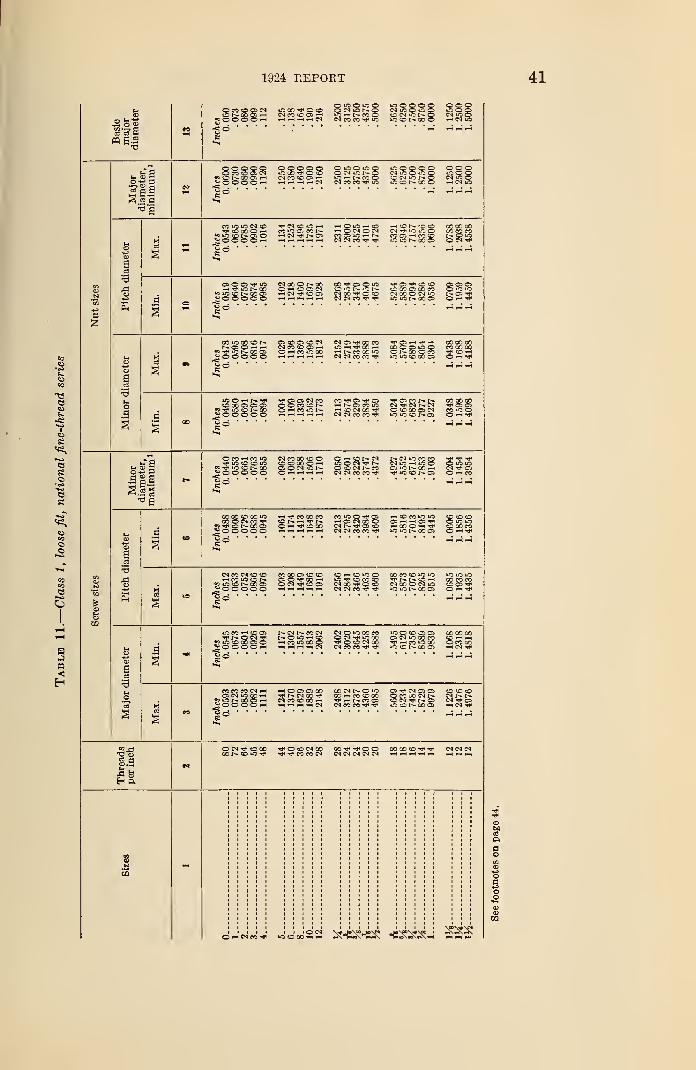
1924 REPORT
OMOONONCCOIHJOOOOH| c3 " "
S CN ^OOOOO ©00
__. NCCCO ^O©NW<CCi-' iC — NCOS CW-C^O CN iO ©,_i ,_, cq cs CO CO Tp iO iO C N 00 O h^iO
3
o o o c o»©©© ©rH
©ooo© © «c © «c
c
cn co to os —« io i-h ro ©CN CN CO CO TP IO
tOOOO© cooN "O O "fi O iOOOCM iONO CM W O
,3 85
CO iO tO CN COTP to CO © —
i
J- O O OO iH
M O iO rH i—i © iO .-h tO <h t£ N 'O «D 00 00 00mwa ws i—< o cn o cn n io io o cococo
•H CN TP OS M O w: h N COCS—icOtO NQiO,_| CN CN CO TP TP CCMCO 0?< V
c
3
ffl O OS TP to
^o © ©o ©
r ••••
NOOOt-OQ OO TP O O kCO — tOCSCS CO IC n NHMVOO CN 00 tP O tOH fH 1-. I-H -H CM CN CO TP TP
Tp os TP to to OS OS OSCO 00 OS 00 CO ccsC« X O (N O t— OS TP•CUSNOOCS O rH TP
3
CStOOStOtNl CN OS Tt< X « TP OS —' TP -P 000000CN CO tO OS i-t tO "H tP OO i-h 00 O OS to o cooooo©-<eo*ooo -"Nrnxio O t- GO © CO TP tO -HpH i-h -h -h CN CN CO CO tp s y ~- O »-h Tf
nto 00 OS OS OS
*= TP iO tO t; 00^OOOOOtp cs cs CN co
s co to r*HCOiOt-- <-« -O CN 00
COtPCStPCS Tf OSMNN 00 CO 00-— *o cn tp cn cn tp © cs
CN (N CO CO TP*
all
O CO CO 1*3TP to to to iOJs^iOONX^ooooo
J CO GO tO © o — to tM t-. CN to CO CO Tp TP TP)C*0«h iO O <N TP r- CNOi-iiOO QiOioiONiQr- Q CO CN r- CO OS US t-- 00 >-h CN TP OS
tN CN CO CO TP TP«OtOI--OS ©1-1CO
X3
CO CO tp CO tO00 O CN CO TP
t) tp tp i-- oc csi o ooo o
i-h TP CO CO CO CO "S O TP OS i-h tO CO tO iO to to COcDN-h^N ( OS CN 00 O OS OS TP © to tOO ^h Tp tO 00 CN I- tP OS tO i-i00©i->tPi-h ^H - i-h i-h (NCNCOCOtP iOiOt^.0005
tp CO COO -H TP
CN CO CN tO tOi-h co «o to r—pUScCNXO
*> O © OO oCO CO OS to © to -h co to ©cs o tp go —i to tp to co toO CN TP tO OS tN CO TP O to,-H — —t i-H CN CN CO TP TP
0 CO CO to tO iC iO ustp r- r- to ~* oococoCN 00 O CN tO tC OS TPO US N X CS O •-- TP
US CO i-" to cstp o cn tpJsuSCCXOO^OOOOH
OS CN "S 00 ~hJCiONXOH_£©ooo ~h
-"OOSCSOO XNNOiOTP 1^- CN 00 Tp 00 — CO tO 00CNCOtCOO'-H TP < r^- CO OSH1HHHCN CNCOCOTPTP
OS tp CN OS OS
tocor-oo© i-h cn tp
§.9
CO 00 to TP TP CN CN CN
©WCNCOTp iOtOOO
aa
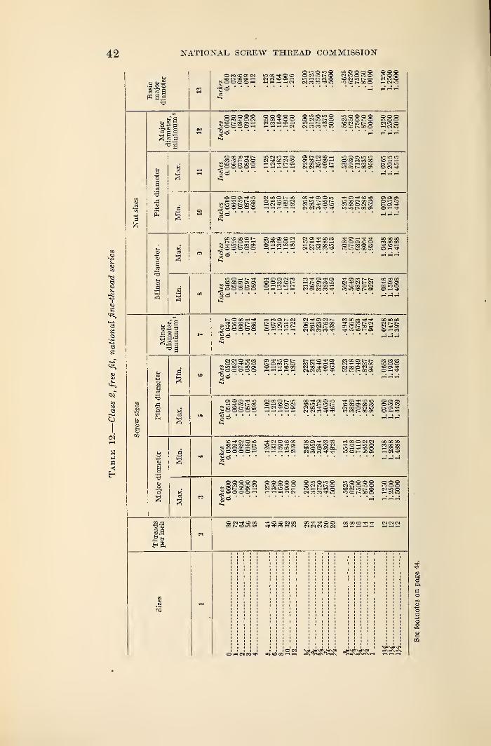
42 NATIONAL SCREW THREAD COMMISSION
ffl 0.2
OiOOiCO o o o o oooioco^oo oN";t-o (N 10o »no L-ro oNM(0 03H O r-i t- CO O OWiCh-O INiCOhhhhm cmcoco-^io *ocor--QOo r-i cm »c
rC oe
3
h4 <3 H
III°a
a
3
aS3•3
oa
a
3
a
OOOOO O O iO oW CO CD Oi rH OHNCOO
CM CO CO IT3I-H I r—t r—I CM
"OOOOO oooN iO O O IOOOONmhO (NiOO
OOOCO-fN
JiJ O O O O rH
•onw^os os r~ cm o i—
i
M^ODOUC OS OOirn 00 rH
rH ,-h rH CM CM CO ^
"OOOJiom ».oicicO'COCOCOOO CO i-h --t
ifi X O OlNrf*
i-H lO f- 00
^ O OO O OMOOONCO OO O) O o f O f O «D OS OS OSO -~» CO OS CM O iO iC N O COO CO CO O«0OHN^COl CM 00 O CD CM 00 O CM iO OS -tft-i^h^h,-!^-! cMtMcOTiHTj* loior-coos ohtj*
CO iC CO o t—
?5-*lCNCOQioooooM CO CO OS tHO i—I CO *C 00 r-( N CO O0 ICH rH rH rH i-H CNCNCOCO-^
Tjn OS rH COOOOOCOOOl'OO CO CO OOOr-ooOco co h0000 05 O ^
CD CO OS OS OS
oo oooCft os CM CO »-*os*«oO O co co t— i—i r~ o> co »oOHCOiOh- hcDNOOHh
r-lr-lrHr-lr-t CM CO CO ^•^oscor-r^. coooooCM rT< CM t— CM O OSOCDCOCSCN COiOOlOiOtDt-Cfl O'-'-^
in © s
.as a
all
NOOOrH-*
i oo o o oHrtCRNN CM OS CM r-t— OS ^ CM CO i—I CO CO 00O O M i-O N 0«OCMI^COOHHrtrH CM CM CO CO
CO OO co COOOOOco co r- cm cm t- t—OSiONOOrH CM OSTp«OONOS OhW
OJtC iOON I> i-H co OSr— oscor-os co CM rH coO rH CO CO CMoO-rfOcO^H i-H i-H •—< t—( CNjCM CO
coooosr^r- cococoCN rt* CO 00 »COOCMCOOCMrf tDOJfiO iO h- 00O1 o —
<
OS O OS ^ *C—I tJ< iC t— OO?s >o co oo gs^ooooo
(MOOONCO oo-^osOo Os CO CO OS OS OSO -—" co os cm co o r»- »o r- co co os oo co Oiowi-hcmtj«coos cmoottoco cmcoocml-o r-osTt*H rH rH rH rH CM CM CO ^ lO iO t- CO OS QHt?
CO CM O COCO OS CM >0
«iOOCCCJO5-000 O rH
CN O OOO CO OS CO CO COOOOCMCM 00 00 COO CO OS Tf OS CO iO CO O N ©-hiOO eoooooCM CO "O CO O T» O CO CO OS. lOrnif tDC5 i-HMOOHHHrHCN CM CO CO UO CO r- 00 OS i-HCM-^f
OOOOO OOOioOiO CO O O O CN 'C I-~ OCMCOCOOS'-t lOrHNCOQiH.HH iHN CM CO CO TP iO
*--;0O00 OOOCMuOOioQ IOOOONiOt-O CM iO Oiocor-ooo ri cm io
as .y
O *-4 CI CO ««;«;22 ^-KSHss: «e^^ SSS
a
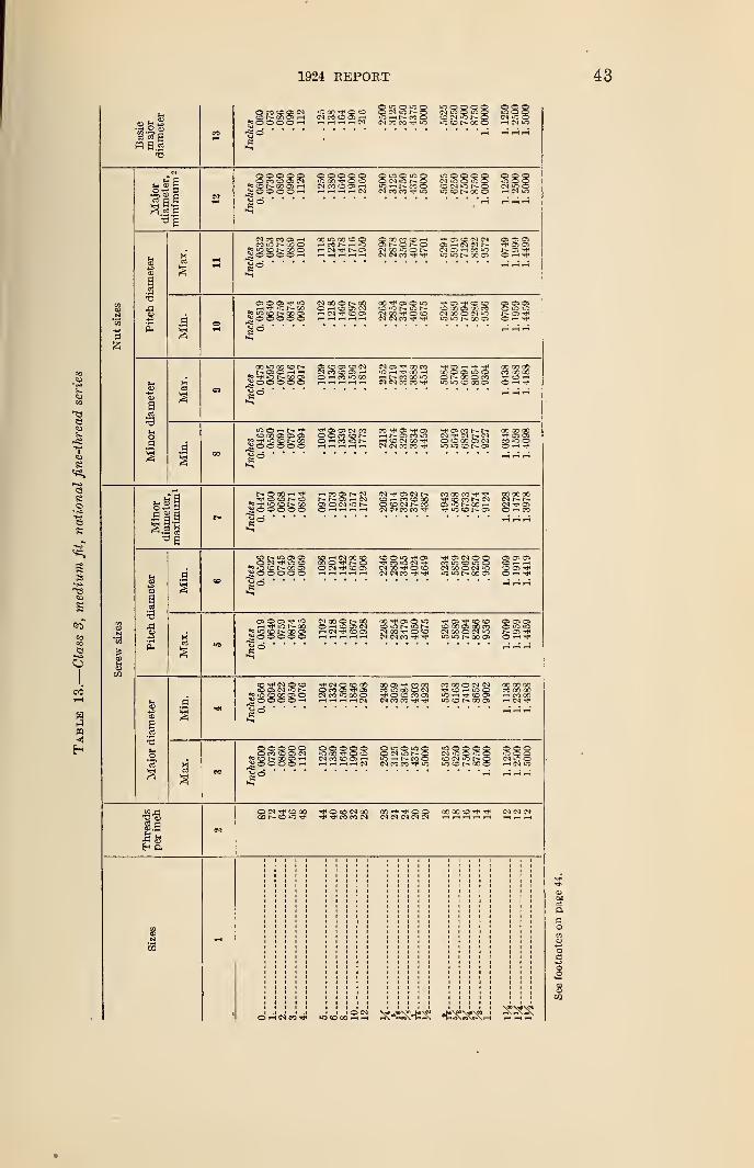
1924 REPORT
o co co Ob cn
gOOO O rH
ONlOh-O NOOOClOr-t—COO <o cm r~ <
8
o
e
g
COCO
H«
III3|
QO O OOs OO OO i-h
O OO o o o o >o oCM CO CO tP »C
•3
a
oa
KUCNCOO5? IQ ep CO O5; O O O O >—
I
.a
i-l ^ iO N OO
^OOOOONXONXO h CO O) <NH CI O O)
00 -rH OS O iO tP OS -P CD O OS OS OSSO 'C N lO n co oo os oo co o m »cCM OO tP O CO CM 00 O CM »C NO 1*(N(NCOtJ-tJH lOiONOOO O >-h *
.s
J^O O OO O O rH CO *c 00
CM OS tP 00 CO tP CS —< -H- tp ooooooid h rf 00 h CO O OS iO O CO 00 OOi-tNCOOOW o r— 00 O CO "3* co —
*
CM CM CO CO tP- lOiOOOOOS o —« tp
lOHNtf tP OS OS CO5 00 OS OS OS OOM tO NSOOOO Hi-It-Hi—( i-H
co tp os -H- as -HHoscot-t- ooooooi-nr-oscoio cm tp <m r— cm 'p as osi—I co CM 00 TP O CD 00 OS CM CO iO oCM CM CO CO Tp lOOONO) O tP
a'-5
S3
.a
-h CO OS !>. CMNNOHNos o <n io t-O iH rH rH rH
M hh OS O N COQOCOtPtP OOOOOO© wr>N cm r- t>-OS *0 t"- O0 *-h CM tP OSTfiOOt-OS Oh«
CD iC OS OSO CM iC o?s io co r— oo cso o oo o
CO i—I <M 00 COOOOTfiNO j£ co o CN 7? "3 cp »o oO CN O OS CM 00 Tf O O NXOMiC CD OS tPrH >-h i-H t-h i-h CNCMCOtPtP uSiCNCOOS OhtJI
OS O OS »o
?o io co r- oo osOoooooCM CO O OOO —
» O OS CMi-h CN Tp CO OS
OO Tp OS O tO tP Os tP CD CO
OS TPO H TP
CO tP CN O COCO OS CM iO t-
J*s io cD 00 OS OS O O O O fH
3CN O CD 30CO OS TP OS
CN CO OO O1—I I—I I—« r-H CM
GO OS TP CO 0Q COOOOCNCM 00 00 00CO O CO O CM TPCOHiCO CO 00 00TP O CO CO OS *0 r—t TP CD OS H CO OOCN CO CO TP tP »0 CD N M O H CN TP
8o O o oCO CO OS CM
*s co oo os i-h
« o OOO hO O OO o OOOiOO iC o o o oONONO
iO h N M OCM CO CO tP IO iQONMO HNC
cd rt
t-H'
tP TP CO CO c
s
53
d-icsn'W .do'sdSSJ SMSRHSS •C^^-.' SStS
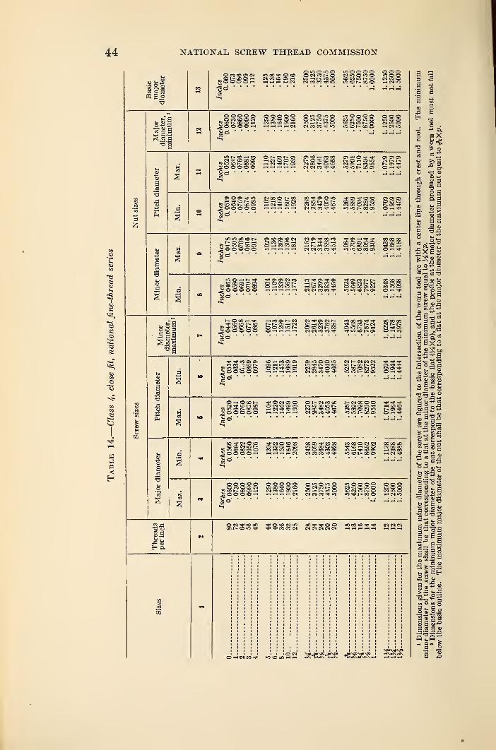
44 NATIONAL SCREW THREAD COMMISSION
•s 5 ®
W S.2a
s
s
es
H
n<
u ai- © 2
III-eg
a
s
a
H <N
O O N ON rt rO ^* iO
lOOOOOC N COO
SO O© ©CN tO ©
ooooo o o o o owoo votoCN ec © OS ~HrH'-iH tH tH CS
O lO O »C oW M cc
© © ©W O Ori CN «3
111— 83
SioooooO !>• OS l^- OSm IN O O COi-t CM os
OS © —* CO 00NtCJ: (COO
CN CN CO ^OS ** O f** Tj*NO-hOiOcn a-, -h eo *e>»CiCNCOCS
cs os ascm r-
OS T© i-t
»o co>o © co cs
S o o © o o© — © OS CNt-h CN CD as
CO * CD O OCN OD O SOCN CN CO "^f
c x> a oo coCN 00 © CN lO
§ »0 U3r~ asO r-H
CO io oO eo
2 © ooo 5OS CO OS CO CNCN CO tO OS i-lO r-l CO lo CO
cn as ^ oo coio i—t -r oo —
<
--i N CO CO oCNCSCCCO'*
CO O OS iO oONXOCOiO «0 CO 00 OS
00 GO 00CO CO COTT« COo —i ^
co ao as os as> ^ tp i- «iooooo
" as cs cn co3 o co co r-»5 h m o h
cO OS ^ OSr- o> co to
-^(OCNCOH*CN CN CO CO
os eo t^. r- CO OO OOas as
CO o o© l-H
NOOOH* i-iCOCSt-CNco © r- to t-- r- a> cs
CN as CN t^.
Si—i CO © CO© cn r- coCN CN CO CO ^
co cc co© co r- cnos to r- co —
i
^P tO © t-» OS
CO CO COCN t- t~-CN •# OSO th fO
s
2
c
cc n
t-i p.
^< ^ CO C3 C5_ —< ?2 "3 © t»f? *c
© w co as csas t-t io ao —
<
- g g © CN -P © OS
as io © © its CN r- CN CN CNlO t- CO t— CNCN CO O CN lO 82:
© —i © ©cn ^ © i~ co
© CN OS ©© cn © as coi-t CN © OS
© r- cn co co
CN CO O ©CN Cfi CO «*
CN CO O ©© os os as ^CN CO © CN iO
-rfw* © ©t~— CS -^T"
©*MO«© os CN io r—n w cc oo a; of CN © © 00o co o ^ osCN CO iO CO © w if, w uT © © CO as
CN CO CO -V
COCO © CN CN© rH iO ©LO i—l ^t* © OS© r- co as
oo co ooco cc oot-H CO COi-* CN
o o o o o© CO © OS CN
^ © © O © rH
©oooolO CO © ©CN CO © OS —
SlO © LO ©CN »0 l
-— OLO — ' t-- CO ©CN CO CO N- lO
IOOOOOCN lo O to O© CN lQ t— QWcONMO
OOOmooCN iO Oi—i CN lO
OO 00 © ^ CN CN CN
OwMCO^J" OOXhh »^v"fc-»tf\n-<^ "V»«£\»tf\K\*H t-* ^
•o
J3
3o
Sa
o .
*" o.
X
I*> oa ~> g
S 35 co pi- y
s«a> cc
a s.2 o
d .°.o
Sxas
—t CO
» o 2
o S o
3 flu
°Bo -9 03
"cj ^ x 3
is o> w ^s aJ s
i- i-« cS
*0 'e — fiJ
2ca-°
£ a 8 w
v- o "
>- U£ °
w ®
« o s a
* 2 a^
|£ga
e -= a aS >.a 2
- M iS •
» 2 a
oi O oo oa •- s S
ga§.°B.2 8 2
_ o_ >
a 5
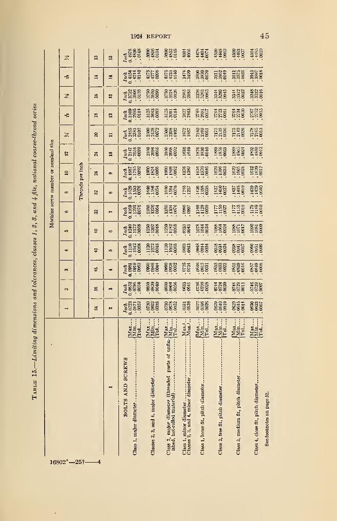
1924 REPORT 45
a
a
a2
v
\««^\
pis
CN
>
per
inch
O
00Threads
CN
CO O CO(-- CO -V
rfS © 00 —«
_ orf* in —i
g: ©»C 00r-.t-.o
^ Tj* O«CiCOCO CN^ -^h O
CO ©CO CO
o ooOS CN I-GC 00 Oco co © OS 00 ©
CO CO o•-> f- COOS CO OCO CO o
CM © ©rC CO © CM
p: co co ©o o ©lOOOCO CO ©
to CN CMt"« CO »-H
CO CO ©?S3& os4 CN
CO CO COCM © ©CO CN ©CO CO ©
© »o
CO CN ©CO CO ©
^f< CN CM-t« i— COCO CO ©CO CO ©
rf£ © OS i-HCJ ~- © -HS co ©
lO —( "*r<N <-( H•-<©'-'CO CO ©
t- COCN tJ4
CM CN
ce —< i--© oI- CO ©CN CN ©
© CNt-. ©CN CN O
© CO COr- r- oCN CN ©
CO CNrfS CO CO ©K CN CS O
© 00 CNOWNlO Tj* ©CN CN ©
© 00 CNO © ©iO CO —
<
CN CN ©CM t"» © © -N00 CC © >
CC 00 •-! w c— —l CN CM C
iO © ©r-- co co~ —< ©CN CN O
IO © ©m* cn
CN CN §
t-~ iO CM« t IO CO<-> -H © O
pC Q0 © ©£2£8
©CO ©© 00 Q
© CO CN© © ©OS-00©
© ©r- ooCO CO
co © ©COO
© © COCN © CO© iO ©
© O -*fCN © CNco © O
OS CO CO
V © iO ©Phh5© © "*P«f CO >o© iO ©
© f-»u0
CN CN
© 00 COCM CO CO
8 SSgNO0CJCO —«
—
<
T T* O
© t>-co ©© ©© ©
j- o r-t-. »0 CM
:83 = 8 ==8 338 3300 ©iO w8
_ ©CN
g32S© CN 00cm^o©
© CM 00CS iC COF- O CT
-< — © © © 888CO ^ Tf
CO CN© © ©© © ©00 <-* !>
© © ©© © ©
gggg ggg
** iO OS 'O
ss ©©c
; cm5 © CM 00
CO © COI - CC ©© © ©
© 00 CNro t- usr, co ©© © o
io r- oor-l © —
I
© 00 ©CO CO ©
00 CN ©m -hCO CO ©CO CO ©
l>- CM iO© —
<
i- r- ©CN CM ©
CM CM S
CM © CNCO CN —
(
CO © ©
© © ©CO CN —
Tf ©
© © ©N © fH
8
CO
is
«ooo
Q
<CO
E-1
On
©B
bo
opa
aa o*j
o«CO
a*->
O*S |
CDCDCD
s
16802°—25t 4
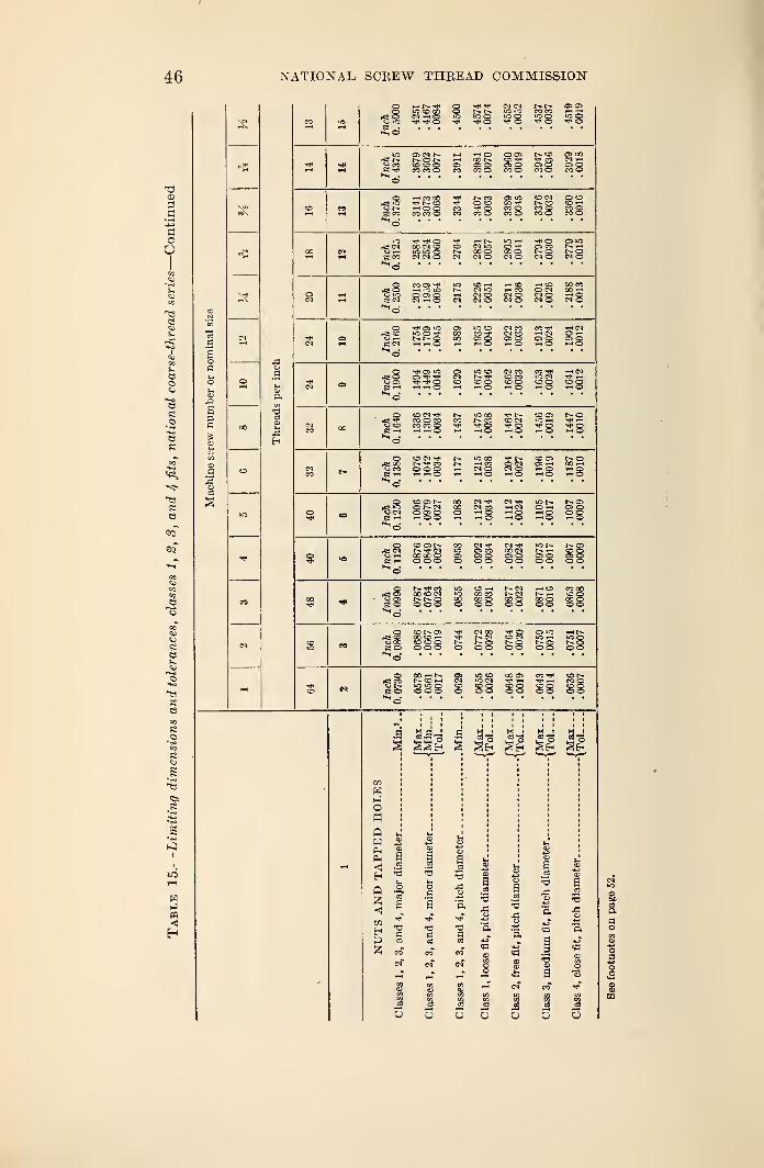
46 NATIONAL SCREW THREAD COMMISSION
Tp
ic oTp O
(N CM
oCO CO —<iCO wotp O O
rfi is.
S 59
as <m t^.t- o r-
CO CO oO OS
CT> OCO o
t-~ CO OS 00TP CO CM -hOS O 0=0CO O CO O
Cj r^.
£ co
»—t CO COtp r- oCO CO o
r- coo ott oCO O
OS iOCOCO OCO O
tO CM OtOCO <D r-<
CO O CO oCO O CO o
ff CO
TP TP OCO CM COm .o oCM CM O
CM OCO oCM O
-r^ O OS iOoi co t— —
<
o oCM O CM O
co as -t<
00)0CM t-h O
CM iOCM OCM O
rH COCM OCM O
HCD CO CO CM CO -CM O i-H CCM O CM C
e cm
TP OS >C
(>. t- Oos CO00 CO ^Poo os or-l 1-1 O
CM COCM COOS o>-i o OS g OS g
cj OS
tP OS iO
rH i-H Or- tp
28CM COCO COCO O «CO eo g
Cj CO
CO CM TPCO O COCO CO O1-H ^ O
«o COCO
TP Ot-< o
TP r--CO CMTP Or- O
CO OS o4C >-H Tp 1—
<
TP O tP g
CO CM tPTP CO
sssO CM
CN COi—< o
00 cnOS Oo o
rfS 0>
e o - 1- o300
co r~ oiCOOHco co oo o o
fc; cocj r~e o
oohsiO UO Qoo o
.a S-9-3 4NMl Hi.^3 <^*^
£ji s£. ejl
«3
wHionQwp«<!
Eh
Q
<!
03
55
a
.a s
a
.2 -S
•a
aJ3
a
3a -3
5
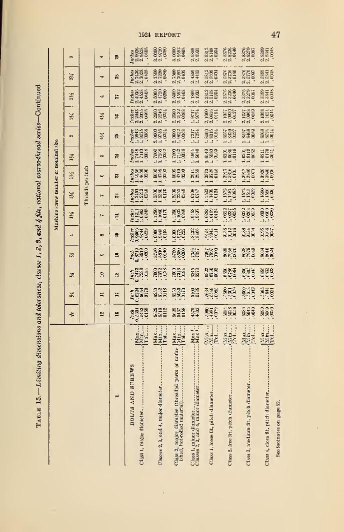
1924 REPORT 47
© CO CO«MlNO o o ©© CM CO
O OS ©© CI COOOlO©o©
os coto COCO OSCO CO
wooCO —I CN00 CO o
CM CN CN CN
i- oco cn ©GO CO ©
« © CO GOV CO CM ©« * O Tj-
f- ©© © ©CM0OtO CM CN©
© CM COO OS or- r-. ©
OS CO© COCO -fw iO lo o
CN CN'
© © ©t~— CO WCO N
© osr- os
co r- ©
CN
is
»s © CO CO*; co cn ©
OS iO w
°o CO tO CO2; r» ©-fi w o co^ CM CN ©
O o o© CN COo r- cn
O © W© »oIO CN CNCN CM ©
O CN CO© OS ©
© CN CO© CO ©•O w COCN CM ©
OS CO© COCO OS
CN CO wwooCO M CICO CO ©
CN CM CN CN
r-- w o © *
—i t~- © -H c
t~- t** O GO *
OS OS i-i © C
W r-J CN CN
co © ©r— coCO CN wCO CO ©
O t—tO CO CNOOIHwoo
© Osr-» osCO CN OCO CO O
t- CO OSm © COO OS OWOO
CO CO oCN CN
ooCD CI "to o oW ©
do CO CO^ w r- ©
os ic cog OS OS ©
© © w© TJ1 IOONCN© OS oO CN GOO CO ©O © CO© OS o
w r*.CM CM
O © w© w a©»0 CO wCO CO o
r- O i—iO CO CM
CO CO oCNw WW WW WW
OO w w© cn
CO CO ©
P5\
*s CO © CO © CO CNO © COiO CM CN
t-- ©O CN CO© © COIO —( COr*. r- o
W ©OSOS ow iO
OS O OSTT CO ©w OS w© >o o
W IO ©O OO w(MOW© © Ow as cnO w COCM w ©© © o
woww r- wCM w O© © ©
to co © O5i <o © cs1*5 OS CO CNg W Tf O
O CO CMO OS OC N CIiO w O
Q O OO w CS© t- CN
W IOw iOOS OSCN CN
CO CO IOr-- cn w00 1^- wCO CO O
!> © wWW©OS GO wCO CO o
© ww -d*OS 00 oCO CO o
© o ©CN OS COCS 00oCO CO ©
c2c
2
Eh
^ cc
°5 © CNw © ^ CN^ CS t - CNg OS OS©
© o oOCONiO CO WCN CN O
o o ©1C X NCN O wW i—« ©
© CN 00IO O wCN O CNw i—i O
CO t—© rt«
O O
CO r>-tO OSWOS OS
CO OS wCO © CN
w w o
CO OS w'JO O CMCNHHo o©
cn r- moo co
iO W o
CN t— lOCN CO COCO CN ©o o o
CN CO OSNhiOOiCOW t-H ©
CN CO OSCN © iOCO CN OO O O
o o oOO iO COigOO
o o oCO O COCO CO ©o o o
«22S00 CO ©
© © ©iO wr- © w00 00 ©
o © ©iO US ©
ic cnGO CO ©
© r»-lO COCO CO
r- ©os os ©OS CO w
!> ©GO OO ©WONO CS oco r- o
cn t
—
?
CO t- oCO w CNo o oCO GO ©
CN 00 W*«; t-. co coO W CN W
O CN COo cn*0 CO wr- r*- ©
o © ^© w COCO Wr» ©
iO CO
CN CN© ©CM O CNOJ CO OSoo o© © o
O ©tO GO ©co r- ©© © ©
OTHCiO O wCO OO o© © ©
© CO COiO CO CNOO DO O© © o
Tt* ©fS* CN iO t>WCNO-hs © © o
O CN 00tOMHCN w w© © ©
o o oloaoNCN O w© © o
CS LOCO CO© to olOuSO
© w CO© © tO© © oiQiOO
O 00 CM©ww© © oiO iO o
IO W© w CM© © ©iO >o ©
y ©rf wCO CN
© »C wiOiOO
iO COCM ©© Tj> WiO »o ©
OS COoiO ©
O w OSCOON© OS O»0 w O
rf CO ©CO CM «o o ©iO iO o
^ w oCO ^ *So ©
>o ©
ww OSSeS
03
wPfl
o
Q55
«J
EhJofp
5
aa3
al
o
a aB°
O C3
a -- - CO
5 ar-i en
II55
J3
s
BOa!
aao
C3 o
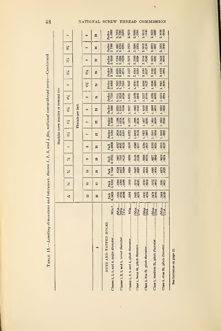
48 NATIONAL SCREW THREAD COMMISSION
a2
o.00
25
Inches
3.0000
2.
7564
2.
7294.0270
2.8376 2.8580.0204
2.8516.0140
2.
8473.0097
2.
8424.0048
COec Inches 2.7600 2.5064
2.
4794.0270
2.
5876
2.6080.0204
2.
6010.0140
2.
6973
.0097
2.
5924.0048
« Inches
2.
5000
2.
2564
2.
2294.0270
2.
3376
2.
3680.0204
2.
3516.0140
2.
3473.0097
2.
3424.0048
oInches
2.
2500
2.
0335
2.
0094.0241
2.
1067
2.
1241
.0184
2.
1184.0127
2.
1140.0089
2.
1101.0044
«3«
U9Inches 2.0000
1.
7835
1.
7694.0241
1.
8557
1.8741.0184
1.
8084.0127
1.
8646
.0089
1.
8601.0044
i-H tO COiO ro ^lO CO CN
CO © tO O
oi coco — —
I
CO CO o "V © T O
Sg CO T?
t-. as-H © O
cq to r-~ ~- © ©t~ ©CN *OCO CO >0 ©COo co ~* tog eg
cou- © *0cc r- —© © ©
co tj- iot« CN © CO-f <— -tj" ©© © © o
—< ©CO oCO ©© ©
CN t-~ iO CO00 CO 00r- cc —< ~h00 00 © ©
S oo
t- r*. ©C V Nr~ r*. ©
oo ©© t^.
OO ©
CNC5CN _ ©© © ©
CN CN «er *
CO co ©CO !N ©COO
*; cn^ ©CO CO ©~ CN ©co r- ©TJ> ©
co cor-~ cnCO ©© ©
CN CN — —
<
© © "»f oS S 3 ©
© ss s
SSe-q Mc K 1 Mi M l
M So So So SoS §e- Se« Eeh
COHJo
pa
<Ei
C55
coE->
&55
5S
3
c=
T3a
a
aBa•5
T3
n i.^ w (D s w„- - £ s «
O O Q O Q O O
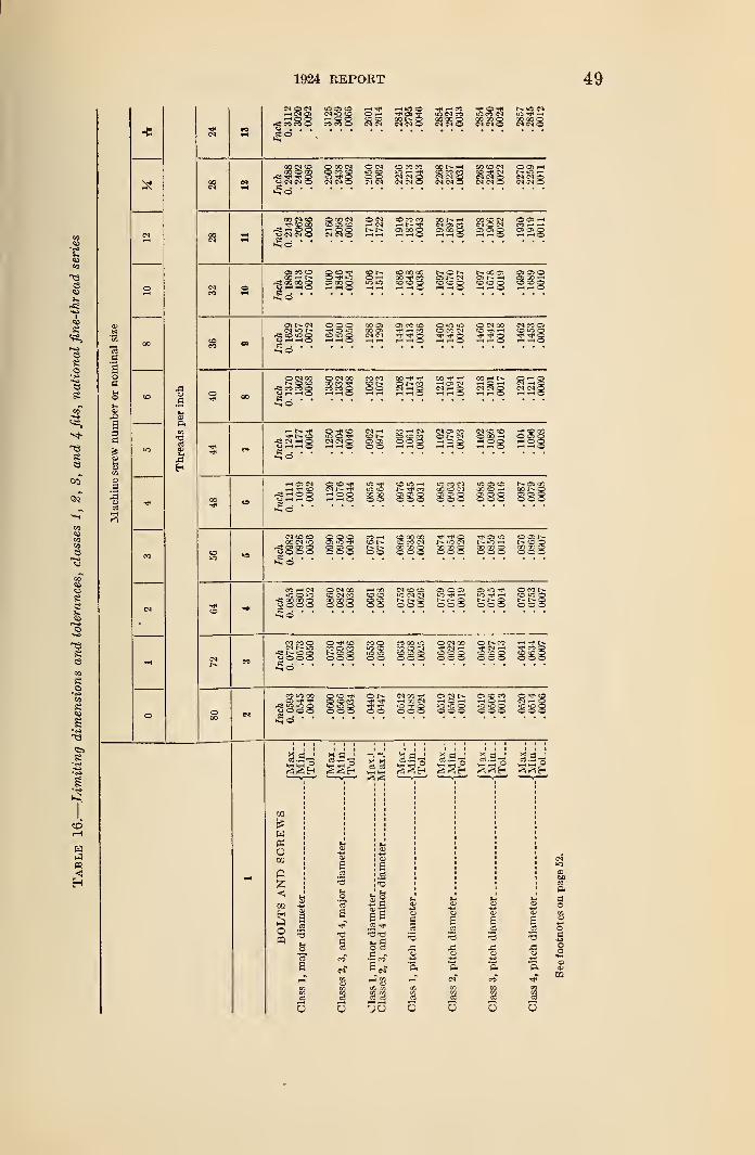
1924 REPORT 49
CM O <?A
; co co' cB
N>0(0 O -H OS -g< ONfJ—I O O O <© Q5f-*W QQtOCCO CO O NMO CM CM O
«o" CO CM
s
esoHOes
ee
so
8
aoa
ot-l
«
aaa
g13
a
p.w
CO CM CO QOON O <N O CO CO OOt—i-1 GO CO CM OOl HQOOOO O CO CO OCS iO -< ft« CO CO CO ©-TN to^ 3 "3 ^ a O O NMQ NNQ CM CM Q NNO
V CM CM O CM CM O CM CJ ncso nn5 CSOO CM CM O£d
OOCMCO OGON O CN COCOCO 0Qh.H ooo« ooh^ CO CO © C& (O —• CM HN* CM OS CO MOM CO -**d <-i o o —h o o t-- r- osooq ojqoq cbqq os os qUNNO CS CN O r-l i-t t-H O HlHO HH'Q -1 Olo
0> CO CD QtO^ *N COGOOO NON t-00O> 0)0300Q-Ht>. o iO O-h QO eo OE— CN OS -H OS CO —
*
^woog cs ao g utji-o 55 to g co co g oog to -3 g12" •~~
• ^ ~i T •~~ ~~
0>t**CM OOO 00 OS OS CO CO 0«00 OMQO N«0)MiCN TP OS tO 00 OS >—< CO O CO CI CO tT> -H to o or< CO JO g OjOg CM C( "P ^ g <at< TP g j# g tP --J- g>§©
©CMCO QNCO COCO OO i*< CO -"p -p co —< r— o*-<ast-~ O co oo co -3* cor- o r- co —< os cm --i o -h cm —< q
rfj CO CO g CO CO g OO CN —I g CM CM g <NMg|-i . n . ii ii . ii . ii . ii
.
r-lt»--* Q^CO NH WHN CM OS CO NO© -f CO MvN© S05 oi- co cp co or- 65 oco-h 000f<2 CM —< g CNCNg OS OS OOO HQg HOg HQg151 . 11 . . . 11 . 11
.
1".11
.
»-< if oiH fH O OC
O iC —
f
coOS OS OOOO
to COCO CO CIOS OS OOOO
iO OS CO00 CO —1o> as oOOO
as 0000 1-oOS OS oOOO
CJ
N tO COCO CM tO
-c; os as ot-» o O o^0 •
•
OOOos \a
OOOCO CO COCO CO CICO X QOOO
TP TP OCO CO OOOO
OS *o1-- o —
<
CO X oOOO
co 'co oo o oow»CO (M CO
»-» 00CO oCO so00
iO CM CMr- r- oOOO
as 10
r~- oOOOo co r-OOQOOO
CO CO Ocm *o
cj O O OO -rtH COCO OS COt- so oOOO
CO OlO (O»c toO o
CO CO oCO -1COOoOOO
5£oCO
eCD
s
s
s
n<
CO iO COOS
Jjifl iOOCJ O O O
O CO COco o OOOO
O t- CM CO *<J*
i-H CO CMiO -t- oOOO
as ciy-t OtO iO o000
as to to1-1 O —
"
tO tO OOOOo •**• oto to OOOO
gg^ gg^ II gg^ ggr^ £g^ gg
in
rt
oCO
o
Jo
Io
sa
n 9O C3
t/j to
35
a.s-3
o
ter_. ter_
.
a.2
tine
CD
a<s
•3
u tch §ft ft
CM* CO
5S3
5S3
5
cmcaa
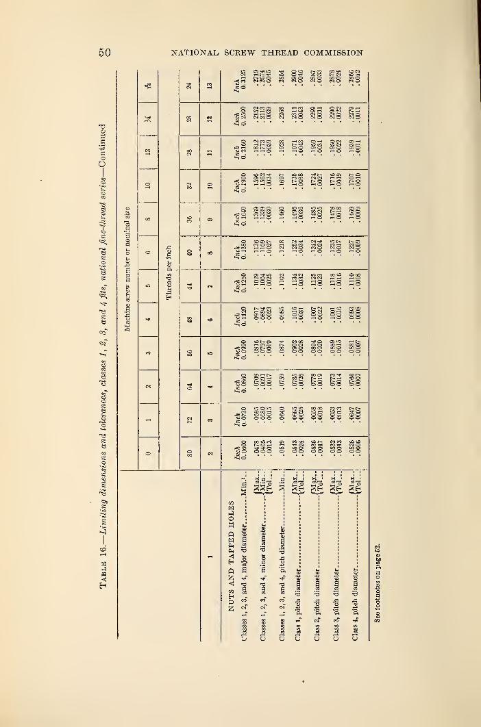
50 NATIONAL SCREW THREAD COMMISSION
r=i CO
CO
00 (ON
CM CO Os
rH rH OCM CM O
OS ~H O CMQl CO OS CMMO (NQCM O CM O
OS ^-trH
CM o« ©
rCS rH<-> CM
CM CO OSrH t"— COoo r- oIH rH O
Cl -H O CM"5 CO >0 (NOs O Os OrH O HO
(ON ^OS COlOiOg
»o 00CO COr- orH O
t— CO OSCM CM rH —
C
£8 £8r- oO rHOrH O
OS OS OCO CO COCO CO oTH rH O
CO COOS CO
28iO tO OO 00oo cm r~ •—
<
28 28
co osCO O CMrH rH CDrH rH O
CM IONCM CO rH
CM O CM gt- OSCM OCM OrH O
os Tj< mCM O CMo o orH r-l O
CMCO COrH OrH O
iO CO CO COCM CM rH —HrH O rH OrH O rH O
O O0rH OrH OrH O
COrH OS CMOS 00 Oo o o
t- CM rH COO CM O rHo o o orH O rH O
rSS OSO O•So
co osrH OS rH00NOo o o
CM OQO CMOS ooo
rC* 00o O00 rH f-O Os i—
t
o o oOO OS COI>- rH rHr- o oo o o o
wowOS 00 rH
ooo S3 88
rs So8
a w 1 x ' x 1 H 1
S 5E* §H §H
03WHOH
w
Eh
z<oaEh
f
a a
8
I
a13a
aa2-3
ao
a23S3
o
•a
a
a
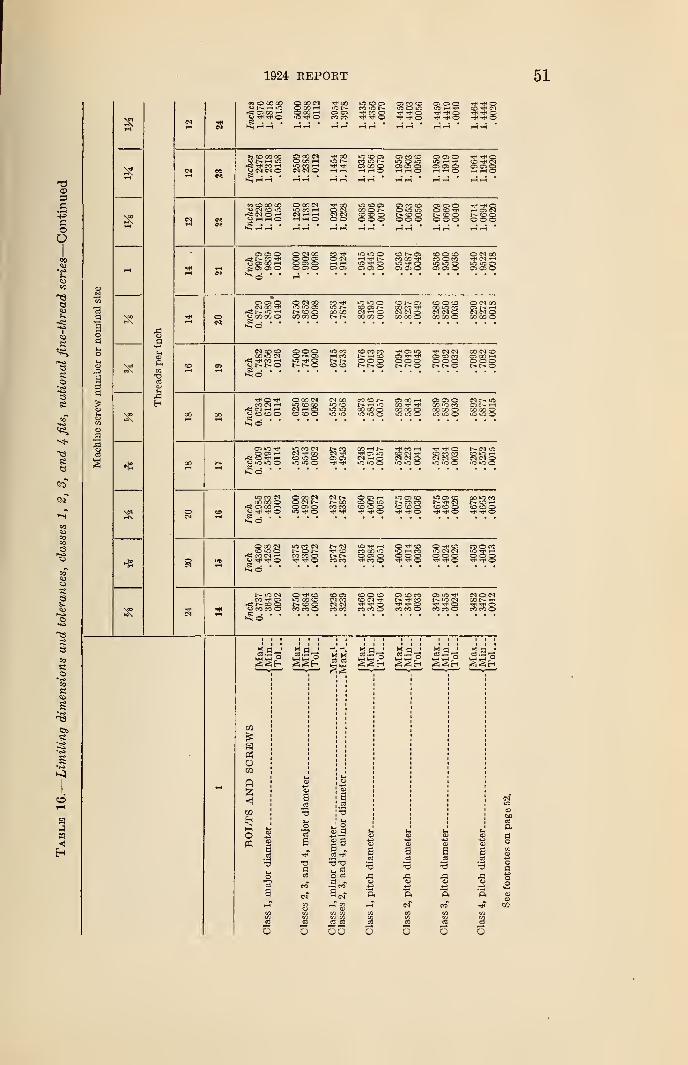
1924 REPORT
«0!OCO« C 00 CI tJ*oO iO to CS owownhic Qoo--» i- ro to i-- ic o tofCT C5 00 O00H ~. ~ tJ-MQ t*4 o<J-*^0 <0>-*7*© CO CO rP ^ O rf« Oa . . • • • • •
*? CDCOOO QOON *<^00 lOCOCS OSCO© QOO TJH oUt-Hir: o co h ior- won ioco m h © cnrfS rf« CO t-i lOMH rp OS 00 O CBOQ OS OS QVCNCN© NCNO H-M i-Hr-HO Hh5 i-iXtS rH Xi 5
eo O 00 00
S3;m cd ai00 O I -© tOOo o o
OS CO SOo<o»or- co ©o o ©
01050o to *J<NtOQ© o©o
rHOlINN(DOo o o
ooo_ C-l GO ^« 00 CO o§© "
"
CO ^io r-00 00
lOiOOcOO>t-—I OCCQ0O
co osOQ CO tJH
00 00 ©CO O OCO iO CO
00 00 oO CM 00
CO 00 o
CN CO CO_ 00 iO CN
CO CO CONH!Do o o1- s
OS iO
© © oI - o
cs CO COO O QO00 CN ©OS CO rHo o ot- 1- o
o ^CO CM i—
1
O to CO oO 00 CMiO CO CO
CO CO OCN 00IO CO
iO iO
co co^ t-H OCO 00 Q>C >0 ©
O CO HCOCO CO o
OS OS oCO O COCO CO o
CN iO
CO CO olOiOO
os io mrCi tO t)< HOiOiCO
to CO CICM COcoolOiOO
CO r-t I>.cs uoWho CO CN(NCIO
iO ©CD CO COCN N OiTjiOO
r- cn »oOlOHCN CN O
iO CO CNOO CO o
i< OS CO i-lCJ Tj* O§0 •
cn r-r- ooCO CO
OOHCO o *oCO CO O©
IO CS COco co
CO CD ©oIOCS CO
COCO ©00 iO CON!DHco co O^ Tt< O
O 00 CNCO to o
-Ci COCN rH« Tjl OiO CO CNNONCO CO o
CN^ CO
CO CO
IO tJH i—
I
CO CO iOO CS oCO ©
iO CN _ .o o ©^ ^ oto CO © CO
r— io cmCO CS
r=i r~ © ©O CO CO ©© csCN COCN CNCO CO
© © ©© CN TP
CO CO ©OS © COr- co
TJH ©CO CO ©
CS IO Tj<io cn©
CO CO ©CN © CNOOt- rH<* rr ©CO CO ©
to
«DCO
o
03
Jon
ag
S3 S3
•9
SI
2-3
o
oo o o
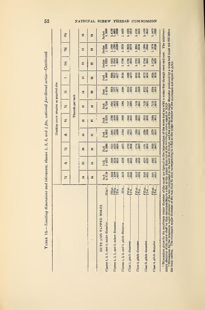
NATIONAL, SCREW THREAD COMMISSION
o o © o
O 35 Ooo ©
S O
rt< CO
g ssOS »0CO "Tf
J3rH CO OHa> o 030»o © ioo
NO MO«oo 100
i—t SO 00 COO (M 00 i-H
I- Q tDQ
CO "HH
00 CO «3CO CO ©CO CO o
O HHio o >oQ rH©
to COGO COO Qo
CO CO CO COr- co <—*
38 §8
Oi iO
CO CN OCO CO O
g §H gfH §H
CO
w
owowPhCM«!
Eh
Q
03
Hp
aOS
'3
oc
a
aI3
aOS
.a
I5
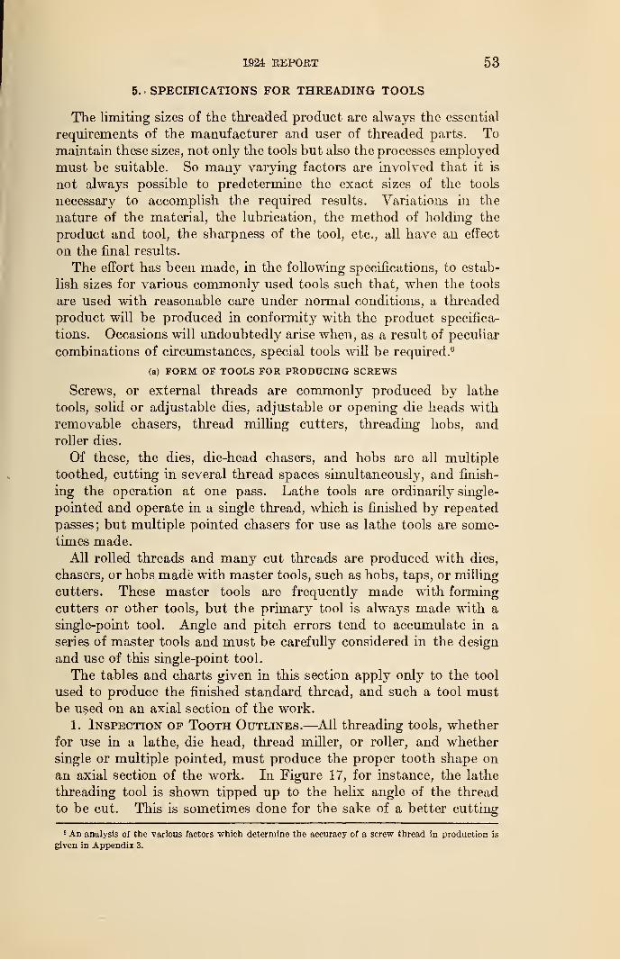
1924 REPORT 53
5.- SPECIFICATIONS FOR THREADING TOOLS
The limiting sizes of the threaded product are always the essential
requirements of the manufacturer and user of threaded parts. Tomaintain these sizes, not only the tools but also the processes employed
must be suitable. So many varying factors are involved that it is
not always possible to predetermine the exact sizes of the tools
necessary to accomplish the required results. Variations in the
nature of the material, the lubrication, the method of holding the
product and tool, the sharpness of the tool, etc., all have an effect
on the final results.
The effort has been made, in the following specifications, to estab-
lish sizes for various commonly used tools such that, when the tools
are used with reasonable care under normal conditions, a threaded
product will be produced in conformity with the product specifica-
tions. Occasions will undoubtedly arise when, as a result of peculiar
combinations of circumstances, special tools will be required. 6
(a) FORM OF TOOLS FOR PRODUCING SCREWS
Screws, or external threads are commonly produced by lathe
tools, solid or adjustable dies, adjustable or opening die heads with
removable chasers, thread milling cutters, threading hobs, androller dies.
Of these, the dies, die-head chasers, and hobs are all multiple
toothed, cutting in several thread spaces simultaneously, and finish-
ing the operation at one pass. Lathe tools are ordinarily single-
pointed and operate in a single thread, which is finished by repeated
passes; but multiple pointed chasers for use as lathe tools are some-
times made.
All rolled threads and many cut threads are produced with dies,
chasers, or hobs made with master tools, such as hobs, taps, or milling
cutters. These master tools are frequently made with forming
cutters or other tools, but the primary tool is always made with a
single-point tool. Angle and pitch errors tend to accumulate in a
series of master tools and must be carefully considered in the design
and use of this single-point tool.
The tables and charts given in this section apply only to the tool
used to produce the finished standard thread, and such a tool mustbe used on an axial section of the work.
1. Inspection of Tooth Outlines.—All threading tools, whether
for use in a lathe, die head, thread miller, or roller, and whether
single or multiple pointed, must produce the proper tooth shape on
an axial section of the work. In Figure 17, for instance, the lathe
threading tool is shown tipped up to the helix angle of the thread
to be cut. This is sometimes done for the sake of a better cutting
6 An analysis of the various factors which determine the accuracy of a screw thread in production is
given in Appendix 3.
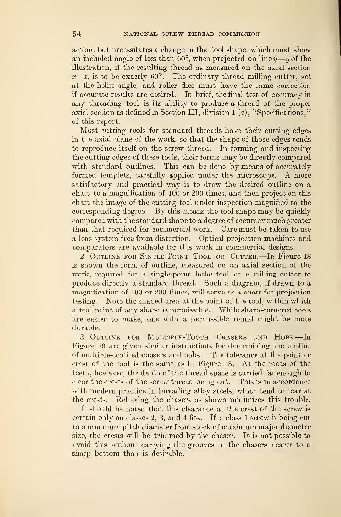
54 NATIONAL SCREW THREAD COMMISSION
action, but necessitates a change in the tool shape, which must showan included angle of less than 60°, when projected on line y
—y of the
illustration, if the resulting thread as measured on the axial section
x—x, is to be exactly 60°. The ordinary thread milling cutter, set
at the helix angle, and roller dies must have the same correction
if accurate results are desired. In brief, the final test of accuracy in
any threading tool is its ability to produce a thread of the proper
axial section as defined in Section III, division 1 (a), "Specifications,"
of this report.
Most cutting tools for standard threads have their cutting edges
in the axial plane of the work, so that the shape of those edges tends
to reproduce itself on the screw thread. In forming and inspecting
the cutting edges of these tools, their forms may be directly comparedwith standard outlines. This can be done by means of accurately
formed templets, carefully applied under the microscope. A moresatisfactory and practical way is to draw the desired outline on a
chart to a magnification of 100 or 200 times, and then project on this
chart the image of the cutting tool under inspection magnified to the
corresponding degree. By this means the tool shape may be quickly
compared with the standard shape to a degree of accuracymuch greater
than that required for commercial work. Care must be taken to use
a lens system free from distortion. Optical projection machines and
comparators are available for this work in commercial designs.
2. Outline for Single-Point Tool or Cutter.—In Figure 18
is shown the form of outline, measured on an axial section of the
work, required for a single-point lathe tool or a milling cutter to
produce directly a standard thread. Such a diagram, if drawn to a
magnification of 100 or 200 times, will serve as a chart for projection
testing. Note the shaded area at the point of the tool, within which
a tool point of any shape is permissible. While sharp-cornered tools
are easier to make, one with a permissible round might be moredurable.
3. Outline for Multiple-Tooth Chasers and Hobs.—In
Figure 19 are given similar instructions for determining the outline
of multiple-toothed chasers and hobs. The tolerance at the point or
crest of the tool is the same as in Figure 18. At the roots of the
teeth, however, the depth of the thread space is carried far enough to
clear the crests of the screw thread being cut. This is in accordance
with modern practice in threading alloy steels, which tend to tear at
the crests. Relieving the chasers as shown minimizes this trouble.
It should be noted that this clearance at the crest of the screw is
certain only on classes 2, 3, and 4 fits. If a class 1 screw is being cut
to a minimum pitch diameter from stock of maximum major diameter
size, the crests will be trimmed by the chaser. It is not possible to
avoid this without carrying the grooves in the chasers nearer to a
sharp bottom than is desirable.
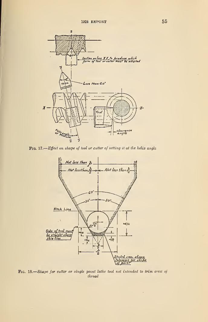
1&24 REPORT 55
Fig. 18.
—
Shape for cutter or single point lathe tool not intended to trim crest oj
thread
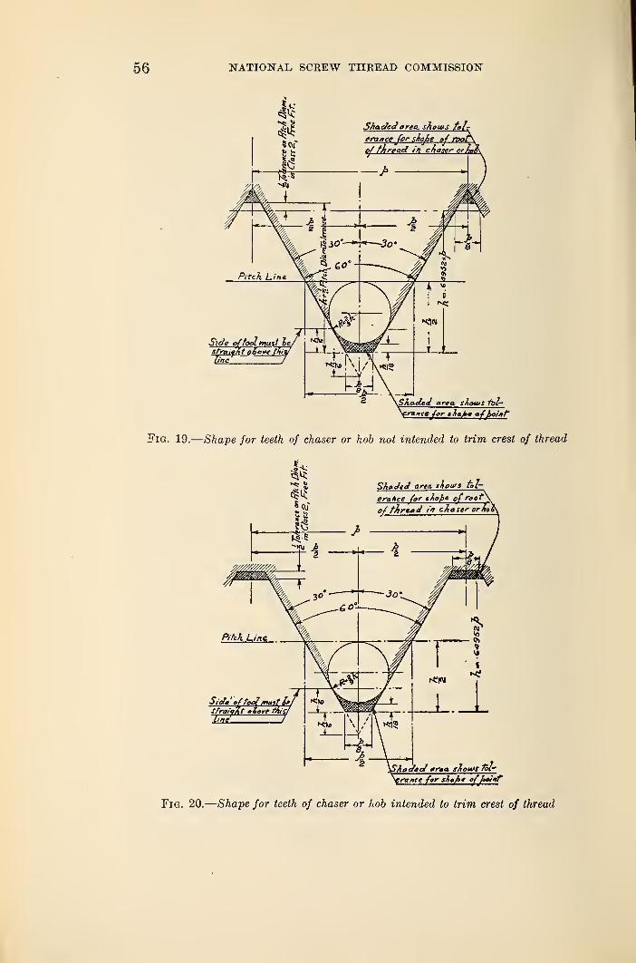
56 NATIONAL, SCREW THREAD COMMISSION
Side offoolmust lestraight a6e¥fline
rxnec/or sTiafae ofpoint
Fig. 19.
—
Shape for teeth of chaser or hob not intended to trim crest of thread
Shaded area, shouis tol-
erance (or t&gf>» of root\
of fjfreaa' cAascrorJto&
SiA ' o{tootmast I*SfraitAt • tcrf tnisl
trance for sink' efhainf
Fig. 20.
—
Shape for teeth of chaser or hob intended to trim crest of thread
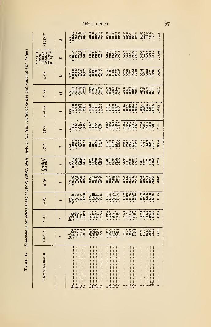
1924 REPORT 57
Si
X
a a s s » V
iSSooo poooo o o
o
ss
WO'O'OiO 1.1 O 'I !0 or-t CN CN CO *0 C CO O !M
i — CI CJ CI
O « O u*. o-rooocoao- so a o m cii cCN O CN 00 »-0 rf CO c
ooSSS SS=s:
O O US o oC X C 'N OO >M M « «SSSSS 83888 83383 8338 =
© © O O 00 CO —• 30 —' -lOOOONiO N C C C)hhh — CI CJ (Nco^r:'?S8S 888SS 8888;
iOhONO•g- irt CO t- CO
;8S38 8
n io c a cio -h —> co r- -h — —< co
(N (N « K « ? l". |n
:S8888 88888CO CN CO CO CO SO o o oCO O X X O iO -rr o o o ococoaiocN co «o oo —i r-
?2 © O © .-< --< CN CN CN© ©OOOO OOOOO O
XII
O Q SO CO00 © CM iO ©~h <N CN CM CO
|88888• • •
•
CO •—* ' " *0 — CN CI CN .-< © CO CM CON©0«0^ O CN O O CO i— © rH "<»
CCiCO^^iO CC N X C5 O »—t CM COSCN SO t^. CO
SO © 30 O_ _ _ _. _ .. .- ' ' ~j 00 © ^ CN
SSSSS SSSS© © © © © © ©©©©©
XSO © so so © ©so co os —i r- _fH -h CM CM CM CO CO "3"© O O © O OOOO©
CO 00 © rH COOlOMH r-iSO CO 00 ^*
Xrs
O0CNCNU5© CO 5 O O 00 O CN 00"S --<©—"» CN O CO Cn © © tO -TfsO-h cosoaoQeo tncjc^i
"' SSSSS sssO Oi CO *fl t» ©»o co as >-» <-<© SO CN -h
— <£/
05
SO CO GC o» O C « O C N © 09 >n © •*O t Q >c co ©~h©©-h h n J :VSOOOOCO CN © O O © OS CN -hNOOCS'. r-i r-i ^ 3 § 3 3 gioicgt^. ggScN->©©©©©
X
15000i © <—
> CO . -}H-HH — CNCNCNCN CO CO CO
?8888 88888 888
-h © 00 HNCSNM ~* »0 CO © CNCOO© CM t— —' CD CN © © CO CN 5CN co co co h* g1 1000x3 ©lOOOXt, _
88888 3
X
X
J3
iO N ^ft *—* "*
|888884d • • •
iC -h CO CNCN © CO O 3"^OONOOO^83883
© © CN O COO 00 © CO COCM CO O t- ©
r^t pH PH I—' « CN<-J © ©© © ©
• * *
cm r- »-. ©CO -H ^ ©CN CO CO CO
r-i iT3 —• COCM CN O 00 ©'ONOO
CN CN O © ©
SSSS© S©SSS SSSSSCN O CO © 00 lOo 00 00 r- cnONOiON t-HhhSNN CO©©©© © ©
O O © CN OCO iO CO o 00r-i W CO«5NSSSS©
CO O CO iO —'
r-- cn r-~N O h m OCN CN CM CO COOOOO©
o o r— —< o 00 — o o ic CN-Hcoo-HCM CN CN CO CO M V f C O CD t"*. CO © rH CN©©©©© ©0O0O O O O r-< rH rH
NOOOM CN CO © -HC O C O OCOOQHhOiOCNm iOCOOOh^lOiOtOh- NXOO-h0©000 © © © —
I
© so o cn© X O O CNS C) CO O C)IN C C Mr- - - N
J3Eh
^0X0* CO CN ^ ©CN CN --. ^ ^ — ^ -< --i
00OV COCN^O© cot*o»o^ ^«
58 NATIONAL SCREW THREAD COMMISSION
When it is desired to follow the older practice which permits
trimming of the crests, the outline shown in Figure 20 may be used.
It is somewhat easier to make than the one shown in Figure 19.
Note that the tolerance allowed on the shape of the points or
crests is the same as in Figures 18 and 19. In both Figures 19 and
20 the shape of the bottom of the thread spaces may be given anycurved form which can be contained within the shaded tolerance
area, and still produce screw threads which will agree with the
standards set up in this report.
In Table 17 are given the required dimensions for drawing the
charts of Figures 18, 19, and 20 correctly for any standard pitch.
(b) TAPS
1. Tap Dimensions.—The tap dimensions given in Tables 18 to
24, inclusive, were prepared with the cooperation of a committee of
tap and die manufacturers, and represent present practice for the
production of tapped holes of the classes indicated. Whether or not
the following specifications for taps will prove to be those mostacceptable can only be determined by their use and trial. These
specifications, therefore, are tentative, and are subject to additions
and revisions as experience proves necessary.
Dimensions are given for three classes of taps : First, commercial
taps; second, class X ground taps; and third, class Y ground taps.
(a) Commercial taps.—The commercial taps should be found
suitable, in most cases, for tapped holes made to class 1, loose-fit
specifications, and for the fractional sizes of class 2, free fit specifica-
tions. With proper selection by trial, under the actual manufac-
turing conditions involved, it should be found possible to use someof the commercial taps for tapped holes made to the class 2, free-fit
specifications in the numbered sizes, and for the fractional sizes of
class 3, medium-fit specifications.
(&) Class X ground taps.—The class X ground taps should be
found suitable when used with reasonable care for tapped holes madeto class 3, medium-fit specifications and class 4, close-fit specifica-
tions.
(c) ClassY ground taps.—The class Y ground taps should be found
suitable when used with reasonable care for tapped holes made to
class 3, medium-fit specifications. The minimum size of the class Ytap is above the basic size to give a longer wearing life. Whereaccuracy requirements permit, class Y ground taps should be used
in preference to class X taps because of their longer useful life.
2. Marking of Taps.—Taps shall be marked indicating the diam-
eter, pitch, and thread series as follows (see Section II, division 2,
''Symbols")- Ground taps shall be marked "X" or "Y" according
to their classification.

1924 REPORT 59
A 1-inch, 8-pitch tap shall be marked 1"—8—NC.A 1-inch, 14-pitch, class Y ground tap shall be marked 1"—14—NF—Y.
3. Shape of Cutting Edge for Taps (and other InternalThreading Tools).—In Figure 21 is shown the form of outline,
measured on an axial section of the "work, required for a tap or
other internal threading tool intended for cutting threads of national
form. These outlines are the same for all pitches and classes of fit.
Such a diagram, if drawn to a magnification of 100 or 200 times, will
serve as a chart for projection testing. Note the shaded area at the
Skacted area shouts toferaxee
for s/itz/ie of /point
Fig. 21.
—
Shape for teeth of tap or internal thread-chasing tool
point of the tool, within which a tool point of any shape is permis-
sible. Also note the shaded area at the root of the thread which
shows permissible variations in tooth outline at this point.
While sharp-cornered tools are easier to make, one with a permis-
sible round at the point might be more durable. In any event, the
maker of the tap or other tool should keep the outline well away from
the lower part of the permissible, area, represented by the basic flat
of }i X p. The danger here is that after a few holes have been
tapped the corners will be rounded over so that the tapped hole
rejects the basic gage.
Table 17 gives the necessary dimensions for drawing the diagram
shown in Figure 21 for any standard pitch.
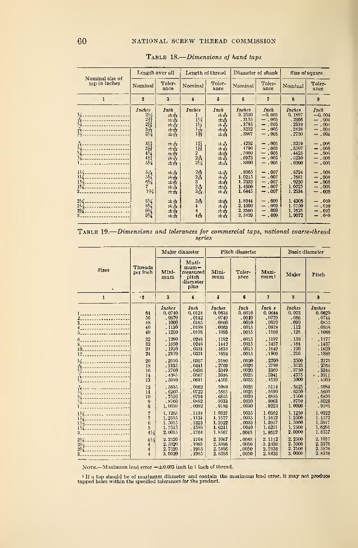
60 NATIONAL SCREW THREAD COMMISSION
Table 18.
—
Dimensions of hand taps
Length over all Length of thread Diameter of shank Size of squareXT *Nominal size 01
tap in inches Nominal Toler- Nominal Toler- Nominal Toler- Nominal Toler-ance ance ance ance
1 2 3 4 6<*
l 8 9
Inches Inch Inches Inch Inches Inch Inches InchM VA ±ft 1 ±ft 0. 2530 -0.005 0. 1897 -0.004A - . 3155 —
. 005 . 2366 _ 004% —- ±ft IX ±ft .3785 - [ 005 .2839 - !o047I* 3ft ±ft 1ft ±ft .3232 - .005 .2424 - .004
y2 —
-
SVs ±ft ift ±ft .3667 — .005 .2750 - .004
IT, 3H ±ft IB ±ft .4292 - .005 .3219 - .006
H CO liti 3±ri — . UUO . 3597 — . 006
4)4 ±ft 2 ±ft .5900 - .005 .4425 - .006Vt 4H ±ft 2ft ±ft .6973 - .005 .5230 - .006l 5Vs ±ft 2H ±A .8000 - .005 .6000 - .006
m— 5ft ±rV 2ft ±ft .8965 - .007 .6724 - .008lJi m ±ft 2ft ±ft 1. 0215 - .007 .7661 - .008m ±ft 3 ±ft 1.2333 - .007 .9250 - .008m — 7 ±ft 3ft ±ft 1.4300 - .007 1. 0725 - .0082 m ±ft 3ft ±ft 1. 6445 - .007 1.2334 - .008
±ft 3rV ±ft 1.8944 - .009 1.420S - .010- ±ft 4 ±A 2. 1000 - .009 1. 5750 - .010
2'A- — 9M ±ft 4 ±ft 2.3500 - .009 1. 7625 - .0103 - 9% ±rV 4ft ±ft 2.5429 - .009 1. 9072 - .O'O
Table 19.
—
Dimensions and tolerances for commercial taps, national coarse-threadseries
SizesThreadsper inch
Major diameter Pitch diameter Basic diameter
Mini-mum
Maxi-mum—measured
pitchdiameter
plus
Mini-mum
Toler-ance
Maxi-mum Major Pitch
1 •X 3 i 5 6 7 8 9
Inches Inch Inches Inch Inch s Inches Inches
1 64 0. 0740 0. 0124 0. 0634 0.0010 0.0644 0.073 0.0629
2 56 .0870 .0142 .0749 .0010 .0759 .086 .0744
3 - — 48 . 1000 .0165 .0860 .0010 .0870 .099 . 0855
4. 40 . 1130 .0198 .0963 .0015 .0978 .112 .09585 40 .1260 .0198 . 1093 .0015 .1108 .125 .1088
6... 32 . 1390 .0248 . 1182 .0015 .1197 .138 .1177
8... 32 .1650 .0248 . 1442 .0015 . 1457 .164 .1437
10 24 . 1910 .0331 . 1634 .0015 . 1649 .190 . 1629
12 24 .2170 .0331 . 1894 .0015 . 1909 .216 .1889
U- 20 .2510 .0397 .2180 .0020 . 2200 .2500 . 2175
ft 18 .3135 .0441 . 2769 .0020 .2789 .3125 .2764
% - — 16 .3760 .0496 .3349 .0020 3369 .3750 . 3344
ft 14 .4385 .0567 .3916 . 0025 .3941 .4375 . .3911
Yi 13 .5010 .0611 .4505 .0025 .4530 .5000 .4500
ft- 12 .5635 .0662 .5089 .0025 .5114 .5625 .5084
X 11 .6260 .0722 .5665 .0025 .5690 . 6250 .5660
H- —%
10 .7510 .0794 .6855 .0030 .6885 .7500 .6850
9 .8760 .0882 .8033 . 0030 .8063 .8750 .8028
1 8 1. 0010 .0992 .9193 .0030 .9223 1.0000 .9188
lYs 7 1. 1265 .1134 1. 0327 .0035 1. 0362 1. 1250 1. 0322
V4 7 1.2515 . 1134 1. 1577 .0035 1. 1612 1.2500 1. 1572
W2 — 6 1. 5015 .1323 1. 3922 .0035 1. 3957 1.5000 1.3917
M~ 5 1.7515 . 1588 1. 6211 .0040 1. 6251 1.7500 1. 6201
2 4H 2. 0015 .1764 1. 8567 .0045 1. 8612 2.0000 1. 8557
2Ji 4M 2. 2520 . 1764 2. 1067 .0045 2.1112 2. 2500 2. 1057
m 4 2. 5020 . 1985 2. 3386 .0050 2. 3436 2.5000 2. 3376
2M 4 2. 7520 . 1985 2. 5886 .0050 2. 5936 2.7500 2. 5876
3 4 3. 0020 . 1985 2. 8386 .0050 2. 8436 3.0000 2. 8376
Note.—Maximum lead error =±0.003 inch in 1 inch of thread.
1 If a tap should be of maximum diameter and contain the maximum lead error, it may not producetapped holes within the specified tolerances for the product.
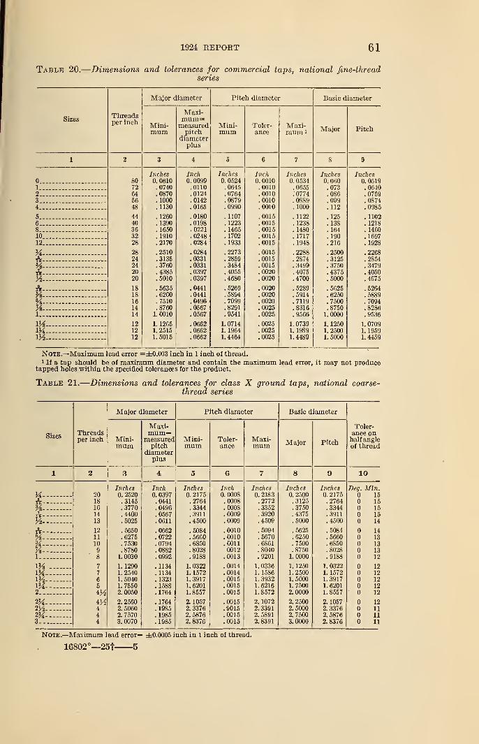
1924 REPORT 61
Table 20.
—
Dimensions and tolerances for commercial taps, national fine-threadseries
Sizesl nreaclsper inch
Major diameter Pitch diameter Basic diameter
Mini-mum
Maxi-mum 3measured
pitchdiameter
plus
Mini-mum
Toler-ance
Maxi-mum i
Major Pitch
ii iM 3 4 5 6 j 8 9
Inches Inch Inches Inch Inches Inches Inchesn 80 0. 0610 0. 0099 0. 0524 0. 0010 0. 0534 0. 060 0. 0519i .0740 .0110 . 0645 . 0010 .0655 .073 .06402 64 . 0870 .0124 .0764 . 0010 .0774 .086 .07593 __ 56 . 1000 . 0142 .0879 . 0010 .0889 . 099 .08744 _ 48 . 1130 .0165 .0990 . 0010 . 1000 .112 .0985
K 44 , . 1260 .0180 .1107 .0015 . 1122 .125 .1102fl 40 . 1390 .0198 . 1223 . 0015 . 1238 . 138 . 12188 36 . 1650 . 0221 . 1465 . 0015 . 1480 . 164 . 146010 _ 32 .1910 .0248 .1702 .0015 . 1717 .190 . 169712 28 . iyoo 1QAQ Ol ft 1 GOO
X - 28 .2510 .0284 .2273 .0015 .2288 .2500 .2268
A - 24 .3135 .0331 .2859 .0015 .2874 .3125 .2854% - 24 .3760 .0331 .3484 .0015 .3499 . 3750 .3479
A - - 20 .4385 .0397 .4055 .0020 .4075 .4375 .4050
Vt 20 .5010 .0397 .4680 .0020 .4700 .5000 .4675
A - - 18 .5635 .0441 .5269 .0020 .5289 .5625 .5264%—- - 18 .6260 .0441 .5894 .0020 .5914 .6250 .5889
*A 16 .7510 .0496 . 7099 .0020 .7119 .7500 .7094% — —
-
14 .8760 .0567 .8291 .0025 .8316 .8750 .82861 14 1. 0010 .0567 .9541 .0025 .9566 1.0000 .9536
m — 12 1. 1265 .0662 1. 0714 .0025 1. 0739 1. 1250 1. 070912 1. 2515 .0662 1. 1964 .0025 1. 1989 1.2500 1. 1959
M~~ 12 1. 5015 .0662 1.4464 .0025 1. 4489 1. 5000 1. 4459
Note.—Maximum lead error =±0.003 inch in 1 inch of thread.1 If a tap should be of maximum diameter and contain the maximum lead error, it may not produce
tapped holes within the specified tolerances for the product.
Table 21.
—
Dimensions and tolerances for class X ground taps, national coarse-thread series
SizesThreadsper inch
Major diameter Pitch diameter Basic diameter
Toler-ance onhalf angleof thread
Mini-mum
Maxi-mum=
measuredpitch
diameterplus
Mini-mum
Toler-ance
Maxi-mum Major Pitch
1 3 3 4 5 6 7 8 9 10
Inches Inch Inches Inch Inches Inches Inches Dea. Min.M. 20 0. 2520 0. 0397 0. 2175 0. 0008 0.2183 0. 2500 0. 2175 15
A 18 .3145 .0441 .2764 .0008 .2772 .3125 .2764 1516 .3770 .0496 .3344 .0008 .3352 .3750 .3344 15
1::::::::: 14 .4400 .0567 .3911 .0009 .3920 .4375 .3911 15
H 13 .5025 .0611 .4500 .0009 .4509 .5000 .4500 14
A- 12 .5650 .0662 .5084 .0010 .5094 .5625 .5084 14
Vs 11 .6275 .0722 .5660 .0010 .5670 .6250 .5660 13%- 10 .7530 .0794 .6850 .0011 .6861 .7500 .6850 13%- 9 .8780 .0882 .8028 0012 .8040 .8750 .8028 13I.. ' 8 1. 0030 .0992 .9188 .0013 .9201 1.0000 .9188 12
1H- 7 1. 1290 .1134 1. 0322 .0014 1. 0336 1. 1250 1. 0322 12
IH- 7 1. 2540 .1134 1. 1572 .0014 1. 1586 1.2500 1. 1572 12
m-- 6 1. 5040 . 1323 1.3917 .0015 1. 3932 1.5000 1.3917 125 1. 7550 .1588 1. 6201 .0015 1.6216 1. 7500 1. 6201 12
2 V/2 2.0050 .1764 1. 8557 .0015 1. 8572 2.0000 1. 8557 • 12
M— 4H 2. 2560 . 1764 2. 1057 .0015 2. 1072 2. 2500 2. 1057 12254- - 4 2. 5060 . 1985 2. 3376 .9015 2. 3391 2. 5000 2. 3376 11
2H- 4 2. 7570 . 1985 2. 5876 .0015 2. 5891 2.7500 2. 5876 11
3 4 3. 0070 . 1985 2.8376 .0015 2.8391 3.0000 2. 8376 11
Note.—Maximum lead error= ±0.0005 inch in 1 inch of thread.
16802°—251 5
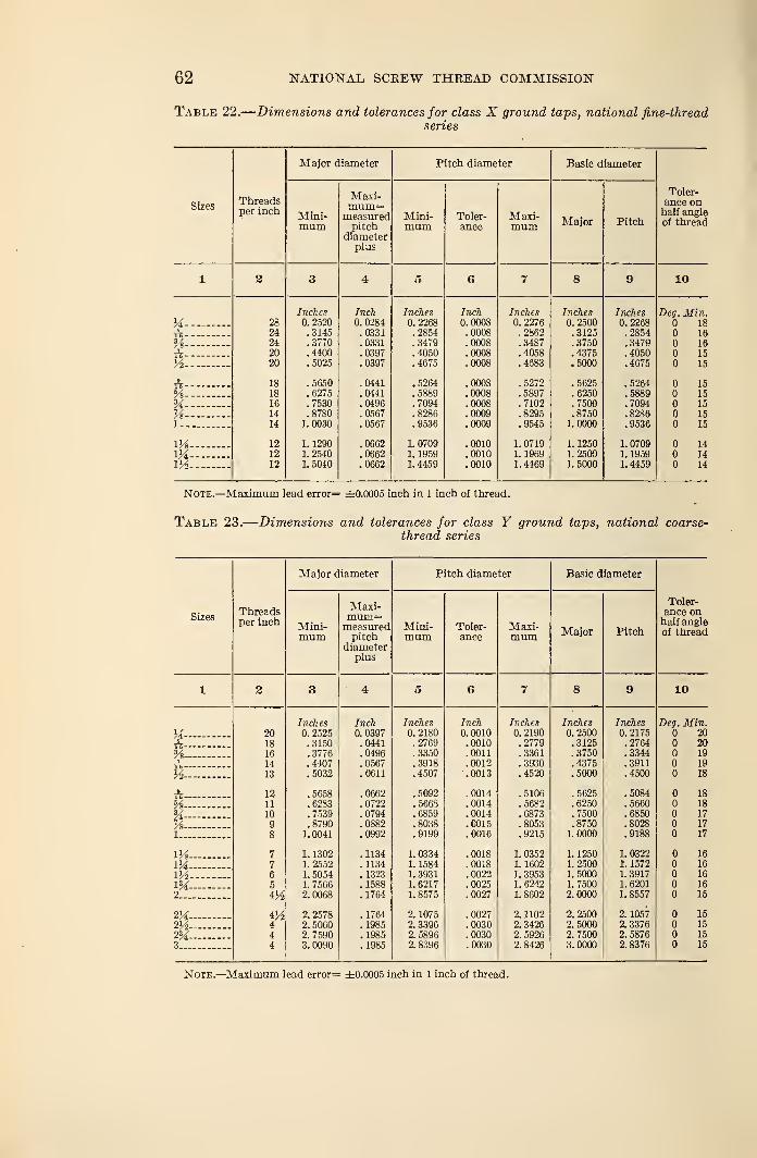
62 NATIONAL SCKEW THREAD COMMISSION
Table 22.
—
Dimensions and tolerances for class X ground taps, national fine-threadseries
SizesTVi roiric1 111 t i 1
1 >
nor l n/">ViI
'1 1 il II 1 1
Major diameter Pitch diameter Basic diameter
i oier-
8.DC6 onhalf angleof thread
Mini-mum
Maxi-mum=measuredpitch
diameterplus
Mini-mum
Toler-ance
M!axi-mum Major Pitch
1 2 A*± o aD QO oy 10
Inches Inch Inches Inch Inches Inches Inches Uty . JxL I It.
M- 28 0. 2520 0. 0284 0. 2268 0.0008 0. 2276 0. 2500 0. 2268 18
A—%-24 .3145 .0331 .2854 .0008 .2862 .3125 .2854 1624 .3770 .0331 .3479 .0008 .3487 .3750 .3479 16
ft-- 20 .4400 .0397 .4050 .0008 .4058 .4375 .4050 15
V2- 20 .5025 .0397 .4675 .0008 .4683 .5000 .4675 15
ft- 18 .5650 .0441 .5264 .0008 .5272 .5625 .5264 1518 .6275 .0441 .5889 .0008 .5897 .6250 .5889 15
%-%-
16 . 7530 .0496 .7094 .0008 .7102 .7500 .7094 1514 .8780 .0567 .8286 .0009 .8295 .8750 .8286 15
1- 14 1.0030 .0567 .9536 .0009 .9545 1.0000 .9536 15
m 12 1. 1290 .0662 1. 0709 .0010 1. 0719 1. 1250 1.0709 14
m~ 12 1. 2540 .0662 1. 1959 .0010 1. 1969 1.2500 1. 1959 14m 12 1. 5040 .0662 1. 4459 .0010 1. 4469 1. 5000 1. 4459 14
Note.—Maximum lead error= ±0.0005 inch in 1 inch of thread.
Table 23.
—
Dimensions and tolerances for class Y ground taps, national coarse-thread series
SizesThreadsper inch
Major diameter Pitch diameter Basic diameter
Toler-ance onhalf angleof thread
Mini-mum
Maxi-mum=measuredpitch
diameterplus
Mini-mum
Toler-ance
Maxi-mum Major Pitch
1 2 3 4 5 6 7 8 9 10
Inches Inch Inches Inch Inches Inches Inches Deg. Min.y* 20 0. 2525 0. 0397 0. 2180 0. 0010 0. 2190 2500 0. 2175 20
ft 18 .3150 .0441 .2769 .0010 .2779 3125 .2764 20SA- 16 .3776 .0496 .3350 .0011 .3361 3750 .3344 197 14 .4407 .0567 .3918 .0012 .3930 4375 .3911 19
K 13 .5032 .0611 .4507 .0013 .4520 5000 .4500 18
ft—- - 12 . 5658 .0662 .5092 .0014 .5106 5625 .5084 18hA 11 .6283 .0722 . 5668 .0014 .5682 6250 .5660 18SA 10 .7539 .0794 .6859 .0014 .6873 7500 .6850 17
Vs 9 .8790 .0882 .8038 .0015 .8053 8750 .8028 17
l 8 1.0041 .0992 .9199 .0016 .9215 1 0000 .9188 17
1H 7 1. 1302 .1134 1. 0334 .0018 1. 0352 1 1250 1. 0322 16
m 7 1. 2552 . 1134 1. 1584 .0018 1. 1602 1 2500 i. 1572 16
m 6 1. 5054 . 1323 1. 3931 .0022 1. 3953 1 5000 1. 3917 16
m 5 1. 7566 .1588 1. 6217 .0025 1.6242 1 7500 1. 6201 16
2 2. 0068 .1764 1. 8575 .0027 1. 8602 2 0000 1. 8557 15
2^ iyt 2. 2578 .1764 2. 1075 .0027 2. 1102 2 2500 2. 1057 15
2H 4 2. 5060 . 1985 2. 3396 .0030 2. 3426 2 5000 2. 3376 15
m 4 2. 7590 . 1985 2. 5896 .0030 2. 5926 2 7500 2. 5876 15
3- 4 3. 0090 .1985 2. 8396 .0030 2. 8426 3 0000 2. 8376 15
Note.—Maximum lead error= ±0.0005 inch in 1 inch of thread.
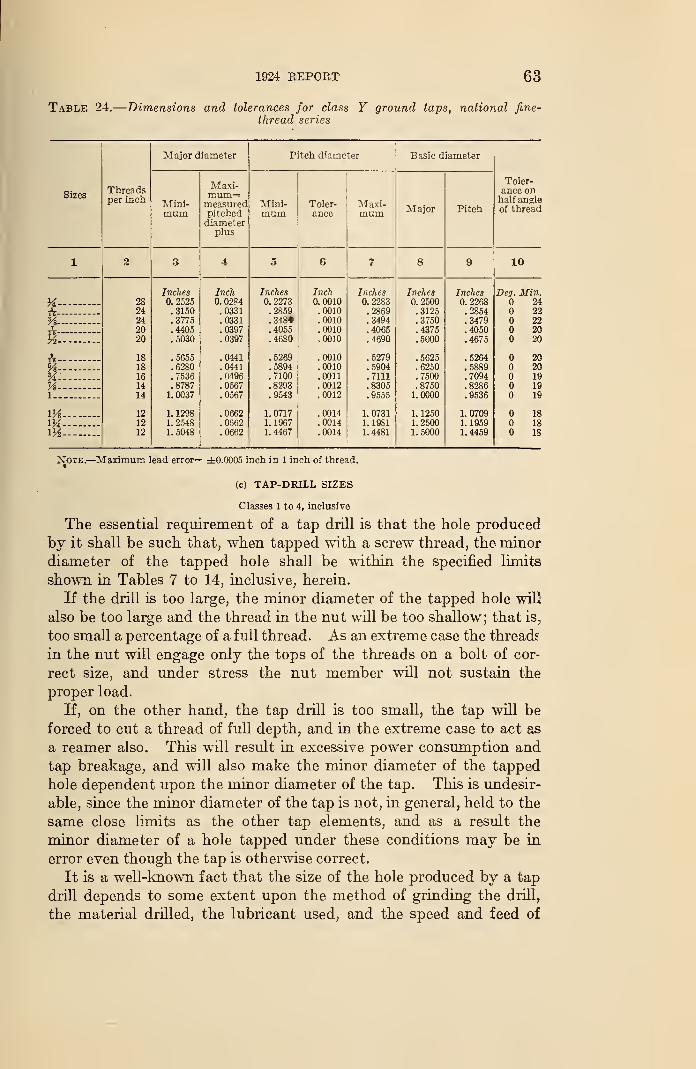
1924 REPORT 63
Table 24.
—
Dimensions and tolerances for class Y ground taps, national fine-
thread series
CI'bizes
Threadsper inch
Major diameter Pitch diameter Basic diameter
Toler-ance onhalf angleof thread
Mini-mum
Maxi-mum=measuredpitcheddiameter
plus
Mini-mum
Toler-ance
Maxi-mum ir iLLil
1 2 3 4 5 6 7 8 10
Inches Inch Inches Inch Inches Inches Inches Deg. Min.a —
-
A28 0. 2525 0.0284 0. 2273 0. 0010 0. 2283 0.2500 0. 2268 2424 .3150 .0331 .2859 .0010 .2869 .3125 .2854 22
Vi —
-
24 .3775 .0331 .348* .0010 .3494 .3750 .3479 22_2_ 20 .4405 .0397 .4055 .0010 .4065 .4375 .4050 20
y2 20 .5030 .0397 .4680 .0010 .4690 .5000 .4675 20
A 18 .5655 .0441 .5269 .0010 .5279 .5625 .5264 20
% 18 .6280 .0441 .5894 .0010 .5904 .6250 .5889 20
% 16 .7536 .0496 .7100 .0011 .7111 .7500 .7094 19
Vs— 14 .8787 .0567 .8293 .0012 .8305 .8750 .8286 191 14 1. 0037 .0567 .9543 .0012 .9555 1.0000 .9536 19
iys 12 1. 1298 .0662 1. 0717 .0014 1. 0731 1. 1250 1.0709 18
1H 12 1. 2548 .0662 1. 1967 .0014 1. 1981 1. 2500 1. 1959 18iy2 12 1. 5048 .0662 1. 4467 .0014 1.4481 1. 5000 1. 4459 18
Note.—Maximum lead error= ±0.0005 inch in 1 inch of thread.
(c) TAP-DRILL SIZES
Classes 1 to 4, inclusive
The essential requirement of a tap drill is that the hole produced
by it shall be such that, when tapped with a screw thread, the minor
diameter of the tapped hole shall be within the specified limits
shown in Tables 7 to 14, inclusive, herein.
If the drill is too large, the minor diameter of the tapped hole will
also be too large and the thread in the nut will be too shallow; that is,
too small a percentage of a full thread. As an extreme case the threads
in the nut will engage only the tops of the threads on a bolt of cor-
rect size, and under stress the nut member will not sustain the
proper load.
If, on the other hand, the tap drill is too small, the tap will be
forced to cut a thread of full depth, and in the extreme case to act as
a reamer also. This will result in excessive power consumption and
tap breakage, and will also make the minor diameter of the tapped
hole dependent upon the minor diameter of the tap. This is undesir-
able, since the minor diameter of the tap is not, in general, held to the
same close limits as the other tap elements, and as a result the
minor diameter of a hole tapped under these conditions may be in
error even though the tap is otherwise correct.
It is a well-known fact that the size of the hole produced by a tap
drill depends to some extent upon the method of grinding the drill,
the material drilled, the lubricant used, and the speed and feed of
64 NATIONAL SCREW THREAD COMMISSION
operation. This being true, it is apparent that fixing the diameter of
the tap drill does not completely fix the diameter of the drilled hole.
The most that can be accomplished is to fix the drill diameters
between certain limits and to depend upon correct grinding, lubrica-
tion, and operation to keep the diameter of the holes within pre-
scribed limits.
In establishing tap-drill sizes, the starting point is the mean betweenthe maximum and minimum minor diameter of the tapped hole.
This permits a variation of the minor diameter, both above and below
the ideal tap-drill size, equal to half the tolerance on minor diameter.
Thus the tap drill may cut oversize by this amount by reason of
incorrect grinding, lubrication, or operation, or on account of differ-
ences in the materials tapped; and it may be allowed to wear under-
size until the tapped hole reaches the lower limit on minor diameter.
It should be noted that the minor diameters of the tapped holes are
the same for classes 1 to 4, inclusive. This condition results from the
requirement on page 18 with reference to clearance on minor diameter:
4. Clearance on Minor Diameter.—A clearance shall be provided at the
minor diameter of the nut by removing from the crest of the basic thread form
an amount equal to one-sixth to one-fourth of the basic thread depth.,
The minor diameter of the tapped hole is therefore greater than
the basic minor diameter by one-third to one-half the basic thread
depth, and the tolerance on the minor diameter is one-sixth the
basic depth.
Minimum minor diameter of tapped hole = basic minor diameter +^
Maximum minor diameter of tapped hole = basic minor diameter+^in which
A = basic thread depth = 0.649519 p
p = pitch=i
n = number of threads per inch.
There are given in Tables 25 and 26 the limiting dimensions
of the minor diameter of the threaded hole, as established by the
commission, together with the tap-drill sizes recommended. There
are also given the diameters of all the drills regularly carried in
stock that fall between the limiting dimensions of the minor diameter
of the threaded hole. Accordingly, drills of these diameters should
produce holes which result in a thread depth of 75 to 83M per cent
of the basic depth of thread.
The commission recommends to manufacturers of tap drills the
making up of complete sets of drills of the sizes required for both
the "national coarse" and "national fine thread series." The user
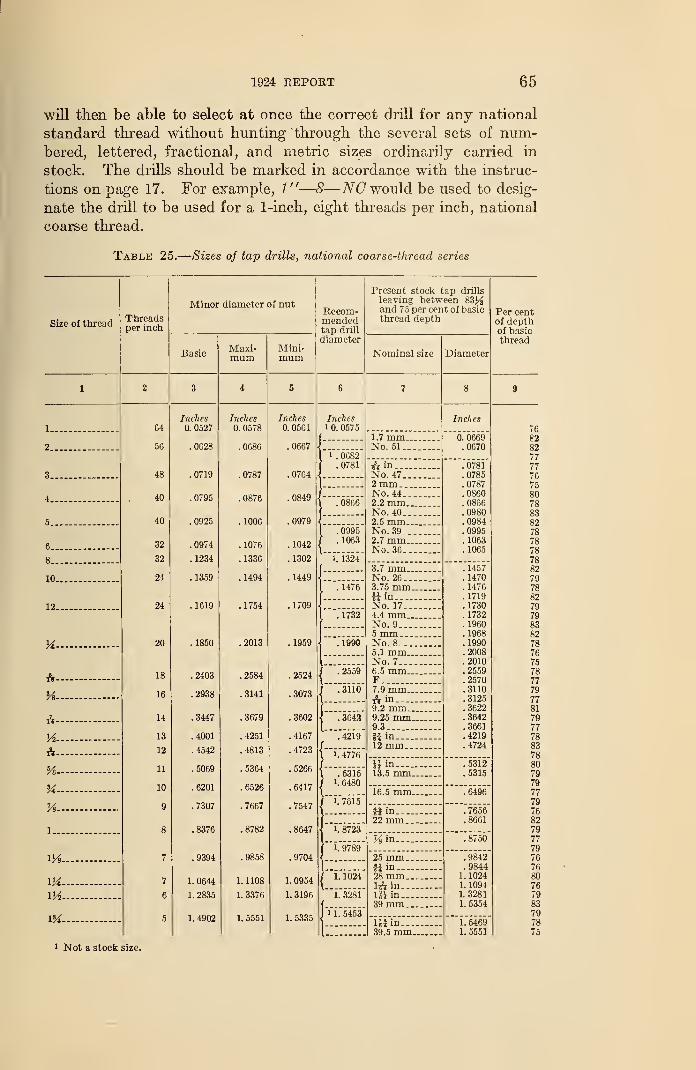
1924 REPORT 65
will then be able to select at once the correct drill for any national
standard thread without hunting through the several sets of num-bered, lettered, fractional, and metric sizes ordinarily carried in
stock. The drills should be marked in accordance with the instruc-
tions on page 17. For example, 1"—8—NO would be used to desig-
nate the drill to be used for a 1-inch, eight threads per inch, national
coarse thread.
Table 25.
—
Sizes of tap drills, national coarse-thread series
Size of threadThreadsper inch
m1 Not a stock size.
64
56
48
40
40
32
32
24
24
20
18
16
14
13
12
11
10
Minor diameter of nut
Basic
Inches0. 0527
.0628
.0719
.0795
.0925
.0974
.1234
. 1359
. 1619
. 1850
.2403
.2938
.3447
.4001
.4542
.5069
.6201
.7307
.8376
.9394
1. 0644
1. 2835
1. 4902
Maxi-mum
Inches0. 0578
.0686
.0787
.0876
. 1006
. 1076
.1336
. 1494
. 1754
.2013
.2584
.3141
.3679
.4251
.4813
.5364
.6526
.7667
.8782
.9858
1. 1108
1. 3376
1. 5551
Mini-mum
Inches0. 0561
.0667
.0764
.0849
.0979
.1042
. 1302
. 1449
.1709
.1959
.2524
.3073
.3602
.4167
.4723
.5266
.6417
.7547
.8647
.9704
1. 0954
1.3196
1. 5335
Recom-mendedtap drill
diameter
Inchesi 0. 0575
i. 0682.0781
.0866
.0995
. 1063
1. 1324
. 1476
71732
.1990
.2559
"."3110
.3642
."4219
1. 4776
.53151. 6480
{---7615
1. 8723
"i.~9789
1. 1024
"i."3281
n."5453
Present stock tap drills
leaving between 83^and 75 per cent of basicthread depth
Nominal size
1.7 mm.No. 51..
A inNo. 47..2 mm . _
.
No. 44..2.2 mm.No. 40..2.5 mm.No. 39 _.
2.7 mm.No. 36..
3.7 mm..No. 26...3.75 mm.
in.
No. 17...4.4 mm..No. 9....5 mmNo. 8_...5.1 mm..No. 7...,6.5 mm..F7.9 mm..A in9.2 mm..9.25 mm.9.3
*i in12 mm..
i* in---.13.5 mm.
16.5 mm.
Hin...22 mm.
:m.
25 mm.Hin---28 mm.1& in..
IJi in..39 mm.
l*f in—39.5 mm.
Diameter
Inches
0. 0669.0670
.0781
.0785
.0787
.0860
.0866
.0980
.0984
.0995
. 1063
. 1065
.1457
. 1470
. 1476
. 1719
.1730
. 1732
.1960
.1968
.1990
.2008
.2010
.2559
.2570
.3110
.3125
.3622
.3642
.3661
.4219
.4724
.5312
.5315
.6496
.7656
.8661
.8750
.9842
.98441. 10241. 10941. 32811. 5354
1. 54691. 5551
Per centof depthof basicthread
82827777767580788382
7882
8279798382787675787779778179777883788079797779768279
7779
80767983797875
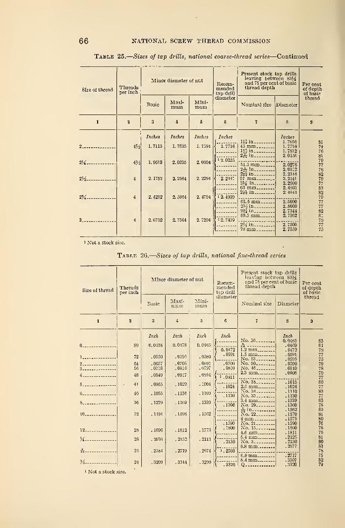
66 NATIONAL SCREW THREAD COMMISSION
Table 25.
—
Sizes of tap drills, national coarse-thread series—Continued
Size of thread
1
Threadsper inch
Minor diameter of nut
BasicMaxi-mum
Mini-mum
Recom-mendedtap drill
diameter
Present stock tap drills
leaving between 8314and 75 per cent of basicthread depth
Nominal size Diameter
Per centof depthof basicthread
2__
3__
m.
4
Inches
1. 7113
1. 9613
2. 1752
2. 4252
2. 6752
Inches
1. 7835
2. 0335
2. 2564
2.5064
2. 7564
Inches
1. 7594
2. 0094
2. 2294
2. 4794
2. 7294
Inches
1. 7716
1 2. 0225
Hi in..45 mm.Hi in..
2A in..
2. 2441
51.5 mm.2^ in
2M in....57 mm...214 in-..63 mm...
I 2. 4939in.
63. 5 mm.2V2 in
2*i in69.5 mm..
i 2. 74392 34in_.70 mm.
Inches1. 76561. 77161.78122. 0156
0276031223442441250048034844
2. 50002. 50002. 73442. 7362
2. 75002. 7559
81
797681
7977768279778382797777
8281797775
1 Not a stock size.
Table 26.
—
Sizes of tap drills, national fine-thread series
Size of threadThreadsper inch
Minor diameter of nut
BasicMaxi-mum
Mini-mum
Recom-mendedtap drill
diameter
Present stock tap drills
leaving between 83^and 75 per cent of basicthread depth
Nominal size Diameter
Per centof depthof basicthread
0...
1
23
4
5 - -
6...
8
10
12
M
A —
-
%1 Not a stock size.
80
72
6456
48
44
40
36
32
28
28
24
24
Inch
0. 0438
.0550
.0657
.0758
.0849
.0955
.1055
. 1279
. 1494
.1696
.2036
.2584
.3209
Inch
0. 0478
.0595
.0708
.0816
.0917
.1029
. 1136
.1369
.1596
.1812
.2152
.2719
.3344
Inch
0. 0465
.0580
.0691
.0797
.0894
.1004
. 1109
.1339
.1562
.1773
.2113
.2674
.3299
Inch
0. 0472.0591
.0700
.0810
i. 0911
'""."1624'
. 1130
\~136o'
.1590
.1800
.2130
"l72703"
No. 56..
&1.2 mm.1.5 mm.No. 53..No. 50..No. 46..2.3 mm.
Inch0.0465.0469.0472. 0591.0595.0700.0810.0906
No. 38..2.6 mm.No. 34..No. 33..3.4 mm.No. 29..
A in....No. 22..4 mm...No. 21..No. 15..4.6 mm.5.4 mm.No. 3...6.8 mm..
.1015
.1024
. 1110
. 1130
. 1339
.1360
. 1562
. 1570
. 1575
. 1590
. 1800
. 1811
. 2126
.2130
.2577
.3320
6.9 mm.8.4 mm.Q
.2717
.3307
.3320
838179777579787977807783
77837883818076787581808378758279
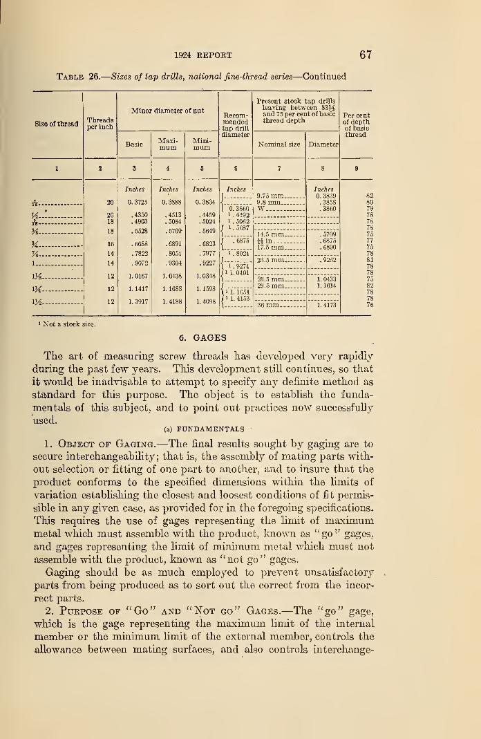
1924 REPORT 67
Table 26.
—
Sizes of tap drills, national fine-thread series—Continued
Size of thread
&-
H-rV-
H-
K-%-i._
lVs-
M-m-
Threadsper inch
Minor diameter of nut
Basic
20
2018
18
16
14
14
12
12
12
Inches
0. 3725
.4350
.4903
.5528
.6688
.7822
.9072
1. 0167
1. 1417
1.3917
Maxi-mum
Inches
0. 388S
.4513
.5084
.5709-
.6891
.8054
.9304
1. 0438
1. 1688
1. 4188
Mini-mum
Inches
0. 3834
.4459
.5024
.5649
.6823
.7977
.9227
1. 0348
1. 1598
1. 4098
Kecom-mendedtap drill
diameter
Inches
0. 3860i
. 4492i
. 50621 . 5687
'""."6875
i. 8024
1 . 92741 1. 0401
i 1. 1651'
1 1. 4153
Present stock tap drills
leaving between 83J-3and 75 per cent of basicthread depth
Nominal size
9.75 mm.9.8 mm..W
14.5 mm.«in..._.17.5 mm.
23.5 mm.
26.5 mm.29.5 mm.
36 mm_
Diameter
Inches0. 3839.3858.3860
.5709
.6875
.9252
1. 04331. 1614
1. 4173
Per centof depthof basicthread
828079787878757775788178787582787876
1 Not a stock size.
6. GAGES
The art of measuring screw threads has developed very rapidly
during the past few years. This development still continues, so that
it would be inadvisable to attempt to specify any definite method as
standard for this purpose. The object is to establish the funda-
mentals of this subject, and to point out practices now successfully
used.(a) FUNDAMENTALS '
1. Object of Gaging.—The final results sought by gaging are to
secure interchangeability ; that is, the assembly of mating parts with-
out selection or fitting of one part to another, and to insure that the
product conforms to the specified dimensions within the limits of
variation establishing the closest and loosest conditions of fit permis-
sible in any given case, as provided for in the foregoing specifications.
This requires the use of gages representing the limit of maximummetal which must assemble with the product, known as "go'-' gages,
and gages representing the limit of minimum metal which must not
assemble with the product, known as "not go" gages.
Gaging should be as much employed to prevent unsatisfactory
parts from being produced as to sort out the correct from the incor-
rect parts.
2. Purpose of "Go" and "Not go" Gages.—The "go" gage,
which is the gage representing the maximum limit of the internal
member or the minimum limit of the external member, controls the
allowance between mating surfaces, and also controls interchange-
68 NATIONAL. SCREW THREAD COMMISSION
ability. "Go" gages control the maximum tightness in the fit of
mating parts. Parts which are acceptable to proper "go" gages will
always interchange. Successful interchangeable manufacturing has
been carried on for many years with the use of "go" gages only.
The "not go" gage, which is the gage representing the minimumlimit of the internal member or the maximum limit of the external
member, controls the extent of the tolerance in one direction. " Notgo" gages limit the amount of looseness between mating
'parts,
and thus control, in large measure, the proper functioning of mating
parts.
3. Gage Classification.—The limiting dimensions of the
threaded parts to be produced must be represented in: (a) Gages
used in checking the product as it is machined, known as "working
gages"; (b) gages for use in the acceptance of the product, knownas "inspection gages"; and (c) gages used to determine the accuracy
of the two preceding classes of gages, known as "master gages."
4. Gages Used to Measure the Product.—The gages used to
check the product may be divided into two general types: "Mechan-ical" and "optical." Both types, however, are controlled by the mas-
ter gages. Most of the product accepted by one type of gaging with
a correct gage will be accepted by the other. It should be pointed
out, however, that those parts which are near either rejection point
may be accepted by one system and rejected by the other.
(a) Mechanical gages. 1—Mechanical gages ordinarily comprise the
inspection and working gages as above defined, and these two classes
are generally of the same design. The dimensions of inspection gages
are such that they represent very nearly the extreme limits of the
part. It is recommended that, when successive inspections are re-
quired, the working gages, either by design or selection, be of such
dimensions that they are inside the limits of the gages used in suc-
ceeding inspections.
(&) Optical gages.—When gages of the optical type are employed,
the elements of wear and "feel" are not involved, hence no differ-
ence in size between inspection and working gages is necessary, but
is desirable.
5. Gages for Reference.— (a) Master gage.—The "master gage"
is a plug-thread gage which represents the physical dimensions of
the nominal or basic size of the part. A master gage shall be
accompanied by a record of its measurement. In case of question,
the deviations of this gage from the basic size shall be ascertained
by the Bureau of Standards at Washington, D. C.
(6) Setting gage {check gage).—A setting gage is a plug-thread
gage to which adjustable ring-thread gages and other thread com-
parators are adjusted for size.
Recommendations as to the design and construction of mechanical gages are given in Appendix 4.
1924 REPORT 69
6. Direction of Tolerances on Gages.— The extreme sizes for
limit gages shall never exceed either extreme limit of the part being
produced. AU variations in the gages, whatever their cause or purpose,
shall bring these gages within these extreme limits. Thus, a gage
which represents a minimum limit may be larger, but never smaller,
than the minimum size specified for the part, while the gage which
represents a maximum limit may be smaller, but never larger, than
the maximum size specified for the part.
7. Temperature at Which Gages Shall be Standard.—Gages
and product shall have their correct nominal dimensions at a tempera-
ture of 68° F. (20° C). .
As gages and products are ordinarily checked at room temperature,
whatever it may happen to be, it is desirable that the thermal coeffi-
cient of expansion of gages be the same as that of the product on which
they are used. Inasmuch as the majority of threaded products con-
sist of iron and steel, and as screw-thread gages are ordinarily madeof hardened steel, because- of its high wear-resisting qualities, this
condition is ordinarily fulfilled without giving it special attention.
8. Measuring Pressure for Three-Wire Measurements.—
A
contact pressure of 2 to 3 pounds shall be used in measuring the pitch
diameter of screw-thread gages by means of wires.
(b) GAGING PRACTICES AND TYPES OF GAGES
The production of accurate parts is primarily a matter of constant
vigilance and of training of workmen. The smaller the tolerances
which are to be maintained, the more complete the inspection or
gaging system must be. In order to secure satisfactory results, the
manufacturing tools provided must be sufficiently accurate, and the
manufacturing methods must be sufficiently reliable, to produce the
required results. After tools and methods of proved reliability are
provided, it is necessary to watch the wear on the tools or changes
in their set-up to insure that the required conditions are maintained.
This is accomplished by periodical tests of the tools, by periodical
gaging of the product, and sometimes by both.
There is a broad, general principle in regard to limit gages which
should be kept in mind; a "go " gage should check simultaneously as
many elements as possible, a "not go" gage, to be effective, can check
but one element. By effective inspection is meant assurance that
specified requirements in regard to size are not exceeded. A "not
go" thread gage made to check the pitch diameter only is usually
sufficient for practical purposes.
A screw thread comprises several elements: First, the major diame-
ter; second, the pitch diameter; third, the minor diameter; fourth,
the angle of the thread; and fifth, the lead. The most difficult ele-
ment of a screw thread to gage is the lead. Lead-testing devices for
checking tools and gages are available, but, in general, their opera-
70 NATIONAL SCREW THREAD COMMISSION
tion is too slow for use as production inspection equipment. In addi-
tion, the lead is the most important element of a screw thread as
regards the nature of the contact between the surfaces of the mating
parts. Furthermore, the result of an error in lead is almost double
that of an equal error in diameter as regards interchangeability. For
exacting threaded work, if the method of inspection of the product
does not effectively detect lead errors, the tools used must be carefully
inspected for lead. In order to reduce the possibilities of disagree-
ment to a minimum, the manufacturer should strive to produce parts
well within the specified limits rather than close to the limiting sizes.
1. Thread Micrometers.—Thread micrometers are extensively
used to measure the pitch diameter of taps and screws. Thread
micrometers should be calibrated periodically against a master gage,
to avoid errors due to fyear on the anvils of the instrument. Asthread micrometers give no indication of lead and angle errors, the
results of tests made with thread micrometers alone can not be taken
as conclusive.
2. Thread Snap Gages.—Thread snap gages are generally adjust-
able and have contact points consisting of cone-pointed anvils, wedge-
shaped prisms with rounded edges, serrated or grooved plates, or
grooved or threaded cylinders adjustably mounted and suitably
spaced in a U-shaped frame. These gages are used to some extent
in gaging external threads, and have the advantages that work maybe inspected with great rapidity by the single motion of passing it
between the anvils of the gage, and given a visual examination for
clearance as well as a tactile inspection. The positions of the anvils
are set to a setting gage, and the anvils are then clamped in position
and sealed.
The usual form of cone-pointed snap gage has a single point on
each side of the frame, and is an effective "not go" gage. It does
not, however, fully meet the requirements for a "go" gage, as it
does not check the lead, and, therefore, must be supplemented with
some type of indicating gage to check the lead when used for checking
pitch diameter, angle, and thread form. Also, as it checks only a
single diameter at a time, the "go " snap gage must be tried at a series
of points to determine whether the maximum diameter of an external
thread is within the tolerance. When provided with three contact
points, two on one side spaced an integral number of threads apart
and one on the other, such a gage checks the lead for progressive,
but not always for local or periodic lead errors, and, thus, it morenearly fulfills the requirements for a "go" thread gage.
Thread snap gages having multiple toothed contact points; that is,
toothed blades, serrated or grooved plates, or grooved or threaded
cylinders are made in a variety of forms, either as separate or com-bined "go" and "not go" gages. The fit of a screw in such a gage
is affected by variations in pitch diameter, lead, and angle of the screw,
1&24 REPORT 71
and the gage accordingly may be used as a "go" gage. Such gages
have been found suitable only for the less accurate classes of work,
such as the loose and free fit classes.
Thread micrometers and thread snap gages are extensively used
for testing the product as it is produced. As these instruments donot test all elements of the screw thread, a "go" gage should always
be used as a supplementary test. Thread micrometers are very
effective means of checking against the change in set-up due to wearon tools, etc.
3. Ring Thread Gages.—Ring thread gages are extensively used
to measure the threads on screws. These are usually adjustable
to suitable setting gages. When the product is to be within specified
limits, "go" and "not go" gages are required. The use of such
gages gives some information as to lead and angle errors as well as
pitch diameter errors.
4. Thread Comparators.—A recent development in the art
of measuring threaded parts is the optical thread comparator, whichembodies the principle of gaging in an optical projection system. In
addition to giving a rapid indication of whether the elements of the
screw thread lie within the limiting dimensions specified, such instru-
ments furnish more detailed information as to the errors in screw
threads than is usually obtained- by means of mechanical gages,
particularly as to irregularities in thread form, lead and diameter.
These instruments can be adapted to measure taps and other thread-
ing tools.
The available forms of projection comparators differ somewhat in
design and principle, but each consists primarily of a source of
parallel light, such as an electric arc or concentrated filament lamp
with condensing lens system, a projection lens system, a screen uponwhich the magnified shadow image of the work is projected, and a
device for holding the work in position in front of the projection
lenses. The screen consists of a tolerance chart on which two out-
lines of the correct thread form at the magnification used are spaced
one above the other a distance equal to the tolerance multiplied bythe magnification. The chart and gage holder are adjusted to posi-
tion by projecting the shadow image of a setting gage and adjusting
to bring the outline of the shadow image and certain lines of the chart
into coincidence, after which the system may be used as a gaging
device.
5. Indicating Gages.—An indicating thread gage has movable
contact points, which are set to a setting gage, and is intended to
give an exact indication of the variations of the dimensions of a screw
thread within the specified limits, rather than to show merely that the
thread is within, or outside of, the specified limits, as is the case with
limit gages. In such gages, the movable contact points actuate a
multiplying lever system, or other means for magnifying their motion,
72 NATIONAL SCREW THREAD COMMISSION
and the amount of the motion is registered on a graduated dial or
scale. Indicating gages are made according to a variety of designs,
some to indicate progressive lead error only, some to indicate pitch
diameter only, some to indicate both separately but on the same gage,
others to indicate the major and minor diameters as well, and still
others to indicate the apparent size. They have been applied almostexclusively to external threads. Those which indicate the apparentsize may be considered as most nearly fulfilling the requirements of a
gaging system. However, those indicating lead errors are veryuseful in controlling lead errors in threading tools and screw-thread
products. Also certain types can be used to indicate the variation
in roundness on pitch or major diameters.
6. Plug Thread Gages.—At the present time the most practical
means of gaging threaded holes or nuts is by the use of plug thread
gages. When the product is to be within specified limits, "go" and"not go" gages are required. The use of such gages gives someinformation as to lead and angle errors as well as pitch diameter
errors. A correct "go" plug gage will reject any parts which exceed
the minimum dimensions specified.
One practice of inspecting tapped holes is to first inspect the tap,
and then to test the tapped holes periodically with "go" and "not
go" gages. The tap can be watched for wear by testing the tapped
holes with a "go" thread gage. One widely used practice consists
of using a "go" plug thread gage, and a "not go" plain plug gage
for the minor diameter.
One practice of inspecting taps is to measure the several elements,
such as pitch diameter, angle, and lead. Another practice consists
of tapping a hole with each tap before it is issued from the tool
crib and testing these tapped holes with "go" and "not go" plug
thread gages.
Sometimes the tap is tested after it is returned to the tool crib.
If it is correct, it is replaced in its proper compartment. If it has
worn below the limits, it is discarded and work produced by it is
checked and corrected when necessary.
7. Plain Gages.—"Go" and "not go" plain cylindrical plug
gages are used for inspecting the minor diameter of the tapped hole.
Plain ring or snap gages are used for inspecting the major diameter
of the screw. When used, it is recommended that the "go" inspec-
tion gage be a ring gage and the "not go" inspection gage be a snap
gage. The working gages may be a combined "go" and "not go"snap gage.
8. Testing or Gages.—Gages should be tested periodically for
wear and to insure that the gages are properly distributed. Whensuccessive inspections in the same plant are involved, it is good
practice to inspect all gages of the same nominal size against each
1924 REPORT 73
other periodically, and to distribute these gages so that the earlier
inspections are made with those which are the greatest amountinside of the component limits, while the later inspections are madewith those gages closest in size to the component limits.
The original testing of a thread gage should include measurementsfor diameters, angle, and lead. If these elements test satisfactorily,
the later inspection need be measurements of pitch diameter only. 8
(c) SPECIFICATIONS FOR GAGES
The following specifications are for the purpose of establishing
definite limits for thread gages rather than for the purpose of specify-
ing the gages required for the various inspection operations.
1. Classification of Gages, and Gage Tolerances.—Screwthread gages are classified according to accuracy into classes X, Y,
and Z, the class X being the most accurate. The tolerance limits
on classes Y and Z "go" gages are placed inside of the extreme
product limits to provide allowance for wear of the gages. The tol-
erances on all "not go" gages, however, are applied from the extreme
product limit as the starting point, as no allowance for wear is neces-
sary. The selection of gages from among these classes for use in the
inspection of threaded product depends entirely upon the specifica-
tions for the product. For example, in the production of parts to
class 4, close fit specifications, class X gages may be required for all
purposes. On the other hand, for parts made to class 1, loose fit speci-
fications, class Z gages may be sufficiently accurate for all purposes.
(a) Master gages.—No fixed tolerances are specified for master
gages. These should be made to the basic size as accurately as pos-
sible and be within the tolerances specified for class X gages. Thevariations from basic size shall be plus. Each master gage shall be
marked with an identification number or symbol, and be accom-
panied by a record of its measurement on major diameter, pitch
diameter, lead, and angle. In case of question, the deviations of
such gages from the exact standard shall be ascertained by the
Bureau of Standards at Washington, D. C.
(6) Class X gages.—Class X gages should be suitable for inspec-
tion and setting gages for all classes of fits. They may also be neces-
sary for working gages for class 4 fits. The tolerances on these gages
shall be as given in Table 28. In all cases the tolerances shall be such
that the gage does not fall outside of the component tolerances. For
example, if a plug thread gage is used as the "go" gage for check-
ing a tapped hole, it can be larger, but not smaller than the mini-
mum size specified. On the other hand, if a plug thread gage is used
as the "go" setting plug for ring thread gages or for optical or other
comparators, it can be smaller, but never larger than the maximumsize of the screw.
'Methods of measuring pitch diameter of screw thread gages are described in Appendix 2.
74 NATIONAL SCREW THREAD COMMISSION
Class X tolerances, as given in Table 28, are specified for all "notgo" gages.
(c) Class Y gages.—Class Y gages should be suitable for inspec-
tion gages for classes 1, 2, and 3 fits. They may also be desired as
working gages for classes 2 and 3 fits. The tolerances on these
gages shall be as given in Table 29.
(d) Class Z gages.—Class Z gages should be suitable for workinggages for class 1, loose fit. The tolerances on these gages shall be as
given in Table 30.
(e) Wear on gages.—-"Go" gages may be permitted to wear to the
extreme product limits. It is desirable, however, that working andinspection gages be so selected that the dimensions of the workinggages are inside of the limiting dimensions represented by the in-
spection gages, in order that all parts passed by the working gage
will be accepted by the inspection gage.
As to wear on "not go" gages, it is purely a question of economyas to when the "not go" gage should be discarded. Continued use
reduces the available working tolerance on the product, and the re-
sulting loss must be balanced against the cost of a new gage.
(f) Tolerance on lead.—The tolerances on lead given in Tables 28
to 30, inclusive, are specified as an allowable variation between anytwo threads not farther apart than the length of engagement of the
assembled threaded product. When this length of engagement is
equal to the diameter, the permissible progressive lead errors per
inch may be determined by dividing these lead tolerances by the
corresponding diameters.
(g) Tolerances on angle of thread.—The tolerances on angle of
thread, as specified in Tables 28 to 30, inclusive, for the various
pitches, are tolerances on one-half of the included angle. This
insures that the bisector of the included angle will be perpendicular
to the axis of the thread within proper limits. The equivalent
deviation from the true thread form caused by such irregularities
as convex or concave sides of thread,* rounded crests, or slight pro-
jections on the thread form, should not exceed the tolerances per-
mitted on angle of thread.
2. Tolerances for Plain Gages.—For plain plug gages, plain
ring gages, and plain snap gages required for measuring diameters of
screw-thread work, the gage tolerances specified in Table 31 should
be used. Attention is directed to the fact that the tolerances on
thread diameters vary in accordance with the number of threads per
inch. In manufacturing a plain plug, ring, or snap gage, in the
absence of information as to the number of threads per inch of the
screw to be made, or for gage dimensions other than thread diame-
ters, the tolerances for plain gages given in Table 31 may be used.
This table contains recommended tolerances for classes X, Y, and Z
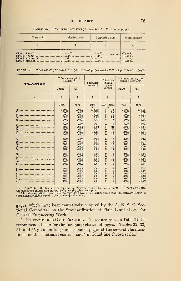
19*24 REPORT 75
Table 27.
—
Recommended uses for classes X, Y, and Z gages
Class of fit Setting gage Inspection gage Working gage
1 3 3 4
Class 1, loose fit Class X Class Y Class Z.Class Y.
Do.Class X.
Class 2, free fit do do.--Class 3, medium fit do... _ Class XClass 4, close fit do do--
Table 28.
—
Tolerances for class X "go" thread gages and all "not go" thread gages
Threads per inch
Tolerance on pitchdiameter 1
Tol6ra.nc6in li !< I
'
Toleranceon halfangle ofthread
Tolerance on major orminor diameters 1
From
—
To— From
—
To—
1 2 3 4 5 6 7
Inch Inch Inch Beg. Min. Inch Inch± ±
80 0.0000 0.0002 0.0002 30 0.0000 0. 000372 .0000 .0002 .0002 30 .0000 .000364 .0000 .0002 .0002 30 .0000 .000456 .0000 .0002 .0002 30 .0000 .0004
48 .0000 .0002 .0002 30 .0000 .0004
44 .0000 .0002 .0002 20 .0000 .0004
40 .0000 .0002 .0002 20 .0000 .0004
36 .0000 .0002 .0002 20 .0000 .0004
32 .0000 .0003 .0003 15 .0000 .0004
28 .0000 .0003 .0003 15 .0000 .0005
24 .0000 .0003 .0003 15 .0000 .0005
20 .0000 .0003 .0003 15 .0000 .0005
18 .0000 .0003 .0003 10 .0000 .0005
16 .0000 .0003 .0003 10 .0000 .0006
14 .0000 .0003 .0003 o 10 .0000 .0006
13 .0000 .0003 .0003 10 .0000 .0006
12 .0000 .0003 .0003 10 .0000 .000611 .0000 .0003 .0003 10 .0000 .000610 .0000 .0003 .0003 10 .0000 .0006
9 .0000 .0003 .0003 10 .0000 .0007
8 .0000 .0004 .0004 5 .0000 .0007
7 .0000 .0004 .0004 5 .0000 .0007
6 .0000 .0004 .0004 5 .0000 .0008
5 .0000 .0004 .0004 5 .0000 .0008
4H- .0000 .0004 .0004 5 .0000 .0008
4 .0000 .0004 .0004 5 .0000 .0009
1 On "go" plugs the tolerance is plus, and on "go" rings the tolerance is minus. On "not go" plugsthe tolerance is minus, and on "not go" rings the tolerance is plus.
3 Allowable variation in lead between any two threads not farther apart than the standard length of
engagement, which is equal to the basic major diameter.
gages, which have been tentatively adopted by the A. E. S. C. Sec-
tional Committee on the Standardization of Plain Limit Gages for
General Engineering Work.
3. Recommended Gage Practice.—There are given in Table 27 the
recommended uses for the foregoing classes of gages. Tables 32, 33,
34, and 35 give limiting dimensions of gages of the several classifica-
tions for the "national coarse" and "national fine thread series."
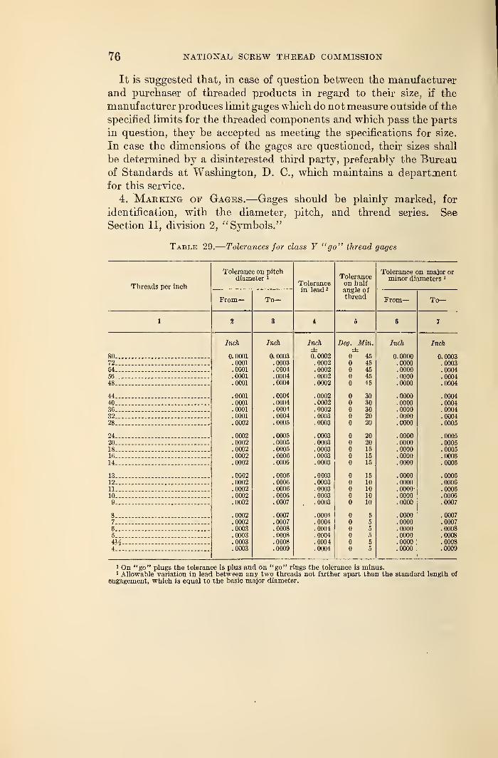
76 NATIONAL SCREW THREAD COMMISSION
It is suggested that, in case of question between the manufacturer
and purchaser of threaded products in regard to their size, if the
manufacturer produces limit gages which do not measure outside of the
specified limits for the threaded components and which pass the parts
in question, they be accepted as meeting the specifications for size.
In case the dimensions of the gages are questioned, their sizes shall
be determined by a disinterested third party, preferably the Bureauof Standards at Washington, D. C, which maintains a department
for this service.
4. Marking of Gages.—Gages should be plainly marked, for
identification, with the diameter, pitch, and thread series. See
Section II, division 2, "Symbols."
Table 29.
—
Tolerances for class Y "go" thread gages
Threads per inch
Tolerance on pitchdiameter 1
1 will (llJvC
in lead 1
Toleranceon halfangle ofthread
Tolerance on major orminor diameters 1
From— To— From— To—
1 2 3 i 5 6 7
Inch Inch Inch Deg. Min. Inch Inch± ±
80 0. 0001 0.0003 0. 0002 45 0. 0000 0.000372 .0001 .0003 .0002 45 .0000 .000364 .0001 .0004 .0002 45 .0000 .000456 .0001 .0004 .0002 45 .0000 .000448 .0001 .0004 .0002 45 .0000 .0004
44 .0001 .0004 .0002 30 .0000 .000440 .0001 .0004 .0002 30 .0000 .000436 .0001 .0004 .0002 30 .0000 .000432 .0001 .0004 .0003 20 .0000 .000428 .0002 .0005 .0003 20 .0000 .0005
24 .0002 .0005 .0003 20 .0000 .000520 .0002 .0005 . 0003 20 .0000 .000518 .0002 .0005 .0003 15 .0000 .000516 .0002 .0006 .0003 15 .0000 .000614 .0002 .0006 .0003 15 .0000 .0006
13 .0002 .0006 .0003 15 .0000 .000612 .0002 .0006 .0003 10 .0000 .000611 .0002 .0006 .0003 10 .0000- .000010 .0002 .0006 .0003 10 .0000 .00069 .0002 .0007 . . 0003 10 .0000 .0007
8 .0002 .0007 .0004 5 .0000 .00077 .0002 .0007 .0004 5 .0000 .0007
6 .0003 .0008 .0004 5 .0000 .00085 .0003 .0008 .0004 5 .0000 .0008
i'A- .0003 .0008 .0004 5 .0000 .00084 .0003 .0009 .0004 5 .0000 .0009
1 On "go" plugs the tolerance is plus and on "go" rings the tolerance is minus.1 Allowable variation in lead between any two threads not farther apart than the standard length of
engagement, which is equal to the basic major diameter.
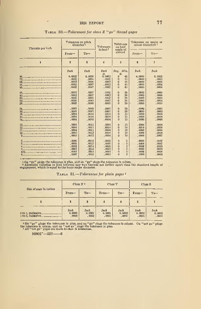
1924 REPORT
Table 30.
—
Tolerances for class Z "go" thread gages
77
Threads per inch
Tolerance on pitchdiameter 1
From- To—
Tolerancein lead 2
Toleranceon halfangle ofthread
Tolerance on major or
minor diameters 1
From- To—
72...
64...
56...
48—
44...
40..36..32..28...
24..20..18..16..
14-
13..12..11-10..9..
8_.7-6..5_.
iV24-
IncJi
0.0002.0002.0002.0002.0002
.0002
.0002
.0003
.0003
.0003
.0003
.0003
.0004
.0004
.0004
.0004
.0004
.0004
.0005
.0005
.0006
.0006
.0006
.0007
.0007
.0007
Inch
0. 0006.0006.0006.0007.0007
.0007
.0007
.0008
.0008
.0008
.0009
.0009
.0010
.0010
.0010
.0011
.0011
.0011
.0012
.0012
.0013
.0013
.0014
.0015
.0015
.0016
Inch±0.0002.0002.0002.0002.0002
.0002
.0002
.0002
.0003
.0003
.0003
.0003
.0004
.0004
.0004
.0004
.0004
.0004
.0004
.0004
.0005
.0005
.0005
.0005
.0005
.0005
Deg. Min.±
4545454545
3030302020
2020151515
15101010
10
55
555
Inch
0.0000.0000.0000.0000.0000
.0000
.0000
.0000
.0000
.0000
.0000
.0000
.0000
.0000
.0000
.0000
.0000
.0000
.0000
.0000
.0000
.0000
.0000
.0000
.0000
.0000
Inch
0. 0003.0003.0004.0004.0004
.0004
.0004
.0004
.0004
.0005
.0005
. 0005
.0005
.0006
.0006
.0006
.0006
.0006
.0006
.0007
.0007
.0007
.0008
.0008
.0008
.0009
1 On "go" plugs the tolerance is plus, and on "go" rings the tolerance is minus. .
2 Allowable variation in lead between any two threads not farther apart than the standard length ofengagement, which is equal to the basic major diameter.
Table 31.
—
Tolerances for plain gages 1
Size of gage in inches
Class X 2 Class Y Class Z
From
—
To— From— To— From— To—
1 2 3 i 5 6 7
to 1, inclusive1 to 3, inclusive
Inch0.0000.0000
Inch0. 0001.0002
Inch0. 0001.0001
Inch0. 0002.0003
Inch0.0002.0003
Inch0. 0003.0005
1 On "go" plugs the tolerance is plus, and on "go" rings the tolerance is minus. On "not go" plugsthe tolerance is minus, and on "not go" rings the tolerance is plus.
2 All "not go" gages are made to class X tolerances.
16802°—251 6
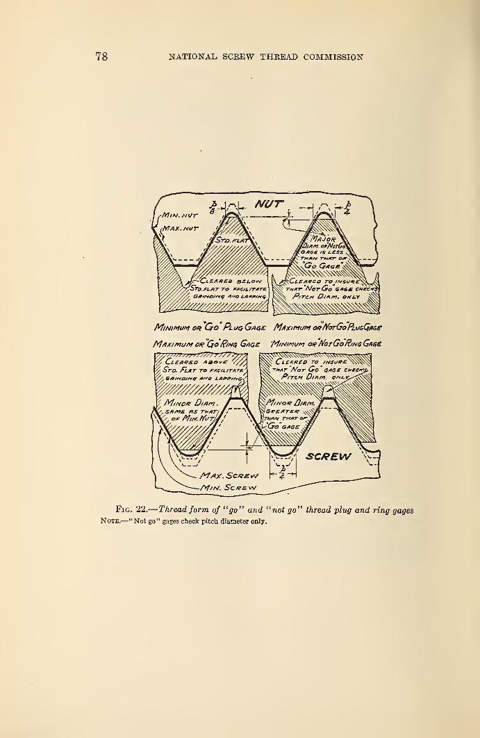
78 NATIONAL, SCREW THREAD COMMISSION
Minimum or Go Plug Gage Maximum ouNorGoPmGQflse
Maximum or "Qo Ring Gags Minimum oqNotGo"Ring Gage
% Cl£AIT£0 Abov£6 S~ro. Flat to r/tcmr/m,
wm^/////a'
Fig. 22.—Thread form of "go" and "not go" thread plug and ring gages
Note.—"Not go" gages check pitch diameter only.
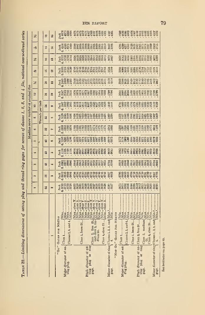
1924 REPORT 79
2 3 liiii 11 1111 IHillll II
sfPi Illillllilli ii liiilllllllill
S s Inch
0.
3732
.
3726Illlllilllllll llllllllllll
2 s lllll llllllllllll 11 Illlllilllllll
3 Inch
0.
2485.2480 .2500
.
2495.2160 .2157 .2158 .2155 .2157 .2151 .2175 .2172 .2173 .2170 .2178 .2175
.
1959
.
19
64
.2383 .2388
.
2428.2433 .2109 .2112
.
2139
.
2142.2149 .2152 .2165
.
2168
.
1959
.
2067
si lllll nisiiiiiiii ii iniiiiiiiiiii
o 1
!1
00 \
1 « GO lllll IIIIIIIIIIH |I Illlllilllllll
Inch
0.
1369
.
1365
.
1380.1376 .1166
.
1163
.
1165
.
1162
.
1163.1158
.
1177
.
1174
.
1176
.
1173
.
1179
.
1176.1042 .1038
.
1293
.
1297
.
1326
.
1330.1128
.
1131.1150
.
1153
.
1158
.
1161
.
1169
.
1172
.
1042
.
1109
Inch
0.
1240
.
1236
.
1250
.
1246.1078
.
1076
.
1077
.
1074
.
1076
.
1071
.
1088
.
1086
.
1087
.
1084
.
1090
.
1088.0979 .0975 .1172
.
1176
.
1202
.
1206
.
1044.1046
.
1064.1060
.
1071
.
1073
.
1081
.
1083.0979
.
1033
§ llllllllllll If Illlllilllllll
CO lllll llllllllllll II Illlllilllllll
o s Inch
0.
0852.0848
0860 0856 0736 0734 0735 0732 0734 0729 0744.0742 .0743 ,0740 .0746 ,0744
0667,0663 ,0796 ,0800 ,0820 .0824 ,0708 .0710 IIIIII II
I—
t
s llHl lUllllllIIl I| IIHIIllllIlll
i :
i i
i i
1!
Ii
t-iii ii
iiiiiiiiiiiiiiii i i i i i i
niiiiililiiijj liHiis'.h g.ss.s's.s'g.sg.s'g.s is saiaiad
T 4 a .1 t j i .d
2 I it § * * S I
i i mi hi u
ja a.s aa a.g3
Hil1 B 1 jef m * a
1 ¥1 b"Go"
Major
diameter
of
set-J
ting
plug.
j
Pitch
diameter
of
set-
ting
plug
or
ring'
Minor
diameter
of
ringj
"Not
G(
Major
diameter
of
set-
ting
plug.
Pitch
diameter
of
set-
ting
plug
or
ring-
gage.
Minor
diameter
of
ringl
gage.
1
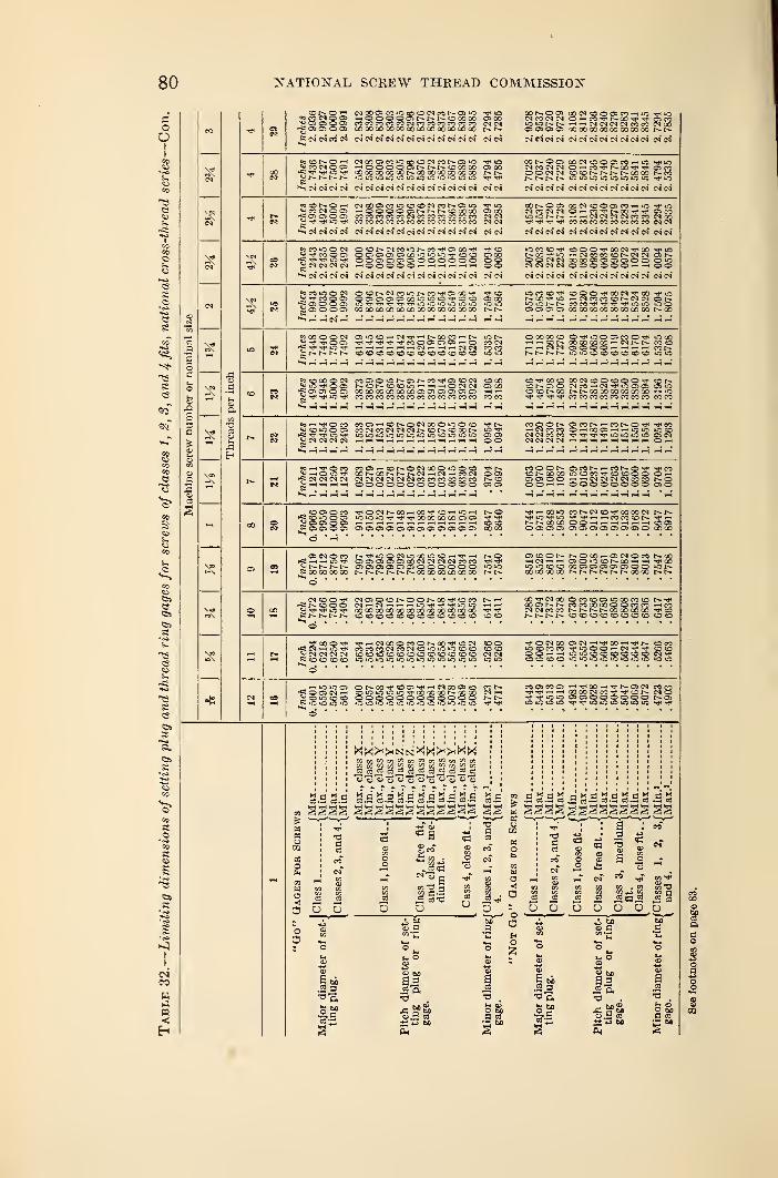
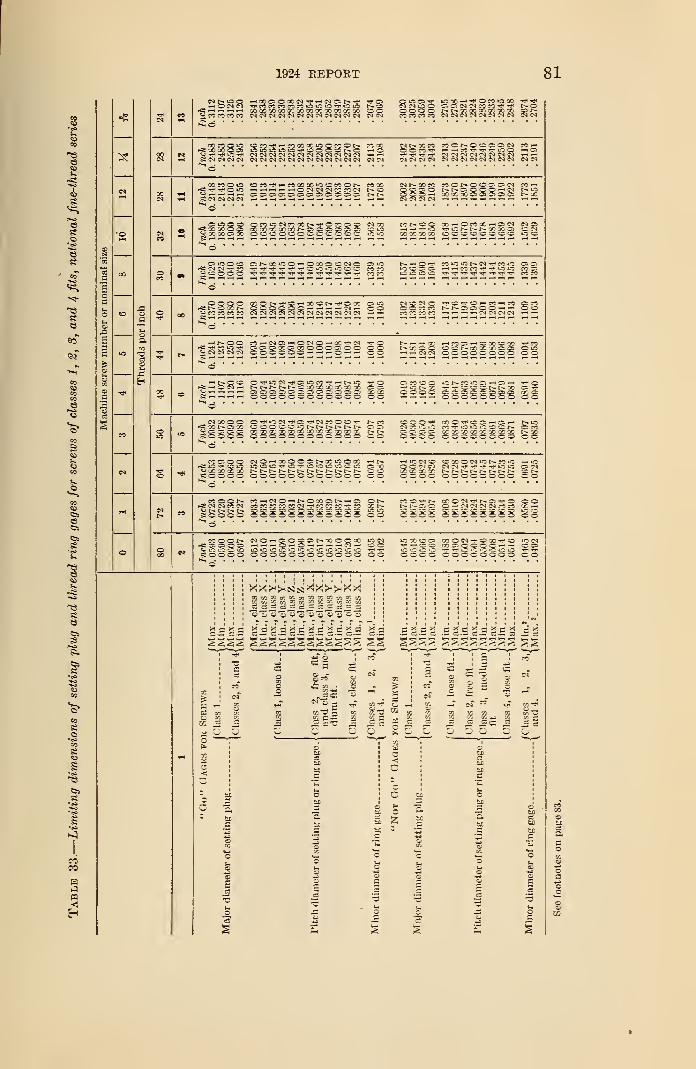
1924 REPORT 81
2
1
3
I
lllll lllllillllllil ililllllllll II**«•• m m_ m
!§!!! ililllllllll 11 mi 11111111 11
jflil ililllllllll 11 nil llllllll 11
Ililllllllll 1! 1111 §§111111 II
islll Ililllllllll 11 §111 lllliili II
1=11= Ililllllllll II Ililllllllll
iIIII Ililllllllll 11 IIII llllllll II
|f If I 111 II II 1111 llllllll 11
Ililllllllll || IIII llllllll i
§|g||§|§lill 11 1111 llllllll 11
llUIUiiill
: : i :
si iiiiiiiiiiii "is
i i i i
: i : :
S2SS!
1CO
IN !
.s s'.s d i is §'.3 s'.s a i s
* . ! 1 5 a I ! «-
I ! 5 1 l a I -
11 1 I11 ll1 !! I 111s
! I1
I
i i;
i
S
IiS i
i t a
r i
1
'
I o o
S !
Major
dlai
I
1Minor
dim
Major
dial
I
I
I
I•5
1
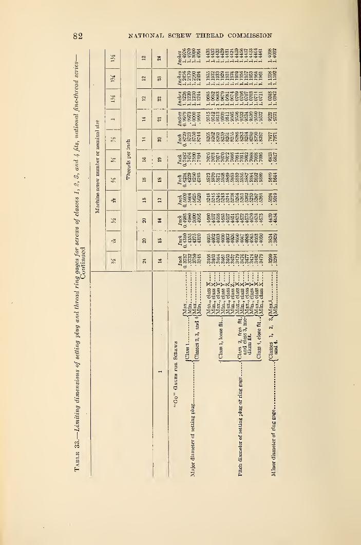
82 NATIONAL SCREW THREAD COMMISSION
g3
inch
eads
per
J3Eh
H3
2?
O O O tH^ N N C G)
rCi -*j4 iO Trl
00 CMO OSO O
^NNOO) CCCOCOfNCOtNiOiCCOCCi OS OS
^NNNN ft i-< i-H H >-H W i-t r-H »H .-t r-i i-l HH
CM CM iC -f
i—( >—t —I i—
I
JS . . . .
CO C5 CO O -rHH
rfS CM 0< lOr- r-- r—
s; co oo oo oo
pCiOONOOie; r- t-
cocooonqonoooohh vtDtD<OCOCCCDNNt^NNN COCOOOOOOOOOOOOO OO
hhhOhOMCOMCO'J'^ NCNlOOiCiO'OOiO'O'OiOOiO CM CMOJ0503Ui050>0>0)OifflC30 OS OS
O<0CDiOC0i0000000Q0C!Cl0 t—l>.<N IN (N iM M CM (N W C-l CN Ol CD OSO0 00 00 00 00 00 00 00 00 00 00 00 t"-l>-
OMM*O(NO-*rH(NQ000iO CO t~-NNNNNOOJOlOiaOOOl 03 i-tOOOOOOOOOOOO 0000NNNNNNNNNNNN ©CD
OS O iO
£ CO CO CO CO
t^I-~f»-COcOcOC000Q000CS00O00O 00 00 Q0C0CO00 00GO00CO
OJtfiOO-CiOOCNMu co to to CO
>—t . . . .
TpTtl-rtlrffT'COCOCOCOlOCOCOiMfMCNOJC^ICvlCN'MiMfMCMC^lOiCiOiCiOiCiCOiOiOiCC
^2OO
rfS 00 00 O CStJ OS OS O OS^ ^HH lO Tf<
ONOO»ONr-(if3(N«OCOiO(OiOmiOiOiONNNNNNCO CO CO CO CO CO CO CO CO CO tO O
OS Tt<>o toTf Tf>tf< -If
O iC iO opCcCiONN^ CO CO CO CO
*^
lowmowcoo^cO'OMOOOOOOOOOOOOO
*cf< OSCO CM00 00CO CO
rfS CO CO "tfr- r-
£ CO CO CO CO
COCO-f'-'COt^OSCOt-.TfCNOSCDOOCOCOiONNNNOONcocococococococococococo
OS rfOS OSCM CNCO CO
<o
o
rtca^c5C3c3t^o5 c3 cflTOC3
s.a a.g 'S..9 s.s s.a s.a
gsgs §§§§§§§§§§§§* ' n
i— a
8 2"§
w ~ N o acorn w w T3 -3
8.
a
S3
.33
^3
p.3
bO
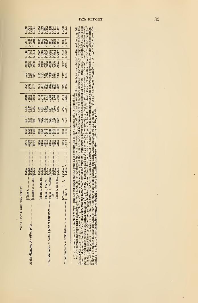
1924 REPORT
00 ^ CO^HNCCO)CO 00 CO CO^1
COOSCOCDOCNTt<r*-COCO-^-O^-rJ*^-*^
00 00as r—O CN
CO CO CO COCN CN CN CN
CDOlCOCDOSiM-^r--
00 CO O C: OJ ffi CJ Oi
cocoCS l>-
00 CO ^CO O-CO -*t<O O < •—
I
o o io io a t- cs o>
oooooooo00 CO^ CNCO »oo o
as ic (N oo
CO CO Os o0005
IC00NOOMN1OiQ iQ iO m
OS OS OS OS C7l OS OS OS
CN 00CN COOS as
a> io cn oooo as uo oio uo co co00 00 00 00
lOCONOOmNiOoi o co io >o ni-h.—iCNCNCNCNCNCN00 00COCOCOCOCOCO
CO CN O COIOCHHCO CO tJ^t> i> t-
COCOCSCNCNiOCNiOHrt^ 1OCDC00 00OOOOOOOO1-- r- t>- 1— t-~ t-
coooo—<oscNt--oH ^ rji lO iCHD N COCOOOCOCOCOCOOOCO
U3 O CO 00
TPiOiOOi—i-rf<cocoTt<r~CNioasascNCNcocoioiot-i^CNCNCNCNCNCN•O iO io »o >C "O *o "O
CO CO 00 COCO CO CN COCO CO O) O)
OscNOSCNOsCNiOOO0"HCOTf^fiOCOCOCOCOCOCOCDCOCDCO
00 CO CO COiOOOOCN CN CO CO
"^f ^COCO'-H'-iCNCN-^-^asasooooooCO CO T]( T}( -J< Tf
iO OO COco co co coCO CO CO CO
ocooasiocooco
COCOCOCOCOCOCOCO
coas i-*
co
co asIM iOco as
cn *^Oio to
as »-LC CO
CO Tt*
oo asco co
as asas coCN COCO CO
.S3
aj XI
.2 «O
60a
1
.2.2.2 S.SS~
2 > S u, °x) S
S.^-oog-SSO bo A-,
*w a™5^ a a
JSf.lo£|lX) .3 <D ^ fl
+* op.2 dxi >.bo
do®> O G3
~X> '
bo a lu
da <s
j is sis a-1 ^ o to
-dga"S.2 bo
bo si• +j d tj* d'd S Sf.a'.i
•dSo'Sp-Hg 60
<D p.- o
a,1- oa« M ?xir
£ Sx) g a> ^ § « 3
OX) g o o ~m£.B
-Ou i- B 3 ^t*- CO
o^s S Sxife-s i-«2n -t-*d« ^^f^.i3
3-«S" o^x)S- g su3w 5 «•9 3|d^So.S^
s.SS bog o'feg a
g dja d a o^^-d p)-p; cSri ^^3§S>,»«* gx3.2
5^!sS,3''0"X>
a 2 <d: "fl o^ g
X)QbD_ uj O 1-^,2
n h tD CO
O o W U ,d— 03£ ,- 25 o
_,*> d"jq
.^5+»xl »C
.5 £ -d 9 a -d feC 3Sw-s S « o 2-9 -
CXI2 o *n
-4-3 OC.m DjD CO —
>
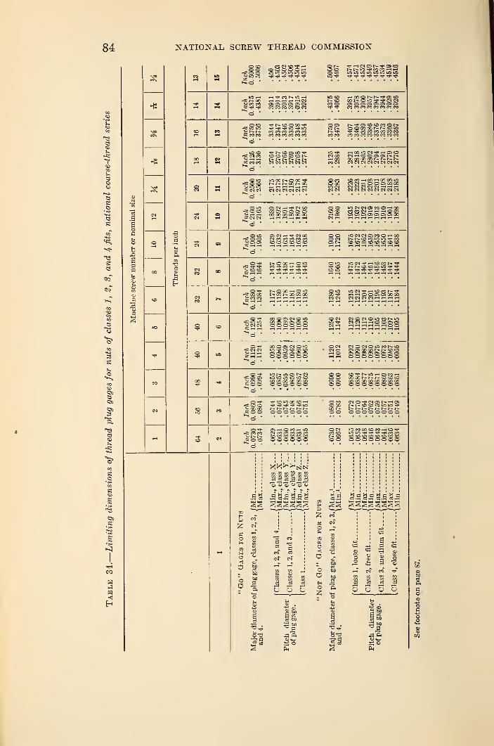
84 NATIONAL, SCREW THREAD COMMISSION
13
escs
e
is,
13Se
94
s
e
&s
r««s
a.
13eso
8
S
13
CO
H
m<
a3
HS
cn
oper
inch
00 Threads
co
*o
Tfl
CO
CN
t—
1
lO rHrgt>00^ CO CO
_ o cdrC* lO lO
.S CO CO
K CO CO
fi o ©K CM CM
u h h*"h
M N (O M* HO O O O O r~t
rH rH rH rH CMC 3) Oi D ^ CJCO CO CO CO CO CO
tJ< lO IQCO CO CO CO CO COCO CO CO CO CO CO
t- (D CO ^r-- r-- r-- r- t-- r--CN CN CN CN CM CN
OHM CM CN CN CM
CI CN rH tJ< CM 00OO aG O QCO GO GO 00 00 00
OS CM rH t* CN COCM CO CO CO CO CO
oo <o© COID Tj*
lO CD
CO oT*
001io r-
CO CO
CN 00rH COCO CN
_ ©"2 o o CO TP CO ^J"1 T}i tH
ooO CNo> r—
o inTfi oCD iD
r^t— *D-"#COCOi-H—
I
iO ifj iO irj U3 iO iO >0
OOr-CDiOTpTFCNCNCOCOCOCOCOCOCOCO
OOCOCCNNCO>0tPtPCOCOCOCOCOCOCOCOCOCOCOCOCOCO
HOO>OINTt<r-DO
CMCMCMCMCNCMCMCM
COM -h 00 CO OO idNINHOOCOQOCOCM N N CN CI H rH rHeNCNCNCNCNCNCNCN
i0N(NOMOr-<00O CA Ol O) G) 03 ffi CO
iDCNCMOSCOOrHOOCD CD CD CD CD CO CD CD
W C-1 tJ< rn D CON ^^.^CDCDJDJD^J^
r=S CO 00
s23O OCO TPCO CM
IDEM-*—I CO CO r- tPhhOOCBOOOCONNNIMHHHH
O tP
g CN CN
CO O Oi CN O iDx ~ 30 os oa cso o o o o oO CN CM © CN O »D CO t- iO»D TP PJNrHHOODffiCM i—< rH rH rH r-t rH rH O O
rC CN CNCO O DS CN O IDIQ CD ID CD CD CDos os .es os os pao o o © o o
©CNCM rHrH O
NOC-lOiOMNiODD XCONNCOOCS OS OS OS OS CS CS CSoooooooo
_ © tP^ Ci CJV CI cscooiO N cO D N CIID iO io m iO COCO X> CO 00 X 00©OO © © ©
© ©CI OOS CD© ©
CD^NiOrHCDCOHoo oo t— r-r-cDcDcDx fj x x X' x co coOOOOOOOO
_1 ©rSS CD CD« 00 COS © ©
TP CD ID 00 CD r-tTP TP TP TP *CP IDr— t-~ r-- r-- r- i~-O © o o © o
O COCD 00co r—© ©
NO^ClDNrHOJr~- I- CD CD >D ID ID tPr- i- r» t- t- r-©OOOOOOO
O TPrsi co co
K O OOS r-H O CO rH IDCN CO CO CO CO COCD CO CO CO CO COO O O © O o
O CMCO CDr- coo o
m CO 00 CO CO H CO rftiOiOtFtHtFtFCOCOcocdcocococdcdcdOOOOOOOO
'o'o'o "c3 CJ
o o o
03 M
oH
oooy,
<a.H S.S S.S S.9 S.S
a3
X °J rl .iS5 is a «
•II
a
5 Q Oa
a—
aju
03
ituO
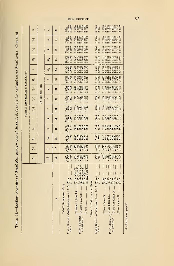
1924 REPORT 85
a>
3a
aoO
T3
s-cou
©
"es-
se
go
a13
8 aso« o oe co co
oo oo oo oCO CO CO CO CO CO00 00 O0 CO 00 00
CN CN Ol CN CN
o r-OO OO CO
OOCDNCOOiM'O
COOOOOOOCOOOCOGOCO CN NNNWN(N(N(N
oo O OS2 © orC lOlO
cn CN
00 oo co osCO OO 00 00 00 001C lO lO lO lO lO
N N N N d N
or- o © o w m o> m< oo —( oo n rH n cc r-i C)iO OOOOOOTOlO)
CD cOCOCOCO»niO>OiOCN CN CNCNCNWCNCNCNCn"
°5CO) CD O © iO CO CNr- co r- co co osCO CO CO CO CO COCO CO CO CO CO CO
CN CN CN CN CN CN
o t^.Oo oIO CO
OOtCHMMO-fOcor-.—<.—k-ccckiiO iO "O m t)< «^ ri<
COCOCOCOCOCOCOCOCNCNCNCNCNCNCNCN
*3COOw o o•> iO IO^CN CN
iQ tO © C - I -o o o o o oO COO CO
CN —<
i«N CN CN CN CN CN CN CNCNCNCNCNCNCNCN
*s O 00<u O Oi= o o~ o o
IO © (O O (D NiC iO IO O iO iO00 00 00 00 00 00
o 00O COo oO OS
CO oo oo O O)N N CO O O C Ccooooooooooooooo
«oco'T- »J3 iO
H IO OS GO COO O O O O hCN CN CN CI CN CNCO CO O O CO o
O rf<O COuz CO
co
©COt-COCO©CNCOt^O"— loot— coCO CO CO CO CN CN CN CICO CO CO CO CO CO CO CO
a«o O 00« o o>g o o i—1 CN CN CN (N CO
OS OS OS Cs Oi OSCO CO CO CO CO CO
O GOO r-O CN
CNOOOO^OOt^COOS(OiOHHWOOOTflOOOOOSCSOSOS-^^M^M^COCOCOCO
«ON« O O^ CN CN
CN CO O 00 iCt^- r- t— r- r- ooio >o m io ic io
O T-Ho ooo ooCN W
cocir-cowr-CNcoo en o m n o O)OOCOcOcocOcOiO
«ONSS CN CN
CN CO -^f OS OO OCN CN CN CN CN COCO CO CO CO CO COO O O O O O
O win coCN ©
OCNr^-CO-—ir^-CNOOM'^OOOON'C'li'T f *f CO M m MOOOOOOOO
eo o2 o o-f= o o^o o
co as cs os os ooooooo
o oO iOoO O)
OiC^OtNQOiCHO O C O ^ « h hCi CN CI CI C3 CI CN CNO) O) OS OS OS OS OS OS
-* <=>t~-iO iO
cv
¥=00 00
COHOiOMOCN CO CO CO CO -fO O o o o oOO 00 00 00 00 00
o o>0 CDr-~ cncoco
OO CO iO N -rf (M CDCNMOONN'O'J'i-<—<OOOO0OOOCOOOOOCOCOCOOO
3
C3S
e
©S
e
8
CO
Hm<Eh
_ © CO*s o oc^ io >0
O CO CN CO i& CNiO iO iO »o iO CO00 00 00 00 00 GOCO CO CO CO CO CO
o f-C COiO o
MOTt-HioNcooT|<COrH HOONNO ~ O OS GO 00 00 00COCOCOCOCOCOCOCO
_ O CO-cowCN CN
sr co co
O CO CN CO ^ i-ico co co co co r-CO CO CO CO CO COic >o O O (C o
O COLO OCN 00CO iO
iO M O) CO M O) r-i CO^^hhOOIQONt^-r-r--r-r-cDcocoU0iOtOiOiO'O>OU)
CN COW CO COe 10 «
THNOOOOiOGO GO CO OS GO OSOOOOOOL~ t-~ li~ l-~ 1-1 L."
CN COCO CNUS iO lO'OiOiO'O'OiOiO
.as
in n [O n [n u]
3J S3 3 3*o "t> "3 "o
PS
o
oo
COcC3 aCO 03
cn" cf
CO COCD 03VI X/i
% a
PSo
oO
O
s.s
s
3a
1—1 cV co"
S s
S
B
Si
OQOO
as1
CS M
P.
ao
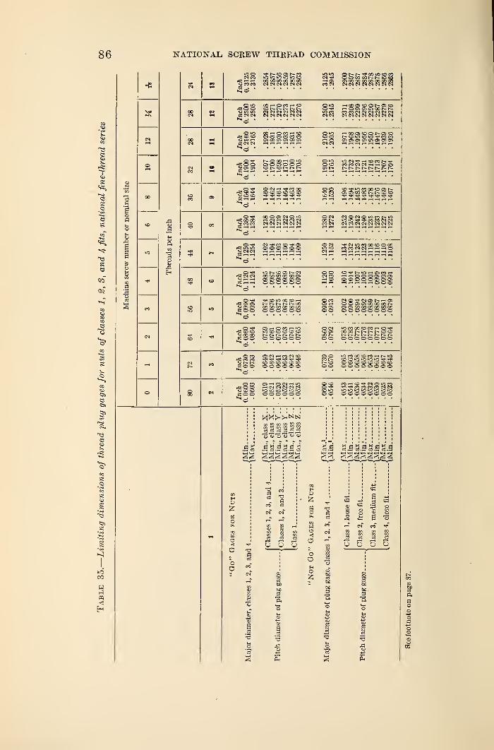
86 NATIONAL. SCREW THREAD COMMISSION
o
00
to
Threads
per
inch
iO
CO
o
o
SN CD O N MCO 00 00 CO oc COCM CM CM CM CM CM
OOhO«h<D rH00 01COONO)0HOOOfflOONNCO CO CM CM CM CN CM CM
p CM CM
00 iH O CO iH epCM CO CO CO CO COOS O)0)00>0i 28
CM CMOS OS OS OS OS OS OS OS
rvOO« OS OS0)00)000 O iOo do
os r-
r*£ Tf ">*H
« CO COS iH i-H
^cm*CO iO
eo-**uo.coootoosi>.O^O^COCO^^COCO
OCMCO t—CO CM
; co co cn cm5 CN CM CN CM CN CM
S ISCM CM
O CM CM >C CO 00 CO O CO>OiO CO CO CM CM i-h >-< fi OCM r-< HHr-IHHHi-
MS CM C^r
. —
I
Shhio co os r- cm00 CO CO CO OO OSOS OS OS OS OS OSo o o o o o
OOCM COi-H O
to-^r-io—iosco>-i•—ii—(OOOOSOSOS000000)0)0)
: os os^ CO to GO O wr-- t^- t-- t^- f~-> ooCO OO CO CO CO COO OO O o o
OOOOCOOOCONOS O CO CO 00 CO CO COoooooooo
_ Orf£ co COcy co coeoo
O CMCO OS00 t—o o
iCCOCOCOCOi-iCO'^COXI-- t— N N C O
t— r-. r- r-- t-oooooooo
cOco
e ooO CM tH CO CM CO
Tf* i?1CO CO CO CD CO COo o o o o o
o oCOt^- COo o
iO CO OO CO CO -—if-iOCO >C iO »C t)< rfiOOOOCOCOO!Doooooooo
O CO** OOCJ CO COe o o
OS r-i O CM i-H IOi-t CM CM CM CM CM»C iO iO "O iQ OO O O O O O
O COO ri<CO oO o
COWCO-PCMOIOCO^-fCOCOCOCOCNCNm iO iO m >o tC IO iOOOOOOOOO
a w „.sa.ss.ss.s
(3
o
o
o
<o
oo
o
•aa
bo3ft
a
3
s «
S § oWHO
o o o o
bo.
"a
a.g
to03a
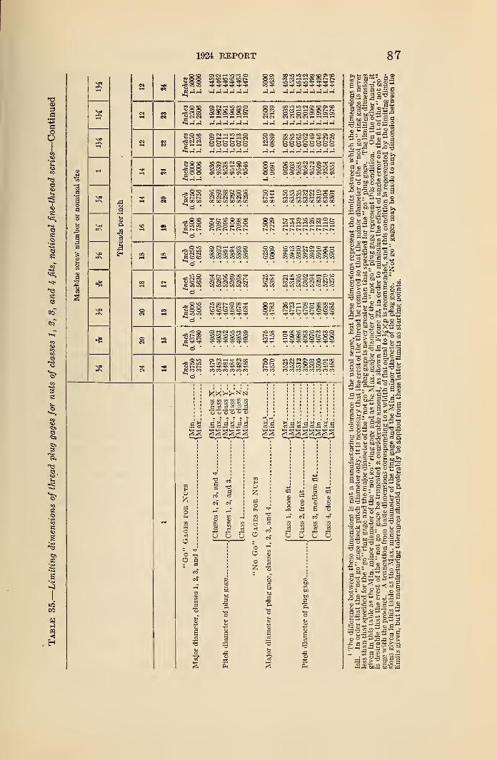
1924 REPORT 87
l-l
i-H
S3oa
lads
per
i
Thr<
HS
1 ^ Tp 5 TP "5
fsiifltOOOOh. © CO
T-< »-H ^-1 r-t C5M
O-HrHpHr-lMr- r- r-- r—o oo ooo
© ©lO CO<M 00 i ^ i- r-- r~oooooooo
^ o o-c: 5 o^ o o ~
-
~ ~- r~-
8C0 1C IN Cl Ol Tf HCO O i(3 "O >0 >C iQ O
o © oooonoo00 00
cocococococoeococooooooooooooooo
^ o -5
.
O O © -< Or- r- r-
OCT)O CMiO CM
_^ o iO
^ CN CM
05 N -H CO C5oo o As o> J- dOO CO O0 CO GO JOiO iO U3 iC iO
coco©i"-©©-"*t-i©©CiO^©©©©
ofC N Mo CO coK "CO
t- © © 00© co CO © CO i-
CM CM CM CN CM CMio io ir) io »n ic
CM 00CO CO
i-hc0iOCM^t-.O1CO
cococococmcmcmcniO iO iQ ic iQ iO iO
© ©© ©*o 00 © COt~- r— r- qc i-- coCO © © co CO co
© CO© 00© r-
cOCOi-(OOi—lOOOOiOCMCM--H©©©C©CO
- lO ot- oo
Jr* CO COe tji Tt*
© CO CM HO CO ©iO O if) >o iO »o©©©©©©
HCCOCOOCOCOOOQOOCONNCOCOw©©©©©©©
© >0rf£ IC iO
e eo co
© CM rH CM COr— oo co co go co
CO CO CO CO CO CO
© ©r- ioCO CO
iOCMCM©CO©—<00
cocococoeocococo
95 W K W W mc§ c3 c3 cd_c3 c3
OH «c3 ^d^d^d^d
PSo
o
aa
8 ~
ooo
p
o
Ha
O
oOo8
43
* an
C3 5 i S So o o o
3p.
ss3 a
2 2
I 1-2w H
[3a w cd
H b£ a
CD '
oS3 M
•9 a
a cd
cd *j
2s
or sa03 OS 2
, fflOij >>.g
§ !S|co 3 o a «bDS fc- « OSa » £ „
•s -3 a 9
Q +» o S-p
a- kJ"11
c3 eg-O cd bD"3 ,
*
"•a £ Z s a 2 «
aB i-l 1 11=5
° a « ooa 2^
s lis g s-si
t- b£"- H a> cS
" ° k M^ S »aS.22 £
« a h " g So 1
a S3 M g" «.5 ° n'a 5 o
So: .j= a s 3n^2.9r S3§
- C; a) CD ==3
a a « JjtS'S.a-w£3 £j3-
O — ^ja j3 CD >
«'S.2 S'Sss
88 NATIONAL SCREW THREAD COMMISSION
SECTION IV. SCREW THREADS OF SPECIAL DIAMETERS,PITCHES, AND LENGTHS OF ENGAGEMENT
The tolerances specified in Section III of this report are based onthe pitch of the threads only, and apply, in general, to bolts, nuts,
etc., of standard pitches and diameters and for lengths of engagementnot greater than the diameter.
In addition to the foregoing threaded components, there are large
quantities of threaded parts produced, such as hub and radiator
caps in the automotive industry, threaded collars on machine tools,
etc., where the diameters are larger, the pitches finer, and the lengths
of engagements shorter than for bolt and nut practice. The follow-
ing specifications have been adopted for such threaded parts, taking
into consideration, when determining the tolerances, the diameter,
pitch, and length of engagement of the particular components.
1. FORM OF THREAD
The national form of thread profile as specified in Section III,
and known previously as the United States form or Sellers' profile,
shall be used.
2. THREAD SERIES
It is recommended that one of the following pitches be selected
whenever it is necessary to use a screw thread of special diameter
and pitch: 4, 6, 8, 10, 12, 14, 16, 18, 20, 24, 28, 32, 36, 40, 48, 56, 64.
3. CLASSIFICATION AND TOLERANCES
There are established herein for general use five distinct classes of
screw-thread fits, which are lettered to distinguish them from the
regular classification of fits. These five classes, together with the
accompanying specifications, are for the purpose of insuring a uniform
practice on screw-thread production throughout the country.
It is not the intention of the commission to arbitrarily place a
general class or grade of work in a specific class of fit. Each manu-facturer and user of screw threads is free to select the class of fit best
adapted to his particular needs.
(a) GENERAL SPECIFICATIONS
The following general specifications apply to all classes of fit
specified for screw threads of special diameters, pitches, and lengths
of engagement.
1. Uniform Minimum Nut.—The pitch diameter of the minimumthreaded hole or nut corresponds to the basic size, the tolerances
being applied above the basic size.
2. Tolerances. 9— (a) The tolerances specified represent the
extreme variations allowed on the product.
! Recommendations and explanations regarding the application of tolerances are given in Appendix 1.
1924 REPORT 89
(b) The tolerance on the nut is plus, and is applied from the basic
size to above basic size.
(c) The tolerance on the screw is minus, and is applied from the
maximum screw size to below the maximum screw size.
(d) The pitch diameter tolerances for a screw and nut of a given
class of fit are the same.
(e) Pitch diameter tolerances include lead and angle variations.
(/) The pitch diameter tolerances are obtained by adding three
values, or increments, one dependent upon the basic major diameter,
another upon the length of engagement, and the third upon the pitch
of the thread. These increments are based on formulas given under" Classification of fits."
(g) The tolerances on the major diameters of the screws and
minor diameters of the nuts are based on the pitch of the thread, as
these control the depth of engagement; they are, therefore, based
on the pitch alone.
Qi) The minimum minor diameter of a screw of a given pitch is
such as to result in a basic flat {}/$ X p) at the root when the pitch
diameter of the screw is at its minimum value. When the maximumscrew is basic, the minimum minor diameter of the screw will be
below the basic minor diameter by the amount of the specified pitch
diameter tolerance.
(i) The maximum minor diameter of a screw of a given pitch
may be such as results from the use of a worn or rounded threading
tool, when the pitch diameter is at its maximum value. In no case,
however, should the form of the screw, as results from tool wear,
be such as to cause the screw to be rejected on the maximum minor
diameter by a "go" ring gage, the minor diameter of which is equal
to the minimum minor diameter of the nut.
(j) The maximum major diameter of the nut of a given pitch is
such as to result in a flat one-third of the basic flat (-faXp) whenthe pitch diameter of the nut is at its maximum value. When the
minimum nut is basic, its maximum major diameter will be above
the basic major diameter by the amount of the specified pitch diame-
ter tolerance plus two-ninths of the basic thread depth.
Qc) The nominal minimum major diameter of a nut is the basic
major diameter. In no case, however, should the minimum major
diameter of the nut, as results from a worn tap or cutting tool, be
such as to cause the nut to be rejected on the minimum major diameter
by a "go" plug gage made to the standard form at the crest.
(Z) The tolerance on minor diameter of a nut of a given pitch is
one-sixth of the basic thread depth regardless of the class of fit being
produced.
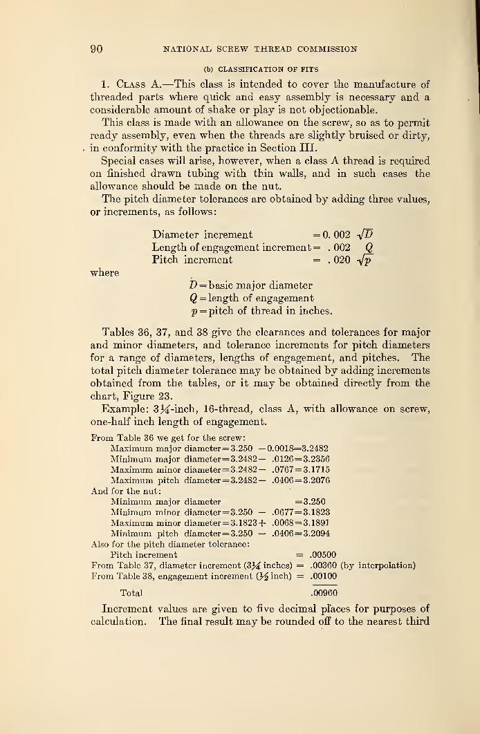
90 NATIONAL SCREW THREAD COMMISSION
(b) CLASSIFICATION OF FITS
1. Class A.—This class is intended to cover the manufacture of
threaded parts where quick and easy assembly is necessary and a
considerable amount of shake or play is not objectionable.
This class is made with an allowance on the screw, so as to permit
ready assembly, even when the threads are slightly bruised or dirty,
in conformity with the practice in Section III.
Special cases will arise, however, when a class A thread is required
on finished drawn tubing with thin walls, and in such cases the
allowance should be made on the nut.
The pitch diameter tolerances are obtained by adding three values,
or increments, as follows
:
Diameter increment = 0. 002 -JDLength of engagement increment = . 002 QPitch increment = . 020 -sfp
where
D = basic major diameter
Q = length of engagement
p = pitch of thread in inches.
Tables 36, 37, and 38 give the clearances and tolerances for major
and minor diameters, and tolerance increments for pitch diameters
for a range of diameters, lengths of engagement, and pitches. Thetotal pitch diameter tolerance may be obtained by adding increments
obtained from the tables, or it may be obtained directly from the
chart, Figure 23.
Example: 3%-inch, 16-thread, class A, with allowance on screw,
one-half inch length of engagement.
From Table 36 we get for the screw:
Maximum major diameter=3.250 —0.0018=3.2482
Minimum major diameter=3.2482— .0126= 3.2356
Maximum minor diameter= 3.2482— .0767=3.1715
Maximum pitch diameter=3.2482— .0406=3.2076
And for the nut:
Minimum major diameter =3.250Minimum minor diameter=3.250 — .0677=3.1823
Maximum minor diameter=3.1823+ .0068=3.1891
Minimum pitch diameter=3.250 - .0406=3.2094
Also for the pitch diameter tolerance:
Pitch increment = .00500
From Table 37, diameter increment (3J^ inches) = .00360 (by interpolation)
From Table 38, engagement increment (J^ inch) = .00100
Total .00960
Increment values are given to five decimal places for purposes of
calculation. The final result may be rounded off to the nearest third
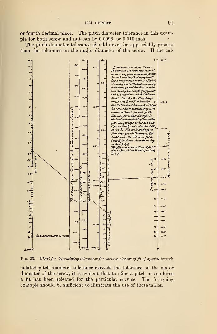
1924 REPORT 91
or fourth decimal place. The pitch diameter tolerance in this exam-
ple for both screw and nut can.be 0.0096, or 0.010 inch.
The pitch diameter tolerance should never be appreciably greater
than the tolerance on the major diameter of the screw. If the cal-
IS
All dimensions in inches
L\tr*e/
•Jj
•4
8
t_ -its—
g.
kj
[0«-j-s|
J)/0£CT/o*tS PC* C/s,Nty CnAfTT
Tb determine Me Tote*ancefora spec*/
scran* or ncffit*** the dia.m€fcr/ rjirt*d$
fi&rintJtj aftd /&tff6 ofeJff*yame4t?
/_4y a sfntyht-edya Across //»esflei/A»lG,
or/srrac///y /me /rfffie/>ei*t'ee*T*sjba#d/y
&MeJ/ameferamf fine £*rrfofc**t
ccvns/><*x/fr.j /cMe /eaft/r efefif*je&erf
o/rt? /fe/e Mejboz/rfar **4/cfi /f /vferscff
//nag. 7%er> /ay tfo s?rzrj6tecffe
across /t'Aes £?a»d7j /stfersecffny e -
///rffBattfye^otntfrvv/outfy /rc7eof**t
/t**T*f'ffie'jbo/nf'co/ras/bo*?/*} ibfAe
nam&or-oft/rreoc/s fier-/oc/t . £ /fio
ToMrvnce/ora Cast sfarBf't'/s
c/es/rvtf] /roTe ffief>o/*?of//rfrrseeZa*
of/Ae sfra/yfaeaye am /wsS; a c/ass
a* //*#-3, 7%e sca/e r&aafoff vr
/6eso //hec yt&t/re7e/er9*ces, £uf~
/o de?*>r/*me tfe ~7o/eraneefor a.
CAssSf/T of/ride /4e sra/e rfiodfoy
a* /we3 fyB.~ffie /IZ/ou/Qnce-/or a. C/ass Afit is
10'
fire* ofjbosife fAr7%fea<£$^er//K4t
-4•it
-I-ft
-irft
I
-fi
-i
oeg4£J
u
I5. /*-
s;
*-«-Q
001% ^
<C
$<- oors
•oo/S
•O0/3
S8r .oor2
«- OOJf
X- Oft
<o- OotO
<B- ooc9
sc- oov6
«-
<0
Fig. 23.
—
Chart for determining tolerances for various classes of fit of special threads
culated pitch diameter tolerance exceeds the tolerance on the major
diameter of the screw, it is evident that too fine a pitch or too loose
a fit has been selected for the particular service. The foregoing
example should be sufficient to illustrate the use of these tables.
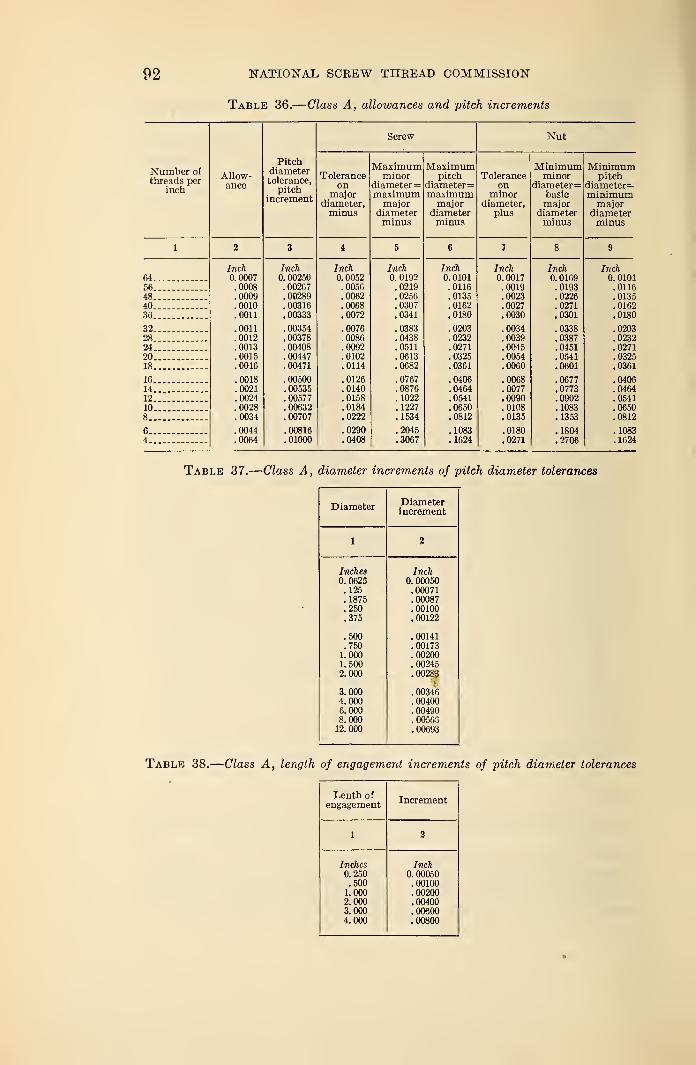
92 NATIONAL SCREW THREAD COMMISSION
Table 36.
—
Class A, allowances and pitch increments
Number of
threads perinch
Allow-ance
64.56.48.40.36.
32.28.24.20.18.
16.14.12.10.
8..
6..4..
Inch0. 0007.0008.0009.0010.0011
.0011
.0012
.0013
.0015
.0016
.0018
.0021
.0024
.0028
.0034
.0044
.0064
Pitchdiametertolerance,
pitchincrement
Inch0. 00250
. 00267
. 00289
.00316
. 00333
.00354
.00378
.00408
.00447
. 00471
.00500
.00535
.00577
.00632
.00707
.00816
.01000
Toleranceon
majordiameter,minus
Screw
Maximumminor
diameter=maximummajor
diameterminus
Inch0. 0052.0056.0062.0068.0072
.0076
.0086
.0092
.0102
.0114
.0126
.0140
.0158
.0184
.0222
.0290
.0408
Inch0. 0192.0219. 0256.0307.0341
.0383
.0438
.0511
.0613
.0682
.0767
.0876
.1022
.1227
.1534
.2045
.3067
Maximumpitch
diameter=maximummajor
diameterminus
Inch0. 0101.0116.0135.0162.0180
.0203
.0232
.0271
.0325
.0361
.0406
.0464
.0541
.0650
.0812
.1083
.1624
Toleranceon
minordiameter,
plus
Nut
Minimumminor
diameter=basicmajor
diameterminus
Inch0.0017.0019.0023.0027.0030
.0034
.0039
.0045
.0054
.0060
.0068
.0077
.0090
.0108
.0135
.0180
.0271
Minimumpitch
diameter=minimummajor
diameterminus
Inch0. 0169.0193.0226.0271.0301
.0338
.0387
.0451
.0541
.0601
.0677
.0773
.0902
.1083
.1353
.1804
.2706
Inch0. 0101.0116.0135.0162.0180
.0203
.0232
.0271
.0325
.0361
.0406
.0464
.0541
.0650
.0812
.1083
.1624
Table 37.
—
Class A, diameter increments of pitch diameter tolerances
Diameter Diameterincrement
2
Inches0.0625.125.1875.250.375
Inch0.00050.00071.00087.00100.00122
.500
.7501.0001.5002.000
.00141
.00173
.00200
.00245
.00283
3.0004.0006.0008.000
12. 000
. 00346
.00400
.00490
.00563
. 00693
Table 38.
—
Class A, length of engagement increments of pitch diameter tolerances
Lenth ofengagement Increment
1 2
Inches0.250.5001.0002.0003.0004.000
Inch0. 00050.00100.00200.00400.00600.00800
1924 REPORT 93
2. Class B.—This class is intended to cover the manufacture of
threaded parts which are to assemble nearly, or entirely, with the
fingers, and a moderate amount of shake or play is not objection-
able; and no allowance is required. It is the same in every particular
as class A, except that it has no allowance.
The pitch diameter tolerances are the same as for class A and are
obtained by adding three values, or increments, as follows:
Diameter increment =0.002 -yjD
Length of engagement increment = .002 QPitch increment = .020 V?
where
Z) = basic major diameter
Q = length of engagement
p = pitch of thread in inches.
Tables 39, 40, and 41 give the tolerances for major and minordiameters, and tolerance increments for pitch diameters for a range
of diameters, lengths of engagement, and pitches. The total pitch
diameter tolerance may be obtained by adding increments obtained
from the tables, or it may be obtained directly from the chart,
Figure 23.
Example: 3^-inch, 16 thread, class B, one-half inch length of en-
gagement.
From Table 39 we get for the screw:
Maximum major diameter =3. 250
Minimum major diameter= 3. 250 -0.0126= 3.2374
Maximum minor diameter= 3. 250 — . 0767= 3. 1733
Maximum pitch diameter= 3. 250 - .0406= 3.2094
And for the nut:
Minimum major diameter =3. 250
Minimum minor diameter= 3. 250 — . 0677= 3. 1823
Maximum minor diameter= 3. 1823+ . 0068= 3. 1891
Minimum pitch diameter= 3. 250 - . 0406= 3. 2094
Also for the pitch diameter tolerance:
Pitch increment = . 00500
From Table 40, diameter increment (3Minches) — . 00360 (by interpolation)
From Table 41, engagement increment i}/2 inch) = .00100
Total . 00960
Increment values are given to five decimal places for purposes of
calculation. The final result may be rounded off to the nearest
third or fourth decimal place. The pitch diameter tolerance in this
example for both screw and nut can be 0.0096, or 0.010 inch.
The pitch diameter tolerance should never be appreciably greater
than the tolerance on the major diameter of the screw. If the calcu-
lated pitch diameter tolerance exceeds the tolerance on the major
diameter of the screw, it is evident that too fine a pitch or too loose
a fit has been selected for the particular service. The foregoing
example should be sufficient to illustrate the use of these tables.
16802°—25t 7
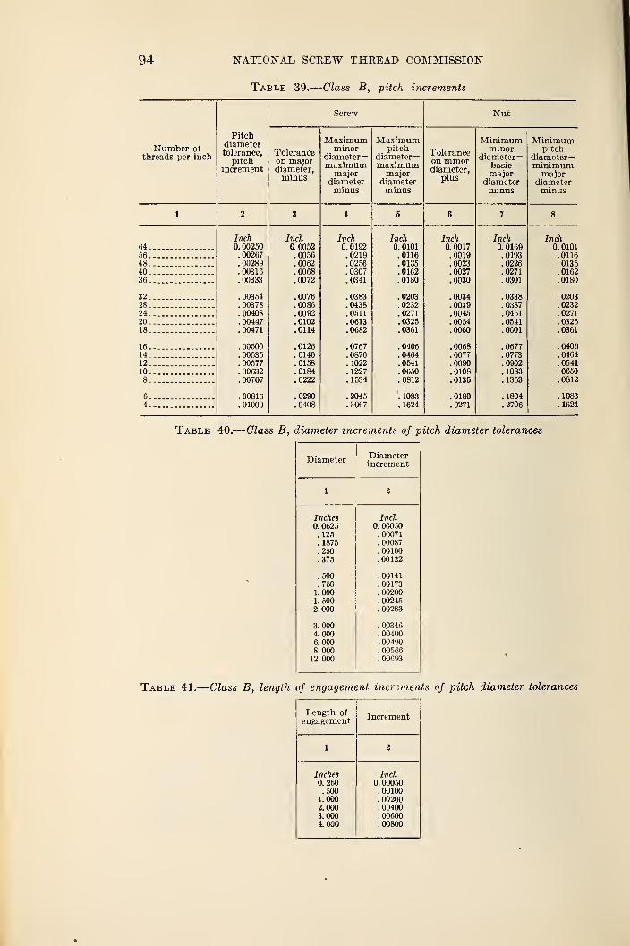
94 NATIONAL SCREW THREAD COMMISSION
Table 39.— Class B, pitch increments
Number ofthreads per inch
Pitchdiametertolerance,
pitchincrement
Toleranceon majordiameter,minus
Screw
Maximumminor
diameter=maximummajor
diameterminus
Maximumpitch
diameter
=
maximummajor
diameterminus
Toleranceon minordiameter,
plus
Nut
Minimumminor
diameter
=
basicmajor
diameterminus
Inch0. 00250
. 00267
.00289
. 00316
.00333
.00354
.00378
. 00408
.00447
.00471
.00500
.00535
.00577
.00632
.00707
.00816
.01000
Inch0.0052.0056.0062.0068.0072
.0076
.0086
.0092
.0102
.0114
.0126
.0140
.0158
.0184
.0222
.0290
.0408
Inch0. 0192.0219.0256.0307.0341
.0383
.0438
.0511
.0613
.0682
.0767
.0876
.1022
.1227
.1534
.2045
.3067
Inch0. 0101.0116.0135.0162.0180
.0203
.0232
.0271
.0325
.0361
.0406
.0464
.0541
.0650
.0812
.1083
.1624
Inch0.0017.0019.0023.0027.0030
.0034
.0039
.0045
.0054
.0060
.0068
.0077
.0090
.0108
.0135
.0180
.0271
Inch0. 0169.0193.0226.0271.0301
.0338
.0387
.0451
.0541
.0601
.0677
.0773
.0902
.1083
.1353
.1804
.2706
Table 40.
—
Class B, diameter increments of pitch diameter tolerances
DiameterDiameterincrement
1 2
Inches0. 0625.125.1875.250.375
Inch0. 00050.00071.00087.00100.00122
.500
.7501.0001.5002.000
.00141
.00173
.00200
. 00245
.00283
3.0004.0006.0008. 00012.000
. Q0346
. 00400
.00490
.00566
.00C93
Table 41.
—
Class B, length of engagement increments of pitch diameter tolerances
Length of
engagement Increment
1 2
Inches0. 250.5001.0002.0003.0004.000
Inch0.00050.00100.00200. 00400.00600.00800
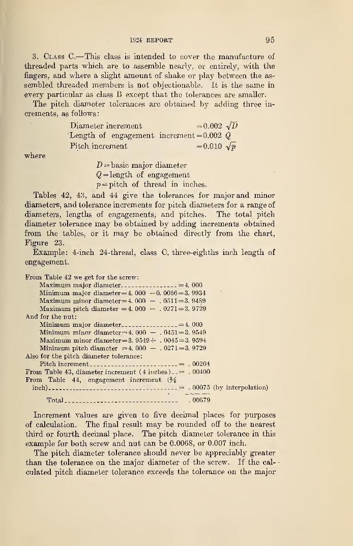
1924 REPORT 95
3. Class C.—This class is intended to cover the manufacture of
threaded parts which are to assemble nearly, or entirely, with the
fingers, and where a shght amount of shake or play between the as-
sembled threaded members is not objectionable. It is the same in
every particular as class B except that the tolerances are smaller.
The pitch diameter tolerances are obtained by adding three in-
crements, as follows:
Diameter increment =0.002 VZ5
Length of engagement increment = 0.002 QPitch increment =0.010 Vj?
where
Z> = basic major diameter
Q = length of engagement
p = pitch of thread in inches.
Tables 42, 43, and 44 give the tolerances for major and minor
diameters, and tolerance increments for pitch diameters for a range of
diameters, lengths of engagements, and pitches. The total pitch
diameter tolerance may be obtained by adding increments obtained
from the tables, or it may be obtained directly from the chart,
Figure 23.
Example: 4-inch 24-thread, class C, three-eighths inch length of
engagement.
From Table 42 we get for the screw:
Maximum major diameter =4. 000
Minimum major diameter=4. 000 -0. 0066= 3. 9934
Maximum minor diameter= 4. 000 — .0511= 3.9489
Maximum pitch diameter =4. 000 -. 0271= 3. 9729
And for the nut:
Minimum major diameter = 4. 000
Minimum minor diameter=4. 000 —. 0451 = 3. 9549
Maximum minor diameter= 3. 9549+ . 0045= 3. 9594
Minimum pitch diameter =4.000 — .0271 = 3.9729
Also for the pitch diameter tolerance:
Pitch increment = . 00204
From Table 43, diameter increment ( 4 inches ) _ _= . 00400
From Table 44, engagement increment
inch) = . 00075 (by interpolation)
Total . 00679
Increment values are given to five decimal places for purposes
of calculation. The final result may be rounded off to the nearest
third or fourth decimal place. The pitch diameter tolerance in this
example for both screw and nut can be 0.0068, or 0.007 inch.
The pitch diameter tolerance should never be appreciably greater
than the tolerance on the major diameter of the screw. If the cal-
culated pitch diameter tolerance exceeds the tolerance on the major
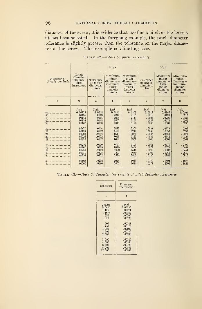
96 NATIONAX/ SCREW THREAD COMMISSION
diameter of the screw, it is evidence that too fine a pitch or too loose a
fit has been selected. In the foregoing example, the pitch diameter
tolerance is slightly greater than the tolerance on the major diame-
ter of the screw. This example is a limiting case.
Table 42.
—
Class C, pitch increments
dumber ofthreads per inch
Pitchdiametertolerance,
Screw Nut
Toleranceon majordiameter,minus
Maximumminor
diameter—maximummajor
diameterminus
Maximumpitch
diameter
=
maximummajor
diameterminus
Toleranceon minordiameter,
plus
Minimumminor
diameter=basicmajor
diameterminus
Minimumpitch
diameter—minimummajor
diameterminus
1 % 3 4 5 6 7 8
Inch Inch Inch Inch Inch Inch Inch64-. 0. 00125 0. 0038 0. 0192 0. 0101 0. 0017 0. 0169 0. 010156-__ - .00134 .0040 .0219 . 0116 .0019 .0193 .011648 . 00144 .0044 .0256 .0135 .0023 .0226 .013540 .00158 .0048 .6307 .0162 .0027 .0271 .016236 . 00167 .0050 .0341 .0180 .0030 .0301 .0180
32 . 00177 .0054 .0383 .0203 .0034 .0338 .020328 .00189 .0062 .0438 .0232 .0039 .0387 .023224 .00204 .0066 .0511 .0271 .0045 .0451 .0271
20.- . 00224 .0072 .0613 . 0325 .0054 .0541 .0325
18.. .00236 .0082 .0682 .0361 .0060 .0601 .0361
16 .00250 .0090 .0767 .0406 .0068 .0677 * .0406
14-.. .00267 .0098 .0876 .0464 .0077 .0773 .046412._ .00289 .0112 . 1022 .0541 .0090 .0902 .054110__ _ .00316 .0128 . 1227 .0650 .0108 . 1083 .06508_- _ .00354 .0152 . 1534 .0812 .0135 . 1353 .0812
6.-- —
-
.00408 .0202 .2045 . 1083 .0180 .1804 .10834 .00500 .0280 .3067 . 1624 .0271 .2706 .1624
Table 43.
—
Class C, diameter increments of pitch diameter tolerances
DiameterDiameterincrement
1 2
Inches0. 0625.125.1875.250.375
Inch0.00050
. 00071
.00087
.00100
.00122
.500
.7501.0001. 5002.000
. 00141
. 00173
. 00200
.00245
. 00283
3.0004. 0006.0008. 000
12. 000
. 00346
.00400
.00490
.00566
. 00693
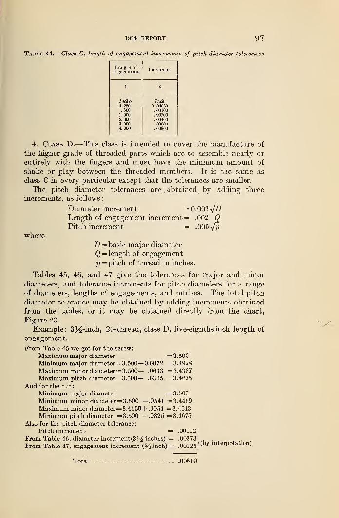
1924 REPORT 97
Table 44.
—
Class C, length of engagement increments of pitch diameter tolerances
Length of
engagement Increment
1 2
Inches0. 250.5001.0002.0003.0004. 000
Inch0. 00050.00100.00200.00400.00600.00800
4. Class D.—This class is intended to cover the manufacture of
the higher grade of threaded parts which are to assemble nearly or
entirely with the fingers and must have the minimum amount of
shake or play between the threaded members. It is the same as
class C in every particular except that the tolerances are smaller.
The pitch diameter tolerances are . obtained by adding three
increments, as follows
:
Diameter increment = 0.002
Length of engagement increment = .002 QPitch increment = .005
where
D = basic major diameter
Q = length of engagement
p = pitch of thread in inches.
Tables 45, 46, and 47 give the tolerances for major and minor
diameters, and tolerance increments for pitch diameters for a range
of diameters, lengths of engagements, and pitches. The total pitch
diameter tolerance may be obtained by adding increments obtained
from the tables, or it may be obtained directly from the chart,
Figure 23.
Example: 33^-inch, 20-thread, class D, five-eighths inch length of
engagement.
From Table 45 we get for the screw:
Maximum major diameter =3.500Minimum major diameter= 3.500— 0.0072 =3.4928
Maximum minor diameter=3.500— .0613 =3.4387
Maximum pitch diameter= 3.500- .0325 =3.4675
And for the nut:
Minimum major diameter =3.500Minimum minor diameter= 3.500 —.0541 =3.4459
Maximum minor diameter= 3.4459+ .0054 =3.4513
Minimum pitch diameter =3.500 —.0325 =3.4675
Also for the pitch diameter tolerance:
Pitch increment = .00112
From Table 46, diameter increment (3^2 inches) = .003731
From Table 47, engagement increment {% inch)= .00125/(by interpolation)
Total .00610
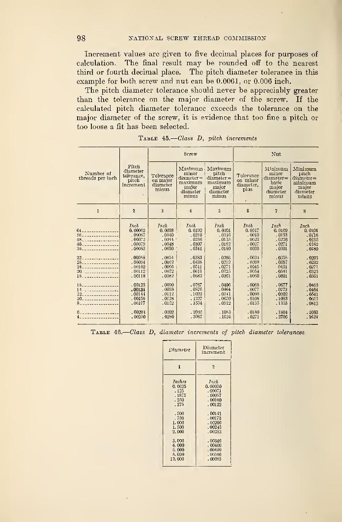
98 NATIONAL SCREW THREAD COMMISSION
Increment values are given to five decimal places for purposes of
calculation. The final result may be rounded off to the nearest
third or fourth decimal place. The pitch diameter tolerance in this
example for both screw and nut can be 0.0061, or 0.006 inch.
The pitch diameter tolerance should never be appreciably greater
than the tolerance on the major diameter of the screw. If the
calculated pitch diameter tolerance exceeds the tolerance on the
major diameter of the screw, it is evidence that too fine a pitch or
too loose a fit has been selected.
Table 45.
—
Class D, pitch increments
Number oft~ Vl rr\Q c nor in f^YiILircaUb ptT lliCIl
Pitchdiametertolerance,
pitchincrement
Screw Nut
Toleranceon majordiameterminus
Maximumminor
diameter
=
maximummajor
diameterminus
Maximumpitch
diameter=maximummajor
diameterminus
Toleranceon minordiameter,
plus
Minimumminor
diameter
=
basicmajor
diameterminus
Minimumpitch
diameter=minimummajor
diameterminus
1 2 3 4 5 6 7 8
Inch Inch Inch Inch Inch Inch Inch64 0. 00062 0. 0038 0. 0192 0. 0101 0. 0017 0. 0169 0. 010156.. .00067 .0040 .0219 .0116 .0019 .0193 .Olio48.. .00072 .0044 .0256 .0135 .0023 .0226 .013540 .00079 .0048 .0307 .0162 .0027 .0271 .016236 .00083 .0050 .0341 .0180 0030 .0301 .0180
32__ .00088 .0054 .0383 .0203 .0034 . 0338 .020328 .00094 .0062 .0438 .0232 .0039 .0387 .023224 .00102 .0066 .0511 .0271 .0045 0451 .027120_. .00112 .0072 .0613 .0325 .0054 .0541 .032518 .00118 .0082 .0682 .0361 .0060 .0601 .0361
16 .00125 .0090 .0767 .0406 .0068 .0677 .040514___ .00134 .0098 .0876 .0464 .0077 .0773 .046412 .00144 .0112 .1022 .0541 .0090 .0902 .054110.. .00158 .0128 . 1227 .0650 .0108 .1083 .06508_. .00177 .0152 . 1534 .0812 .0135 .1353 .0812
6 .00204 .0202 .2045 .1083 .0180 .1804 .10834 .00250 .0280 .3067 .1624 .0271 .2706 .1624
Table 46.
—
Class D, diameter increments of pitch diameter tolerances
DiameterDiameterincrement
1i
Inches0. 0625.125.1875.250.375
Inch0. 00050.00071.00087. 00100. 00122
.500
.7501.0001.5002. 000
. 00141
. 00173
.00200
. 00245
.00283
3.0004. 0006.0008. 00012.000
. 00346
. 00400
.00490
.00566
.00693
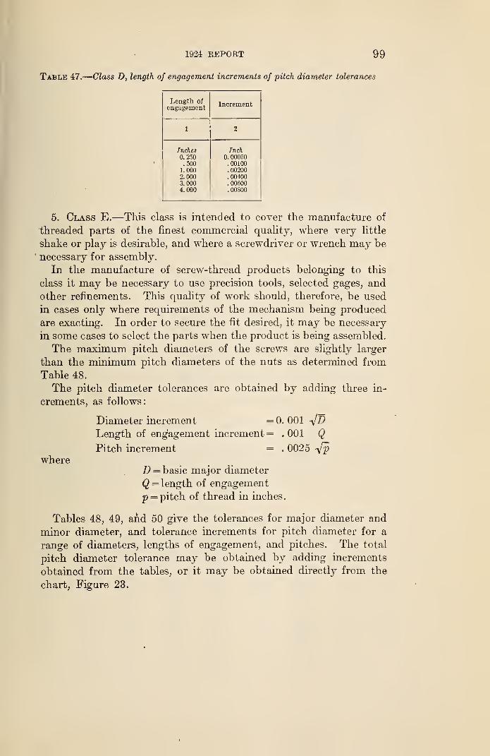
1&34 REPORT 99
Table 47.
—
Class D, length of engagement increments of pitch diameter tolerances
Length of
engagementIncrement
1 1
Inches0.250.500
1. 0002.0003.0004. 000
Inch0. 00050
. 00100
.00200
. 00400
. 00600
. 00800
5. Class E.—This class is intended to cover the manufacture of
threaded parts of the finest commercial quality, where very little
shake or play is desirable, and where a screwdriver or wrench may be
necessary for assembly.
In the manufacture of screw-thread products belonging to this
class it may be necessary to use precision tools, selected gages, and
other refinements. This quality of work should, therefore, be used
in cases only where requirements of the mechanism being produced
are exacting. In order to secure the fit desired, it may be necessary
in some cases to select the parts when the product is being assembled.
The maximum pitch diameters of the screws are slightly larger
than the minimum pitch diameters of the nuts as determined from
Table 48.
The pitch diameter tolerances are obtained by adding three in-
crements, as follows:
Diameter increment =0.001 -yjD
Length of engagement increment = .001 QPitch increment = . 0025 Vz>
whereD = basic major diameter
Q = length of engagement
p = pitch of thread in inches.
Tables 48, 49, and 50 give the tolerances for major diameter and
minor diameter, and tolerance increments for pitch diameter for a
range of diameters, lengths of engagement, and pitches. The total
pitch diameter tolerance may be obtained by adding increments
obtained from the tables, or it may be obtained directly from the
chart, Figure 23.
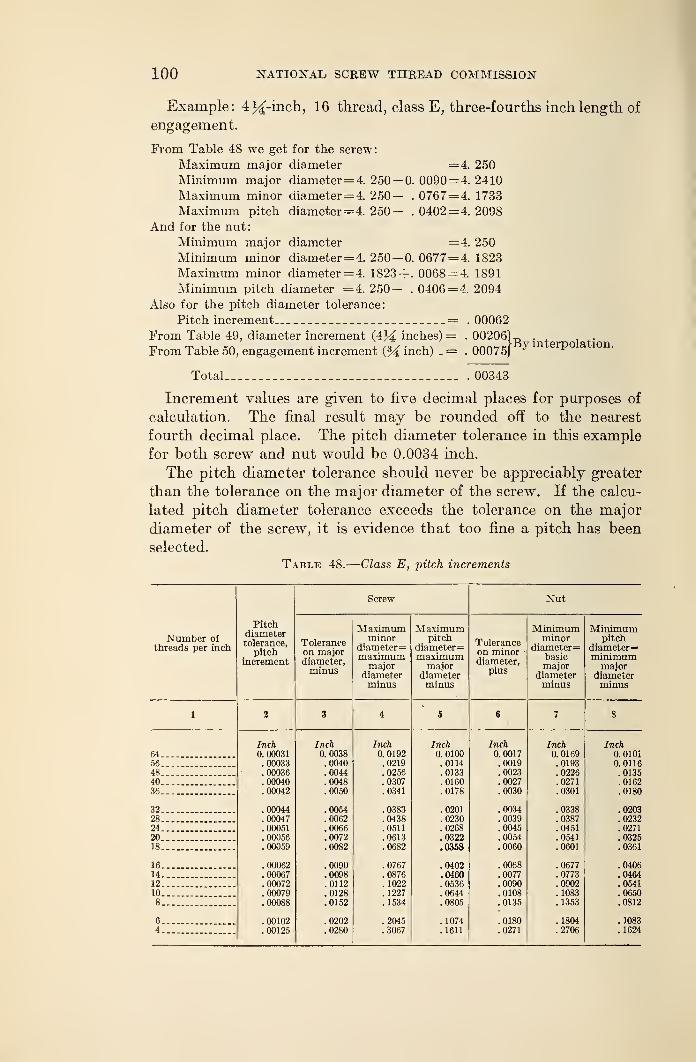
100 NATIONAL SCREW THREAD COMMISSION
Example: 434-inch, 16 thread, class E, three-fourths inch length of
engagement.
From Table 48 we get for the screw:
Maximum major diameter = 4. 250
Minimum major diameter=4. 250— 0. 0090= 4. 2410
Maximum minor diameter= 4. 250— . 0767= 4. 1733
Maximum pitch diameter= 4. 250— . 0402= 4. 2098
And for the nut:
Minimum major diameter =4. 250
Minimum minor diameter= 4. 250—0. 0677= 4. 1823
Maximum minor diameter= 4. 1823+ . 0068= 4. 1891
Minimum pitch diameter =4. 250— . 0406= 4. 2094
Also for the pitch diameter tolerance:
Pitch increment = . 00062
From Table 49, diameter increment (4J4 inches) = . 00206
From Table 50, engagement increment (94 inch) . = . 00075J^y interpolation.
Total . 00343
Increment values are given to five decimal places for purposes of
calculation. The final result may he rounded off to the nearest
fourth decimal place. The pitch diameter tolerance in this example
for both screw and nut would be 0.0034 inch.
The pitch diameter tolerance should never be appreciably greater
than the tolerance on the major diameter of the screw. If the calcu-
lated pitch diameter tolerance exceeds the tolerance on the major
diameter of the screw, it is evidence that too fine a pitch has been
selected.
Table 48.
—
Class E, -pitch increments
Number of
threads per inch
Pitchdiametertolerance,
pitchincrement
Screw Nut
Toleranceon majordiameter,minus
Maximumminor
diameter=maximummajor
diameterminus
Maximumpitch
diameter
=
maximummajor
diameterminus
Toleranceon minordiameter,
plus
Minimumminor
diameter
=
basicmajor
diameterminus
Minimumpitch
diameter
=
minimummajor
diameterminus
1 2 3 4 5 6 7 8
Inch Inch Inch Inch Inch Inch Inch64 0. 00031 0.0038 0. 0192 0.0100 0. 0017 0. 0169 0. 010156 .00033 .0040 .0219 .0114 .0019 .0193 0. 011648 .00036 .0044 .0256 .0133 .0023 .0226 .013540... .00040 .0048 .0307 .0160 .0027 .0271 .016236 .00042 .0050 .0341 .0178 .0030 .0301 .0180
32 .00044 .0054 .0383 .0201 .0034 .0338 .020328 .00047 .0062 .0438 .0230 .0039 .0387 .023224.. . 00051 .0066 .0511 .0268 .0045 .0451 .0271
20 .00056 .0072 .0613 .0322 .0054 .0541 .032518 .00059 .0082 .0682 .0358 .0060 .0601 .0361
16 . 00062 .0090 .0767 .0402 .0068 .0677 .040614 .00067 .0098 .0876 .0460 .0077 .0773 .046412 .00072 .0112 . 1022 .0536 .0090 .0902 .054110 .00079 .0128 . 1227 .0644 .0108 . 1083 .06508 .00088 .0152 .1534 .0805 .0135 . 1353 .0812
6 .00102 .0202 .2045 .1074 .0180 .1804 .10834 .00125 .0280 .3067 . 1611 .0271 .2706 . 1624
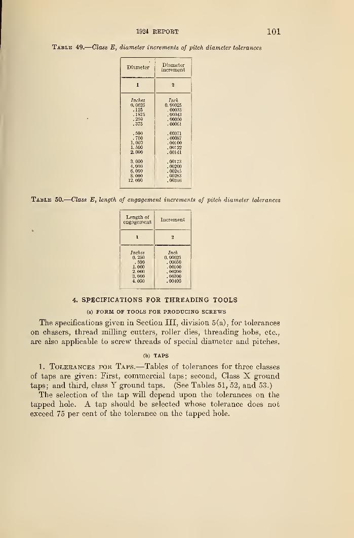
1924 REPORT 101
Table 49.
—
Class E, diameter increments of pitch diameter tolerances
Diameter Diameterincrement
1 jg
Inches Inch0. 0625 0. 00025
. 125 . 00035
.1875 .00043
.250 . 00050
.375 .00061
. 500 . 00071
. 750 . 000871.000 . 001001. 500 .001222.000 . 00141
3.000 .001734.000 . 002006. 000 .002458.000 .0028312.000 .00346
Table 50.
—
Class E, length of engagement increments of pitch diameter tolerances
Length ofengagement Increment
1 2
Inches0. 250.500
1. 0002.0003. 0004. 000
Inch0. 00025.00050. 00100. 00200. 00300.00400
4. SPECIFICATIONS FOR THREADING TOOLS
(a) FORM OF TOOLS FOR PRODUCING SCREWS
The specifications given in Section III, division 5(a), for tolerances
on chasers, thread milling cutters, roller dies, threading hobs, etc.,
are also applicable to screw threads of special diameter and pitches.
(b) TAPS
1. Tolerances for Taps.—Tables of tolerances for three classes
of taps are given: First, commercial taps; second, Class X ground
taps; and third, class Y ground taps. (See Tables 51, 52, and 53.)
The selection of the tap will depend upon the tolerances on the
tapped hole. A tap should be selected whose tolerance does not
exceed 75 per cent of the tolerance on the tapped hole.
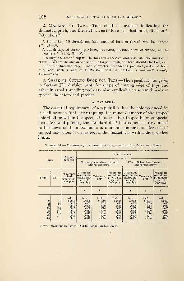
102 NATIONAL SCREW THREAD COMMISSION
2. Marking of Taps.—Taps shall be marked indicating the
diameter, pitch, and thread form as follows (see Section II, division 2,
" Symbols"):
A 1-inch tap, 16 threads per inch, national form of thread, will be marked1"—16—N.A 1-inch tap, 16 threads per inch, left hand, national form of thread, will be
marked: 1"—16 L. H.—N.A multiple threaded tap will be marked as above, and also with the number of
starts. Where the size of the shank is large enough, the lead should also be given.
A double-threaded tap; 1 inch diameter, 16 threads per inch, national formof thread, with a lead of 0.125 inch will be marked: 1"—16—N Double,
Lead—0.125.
3. Shape of Cutting Edge for Taps.—The specifications given
in Section III, division 5(b), for shape of cutting edge of taps andother internal threading tools are also applicable to screw threads of
special diameters and pitches.
(c) TAP DRILLS
The essential requirement of a tap drill is that the hole produced byit shall be such that, after tapping, the minor diameter of the tapped
hole shall be within the specified limits. For tapped holes of special
diameters and pitches, the standard drill that comes nearest in siz*
to the mean of the maximum and minimum minor diameters of the
tapped hole should be selected, if the diameter is within the specified
limits.
Table 51.
—
Tolerances for commercial taps, special diameters and pitches
SizesMajor
diameter
Pitch diameter
Coarser pitches than "nationalfine-thread series"
Finer pitches than "nationalfine-thread series"
From— To—Minimum= basic
major diam-eter plus
Minimum=minimumpitch diam-
eter of
hole plus
Tolerance,plus
Maximum=minimumpitch diam-
eter of
hole plus
Minimum=minimumpitch diam-
eter ofhole plus
Tolerance,plus
Maximum=minimumpitch diam-
eter of
hole plus
1 2 3 i 5 C 7 8
Mk
lVs
V/s
2Vs2%3H
%%
1m2
2M34
. Inch0. 0010.0010.0010.0015.0015.0015.0015.0015
Inch0. 0005.0005.0005.0005.0010.0010.0010.0010
Inch0. 0020.0025.0030.0035.0040.0045.0050.0055
Inch0. 0025.0030.0035.0040.0050.0055.0060.0065
Inch0. 0005
. 0005
.0005
.0005
.0005
.0005
.0005
.0005
Inch0. 0015.0020.0025.0030.0030.0035.0035.0045
Inch0. 0020.0025.0030. 0035.0035.0040.0040.0050
Note.—Maximum lead error =± 0.003 inch in 1 inch of thread.
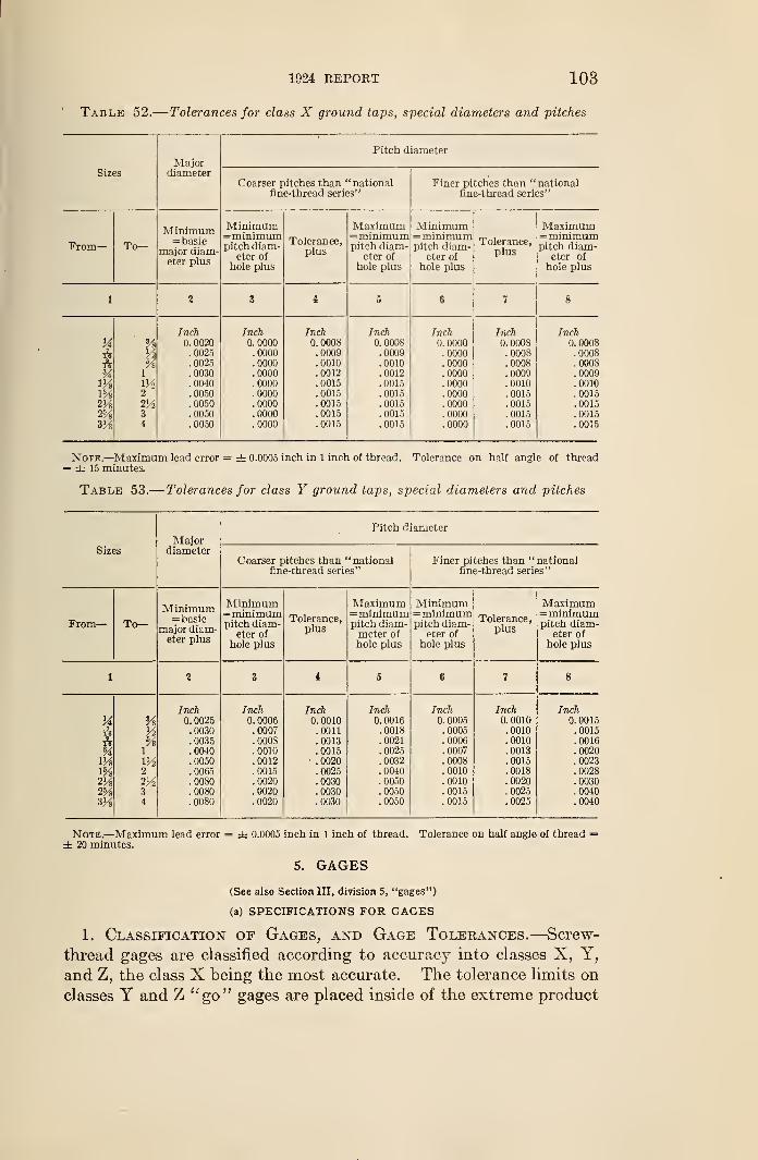
1924 REPOBT 103
Table 52.
—
Tolerances for class X ground taps, special diameters and pitches
MajorPitch diameter
Sizes diameterCoarser pitches than "national
fine-thread series"Finer pitches than "national
fine-thread series"
From
—
To—Minimum= basic
major diam-eter plus
Minimum=minimumpitch diam-
eter of
hole plus
Tolerance,plus
Maximum=minimumpitch diam-
eter of
hole plus
Minimum=minimumpitch diam-
eter of
hole plus
Tolerance,plus
Maximum=minimumpitch diam-
eter of
hole plus
1 2 3 i 5 6 1 8
Hiu
2VS2%VA
VtVi
%1m2
2V234
Inch0. 0020.0025.0025.0030.0040.0050.0050.0050.0050
Inch0. 0000.0000.0000.0000.0000.0000.0000.0000.0000
Inch0. 0008.0009.0010.0012.0015.0015.0015.0015.0015
Inch0. 0008.0009.0010.0012.0015.0015.0015.0015.0015
Inch0. 0000.0000.0000.0000.0000.0000.0000.0000.0000
Inch0. OOOS.0008.0008.0009.0010.0015.0015.0015.0015
Inch0. 0008.0008.0008.0009.0010.0015.0015.0015.0015
Note.—Maximum lead error = ± 0.0005 inch in 1 inch of thread. Tolerance on half angle of thread= ± 15 minutes.
Table 53.
—
Tolerances for class Y ground taps, special diameters and pitches
MajorPitch diameter
Sizes diameterCoarser pitches than "national
fine-thread series"Finer pitches than "national
fine-thread series"
From— To—Minimum= basic
major diam-eter plus
Minimum=minimumpitch diam-
eter of
hole plus
Tolerance,plus
Maximum=minimumpitch diam-meter ofhole plus
Minimum=minimumpitch diam-
eter of
hole plus
Tolerance,plus
Maximum=minimumpitch diam-
eter ofhole plus
1 2 3 I 5 6 7 8
HAA%Wtm2Vs2%
aVi
Y%1
m2
2Vi3
4
Inch0. 0025.0030.0035.0040.0050.0065.0080.0080.0080
Inch0. 0006.0007.0008.0010.0012.0015.0020.0020.0020
Inch0. 0010.0011.0013.0015.0020.0025.0030.0030.0030
Inch0. 0016.0018.0021.0025.0032.0040.0050.0050.0050
Inch0. 0005.0005.0006.0007.0008.0010.0010.0015.0015
Inch0. 0010.0010.0010.0013.0015.0018.0020.0025.0025
Inch0. 0015.0015.0016.0020.0023.0028.0030.0040.0040
Note.—Maximum lead error = ± 0.0005 inch in 1 inch of thread. Tolerance on half angle of thread =± 20 minutes.
5. GAGES
(See also Section HI, division 5, "gages")
(a) SPECIFICATIONS FOR GAGES
1. Classification of Gages, and Gage Tolerances.—Screw-
thread gages are classified according to accuracy into classes X, Y,
and Z, the class X being the most accurate. The tolerance limits on
classes Y and Z "go" gages are placed inside of the extreme product
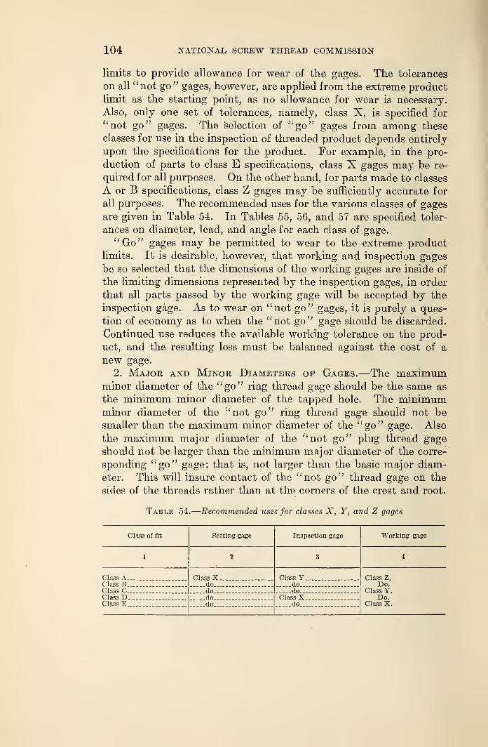
104 NATIONAL SCREW THREAD COMMISSION
limits to provide allowance for wear of the gages. The tolerances
on all "not go" gages, however, are applied from the extreme productlimit as the starting point, as no allowance for wear is necessary.
Also, only one set of tolerances, namely, class X, is specified for
"not go" gages. The selection of "go" gages from among these
classes for use in the inspection of threaded product depends entirely
upon the specifications for the product. For example, in the pro-
duction of parts to class E specifications, class X gages may be re-
quired for all purposes. On the other hand, for parts made to classes
A or B specifications, class Z gages may be sufficiently accurate for
all purposes. The recommended uses for the various classes of gages
are given in Table 54. In Tables 55, 56, and 57 are specified toler-
ances on diameter, lead, and angle for each class of gage.
"Go" gages may be permitted to wear to the extreme product
limits. It is desirable, however, that working and inspection gages
be so selected that the dimensions of the working gages are inside of
the limiting dimensions represented by the inspection gages, in order
that all parts passed by the working gage will be accepted by the
inspection gage. As to wear on "not go" gages, it is purely a ques-
tion of economy as to when the "not go" gage should be discarded.
Continued use reduces the available working tolerance on the prod-
uct, and the resulting loss must be balanced against the cost of a
new gage.
2. Major and Minor Diameters op Gages.—The maximumminor diameter of the "go" ring thread gage should be the same as
the minimum minor diameter of the tapped hole. The minimumminor diameter of the "not go" ring thread gage should not besmaller than the maximum minor diameter of the "go" gage. Also
the maximum major diameter of the "not go" plug thread gage
should not be larger than the minimum major diameter of the corre-
sponding "go" gage; that is, not larger than the basic major diam-
eter. This will insure contact of the "not go" thread gage on the
sides of the threads rather than at the corners of the crest and root.
Table 54.
—
Recommended uses for classes X, Y, and Z gages
Class of fit Setting gage Inspection gage Working gage
1 3 i
Class A Class X Class Y Class Z.Do.
Class Y.Do.
Class X.
Class B do _ doClass C do do.Class D._ _ do Class XClass E do do
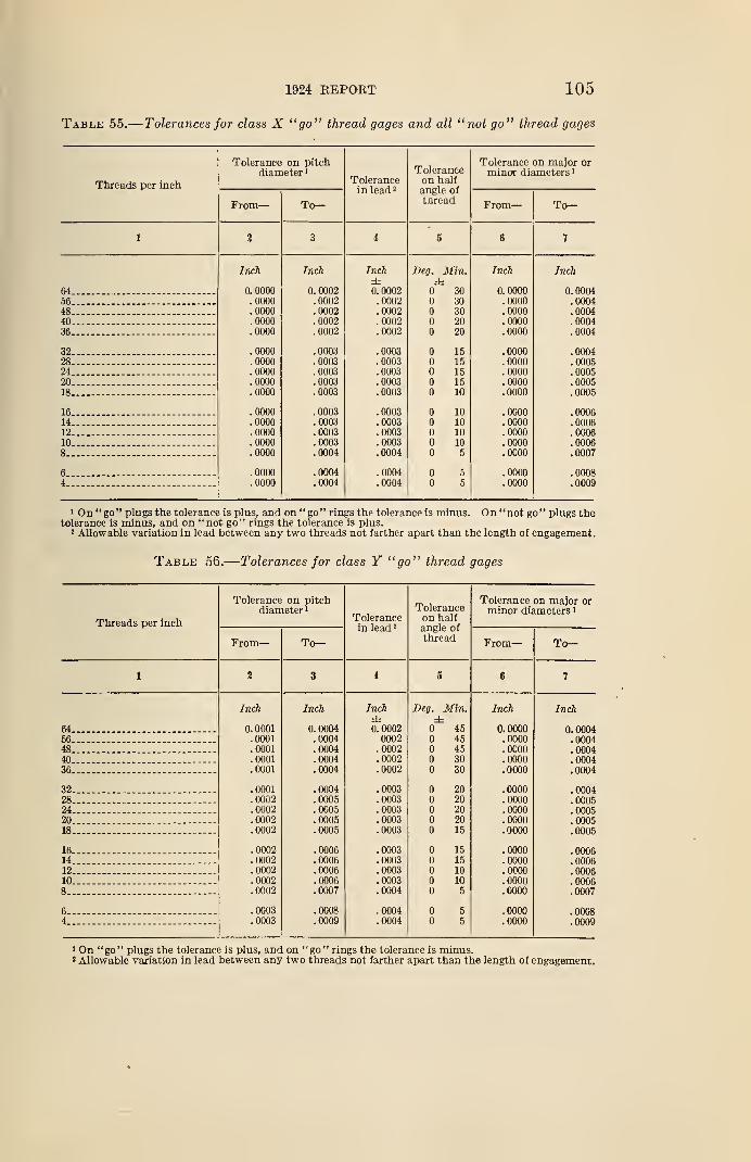
Table 55.
—
1924 REPORT 105
Tolerances for class X "go" thread gages and all "not go" thread gages
Threads per inch
Tolerance on pitchdiameter 1
Tolerancein lead 3
Toleranceon halfangle ofthread
Tolerance on major orminor diameters 1
From
—
To— From— To—
1 9Aoo 4 S f
Inch Inch Inch Beg. Min. Inch Inch±
64 0. 0000 0. 0002 f* Anno0. UUU2 30 0. 0000 0.0004
56 .0000 .0002 . 0002 30 .0000 .000448 . 0000 . 0002 .0002 30 . 0000 . 000440 !oooo !0002 .0002 20 ioooo !o00436 .0000 .0002 . 0002 20 .0000 .0004
32 .0000 .0003 .0003 15 .0000 .000428 .0000 .0003 .0003 15 .0000 .000524 .0000 .0003 .0003 15 .0000 .000520 .0000 .0003 .0003 15 .0000 .000518 .0000 .0003 .0003 10 .0000 .0005
16 .0000 .0003 .0003 10 .0000 .000614 .0000 .0003 .0003 10 .0000 .000612 .0000 .0003 .0003 10 .0000 .000610 .0000 .0003 .0003 10 .0000 .00068 .0000 .0004 .0004 5 .0000 .0007
6 .0000 .0004 .0004 5 .0000 .00084 .0000 .0004 .0004 5 .0000 .0009
1 On "go" plugs the tolerance is plus, and on "go" rings the tolerance is minus. On "not go" plugs thetolerance is minus, and on "not go" rings the tolerance is plus.
1 Allowable variation in lead between any two threads not farther apart than the length of engagement.
Table 56.
—
Tolerances for class Y "go" thread gages
Threads per inch
Tolerance on pitchdiameter 1
Tolerancein lead 2
Toleranceon halfangle ofthread
Tolerance on major orminor diameters 1
From
—
To— From— To—
1 2 3 i 5 6 7
Inch Inch Inch Beg, Min. Inch Inch± ±
64 0. 0001 0. 0004 0. 0002 45 0.0000 0. 000456 .0001 .0004 0002 45 .0000 .000448 .0001 .0004 .0002 45 .0000 .000440 .0001 .0004 .0002 30 .0000 .000436 .0001 .0004 .0002 30 .0000 .0004
32 .0001 .0004 .0003 20 .0000 .000428 .0002 .0005 .0003 20 .0000 .000524 .0002 .0005 .0003 20 .0000 .000520 .0002 .0005 .0003 20 .0000 .000518 .0002 .0005 .0003 15 .0000 .0005
16 .0002 .0006 .0003 15 .0000 .000614 .0002 .0006 .0003 15 .0000 .000612 .0002 .0006 .0003 10 .0000 .000610 .0002 .0006 .0003 10 .0000 .00068 .0002 .0007 .0004 5 .0000 .0007
6 .0003 .0008 .0004 5 .0000 .00084 .0003 .0009 .0004 5 .0000 .0009
1 On "go" plugs the tolerance is plus, and on "go" rings the tolerance is minus.2 Allowable variation in lead between any two threads not farther apart than the length of engagement.
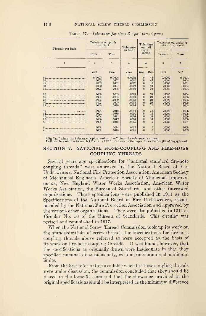
106 NATIONAL SCREW THREAD COMMISSION
Table 57.
—
Tolerances for class Z "go" thread gages
Threads per inch
Tolerance on pitchdiameter 1
Tolerancein lead 3
Toleranceon halfangle ofthread
Tolerance on major orminor diameters 1
_r rom— I o— I rom
—
To
—
1 2 3 S 6 7
Inch Inch Inch Beg. Min. Inch Inch± ±
64 0. 0002 0. 0006 0. 0002 45 0. 0000 0.000456 .0002 .0007 . 0002 45 .0000 .000448 .0002 .0007 . 0002 45 .0000 .000440 .0002 .0007 .0002 30 .0000 .000436 .0003 .0008 .0002 30 .0000 .0004
32 .0003 .0008 .0003 20 .0000 .000428 .0003 .0008 . 0003 20 .0000 .000524 .0003 .0009 !0003 20 .0000 .000520 .0003 .0009 .0003 20 .0000 .000518 .0004 .0010 .0004 15 .0000 .0005
16 .0004 .0010 .0004 15 .0000 .000614 .0004 .0010 .0004 15 .0000 .000612 .0004 .0011 .0004 10 .0000 .000610 . 0005 .0012 .0004 10 .0000 .00068 .0006 .0013 .0005 5 .0000 .0007
6 .0006 .0014 .0005 5 .0000 .00084 .0007 .0016 .0005 5 .0000 .0009
1 On "go" plugs the tolerance is plus, and on "go" rings the tolerance is minus.2 Allowable variation in lead between any two threads not farther apart than the length of engagement.
SECTION V. NATIONAL HOSE-COUPLING AND FIRE-HOSECOUPLING THREADS
Several years ago specifications for "national standard fire-hose
coupling threads" were approved by the National Board of Fire
Underwriters, National Fire Protection Association, American Society
of Mechanical Engineers, American Society of Municipal Improve-
ments, New England Water Works Association, American Water
Works Association, the Bureau of Standards, and other interested
organizations. These specifications were published in 1911 as the
Specifications of the National Board of Fire Underwriters, recom-
mended by the National Fire Protection Association and approved bythe various other organizations. They were also published in 1914 as
Circular No. 50 of the Bureau of Standards. This circular was
revised and republished in 1917.
When the National Screw Thread Commission took up its work on
the standardization of screw threads, the specifications for fire-hose
coupling threads above referred to were accepted as the basis of
its work on fire-hose coupling threads. It was found, however, that
the specifications as originally drawn were inadequate in that they
specified nominal dimensions only, with no maximum and minimumlimits.
From the best information available when fire-hose coupling threads
were under discussion, the commission concluded that they should be
placed in the loose-fit class and that the allowance provided in the
original specifications should be interpreted as the minimum difference
1924 REPORT 107
in pitch diameter of the couplings and nipples ; that is, that a looser fit
could be tolerated than that represented by the nominal .dimensions,
but that a tighter fit would be objectionable. The nominal size of
the coupling was, therefore, taken as the minimum coupling, and the
nominal size of the nipple as the maximum nipple; the loose-fit
tolerances being applied in such a direction as to make the maximumcoupling larger and the minimum nipple smaller than the nominalsize by the amount of the tolerance. The dimensions for "national
fire-hose coupling threads" appearing in the 1921 Progress Keport of
the commission were calculated on that basis.
It later appeared from evidence presented by the National Board of
Fire Underwriters that the fits resulting from the limiting dimensions
specified in the 1921 Progress Report may in extreme cases be looser
than good practice warrants. The commission was, therefore, re-
quested to revise its specifications for fire-hose coupling threads in
such a manner that the resulting fits would be somewhat closer than
those originally permitted. The revision requested was accomplished
by reducing the allowance between the minimum coupling and the
maximum nipple; the minimum coupling dimension being retained as
published in the 1921 Progress Report. However, from evidence
presented by certain manufacturers, it appeared desirable to provide
a larger wear limit for gages and also permit the use of field inspection
gages which were outside of the limits set for the manufacturers'
gages, in order to insure the approval, by the purchaser, of threaded
couplings which had passed the manufacturers' gages. To permit
this, the tolerances on both the coupling and nipple were increased
slightly.
Furthermore, since the publication of the 1921 Progress Report, it
has been found desirable, in order to facilitate production and simplify
the manufacture of threading tools and gages, to adopt the national
form of thread for "national fire-hose coupling threads." This,
however, is a very minor change and only slightly affects the thread
form at crest and root.
The specifications have been further supplemented by recommendedlimiting dimensions of gages such that every coupling and nipple
accepted will be known to be within the limiting dimensions specified.
Only such a system can insure that the finished product will assemble
and function properly.
Comparison of the resulting dimensions with those contained in the
original specifications of the National Board of Fire Underwriters and
in Bureau of Standards Circular No. 50, shows that the two are not in
conflict. The nominal dimensions originally specified for couplings
and nipples are not inconsistent with the above limiting dimensions,
and the revised dimensions should not be considered as changing in
any way the original specifications for "national fire-hose coupling
threads," but as supplementing those specifications, and as expressing
108 NATIONAL SCREW THREAD COMMISSION
them in definite and measurable terms. It should be understood that
these dimensions for "national fire-hose coupling threads" are the
limiting dimensions for the finished product and not for the threading
tools.
With regard to the "national hose-coupling threads," which range
in size from three-fourths to 2 inches, the series of sizes and pitches
originally adopted by the commission are essentially the same as the
corresponding sizes of the "national straight pipe threads," with the
exception of the three-fourths-inch size. In this case 11 and 11%threads, with a diameter of 1^ inches, was already in very extensive
use. The adoption of the so-called "straight iron pipe thread" wasindorsed by the Nation Association of Brass Manufacturers, and at
the time of its adoption was recommended by the committee onSmall Hose Couplings of the National Fire Protection Association
and tentatively adopted by that association.
In ordering threading tools for producing 'national hose-coupling
and fire-hose coupling threads," it should be pointed out that newtaps should be near the maximum permissible size of the coupling,
and new dies near the minimum permissible size of the nipple, in
order that reasonable wear may be provided. As the threading tools
wear by use, the couplings will become smaller and the nipples larger
until the limiting dimensions are reached. These must not be ex-
ceeded. When the product reaches, or comes dangerously close to the
limiting size, the threading tools should be readjusted or replaced.
1. FORM OF THREAD
1. Angle of Thread.—The basic angle of thread (A) between the
sides of the thread measured in an axial plane is 60°. The line bisect-
ing this 60° angle is perpendicular to the axis of the screw thread.
2. Flat at Crest and Root.—The flat at the root and crest of
the basic thread form is l/% X p, or 0.125 X p.
3. Depth of Thread.—The depth of the basic thread form is
T. r,n A ~rm 7 0.6495197i = 0.649519Xp, or7i = —
where
p = pitch in inches
n = number of threads per inch
h = basic depth of thread.
2. THREAD SERIES
(a) National Hose-Coupling Threads.—There is specified in
Table 58 a thread series and basic dimensions for hose-coupling
threads from three-fourths to 2 inches in diameter, which will be
known as the "national hose-coupling threads."
The "national hose-coupling thread" shall be used on all couplings
and connections where sizes between three-fourths and 2 inches in
diameter are required.
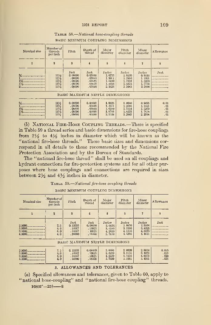
1924 REPORT 109
Table 58.
—
National hose-coupling threads
BASIC MINIMUM COUPLING DIMENSIONS
Nominal size
Number ofthreadsper inch
PitchDepth ofthread
Majordiameter
Pitchdiameter
Minordiameter Allowance
1 2 3 4 5 6 7 8
Uny2uy2ny2
Inch0. 08696
. 08696
. 08696
. 08696
. 08696
Inch0. 05648
. 05648
. 05648
. 05648
. 05648
Inches1. 07251. 30511. 64991. 88882. 3628
Inches1. 01601.24861. 59341. 83232. 3063
Inches0. 95951. 19211. 53691. 77582. 2498
Inch
1
V4m2 _
BASIC MAXIMUM NIPPLE DIMENSIONS
u - 0. 08696 0. 05648 1.0625 1.0060 0.94951 . 08696 . 05648 1. 2951 1. 2386 1. 1821m —- . 08696 . 05648 1. 6399 1. 5834 1. 5269m — — ny2 . 08696 . 05648 1. 8788 1. 8223 1. 76582.... ny2 . 08696 . 05648 2. 3528 2. 2963 2. 2398
(&) National Fire-Hose Coupling Threads.—There is specified
in Table 59 a thread series and basic dimensions for fire-hose couplings
from 2y2 to 43^ inches in diameter which will be known as the
"national fire-hose threads." These basic sizes and dimensions cor-
respond in all details to those recommended by the National Fire
Protection Association and by the Bureau of Standards.
The "national fire-hose thread" shall be used on all couplings and
hydrant connections for fire-protection systems and for all other pur-
poses where hose couplings and connections are required in sizes
between 2% and 4}4 inches in diameter.
Table 59.
—
National fire-hose coupling threads
BASIC MINIMUM COUPLING DIMENSIONS
Nominal size
Number of
threadsper inch
PitchDepth ofthread
Majordiameter
Pitchdiameter
Minordiameter
Allowance
1 % 3 i 5 6 7 8
2.5000 7.56.06.04.0
Inch0. 13333. 16667. 16667.25000
Inch0. 08660
. 10825
. 10825
.16238
Inches3. 08363. 63894. 26395. 7859
Inches2. 99703.53064. 15565. 6235
Inches2. 91043. 42234. 04735. 4611
Inch
3.00003.50004.5000
BASIC MAXIMUM NIPPLE DIMENSIONS
2.5000. 7.5 0. 13333 0. 08660 3. 0686 2. 9820 2. 8954 0.0153.0000 6.0 . 16667 . 10825 3. 6239 3. 5156 3. 4073 .015
3.5000.. 6.0 . 16667 . 10825 4. 2439 4. 1356 4. 0273 .020
4.5000 4.0 .25000 . 16238 5.7609 5. 5985 5. 4361 .025
3. ALLOWANCES AND TOLERANCES
(a) Specified allowances and tolerances, given to Table 60, apply to
" national hose-coupling" and " national fire-hose coupling " threads.
16802°—25t 8
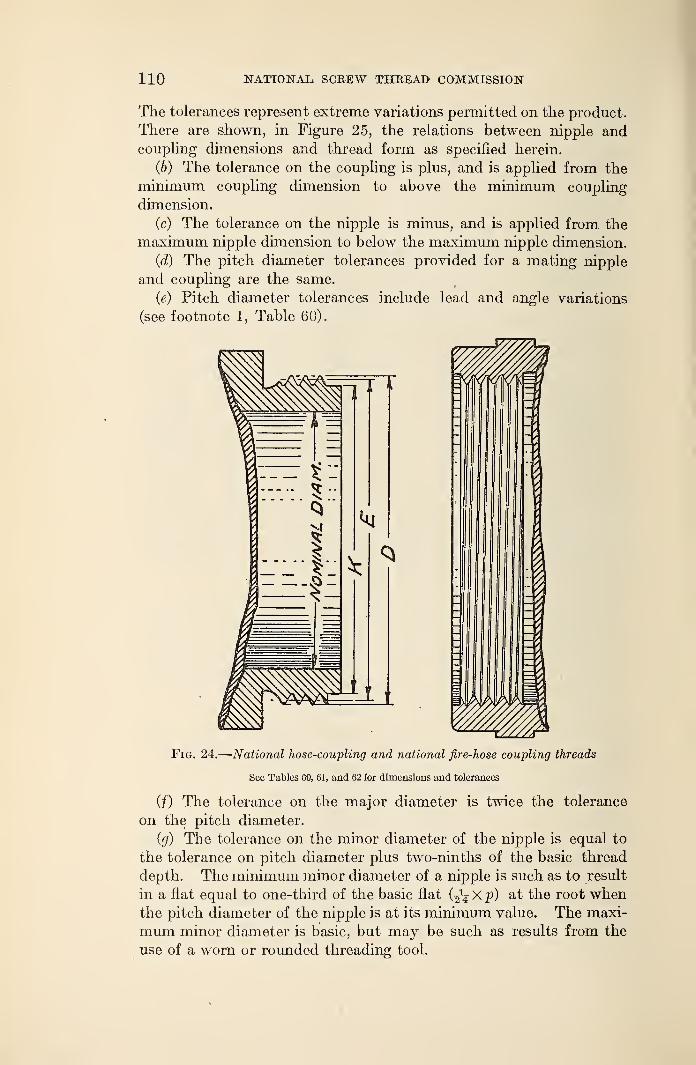
110 NATIONAL SCE.EW THREAD COMMISSION
The tolerances represent extreme variations permitted on the product.
There are shown, in Figure 25, the relations between nipple andcoupling dimensions and thread form as specified herein.
(b) The tolerance on the coupling is plus, and is applied from the
minimum coupling dimension to above the minimum coupling
dimension.
(c) The tolerance on the nipple is minus, and is applied from the
maximum nipple dimension to below the maximum nipple dimension.
(d) The pitch diameter tolerances provided for a mating nipple
and coupling are the same.
(e) Pitch diameter tolerances include lead and angle variations
(see footnote 1, Table 60).
Fig. 24.
—
National hose-coupling and national fire-hose coupling threads
See Tables 60, 61, and 62 for dimensions and tolerances
(f) The tolerance on the major diameter is twice the tolerance
on the pitch diameter.
(g) The tolerance on the minor diameter of the nipple is equal to
the tolerance on pitch diameter plus two-ninths of the basic thread
depth. The minimum minor diameter of a nipple is such as to result
in a flat equal to one-third of the basic flat 0^ X p) at the root whenthe pitch diameter of the nipple is at its minimum value. The maxi-
mum minor diameter is basic, but may be such as results from the
use of a worn or rounded threading tool.
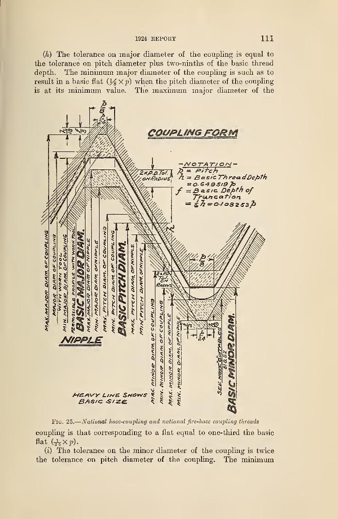
1924 KEPOKT 111
(h) The tolerance on major diameter of the coupling is equal to
the tolerance on pitch diameter plus two-ninths of the basic thread
depth. The minimum major diameter of the coupling is such as to
result in a basic flat Xp) when the pitch diameter of the coupling
is at its minimum value. The maximum major diameter of the
COUPUNG FORM
/VO 7~A T/O/sl -= Pitchr Basic T~h rea
: B a. s/c Depth ofJ~ru.ficat/on
A/£/ivy c/a/e Shows £
Fig. 25.
—
National hose-coupling and national fire-hose coupling threads
coupling is that corresponding to a flat equal to one-third the basic
flat (^Xp).(i) The tolerance on the minor diameter of the coupling is twice
the tolerance on pitch diameter of the coupling. The minimum
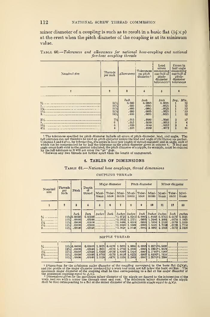
112 NATIONAL SCREW THREAD COMMISSION
minor diameter of a coupling is such as to result in a basic flat (3^ X p)
at the crest when the pitch diameter of the coupling is at its minimumvalue.
Table 60.
—
Tolerances and allowances for national hose-coupling and nationalfire-hose coupling threads
Lead TTrrnrQ in11/1 L KJL O 1X1
errors half angle
Threads Tolerances consuming consumingNominal size Allowances on pitch one-half of one-half of
per inchdiameter 1 pitch- pitch-
diameter diametertolerances 2 tolerances
1 2 3 i 5 6
Inch Inch Inch Deg. Min.0. 010 0. 0085 0. 0025 1 52
1. .010 .0085 .0025 1 52M im .010 .0085 .0025 1 52m ny2 .010 .0085 .0025 1 522 ny2 .010 .0085 .0025 1 52
2^ m .015 .0160 .0046 2 173 6 .015 .0180 .0052 2 4
6 .020 .0180 .0052 2 4
4V2 4 .025 .0250 .0072 1 55
1 The tolerances specified for pitch diameter include all errors of pitch diameter, lead, and angle. Thefull tolerance can not therefore be used on pitch diameter unless the lead and angle of the thread are perfect.Columns 5 and 6 give, for information, the errors in lead (per length of thread engaged) and in angle, each of
which can be compensated for by half the tolerance on the pitch diameter given in column 4. If lead andangle errors both exist to the amount tabulated, the pitch diameter of a nipple, for example, must be reducedby the full tolerance or it will not enter the "go" gage.
2 Between any two threads not farther apart than the length of engagement.
4. TABLES OF DIMENSIONS
Table 61.
—
National hose couplings, thread dimensions
COUPLING THREAD
Nominalsize
Threadsperinch
PitchDepth
ofthread
Major diameter Pitch diameter Minor diameter
Maxi-mum
Toler-ance
Mini-mum
Maxi-mum
Toler-ance
Mini-mum
Maxi-mum
Toler-ance
Mini-mum
1 2 3 i 5 6,
7 8 9 10 11 12 13
uimiva
Inch0. 08696
. 08696
. 08696
. 08696
. 08696
Inch0. 05648
. 05648
. 05648
.05648
. 05648
Inches Inch Inches1. 0725
1 1. 30511 1. 64991 1. 8888i 2. 3628
Inches1.02451. 25711. 60191. 84082. 3148
Inch0.0085.0085.0085.0085.0085
Inches1. 01601. 24861. 59341. 83232. 3063
Inches0. 97651. 20911. 55391.79282. 2668
Inch0. 0170.0170.0170.0170.0170
Inches0. 95951. 19211. 53691. 77582.2498
1
IXVA2
NIPPLE THREAD
54 11%nteimimn%
0. 08696. 08696.08696. 08696. 08696
0. 05648. 05648. 05648. 05648. 05648
1. 06251. 29511. 63991. 87882.3528
0. 0170.0170.0170.0170.0170
1. 04551. 27811. 62291. 86182. 3358
1.00601. 23861. 58341. 82232.2963
0.0085.0085.0085.0085.0085
0.99751.23011. 57491. 81382.2878
2 0.94952 1. 18212 1. 52692 1. 76582 2. 2398
1
IX— -m—2
1 Dimensions for the minimum major diameter of the coupling correspond to the basic flat (J^Xp),and the profile at the major diameter produced by a worn tool must not fall below the basic outline. Themaximum major diameter of the coupling shall be that corresponding to a flat at the major diameter ofthe maximum coupling equal to AX p.
2 Dimensions given for the maximum minor diameter of the nipple are figured to the intersection of theworn tool arc with a center line through crest and root. The minimum minor diameter of the nippleshall be that corresponding to a flat at the minor diameter of the minimum nipple equal to -hXV-
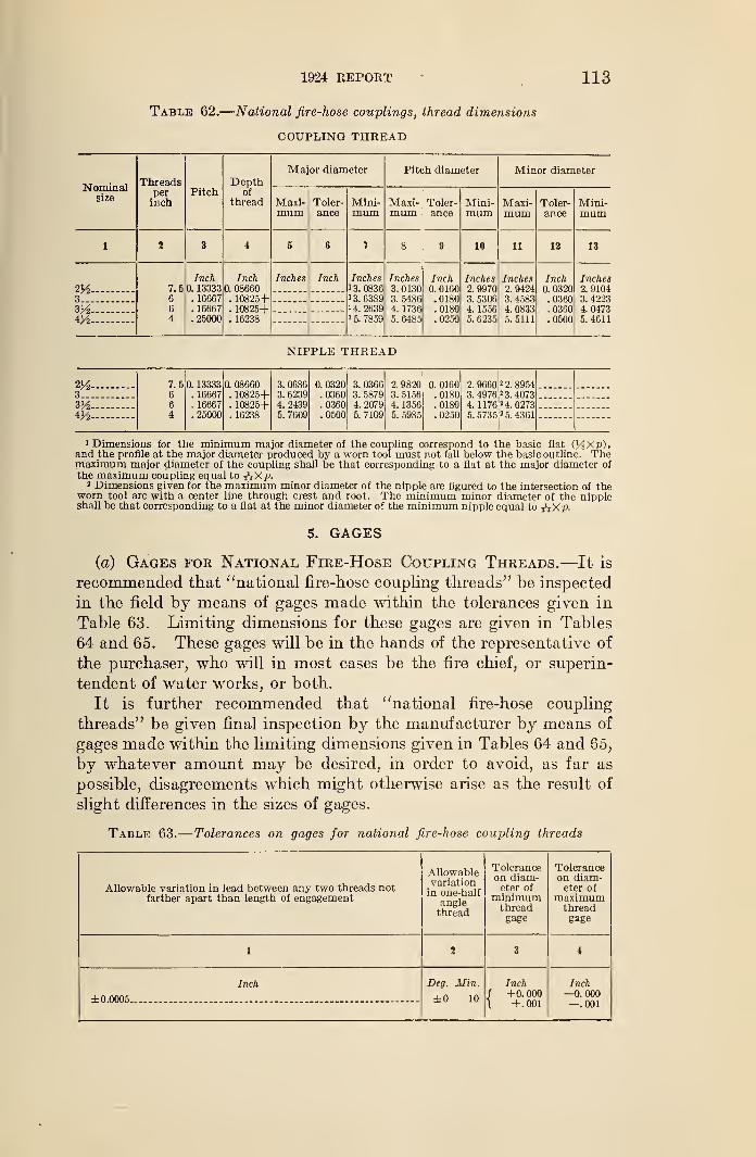
1924 REPORT 113
Table 62.
—
National fire-hose couplings, thread dimensions
COUPLING THREAD
Nominalsize
X IireaUo
perinch
Pitch ofthread
Major diameter Pitch diameter Minor diameter
Maxi-mum
Toler-ance
Mini-mum
Maxi-mum
Toler-ance
Mini-mum
Maxi-mum
Toler-ance
Mini-mum
1 2 3 4 5 G 7 8 9 10 11 12 13
— 7.5664
Inch0. 13333
. 16667
. 16667
.25000
Inch0. 08660
. 10825+
. 10825+
. 16238
Inches Inch Inches1 3. 08361 3. 63891 4. 26391 5. 7859
Inches3. 01303. 54864. 1736
5. 6485
Inch0. 0160.0180.0180.0250
Inches2. 99703. 53064. 15565. 6235
Inches2. 94243. 45834. 08335. 5111
Inch0. 0320.0360.0360.0500
Inches2. 91043. 42234. 04735. 4611
3
3V2mNIPPLE THREAD
2%3
7.566
4
0. 13333. 16667. 16667.25000
0. 08660. 10825+. 10825+. 16238
3. 06863. 62394. 24395. 7609
0. 0320.0360.0360.0500
3. 03663. 58794. 20795. 7109
2. 98203. 51564. 13565. 5985
0. 0160.0180.0180.0250
2. 9660 2 2. 89.54
3. 4976 ' 3. 40734. 1176 2 4. 02735. 5735 2 5. 4361
3V24K2- -
'Dimensions for the minimum major diameter of the coupling correspond to the basic flat (l/iXp),
and the profile at the major diameter produced by a worn tool must not fall below the basic outline. Themaximum major diameter of the coupling shall be that corresponding to a flat at the major diameter of
the maximum coupling equal to ?'4 Xp.2 Dimensions given for the maximum minor diameter of the nipple are figured to the intersection of the
worn tool arc with a center line through crest and root. The minimum minor diameter of the nippleshall be that corresponding to a flat at the minor diameter of the minimum nipple equal to j'jXp.
5. GAGES
(a) Gages for National Fire-Hose Coupling Threads.—It is
recommended that "national fire-hose coupling threads" be inspected
in the field by means of gages made within the tolerances given in
Table 63. Limiting dimensions for these gages are given in Tables
64 and 65. These gages will be in the hands of the representative of
the purchaser, who will in most cases be the fire chief, or superin-
tendent of water works, or both.
It is further recommended that "national fire-hose coupling
threads" be given final inspection by the manufacturer by means of
gages made within the limiting dimensions given in Tables 64 and 65,
by whatever amount may be desired, in order to avoid, as far as
possible, disagreements which might otherwise arise as the result of
slight differences in the sizes of gages.
Table 63.
—
Tolerances on gages for national fire-hose coupling threads
Allowable variation in lead between any two threads notfarther apart than length of engagement
Allowablevariationin one-half
anglethread
Toleranceon diam-eter of
minimumthreadgage
Toleranceon diam-eter of
maximumthreadgage
1 2 3 4
Inch
±0.0005 -
Beg. Min.
±0 10
Inch1 +0.000\ +.001
Inch—0.000—.001
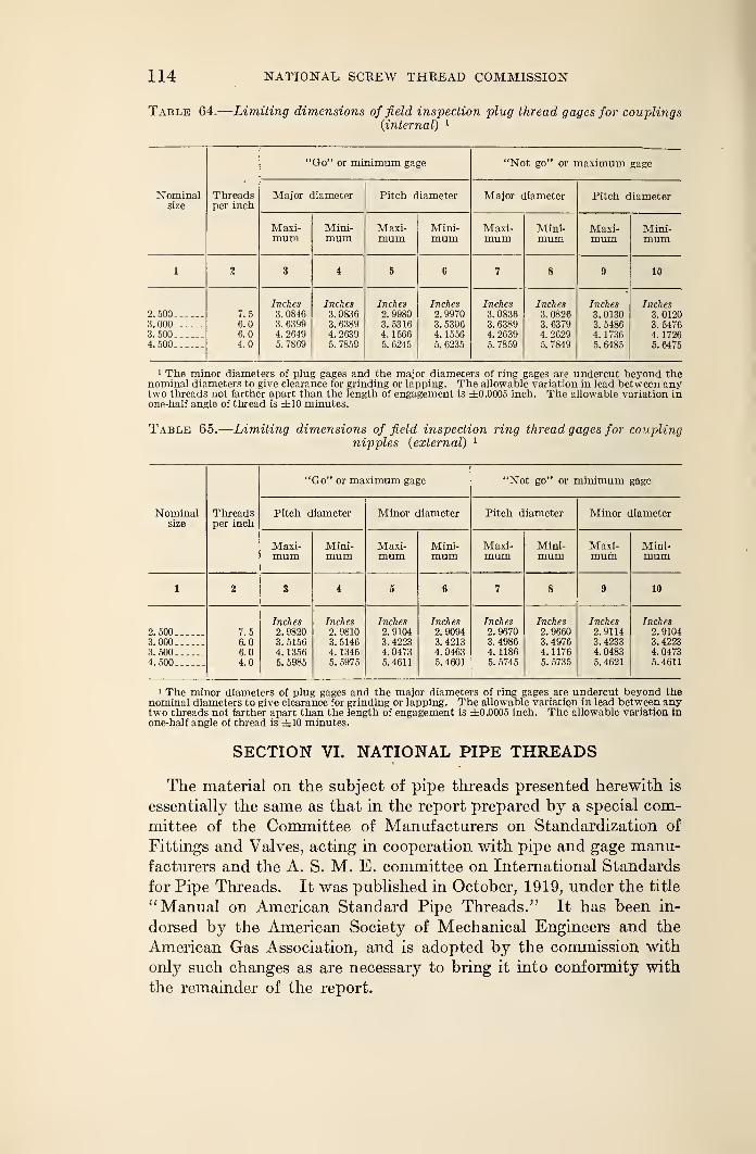
114 NATIONAL, SCREW THREAD COMMISSION
Table 64.
—
Limiting dimensions of field inspection plug thread gages for couplings(internal) 1
Nominalsize
Threadsper inch
"Go" or minimum gage "Not go" or maximum gage
Major diameter Pitch diameter Major diameter Pitch diameter
Maxi-mum
Mini-mum
Maxi-mum
Mini-mum
Maxi-mum
Mini-mum
Maxi-mum
Mini-mum
1 2 3 4 5 6 7 8 9 10
2. 5003.0003.5004.500
7.56.06.04.0
Inches3. 08463. 63994. 26495. 7869
Inches3. 08363. 63894. 26395. 7859
Inches2. 99803. 53164. 15665. 6245
Inches2. 99703. 53064. 15565. 6235
Inches3. 08363. 63894. 26395. 7859
Inches3. 08263. 63794. 26295. 7849
Inches3. 01303. 54864. 17365. 6485
Inches3. 01203. 54764. 17265. 6475
i The minor diameters of plug gages and the major diameters of ring gages are undercut beyond thenominal diameters to give clearance for grinding or lapping. The allowable variation in lead between anytwo threads not farther apart than the length of engagement is ±0.0005 inch. The allowable variation inone-half angle of thread is ±10 minutes.
Table 65.
—
Limiting dimensions of field inspection ring thread gages for couplingnipples (external) 1
Nominalsize
Threadsper inch
"Go" or maximum gage "Not go" or minimum gage
Pitch diameter Minor diameter Pitch diameter Minor diameter
Maxi-mum
Mini-mum
Maxi-mum
Mini-mum
Maxi-mum
Mini-mum
Maxi-mum
Mini-mum
1 2 3 4 5 6 7 8 9 10
2.5003.0003.5004.500
7.56.06.04.0
Inches2. 98203. 51564. 13565. 5985
Inches2. 98103. 51464. 13465. 5975
Inches2.91043. 42234. 04735. 4611
Inches2. 90943. 42134. 04635. 4601
Inches2. 96703. 49864. 11865. 5745
Inches2. 96603. 49764.11765. 5735
Inches2.91143. 42334. 04835. 4621
Inches2. 91043. 42234. 04735. 4611
1 The minor diameters of plug gages and the major diameters of ring gages are undercut beyond thenominal diameters to give clearance for grinding or lapping. The allowable variation in lead between anytwo threads not farther apart than the length of engagement is ±0.0005 inch. The allowable variation in
one-half angle of thread is ±10 minutes.
SECTION VI. NATIONAL PIPE THREADS
The material on the subject of pipe threads presented herewith is
essentially the same as that in the report prepared by a special com-
mittee of the Committee of Manufacturers on Standardization of
Fittings and Valves, acting in cooperation with pipe and gage manu-facturers and the A. S. M. E. committee on International Standards
for Pipe Threads. It was published in October, 1919, under the title
"Manual on American Standard Pipe Threads." It has been in-
dorsed by the American Society of Mechanical Engineers and the
American Gas Association, and is adopted by the commission with
only such changes as are necessary to bring it into conformity with
the remainder of the report.
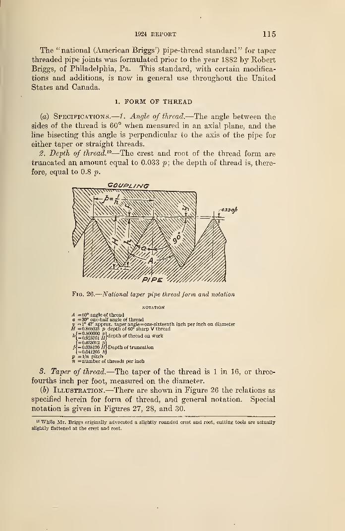
1&24 REPORT 115
The " national (American Briggs') pipe-thread standard" for taper
threaded pipe joints was formulated prior to the year 1882 by Robert
Briggs, of Philadelphia, Pa. This standard, with certain modifica-
tions and additions, is now in general use throughout the United
States and Canada.
1. FORM OF THREAD
(a) Specifications.—1. Angle of thread.—The angle between the
sides of the thread is 60° when measured in an axial plane, and the
line bisecting this angle is perpendicular to the axis of the pipe for
either taper or straight threads.
2. Depth of thread. 10—The crest and root of the thread form are
truncated an amount equal to 0.033 p; the depth of thread is, there-
fore, equal to 0.8 p.
Fig. 26.
—
National taper pipe thread form and notation
NOTATION
A =60° angle of threado =30° one-half angle of thready = 1° 47' approx. taper angle=one-sixteenth inch per inch on diameterH =0.866025 p depth of 60° sharp V thread
A{=a923761 ff}
dePth of thread on work
|=0]033012 pJ{ =0.038120 HfDepth of truncation1=0.041266 ftj
p =]/n pitchn =number of threads per inch
8. Taper of thread.—The taper of the thread is 1 in 16, or three-
fourths inch per foot, measured on the diameter.
(Jo) Illustration.—There are shown in Figure 26 the relations as
specified herein for form of thread, and general notation. Special
notation is given in Figures 27, 28, and 30.
10 While Mr. Briggs originally advocated a slightly rounded crest and root, cutting tools are actually
slightly flattened at the crest and root.
116 NATIONAL SCREW THREAD COMMISSION
2. SYMBOLS
The list of symbols given in Section II—2, together with addi-
tional symbols given below, should be used in formulas for expressing
relations of pipe threads and for use on drawings, etc.
Pitch diameter of thread at end of pipe EPitch diameter of thread at gaging notch EiPitch diameter of thread at L2 from end of pipe E2
Maximum pitch diameter, external locknut thread Ee
Minimum pitch diameter, internal locknut thread E\
Distance from gaging notch to end of pipe= normal engagement by hand L\
Length of effective thread L2
Nominal outside diameter of pipe= major diameter of pipe thread at L2 fromend of pipe ^ D
Internal diameter of pipe d
3. THREAD SERIES
(a) National (American Briggs') Taper Pipe Threads.—Taperexternal and internal pipe threads are recommended for threaded
pipe joints and pipe fittings for any service. The sizes and basic
dimensions of the "national (American Briggs') taper pipe threads"
are specified in Table 66.
1. Outside diameter of pipe.—The outside diameters of pipe are
given in column 5 of Table 66.
2. Diameters of taper threads.—The pitch diameters of the taper
threads are determined by formulas based on the outside diameter
of pipe and the pitch of thread. These are as follows 11 (see Sym-bols above) :
# = Z>-(0.05 D + l.l) pE
t= E + 0.0625 L
1
3. Length of thread.—The length of the taper external thread is
determined by a formula based on the outside diameter of pipe and
the pitch of the thread. This is as follows 11 (see Symbols above)
:
i3 =(0.8 D + 6.8) p
4- Length of engagement.—The normal length of engagement be-
tween taper external and internal threads, when screwed together byhand, is shown in column 6 of Table 66. This length is controlled
by means of gages.
5. Tolerances.—The tolerance on diameter is the equivalent of the
variation in diameter due to taper over one and one-half turns
either way from the basic dimensions. 12
11 These formulas are not expressed in the same terms as the formulas originally established by Mr.Briggs, because they are used to determine directly the pitch diameter and the length of effective thread,
which includes two threads slightly imperfect at the crest; whereas the Briggs formulas determined the
major diameter and the length of perfect thread, the two threads imperfect on the crest not being included
in the formula. However, both forms give identical results.
13 On account of the gage tolerance of one-half turn on working gages, this is equivalent to one turn plus
or one turn minus from the gaging notch when using working gages (see figs. 34 and 35).
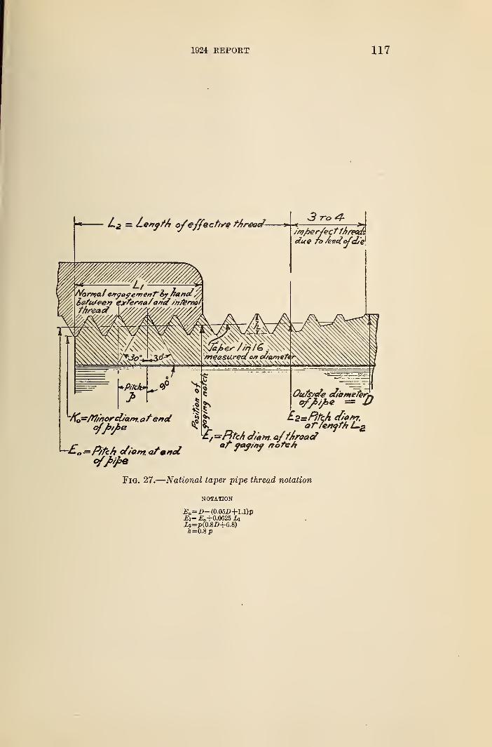
1924 REPORT 117
Fig. 27.
—
National taper pipe thread notation
NOTATION
£o= D-(0.05Z)+l.l)pEi=Eo+0M25LiU=P(0.8D+6.S)A=0.8p
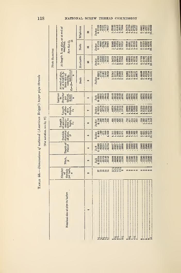
118 ITATIONAL SCREW THREAD COMMISSION
o
-a
os cO'-' co t-CN COOO t— rH
? t-- OOCN COX co tp co r- as
tp — r-H Tp
CN ic 00 CN 12
oo o i—t cn r--t~- O tP CN n"JCD »0 tp t—t— t— t— 1» coco oo co oo tp
>0 N rH »C NCN CO CO CN CNJ
d 5 x co Qi—I rH i—" CN CN CO CO TP ^p iO CD t- 00 OS ©
CO OS rH CO t—NCOO^OO«5 05 QO O0
r- oo cm r- coCO tP CO I*" os
CO 00 Tp COCO CO CO CN i—
I
00 CO CN CO CN
O —I CN tP OSiO GO —i CD CNCO CO r— T> OS
CN lO OO CN r~ COCOCOQOt
t- tp co t- tpOS co © as osiCMONOSO Q OS CN
tO 05 Tp OHHHNN COCOTPTpiO CDN00CRO
MOCNCONiNHNrHlCJ
*5 00 iO CN *C *C2; r— os co oo as-fj co co t- a>
CO CO OS CN oor- >o tp co
CN CO Tf O HCN iO OO CO O800DNHO OS OS COTp Os CO 00 tP
OS CO iO Cs COCO O I- CO COt- tp i-< as cn
IO iC >C iO CO
rH r-i j-H CN CN CO CO tP tP iO COt-dOCs©
° d <U Qd
rH OS i—I CO 00iO CO CO Tp COSt- CN OO
t— rH lC COCO Tp CD t— OS
CO CO OS CN COCO i—i O O iOco r- co os osrH lO OS CO r—i
cn m t— cn i—
rH. i—t i-H CN CN
CN O 00 'O COco co cn r—ON^rnOTp CO CO CO OSCO CO CO 00 CO
CO CO T(i Tp >o
OS Tp O* TP rH© CO »0 CO COCQCOt-iO
CPT3 "3
? CD V- CN
g-pH fa ftuO
rHh-NCDCOCO "rp TP— - — r~&
CO CO CO CO rHTP TP TP TP 00
;ss8ss sssssCO CO CO CO 00r- t- r-- r-O OO Q OO O ©OO 38888
•Go -a?c>2 Pa .,
iOCOCOhh2* co rH r- co ic
CO 00 CO CN Ot— i^. tp io tocn co co co r—CO O CN iO COCO N N N H
SO O © CO
CN CN CO CO TP
© © © o ©CN CN CN CN >CrHHHHtNIO CO t- 00 OS
.a 2 . >> O O O O OSCO O TP CN CO
2 rH CN CN CO CO
CO -H TP »C t-CD CN TP t- COt- co oo co as
00 O CO O OO CO CO rHOiOO <-<CN
21 "etc
o
5 Q TP TP 25J Tp iO CO O0 O
inoioiooCN CN CN CN iOCD CO CD CD
rH HHHNN CO rP TP iC iO cot- CO OS o
CO tP tP tPCO Tp -^p rH rH
rC as tp tpO CN tP Tp IO u0£OOO© O
r- 1— r— t- ©IO "C iO iCCos os as as c_SCO CD CO OOOO rH
tP CO CD CO CO. O lO IO Tj* Tp
rtS t— IO IO rH rHcj co io i-o r—« O O © O ©
CO CO CO CO Cas as as os c_CO CO CO co «oO0 00 CO 00 CNO O O O rH
53 " -3r, -O OB o g — S3 fa. <-<
r> CD
t- O0 OO TP TP 0O 00 00 0OO0 0000000000
rXr^eS\f-\e< rH rH rH CN CN COCOTPTplO CoV- 00 OS rH
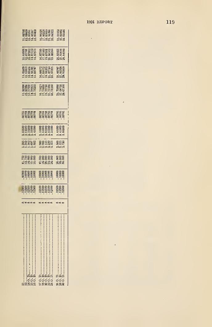
1924 REPORT
OO OO OS CN
CO CO QC CO O03 CO iO00 00 00 OO 00
S?S2TP 0> IOg) coGO 00 00
CO 00 CO i-H Is"o r— cm tt1 io
CO CO 00 00 00
l-S CN CO Tt< IO
O Q CO CO OS
Is- r- co co00 CO CO 00 00
' CO 00CN iO 00CO >—1 CO
00 00 OO
as co ,-< ^-o o co osHOlTf ION
i-H cn co id
CM CN CO COr^- 1-— o co coco co c5 r- cnco oo co r- r-00 CO 00 00 00
t-- 00 OSOS <N IO!> CO 00to co »o00 00 00
iC t-' OSCN CN CN
CDhOOOCN >S 00 CM
CO CO t— CO CO"O O N N 1^
rH CN CO t** tf-j
SSS88 SSSS8 SSS
OOOOOC5 io o c o
OOOOOO O Q Q OOOOQOin io ic io lqiO CO 00 O CN
CN CN CN CN CN CN CN CN CO CO CO CO CO
tfJOMC-CNCO CO CO 00 i—1
CN CO iO CO 00 S O »-t CN CO
i—i CN CN CN CN CN CN CN
»-i cn m co
5 O O O: oi g o; o o o
OOOOOOOOOOo o o o -OO o o s s
OOOOOOO OOO
O Q O O QOOOOOCM CN CN CN IN
O O Q O OOOOOOCN CN CN CN CN
coooooooco oooooocooo ooooco
;ddd ddddd oddi-H CN Tfl iO CO f- 00 Q CN COOOOrtHHHH i—I i—I CN CN CN CN CN CO
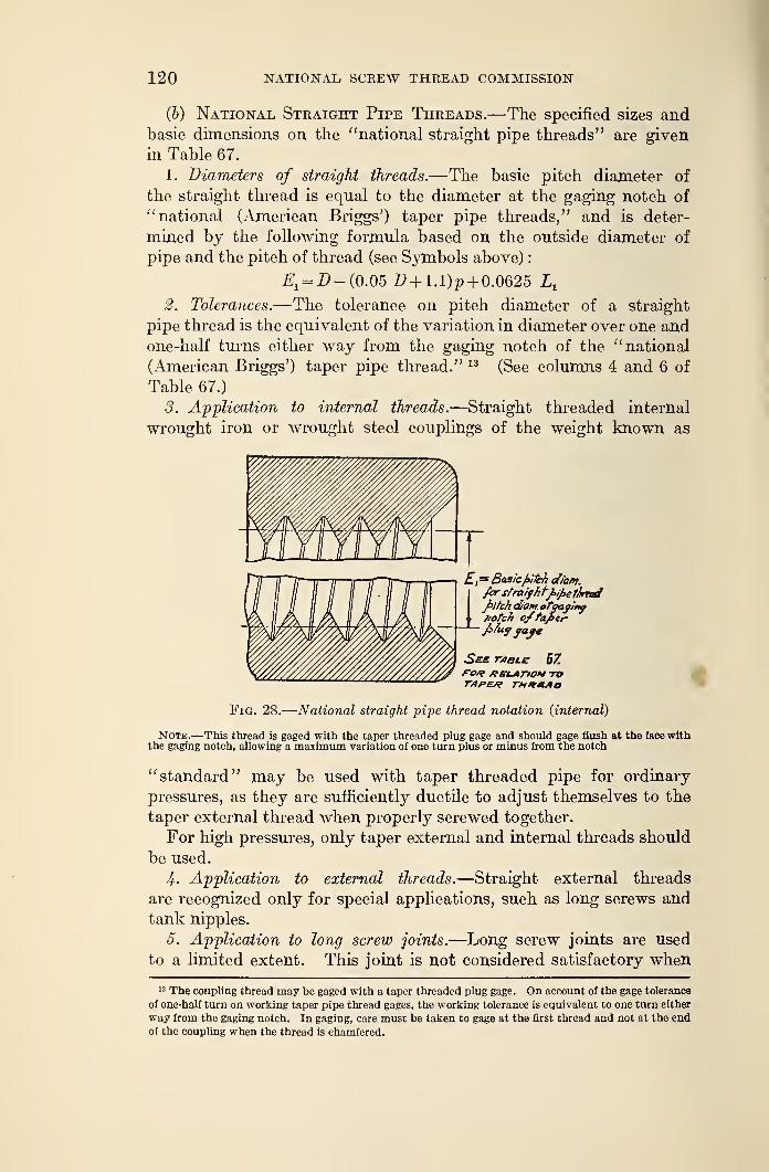
120 NATIONAL SCREW THREAD COMMISSION
(&) National Straight Pipe Threads.—The specified sizes andbasic dimensions on the "national straight pipe threads" are given
in Table 67.
1. Diameters of straight threads.—The basic pitch diameter of
the straight thread is equal to the diameter at the gaging notch of
"national (American Briggs') taper pipe threads," and is deter-
mined by the following formula based on the outside diameter of
pipe and the pitch of thread (see Symbols above)
:
Et=D- (0.05 # + 1.% + 0.0625 L
t
2. Tolerances.—The tolerance on pitch diameter of a straight
pipe thread is the equivalent of the variation in diameter over one andone-half turns either way from the gaging notch of the "national
(American Briggs') taper pipe thread." 13 (See columns 4 and 6 of
Table 67.)
3. Application to internal threads.—Straight threaded internal
wrought iron or wrought steel couplings of the weight known as
Fig. 28.
—
National straight pipe thread notation (internal)
Note.—This thread is gaged with the taper threaded plug gage and should gage flush at the face withthe gaging notch, allowing a maximum variation of one turn plus or minus from the notch
"standard" may be used with taper threaded pipe for ordinary
pressures, as they are sufficiently ductile to adjust themselves to the
taper external thread when properly screwed together.
For high pressures, only taper external and internal threads should
be used.
4- Application to external threads.—Straight external threads
are recognized only for special applications, such as long screws and
tank nipples.
5. Application to long screw joints.—Long screw joints are used
to a limited extent. This joint is not considered satisfactory when
13 The coupling thread may be gaged with a taper threaded plug gage. On account of the gage tolerance
of one-half turn on working taper pipe thread gages, the working tolerance is equivalent to one turn either
way from the gaging notch. In gagiDg, care must be taken to gage at the first thread and not at the endof the coupling when the thread is chamfered.
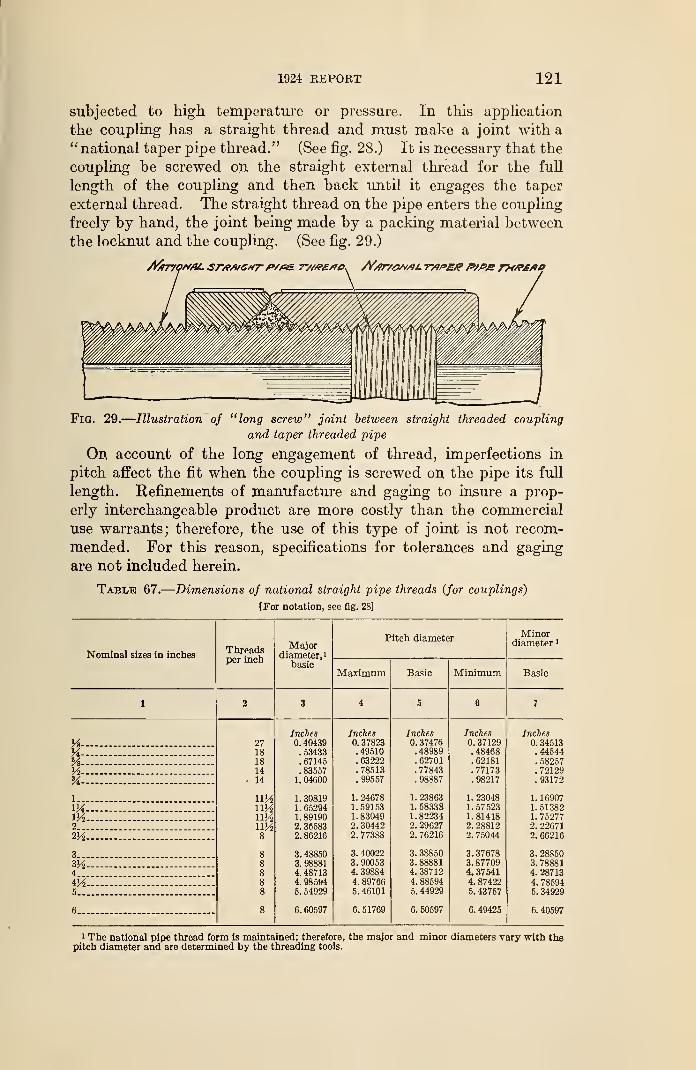
1924 REPORT 121
subjected to high temperature or pressure. In this application
the coupling has a straight thread and must make a joint with a" national taper pipe thread." (See fig. 28.) It is necessary that the
coupling be screwed on the straight external thread for the full
length of the coupling and then back until it engages the taper
external thread. The straight thread on the pipe enters the coupling
freely by hand, the joint being made by a packing material between
the locknut and the coupling. (See fig. 29.)
Fig. 29.
—
Illustration of "long screw" joint between straight threaded coupling
and taper threaded pipe
On account of the long engagement of thread, imperfections in
pitch affect the fit when the coupling is screwed on the pipe its full
length. Refinements of manufacture and gaging to insure a prop-
erly interchangeable product are more costly than the commercial
use warrants; therefore, the use of this type of joint is not recom-
mended. For this reason, specifications for tolerances and gaging
are not included herein.
Table 67.
—
Dimensions of national straight pipe threads (for couplings)
[For notation, see fig. 28]
Nominal sizes in inchesThreadsper inch
Majordiameter, 1
basic
Pitch diameterMinor
diameter 1
Maximum Basic Minimum Basic
1 2 3 4 5 6 7
Inches Inches Inches Inches Inches
H - 27 0. 40439 0. 37823 0. 37476 0.37129 1 0.34513
X - 18 . 53433 . 49510 . 48989 . 48468 .44544
% 18 . 67145 . 63222 . 62701 .62181 . 58257
Vi — - 14 . 83557 .78513 . 77843 .77173 .72129SA - 14 1. 04600 . 99557 .98887 . 98217 . 93172
l mi 1. 30819 1.24678 1. 23863 1. 23048 1. 16907
VA im 1. 65294 1. 59153 1. 58338 1.57523 1.51382m - ny2 1.89190 1. 83049 1.82234 1.81418 1. 752772 ny2 2. 36583 2. 30442 2. 29627 2. 28812 2. 22671m 8 2. 86216 2. 77388 2. 76216 2. 75044 2. 66216
3 8 3. 48850 3. 40022 3. 38850 3. 37678 3. 28850
m.~ - 8 3. 98881 3. 90053 3. 88881 3.87709 3. 788814 8 4. 48713 4. 39884 4. 38712 4. 37541 4. 28713
VA 8 4. 98594 4. 89766 4. 88594 4. 87422 4. 785945 8 5. 54929 5. 46101 5. 44929 5. 43757 5. 34929
6 8 6. 60597 6. 51769 6. 50597 6. 49425 6. 40597
1 The national pipe thread form is maintained; therefore, the major and minor diameters vary with thepitch diameter and are determined by the threading tools.
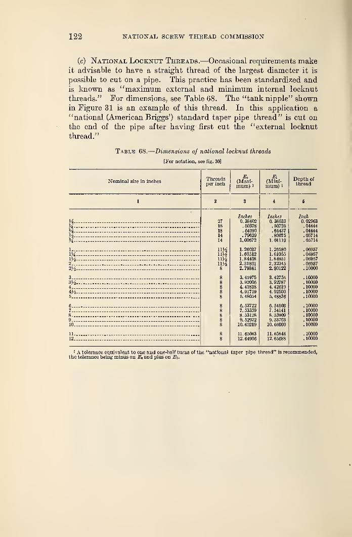
122 NATIONAL, SCREW THREAD COMMISSION
(c) National Locknut Threads.—Occasional requirements makeit advisable to have a straight thread of the largest diameter it is
possible to cut on a pipe. This practice has been standardized and
is known as "maximum external and minimum internal locknut
threads." For dimensions, see Table 68. The "tank nipple" shownin Figure 31 is an example of this thread. In this application a
"national (American Briggs') standard taper pipe thread" is cut on
the end of the pipe after having first cut the "external locknut
thread."
Table 68.
—
Dimensions of national locknut threads
[For notation, see fig. 30]
Nominal size in inchesThreadsper inch
&(Maxi-mum) 1
(Mini-mum) 1
Depth of
thread
H-X-H-lA-H-
1..
m2..
2M
3..
3K24...
iH5..
6..
7_.
8..fl-it)-
11.
12.
27181814
14
ny2ny2ny2uy28
88888
888
Inches0. 38402.50378.64090.796291.00672
1. 260371.605121. 844082. 318012. 79341
3. 419753. 920064, 418384. 917195. 48054
6. 537227. 533598. 531289. 52922
10. 65219
11. 6506312. 64906
Inches0. 38633
. 50725
.64437
.800751.01119
1. 265801. 610551. 849512. 323452. 80122
3. 427563. 927874. 426194. 925005. 48836
6. 545037. 541418. 539099. 53703
10. 66000
11. 6584412. 65688
Inch0. 02963.04444.04444. 05714. 05714
.06957
. 06957
.06957
. 06957
. 10000
.10000
.10000
.10000
.10000
.10000
.10000
.10000
.10000
.10000
.10000
.10000
.10000
1 A tolerance equivalent to one and one-half turns of the "national taper pipe thread'the tolerance being minus on E* and plus on Ei.
' is recommended,
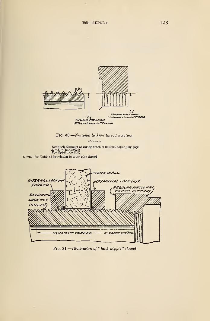
1924 REPORT
Fig. 30.
—
National lo-knut thread notation
NOTATION
E\= pitch diameter at gaging notch of national taper plug gage£e=£i+(4pX0.0625)£i= £i+(5pX0.0625)
Note.—See Table 68 for relation to taper pipe thread
Fig. 31.
—
Illustration of "tank nipple" thread
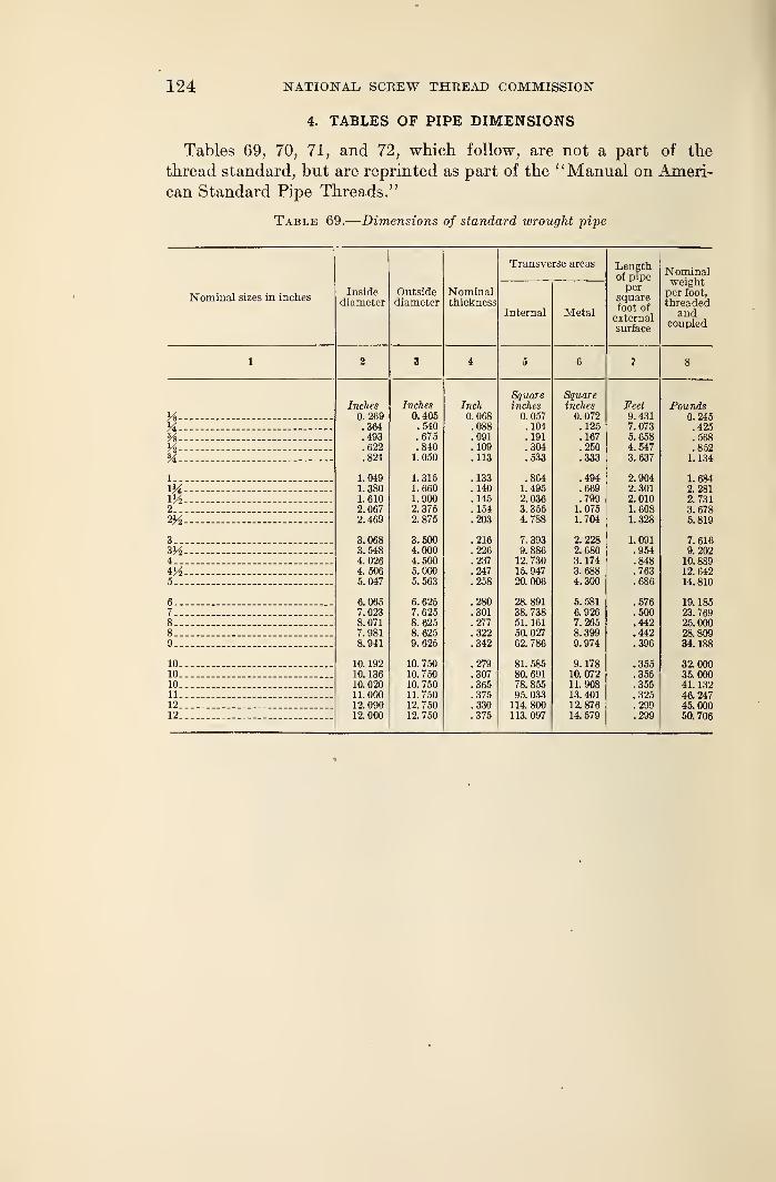
124 NATIONAL SCREW THREAD COMMISSION
4. TABLES OF PIPE DIMENSIONS
Tables 69, 70, 71, and 72, which follow, are not a part of the
thread standard, but are reprinted as part of the "Manual on Ameri-
can Standard Pipe Threads."
Table 69.
—
Dimensions of standard wrought pipe
Nominal sizes in inches
K-%-V*-%-
1__
V4,m2..
3..
4..VA5—
6_.7..8..8..9..
10.10.
10.11.12.12.
Insidediameter
Inches0. 269.364.493.622.824
1.0491. 3801.6102. 0672. 469
3. 0683.5484.0264. 5065.047
6. 0657. 0238.0717.9818. 941
10. 19210. 13610. 02011.00012. 09012. 000
Outsidediameter
Inches0.405.540.675.8401.050
1.3151. 6601. 9002. 3752. 875
5000UU500000
5. 563
6. 6257.6258. 6258.6259.625
10. 75010. 75010. 75011.75012. 75012. 750
Nominalthickness
Inch0.068.088.091.109.113
. 133
.140
.145
. 154
.203
.216
.226
.237
.247
.258
.280
.301
.277
.322
.342
.279
.307
.365
.375
.330
.375
Transverse areas
Internal
Squareinches0.057
. 104
.191
.304
.533
.8641. 4952.0363. 3554.788
7.3939.886
12. 73015. 94720. 006
28.89138. 73851. 161
50. 02762. 786
81. 58580. 69178. 85595. 033
114. 800113.097
Metal
Lengthof pipeper
squarefoot ofexternalsurface
Squareinches
0. 072. 125.167.250.333
.494
.669
.7991. 0751. 704
2.2282.6803. 1743.6884.300
5.5816. 9267.2658.3999. 974
9. 17810.07211. 90813. 40112. 87614. 579
Feet9. 4317.0735. 6584. 5473.637
2.9042.3012.0101. 6081. 328
1. 091.954.848.763.686
.576
.500
.442
.442
.396
.355
.355
.355
.325
.299
.299
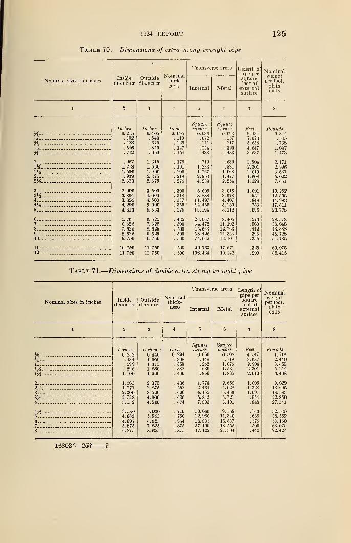
1924 REPORT
Table 70.
—
Dimensions of extra strong wrought pipe
125
Nominal sizes in inches
Ys-X-Ys-
3A-
1-VAm2__
3„VA4.-
4H5-
6..7„8„9..10.
11-12.
Insidediameter
Inches0. 215.302.423.546.742
.9571. 2781.5001. 9392.323
2.9003. 3643. 8264. 2904. 813
5.7616.6257. 6258. 6259.750
10. 75011. 750
Outsidediameter
Inches0. 405.540.675.840
1. 050
1.3151. 6601.9002.3752.875
3.5004.0004.5005. 0005.563
6. 6257. 6258. 6259.625
10. 750
11. 75012. 750
Nominalthick-ness
Inch0. 095.119.126. 147. 154
.179
.191
.200
.218
.276
.300
.318
.337
.355
.375
.432
.500
.500
.500
.500
.500
.500
Transverse areas
Internal
Squareinches
0. 036.072. 141.234.433
.7191.2831. 7672.9534.238
6.6058.888
11. 49714. 45518. 194
26. 06734. 47245. 66358. 42674. 662
90. 763108. 434
Metal
Squareinches0.093
. 157
.217
.320
.433
.639
.8811.0681. 4772.254
3. 0163. 6784. 4075. 1806. 112
8. 40511. 19212.76314. 33416. 101
17. 67119. 242
Length of
pipe persquarefoot ofexternalsurface
Feet9. 4317. 0735.6584.5473.637
2.9042. 3012.0101.6081. 328
1.091.954.848.763.686
.576
.500
.442
.396
.355
.325
.299
Tablti 71.
—
Dimensions of double extra strong wrought pipe
Nominal sizes in inchesInside
diameterOutsidediameter
Nominalthick-ness
Transverse areas
Internal Metal
Length ofpipe persquarefoot ofexternalsurface
Yi-Yi-1—
m2..
VA3_-
4..
5-6„7_.
Inches0. 252.434.599.896
1. 100
1. 5031. 7712. 3002.7283. 152
3. 5804. 0634.8975. 8756.875
Inches0.8401. 0501.3151. 6601. 900
2.3752.8753.5004.0004. 500
5. 0005. 5636. 6257.6258. 625
Inch0.294.308.358.382.400
.436
.552
.600
.636
.674
.710
.750
.864
.875
.875
Squareinches
0. 050.148.282.630.950
1. 7742. 4644. 1555. 8457. 803
10. 06612. 96618. 83527. 10937. 122
Squareinches
0. 504.7181.0761. 5341.885
2.6564.0285. 4666. 7218. 101
9. 56911. 34015. 63718. 55521. 304
Feet4.5473. 6372. 9042.3012. 010
1. 6081. 3281. 091.954.848
.763
.686
.57
.500
.442
16802°—25t 9
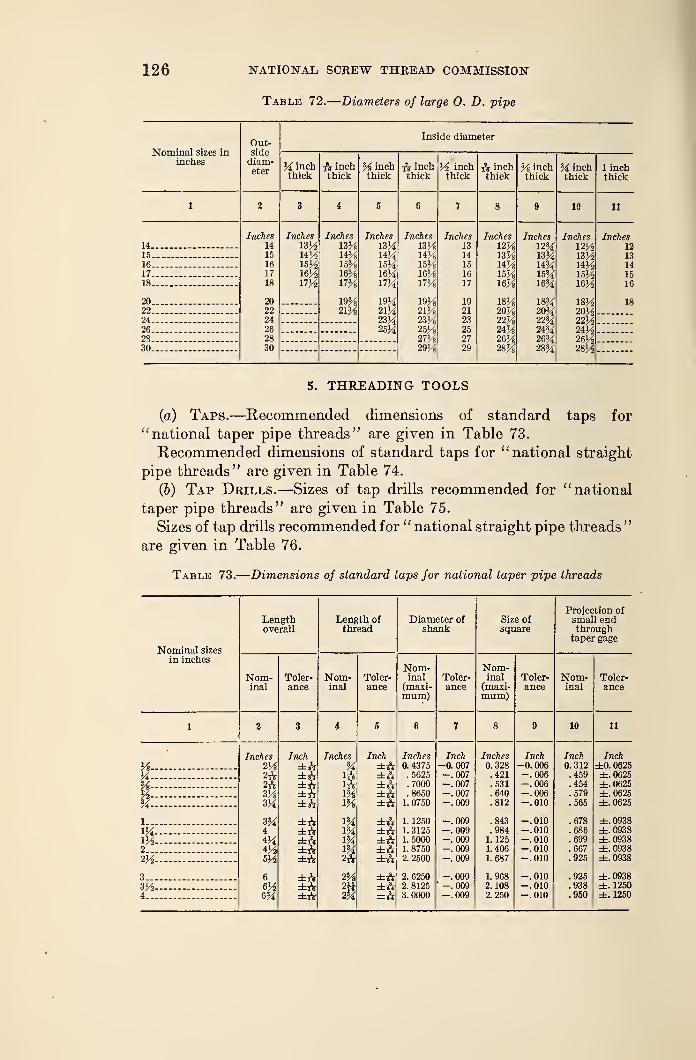
126 NATIONAL SCREW THREAD COMMISSION
Table 72.
—
Diameters of large 0. D. pipe
Nominal sizes ininches
Out-sidediam-eter
Inside diameter
% inchthick
fa inchthick
% inchthick
fa inchthick
% inchthick
fa inchthick
% inchthick
% inchthick
1 inchthick
1 2 3 i 5 8 J 8 9 10 11
Inches14
Inches
izH14%15%16%17%
Inches
13%14%
Inches
13%14%15%16%17%
19%21%23%25%
Inches13%14%15%16%17%
19%21%23%25%27%29%
Inches13
Inches12%13%14%15%16%
18%20%22%24%26%28%
Inches12%13%14%15%16%
18%205422%24%26%28%
Inches12%13%14%15%16%
18%20%22%24%26%28%
Inches1213
14
15-.- 15 14
16 16 15% 15
17- 17 16% 16 1518.... 18 17%
19%21%
17 16
20. 20 19 1822 22 21
24 24 2326 26 2528. 28 2730 30 29
5. THREADING TOOLS
(a) Taps.—Recommended dimensions of standard taps for
"national taper pipe threads" are given in Table 73.
Recommended dimensions of standard taps for " national straight
pipe threads" are given in Table 74.
(&) Tap Drills.—Sizes of tap drills recommended for "national
taper pipe threads" are given in Table 75.
Sizes of tap drills recommended for "national straight pipe threads "
are given in Table 76.
Table 73.
—
Dimensions of standard taps for national taper pipe threads
Projection ofLength Length of Diameter of Size of small endoverall thread shank square through
taper gage
Nominal sizes
in inchesNom- Nom-
Nom- Toler- Nom- Toler- inal Toler- inal Toler- Nom- Toler-inal ance inal ance (maxi- ance (maxi- ance inal ance
mum) mum)
1 2 3 i 5 6 7 8 9 10 11
Inches Inch Inches Inch Inches Inch Inches Inch Inch Inch
% 2% ±ft % ±A 0. 4375 -0.007 0. 328 -0.006 0.312 ±0.0625%- - 2rV ±A irV ±A . 5625 -.007 .421 -.006 .459 ±. 0625
%-%
2rV ±& ±A .7000 -.007 .531 -.006 .454 ±. 0625
3% ±A 1% ±A .8650 -.007 .640 -.006 .579 ±. 0625
% 3% ±A 1% ±A 1. 0750 -.009 .812 -.010 .565 ±. 0625
1 3% ±A 1% ±A 1. 1250 -.009 .843 -.010 .678 ±. 0938
1% ----- 4 ±A 1% ±A 1.3125 -.009 .984 -.010 .686 ±.09381%-— 4% ±A 1% ±A 1.5000 -.009 1. 125 -.010 .699 ±.09382 4% ±A 1% ±A 1. 8750 -.009 1. 406 -.010 .667 ±.09382% 5% ±rV 2fa ±A 2.2500 -.009 1. 687 -.010 .925 ±.0938
3.. 6 ±rV 2% ±A 2. 6250 -.009 1.968 -.010 .925 ±.09383% 6% ±rV 2H ±A 2. 8125 ' -.009 2. 108 -.010 .938 ±. 1250
4 6% ±rV 2% ±A 3.0000 -.009 2. 250 -.010 .950 ±. 1250
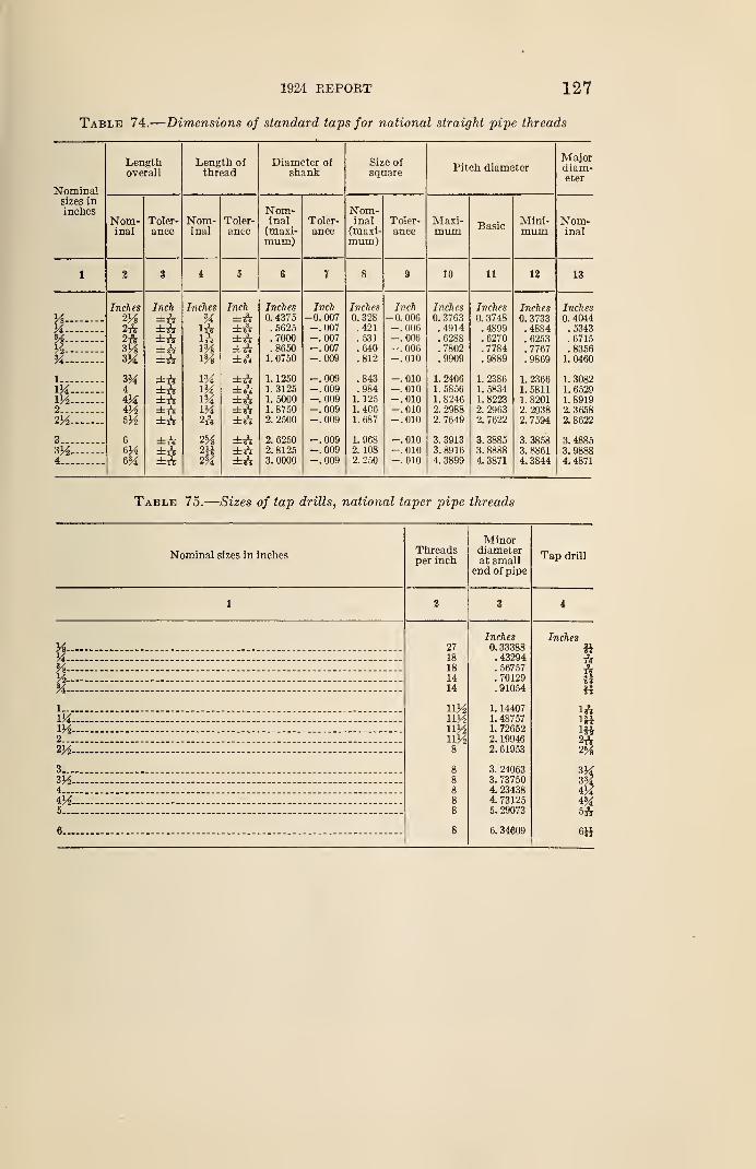
1924 KEPOBT 127
Table 74.
—
Dimensions of standard taps for national straight pipe threads
Nominalsizes ininches
Lengthoverall
Nom-inal
Toler-ance
Length ofthread
Nom-inal
Toler-ance
Diameter ofshank
Nom-inal(maxi-mum)
Toler-ance
Size ofsquare
Nom-inal(maxi-mum)
Toler-ance
Pitch diameter
Maxi-mum Basic
Mini-mum
Majordiam-eter
Nom-inal
10 11 12 13
Ys-
k-
A-*A-
l._
IKVA2__m3__
VA4.-
Inches
2A2rVzy»
3M
3M4i lAiA
6A
Inch
±A±A±A±A±A±A±A±A±A±A±ft±tV±A
InchesSA1AIf.1%1J*
154
1M
2A
2%2tt2%
Inch=fcA
±A±A±A±A±A±A±A±A±A±A±A±A
Inches0. 4375.5625.7000.8650
1. 0750
1. 12501. 31251. 50001. 87502. 2500
2. 62502. 81253. 0000
Inch-0. 007-.007-.007-.007-.009
-. 009-.009-.009-.009-.009
-.009-.009-.009
Inches0. 328.421.531.640.812
.843
.9841. 1251. 4C61.687
1. 9682. 1082. 250
Inch-0. 006-.006-.006-.006-. 010
-.010-.010-.010-.010-.010
-.010-.010-.010
Inches0. 3763.4914.6288.7802.9909
1. 24061. 58561. 82462. 29882. 7649
3. 39133. 89164. 3899
Inches0. 3748.4899. 6270.7784
1. 23861. 58341. 82232. 29632. 7622
3. 38853. 88884. 3871
Inches0. 3733.4884.6253.7767
1.23665811820129387594
3. 38583. 88614. 3844
Inches0. 4044
. 5343
.6715
.83561.0460
1. 30821. 6529891936588622
.48853.
3.98884. 4871
Table 75.
—
Sizes of tap drills, national taper pipe threads
Nominal sizes in inchesThreadsper inch
Minordiameterat small
end of pipe
Tap drill
Ys-A-
A-
1...
VA.m2...
iYz.
3...
4...
iA5...
6...
27181814
14
UAiVAnAny28
88
Inches0. 33388.43294. 56757. 70129. 91054
1. 14407L 487571. 726522. 199462. 61953
3. 240633. 737504. 234384. 731255. 29073
6. 34609
Inches
aAA14
1A
m2A
V4iAi'A
5A
6»
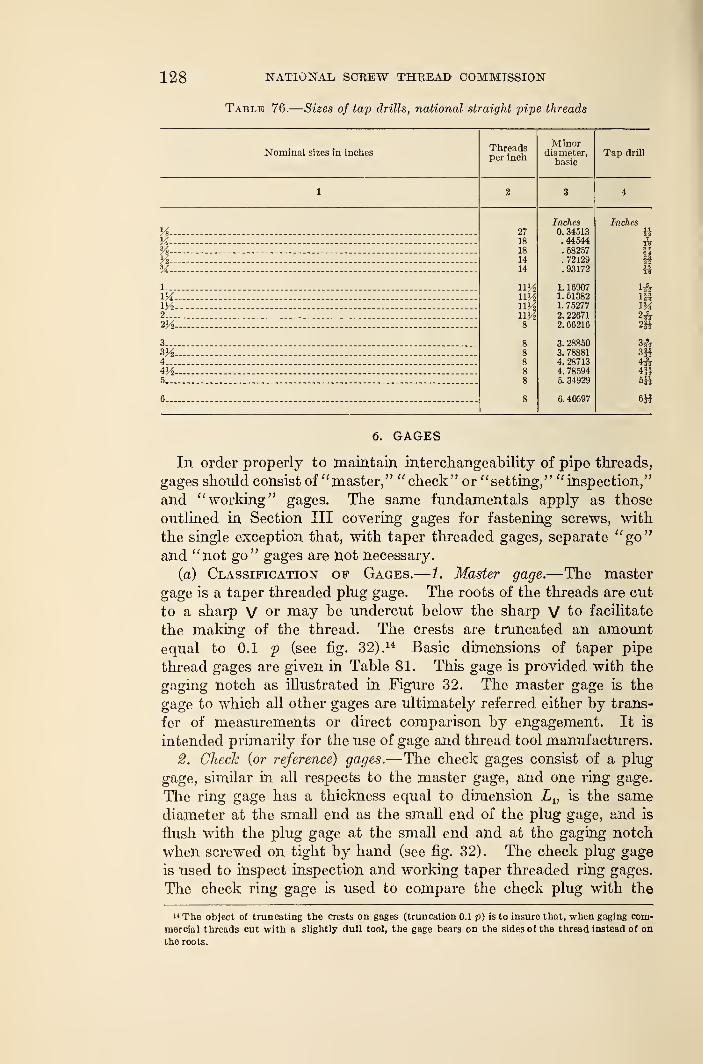
128 NATIONAL SCKEW THREAD COMMISSION
Table 76.
—
Sizes of tap drills, national straight pipe threads
Nominal sizes in inchesThreadsper inch
Minordiameter,
basic
Vi-
y2-SA-
1...
m2...
3__.
3Ji4...
5...
6—
2718
18
1414
ny2uy2
Inches0. 34513.44544. 58257.72129. 93172
1. 169071. 513821. 752772. 226712. 66216
2885078881287137859434929
6. 40597
6. GAGES
In order properly to maintain interchangeability of pipe threads,
gages should consist of "master," " check" or "setting," "inspection,"
and "working" gages. The same fundamentals apply as those
outlined in Section III covering gages for fastening screws, with
the single exception that, with taper threaded gages, separate "go"and "not go" gages are not necessary.
(a) Classification of Gages.—1. Master gage.—The master
gage is a taper threaded plug gage. The roots of the threads are cut
to a sharp V or may be undercut below the sharp V to facilitate
the making of the thread. The crests are truncated an amountequal to 0.1 p (see fig. 32) ,
14 Basic dimensions of taper pipe
thread gages are given in Table 81. This gage is provided with the
gaging notch as illustrated in Figure 32. The master gage is the
gage to which all other gages are ultimately referred either by trans-
fer of measurements or direct comparison by engagement. It is
intended primarily for the use of gage and thread tool manufacturers.
2. Check {or reference) gages.—The check gages consist of a plug
gage, similar in all respects to the master gage, and one ring gage.
The ring gage has a thickness equal to dimension Lv is the samediameter at the small end as the small end of the plug gage, and is
flush with the plug gage at the small end and at the gaging notch
when screwed on tight by hand (see fig. 32). The check plug gage
is used to inspect inspection and working taper threaded ring gages.
The check ring gage is used to compare the check plug with the
h The object of truncating the crests on gages (truncation 0.1 p) is to insure that, when gaging com-
mercial threads cut with a slightly dull tool, the gage bears on the sides of the thread instead of on
the roots.
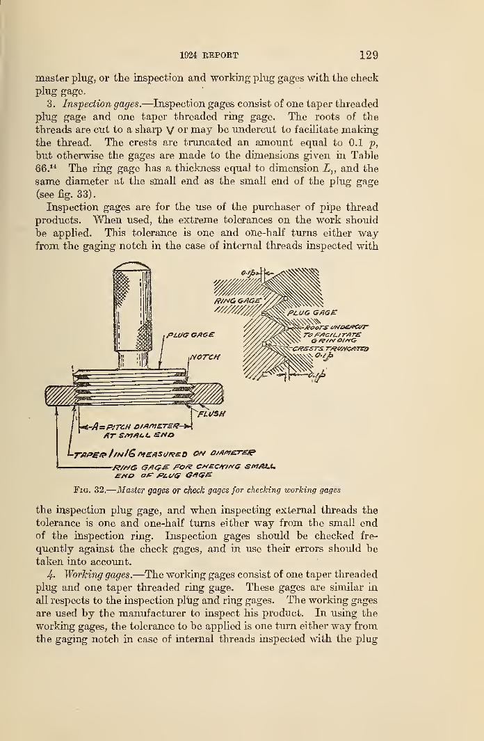
1924 REPORT 129
master plug, or the inspection and working plug gages with the check
plug gage.
3. Inspection gages.—Inspection gages consist of one taper threaded
plug gage and one taper threaded ring gage. The roots of the
threads are cut to a sharp V or may be undercut to facilitate makingthe thread. The crests are truncated an amount equal to 0.1 p,
but otherwise the gages are made to the dimensions given in Table
66.14 The ring gage has a thickness equal to dimension Lv and the
same diameter at the small end as the small end of the plug gage
(see fig. 33).
Inspection gages are for the use of the purchaser of pipe thread
products. When used, the extreme tolerances on the work should
be applied. This tolerance is one and one-half turns either wayfrom the gaging notch in the case of internal threads inspected with
L JPITCH £)/Afi7ET£i?-*m\
JR/A/G G/ICrE AO/? CHECf/KG SMALL.£j*o o/r PLUG G*US&
Fig. 32.
—
Master gages or check gages for checking working gages
the inspection plug gage, and when inspecting external threads the
tolerance is one and one-half turns either way from the small endof the inspection ring. Inspection gages should be checked fre-
quently against the check gages, and in use their errors should be
taken into account.
4- Working gages.—The working gages consist of one taper threaded
plug and one taper threaded ring gage. These gages are similar in
all respects to the inspection plug and ring gages. The working gages
are used by the manufacturer to inspect his product. In using the
working gages, the tolerance to be applied is one turn either way from
the gaging notch in case of internal threads inspected with the plug
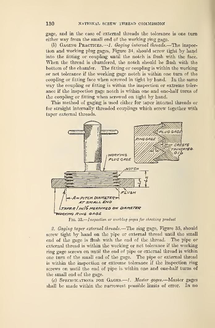
130 NATIONAL SCREW THREAD COMMISSION
gage, and in the case of external threads the tolerance is one tumeither way from the small end of the working ring gage.
(b) Gaging Practices.—1. Gaging internal threads.—The inspec-
tion and working plug gages, Figure 34, should screw tight by handinto the fitting or coupling until the notch is flush with the face.
When the thread is chamfered, the notch should he flush with the
bottom of the chamfer. The fitting or coupling is within the working
or net tolerance if the working gage notch is within one turn of the
coupling or fitting face when screwed in tight by hand. In the sameway the coupling or fitting is within the inspection or extreme toler-
ance if the inspection gage notch is within one and one-half turns of
the coupling or fitting when screwed on tight by hand.
This method of gaging is used either for taper internal threads or
for straight internally threaded couplings which screw together with
taper external threads.
cessrs
A=PITCH DIAMETER--?*
/IT S/*7/H-I- ENDtaps./? //a/16measured o/v Q//wtaref?
Fig. 33.
—
Inspection or working gages for checking product
2. Gaging taper external threads.—The ring gage, Figure 35, should
screw tight by hand on the pipe or external thread until the small
end of the gage is flush with the end of the thread. The pipe or
external thread is within the working or net tolerance if the working
ring gage screws on until the end of pipe or external thread is within
one turn of the small end of the gage. The pipe or external thread
is within the inspection or extreme tolerance if the inspection ring
screws on until the end of pipe is within one and one-half turns of
the small end of the gage.
(c) Specifications for Gages.—1. Master gages.—Master gages
shall be made within the narrowest possible limits of error. In no
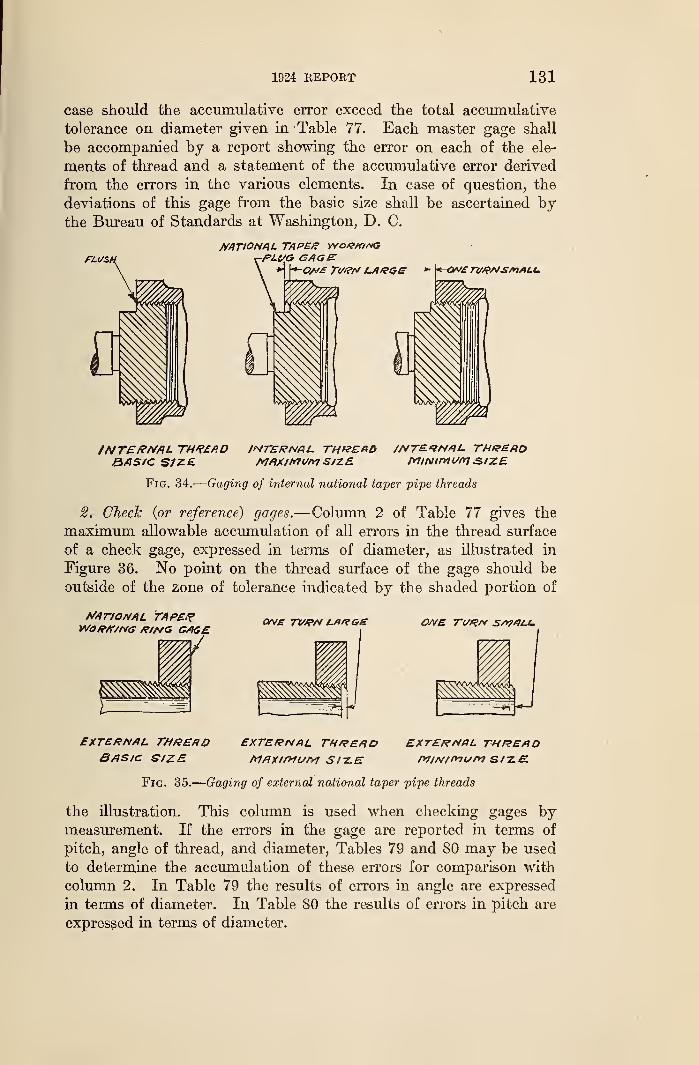
1924 REPORT 131
case should the accumulative error exceed the total accumulative
tolerance on diameter given in Table 77. Each master gage shall
be accompanied by a report showing the error on each of the ele-
ments of thread and a statement of the accumulative error derived
from the errors in the various elements. In case of question, the
deviations of this gage from the basic size shall be ascertained bythe Bureau of Standards at Washington, D. C.
PLUS,
NATIONAL TAPER VYO&/0/VG-PLf/G CAGE
*" \*-QN£ Tt/RN l-A&GG - \*^QN£TVRNS/>1/ILU
/NVERNAL THREADBASIC SfZE
INTERNAL. TH&EABMAXIMUM SIZE
//VTEfNAL. THREADMINIMUM SIZE
Fig. 34.
—
Gaging of internal national taper pipe threads
2. Check {or reference) gages.—Column 2 of Table 77 gives the
maximum allowable accumulation of all errors in the thread surface
of a check gage, expressed in terms of diameter, as illustrated in
Figure 36. No point on the thread surface of the gage should be
outside of the zone of tolerance indicated by the shaded portion of
NATIONAL TAPERWOP/T/NG P/a/G GAGE
ONE TI//?N Lfir?G£ ONE T(/RN S/VAAi.
EXTERNAL THREADBASIC SIZE
EXTERNAL THREADMAXIMUM S/-Z.E
EXTERNAL. THREADMINI1*1ur*1 SIZE.
gages by
Fig. 35.
—
Gaging of external national taper pipe threads
the illustration. This column is used when checking
measurement. If the errors in the gage are reported in terms of
pitch, angle of thread, and diameter, Tables 79 and 80 may be used
to determine the accumulation of these errors for comparison with
column 2. In Table 79 the results of errors in angle are expressed
in terms of diameter. In Table 80 the results of errors in pitch are
expressed in terms of diameter.
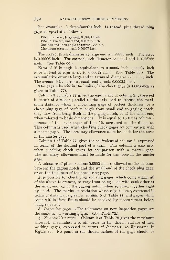
132 NATIONAL SCREW THREAD COMMISSION
For example: A three-fourths inch, 14 thread, pipe thread plug
gage is reported as follows:
Pitch diameter, large end, 0.98881 inch.
Pitch diameter, small end, 0.96775 inch.
One-half included angle of thread, 29° 58'.
Maximum error in lead, 0.00007 inch.
The correct pitch diameter at large end is 0.98886 inch. The error
is 0.00005 inch. The correct pitch diameter at small end is 0.96768
inch. (See Table 66.)
Error of 2' in angle is equivalent to 0.00005 inch. 0.00007 inch
error in lead is equivalent to 0.00012 inch. (See Table 66.) Theaccumulative error at large end in terms of diameter = 0.00023 inch.
The accumulative error at small end equals 0.00025 inch.
The gage falls within the limi ts of the check gage (0.00028 inch as
given in Table 77).
Column 3 of Table 77 gives the equivalent of column 2, expressed
in terms of distance parallel to the axis, and represents the maxi-
mum distance which a check ring gage of perfect thickness, or a
check plug gage of perfect length from small end to gaging notch,
may vary from being flush at the gaging notch, or at the small end,
when referred to basic dimensions. It is equal to 16 times column 2
because of the basic taper of 1 in 16, measured on the diameter.
This column is used when checking check gages by comparison with
a master gage. The necessary allowance must be made for the error
in the master gage.
Column 4 of Table 77, gives the equivalent of column 3, expressed
in terms of the decimal part of a turn. This column is also used
when checking check gages by comparison with a master gage.
The necessary allowance must be made for the error in the master
gage.
A tolerance of plus or minus 0.0002 inch is allowed on the distance
between the gaging notch and the small end of the check plug gage,
or on the thickness of the check ring gage.
It is possible for check plug and ring gages, which come within all
of the above tolerances, to vary from being flush with each other at
the small end, or at the gaging notch, when screwed together tight
by hand. The maximum variation which might occur, expressed in
terms of distance, is given in column 5 of Table 77, and gages which
come within these limits should be checked by measurement before
being rejected.
3. Inspection gages.—The tolerances on new inspection gages are
the same as on working gages. (See Table 78.)
4. New working gages.—Column 2 of Table 78 gives the maximumallowable accumulation of all errors in the thread surface of newworking gages, expressed in terms of diameter, as illustrated in
Figure 36. No point in the thread surface of the gage should be
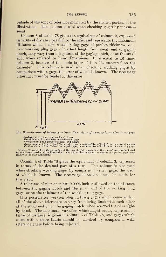
1924 REPORT 133
outside of the zone of tolerance indicated by the shaded portion of the
illustration. This column is used when checking gages by measure-ment.
Column 3 of Table 78 gives the equivalent of column 2, expressed
in terms of distance parallel to the axis, and represents the maximumdistance which a new working ring gage of perfect thickness, or a
new working plug gage of perfect length from small end to gagingnotch, may vary from being flush at the gaging notch, or at the small
end, when referred to basic dimensions. It is equal to 16 times
column 2, because of the basic taper of 1 in 16, measured on the
diameter. This column is used when checking working gages bycomparison with a gage, the error of which is known. The necessary
allowance must be made for this error.
TAPER I irtl&MEASURED ON DtAftl.
AXISC £ B
Fig. 36.
—
Relation of tolerance to basic dimensions of a correct taper pipe thread gage
JE =basic pitch diameter at small end of gage£=minimum pitch diameter at small end of gageC—maximum pitch diameter at small end of gageB= E„—column 2 from Table 77 for check gages, or column 2 from Table 78 for new working gagesC= £o+column 2 from Table 77 for check gages, or column 2 from Table 78 for new working gages
Note.—No point of the thread surface of the gage should be outside of the zone of tolerance indicatedby the shaded portion of the illustration. The dotted line indicates the outline of a perfect gage madeexactly to the basic dimensions.
Column 4 of Table 78 gives the equivalent of column 3, expressed
in terms of the decimal part of a turn. This column is also used
when checking working gages by comparison with a gage, the error
of which is known. The necessary allowance must be made for
this error.
A tolerance of plus or minus 0.0005 inch is allowed on the distance
between the gaging notch and the small end of the working plug
gage, or on the thickness of the working ring gage.
It is possible for working plug and ring gages which come within
all of the above tolerances to vary from being flush with each other
at the small end or at the gaging notch, when screwed together tight
by hand. The maximum variation which might occur, expressed in
terms of distance, is given in column 5 of Table 78, and gages which
come within these limits should be checked by comparison with
reference gages before being rejected.
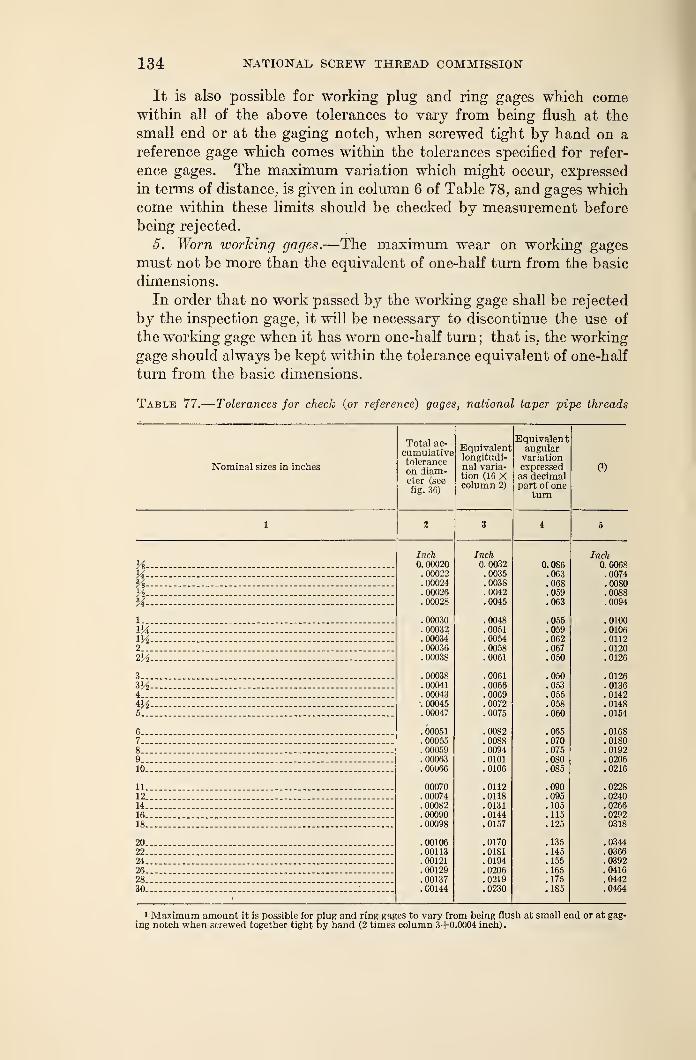
134 NATIONAL SCREW THREAD COMMISSION
It is also possible for working plug and ring gages which comewithin all of the above tolerances to vary from being flush at the
small end or at the gaging notch, when screwed tight by hand on a
reference gage which comes within the tolerances specified for refer-
ence gages. The maximum variation which might occur, expressed
in terms of distance, is given in column 6 of Table 78, and gages whichcome within these limits should be checked by measurement before
being rejected.
5. Worn working gages.—The maximum wear on working gages
must not be more than the equivalent of one-half turn from the basic
dimensions.
In order that no work passed by the working gage shall be rejected
by the inspection gage, it will be necessary to discontinue the use of
the working gage when it has worn one-half turn; that is, the working
gage should always be kept within the tolerance equivalent of one-half
turn from the basic dimensions.
Table 77.
—
Tolerances for chech (or reference) gages, national taper pipe threads
Nominal sizes in inches
Total ac-
cumulativetoleranceon diam-eter (seefig. 36)
Equivalentlongitudi-nal varia-tion (16 Xcolumn 2)
Equivalentangularvariationexpressedas decimalpart of one
turn
(')
Vs-X-%-
M-
1-m2__
2V2
3..
4..
4V25..
6-7„8-9..
lu-
ll.
12.
14.
16.
18.
20.22.
24.
26.28.30.
Inch0. 00020
. 00022
. 00024
. 00026
.00028
.00030
. 00032
. 00034
.00036
. 00038
. 00038
.00041
.00043'. 00045.00047
. 00051
. 00055
. 00059
. 00063
. 00066
00070. 00074. 00082.00090. 00098
. 00106
.00113
.00121
.00129
. 00137
.00144
Inch0. 0032.0035.0038.0042.0045
.0048
.0051
.0054
.0058
.0061
.0061
.0066
.0069
.0072
.0075
.0082
.0088
.0094
.0101
.0106
.0112
.0118
.0131
.0144
.0157
.0170
.0181
.0194
.0206
.0219
.0230
0.086.063.068.059.063
.055
.059
.062
.067
.050
.050
.053
.055
.058
.060
.065
.070
.075
.080
.090
.095
. 105
.115
.125
.135
.145
.155
.165
.175
.185
Inch0.0068.0074.0080.0088.0094
.0100
.0106
.0112
.0120
.0126
.0126
.0136
.0142
.0148
.0154
.0168
.0180
.0192
.0206
.0216
.0228
.0240
.0266
.02920318
.0344
.0366
.0392
.0416
.0442
.0464
1 Maximum amount it is possible for plug and ring gages to vary from being flush at small end or at gag-ing notch when screwed together tight by hand (2 times column 3+0.0004 inch).
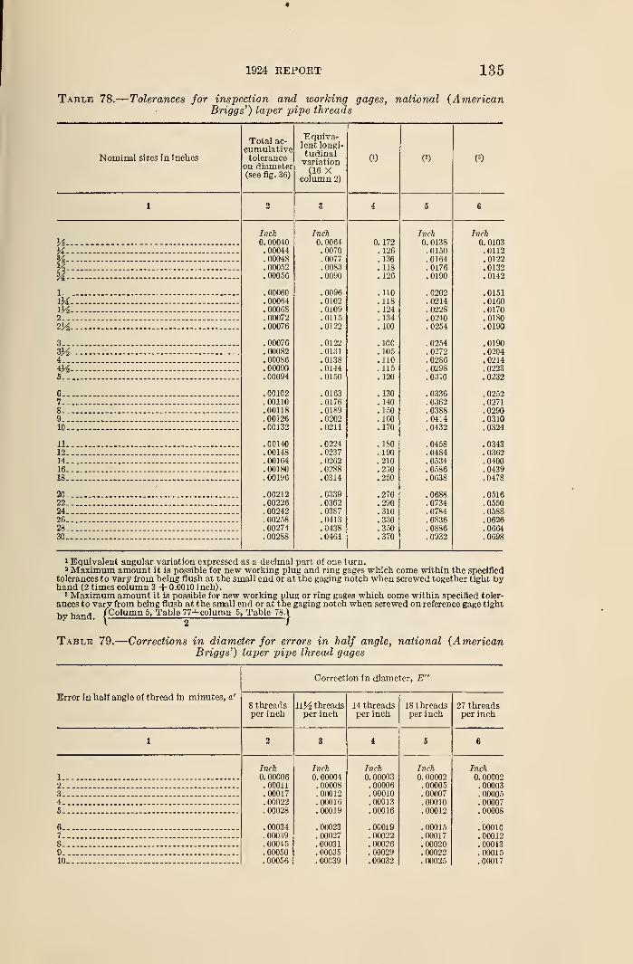
*
1924 REPORT 135
Table 78.
—
Tolerances for inspection and working gages, national (AmericanBriggs') taper pipe threads
Nominal sizes in incbes
i otai ac-
cumulativetolerance
on diameter(see ng. 6b)
Equiva-lent longi-tudinalvariation(16 X
column 2)
(!) (
!)
1 % 3 4 5 6
Inch Inch Inch Inch
H U. UUU4U 0. 0064 0. 172 0. 0138 0. 0103
M flfifXA A. UUU44 . 0070 . 126 . 0150 . 0112
Yi—
-
.00048 .0077 .136 .0164 .0122
Vi%
. 00052 .0083 .118 .0176 .0132
. 00056 . 0090 . 126 . 0190 . 0142
lf\f\C\D{\
. UUUoU . 0096 . 110 . 0202 . 0151134 . 00064 . 0102 . 118 . 0214 . 0160\y2 . 00068 .0109 . 124 .0228 .01702 . 00072 .0115 .134 .0240 .0180m— f\f\f\'~rc
. UuU7o . 0122 . 100 . 0254 . 0190
3 f\nr\iet. UUU/O . 0122
i t\n. 100 . 0254 . 0190
nnnoo. UUUo-S . 0131 . 105 . 0272 . 0204
4 . 00086 .0138 .110 .0286 .021404— .00090 .0144 . 115 .0298 .02235 . uou»4 . 0150 . 120 . 0310 . 0232
6 , 00102 . 0163 . 130 . 0336 . 02527 . 00110 . 0176 . 140 . 0362 . 02718 . 00118 . 0189 . 150 . 0388 . 02909 .00126 .0202 .160 .0414 .031010 .00132 .0211 . 170 . 0432 . 0324
11 . 00140 .0224 .180 .0458 .034312 . 00148 .0237 . 190 .0484 .036214 . 00164 .0262 .210 .0534 .040016 . 00180 . 02S8 .230 .0586 .043918 .00196 .0314 .250 .0638 .0478
20 .00212 .0339 .270 .0688 .051622 . 00226 .0362 .290 .0734 .055024 . 00242 .0387 .310 .0784 .058826 . 00258 .0413 .330 .0836 .062628 . 00274 .0438 .350 .0886 .066430 . 00288 .0461 .370 .0932 .0698
1 Equivalent angular variation expressed as a decimal part of one turn.2 Maximum amount it is possible for new working plug and ring gages wbich come within the specified
tolerances to vary from being flush at the small end or at the gaging notch when screwed together tight byhand (2 times column 3 + 0.0010 inch)
.
3 Maximum amount it is possible for new working plug or ring gages which come within specified toler-
ances to vary from being flush at the small end or at the gaging notch when screwed on reference gage tight
bvhand JColumn 5 -Table 77+column 5, Table 78.\
Table 79.
—
Corrections in diameter for errors in half angle, national (AmericanBriggs') taper pipe thread gages
Error in half angle of thread in minutes, o'
Correction in diameter, E"
8 threadsper inch
ll*A threadsper inch
14 threadsper inch
18 threadsper inch
27 threadsper inch
1 2 3 4 5 6
1
Inch0. 00006.00011.00017. 00022.00028
. 00034
. 00039
. 00045
. 00050
. 00056
Inch0. 00004
. 00008
.00012
.00016
. 00019
. 00023
. 00027
.00031
.00035
.00039
Inch0. 00003.00006.00010.00013. 00016
.00019
. 00022
. 00026
.00029
.00032
Inch0. 00002
. 00005
. 00007
.00010
. 00012
.00015
.00017
. 00020
. 00022
. 00025
Inch0. 00002
. 00003
.00005
. 00007
.00008
.00010
.00012
.00013
.00015
.00017
2..3--45
6--7-8-9..10
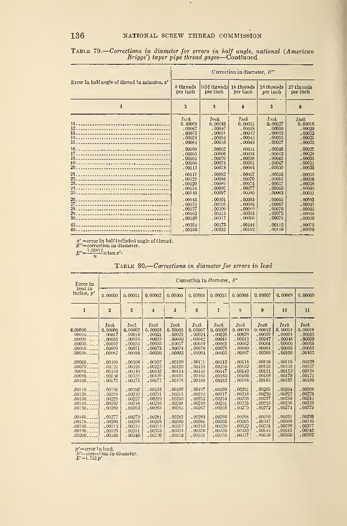
»
136 NATIONAL SCREW THREAD COMMISSION
Table 79.
—
Corrections in diameter for errors in half angle, national (AmericanBriggs') taper -pipe thread gages—Continued
Correction in diameter, E"
Error in half angle of thread in minutes, a'
8 threads 11)4 threads 14 threads 18 threads 27 threadsper inch per inch per inch per inch per inch
n ia J4_
CO
Inch Inch Inch Inch Inch11 0. 00062 0. 00043 0. 00035 0. 00027 0. 0001812 .00067 . 00047 . 00038 .00030 .0002013 .00073 .00051 .00042 . 00032 .0002214. .00078 .00054 . 00045 . 00035 .00023i f\
. 00084 . uuuos nnnQ7. UliUo / . 00025
16 . 00089 .00062 . 00051 .00040 . 0002717 . 00095 .00066 . 00054 . 00042 .0002818 _ .00101 .00070 .00058 .00045 .0003019 .00106 .00074 .00061 .00047 .0003120.. . 00112 . 00078 . 00064 .00050 .00033
21 .00117 .00082 .00087 . 00052 .0003522 .00123 .00086 .00070 . 00055 .0003623 .00129 . 00089 .00074 .00057 .0003824 .00134 . 00093 . 00077 .00060 .0004025. .00140 .00097 . 00080 .00062 .00041
26. - — .00145 . 00101 . 00083 . 00065 .0004327 .00151 .00105 .00086 .00067 .0004528 .00157 .00109 .00089 .00070 .0004629 _ _ .00162 .00113 . 00093 .00072 .0004830 .00168 .00117 .00096 .00075 .00050
45— . 00252 . 00175 .00144 .00112 . 0007560 — — .00336 . 00233 .00192 . 00149 .00099
a' =error in half included angle of thread.E"= correction in diameter.
1.53812^. ,E = Xtan a'-
Table 80.
—
Corrections in diameter for errors in lead
Error inCorrection in diameter, E'
ieaa ininches, p'
0. 00000 0. 00001 0. 00002 0. 00003 0. 00004 0.00005 0. 00006 0.00007 0. 00008 0. 00009
1 2 3 4 5 G 7 8 9 10 11
Inch Inch Inch Inch Inch Inch Inch Inch Inch Inch0.00000 0. 00000 0. 00002 0. 00003 0. 00005 0. 00007 0. 00009 0. 00010 0. 00012 0. 00014 0. 00016.00010 .00017 . 00019 . 00021 .00023 . 00024 . 00026 .00028 . 00029 . 00031 . 00033.00020 . 00035 . 00036 .00038 . 00040 .00042 .00043 . 00045 .00047 . 00048 .00050.00030 . 00052 .00054 .00055 . 00057 . 00059 .00061 . 00062 . 00064 .00066 .00068.00040 . 00069 .00071 . 00073 . 00074 . 00076 . 00078 . 00080 .00081 .00083 . 00085
.00050 . 00087 .00088 .00090 . 00092 . 00094 . 00095 . 00097 . 00099 .00100 .00102
.00060 .00104 .00106 . 00107 . 00109 .00111 .00113 .00114 .00116 .00118 .00120
.00070 .00121 . 00123 . 00125 .00126 . 00128 . 00130 . 00132 . 00133 .00135 . 00137
.00080 . 00139 . 001 10 . 00112 .00144 .00145 . 00147 .00149 .00151 . 00152 . 00154
.00090 .00156 .00158 . 00159 . 00161 . 00163 .00165 .00166 . 00168 .00170 .00171
.00100 .00173 . 00175 . 00177 . 0017S .00180 . 00182 . 00184 . 00185 . 00187 . 00189
.00110 .00191 . 00192 .00194 .00196 .00197 . 00199 .00201 . 00203 . 00204 .00206
.00120 . 00208 .00210 .00211 . 00213 .00215 . 00217 .00218 . 00220 . 00222 . 00223
.00130 . 00225 . 00227 . 00229 . 00230 . 00232 . 00234 . 00236 . 00237 . 00239 . 00241
.00140 .00242 .00244 . 00246 . 00248 . 00249 . 00251 . 00253 . 00255 . 00256 . 00258
.00150 . 00260 . 00262 .00263 .00265 . 00267 . 00268 . 00270 . 00272 . 00274 . 00275
.00160 . 00277 . 00279 . 00281 .00282 . 00284 . 00286 .00288 . 00289 . 00291 . 00293
.00170 .00294 . 00296 . 00298 . 00300 .00301 . 00303 . 00305 . 00307 . 00308 . 00310
.00180 .00312 .00313 .00315 .00317 .00319 . 00320 . 00322 . 00324 .00326 . 00327
.00190 . 00329 . 00331 . 00333 . 00334 . 00336 . 00338 .00339 .00341 . 00343 .00345
.00200 . 00346 . 00348 . 00350 . 00352 . 00353 . 00355 .00357 . 00359 .00360 .00362
p'=error in lead.£'= correction in diameter.£'=1.732p'
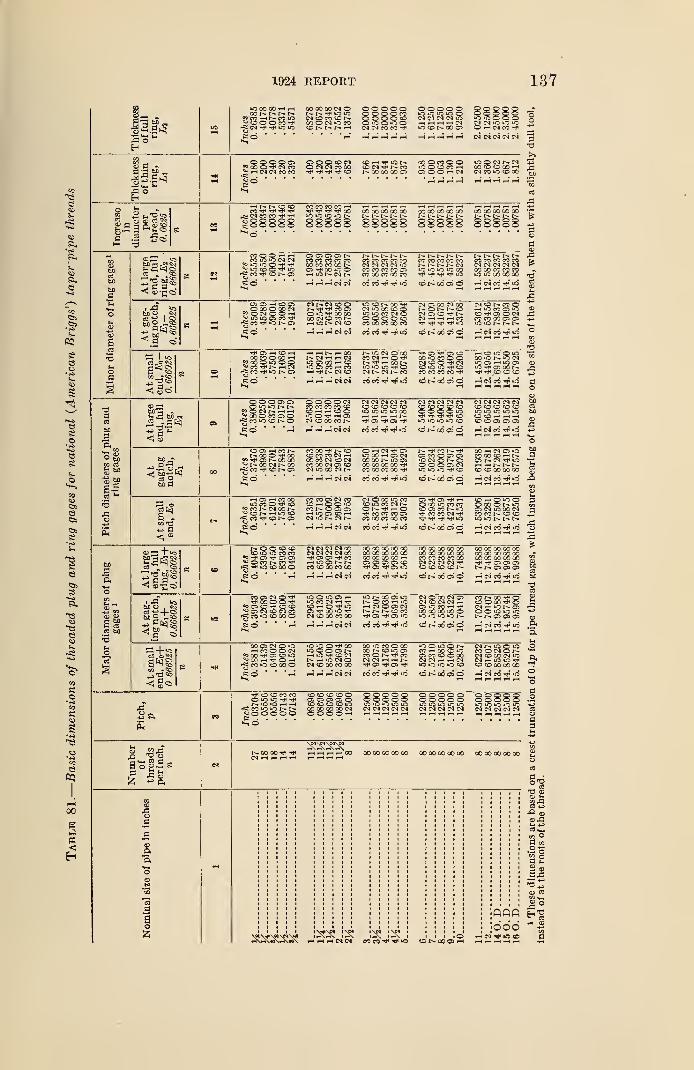
1924 REPORT
BosO
to oo co 1 rH
*5 co i-H r- co to
o .K©
O © O O OS
V -h CM CM CO CO
o o o o oO O O O TOO O O O SOo »o O LC oCM CM CO CO tP
o o o o oin o in o oCJ CM CM CM tO
»o © r- co ©
© © © o ©O O © o oiO lo o o oCJ M iO iO iOO rH CM CO tP
T-l rH rH i—( i—< rH rH rH rH < rH CNCNCNCMCN
o o © © CN© CM CM CO COTp tp Tp ^p co
CO rH Tp lO© CN TP CO00 OO 00 OS
00 O CO © ©CS © © rH CM
iO O N N CN
CM CO lO © CO
3
03 © S OS ©5
I—
I
iHNr»©o co co co co i—
<
_r» CN CO CO Tp t*i
u o © © © ©g © © © © ©
lOiO© © © o o© © © © ©00 00 00 00 00t-- i>. r-- r- r-© © © o ©© © © © ©
00 00 00 00 00t> t» r- t--© o © © ©© © © © ©
00 OO 00 00 00r- j-- r— r--© O o © oo © o o o
t2I
tcs
t- <d K} oCO © © ' >—
<
CO tO tO CM CM*i o m o^ IO CO © TP IO
co co as
eo " ' ""
© os os os r-»CO CO CO CO COoo co co oo r»© oo to ©
t- 1-- 1- t^* 1>-CO CO CO CO COCM CM CM CM IOCO CO CO CO OSCO 00 CO 00 CO
r- r- r^- f- r—CO CO CO CO CO
i - r- t- cmiO to iO iO 00Tp "HH Tp Tp tO
r-- 1-- r— r— r—CO CO CO CO COCN CM CM CM CICO 00 CO CO COto tO OO 00 00
H H H CO CO Tp tP. to © !>. 00 © ©w i-c CM CO tP iO,«i
rH rH rH i—I rH £
if5• 5*
OS © rH © OS© CO © OO CM£3 O CM © © -h^lOiOOSCOH*-fi CO tp iO r- ©
CN CM © ©r- tp Tp co ©o to tp oo oooo © co r-»7-t io cm co
to CO I- 00 -PCM U0 00 CO ©t-O iO CO CI -o© © © © COCO 00 CO 00 CO
CI OS 00 CM 00l-Or-NCDC) OS O t? NCM rH t-H rH COtP -<p tP Tp to
cm co r- co ©•HOCCOS iOco -r os o ClCO CO 00 OS ©lOiONNN
rH rH rH CM CM CO CO tP tP lO © r- 00 © © rH CM CO tP tO
TfCSHCHCO CO © 00 rH
? CO © »o © ©2i CO Tj< t- rH CM
CO Tp tO N- ©
HHNHCOt"- CM rH H CNtO OS CO rH COIO OS CO rH COrH TP r-- CM CO
N ifj (N O COCO CN -H o thHCONtO tO iO th Ocm r- cm co
Tp OS Tp OS ©00 to CO © ©C I CO © tH CNCO IO IO tt< COCO CO CO CO Tp
rH CO IO © tOCO »0 to CNlO OS rH lO OSto tp os oo r—Tp Tp CO © ©
rH t-h i—l CM CM CO CO Tp tp to © I>- 00 © O rH CM CO tp tO
04.
3J3
© © © © ©QiOiONNpOCNNHH« oo © CO © ©^ co to co r— ©
© © © © CNCO CO CO CO ©CO rH rH CO ©tO © Tf rH OSCN CO 00 CO t--
CN CN CM CM CMCD © © © ©iO "O tO tO CO
tH OS Tj< OS tH
CN CM Cl CM CM© © © CO CO© © ©© toTf "f Tj< Tj* COiO iO tO to CO
CM CI CM CM CM© © © © ©LO iO tO iO <o© CO rH r- rH© co OS os OS
rH rH rH rH CM CM CO CO tH tH LO © t- X © © rH CN CO th iO
© os —« cot-- oo © TP CO
55 Tp os oo co^ oo cm ootft CO Tp CO OS
co oo r- co© CO CO CM rH00 CO CM CO CMCO 00 CM OS ©CM O 00 CM
© rH CI TP OStO 00 cs CMco oc r— to osoo oo oo 00 tpCO 00 CO CO tP
t- tp co r— tp© co © © ©© © © © CMtO iO tO Tp CO
CO rH CM OS IOCO 00 © rH I--os cm tp to
© © 00 CO oo
rH rH rH CN CM CO CO TP Tp lO © t~- CO CS O rH CM CO Tp (O rQ
a6!
a< »
rH OS H CO COto CO © tP CO
*s co r-. cm oo^CONiHiQCOCO tP CO t~* OS
CO CO © CM CO© rH O © tOco © os osrH LO © CO rHCN to t— CM
CI © 00 tO CO© to co cm r-ON-J'hOtP CO CO CO ©CO 00 CO 00 CO
OS TT OS Tp rH© 00 to CO COco os co r— totp CO CO CM tpTV* Tp TP Tp LO
CO rH O tO ©© oo © r~ to© CM tO 00 CIco co r-» © ©
HHHNN CO CO Tp TP LO © 00 © © rH CN CO tp lo
3
cp "T"«<j
03^ co
<i ©-no
© © © ©CO tO iO CO COW TP OS TP OS ©
2 © CO t>» CO tPrC£ to CO 00 ©
cm eg 1M CM ooTp OS OS TP COH IOCS NNCO © 00 CO 00
00 00 00 oo og00 OO CO 00 0000' 00 JO 00 rHOS OS OS OS COTp OS TP OS tO
OO 00 CO CO CO00 OO 30 00 COCO CO CO CO oOCM CM (M (M tp© © © © I -
00 00 00 CO COOO CO 00 CO 00CO CO 00 00 QOTP Tp cs OS ©t~— © © OS
rn rH rH CM CM CO CO Tp Tp to ©r>-00©© CM CO tp to CuO
OS <D
S bo
t»DO . C^
be 2 L<p
d Co
CO © CM © tPTP 00 © © -P
55 © © tP co ©OS CM © CI CO
rc; co to co oo ©
tO © lO © rHIO CO C) rH TPCO rH © TP IO
to r— co © toNOrOHicrH CM © © CMr- r>- co cotp as Tp os to
CI O 00 CM OSCM CO CI <M rH© O CO rH TPX -y: '00 oo ©tO to tO tO t—
co 00 tp o© © 00 Tp Ocn rH to r— os© © to to »or~- t^- os cs os
i rH rH CM CM CO CO tP -p iO ©t^-00©©
a^p
<1 go
00 © CM Q torH CO © © CM
=9 CO tp os CO tO^ 00 rH TP O rHco to © oo ©
LO tO O TP QOto © o ©rH tO TP CO CMI"- rH tO CM ©CM © O0 CO 00
CO to CO © COOO t~— CO to OSco © o. Tp coCM CM rH rH r-Tp OS Tp OS Tp
tOOiQONCO rH oo CO «o
§58228»o to tO tO ©
CNN iO C IOCO © CM © NCM CO 00 CM tOCJ IO lO Tp© © CO 00 00
ft
H H H CN CM CO CO Tp rp lO (CNQCOO rH CM CO tp iO ~.rH rH i-H i—I rH rH *S
S© © CO COlO lO Tp TPNlClOHH-C«iOiONNcioOOOO
© © © © ©© © © © ©IO to to to toCM CM CM CN CM
©QOQO© © © © oIO IO to to toCM CM CM CM CM
© © © © ©© © © o ©to to "O to tOCM CM CM CM CM
cd "^arO *g O
r? ft
ooootp TprSrSrfSKHHrtHQO 00 00 00 00 00 O0 00 Q0 00 00 00 00 00 00 00
o.
ft'
—
o
I © rH CM TP to COr^rH\»tiVrH\*»\ rH rH rH CM CM COCCt^tJIiO ©l^OO©^ rHrHrHi-HrH
03
-5apTr,
acv
B3
;6dd^ W ^ to
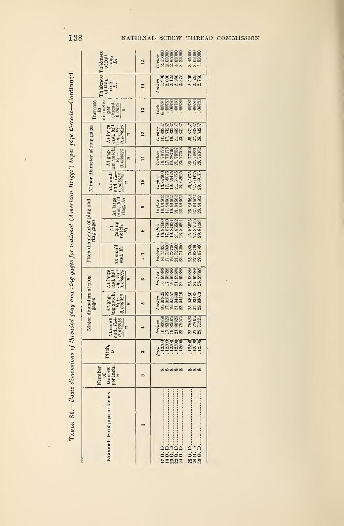
138 NATIONAL SCREW THREAD COMMISSION
1924 REPORT 139
SECTION VII. WOOD SCREWS
This specification summarizes the results of the standardization of
wood screws by the manufacturers in cooperation with the Bureau of
Standards and the technical committee on builders' hardware of the
Federal Specifications Board. It has been officially adopted by the
Federal Specifications Board for the use of all departments and in-
dependent establishments of the Government in the purchase of
wood screws, and published as Circular No. 140 of the Bureau of
Standards.
The former difference of 0.013165 inch in diameter, used as a basis
for the arithmetical progression of the numbering system, has been
discarded in favor of a difference of 0.013 inch (even) as established
by the commission for machine screws. This provides interchange-
ability for the numbered sizes of machine screws and wood screws
in connection with articles that may be fastened either to metal or
wood.
Flat, round, and oval head types are covered in the specification.
The numbered sizes of wood screws run consecutively from No.
(0.060 inch, or 1.5 mm) to No. 24 (0.372 inch, or 9.4 mm), omitting
Nos. 13, 15, 17, 19, 21, 22, and 23.
The number of sizes of brass and steel screws manufactured as
standard have been reduced from 555 to 291, a reduction of 47 per
cent.1. GENERAL SPECIFICATIONS
(a) Material and Workmanship.—Screws shall be made of steel
or brass, as specified, and shall be free from any defects which wouldaffect their serviceability.
(&) Points.—Standard screws shall be furnished with gimlet points.
Cone and diamond pointed screws are special.
(c) Types.—Screws shall be furnished in flat, round or oval
heads as ordered. (See fig. 37.)
(d) Measurements of Lengths.—The length of all screws shall
be measured from the largest diameter of bearing surface of the headto the extreme end of the point measured parallel to the axis of the
screw.
(e) Threaded Length.—Screws shall be threaded approximately
two-thirds of the nominal length.
(/) Measurement of Diameters.—The diameter shall be meas-ured on the body of the screw under the head.
ig) Tolerance on Diameter.—The maximum variation ondiameter permitted is +0.004 and —0.007 inch, or +0.1 and —0.2
mm.
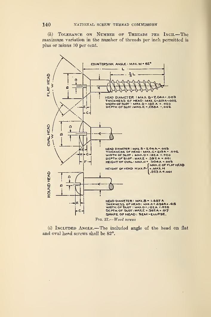
140 NATIONAL SCREW THREAD COMMISSION"
(h) Tolerance on Number of Threads per Inch.—Themaximum variation in the number of threads per inch permitted is
plus or minus 10 per cent.
HEAD DIAMETER : MA X. B * Z.OAA- .0 03THICKNESS OF HEAD : MAX.C-.SI9A-.OOtWIDTH OF SLOT i MAX.D = .I8£A t.020DEPTH OF SLOT : MAX.E. C ,Z.S6A -.OOZ.
HEAD DIAMETER: MA*..6* 2. 04- A. .OOSTHICKNESS OF HEAD: MAX. C >= .619 A - .OOlWIDTH OF SLOT: MAX.D = .1 S2.A +.0"2.0
DEPTH OF SLOT: MAX.E = .592. A -v.OOl
HEIGHT OF OVAL. ". MAX.H = 304A -t.OOSf MAX ,C OF FLAT HEAD
HEIGHT OF HEAD: MAXF'W.MAX.Hy.SZ^ A-KOOI
Fig.
HEAD DIAMETER •• MAX .B * 1-667 ATHICKNESS OF HEAO*. MAX .C - ,6 3SA* .OlSWIDTH OF SLOT : MAX.De.16'2.A f-O-ZO
DEPTH OF SLOT: MAX.E - .3<oZA* .0»7
5HAPE OF HEAD : SEMI -ELLIPSE.
37.
—
Wood screws
(i) Included Angle.—The included angle of the head on flat
and oval head screws shall be 82°.
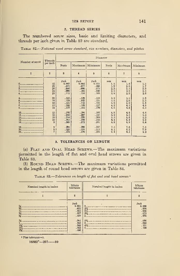
1924 REPORT 141
2. THREAD SERIES
The numbered screw sizes, basic and limiting diameters, andthreads per inch given in Table 82 are standard.
Table 82.
—
National wood screw standard, size numbers, diameters, and pitches
±\ LI 111 iJ\T'L \J I 1 < >sThreadsper inch
Diameter
Basic Maximum Minimum Basic Maximum Minimum
1 1 3 1 5 6 7 8
Inch Inch Inch mm mm mm32 0. 060 0. 064 0. 053 1.5 1.6 1.3
1 28 .073 .077 .066 1.9 2.0 1.72 _ 26 .086 .090 .079 2.2 2.3 2.03.,. 24 .099 .103 .092 2.5 2. 6 2.34 22 .112 .116 . 105 2.8 2.9 2.6
5- 20 .125 .129 .118 3.2 3.3 3.06 18 .138 . 142 .131 3.5 3.6 3.37 _ 16 .151 .155 . 144 3.8 3.9 3.68 15 .164 .168 .157 4.2 4.3 4.09 14 .177 .181 .170 4.5 4.6 4.3
10 13 .190 .194 .183 4.8 4.9 4.611 12 .203 .207 .196 5.2 5.3 5.012 _ 11 .216 .220 .209 5.5 5.6 5.314 10 .242 .246 .235 6.
1
6.2 5.916 9 .268 .272 .261 6.8 6.9 6.6
18 8 .294 .298 .287 7.5 7.6 7.320 8 .320 .324 .313 8.1 8.2 7.924 7 .372 .376 .365 9.4 9.5 9.2
3. TOLERANCES ON LENGTH
(a) Flat and Oval Head Screws.—The maximum variations
permitted in the length of flat and oval head screws are given in
Table 83.
(&) Round Head Screws.—The maximum variations permitted
in the length of round head screws are given in Table 84.
Table 83.
—
Tolerances on length of flat and oval head screws 1
Nominal length in inchesMinus
toleranceNominal length in inches
Minustolerance
1 2 1 2
KInch
0.031.033.035.037.039
.041
.043
.048
.052
.056
2 .'.
Inch0.060.064.068.072.076
.084
.092
. 101
. 109
'A- - —V2 lYi —% 2%>A - - — 3
Vs 3H-— -
1 4
VA 4'AVA - - 5
I'A
1 Plus tolerance=0.
16802°—25t 10
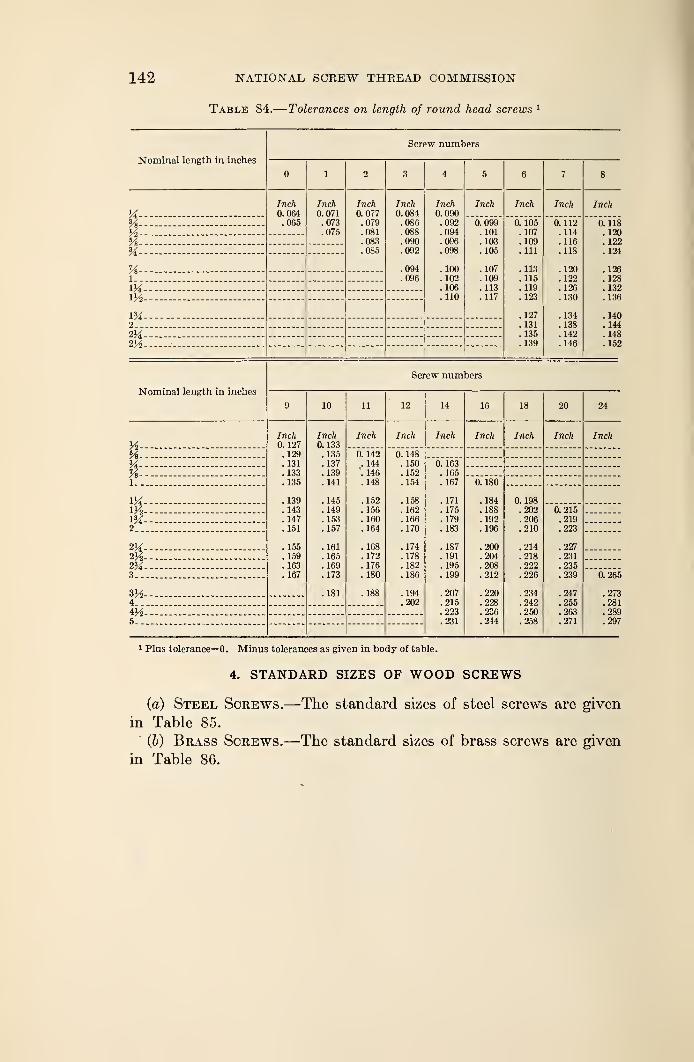
142 NATIONAL, SCREW THREAD COMMISSION
Table 84.— Tolerances on length of round head screws 1
Nominal length in inches
Screw numbers
1 2 3 4 5 6 7 8
Inch0. 064.065
Inch0. 071.073.075
Inch0. 077.079.081.083.085
Inch0. 084.086.088.090.092
.094
.096
Inch0. 090.092.094.096.098
.100
. 102
. 106
. 110
Inch Inch Inch Inch
*A-- - 0.099.101.103. 105
. 107
. 109
.113
.117
6. Vol.107. 109. Ill
.113
.115
.119
. 123
. 127
.131
. 135
.139
0. 112. 114.116.118
. 120
. 122
. 126
.130
.134
. 138
. 142
.146
0. 118
. 120
. 122
.124
. 126
. 128
.132
. 136
. 140
. 144
.148
.152
Yl% —-SAVs- -1
1M -m— -
m —
-
2
2M-- — —
-
2y2 -— -
Nominal length in inches
Screw numbers
9 10 11 12 14 16 18 20 24
k- — Inch0. 127
. 129
.131
. 133
.135
. 139
.143
. 147
. 151
.155
. 159
. 163
.167
Inch0. 133
. 135
.137
. 139
.141
. 145
. 149
. 153
.157
. 161
. 165
. 169
. 173
. 181
Inch Inch Inch Inch Inch Inch Inch
Vs- - 0. 142. 144
". 146. 148
.152
. 156
. 160
. 164
.168
. 172
. 176
.180
.188
0. 148. 150. 152.154
. 158
. 162
. 166
.170
. 174
.178
.182
. 186
.194
.202
- 0. 163. 165. 167
. 171
.175
.179
.183
.187
. 191
. 195
.199
.207
.215
.223
.231
Vs--l-_ 0. 180
.184
.188
. 192
. 196
.200
.204
.208
.212
.220
.228
.236
.244
M— 0. 198
.202
.206
.210
.214
.218
.222
.226
.234
.242
.250
.258
Wv-- - - 0.215.219.223
.227
. 231
.235
.239
.247
.255
.263
.271
XH- -
2--
2H- —23A--3._ 0. 265
.273
.281
.289
.297
3H-4..
5_ _•_
1 Plus tolerance=0. Minus tolerances as given in body of table.
4. STANDARD SIZES OF WOOD SCREWS
(a) Steel Screws.—The standard sizes of steel screws are given
in Table 85.
(6) Brass Screws.—The standard sizes of brass screws are given
in Table 86.
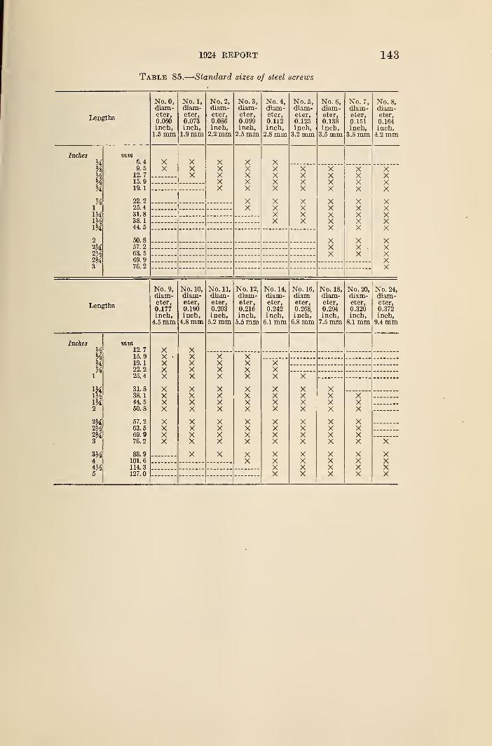
1924 REPORT
Table 85.
—
Standard sizes of steel screws
143
Lengths
No. 0,diam-eter,0.060inch,1.5 mm
No. 1,
diam-eter,0.073inch,
1.9 mm
No. 2,
diam-eter,0.086inch,
2.2 mm
No. 3,diam-eter,0.099inch,
2.5 mm
No. 4,
diam-eter,0.112inch,2.8 mm
No. 5,
diam-eter,0.125inch,
3.2 mm
No. 6,
diam-eter,0.138inch,
3.5 mm
No. 7,diam-eter,0.151inch,
3.8 mm
No. 8,
diam-eter,
0.164inch,4.2 mm
Inches
V*
Vi
A%%Vs
1
V4,mm2
m3
771771
6.49.512.715.919.1
22.225.431.838.144.5
50.857.263.569.976.2
XX
XXX
XXXXX
XXXXX
XX
XXXXX
XXXX
XXXX
XXXX
XXXX
XXXXX
xXX
X XX XV VX
XXXXX
XX •
X
X
XXXXX
XXXXX
Lengths
No. 9,
diam-eter,
0.177inch,
4.5 mm
No. 10,
diam-eter,0.190inch,4.8 mm
No. 11,
diam-eter,0.203inch,5.2 mm
No. 12,
diam-eter,0.216inch,5.5 mm
No. 14,
diam-eter,0.242inch,
6.1 mm
No. 16,
diameter,
0.268.
inch,6.8 mm
No. 18,
diam-eter,0.294inch,7.5 mm
No. 20,
diam-eter,0.320inch,
8.1 mm
No. 24,
diam-eter,0.372inch,
9.4 mm
Inches
%%
1
V/tm
V4.VA2%3
VAi
5
771771
12.715.919.122.225.4
31.838.144.550.8
57.263.569.976.2
88.9101. 6
114.3127.0
XX •
XXX
XXXX
XXXX
XXXXX
XXXX
XXXX
X
XXXX
XXXX
XXXX
X
XXXX
XXXX
XXXX
XX
XXX
XXXX
XXXX
XXXX
X
XXXX
XXXX
XXXX
XXXX
XXXX
XXXX
XXX
XXXX
XXXX
X
XXXX
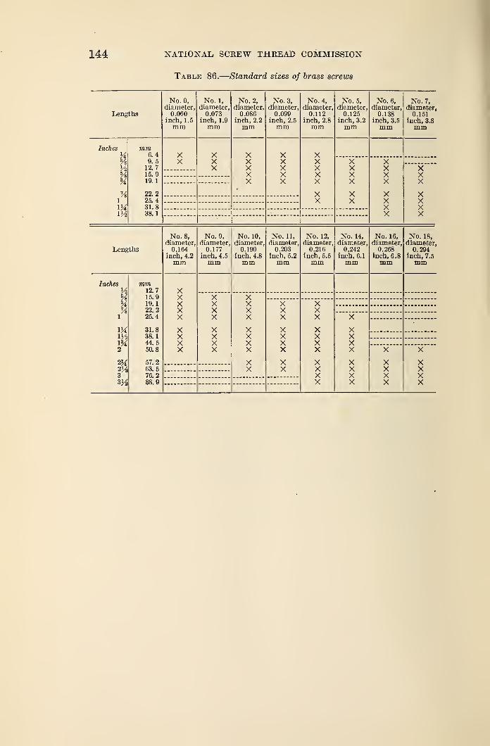
144 NATIONAL SCREW THREAD COMMISSION
Table 86.
—
Standard sizes of brass screws
Lengths
Inches
%A%
imVA
mm6.49. 5
12. 715. 919.1
22.225. 431. 838.
1
No. 0,
diameter,0.060
inch, 1.5
mm
XX
No. 1,
diameter,0.073
inch, 1.9
mm
XXX
No. 2,
diameter,0.086
inch, 2.2
XXXXX
No. 3,
diameter,0.099
inch, 2.5
mm
XXXXX
No. 4,
diameter,0.112
inch, 2.8
mm
XXXXX
XX
No. 5,
diameter,0.125
inch, 3.2
mm
XXXX
XX
No. 6,
diameter,0.138
inch, 3.5
mm
XXXX
XXXX
No. 7,
diameter,0.151
inch, 3.8
mm
XXX
XXXX
Lengths
No. 8,
diameter,0.164
inch, 4.2
mm
Inches
A%H%
l
IX
w2
2J42A3
mm12.715. 919.
1
22. 225.4
31.838.
1
44. 5
50.8
57.263. 5
76. 288.9
XXXXX
XXXX
No. 9,
diameter,0.177
inch, 4.5
XXXX
XXXX
No. 10,
diameter,0.190
inch, 4.8
mm
XXXX
XXXX
XX
No. 11,
diameter.0.203
inch, 5.2
mm
XXX
XXXX
XX
No. 12,
diameter0.216
inch, 5.5
mm
XXX
XXXX
XXXX
No. 14,
diameter,0.242
inch, 6.1
XXXX
XXXX
No. 16,
diameter,0.268
inch, 6.8
X
XXXX
No. 18,
diameter,0.294
inch, 7.5
mm
X
XXXX
APPENDIX 1. DERIVATION OF TOLEPvANCES
1. PITCH DIAMETER TOLERANCES
(a) Tolerances for Fastening Screws.—The tolerances for fastening
screws specified in Section III were arrived at by combining two factors, knownas the net pitch diameter tolerance and the gage tolerance. The theoretical
net tolerances for all screws and nuts of a given class of fit bear a definite mathe-matical relationship to each other, and it was intended that these should in noway be reduced by permissible manufacturing tolerances for master gages; that
is, gages within class X tolerances. Consequently the net tolerances wereincreased by the equivalent diametrical space required to provide for the class Xtolerances on diameter, lead, and angle, to produce the extreme tolerances
specified for the product. In practice, the actual net tolerances will dependupon the method of gaging and upon the accuracy of the gages used.
1. Basis of net tolerances.—The net pitch diameter tolerances for the various
classes of fit are based on the following series for a pitch of fa inch:
Pitch diameter tolerances for pitches finer than -fa inch are to each other
and to the tolerance for -fa inch as the 0.6th power of their respective pitches.
Pitch diameter tolerances for pitches coarser than fa inch are to each other
and to the tolerance for -fa inch as the 0.9th power of their respective pitches.
The exponent 0.6 was chosen for pitches finer than fa inch because the result-
ing tolerances, except in two instances, do not vary more than 0.0001 inch fromthe pitch diameter tolerances specified in the A. S. M. E. Machine Screw Standard.
2. Gage tolerance.—The gage tolerance to be added to the net tolerance to
obtain the extreme tolerance, which determines the absolute limits within which
all variations of the work must be kept, is determined as follows:
Add together the following:
Pitch diameter tolerance of "go" gage,
Diametrical equivalent of lead tolerance of "go" gage,
Diametrical equivalent of angle tolerance of "go" gage,
Pitch diameter tolerance of "not go" gage.
Then subtract the following from the above sum:One-half diametrical equivalent of lead tolerance of "not go" gage.
Diametrical equivalent of angle tolerance of "not go" gage.
(b) Tolerances for Screw Threads of Special Diameters, Pitches,
and Lengths of Engagement.—As stated in Section IV, the pitch diameter
tolerances for special sizes of threads of national form are obtained by adding
three values, or increments; one dependent upon the basic major diameter,
another upon the length of engagement, and the third upon the pitch. Theformulas from which increments are derived are such that if used to derive
tolerances for threads having a length of engagement equal to one diameter
and falling within the regular series of sizes and classification of fits given in
Section III, the resulting values will closely approximate the extreme tolerances
specified in Section III. These formulas are summarized in Table 87.
Class 3, medium fit
Class 4, close fit
Class 1, loose fit
Class 2, free fit_
Inch
0. 0045
. 0030
. 0020
. 0010
145
146 NATIONAL SCEEW THREAD COMMISSION
Table 87.
—
Schedule of tolerance increments for special threads
Special classification of fit Corresponding regular classificationDiameterincrement
Length ofengagementincrement
Pitch in-
crement
1 2 3 1 5
Class A Class 1, loose fit 0.002-vTd
.002-/D
.002V-D
.002-Vo
.001V0
0. 002Q.002Q
.002Q
.002Q
.001Q
0.020 4t>.020 Vp.010 Vp.005 V V.0025Vp
Class B Class 1, loose fit (without allowance).-
Class 2, free fitClass CClass T> Class 3, medium fit--
Class E Class 4, close fit
2. RELATION OF LEAD AND ANGLE ERRORS TO PITCH DIAMETERTOLERANCES
It has been stated in various sections of the report that the tolerances specified
for pitch diameter include all errors of pitch diameter, lead, and angle. Also,
there were tabulated the errors in lead and angle, each of which could be com-pensated for by one-half of the specified pitch diameter tolerances. These
equivalents were derived from definite mathematical relations which are given
below. A rigorous mathematical analysis upon which these formulas are based
is presented in Appendix 3 of Letter Circular No. 23, issued by the Bureau of
Standards.
(a) Diameter Equivalent of Lead Error.—The formula expressing the
relation between lead error between any two threads within the length of engage-
ment and its diameter equivalent is as follows:
S'= (±p') cot a,
in which
E' = pitch diameter increment due to lead error,
p'= the maximum lead error between any two of the threads engaged,
a =half-angle of thread.
The quantity E' is always added to the measured pitch diameter in the case of
external thread, and it is always subtracted in the case of an internal thread, re-
gardless of the sign introduced by the lead error p'.
For threads of national form, the above formula reduces to:
£' = 1.7321 p'
(6) Diameter Equivalent of Angle Error.—The general formula expressing
the relation between error in the half angle of thread and its diameter equivalent;
that is, the amount of the pitch diameter tolerance absorbed by such an error is:
cot a'-h
E" sin a cos a±cot a
in which
E"= pitch diameter increment due to error in half-angle,
h = basic thread depth,
a = basic half-angle of thread,
a' = error in half-angle of thread.
The sign of cot a is plus when the half angle of thread is less than nominal, and
minus when the half angle is greater than nominal. By omitting ± cot a from
the formula an approximate mean value for a' or E" is obtained which differs
»
1924 REPOKT
»
147
very little from either extreme value. The commission has, therefore, adopted
for general use the formula:
. , hcot a =-577—=
E sin a cos a
For threads of national form this formula reduces to:
or
cot a =2^r,
3E"=~2 V *an «'
For the form of thread recommended for pipe-thread gages the formula becomes:
,_ 1.53812 pWCOt CL-
OT
„„ 1.53812E = tan a
APPENDIX 2. WIRE METHODS OF MEASUREMENT OFPITCH DIAMETER
Throughout this report emphasis has been placed on pitch-diameter tolerances
and limits, as upon these the fit of a screw thread largely depends. The main-
tenance of these tolerances and limits requires the use of limit thread gages, andthese, in turn, depend upon the absolute values or measurements of master
gages. The measurement of pitch diameter presents certain difficulties which
may result in an uncertainty as to its true value. The adoption of a uniform
practice in making such measurement is, therefore, desirable. The so-called
"three-wire method" of measuring pitch diameter, as here outlined, has been
found to be the most accurate and satisfactory when properly carried out, andis recommended for universal use in the direct measurement of thread plug gages.
1. SIZE OF WIRES
In the three-wire method of measuring pitch diameter small hardened steel
cylinders or wires of correct size are placed in the thread groove, two on one
side of the screw and one on the opposite side, as shown in Figure 38. Thecontact face of the micrometer anvil or spindle over the two wires must besufficiently large in diameter to touch both wires; that is, it must be equal to
or greater than the pitch of the thread. It is best to select wires of such a size
that they touch the sides of the thread at the mid slope, for the reason that the
measurement of pitch diameter is least affected by any error in thread angle
which may be present when such size is used. The size of wire which touches
exactly at the mid slope of a perfect thread of a given pitch is termed the "best-
size" wire for that pitch. Any size, however, may be used which will permit
the wires to rest on the sides of the thread and also project above the top of
the thread.
The depth at which a wire of given diameter will rest in a thread groove depends
primarily on the pitch and included angle of the thread; and secondarily, on the
angle made by the helix, at the point of contact of the wire and the thread, with
a plane perpendicular to the axis of the screw. Inasmuch as variation in the
helix angle has a very small effect in determining the diameter of the wire whichtouches at the mid slope of the thread, and as it is desirable to use one size of
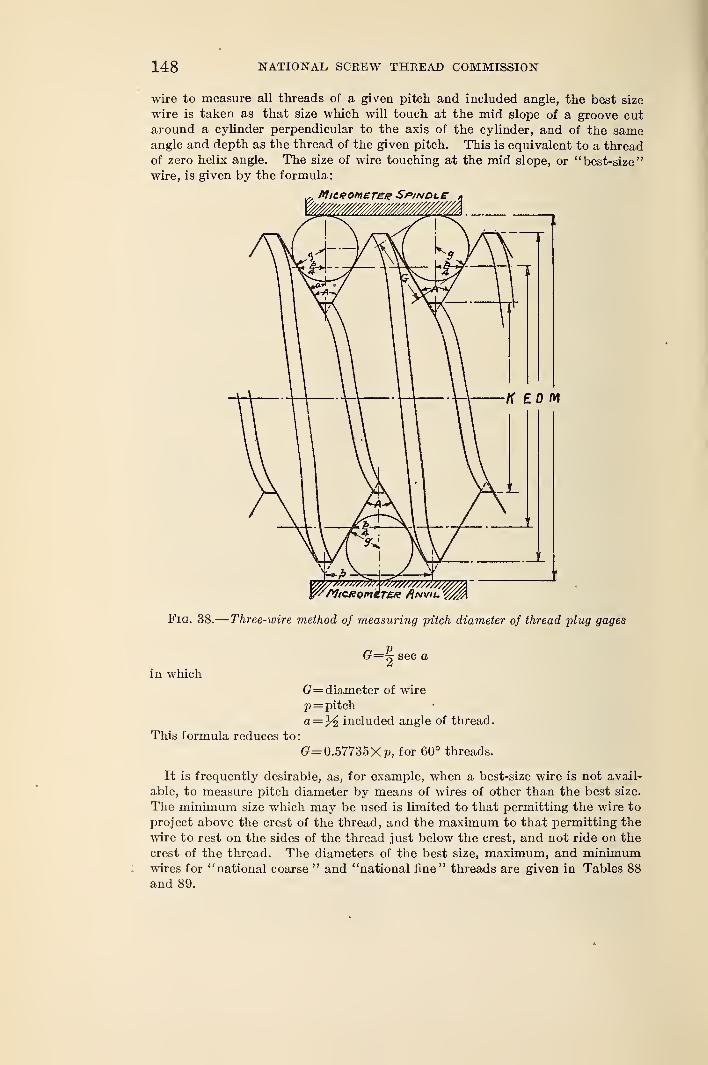
148 NATIONAL SCREW THREAD COMMISSION
wire to measure all threads of a given pitch and included angle, the best size
wire is taken as that size which will touch at the mid slope of a groove cutaround a cylinder perpendicular to the axis of the cylinder, and of the sameangle and depth as the thread of the given pitch. This is equivalent to a threadof zero helix angle. The size of wire touching at the mid slope, or "best-size"
wire, is given by the formula:
r flficeoniEree SptNDt.£ »
YAltCRomiT£R Anvil'
Fig. 38.— Three-wire method of measuring pitch diameter of thread plug gages
in which
This formula reduces to:
G= 2 sec a
G= diameter of wire
p= pitch
a=% included angle of thread.
G= 0.57735 Xp, for 60° threads.
It is frequently desirable, as, for example, when a best-size wire is not avail-
able, to measure pitch diameter by means of wires of other than the best size.
The minimum size which may be used is limited to that permitting the wire to
project above the crest of the thread, and the maximum to that permitting the
wire to rest on the sides of the thread just below the crest, and not ride on the
crest of the thread. The diameters of the best size, maximum, and minimumwires for "national coarse " and "national fine" threads are given in Tables 88
and 89.
1924 REPORT 149
2. SPECIFICATION FOR WIRES
A suitable specification for wires is as follows
:
1. The wires should be cylinders of steel with working surfaces glass hard andaccurately finished.
2. The working surface should be about 1 inch in length, and the wire should
have a suitable handle which is provided at one end with an eye or other suitable
means of suspension.
3. One side of the handle, which should be flattened, should be marked with
the pitch for which the wire is the best size, and with the diameter of the working
part of the wire.
4. The wire should be round within 0.00002 inch and should be straight to
0.00002 inch over any quarter-inch interval.
5. One set of wires should consist of three wires which should have the samediameter within 0.00003 inch, and this common diameter should be within
0.0001 inch of that corresponding to the best size for the pitch for which the wire
is to be used.
3. METHODS OF MEASURING AND USING WIRES
In order to measure the pitch diameter of a screw-thread gage to an accuracy
of 0.0001 inch by means of wires, it is necessary to know the wire diameters to
0.00003 inch. The micrometer to be used for measuring wires should be one
which is graduated to ten-thousandths of an inch and upon which hundred-
thousandths of an inch can be estimated. Such micrometers are available in
various forms of precision bench micrometers, and measuring machines. Care
should be taken to make sure that the measuring faces of the micrometer are
flat and parallel to within 0.00002 inch. The taper of wires can best be deter-
mined by measuring between a flat micrometer contact and a cylindrical anvil.
Any pits or worn spots on the wires can be detected with the same arrangement.
Variations in roundness and straightness are usually determined by rotating the
wire between flat contacts one-fourth inch in diameter. However, one form of
variation in roundness can only be detected by rotating the wire in a V groove
against a flat micrometer contact. The V groove may be the thread space in
a hardened and well-finished thread plug gage.
The contact pressure used in making measurements is also an important
factor, since the wires, when in use, rest on the sides of the thread, and a given
pressure exerted on the top of the thread has a magnified effect in distorting the
wire and causing the measurement of the pitch diameter to be slightly less than
it should be. In making measurements over the wires inserted in the thread
groove, it has been common shop practice to hold the wires down into the thread
by means of elastic bands. This has a tendency to prevent the wires fromadjusting themselves to the proper position in the thread grooves; thus a false
measurement is obtained. In some cases it has also been the practice to support
the screw being measured on two wires, which are in turn supported on a hori-
zontal surface, and measuring from this surface to the top of a wire placed in athread over the gage. If the screw is of large diameter, its weight causes a
distortion of the wires and an inaccurate reading is obtained. For these reasons
these practices should be avoided and subsidiary apparatus for supporting the
wires and micrometer should be used.
A contact pressure of 2 pounds is recommended in making wire measurementsof screw-thread gages. A skilled inspector naturally uses a light pressure or
"feel" in making wire measurements by means of a micrometer caliper. Theactual contact pressure used by a group of inspectors was found to vary from
X to 3 pounds. The effect of variation in contact pressure in measuring threads
150 NATIONAL SCBEW THREAD COMMISSION
of fine pitches is indicated by the difference in readings obtained with 2 and 5
pounds pressure on a 24-pitch thread plug gage. The reading over the wires
with 5 pounds pressure was 0.00013 inch less than with 2 pounds pressure.
Measurements of a thread plug gage made in accordance with these instruc-
tions, with wires which conform to the above specifications, should be accurate
to 0.0001 inch. If the diameters of the wires are known only to an accuracy of
0.0001 inch, an accuracy better than 0.0003 inch in the measurement of pitch
diameter can not be expected.
4. MEASUREMENT OF PITCH DIAMETER OF NATIONAL STRAIGHTTHREADS
The general formula for determining the pitch diameter of any thread whosesides are symmetrical with respect to a line drawn through the vertex and per-
pendicular to the axis of the thread, in which the very slight effect of helix angle is
not taken into account, is
:
15
E=M+^^-G (1+ cosec a)
in whichE= pitch diameter
M= measurement over wires
a= one-half included angle of thread
n=number of threads per inch
G= diameter of wires.
This formula differs from those given in most engineering handbooks in that the
latter, as generally given, yield a result which should check with the major
diameter of the screw measured, while the pitch diameter itself is not mentioned.
For a 60° thread of correct angle and thread form this formula simplifies to
:
£=M+0^60_3_3(?
n
For a given set of best-size wires
E=M-Xwhen
cot aX= G (1+ cosec a) -
2n
The quantity X is a constant for a given thread angle, and, when the wires are
used for measuring threads of the pitch and angle for which they are the best size,
15 The general formula, in which the helix angle is taken into account, is:
cot a S2
E=M-\—^—G (1+cosec a+y cos a cot a)
in which S= tangent of the helix angle.
The value of S, the tangent of the helix angle, is given by the formula:
sL 1
3.1416 £ 3.1416 NEin which
i=leadiV=number of turns per inch
.E=nominal pitch diameter.
In commercial practice the term ( -~- cos a cot a ) is neglected, as its value is small, being in all cases less
than 0.00015 inch for standard fastening screws when the best-size wire is used, and the above formula takes
the simplified form given above. This practice is permissible provided that it is uniformly followed, and in
order to maintain uniformity of practice, and thus avoid confusion, the Bureau of Standards uses the latter
(GS 2 \cos o cot a j exceeds 0.00015 inch, as in the case of Acme
and multiple threads, or other threads having exceptionally large helix angles.
1924 REPORT 151
the pitch diameter is obtained by the simple operation of subtracting this constant
or factor from the measurement taken over the wires. In fact, when best-size
wires are used, this factor is changed very little by a moderate variation or error
in the angle of the thread. Consequently, the factors for the various sets of wires
in use may be tabulated, thus saving a considerable amount of time in the inspec-
tion of gages. However, when wires of other than the best size are used, this
factor changes quite appreciably with a variation in the angle of the thread.
It has been shown that, with the exception of coarse pitch screws, variation in
angle from nominal value causes no appreciable change in the quantity X for the
best-size wires. On the other hand, when a wire near the maximum or minimumallowable size is used, a considerable change occurs, and the values of the cotangent
and cosecant of the actual measured half angle are to be used. It is apparent,
therefore, that there is a great advantage in using wires very closely approximat-
ing the best size. For convenience in carrying out computations, the values of
for standard pitches are given in Table 88.
5. MEASUREMENT OF PITCH DIAMETER OF NATIONAL TAPERTHREADS
The pitch diameter of a taper thread plug gage is measured in much the samemanner as that of a straight thread gage, except that a definite position at which
the measurement is to be made must be located. A point at a known distance
L from the end of the gage is located by means of a combination of precision gage
blocks and the cone point furnished as an accessory with these blocks, as shown in
Figure 39 at A. The gage is set vertically on a surface plate, the cone point is
placed with its axis horizontal at the desired height, and the plug is turned until
the point fits accurately into the thread. The position of this point is marked byplacing a bit of Prussian blue or wax immediately above it. Measurement is
made over the wires in the usual manner, but care must be taken that the contact
surfaces of the micrometer make contact with all three wires, since the micrometer
is not perpendicular to the axis of the screw when there is proper contact. See
Figure 39. On account of this inclination, the measurement over the wires mustbe multiplied by the secant of the half angle of the taper of the thread. Theformula for the pitch diameter of any taper thread plug gage, the threads of whichare symmetrical with respect to a line perpendicular to the axis, then has the
form: 16
E=M sec y+C
2^a~£r (1+cosee a)
in which
E= pitch diameter
M= measurement over wires
y—half angle of taper of thread
n=number of threads per inch=l/pa
=
half angle of thread
G= diameter of wires.
Thus the pitch diameter of a "national (American Briggs') standard pipe thread
gage" having correct angle (60°) and taper (M inch per foot) is then given
by the formula:
#=1.00048 M+0.86603 p-3G
16 See footnote 15.
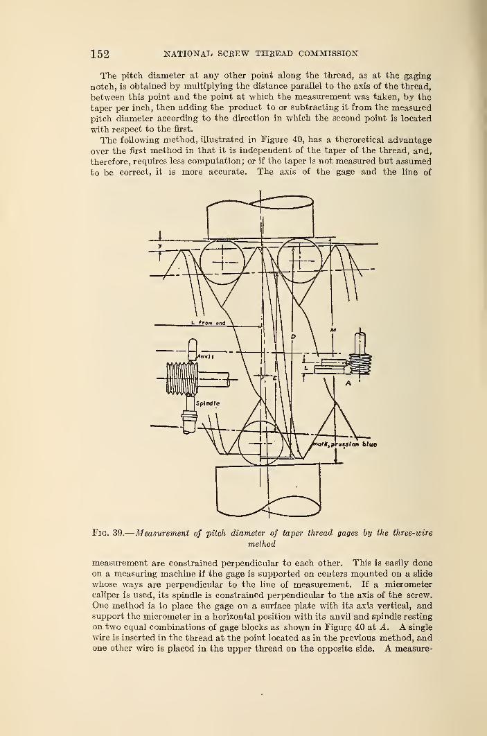
152 NATIONAL SCREW THREAD COMMISSION
The pitch diameter at any other point along the thread, as at the gaging
notch, is obtained by multiplying the distance parallel to the axis of the thread,
between this point and the point at which the measurement was taken, by the
taper per inch, then adding the product to or subtracting it from the measured
pitch diameter according to the direction in which the second point is located
with respect to the first.
The following method, illustrated in Figure 40, has a theroretical advantage
over the first method in that it is independent of the taper of the thread, and,
therefore, requires less computation; or if the taper is not measured but assumed
to be correct, it is more accurate. The axis of the gage and the line of
Fig. 39.
—
Measurement of pitch diameter of taper thread gages by the three-wire
method
measurement are constrained perpendicular to each other. This is easily doneon a measuring machine if the gage is supported on centers mounted on a slide
whose ways are perpendicular to the line of measurement. If a micrometer
caliper is used, its spindle is constrained perpendicular to the axis of the screw.
One method is to place the gage on a surface plate with its axis vertical, andsupport the micrometer in a horizontal position with its anvil and spindle resting
on two equal combinations of gage blocks as shown in Figure 40 at A. A single
wire is inserted in the thread at the point located as in the previous method, andone other wire is placed in the upper thread on the opposite side. A measure-
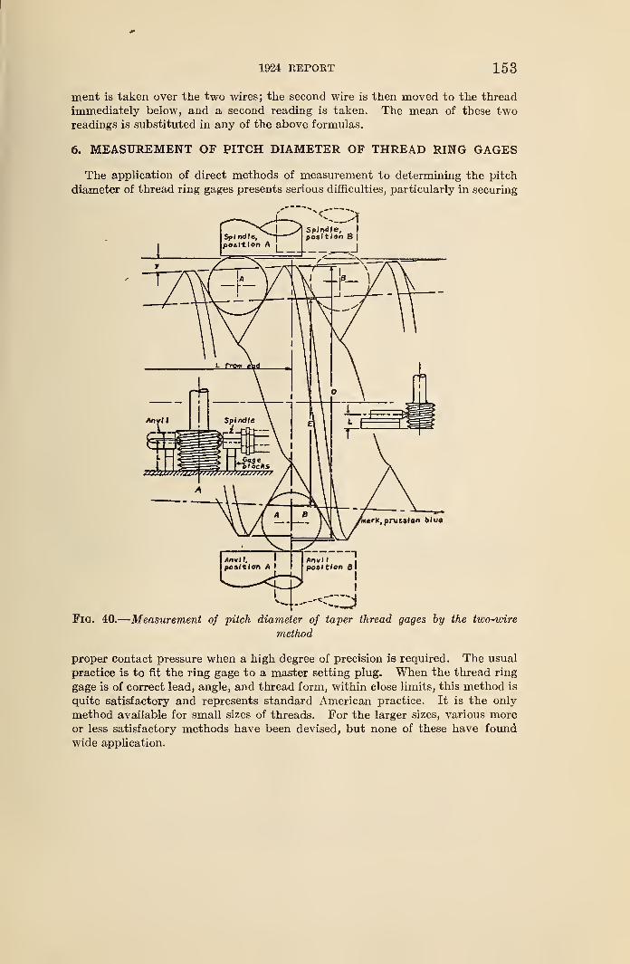
J*
1924 REPORT 153
ment is taken over the two wires; the second wire is then moved to the thread
immediately below, and a second reading is taken. The mean of these tworeadings is substituted in any of the above formulas.
6. MEASUREMENT OF PITCH DIAMETER OF THREAD RING GAGES
The application of direct methods of measurement to determining the pitch
diameter of thread ring gages presents serious difficulties, particularly in securing
Fig. 40.
—
Measurement of pitch diameter of taper thread gages by the two-wire
method
proper contact pressure when a high degree of precision is required. The usual
practice is to fit the ring gage to a master setting plug. When the thread ring
gage is of correct lead, angle, and thread form, within close limits, this method is
quite satisfactory and represents standard American practice. It is the only
method available for small sizes of threads. For the larger sizes, various moreor less satisfactory methods have been devised, but none of these have found
wide application.
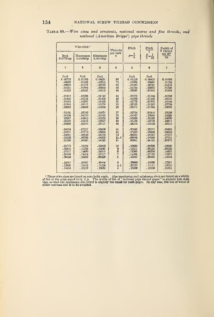
154 NATIONAL SCREW THREAD COMMISSION
Table 88.
—
Wire sizes and constants, national coarse and fine threads, andnational (American Briggs') pipe threads
Wire sizes *
ThreadsPitch Pitch Depth of
2 V threadper inch 1 cot 30°
Best Maximum Minimum u I?= 1
A KTTQ Cf\/r\U.O/ /doUp i.uwoodp U.oOolo^p 2 ™27» 2n
1 % 3 5 j
Inch Inch Inch Inch Inch00722 0. 01263 0. 00631 80 0. 01250 0. 00625 0. 01083
. 00802 . 01403 . 00702 72 . 01389 .00694 . 01203AAOAO A1 K"7C1
. 00789 64 . 01562 . 00781 . 01353. 01031 . 01804 . 00902 56 . 01786 .00893 .01546. 01203 . 02105 . 01052 48 .02083 . 01042 .01804
. 01312 . 02296 .01148 44 . 02273 .01136 . 01968
. 01443 . 02526 . 01263 40 .02500 . 01250 . 02165
. 01604 . 02807 . 01403 36 . 02778 . 01389 . 02406
. 01804 . 03157 . 01579 32 . 03125 . 01562 . 02706
. 02062 . 03608 .01804 28 . 03571 . 01786 . 03093
. 02138 . 03742 . 01871 27 .03704 . 01852 .03208
.02406 .04210 . 02105 24 .04167 . 02083 .036P8. 05052 . 02526 OA
. 05000 . 02500 . 04330. 03208 . 05613 .02807 18 . 05556 . 02778 .04811. 03608 . 06315 . 03157 16 . 06250 .03125 . 05413
.04124 . 07217 . 03608 14 . 07143 . 03571 . 06186
.04441 . 07772 . 03886 13 .7692 . 03846 . 06662
.04811 . 08420 . 04210 12 .08333 .04167 . 07217
. 05020 . 08786 . 04393 11.5 . 08696 .04348 . 07531
. 05249 . 09185 . 04593 11 09091 .04545 . 07873
. 05773 .10104 . 05052 10 .10000 .05000 . 08660
.06415 . 11226 . 05613 9 .11111 . 05556 .09623
. 07217 . 12630 .06315 8 .12500 .06250 . 10825
. 08248 . 14434 . 07217 7 .14286 . 07143 . 12372
.09623 . 16839 . 08420 6 . 16667 .08333 .14434
.11547 . 20207 . 10104 5 .20000 . 10000 . 17321
. 12830 . 22453 . 11226 4.5 . 22222 .11111 .19245
.14434 . 25259 . 12630 4 .25000 . 12500 . 21651
1 These wire sizes are based on zero helix angle. Also maximum and minimum sizes are based on a widthof flat at the crest equal to% X p. The width of flat of "national pipe thread gages " is slightly less thanthis, so that the minimum size listed is slightly too small for such gages. In any case, the use of wires of
either extreme size is to be avoided.
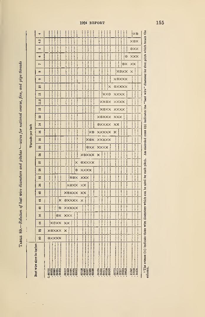
1924 REPORT 155
o.9
oCO
;X®
x®x
®xx
CO ® XXX
r- ®X XX
00 X®XX X
05 x®xxx
o X ®xxxx
XX® xxxx
11.5 xx®x xxxx
CM x®xx xxxx
CO X®XXX XXX
* ®XXXX XX
to X® XXXXX x
00 X®X XXXXX
®xx xxxx
X®XXX X
N X ®xxxx
® xxxx
CO X®X XXX
CDCO X®XX XX
o X®XXX XX
X ®XXXX X
00 ® XXXXX
COto ®X XXX
2#to X0XX XX
X®XXX X
o00 ®XXXX
CP
sa
3
i5o
s>
n
a
3
156 NATIONAL SCREW THREAD COMMISSION
APPENDIX 3. CONTROL OF ACCURACY OF THREAD ELE-MENTS IN THE PRODUCTION OF THREADED PRODUCT
In order to maintain the dimensions of threaded product within the limiting
sizes specified, it is essential that the tools used and the processes applied besuitable for the particular requirements. An analysis of the various factors
controlling the accuracy of the individual thread elements is here presented. In
this analysis, the fundamental factors controlling the accuracy of the elements of
a screw thread are stated, and are followed by a brief discussion of the relationship
of these factors to each of the prevailing commercial methods of producing screw
threads. It is recognized, however, that certain varying factors are involved,
such as lubrication, method of holding the work or tool, sharpness of cutting
edges, etc., so that it is not always possible to predetermine the exact sizes of
the tools required to accomplish the desired results.
Screw threads are usually produced either by cutting or rolling. Five general
methods of cutting, two of rolling, and two of finishing screw threads are in com-mon use.
1. FUNDAMENTAL FACTORS
The accuracy of the individual elements of a thread is controlled mainly as
follows:
Angle by the angle between, and contour of the cutting edges of the tool used
for cutting, or of the sides of the grooves of the die used for rolling.
Lead by the rate of the longitudinal motion of the tool with respect to the rate
of revolution of the part to be threaded.
Major diameter of external thread by the outside diameter of the stock, or by
the forming tool.
Minor diameter of internal thread by the diameter of the hole in the work before
threading. In the case of a drilled hole, this depends on the diameter and accuracy
of grinding of the tap drill used.
Pitch diameter by the radial setting of the forming surface of the tool.
Threadform by the form and position of the tool, and the conditions under which
it is used.
Inspection of the angle and profile of the thread-forming tool is essential to
control the accuracy of the thread produced. The same means and methods can
be applied to such inspection as are applied in the measurement of screw thread
gages and threaded product. Attention is directed to the optical projection
apparatus for measuring angle and lead, and examining profile; the microscope,
which may be readily adapted to shop requirements; and indicating gages, which
may be designed to check the dimensions of threading tools.
The sources of lead errors require special consideration and for this purpose the
methods of producing- screw threads may be considered under two headings,
namely, those in which relative longitudinal motion of the tool and product is
controlled by means of a lead screw, and those in which the tool is self-leading.
(a) Tool Controlled by Lead Screw.—In cutting a thread on a lathe or
other machine embodying a lead screw, using a single point cutting tool or single
milling cutter, progressive lead errors are caused by (1) a progressive lead error
in the lead screw; (2) lack of parallelism of the motion of the cutting tool, the
axis of the lead screw, and the axis of the part to be threaded; and (3) incorrect
ratio of the rate of revolution of the s pindle to that of the lead screw, due to an
incorrect or approximate combination of gears.
Local lead errors are caused by (1) local lead errors in the lead screw; (2) lost
motion in the action of the lead screw or connecting mechanism; (3) varying
frictional resistance in the mechanism; (4) when a live center is used, irregular
1924 REPORT 157
play of its spindle in the bearings; and (5) variations in the amount of metal
removed by the cutting tool.
Periodic lead errors are caused by (1) periodic lead errors in the lead screw;
(2) eccentricity of motion of the lead screw; (3) thrust bearings of spindle or
lead screw running out of true; (4) variations in the spacing of gear teeth, or
eccentric gears or mountings; (5) when a live center is used, eccentricity of motion
of its spindle; and (6) periodic variations in the amount of metal removed, dueto lack of uniformity of the material in diameter, straightness, or physical prop-
erties.
When a multiple-toothed threading tool is controlled by a lead screw, vari-
ations from correct spacing of the teeth of the tool are superimposed on the lead
errors resulting from any of the above causes in that portion of the thread not
passed over by every tooth of the tool. In the portion of the thread completely
passed over by the tool, the effect of the difference in lead between the tool andlead screw is to produce a thin thread.
The simplest method of inspecting a machine tool to determine whether it
will cut a screw thread within satisfactory limits is to cut carefully a sample
screw on the machine and measure the lead errors of the screw. The obvious
remedy for errors from such sources is the careful inspection of the various
elements of the machine, and correction of the errors thus located, either byimproving the design or by carefully refinishing or remaking the parts to a greater
degree of accuracy.
(b) Self-Leading Threading Tool.—When a thread is cut by means of atap or die, which, as ordinarily used, is self-leading and not controlled by a lead
screw, lead errors may occur as the result of: (1) Incorrect lead of the tap or die;
(2) too much or too little relief at the throat of the die or on the chamfer at the
end of the tap; (3) the setting of an adjustable die or tap chaser to cut a thread
considerably larger or smaller than that for which the tool was intended; that is,
to cut a helix angle considerably different from the helix angle of the chaser;
(4) excessive resistance to longitudinal motion; (5) improper alinement of the
axis of the tap or die with that of the work, etc.; and (6) excessive angle relief.
The accuracy of the lead of the tap or of the chasers in the die is the mostdifficult of these sources of error to control, and indeed presents serious dif-
ficulties. There is, first, the difficulty of cutting a tap or chaser which is free
from lead errors resulting from any of the causes outlined above; and second,
the distortion which the steel composing the tap or die undergoes in hardening.
In the inspection of such thread forming tools, practically the same means andmethods can be applied as in the measurement of screw-thread gages. For
checking the lead, indicating gages or some of the usual lead-measuring devices
for screw-thread gages may be used. To measure the lead of a die chaser, the
chaser must be held in a fixture in such a position that the direction of measure-
ment corresponds to the direction of longitudinal motion of the chaser threads
when cutting a thread.
2. CUTTING OF SCREW THREADS
(a) Single-Point Tool.—A screw thread may be produced by traversing a
single-point threading tool—shaped to correspond to the shape of the thread
space in an axial plane, and so placed as to cut an angle, equal to the angle of
the top surface of the tool, in correct relation to the axis of the thread—along
the revolving part to be threaded at such a rate as to produce a thread of the
desired lead. This is the common method of cutting screws in an engine lathe;
a lead screw driven by gearing being the ftsual means for imparting to the tool
the longitudinal motion at the desired rate. This method is used commercially
16802°—25t 11
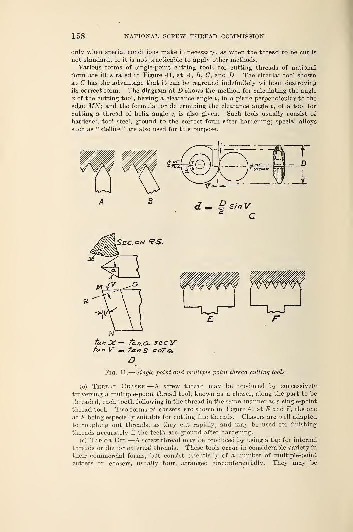
158 NATIONAL SCREW THREAD COMMISSION
only when special conditions make it necessary, as when the thread to be cut is
not standard, or it is not practicable to apply other methods.
Various forms of single-point cutting tools for cutting threads of national
form are illustrated in Figure 41, at A, B, C, and D. The circular tool shownat C has the advantage that it can be reground indefinitely without destroying
its correct form. The diagram at D shows the method for calculating the angle
x of the cutting tool, having a clearance angle v, in a plane perpendicular to the
edge MN; and the formula for determining the clearance angle v, of a tool for
cutting a thread of helix angle s, is also given. Such tools usually consist of
hardened tool steel, ground to the correct form after hardening; special alloys
such as "stellite" are also used for this purpose.
tan DC — fh.n.CL secVfan V = fay/S coTau
DFig. 41.
—
Single point and multiple point thread cutting tools
(b) Thread Chaser.—A screw thread may be produced by successively
traversing a multiple-point thread tool, known as a chaser, along the part to be
threaded, each tooth following in the thread in the same manner as a single-point
thread tool. Two forms of chasers are shown in Figure 41 at E and F, the one
at F being especially suitable for cutting fine threads. Chasers are well adapted
to roughing out threads, as they cut rapidly, and may be used for finishing
threads accurately if the teeth are ground after hardening.
(c) Tap or Die.—A screw thread may be produced by using a tap for internal
threads or die for external threads. These tools occur in considerable variety in
their commercial forms, but consist essentially of a number of multiple-point
cutters or chasers, usually four, arranged circumferentially. They may be
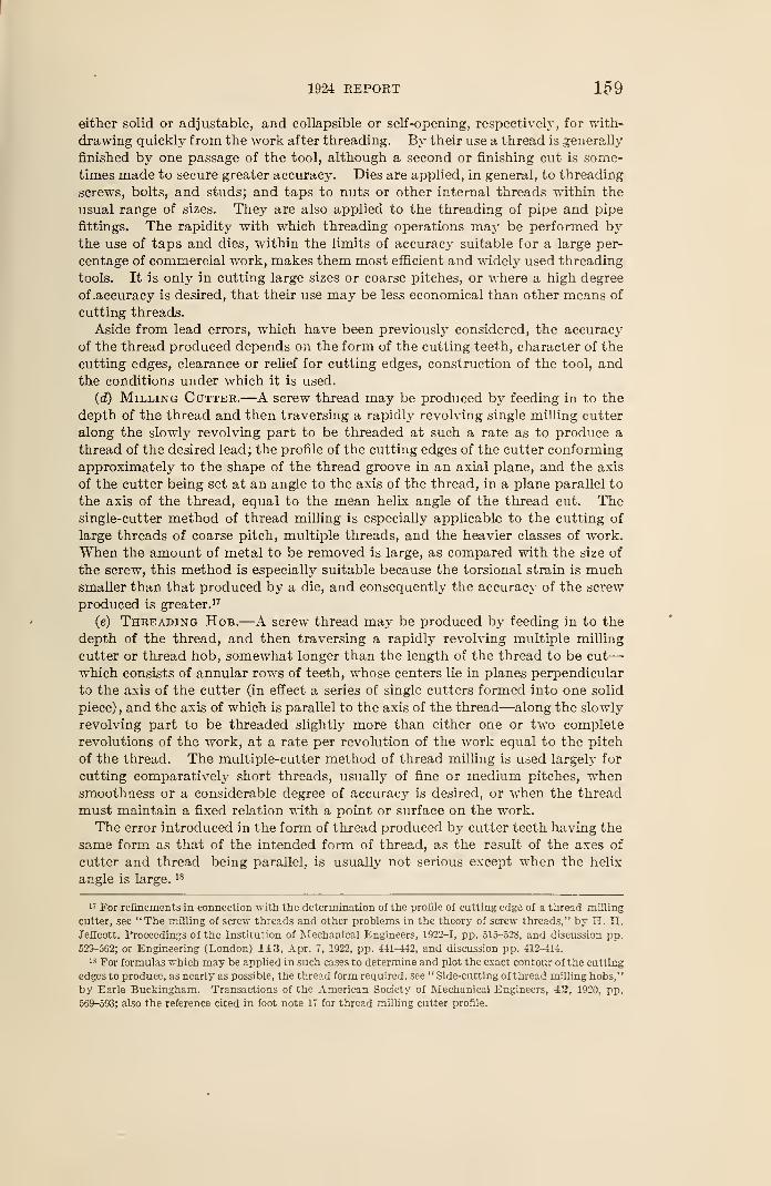
1924 REPORT 159
either solid or adjustable, and collapsible or self-opening, respectively, for with-
drawing quickly from the work after threading. By their use a thread is generally
finished by one passage of the tool, although a second or finishing cut is some-
times made to secure greater accuracy. Dies are applied, in general, to threading
screws, bolts, and studs; and taps to nuts or other internal threads within the
usual range of sizes. They are also applied to the threading of pipe and pipe
fittings. The rapidity with which threading operations may be performed bythe use of taps and dies, within the limits of accuracy suitable for a large per-
centage of commercial work, makes them most efficient and widely used threading
tools. It is only in cutting large sizes or coarse pitches, or where a high degree
of .accuracy is desired, that their use may be less economical than other means of
cutting threads.
Aside from lead errors, which have been previously considered, the accuracy
of the thread produced depends on the form of the cutting teeth, character of the
cutting edges, clearance or relief for cutting edges, construction of the tool, andthe conditions under which it is used.
(d) Milling Cutter.—A screw thread may be produced by feeding in to the
depth of the thread and then traversing a rapidly revolving single milling cutter
along the slowly revolving part to be threaded at such a rate as to produce a
thread of the desired lead; the profile of the cutting edges of the cutter conforming
approximately to the shape of the thread groove in an axial plane, and the axis
of the cutter being set at an angle to the axis of the thread, in a plane parallel to
the axis of the thread, equal to the mean helix angle of the thread cut. Thesingle-cutter method of thread milling is especially applicable to the cutting of
large threads of coarse pitch, multiple threads, and the heavier classes of work.
When the amount of metal to be removed is large, as compared with the size of
the screw, this method is especially suitable because the torsional strain is muchsmaller than that produced by a die, and consequently the accuracy of the screw
produced is greater. 17
(e) Threading Hob.—A screw thread may be produced by feeding in to the
depth of the thread, and then traversing a rapidly revolving multiple milling
cutter or thread hob, somewhat longer than the length of the thread to be cut
—
which consists of annular rows of teeth, whose centers lie in planes perpendicular
to the axis of the cutter (in effect a series of single cutters formed into one solid
piece) , and the axis of which is parallel to the axis of the thread—along the slowly
revolving part to be threaded slightly more than either one or two complete
revolutions of the work, at a rate per revolution of the work equal to the pitch
of the thread. The multiple-cutter method of thread milling is used largely for
cutting comparatively short threads, usually of fine or medium pitches, whensmoothness or a considerable degree of accuracy is desired, or when the thread
must maintain a fixed relation with a point or surface on the work.
The error introduced in the form of thread produced by cutter teeth having the
same form as that of the intended form of thread, as the result of the axes of
cutter and thread being parallel, is usually not serious except when the helix
angle is large. 18
17 For refinements in connection with the determination of the profile of cutting edge of a thread milling
cutter, see "The milling of screw threads and other problems in the theory of screw threads," by H. H.Jeffeott. Proceedings of the Institution of Mechanical Engineers, 1922-1, pp. 515-52S, and discussion pp.
529-562; or Engineering (London) 113, Apr. 7, 1922, pp. 441-442, and discussion pp. 412-411.
18 For formulas which may be applied in such cases to determine and plot the exact contour of the cutting
edges to produce, as nearly as possible, the thread form required, see " Side-cutting of thread milling hobs,"
by Earle Buckingham. Transactions of the American Society of Mechanical Engineers, 42, 1920, pp.
569-593; also the reference cited in foot note 17 for thread milling cutter profile.
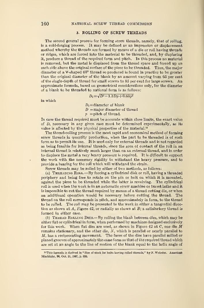
160 NATIONAL, SCREW THREAD COMMISSION
3. ROLLING OF SCREW THREADS
The second general process for forming screw threads, namely, that of rolling,
is a cold-forging process. It may be defined as an impression or displacement
method whereby the threads are formed by means of a die or roll having threads
or ridges, which are forced into the material to be threaded, and, by displacing
it, produce a thread of the required form and pitch. In this process no material
is removed, but the metal is displaced from the thread space and forced up oneach side above the original surface of the piece to be threaded. Thus, the majordiameter of a V-shaped 60° thread so produced is found in practice to be greater
than the original diameter of the blank by an amount varying from 65 per cent
of the single-depth of thread for small screws to 85 per cent for large screws. Anapproximate formula, based on geometrical considerations only, for the diameter
of a blank to be threaded to national form is as follows:
in which
Di= diameter of blank
D = major diameter of thread
p = pitch of thread.
In case the thread required must be accurate within close limits, the exact value
of Di necessary in any given case must be determined experimentally, as its
value is affected by the physical properties of the material. 19
The thread-rolling process is the most rapid and economical method of forming
screw threads in quantity production, when the part to be threaded is of such
form as to permit its use. It is used only for external threads and is not regarded
as being feasible for internal threads, since the area of contact of the roll in aninternal thread is relatively much larger than on an external thread, and in order
to displace the metal a very heavy pressure is required. It is difficult to support
the work with the necessary rigidity to withstand the heavy pressure, and to
provide a bearing for the roll which will withstand the strain.
Screw threads may be rolled by either of two methods, as follows:
(a) Threading Roll.—By forcing a cylindrical disk or roll, having a threaded
periphery and being free to rotate on the pin or bolt on which it is mounted,
against the piece to be threaded while the latter is revolving. The cylindrical
roll is used when the work is in an automatic screw machine or turret lathe and it
is impossible to cut the thread required by means of a thread cutting die, or whenan additional operation would be necessary before cutting the thread. Thethread on the roll corresponds in pitch, and approximately in form, to the thread
to be rolled. The roll may be presented to the work in either a tangential direc-
tion as shown at A, Figure 42, or radially as shown at B; a satisfactory thread is
formed in either case.
(6) Thread Rolling Dies.—By rolling the blank between dies, which may be
either flat or cylindrical in form, when performed by machines designed exclusively
for this work. When flat dies are used, as shown in Figure 42 at C, one die Mremains stationary, and the other die, N, which is parallel or nearly parallel to
M, has a reciprocating movement. The faces of the dies have parallel milled or
planed grooves of approximately the same form as that of the required thread which
are set at an angle to the line of motion of the blank equal to the helix angle of
19 This formula is derived in "Size of stock for bolts having rolled threads," by F. Webster. American
Machinist, 30, Oct. 31, 1907, p. 630.
1924 REPORT 161
the thread to be produced. The angles of the grooves and ridges in a plane per-
pendicular to the direction of the grooves are given by the formula:
Tan ai= tan a cos s
in which
ai= half angle of ridge of die
a =half angle of thread to be rolled
s = helix angle of thread.
The spacing of the ridges is determined by the formula:
Pi= p cos s
in which
Pi= spacing of ridges of die
p = pitch of thread to be rolled
s = helix angle of thread.
The blank is inserted at one end of the stationary die, and rolls between the
die faces until it is ejected at the other; the thread being formed in one passage
of the blank. When cylindrical dies are used, one of the dies, which is a complete
cylinder, revolves continuously in one direction and the other is a stationary
cylindrical segment. This method is used extensively for threading almost all
A
Fig. 42.
—
Methods of rolling screw threads
forms of small and medium sizes of screws and bolts, when required in suffi-
ciently large quantities to warrant the use of a thread rolling machine. 20
4. FINISHING OF SCREW THREADS
On account of the difficulty of producing an accurately finished thread by meansof a cutting tool, in ordinary gage-making practice the thread is lapped, or groundand lapped, in order to finish all elements of the thread to correct dimensions.
The process of grinding is applied to hardened screws only, and is intended to
correct any errors present as the result of distortion in the hardening process,
as well as those resulting from the cutting operation. Lapping is usually applied
to hardened screws threads, and may be either substituted for grinding, or per-
formed after grinding to remove the marks left by the grinding wheel and to
produce a smooth and highly-polished surface. These processes are used largely
in the production of screw-thread gages.
J0 The principles involved in determining the spacing and angle of ridges of flat dies, and position of the
dies, are considered in " Principles of thread rolling and the setting of dies,'' by J. F. Springer, AmericanMachinist, 33, Apr. 21, 1910, pp. 739-741.
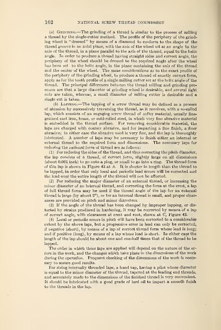
162 NATIONAL SCREW THREAD COMMISSION
(a) Grinding.—The grinding of a thread is similar to the process of milling
a thread by the single-cutter method. The profile of the periphery of the grind-
ing wheel is "dressed" by means of a diamond to conform to the shape of the
thread groove in an axial plane, with the axis of the wheel set at an angle to the
axis of the thread, in a plane parallel to the axis of the thread, equal to the helix
angle. In order to produce a thread having straight sides and correct angle, the
periphery of the wheel should be dressed to the required angle after the wheelhas been set to the helix angle, in the plane containing the axis of the thread
and the center of the wheel. The same considerations as to the exact profile of
the periphery of the grinding wheel, to produce a thread of exactly correct form,
apply as for the tooth profile of a single milling cutter set at the helix angle of the
thread. The principal differences between the thread milling and grinding pro-
cesses are that a large diameter of grinding wheel is desirable, and several light
cuts are taken, whereas, a small diameter of milling cutter is desirable and asingle cut is taken.
(b) Lapping.—The lapping of a screw thread may be defined as a process
of abrasion by successively traversing the thread, as it revolves, with a so-called
lap, which consists of an engaging screw thread of softer material, usually fine-
grained cast iron, brass, or cold-rolled steel, in which very fine abrasive material
is embedded in the thread surface. For removing considerable material, the
laps are charged with coarser abrasive, and for imparting a fine finish, a finer
abrasive; in either case the abrasive used is very fine, and the lap is thoroughly
lubricated. A number of laps may be necessary to finish either an internal or
external thread to the required form and dimensions. The necessary laps for
reducing the national form of thread are as follows:
(1) For reducing the sides of the thread, and thus correcting the pitch diameter,
the lap consists of a thread, of correct form, slightly large on all dimensions
(about 0.001 inch) to go onto a plug, or small to go into a ring. The thread formof this lap is shown in Figure 43 at A. It is shorter in length than the thread to
be lapped, in order that only local and periodic lead errors will be corrected andthe lead over the entire length of the thread will not be affected.
(2) For reducing the major diameter of an external thread, or increasing the
minor diameter of an internal thread, and correcting the form at the crest, a lap
of full thread form may be used if the thread angle of the lap for an external
thread is large (by about 2°) , or for an internal thread is small, and proper clear-
ances are provided on pitch and minor diameters.
(3) If the angle of the thread has been changed by improper lapping, or dis-
torted by strains produced in hardening, it may be corrected by means of a lap
of correct angle, with clearances at crest and root, shown at C, Figure 43.
(4) Local or periodic errors in pitch will have been corrected to a considerable
extent by the above laps, but a progressive error in lead can only be corrected,
if negative (short), by means of a lap of correct thread form whose lead is long;
and if positive (long),by means of a lap whose lead is short. In either case the
length of the lap should be about one and one-half times that of the thread to be
lapped.
The order in which these laps are applied will depend on the nature of the er-
rors in the work, and the changes which take place in the dimensions of the work
during the operation. Frequent checking of the dimensions of the work is neces-
sary to assure good results.
For sizing internally threaded laps, a hand tap, having a pilot whose diameter
is equal to the minor diameter of the thread, tapered at the leading end threads,
and accurately made to the dimensions of the finished thread is very convenient.
It should be lubricated with a good grade of lard oil to impart a smooth finish
to the threads in the lap.
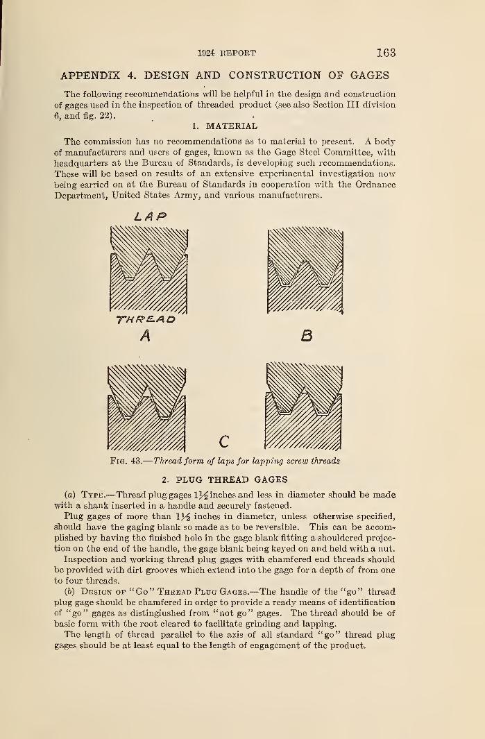
1924 REPORT 163
APPENDIX 4. DESIGN AND CONSTRUCTION OF GAGES
The following recommendations will be helpful in the design and construction
of gages used in the inspection of threaded product (see also Section III division
6, and fig. 22).
1. MATERIAL
The commission has no recommendations as to material to present. A body
of manufacturers and users of gages, known as the Gage Steel Committee, with
headquarters at the Bureau of Standards, is developing such recommendations.
These will be based on results of an extensive experimental investigation nowbeing carried on at the Bureau of Standards in cooperation with the OrdnanceDepartment, United States Army, and various manufacturers.
LAP
A 3
Fig. 43.
—
Thread form of laps for lapping screw threads
2. PLUG THREAD GAGES
(a) Type.—Thread plug gages inches and less in diameter should be madewith a shank inserted in a handle and securely fastened.
Plug gages of more than iy% inches in diameter, unless otherwise specified,
should have the gaging blank so made as to be reversible. This can be accom-plished by having the finished hole in the gage blank fitting a shouldered projec-
tion on the end of the handle, the gage blank being keyed on and held with a nut.
Inspection and working thread plug gages with chamfered end threads should
be provided with dirt grooves which extend into the gage for a depth of from one
to four threads.
(b) Design of "Co" Thread Plug Gages.—The handle of the "go" thread
plug gage should be chamfered in order to provide a ready means of identification
of "go" gages as distinguished from "not go" gages. The thread should be of
basic form with the root cleared to facilitate grinding and lapping.
The length of thread parallel to the axis of all standard "go" thread plug
gages should be at least equal to the length of engagement of the product.
164 NATIONAL SCREW THREAD COMMISSION"
(c) Design of "Not Go" Thread Plug Gages.—All "not go" thread plug
gages should be made to check the pitch diameter only. This necessitates
removal of the crest of the thread, so that the dimension of the major diameter is
never greater than that specified for the "go" gage, and also the removal of the
portion of the thread at the root. • The crest of the thread should be truncated to
to a depth corresponding to a flat equal to p/4 and the groove be widened from a
position one-fourth the depth of the sharp V thread below the pitch diameter line
to the bottom of the V-thread groove. This form of thread checks principally the
pitch diameter and has sufficient gaging surface to provide against rapid wear.
3. RING THREAD GAGES
(a) Type.—All ring thread gages should be made adjustable. The thread
should have the root cleared to facilitate grinding and lapping, and the crest
truncated to correspond to the minor diameter of the internal thread of the
product.
(b) Design of "Go" Thread Ring Gages.—The "go" gage should be dis-
tinguished from the "not go" gage by having a decided chamfer, and both gages
should have their outside diameters knurled if made circular.
(c) Design of "Not Go" Thread Ring Gages.—All "not go" ring thread
gages should be made to check the pitch diameter only. This necessitates
removal of the crest of the thread so that the dimension of the minor diameter is
never less than that specified for the maximum or "go " gage and also the removal
of the portion of the thread at the root of the standard form.
4. PLAIN PLUG GAGES
Plain plug gages of 1*^ inches and less in diameter should be made with a plug
inserted in the handle and securely fastened. Plain plug gages of more than 1}£inches in diameter should have the gaging blank so made as to be reversible.
This can be accomplished by having a finished hole in the gage-blank fitting a
shouldered projection on the end of the handle, the gage blank being held on
with a nut.
The "go" plain plug gage should be distinguished from the "not go" gage byhaving a decided chamfer on the handle of the "go" gage.
5. PLAIN RING GAGES
Both the "go" and "not go" gages should have their outside diameters knurled
if made circular.
The "go" gage should have a decided chamfer in order to provide a ready meansof identification for distinguishing the "go" from the "not go" gage.
6. PLAIN SNAP GAGES
Snap gages may be either adjustable or nonadjustable. It is recommendedthat all snap gages up to and including one-eighth inch be of the built-up type.
For larger snap gages, forge blanks, flat plate stock, or other suitable construc-
tion may be used.
Sufficient clearance beyond the mouth of the gage should be provided to
permit the gaging of cylindrical work.
Snap gages for measuring lengths and diameters may have one gaging dimen-
sion only, or may have a maximum and minimum gaging dimension, both on
one end, or on opposite ends of the gage. When the maximum and minimumgaging dimensions are placed on opposite ends of the gage, the maximum or
"go" end of the snap gage should be distinguished from the minimum or "not
to" end by having the corners of the gage on the "go" end decidedly chamfered.
1924 REPORT 165
APPENDIX S. FUTURE WORK OF THE COMMISSIONThe following brief summary of the uncompleted projects to which the com-
mission has devoted its attention is presented for the purpose of acquainting the
public with the progress made, and of inviting the cooperation of all interested
parties in bringing as much of this work as possible to a satisfactory conclusion.
While some of these projects are practically completed, others have assumedconsiderable proportions, on account of the variety of interests which must be
considered, and some will undoubtedly require much time to complete. It is
the intention of the commission to issue supplementary reports from time to
time, as additional standardization projects are completed.
1. SCREW THREADS USED IN ELECTRICAL INDUSTRY
Three different forms of thread are in common use on electrical equipment,
each type finding application on a certain class of work, but much confusion
has existed as to their proper uses and combinations. Specifications have been
formulated for the following types of screw threads: (1) Screw threads for con-
duit, and conduit couplings and fittings, (2) special straight pipe threads for
fixtures, (3) fine threads for brass tubing, and (4) rolled threads for screw shells
of electric sockets and lamp bases.
Data regarding item 2 are given in A. S. M. E. Bulletin No. 1525, report on"Straight Pipe Threads" of the Committee on Standardization of Special
Threads for Fixtures and Fittings. Data on item 3 are given in a bulletin
issued by the National Council of Lighting Fixture Manufacturers in 1921.
Data on item 4 are given in A. S. M. E. Bulletin No. 1474, report on "Rolled
Threads for Screw Shells of Electric Sockets and Lamp Bases" of the Com-mittee on Standardization of Special Threads for Fixtures and Fittings.
These specifications will be available in mimeographed form pending the
publication of further sections of this report.
2. BOLT AND NUT PROPORTIONS AND WRENCH OPENINGS
Another project to which the commission has given attention is the standardiza-
tion of bolt and nut proportions, particularly as to the widths across flats, because
of the desirability of reducing the number of sizes of bar stock, dies, and wrenches
necessary.
Several months after the commission undertook this work, the Sectional
Committee on the Standardization of Bolt, Nut, and Rivet Proportions wasorganized under the procedure of the American Engineering Standards Committeewith the Society of Automotive Engineers and the American Society of Mechani-
cal Engineers acting as joint sponsors. To avoid duplication of effort and prevent
the promulgation of two conflicting standards, a subcommittee of the commis-
sion and a subcommittee of the sectional committee have worked in close coopera-
tion in developing proposed standards for wrench-head bolts and nuts.
The results of the work of these subcommittees were published late in 1923 bythe sponsors, as a tentative report of subcommittee No. 2 of the sectional com-mittee entitled "Proposed Standard Sizes of Wrench Head Bolts and Nuts,"
for the purpose of obtaining criticisms and comments of all interested manufac-
turers and users, before the subcommittee made its final report to the sectional
committee. The proposed sizes are intended to supersede all existing standards
of wrench head bolts and nuts, of which a large number have grown up in various
industries and sections of the country. As the result of the adoption of such
standard series of sizes, there will be a marked saving in the number of sizes of
bar stock and of finished bolts and nuts which the manufacturers and dealers
must carry, and in the number of wrenches which the consumer requires to fit
articles produced by the different industries.
166 NATIONAL SCREW THREAD COMMISSION
In fixing tolerances on widths across flats of bolt heads, nuts, and wrenches,
it was intended that a minimum clearance be provided which would assure a fit
of the wrench to the bolt head and nut, and a maximum clearance which wouldnot permit the rounding of the corners of a hexagonal nut or bolt head nor spread-
ing of the wrench jaws.
3. MACHINE SCREW AND STOVE BOLT PROPORTIONS
As in the standardization of bolt and nut proportions and wrench openings, the
same subcommittee of the commission and a subcommittee of the Sectional
Committee on the Standardization of Bolt, Nut, and Rivet Proportions haveworked in cooperation to develop standard dimensions for machine-screw heads.
The proposed standard sizes were published in March, 1924, by the sponsor
bodies as a tentative report of subcommittee No. 3 of the sectional committeeentitled, "Proposed Standard Sizes of Slotted Heads for Machine and WoodScrews." This report is being submitted to all interested manufacturers, dealers,
and users of these products for criticism and comment. This report contains
head sizes for a number of machine screw sizes which are not a part of the national
coarse or national fine thread series. The commission recommends that these
sizes be eliminated.
There has been considerable difficulty in arriving at a satisfactory standard
for stove bolt proportions on account of the difference in the types of manufac-turing equipment used by Eastern and Western manufacturers. This difficulty
is discussed in the above-mentioned report of subcommittee No. 3. Although
the commission has not come to an agreement on head dimensions for stove
bolts, it recommends that thread diameters and pitches conform to the specifica-
tions given in Section III of this report for the national coarse thread series,
class 1, loose fit.
4. OIL-WELL CASING THREADS
One of the special problems brought to the attention of the commission wasthe great need for standardization of oil-well casing threads. Definite worktoward such standardization was initiated by the Mid-Continent Oil and GasAssociation, in 1921, but this was complicated by a proposal to simplify casing
sizes and weights, and provide new standard sizes of nesting casing required
for the deeper well drilling which is now necessary. Certain manufacturers have
also endeavored to come to an agreement on thread standards, and a further
influence toward that end has been the fostering of standardization of oil-field
equipment by the American Petroleum Institute, and by Purchasing Agents'
Associations.
Aside from the variety of casing sizes, further complications arise from the
fact that three tapers and three or four pitches have been in use. Through the
cooperative efforts of the American Petroleum Institute, the Standardization
Committee of the Mid-Continent Oil and Gas Association, and the commission
the standardization of casing threads has progressed to the point where certain
agreements as to pitches and tapers have been effected. On the larger sizes
8 threads per inch, and on the smaller sizes, 10 threads per inch will be standard,
with the dividing line at about 8 inches diamater of casing. The taper on the
larger sizes will be three-fourths inch per foot, and on the smaller sizes three-
eighths inch per foot, the change in taper and in pitch taking place at the samepoint. The American Petroleum Institute has determined upon a series of
casing sizes which will meet present requirements, and only minor details in the
specifications remain to be developed.
The standardization of oil-well casing and casing threads has an important
bearing on the national defense, and for this reason the commission is very muchgratified with the progress made by the industry in such standardization.
1924 REPORT 167
S. WRENCH FIT OF THREADED STUDS
As announced in the 1921 report, insufficient data were available for the proper
specification of tolerances and allowances (interferences) for class 5, wrench fit.
The commission, in cooperation with the Bureau of Standards, has since col-
lected and compiled much information as to stud fits from technical literature
and by correspondence with manufacturers of automobiles, trucks, gas and steam
engines, tractors, and other types of machinery in which studs are used. While
the information thus obtained was very complete and valuable, the commission
feels it necessary to obtain additional experimental data as to safe and proper
limits for such interferences, on account of the wide variations in commercial
practice as to maximum and minimum interferences.
The Bureau of Standards is conducting a series of tests, and has already
obtained considerable data, in which the relations between pitch diameter inter-
ference, thread form, and assembling torque for representative sizes and pitches
are being determined. The results of a somewhat similar series of tests also have
been submitted by a large automobile manufacturer. As a result of this workthe commission expects to be in a position to make definite recommendations in
the not far distant future.
6. WIRE GAGES, AND STOCK SIZES OF WIRE, METAL SHEET, ANDPLATE
The interest of the commission in sizes of stock for screws, and bolts, and in
tap-drill sizes, led to an investigation of the possibilities for the simplification of
wire gages. The existing confusion in the industries due to the many wire andsheet metal gages in use is well known. One of the causes of uncertainty arising
from the multiplicity of gages in use is the failure on the part of a purchaser to
designate a particular wire gage or to state the decimal size corresponding to the
gage number; also errors frequently occur in transmitting this information. Afurther complication arises from the fact that, in common trade practices, dif-
ferent gages are used for different materials. The result is that, if, for example,
a purchaser who has been accustomed to using a No. 10 steel wire for a certain
purpose should order a No. 10 copper wire for the same purpose, he would receive
a wire of a different diameter. Alleged sharp and dishonest practices arising
from this situation have been brought to the attention of the Department of
Commerce.In the course of its investigation, the commission held a hearing on October 8,
1923, in New York, N. Y., to consider the question. From the discussion at this
hearing and the letters received, the commission has arrived at the following
conclusions:
The following gages are in customary use in the United States:
Designation of gage Material on which gage is used
American Wire, or Brown & Sharpe.. Copper, brass, bronze, and other non-ferrous wires and sheets.
Steel Wire, or Washburn & Moen Steel wire (other than music wire anddrill rod)
.
Birmingham, or Stub's Iron Wire Telegraph and telephone wire, and to
some extent thickness of nonferrous
sheets, and wall thickness of tubing.
Twist drill and steel wire Twist drills and drill rods.
U. S. Standard for sheets and plates,. Sheet and plate iron and steel.
Music wire Piano and other music wire.
Sheet zinc Zinc sheets.
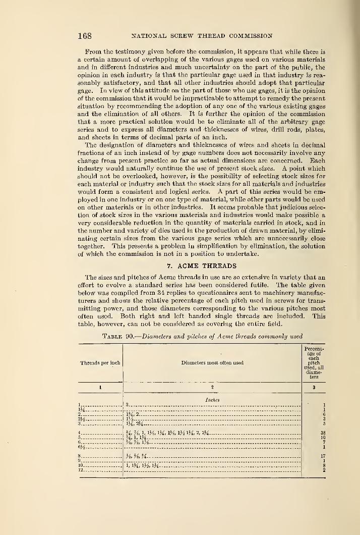
168 NATIONAL SCREW THREAD COMMISSION
From the testimony given before the commission, it appears that while there is
a certain amount of overlapping of the various gages used on various materials
and in different industries and much uncertainty on the part of the public, the
opinion in each industry is that the particular gage used in that industry is rea-
sonably satisfactory, and that all other industries should adopt that particular
gage. In view of this attitude on the part of those who use gages, it is the opinion
of the commission that it would be impracticable to attempt to remedy the present
situation by recommending the adoption of any one of the various existing gages
and the elimination of all others. It is further the opinion of the commission
that a more practical solution would be to eliminate all of the arbitrary gage
series and to express all diameters and thicknesses of wires, drill rods, plates,
and sheets in terms of decimal parts of an inch.
The designation of diameters and thicknesses of wires and sheets in decimal
fractions of an inch instead of by gage numbers does not necessarily involve anychange from present practice so far as actual dimensions are concerned. Eachindustry would naturally continue the use of present stock sizes. A point which
should not be overlooked, however, is the possibility of selecting stock sizes for
each material or industry such that the stock sizes for all materials and industries
would form a consistent and logical series. A part of this series would be em-ployed in one industry or on one type of material, while other parts would be used
on other materials or in other industries. It seems probable that judicious selec-
tion of stock sizes in the various materials and industries would make possible a
very considerable reduction in the quantity of materials carried in stock, and in
the number and variety of dies used in the production of drawn material, by elimi-
nating certain sizes from the various gage series which are unnecessarily close
together. This presents a problem in simplification by elimination, the solution
of which the commission is not in a position to undertake.
7. ACME THREADS
The sizes and pitches of Acme threads in use are so extensive in variety that an
effort to evolve a standard series has been considered futile. The table given
below was compiled from 34 replies to questionaires sent to machinery manufac-
turers and shows the relative percentage of each pitch used in screws for trans-
mitting power, and those diameters corresponding to the various pitches mostoften used. Both right and left handed single threads are included. This
table, however, can not be considered as covering the entire field.
Table 90.
—
Diameters and pitches of Acme threads commonly used
Threads per inch Diameters most often used
Percent-age of
eachpitch
used, all
diame-ters
1 2 3
1
Inches3 1
1
63
5
38107
1
171
82
IX2... m, 2m m3 1X,2X -
4 x, i, iys , ix, \%, m ix, 2, ix —5 X,h IX— - - -
6 54 v», m~ -
6V2
8 J4 54 X— - -
910 i, ix, m, ix12
1924 REPORT
8. OTHER STANDARDIZATION PROJECTS
(a) Tolerance Specifications for Pipe Threads Subject to High Pres-
sures.—The requirements of taper threads for high-pressure work are not as
generally realized as they should be, and attempts are frequently made to use
commercial pipe threads, made to the usual tolerance specifications, with very
unsatisfactory results. An investigation as to tolerances on the individual thread
elements of pipe threads for such purposes is proposed.
(6) Instrument Tubing Threads.—The lack of a universal standard for
threads on brass tubing for instrument work is not as important a question
from the standpoint of the general public as standard threads for tubing for
domestic purposes, for which specifications will be given in the section on screw
threads used in electrical industry. Nevertheless, it would be very desirable
to have definite recommended pitches for various sizes of instrument tubing.^
The French have considered the matter of sufffcient importance to formulate(\
a definite standard for threaded brass tubes for optical instruments, which wasadopted in December, 1916. Very little information is available as to American
practice, but standards are used for certain special purposes, such as threads
on miscroscope objectives, which are to a large extent interchangeable.
(c) Threads on Instrument Screws.—Smaller sizes and finer pitches of
screws than those provided in the national coarse and national fine thread series,
together with the latter, are extensively used in instrument work. Various
manufacturers' standards for the small sizes are in use but there has been noconcerted effort among American manufacturers to adopt a common standard.
(d) Form of Thread for Valve Stems.—From the points of view of the
threading tool and valve manufacturers, it would be desirable to standardize
the form of thread used on valve stems. A variety of forms are now in use,
principally the truncated 60° thread and modified Acme thread.
(e) Threads on Condenser Tube Ferrules.—It has been brought to
the attention of the commission that several different pitches are used on the
same nominal sizes of condenser tube ferrules. This is a source of inconvenience
and expense in making repairs.
(/) Plumbers' Fine Threads.—Fine pitch taper threads on thin-walled brass
tubing are being produced to various plumbing manufacturers' standards. Aunification of these standards is desirable.
(g) Special Threads.—Other threads in use in the United States, for whichstandard specifications may be formulated are the Buttress Thread, HarveyGrip Thread, Knuckle Thread, Square Thread, etc.
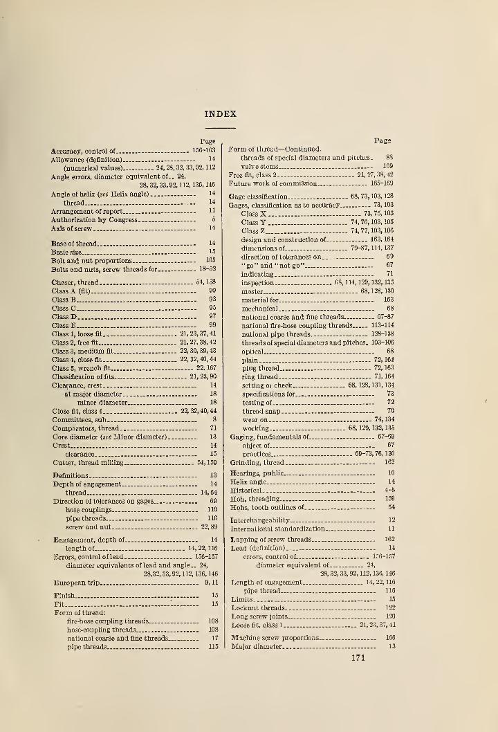
INDEX
Page
Accuracy, control of - 156-163
Allowance (definition) 14
(numerical values).— 24, 28, 32, 33, 92, 112
Angle errors, diameter equivalent of.. 24,
28, 32, 33,92,112,136, 146
Angle of helix (see Helix angle) 14
thread 14
Arrangement of report _ -- HAuthorization by Congress . 5
Axis of screw 14
Base of thread - -- 14
Basic size - 15
Bolt and nut proportions 165
Bolts and nuts, screw threads for 18-52
Chaser, thread 54,158
Class A (fit) 90
Class B 93
Class C 95
Class D - 97
Class E - 99
Class 1, loose fit 21,23,37,41
Class 2, free fit 21,27,38,42
Class 3, medium fit.... 22, 30, 39, 43
Class 4, close fit 22, 32, 40, 44
Class 5, wrench fit 22, 167
Classification of fits 21,23,90
Clearance, crest 14
at major diameter 18
minor diameter 18
Close fit, class 4. 22, 32, 40, 44
Committees, sub 8
Comparators, thread. 71
Core diameter (see Minor diameter) 13
Crest 14
clearance 15
Cutter, thread milling 54, 159
Definitions 13
Depth of engagement 14
thread 14,64
Direction of tolerances on gages 69
hose couplings 110
pipe threads 116
screw and nut 22,89
Engagement, depth of 14
length of 14,22,116
Errors, control of lead 156-157
diameter equivalents of lead and angle.. 24,
28,32, 33, 92, 112, 136, 146
European trip 9, 11
Finish 15
Fit - 1 15
Form of thread:
fire-hose coupling threads 108
hose-coupling threads. 108
national coarse and fine threads 17
pipe threads 115
PageForm of thread—Continued.
threads of special diameters and pitches. 88
valve stems 169
Free fit, class 2 21, 27, 38, 42
Future work of commission 165-169
Gage classification 68, 73, 103, 128
Gages, classification as to accuracy 73, 103
Class X 73,75, 105
Class Y — 74, 76, 103, 105
Class Z 74,77,103, 106
design and construction of 163, 164
dimensions of 79-87,114,137
direction of tolerances on 69
"go" and "not go" 67
indicating 71
inspection 68, 114, 129, 132, 135
master - 68,128, 130
material for - 163
mechanical - 68
national coarse and fine threads 67-87
national fire-hose coupling threads 113-114
national pipe threads. 128-138
threads of special diameters and pitches. 103-106
optical 68
plain 72,164
plug thread.. 72, 163
ring thread 71,164
setting or check 68, 128, 131, 134
specifications for 73
testing of 72
thread snap 70
wear on 74, 134
working 68,129, 132,135
Gaging, fundamentals of 67-69
object of 67
practices 69-73,76,130
Grinding, thread 162
Hearings, public... 10
Helix angle 14
Historical 4-5
Hob, threading 159
Hobs, tooth outlines of 51
Interchangeability 12
International standardization 11
Lapping of screw threads... 162
Lead (definition) 14
errors, control of 156-157
diameter equivalent of 24,
28, 32, 33, 92, 112, 136, 146
Length of engagement _ 14, 22, 116
pipe thread 116
Limits 15
Locknut threads 122
Long screw joints 120
Loose fit, class 1 21, 23, 37, 41
Machine screw proportions 166
Major diameter 13
171
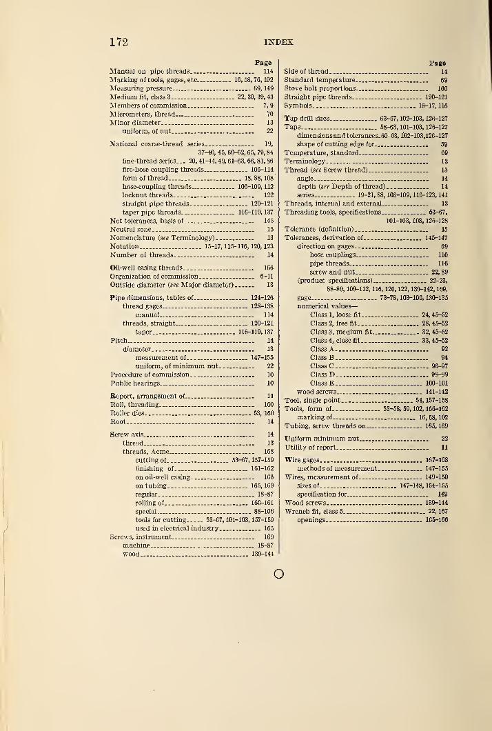
172 INDEX
PageManual on pipe threads 114
Marking of tools, gages, etc 16, 58, 76, 102
Measuring pressure 69, 149
Medium fit, class 3 22, 30, 39, 43
Members of commission 7,
9
Micrometers, thread 70
Minor diameter 13
uniform, of nut _ 22
National coarse-thread series 19,
37-40, 45, 60-62, 65, 79, 84
fine-thread series... 20, 41-44, 49, 61-63, 66, 81, 86
fire-hose coupling threads 106-114
form of thread 18,88,108
hose-coupling threads 106-109, 112
locknut threads ._ 122
straight pipe threads 120-121
taper pipe threads. 116-119,137
Net tolerances, basis of 145
Neutral zone. 15
Nomenclature (see Terminology) 13
Notation 15-17, 115-116, 120, 123
Number of threads 14
Oil-well casing threads 166
Organization of commission 6-11
Outside diameter (see Major diameter) 13
Pipe dimensions, tables of 124-126
thread gages 128-138
manual 114
threads, straight 120-121
taper 116-119,137
Pitch .. 14
diameter 13
measurement of - 147-155
uniform, of minimum nut 22
Procedure of commission 10
Public hearings. 10
Report, arrangement of 11
Roll, threading. 160
Roller dies 53, 160
Root 14
Screw axis 14
thread 13
threads, Acme 168
cutting of 53-67, 157-159
finishing of... 161-162
on oil-well casing 166
on tubing 165, 169
regular. _ _ _ 18-87
rolling of - 160-161
special 88-106
tools for cutting 53-67, 101-103, 157-159
used in electrical industry 165
Screws, instrument 169
machine 18-87
wood 139-144
PageSide of thread 14
Standard temperature... 69
Stove bolt proportions 166
Straight pipe threads 120-121
Symbols 16-17,116
Tap drill sizes 63-67, 102-103, 126-127
Taps 58-63, 101-103, 126-127
dimensions and tolerances. 60-63, 102-103,126-127
shape of cutting edge for 59
Temperature, standard 69
Terminology 13
Thread (see Screw thread) 13
angle... 14
depth (see Depth of thread) 14
series 19-21, 88, 108-109, 116-123, 141
Threads, internal and external 13
Threading tools, specifications 63-67,
101-103, 108, 126-128
Tolerance (definition) 15
Tolerances, derivation of 145-147
direction on gages 69
hose couplings... 110
pipe threads 116
screw and nut 22, 89
(product specifications) 22-23,
88-89, 109-112, 116, 120, 122, 139-142, 169,
gage 73-78,103-106,130-135
numerical values
—
Class 1, loose fit 24, 45-52
Class 2, free fit 28, 45-52
Class 3, medium fit 32, 45-52
Class 4, close fit 33, 45-52
Class A 92
Class B 94
Class C 96-97
Class D 98-99
Class E 100-101
wood screws 141-142
Tool, single point 54, 157-158
Tools, form of 53-58, 59, 102, 156-162
marking of— 16,58,102
Tubing, screw threads on 165, 169
Uniform minimum nut.
Utility of report
22
11
Wire gages 167-168
methods of measurement 147-155
Wires, measurement of 149-150
sizes of. 147-148,154-155
specification for 149
Wood screws 139-144
Wrench fit, class 5 22, 167
openings 165-166
o

i
I