reglo icc operating manual
TRANSCRIPT

1
Reglo ICC Operating Manual
We recommend that you read this operating manual carefully. When operating a pump, certain hazards cannot be excluded. IDEX Health and Science, LLC is not liable for any damage resulting from the use of an ISMATEC® pump. IDEX Health and Science, LLC is not responsible for the unsafe handling
of chemicals.
IDEX Health and Science – Home of Upchurch Scientific and Ismatec Products 619 Oak Street Oak Harbor, WA (360) 679‐2528
2
Content
1 Safety Precautions ................................................................................................................................ 3
2 Warranty ............................................................................................................................................... 3
3 Product .................................................................................................................................................. 4
4 Rear Panel ............................................................................................................................................. 4
5 Main Voltage ......................................................................................................................................... 4
6 Pump Operation .................................................................................................................................... 4
6.1 Key Pad and Screen ....................................................................................................................... 4
6.2 Icons .............................................................................................................................................. 5
6.3 Changing Parameters .................................................................................................................... 5
6.4 Menus ........................................................................................................................................... 6
6.4.1 STATUS Menu ........................................................................................................................ 6
6.4.2 PUMPING Menu .................................................................................................................... 6
6.4.3 SETUP Menu .......................................................................................................................... 8
6.4.4 CALIBRATION Menu .............................................................................................................. 9
6.4.5 GLOBAL SETTINGS Menu ..................................................................................................... 10
6.5 Installing Tubing .......................................................................................................................... 10
6.6 Information Screens .................................................................................................................... 10
6.7 Differential Pressure ................................................................................................................... 10
6.8 When the Pump is Idle ................................................................................................................ 11
7 Over Current Protection ..................................................................................................................... 11
8 Cassettes ............................................................................................................................................. 11
9 Repair .................................................................................................................................................. 12
10 Cleaning .............................................................................................................................................. 12
11 Disposal ............................................................................................................................................... 12
12 Technical Specifications ...................................................................................................................... 13
13 Tubing Size and Flow Rate Chart......................................................................................................... 14
14 IDEX Reglo ICC Serial Command Protocol ........................................................................................... 15

3
1 Safety Precautions ISMATEC® tubing pumps are designed for pumping and dispensing applications in laboratories and industry. As such it is assumed that Good Laboratory Practice (GLP) and the following recommendations will be observed.
The pump must not be operated outside the designed operating and environmental conditions. In particular, it is the user's responsibility not to exceed the specified maximum differential pressure for the pump head.
The pump must not be used: ‐ for any medical applications. ‐ in explosion proof chambers or in the presence of flammable gases or fumes.
The pump must be switched off when pump heads, cassettes or tubing are inserted or changed. The permeability of tubing depends on the material used and pressure conditions. Tubing can also become electro‐statically charged. Please be aware of possible hazards when handling tubing in explosi‐on‐proof chambers.
Pump heads consist of revolving parts. Therefore, the pump must not be operated before the cassettes are fully seated on the pump head.
Do not manipulate the pump head before the pump is switched off and disconnected from the main power supply.
Use extreme caution to ensure that no part of your body such as fingers, long hair, etc. or jewelry, or loose objects such as cables or tubing, etc. are near the pump head during operation.
Tubing can tear and burst during operation. The necessary safety measures based on the specific situation must be taken. When pumping corrosive media we recommend placing the pump in a collecting basin.
The pump should not come in contact with liquid. Do not open or remove the housing while the pump is operating. Service and repairs carried out by the customer or by third‐party companies voids all warranties. Appliance coupler of the power supply is used to disconnect the device from mains supply.
2 Warranty We warrant the pump to be free of defects, provided they have been installed and operated correctly according to our operating instructions for a period of 2 years from date of purchase. If production or material faults can be proven, the defective parts will be repaired or replaced free of charge at our discretion. A defective pump must be returned in the original ISMATEC® packaging or in packaging of equal quality. The duration of the warranty is not affected by making a claim for warranty service. Further claims are excluded. Shipping costs are charged to the customer. Our warranty becomes invalid in the case of:
• Improper operation by the user, or if the pump is diverted from its proper use. • Unauthorized modification or misuse by the user or by a third party. • Improper site preparation and maintenance. • Operation outside of the environmental and electrical specifications for the product. • Use of third‐party software, hardware, accessories or consumables purchased by the user and which do
not comply with our specifications.
Do not place your fingers on or around the pump head

4
3 Product Reglo ICC is a peristaltic pump with independently controllable channels. The intended use for this pump is precise fluid dispensing at low flow rates up to 43ml/min for fluid delivery applications.
Contents of the package • Reglo ICC Pump (type as ordered) • 1 power supply • 3 cassettes • 1 power cord with country specific plug • Operating manual
Please check the package and its contents for transport damage. If you find any signs of damage, please contact your local ISMATEC® representative immediately.
4 Rear Panel 1. 24VDC power Inlet plug 2. On / Off Switch, circuit breaker 3. RS‐232 In, DB9‐female 4. RS‐232 Out, DB9‐male 5. USB 2.0, Mini‐B
5 Main Voltage Use only the supplied power supply and cord for your Reglo ICC pump. DO NOT use any other substitutes or damage may occur! The power supply is designed to provide DC voltage for your Reglo ICC pump. It has built in circuit over current protection in the event the pump is overloaded or a malfunction occurs. The power supply is connected to the pump by a 4‐pin power DIN snap and lock plug. Appliance coupler of the power supply is used to disconnect the device from the mains supply.
‐ Voltage 100‐264VAC ‐ 50 / 60 Hz
6 Pump Operation
6.1 Key Pad and Screen 1. Run / Stop Button
a. Starts and stops the pump b. Interrupts and resumes a dispensing cycle
2. Reset Button a. Escape out of editing a parameter without changing b. Resets dispensing cycle when pump is paused
3. Directional Arrows a. Used to navigate screen and highlight selections b. Up, down, left, right
4. OK / Enter Button a. Press to edit parameter b. Saves edit to parameter once complete
5. LCD Display
2. 1.
4. 3.
5.
1. 2.
4.
3. 5.
5
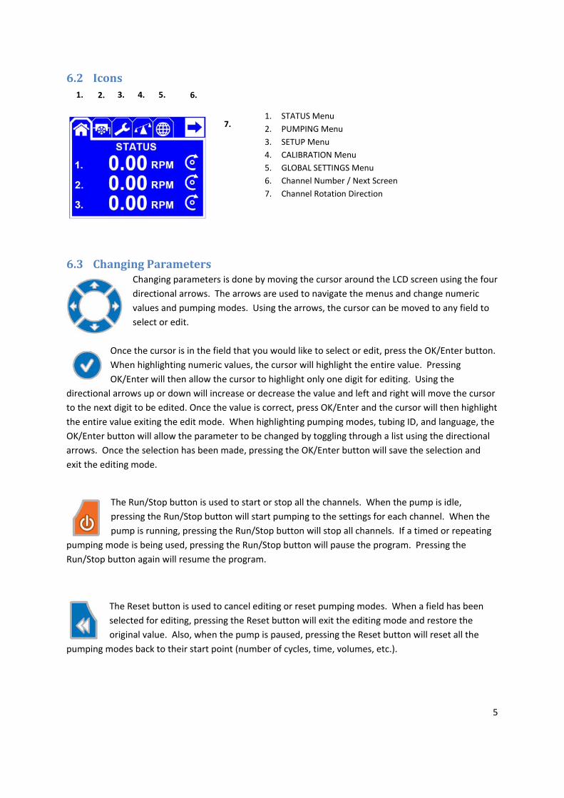
6.2 Icons
1. STATUS Menu 2. PUMPING Menu 3. SETUP Menu 4. CALIBRATION Menu 5. GLOBAL SETTINGS Menu 6. Channel Number / Next Screen 7. Channel Rotation Direction
6.3 Changing Parameters Changing parameters is done by moving the cursor around the LCD screen using the four directional arrows. The arrows are used to navigate the menus and change numeric values and pumping modes. Using the arrows, the cursor can be moved to any field to select or edit.
Once the cursor is in the field that you would like to select or edit, press the OK/Enter button. When highlighting numeric values, the cursor will highlight the entire value. Pressing OK/Enter will then allow the cursor to highlight only one digit for editing. Using the
directional arrows up or down will increase or decrease the value and left and right will move the cursor to the next digit to be edited. Once the value is correct, press OK/Enter and the cursor will then highlight the entire value exiting the edit mode. When highlighting pumping modes, tubing ID, and language, the OK/Enter button will allow the parameter to be changed by toggling through a list using the directional arrows. Once the selection has been made, pressing the OK/Enter button will save the selection and exit the editing mode.
The Run/Stop button is used to start or stop all the channels. When the pump is idle, pressing the Run/Stop button will start pumping to the settings for each channel. When the pump is running, pressing the Run/Stop button will stop all channels. If a timed or repeating
pumping mode is being used, pressing the Run/Stop button will pause the program. Pressing the Run/Stop button again will resume the program.
The Reset button is used to cancel editing or reset pumping modes. When a field has been selected for editing, pressing the Reset button will exit the editing mode and restore the original value. Also, when the pump is paused, pressing the Reset button will reset all the
pumping modes back to their start point (number of cycles, time, volumes, etc.).
1. 2. 3. 4. 6. 5.
7.

6
6.4 Menus
6.4.1 STATUS Menu The STATUS Menu has three screens. The Status screen (a) displays the current pumping parameters for each channel. The unit displayed varies depending on the pumping mode selected. The Total Volume screen (b) displays the total volume that has been pumped since the last time it was reset. The Total Time screen (c) displays the total hours pumped for each channel since the last time it was reset. The time and volume can be reset by navigating to the desired value and pressing OK/Enter button. Highlighting the arrow in the upper right hand corner of the screen and pressing the OK/Enter button will toggle through the three status screens.
6.4.2 PUMPING Menu
The PUMPING Menu allows you to set up the pumping parameters for all of the available channels. The channel number that is being programmed is indicated in the upper right hand corner. You can select the rotation direction, pumping mode, and values for each channel in the PUMPING menu.
6.4.2.1 Flow Rate Mode Flow Rate Mode provides a continuous operation at a set rate and direction. Adjustable parameters are rotation direction, flow rate, flow rate units. Rotation direction can be selected as clockwise (CW) or counter‐clockwise (CCW). Flow rate can be changed in the range specified by the selected unit and/or tubing inner diameter (ID) (see Section 6.4.3). Selectable flow rate units are RPM, µl/min, ml/min and L/min. Flow rate and rotation direction can be changed during the operation as well.
(a) (c) (b)

7
6.4.2.2 Volume over Time Mode Volume over Time Mode allows the user to dispense a desired volume over a desired time. The pump will determine the speed of rotation by set volume and time. Adjustable parameters are rotation direction, volume, volume units, time, and time units. Rotation direction can be selected as CW or CCW. Combinations of time and volume can be set to any value as long as it is in the range of the pump’s capabilities. If the time value entered is less than what the pump is capable of for desired
volume, it will default to the shortest dispense time possible. Volume units selectable are µl, ml and L. Time units selectable are seconds, minutes and hours. None of the parameters are changeable during pumping or when operation is paused. Dispensing program can be reset during operation by pressing the Reset button after pumping is paused.
6.4.2.3 Volume Mode Volume Mode allows the user to dispense a set volume with a set flow rate. Adjustable parameters are rotation direction, flow rate, flow rate units, volume, and volume units. Rotation direction can be selected as CW or CCW. Flow rate can be changed in the range specified by the selected unit and/or tubing ID (see Section 6.4.3). Selectable flow rate units are RPM, µl/min, ml/min and L/min. Selectable volume units are µl, ml and L. Only flow rate can be changed during pumping or when the
operation is paused. Dispensing program can be reset during operation by pressing the Reset button after pumping is paused.
6.4.2.4 Time Mode Time Mode allows the user to dispense for a set time duration with a set flow rate. Adjustable parameters are rotation direction, flow rate, flow rate units, time, and time units. Rotation direction can be selected as CW or CCW. Flow rate can be changed in the range specified by the selected unit and/or tubing ID (see Section 6.4.3). Selectable flow rate units are RPM, µl/min, ml/min and L/min. Selectable time units are sec, min, and hours. Only flow rate can be changed during pumping or when the
operation is paused. Dispensing program can be reset during operation by pressing the Reset button after pumping is paused.
6.4.2.5 Volume with Pause Mode Volume with Pause Mode allows the user to dispense a set volume over multiple cycles. Adjustable parameters are rotation direction, flow rate, flow rate units, volume, volume units, pause time between cycles, pause time unit, and number of cycles. Rotation direction can be selected as CW or CCW. Flow rate can be changed in the range specified by the selected unit and/or tubing ID (see Section 6.4.3). Selectable flow rate units are RPM, µl/min, ml/min and L/min. Selectable volume units are µl,
ml and L. Selectable pause time units are sec, min, and hours. Only flow rate can be changed during

8
pumping or when the operation is paused. Dispensing program can be reset during operation by pressing the Reset button after pumping is paused.
6.4.2.6 Time with Pause Mode Time with Pause Mode allows the user to dispense for a set time duration over multiple cycles. Adjustable parameters are rotation direction, flow rate, flow rate units, time, time units, pause time between cycles, pause time unit, and number of cycles. Rotation direction can be selected as CW or CCW. Flow rate can be changed in the range specified by the selected unit and/or tubing ID (see Section 6.4.3). Selectable flow rate units are RPM, µl/min, ml/min and L/min. Selectable time units are
sec, min, and hours. Selectable pause time units are sec, min, and hours. Only flow rate can be changed during pumping or when the operation is paused. Dispensing program can be reset during operation by pressing the Reset button after pumping is paused.
6.4.2.7 Disabled Mode Disabled Mode disables the selected channel for pumping. The channels that are not anticipated to pump any fluid should be set to this mode.
6.4.3 SETUP Menu
In the SETUP Menu the tubing ID is set by selecting the size of tubing being used in the highlighted channel selected in the upper right hand corner. The tubing ID is selected from the drop down menu. The number of roller backsteps for drip free dispensing can also be set between 0‐100 (0 = Default Value).

9
6.4.4 CALIBRATION Menu In the CALIBRATION Menu each channel can be calibrated independently. The channel being calibrated is listed in the upper right hand corner.
The Reglo ICC allows each channel to be set up and calibrated. This allows for maximum flexibility and optimum channel to channel precision. Prior to the calibration each channel must be configured for tubing ID, the number of backsteps that are desired for drip free dispensing, and calibration of that channel.
The Reglo ICC allows you to enter the volume of fluid to dispense for calibration, dispense time for the specified volume, and pumping direction. Once you have entered those values, dispense desired volume into a container. Measure the actual amount of the fluid by weight or volume and enter that value on the last screen to adjust the pump for your application. The calibration can be interrupted by pressing Run/Stop button which will cancel the existing progress. New uninterrupted calibration run will be required in order to calibrate the channel properly. When adjusting the dispense time for calibration, if requested time is shorter than the pump’s physical capabilities the dispense time will automatically default to minimum achievable dispense time.
You can complete the calibration by pressing Ok/Enter button following your measurement input. You will receive a message and checkmark once your calibration is successful.
You can cancel the calibration after the calibration run by pressing the Reset button. You will receive the message displaying that the calibration has been canceled.

10
6.4.5 GLOBAL SETTINGS Menu In the GLOBAL SETTINGS Menu the display language can be selected between English, French, Spanish, and German. The pump can also be reset to the factory defaults at this menu.
6.5 Installing Tubing 1. Switch the pump off 2. Remove the cassette by slightly pressing the fixing‐tongue and lifting it simultaneously 3. Insert the 2‐stop or 3‐stop color‐coded tubing with one stopper into the cassette 4. Let the tubing hang down (prevent it from being twisted) 5. Insert the tubing with the second stopper at the other end of the cassette 6. Reinsert the cassette into the roller‐head 7. Make sure each cassette is positioned and aligned well between dedicated segments on the bars 8. Turn the pump on 9. When the pump is idle, release all cassettes to maximize tubing life (beware of siphoning or back flow)
6.6 Information Screens
Indicates that the pump is being remotely controlled by a PC via USB connection.
Indicates that the internal temperature has exceeded a safe threshold and pumping will stop automatically to protect the pump. Turn the pump power switch off and check your parameters, differential pressure and pump head for blockage. The pump will not operate in an overheated condition. Allow the pump to cool before turning the power switch back on.
6.7 Differential Pressure The Reglo ICC can be used for continuous duty at a maximum differential pressure of 1.0 bar (smaller tube sizes and/or lever type cassettes allow higher pressures).he pump is idle

11
6.8 When the Pump is Idle When the pump is idle, we recommend releasing the tubing cassette from the pump head. Releasing the cassette on the right side is sufficient. This helps to protect the tubing from unnecessary strain and prolongs its service life. However, a syphoning effect can occur when the tubing cassette is released from the pump head. Use caution to prevent the fluid from flowing back to the reservoir.
7 Over Current Protection The Reglo ICC features an external power supply that has overload protection as well as a combined circuit breaker and ON/OFF switch on the pump. There are NO replaceable fuses or service items inside the pump. This system is designed to disable power to the pump drive in case of excessive current to prevent damage. When an overload condition occurs, the pump will power down and it is recommend to immediately switch the pump off and unplug the pump from the wall. . Before the pump is re‐started, it is most important to check the reason for the overload (e.g. excess differential pressure etc.). Only when the cause of the overload has been detected and the failure corrected accordingly may the pump be started again. If the condition persists, contact an Ismatec technical support representative immediately.
8 Cassettes Your Reglo ICC can use the Click‐n‐Go© cassettes or the pressure lever cassettes. When using new tubing for the first time, it may occur that, depending on the tubing used (hardness and diameter) the pump cannot be primed and, hence, does not deliver the liquid. If that is the case we recommend you wet the tubing and run the pump with the tubing inserted for about 15 to 30 minutes.
Ordering Spare Parts Cassette MS/CA Click-n-Go© Material POM‐C Order No. IS 3510 Cassette MS/CA pressure lever Material POM‐C Order No. IS 0649 Cassette MS/CA pressure lever Material PVDF Order No. IS 3629 The cassettes with pressure lever are available on request. This type of cassette may provide better results both for the Tygon MH tubing and at elevated differential pressure conditions.
Cassette Material Materials POM‐C Polyoxymethylene‐Copolymer – Good chemical resistance to many organic solvents and strong alkaline chemicals – Is affected by strong acids and oxidizing substances – UV‐stabilized and stable up to temperatures of 80°C/176°F (dry, continuous use) or 136°C/277°F (dry, for a short time) Materials PVDF Polyvinylidene fluoride – Very good chemical resistance to acids and most aliphatic, aromatic and chlorinated solvents – Not suitable for long contact with esters, ketones, amines and strong alkaline chemicals – Stable both to UV radiation and temperatures up to 110°C/230°F (continuous use) or 142°C/288°F (for a short time)

12
Installing and adjusting Pressure Lever cassettes
1. Switch the pump off 2. Push the pressure lever down (it must be relaxed) 3. Insert the tubing with color‐coded collars into cassette 4. Reinsert the cassette(s) onto the rollers. Ensure that it snaps in on both sides 5. Switch the pump on and start it 6. Lift the pressure lever step by step until the medium is drawn in and a continuous flow is achieved
Notes on Pressure Lever Cassettes
– Under certain circumstances (e.g. new tubing, elevated differential pressure, etc.) we recommend the user lift the lever by just one more step
– Never over‐tighten the pressure lever – The setting of the pressure lever determines the occlusion – The optimum occlusion depends on tubing material, inner diameter, wall thickness, age of tubing, and
application conditions – As a side‐effect, the occlusion setting also affects the flow rate
‐ This, however, should not encourage the user to use the pressure lever for flow rate adjustments because long‐term impact is not predictable
– If, however, the occlusion setting is used to adjust the flow rate, the channel‐to‐channel flow rate conformity may lead to good results in the beginning of the operation, yet the individual flow rates may increasingly diverge at a later stage
– For an optimum long‐term flow rate stability and channel‐to‐channel conformity we suggest using the Click‐n‐Go© cassettes.
9 Repair The Reglo ICC is designed for many years of trouble free service. The Reglo ICC does not have any fuses or adjustments inside the pump. If you wish to attempt any repairs after the warranty period, please contact your local Ismatec Distributor for parts.
10 Cleaning When replacing the tubes and/or cassettes the pump head should be wiped to avoid any debris or residue. The pump head can be cleaned with mild detergent water before and after duty cycles for extended life. The exterior of the pump can be gently wiped with IPA (Isopropyl Alcohol). Use a 50% mixture of IPA and water on a lint‐free soft cloth to clean the LCD screen. Do not spray or pour any liquid on the LCD screen.
11 Disposal Please retain packing materials until the product warranty ends. Afterwards please discard packing materials in an environmental friendly manner according to local regulations. Once the useful life of the product has ended, please ensure proper disposal according to local laws. Plastic and electronic components should be disposed of at a recycling facility. Please refer to local regulations regarding proper disposal.
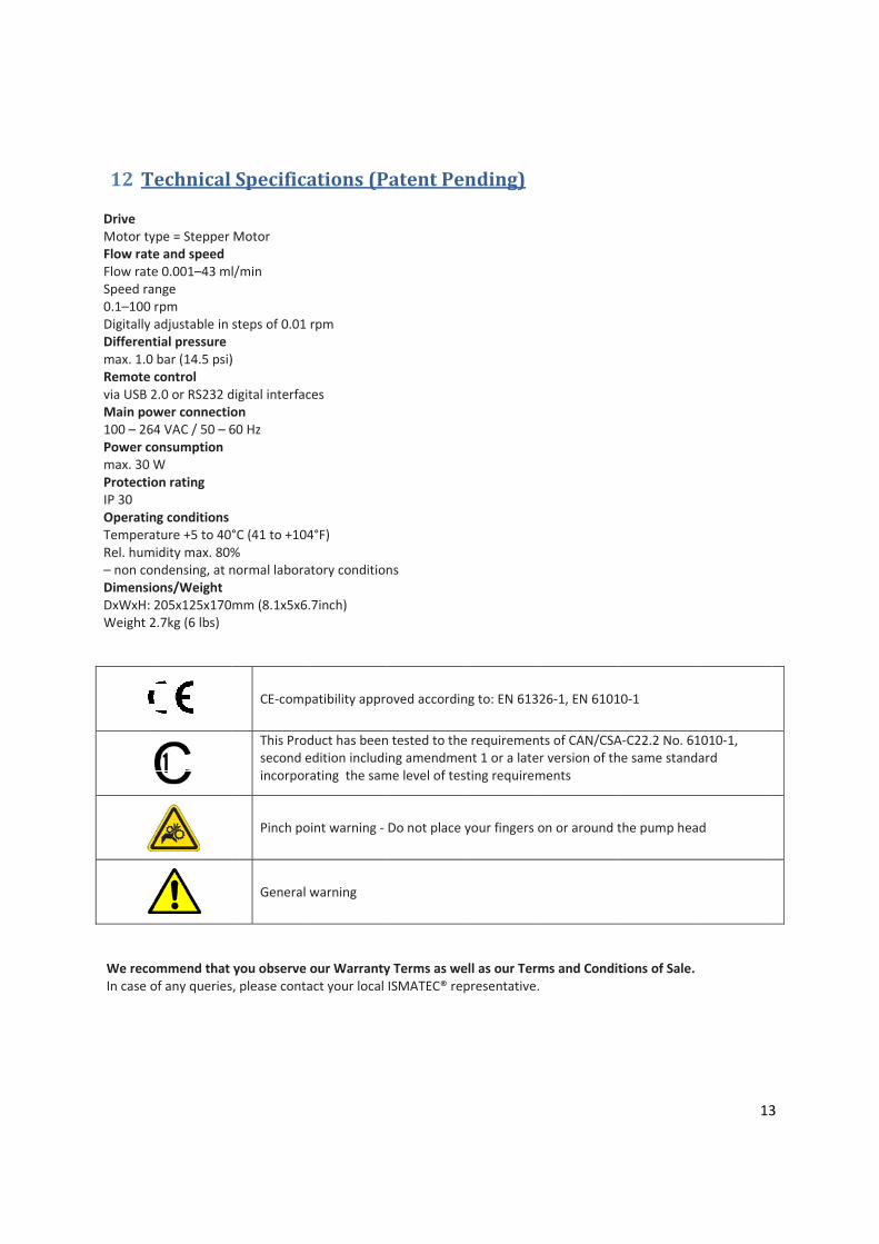
12 TSpecificatDrive Motor tyFlow rateFlow rateSpeed ra0.1–100 Digitally aDifferentmax. 1.0 Remote cvia USB 2Main pow100 – 264Power comax. 30 WProtectioIP 30 OperatinTemperaRel. hum– non conDimensioDxWxH: 2Weight 2
We recoIn case o
echnical tions
ype = Stepper e and speed e 0.001–43 mlnge rpm adjustable in tial pressure bar (14.5 psi)control 2.0 or RS232 dwer connectio4 VAC / 50 – 6onsumption W on rating
ng conditions ature +5 to 40°idity max. 80%ndensing, at nons/Weight 205x125x1702.7kg (6 lbs)
ommend that of any queries
Specifica
Motor
l/min
steps of 0.01
)
digital interfacon 60 Hz
°C (41 to +104% normal labora
mm (8.1x5x6.
CE‐comp
This Prodsecond eincorpor
Pinch po
General
you observe , please conta
ations (P
rpm
ces
4°F)
atory conditio
.7inch)
patibility appr
duct has beenedition includirating the sam
oint warning ‐
warning
our Warrantyact your local
Patent Pe
ns
oved accordin
n tested to theing amendmeme level of tes
Do not place
y Terms as weISMATEC® re
ending)
ng to: EN 6132
e requirementent 1 or a latersting requirem
your fingers o
ell as our Termpresentative.
26‐1, EN 6101
ts of CAN/CSAr version of thments
on or around t
ms and Condit
10‐1
A‐C22.2 No. 61he same stand
the pump hea
tions of Sale.
13
1010‐1, dard
ad
3

14
13 Tubing Size and Flow Rate Chart
Rollers 8
RPM 1.0 100
Tube ID Order No
Flow Rates ml/min
min max 0.13 SC0189 0.002 0.11 0.19 SC0049 0.003 0.23 0.25 SC0050 0.005 0.41 0.38 SC0051 0.010 0.94 0.44 SC0052 0.013 1.3 0.51 SC0053 0.017 1.7 0.57 SC0054 0.021 2.1 0.64 SC0055 0.026 2.6 0.76 SC0056 0.036 3.6 0.89 SC0057 0.049 4.9 0.95 SC0058 0.056 5.6 1.02 SC0059 0.063 6.3 1.09 SC0060 0.072 7.2 1.14 SC0061 0.078 7.8 1.22 SC0062 0.088 8.8 1.3 SC0063 0.10 10 1.42 SC0064 0.11 11 1.52 SC0065 0.13 13 1.65 SC0066 0.15 15 1.75 SC0067 0.16 16 1.85 SC0068 0.17 17 2.06 SC0069 0.20 20 2.29 SC0070 0.24 24 2.54 SC0071 0.27 27 2.79 SC0072 0.31 31 3.17 SC0224 0.35 35
15
14 IDEX Reglo ICC Serial Command Protocol The Reglo ICC Pump supports a serial communication protocol for controlling the pump’s operation as well as setting and getting current pump configuration parameters.
Each pump has a configurable address (1‐8) which is set to 1 at the factory. This address is used with all direct‐addressed commands to send the command to single pump on a multi‐pump serial daisy‐chain of pumps. The set address command is used to reconfigure a pump’s address, but is received by every pump in the chain.
All protocol messages are composed of ASCII characters.
ASCII Character Definitions
The following symbols are used in the message definitions in this document.
• [SP] – space (0x20)
• [CR] – carriage return (0x0d)
• [LF] – line feed (0x0a)
Definitions
• * – default command response message.
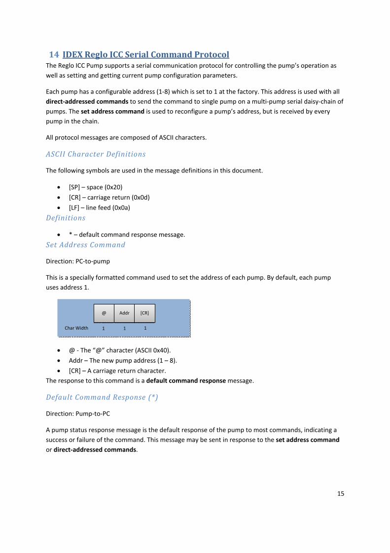
Set Address Command
Direction: PC‐to‐pump
This is a specially formatted command used to set the address of each pump. By default, each pump uses address 1.
• @ ‐ The “@” character (ASCII 0x40).
• Addr – The new pump address (1 – 8).
• [CR] – A carriage return character. The response to this command is a default command response message.
Default Command Response (*)
Direction: Pump‐to‐PC
A pump status response message is the default response of the pump to most commands, indicating a success or failure of the command. This message may be sent in response to the set address command or direct‐addressed commands.
@
1 1 1 Char Width
Addr [CR]
16
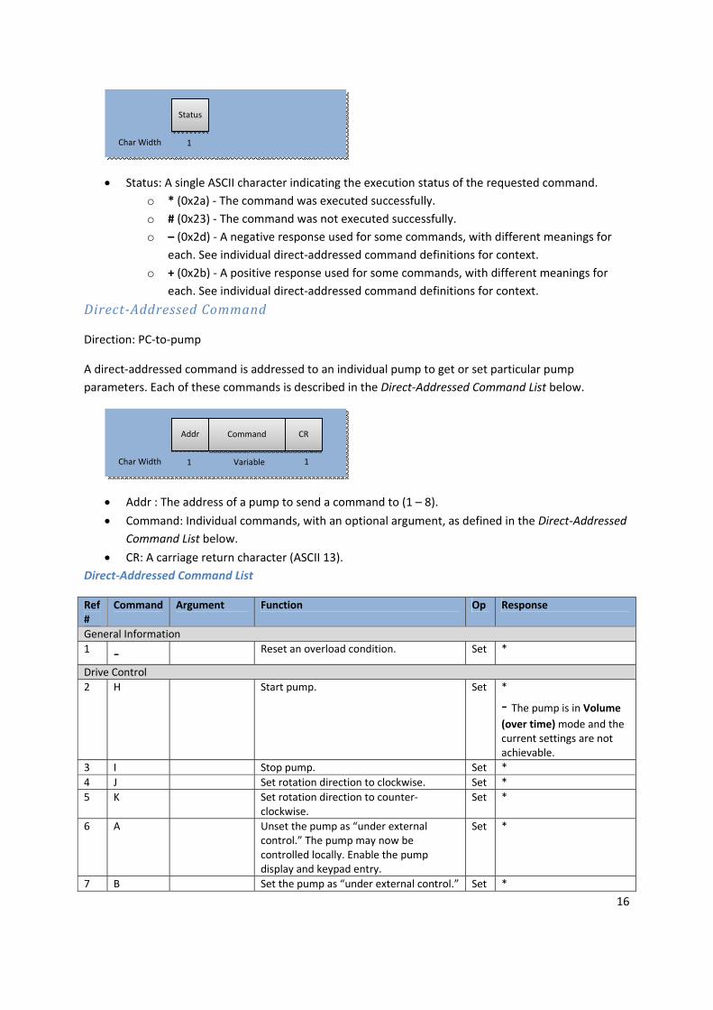
• Status: A single ASCII character indicating the execution status of the requested command. o * (0x2a) ‐ The command was executed successfully. o # (0x23) ‐ The command was not executed successfully. o – (0x2d) ‐ A negative response used for some commands, with different meanings for
each. See individual direct‐addressed command definitions for context. o + (0x2b) ‐ A positive response used for some commands, with different meanings for
each. See individual direct‐addressed command definitions for context.
DirectAddressed Command
Direction: PC‐to‐pump
A direct‐addressed command is addressed to an individual pump to get or set particular pump parameters. Each of these commands is described in the Direct‐Addressed Command List below.
• Addr : The address of a pump to send a command to (1 – 8).
• Command: Individual commands, with an optional argument, as defined in the Direct‐Addressed Command List below.
• CR: A carriage return character (ASCII 13). Direct‐Addressed Command List
Ref #
Command Argument Function Op Response
General Information 1 ‐ Reset an overload condition. Set *
Drive Control 2 H Start pump. Set *
‐ The pump is in Volume (over time) mode and the current settings are not achievable.
3 I Stop pump. Set * 4 J Set rotation direction to clockwise. Set * 5 K Set rotation direction to counter‐
clockwise. Set *
6 A Unset the pump as “under external control.” The pump may now be controlled locally. Enable the pump display and keypad entry.
Set *
7 B Set the pump as “under external control.” Set *
Addr
1 Variable 1Char Width
Command CR
Status
1 Char Width

17
Ref #
Command Argument Function Op Response
The pump display is under the control of the D and DA commands and keypad entry at the pump is disabled.
8 D‐‐‐‐‐ (5) Numeric
digits to write to the control panel.
Write numbers to the pump to display while under external control.
Set *
9 DA‐‐‐‐ (4) Alphabetic
characters to write to the control panel.
Write letters to the pump to display while under external control.
Set *
10 L Set pump to RPMmode. Set * 11 M Set pump to Flow Ratemode. Set * 12 N Set pump to Timemode. Set * 13 O Set pump to Volume (at rate)mode. Set * 14 ] Set pump to “pause” mode. This
essentially stops the pump. Set *
15 P Set pump to Time + Pausemode. Set * 16 Q Set pump to Volume + Pausemode. Set * 17 G Set pump to Volume (over time)mode. Set *
‐ volume too small and time too long
+ volume too large and time too short
Parameter Control 18 E Returns whether the pump is currently
running or not. Get + running
‐ stopped 19 # Returns the following fields, each
separated by a space: Pump model description (variable length)– A text field describing the model of pump. This description may contain spaces. Pump software version (3 digits) – The version of software currently running in the pump. Pump head model type code (3 digits) – A code describing the type of pump head installed. The first digit represents the number of channels for the pump, and the second 2 digits represent the number of rollers.
Get [model][SP][s/w ver][SP][head code][CR][LF]
20 ( Returns the pump software version –The version of software currently running in the pump. This value is returned in 4 characters with the value right justified and zero‐padded.
Get 0123[CR][LF]
21 ) Returns the pump head model type code– A 3 digit code describing the type of pump head installed. The first digit represents the number of channels for
Get 0123[CR][LF]

18
Ref #
Command Argument Function Op Response
the pump, and the second 2 digits represent the number of rollers. This value is returned in 4 characters with the value right justified and zero‐padded.
22 ) ‐‐‐‐ Sets the pump head model type code – A 3 digit code describing the type of pump head installed. The first digit represents the number of channels for the pump, and the second 2 digits represent the number of rollers. This value must be set with 4 characters with the value right justified and zero‐padded.
Set *
23 S Gets the current speed setting in RPM with 2 decimal places.
Get 100.00[CR][LF]
24 S‐‐‐‐(‐‐) (4‐6) speed For 4, 5,or 6 digits, the units are 1/100
RPM. Format is 0HTU.th. Set *
25 + Get the current tubing inside diameter inmm. 2 decimal places are returned.
Get 1.23[SP]mm[CR][LF]
26 +‐‐‐‐ (4) tubing diameter
Set the current tubing inside diameter in 1/100 Format is TU.th
Set *
27 V Get the current setting for pump time in 1/10 second.
Get 105[CR][LF]
28 V‐‐‐‐ (4) time setting
Set the current setting for pump time in 1/10 second. Format is HTU.t
Set *
29 VM‐‐‐ (3) time
setting Set the current setting for pump time in minutes (0 – 999). Format is 0HTU.
Set *
30 VH‐‐‐ (3) time setting
Set the current setting for pump time in hours (0 – 999). Format is 0HTU.
Set *
31 U Get the current setting for volume to pump in roller steps.
Get 100[CR][LF]
32 U‐‐‐‐‐ (5) roller steps Set the current setting for volume to pump in roller steps (0 – 65535).
Set *
33 u‐‐‐‐(‐) (4‐5) high‐order roller steps
Use to set the current setting for volume to pump in roller steps to a value greater than 65535. When set, the number of steps to pump is (u * 65536) + U.
Set *
34
r Get the pump’s current setting for roller step volume (RSV) in nanoliters (nl).
Get 9500E‐1[CR][LF]
35 r‐‐‐‐‐‐ (6) roller step volume
Set the pump’s current setting for roller step volume (RSV) in nanoliters (nl). Format is xxxxee
Set *
36 r000000 Set the pump’s current setting for roller step volume to the default value. This sets RSV to the value indicated by the pump’s internal table based on pump heads and tubing sizes.
Set *
37 f Get the current setting for flow rate in ml/min.
Get 1200E‐2[CR][LF]
38
f‐‐‐‐‐‐ (6) flow rate
Set the current setting for flow rate in ml/min. Format is U.thtee.
Set 1200E‐2[CR][LF]
39 v Get the current setting for volume in ml. Get 6320E+1[CR][LF] 40 v (6) volume
Set the current setting for volume in ml.Format is U.thtee
Set 6320E+1[CR][LF]

19
Ref #
Command Argument Function Op Response
41 % Get the current backsteps setting. Get 0[CR][LF] 42 %‐‐‐‐ (4) Set the current backsteps setting. Set *
43 T Get the current setting for pause time in 1/10 second.
Get 105[CR][LF]
44 T‐‐‐‐ (4) Set the current setting for pause time in 1/10 second. Format Is HTU.t
Set *
45 TM‐‐‐ (3) Set the current setting for pause time in minutes (0 – 999). Format is HTU.
Set *
46 TH‐‐‐ (3) Set the current setting for pause time in
hours (0 – 999). Format is HTU. Set *
47 “ Get the current setting for pump cycles. Get 0[CR][LF] 48 “‐‐‐‐ (4) Set the current setting for pump cycles.
Format is THUT. Set *
49 : Get the total (trip) volume pumped since the last reset in ul, ml or liters.
Get 4.983[SP]ml[CR][LF]
50 W Reset the total (trip) volume count. Set * 51 * Force the pump to save its current pump
settings values ( time, pause time, speed, backsteps, cycle count, etc) to non‐volatile memory. They will be available after device power down.
Set *
52 0 Sets all the current pump setting values above to “default” and saves the settings.
Set *
Inputs and Outputs 53 C Get the current state of the foot switch. Get ‐ open
+ grounded
Examples
Set speed of pump 1 to 098.76 RPM
Set speed of pump 1 to 98 RPM
or
* Response
1S0098[CR] Command
1S009800[CR] Command
* Response
1S009876[CR] Command
20
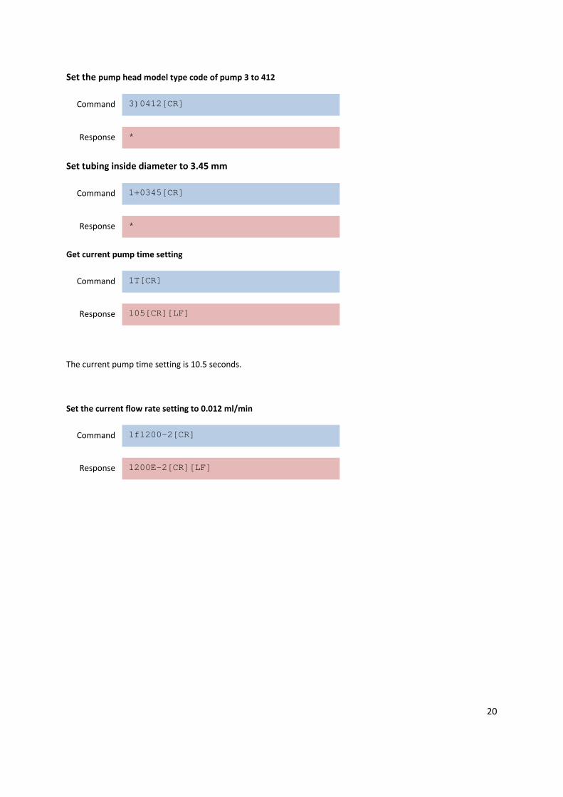
Set the pump head model type code of pump 3 to 412
Set tubing inside diameter to 3.45 mm
Get current pump time setting
The current pump time setting is 10.5 seconds.
Set the current flow rate setting to 0.012 ml/min
1200E-2[CR][LF] Response
1f1200-2[CR] Command
105[CR][LF] Response
1T[CR] Command
* Response
1+0345[CR] Command
* Response
3)0412[CR] Command