realization оf inertial navigation system on flight computer
TRANSCRIPT
16 Scientific Technical Review, 2011,Vol.61,No.3-4,pp.16-24
UDK: 623.746-519 COSATI: 01-03-10, 17-07-03
Realization оf Inertial Navigation System on Flight Computer for Unmanned Aerial Vehicle
Nada Asanović1)
Ivana Trajkovski1) Vladimir Vukmirica1)
Stojan Stanojković1)
This paper presents a realized design of a flight computer for unmaned aerial vehicle (UAV) and the implementation of an inertial navigation system (INS) in it. Inertial navigation systems usually consist of the inertial measuring unit (IMU) with three mutually perpendicular gyroscopes and accelerometers that represent three input axes to the system and the navigation algorithm. The input values for the navigation algorithm are signals of gyroscopes and accelerometers. The paper describes all flight computer components such as an inertial measurement unit (IMU), a GPS, a servo switch controller (SSC), a supply and controller board as well as software applications with the emphasis on the navigation algorithm. The procedures for each component testing as well as for inertial navigation testing are presented. The realization of a UAV flight computer with the implemented INS is a significant achievement in this kind of technology.
Key words: unmanned aerial vehicle, navigation system, inertial system, gyroscope, accelerometer, flight computer for unmanned aerial vehicle..
1) Military Technical Institute (VTI), Ratka Resanovića 1, 11132 Belgrade, SERBIA
Introduction LIGHT computers for UAV should be realized by one or more microcontrollers. Some of them are [8 - 11]:
- AP50. Two primary computers work in concert on the AP50. The Flight Processor (FP) maintains the stability of the aircraft. The Mission Processor (MP) performs all navigation and communicates with the Ground Control Station. Additional support microprocessors are dedicated to the RC radio receiver and the servos. Servos are up-dated at the standard 19 ms frame rate.
- The Autopilot 4 (AP04 UAV Navigation) is a fully inte-grated autopilot with manual override, radio link, and payload control capabilities, and is capable of fully auto-matic take-off, flight plan following, and landing.
- UNAV3300 LLC, A digital flight control and telemetry system using 3-axes MEMS, IMU attitude sensor and 3-axis Kalman filter. It is a full featured, tightly integrated digital autopilot and ground station system. The autopilot updates the attitude control loop 18 times
per second while managing the vehicle flight path, GPS waypoint navigation and data-link. The 3300 is capable of providing a fullduplex (up & down) data link with the ground station. - MicroPilot 2028: small size without sacrificing function-
ality; 28 grams, 4 cm by 10 cm; fully integrated with 3-axis gyros & accelerometers, GPS, pressure altimeter, pressure airspeed sensors, all on a single circuit board.
- Microbotics Autopilot Platform: small size (2.63" W x 2.10" H x 2.63"D), 30 fully programmable digital I/O lines, 4 RS-232, full duplex UARTS, PWM inputs and outputs for servo control, 12 Analog inputs (12 bit), 5
VDC supply for analog, Hall-effect, or other sensors. User programmable 32-bit RISC processor, Onboard non-volatile memory for external sensor calibration, waypoint storage, etc. Optional internally mounted MIDG II INS/GPS sensor, Internal wireless modem with up to 20 mile range, SD memory card slot for real-time data recording. This paper deals with the description of implementation
of the inertial navigation system in a flight computer for UAV.
A design of a flight computer for UAV was realized in the MTI as an original design, different from previously described ones.
Both hardware and software solution for the flight computer as well as the functional testing procedures before loading the system software are described. The functional testings were done in the laboratory for inertial sensors and systems. The testing of the inertial navigation system was performed on the grounds of the MTI (driving) as well as during the UAV functional testing (in flight condition).
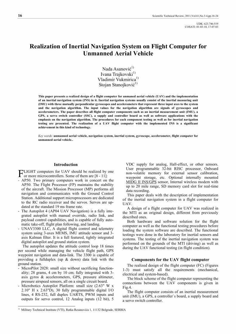
Components for the UAV flight computer The realized design of the flight computer (FC) (Figures
1-3) must satisfy all the requirements (mechanical, electrical and system-based).
The block scheme of the flight computer representing the connections between the UAV components is given in Fig.4.
The flight computer consists of an inertial measurement unit (IMU), a GPS, a controller`s board, a supply board and a servo switch controller.
F
ASANOVIĆ,N., TRAJKOVSKI,I., etc.: REALIZATION ОF INERTIAL NAVIGATION SYSTEM ON FLIGHT COMPUTER FOR UNMANNED AERIAL VEHICLE 17
Figure 1. FC for UAV
Figure 2. FC for UAV – top view
Figure 3. FC for UAV – mechanical design
Figure 4. Block scheme of the FC for UAV
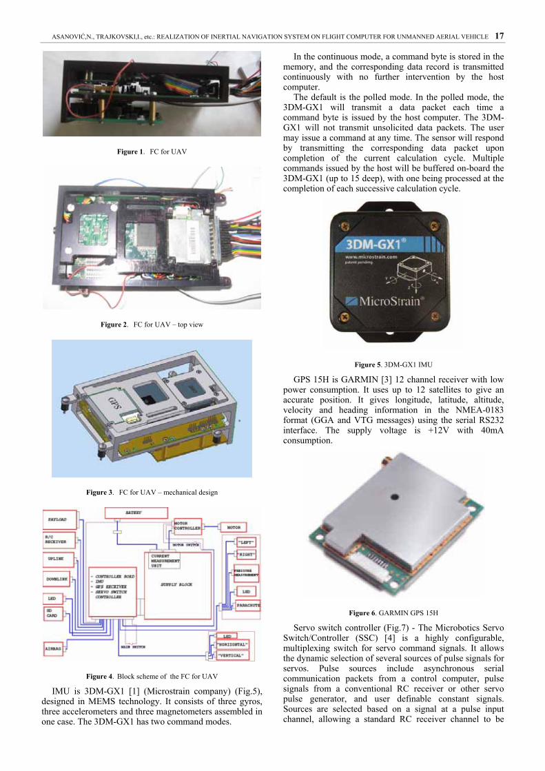
IMU is 3DM-GX1 [1] (Microstrain company) (Fig.5), designed in MEMS technology. It consists of three gyros, three accelerometers and three magnetometers assembled in one case. The 3DM-GX1 has two command modes.
In the continuous mode, a command byte is stored in the memory, and the corresponding data record is transmitted continuously with no further intervention by the host computer.
The default is the polled mode. In the polled mode, the 3DM-GX1 will transmit a data packet each time a command byte is issued by the host computer. The 3DM-GX1 will not transmit unsolicited data packets. The user may issue a command at any time. The sensor will respond by transmitting the corresponding data packet upon completion of the current calculation cycle. Multiple commands issued by the host will be buffered on-board the 3DM-GX1 (up to 15 deep), with one being processed at the completion of each successive calculation cycle.
Figure 5. 3DM-GX1 IMU
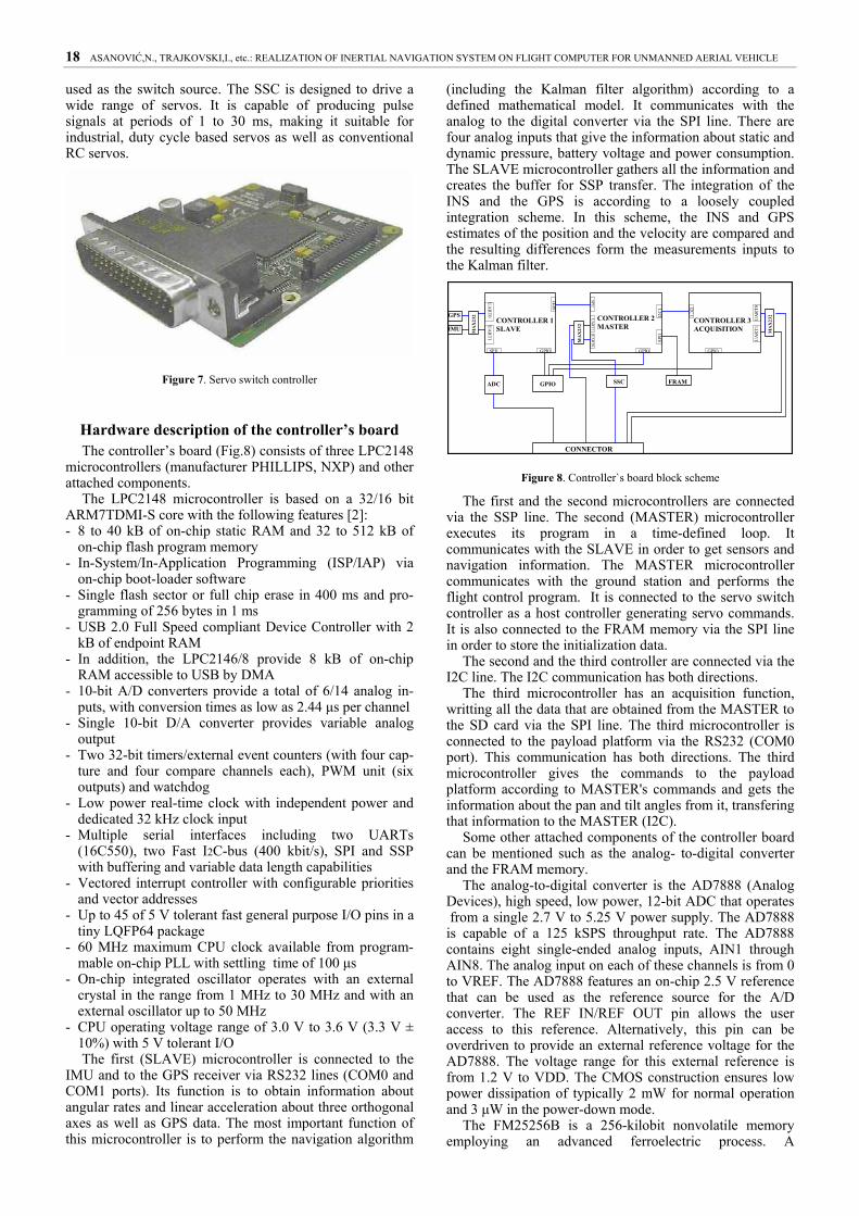
GPS 15H is GARMIN [3] 12 channel receiver with low power consumption. It uses up to 12 satellites to give an accurate position. It gives longitude, latitude, altitude, velocity and heading information in the NMEA-0183 format (GGA and VTG messages) using the serial RS232 interface. The supply voltage is +12V with 40mA consumption.
Figure 6. GARMIN GPS 15H
Servo switch controller (Fig.7) - The Microbotics Servo Switch/Controller (SSC) [4] is a highly configurable, multiplexing switch for servo command signals. It allows the dynamic selection of several sources of pulse signals for servos. Pulse sources include asynchronous serial communication packets from a control computer, pulse signals from a conventional RC receiver or other servo pulse generator, and user definable constant signals. Sources are selected based on a signal at a pulse input channel, allowing a standard RC receiver channel to be
18 ASANOVIĆ,N., TRAJKOVSKI,I., etc.: REALIZATION ОF INERTIAL NAVIGATION SYSTEM ON FLIGHT COMPUTER FOR UNMANNED AERIAL VEHICLE
used as the switch source. The SSC is designed to drive a wide range of servos. It is capable of producing pulse signals at periods of 1 to 30 ms, making it suitable for industrial, duty cycle based servos as well as conventional RC servos.
Figure 7. Servo switch controller
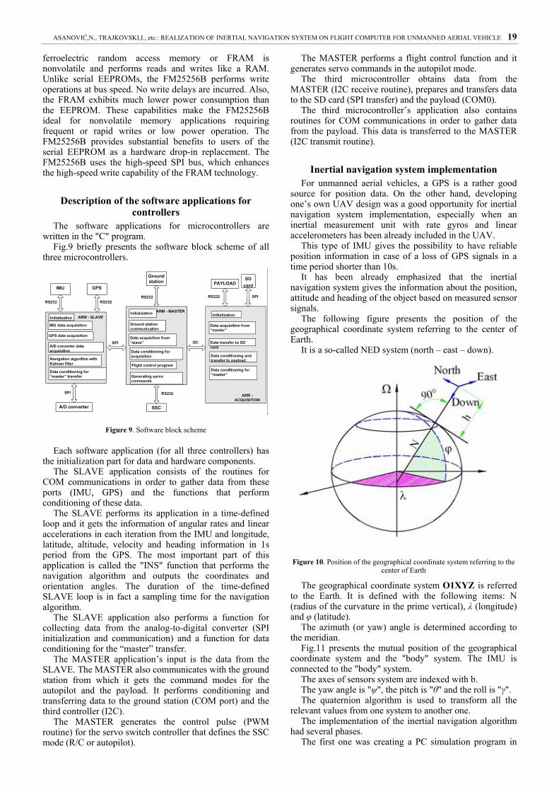
Hardware description of the controller’s board The controller’s board (Fig.8) consists of three LPC2148
microcontrollers (manufacturer PHILLIPS, NXP) and other attached components.
The LPC2148 microcontroller is based on a 32/16 bit ARM7TDMI-S core with the following features [2]: - 8 to 40 kB of on-chip static RAM and 32 to 512 kB of
on-chip flash program memory - In-System/In-Application Programming (ISP/IAP) via
on-chip boot-loader software - Single flash sector or full chip erase in 400 ms and pro-
gramming of 256 bytes in 1 ms - USB 2.0 Full Speed compliant Device Controller with 2
kB of endpoint RAM - In addition, the LPC2146/8 provide 8 kB of on-chip
RAM accessible to USB by DMA - 10-bit A/D converters provide a total of 6/14 analog in-
puts, with conversion times as low as 2.44 μs per channel - Single 10-bit D/A converter provides variable analog
output - Two 32-bit timers/external event counters (with four cap-
ture and four compare channels each), PWM unit (six outputs) and watchdog
- Low power real-time clock with independent power and dedicated 32 kHz clock input
- Multiple serial interfaces including two UARTs (16C550), two Fast I2C-bus (400 kbit/s), SPI and SSP with buffering and variable data length capabilities
- Vectored interrupt controller with configurable priorities and vector addresses
- Up to 45 of 5 V tolerant fast general purpose I/O pins in a tiny LQFP64 package
- 60 MHz maximum CPU clock available from program-mable on-chip PLL with settling time of 100 μs
- On-chip integrated oscillator operates with an external crystal in the range from 1 MHz to 30 MHz and with an external oscillator up to 50 MHz
- CPU operating voltage range of 3.0 V to 3.6 V (3.3 V ± 10%) with 5 V tolerant I/O The first (SLAVE) microcontroller is connected to the
IMU and to the GPS receiver via RS232 lines (COM0 and COM1 ports). Its function is to obtain information about angular rates and linear acceleration about three orthogonal axes as well as GPS data. The most important function of this microcontroller is to perform the navigation algorithm
(including the Kalman filter algorithm) according to a defined mathematical model. It communicates with the analog to the digital converter via the SPI line. There are four analog inputs that give the information about static and dynamic pressure, battery voltage and power consumption. The SLAVE microcontroller gathers all the information and creates the buffer for SSP transfer. The integration of the INS and the GPS is according to a loosely coupled integration scheme. In this scheme, the INS and GPS estimates of the position and the velocity are compared and the resulting differences form the measurements inputs to the Kalman filter.
ADC
CONTROLLER 1SLAVE
SPI1
UA
RT0
MA
X23
2
UA
RT1
SPI2
SPI2
MA
X23
2
GPS UA
RT1
UA
RT0
SSC
I2C
1
I2C1
SPI1
GPIO GPIO
CONNECTOR
GPIO
IMU MA
X23
2
UA
RT1
GPIO
UA
RT0
FRAM
CONTROLLER 3ACQUISITION
CONTROLLER 2MASTER
Figure 8. Controller`s board block scheme
The first and the second microcontrollers are connected via the SSP line. The second (MASTER) microcontroller executes its program in a time-defined loop. It communicates with the SLAVE in order to get sensors and navigation information. The MASTER microcontroller communicates with the ground station and performs the flight control program. It is connected to the servo switch controller as a host controller generating servo commands. It is also connected to the FRAM memory via the SPI line in order to store the initialization data.
The second and the third controller are connected via the I2C line. The I2C communication has both directions.
The third microcontroller has an acquisition function, writting all the data that are obtained from the MASTER to the SD card via the SPI line. The third microcontroller is connected to the payload platform via the RS232 (COM0 port). This communication has both directions. The third microcontroller gives the commands to the payload platform according to MASTER's commands and gets the information about the pan and tilt angles from it, transfering that information to the MASTER (I2C).
Some other attached components of the controller board can be mentioned such as the analog- to-digital converter and the FRAM memory.
The analog-to-digital converter is the AD7888 (Analog Devices), high speed, low power, 12-bit ADC that operates from a single 2.7 V to 5.25 V power supply. The AD7888 is capable of a 125 kSPS throughput rate. The AD7888 contains eight single-ended analog inputs, AIN1 through AIN8. The analog input on each of these channels is from 0 to VREF. The AD7888 features an on-chip 2.5 V reference that can be used as the reference source for the A/D converter. The REF IN/REF OUT pin allows the user access to this reference. Alternatively, this pin can be overdriven to provide an external reference voltage for the AD7888. The voltage range for this external reference is from 1.2 V to VDD. The CMOS construction ensures low power dissipation of typically 2 mW for normal operation and 3 μW in the power-down mode.
The FM25256B is a 256-kilobit nonvolatile memory employing an advanced ferroelectric process. A
ASANOVIĆ,N., TRAJKOVSKI,I., etc.: REALIZATION ОF INERTIAL NAVIGATION SYSTEM ON FLIGHT COMPUTER FOR UNMANNED AERIAL VEHICLE 19
ferroelectric random access memory or FRAM is nonvolatile and performs reads and writes like a RAM. Unlike serial EEPROMs, the FM25256B performs write operations at bus speed. No write delays are incurred. Also, the FRAM exhibits much lower power consumption than the EEPROM. These capabilities make the FM25256B ideal for nonvolatile memory applications requiring frequent or rapid writes or low power operation. The FM25256B provides substantial benefits to users of the serial EEPROM as a hardware drop-in replacement. The FM25256B uses the high-speed SPI bus, which enhances the high-speed write capability of the FRAM technology.
Description of the software applications for controllers
The software applications for microcontrollers are written in the "C" program.
Fig.9 briefly presents the software block scheme of all three microcontrollers.
Figure 9. Software block scheme
Each software application (for all three controllers) has the initialization part for data and hardware components.
The SLAVE application consists of the routines for COM communications in order to gather data from these ports (IMU, GPS) and the functions that perform conditioning of these data.
The SLAVE performs its application in a time-defined loop and it gets the information of angular rates and linear accelerations in each iteration from the IMU and longitude, latitude, altitude, velocity and heading information in 1s period from the GPS. The most important part of this application is called the "INS" function that performs the navigation algorithm and outputs the coordinates and orientation angles. The duration of the time-defined SLAVE loop is in fact a sampling time for the navigation algorithm.
The SLAVE application also performs a function for collecting data from the analog-to-digital converter (SPI initialization and communication) and a function for data conditioning for the “master” transfer.
The MASTER application’s input is the data from the SLAVE. The MASTER also communicates with the ground station from which it gets the command modes for the autopilot and the payload. It performs conditioning and transferring data to the ground station (COM port) and the third controller (I2C).
The MASTER generates the control pulse (PWM routine) for the servo switch controller that defines the SSC mode (R/C or autopilot).
The MASTER performs a flight control function and it generates servo commands in the autopilot mode.
The third microcontroller obtains data from the MASTER (I2C receive routine), prepares and transfers data to the SD card (SPI transfer) and the payload (COM0).
The third microcontroller’s application also contains routines for COM communications in order to gather data from the payload. This data is transferred to the MASTER (I2C transmit routine).
Inertial navigation system implementation For unmanned aerial vehicles, a GPS is a rather good
source for position data. On the other hand, developing one’s own UAV design was a good opportunity for inertial navigation system implementation, especially when an inertial measurement unit with rate gyros and linear accelerometers has been already included in the UAV.
This type of IMU gives the possibility to have reliable position information in case of a loss of GPS signals in a time period shorter than 10s.
It has been already emphasized that the inertial navigation system gives the information about the position, attitude and heading of the object based on measured sensor signals.
The following figure presents the position of the geographical coordinate system referring to the center of Earth.
It is a so-called NED system (north – east – down).
Figure 10. Position of the geographical coordinate system referring to the center of Earth
The geographical coordinate system О1XYZ is referred to the Earth. It is defined with the following items: N (radius of the curvature in the prime vertical), λ (longitude) and φ (latitude).
The azimuth (or yaw) angle is determined according to the meridian.
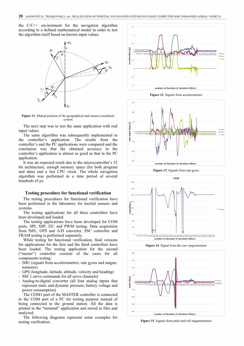
Fig.11 presents the mutual position of the geographical coordinate system and the "body" system. The IMU is connected to the "body" system.
The axes of sensors system are indexed with b. The yaw angle is "ψ", the pitch is "θ" and the roll is "γ". The quaternion algorithm is used to transform all the
relevant values from one system to another one. The implementation of the inertial navigation algorithm
had several phases. The first one was creating a PC simulation program in
20 ASANOVIĆ,N., TRAJKOVSKI,I., etc.: REALIZATION ОF INERTIAL NAVIGATION SYSTEM ON FLIGHT COMPUTER FOR UNMANNED AERIAL VEHICLE
the C/C++ environment for the navigation algorithm according to a defined mathematical model in order to test the algorithm itself based on known input values.
Figure 11. Mutual position of the geographical and sensors coordinate system
The next step was to test the same application with real input values.
The same algorithm was subsequently implemented in the controller’s application. The results from the controller’s and the PC applications were compared and the conclusion was that the obtained accuracy in the controller’s application is almost as good as that in the PC application.
It was an expected result due to the microcontroller’s 32 bit architecture, enough memory space (for both program and data) and a fast CPU clock. The whole navigation algorithm was performed in a time period of several hundreds of µs.
Testing procedure for functional verification The testing procedures for functional verification have
been performed in the laboratory for inertial sensors and systems.
The testing applications for all three controllers have been developed and loaded.
The testing applications have been developed for COM ports, SPI, SSP, I2C and PWM testing. Data acquisition from IMU, GPS and A/D converter, SSC controller and FRAM testing is performed separately.
While testing for functional verification, final versions for applications for the first and the third controllers have been loaded. The testing application for the second (“master”) controller consists of the cases for all components testing: - IMU (signals from accelerometers, rate gyros and magne-
tometers) - GPS (longitude, latitude, altitude, velocity and heading) - SSC ( servo commands for all servo channels) - Analog-to-digital converter (all four analog inputs that
represent static and dynamic pressure, battery voltage and power consumption) The COM1 port of the MASTER controller is connected
to the COM port of a PC for testing purpose instead of being connected to the ground station. All the data is printed in the “terminal” application and stored in files and analyzed.
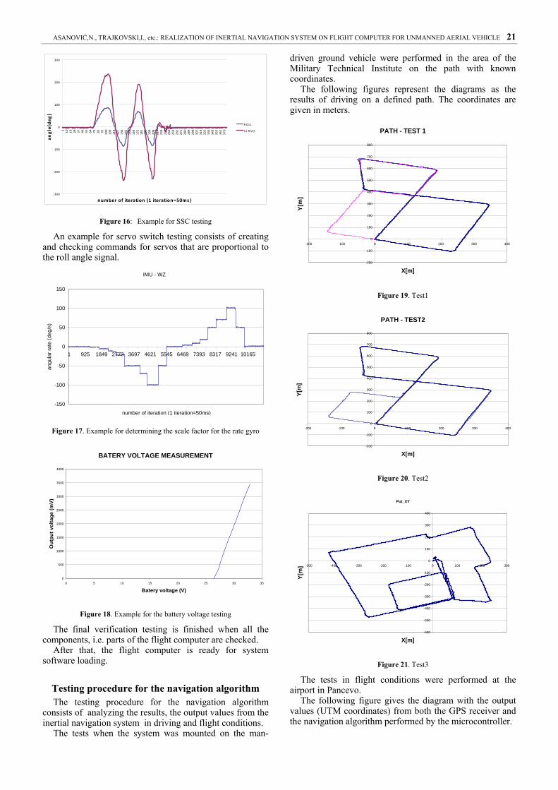
The following diagrams represent some examples for testing verification.
‐2
‐1.5
‐1
‐0.5
0
0.5
1
1.5
1 15 29 43 57 71 85 99 113
127
141
155
169
183
197
211
225
239
253
267
281
295
309
323
337
351
365
379
393
407
421
435
449
463
477
491
505
519
533
547
561
575
589
603
617
631
645
659
673
687
number of iteration (1 iteration=50ms )
acce
leration [g]
AX
AY
AZ
Figure 12. Signals from accelerometers
‐150
‐100
‐50
0
50
100
150
1 15 29 43 57 71 85 99 113
127
141
155
169
183
197
211
225
239
253
267
281
295
309
323
337
351
365
379
393
407
421
435
449
463
477
491
505
519
533
547
561
575
589
603
617
631
645
659
673
687
number of iteration (1 iteration=50ms )
rate angle (deg
./s)
WX
WY
WZ
Figure 13. Signals from rate gyros
YAW
0
50
100
150
200
250
300
350
400
1 15 29 43 57 71 85 99 113
127
141
155
169
183
197
211
225
239
253
267
281
295
309
323
337
351
365
379
393
407
421
435
449
463
477
491
505
519
533
547
561
575
589
603
617
631
645
659
673
687
number of iteration (1 iteration=50ms )
angle(deg
.)
Y AW
Figure 14. Signal from the yaw magnetometer
‐200
‐150
‐100
‐50
0
50
100
150
200
1 15 29 43 57 71 85 99 113
127
141
155
169
183
197
211
225
239
253
267
281
295
309
323
337
351
365
379
393
407
421
435
449
463
477
491
505
519
533
547
561
575
589
603
617
631
645
659
673
687
number of iteration (1 iteration=50ms )
angle (deg
)
P ITCHROLL
Figure 15. Signals from pitch and roll magnetometers
ASANOVIĆ,N., TRAJKOVSKI,I., etc.: REALIZATION ОF INERTIAL NAVIGATION SYSTEM ON FLIGHT COMPUTER FOR UNMANNED AERIAL VEHICLE 21
‐300
‐200
‐100
0
100
200
3001 10 19 28 37 46 55 64 73 82 91 100
109
118
127
136
145
154
163
172
181
190
199
208
217
226
235
244
253
262
271
280
289
298
307
316
325
334
343
352
361
370
number of iteration (1 iteration=50ms )
angle(deg
)
R OL L
S E R VO
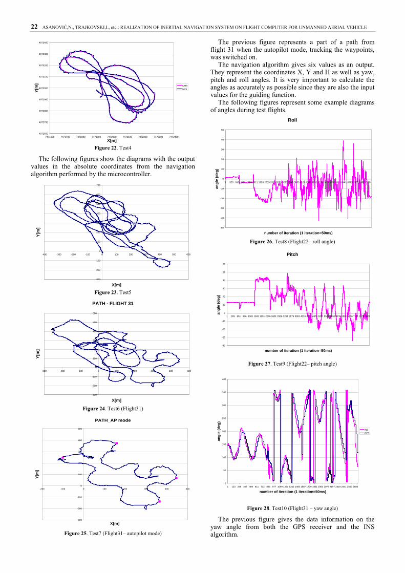
Figure 16: Example for SSC testing
An example for servo switch testing consists of creating and checking commands for servos that are proportional to the roll angle signal.
IMU - WZ
-150
-100
-50
0
50
100
150
1 925 1849 2773 3697 4621 5545 6469 7393 8317 9241 10165
number of iteration (1 iteration=50ms)
angu
lar r
ate
(deg
/s)
Figure 17. Example for determining the scale factor for the rate gyro
BATERY VOLTAGE MEASUREMENT
0
500
1000
1500
2000
2500
3000
3500
4000
0 5 10 15 20 25 30 35
Batery voltage (V)
Out
put v
olta
ge (m
V)
Figure 18. Example for the battery voltage testing
The final verification testing is finished when all the components, i.e. parts of the flight computer are checked.
After that, the flight computer is ready for system software loading.
Testing procedure for the navigation algorithm The testing procedure for the navigation algorithm
consists of analyzing the results, the output values from the inertial navigation system in driving and flight conditions.
The tests when the system was mounted on the man-
driven ground vehicle were performed in the area of the Military Technical Institute on the path with known coordinates.
The following figures represent the diagrams as the results of driving on a defined path. The coordinates are given in meters.
PATH - TEST 1
-200
-100
0
100
200
300
400
500
600
700
800
-200 -100 0 100 200 300 400
X[m]
Y[m
]
Figure 19. Test1
PATH - TEST2
-200
-100
0
100
200
300
400
500
600
700
800
-200 -100 0 100 200 300 400
X[m]
Y[m
]
Figure 20. Test2
Put_XY
-600
-500
-400
-300
-200
-100
0
100
200
300
400
-500 -400 -300 -200 -100 0 100 200 300
X[m]
Y[m
]
Figure 21. Test3
The tests in flight conditions were performed at the airport in Pancevo.
The following figure gives the diagram with the output values (UTM coordinates) from both the GPS receiver and the navigation algorithm performed by the microcontroller.
22 ASANOVIĆ,N., TRAJKOVSKI,I., etc.: REALIZATION ОF INERTIAL NAVIGATION SYSTEM ON FLIGHT COMPUTER FOR UNMANNED AERIAL VEHICLE
4972600
4972700
4972800
4972900
4973000
4973100
4973200
4973300
4973400
7471600 7471700 7471800 7471900 7472000 7472100 7472200 7472300 7472400
X[m]
Y[m
]
ARMGPS
Figure 22. Test4
The following figures show the diagrams with the output values in the absolute coordinates from the navigation algorithm performed by the microcontroller.
-300
-200
-100
0
100
200
300
400
500
600
700
-400 -300 -200 -100 0 100 200 300 400 500 600
X[m]
Y[m
]
Figure 23. Test5
PATH - FLIGHT 31
-300
-200
-100
0
100
200
300
400
500
600
-300 -200 -100 0 100 200 300 400 500
X[m]
Y[m
]
Figure 24. Test6 (Flight31)
PATH_AP mode
-300
-200
-100
0
100
200
300
400
500
-200 -100 0 100 200 300 400 500
X[m]
Y[m
]
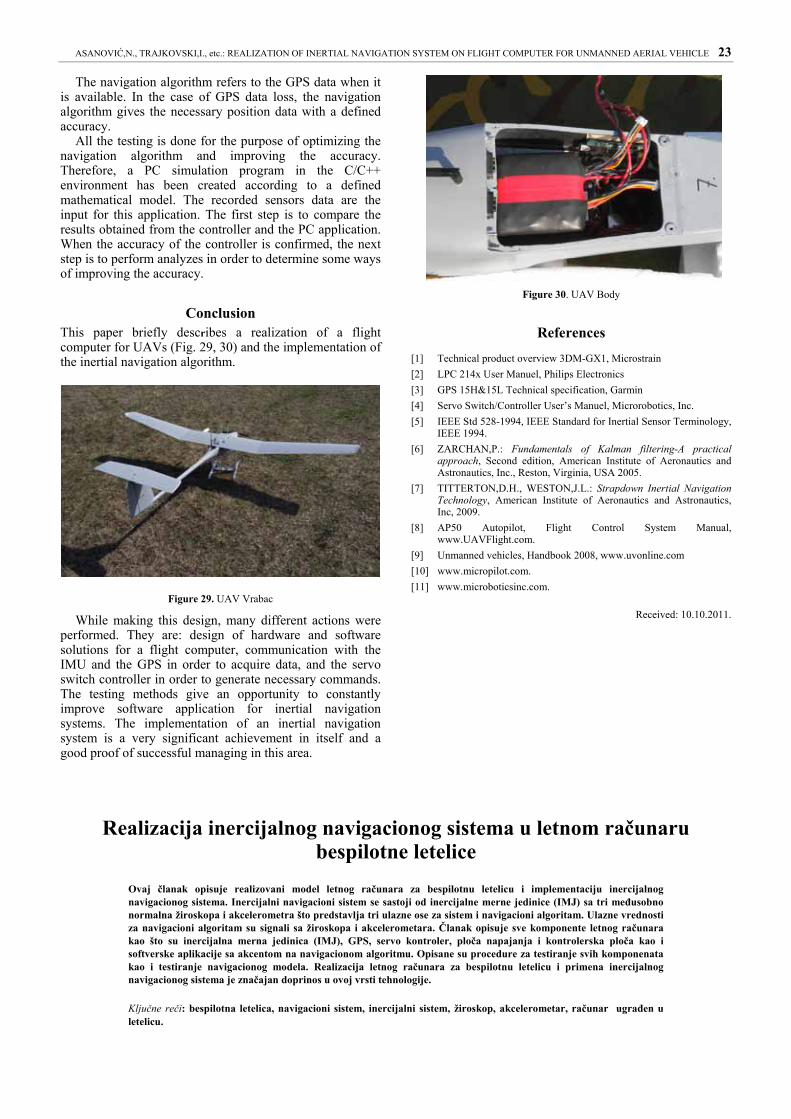
Figure 25. Test7 (Flight31– autopilot mode)
The previous figure represents a part of a path from flight 31 when the autopilot mode, tracking the waypoints, was switched on.
The navigation algorithm gives six values as an output. They represent the coordinates X, Y and H as well as yaw, pitch and roll angles. It is very important to calculate the angles as accurately as possible since they are also the input values for the guiding function.
The following figures represent some example diagrams of angles during test flights.
Roll
-50
-40
-30
-20
-10
0
10
20
30
40
50
1 323 645 967 1289 1611 1933 2255 2577 2899 3221 3543 3865 4187 4509 4831 5153 5475 5797 6119 6441 6763 7085 7407 7729
number of iteration (1 iteration=50ms)
angl
e (d
eg)
Figure 26. Test8 (Flight22– roll angle)
Pitch
-40
-30
-20
-10
0
10
20
30
40
50
60
1 326 651 976 1301 1626 1951 2276 2601 2926 3251 3576 3901 4226 4551 4876 5201 5526 5851 6176 6501 6826 7151 7476 7801
number of iteration (1 iteration=50ms)
angl
e (d
eg)
Figure 27. Test9 (Flight22– pitch angle)
0
50
100
150
200
250
300
350
400
1 123 245 367 489 611 733 855 977 1099 1221 1343 1465 1587 1709 1831 1953 2075 2197 2319 2441 2563 2685
number of iteration (1 iteration=50ms)
angl
e (d
eg)
INSGPS
Figure 28. Test10 (Flight31 – yaw angle)
The previous figure gives the data information on the yaw angle from both the GPS receiver and the INS algorithm.
ASANOVIĆ,N., TRAJKOVSKI,I., etc.: REALIZATION ОF INERTIAL NAVIGATION SYSTEM ON FLIGHT COMPUTER FOR UNMANNED AERIAL VEHICLE 23
The navigation algorithm refers to the GPS data when it is available. In the case of GPS data loss, the navigation algorithm gives the necessary position data with a defined accuracy.
All the testing is done for the purpose of optimizing the navigation algorithm and improving the accuracy. Therefore, a PC simulation program in the C/C++ environment has been created according to a defined mathematical model. The recorded sensors data are the input for this application. The first step is to compare the results obtained from the controller and the PC application. When the accuracy of the controller is confirmed, the next step is to perform analyzes in order to determine some ways of improving the accuracy.
Conclusion This paper briefly describes a realization of a flight computer for UAVs (Fig. 29, 30) and the implementation of the inertial navigation algorithm.
Figure 29. UAV Vrabac
While making this design, many different actions were performed. They are: design of hardware and software solutions for a flight computer, communication with the IMU and the GPS in order to acquire data, and the servo switch controller in order to generate necessary commands. The testing methods give an opportunity to constantly improve software application for inertial navigation systems. The implementation of an inertial navigation system is a very significant achievement in itself and a good proof of successful managing in this area.
Figure 30. UAV Body
References
[1] Technical product overview 3DM-GX1, Microstrain [2] LPC 214x User Manuel, Philips Electronics [3] GPS 15H&15L Technical specification, Garmin [4] Servo Switch/Controller User’s Manuel, Microrobotics, Inc. [5] IEEE Std 528-1994, IEEE Standard for Inertial Sensor Terminology,
IEEE 1994. [6] ZARCHAN,P.: Fundamentals of Kalman filtering-A practical
approach, Second edition, American Institute of Aeronautics and Astronautics, Inc., Reston, Virginia, USA 2005.
[7] TITTERTON,D.H., WESTON,J.L.: Strapdown Inertial Navigation Technology, American Institute of Aeronautics and Astronautics, Inc, 2009.
[8] AP50 Autopilot, Flight Control System Manual, www.UAVFlight.com.
[9] Unmanned vehicles, Handbook 2008, www.uvonline.com [10] www.micropilot.com. [11] www.microboticsinc.com.
Received: 10.10.2011.
Realizacija inercijalnog navigacionog sistema u letnom računaru bespilotne letelice
Ovaj članak opisuje realizovani model letnog računara za bespilotnu letelicu i implementaciju inercijalnog navigacionog sistema. Inercijalni navigacioni sistem se sastoji od inercijalne merne jedinice (IMJ) sa tri međusobno normalna žiroskopa i akcelerometra što predstavlja tri ulazne ose za sistem i navigacioni algoritam. Ulazne vrednosti za navigacioni algoritam su signali sa žiroskopa i akcelerometara. Članak opisuje sve komponente letnog računara kao što su inercijalna merna jedinica (IMJ), GPS, servo kontroler, ploča napajanja i kontrolerska ploča kao i softverske aplikacije sa akcentom na navigacionom algoritmu. Opisane su procedure za testiranje svih komponenata kao i testiranje navigacionog modela. Realizacija letnog računara za bespilotnu letelicu i primena inercijalnog navigacionog sistema je značajan doprinos u ovoj vrsti tehnologije.
Ključne reči: bespilotna letelica, navigacioni sistem, inercijalni sistem, žiroskop, akcelerometar, računar ugrađen u letelicu.
24 ASANOVIĆ,N., TRAJKOVSKI,I., etc.: REALIZATION ОF INERTIAL NAVIGATION SYSTEM ON FLIGHT COMPUTER FOR UNMANNED AERIAL VEHICLE
Реализация инерциальной навигационной системы на компьютере летающих беспилотных летательных аппаратов
Эта статья описывает компьютерную модель реализованую на летающем беспилотном летательном аппарате и встроенную инерциальную навигационную систему. Инерциальная навигационная система состоит из инерциальной единицы измерения (МИИ) с тремя взаимно перпендикулярными акселерометрами и гироскопами, которая представляет собой трёхосный вход в систему и алгоритм навигации. Входные значения для алгоритма навигации, это сигналы от гироскопов и акселерометров. Настоящая статья описывает все компоненты компьютера на летающем беспилотном летательном аппарате, такие как блок инерциальных датчиков (МИИ), GPS, контроллер питания, мощность плиты питания и плиты контроллера, а в том числе и программное обеспечение фокусированное по алгоритму навигации. В нём описываются процедуры тестирования всех компонентов и моделей ходовых испытаний. Реализация компьютера на летающих беспилотных летательных аппаратах и применение инерциальной навигационной системы являются важным вкладом в этот тип технологии.
Ключевые слова: беспилотные летательные аппараты, навигационная система, инерциальная система, гироскоп, акселерометр, компьютер встроенный в летательный аппарат.
La réalisation du système inertiel de navigation chez l’ordinateur de vol de l’aéronef sans pilote
Cet article décrit le modèle réalisé d’un ordinateur de vol pour l’aéronef sans pilote et l’installation du système inertiel de navigation. Le système inertiel de navigation se compose de l’unité inertielle de mesure avec trois gyroscopes mutuellement normaux et d’un accéléromètre ce qui représente trois axes d’entrée pour le système et l’algorithme de navigation. Les valeurs d’entrée pour l’algorithme de navigation sont les signaux des gyroscopes et des accéléromètres. Ce travail présente toutes les composantes de l’ordinateur de vol telles que l’unité inertielle de mesure, GPS, le servo-contrôleur, le panneau d’alimentation et la table de contrôle ainsi que les application logiciel avec l’accent sur l’algorithme de navigation. On a décrit les procédures pour tester toutes ces composantes ainsi que les tests pour le modèle de navigation. La réalisation de l’ordinateur de vol pour l’aéronef sans pilote et l’utilisation du système inertiel de navigation sont une contribution signifiante dans ce domaine technologique.
Mots clés: aéronef sans pilote, système de navigation, système inertiel, gyroscope, accéléromètre, ordinateur de vol.