real time billing system by zhiming dai ... - core
TRANSCRIPT
REAL TIME BILLING SYSTEM
By
ZHIMING DAI
Bachelor of Engineering
Shanghai University of Technology
Shanghai, China
1991
Submitted to the Faculty of theGraduate College of the
Oklahoma State Universityin partial fulfillment of
the requirements forthe Degree of
MASTER OF SCIENCEJuly, 2000

Oklahoma State University Library
REAL TIME BILLING SYSTEM
Thesis Approved:
Thesis Adviser
II

ACKNOWLEDGMENTS
I wish to express sincere appreciation to Dr. Jacques LaFrance for the encour
agement and advice throughout my graduate program. Many thanks also go to Dr. Dai
and Dr. Hedrick for serving on my graduate committee. Their suggestions and support
were very helpful throughout the study.
Without their involvement the study would not have been possible. To my friend
Peter Zuyus Jr. for his expert advice and proofing skills; thanks go to John Graber my
friend for his friendship. You made the ending go so smoothly.
My wife, Mei, encouraged and supported me all the way and helped me keep the
end goal constantly in sight. Thanks go to them for their undivided time in the final
stages of the project. I extend a sincere thank you to all of these people.
III
Chapter
TABLE OF CONTENTS
Page
I. INTRODUCTION I
II. REVIEW OF PREVIOUS LITERATURE OR WORK 3
Background 3Statement of the problem 4Intent of Study 5Literature Study 7
Ill. INTEGRATION 8
Object Oriented Design 8Various Requirements in real time billing system 12Software point of view 15
IV. DESIGN IN DETAIL 21
Introduction 21Entity 22Object Model 30Dynamic Model 34Functional Model 37
V. SUMMARY AND CONCLUSIONS 45
REFERENCES 49
APPENDIX. A 51
APPENDIX B 52
IV
LIST OF FIGURES
I. Prepaid phone, Postpaid phone, Calling Card, Prepaid Card, live Period, Action,Home Carrier, Rate plan, Reference Class Diagram 30
2. Physical information, Provider information and Charge Plan Class Diagram .....31
3. Live period state diagram 35
4. Data base transaction diagram 36
5. Functional Model of Place CaL 38
6. Functional Model of Disconnect Call .41
7. Functional Model of Inquire balance .43
8. Functional Model of Transfer balance .44
9. Three-tier of architecture in Real time billing system l/
v
CHAPTER I
INTRODUCTION
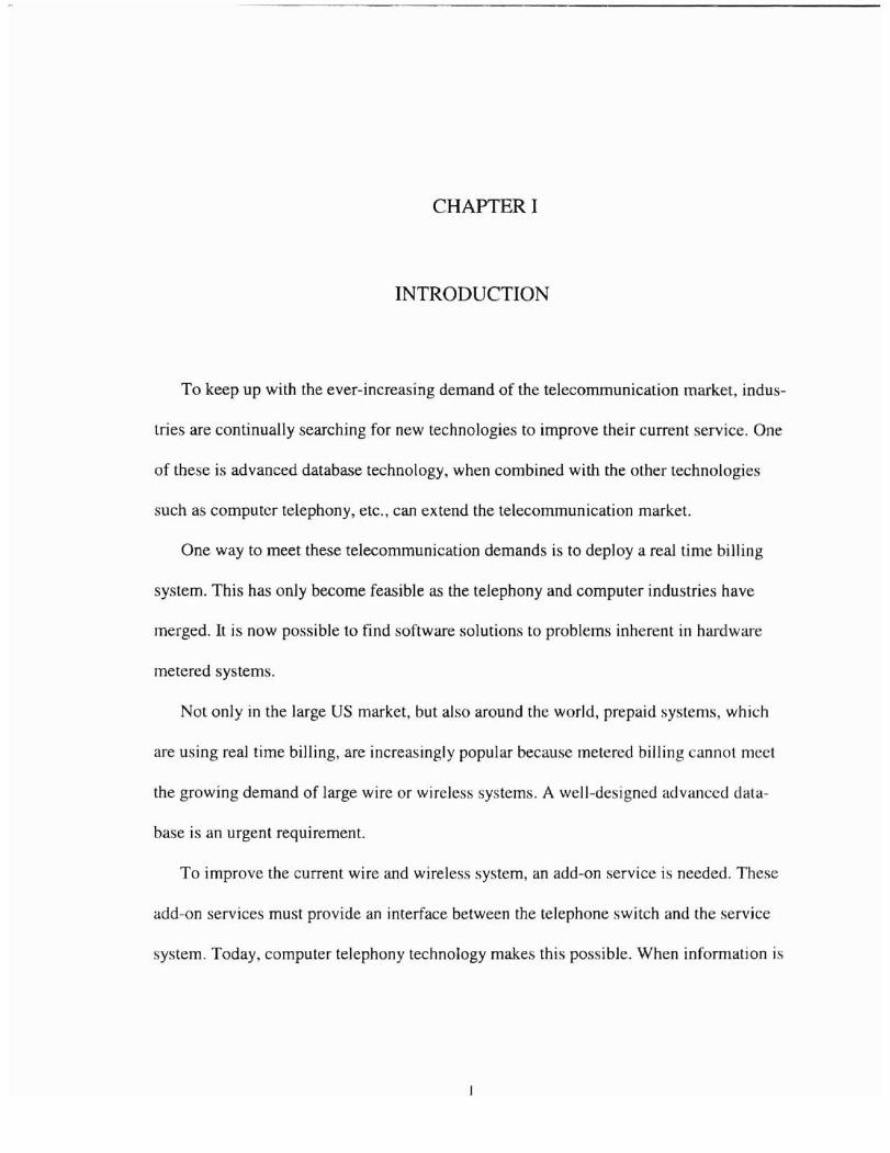
To keep up with the ever-increasing demand of the telecommunication market, indus
tries are continually searching for new technologies to improve their current service. One
of these is advanced database technology, when combined with the other technologies
such as computer telephony, etc., can extend the telecommunication market.
One way to meet these telecommunication demands is to deploy a real time billing
system. This has only become feasible as the telephony and computer industries have
merged. It is now possible to find software solutions to problems inherent in hardware
metered systems.
Not only in the large US market, but also around the world, prepaid systems, which
are using real time billing, are increasingly popular because metered billing cannot meet
the growing demand of large wire or wireless systems. A well-designed advanced data
base is an urgent requirement.
To improve the current wire and wireless system, an add-on service is needed. These
add-on services must provide an interface between the telephone switch and the service
system. Today, computer telephony technology makes this possible. When information is
received by a switch interface, a high-speed process is required. The only solution to
make it possible to process the increasing volume of information quickly is to deploy a
superior performance and reliable relational database. These types of databases not only
need to handle the information from the switch. but also need to meet customer admini
stration and terminal requirements.
This paper discusses the design of a real time billing system engine to erve prepaid
systems. To approach this system design, the first need is to analyze the requirements,
and utilize Object-Oriented Design, with the object model, dynamic model and functional
model, to analyze the system. Once the relationships among all these entities are under
stood fully, the real time billing system then can be implemented as a database with sev
eral applications. It is essentially a real time billing system.
Today, this add-on service for wire or wireless systems is the so-called prepaid sys
tem. All of these prepaid systems will gradually evolve into three-tier or n-tier architec
ture. When based on the Object-Oriented Models, a real time billing system also can be
constructed using a three-tier architecture.
2
CHAPTER II
REVIEW OF PREVIOUS LITERATURE OR WORK
Background
Before 1992, a standard term to describe the emerging computer and telephony indus
try was not available [17]. The world of data communications, computing, and voice
communications remained separate and often mutually hostile to each other because they
had been viewed as separate entities for so long - especially in the minds of the people
who worked in these industries. Telephony people are very different from computer or IT
(information technology) people. In the past, telephony people typically took much
longer to understand the needs of business than the computer professional did. Perhaps
the telephone business is partially to blame for this fault because telephony never has
been brought under the authority of IT [I7J.
Finally, in 1992, the term computer telephony became official. The person who
coined the phrase computer telephony (circa 1992) is Harry Newton [17], a telecommu
nications expert and the publisher of several magazines and books covering telecommu
nications, including the leading magazine serving the industry, Computer Telephony. The
following description is Harry Newton's definition of computer telephony, Newton's
Telecom Dictionary: "Computer telephony is the term used to describe the industry that
3
concerns itself with applying computer intelligence to telecommunication devices, espe
cially switches and phones [9]. The term covers many technologies, including computer
telephone integration via the local area network (LAN), interactive voice processing,
voice mail, auto attendant, voice recognition, text-to-speech, facsimile, simultaneous
voice data, signal processing, video conferencing, predictive dialing, audiotext, 'giving
data a voice,' call centers, help desks, collaborative computing, and traditional telephone
call switching and caB control. [17]"
As computers become part of telephony systems and vice versa, the term will become
more applicable and widely understood. The actual integration can take many forms, but
the ultimate goal is the same: to merge data networks with the telephone network and ex
tend the capability of telephony devices and computer systems to communicate with each
other. By the end of the decade, experts foresee a situation in which many enterprise net
works will consist of one fast, digital, high-bandwidth network carrying voice, data, in
formation, and video.
Today, in order to develop a powerful system in the computer telephony industries,
expertise is needed not only in telephone technology, but also in advanced computer sci-
ence.
Statement of the Problem
In recent years, innovative billing has emerged as a powerful tool for the telephony
industry - witness the success of billing options such as flexible time-of-day discounts,
pay-per-use features, and by-the-second call ing rates in the consumer market [1].
4

In the cellular industry, problems arise from the complexity of compiling infonnation
from a multitude of sources. The billing systems of each of the newly acquired members
of the network must then be coordinated and integrated totally [12]. "Five or six years
ago, billing was not so important," says Ross Buckenham, PageMart President. " Now it
is strategic. And after the quality of the network in terms of messaging reliability, the
most tangible item the customers receive from the carrier is their bill. It must be accurate
and provide the details they want to see [12]."
As the phrase of "choose your real-time billing solution carefully" is being poken in
wireless industry right now, real time biJling systems must meet certain needs. For a bill
ing solution to offer true real-time call processing, the system needs a data link from the
switch to the billing platform, unlike the meter billing system that is the current wireless
telephone switch billing system. With a real-time data link, the call detail can be recorded
at any interval and service can be suspended automatically when credit limits are reached.
Real time billing also can prove a boon to phone-rental businesses by introducing imme
diate payment methods while simultaneously lowering the cost of usage. The method that
is chosen to deploy depends on the unique needs and capabilities ot the service provider
[ 15).
Intent of Study
To serve the most important demand of the telephony industries, a call completing
backbone - database of a real time billing system is essential. How to design a complex
but flexible software billing system is the subject of this paper.
5

As Dijkstra suggests, "The technique of mastering complexity has been known since
ancient times: divide et impera (divide and rule) [4]." When designing a complex soft
ware system, it is essential to decompose it into smaller and smaller parts, each of which
may be refined independently. In this manner, the very real constraint that exists upon the
channel capacity of human cognition can be satisfied: to understand any given level of a
system, only a few parts (rather than all parts) need to be comprehended at once.
Most people have been trained formally in the way of top-down structured design,
and so approach decomposition as a simple matter of algorithmic decomposition, wherein
each module in the system denotes a major step in some overall process. Now, there is an
alternate decomposition possible for the same system, which is called Object-Oriented
Decomposition. A system can be decomposed according to the key abstractions in the
problem domain, rather than decomposing the problem into steps.
Object-Oriented Design is better at helping organize the inherent complexity of soft
ware systems. It yields smaller systems through the reuse of common mechani ms, thus
providing an important economy of expression. Object-Oriented systems also are more
resilient to change and thus able to evolve over time, because their de ign is based upon
stable intermediate forms [4].
The approach to real time billing system design begins by analyzing the agents that
either cause action or are the subjects upon which the operations act to decompose the
requirements. Then from the three views of the all these requirements, three models are
built, these are the object model, dynamic model and functional model, to analyze the
system. Once the relationship among all these entities is understood, then a system can be
designed and implemented as a database with applications. which will be a real time bill
ing system.
Literature Study
Today many telecommunication companies such as Lucent Technologie , Celltech,
AMDOCS, etc. are paying more attention to the prepaid billing market. Each one ap
proaches the target in different ways depending on their unique needs [14]. Switch manu
facturers are trying to build in billing systems, and wireless service companies also are
trying to develop a new interface for cellular switches. However, the wireless industry
has many customers and many switches, all with different requirements, so developing a
real time billing system to meet all these requirements is almost impossible today.
For a rapidly growing market, waiting for a universal real time billing system is al
most impossible. Today, Post Paid telephone, Prepaid Paid telephone Calling card and
Prepaid Paid debit card are the most important languages in the telephony indu tries, so
designing a real time billing system development platform for these domains i neces
sary.
Object Oriented Design is one of the most advanced methods for developing correct
ness, reliability and robustness into software in different application areas. Real-time sys
tems are one of the large classes of software systems [10], and Object Oriented database
systems is an active area at present [22]. Though a Jot of research remains to be done in
these domains, the integration of these methods has opened up opportunities for achiev
ing leading edge technology.
7

CHAPTER III
INTEGRATION
Object Oriented Design
To clarify the idea of this paper's research, a description of the concept of Object
Oriented Design is important. The issue of the data analysis needs to be discussed first.
Then the OMT methodology, which uses three kinds of models to describe a system: the
object model, describing the objects in the system and their relationships; the dynamic
model, describing the data transformations of the system: and the functional model, de
scribing the data transformations of the sy tern. Each model is applicable during all
stages of development and acquires implementation detail as development progresses. A
complete description of a system requires all three models [] 6].
The objective of the platform is to create a successful architecture for a real time bill
ing system, which could be deployed by the telephony industry, and then can meet differ
ent customer requirements.
The most important part of designing a database application is deciding what data
must be stored in order to satisfy all the applications. To be more precise, the most impor
tant task is the design of the conceptual schema. This process has two distinct phases.
The first, termed Data Analysis by D.S.Bowers [5], is concerned with discovering what
8
data must be represented; the second, Data Modeling, addres es the problems of how the
data will actually be represented.
The primary purpose of a database system is to store data. Those data rarely are im
pIe in structure, nor are they likely to be small in quantity, and often they will be of a sen
sitive nature, requiring elaborate security protection mechanisms. Further, it is probable
that much will depend on the stored data, so that it will be necessary to preserve their ac
curacy and consistency at all times. Different from a file structure, the fundamental fea
ture of a database system, which distinguishes it from any other file management ystem,
is that a database is built around the concept of shared data. The sharing is more than the
use of one or more of the data files by a number of distinct applications programs. Rather,
it likely to be the concepts embodied within the data that are shared among the applica
tions.
The conceptual schema of a database, as proposed in the ANSI/SPARe architecture
[5], is the complete set of concepts which is required to be represented in the database,
and forms a user view or external schema. The derivation of the conceptual schema and
the views is the process of the data analysis. It is a process of abstraction, in which it is
not the detailed processing requirements of the applications, but, rather, the concepts that
the data used by the applications actually describe. The objective is to derive a conceptual
model of the real world that specifies which data are to be included. Thus, it is necessary
to identify the concepts about which it is needed to store information, and to determine
the characteristics of those data.
The process, which is known as the data analysis, usually starts with some form of
system description. In general, the system description comprises a set of overlapping
9
views of the data to be manipulated, perhaps related pecifically to an overall global
view, or, more likely, completely independent. It should be emphasized that the tech
niques can lead only to a description of the structure of the underlying data, and doe not
necessarily relate to the processing requirements of the application, which is a data mod
eling task.
The objective of data analysis is to deduce from the system descriptions( ) the entity
types, relationship types and attributes that comprise the data structure of the system. To
generate a data structure diagram which depicts graphically the elements of conceptual
schema, where separate descriptions are given for a number of views of the system, it is
necessary to combine the resulting data structure diagrams to form the conceptual
schema.
The data analysis approach has two methods. First, the entity-relationship (E/R) or
top-down approach that consists essentially of identifying the entity, relationship and at
tribute types by inspection from the system description" Second, the determinacy or bOL
tom-up approach which deduces the entities and attributes from the determinate implicit
in the system description. Neither technique is infallible; each ha its own problems, but
they complement each other to identify the object.
The data analysis yields a diagram that represents the object on paper, but the dia
gram could not be input into a computer itself. Data modeling turns all the paper symbols
into a structure lead"ng toward real implementation.
The next stage after the data analysis, the data modeling, consists of organizing the
required data structure into a form, which can be represented by appropriate software,
usually, a database management system. In the Object Oriented Design domain, it is very
10

useful to model a system from three related but different viewpoints, each capturing im
portant aspects of the system, all of which are required for a complete de cription. OMT
(Object Modeling Technique) is the name of the methodology that combines the e three
views of modeling systems, the object modeL, dynamic model, and functional model [16].
An object model represents the static, structural, "data" aspects of a system. - Their
identity, their relationships to other objects, their attributes, and their operations (19]. The
object model provides the essential framework into which the dynamic and functional
models can be placed.
The object model is represented graphically with object diagrams containing object
classes. CLasses are arranged into hierarchies sharing a common structure and behavior
and are associated with other classes. Classes define the attribute values carried by each
object instance and operations, which each object performs or undergoes.
The dynamic model represents the temporal, behavioral, "control" aspects of a sys
tem. It describes those aspects of a system concerned with the time and sequencing of
operations - events that mark changes, sequences of events, states that define the context
for events, and the organization of events and states. The dynamic model captures con
troL that aspect of a system that describes the sequences of operations that occur, without
regard for what the operations do, on what they operate, or how they are implemented.
The dynamic model is represented graphically with state diagrams. Each state dia
gram shows the state and event sequences permitted in a system for one class of objects.
State diagrams also refer to the other models. Actions in the state diagrams correspond to
functions from the functional model; events in a state diagram become operations on ob
jects in the object model.
11
The functional model represents the transformational, "function" a pects of a y tern.
It describes those aspects of a system concerned with transformations of values
functions, mappings, constraints, and functional dependencies. The functional model cap
tures what a system does, without regard for how or when it is done.
The functional model is represented with data flow diagrams. Data flow diagrams
show the dependencies between values and the computation of output values from input
values and functions, without regard to if or when the functions are executed. Traditional
computing concepts such as expression trees are examples of functional models, as are
less traditional concepts such as spreadsheets. Functions are invoked as actions in the dy
namic model and are shown as operations on objects in the object model.
Various Requirements in Real Time Billing System
A specification of the requirements is the entry point of the system wherein the sys
tem information is collected. For example, in this system there is the requirement for the
prepaid service. The prepaid service includes Prepaid Phone, Calling Card and Prepaid
Card. A real time billing service should enhance the cellular and phone system so that it
provides a comprehensive prepaid platform and also retains its competitive edge in both
the current and new domestic and international markets.
Basically the prepaid phone is a service that attaches the balance to a regular phone
up front, the phone cannot be used once the balance is depleted, and it must be replen
ished if the phone holder wants to make a call again. The calling card service is a service
which not only attaches the balance to the telephone, but also allows the phone holder
12
make phone calls from outside his or her own phone. The prepaid card service is almo t
the same as the calling card service, the only difference is that the balance is attached to a
virtual phone which is represented by a number generated within the billing ystem.
To build a system to meet the requirements for Prepaid Phone, Calling Card and Pre
paid Card, summarizing the functionality of these services is neces ary. Thi summary t
intended to provide an overview of the functionality required.
The prepaid service is related to several different domains, such as telephone call in
terface, responder software, rating engine, administration, terminal and reporting. All of
these domains, as a part of the service of the hilling system, involve different technolo
gies, which include Telephony, Database, and Real Time Process technology.
Telephony is the interface to a prepaid system. The database is the backbone of this
real time billing system, and the real time process technology is the skill to make sure a
prepaid system has a competitive edge in the prepaid market.
The prepaid service must support Prepaid Phone, Calling Card and Prepaid Card.
These phones and cards can work separately or be mixed together, but no matter how the
system is setup, it must include features uch as automatic or manual recognition, auto
matic or manual validation, automatic or manual rating, automatic or manual dialing, and
balance manually transferred.
Other than the general description above, phone accounts must be referenced and
managed by the phone number, card accounts must be referenced and managed by the
prepaid card number and serial number, and a prepaid card without a service account
only exists for the life of the card. These phone accounts always are replenished by using
13
prepaid cards or through operations of the customer service such as payment, tran fer
prepaid card, initial balance, etc.
The prepaid card is the key to the real time billing system, because it not only holds
the money value for the service provider, hut it also holds the data that the system re
quires. It is the lifeblood of the system. The information contained in the prepaid card,
which includes numbers and serial numbers, supports the use of the same card as a stand
alone card account or as a replenishment card for phone accounts. It also can be used for
card management in administration and will have the function of creating, loading, and
reporting.
There are three main services to be considered: one is the prepaid phone service
alone, two is the calling card service, and three is the prepaid card service.
The prepaid phone service validation includes both automatic recognition and valida
tion of ANI and DNIS. The validation method must recognize whether or not ANI or
DNIS (depending on whether it is calling party paid or both party paid) is a subscriber
and also if the subscriber has enough funds and permissions, then the caJl i processed
depending on the service of functions (i.e. call process or IVR ). The calling card service
validation needs manual recognition, but other than that is the same as the prepaid phone
serVIce.
For the prepaid card only service validation, ANI is typically for further use and in
this case is ignored. DNIS is the access code from the telephone switch. Manual valida
tion is required in order to recognize the subscriber and the phone account number and
password must be provided. The validation method must recognize whether or not a
phone account and password is acceptable. Also a check is made for enough funds and
14
permission. The call is then processed depending on the service of the function (i.e. call
process or IVR).
All of these features must be able to exist on the same platform, so that no matter
what kind of requirement comes from a customer, the real time billing system always
works on demand.
Software Point of View
Analyzing the above requirements, a real time billing system must include the call
progress, standard IVR administration menus, validation and billing, customer service
and standard reporting.
The call progress is the most important feature in this system. It can be separated into
the phone account calling, card account calling, unrecognized phone only service account
calling and unrecognized card account calling.
The phone account calling can make outbound calls to both non-prepaid phone sub
scribers and prepaid phone subscribers. Prepaid phone subscribers also can receive an
inbound call from a non-prepaid phone. A prepaid phone sub criber can also make a call
to the IVR administration menu for phone account information, and can retrieve card ac
count information.
The card account calling is a system that allows a customer to make a call to the IVR
administration menu to retrieve card information. It also allows a customer to make an
outbound call from the IVR administration menu to a prepaid phone subscriber or a non
prepaid phone.
15
In the unrecognized phone only service account, a phone number call maybe auto
matically received by the TIN (Telephone Interface Node), yet the re ponder doe not
recognize the number. Special instructions on how to become a subscriber of the prepaid
service will then be offered in the form of a single special treatment or an "unrecognized
subscriber IVR."
In the unrecognized card account, a phone number is manually entered into the TIN,
yet the responder does not recognize it. Special instructions on how to become a sub
scriber of the prepaid service will then be offered in the form of a single special treatment
or an unrecognized subscriber IVR.
An IVR menu has the following options: the ability to access the dollar balance or the
minutes/days to expiration of a phone or card number account, the ability to transfer the
phone call to an operator depending on the level of subscriber service or the rate plan, the
ability to transfer card to phone account (i.e. balance, expiration, rate plan etc.), and the
ability to make announcements of special local advertisements.
Validation and billing is the core of a real time billing system. First an understanding
of the life cycle of a subscriber is needed, and then different charging options must be
considered. Finally, information must be collected after the process in order to do the var
ied billing, reports, and other administrative functions.
The subscriber, who is the customer in prepaid service, must have sufficient funds (in
terms of money or minutes) in order to make a phone call. Depending on the rate engine,
the system should give the maximum time to make a call. There are many other attributes
involved in validation. The expiration days is the metric used to "age"the customer. The
standard aging of subscribers is "inactive" (inventory), "active", "passive", "expired" and
16
"dead". Each age has a different option to access a prepaid server. Inventory mean the
subscriber has the phone, but has not made a call yet. Depending on the carrier require
ment, the phone can be activated "in the box", which means the subscriber will be
activated when the first call is made. Alternatively, the carrier may require the subscriber
to contact customer service to activate the service.
In the "active" age, the subscriber can do every thing that is provided by the prepaid
service. In the "passive" age, the subscriber service time has expired, but can easily be
reactivated. The prepaid service sets a date of expiration for every subscriber upon activa
tion, so the subscriber in "passive" age can have the option to continue all access or
might only access IVR to replenish the account to reactivate. The "expired" age is when
the subscriber has used up all the grace period, so typically this subscriber call only re
plenish the account or reactivate a new account. This age is intended to provide the car
rier time to notify the subscriber that he or she needs to do something with the account
before it is closed. In the last age, "dead", the subscriber can do nothing about the ac
count, the carrier will go into a recycle period, wait for a few days, then resell this ac
count.
The prepaid service must also provide features so that different subscribers in differ
ent rate plans will have different charges when making a call. For example, in Mexico,
the government requires carriers to sell special rate plans to government employees, so
government employees can make longer calls than regular subscribers on the same
amount of money.
The prepaid service must provide for different period increments to charge phone
calls. For example, three periods could be set. The first period might be from 1 to 60 sec-
17
onds with 30 seconds as an increment charge of $1. For a call under 30 seconds, even 1
second, the charge still is $1. If the call is 31 seconds, the charge is then $2. The econd
period could be from 61 to 120 seconds, with 60 seconds as an increment charge of $2.
Now, if the call is 61 seconds, then the charge will be $4 (first period $2, second period
$2). The third period is from 180 seconds to the max call length, with 120 seconds a an
increment charge of $4. If a call is 181 seconds, the charge will then be $8.
The prepaid service must also have the ability to charge different rates when call are
made from different locations to the same destination number, and the abi Iity to charge
differently hetween making a call and receiving a call. The prepaid service must also
have the ability to charge different rates that vary from hour to hour, day to day, week to
week, holiday to work day.
When the phone is connected, the real time calculation must determine how long the
call can be made, and then write the transaction out for reporting purposes after the phone
is disconnected. The transaction includes where the call came from, what time the call
was made, how to charge the subscriber, how long the connection was made, etc. The
database has to be designed efficiently for quick response after the phone is connected,
otherwise the subscriber will not wait for the results and hang up.
The customer service is the place where the subscriber can retrieve information. So
the prepaid service must provide the subscriber information and operator operation. The
subscriber information includes subscriber phone number, age, name, location, phone
number, password, date of birth, customer number (The unique ID defined in the carrier),
debit card information, credit card information, rate plan, last debit card used, status of
subscriber, last time access prepaid system and special charge information. Operator op-
18
erations include make payment, transfer debit card, search subscriber, change rate plan,
change status of subscriber, search debit card infonnation, activate the subscriber from
the inventory and change subscriber information.
The standard reports serve different purposes, basically all reports are associated with
call tracing. There are two kinds of reports, daily reports and on demand reports, such as
subscriber call details reports, monthly reports or yearly reports. In order to provide the
report, the scheduler program has to be part of the report engine. The report for a sub
scriber is call detail. This includes the time a call was made, what service was used (if it
is call process or terminal transaction), how long the call was, what the charge was, the
balance before making the call, the balance after making the call, where the call came
from and the subscriber status.
The system administrator must have daily traffic reports and daily carrier reports.
Daily traffic reports are for estimating the volume of calls to improve perfonnance.
This includes how many calls are made daily, caIl breakdown hourly, and how much
money is made each day.
Daily carrier reports include how many subscribers are active daily, how many sub
scribers are in the inventory, how many subscribers have moved from the age of "active"
to "passive", how many subscribers have moved from the age of "passive" to "expired",
how many subscribers have moved out to the "dead" age and how many debit cards were
used.
The finance office needs the total subscribers' report and the debit card report. The
total subscribers' report includes how many subscribers still are in the inventory, and how
many subscribers are active in a certain period. Debit card reports include how many
19

debit cards still are not used, how many debit cards have been used by the prepaid ser
vice, and how many debit cards have been used by the customer service.
20
CHAPTER IV
DESIGN IN DETAIL
lntroduction
By identifying the various requirements of a prepaid system, a structure has been laid
down to cover all of the requirements that are relevant to a real time billing system, but as
it stands, it is disorganized. So that a normalized schema for the database can be defined,
these requirements must be classified and arranged into a meaningful hierarchy.
By identifying the most general clusters of information into the object model, these
clusters can be analyzed. They are the TIN interface, subscriber, reference, rate plan,
charge plan, hour plan, rating engine, free call table, information, class service, debit
card, call detail, daily reports, on demand reports, etc. From the relationships among
these clusters, a dynamic model can then be constructed. The main concentration will be
on the call process, the rating process, the reporting process and the scheduler.
Finally, details can be retrieved for functional purposes, such as how to process the
call, data links between a telephone interface and the database, how to charge a single
call in various scenarios and how to obtain reports from huge volumes of data.
21
Entity
Startjng at the input into the system. the information can be cla ified as the prepaid
phone, calling card and prepaid card, shown in Figure 1 and Figure 2. So the prepaid
phone table is shown as below:
• Phone number "key)
• Account ID(key)
• Phone ID(key)
• Live Status ID(key)
• Agent ID(key)
• Date time issued
• Next prepaid card
Plea e note, if a small change is made in the billing process, the postpaid phone servic
also can be built into this system. The only difference between the postpaid phone and the
prepaid phone is the method of billing, no extra information needs to be recorded beyond
that of the prepaid phone.
The calling card is usually associated with a customer ID, but it does not need detailed
customer information. Like a debit card, it still has a serial number to be traced by the
vendor. The calling card table is shown below:
• Card number(key)
• Serial number(key)
• Account ID(key)
22
• Live Status ID (key)
• Agent ID(key)
• Date time issued
• Expiration date
• Next prepaid card
The prepaid card is good news for the person who has bad credit or no credit and need
to make phone calls. Also the prepaid card service does not need the customer informa
tion at all, only a serial number for tracing. The prepaid card table is shown next:
• Card number(key)
• Serial number(key)
• Live Status ID (key)
• Home Carrier ID (key)
• Rate Plan ID(key)
• Agent ID(key)
• Date time issued
• Expiration date
• Balance
• Next prepaid card
The customer account information always has to be recorded into the system as the
account table. The account table is shown below:
• Account ID (key)
• Reference ID (key)
• Rate Plan ID (key)
23
• Note ID (key)
• Home Carrier ID (key)
• Balance
• Expiration date
• Free Tries VRU
The reference table is shown below:
• Reference ID (key)
• Name
• Date of Birth
• Credit
• Address
• Password
• Customer Identification Number
• Time to join system
The paid phone, calling card, and prepaid card all have to use the live period to age the
usage in the system. It also is a way to encourage people to pay more money to their ser
vice, so defining the live period is very important. Here is a design of the live period table
that depends on the expiration day.
• Live Status ID(key)
• Action ID (key)
• Start Period
• End Period
24
When the age is over according to the live period table, what needs to be done for the
customer is defined in the action table as below:
• Action ID (key)
• Charge ID(key)
• Set expiration to End Period
• Set balance to empty
• Move out the system
The note table is very import to the customer terminal, so note data is also re
corded as follows:
• Note ID (key)
• Time to enter
• Reason to enter
• Note
The agent identifies the person who is the responder for this entity for finance pur-
poses. The agent table is shown below:
• Agent ID (key)
• Reference ID(key)
• Note ID (key)
• Commission
Since the system has an operator to perform the actions to manage the prepaid phone.
calling card and prepaid card, operator information has to be recorded. The operator table
is shown below:
• Operator ID (key)
25
• Name
• Home Carrier 10 (key)
• Permission
• Time to add into system
• Last time to access.
Rating a call involves a lot of information, including the origin of the call, de tination
information, and the information of the service provider. So to rate a call, at a minimum
includes the physical information and the provider information. The physical information
will be recorded as the information digits mapping table:
• Information digits (key)
• Original rate center 10
The original rate center is the location of the original location to make a call. The
original rate center table is shown below:
• Original rate center 10 (key)
• Description
In the telephony industry, the calculation of the physical location is dependent on the
distance between the original rate center and the destination number. This table called
H&V table, is defined below:
• Original rate center ID(key)
• Destination number of prefix-NPXX ( key)
• Distance 10
The most complicated information is the provider information, because there are so
many service providers around the world. Each one intends to make profit on their "air
26

money", so identifying the different charges is the key to fonning this tructure. Fir t, the
calling type must be determined since charges differ depending on the way a call is made
in the system. Calling types are defined as inbound (receive call), outbound (send a call),
mobile inbound (receive call between subscriber to subscriber), and mobile outbound
(send call between subscriber to subscriber), The call type table is defined below:
• CallType ID (key)
• Description
Next, in the outbound call, several types have to be cataloged since there are different
services to make that happen. Generally in the USA., three different types have to be de
fined; local, long distance, and international. In a foreign country, this may be different,
such as an inter-division call, regional call and so on. The outbound special type table has
to be defined:
• Outbound call type ID (key)
• Description
Combining the calling type with the outbound special type isolates the po sibilityof
any calls needed. So the call key table is given as follows:
• Call Key ID (key)
• CallType ID (key)
• Outbound call type ID (key)
Since, providers want to charge calls by time differences, in order to fit most system
requirements, the time table has to be defined. The first need is to define the charge time
table:
• Charge Time ill (key)
27
• Description
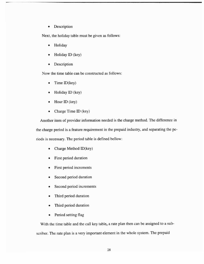
Next, the holiday table must be given as follows:
• Holiday
• Holiday ill (key)
• Description
Now the time table can be constructed as follows:
• Time ID(key)
• Holiday ID (key)
• Hour ill (key)
• Charge Time ID (key)
Another item of provider information needed is the charge method. The difference in
the charge period is a feature requirement in the prepaid industry, and separating the pe
riods is necessary. The period table is defined bellow:
• Charge Method ID(key)
• First period duration
• First period increments
• Second period duration
• Second period increment
• Third period duration
• Third period duration
• Period setting flag
With the time table and the call key table, a rate plan then can be assigned to a ub
scriber. The rate plan is a very important element in the whole system. The prepaid
28
phone, calling card and prepaid card all have different rating charges depending on the
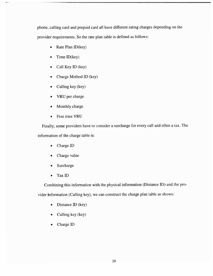
provider requirements. So the rate plan table is defined as follow:
• Rate Plan 1O(key)
• Time 1O(key)
• Call Key 10 (key)
• Charge Method 10 (key)
• Calling key (key)
• VRU per charge
• Monthly charge
• Free tries VRU
Finally, some providers have to consider a surcharge for every call and often a tax. The
infonnation of the charge table is:
• Charge 10
• Charge value
• Surcharge
• Tax 10
Combining this infonnation with the physical information (Distance 10) and the pro-
vider information (Calling key), we can construct the charge plan table as shown:
• Distance ID (key)
• Calling key (key)
• Charge ID
29

Object Model
Figure 1. Prepaid phone, Postpaid phone, Calling Card, Prepaid Card, live Period, Action, HomeCarrier, Rate plan, Reference Class Diagram.
3D
.Flnd VRU CNrgll()
.Flnd IoAcrmyCtwgo()
.RoclJce Free TrillS NlntlorO
.RIISBtFr TrillS NlIIWO
.Flnd Tlme 100~IndCtoIrg& MlIlhad 100·Flnd Calli'll K8l()
Reta P1en 10~TlmoiD~alIKeyID~twg.loA&thadID~lIIl1'llley~VRU.,..-ctwgo~crmyctwg&~reetl88VRU
IsH
~JndatdBscrll'Gao(l
.--JC""c&Tlme
FlndCBll1 KtI)'
//
\
H&V
au. alT
~Indat dllScrlpClao()
rlglr<ll Reta C....... 10~IISUr1lllon rurtler 011>'''110- NPXX~1.tareeID
\
'\\
'\\\
\...'J
Cha"gePian
~lstareelD~lIIl1'll ley~twg&ID
~lndat Ctw~o()_
""g& M8Ihad 10~Flr.t .,..-100 cl.r8llao~Flr.t PIO'ladlrcr_~SecandPIO'IOO <l.retlon
~lnda'tcalIIeyIDO ~Secand PIO'lod 1",,_\ ~T~rd PIO'IOO <l.rallao
\
~Tl1rdper1adlrcr_
~"'IOO settllllieg
~Indat dllScripClao()
~.IT)Il8IDlIIlWlISCrtpClao
----------------------------..--------~---------,
Call
CIWC&
~h8<g&ID~IWg& ....U8
~",ctwg&
~T""ID
~Indatcherge()
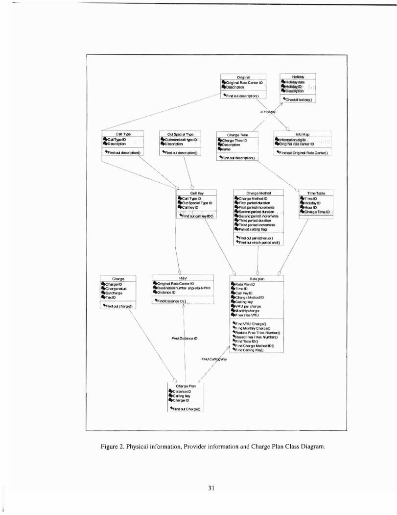
Figure 2. Physical information, Provider information and Charge Plan Class Diagram.
3]
The class diagram is shown in figure 2.
It is no accident that this diagram resembles an entity-relationship diagram. A the
figure shows, we can see the relationships among all classes. In figure one, for example,
Live Period to Action is I to m; Prepaid Phone to Phone Information is m to L; Postpaid
phone to Phone information is m to I; Prepaid Phone, Postpaid phone, Calling card and
Prepaid Card to Live Period are 1 to 1; Prepaid phone, Postpaid phone and Calling card
to Customer Account are m to I; Customer Account to Horne Carrier and Rate plan, Ref
erence are 1 to ]; Customer Account to Notes is I to m; Agent to Reference is I to 1; Op
erator to Reference is 1 to I.
In figure two, the physical information and provider information class relationship
will be as follows: Information Map to Original is m to 1; H&V to Original is m to I;
Call key to Call Type and Out Special Type are n to m, Charge Time to Holiday is m to
n, Rate Plan to Call key, Time Table, and Charge Method are n to m, Charge Plan to
H&V and Rate Plan are n to m, etc.
The CDR (call record) table is the result of the transactions of Processing Call and
Terminal. After each transaction, the provider must make finance reports and system sta
tistics reports, so the CDR has to be recorded. This table basically includes the call proc
ess, physical information and provider information, so the CDR table is defined as fol
lows:
• ID number
• Type ofID
• Onis
• Original Rate Center
:n

• Time to make call
• Time to end call
• Rate plan ( customer could change in his life time)
• Rate Plan Detail ( system can change that from time to time)
• New balance
• Old balance
• Expiration date
• Switch Trunk information
• Prepaid Card to use
• Transaction type
• Market Information
Not only does the call process need to be recorded, but also terminal transactions
need to be written down as the TCDR table. Depending on the terminal functions, the fo\
lowing information has to be recorded.
• I[) numher
• Type of ID
• Market ID
• Operator ID
• Transaction type
• New balance
• Old balance
• Expiration date
• Time to process
33
According to the analysis, the identity of the system is defined by all these table .
The relationships to other objects are shown in Figures 1 and 2. The attribute of the e
objects are listed under their identities as above. In order to maintain all these objects,
add, remove and update functions must be defined. These are the operations of their ob
jects.
Dynamic Model
By examining its static structure, a system can best be understood by first looking at
the structure of its objects and their relationships to each other at a single moment in
time. Then moving on to examine the system with time changes, which is constructing
the dynamic model. The live period of the subscriber is the first model that can be exam
ined.
34
Inventory
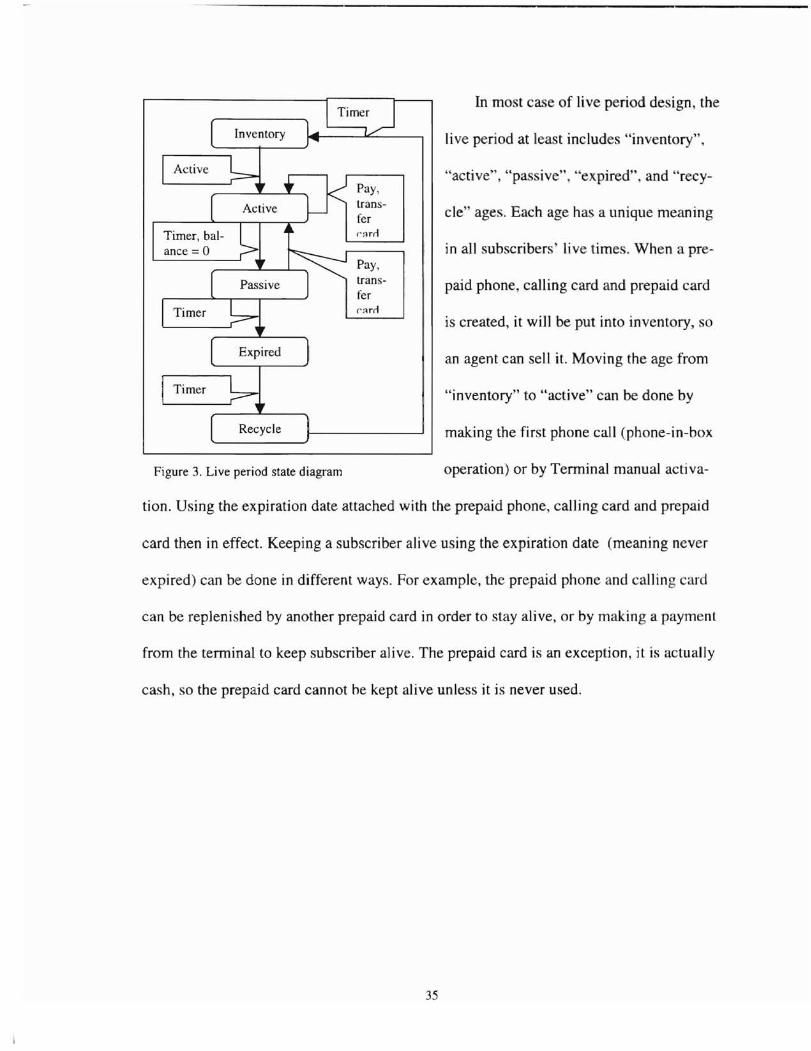
Figure 3. Live period state diagram
Pay,transferr:lrrl
Pay,transferr':lrrl
In most case of live period design, the
live period at least includes "inventory",
"active", "passive", "expired", and "recy-
cle" ages. Each age has a unique meaning
in all subscribers' live times. When a pre-
paid phone, calling card and prepaid card
is created, it will be put into inventory, so
an agent can sell it. Moving the age from
"inventory" to "active" can be done by
making the first phone call (phone-in-box
operation) or by Terminal manual activa-
tion. Using the expiration date attached with the prepaid phone, calling card and prepaid
card then in effect. Keeping a subscriber alive using the expiration date (meaning never
expired) can be done in different ways. For example, the prepaid phone and calling card
can be replenished by another prepaid card in order to stay alive, or by making a payment
from the terminal to keep subscriber alive. The prepaid card is an exception, it is actually
cash, so the prepaid card cannot he kept alive unless it is never used.
35
I Offer call
Requirebalance
Keepalive
Hang upcall
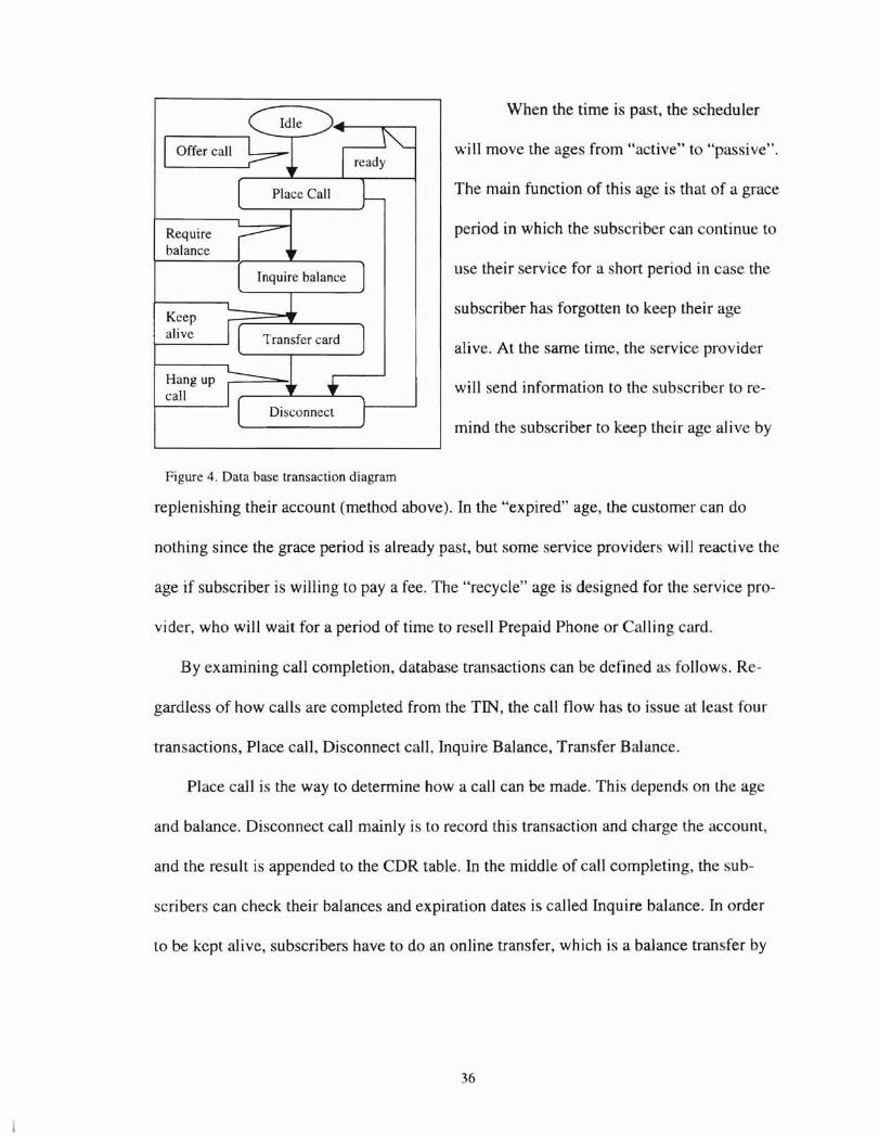
Figure 4. Data base transaction diagram
When the time is past, the scheduler
will move the ages from "active" to "passive".
The main function of this age is that of a grace
period in which the subscriber can continue to
use their service for a short period in case the
subscriber has forgotten to keep their age
alive. At the same time, the service provider
will send information to the subscriber to re-
mind the subscriber to keep their age alive by
replenishing their account (method above). In the "expired" age, the customer can do
nothing since the grace period is already past, but some service providers will reacti ve the
age if subscriber is willing to pay a fee. The "recycle" age is designed for the service pro-
vider, who will wait for a period of time to resell Prepaid Phone or Calling card.
By examining call completion, database transactions can be defined as follows. Re-
gardless of how calls are completed from the TIN, the call flow has to issue at lea t four
transactions, Place call, Disconnect call, Inquire Balance, Transfer Balance.
Place call is the way to determine how a call can be made. This depends on the age
and balance. Disconnect call mainly is to record this transaction and charge the account,
and the result is appended to the CDR table. In the middle of call completing, the sub-
scribers can check their balances and expiration dates is called Inquire balance. In order
to be kept alive, subscribers have to do an online transfer, which is a balance transfer by
36
Prepaid Card or Manual payment to their prepaid account. Figure 4 how all these trans
actions.
Functional Model
Defining functionality on top of the object model and dynamic model creates a func
tional model. A database language such as PUSQL can be used to implement all of the
functions.
One of the most important functions to manipulate the data is the transaction of call
completion. As the dynamic model (Figure 4) indicates, database transactions include the
place call, disconnect call, inquire database, and transfer card transactions.
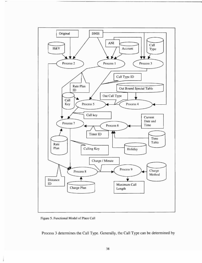
Figure 5 shows the functional model of Place Call. Each step in the data flow proc
ess will be described.
Process 1 determines the Rate Plan 10. When the system receives a call, there are
three parameters that can be received by the system. They are ANI, DNIS and original
rate center. Analyzing ANI can determine if it belongs to the prepaid phone, postpaid
phone, calling card or prepaid card. The key is to determine whether the caller is a user of
a prepaid service or not. After the determination, the customer account table is earched
to find the Rate Plan ill and Balance of this subscriber. If ANI is a prepaid card, the Rate
Plan ill and Balance is found in the prepaid card table instead of the account table.
Process 2 determines the Distance 10. Sometimes the Original input is information
digits. The Original can be found by searching the Info Map table (Figure 2). Searching
the H&V table by the Original and D IS, Distance ill can be retrieved.
37
Process 2
Process 7
TimeTable
CurrentDate andTime
Process 3
Holiday
Account
Process 1
~gKeY
Original
Charge PlanMaximum CallLenglh
Figure 5. Functional Model of Place Call
Process 3 determines the Call Type. Generally, the Call Type can be determined by
38
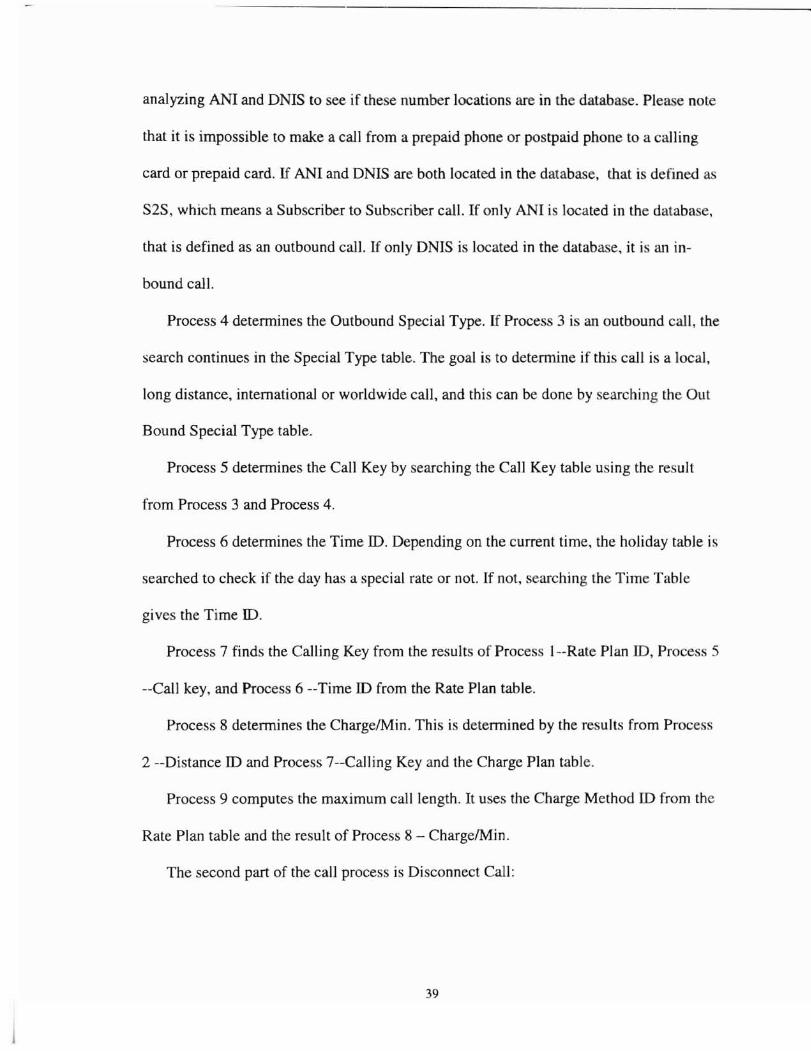
analyzing ANI and DNIS to see if these number locations are in the database. Please note
that it is impossible to make a call from a prepaid phone or postpaid phone to a calling
card or prepaid card. If ANI and DNIS are both located in the database, that i defined a
S2S, which means a Subscriber to Subscriber call. If only ANI i located in the database,
that is defined as an outbound call. If only DNIS is located in the database, it i an in
bound call.
Process 4 determines the Outbound Special Type. If Process 3 is an outbound call, the
search continues in the Special Type table. The goal is to determine if this call is a local,
long distance, international or worldwide call, and this can be done by searching the Out
Bound Special Type table.
Process 5 determines the Call Key by searching the Call Key table using the result
from Process 3 and Process 4.
Process 6 determines the Time ID. Depending on the current time, the holiday table is
searched to check if the day has a special rate or not. If not, searching the Time Table
gives the Time ID.
Process 7 finds the Calling Key from the results of Process I--Rate Plan ill, Proces 5
--Call key, and Process 6 --Time ID from the Rate Plan table.
Process 8 determines the Charge/Min. This is determined by the results from Process
2 --Distance ID and Process 7--Calling Key and the Charge Plan table.
Process 9 computes the maximum call length. It uses the Charge Method ill from the
Rate Plan table and the result of Process 8 - Charge/Min.
The second part of the call process is Disconnect Call:
39
As Figure 4 shows, there are several other transactions that have already been proc-
essed before the Disconnect Call transaction occur . If the record keeping carries over to
this transaction, the process will be much faster. It is very useful to examine the input to
this transaction. Before the Disconnect Call transaction occurs, there are two other tran -
actions already completed: the call completing process and VRU proces . The call com-
pleting process needs to calculate the charge, so the balance will be reduced in the sub-
scriber account. The VRU process in most cases does not charge the subscribers' balance,
but for recording traffic purpose, it needs to be recorded in the CDR. The bottom line is
that all these transactions need to be recorded in the CDR.
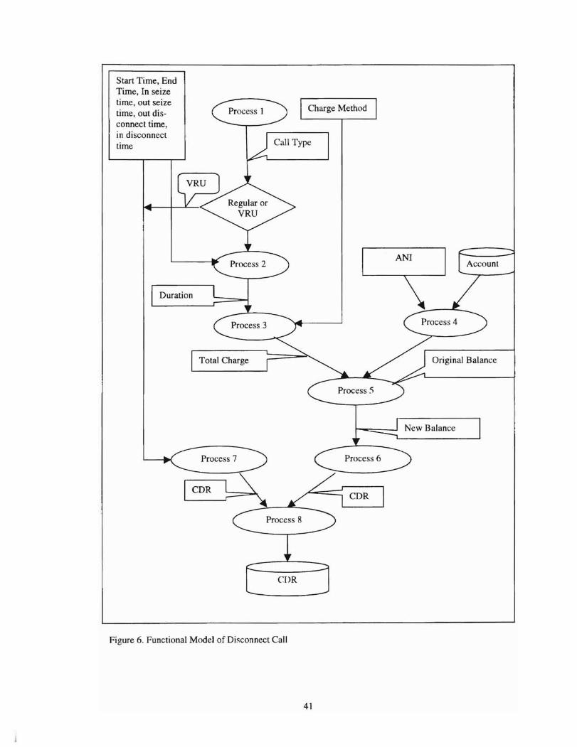
The data flow for Disconnect Call is shown in Figure 6. A brief description of the
processes follows.
Process 1 deteITIlines the Call Type - call completing or VRU access.
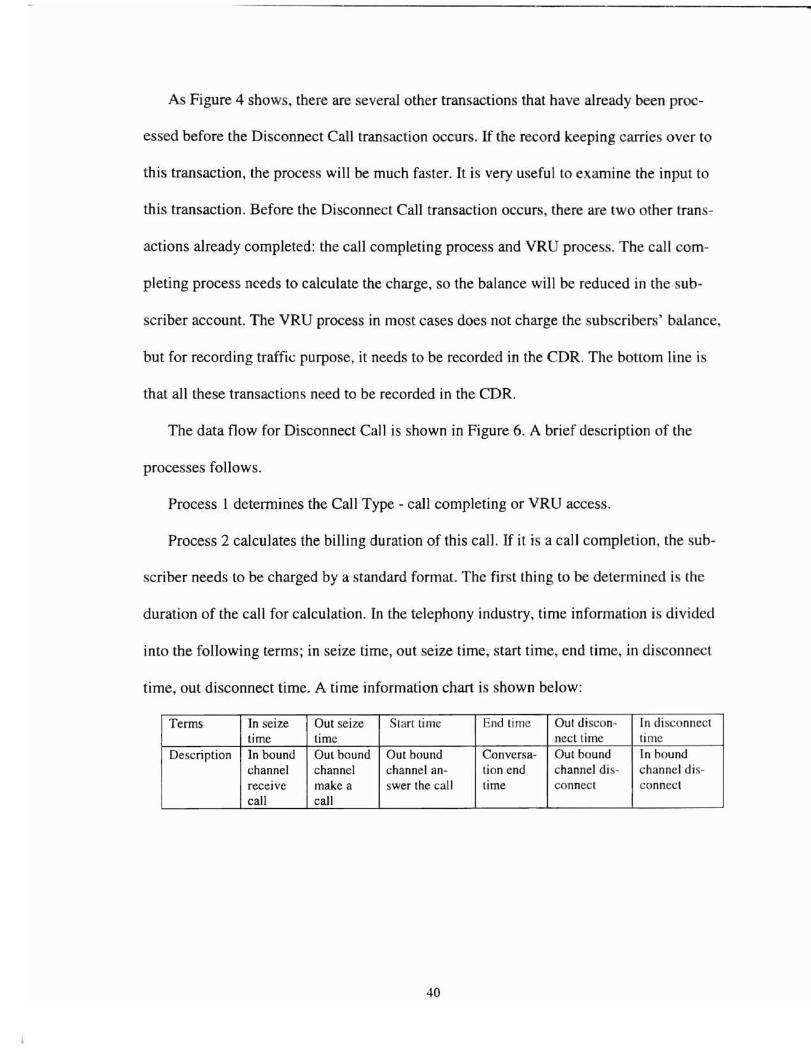
Process 2 calculates the billing duration of this call. If it is a call completion, the sub-
scriber needs to be charged by a standard format. The first thing to be determined i the
duration of the call for calculation. In the telephony industry, time information is divided
into the following terms; in seize time, out seize time, start time, end time, in di connect
time, out disconnect time. A time information chart is shown below:
Terms In seize Out seize Start time End lime Out discon- In disconnecttime time nect time time
Description In bound Out bound Out bound Conversa- Out bound In boundchannel channel channel an- tion end channel dis- channel dis-receive make a swer the call time connect connectcall call
40
Start Time. EndTime. In seizetime. out seizetime. out disconnect time,in disconnecttime
Duration
Process I
Process 3
Total Charge
Charge Method
ANI
Original Balance
Process 7
CDR
Process 6
New Balance
Figure 6. Functional Model of Disconnect Call
41
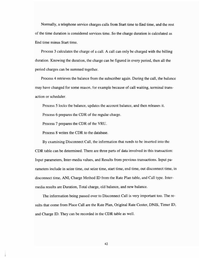
Normally, a telephone service charges calls from Start time to End time, and the rest
of the time duration is considered services time. So the charge duration is calculated as
End time minus Start time.
Process 3 calculates the charge of a call. A call can only be charged with the billing
duration. Knowing the duration, the charge can be figured in every period, then all the
period charges can be summed together.
Process 4 retrieves the balance from the subscriber again. During the call, the balance
may have changed for some reason, for example because of call waiting, terminal trans
action or scheduler.
Process 5 locks the balance, updates the account balance, and then releases it.
Process 6 prepares the CDR of the regular charge.
Process 7 prepares the CDR of the VRD.
Process 8 writes the CDR to the database.
By examining Disconnect Call, the information that needs to be inserted into the
CDR table can be determined. There are three parts of data involved in this tran action:
Input parameters, Inter-media values, and Results from previou transactions. Input pa
rameters include in seize time, out seize time, start time, end time, out disconnect time, in
disconnect time, ANI, Charge Method ID from the Rate Plan table, and Call type. Inter
media results are Duration, Total charge, old balance, and new balance.
The information being passed over to Disconnect Call is very important too. The re
sults that come from Place Call are the Rate Plan, Original Rate Center, DNIS, Timer ID,
and Charge ID. They can be recorded in the CDR table as well.
42
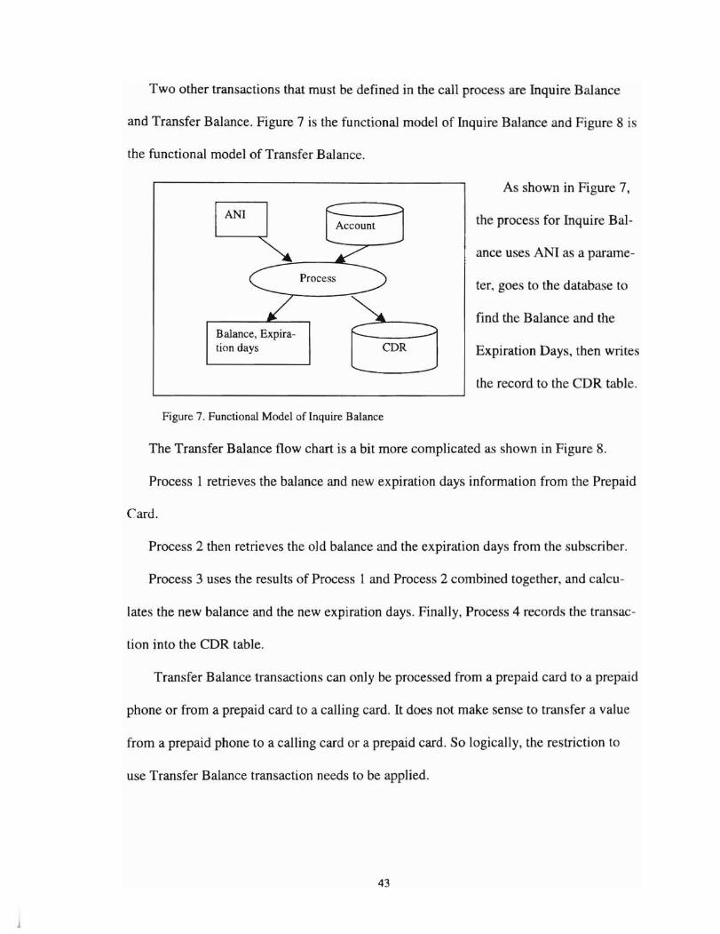
Two other transactions that must be defined in the call process are Inquire Balance
and Transfer Balance. Figure 7is the functional model of Inquire Balance and Figure 8 is
the functional model of Transfer Balance.
Account
~--=~--..-..--
Process
Balance, Expiration days CDR
As shown in Figure 7,
the process for Inquire Bal-
ance uses ANI as a parame-
ter, goes to the database to
find the Balance and the
Expiration Days, then writes
the record to the CDR table.
Figure 7. Functional Model of Inquire Balance
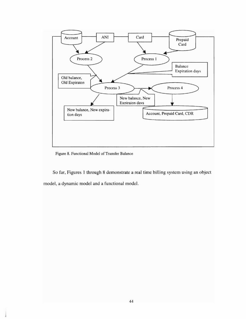
The Transfer Balance flow chart is a bit more complicated as shown in Figure 8.
Process 1 retrieves the balance and new expiration days information from the Prepaid
Card.
Process 2 then retrieves the old balance and the expiration days from the subscriber.
Process 3 uses the results of Process 1 and Process 2 combined together, and calcu-
lates the new balance and the new expiration days. Finally, Process 4 records the transac-
tion into the CDR table.
Transfer Balance transactions can only be processed from a prepaid card to a prepaid
phone or from a prepaid card to a calling card. It does not make sense to transfer a value
from a prepaid phone to a calling card or a prepaid card. So logically, the restriction to
use Transfer Balance transaction needs to be applied.
43
Old balance,Old Expiraton
New balance, New expiIation days
BalanceExpiralion day
Process 4
New balance, NewExoiraion days
Account, Prepaid Ca.rd, CDR
Figure 8. Functional Model of Transfer Balance
So far, Figures 1 through 8 demonstrate a real time billing sy tern using an object
model, a dynamic model and a functional model.
44
CHAPTER V
SUMMARY AND CONCLUSIONS
First, twenty-six tables are defined in this design (APPENDIX B).
Second, operations can be found from the different views (Call Proces ,Maintenance,
and Customer Service) in the real time billing system.
From the Call Process point of view, functions include:
Place call
Disconnect Call
Inquire balance
Transfer card
From the maintenance point of view, twenty-six database tables have to be main
tained (add, remove and update functions), These operations have to be implemented.
From the Customer Service point of view, eleven functions have to be implemented
in the system:
Suspend
Unsuspend
Create Subscriber
Create Debit Card
45
Remove subscriber
Make Payment
Change Rate Plan
Find the Subscriber
Note
Reference
Change Pin number.
Depending on various customer requirements, reports should be generated from the
information in the CDR and TCDR database tables.
Obviously a real time billing system executes on a distributed network. The immedi
ate implication of this decision is that a real time billing system does not consist of a sin
gle program.
All these functions which operate on data can be implemented by a database language
named PUSQL, so this database application obviously runs on database . The stand
alone database can then be accessed through a database application by all the peripheral
applications. These applications can be written in traditional high level languages such as
C, C++, VB. Today, it is even possible to build all these peripheral application a web
based applications.
In this section the real time billing system can be viewed from a higher level. Apply
ing operations on the database can be separated from the database structure, which is
called the Business Rule and Integration Layer. Separating all the peripheral applications,
which access the database through some sort of network, can clearly simplify the whole
46
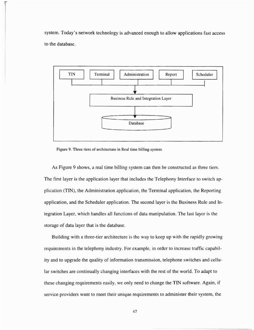
system. Today's network technology is advanced enough to allow applications fast acce
to the database.
I Scheduler I
Business Rule and Integration Layer
Database
Figure 9. Three tiers of architecture in Real time billing system.
As Figure 9 shows, a rea] time billing system can then be constructed as three tiers.
The first layer is the application layer that includes the Telephony Interface to switch ap
plication (TIN), the Administration application, the Terminal application, the Reporting
application, and the Scheduler application. The second layer is the Business Rule and In
tegration Layer, which handles all functions of data manipulation. The last layer is the
storage of data layer that is the database.
Building with a three-tier architecture is the way to keep up with the rapidly growing
requirements in the telephony industry. For example, in order to increase traffic capabil
ity and to upgrade the quality of information transmission, telephone switches and cellu
lar switches are continually changing interfaces with the rest of the world. To adapt to
these changing requirements easily, we only need to change the TIN software. Again, if
service providers want to meet their unique requirements to administer thei.r system, the
47
modifications only affect the first layer. Certainly reports are different from one carrier to
another, and it is much simpler to only change the Report application without affecting
the other applications. Once the second layer is implemented, every application will share
the same routine to access the data, creating a consistent acce s method. This is a benefit
for all the applications if any function and/or business rule has to be changed by new re
quirements. Running the database alone has a lot of advantages as well.
This paper discusses the creation of a real time billing system with Object-Oriented
design, using the object model, dynamic model and functional model. A database can be
derived easily from all these models, and depending on the models, functions will then be
seamlessly implemented as above. Using the three-tier architecture, the applications can
be separated easily from a complicated system. According to this analysis, a real time
billing system can then be composed of the peripheral applications, database applications
and the database itself.
Certainly, this paper does not cover all the Object-Oriented Design methods. The en
tire requirements are limited by my experience, but clearly, Object-oriented Design is the
direction to approach the design of a complex software system.
48

REFERENCES
j. Adams, Steve. "A little advantage goes a long way." Journal of Communications New, Volume 36,Number 1, January 1999.
2. Alterio, Robbie. "Best Enhanced Services Product: APEX's Tasty AU-Encompassing BiUing System."Journal of Computer Telephony - Best oiCT Expo Spring 99, Volume 7, Number 4, April 1999.
3. Bertino, Elisa, Lorenzo Martino. Object-Oriented Database Systems. Working, England: Addisonwesley Publishing Ltd. 1993.
4. Booch, Grady. Object Oriented Design with Applications. Redwood City, CA: The Benjamin/Cummings Publishing Company, Inc. 1991.
5. Bowers ,D.S.. From Data To Database. Wokingham: Van Nostrand Reinhold, 1988.
6. Cellular Telecommunications Industry Association. "Calling Party Pay." Jouma] of The World ofWireless Communications Volume 5, Number 1, January 1998.
7. Clark, David L.. Database Design -Applications of Library Cataloging Techniques, the first edition.New York, NY: McGraw-HilI, 1991.
8. Dziatkiewicz, Mark. "Can Calling Party Pay Off?" Journal of Wireless Business, Volume 4, Numberll, November 1998.
9. Edgar, Bob. PC Telephony, 3rd Edition,New York, NY: Flatiron Publishing, Inc., 1995.
JO. Ghezzi, Carlo, Mehdi Jazayeri and Dino Mandrio1i. Fundamentals of Software Engineering. Englewood Cliffs, NJ: Prentice Hall, 1991.
11. Jezequel, Jean-Marc. Object-Oriented Software engineering with Eiffel. Menlo Park, CA: AddisonWesley, 1996.
12. Lee, Barbara. "Wireless Billing." Journal of Wireless Business, Volume 4, Number II, November1998.
13. Lorenz, Mark. Object-Oriented Software Development - a practical Guide. Englewood Cliffs, NJ:Prentice Hall, 1993.
14. McConnell, Katie. "Saville Systems: Committed to a Customer-Centric Approach." Journal of Wireless Business & Technology, Volume4, Number 12, December 1998.
15. Packhem, David. "Competing in Real Time." Journal of Wireless Review Volume IS. Number 11,page 70, June I, 1998.
16. Rumbaugh, James, Michael Blaha, William Premerlani, Frederick Eddy and William Lorensen. Object-Oriented Modeling and Design. Englewood Cliffs, NJ: Prentice Hall, 1991.
49

17. Shapiro, Jeffrey R.. Computer Telephony Strategies. Foster City, CA: IDG Books Worldwide, 1996.
18. Strange, Keiser. Digital Telephony and Network Integration. New York, NY: Van Nostrand ReinholdCo., 1985.
19. Ullman, Jeffrey. Principles of Database and Knowledge-Base Systems, Volumes I. Rockville, MD:Computer Science Press, 1988.
20. Walden, Kim and Jean-Marc Nerson. Seamless Object-Oriented Software Architecture - analy is anddesign of reliable systems. Hemel Hempstead: Prentice Hall International Ltd, 1995.
21. Walters, Rob. crr in Action.: New York. NY: John Wiley & Sons,1997.
22. Zdonik, Stanley B., and David Maier. Readings in Object-Oriented Database Systems. SanMateo, CAMongan Kaufmann, 1990.
50
ANI
ANSI
CDR
DNIS
H&V
IVR
OMT
S2S
SPARC
TIN
VRU
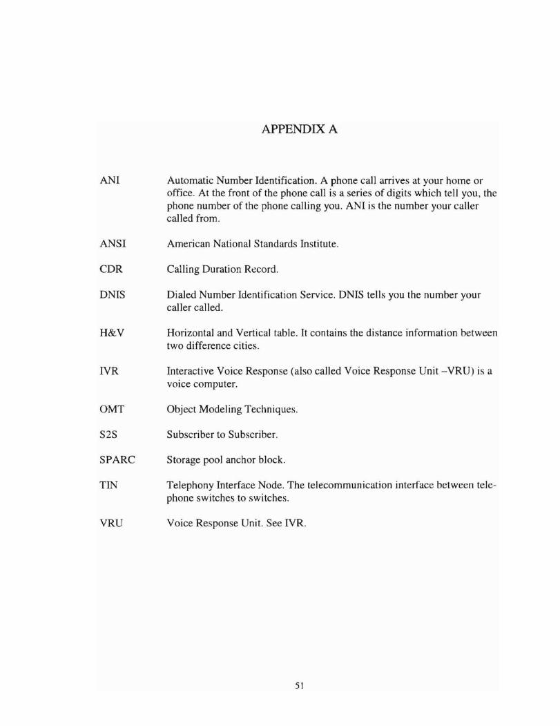
APPENDIX A
Automatic Number Identification. A phone call arrives at your home oroffice. At the front of the phone call is a series of digits which tell you, thephone number of the phone calling you. ANI is the number your callercalled from.
American National Standards Institute.
Calling Duration Record.
Dialed Number Identification Service. DNIS tells you the number yourcaller called.
Horizontal and Vertical table. It contains the distance information betweentwo difference cities.
Interactive Voice Response (also called Voice Response Unit -VRU) is avoice computer.
Object Modeling Techniques.
Subscriber to Subscriber.
Storage pool anchor block.
Telephony Interface Node. The telecommunication interface between telephone switches to switches.
Voice Response Unit. See IVR.
51
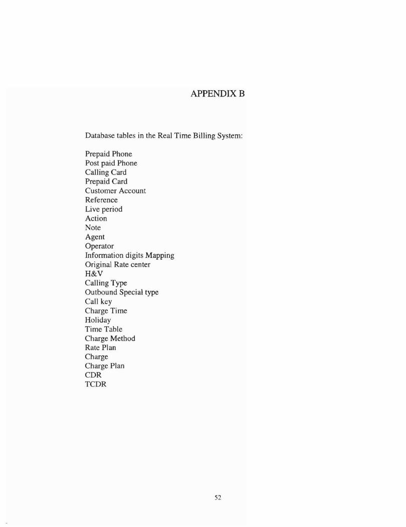
APPENDIXB
Database tables in the Real Time Billing System:
Prepaid PhonePost paid PhoneCalling CardPrepaid CardCustomer AccountReferenceLive periodActionNoteAgentOperatorInformation digits MappingOriginal Rate centerH&VCalling TypeOutbound Special typeCall keyCharge TimeHolidayTime TableCharge MethodRate PlanChargeCharge PlanCDRTCDR
52
VITA
Zhiming Dai
Candidate for the Degree of
Master of Science
Thesis: REAL TIME BllLING SYSTEM
Major Field: Computer Science
Biographical:
Personal Data: Born in Shanghai, China, March 03,1969, the son of Wang ChengDai and ZhengYing Yang.
Education: Graduated from the No.2 middle school to the East China NormalUniversity, in June 1987; received Bachelor of Engineering Degree fromShanghai University of Technology at Shanghai in June 1991; compI tedrequirements for the Master of Science degree at Oklahoma State University in July, 2000.
Professional Experience: Software Engineer, Department of Engineering, MPS!.June, 1991 to April, 1995; Senior Software Engineer, Department ofResearch and Development, Boston Communication Group Inc., May, )995to August, 1998; Senior Manager, Department of Research and Development, Boston Communication Group Inc., August, 1998 until now.