reactive design patterns
TRANSCRIPT
Reactive Design Patterns
ROLAND KUHN
WITH BRIAN HANAFEEAND JAMIE ALLEN
FOREWORD BY JONAS BONÉR
M A N N I N GSHELTER ISLAND

For online information and ordering of this and other Manning books, please visitwww.manning.com. The publisher offers discounts on this book when ordered in quantity. For more information, please contact
Special Sales DepartmentManning Publications Co.20 Baldwin RoadPO Box 761Shelter Island, NY 11964Email: [email protected]
©2017 by Manning Publications Co. All rights reserved.
No part of this publication may be reproduced, stored in a retrieval system, or transmitted, in any form or by means electronic, mechanical, photocopying, or otherwise, without prior written permission of the publisher.
Many of the designations used by manufacturers and sellers to distinguish their products are claimed as trademarks. Where those designations appear in the book, and Manning Publications was aware of a trademark claim, the designations have been printed in initial caps or all caps.
Recognizing the importance of preserving what has been written, it is Manning’s policy to have the books we publish printed on acid-free paper, and we exert our best efforts to that end. Recognizing also our responsibility to conserve the resources of our planet, Manning booksare printed on paper that is at least 15 percent recycled and processed without the use of elemental chlorine.
Manning Publications Co. Development editor: Jennifer Stout20 Baldwin Road Technical development editor: Brian HanafeePO Box 761 Project editors: Tiffany Taylor and Janet VailShelter Island, NY 11964 Line editor: Ben Kovitz
Copyeditor: Tiffany TaylorProofreader: Katie Tennant
Technical proofreader: Thomas LockneyTypesetter: Dottie Marsico
Cover designer: Leslie Haimes
ISBN 9781617291807Printed in the United States of America1 2 3 4 5 6 70 8 9 10 – EBM – 22 21 20 19 18 17

To my children — Roland

v
brief contentsPART 1 INTRODUCTION................................................................ 1
1 ■ Why Reactive? 32 ■ A walk-through of the Reactive Manifesto 123 ■ Tools of the trade 39
PART 2 THE PHILOSOPHY IN A NUTSHELL ................................... 654 ■ Message passing 675 ■ Location transparency 816 ■ Divide and conquer 917 ■ Principled failure handling 1008 ■ Delimited consistency 1059 ■ Nondeterminism by need 113
10 ■ Message flow 120
PART 3 PATTERNS .................................................................... 12511 ■ Testing reactive applications 12712 ■ Fault tolerance and recovery patterns 16213 ■ Replication patterns 18414 ■ Resource-management patterns 22015 ■ Message flow patterns 25516 ■ Flow control patterns 29417 ■ State management and persistence patterns 311

vii
contentsforeword xvpreface xviiacknowledgments xixabout this book xxiabout the authors xxiv
PART 1 INTRODUCTION.................................................1
1 Why Reactive? 31.1 The anatomy of a Reactive application 41.2 Coping with load 51.3 Coping with failures 71.4 Making the system responsive 81.5 Avoiding the ball of mud 101.6 Integrating nonreactive components 101.7 Summary 11
2 A walk-through of the Reactive Manifesto 122.1 Reacting to users 12
Understanding the traditional approach 13 ■ Analyzing latency with a shared resource 15 ■ Limiting maximum latency with a queue 16

CONTENTSviii
2.2 Exploiting parallelism 18Reducing latency via parallelization 18 ■ Improving parallelism with composable Futures 20 ■ Paying for the serial illusion 21
2.3 The limits of parallel execution 23Amdahl’s Law 23 ■ Universal Scalability Law 24
2.4 Reacting to failure 26Compartmentalization and bulkheading 28 ■ Using circuit breakers 29 ■ Supervision 30
2.5 Losing strong consistency 31ACID 2.0 33 ■ Accepting updates 34
2.6 The need for Reactive design patterns 35Managing complexity 36 ■ Bringing programming models closer to the real world 37
2.7 Summary 38
3 Tools of the trade 393.1 Early Reactive solutions 393.2 Functional programming 41
Immutability 41 ■ Referential transparency 44 ■ Side effects 45 ■ Functions as first-class citizens 46
3.3 Responsiveness to users 47Prioritizing the three performance characteristics 47
3.4 Existing support for Reactive design 48Green threads 48 ■ Event loops 49 ■ Communicating Sequential Processes 50 ■ Futures and promises 52Reactive Extensions 57 ■ The Actor model 58Summary 62
PART 2 THE PHILOSOPHY IN A NUTSHELL ....................65
4 Message passing 674.1 Messages 674.2 Vertical scalability 684.3 Event-based vs. message-based 694.4 Synchronous vs. asynchronous 714.5 Flow control 73
CONTENTS ix
4.6 Delivery guarantees 764.7 Events as messages 784.8 Synchronous message passing 804.9 Summary 80
5 Location transparency 815.1 What is location transparency? 815.2 The fallacy of transparent remoting 825.3 Explicit message passing to the rescue 835.4 Optimization of local message passing 845.5 Message loss 855.6 Horizontal scalability 875.7 Location transparency makes testing simpler 875.8 Dynamic composition 885.9 Summary 90
6 Divide and conquer 916.1 Hierarchical problem decomposition 92
Defining the hierarchy 92
6.2 Dependencies vs. descendant modules 94Avoiding the matrix 95
6.3 Building your own big corporation 966.4 Advantages of specification and testing 976.5 Horizontal and vertical scalability 986.6 Summary 99
7 Principled failure handling 1007.1 Ownership means commitment 1007.2 Ownership implies lifecycle control 1027.3 Resilience on all levels 1047.4 Summary 104
8 Delimited consistency 1058.1 Encapsulated modules to the rescue 1068.2 Grouping data and behavior
according to transaction boundaries 107

CONTENTSx
8.3 Modeling workflows across transactional boundaries 1078.4 Unit of failure = unit of consistency 1088.5 Segregating responsibilities 1098.6 Persisting isolated scopes of consistency 1118.7 Summary 112
9 Nondeterminism by need 1139.1 Logic programming and declarative data flow 1139.2 Functional reactive programming 1159.3 Sharing nothing simplifies concurrency 1169.4 Shared-state concurrency 1179.5 So, what should we do? 1179.6 Summary 119
10 Message flow 12010.1 Pushing data forward 12010.2 Modeling the processes of your domain 12210.3 Identifying resilience limitations 12210.4 Estimating rates and deployment scale 12310.5 Planning for flow control 12410.6 Summary 124
PART 3 PATTERNS .....................................................125
11 Testing reactive applications 12711.1 How to test 127
Unit tests 128 ■ Component tests 129 ■ String tests 129Integration tests 129 ■ User-acceptance tests 130 ■ Black-box vs. white-box tests 130
11.2 Test environment 13111.3 Testing asynchronously 132
Providing blocking message receivers 133 ■ The crux of choosing timeouts 135 ■ Asserting the absence of a message 141Providing synchronous execution engines 142 ■ Asynchronous assertions 144 ■ Fully asynchronous tests 145 ■ Asserting the absence of asynchronous errors 147
CONTENTS xi
11.4 Testing nondeterministic systems 150The trouble with execution schedules 151 ■ Testing distributed components 151 ■ Mocking Actors 152 ■ Distributed components 153
11.5 Testing elasticity 15411.6 Testing resilience 154
Application resilience 155 ■ Infrastructure resilience 158
11.7 Testing responsiveness 16011.8 Summary 161
12 Fault tolerance and recovery patterns 16212.1 The Simple Component pattern 162
The problem setting 163 ■ Applying the pattern 163The pattern, revisited 165 ■ Applicability 166
12.2 The Error Kernel pattern 166The problem setting 167 ■ Applying the pattern 167The pattern, revisited 170 ■ Applicability 171
12.3 The Let-It-Crash pattern 171The problem setting 172 ■ Applying the pattern 172The pattern, revisited 173 ■ Implementation considerations 174 ■ Corollary: the Heartbeat pattern 175Corollary: the Proactive Failure Signal pattern 176
12.4 The Circuit Breaker pattern 177The problem setting 177 ■ Applying the pattern 178The pattern, revisited 181 ■ Applicability 182
12.5 Summary 182
13 Replication patterns 18413.1 The Active–Passive Replication pattern 184
The problem setting 185 ■ Applying the pattern 186The pattern, revisited 196 ■ Applicability 197
13.2 Multiple-Master Replication patterns 197Consensus-based replication 198 ■ Replication with conflict detection and resolution 201 ■ Conflict-free replicated data types 203
13.3 The Active–Active Replication pattern 210The problem setting 211 ■ Applying the pattern 211
CONTENTSxii
The pattern, revisited 217 ■ The relation to virtual synchrony 218
13.4 Summary 219
14 Resource-management patterns 22014.1 The Resource Encapsulation pattern 221
The problem setting 221 ■ Applying the pattern 221The pattern, revisited 227 ■ Applicability 228
14.2 The Resource Loan pattern 229The problem setting 229 ■ Applying the pattern 230The pattern, revisited 232 ■ Applicability 233Implementation considerations 233 ■ Variant: using the Resource Loan pattern for partial exposure 234
14.3 The Complex Command pattern 234The problem setting 235 ■ Applying the pattern 236The pattern, revisited 243 ■ Applicability 243
14.4 The Resource Pool pattern 244The problem setting 244 ■ Applying the pattern 245The pattern, revisited 247 ■ Implementation considerations 248
14.5 Patterns for managed blocking 248The problem setting 249 ■ Applying the pattern 249The pattern, revisited 251 ■ Applicability 253
14.6 Summary 253
15 Message flow patterns 25515.1 The Request–Response pattern 255
The problem setting 256 ■ Applying the pattern 257Common instances of the pattern 258 ■ The pattern, revisited 263 ■ Applicability 264
15.2 The Self-Contained Message pattern 265The problem setting 265 ■ Applying the pattern 266The pattern, revisited 268 ■ Applicability 268
15.3 The Ask pattern 269The problem setting 269 ■ Applying the pattern 270The pattern, revisited 273 ■ Applicability 274
15.4 The Forward Flow pattern 275The problem setting 275 ■ Applying the pattern 275The pattern, revisited 276 ■ Applicability 276
CONTENTS xiii
15.5 The Aggregator pattern 277The problem setting 277 ■ Applying the pattern 277The pattern, revisited 281 ■ Applicability 281
15.6 The Saga pattern 282The problem setting 282 ■ Applying the pattern 283The pattern, revisited 284 ■ Applicability 286
15.7 The Business Handshake pattern (a.k.a. Reliable Delivery pattern) 286The problem setting 287 ■ Applying the pattern 287The pattern, revisited 292 ■ Applicability 292
15.8 Summary 293
16 Flow control patterns 29416.1 The Pull pattern 294
The problem setting 295 ■ Applying the pattern 295The pattern, revisited 297 ■ Applicability 298
16.2 The Managed Queue pattern 298The problem setting 298 ■ Applying the pattern 299The pattern, revisited 300 ■ Applicability 301
16.3 The Drop pattern 301The problem setting 301 ■ Applying the pattern 302The pattern, revisited 303 ■ Applicability 306
16.4 The Throttling pattern 306The problem setting 307 ■ Applying the pattern 307The pattern, revisited 309
16.5 Summary 310
17 State management and persistence patterns 31117.1 The Domain Object pattern 312
The problem setting 312 ■ Applying the pattern 313The pattern, revisited 315
17.2 The Sharding pattern 316The problem setting 316 ■ Applying the pattern 316The pattern, revisited 318 ■ Important caveat 319
17.3 The Event-Sourcing pattern 319The problem setting 319 ■ Applying the pattern 320The pattern, revisited 321 ■ Applicability 322

CONTENTSxiv
17.4 The Event Stream pattern 322The problem setting 323 ■ Applying the pattern 323The pattern, revisited 325 ■ Applicability 325
17.5 Summary 326
appendix A Diagramming Reactive systems 327appendix B An illustrated example 329appendix C The Reactive Manifesto 343
index 351
xv
forewordI’m grateful that Roland has taken the time to write this foundational book, and Ican’t think of anyone more capable of pulling it off. Roland is an unusually clear anddeep thinker; he coauthored the Reactive Manifesto, has been the technical lead forthe Akka project for several years, has coauthored and taught the very popular Cour-sera course on Reactive programming and design, and is the best technical writer Ihave met.
Clearly, I’m very excited about this book. It outlines what Reactive architec-ture/design is all about, and does an excellent job explaining it from first principles ina practical context. Additionally, it is a catalog of patterns that explains the bigger pic-ture, how to think about system design, and how it is all connected—much like whatMartin Fowler’s Patterns of Enterprise Application Architecture did 15 years ago.
During my professional life, I have seen the immense benefits of resilient, looselycoupled, message-driven systems firsthand, especially when compared with more-traditional approaches that propose to hide the nature of distributed systems. In 2013,I had the idea of formalizing the experiences and lessons learned: the Reactive Mani-festo was born. It started out as a set of rough notes that I remember presenting to thecompany at one of Typesafe’s (now Lightbend) internal technical meetups. Coinci-dentally, this meetup was collocated with the Scala Days New York conference, whereRoland, Martin Odersky, and Erik Meijer shot their bad, and unintentionally quitefunny, promotion video of their Coursera course on Reactive programming. The storyaround the Reactive principles resonated with the other engineers and was publishedin July of 2013. Since then, the Manifesto has been receiving a lot of great feedbackfrom the community. It was rewritten and vastly improved by Roland, Martin Thomp-son, Dave Farley, and myself, leading up to version 2.0 published in September 2014.

FOREWORDxvi
By the end of 2016, it had been signed by more than 17,000 people. During this time,we have seen Reactive progress from a virtually unacknowledged technique used onlyby fringe projects within a select few corporations to a part of the overall platformstrategy of numerous big players in many different fields, including middleware,financial services, retail, social media, betting/gaming, and so on.
The Reactive Manifesto defines “Reactive Systems” as a set of architectural designprinciples that are geared toward meeting the demands that systems face—today andtomorrow. These principles are most definitely not new; they can be traced back tothe ’70s and ’80s and the seminal work by Jim Gray and Pat Helland on the TandemSystem, as well as Joe Armstrong and Robert Virding on Erlang. However, these pio-neers were ahead of their time, and it was not until the past five years that the technol-ogy industry was forced to rethink current best practices for enterprise systemdevelopment and learned to apply the hard-won knowledge of the Reactive principlesto today’s world of multicore architectures, Cloud Computing, and the Internet ofThings.
By now, the Reactive principles have had a big impact on the industry, and as withmany successful ideas, they get overloaded and reinterpreted. This is not a bad thing;ideas need to evolve to stay relevant. However, this can also cause confusion and leadto dilution of the original intent. One example is the unfortunate emerging miscon-ception that Reactive is nothing but programming in an asynchronous and nonblock-ing style using callbacks or stream-oriented combinators—techniques that are aptlyclassified as Reactive Programming. Concentrating on this aspect alone means miss-ing out on many of the benefits of the Reactive principles. It is the contribution of thisbook to take a much larger perspective—a systems view—moving the focus from howindividual components function in isolation to the design of collaborative, resilient,and elastic systems: Reactive systems.
This future classic belongs on the shelf of every professional programmer, rightnext to GoF1 and Domain-Driven Design.2!Enjoy the ride—I certainly did�
JONAS BONÉR
CTO AND FOUNDER OF LIGHTBEND
CREATOR OF AKKA
1 Design Patterns: Elements of Reusable Object-Oriented Software by Gamma, Helm, Johnson, and Vlissides (Addison-Wesley, 1995).
2 Domain-Driven Design by Eric Evans (Addison-Wesley, 2004).
xvii
prefaceEven before I had officially joined the Akka team, Mike Stephens from Manning triedto convince me to write a book on Akka. I was tempted to say yes, but in the context ofan impending change of jobs and countries, my wife brought me to my senses: such aproject would be too much to handle. The idea of writing a book stuck in my head,though. Three years later—after the Reactive Manifesto had been published—MartinOdersky, Erik Meijer, and I taught the course Principles of Reactive Programming onthe Coursera platform, reaching more than 120,000 students in two iterations. Theidea for that course had been born at a Typesafe engineering meeting where I sug-gested to Martin that we should nurture the blossoming movement of Reactive pro-gramming by demonstrating how to use these tools effectively while avoiding thepitfalls—my own experience answering questions on the Akka mailing list had givenme a good idea of the topics people commonly struggled with.
A video course is a wonderful way of reaching a large number of students, interact-ing with them on the discussion forums, and in general improving the lives of others.Unfortunately, the discussion of the subject is necessarily limited in its depth andbreadth by the format: only so much can be shown in seven weekly lectures. Therefore,I still longed for formalizing and passing on my knowledge about Reactive systems bywriting a book. It would have been straightforward to write about Akka, but I felt thatif I wrote a book, its scope should be wider than that. I love working on Akka—it has lit-erally changed the course of my life—but Akka is merely a tool for expressing distrib-uted and highly reliable systems, and it is not the only tool needed in this regard.
Thus began the journey toward the work you are holding in your hands right now.It was a daunting task, and I knew that I would need help. Luckily, Jamie was just

PREFACExviii
about to finish Effective Akka 3 and was immediately on board. Neither of us had theluxury of writing during daytime; consequently, the book started out slow and keptlagging behind the plan. Instead of having three chapters ready to enter the earlyaccess program during the first iteration of the course Principles of Reactive Program-ming, we could only announce it several months later. It is astonishing how muchdetail one finds missing when starting out from the viewpoint that the contents arebasically already known and just need to be transferred into the computer. Over time,Jamie got even busier with his day job, until he had to stop contributing entirely.Later, Brian joined the project as Manning’s technical development editor, and itsoon became clear that he could not only make very good suggestions but also imple-ment them. We made it official by signing him up as a coauthor, and then Brianhelped me push the manuscript over the finish line.
This book contains not only advice on when and how to use the tools of Reactiveprogramming, but also the reasoning behind the advice, so that you may adapt it todifferent requirements and new applications. I hope that it will inspire you to learnmore and to explore the wonderful world of Reactive systems.
ROLAND KUHN
3 Effective Akka by Jamie Allen (O’Reillly Media, 2013).

xix
acknowledgmentsROLAND KUHN My first thanks go to Jamie, without whom I would not have daredtake on this project. But my deepest gratitude is to Jonas Bonér, who created Akka,entrusted Akka to my care for many years, and supported me on every step along theway. I am also deeply thankful to Viktor Klang for countless rigorous discussions aboutall topics of life (and distributed systems) but, more importantly, for teaching me howto lead by example and how important it is to not let the devil over the bridge. Jonas,Viktor, and Patrik Nordwall also deserve special thanks for covering my duties as AkkaTech Lead while I took a mini-sabbatical of three months to work intensely on thisbook. I greatly appreciate Brian and Jamie stepping up and shouldering part of thetremendous weight of such a project: it is gratifying and motivating to work alongsidesuch trusted companions.
For helpful reviews of the early manuscript, I would like to thank Sean Walsh andDuncan DeVore, as well as Bert Bates, who helped shape the overall arrangement ofhow the patterns are presented. I also thank Endre Varga, who spent considerableeffort developing the KVStore exercise for Principles of Reactive Programming thatforms the basis for the state replication code samples used in chapter 13. Thanks alsogo to Pablo Medina for helping me with the CKite example code in section 13.2, andto Thomas Lockney, technical proofreader, who kept a sharp eye out for errors. Thefollowing peer reviewers gave generously of their time: Joel Kotarski, Valentine Sinit-syn, Mark Elston, Miguel Eduardo Gil Biraud, William E. Wheeler, Jonathan Freeman,Franco Bulgarelli, Bryan Gilbert, Carlos Curotto, Andy Hicks, William Chan, JacekSokulski, Dr. Christian Bridge-Harrington, Satadru Roy, Richard Jepps, Sorbo Bagchi,NenkoTabakov, Martin Anlauf, Kolja Dummann, Gordon Fische, Sebastien Boisver,

ACKNOWLEDGMENTSxx
and Henrik Løvborg. I am grateful to the Akka community for being such a welcom-ing and fertile place for developing our understanding of distributed systems.
I would like to thank the team at Manning who made this book possible, especiallyMike Stephens for nagging until I gave in, Jenny Stout for urging me to make prog-ress, and Candace Gillhoolley from marketing. I would like to distinguish Ben Kovitzas an extremely careful and thorough copy editor, and I thank Tiffany Taylor forfinding even more redundant words to be removed from the final text, as well as KatieTennant for identifying and fixing unclear passages.
Finally, in the name of all readers, I extend my utmost appreciation and love to mywife, Alex. You endured my countless hours of spiritual absence with great compassion.
JAMIE ALLEN I wish to thank my wife, Yeon, and my three children, Sophie, Layla, andJames. I am also grateful to Roland for allowing me to participate in this project, and toBrian for pushing the project over the finish line and contributing his expertise.
BRIAN HANAFEE I thank my wife, Patty, for supporting me, always, and my daughters,Yvonne and Barbara, for helping me with Doctor Who history and sometimes pretend-ing my jokes are funny. Thank you, Susan Conant and Bert Bates, for getting mestarted and teaching me how to edit and teach in book form. Finally, thank you,Roland and Jamie, for showing me Reactive principles and welcoming me into thisproject.
xxi
about this bookThis book is intended to be a comprehensive guide to understanding and designingReactive systems. Therefore, it includes not only an annotated version of the ReactiveManifesto, but also the reasoning that led to its inception. The main part of the bookis a selection of design patterns that implement many facets of Reactive system design,with pointers toward deeper literature resources for further study. While the pre-sented patterns form a cohesive whole, the list is not exhaustive—it cannot be—butthe included background knowledge will enable the reader to identify, distill, andcurate new patterns as the need arises.
Whom this book is forThis book was written for everyone who may want to implement Reactive systems:
� It covers the architecture of such systems as well as the philosophy behind it,giving architects an overview of the characteristics of Reactive applications andtheir components and discussing the applicability of the patterns.
� Practitioners will benefit from a detailed discussion of the scenario solved byeach pattern, the steps to take in applying it—illustrated with complete sourcecode—as well as a guide to transfer and adapt the pattern to different cases.
� Learners wishing to deepen their knowledge, for example, after viewing thecourse material of Principles of Reactive Programming, will be delighted toread about the thought processes behind the Reactive principles and to followthe literature references for further study.
This book does not require prior knowledge of Reactive systems; it builds upon famil-iarity with software development in general and refers to some experience with the
ABOUT THIS BOOKxxii
difficulties arising from distributed systems. For some parts, a basic understanding offunctional programming is helpful (in the sense of programming with immutable val-ues and pure functions), but category theory does not feature in this book.
How to read this bookThe contents of this book are arranged such that it lends itself well to being read as astory, cover to cover, developing from an introductory example and an overview of theReactive Manifesto and the Reactive toolbox, continuing with the philosophy behindReactive principles, and culminating in the description of patterns covering the differ-ent aspects of designing a Reactive system. This journey covers a lot of ground and thetext contains references to additional background information. Reading it in one gowill leave you with an intuition of the scope of the book and what information is foundwhere, but it will typically only be the entry point for further study; you will return forthe extraction of deeper insights while applying the acquired knowledge in projects ofyour own.
If you are already familiar with the challenges of Reactive systems, you may skip thefirst chapter, and you will likely skim chapter 3 on the tools of the trade because youhave already worked with most of those. The impatient will be tempted to start readingthe patterns in part 3, but it is recommended to take a look at part 2 first: the patterndescriptions frequently refer to the explanations and background knowledge of thismore theoretical part that form the basis on which the patterns have been developed.
It is expected that you will return to the more philosophical chapters—especiallychapters 8 and 9—after having gained more experience with the design and imple-mentation of Reactive systems; don’t worry if these discussions do not immediatelybecome fully transparent upon first reading.
ConventionsDue to the overloading of the English term “future” for a programming concept thatdeviates significantly from the original meaning, all uses of the word referring to theprogramming concept appear capitalized as Future, even when not appearing incode font.
The situation is slightly different for the term “actor,” which in plain English refersto a person on stage as well as a participant in an action or process. This term appearscapitalized only when referring specifically to the Actor model, or when the name ofthe Actor trait appears in code font.
Source code for the examplesAll source code for the examples used in this book are available for download onGitHub here: https://github.com/ReactiveDesignPatterns/CodeSamples/.
GitHub also offers facilities for raising issues with the samples or discussing them;please make use of them. You are also welcome to open pull requests with improve-ments; this way, all future readers will benefit from your thoughtfulness and experience.
ABOUT THIS BOOK xxiii
Most of the samples are written in Java or Scala and use sbt for the build definition;please refer to www.scala-sbt.org/ for detailed documentation. A Java development kitsupporting Java 8 will be required to build and run the samples.
Other online resourcesAn overview of the presented patterns as well as further material is available atwww.reactivedesignpatterns.org/. In addition, purchase of Reactive Design Patternsincludes free access to a private web forum run by Manning Publications where youcan make comments about the book, ask technical questions, and receive help fromthe lead author and from other users. To access the forum and subscribe to it, pointyour web browser to www.manning.com/books/reactive-design-patterns. This pageprovides information on how to get on the forum once you are registered, what kindof help is available, and the rules of conduct on the forum.
Manning’s commitment to our readers is to provide a venue where a meaningfuldialog between individual readers and between readers and authors can take place. Itis not a commitment to any specific amount of participation on the part of theauthors, whose contribution to the AO forum remains voluntary (and unpaid). Wesuggest you try asking them some challenging questions lest their interest stray! TheAuthor Online forum and the archives of previous discussions will be accessible fromthe publisher’s website as long as the book is in print.

xxiv
about the authorsDr. Roland Kuhn studied physics at the Technische Universität München andobtained a doctorate with a dissertation on measurements of the gluon spin structureof the nucleon at a high-energy particle physics experiment at CERN (Geneva, Switzer-land). This entailed usage and implementation of large computing clusters and fastdata processing networks, which laid the foundation for his thorough understandingof distributed computing. Afterward, he worked for four years at the German spaceoperations center, building control centers and ground infrastructure for military sat-ellite missions, before joining the Akka team at Lightbend (then called Typesafe),which he led from November 2012 to March 2016. During this time he co-taught thecourse Principles of Reactive Programming on the Coursera platform together withMartin Odersky and Erik Meijer, a course that was visited by more than 120,000 stu-dents. Together with Jonas Bonér, he authored the first version of the Reactive Mani-festo, published in June 2013. Currently, Roland is CTO of Actyx, a Munich-basedcompany he cofounded, bringing the benefits of modern Reactive systems to smalland midsize manufacturing enterprises across Europe.
Brian Hanafee received his BS in EECS from the University of California, Berkeley. Heis a Principal Systems Architect at Wells Fargo Bank, where he designs internet bank-ing and payment systems and is a consistent advocate for raising the technology bar.Previously he was with Oracle, working on new and emerging products and systemsfor interactive television and for text processing. He sent his first email from a movingvehicle in 1994. Prior to that, Brian was an Associate at Booz, Allen & Hamilton and atAdvanced Decision Systems, where he applied AI techniques to military planning

ABOUT THE AUTHORS xxv
systems. He also wrote software for one of the first ejection-safe helmet-mounted dis-play systems.
Jamie Allen is the Director of Engineering for the UCP project at Starbucks, an effort toredefine the digital experience for every customer across all of our operating modelsand locations. He is the author of Effective Akka (O’Reilly, 2013), and previously workedwith Roland and Jonas at Typesafe/Lightbend for over four years. Jamie has been aScala and actor developer since 2008, and has worked with numerous clients aroundthe world to help them understand and adopt Reactive application approaches.


Part 1
Introduction
Have you ever wondered how high-profile web applications are imple-mented? Social networks and huge retail sites must have some secret ingredientthat makes them work quickly and reliably, but what is it? In this book, you willlearn about the design principles and patterns behind such systems that neverfail and are capable of serving the needs of billions of people. Although the sys-tems you build may not have such ambitious requirements, the primary qualitiesare common:
� You want your application to work reliably, even though parts (hardwareor software) may fail.
� You want it to keep working when you have more users to support, andyou want to be able to add or remove resources to adapt its capacity tochanging demand (capacity planning is hard to get right without a crystalball).
In chapter 1, we will sketch the development of an application that exhibitsthese qualities and more. We will illustrate the challenges you will encounter andpresent solutions based on a concrete example—a hypothetical implementationof the Gmail service—but we will do so in a technology-agnostic fashion.
This use case sets the stage for the detailed discussion of the Reactive Mani-festo that follows in chapter 2. The manifesto is written in a concise, high-levelform in order to concentrate on its essence: the combination of individually use-ful program characteristics into a cohesive whole that is larger than the sum ofits parts. We will show this by breaking the high-level traits into smaller piecesand explaining how everything fits back together.

2 PART 1 Introduction
We will complete this part of the book in chapter 3 with a whirlwind tour throughthe tools of the trade: functional programming, Futures and Promises, Communicat-ing Sequential Processes (CSP), Observers and Observables (Reactive Extensions),and the Actor model.
3
Why Reactive?
We start from the desire to build a system that is responsive to users. This means thesystem should respond to user input in a timely fashion under all circumstances.Because any single computer can fail at any time, we need to distribute such a sys-tem over multiple computers. Adding this fundamental requirement for distribu-tion makes us recognize the need for new architecture patterns (or to rediscoverold ones). In the past, we developed methods that allowed us to retain the illusionof single-threaded local processing while having it magically executed on multiplecores or network nodes, but the gap between that illusion and reality is becomingprohibitively large.1 The solution is to make the distributed, concurrent nature ofour applications explicit in the programming model, using it to our advantage.
This book will teach you how to write systems that stay responsive in the face ofpartial outages, program failure, changing loads, and even bugs in the code. Youwill see that this requires adjustments to the way you think about and design yourapplications. Here are the four tenets of the Reactive Manifesto,2 which defines acommon vocabulary and lays out the basic challenges that a modern computer sys-tem needs to meet:
� It must react to its users (responsive).� It must react to failure and stay available (resilient).� It must react to variable load conditions (elastic).� It must react to inputs (message-driven).
1 For example, Java EE services allow us to transparently call remote services that are wired in automatically,possibly even including distributed database transactions. The possibility of network failure or remote ser-vice overload, and so on, is completely hidden, abstracted away, and consequently out of reach for devel-opers to meaningfully take into account.
2 http://reactivemanifesto.org

4 CHAPTER 1 Why Reactive?
In addition, creating a system with these properties in mind will guide you toward bet-ter modularization, both of the runtime deployment and of the code itself. Therefore,we add two more attributes to the list of benefits: maintainability and extensibility.Another way to structure the attributes is shown in figure 1.1.
In the following chapters, you will learn about the reasoning of the Reactive Mani-festo in detail, and you will get to know several tools of the trade and the philosophybehind their design, enabling you to effectively use these tools to implement reactivedesigns. The design patterns that emerge from these tools are presented in the thirdpart of the book. To set the stage for diving into the manifesto, we will first explore thechallenges of creating a Reactive application, using the example of a well-known emailservice: we will imagine a reimplementation of Gmail.
1.1 The anatomy of a Reactive applicationThe first task when starting such a project is to sketch an architecture for the deploy-ment and draft the list of software artifacts that need to be developed. This may not bethe final architecture, but you need to chart the problem space and explore poten-tially difficult aspects. We will start the Gmail example by enumerating the differenthigh-level features of the application:
� The application must offer a view of the mailboxes to the user and display theircontents.
� To this end, the system must store all emails and keep them available.� It must allow the user to compose and send email.� To make this more comfortable, the system should offer a list of contacts and
allow the user to manage them.� A good search function for locating emails is required.
The real Gmail application has more features, but this list will suffice for our pur-poses. Some of these features are more intertwined than the others: for example, dis-playing emails and composing them are both part of the user interface and share (orcompete for) the same screen space, whereas the implementation of email storage isonly distantly related to these two. The implementation of the search function willneed to be closer to the storage than the front-end presentation.
Value Responsive Maintainable Extensible
Means Elastic Resilient
Form Message-driven Figure 1.1 The structure of Reactive values
5Coping with load
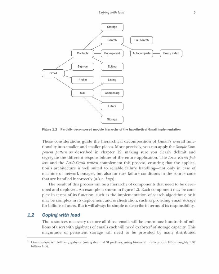
These considerations guide the hierarchical decomposition of Gmail’s overall func-tionality into smaller and smaller pieces. More precisely, you can apply the Simple Com-ponent pattern as described in chapter 12, making sure you clearly delimit andsegregate the different responsibilities of the entire application. The Error Kernel pat-tern and the Let-It-Crash pattern complement this process, ensuring that the applica-tion’s architecture is well suited to reliable failure handling—not only in case ofmachine or network outages, but also for rare failure conditions in the source codethat are handled incorrectly (a.k.a. bugs).
The result of this process will be a hierarchy of components that need to be devel-oped and deployed. An example is shown in figure 1.2. Each component may be com-plex in terms of its function, such as the implementation of search algorithms; or itmay be complex in its deployment and orchestration, such as providing email storagefor billions of users. But it will always be simple to describe in terms of its responsibility.
1.2 Coping with loadThe resources necessary to store all those emails will be enormous: hundreds of mil-lions of users with gigabytes of emails each will need exabytes3 of storage capacity. Thismagnitude of persistent storage will need to be provided by many distributed
3 One exabyte is 1 billion gigabytes (using decimal SI prefixes; using binary SI prefixes, one EB is roughly 1.07billion GB).
Storage
Search Full search
Contacts Pop-up card Autocomplete Fuzzy index
Gmail
Sign-on Editing
Profile Listing
Mail Composing
Filters
Storage
Figure 1.2 Partially decomposed module hierarchy of the hypothetical Gmail implementation
6 CHAPTER 1 Why Reactive?
machines. No single storage device offers so much space, and it would be unwise tostore everything in one location. Distribution makes the dataset resilient against localperils like natural disasters; but, more important, it also allows the data to be accessedefficiently from a larger region. For a worldwide user base, the data should be globallydistributed as well. It would be preferable to have the emails of a Japanese user storedin or close to Japan (assuming that is where the user logs in from most of the time).
This insight leads us to the Sharding pattern described in chapter 17: you can splitup the overall dataset into many small pieces—or shards—that you then distribute.Because the number of shards is much smaller than the number of users, it is practicalto make the location of each shard known throughout the system. In order to find auser’s mailbox, you only need to identify the shard it belongs to. You can do that byequipping every user with an ID that expresses geographical affinity (for example,using the first few digits to denote the country of residence), which is then mathemat-ically partitioned into the correct number of shards (for example, shard 0 containsIDs 0–999,999; shard 1 contains IDs 1,000,000–1,999,999; and so on).
The key here is that the dataset naturally consists of many independent pieces thatcan easily be separated from each other. Operations on one mailbox never affectanother mailbox directly, so the shards also do not need to communicate amongthemselves. Each serves only one particular part of the solution.
Another area in which the Gmail application will need a lot of resources is in thedisplay of folders and emails to the user. It would be impossible to provide this func-tionality in a centralized fashion, not only for reasons of latency (even at the speed oflight, it takes noticeable time to send information around the globe) but also due tothe sheer number of interactions that millions of users perform every second. Here,you will also split the work among many machines, starting with the users’ computers:most of the graphical presentation is rendered within the browser, shifting the work-load very close to where it is needed and in effect sharding it for each user.
The web browser will need to get the raw information from a server, ideally onethat is close by to minimize network round-trip time. The task of connecting a userwith their mailbox and routing requests and responses accordingly is one that can alsoeasily be sharded. In this case, the browser’s network address directly provides allneeded characteristics, including an approximate geographic location.
One noteworthy aspect is that in all the aforementioned cases, resources can beadded by making the shards smaller, distributing the load over more machines. Themaximum number is given by the number of users or used network addresses, whichwill be more than enough to provide sufficient resources. This scheme will needadjustment only when serving a single user requires more computing power than asingle machine can provide, at which point a user’s dataset or computing problemneeds to be broken down into smaller pieces.
This means that by splitting a system into distributable parts, you gain the abilityto scale the service capacity, using a larger number of shards to serve more users. Aslong as the shards are independent from each other, the system is in theory infinitely
7Coping with failures
scalable. In practice, the orchestration and operation of a worldwide deploymentwith millions of nodes requires substantial effort and must of course be worth it.
1.3 Coping with failuresSharding datasets or computational resources solves the problem of providing suffi-cient resources for the nominal case, when everything is running smoothly and net-works are operational. In order to cope with failures, you need the ability to keeprunning when things go wrong:
� A machine may fail temporarily (for example, due to overheating or kernelpanic) or permanently (electrical or mechanical failure, fire, flood, and so on).
� Network components may fail, both within a computing center as well as out-side on the internet—including the case that intercontinental overseas cablesgo down, resulting in a split of the internet into disconnected regions.
� Human operators or automated maintenance scripts may accidentally destroyparts of the data.
The only solution to this problem is to replicate the system—its data or functional-ity—in more than one location. The geographical placement of the replicas needs tomatch the scope of the system; a global email service should serve each customer frommultiple countries, for example.
Replication is a more difficult and diverse topic than sharding because intuitivelyyou mean to have the same data in multiple places—but keeping the replicas synchro-nized to match this expectation comes at a high cost. Should writing to the nearestlocation fail or be delayed if a more distant replica is momentarily unavailable?Should it be impossible to see the old data on a distant replica after the nearest onehas already signaled completion of the operation? Or should such inconsistency justbe unlikely or very short-lived? These questions will be answered differently betweenprojects or even for different modules of one particular system. Therefore, you arepresented with a spectrum of solutions that allows you to make trade-offs betweenoperational complexity, performance, availability, and consistency.
We will discuss several approaches covering a wide range of characteristics in chap-ter 13. The basic choices are as follows:
� Active–passive replication—Replicas agree on which one of them can acceptupdates. Fail-over to a different replica requires consensus among the remain-ing ones when the active replica no longer responds.
� Consensus-based multiple-master replication—Each update is agreed on by suffi-ciently many replicas to achieve consistent behavior across all of them, at thecost of availability and latency.
� Optimistic replication with conflict detection and resolution—Multiple active replicasdisseminate updates and roll back transactions during conflict or discard con-flicting updates that were performed during a network partition.
8 CHAPTER 1 Why Reactive?
� Conflict-free replicated data types—This approach prescribes merge strategies suchthat conflicts cannot arise by definition, at the cost of providing only eventualconsistency and requiring special care when creating the data model.
In the Gmail example, several services should provide consistency to the user: if a usersuccessfully moves an email to a different folder, they expect it to stay in that folderregardless of which client they use to access their mailboxes. The same goes forchanges to a contact’s telephone number or the user's profile. For these data, youcould use active–passive replication to keep things simple by making the failureresponse actions coarse-grained—that is, on a per-replica scope. Or you could useoptimistic replication under the assumption that a single user will not concurrentlymake conflicting changes to the same data item—but keep in mind that this is a fairassumption only for human users.
Consensus-based replication is needed within the system as an implementationdetail of sharding by user ID, because the relocation of a shard must be recorded accu-rately and consistently for all clients. It would lead to user-visible distortions like anemail disappearing and then reappearing if a client were to flip-flop between decom-missioned and live replicas.
1.4 Making the system responsiveThe previous two sections introduced reasons for distributing the system across sev-eral machines, computing centers, or possibly even continents, matching the scopeand reliability requirements of the application. The foremost purpose of this exerciseis to build an email service for end users, though, and for them the only metric thatcounts is whether the service does what they need when they need it. In other words,the application must respond quickly to any request a user makes.
The easiest way to achieve this is, of course, to write an application that runs locallyand that has all emails stored on the local machine as well: going across the networkto fetch an answer will always take longer and be less reliable than having the answerclose by. There is, thus, a tension between the need to distribute and the need to stayresponsive. All distribution must be justified, as in the Gmail example.
Where distribution is necessary, you encounter new challenges in the quest forresponsiveness. The most annoying behavior of many distributed applications today isthat their user interaction grinds to a halt when network connectivity is poor. Interest-ingly, it seems much simpler to deal with the complete absence of a connection thanwith a trickling flow of data. One pattern that is helpful in this context is the CircuitBreaker pattern discussed in detail in chapter 12. With this tool, you can monitor theavailability and performance of a service that you are calling on for some function sothat when the quality falls below a threshold (either too many failures or too long aresponse latency), the circuit breaker trips, forcing a switch to a mode where that ser-vice is not used. The unavailability of parts of the system needs to be considered fromthe beginning; the Circuit Breaker pattern addresses this concern.
9Making the system responsive
Another threat to responsiveness arises when a service that the applicationdepends on becomes momentarily overloaded. A backlog of requests will accumulate,and while these are processed, response latencies will be much longer than normal.This situation can be avoided by employing flow control, as described in chapter 16. Inthe Gmail example, there are several points at which circuit breakers and flow controlare needed:
� Between the front end that runs on the users’ devices and the web servers thatprovide access to back-end functionality
� Between the web servers and back-end services
The reason for the first point has already been mentioned: the desire to keep the user-visible part of the application responsive under all conditions, even if sometimes theonly thing it can do is signal that the server is down and that the request will be com-pleted at a later time. Depending on how much functionality can or should practicallybe duplicated in the front end for this offline mode, some areas of the user interfacemay need to be deactivated.
The reason for the second point is that the front end would otherwise need tohave different circuit breakers for different kinds of requests to the web server, eachcircuit breaker corresponding to the specific subset of back-end services needed byone kind of request. Switching the entire application to offline mode when only asmall part of the back-end services are unavailable would be an unhelpful over-response. Tracking this in the front end would couple its implementation to the pre-cise structure of the back end, requiring the front-end code to be changed wheneverthe service composition of the back end was altered. The web-server layer should hidethese details and provide its clients with responses as quickly as possible under all cir-cumstances.
Take, for example, the back-end service that provides the information shown onthe contact card that pops up when hovering the pointer over an email sender’sname. This is a nonessential function, considering the overall function of Gmail, sothe web server may return a temporary failure code for such requests while that back-end service is unavailable. The front end does not need to track this state; it canmerely refrain from showing the pop-up card and retry the request when interactionwith the user triggers it again.
This reasoning applies not only at the web server layer. In a large application thatconsists of hundreds or thousands of back-end services, it is imperative to confine thetreatment of failure and unavailability in this fashion; otherwise, the system would beunreasonable in the sense that its behavior could no longer be understood byhumans. Just as functionality is modularized, the treatment of failure conditions mustbe encapsulated in comprehensible scopes as well.

10 CHAPTER 1 Why Reactive?
1.5 Avoiding the ball of mudThe Gmail application at this point consists of a front-end part that runs on the user’sdevice, back-end services that provide storage and functionality, and web servers thatact as entry points into the back end. The latter serve an important purpose beyondthe responsiveness discussed in the previous section: they decouple the front endfrom the back end architecturally. Having this clearly defined ingress point for clientrequests makes it simpler to reason about the interplay between the part of the appli-cation that runs on the users’ devices and the part that runs on servers in the cloud.
The back end so far consists of a multitude of services whose partitioning and rela-tionships resulted from the application of the Simple Component pattern. By itself,this pattern does not provide the checks and balances that keep the architecture fromdevolving into a large mess where every service talks with almost every other service.Such a system would be hard to manage even with perfect individual failure handling,circuit breakers, and flow control; it certainly would not be possible for a human tounderstand it in its entirety and confidently make changes to it. This scenario hasinformally been called the big ball of mud.
With the problem lying in the unrestrained interaction between arbitrary back-endservices, the solution is to focus on the communication paths within the entire appli-cation and to specifically design them. This is called message flow and is discussed indetail in chapter 15.
The service decomposition shown in figure 1.2 is too coarse-grained to serve as anexample for a “ball of mud,” but an illustration for the principle of message-flowdesign would be that the service that handles email composition probably should nottalk directly to the contact pop-up service: if composing an email entails showing thecontact card of someone mentioned in the email, then instead of making the backend responsible for that, the front end should ask for the pop-up, just as it does whenthe user hovers the mouse pointer over an email header. In this way, the number ofpossible message-flow paths is reduced by one, making the overall interaction modelof back-end services a little simpler.
Another benefit of carefully considering message flow lies in facilitating testingand making it easier to ensure coverage of all interaction scenarios. With a compre-hensive message-flow design, it is obvious which other services a component interactswith and what is expected from the component in terms of throughput and latency.This can be turned around and used as a canary in the coal mine: whenever it is diffi-cult to assess which scenarios should be tested for a given component, that is a signthat the system is in danger of becoming a big ball of mud.
1.6 Integrating nonreactive componentsThe final important aspect of creating an application according to Reactive principlesis that it will, in most cases, be necessary to integrate with existing systems or infra-structure that does not provide the needed characteristics. Examples are device driv-ers that lack encapsulation (for example, by terminating the entire process in case of
11Summary
failure), APIs that execute their effects synchronously and thereby block the callerfrom reacting to other inputs or timeouts in the meantime, systems with unboundedinput queues that do not respect bounded response latency, and so on.
Most of these issues are dealt with using the resource-management patterns discussedin chapter 14. The basic principle is to retrofit the needed encapsulation and asyn-chronous boundaries by interacting with the resource within a dedicated Reactivecomponent, using extra threads, processes, or machines as necessary. This allowsthese resources to be integrated seamlessly into the architecture.
When interfacing with a system that does not provide bounded response latency, itis necessary to retrofit the ability to signal momentary overload situations. This can tosome degree be achieved by employing circuit breakers, but in addition you must con-sider what the response to overload should be. The flow-control patterns described inchapter 16 help in this case as well.
An example in the context of the Gmail application is a hypothetical integrationwith an external utility, such as a shared shopping list. Within the Gmail front end,the user can add items to the shopping list by extracting the needed informationsemiautomatically from emails. This function would be supported in the back end bya service that encapsulates the external utility’s API. Assuming that the interactionwith the shopping list requires the use of a native library that is prone to crash andbring down the process it is running in, it is desirable to dedicate a process to thistask alone. This encapsulated form of the external API is then integrated via the oper-ating system’s interprocess communication (IPC) facilities, such as pipes, sockets, andshared memory.
Assuming further that the shopping list’s implementation employs a practicallyunbounded input queue, you need to consider what should happen when latenciesincrease. For example, if it takes minutes for an item to show up on the shopping list,users will be confused and perhaps frustrated. A solution to this problem would be tomonitor the shopping list and observe the latency from the Gmail back-end servicethat manages this interaction. When the currently measured latency exceeds theacceptable threshold, the service will either respond to requests with a rejection and atemporary failure code, or perform the operation and include a warning notice in theresponse. The front-end application can then notify the user of either outcome: inone case it suggests retrying later, and in the other it informs them about the delay.
1.7 SummaryIn this chapter, we explored the Reactive landscape in the context of the principleslaid out in the Reactive Manifesto and surveyed the main challenges facing you whenbuilding applications in this style. For a more detailed example of designing a Reac-tive application, please refer to appendix B. The next chapter takes a deep dive intothe manifesto itself, providing a detailed discussion of the points that are condensedinto a compressed form in appendix C.
12
A walk-through ofthe Reactive Manifesto
This chapter introduces the manifesto in detail: where the original text is as shortas possible and rather dense, we unfold it and discuss it in great depth. For morebackground information on the theory behind the manifesto, please refer to part 2of the book.
2.1 Reacting to usersSo far, this book has used the word user informally and mostly in the sense ofhumans who interact with a computer. You interact only with your web browser inorder to read and write emails, but many computers are needed in the backgroundto perform these tasks. Each of these computers offers a certain set of services, andthe consumer or user of these services will in most cases be another computer thatis acting on behalf of a human, either directly or indirectly.
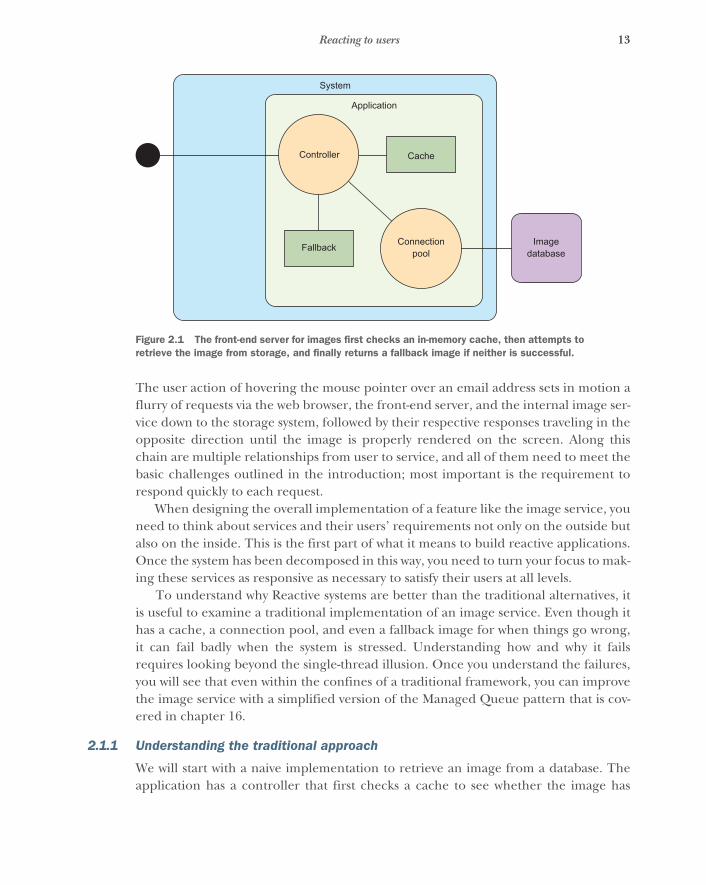
The first layer of services is provided by the front-end server and consumed bythe web browser. The browser makes requests and expects responses—predomi-nantly using HTTP, but also via WebSockets. The resources that are requested canpertain to emails, contacts, chats, searching, and many more (plus the definition ofthe styles and layout of the website). One such request might be related to theimages of people you correspond with: when you hover over an email address, apop-up window appears that contains details about that person, including a photo-graph or an avatar image. In order to render that image, the web browser makes arequest to the front-end server. Figure 2.1 shows how this might be implementedusing a traditional servlets approach.
13Reacting to users
The user action of hovering the mouse pointer over an email address sets in motion aflurry of requests via the web browser, the front-end server, and the internal image ser-vice down to the storage system, followed by their respective responses traveling in theopposite direction until the image is properly rendered on the screen. Along thischain are multiple relationships from user to service, and all of them need to meet thebasic challenges outlined in the introduction; most important is the requirement torespond quickly to each request.
When designing the overall implementation of a feature like the image service, youneed to think about services and their users’ requirements not only on the outside butalso on the inside. This is the first part of what it means to build reactive applications.Once the system has been decomposed in this way, you need to turn your focus to mak-ing these services as responsive as necessary to satisfy their users at all levels.
To understand why Reactive systems are better than the traditional alternatives, itis useful to examine a traditional implementation of an image service. Even though ithas a cache, a connection pool, and even a fallback image for when things go wrong,it can fail badly when the system is stressed. Understanding how and why it failsrequires looking beyond the single-thread illusion. Once you understand the failures,you will see that even within the confines of a traditional framework, you can improvethe image service with a simplified version of the Managed Queue pattern that is cov-ered in chapter 16.
2.1.1 Understanding the traditional approach
We will start with a naive implementation to retrieve an image from a database. Theapplication has a controller that first checks a cache to see whether the image has
Controller
Application
System
Cache
Fallback Connectionpool
Imagedatabase
Figure 2.1 The front-end server for images first checks an in-memory cache, then attempts to retrieve the image from storage, and finally returns a fallback image if neither is successful.
14 CHAPTER 2 A walk-through of the Reactive Manifesto
been retrieved recently. If the controller finds the image in the cache, it returns theimage right away. If not, it tries to retrieve the image from the database. If it finds theimage there, the image is added to the cache and also returned to the originalrequester. If the image is not found, a static fallback image is returned, to avoid pre-senting the user with an error. This pattern should be familiar to you. This simplisticcontroller might contain code like the following.
public interface Images {Image get(String Key);void add(String key, Image image);
}
public Images cache;public Images database;
Image result = cache.get(key);if (result != null) {
return result;} else {
result = database.get(key);if (result != null) {
cache.add(key, result);return result;
} else {return fallback;
}}
At the next level of detail, the application may be built on a framework that has someability to handle concurrency, such as Java servlets. When a new request is received,the application framework assigns it to a request thread. That thread is then responsi-ble for carrying the request through to a response. The more request threads are con-figured, the more simultaneous requests the system is expected to handle.
On a cache hit, the request thread can provide a response immediately. On acache miss, the internal implementation of Images needs to obtain a connection fromthe pool. The database query itself may be performed on the request thread, or theconnection pool may use a separate thread pool. Either way, the request thread isobliged to wait for the database query to complete or time out before it can fulfill therequest.
When you are tuning the performance of a system such as this, one of the keyparameters is the ratio of request threads to connection-pool entries. There is notmuch point in making the connection pool larger than the request-thread pool. If it isthe same size and all the request threads are waiting on database queries, the systemmay find itself temporarily with little to do other than wait for the database torespond. That would be unfortunate if the next several requests could have beenserved from the cache; instead of being handled immediately, they will have to wait for
Listing 2.1 Excerpt from a simple controller for an image service
Assumed thread-safeWraps a database connection pool
Image is found in the cache
Image is found in the database, added to the cache, and returned to the client
Image is not retrieved from the database
15Reacting to users
an unrelated database query to complete so that a request thread will become avail-able. On the other hand, setting the connection pool too small will make it a bottle-neck; this risks the system being limited by request threads stuck waiting for aconnection.
The best answer for a given load is somewhere between the extremes. The nextsection looks at finding a balance.
2.1.2 Analyzing latency with a shared resource
The simplistic implementation can be analyzed first by examining one extreme con-sisting of an infinite number of request threads sharing a fixed number of databaseconnections. Assume each database query takes a consistent time W to complete, andfor now ignore the cache. We will revisit the effect of the cache in section 2.3.1, whenwe introduce Amdahl’s Law. You want to know how many database connections L willbe used for a given load, which is represented as λ. A formula called Little’s Law givesthe answer:
Little’s Law is valid for the long-term averages of the three quantities independent ofthe actual timing with which requests arrive or the order in which they are processed.If the database takes on average 30 ms to respond, and the system is receiving 500requests per second, you can apply Little’s Law:
The average number of connections being used will be 15, so you will need at leastthat many connections to keep up with the load.
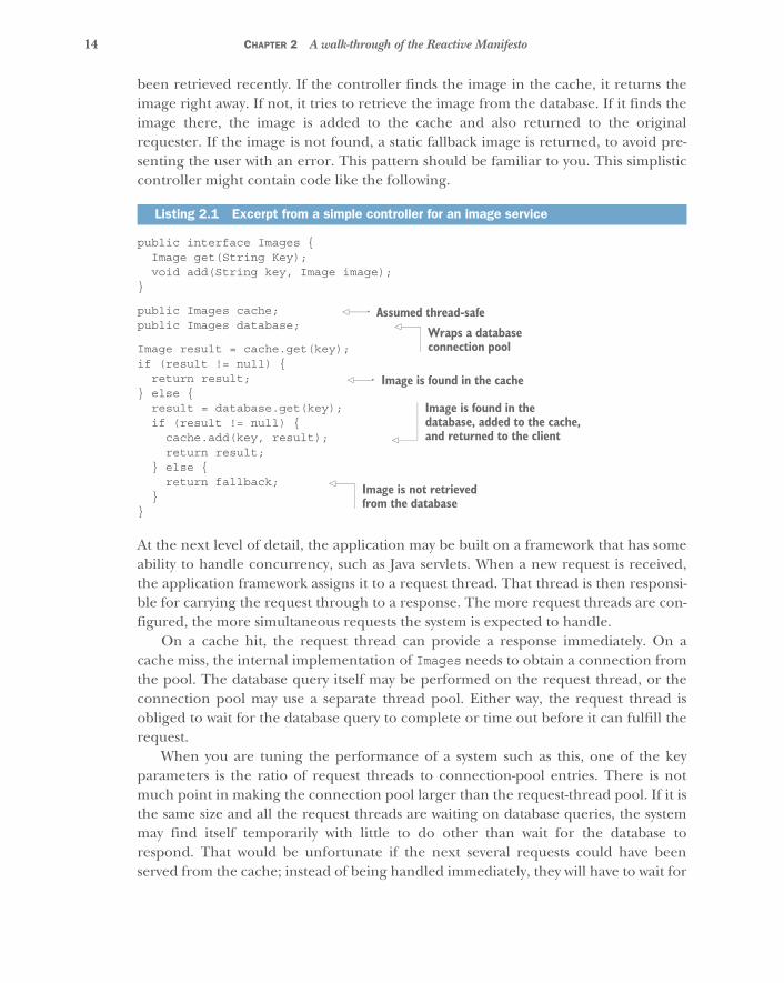
If there are requests waiting to be serviced, they must have some place to wait. Typ-ically, they wait in a queue data structure somewhere. As each request is completed,the next request is taken from the queue for processing. Referring to figure 2.2, youmay notice that there is no explicit queue. If this were coded using traditional syn-chronous Java servlets, the queue would consist of an internal collection of requestthreads waiting for their turn with the database connection. On average, there wouldbe 15 such threads waiting. That is not good, because, whereas a queue is a light-weight data structure, the request threads in the queue are relatively expensiveresources. Worse, 15 is just the average: the peaks are much higher. In reality, thethread pool will not be infinite. If there are too many requests, they will spill back intothe TCP buffer and eventually back to the browser, resulting in unhelpful errors ratherthan the desired fallback image.
The first thing you might do is increase the number of entries in the database con-nection pool. As long as the database can continue to handle the resulting load, thiswill help the average case. The important thing to note is that you are still working with
L λ W×=
L 500 requests/second 0.03 seconds/request×=
L ��=

16 CHAPTER 2 A walk-through of the Reactive Manifesto
average times. Real-world events can lead to failure modes that are far worse. For exam-ple, if the database stops responding at all for several minutes, 500 requests per secondwill overwhelm an otherwise sufficient thread pool. You need to protect the system.
2.1.3 Limiting maximum latency with a queue
The initial implementation blocked and waited for a database connection to becomeavailable; it returned null only if the requested image was not found in the database.A simple change will add some protection: if a database connection is not available,return null right away. This will free the request thread to return the fallback imagerather than stalling and consuming a large amount of resources.
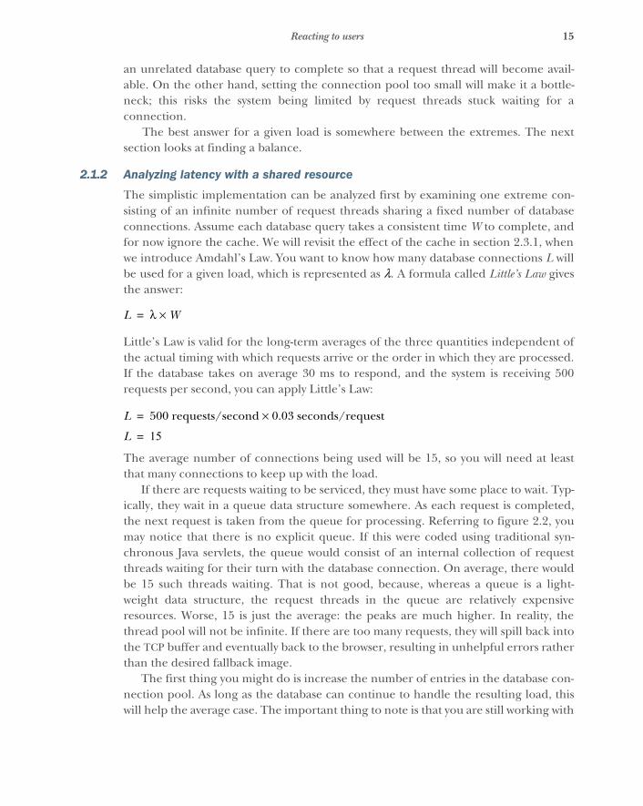
This approach couples two separate decisions into one: the number of databasequeries that can be accepted simultaneously is equal to the size of the connectionpool. That may not be the result you want: it means the system will either return rightaway if no connection is available or return in 30 ms if one is available. Suppose youare willing to wait a bit longer in exchange for a much better rate of success. At thispoint, you can introduce an explicit queue, as shown in figure 2.3. Now, instead ofreturning right away if no connection is available, new requests are added to thequeue. They are turned away only if the queue itself is full.
The addition provides much better control over system behavior. For example, aqueue with a maximum length of only 3 entries will respond in no more than a totalof 120 ms, including 90 ms progressing through the queue and another 30 ms for thedatabase query. The size of the queue provides an upper bound that you can control.Depending on the rate of requests, the average response may be lower, perhaps less
Controller
TCP buffer
X
Application
System
Cache
Fallback Connectionpool
Imagedatabase
Figure 2.2 Using standard listener threads and a connection pool results in the listeners acting as queue entries, with overflow into the system TCP buffers.
17Reacting to users
than 100 ms. If the cache that was ignored in the analysis is now considered, the aver-age drops still further. With a 50% cache-hit rate, the image server could offer anaverage response time of less than 50 ms.
Given what you know about how that 50 ms average is achieved, you also wouldknow not to set a timeout less than 120 ms. If that time was not acceptable, the simplersolution would be to use a smaller queue. A developer who knows only that the aver-age is less than 50 ms might assume it is a Gaussian distribution and be tempted to seta timeout value at perhaps 80 or 100 ms. Indeed, the assumptions that went into thisanalysis are vulnerable to the same error, because the assumption that the databaseprovides a consistent 30 ms response time would be questionable in a real-world imple-mentation. Real databases have caches of their own.
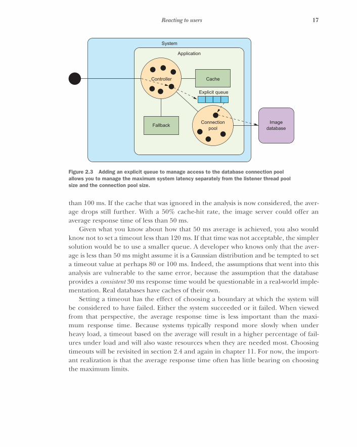
Setting a timeout has the effect of choosing a boundary at which the system willbe considered to have failed. Either the system succeeded or it failed. When viewedfrom that perspective, the average response time is less important than the maxi-mum response time. Because systems typically respond more slowly when underheavy load, a timeout based on the average will result in a higher percentage of fail-ures under load and will also waste resources when they are needed most. Choosingtimeouts will be revisited in section 2.4 and again in chapter 11. For now, the import-ant realization is that the average response time often has little bearing on choosingthe maximum limits.
Controller
Application
System
Cache
Fallback Connectionpool
Imagedatabase
Explicit queue
Figure 2.3 Adding an explicit queue to manage access to the database connection pool allows you to manage the maximum system latency separately from the listener thread pool size and the connection pool size.

18 CHAPTER 2 A walk-through of the Reactive Manifesto
2.2 Exploiting parallelismThe simplest case of a user–service relationship is invoking a method or function:
val result = f(42)
The user provides the argument “42” and hands over control of the CPU to the func-tion f, which might calculate the 42nd Fibonacci number or the factorial of 42. What-ever the function does, you expect it to return some result value when it is finished.This means that invoking the function is the same as making a request, and the func-tion returning a value is analogous to it replying with a response. What makes thisexample so simple is that most programming languages include syntax like this, whichallows direct usage of the response under the assumption that the function doesindeed reply. If that were not to happen, the rest of the program would not be exe-cuted, because it could not continue without the response. The underlying executionmodel is that the evaluation of the function occurs synchronously, on the samethread, and this ties the caller and the callee together so tightly that failures affectboth in the same way.
Sequential execution of functions is well supported by all popular programminglanguages out of the box, as illustrated in figure 2.4 and shown in this example usingJava syntax:
ReplyA a = computeA();ReplyB b = computeB();ReplyC c = computeC();Result r = aggregate(a, b, c);
The sequential model is easy to understand. It was adequate for early computers thathad only one processing core, but it necessitates waiting for all the results to be com-puted by the same resource while other resources remain idle.
2.2.1 Reducing latency via parallelization
In many cases, there is one possibility for latency reduction that immediately presentsitself. If, for the completion of a request, several other services must be involved, thenthe overall result will be obtained more quickly if the other services can perform their
Task
A B C
Figure 2.4 A task consisting of three subtasks that are executed sequentially: the total response latency is given by the sum of the three individual latencies.
19Exploiting parallelism
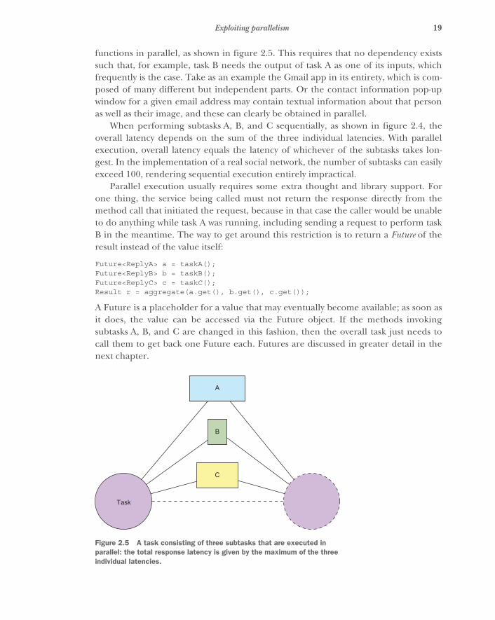
functions in parallel, as shown in figure 2.5. This requires that no dependency existssuch that, for example, task B needs the output of task A as one of its inputs, whichfrequently is the case. Take as an example the Gmail app in its entirety, which is com-posed of many different but independent parts. Or the contact information pop-upwindow for a given email address may contain textual information about that personas well as their image, and these can clearly be obtained in parallel.
When performing subtasks A, B, and C sequentially, as shown in figure 2.4, theoverall latency depends on the sum of the three individual latencies. With parallelexecution, overall latency equals the latency of whichever of the subtasks takes lon-gest. In the implementation of a real social network, the number of subtasks can easilyexceed 100, rendering sequential execution entirely impractical.
Parallel execution usually requires some extra thought and library support. Forone thing, the service being called must not return the response directly from themethod call that initiated the request, because in that case the caller would be unableto do anything while task A was running, including sending a request to perform taskB in the meantime. The way to get around this restriction is to return a Future of theresult instead of the value itself:
Future<ReplyA> a = taskA();Future<ReplyB> b = taskB();Future<ReplyC> c = taskC();Result r = aggregate(a.get(), b.get(), c.get());
A Future is a placeholder for a value that may eventually become available; as soon asit does, the value can be accessed via the Future object. If the methods invokingsubtasks A, B, and C are changed in this fashion, then the overall task just needs tocall them to get back one Future each. Futures are discussed in greater detail in thenext chapter.
Task
A
B
C
Figure 2.5 A task consisting of three subtasks that are executed in parallel: the total response latency is given by the maximum of the three individual latencies.
20 CHAPTER 2 A walk-through of the Reactive Manifesto
The previous code snippet uses a type called Future that is defined in the Java stan-dard library (in the package java.util.concurrent). The only method it defines foraccessing the value is the blocking get() method. Blocking here means the callingthread is suspended and cannot do anything else until the value has become available.We can picture the use of this kind of Future like so (written from the perspective ofthe thread handling the overall task):
When my boss gives me the task to assemble the overview file of a certain client,I will dispatch three runners: one to the client archives to fetch the address,photograph, and contract status; one to the library to fetch all articles the clienthas written; and one to the post office to collect all new messages for this client.This is a vast improvement over having to perform these tasks myself, but now Ineed to wait idly at my desk until the runners return, so that I can collateeverything they bring into an envelope and hand that back to my boss.
It would be much nicer if I could leave a note telling the runners to place theirfindings in the envelope and telling the last one to come back to dispatchanother runner to hand it to my boss without involving me. That way I couldhandle many more requests and would not feel useless most of the time.
2.2.2 Improving parallelism with composable Futures
What the developer should do is describe how the values should be composed to formthe final result and let the system find the most efficient way to compute the values.This is possible with composable Futures, which are part of many programming lan-guages and libraries, including newer versions of Java (CompletableFuture is intro-duced in JDK 8). Using this approach, the architecture turns completely fromsynchronous and blocking to asynchronous and nonblocking; the underlying machin-ery needs to become task-oriented in order to support this. The result is far moreexpressive than the relatively primitive precursor, the callback. The previous exampletransforms into the following, using Scala syntax:1
val fa: Future[ReplyA] = taskA()val fb: Future[ReplyB] = taskB()val fc: Future[ReplyC] = taskC()val fr: Future[Result] = for (a <- fa; b <- fb; c <- fc)
yield aggregate(a, b, c)
Initiating a subtask as well as its completion are just events that are raised by one partof the program and reacted to in another part: for example, by registering an actionto be taken with the value supplied by a completed Future. In this fashion, the latencyof the method call for the overall task does not even include the latencies for subtasksA, B, and C, as shown in figure 2.6. The system is free to handle other requests while
1 This would also be possible with the Java 8 CompletionStage using the andThen combinator, but due tothe lack of for-comprehensions, the code would grow in size relative to the synchronous version. The Scalaexpression on the last line transforms to corresponding calls to flatMap, which are equivalent toCompletionStage’s andThen.
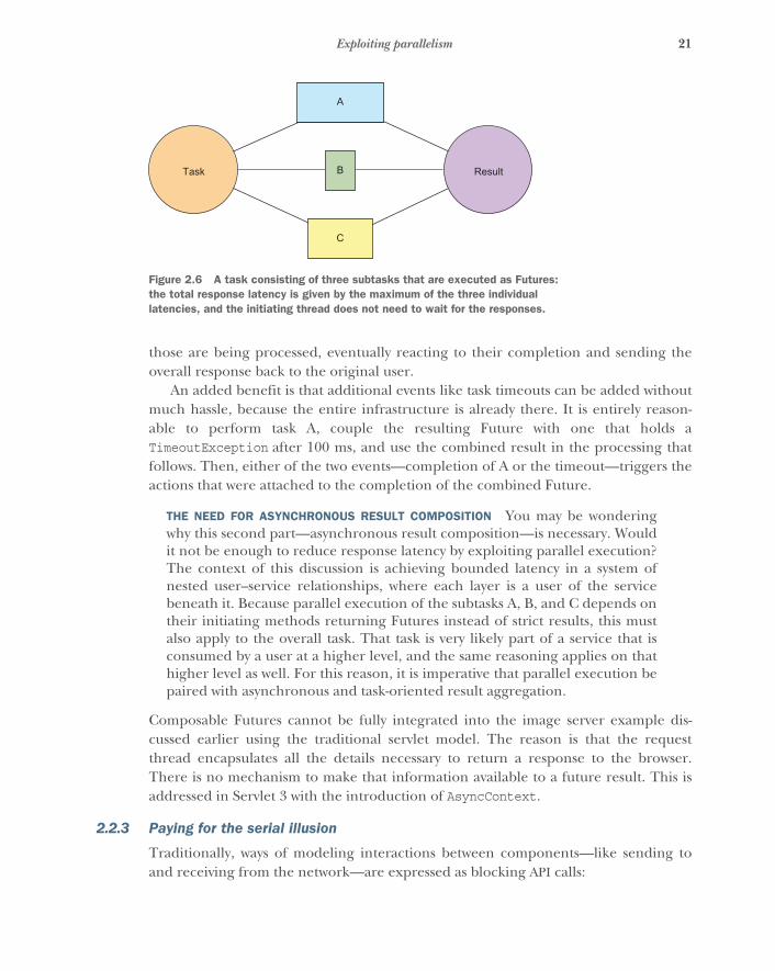
21Exploiting parallelism
those are being processed, eventually reacting to their completion and sending theoverall response back to the original user.
An added benefit is that additional events like task timeouts can be added withoutmuch hassle, because the entire infrastructure is already there. It is entirely reason-able to perform task A, couple the resulting Future with one that holds aTimeoutException after 100 ms, and use the combined result in the processing thatfollows. Then, either of the two events—completion of A or the timeout—triggers theactions that were attached to the completion of the combined Future.
THE NEED FOR ASYNCHRONOUS RESULT COMPOSITION You may be wonderingwhy this second part—asynchronous result composition—is necessary. Wouldit not be enough to reduce response latency by exploiting parallel execution?The context of this discussion is achieving bounded latency in a system ofnested user–service relationships, where each layer is a user of the servicebeneath it. Because parallel execution of the subtasks A, B, and C depends ontheir initiating methods returning Futures instead of strict results, this mustalso apply to the overall task. That task is very likely part of a service that isconsumed by a user at a higher level, and the same reasoning applies on thathigher level as well. For this reason, it is imperative that parallel execution bepaired with asynchronous and task-oriented result aggregation.
Composable Futures cannot be fully integrated into the image server example dis-cussed earlier using the traditional servlet model. The reason is that the requestthread encapsulates all the details necessary to return a response to the browser.There is no mechanism to make that information available to a future result. This isaddressed in Servlet 3 with the introduction of AsyncContext.
2.2.3 Paying for the serial illusion
Traditionally, ways of modeling interactions between components—like sending toand receiving from the network—are expressed as blocking API calls:
Task
A
B
C
Result
Figure 2.6 A task consisting of three subtasks that are executed as Futures: the total response latency is given by the maximum of the three individual latencies, and the initiating thread does not need to wait for the responses.
22 CHAPTER 2 A walk-through of the Reactive Manifesto
final Socket socket = ...socket.getOutputStream.write(requestMessageBytes);final int bytesRead = socket.getInputStream().read(responseBuffer);
Each of these blocking calls interacts with the network equipment, generating mes-sages and reacting to messages under the hood, but this fact is completely hidden inorder to construct a synchronous façade on top of the underlying message-driven sys-tem. The thread executing these commands will suspend its execution if not enoughspace is available in the output buffer (for the first line) or if the response is not imme-diately available (on the second line). Consequently, this thread cannot do any otherwork in the meantime: every activity of this type that is ongoing in parallel needs itsown thread, even if many of those are doing nothing but waiting for events to occur.
If the number of threads is not much larger than the number of CPU cores in thesystem, then this does not pose a problem. But given that these threads are mostlyidle, you want to run many more of them. Assuming that it takes a few microsecondsto prepare the requestMessageBytes and a few more microseconds to process theresponseBuffer, whereas the time for traversing the network and processing therequest on the other end is measured in milliseconds, it is clear that each threadspends more than 99% of its time in a waiting state.
In order to fully utilize the processing power of the available CPUs, this means run-ning hundreds if not thousands of threads, even on commodity hardware. At thispoint, you should note that threads are managed by the operating system kernel forefficiency reasons.2 Because the kernel can decide to switch out threads on a CPU coreat any point in time (for example, when a hardware interrupt happens or the timeslice for the current thread is used up), a lot of CPU state must be saved and laterrestored so that the running application does not notice that something else was usingthe CPU in the meantime. This is called a context switch and costs thousands ofcycles3 every time it occurs. The other drawback of using large numbers of threads isthat the scheduler—the part of the kernel that decides which thread to run on whichCPU core at any given time—will have a hard time finding out which threads are run-nable and which are waiting and then selecting one such that each thread gets its fairshare of the CPU.
The takeaway of the previous paragraph is that using synchronous, blocking APIsthat hide the underlying message-driven structure wastes CPU resources. If messageswere made explicit in the API such that instead of suspending a thread, you would justsuspend the computation—freeing up the thread to do something else—then thisoverhead would be reduced substantially. The following example shows (remote) mes-saging between Akka Actors from Java 8:
2 Multiplexing several logical user-level threads on a single OS thread is called a many-to-one model or greenthreads. Early JVM implementations used this model, but it was abandoned quickly (http://docs.oracle.com/cd/E19455-01/806-3461/6jck06gqh/index.html).
3 Although CPUs have gotten faster, their larger internal state has negated the advances made in pure execu-tion speed such that a context switch has taken roughly 1 µs without much improvement for two decades.
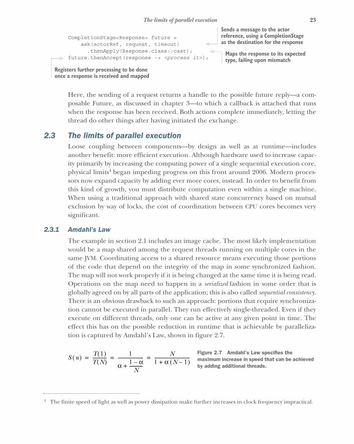
23The limits of parallel execution
CompletionStage<Response> future =ask(actorRef, request, timeout)
.thenApply(Response.class::cast);future.thenAccept(response -> <process it>);
Here, the sending of a request returns a handle to the possible future reply—a com-posable Future, as discussed in chapter 3—to which a callback is attached that runswhen the response has been received. Both actions complete immediately, letting thethread do other things after having initiated the exchange.
2.3 The limits of parallel executionLoose coupling between components—by design as well as at runtime—includesanother benefit: more efficient execution. Although hardware used to increase capac-ity primarily by increasing the computing power of a single sequential execution core,physical limits4 began impeding progress on this front around 2006. Modern proces-sors now expand capacity by adding ever more cores, instead. In order to benefit fromthis kind of growth, you must distribute computation even within a single machine.When using a traditional approach with shared state concurrency based on mutualexclusion by way of locks, the cost of coordination between CPU cores becomes verysignificant.
2.3.1 Amdahl’s Law
The example in section 2.1 includes an image cache. The most likely implementationwould be a map shared among the request threads running on multiple cores in thesame JVM. Coordinating access to a shared resource means executing those portionsof the code that depend on the integrity of the map in some synchronized fashion.The map will not work properly if it is being changed at the same time it is being read.Operations on the map need to happen in a serialized fashion in some order that isglobally agreed on by all parts of the application; this is also called sequential consistency.There is an obvious drawback to such an approach: portions that require synchroniza-tion cannot be executed in parallel. They run effectively single-threaded. Even if theyexecute on different threads, only one can be active at any given point in time. Theeffect this has on the possible reduction in runtime that is achievable by paralleliza-tion is captured by Amdahl’s Law, shown in figure 2.7.
4 The finite speed of light as well as power dissipation make further increases in clock frequency impractical.
Sends a message to the actor reference, using a CompletionStage as the destination for the response
Maps the response to its expected type, failing upon mismatch
Registers further processing to be done once a response is received and mapped
S n( ) T �( )T N( )------------- �
α � α–N
------------+----------------------- N
� α N �–( )+--------------------------------= = =
Figure 2.7 Amdahl’s Law specifies the maximum increase in speed that can be achieved by adding additional threads.
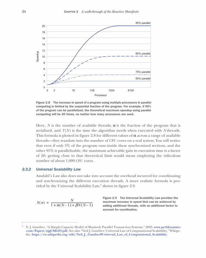
24 CHAPTER 2 A walk-through of the Reactive Manifesto
Here, N is the number of available threads, α is the fraction of the program that isserialized, and T(N) is the time the algorithm needs when executed with N threads.This formula is plotted in figure 2.8 for different values of α across a range of availablethreads—they translate into the number of CPU cores on a real system. You will noticethat even if only 5% of the program runs inside these synchronized sections, and theother 95% is parallelizable, the maximum achievable gain in execution time is a factorof 20; getting close to that theoretical limit would mean employing the ridiculousnumber of about 1,000 CPU cores.
2.3.2 Universal Scalability Law
Amdahl’s Law also does not take into account the overhead incurred for coordinatingand synchronizing the different execution threads. A more realistic formula is pro-vided by the Universal Scalability Law,5 shown in figure 2.9.
5 N. J. Gunther, “A Simple Capacity Model of Massively Parallel Transaction Systems,” 2003, www.perfdynamics.com/Papers/njgCMG93.pdf. See also “Neil J. Gunther: Universal Law of Computational Scalability,” Wikipe-dia, https://en.wikipedia.org/wiki/Neil_J._Gunther#Universal_Law_of_Computational_Scalability.
20
18
16
14
12
10
Spee
dup
8
6
4
2
00 2 16 128
Processor
95% parallel
90% parallel
75% parallel
50% parallel
1024 8192
Figure 2.8 The increase in speed of a program using multiple processors in parallel computing is limited by the sequential fraction of the program. For example, if 95% of the program can be parallelized, the theoretical maximum speedup using parallel computing will be 20 times, no matter how many processors are used.
S n( ) N� α N �–( ) βN N �–( )+ +-----------------------------------------------------------------=
Figure 2.9 The Universal Scalability Law provides the maximum increase in speed that can be achieved by adding additional threads, with an additional factor to account for coordination.
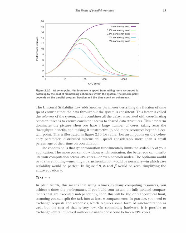
25The limits of parallel execution
The Universal Scalability Law adds another parameter describing the fraction of timespent ensuring that the data throughout the system is consistent. This factor is calledthe coherency of the system, and it combines all the delays associated with coordinatingbetween threads to ensure consistent access to shared data structures. This new termdominates the picture when you have a large number of cores, taking away thethroughput benefits and making it unattractive to add more resources beyond a cer-tain point. This is illustrated in figure 2.10 for rather low assumptions on the coher-ency parameter; distributed systems will spend considerably more than a smallpercentage of their time on coordination.
The conclusion is that synchronization fundamentally limits the scalability of yourapplication. The more you can do without synchronization, the better you can distrib-ute your computation across CPU cores—or even network nodes. The optimum wouldbe to share nothing—meaning no synchronization would be necessary—in which casescalability would be perfect. In figure 2.9, α and β would be zero, simplifying theentire equation to
In plain words, this means that using n times as many computing resources, youachieve n times the performance. If you build your system on fully isolated compart-ments that are executed independently, then this will be the only theoretical limit,assuming you can split the task into at least n compartments. In practice, you need toexchange requests and responses, which requires some form of synchronization aswell, but the cost of that is very low. On commodity hardware, it is possible toexchange several hundred million messages per second between CPU cores.
20
18
16
14
12
10
Perfo
rman
ce in
crea
se
8
6
4
2
01 10 100
CPU cores
1000 10000
no coherency cost0.2% coherency cost0.5% coherency cost
1% coherency cost5% coherency cost
Figure 2.10 At some point, the increase in speed from adding more resources is eaten up by the cost of maintaining coherency within the system. The precise point depends on the parallel program fraction and the time spent on coherency.
S n( ) n=
26 CHAPTER 2 A walk-through of the Reactive Manifesto
2.4 Reacting to failureThe previous sections concern designing a service implementation such that everyrequest is met with a response within a given time. This is important because otherwisethe user cannot determine whether the request has been received and processed. Buteven with flawless execution of this design, unexpected things will happen eventually:
� Software will fail . There will always be that exception you forgot to handle (orthat was not documented by the library you are using); or you may get synchro-nization only a tiny bit wrong, causing a deadlock to occur; or the condition youformulated for breaking a loop may not cope with a weird edge case. You canalways trust the users of your code to figure out ways to eventually find all thesefailure conditions and more.
� Hardware will fail . Everyone who has operated computing hardware knows thatpower supplies are notoriously unreliable; that hard disks tend to turn intoexpensive door stops, either during the initial burn-in phase or after a fewyears; and that dying fans lead to the silent death of all kinds of components byoverheating them. In any case, your invaluable production server will, accord-ing to Murphy’s Law, fail exactly when you most need it.
� Humans will fail . When you task maintenance personnel with replacing a failedhard disk in RAID5, a study6 finds that there is a 10% chance that they willreplace the wrong one, leading to the loss of all data. An anecdote fromRoland’s days as a network administrator is that cleaning personnel unpluggedthe power of the main server for the workgroup—both redundant cords at thesame time—in order to connect the vacuum cleaner. None of these thingsshould happen, but it is human nature that you will have a bad day from time totime.
� Timeout is failure. The reason for a timeout may not be related to the internalbehavior of the system. For example, network congestion can delay messagesbetween components of your system even when all the components are func-tioning normally. The source of delay may be some other system that shares thenetwork. From the perspective of handling an individual request, it does notmatter whether the cause is permanent or transient. The fact is that the onerequest has taken too long and therefore has failed.
The question therefore is not if a failure occurs but only when or how often. The user ofa service does not care how an internal failure happened or what exactly went wrong,because the only response the user will get is that no normal response is received.Connections may time out or be rejected, or the response may consist of an opaqueinternal error code. In any case, the user will have to carry on without the response,which for humans probably means using a different service: if you try to book a flight
6 Aaron B. Brown (IBM Research), “Oops! Coping with Human Error,” ACM Queue 2, no. 8 (Dec. 6, 2004),http://queue.acm.org/detail.cfm?id=1036497.
27Reacting to failure
and the booking site stops responding, then you will take your business elsewhere andprobably not come back anytime soon (or, in a different business, like online banking,users will overwhelm the support hotline).
A high-quality service is one that performs its function very reliably, preferablywithout any downtime at all. Because failure of computer systems is not an abstractpossibility but is in fact certain, the question arises: how can you hope to construct areliable service? The Reactive Manifesto chooses the term resilience instead of reliabilityprecisely to capture this apparent contradiction.
The key notion here is to aim at fault tolerance instead of fault avoidance, becauseavoidance will not be fully successful. It is of course good to plan for as many failurescenarios as you can, to tailor programmatic responses such that normal operationscan be resumed as quickly as possible—ideally without the user noticing anything.The same must also apply to those failure cases that were not foreseen and explicitlyaccommodated in the design, knowing that these will happen as well.
But resilience goes one step further than fault tolerance: a resilient system not onlywithstands a failure but also recovers its original shape and feature set. As an example,consider a satellite that is placed in orbit. In order to reduce the risk of losing the mis-sion, every critical function is implemented at least twice, be it hardware or software.For the case that one component fails, there are procedures that switch to the backupcomponent. Exercising such a fail-over keeps the satellite functioning, but from thenon the affected component will not tolerate additional faults because there was onlyone backup. This means the satellite subsystems are fault tolerant but not resilient.
There is only one generic way to protect your system from failing as a whole whena part fails: distribute and compartmentalize. The former can informally be translated as“don’t put all your eggs in one basket,” and the latter adds “protect your baskets fromone another.” When it comes to handling a failure, it is important to delegate, so thatthe failed compartment itself is not responsible for its own recovery.
Distribution can take several forms. The one you probably think of first involvesreplicating an important database across several servers such that, in the event of ahardware failure, the data are safe because copies are readily available. If you arereally concerned about those data, then you may go as far as placing the replicas indifferent buildings in order not to lose all of them in the case of fire—or to keep themindependently operable when one of them suffers a complete power outage. For thereally paranoid, those buildings would need to be supplied by different power grids,better yet in different countries or on separate continents.
What does resilience mean?Merriam-Webster defines resilience as follows:
� The ability of a substance or object to spring back into shape� The capacity to recover quickly from difficulties
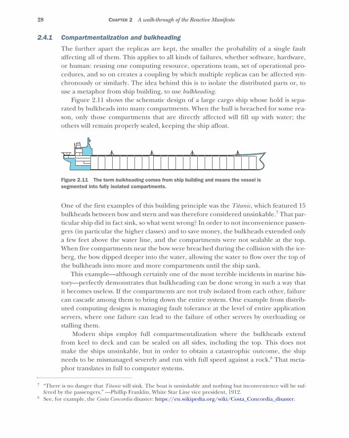
28 CHAPTER 2 A walk-through of the Reactive Manifesto
2.4.1 Compartmentalization and bulkheading
The further apart the replicas are kept, the smaller the probability of a single faultaffecting all of them. This applies to all kinds of failures, whether software, hardware,or human: reusing one computing resource, operations team, set of operational pro-cedures, and so on creates a coupling by which multiple replicas can be affected syn-chronously or similarly. The idea behind this is to isolate the distributed parts or, touse a metaphor from ship building, to use bulkheading.
Figure 2.11 shows the schematic design of a large cargo ship whose hold is sepa-rated by bulkheads into many compartments. When the hull is breached for some rea-son, only those compartments that are directly affected will fill up with water; theothers will remain properly sealed, keeping the ship afloat.
One of the first examples of this building principle was the Titanic, which featured 15bulkheads between bow and stern and was therefore considered unsinkable.7 That par-ticular ship did in fact sink, so what went wrong? In order to not inconvenience passen-gers (in particular the higher classes) and to save money, the bulkheads extended onlya few feet above the water line, and the compartments were not sealable at the top.When five compartments near the bow were breached during the collision with the ice-berg, the bow dipped deeper into the water, allowing the water to flow over the top ofthe bulkheads into more and more compartments until the ship sank.
This example—although certainly one of the most terrible incidents in marine his-tory—perfectly demonstrates that bulkheading can be done wrong in such a way thatit becomes useless. If the compartments are not truly isolated from each other, failurecan cascade among them to bring down the entire system. One example from distrib-uted computing designs is managing fault tolerance at the level of entire applicationservers, where one failure can lead to the failure of other servers by overloading orstalling them.
Modern ships employ full compartmentalization where the bulkheads extendfrom keel to deck and can be sealed on all sides, including the top. This does notmake the ships unsinkable, but in order to obtain a catastrophic outcome, the shipneeds to be mismanaged severely and run with full speed against a rock.8 That meta-phor translates in full to computer systems.
7 “There is no danger that Titanic will sink. The boat is unsinkable and nothing but inconvenience will be suf-fered by the passengers.” —Phillip Franklin, White Star Line vice president, 1912.
8 See, for example, the Costa Concordia disaster: https://en.wikipedia.org/wiki/Costa_Concordia_disaster.
Figure 2.11 The term bulkheading comes from ship building and means the vessel is segmented into fully isolated compartments.
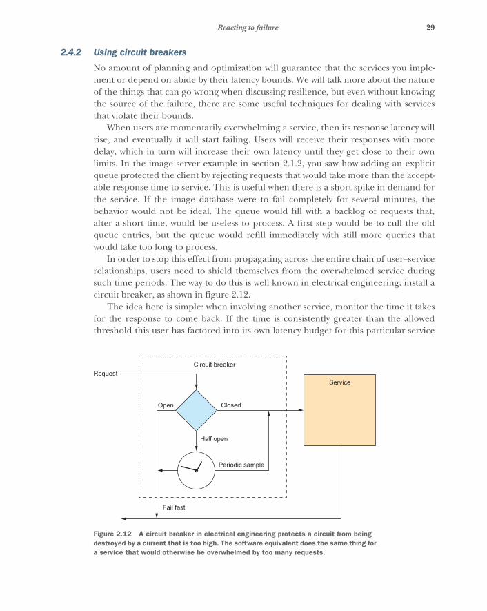
29Reacting to failure
2.4.2 Using circuit breakers
No amount of planning and optimization will guarantee that the services you imple-ment or depend on abide by their latency bounds. We will talk more about the natureof the things that can go wrong when discussing resilience, but even without knowingthe source of the failure, there are some useful techniques for dealing with servicesthat violate their bounds.
When users are momentarily overwhelming a service, then its response latency willrise, and eventually it will start failing. Users will receive their responses with moredelay, which in turn will increase their own latency until they get close to their ownlimits. In the image server example in section 2.1.2, you saw how adding an explicitqueue protected the client by rejecting requests that would take more than the accept-able response time to service. This is useful when there is a short spike in demand forthe service. If the image database were to fail completely for several minutes, thebehavior would not be ideal. The queue would fill with a backlog of requests that,after a short time, would be useless to process. A first step would be to cull the oldqueue entries, but the queue would refill immediately with still more queries thatwould take too long to process.
In order to stop this effect from propagating across the entire chain of user–servicerelationships, users need to shield themselves from the overwhelmed service duringsuch time periods. The way to do this is well known in electrical engineering: install acircuit breaker, as shown in figure 2.12.
The idea here is simple: when involving another service, monitor the time it takesfor the response to come back. If the time is consistently greater than the allowedthreshold this user has factored into its own latency budget for this particular service
Service
Circuit breakerRequest
ClosedOpen
Half open
Periodic sample
Fail fast
Figure 2.12 A circuit breaker in electrical engineering protects a circuit from being destroyed by a current that is too high. The software equivalent does the same thing for a service that would otherwise be overwhelmed by too many requests.
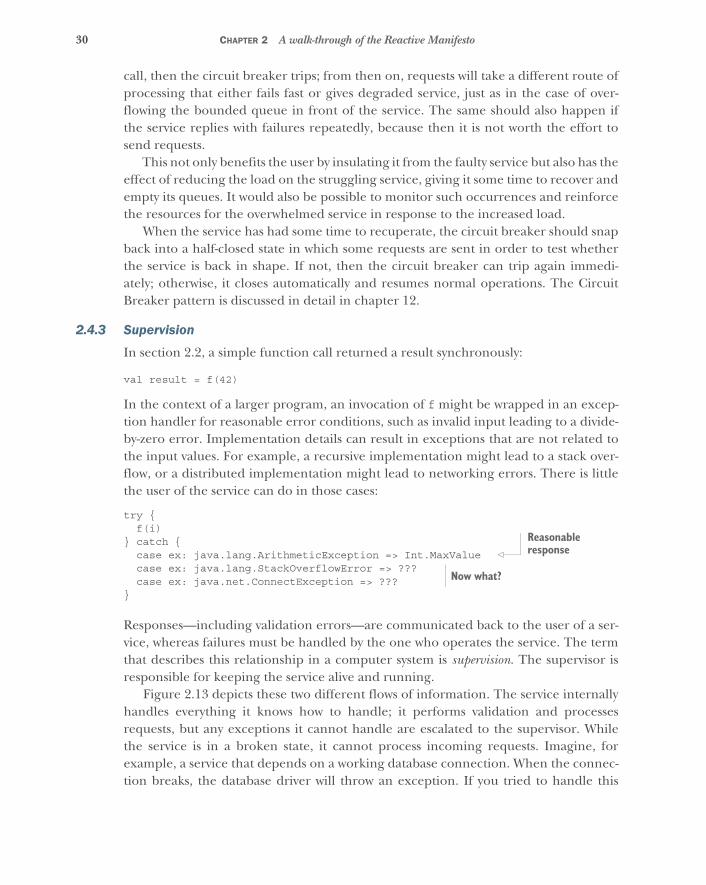
30 CHAPTER 2 A walk-through of the Reactive Manifesto
call, then the circuit breaker trips; from then on, requests will take a different route ofprocessing that either fails fast or gives degraded service, just as in the case of over-flowing the bounded queue in front of the service. The same should also happen ifthe service replies with failures repeatedly, because then it is not worth the effort tosend requests.
This not only benefits the user by insulating it from the faulty service but also has theeffect of reducing the load on the struggling service, giving it some time to recover andempty its queues. It would also be possible to monitor such occurrences and reinforcethe resources for the overwhelmed service in response to the increased load.
When the service has had some time to recuperate, the circuit breaker should snapback into a half-closed state in which some requests are sent in order to test whetherthe service is back in shape. If not, then the circuit breaker can trip again immedi-ately; otherwise, it closes automatically and resumes normal operations. The CircuitBreaker pattern is discussed in detail in chapter 12.
2.4.3 Supervision
In section 2.2, a simple function call returned a result synchronously:
val result = f(42)
In the context of a larger program, an invocation of f might be wrapped in an excep-tion handler for reasonable error conditions, such as invalid input leading to a divide-by-zero error. Implementation details can result in exceptions that are not related tothe input values. For example, a recursive implementation might lead to a stack over-flow, or a distributed implementation might lead to networking errors. There is littlethe user of the service can do in those cases:
try {f(i)
} catch {case ex: java.lang.ArithmeticException => Int.MaxValuecase ex: java.lang.StackOverflowError => ???case ex: java.net.ConnectException => ???
}
Responses—including validation errors—are communicated back to the user of a ser-vice, whereas failures must be handled by the one who operates the service. The termthat describes this relationship in a computer system is supervision. The supervisor isresponsible for keeping the service alive and running.
Figure 2.13 depicts these two different flows of information. The service internallyhandles everything it knows how to handle; it performs validation and processesrequests, but any exceptions it cannot handle are escalated to the supervisor. Whilethe service is in a broken state, it cannot process incoming requests. Imagine, forexample, a service that depends on a working database connection. When the connec-tion breaks, the database driver will throw an exception. If you tried to handle this
Reasonable response
Now what?
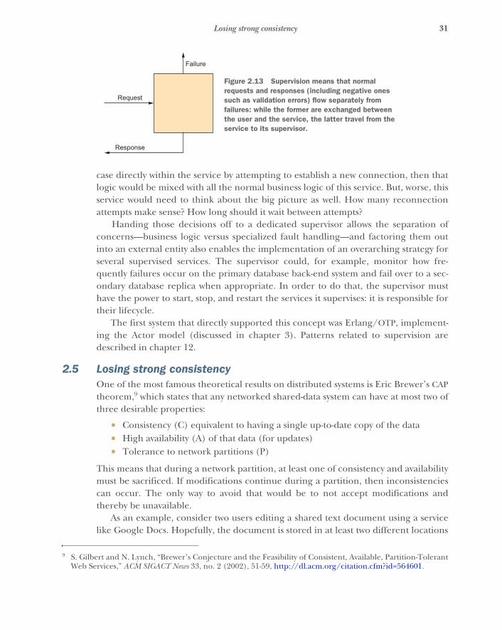
31Losing strong consistency
case directly within the service by attempting to establish a new connection, then thatlogic would be mixed with all the normal business logic of this service. But, worse, thisservice would need to think about the big picture as well. How many reconnectionattempts make sense? How long should it wait between attempts?
Handing those decisions off to a dedicated supervisor allows the separation ofconcerns—business logic versus specialized fault handling—and factoring them outinto an external entity also enables the implementation of an overarching strategy forseveral supervised services. The supervisor could, for example, monitor how fre-quently failures occur on the primary database back-end system and fail over to a sec-ondary database replica when appropriate. In order to do that, the supervisor musthave the power to start, stop, and restart the services it supervises: it is responsible fortheir lifecycle.
The first system that directly supported this concept was Erlang/OTP, implement-ing the Actor model (discussed in chapter 3). Patterns related to supervision aredescribed in chapter 12.
2.5 Losing strong consistencyOne of the most famous theoretical results on distributed systems is Eric Brewer’s CAPtheorem,9 which states that any networked shared-data system can have at most two ofthree desirable properties:
� Consistency (C) equivalent to having a single up-to-date copy of the data� High availability (A) of that data (for updates)� Tolerance to network partitions (P)
This means that during a network partition, at least one of consistency and availabilitymust be sacrificed. If modifications continue during a partition, then inconsistenciescan occur. The only way to avoid that would be to not accept modifications andthereby be unavailable.
As an example, consider two users editing a shared text document using a servicelike Google Docs. Hopefully, the document is stored in at least two different locations
9 S. Gilbert and N. Lynch, “Brewer’s Conjecture and the Feasibility of Consistent, Available, Partition-TolerantWeb Services,” ACM SIGACT News 33, no. 2 (2002), 51-59, http://dl.acm.org/citation.cfm?id=564601.
Failure
Request
Response
Figure 2.13 Supervision means that normal requests and responses (including negative ones such as validation errors) flow separately from failures: while the former are exchanged between the user and the service, the latter travel from the service to its supervisor.
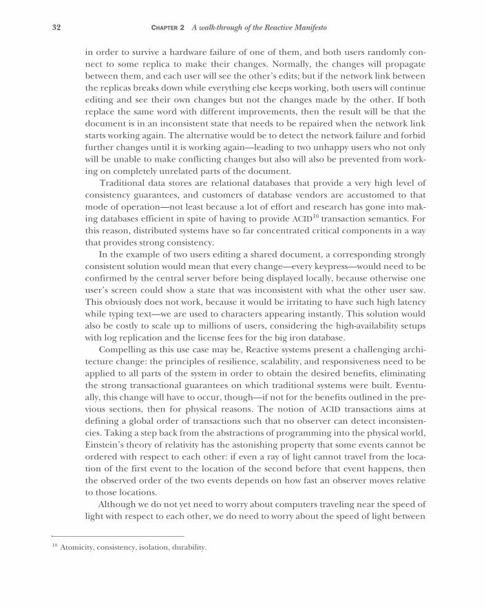
32 CHAPTER 2 A walk-through of the Reactive Manifesto
in order to survive a hardware failure of one of them, and both users randomly con-nect to some replica to make their changes. Normally, the changes will propagatebetween them, and each user will see the other’s edits; but if the network link betweenthe replicas breaks down while everything else keeps working, both users will continueediting and see their own changes but not the changes made by the other. If bothreplace the same word with different improvements, then the result will be that thedocument is in an inconsistent state that needs to be repaired when the network linkstarts working again. The alternative would be to detect the network failure and forbidfurther changes until it is working again—leading to two unhappy users who not onlywill be unable to make conflicting changes but also will also be prevented from work-ing on completely unrelated parts of the document.
Traditional data stores are relational databases that provide a very high level ofconsistency guarantees, and customers of database vendors are accustomed to thatmode of operation—not least because a lot of effort and research has gone into mak-ing databases efficient in spite of having to provide ACID10 transaction semantics. Forthis reason, distributed systems have so far concentrated critical components in a waythat provides strong consistency.
In the example of two users editing a shared document, a corresponding stronglyconsistent solution would mean that every change—every keypress—would need to beconfirmed by the central server before being displayed locally, because otherwise oneuser’s screen could show a state that was inconsistent with what the other user saw.This obviously does not work, because it would be irritating to have such high latencywhile typing text—we are used to characters appearing instantly. This solution wouldalso be costly to scale up to millions of users, considering the high-availability setupswith log replication and the license fees for the big iron database.
Compelling as this use case may be, Reactive systems present a challenging archi-tecture change: the principles of resilience, scalability, and responsiveness need to beapplied to all parts of the system in order to obtain the desired benefits, eliminatingthe strong transactional guarantees on which traditional systems were built. Eventu-ally, this change will have to occur, though—if not for the benefits outlined in the pre-vious sections, then for physical reasons. The notion of ACID transactions aims atdefining a global order of transactions such that no observer can detect inconsisten-cies. Taking a step back from the abstractions of programming into the physical world,Einstein’s theory of relativity has the astonishing property that some events cannot beordered with respect to each other: if even a ray of light cannot travel from the loca-tion of the first event to the location of the second before that event happens, thenthe observed order of the two events depends on how fast an observer moves relativeto those locations.
Although we do not yet need to worry about computers traveling near the speed oflight with respect to each other, we do need to worry about the speed of light between
10 Atomicity, consistency, isolation, durability.
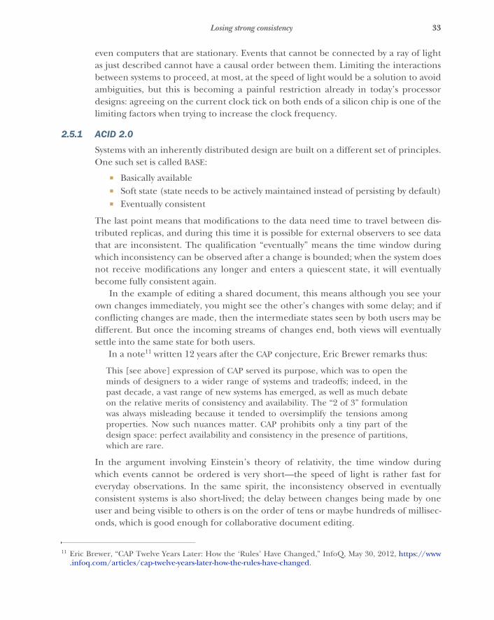
33Losing strong consistency
even computers that are stationary. Events that cannot be connected by a ray of lightas just described cannot have a causal order between them. Limiting the interactionsbetween systems to proceed, at most, at the speed of light would be a solution to avoidambiguities, but this is becoming a painful restriction already in today’s processordesigns: agreeing on the current clock tick on both ends of a silicon chip is one of thelimiting factors when trying to increase the clock frequency.
2.5.1 ACID 2.0
Systems with an inherently distributed design are built on a different set of principles.One such set is called BASE:
� Basically available� Soft state (state needs to be actively maintained instead of persisting by default)� Eventually consistent
The last point means that modifications to the data need time to travel between dis-tributed replicas, and during this time it is possible for external observers to see datathat are inconsistent. The qualification “eventually” means the time window duringwhich inconsistency can be observed after a change is bounded; when the system doesnot receive modifications any longer and enters a quiescent state, it will eventuallybecome fully consistent again.
In the example of editing a shared document, this means although you see yourown changes immediately, you might see the other’s changes with some delay; and ifconflicting changes are made, then the intermediate states seen by both users may bedifferent. But once the incoming streams of changes end, both views will eventuallysettle into the same state for both users.
In a note11 written 12 years after the CAP conjecture, Eric Brewer remarks thus:
This [see above] expression of CAP served its purpose, which was to open theminds of designers to a wider range of systems and tradeoffs; indeed, in thepast decade, a vast range of new systems has emerged, as well as much debateon the relative merits of consistency and availability. The “2 of 3” formulationwas always misleading because it tended to oversimplify the tensions amongproperties. Now such nuances matter. CAP prohibits only a tiny part of thedesign space: perfect availability and consistency in the presence of partitions,which are rare.
In the argument involving Einstein’s theory of relativity, the time window duringwhich events cannot be ordered is very short—the speed of light is rather fast foreveryday observations. In the same spirit, the inconsistency observed in eventuallyconsistent systems is also short-lived; the delay between changes being made by oneuser and being visible to others is on the order of tens or maybe hundreds of millisec-onds, which is good enough for collaborative document editing.
11 Eric Brewer, “CAP Twelve Years Later: How the ‘Rules’ Have Changed,” InfoQ, May 30, 2012, https://www.infoq.com/articles/cap-twelve-years-later-how-the-rules-have-changed.
34 CHAPTER 2 A walk-through of the Reactive Manifesto
BASE has served as an important step in evolving our understanding of which prop-erties are useful and which are unattainable, but as a definitive term it is too imprecise.Another proposal brought forward by Pat Helland at React Conf 2014 is ACID 2.0:
� Associative� Commutative� Idempotent� Distributed
The last point just completes the familiar acronym, but the first three describe under-lying mathematical principles that allow operations to be performed in a form that iseventually consistent by definition: if every action is represented such that it can beapplied in batches (associative) and in any order (commutative) and such that apply-ing it multiple times is not harmful (idempotent), then the end result does not dependon which replica accepts the change and in which order the updates are disseminatedacross the network—even resending is fine if reception is not yet acknowledged.
Other authors, such as Peter Bailis and Martin Kleppmann, are pushing the enve-lope of how far we can extend consistency guarantees without running into the forbid-den spot of the CAP theorem: with the help of tracking the causality relationshipbetween different updates, it seems possible to get very close to ACID semantics whileminimizing the sacrifice in terms of availability. It will be interesting to see where thisfield of research will be in 10 years.
2.5.2 Accepting updates
Only during a network partition is it problematic to accept modifications on both dis-connected sides, although even for this case solutions are emerging in the form ofconflict-free replicated data types (CRDTs). These have the property of mergingcleanly when the partition ends, regardless of the modifications that were done oneither side.
Google Docs employs a similar technique called operational transformation.12 In thescenario in which replicas of a document get out of sync due to a network partition,local changes are still accepted and stored as operations. When the network connec-tion is back in working condition, the different chains of operations are merged bybringing them into a linearized sequence. This is done by rebasing one chain on topof the other so that instead of operating on the last synchronized state, the one chainis transformed to operate on the state that results from applying the other chainbefore it. This resolves conflicting changes in a deterministic way, leading to a consis-tent document for both users after the partition has healed.
Data types with these nice properties come with certain restrictions in terms ofwhich operations they can support. There will naturally be problems that cannot be
12 David Wang, Alex Mah, and Soren Lassen, “Google Wave Operational Transformation,” July 2010,http://mng.bz/Bry5.

35The need for Reactive design patterns
stated using them, in which case you have no choice but to concentrate these data inone location only and forgo distribution. But our intuition is that necessity will drivethe reduction of these issues by researching alternative models for the respectiveproblem domain, forming a compromise between the need to provide responsive ser-vices that are always available and the business-level desire for strong consistency. Oneexample from the real world is automated teller machines (ATMs): bank accounts arethe traditional example of strong transactional reasoning, but the mechanical imple-mentation of dispensing cash to account owners has been eventually consistent for along time.
When you go to an ATM to withdraw cash, you would be annoyed with your bank ifthe ATM did not work, especially if you needed the money to buy that anniversarypresent for your spouse. Network problems do occur frequently, and if the ATMrejected customers during such periods, that would lead to lots of unhappy custom-ers—we know that bad stories spread a lot easier than stories that say “It just worked asit was supposed to.” The solution is to still offer service to the customer even if certainfeatures like overdraft protection cannot work at the time. You might, for example,get less cash than you wanted while the machine cannot verify that your account hassufficient funds, but you would still get some bills instead of a dire “Out of Service”error. For the bank, this means your account may be overdrawn, but chances are thatmost people who want to withdraw money have enough to cover the transaction. Andif the account has turned into a mini loan, there are established means to fix that:society provides a judicial system to enforce those parts of the contract that themachine could not, and in addition the bank charges fees and earns interest as long asthe account holder owes it money.
This example highlights that computer systems do not have to solve all the issuesaround a business process in all cases, especially when the cost of doing so would beprohibitive. It can also be seen as a system that falls back to an approximate solutionuntil its nominal functionality can be restored.
2.6 The need for Reactive design patternsMany of the discussed solutions and most of the underlying problems are not new.Decoupling the design of different components of a program has been the goal ofcomputer science research since its inception, and it has been part of the common lit-erature since the famous 1994 Design Patterns book.13 As computers became more andmore ubiquitous in our daily lives, programming moved accordingly into the focus ofsociety and changed from an art practiced by academics and later by young “fanatics”in their basements to a widely applied craft. The growth in sheer size of computer sys-tems deployed over the past two decades led to the formalization of designs buildingon top of the established best practices and widening the scope of what we consider
13 Erich Gamma et al., Design Patterns: Elements of Reusable Object-Oriented Software, Addison-Wesley Professional(1994).

36 CHAPTER 2 A walk-through of the Reactive Manifesto
charted territory. In 2003, Enterprise Integration Patterns14 covered message passingbetween networked components, defining communication and message-handling pat-terns—for example, implemented by the Apache Camel project. The next step wascalled service-oriented architecture (SOA).
While reading this chapter, you will have recognized elements of earlier stages,such as the focus on message passing and services. The question naturally arises, whatdoes this book add that has not already been described sufficiently elsewhere? Espe-cially interesting is a comparison to the definition of SOA in Arnon Rotem-Gal-Oz’sSOA Patterns (Manning, 2012):
DEFINITION: Service-oriented architecture (SOA) is an architectural stylefor building systems based on interactions of loosely coupled, coarse-grained,and autonomous components called services. Each service exposes processesand behavior through contracts, which are composed of messages atdiscoverable addresses called endpoints. A service’s behavior is governed bypolicies that are external to the service itself. The contracts and messages areused by external components called service consumers.
This definition focuses on the high-level architecture of an application, which is madeexplicit by demanding that the service structure be coarse-grained. The reason for thisis that SOA approaches the topic from the perspective of business requirements andabstract software design, which without doubt is very useful. But as we have argued,technical reasons push the coarseness of services down to finer levels and demandthat abstractions like synchronous blocking network communication be replaced byexplicitly modeling the message-driven nature of the underlying system.
2.6.1 Managing complexity
Lifting the level of abstraction has proven to be the most effective measure for increas-ing the productivity of programmers. Exposing more of the underlying details seemslike a step backward on this count, because abstraction is usually meant to hide com-plications from view. This consideration neglects the fact that there are two kinds ofcomplexity:
� Essential complexity is the kind that is inherent in the problem domain.� Incidental complexity is the kind that is introduced solely by the solution.
Coming back to the example of using a traditional database with transactions as thebacking store for a shared document editor, the ACID solution tries to hide the essentialcomplexity present in the domain of networked computer systems, introducing inci-dental complexity by requiring the developer to try to work around the performanceand scalability issues that arise.
14 Gregor Hohpe and Bobby Woolf, Enterprise Integration Patterns: Designing, Building, and Deploying MessagingSolutions, Addison-Wesley Professional (2003).
37The need for Reactive design patterns
A proper solution exposes all the essential complexity of the problem domain,making it accessible to be tackled as is appropriate for the concrete use case, andavoids burdening the user with incidental complexity that results from a mismatchbetween the chosen abstraction and the underlying mechanics.
This means that as your understanding of the problem domain evolves—for exam-ple, recognizing the need for distribution of computation at much finer granularitythan before—you need to keep reevaluating the existing abstractions in view ofwhether they capture the essential complexity and how much incidental complexitythey add. The result will be an adaptation of solutions, sometimes representing a shiftin which properties you want to abstract over and which you want to expose. Reactiveservice design is one such shift, which makes some patterns like synchronous, stronglyconsistent service coupling obsolete. The corresponding loss in level of abstraction iscountered by defining new abstractions and patterns for solutions, akin to restackingthe building blocks on top of a realigned foundation.
The new foundation is message orientation, and in order to compose large-scaleapplications on top of it, you need suitable tools to work with. The patterns discussedin the third part of this book are a combination of well-worn, comfortable instrumentslike the Circuit Breaker pattern as well as emerging patterns learned from wider usageof the Actor model. But a pattern consists of more than a description of a prototypicalsolution; more important, it is characterized by the problem it tries to solve. The maincontribution of this book is therefore to discuss Reactive design patterns in light ofthe four tenets of the Reactive Manifesto.
2.6.2 Bringing programming models closer to the real world
Our final remark on the consequences of Reactive programming takes up the strandsthat shone through in several places already. You have seen that the desire to createself-contained pieces of software that deliver service to their users reliably and quicklyled to a design that builds on encapsulated, independently executed units of compu-tation. The compartments between the bulkheads form private spaces for services thatcommunicate only using messages in a high-level messaging language.
These design constraints are familiar from the physical world and from our society:humans also collaborate on larger tasks, perform individual tasks autonomously, com-municate via high-level language, and so on. This allows us to visualize abstract soft-ware concepts using well-known, customary images. We can tackle the architecture ofan application by asking, “How would you do it given a group of people?” Softwaredevelopment is an extremely young discipline compared to the organization of laborbetween humans over the past millennia, and by using the knowledge we have builtup, we have an easier time breaking down systems in ways that are compatible with thenature of distributed, autonomous implementation.
38 CHAPTER 2 A walk-through of the Reactive Manifesto
Of course, we should stay away from abuses of anthropomorphism: we are slowlyeliminating terminology like “master/slave” in recognition that not everybody takesthe technical context into account when interpreting them.15 But even responsibleuse offers plentiful opportunities for spicing up possibly dull work a little: for exam-ple, by calling a component responsible for writing logs to disk a Scribe. Implement-ing that class will have the feel of creating a little robot that will do certain things youtell it to and with which you can play a bit—others call that activity writing tests andmake a sour face while saying so. With Reactive programming, you can turn thisaround and realize: it’s fun!
2.7 SummaryThis chapter laid the foundation for the rest of the book, introducing the tenets of theReactive Manifesto:
� Responsive� Resilient� Elastic� Message-driven
We have shown how the need to stay responsive in the face of component failuredefines resilience, and likewise how the desire to withstand surges in the incomingload elucidates the meaning of scalability. Throughout this discussion, you have seenthe common theme of message orientation as an enabler for meeting the other threechallenges.
In the next chapter, we will introduce the tools of the trade: event loops, Futuresand Promises, Reactive Extensions, and the Actor model. All these make use of thefunctional programming paradigm, which we will look at first.
15 Although terminology offers many interesting side notes: for example, a client is someone who obeys (fromthe Latin cluere), whereas server derives from slave (from the Latin servus)—so a client–server relationship issomewhat strange when interpreted literally. An example of naming that can easily prompt out-of-context interpretation is a hypothetical method namelike harvest_dead_children(). In the interest of reducing nontechnical arguments about code, it is bestto avoid such terms.
39
Tools of the trade
The previous chapter explained why you need to be Reactive. Now we will turn ourattention to the question of how you can achieve this goal. In this chapter, you willlearn:
� The earliest Reactive approaches� Important functional programming techniques� Strengths and weaknesses of the existing Reactive tools and libraries
3.1 Early Reactive solutionsOver the past 30 years, people have designed many tools and paradigms to helpbuild Reactive applications. One of the oldest and most notable is the Erlang pro-gramming language (www.erlang.org), created by Joe Armstrong and his team atEricsson in the mid-1980s. Erlang was the first language that brought Actors,described later in this chapter, into mainstream popularity.
Armstrong and his team faced a daunting challenge: to build a language thatwould support the creation of distributed applications that are nearly impervious tofailure. Over time, Erlang evolved in the Ericsson laboratory, culminating with itsuse in the late 1990s to build the AXD 301 telephone switch, which reportedlyachieved “nine nines” of uptime—availability 99.9999999% of the time. Considerexactly what that means. For a single application running on a single machine, thatwould be roughly 3 seconds of downtime in 100 years!
100 years* 365 days/year* 24 hours/day* 60 minutes/day* 60 seconds/minute
= 3,153,600,000 seconds
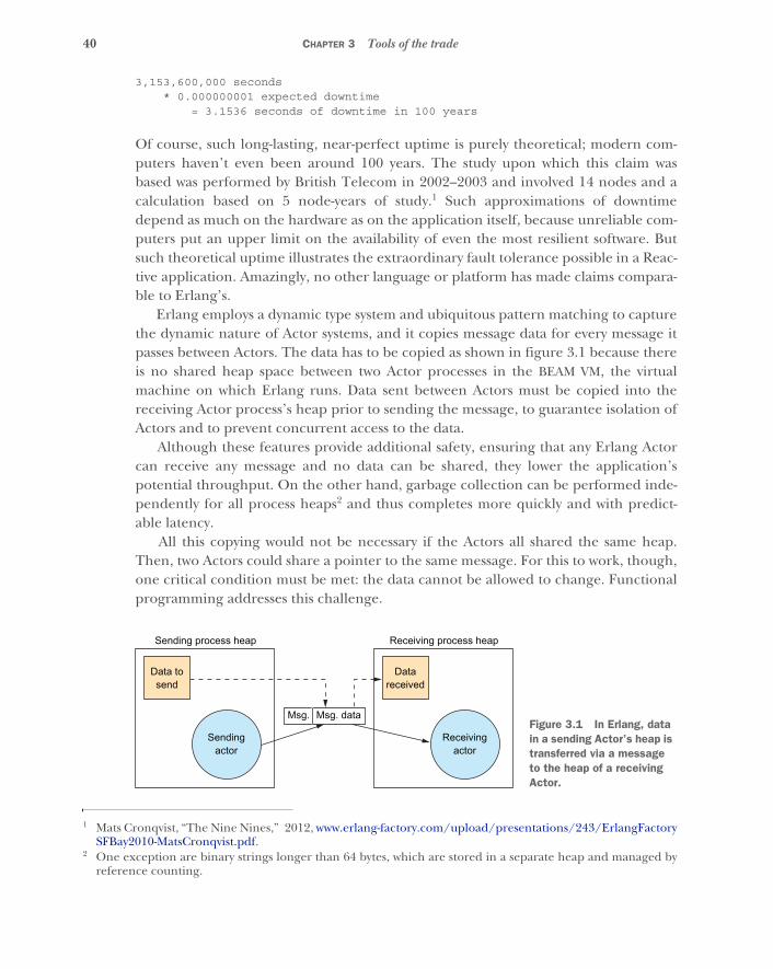
40 CHAPTER 3 Tools of the trade
3,153,600,000 seconds* 0.000000001 expected downtime
= 3.1536 seconds of downtime in 100 years
Of course, such long-lasting, near-perfect uptime is purely theoretical; modern com-puters haven’t even been around 100 years. The study upon which this claim wasbased was performed by British Telecom in 2002–2003 and involved 14 nodes and acalculation based on 5 node-years of study.1 Such approximations of downtimedepend as much on the hardware as on the application itself, because unreliable com-puters put an upper limit on the availability of even the most resilient software. Butsuch theoretical uptime illustrates the extraordinary fault tolerance possible in a Reac-tive application. Amazingly, no other language or platform has made claims compara-ble to Erlang’s.
Erlang employs a dynamic type system and ubiquitous pattern matching to capturethe dynamic nature of Actor systems, and it copies message data for every message itpasses between Actors. The data has to be copied as shown in figure 3.1 because thereis no shared heap space between two Actor processes in the BEAM VM, the virtualmachine on which Erlang runs. Data sent between Actors must be copied into thereceiving Actor process’s heap prior to sending the message, to guarantee isolation ofActors and to prevent concurrent access to the data.
Although these features provide additional safety, ensuring that any Erlang Actorcan receive any message and no data can be shared, they lower the application’spotential throughput. On the other hand, garbage collection can be performed inde-pendently for all process heaps2 and thus completes more quickly and with predict-able latency.
All this copying would not be necessary if the Actors all shared the same heap.Then, two Actors could share a pointer to the same message. For this to work, though,one critical condition must be met: the data cannot be allowed to change. Functionalprogramming addresses this challenge.
1 Mats Cronqvist, “The Nine Nines,” 2012, www.erlang-factory.com/upload/presentations/243/ErlangFactorySFBay2010-MatsCronqvist.pdf.
2 One exception are binary strings longer than 64 bytes, which are stored in a separate heap and managed byreference counting.
Sendingactor
Sending process heap
Receivingactor
Datareceived
Receiving process heap
Msg. Msg. data
Data tosend
Figure 3.1 In Erlang, data in a sending Actor’s heap is transferred via a message to the heap of a receiving Actor.
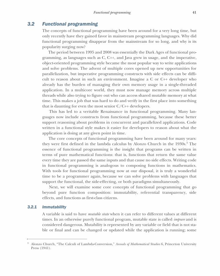
41Functional programming
3.2 Functional programmingThe concepts of functional programming have been around for a very long time, butonly recently have they gained favor in mainstream programming languages. Why didfunctional programming disappear from the mainstream for so long, and why is itspopularity surging now?
The period between 1995 and 2008 was essentially the Dark Ages of functional pro-gramming, as languages such as C, C++, and Java grew in usage, and the imperative,object-oriented programming style became the most popular way to write applicationsand solve problems. The advent of multiple cores opened up new opportunities forparallelization, but imperative programming constructs with side effects can be diffi-cult to reason about in such an environment. Imagine a C or C++ developer whoalready has the burden of managing their own memory usage in a single-threadedapplication. In a multicore world, they must now manage memory across multiplethreads while also trying to figure out who can access shared mutable memory at whattime. This makes a job that was hard to do and verify in the first place into somethingthat is daunting for even the most senior C/C++ developers.
This has led to a veritable Renaissance in functional programming. Many lan-guages now include constructs from functional programming, because these bettersupport reasoning about problems in concurrent and parallelized applications. Codewritten in a functional style makes it easier for developers to reason about what theapplication is doing at any given point in time.
The core concepts of functional programming have been around for many years:they were first defined in the lambda calculus by Alonzo Church in the 1930s.3 Theessence of functional programming is the insight that programs can be written interms of pure mathematical functions: that is, functions that return the same valueevery time they are passed the same inputs and that cause no side effects. Writing codein functional programming is analogous to composing functions in mathematics.With tools for functional programming now at our disposal, it is truly a wonderfultime to be a programmer again, because we can solve problems with languages thatsupport the functional, the side-effecting, or both paradigms simultaneously.
Next, we will examine some core concepts of functional programming that gobeyond pure function composition: immutability, referential transparency, sideeffects, and functions as first-class citizens.
3.2.1 Immutability
A variable is said to have mutable state when it can refer to different values at differenttimes. In an otherwise purely functional program, mutable state is called impure and isconsidered dangerous. Mutability is represented by any variable or field that is not sta-ble or final and can be changed or updated while the application is running; some
3 Alonzo Church, “The Calculi of Lambda-Conversion,” Annals of Mathematical Studies 6, Princeton UniversityPress (1941).
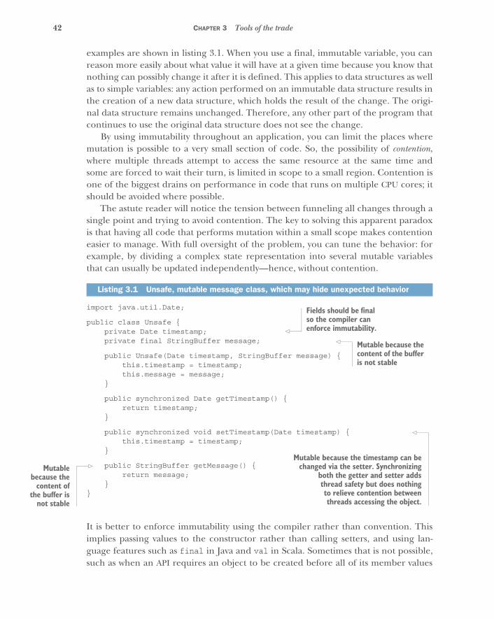
42 CHAPTER 3 Tools of the trade
examples are shown in listing 3.1. When you use a final, immutable variable, you canreason more easily about what value it will have at a given time because you know thatnothing can possibly change it after it is defined. This applies to data structures as wellas to simple variables: any action performed on an immutable data structure results inthe creation of a new data structure, which holds the result of the change. The origi-nal data structure remains unchanged. Therefore, any other part of the program thatcontinues to use the original data structure does not see the change.
By using immutability throughout an application, you can limit the places wheremutation is possible to a very small section of code. So, the possibility of contention,where multiple threads attempt to access the same resource at the same time andsome are forced to wait their turn, is limited in scope to a small region. Contention isone of the biggest drains on performance in code that runs on multiple CPU cores; itshould be avoided where possible.
The astute reader will notice the tension between funneling all changes through asingle point and trying to avoid contention. The key to solving this apparent paradoxis that having all code that performs mutation within a small scope makes contentioneasier to manage. With full oversight of the problem, you can tune the behavior: forexample, by dividing a complex state representation into several mutable variablesthat can usually be updated independently—hence, without contention.
import java.util.Date;
public class Unsafe {private Date timestamp;private final StringBuffer message;
public Unsafe(Date timestamp, StringBuffer message) {this.timestamp = timestamp;this.message = message;
}
public synchronized Date getTimestamp() {return timestamp;
}
public synchronized void setTimestamp(Date timestamp) {this.timestamp = timestamp;
}
public StringBuffer getMessage() {return message;
}}
It is better to enforce immutability using the compiler rather than convention. Thisimplies passing values to the constructor rather than calling setters, and using lan-guage features such as final in Java and val in Scala. Sometimes that is not possible,such as when an API requires an object to be created before all of its member values
Listing 3.1 Unsafe, mutable message class, which may hide unexpected behavior
Fields should be final so the compiler can enforce immutability.
Mutable because the content of the buffer is not stable
Mutable because the timestamp can bechanged via the setter. Synchronizing
both the getter and setter addsthread safety but does nothingto relieve contention betweenthreads accessing the object.
Mutablebecause the
content ofthe buffer is
not stable
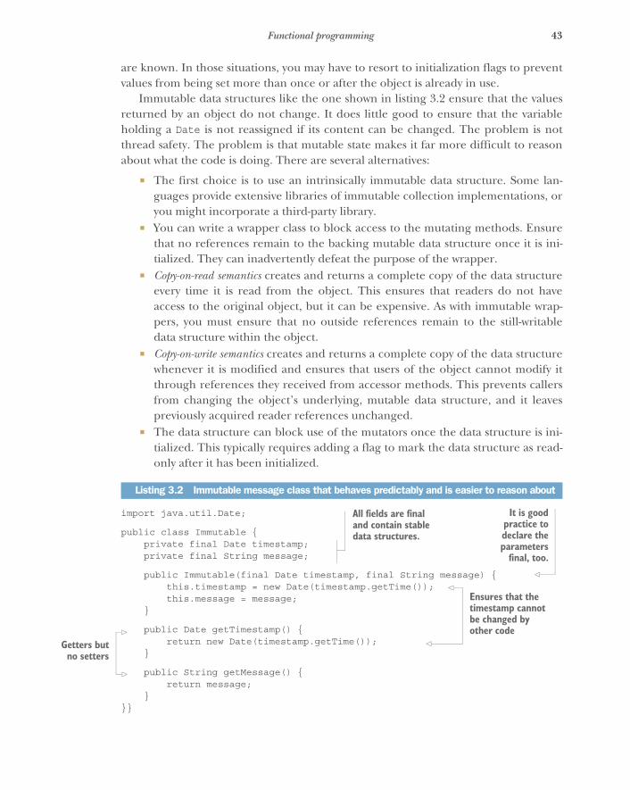
43Functional programming
are known. In those situations, you may have to resort to initialization flags to preventvalues from being set more than once or after the object is already in use.
Immutable data structures like the one shown in listing 3.2 ensure that the valuesreturned by an object do not change. It does little good to ensure that the variableholding a Date is not reassigned if its content can be changed. The problem is notthread safety. The problem is that mutable state makes it far more difficult to reasonabout what the code is doing. There are several alternatives:
� The first choice is to use an intrinsically immutable data structure. Some lan-guages provide extensive libraries of immutable collection implementations, oryou might incorporate a third-party library.
� You can write a wrapper class to block access to the mutating methods. Ensurethat no references remain to the backing mutable data structure once it is ini-tialized. They can inadvertently defeat the purpose of the wrapper.
� Copy-on-read semantics creates and returns a complete copy of the data structureevery time it is read from the object. This ensures that readers do not haveaccess to the original object, but it can be expensive. As with immutable wrap-pers, you must ensure that no outside references remain to the still-writabledata structure within the object.
� Copy-on-write semantics creates and returns a complete copy of the data structurewhenever it is modified and ensures that users of the object cannot modify itthrough references they received from accessor methods. This prevents callersfrom changing the object’s underlying, mutable data structure, and it leavespreviously acquired reader references unchanged.
� The data structure can block use of the mutators once the data structure is ini-tialized. This typically requires adding a flag to mark the data structure as read-only after it has been initialized.
import java.util.Date;
public class Immutable {private final Date timestamp;private final String message;
public Immutable(final Date timestamp, final String message) {this.timestamp = new Date(timestamp.getTime());this.message = message;
}
public Date getTimestamp() {return new Date(timestamp.getTime());
}
public String getMessage() {return message;
}}}
Listing 3.2 Immutable message class that behaves predictably and is easier to reason about
All fields are final and contain stable data structures.
It is goodpractice todeclare theparameters
final, too.
Ensures that the timestamp cannot be changed by other code
Getters butno setters

44 CHAPTER 3 Tools of the trade
Java does not make everything immutable by default, but liberal use of the final key-word is helpful. In Scala, case classes provide immutability by default as well as addi-tional, very convenient features such as correct equality and hash-code functions:
import java.util.Date
case class Message(timestamp: Date, message: String)
3.2.2 Referential transparency
An expression is said to be referentially transparent if replacing it with a single value (aconstant) has no impact on the execution of the program.4 So, evaluating a referen-tially transparent expression—that is, performing an operation on some data—has noimpact on that data, and no side effects can occur. For example, the act of adding,removing, or updating a value in an immutable list results in a new list being createdwith the changed values; any part of the program still observing the original list seesno change.
Consider Java’s java.lang.StringBuffer class. If you call the reverse method ona StringBuffer, you will get a reference to a StringBuffer with the values reversed.But the original StringBuffer reference refers to the same instance and thereforenow also has changed its value:
final StringBuffer original = new StringBuffer(“foo”);final StringBuffer reversed = myStringBuffer.reverse();System.out.println(String.format(
"original '%s', new value '%s'",original,reversed));
This is an example of referential opacity: the value of the expression myStringBuffer.reverse() changes when it is evaluated. It cannot be replaced by its result withoutaltering the way the program executes. The java.lang.StringBuilder class has thesame problem.
Note, however, that a function call can be referentially transparent even if thefunction modifies internal state, as long as the function call can be replaced with itsresult without affecting the program’s output. For example, if an operation is likely tobe performed multiple times, internally caching the result the first time can speed upexecution without violating referential transparency. An example of this approach isshown in the next listing.
4 http://en.wikipedia.org/wiki/Referential_transparency_(computer_science)
Even with case classes, you must take care that the fields hold immutable data structures—using the Date’s setters will break this.
Result: original 'oof', new value 'oof'
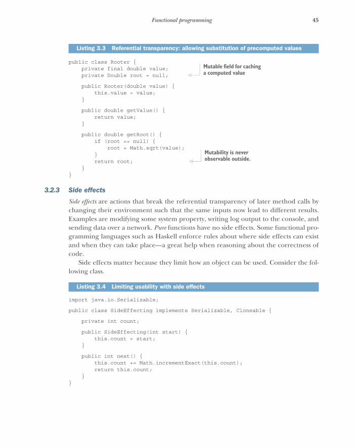
45Functional programming
public class Rooter {private final double value;private Double root = null;
public Rooter(double value) {this.value = value;
}
public double getValue() {return value;
}
public double getRoot() {if (root == null) {
root = Math.sqrt(value);}return root;
}}
3.2.3 Side effects
Side effects are actions that break the referential transparency of later method calls bychanging their environment such that the same inputs now lead to different results.Examples are modifying some system property, writing log output to the console, andsending data over a network. Pure functions have no side effects. Some functional pro-gramming languages such as Haskell enforce rules about where side effects can existand when they can take place—a great help when reasoning about the correctness ofcode.
Side effects matter because they limit how an object can be used. Consider the fol-lowing class.
import java.io.Serializable;
public class SideEffecting implements Serializable, Cloneable {
private int count;
public SideEffecting(int start) {this.count = start;
}
public int next() {this.count += Math.incrementExact(this.count);return this.count;
}}
Listing 3.3 Referential transparency: allowing substitution of precomputed values
Listing 3.4 Limiting usability with side effects
Mutable field for caching a computed value
Mutability is never observable outside.
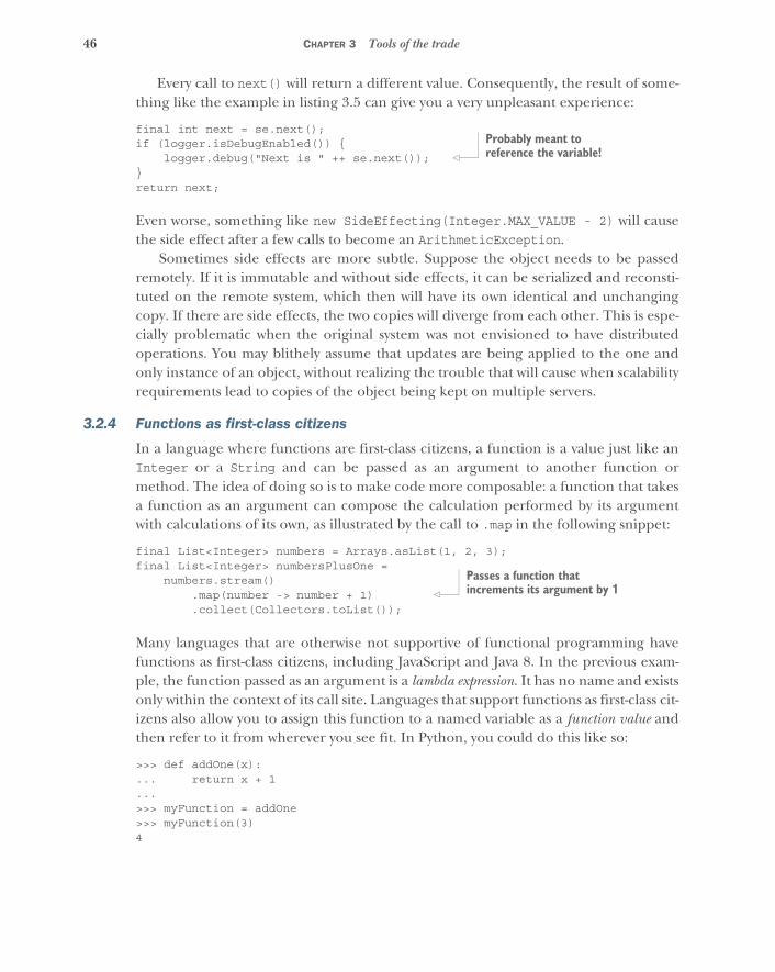
46 CHAPTER 3 Tools of the trade
Every call to next() will return a different value. Consequently, the result of some-thing like the example in listing 3.5 can give you a very unpleasant experience:
final int next = se.next();if (logger.isDebugEnabled()) {
logger.debug("Next is " ++ se.next());}return next;
Even worse, something like new SideEffecting(Integer.MAX_VALUE - 2) will causethe side effect after a few calls to become an ArithmeticException.
Sometimes side effects are more subtle. Suppose the object needs to be passedremotely. If it is immutable and without side effects, it can be serialized and reconsti-tuted on the remote system, which then will have its own identical and unchangingcopy. If there are side effects, the two copies will diverge from each other. This is espe-cially problematic when the original system was not envisioned to have distributedoperations. You may blithely assume that updates are being applied to the one andonly instance of an object, without realizing the trouble that will cause when scalabilityrequirements lead to copies of the object being kept on multiple servers.
3.2.4 Functions as first-class citizens
In a language where functions are first-class citizens, a function is a value just like anInteger or a String and can be passed as an argument to another function ormethod. The idea of doing so is to make code more composable: a function that takesa function as an argument can compose the calculation performed by its argumentwith calculations of its own, as illustrated by the call to .map in the following snippet:
final List<Integer> numbers = Arrays.asList(1, 2, 3);final List<Integer> numbersPlusOne =
numbers.stream().map(number -> number + 1).collect(Collectors.toList());
Many languages that are otherwise not supportive of functional programming havefunctions as first-class citizens, including JavaScript and Java 8. In the previous exam-ple, the function passed as an argument is a lambda expression. It has no name and existsonly within the context of its call site. Languages that support functions as first-class cit-izens also allow you to assign this function to a named variable as a function value andthen refer to it from wherever you see fit. In Python, you could do this like so:
>>> def addOne(x):... return x + 1...>>> myFunction = addOne>>> myFunction(3)4
Probably meant to reference the variable!
Passes a function that increments its argument by 1
47Responsiveness to users
3.3 Responsiveness to usersBeyond functional programming, to build Reactive applications you also need to usetools that give you responsiveness. This is not responsive web design,5 as it is known inthe user-experience world, where a front end is said to be “responsive” if it resizesitself appropriately for the user’s viewing device. Responsiveness in Reactive applica-tions means being able to quickly respond to user requests in the face of failure thatcan occur anywhere inside or outside the application. The performance trade-offs ofReactive applications are defined by the axiom that you can choose any two of the fol-lowing three characteristics:
� High throughput� Low latency, but also smooth and not jittery� Small footprint
These will all be defined further along in this section.
3.3.1 Prioritizing the three performance characteristics
When you make architecture choices for a Reactive application, you are in essence giv-ing priority to two of those three characteristics and choosing to sacrifice the remain-ing characteristic where necessary. This is not a law or theorem, but more of a guidingprinciple that is likely to be true in most cases. To get a very fast application withsmooth, low latency, you typically have to give it more resources (footprint). An exam-ple of this is a high-performance messaging library written in Java, known as the Disrup-tor (http://lmax-exchange.github.io/disruptor). To get its tremendous throughputand smooth latency, the Disruptor has to preallocate all the memory it will ever use forits internal ring buffer, in order to prevent allocations at runtime that could lead tostop-the-world garbage collections and compaction pauses in the Java virtual machine.The Disruptor gains throughput by pinning itself to a specific execution core, therebyavoiding the cost of context switches6 between threads being swapped in and out onthat core. This is another aspect of application footprint: there is now one fewer exe-cution core available for use by other threads on that computer.
The Storm framework (https://github.com/nathanmarz/storm), created byNathan Marz and released in 2011 to much acclaim, provides capabilities for distrib-uted processing of streaming data. Storm was created at Marz’s startup, BackType,which was purchased by Twitter and became the basis for its real-time analytics appli-cations. But the implementation was not particularly fast, because it was built usingClojure and pure functional programming constructs. When Marz released version0.7 in 2012, he used the Disruptor to increase throughput by as much as three times,at the cost of footprint. This trade-off matters to those who choose to deploy an appli-cation that uses Storm, particularly in the cloud, where one core on the VM must be
5 http://en.wikipedia.org/wiki/Responsive_web_design6 http://en.wikipedia.org/wiki/Context_switch
48 CHAPTER 3 Tools of the trade
devoted solely to the Disruptor to maintain its speed. Note that the number of coresavailable to an application in a virtual environment is not an absolute value. As DougLea,7 the author of many concurrency libraries on the JVM, such as the ForkJoinPooland CompletableFuture, has said, “Ask your hypervisor how much memory you have,or how many cores you have. It’ll lie. Every time. It’s designed to lie. You paid themmoney so it would lie.”8 Developers have to take these variables into account whenconsidering footprint in a cloud deployment.
Some platforms have constraints that limit their ability to make these trade-offs.For example, a mobile application typically cannot give up footprint to increasethroughput and make latency smoother, because a mobile platform typically has verylimited resources. Imagine the cost of pinning a core on a mobile phone, both interms of reduced resource availability for other applications and the phone’s operat-ing system. A mobile phone has limited memory as well as constraints on power usage:you don’t want to drain the battery so quickly that no one would want to use yourapplication. So, mobile applications typically attempt to minimize footprint whileincreasing throughput at the expense of latency, because users are more willing toaccept latency on a mobile platform. Anyone who has used an application from aphone has experienced slowness due to network issues or packet loss.
3.4 Existing support for Reactive designNow that we have reviewed the basic concepts needed to understand and evaluatetools and language constructs for implementing Reactive design, it is time to look atthe leading examples. Many languages have innovated in the area of dividing workand making it asynchronous.
For each concept or implementation described in this section, we will provide anevaluation of how well it meets the tenets of the Reactive Manifesto. Note thatalthough all are asynchronous and nonblocking in and of themselves, it is still up toyou to ensure that the code you write remains asynchronous and nonblocking as well,in order to remain Reactive.
3.4.1 Green threads
Some languages do not include built-in constructs for running multiple threadswithin the same operating system process. In these cases, it is still possible to imple-ment asynchronous behavior via green threads: threads scheduled by the user processrather than the operating system.9
Green threads can be very efficient but are restricted to a single physical machine.It is impossible, without the aid of delimited portable continuations,10 to share the
7 http://en.wikipedia.org/wiki/Doug_Lea8 Doug Lea, “Engineering Concurrent Library Components” (talk, Emerging Technologies Conference, 2013),
http://chariotsolutions.com/screencast/phillyete-screencast-7-doug-lea-engineering-concurrent-library-components.9 http://en.wikipedia.org/wiki/Green_threads10 http://en.wikipedia.org/wiki/Delimited_continuation
49Existing support for Reactive design
processing of a thread across multiple physical machines. Delimited portable continu-ations allow you to mark points in logic where the execution stack can be wrapped upand exported either locally or to another machine. These continuations can then betreated as functions. This is a powerful idea, implemented in a Scheme library calledTermite (https://code.google.com/p/termite). But green threads and continuationsdo not provide for resilience, because there is currently no way to supervise their exe-cution; they are therefore lacking with respect to fault tolerance.
Waldo et al. note11 that it is not a good idea to try to make logic that executes in adistributed context appear to be local. This postulate applies to green threads as well.If we take “local” to mean local to the thread, and “distributed/remote” to mean onanother thread and thus asynchronous, you would not want “distributed/remote” toappear “local” because this would obscure the difference between synchronous andasynchronous operations. It would be hard to tell which operations can block the pro-gram’s progress and which cannot!
REACTIVE EVALUATION OF GREEN THREADS
Green threads are asynchronous and nonblocking, but they do not support messagepassing. They do not scale up to use multiple cores on a machine by themselves,although if the runtime supports it, it is possible to have more than one in a process,or multiple processes can be run. They do not scale outward across nodes in a net-work. They also do not provide any mechanisms for fault tolerance, so it is up to devel-opers who use them to write their own constructs to handle any failure that may occur.
3.4.2 Event loops
When a language or platform does not support multiple threads in one process, youcan still get asynchronous behavior by making green threads that share an event loop.This loop provides a mechanism for sharing a single execution thread among severallogical threads at the same time. The idea is that although only a single thread canexecute at a given moment, the application should not block on any operation andshould instead make each thread yield until such time as the external work it needs,such as calling a data store, is completed. At that time, the application can invoke acallback to perform a predefined behavior. This is very powerful: Node.js(http://nodejs.org), for example, uses a single-threaded JavaScript runtime to per-form considerably more work because it doesn’t have to wait for every operation tocomplete before handling other work.
Event loops are most typically implemented with callbacks. This would be okay ifonly a single callback could be referenced at a time, but as an application’s functionalitygrows, this typically is not the case. The terms callback hell and pyramid of doom have beencoined to represent the interwoven spaghetti code that often results from popular toolslike Node.js. Furthermore, event loops based on a single-threaded process are viable
11 Jim Waldo, Geoff Wyant, Ann Wollrath, Sam Kendall: “A Note on Distributed Computing,” Sun MicrosystemsLaboratories, 1994, http://citeseerx.ist.psu.edu/viewdoc/summary?doi=10.1.1.41.7628.
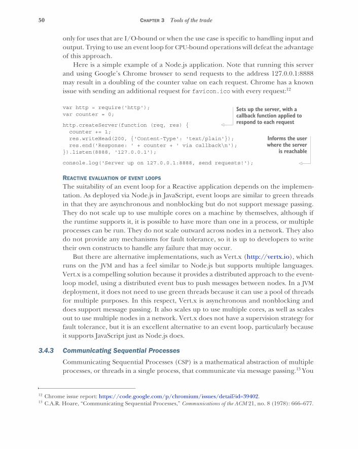
50 CHAPTER 3 Tools of the trade
only for uses that are I/O-bound or when the use case is specific to handling input andoutput. Trying to use an event loop for CPU-bound operations will defeat the advantageof this approach.
Here is a simple example of a Node.js application. Note that running this serverand using Google’s Chrome browser to send requests to the address 127.0.0.1:8888may result in a doubling of the counter value on each request. Chrome has a knownissue with sending an additional request for favicon.ico with every request:12
var http = require('http');var counter = 0;
http.createServer(function (req, res) {counter += 1;res.writeHead(200, {'Content-Type': 'text/plain'});res.end('Response: ' + counter + ' via callback\n');
}).listen(8888, '127.0.0.1');
console.log('Server up on 127.0.0.1:8888, send requests!');
REACTIVE EVALUATION OF EVENT LOOPS
The suitability of an event loop for a Reactive application depends on the implemen-tation. As deployed via Node.js in JavaScript, event loops are similar to green threadsin that they are asynchronous and nonblocking but do not support message passing.They do not scale up to use multiple cores on a machine by themselves, although ifthe runtime supports it, it is possible to have more than one in a process, or multipleprocesses can be run. They do not scale outward across nodes in a network. They alsodo not provide any mechanisms for fault tolerance, so it is up to developers to writetheir own constructs to handle any failure that may occur.
But there are alternative implementations, such as Vert.x (http://vertx.io), whichruns on the JVM and has a feel similar to Node.js but supports multiple languages.Vert.x is a compelling solution because it provides a distributed approach to the event-loop model, using a distributed event bus to push messages between nodes. In a JVMdeployment, it does not need to use green threads because it can use a pool of threadsfor multiple purposes. In this respect, Vert.x is asynchronous and nonblocking anddoes support message passing. It also scales up to use multiple cores, as well as scalesout to use multiple nodes in a network. Vert.x does not have a supervision strategy forfault tolerance, but it is an excellent alternative to an event loop, particularly becauseit supports JavaScript just as Node.js does.
3.4.3 Communicating Sequential Processes
Communicating Sequential Processes (CSP) is a mathematical abstraction of multipleprocesses, or threads in a single process, that communicate via message passing.13 You
12 Chrome issue report: https://code.google.com/p/chromium/issues/detail?id=39402.13 C.A.R. Hoare, “Communicating Sequential Processes,” Communications of the ACM 21, no. 8 (1978): 666–677.
Sets up the server, with a callback function applied to respond to each request
Informs the userwhere the server
is reachable
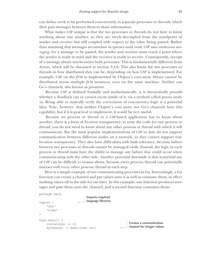
51Existing support for Reactive design
can define work to be performed concurrently in separate processes or threads, whichthen pass messages between them to share information.
What makes CSP unique is that the two processes or threads do not have to knowanything about one another, so they are nicely decoupled from the standpoint ofsender and receiver but still coupled with respect to the value being passed. Ratherthan assuming that messages accumulate in queues until read, CSP uses rendezvous mes-saging : for a message to be passed, the sender and receiver must reach a point wherethe sender is ready to send and the receiver is ready to receive. Consequently, receiptof a message always synchronizes both processes. This is fundamentally different fromActors, which will be discussed in section 3.4.6. This also limits the two processes orthreads in how distributed they can be, depending on how CSP is implemented. Forexample, CSP on the JVM as implemented by Clojure’s core.async library cannot bedistributed across multiple JVM instances, even on the same machine. Neither canGo’s channels, also known as goroutines.
Because CSP is defined formally and mathematically, it is theoretically provablewhether a deadlock can or cannot occur inside of it, via a method called process analy-sis. Being able to statically verify the correctness of concurrency logic is a powerfulidea. Note, however, that neither Clojure’s core.async nor Go’s channels have thiscapability; but if it is practical to implement, it would be very useful.
Because no process or thread in a CSP-based application has to know aboutanother, there is a form of location transparency: to write the code for one process orthread, you do not need to know about any other process or thread with which it willcommunicate. But the most popular implementations of CSP to date do not supportcommunication between different nodes on a network, so they cannot support truelocation transparency. They also have difficulties with fault tolerance, because failurebetween two processes or threads cannot be managed easily. Instead, the logic in eachprocess or thread must have the ability to manage any failure that could occur whencommunicating with the other side. Another potential downside is that nontrivial useof CSP can be difficult to reason about, because every process/thread can potentiallyinteract with every other process/thread at each step.
Here is a simple example of two communicating processes in Go. Interestingly, a Gofunction can create a channel and put values onto it as well as consume them, in effectstashing values off to the side for use later. In this example, one function produces mes-sages and puts them onto the channel, and a second function consumes them:
package main
import ("fmt""time"
)
func main() {iterations := 10myChannel := make(chan int)
Imports required language libraries
Creates a communication channel for integer values
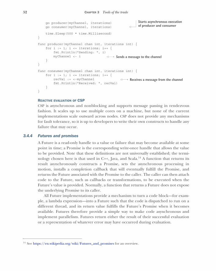
52 CHAPTER 3 Tools of the trade
go producer(myChannel, iterations)go consumer(myChannel, iterations)
time.Sleep(500 * time.Millisecond)}
func producer(myChannel chan int, iterations int) {for i := 1; i <= iterations; i++ {
fmt.Println("Sending: ", i)myChannel <- i
}}
func consumer(myChannel chan int, iterations int) {for i := 1; i <= iterations; i++ {
recVal := <-myChannelfmt.Println("Received: ", recVal)
}}
REACTIVE EVALUATION OF CSPCSP is asynchronous and nonblocking and supports message passing in rendezvousfashion. It scales up to use multiple cores on a machine, but none of the currentimplementations scale outward across nodes. CSP does not provide any mechanismsfor fault tolerance, so it is up to developers to write their own constructs to handle anyfailure that may occur.
3.4.4 Futures and promises
A Future is a read-only handle to a value or failure that may become available at somepoint in time; a Promise is the corresponding write-once handle that allows the valueto be provided. Note that these definitions are not universally established; the termi-nology chosen here is that used in C++, Java, and Scala.14 A function that returns itsresult asynchronously constructs a Promise, sets the asynchronous processing inmotion, installs a completion callback that will eventually fulfill the Promise, andreturns the Future associated with the Promise to the caller. The caller can then attachcode to the Future, such as callbacks or transformations, to be executed when theFuture’s value is provided. Normally, a function that returns a Future does not exposethe underlying Promise to its caller.
All Future implementations provide a mechanism to turn a code block—for exam-ple, a lambda expression—into a Future such that the code is dispatched to run on adifferent thread, and its return value fulfills the Future’s Promise when it becomesavailable. Futures therefore provide a simple way to make code asynchronous andimplement parallelism. Futures return either the result of their successful evaluationor a representation of whatever error may have occurred during evaluation.
14 See https://en.wikipedia.org/wiki/Futures_and_promises for an overview.
Starts asynchronous execution of producer and consumer
Sends a message to the channel
Receives a message from the channel
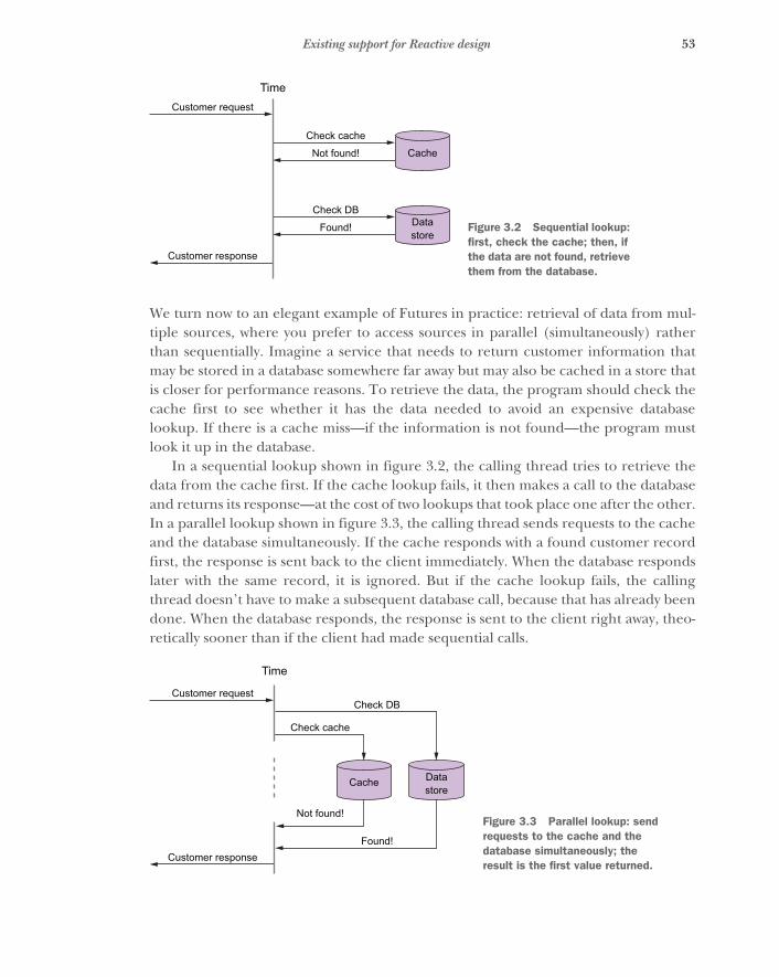
53Existing support for Reactive design
We turn now to an elegant example of Futures in practice: retrieval of data from mul-tiple sources, where you prefer to access sources in parallel (simultaneously) ratherthan sequentially. Imagine a service that needs to return customer information thatmay be stored in a database somewhere far away but may also be cached in a store thatis closer for performance reasons. To retrieve the data, the program should check thecache first to see whether it has the data needed to avoid an expensive databaselookup. If there is a cache miss—if the information is not found—the program mustlook it up in the database.
In a sequential lookup shown in figure 3.2, the calling thread tries to retrieve thedata from the cache first. If the cache lookup fails, it then makes a call to the databaseand returns its response—at the cost of two lookups that took place one after the other.In a parallel lookup shown in figure 3.3, the calling thread sends requests to the cacheand the database simultaneously. If the cache responds with a found customer recordfirst, the response is sent back to the client immediately. When the database respondslater with the same record, it is ignored. But if the cache lookup fails, the callingthread doesn’t have to make a subsequent database call, because that has already beendone. When the database responds, the response is sent to the client right away, theo-retically sooner than if the client had made sequential calls.
Check DBDatastore
Found!
Check cache
Customer request
Time
Customer response
CacheNot found!
Figure 3.2 Sequential lookup: first, check the cache; then, if the data are not found, retrieve them from the database.
Check DB
Datastore
Found!
Check cache
Customer request
Time
Customer response
Cache
Not found!Figure 3.3 Parallel lookup: send requests to the cache and the database simultaneously; the result is the first value returned.
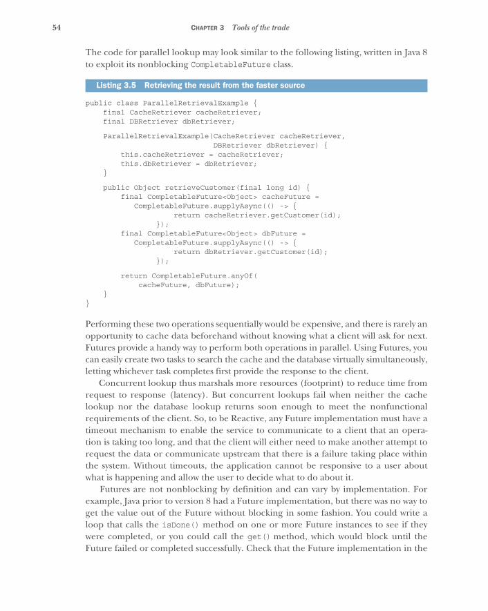
54 CHAPTER 3 Tools of the trade
The code for parallel lookup may look similar to the following listing, written in Java 8to exploit its nonblocking CompletableFuture class.
public class ParallelRetrievalExample {final CacheRetriever cacheRetriever;final DBRetriever dbRetriever;
ParallelRetrievalExample(CacheRetriever cacheRetriever,DBRetriever dbRetriever) {
this.cacheRetriever = cacheRetriever;this.dbRetriever = dbRetriever;
}
public Object retrieveCustomer(final long id) {final CompletableFuture<Object> cacheFuture =
CompletableFuture.supplyAsync(() -> {return cacheRetriever.getCustomer(id);
});final CompletableFuture<Object> dbFuture =
CompletableFuture.supplyAsync(() -> {return dbRetriever.getCustomer(id);
});
return CompletableFuture.anyOf(cacheFuture, dbFuture);
}}
Performing these two operations sequentially would be expensive, and there is rarely anopportunity to cache data beforehand without knowing what a client will ask for next.Futures provide a handy way to perform both operations in parallel. Using Futures, youcan easily create two tasks to search the cache and the database virtually simultaneously,letting whichever task completes first provide the response to the client.
Concurrent lookup thus marshals more resources (footprint) to reduce time fromrequest to response (latency). But concurrent lookups fail when neither the cachelookup nor the database lookup returns soon enough to meet the nonfunctionalrequirements of the client. So, to be Reactive, any Future implementation must have atimeout mechanism to enable the service to communicate to a client that an opera-tion is taking too long, and that the client will either need to make another attempt torequest the data or communicate upstream that there is a failure taking place withinthe system. Without timeouts, the application cannot be responsive to a user aboutwhat is happening and allow the user to decide what to do about it.
Futures are not nonblocking by definition and can vary by implementation. Forexample, Java prior to version 8 had a Future implementation, but there was no way toget the value out of the Future without blocking in some fashion. You could write aloop that calls the isDone() method on one or more Future instances to see if theywere completed, or you could call the get() method, which would block until theFuture failed or completed successfully. Check that the Future implementation in the
Listing 3.5 Retrieving the result from the faster source

55Existing support for Reactive design
version of the language you are using is nonblocking; if it is not, consider alternativeswithout this shortcoming.
Similar to event loops, Futures can be implemented with callbacks, allowing you topredefine logic to be applied upon the completion of the Future. But, as with Node.js,callbacks can quickly turn ugly when more than one is applied at a time. Some lan-guages that support functional programming allow you to map over a Future: thisdefines behavior that occurs only when the Future successfully completes, but not if itfails. By means of higher-order functions15 such as map, these languages frequentlygive you the ability to compose behavior that depends on successful completionof many Futures into simple, elegant logic using syntactic sugar such as a for- or list-comprehension.16 This is particularly useful when staging results from multipleFutures into a single result, as in the next example.
def getProductInventoryByPostalCode(productSku: Long,postalCode: String):
Future[(Long, Map[Long, Long])] = {
implicit val ec = ExecutionContext.fromExecutor(new ForkJoinPool())
val localInventoryFuture = Future {inventoryService.currentInventoryInWarehouse(
productSku, postalCode)}val overallInventoryFutureByWarehouse = Future {
inventoryService.currentInventoryOverallByWarehouse(productSku)
}
for {local <- localInventoryFutureoverall <- overallInventoryFutureByWarehouse
} yield (local, overall)}
Multiple Futures can “race” to fulfill a single Promise, where the first Future to com-plete supplies the Promise’s value. Because a Promise’s value can be written only once,you can be sure the Future that gets its value from that Promise will not change itsvalue even if other asynchronous tasks, completing later, try to rewrite it. Listing 3.6demonstrates this technique with the .anyOf method of CompletableFuture: itreturns whichever Future finishes first. Notice that this Future’s value is not defined bya code block within retrieveCustomer: a Promise can be fulfilled with a value pro-vided by any event—even synchronously, if it is already available.
15 http://en.wikipedia.org/wiki/Higher-order_function16 http://en.wikipedia.org/wiki/List_comprehension
Listing 3.6 Aggregating a single result from two futures in Scala
The thread pool onwhich the Futures
will be executed
Creates both Futures up front to start the queries in parallel
A for-comprehension in Scala: equivalent to nested function calls to flatMap and map
Returns the combined result
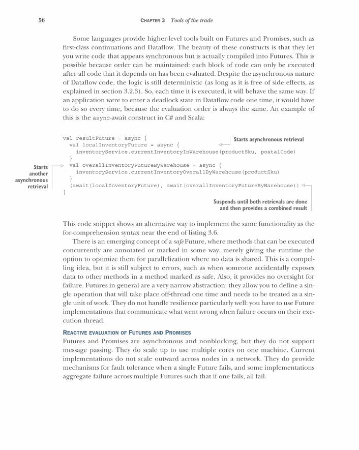
56 CHAPTER 3 Tools of the trade
Some languages provide higher-level tools built on Futures and Promises, such asfirst-class continuations and Dataflow. The beauty of these constructs is that they letyou write code that appears synchronous but is actually compiled into Futures. This ispossible because order can be maintained: each block of code can only be executedafter all code that it depends on has been evaluated. Despite the asynchronous natureof Dataflow code, the logic is still deterministic (as long as it is free of side effects, asexplained in section 3.2.3). So, each time it is executed, it will behave the same way. Ifan application were to enter a deadlock state in Dataflow code one time, it would haveto do so every time, because the evaluation order is always the same. An example ofthis is the async-await construct in C# and Scala:
val resultFuture = async {val localInventoryFuture = async {
inventoryService.currentInventoryInWarehouse(productSku, postalCode)}val overallInventoryFutureByWarehouse = async {
inventoryService.currentInventoryOverallByWarehouse(productSku)}(await(localInventoryFuture), await(overallInventoryFutureByWarehouse))
}
This code snippet shows an alternative way to implement the same functionality as thefor-comprehension syntax near the end of listing 3.6.
There is an emerging concept of a safe Future, where methods that can be executedconcurrently are annotated or marked in some way, merely giving the runtime theoption to optimize them for parallelization where no data is shared. This is a compel-ling idea, but it is still subject to errors, such as when someone accidentally exposesdata to other methods in a method marked as safe. Also, it provides no oversight forfailure. Futures in general are a very narrow abstraction: they allow you to define a sin-gle operation that will take place off-thread one time and needs to be treated as a sin-gle unit of work. They do not handle resilience particularly well: you have to use Futureimplementations that communicate what went wrong when failure occurs on their exe-cution thread.
REACTIVE EVALUATION OF FUTURES AND PROMISES
Futures and Promises are asynchronous and nonblocking, but they do not supportmessage passing. They do scale up to use multiple cores on one machine. Currentimplementations do not scale outward across nodes in a network. They do providemechanisms for fault tolerance when a single Future fails, and some implementationsaggregate failure across multiple Futures such that if one fails, all fail.
Starts asynchronous retrieval
Startsanother
asynchronousretrieval
Suspends until both retrievals are doneand then provides a combined result
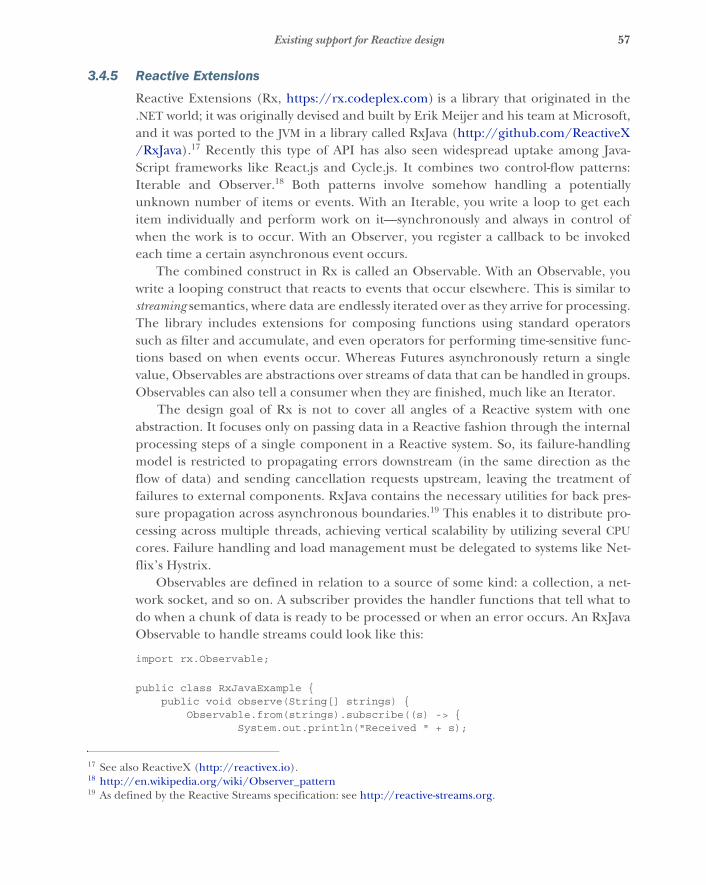
57Existing support for Reactive design
3.4.5 Reactive Extensions
Reactive Extensions (Rx, https://rx.codeplex.com) is a library that originated in the.NET world; it was originally devised and built by Erik Meijer and his team at Microsoft,and it was ported to the JVM in a library called RxJava (http://github.com/ReactiveX/RxJava).17 Recently this type of API has also seen widespread uptake among Java-Script frameworks like React.js and Cycle.js. It combines two control-flow patterns:Iterable and Observer.18 Both patterns involve somehow handling a potentiallyunknown number of items or events. With an Iterable, you write a loop to get eachitem individually and perform work on it—synchronously and always in control ofwhen the work is to occur. With an Observer, you register a callback to be invokedeach time a certain asynchronous event occurs.
The combined construct in Rx is called an Observable. With an Observable, youwrite a looping construct that reacts to events that occur elsewhere. This is similar tostreaming semantics, where data are endlessly iterated over as they arrive for processing.The library includes extensions for composing functions using standard operatorssuch as filter and accumulate, and even operators for performing time-sensitive func-tions based on when events occur. Whereas Futures asynchronously return a singlevalue, Observables are abstractions over streams of data that can be handled in groups.Observables can also tell a consumer when they are finished, much like an Iterator.
The design goal of Rx is not to cover all angles of a Reactive system with oneabstraction. It focuses only on passing data in a Reactive fashion through the internalprocessing steps of a single component in a Reactive system. So, its failure-handlingmodel is restricted to propagating errors downstream (in the same direction as theflow of data) and sending cancellation requests upstream, leaving the treatment offailures to external components. RxJava contains the necessary utilities for back pres-sure propagation across asynchronous boundaries.19 This enables it to distribute pro-cessing across multiple threads, achieving vertical scalability by utilizing several CPUcores. Failure handling and load management must be delegated to systems like Net-flix’s Hystrix.
Observables are defined in relation to a source of some kind: a collection, a net-work socket, and so on. A subscriber provides the handler functions that tell what todo when a chunk of data is ready to be processed or when an error occurs. An RxJavaObservable to handle streams could look like this:
import rx.Observable;
public class RxJavaExample {public void observe(String[] strings) {
Observable.from(strings).subscribe((s) -> {System.out.println("Received " + s);
17 See also ReactiveX (http://reactivex.io).18 http://en.wikipedia.org/wiki/Observer_pattern19 As defined by the Reactive Streams specification: see http://reactive-streams.org.
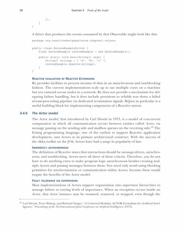
58 CHAPTER 3 Tools of the trade
});}
}
A driver that produces the events consumed by that Observable might look like this:
package org.reactivedesignpatterns.chapter3.rxjava;
public class RxJavaExampleDriver {final RxJavaExample rxJavaExample = new RxJavaExample();
public static void main(String[] args) {String[] strings = { "a", "b", "c" };rxJavaExample.observe(strings);
}}
REACTIVE EVALUATION OF REACTIVE EXTENSIONS
Rx provides facilities to process streams of data in an asynchronous and nonblockingfashion. The current implementations scale up to use multiple cores on a machinebut not outward across nodes in a network. Rx does not provide a mechanism for del-egating failure handling, but it does include provisions to reliably tear down a failedstream-processing pipeline via dedicated termination signals. RxJava in particular is auseful building block for implementing components of a Reactive system.
3.4.6 The Actor model
The Actor model, first introduced by Carl Hewitt in 1973, is a model of concurrentcomputation in which all communication occurs between entities called Actors, viamessage passing on the sending side and mailbox queues on the receiving side.20 TheErlang programming language, one of the earliest to support Reactive applicationdevelopment, uses Actors as its primary architectural construct. With the success ofthe Akka toolkit on the JVM, Actors have had a surge in popularity of late.
INHERENTLY ASYNCHRONOUS
The definition of Reactive states that interactions should be message-driven, asynchro-nous, and nonblocking. Actors meet all three of these criteria. Therefore, you do nothave to do anything extra to make program logic asynchronous besides creating mul-tiple Actors and passing messages between them. You need only avoid using blockingprimitives for synchronization or communication within Actors, because these wouldnegate the benefits of the Actor model.
FAULT TOLERANCE VIA SUPERVISION
Most implementations of Actors support organization into supervisor hierarchies tomanage failure at varying levels of importance. When an exception occurs inside anActor, that Actor instance may be resumed, restarted, or stopped, even though the
20 Carl Hewitt, Peter Bishop, and Richard Steiger, “A Universal Modular ACTOR Formalism for Artificial Intel-ligence,” Proceedings of the 3rd International Joint Conference on Artificial Intelligence (1973).

59Existing support for Reactive design
failure occurred on a different asynchronous thread. Erlang’s Open Telecom Plat-form (OTP, https://github.com/erlang/otp) defines a pattern for building supervi-sion hierarchies for Actors, allowing a parent Actor to manage failure for all childrenbelow it, possibly elevating some failures to an appropriate “grandparent” Actor.
This approach makes failure handling part of the application’s domain, just likeclasses that represent application-specific data. When designing an Actor application,you should take the time to think of all the ways the application could fail at all levelsof the supervisor hierarchy, and what each level should do about each kind of failure.You should also consider how to handle failures that you cannot foresee, and allow theapplication to respond to those as well. Even though you cannot anticipate the precisecause of every failure, you can always safely assume that the component that failed isnow in an invalid state and needs to be discarded. This principle, called let it crash,enables people to design thoughtful responses to failure scenarios beyond those theycan think of in advance. Without a supervision hierarchy, this kind of resilience wouldnot be feasible; at best you would have failure-handling code strewn about the logic ofthe application. All of the aforementioned fault-tolerance patterns are described indetail in chapter 12.
LOCATION TRANSPARENCY
Erlang and Akka provide proxies through which all Actor interactions must takeplace: a PID in Erlang and an ActorRef in Akka. So, an individual Actor does not needto know the physical location of the Actor to which it is sending a message—a featurecalled location transparency, treated at length in chapter 5. This makes message-sendingcode more declarative, because all the physical “how-to” details of how the message isactually sent are dealt with behind the scenes. Location transparency enables you toadd even such sophisticated features as starting a new Actor and rerouting all mes-sages to it if a receiving Actor goes down mid-conversation, without anyone needing toalter the message-sending code.
A drawback of the Actor model is that producers and consumers of messages arecoupled to one another: the sender of a message must have a reference to the Actorinstance that it wants to send to. This reference is just as necessary as a recipientaddress on a letter, without which the mail service would not know where to deliver it.An Actor reference is much like a postal address in that it only tells where to transportmessages, not what the recipient looks like or what state they are in. A benefit of thisapproach is that each Actor is somewhat decoupled from failures occurring inanother, because Actors have no access to each other except through these refer-ences. A supervising Actor responsible for handling failures is also protected by thisisolating layer of message passing.
NO CONCURRENCY WITHIN ONE ACTOR
Because each Actor contains only a single thread of execution within itself, and nothread can call into an Actor directly, there is no concurrency within an Actorinstance unless you intentionally introduce it by other means. Therefore, Actors can
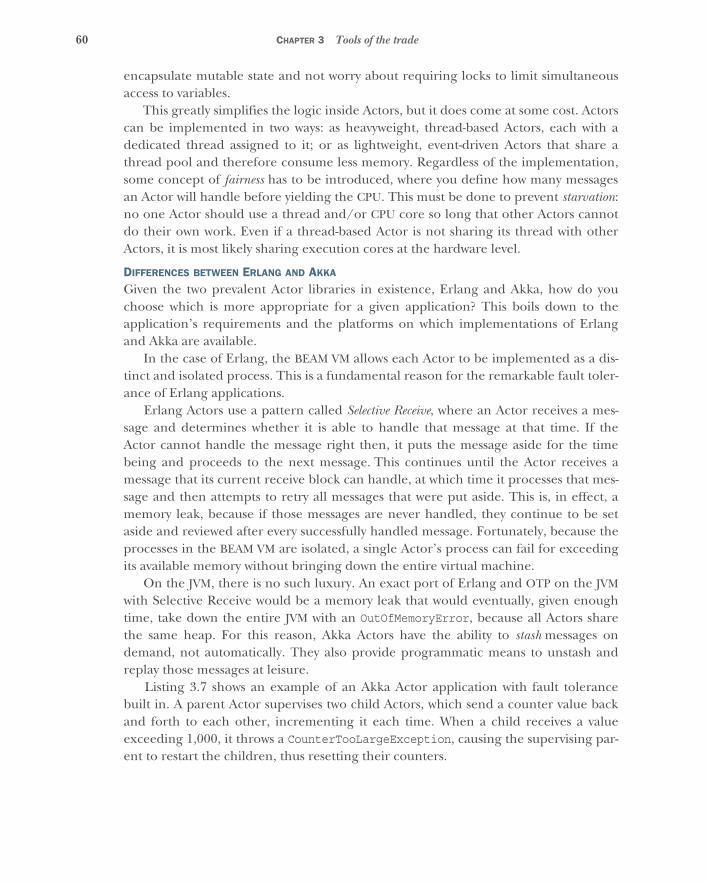
60 CHAPTER 3 Tools of the trade
encapsulate mutable state and not worry about requiring locks to limit simultaneousaccess to variables.
This greatly simplifies the logic inside Actors, but it does come at some cost. Actorscan be implemented in two ways: as heavyweight, thread-based Actors, each with adedicated thread assigned to it; or as lightweight, event-driven Actors that share athread pool and therefore consume less memory. Regardless of the implementation,some concept of fairness has to be introduced, where you define how many messagesan Actor will handle before yielding the CPU. This must be done to prevent starvation:no one Actor should use a thread and/or CPU core so long that other Actors cannotdo their own work. Even if a thread-based Actor is not sharing its thread with otherActors, it is most likely sharing execution cores at the hardware level.
DIFFERENCES BETWEEN ERLANG AND AKKA
Given the two prevalent Actor libraries in existence, Erlang and Akka, how do youchoose which is more appropriate for a given application? This boils down to theapplication’s requirements and the platforms on which implementations of Erlangand Akka are available.
In the case of Erlang, the BEAM VM allows each Actor to be implemented as a dis-tinct and isolated process. This is a fundamental reason for the remarkable fault toler-ance of Erlang applications.
Erlang Actors use a pattern called Selective Receive, where an Actor receives a mes-sage and determines whether it is able to handle that message at that time. If theActor cannot handle the message right then, it puts the message aside for the timebeing and proceeds to the next message. This continues until the Actor receives amessage that its current receive block can handle, at which time it processes that mes-sage and then attempts to retry all messages that were put aside. This is, in effect, amemory leak, because if those messages are never handled, they continue to be setaside and reviewed after every successfully handled message. Fortunately, because theprocesses in the BEAM VM are isolated, a single Actor’s process can fail for exceedingits available memory without bringing down the entire virtual machine.
On the JVM, there is no such luxury. An exact port of Erlang and OTP on the JVMwith Selective Receive would be a memory leak that would eventually, given enoughtime, take down the entire JVM with an OutOfMemoryError, because all Actors sharethe same heap. For this reason, Akka Actors have the ability to stash messages ondemand, not automatically. They also provide programmatic means to unstash andreplay those messages at leisure.
Listing 3.7 shows an example of an Akka Actor application with fault tolerancebuilt in. A parent Actor supervises two child Actors, which send a counter value backand forth to each other, incrementing it each time. When a child receives a valueexceeding 1,000, it throws a CounterTooLargeException, causing the supervising par-ent to restart the children, thus resetting their counters.
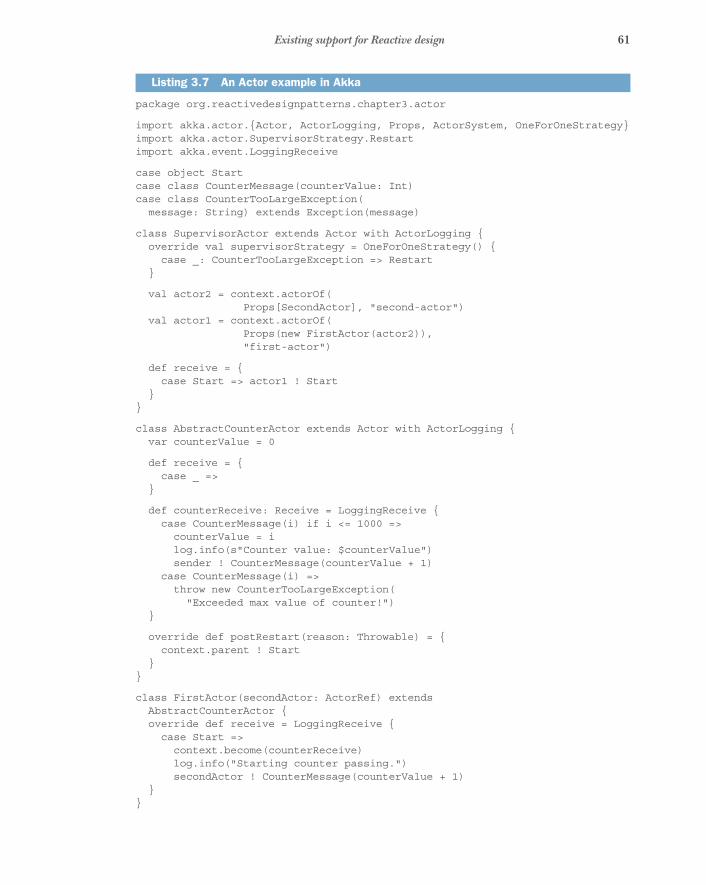
61Existing support for Reactive design
package org.reactivedesignpatterns.chapter3.actor
import akka.actor.{Actor, ActorLogging, Props, ActorSystem, OneForOneStrategy}import akka.actor.SupervisorStrategy.Restartimport akka.event.LoggingReceive
case object Startcase class CounterMessage(counterValue: Int)case class CounterTooLargeException(message: String) extends Exception(message)
class SupervisorActor extends Actor with ActorLogging {override val supervisorStrategy = OneForOneStrategy() {case _: CounterTooLargeException => Restart
}
val actor2 = context.actorOf(Props[SecondActor], "second-actor")
val actor1 = context.actorOf(Props(new FirstActor(actor2)),"first-actor")
def receive = {case Start => actor1 ! Start
}}
class AbstractCounterActor extends Actor with ActorLogging {var counterValue = 0
def receive = {case _ =>
}
def counterReceive: Receive = LoggingReceive {case CounterMessage(i) if i <= 1000 =>counterValue = ilog.info(s"Counter value: $counterValue")sender ! CounterMessage(counterValue + 1)
case CounterMessage(i) =>throw new CounterTooLargeException("Exceeded max value of counter!")
}
override def postRestart(reason: Throwable) = {context.parent ! Start
}}
class FirstActor(secondActor: ActorRef) extendsAbstractCounterActor {override def receive = LoggingReceive {case Start =>context.become(counterReceive)log.info("Starting counter passing.")secondActor ! CounterMessage(counterValue + 1)
}}
Listing 3.7 An Actor example in Akka
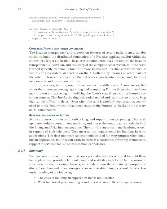
62 CHAPTER 3 Tools of the trade
class SecondActor() extends AbstractCounterActor {override def receive = counterReceive
}
object Example extends App {val system = ActorSystem("counter-supervision-example")val supervisor = system.actorOf(Props[SupervisorActor])supervisor ! Start
}
COMBINING ACTORS WITH OTHER CONSTRUCTS
The location transparency and supervision features of Actors make them a suitablechoice to build the distributed foundation of a Reactive application. But within thecontext of a larger application, local orchestration often does not require the locationtransparency, supervision, and resiliency of the complete Actor system. In those cases,you will typically combine Actors with more lightweight Reactive constructs such asFutures or Observables, depending on the API offered by libraries or other parts ofthe system. Those choices sacrifice the full Actor characteristics in exchange for lowermemory cost and invocation overhead.
In those cases, is it important to remember the differences. Actors are explicitabout their message passing. Spawning and composing Futures from within an Actormay lure you into accessing or modifying the Actor’s state from within a Future’s exe-cution context. That breaks the single-threaded model and leads to concurrency bugsthat can be difficult to detect. Even when the state is carefully kept separate, you willneed to think about which thread pool executes the Futures’ callbacks or the Observ-ables’ combinators.
REACTIVE EVALUATION OF ACTORS
Actors are asynchronous and nonblocking, and support message passing. They scaleup to use multiple cores on one machine, and they scale outward across nodes in boththe Erlang and Akka implementations. They provide supervision mechanisms, as well,in support of fault tolerance. They meet all the requirements for building Reactiveapplications. This does not mean Actors should be used for every purpose when build-ing an application, but they can easily be used as a backbone, providing architecturalsupport to services that use other Reactive technologies.
3.4.7 Summary
We have now reviewed the essential concepts and constructs required to build Reac-tive applications, providing fault tolerance and scalability to help you be responsive toyour users. In the following chapters, we will delve into the Reactive philosophy anddiscuss how these and other concepts relate to it. At this point, you should have a clearunderstanding of the following:
� The costs of building an application that is not Reactive� What functional programming is and how it relates to Reactive applications

63Existing support for Reactive design
� The trade-offs involved in choosing between high throughput, low/smoothlatency, and small footprint
� Pros and cons of all application toolkits that support the Reactive model� How the Actor model simultaneously addresses both fault tolerance and scalability

Part 2
The philosophyin a nutshell
Part 1 took a comprehensive look at what it means for a system to be Reactive.You saw how the requirement to always react to user input entails resilience andscalability in order to retain responsiveness even during failures and varying loadconditions. Throughout our exploration of these desirable properties, youencountered the need for the underlying implementation to be message-driven.
Part 2 complements the description of the four Reactive traits: it presents aset of building blocks from which a Reactive architecture can be constructed.Where part 1 described what we want to achieve and why, this part focuses onhow to do it. The guiding principles developed here, together with the tools ofthe trade introduced in chapter 3, form the foundation on which the patterns inpart 3 are built.
We decided to present the material in a contiguous, cohesive fashion so thatit can serve as a compact reference when you are gauging the design of your ownpatterns that you develop as you build Reactive applications. As a 360-degreeview of a fully reactive architecture, this part covers a lot of ground. You maywant to read chapter 4 and then skim the rest of this part, returning to it afteryou have studied the corresponding patterns in part 3 of this book.
In this part, you will learn about the following:
� Enabling encapsulation and isolation with explicit asynchronous messagepassing
� Improving compositionality and adding horizontal scalability with loca-tion transparency

66 PART 2 The philosophy in a nutshell
� Structuring your system in hierarchical modules following divide et regna1
� How this hierarchy allows principled failure handling� Achieving sufficiently consistent program semantics in a distributed system� Avoiding nondeterminism where possible and adding it where necessary� Guiding application design based on the topology of its message flows
1 Latin: literal translation is “divide and reign;” commonly translated “divide and conquer.”
67
Message passing
The fundamental notion on which message passing is built is that of an event: thefact that a certain condition has occurred (the event) is bundled together with con-textual information—like who did what when and where—and is signaled by theproducer as a message. Interested parties are informed by the producer using a com-mon transport mechanism and consume the message.
In this chapter, we will discuss in detail the main aspects of message passing:
� The difference between focusing on messages or events� Whether to do it synchronously or asynchronously� How messages can be transmitted without overwhelming the recipient and
with varying degrees of reliability
You will also see how message passing enables vertical scalability. Finally, we will dis-cuss the correspondence between events and messages—or how to model one interms of the other.
4.1 MessagesIn the real world, when you mail a letter to someone, you do not expect the con-tents of the letter to change after it is sent. You expect the letter that arrives to bethe same as the one that was sent, and after it arrives you do not expect it to changeinto a different letter. This is true regardless of whether the letter is sent around theworld and takes days or weeks to arrive, or is sent across town, or even is handed tothe recipient in person. Immutability is important.
In the first part of chapter 3, we touched on Erlang and an early implementa-tion of the Actor model. In that model, Actors communicate by sending messages toeach other. Those messages are between processes, but that doesn’t always have tobe the case. Messages may be sent to other computers, to other processes in thesame computer, or even within the same process. You have to ensure that a message
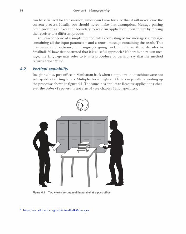
68 CHAPTER 4 Message passing
can be serialized for transmission, unless you know for sure that it will never leave thecurrent process. Ideally, you should never make that assumption. Message passingoften provides an excellent boundary to scale an application horizontally by movingthe receiver to a different process.
You can conceive of a simple method call as consisting of two messages: a messagecontaining all the input parameters and a return message containing the result. Thismay seem a bit extreme, but languages going back more than three decades toSmalltalk-80 have demonstrated that it is a useful approach.2 If there is no return mes-sage, the language may refer to it as a procedure or perhaps say that the methodreturns a void value.
4.2 Vertical scalabilityImagine a busy post office in Manhattan back when computers and machines were notyet capable of sorting letters. Multiple clerks might sort letters in parallel, speeding upthe process as shown in figure 4.1. The same idea applies to Reactive applications wher-ever the order of requests is not crucial (see chapter 14 for specifics).
2 https://en.wikipedia.org/wiki/Smalltalk#Messages
12
6
1
5
11
7
2
4
10
839
Figure 4.1 Two clerks sorting mail in parallel at a post office
69Event-based vs. message-based
Imagine a piece of code that performs an expensive calculation (prime factorization,graph search, XML transformation, or the like). If this code is accessible only by syn-chronous method calls, the onus is on the caller to provide for parallel execution inorder to benefit from multiple CPUs—say, by using Futures to dispatch the methodcalls onto a thread pool. One problem with this is that only the implementer of thecalled code knows if it can be run in parallel without concurrency issues. A typicalproblem occurs when the calculation stores and reuses auxiliary data structures withinits enclosing class or object without proper internal synchronization.
Message passing solves this problem by decoupling sender and receiver. Theimplementation of the calculation can distribute incoming messages across severalexecution units without the sender needing to know.
The beauty of this approach is that the semantics of message passing do notdepend on how a receiver will process a message. Scaling a computation vertically ondozens of processor cores can be realized transparently, hidden from the calling codeas an implementation detail or a configuration option.
4.3 Event-based vs. message-basedThere are two models for connecting data consumers with data producers: event-basedand message-based. Event-based systems provide a way to attach responses to specificevents. The system then becomes responsible for executing the correct response to anevent whenever that event occurs. Event-based systems are typically organized aroundan event loop. Whenever something happens, the corresponding event is appendedto a queue. The event loop continually pulls events from this queue and executes thecallbacks that have been attached to them. Each callback is typically a small, anony-mous procedure that responds to a specific event such as a mouse click. It may gener-ate new events, which are then also appended to the queue and processed when theirturn comes. This model is employed by single-threaded runtimes like Node.js and bythe GUI toolkits for most graphical operating systems.
In contrast, message-based systems provide a way to send messages to specificrecipients. The anonymous callback is replaced by an active recipient that consumesmessages received from potentially anonymous producers. Whereas in an event-basedsystem, event producers are addressable so that callbacks can be registered with them,in a message-based system the consumers are addressable so they can be given respon-sibility for processing certain messages. Neither the message producer nor the messag-ing system need concern itself with the correct response to a message; the currentconfiguration of consumers determines that. For example, when some part of a sys-tem produces a log event, it does not worry about whether log events are being con-sumed by the network, a database, or the file system, or whether log files are rotatedevery 6 or 24 hours. The logger, which receives the log event, is responsible for doingthe right thing with it.
70 CHAPTER 4 Message passing
Making the consumer responsible for processing its own incoming messages hasseveral advantages:
� It allows processing to proceed sequentially for individual consumers, enablingstateful processing without the need for synchronization. This translates well atthe machine level because consumers will aggregate incoming events and pro-cess them in one go, a strategy for which current hardware is highly optimized.
� Sequential processing enables the response to an event to depend on the cur-rent state of the consumer. So, previous events can have an influence on theconsumer’s behavior. A callback-based scheme, in contrast, requires the con-sumer to decide what its response will be when it subscribes to the event, notwhen the event occurs.
� Consumers can choose to drop events or short-circuit processing during systemoverload. More generally, explicit queueing allows the consumer to control theflow of messages. We will explain more about flow control in section 4.5.
� Last but not least, it matches how humans work in that we also process requestsfrom our coworkers sequentially.
The last point may be surprising to you, but we find familiar mental images helpful forvisualizing how a component behaves. Take a moment to imagine an old-fashionedpost office, as shown in figure 4.2, where the clerk sorts letters from an incoming pileinto different boxes for delivery. The clerk picks up an envelope, inspects the addresslabel, and makes a decision. After throwing the letter into the right box, the clerkturns back to the pile of unsorted mail and either picks up the next letter or noticesthat the time is already past noon and takes a lunch break. With this picture in mind,you already have an intuitive understanding of a message router. Now you only needto dump that into code. This task is a lot easier than it would have been before this lit-tle mental exercise.
The similarity between message passing and human interaction goes beyondsequential processes. Instead of directly reading (and writing) each others’ thoughts,we exchange messages: we talk, we write notes, we observe facial expressions, and soon. We express the same principle in software design by forming encapsulated objectsthat interact by passing messages. These objects are not the ones you know from lan-guages like Java, C#, or C++, because communication in those languages is synchro-nous and the receiver has no say in whether or when to handle the request. In theanthropomorphic view, that corresponds to your boss calling you on the telephoneand insisting that you find out the answer to a question on the spot. We all know thatthis kind of call should be the exception rather than the rule, lest no work get done.We prefer to answer, “Yes, I will get back to you when I have the result”; or, even better,the boss should send an email instead of making a disruptive telephone call, especiallyif finding the answer may take some time. The “I will get back to you” approach corre-sponds to a method that returns a Future. Sending email is equivalent to explicit mes-sage passing.

71Synchronous vs. asynchronous
Now that we have established that message passing is a useful abstraction, we need toaddress two fundamental problems that arise while handling messages, whether in apostal service or in a computer:
� Sometimes we must be able to guarantee the delivery of a certain very import-ant letter.
� If messages are sent faster than they can be delivered, they will pile up some-where, and eventually either the system will collapse or mail will be lost.
We will look at the issue of delivery guarantees later in this chapter. Next, we will takea peek at how Reactive systems control the flow of messages to ensure that requestscan be handled in a timely fashion and without overwhelming the receiver.
4.4 Synchronous vs. asynchronousThe communication from producer to consumer can be realized in two ways:
� In synchronous communication, both parties need to be ready to communicateat the same time.
� In asynchronous communication, the sender can send whether the recipient isready or not.
Figure 4.3 illustrates synchronous message passing at a post office. A customer, Jill, hasrun out of postage stamps, so she needs to ask the clerk, James, for assistance. Luckily,
12
6
1
5
11
7
2
4
10
839
1) Take envelope
4) Check for lunch break
3) File into drawers
2) Determine destination
Figure 4.2 A clerk in the back room of a post office sorts mail from an incoming pile into addressee boxes.
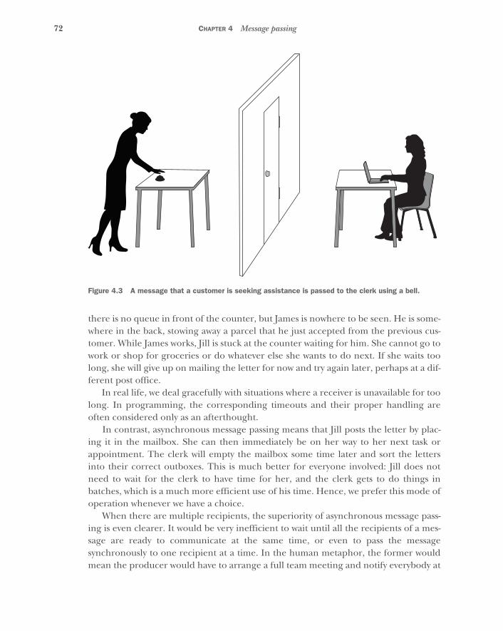
72 CHAPTER 4 Message passing
there is no queue in front of the counter, but James is nowhere to be seen. He is some-where in the back, stowing away a parcel that he just accepted from the previous cus-tomer. While James works, Jill is stuck at the counter waiting for him. She cannot go towork or shop for groceries or do whatever else she wants to do next. If she waits toolong, she will give up on mailing the letter for now and try again later, perhaps at a dif-ferent post office.
In real life, we deal gracefully with situations where a receiver is unavailable for toolong. In programming, the corresponding timeouts and their proper handling areoften considered only as an afterthought.
In contrast, asynchronous message passing means that Jill posts the letter by plac-ing it in the mailbox. She can then immediately be on her way to her next task orappointment. The clerk will empty the mailbox some time later and sort the lettersinto their correct outboxes. This is much better for everyone involved: Jill does notneed to wait for the clerk to have time for her, and the clerk gets to do things inbatches, which is a much more efficient use of his time. Hence, we prefer this mode ofoperation whenever we have a choice.
When there are multiple recipients, the superiority of asynchronous message pass-ing is even clearer. It would be very inefficient to wait until all the recipients of a mes-sage are ready to communicate at the same time, or even to pass the messagesynchronously to one recipient at a time. In the human metaphor, the former wouldmean the producer would have to arrange a full team meeting and notify everybody at
Figure 4.3 A message that a customer is seeking assistance is passed to the clerk using a bell.
73Flow control
the same time; the latter would mean walking around, patiently waiting at each recipi-ent’s desk until they’re available. It would be far preferable to send an asynchronousmessage instead—a letter in the old days, probably an email today. So, for conve-nience, when we say message passing we will always mean asynchronous communicationbetween a producer and any number of consumers using messages.
To put this another way, asynchronous message passing means the recipient will even-tually learn about a new incoming message and then consume it as soon as appropri-ate. There are two ways in which the recipient can be informed: it can register acallback describing what should happen in case of a certain event, or it can receive themessage in a mailbox (also called a queue) and decide on a case-by-case basis what todo with it.
4.5 Flow controlFlow control is the process of adjusting the transmission rate of a stream of messages toensure that the receiver is not overwhelmed. Whenever this process informs thesender that it must slow down, the sender is said to experience back pressure.
Direct method invocations, such as are common in languages from the C family, bytheir nature include a specific kind of flow control: the sender of a request is blockedby the receiver until processing is finished. When multiple senders compete for areceiver’s resources, processing is commonly serialized through some form of syn-chronization like locks or semaphores, which additionally blocks each sender until
A personal anecdoteThe Actor toolkit Akka was built to express message passing from the very beginning;this is what the Actor model is all about. But before version 2.0, this principle wasnot pervasive throughout Akka. It was only present at the surface, in the user-levelAPI. Under the covers, we used locks for synchronization and called synchronouslyinto the supervisor’s strategy when a supervised Actor failed. Consequently, remotesupervision was not possible with this architecture. In fact, everything concerningremote Actor interactions was a little quirky and difficult to implement. Users beganto notice that the creation of an Actor was executed synchronously on the initiator’sthread, leading to a recommendation to refrain from performing time-consumingtasks in an Actor’s constructor and send an initialization message instead.
When the list of these and similar issues grew too long, we sat down and redesignedthe entire internal architecture of Akka to be based purely on asynchronous messagepassing. Every feature that was not expressible under this rule was removed, and theinner workings were made fully nonblocking. As a result, all the pieces of the puzzleclicked into place: with the removal of tight coupling between the individual movingparts, we were able to implement supervision, location transparency, and extremescalability at an affordable engineering price. The only downside is that certain parts—for example, propagating failure up a supervisor hierarchy—do not tolerate messageloss, which now requires more effort to implement for remote communication.

74 CHAPTER 4 Message passing
previous senders’ messages have been serviced. This implicit back pressure may soundconvenient at first, but as systems grow and nonfunctional requirements becomemore important, it turns into an impediment. Instead of implementing the businesslogic, you find yourself debugging performance bottlenecks.
Message passing gives you a wider range of options for flow control because itincludes the notion of queueing. For example, as discussed in chapter 2, if you use abounded queue, you have options for how to respond when the queue is full: you candrop the newest message, the oldest message, or all the messages, according to whatbest suits the requirements. A case where you might drop all messages would be a real-time system aimed at displaying the latest data. You might include a small buffer tosmooth out processing or latency jitter, but moving new messages through the queuequickly is more important than processing backlogged messages. Because the consum-ing process reads from the message queue, it can make whatever decision is appropri-ate when it finds itself backlogged.
Another option is that you can sort incoming messages into multiple queues basedon priorities and dequeue them according to specific bandwidth allocations. You canalso generate an immediate negative reply to a sender when dropping messages, ifdesired. We will discuss these and other possibilities in chapter 15.
Two basic flow-control schemes are depicted in figure 4.4: the left clerk tries todeliver sacks full of letters to the right clerk, who sorts them at a table. In negativeacknowledgment(NACK), the right clerk rejects a new delivery when the table is full. Inpositive acknowledgment(ACK), the left clerk waits to be informed by the right clerk thatthe right clerk has run out of letters to sort. There are many variations on this scheme,some of which are presented in chapter 15. The subject lends itself well to humanmetaphors like the one given here; feel free to let your mind roam and discover someof them in everyday life.
In essence, message passing unbundles the implied flow control from commonobject-oriented programming languages and allows customized solutions. This choicedoes not come without a cost, of course: at the least, you need to think about whichflow-control semantics you want, and, hence, you must choose the granularity atwhich to apply message passing and below which direct method calls and object-oriented composition are preferable. To illustrate, imagine a service-oriented archi-tecture with asynchronous interfaces. The services themselves might be implementedin traditional synchronous style and communicate among each other via messagepassing. When refactoring one of the service implementations, you might find itappropriate to apply more fine-grained flow control within it, thus lowering the gran-ularity level. This choice can be made differently depending on the service’s require-ments as well as how the responsible development team likes to work.
With a basic understanding of how to avoid overloading a message-delivery system,we can now turn our attention to the issue of how to ensure delivery of certain import-ant messages.

75Flow control
Stop! I can’t take more!
Flow control with negative acknowledgement
Flow control with positive acknowledgement
I’m done,bring some more!
Figure 4.4 Two basic flow-control schemes
76 CHAPTER 4 Message passing
4.6 Delivery guaranteesDespite every postal clerk’s best efforts, sometimes a letter gets lost. The probabilitymay be low, but still it happens—several times per year. What happens then? The let-ter might have contained birthday wishes, in which case it will hopefully be discoveredby the sender and receiver when they meet for the next time. Or it might have beenan invoice, in which case it will not be paid, and a reminder will be sent. The import-ant theme to note here is that humans normally follow up on interactions, allowingthe detection of message loss. In some cases, there are unpleasant consequences whena message is lost, but life goes on and we do not stop our entire society because oneletter was not delivered. In this section, we will show you how Reactive applicationswork the same way, but we will start at the opposite end: with synchronous systems.
When we write down a method call, we can be pretty certain that it will be exe-cuted when the program reaches the corresponding line; we are not used to lossesbetween lines. But strictly speaking, we need to take into account the possibility thatthe process will terminate or the machine will die; or it could overflow the call stackor otherwise raise a fatal signal. As you saw earlier, it is not difficult to think of amethod call as a message sent to an object, and with this formulation we could saythat even in a synchronous system, we have to address the possibility that a message—a method invocation—can get lost. We could thus take the extreme standpoint thatthere can never be an unbreakable guarantee that a request will be processed orresult in a response.
Very few people, however, would deem such a stance constructive, because we rea-sonably accept limitations and exceptions to rules. We apply common sense and callthose who don’t pedantic. For example, human interaction usually proceeds underthe implicit assumption that neither party dies. Instead of dwelling on the rare cases,we concern ourselves more with managing our inherent unreliability, making surecommunications were received, and reminding colleagues of important work items ordeadlines. But when transforming a process into a computer program, we expect it tobe completely reliable: to perform its function without fail. It is our nature to loathethe hassle of countering irregularities, and we turn to machines to be rid of it. The sadfact is that the machines we build may be faster and more reliable, but they are notperfect, and we must therefore continue to worry about unforeseen failures.
Everyday life again provides a good model to borrow from. Whenever one personrequests a service from another, they have to deal with the possibility that there will beno reply. The other person may be busy, or the request or reply may get lost along theway—for example, if a letter (or email) is lost. In these cases, the person who madethe request needs to try again until they get a response or the request becomes irrele-vant, as illustrated in figure 4.5. Analogous activity in the realm of computer program-ming is obvious: a message sent from one object to another may be lost, or thereceiving object may be unable to handle the request because something it dependson is currently unavailable—the disk may be full or a database may be down—and sothe sending object will need to either retry until the request is successful or give up.
77Delivery guarantees
With synchronous method calls, there is usually no way to recover from a “lost mes-sage.” If a procedure doesn’t return, usually it is because of something catastrophiclike abnormal program continuation; there is no way for the caller to try to recoverand continue. Message passing makes it feasible to persist the request and retry itwhenever the failure condition is corrected. Even if an entire computing center goesdown because of a power outage, a program can continue after the power comes backon as long as the needed messages were held in nonvolatile storage. As with flow con-trol, you need to choose an appropriate granularity at which to apply message passing,based on each application’s requirements.
With this in mind, it becomes natural to design an application based on reducedmessage-delivery guarantees. Building in this knowledge from the beginning makesthe resulting application resilient against message loss, no matter whether it is causedby network interruption, a back-end service outage, excessive load, or even program-ming errors.
Implementing a runtime environment with very strong delivery guarantees isexpensive in that extra mechanisms need to be built in—for example, resending net-work messages until receipt is confirmed—and these mechanisms degrade perfor-mance and scalability even when no failures occur. The cost rises dramatically in adistributed system, mostly because confirmations require network round trips havinglatencies orders of magnitude larger than on a local system (for example, between twocores on a single CPU). Providing weaker delivery guarantees allows you to implementthe common cases much more simply and quickly, and pay the price for stronger
Did you talk toFred about thenext release?
Figure 4.5 The Retry pattern in daily life
78 CHAPTER 4 Message passing
guarantees only where truly needed. Note the correspondence with how the postalservice charges for normal and registered mail.
The principal choices for delivery guarantees are as follows:
� At-most-once delivery—Each request is sent once and never retried. If it is lost orthe recipient fails to process it, there is no attempt to recover. Therefore, thedesired function may be invoked once or not at all. This is the most basic deliv-ery guarantee. It has the lowest implementation overhead, because neithersender nor receiver is required to maintain information on the state of theircommunication.
� At-least-once delivery—Trying to guarantee that a request is processed requirestwo additions to at-most-once semantics. First, the recipient must acknowledgereceipt or execution (depending on the requirements) by sending a confirma-tion message. Second, the sender must retain the request in order to resend it ifthe sender doesn’t receive the confirmation. Because a resend can be the resultof a lost confirmation, the recipient may receive the message more than once.Given enough time and the assumption that communication will eventually suc-ceed, the message will be received at least once.
� Exactly once delivery—If a request must be processed but must not be processedtwice, then, in addition to at-least-once semantics, the recipient must dedupli-cate messages: that is, they must keep track of which requests have already beenprocessed. This is the most costly scheme because it requires both sender andreceiver to track communication state. If, in addition, requests must be pro-cessed in the order they were sent, then throughput may be further limited bythe need to complete confirmation round trips for each request before pro-ceeding with the next—unless flow-control requirements are compatible withbuffering on the receiver side.
Implementations of the Actor model usually provide at-most-once delivery out of thebox and allow the other two layers to be added on top for communication paths thatrequire them. Interestingly, local method calls also provide at-most-once delivery,albeit with a tiny probability for nondelivery.
Consideration of flow-control and message-delivery guarantees is importantbecause message passing makes limitations of communication explicit and clearlyexposes inconvenient corner cases. In the next section, we will focus on the naturalmatch between messages and real-world events and how this promotes a simple consis-tency across layers in an application.
4.7 Events as messagesIn hard real-time systems, the foremost concern is keeping the maximal response timeto external events within strict limits—that is, to enforce a tight temporal couplingbetween each event and its response. At the other end of the spectrum, a high-volumestorage system for archiving log messages needs high throughput much more than it
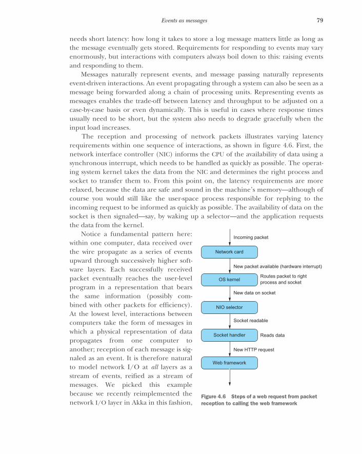
79Events as messages
needs short latency: how long it takes to store a log message matters little as long asthe message eventually gets stored. Requirements for responding to events may varyenormously, but interactions with computers always boil down to this: raising eventsand responding to them.
Messages naturally represent events, and message passing naturally representsevent-driven interactions. An event propagating through a system can also be seen as amessage being forwarded along a chain of processing units. Representing events asmessages enables the trade-off between latency and throughput to be adjusted on acase-by-case basis or even dynamically. This is useful in cases where response timesusually need to be short, but the system also needs to degrade gracefully when theinput load increases.
The reception and processing of network packets illustrates varying latencyrequirements within one sequence of interactions, as shown in figure 4.6. First, thenetwork interface controller (NIC) informs the CPU of the availability of data using asynchronous interrupt, which needs to be handled as quickly as possible. The operat-ing system kernel takes the data from the NIC and determines the right process andsocket to transfer them to. From this point on, the latency requirements are morerelaxed, because the data are safe and sound in the machine’s memory—although ofcourse you would still like the user-space process responsible for replying to theincoming request to be informed as quickly as possible. The availability of data on thesocket is then signaled—say, by waking up a selector—and the application requeststhe data from the kernel.
Notice a fundamental pattern here:within one computer, data received overthe wire propagate as a series of eventsupward through successively higher soft-ware layers. Each successfully receivedpacket eventually reaches the user-levelprogram in a representation that bearsthe same information (possibly com-bined with other packets for efficiency).At the lowest level, interactions betweencomputers take the form of messages inwhich a physical representation of datapropagates from one computer toanother; reception of each message is sig-naled as an event. It is therefore naturalto model network I/O at all layers as astream of events, reified as a stream ofmessages. We picked this examplebecause we recently reimplemented thenetwork I/O layer in Akka in this fashion,
Web framework
Incoming packet
New packet available (hardware interrupt)
Routes packet to rightprocess and socket
Reads data
New data on socket
Socket readable
New HTTP request
Network card
OS kernel
NIO selector
Socket handler
Figure 4.6 Steps of a web request from packet reception to calling the web framework
80 CHAPTER 4 Message passing
but opportunities for exploiting the correspondence between messages sent at differ-ent levels are ubiquitous. All the lowest-level inputs to a computer are event-based(keyboard and mouse, camera and audio frames, and so on) and can be convenientlypassed around as messages. In this way, message passing is the most natural form ofcommunication between independent objects of any kind.
4.8 Synchronous message passingExplicit message passing often provides a convenient way for isolated parts of an appli-cation to communicate, or helps delineate source code components, even when thereis no need for asynchronous communication. But if asynchrony is not needed, usingasynchronous message passing to decouple components introduces an unnecessarycost: the administrative runtime overhead of dispatching tasks for asynchronous exe-cution as well as extra scheduling latency. In this case, synchronous message passing isusually a wiser choice.
We mention this because synchronous message propagation is often useful forstream processing. For example, fusing a series of transformations together keeps thetransformed data local to one CPU core and thereby makes better use of its associatedcaches. Synchronous messaging thus serves a different purpose than decoupling partsof a Reactive application, and our derivation of the necessity of asynchrony in section4.4 does not apply.
4.9 SummaryIn this chapter, we have discussed in detail the motivation for message passing, espe-cially in contrast to synchronous communication. We have illuminated the differencebetween addressable event sources in event-driven systems and addressable messagerecipients in message-driven systems. We have examined the greater variety of formsof flow control that message passing affords, and you have learned about the differentlevels of message-delivery guarantees.
We briefly touched on the correspondence between events and messages, and youhave seen how message passing enables vertical scalability. In the following chapter, wewill show how location transparency complements this by enabling horizontal scalability.
81
Location transparency
The previous chapter introduced message passing as a way to decouple collaborat-ing objects. Making communication asynchronous and nonblocking instead of call-ing synchronous methods enables the receiver to perform its work in a differentexecution context, such as a different thread. But why stop at interactions withinone computer? Message passing works the same way in both local and remote inter-actions. There is no fundamental difference between scheduling a task to run lateron the local machine and sending a network packet to a different host to triggerexecution there. In this chapter, we will explore the possibilities offered by this per-spective as well as the consequences it has for quantitative aspects of performancesuch as latency, throughput, and probability of message loss.
5.1 What is location transparency?You may recall the example shown in figure 5.1 from section 1.1, where we dis-cussed the tenets of the Reactive Manifesto using a hypothetical simplified view ofthe Gmail application. If you were to start designing this system, you would split itinto services with various presumed dependencies between them; you would beginmapping out the interfaces that support interservice communication; and youwould probably spend a thought or two on how the entire application will bedeployed on the available hardware (or what hardware is needed). You would thenimplement the design by writing each of the services and codifying the drafteddependencies and communication patterns—for example, using an asynchronousHTTP client to talk with another service’s REST API or using a message broker.
Message passing in this example is clearly marked out within the program code,using different syntax than for local interactions. Consequently the calling objectneeds to be aware of the location of the receiving object, or at least it needs to knowthat the receiver does not support normal method calls.
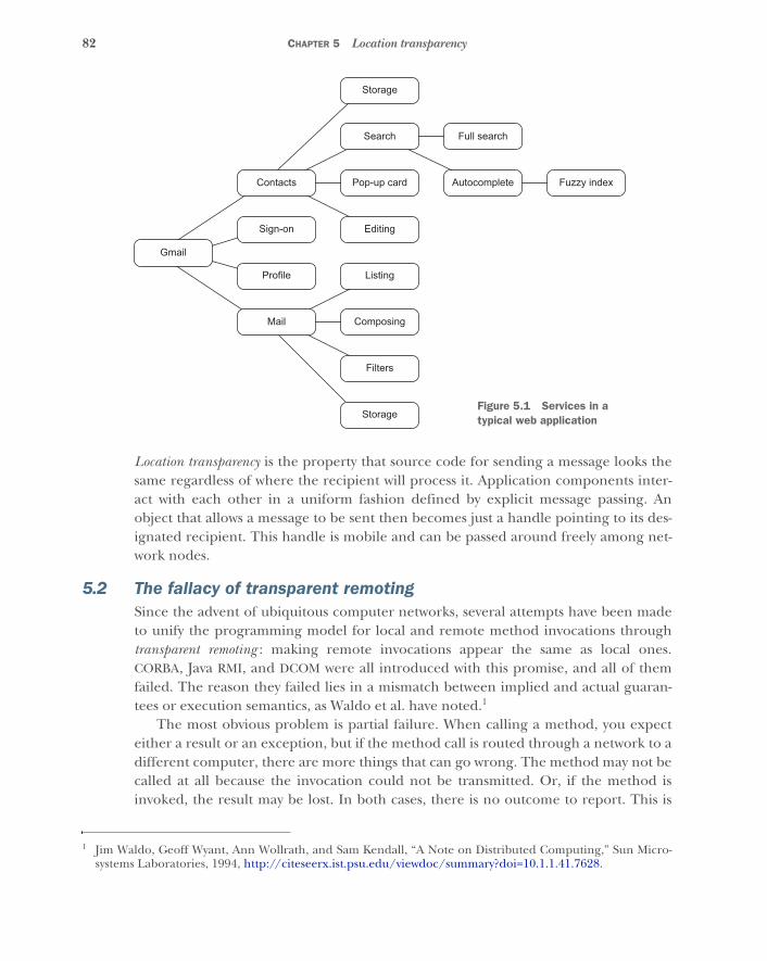
82 CHAPTER 5 Location transparency
Location transparency is the property that source code for sending a message looks thesame regardless of where the recipient will process it. Application components inter-act with each other in a uniform fashion defined by explicit message passing. Anobject that allows a message to be sent then becomes just a handle pointing to its des-ignated recipient. This handle is mobile and can be passed around freely among net-work nodes.
5.2 The fallacy of transparent remotingSince the advent of ubiquitous computer networks, several attempts have been madeto unify the programming model for local and remote method invocations throughtransparent remoting : making remote invocations appear the same as local ones.CORBA, Java RMI, and DCOM were all introduced with this promise, and all of themfailed. The reason they failed lies in a mismatch between implied and actual guaran-tees or execution semantics, as Waldo et al. have noted.1
The most obvious problem is partial failure. When calling a method, you expecteither a result or an exception, but if the method call is routed through a network to adifferent computer, there are more things that can go wrong. The method may not becalled at all because the invocation could not be transmitted. Or, if the method isinvoked, the result may be lost. In both cases, there is no outcome to report. This is
1 Jim Waldo, Geoff Wyant, Ann Wollrath, and Sam Kendall, “A Note on Distributed Computing,” Sun Micro-systems Laboratories, 1994, http://citeseerx.ist.psu.edu/viewdoc/summary?doi=10.1.1.41.7628.
Storage
Search Full search
Contacts Pop-up card Autocomplete Fuzzy index
Gmail
Sign-on Editing
Profile Listing
Mail Composing
Filters
StorageFigure 5.1 Services in a typical web application
83Explicit message passing to the rescue
typically resolved by raising a timeout exception in the caller’s thread. This requiresthat the calling code deal with the uncertainty of whether the desired function wasinvoked.
Other problems arise from the performance expectations associated with amethod call. Traversing the network incurs an increase in latency of at least the timeof one round trip: the invocation needs to be sent to the recipient, and the resultneeds to travel back to the sender. This is several orders of magnitude longer than theoverhead involved in executing a method locally. A local method call takes about ananosecond on current hardware; a remote call takes tens to hundreds of microsec-onds in a local network and up to hundreds of milliseconds in a globally distributedsystem. You need to take this latency into account in order to ensure that analgorithm’s implementation fulfills its nonfunctional requirements. If an innocent-looking method call takes a million times longer than you would naïvely expect, theconsequences can be devastating.
In addition to increased latency, remote invocations also suffer from much lowerthroughput than their local counterparts. Passing huge in-memory datasets as argu-ments to a local method may be slow due to the need to bring the relevant data intoCPU caches, but that is still much faster than serializing the data and sending themover the network. The difference in throughput can easily exceed a factor of 1,000.
Therefore, giving remote interactions the same semantics as local ones is not desir-able in theory, nor has it been successful in practice. Waldo et al. argue that theinverse—changing local semantics to match the constraints of remote communica-tion—would be too invasive and so should also not be done. They recommend clearlydelineating local and remote computing and choosing different representations inthe source code.
5.3 Explicit message passing to the rescueYou have seen that message passing models the semantics of remote communicationnaturally: there is no preconceived expectation that messages will be transmittedinstantaneously or processed immediately. Replies are also messages, and messagesmay be lost. Two components communicating with messages can thus be located onthe same machine or on different network hosts without changing any characteristicquality of their interaction. The components’ inner workings may comprise any num-ber of objects collaborating by synchronous local method calls, as long as messagepassing is explicitly different, as explained above.
Location transparency does not aim to make remote interactions look like localones. Its goal, rather, is to unify the expression of message passing under a commonabstraction for both local and remote interaction. A concrete example of this is theActor model from chapter 3, where all communication between Actors is mediatedthrough stable placeholders—called ActorRefs in Akka or process IDs and registered namesin Erlang—whose only purpose is to offer a generic message-passing facility:
actorRef ! message
84 CHAPTER 5 Location transparency
This code snippet2 sends the message given on the right to the Actor represented bythe reference on the left. Note that this operation does not call a method on the Actoritself. Instead, the Actor reference is a façade that transfers the message—across thenetwork if necessary—to wherever the Actor is located. There, it is appended to theActor’s incoming message queue for later processing.
This is the crucial point where location transparency and transparent remoting dif-fer. With location transparency, message passing is always explicit. Every instance ofmessage passing is potentially remote, yet the sender need not concern itself withwhether the Actor is local or remote, nor with the mechanics of sending the message,nor with whether the message will be transmitted in nanoseconds or microseconds.The sender also does not stop to wait for a response. It is satisfied when the messagehas been passed to the Actor reference.
Contrast this with transparent remoting, where a local proxy object is created andthe desired method is called directly on it, hiding the fact that message passing hap-pens underneath. Additional concrete problems arise with transparent remoting indefining the semantics of methods that do not return a value: for example, should thecurrent thread block until the remote object has processed the call, or should itreturn to its caller immediately?
By treating all message passing as potentially remote, you gain the freedom to relo-cate components without having to change their code. You can write software onceand deploy it on different hardware setups by just changing where the parts areinstantiated. Akka, for example, allows remote deployment of Actors to be specified inthe configuration file. The operations team can therefore in principle determine thehardware layout without regard for which partitioning the engineering team foresaw.Of course, this depends on the assumption that all message passing was consideredpotentially remote during implementation. It would be prudent for the developmentand operations teams to consult with each other in order to have a common under-standing of the deployment scenarios.
5.4 Optimization of local message passingLocal message passing can thus become merely an optimization of remote messagepassing. Without changing the source code, local messages could be passed by refer-ence, obviating the need to serialize and deserialize them, greatly reducing latencyand increasing throughput. Erlang, however, by default maintains full correspon-dence between local and remote and does not apply this optimization: it serializes anddeserializes all message sends, including purely local ones. This further decouples dif-ferent components from each other at the cost of performance.
The advantages of message passing as discussed so far—loose coupling, horizontalscalability, and flow control—can of course be desirable for a purely local program. In
2 Readers unfamiliar with Scala may find the syntax actorRef ! message strange. The ! is the name of amethod defined on the trait ActorRef. Scala allows a call to a method with a single parameter to be simplifiedby eliminating the . and the parentheses, so the code snippet is equivalent to actorRef.!(message).
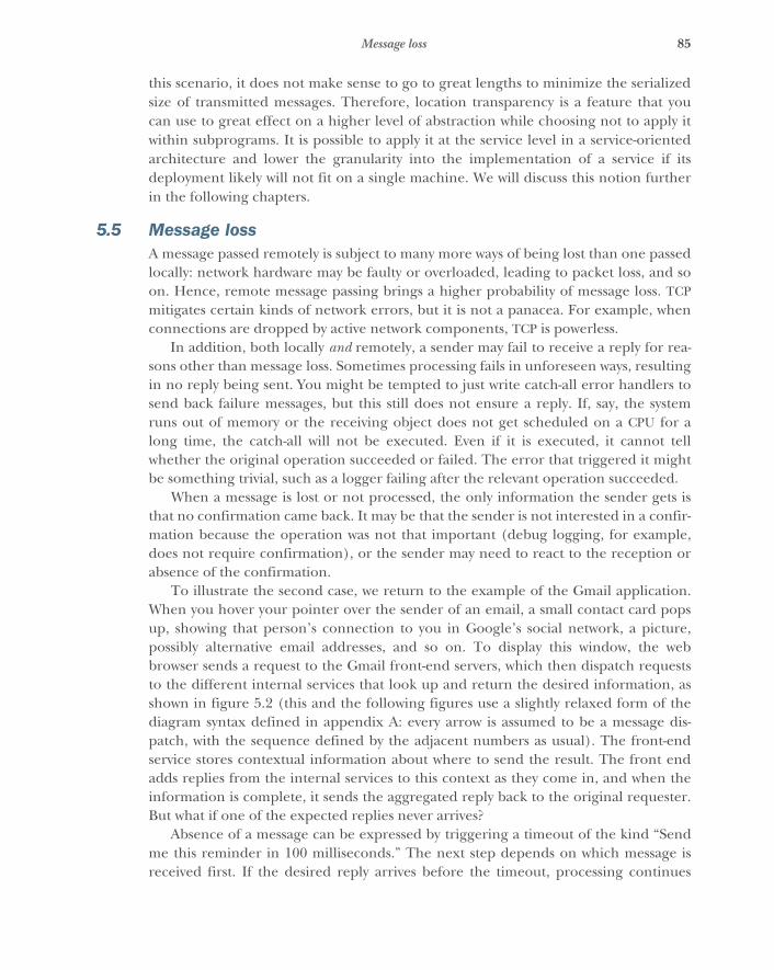
85Message loss
this scenario, it does not make sense to go to great lengths to minimize the serializedsize of transmitted messages. Therefore, location transparency is a feature that youcan use to great effect on a higher level of abstraction while choosing not to apply itwithin subprograms. It is possible to apply it at the service level in a service-orientedarchitecture and lower the granularity into the implementation of a service if itsdeployment likely will not fit on a single machine. We will discuss this notion furtherin the following chapters.
5.5 Message lossA message passed remotely is subject to many more ways of being lost than one passedlocally: network hardware may be faulty or overloaded, leading to packet loss, and soon. Hence, remote message passing brings a higher probability of message loss. TCPmitigates certain kinds of network errors, but it is not a panacea. For example, whenconnections are dropped by active network components, TCP is powerless.
In addition, both locally and remotely, a sender may fail to receive a reply for rea-sons other than message loss. Sometimes processing fails in unforeseen ways, resultingin no reply being sent. You might be tempted to just write catch-all error handlers tosend back failure messages, but this still does not ensure a reply. If, say, the systemruns out of memory or the receiving object does not get scheduled on a CPU for along time, the catch-all will not be executed. Even if it is executed, it cannot tellwhether the original operation succeeded or failed. The error that triggered it mightbe something trivial, such as a logger failing after the relevant operation succeeded.
When a message is lost or not processed, the only information the sender gets isthat no confirmation came back. It may be that the sender is not interested in a confir-mation because the operation was not that important (debug logging, for example,does not require confirmation), or the sender may need to react to the reception orabsence of the confirmation.
To illustrate the second case, we return to the example of the Gmail application.When you hover your pointer over the sender of an email, a small contact card popsup, showing that person’s connection to you in Google’s social network, a picture,possibly alternative email addresses, and so on. To display this window, the webbrowser sends a request to the Gmail front-end servers, which then dispatch requeststo the different internal services that look up and return the desired information, asshown in figure 5.2 (this and the following figures use a slightly relaxed form of thediagram syntax defined in appendix A: every arrow is assumed to be a message dis-patch, with the sequence defined by the adjacent numbers as usual). The front-endservice stores contextual information about where to send the result. The front endadds replies from the internal services to this context as they come in, and when theinformation is complete, it sends the aggregated reply back to the original requester.But what if one of the expected replies never arrives?
Absence of a message can be expressed by triggering a timeout of the kind “Sendme this reminder in 100 milliseconds.” The next step depends on which message isreceived first. If the desired reply arrives before the timeout, processing continues
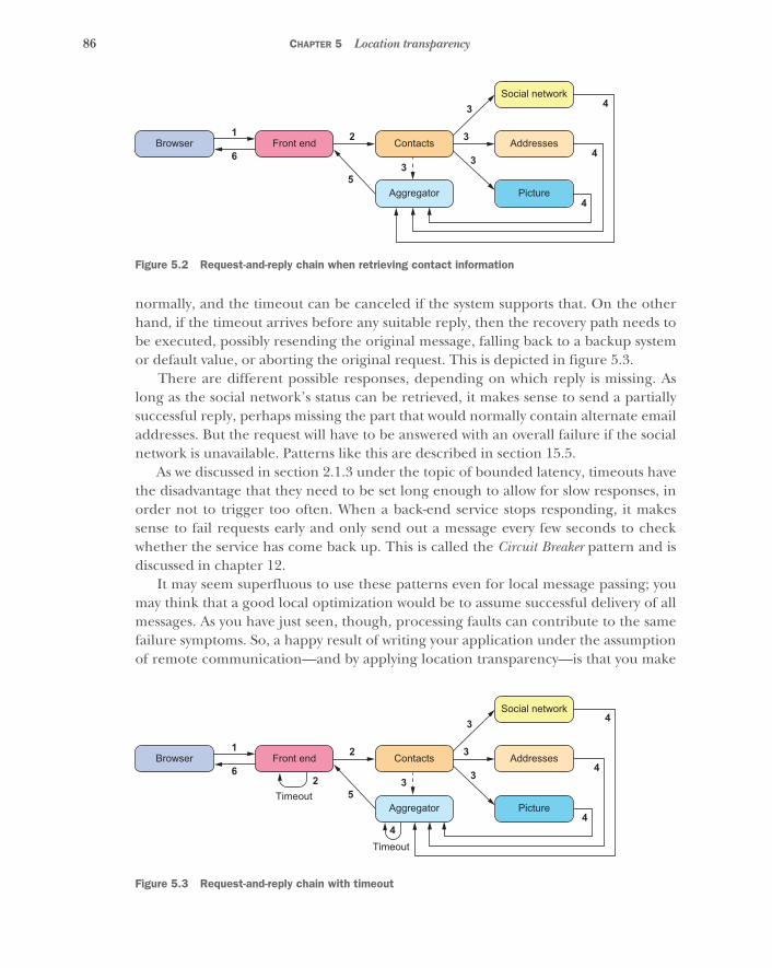
86 CHAPTER 5 Location transparency
normally, and the timeout can be canceled if the system supports that. On the otherhand, if the timeout arrives before any suitable reply, then the recovery path needs tobe executed, possibly resending the original message, falling back to a backup systemor default value, or aborting the original request. This is depicted in figure 5.3.
There are different possible responses, depending on which reply is missing. Aslong as the social network’s status can be retrieved, it makes sense to send a partiallysuccessful reply, perhaps missing the part that would normally contain alternate emailaddresses. But the request will have to be answered with an overall failure if the socialnetwork is unavailable. Patterns like this are described in section 15.5.
As we discussed in section 2.1.3 under the topic of bounded latency, timeouts havethe disadvantage that they need to be set long enough to allow for slow responses, inorder not to trigger too often. When a back-end service stops responding, it makessense to fail requests early and only send out a message every few seconds to checkwhether the service has come back up. This is called the Circuit Breaker pattern and isdiscussed in chapter 12.
It may seem superfluous to use these patterns even for local message passing; youmay think that a good local optimization would be to assume successful delivery of allmessages. As you have just seen, though, processing faults can contribute to the samefailure symptoms. So, a happy result of writing your application under the assumptionof remote communication—and by applying location transparency—is that you make
Social network
Browser1
6
2 3
3 4
3
4
4
53
Front end Contacts Addresses
Aggregator Picture
Figure 5.2 Request-and-reply chain when retrieving contact information
Social network
Browser1
6
2
2
3
3
35
3
Front end
Timeout
4Timeout
Contacts Addresses
Aggregator Picture
4
4
4
Figure 5.3 Request-and-reply chain with timeout
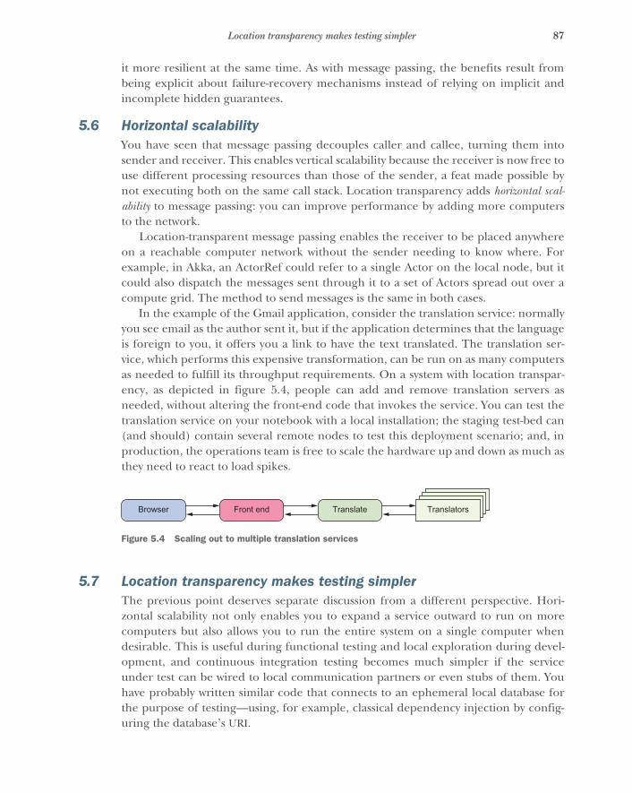
87Location transparency makes testing simpler
it more resilient at the same time. As with message passing, the benefits result frombeing explicit about failure-recovery mechanisms instead of relying on implicit andincomplete hidden guarantees.
5.6 Horizontal scalabilityYou have seen that message passing decouples caller and callee, turning them intosender and receiver. This enables vertical scalability because the receiver is now free touse different processing resources than those of the sender, a feat made possible bynot executing both on the same call stack. Location transparency adds horizontal scal-ability to message passing: you can improve performance by adding more computersto the network.
Location-transparent message passing enables the receiver to be placed anywhereon a reachable computer network without the sender needing to know where. Forexample, in Akka, an ActorRef could refer to a single Actor on the local node, but itcould also dispatch the messages sent through it to a set of Actors spread out over acompute grid. The method to send messages is the same in both cases.
In the example of the Gmail application, consider the translation service: normallyyou see email as the author sent it, but if the application determines that the languageis foreign to you, it offers you a link to have the text translated. The translation ser-vice, which performs this expensive transformation, can be run on as many computersas needed to fulfill its throughput requirements. On a system with location transpar-ency, as depicted in figure 5.4, people can add and remove translation servers asneeded, without altering the front-end code that invokes the service. You can test thetranslation service on your notebook with a local installation; the staging test-bed can(and should) contain several remote nodes to test this deployment scenario; and, inproduction, the operations team is free to scale the hardware up and down as much asthey need to react to load spikes.
5.7 Location transparency makes testing simplerThe previous point deserves separate discussion from a different perspective. Hori-zontal scalability not only enables you to expand a service outward to run on morecomputers but also allows you to run the entire system on a single computer whendesirable. This is useful during functional testing and local exploration during devel-opment, and continuous integration testing becomes much simpler if the serviceunder test can be wired to local communication partners or even stubs of them. Youhave probably written similar code that connects to an ephemeral local database forthe purpose of testing—using, for example, classical dependency injection by config-uring the database’s URI.
Browser Front end Translate Translators
Figure 5.4 Scaling out to multiple translation services
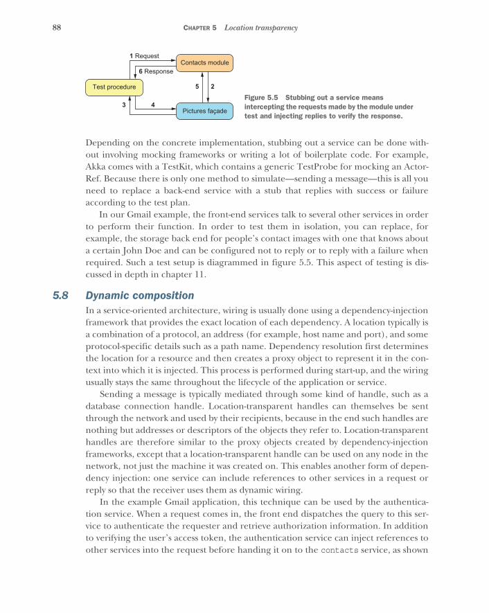
88 CHAPTER 5 Location transparency
Depending on the concrete implementation, stubbing out a service can be done with-out involving mocking frameworks or writing a lot of boilerplate code. For example,Akka comes with a TestKit, which contains a generic TestProbe for mocking an Actor-Ref. Because there is only one method to simulate—sending a message—this is all youneed to replace a back-end service with a stub that replies with success or failureaccording to the test plan.
In our Gmail example, the front-end services talk to several other services in orderto perform their function. In order to test them in isolation, you can replace, forexample, the storage back end for people’s contact images with one that knows abouta certain John Doe and can be configured not to reply or to reply with a failure whenrequired. Such a test setup is diagrammed in figure 5.5. This aspect of testing is dis-cussed in depth in chapter 11.
5.8 Dynamic compositionIn a service-oriented architecture, wiring is usually done using a dependency-injectionframework that provides the exact location of each dependency. A location typically isa combination of a protocol, an address (for example, host name and port), and someprotocol-specific details such as a path name. Dependency resolution first determinesthe location for a resource and then creates a proxy object to represent it in the con-text into which it is injected. This process is performed during start-up, and the wiringusually stays the same throughout the lifecycle of the application or service.
Sending a message is typically mediated through some kind of handle, such as adatabase connection handle. Location-transparent handles can themselves be sentthrough the network and used by their recipients, because in the end such handles arenothing but addresses or descriptors of the objects they refer to. Location-transparenthandles are therefore similar to the proxy objects created by dependency-injectionframeworks, except that a location-transparent handle can be used on any node in thenetwork, not just the machine it was created on. This enables another form of depen-dency injection: one service can include references to other services in a request orreply so that the receiver uses them as dynamic wiring.
In the example Gmail application, this technique can be used by the authentica-tion service. When a request comes in, the front end dispatches the query to this ser-vice to authenticate the requester and retrieve authorization information. In additionto verifying the user’s access token, the authentication service can inject references toother services into the request before handing it on to the contacts service, as shown
Test procedure
1 Request
6 Response
3 4
25
Contacts module
Pictures façade
Figure 5.5 Stubbing out a service means intercepting the requests made by the module under test and injecting replies to verify the response.
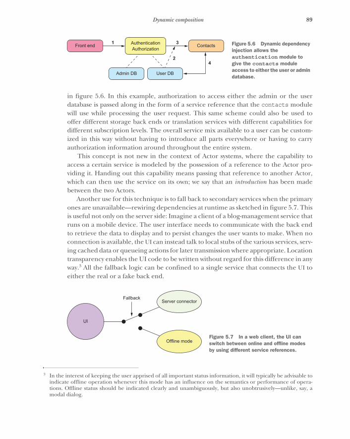
89Dynamic composition
in figure 5.6. In this example, authorization to access either the admin or the userdatabase is passed along in the form of a service reference that the contacts modulewill use while processing the user request. This same scheme could also be used tooffer different storage back ends or translation services with different capabilities fordifferent subscription levels. The overall service mix available to a user can be custom-ized in this way without having to introduce all parts everywhere or having to carryauthorization information around throughout the entire system.
This concept is not new in the context of Actor systems, where the capability toaccess a certain service is modeled by the possession of a reference to the Actor pro-viding it. Handing out this capability means passing that reference to another Actor,which can then use the service on its own; we say that an introduction has been madebetween the two Actors.
Another use for this technique is to fall back to secondary services when the primaryones are unavailable—rewiring dependencies at runtime as sketched in figure 5.7. Thisis useful not only on the server side: Imagine a client of a blog-management service thatruns on a mobile device. The user interface needs to communicate with the back endto retrieve the data to display and to persist changes the user wants to make. When noconnection is available, the UI can instead talk to local stubs of the various services, serv-ing cached data or queueing actions for later transmission where appropriate. Locationtransparency enables the UI code to be written without regard for this difference in anyway.3 All the fallback logic can be confined to a single service that connects the UI toeither the real or a fake back end.
3 In the interest of keeping the user apprised of all important status information, it will typically be advisable toindicate offline operation whenever this mode has an influence on the semantics or performance of opera-tions. Offline status should be indicated clearly and unambiguously, but also unobtrusively—unlike, say, amodal dialog.
AuthenticationAuthorization
ContactsFront end 1 3
42
Admin DB User DB
Figure 5.6 Dynamic dependency injection allows the authentication module to give the contacts module access to either the user or admin database.
UI
Server connectorFallback
Offline modeFigure 5.7 In a web client, the UI can switch between online and offline modes by using different service references.
90 CHAPTER 5 Location transparency
5.9 SummaryIn this chapter, you have seen how explicit message passing enables you to view localmessages as a special case of fully distributed remote messaging—in contrast to trans-parent remoting, which aims to make remote interactions look like local ones. We dis-cussed how differences in latency, throughput, and message-loss probability affectyour ability to treat local and remote interactions in a unified way.
You have also seen the benefits of location-transparent messaging: it extends thevertical scalability afforded by message passing to scalability along the horizontal axis;it eases testing of software components; and it allows software components to be com-posed dynamically. In the next chapter, we will look more deeply into what a compo-nent is and how you can break a larger task into independent, smaller ones.
91
Divide and conquer
The previous chapter presumed that programs typically consist of multiple partsthat are segregated in some way. Different areas of functionality may be developedby separate teams, modules are accessed via interfaces and packaged such that theycan be replaced, and so on. Over the past few decades, much effort has been spenton syntax and semantics for defining modules in programming languages and onlibraries and the infrastructure needed to deploy them. The important question is,how do we go about dividing up a problem in order to successfully solve it?
Rewinding the clock more than 2,000 years, we find one of the earliest practi-tioners of the governance maxim divide et regna: Julius Caesar. The idea is simple:when faced with a number of enemies, create discord and divide them. This willallow you to vanquish them one by one, even though they would easily havedefeated you if they had stood united. This strategy was used by the Roman Empireboth internally and externally: the key was to purposefully treat different oppo-nents differently, handing out favors and punishment asymmetrically. And thistreatment was probably applied recursively, with senators and prefects learningfrom Caesar’s success.1
We do not have the problem of leading a huge empire, nor is fomenting discordone of our methods, but we can still learn from this old Latin saying. We can breaka large programming problem down into a manageable handful of subproblems,and then do the same to the subproblems. Thus, we can gradually narrow the scopeof what we are working on, drilling progressively deeper into the details of how toimplement each particular piece.
1 The authors have no direct evidence for this, but it sounds implausible to propose the opposite.
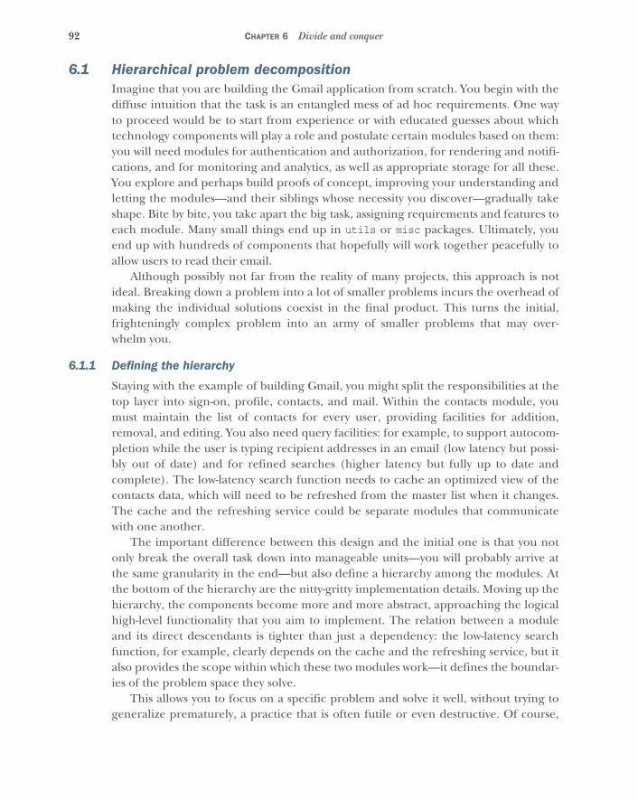
92 CHAPTER 6 Divide and conquer
6.1 Hierarchical problem decompositionImagine that you are building the Gmail application from scratch. You begin with thediffuse intuition that the task is an entangled mess of ad hoc requirements. One wayto proceed would be to start from experience or with educated guesses about whichtechnology components will play a role and postulate certain modules based on them:you will need modules for authentication and authorization, for rendering and notifi-cations, and for monitoring and analytics, as well as appropriate storage for all these.You explore and perhaps build proofs of concept, improving your understanding andletting the modules—and their siblings whose necessity you discover—gradually takeshape. Bite by bite, you take apart the big task, assigning requirements and features toeach module. Many small things end up in utils or misc packages. Ultimately, youend up with hundreds of components that hopefully will work together peacefully toallow users to read their email.
Although possibly not far from the reality of many projects, this approach is notideal. Breaking down a problem into a lot of smaller problems incurs the overhead ofmaking the individual solutions coexist in the final product. This turns the initial,frighteningly complex problem into an army of smaller problems that may over-whelm you.
6.1.1 Defining the hierarchy
Staying with the example of building Gmail, you might split the responsibilities at thetop layer into sign-on, profile, contacts, and mail. Within the contacts module, youmust maintain the list of contacts for every user, providing facilities for addition,removal, and editing. You also need query facilities: for example, to support autocom-pletion while the user is typing recipient addresses in an email (low latency but possi-bly out of date) and for refined searches (higher latency but fully up to date andcomplete). The low-latency search function needs to cache an optimized view of thecontacts data, which will need to be refreshed from the master list when it changes.The cache and the refreshing service could be separate modules that communicatewith one another.
The important difference between this design and the initial one is that you notonly break the overall task down into manageable units—you will probably arrive atthe same granularity in the end—but also define a hierarchy among the modules. Atthe bottom of the hierarchy are the nitty-gritty implementation details. Moving up thehierarchy, the components become more and more abstract, approaching the logicalhigh-level functionality that you aim to implement. The relation between a moduleand its direct descendants is tighter than just a dependency: the low-latency searchfunction, for example, clearly depends on the cache and the refreshing service, but italso provides the scope within which these two modules work—it defines the boundar-ies of the problem space they solve.
This allows you to focus on a specific problem and solve it well, without trying togeneralize prematurely, a practice that is often futile or even destructive. Of course,
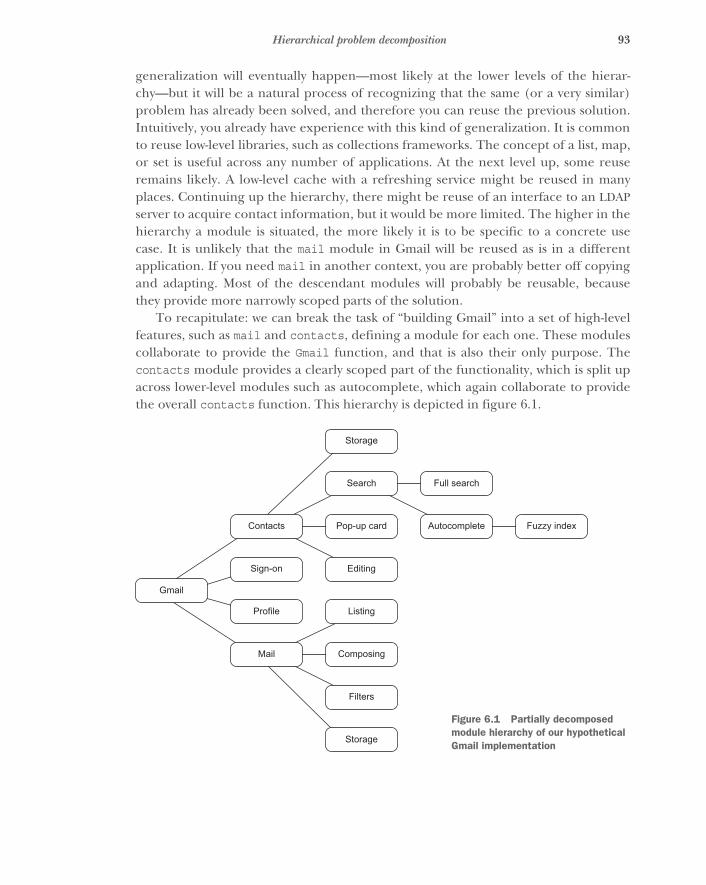
93Hierarchical problem decomposition
generalization will eventually happen—most likely at the lower levels of the hierar-chy—but it will be a natural process of recognizing that the same (or a very similar)problem has already been solved, and therefore you can reuse the previous solution.Intuitively, you already have experience with this kind of generalization. It is commonto reuse low-level libraries, such as collections frameworks. The concept of a list, map,or set is useful across any number of applications. At the next level up, some reuseremains likely. A low-level cache with a refreshing service might be reused in manyplaces. Continuing up the hierarchy, there might be reuse of an interface to an LDAPserver to acquire contact information, but it would be more limited. The higher in thehierarchy a module is situated, the more likely it is to be specific to a concrete usecase. It is unlikely that the mail module in Gmail will be reused as is in a differentapplication. If you need mail in another context, you are probably better off copyingand adapting. Most of the descendant modules will probably be reusable, becausethey provide more narrowly scoped parts of the solution.
To recapitulate: we can break the task of “building Gmail” into a set of high-levelfeatures, such as mail and contacts, defining a module for each one. These modulescollaborate to provide the Gmail function, and that is also their only purpose. Thecontacts module provides a clearly scoped part of the functionality, which is split upacross lower-level modules such as autocomplete, which again collaborate to providethe overall contacts function. This hierarchy is depicted in figure 6.1.
Storage
Search Full search
Contacts Pop-up card Autocomplete Fuzzy index
Gmail
Sign-on Editing
Profile Listing
Mail Composing
Filters
Storage
Figure 6.1 Partially decomposed module hierarchy of our hypothetical Gmail implementation
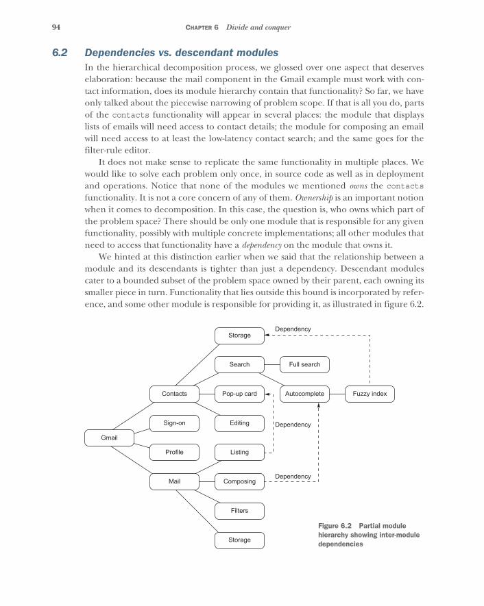
94 CHAPTER 6 Divide and conquer
6.2 Dependencies vs. descendant modulesIn the hierarchical decomposition process, we glossed over one aspect that deserveselaboration: because the mail component in the Gmail example must work with con-tact information, does its module hierarchy contain that functionality? So far, we haveonly talked about the piecewise narrowing of problem scope. If that is all you do, partsof the contacts functionality will appear in several places: the module that displayslists of emails will need access to contact details; the module for composing an emailwill need access to at least the low-latency contact search; and the same goes for thefilter-rule editor.
It does not make sense to replicate the same functionality in multiple places. Wewould like to solve each problem only once, in source code as well as in deploymentand operations. Notice that none of the modules we mentioned owns the contactsfunctionality. It is not a core concern of any of them. Ownership is an important notionwhen it comes to decomposition. In this case, the question is, who owns which part ofthe problem space? There should be only one module that is responsible for any givenfunctionality, possibly with multiple concrete implementations; all other modules thatneed to access that functionality have a dependency on the module that owns it.
We hinted at this distinction earlier when we said that the relationship between amodule and its descendants is tighter than just a dependency. Descendant modulescater to a bounded subset of the problem space owned by their parent, each owning itssmaller piece in turn. Functionality that lies outside this bound is incorporated by refer-ence, and some other module is responsible for providing it, as illustrated in figure 6.2.
Storage
Search Full search
Contacts Pop-up card Autocomplete
Dependency
Dependency
Dependency
Fuzzy index
Gmail
Sign-on Editing
Profile Listing
Mail Composing
Filters
Storage
Figure 6.2 Partial module hierarchy showing inter-module dependencies
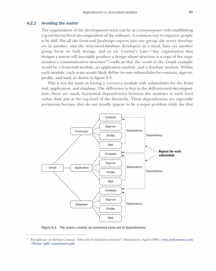
95Dependencies vs. descendant modules
6.2.1 Avoiding the matrix
The organization of the development team can be at cross-purposes with establishinga good hierarchical decomposition of the software. A common way to organize peopleis by skill. Put all the front-end JavaScript experts into one group, the server develop-ers in another, and the structured-database developers in a third, have yet anothergroup focus on bulk storage, and so on. Conway’s Law—“Any organization thatdesigns a system will inevitably produce a design whose structure is a copy of the orga-nization’s communication structure”2—tells us that the result in the Gmail examplewould be a front-end module, an application module, and a database module. Withineach module, each team would likely define its own submodules for contacts, sign-on,profile, and mail, as shown in figure 6.3.
This is not the same as having a contacts module with submodules for the frontend, application, and database. The difference is that in the skill-oriented decomposi-tion, there are small, horizontal dependencies between the modules at each levelrather than just at the top level of the hierarchy. These dependencies are especiallypernicious because they do not usually appear to be a major problem while the first
2 Paraphrase of Melvin Conway, “How Do Committees Invent?” Datamation (April 1968), www.melconway.com/Home/pdf/committees.pdf.
Contacts
Sign-on
Profile
Dependency
Dependency
Repeat for eachsubmodule
DependencyDependency
Dependency
Gmail
Application
Front end
Database
Contacts
Sign-on
Profile
Contacts
Sign-on
Profile
Figure 6.3 The matrix creates an unwanted extra set of dependencies.
96 CHAPTER 6 Divide and conquer
version is being built. Early in the lifecycle of a piece of software, nearly every submod-ule typically needs to be changed in every release; so whether a given module isdeployed as part of the latest whole application release or as part of the latest contactsrelease makes no difference. Later, horizontal dependencies become problematic.They force a release focused on a single technology, such as upgrading the databaseversion, to affect every module at the same level in the hierarchy. At the same time,every major feature release affects every module along a vertical axis.
6.3 Building your own big corporationA metaphor that often works well for picturing and speaking about hierarchical prob-lem decomposition is that of a big corporation. At the top, management defines theoverall goal and direction (CEO, Chief Architect, and so on). Then there are depart-ments that handle different, very high-level aspects of the goal. Each department isstructured into various subgroups of different granularity, until at the bottom wereach the small teams that carry out very specific, narrowly scoped tasks. The ideasbehind this structure are similar to the responsibility-oriented problem decomposi-tion described previously: without proper segregation of the responsibilities of thedepartments, their members would constantly step on each other’s toes while doingtheir work.
As you work through this hierarchy, think ahead to something that will be consid-ered more in the next chapter: handling failures. If an individual in the hierarchy failsto do their job, the next person up in the hierarchy must handle it. Responsibilityflows toward the person in charge, not in lazy circles among coworkers!
If you think now, “Well, that all sounds nice in theory, but my own experience hasbeen that this is exactly how corporations do not work,” the good news is that whenapplying these techniques to a programming problem, you get to choose the structureand define the relationships between the parts of the hierarchy you create—you getthe chance to create your own BigCorp and do it right!3 You get the chance to notrepeat the management mistakes of the past. “Matrix management” schemes werepopular from the late 1970s to the early 1980s, and they did not work well. The title ofan article published in the aftermath of the fad provides some insight: Matrix Manage-ment: Not a Structure, a Frame of Mind.4
A hierarchical decomposition of responsibilities is shown in figure 6.4, on theexample of our venerable Gmail application. Naming the modules according to therole they play within the overall organization of the application helps establish a com-mon vocabulary among the teams and stakeholders involved in development.
3 You will probably discover that things are not as easy as you think they should be, which is equally instructive.4 Christopher A. Bartlett and Sumantra Ghoshal, “Matrix Management: Not a Structure, a Frame of Mind,” Har-
vard Business Review (July-August 1990).
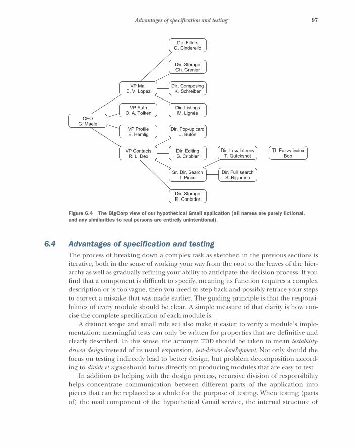
97Advantages of specification and testing
6.4 Advantages of specification and testingThe process of breaking down a complex task as sketched in the previous sections isiterative, both in the sense of working your way from the root to the leaves of the hier-archy as well as gradually refining your ability to anticipate the decision process. If youfind that a component is difficult to specify, meaning its function requires a complexdescription or is too vague, then you need to step back and possibly retrace your stepsto correct a mistake that was made earlier. The guiding principle is that the responsi-bilities of every module should be clear. A simple measure of that clarity is how con-cise the complete specification of each module is.
A distinct scope and small rule set also make it easier to verify a module’s imple-mentation: meaningful tests can only be written for properties that are definitive andclearly described. In this sense, the acronym TDD should be taken to mean testability-driven design instead of its usual expansion, test-driven development. Not only should thefocus on testing indirectly lead to better design, but problem decomposition accord-ing to divide et regna should focus directly on producing modules that are easy to test.
In addition to helping with the design process, recursive division of responsibilityhelps concentrate communication between different parts of the application intopieces that can be replaced as a whole for the purpose of testing. When testing (partsof) the mail component of the hypothetical Gmail service, the internal structure of
Dir. FiltersC. Cinderello
Dir. StorageCh. Grenier
VP MailE. V. Lopez
Dir. ComposingK. Schreiber
Dir. Full searchS. Rigoroso
Dir. Low latencyT. Quickshot
TL Fuzzy indexBob
CEOG. Maele
VP AuthO. A. Tolken
Dir. ListingsM. Lignée
VP ProfileE. Hemlig
Dir. Pop-up cardJ. Bufón
VP ContactsR. L. Dex
Dir. EditingS. Cribbler
Sr. Dir. SearchI. Pince
Dir. StorageE. Contador
Figure 6.4 The BigCorp view of our hypothetical Gmail application (all names are purely fictional, and any similarities to real persons are entirely unintentional).
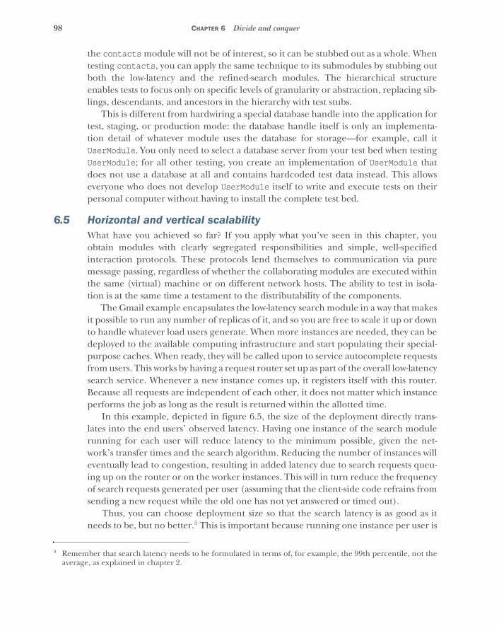
98 CHAPTER 6 Divide and conquer
the contacts module will not be of interest, so it can be stubbed out as a whole. Whentesting contacts, you can apply the same technique to its submodules by stubbing outboth the low-latency and the refined-search modules. The hierarchical structureenables tests to focus only on specific levels of granularity or abstraction, replacing sib-lings, descendants, and ancestors in the hierarchy with test stubs.
This is different from hardwiring a special database handle into the application fortest, staging, or production mode: the database handle itself is only an implementa-tion detail of whatever module uses the database for storage—for example, call itUserModule. You only need to select a database server from your test bed when testingUserModule; for all other testing, you create an implementation of UserModule thatdoes not use a database at all and contains hardcoded test data instead. This allowseveryone who does not develop UserModule itself to write and execute tests on theirpersonal computer without having to install the complete test bed.
6.5 Horizontal and vertical scalabilityWhat have you achieved so far? If you apply what you’ve seen in this chapter, youobtain modules with clearly segregated responsibilities and simple, well-specifiedinteraction protocols. These protocols lend themselves to communication via puremessage passing, regardless of whether the collaborating modules are executed withinthe same (virtual) machine or on different network hosts. The ability to test in isola-tion is at the same time a testament to the distributability of the components.
The Gmail example encapsulates the low-latency search module in a way that makesit possible to run any number of replicas of it, and so you are free to scale it up or downto handle whatever load users generate. When more instances are needed, they can bedeployed to the available computing infrastructure and start populating their special-purpose caches. When ready, they will be called upon to service autocomplete requestsfrom users. This works by having a request router set up as part of the overall low-latencysearch service. Whenever a new instance comes up, it registers itself with this router.Because all requests are independent of each other, it does not matter which instanceperforms the job as long as the result is returned within the allotted time.
In this example, depicted in figure 6.5, the size of the deployment directly trans-lates into the end users’ observed latency. Having one instance of the search modulerunning for each user will reduce latency to the minimum possible, given the net-work’s transfer times and the search algorithm. Reducing the number of instances willeventually lead to congestion, resulting in added latency due to search requests queu-ing up on the router or on the worker instances. This will in turn reduce the frequencyof search requests generated per user (assuming that the client-side code refrains fromsending a new request while the old one has not yet answered or timed out).
Thus, you can choose deployment size so that the search latency is as good as itneeds to be, but no better.5 This is important because running one instance per user is
5 Remember that search latency needs to be formulated in terms of, for example, the 99th percentile, not theaverage, as explained in chapter 2.
99Summary
obviously ridiculously wasteful. Reducing the number of instances as much as you canis in your best business interest.
6.6 SummaryBy taking inspiration from ancient Roman emperors, we have derived a method ofsplitting an enormous task into a handful of smaller ones and repeating this processwith each subtask until we are left with the components that collaboratively make upour entire application. Focusing on responsibility boundaries allows us to distinguishbetween who uses a component versus who owns it. We illustrated this procedure withthe example of how a big corporation is structured.
On this journey, you have seen that such a hierarchical component structure bene-fits the specification and hence the testing of components. We also noted that compo-nents with segregated responsibilities naturally form units for scaling applicationdeployment vertically as well as horizontally. We will study another benefit of thisstructure in the next chapter when we talk about failure handling.
Search
Low-latencysearchFront end
Fuzzy index Figure 6.5 Scalable deployment of the low-latency search service is monitored and scaled up/down by the search supervisor.
100
Principled failure handling
You have seen that resilience requires distributing and compartmentalizing sys-tems. Distribution is the only way to avoid being knocked out by a single failure, bethat hardware, software, or human; and compartmentalization isolates the distrib-uted units from each other such that the failure of one of them does not spread tothe others. The conclusion was that in order to restore proper function after a fail-ure, you need to delegate the responsibility of reacting to this event to a supervisor.
The importance of ownership appeared already within the decomposition of asystem according to divide et regna, expressed as the difference between a descen-dant module and a dependency. Descendants own a piece of the parent’s function-ality, but foreign functions are incorporated only by reference. The resultinghierarchy gives the supervision structure for the modules.
7.1 Ownership means commitmentIn the previous chapter, you saw an analogy between a system hierarchy and a cor-porate organization. Imagine yourself for the moment to be a customer in a storebelonging to one of these organizations. If you are talking to a sales clerk about buy-ing a shirt and that person tells you that they do not like their job and wanders offmidconversation, it is not your responsibility to resolve the situation. It is the respon-sibility of the store manager to handle it. This seems obvious and perhaps evenhumorous, but consider the situation with software. It is not at all uncommon forsoftware to tell callers about internal problems it is having, by throwing exceptions.
This does not make much sense. The caller is rarely in a position to do something useful about the failure. If the
failing module has been properly encapsulated, the caller must be completelyinsulated from the implementation details, but those implementation details areoften exposed in the exception. For example, suppose a simple lookup function is
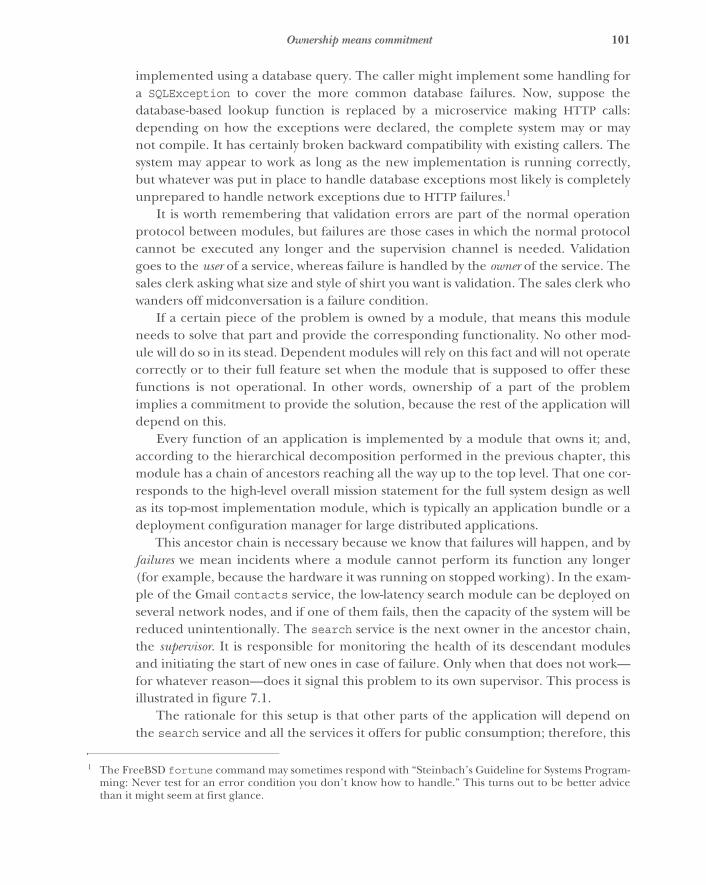
101Ownership means commitment
implemented using a database query. The caller might implement some handling fora SQLException to cover the more common database failures. Now, suppose thedatabase-based lookup function is replaced by a microservice making HTTP calls:depending on how the exceptions were declared, the complete system may or maynot compile. It has certainly broken backward compatibility with existing callers. Thesystem may appear to work as long as the new implementation is running correctly,but whatever was put in place to handle database exceptions most likely is completelyunprepared to handle network exceptions due to HTTP failures.1
It is worth remembering that validation errors are part of the normal operationprotocol between modules, but failures are those cases in which the normal protocolcannot be executed any longer and the supervision channel is needed. Validationgoes to the user of a service, whereas failure is handled by the owner of the service. Thesales clerk asking what size and style of shirt you want is validation. The sales clerk whowanders off midconversation is a failure condition.
If a certain piece of the problem is owned by a module, that means this moduleneeds to solve that part and provide the corresponding functionality. No other mod-ule will do so in its stead. Dependent modules will rely on this fact and will not operatecorrectly or to their full feature set when the module that is supposed to offer thesefunctions is not operational. In other words, ownership of a part of the problemimplies a commitment to provide the solution, because the rest of the application willdepend on this.
Every function of an application is implemented by a module that owns it; and,according to the hierarchical decomposition performed in the previous chapter, thismodule has a chain of ancestors reaching all the way up to the top level. That one cor-responds to the high-level overall mission statement for the full system design as wellas its top-most implementation module, which is typically an application bundle or adeployment configuration manager for large distributed applications.
This ancestor chain is necessary because we know that failures will happen, and byfailures we mean incidents where a module cannot perform its function any longer(for example, because the hardware it was running on stopped working). In the exam-ple of the Gmail contacts service, the low-latency search module can be deployed onseveral network nodes, and if one of them fails, then the capacity of the system will bereduced unintentionally. The search service is the next owner in the ancestor chain,the supervisor. It is responsible for monitoring the health of its descendant modulesand initiating the start of new ones in case of failure. Only when that does not work—for whatever reason—does it signal this problem to its own supervisor. This process isillustrated in figure 7.1.
The rationale for this setup is that other parts of the application will depend onthe search service and all the services it offers for public consumption; therefore, this
1 The FreeBSD fortune command may sometimes respond with “Steinbach’s Guideline for Systems Program-ming: Never test for an error condition you don’t know how to handle.” This turns out to be better advicethan it might seem at first glance.
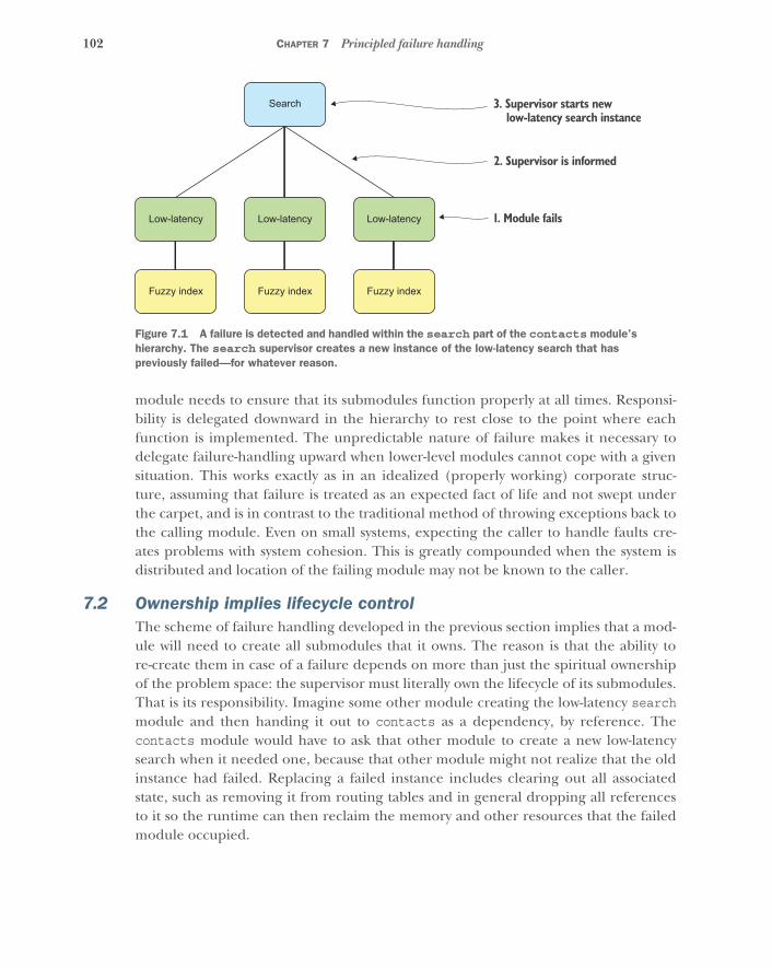
102 CHAPTER 7 Principled failure handling
module needs to ensure that its submodules function properly at all times. Responsi-bility is delegated downward in the hierarchy to rest close to the point where eachfunction is implemented. The unpredictable nature of failure makes it necessary todelegate failure-handling upward when lower-level modules cannot cope with a givensituation. This works exactly as in an idealized (properly working) corporate struc-ture, assuming that failure is treated as an expected fact of life and not swept underthe carpet, and is in contrast to the traditional method of throwing exceptions back tothe calling module. Even on small systems, expecting the caller to handle faults cre-ates problems with system cohesion. This is greatly compounded when the system isdistributed and location of the failing module may not be known to the caller.
7.2 Ownership implies lifecycle controlThe scheme of failure handling developed in the previous section implies that a mod-ule will need to create all submodules that it owns. The reason is that the ability tore-create them in case of a failure depends on more than just the spiritual ownershipof the problem space: the supervisor must literally own the lifecycle of its submodules.That is its responsibility. Imagine some other module creating the low-latency searchmodule and then handing it out to contacts as a dependency, by reference. Thecontacts module would have to ask that other module to create a new low-latencysearch when it needed one, because that other module might not realize that the oldinstance had failed. Replacing a failed instance includes clearing out all associatedstate, such as removing it from routing tables and in general dropping all referencesto it so the runtime can then reclaim the memory and other resources that the failedmodule occupied.
Fuzzy index Fuzzy index Fuzzy index
Low-latency Low-latency Low-latency
Search 3. Supervisor starts new low-latency search instance
2. Supervisor is informed
1. Module fails
Figure 7.1 A failure is detected and handled within the search part of the contacts module’s hierarchy. The search supervisor creates a new instance of the low-latency search that has previously failed—for whatever reason.
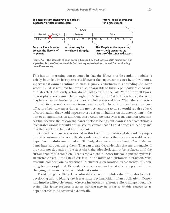
103Ownership implies lifecycle control
This has an interesting consequence in that the lifecycle of descendant modules isstrictly bounded by its supervisor’s lifecycle: the supervisor creates it, and without asupervisor it cannot continue to exist. Figure 7.2 illustrates this bounding. An actorsystem, BBC1, is required to have an actor available to fulfill a particular role. As withour sales clerk previously, actors do not last forever in the role. When Hartnell leaves,he is replaced successively by Troughton, Pertwee, and Baker. In each case, the actormay have spawned further actors to accomplish additional tasks. When the actor is ter-minated, its spawned actors are terminated as well. There is no mechanism to handoff actors from one supervisor to the next. Attempting to do so would require a levelof coordination that would impose severe design limitations on the actor system in thebest of circumstances. In addition, there would be risks even if the hand-off were suc-cessful, because the reason the parent actor is being shut down is that something isirreparably wrong. It would not be safe to assume that all child actors are healthy andthat the problem is limited to the parent.
Dependencies are not restricted in this fashion. In traditional dependency injec-tion, it is customary to create the dependencies first such that they are available whendependent modules are started up. Similarly, they are terminated only after all depen-dents have stopped using them. That can create dependencies that are untenable. Ifthe customer depends on the sales clerk, the sales clerk cannot be replaced until thecustomer activity is complete. That is convenient in theory but could put the system inan unstable state if the sales clerk fails in the midst of a customer interaction. Withdynamic composition, as described in chapter 5 on location transparency, this cou-pling becomes optional. Dependencies can come and go at arbitrary points in time,changing the wiring between modules at runtime.
Considering the lifecycle relationship between modules therefore also helps indeveloping and validating the hierarchical decomposition of an application. Owner-ship implies a lifecycle bound, whereas inclusion by reference allows independent life-cycles. The latter requires location transparency in order to enable references todependencies to be acquired dynamically.
Hartnell Troughton
1 2 3 4 5 6 7 8 9 10 11
Pertwee
BBC1
12 13 14 15 16 17 18
Baker
Actors should be preparedfor a graceful end.
The actor system often provides a defaultsupervisor for user-created actors.
The lifecycle of the supervisingactor strictly separates thelifecycle of the contained actors.
An actor lifecycle never exceeds the lifecycle of its parent.
An actor may beterminated abruptly.
Figure 7.2 The lifecycle of each actor is bounded by the lifecycle of its supervisor. The supervisor is therefore responsible for creating supervised actors and for terminating them if necessary.
104 CHAPTER 7 Principled failure handling
7.3 Resilience on all levelsThe way you deal with failure is inherently hierarchical; this is true in our society as wellas in programming. The most common way to express failure in a computer programis to raise an exception, which is then propagated up the call stack by the runtime anddelivered to the innermost enclosing exception handler that declares itself responsi-ble. The same principle is expressed in pure functional programming by the returntype of a called function in that it models either a successful result or an error condi-tion (or a list thereof, especially for functions that validate input to the program). Inboth cases, the responsibility of handling failure is delegated upward; but in contrast tothe Reactive approach described in this chapter, these techniques conflate the usagehierarchy with supervision—the user of a service gets to handle its failures as well.
The principled approach to handling failure described in this chapter adds onemore facet to the module hierarchy: every module is a unit of resilience. This isenabled by the encapsulation afforded by message passing and by the flexibility inher-ent in location transparency. A module can fail and be restored to proper functionwithout its dependents needing to take action. The supervisor will handle this foreveryone else’s benefit.
This is true at all levels of the application hierarchy, although obviously theamount of work to be done during a restart depends on the fraction of the applicationthat has failed. Therefore, it is important to isolate failure as early as possible, keepingthe units small and the cost of recovery low, which will be discussed in detail as theError Kernel pattern in section 12.2. Even in those cases where more drastic action isneeded, the restart of the complete contacts service of the example Gmail applica-tion will leave most of the mail functionality intact (searching, viewing, and sortingmail does not depend critically on it; only convenience may suffer). Consequently,resilience can be achieved at all levels of granularity, and a Reactive design will natu-rally lend itself well to this goal.
7.4 SummaryIn this chapter, we used the hierarchical component structure to determine a princi-pled way of handling failure. The parent component is responsible for the functional-ity of its descendants, so it is logical to delegate the handling of such failures thatcannot be dealt with locally to that same parent. This pattern allows the constructionof software that is robust even in unforeseen cases, and it is the cornerstone for imple-menting resilience.
The next chapter investigates another aspect of building distributed components:consistency comes at a price. Once again, we will split the problem into a hierarchy ofindependent components.
105
Delimited consistency
One possible definition of a distributed system is a system whose parts can fail inde-pendently.1 Reactive design is distributed by its very nature: you want to model com-ponents that are isolated from each other and interact only via location-transparentmessage passing in order to create a resilient supervisor hierarchy. This means theresulting application layout will suffer the consequences of being distributed. In astateless system, the consequences relate primarily to failure handling, and recoveryis handled as described in the previous chapter. When the system has state, it is notso simple. Even when each part of the system works perfectly, time is a factor. As youlearned in chapter 2, a consequence of being distributed is that strong consistencycannot be guaranteed. In this chapter, you will learn about delimited consistency,which is the next-best alternative.
This can be illustrated by the example of the mail functionality of our exampleGmail application. Because the number of users is expected to be huge, you willhave to split the storage of all mail across many different computers located in mul-tiple data centers distributed across the world. Assuming that a person’s folders canbe split across multiple computers, the act of moving an email from one folder toanother may imply that it moves between computers. It will be either copied first tothe destination and then deleted at the origin, or placed in transient storage,deleted at the origin, and then copied to the destination.
In either case, the overall count of emails for that person should stay constantthroughout the process; but if you count the emails by asking the computersinvolved in their storage, you may see the email “in flight” and count it either twice
1 A more humorous one by Leslie Lamport is as follows: “A distributed system is one in which the failure ofa computer you didn’t even know existed can render your own computer unusable.” (Email message, May28, 1987, http://research.microsoft.com/en-us/um/people/lamport/pubs/distributed-system.txt.)
106 CHAPTER 8 Delimited consistency
or not at all. Ensuring that the count is consistent would entail excluding the act ofcounting while the transfer was in progress. The cost of strong consistency is thereforethat otherwise independent components of the distributed system need to coordinatetheir actions by way of additional communication, which means taking more time andusing more network bandwidth. This observation is not specific to the Gmail examplebut holds true in general for the problem of having multiple distributed parties agreeon something. This is also called distributed consensus.
8.1 Encapsulated modules to the rescueFortunately, these consequences are not as severe as they may seem at first. Pat Hel-land,2 a pioneer and long-time contributor to the research on strong consistency,argues that once a system’s scale grows to a critical size, it can no longer be stronglyconsistent. The cost of coordinating a single global order of all changes that occurwithin it would be forbiddingly high, and adding more (distributed) resources at thatpoint will only diminish the system’s capacity instead of increasing it. Instead, we willbe constructing systems from small building blocks—entities3—that are internally con-sistent but interact in an eventually consistent fashion.
The dataset contained within such an entity can be treated in a fully consistentfashion, applying changes such that they occur—or at least appear to occur—in onespecific order. This is possible because each entity lives within a distinct scope of serializ-ability, which means the entity itself is not distributed and the datasets of different enti-ties cannot overlap. The behavior of such a system is strongly consistent—transactional—only for operations that do not span multiple entities.
Helland goes on to postulate that we will develop platforms that manage the com-plexity of distributing and interacting with these independent entities, allowing theexpression of business logic in a fashion that does not need to concern itself with thedeployment details as long as it obeys the transaction bounds. The entities he talksabout are very similar to the encapsulated modules developed in this book so far. Thedifference is mainly that he focuses on managing the data stored within a system,whereas we have concerned ourselves foremost with decomposing the functionalityoffered by a complex application. In the end, both are the same: as viewed by a user,the only thing that matters is that the obtained responses reflect the correct state ofthe service at the time of the request, where state is nothing more than the dataset theservice maintains internally. A system that supports Reactive application design istherefore a natural substrate for fulfilling Pat Helland’s prediction.
2 See his paper “Life Beyond Distributed Transactions,” CIDR (2007), http://www.ics.uci.edu/~cs223/papers/cidr07p15.pdf.
3 In the context of domain-driven design, these would be called aggregate roots ; the different uses of the wordentity are owed to its intrinsic generality.
107Modeling workflows across transactional boundaries
8.2 Grouping data and behavior according to transaction boundariesThe example problem of storing a person’s email folders in a distributed fashion canbe solved by applying the strategy outlined in the previous section. If you want toensure that emails can be moved without leading to inconsistent counts, then eachperson’s complete email dataset must be managed by one entity. The example appli-cation decomposition would have a module for this purpose and would instantiate itonce for every person using the system. This does not mean all mail would be literallystored within that instance. It only means all access to a person’s email content wouldbe via this dedicated instance.
In effect, this acts like a locking mechanism that serializes access, with the obviousrestriction that an individual person’s email cannot be scaled out to multiple manag-ers in order to support higher transaction rates. This is fine, because a human is manyorders of magnitude slower than a computer when it comes to processing email, soyou will not run into performance problems by limiting scalability in this direction.What is more important is that this enables you to distribute the management of allusers’ mailboxes across any number of machines, because each instance is indepen-dent of all others. The consequence is that it is not possible to move emails betweendifferent people’s accounts while maintaining the overall email count, but that is not asupported feature anyway.
To formalize what we just discussed, the trick is to slice the behavior and accompa-nying dataset in such a way that each slice offers the desired features in isolation andno transactions are necessary that span multiple slices. This technique is applied anddiscussed in great detail in the literature on domain-driven design (DDD).4
8.3 Modeling workflows across transactional boundariesThe way in which the dataset is sliced accommodates performing a certain set of oper-ations in a strongly consistent manner but precludes this quality of behavior for allother conceivable operations. In most cases, there will be operations that are desirablebut not supported. Slicing the data in another way is not an option, because thatwould break more important use cases. In this situation, the design must fall back toan eventually consistent way of performing those other operations, meaning thatalthough it keeps the atomicity of the transaction, it abandons complete consistencyand isolation.
To illustrate this, consider the case of moving an email from Alice’s mailbox to thatof another person named Bob, possibly stored in a data center on another continent.Although this operation cannot occur such that both the source and destination mail-boxes execute this operation at the same time, it can ensure that the email eventuallywill be present only in Bob’s mailbox. You can facilitate this by creating an instance of
4 See, for example, Eric Evans, Domain-Driven Design , Addison-Wesley (2003); or Vaughn Vernon, ImplementingDomain-Driven Design, Addison-Wesley (2013).
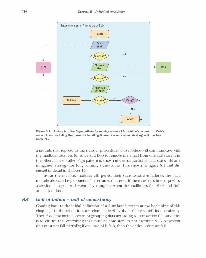
108 CHAPTER 8 Delimited consistency
a module that represents the transfer procedure. This module will communicate withthe mailbox instances for Alice and Bob to remove the email from one and store it inthe other. This so-called Saga pattern is known in the transactional database world as amitigation strategy for long-running transactions. It is shown in figure 8.1 and dis-cussed in detail in chapter 14.
Just as the mailbox modules will persist their state to survive failures, the Sagamodule also can be persistent. This ensures that even if the transfer is interrupted bya service outage, it will eventually complete when the mailboxes for Alice and Bobare back online.
8.4 Unit of failure = unit of consistencyComing back to the initial definition of a distributed system at the beginning of thischapter, distributed entities are characterized by their ability to fail independently.Therefore, the main concern of grouping data according to transactional boundariesis to ensure that everything that must be consistent is not distributed. A consistentunit must not fail partially; if one part of it fails, then the entire unit must fail.
No
Start
Saga: move email from Alice to Bob
Finished
Abort
Fetchmail
Store atBob
Removeat Alice
Success?No
No
No
Success?
Success? Retry?
Alice Bob
Figure 8.1 A sketch of the Saga pattern for moving an email from Alice’s account to Bob’s account, not including the cases for handling timeouts when communicating with the two accounts

109Segregating responsibilities
In the example of the transfer of an email between Alice’s and Bob’s mailboxes,the Saga that performs this task is one such unit. If one part of it fails, then the wholetransfer must fail; otherwise, the email could be duplicated or vanish completely. Thisdoes not preclude the different subtasks being performed by submodules of the Saga,but it requires that if one of the submodules fails, the Saga must fail as a whole.
Pat Helland’s entities and our units of consistency therefore match up with the mod-ules of the supervisor hierarchy developed earlier in this chapter. This is another help-ful property that can guide and validate the hierarchical decomposition of a system.
8.5 Segregating responsibilitiesWe have postulated that the process of breaking a problem into smaller pieces repeatsiteratively until the remaining parts are bite-sized and can be efficiently specified,implemented, and tested. But what exactly is the right size? The criteria so far are asfollows:
� A module does one job and does it well.� The scope of a module is bounded by the responsibility of its parent.� Module boundaries define the possible granularity of horizontal scaling by
replication.� Modules encapsulate failure, and their hierarchy defines supervision.� The lifecycle of a module is bounded by that of its parent.� Module boundaries coincide with transaction boundaries.
You have seen along the way that these criteria go hand in hand and are interrelated;abiding by one of them is likely to satisfy the others as well. You have a choice as tohow big to make your modules. During the process of implementing and testingthem—or, with experience, even during the design process—you may find that youdid not choose wisely.
In the case of a too-fine-grained split, you will notice the need to use messagingpatterns like Saga excessively often, or have difficulty achieving the consistency guar-antees you require. The cure is relatively simple. The act of combining the responsi-bilities of two modules means you compose their implementations, which is unlikelyto lead to new conflicts because the modules previously were completely independentand isolated from each other.
If the split is too coarse, you will suffer from complicated interplay of different con-cerns within a module. Supervision strategies will be difficult to identify or will inhibitnecessary scalability. This defect is not as simple to repair, because separating out dif-ferent parts of the behavior entails introducing new transaction boundaries betweenthem. If the different parts become descendant modules, this may not have grave con-sequences because the parent module can still act as the entry point that serializesoperations. If the issue that prompted the split was insufficient scalability, then thiswill not work because the implied synchronization cost by way of going through a sin-gle funnel was precisely the problem.

110 CHAPTER 8 Delimited consistency
Segregating the responsibilities of such an object will necessarily require that someoperations be relegated to eventually consistent behavior. One possibility that oftenapplies is to separate the mutating operations (the commands) from the read opera-tions (the queries). Greg Young coined the term Command and Query Responsibility Segre-gation (CQRS) describing this split, which allows the write side of a dataset to be scaledand optimized independently from its read side. The write side will be the only placewhere modifications to the data are permitted, allowing the read side to act as a proxythat only passively caches the information that can be queried.
Changes are propagated between modules by way of events, which are immutablefacts that describe state changes that have already occurred. In contrast, the com-mands that are accepted at the write side merely express the intent that a change shallhappen.
COMPARING CQRS TO A DATABASE VIEW Relational databases have the conceptof a view, which is similar to the query side of CQRS. The difference lies inwhen the query is executed. Database implementations typically force theadministrator to decide ahead of time. A traditional, pure implementationalways defers execution until the data is requested, which can cause a signifi-cant performance impact on reads. In response to that, some implementa-tions allow the result of the query to be stored physically in a snapshot. Thistypically moves the cost of updating the query result to the time the data iswritten, so the write operations are delayed until all the snapshots are alsoupdated. CQRS sacrifices consistency guarantees in exchange for more flexi-bility about when the updates appear in the query results.
In the Gmail example, you might implement the module that generates the overviewof all folders and their unread email counts such that it accesses the stored folder datawhenever it is asked for a summary to be displayed in the user’s browser. The storagemodule will have to perform several functions:
� Ingest new email as it arrives from the filtering module� List all emails in a folder� Offer access to the raw data and metadata for individual emails
The state of an email—for example, whether it has been read or not—will reside natu-rally with the message itself, in the raw email object storage. One initial design may beto store the folders to which it belongs together with each message; consequently youobtain one fully consistent dataset for each user into which all emails are stored. Thisdataset is then queried in order to get the overview of read and unread messagecounts per folder. The corresponding query must traverse the metadata of all storedemails and tally them according to folder name and status.
Doing that is costly, because the most frequent operation—checking for newemail—will need to touch all the metadata, including old emails that were read longago. An additional downside is that ingesting new email will suffer from this merelyobserver function, because both kinds of activities typically will be executed by the

111Persisting isolated scopes of consistency
storage module one after the other in order to avoid internal concurrency andthereby nondeterminism.
This design can be improved by separating the responsibilities for updating andquerying the email storage, as shown in figure 8.2. Changes to the storage contents—such as the arrival of new email, adding and removing folder membership from mes-sages, and removing the “unread” flag—are performed by the write side, which per-sists these changes into the binary object storage. Additionally, the write side informsthe read view about relevant metadata changes so that this view can keep itself up todate about the read and unread email counts in each folder. This allows overview que-ries to be answered efficiently without having to traverse the metadata storage. In caseof a failure, the read view can always be regenerated by performing this traversal once.The view itself does not need to be persistent.
8.6 Persisting isolated scopes of consistencyThe topic of achieving persistence in systems designed for scalability is discussed indetail in chapter 17, but the application design described in this chapter has implica-tions for the storage layer that deserve further elaboration. In a traditional database-centric application, all data are held in a globally consistent fashion in a transactionaldata store. This is necessary because all parts of the application have access to theentire dataset, and transactions can span various parts of it. Effort is required to defineand tune the transactions at the application level as well as to make the engine effi-cient at executing these complex tasks at the database level.
With encapsulated modules that each fully own their datasets, these constraints aresolved during the design phase. You would need one database per module instance,and each database would support modifications only from a single client. Almost all
Filtersmodule
Listingsmodule
Storagewrite side
BLOBstorage
Foldersread view
Per-user storage
Figure 8.2 Per-user storage segregated into command and query responsibilities. New emails are written to the storage, informing the read view about changes to the metadata. Summary queries can be answered by the read view, whereas raw email contents are retrieved directly from shared binary storage.
112 CHAPTER 8 Delimited consistency
the complexity of a traditional database would go unused with such a use case becausethere would be no transactions to schedule or conflicts to resolve.
Coming back to CQRS, we note that there is logically only one flow of data from theactive instances to the storage engine: The application module sends informationabout its state changes in order to persist them. The only information it needs fromthe storage is confirmation of successful execution of this task, upon which the mod-ule can acknowledge reception of the data to its clients and continue processing itstasks. This reduces the storage engine’s requirements to just act as an append-onlylog of the changes—events—that the application modules generate. This scheme iscalled event sourcing because the persisted events are the source of truth from whichapplication state can be recovered as needed.
An implementation with this focus is much simpler and more efficient than usinga transactional database, because it does not need to support mutual exclusion of con-current updates or any form of altering persisted data. In addition, streaming consec-utive writes is the operation for which all current storage technologies achieve thehighest possible throughput. Logging a stream of events for each module has theadditional advantage that these streams contain useful information that can be con-sumed by other modules: for example, updating a dedicated read view onto the dataor providing monitoring and alerting functionality, as discussed in chapter 17.
8.7 SummaryIn this chapter, you saw that strong consistency is not achievable across a distributedsystem. It is limited to smaller scopes and to units that fail as a whole. This has led toadding a new facet of the component structure: the recommendation that you con-sider the business domain of the application in order to determine bounded contextsthat are fully decoupled from each other. The terminology here is taken fromdomain-driven design.
The driving force behind this search for a replacement for traditional transaction-ality and serializability stems from the nondeterminism that is inherent in distributedsystems. The next chapter places this finding into the larger context of the full rangefrom logic programming and deterministic dataflow to full-on nondeterminism expe-rienced with threads and locks.
113
Nondeterminism by need
This chapter is the most abstract part of this book, and it is not required for initialunderstanding of the later chapters. You are welcome to skip ahead to chapter 10,as long as you promise to come back here at a later time.
In chapter 3, we introduced functional programming as one of the tools of theReactive trade. The second part of this book has up to this point been concernedwith splitting a problem into encapsulated modules that interact only via asynchro-nous message passing, an act that is fundamentally impure: sending a message toan external object implies that the state change of that other object cannot be mod-eled within the sender. It is necessarily a side effect. That is not incidental; it is thesole reason to compartmentalize.1
It seems at first sight that the design we have chosen is fundamentally at oddswith one of the core paradigms that we advertise. But this contradiction is not real,as you will see now, during a journey that could be titled “The Gradual Expulsionfrom Paradise.”
9.1 Logic programming and declarative data flowIdeally, we would want to specify input data and the characteristics of the solution,and the programming language would do the rest for us. An example is to specifythat, given a list of values, we demand in return a list that contains the same ele-ments, but in ascending order; for this, we would say that the nth element shouldalways be greater than the (n −1)th element. The interpreter for our programwould then figure out a sorting algorithm and apply it to any input we supplied to
1 Tracking the sending of a message as an effect can of course be done, but the gain is small. It would haveto be done in close proximity to the place it originates, and the modules in our hierarchical decompositionare intended to be small.
114 CHAPTER 9 Nondeterminism by need
the resulting program—but it would first tell us that the input list could not containduplicate elements. Having such a programming language would free us from theconcerns of how the inputs were combined and processed; the computer would auto-matically figure out the correct algorithm and perform it. This process would be fullydeterministic as far as the formulated desired characteristics were concerned.
Research in this direction led to the discipline of logic programming and the cre-ation of programming languages like Prolog and Datalog in the 1980s. Although notquite as advanced as the aforementioned ideal—which does sound too good to betrue in the sense of “do what I mean”—these languages allow us to state the rules of adomain and ask the compiler to prove additional theorems that then correspond tothe solution for a given problem. Logic programming so far has not had significantinfluence on mainstream software development, foremost due to its disadvantageswith respect to runtime performance in comparison with imperative languages thatare much farther removed from paradise.
A step toward the mainstream takes us to pure functional programming, expressingprograms and algorithms with functions and immutable values, where a function is anexample of such a value. This way of programming is close to mathematics in that func-tions describe transformations that can be composed with other functions without hav-ing to specify the input values up front—a program can first calculate which sequenceof functions to apply and then feed the inputs to them. Compared with logic program-ming, we trade decent runtime performance for the duty of figuring out the correctalgorithms ourselves. Instead of generating the algorithm for us, the compiler can atbest verify that the algorithm we provided has the desired properties. This verificationrequires the use of a type system that is powerful enough to encode the characteristicswe want. In this camp, we find a large number of languages to choose from, includingHaskell, Coq, Agda, and, recently, Idris. Many of the code samples in this book are writ-ten in the Scala language, which can express pure functional programs but incorpo-rates support for mutability and object orientation as well.
Programming in a pure functional style means the evaluation of every expressionalways yields the same result when given the same inputs. There are no side effects.This enables the compiler to schedule evaluation on an as-needed basis instead ofdoing it strictly in the order given in the source code, including the possibility of par-allel execution. The necessary precondition for this is that all values are immutable—nothing can change after it has been created. This has the very beneficial conse-quence that values can be freely shared among concurrently executing threads with-out any need for synchronization.
A close cousin of the functional paradigm is dataflow programming. The differ-ence is that the former focuses on functions and their composition, whereas the latterconcentrates on the movement of data through a network (more precisely, a directedacyclic graph) of connected computations. Every node of this network is a single-assignment variable that is calculated once all inputs of its defining expressions havebeen determined. Therefore, the result of injecting data into the processing network
115Functional reactive programming
is always fully deterministic, even though all computations within it conceptually runin parallel. Dataflow programming is, for example, part of the Oz language,2 but itcan also be embedded in a language like Scala using composable Futures, as shown inchapter 3.
9.2 Functional reactive programmingA hybrid between the application of (pure) functions and the description of a process-ing network is functional reactive programming (FRP), which focuses on the propagationand transformation of change: for example, from measurements that arrive from asensor to a GUI element on the human operator’s screen. In its pure form, FRP is closeto dataflow programming in that it determines the changes to all input signals of agiven transformation before evaluating it. This restricts implementations to run effec-tively single-threaded in order to avoid the problem of glitches, which refers to the phe-nomenon that the output of an element fluctuates during the propagation of anupdate throughout the network.
Recently, the term FRP has also been used for implementations that are not glitch-free, such as Rx.NET, RxJava, and various JavaScript frameworks like React, Knockout,Backbone, and so on. These concentrate on the efficient propagation of events andconvenient wiring of the processing network, compromising on mathematical purity.As an example, consider the following functions:
f(x) = x + 1g(x) = x - 1h(x) = f(x) - g(x)
In mathematical terms, h(x) would always be exactly 2, because we can substitute thedefinitions of the other two functions into its body and witness that the only variableinput cancels out. Written in the aforementioned frameworks, the result would be 2most of the time, but the values 1 and 3 would also be emitted from time to time(unless you took care to manually synchronize the two update streams for f and g).
This deviation from fully deterministic behavior is not random coincidence, and itis also not due to defects in these frameworks. It is a consequence of allowing the con-current execution of effectful code, meaning code that manipulates the state of theuniverse surrounding the program. Both aspects—concurrency and effects—areessential to achieve good performance on today’s hardware, making nondeterminisma necessary evil. Another angle on this is presented in languages like Bloom3 thatemploy the CALM4 correspondence to identify those parts of a program that requireexplicit coordination, expressing the rest as so-called disorderly programming.
2 See http://mozart.github.io/mozart-v1/doc-1.4.0/tutorial/node8.html for more details on dataflow concur-rency.
3 See www.bloom-lang.net/features for an overview.4 Consistency and logical monotonicity. For a formal treatment, see Ameloot et al., “Relational Transducers for
Declarative Networking,” Journal of the ACM 60, no. 2 (2010), http://arxiv.org/pdf/1012.2858v1.pdf.
116 CHAPTER 9 Nondeterminism by need
Glitch-free applications can be written using frameworks that are not glitch-free.The only problematic operations are those that merge streams of updates that comefrom a common source and should therefore show a certain correlation. Processingnetworks that do not contain such operations will not suffer from nondeterminism.
9.3 Sharing nothing simplifies concurrencyWhen concurrency as well as stateful behavior are required, there is no escape fromnondeterminism. This is obvious when considering the distributed execution of com-ponents that communicate via asynchronous message passing: the order in whichmessages from Alice and Bob reach Charlie is undefined unless Alice and Bob expendconsiderable effort to synchronize their communication.5 The answer to Bob’s ques-tion, “Have you heard from Alice yet?” would thus vary unpredictably among differentexecutions of this scenario.
In the same way that distribution entails concurrency, the opposite is also true.Concurrency means two threads of execution can make progress at the same time,independent of each other. In a non-ideal world, this means both threads can also failindependently, making them distributed by definition.
Therefore, whenever a system comprises concurrent or distributed components,there will be nondeterminism in the interaction between these components. Nonde-terminism has a significant cost in terms of the ability to reason about the behavior ofthe program, and consequently we spend considerable effort on ensuring that all pos-sible outcomes have been accounted for. In order to keep this overhead limited towhat is required, we want to bound the nondeterminism we allow in a program to thatwhich is caused by the distributed nature of its components, meaning that we onlyconsider the unpredictability in the messaging sequence between encapsulated mod-ules and forbid any direct coupling between them.
In this sense, the term shared-nothing concurrency means the internal mutable stateof each module is safely stowed away inside it and not shared directly with other mod-ules. An example of what is forbidden is sending a reference to a mutable object (forexample, a Java array) from one module to another while also keeping a reference. Ifboth modules subsequently modify the object from within their transaction boundary,their logic will be confused by the additional coupling that has nothing to do withmessage passing.
The strategies to deal with nondeterminism can be classified into two groups:
� We can reject those orderings of events that are problematic, introducingexplicit synchronization to reduce the effect of nondeterminism to a level atwhich it no longer changes the program’s characteristics.
5 For example, Alice could wait until Bob has heard back from Charlie—and told her so—before sending hermessage.
117So, what should we do?
� Alternatively, we can restrict the program to use of operations that are commu-tative, which means the order in which they are executed has no influence onthe final result of the distributed computation.6
The former involves a runtime cost for coordination, whereas the latter involves adevelopment cost for restricting the exchanged dataset to be expressible efficiently ina conflict-free representation.
9.4 Shared-state concurrencyThe final step of the journey away from paradise brings us into the world of threadsand locks and atomic CPU instructions, and it can be argued whether this correspondsto the necessary evil (that is, the here and now) or places us directly in Hell. The back-ground for this scenario is that current computers are based on the Von Neumannarchitecture, with the extension that multiple independent execution units share thesame memory. The way data are transferred between CPU cores is therefore by read-ing to and writing from this shared memory instead of sending messages directly, withthe consequence that all cores need to carefully coordinate their accesses.
Programming with threads and synchronization primitives maps directly to thisarchitecture,7 and it is your duty to embed the correct level of coordination in yourprogram because the CPU would otherwise operate in its fastest possible and mostreckless mode. The resulting code contains a tightly interwoven web of business logicand low-level synchronization, because memory accesses are so ubiquitous.
The problem with this code is that synchronization protocols do not compose well:if Alice knows how to conduct a conversation with Bob without getting confused, andBob knows how to converse with Charlie, that does not mean the same way of talkingwith each other will allow a shared group conversation among all three of them. Wealso know from social experience that getting a larger group of people to agree onsomething is disproportionately more difficult than achieving agreement between justtwo persons.
9.5 So, what should we do?Along the journey from paradise toward the netherworld, we have gradually lost theability to predict the behavior of our programs. Toward the end, it became nearlyimpossible to validate a design by reasoning about the way it is built up from simplerparts because the interplay between the building blocks entangles their internalbehavior. This leads to the necessity of performing extensive testing and hopefullyexhaustive verification scenarios for programs that are constructed directly uponthreads and locks.
6 These are called conflict-free replicated data types (CRDT). See Shapiro et al., INRIA (2011), http://citeseerx.ist.psu.edu/viewdoc/download?doi=10.1.1.231.4257&rep=rep1&type=pdf.
7 We are glossing over the fact that threads are an illusion provided by the operating system to allow more con-current executions than the number of available CPU cores.

118 CHAPTER 9 Nondeterminism by need
Threads and low-level synchronization primitives are important tools for situationswhere performance requirements or the nature of the problem (such as writing a low-level device driver) force us to exercise precise control over how the CPU instructionsare carried out. This situation is one that most programmers will rarely find them-selves in. We can in almost all cases rely on someone else to have solved that level ofthe problem for us. An example is the implementation of an Actor framework thatuses low-level features to provide users with a higher level of abstraction.
Retracing our steps, we see that going from shared-state concurrency to shared-nothing concurrency eliminates an entire class of problems from the applicationdomain. We no longer need to concern ourselves with the way CPUs synchronize theiractions, because we write encapsulated components that only send immutable mes-sages that can be shared without issues. Freed from this concern, we can concentrateon the essence of distributed programming for solving our business problems, andthis is where we want to be in case distribution is necessary.
The next step backward removes the need for concurrency and distribution,enabling the resulting program to shed all nondeterminism and greatly enhance thepower of reasoning about the composition of a larger application from simple pieces.This is desirable because it eliminates yet another class of defects from the applicationdomain. We no longer need to worry about having to manually ensure that things runin the correct sequence. With FRP or dataflow, we reason only about how data aretransformed, not how the machine executes this transformation. Pure functional pro-gramming allows us to compose the application of calculations much in the same waywe would write them down mathematically—time no longer plays a role.8
Absent an efficient and proven implementation of logic programming, this laststep brought us to the place we want to be: a fully deterministic, reasonable program-ming model. The tools to program in this way are widely available, so we should usethem wherever we can.
The dividing line between concurrent nondeterminism and reasonable determin-ism is established by the need for distribution. A distributed system can never be fullydeterministic because of the possibility of partial failure. Employing a distributed solu-tion must always be weighed against the associated cost; and apart from the distrib-uted parts of a program, we should always strive to stay as close to functional anddeclarative programming with immutable values as is feasible.
In chapters 4–8, we have detailed the reasons why and when distribution is neces-sary and useful; the desire to stay nondistributed as long as possible does not changethis reasoning. The contribution of this chapter is to present a weight on the oppositeside of resilience, scalability, and responsibility segregation. You will have to place
8 Roland’s favorite analogy is cooking: “I know in principle how to cook all parts of a meal, and in practice I canalso do it one part at a time (for example, concentrating on the meat until it is finished), but as soon as I tryto do several things at once, I start making mistakes. It would be nice if time could be eliminated from thisprocess, because that would allow me to do one thing after the other without the hassle of switching my focusrepeatedly. This is much like the difference between explicit concurrency and declarative programming.”

119Summary
both on the scales and balance them well for each design you develop. For furtherreading on this topic, we recommend the literature detailing the design of the Oz lan-guage, in particular Peter van Roy’s paper “Convergence in Language Design.”9
9.6 SummaryThis chapter has taken you all the way from pure, deterministic programmingapproaches via shared-nothing concurrency to threads and locks. You have seen thatall these tools have a place in your tool belt and that you should be careful to stay asclose to the initially mentioned paradigms as you can. Only employ nondeterministicmechanisms where needed, whether for scalability or resilience. In the next chapter,we will complete part 2 of this book by coming back to where we set out from in chap-ter 1: considering how messages flow through applications.
9 Peter van Roy, “Convergence in Language Design: A Case of Lightning Striking Four Times in the SamePlace,” Proceedings of the 8th International Conference on Functional and Logic Programming (2006): 2–12,https://mozart.github.io/publications.
120
Message flow
Now that you have established a hierarchy of encapsulated modules that representan application, you need to orchestrate them and realize the solution. The keypoint developed throughout the previous chapters is that modules communicateonly asynchronously by passing messages. They do not directly share mutable state.You have seen many advantages of this approach along the way, enabling scalabilityand resilience, especially in concert with location transparency. The alternative,shared-state concurrency, is hard to get right.
There is one further advantage: basing a distributed design exclusively on mes-sages allows you to model and visualize the business processes within your applica-tion as message flows. This helps avoid limitations to scalability or resilience early inthe planning process.
10.1 Pushing data forwardThe fastest way for a message to travel from Alice via Bob to Charlie is if every sta-tion along the path sends the message onward as soon as the station receives it. Theonly delays in this process are due to the transmission of the message between thestations and the processing of the message within each station.
As obvious as this statement is, it is instructive to consider the overhead addedby other schemes. Alice could, for example, place the message in shared storageand tell Bob about it. Bob would then retrieve the message from storage, possiblywriting it back with some added information, and then tell Charlie about it, whowould also look at the shared storage. In addition to the two message sends, youwould have to perform three or four interactions with a shared storage facility.Sharing mutable data between distributed entities is not the path to happiness.
Alice also might be concerned about whether Bob currently has time to dealwith the message, and might ask him for permission to send it. Bob would reply
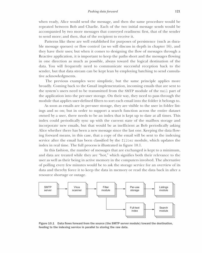
121Pushing data forward
when ready, Alice would send the message, and then the same procedure would berepeated between Bob and Charlie. Each of the two initial message sends would beaccompanied by two more messages that conveyed readiness: first, that of the senderto send more; and then, that of the recipient to receive it.
Patterns like these are well established for purposes of persistence (such as dura-ble message queues) or flow control (as we will discuss in depth in chapter 16), andthey have their uses; but when it comes to designing the flow of messages through aReactive application, it is important to keep the paths short and the messages flowingin one direction as much as possible, always toward the logical destination of thedata. You will frequently need to communicate successful reception back to thesender, but that data stream can be kept lean by employing batching to send cumula-tive acknowledgments.
The previous examples were simplistic, but the same principle applies morebroadly. Coming back to the Gmail implementation, incoming emails that are sent tothe system’s users need to be transmitted from the SMTP module of the mail part ofthe application into the per-user storage. On their way, they need to pass through themodule that applies user-defined filters to sort each email into the folder it belongs to.
As soon as emails are in per-user storage, they are visible to the user in folder list-ings and so on; but in order to support a search function across the entire datasetowned by a user, there needs to be an index that is kept up to date at all times. Thisindex could periodically sync up with the current state of the mailbox storage andincorporate new emails, but that would be as inefficient as Bob periodically askingAlice whether there has been a new message since the last one. Keeping the data flow-ing forward means, in this case, that a copy of the email will be sent to the indexingservice after the email has been classified by the filter module, which updates theindex in real time. The full process is illustrated in figure 10.1.
In this fashion, the number of messages that are exchanged is kept to a minimum,and data are treated while they are “hot,” which signifies both their relevance to theuser as well as their being in active memory in the computers involved. The alternativeof polling every few minutes would be to ask the storage service for an overview of itsdata and thereby force it to keep the data in memory or read the data back in after aresource shortage or outage.
SMTPserver
Virusscanner
Filtermodule
Per-usestorage
Listingsmodule
Full-textindex
Searchmodule
Figure 10.1 Data flows forward from the source (the SMTP server module) toward the destination, feeding to the indexing service in parallel to storing the raw data.
122 CHAPTER 10 Message flow
10.2 Modeling the processes of your domainProgramming with messages exchanged between autonomous modules also lendsitself well to the use of ubiquitous language as practiced in domain-driven design. Cus-tomers of the software development process, who can be users or product owners, willbe most comfortable describing what they want in terms that they understand. Thiscan be exploited for mutual benefit by turning the common language of the problemdomain into modules and messages of the application architecture, giving concreteand rigorous definitions. The resulting model will be comprehensible for customersand developers alike, and it will serve as a fixed point for communicating about theemerging product during the development process.
We hinted at the reason behind this utility in section 2.6.2: anthropomorphic met-aphors help humans visualize and choreograph processes. It is an act we enjoy, andthis creates a fertile ground for finding ways of moving abstract business requirementsinto the realm of intuitive treatment. This is the reason we talk about Alice, Bob, andCharlie instead of nodes A, B, and C; in the latter case, we would struggle to try tokeep our reasoning technical, whereas in the former case we can freely apply thewealth of social experience we have accumulated. It is not surprising that we findgood analogies for distributed computing in our society: we are the prototypical dis-tributed system!
Intuition is widely applicable in this process: when two facts need to be combinedto perform a certain task, then you know there must be one person who knows bothand combines them. This corresponds to the delimited consistency rule. Hierarchicaltreatment of failure is based on how our society works, and message passing expressesexactly how we communicate. You should use these helpers wherever you can.
10.3 Identifying resilience limitationsWhen laying out message flows within an application according to the business pro-cesses you want to model, you will see explicitly who needs to communicate withwhom, or which module will need to exchange messages with what other module. Youhave also created the hierarchical decomposition of the overall problem and thusobtained the supervision hierarchy, and this will tell you which message flows aremore or less likely to be interrupted by failure.
When sending to a module that is far down in the hierarchy and performing workthat is intrinsically risky, such as using an external resource, you must foresee commu-nication procedures for reestablishing the message flow after the supervisor hasrestarted the module. As shown in figure 10.2, in some cases it can be better to sendmessages via the supervisor from the start so the clients that are the senders of themessages need not reacquire a reference to the freshly started target module so often.They still will need to have recovery procedures in place to implement proper com-partmentalization and isolation, but invoking those less frequently will further reducethe effect of a failure.

123Estimating rates and deployment scale
Messages may be sent directly to an actor or to a supervisor acting as a router if theactor itself performs risky operations such as I/O.
For this reason, you will see some message flows that are directed from a module toits descendant; but in most cases the supervisor is only involved as a proxy, and thereal client is not part of the same supervision subtree. In general, most message flowsare horizontal, and supervision is performed on the vertical axis, coming back to thenotion that usually the user and the owner of a service are not the same.
10.4 Estimating rates and deployment scaleFocusing on message flows and sketching them out across the application layoutallows you to make some educated guesses or apply input rates from previous experi-ence or measurement. As messages flow through the system and are copied, merged,split up, and disseminated, you can trace the associated rate information to obtain animpression of the load the application modules will experience.
When the first prototypes of the most critical modules are ready for testing, youcan begin evaluating their performance and use Little’s formula to estimate the neces-sary deployment size, as detailed in section 2.1.2. You can validate your assumption asto which modules need to be scaled out for performance reasons and where you canconsolidate pieces that were split up erroneously.
The ability to perform these predictions and assessments stems from the fact thatyou have defined messages as concrete units of work that can be counted, buffered,spread out, and so on. You benefit from being explicit about message passing in thedesign. If you were to hide the distributed nature of the program behind synchronousRPC, this planning tool would be lost, and you would be more concerned about tryingto anticipate the size of the thread pools needed in your processes. That is more diffi-cult to do because it requires understanding both the domain and the characteristicsof the system where the application will be deployed, which may vary over the life ofthe system and across the different development, test, and production systems.
Messages up and down thesupervisor hierarchy shouldbe kept to a minimum.
The client keeps a directreference to an actor that isexpected to fail only rarely.
The supervisor acts as a proxy router. Sending messages down the hierarchy is preferable to forcing the client to reestablish connections to an unreliable actor.
Actors that write to disk aremore prone to failure and so areisolated from their clients by asupervisor acting as a proxy.
Client
Supervisor
Compute
Proxy
I/O
Figure 10.2 Messages may be sent directly to an actor or to a supervisor acting as a router if the actor itself performs risky operations such as I/O.
124 CHAPTER 10 Message flow
10.5 Planning for flow controlClosely related to the estimation process is that you need to foresee bulkheadsbetween different parts of your application. When input message rates exceed the lim-its you planned for, or when the dynamic scaling of the application is not fast enoughto cope with a sudden spike in traffic, you must have measures in place to contain theoverflow and protect the other parts of the system.
With a clear picture of how increased message rates are propagated within theapplication, you can determine at which points requests will be rejected (presumablyclose to the entrance of the application) and where you need to store messages on diskso that they are processed after the spike has passed or more capacity has been provi-sioned. These mechanisms will need to be activated at runtime when their time comes,and this process should be fully automatic. Human responses are typically too slow,especially on Sunday morning at 3:00 a.m. You need to propagate the congestion infor-mation upstream to enable the sender of a message stream to act on it and refrainfrom overwhelming the recipient. Patterns for implementing this are discussed inchapter 15; of particular interest are Reactive Streams (www.reactive-streams.org) as ageneric mechanism for mediating back pressure in a distributed setting.
10.6 SummaryIn this and the previous chapters in part 2 of the book, we have discussed the drivingprinciples behind a Reactive application design. The central concept is to decomposethe overall business problem in a hierarchical fashion according to divide et regna intofully encapsulated modules that communicate only by asynchronous, nonblocking,location-transparent message passing. The modularization process is guided and vali-dated by the following rules:
� A modules does one job and does it well.� The responsibility of a module is bounded by the responsibility of its parent.� Module boundaries define the possible granularity of horizontal scaling by
replication.� Modules encapsulate failure, and their hierarchy defines supervision.� The lifecycle of a module is bounded by that of its parent.� Module boundaries coincide with transaction boundaries.
We illuminated different paradigms ranging from logic programming to shared-stateconcurrency and concluded that you should prefer a functional, declarative stylewithin these modules and consider the cost of distribution and concurrency whenchoosing the granularity of your modules. You saw the advantages of explicitly model-ing message flows within the system for the purposes of keeping communication pathsand latencies short, modeling business processes using ubiquitous language, estimat-ing rates and identifying resilience limitations, and planning how to perform flowcontrol.
Part 3
Patterns
We have spent a fair amount of time so far discussing the what and why ofbeing Reactive. Now it is time to focus on the how. In part 3, we will present pat-terns of development that will help you implement Reactive applications. We willbegin by discussing how to test to ensure that your application is Reactive so youcan build forward with confidence that you are meeting the Reactive contract,from the smallest components to an entire cross–data center deployment. Thenwe will delve into specific patterns for building Reactive systems across all dimen-sions of Reactive concepts.
In this part, you will learn about the following:
� Testing Reactive systems, with a specific emphasis on asynchronous testing� Layering internal and external fault tolerance into your application� Managing the resources used by your Reactive application� Managing the flow of messages and data within and between your applica-
tions� Managing state and persist data in Reactive systems
We will present the individual patterns by first introducing their essence in oneshort paragraph (for easy reference when you revisit them), followed by infor-mation about where the pattern emerged, and then details of an example wherethe pattern is applied to a concrete problem. Each pattern is then summarizedwith the concerns it addresses, its quintessential features, and its scope of appli-cability.
Part 2 discussed the building blocks on which a Reactive system can be built.It may be worthwhile to frequently recall that background while reading for-ward—in our experience, it is usually the second approach to a topic that bringsthe “eureka!” moments.

127
Testing reactiveapplications
Now that we have covered the philosophy, we need to discuss how to verify that theReactive applications you build are elastic, resilient, and responsive. Testing is cov-ered first because of the importance of proving Reactive capabilities. Just as test-driven design (TDD) allows you to ensure that you are writing logic that meets yourrequirements from the outset, you must focus on putting into place the infrastruc-ture required to verify elasticity, resilience, and responsiveness.
What we will not cover is how to test your business logic—countless goodresources are available on that topic. We will assume that you have picked a meth-odology and matching tools for verifying the local and synchronous parts of yourapplication and will focus instead on the aspect of distribution that is inherent toReactive systems.
11.1 How to testTesting applications is the foremost effort developers can undertake to ensure thatcode is written to meet all its requirements without defects. Here, a truly Reactiveapplication has several dimensions beyond merely fulfilling the specifications forthe logic to be implemented, guided by the principles of responsiveness, elasticity,and resilience. In this book, where patterns are outlined to enable Reactive applica-tions, testing is integral to each pattern described so that you can verify that yourapplication is Reactive. In this chapter, we lay the foundations for this by coveringcommon techniques and principles.
Before delving into patterns of testing, we must define a vocabulary. For anyonewho has worked for a mature development organization, testing as a means to
128 CHAPTER 11 Testing reactive applications
reduce risk is ingrained. Consulting firms are also well known for having stringenttesting methodologies, in order to reduce the risk of a lawsuit from clients who haveexpectations about the level of quality for software being delivered. Every test plan isreviewed and approved by each level of the project leadership, from team leadsthrough architects and project management, with the ultimate responsibility residingwith the partner or organizational stakeholder to ensure that accountability exists forany improper behavior that may occur. As a result, many levels of functional tests havebeen identified and codified into standards for successful delivery.
ERRORS VS. FAILURES In this chapter—in particular, when we touch on resil-ience—it will be helpful to recall the distinction between errors and failures, asdefined by the glossary1 of the Reactive Manifesto:
A failure is an unexpected event within a service that prevents it from continuing tofunction normally. A failure will generally prevent responses to the current, and possiblyall following, client requests. This is in contrast with an error, which is an expected andcoded-for condition—for example an error discovered during input validation—that willbe communicated to the client as part of the normal processing of the message. Failures areunexpected and will require intervention before the system can resume at the same level ofoperation. This does not mean that failures are always fatal, rather that some capacity ofthe system will be reduced following a failure. Errors are an expected part of normaloperations, are dealt with immediately and the system will continue to operate at the samecapacity following an error.
NOTE Examples of failures are hardware malfunctions, processes terminat-ing due to fatal resource exhaustion, and program defects that result in cor-rupted internal state.
11.1.1 Unit tests
Unit tests are the best known of all the kinds of tests: an independent unit of sourcecode, such as a class or function, is tested rigorously to ensure that every line and con-dition in the logic meets the specification outlined by the design or product owner.Depending on how the code is structured, this can be easy or difficult—monolithicfunctions or methods inside such a source unit can be difficult to test due to all thevarying conditions that can exist in these units.
It is best to structure code into individual, atomic units of work that perform onlyone action. When this is done, writing unit tests for these units is simple—what are theexpected inputs that should successfully result in a value against which assertions canbe made, and what are the expected inputs that should not succeed and result in anexception or error?
Because unit tests focus on whether the right response is delivered for a given setof inputs, this level of testing typically does not involve testing for Reactive properties.
1 www.reactivemanifesto.org/glossary#Failure
129How to test
11.1.2 Component tests
Component tests are also generally familiar to anyone who writes tests: they test a ser-vice’s application programming interface (API). Inputs are passed to each publicinterface exposed by the API, and, for several variations of correct input data, it is veri-fied that the service returns a valid response.
Error conditions are tested by passing invalid data into each API and checking thatthe appropriate validation error is returned from the service. Validation errors shouldbe an important design consideration for any public API, in order to convey an expliciterror for any input that is deemed invalid for the service to handle appropriately.
Concurrency should also be explored at this level, where a service that should beable to handle multiple requests simultaneously returns the correct value for each cli-ent. This can be difficult to test for systems that are synchronous in nature, becauseconcurrency in this case can involve locking schemes; it can be difficult for the personwriting the test to create a setup to prove that multiple requests are being handled atthe same time.
At this level, you also start testing the responsiveness of a service, to see whether itcan reliably keep its service-level agreement (SLA) under nominal conditions. And, fora component that acts as a supervisor for another, you will also encounter aspects ofresilience: does the supervisor react correctly to unexpected failures in its subordinates?
11.1.3 String tests
Now we diverge from the ordinary practices of testing, where you need to verify thatrequests into one service or microservice that depends on other such services ormicroservices can return the appropriate values. It is important to avoid gettingbogged down in the low-level details of functionality that has already been tested atthe unit- and component-test levels.
At this level, you also begin to consider failure scenarios in addition to the nominaland error cases: how should a service react to the inability of its dependencies to per-form their functions? In addition, it is important to verify that SLAs are kept whendependent services take longer to respond than usual, both when they meet and whenthey do not meet their respective SLAs.
11.1.4 Integration tests
Typically, systems you build do not exist in a vacuum; prior to this level of testing,dependencies on external components are stubbed out or mocked so that you do notrequire access to these systems to prove that everything else in the system meets yourrequirements. But when you reach the level of integration testing, you should ensurethat such interactions are proven to work and handle nominal as well as erroneousinput as expected.
At this level, you also test for resilience by injecting failures: for example, by shut-ting off services to see how their communication partners and supervisors react. Youalso need to verify that SLAs are kept under nominal as well as failure scenarios andunder varying degrees of external load.
130 CHAPTER 11 Testing reactive applications
11.1.5 User-acceptance tests
This final level of testing is not always explicitly executed. Most notable exceptionsinclude situations where the consequences of failing to meet the requirements aresevere (for example, space missions, high-volume financial processing, and militaryapplications). The purpose is to prove that the overall implementation meets the proj-ect goals set by the client paying for the system to be built. But such testing can beapplicable for organizations who treat the product owner as a client and the deliveryteam as the consulting firm. User-acceptance testing is the level at which the check-writer defines proofs that the system meets their needs, in isolation from those testsimplemented by the consulting firm. This provides independent validation that theapplication, with all its various components and services, fulfills the ultimate goal ofthe project.
This level of testing may sound unnecessary for projects where an external contrac-tor or firm has been hired to build the implementation, but we argue otherwise. Oneof the great benefits of test tooling such as behavior-driven development (BDD)2 is toprovide a domain-specific-language (DSL)3 for testing that even nontechnical teammembers can read or even implement. Using tools like well-known implementationsand variants of Cucumber (https://cucumber.io)—such as Cuke4Duke(https://github.com/cucumber/cuke4duke), Specs2 (http://etorreborre.github.io/specs2), and ScalaTest (www.scalatest.org)—provides business-process leaders onteams with the capability to write and verify tests.
11.1.6 Black-box vs. white-box tests
When testing a component, you must decide whether the test will have access to thecomponent’s internal details. Such details include being able to send commands thatare not part of the public interface or to query the internal state that is normallyencapsulated and hidden. Testing without access to these is called black-boxtesting because the component is viewed as a box that hides its inner workings in dark-ness. The opposite is termed white-box testing because all details are laid bare, like in alaboratory clean room where all internals can be inspected.
A Reactive system is defined by its responses to external stimulus, which means test-ing for the Reactive properties of your applications or components will primarily beblack-box testing, even if you prefer to use white-box testing within the unit tests forthe business logic itself. As an example, you might have a minute specification that isvery precise about how the incoming data are to be processed, and the algorithm isimplemented such that intermediate results can be inspected along the way. The unittests for this part of the application will be tightly coupled to the implementationitself; and for any change made to the internals, there is a good chance that some testcases will be invalidated.
2 http://en.wikipedia.org/wiki/Behavior-driven_development3 http://en.wikipedia.org/wiki/Domain-specific_language
131Test environment
This piece of code will form the heart of your application, but it is not the onlypart: data need to be ingested for processing, the algorithm must be executed, andresults need to be emitted, and all these aspects require communication and are gov-erned by Reactive principles. You will hence write other tests that verify that the corealgorithm is executed when appropriate and with the right inputs and that the outputarrives at the desired place after the allotted time in order to keep the SLA for the ser-vice you are implementing. All these aspects do not depend on the internal details ofthe core algorithm; they operate without regard to its inner workings. This has theadded benefit that the higher-level tests for responsiveness, elasticity, and resiliencewill have a higher probability of staying relevant and correct while the core code isbeing refactored, bugs are fixed, or new features are added.
11.2 Test environmentAn important consideration for writing tests is that they must be executed on hard-ware that is at least somewhat representative of that on which it will ultimately bedeployed, particularly for systems where latency and throughput must be validated (tobe discussed in section 11.7). This may provide some insight into how well a compo-nent or an algorithm may perform, particularly if the task is CPU-intensive, relative toanother implementation tested on the same platform.
Many popular benchmarks in the development community are run on laptops:machines with limited resources with respect to number of cores, size of caches andmemory, disk subsystems that do not perform data replication, and operating systemsthat do not match intended production deployments. A laptop is typically constructedwith different design goals than a server-class machine, leading to different perfor-mance characteristics where some activities may be performed faster and others slowerthan on the final hardware. Although the laptop may have capabilities that exceed aspecific server-class machine (for example, a solid-state drive as opposed to a hard diskfor storage) and that make it perform better in certain situations, it likely will not rep-resent the performance to be expected when the application reaches production. Bas-ing decisions on the results of tests executed in such an environment may lead to poordecisions being made about how to improve the performance of an application.
It is an expensive proposition to ask all companies, particularly those with limitedfinancial resources such as startups, to consider mirroring their production environ-ment for testing purposes. But the cost of not doing so can be enormous if an organi-zation makes a poor choice based on meaningless findings derived from adevelopment environment.
Note that deployment in the cloud can make testing more difficult as well. Hyper-visors do not necessarily report accurately about the resources they make available in amultitenancy environment, particularly with respect to the number of cores availableto applications at any given time. This can make for highly dynamic and unpredict-able performance in production. Imagine trying to size thread pools in a very specificway for smaller instances in the cloud where you are not expecting access to more
132 CHAPTER 11 Testing reactive applications
than four virtual CPUs, but there is no guarantee you will receive that at any givenmoment. If you must verify specific performance via throughput and/or latency, dedi-cated hardware is a considerably better option.
11.3 Testing asynchronouslyThe most prominent difficulty that arises when testing Reactive systems is that the per-vasive use of asynchronous message passing requires a different way of formulating testcases. Consider testing a translation function that can turn Swedish text into English.
val input = "Hur mår du?"val output = "How are you?"translate(input) should be(output)
This example uses ScalaTest syntax. The first two lines define the expected input andoutput strings, and the third line invokes the translation function with the input andasserts that this should result in the expected output. The underlying assumption isthat the translate() function computes its value synchronously and that it is donewhen the function call returns.
A translation service that can be replicated and scaled out will not have the possi-bility of directly returning the value: it must be able to asynchronously send the inputstring to the processing resources. This could be modeled by returning a Future4 forthe result string that will eventually hold the desired value:
val input = "Hur mår du?"val output = "How are you?"val future = translate(input)// what now?
The only thing you can assert at this point is that the function does indeed return aFuture, but probably there will not yet be a value available within it, so you cannotcontinue with the test procedure.
Another presentation of the translation service might use Actor messaging, whichmeans the request is sent as a one-way message and the reply is expected to be sent asanother one-way message at a later point in time. In order to receive this reply, thereneeds to be a suitable recipient:
val input = "Hur mår du?"val output = "How are you?"val probe = TestProbe()translationService ! Translate(input, probe.ref)// when can we continue?
Listing 11.1 Testing a purely synchronous translation function
4 Recall that a Future is a handle to a value that may be delivered asynchronously at a later time. The code thatsupplies the value will fulfill the corresponding Promise with it, enabling code that holds a reference to theFuture to react to the value using callbacks or transformations. Flip back to chapter 2 to refresh yourself onthe details if necessary.
An Akka utility
133Testing asynchronously
TestProbe is an object that contains a message queue to which messages can be sentvia the corresponding ActorRef. You use it as the return address in the message to thetranslation service Actor. Eventually the service will reply, and the message with theexpected output string should arrive within the probe; but again, you cannot proceedwith the test procedure at this point because you do not know when exactly that willbe the case.
11.3.1 Providing blocking message receivers
NOTE The methods used to implement the solutions that follow typically arenot recommended for regular use because of their thread-blocking nature,but bear with us: even for testing, we will present nicely nonblocking solutionslater. Using classical test frameworks can require you to fall back to what isdiscussed here, and it is educational to consider the progression presented inthis section.
One solution to the dilemma is to suspend the test procedure until the translation ser-vice has performed its work and then inspect the received value. In case of the Future,you can poll its status in a loop:
while (!future.isCompleted) Thread.sleep(50)
This will check every 50 ms whether the Future has received its value or was com-pleted with an error, not letting the test continue before one or the other occurs. Thesyntax used is that of scala.concurrent.Future; in other implementations, the nameof the status query method could be isDone() (java.util.concurrent.Future),isPending() (JavaScript Q), or inspect() (JavaScript when), to name a few examples.In a real test procedure, the number of loop iterations must be bounded:
var i = 20while (!future.isCompleted && i > 0) {
i -= 1Thread.sleep(50)
}if (i == 0) fail("translation was not received in time")
This will wait only for up to roughly 1 second and fail the test if the Future is not com-pleted within that time window. Otherwise, message loss or a programming errorcould lead to the Future never receiving a value; then the test procedure would hangand never yield a result.
Most Future implementations include methods that support awaiting a result syn-chronously. A selection is shown in table 11.1.
134 CHAPTER 11 Testing reactive applications
These methods can be used in tests to retain the same test procedure as for the verifi-cation of the synchronous translation service.
val input = "Hur mår du?"val output = "How are you?"val result = Await.result(translate(input), 1.second)result should be(output)
With this formulation, you can take an existing test suite for the translation serviceand mechanically replace all invocations that used to return a strict value so that theysynchronously await the value using the returned Future. Because the test procedureis typically executed on its own dedicated thread, this should not interfere with theimplementation of the service on its own.
It must be stressed that this technique is likely to fail if applied outside of testingand in production code. The reason is that the caller of the translation service willthen no longer be an isolated external test procedure; it will most likely be anotherservice that may use the same asynchronous execution resources. If enough calls aremade concurrently in this thread-blocking fashion, then all threads of the underlyingpool will be consumed, idly waiting for responses, and the desired computation willnot be executed because no thread will be available to pick it up. Timeouts or dead-lock will ensue.
Coming back to the test procedures, we still have one open question: how does thiswork for the case of one-way messaging as in the Actor example? You used aTestProbe as the return address for the reply. Such a probe is equivalent to an Actorwithout processing capabilities of its own, which provides utilities for synchronouslyawaiting messages. The test procedure would in this case look like the following.
val input = "Hur mår du?"val output = "How are you?"val probe = TestProbe()translationService ! Translate(input, probe.ref)probe.expectMsg(1.second, output)
Table 11.1 Methods for synchronously awaiting a Future result
Language Synchronous implementation
Java future.get(1, TimeUnit.SECONDS);
Scala Await.result(future, 1.second)
C++ std::chrono::milliseconds span(1000);future.wait_for(span);
Listing 11.2 Awaiting the result blocks synchronously on the translation
Listing 11.3 Expecting replies with a TestProbe

135Testing asynchronously
The expectMsg() method will wait up to 1 second for a new message to arrive and, ifthat happens, compare it to the expected object—the output string, in this case. Ifnothing or the wrong message is received, then the test procedure will fail with anassertion error.
11.3.2 The crux of choosing timeouts
Most synchronous test procedures verify that a certain sequence of actions results in agiven sequence of results: set up the translation service, invoke it, and compare thereturned value to the expected one. This means the aspect of time does not play a rolein these tests: the test result will not depend on whether running the test is a matter ofmilliseconds or takes a few hours. The basic assumption is that all processing occurs inthe context of the test procedure, literally beneath its frame of control. Therefore, it isenough to react to returned values or thrown exceptions. There will always be aresult—infinite loops will be noticed eventually by the human observer.
In an asynchronous system, this assumption no longer holds: it is possible that theexecution of the module under test occurs far removed from the test procedure, andreplies may not only arrive late, they can also be lost. The latter can be due to pro-gramming errors (not sending a reply message, not fulfilling a Promise in some edgecase, and so on), or it can be due to failures like message loss on the network orresource exhaustion—if an asynchronous task cannot be enqueued to be run, then itsresult will never be computed.
For this reason, it is unwise to wait indefinitely for replies during test procedures,because you do not want the entire test run to grind to a halt halfway through justbecause of one lost message. You need to place an upper bound on waiting times, failtests that violate it, and move on.
This upper bound should be long enough to allow natural fluctuations in execu-tion times without leading to sporadic test failures; such flakiness would wasteresources during development in order to investigate each test failure as to whether itwas legitimate or bad luck. Typical sources of bad luck include garbage-collectionpauses, network hiccups, and temporary system overload, and all of these can cause amessage send that normally takes microseconds to be delayed by up to several seconds.
On the other hand, the upper bound needs to be as low as possible, because itdefines the time it takes to give up and move on. You do not want to wait for a verifica-tion run to take several hours when one hour would suffice.
SCALING TIMEOUTS FOR DIFFERENT TEST ENVIRONMENTS
Choosing the right timeouts is therefore a compromise between worst-case test execu-tion time and false positive error probability. On current notebook computers, it isrealistic to expect asynchronous scheduling to occur on the scale of tens of millisec-onds. Normally, it happens much faster; but if you are, for example, executing a largetest suite with thousands of tests on the JVM, you need to take into account that thegarbage collector will occasionally run for a few milliseconds, and you do not wantthat to lead to test failures because it is expected behavior for a development system.
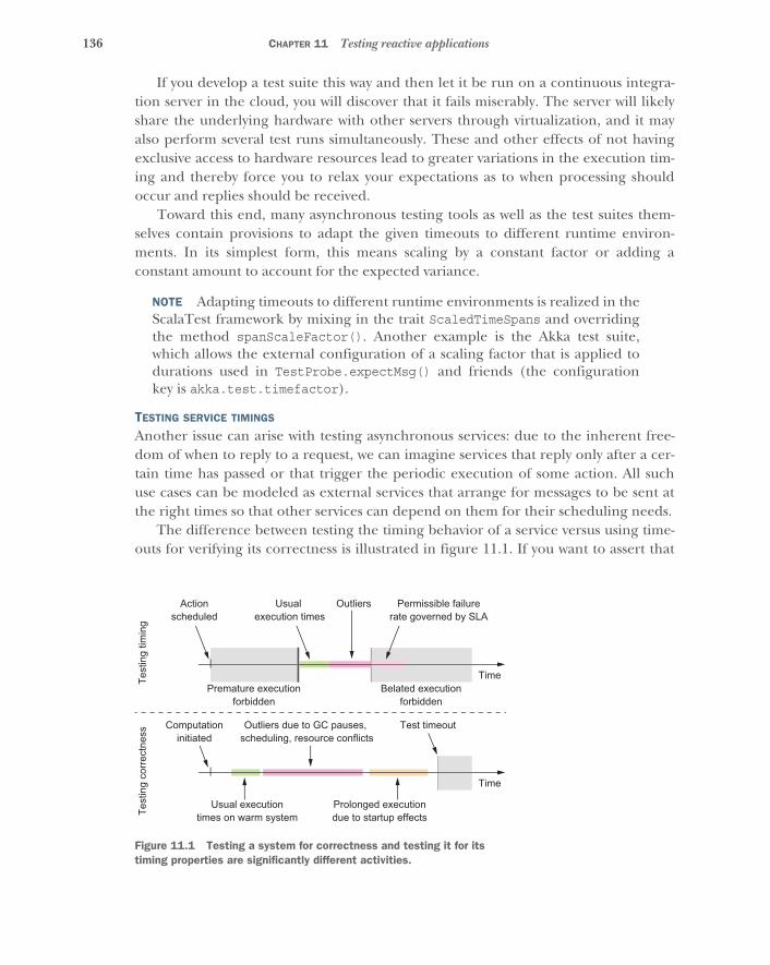
136 CHAPTER 11 Testing reactive applications
If you develop a test suite this way and then let it be run on a continuous integra-tion server in the cloud, you will discover that it fails miserably. The server will likelyshare the underlying hardware with other servers through virtualization, and it mayalso perform several test runs simultaneously. These and other effects of not havingexclusive access to hardware resources lead to greater variations in the execution tim-ing and thereby force you to relax your expectations as to when processing shouldoccur and replies should be received.
Toward this end, many asynchronous testing tools as well as the test suites them-selves contain provisions to adapt the given timeouts to different runtime environ-ments. In its simplest form, this means scaling by a constant factor or adding aconstant amount to account for the expected variance.
NOTE Adapting timeouts to different runtime environments is realized in theScalaTest framework by mixing in the trait ScaledTimeSpans and overridingthe method spanScaleFactor(). Another example is the Akka test suite,which allows the external configuration of a scaling factor that is applied todurations used in TestProbe.expectMsg() and friends (the configurationkey is akka.test.timefactor).
TESTING SERVICE TIMINGS
Another issue can arise with testing asynchronous services: due to the inherent free-dom of when to reply to a request, we can imagine services that reply only after a cer-tain time has passed or that trigger the periodic execution of some action. All suchuse cases can be modeled as external services that arrange for messages to be sent atthe right times so that other services can depend on them for their scheduling needs.
The difference between testing the timing behavior of a service versus using time-outs for verifying its correctness is illustrated in figure 11.1. If you want to assert that
Actionscheduled
Computationinitiated
Test
ing
corre
ctne
ssTe
stin
g tim
ing
Outliers due to GC pauses, scheduling, resource conflicts
Usual executiontimes on warm system
Prolonged executiondue to startup effects
Test timeout
Usual execution times
Premature executionforbidden
Belated executionforbidden
Time
Time
Outliers Permissible failurerate governed by SLA
Figure 11.1 Testing a system for correctness and testing it for its timing properties are significantly different activities.
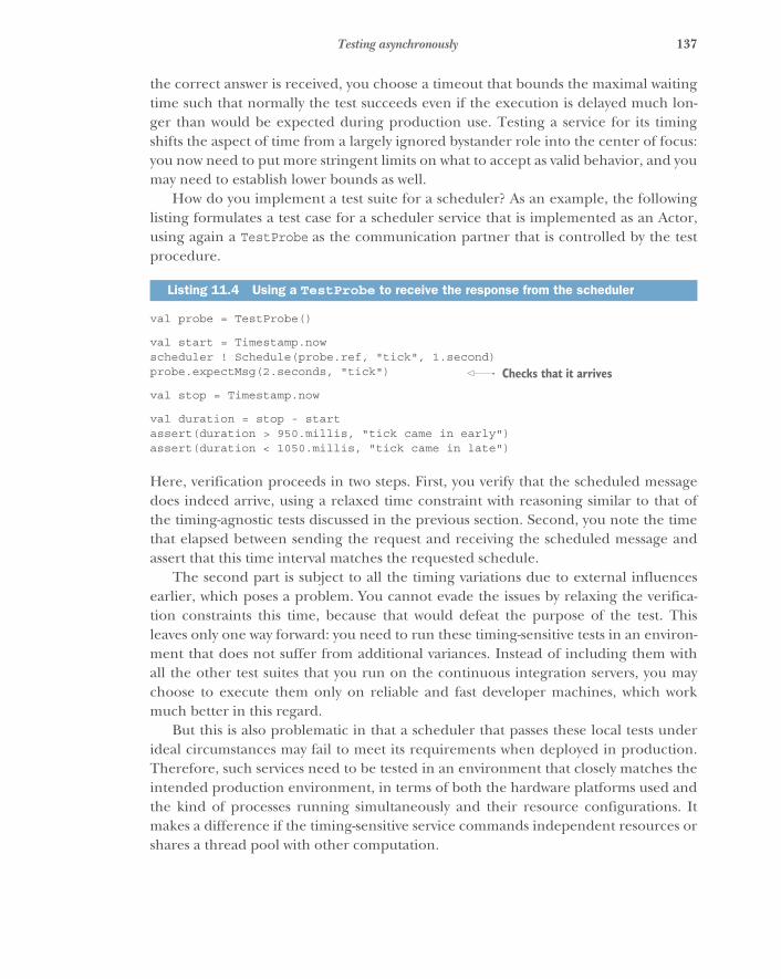
137Testing asynchronously
the correct answer is received, you choose a timeout that bounds the maximal waitingtime such that normally the test succeeds even if the execution is delayed much lon-ger than would be expected during production use. Testing a service for its timingshifts the aspect of time from a largely ignored bystander role into the center of focus:you now need to put more stringent limits on what to accept as valid behavior, and youmay need to establish lower bounds as well.
How do you implement a test suite for a scheduler? As an example, the followinglisting formulates a test case for a scheduler service that is implemented as an Actor,using again a TestProbe as the communication partner that is controlled by the testprocedure.
val probe = TestProbe()
val start = Timestamp.nowscheduler ! Schedule(probe.ref, "tick", 1.second)probe.expectMsg(2.seconds, "tick")
val stop = Timestamp.now
val duration = stop - startassert(duration > 950.millis, "tick came in early")assert(duration < 1050.millis, "tick came in late")
Here, verification proceeds in two steps. First, you verify that the scheduled messagedoes indeed arrive, using a relaxed time constraint with reasoning similar to that ofthe timing-agnostic tests discussed in the previous section. Second, you note the timethat elapsed between sending the request and receiving the scheduled message andassert that this time interval matches the requested schedule.
The second part is subject to all the timing variations due to external influencesearlier, which poses a problem. You cannot evade the issues by relaxing the verifica-tion constraints this time, because that would defeat the purpose of the test. Thisleaves only one way forward: you need to run these timing-sensitive tests in an environ-ment that does not suffer from additional variances. Instead of including them withall the other test suites that you run on the continuous integration servers, you maychoose to execute them only on reliable and fast developer machines, which workmuch better in this regard.
But this is also problematic in that a scheduler that passes these local tests underideal circumstances may fail to meet its requirements when deployed in production.Therefore, such services need to be tested in an environment that closely matches theintended production environment, in terms of both the hardware platforms used andthe kind of processes running simultaneously and their resource configurations. Itmakes a difference if the timing-sensitive service commands independent resources orshares a thread pool with other computation.
Listing 11.4 Using a TestProbe to receive the response from the scheduler
Checks that it arrives
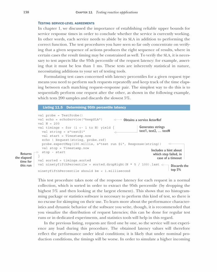
138 CHAPTER 11 Testing reactive applications
TESTING SERVICE-LEVEL AGREEMENTS
In chapter 1, we discussed the importance of establishing reliable upper bounds forservice response times in order to conclude whether the service is currently working.In other words, each service needs to abide by its SLA in addition to performing thecorrect function. The test procedures you have seen so far only concentrate on verify-ing that a given sequence of actions produces the right sequence of results, where incertain cases the result timing may be constrained as well. To verify the SLA, it is neces-sary to test aspects like the 95th percentile of the request latency: for example, assert-ing that it must be less than 1 ms. These tests are inherently statistical in nature,necessitating additions to your set of testing tools.
Formulating test cases concerned with latency percentiles for a given request typemeans you need to perform such requests repeatedly and keep track of the time elaps-ing between each matching request–response pair. The simplest way to do this is tosequentially perform one request after the other, as shown in the following example,which tests 200 samples and discards the slowest 5%.
val probe = TestProbe()val echo = echoService("keepSLA")val N = 200val timings = for (i <- 1 to N) yield {
val string = s"test$i"val start = Timestamp.nowecho ! Request(string, probe.ref)probe.expectMsg(100.millis, s"test run $i", Response(string))val stop = Timestamp.nowstop - start
}val sorted = timings.sortedval ninetyfifthPercentile = sorted.dropRight(N * 5 / 100).last
ninetyfifthPercentile should be < 1.millisecond
This test procedure takes note of the response latency for each request in a normalcollection, which is sorted in order to extract the 95th percentile (by dropping thehighest 5% and then looking at the largest element). This shows that no histogram-ming package or statistics software is necessary to perform this kind of test, so there isno excuse for skimping on their use. To learn more about the performance character-istics and dynamic behavior of the software you write, though, it is recommended thatyou visualize the distribution of request latencies; this can be done for regular testruns or in dedicated experiments, and statistics tools will help in this regard.
In the previous listing, requests are fired one by one, so the service will not experi-ence any load during this procedure. The obtained latency values will thereforereflect the performance under ideal conditions; it is likely that under nominal pro-duction conditions, the timings will be worse. In order to simulate a higher incoming
Listing 11.5 Determining 95th percentile latency
Obtains a service ActorRef
Generates strings test1, test2, … testN
Includes a hint aboutwhich step failed, in
case of a timeoutReturns
the elapsedtime forthis run Discards the
top 5%
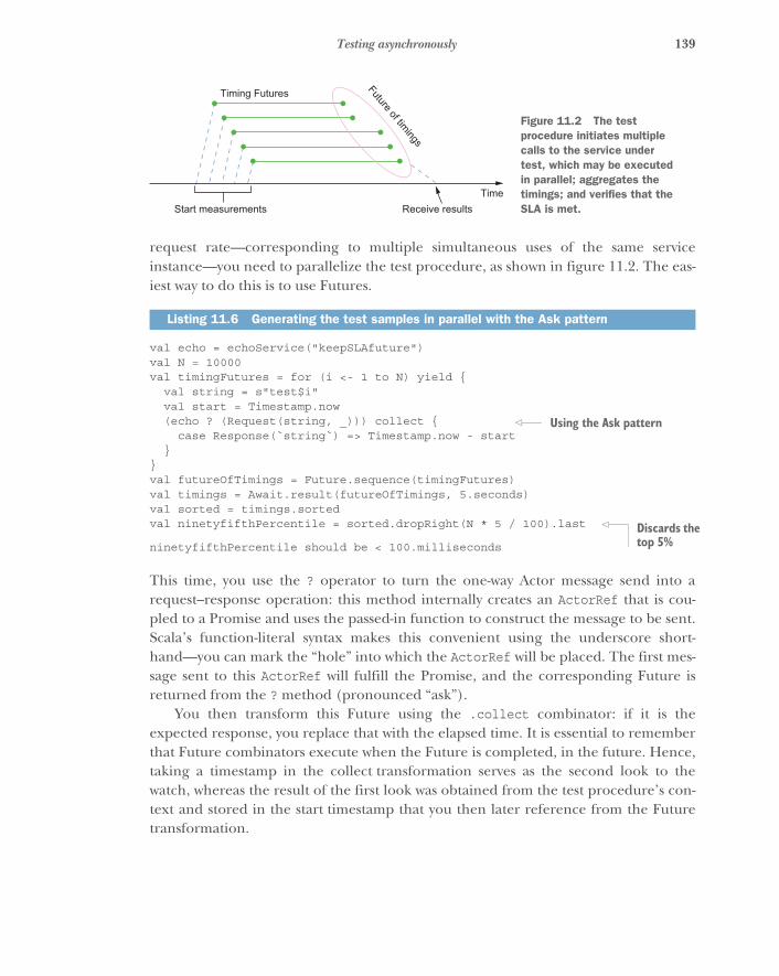
139Testing asynchronously
request rate—corresponding to multiple simultaneous uses of the same serviceinstance—you need to parallelize the test procedure, as shown in figure 11.2. The eas-iest way to do this is to use Futures.
val echo = echoService("keepSLAfuture")val N = 10000val timingFutures = for (i <- 1 to N) yield {
val string = s"test$i"val start = Timestamp.now(echo ? (Request(string, _))) collect {
case Response(`string`) => Timestamp.now - start}
}val futureOfTimings = Future.sequence(timingFutures)val timings = Await.result(futureOfTimings, 5.seconds)val sorted = timings.sortedval ninetyfifthPercentile = sorted.dropRight(N * 5 / 100).last
ninetyfifthPercentile should be < 100.milliseconds
This time, you use the ? operator to turn the one-way Actor message send into arequest–response operation: this method internally creates an ActorRef that is cou-pled to a Promise and uses the passed-in function to construct the message to be sent.Scala’s function-literal syntax makes this convenient using the underscore short-hand—you can mark the “hole” into which the ActorRef will be placed. The first mes-sage sent to this ActorRef will fulfill the Promise, and the corresponding Future isreturned from the ? method (pronounced “ask”).
You then transform this Future using the .collect combinator: if it is theexpected response, you replace that with the elapsed time. It is essential to rememberthat Future combinators execute when the Future is completed, in the future. Hence,taking a timestamp in the collect transformation serves as the second look to thewatch, whereas the result of the first look was obtained from the test procedure’s con-text and stored in the start timestamp that you then later reference from the Futuretransformation.
Listing 11.6 Generating the test samples in parallel with the Ask pattern
Timing Futures
Receive resultsStart measurementsTime
Future of timings
Figure 11.2 The test procedure initiates multiple calls to the service under test, which may be executed in parallel; aggregates the timings; and verifies that the SLA is met.
Using the Ask pattern
Discards the top 5%
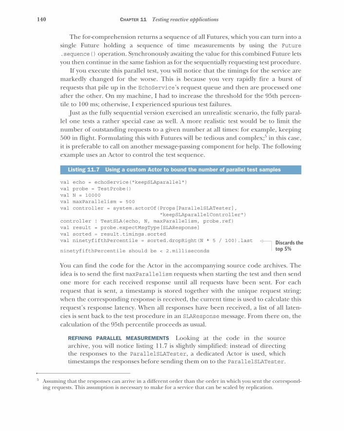
140 CHAPTER 11 Testing reactive applications
The for-comprehension returns a sequence of all Futures, which you can turn into asingle Future holding a sequence of time measurements by using the Future.sequence() operation. Synchronously awaiting the value for this combined Future letsyou then continue in the same fashion as for the sequentially requesting test procedure.
If you execute this parallel test, you will notice that the timings for the service aremarkedly changed for the worse. This is because you very rapidly fire a burst ofrequests that pile up in the EchoService’s request queue and then are processed oneafter the other. On my machine, I had to increase the threshold for the 95th percen-tile to 100 ms; otherwise, I experienced spurious test failures.
Just as the fully sequential version exercised an unrealistic scenario, the fully paral-lel one tests a rather special case as well. A more realistic test would be to limit thenumber of outstanding requests to a given number at all times: for example, keeping500 in flight. Formulating this with Futures will be tedious and complex;5 in this case,it is preferable to call on another message-passing component for help. The followingexample uses an Actor to control the test sequence.
val echo = echoService("keepSLAparallel")val probe = TestProbe()val N = 10000val maxParallelism = 500val controller = system.actorOf(Props[ParallelSLATester],
"keepSLAparallelController")controller ! TestSLA(echo, N, maxParallelism, probe.ref)val result = probe.expectMsgType[SLAResponse]val sorted = result.timings.sortedval ninetyfifthPercentile = sorted.dropRight(N * 5 / 100).last
ninetyfifthPercentile should be < 2.milliseconds
You can find the code for the Actor in the accompanying source code archives. Theidea is to send the first maxParallelism requests when starting the test and then sendone more for each received response until all requests have been sent. For eachrequest that is sent, a timestamp is stored together with the unique request string;when the corresponding response is received, the current time is used to calculate thisrequest’s response latency. When all responses have been received, a list of all laten-cies is sent back to the test procedure in an SLAResponse message. From there on, thecalculation of the 95th percentile proceeds as usual.
REFINING PARALLEL MEASUREMENTS Looking at the code in the sourcearchive, you will notice listing 11.7 is slightly simplified: instead of directingthe responses to the ParallelSLATester, a dedicated Actor is used, whichtimestamps the responses before sending them on to the ParallelSLATester.
5 Assuming that the responses can arrive in a different order than the order in which you sent the correspond-ing requests. This assumption is necessary to make for a service that can be scaled by replication.
Listing 11.7 Using a custom Actor to bound the number of parallel test samples
Discards the top 5%
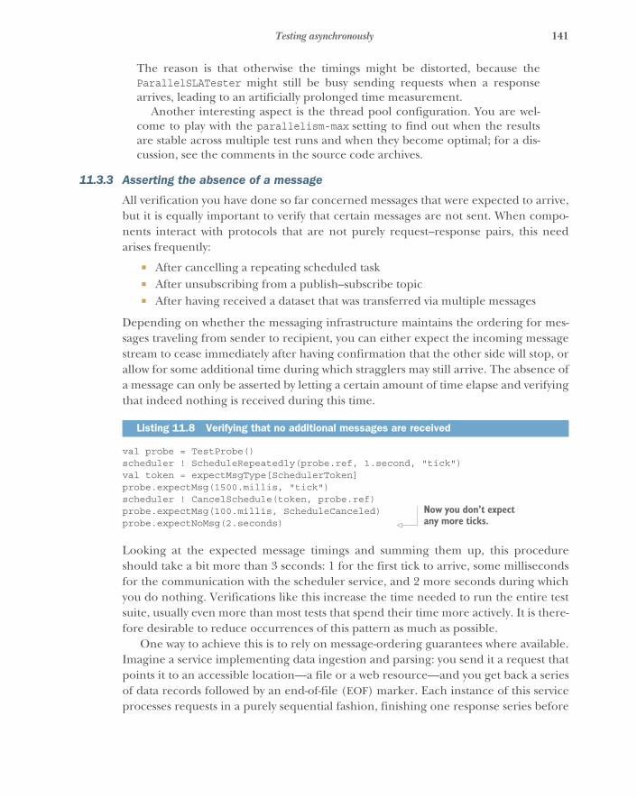
141Testing asynchronously
The reason is that otherwise the timings might be distorted, because theParallelSLATester might still be busy sending requests when a responsearrives, leading to an artificially prolonged time measurement.
Another interesting aspect is the thread pool configuration. You are wel-come to play with the parallelism-max setting to find out when the resultsare stable across multiple test runs and when they become optimal; for a dis-cussion, see the comments in the source code archives.
11.3.3 Asserting the absence of a message
All verification you have done so far concerned messages that were expected to arrive,but it is equally important to verify that certain messages are not sent. When compo-nents interact with protocols that are not purely request–response pairs, this needarises frequently:
� After cancelling a repeating scheduled task� After unsubscribing from a publish–subscribe topic� After having received a dataset that was transferred via multiple messages
Depending on whether the messaging infrastructure maintains the ordering for mes-sages traveling from sender to recipient, you can either expect the incoming messagestream to cease immediately after having confirmation that the other side will stop, orallow for some additional time during which stragglers may still arrive. The absence ofa message can only be asserted by letting a certain amount of time elapse and verifyingthat indeed nothing is received during this time.
val probe = TestProbe()scheduler ! ScheduleRepeatedly(probe.ref, 1.second, "tick")val token = expectMsgType[SchedulerToken]probe.expectMsg(1500.millis, "tick")scheduler ! CancelSchedule(token, probe.ref)probe.expectMsg(100.millis, ScheduleCanceled)probe.expectNoMsg(2.seconds)
Looking at the expected message timings and summing them up, this procedureshould take a bit more than 3 seconds: 1 for the first tick to arrive, some millisecondsfor the communication with the scheduler service, and 2 more seconds during whichyou do nothing. Verifications like this increase the time needed to run the entire testsuite, usually even more than most tests that spend their time more actively. It is there-fore desirable to reduce occurrences of this pattern as much as possible.
One way to achieve this is to rely on message-ordering guarantees where available.Imagine a service implementing data ingestion and parsing: you send it a request thatpoints it to an accessible location—a file or a web resource—and you get back a seriesof data records followed by an end-of-file (EOF) marker. Each instance of this serviceprocesses requests in a purely sequential fashion, finishing one response series before
Listing 11.8 Verifying that no additional messages are received
Now you don’t expect any more ticks.
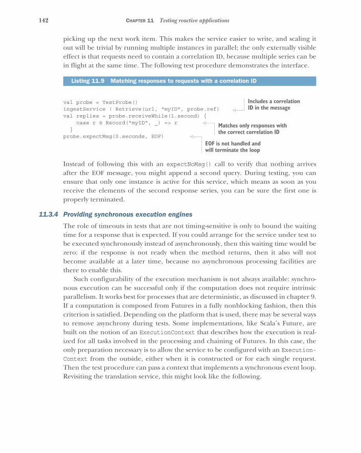
142 CHAPTER 11 Testing reactive applications
picking up the next work item. This makes the service easier to write, and scaling itout will be trivial by running multiple instances in parallel; the only externally visibleeffect is that requests need to contain a correlation ID, because multiple series can bein flight at the same time. The following test procedure demonstrates the interface.
val probe = TestProbe()ingestService ! Retrieve(url, "myID", probe.ref)val replies = probe.receiveWhile(1.second) {
case r @ Record("myID", _) => r}
probe.expectMsg(0.seconds, EOF)
Instead of following this with an expectNoMsg() call to verify that nothing arrivesafter the EOF message, you might append a second query. During testing, you canensure that only one instance is active for this service, which means as soon as youreceive the elements of the second response series, you can be sure the first one isproperly terminated.
11.3.4 Providing synchronous execution engines
The role of timeouts in tests that are not timing-sensitive is only to bound the waitingtime for a response that is expected. If you could arrange for the service under test tobe executed synchronously instead of asynchronously, then this waiting time would bezero: if the response is not ready when the method returns, then it also will notbecome available at a later time, because no asynchronous processing facilities arethere to enable this.
Such configurability of the execution mechanism is not always available: synchro-nous execution can be successful only if the computation does not require intrinsicparallelism. It works best for processes that are deterministic, as discussed in chapter 9.If a computation is composed from Futures in a fully nonblocking fashion, then thiscriterion is satisfied. Depending on the platform that is used, there may be several waysto remove asynchrony during tests. Some implementations, like Scala’s Future, arebuilt on the notion of an ExecutionContext that describes how the execution is real-ized for all tasks involved in the processing and chaining of Futures. In this case, theonly preparation necessary is to allow the service to be configured with an Execution-Context from the outside, either when it is constructed or for each single request.Then the test procedure can pass a context that implements a synchronous event loop.Revisiting the translation service, this might look like the following.
Listing 11.9 Matching responses to requests with a correlation ID
Includes a correlation ID in the message
Matches only responses with the correct correlation ID
EOF is not handled and will terminate the loop
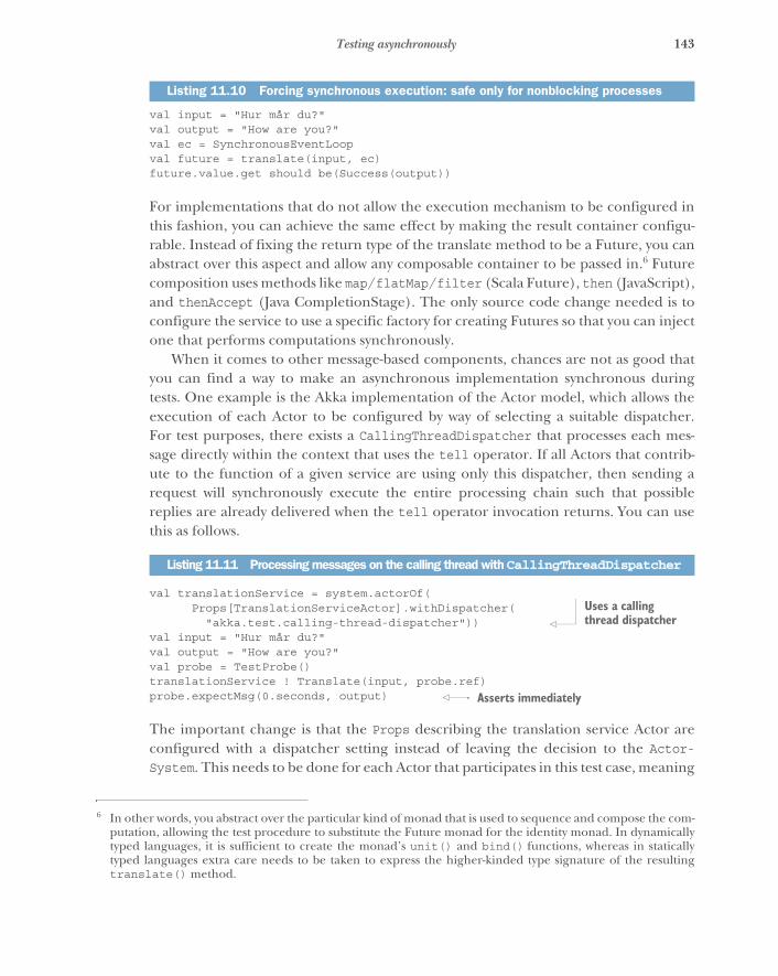
143Testing asynchronously
val input = "Hur mår du?"val output = "How are you?"val ec = SynchronousEventLoopval future = translate(input, ec)future.value.get should be(Success(output))
For implementations that do not allow the execution mechanism to be configured inthis fashion, you can achieve the same effect by making the result container configu-rable. Instead of fixing the return type of the translate method to be a Future, you canabstract over this aspect and allow any composable container to be passed in.6 Futurecomposition uses methods like map/flatMap/filter (Scala Future), then (JavaScript),and thenAccept (Java CompletionStage). The only source code change needed is toconfigure the service to use a specific factory for creating Futures so that you can injectone that performs computations synchronously.
When it comes to other message-based components, chances are not as good thatyou can find a way to make an asynchronous implementation synchronous duringtests. One example is the Akka implementation of the Actor model, which allows theexecution of each Actor to be configured by way of selecting a suitable dispatcher.For test purposes, there exists a CallingThreadDispatcher that processes each mes-sage directly within the context that uses the tell operator. If all Actors that contrib-ute to the function of a given service are using only this dispatcher, then sending arequest will synchronously execute the entire processing chain such that possiblereplies are already delivered when the tell operator invocation returns. You can usethis as follows.
val translationService = system.actorOf(Props[TranslationServiceActor].withDispatcher(
"akka.test.calling-thread-dispatcher"))val input = "Hur mår du?"val output = "How are you?"val probe = TestProbe()translationService ! Translate(input, probe.ref)probe.expectMsg(0.seconds, output)
The important change is that the Props describing the translation service Actor areconfigured with a dispatcher setting instead of leaving the decision to the Actor-System. This needs to be done for each Actor that participates in this test case, meaning
Listing 11.10 Forcing synchronous execution: safe only for nonblocking processes
6 In other words, you abstract over the particular kind of monad that is used to sequence and compose the com-putation, allowing the test procedure to substitute the Future monad for the identity monad. In dynamicallytyped languages, it is sufficient to create the monad’s unit() and bind() functions, whereas in staticallytyped languages extra care needs to be taken to express the higher-kinded type signature of the resultingtranslate() method.
Listing 11.11 Processing messages on the calling thread with CallingThreadDispatcher
Uses a calling thread dispatcher
Asserts immediately
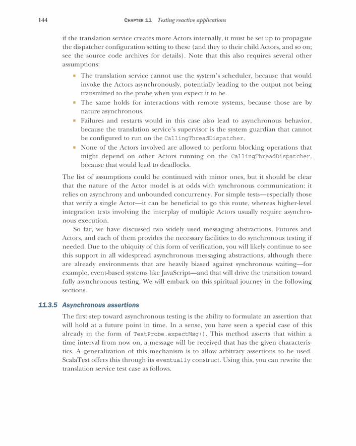
144 CHAPTER 11 Testing reactive applications
if the translation service creates more Actors internally, it must be set up to propagatethe dispatcher configuration setting to these (and they to their child Actors, and so on;see the source code archives for details). Note that this also requires several otherassumptions:
� The translation service cannot use the system’s scheduler, because that wouldinvoke the Actors asynchronously, potentially leading to the output not beingtransmitted to the probe when you expect it to be.
� The same holds for interactions with remote systems, because those are bynature asynchronous.
� Failures and restarts would in this case also lead to asynchronous behavior,because the translation service’s supervisor is the system guardian that cannotbe configured to run on the CallingThreadDispatcher.
� None of the Actors involved are allowed to perform blocking operations thatmight depend on other Actors running on the CallingThreadDispatcher,because that would lead to deadlocks.
The list of assumptions could be continued with minor ones, but it should be clearthat the nature of the Actor model is at odds with synchronous communication: itrelies on asynchrony and unbounded concurrency. For simple tests—especially thosethat verify a single Actor—it can be beneficial to go this route, whereas higher-levelintegration tests involving the interplay of multiple Actors usually require asynchro-nous execution.
So far, we have discussed two widely used messaging abstractions, Futures andActors, and each of them provides the necessary facilities to do synchronous testing ifneeded. Due to the ubiquity of this form of verification, you will likely continue to seethis support in all widespread asynchronous messaging abstractions, although thereare already environments that are heavily biased against synchronous waiting—forexample, event-based systems like JavaScript—and that will drive the transition towardfully asynchronous testing. We will embark on this spiritual journey in the followingsections.
11.3.5 Asynchronous assertions
The first step toward asynchronous testing is the ability to formulate an assertion thatwill hold at a future point in time. In a sense, you have seen a special case of thisalready in the form of TestProbe.expectMsg(). This method asserts that within atime interval from now on, a message will be received that has the given characteris-tics. A generalization of this mechanism is to allow arbitrary assertions to be used.ScalaTest offers this through its eventually construct. Using this, you can rewrite thetranslation service test case as follows.
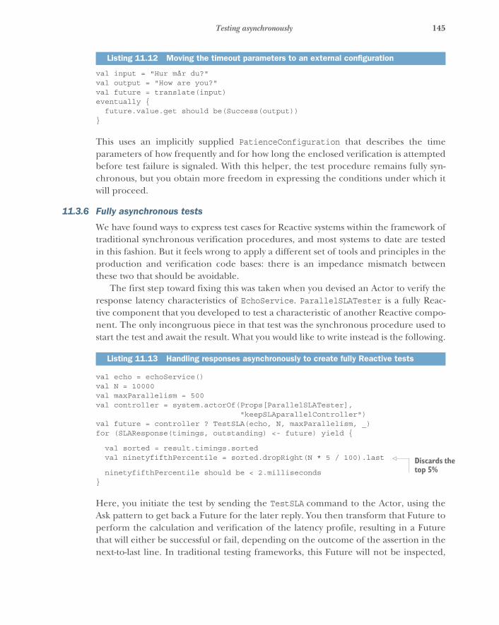
145Testing asynchronously
val input = "Hur mår du?"val output = "How are you?"val future = translate(input)eventually {
future.value.get should be(Success(output))}
This uses an implicitly supplied PatienceConfiguration that describes the timeparameters of how frequently and for how long the enclosed verification is attemptedbefore test failure is signaled. With this helper, the test procedure remains fully syn-chronous, but you obtain more freedom in expressing the conditions under which itwill proceed.
11.3.6 Fully asynchronous tests
We have found ways to express test cases for Reactive systems within the framework oftraditional synchronous verification procedures, and most systems to date are testedin this fashion. But it feels wrong to apply a different set of tools and principles in theproduction and verification code bases: there is an impedance mismatch betweenthese two that should be avoidable.
The first step toward fixing this was taken when you devised an Actor to verify theresponse latency characteristics of EchoService. ParallelSLATester is a fully Reac-tive component that you developed to test a characteristic of another Reactive compo-nent. The only incongruous piece in that test was the synchronous procedure used tostart the test and await the result. What you would like to write instead is the following.
val echo = echoService()val N = 10000val maxParallelism = 500val controller = system.actorOf(Props[ParallelSLATester],
"keepSLAparallelController")val future = controller ? TestSLA(echo, N, maxParallelism, _)for (SLAResponse(timings, outstanding) <- future) yield {
val sorted = result.timings.sortedval ninetyfifthPercentile = sorted.dropRight(N * 5 / 100).last
ninetyfifthPercentile should be < 2.milliseconds}
Here, you initiate the test by sending the TestSLA command to the Actor, using theAsk pattern to get back a Future for the later reply. You then transform that Future toperform the calculation and verification of the latency profile, resulting in a Futurethat will either be successful or fail, depending on the outcome of the assertion in thenext-to-last line. In traditional testing frameworks, this Future will not be inspected,
Listing 11.12 Moving the timeout parameters to an external configuration
Listing 11.13 Handling responses asynchronously to create fully Reactive tests
Discards the top 5%
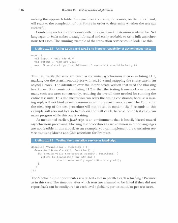
146 CHAPTER 11 Testing reactive applications
making this approach futile. An asynchronous testing framework, on the other hand,will react to the completion of this Future in order to determine whether the test wassuccessful.
Combining such a test framework with the async/await extension available for .Netlanguages or Scala makes it straightforward and easily readable to write fully asynchro-nous test cases. The running example of the translation service would look like this.
async {val input = "Hur mår du?"val output = "How are you?"await(translate(input).withTimeout(5.seconds)) should be(output)
}
This has exactly the same structure as the initial synchronous version in listing 11.1,marking out the asynchronous piece with await() and wrapping the entire case in anasync{} block. The advantage over the intermediate version that used the blockingAwait.result() construct in listing 11.2 is that the testing framework can executemany such test cases concurrently, reducing the overall time needed for running theentire test suite. This also means you can relax the timing constraints, because a miss-ing reply will not bind as many resources as in the synchronous case. The Future forthe next step of the test procedure will not be set in motion; the 5 seconds in thisexample will also not tick so heavily on the wall clock, because other test cases canmake progress while this one is waiting.
As mentioned earlier, JavaScript is an environment that is heavily biased towardasynchronous processing; blocking test procedures as are common in other languagesare not feasible in this model. As an example, you can implement the translation ser-vice test using Mocha and Chai assertions for Promises.
describe('Translator', function() {describe('#translate()', function() {
it('should yield the correct result', function() {return tr.translate('Hur mår du?')
.should.eventually.equal('How are you?');})
})});
The Mocha test runner executes several test cases in parallel, each returning a Promiseas in this case. The timeouts after which tests are assumed to be failed if they did notreport back can be configured at each level (globally, per test suite, or per test case).
Listing 11.14 Using async and await to improve readability of asynchronous tests
Listing 11.15 Testing the translation service in JavaScript
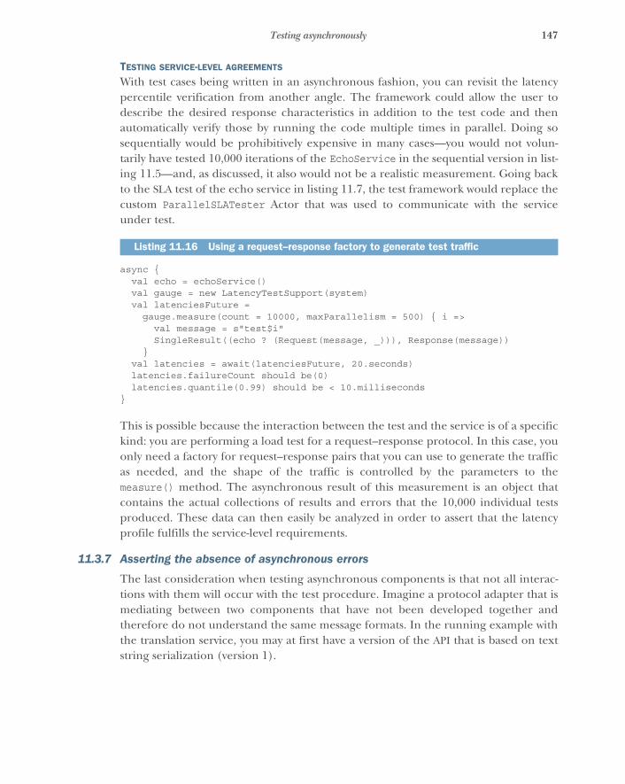
147Testing asynchronously
TESTING SERVICE-LEVEL AGREEMENTS
With test cases being written in an asynchronous fashion, you can revisit the latencypercentile verification from another angle. The framework could allow the user todescribe the desired response characteristics in addition to the test code and thenautomatically verify those by running the code multiple times in parallel. Doing sosequentially would be prohibitively expensive in many cases—you would not volun-tarily have tested 10,000 iterations of the EchoService in the sequential version in list-ing 11.5—and, as discussed, it also would not be a realistic measurement. Going backto the SLA test of the echo service in listing 11.7, the test framework would replace thecustom ParallelSLATester Actor that was used to communicate with the serviceunder test.
async {val echo = echoService()val gauge = new LatencyTestSupport(system)val latenciesFuture =
gauge.measure(count = 10000, maxParallelism = 500) { i =>val message = s"test$i"SingleResult((echo ? (Request(message, _))), Response(message))
}val latencies = await(latenciesFuture, 20.seconds)latencies.failureCount should be(0)latencies.quantile(0.99) should be < 10.milliseconds
}
This is possible because the interaction between the test and the service is of a specifickind: you are performing a load test for a request–response protocol. In this case, youonly need a factory for request–response pairs that you can use to generate the trafficas needed, and the shape of the traffic is controlled by the parameters to themeasure() method. The asynchronous result of this measurement is an object thatcontains the actual collections of results and errors that the 10,000 individual testsproduced. These data can then easily be analyzed in order to assert that the latencyprofile fulfills the service-level requirements.
11.3.7 Asserting the absence of asynchronous errors
The last consideration when testing asynchronous components is that not all interac-tions with them will occur with the test procedure. Imagine a protocol adapter that ismediating between two components that have not been developed together andtherefore do not understand the same message formats. In the running example withthe translation service, you may at first have a version of the API that is based on textstring serialization (version 1).
Listing 11.16 Using a request–response factory to generate test traffic

148 CHAPTER 11 Testing reactive applications
case class TranslateV1(query: String, replyTo: ActorRef)
The languages to be used for input and output are encoded within the query string,and the reply that is sent to the replyTo address will be just a String. This works for aproof of concept, but later you may want to replace the protocol with a more strictlytyped, intuitive version (version 2).
case class TranslateV2(phrase: String,inputLanguage: String,outputLanguage: String,replyTo: ActorRef)
sealed trait TranslationResponseV2case class TranslationV2(inputPhrase: String,
outputPhrase: String,inputLanguage: Language,outputLanguage: Language)
case class TranslationErrorV2(inputPhrase: String,inputLanguage: Language,outputLanguage: Language,errorMessage: String)
This redesign allows more advanced features like automatic detection of the inputlanguage to be implemented. Unfortunately, other teams have progressed with imple-menting a translator using the version 1 protocol already. Let us assume that the deci-sion is made to bridge between this and new clients by adding an adapter that acceptsrequests made with version 2 of the protocol and serves the replies that are providedby a translation service speaking the version 1 protocol in the background.
For this adapter, you will typically write integration tests, making sure that given afunctioning version 1 back end, the adapter correctly implements version 2 of the pro-tocol. To save maintenance effort, you will also write dedicated tests that concentrateon the transformation of requests and replies; this will save time when debugging fail-ures, because you can more easily associate them with either the adapter or the back-end service. A test procedure could look like this.
val v1 = TestProbe()val v2 = system.actorOf(TranslationService.propsV2(v1.ref))val client = TestProbe()
v2 ! TranslateV2("Hur mår du?", "sv", "en", client.ref)
val req1 = v1.expectMsgType[TranslateV1]req1.query should be("sv:en:Hur mår du?")
req1.replyTo ! "How are you?"
Listing 11.17 Simple translation API
Listing 11.18 Adding stricter types to the translation API
Listing 11.19 Testing the translation version adapter
Initiates a request to the adapter
Verifies that the adapter asks the V1 service back end
Initiates a reply
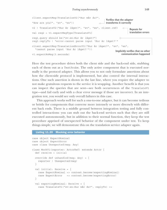
149Testing asynchronously
client.expectMsg(TranslationV2("Hur mår du?",
"How are you?", "sv", "en"))
v2 ! TranslateV2("Hur är läget?", "sv", "en", client.ref)
val req2 = v1.expectMsgType[TranslateV1]
req2.query should be("sv:en:Hur är läget?")req2.replyTo ! "error:cannot parse input 'Hur är läget?'"
client.expectMsg(TranslationErrorV2("Hur är läget?", "sv", "en","cannot parse input 'Hur är läget?'"))
v1.expectNoMsg(3.seconds)
Here the test procedure drives both the client side and the back-end side, stubbingeach of them out as a TestProbe. The only active component that is executed nor-mally is the protocol adapter. This allows you to not only formulate assertions abouthow the client-side protocol is implemented, but also control the internal interac-tions. One such assertion is shown in the last line, where you require the adapter tonot make gratuitous requests to the service it is wrapping. Another benefit is that youcan inspect the queries that are sent—see both occurrences of the TranslateV1type—and fail early and with a clear error message if those are incorrect. In an inte-gration test, you would see only overall failures in this case.
This approach works well for such a one-to-one adapter, but it can become tediousor brittle for components that converse more intensely or more diversely with differ-ent back ends. There is a middle ground between integration testing and fully con-trolled interactions: you can stub out the back-end services such that they are stillexecuted autonomously, but in addition to their normal function, they keep the testprocedure apprised of unexpected behavior of the component under test. To keepthings simple, we will demonstrate this on the translation service adapter again.
case object ExpectNominalcase object ExpectErrorcase class Unexpected(msg: Any)
class MockV1(reporter: ActorRef) extends Actor {def receive = initial
override def unhandled(msg: Any) = {reporter ! Unexpected(msg)
}
val initial: Receive = {case ExpectNominal => context.become(expectingNominal)case ExpectError => context.become(expectingError)
}
val expectingNominal: Receive = {case TranslateV1("sv:en:Hur mår du?", replyTo) =>
Listing 11.20 Mocking error behavior
Verifies that the adapter transforms it correctly
Repeats for translation errors
Implicitly verifies that no othercommunication happened
150 CHAPTER 11 Testing reactive applications
replyTo ! "How are you?"context.become(initial)
}
val expectingError: Receive = {case TranslateV1(other, replyTo) =>
replyTo ! s"error:cannot parse input '$other'"context.become(initial)
}}
This mock of the version 1 back end will provide the expected responses during a test,but it will do so only at the appropriate points in time: the test procedure has toexplicitly unlock each of the steps by sending either an ExpectNominal or an Expect-Error message. Using this, the test procedure changes to the following.
val asyncErrors = TestProbe()val v1 = system.actorOf(mockV1props(asyncErrors.ref))val v2 = system.actorOf(propsV2(v1))val client = TestProbe()
v1 ! ExpectNominalv2 ! TranslateV2("Hur mår du?", "sv", "en", client.ref)
client.expectMsg(TranslationV2("Hur mår du?", "How are you?","sv", "en"))
asyncErrors.expectNoMsg(0.seconds)
v1 ! ExpectErrorv2 ! TranslateV2("Hur är läget?", "sv", "en", client.ref)client.expectMsg(TranslationErrorV2("Hur är läget?", "sv", "en",
"cannot parse input 'sv:en:Hur är läget?'"))
asyncErrors.expectNoMsg(1.second)
The test procedure in this case still drives both the client side and the back end, butthe latter is more autonomous and allows the test to be written more concisely. Thefirst verification of the absence of asynchronous errors is performed such that it doesnot introduce additional latency; its purpose is only to aid in debugging test failures incase an asynchronous error from the nominal test step does not subsequently lead todirectly visible test failures but instead only bubbles up in the last line of the test.
11.4 Testing nondeterministic systemsThe previous section introduced the difficulties that arise from the asynchronousnature of Reactive systems. This had several interesting consequences even though theprocess that you were testing was fully deterministic: given a certain stimulus, the com-ponent will eventually respond with the correct answer—the translation of a givenphrase should always yield the same result. In chapter 8, we discussed that in distributed
Listing 11.21 Testing for correct error handling
Initiates a request to the adapter
Certifies that the adapter transforms it correctly
Nonblocking check for async errors
Verifiestranslation
errors
Final check for async errors
151Testing nondeterministic systems
systems, determinism cannot always be achieved: the main reasons are unreliablemeans of communication and inherent concurrency. Because distribution is integral toReactive system design, you nevertheless need to be able to test components thatexhibit genuine nondeterminism. Such tests are harder to express because the order ofexecution is not specified as a sequential progression of logic, and for a single test pro-cedure, different outcomes or state transitions are possible and permissible.
11.4.1 The trouble with execution schedules
Anyone who has written tests that are based on a particular event occurring within aspecified time has likely seen spurious failures, where a test succeeds most of the timebut fails on occasion. What if the execution is correct but the timings are differentbecause of varying insertion orders into queues, or different values being returnedbased on what was requested in what order?
It is imperative that application developers define all the correct behaviors thatcan occur based on varying execution schedules. This can be difficult, because itimplies that the variance is finite and knowable; and the larger a system is, and withgreater numbers of interactions, the more difficult this can be with respect to preci-sion. An example of a tool that supports this kind of functionality is Apache JMeter(http://jmeter.apache.org), where you can use logical controllers to fire requests invarying orders and timings to see whether the responses received match expectationsfor system behavior. Logical controllers have other useful features as well, includingrequest modification, request repeating, and more. By executing tests with tools suchas JMeter, you can root out more logical inconsistencies in your Reactive applicationthan if you always rely on tests being executed in one order and one timing.
11.4.2 Testing distributed components
With distributed systems, which Reactive applications are by definition, some moredifficult problems must be considered. Foremost is the idea that a distributed interac-tion can succeed in one dimension while failing in another. For example, imagine adistributed system where data must be updated across four nodes, but suppose some-thing goes awry on one of the servers and it never responds with a successful updateresponse before a timeout occurs. These are known as partial failures,7 where latencycan increase and throughput can fall because interactions between the many servicesthat make up the application are unable to complete all tasks (see figure 11.3).
What is particularly tricky about these kinds of failure is that it is unlikely that youcan consider all the ways in which a Reactive application may fail partially and deriveappropriate behavior for each case. Instead, you should consider what the applicationshould do when something occurs that you did not expect. We discuss this in muchmore detail in chapter 12.
7 http://en.wikipedia.org/wiki/Fault_tolerance
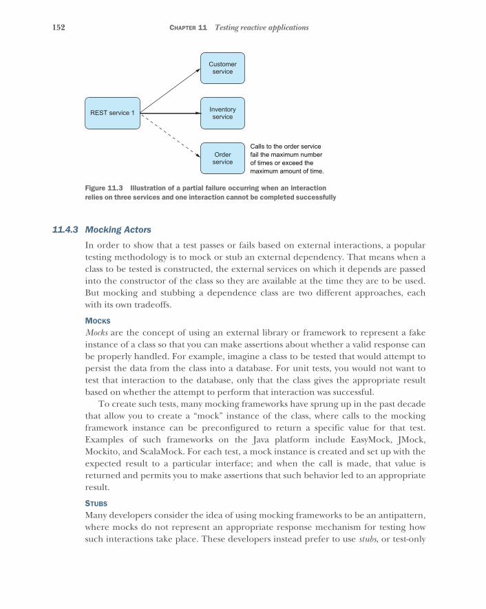
152 CHAPTER 11 Testing reactive applications
11.4.3 Mocking Actors
In order to show that a test passes or fails based on external interactions, a populartesting methodology is to mock or stub an external dependency. That means when aclass to be tested is constructed, the external services on which it depends are passedinto the constructor of the class so they are available at the time they are to be used.But mocking and stubbing a dependence class are two different approaches, eachwith its own tradeoffs.
MOCKS
Mocks are the concept of using an external library or framework to represent a fakeinstance of a class so that you can make assertions about whether a valid response canbe properly handled. For example, imagine a class to be tested that would attempt topersist the data from the class into a database. For unit tests, you would not want totest that interaction to the database, only that the class gives the appropriate resultbased on whether the attempt to perform that interaction was successful.
To create such tests, many mocking frameworks have sprung up in the past decadethat allow you to create a “mock” instance of the class, where calls to the mockingframework instance can be preconfigured to return a specific value for that test.Examples of such frameworks on the Java platform include EasyMock, JMock,Mockito, and ScalaMock. For each test, a mock instance is created and set up with theexpected result to a particular interface; and when the call is made, that value isreturned and permits you to make assertions that such behavior led to an appropriateresult.
STUBS
Many developers consider the idea of using mocking frameworks to be an antipattern,where mocks do not represent an appropriate response mechanism for testing howsuch interactions take place. These developers instead prefer to use stubs, or test-only
Customerservice
Inventoryservice
Orderservice
Calls to the order service fail the maximum number of times or exceed the maximum amount of time.
REST service 1
Figure 11.3 Illustration of a partial failure occurring when an interaction relies on three services and one interaction cannot be completed successfully
153Testing nondeterministic systems
implementations of the interface that provide positive or negative responses for eachinterface based on the kind of response expected. This is considered less brittle at thetime refactoring to an interface takes place, because the response from the stubbedmethod call is better defined.
There is a further consideration with respect to stubs: many developers complainthat creating stubs for an interface is painful because it means they have to provideimplementations of each public interface even when they are not used for a particulartest, because the implementation of the interface specific to the test still requires eachmethod in the interface to have defined behavior, even if that behavior is to do noth-ing. But developers such as Robert Martin have argued that using mocking frame-works is a “smell test” for APIs that have begun to exceed the single responsibilityprinciple:8 if the interface is painful to implement as a test stub because so manyinterfaces have to be implemented, then the class interface is trying to do too muchand is exceeding the best practice rules for how each class should be defined withrespect to the number of things it can do.
These kinds of arguments are best left to development teams to define, because itis easy to find edge cases that exceed such rules of thumb. As an extreme example, ifyou have an interface with 100 public interfaces, you will have to provide an imple-mentation of all of them in order to construct a stub for a single test, and this is diffi-cult to do. It is even more difficult to maintain as the API changes duringdevelopment. If your interfaces are small and represent atomic, granular responsibili-ties, writing stubs is much simpler and allows for more expressive interpretations ofhow those dependencies can respond based on certain inputs, particularly when theinteractions between the calling class under test and the dependency become morecomplex.
REVERSE ONION TESTING PATTERN
A key concept for building effective tests for all applications is to create tests for theentire application from the inside and work outward. This kind of testing is called theReverse Onion pattern, where the approach is likened to peeling the layers of an onioninversely: putting them back from the center out. This blends directly into the strategyof testing that was discussed in the beginning of the chapter. In taking this approach,the most minute expressions and functions are tested first, moving outward to servicesin isolation and then to the interactions themselves.
11.4.4 Distributed components
Contextual handlers such as Akka TestKit’s TestProbe are extremely handy for writingReverse Onion tests. Constructs like these allow you to differentiate between theresponses for each request. Each test must have the ability to provide implementa-tions, whether by mocks or stubs, of the Actors/classes on which they depend, so thatyou can enforce and verify the behavior you expect based on their responses. Once
8 http://en.wikipedia.org/wiki/Single_responsibility_principle
154 CHAPTER 11 Testing reactive applications
you have built tests with these characteristics, you can effectively test partial failurefrom the responses you get based on each failed interaction with each of those depen-dencies for an Actor/class. If you are making a call to three services and you want totest the behavior of the class when two of the three succeed and the third fails, you cando so by stubbing out behavior where the two successful stubs return expected valuesand the third returns an error (or never returns at all).
11.5 Testing elasticityFor many developers, the concept of testing load or volume is well known. But forReactive applications, the focus changes from that traditional approach to being ableto verify that your application deployment is elastic within the confines of your avail-able infrastructure. Just like everything else in application development, your systemneeds bounds in time and space, and the space limitation should be the maximumnumber of nodes you can spin up before you begin applying back pressure. In somecases, you may be running on top of a platform as a service (PaaS) where you “spillover” into public infrastructure like AWS or Rackspace images. But for many compa-nies, that is not an option.
To test and verify elasticity, you first have to know the bounds of throughput pernode and the amount of infrastructure you will be deploying to. This should ideallycome from the nonfunctional requirements of your application from the outset of theproject; but if you have a clear idea of what your existing application’s throughputprofile looks like, you can start from there.
Assuming each node can handle 1,000 requests per second, and you have 10 nodeson which you can deploy, you want to test that traffic below a certain threshold onlyresults in the minimum number of servers running that you specify. Tools such as Mara-thon with Mesos are run through Docker instances that you can query to see whethernodes are up or down, and Marathon has a REST API through which you can make otherassertions about the status of the cluster. To provide load to the system, several useful freeutilities do the job exceptionally well, such as Bees With Machine Guns (https://github.com/newsapps/beeswithmachineguns) and Gatling (http://gatling.io).
11.6 Testing resilienceApplication resilience is a term that needs to be deconstructed. Failure can occur atmany levels, and each of them needs to be tested to ensure that an application can beReactive to virtually anything that can happen. The Reactive Manifesto states that“Resilience is achieved by replication, containment, isolation, and delegation.” Thismeans you need to be able to break down the varying ways that an application can fail,from the micro to the macro level, and test that it can withstand all the things that cango wrong. In every case, a request must be handled and responded to regardless ofwhat happened after it was received.
155Testing resilience
11.6.1 Application resilience
First are the application concerns, where you must focus on behaviors specific to howthe application was coded. These are the areas with which most developers arealready familiar and usually involve testing that an exception was received or what theapplication did as a result of injecting some data or functionality that should fail. In aReactive application, you should expect that exceptions or failures (as described insection 2.4.3) are not seen by the sender of a message, but communicated throughother messages that elevate the failure to being domain events.
This is an important point. Failure has traditionally been regarded as separatefrom the domain of the application and is typically handled as a tactical issue thatmust be prevented or communicated outside the realm of the domain for which theapplication was built. By making failure messages first-class citizens of the applicationdomain, you have the ability to handle failure in a much more strategic fashion. Youcan create two domains about the application—a domain of success and a domain offailure—and treat each appropriately with staged failure handling.
As an example, imagine an error retrieving valid data from an external source suchas a database, where the call to retrieve the data succeeded but the data returned wasnot valid. This can be handled at one level of the application specific to that request,and either whatever valid data was retrieved is returned to the message sender, or amessage connoting that the data was invalid is returned. But if the connection to theexternal source is lost, that is a broader domain event than the individual request forthe data and should be handled by a higher-level component, such as whomever pro-vided the connection that was used in the first place, so that it can begin the process ofreestablishing the connection that was lost.
Application resilience comes in two forms: external and internal. External resilienceis handled through validation, where data passed into the application is checked toensure that it meets the requirement of the API; if not, a notification is passed back tothe sender (for example, a telephone country code that does not exist in a database ofknown numbers against which it is checked). Internal resilience includes those errorsthat occur within the application’s handling of that request once it has been validated.
EXECUTION RESILIENCE
As discussed in previous chapters, the most important aspect of execution resilience issupervision of the thread or process where failure can occur. Without it, there is noway for you to discern what happened to a thread or process that failed, and you maynot have any way of knowing that a failure occurred at all. Once supervision is inplace, you have the capability to handle failure, but you may not necessarily have theability to test that you are doing the right thing as a result.
To get around this issue, developers sometimes expose internal state for the super-vised functionality just so they can effectively test whether that state was unharmed orsomehow affected by the supervisor’s management of it. For example, an Actor that isresumed would see no change in its internal state, but an Actor that was restarted
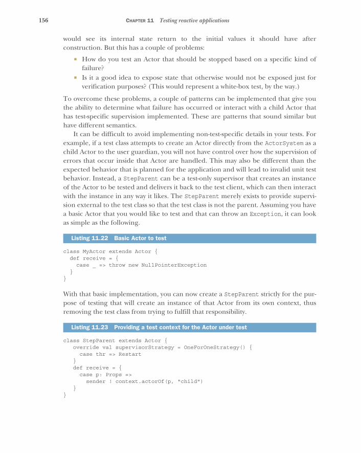
156 CHAPTER 11 Testing reactive applications
would see its internal state return to the initial values it should have afterconstruction. But this has a couple of problems:
� How do you test an Actor that should be stopped based on a specific kind offailure?
� Is it a good idea to expose state that otherwise would not be exposed just forverification purposes? (This would represent a white-box test, by the way.)
To overcome these problems, a couple of patterns can be implemented that give youthe ability to determine what failure has occurred or interact with a child Actor thathas test-specific supervision implemented. These are patterns that sound similar buthave different semantics.
It can be difficult to avoid implementing non-test-specific details in your tests. Forexample, if a test class attempts to create an Actor directly from the ActorSystem as achild Actor to the user guardian, you will not have control over how the supervision oferrors that occur inside that Actor are handled. This may also be different than theexpected behavior that is planned for the application and will lead to invalid unit testbehavior. Instead, a StepParent can be a test-only supervisor that creates an instanceof the Actor to be tested and delivers it back to the test client, which can then interactwith the instance in any way it likes. The StepParent merely exists to provide supervi-sion external to the test class so that the test class is not the parent. Assuming you havea basic Actor that you would like to test and that can throw an Exception, it can lookas simple as the following.
class MyActor extends Actor {def receive = {
case _ => throw new NullPointerException}
}
With that basic implementation, you can now create a StepParent strictly for the pur-pose of testing that will create an instance of that Actor from its own context, thusremoving the test class from trying to fulfill that responsibility.
class StepParent extends Actor {override val supervisorStrategy = OneForOneStrategy() {
case thr => Restart}def receive = {
case p: Props =>sender ! context.actorOf(p, "child")
}}
Listing 11.22 Basic Actor to test
Listing 11.23 Providing a test context for the Actor under test
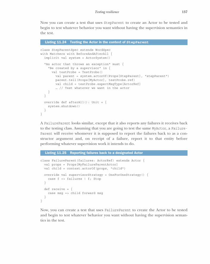
157Testing resilience
Now you can create a test that uses StepParent to create an Actor to be tested andbegin to test whatever behavior you want without having the supervision semantics inthe test.
class StepParentSpec extends WordSpecwith Matchers with BeforeAndAfterAll {
implicit val system = ActorSystem()
"An actor that throws an exception" must {"Be created by a supervisor" in {
val testProbe = TestProbe()val parent = system.actorOf(Props[StepParent], "stepParent")parent.tell(Props[MyActor], testProbe.ref)val child = testProbe.expectMsgType[ActorRef]… // Test whatever we want in the actor
}}
override def afterAll(): Unit = {system.shutdown()
}}
A FailureParent looks similar, except that it also reports any failures it receives backto the testing class. Assuming that you are going to test the same MyActor, a Failure-Parent will receive whomever it is supposed to report the failures back to as a con-structor argument and, on receipt of a failure, report it to that entity beforeperforming whatever supervision work it intends to do.
class FailureParent(failures: ActorRef) extends Actor {val props = Props[MyFailureParentActor]val child = context.actorOf(props, "child")
override val supervisorStrategy = OneForOneStrategy() {case f => failures ! f; Stop
}
def receive = {case msg => child forward msg
}}
Now, you can create a test that uses FailureParent to create the Actor to be testedand begin to test whatever behavior you want without having the supervision seman-tics in the test.
Listing 11.24 Testing the Actor in the context of StepParent
Listing 11.25 Reporting failures back to a designated Actor
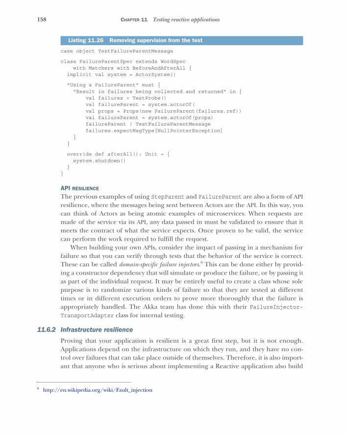
158 CHAPTER 11 Testing reactive applications
case object TestFailureParentMessage
class FailureParentSpec extends WordSpecwith Matchers with BeforeAndAfterAll {
implicit val system = ActorSystem()
"Using a FailureParent" must {"Result in failures being collected and returned" in {
val failures = TestProbe()val failureParent = system.actorOf(val props = Props(new FailureParent(failures.ref))
val failureParent = system.actorOf(props)failureParent ! TestFailureParentMessagefailures.expectMsgType[NullPointerException]
}}
override def afterAll(): Unit = {system.shutdown()
}}
API RESILIENCE
The previous examples of using StepParent and FailureParent are also a form of APIresilience, where the messages being sent between Actors are the API. In this way, youcan think of Actors as being atomic examples of microservices. When requests aremade of the service via its API, any data passed in must be validated to ensure that itmeets the contract of what the service expects. Once proven to be valid, the servicecan perform the work required to fulfill the request.
When building your own APIs, consider the impact of passing in a mechanism forfailure so that you can verify through tests that the behavior of the service is correct.These can be called domain-specific failure injectors.9 This can be done either by provid-ing a constructor dependency that will simulate or produce the failure, or by passing itas part of the individual request. It may be entirely useful to create a class whose solepurpose is to randomize various kinds of failure so that they are tested at differenttimes or in different execution orders to prove more thoroughly that the failure isappropriately handled. The Akka team has done this with their FailureInjector-TransportAdapter class for internal testing.
11.6.2 Infrastructure resilience
Proving that your application is resilient is a great first step, but it is not enough.Applications depend on the infrastructure on which they run, and they have no con-trol over failures that can take place outside of themselves. Therefore, it is also import-ant that anyone who is serious about implementing a Reactive application also build
Listing 11.26 Removing supervision from the test
9 http://en.wikipedia.org/wiki/Fault_injection
159Testing resilience
or use a framework to help them test the application’s ability to cope with infrastruc-ture failures that happen around it.
Some may use the term partition and mean only from the network perspective, butthat is not necessarily true. Partitions happen any time a system has increased latencyin response to any reason, including stop-the-world garbage collection, databaselatency, infinite looping, and so on.
NETWORK RESILIENCE (LAN AND WAN)One of the most notorious kinds of infrastructure failures is a network partition,10 wherea network is incapable of routing between two or more subnetworks for various rea-sons. Networks can, and do, fail. Routers can go down just like any other computer,and occasionally paths provided by routing tables that are periodically revised andoptimized cannot be resolved. It is best to assume that this will happen to your appli-cation and have a protocol for application management in the face of such an event.
CLUSTER RESILIENCE
In the case of a network partition, it is entirely plausible that two or more nodes in aclustered application will not be able to reach each other, and each will assume leader-ship of a new subcluster that cannot be rejoined or merged. This is called the split-brain problem.11 The optimistic approach is to allow the two or more subclusters to con-tinue as normal, but if there is any state to be shared between them, this can be diffi-cult to maintain as far as updates that occur in each being resolved to the correct finalanswer if and when they rejoin. The pessimistic approach is to assume that all is lost,shut down both subclusters, and attempt to restart the application entirely, so thatconsistency is maintained.
Some cluster-management tools attempt to take a middling approach, where anysubcluster with a majority of nodes (greater than 50% of known nodes) will automati-cally attempt to become the leader of a cluster that stays in operation. Any subclusterwith less than 50% of known nodes will then automatically shut down. In theory, thissounds reasonable, but cluster splits can be unreasonable occurrences. It is entirelylikely that such a split in the cluster will result in multiple subclusters with less than50% of known nodes in all of them, and that they will all shut down as a result. Theoperations teams that manage distributed systems in production have to be always onguard for such events and, again, have a protocol in place for handling them.
NODE AND MACHINE RESILIENCE
Nodes, or instances, are processes running on a machine that represent one instanceof an application currently able to perform work. If there is only one node in theentire application, it is not a distributed application and represents a single point of fail-ure(SPOF). If there is more than one node, possibly running on the same physicalmachine or across several of them, it is a distributed application. If all nodes are run-ning on just one machine, this represents another SPOF, because any failure to the
10 http://en.wikipedia.org/wiki/Network_partition11 http://en.wikipedia.org/wiki/Split-brain_(computing)
160 CHAPTER 11 Testing reactive applications
machine will take down the entire application. To make an application provably Reac-tive, you must be able to test that the removal of any node or machine at runtime doesnot affect your ability to withstand your application’s expected traffic.
DATA-CENTER RESILIENCE
Similar to the other infrastructural concepts, deploying an application to a single datacenter is an SPOF and not a Reactive approach. Instead, deployment to multiple datacenters is a requirement to ensure that any major outage in one leaves your applica-tion with the capacity to handle all requests in others.
11.7 Testing responsivenessWhen testing elasticity and resilience, the focus is primarily on the number of requestsyour application can handle at any given time and with any given conditions. Butresponsiveness is mostly about latency, or the time it takes to handle each request. Asdiscussed in previous chapters, one of the biggest mistakes developers make is trackinglatency by a metric defined qualitatively, typically by average. But average is a terrible
Testing resilience in productionNetflix has created a suite of tools to help it test the robustness of its applicationswhile running in production, called the Simian Army.a Netflix has had major outageshappen in production and prefers to continue testing its application’s resiliency at thenode and machine level even in production. This gives the company tremendous con-fidence that it can continue to service its customers even in the face of significantfailures.
To test node resilience, Netflix uses Chaos Monkey, which randomly disables produc-tion instances when executed. Note that this tool is only executed with operationsengineers in attendance who closely monitor for any outages that could occur as aresult of the outages the tool induces. As a result of success with this tool, Netflixcreated a legion of other such tools to check for latency, security credential expira-tion, unused resources, and more.
To check resilience of an entire AWS availability zone, which is an isolation barrierwithin a deployment region, Netflix uses the Chaos Gorilla. This simulates a failureof an entire availability zone and checks whether the application is able to transitionwork to instances in other availability zones without downtime. To test data centerresilience, Netflix uses the Chaos Kong tool, because the company currently usesmultiple AWS regions for the United States alone.
Whether or not you use existing tools, such as those from Netflix, or build your own,it is critical that you test your application’s resilience in the face of myriad infrastruc-ture failures to ensure that your users continue to get the responses they expect.Focus on applying these tools for any application that is critical to the success of yourbusiness.
a. http://techblog.netflix.com/2011/07/netflix-simian-army.html
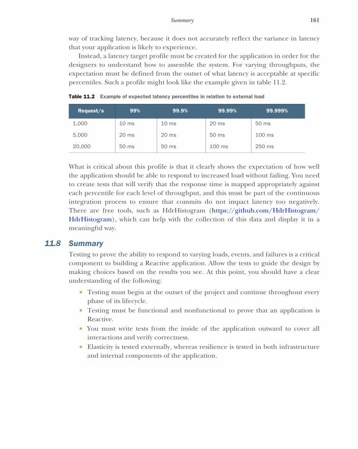
161Summary
way of tracking latency, because it does not accurately reflect the variance in latencythat your application is likely to experience.
Instead, a latency target profile must be created for the application in order for thedesigners to understand how to assemble the system. For varying throughputs, theexpectation must be defined from the outset of what latency is acceptable at specificpercentiles. Such a profile might look like the example given in table 11.2.
What is critical about this profile is that it clearly shows the expectation of how wellthe application should be able to respond to increased load without failing. You needto create tests that will verify that the response time is mapped appropriately againsteach percentile for each level of throughput, and this must be part of the continuousintegration process to ensure that commits do not impact latency too negatively.There are free tools, such as HdrHistogram (https://github.com/HdrHistogram/HdrHistogram), which can help with the collection of this data and display it in ameaningful way.
11.8 SummaryTesting to prove the ability to respond to varying loads, events, and failures is a criticalcomponent to building a Reactive application. Allow the tests to guide the design bymaking choices based on the results you see. At this point, you should have a clearunderstanding of the following:
� Testing must begin at the outset of the project and continue throughout everyphase of its lifecycle.
� Testing must be functional and nonfunctional to prove that an application isReactive.
� You must write tests from the inside of the application outward to cover allinteractions and verify correctness.
� Elasticity is tested externally, whereas resilience is tested in both infrastructureand internal components of the application.
Table 11.2 Example of expected latency percentiles in relation to external load
Request/s 99% 99.9% 99.99% 99.999%
1,000 10 ms 10 ms 20 ms 50 ms
5,000 20 ms 20 ms 50 ms 100 ms
20,000 50 ms 50 ms 100 ms 250 ms
162
Fault toleranceand recovery patterns
In this chapter, you will learn how to incorporate the possibility of failure into thedesign of your application. We will demonstrate the patterns on the concrete usecase of building a resilient computation engine that allows batch job submissionsand their execution on elastically provisioned hardware resources. We will build onwhat you learned in chapters 6 and 7, so you may want to revisit them.
We will start by considering a single component and its failure and recoverystrategies and then build up more-complex systems by means of hierarchical com-position as well as client–server relationships. In particular, we will discuss the fol-lowing patterns:
� The Simple Component pattern (a.k.a. the single responsibility principle)� The Error Kernel pattern� The Let-It-Crash pattern� The Circuit Breaker pattern
12.1 The Simple Component patternA component shall do only one thing, but do it in full.
This pattern applies wherever a system performs multiple functions or the func-tions it performs are so complex that they need to be broken into different compo-nents. An example is a text editor that includes spell checking: these are twoseparate functions (editing can be done without spell checking, and spelling canalso be checked on the finished text and does not require editing capabilities), buton the other hand, neither of these functions is trivial.
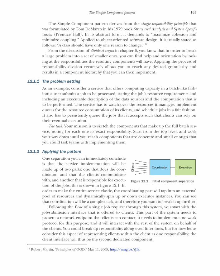
163The Simple Component pattern
The Simple Component pattern derives from the single responsibility principle thatwas formulated by Tom DeMarco in his 1979 book Structured Analysis and System Specifi-cation (Prentice Hall). In its abstract form, it demands to “maximize cohesion andminimize coupling.” Applied to object-oriented software design, it is usually stated asfollows: “A class should have only one reason to change.”12
From the discussion of divide et regna in chapter 6, you know that in order to breaka large problem into a set of smaller ones, you can find help and orientation by look-ing at the responsibilities the resulting components will have. Applying the process ofresponsibility division recursively allows you to reach any desired granularity andresults in a component hierarchy that you can then implement.
12.1.1 The problem setting
As an example, consider a service that offers computing capacity in a batch-like fash-ion: a user submits a job to be processed, stating the job’s resource requirements andincluding an executable description of the data sources and the computation that isto be performed. The service has to watch over the resources it manages, implementquotas for the resource consumption of its clients, and schedule jobs in a fair fashion.It also has to persistently queue the jobs that it accepts such that clients can rely ontheir eventual execution.
The task: Your mission is to sketch the components that make up the full batch ser-vice, noting for each one its exact responsibility. Start from the top level, and workyour way down until you reach components that are concrete and small enough thatyou could task teams with implementing them.
12.1.2 Applying the pattern
One separation you can immediately concludeis that the service implementation will bemade up of two parts: one that does the coor-dination and that the clients communicatewith, and another that is responsible for execu-tion of the jobs; this is shown in figure 12.1. Inorder to make the entire service elastic, the coordinating part will tap into an externalpool of resources and dynamically spin up or down executor instances. You can seethat coordination will be a complex task, and therefore you want to break it up further.
Following the flow of a single job request through this system, you start with thejob-submission interface that is offered to clients. This part of the system needs topresent a network endpoint that clients can contact; it needs to implement a networkprotocol for this purpose; and it will interact with the rest of the system on behalf ofthe clients. You could break up responsibility along even finer lines, but for now let usconsider this aspect of representing clients within the client as one responsibility; theclient interface will thus be the second dedicated component.
12 Robert Martin, “Principles of OOD,” May 11, 2005, http://mng.bz/tJIk.
Clie
nts
Coordination Execution
Figure 12.1 Initial component separation
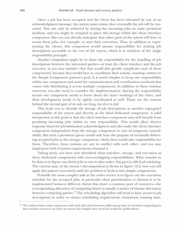
164 CHAPTER 12 Fault tolerance and recovery patterns
Once a job has been accepted and the client has been informed by way of anacknowledgment message, the system must ensure that eventually the job will be exe-cuted. This can only be achieved by storing the incoming jobs on some persistentmedium, and you might be tempted to place this storage within the client interfacecomponent. But you can already anticipate that other parts of the system will have toaccess these jobs—for example, to start their execution. Thus, in addition to repre-senting the clients, this component would assume responsibility for making jobdescriptions accessible to the rest of the system, which is in violation of the singleresponsibility principle.
Another temptation might be to share the responsibility for the handling of jobdescriptions between the interested parties—at least the client interface and the jobexecutor, as you may surmise—but that would also greatly complicate each of thesecomponents, because they would have to coordinate their actions, running counter tothe Simple Component pattern’s goal. It is much simpler to keep one responsibilitywithin one component and avoid the communication and coordination overhead thatcomes with distributing it across multiple components. In addition to these runtimeconcerns, you also need to consider the implementation: sharing the responsibilitymeans one component needs to know about the inner workings of the other, andtheir development needs to be tightly coordinated as well. Those are the reasonsbehind the second part of do only one thing, but do it in full.
This leads you to identify the storage of job descriptions as another segregatedresponsibility of the system and thereby as the third dedicated component. A validinterjection at this point is that the client interface component may well benefit frompersisting incoming jobs within its own responsibility. This would allow shorterresponse times for job-submission acknowledgment and also make the client interfacecomponent independent from the storage component in case of temporary unavail-ability. But such a persistent queue would only have the purpose of eventually deliver-ing accepted jobs to the storage component, which then would take responsibility forthem. Therefore, these notions are not in conflict with each other, and you mayimplement both if system requirements demand it.
Taking stock, you have now identified client interface, storage, and execution asthree dedicated components with non-overlapping responsibilities. What remains tobe done is to figure out which jobs to run in what order: this part is called job scheduling.The current state of the system’s decomposition is shown in figure 12.2; now you willapply this pattern recursively until the problem is broken into simple components.
Probably the most complex task in the entire service is to figure out the executionschedule for the accepted jobs, in particular when prioritization or fairness is to beimplemented between different clients that share a common pool of resources—thecorresponding allocation of computing shares is usually a matter of intense discussionbetween competing parties.13 The scheduling algorithm will need to have access to jobdescriptions in order to extract scheduling requirements (maximum running time,
13 The authors have some experience with such allocation between different groups of scientists competing fordata analysis resources in order to extract the insights they need for academic publications.
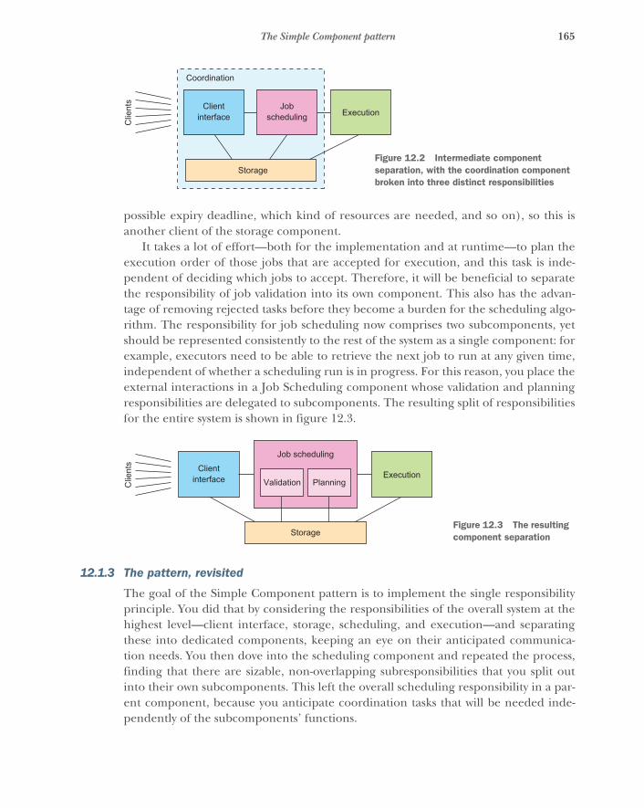
165The Simple Component pattern
possible expiry deadline, which kind of resources are needed, and so on), so this isanother client of the storage component.
It takes a lot of effort—both for the implementation and at runtime—to plan theexecution order of those jobs that are accepted for execution, and this task is inde-pendent of deciding which jobs to accept. Therefore, it will be beneficial to separatethe responsibility of job validation into its own component. This also has the advan-tage of removing rejected tasks before they become a burden for the scheduling algo-rithm. The responsibility for job scheduling now comprises two subcomponents, yetshould be represented consistently to the rest of the system as a single component: forexample, executors need to be able to retrieve the next job to run at any given time,independent of whether a scheduling run is in progress. For this reason, you place theexternal interactions in a Job Scheduling component whose validation and planningresponsibilities are delegated to subcomponents. The resulting split of responsibilitiesfor the entire system is shown in figure 12.3.
12.1.3 The pattern, revisited
The goal of the Simple Component pattern is to implement the single responsibilityprinciple. You did that by considering the responsibilities of the overall system at thehighest level—client interface, storage, scheduling, and execution—and separatingthese into dedicated components, keeping an eye on their anticipated communica-tion needs. You then dove into the scheduling component and repeated the process,finding that there are sizable, non-overlapping subresponsibilities that you split outinto their own subcomponents. This left the overall scheduling responsibility in a par-ent component, because you anticipate coordination tasks that will be needed inde-pendently of the subcomponents’ functions.
Clie
nts
Coordination
Storage
Clientinterface
Jobscheduling Execution
Figure 12.2 Intermediate component separation, with the coordination component broken into three distinct responsibilities
Clie
nts Client
interface
Job scheduling
Storage
ExecutionValidation Planning
Figure 12.3 The resulting component separation
166 CHAPTER 12 Fault tolerance and recovery patterns
By this process, you arrived at segregated components that can be treated inde-pendently during the further development of the system. Each of these has oneclearly defined purpose, and each core responsibility of the system lies with exactlyone component. Although the overall system and the internals of any componentmay be complex, the single responsibility principle yields the simplest division ofcomponents to further define—it frees you from always having to consider the entirepicture when working on smaller pieces. This is its quintessential feature: it addressesthe concern of system complexity. Additionally, following the Simple Component pat-tern simplifies the treatment of failures, a capability you will exploit in the followingtwo patterns.
12.1.4 Applicability
Simple Component is the most basic pattern to follow, and it is universally applicable.Its application may lead you to a finer-grained division of responsibility or to the reali-zation that you are dealing with only a single component—the important part is thatafterward you know why you chose your system structure as you did. It helps with alllater phases of design and implementation if you document and remember this,because when questions come up later about where to place certain functionality indetail, you can let yourself be guided by the simple question, “What is its purpose?”The answer will directly point you toward one of the responsibilities you identified, orit will send you back to the drawing board if you forgot to consider it.
It is important to remember that this pattern is meant to be applied in a recursivefashion, making sure that none of the identified responsibilities remain too complex orhigh-level. One word of warning, though: once you start dividing up components hier-archically, it is easy to get carried away and go too far—the goal is simple componentsthat have a real responsibility, not trivial components without a valid reason to exist.
12.2 The Error Kernel patternIn a supervision hierarchy, keep important application state or functionality near the rootwhile delegating risky operations towards the leaves.
This pattern builds on the Simple Component pattern and is applicable wherevercomponents with different failure probability and reliability requirements are com-bined into a larger system or application—some functions of the system must never godown, whereas others are necessarily exposed to failure. Applying the Simple Compo-nent pattern will frequently leave you in this position, so it pays to familiarize yourselfwell with the Error Kernel pattern.
This pattern has been established in Erlang programs for decades14 and was one ofthe main inspirations for Jonas Bonér to implement an Actor framework—Akka—onthe JVM. The name Akka was originally conceived as a palindrome of Actor Kernel,referring to this core design pattern.
14 The legendary reliability of the Ericsson AXD301 is attributed in part to this design pattern. Its success popu-larized both the pattern and the Erlang language and runtime that were used in its implementation.
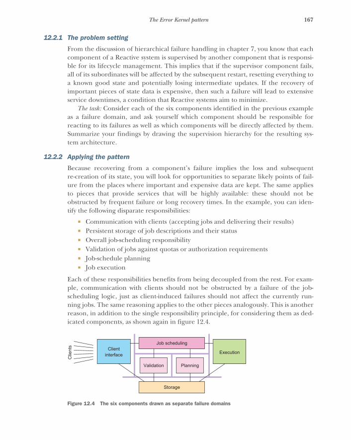
167The Error Kernel pattern
12.2.1 The problem setting
From the discussion of hierarchical failure handling in chapter 7, you know that eachcomponent of a Reactive system is supervised by another component that is responsi-ble for its lifecycle management. This implies that if the supervisor component fails,all of its subordinates will be affected by the subsequent restart, resetting everything toa known good state and potentially losing intermediate updates. If the recovery ofimportant pieces of state data is expensive, then such a failure will lead to extensiveservice downtimes, a condition that Reactive systems aim to minimize.
The task: Consider each of the six components identified in the previous exampleas a failure domain, and ask yourself which component should be responsible forreacting to its failures as well as which components will be directly affected by them.Summarize your findings by drawing the supervision hierarchy for the resulting sys-tem architecture.
12.2.2 Applying the pattern
Because recovering from a component’s failure implies the loss and subsequentre-creation of its state, you will look for opportunities to separate likely points of fail-ure from the places where important and expensive data are kept. The same appliesto pieces that provide services that will be highly available: these should not beobstructed by frequent failure or long recovery times. In the example, you can iden-tify the following disparate responsibilities:
� Communication with clients (accepting jobs and delivering their results)� Persistent storage of job descriptions and their status� Overall job-scheduling responsibility� Validation of jobs against quotas or authorization requirements� Job-schedule planning� Job execution
Each of these responsibilities benefits from being decoupled from the rest. For exam-ple, communication with clients should not be obstructed by a failure of the job-scheduling logic, just as client-induced failures should not affect the currently run-ning jobs. The same reasoning applies to the other pieces analogously. This is anotherreason, in addition to the single responsibility principle, for considering them as ded-icated components, as shown again in figure 12.4.
Clie
nts Client
interface
Storage
Execution
Validation Planning
Job scheduling
Figure 12.4 The six components drawn as separate failure domains
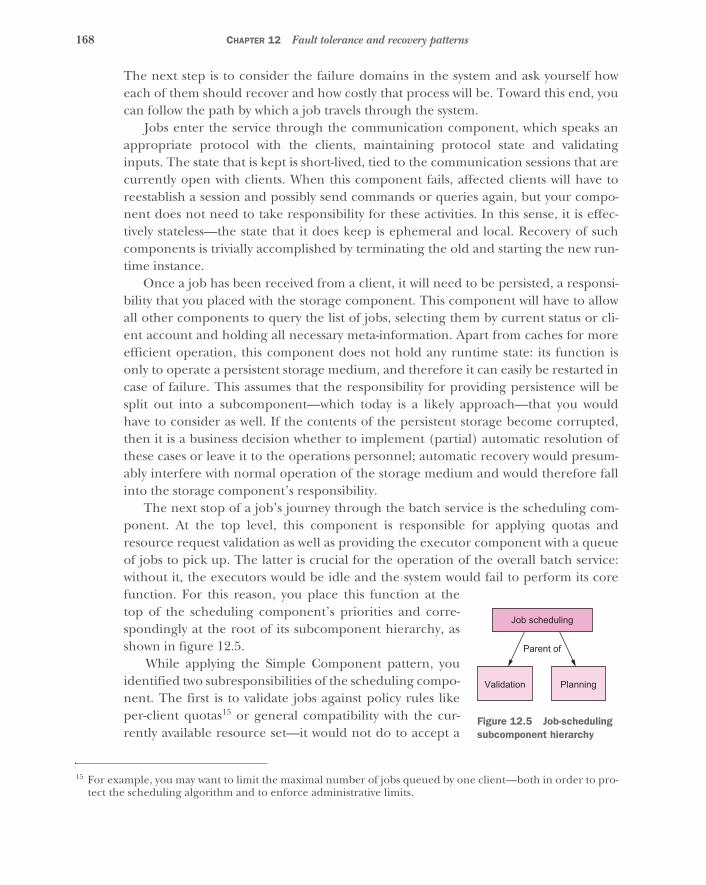
168 CHAPTER 12 Fault tolerance and recovery patterns
The next step is to consider the failure domains in the system and ask yourself howeach of them should recover and how costly that process will be. Toward this end, youcan follow the path by which a job travels through the system.
Jobs enter the service through the communication component, which speaks anappropriate protocol with the clients, maintaining protocol state and validatinginputs. The state that is kept is short-lived, tied to the communication sessions that arecurrently open with clients. When this component fails, affected clients will have toreestablish a session and possibly send commands or queries again, but your compo-nent does not need to take responsibility for these activities. In this sense, it is effec-tively stateless—the state that it does keep is ephemeral and local. Recovery of suchcomponents is trivially accomplished by terminating the old and starting the new run-time instance.
Once a job has been received from a client, it will need to be persisted, a responsi-bility that you placed with the storage component. This component will have to allowall other components to query the list of jobs, selecting them by current status or cli-ent account and holding all necessary meta-information. Apart from caches for moreefficient operation, this component does not hold any runtime state: its function isonly to operate a persistent storage medium, and therefore it can easily be restarted incase of failure. This assumes that the responsibility for providing persistence will besplit out into a subcomponent—which today is a likely approach—that you wouldhave to consider as well. If the contents of the persistent storage become corrupted,then it is a business decision whether to implement (partial) automatic resolution ofthese cases or leave it to the operations personnel; automatic recovery would presum-ably interfere with normal operation of the storage medium and would therefore fallinto the storage component’s responsibility.
The next stop of a job’s journey through the batch service is the scheduling com-ponent. At the top level, this component is responsible for applying quotas andresource request validation as well as providing the executor component with a queueof jobs to pick up. The latter is crucial for the operation of the overall batch service:without it, the executors would be idle and the system would fail to perform its corefunction. For this reason, you place this function at thetop of the scheduling component’s priorities and corre-spondingly at the root of its subcomponent hierarchy, asshown in figure 12.5.
While applying the Simple Component pattern, youidentified two subresponsibilities of the scheduling compo-nent. The first is to validate jobs against policy rules likeper-client quotas15 or general compatibility with the cur-rently available resource set—it would not do to accept a
15 For example, you may want to limit the maximal number of jobs queued by one client—both in order to pro-tect the scheduling algorithm and to enforce administrative limits.
Parent of
PlanningValidation
Job scheduling
Figure 12.5 Job-scheduling subcomponent hierarchy
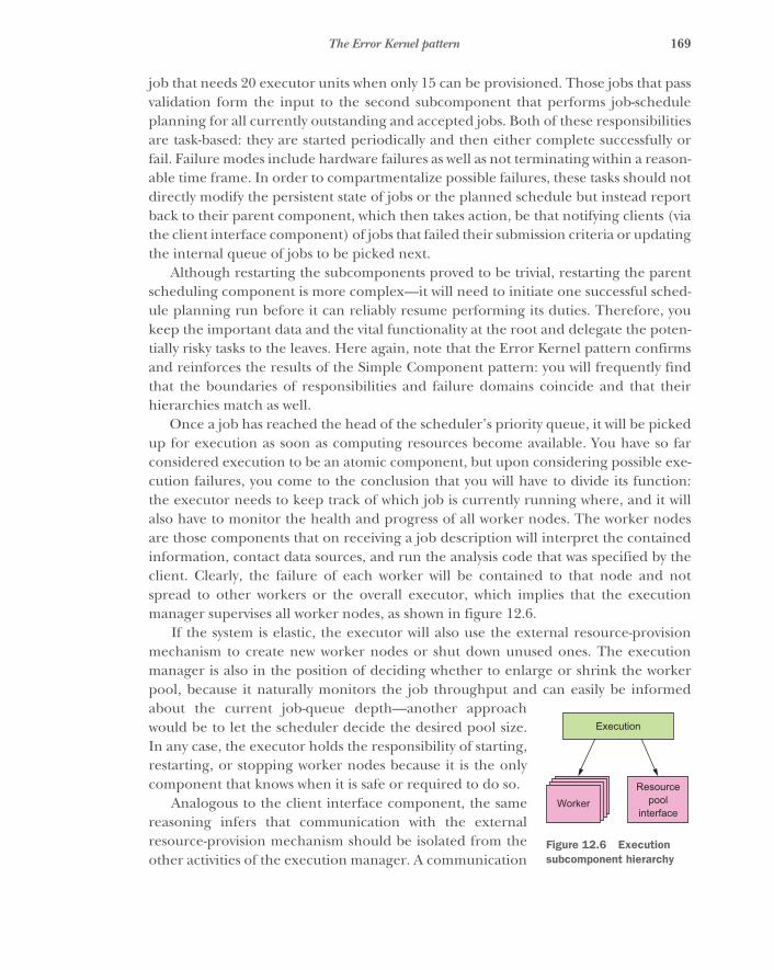
169The Error Kernel pattern
job that needs 20 executor units when only 15 can be provisioned. Those jobs that passvalidation form the input to the second subcomponent that performs job-scheduleplanning for all currently outstanding and accepted jobs. Both of these responsibilitiesare task-based: they are started periodically and then either complete successfully orfail. Failure modes include hardware failures as well as not terminating within a reason-able time frame. In order to compartmentalize possible failures, these tasks should notdirectly modify the persistent state of jobs or the planned schedule but instead reportback to their parent component, which then takes action, be that notifying clients (viathe client interface component) of jobs that failed their submission criteria or updatingthe internal queue of jobs to be picked next.
Although restarting the subcomponents proved to be trivial, restarting the parentscheduling component is more complex—it will need to initiate one successful sched-ule planning run before it can reliably resume performing its duties. Therefore, youkeep the important data and the vital functionality at the root and delegate the poten-tially risky tasks to the leaves. Here again, note that the Error Kernel pattern confirmsand reinforces the results of the Simple Component pattern: you will frequently findthat the boundaries of responsibilities and failure domains coincide and that theirhierarchies match as well.
Once a job has reached the head of the scheduler’s priority queue, it will be pickedup for execution as soon as computing resources become available. You have so farconsidered execution to be an atomic component, but upon considering possible exe-cution failures, you come to the conclusion that you will have to divide its function:the executor needs to keep track of which job is currently running where, and it willalso have to monitor the health and progress of all worker nodes. The worker nodesare those components that on receiving a job description will interpret the containedinformation, contact data sources, and run the analysis code that was specified by theclient. Clearly, the failure of each worker will be contained to that node and notspread to other workers or the overall executor, which implies that the executionmanager supervises all worker nodes, as shown in figure 12.6.
If the system is elastic, the executor will also use the external resource-provisionmechanism to create new worker nodes or shut down unused ones. The executionmanager is also in the position of deciding whether to enlarge or shrink the workerpool, because it naturally monitors the job throughput and can easily be informedabout the current job-queue depth—another approachwould be to let the scheduler decide the desired pool size.In any case, the executor holds the responsibility of starting,restarting, or stopping worker nodes because it is the onlycomponent that knows when it is safe or required to do so.
Analogous to the client interface component, the samereasoning infers that communication with the externalresource-provision mechanism should be isolated from theother activities of the execution manager. A communication
WorkerResource
poolinterface
Execution
Figure 12.6 Execution subcomponent hierarchy
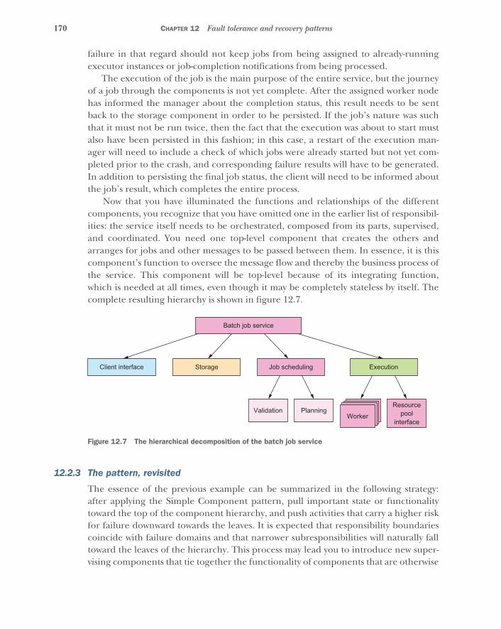
170 CHAPTER 12 Fault tolerance and recovery patterns
failure in that regard should not keep jobs from being assigned to already-runningexecutor instances or job-completion notifications from being processed.
The execution of the job is the main purpose of the entire service, but the journeyof a job through the components is not yet complete. After the assigned worker nodehas informed the manager about the completion status, this result needs to be sentback to the storage component in order to be persisted. If the job’s nature was suchthat it must not be run twice, then the fact that the execution was about to start mustalso have been persisted in this fashion; in this case, a restart of the execution man-ager will need to include a check of which jobs were already started but not yet com-pleted prior to the crash, and corresponding failure results will have to be generated.In addition to persisting the final job status, the client will need to be informed aboutthe job’s result, which completes the entire process.
Now that you have illuminated the functions and relationships of the differentcomponents, you recognize that you have omitted one in the earlier list of responsibil-ities: the service itself needs to be orchestrated, composed from its parts, supervised,and coordinated. You need one top-level component that creates the others andarranges for jobs and other messages to be passed between them. In essence, it is thiscomponent’s function to oversee the message flow and thereby the business process ofthe service. This component will be top-level because of its integrating function,which is needed at all times, even though it may be completely stateless by itself. Thecomplete resulting hierarchy is shown in figure 12.7.
12.2.3 The pattern, revisited
The essence of the previous example can be summarized in the following strategy:after applying the Simple Component pattern, pull important state or functionalitytoward the top of the component hierarchy, and push activities that carry a higher riskfor failure downward towards the leaves. It is expected that responsibility boundariescoincide with failure domains and that narrower subresponsibilities will naturally falltoward the leaves of the hierarchy. This process may lead you to introduce new super-vising components that tie together the functionality of components that are otherwise
WorkerResource
poolinterface
ExecutionJob scheduling
Batch job service
StorageClient interface
PlanningValidation
Figure 12.7 The hierarchical decomposition of the batch job service
171The Let-It-Crash pattern
siblings in the hierarchy, or it may guide you toward a more fine-grained componentstructure in order to simplify failure handling or decouple and isolate critical func-tions to keep them out of harm’s way. The quintessential function of the Error Kernelpattern is to integrate the operational constraints of the system into its responsibility-based problem decomposition.
12.2.4 Applicability
The Error Kernel pattern is applicable if any of the following are true:
� Your system consists of components that have different reliability requirements.� You expect components to have significantly different failure probabilities and
failure severities.� The system has important functionality that it must provide as reliably as possi-
ble while also having components that are exposed to failure.� Important information that is kept in one part of the system is expensive to
re-create, whereas other parts are expected to fail frequently.
The Error Kernel pattern is not applicable if the following are true:
� No hierarchical supervision scheme is used.� The system already uses the Simple Component pattern, so it does not have
multiple failure probabilities.� All components are either stateless or tolerant to data loss.
We will discuss the second kind of scenarios in more depth in the next chapter whenwe present the Active–Active Replication pattern.
12.3 The Let-It-Crash patternPrefer a full component restart to internal failure handling.
In chapter 7, we discussed principled failure handling, noting that the internal recoverymechanisms of each component are limited because they are not sufficiently separatedfrom the failing parts—everything within a component can be affected by a failure.This is especially true for hardware failures that take down the component as a whole,but it is also true for corrupted state that is the result of some programming error onlyobservable in rare circumstances. For this reason, it is necessary to delegate failurehandling to a supervisor instead of attempting to solve it within the component.
This principle is also called crash-only software: 16 the idea is that transient but rarefailures are often costly to diagnose and fix, making it preferable to recover a workingsystem by rebooting parts of it. This hierarchical restart-based failure handling makes
16 Both of the following articles are by George Candea and Armando Fox: “Recursive Restartability: Turning theReboot Sledgehammer into a Scalpel,” USENIX HotOS VIII, 2001, http://dslab.epfl.ch/pubs/recursive_restartability.pdf; and “Crash-Only Software,” USENIX HotOS IX, 2003, https://www.usenix.org/legacy/events/hotos03/tech/full_papers/candea/candea.pdf.
172 CHAPTER 12 Fault tolerance and recovery patterns
it possible to greatly simplify the failure model and at the same time leads to a morerobust system that even has a chance to survive failures that were entirely unforeseen.
12.3.1 The problem setting
We will demonstrate this design philosophy using the example of the worker nodesthat perform the bulk of the work in the batch service whose component hierarchywas developed in the previous two patterns. Each of these is presumably deployed onits own hardware—virtualized or not—that it does not share with other components;ideally, there is no common failure mode between different worker nodes other thana computing center outage.
The problem you are trying to solve is that the workers’ code may contain pro-gramming errors that rarely manifest—but when they do, they will impede the abilityto process batch jobs. Examples of this kind are very slow resource leaks that can goundetected for a long time but will eventually kill the machine; such a leak couldresult from open files, retained memory, background threads, and so on, and it maynot occur every time but could be caused by a rare coincidence of circumstances.Another example is a security vulnerability that allows the executed batch job to inten-tionally corrupt the state of the worker node in order to subvert its function and per-form unauthorized actions within the service’s private network—such subversionoften is not completely invisible and leads to spurious failures that should not bepapered over.
The task: Your mission is to consider the components you have identified for thebatch service and describe how a crash and restart would affect each of them andwhich implementation constraints arise from the let-it-crash philosophy.
12.3.2 Applying the pattern
The Let-It-Crash pattern by itself is simple: whenever a component—for example, aworker node—is detected to be faulty, no attempt is made to repair the damage.Instead of doctoring its internal state, you restart it completely, releasing all of itsresources and starting it up again from scratch. If you obtained the worker nodes byasking an infrastructure service to provision them, you can go back to the most basicstate imaginable: you decommission the old worker node and provision an entirelynew one. This way, no corruption or accumulated failure condition can have survivedin the fresh instance, because you begin from a known good state again.
Applying this approach to the client interface nodes means all currently active cli-ent connections will be severed for the failed node, leading to connection-abort errorsin the clients. Upon detecting such an abort condition, the client should try to recon-nect, which is your first conclusion. The second follows immediately when consideringthat the new connection should not be routed to the failed node; this usually meanschanging the load balancer configuration to remove the failed node. Then, a newnode needs to be brought online and added to the load balancer to restore the sameprocessing capacity as before. With these measures, you can confidently crash andrestart a client interface node at any given point in time. You do not need to consider
173The Let-It-Crash pattern
the internal communication, because no other components depend on this one: theclient interface has only dependencies, no dependents. The consequence of this is thatnew client requests that a fresh node receives will refer to the storage or schedulingcomponents as the sources of truth—the client interface can be “stateless.”17
For the storage component, a node failure means the stored data are invalid orlost—the consequence of either possibility is that the data cannot be relied on anylonger, so these states are fundamentally equivalent. Because the purpose of the com-ponent is to store data permanently, you will have to distribute storage components asper the discussion in section 2.4. We will cover data replication in the next chapter;for now, it suffices to assume that there will be other storage nodes that hold copies ofthe data. After stopping the failed node, you will therefore need to start a new onethat synchronizes itself with the other replicas, taking on the share of responsibilitythat the failed node had. If the new node uses the previous node’s permanent storagedevice, then recovery can be speeded up by synchronizing only those updates thatoccurred after the failure. It should be noted that failure is not the same as shuttingdown and starting up again: the storage devices will keep the data across the shut-down, and the system will start up normally afterward—this can even be done in manycases of infrastructure outages (such as network or power failures).
In the case of the scheduling component, a crash and restart means repopulatingthe internal state from persistent job storage and resuming operations. This is trivialfor an aborted planning run or a failure during job validation, and it can also be han-dled easily for the top-level scheduling component: you used the Error Kernel patternto keep this piece of software simple so you could assume that a restart cycle takes asufficiently short time to be deemed an acceptable downtime, unless specific require-ments force you to use replication here as well.
The execution component works similarly in that the worker nodes can crash andbe restarted as discussed, where the supervisor makes sure the affected batch job isstarted again on another available node (or on the newly provisioned one). For theresource pool interface, you can tolerate a short downtime while it is restarted,because its services are rarely needed; and when they are needed, reaction times willbe of the order of many seconds or even minutes.
12.3.3 The pattern, revisited
We have looked at each of the components in the system’s supervision hierarchy andconsidered the consequences of a failure and subsequent restart. In some cases, youencounter implementation constraints like having to update the request-routinginfrastructure so that the failed node is no longer considered and the replacement istaken into account once it is ready. In other cases, you approach the formulation ofSLAs by saying that a short downtime may be acceptable: in a real system, you would
17 This word has become so widely (mis)used that it does not stand on its own any longer. The authors’ view isthat a truly stateless service that does not contain any mutable internal state does not exist (it would not be acomponent with a purpose to exist), and a more meaningful interpretation is to equate statelessness with theabsence of persistent mutable state.
174 CHAPTER 12 Fault tolerance and recovery patterns
quantify this both in the failure frequency (for example, by way of the mean timebetween failures [MTBF]18) and the extent of the outage (also called the mean time torepair [MTTR]19).
This pattern can also be turned around so that components are “crashed” inten-tionally on a regular basis instead of waiting for failures to occur—this could betermed the Pacemaker pattern. Deliberately inducing failures has been standard operat-ing procedure for a long time in high-availability scenarios, to verify that failovermechanisms are effective and perform according to specification. The concept hasbeen popularized in recent years by the Chaos Monkey employed by Netflix20 to estab-lish and maintain the resilience of the company’s infrastructure. The chaotic natureof this approach manifests in that single nodes are killed at random without priorselection or human consideration. The idea is that in this way, failure modes are exer-cised that could potentially be missed in human enumeration of all possible cases. Ona higher level, entire data centers and geographic regions are taken offline in a moreprepared manner to verify global resource reallocation—this is done on the live pro-duction system because no simulation environment could practically emulate the loadand client dynamics of such a large-scale application.
Another way to look at this is to consider the definition of availability: it is the frac-tion of time during which the system is not in a failure state and thus able to processrequests, which in mathematical terms is (MTBF – MTTR) / MTBF. This can beincreased either by making MTBF larger—which corresponds to less frequent but pos-sibly extensive failures—or by making MTTR smaller. In the latter case, the maximumconsecutive downtime period is smaller and the system operates more smoothly,which is the goal of the Let-It-Crash pattern.
12.3.4 Implementation considerations
Although this pattern is deeply ingrained in Reactive application design already, it isnevertheless documented here to take note of its important consequences on thedesign of components and their interaction:
� Each component must tolerate a crash and restart at any point in time, just as apower outage can happen without warning. This means all persistent state mustbe managed such that the service can resume processing requests with all neces-sary information and ideally without having to worry about state corruption.
� Each component must be strongly encapsulated so that failures are fully con-tained and cannot spread. The practical realization depends on the failuremodel for the hierarchy level under consideration; the options range from
18 https://en.wikipedia.org/wiki/Mean_time_between_failures19 https://en.wikipedia.org/wiki/Mean_time_to_repair20 At the time of writing, the largest streaming video provider in the United States. Chaos Monkey is part of the
Simian Army project that is available as open source software at https://github.com/Netflix/SimianArmy.The approach is described in detail at http://techblog.netflix.com/2012/07/chaos-monkey-released-into-wild.html.
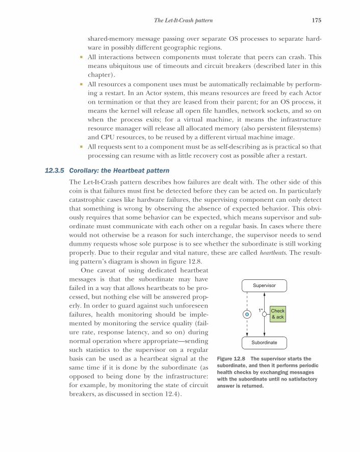
175The Let-It-Crash pattern
shared-memory message passing over separate OS processes to separate hard-ware in possibly different geographic regions.
� All interactions between components must tolerate that peers can crash. Thismeans ubiquitous use of timeouts and circuit breakers (described later in thischapter).
� All resources a component uses must be automatically reclaimable by perform-ing a restart. In an Actor system, this means resources are freed by each Actoron termination or that they are leased from their parent; for an OS process, itmeans the kernel will release all open file handles, network sockets, and so onwhen the process exits; for a virtual machine, it means the infrastructureresource manager will release all allocated memory (also persistent filesystems)and CPU resources, to be reused by a different virtual machine image.
� All requests sent to a component must be as self-describing as is practical so thatprocessing can resume with as little recovery cost as possible after a restart.
12.3.5 Corollary: the Heartbeat pattern
The Let-It-Crash pattern describes how failures are dealt with. The other side of thiscoin is that failures must first be detected before they can be acted on. In particularlycatastrophic cases like hardware failures, the supervising component can only detectthat something is wrong by observing the absence of expected behavior. This obvi-ously requires that some behavior can be expected, which means supervisor and sub-ordinate must communicate with each other on a regular basis. In cases where therewould not otherwise be a reason for such interchange, the supervisor needs to senddummy requests whose sole purpose is to see whether the subordinate is still workingproperly. Due to their regular and vital nature, these are called heartbeats. The result-ing pattern’s diagram is shown in figure 12.8.
One caveat of using dedicated heartbeatmessages is that the subordinate may havefailed in a way that allows heartbeats to be pro-cessed, but nothing else will be answered prop-erly. In order to guard against such unforeseenfailures, health monitoring should be imple-mented by monitoring the service quality (fail-ure rate, response latency, and so on) duringnormal operation where appropriate—sendingsuch statistics to the supervisor on a regularbasis can be used as a heartbeat signal at thesame time if it is done by the subordinate (asopposed to being done by the infrastructure:for example, by monitoring the state of circuitbreakers, as discussed in section 12.4).
Check& ack
1*
Supervisor
Subordinate
Figure 12.8 The supervisor starts the subordinate, and then it performs periodic health checks by exchanging messages with the subordinate until no satisfactory answer is returned.
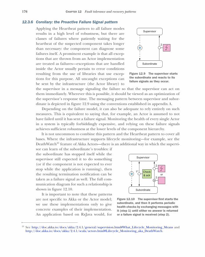
176 CHAPTER 12 Fault tolerance and recovery patterns
12.3.6 Corollary: the Proactive Failure Signal pattern
Applying the Heartbeat pattern to all failure modesresults in a high level of robustness, but there areclasses of failures where patiently waiting for theheartbeat of the suspected component takes longerthan necessary: the component can diagnose somefailures itself. A prominent example is that all excep-tions that are thrown from an Actor implementationare treated as failures—exceptions that are handledinside the Actor usually pertain to error conditionsresulting from the use of libraries that use excep-tions for this purpose. All uncaught exceptions canbe sent by the infrastructure (the Actor library) tothe supervisor in a message signaling the failure so that the supervisor can act onthem immediately. Wherever this is possible, it should be viewed as an optimization ofthe supervisor’s response time. The messaging pattern between supervisor and subor-dinate is depicted in figure 12.9 using the conventions established in appendix A.
Depending on the failure model, it can also be adequate to rely entirely on suchmeasures. This is equivalent to saying that, for example, an Actor is assumed to nothave failed until it has sent a failure signal. Monitoring the health of every single Actorin a system is typically forbiddingly expensive, and relying on these failure signalsachieves sufficient robustness at the lower levels of the component hierarchy.
It is not uncommon to combine this pattern and the Heartbeat pattern to cover allbases. Where the infrastructure supports lifecycle monitoring—for example, see theDeathWatch21 feature of Akka Actors—there is an additional way in which the supervi-sor can learn of the subordinate’s troubles: ifthe subordinate has stopped itself while thesupervisor still expected it to do something(or if the component is not expected to everstop while the application is running), thenthe resulting termination notification can betaken as a failure signal as well. The full com-munication diagram for such a relationship isshown in figure 12.10.
It is important to note that these patternsare not specific to Akka or the Actor model;we use these implementations only to giveconcrete examples of their implementation.An application based on RxJava would, for
21 See http://doc.akka.io/docs/akka/2.4.1/general/supervision.html#What_Lifecycle_Monitoring_Means andhttp://doc.akka.io/docs/akka/2.4.1/scala/actors.html#Lifecycle_Monitoring_aka_DeathWatch.
Supervisor
Subordinate
2
Figure 12.9 The supervisor starts the subordinate and reacts to its failure signals as they occur.
Supervisor
Subordinate
2
2or
Check& ack
1*
Figure 12.10 The supervisor first starts the subordinate, and then it performs periodic health checks by exchanging messages with it (step 1) until either no answer is returned or a failure signal is received (step 2).
177The Circuit Breaker pattern
example, use the Hystrix library for health monitoring, allowing components to berestarted as needed. Another example is that the deployment of components asmicroservices on Amazon EC2 could use the AWS API to learn of some nodes’ termina-tion and react in the same fashion as just described for the DeathWatch feature.
12.4 The Circuit Breaker patternProtect services by breaking the connection to their users during prolonged failure conditions.
In previous sections, we discussed how to segregate a system into a hierarchy of com-ponents and subcomponents for the purpose of isolating responsibilities and encapsu-lating failure domains. This pattern describes how to safely connect different parts ofthe system so that failures do not spread uncontrollably across them. Its origin lies inelectrical engineering: in order to protect electrical circuits from each other andintroduce decoupled failure domains, a technique was established of breaking theconnection when the transmitted power exceeds a given threshold.
Translated to a Reactive application, this means the flow of requests from one com-ponent to the next may be broken up deliberately when the recipient is overloaded orotherwise failing. Doing so serves two purposes: first, the recipient gets some breath-ing room to recover from possible load-induced failures; and second, the senderdecides that requests will fail instead of wasting time with waiting for negative replies.
Although circuit breakers have been used in electrical engineering since the1920s, the use of this principle has been popularized in software design only recently:for example, by Michael Nygard’s book Release It! (Pragmatic Programmers, 2007).
12.4.1 The problem setting
The batch job execution facility designed in the previous three sections will serve youyet again. We already hinted at one situation that would do well to include a circuitbreaker: when the service is offered to external clients who submit jobs at their own rateand schedule, and jobs are not naturally bounded by the capacity of the batch system.
To visualize what this means, we will consider a single client that contacts the batchservice to submit a single job. The client will get multiple status updates as the submit-ted job progresses through the system:
� Upon having received and persisted the job description� Upon having accepted the job for execution, or upon rejecting it due to policy
violations� Upon starting execution� Upon finishing execution
The first of these steps is very important: it assures the client that there will be furtherupdates about this job because it has been admitted into the system and will at least beexamined. Providing this guarantee is costly—it involves storing the job description innonvolatile and replicated memory—and therefore a client could easily generate morejobs per second than the system can safely ingest. In this case, the client interface

178 CHAPTER 12 Fault tolerance and recovery patterns
would overload the storage subsystem: this would have a ripple effect for the job-scheduling and execution components, which would experience degraded perfor-mance when accessing job descriptions for their purposes. The system might still workin this state, but its performance characteristics would be quite different from normaloperation; it would be in “overload mode.”
The task: Your mission is to sketch the use of circuit breakers between the clientinterface component and the storage component to both ensure that clients cannotwillfully overload the storage and ensure that the client interface gives timelyresponses even when the storage component is unreachable or has failed.
12.4.2 Applying the pattern
When implementing the client interface module, you will have to write one piece ofcode that sends requests to the storage subsystem. If you make sure all such requeststake this single route, you will have an easy time reacting to the problematic scenariosoutlined earlier. You need to keep track of the response latency for all requests thatare made. When you observe that this latency rises consistently above the agreed limit,then you can switch into “emergency mode”: instead of trying new requests, you willanswer all subsequent ones immediately with negative replies. You will fabricate thenegative replies on behalf of the storage subsystem, because it cannot do even thatwithin the allowed time window under the current conditions.
In addition, you should monitor the failure rate of replies that come back from thestorage subsystem. It does not make much sense to keep sending more storagerequests when all of them will be answered negatively anyway; instead of wasting net-work bandwidth, you should again switch into emergency mode, fabricating the nega-tive replies. An example implementation of this scheme in Akka would look like thefollowing listing.
private object StorageFailed extends RuntimeExceptionprivate def sendToStorage(job: Job): Future[StorageStatus] = {
val f: Future[StorageStatus] = . . .
f.map {case StorageStatus.Failed => throw StorageFailedcase other => other
}}
private val breaker = CircuitBreaker(system.scheduler,5,300.millis,30.seconds,
)
Listing 12.1 Using a circuit breaker to give a failed component time to recover
Makes an asynchronous requestto the storage subsystem
Maps storage failures to Future failures to alert the breaker
Used for scheduling timeoutsNumber of failures in a row Timeout for each service call Time before trying to close after tripping
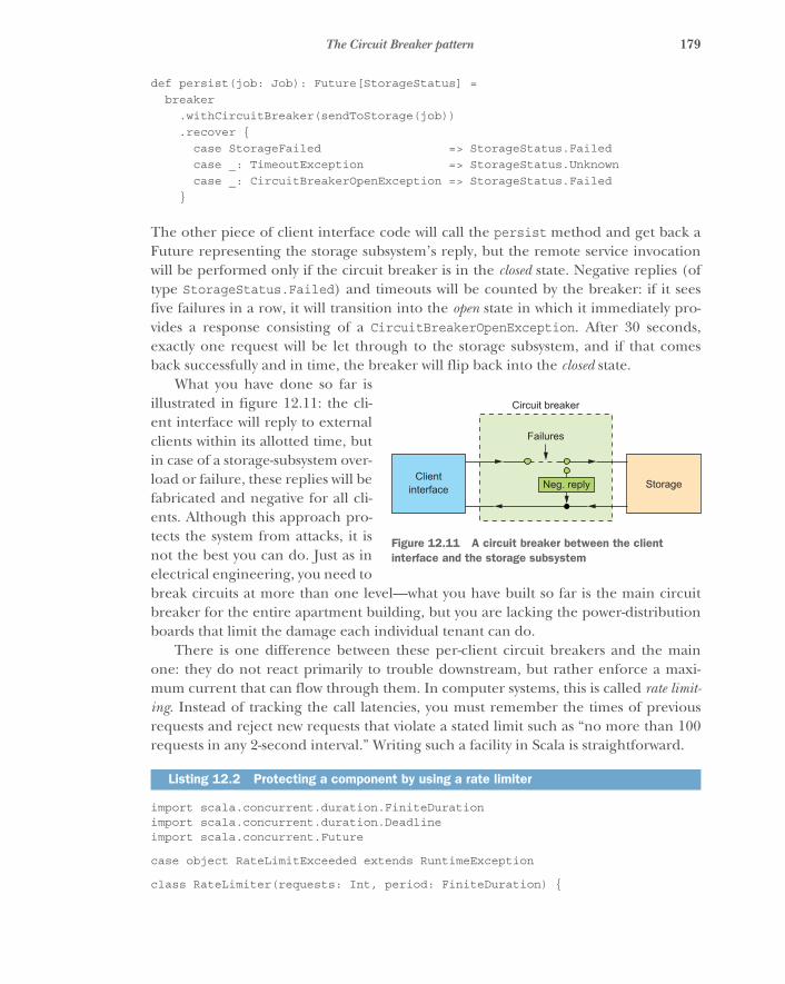
179The Circuit Breaker pattern
def persist(job: Job): Future[StorageStatus] =breaker
.withCircuitBreaker(sendToStorage(job))
.recover {case StorageFailed => StorageStatus.Failedcase _: TimeoutException => StorageStatus.Unknowncase _: CircuitBreakerOpenException => StorageStatus.Failed
}
The other piece of client interface code will call the persist method and get back aFuture representing the storage subsystem’s reply, but the remote service invocationwill be performed only if the circuit breaker is in the closed state. Negative replies (oftype StorageStatus.Failed) and timeouts will be counted by the breaker: if it seesfive failures in a row, it will transition into the open state in which it immediately pro-vides a response consisting of a CircuitBreakerOpenException. After 30 seconds,exactly one request will be let through to the storage subsystem, and if that comesback successfully and in time, the breaker will flip back into the closed state.
What you have done so far isillustrated in figure 12.11: the cli-ent interface will reply to externalclients within its allotted time, butin case of a storage-subsystem over-load or failure, these replies will befabricated and negative for all cli-ents. Although this approach pro-tects the system from attacks, it isnot the best you can do. Just as inelectrical engineering, you need tobreak circuits at more than one level—what you have built so far is the main circuitbreaker for the entire apartment building, but you are lacking the power-distributionboards that limit the damage each individual tenant can do.
There is one difference between these per-client circuit breakers and the mainone: they do not react primarily to trouble downstream, but rather enforce a maxi-mum current that can flow through them. In computer systems, this is called rate limit-ing. Instead of tracking the call latencies, you must remember the times of previousrequests and reject new requests that violate a stated limit such as “no more than 100requests in any 2-second interval.” Writing such a facility in Scala is straightforward.
import scala.concurrent.duration.FiniteDurationimport scala.concurrent.duration.Deadlineimport scala.concurrent.Future
case object RateLimitExceeded extends RuntimeException
class RateLimiter(requests: Int, period: FiniteDuration) {
Listing 12.2 Protecting a component by using a rate limiter
Clientinterface Storage
Failures
Circuit breaker
Neg. reply
Figure 12.11 A circuit breaker between the client interface and the storage subsystem

180 CHAPTER 12 Fault tolerance and recovery patterns
private val startTimes = {val onePeriodAgo = Deadline.now - periodArray.fill(requests)(onePeriodAgo)
}
private var position = 0
private def enqueue(time: Deadline) = {startTimes(position) = timeposition += 1if (position == requests) position = 0
}
def call[T](block: => Future[T]): Future[T] = {val now = Deadline.nowif ((now - startTimes(position)) < period) {
Future.failed(RateLimitExceeded)} else {
enqueue(now)block
}}
}
Now you can combine both kinds of circuit breakers to obtain the full picture shownin figure 12.12. Clients are identified by their authentication credentials, so you canassign one CircuitBreaker for each user independent of how many network connec-tions they use. For each client, you maintain a RateLimiter that protects the clientinterface from being flooded with requests. On the outgoing side, toward the storagecomponent, you use one shared CircuitBreaker to guard against the remote subsys-tem’s failures. The per-client code could look like the following.
private val limiter = new RateLimiter(100, 2.seconds)
def persistForThisClient(job: Job): Future[StorageStatus] =limiter
.call(persist(job))
.recover {case RateLimitExceeded => StorageStatus.Failed
}
Listing 12.3 Circuit breaker: limiting requests from a client
Index of the next slot to be used, keeping track of when the last job was enqueued in it to enforce the rate limit
Obtains the current timestamp
Per-client breakers
Storage
Failures
Neg. replyNeg. reply
Ratelimiter
Neg. reply
Figure 12.12 Complete circuit breaker setup between the client interface and the storage subsystem
This is assumed to not be invoked concurrently as it is for a single client.
181The Circuit Breaker pattern
ADVANCED USAGE
It is common practice to gate a client that repeatedly violates its rate limit: gatinginforms the client that it has made too many requests beyond the allowed rate and willbe blocked temporarily. This is an incentive to the writers of client code to properlylimit the service calls on their end instead of always sending at full speed—that is anefficient tactic for achieving maximum throughput. In order to do that, you only needto add another circuit breaker, as shown next.
private val limiter = new RateLimiter(100, 2.seconds)private val breaker = CircuitBreaker(system.scheduler,
10, Duration.Zero, 10.seconds)
def persistForThisClient(job: Job): Future[StorageStatus] =breaker
.withCircuitBreaker(limiter.call(persist(job)))
.recover {case RateLimitExceeded => StorageStatus.Failedcase _: CircuitBreakerOpenException => StorageStatus.Gated
}
In order to trip the circuit breaker, the client will have to send 10 requests while beingabove the rate limit; assuming regular request spacing, this means the client needs tosubmit at a rate that is at least 10% higher than allowed. In this case, it will be blockedfrom service for the next 10 seconds, and it will be informed by way of receiving aGated status reply. Duration.Zero in listing 12.4 has the function of turning off thetimeout tracking for individual requests; this is not needed here because it will be per-formed by the persist call.
12.4.3 The pattern, revisited
You have decoupled the client interface and the storage subsystem by introducing pre-determined breaking points on the path from one to the other. Thereby, you haveprotected the storage from being overloaded in general (the main circuit breaker)and you have protected the client interface’s function from single misbehaving clients(the rate-limiting per-client circuit breakers). Being overloaded is a condition that youshould strive to avoid when possible because running at 100% capacity is in most casesless efficient than leaving a little headroom. The reason is that at full capacity, moretime is wasted competing for the available resources (CPU time, memory bandwidth,caches, IO channels) than it is when requests can travel through the system mostlyunhindered by congestion.
The second problem we have considered here is that the client interface cannotacknowledge reception of a job description before it receives the successful reply fromthe storage subsystem. If this reply does not arrive within the allotted time, then theresponse to the client will be delayed for longer than the SLA allows—the service willviolate its latency bound. This means during time periods when the storage subsystem
Listing 12.4 Gating a client
182 CHAPTER 12 Fault tolerance and recovery patterns
fails to answer promptly, the client interface will have to come to its own conclusions;if it cannot ask another (nonlocal) component, then it must locally determine theappropriate response to its own clients. You have also used the circuit breaker to pro-tect the client interface from failures of the storage subsystem, fabricating negativeresponses in case no others are readily available.
In addition, you have seen that the circuit breaker you installed for overload pro-tection handles the situation where the storage subsystem does not answer successfullyor in time—the reaction is independent of the underlying reason. This makes the systemmore resilient compared to handling every single error case separately. And this is what is meantby bulkheading failure domains to achieve compartmentalization and encapsulation.
12.4.4 Applicability
This pattern is applicable wherever two decoupled components communicate andwhere failures—foreseen or unexpected—will not travel upstream to infect and slowother components, or where overload conditions will not travel downstream to inducefailure. Decoupling has a cost in that all calls pass through another tracking step, andtimeouts need to be scheduled. Hence, it should not be applied at too fine a level ofgranularity; it is most useful between different components in a system. This appliesespecially to services that are reached via network connections (such as authenticationproviders and persistent storage), where the circuit breaker also reacts appropriatelyto network failures by concluding that the remote service is not currently reachable.
Another important aspect of using circuit breakers is that monitoring their statereveals interesting insight into the runtime behavior and performance of a service.When circuit breakers trip while protecting a given service, operations personnel willusually want to be alerted in order to look into the outage.
NOTE A circuit breaker is a means to fail fast—it must not be used to post-pone requests and send them later. The problem with such a scheme is thatwhen the circuit breaker closes, the deferred requests will likely overload thetarget system. This phenomenon is called a thundering herd, and it can createfeedback loops that lead to a system oscillating between being unavailableand being overloaded.
12.5 SummaryIn this chapter, we have covered a lot of ground on the design and implementation ofresilient systems:
� We described simple components that obey the single responsibility principle.� You saw the application of hierarchical failure handling in practice while imple-
menting the Error Kernel pattern.� We noted the implications of relying on component restarts to recover from
failure, in our discussion of the Let-It-Crash pattern.

183Summary
� You learned how to decouple components from each other using the CircuitBreaker pattern for either side’s protection.
In the next chapter, we will dive into stateful replication patterns in order to imple-ment components that are impervious to outages at varying degrees of downtime andimplementation complexity. Although these patterns are also related to fault toler-ance and recovery, they warrant a chapter of their own.
184
Replication patterns
The previous chapter introduced powerful architectural and implementation pat-terns for breaking down a larger system into simple components that are isolatedfrom each other while encapsulating failures. One aspect that we did not cover ishow to distribute the functionality of a component such that it can withstand hard-ware and infrastructure outages without loss of availability. This topic is largeenough by itself to be treated in a separate chapter. In particular, in this chapteryou will learn about the following:
� The Active–Passive Replication pattern, for cases where explicit failover isacceptable or desirable
� Three different Multiple-Master Replication patterns that allow clients tocontact any replica of their choosing
� The Active–Active Replication pattern, which specializes in zero downtimefor a selected class of failures
NOTE This chapter presents some deep treatment of replication with itspitfalls and limitations. Unfortunately, for this topic, the devil is in thedetails, and some surprising semantics result from seemingly insignificantproperties of the underlying implementation. Therefore, it may be ade-quate to only skim this chapter upon reading this book for the first timeand come back to it when necessary or when your experience with buildingReactive systems inspires a wish to deepen your knowledge of these aspects.
13.1 The Active–Passive Replication patternKeep multiple copies of the service running in different locations, but only acceptmodifications to the state in one location at any given time.
185The Active–Passive Replication pattern
This pattern is also sometimes referred to as failover or master–slave replication. You havealready seen one particular form of failover: the ability to restart a component meansthat after a failure, a new instance is created and takes over functionality, like passingthe baton from one runner to the next. For a stateful service, the new instanceaccesses the same persistent storage location as the previously failed one, recoveringthe state before the crash and continuing from there. This works only as long as thepersistent storage is intact; if that fails, then restarting is not possible—the service willforget all of its previous state and start from scratch. Imagine your web shop forgettingabout all registered users—that would be a catastrophe!
We use the term active–passive replication to more precisely denote that in order tobe able to recover even when one service instance fails completely—including loss ofits persistent storage—you distribute its functionality and its full dataset across severalphysical locations. The need for such measures was discussed in section 2.4: replica-tion means not putting all of your eggs in one basket.
Replicating and thereby distributing a piece of functionality requires a certainamount of coordination, in particular considering operations that change the per-sistent state. The goal of active–passive replication is to ensure that at any given time,only one of the replicas has the right to perform modifications. This allows individualmodifications to be made without requiring consensus about them, as long as there isconsensus about what the currently active party is, just as electing a mayor serves thepurpose of simplifying the process of coordination within a city.
13.1.1 The problem setting
In the batch service example, the most important component used by all the othercomponents is the storage module. Restarting this component after a failure allows itto recover from many issues, but you must take care to protect its data from being lost.This means storing the data in multiple places and allowing the other components toretrieve the data from any of them.
In order to visualize what this means, we will consider an incoming request thatarrives at the client interface. Because the storage component is now spread acrossmultiple locations, the client interface will need to know multiple addresses in orderto talk to it. Assume that there is a service registry via which all components can obtainthe addresses of their communication partners. When the storage component startsup, it will register all of its locations and their addresses in the registry, where the cli-ent interface can retrieve them. This allows new replicas to be added and old ones tobe replaced at runtime. A static list of addresses might be sufficient in some cases, butit is in general desirable to be able to change addresses, especially in a cloud comput-ing environment.
Which replica is the active one will change over time. There are several options forrouting requests to it:
� The storage component can inform its clients via the service registry regardingwhich address belongs to the currently active replica. This simplifies the
186 CHAPTER 13 Replication patterns
implementation of the client but also leads to additional lag for picking up achange of replica after a failure.
� The internal consensus mechanism for electing the active replica can be madeaccessible to the clients, allowing them to follow changes by listening in on theelection protocol. This provides timely updates but couples the implementationof client and service by requiring them to share a larger protocol.
� All replicas can offer the service of forwarding requests to the currently activereplica. This frees clients from having to track replica changes closely whileavoiding downtime or close coupling. A possible downside of this approach isthat requests sent via different replicas may arrive with substantially differentdelays, thereby making the ordering of request processing less deterministic.
The task: Your mission is to implement active–passive replication for a key–value store(represented by an in-memory map) using Akka Cluster, with the location of theactive replica being managed by the Cluster Singleton feature. An important propertyof the implementation is that once the service replies with a confirmation, the requestmust have been processed and its results persisted to disk such that after a subsequentfailure, the new active replica will behave correctly.
13.1.2 Applying the pattern
Basing this illustration on Akka Cluster allows us to focus on the replication logic anddelegate the election of the active replica to the Cluster Singleton feature that isoffered by this library. A cluster singleton is an actor that is spawned on the oldest clus-ter member with a given role. The Akka implementation ensures that there cannot beconflicting information about which member is the oldest within the same cluster,which means there cannot be two instances of the cluster singleton running simulta-neously. This guarantee relies on the proper configuration of the cluster: during anetwork partition, each of the isolated parts will have to decide whether to continueoperation or shut itself down; and if the rules are formulated such that two parts cancontinue running, then a singleton will be elected within each of these parts. Wherethis is not desired, a strict quorum must be employed that is larger than half the totalnumber of nodes in the cluster—with the consequence that during a three-way split,the entire cluster may shut down. Further discussion of these topics can be found inchapter 17; for now, it is sufficient to know that the Cluster Singleton mechanismensures that there will be only one active replica running at any time.
As a first step, you implement the actor that controls the active replica. This actorwill be instantiated by the Cluster Singleton mechanism as a cluster-wide singleton, asjust explained. Its role is to accept and answer requests from clients as well as to dissem-inate updates to all passive replicas. To keep things simple, you will implement a generickey–value store that associates JSON values and uses text strings as keys. This will saveyou the trouble of defining the required data types for your batch service operation—which is not central to the application of this pattern, in any case. The full source code

187The Active–Passive Replication pattern
for this example can be found at www.manning.com/books/reactive-design-patternsand in the book’s GitHub repository at https://github.com/ReactiveDesignPatterns.
Before we begin, here are the protocol messages by which clients interact with thereplicated storage:
case class Put(key: String, value: JsValue, replyTo: ActorRef)case class PutConfirmed(key: String, value: JsValue)case class PutRejected(key: String, value: JsValue)case class Get(key: String, replyTo: ActorRef)case class GetResult(key: String, value: Option[JsValue])
In response to a Put command, you expect either a confirmation or rejection reply,whereas the result of a Get command will always indicate the currently bound valuefor the given key (which may optionally be empty). A command may be rejected incase of replication failures or service overload, as you will see later. The type JsValuerepresents an arbitrary JSON value in the play-json library, but the choice of serializa-tion library is not essential here.
When the singleton actor starts up, it must first contact a passive replica to obtainthe current starting state. It is most efficient to ask the replica within the same actorsystem (that is, on the same network host), because doing so avoids serializing theentire data store and sending it over the network. In the following implementation,the address of the local replica is provided to the actor via its constructor.
class Active(localReplica: ActorRef,replicationFactor: Int,maxQueueSize: Int)
extends Actor with Stash with ActorLogging {
private var theStore: Map[String, JsValue] = _
private var seqNr: Iterator[Int] = _
log.info("taking over from local replica")localReplica ! TakeOver(self)
def receive = {case InitialState(m, s) =>
log.info("took over at sequence {}", s)theStore = mseqNr = Iterator from scontext.become(running)unstashAll()
case _ => stash()}
val running: Receive = ...}
While the actor is waiting for the initial state message, it needs to ignore all incomingrequests. Instead of dropping them or making up fake replies, you stash them withinthe actor, to be answered as soon as you have the necessary data. Akka directly supports
Listing 13.1 Singleton taking over as the active replica
Data store, held in memory for the sake of a simple example
Sequence-number generator for Replicate requests
Asks for InitialData to be provided by the local storage replica
Behavior of the running state
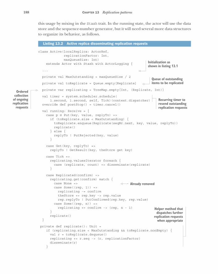
188 CHAPTER 13 Replication patterns
this usage by mixing in the Stash trait. In the running state, the actor will use the datastore and the sequence-number generator, but it will need several more data structuresto organize its behavior, as follows.
class Active(localReplica: ActorRef,replicationFactor: Int,maxQueueSize: Int)
extends Actor with Stash with ActorLogging {
...
private val MaxOutstanding = maxQueueSize / 2
private val toReplicate = Queue.empty[Replicate]
private var replicating = TreeMap.empty[Int, (Replicate, Int)]
val timer = system.scheduler.schedule( 1.second, 1.second, self, Tick)(context.dispatcher)
override def postStop() = timer.cancel()
val running: Receive = {case p @ Put(key, value, replyTo) =>
if (toReplicate.size < MaxOutstanding) {toReplicate.enqueue(Replicate(seqNr.next, key, value, replyTo))replicate()
} else {replyTo ! PutRejected(key, value)
}
case Get(key, replyTo) =>replyTo ! GetResult(key, theStore get key)
case Tick =>replicating.valuesIterator foreach {
case (replicate, count) => disseminate(replicate)}
case Replicated(confirm) =>replicating.get(confirm) match {
case None =>case Some((rep, 1)) =>
replicating -= confirmtheStore += rep.key -> rep.valuerep.replyTo ! PutConfirmed(rep.key, rep.value)
case Some((rep, n)) =>replicating += confirm -> (rep, n - 1)
}replicate()
}
private def replicate(): Unit =if (replicating.size < MaxOutstanding && toReplicate.nonEmpty) {
val r = toReplicate.dequeue()replicating += r.seq -> (r, replicationFactor)disseminate(r)
}
Listing 13.2 Active replica disseminating replication requests
Initialization as shown in listing 13.1
Queue of outstanding items to be replicated
Orderedcollection
of ongoingreplication
requests
Recurring timer to resend outstanding replication requests
Already removed
Helper method thatdispatches further
replication requestswhen appropriate
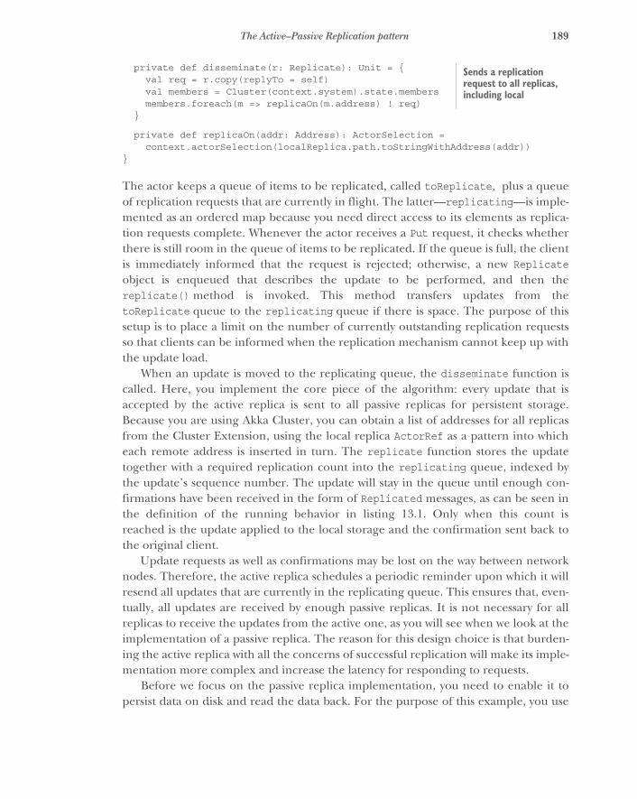
189The Active–Passive Replication pattern
private def disseminate(r: Replicate): Unit = {val req = r.copy(replyTo = self)val members = Cluster(context.system).state.membersmembers.foreach(m => replicaOn(m.address) ! req)
}
private def replicaOn(addr: Address): ActorSelection =context.actorSelection(localReplica.path.toStringWithAddress(addr))
}
The actor keeps a queue of items to be replicated, called toReplicate, plus a queueof replication requests that are currently in flight. The latter—replicating—is imple-mented as an ordered map because you need direct access to its elements as replica-tion requests complete. Whenever the actor receives a Put request, it checks whetherthere is still room in the queue of items to be replicated. If the queue is full, the clientis immediately informed that the request is rejected; otherwise, a new Replicateobject is enqueued that describes the update to be performed, and then thereplicate() method is invoked. This method transfers updates from thetoReplicate queue to the replicating queue if there is space. The purpose of thissetup is to place a limit on the number of currently outstanding replication requestsso that clients can be informed when the replication mechanism cannot keep up withthe update load.
When an update is moved to the replicating queue, the disseminate function iscalled. Here, you implement the core piece of the algorithm: every update that isaccepted by the active replica is sent to all passive replicas for persistent storage.Because you are using Akka Cluster, you can obtain a list of addresses for all replicasfrom the Cluster Extension, using the local replica ActorRef as a pattern into whicheach remote address is inserted in turn. The replicate function stores the updatetogether with a required replication count into the replicating queue, indexed bythe update’s sequence number. The update will stay in the queue until enough con-firmations have been received in the form of Replicated messages, as can be seen inthe definition of the running behavior in listing 13.1. Only when this count isreached is the update applied to the local storage and the confirmation sent back tothe original client.
Update requests as well as confirmations may be lost on the way between networknodes. Therefore, the active replica schedules a periodic reminder upon which it willresend all updates that are currently in the replicating queue. This ensures that, even-tually, all updates are received by enough passive replicas. It is not necessary for allreplicas to receive the updates from the active one, as you will see when we look at theimplementation of a passive replica. The reason for this design choice is that burden-ing the active replica with all the concerns of successful replication will make its imple-mentation more complex and increase the latency for responding to requests.
Before we focus on the passive replica implementation, you need to enable it topersist data on disk and read the data back. For the purpose of this example, you use
Sends a replication request to all replicas, including local
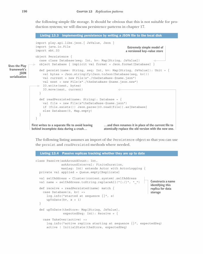
190 CHAPTER 13 Replication patterns
the following simple file storage. It should be obvious that this is not suitable for pro-duction systems; we will discuss persistence patterns in chapter 17.
import play.api.libs.json.{ JsValue, Json }import java.io.Fileimport sbt.IO
object Persistence {case class Database(seq: Int, kv: Map[String, JsValue])object Database { implicit val format = Json.format[Database] }
def persist(name: String, seq: Int, kv: Map[String, JsValue]): Unit = {val bytes = Json.stringify(Json.toJson(Database(seq, kv)))val current = new File(s"./theDataBase-$name.json")val next = new File(s"./theDataBase-$name.json.new")IO.write(next, bytes)IO.move(next, current)
}
def readPersisted(name: String): Database = {val file = new File(s"theDataBase-$name.json")if (file.exists()) Json.parse(IO.read(file)).as[Database]else Database(0, Map.empty)
}}
The following listing assumes an import of the Persistence object so that you can usethe persist and readPersisted methods where needed.
class Passive(askAroundCount: Int,askAroundInterval: FiniteDuration,maxLag: Int) extends Actor with ActorLogging {
private val applied = Queue.empty[Replicate]
val selfAddress = Cluster(context.system).selfAddressval name = selfAddress.toString.replaceAll("[:/]", "_")
def receive = readPersisted(name) match {case Database(s, kv) =>
log.info("started at sequence {}", s)upToDate(kv, s + 1)
}
def upToDate(theStore: Map[String, JsValue],expectedSeq: Int): Receive = {
case TakeOver(active) =>log.info("active replica starting at sequence {}", expectedSeq)active ! InitialState(theStore, expectedSeq)
Listing 13.3 Implementing persistence by writing a JSON file to the local disk
Listing 13.4 Passive replicas tracking whether they are up to date
Extremely simple model ofa versioned key–value store
Uses the Playframework’s
JSONserialization
First writes to a separate file to avoid leaving behind incomplete data during a crash…
…and then renames it in place of the current file to atomically replace the old version with the new one.
Constructs a name identifying this replica for data storage
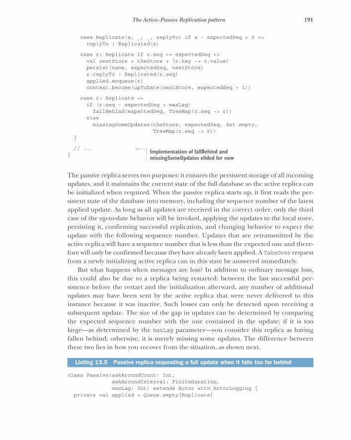
191The Active–Passive Replication pattern
case Replicate(s, _, _, replyTo) if s - expectedSeq < 0 =>replyTo ! Replicated(s)
case r: Replicate if r.seq == expectedSeq =>val nextStore = theStore + (r.key -> r.value)persist(name, expectedSeq, nextStore)r.replyTo ! Replicated(r.seq)applied.enqueue(r)context.become(upToDate(nextStore, expectedSeq + 1))
case r: Replicate =>if (r.seq - expectedSeq > maxLag)
fallBehind(expectedSeq, TreeMap(r.seq -> r))else
missingSomeUpdates(theStore, expectedSeq, Set.empty,TreeMap(r.seq -> r))
}
// ...}
The passive replica serves two purposes: it ensures the persistent storage of all incomingupdates, and it maintains the current state of the full database so the active replica canbe initialized when required. When the passive replica starts up, it first reads the per-sistent state of the database into memory, including the sequence number of the latestapplied update. As long as all updates are received in the correct order, only the thirdcase of the up-to-date behavior will be invoked, applying the updates to the local store,persisting it, confirming successful replication, and changing behavior to expect theupdate with the following sequence number. Updates that are retransmitted by theactive replica will have a sequence number that is less than the expected one and there-fore will only be confirmed because they have already been applied. A TakeOver requestfrom a newly initializing active replica can in this state be answered immediately.
But what happens when messages are lost? In addition to ordinary message loss,this could also be due to a replica being restarted: between the last successful per-sistence before the restart and the initialization afterward, any number of additionalupdates may have been sent by the active replica that were never delivered to thisinstance because it was inactive. Such losses can only be detected upon receiving asubsequent update. The size of the gap in updates can be determined by comparingthe expected sequence number with the one contained in the update; if it is toolarge—as determined by the maxLag parameter—you consider this replica as havingfallen behind; otherwise, it is merely missing some updates. The difference betweenthese two lies in how you recover from the situation, as shown next.
class Passive(askAroundCount: Int,askAroundInterval: FiniteDuration,maxLag: Int) extends Actor with ActorLogging {
private val applied = Queue.empty[Replicate]
Listing 13.5 Passive replica requesting a full update when it falls too far behind
Implementation of fallBehind and missingSomeUpdates elided for now
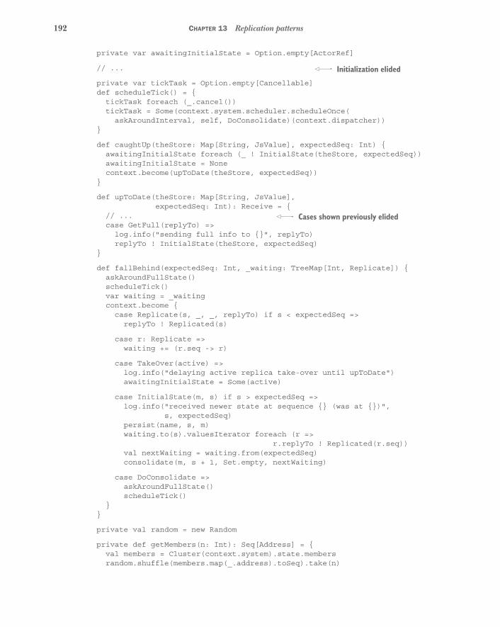
192 CHAPTER 13 Replication patterns
private var awaitingInitialState = Option.empty[ActorRef]
// ...
private var tickTask = Option.empty[Cancellable]def scheduleTick() = {
tickTask foreach (_.cancel())tickTask = Some(context.system.scheduler.scheduleOnce(
askAroundInterval, self, DoConsolidate)(context.dispatcher))}
def caughtUp(theStore: Map[String, JsValue], expectedSeq: Int) {awaitingInitialState foreach (_ ! InitialState(theStore, expectedSeq))awaitingInitialState = Nonecontext.become(upToDate(theStore, expectedSeq))
}
def upToDate(theStore: Map[String, JsValue],expectedSeq: Int): Receive = {
// ...case GetFull(replyTo) =>
log.info("sending full info to {}", replyTo)replyTo ! InitialState(theStore, expectedSeq)
}
def fallBehind(expectedSeq: Int, _waiting: TreeMap[Int, Replicate]) {askAroundFullState()scheduleTick()var waiting = _waitingcontext.become {
case Replicate(s, _, _, replyTo) if s < expectedSeq =>replyTo ! Replicated(s)
case r: Replicate =>waiting += (r.seq -> r)
case TakeOver(active) =>log.info("delaying active replica take-over until upToDate")awaitingInitialState = Some(active)
case InitialState(m, s) if s > expectedSeq =>log.info("received newer state at sequence {} (was at {})",
s, expectedSeq)persist(name, s, m)waiting.to(s).valuesIterator foreach (r =>
r.replyTo ! Replicated(r.seq))val nextWaiting = waiting.from(expectedSeq)consolidate(m, s + 1, Set.empty, nextWaiting)
case DoConsolidate =>askAroundFullState()scheduleTick()
}}
private val random = new Random
private def getMembers(n: Int): Seq[Address] = {val members = Cluster(context.system).state.membersrandom.shuffle(members.map(_.address).toSeq).take(n)
Initialization elided
Cases shown previously elided

193The Active–Passive Replication pattern
}private def askAroundFullState(): Unit = {
log.info("asking for full data")getMembers(1).foreach(addr => replicaOn(addr) ! GetFull(self))
}private def replicaOn(addr: Address): ActorSelection =
context.actorSelection(self.path.toStringWithAddress(addr))}
When falling behind, you first ask a randomly selected replica for a full dump of thedatabase and schedule a timer. Then you change behavior into a waiting state inwhich new updates are accumulated for later application, very old updates are imme-diately confirmed, and requests to take over are deferred. This state can only be leftonce an initial-state message has been received; at this point, you persist this newerstate of the database, confirm all accumulated updates whose sequence number issmaller than the now-expected one, and try to apply all remaining updates by callingthe consolidate function that is shown next.
private val matches = (p: (Int, Int)) => p._1 == p._2
private def consolidate(theStore: Map[String, JsValue],expectedSeq: Int,askedFor: Set[Int],waiting: TreeMap[Int, Replicate]): Unit = {
val prefix =waiting.keysIterator
.zip(Iterator from expectedSeq)
.takeWhile(matches)
.size
val nextStore =waiting.valuesIterator
.take(prefix)
.foldLeft(theStore) { (store, replicate) =>persist(name, replicate.seq, theStore)replicate.replyTo ! Replicated(replicate.seq)applied.enqueue(replicate)store + (replicate.key -> replicate.value)
}val nextWaiting = waiting.drop(prefix)val nextExpectedSeq = expectedSeq + prefix
applied.drop(Math.max(0, applied.size - maxLag))
if (nextWaiting.nonEmpty) {if (nextWaiting.lastKey - nextExpectedSeq > maxLag)
fallBehind(nextExpectedSeq, nextWaiting)else
missingSomeUpdates(nextStore, nextExpectedSeq, askedFor,nextWaiting)
} else caughtUp(nextStore, nextExpectedSeq)}
Listing 13.6 Consolidation: applying updates that were held previously
Calculates the length of the directly applicable queue prefix
Caps the size of the applied buffer
Checks whether you fell behind too much
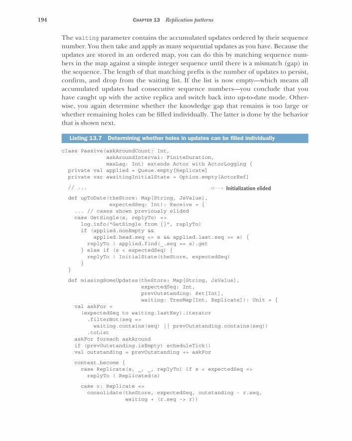
194 CHAPTER 13 Replication patterns
The waiting parameter contains the accumulated updates ordered by their sequencenumber. You then take and apply as many sequential updates as you have. Because theupdates are stored in an ordered map, you can do this by matching sequence num-bers in the map against a simple integer sequence until there is a mismatch (gap) inthe sequence. The length of that matching prefix is the number of updates to persist,confirm, and drop from the waiting list. If the list is now empty—which means allaccumulated updates had consecutive sequence numbers—you conclude that youhave caught up with the active replica and switch back into up-to-date mode. Other-wise, you again determine whether the knowledge gap that remains is too large orwhether remaining holes can be filled individually. The latter is done by the behaviorthat is shown next.
class Passive(askAroundCount: Int,askAroundInterval: FiniteDuration,maxLag: Int) extends Actor with ActorLogging {
private val applied = Queue.empty[Replicate]private var awaitingInitialState = Option.empty[ActorRef]
// ...
def upToDate(theStore: Map[String, JsValue],expectedSeq: Int): Receive = {
... // cases shown previously elidedcase GetSingle(s, replyTo) =>
log.info("GetSingle from {}", replyTo)if (applied.nonEmpty &&
applied.head.seq <= s && applied.last.seq >= s) {replyTo ! applied.find(_.seq == s).get
} else if (s < expectedSeq) {replyTo ! InitialState(theStore, expectedSeq)
}}
def missingSomeUpdates(theStore: Map[String, JsValue],expectedSeq: Int,prevOutstanding: Set[Int],waiting: TreeMap[Int, Replicate]): Unit = {
val askFor =(expectedSeq to waiting.lastKey).iterator
.filterNot(seq =>waiting.contains(seq) || prevOutstanding.contains(seq))
.toListaskFor foreach askAroundif (prevOutstanding.isEmpty) scheduleTick()val outstanding = prevOutstanding ++ askFor
context.become {case Replicate(s, _, _, replyTo) if s < expectedSeq =>
replyTo ! Replicated(s)
case r: Replicate =>consolidate(theStore, expectedSeq, outstanding - r.seq,
waiting + (r.seq -> r))
Listing 13.7 Determining whether holes in updates can be filled individually
Initialization elided
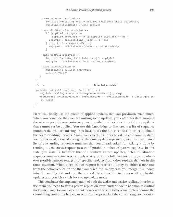
195The Active–Passive Replication pattern
case TakeOver(active) =>log.info("delaying active replica take-over until upToDate")awaitingInitialState = Some(active)
case GetSingle(s, replyTo) =>if (applied.nonEmpty &&
applied.head.seq <= s && applied.last.seq >= s) {replyTo ! applied.find(_.seq == s).get
} else if (s < expectedSeq) {replyTo ! InitialState(theStore, expectedSeq)
}
case GetFull(replyTo) =>log.info("sending full info to {}", replyTo)replyTo ! InitialState(theStore, expectedSeq)
case DoConsolidate =>outstanding foreach askAroundscheduleTick()
}}
// ...
private def askAround(seq: Int): Unit = {log.info("asking around for sequence number {}", seq)getMembers(askAroundCount).foreach(addr => replicaOn(addr) ! GetSingle(seq, self))
}}
Here, you finally use the queue of applied updates that you previously maintained.When you conclude that you are missing some updates, you enter this state knowingthe next expected consecutive sequence number and a collection of future updatesthat cannot yet be applied. You use this knowledge to first create a list of sequencenumbers that you are missing—you have to ask the other replicas in order to obtainthe corresponding updates. Again, you schedule a timer to ask, in case some updatesare not received; to avoid asking for the same update repeatedly, you must maintain alist of outstanding sequence numbers that you already asked for. Asking is done bysending a GetSingle request to a configurable number of passive replicas. In thisstate, you install a behavior that will confirm known updates, defer initializationrequests from an active replica, reply to requests for a full database dump, and, when-ever possible, answer requests for specific updates from other replicas that are in thesame situation. When a replication request is received, it may be either a new onefrom the active replica or one that you asked for. In any case, you merge this updateinto the waiting list and use the consolidate function to process all applicableupdates and possibly switch back to up-to-date mode.
This concludes the implementation of both the active and passive replicas. In order touse them, you need to start a passive replica on every cluster node in addition to startingthe Cluster Singleton manager. Client requests can be sent to the active replica by using theCluster Singleton Proxy helper, an actor that keeps track of the current singleton location
Other helpers elided
196 CHAPTER 13 Replication patterns
by listening to the cluster-membership change events. The full source code, including arunnable demo application, can be found at www.manning.com/books/reactive-design-patterns or https://github.com/ReactiveDesignPatterns.
13.1.3 The pattern, revisited
The implementation of this pattern consists of four parts:
� A cluster membership service that allows discovery and enumeration of allreplica locations
� A Cluster Singleton mechanism that ensures that only one active replica is run-ning at all times
� The active replica that accepts requests from clients, broadcasts updates to allpassive replicas, and answers them after successful replication
� A number of passive replicas that persist state updates and help each otherrecover from message loss
For the first two, this example uses the facilities provided by Akka Cluster, because theimplementation of a full cluster solution is complex and not usually done fromscratch. Many other implementations can be used for this purpose; the only import-ant qualities are listed here. The implementation of both types of replica is morelikely to be customized and tailored to a specific purpose. We demonstrated the pat-tern with a use case that exhibits the minimal set of operations representative of awide range of applications: the Get request stands for operations that do not modifythe replicated state and that can therefore be executed immediately on the activereplica, whereas the Put request characterizes operations whose effects must be repli-cated such that they are retained across failures.
The performance of this replication scheme is very good as long as no failuresoccur, because the active replica does not need to perform coordination tasks; all readrequests can be served without requiring further communication, and write requestsonly need to be confirmed by a large enough subset of all replicas. This allows writeperformance to be balanced with reliability, in that a larger replication factor reducesthe probability of data loss and a smaller replication factor reduces the impact of slowresponses from some replicas—by requiring N responses, you are satisfied by the Ncurrently fastest replicas.
During failures, you will see two different modes of performance degradation. If anetwork node hosting a passive replica fails, then there will be increased network traf-fic after its restart in order to catch up with the latest state. If the network host run-ning the active replica fails, there will be a period during which no active replica willbe running: it takes a while for the cluster to determine that the node has failed andto disseminate the knowledge that a new singleton needs to be instantiated. Thesecoordination tasks need to be performed carefully in order to be reasonably certainthat the old singleton cannot interfere with future operations even if its node laterbecomes reachable again after a network partition. For typical cloud deployments,
197Multiple-Master Replication patterns
this process takes on the order of seconds; it is limited by fluctuations in networktransmission latency and reliability.
While discussing failure modes, we must also consider edge cases that can lead toincorrect behavior. Imagine that the active replica fails after sending out an update,and the next elected active replica does not receive this message. In order to noticethat some information was lost, the new active replica would need to receive anupdate with a higher sequence number—but with the presented algorithm, that willnever happen. Therefore, when it accepts the first update after the failover, the newactive replica will unknowingly reuse a sequence number that some other replicashave seen for a different update. This can be avoided by requiring all known replicasto confirm the highest-known sequence number after a failover, which of course addsto the downtime.
Another problem is to determine when to erase and when to retain the persistentstorage after a restart. The safest option is to delete and repopulate the database inorder to not introduce conflicting updates after a network partition that separatedthe active replica from the surviving part of the cluster. On the other hand, this willlead to a significant increase in network usage that is unnecessary in most cases, andit would be fatal if the entire cluster were shut down and restarted. This problem canbe solved by maintaining an epoch counter that is increased for every failover so areplica can detect that it has outdated information after a restart—for this, the activereplica will include its epoch and its starting sequence number in the replication pro-tocol messages.
Depending on the use case, you must make a trade-off among reliable operation,performance, and implementation complexity. Note that it is impossible to imple-ment a solution that works perfectly for all imaginable failure scenarios.
13.1.4 Applicability
Because active–passive replication requires consensus regarding the active replica,this scheme may lead to periods of unavailability during widespread outages or net-work partitions. This is unavoidable because the inability to establish a quorum withthe currently reachable cluster members may mean there is a quorum among thosethat are unreachable—but electing two active replicas at the same time must beavoided in order to retain consistency for clients. Therefore, active–passive replicationis not suitable where perfect availability is required.
13.2 Multiple-Master Replication patternsKeep multiple copies of a service running in different locations, accept modificationseverywhere, and disseminate all modifications among them.
With active–passive replication, the basic mode of operation is to have a relatively sta-ble active replica that processes read and write requests without further coordination,keeping the nominal case as simple and efficient as possible, while requiring specialaction during failover. This means clients have to send their requests to the currently
198 CHAPTER 13 Replication patterns
active replica, with uncertainty resulting in case of failure. Because the selection of theactive replica is done until further notice instead of per request, the client will notknow what happened in case of a failure: has the request been disseminated or not?
Allowing requests to be accepted at all replicas means the client can participate inthe replication and thereby obtain more precise feedback about the execution of itsrequests. The collocation of the client and the replica does not necessarily mean bothare running in the process; placing them in the same failure domain makes their com-munication more reliable and their shared failure model simpler, even if this justmeans running both on the same computer or even in the same computing center.The further distributed a system becomes, the more prominent are the problemsinherent to distribution, exacerbated by increased communication latency andreduced transmission reliability.
There are several strategies for accepting requests at multiple active replicas, whichdiffer mainly in how they handle requests that arrive during a network partition. Inthis section, we will look at three classes of strategies:
� The most consistent results are achieved by establishing consensus about theapplication of each single update at the cost of not processing requests whiledealing with failures.
� Availability can be increased by accepting potentially conflicting updates duringa partition and resolving the conflicts afterward, potentially discarding updates thatwere accepted at either side.
� Perfect availability without data losses can be achieved by restricting the datamodel such that concurrent updates are conflict-free by definition.
13.2.1 Consensus-based replication
Given a group of people, we have a basic understanding of what consensus means:within the group, all members agree on a proposal and acknowledge that this agree-ment is unanimous. From personal experience, we know that reaching consensus is aprocess that can take quite a bit of time and effort for coordination, especially if thematter starts out as being contentious—in other words, if initially there are multiplecompeting proposals, and the group must decide which single one to support.
In computer science, the term consensus1 means roughly the same thing, but ofcourse the definition is more precise: given a cluster of N nodes and a set of proposalsP1 to Pm every nonfailing node will eventually decide on a single proposal Px without thepossibility to revoke that decision. All nonfailing nodes will decide on the same Px. Inthe example of a key–value store, this means one node proposes to update a key’s value,and, after the consensus protocol is finished, there will be a consistent cluster-wide deci-sion about whether the update was performed—or in which order, relative to otherupdates. During this process, some cluster nodes may fail; and if the number of failingnodes is less than the failure-tolerance threshold of the algorithm, then consensus can
1 See, for example, https://en.wikipedia.org/wiki/Consensus_(computer_science) for an overview.
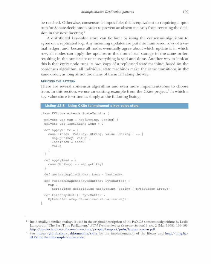
199Multiple-Master Replication patterns
be reached. Otherwise, consensus is impossible; this is equivalent to requiring a quo-rum for Senate decisions in order to prevent an absent majority from reverting the deci-sion in the next meeting.2
A distributed key–value store can be built by using the consensus algorithm toagree on a replicated log. Any incoming updates are put into numbered rows of a vir-tual ledger; and, because all nodes eventually agree about which update is in whichrow, all nodes can apply the updates to their own local storage in the same order,resulting in the same state once everything is said and done. Another way to look atthis is that every node runs its own copy of a replicated state machine; based on theconsensus algorithm, all individual state machines make the same transitions in thesame order, as long as not too many of them fail along the way.
APPLYING THE PATTERN
There are several consensus algorithms and even more implementations to choosefrom. In this section, we use an existing example from the CKite project,3 in which akey–value store is written as simply as the following listing.
class KVStore extends StateMachine {
private var map = Map[String, String]()private var lastIndex: Long = 0
def applyWrite = {case (index, Put(key: String, value: String)) => {
map.put(key, value);lastIndex = indexvalue
}}
def applyRead = {case Get(key) => map.get(key)
}
def getLastAppliedIndex: Long = lastIndex
def restoreSnapshot(byteBuffer: ByteBuffer) =map =
Serializer.deserialize[Map[String, String]](byteBuffer.array())
def takeSnapshot(): ByteBuffer =ByteBuffer.wrap(Serializer.serialize(map))
}
2 Incidentally, a similar analogy is used in the original description of the PAXOS consensus algorithms by LeslieLamport in “The Part-Time Parliament,” ACM Transactions on Computer Systems16, no. 2 (May 1998): 133-169,http://research.microsoft.com/en-us/um/people/lamport/pubs/lamport-paxos.pdf.
3 See https://github.com/pablosmedina/ckite for the implementation of the library and http://mng.bz/dLYZ for the full sample source code.
Listing 13.8 Using CKite to implement a key–value store
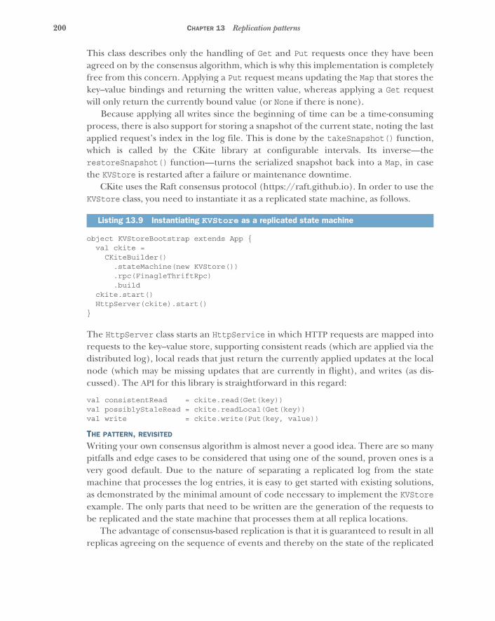
200 CHAPTER 13 Replication patterns
This class describes only the handling of Get and Put requests once they have beenagreed on by the consensus algorithm, which is why this implementation is completelyfree from this concern. Applying a Put request means updating the Map that stores thekey–value bindings and returning the written value, whereas applying a Get requestwill only return the currently bound value (or None if there is none).
Because applying all writes since the beginning of time can be a time-consumingprocess, there is also support for storing a snapshot of the current state, noting the lastapplied request’s index in the log file. This is done by the takeSnapshot() function,which is called by the CKite library at configurable intervals. Its inverse—therestoreSnapshot() function—turns the serialized snapshot back into a Map, in casethe KVStore is restarted after a failure or maintenance downtime.
CKite uses the Raft consensus protocol (https://raft.github.io). In order to use theKVStore class, you need to instantiate it as a replicated state machine, as follows.
object KVStoreBootstrap extends App {val ckite =
CKiteBuilder().stateMachine(new KVStore()).rpc(FinagleThriftRpc).build
ckite.start()HttpServer(ckite).start()
}
The HttpServer class starts an HttpService in which HTTP requests are mapped intorequests to the key–value store, supporting consistent reads (which are applied via thedistributed log), local reads that just return the currently applied updates at the localnode (which may be missing updates that are currently in flight), and writes (as dis-cussed). The API for this library is straightforward in this regard:
val consistentRead = ckite.read(Get(key))val possiblyStaleRead = ckite.readLocal(Get(key))val write = ckite.write(Put(key, value))
THE PATTERN, REVISITED
Writing your own consensus algorithm is almost never a good idea. There are so manypitfalls and edge cases to be considered that using one of the sound, proven ones is avery good default. Due to the nature of separating a replicated log from the statemachine that processes the log entries, it is easy to get started with existing solutions,as demonstrated by the minimal amount of code necessary to implement the KVStoreexample. The only parts that need to be written are the generation of the requests tobe replicated and the state machine that processes them at all replica locations.
The advantage of consensus-based replication is that it is guaranteed to result in allreplicas agreeing on the sequence of events and thereby on the state of the replicated
Listing 13.9 Instantiating KVStore as a replicated state machine
201Multiple-Master Replication patterns
data. It is therefore straightforward to reason about the correctness of the distributedprogram, in the sense that it will not get into an inconsistent state.
The price for this peace of mind is that in order to avoid mistakes, the algorithmmust be conservative: it cannot boldly make progress in the face of arbitrary failureslike network partitions and node crashes. Requiring a majority of the nodes to agreeon an update before progressing to the next one not only takes time but also can failaltogether during network partitions, such as a three-way split where none of the partsrepresents a majority.
13.2.2 Replication with conflict detection and resolution
If you want to change your replication scheme such that it can continue to operateduring a transient network partition, then you will have to make some compromises.Obviously, it is impossible to reach consensus without communication, so if all clusternodes are to make progress in accepting and processing requests at all times, conflict-ing actions may be performed.
Consider the example of the storage component within your batch service thatstores the execution status of some computing job. When the job is submitted, it isrecorded as “new”; then it becomes “scheduled,” “executing,” and finally “finished”(ignoring failures and retries for the sake of simplicity here). But another possibility isthat the client that submitted the job decides to cancel its execution because the com-putation is no longer needed, perhaps because parameters have changed and a new jobhas been submitted. The client will attempt to change the job status to “canceled,” withfurther possible consequences, depending on the current job status—it may be takenout of the scheduled queue, or it may need to be aborted if it is currently executing.
Assuming that you want to make the storage component as highly available as pos-sible, you may let it accept job-status updates even during a network partition that sep-arates the storage cluster into two halves and renders it unable to successfully apply aconsensus protocol until communication is restored. If the client interface sends thewrite of the “canceled” status to one half while the execution service starts runningthe job and therefore sets the “executing” status on the other half, then the two partsof the storage component have accepted conflicting information. When the networkpartition is repaired and communication is possible again, the replication protocolwill need to figure out that this has occurred and react accordingly.
APPLYING THE PATTERN
The most prominent tool for detecting whether cluster nodes have performed con-flicting updates is called a version vector.4 With this, each replica can keep track of whoupdated the job status since the last successful replication, by incrementing a counter:
4 In particular, you do not need a vector clock: see Carlos Baquero, “Version Vectors Are Not Vector Clocks,”HASlab, July 8, 2011, https://haslab.wordpress.com/2011/07/08/version-vectors-are-not-vector-clocks for adiscussion (in short: you only need to track whether updates were performed by a replica, not how many wereperformed). See also Nuno Preguiça et al., “Dotted Version Vectors,” November 2010, http://arxiv.org/abs/1011.5808 for a description.
202 CHAPTER 13 Replication patterns
� The status starts out as “scheduled” with an empty version vector on both nodesA and B.
� When the client interface updates the status on node A, the replica will registerit as “canceled” with a version vector of <A:1> (all nodes that are not mentionedare assumed to have version zero).
� When the executor updates the status on node B, it will be registered as “exe-cuting” with the version vector <B:1>.
� When replicas A and B compare notes after the partition has been repaired, thestatus will be both “canceled” and “executing,” with version vectors <A:1> and<B:1>; and because neither fully includes the other, a conflict will be detected.
The conflict will then have to be resolved one way or another. A SQL database willdecide based on a fixed or configurable policy: for example, storing a timestamptogether with each value and picking the latest update. In this case, there is nothing tocode, because the conflict resolution happens within the database; the user code canbe written just like in the nonreplicated case.
Another possibility is implemented by the Riak database (http://mdocs.basho.com/riak/latest/theory/concepts/Replication), which presents both values to anyclient that subsequently reads the key affected by the conflict, requiring the client tofigure out how to proceed and bring the data store back into a consistent state by issu-ing an explicit write request with the merged value; this is called read repair. An exam-ple of how this is done is part of the Riak documentation.5
In the batch service example, you could employ domain-specific knowledgewithin your implementation of the storage component: after a partition was repaired,all replicas would exchange version information for all intermediately changed keys.When this conflict was noticed, it would be clear that the client wished to abort thenow-executing job—the repair procedure would automatically change the job statusto “canceled” (with a version vector of <A:1,B:1> to document that this included bothupdates) and ask the executor to terminate the execution of this job. One possibilityfor implementing this scheme would be to use a data store like Riak and performread repair at the application level together with the separately stored knowledgeabout which keys were written to during the partition.
THE PATTERN, REVISITED
We have introduced conflict detection and resolution at the level of a key–value storeor database where the concern of state replication is encapsulated by an existing solu-tion in the form of a relational database management system or other data store. Inthis case, the pattern consists of recording all actions as changes to the stored datasuch that the storage product can detect and handle conflicts that arise from accept-ing updates during network partitions or other times of partial system unavailability.
When using server-side conflict resolution (as is done by popular SQL databaseproducts), the application code is freed from this concern at the cost of potentially
5 See http://docs.basho.com/riak/latest/dev/using/conflict-resolution/.

203Multiple-Master Replication patterns
losing updates during the repair process—choosing the most recent update meansdiscarding all others. Client-side conflict resolution allows tailored reactions that maybenefit from domain-specific knowledge; but, on the other hand, it makes applica-tion code more complex to write, because all read accesses to a data store managedin this fashion must be able to deal with receiving multiple equally valid answers to asingle query.
13.2.3 Conflict-free replicated data types
In the previous section, you achieved perfect availability of the batch service’s storagecomponent—where perfect means “it works as long as one replica is reachable”—at thecost of either losing updates or having to care about manual conflict resolution. Youcan improve on this even further, but unfortunately at another cost: it is not possibleto avoid conflicts while maintaining perfect availability without restricting the datatypes that can be expressed.
As an example, consider a counter that should be replicated. Conflict freedomwould be achieved by making sure an increment registered at any replica would even-tually be visible (effective) at all replicas independent of other concurrent incre-ments. Clearly it is not enough to replicate the counter value: if an increment of 3 isaccepted by node A, whereas an increment of 5 is accepted at node B, then the valueafter replication will either signal a conflict or miss one of the updates, as discussed inthe previous section. Therefore, you split the counter into individual per-node sub-counters, where each node only ever modifies its own subcounter. Reading thecounter then means summing up all the per-node subcounters.6 In this fashion, bothincrements of 3 and 5 will be effective, because the per-node values cannot see con-flicting updates. And after the replication is complete, the total sum will have beenincremented by 8.
With this example, it becomes clear that it is possible to create a data structure thatfulfills the goal, but the necessary steps in the implementation of this replicatedcounter are tailored to this particular use case and cannot be used in general—in par-ticular, it relies upon the fact that summing all subcounters correctly expresses theoverall counter behavior. This is possible for a wide range of data types, including setsand maps, but it fails wherever global invariants cannot be translated to local ones.For a set, it is easy to avoid duplicates because duplicate checking can be done oneach insertion, but constructing a counter whose value must stay within a given rangerequires coordination again.
The data types we are talking about here are called conflict-free replicated data types(CRDTs)7 and are currently being introduced in a number of distributed systems
6 An implementation in the context of Akka Distributed Data can be studied at http://mng.bz/rf2V. This typeof counter can only grow, hence its name: GCounter.
7 See M. Shapiro et al., “A Comprehensive Study of Convergent and Commutative Replicated Data Types,”2011, https://hal.inria.fr/inria-00555588 for an overview; and C. Baquero, “Specification of Convergent AbstractData Types for Autonomous Mobile Computing,” 1997, http://haslab.uminho.pt/cbm/publications/specification-convergent-abstract-data-types-autonomous-mobile-computing for early ground work.
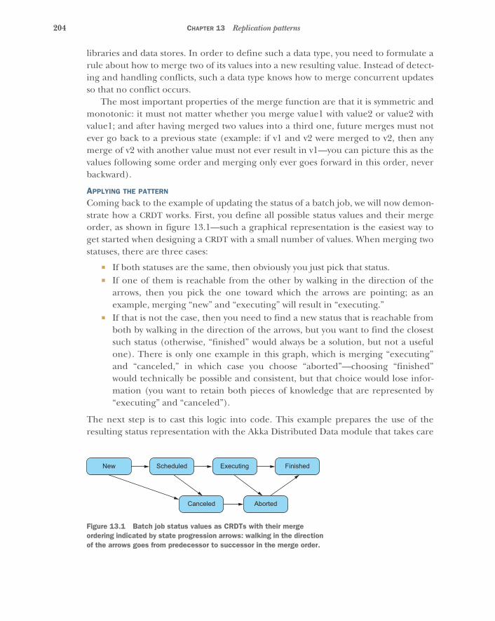
204 CHAPTER 13 Replication patterns
libraries and data stores. In order to define such a data type, you need to formulate arule about how to merge two of its values into a new resulting value. Instead of detect-ing and handling conflicts, such a data type knows how to merge concurrent updatesso that no conflict occurs.
The most important properties of the merge function are that it is symmetric andmonotonic: it must not matter whether you merge value1 with value2 or value2 withvalue1; and after having merged two values into a third one, future merges must notever go back to a previous state (example: if v1 and v2 were merged to v2, then anymerge of v2 with another value must not ever result in v1—you can picture this as thevalues following some order and merging only ever goes forward in this order, neverbackward).
APPLYING THE PATTERN
Coming back to the example of updating the status of a batch job, we will now demon-strate how a CRDT works. First, you define all possible status values and their mergeorder, as shown in figure 13.1—such a graphical representation is the easiest way toget started when designing a CRDT with a small number of values. When merging twostatuses, there are three cases:
� If both statuses are the same, then obviously you just pick that status.� If one of them is reachable from the other by walking in the direction of the
arrows, then you pick the one toward which the arrows are pointing; as anexample, merging “new” and “executing” will result in “executing.”
� If that is not the case, then you need to find a new status that is reachable fromboth by walking in the direction of the arrows, but you want to find the closestsuch status (otherwise, “finished” would always be a solution, but not a usefulone). There is only one example in this graph, which is merging “executing”and “canceled,” in which case you choose “aborted”—choosing “finished”would technically be possible and consistent, but that choice would lose infor-mation (you want to retain both pieces of knowledge that are represented by“executing” and “canceled”).
The next step is to cast this logic into code. This example prepares the use of theresulting status representation with the Akka Distributed Data module that takes care
New Scheduled Executing Finished
Canceled Aborted
Figure 13.1 Batch job status values as CRDTs with their merge ordering indicated by state progression arrows: walking in the direction of the arrows goes from predecessor to successor in the merge order.

205Multiple-Master Replication patterns
of the replication and merging of CRDT values. All that is needed is the merge func-tion, which is the only abstract method on the ReplicatedData interface.
final case class Status(val name: String)(_pred: => Set[Status],_succ: => Set[Status])
extends ReplicatedData {
type T = Statusdef merge(that: Status): Status = mergeStatus(this, that)
lazy val predecessors = _predlazy val successors = _succ
}
val New: Status =Status("new")(Set.empty, Set(Scheduled, Canceled))
val Scheduled: Status =Status("scheduled")(Set(New), Set(Executing, Canceled))
val Executing: Status =Status("executing")(Set(Scheduled), Set(Aborted, Finished))
val Finished: Status =Status("finished")(Set(Executing, Aborted), Set.empty)
val Canceled: Status =Status("canceled")(Set(New, Scheduled), Set(Aborted))
val Aborted: Status =Status("aborted")(Set(Canceled, Executing), Set(Finished))
This is a trivial transcription of the graph from figure 13.1, where each node in the sta-tus graph is represented by a Scala object with two sets of nodes describing the incom-ing and outgoing arrows, respectively: an arrow always goes from predecessor tosuccessor (for example, Scheduled is a successor of New, and New is a predecessor ofScheduled). We could have chosen a more compact representation where each arrowis encoded only once: for example, if we had provided only the successor information,then after construction of all statuses, a second pass would have filled in the predeces-sor sets automatically. Here, we opted to be more explicit and save the code for thepost-processing step. Now it is time to look at the merge logic in the following listing.
def mergeStatus(left: Status, right: Status): Status = {/** Keep the left Status in hand and determine whether it is a* predecessor of the candidate, moving on to the candidate’s* successor if not successful. The list of exclusions is used to* avoid performing already determined unsuccessful comparisons* again.*/
def innerLoop(candidate: Status, exclude: Set[Status]): Status =if (isSuccessor(candidate, left, exclude)) {
candidate
Listing 13.10 Code representation of the graph in figure 13.1
Listing 13.11 Merging two statuses to produce a third, merged status
Merges another status with this statusArrows into and
out of this status

206 CHAPTER 13 Replication patterns
} else {val nextExclude = exclude + candidateval branches =
candidate.successors.map(succ => innerLoop(succ, nextExclude))branches.reduce((l, r) =>
if (isSuccessor(l, r, nextExclude)) r else l)}
def isSuccessor(candidate: Status, fixed: Status,exclude: Set[Status]): Boolean =
if (candidate == fixed) trueelse {
val toSearch = candidate.predecessors -- excludetoSearch.exists(pred => isSuccessor(pred, fixed, exclude))
}
innerLoop(right, Set.empty)}
In this algorithm, you merge two statuses, one called left and one called right. Youkeep the left value constant during the entire process and consider right a candi-date that you may need to move in the direction of the arrows. As an illustration, con-sider merging New and Canceled:
� If New is taken as the left argument, then you will enter the inner loop withCanceled as the candidate, and the first conditional will call isSuccessor, withthe first two arguments being Canceled and New. These are not equal, so theelse branch of isSuccessor will search all predecessors of Canceled (New andScheduled) to determine whether one of them is a successor of New; this nowsatisfies the condition of candidate == fixed, so isSuccessor returns trueand the candidate in innerLoop (Canceled) will be returned as the mergeresult.
� If New is taken as the right argument, then the first isSuccessor call will yieldfalse. You enter the other branch in which both successors of the candidateNew will be examined; trying Scheduled will be equally fruitless, escalating toExecuting and Canceled as its successors. Abbreviating the story a little, youwill eventually find that the merge result for the Executing candidate will beAborted, whereas for Canceled it is Canceled itself. These branches are thenreduced into a single value by pairwise comparison and picking the predeces-sor, which is Canceled in the case of trying Scheduled just now. Returning tothe outermost loop invocation, you thus twice get the same result of Canceledfor the two branches, which is also the end result.
This procedure is somewhat complicated by the fact that you have allowed the two sta-tuses of Executing and Canceled to be unrelated to each other, necessitating the abil-ity to find a common descendant. We will come back to why this is needed in theexample, but first we will look at how this CRDT is used by a hypothetical (and vastly
207Multiple-Master Replication patterns
oversimplified) client interface. In order to instantiate the CRDT, you need to define akey that identifies it across the cluster:
object StorageComponent extends Key[ORMap[Status]]("StorageComponent")
You need to associate a Status with each batch job, and the most fitting predefinedCRDT for this purpose is an observed-remove map (ORMap). The name stems from thefact that only keys whose presence has previously been observed can be removed fromthe map. Removal is a difficult operation because you have seen that CRDTs need amonotonic, forward-moving merge function—removing a key at one node and repli-cating the new map would mean only that the other nodes would add it right backduring merges, because that is the mechanism by which the key is spread across thecluster initially.8
One thing to note here is that CRDTs can be composed as shown earlier: theORMap uses Strings as keys (this is fixed by the Akka Distributed Data implementa-tion) and some other CRDTs as values. Instead of using the custom Status type, youcould use an observed-remove set (ORSet) of PNCounters if you needed sets of counters tobegin with, just to name one possibility. This makes it possible to create container datatypes with well-behaved replication semantics that are reusable in different contexts.Within the client interface—represented as a vastly oversimplified actor in the follow-ing listing—you can use the status map by referencing the StorageComponent key.
class ClientInterfaceextends Actor with ActorLogging {
val replicator = DistributedData(context.system).replicatorimplicit val cluster = Cluster(context.system)
def receive = {case Submit(job) =>
log.info("submitting job {}", job)replicator !
Replicator.Update(StorageComponent, ORMap.empty[Status],Replicator.WriteMajority(5.seconds))
(map => map + (job -> New))
case Cancel(job) =>log.info("cancelling job {}", job)replicator !
Replicator.Update(StorageComponent, ORMap.empty[Status],Replicator.WriteMajority(5.seconds))
(map => map + (job -> Canceled))
case r: Replicator.UpdateResponse[_] =>log.info("received update result: {}", r)
8 For details of how this is implemented, see Annette Bieniusa et al., “An Optimized Conflict-Free ReplicatedSet,” October 2012, https://hal.inria.fr/hal-00738680.
Listing 13.12 Using Akka Distributed Data to disseminate state changes
208 CHAPTER 13 Replication patterns
case PrintStatus =>replicator ! Replicator.Get(StorageComponent,
Replicator.ReadMajority(5.seconds))
case g: Replicator.GetSuccess[_] =>log.info("overall status: {}", g.get(StorageComponent))
}}
The Replicator is the actor provided by the Akka Distributed Data module that isresponsible for running the replication protocol between cluster nodes. Most genericCRDTs like ORMap need to identify the originator of a given update, and for that theCluster extension is implicitly used—here it is needed by both function literals thatmodify the map during the handing of Submit and Cancel requests.
With the Update command, you include the StorageComponent key, the initialvalue (if the CRDT was not referenced before), and a replication-factor setting. Thissetting determines the point at which the confirmation of a successful update will besent back to the ClientInterface actor: you choose to wait until the majority of clus-ter nodes have been notified, but you could just as well demand that all nodes havebeen updated, or you could be satisfied once the local node has the new value andstarts to disseminate it. The latter is the least reliable but is perfectly available (assum-ing that a local failure implies that the ClientInterface is affected as well); waitingfor all nodes is most reliable for retaining the stored data but can easily fail at storage.Using the majority is a good compromise that works well in many situations—just asfor legislative purposes.
The modifications performed by the client interface do not care about the previ-ous job status. They create a New entry or overwrite an existing one with Canceled.The executor component demonstrates more interesting usage, as shown next.
class Executor extends Actor with ActorLogging {val replicator = DistributedData(context.system).replicatorimplicit val cluster = Cluster(context.system)
var lastState = Map.empty[String, Status]
replicator ! Replicator.Subscribe(StorageComponent, self)
def receive = {case Execute(job) =>
log.info("executing job {}", job)replicator !
Replicator.Update(StorageComponent, ORMap.empty[Status],Replicator.WriteMajority(5.seconds),Some(job))
{ map =>require(map.get(job) == Some(New))map + (job -> Executing)
}
Listing 13.13 Introducing a request identifier for the job
209Multiple-Master Replication patterns
case Finish(job) =>log.info("job {} finished", job)replicator !
Replicator.Update(StorageComponent, ORMap.empty[Status],Replicator.WriteMajority(5.seconds))
(map => map + (job -> Finished))
case Replicator.UpdateSuccess(StorageComponent, Some(job)) =>log.info("starting job {}", job)
case r: Replicator.UpdateResponse[_] =>log.info("received update result: {}", r)
case ch: Replicator.Changed[_] =>val current = ch.get(StorageComponent).entriesfor {
(job, status) <- current.iteratorif (status == Aborted)if (lastState.get(job) != Some(Aborted))
} log.info("aborting job {}", job)lastState = current
}}
When it is time to execute a batch job, the update request for the CRDT includes arequest identifier (Some(job)) that has so far been left out: this value will be includedin the success or failure message that the replicator sends back. The provided updatefunction now checks a precondition: that the currently known status of the givenbatch job is still New. Otherwise, the update will be aborted with an exception. Onlyupon receiving the UpdateSuccess message with this job name will the actual execu-tion begin; otherwise, a ModifyFailure will be logged (which is a subtype of Update-Response).
Finally, the executor should abort batch jobs that were canceled after beingstarted. This is implemented by subscribing to change events from the replicator forthe StorageComponent CRDT. Whenever there is a change, the replicator will takenote of it; and as soon as the (configurable) notification interval elapses, aReplicator.Changed message will be sent with the current state of the CRDT. Theexecutor keeps track of the previously received state and can therefore determinewhich jobs have newly become Aborted. In this example, you log this; in a real imple-mentation, the Worker instance(s) for this job would be asked to terminate. The fullexample, including the necessary cluster setup, can be found in the source codearchives for this chapter.
THE PATTERN, REVISITED
Conflict-free replication allows perfect availability but requires the problem to be castin terms of special data types (CRDTs). The first step is to determine which semanticsare needed. In this case, you needed a tailor-made data type, but a number of generi-cally useful ones are readily available. Once the data type has been defined, a replica-tion mechanism must be used or developed that will disseminate all state changes and
210 CHAPTER 13 Replication patterns
invoke the merge function wherever necessary. This could be a library, as in the exam-ple shown in listing 13.12, or an off-the-shelf data store based on CRDTs.
Although it is easy to get started like this, note that this solution cannot offerstrong consistency: updates can occur truly concurrently across the entire system,making the value history of a given key nonlinearizable (which means different clientscan see conflicting value histories that are eventually reconciled). This may present achallenge in environments that are most familiar with and used to transactionalbehavior of a central authority—the centrality of this approach is precisely the limita-tion in terms of resilience and elasticity that conflict-free replication overcomes, at thecost of offering at most eventual consistency.
13.3 The Active–Active Replication patternKeep multiple copies of a service running in different locations, and perform allmodifications at all of them.
In the previous patterns, you achieved resilience for the storage subsystem of theexample batch job processing facility by replicating it across different locations (datacenters, availability zones, and so on). You saw that you can achieve strong consistencyonly when implementing a failover mechanism; both CRDT-based replication and con-flict detection avoid this at the cost of not guaranteeing full consistency. One propertyof failover is that it takes some time: first, you need to detect that there is trouble, andthen, you must establish consensus about how to fix it—for example, by switching toanother replica. Both activities require communication and therefore cannot be com-pleted instantaneously. Where this is not tolerable, you need a different strategy, butbecause there is no magic bullet, you must expect different restrictions.
Instead of failing over as a consequence of detecting problems, you can assumethat failures occur and therefore hedge your bets: rather than contacting only onereplica, always perform the desired operation on all of them. If a replica does notrespond correctly, then you conclude that it has failed and refrain from contacting itagain. A new replica will be added based on monitoring and supervision.
In computer science, the first description of active–active replication was offered byLeslie Lamport,9 who proposed that distributed state machines can be synchronized byusing the fact that time passes in a sufficiently similar fashion for all of them. Hisdescription yields a more generic framework for replication than is presented in thissection. The definition of active–active replication used here10 is inspired by the spaceindustry, where, for example, measurements are performed using multiple sensors atall times and hardware-based voting mechanisms select the prevalent observationamong them, discarding minority deviations by presuming them to be the result of fail-ures. As an example, the main bus voltage of a satellite may be monitored by a regulator
9 Leslie Lamport, “Using Time Instead of Timeout for Fault-Tolerant Distributed Systems,” ACM Transactionson Programming Languages and Systems 6, no. 2 (April 1984): 254-280.
10 Note that database vendors sometimes use active–active replication to mean conflict detection and resolution asdescribed in the previous section.
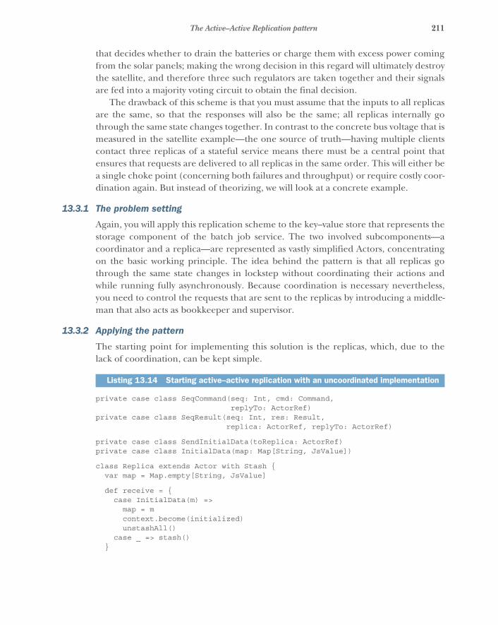
211The Active–Active Replication pattern
that decides whether to drain the batteries or charge them with excess power comingfrom the solar panels; making the wrong decision in this regard will ultimately destroythe satellite, and therefore three such regulators are taken together and their signalsare fed into a majority voting circuit to obtain the final decision.
The drawback of this scheme is that you must assume that the inputs to all replicasare the same, so that the responses will also be the same; all replicas internally gothrough the same state changes together. In contrast to the concrete bus voltage that ismeasured in the satellite example—the one source of truth—having multiple clientscontact three replicas of a stateful service means there must be a central point thatensures that requests are delivered to all replicas in the same order. This will either bea single choke point (concerning both failures and throughput) or require costly coor-dination again. But instead of theorizing, we will look at a concrete example.
13.3.1 The problem setting
Again, you will apply this replication scheme to the key–value store that represents thestorage component of the batch job service. The two involved subcomponents—acoordinator and a replica—are represented as vastly simplified Actors, concentratingon the basic working principle. The idea behind the pattern is that all replicas gothrough the same state changes in lockstep without coordinating their actions andwhile running fully asynchronously. Because coordination is necessary nevertheless,you need to control the requests that are sent to the replicas by introducing a middle-man that also acts as bookkeeper and supervisor.
13.3.2 Applying the pattern
The starting point for implementing this solution is the replicas, which, due to thelack of coordination, can be kept simple.
private case class SeqCommand(seq: Int, cmd: Command,replyTo: ActorRef)
private case class SeqResult(seq: Int, res: Result,replica: ActorRef, replyTo: ActorRef)
private case class SendInitialData(toReplica: ActorRef)private case class InitialData(map: Map[String, JsValue])
class Replica extends Actor with Stash {var map = Map.empty[String, JsValue]
def receive = {case InitialData(m) =>
map = mcontext.become(initialized)unstashAll()
case _ => stash()}
Listing 13.14 Starting active–active replication with an uncoordinated implementation
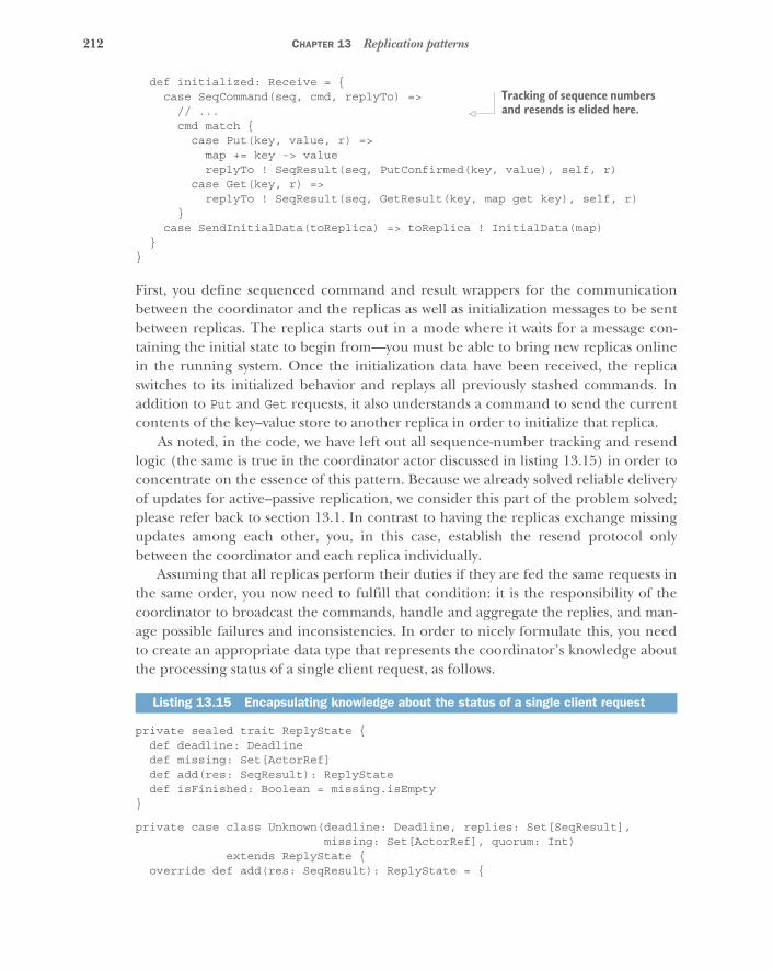
212 CHAPTER 13 Replication patterns
def initialized: Receive = {case SeqCommand(seq, cmd, replyTo) =>
// ...cmd match {
case Put(key, value, r) =>map += key -> valuereplyTo ! SeqResult(seq, PutConfirmed(key, value), self, r)
case Get(key, r) =>replyTo ! SeqResult(seq, GetResult(key, map get key), self, r)
}case SendInitialData(toReplica) => toReplica ! InitialData(map)
}}
First, you define sequenced command and result wrappers for the communicationbetween the coordinator and the replicas as well as initialization messages to be sentbetween replicas. The replica starts out in a mode where it waits for a message con-taining the initial state to begin from—you must be able to bring new replicas onlinein the running system. Once the initialization data have been received, the replicaswitches to its initialized behavior and replays all previously stashed commands. Inaddition to Put and Get requests, it also understands a command to send the currentcontents of the key–value store to another replica in order to initialize that replica.
As noted, in the code, we have left out all sequence-number tracking and resendlogic (the same is true in the coordinator actor discussed in listing 13.15) in order toconcentrate on the essence of this pattern. Because we already solved reliable deliveryof updates for active–passive replication, we consider this part of the problem solved;please refer back to section 13.1. In contrast to having the replicas exchange missingupdates among each other, you, in this case, establish the resend protocol onlybetween the coordinator and each replica individually.
Assuming that all replicas perform their duties if they are fed the same requests inthe same order, you now need to fulfill that condition: it is the responsibility of thecoordinator to broadcast the commands, handle and aggregate the replies, and man-age possible failures and inconsistencies. In order to nicely formulate this, you needto create an appropriate data type that represents the coordinator’s knowledge aboutthe processing status of a single client request, as follows.
private sealed trait ReplyState {def deadline: Deadlinedef missing: Set[ActorRef]def add(res: SeqResult): ReplyStatedef isFinished: Boolean = missing.isEmpty
}
private case class Unknown(deadline: Deadline, replies: Set[SeqResult],missing: Set[ActorRef], quorum: Int)
extends ReplyState {override def add(res: SeqResult): ReplyState = {
Listing 13.15 Encapsulating knowledge about the status of a single client request
Tracking of sequence numbers and resends is elided here.

213The Active–Active Replication pattern
val nextReplies = replies + resval nextMissing = missing - res.replicaif (nextReplies.size >= quorum) {
val answer =replies.toSeq
.groupBy(_.res)
.collectFirst { case (k, s) if s.size >= quorum => s.head }if (answer.isDefined) {
val right = answer.getval wrong =
replies.collect {case SeqResult(_, res, replica, _) if res != right =>
replica}
Known(deadline, right, wrong, nextMissing)} else if (nextMissing.isEmpty) {
Known.fromUnknown(deadline, nextReplies)} else Unknown(deadline, nextReplies, nextMissing, quorum)
} else Unknown(deadline, nextReplies, nextMissing, quorum)}
}
private case class Known(deadline: Deadline, reply: SeqResult,wrong: Set[ActorRef], missing: Set[ActorRef])
extends ReplyState {override def add(res: SeqResult): ReplyState = {
val nextWrong =if (res.res == reply.res) wrong else wrong + res.replica
Known(deadline, reply, nextWrong, missing - res.replica)}
}private object Known {
def fromUnknown(deadline: Deadline,replies: Set[SeqResult]): Known = {
val counts = replies.groupBy(_.res)val biggest = counts.iterator.map(_._2.size).maxval winners = counts.collectFirst {
case (res, win) if win.size == biggest => win}.getval losers = (replies -- winners).map(_.replica)Known(deadline, winners.head, losers, Set.empty)
}}
ReplyState tracks when the time limit for a client response expires; whether the replyvalue is already known; which replica’s response deviated from the prevalent one; andwhich replica’s response is still outstanding. When a new request is made, you beginwith an Unknown reply state containing an empty set of replies and a set of missingreplica ActorRefs that contains all current replicas. As responses from replicas arereceived, your knowledge grows, as represented by the add() function: the response isadded to the set of replies, and as soon as the required quorum of replicas hasresponded with a consistent answer, ReplyState switches to Known (taking note of the
Did not reach consensus on this one: use a simple majority
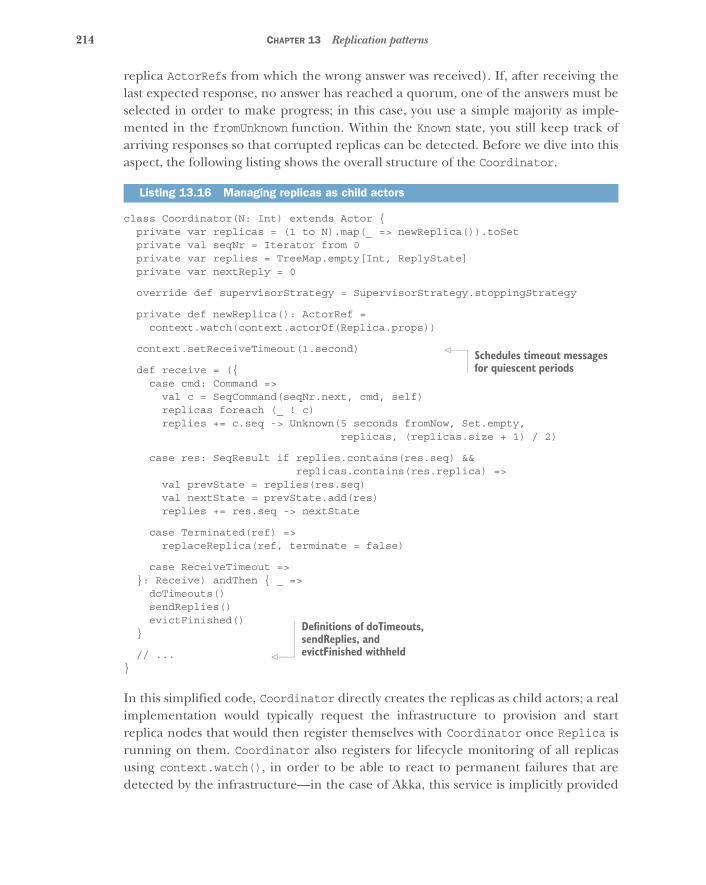
214 CHAPTER 13 Replication patterns
replica ActorRefs from which the wrong answer was received). If, after receiving thelast expected response, no answer has reached a quorum, one of the answers must beselected in order to make progress; in this case, you use a simple majority as imple-mented in the fromUnknown function. Within the Known state, you still keep track ofarriving responses so that corrupted replicas can be detected. Before we dive into thisaspect, the following listing shows the overall structure of the Coordinator.
class Coordinator(N: Int) extends Actor {private var replicas = (1 to N).map(_ => newReplica()).toSetprivate val seqNr = Iterator from 0private var replies = TreeMap.empty[Int, ReplyState]private var nextReply = 0
override def supervisorStrategy = SupervisorStrategy.stoppingStrategy
private def newReplica(): ActorRef =context.watch(context.actorOf(Replica.props))
context.setReceiveTimeout(1.second)
def receive = ({case cmd: Command =>
val c = SeqCommand(seqNr.next, cmd, self)replicas foreach (_ ! c)replies += c.seq -> Unknown(5 seconds fromNow, Set.empty,
replicas, (replicas.size + 1) / 2)
case res: SeqResult if replies.contains(res.seq) &&replicas.contains(res.replica) =>
val prevState = replies(res.seq)val nextState = prevState.add(res)replies += res.seq -> nextState
case Terminated(ref) =>replaceReplica(ref, terminate = false)
case ReceiveTimeout =>}: Receive) andThen { _ =>
doTimeouts()sendReplies()evictFinished()
}
// ...}
In this simplified code, Coordinator directly creates the replicas as child actors; a realimplementation would typically request the infrastructure to provision and startreplica nodes that would then register themselves with Coordinator once Replica isrunning on them. Coordinator also registers for lifecycle monitoring of all replicasusing context.watch(), in order to be able to react to permanent failures that aredetected by the infrastructure—in the case of Akka, this service is implicitly provided
Listing 13.16 Managing replicas as child actors
Schedules timeout messages for quiescent periods
Definitions of doTimeouts, sendReplies, and evictFinished withheld
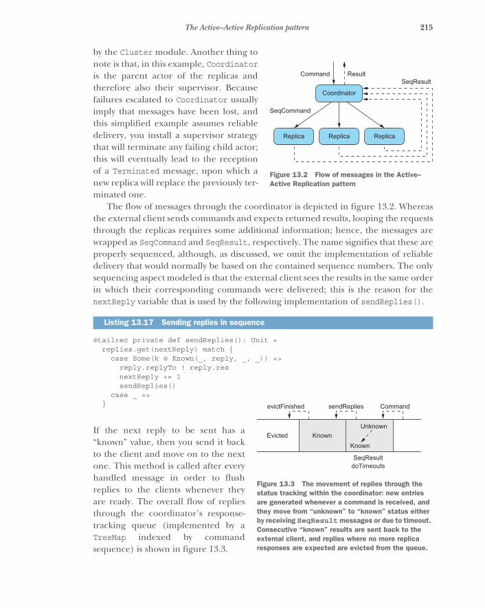
215The Active–Active Replication pattern
by the Cluster module. Another thing tonote is that, in this example, Coordinatoris the parent actor of the replicas andtherefore also their supervisor. Becausefailures escalated to Coordinator usuallyimply that messages have been lost, andthis simplified example assumes reliabledelivery, you install a supervisor strategythat will terminate any failing child actor;this will eventually lead to the receptionof a Terminated message, upon which anew replica will replace the previously ter-minated one.
The flow of messages through the coordinator is depicted in figure 13.2. Whereasthe external client sends commands and expects returned results, looping the requeststhrough the replicas requires some additional information; hence, the messages arewrapped as SeqCommand and SeqResult, respectively. The name signifies that these areproperly sequenced, although, as discussed, we omit the implementation of reliabledelivery that would normally be based on the contained sequence numbers. The onlysequencing aspect modeled is that the external client sees the results in the same orderin which their corresponding commands were delivered; this is the reason for thenextReply variable that is used by the following implementation of sendReplies().
@tailrec private def sendReplies(): Unit =replies.get(nextReply) match {
case Some(k @ Known(_, reply, _, _)) =>reply.replyTo ! reply.resnextReply += 1sendReplies()
case _ =>}
If the next reply to be sent has a“known” value, then you send it backto the client and move on to the nextone. This method is called after everyhandled message in order to flushreplies to the clients whenever theyare ready. The overall flow of repliesthrough the coordinator’s response-tracking queue (implemented by aTreeMap indexed by commandsequence) is shown in figure 13.3.
Listing 13.17 Sending replies in sequence
Coordinator
SeqResultResultCommand
SeqCommand
ReplicaReplicaReplica
Figure 13.2 Flow of messages in the Active–Active Replication pattern
SeqResultdoTimeouts
Command
KnownUnknown
KnownEvicted
sendRepliesevictFinished
Figure 13.3 The movement of replies through the status tracking within the coordinator: new entries are generated whenever a command is received, and they move from “unknown” to “known” status either by receiving SeqResult messages or due to timeout. Consecutive “known” results are sent back to the external client, and replies where no more replica responses are expected are evicted from the queue.
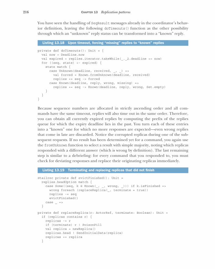
216 CHAPTER 13 Replication patterns
You have seen the handling of SeqResult messages already in the coordinator’s behav-ior definition, leaving the following doTimeouts() function as the other possibilitythrough which an “unknown” reply status can be transformed into a “known” reply.
private def doTimeouts(): Unit = {val now = Deadline.nowval expired = replies.iterator.takeWhile(_._2.deadline <= now)for ((seq, state) <- expired) {
state match {case Unknown(deadline, received, _, _) =>
val forced = Known.fromUnknown(deadline, received)replies += seq -> forced
case Known(deadline, reply, wrong, missing) =>replies += seq -> Known(deadline, reply, wrong, Set.empty)
}}
}
Because sequence numbers are allocated in strictly ascending order and all com-mands have the same timeout, replies will also time out in the same order. Therefore,you can obtain all currently expired replies by computing the prefix of the repliesqueue for which the expiry deadline lies in the past. You turn each of these entriesinto a “known” one for which no more responses are expected—even wrong repliesthat come in late are discarded. Notice the corrupted replicas during one of the sub-sequent requests. If no result has been determined yet for a command, you again usethe fromUnknown function to select a result with simple majority, noting which replicasresponded with a different answer (which is wrong by definition). The last remainingstep is similar to a debriefing: for every command that you responded to, you mustcheck for deviating responses and replace their originating replicas immediately.
@tailrec private def evictFinished(): Unit =replies.headOption match {
case Some((seq, k @ Known(_, _, wrong, _))) if k.isFinished =>wrong foreach (replaceReplica(_, terminate = true))replies -= seqevictFinished()
case _ =>}
private def replaceReplica(r: ActorRef, terminate: Boolean): Unit =if (replicas contains r) {
replicas -= rif (terminate) r ! PoisonPillval replica = newReplica()replicas.head ! SendInitialData(replica)replicas += replica
}
Listing 13.18 Upon timeout, forcing “missing” replies to “known” replies
Listing 13.19 Terminating and replacing replicas that did not finish

217The Active–Active Replication pattern
The evictFinished function checks whether the reply status of the oldest queuedcommand is complete (no more responses are expected). If so, it initiates the replace-ment of all faulty replicas and removes the status from the queue, repeating this pro-cess until the queue is empty or an unfinished reply status is encountered. Replacing areplica would normally mean asking the infrastructure to terminate the correspond-ing machine and provision a new one, but in this simplified example you just termi-nate the child actor and create a new one.
In order to get the new replica up to speed, you need to provide it with the currentreplicated state. One simple possibility is to ask one of the remaining replicas to trans-fer its current state to the new replica. Because this message will be delivered after allcurrently outstanding commands and before any subsequent commands, this state willbe exactly the one needed by the new replica to be included in the replica set for newcommands right away—the stashing and replay of these commands within theReplica actor has exactly the correct semantics. In a real implementation, therewould need to be a timeout-and-resend mechanism for this initialization, to covercases where the replica that is supposed to transfer its state fails before it can completethe transmission. It is important to note that the faulty replica is excluded from beingused as the source of the initialization data, just as the new replica is.
13.3.3 The pattern, revisited
The Active–Active Replication pattern emerged from a conversation with some soft-ware architects working at a financial institution. It solves a specific problem: how canyou keep a service running in fault-tolerant fashion with fully replicated state whilenot suffering from costly consensus overhead and avoiding any downtime during fail-ure—not even allowing a handful of milliseconds for failure detection and failover?
The solution consists of two parts: the replicas execute commands and generateresults without regard to each other, and the coordinator ensures that all replicasreceive the same sequence of commands. Faulty replicas are detected by comparingthe responses received to each individual command and flagging deviations. In theexample implementation, this was the only criterion; a variation might be to alsoreplace replicas that are consistently failing to meet their deadlines.
A side effect of this pattern is that external responses can be generated as soon asthere is agreement about what that response will be, which means requiring onlythree out of five replicas would shorten the usually long tail of the latency distribu-tion. Assuming that slow responses are not correlated between the replicas (that is,they are not caused by the specific properties of the command or otherwise related),then the probability of more than two replicas exceeding their 99th percentile latencyis only 0.001%, which naïvely means the individual 99th percentile is the cluster’s99.999th percentile.11
11 This is of course too optimistic, because outliers in the latency distribution are usually caused by somethingthat might well be correlated between machines. For example, garbage collection pauses for JVMs that werestarted at the same time, and executing the same program with the same inputs will tend to occur roughly atthe same time as well.
218 CHAPTER 13 Replication patterns
13.3.4 The relation to virtual synchrony
This pattern is similar in some aspects to the virtual synchrony12 work done by Ken Bir-man et al. in the 1980s. The goal of both is to allow replicated distributed processes torun as if synchronized and to make the same state transitions in the same order.Although our example restricts and simplifies the solution by requiring a central entrypoint—the coordinator—the virtual synchrony model postulates no such choke point.As we discussed in section 13.2, this would normally require a consensus protocol tobe used to ensure that transitions occur only once all replicas have acknowledged thatthey will make the transition. Unfortunately, this approach is doomed to fail, asproven by Fischer, Lynch, and Paterson in what is usually referred to as the FLP 13
result. The practical probability for this kind of failure is vanishingly small, but it isenough to question the endeavor of trying to provide perfect ordering guarantees in adistributed system.
Virtual synchrony avoids this limitation by noticing that, in most cases, the order-ing of processing two requests from different sources is not important: if the effects oftwo requests A and B are commutative, then it does not matter whether they areapplied in the order A, B or B, A, because the state of the replica will be identical inthe end. This is similar to how CRDTs achieve perfect availability without conflicts:impossibility laws do not matter if the available data types and operations arerestricted in a way that conflicts cannot arise.
Taking a step back and considering daily life, we usually think in terms of causeand effect: I (Roland) observe that my wife’s coffee mug is empty, fill it with coffee,and tell her about it, expecting that when she looks at the mug, she will be pleasedbecause it is now full. By waiting to tell her until after my refill, I make sure the laws ofphysics—in particular, causality—will ensure the desired outcome (barring catastro-phes). This kind of thinking is so ingrained that we like to think about everything inthis fashion, including distributed systems. When using a transactional database, cau-sality is ensured by the serializability of all transactions: they happen as if one wereexecuted after the other, every transaction seeing the complete results of all previ-ously executed transactions. Although this works great as a programming abstraction,it is stronger than needed; causality does not imply that things happen in one univer-sal order. In fact, the laws of special relativity clearly describe which events can be caus-ally related and which cannot—events that happen at remote locations are trulyconcurrent if you cannot fly from one to the other even at the speed of light.
This fact may serve to motivate the finding that causal consistency is the best youcan implement in a distributed system.14 Virtual synchrony achieves greater resilience
12 https://en.wikipedia.org/wiki/Virtual_synchrony. See Ken Birman, “A History of the Virtual Synchrony Rep-lication Model,” https://www.cs.cornell.edu/ken/history.pdf for an introduction and historical discussion.
13 Michael Fischer, Nancy Lynch, and Michael Paterson, “Impossibility of Distributed Consensus with OneFaulty Process,” ACM, April 1985, http://dl.acm.org/citation.cfm?id=214121.
14 Wyatt Lloyd et al., “Don’t Settle for Eventual: Scalable Causal Consistency for Wide-Area Storage with COPS,”SOSP ’11, ACM 2011, http://dl.acm.org/citation.cfm?id=2043593.
219Summary
and less coordination overhead than consensus-based replication by allowing mes-sages that are not causally related to be delivered to the replicas in random order. Inthis way, it can achieve performance similar to the active–active replication describedin this section, at the cost of carefully translating the desired program such that itrelies only on causal ordering. If the program cannot be written in this fashionbecause, for example, some effects are not commutative, then at least for these opera-tions the coordination cost of establishing consensus must be paid. In this sense, thecoordinator represents a trade-off that introduces a single choke point in exchangefor being able to run arbitrary algorithms in a replicated fashion without the need foradaptation.
13.4 SummaryIn this chapter, we discussed various replication patterns that allow you to distributesystems in space so as to not put all of your eggs in one basket. When it comes to repli-cation, you are presented with a choice: do you favor consistency, reliability, or avail-ability? The answer depends on the requirements of the use case at hand and is rarelyblack and white—there is a continuous range between these extremes, and most pat-terns are tunable. The following list can be used for orientation:
� Active–passive replication is relatively simple to use, based on an existing cluster-singleton implementation. It is fast during normal operation, suffers downtimeduring fail-overs, and offers good consistency due to having a single activereplica.
� Consensus-based replication enables greater resilience by allowing updates to beaccepted by any replica. But in return for offering perfect consistency, it suffersfrom high coordination overhead and, consequently, low throughput. Prefer-ring consistency entails unavailability during severe failures.
� Replication based on conflict detection and resolution allows the system to stay avail-able during severe failure conditions, but this can lead to data losses or requiremanual conflict resolution.
� Conflict-free replicated data types are formulated such that conflicts cannot arise byconstruction. Therefore, this scheme can achieve perfect availability evenduring severe failures; the data types are restricted, requiring special adaptationof the program code as well as designing it for an eventual consistency model.
� Active–active replication addresses the concern of avoiding downtime during fail-ures while maintaining a generic programming model. The cost is that allrequests must be sent through a single choke point in order to guarantee con-sistent behavior of all replicas—alternatively, the program can be recast interms of causal consistency to achieve high performance and high availabilityby employing virtual synchrony.
This summary is of course grossly simplified. Please refer back to the individual sec-tions for a more complete discussion of the limitations of each approach.
220
Resource-managementpatterns
One concern that most systems share is that you need to manage or representresources: file storage space, computation power, access to databases or web APIs,physical devices like printers and card readers, and many more. A component thatyou create may provide such a resource to the rest of the system on its own, or youmay need to incorporate external resources. In this chapter, we will discuss patternsfor dealing with resources in Reactive applications. In particular, we will look at thefollowing:
� The Resource Encapsulation pattern� The Resource Loan pattern� The Complex Command pattern� The Resource Pool pattern� Patterns for managed blocking
In the previous two chapters, we introduced the example of the batch job service, asystem that allows clients to submit computation jobs in order to have them exe-cuted by a fleet of elastically provisioned worker nodes. We focused on the hierar-chical decomposition and failure handling of such a system. Now we will take acloser look at the provisioning and management of the worker nodes, which arethe primary resources managed by the batch job service.
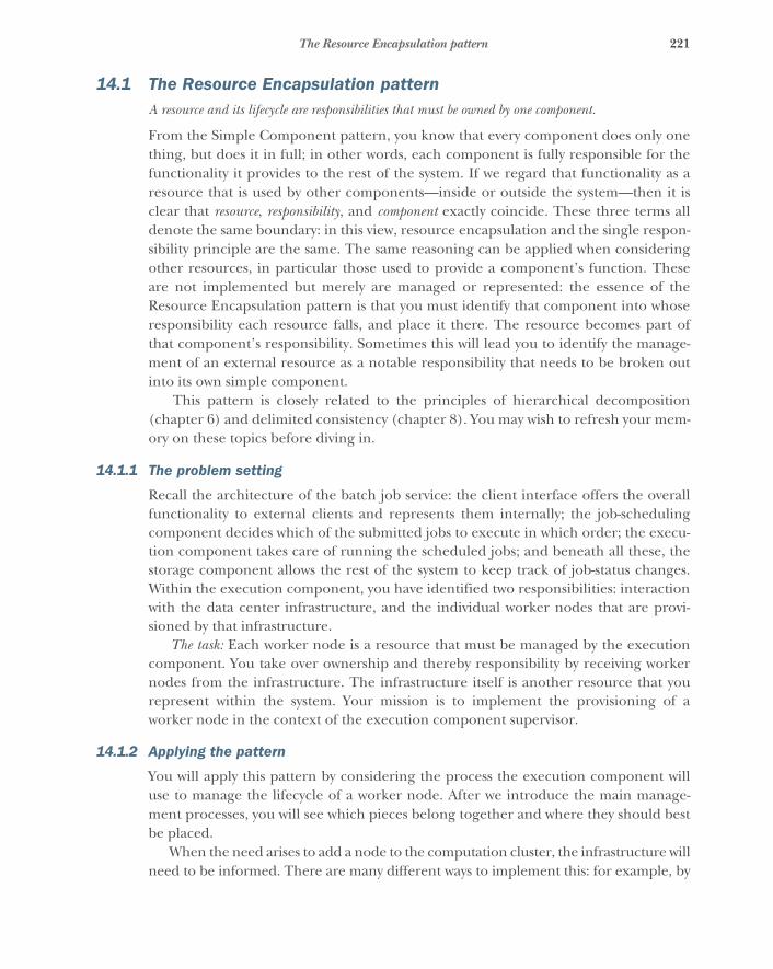
221The Resource Encapsulation pattern
14.1 The Resource Encapsulation patternA resource and its lifecycle are responsibilities that must be owned by one component.
From the Simple Component pattern, you know that every component does only onething, but does it in full; in other words, each component is fully responsible for thefunctionality it provides to the rest of the system. If we regard that functionality as aresource that is used by other components—inside or outside the system—then it isclear that resource, responsibility, and component exactly coincide. These three terms alldenote the same boundary: in this view, resource encapsulation and the single respon-sibility principle are the same. The same reasoning can be applied when consideringother resources, in particular those used to provide a component’s function. Theseare not implemented but merely are managed or represented: the essence of theResource Encapsulation pattern is that you must identify that component into whoseresponsibility each resource falls, and place it there. The resource becomes part ofthat component’s responsibility. Sometimes this will lead you to identify the manage-ment of an external resource as a notable responsibility that needs to be broken outinto its own simple component.
This pattern is closely related to the principles of hierarchical decomposition(chapter 6) and delimited consistency (chapter 8). You may wish to refresh your mem-ory on these topics before diving in.
14.1.1 The problem setting
Recall the architecture of the batch job service: the client interface offers the overallfunctionality to external clients and represents them internally; the job-schedulingcomponent decides which of the submitted jobs to execute in which order; the execu-tion component takes care of running the scheduled jobs; and beneath all these, thestorage component allows the rest of the system to keep track of job-status changes.Within the execution component, you have identified two responsibilities: interactionwith the data center infrastructure, and the individual worker nodes that are provi-sioned by that infrastructure.
The task: Each worker node is a resource that must be managed by the executioncomponent. You take over ownership and thereby responsibility by receiving workernodes from the infrastructure. The infrastructure itself is another resource that yourepresent within the system. Your mission is to implement the provisioning of aworker node in the context of the execution component supervisor.
14.1.2 Applying the pattern
You will apply this pattern by considering the process the execution component willuse to manage the lifecycle of a worker node. After we introduce the main manage-ment processes, you will see which pieces belong together and where they should bestbe placed.
When the need arises to add a node to the computation cluster, the infrastructure willneed to be informed. There are many different ways to implement this: for example, by
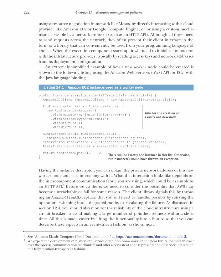
222 CHAPTER 14 Resource-management patterns
using a resource-negotiation framework like Mesos, by directly interacting with a cloudprovider like Amazon EC2 or Google Compute Engine, or by using a custom mecha-nism accessible by a network protocol (such as an HTTP API). Although all these needto send requests across the network, they often present their client interface in theform of a library that can conveniently be used from your programming language ofchoice. When the execution component starts up, it will need to initialize interactionwith the infrastructure provider, typically by reading access keys and network addressesfrom its deployment configuration.
An extremely simplified example of how a new worker node could be created isshown in the following listing using the Amazon Web Services (AWS) API for EC21 withthe Java language binding.
public Instance startInstance(AWSCredentials credentials) {AmazonEC2Client amazonEC2Client = new AmazonEC2Client(credentials);
RunInstancesRequest runInstancesRequest =new RunInstancesRequest()
.withImageId("my-image-id-for-a-worker")
.withInstanceType("m1.small")
.withMinCount(1)
.withMaxCount(1);
RunInstancesResult runInstancesResult =amazonEC2Client.runInstances(runInstancesRequest);
Reservation reservation = runInstancesResult.getReservation();List<Instance> instances = reservation.getInstances();
return instances.get(0);}
Having the instance descriptor, you can obtain the private network address of this newworker node and start interacting with it. What that interaction looks like depends onthe intercomponent communication fabric you are using, which could be as simple asan HTTP API.2 Before we go there, we need to consider the possibility that AWS maybecome unreachable or fail for some reason. The client library signals this by throw-ing an AmazonClientException that you will need to handle, possibly by retrying theoperation, switching into a degraded mode, or escalating the failure. As discussed insection 12.4, you should also monitor the reliability of the cloud infrastructure using acircuit breaker to avoid making a large number of pointless requests within a shorttime. All this is made easier by lifting the functionality into a Future so that you candescribe these aspects in an event-driven fashion, as shown next.
1 See “Amazon Elastic Compute Cloud Documentation” at http://aws.amazon.com/documentation/ec2.
Listing 14.1 Amazon EC2 instance used as a worker node
2 We expect the development of higher-level service definition frameworks in the near future that will abstractover the precise communication mechanism and offer a consistent code representation of service interactionin a fully location-transparent fashion.
Asks for the creation of exactly one new node
There will be exactly one instance in this list. Otherwise, runInstances() would have thrown an exception.
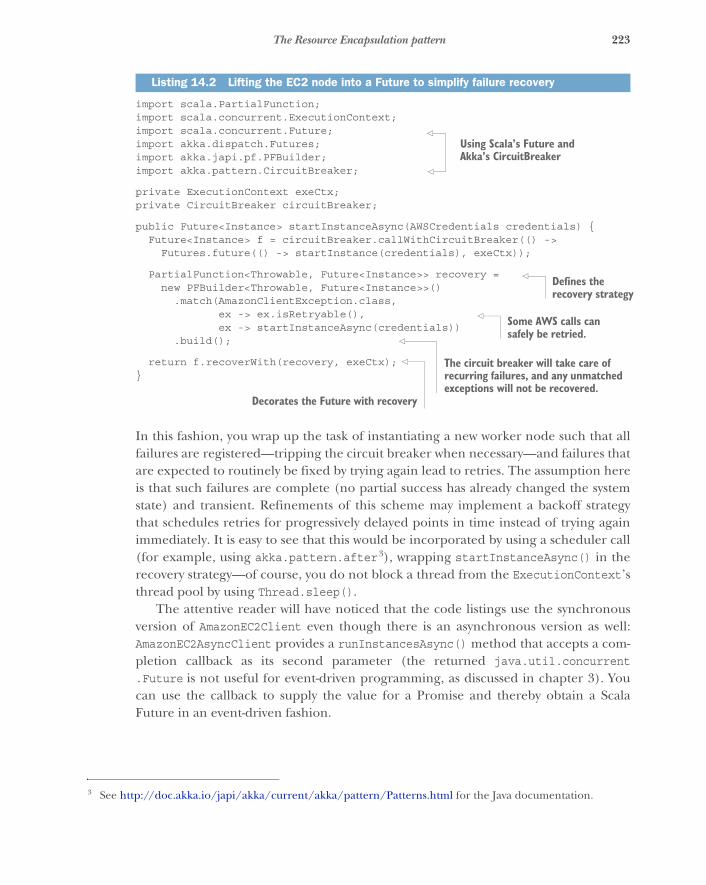
223The Resource Encapsulation pattern
import scala.PartialFunction;import scala.concurrent.ExecutionContext;import scala.concurrent.Future;import akka.dispatch.Futures;import akka.japi.pf.PFBuilder;import akka.pattern.CircuitBreaker;
private ExecutionContext exeCtx;private CircuitBreaker circuitBreaker;
public Future<Instance> startInstanceAsync(AWSCredentials credentials) {Future<Instance> f = circuitBreaker.callWithCircuitBreaker(() ->
Futures.future(() -> startInstance(credentials), exeCtx));
PartialFunction<Throwable, Future<Instance>> recovery =new PFBuilder<Throwable, Future<Instance>>()
.match(AmazonClientException.class,ex -> ex.isRetryable(),ex -> startInstanceAsync(credentials))
.build();
return f.recoverWith(recovery, exeCtx);}
In this fashion, you wrap up the task of instantiating a new worker node such that allfailures are registered—tripping the circuit breaker when necessary—and failures thatare expected to routinely be fixed by trying again lead to retries. The assumption hereis that such failures are complete (no partial success has already changed the systemstate) and transient. Refinements of this scheme may implement a backoff strategythat schedules retries for progressively delayed points in time instead of trying againimmediately. It is easy to see that this would be incorporated by using a scheduler call(for example, using akka.pattern.after3), wrapping startInstanceAsync() in therecovery strategy—of course, you do not block a thread from the ExecutionContext’sthread pool by using Thread.sleep().
The attentive reader will have noticed that the code listings use the synchronousversion of AmazonEC2Client even though there is an asynchronous version as well:AmazonEC2AsyncClient provides a runInstancesAsync() method that accepts a com-pletion callback as its second parameter (the returned java.util.concurrent.Future is not useful for event-driven programming, as discussed in chapter 3). Youcan use the callback to supply the value for a Promise and thereby obtain a ScalaFuture in an event-driven fashion.
Listing 14.2 Lifting the EC2 node into a Future to simplify failure recovery
3 See http://doc.akka.io/japi/akka/current/akka/pattern/Patterns.html for the Java documentation.
Using Scala’s Future and Akka’s CircuitBreaker
Defines the recovery strategy
Some AWS calls can safely be retried.
The circuit breaker will take care of recurring failures, and any unmatched exceptions will not be recovered.
Decorates the Future with recovery

224 CHAPTER 14 Resource-management patterns
public Future<RunInstancesResult> runInstancesAsync(RunInstancesRequest request,AmazonEC2Async client) {
Promise<RunInstancesResult> promise = Futures.promise();client.runInstancesAsync(request,
new AsyncHandler<RunInstancesRequest, RunInstancesResult>() {@Overridepublic void onSuccess(RunInstancesRequest request,
RunInstancesResult result) {promise.success(result);
}
@Overridepublic void onError(Exception exception) {
promise.failure(exception);}
});return promise.future();
}
Unfortunately, the AWS library implements the asynchronous version in terms of thesame blocking HTTP network library that also powers the synchronous version (basedon the Apache HTTP client library)—it just runs the code on a separate thread pool.You could configure that thread pool to be the same ExecutionContext you use to runyour Scala Futures by supplying it as a constructor argument when instantiatingAmazonEC2AsyncClient. That would not be a net win, however, because instead of justwrapping the synchronous call in a Future, you would have to bridge all client methodsin the fashion shown in listing 14.3—an overhead of 15–20 lines per API method. Theexecution mechanics would be the same, but adapting the different asynchronous APIstyles would involve significant extra programming effort (and, hence, more opportu-nity for errors). We will take a deeper look at situations like this in section 14.5 when wediscuss patterns for managed blocking.
Now that you have started the worker node, you need to also manage the rest of itslifecycle: the execution component needs to keep track of which workers are available,monitor their health by performing regular status checks, and shut them down whenthey are no longer needed. Performing health checks typically means making servicecalls that query performance indicators that the service is monitoring internally. Thefact that a response is received signals general availability, and the measured quantitiescan be factored into future decisions about whether to scale the number of workernodes up or down. The measured quantities can also be indicative of specific prob-lems, such as unusually high memory consumption, that require dedicated reactions(for example, an operator alert or automatic reboot after a diagnostic memory dump).
This brings you to the final step of a worker node’s lifecycle: the execution compo-nent needs to instruct the infrastructure to shut down a node. Completing the AWSexample, this would be done as follows.
Listing 14.3 Bridging client methods to execute an Amazon async client

225The Resource Encapsulation pattern
public Future<TerminateInstancesResult> terminateInstancesAsync(AmazonEC2Client client, Instance... instances) {
List<String> ids = Arrays.stream(instances).map(i -> i.getInstanceId()).collect(Collectors.toList());
TerminateInstancesRequest request = new TerminateInstancesRequest(ids);
Future<TerminateInstancesResult> f =circuitBreaker.callWithCircuitBreaker(
() -> Futures.future(() -> client.terminateInstances(request),executionContext)
);
PartialFunction<Throwable, Future<TerminateInstancesResult>> recovery =new PFBuilder<Throwable, Future<TerminateInstancesResult>>()
.match(AmazonClientException.class,ex -> ex.isRetryable(),ex -> terminateInstancesAsync(client, instances))
.build();return f.recoverWith(recovery, executionContext);
}
Of course, you will want to use the same circuit breaker and ExecutionContext as forthe runInstancesAsync() implementation in listing 14.4, because it is the same infra-structure service that you are addressing—it is not reasonable to assume that creatingand terminating machine instances are independent operations such that one keepsworking while the other is systematically unavailable (as in failing to respond, notdenying invalid input). Therefore, you place the responsibility for communicatingwith the infrastructure service in its own execution subcomponent (called theresource pool interface in section 12.3). Although AmazonEC2Client offers a rich anddetailed API (we glossed over the creation of security groups, configuration of avail-ability zones and key pairs, and so on), the resource pool need only offer high-leveloperations like creating and terminating worker nodes. You present only a tailoredview of the externally provided capabilities to the components in your system, and youdo so via a single component dedicated to this purpose.
This has another important benefit: you not only have encapsulated the responsi-bility for dealing with the vicissitudes of the external service’s availability, but you canalso switch to a completely different infrastructure service provider by replacing thisone internal representation. The execution component does not need to knowwhether the worker nodes are running on Amazon’s Elastic Compute Cloud or Goo-gle’s Compute Engine (or whatever computing infrastructure is in vogue at the timeyou are reading this), as long as it can communicate with the services the workernodes provide.
Another aspect of this placement of responsibility is that this is the natural—andonly—location where you can implement service-call quota management: if the infra-structure API imposed limits on how frequently you could make requests, then you
Listing 14.4 Terminating the EC2 instances
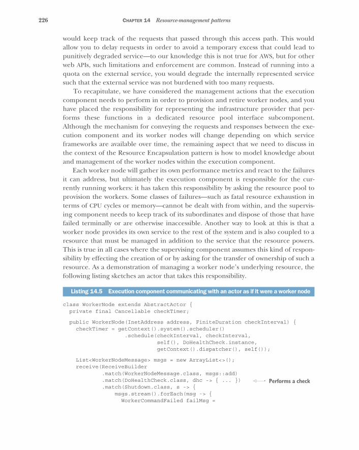
226 CHAPTER 14 Resource-management patterns
would keep track of the requests that passed through this access path. This wouldallow you to delay requests in order to avoid a temporary excess that could lead topunitively degraded service—to our knowledge this is not true for AWS, but for otherweb APIs, such limitations and enforcement are common. Instead of running into aquota on the external service, you would degrade the internally represented servicesuch that the external service was not burdened with too many requests.
To recapitulate, we have considered the management actions that the executioncomponent needs to perform in order to provision and retire worker nodes, and youhave placed the responsibility for representing the infrastructure provider that per-forms these functions in a dedicated resource pool interface subcomponent.Although the mechanism for conveying the requests and responses between the exe-cution component and its worker nodes will change depending on which serviceframeworks are available over time, the remaining aspect that we need to discuss inthe context of the Resource Encapsulation pattern is how to model knowledge aboutand management of the worker nodes within the execution component.
Each worker node will gather its own performance metrics and react to the failuresit can address, but ultimately the execution component is responsible for the cur-rently running workers: it has taken this responsibility by asking the resource pool toprovision the workers. Some classes of failures—such as fatal resource exhaustion interms of CPU cycles or memory—cannot be dealt with from within, and the supervis-ing component needs to keep track of its subordinates and dispose of those that havefailed terminally or are otherwise inaccessible. Another way to look at this is that aworker node provides its own service to the rest of the system and is also coupled to aresource that must be managed in addition to the service that the resource powers.This is true in all cases where the supervising component assumes this kind of respon-sibility by effecting the creation of or by asking for the transfer of ownership of such aresource. As a demonstration of managing a worker node’s underlying resource, thefollowing listing sketches an actor that takes this responsibility.
class WorkerNode extends AbstractActor {private final Cancellable checkTimer;
public WorkerNode(InetAddress address, FiniteDuration checkInterval) {checkTimer = getContext().system().scheduler()
.schedule(checkInterval, checkInterval,self(), DoHealthCheck.instance,getContext().dispatcher(), self());
List<WorkerNodeMessage> msgs = new ArrayList<>();receive(ReceiveBuilder
.match(WorkerNodeMessage.class, msgs::add)
.match(DoHealthCheck.class, dhc -> { ... })
.match(Shutdown.class, s -> {msgs.stream().forEach(msg -> {
WorkerCommandFailed failMsg =
Listing 14.5 Execution component communicating with an actor as if it were a worker node
Performs a check
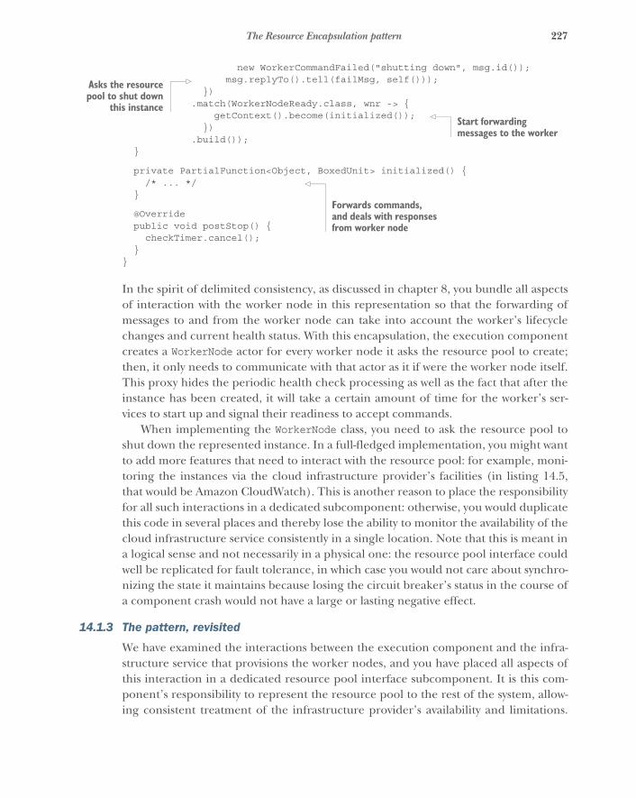
227The Resource Encapsulation pattern
new WorkerCommandFailed("shutting down", msg.id());msg.replyTo().tell(failMsg, self()));
}).match(WorkerNodeReady.class, wnr -> {
getContext().become(initialized());})
.build());}
private PartialFunction<Object, BoxedUnit> initialized() {/* ... */
}
@Overridepublic void postStop() {
checkTimer.cancel();}
}
In the spirit of delimited consistency, as discussed in chapter 8, you bundle all aspectsof interaction with the worker node in this representation so that the forwarding ofmessages to and from the worker node can take into account the worker’s lifecyclechanges and current health status. With this encapsulation, the execution componentcreates a WorkerNode actor for every worker node it asks the resource pool to create;then, it only needs to communicate with that actor as it if were the worker node itself.This proxy hides the periodic health check processing as well as the fact that after theinstance has been created, it will take a certain amount of time for the worker’s ser-vices to start up and signal their readiness to accept commands.
When implementing the WorkerNode class, you need to ask the resource pool toshut down the represented instance. In a full-fledged implementation, you might wantto add more features that need to interact with the resource pool: for example, moni-toring the instances via the cloud infrastructure provider’s facilities (in listing 14.5,that would be Amazon CloudWatch). This is another reason to place the responsibilityfor all such interactions in a dedicated subcomponent: otherwise, you would duplicatethis code in several places and thereby lose the ability to monitor the availability of thecloud infrastructure service consistently in a single location. Note that this is meant ina logical sense and not necessarily in a physical one: the resource pool interface couldwell be replicated for fault tolerance, in which case you would not care about synchro-nizing the state it maintains because losing the circuit breaker’s status in the course ofa component crash would not have a large or lasting negative effect.
14.1.3 The pattern, revisited
We have examined the interactions between the execution component and the infra-structure service that provisions the worker nodes, and you have placed all aspects ofthis interaction in a dedicated resource pool interface subcomponent. It is this com-ponent’s responsibility to represent the resource pool to the rest of the system, allow-ing consistent treatment of the infrastructure provider’s availability and limitations.
Asks the resourcepool to shut down
this instanceStart forwarding messages to the worker
Forwards commands, and deals with responses from worker node
228 CHAPTER 14 Resource-management patterns
This encapsulation is also in accordance with the principle of abstracting over theconcrete implementation of a potentially exchangeable resource; in this case, you sim-plify the adaptation to a different cloud infrastructure provider.
The second aspect we have illuminated is that worker nodes are based on dynami-cally provisioned resources that need to be owned by their supervising component.Therefore, you have placed the responsibility of monitoring the worker node andcommunicating with it in a WorkerNode subcomponent of the execution component,sketched as an actor for illustration. Although communication with the services pro-vided by a worker node is taken care of by the service fabric or framework, there is aremaining responsibility that cannot be satisfied from within the worker node becauseit is about the management of the node’s underlying resources.
The Resource Encapsulation pattern is used in two cases: to represent an externalresource and to manage a supervised resource—both in terms of its lifecycle and itsfunction, in accordance with the Simple Component pattern and the principle ofdelimited consistency. One aspect we glossed over is the precise relation of the Worker-Node subcomponents to their execution component parent: should a WorkerNodesupervisor be its own component, or should it be bundled with the execution compo-nent? Both approaches are certainly possible: the code modularity offered by object-oriented programming can express the necessary encapsulation of concerns just as wellas deploying a WorkerNode service instance on the hardware resources that the execu-tion component is using. Spinning up a separate node would again require you to estab-lish a supervision scheme and therefore not solve the problem.4 The way the decisionis made will depend on the case at hand. Influential factors are as follows:
� Complexity of the resource-management task� Runtime overhead of service separation for the chosen service framework� Development effort of adding another asynchronous messaging boundary
In many cases, it will be preferable to run the management subcomponents withintheir parent’s context (that is, to encapsulate this aspect in a separate class or functionlibrary). When using an actor-based framework, it is typically a good middle ground toseparate resource management into its own actor, making it look and behave like aseparate component while sharing most of the runtime context and avoiding largeruntime overhead.
14.1.4 Applicability
The Resource Encapsulation pattern is an architectural pattern that mainly informs thedesign of the component hierarchy and the placement of implementation details in codemodules—either reinforcing the previously established hierarchical decomposition or
4 Note that this depends on the service framework used, though, in that automatic resource cleanup in combi-nation with health monitoring may already be provided—meaning this pattern is incorporated at the frame-work level.
229The Resource Loan pattern
leading to its refinement. The concrete expression in code depends on the nature ofthe resource that is being managed or represented. The pattern is applicable whereverresources are integrated into a system, in particular when these resources have a life-cycle that needs to be managed or represented.
In some cases, the nature of resources used by the system is not immediately visi-ble: in this section’s example, a beginner’s mistake might be to leave the worker nodeinstances to their own devices after creation, having them shut themselves down whenno longer needed. This works well most of the time, but failure cases with lingeringbut defunct instances will manifest in the form of surprisingly large infrastructurecosts, at which point it will become obvious that reliable lifecycle management isrequired.
14.2 The Resource Loan patternGive a client exclusive transient access to a scarce resource without transferring ownership.
A variant of the Resource Loan pattern is widely used in non-Reactive systems, the mostprominent example being that of a database connection pool. Database access is repre-sented by a connection object via which arbitrary operations can be performed. The cre-ation of connections is expensive, and their number is limited; therefore, a connectionis not owned by client code but is taken from a pool before performing an operation andput back afterward. The connection pool is responsible for managing the lifecycle of itsconnections, and client code obtains temporary permission to use them. Failures in thisscenario are communicated to the client, but their effect on the connection in questionis handled by the pool—the pool owns and supervises the connections.
In a Reactive system, you strive to minimize contention as well as the need for coor-dination: hence, the classic database connection pool usually only features as an inter-nal implementation detail of a component whose data storage is realized by means ofa relational database. But you will frequently encounter the use of scarce resources inyour systems, and the same philosophy that drives the connection pool abstraction isuseful in Reactive system design as well.
14.2.1 The problem setting
Toward the end of the discussion of the Resource Encapsulation pattern, we touchedon the possibility of separating the ownership and the use of a resource: not beingresponsible for supervision aspects frees the user from having to perform monitoringtasks or recovery actions. In the example of the execution component of the batch jobservice, it may seem extraneous that the WorkerNode subcomponent needs to watchover the physical instance provisioned via the resource pool interface. Would it not benicer if the resource pool were not merely a messaging façade for talking to a cloudprovider but also took responsibility for the lifecycle management of the instances itprovisions?
230 CHAPTER 14 Resource-management patterns
The task: Your mission is to change the relationship between the resource poolinterface component and the execution component such that the resource pool willretain ownership of the worker nodes it provides, and the execution supervisor canconcentrate on managing the batch jobs.
14.2.2 Applying the pattern
Before we look at this in more detail, we need to establish some terminology. Theword loan is often used in a financial context: a lender gives a certain sum to aborrower, who is expected to pay it back later, usually with interest. More generally, thisterm applies to any asset that can be transferred, with the important notions that own-ership of the asset remains with the lender throughout the process and the transfer istemporary and will eventually be reversed. Renting an apartment falls in this category:the landlord lets you live in their property and expects you to vacate it when the leaseends; meanwhile, the landlord stays responsible for the general upkeep of the build-ing and everything that was rented with it. This example also illustrates the exclusivityof the arrangement, given that an apartment can only be rented to one tenant at atime. Therefore, the resource (the apartment, in this case) is also scarce: it cannot becopied or inhabited by multiple tenants independently at the same time. Thisresource comes at a per-instance cost.
To answer the question of having the resource pool take responsibility for the life-cycle of the instances it provisions, we will consider the worker nodes provisioned bythe resource pool interface to be like apartments that the execution component wantsto use. It will place a worker in each apartment; the worker will then process batchjobs. A worker node is a potential home for a batch-job process. In this scenario, apart-ments are provided by the cloud infrastructure, but this is the most basic, empty apart-ment you can think of—there is nothing interesting in it until someone moves in. Theworker node components in the structure of the batch job service correspond to peo-ple who need a apartment to live in. Once a worker has moved into an apartment, theexecution component can send work items to their address and receive replies fromthem—business-level information can flow. The missing piece is a kind of conciergewho looks after the apartments rented for workers and checks regularly with the prop-erty and with the worker to see that everything is in order. This allows the executioncomponent (the work provider) to concentrate entirely on conversations about thework that is to be done; monitoring of the workforce is done by the concierge. Theconcierge is responsible for ending the lease when a worker moves out, solving theproblem of possibly leaking resources.
Switching back from the anthropomorphic metaphor to computer programming,when the execution component asks the resource pool interface for a new workernode, the resource pool uses the cloud infrastructure to provision a new machineinstance: for example, using the AWS EC2 API, as shown in the previous pattern discus-sion. But instead of just returning the instance identifier and network address to theexecution component, the resource pool now assumes responsibility for the workernode: it needs to begin monitoring the service by performing regular health checks.
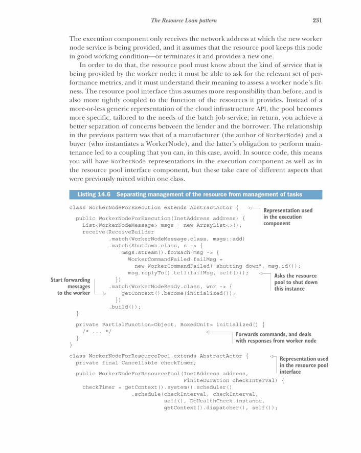
231The Resource Loan pattern
The execution component only receives the network address at which the new workernode service is being provided, and it assumes that the resource pool keeps this nodein good working condition—or terminates it and provides a new one.
In order to do that, the resource pool must know about the kind of service that isbeing provided by the worker node: it must be able to ask for the relevant set of per-formance metrics, and it must understand their meaning to assess a worker node’s fit-ness. The resource pool interface thus assumes more responsibility than before, and isalso more tightly coupled to the function of the resources it provides. Instead of amore-or-less generic representation of the cloud infrastructure API, the pool becomesmore specific, tailored to the needs of the batch job service; in return, you achieve abetter separation of concerns between the lender and the borrower. The relationshipin the previous pattern was that of a manufacturer (the author of WorkerNode) and abuyer (who instantiates a WorkerNode), and the latter’s obligation to perform main-tenance led to a coupling that you can, in this case, avoid. In source code, this meansyou will have WorkerNode representations in the execution component as well as inthe resource pool interface component, but these take care of different aspects thatwere previously mixed within one class.
class WorkerNodeForExecution extends AbstractActor {
public WorkerNodeForExecution(InetAddress address) {List<WorkerNodeMessage> msgs = new ArrayList<>();receive(ReceiveBuilder
.match(WorkerNodeMessage.class, msgs::add)
.match(Shutdown.class, s -> {msgs.stream().forEach(msg -> {
WorkerCommandFailed failMsg =new WorkerCommandFailed("shutting down", msg.id());
msg.replyTo().tell(failMsg, self()));})
.match(WorkerNodeReady.class, wnr -> {getContext().become(initialized());
}).build());
}
private PartialFunction<Object, BoxedUnit> initialized() {/* ... */
}}
class WorkerNodeForResourcePool extends AbstractActor {private final Cancellable checkTimer;
public WorkerNodeForResourcePool(InetAddress address,FiniteDuration checkInterval) {
checkTimer = getContext().system().scheduler().schedule(checkInterval, checkInterval,
self(), DoHealthCheck.instance,getContext().dispatcher(), self());
Listing 14.6 Separating management of the resource from management of tasks
Representation used in the execution component
Asks the resource pool to shut down this instance
Start forwardingmessages
to the worker
Forwards commands, and deals with responses from worker node
Representation used in the resource pool interface
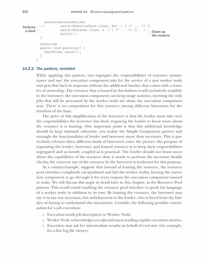
232 CHAPTER 14 Resource-management patterns
receive(ReceiveBuilder.match(DoHealthCheck.class, dhc -> { /* ... */ }).match(Shutdown.class, s -> { /* ... */ }).build());
}
@Overridepublic void postStop() {
checkTimer.cancel();}
}
14.2.3 The pattern, revisited
While applying this pattern, you segregate the responsibilities of resource mainte-nance and use: the execution component asks for the service of a new worker nodeand gets that back in response without the additional burden that comes with a trans-fer of ownership. The resource that is loaned in this fashion is still exclusively availableto the borrower; the execution component can keep usage statistics, knowing the onlyjobs that will be processed by the worker node are those the execution componentsent. There is no competition for this resource among different borrowers for theduration of the loan.
The price of this simplification of the borrower is that the lender must take overthe responsibilities the borrower has shed, requiring the lender to know more aboutthe resource it is loaning. One important point is that this additional knowledgeshould be kept minimal; otherwise, you violate the Simple Component pattern andentangle the functionalities of lender and borrower more than necessary. This is par-ticularly relevant when different kinds of borrowers enter the picture: the purpose ofseparating the lender, borrower, and loaned resource is to keep their responsibilitiessegregated and as loosely coupled as is practical. The lender should not know moreabout the capabilities of the resource than it needs to perform the necessary healthchecks; the concrete use of the resource by the borrower is irrelevant for this purpose.
As a counterexample, suppose that instead of loaning the resource, the resourcepool interface completely encapsulated and hid the worker nodes, forcing the execu-tion component to go through it for every request the execution component wantedto make. We will discuss this angle in detail later in this chapter, as the Resource Poolpattern. This would entail enabling the resource pool interface to speak the languageof a worker node in addition to its own. By loaning the resource, the borrower mayuse it in any way necessary, but unbeknownst to the lender, who is freed from the bur-den of having to understand this interaction. Consider the following possible conver-sation for a job execution:
1 Execution sends job description to Worker Node.2 Worker Node acknowledges receipt and starts sending regular execution metrics.3 Execution may ask for intermediate results on behalf of end user (for example,
for a live log file viewer).
Performsa check Cleans up
this resource
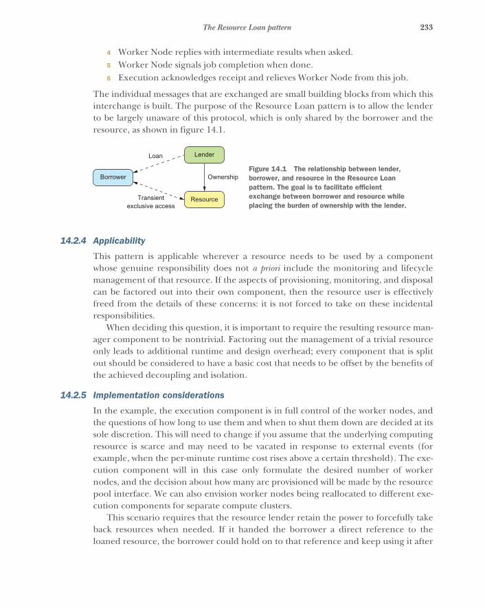
233The Resource Loan pattern
4 Worker Node replies with intermediate results when asked.5 Worker Node signals job completion when done.6 Execution acknowledges receipt and relieves Worker Node from this job.
The individual messages that are exchanged are small building blocks from which thisinterchange is built. The purpose of the Resource Loan pattern is to allow the lenderto be largely unaware of this protocol, which is only shared by the borrower and theresource, as shown in figure 14.1.
14.2.4 Applicability
This pattern is applicable wherever a resource needs to be used by a componentwhose genuine responsibility does not a priori include the monitoring and lifecyclemanagement of that resource. If the aspects of provisioning, monitoring, and disposalcan be factored out into their own component, then the resource user is effectivelyfreed from the details of these concerns: it is not forced to take on these incidentalresponsibilities.
When deciding this question, it is important to require the resulting resource man-ager component to be nontrivial. Factoring out the management of a trivial resourceonly leads to additional runtime and design overhead; every component that is splitout should be considered to have a basic cost that needs to be offset by the benefits ofthe achieved decoupling and isolation.
14.2.5 Implementation considerations
In the example, the execution component is in full control of the worker nodes, andthe questions of how long to use them and when to shut them down are decided at itssole discretion. This will need to change if you assume that the underlying computingresource is scarce and may need to be vacated in response to external events (forexample, when the per-minute runtime cost rises above a certain threshold). The exe-cution component will in this case only formulate the desired number of workernodes, and the decision about how many are provisioned will be made by the resourcepool interface. We can also envision worker nodes being reallocated to different exe-cution components for separate compute clusters.
This scenario requires that the resource lender retain the power to forcefully takeback resources when needed. If it handed the borrower a direct reference to theloaned resource, the borrower could hold on to that reference and keep using it after
Borrower
Resource
LenderLoan
Ownership
Transientexclusive access
Figure 14.1 The relationship between lender, borrower, and resource in the Resource Loan pattern. The goal is to facilitate efficient exchange between borrower and resource while placing the burden of ownership with the lender.
234 CHAPTER 14 Resource-management patterns
the loan was withdrawn. The solution is to hand out a proxy instead of the resource.This is easily possible in a setting where service references are location transparent,because the borrower does not care or know about the precise routing of requests tothe resource. The proxy must be able to forward requests and responses between theborrower and the resource, and it also must obey a deactivation command from thelender, after which it rejects all requests from the borrower. In this fashion, the lendercan cut the resource loose from the borrower as required and decommission or real-locate the resource without interference from unruly borrowers.
Another consideration is that a resource that has been loaned to another serviceinstance should be returned when the borrower terminates. Otherwise, the lendermay not notice that the resource is no longer being used—it may stay around, healthyand fully functional, for a long time. Failing to recognize this situation amounts to aresource leak.
14.2.6 Variant: using the Resource Loan pattern for partial exposure
The mechanics for handing out a subcomponent to an external client can also beused to expose part of a component’s functionality or data. Imagine a component thatholds a large, multidimensional array of floating-point numbers resulting from theanalysis of a huge amount of data. Clients may be interested in particular slices of thearray but are not allowed to make changes. Using the Resource Loan pattern, thecomponent can offer a protocol for obtaining a handle to a particularly shaped sliceof the data for read-only access. The client invokes methods on this handle to obtainparticular values, wrapped in a Future. This allows the implementation to decide howmany of the referenced values to ship to the client immediately and how to retrievethe rest when the client eventually asks for them—imagine a slice big enough to causeconsiderable network usage if it were transferred up front.
By using the Resource Loan pattern, the component that manages the multidi-mensional array knows exactly how many read-only handles are currently active, and itcan invalidate them when needed. For example, only a limited number of snapshotscan be kept in memory—with clients having handles to them—and when furtherchanges need to be made, the oldest snapshot will be retired to free up its space.
14.3 The Complex Command patternSend compound instructions to the resource to avoid excessive network usage.
You have encapsulated the resources your system uses in components that manage,represent, and directly implement their functionality. This allows you to confineresponsibility not only for code-modularity reasons (chapter 6) but also for verticaland horizontal scalability (chapters 4 and 5) and principled failure handling (chapter7). The price of all these advantages is that you introduce a boundary between theresource and the rest of the system that can only be crossed by asynchronous messag-ing. The Resource Loan pattern may help to move a resource as close as possible to itsusers, but this barrier will remain, leading to increased latency and, usually, decreased
235The Complex Command pattern
communication bandwidth. The core of the Complex Command pattern lies in send-ing the behavior to the resource in order to save time and network bandwidth in caseof loquacious interchanges between resource and users; the user of the resource isonly interested in the comparatively small result.
This pattern has been used for this purpose for a long time. We will approach it byway of a common example. Consider a large dataset, so large that it cannot possibly fitinto the working memory of a single machine. The data will be stored on a cluster ofmachines, each having only a small fraction of the data—this is known as big data. Thisdataset is a resource that will be used by other parts of the system. Other componentsthat interact with these data will send queries that have to be dispatched to the rightcluster nodes according to where the data are located. If the data store only allowedthe retrieval of individual data elements and left it to the clients to analyze them, thenany summarizing operation would involve the transfer of a huge amount of data; theresulting increase in network usage and the correspondingly high response latencywould be exacerbated by more-complex analyses requiring frequent back and forthbetween the client and the data source. Therefore, big data systems work by havingthe user send the computation job to the cluster instead of having the computationinterrogate the cluster from the outside.
Another way to think of this pattern is to picture the client and the resource (thelarge dataset) as two nations that are about to negotiate a contract. To facilitate an effi-cient exchange, an ambassador (the batch job) is sent from one nation to the other.Negotiations may take many days, but in the end the ambassador comes home withthe result.
14.3.1 The problem setting
We can generalize this problem as follows: a client wants to extract a result from aresource, a value that is relatively small compared to the quantity of data that need tobe moved in the course of the loquacious exchange required to obtain that value. Thecomputation process is more intimately coupled with the data than with the clientcomponent that initiates it; the client is not genuinely interested in how the data areprocessed, as long as it gets the result. The resource, on the other hand, only holdsthe data and does not know the process by which the client’s requested result can beextracted. Therefore, the process description needs to be sent from the client to theresource; the client needs to be provided with this description by the programmer,who presumably knows both the need and the structure of the data.
This is precisely what a batch job service is all about. You need to amend your men-tal picture slightly: the graphical overview has not changed from section 12.2, but werepeat it in figure 14.2 as a refresher. The worker nodes are no longer stateless ser-vices that can be provisioned and decommissioned dynamically; instead, there is afixed set of worker nodes in the big data cluster, and each persistently holds the parti-tion of data it has been entrusted with. The execution component will take care ofsending jobs to the correct worker nodes according to the data the jobs need, which
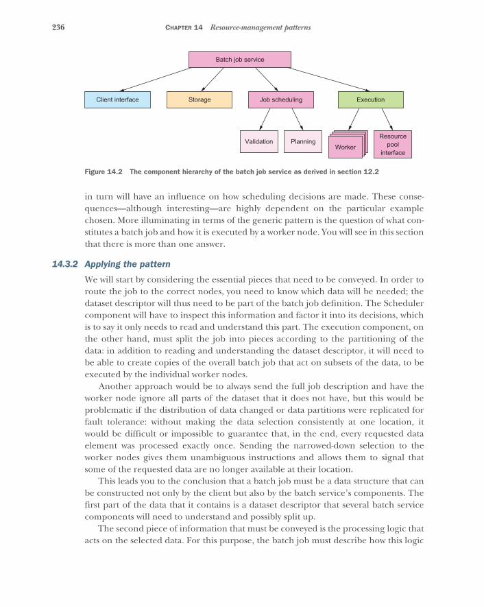
236 CHAPTER 14 Resource-management patterns
in turn will have an influence on how scheduling decisions are made. These conse-quences—although interesting—are highly dependent on the particular examplechosen. More illuminating in terms of the generic pattern is the question of what con-stitutes a batch job and how it is executed by a worker node. You will see in this sectionthat there is more than one answer.
14.3.2 Applying the pattern
We will start by considering the essential pieces that need to be conveyed. In order toroute the job to the correct nodes, you need to know which data will be needed; thedataset descriptor will thus need to be part of the batch job definition. The Schedulercomponent will have to inspect this information and factor it into its decisions, whichis to say it only needs to read and understand this part. The execution component, onthe other hand, must split the job into pieces according to the partitioning of thedata: in addition to reading and understanding the dataset descriptor, it will need tobe able to create copies of the overall batch job that act on subsets of the data, to beexecuted by the individual worker nodes.
Another approach would be to always send the full job description and have theworker node ignore all parts of the dataset that it does not have, but this would beproblematic if the distribution of data changed or data partitions were replicated forfault tolerance: without making the data selection consistently at one location, itwould be difficult or impossible to guarantee that, in the end, every requested dataelement was processed exactly once. Sending the narrowed-down selection to theworker nodes gives them unambiguous instructions and allows them to signal thatsome of the requested data are no longer available at their location.
This leads you to the conclusion that a batch job must be a data structure that canbe constructed not only by the client but also by the batch service’s components. Thefirst part of the data that it contains is a dataset descriptor that several batch servicecomponents will need to understand and possibly split up.
The second piece of information that must be conveyed is the processing logic thatacts on the selected data. For this purpose, the batch job must describe how this logic
WorkerResource
poolinterface
ExecutionJob scheduling
Batch job service
StorageClient interface
PlanningValidation
Figure 14.2 The component hierarchy of the batch job service as derived in section 12.2
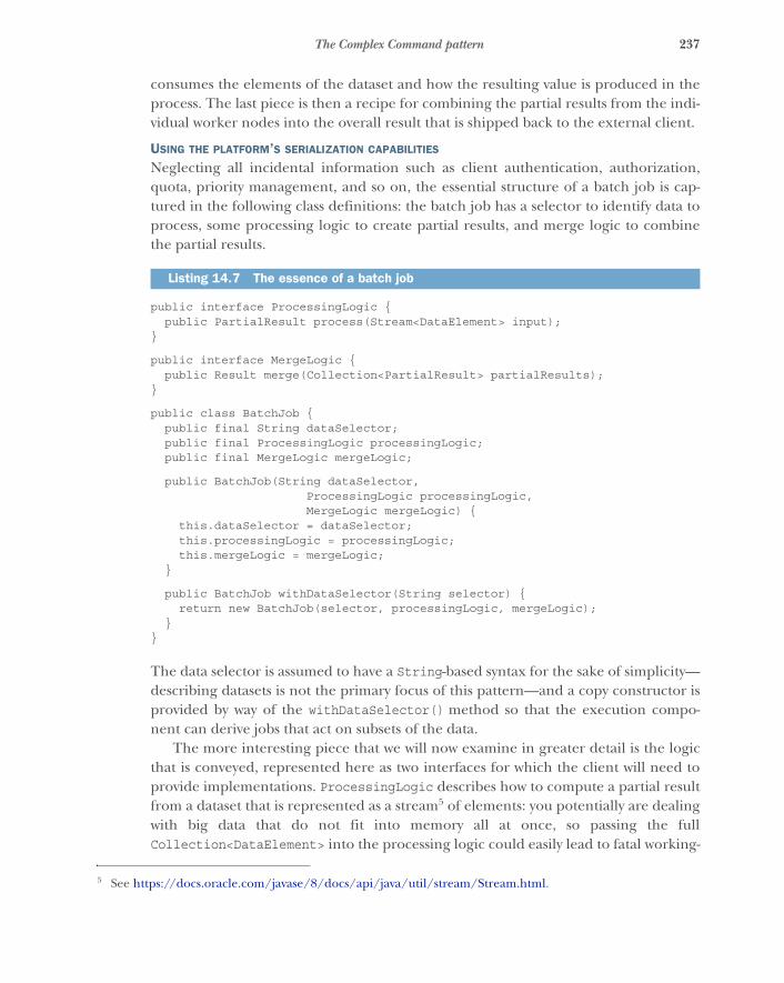
237The Complex Command pattern
consumes the elements of the dataset and how the resulting value is produced in theprocess. The last piece is then a recipe for combining the partial results from the indi-vidual worker nodes into the overall result that is shipped back to the external client.
USING THE PLATFORM’S SERIALIZATION CAPABILITIES
Neglecting all incidental information such as client authentication, authorization,quota, priority management, and so on, the essential structure of a batch job is cap-tured in the following class definitions: the batch job has a selector to identify data toprocess, some processing logic to create partial results, and merge logic to combinethe partial results.
public interface ProcessingLogic {public PartialResult process(Stream<DataElement> input);
}
public interface MergeLogic {public Result merge(Collection<PartialResult> partialResults);
}
public class BatchJob {public final String dataSelector;public final ProcessingLogic processingLogic;public final MergeLogic mergeLogic;
public BatchJob(String dataSelector,ProcessingLogic processingLogic,MergeLogic mergeLogic) {
this.dataSelector = dataSelector;this.processingLogic = processingLogic;this.mergeLogic = mergeLogic;
}
public BatchJob withDataSelector(String selector) {return new BatchJob(selector, processingLogic, mergeLogic);
}}
The data selector is assumed to have a String-based syntax for the sake of simplicity—describing datasets is not the primary focus of this pattern—and a copy constructor isprovided by way of the withDataSelector() method so that the execution compo-nent can derive jobs that act on subsets of the data.
The more interesting piece that we will now examine in greater detail is the logicthat is conveyed, represented here as two interfaces for which the client will need toprovide implementations. ProcessingLogic describes how to compute a partial resultfrom a dataset that is represented as a stream5 of elements: you potentially are dealingwith big data that do not fit into memory all at once, so passing the fullCollection<DataElement> into the processing logic could easily lead to fatal working-
Listing 14.7 The essence of a batch job
5 See https://docs.oracle.com/javase/8/docs/api/java/util/stream/Stream.html.

238 CHAPTER 14 Resource-management patterns
memory exhaustion (an OutOfMemoryError in Java). MergeLogic then takes the par-tial results and combines them into the overall result that the client wants; here, youexpect the involved amount of data to be relatively small—even thousands of partialresults should not take up a large amount of memory, because you are working underthe assumption that the result value is much smaller than the analyzed dataset.
In order to send a BatchJob message from the client to the batch job service, youneed to serialize this Java object. In listing 14.7, you could add extends Serializablein a few places and add some serialVersionUID values, with the result that the JavaRuntime Environment (JRE) would be able to turn a BatchJob object into a sequenceof bytes that could be transferred. On the other end—within the batch job service—you would need to reverse that process, but here you hit a snag: the JRE can only dese-rialize classes whose definition it already knows about. The serialized representationcontains only the class names of the objects that are referenced and the serialized formof the primitive values they contain (integers, characters, arrays); the bytecode thatdescribes the behavior of the objects is missing.
In order to transfer that, you will have to add the corresponding vocabulary to theprotocol between the batch service and its clients. They will have to upload theJAR6 files in conjunction with the job so that the necessary class definitions can bemade known wherever a BatchJob message needs to be interpreted. This can be atedious and brittle undertaking where any forgotten class or wrong library versionleads to fatal JVM errors that make it impossible to run the job. Also, note that thisapproach ties both clients and service together in their choice of runtime environ-ment: in listing 14.7, both parties need to use compatible versions of the Java Runtimein order to successfully transfer and run the bytecode as well as the serialized objects.Using the batch job service from a client written in JavaScript, Ruby, Haskell, and soon would not be possible.
USING ANOTHER LANGUAGE AS A BEHAVIOR TRANSFER FORMAT
Another way to look at this is that the batch job service defines a language choice thatis implicit to its client interface protocol. Batch jobs must be formulated such that theservice can understand and execute them. You can turn this around to exercise greaterfreedom in this regard: if the service—still written in Java—were to accept the process-ing logic in another language, preferably one that is widely used and optimized forbeing shipped and run in a variety of environments; then, you could sidestep the tightcode coupling you faced when transferring Java classes directly. There are severaloptions in this regard, including JavaScript, due to its ubiquity and ease of interpreta-tion; and Python, due to its popularity for data analytics purposes. The Java 8 Runtimeincludes a JavaScript engine that you can readily use to demonstrate this approach.
6 Java archive: basically, compressed files containing the machine-readable class definitions of a library, orga-nized in class files.
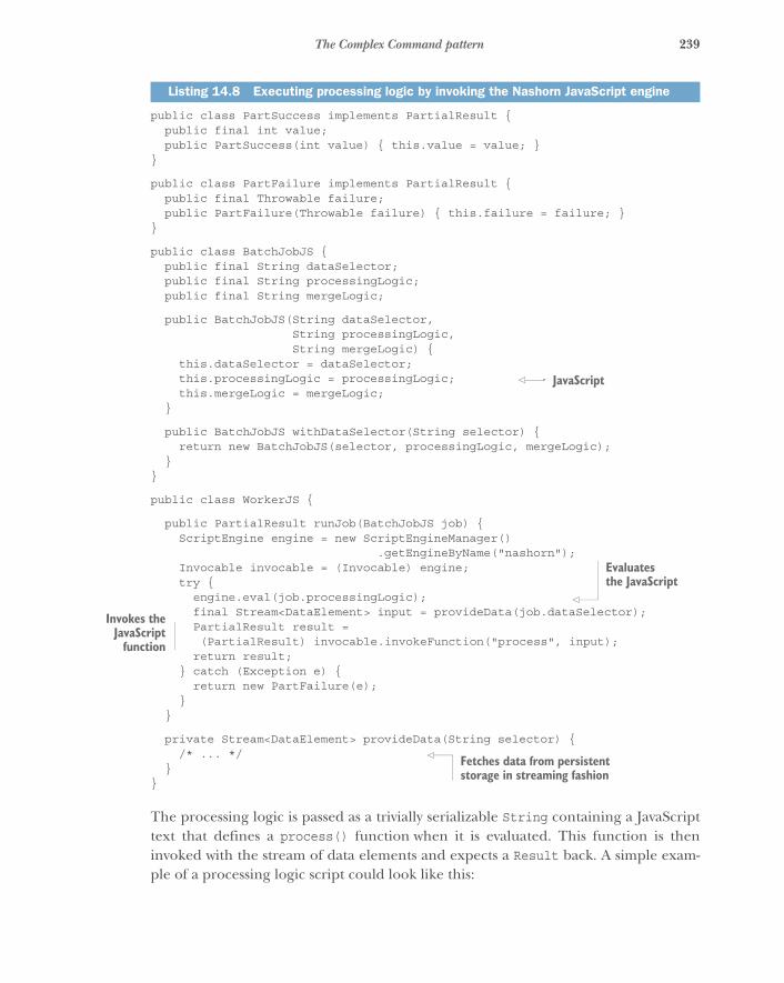
239The Complex Command pattern
public class PartSuccess implements PartialResult {public final int value;public PartSuccess(int value) { this.value = value; }
}
public class PartFailure implements PartialResult {public final Throwable failure;public PartFailure(Throwable failure) { this.failure = failure; }
}
public class BatchJobJS {public final String dataSelector;public final String processingLogic;public final String mergeLogic;
public BatchJobJS(String dataSelector,String processingLogic,String mergeLogic) {
this.dataSelector = dataSelector;this.processingLogic = processingLogic;this.mergeLogic = mergeLogic;
}
public BatchJobJS withDataSelector(String selector) {return new BatchJobJS(selector, processingLogic, mergeLogic);
}}
public class WorkerJS {
public PartialResult runJob(BatchJobJS job) {ScriptEngine engine = new ScriptEngineManager()
.getEngineByName("nashorn");Invocable invocable = (Invocable) engine;try {
engine.eval(job.processingLogic);final Stream<DataElement> input = provideData(job.dataSelector);PartialResult result =(PartialResult) invocable.invokeFunction("process", input);
return result;} catch (Exception e) {
return new PartFailure(e);}
}
private Stream<DataElement> provideData(String selector) {/* ... */
}}
The processing logic is passed as a trivially serializable String containing a JavaScripttext that defines a process() function when it is evaluated. This function is theninvoked with the stream of data elements and expects a Result back. A simple exam-ple of a processing logic script could look like this:
Listing 14.8 Executing processing logic by invoking the Nashorn JavaScript engine
JavaScript
Evaluates the JavaScript
Invokes theJavaScript
function
Fetches data from persistent storage in streaming fashion
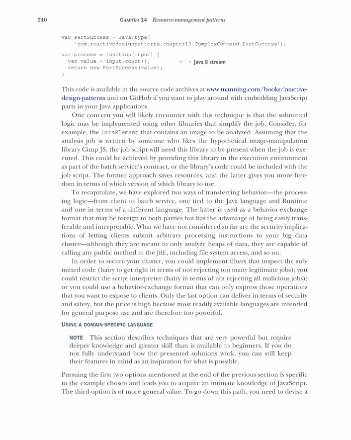
240 CHAPTER 14 Resource-management patterns
var PartSuccess = Java.type('com.reactivedesignpatterns.chapter13.ComplexCommand.PartSuccess');
var process = function(input) {var value = input.count();return new PartSuccess(value);
}
This code is available in the source code archives at www.manning.com/books/reactive-design-patterns and on GitHub if you want to play around with embedding JavaScriptparts in your Java applications.
One concern you will likely encounter with this technique is that the submittedlogic may be implemented using other libraries that simplify the job. Consider, forexample, the DataElement that contains an image to be analyzed. Assuming that theanalysis job is written by someone who likes the hypothetical image-manipulationlibrary Gimp JS, the job script will need this library to be present when the job is exe-cuted. This could be achieved by providing this library in the execution environmentas part of the batch service’s contract, or the library’s code could be included with thejob script. The former approach saves resources, and the latter gives you more free-dom in terms of which version of which library to use.
To recapitulate, we have explored two ways of transferring behavior—the process-ing logic—from client to batch service, one tied to the Java language and Runtimeand one in terms of a different language. The latter is used as a behavior-exchangeformat that may be foreign to both parties but has the advantage of being easily trans-ferable and interpretable. What we have not considered so far are the security implica-tions of letting clients submit arbitrary processing instructions to your big datacluster—although they are meant to only analyze heaps of data, they are capable ofcalling any public method in the JRE, including file system access, and so on.
In order to secure your cluster, you could implement filters that inspect the sub-mitted code (hairy to get right in terms of not rejecting too many legitimate jobs); youcould restrict the script interpreter (hairy in terms of not rejecting all malicious jobs);or you could use a behavior-exchange format that can only express those operationsthat you want to expose to clients. Only the last option can deliver in terms of securityand safety, but the price is high because most readily available languages are intendedfor general purpose use and are therefore too powerful.
USING A DOMAIN-SPECIFIC LANGUAGE
NOTE This section describes techniques that are very powerful but requiredeeper knowledge and greater skill than is available to beginners. If you donot fully understand how the presented solutions work, you can still keeptheir features in mind as an inspiration for what is possible.
Pursuing the first two options mentioned at the end of the previous section is specificto the example chosen and leads you to acquire an intimate knowledge of JavaScript.The third option is of more general value. To go down this path, you need to devise a
Java 8 stream
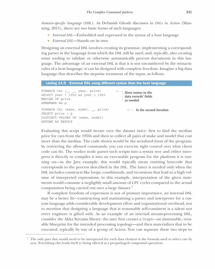
241The Complex Command pattern
domain-specific language (DSL). As Debasish Ghosh discusses in DSLs in Action (Man-ning, 2011), there are two basic forms of such languages:
� Internal DSL—Embedded and expressed in the syntax of a host language� External DSL—Stands on its own
Designing an external DSL involves creating its grammar, implementing a correspond-ing parser in the language from which the DSL will be used, and, typically, also creatingsome tooling to validate or otherwise automatically process documents in this lan-guage. The advantage of an external DSL is that it is not encumbered by the syntacticrules of a host language: it can be designed with complete freedom. Imagine a big datalanguage that describes the stepwise treatment of the input, as follows.
FOREACH Car (_, _, year, price)SELECT year ? 1950 && year < 1960MEDIAN OF priceREMEMBER AS p
FOREACH Car (make, model, _, price)SELECT price > pDISTINCT VALUES OF (make, model)RETURN AS RESULT
Evaluating this script would iterate over the dataset twice: first to find the medianprice for cars from the 1950s and then to collect all pairs of make and model that costmore than the median. The code shown would be the serialized form of the program;by restricting the allowed commands, you can exercise tight control over what clientcode can do. The worker node parses such scripts into a syntax tree and either inter-prets it directly or compiles it into an executable program for the platform it is run-ning on—in the Java example, this would typically mean emitting bytecode thatcorresponds to the process described in the DSL. The latter is needed only when theDSL includes constructs like loops, conditionals, and recursions that lead to a high vol-ume of interpreted expressions; in this example, interpretation of the given state-ments would consume a negligibly small amount of CPU cycles compared to the actualcomputation being carried out over a large dataset.7
If complete freedom of expression is not of primary importance, an internal DSLmay be a better fit—constructing and maintaining a parser and interpreter for a cus-tom language adds considerable development effort and organizational overhead, notto mention that designing a language that is reasonably self-consistent is a talent notevery engineer is gifted with. As an example of an internal stream-processing DSL,consider the Akka Streams library: the user first creates a Graph—an immutable, reus-able blueprint for the intended processing topology—and then materializes that to beexecuted, typically by way of a group of Actors. You can separate these two steps so
Listing 14.9 External DSL using different syntax than the host language
7 The only part that would need to be interpreted for each data element is the formula used to select cars byyear. Everything else lends itself to being offered as a prepackaged compound operation.
Gives names to the data records’ fields as needed
In the second iteration
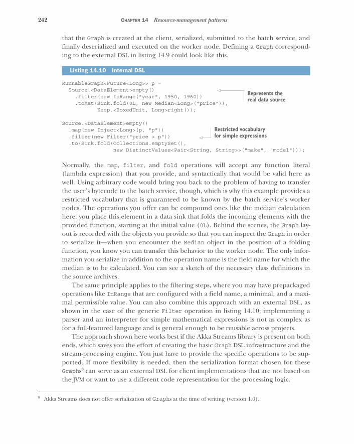
242 CHAPTER 14 Resource-management patterns
that the Graph is created at the client, serialized, submitted to the batch service, andfinally deserialized and executed on the worker node. Defining a Graph correspond-ing to the external DSL in listing 14.9 could look like this.
RunnableGraph<Future<Long>> p =Source.<DataElement>empty()
.filter(new InRange("year", 1950, 1960))
.toMat(Sink.fold(0L, new Median<Long>("price")),Keep.<BoxedUnit, Long>right());
Source.<DataElement>empty().map(new Inject<Long>(p, "p")).filter(new Filter("price > p")).to(Sink.fold(Collections.emptySet(),
new DistinctValues<Pair<String, String>>("make", "model")));
Normally, the map, filter, and fold operations will accept any function literal(lambda expression) that you provide, and syntactically that would be valid here aswell. Using arbitrary code would bring you back to the problem of having to transferthe user’s bytecode to the batch service, though, which is why this example provides arestricted vocabulary that is guaranteed to be known by the batch service’s workernodes. The operations you offer can be compound ones like the median calculationhere: you place this element in a data sink that folds the incoming elements with theprovided function, starting at the initial value (0L). Behind the scenes, the Graph lay-out is recorded with the objects you provide so that you can inspect the Graph in orderto serialize it—when you encounter the Median object in the position of a foldingfunction, you know you can transfer this behavior to the worker node. The only infor-mation you serialize in addition to the operation name is the field name for which themedian is to be calculated. You can see a sketch of the necessary class definitions inthe source archives.
The same principle applies to the filtering steps, where you may have prepackagedoperations like InRange that are configured with a field name, a minimal, and a maxi-mal permissible value. You can also combine this approach with an external DSL, asshown in the case of the generic Filter operation in listing 14.10; implementing aparser and an interpreter for simple mathematical expressions is not as complex asfor a full-featured language and is general enough to be reusable across projects.
The approach shown here works best if the Akka Streams library is present on bothends, which saves you the effort of creating the basic Graph DSL infrastructure and thestream-processing engine. You just have to provide the specific operations to be sup-ported. If more flexibility is needed, then the serialization format chosen for theseGraphs8 can serve as an external DSL for client implementations that are not based onthe JVM or want to use a different code representation for the processing logic.
Listing 14.10 Internal DSL
8 Akka Streams does not offer serialization of Graphs at the time of writing (version 1.0).
Represents the real data source
Restricted vocabulary for simple expressions
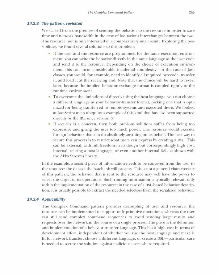
243The Complex Command pattern
14.3.3 The pattern, revisited
We started from the premise of sending the behavior to the resource in order to savetime and network bandwidth in the case of loquacious interchanges between the two.The resource user is only interested in a comparatively small result. Exploring the pos-sibilities, we found several solutions to this problem:
� If the user and the resource are programmed for the same execution environ-ment, you can write the behavior directly in the same language as the user codeand send it to the resource. Depending on the choice of execution environ-ment, this can incur considerable incidental complexity—in the case of Javaclasses, you would, for example, need to identify all required bytecode, transferit, and load it at the receiving end. Note that the choice will be hard to revertlater, because the implied behavior-exchange format is coupled tightly to theruntime environment.
� To overcome the limitations of directly using the host language, you can choosea different language as your behavior-transfer format, picking one that is opti-mized for being transferred to remote systems and executed there. We lookedat JavaScript as an ubiquitous example of this kind that has also been supporteddirectly by the JRE since version 8.
� If security is a concern, then both previous solutions suffer from being tooexpressive and giving the user too much power. The resource would executeforeign behaviors that can do absolutely anything on its behalf. The best way tosecure this process is to restrict what users can express by creating a DSL. Thiscan be external, with full freedom in its design but correspondingly high cost;internal, reusing a host language; or even another internal DSL, as shown withthe Akka Streams library.
In the example, a second piece of information needs to be conveyed from the user tothe resource: the dataset the batch job will process. This is not a general characteristicof this pattern; the behavior that is sent to the resource may well have the power toselect the target of its operations. Such routing information is typically relevant onlywithin the implementation of the resource; in the case of a DSL-based behavior descrip-tion, it is usually possible to extract the needed selectors from the serialized behavior.
14.3.4 Applicability
The Complex Command pattern provides decoupling of user and resource: theresource can be implemented to support only primitive operations, whereas the usercan still send complex command sequences to avoid sending large results andrequests over the network in the course of a single process. The price is the definitionand implementation of a behavior transfer language. This has a high cost in terms ofdevelopment effort, independent of whether you use the host language and make itfit for network transfer, choose a different language, or create a DSL—particular careis needed to secure the solution against malicious users where required.
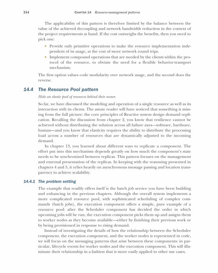
244 CHAPTER 14 Resource-management patterns
The applicability of this pattern is therefore limited by the balance between thevalue of the achieved decoupling and network bandwidth reduction in the context ofthe project requirements at hand. If the cost outweighs the benefits, then you need topick one:
� Provide only primitive operations to make the resource implementation inde-pendent of its usage, at the cost of more network round trips.
� Implement compound operations that are needed by the clients within the pro-tocol of the resource, to obviate the need for a flexible behavior-transportmechanism.
The first option values code modularity over network usage, and the second does thereverse.
14.4 The Resource Pool patternHide an elastic pool of resources behind their owner.
So far, we have discussed the modeling and operation of a single resource as well as itsinteraction with its clients. The astute reader will have noticed that something is miss-ing from the full picture: the core principles of Reactive system design demand repli-cation. Recalling the discussion from chapter 2, you know that resilience cannot beachieved without distributing the solution across all failure axes—software, hardware,human—and you know that elasticity requires the ability to distribute the processingload across a number of resources that are dynamically adjusted to the incomingdemand.
In chapter 13, you learned about different ways to replicate a component. Theeffort put into this mechanism depends greatly on how much the component’s stateneeds to be synchronized between replicas. This pattern focuses on the managementand external presentation of the replicas. In keeping with the reasoning presented inchapters 4 and 5, it relies heavily on asynchronous message passing and location trans-parency to achieve scalability.
14.4.1 The problem setting
The example that readily offers itself is the batch job service you have been buildingand enhancing in the previous chapters. Although the overall system implements amore complicated resource pool, with sophisticated scheduling of complex com-mands (batch jobs), the execution component offers a simple, pure example of aresource pool: after the Scheduler component has decided the order in whichupcoming jobs will be run, the execution component picks them up and assigns themto worker nodes as they become available—either by finishing their previous work orby being provisioned in response to rising demand.
Instead of investigating the details of how the relationship between the Schedulercomponent, the execution component, and the worker nodes is represented in code,we will focus on the messaging patterns that arise between these components: in par-ticular, lifecycle events for worker nodes and the execution component. This will illu-minate their relationship in a fashion that is more easily applied to other use cases.
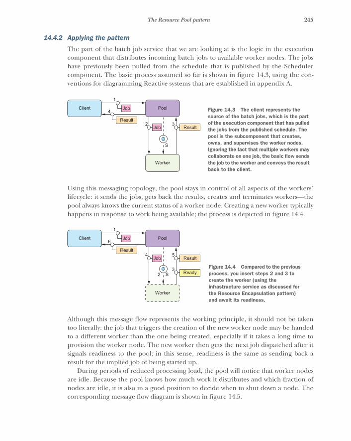
245The Resource Pool pattern
14.4.2 Applying the pattern
The part of the batch job service that we are looking at is the logic in the executioncomponent that distributes incoming batch jobs to available worker nodes. The jobshave previously been pulled from the schedule that is published by the Schedulercomponent. The basic process assumed so far is shown in figure 14.3, using the con-ventions for diagramming Reactive systems that are established in appendix A.
Using this messaging topology, the pool stays in control of all aspects of the workers’lifecycle: it sends the jobs, gets back the results, creates and terminates workers—thepool always knows the current status of a worker node. Creating a new worker typicallyhappens in response to work being available; the process is depicted in figure 14.4.
Although this message flow represents the working principle, it should not be takentoo literally: the job that triggers the creation of the new worker node may be handedto a different worker than the one being created, especially if it takes a long time toprovision the worker node. The new worker then gets the next job dispatched after itsignals readiness to the pool; in this sense, readiness is the same as sending back aresult for the implied job of being started up.
During periods of reduced processing load, the pool will notice that worker nodesare idle. Because the pool knows how much work it distributes and which fraction ofnodes are idle, it is also in a good position to decide when to shut down a node. Thecorresponding message flow diagram is shown in figure 14.5.
Client Pool
Worker
Job
Job
1
4
2 3
S
ResultResult
Figure 14.3 The client represents the source of the batch jobs, which is the part of the execution component that has pulled the jobs from the published schedule. The pool is the subcomponent that creates, owns, and supervises the worker nodes. Ignoring the fact that multiple workers may collaborate on one job, the basic flow sends the job to the worker and conveys the result back to the client.
Client Pool
Worker
Job
Job
1
6
4 5
S
Result
32 Ready
Result
Figure 14.4 Compared to the previous process, you insert steps 2 and 3 to create the worker (using the infrastructure service as discussed for the Resource Encapsulation pattern) and await its readiness.

246 CHAPTER 14 Resource-management patterns
The final aspect of the worker’s lifecycle is how to handle failures. The pool shouldmonitor all worker nodes by performing periodic health checks9 and possibly also ask-ing for progress updates. When a worker fails while processing a job, the pool eithersends this failure back to the execution component to be recorded and relayed to theexternal client or retries the job by giving it to another worker. The recovery processfor the failed worker depends on the requirements of the use case. The preferableapproach is described in the Let-It-Crash pattern: decommission the worker and all ofits resources, and provision a fresh one. When a worker fails while idle, only the recov-ery process needs to be performed.
The message flows you have seen so far all assume that the worker node receives ajob in a single message and replies with a result that again fits in a single message. Thiscovers a broad range of services but nowhere near all of them, notable exceptionsbeing streaming services that provide a response that is a priori not bounded, and ser-vices where the purpose is the transmission at a given rate so the external client canprocess the data as they arrive without having to buffer them. Another exception dis-cussed with the Resource Loan pattern is that the external client may reserve a workerand engage in an ongoing conversation with it to perform a complex task.
Accommodating these usage patterns requires a slight reinterpretation of the basicmessage flow, as shown in figure 14.6. Variants of this flow send all messages betweenworker and external client (step 5) via the intermediary that represents the client forthe pool, or do not signal completion from the worker and instead have the externalclient convey this signal via the same route taken by the job description. The formerallows tighter control over which protocols are permitted between external client andworker, whereas the latter gives the pool more detailed information about when work-ers are finishing their jobs.
The important notion is that you retain the same processes for the creation andtermination of worker nodes by keeping the same basic message-flow structurebetween pool and worker. The pool initiates the work, and the worker eventuallyreplies with a completion notification.
9 This functionality may be included in the services framework that is being used.
Client Pool
Worker
Job
Job
1
4
2 3
S 5
ResultResult
Figure 14.5 After the worker has finished processing a job, the pool sends the termination signal and refrains from sending further jobs to that worker. There can be a sizable delay between messages 4 and 5 to implement an idle timeout.
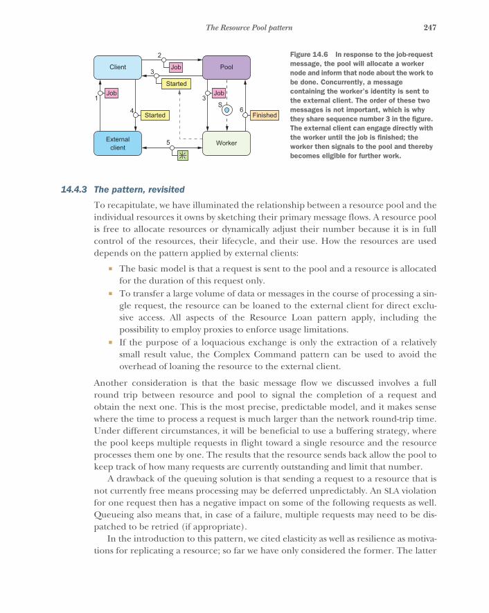
247The Resource Pool pattern
14.4.3 The pattern, revisited
To recapitulate, we have illuminated the relationship between a resource pool and theindividual resources it owns by sketching their primary message flows. A resource poolis free to allocate resources or dynamically adjust their number because it is in fullcontrol of the resources, their lifecycle, and their use. How the resources are useddepends on the pattern applied by external clients:
� The basic model is that a request is sent to the pool and a resource is allocatedfor the duration of this request only.
� To transfer a large volume of data or messages in the course of processing a sin-gle request, the resource can be loaned to the external client for direct exclu-sive access. All aspects of the Resource Loan pattern apply, including thepossibility to employ proxies to enforce usage limitations.
� If the purpose of a loquacious exchange is only the extraction of a relativelysmall result value, the Complex Command pattern can be used to avoid theoverhead of loaning the resource to the external client.
Another consideration is that the basic message flow we discussed involves a fullround trip between resource and pool to signal the completion of a request andobtain the next one. This is the most precise, predictable model, and it makes sensewhere the time to process a request is much larger than the network round-trip time.Under different circumstances, it will be beneficial to use a buffering strategy, wherethe pool keeps multiple requests in flight toward a single resource and the resourceprocesses them one by one. The results that the resource sends back allow the pool tokeep track of how many requests are currently outstanding and limit that number.
A drawback of the queuing solution is that sending a request to a resource that isnot currently free means processing may be deferred unpredictably. An SLA violationfor one request then has a negative impact on some of the following requests as well.Queueing also means that, in case of a failure, multiple requests may need to be dis-patched to be retried (if appropriate).
In the introduction to this pattern, we cited elasticity as well as resilience as motiva-tions for replicating a resource; so far we have only considered the former. The latter
Client Pool
Externalclient
Worker
Job
Job
2
3
31
64
5
SFinished
Job
Started
Started
Figure 14.6 In response to the job-request message, the pool will allocate a worker node and inform that node about the work to be done. Concurrently, a message containing the worker’s identity is sent to the external client. The order of these two messages is not important, which is why they share sequence number 3 in the figure. The external client can engage directly with the worker until the job is finished; the worker then signals to the pool and thereby becomes eligible for further work.
248 CHAPTER 14 Resource-management patterns
is more troublesome due to the ownership and supervision relationship between thepool and its resources: if the pool fails, then the resources are orphaned. There aretwo ways to deal with this: you can replicate the pool, including its resources—run-ning complete setups in different data centers, for example; or you can replicate onlythe pool manager and transfer ownership of resources in order to realize a failoverbetween them. Ownership transfer can only be initiated by the current owner if it isstill functioning; otherwise, each resource must monitor the pool it belongs to10 andoffer itself to a new owner upon receiving a failure notification for its parent.11 To rep-licate the pool manager, any of the replication schemes discussed in the previouschapter can be used, chosen according to the requirements of the use case at hand.
14.4.4 Implementation considerations
This pattern may be implemented by the services framework: deployment of aresource includes replication factors or performance metrics for dynamic scaling, andlooking up that resource results in a resource pool proxy that is interposed betweenclient and resource implicitly. This works without central coordination of the poolproxies generated at the lookup site if the resource either is stateless (just offers com-putation functions) or uses multiple-master replication. In these cases, there can beone proxy per dependent service instance, removing any single point of failure. Apotential difficulty with this is that it assumes the resources handle incoming requestsfrom multiple sources. This can be challenging in the context of applying theResource Loan pattern or the Complex Command pattern, because requests may bedelayed in a less controlled fashion than if a central authority distributes them.
14.5 Patterns for managed blockingBlocking a resource requires consideration and ownership.
In the example code for how the execution component in the batch job service provi-sions new worker nodes, you have already encountered the situation that an API youare using is designed to block its calling thread. In the case of the AWS API, there areways around that, but this is not always the case. Many libraries or frameworks that youmay want to or have to use do not offer the option of event-driven interaction. JavaDatabase Connectivity (JDBC)12 is a well-known example that comes to mind. In orderto use these APIs in a Reactive system component, you need to take special care toproperly manage the resources that are implicitly seized, most notably the threadsrequired for their execution.
10 This should typically be implemented by the services framework in a generic fashion.11 Readers fluent in Akka will notice that reparenting is not supported for Actors, but we are talking about a pool
of resource components in general and not Actors that encapsulate resources. The service abstraction we arereferring to here is a higher-level construct than the Actor model.
12 Java Database Connectivity (http://docs.oracle.com/javase/8/docs/technotes/guides/jdbc), part of the Javaplatform, is a generic access layer for relational databases by which applications are decoupled from the spe-cific database implementation that is used. It is a standard mechanism to provide data sources through depen-dency injection in application containers, usually driven by external deployment configuration files.
249Patterns for managed blocking
14.5.1 The problem setting
Consider a component that manages knowledge in a fashion that translates well into arelational database model—this may be a booking ledger, user and group manage-ment, the classic pet shop, and so on. In the batch service example, this may occur inthe authentication and authorization service that the Client Interface componentuses to decide whether a given request is legitimate. You could write this componentfrom scratch, modeling every domain object as a persistent actor, or you can reuse theenormous power that is conveniently available through off-the-shelf database manage-ment systems. In the absence of good reasons to the contrary, it is preferable to reuseexisting working solutions, so you will use a JDBC driver in your implementation basedon Java and Akka actors.
The problem you are facing is that executing a database query may take an arbi-trary amount of time: the database may be overloaded or failing, the query may not befully optimized due to a lack of indices, or it might be a very complex query over alarge dataset to begin with. If you execute a slow query in an Actor that runs on ashared thread pool, that thread will effectively be unavailable to the pool—andthereby to all other actors—until the result set has been communicated back. Otheractors on the same thread pool may have scheduled timers that may be processed onlywith a large delay unless enough other threads are available. The bigger the threadpool, the more such blocking actions it can tolerate at the same time; but threads area finite resource on the JVM, and that translates into a limited tolerance for suchblockers.
14.5.2 Applying the pattern
The source of the problem is that a shared resource—the thread pool—is being usedin a fashion that is violating the cooperative contract of the group of users. Actors areexpected to process messages quickly and then give other actors a chance to run: thisis the basis for their efficient thread-sharing mechanism. Making a resource unavail-able to others by seizing it means the Actor that blocks the thread claims exclusiveownership, at least for the duration of the database query in this example. You haveseen for the Resource Loan pattern that the owner can grant exclusive access toanother component, but that must always happen explicitly: you must ask the ownerfor permission.
A thread pool usually does not have a mechanism for signaling that a given threadis being blocked exclusively for the currently running task.13 If you cannot ask theowner of a shared thread for permission, the logical conclusion is that you need toown a thread on which you can run the database query. This can be done by creatinga private thread pool that is managed by the actor: now you can submit the blockingJDBC calls as tasks to this pool.
13 An exception is the ForkJoinPool, which can be informed using ForkJoinPool.managedBlock() (seehttps://docs.oracle.com/javase/8/docs/api/java/util/concurrent/ForkJoinPool.ManagedBlocker.html).But in this case, management of the additionally created threads is also limited.
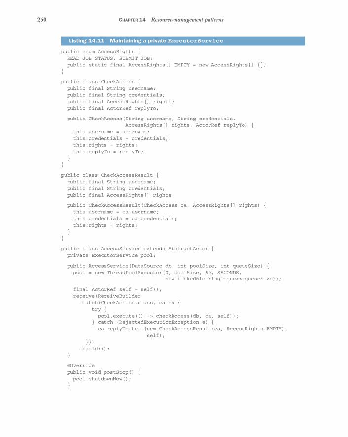
250 CHAPTER 14 Resource-management patterns
public enum AccessRights {READ_JOB_STATUS, SUBMIT_JOB;public static final AccessRights[] EMPTY = new AccessRights[] {};
}
public class CheckAccess {public final String username;public final String credentials;public final AccessRights[] rights;public final ActorRef replyTo;
public CheckAccess(String username, String credentials,AccessRights[] rights, ActorRef replyTo) {
this.username = username;this.credentials = credentials;this.rights = rights;this.replyTo = replyTo;
}}
public class CheckAccessResult {public final String username;public final String credentials;public final AccessRights[] rights;
public CheckAccessResult(CheckAccess ca, AccessRights[] rights) {this.username = ca.username;this.credentials = ca.credentials;this.rights = rights;
}}
public class AccessService extends AbstractActor {private ExecutorService pool;
public AccessService(DataSource db, int poolSize, int queueSize) {pool = new ThreadPoolExecutor(0, poolSize, 60, SECONDS,
new LinkedBlockingDeque<>(queueSize));
final ActorRef self = self();receive(ReceiveBuilder.match(CheckAccess.class, ca -> {
try {pool.execute(() -> checkAccess(db, ca, self));
} catch (RejectedExecutionException e) {ca.replyTo.tell(new CheckAccessResult(ca, AccessRights.EMPTY),
self);}})
.build()); }
@Override public void postStop() { pool.shutdownNow(); }
Listing 14.11 Maintaining a private ExecutorService
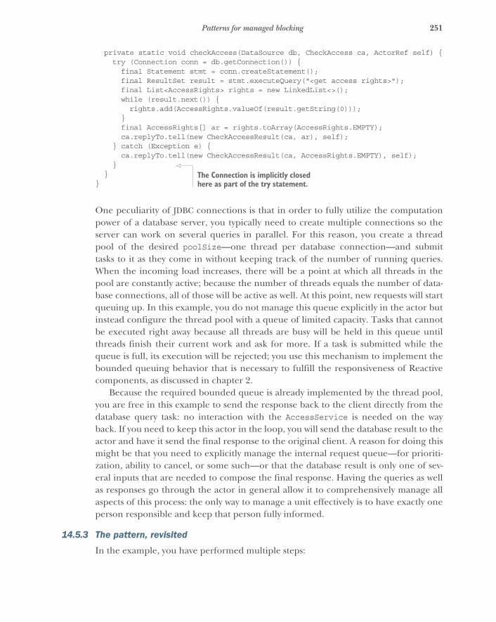
251Patterns for managed blocking
private static void checkAccess(DataSource db, CheckAccess ca, ActorRef self) { try (Connection conn = db.getConnection()) {
final Statement stmt = conn.createStatement();final ResultSet result = stmt.executeQuery("<get access rights>");final List<AccessRights> rights = new LinkedList<>();while (result.next()) {rights.add(AccessRights.valueOf(result.getString(0)));
}final AccessRights[] ar = rights.toArray(AccessRights.EMPTY);ca.replyTo.tell(new CheckAccessResult(ca, ar), self);
} catch (Exception e) {ca.replyTo.tell(new CheckAccessResult(ca, AccessRights.EMPTY), self);
}}
}
One peculiarity of JDBC connections is that in order to fully utilize the computationpower of a database server, you typically need to create multiple connections so theserver can work on several queries in parallel. For this reason, you create a threadpool of the desired poolSize—one thread per database connection—and submittasks to it as they come in without keeping track of the number of running queries.When the incoming load increases, there will be a point at which all threads in thepool are constantly active; because the number of threads equals the number of data-base connections, all of those will be active as well. At this point, new requests will startqueuing up. In this example, you do not manage this queue explicitly in the actor butinstead configure the thread pool with a queue of limited capacity. Tasks that cannotbe executed right away because all threads are busy will be held in this queue untilthreads finish their current work and ask for more. If a task is submitted while thequeue is full, its execution will be rejected; you use this mechanism to implement thebounded queuing behavior that is necessary to fulfill the responsiveness of Reactivecomponents, as discussed in chapter 2.
Because the required bounded queue is already implemented by the thread pool,you are free in this example to send the response back to the client directly from thedatabase query task: no interaction with the AccessService is needed on the wayback. If you need to keep this actor in the loop, you will send the database result to theactor and have it send the final response to the original client. A reason for doing thismight be that you need to explicitly manage the internal request queue—for prioriti-zation, ability to cancel, or some such—or that the database result is only one of sev-eral inputs that are needed to compose the final response. Having the queries as wellas responses go through the actor in general allow it to comprehensively manage allaspects of this process: the only way to manage a unit effectively is to have exactly oneperson responsible and keep that person fully informed.
14.5.3 The pattern, revisited
In the example, you have performed multiple steps:
The Connection is implicitly closed here as part of the try statement.
252 CHAPTER 14 Resource-management patterns
1 You noticed that the use case required a resource that was not immediatelyobvious. Resources are often represented by objects in the programming lan-guage that are explicitly passed around or configured, but there are implicitresources that are always assumed and rarely considered explicitly—like threadsor working memory—because they are usually shared such that the systemworks well in most scenarios, by convention. Whenever you run into one of thecorner cases, you will need to make these resources explicit in your systemdesign.
2 Having recognized the resources that you need to perform a certain function,you modeled them explicitly: in the example, these are the thread pool and thedatabase connection pool. The thread pool is configured with a given numberof threads and a maximal submission queue length in order to place an upperbound on the amount of auxiliary resources that are used by it. The same goesfor the database connection pool, whose configuration we left out of the exam-ple code.
3 In keeping with resource encapsulation, you placed the management of theseresources in one component, represented by an actor. The lifecycle of theresources is contained within the lifecycle of the actor. The thread pool is createdwhen starting and shut down when stopping. The database connections are man-aged individually on a per-request basis, taking care to obtain them such that theyare released independently of how the processing ends. This is inspired by Let-It-Crash thinking in that shutting down the thread pool will release all associatedresources, including the currently used database connections.
4 The last step implements the Simple Component pattern, in that the responsi-bility of the component you are developing is to provide authorization informa-tion for users based on their credentials. Toward this end, you need resourcesand the logic that uses them, all bundled up in one component that does onlyits job but does it in full.
Although many APIs are widely employed that make implicit use of hidden resourceslike the calling thread, you will see this pattern used to manage the blocking ofthreads: hence, the name. The term managed blocking first became known to us when itwas used in the ForkJoinPool developed for Java 7, although it was mentioned in the.NET ecosystem several years earlier. ForkJoinPool is not intended as a generic execu-tor but rather as a targeted tool to help the parallelization of tasks that operate onlarge collections of data, splitting up work among the available CPUs and joining thepartial results together. Managed blocking support is needed to keep the CPUs busywhile certain threads are stalled, waiting for I/O (from network or disk). Therefore,entering a managed-blocking section will, roughly speaking, spawn a new workerthread that continues the number crunching while the current thread becomes tem-porarily inactive.
You can generalize this pattern such that it is more widely applicable by consideringany kind of resource that needs to be blocked as well as allowing for tailored management
253Summary
strategies of the blocked resource. An example could be the explicit management of asegregated memory region that is split off from the main application heap in order toboth place an upper bound on its size and explicitly control the access to thisresource—using normal heap memory is unconstrained for all components in thesame process and means one misbehaving party can hamper the function of all ofthem. Another angle is that managed blocking is similar to the Resource Loan patternin the case of resources that are already encapsulated as Reactive components.
14.5.4 Applicability
The first step of this pattern—investigating the use of hidden resources in ways thatviolate their sharing contract—should always be applied. Failure to recognize such acase will lead to scalability issues or application failures through resource exhaustion(such as OutOfMemoryError), as we have frequently encountered in consultingengagements.
On the other hand, it is important not to get carried away and claim exclusive own-ership of resources at a too fine-grained level or in cases that could live with havingonly shared access. This is particularly visible in the case of thread pools: the actormodel is successful in utilizing the machine’s resources due to sharing the corepieces—CPUs and memory—in an event-driven activation scheme. Giving one threadto each actor would seem to give each of them exclusive access to a computingresource; but not only does this incur orders of magnitude more overhead per actor,but it also leads to significant contention on the underlying CPUs, with all threadsfighting for their chance to run.
Recognizing the use of resources is as important as learning to qualify the cases inwhich exclusion is needed and where sharing is appropriate—and under which rules.Unfortunately, there is no simple rule to decide this.
14.6 SummaryThis chapter was devoted entirely to the modeling and management of resources. Justas that term is generic, the patterns described also apply flexibly in a wide range ofcases:
� Each resource should be owned by one component that is fully responsible forits lifecycle. Ownership is exclusive—there can be only one owner—butresources may be used by a wide variety of clients inside or outside the Reactivesystem you are building, sometimes needing more direct access than is possibleby always having the owner as an intermediary.
� The Resource Loan pattern helps by bringing the resource as close to its client aspossible. It allows the distance to be reduced to only one asynchronous message-passing boundary for the purpose of transient exclusive access, in order to per-form a complex operation.

254 CHAPTER 14 Resource-management patterns
� The Complex Command pattern turns this around by packaging the client’spart of a loquacious exchange such that it can be sent to the resource, like send-ing an ambassador to a foreign country.
� The Resource Pool pattern tackles the concern of implementing elasticity andresilience by hiding the individually owned resources behind their manager.The resulting increase in distance between clients and resources can be miti-gated by combining this pattern with the previous two.
� We considered resource use in the implementation of components, especiallythose that use libraries and frameworks that implicitly utilize resources that areotherwise shared in Reactive systems, and looked at an example of managingthe blocking of threads in an otherwise event-driven system.
255
Message flow patterns
In this chapter, we will explore some of the most basic patterns of communicationthat occur between Reactive components: specifically, we will talk about how mes-sages flow between them. We discussed the theoretical background in chapter 10,noting that the design of communication paths within a system is crucial to its suc-cess—the same holds for real-world organizations as well as Reactive applications.
Most of the patterns we will encounter are extremely generic, starting with theRequest–Response pattern. They can be applied in a variety of cases and come inmany forms. The examples are therefore less specific than in other chapters, but wewill use the front-end façade of a larger service as a problem setting. You can thinkof this as a more detailed look at the client interface component of the batch jobservice, our running example. The particular patterns we will cover are as follows:
� The Request–Response pattern� The Self-Contained Message pattern� The Ask pattern� The Forward Flow pattern� The Aggregator pattern� The Saga pattern� The Business Handshake pattern
15.1 The Request–Response patternInclude a return address in the message to receive a response.
This is the most basic interaction pattern we know; it is the foundational buildingblock for all natural communication, deeply ingrained in human training. A parentwill say something to their infant child, who will initially gesture or makesome sounds in response; later, the child will articulate words and sentences.
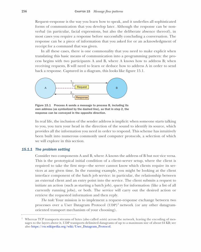
256 CHAPTER 15 Message flow patterns
Request–response is the way you learn how to speak, and it underlies all sophisticatedforms of communication that you develop later. Although the response can be non-verbal (in particular, facial expressions, but also the deliberate absence thereof), inmost cases you require a response before successfully concluding a conversation. Theresponse can be a piece of information that you asked for or an acknowledgment ofreceipt for a command that was given.
In all these cases, there is one commonality that you need to make explicit whentranslating this basic means of communication into a programming pattern: the pro-cess begins with two participants A and B, where A knows how to address B; whenreceiving requests, B will need to learn or deduce how to address A in order to sendback a response. Captured in a diagram, this looks like figure 15.1.
In real life, the inclusion of the sender address is implicit: when someone starts talkingto you, you turn your head in the direction of the sound to identify its source, whichprovides all the information you need in order to respond. This scheme has intuitivelybeen built into numerous commonly used computer protocols, a selection of whichwe will explore in this section.
15.1.1 The problem setting
Consider two components A and B, where A knows the address of B but not vice versa.This is the prototypical initial condition of a client–server setup, where the client isrequired to take the first step—the server cannot know which clients require its ser-vices at any given time. In the running example, you might be looking at the clientinterface component of the batch job service: in particular, the relationship betweenan external client and an entry point into the service. The client submits a request toinitiate an action (such as starting a batch job), query for information (like a list of allcurrently running jobs), or both. The service will carry out the desired action orretrieve the requested information and then reply.
The task: Your mission is to implement a request–response exchange between twoprocesses over a User Datagram Protocol (UDP)1 network (or any other datagram-oriented transport mechanism of your choosing).
1 Whereas TCP transports streams of bytes (also called octets) across the network, leaving the encoding of mes-sages to the layers above it, UDP transports delimited datagrams of up to a maximum size of about 64 KB; seealso https://en.wikipedia.org/wiki/User_Datagram_Protocol.
2
Response
1
RequestA B
Figure 15.1 Process A sends a message to process B, including its own address (as symbolized by the dashed line), so that in step 2, the response can be conveyed in the opposite direction.

257The Request–Response pattern
15.1.2 Applying the pattern
We will start with process B (called Server), which will receive a request and sendback a response. The procedure is defined by the operating system and therefore fol-lows roughly the same path in most programming languages: a socket needs to beopened and bound to a UDP port; then, a datagram needs to be received from thissocket; and finally, a datagram needs to be sent via this socket. This basic process isshown in Java in the following listing.
public class Server {static public final int SERVER_PORT = 8888;
static public void main(String[] args) throws IOException {
try (final DatagramSocket socket =new DatagramSocket(SERVER_PORT)) {
final byte[] buffer = new byte[1500];final DatagramPacket packet1 =
new DatagramPacket(buffer, buffer.length);socket.receive(packet1);
final SocketAddress sender = packet1.getSocketAddress();System.out.println("server: received " +
new String(packet1.getData()));System.out.println("server: sender was " + sender);
final byte[] response = "got it!".getBytes();final DatagramPacket packet2 =
new DatagramPacket(response, response.length, sender);socket.send(packet2);
}}
}
If you run this program, nothing will happen—the process will patiently wait at thesocket.receive() call for a UDP packet to arrive. In order to send this packet, youneed to write the mirror image of this process, Client (process A), which will firstsend a packet and then receive one.
public class Client {static public void main(String[] args) throws IOException {
try (final DatagramSocket socket = new DatagramSocket()) {
final byte[] request = "hello".getBytes();final SocketAddress serverAddress =
new InetSocketAddress("localhost", Server.SERVER_PORT);final DatagramPacket packet1 =
new DatagramPacket(request, request.length, serverAddress);socket.send(packet1);
Listing 15.1 Server responding to the address that originated the request
Listing 15.2 Client sending a request and then blocking until the server responds
Binds a socket for receiving packets
Receives one packet
Extracts the return address
Sends a response
Gets a local socket with a random port
Sends a message to the server

258 CHAPTER 15 Message flow patterns
final byte[] buffer = new byte[1500];final DatagramPacket packet2 =
new DatagramPacket(buffer, buffer.length);socket.receive(packet2);
final SocketAddress sender = packet2.getSocketAddress();System.out.println("client: received " +
new String(packet2.getData()));System.out.println("client: sender was " + sender);
}}
}
Running this process sets the exchange in motion. You will see that the server receivesa packet:
server: received helloserver: sender was /127.0.0.1:55589
And the client receives a packet as well:
client: received got it!client: sender was /127.0.0.1:8888
Why does this work? The crucial piece to this message exchange is that a UDP packettraveling over a network carries not only the IP address and port of its intendedreceiver, but also the IP address and port of the socket it was sent from. This “returnaddress” is extracted in the server’s code using the getSocketAddress() method ofDatagramPacket. After logging the information to the console, you inject it into thesecond packet in order to describe its intended destination—you copy the returnaddress from the received request letter onto the envelope of the response letter.
The other crucial precondition for success is that the client knows beforehand howto reach the server. Although this is intuitive and barely feels worthy of mention, it isessential. In summary:
� The client sends the request in a UDP datagram to the server using an already-known destination address.
� The server sends the response in a UDP datagram to the client using the addressinformation contained in the previously received request datagram.
15.1.3 Common instances of the pattern
The Request–Response pattern may be built into a protocol. The client sends arequest, and it is assumed that a response will be returned to the same client. The pat-tern then can be used to provide the illusion of synchronous behavior: a functionmakes a call and returns the result to the caller. Believing the illusion is at your peril,because there is no guarantee that the response will ever arrive. Alternatively, the pat-tern may be implemented using two explicit asynchronous messages.
Waits to receive one packet

259The Request–Response pattern
HTTPThe most commonly—in fact, ubiquitously—used implementation of the request-response pattern is HTTP, which has the pattern built in. This protocol builds on astream transport layer that conveys requests as streams of bytes from client to serverand responses in the opposite direction; this transport layer is almost exclusively pro-vided in the form of TCP over IPv4 or IPv6 at the time of writing, with the option ofadding encryption by sandwiching Transport Layer Security (TLS)2 between HTTPand TCP.
An HTTP connection is established from the client to the server, and these rolesalso determine the roles within the conversation: the client sends requests and theserver sends responses, exactly one for each request. This model is popular because itfits the majority of use cases: the client wants the server to do something. In the exam-ple problem setting, you might formulate the following request:
GET /request?msg=hello HTTP/1.1Host: client-interface.our.application.domainAccept: application/json
The server might then respond with a message like this (the uninteresting part isreplaced with an ellipsis):
HTTP/1.1 200 OK...Content-Type: application/jsonContent-Length: 22
{"response":"got it!"}
There is a wealth of literature about how to structure the contents of these requestsand responses, with representational state transfer (REST)3 resource representationbeing a popular pattern, but we are currently more interested in how HTTP imple-ments the Request–Response pattern. While applying the pattern to a simple UDPexchange, you have seen that the client’s address needs to be conveyed to the serverin order to allow the response to be communicated. This is easy because UDP alreadycaters to this need: the sending port’s address is included in the network packet bywhich the datagram travels over the network. TCP also includes the sender as well asthe receiver address in all network packets that make up a connection. This allows itto transport bytes not only from client to server but also in the opposite direction, andthat is exactly how the HTTP response is sent back to the HTTP client.
ACTORS
In the Actor model, the only defined means of communication is by way of sendingsingle messages: no connections, responses, or similar are defined. Using the Akka
2 The successor to the Secure Socket Layer (SSL) that was the first widely used encryption layer on top of TCPuntil its deprecation in 2015 (see https://tools.ietf.org/html/rfc7568).
3 See also https://en.wikipedia.org/wiki/Representational_state_transfer.

260 CHAPTER 15 Message flow patterns
implementation of this model, you might solve the task posed initially in the followingfashion.
object RequestResponseActors {
case class Request(msg: String)case class Response(msg: String)
class Responder extends Actor {def receive = {
case Request(msg) =>println(s"got request: $msg")sender() ! Response("got it!")
}}
class Requester(responder: ActorRef) extends Actor {responder ! Request("hello")
def receive = {case Response(msg) =>
println(s"got response: $msg")context.system.terminate()
}}
def main(args: Array[String]): Unit = {val sys = ActorSystem("ReqRes")val responder = sys.actorOf(Props[Responder], "responder")val requester = sys.actorOf(Props(new Requester(responder)), "requester")
}
}
You first define the message types for the request and the response, and you formulatea Responder actor that, given a request, replies with a response, printing a message tothe console so you can see that something happens. Then you define a second actor—Requester—that is instantiated with the ActorRef of a responder. This requesteractor first sends a request and then reacts to the reception of a response by printing amessage to the console and shutting down the entire process. The main programstarts up first a responder and then an associated requester. When you run this pro-gram, you will see the expected output:
got request: hellogot response: got it!
This formulation of the Request–Response pattern is enabled by an Akka-specific fea-ture: when sending the request message, the requester’s own ActorRef is implicitlypicked up by the ! (tell) operator, and the Request message is placed in an Akka-internal envelope that also carries this sender ActorRef. This is how thesender() method can access the return address within the Responder actor to send
Listing 15.3 Untyped Akka Actors modeling request–response
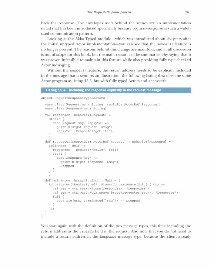
261The Request–Response pattern
back the response. The envelopes used behind the scenes are an implementationdetail that has been introduced specifically because request–response is such a widelyused communication pattern.
Looking at the Akka Typed module—which was introduced about six years afterthe initial untyped Actor implementation—you can see that the sender() feature isno longer present. The reasons behind this change are manifold, and a full discussionis out of scope for this book, but the main reason can be summarized by saying that itwas proven infeasible to maintain this feature while also providing fully type-checkedActor messaging.
Without the sender() feature, the return address needs to be explicitly includedin the message that is sent. As an illustration, the following listing describes the sameActor program as listing 15.3, but with fully typed Actors and ActorRefs.
object RequestResponseTypedActors {
case class Request(msg: String, replyTo: ActorRef[Response])case class Response(msg: String)
val responder: Behavior[Request] =Static {
case Request(msg, replyTo) =>println(s"got request: $msg")replyTo ! Response("got it!")
}
def requester(responder: ActorRef[Request]): Behavior[Response] =SelfAware { self =>
responder ! Request("hello", self)Total {
case Response(msg) =>println(s"got response: $msg")Stopped
}}
def main(args: Array[String]): Unit = {ActorSystem("ReqResTyped", Props(ContextAware[Unit] { ctx =>
val res = ctx.spawn(Props(responder), "responder")val req = ctx.watch(ctx.spawn(Props(requester(res)), "requester"))Full {
case Sig(ctx, Terminated(`req`)) => Stopped}
}))}
}
You start again with the definition of the two message types, this time including thereturn address as the replyTo field in the request. Also note that you do not need toinclude a return address in the Response message type, because the client already
Listing 15.4 Including the response explicitly in the request message
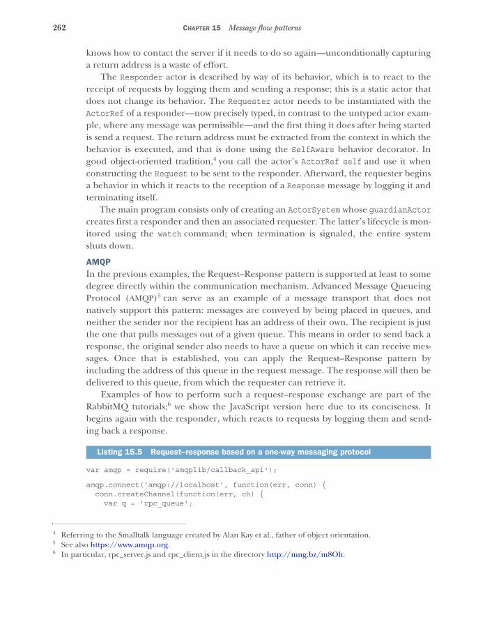
262 CHAPTER 15 Message flow patterns
knows how to contact the server if it needs to do so again—unconditionally capturinga return address is a waste of effort.
The Responder actor is described by way of its behavior, which is to react to thereceipt of requests by logging them and sending a response; this is a static actor thatdoes not change its behavior. The Requester actor needs to be instantiated with theActorRef of a responder—now precisely typed, in contrast to the untyped actor exam-ple, where any message was permissible—and the first thing it does after being startedis send a request. The return address must be extracted from the context in which thebehavior is executed, and that is done using the SelfAware behavior decorator. Ingood object-oriented tradition,4 you call the actor’s ActorRef self and use it whenconstructing the Request to be sent to the responder. Afterward, the requester beginsa behavior in which it reacts to the reception of a Response message by logging it andterminating itself.
The main program consists only of creating an ActorSystem whose guardianActorcreates first a responder and then an associated requester. The latter’s lifecycle is mon-itored using the watch command; when termination is signaled, the entire systemshuts down.
AMQPIn the previous examples, the Request–Response pattern is supported at least to somedegree directly within the communication mechanism. Advanced Message QueueingProtocol (AMQP)5 can serve as an example of a message transport that does notnatively support this pattern: messages are conveyed by being placed in queues, andneither the sender nor the recipient has an address of their own. The recipient is justthe one that pulls messages out of a given queue. This means in order to send back aresponse, the original sender also needs to have a queue on which it can receive mes-sages. Once that is established, you can apply the Request–Response pattern byincluding the address of this queue in the request message. The response will then bedelivered to this queue, from which the requester can retrieve it.
Examples of how to perform such a request–response exchange are part of theRabbitMQ tutorials;6 we show the JavaScript version here due to its conciseness. Itbegins again with the responder, which reacts to requests by logging them and send-ing back a response.
var amqp = require('amqplib/callback_api');
amqp.connect('amqp://localhost', function(err, conn) {conn.createChannel(function(err, ch) {
var q = 'rpc_queue';
4 Referring to the Smalltalk language created by Alan Kay et al., father of object orientation.5 See also https://www.amqp.org.6 In particular, rpc_server.js and rpc_client.js in the directory http://mng.bz/m8Oh.
Listing 15.5 Request–response based on a one-way messaging protocol
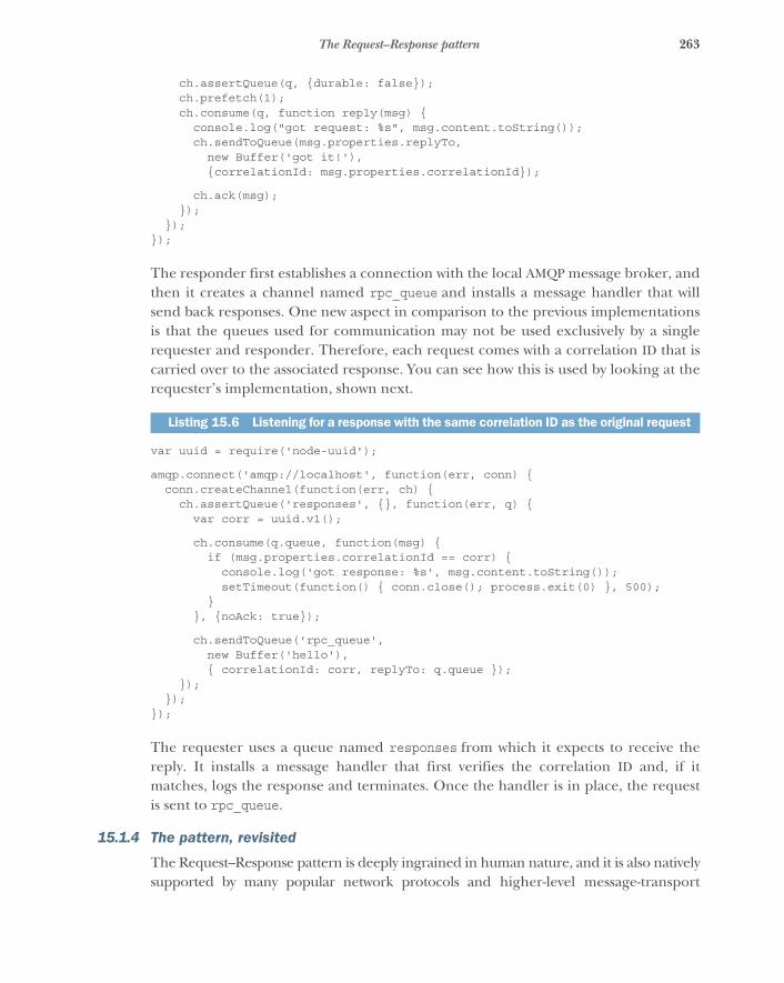
263The Request–Response pattern
ch.assertQueue(q, {durable: false});ch.prefetch(1);ch.consume(q, function reply(msg) {
console.log("got request: %s", msg.content.toString());ch.sendToQueue(msg.properties.replyTo,
new Buffer('got it!'),{correlationId: msg.properties.correlationId});
ch.ack(msg);});
});});
The responder first establishes a connection with the local AMQP message broker, andthen it creates a channel named rpc_queue and installs a message handler that willsend back responses. One new aspect in comparison to the previous implementationsis that the queues used for communication may not be used exclusively by a singlerequester and responder. Therefore, each request comes with a correlation ID that iscarried over to the associated response. You can see how this is used by looking at therequester’s implementation, shown next.
var uuid = require('node-uuid');
amqp.connect('amqp://localhost', function(err, conn) {conn.createChannel(function(err, ch) {
ch.assertQueue('responses', {}, function(err, q) {var corr = uuid.v1();
ch.consume(q.queue, function(msg) {if (msg.properties.correlationId == corr) {
console.log('got response: %s', msg.content.toString());setTimeout(function() { conn.close(); process.exit(0) }, 500);
}}, {noAck: true});
ch.sendToQueue('rpc_queue',new Buffer('hello'),{ correlationId: corr, replyTo: q.queue });
});});
});
The requester uses a queue named responses from which it expects to receive thereply. It installs a message handler that first verifies the correlation ID and, if itmatches, logs the response and terminates. Once the handler is in place, the requestis sent to rpc_queue.
15.1.4 The pattern, revisited
The Request–Response pattern is deeply ingrained in human nature, and it is also nativelysupported by many popular network protocols and higher-level message-transport
Listing 15.6 Listening for a response with the same correlation ID as the original request
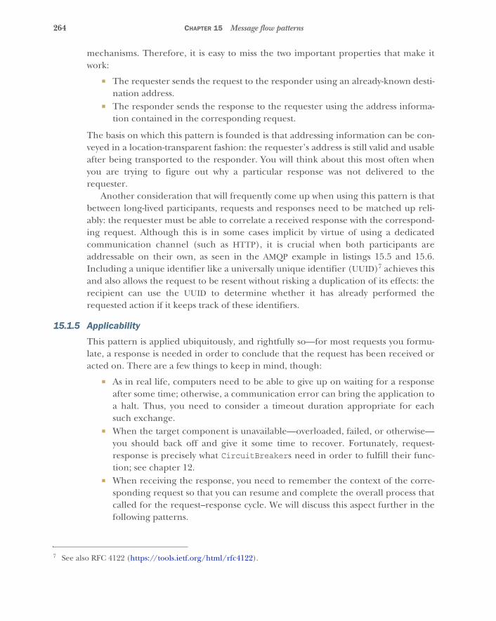
264 CHAPTER 15 Message flow patterns
mechanisms. Therefore, it is easy to miss the two important properties that make itwork:
� The requester sends the request to the responder using an already-known desti-nation address.
� The responder sends the response to the requester using the address informa-tion contained in the corresponding request.
The basis on which this pattern is founded is that addressing information can be con-veyed in a location-transparent fashion: the requester’s address is still valid and usableafter being transported to the responder. You will think about this most often whenyou are trying to figure out why a particular response was not delivered to therequester.
Another consideration that will frequently come up when using this pattern is thatbetween long-lived participants, requests and responses need to be matched up reli-ably: the requester must be able to correlate a received response with the correspond-ing request. Although this is in some cases implicit by virtue of using a dedicatedcommunication channel (such as HTTP), it is crucial when both participants areaddressable on their own, as seen in the AMQP example in listings 15.5 and 15.6.Including a unique identifier like a universally unique identifier (UUID)7 achieves thisand also allows the request to be resent without risking a duplication of its effects: therecipient can use the UUID to determine whether it has already performed therequested action if it keeps track of these identifiers.
15.1.5 Applicability
This pattern is applied ubiquitously, and rightfully so—for most requests you formu-late, a response is needed in order to conclude that the request has been received oracted on. There are a few things to keep in mind, though:
� As in real life, computers need to be able to give up on waiting for a responseafter some time; otherwise, a communication error can bring the application toa halt. Thus, you need to consider a timeout duration appropriate for eachsuch exchange.
� When the target component is unavailable—overloaded, failed, or otherwise—you should back off and give it some time to recover. Fortunately, request-response is precisely what CircuitBreakers need in order to fulfill their func-tion; see chapter 12.
� When receiving the response, you need to remember the context of the corre-sponding request so that you can resume and complete the overall process thatcalled for the request–response cycle. We will discuss this aspect further in thefollowing patterns.
7 See also RFC 4122 (https://tools.ietf.org/html/rfc4122).
265The Self-Contained Message pattern
15.2 The Self-Contained Message patternEach message will contain all information needed to process a request as well as tounderstand its response.
We touched on this at the end of the previous section: when sending a request, youneed to remember what you want to do with the response that will eventually comeback. In other words, you need to manage the state of the larger operation that thisexchange is a part of while the request and response travel between components. Thisstate management can be done entirely by the requester—storing contextual informa-tion—or it can be pushed out of it by having the entire context travel with the requestand response across the network. In practice, this responsibility is usually shared, leav-ing part of the state in the requester and having part of it travel with the message. Thepoint of this pattern is that you should strive to include sufficient information in themessage so the state that is relevant to the current request is fully represented—removing and relocating relevant information should be considered a premature opti-mization until proven otherwise.
15.2.1 The problem setting
Imagine a service that acts as an email gateway, providing other components of the sys-tem with the functionality of sending email notifications to customers. A protocol isdefined for transporting email across computer networks: the Simple Mail TransferProtocol (SMTP).8 This is one of the oldest protocols used on the internet, built ontop of TCP and designed to be human readable. An example session for sending anemail from Alice to Bob might look like this (with C being the client and S being theserver):
S: 220 mailhost.example.com ESMTP PostfixC: HELO alice-workstation.example.comS: 250 Hello alice-workstation.example.comC: MAIL FROM:<[email protected]>S: 250 OkC: RCPT TO:<[email protected]>S: 250 OkC: DATAS: 354 End data with <CR><LF>.<CR><LF>C: From: "Alice" <[email protected]>C: To: "Bob" <[email protected]>C: Date: Fri, 23 October 2015 10:34:12 +0200C: Subject: lunchC:C: Hi Bob,C:C: sorry, I cannot make it, something else came up.C:C: Regards, AliceC: .
8 See also https://en.wikipedia.org/wiki/Simple_Mail_Transfer_Protocol.

266 CHAPTER 15 Message flow patterns
S: 250 Ok, queued as 4567876345C: QUITS: 221 Bye
In the course of this session, 13 messages are exchanged between client and server,with both sides tracking the progressing state of the session.
The task: Your mission is to sketch the data types and protocol sequence for trans-mitting an email to the email gateway service such that the client receives an accep-tance confirmation from the service and the session state between client and service isminimized.
15.2.2 Applying the pattern
You need to transmit information both ways between client and server, and the mini-mal protocol shape for such an interaction is the Request–Response pattern discussedpreviously. The information you need to send to the service is as follows:
� Sender email address� Recipient(s) email address(es)� Email body� Correlation ID so the client can recognize a subsequent confirmation
The service will then reply with, at the very least, a status code and the correlation ID.The following listing sketches the request and response data types using the Scala lan-guage, due to its convenient case class feature.
case class SendEmail(sender: String, recipients: List[String],body: String, correlationID: UUID,replyTo: ActorRef[SendEmailResult])
case class SendEmailResult(correlationID: UUID, status: StatusCode,explanation: Option[String])
The inclusion of the email addresses of sender and recipients would probably be rep-resented using a more specific class than a plain String that ensures a valid addresssyntax, but we leave out such details in order to concentrate on the data exchange.
Does this protocol fulfill the requirements? The client transmits all informationthe service needs in a single message: the sequence of protocol steps performed bySMTP is collapsed into a single request–response cycle. This enables the email gatewayservice to begin the further processing of the email immediately after having receivedthe single request message. This means the gateway does not need to maintain any ses-sion state pertaining to this exchange beyond the processing of this single message; itonly needs to send the response, and the session is completed. Depending on the reli-ability guarantees the gateway provides, the response may have to be deferred untilthe intention of sending an email has been recorded in persistent storage—or evenuntil after the email has been relayed to the target mail system—in which case, the
Listing 15.7 Encapsulated information needed for multiple SMTP exchanges

267The Self-Contained Message pattern
return address and correlation ID must be retained until finished. But this extensionof the session lifetime is not dictated by the protocol; it is inherent in those strongerguarantees. From the client’s perspective, this approach also achieves all that isneeded: sending the email takes just one message, and the client then retains the cor-relation ID in order to continue its own processing as soon as the email has been sent.
If this simple approach fulfills all of your requirements, a question presents itself:why is the SMTP exchange so much more complex? Back in the 1970s, it took a verylong time to send data across a network connection; the protocol therefore performsthe exchange in many small steps, allowing the server to reject an email as early asneeded (for example, after the sender or recipient address has been transmitted—thelatter is done in case the target address does not exist). Today, sending a few kilobytesof text between continents is not a concern, but you still may want to avoid sending avery large email body—possibly including large file attachments—in a single requestmessage. The reason might be so you could handle rejection without sending a poten-tially large number of useless bytes, but it is also important to consider resource usagein terms of how much bandwidth is taken up during the process. Receiving a largemessage at its own pace is the recipient’s prerogative, and the line-based exclusive TCPconnection handling used for SMTP allows this to be done naturally.
You do not need to change the shape of the protocol beyond request–response,though, in order to give the recipient some control over whether and how to consumethe email body. The only feature required is that the bulk data transfer happens out ofband: for example, if the framework supports sending parts of the message as on-demand streams.
case class SendEmail(sender: String, recipients: List[String],correlationID: UUID, replyTo: ActorRef[SendEmailResult])
(body: Source[String]) extends StreamedRequest {override def payload = body
}
This sketch hints at a hypothetical microservice framework that would handle thestreaming of the designated message parts transparently, serializing only the data ele-ments in the first argument list (up to replyTo) eagerly in the request message andtransferring the payload data on demand. Another way to achieve this is to include inthe message the location (for example, by way of a URL such as http://example.com/emails/12) where the email body can be obtained; then, the gateway service cancontact that location on its own if and when it needs to.
case class SendEmail(sender: String, recipients: List[String],bodyLocation: URL, correlationID: UUID,replyTo: ActorRef[SendEmailResult])
Listing 15.8 Separating the body so it can be delivered on demand
Listing 15.9 Enabling the body to be pulled by the recipient
268 CHAPTER 15 Message flow patterns
15.2.3 The pattern, revisited
In the previous section, you collapsed a 13-step protocol session into 2 steps: sendingone message in either direction is the minimum you can do while still allowing the cli-ent to ascertain that the email has in fact been relayed to the gateway service. As a vari-ation, we considered how you can split out one part—the transmission of the emailbody—into a separate subprotocol that is transparently handled by the used frame-work or into a secondary conversation between the service and another endpoint. Thevariation does not complicate the client-service conversation in principle.
The advantages of this change are manifold. We started with the postulated desireof minimizing the session state that needs to be maintained between client and servicethroughout the conversation. This is an important aspect in that the service can nowbecome stateless in this sense: it can react to the request with a response while notretaining any more information about the client, and the conversation does not needto continue. If the service wants to recognize subsequently re-sent requests, it onlyneeds to store the UUID; it does not need to track the individual clients.
A possibly even greater advantage is that removing the need to store conversa-tional state makes it possible to distribute the processing of the requests in space ortime: a SendMail message can be enqueued, serialized to disk, replayed, and routed toone of many email gateway service instances; it can even be automatically retried bythe framework if the correspondence with its SendEmailResult is suitably repre-sented, and so on. Shortening the conversation to its minimum affords you a lot offreedom in how you handle and possibly transform the message.
This goes hand in hand with easier recovery procedures. Because the request con-tains everything needed to process it, it also is fully sufficient to reprocess it after a fail-ure. In contrast, a lengthy, stateful conversation would have to be reestablished—and,in most cases, begun by the client—which calls for specific recovery procedures to bein place among all participants.
15.2.4 Applicability
This pattern is universally applicable in the sense of striving to keep the conversationprotocols as simple as feasible. You may not always be able to reduce the interaction toa single request–response pair, but when that is possible, it greatly increases your free-dom in handling the protocol. Where multiple steps are necessary to achieve thedesired goal, it still is preferable to keep the messages that are exchanged as completeand self-contained as can be afforded, because relying on implicitly shared sessionstate complicates the implementation of all communication partners and makes theircommunication more brittle.
The main reason for not applying this pattern is that the amount of state is largerthan can reasonably be transmitted.
269The Ask pattern
15.3 The Ask patternDelegate the handling of a response to a dedicated ephemeral component.
This pattern can be arrived at by two trains of thought:
� In a purely message-driven system such as the Actor model, it frequently occursthat after performing a request–response cycle with another Actor, the currentbusiness process needs to continue with further steps. Toward this end, theActor could keep a map of correlation IDs and associated continuation informa-tion (such as the details of the ongoing business transaction started by an ear-lier received message), or it could spawn an ephemeral child Actor, give itsaddress as the return address for the response, and thereby delegate the contin-uation of the process. The latter is the approach described in Gul Agha’s the-sis:9 it is the Actor way of thinking. Because this pattern occurs frequently, itmay receive special support from libraries or frameworks.
� Traditional RPC systems are exclusively based on the premise of request-response calls, pretending the same semantics as a local procedure call. Theirsynchronous presentation results in distributed systems coupled in undesirableways, as discussed throughout the first part of this book. In order to decouplecaller and callee, the locally returned type is changed from a strict result valueto a Future—a container for a result value that may arrive later. The continua-tion of the caller’s business process then needs to be lifted into the Future aswell, using transformation combinators to perform the successive steps. ThisFuture is an ephemeral component whose purpose is the reception of the even-tual response and the initiation of follow-up actions, exactly like the child Actorin the previous bullet point.
15.3.1 The problem setting
Recall the previous section’s example: a client exchanges a request–response pair withan email gateway service in order to send an email. This happens in the course ofanother business transaction: perhaps an account-verification process during whichthe account holder is sent a link via which the process will continue. After the email hasbeen sent on its way, you may want to update the website, saying that the user shouldcheck their in-box and offering a link to send the email again in case it was lost.
The task: Your mission is to implement an Actor that, upon receiving aStartVerificationProcess command, contacts the email gateway service (repre-sented by an ActorRef) to send the verification link. After receiving the response,the Actor should respond to the command received previously with a Verification-ProcessStarted or VerificationProcessFailed message, depending on the out-come of the email request.
9 Gul Agha, “ACTORS: A Model of Concurrent Computation in Distributed Systems,” 1985, https://dspace.mit.edu/handle/1721.1/6952.
270 CHAPTER 15 Message flow patterns
15.3.2 Applying the pattern
The following listing sets the stage by defining the message types you will need in addi-tion to the SendEmail protocol defined in the previous section.
case class StartVerificationProcess(userEmail: String,replyTo: ActorRef[VerificationProcessResponse])
sealed trait VerificationProcessResponsecase class VerificationProcessStarted(userEmail: String)
extends VerificationProcessResponsecase class VerificationProcessFailed(userEmail: String)
extends VerificationProcessResponse
The Actor can then be written in Akka Typed, as shown next.
def withChildActor(emailGateway: ActorRef[SendEmail]):Behavior[StartVerificationProcess] =
ContextAware { ctx: ActorContext[StartVerificationProcess] =>val log = Logging(ctx.system.eventStream, "VerificationProcessManager")
Static {case StartVerificationProcess(userEmail, replyTo) =>
val corrID = UUID.randomUUID()val childRef = ctx.spawnAnonymous(Props(FullTotal[SendEmailResult] {
case Sig(ctx, PreStart) =>ctx.setReceiveTimeout(5.seconds)Same
case Sig(_, ReceiveTimeout) =>log.warning("verification process initiation timed out for {}",
userEmail)replyTo ! VerificationProcessFailed(userEmail)Stopped
case Msg(_, SendEmailResult(`corrID`, StatusCode.OK, _)) =>log.debug("successfully started the verification process for {}",
userEmail)replyTo ! VerificationProcessStarted(userEmail)Stopped
case Msg(_, SendEmailResult(`corrID`, StatusCode.Failed, expl)) =>log.info("failed to start the verification process for {}: {}",
userEmail, expl)replyTo ! VerificationProcessFailed(userEmail)Stopped
case Msg(_, SendEmailResult(wrongID, _, _)) =>log.error("received wrong SendEmailResult for corrID {}", corrID)Same
}))
Listing 15.10 Simple protocol to request starting the verification process
Listing 15.11 An anonymous child actor forwards results

271The Ask pattern
val request = SendEmail("[email protected]", List(userEmail),constructBody(userEmail, corrID), corrID,childActor)
emailGateway ! request}
}
Given the ActorRef representing the email gateway service, you construct a behaviorthat will keep serving StartVerificationProcess messages; hence, it uses theStatic behavior constructor. You extract the enclosing ActorContext (the typeascription is given merely for clarity) because you will need to use it to create childActors as well as to emit logging information. For every command you receive, youcreate a new UUID that serves as an identifier for the email sent subsequently. Thenyou create an anonymous10 Actor whose ActorRef is used as the return address for theSendEmail request you finally send to the email gateway service.
The created child Actor uses the FullTotal behavior constructor because it willneed to receive a system notification: the receive-timeout feature is used to abort theprocess if the email gateway does not respond within the allotted time. If a response isreceived before this timeout expires, you distinguish three cases:
� A successful result with the correct correlation ID leads to a successful responseto the original request.
� A failure result with the correct correlation ID is translated to a failure response.� A response with a nonmatching correlation ID is logged and ignored.11
In all cases leading to a response sent to the original client, the child Actor terminatesitself after the response has been sent—the purpose of this ephemeral component isfulfilled, and there is nothing left to be done.
This pattern is so widely applicable that Akka provides special support for it: whenexpecting a request–response conversation, the response message can be captured in aFuture where it is then further processed. The example can be reformulated as follows.
def withAskPattern(emailGateway: ActorRef[SendEmail]):Behavior[StartVerificationProcess] =
ContextAware { ctx =>val log = Logging(ctx.system.eventStream, "VerificationProcessManager")implicit val timeout = Timeout(5.seconds)import ctx.executionContext
10 That is, unnamed—the library will compute a unique name for it.11 Receiving the nonmatching response will reset the receive timeout, though. We do not correct for this poten-
tial lengthening of the response timeout in this case in order to not complicate the example too much; itcould well be argued that a wrongly dispatched response should be a rare occurrence, if it happens at all.
Listing 15.12 Future produced by the Ask pattern and mapped
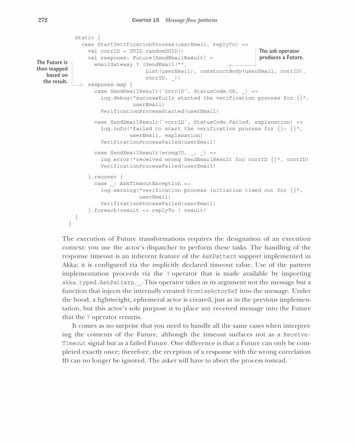
272 CHAPTER 15 Message flow patterns
Static {case StartVerificationProcess(userEmail, replyTo) =>
val corrID = UUID.randomUUID()val response: Future[SendEmailResult] =
emailGateway ? (SendEmail("",List(userEmail), constructBody(userEmail, corrID),corrID, _))
response.map {case SendEmailResult(`corrID`, StatusCode.OK, _) =>
log.debug("successfully started the verification process for {}",userEmail)
VerificationProcessStarted(userEmail)
case SendEmailResult(`corrID`, StatusCode.Failed, explanation) =>log.info("failed to start the verification process for {}: {}",
userEmail, explanation)VerificationProcessFailed(userEmail)
case SendEmailResult(wrongID, _, _) =>log.error("received wrong SendEmailResult for corrID {}", corrID)VerificationProcessFailed(userEmail)
}.recover {case _: AskTimeoutException =>
log.warning("verification process initiation timed out for {}",userEmail)
VerificationProcessFailed(userEmail)}.foreach(result => replyTo ! result)
}}
The execution of Future transformations requires the designation of an executioncontext: you use the actor’s dispatcher to perform these tasks. The handling of theresponse timeout is an inherent feature of the AskPattern support implemented inAkka; it is configured via the implicitly declared timeout value. Use of the patternimplementation proceeds via the ? operator that is made available by importingakka.typed.AskPattern._. This operator takes as its argument not the message but afunction that injects the internally created PromiseActorRef into the message. Underthe hood, a lightweight, ephemeral actor is created, just as in the previous implemen-tation, but this actor’s sole purpose is to place any received message into the Futurethat the ? operator returns.
It comes as no surprise that you need to handle all the same cases when interpret-ing the contents of the Future, although the timeout surfaces not as a Receive-Timeout signal but as a failed Future. One difference is that a Future can only be com-pleted exactly once; therefore, the reception of a response with the wrong correlationID can no longer be ignored. The asker will have to abort the process instead.
The ask operator produces a Future.
The Future isthen mapped
based onthe result.
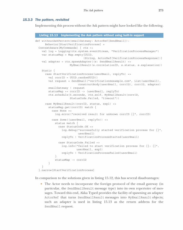
273The Ask pattern
15.3.3 The pattern, revisited
Implementing this process without the Ask pattern might have looked like the following.
def withoutAskPattern(emailGateway: ActorRef[SendEmail]):Behavior[StartVerificationProcess] =
ContextAware[MyCommands] { ctx =>val log = Logging(ctx.system.eventStream, "VerificationProcessManager")var statusMap = Map.empty[UUID,
(String, ActorRef[VerificationProcessResponse])]val adapter = ctx.spawnAdapter((s: SendEmailResult) =>
MyEmailResult(s.correlationID, s.status, s.explanation))
Static {case StartVerificationProcess(userEmail, replyTo) =>
val corrID = UUID.randomUUID()val request = SendEmail("[email protected]", List(userEmail),
constructBody(userEmail, corrID), corrID, adapter)emailGateway ! requeststatusMap += corrID -> (userEmail, replyTo)ctx.schedule(5.seconds, ctx.self, MyEmailResult(corrID,
StatusCode.Failed, "timeout"))
case MyEmailResult(corrID, status, expl) =>statusMap.get(corrID) match {
case None =>log.error("received result for unknown corrID {}", corrID)
case Some((userEmail, replyTo)) =>status match {
case StatusCode.OK =>log.debug("successfully started verification process for {}",
userEmail)replyTo ! VerificationProcessStarted(userEmail)
case StatusCode.Failed =>log.info("failed to start verification process for {}: {}",
userEmail, expl)replyTo ! VerificationProcessFailed(userEmail)
}statusMap -= corrID
}}
}.narrow[StartVerificationProcess]
In comparison to the solutions given in listing 15.12, this has several disadvantages:
� The Actor needs to incorporate the foreign protocol of the email gateway (inparticular, the SendEmailResult message type) into its own repertoire of mes-sages. Toward this end, Akka Typed provides the facility of spawning an adapterActorRef that turns SendEmailResult messages into MyEmailResult objects;such an adapter is used in listing 15.13 as the return address for theSendEmail request.
Listing 15.13 Implementing the Ask pattern without using built-in support
274 CHAPTER 15 Message flow patterns
� The Actor needs to explicitly maintain the sum of the status information for allcurrently open transactions. You implement this in listing 15.13 by maintaininga mapping from correlation IDs to the eventually needed parameters—the user’semail and the original requester’s ActorRef, in this case. Maintaining this map-ping requires more discipline than with the Ask pattern in that you need to takecare to properly remove stale state when transactions end; this cleanup is conve-niently bundled with the ephemeral actor’s lifecycle when using the Ask pattern.
� Handling timeouts requires notification of this Actor while retaining enoughidentifying information. In this example, it needs to track the correlation ID ofeach transaction. In the example case, this can be trivially mapped to a failedSendEmailResult, but in general this may necessitate the addition of yetanother message type to the Actor’s internal protocol.
� The Actor needs to respond to more messages than it would otherwise need,opening up the possibility of wrong messages being sent to this exposed servicemore easily and with greater reach than would be the case if handling these othertypes of messages were delegated to ephemeral endpoints as with the Ask pattern.
In listing 15.13, the sketched verification-management service confers with only oneother service, and handling the associated status information amounts to roughly thesame number of lines as when using the Ask pattern. If you imagine a service thatneeds to communicate with several other services as well, it becomes clear that consis-tent management of all associated state will pile up—it will become intertwined in non-trivial ways and be more difficult to evolve and maintain. Using the Ask pattern, on theother hand, allows you to separate out the subconversations that occur while process-ing a larger business transaction; it helps you to decouple the handling of session stateby segregating it for each conversation and delegating it to a subcomponent.
15.3.4 Applicability
The Ask pattern is applicable wherever a request–response cycle needs to be per-formed before continuing with the further processing of an enclosing business trans-action. This holds only for non-ephemeral components, though: if the enclosingtransaction is already handled by a dedicated ephemeral component, then usually nocomplexity overhead is incurred by keeping the state management for the request-response cycle within that component.
One consequence of using the Ask pattern is that the parent component is notautomatically aware of the progress of the subconversation; it must be informedexplicitly if it needs to stay in the loop. This can be relevant if the number of concur-rently outstanding requests needs to be limited, whether in order to protect the targetservice from being overwhelmed with a sudden onslaught of requests or in order tonot overwhelm local computing and network resources with too many concurrentconversations. Using the Ask pattern indiscriminately can easily be equivalent toemploying an unbounded queue, with all the negative effects on response latency thatare discussed in section 2.1.3, plus ample opportunity to exhaust all available memory.

275The Forward Flow pattern
15.4 The Forward Flow patternLet the information and the messages flow directly toward their destination where possible.
This pattern sounds intuitive, maybe even trivial: why would you deliberately sendmessages via detours when that is not required? The answer is that this rarely occursconsciously; it is the result of applying a convenient, well-known pattern overeagerly.The pattern in question is your good friend the Request–Response pattern, with orwithout the Ask pattern’s sugar coating. Overusing this pattern leads to unnecessaryconsumption of network bandwidth and increased response latency; thinking aboutforward flow lets you recognize these cases and improve your service quality.
15.4.1 The problem setting
Imagine a message router that dispatches incoming file streaming requests to a poolof service instances that host these files. They could be video files that are sent to cli-ents for streaming display on users’ screens.
The task: Your mission is to sketch the sequence of messages sent among client,router, and file server such that the router does not become a bottleneck in thestreaming video dissemination process.
15.4.2 Applying the pattern
Starting from naïve request–response communication, you might foresee that the cli-ent sends to the router, the router embodies the client from the perspective of thefile server, and thus responses flow via the router back to the client. This is shown infigure 15.2.
In this scheme, the router must be able to forward all the streams coming from thefile servers back to all the clients, meaning its network interface’s bandwidth will placean upper limit on how many bytes per second can be streamed by the entire system.Network links are becoming faster and faster, but if this streaming service is intendedto serve customers on the internet, then it will reach its limit fairly soon. Therefore,you must think a bit more about the meaning of request and response in this scenario:the client sends a request, and the logical destination is the file server, not the router.The response is a video stream whose source is the file server and whose destination isthe client. Although you need the router as an intermediary for the request—balanc-ing the load across a pool of replicated file servers hosting the particular video file
Client Router
Video
1
Request File server
Video
2
4 3 Request
Figure 15.2 Flow of messages when nesting the Ask pattern: all responses travel via the intermediate router component.
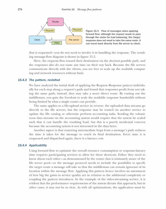
276 CHAPTER 15 Message flow patterns
that is requested—you do not need to involve it in handling the response. The result-ing message-flow diagram is shown in figure 15.3.
Here, the requests flow toward their destination via the shortest possible path, andthe responses also do not waste any time on their way back. Because the file serverscommunicate directly with the clients, you are free to scale up the available comput-ing and network resources without limit.
15.4.3 The pattern, revisited
We have analyzed the initial draft of applying the Request–Response pattern individu-ally for each step along a request’s path and found that responses profit from not tak-ing the same path; instead, they may take a more direct route. By cutting out themiddleman, you gain the freedom to scale the available response bandwidth withoutbeing limited by what a single router can provide.
The same applies to a file-upload service in reverse: the uploaded data streams godirectly to the file servers, but the response may be routed via another service toupdate the file catalog or otherwise perform accounting tasks. Sending the volumi-nous data streams via the accounting system would require that the system be scaledsuch that it can handle the resulting load, but this is a purely incidental concernbecause the accounting system is not interested in the data bytes.
Another aspect is that removing intermediate hops from a message’s path reducesthe time it takes for the message to reach its final destination. Every time it isenqueued and dispatched again, there is a latency cost.
15.4.4 Applicability
Using forward flow to optimize the overall resource consumption or response-latencytime requires participating services to allow for these shortcuts. Either they need toknow about each other—as demonstrated by the router that is intimately aware of thefile server pool—or the message protocol needs to include the possibility to specifythe target route a message will take so that the middleman can remain ignorant of itslocation within the message flow. Applying this pattern hence involves an assessmentof how big the gains in service quality are in relation to the additional complexity orcoupling the pattern introduces. In the example of the video-streaming service, it isevident that the performance requirements of the system dictate this approach; but inother cases, it may not be as clear. As with all optimizations, the application must be
Router
1Request
Client File serverVideo
2
3
Request Figure 15.3 Flow of messages when applying forward flow: although the request needs to pass through the router for load balancing, the (large) response does not need to take the same route. It can travel back directly from file server to client.
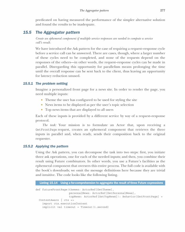
277The Aggregator pattern
predicated on having measured the performance of the simpler alternative solutionand found the results to be inadequate.
15.5 The Aggregator patternCreate an ephemeral component if multiple service responses are needed to compute a servicecall’s result.
We have introduced the Ask pattern for the case of requiring a request–response cyclebefore a service call can be answered. There are cases, though, where a larger numberof these cycles need to be completed, and none of the requests depend on theresponses of the others—in other words, the request–response cycles can be made inparallel. Disregarding this opportunity for parallelism means prolonging the timeuntil the overall response can be sent back to the client, thus leaving an opportunityfor latency reduction unused.
15.5.1 The problem setting
Imagine a personalized front page for a news site. In order to render the page, youneed multiple inputs:
� Theme the user has configured to be used for styling the site� News items to be displayed as per the user’s topic selection� Top news items that are displayed to all users
Each of these inputs is provided by a different service by way of a request–responseprotocol.
The task: Your mission is to formulate an Actor that, upon receiving aGetFrontPage request, creates an ephemeral component that retrieves the threeinputs in parallel and, when ready, sends their composition back to the originalrequester.
15.5.2 Applying the pattern
Using the Ask pattern, you can decompose the task into two steps: first, you initiatethree ask operations, one for each of the needed inputs; and then, you combine theirresult using Future combinators. In other words, you use a Future’s facilities as theephemeral component that oversees this entire process. The full code is available withthe book’s downloads; we omit the message definitions here because they are trivialand intuitive. The code looks like the following listing.
def futureFrontPage(themes: ActorRef[GetTheme],personalNews: ActorRef[GetPersonalNews],topNews: ActorRef[GetTopNews]): Behavior[GetFrontPage] =
ContextAware { ctx =>import ctx.executionContextimplicit val timeout = Timeout(1.second)
Listing 15.14 Using a for-comprehension to aggregate the result of three Future expressions
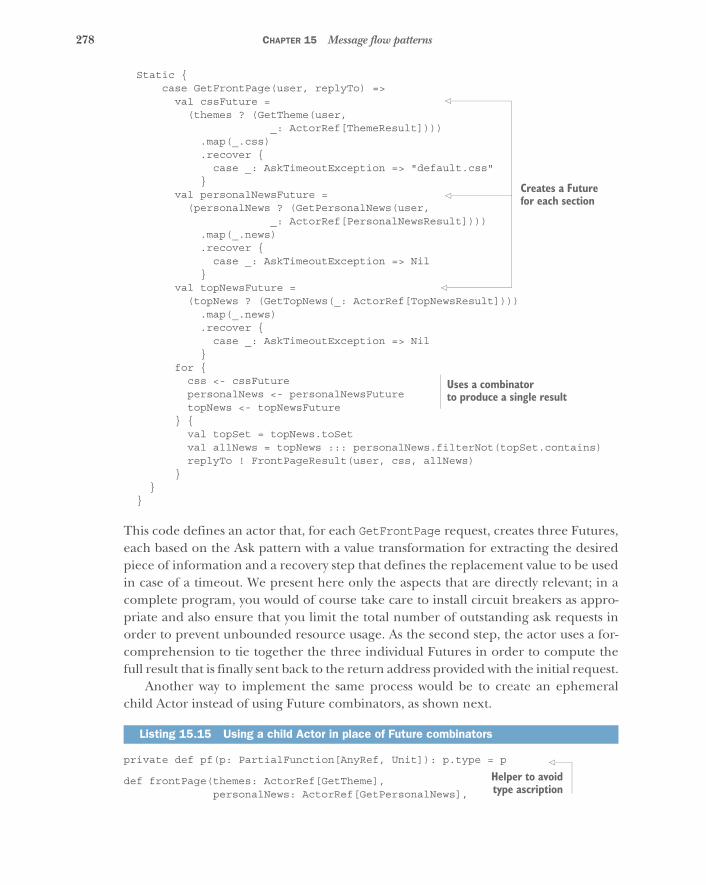
278 CHAPTER 15 Message flow patterns
Static {case GetFrontPage(user, replyTo) =>
val cssFuture =(themes ? (GetTheme(user,
_: ActorRef[ThemeResult]))).map(_.css).recover {
case _: AskTimeoutException => "default.css"}
val personalNewsFuture =(personalNews ? (GetPersonalNews(user,
_: ActorRef[PersonalNewsResult]))).map(_.news).recover {
case _: AskTimeoutException => Nil}
val topNewsFuture =(topNews ? (GetTopNews(_: ActorRef[TopNewsResult])))
.map(_.news)
.recover {case _: AskTimeoutException => Nil
}for {
css <- cssFuturepersonalNews <- personalNewsFuturetopNews <- topNewsFuture
} {val topSet = topNews.toSetval allNews = topNews ::: personalNews.filterNot(topSet.contains)replyTo ! FrontPageResult(user, css, allNews)
}}
}
This code defines an actor that, for each GetFrontPage request, creates three Futures,each based on the Ask pattern with a value transformation for extracting the desiredpiece of information and a recovery step that defines the replacement value to be usedin case of a timeout. We present here only the aspects that are directly relevant; in acomplete program, you would of course take care to install circuit breakers as appro-priate and also ensure that you limit the total number of outstanding ask requests inorder to prevent unbounded resource usage. As the second step, the actor uses a for-comprehension to tie together the three individual Futures in order to compute thefull result that is finally sent back to the return address provided with the initial request.
Another way to implement the same process would be to create an ephemeralchild Actor instead of using Future combinators, as shown next.
private def pf(p: PartialFunction[AnyRef, Unit]): p.type = p
def frontPage(themes: ActorRef[GetTheme],personalNews: ActorRef[GetPersonalNews],
Listing 15.15 Using a child Actor in place of Future combinators
Creates a Future for each section
Uses a combinator to produce a single result
Helper to avoidtype ascription

279The Aggregator pattern
topNews: ActorRef[GetTopNews]): Behavior[GetFrontPage] =ContextAware { ctx =>
Static {case GetFrontPage(user, replyTo) =>
val childRef = ctx.spawnAnonymous(Props {val builder = new FrontPageResultBuilder(user)Partial[AnyRef](
pf {case ThemeResult(css) => builder.addCSS(css)case PersonalNewsResult(news) => builder.addPersonalNews(news)case TopNewsResult(news) => builder.addTopNews(news)case ReceiveTimeout => builder.timeout()
} andThen { _ =>if (builder.isComplete) {
replyTo ! builder.resultStopped
} else Same})
})themes ! GetTheme(user, childRef)personalNews ! GetPersonalNews(user, childRef)topNews ! GetTopNews(childRef)ctx.schedule(1.second, childRef, ReceiveTimeout)
}}
The structure of the ephemeral child Actor consists of two aspects: first, any new pieceof information is incorporated into the current set of knowledge as managed by amutable builder (shown in listing 15.15), and then the builder is queried as towhether the answer is now complete, in which case the process is completed by send-ing the result back to the original requester. The process is set in motion by sendingthe three requests to their respective providers while giving the child Actor’s refer-ence as the return address.
class FrontPageResultBuilder(user: String) {private var css: Option[String] = Noneprivate var personalNews: Option[List[String]] = Noneprivate var topNews: Option[List[String]] = None
def addCSS(css: String): Unit = this.css = Option(css)def addPersonalNews(news: List[String]): Unit =
this.personalNews = Option(news)def addTopNews(news: List[String]): Unit = this.topNews = Option(news)
def timeout(): Unit = {if (css.isEmpty) css = Some("default.css")if (personalNews.isEmpty) personalNews = Some(Nil)if (topNews.isEmpty) topNews = Some(Nil)
}
def isComplete: Boolean =css.isDefined && personalNews.isDefined && topNews.isDefined
Listing 15.16 Using a builder to express the domain more directly
Spawns an ephemeral child Actor
Direct responsesto the child Actor Ensures that the child
times out if it does not receive a complete set of responses
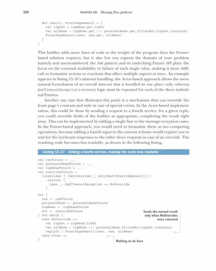
280 CHAPTER 15 Message flow patterns
def result: FrontPageResult = {val topSet = topNews.get.toSetval allNews = topNews.get ::: personalNews.get.filterNot(topSet.contains)FrontPageResult(user, css.get, allNews)
}}
This builder adds more lines of code to the weight of the program than the Future-based solution requires, but it also lets you express the domain of your problemnatively and unencumbered: the Ask pattern and its underlying Future API place thefocus on the eventual availability or failure of each single value, making it more diffi-cult to formulate actions or reactions that affect multiple aspects at once. An exampleappears in listing 15.16’s timeout handling: the Actor-based approach allows the morenatural formulation of an overall timeout that is handled in one place only, whereasAskTimeoutException’s recovery logic must be repeated for each of the three individ-ual Futures.
Another use case that illustrates this point is a mechanism that can override thefront page’s contents and style in case of special events. In the Actor-based implemen-tation, this could be done by sending a request to a fourth service; for a given reply,you could override fields of the builder as appropriate, completing the result rightaway. This can be implemented by adding a single line to the message-reception cases.In the Future-based approach, you would need to formulate these as two competingoperations, because adding a fourth input to the current scheme would require you towait for the irrelevant responses to the other three requests in case of an override. Theresulting code becomes less readable, as shown in the following listing.
val cssFuture = ...val personalNewsFuture = ...val topNewsFuture = ...val overrideFuture =
(overrides ? (GetOverride(_: ActorRef[OverrideResult]))).recover {
case _: AskTimeoutException => NoOverride}
for {css <- cssFuturepersonalNews <- personalNewsFuturetopNews <- topNewsFutureovr <- overrideFuture
} ovr match {case NoOverride =>
val topSet = topNews.toSetval allNews = topNews ::: personalNews.filterNot(topSet.contains)replyTo ! FrontPageResult(user, css, allNews)
case other =>}
Listing 15.17 Adding a fourth service, making the code less readable
Sends the normal resultonly when NoOverrides
were returned
Nothing to do here
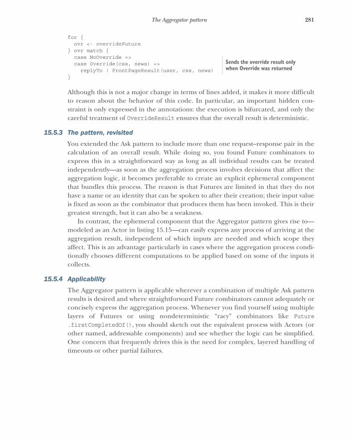
281The Aggregator pattern
for {ovr <- overrideFuture
} ovr match {case NoOverride =>case Override(css, news) =>
replyTo ! FrontPageResult(user, css, news)}
Although this is not a major change in terms of lines added, it makes it more difficultto reason about the behavior of this code. In particular, an important hidden con-straint is only expressed in the annotations: the execution is bifurcated, and only thecareful treatment of OverrideResult ensures that the overall result is deterministic.
15.5.3 The pattern, revisited
You extended the Ask pattern to include more than one request–response pair in thecalculation of an overall result. While doing so, you found Future combinators toexpress this in a straightforward way as long as all individual results can be treatedindependently—as soon as the aggregation process involves decisions that affect theaggregation logic, it becomes preferable to create an explicit ephemeral componentthat bundles this process. The reason is that Futures are limited in that they do nothave a name or an identity that can be spoken to after their creation; their input valueis fixed as soon as the combinator that produces them has been invoked. This is theirgreatest strength, but it can also be a weakness.
In contrast, the ephemeral component that the Aggregator pattern gives rise to—modeled as an Actor in listing 15.15—can easily express any process of arriving at theaggregation result, independent of which inputs are needed and which scope theyaffect. This is an advantage particularly in cases where the aggregation process condi-tionally chooses different computations to be applied based on some of the inputs itcollects.
15.5.4 Applicability
The Aggregator pattern is applicable wherever a combination of multiple Ask patternresults is desired and where straightforward Future combinators cannot adequately orconcisely express the aggregation process. Whenever you find yourself using multiplelayers of Futures or using nondeterministic “racy” combinators like Future.firstCompletedOf(), you should sketch out the equivalent process with Actors (orother named, addressable components) and see whether the logic can be simplified.One concern that frequently drives this is the need for complex, layered handling oftimeouts or other partial failures.
Sends the override result only when Override was returned
282 CHAPTER 15 Message flow patterns
15.6 The Saga patternDivide long-lived, distributed transactions into quick local ones with compensating actionsfor recovery.
In other words: Create an ephemeral component to manage the execution of a sequence ofactions distributed across multiple components.
The term saga was coined by Hector Garcia-Molina.12 His paper describes a schemefor breaking up long-lived business transactions in order to shorten the time periodduring which databases need to hold locks—these locks are needed to ensure atomic-ity and consistency of the transaction, the downside of which is that other transactionstouching the same data cannot proceed concurrently.
In a distributed system, you need to break up transactions involving multiple par-ticipants for other reasons: obtaining a shared lock is an expensive operation that caneven be impossible in the face of certain failures like network partitions. As we dis-cussed in chapter 8, the key to scalability and loose coupling is to consider each com-ponent an island of delimited consistency. But how do you model business transactionsthat require inputs from multiple components while also effecting modifications tomultiple components? It turns out the research topic of sagas provides an effective,robust solution for many use cases.
NOTE This section gives only a brief overview; a full book could be written onthis topic alone. A very similar concept is the process manager in the CQRS liter-ature13—the main difference is that a saga focuses on transactional aspects(atomicity and consistency), whereas a process manager is primarily seen as fac-toring out the description of a particular process from the components thatparticipate in it.
15.6.1 The problem setting
The prototypical example of a business transaction that affects more than one consis-tent entity (or aggregate in domain-driven design [DDD] terms) is a money transferfrom one bank account to another. Questions of this kind arise immediately whenscaling out the application state managed previously by a single RDBMS instance ontoa distributed cluster of machines, whether for elasticity or resilience reasons. Thecode of the nondistributed system would tie the update to both accounts in a singletransaction, relying on the RDBMS to uphold the guarantees of atomicity, consistency,isolation, and durability. In the distributed system, there is no such mechanism,requiring the use of the Saga pattern.
The task: Your mission is to sketch the conversation between an ephemeral sagacomponent and the two bank account components in order to perform a money
12 Hector Garcia-Molina, “Sagas,” ACM, 1987 (http://dl.acm.org/citation.cfm?id=38742).13 See “CQRS Journey” (July 2012) on MSDN, reference 6: “A Saga on Sagas,” https://msdn.microsoft.com/en-us
/library/jj591569.aspx.

283The Saga pattern
transfer, considering that individual steps can fail permanently (for example, becausethe source account does not have sufficient funds or the destination account is closedafter the process begins). Unreliable communication will be considered in the follow-ing pattern. You may then also implement the saga component in code: for example,as a persistent actor.
15.6.2 Applying the pattern
When designing a communication protocol between multiple parties, one naturalanalogy is to envision a conversation among a group of people. Here, you want todescribe how Sam—the saga—confers with Alice and Bob to transfer part of Alice’sbudget to Bob. The analogy works best if the essential properties of the process arerepresented: in this case, handing over the money in cash would not be possible,because that kind of fully synchronous process is not how distributed systems work.Therefore, you will reallocate $10,000 of budget between them.
Before we consider various failure scenarios, we will sketch the nominal successfulcase, which might go like the following:
Sam: “Alice, please reduce your budget by $10,000 if possible.” Alice: “OK. I’ve done so.” Sam: “Bob, please increase your budget by $10,000.” Bob: “Thanks, Sam; it’s done.” Sam: “Thanks everyone; transfer finished!”
There is no need for Alice and Bob to talk to each other, because Sam coordinates thetransfer. Given this scenario, we might as well have let both subconversations occur inparallel to each other. Now we will consider some failure modes—for example, if Alicedoes not have sufficient budget:
Sam: “Alice, please reduce your budget by $10,000 if possible.” Alice: “Sorry, Sam, my budget is too low already.” Sam: “Listen up, everyone—this transfer is aborted!”
This case is simple. The first step of the process fails in a nontransient fashion, so noharm is done and an abort is immediately possible. A more complicated case occurs ifBob is unable to receive the increased budget amount:
Sam: “Alice, please reduce your budget by $10,000 if possible.” Alice: “OK. I’ve done so.” Sam: “Bob, please increase your budget by $10,000.” Bob: “Sorry, Sam, my project was just canceled—I no longer have a budget.” Sam: “Alice, please increase your budget by $10,000.”” Alice: “Thanks, Sam; it’s done.” Sam: “Listen up, everyone—this transfer is aborted!”
284 CHAPTER 15 Message flow patterns
In this case, the second step that Sam wants to perform cannot be carried out. At thispoint, Alice has already reduced her budget, so logically Sam holds $10,000 in hishands—but he has no budget to manage for himself. The solution for this dilemma isthat Sam gives the $10,000 back to Alice. This is called a compensating transaction. Usingthis trick, we can also make the entire transfer opportunistically parallel and stillremain correct:
Sam: “Alice, please reduce your budget by $10,000 if possible. Bob, please increaseyour budget by $10,000.”
Bob: “Thanks, Sam. It’s done.”” Alice: “Sorry, Sam, my budget is too low already.” Sam: “Bob, please reduce your budget by $10,000.” Bob: “OK. I’ve done so.” Sam: “Listen up, everyone—this transfer is aborted!”
Of course, we have assumed here that the compensating transactions always succeed;but what if that is not the case? What if in the last example Bob had already—and sur-prisingly quickly—spent the $10,000 while Sam was waiting for Alice to respond? Inthis case, the system would be in an inconsistent state that Sam could not fix withoutexternal help. The moral of this gedankenexperiment is that computers and algo-rithms cannot be held responsible for dealing with all possible corner cases, especiallywhen it comes to distributed systems where the convenient simplifications of a fullysequential local execution cannot be applied. In such cases, inconsistencies must berecognized as possible system states and signaled upward: for example, to be decidedby the humans who operate the system. For further reading on this topic, please seePat Helland’s “Memories, Guesses, and Apologies.”14
15.6.3 The pattern, revisited
Given two accounts—symbolized by Alice and Bob—we have introduced another pro-cess: a saga whose role was played by Sam in order to orchestrate the transfer of budgetfrom one account to the other. Getting Alice and Bob to agree directly on this transferwould be a costly process during which both would be unavailable for other requests,because those could invalidate the current state of the consensus-building conversa-tion; this would be the analogous solution using a distributed transaction in the ACIDsense (a transaction like the ones we are used to from relational database managementsystems [RDBMSs]). Instead, we have placed the responsibility for leaving the system ina consistent state with the new external process that runs this process.
You have seen that in order to do this, you have to not only describe the individualtransactions that are done on each account but also provide compensating transac-tions that come into play if the saga needs to be aborted. This is the same as perform-ing a transaction rollback on a RDBMS; but because you are no longer dealing with a
14 MSDN blog, 2007, http://blogs.msdn.com/b/pathelland/archive/2007/05/15/memories-guesses-and-apologies.aspx.
285The Saga pattern
single realm of consistency, the system can no longer automatically deduce what con-stitutes a rollback. Hector Garcia-Molina notes that writing the compensating transac-tions is not a black art, though; it is usually of the same difficulty as encoding thetransactions.
One property of compensating transactions that we have glossed over so farrequires a bit of formalism: where transaction T1 takes the component from state S0 tostate S1, the compensating transaction C1 takes it from S1 back to S0. We are applyingthese transactions within the consistency boundaries of several different compo-nents—Alice and Bob, in the earlier example—and within one of these componentsan execution of a sequence of transactions T1..Tn would take that component fromstate S0 to Sn. Because transactions do not, in general, commute with each other, tak-ing the system back from state Sn to S0 would require the application of the compen-sating transactions Cn..C1: the compensating transactions would be applied in reverseorder, and this order matters. We have played with the thought of parallelizing partsof the two subconversations (Sam-Alice and Sam-Bob), but you must always be carefulto maintain a deterministic and thus reversible order for all transactions that are per-formed with Alice and Bob individually. For an in-depth discussion of compensationsemantics, please refer to Garcia-Molina’s “Sagas” paper.
At the beginning of this pattern’s description, we mentioned the term processmanager from CQRS terminology. This term refers to another property of the patternwe have described: in order to carry out the budget transfer, neither Alice nor Bobneeded to know how it worked; they only needed to be able to manage their own bud-get and respond to requests to reduce or increase it. This is an important benefit inthat it allows the description of complex business processes to be decoupled from theimplementation of the affected components both at runtime and during develop-ment. The process manager is the single place that holds all knowledge about thisbusiness process: if changes are required, they are made only to this software module.
In Reactive systems, the need to factor out this process into its own ephemeral com-ponent arises from both sides: we need to model workflows that affect multiple compo-nents while maintaining eventual consistency, and we need to factor out cross-component activities such that we do not strongly couple the development or execu-tion of these components. The “Sagas” paper was not written with distributed systemsin mind, but it does offer a solution to both these problems. It also predates the CQRSterminology by nearly two decades; and because we like the concise and metaphoricalname of the proposed abstraction, we call this pattern the Saga pattern.
Coming back to the example, Sam has one quality we have not yet discussed: whenyou model a process this way, you expect that the transfer will eventually be finished oraborted, no matter what happens. You do not expect Sam to be distracted and forgetabout the whole thing. Not only would that be pushing the analogy too far, but it isalso a property that you do not wish your computer systems to have—you want themto be reliable. In computer terms, the state the saga manages must be persistent. If themachine that runs the saga fails, you need the ability to restart the process elsewhere
286 CHAPTER 15 Message flow patterns
and have it resume its operations. Only then can you be sure the process will eventu-ally complete, assuming that you keep providing computing resources.
The Aggregator pattern describes a simple form of a workflow—the retrieval ofinformation from multiple sources and its subsequent conversion into an overallresult—whereas the Saga pattern allows arbitrary processes to be formulated. TheAggregator pattern is a simple, special case, whereas the Saga pattern describes servicecomposition in general.
15.6.4 Applicability
The astute reader will have grown increasingly impatient, waiting for the discussion ofthe elephant in the room: if this pattern is presented as a solution in place of distrib-uted transactions, then how do we reconcile this with the fact that sagas are not iso-lated from each other? Going back to the example, you could easily imagine anotherprocess that tallies all allocated budgets across the company by interrogating all proj-ect leads, including Alice and Bob: if this tally process asks during the transfer suchthat Alice has already reduced her budget but Bob has not yet increased his, the tallywill come up $10,000 short because the money is “in flight.” Running the tallying pro-cess during a quiescent period when no transfers are ongoing would lead to the cor-rect result, but otherwise there would always be a risk of errors.
In some systems this is not acceptable. These systems cannot tolerate being distrib-uted in the sense of splitting them into multiple autonomous, decoupled compo-nents. Sagas cannot be used to fix this problem in general.
The Saga pattern is applicable wherever a business process needs to be modeledthat involves multiple independent components: in other words, wherever a businesstransaction spans multiple regions of delimited consistency. In these cases, the patternoffers atomicity (the ability to roll back by applying compensating transactions) andeventual consistency (in the sense that application-level consistency is restored by issuingapologies; see Pat Helland’s aforementioned blog article), but it does not offer isolation.
15.7 The Business Handshake pattern (a.k.a. Reliable Delivery pattern)Include identifying and/or sequencing information in the message, and keep retrying untilconfirmation is received.
While discussing the previous pattern, we made the implicit assumption that commu-nication between the saga and the affected components is reliable. We pictured agroup of people standing in the same office and discussing the process without exter-nal disturbances. This is a useful way to begin, because it allows you to focus on theessential parts of a conversation; but we know that life does not always work like that—in particular in distributed systems, where messages can be lost or delayed due tounforeseeable, inexorable subsystem failures.
Fortunately, we can treat the two concerns on separate levels: imagining that theconversation occurs in a busy, noisy office does not invalidate the basic structure of
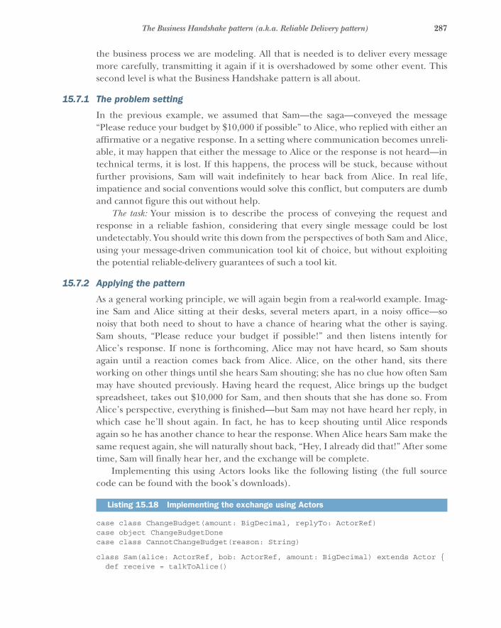
287The Business Handshake pattern (a.k.a. Reliable Delivery pattern)
the business process we are modeling. All that is needed is to deliver every messagemore carefully, transmitting it again if it is overshadowed by some other event. Thissecond level is what the Business Handshake pattern is all about.
15.7.1 The problem setting
In the previous example, we assumed that Sam—the saga—conveyed the message“Please reduce your budget by $10,000 if possible” to Alice, who replied with either anaffirmative or a negative response. In a setting where communication becomes unreli-able, it may happen that either the message to Alice or the response is not heard—intechnical terms, it is lost. If this happens, the process will be stuck, because withoutfurther provisions, Sam will wait indefinitely to hear back from Alice. In real life,impatience and social conventions would solve this conflict, but computers are dumband cannot figure this out without help.
The task: Your mission is to describe the process of conveying the request andresponse in a reliable fashion, considering that every single message could be lostundetectably. You should write this down from the perspectives of both Sam and Alice,using your message-driven communication tool kit of choice, but without exploitingthe potential reliable-delivery guarantees of such a tool kit.
15.7.2 Applying the pattern
As a general working principle, we will again begin from a real-world example. Imag-ine Sam and Alice sitting at their desks, several meters apart, in a noisy office—sonoisy that both need to shout to have a chance of hearing what the other is saying.Sam shouts, “Please reduce your budget if possible!” and then listens intently forAlice’s response. If none is forthcoming, Alice may not have heard, so Sam shoutsagain until a reaction comes back from Alice. Alice, on the other hand, sits thereworking on other things until she hears Sam shouting; she has no clue how often Sammay have shouted previously. Having heard the request, Alice brings up the budgetspreadsheet, takes out $10,000 for Sam, and then shouts that she has done so. FromAlice’s perspective, everything is finished—but Sam may not have heard her reply, inwhich case he’ll shout again. In fact, he has to keep shouting until Alice respondsagain so he has another chance to hear the response. When Alice hears Sam make thesame request again, she will naturally shout back, “Hey, I already did that!” After sometime, Sam will finally hear her, and the exchange will be complete.
Implementing this using Actors looks like the following listing (the full sourcecode can be found with the book’s downloads).
case class ChangeBudget(amount: BigDecimal, replyTo: ActorRef)case object ChangeBudgetDonecase class CannotChangeBudget(reason: String)
class Sam(alice: ActorRef, bob: ActorRef, amount: BigDecimal) extends Actor {def receive = talkToAlice()
Listing 15.18 Implementing the exchange using Actors

288 CHAPTER 15 Message flow patterns
def talkToAlice(): Receive = {alice ! ChangeBudget(-amount, self)context.setReceiveTimeout(1.second)
{case ChangeBudgetDone => context.become(talkToBob())case CannotChangeBudget(reason) => context.stop(self)case ReceiveTimeout => alice ! ChangeBudget(-amount, self)
}}
def talkToBob(): Receive = ...}
class Alice extends Actor {var budget: BigDecimal = 10
var alreadyDone: Set[ActorRef] = Set.empty
def receive = {case ChangeBudget(amount, replyTo) if alreadyDone(replyTo) =>
replyTo ! ChangeBudgetDone
case ChangeBudget(amount, replyTo) if amount + budget > 0 =>budget += amountalreadyDone += replyTocontext.watch(replyTo)replyTo ! ChangeBudgetDone
case ChangeBudget(_, replyTo) =>replyTo ! CannotChangeBudget("insufficient budget")
case Terminated(saga) =>alreadyDone -= saga
}}
First, note that Sam includes identifying information with the ChangeBudget commandin the form of his own ActorRef—this is a token that is guaranteed to be unique, andit identifies exactly one budget change for Alice because Sam is a short-lived saga. Sec-ond, note how Sam keeps resending the same command using the Receive-Timeout mechanism until the reply from Alice has been received. If the budget reduc-tion fails, the saga terminates; otherwise, it continues by talking with Bob in the samefashion it did with Alice.
On the receiving end, you see that Alice validates the incoming command: if youhave already seen a command with the same return address, then there is nothing tobe done apart from confirming that it has already been done, whereas in the case ofinsufficient funds, you must send a negative response. But if the command is new andvalid, you execute its effect—changing the budget—and reply to the requester that youhave done so. In addition, you must keep track of what you have done. Here, you storethe return address in a set so that you can later recognize it in case of a retransmittedcommand. This set would grow indefinitely over time unless you clean it up; for this,you use the DeathWatch mechanism. When the saga ends, its Actor is terminated, and
Analog to the previous code
You need to keep track of what has already been done. Here each “Sam” issues only one request (being a Saga).
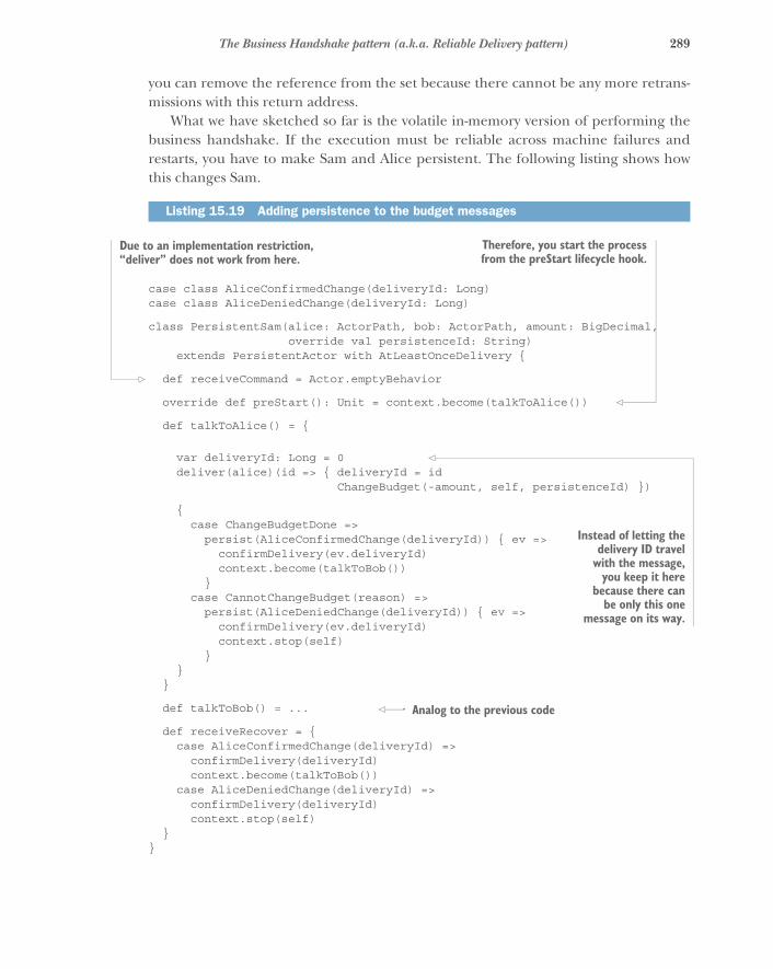
289The Business Handshake pattern (a.k.a. Reliable Delivery pattern)
you can remove the reference from the set because there cannot be any more retrans-missions with this return address.
What we have sketched so far is the volatile in-memory version of performing thebusiness handshake. If the execution must be reliable across machine failures andrestarts, you have to make Sam and Alice persistent. The following listing shows howthis changes Sam.
case class AliceConfirmedChange(deliveryId: Long)case class AliceDeniedChange(deliveryId: Long)
class PersistentSam(alice: ActorPath, bob: ActorPath, amount: BigDecimal,override val persistenceId: String)
extends PersistentActor with AtLeastOnceDelivery {
def receiveCommand = Actor.emptyBehavior
override def preStart(): Unit = context.become(talkToAlice())
def talkToAlice() = {
var deliveryId: Long = 0deliver(alice)(id => { deliveryId = id
ChangeBudget(-amount, self, persistenceId) })
{case ChangeBudgetDone =>
persist(AliceConfirmedChange(deliveryId)) { ev =>confirmDelivery(ev.deliveryId)context.become(talkToBob())
}case CannotChangeBudget(reason) =>
persist(AliceDeniedChange(deliveryId)) { ev =>confirmDelivery(ev.deliveryId)context.stop(self)
}}
}
def talkToBob() = ...
def receiveRecover = {case AliceConfirmedChange(deliveryId) =>
confirmDelivery(deliveryId)context.become(talkToBob())
case AliceDeniedChange(deliveryId) =>confirmDelivery(deliveryId)context.stop(self)
}}
Listing 15.19 Adding persistence to the budget messages
Due to an implementation restriction, “deliver” does not work from here.
Therefore, you start the processfrom the preStart lifecycle hook.
Instead of letting thedelivery ID travel
with the message,you keep it here
because there canbe only this one
message on its way.
Analog to the previous code
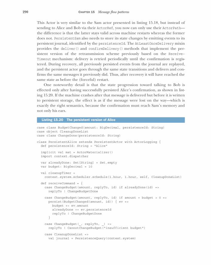
290 CHAPTER 15 Message flow patterns
This Actor is very similar to the Sam actor presented in listing 15.18, but instead ofsending to Alice and Bob via their ActorRef, you now can only use their ActorPath—the difference is that the latter stays valid across machine restarts whereas the formerdoes not. PersistentSam also needs to store its state changes by emitting events to itspersistent journal, identified by the persistenceId. The AtLeastOnceDelivery mixinprovides the deliver() and confirmDelivery() methods that implement the per-sistent version of the retransmission scheme previously based on the Receive-Timeout mechanism: delivery is retried periodically until the confirmation is regis-tered. During recovery, all previously persisted events from the journal are replayed,and the persistent actor goes through the same state transitions and delivers and con-firms the same messages it previously did. Thus, after recovery it will have reached thesame state as before the (forceful) restart.
One noteworthy detail is that the state progression toward talking to Bob iseffected only after having successfully persisted Alice’s confirmation, as shown in list-ing 15.20. If the machine crashes after that message is delivered but before it is writtento persistent storage, the effect is as if the message were lost on the way—which isexactly the right semantics, because the confirmation must reach Sam’s memory andnot only his ears.
case class BudgetChanged(amount: BigDecimal, persistenceId: String)case object CleanupDoneListcase class ChangeDone(persistenceId: String)
class PersistentAlice extends PersistentActor with ActorLogging {def persistenceId: String = "Alice"
implicit val mat = ActorMaterializer()import context.dispatcher
var alreadyDone: Set[String] = Set.emptyvar budget: BigDecimal = 10
val cleanupTimer =context.system.scheduler.schedule(1.hour, 1.hour, self, CleanupDoneList)
def receiveCommand = {case ChangeBudget(amount, replyTo, id) if alreadyDone(id) =>
replyTo ! ChangeBudgetDone
case ChangeBudget(amount, replyTo, id) if amount + budget > 0 =>persist(BudgetChanged(amount, id)) { ev =>
budget += ev.amountalreadyDone += ev.persistenceIdreplyTo ! ChangeBudgetDone
}
case ChangeBudget(_, replyTo, _) =>replyTo ! CannotChangeBudget("insufficient budget")
case CleanupDoneList =>val journal = PersistenceQuery(context.system)
Listing 15.20 The persistent version of Alice

291The Business Handshake pattern (a.k.a. Reliable Delivery pattern)
.readJournalFor[LeveldbReadJournal](LeveldbReadJournal.Identifier)for (persistenceId <- alreadyDone) {
val stream = journal.currentEventsByPersistenceId(persistenceId).map(_.event).collect {
case AliceConfirmedChange(_) => ChangeDone(persistenceId)}
stream.runWith(Sink.head).pipeTo(self)}
case ChangeDone(id) =>persist(ChangeDone(id)) { ev =>
alreadyDone -= ev.persistenceId}
}
def receiveRecover = {case BudgetChanged(amount, id) =>
budget += amountalreadyDone += id
case ChangeDone(id) =>alreadyDone -= id
}
override def postStop(): Unit = cleanupTimer.cancel()}
The main difference between the persistent and the transient versions of Alice lies inhow you recognize commands that have already been executed. Here, you againuse the uniqueness of the requesting saga’s name: in this case, you use thepersistenceId that is included in the message for this purpose. Triggeringthe cleanup of the set of known identities by using DeathWatch is not the correctanswer here, because sagas can be restarted after a crash: reception of theTerminated notification does not signal the completion of the saga but rather that itscurrent actor ceased to exist—which might be caused by a machine failure or networkoutage. Instead, you use the events that the saga persists. Once per hour, Alice asks thejournal for all currently stored events for all sagas it knows: every saga that has per-sisted an AliceConfirmedChange event clearly will not retransmit that command, soyou can safely remember that this saga’s change is finished and remove its identityfrom the stored set.
This example uses a specific event that Alice knows Sam persists. This may be tooclose a coupling between the code modules of the saga and the account entity; insteadit may be preferable to emit a known, well-documented event at the end of the saga’slifecycle so that all affected components can hook their cleanup actions to that event.This minimizes the shared knowledge that the teams developing either module musthave, and it simplifies writing tests that mock out the saga from the affected compo-nent’s viewpoint.
292 CHAPTER 15 Message flow patterns
15.7.3 The pattern, revisited
The reliable execution of transactions across components and thereby across consis-tency boundaries requires four things:
� The requester must keep resending the request until a matching response isreceived.
� The requester must include identifying information with the request.� The recipient must use the identifying information to prevent multiple execu-
tions of the same request.� The recipient must always respond, even for retransmitted requests.
We call this the Business Handshake pattern because it is crucial that the responseimplies successful processing of the request. This is what enables the pattern to ensureexactly-once execution of the desired effects. It would not be enough to merely con-firm the delivery of the request to the recipient; this would not allow the conclusionthat the recipient also performed the requested work. The distinction is naturallyclear in cases where a response carries desired information as part of the business pro-cess, but the same applies to requests that just result in a state change for the recipientand where the requester does not need any resulting values in order to continue. Forthis reason, reliable communication cannot be delegated to a transport mechanism ormiddleware software product—you must foresee the necessary confirmations on thebusiness level in order to achieve reliable processing.
The example uses a saga as the source of the requests. This makes it necessary totrack the individual identities of commands (by using the uniqueness of the saga’sidentity), which presents a burden in that cleaning up the memory of what has beendone can be nontrivial. If the sender and recipient of reliable communication areboth long-lived, and the exchange spans a large number of messages, it is more effi-cient to use sequence numbers, instead. With this simplification, a single counter issufficient within the sender and recipient to track the number of the next message (inthe sender) and the youngest message’s number that has successfully been received(in the recipient). The recipient then expects the sequence number to increasemonotonically and contiguously, enabling the recipient to detect missing messagesand thereby maintain the correct order of processing even when messages are retrans-mitted out of order.
15.7.4 Applicability
The Business Handshake pattern is applicable wherever requests must be conveyedand processed reliably. In situations where commands must not be lost even acrossmachine failures, you need to use the persistent form of the pattern; if losses due tounforeseen failures can be tolerated, you can use the nonpersistent form. It is import-ant to note that persistent storage is a costly operation that significantly reduces thethroughput between two components.
293Summary
One noteworthy aspect is that this pattern can be applied between two compo-nents that are communicating via intermediaries: if handling of requests and/orresponses along the path between the business handshake partners is idempotent,then the intermediaries can forgo the use of expensive persistence mechanisms andinstead rely on at-least-once delivery that the exchange between the handshake part-ners gives them.
15.8 SummaryIn this chapter, you learned the elementary building blocks for modeling informationflows in Reactive systems:
� We familiarized you with the superficially trivial pattern of request andresponse, taking note of the benefits of complete and self-contained messages.
� We presented the Ask pattern as a shrink-wrapped request–response pair, incontrast with the performance advantages of forward message flow.
� For more-complex relations between components, we explored the Aggregatorand Saga patterns. The latter provides a way to distribute systems that wouldotherwise be difficult to separate due to transaction boundaries.
� We added reliability to peer-to-peer communications using the Business Hand-shake pattern.
Many other specialized patterns are relevant to building message-driven applications.For further reading, we recommend Vaughn Vernon’s Reactive Messaging Patterns withthe Actor Model (Addison-Wesley, 2015) and Enterprise Integration Patterns by GregorHohpe and Bobby Woolf (Addison-Wesley, 2003).
294
Flow control patterns
In the previous chapters, you learned how to decompose systems into smallerpieces and how these pieces communicate to solve greater tasks. One aspect wehave left out so far is that in addition to who interacts with whom, you must alsoconsider the timeliness of communication. In order for your system to be resilientto varying loads, you need mechanisms that prevent components from failinguncontrollably due to overwhelming request rates. This chapter therefore intro-duces four basic patterns:
� The Pull pattern propagates back pressure from consumers to producers.� The Managed Queue pattern makes back pressure measurable and action-
able.� The Drop pattern protects components under severe overload conditions.� The Throttling pattern helps you avoid overload conditions where possible.
There are many variations on these patterns and a lot of applicable theory to bestudied (in particular, control theory and queueing theory), but a treatment ofthese fields of research is outside the scope of this book. We hope you will beinspired by the basics presented in this chapter and refer to the scientific literaturefor in-depth coverage.
16.1 The Pull patternHave the consumer ask the producer for batches of data.
One challenge in Reactive systems is how to balance the relationship between produc-ers and consumers of messages—be they requests that need processing or facts ontheir way to persistent storage. The difficulty lies in the dynamic nature of the prob-lems that may arise from incorrect implementations: only under realistic input loadcan you observe whether a fast producer might overwhelm a resource-constrained
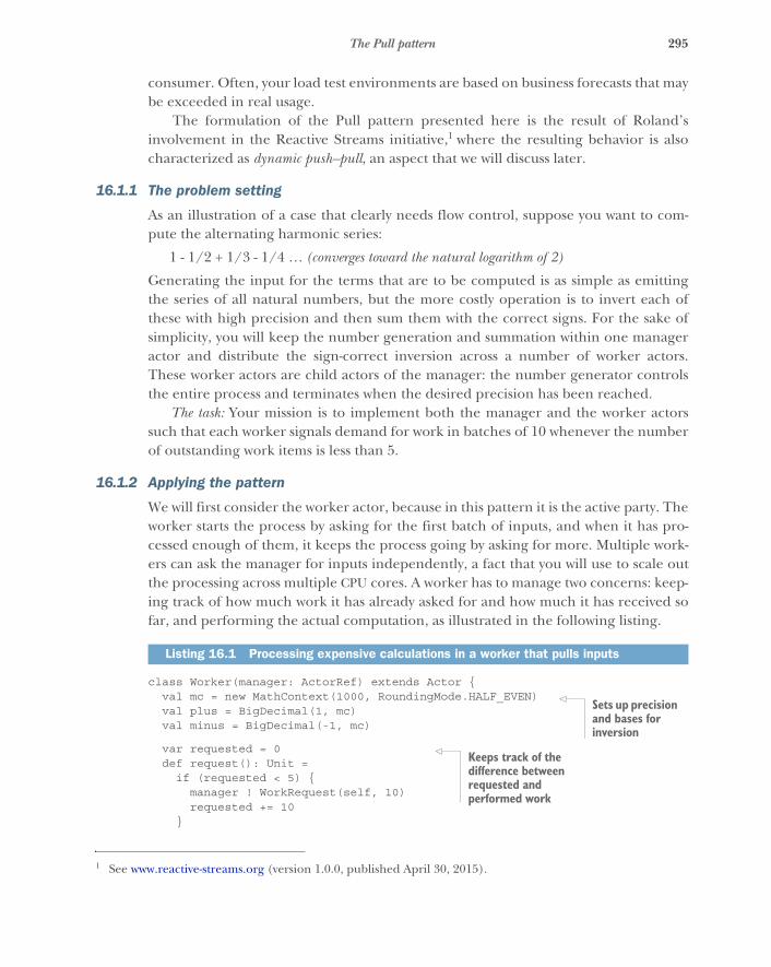
295The Pull pattern
consumer. Often, your load test environments are based on business forecasts that maybe exceeded in real usage.
The formulation of the Pull pattern presented here is the result of Roland’sinvolvement in the Reactive Streams initiative,1 where the resulting behavior is alsocharacterized as dynamic push–pull, an aspect that we will discuss later.
16.1.1 The problem setting
As an illustration of a case that clearly needs flow control, suppose you want to com-pute the alternating harmonic series:
1 - 1/2 + 1/3 - 1/4 … (converges toward the natural logarithm of 2)
Generating the input for the terms that are to be computed is as simple as emittingthe series of all natural numbers, but the more costly operation is to invert each ofthese with high precision and then sum them with the correct signs. For the sake ofsimplicity, you will keep the number generation and summation within one manageractor and distribute the sign-correct inversion across a number of worker actors.These worker actors are child actors of the manager: the number generator controlsthe entire process and terminates when the desired precision has been reached.
The task: Your mission is to implement both the manager and the worker actorssuch that each worker signals demand for work in batches of 10 whenever the numberof outstanding work items is less than 5.
16.1.2 Applying the pattern
We will first consider the worker actor, because in this pattern it is the active party. Theworker starts the process by asking for the first batch of inputs, and when it has pro-cessed enough of them, it keeps the process going by asking for more. Multiple work-ers can ask the manager for inputs independently, a fact that you will use to scale outthe processing across multiple CPU cores. A worker has to manage two concerns: keep-ing track of how much work it has already asked for and how much it has received sofar, and performing the actual computation, as illustrated in the following listing.
class Worker(manager: ActorRef) extends Actor {val mc = new MathContext(1000, RoundingMode.HALF_EVEN)val plus = BigDecimal(1, mc)val minus = BigDecimal(-1, mc)
var requested = 0def request(): Unit =
if (requested < 5) {manager ! WorkRequest(self, 10)requested += 10
}
1 See www.reactive-streams.org (version 1.0.0, published April 30, 2015).
Listing 16.1 Processing expensive calculations in a worker that pulls inputs
Sets up precision and bases for inversion
Keeps track of the difference between requested and performed work
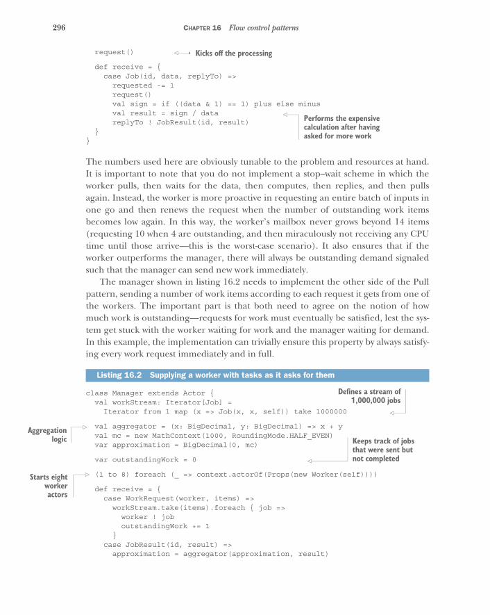
296 CHAPTER 16 Flow control patterns
request()
def receive = {case Job(id, data, replyTo) =>
requested -= 1request()val sign = if ((data & 1) == 1) plus else minusval result = sign / datareplyTo ! JobResult(id, result)
}}
The numbers used here are obviously tunable to the problem and resources at hand.It is important to note that you do not implement a stop–wait scheme in which theworker pulls, then waits for the data, then computes, then replies, and then pullsagain. Instead, the worker is more proactive in requesting an entire batch of inputs inone go and then renews the request when the number of outstanding work itemsbecomes low again. In this way, the worker’s mailbox never grows beyond 14 items(requesting 10 when 4 are outstanding, and then miraculously not receiving any CPUtime until those arrive—this is the worst-case scenario). It also ensures that if theworker outperforms the manager, there will always be outstanding demand signaledsuch that the manager can send new work immediately.
The manager shown in listing 16.2 needs to implement the other side of the Pullpattern, sending a number of work items according to each request it gets from one ofthe workers. The important part is that both need to agree on the notion of howmuch work is outstanding—requests for work must eventually be satisfied, lest the sys-tem get stuck with the worker waiting for work and the manager waiting for demand.In this example, the implementation can trivially ensure this property by always satisfy-ing every work request immediately and in full.
class Manager extends Actor {val workStream: Iterator[Job] =
Iterator from 1 map (x => Job(x, x, self)) take 1000000
val aggregator = (x: BigDecimal, y: BigDecimal) => x + yval mc = new MathContext(1000, RoundingMode.HALF_EVEN)var approximation = BigDecimal(0, mc)
var outstandingWork = 0
(1 to 8) foreach (_ => context.actorOf(Props(new Worker(self))))
def receive = {case WorkRequest(worker, items) =>
workStream.take(items).foreach { job =>worker ! joboutstandingWork += 1
}case JobResult(id, result) =>
approximation = aggregator(approximation, result)
Listing 16.2 Supplying a worker with tasks as it asks for them
Kicks off the processing
Performs the expensive calculation after having asked for more work
Defines a stream of1,000,000 jobs
Aggregationlogic Keeps track of jobs
that were sent but not completed
Starts eightworkeractors
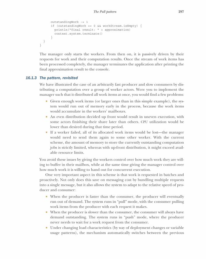
297The Pull pattern
outstandingWork -= 1if (outstandingWork == 0 && workStream.isEmpty) {
println("final result: " + approximation)context.system.terminate()
}}
}
The manager only starts the workers. From then on, it is passively driven by theirrequests for work and their computation results. Once the stream of work items hasbeen processed completely, the manager terminates the application after printing thefinal approximation result to the console.
16.1.3 The pattern, revisited
We have illustrated the case of an arbitrarily fast producer and slow consumers by dis-tributing a computation over a group of worker actors. Were you to implement themanager such that it distributed all work items at once, you would find a few problems:
� Given enough work items (or larger ones than in this simple example), the sys-tem would run out of memory early in the process, because the work itemswould accumulate in the workers’ mailboxes.
� An even distribution decided up front would result in uneven execution, withsome actors finishing their share later than others. CPU utilization would belower than desired during that time period.
� If a worker failed, all of its allocated work items would be lost—the managerwould need to send them again to some other worker. With the currentscheme, the amount of memory to store the currently outstanding computationjobs is strictly limited, whereas with up-front distribution, it might exceed avail-able resource limits.
You avoid these issues by giving the workers control over how much work they are will-ing to buffer in their mailbox, while at the same time giving the manager control overhow much work it is willing to hand out for concurrent execution.
One very important aspect in this scheme is that work is requested in batches andproactively. Not only does this save on messaging cost by bundling multiple requestsinto a single message, but it also allows the system to adapt to the relative speed of pro-ducer and consumer:
� When the producer is faster than the consumer, the producer will eventuallyrun out of demand. The system runs in “pull” mode, with the consumer pullingwork items from the producer with each request it makes.
� When the producer is slower than the consumer, the consumer will always havedemand outstanding. The system runs in “push” mode, where the producernever needs to wait for a work request from the consumer.
� Under changing load characteristics (by way of deployment changes or variableusage patterns), the mechanism automatically switches between the previous
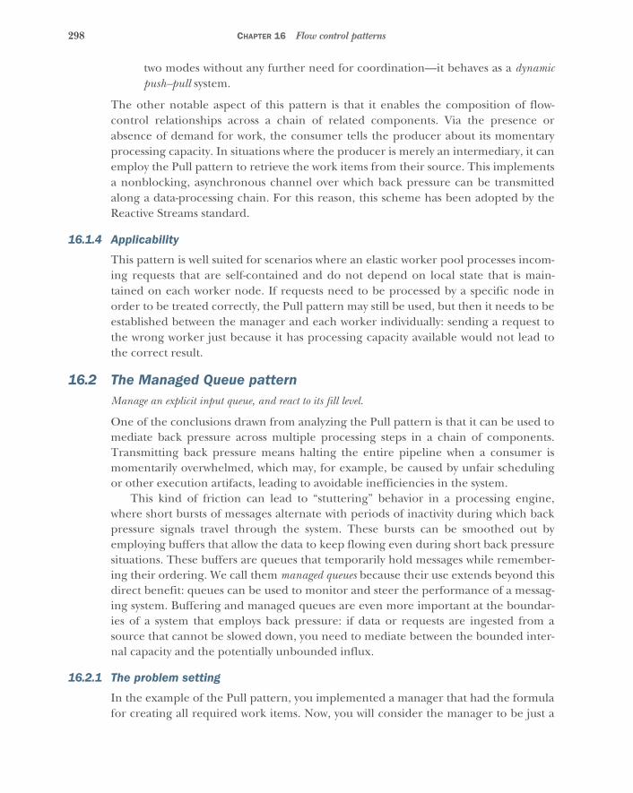
298 CHAPTER 16 Flow control patterns
two modes without any further need for coordination—it behaves as a dynamicpush–pull system.
The other notable aspect of this pattern is that it enables the composition of flow-control relationships across a chain of related components. Via the presence orabsence of demand for work, the consumer tells the producer about its momentaryprocessing capacity. In situations where the producer is merely an intermediary, it canemploy the Pull pattern to retrieve the work items from their source. This implementsa nonblocking, asynchronous channel over which back pressure can be transmittedalong a data-processing chain. For this reason, this scheme has been adopted by theReactive Streams standard.
16.1.4 Applicability
This pattern is well suited for scenarios where an elastic worker pool processes incom-ing requests that are self-contained and do not depend on local state that is main-tained on each worker node. If requests need to be processed by a specific node inorder to be treated correctly, the Pull pattern may still be used, but then it needs to beestablished between the manager and each worker individually: sending a request tothe wrong worker just because it has processing capacity available would not lead tothe correct result.
16.2 The Managed Queue patternManage an explicit input queue, and react to its fill level.
One of the conclusions drawn from analyzing the Pull pattern is that it can be used tomediate back pressure across multiple processing steps in a chain of components.Transmitting back pressure means halting the entire pipeline when a consumer ismomentarily overwhelmed, which may, for example, be caused by unfair schedulingor other execution artifacts, leading to avoidable inefficiencies in the system.
This kind of friction can lead to “stuttering” behavior in a processing engine,where short bursts of messages alternate with periods of inactivity during which backpressure signals travel through the system. These bursts can be smoothed out byemploying buffers that allow the data to keep flowing even during short back pressuresituations. These buffers are queues that temporarily hold messages while remember-ing their ordering. We call them managed queues because their use extends beyond thisdirect benefit: queues can be used to monitor and steer the performance of a messag-ing system. Buffering and managed queues are even more important at the boundar-ies of a system that employs back pressure: if data or requests are ingested from asource that cannot be slowed down, you need to mediate between the bounded inter-nal capacity and the potentially unbounded influx.
16.2.1 The problem setting
In the example of the Pull pattern, you implemented a manager that had the formulafor creating all required work items. Now, you will consider the manager to be just a

299The Managed Queue pattern
mediator, with the source of the work items outside of its control: the manager willreceive work requests while maintaining the Pull pattern with its workers. In order tosmooth out the behavior in the case of momentary lack of requests from the workers,you will install a buffer within the manager.
The task: Your mission is to adapt the worker and manager actors from the Pull pat-tern example such that the numbers to be inverted are generated externally. Themanager will keep a buffer of no more than 1,000 work items, responding with a rejec-tion message to work items that are received while the buffer is full.
16.2.2 Applying the pattern
The main part you need to change is the manager actor. Instead of generating workitems on demand, it now needs to hold two queues: one for work items while all work-ers are busy and one for workers’ requests when no work items are available. An exam-ple is shown next.
class Manager extends Actor {var workQueue = Queue.empty[Job]var requestQueue = Queue.empty[WorkRequest]
(1 to 8) foreach (_ => context.actorOf(Props(new Worker(self))))
def receive = {case job @ Job(id, _, replyTo) =>
if (requestQueue.isEmpty) {if (workQueue.size < 1000) workQueue :+= jobelse replyTo ! JobRejected(id)
} else {val WorkRequest(worker, items) = requestQueue.headworker ! jobif (items > 1) worker ! DummyWork(items - 1)requestQueue = requestQueue.drop(1)
}case wr @ WorkRequest(worker, items) =>
if (workQueue.isEmpty) {requestQueue :+= wr
} else {workQueue.iterator.take(items).foreach(job => worker ! job)val sent = Math.min(workQueue.size, items)if (sent < items) worker ! DummyWork(items - sent)workQueue = workQueue.drop(items)
}}
}
Because you would like to use workers in round-robin fashion in this example, a casearises that requires an adaptation of the protocol between manager and worker: whensatisfying a queued work request from a received job, you need to follow up theJob message with a DummyWork message that tells the worker that the remaining
Listing 16.3 Managing a work queue to react to overload
If there are no requests, the work queue will grow, leading to rejection when full.
Work requests that cannot be satisfied immediately are queued for later.
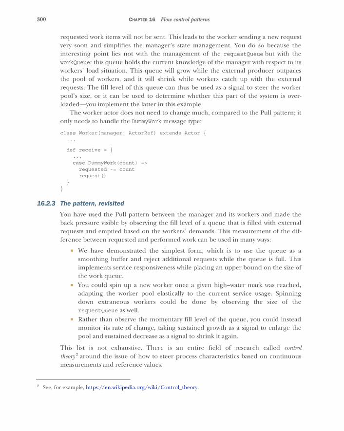
300 CHAPTER 16 Flow control patterns
requested work items will not be sent. This leads to the worker sending a new requestvery soon and simplifies the manager’s state management. You do so because theinteresting point lies not with the management of the requestQueue but with theworkQueue: this queue holds the current knowledge of the manager with respect to itsworkers’ load situation. This queue will grow while the external producer outpacesthe pool of workers, and it will shrink while workers catch up with the externalrequests. The fill level of this queue can thus be used as a signal to steer the workerpool’s size, or it can be used to determine whether this part of the system is over-loaded—you implement the latter in this example.
The worker actor does not need to change much, compared to the Pull pattern; itonly needs to handle the DummyWork message type:
class Worker(manager: ActorRef) extends Actor {...
def receive = {...case DummyWork(count) =>
requested -= countrequest()
}}
16.2.3 The pattern, revisited
You have used the Pull pattern between the manager and its workers and made theback pressure visible by observing the fill level of a queue that is filled with externalrequests and emptied based on the workers’ demands. This measurement of the dif-ference between requested and performed work can be used in many ways:
� We have demonstrated the simplest form, which is to use the queue as asmoothing buffer and reject additional requests while the queue is full. Thisimplements service responsiveness while placing an upper bound on the size ofthe work queue.
� You could spin up a new worker once a given high–water mark was reached,adapting the worker pool elastically to the current service usage. Spinningdown extraneous workers could be done by observing the size of therequestQueue as well.
� Rather than observe the momentary fill level of the queue, you could insteadmonitor its rate of change, taking sustained growth as a signal to enlarge thepool and sustained decrease as a signal to shrink it again.
This list is not exhaustive. There is an entire field of research called controltheory 2 around the issue of how to steer process characteristics based on continuousmeasurements and reference values.
2 See, for example, https://en.wikipedia.org/wiki/Control_theory.
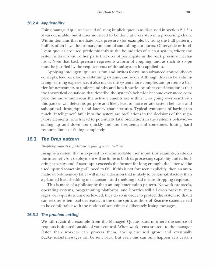
301The Drop pattern
16.2.4 Applicability
Using managed queues instead of using implicit queues as discussed in section 2.1.3 isalways desirable, but it does not need to be done at every step in a processing chain.Within domains that mediate back pressure (for example, by using the Pull pattern),buffers often have the primary function of smoothing out bursts. Observable or intel-ligent queues are used predominantly at the boundaries of such a system, where thesystem interacts with other parts that do not participate in the back pressure mecha-nism. Note that back pressure represents a form of coupling, and as such its scopemust be justified by the requirements of the subsystem it is applied to.
Applying intelligent queues is fun and invites forays into advanced control-theoryconcepts, feedback loops, self-tuning systems, and so on. Although this can be a stimu-lating learning experience, it also makes the system more complex and presents a bar-rier for newcomers to understand why and how it works. Another consideration is thatthe theoretical equations that describe the system’s behavior become ever more com-plex the more numerous the active elements are within it, so going overboard withthis pattern will defeat its purpose and likely lead to more erratic system behavior andsuboptimal throughput and latency characteristics. Typical symptoms of having toomuch “intelligence” built into the system are oscillations in the decisions of the regu-latory elements, which lead to potentially fatal oscillations in the system’s behavior—scaling up and down too quickly and too frequently and sometimes hitting hardresource limits or failing completely.
16.3 The Drop patternDropping requests is preferable to failing uncontrollably.
Imagine a system that is exposed to uncontrollable user input (for example, a site onthe internet). Any deployment will be finite in both its processing capability and its buff-ering capacity, and if user input exceeds the former for long enough, the latter will beused up and something will need to fail. If this is not foreseen explicitly, then an auto-matic out-of-memory killer will make a decision that is likely to be less satisfactory thana planned load-shedding mechanism—and shedding load means dropping requests.
This is more of a philosophy than an implementation pattern. Network protocols,operating systems, programming platforms, and libraries will all drop packets, mes-sages, or requests when overloaded; they do so in order to protect the system so that itcan recover when load decreases. In the same spirit, authors of Reactive systems needto be comfortable with the notion of sometimes deliberately losing messages.
16.3.1 The problem setting
We will revisit the example from the Managed Queue pattern, where the source ofrequests is situated outside of your control. When work items are sent to the managerfaster than workers can process them, the queue will grow, and eventuallyJobRejected messages will be sent back. But even this can only happen at a certain
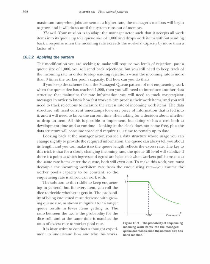
302 CHAPTER 16 Flow control patterns
maximum rate; when jobs are sent at a higher rate, the manager’s mailbox will beginto grow, and it will do so until the system runs out of memory.
The task: Your mission is to adapt the manager actor such that it accepts all workitems into its queue up to a queue size of 1,000 and drops work items without sendingback a response when the incoming rate exceeds the workers’ capacity by more than afactor of 8.
16.3.2 Applying the pattern
The modification you are seeking to make will require two levels of rejection: past aqueue size of 1,000, you will send back rejections; but you still need to keep track ofthe incoming rate in order to stop sending rejections when the incoming rate is morethan 8 times the worker pool’s capacity. But how can you do that?
If you keep the scheme from the Managed Queue pattern of not enqueueing workwhen the queue size has reached 1,000, then you will need to introduce another datastructure that maintains the rate information: you will need to track WorkRequestmessages in order to know how fast workers can process their work items, and you willneed to track rejections to measure the excess rate of incoming work items. The datastructure will need current timestamps for every piece of information that is fed intoit, and it will need to know the current time when asking for a decision about whetherto drop an item. All this is possible to implement, but doing so has a cost both atdevelopment time and at runtime—looking at the clock does not come free, plus thedata structure will consume space and require CPU time to remain up to date.
Looking back at the manager actor, you see a data structure whose usage you canchange slightly to provide the required information: the queue can always tell you aboutits length, and you can make it so the queue length reflects the excess rate. The key tothis trick is that for a slowly changing incoming rate, the queue fill level will stabilize ifthere is a point at which ingress and egress are balanced: when workers pull items out atthe same rate items enter the queue, both will even out. To make this work, you mustdecouple the incoming work-item rate from the enqueueing rate—you assume theworker pool’s capacity to be constant, so theenqueueing rate is all you can work with.
The solution to this riddle to keep enqueue-ing in general, but for every item, you roll thedice to decide whether it gets in. The probabil-ity of being enqueued must decrease with grow-ing queue size, as shown in figure 16.1: a longerqueue results in fewer items getting in. Theratio between the two is the probability for thedice roll, and at the same time it matches theratio of excess rate to worker-pool rate.
It is instructive to conduct a thought experi-ment to understand how and why this works.
Queue size1000
1
Figure 16.1 The probability of enqueueing incoming work items into the managed queue decreases once the nominal size has been reached.
303The Drop pattern
Assume that the system starts with an empty queue and a rate mismatch of a factor of10. The queue will quickly become full (reach 1,000 elements), at which point rejec-tions will be generated. But the queue will continue to grow—only more slowly, due tothe probabilistic enqueueing. Once the queue size is so big that the enqueueing prob-ability drops to 10%, the enqueueing rate will match the dequeueing rate, and the sizeof the queue will remain stable until either the external work-item rate or the worker-pool capacity changes.
In terms of code, not much is needed to implement this scheme, as you can seehere:
val queueThreshold = 1000val dropThreshold = 1384def random = ThreadLocalRandom.current
def shallEnqueue(atSize: Int) =(atSize < queueThreshold) || {
val dropFactor = (atSize - queueThreshold) >> 6random.nextInt(dropFactor + 2) == 0
}
You use this logic to handle incoming Job messages:
case job @ Job(id, _, replyTo) =>if (requestQueue.isEmpty) {
val atSize = workQueue.sizeif (shallEnqueue(atSize)) workQueue :+= jobelse if (atSize < dropThreshold) replyTo ! JobRejected(id)
} else ...
This means you will enqueue a certain fraction of incoming jobs even when the queuesize is greater than 1,000, and the probability of enqueueing a given job decreaseswith growing queue size. At size 1,000, dropFactor is 0, and the probability of pickinga zero from nextInt(2) is 50%. At size 1,064, dropFactor is 1, and the probabilitydecreases to 33%—and so on, until at the drop threshold of 1,384, the probability is1/8. dropThreshold is therefore chosen such that the desired cutoff point for rejec-tion messages is implemented.
16.3.3 The pattern, revisited
The example includes two modes of overload reactions: either you send back anincomplete response (degraded functionality), or you do not reply at all. You imple-ment the metric for selecting one of these modes based on the work-item queue themanager maintains. For this, you need to allow the queue to grow past its logicalcapacity bound, where the excess is regulated to be proportional to the rate mismatchbetween producers and consumers of work items—by choosing a different formulafor dropFactor, you could make this relation quadratic, exponential, or whatever isrequired.
304 CHAPTER 16 Flow control patterns
The important piece here is that providing degraded functionality only works upto a given point, and the service should foresee a mechanism that kicks in once thispoint is reached. Providing no functionality at all—dropping requests—is cheaper thanproviding degraded functionality, and under severe overload conditions this is all theservice can do to retain control over its resources.
One notable side effect of the chosen implementation technique is that during anintense burst, you now enqueue a certain fraction of work items, whereas the strictlybounded queue as implemented in the Managed Queue pattern example wouldreject the entire burst (assuming that the burst occurs faster than consumption by theworkers).
EXTENSION TO IMPLICIT QUEUES
We have so far only regarded the behavior of the explicit queue maintained by themanager actor. This actor, however, has only finite computing resources at its disposal,and even the calculations for deciding whether to drop a message have a certain cost.If the incoming rate is higher than the manager actor can decide about, its mailboxwill grow: over time, it will eat up the JVM heap and lead to fatal termination throughan OutOfMemoryError. This can only be avoided by limiting the implicit queues—themanager’s mailbox, in this case—in addition to the explicit queues.
Because you are dealing with an aspect that is implicitly handled by the framework(Akka, in this example), you do not need to write much code to implement this. Youonly need to instruct Akka to install a bounded mailbox for the manager actor:
val managerProps = Props(new Manager).withMailbox("bounded-mailbox")
When this description is used to create the manager actor, Akka will look in its config-uration for a section describing the bounded mailbox. The following settings config-ure a mailbox that is bounded to 1,000 messages:
bounded-mailbox {mailbox-type = "akka.dispatch.BoundedMailbox"mailbox-capacity = 1000mailbox-push-timeout-time = 0s
}
This has an important drawback: this mailbox drops not only Job messages fromexternal sources but also WorkRequest messages from the worker actors. In order tomake those cope with such losses, you must implement a resending mechanism(which would be needed in any case, if the workers were deployed remotely), but thiswill not fix a more severe issue. For example, if the external rate is 10 times as high aswhat can be processed, then only 1 in 10 work requests will make it back, leading toworkers idling because they cannot tell the manager about their demand as quickly asthey need to.
This demonstrates that dropping at a lower level will always be less precise thandropping at the level that has all the necessary information, but it is the nature ofoverload situations that this knowledge can be too costly to maintain. The bounded
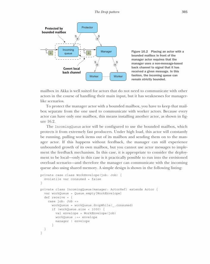
305The Drop pattern
mailbox in Akka is well suited for actors that do not need to communicate with otheractors in the course of handling their main input, but it has weaknesses for manager-like scenarios.
To protect the manager actor with a bounded mailbox, you have to keep that mail-box separate from the one used to communicate with worker actors. Because everyactor can have only one mailbox, this means installing another actor, as shown in fig-ure 16.2.
The IncomingQueue actor will be configured to use the bounded mailbox, whichprotects it from extremely fast producers. Under high load, this actor will constantlybe running, pulling work items out of its mailbox and sending them on to the man-ager actor. If this happens without feedback, the manager can still experienceunbounded growth of its own mailbox, but you cannot use actor messages to imple-ment the feedback mechanism. In this case, it is appropriate to consider the deploy-ment to be local—only in this case is it practically possible to run into the envisionedoverload scenario—and therefore the manager can communicate with the incomingqueue also using shared memory. A simple design is shown in the following listing:
private case class WorkEnvelope(job: Job) {@volatile var consumed = false
}
private class IncomingQueue(manager: ActorRef) extends Actor {var workQueue = Queue.empty[WorkEnvelope]def receive = {
case job: Job =>workQueue = workQueue.dropWhile(_.consumed)if (workQueue.size < 1000) {
val envelope = WorkEnvelope(job)workQueue :+= envelopemanager ! envelope
}}
}
Protected bybounded mailbox
Covert localback channel
Incomingqueue Manager
Worker Worker
Protector
S S
S S
Figure 16.2 Placing an actor with a bounded mailbox in front of the manager actor requires that the manager uses a non-message-based back channel to signal that it has received a given message. In this fashion, the incoming queue can remain strictly bounded.

306 CHAPTER 16 Flow control patterns
The only thing the manager has to do is set the consumed flag to true upon receipt ofa WorkEnvelope. Further improvements that are omitted for the sake of simplicityinclude cleaning out the incoming queue periodically, in case there are long pauses inthe incoming request stream during which work items would be unduly retained inmemory. The full code for this example can be found with the book’s downloads inthe file DropPatternWithProtection.scala.
Although this extension seems specific to Akka, it is generic. In any OS and serviceplatform, there will be implicit queues that transport requests from the network to localprocesses as well as within these processes—these could be message queues, threadpool task queues, threads that are queued for execution, and so on. Some of thesequeues are configurable, but changing their configuration will have indiscriminateeffects on all kinds of messages passing through them; we noted earlier that the neces-sary knowledge exists at a higher level, but that higher level may need protection fromlower levels that can only make coarse-grained decisions. The workarounds differ; theAkka example given in this section is tailored to this particular case, but the need toapply such custom solutions will arise wherever you push a platform to its limits.
16.3.4 Applicability
During system overload, some kind of failure is bound to happen. Determining whatkind it will be is a business decision: should the system protect itself by foregoingresponsiveness, or should it come to a crawling but uncontrolled halt when resourcesare exhausted? The intuitive answer is the former, whereas typical engineering prac-tice implements the latter—not deliberately, but due to neglect resulting from otheraspects of the application design having higher priority. This pattern is always applica-ble, if only in the sense that not shedding load by dropping requests should be a well-understood and deliberate decision.
16.4 The Throttling patternThrottle your own output rate according to contracts with other services.
We have discussed how each component can mediate, measure, and react to backpressure in order to avoid uncontrollable overload situations. With these means atyour disposal, it is not just fair but obligatory that you respect the ingestion limits ofother components. In situations where you outpace consumers of your outputs, youcan slow to match their rate, and you can even ensure that you do not violate a prear-ranged rate agreement.
In section 12.4.2, you saw that a circuit breaker can be designed such that it rejectsrequests that would otherwise lead to a request rate that is too high. With the Pull pat-tern, you can turn this around and not generate requests more quickly than they areallowed to be sent.
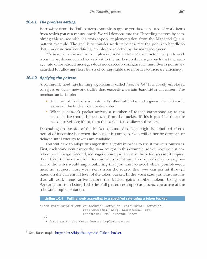
307The Throttling pattern
16.4.1 The problem setting
Borrowing from the Pull pattern example, suppose you have a source of work itemsfrom which you can request work. We will demonstrate the Throttling pattern by com-bining this source with the worker-pool implementation from the Managed Queuepattern example. The goal is to transfer work items at a rate the pool can handle sothat, under normal conditions, no jobs are rejected by the managed queue.
The task: Your mission is to implement a CalculatorClient actor that pulls workfrom the work source and forwards it to the worker-pool manager such that the aver-age rate of forwarded messages does not exceed a configurable limit. Bonus points areawarded for allowing short bursts of configurable size in order to increase efficiency.
16.4.2 Applying the pattern
A commonly used rate-limiting algorithm is called token bucket.3 It is usually employedto reject or delay network traffic that exceeds a certain bandwidth allocation. Themechanism is simple:
� A bucket of fixed size is continually filled with tokens at a given rate. Tokens inexcess of the bucket size are discarded.
� When a network packet arrives, a number of tokens corresponding to thepacket’s size should be removed from the bucket. If this is possible, then thepacket travels on; if not, then the packet is not allowed through.
Depending on the size of the bucket, a burst of packets might be admitted after aperiod of inactivity; but when the bucket is empty, packets will either be dropped ordelayed until enough tokens are available.
You will have to adapt this algorithm slightly in order to use it for your purposes.First, each work item carries the same weight in this example, so you require just onetoken per message. Second, messages do not just arrive at the actor: you must requestthem from the work source. Because you do not wish to drop or delay messages—where the latter would imply buffering that you want to avoid where possible—youmust not request more work items from the source than you can permit throughbased on the current fill level of the token bucket. In the worst case, you must assumethat all work items arrive before the bucket gains another token. Using theWorker actor from listing 16.1 (the Pull pattern example) as a basis, you arrive at thefollowing implementation.
class CalculatorClient(workSource: ActorRef, calculator: ActorRef,ratePerSecond: Long, bucketSize: Int,batchSize: Int) extends Actor {
/** first part: the token bucket implementation
3 See, for example, https://en.wikipedia.org/wiki/Token_bucket.
Listing 16.4 Pulling work according to a specified rate using a token bucket
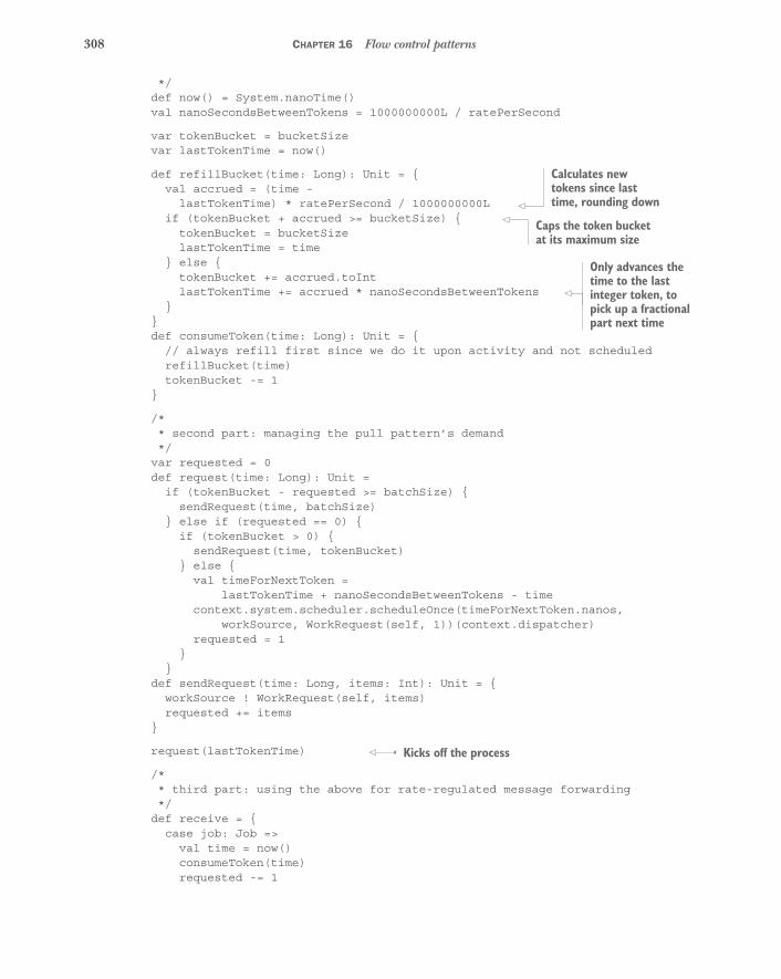
308 CHAPTER 16 Flow control patterns
*/def now() = System.nanoTime()val nanoSecondsBetweenTokens = 1000000000L / ratePerSecond
var tokenBucket = bucketSizevar lastTokenTime = now()
def refillBucket(time: Long): Unit = {val accrued = (time -
lastTokenTime) * ratePerSecond / 1000000000Lif (tokenBucket + accrued >= bucketSize) {
tokenBucket = bucketSizelastTokenTime = time
} else {tokenBucket += accrued.toIntlastTokenTime += accrued * nanoSecondsBetweenTokens
}}def consumeToken(time: Long): Unit = {
// always refill first since we do it upon activity and not scheduledrefillBucket(time)tokenBucket -= 1
}
/** second part: managing the pull pattern’s demand*/
var requested = 0def request(time: Long): Unit =
if (tokenBucket - requested >= batchSize) {sendRequest(time, batchSize)
} else if (requested == 0) {if (tokenBucket > 0) {
sendRequest(time, tokenBucket)} else {
val timeForNextToken =lastTokenTime + nanoSecondsBetweenTokens - time
context.system.scheduler.scheduleOnce(timeForNextToken.nanos,workSource, WorkRequest(self, 1))(context.dispatcher)
requested = 1}
}def sendRequest(time: Long, items: Int): Unit = {
workSource ! WorkRequest(self, items)requested += items
}
request(lastTokenTime)
/** third part: using the above for rate-regulated message forwarding*/
def receive = {case job: Job =>
val time = now()consumeToken(time)requested -= 1
Calculates new tokens since last time, rounding down
Caps the token bucket at its maximum size
Only advances the time to the last integer token, to pick up a fractional part next time
Kicks off the process
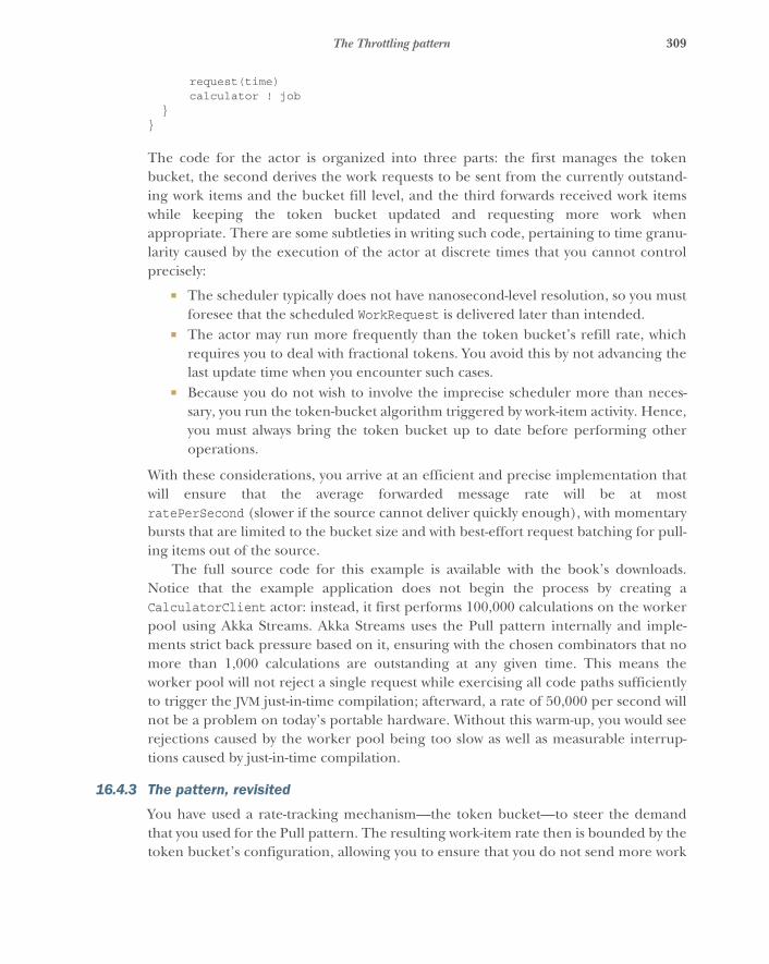
309The Throttling pattern
request(time)calculator ! job
}}
The code for the actor is organized into three parts: the first manages the tokenbucket, the second derives the work requests to be sent from the currently outstand-ing work items and the bucket fill level, and the third forwards received work itemswhile keeping the token bucket updated and requesting more work whenappropriate. There are some subtleties in writing such code, pertaining to time granu-larity caused by the execution of the actor at discrete times that you cannot controlprecisely:
� The scheduler typically does not have nanosecond-level resolution, so you mustforesee that the scheduled WorkRequest is delivered later than intended.
� The actor may run more frequently than the token bucket’s refill rate, whichrequires you to deal with fractional tokens. You avoid this by not advancing thelast update time when you encounter such cases.
� Because you do not wish to involve the imprecise scheduler more than neces-sary, you run the token-bucket algorithm triggered by work-item activity. Hence,you must always bring the token bucket up to date before performing otheroperations.
With these considerations, you arrive at an efficient and precise implementation thatwill ensure that the average forwarded message rate will be at mostratePerSecond (slower if the source cannot deliver quickly enough), with momentarybursts that are limited to the bucket size and with best-effort request batching for pull-ing items out of the source.
The full source code for this example is available with the book’s downloads.Notice that the example application does not begin the process by creating aCalculatorClient actor: instead, it first performs 100,000 calculations on the workerpool using Akka Streams. Akka Streams uses the Pull pattern internally and imple-ments strict back pressure based on it, ensuring with the chosen combinators that nomore than 1,000 calculations are outstanding at any given time. This means theworker pool will not reject a single request while exercising all code paths sufficientlyto trigger the JVM just-in-time compilation; afterward, a rate of 50,000 per second willnot be a problem on today’s portable hardware. Without this warm-up, you would seerejections caused by the worker pool being too slow as well as measurable interrup-tions caused by just-in-time compilation.
16.4.3 The pattern, revisited
You have used a rate-tracking mechanism—the token bucket—to steer the demandthat you used for the Pull pattern. The resulting work-item rate then is bounded by thetoken bucket’s configuration, allowing you to ensure that you do not send more work
310 CHAPTER 16 Flow control patterns
to another component than was agreed on beforehand. Although a managed queuelets a service protect itself to a degree (see also the discussion of the Drop pattern andits limitations), the Throttling pattern implements service collaboration where theuser also protects the service by promising to not exceed a given rate. This can be usedrestrictively to make rejections unlikely under nominal conditions, or it can be usedmore liberally to avoid having to call on the Drop pattern. But neither the ManagedQueue pattern nor the Drop pattern is replaced by the Throttling pattern; it is import-ant to consider overload protection from both the consumer and producer sides.
16.5 SummaryIn this chapter, we considered that communication happens at a certain rate. Youlearned about different ways in which this rate can be regulated and acted on:
� The Pull pattern matches the rates of producer and consumer such that theslower party sets the pace. It works without explicitly measuring time or rates.
� The Managed Queue pattern decouples the incoming and outgoing rates witha configurable leeway—the queue size—and makes the rate difference betweenproducer and consumer measurable and actionable.
� The Drop pattern provides an escalation for the Managed Queue pattern whenthe rate mismatch is too big to be handled by degrading the service functional-ity.
� The Throttling pattern regulates a message stream’s speed according to config-ured rate and burstiness parameters; it is the only presented pattern that explic-itly deals with time.

311
State managementand persistence patterns
The previous chapter introduced the concepts of message rate, load, and time; pre-viously, we had only considered the timeless relationship between different compo-nents. This chapter adds another orthogonal dimension to complete the picture: itis the purpose of almost all components to maintain state, and we have not yet dis-cussed how this should be done. The patterns presented are closely related to eachother and form a cohesive unit:
� The Domain Object pattern decouples business logic from communicationmachinery.
� The Sharding pattern allows you to store any number of domain objects onan elastic cluster.
� The Event-Sourcing pattern unifies change notifications and persistence bydeclaring the event log to be the sole source of truth.
� The Event Stream pattern uses this source of truth to derive and disseminateinformation.
This chapter can only serve as a basic introduction to these patterns. We hope itinspires you to delve into the rich literature and online resources on domain-drivendesign, event sourcing, and command-query responsibility separation (see the foot-notes throughout the chapter for pointers).
312 CHAPTER 17 State management and persistence patterns
17.1 The Domain Object patternSeparate the business domain logic from communication and state management.
In chapter 6, we discussed the principle of divide and conquer; and in section 12.1, youlearned how to apply this in the form of the Simple Component pattern. The result-ing components have a clearly defined responsibility: they do one thing and do it infull. Often, this involves maintaining state that persists between invocations of thesecomponents. Although it may be intuitive to identify a component with its state—forexample, by saying that a shopping cart in its entirety is implemented by an actor—this has notable downsides:
� The business logic becomes entangled with the communication protocols andwith execution concerns.
� The only available mode of testing this component is through asynchronousintegration tests—the implemented business behavior is accessible only via theexternally defined protocols.
The Domain Object pattern describes how to maintain a clear boundary and separa-tion between the different concerns of business logic, state management, andcommunication. This pattern is intuitively understandable without additional knowl-edge, but we highly recommended that you study domain-driven design,1 because itprovides more in-depth techniques for defining the ubiquitous language used withineach bounded context. Bounded contexts typically correspond to components in yourhierarchical system decomposition, and the ubiquitous language is the natural lan-guage in which domain experts describe the business function of the component.
17.1.1 The problem setting
In this chapter, we will use the example of implementing a shopping cart component.Although there may be a variety of facets to be covered in a real-world implementa-tion, it is sufficient for the demonstration of the important aspects of these patterns tobe able to associate an owner, add and remove items, and query the list of items in theshopping cart.
The task: Your mission is to implement a domain model for the shopping cart thatcontains only the business information and offers synchronous methods for perform-ing business operations. Then, you will implement an actor that encapsulates adomain model instance and exposes the business operations as part of its communica-tion protocol.
1 See, for example, Eric Evans, Domain-Driven Design (Addison-Wesley, 2003); or Vaughn Vernon, ImplementingDomain-Driven Design (Addison-Wesley, 2013).
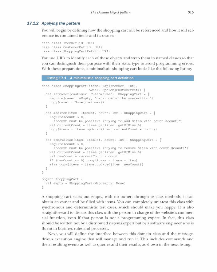
313The Domain Object pattern
17.1.2 Applying the pattern
You will begin by defining how the shopping cart will be referenced and how it will ref-erence its contained items and its owner:
case class ItemRef(id: URI)case class CustomerRef(id: URI)case class ShoppingCartRef(id: URI)
You use URIs to identify each of these objects and wrap them in named classes so thatyou can distinguish their purpose with their static type to avoid programming errors.With these preparations, a minimalistic shopping cart looks like the following listing.
case class ShoppingCart(items: Map[ItemRef, Int],owner: Option[CustomerRef]) {
def setOwner(customer: CustomerRef): ShoppingCart = {require(owner.isEmpty, "owner cannot be overwritten")copy(owner = Some(customer))
}
def addItem(item: ItemRef, count: Int): ShoppingCart = {require(count > 0,
s"count must be positive (trying to add $item with count $count)")val currentCount = items.get(item).getOrElse(0)copy(items = items.updated(item, currentCount + count))
}
def removeItem(item: ItemRef, count: Int): ShoppingCart = {require(count > 0,
s"count must be positive (trying to remove $item with count $count)")val currentCount = items.get(item).getOrElse(0)val newCount = currentCount - countif (newCount <= 0) copy(items = items - item)else copy(items = items.updated(item, newCount))
}}
object ShoppingCart {val empty = ShoppingCart(Map.empty, None)
}
A shopping cart starts out empty, with no owner; through its class methods, it canobtain an owner and be filled with items. You can completely unit-test this class withsynchronous and deterministic test cases, which should make you happy. It is alsostraightforward to discuss this class with the person in charge of the website’s commer-cial function, even if that person is not a programming expert. In fact, this classshould be written not by a distributed systems expert but by a software engineer who isfluent in business rules and processes.
Next, you will define the interface between this domain class and the message-driven execution engine that will manage and run it. This includes commands andtheir resulting events as well as queries and their results, as shown in the next listing.
Listing 17.1 A minimalistic shopping cart definition
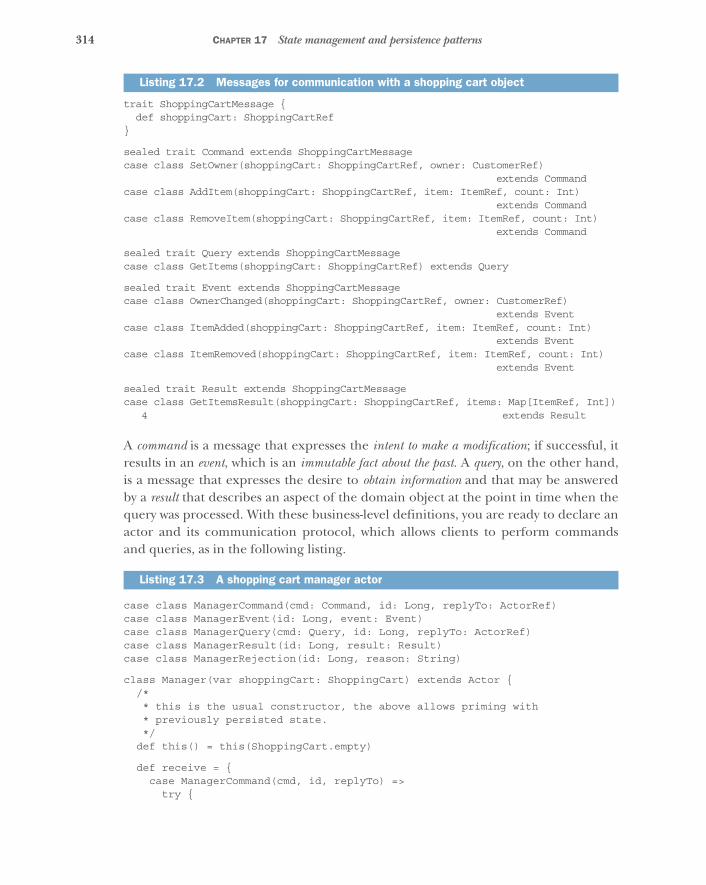
314 CHAPTER 17 State management and persistence patterns
trait ShoppingCartMessage {def shoppingCart: ShoppingCartRef
}
sealed trait Command extends ShoppingCartMessagecase class SetOwner(shoppingCart: ShoppingCartRef, owner: CustomerRef)
extends Commandcase class AddItem(shoppingCart: ShoppingCartRef, item: ItemRef, count: Int)
extends Commandcase class RemoveItem(shoppingCart: ShoppingCartRef, item: ItemRef, count: Int)
extends Command
sealed trait Query extends ShoppingCartMessagecase class GetItems(shoppingCart: ShoppingCartRef) extends Query
sealed trait Event extends ShoppingCartMessagecase class OwnerChanged(shoppingCart: ShoppingCartRef, owner: CustomerRef)
extends Eventcase class ItemAdded(shoppingCart: ShoppingCartRef, item: ItemRef, count: Int)
extends Eventcase class ItemRemoved(shoppingCart: ShoppingCartRef, item: ItemRef, count: Int)
extends Event
sealed trait Result extends ShoppingCartMessagecase class GetItemsResult(shoppingCart: ShoppingCartRef, items: Map[ItemRef, Int])
4 extends Result
A command is a message that expresses the intent to make a modification; if successful, itresults in an event, which is an immutable fact about the past. A query, on the other hand,is a message that expresses the desire to obtain information and that may be answeredby a result that describes an aspect of the domain object at the point in time when thequery was processed. With these business-level definitions, you are ready to declare anactor and its communication protocol, which allows clients to perform commandsand queries, as in the following listing.
case class ManagerCommand(cmd: Command, id: Long, replyTo: ActorRef)case class ManagerEvent(id: Long, event: Event)case class ManagerQuery(cmd: Query, id: Long, replyTo: ActorRef)case class ManagerResult(id: Long, result: Result)case class ManagerRejection(id: Long, reason: String)
class Manager(var shoppingCart: ShoppingCart) extends Actor {/** this is the usual constructor, the above allows priming with* previously persisted state.*/
def this() = this(ShoppingCart.empty)
def receive = {case ManagerCommand(cmd, id, replyTo) =>
try {
Listing 17.2 Messages for communication with a shopping cart object
Listing 17.3 A shopping cart manager actor
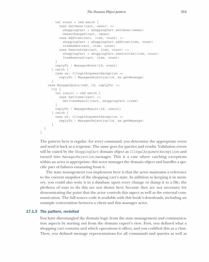
315The Domain Object pattern
val event = cmd match {case SetOwner(cart, owner) =>
shoppingCart = shoppingCart.setOwner(owner)OwnerChanged(cart, owner)
case AddItem(cart, item, count) =>shoppingCart = shoppingCart.addItem(item, count)ItemAdded(cart, item, count)
case RemoveItem(cart, item, count) =>shoppingCart = shoppingCart.removeItem(item, count)ItemRemoved(cart, item, count)
}replyTo ! ManagerEvent(id, event)
} catch {case ex: IllegalArgumentException =>
replyTo ! ManagerRejection(id, ex.getMessage)}
case ManagerQuery(cmd, id, replyTo) =>try {
val result = cmd match {case GetItems(cart) =>
GetItemsResult(cart, shoppingCart.items)}replyTo ! ManagerResult(id, result)
} catch {case ex: IllegalArgumentException =>
replyTo ! ManagerRejection(id, ex.getMessage)}
}}
The pattern here is regular: for every command, you determine the appropriate eventand send it back as a response. The same goes for queries and results. Validation errorswill be raised by the ShoppingCart domain object as IllegalArgumentExceptions andturned into ManagerRejection messages. This is a case where catching exceptionswithin an actor is appropriate: this actor manages the domain object and handles a spe-cific part of failures emanating from it.
The state management you implement here is that the actor maintains a referenceto the current snapshot of the shopping cart’s state. In addition to keeping it in mem-ory, you could also write it to a database upon every change or dump it to a file; theplethora of ways to do this are not shown here because they are not necessary fordemonstrating the point that the actor controls this aspect as well as the external com-munication. The full source code is available with this book’s downloads, including anexample conversation between a client and this manager actor.
17.1.3 The pattern, revisited
You have disentangled the domain logic from the state management and communica-tion aspects by starting out from the domain expert’s view. First, you defined what ashopping cart contains and which operations it offers, and you codified this as a class.Then, you defined message representations for all commands and queries as well as
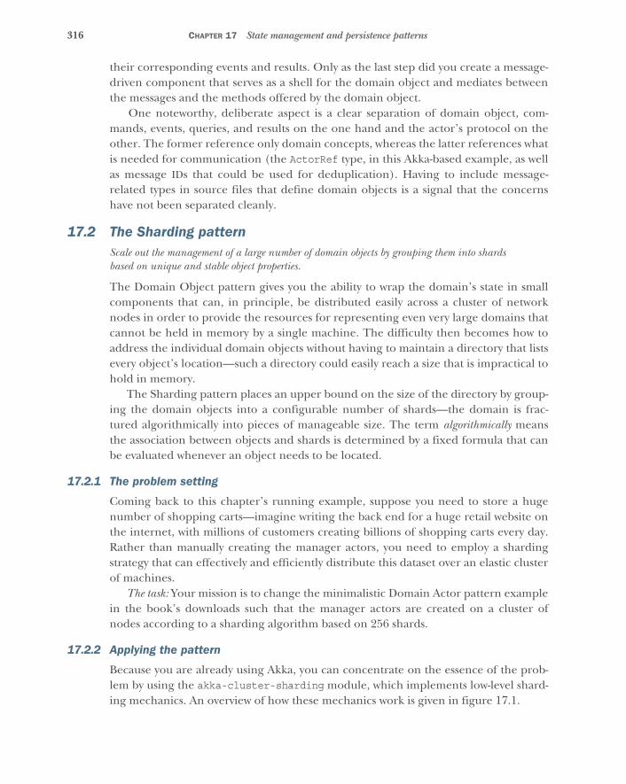
316 CHAPTER 17 State management and persistence patterns
their corresponding events and results. Only as the last step did you create a message-driven component that serves as a shell for the domain object and mediates betweenthe messages and the methods offered by the domain object.
One noteworthy, deliberate aspect is a clear separation of domain object, com-mands, events, queries, and results on the one hand and the actor’s protocol on theother. The former reference only domain concepts, whereas the latter references whatis needed for communication (the ActorRef type, in this Akka-based example, as wellas message IDs that could be used for deduplication). Having to include message-related types in source files that define domain objects is a signal that the concernshave not been separated cleanly.
17.2 The Sharding patternScale out the management of a large number of domain objects by grouping them into shardsbased on unique and stable object properties.
The Domain Object pattern gives you the ability to wrap the domain’s state in smallcomponents that can, in principle, be distributed easily across a cluster of networknodes in order to provide the resources for representing even very large domains thatcannot be held in memory by a single machine. The difficulty then becomes how toaddress the individual domain objects without having to maintain a directory that listsevery object’s location—such a directory could easily reach a size that is impractical tohold in memory.
The Sharding pattern places an upper bound on the size of the directory by group-ing the domain objects into a configurable number of shards—the domain is frac-tured algorithmically into pieces of manageable size. The term algorithmically meansthe association between objects and shards is determined by a fixed formula that canbe evaluated whenever an object needs to be located.
17.2.1 The problem setting
Coming back to this chapter’s running example, suppose you need to store a hugenumber of shopping carts—imagine writing the back end for a huge retail website onthe internet, with millions of customers creating billions of shopping carts every day.Rather than manually creating the manager actors, you need to employ a shardingstrategy that can effectively and efficiently distribute this dataset over an elastic clusterof machines.
The task: Your mission is to change the minimalistic Domain Actor pattern examplein the book’s downloads such that the manager actors are created on a cluster ofnodes according to a sharding algorithm based on 256 shards.
17.2.2 Applying the pattern
Because you are already using Akka, you can concentrate on the essence of the prob-lem by using the akka-cluster-sharding module, which implements low-level shard-ing mechanics. An overview of how these mechanics work is given in figure 17.1.

317The Sharding pattern
The only remaining pieces needed to enlist the sharding module’s support are asfollows:
� A recipe for how to create entities when they are first referenced� A formula that extracts the unique entity ID from a command or query� A formula that extracts the shard number from a command or query
The first will be a Props object, and the latter two will be functions. The shardextraction guides the message to the correct shard region, and the shard actor thenuses the entity ID to find the correct domain object manager among its child actors.You group these two functions together with an identifier for the shopping cart shard-ing system, as follows.
object ShardSupport {val extractEntityId: ShardRegion.ExtractEntityId = {
case mc @ ManagerCommand(cmd, _, _) =>cmd.shoppingCart.id.toString -> mc
case mc @ ManagerQuery(query, _, _) =>query.shoppingCart.id.toString -> mc
}
Listing 17.4 Defining sharding algorithms for a shopping cart
Node 1 Node N
Client Domainobject
Shardregion
Cluster singleton
Akka data replication
Domainobject
2
3
2
1
3
S S
2
Client Domainobject
Shardregion
Domainobject
3 2
Shard coordinator
S S
Figure 17.1 Sharding requires that a ShardRegion is started on all participating nodes and registers itself with the ShardCoordinator. When a message is to be sent from a client to one of the managed domain objects—called an entity here—it will be sent via the local ShardRegion, which will consult the coordinator cluster singleton as to where the shard that contains the domain object should be located. The shard will be created on demand if it does not yet exist. The shard is maintained by an actor situated between the region and the entities (not shown here for the sake of simplicity). The allocation of shards to regions is replicated in memory among all nodes using the Data Replication module (see section 13.2.3 on CRDTs).
Identifies entities bythe shopping cart ID;
commands that do notmatch are dropped
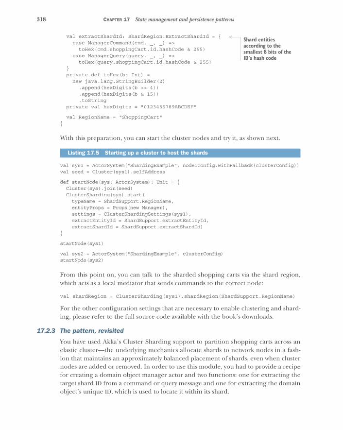
318 CHAPTER 17 State management and persistence patterns
val extractShardId: ShardRegion.ExtractShardId = {case ManagerCommand(cmd, _, _) =>
toHex(cmd.shoppingCart.id.hashCode & 255)case ManagerQuery(query, _, _) =>
toHex(query.shoppingCart.id.hashCode & 255)}private def toHex(b: Int) =
new java.lang.StringBuilder(2).append(hexDigits(b >> 4)).append(hexDigits(b & 15)).toString
private val hexDigits = "0123456789ABCDEF"
val RegionName = "ShoppingCart"}
With this preparation, you can start the cluster nodes and try it, as shown next.
val sys1 = ActorSystem("ShardingExample", node1Config.withFallback(clusterConfig))val seed = Cluster(sys1).selfAddress
def startNode(sys: ActorSystem): Unit = {Cluster(sys).join(seed)ClusterSharding(sys).start(typeName = ShardSupport.RegionName,entityProps = Props(new Manager),settings = ClusterShardingSettings(sys1),extractEntityId = ShardSupport.extractEntityId,extractShardId = ShardSupport.extractShardId)
}
startNode(sys1)
val sys2 = ActorSystem("ShardingExample", clusterConfig)startNode(sys2)
From this point on, you can talk to the sharded shopping carts via the shard region,which acts as a local mediator that sends commands to the correct node:
val shardRegion = ClusterSharding(sys1).shardRegion(ShardSupport.RegionName)
For the other configuration settings that are necessary to enable clustering and shard-ing, please refer to the full source code available with the book’s downloads.
17.2.3 The pattern, revisited
You have used Akka’s Cluster Sharding support to partition shopping carts across anelastic cluster—the underlying mechanics allocate shards to network nodes in a fash-ion that maintains an approximately balanced placement of shards, even when clusternodes are added or removed. In order to use this module, you had to provide a recipefor creating a domain object manager actor and two functions: one for extracting thetarget shard ID from a command or query message and one for extracting the domainobject’s unique ID, which is used to locate it within its shard.
Listing 17.5 Starting up a cluster to host the shards
Shard entities according to the smallest 8 bits of the ID’s hash code
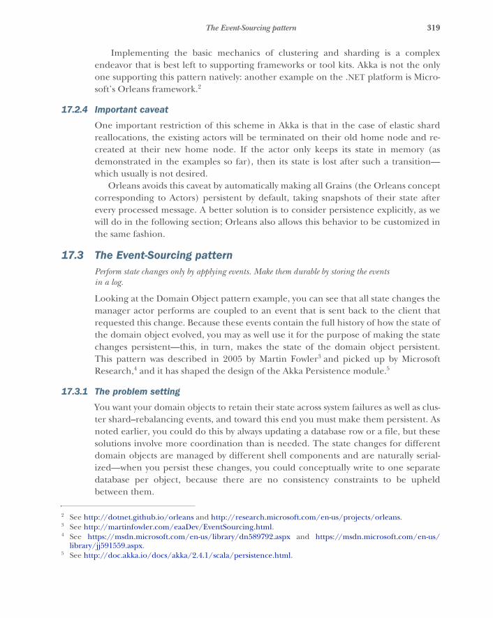
319The Event-Sourcing pattern
Implementing the basic mechanics of clustering and sharding is a complexendeavor that is best left to supporting frameworks or tool kits. Akka is not the onlyone supporting this pattern natively: another example on the .NET platform is Micro-soft’s Orleans framework.2
17.2.4 Important caveat
One important restriction of this scheme in Akka is that in the case of elastic shardreallocations, the existing actors will be terminated on their old home node and re-created at their new home node. If the actor only keeps its state in memory (asdemonstrated in the examples so far), then its state is lost after such a transition—which usually is not desired.
Orleans avoids this caveat by automatically making all Grains (the Orleans conceptcorresponding to Actors) persistent by default, taking snapshots of their state afterevery processed message. A better solution is to consider persistence explicitly, as wewill do in the following section; Orleans also allows this behavior to be customized inthe same fashion.
17.3 The Event-Sourcing patternPerform state changes only by applying events. Make them durable by storing the events in a log.
Looking at the Domain Object pattern example, you can see that all state changes themanager actor performs are coupled to an event that is sent back to the client thatrequested this change. Because these events contain the full history of how the state ofthe domain object evolved, you may as well use it for the purpose of making the statechanges persistent—this, in turn, makes the state of the domain object persistent.This pattern was described in 2005 by Martin Fowler3 and picked up by MicrosoftResearch,4 and it has shaped the design of the Akka Persistence module.5
17.3.1 The problem setting
You want your domain objects to retain their state across system failures as well as clus-ter shard–rebalancing events, and toward this end you must make them persistent. Asnoted earlier, you could do this by always updating a database row or a file, but thesesolutions involve more coordination than is needed. The state changes for differentdomain objects are managed by different shell components and are naturally serial-ized—when you persist these changes, you could conceptually write to one separatedatabase per object, because there are no consistency constraints to be upheldbetween them.
2 See http://dotnet.github.io/orleans and http://research.microsoft.com/en-us/projects/orleans.3 See http://martinfowler.com/eaaDev/EventSourcing.html.4 See https://msdn.microsoft.com/en-us/library/dn589792.aspx and https://msdn.microsoft.com/en-us/
library/jj591559.aspx.5 See http://doc.akka.io/docs/akka/2.4.1/scala/persistence.html.
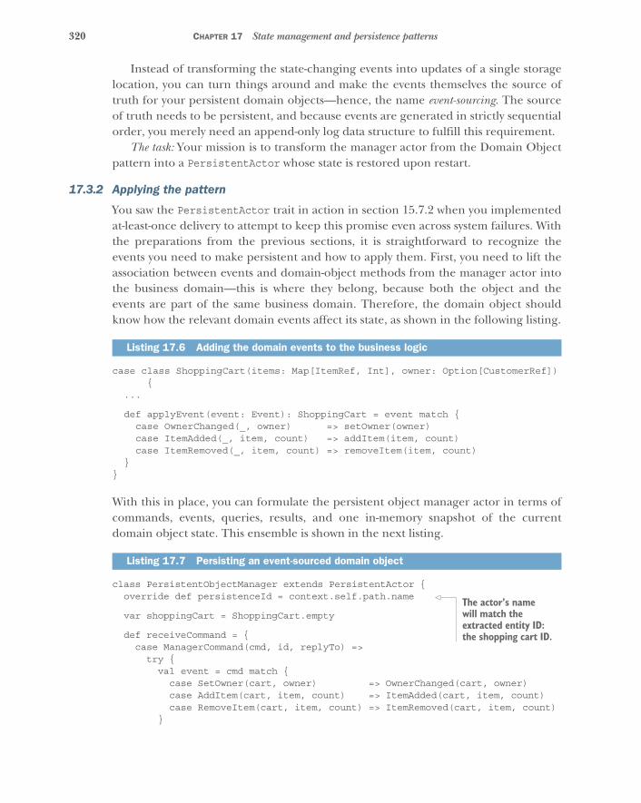
320 CHAPTER 17 State management and persistence patterns
Instead of transforming the state-changing events into updates of a single storagelocation, you can turn things around and make the events themselves the source oftruth for your persistent domain objects—hence, the name event-sourcing. The sourceof truth needs to be persistent, and because events are generated in strictly sequentialorder, you merely need an append-only log data structure to fulfill this requirement.
The task: Your mission is to transform the manager actor from the Domain Objectpattern into a PersistentActor whose state is restored upon restart.
17.3.2 Applying the pattern
You saw the PersistentActor trait in action in section 15.7.2 when you implementedat-least-once delivery to attempt to keep this promise even across system failures. Withthe preparations from the previous sections, it is straightforward to recognize theevents you need to make persistent and how to apply them. First, you need to lift theassociation between events and domain-object methods from the manager actor intothe business domain—this is where they belong, because both the object and theevents are part of the same business domain. Therefore, the domain object shouldknow how the relevant domain events affect its state, as shown in the following listing.
case class ShoppingCart(items: Map[ItemRef, Int], owner: Option[CustomerRef]){
...
def applyEvent(event: Event): ShoppingCart = event match {case OwnerChanged(_, owner) => setOwner(owner)case ItemAdded(_, item, count) => addItem(item, count)case ItemRemoved(_, item, count) => removeItem(item, count)
}}
With this in place, you can formulate the persistent object manager actor in terms ofcommands, events, queries, results, and one in-memory snapshot of the currentdomain object state. This ensemble is shown in the next listing.
class PersistentObjectManager extends PersistentActor {override def persistenceId = context.self.path.name
var shoppingCart = ShoppingCart.empty
def receiveCommand = {case ManagerCommand(cmd, id, replyTo) =>try {val event = cmd match {case SetOwner(cart, owner) => OwnerChanged(cart, owner)case AddItem(cart, item, count) => ItemAdded(cart, item, count)case RemoveItem(cart, item, count) => ItemRemoved(cart, item, count)
}
Listing 17.6 Adding the domain events to the business logic
Listing 17.7 Persisting an event-sourced domain object
The actor’s name will match the extracted entity ID: the shopping cart ID.
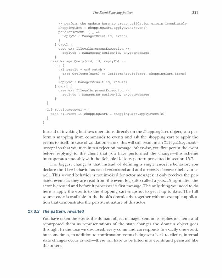
321The Event-Sourcing pattern
// perform the update here to treat validation errors immediatelyshoppingCart = shoppingCart.applyEvent(event)persist(event) { _ =>replyTo ! ManagerEvent(id, event)
}} catch {case ex: IllegalArgumentException =>replyTo ! ManagerRejection(id, ex.getMessage)
}case ManagerQuery(cmd, id, replyTo) =>try {val result = cmd match {case GetItems(cart) => GetItemsResult(cart, shoppingCart.items)
}replyTo ! ManagerResult(id, result)
} catch {case ex: IllegalArgumentException =>replyTo ! ManagerRejection(id, ex.getMessage)
}}
def receiveRecover = {case e: Event => shoppingCart = shoppingCart.applyEvent(e)
}}
Instead of invoking business operations directly on the ShoppingCart object, you per-form a mapping from commands to events and ask the shopping cart to apply theevents to itself. In case of validation errors, this will still result in an IllegalArgument-Exception that you turn into a rejection message; otherwise, you first persist the eventbefore replying to the client that you have performed the change—this schemeinteroperates smoothly with the Reliable Delivery pattern presented in section 15.7.
The biggest change is that instead of defining a single receive behavior, youdeclare the live behavior as receiveCommand and add a receiveRecover behavior aswell. This second behavior is not invoked for actor messages: it only receives the per-sisted events as they are read from the event log (also called a journal) right after theactor is created and before it processes its first message. The only thing you need to dohere is apply the events to the shopping cart snapshot to get it up to date. The fullsource code is available in the book’s downloads, together with an example applica-tion that demonstrates the persistent nature of this actor.
17.3.3 The pattern, revisited
You have taken the events the domain object manager sent in its replies to clients andrepurposed them as representations of the state changes the domain object goesthrough. In the case we discussed, every command corresponds to exactly one event;but sometimes, in addition to confirmation events being sent back to clients, internalstate changes occur as well—these will have to be lifted into events and persisted likethe others.
322 CHAPTER 17 State management and persistence patterns
It is important to note that the events that describe state changes of domainobjects are part of the business domain as well: they have business meaning outsidethe technical context of the program code. With this in mind, it may be appropriateto choose a smaller granularity for the events than would be the case by following thederivation from the Domain Object pattern followed here—this path is more useful asa learning guide and should not be taken to be a definition. Please refer to the event-sourcing literature for an in-depth treatment of how to design and evolve events.
17.3.4 Applicability
This pattern is applicable where the durability of an object’s state history is practicaland potentially interesting (you will hear more about this last part in the following sec-tion). A shopping cart may see some fluctuation before checkout, payment, and deliv-ery, but the total number of events within it should not exceed hundreds—thesecorrespond to manual user actions, after all. The state of a token bucket filter within anetwork router, on the other hand, changes constantly, goes back and forth throughthe same states, and may, most important, see trillions of changes within relativelyshort periods of time; it is therefore not likely to be practically persistable, let alone byusing event sourcing.
For domain objects that may accumulate state over a longer time period, andwhere the event reply during recovery may eventually take longer than is affordable,there is a workaround, but it should be used with care. From time to time, the domainobject’s snapshot state may be persisted together with the event sequence number it isbased on; then, recovery can start from this snapshot instead of having to go back tothe beginning of time. The problem with this approach is that changes to the domainlogic (bug fixes) can easily invalidate the snapshots, which fact must be recognizedand considered. The underlying issue is that although the events have meaning in thebusiness domain, the snapshot does not—it is just a projection of the implementationdetails of the domain object logic.
Event sourcing generally is not applicable in cases where it would be desirable todelete events from the log. Not only is the entire concept built on the notion of repre-senting immutable facts, but this desire usually arises when the persisted state does nothave meaning in the business domain—for example, when using a PersistentActoras a durable message queue. There are much more performant solutions to this prob-lem that are also easier to use: see, for example, Kafka (http://kafka.apache.org) andother distributed queues.
17.4 The Event Stream patternPublish the events emitted by a component so that the rest of the system can derive knowledgefrom them.
The events that a component stores in its log represent the sum of all the knowledge ithas ever possessed. This is a treasure trove for the rest of the system to delve into:although the shopping cart system is only interested in maintaining the current state ofcustomer activity, other concerns are tangential to it, such as tracking the popularity of
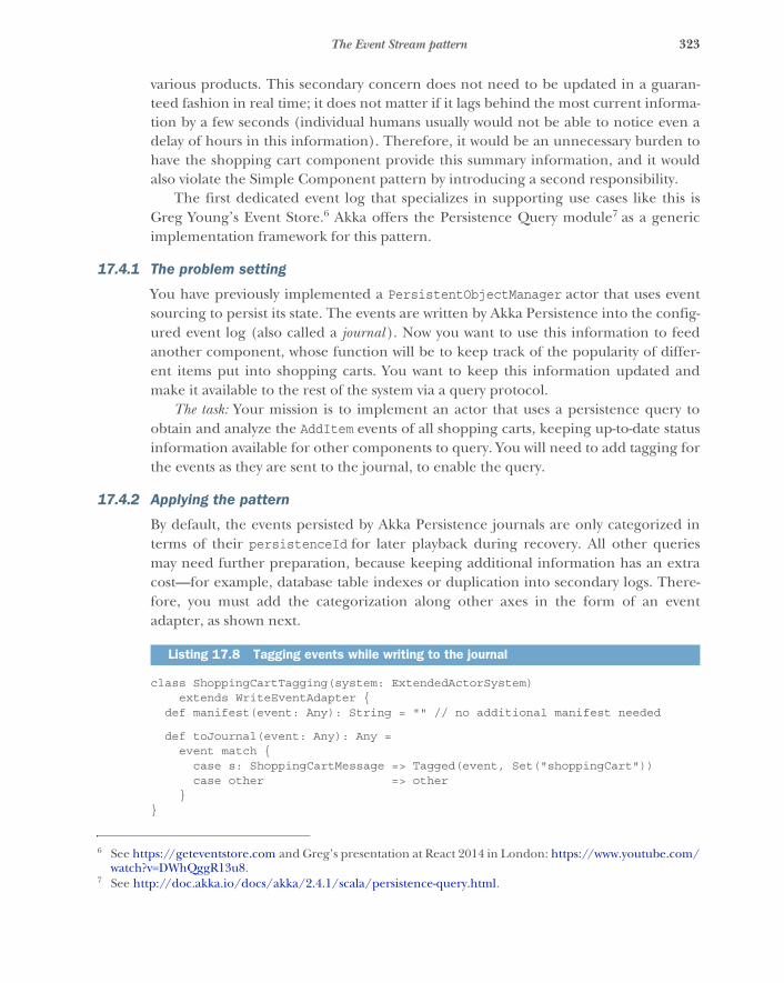
323The Event Stream pattern
various products. This secondary concern does not need to be updated in a guaran-teed fashion in real time; it does not matter if it lags behind the most current informa-tion by a few seconds (individual humans usually would not be able to notice even adelay of hours in this information). Therefore, it would be an unnecessary burden tohave the shopping cart component provide this summary information, and it wouldalso violate the Simple Component pattern by introducing a second responsibility.
The first dedicated event log that specializes in supporting use cases like this isGreg Young’s Event Store.6 Akka offers the Persistence Query module7 as a genericimplementation framework for this pattern.
17.4.1 The problem setting
You have previously implemented a PersistentObjectManager actor that uses eventsourcing to persist its state. The events are written by Akka Persistence into the config-ured event log (also called a journal ). Now you want to use this information to feedanother component, whose function will be to keep track of the popularity of differ-ent items put into shopping carts. You want to keep this information updated andmake it available to the rest of the system via a query protocol.
The task: Your mission is to implement an actor that uses a persistence query toobtain and analyze the AddItem events of all shopping carts, keeping up-to-date statusinformation available for other components to query. You will need to add tagging forthe events as they are sent to the journal, to enable the query.
17.4.2 Applying the pattern
By default, the events persisted by Akka Persistence journals are only categorized interms of their persistenceId for later playback during recovery. All other queriesmay need further preparation, because keeping additional information has an extracost—for example, database table indexes or duplication into secondary logs. There-fore, you must add the categorization along other axes in the form of an eventadapter, as shown next.
class ShoppingCartTagging(system: ExtendedActorSystem)extends WriteEventAdapter {
def manifest(event: Any): String = "" // no additional manifest needed
def toJournal(event: Any): Any =event match {
case s: ShoppingCartMessage => Tagged(event, Set("shoppingCart"))case other => other
}}
6 See https://geteventstore.com and Greg’s presentation at React 2014 in London: https://www.youtube.com/watch?v=DWhQggR13u8.
7 See http://doc.akka.io/docs/akka/2.4.1/scala/persistence-query.html.
Listing 17.8 Tagging events while writing to the journal
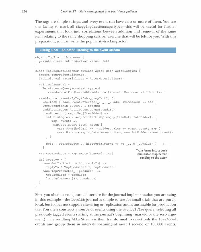
324 CHAPTER 17 State management and persistence patterns
The tags are simple strings, and every event can have zero or more of them. You usethis facility to mark all ShoppingCartMessage types—this will be useful for furtherexperiments that look into correlations between addition and removal of the sameitem relating to the same shopping cart, an exercise that will be left for you. With thispreparation, you can write the popularity-tracking actor.
object TopProductListener {private class IntHolder(var value: Int)
}
class TopProductListener extends Actor with ActorLogging {import TopProductListener._implicit val materializer = ActorMaterializer()
val readJournal =PersistenceQuery(context.system)
.readJournalFor[LeveldbReadJournal](LeveldbReadJournal.Identifier)
readJournal.eventsByTag("shoppingCart", 0).collect { case EventEnvelope(_, _, _, add: ItemAdded) => add }.groupedWithin(100000, 1.second).addAttributes(Attributes.asyncBoundary).runForeach { seq: Seq[ItemAdded] =>
val histogram = seq.foldLeft(Map.empty[ItemRef, IntHolder]) {(map, event) =>
map.get(event.item) match {case Some(holder) => { holder.value += event.count; map }case None => map.updated(event.item, new IntHolder(event.count))
}}self ! TopProducts(0, histogram.map(p => (p._1, p._2.value)))
}
var topProducts = Map.empty[ItemRef, Int]
def receive = {case GetTopProducts(id, replyTo) =>
replyTo ! TopProducts(id, topProducts)case TopProducts(_, products) =>
topProducts = productslog.info("new {}", products)
}}
First, you obtain a read-journal interface for the journal implementation you are usingin this example—the LevelDb journal is simple to use for small trials that are purelylocal, but it does not support clustering or replication and is unsuitable for productionuse. You then construct a source of events using the eventsByTag query, selecting allpreviously tagged events starting at the journal’s beginning (marked by the zero argu-ment). The resulting Akka Stream is then transformed to select only the ItemAddedevents and group them in intervals spanning at most 1 second or 100,000 events,
Listing 17.9 An actor listening to the event stream
Transforms into a trulyimmutable map before
sending to the actor
325The Event Stream pattern
whichever occurs first. Then, you mark the grouped source you have constructed up tothis point as having an asynchronous boundary around it—you want to inform AkkaStreams that it should run these steps in an actor that is separate from what follows,because you do not want the analysis process to influence the time-based grouping.The last step is to create a histogram that assigns the addition frequency to each type ofitem. To avoid creating a lot of garbage objects in the process, you use an immutablemap to hold mutable counters that are then updated in the foldLeft operation.
The resulting histograms are then sent to the actor wrapped in aTopProducts message at least once per second. The actor will store this informationand allow others to retrieve it with a GetTopProducts inquiry. The book’s downloadsinclude the full source, including a shopping cart simulator that creates enough activ-ity to see this in action.
17.4.3 The pattern, revisited
You have added a common categorization for all shopping cart events to thepersistence-journal configuration and used this from another actor that consumes theevents to derive a secondary view from the data. This secondary view does not hold thesame information; it removes the individual, fine-grained structure and introduces atime-based analysis into it—you have transformed one representation of informationinto a related but decoupled second representation of information.
In the example code above, the derived information is computed live, initiallycatching up from the beginning of the journal; but there are other approaches: youcould make TopProductListener persistent, storing up to the offset at which the jour-nal has already been analyzed and restarting at that point. You could also persist thecomputation results, aggregating the product-popularity history for yet another stepof analysis by another component.
Another use case for this pattern is to use the events emitted by the authoritativesource—the shopping cart’s business logic—to maintain another representation: forexample, in a relational database, allowing extensive, flexible querying capabilities.This could also be described in other terms: the normal form of the data is kept in theplace that accepts updates, whereas the information is asynchronously distributed toother places that hold the same data in denormalized form, optimized for retrieval andnot updates. This explains why the Event Stream pattern is central to the idea of CQRS.
Event streams may also transport information across different components andthereby into foreign bounded contexts where a different business domain defines theubiquitous language. In this case, the events need to be translated from one languageto the other by a component at the boundary. This component will usually live withinthe bounded context that consumes the stream, in order to free the source of datafrom having to know all of its consumers.
17.4.4 Applicability
An important property of event streams is that they do not represent the current stateof an object of the system: they only consist of immutable facts about the past that

326 CHAPTER 17 State management and persistence patterns
have already been committed to persistent storage. The components that emit theseevents may have progressed to newer states that will only be reflected later in the eventstream. The delay between event emission and stream dissemination is a matter ofjournal-implementation quality, but the fact that there is a significant delay is inherentto this architecture and cannot be avoided.
This implies that all operations that must interact with the authoritative, currentdata must be done on the original domain objects and cannot be decoupled by theEvent Stream pattern. For a more in-depth discussion, please refer back to chapter 8on delimited consistency.
For all cases where time delay and consistency restrictions are not an issue, it ispreferable to rely on this pattern instead of tightly coupling the source of changeswith its consumers. The Event Stream pattern provides the reliable dissemination ofinformation across the entire system, allowing all consumers to choose their desiredreliability by maintaining read offsets and persisting their state where needed. Thebiggest benefit is that this places the source of truth firmly in a single place—the jour-nal—and removes doubt as to the location from which different pieces of informationmay be derived.
17.5 SummaryWith this chapter, we conclude the third and final part of this book. The patterns inthe chapter provide guidance about how to structure the state management in Reac-tive systems and should be used in unison:
� The Domain Object pattern decouples the business domain representation frommessage-driven execution and allows domain experts to describe, specify, and testlogic without having to care about distributed system concerns or asynchrony.
� The Sharding pattern allows the efficient storage of an arbitrary number ofdomain objects, given a cluster with sufficient resources.
� The Event-Sourcing pattern turns the destructive update of persistent state intoa nondestructive accumulation of information by recognizing that the full his-tory of an object’s state is represented by the change events it emits.
� The Event Stream pattern uses these persisted change events to implement reli-able and scalable dissemination of information throughout the entire systemwithout burdening the originating domain objects with this task. The emittedevents can be distributed by the supporting infrastructure and consumed by anynumber of interested clients to derive new information from their combinationor to maintain denormalized views onto the data that are optimized for queries.
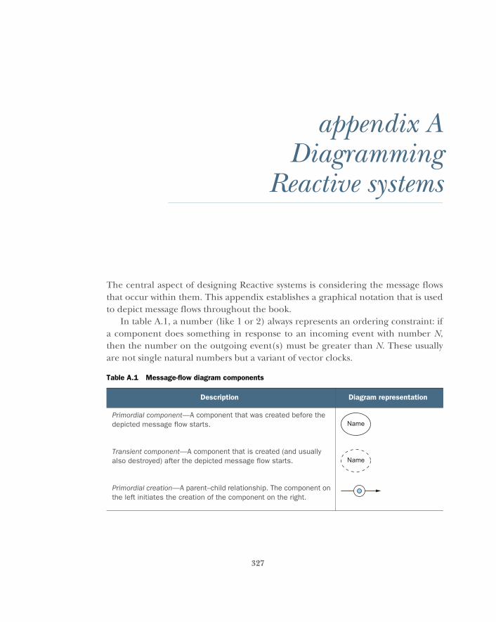
327
appendix ADiagramming
Reactive systems
The central aspect of designing Reactive systems is considering the message flowsthat occur within them. This appendix establishes a graphical notation that is usedto depict message flows throughout the book.
In table A.1, a number (like 1 or 2) always represents an ordering constraint: ifa component does something in response to an incoming event with number N,then the number on the outgoing event(s) must be greater than N. These usuallyare not single natural numbers but a variant of vector clocks.
Table A.1 Message-flow diagram components
Description Diagram representation
Primordial component—A component that was created before the depicted message flow starts.
Transient component—A component that is created (and usually also destroyed) after the depicted message flow starts.
Primordial creation—A parent–child relationship. The component on the left initiates the creation of the component on the right.
Name
Name
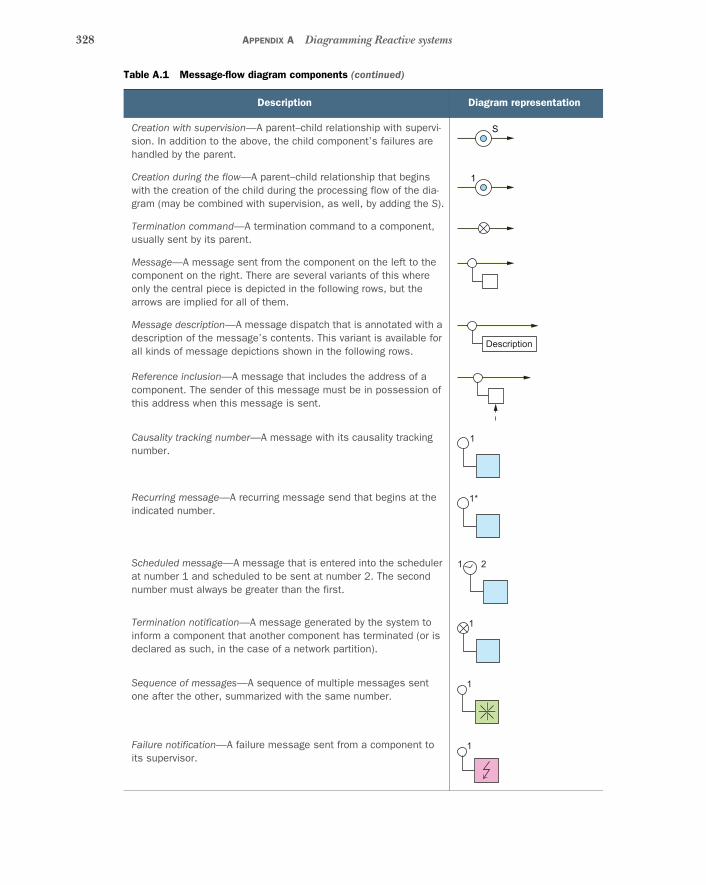
328 APPENDIX A Diagramming Reactive systems
Creation with supervision—A parent–child relationship with supervi-sion. In addition to the above, the child component’s failures are handled by the parent.
Creation during the flow—A parent–child relationship that begins with the creation of the child during the processing flow of the dia-gram (may be combined with supervision, as well, by adding the S).
Termination command—A termination command to a component, usually sent by its parent.
Message—A message sent from the component on the left to the component on the right. There are several variants of this where only the central piece is depicted in the following rows, but the arrows are implied for all of them.
Message description—A message dispatch that is annotated with a description of the message’s contents. This variant is available for all kinds of message depictions shown in the following rows.
Reference inclusion—A message that includes the address of a component. The sender of this message must be in possession of this address when this message is sent.
Causality tracking number—A message with its causality tracking number.
Recurring message—A recurring message send that begins at the indicated number.
Scheduled message—A message that is entered into the scheduler at number 1 and scheduled to be sent at number 2. The second number must always be greater than the first.
Termination notification—A message generated by the system to inform a component that another component has terminated (or is declared as such, in the case of a network partition).
Sequence of messages—A sequence of multiple messages sent one after the other, summarized with the same number.
Failure notification—A failure message sent from a component to its supervisor.
Table A.1 Message-flow diagram components (continued)
Description Diagram representation
S
1
Description
1
1*
21
1
1
1

329
appendix BAn illustrated example
This appendix demonstrates a hands-on approach to Reactive system design, illus-trating the tenets of the Manifesto through concrete examples. We encounter thesewhile solving issues that come up when building applications that are scalable to aglobal user base. Globally distributed interaction is also at the heart of the exampleproblem we will tackle here: you will build an app with which users can share theirlocation in real time and in which they can watch others move on a map. An exten-sion to this core function is that users can exchange text messages with other usersin their vicinity.
To be more precise, the location of each individual is used for two purposes:
� Each user can share their location with a set of other users who can track iton a map.
� Each user can share their location in anonymized form so that aggregateddata can be displayed to all users (such as, “37 users per hour moving west-ward on highway 50 through Dodge City, Kansas”).
B.1 Geographic partitioningHow do you construct such an application? One thing is clear: most of the informa-tion processing will be local, as in pertaining to some specific place on Earth.Therefore, you need to divide the Earth into regions, starting perhaps with oneregion per continent (plus some for the oceans). The granularity of countrieswithin each continent varies greatly, so for simplicity you will continue by cuttingeach continent along lines of latitude and longitude. The result is 16 tiles, 4 by 4, asshown in figure B.1.

330 APPENDIX B An illustrated example
Continue this process recursively, as shown in the figure, quadrupling the resolutionin longitude and latitude at each step until it is fine enough—say, less than one mile ineither direction.1 Now you have a way to associate every possible location on Earthwith a map region. For example, consider Dodge City, Kansas:
� It is in North America ...� … in tile number 11 (at level 1)� … within that in subtile number 14 (at level 2)� … within that in subtile number 9 (at level 3)� … and so on
When someone shares their location, the lowest-level map tile containing that loca-tion must be informed that there is a user positioned within it. Other users looking atthe same map tile can register for (anonymized) updates about what happens in that
1 There are more-refined ways to partition a map, but this is a sufficiently simple approach that allows you toconcentrate on the essence of the program. For further study, please refer to information about R-trees orother literature.
1 2 3 4
5 6 7 8
9 10 11 12
13 14 15 16
Figure B.1 The North American continent, divided recursively into 4-by-4 tiles
331Planning the flow of information
little map area. The influx of position updates for each of these lowest-level map tilesis given by how many users are logged in to the application in that geographic area,and the outflux conversely is given by how many users are watching that precise maptile. Therefore, no matter how many users may eventually be using this application,you can regulate the amount of information processing per map tile by choosing thegranularity—which means choosing the number of levels in your partitioning.
The first important point about implementing a Reactive application is thus toidentify the minimal unit of processing that can operate independently. You can exe-cute the bookkeeping functions of where people are moving within a map tile sepa-rately from the bookkeeping of all other map tiles, possibly on different computers oreven in different data centers—each catering to one continent, for example. You canadapt the processing capacity of the overall system to the load by growing or shrinkingthe number of these processing units: merging two or more into one is not a problem,because they were independent to begin with, so the only limit is given by how fineyou can make this split. The result is a system that can be scaled up and down elasti-cally and can thereby react to varying load.
But we are getting ahead of ourselves, because the current design is not yet com-plete. Users will always—knowingly or not—push applications to their limits, and inthis case a simple exploit will ruin your calculations: zoom out on the map tile you arewatching, and your interest will cover a large number of map tiles, resulting in a corre-spondingly large rate of position updates being requested and sent. This will over-whelm the curious user’s client with too much data; and if too many users do this,your expectations about the outflux of data from a map tile will be exceeded. Both ofthese factors cause more communication bandwidth to be used than you planned for,and the consequence will be system overload and failure.
B.2 Planning the flow of informationIn a Reactive application, each part—each independent unit of processing—reacts tothe information it receives. Therefore, it is very important to consider which informa-tion flows where and how large each of these flows is. The principle data flows for theexample application are shown in figure B.2.
In the example application, you could define that each user sends one positionupdate every 5 seconds while the app is running on their mobile device—phone, tab-let, or watch. You can ascertain that by writing the client app yourself or by enforcingthis limit in the API that the application offers to the author of client apps. Each posi-tion update will amount to roughly 100 bytes, give or take (10 bytes each for time-stamp, latitude, and longitude; 40 bytes for lower-level protocol overhead, such asTCP/IPv4; plus additional space for encryption, authentication, and integrity data).Factoring in some overhead for congestion avoidance and message schedulingbetween multiple clients, you will assume that each client’s position-update streamcosts roughly 50 bytes per second on average.
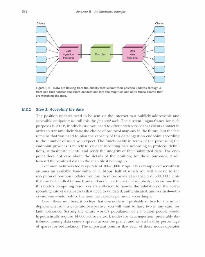
332 APPENDIX B An illustrated example
B.2.1 Step 1: Accepting the data
The position updates need to be sent via the internet to a publicly addressable andaccessible endpoint; we call this the front-end node. The current lingua franca for suchpurposes is HTTP, in which case you need to offer a web service that clients contact inorder to transmit their data; the choice of protocol may vary in the future, but the factremains that you need to plan the capacity of this data-ingestion endpoint accordingto the number of users you expect. The functionality in terms of the processing theendpoint provides is merely to validate incoming data according to protocol defini-tions, authenticate clients, and verify the integrity of their submitted data. The end-point does not care about the details of the position; for those purposes, it willforward the sanitized data to the map tile it belongs to.
Common networks today operate at 100–1,000 Mbps. This example conservativelyassumes an available bandwidth of 50 Mbps, half of which you will allocate to thereception of position updates; you can therefore arrive at a capacity of 500,000 clientsthat can be handled by one front-end node. For the sake of simplicity, also assume thatthis node’s computing resources are sufficient to handle the validation of the corre-sponding rate of data packets that need to validated, authenticated, and verified—oth-erwise, you would reduce the nominal capacity per node accordingly.
Given these numbers, it is clear that one node will probably suffice for the initialdeployment from a data-rate perspective; you will want to have two in any case, forfault tolerance. Serving the entire world’s population of 7.5 billion people wouldhypothetically require 14,000 active network nodes for data ingestion, preferably dis-tributed among data centers spread across the planet and with a healthy percentageof spares for redundancy. The important point is that each of these nodes operates
Dataingestionfront end
Mapview
front endMap tiles
Clients Clients
Figure B.2 Data are flowing from the clients that submit their position updates through a front end that handles the client connections into the map tiles and on to those clients that are watching the map.
333Planning the flow of information
fully independently of all the others: no communication or coordination is necessarybetween them in order to unwrap, check, and route position updates, which enablesyou to do this simple back-of-an-envelope estimation of what you need to grow thispart of the system to a given scale.
B.2.2 Step 2: Getting the data to their geographical home
The function of the front-end node is to accept and sanitize the incoming data andthen send it on to the map tile it belongs to. The rough estimate of the data rateslikely applies to the sanitized data as well; you will trade data integrity and authentica-tion data for client IDs and associated data. Those were implicit to the client’s networkconnection with the front-end node, but now they need to be explicitly incorporatedin the data packet on the network connection between the front-end node and eachmap tile for which it receives updates.
Hosting a map tile on a single network node translates to the ability to handle500,000 clients within that map area. Therefore, the tiles need to be small enoughthat this limit is never violated. If all map tiles are the same size—that is, if the samelevel of partitioning is used throughout the entire map—then some tiles will be muchmore frequented than others. Densely populated areas like Manhattan, San Francisco,and Tokyo will be close to the limit, whereas most of the tiles covering the PacificOcean will rarely have anyone move on them. You can account for this asymmetry bycollocating a number of low-rate map tiles on the same processing node while keep-ing high-rate tiles on their own nodes.
Recall that it is crucial for the front-end nodes to be able to perform their workindependently of each other, in order to be able to adjust the system capacity by add-ing or removing nodes; you will see another reason for this when we discuss how toreact to failures within the system. But how can you achieve consensus about whichmap tile is hosted by which internal network node? The answer is that you make therouting process simple and deterministic by having a map tile–allocation service dis-seminate a data structure that describes the placement of all tiles. This data structurecan be optimized and compressed by using the hierarchical structure of the map par-titioning. Another consideration is that once this application has grown beyond a sin-gle data center, you can route clients to the correct data center that hosts thegeographic region in which they are currently located, at which point each front-endnode only needs to know the location of tiles for which its data center is responsible.
An interesting question at this point is how you react to changes in your applica-tion deployment: when a node dies or is manually replaced, or when map tiles arereshuffled to adapt to changed user habits, how is this communicated to the front-endnodes? And what happens to updates that are sent to the “wrong” node? The straight-forward answer is that during such a change, there will be a time window duringwhich position updates pertaining to certain map tiles will be lost. As long as you canreasonably expect this outage to be temporary and on the order of a few seconds long,then chances are, nobody will notice; one or two missing location updates will not
334 APPENDIX B An illustrated example
have a major effect on the aggregated statistics of a map tile (or can be compensatedfor), and not seeing a friend’s position move on a map for a few seconds once in ablue moon is unlikely to be of consequence.
B.2.3 Step 3: Relocating the data for efficient querying
You have now ensured that the influx of each map tile will not exceed a certain thresh-old that is given by the capabilities of the processing hardware. The issue that sparkedthis foray into data-rate planning was that the outflux is not limited, because clientscan zoom out and thereby request and consume more data than they produce andsubmit.
When you visualize the map that will show the movement of all the anonymizedusers within its area, what do you expect to see when you zoom out? You certainly can-not follow each individual and track their course once there are more than a handfulof them in the region you are looking at. And when you zoom out to view all ofEurope, the best you can hope for is aggregate information about population densityor average velocity—you will not be able to discern individual positions.
In the same way you designed the information flow for data ingestion, you canlook at data extraction. Looking at a map of Europe is an easy case, because it doesnot require much data: the large-scale averages and aggregate numbers do notchange quickly. The largest data demand will be given by users who are being trackedindividually while being closely zoomed in. Assume that you allow up to 30 users to beshown individually before switching to an aggregated view, and further assume thatyou can limit the data consumption of the aggregate view to be equivalent to those 30tracked points. One update will have to contain a timestamp and up to 30 tuples ofidentifier, latitude, and longitude. These can presumably be compressed because theyare in a small map region, perhaps amounting to 15 bytes for each 3-tuple. Includingsome overall status information, you arrive at roughly 500 bytes for a single update,which means about 100 bytes per second on average for 1 update every 5 seconds.
Calculating again with an available network bandwidth of 50 Mbps, where half isallocated to client-facing traffic, this yields a capacity of serving 200,000 map viewsfrom a single front-end node (subtracting 20% overhead).2 These front-end nodes arealso answering requests from clients, but they are of a different kind than the nodesresponsible for data ingestion. When a user logs in to the app, their mobile device willbegin sending position updates to the ingestion nodes; and every time the userchanges the map view on their device, a request will be sent to the front-end nodes,registering for the updates to be displayed on the screen. This naturally decouples thetwo activities and allows a user to view a far-away map region without additional head-aches for implementers.
2 Sending from one host to a multitude of others requires less overhead than having a multitude of clients sendto a single host. See also the TCP incast problem (www.pdl.cmu.edu/Incast).
335Planning the flow of information
At this point, the big question is, where do these map-view front-end nodes gettheir data? You have so far only provided the position updates to the lowest-level maptiles, and requesting their updates in order to calculate aggregate values will not work:serving 200,000 views could mean having to listen to the updates of millions of maptiles, corresponding to hundreds of terabytes per second.
There is only one solution to this dilemma: you must filter and preprocess the dataat their source. Each lowest-level map tile knows the precise location and movementof all users within its geographic region, and it is easy to calculate their number, aver-age movement speed and direction, center of gravity, and other interesting quantities.These summary data are then sent every 5 seconds to the map tile one level up thatcontains this tile.
As a concrete example, consider that the lowest level is seven partition steps belowthe North American continent. The center of Dodge City, Kansas, on level 7 calculatesthe summary information and sends it to the encompassing level-6 map tile, whichalso receives such summaries from the 15 other level-7 neighbors it contains. Thegood thing about aggregate quantities such as user count, center of gravity, and so onis that they can be merged with one another to aggregate at higher and higher granu-larity (summing up the users, calculating the weighted center of gravity of the individ-ual centers, and so on). The level-6 map tile performs this aggregation every 5 secondsand sends its summary up to its encompassing level-5 parent, and this process isrepeated all the way up to the top level.
The data rate needed for this transfer is fixed to the size of the summary datapacket: once every 5 seconds for each sender, and 16 times that amount for eachrecipient. You can assume that each data packet should fit within 100 bytes. In manycases, these data do not even need to travel across the network, because sparsely popu-lated map areas are collocated on the same processing node, and the summary levelscan be collocated with the lowest-level map tiles as well.
When a map view front-end node needs to access the summary information at level4 to display a map spanning approximately 100 by 100 miles, it will request the sum-mary information from the roughly 16 level-4 map tiles covering the viewport. Know-ing that network bandwidth will likely be the most limiting factor for these view front-end nodes, you can optimize their use internally by redirecting external clientsbetween them such that one front-end node handles many similar requests—for thesame approximate geographic region at the same summary level. That way, a node cansatisfy multiple clients from the same internal data stream. This is shown in figure B.3.
The one piece that still needs consideration is how to handle the fully zoomed-incase: when a user points their map at Big Ben to see all the tourists milling about inthe center of London, care must be taken to not send all the data from that highly fre-quented map tile to the front-end node, because that could potentially take up all theavailable bandwidth by itself. We said earlier that a map should display only summaryinformation as soon as the number of individual data points exceeds 30. In this case,
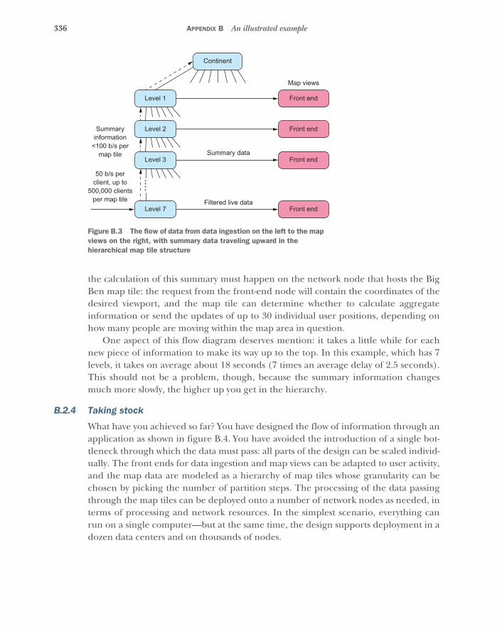
336 APPENDIX B An illustrated example
the calculation of this summary must happen on the network node that hosts the BigBen map tile: the request from the front-end node will contain the coordinates of thedesired viewport, and the map tile can determine whether to calculate aggregateinformation or send the updates of up to 30 individual user positions, depending onhow many people are moving within the map area in question.
One aspect of this flow diagram deserves mention: it takes a little while for eachnew piece of information to make its way up to the top. In this example, which has 7levels, it takes on average about 18 seconds (7 times an average delay of 2.5 seconds).This should not be a problem, though, because the summary information changesmuch more slowly, the higher up you get in the hierarchy.
B.2.4 Taking stock
What have you achieved so far? You have designed the flow of information through anapplication as shown in figure B.4. You have avoided the introduction of a single bot-tleneck through which the data must pass: all parts of the design can be scaled individ-ually. The front ends for data ingestion and map views can be adapted to user activity,and the map data are modeled as a hierarchy of map tiles whose granularity can bechosen by picking the number of partition steps. The processing of the data passingthrough the map tiles can be deployed onto a number of network nodes as needed, interms of processing and network resources. In the simplest scenario, everything canrun on a single computer—but at the same time, the design supports deployment in adozen data centers and on thousands of nodes.
Front end
Map views
Summary data
Filtered live data
50 b/s perclient, up to
500,000 clientsper map tile
Summaryinformation
<100 b/s permap tile
Level 2 Front end
Level 3 Front end
Level 7 Front end
Continent
Level 1
Figure B.3 The flow of data from data ingestion on the left to the map views on the right, with summary data traveling upward in the hierarchical map tile structure
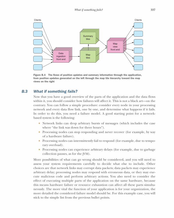
337What if something fails?
B.3 What if something fails?Now that you have a good overview of the parts of the application and the data flowswithin it, you should consider how failures will affect it. This is not a black art—on thecontrary. You can follow a simple procedure: consider every node in your processingnetwork and every data flow link, one by one, and determine what happens if it fails.In order to do this, you need a failure model. A good starting point for a network-based system is the following:
� Network links can drop arbitrary bursts of messages (which includes the casewhere “the link was down for three hours”).
� Processing nodes can stop responding and never recover (for example, by wayof a hardware failure).
� Processing nodes can intermittently fail to respond (for example, due to tempo-rary overload).
� Processing nodes can experience arbitrary delays (for example, due to garbagecollection pauses, as for the JVM).
More possibilities of what can go wrong should be considered, and you will need toassess your system requirements carefully to decide what else to include. Otherchoices are that network links may corrupt data packets; data packets may experiencearbitrary delay; processing nodes may respond with erroneous data, or they may exe-cute malicious code and perform arbitrary actions. You also need to consider theeffect of executing multiple parts of the application on the same hardware, becausethis means hardware failure or resource exhaustion can affect all these parts simulta-neously. The more vital the function of your application is for your organization, themore detailed the considered failure model should be. For this example case, you willstick to the simple list from the previous bullet points.
Mapview
front end
Summarytiles
Dataingestionfront end
Maptiles
Clients Clients
Figure B.4 The flows of position updates and summary information through the application, from position updates generated on the left through the map tile hierarchy toward the map views on the right
338 APPENDIX B An illustrated example
B.3.1 A client fails
Mobile devices can fail for a host of reasons ranging from their destruction, to emptybatteries, to a software crash. Users are used to dealing with those (replacing thephone, charging it, or restarting the phone or an app), and they do not expect thingsto work while their device has failed. Therefore, you only need to concern yourselfwith the effects of a failure on the internal processes of your application.
First, the stream of position updates will cease. When this happens, we might wantto generate a visible representation for others who were seeing this user on their map,perhaps changing the color of the marker or making it translucent. The lowest-levelmap tile will be responsible for tracking whether the users that move within it are alive.
Second, the map view for the client will no longer be able to send updates, net-work buffers will fill up, and socket writes will eventually time out. Therefore, youmust protect the map view front ends from becoming clogged with defunct client reg-istrations. This is commonly done by including a heartbeat signal in the protocol andclosing the connection when the heartbeats stop coming in.
B.3.2 A client network link fails
From the perspective of the application, it does not matter why position updatescease: the failure of the mobile device or its software is indistinguishable from a failednetwork connection. The consequences are thus the same as discussed in the previoussection.
From the perspective of the client, on the other hand, in general it is not distin-guishable whether the front-end node it was connected to failed or the network link isat fault: both will look largely the same. Hence, the remedy is also the same as dis-cussed in the next section.
B.3.3 A data-ingestion front-end node fails
The role of such a node is to sanitize and forward position updates, so a failure meansthe client will eventually run into trouble sending data to it. In the same way the mapview monitors the health of its client using heartbeats, you can also solve this situation:the client will reconnect to a different front-end node if something goes amiss, regard-less of whether the failure is temporary or fatal. This is typically realized by placing anetwork load balancer in front of the pool of real web service endpoint nodes, a strat-egy that is possible only because it does not matter exactly which node a client sendsits updates through into the system: the gateways are all equally suited.
In any case, the mobile app should let the user know that there is trouble with theconnection. This is much better than having the user figure it out via missing activ-ity—that way, you can clearly distinguish between problems local to the app and prob-lems with network communication.
The other action that must be taken upon the failure of a front-end node is toproperly dispose of it (stopping the application, taking down the machine) and spinup a new instance that starts from a known good configuration. The precise kind of
339What if something fails?
failure is irrelevant: the overall system returns to a fully fault-tolerant state by doingthe most robust, simplest thing possible. Consequently, whatever went wrong is con-tained within the removed node and cannot spread to the others. The recovery mustbe initiated by a separate service that cannot be infected with the failure; this is calleda supervisor service. The supervisor monitors its subordinates for proper function and,as described, takes corrective action when necessary.
B.3.4 A network link from data ingestion to map tile fails
This situation has no negative impact on the overall function of the application. Itseffect is the same as if the connected clients stop sending position updates to theaffected map tile. Therefore, depending on which communication protocol is usedfor this network link, both parties should monitor the health of their connection andrelease all associated resources if the connection becomes stale.
The simplicity of this problem and of its solution is due to the fact that neitherside—front-end node nor map tile—depends on the other for correct function. Dataflow in only one direction from one to the other, and if data stop flowing, both sidesknow how to deal with the situation. This is called loose coupling, and it is essential forachieving robust failure handling.
B.3.5 A map tile–processing node fails
Because this is the heart of the application, we will consider the different failuremodes more carefully:
� Hardware failure—In case of a node crash, all map tiles that were hosted by thisnode will be failed with it. The front-end nodes will eventually notice and stopsending updates, but you need to recover from this situation. The front endscannot be responsible for that, because it would involve coordination of whoperforms the necessary steps. Therefore, you install a supervisor service thatmonitors all map tile nodes and spins up a new instance in case of a crash. Wediscussed earlier that this service will then update the routing knowledge of allfront-end nodes so they begin sending updates to the new destination.
� Temporary overload—If a map tile sees more traffic than was planned for, it willneed to be moved to a separate processing node; otherwise, it will takeresources from all of its collocated neighbors, and the overload will spread andturn into a node failure. This scenario must also be handled by the supervisorservice, which for this purpose needs to gather usage statistics and, if necessary,rebalance the map tiles across the available nodes. If the load is increasing in allparts of the system, then this supervisor should also be able to request that newnodes be brought online so the additional load can be handled. Conversely,once load drops significantly, the supervisor should reallocate map tiles to freeup and release redundant nodes.
� Permanent overload—It is also possible that the partitioning of your map is notadequate and a single map tile is hit consistently by too many requests. Becauseyou cannot split or reallocate this map tile, such a failure will need to raise an
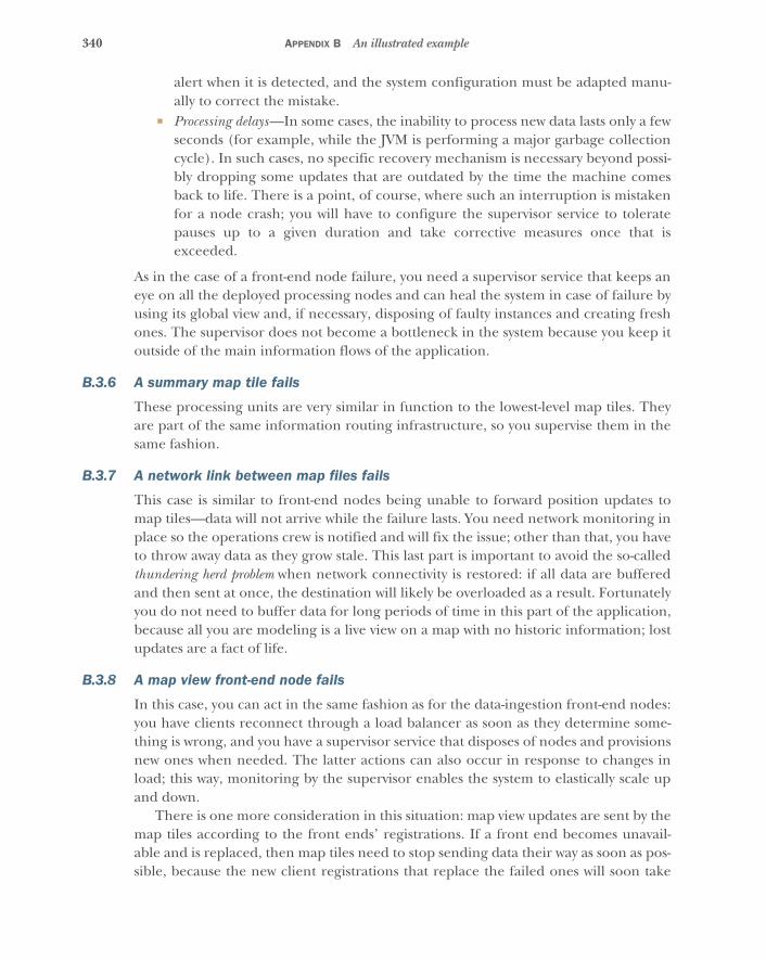
340 APPENDIX B An illustrated example
alert when it is detected, and the system configuration must be adapted manu-ally to correct the mistake.
� Processing delays—In some cases, the inability to process new data lasts only a fewseconds (for example, while the JVM is performing a major garbage collectioncycle). In such cases, no specific recovery mechanism is necessary beyond possi-bly dropping some updates that are outdated by the time the machine comesback to life. There is a point, of course, where such an interruption is mistakenfor a node crash; you will have to configure the supervisor service to toleratepauses up to a given duration and take corrective measures once that isexceeded.
As in the case of a front-end node failure, you need a supervisor service that keeps aneye on all the deployed processing nodes and can heal the system in case of failure byusing its global view and, if necessary, disposing of faulty instances and creating freshones. The supervisor does not become a bottleneck in the system because you keep itoutside of the main information flows of the application.
B.3.6 A summary map tile fails
These processing units are very similar in function to the lowest-level map tiles. Theyare part of the same information routing infrastructure, so you supervise them in thesame fashion.
B.3.7 A network link between map files fails
This case is similar to front-end nodes being unable to forward position updates tomap tiles—data will not arrive while the failure lasts. You need network monitoring inplace so the operations crew is notified and will fix the issue; other than that, you haveto throw away data as they grow stale. This last part is important to avoid the so-calledthundering herd problem when network connectivity is restored: if all data are bufferedand then sent at once, the destination will likely be overloaded as a result. Fortunatelyyou do not need to buffer data for long periods of time in this part of the application,because all you are modeling is a live view on a map with no historic information; lostupdates are a fact of life.
B.3.8 A map view front-end node fails
In this case, you can act in the same fashion as for the data-ingestion front-end nodes:you have clients reconnect through a load balancer as soon as they determine some-thing is wrong, and you have a supervisor service that disposes of nodes and provisionsnew ones when needed. The latter actions can also occur in response to changes inload; this way, monitoring by the supervisor enables the system to elastically scale upand down.
There is one more consideration in this situation: map view updates are sent by themap tiles according to the front ends’ registrations. If a front end becomes unavail-able and is replaced, then map tiles need to stop sending data their way as soon as pos-sible, because the new client registrations that replace the failed ones will soon take
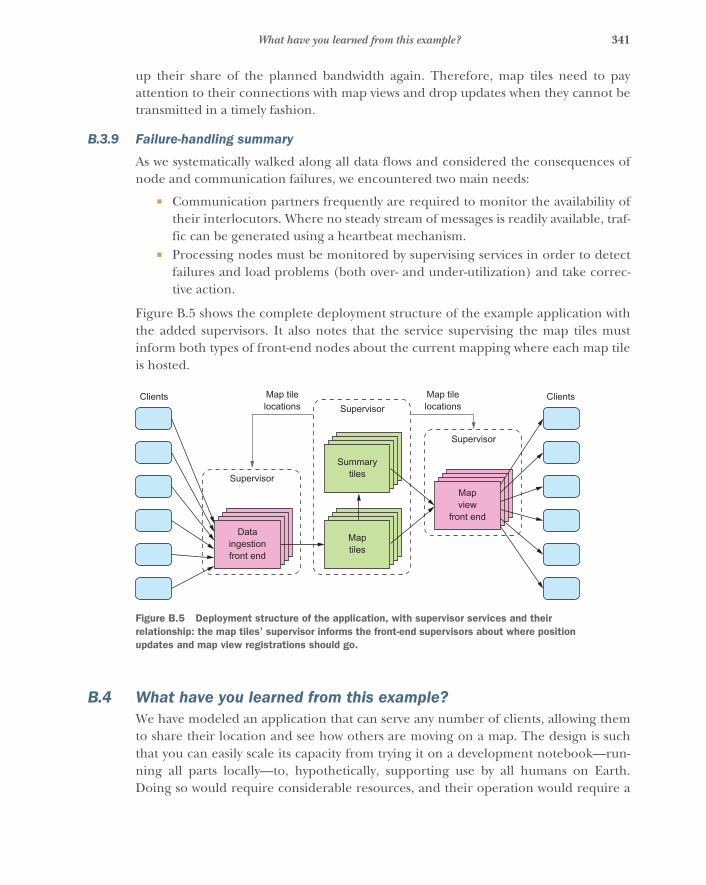
341What have you learned from this example?
up their share of the planned bandwidth again. Therefore, map tiles need to payattention to their connections with map views and drop updates when they cannot betransmitted in a timely fashion.
B.3.9 Failure-handling summary
As we systematically walked along all data flows and considered the consequences ofnode and communication failures, we encountered two main needs:
� Communication partners frequently are required to monitor the availability oftheir interlocutors. Where no steady stream of messages is readily available, traf-fic can be generated using a heartbeat mechanism.
� Processing nodes must be monitored by supervising services in order to detectfailures and load problems (both over- and under-utilization) and take correc-tive action.
Figure B.5 shows the complete deployment structure of the example application withthe added supervisors. It also notes that the service supervising the map tiles mustinform both types of front-end nodes about the current mapping where each map tileis hosted.
B.4 What have you learned from this example?We have modeled an application that can serve any number of clients, allowing themto share their location and see how others are moving on a map. The design is suchthat you can easily scale its capacity from trying it on a development notebook—run-ning all parts locally—to, hypothetically, supporting use by all humans on Earth.Doing so would require considerable resources, and their operation would require a
Mapview
front end
SummarytilesSupervisor
Dataingestionfront end
Maptiles
Clients ClientsSupervisor
Map tilelocations
Map tilelocations
Supervisor
Figure B.5 Deployment structure of the application, with supervisor services and their relationship: the map tiles’ supervisor informs the front-end supervisors about where position updates and map view registrations should go.

342 APPENDIX B An illustrated example
large effort, but from the technical side, the application is prepared. You haveachieved that by considering foremost the information that will be processed by theapplication and the main flows of data that are necessary.
The most important characteristic is that data always flow forward from theirsource (position updates of mobile devices) via processing stages (map tiles) towardtheir final destination (the map displayed on mobile devices). The processing nodeson this path of information are loosely coupled in that failures of one are dealt with thesame way as communication outages.
You build resilience into a design by considering the major parts of the applicationto be isolated from each other, communicating only over networks. If multiple partsare running on the same machine, a failure of the machine—or resource exhaustioncaused by one part—will make all of them fail simultaneously. It is especially import-ant for achieving fault tolerance that the services tasked with repairing the systemafter failures—the supervisors—are isolated from other parts and are running ontheir own resources.
In this way, you have experienced all the main tenets of the Reactive Manifesto:
� The application is responsive due to resource planning and map partitioning.� The application is resilient because you built in mechanisms to repair failed
components and connect to properly functioning ones.� The application is elastic because it monitors the load experienced by the differ-
ent parts and can redistribute the load when it changes, a feat that is possibledue to the lack of global bottlenecks and processing units that can work inde-pendently of each other.
� All of this is enabled by message-driven communication between the parts of theapplication.
B.5 Where do you go from here?The attentive reader will have noticed that not all functionality has been implementedfor the example application. We have detailed how to implement the second require-ment of sharing anonymized position updates, but we left out the first requirementthat a user should be able to share their location with a set of other users. It will be agood exercise to apply the same reasoning in this case, designing additional parts ofthe application that keep data in a user-centric fashion rather than the map-centricone you have built so far. Modifications of the trust relationship between users willhave to be processed more reliably than position updates, but they will also be vastlyless frequent.
343
appendix CThe Reactive Manifesto
Version 2.0, published on September 16, 2014
C.1 Main textOrganisations working in disparate domains are independently discovering pat-terns for building software that look the same. These systems are more robust,more resilient, more flexible and better positioned to meet modern demands.
These changes are happening because application requirements have changeddramatically in recent years. Only a few years ago a large application had tens ofservers, seconds of response time, hours of offline maintenance and gigabytes ofdata. Today applications are deployed on everything from mobile devices to cloud-based clusters running thousands of multi-core processors. Users expect millisec-ond response times and 100% uptime. Data is measured in Petabytes. Today’sdemands are simply not met by yesterday’s software architectures.
We believe that a coherent approach to systems architecture is needed, and webelieve that all necessary aspects are already recognised individually: we want sys-tems that are Responsive, Resilient, Elastic and Message Driven. We call these Reac-tive Systems.
Systems built as Reactive Systems are more flexible, loosely-coupled and scalable(see section C.2.15). This makes them easier to develop and amenable to change.They are significantly more tolerant of failure (see section C.2.7) and when failuredoes occur they meet it with elegance rather than disaster. Reactive Systems arehighly responsive, giving users (see section C.2.17) effective interactive feedback.
Reactive Systems are:
344 APPENDIX C The Reactive Manifesto
� Responsive: The system (see section C.2.16) responds in a timely manner if at allpossible. Responsiveness is the cornerstone of usability and utility, but morethan that, responsiveness means that problems may be detected quickly anddealt with effectively. Responsive systems focus on providing rapid and consis-tent response times, establishing reliable upper bounds so they deliver a consis-tent quality of service. This consistent behaviour in turn simplifies errorhandling, builds end user confidence, and encourages further interaction.
� Resilient: The system stays responsive in the face of failure (see section C.2.7).This applies not only to highly-available, mission critical systems—any system thatis not resilient will be unresponsive after a failure. Resilience is achieved by repli-cation (see section C.2.13), containment, isolation (see section C.2.8) and dele-gation (see section C.2.5). Failures are contained within each component (seesection C.2.4), isolating components from each other and thereby ensuring thatparts of the system can fail and recover without compromising the system as awhole. Recovery of each component is delegated to another (external) compo-nent and high-availability is ensured by replication where necessary. The client ofa component is not burdened with handling its failures.
� Elastic: The system stays responsive under varying workload. Reactive Systemscan react to changes in the input rate by increasing or decreasing the resources(see section C.2.14) allocated to service these inputs. This implies designs thathave no contention points or central bottlenecks, resulting in the ability toshard or replicate components and distribute inputs among them. Reactive Sys-tems support predictive, as well as Reactive, scaling algorithms by providing rel-evant live performance measures. They achieve elasticity (see section C.2.6) in acost-effective way on commodity hardware and software platforms.
� Message Driven: Reactive Systems rely on asynchronous (see section C.2.1) message-passing (see section C.2.10) to establish a boundary between components thatensures loose coupling, isolation, and location transparency (see section C.2.9).This boundary also provides the means to delegate failures (see section C.2.7) asmessages. Employing explicit message-passing enables load management, elasticity,and flow control by shaping and monitoring the message queues in the system andapplying back-pressure (see section C.2.2) when necessary. Location transparentmessaging as a means of communication makes it possible for the management offailure to work with the same constructs and semantics across a cluster or within asingle host. Non-blocking (see section C.2.11) communication allows recipients toonly consume resources (see section C.2.14) while active, leading to less systemoverhead.
Large systems are composed of smaller ones and therefore depend on the Reactiveproperties of their constituents. This means that Reactive Systems apply design princi-ples so these properties apply at all levels of scale, making them composable. The larg-est systems in the world rely upon architectures based on these properties and serve
345Glossary
the needs of billions of people daily. It is time to apply these design principles con-sciously from the start instead of rediscovering them each time.
C.2 Glossary
C.2.1 Asynchronous
The Oxford Dictionary defines asynchronous as “not existing or occurring at the sametime.” In the context of this manifesto we mean that the processing of a requestoccurs at an arbitrary point in time, sometime after it has been transmitted from cli-ent to service. The client cannot directly observe, or synchronize with, the executionthat occurs within the service. This is the antonym of synchronous processing whichimplies that the client only resumes its own execution once the service has processedthe request.
C.2.2 Back-Pressure
When one component (see section C.2.4) is struggling to keep-up, the system (seesection C.2.16) as a whole needs to respond in a sensible way. It is unacceptable forthe component under stress to fail catastrophically or to drop messages in an uncon-trolled fashion. Since it can’t cope and it can’t fail it should communicate the factthat it is under stress to upstream components and so get them to reduce the load.This back-pressure is an important feedback mechanism that allows systems to grace-fully respond to load rather than collapse under it. The back-pressure may cascade allthe way up to the user, at which point responsiveness may degrade, but this mecha-nism will ensure that the system is resilient under load, and will provide informationthat may allow the system itself to apply other resources to help distribute the load,see Elasticity (section C.2.6).
C.2.3 Batching
Current computers are optimized for the repeated execution of the same task:instruction caches and branch prediction increase the number of instructions thatcan be processed per second while keeping the clock frequency unchanged. Thismeans that giving different tasks to the same CPU core in rapid succession will notbenefit from the full performance that could otherwise be achieved: if possible weshould structure the program such that its execution alternates less frequentlybetween different tasks. This can mean processing a set of data elements in batches, orit can mean performing different processing steps on dedicated hardware threads.
The same reasoning applies to the use of external resources (see section C.2.14)that need synchronization and coordination. The I/O bandwidth offered by persistentstorage devices can improve dramatically when issuing commands from a singlethread (and thereby CPU core) instead of contending for bandwidth from all cores.Using a single entry point has the added advantage that operations can be reorderedto better suit the optimal access patterns of the device (current storage devices per-form better for linear than random access).
346 APPENDIX C The Reactive Manifesto
Additionally, batching provides the opportunity to share out the cost of expensiveoperations such as I/O or expensive computations. For example, packing multipledata items into the same network packet or disk block to increase efficiency andreduce utilisation.
C.2.4 Component
What we are describing is a modular software architecture, which is a very old idea,see for example Parnas (1972).1 We are using the term “component” due to its prox-imity with compartment, which implies that each component is self-contained, encap-sulated and isolated (see section C.2.8) from other components. This notion appliesforemost to the runtime characteristics of the system, but it will typically also bereflected in the source code’s module structure as well. While different componentsmight make use of the same software modules to perform common tasks, the pro-gram code that defines the top-level behavior of each component is then a module ofits own. Component boundaries are often closely aligned with Bounded Contexts2 inthe problem domain. This means that the system design tends to reflect the problemdomain and so is easy to evolve, while retaining isolation. Message protocols (see sec-tion C.2.12) provide a natural mapping and communications layer between BoundedContexts (components).
C.2.5 Delegation
Delegating a task asynchronously (see section C.2.1) to another component (see sec-tion C.2.4) means that the execution of the task will take place in the context of thatother component. This delegated context could entail running in a different errorhandling context, on a different thread, in a different process, or on a different net-work node, to name a few possibilities. The purpose of delegation is to hand over theprocessing responsibility of a task to another component so that the delegating com-ponent can perform other processing or optionally observe the progress of the dele-gated task in case additional action is required such as handling failure or reportingprogress.
C.2.6 Elasticity (in contrast to Scalability)
Elasticity means that the throughput of a system scales up or down automatically tomeet varying demand as resource is proportionally added or removed. The systemneeds to be scalable (see section C.2.15) to allow it to benefit from the dynamic addi-tion, or removal, of resources at runtime. Elasticity therefore builds upon scalabilityand expands on it by adding the notion of automatic resource (see section C.2.14)management.
1 https://www.cs.umd.edu/class/spring2003/cmsc838p/Design/criteria.pdf2 http://martinfowler.com/bliki/BoundedContext.html
347Glossary
C.2.7 Failure (in contrast to Error)
A failure is an unexpected event within a service that prevents it from continuing tofunction normally. A failure will generally prevent responses to the current, and possi-bly all following, client requests. This is in contrast with an error, which is an expectedand coded-for condition—for example an error discovered during input validation,that will be communicated to the client as part of the normal processing of the mes-sage. Failures are unexpected and will require intervention before the system (see sec-tion C.2.16) can resume at the same level of operation. This does not mean thatfailures are always fatal, rather that some capacity of the system will be reduced follow-ing a failure. Errors are an expected part of normal operations, are dealt with immedi-ately and the system will continue to operate at the same capacity following an error.
Examples of failures are hardware malfunction, processes terminating due to fatalresource exhaustion, program defects that result in corrupted internal state.
C.2.8 Isolation (and Containment)
Isolation can be defined in terms of decoupling, both in time and space. Decouplingin time means that the sender and receiver can have independent life-cycles—they donot need to be present at the same time for communication to be possible. It isenabled by adding asynchronous (see section C.2.1) boundaries between the compo-nents (see section C.2.4), communicating through message-passing (see sectionC.2.10). Decoupling in space (defined as Location Transparency, see section C.2.9)means that the sender and receiver do not have to run in the same process, but wher-ever the operations division or the runtime itself decides is most efficient—whichmight change during an application’s lifetime.
True isolation goes beyond the notion of encapsulation found in most object-oriented languages and gives us compartmentalization and containment of:
� State and behavior: it enables share-nothing designs and minimizes contentionand coherence cost (as defined in the Universal Scalability Law;3
� Failures: it allows failures (see section C.2.7) to be captured, signalled and man-aged at a fine-grained level instead of letting them cascade to other compo-nents.
Strong isolation between components is built on communication over well-definedprotocols (see section C.2.12) and enables loose coupling, leading to systems that areeasier to understand, extend, test and evolve.
C.2.9 Location Transparency
Elastic (see section C.2.6) systems need to be adaptive and continuously react tochanges in demand, they need to gracefully and efficiently increase and decreasescale. One key insight that simplifies this problem immensely is to realize that we are
3 http://www.perfdynamics.com/Manifesto/USLscalability.html
348 APPENDIX C The Reactive Manifesto
all doing distributed computing. This is true whether we are running our systems on asingle node (with multiple independent CPUs communicating over the QPI link) oron a cluster of nodes (with independent machines communicating over the network).Embracing this fact means that there is no conceptual difference between scaling ver-tically on multi-core or horizontally on the cluster.
If all of our components (see section C.2.4) support mobility, and local communi-cation is just an optimization, then we do not have to define a static system topologyand deployment model upfront. We can leave this decision to the operations person-nel and the runtime, which can adapt and optimize the system depending on how itis used.
This decoupling in space (see the definition for Isolation, section C.2.8), enabledthrough asynchronous (see section C.2.1) message-passing (see section C.2.10), anddecoupling of the runtime instances from their references is what we call LocationTransparency. Location Transparency is often mistaken for “transparent distributedcomputing”, while it is actually the opposite: we embrace the network and all its con-straints—like partial failure, network splits, dropped messages, and its asynchronousand message-based nature—by making them first class in the programming model,instead of trying to emulate in-process method dispatch on the network (à la RPC, XAetc.). Our view of Location Transparency is in perfect agreement with A Note On Dis-tributed Computing 4 by Waldo et al.
C.2.10 Message-Driven (in contrast to Event-Driven)
A message is an item of data that is sent to a specific destination. An event is a signalemitted by a component (see section C.2.4) upon reaching a given state. In a message-driven system addressable recipients await the arrival of messages and react to them,otherwise lying dormant. In an event-driven system notification listeners are attachedto the sources of events such that they are invoked when the event is emitted. Thismeans that an event-driven system focuses on addressable event sources while a mes-sage-driven system concentrates on addressable recipients. A message can contain anencoded event as its payload.
Resilience is more difficult to achieve in an event-driven system due to the short-lived nature of event consumption chains: when processing is set in motion and listen-ers are attached in order to react to and transform the result, these listeners typicallyhandle success or failure (see section C.2.7) directly and in the sense of reportingback to the original client. Responding to the failure of a component in order torestore its proper function, on the other hand, requires a treatment of these failuresthat is not tied to ephemeral client requests, but that responds to the overall compo-nent health state.
4 http://citeseerx.ist.psu.edu/viewdoc/summary?doi=10.1.1.41.7628
349Glossary
C.2.11 Non-Blocking
In concurrent programming an algorithm is considered non-blocking if threads com-peting for a resource do not have their execution indefinitely postponed by mutualexclusion protecting that resource. In practice this usually manifests as an API thatallows access to the resource (see section C.2.14) if it is available otherwise it immedi-ately returns informing the caller that the resource is not currently available or thatthe operation has been initiated and not yet completed. A non-blocking API to aresource allows the caller the option to do other work rather than be blocked waitingon the resource to become available. This may be complemented by allowing the cli-ent of the resource to register for getting notified when the resource is available orthe operation has completed.
C.2.12 Protocol
A protocol defines the treatment and etiquette for the exchange or transmission ofmessages between components (see section C.2.4). Protocols are formulated as rela-tions between the participants to the exchange, the accumulated state of the protocoland the allowed set of messages to be sent. This means that a protocol describes whichmessages a participant may send to another participant at any given point in time.Protocols can be classified by the shape of the exchange, some common classes arerequest-reply, repeated request-reply (as in HTTP), publish-subscribe, and stream(both push and pull).
In comparison to local programming interfaces a protocol is more generic since itcan include more than two participants and it foresees a progression of the state ofthe message exchange; an interface only specifies one interaction at a time betweenthe caller and the receiver.
It should be noted that a protocol as defined here just specifies which messagesmay be sent, but not how they are sent: encoding, decoding (i.e., codecs), and trans-port mechanisms are implementation details that are transparent to the components’use of the protocol.
C.2.13 Replication
Executing a component (see section C.2.4) simultaneously in different places isreferred to as replication. This can mean executing on different threads or threadpools, processes, network nodes, or computing centers. Replication offers scalability(see section C.2.15), where the incoming workload is distributed across multipleinstances of a component, or resilience, where the incoming workload is replicated tomultiple instances which process the same requests in parallel. These approaches canbe mixed, for example by ensuring that all transactions pertaining to a certain user ofthe component will be executed by two instances while the total number of instancesvaries with the incoming load, (see Elasticity, section C.2.6).

350 APPENDIX C The Reactive Manifesto
C.2.14 Resource
Everything that a component (see section C.2.4) relies upon to perform its function isa resource that must be provisioned according to the component’s needs. Thisincludes CPU allocation, main memory and persistent storage as well as network band-width, main memory bandwidth, CPU caches, inter-socket CPU links, reliable timerand task scheduling services, other input and output devices, external services likedatabases or network file systems etc. The elasticity (see section C.2.6) and resilienceof all these resources must be considered, since the lack of a required resource willprevent the component from functioning when required.
C.2.15 Scalability
The ability of a system (see section C.2.16) to make use of more computing resources(see section C.2.14) in order to increase its performance is measured by the ratio ofthroughput gain to resource increase. A perfectly scalable system is characterized byboth numbers being proportional: a twofold allocation of resources will double thethroughput. Scalability is typically limited by the introduction of bottlenecks or syn-chronization points within the system, leading to constrained scalability, see Amdahl’sLaw and Gunther’s Universal Scalability Model.5
C.2.16 System
A system provides services to its users (see section C.2.17) or clients. Systems can belarge or small, in which case they comprise many or just a few component (see sectionC.2.4). All components of a system collaborate to provide these services. In many casesthe components are in a client-server relationship within the same system (considerfor example front-end components relying upon back-end components). A systemshares a common resilience model, by which we mean that failure (see section C.2.7)of a component is handled within the system, delegated (see section C.2.5) from onecomponent to the other. It is useful to view groups of components within a system assubsystems if they are isolated (see section C.28) from the rest of the system in theirfunction, resources (see section C.2.14) or failure modes.
C.2.17 User
We use this term informally to refer to any consumer of a service, be that a human oranother service.
5 http://blogs.msdn.com/b/ddperf/archive/2009/04/29/parallel-scalability-isn-t-child-s-play-part-2-amdahl-s-law-vs-gunther-s-law.aspx

351
Symbols! operator 260? operator 139, 272
Aaborted jobs 209AccessService 251ACID 2.0 32–34ACK (positive acknowledg-
ment) 74Active-Active Replication
pattern 171, 210–219Active-Passive Replication
pattern 184–197ActorRef 83, 133, 139, 189,
260, 262, 274Actors 58–62
combining with other constructs 62
differences between Erlang and Akka 60–61
fault tolerance via supervision 58–59
inherently asynchronous 58location transparency 59mocking 152–153
mocks 152reverse onion testing
pattern 153stubs 152–153
no concurrency within one Actor 59–60
reactive evaluation of 62ActorSystem 143, 156, 262AddItem event 323aggregate roots 106Aggregator pattern 277, 281
Agha, Gul 269Akka
Cluster Sharding module316
differences between Erlang and 60–61
overview 73algorithmically 316Amazon Web Services. See AWSAmazonClientException 222AmazonEC2AsyncClient
223–224AmazonEC2Client 223, 225Amdahl’s Law 15, 23–24AMQP (Advanced Message
Queueing Protocol)262
andThen method 20anonymized updates 330anyOf method 55API (application program-
ming interface)overview 129resilience of 158
application resilience154–158
API resilience 158execution resilience
155–158ArithmeticException 46Armstrong, Joe 39Ask pattern 269, 274, 278AskPattern support 272assertions 144–145async() method 146async-await construct 56
AsyncContext class 21asynchronous communica-
tion, vs. synchronous71–73
asynchronous message passing116
asynchronous, defined 345asynchronously testing reac-
tive applications132–150
assertions 144–145asynchronous errors, assert-
ing absence of147–150
blocking message receivers133–135
fully asynchronous tests145–147
messages, asserting absence of 141–142
synchronous execution engines, providing142–144
timeouts, choosing 135–141scaling timeouts for dif-
ferent test environ-ments 135–136
testing service timings136–137
testing service-level agreements 138–141
at-least-once delivery 78, 290at-most-once delivery 78await() method 146AWS (Amazon Web
Services) 222
index

352 INDEX
Bback pressure 73, 345Baquero, Carlos 201BASE 33–34batching, defined 345–346BatchJob message 238BDD (behavior-driven
development) 130BEAM VM 60Bees With Machine Guns 154behavior-transport mechanism
244big ball of mud scenario 10big data 235binary object storage 111bind() function Monad 143Birman, Ken 218black-box vs. white-box tests
130–131blocking managed patterns
248–253blocking message receivers
133–135Bonér, Jonas 166bounded context 312bugs 5bulkheading 28, 182Business Handshake pattern
286, 292–293
CCalculatorClient 309callback hell 49callbacks 69CallingThreadDispatcher
143–144canceled status 201, 206Candea, George 171causality tracking number 328Chaos Gorilla 160Chaos Kong 160Chaos Monkey 160, 174Church, Alonzo 41Circuit Breaker pattern 8, 86,
177–182circuit breakers 29–30, 182CircuitBreaker 180, 264CircuitBreakerOpenException
179CKite project 199client interface module 178ClientInterface class 207–208Clojure 47close state 179Cluster extension 208
cluster resilience 159Cluster Sharding support, Akka
318Cluster Singleton mechanism
186Cluster Singleton Proxy helper
195coherency factor 25collect combinator 139command-query responsibility
segregation. See CQRScommitment, ownership and
100–102communicating sequential
processes 50–52compartmentalization 28, 122compartmentalize 27compensating transaction 284CompletableFuture 48, 54–55CompletionStage class 20Complex Command pattern
234–244, 247component tests 129component, defined 346composable Futures, improving
parallelism with 20–21concurrency
shared-state 117sharing nothing 116–117
conflict-free replicated data types 8
conflict-free updates 198connection-abort errors 172consensus 198consensus-based multiple-
master replication 7consensus-based replication 8consistency
delimitedencapsulated modules 106grouping data and behav-
ior according to trans-action boundaries 107
modeling workflows across transactional boundaries 107–108
persisting isolated scopes of consistency 111–112
segregating responsibilities109–111
unit of consistency108–109
strong, losing 31–35accepting updates 34–35ACID 2.0 33–34
consistent response time 17consolidate function 193, 195consumed flag 306contacts module, Gmail 93, 95contacts service 88contention 42context switch 22context.watch() method 214contextual handlers 153Coordinator 215copy-on-read semantics 43copy-on-write semantics 43CounterTooLargeException 60CPU cores 117CPU utilization 297CPU-bound operations 50CQRS (command-query
responsibility segrega-tion) 110
crash-only software principle171
CRDTs (conflict-free replicated data types) 34, 117, 203
creation during flow 328creation with supervision 328Cuke4Duke 130
Ddata-center resilience 160DataElement 240DatagramPacket 258Datalog 114DDD (domain-driven design)
122, 282, 312deadlocks 134DeathWatch feature 176, 288debug logging 85declarative data flow, logic
programming and113–115
dedicated heartbeat messages175
delegation, defined 346delimited consistency 282
encapsulated modules 106grouping data and behavior
according to transac-tion boundaries 107
modeling workflows across transactional boundar-ies 107–108
persisting isolated scopes of consistency 111–112
segregating responsibilities109–111
unit of consistency 108–109

353INDEX
deliver() method 290delivery guarantees 76–78DeMarco, Tom 163dependencies, vs. descendant
modules 94–96dependency resolution 88dependent modules 101deployment scale, estimating
123descendant modules, vs.
dependencies 94–96direct method invocations 73Disruptor 47–48distributed components
overview 153–154testing 151
distributed consensus 106Distributed Data, Akka 203,
207distribution 27divide and conquer principle
312divide et regna 91, 100, 124dividing up problems
advantages of specification and testing 97–98
dependencies vs. descendant modules 94–96
hierarchical problem decomposition 92–93
horizontal and vertical scalability 98–99
Domain Object pattern312–316
domain, processes of 122domain-driven design. See DDDdomain-specific failure
injectors 158domain-specific language.
See DSLdoTimeouts() function 216Drop pattern 301–306dropFactor 303dropThreshold 303DSL (domain-specific
language) 130, 240DummyWork message 299durable message queues 121Duration.Zero 181dynamic composition 88–89dynamic push-pull 295, 298
Eearly reactive solutions 39–40EchoService 140, 145, 147
effectful code 115elastic applications 342elasticity
defined 346overview 154
encapsulated modules 106, 111EOF (end-of-file) marker 141Erlang 40
differences between Akka and 60–61
overview 39–40error conditions 129Error Kernel pattern 5, 104,
166–171Evans, Eric 107, 312event log 321event loops 49–50, 69event sourcing 112Event Stream pattern 322–326event-based systems, vs.
message-based 69–71events, as messages 78–80eventsByTag query 324Event-Sourcing pattern
319–322eventual consistency 286eventually construct 144evictFinished function 217exactly once delivery 78executing status 201, 206execution resilience 155–158execution schedules 151ExecutionContext 142, 223–224ExpectError message 150expectMsg() method 135ExpectNominal message 150expectNoMsg() method 142explicit message passing 82–84external DSL 241external resilience 155
Ffailover 185failure notification 328FailureInjectorTransport-
Adapter class 158FailureParent class 157failures 337–341
client failure 337–338client network link
failure 338coping with 7–8data-ingestion front-end
node failure 338–339defined 347
map tile-processing node fails failure 339–340
map view front-end node failure 340–341
network link between map files failure 340
network link from data inges-tion to map tile failure339
ownership andcommitment and 100–102lifecycle control and
102–103reacting to 26–31
circuit breakers 29–30compartmentalization and
bulkheading 28supervision 30–31
resilience and 104See also recovery patterns
fault tolerance, via supervision58–59
favicon.ico 50Filter operation 242final keyword 44
Java 42first-class citizens, functions as
46Fischer, Lynch, Paterson.
See FLPflatMap method 20, 143flow control 9, 73–74, 121flow control patterns
Drop pattern 301–306Managed Queue pattern
298–301Pull pattern 294–298Throttling pattern 306–310
flow of information, planning 331–337
accepting the data 332–333getting data to their geo-
graphical home333–334
relocating data for efficient querying 334–336
flow of messagesestimating rates and deploy-
ment scale 123identifying resilience
limitations 122–123modeling processes of
domain 122planning for control of 124pushing data forward
120–121

354 INDEX
FLP (Fischer, Lynch, Paterson)218
ForkJoinPool 48, 249, 252fortune command 101Forward Flow pattern 275–277Fowler, Martin 319Fox, Armando 171FreeBSD 101fromUnknown function 214,
216front-end node 332FullTotal 271fully asynchronous tests
145–147functional programming
41–46, 115–116functions as first-class citizens
46immutability 41–44referential transparency
44–45side effects 45–46
functions, as first-class citizens46
Future placeholder 19Future.firstCompletedOf()
method 281Future.sequence() method
140Futures
improving parallelism with20–21
overview 52–56
GGarcia-Molina, Hector 282gating 181Gatling 154GCounter 203geographic partitioning
329–331GetFrontPage 277GetSingle request 195getSocketAddress() method
258GetTopProducts 325Ghosh, Debasish 241glitches, avoiding 115Gmail 93Google Compute Engine 222goroutines 51granularity level 74Graph 241–242green threads 22, 48–49
grouping data and behavior, according to transac-tion boundaries 107
guardianActor 262Gunther, Neil J. 24
Hhardware failure 26, 339HdrHistogram 161heartbeats 175Helland, Pat 106, 109, 284Helper method 188hierarchical problem decompo-
sition 92–93horizontal scalability 87, 98–99HttpServer class 200HttpService class 200human failure 26hypervisors 131Hystrix library 177
II/O-bound loops 50IllegalArgumentException
315, 321Images 14immutability 41–44impure 41IncomingQueue actor 305information flow. See flow of
information, planninginfrastructure resilience
158–160cluster resilience 159data-center resilience 160network resilience (LAN and
WAN) 159node and machine resilience
159–160in-memory map 186input rates, estimating 123InRange 242inspect() method 133integration tests 129internal DSL 241internal resilience 155IPC (interprocess communica-
tion) 11isolation 122, 347
Jjava.util.concurrent.Future 223JDBC (Java Database
Connectivity) 248JMeter 151
Job message 299job scheduling 164JobRejected message 301journals 321, 323JRE (Java Runtime Environ-
ment) 238JsValue 187
KKafka 322key-value store 186Known state 214KVStore class 200KVStoreBootstrap 200
Llambda expression 46Lamport, Leslie 199, 210LAN (local area network)
resilience 159latency
analyzing with shared resource 15–16
maximum, limiting with queue 16–17
reducing via parallelism18–20
left status 206let it crash principle 59Let-It-Crash pattern 5, 171–177LevelDb journal 324lifecycle control, ownership
and 102–103Little’s Law 15Lloyd, Wyatt 218load, coping with 5–7local messages, passing 84–85location transparency 59
defined 347–348dynamic composition 88–89explicit message passing
83–84fallacy of transparent remot-
ing 82–83horizontal scalability 87message loss 85–87optimization of local message
passing 84–85overview 81–82testing simplified using
87–88logic programming 114loose coupling 339loosely coupled nodes 342low-latency search function 92

355INDEX
Mmail module, Gmail 93mailbox 73managed blocking
overview 252patterns for 248–253
Managed Queue pattern298–301
managed queues 298ManagerRejection message
315many-to-one model 22map method 143map tile 333Marz, Nathan 47master-slave replication 185maxLag parameter 191maxParallelism 140measure() method 147Median object 242Meijer, Erik 57merge function 205, 207, 210MergeLogic 238merging statuses 205message flow patterns
Aggregator pattern 277–281Ask pattern 269–274Business Handshake pattern
286–293Forward Flow pattern
275–277Request-Response
pattern 263–264Saga pattern 282–286Self-Contained Message
pattern 265–268message-based systems, vs.
event-based systems69–71
message-delivery guarantees 77message-driven, defined 348messages
absence of, asserting141–142
flow ofcontrol of 73–74estimating rates and
deployment scale 123identifying resilience
limitations 122–123modeling processes of
domain 122planning for control
of 124pushing data
forward 120–121
in message-flow diagram 328passing of
asynchronous 71–73delivery guarantees 76–78event-based vs. message-
based 69–71events as messages 78–80flow control 73–74overview 67–68synchronous 71–73, 80vertical scalability 68–69
method call 83misc pack 92Mocha 146mocking actors 152–153
mocks 152reverse onion testing pattern
153stubs 152–153
modeling, processes of domain122
ModifyFailure 209module boundaries 109Multiple-Master Replication
patterns 197–210conflict-free replicated data
types 203–210Applying pattern 204–209pattern, revisited 209–210
consensus-based replication198–201
Applying pattern 199–200pattern, revisited 200–201
replication with conflict detection and resolu-tion 201–203
Applying pattern 201–202pattern, revisited 202–203
mutable state 41MyEmailResult 273
NNACK (negative acknowledg-
ment) 74Netflix Simian Army tool suite.
See Simian Armynetwork I/O layer, Akka 79network resilience 159next() method 46nextInt 303nextReply variable 215NIC (network interface
controller) 79node and machine resilience
159–160node failure 173
Node.js 49non-blocking communication
344non-blocking, defined 349nondeterminism
functional reactive program-ming 115–116
logic programming and declarative data flow 113–115
shared-state concurrency117
sharing nothing simplifies concurrency 116–117
nondeterministic systems150–154
distributed components153–154
execution schedules 151mocking actors 152–153
mocks 152reverse onion testing
pattern 153stubs 152–153
testing distributed compo-nents 151
nonreactive components, integrating 10–11
NoOverrides 280null 16Nygard, Michael 177
Ooctets 256offline mode 9offline status 89one-way messaging 134open state 179operational transformation
technique 34optimistic replication 7Orleans framework, Microsoft
319ORMap (observed-remove
map) 207ORset (observed-remove set)
207OTP (Open Telecom Platform)
59outgoing events 327OutOfMemoryError 60, 238,
304overload 181ownership 94
commitment and 100–102lifecycle control and 102–103

356 INDEX
PPaaS (platform as a service)
154Pacemaker pattern 174parallel execution 19parallelism 18–23
improving with composable Futures 20–21
limits of 23–25Amdahl's Law 23–24Universal Scalability
Law 24–25paying for serial illusion
21–23reducing latency via 18–20
parallelism-max setting 141ParallelSLATester 140, 147partial failure 82partition 159passing messages
delivery guarantees 76–78event-based vs. message-
based 69–71events as messages 78–80flow control 73–74overview 67–68synchronous message passing
80synchronous vs. asynchro-
nous 71–73vertical scalability 68–69
PatienceConfiguration 145permanent overload 339persist method 179, 181persistence patterns
Domain Object pattern312–316
Event Stream pattern322–326
Event-Sourcing pattern319–322
Sharding pattern 316–319persistenceId 290, 323persistent storage 185PersistentActor trait 320, 322PersistentObjectManager
actor 323PersistentSam 290persisting isolated scopes of
consistency 111–112placeholders 83platform as a service. See PaaSplay-json library 187PNCounter 207poolSize 251
positive acknowledgment (ACK) 74
potentially remote messages 84Preguiça, Nuno 201primordial component 327primordial creation 327principled failure handling
171process analysis 51process manager 282, 285process() function 239processes of domain, modeling
122processing delays 340ProcessingLogic 237Prolog 114PromiseActorRef 272Promises 52–56Props object 143, 317protocol, defined 349proxy object 88Pull pattern 294–298pure functional programming
118pure functions 45push mode 297pushing data forward 120–121Put command 187pyramid of doom 49
Qquery facilities 92queue
limiting maximum latency with 16–17
overview 73
Rrate limiting 179–180, 307ratePerSecond 309RDBMSs (relational database
management systems)284
reactive applications, anatomy of 4–5
reactive design patterns, need for 35–38
bringing programming mod-els closer to real world37–38
managing complexity 36–37Reactive Extensions 57–58Reactive Manifesto
losing strong consistency31–35
accepting updates 34–35ACID 2.0 33–34
need for reactive design patterns 35–38
bringing programming models closer to real world 37–38
managing complexity36–37
parallelism 18–23Improving parallelism with
composable Futures20–21
limits of parallel execution23–25
paying for serial illusion21–23
reducing latency via parallelization 18–20
reacting to failure 26–31circuit breakers 29–30compartmentalization and
bulkheading 28supervision 30–31
reacting to users 12–17analyzing latency with
shared resource 15–16limiting maximum latency
with queue 16–17traditional approach
13–15terminology 345–350
asynchronous 345back-pressure 345batching 345–346component 346delegation 346elasticity (in contrast to
scalability) 346failure (in contrast to
error) 347isolation (and
containment) 347location transparency
347–348message-driven (in con-
trast to event-driven)348
non-blocking 349protocol 349replication 349resource 350scalability 350system 350user 350

357INDEX
read repair 202readPersisted method 190receiveCommand 321ReceiveTimeout
mechanism 272, 288recovery patterns
Circuit Breaker pattern177–182
Error Kernel pattern166–171
Let-It-Crash pattern 171–177Simple Component pattern
162–166recurring message 328reference inclusion 328referential opacity 44referential transparency 44–45Reliable Delivery pattern.
See Business Hand-shake pattern
remote call 83remoting, fallacy of 82–83rendezvous messaging 51Replica actor 217replicate() method 189ReplicatedData interface 205replication patterns
Active-Active Replication pattern 210–219
Active-Passive Replication pattern 184–197
Multiple-Master Replication patterns 197–210
conflict-free replicated data types 203–210
consensus-based replication 198–201
replication with conflict detection and resolution 201–203
replication, defined 349Replicator.Changed message
209ReplyState 213replyTo 148, 267representational state transfer.
See RESTrequestMessageBytes 22requestQueue 300Request-Response pattern
263–264request-thread pool 14resilience 27, 154–160
application resilience155–158
API resilience 158
execution resilience155–158
infrastructure resilience158–160
cluster resilience 159data-center resilience 160network resilience (LAN
and WAN) 159node and machine
resilience 159–160limitations of, identifying
122–123on all levels 104
resilient applications 342Resource Encapsulation
pattern 221, 226–229Resource Loan pattern
229–234Resource Pool pattern 244–248resource, defined 350Resource-management patterns
Complex Command pattern234–244
for managed blocking248–253
Resource Encapsulation pattern 221–229
Resource Loan pattern229–234
Resource Pool pattern244–248
resource-management patterns11
Responder actor 260response queue 263responseBuffer 22responsive applications 342responsiveness 160–161REST (representational state
transfer) 259restoreSnapshot() function
200reverse method 44reverse onion testing pattern
153Riak database 202right status 206Roy, Peter van 119rpc_queue channel 263runInstances() function 222runInstancesAsync() method
223RuntimeException 178RxJava 57
Ssafe Future 56saga 282, 285Saga pattern 108, 282–286scala.concurrent.Future 133scalability
defined 350horizontal 87, 98–99vertical 98–99
ScalaTest 130, 132ScaledTimeSpans trait 136scheduled message 328scheduling algorithm 164Scribe class 38search service 101segregating responsibilities
109–111Selective Receive pattern 60Self-Contained Message
pattern 265–268SendEmailResult 268, 273sender() method 260SendMail 268sendReplies() method 215SeqCommand 215SeqResult 215sequence gaps 194sequence of messages 328sequential consistency 23sequential processing 70serializability 106service timings, testing
136–137service-level agreements.
See SLAsservice-oriented architecture.
See SOAShardCoordinator 317Sharding pattern 6, 316–319ShardRegion 317shards 6shared-nothing concurrency
116shared-state concurrency 117ShoppingCart object 321ShoppingCartMessage 324Simian Army 160, 174
Chaos Gorilla 160Chaos Kong 160Chaos Monkey 160, 174
Simple Component pattern 5, 162–166
single point of failure. See SPOFsingle responsibility
principle 153, 163

358 INDEX
single-thread illusion 13SLAResponse message 140SLAs (service-level agreements)
129, 138–140slicing data 107SMTP (Simple Mail Transfer
Protocol) 121, 265snapshots 110SOA (service-oriented
architecture) 36socket.receive() method 257software failure 26sorting messages 74spanScaleFactor() method 136split-brain problem 159SPOF (single point of failure)
159SQLException 101startInstanceAsync() function
223StartVerificationProcess
command 269, 271stash messages 60Stash trait 188StepParent class 156StorageComponent key 207StorageFailed 178StorageStatus.Failed 179Storm framework 47streaming semantics 57string tests 129StringBuffer class 44StringBuilder class 44strong consistency 105stubs 152–153supervisor service 339synchronous communication,
vs. asynchronous 71–73synchronous execution
engines, providing142–144
synchronous message passing80
system, defined 350
TTakeOver request 191takeSnapshot() function 200TDD (test-driven design) 97,
127tell operator 143, 260temporary overload 339termination notification 291,
328Termite 49
testing reactive applicationsasynchronously 132–150
assertions 144–145asynchronous errors,
asserting absence of147–150
choosing timeouts135–141
fully asynchronous tests145–147
messages, asserting absence of 141–142
providing blocking mes-sage receivers 133–135
synchronous execution engines, providing142–144
elasticity 154environment for 131–132how to test 127–131
black-box vs. white-box tests 130–131
component tests 129integration tests 129string tests 129unit tests 128user-acceptance tests 130
nondeterministic systems150–154
distributed components153–154
execution schedules 151mocking actors 152–153testing distributed
components 151resilience 154–160
application resilience155–158
infrastructure resilience158–160
responsiveness 160–161TestKit 88TestProbe 88, 133–134, 137,
149TestProbe.expectMsg() method
136, 144TestSLA command 145thenAccept method 143Thread.sleep() method 223thread-based Actor 60Throttling pattern 306–310thundering herd problem 182,
340timeout failures 26TimeoutException class 21
timeoutschoosing 135–141
scaling timeouts for differ-ent test environments135–136
testing service timings136–137
testing service-level agreements 138–141
TLS (Transport Layer Security)259
token bucket 307–308tools
Actor model 58–62combining Actors with
other constructs 62differences between
Erlang and Akka 60–61fault tolerance via
supervision 58–59inherently asynchronous
58location transparency 59no concurrency within one
actor 59–60reactive evaluation of
Actors 62communicating sequential
processes 50–52early reactive solutions
39–40event loops 49–50functional programming
41–46functions as first-class
citizens 46immutability 41–44referential transparency
44–45side effects 45–46
Futures 52–56green threads 48–49Promises 52–56Reactive Extensions 57–58responsiveness to users
47–48TopProductListener 325toReplicate 189transactional boundaries
grouping data and behavior according to 107
modeling workflows across107–108
transient component 327translate() method 143

359INDEX
TranslateV1 type 149transparency, referential 44–45transparent remoting, fallacy of
82–83Transport Layer Security.
See TLSTreeMap 215
Uubiquitous language 122, 312UDP (User Datagram Protocol)
256UI code 89unit of consistency 108–109unit tests 128unit() function Monad 143Universal Scalability Law
24–25, 347Update command 208update function 209UpdateResponse 209UpdateSuccess message 209user, defined 350user-acceptance tests 130
UserModule 98users, reacting to 12–17
analyzing latency with shared resource 15–16
limiting maximum latency with queue 16–17
traditional approach 13–15users, responsiveness to 47–48utils package 92UUID (universally unique
identifier) 264
Vval, Scala 42validating input 104validation errors 129, 315VerificationProcessFailed 269VerificationProcessStarted 269Vernon, Vaughn 107, 312version vector 201Vert.x 50vertical scalability 68–69, 98–99virtual synchrony 218
Wwaiting parameter 194WAN (wide area network)
resilience 159watch command 262withDataSelector() method
237WorkEnvelope 306worker nodes 169WorkerNode class 227–228,
231workflows, modeling across
transactional boundaries 107–108
workQueue 300WorkRequest message 302
YYoung, Greg 110, 323
Zzero argument 324
SOFTWARE DEVELOPMENT
M odern web applications serve potentially vast numbers of users- and they need to keep working as servers fail and new ones come online, users
overwhelm limited resources, and information is distributed globally. A Reactive application adjusts to partial failures and varying loads, remaining responsive in an ever-changing distributed environment. The secret is message-driven architecture- and design patterns to organize it.
Reactive Design Patterns presents the principles, patterns, and best practices of Reactive application design. You'll learn how to keep one slow component from bogging down others with the Circuit Breaker pattern, how to shepherd a many-staged transaction to completion with the Saga pattern, how to divide data sets by Sharding, and much more. You'll even see how to keep your source code readable and the system testable despite many potential interactions and points of failure.
WHAT•s INSIDE • The definitive guide to the Reactive Manifesto • Patterns for flow control, delimited consistency, fault
tolerance, and much more • Hard-won lessons about what doesn't work • Architectures that scale under tremendous load
Most examples use Scala, Java, and Akka. Readers should be familiar with distributed systems.
Dr. Roland Kuhn led the Akka team at Lightbend and coauthored the Reactive Manifesto. Brian Hanafee and Jamie Allen are experienced distributed systems architects.
To download their free eBook in PDF, ePub, and Kindle formats, owners of this book should visit manning.com/books/reactive-design-patterns
Jll MANNING US$ 49.99 I Can $65.99
"Does an excellent job explaining Reactive architecture and design, starting with first principles and putting them into a practical context." - From the Foreword by Jonas Boner
Creator of Akka
"If the Reactive Manifesto gave us a battle cry, this work gives us the strategic handbook for battle." - Joel Kotarski, The Rawlings Group
"An engaging tour of distributed computing and the building blocks of responsive, resilient software." - William Chan, linked In
"This book is so reactive, it belongs on the left-hand side of the periodic table!" - Andy Hicks, Tanis Systems
9 7