rd8200™ locator specification - rapid-tech equipment
TRANSCRIPT
RD8200™
locator specificationPrecision locators
RD8200 Locator Specification
1. Product Summary
1.1 Product Descriptions Multi-purpose Precision Locator
Cable and Pipe Locator
Locate System Receiver
Multi-function Precision Locator
1.2 Intended Use Locating the position / path of buried cables and pipes
Detecting and pinpointing insulation faults on buried cables and pipes
Creating survey records of buried cables and pipes locations
1.3 Standard Equipment Locator
Quickstart guide
Type C to USB A data cable
2. Performance
2.1 Sensitivity 6E-15 Tesla
5µA at 1 meter (33kHz)
2.2 Dynamic range 140dB rms/√Hz
2.3 Selectivity 120dB/Hz
2.4 Depth measurement precision1 ± 3%
2.5 Locate accuracy ± 5% of depth
2.6 Active Locate filter bandwidth ± 3Hz, 0 < 1kHz ± 10Hz, ≥ 1kHz
2.7 Start-up time <1 second
2.8 Maximum depth readout2 Metric: Cable / Pipe: 30m Sonde: 19.5m
Imperial: Cable / Pipe: 98' Sonde: 64'
3. Locate Functions
3.1 Active Locate Modes Five:• Peak• Peak+™ (choice of combined Peak & Guidance or Peak & Null)• Guidance• Broad Peak™
• Null
3.2 Gain control Guidance Mode: Automatic
Other modes: Manual gain using “+” or “-“ with one touch to return to center (50% of Full Scale)
3.3 Custom locate frequencies Up to 5 additional frequencies in the range 50Hz to 1kHz at 1Hz resolution
3.4 Active locate frequencies 21 Frequencies:
ELF (98/128Hz), 512Hz, 570Hz, 577Hz, 640Hz, 760Hz, 870Hz, 920Hz, 940Hz, 1090Hz, 1450Hz, 4096Hz, 8kHz, 8440Hz, 9820Hz, 33kHz, 65kHz, 82kHz, 83kHz, 131kHz and 200kHz
3.5 Sonde Frequencies 4 Frequencies:
512Hz, 640Hz, 8kHz and 33kHz
3.6 Fault Find 8KFF and CDFF
Locate insulation sheath faults on pipes and cables to 10cm / 4" accuracy using the accessory A-Frame and a compatible transmitter
HARMONIC 50 Hz regions 60 Hz regions
Primary 50 Hz 60 Hz
3rd 150 Hz 180 Hz
5th 250 Hz 300 Hz
7th 350 Hz 420 Hz
9th 450 Hz 540 Hz
3.7 Current Direction™ (CD) Signal Pairs
14 CD Pairs:219.9/439.8Hz, 256/512Hz, 280/560Hz, 285/570Hz, 320/640Hz, 380/760Hz, 460/920Hz, 4096/8192Hz, 680/340Hz (INV), 800/400Hz (INV), 920/460Hz (INV), 968/484Hz (INV), 1168/584Hz (INV), 1248/624Hz (INV),
Confirm operator is following the target pipe or cable with CD arrows and a compatible transmitter
3.8 Passive Locate Modes • Power• Radio• CPS – cathodic protection system• CATV – Cable TV• Passive Avoidance – simultaneous locate of power and radio
3.9 Power Filters™ function Switch out of sensitive Power Mode to locate on any of 5 individual mains harmonic frequencies:
3.10 Information displayed • Signal strength - moving bar graph and numeric value• Mode indication (Peak, Null, Guidance, Broad Peak, Peak+ with option of Guidance arrows or Null arrows)• Line or Sonde locate type• Proportional left/right indication• Compass: full 360° line direction indicator• Accessories in use indication• Accessory specific custom screen• Depth and current readout (Line location)• Depth readout (Sonde location)• Gain level (in dB)• Frequency selected• Battery condition• Speaker volume• Operating frequency• Bluetooth status• GPS satellites in view (where fitted)• GPS status (where fitted)• Configuration menu and submenus• Software version• Last calibration date• Survey measurement counter• Current Direction mode indicator• Current Direction arrows• Fault Find mode indicator• Transmitter communication status• Transmitter standby status• StrikeAlert™ warning• Overload warning• Swing warning
3.11 Audio output tones Volume level: VOL0, VOL1, VOL2, VOL3, VOL4 and VOL5
Audio Level Pitch: Low and High
Audio feedback for menu navigation
StrikeAlert audio warningSwing audio warning
Power / Passive Avoidance / Radio modes:Real Sound™ derived from detected electromagnetic signal
Peak / Peak+ modes and CPS / CATV modes:Synthesized audio tone proportional to signal strength
Guidance mode:Continuous tone when locator is to the left of target, intermittent tone when to the right of target
Null mode:Synthesized Audio tone proportional to signal strength. Low pitch to left of target, high pitch to right of target
3.12 Accessory locate functions Locator clamps: Used to identify individual target cable(s) in a bundle or cabinet using signal strength read-outStethoscopes: Used to identify individual target cable(s) in a bundle or confined space such as a cabinet using signal strength read-outCD / CM clamp: Used to measure locate current and to confirm target cable using Current Direction
Please refer to Section 13 Compatible Accessories – for a complete list of locator accessories
4. Locate Function Enhancements
4.1 StrikeAlert Audio and visual warning when a cable or pipe less than 30cm deep is detected. Operates in Active and Passive locating modes
4.2 Haptic Vibration Handle vibrates when StrikeAlert, Swing and Overload warnings activated
4.3 Swing Warning Audio and visual warning when the user is swinging the locator excessively
4.4 Dynamic Overload Protection™ 40dB, automatic • Automatically manages the system gain to compensate for strong signals e.g. from mains power or
substations, to enable accurate locating
4.5 Overload warning If the RD8200 becomes overloaded, users will be alerted by a flashing mode icon. Both the depth and current measurements will be disabled in the event of an overload.
4.6 Current Direction™ (CD) • Measures the direction of current flowing in buried pipes or cables to ensure that an operator is able to identify and follow the target utility
• Provides operator with arrows indicating the direction of current flowing in the located pipe or cable to confirm that they are following the target utility
4.7 iLOC™ Metric: Remote transmitter control from up to 450m away3
Imperial: Remote transmitter control from up to 1400' away3
Control transmitter frequency, power level and SideStep
4.8 SideStep™ Enables locating where other signals are interfering, and without compromising the optimum locate frequency
Remotely shifts the locate and transmitter frequency by several Hz, out of the bandwidth of other locate signals that may be interfering with the locate
4.9 Simultaneous depth and current readout
Both utility depth and locate signal current are displayed simultaneously, giving the operator more
information to help them to follow the target utility
4.10 Survey Measurements Store up to 1,000 survey points within the locator, and append GPS data from internal GPS (if fitted) or external GNSS sources over Bluetooth®
Export data immediately or as a batch over Bluetooth
4.11 Fault Find Apply a Fault Find signal with a Tx-5 and Tx-10 transmitter, then use an accessory A-Frame to detect and pinpoint insulation faults
Fault find accuracy:Metric: 100mmImperial: 4"
4.12 4kHz locate frequency and 4kHz CD
Designed for tracing higher impedance lines such as twisted pair telecoms or street lighting over distance
Combine with Current Direction to help trace the target utility through dense or complex infrastructure
4.13 Peak+ mode Use the accurate Peak bargraph, and add either proportional Guidance arrows for faster locating, or Null arrows to check for the presence of distortion
4.14 Integrated GPS option Faster surveying using integrated GPS – no need for a separate hand-held device
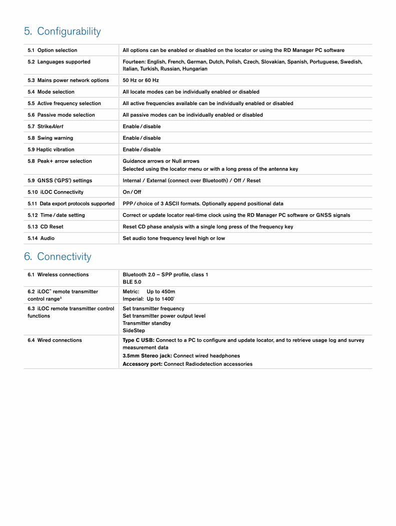
5. Configurability
5.1 Option selection All options can be enabled or disabled on the locator or using the RD Manager PC software
5.2 Languages supported Fourteen: English, French, German, Dutch, Polish, Czech, Slovakian, Spanish, Portuguese, Swedish, Italian, Turkish, Russian, Hungarian
5.3 Mains power network options 50 Hz or 60 Hz
5.4 Mode selection All locate modes can be individually enabled or disabled
5.5 Active frequency selection All active frequencies available can be individually enabled or disabled
5.6 Passive mode selection All passive modes can be individually enabled or disabled
5.7 StrikeAlert Enable / disable
5.8 Swing warning Enable / disable
5.9 Haptic vibration Enable / disable
5.8 Peak+ arrow selection Guidance arrows or Null arrows
Selected using the locator menu or with a long press of the antenna key
5.9 GNSS (‘GPS’) settings Internal / External (connect over Bluetooth) / Off / Reset
5.10 iLOC Connectivity On / Off
5.11 Data export protocols supported PPP / choice of 3 ASCII formats. Optionally append positional data
5.12 Time / date setting Correct or update locator real-time clock using the RD Manager PC software or GNSS signals
5.13 CD Reset Reset CD phase analysis with a single long press of the frequency key
5.14 Audio Set audio tone frequency level high or low
6. Connectivity
6.1 Wireless connections Bluetooth 2.0 – SPP profile, class 1 BLE 5.0
6.2 iLOC™ remote transmitter control range3
Metric: Up to 450mImperial: Up to 1400'
6.3 iLOC remote transmitter control functions
Set transmitter frequencySet transmitter power output levelTransmitter standbySideStep
6.4 Wired connections Type C USB: Connect to a PC to configure and update locator, and to retrieve usage log and survey measurement data
3.5mm Stereo jack: Connect wired headphones
Accessory port: Connect Radiodetection accessories
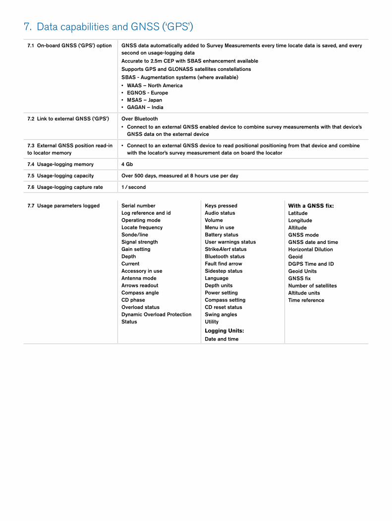
7. Data capabilities and GNSS (‘GPS’)
7.1 On-board GNSS (‘GPS’) option GNSS data automatically added to Survey Measurements every time locate data is saved, and every second on usage-logging data
Accurate to 2.5m CEP with SBAS enhancement available
Supports GPS and GLONASS satellites constellations
SBAS - Augmentation systems (where available)
• WAAS – North America• EGNOS - Europe• MSAS – Japan• GAGAN – India
7.2 Link to external GNSS (‘GPS’) Over Bluetooth
• Connect to an external GNSS enabled device to combine survey measurements with that device’s GNSS data on the external device
7.3 External GNSS position read-in to locator memory
• Connect to an external GNSS device to read positional positioning from that device and combine with the locator’s survey measurement data on board the locator
7.4 Usage-logging memory 4 Gb
7.5 Usage-logging capacity Over 500 days, measured at 8 hours use per day
7.6 Usage-logging capture rate 1 / second
7.7 Usage parameters logged Serial numberLog reference and idOperating modeLocate frequencySonde/lineSignal strengthGain settingDepthCurrentAccessory in useAntenna modeArrows readoutCompass angleCD phaseOverload status Dynamic Overload Protection Status
Keys pressedAudio statusVolumeMenu in useBattery statusUser warnings statusStrikeAlert statusBluetooth statusFault find arrowSidestep statusLanguageDepth unitsPower settingCompass settingCD reset statusSwing anglesUtility
Logging Units:
Date and time
With a GNSS fix:LatitudeLongitudeAltitudeGNSS modeGNSS date and timeHorizontal DilutionGeoidDGPS Time and IDGeoid UnitsGNSS fixNumber of satellitesAltitude unitsTime reference
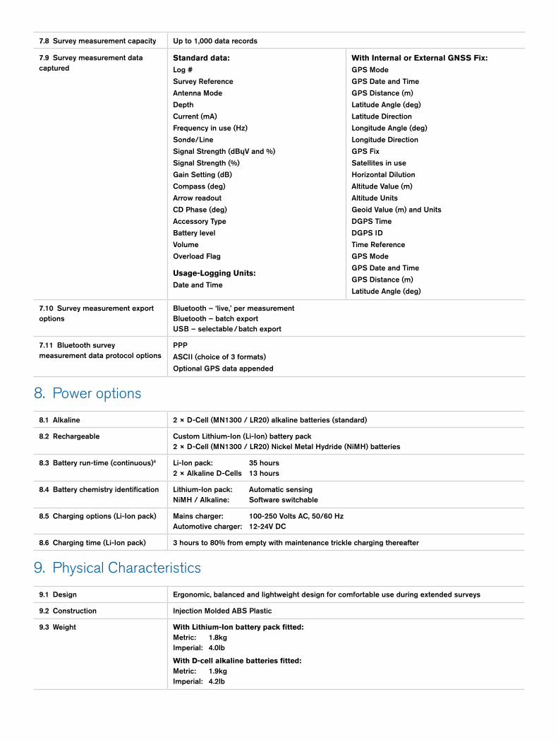
7.8 Survey measurement capacity Up to 1,000 data records
7.10 Survey measurement export options
Bluetooth – ‘live,’ per measurementBluetooth – batch exportUSB – selectable / batch export
7.11 Bluetooth survey measurement data protocol options
PPP
ASCII (choice of 3 formats)
Optional GPS data appended
7.9 Survey measurement data captured
Standard data:
Log #
Survey Reference
Antenna Mode
Depth
Current (mA)
Frequency in use (Hz)
Sonde/Line
Signal Strength (dBųV and %)
Signal Strength (%)
Gain Setting (dB)
Compass (deg)
Arrow readout
CD Phase (deg)
Accessory Type
Battery level
Volume
Overload Flag
Usage-Logging Units:
Date and Time
With Internal or External GNSS Fix:
GPS Mode
GPS Date and Time
GPS Distance (m)
Latitude Angle (deg)
Latitude Direction
Longitude Angle (deg)
Longitude Direction
GPS Fix
Satellites in use
Horizontal Dilution
Altitude Value (m)
Altitude Units
Geoid Value (m) and Units
DGPS Time
DGPS ID
Time Reference
GPS Mode
GPS Date and Time
GPS Distance (m)
Latitude Angle (deg)
8. Power options
8.1 Alkaline 2 × D-Cell (MN1300 / LR20) alkaline batteries (standard)
8.2 Rechargeable Custom Lithium-Ion (Li-Ion) battery pack2 × D-Cell (MN1300 / LR20) Nickel Metal Hydride (NiMH) batteries
8.3 Battery run-time (continuous)4 Li-Ion pack: 35 hours2 × Alkaline D-Cells 13 hours
8.4 Battery chemistry identification Lithium-Ion pack: Automatic sensingNiMH / Alkaline: Software switchable
8.5 Charging options (Li-Ion pack) Mains charger: 100-250 Volts AC, 50/60 HzAutomotive charger: 12-24V DC
8.6 Charging time (Li-Ion pack) 3 hours to 80% from empty with maintenance trickle charging thereafter
9. Physical Characteristics
9.1 Design Ergonomic, balanced and lightweight design for comfortable use during extended surveys
9.2 Construction Injection Molded ABS Plastic
9.3 Weight With Lithium-Ion battery pack fitted:Metric: 1.8kg Imperial: 4.0lb
With D-cell alkaline batteries fitted:Metric: 1.9kg Imperial: 4.2lb
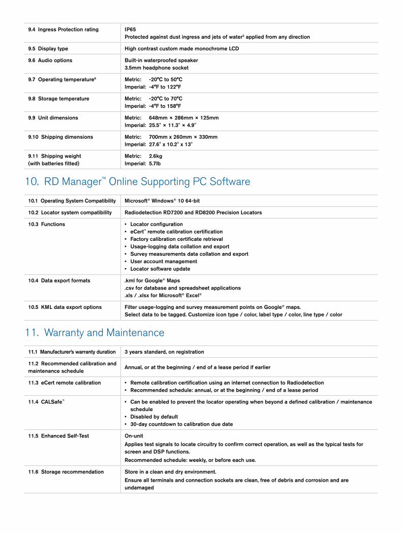
9.4 Ingress Protection rating IP65 Protected against dust ingress and jets of water5 applied from any direction
9.5 Display type High contrast custom made monochrome LCD
9.6 Audio options Built-in waterproofed speaker3.5mm headphone socket
9.7 Operating temperature6 Metric: -20°C to 50°C Imperial: -4°F to 122°F
9.8 Storage temperature Metric: -20°C to 70°C Imperial: -4°F to 158°F
9.9 Unit dimensions Metric: 648mm × 286mm × 125mmImperial: 25.5" × 11.3" × 4.9"
9.10 Shipping dimensions Metric: 700mm x 260mm × 330mmImperial: 27.6" x 10.2" x 13"
9.11 Shipping weight (with batteries fitted)
Metric: 2.6kg Imperial: 5.7lb
10. RD Manager™ Online Supporting PC Software
10.1 Operating System Compatibility Microsoft® Windows® 10 64-bit
10.2 Locator system compatibility Radiodetection RD7200 and RD8200 Precision Locators
10.3 Functions • Locator configuration• eCert™ remote calibration certification• Factory calibration certificate retrieval• Usage-logging data collation and export• Survey measurements data collation and export• User account management• Locator software update
10.4 Data export formats .kml for Google® Maps.csv for database and spreadsheet applications.xls / .xlsx for Microsoft® Excel®
10.5 KML data export options Filter usage-logging and survey measurement points on Google® maps. Select data to be tagged. Customize icon type / color, label type / color, line type / color
11. Warranty and Maintenance
11.1 Manufacturer’s warranty duration 3 years standard, on registration
11.2 Recommended calibration and maintenance schedule
Annual, or at the beginning / end of a lease period if earlier
11.3 eCert remote calibration • Remote calibration certification using an internet connection to Radiodetection• Recommended schedule: annual, or at the beginning / end of a lease period
11.4 CALSafe™ • Can be enabled to prevent the locator operating when beyond a defined calibration / maintenance schedule
• Disabled by default• 30-day countdown to calibration due date
11.5 Enhanced Self-Test On-unit
Applies test signals to locate circuitry to confirm correct operation, as well as the typical tests for screen and DSP functions.
Recommended schedule: weekly, or before each use.
11.6 Storage recommendation Store in a clean and dry environment.
Ensure all terminals and connection sockets are clean, free of debris and corrosion and are undamaged
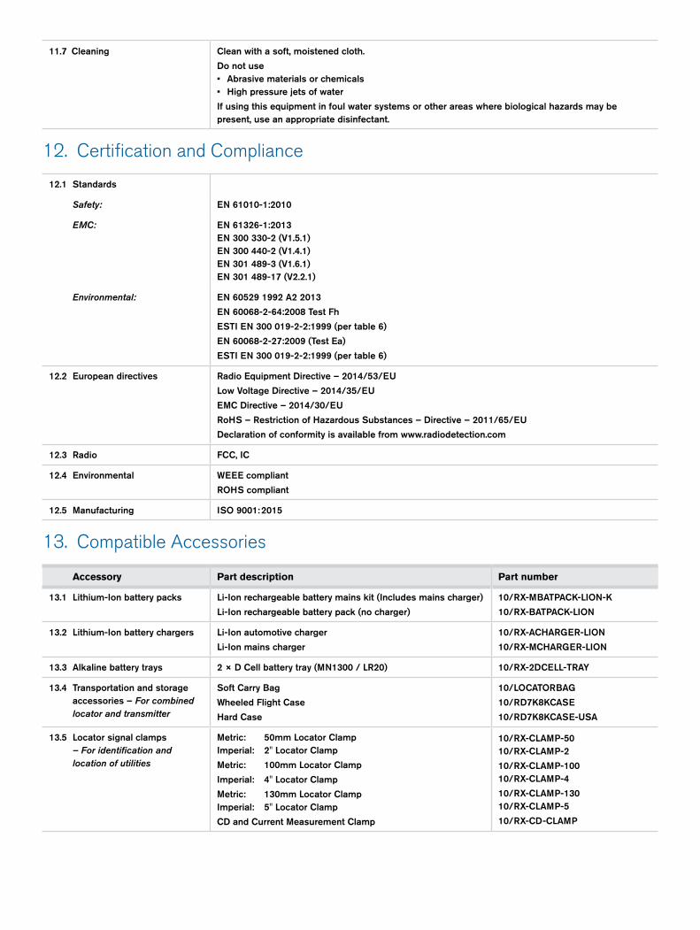
11.7 Cleaning Clean with a soft, moistened cloth.
Do not use • Abrasive materials or chemicals• High pressure jets of water
If using this equipment in foul water systems or other areas where biological hazards may be present, use an appropriate disinfectant.
12. Certification and Compliance
12.1 Standards
Safety: EN 61010-1:2010
EMC: EN 61326-1:2013 EN 300 330-2 (V1.5.1)EN 300 440-2 (V1.4.1) EN 301 489-3 (V1.6.1)EN 301 489-17 (V2.2.1)
Environmental: EN 60529 1992 A2 2013
EN 60068-2-64:2008 Test Fh
ESTI EN 300 019-2-2:1999 (per table 6)
EN 60068-2-27:2009 (Test Ea)
ESTI EN 300 019-2-2:1999 (per table 6)
12.2 European directives Radio Equipment Directive – 2014/53/EU
Low Voltage Directive – 2014/35/EU
EMC Directive – 2014/30/EU
RoHS – Restriction of Hazardous Substances – Directive – 2011/65/EU
Declaration of conformity is available from www.radiodetection.com
12.3 Radio FCC, IC
12.4 Environmental WEEE compliant
ROHS compliant
12.5 Manufacturing ISO 9001: 2015
13. Compatible Accessories
Accessory Part description Part number
13.1 Lithium-Ion battery packs Li-Ion rechargeable battery mains kit (Includes mains charger)
Li-Ion rechargeable battery pack (no charger)
10/RX-MBATPACK-LION-K
10/RX-BATPACK-LION
13.2 Lithium-Ion battery chargers Li-Ion automotive charger
Li-Ion mains charger
10/RX-ACHARGER-LION
10/RX-MCHARGER-LION
13.3 Alkaline battery trays 2 × D Cell battery tray (MN1300 / LR20) 10/RX-2DCELL-TRAY
13.4 Transportation and storage accessories – For combined locator and transmitter
Soft Carry Bag
Wheeled Flight Case
Hard Case
10/LOCATORBAG
10/RD7K8KCASE
10/RD7K8KCASE-USA
13.5 Locator signal clamps – For identification and location of utilities
Metric: 50mm Locator ClampImperial: 2" Locator Clamp
Metric: 100mm Locator Clamp
Imperial: 4" Locator Clamp
Metric: 130mm Locator ClampImperial: 5" Locator Clamp
CD and Current Measurement Clamp
10/RX-CLAMP-5010/RX-CLAMP-2
10/RX-CLAMP-10010/RX-CLAMP-4
10/RX-CLAMP-13010/RX-CLAMP-5
10/RX-CD-CLAMP
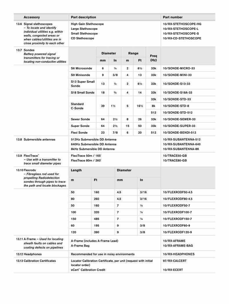
Accessory Part description Part number
13.6 Signal stethoscopes – To locate and identify individual utilities e.g. within walls, congested areas or when cables/utilities are in close proximity to each other
High Gain Stethoscope
Large Stethoscope
Small Stethoscope
CD Stethoscope
10/RX-STETHOSCOPE-HG
10/RX-STETHOSCOPE-L
10/RX-STETHOSCOPE-S
10/RX-CD-STETHOSCOPE
13.7 Sondes Battery powered signal transmitters for tracing or locating non-conductive utilities
mm
In
m
Ft
Freq(Hz)
S6 Microsonde 6 ¼ 2 6½ 33k 10/SONDE-MICRO-33
S9 Minisonde 9 3/8 4 13 33k 10/SONDE-MINI-33
S13 Super Small Sonde
13 ½ 2 6½ 33k 10/SONDE-S13-33
S18 Small Sonde 18 ¾ 4 14 33k 10/SONDE-S18A-33
Standard C-Sonde
39 1½ 5 16½
33k 10/SONDE-STD-33
8k 10/SONDE-STD-8
512 10/SONDE-STD-512
Sewer Sonde 64 2½ 8 26 33k 10/SONDE-SEWER-33
Super Sonde 64 2½ 15 50 33k 10/SONDE-SUPER-33
Flexi Sonde 23 7/8 6 20 512 10/SONDE-BENDI-512
13.10 Flexrods – Fibreglass rod used for propelling Radiodetection sondes through pipes to trace the path and locate blockages
Length
m Ft
Diameter
mm In
50 160 4.5 3/16 10/FLEXRODF50-4.5
80 260 4.5 3/16 10/FLEXRODF80-4.5
50 160 7 ¼ 10/FLEXRODF50-7
100 320 7 ¼ 10/FLEXRODF100-7
150 485 7 ¼ 10/FLEXRODF150-7
60 195 9 3/8 10/FLEXRODF60-9
120 390 9 3/8 10/FLEXRODF120-9
Diameter Range
13.8 Submersible antennas 512Hz Submersible DD Antenna
640Hz Submersible DD Antenna
8kHz Submersible DD Antenna
10/RX-SUBANTENNA-512
10/RX-SUBANTENNA-640
10/RX-SUBANTENNA-8K
13.9 FlexiTrace™ – Use with a transmitter to trace small diameter pipes
FlexiTrace 50m / 165'
FlexiTrace 80m / 260'
10/TRACE50-GB
10/TRACE80-GB
13.11 A-Frame – Used for locating sheath faults on cables and coating defects on pipelines
A-Frame (includes A-Frame Lead)
A-Frame Bag
10/RX-AFRAME
10/RX-AFRAME-BAG
13.12 Headphones Recommended for use in noisy environments 10/RX-HEADPHONES
13.13 Calibration Certificates Locator Calibration Certificate, per unit (request with initial locator order)
eCert™ Calibration Credit
97/RX-CALCERT
10/RX-ECERT

All specification are measured in test conditions, at 21°C / 70°F, and fitted with 2 × good quality alkaline batteries unless otherwise noted.
1 Based on volumetric testing at a known fixed depth. True depth accuracy depends on factors such as ground composition, utility characteristics and the locate frequency / signal strength employed. Always follow local safe digging guidelines.
2 The RD8200 will locate to greater depths in the right conditions, but depth accuracy will be compromised. Depth measurement will not be displayed beyond these depths.
3 Tested with clear line-of-sight. Range is dependent on electrical environment and weather conditions. For optimum range, face the locator toward the transmitter and raise the transmitter 2' / 60cm from the ground.
4 To provide repeatable measurements, run-time is measured with GPS and Bluetooth functions switched to ‘off’.
5 Water projected by a nozzle at a pressure of 30kPa /0.3 bar / 4.4 psi in accordance with BS EN 60529 1992 A2 2013.
6 At very low temperatures, battery life will be degraded, LCD performance may slow and measurement precision may reduce.
Copyright © 2020 Radiodetection Ltd. All rights reserved. Radiodetection is a subsidiary of SPX Corporation. Radiodetection, and RD8200 are registered trademarks of Radiodetection in the United States and/or other countries. Trademarks and Notices. The following are trademarks of Radiodetection: RD8200, eCert, iLOC, TruDepth, SideStep, SideStepauto, RD Manager Online, Peak+, Power filters, SurveyCERT, StrikeAlert, CALSafe, Current Direction. The design of the RD8200 locators and transmitters has been registered. The design of the 4 chevrons has been registered. The Bluetooth word, mark and logos are registered trademarks of Bluetooth SIG, Inc. and any use of such trademarks by Radiodetection is under license. Due to a policy of continued development, we reserve the right to alter or amend any published specification without notice. This document may not be copied, reproduced, transmitted, modified or used, in whole or in part, without the prior written consent of Radiodetection Ltd.
90/RD8200-DATA-ENG/01
Visit www.radiodetection.com
Global locations
Radiodetection (USA)28 Tower Road, Raymond, Maine 04071, USA Toll Free: +1 (877) 247 3797 Tel: +1 (207) 655 8525 [email protected]
Schonstedt Instrument Company (USA) 100 Edmond Road, Kearneysville, WV 25430 USA Toll Free: +1 888 367 7014 Tel: +1 304 724 4722 [email protected]
Radiodetection (Canada)344 Edgeley Boulevard, Unit 34, Concord, Ontario L4K 4B7, Canada Toll Free: +1 (800) 665 7953 Tel: +1 (905) 660 9995 [email protected]
Radiodetection Ltd. (UK)Western Drive, Bristol, BS14 0AF, UK Tel: +44 (0) 117 976 7776 [email protected]
Radiodetection (France)13 Grande Rue, 76220, Neuf Marché, France Tel: +33 (0) 2 32 89 93 60 [email protected]
Radiodetection (Benelux)Industriestraat 11, 7041 GD ’s-Heerenberg, Netherlands Tel: +31 (0) 314 66 47 00 [email protected]
Radiodetection (Germany)Groendahlscher Weg 118, 46446 Emmerich am Rhein, Germany Tel: +49 (0) 28 51 92 37 20 [email protected]
Radiodetection (Asia-Pacific)Room 708, CC Wu Building, 302-308 Hennessy Road, Wan Chai, Hong Kong SAR, China Tel: +852 2110 8160 [email protected]
Radiodetection (China)13 Fuqianyi Street, Minghao Building D304, Tianzhu Town, Shunyi District, Beijing 101312, China Tel: +86 (0) 10 8146 3372 [email protected]
Radiodetection (Australia)Unit H1, 101 Rookwood Road, Yagoona NSW 2199, Australia Tel: +61 (0) 2 9707 3222 [email protected]
Scan to see a full list of our
office locations