rcc t beam based on limit method - mp polytechnic
TRANSCRIPT

Date 20.5.2020
Department of Civil Engineering do Diploma –
4th SEM
05- Lecture Notes on
R.C.C. T Beam
Based on limit method
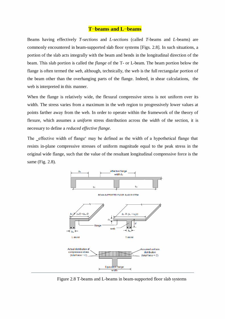
T−beams and L−beams
Beams having effectively T-sections and L-sections (called T-beams and L-beams) are
commonly encountered in beam-supported slab floor systems [Figs. 2.8]. In such situations, a
portion of the slab acts integrally with the beam and bends in the longitudinal direction of the
beam. This slab portion is called the flange of the T- or L-beam. The beam portion below the
flange is often termed the web, although, technically, the web is the full rectangular portion of
the beam other than the overhanging parts of the flange. Indeed, in shear calculations, the
web is interpreted in this manner.
When the flange is relatively wide, the flexural compressive stress is not uniform over its
width. The stress varies from a maximum in the web region to progressively lower values at
points farther away from the web. In order to operate within the framework of the theory of
flexure, which assumes a uniform stress distribution across the width of the section, it is
necessary to define a reduced effective flange.
The ‗effective width of flange‘ may be defined as the width of a hypothetical flange that
resists in-plane compressive stresses of uniform magnitude equal to the peak stress in the
original wide flange, such that the value of the resultant longitudinal compressive force is the
same (Fig. 2.8).
Figure 2.8 T-beams and L-beams in beam-supported floor slab systems
The effective flange width is found to increase with increased span, increased web width and
increased flange thickness. It also depends on the type of loading (concentrated, distributed,
etc.) and the support conditions (simply supported, continuous, etc.). Approximate formulae
for estimating the ‗effective width of flange‘ b (Cl. 23.1.2 of Code) are given as follows: f
b l0 / 6 bw 6D f for T Beam (12)
f l0 /12 bw 3Df for L Beam
where bw
is the breadth of the web, Df is the thickness of the flange [Fig 2.8], and l0 is the
―distance between points of zero moments in the beam‖ (which may be assumed as 0.7 times
the effective span in continuous beams and frames). Obviously, b cannot extend beyond the f
slab portion tributary to a beam, i.e., the actual width of slab available. Hence, the calculated
b should be restricted to a value that does not exceed (s +s )/2 in the case of T−beams, and f 1 2
s /2 + b /2 in the case of L−beams, where the spans s and s of the slab are as marked in Fig. 1 w 1 2
2.8.
In some situations, isolated T−beams and L−beams are encountered, i.e., the slab is
discontinuous at the sides, as in a footbridge or a ‗stringer beam‘ of a staircase. In such cases,
the Code [Cl. 23.1.2(c)] recommends the use of the following formula to estimate the
‗effective width of flange‘ b : f
l0 b for isolated T Beams l0 / b 4 w
bf 0.5l (13) 0 b for isolated L Beam
l0 / b 4 w
where b denotes the actual width of flange; evidently, the calculated value of b should not f
exceed b.
Analysis of Singly Reinforced Flanged Sections
The procedure for analysing flanged beams at ultimate loads depends on whether the neutral
axis is located in the flange region [Fig. 2.8(a)] or in the web region [Fig. 2.8(b)].
If the neutral axis lies within the flange (i.e., xu
≤ Df ), then as in the analysis at service
loads all the concrete on the tension side of the neutral axis is assumed ineffective, and the T-
section may be analysed as a rectangular section of width bf
and effective depth d [Fig.
2.8(a)]. Accordingly, Eq. (7) and Eq. (9) are applicable with b replaced by bf .
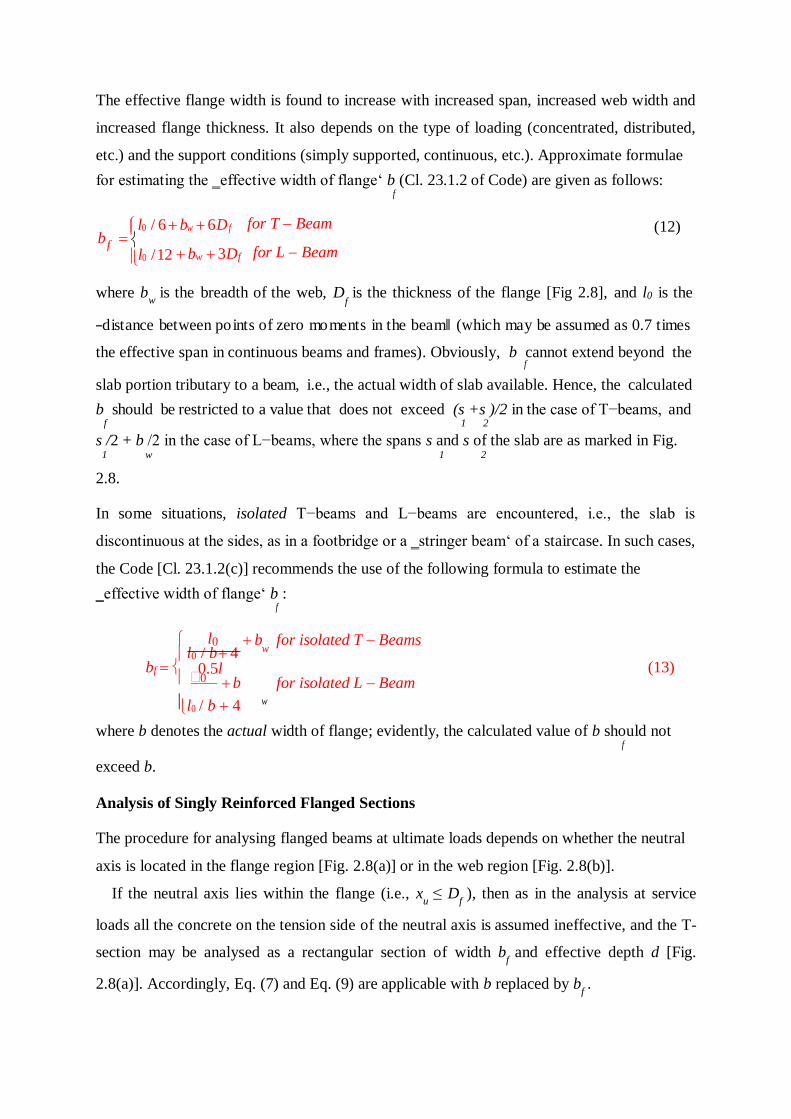
If the neutral axis lies in the web region (i.e., x > D ), then the compressive stress is carried u f
by the concrete in the flange and a portion of the web, as shown in Fig. 2.8(b). It is
convenient to consider the contributions to the resultant compressive force C , from the web u
portion (b × x ) and the flange portion (width b − b ) separately, and to sum up these effects. w u f w
Estimating the compressive force C in the ‗web‘ and its moment contribution M is easy, uw uw
as the full stress block is operative:
Cuw 0.361 fckbwxu
Muw Cuw(d 0.416xu )
(14)
(15)
Figure 2.9 Behaviour of flanged beam section at ultimate limit state
However, estimating the compressive force Cuf
in the flange is rendered difficult by the fact
that the stress block for the flange portions may comprise a rectangular area plus a truncated
parabolic area [Fig. 2.8(b)]. A general expression for the total area of the stress block
operative in the flange, as well as an expression for the centroidal location of the stress block,
is evidently not convenient to derive for such a case. However, when the stress block over the
flange depth contains only a rectangular area (having a uniform stress 0.447 fck
), which
occurs when 3 x D , an expression for C and its moment contribution M can easily be
7 u f uf uf
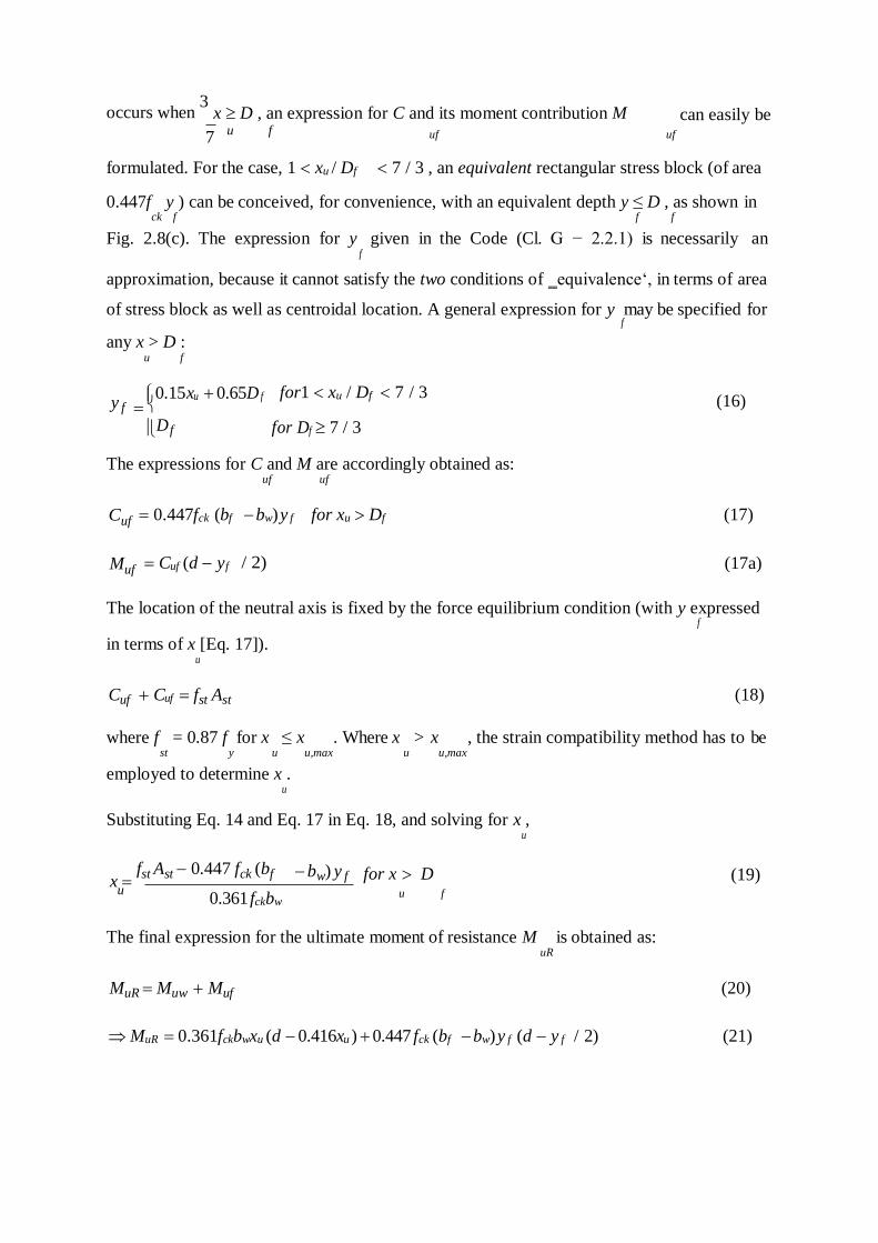
formulated. For the case, 1 xu / Df 7 / 3 , an equivalent rectangular stress block (of area
0.447f y ) can be conceived, for convenience, with an equivalent depth y ≤ D , as shown in ck f f f
Fig. 2.8(c). The expression for y given in the Code (Cl. G − 2.2.1) is necessarily an f
approximation, because it cannot satisfy the two conditions of ‗equivalence‘, in terms of area
of stress block as well as centroidal location. A general expression for y may be specified for f
any x > D : u f
y f 0.15xu 0.65D f for1 xu / Df 7 / 3
(16)
D f for Df 7 / 3
The expressions for C and M are accordingly obtained as: uf uf
Cuf
Muf
0.447fck (bf
Cuf (d yf
bw) y f
/ 2)
for xu Df (17)
(17a)
The location of the neutral axis is fixed by the force equilibrium condition (with y expressed f
in terms of x [Eq. 17]). u
Cuf Cuf fst Ast (18)
where f = 0.87 f for x ≤ x . Where x > x , the strain compatibility method has to be st y u u,max u u,max
employed to determine x . u
Substituting Eq. 14 and Eq. 17 in Eq. 18, and solving for x , u
x fst Ast 0.447 fck (bf bw) y f for x D (19)
u 0.361 fckbw u f
The final expression for the ultimate moment of resistance M is obtained as: uR
MuR Muw Muf (20)
MuR 0.361fckbwxu (d 0.416xu ) 0.447 fck (bf bw) y f (d y f / 2) (21)
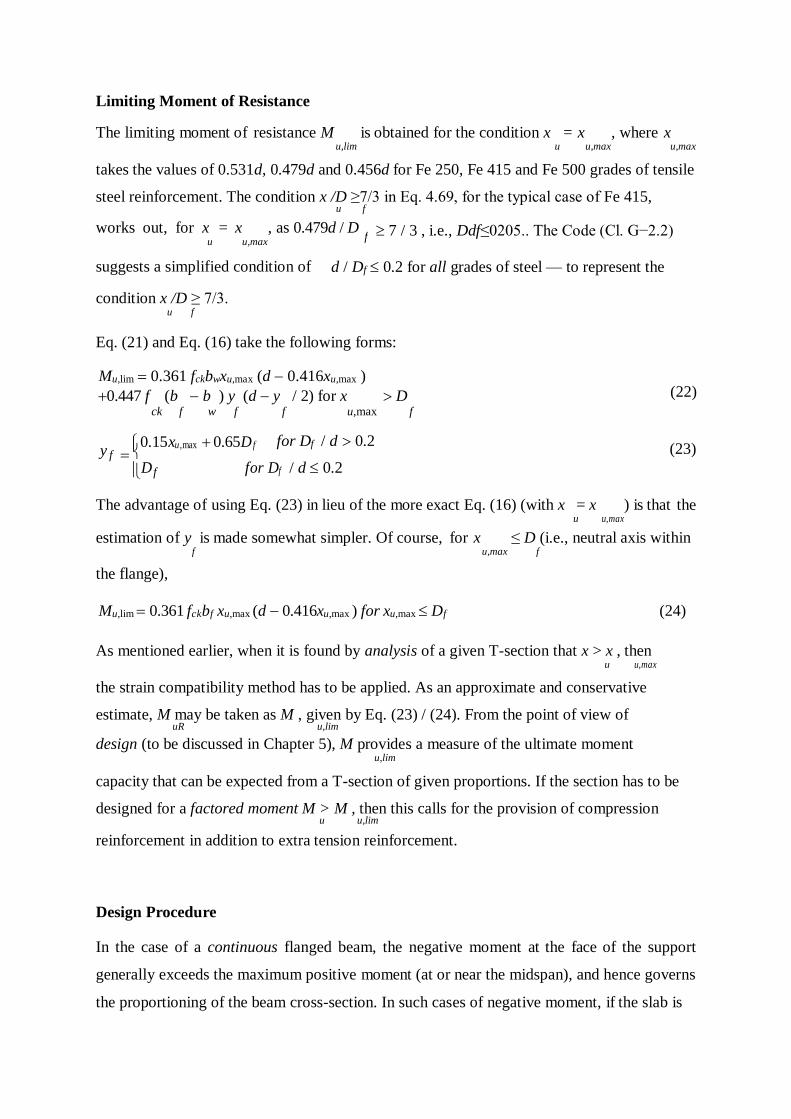
Limiting Moment of Resistance
The limiting moment of resistance M is obtained for the condition x = x , where x u,lim u u,max u,max
takes the values of 0.531d, 0.479d and 0.456d for Fe 250, Fe 415 and Fe 500 grades of tensile
steel reinforcement. The condition x /D ≥7/3 in Eq. 4.69, for the typical case of Fe 415, u f
works out, for x = x , as 0.479d / D u u,max
7 / 3 , i.e., Ddf≤0205.. The Code (Cl. G−2.2)
suggests a simplified condition of
condition x /D ≥ 7/3. u f
d / Df 0.2 for all grades of steel — to represent the
Eq. (21) and Eq. (16) take the following forms:
Mu,lim 0.361 fckbwxu,max (d 0.416xu,max )
0.447 f (b b ) y (d y / 2) for x D (22) ck f w f f u,max f
y f 0.15xu,max 0.65D f for Df / d 0.2
(23)
D f for Df / d 0.2
The advantage of using Eq. (23) in lieu of the more exact Eq. (16) (with x = x ) is that the u u,max
estimation of y is made somewhat simpler. Of course, for x ≤ D (i.e., neutral axis within f u,max f
the flange),
Mu,lim 0.361 fckbf xu,max (d 0.416xu,max ) for xu,max Df (24)
As mentioned earlier, when it is found by analysis of a given T-section that x > x , then
u u,max
the strain compatibility method has to be applied. As an approximate and conservative
estimate, M may be taken as M , given by Eq. (23) / (24). From the point of view of uR u,lim
design (to be discussed in Chapter 5), M provides a measure of the ultimate moment u,lim
capacity that can be expected from a T-section of given proportions. If the section has to be
designed for a factored moment M > M , then this calls for the provision of compression u u,lim
reinforcement in addition to extra tension reinforcement.
Design Procedure
In the case of a continuous flanged beam, the negative moment at the face of the support
generally exceeds the maximum positive moment (at or near the midspan), and hence governs
the proportioning of the beam cross-section. In such cases of negative moment, if the slab is
f
located on top of the beam (as is usually the case), the flange is under flexural tension and
hence the concrete in the flange is rendered ineffective. The beam section at the support is
therefore to be designed as a rectangular section for the factored negative moment. Towards
the midspan of the beam, however, the beam behaves as a proper flanged beam (with the
flange under flexural compression). As the width of the web b and the overall depth D are w
already fixed from design considerations at the support, all that remains to be determined is
the area of reinforcing steel; the effective width of flange is determined as suggested by the
Code .
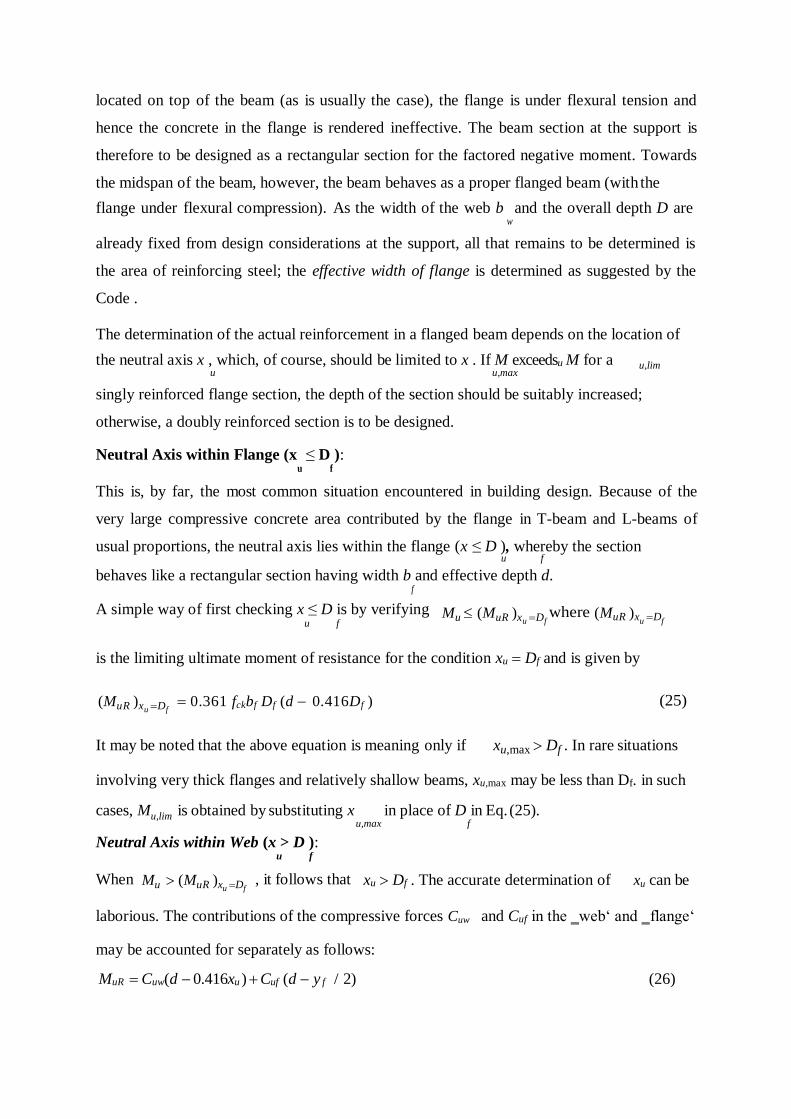
The determination of the actual reinforcement in a flanged beam depends on the location of
the neutral axis x , which, of course, should be limited to x . If M exceedsu M for a u u,max
u,lim
singly reinforced flange section, the depth of the section should be suitably increased;
otherwise, a doubly reinforced section is to be designed.
Neutral Axis within Flange (x u
≤ D ): f
This is, by far, the most common situation encountered in building design. Because of the
very large compressive concrete area contributed by the flange in T-beam and L-beams of
usual proportions, the neutral axis lies within the flange (x ≤ D ), whereby the section u f
behaves like a rectangular section having width b and effective depth d. f
A simple way of first checking x ≤ D is by verifying u f
Mu (MuR )xu Df where (MuR )xu Df
is the limiting ultimate moment of resistance for the condition xu Df and is given by
(MuR )xu Df
0.361 fckbf Df (d 0.416Df ) (25)
It may be noted that the above equation is meaning only if xu,max Df . In rare situations
involving very thick flanges and relatively shallow beams, xu,max may be less than Df. in such
cases, Mu,lim is obtained by substituting x in place of D in Eq. (25). u,max f
Neutral Axis within Web (x > D ): u f
When Mu (MuR )xu Df , it follows that xu Df . The accurate determination of xu can be
laborious. The contributions of the compressive forces Cuw
may be accounted for separately as follows:
and Cuf in the ‗web‘ and ‗flange‘
MuR Cuw(d 0.416xu ) Cuf (d y f / 2) (26)
uR x 7D /3
Cuw 0.361 fckbwxu (27)
Cuf 0.447fck (bf bw) y f (28)
and the equivalent flange thickness yf is equal to or less than Df depending on whether xu
exceeds 7Df/3 or not.
For x ≥ 7D /3, the value of the ultimate moment of resistance (M ) u,max f u f
corresponding to xu 7Df / 3and y f Df may be first computed. If the factored moment
Mu (MuR )xu
7Df /3 , it follows that xu 7Df / 3 and y f Df . Otherwise,
Df xu 7Df / 3 for (MuR )x D Mu (MuR )x 7D /3 and
u f u f
y f 0.15xu 0.65Df
(29)
Inserting the appropriate value — Df or the expression for yf in Eq. (29), in Eq. (26), the
resulting quadratic equation (in terms of the unknown xu ) can be solved to yield the correct
value of xu.. Corresponding to this value of x the values of C and C can be computed [Eq. u, uw uf
(27) , (28)] and the required A obtained by solving the force equilibriumequation. st
Tu 0.87 f f Ast Cuw Cuf
( A ) Cuw Cuf (30)
st required 0.87 f y
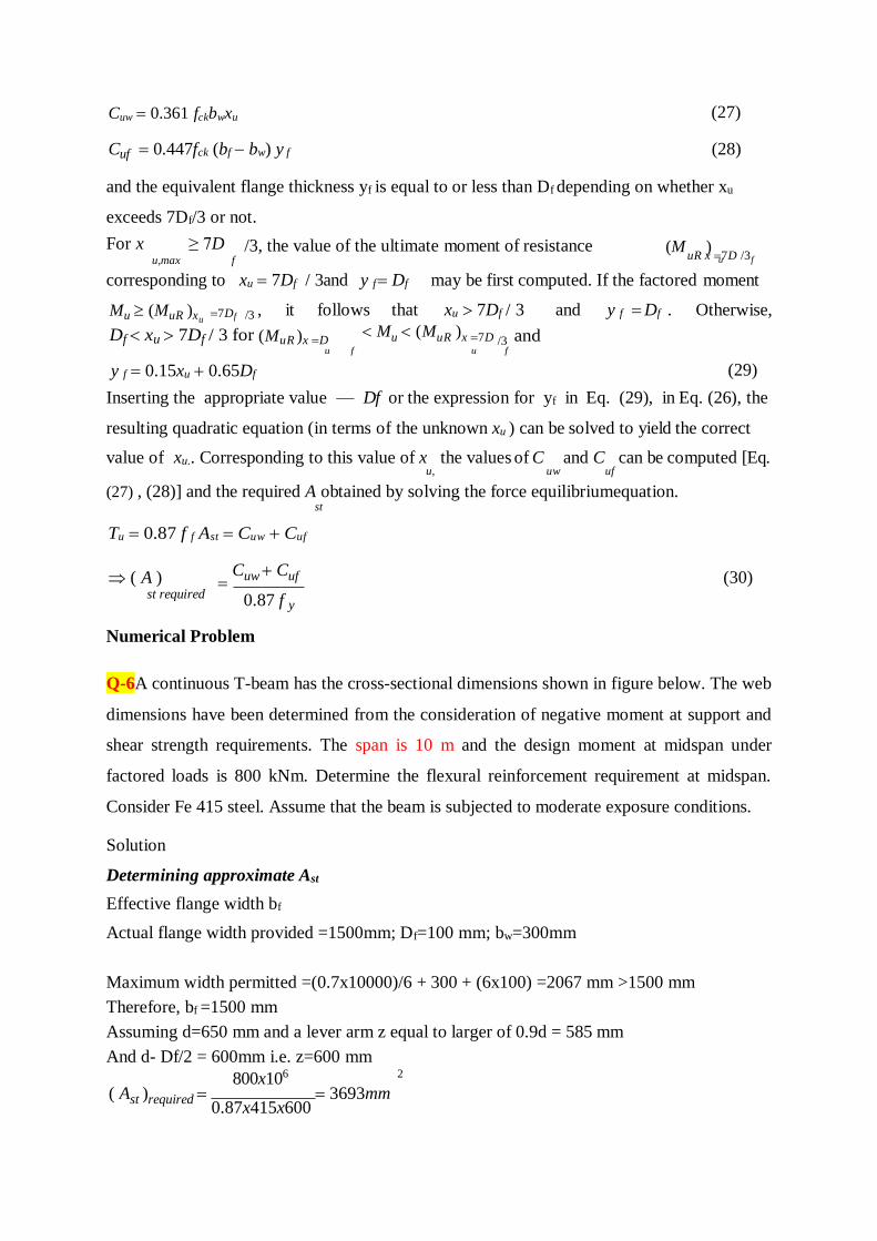
Numerical Problem
Q-6A continuous T-beam has the cross-sectional dimensions shown in figure below. The web
dimensions have been determined from the consideration of negative moment at support and
shear strength requirements. The span is 10 m and the design moment at midspan under
factored loads is 800 kNm. Determine the flexural reinforcement requirement at midspan.
Consider Fe 415 steel. Assume that the beam is subjected to moderate exposure conditions.
Solution
Determining approximate Ast
Effective flange width bf
Actual flange width provided =1500mm; Df=100 mm; bw=300mm
Maximum width permitted =(0.7x10000)/6 + 300 + (6x100) =2067 mm >1500 mm
Therefore, bf =1500 mm
Assuming d=650 mm and a lever arm z equal to larger of 0.9d = 585 mm
And d- Df/2 = 600mm i.e. z=600 mm
800x106 2
( Ast )required 0.87x415x600
3693mm
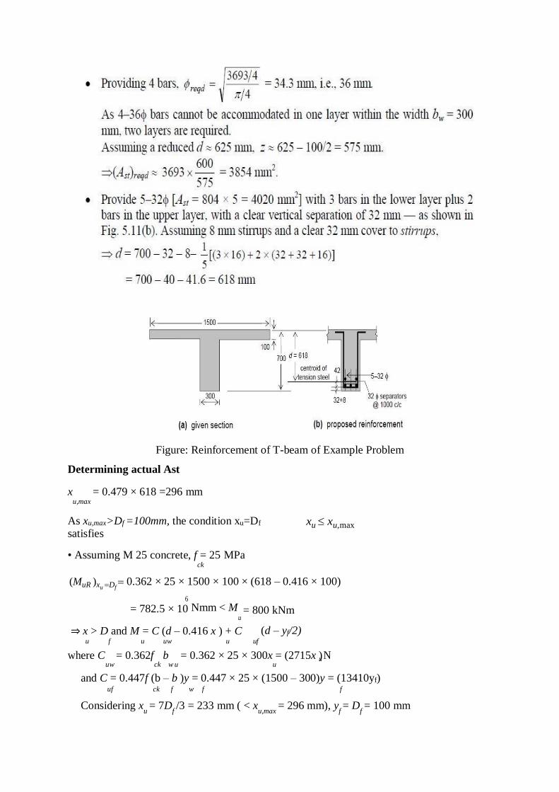
Figure: Reinforcement of T-beam of Example Problem
Determining actual Ast
x = 0.479 × 618 =296 mm u,max
As xu,max>Df =100mm, the condition xu=Df
satisfies
• Assuming M 25 concrete, f = 25 MPa ck
xu xu,max
(MuR )xu Df 0.362 × 25 × 1500 × 100 × (618 – 0.416 × 100)
6
= 782.5 × 10 Nmm < M u
⇒ x > D and M = C (d – 0.416 x ) + C
= 800 kNm
(d – yf/2) u f u uw u uf
where C = 0.362f b = 0.362 × 25 × 300x = (2715x )u N uw ck w u u
and C = 0.447f (b – b )y = 0.447 × 25 × (1500 – 300)y = (13410yf) uf ck f w f f
Considering xu = 7D
f /3 = 233 mm ( < x
u,max = 296 mm), y
f = D
f = 100 mm
u f ⇒ (MuR )x 7D /3 (2715 × 233)(618 – 0.416 × 233) + (13410x100)x(618-100/2)
=1091.3x106 Nmm >Mu = 800 KNm
Evidently, D x
7 D
, for which y =0.15x +o.65D
f u 3
f f u f
C = 13410(0.15x.65 × 100) = (2011.5x + 871650) N uf u
M = 800 × 106 = (2715x )(618 – 0.416x ) u u u
+ (2011.5xu+871650)x[618-(0.15xu+65)/2] = -1280.3x 2 + 2790229.5 x + 510.35×10⁶
u u
Solving this quadratic equation,
x = 109.3 mm < x = 296 m u u,max
⇒ y = 0.15x + 65 = 81.4 mm f u
Applying T = 0.87f A = C +Cuf
u y st uw
( A ) (2715x109.3) (13410x81.4)
3845 mm2
st required 0.87x415
The reinforcement (5-32Φ; Ast=4020 mm2, based on appropriate estimate of Ast [Fig.] is
evidently adequate and appropriate.
A.K.Agrawal
A.M.I.E. civil
Lecturer
Civil Engg. Deptt
M.P.Polytechnic ,GKP

