quality winches, cranes and hoists since 1948
TRANSCRIPT
Quality Winches, Cranes and Hoists since 1948
TOLL FREE800-843-7648
FAX507-454-5282
ONLINEWWW.THERN.C
ThernCustomer
Service
Hours 7:30 am - 4:30 pm CST
Toll-Free 800.843.7648
Phone 507.454.2996
Fax 507.454.5282
eMail [email protected]
Web www.thern.com
Expedited Delivery. When you need better than standard delivery, we can hand-hold your order from entry to shipment to ensure best delivery.
Engineered Solutions. We embrace any opportunity to put our years of experience to the task to help you come up with a unique, custom engineered solution to your most demanding applications.
System Solutions. Sheaves, controls, rigging — we can help put together the best system to solve your lifting, pulling or tensioning need.
Technical Assistance. Not sure how to select the right winch for your application? Let one of our experienced technical sales engineers help you, every step of the way.
Wire Rope. Winches need wire rope, and we can help you select the best wire rope for your application and supply it with the winch, if you wish. We can even spool it onto the drum for you, saving you valuable time in installation.
Every product we manufacture must meet our strict quality standards or it doesn’t carry the Thern name. Our quality management system is certified to ISO 9001/2008 standards. All inspection tools are maintained and calibrated regularly as required under the ISO standard. All new products are rigorously tested to ensure performance and durability. Thern has the ability to test products statically and dynamically with load capacities up to 55,000 lbs. and line speeds of up to 200 fpm. Test and inspection certificates are available upon request.
Thern is a family owned manufacturer focused on building long term relationships by creating personal connections with our customers to ensure stability and mutual success. With careful consideration, we apply all of our abilities to understand our customers’ needs and work toward exceeding their expectations.
We strive to provide best-fit solutions to our customers’ lifting, pulling and tensioning applications,with top quality products and services, timely responses, and accurate information.
Ask UsAbout Our
Value-Added Services
SERVICES
QualityAssurance
OurMission
ThernWinches & Cranes
FLCL-0916
Complete, downloadable details on linewww.thern.comThese products are not for lifting people, or things over people.
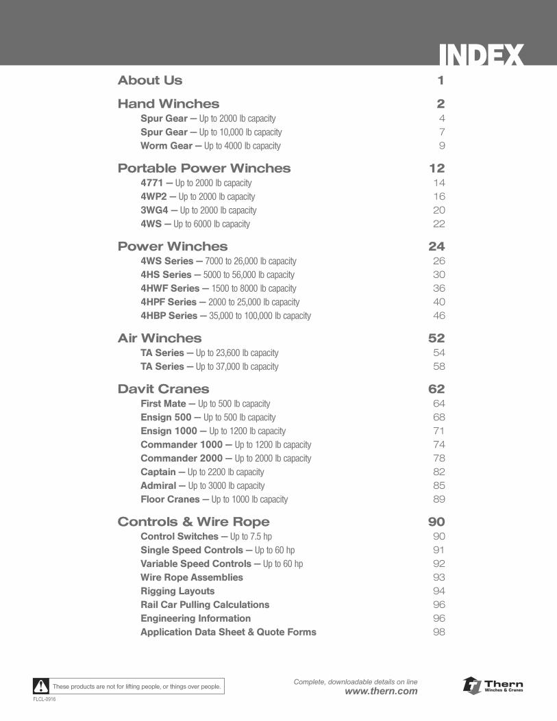
INDEXAbout Us 1
Hand Winches 2Spur Gear — Up to 2000 lb capacity 4Spur Gear — Up to 10,000 lb capacity 7Worm Gear — Up to 4000 lb capacity 9
Portable Power Winches 124771 — Up to 2000 lb capacity 144WP2 — Up to 2000 lb capacity 163WG4 — Up to 2000 lb capacity 20 4WS — Up to 6000 lb capacity 22
Power Winches 244WS Series — 7000 to 26,000 lb capacity 264HS Series — 5000 to 56,000 lb capacity 304HWF Series — 1500 to 8000 lb capacity 364HPF Series — 2000 to 25,000 lb capacity 404HBP Series — 35,000 to 100,000 lb capacity 46
Air Winches 52TA Series — Up to 23,600 lb capacity 54TA Series — Up to 37,000 lb capacity 58
Davit Cranes 62First Mate — Up to 500 lb capacity 64Ensign 500 — Up to 500 lb capacity 68Ensign 1000 — Up to 1200 lb capacity 71Commander 1000 — Up to 1200 lb capacity 74Commander 2000 — Up to 2000 lb capacity 78Captain — Up to 2200 lb capacity 82Admiral — Up to 3000 lb capacity 85Floor Cranes — Up to 1000 lb capacity 89
Controls & Wire Rope 90Control Switches — Up to 7.5 hp 90Single Speed Controls — Up to 60 hp 91Variable Speed Controls — Up to 60 hp 92 Wire Rope Assemblies 93 Rigging Layouts 94 Rail Car Pulling Calculations 96 Engineering Information 96 Application Data Sheet & Quote Forms 98
ii
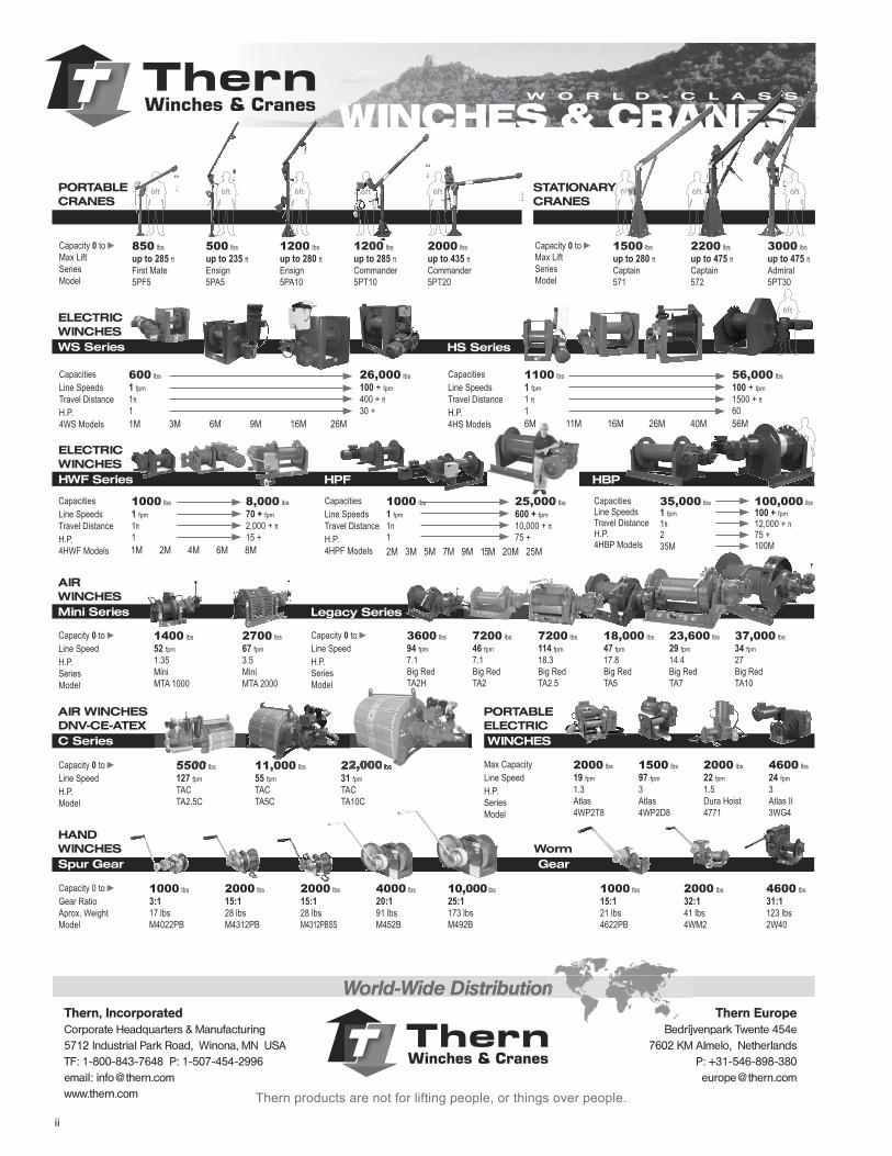
Capacity 0 to ►Line SpeedH.P.SeriesModel
1400 lbs52 fpm1.35MiniMTA 1000
2700 lbs67 fpm3.5MiniMTA 2000
Capacity 0 to ►Line SpeedH.P.Model
5500 lbs127 fpmTACTA2.5C
11,000 lbs55 fpmTACTA5C
22,000 lbs31 fpmTACTA10C
PORTABLECRANES
Capacity 0 to ►Max LiftSeriesModel
850 lbsup to 285 ftFirst Mate5PF5
Capacity 0 to ►Max LiftSeriesModel
1500 lbsup to 280 ftCaptain571
2200 lbsup to 475 ftCaptain572
3000 lbsup to 475 ftAdmiral5PT30
500 lbsup to 235 ftEnsign5PA5
1200 lbsup to 280 ft Ensign5PA10
1200 lbsup to 285 ftCommander5PT10
2000 lbsup to 435 ftCommander5PT20
ThernWinches & Cranes WINCHES & CRANES
W O R L D - C L A S S
STATIONARYCRANES
HANDWINCHESSpur Gear
Capacity 0 to ►Gear RatioAprox. WeightModel
1000 lbs3:117 lbsM4022PB
1000 lbs15:121 lbs4622PB
2000 lbs32:141 lbs4WM2
4600 lbs31:1123 lbs2W40
2000 lbs15:128 lbsM4312PB
2000 lbs15:128 lbsM4312PBSS
4000 lbs20:191 lbsM452B
10,000 lbs25:1173 lbsM492B
AIRWINCHESMini Series Legacy Series
AIR WINCHESDNV-CE-ATEXC Series
HBPHPF
CapacitiesLine SpeedsTravel DistanceH.P.4WS Models
ELECTRIC WINCHESWS Series HS Series
Worm Gear
PORTABLEELECTRIC WINCHES
Max CapacityLine SpeedH.P.SeriesModel
2000 lbs19 fpm1.3Atlas4WP2T8
1500 lbs97 fpm3Atlas4WP2D8
2000 lbs22 fpm1.5Dura Hoist4771
4600 lbs24 fpm3Atlas II3WG4
600 lbs1 fpm1ft1
26,000 lbs100 + fpm400 + ft30 +
1M 3M 6M 9M 16M 26M
CapacitiesLine SpeedsTravel DistanceH.P.4HS Models
1100 lbs1 fpm1 ft1
56,000 lbs100 + fpm1500 + ft60
6M 11M 16M 26M 40M 56M
CapacitiesLine SpeedsTravel DistanceH.P.4HWF Models
1000 lbs1 fpm1ft1
8,000 lbs70 + fpm2,000 + ft15 +
1M 2M 4M 6M 8M
CapacitiesLine SpeedsTravel DistanceH.P.4HPF Models
1000 lbs1 fpm1ft1
25,000 lbs600 + fpm10,000 + ft75 +
2M 3M 5M 7M 9M 15M 20M 25M
CapacitiesLine SpeedsTravel DistanceH.P.4HBP Models
35,000 lbs1 fpm1ft235M
100,000 lbs100 + fpm12,000 + ft75 +100M
World-Wide Distribution
ThernWinches & Cranes
Thern EuropeBedrijvenpark Twente 454e
7602 KM Almelo, NetherlandsP: [email protected]
Thern, IncorporatedCorporate Headquarters & Manufacturing5712 Industrial Park Road, Winona, MN USATF: 1-800-843-7648 P: 1-507-454-2996email: [email protected]
World-Wide Distribution
Thern Bedrijvenpark Twente 454e
ELECTRICWINCHESHWF Series
22,000 lbs5500
Thern products are not for lifting people, or things over people.
Capacity 0 to ►Line SpeedH.P.SeriesModel
18,000 lbs47 fpm17.8Big RedTA5
37,000 lbs34 fpm27Big RedTA10
23,600 lbs29 fpm14.4Big RedTA7
7200 lbs46 fpm7.1Big RedTA2
7200 lbs114 fpm18.3Big RedTA2.5
3600 lbs94 fpm7.1Big RedTA2H

ThernWinches & Cranes
1FLCL-0318
Complete, downloadable details on linewww.thern.comThese products are not for lifting people, or things over people.
ABOUT US
What We DoThern specializes in the design and manufacture of winches and cranes. Thern winches and cranes have established a world-wide reputation for toughness, versatility and reliability. Our ability to provide clients with a full range of services, and custom-built solutions has made us a leader among our peers. Whether you need to lift, pull, tension or position, from 100 lbs. to 100,000 lbs., Thern has the perfect product for you.
Design LeaderSuperior quality is designed into every product we manufacture. Any manufacturer can say they build a better crane or winch. Thern can back that claim up with a steadfast reputation for dependable products chosen time and again by companies worldwide. Thern products are manufactured to high quality standards because your application is our application. We also understand that some jobs require a tool that isn’t available right off the shelf. That’s why Thern employs an experienced engineering and technical sales staff that can consult, design and manufacture custom products to provide the best possible solution for your application.
Quality AssuranceEvery product we manufacture must meet our strict quality standards or it doesn’t carry the Thern name. Our quality management system is certified to ISO 9001/2008. All new products are rigorously tested to ensure performance and durability. Thern has the ability to test products statically and dynamically with load capacities up to 55,000 lb and line speeds of up to 200 fpm. Test and inspection certificates are available upon request.
Markets We ServeSince 1948, Thern has been serving a broad range of industries all over the world. Some key industries served by our products include: Water/Wastewater, Entertainment, Oil and Gas, Bulk Handling, Government/Defense, Mining, Construction, Manufacturing and Marine.
Customer CareThe glue that holds our performance together is “service.” We specialize in getting the job done right. Thern is a professional company that is easy to do business with, whether you want to lower the Ball in Time’s Square every New Year’s Eve or position a load-out chute at a mine in Australia, our expertise and experience is here to serve you. It’s been said before, and it’s worth saying again: Thern is big enough to handle any project yet small enough to care.
Winona, MN USA
ThernWinches & Cranes
2
Complete, downloadable details on linewww.thern.com
FLCL-0318
These products are not for lifting people, or things over people.
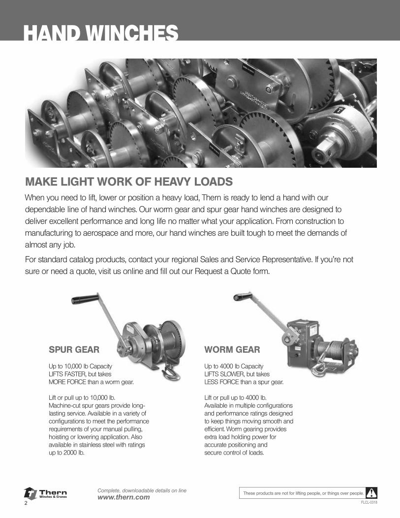
HAND WINCHES
MAKE LIGHT WORK OF HEAVY LOADSWhen you need to lift, lower or position a heavy load, Thern is ready to lend a hand with our dependable line of hand winches. Our worm gear and spur gear hand winches are designed to deliver excellent performance and long life no matter what your application. From construction to manufacturing to aerospace and more, our hand winches are built tough to meet the demands of almost any job.
For standard catalog products, contact your regional Sales and Service Representative. If you’re not sure or need a quote, visit us online and fill out our Request a Quote form.
SPUR GEAR
Up to 10,000 lb CapacityLIFTS FASTER, but takes MORE FORCE than a worm gear.
Lift or pull up to 10,000 lb. Machine-cut spur gears provide long-lasting service. Available in a variety of configurations to meet the performance requirements of your manual pulling, hoisting or lowering application. Also available in stainless steel with ratings up to 2000 lb.
WORM GEAR
Up to 4000 lb CapacityLIFTS SLOWER, but takes LESS FORCE than a spur gear.
Lift or pull up to 4000 lb. Available in multiple configurations and performance ratings designed to keep things moving smooth and efficient. Worm gearing provides extra load holding power for accurate positioning and secure control of loads.
3FLCL-0318
These products are not for lifting people or things over people.
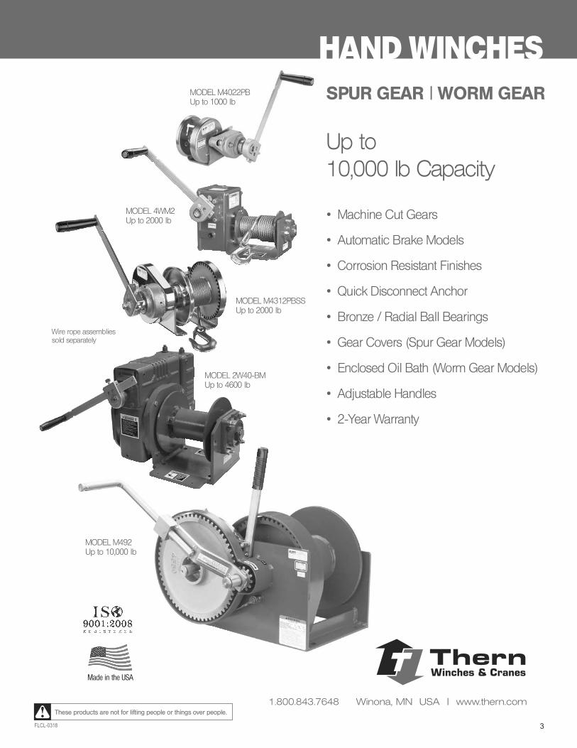
HAND WINCHES
Made in the USA
Up to10,000 lb Capacity
• Machine Cut Gears
• Automatic Brake Models
• Corrosion Resistant Finishes
• Quick Disconnect Anchor
• Bronze / Radial Ball Bearings
• Gear Covers (Spur Gear Models)
• Enclosed Oil Bath (Worm Gear Models)
• Adjustable Handles
• 2-Year Warranty
MODEL M4022PBUp to 1000 lb
SPUR GEAR | WORM GEAR
MODEL M492Up to 10,000 lb
Wire rope assemblies sold separately
MODEL 4WM2Up to 2000 lb
MODEL M4312PBSSUp to 2000 lb
MODEL 2W40-BMUp to 4600 lb
ThernWinches & Cranes
1.800.843.7648 Winona, MN USA | www.thern.com
ThernWinches & Cranes
4
Complete, downloadable details on linewww.thern.com
FLCL-0318
These products are not for lifting people, or things over people.
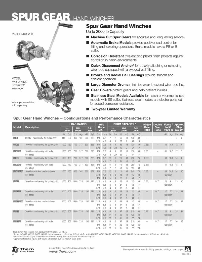
SPUR GEAR HAND WINCHES
MODEL M4022PB
MODEL M4312PBSSShown with wire rope
Wire rope assemblies sold separately
Spur Gear Hand WinchesUp to 2000 lb Capacity■ Machine Cut Spur Gears for accurate and long lasting service.
■ Automatic Brake Models provide positive load control for lifting and lowering operations. Brake models have a PB or B suffix.
■ Corrosion Resistant trivalent zinc plated finish protects against corrosion in harsh environments.
■ Quick Disconnect Anchor1 for quickly attaching or removing wire rope equipped with a swaged ball fitting.
■ Bronze and Radial Ball Bearings provide smooth and efficient operation.
■ Large Diameter Drums minimize wear to extend wire rope life.
■ Gear Covers protect gears and help prevent injuries.
■ Stainless Steel Models Available for harsh environments, see models with SS suffix. Stainless steel models are electro-polished for added corrosion resistance.
■ Two-year Limited Warranty
Spur Gear Hand Winches — Configurations and Performance Characteristics
Model DescriptionLOAD RATING Wire
Rope Dia. 1
DRUM CAPACITY 2 Single Gear Ratio
Double Gear Ratio
Force 3 to lift
1000 lb
Approx.Ship
Weight1st
LayerMid
DrumFull
Drum1st
LayerMid
DrumFull
Drum
(lb) (kg) (lb) (kg) (lb) (kg) (in) (mm) (ft) (m) (ft) (m) (ft) (m) (lb) (kg) (lb) (kg)
M401 500 lb — marine duty (for pulling only) 500 226 400 181 300 136 1/8 3.2 7 2 60 18 130 39 — — — — 8 33/16 4.8 4 1 27 8 60 18
M4022 1000 lb — marine duty (for pulling only) 1000 453 700 317 500 226 1/8 3.2 4 1 52 15 130 39 2.85:1 — 40 18.1 12 53/16 4.8 3 0.9 26 7 57 17
M4022PB 1000 lb — marine duty with brake 1000 453 700 317 500 226 1/8 3.2 4 1 52 15 130 39 2.85:1 — 41 18.6 17 7(for lifting) 3/16 4.8 3 0.9 26 7 57 17
M4032 1000 lb — marine duty (for pulling only) 1000 453 700 317 500 226 1/8 3.2 11 3 110 33 250 76 2.85:1 — 40 18.1 14 63/16 4.8 7 2 51 15 110 33
M4032PB 1000 lb — marine duty with brake 1000 453 700 317 500 226 1/8 3.2 11 3 110 33 250 76 2.85:1 — 41 18.6 18 8(for lifting) 3/16 4.8 7 2 51 15 110 33
M4042PBSS 1000 lb — stainless steel with brake 1000 453 800 362 600 272 1/8 3.2 12 3 110 33 240 73 3.83:1 — 46 20.9 24 10(for lifting) 3/16 4.8 8 2 48 14 110 33 (sgl gear) 1/4 6.4 5 1 27 8 59 17
M4312 2000 lb — marine duty (for pulling only) 2000 907 1600 725 1200 544 3/16 4.8 8 2 48 14 110 33 3.83:1 14.7:1 20 9.1 23 101/4 6.4 5 1 27 8 59 17 (dbl gear)
5/16 7.9 4 1 17 5 39 11M4312PB 2000 lb — marine duty with brake 2000 907 1600 725 1200 544 3/16 4.8 8 2 48 14 110 33 — 14.7:1 17 7.7 28 12
(for lifting) 1/4 6.4 5 1 27 8 59 17 (dbl gear) 5/16 7.9 4 1 17 5 39 11
M4312PBSS 2000 lb — stainless steel with brake 2000 907 1600 725 1200 544 3/16 4.8 8 2 48 14 110 33 — 14.7:1 17 7.7 28 12(for lifting) 1/4 6.4 5 1 27 8 59 17 (dbl gear) 5/16 7.9 4 1 17 5 39 11
M4412 2000 lb — marine duty (for pulling only) 2000 907 1600 725 1200 544 3/16 4.8 18 5 97 29 210 64 3.83:1 14.7:1 20 9.1 25 111/4 6.4 14 4 52 15 120 36 (dbl gear)
5/16 7.9 11 3 35 10 77 23M4412PB 2000 lb — marine duty with brake 2000 907 1600 725 1200 544 3/16 4.8 18 5 97 29 210 64 — 14.7:1 17 7.7 30 13
(for lifting) 1/4 6.4 14 4 52 15 120 36 (dbl gear) 5/16 7.9 11 3 35 10 77 23
Please contact Thern or nearest Thern Distributor for firm fixed price and delivery.1 For Models M4022, M4022PB, M4032, M4032PB, ball end is available for 1/8-inch and 3/16-inch only. For Models 4042PBSS, M4312, M4312PB, M4312PBSS, M4412, M4412PB, ball end is available for 3/16-inch and 1/4-inch only.2 Actual drum capacities may be 25-30% less due to nonuniform winding. Wire rope tension will also affect drum capacity.3 Approximate handle force required to lift 1000 lbs with an empty drum and maximum handle length.
ThernWinches & Cranes
5FLCL-0318
Complete, downloadable details on linewww.thern.comThese products are not for lifting people, or things over people.
HAND WINCHES SPUR GEAR
Important: It is the owner's or operator's responsibility to determinethe suitability of the equipment to its intended use.Study all applicable codes, manuals, and regulations.Be sure to read the Owner's Manual supplied with theequipment before operating it.
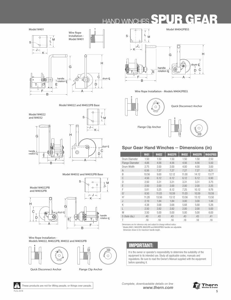
Spur Gear Hand Winches – Dimensions (in)M401 M4022 M4022PB M4032 M4032PB M4042PBSS
drum dia. 1.50 1.50 1.50 1.50 1.50 2.50flange dia. 4.06 4.56 4.56 4.56 4.56 5.50drum width 2.75 2.00 2.00 4.00 4.00 3.00A 6.56 7.27 7.27 7.27 7.27 8.21B 10.56 9.00 12.12 11.00 14.12 13.77C 4.56 6.12 6.12 6.12 6.12 6.90D 2.50 3.31 3.31 3.31 3.31 3.75E 2.50 2.00 2.00 2.00 2.00 2.25F 5.81 5.25 8.12 7.25 10.12 9.76G 1 8.50 11.03 10.59 11.03 10.59 10.59H 1 11.28 13.56 13.12 13.56 13.12 13.50J 2.19 1.84 1.84 3.00 3.00 1.44K 4.38 3.68 3.68 5.68 5.68 5.26L 2.50 2.82 2.82 2.00 2.00 5.00M 3.50 5.00 5.00 5.00 5.00 6.00S(hole dia.) .40 .43 .43 .43 .43 .41T .18 .18 .18 .18 .18 .18Dimensions are for reference only and subject to change without notice.1 Models M401, M4022PB, M4032PB and M4042PBSS handles are
adjustable, dimension shown is for maximum handle length.
FB
T E
G
drum CLL
handlerotation C
D
A
C
H
L
K
M
J
S
Wire RopeInstallation -Model M401
A
C
H
D
FB
E
G
T
L M
KJ
S
drum CL
Lhandlerotation C
AFB
TC
E
G H
D
drum CL
Lhandlerotation C
A
C
H
D
FB
TE
Gdrum CL
Lhandlerotation C
wire rope
wire rope
LM
KJ
S
L M
KJ
S
Model M4022PB and M4032PB
Quick Disconnect Anchor Flange Clip Anchor
Flange Clip Anchor
Wire Rope Installation - Models M4022, M4022PB, M4032 and M4032PB
Model M4032 and M4032PB Base
Model M4022and M4032
Model M4022 and M4022PB Base
Model M401
Wire Rope Installation - Models M4042PBSS
Model M4042PBSS
See Additional Dimensions on Next Page
Quick Disconnect Anchor
Spur Gear Hand Winches — Dimensions (in) M401 M4022 M4022PB M4032 M4032PB M4042PBSS
Drum Diameter 1.50 1.50 1.50 1.50 1.50 2.50Flange Diameter 4.06 4.56 4.56 4.56 4.56 5.50Drum Width 2.75 2.00 2.00 4.00 4.00 3.00A 6.56 7.27 7.27 7.27 7.27 8.21B 10.56 9.00 12.12 11.00 14.12 13.77C 4.56 6.12 6.12 6.12 6.12 6.90D 2.50 3.31 3.31 3.31 3.31 3.75E 2.50 2.00 2.00 2.00 2.00 2.25F 5.81 5.25 8.12 7.25 10.12 9.76G1 8.50 11.03 10.59 11.03 10.59 10.59H1 11.28 13.56 13.12 13.56 13.12 13.50J 2.19 1.84 1.84 3.00 3.00 1.44K 4.38 3.68 3.68 5.68 5.68 5.26L 2.50 2.82 2.82 2.00 2.00 5.00M 3.50 5.00 5.00 5.00 5.00 6.00S (hole dia.) .40 .43 .43 .43 .43 .41T .18 .18 .18 .18 .18 .18Dimensions are for reference only and subject to change without notice.1 Models M401, M4022PB, M4032PB and M4042PBSS handles are adjustable.
Dimension shown is for maximum handle length.
IMPORTANT:It is the owner or operator’s responsibility to determine the suitability of the equipment to its intended use. Study all applicable codes, manuals and regulations. Be sure to read the Owner’s Manual supplied with the equipment before operating it.
ThernWinches & Cranes
6
Complete, downloadable details on linewww.thern.com
FLCL-0318
These products are not for lifting people, or things over people.
A FB
T
C
GH
D
KJ
SL
M
drum CLL
handlerotation C
E
A
C
H
D
FB
E
G
T
KJ
S LM
drum CLL
handlerotation C
Important: It is the owner's or operator's responsibility to determine the suitability of the equipment toits intended use. Study all applicable codes,manuals, and regulations. Be sure to read theOwner's Manual supplied with the equipmentbefore operating it.
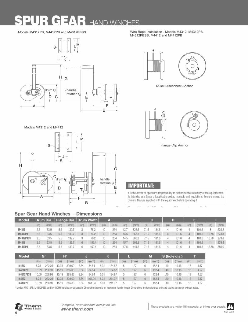
Models M4312 and M4412
Spur Gear Hand Winches – Dimensions (in)M4312 M4312PB M4312PBSS M4412 M4412PB
drum dia. 2.50 2.50 2.50 2.50 2.50flange dia. 5.50 5.50 5.50 5.50 5.50drum width 3.00 3.00 3.00 6.00 6.00A 10.00 10.00 10.00 10.00 10.00B 12.70 14.50 14.50 15.70 17.50C 7.15 7.15 7.15 7.15 7.15D 4.00 4.00 4.00 4.00 4.00E 4.00 4.00 4.00 4.00 4.00F 8.00 10.78 10.78 11.00 13.78G 1 8.75 10.59 10.59 8.75 10.59H 1 13.35 15.19 15.19 13.35 15.19J 3.34 3.34 3.34 6.34 6.34K 5.31 5.31 5.31 8.31 8.31L 5.00 5.00 5.00 5.00 5.00M 6.00 6.00 6.00 6.00 6.00S (hole dia.) .40 .40 .41 .40 .40T .18 .18 .18 .18 .18
Dimensions are for reference only and subject to change without notice.1 Models M4312PB, M4312PBSS and M4412PB handles are
adjustable, dimension shown is for maximum handle length.
Models M4312PB, M4412PB and M4312PBSS
wire rope
Wire Rope Installation - Models M4312, M4312PB,M4312PBSS, M4412 and M4412PB
Quick Disconnect Anchor
Flange Clip Anchor
SPUR GEAR HAND WINCHES
Spur Gear Hand Winches — DimensionsModel Drum Dia. Flange Dia. Drum Width A B C D E F
(in) (mm) (in) (mm) (in) (mm) (in) (mm) (in) (mm) (in) (mm) (in) (mm) (in) (mm) (in) (mm)M4312 2.5 63.5 5.5 139.7 3 76.2 10 254 12.7 322.6 7.15 181.6 4 101.6 4 101.6 8 203.2M4312PB 2.5 63.5 5.5 139.7 3 76.2 10 254 14.5 368.3 7.15 181.6 4 101.6 4 101.6 10.78 273.8M4312PBSS 2.5 63.5 5.5 139.7 3 76.2 10 254 14.5 368.3 7.15 181.6 4 101.6 4 101.6 10.78 273.8M4412 2.5 63.5 5.5 139.7 6 152.4 10 254 15.7 398.8 7.15 181.6 4 101.6 4 101.6 11 279.4M4412PB 2.5 63.5 5.5 139.7 6 152.4 10 254 17.5 444.5 7.15 181.6 4 101.6 4 101.6 13.78 350.0
Model G1 H1 J K L M S (hole dia.) T(in) (mm) (in) (mm) (in) (mm) (in) (mm) (in) (mm) (in) (mm) (in) (mm) (in) (mm)
M4312 8.75 222.25 13.35 339.09 3.34 84.84 5.31 134.87 5 127 6 152.4 .40 10.16 .18 4.57M4312PB 10.59 268.99 15.19 385.83 3.34 84.84 5.31 134.87 5 127 6 152.4 .40 10.16 .18 4.57M4312PBSS 10.59 268.99 15.19 385.83 3.34 84.84 5.31 134.87 5 127 6 152.4 .40 10.16 .18 4.57M4412 8.75 222.25 13.35 339.09 6.34 161.04 8.31 211.07 5 127 6 152.4 .40 10.16 .18 4.57M4412PB 10.59 268.99 15.19 385.83 6.34 161.04 8.31 211.07 5 127 6 152.4 .40 10.16 .18 4.57
1 Models M4312PB, M4312PBSS and M4412PB handles are adjustable. Dimension shown is for maximum handle length. Dimensions are for reference only and subject to change without notice.
IMPORTANT:It is the owner or operator’s responsibility to determine the suitability of the equipment to its intended use. Study all applicable codes, manuals and regulations. Be sure to read the Owner’s Manual supplied with the equipment before operating it.
ThernWinches & Cranes
7FLCL-0318
Complete, downloadable details on linewww.thern.comThese products are not for lifting people, or things over people.
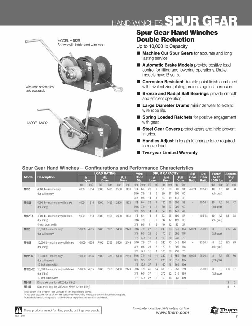
HAND WINCHES SPUR GEARMODEL M452BShown with brake and wire rope
MODEL M492
Wire rope assemblies sold separately
Spur Gear Hand Winches — Configurations and Performance Characteristics
Model DescriptionLOAD RATING Wire
Rope Dia.
DRUM CAPACITY 1 Sgl GearRatio
Dbl GearRatio
Force2
to lift1000 lbs
Approx.Ship Wt.
1stLayer
MidDrum
FullDrum
1stLayer
MidDrum
FullDrum
(lb) (kg) (lb) (kg) (lb) (kg) (in) (mm) (ft) (m) (ft) (m) (ft) (m) (lb) (kg) (lb) (kg)
M452 4000 lb – marine duty 4000 1814 3300 1496 2500 1133 1/4 6.4 23 7 130 39 300 91 4.42:1 19.54:1 10 4.5 83 38
(for pulling only) 5/16 7.9 18 5 89 27 200 60 (dbl gear)
3/8 9.5 14 4 64 19 140 42
M452B 4000 lb – marine duty with brake 4000 1814 3300 1496 2500 1133 1/4 6.4 23 7 130 39 300 91 — 19.54:1 10 4.5 91 42
(for lifting) 5/16 7.9 18 5 89 27 200 60 (dbl gear)
3/8 9.5 14 4 64 19 140 42
M452B-A 4000 lb – marine duty with brake 4000 1814 3300 1496 2500 1133 1/4 6.4 13 3 83 25 190 57 — 19.54:1 10 4.5 83 38
(for lifting) 5/16 7.9 9 2 56 17 120 36 (dbl gear)
4-inch drum width 3/8 9.5 7 2 40 12 89 27
M492 10,000 lb – marine duty 10,000 4535 7400 3356 5400 2449 5/16 7.9 27 8 240 73 540 164 5.00:1 25.00:1 8 3.6 166 76
(for pulling only) 3/8 9.5 21 6 170 51 390 118 (dbl gear)
1/2 12.7 15 4 100 30 230 70
M492B 10,000 lb – marine duty with brake 10,000 4535 7400 3356 5400 2449 5/16 7.9 27 8 240 73 540 164 — 25.00:1 8 3.6 173 79
(for lifting) 3/8 9.5 21 6 170 51 390 118 (dbl gear)
1/2 12.7 15 4 100 30 230 70
M492-12 10,000 lb – marine duty 10,000 4535 7400 3356 5400 2449 5/16 7.9 46 14 380 115 850 259 5.00:1 25.00:1 8 3.6 175 80
(for pulling only) 3/8 9.5 37 11 270 82 610 185 (dbl gear)
12-inch drum width 1/2 12.7 27 8 160 48 360 109
M492B-12 10,000 lb – marine duty with brake 10,000 4535 7400 3356 5400 2449 5/16 7.9 46 14 380 115 850 259 — 25.00:1 8 3.6 190 87
(for lifting) 3/8 9.5 37 11 270 82 610 185 (dbl gear)
12-inch drum width 1/2 12.7 27 8 160 48 360 109
MB451 Disc brake only for M452 (for lifting) 13 6
MB491 Disc brake only for M492 and M492-12 (for lifting) 15 7
Please contact Thern or nearest Thern Distributor for firm, fixed price and delivery.1 Actual drum capacities may be 25-30% less due to nonuniform winding. Wire rope tension will also affect drum capacity.2 Approximate handle force required to lift 1000 lb with an empty drum and maximum handle length.
Spur Gear Hand Winches Double ReductionUp to 10,000 lb Capacity■ Machine Cut Spur Gears for accurate and long
lasting service.
■ Automatic Brake Models provide positive load control for lifting and lowering operations. Brake models have B suffix.
■ Corrosion Resistant durable paint finish combined with trivalent zinc plating protects against corrosion.
■ Bronze and Radial Ball Bearings provide smooth and efficient operation.
■ Large Diameter Drums minimize wear to extend wire rope life.
■ Spring Loaded Ratchets for positive engagement with gear.
■ Steel Gear Covers protect gears and help prevent injuries.
■ Handles Adjust in length to change force required to move load.
■ Two-year Limited Warranty
ThernWinches & Cranes
8
Complete, downloadable details on linewww.thern.com
FLCL-0318
These products are not for lifting people, or things over people.
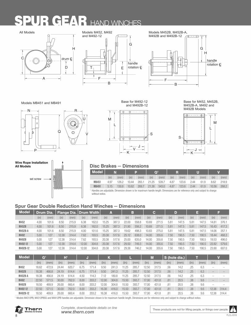
SPUR GEAR HAND WINCHES
Disc Brakes – Dimensions (in)MB451 MB491
N 4.97 5.15P 10.44 10.62Q 1 21.25 21.38R 4.87 4.87U 2.44 2.44V 8.62 10.56Dimensions are for reference only and aresubject to change without notice.1 Handles are adjustable, dimension shown is
for maximum handle length.
Spur Gear Hand Winches – Dimensions (in)M452 M452B M452B-A M492 M492B M492-12 M492B-12
drum dia. 4.00 4.00 4.00 5.00 5.00 5.00 5.00flange dia. 8.50 8.50 8.50 12.38 12.38 12.38 12.38drum width 6.38 6.38 4.00 7.62 7.62 12.00 12.00A 15.25 15.25 15.25 20.38 20.38 20.38 20.38B 22.00 21.90 19.62 25.12 25.00 29.50 29.38C 10.69 10.69 10.83 14.00 14.00 14.00 14.00D 5.81 5.81 5.81 7.50 7.50 7.50 7.50E 5.81 5.81 5.81 7.50 7.50 7.50 7.50F 14.81 16.43 14.06 18.44 19.53 22.82 23.90G 1 18.62 18.38 18.38 22.50 18.50 22.50 18.50H 1 24.44 24.19 24.19 30.00 26.00 30.00 26.00J 6.75 6.75 4.50 8.00 8.00 8.00 8.00K 9.50 9.50 7.12 12.00 12.00 16.38 16.38L 11.25 11.25 11.25 15.50 15.50 15.50 15.50M 12.50 12.50 12.50 17.00 17.00 17.00 17.00S (hole dia.) .56 .56 .56 .81 .81 .81 .81T .25 .25 .25 .38 .38 .38 .38V – – – – – 12.38 12.38
Dimensions are for reference only and subject to change without notice.1 Handles are adjustable, dimension shown is for maximum handle length.
Q
U
V
N
P
R
FB
E
G
T Lhandlerotation C
A
C
H
D
drum CL
FB
Lhandlerotation C
GH
K
S
LM
JVK
S
LM
J
Important: It is the owner's or operator's responsi-bility to determine the suitability of theequipment to its intended use. Study allapplicable codes, manuals, and regula-tions. Be sure to read the Owner'sManual supplied with the equipmentbefore operating it.
Models MB451 and MB491 Base for M452, M452B,M452B-A, M492 andM492B Models
Base for M492-12 and M492B-12
Models M452B, M452B-A,M492B and M492B-12
Models M452, M492and M492-12
All Models
set screw Wire Rope Installation - All Models
Spur Gear Double Reduction Hand Winches — DimensionsModel Drum Dia. Flange Dia. Drum Width A B C D E F
(in) (mm) (in) (mm) (in) (mm) (in) (mm) (in) (mm) (in) (mm) (in) (mm) (in) (mm) (in) (mm)M452 4.00 101.6 8.50 215.9 6.38 162.0 15.25 387.3 22.00 558.8 10.69 271.5 5.81 147.5 5.81 147.5 14.81 376.1M452B 4.00 101.6 8.50 215.9 6.38 162.0 15.25 387.3 21.90 556.2 10.69 271.5 5.81 147.5 5.81 147.5 16.43 417.3M452B-A 4.00 101.6 8.50 215.9 4.00 101.6 15.25 387.3 19.62 498.3 10.83 275.0 5.81 147.5 5.81 147.5 14.06 357.1M492 5.00 127 12.38 314.4 7.62 193.5 20.38 517.6 25.12 638.0 14.00 355.6 7.50 190.5 7.50 190.5 18.44 468.3M492B 5.00 127 12.38 314.4 7.62 193.5 20.38 517.6 25.00 635.0 14.00 355.6 7.50 190.5 7.50 190.5 19.53 496.0M492-12 5.00 127 12.38 314.4 12.00 304.8 20.38 517.6 29.50 749.3 14.00 355.6 7.50 190.5 7.50 190.5 22.82 579.6M492B-12 5.00 127 12.38 314.4 12.00 304.8 20.38 517.6 29.38 746.2 14.00 355.6 7.50 190.5 7.50 190.5 23.90 607.0
Model G1 H1 J K L M S (hole dia.) T V(in) (mm) (in) (mm) (in) (mm) (in) (mm) (in) (mm) (in) (mm) (in) (mm) (in) (mm) (in) (mm)
M452 18.62 472.9 24.44 620.7 6.75 171.4 9.50 241.3 11.25 285.7 12.50 317.5 .56 14.2 .25 6.3 — —M452B 18.38 466.8 24.19 614.4 6.75 171.4 9.50 241.3 11.25 285.7 12.50 317.5 .56 14.2 .25 6.3 — —M452B-A 18.38 466.8 24.19 614.4 4.50 114.3 7.12 180.8 11.25 285.7 12.50 317.5 .56 14.2 .25 6.3 — —M492 22.50 571.5 30.00 762.0 8.00 203.2 12.00 304.8 15.50 393.7 17.00 431.8 .81 20.5 .38 9.6 — —M492B 18.50 469.9 26.00 660.4 8.00 203.2 12.00 304.8 15.50 393.7 17.00 431.8 .81 20.5 .38 9.6 — —M492-12 22.50 571.5 30.00 762.0 8.00 203.2 16.38 416.0 15.50 393.7 17.00 431.8 .81 20.5 .38 9.6 12.38 314.4M492B-12 18.50 469.9 26.00 660.4 8.00 203.2 16.38 416.0 15.50 393.7 17.00 431.8 .81 20.5 .38 9.6 12.38 314.4
1 Models M4312PB, M4312PBSS and M4412PB handles are adjustable. Dimension shown is for maximum handle length. Dimensions are for reference only and subject to change without notice.
Disc Brakes – Dimensions (in)MB451 MB491
N 4.97 5.15P 10.44 10.62Q 1 21.25 21.38R 4.87 4.87U 2.44 2.44V 8.62 10.56Dimensions are for reference only and aresubject to change without notice.1 Handles are adjustable, dimension shown is
for maximum handle length.
Spur Gear Hand Winches – Dimensions (in)M452 M452B M452B-A M492 M492B M492-12 M492B-12
drum dia. 4.00 4.00 4.00 5.00 5.00 5.00 5.00flange dia. 8.50 8.50 8.50 12.38 12.38 12.38 12.38drum width 6.38 6.38 4.00 7.62 7.62 12.00 12.00A 15.25 15.25 15.25 20.38 20.38 20.38 20.38B 22.00 21.90 19.62 25.12 25.00 29.50 29.38C 10.69 10.69 10.83 14.00 14.00 14.00 14.00D 5.81 5.81 5.81 7.50 7.50 7.50 7.50E 5.81 5.81 5.81 7.50 7.50 7.50 7.50F 14.81 16.43 14.06 18.44 19.53 22.82 23.90G 1 18.62 18.38 18.38 22.50 18.50 22.50 18.50H 1 24.44 24.19 24.19 30.00 26.00 30.00 26.00J 6.75 6.75 4.50 8.00 8.00 8.00 8.00K 9.50 9.50 7.12 12.00 12.00 16.38 16.38L 11.25 11.25 11.25 15.50 15.50 15.50 15.50M 12.50 12.50 12.50 17.00 17.00 17.00 17.00S (hole dia.) .56 .56 .56 .81 .81 .81 .81T .25 .25 .25 .38 .38 .38 .38V – – – – – 12.38 12.38
Dimensions are for reference only and subject to change without notice.1 Handles are adjustable, dimension shown is for maximum handle length.
Q
U
V
N
P
R
FB
E
G
T Lhandlerotation C
A
C
H
D
drum CL
FB
Lhandlerotation C
GH
K
S
LM
JVK
S
LM
J
Important: It is the owner's or operator's responsi-bility to determine the suitability of theequipment to its intended use. Study allapplicable codes, manuals, and regula-tions. Be sure to read the Owner'sManual supplied with the equipmentbefore operating it.
Models MB451 and MB491 Base for M452, M452B,M452B-A, M492 andM492B Models
Base for M492-12 and M492B-12
Models M452B, M452B-A,M492B and M492B-12
Models M452, M492and M492-12
All Models
set screw Wire Rope Installation - All Models
Wire Rope Installation All Models Disc Brakes — Dimensions
Model N P Q1 R U V(in) (mm) (in) (mm) (in) (mm) (in) (mm) (in) (mm) (in) (mm)
MB451 4.97 126.2 10.44 265.1 21.25 539.7 4.87 123.6 2.44 61.9 8.62 218.9MB491 5.15 130.8 10.62 269.7 21.38 543.0 4.87 123.6 2.44 61.9 10.56 268.2
1 Handles are adjustable. Dimension shown is for maximum handle length. Dimensions are for reference only and subject to change without notice.
ThernWinches & Cranes
9FLCL-0318
Complete, downloadable details on linewww.thern.comThese products are not for lifting people, or things over people.
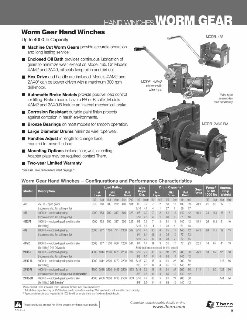
Worm Gear Hand WinchesUp to 4000 lb Capacity
■ Machine Cut Worm Gears provide accurate operation and long lasting service.
■ Enclosed Oil Bath provides continuous lubrication of gears to minimize wear, except on Model 465. On Models 4WM2 and 2W40, oil seals keep oil in and dirt out.
■ Hex Drive and handle are included. Models 4WM2 and 2W40* can be power driven with a maximum 300 rpm drill-motor.
■ Automatic Brake Models provide positive load control for lifting. Brake models have a PB or B suffix. Models 4WM2 and 2W40-B feature an internal mechanical brake.
■ Corrosion Resistant durable paint finish protects against corrosion in harsh environments.
■ Bronze Bearings on most models for smooth operation.
■ Large Diameter Drums minimize wire rope wear.
■ Handles Adjust in length to change force required to move the load.
■ Mounting Options include floor, wall, or ceiling. Adapter plate may be required, contact Thern.
■ Two-year Limited Warranty
HAND WINCHES WORM GEAR
MODEL 4WM2shown with
wire rope
MODEL 465
Worm Gear Hand Winches — Configurations and Performance Characteristics
Model DescriptionLoad Rating Wire
Rope Dia.
Drum Capacity 1
GearRatio
Force 2
to lift1000 lbs
Approx.Ship
Weight1st
LayerMid
DrumFull
Drum1st
LayerMid
DrumFull
Drum
(lb) (kg) (lb) (kg) (lb) (kg) (in) (mm) (ft) (m) (ft) (m) (ft) (m) (lb) (kg) (lb) (kg)465 750 lb – open gears 750 340 600 272 400 181 1/8 3.2 7 2 58 17 130 39 20:1 21 9.5 12 5
(recommended for pulling only) 3/16 4.8 4 1 27 8 59 17 462 1000 lb – enclosed gearing 1000 453 700 317 500 226 1/8 3.2 7 2 61 18 140 42 15:1 34 15.4 15 7
(recommended for pulling only) 3/16 4.8 4 1 28 8 61 18 4622PB 1000 lb – enclosed gearing with brake 1000 453 700 317 500 226 1/8 3.2 7 2 61 18 140 42 15:1 26 11.8 21 10
(for lifting) 3/16 4.8 4 1 28 8 61 18 472 2000 lb – enclosed gearing 2000 907 1700 771 1300 589 3/16 4.8 15 4 65 19 140 42 24:1 24 10.9 32 15
(recommended for pulling only) 1/4 6.4 11 3 35 10 77 23 5/16 7.9 8 0 23 7 52 15
4WM2 2000 lb – enclosed gearing with brake 2000 907 1500 680 1200 544 1/4 6.4 11 3 35 10 77 23 32:1 14 6.4 41 19
(for lifting) Drill Driveable 3/16 (not recommended for this winch)2W40-L 4000 lb – enclosed gearing 4000 1814 2800 1270 2200 997 5/16 7.9 18 5 91 27 200 60 26:1 18 8.2 126 58
(recommended for pulling only) 3/8 9.5 14 4 65 19 140 422W40-BL 4000 lb – enclosed gearing with brake 4000 1814 2800 1270 2200 997 5/16 7.9 18 5 91 27 200 60 145 66
(for lifting) 3/8 9.5 14 4 65 19 140 422W40-M 4600 lb – enclosed gearing 4600 2086 3300 1496 2500 1133 5/16 7.9 18 5 91 27 200 60 31:1 11 5.0 123 56
(recommended for pulling only) Drill Driveable* 3/8 9.5 14 4 65 19 140 422W40-BM 4600 lb – enclosed gearing with brake 4600 2086 3300 1496 2500 1133 5/16 7.9 18 5 91 27 200 60 141 64
(for lifting) Drill Driveable* 3/8 9.5 14 4 65 19 140 42Please contact Thern or nearest Thern Distributor for firm fixed price and delivery.1 Actual drum capacities may be 25-30% less, due to nonuniform winding. Wire rope tension will also affect drum capacity.2 Approximate handle force required to lift 1000 lb with an empty drum, and maximum handle length.
*See Drill Drive performance chart on page 11.
MODEL 2W40-BM
Wire rope assemblies
sold separately
ThernWinches & Cranes
10
Complete, downloadable details on linewww.thern.com
FLCL-0318
These products are not for lifting people, or things over people.
Worm Gear Hand Winches – Dimensions (in)465 462 4622PB 472 482 482B 4WM2
drum dia. 1.50 1.50 1.50 2.50 4.00 4.00 2.50flange dia. 4.00 4.06 4.06 5.00 8.50 8.50 5.00drum width 2.81 2.81 2.81 5.00 6.50 6.50 5.00A 6.50 7.75 7.50 10.12 13.97 13.97 13.50B 10.50 10.25 11.81 12.00 18.88 20.94 15.56C 5.44 5.63 5.62 7.12 12.80 12.80 8.56D 3.40 2.38 2.40 3.06 5.75 5.75 3.31E 1.40 4.38 4.38 5.81 10.38 10.38 6.04F 6.38 5.88 7.60 7.94 12.50 15.47 11.56G 8.75 9.00 10.59 7.25 12.25 18.38 10.59H 10.59 13.38 15.59 13.38 22.62 29.19 17.30 J 2.00 2.00 2.00 3.75 7.00 7.00 1.75K 5.75 4.44 4.44 6.69 9.00 9.00 3.75L 2.50 2.50 2.50 4.00 6.00 6.00 4.00M 4.50 3.50 3.50 5.00 8.00 8.00 13.50S (hole dia.) .40 .40 .40 .40 .56 .56 .41T .19 .19 .19 .25 .50 .50 –
Dimensions are for reference only and subject to change without notice.
FB
TE
G
D
A
C
H
M
KJ
S L
drum CL
Lhandlerotation C
T D
A
H
FB
E
G
C
M
KJ
S L
drum CLL
handlerotation C
handlerotation UP
FB
A
Ddrum CL
1.125 in. hex input
C
GHhandlerotation CL
handlerotation UP
E
M
L
KJS
(holedia.)
T D
A
H
FB
E
G
C
M
KJ
S L
drum CLL
handlerotation C
Wire Rope InstallationModels 462 and 4622PBbolt
setscrew
Model 465
Wire Rope InstallationModel 465
Model 4WM2
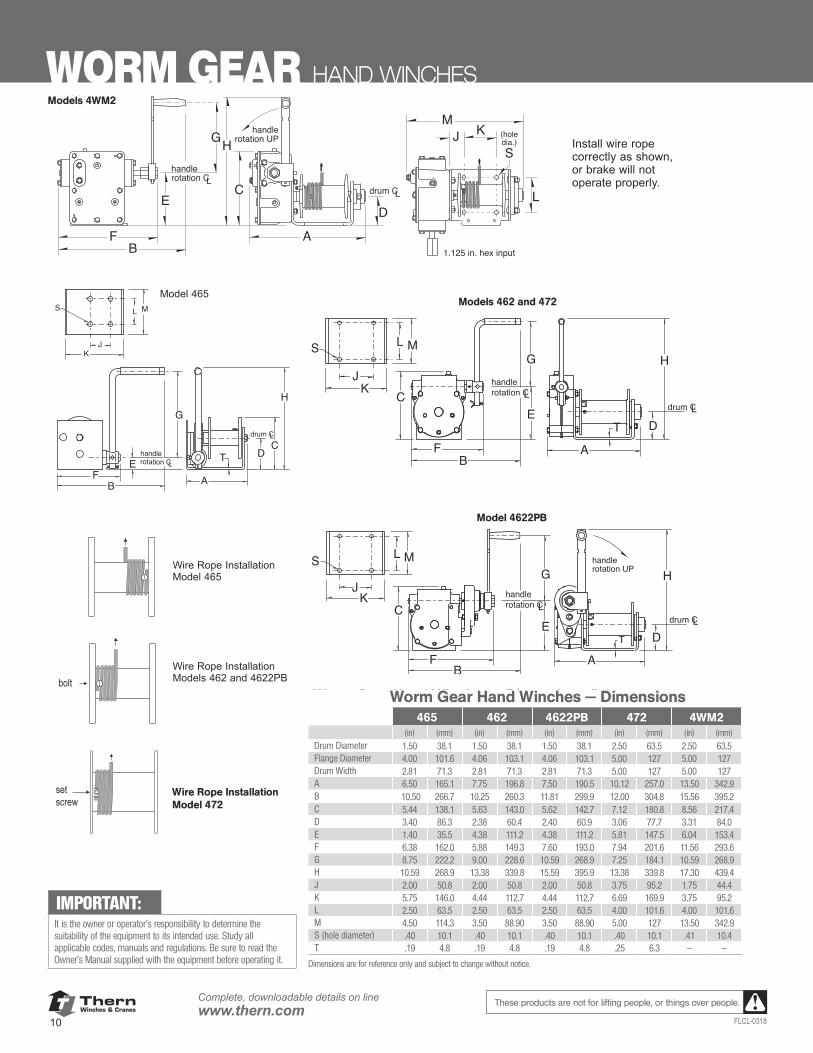
Install wire ropecorrectly as shown,or brake will notoperate properly.
Important: It is the owner's or operator's responsibilityto determine the suitability of the equip-ment to its intended use. Study all applica-ble codes, manuals, and regulations. Besure to read the Owner's Manual suppliedwith the equipment before operating it.
WORM GEAR HAND WINCHES
Models 462 and 472
Model 4622PB
Wire Rope InstallationModel 472
Worm Gear Hand Winches — Dimensions465 462 4622PB 472 4WM2
(in) (mm) (in) (mm) (in) (mm) (in) (mm) (in) (mm)
Drum Diameter 1.50 38.1 1.50 38.1 1.50 38.1 2.50 63.5 2.50 63.5Flange Diameter 4.00 101.6 4.06 103.1 4.06 103.1 5.00 127 5.00 127Drum Width 2.81 71.3 2.81 71.3 2.81 71.3 5.00 127 5.00 127A 6.50 165.1 7.75 196.8 7.50 190.5 10.12 257.0 13.50 342.9B 10.50 266.7 10.25 260.3 11.81 299.9 12.00 304.8 15.56 395.2C 5.44 138.1 5.63 143.0 5.62 142.7 7.12 180.8 8.56 217.4D 3.40 86.3 2.38 60.4 2.40 60.9 3.06 77.7 3.31 84.0E 1.40 35.5 4.38 111.2 4.38 111.2 5.81 147.5 6.04 153.4F 6.38 162.0 5.88 149.3 7.60 193.0 7.94 201.6 11.56 293.6G 8.75 222.2 9.00 228.6 10.59 268.9 7.25 184.1 10.59 268.9H 10.59 268.9 13.38 339.8 15.59 395.9 13.38 339.8 17.30 439.4J 2.00 50.8 2.00 50.8 2.00 50.8 3.75 95.2 1.75 44.4K 5.75 146.0 4.44 112.7 4.44 112.7 6.69 169.9 3.75 95.2L 2.50 63.5 2.50 63.5 2.50 63.5 4.00 101.6 4.00 101.6M 4.50 114.3 3.50 88.90 3.50 88.90 5.00 127 13.50 342.9S (hole diameter) .40 10.1 .40 10.1 .40 10.1 .40 10.1 .41 10.4T .19 4.8 .19 4.8 .19 4.8 .25 6.3 — —
Dimensions are for reference only and subject to change without notice.
IMPORTANT:It is the owner or operator’s responsibility to determine the suitability of the equipment to its intended use. Study all applicable codes, manuals and regulations. Be sure to read the Owner’s Manual supplied with the equipment before operating it.
Models 4WM2
ThernWinches & Cranes
11FLCL-0318
Complete, downloadable details on linewww.thern.comThese products are not for lifting people, or things over people.
HAND WINCHES WORM GEAR
D T
L
J
S
M
K
H
A
EC
F
B
G
B
A
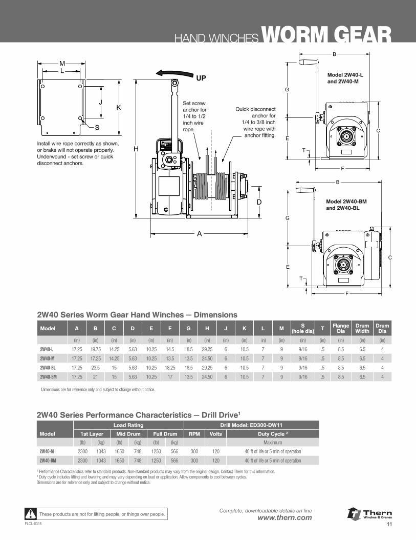
2W40 Series Worm Gear Hand Winches — Dimensions
Model A B C D E F G H J K L M S (hole dia) T Flange
DiaDrum Width
Drum Dia
(in) (in) (in) (in) (in) (in) in) (in) (in) (in) in) (in) (in) (in) (in) (in) (in)
2W40-L 17.25 19.75 14.25 5.63 10.25 14.5 18.5 29.25 6 10.5 7 9 9/16 .5 8.5 6.5 4
2W40-M 17.25 17.25 14.25 5.63 10.25 13.5 13.5 24.50 6 10.5 7 9 9/16 .5 8.5 6.5 4
2W40-BL 17.25 23.5 15 5.63 10.25 18.25 18.5 29.25 6 10.5 7 9 9/16 .5 8.5 6.5 4
2W40-BM 17.25 21 15 5.63 10.25 17 13.5 24.50 6 10.5 7 9 9/16 .5 8.5 6.5 4
Dimensions are for reference only and subject to change without notice.
2W40 Series Performance Characteristics — Drill Drive1
Load Rating Drill Model: ED300-DW11
Model 1st Layer Mid Drum Full Drum RPM Volts Duty Cycle 2
(lb) (kg) (lb) (kg) (lb) (kg) Maximum
2W40-M 2300 1043 1650 748 1250 566 300 120 40 ft of life or 5 min of operation
2W40-BM 2300 1043 1650 748 1250 566 300 120 40 ft of life or 5 min of operation
1 Performance Characteristics refer to standard products. Non-standard products may vary from the original design. Contact Thern for this information.2 Duty cycle includes lifting and lowering and may vary depending on load or application. Allow components to cool between cycles.Dimensions are for reference only and subject to change without notice.
Install wire rope correctly as shown, or brake will not operate properly. Underwound - set screw or quick disconnect anchors.
D T
L
J
S
M
K
H
A
EC
F
B
G
B
A
Model 2W40-L and 2W40-M
C
D T
L
J
S
K
M
H
E
G
A
B
F
B
A
Model 2W40-BM and 2W40-BL
D
H
A
UP
Set screw anchor for 1/4 to 1/2 inch wire rope.
Quick disconnect anchor for
1/4 to 3/8 inch wire rope with anchor fitting.
ThernWinches & Cranes
12
Complete, downloadable details on linewww.thern.com
FLCL-0318
These products are not for lifting people, or things over people.
PORTABLE POWER WINCHES
MOVE IT WITH CONFIDENCE
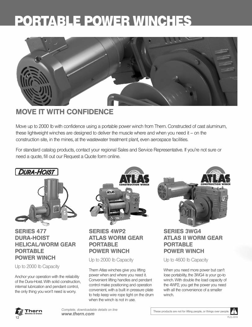
Move up to 2000 lb with confidence using a portable power winch from Thern. Constructed of cast aluminum, these lightweight winches are designed to deliver the muscle where and when you need it – on the construction site, in the mines, at the wastewater treatment plant, even aerospace facilities.
For standard catalog products, contact your regional Sales and Service Representative. If you’re not sure or need a quote, fill out our Request a Quote form online.
SERIES 477DURA-HOISTHELICAL/WORM GEARPORTABLEPOWER WINCH
Up to 2000 lb Capacity
Anchor your operation with the reliability of the Dura-Hoist. With solid construction, internal lubrication and pendant control, the only thing you won’t need is worry.
SERIES 4WP2ATLAS WORM GEARPORTABLEPOWER WINCH
Up to 2000 lb Capacity
Thern Atlas winches give you lifting power when and where you need it. Convenient lifting handles and pendant control make positioning and operation convenient, with a built in pressure plate to help keep wire rope tight on the drum when the winch is not in use.
SERIES 3WG4ATLAS II WORM GEARPORTABLEPOWER WINCH
Up to 4600 lb Capacity
When you need more power but can’t lose portability, the 3WG4 is your go-to winch. With double the load capacity of the 4WP2, you get the power you need with all the convenience of a smaller winch.
II
13FLCL-0318
These products are not for lifting people, or things over people.
PORTABLE POWER WINCHES
Made in the USA
Wire rope assemblies sold separately
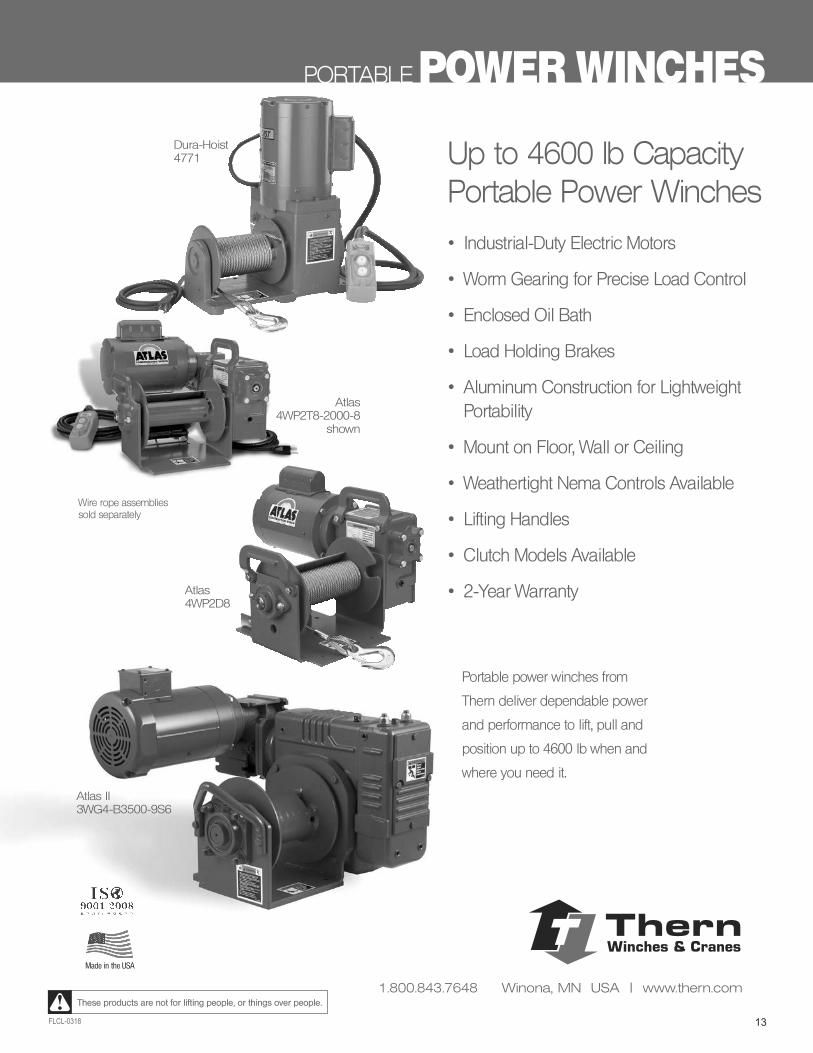
Up to 4600 lb CapacityPortable Power Winches
• Industrial-Duty Electric Motors
• Worm Gearing for Precise Load Control
• Enclosed Oil Bath
• Load Holding Brakes
• Aluminum Construction for Lightweight Portability
• Mount on Floor, Wall or Ceiling
• Weathertight Nema Controls Available
• Lifting Handles
• Clutch Models Available
• 2-Year Warranty
Portable power winches from
Thern deliver dependable power
and performance to lift, pull and
position up to 4600 lb when and
where you need it.
Atlas II 3WG4-B3500-9S6
Dura-Hoist4771
Atlas 4WP2T8-2000-8
shown
Atlas 4WP2D8
ThernWinches & Cranes
1.800.843.7648 Winona, MN USA | www.thern.com
ThernWinches & Cranes
14
Complete, downloadable details on linewww.thern.com
FLCL-0318
These products are not for lifting people, or things over people.
POWER WINCHES PORTABLE
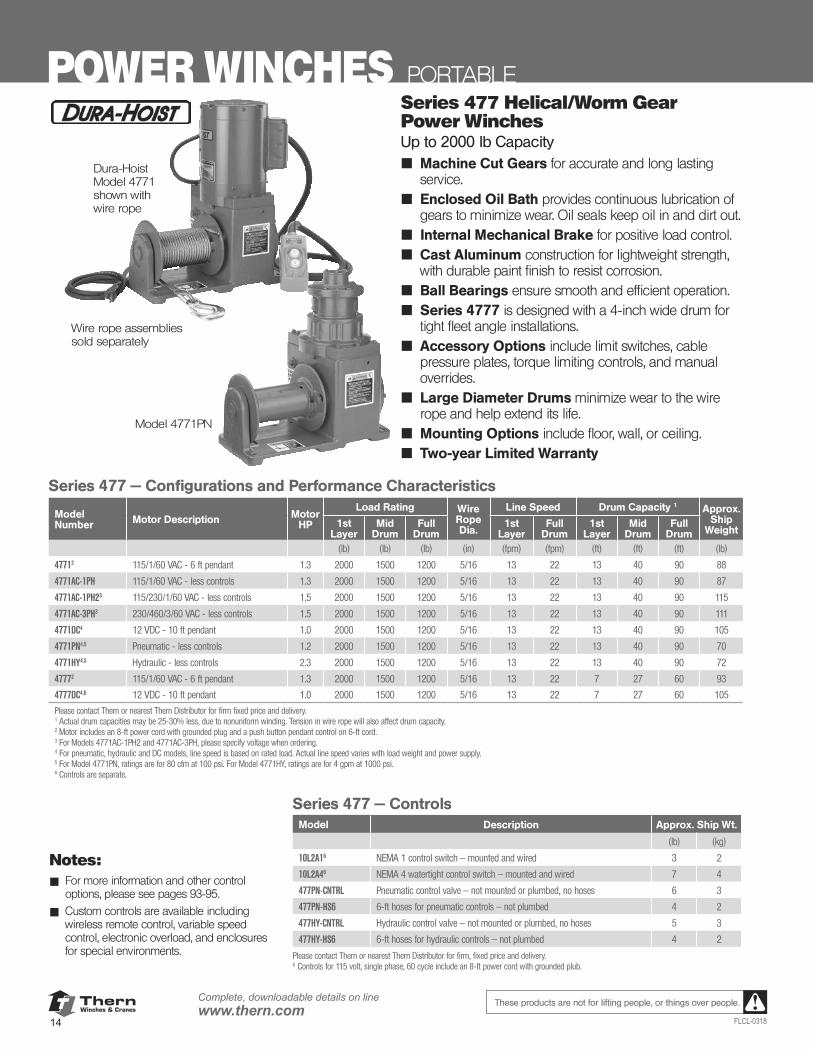
Dura-HoistModel 4771 shown with wire rope
Wire rope assembliessold separately
Model 4771PN
Series 477 — Configurations and Performance Characteristics
ModelNumber Motor Description Motor
HP
Load Rating Wire Rope Dia.
Line Speed Drum Capacity 1 Approx.Ship
Weight1st
LayerMid
DrumFull
Drum1st
LayerFull
Drum1st
LayerMid
DrumFull
Drum(lb) (lb) (lb) (in) (fpm) (fpm) (ft) (ft) (ft) (lb)
47712 115/1/60 VAC - 6 ft pendant 1.3 2000 1500 1200 5/16 13 22 13 40 90 88
4771AC-1PH 115/1/60 VAC - less controls 1.3 2000 1500 1200 5/16 13 22 13 40 90 87
4771AC-1PH23 115/230/1/60 VAC - less controls 1.5 2000 1500 1200 5/16 13 22 13 40 90 115
4771AC-3PH3 230/460/3/60 VAC - less controls 1.5 2000 1500 1200 5/16 13 22 13 40 90 111
4771DC4 12 VDC - 10 ft pendant 1.0 2000 1500 1200 5/16 13 22 13 40 90 105
4771PN4,5 Pneumatic - less controls 1.2 2000 1500 1200 5/16 13 22 13 40 90 70
4771HY4,5 Hydraulic - less controls 2.3 2000 1500 1200 5/16 13 22 13 40 90 72
47772 115/1/60 VAC - 6 ft pendant 1.3 2000 1500 1200 5/16 13 22 7 27 60 93
4777DC4,6 12 VDC - 10 ft pendant 1.0 2000 1500 1200 5/16 13 22 7 27 60 105
Please contact Thern or nearest Thern Distributor for firm fixed price and delivery.1 Actual drum capacities may be 25-30% less, due to nonuniform winding. Tension in wire rope will also affect drum capacity.2 Motor includes an 8-ft power cord with grounded plug and a push button pendant control on 6-ft cord.3 For Models 4771AC-1PH2 and 4771AC-3PH, please specify voltage when ordering.4 For pneumatic, hydraulic and DC models, line speed is based on rated load. Actual line speed varies with load weight and power supply.5 For Model 4771PN, ratings are for 80 cfm at 100 psi. For Model 4771HY, ratings are for 4 gpm at 1000 psi.6 Controls are separate.
Notes:■ For more information and other control
options, please see pages 93-95.
■ Custom controls are available including wireless remote control, variable speed control, electronic overload, and enclosures for special environments.
Series 477 Helical/Worm Gear Power WinchesUp to 2000 lb Capacity■ Machine Cut Gears for accurate and long lasting
service.■ Enclosed Oil Bath provides continuous lubrication of
gears to minimize wear. Oil seals keep oil in and dirt out.■ Internal Mechanical Brake for positive load control.■ Cast Aluminum construction for lightweight strength,
with durable paint finish to resist corrosion.■ Ball Bearings ensure smooth and efficient operation.■ Series 4777 is designed with a 4-inch wide drum for
tight fleet angle installations.■ Accessory Options include limit switches, cable
pressure plates, torque limiting controls, and manual overrides.
■ Large Diameter Drums minimize wear to the wire rope and help extend its life.
■ Mounting Options include floor, wall, or ceiling.■ Two-year Limited Warranty
Series 477 — ControlsModel Description Approx. Ship Wt.
(lb) (kg)
10L2A16 NEMA 1 control switch — mounted and wired 3 2
10L2A46 NEMA 4 watertight control switch — mounted and wired 7 4
477PN-CNTRL Pneumatic control valve — not mounted or plumbed, no hoses 6 3
477PN-HS6 6-ft hoses for pneumatic controls — not plumbed 4 2
477HY-CNTRL Hydraulic control valve — not mounted or plumbed, no hoses 5 3
477HY-HS6 6-ft hoses for hydraulic controls — not plumbed 4 2
Please contact Thern or nearest Thern Distributor for firm, fixed price and delivery.6 Controls for 115 volt, single phase, 60 cycle include an 8-ft power cord with grounded plub.
ThernWinches & Cranes
15FLCL-0318
Complete, downloadable details on linewww.thern.comThese products are not for lifting people, or things over people.
PORTABLE POWER WINCHES
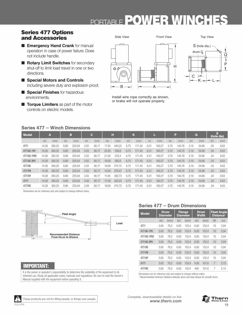
Series 477 — Winch DimensionsModel A B C H K L P Q S
(hole dia)(in) (mm) (in) (mm) (in) (mm) (in) (mm) (in) (mm) in) (mm) (in) (mm) (in) (mm) (in) (mm)
4771 14.38 365.25 8.86 225.04 3.55 90.17 17.45 443.23 6.75 171.45 6.31 160.27 5.70 144.78 2.16 54.86 .34 8.63
4771AC-1PH 14.38 365.25 8.86 225.04 3.55 90.17 22.00 558.8 6.75 171.45 6.31 160.27 5.70 144.78 2.16 54.86 .34 8.63
4771AC-1PH2 14.38 365.25 8.86 225.04 3.55 90.17 21.00 533.4 6.75 171.45 6.31 160.27 5.70 144.78 2.16 54.86 .34 8.63
4771AC-3PH 14.38 365.25 8.86 225.04 3.55 90.17 19.00 482.6 6.75 171.45 6.31 160.27 5.70 144.78 2.16 54.86 .34 8.63
4771DC 14.38 365.25 8.86 225.04 3.55 90.17 18.69 474.72 6.75 171.45 6.31 160.27 5.70 144.78 2.16 54.86 .34 8.63
4771PN 14.38 365.25 8.86 225.04 3.55 90.17 14.94 379.47 6.75 171.45 6.31 160.27 5.70 144.78 2.16 54.86 .34 8.63
4771HY 14.38 365.25 8.86 225.04 3.55 90.17 11.84 300.73 6.75 171.45 6.31 160.27 5.70 144.78 2.16 54.86 .34 8.63
4777 14.38 365.25 8.86 225.04 3.49 90.17 17.45 443.23 6.75 171.45 6.31 160.27 5.70 144.78 2.16 54.86 .34 8.63
4777DC 14.38 365.25 8.86 225.04 3.49 90.17 18.69 474.72 6.75 171.45 6.31 160.27 5.70 144.78 2.16 54.86 .34 8.63
Dimensions are for reference only and subject to change without notice.
Series 477 — Drum Dimensions
Model Drum Diameter
Flange Diameter
Drum Width
Fleet Angle Distance1
(in) (mm) (in) (mm) (in) (mm) (ft) (m)
4771 3.00 76.2 6.00 152.4 6.00 152.4 10 3.04
4771AC-1PH 3.00 76.2 6.00 152.4 6.00 152.4 10 3.04
4771AC-1PH2 3.00 76.2 6.00 152.4 6.00 152.4 10 3.04
4771AC-3PH 3.00 76.2 6.00 152.4 6.00 152.4 10 3.04
4771DC 3.00 76.2 6.00 152.4 6.00 152.4 10 3.04
4771PN 3.00 76.2 6.00 152.4 6.00 152.4 10 3.04
4771HY 3.00 76.2 6.00 152.4 6.00 152.4 10 3.04
4777 3.00 76.2 6.00 152.4 4.00 101.6 7 2.13
4777DC 3.00 76.2 6.00 152.4 400 101.6 7 2.13
Dimensions are for reference only and subject to change without notice.1 Recommended minimum distance between drum and lead sheave for smooth drum.
Series 477 – Winch Dimensions (in)model number A B C H K L P Q S (hole dia.)4771 14.38 8.86 3.55 17.45 6.75 6.31 5.70 2.16 .344771AC-1PH 14.38 8.86 3.55 22.00 6.75 6.31 5.70 2.16 .344771AC-1PH2 14.38 8.86 3.55 21.00 6.75 6.31 5.70 2.16 .344771AC-3PH 14.38 8.86 3.55 19.00 6.75 6.31 5.70 2.16 .344771DC 14.38 8.86 3.55 18.69 6.75 6.31 5.70 2.16 .344771PN 14.38 8.86 3.55 14.94 6.75 6.31 5.70 2.16 .344771HY 14.38 8.86 3.55 11.84 6.75 6.31 5.70 2.16 .344777 14.38 8.86 3.49 17.45 6.75 6.31 5.70 2.16 .344777DC 14.38 8.86 3.49 18.69 6.75 6.31 5.70 2.16 34Dimensions are for reference only and subject to change without notice.
Important: It is the owner's or operator's responsi-bility to determine the suitability of theequipment to its intended use. Studyall applicable codes, manuals, and reg-ulations. Be sure to read the Owner'sManual supplied with the equipmentbefore operating it.
Install wire rope correctly as shown,or brake will not operate properly.
S (hole dia.)
drum CL
P
Q
KC
L
H
B A
Options and AccessoriesEmergency Hand Crank formanual operation in case ofpower failure. Does not includehandle.
Rotary Limit Switches for sec-ondary shut-off to limit loadtravel in one or two directions.
Special Motors and Controlsincluding severe duty andexplosion proof.
Special Finishes for hazardousenvironments.
Torque Limiters as part of themotor controls on electricmodels.
Series 477 – Drum Dimensionsmodel drum flange drum fleet angleextension diameter diameter width distance1
4771 3.00 in 6.00 in 6.00 in 10 ft4771AC-1PH 3.00 in 6.00 in 6.00 in 10 ft4771AC-1PH2 3.00 in 6.00 in 6.00 in 10 ft4771AC-3PH 3.00 in 6.00 in 6.00 in 10 ft4771DC 3.00 in 6.00 in 6.00 in 10 ft4771PN 3.00 in 6.00 in 6.00 in 10 ft4771HY 3.00 in 6.00 in 6.00 in 10 ft4777 3.00 in 6.00 in 4.00 in 7 ft4777DC 3.00 in 6.00 in 4.00 in 7 ftDimensions are for reference only and subject to change without notice.1 Recommended minimum distance between drum and lead sheave for smooth drum.
Recommended DistanceFrom Drum to Sheave
Fleet Angle
Load
Side View Front View Top ViewSeries 477 Options and Accessories■ Emergency Hand Crank for manual
operation in case of power failure. Does not include handle.
■ Rotary Limit Switches for secondary shut-off to limit load travel in one or two directions.
■ Special Motors and Controls including severe duty and explosion proof.
■ Special Finishes for hazardous environments.
■ Torque Limiters as part of the motor controls on electric models.
IMPORTANT:It is the owner or operator’s responsibility to determine the suitability of the equipment to its intended use. Study all applicable codes, manuals and regulations. Be sure to read the Owner’s Manual supplied with the equipment before operating it.
ThernWinches & Cranes
16
Complete, downloadable details on linewww.thern.com
FLCL-0318
These products are not for lifting people, or things over people.
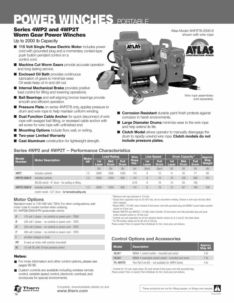
POWER WINCHES PORTABLEAtlas Model 4WP2T8-2000-8
shown with wire rope
Wire rope assembliessold separately
Notes:■ For more information and other control options, please see
pages 93-95.
■ Custom controls are available including wireless remote control, variable speed control, electronic overload, and enclosures for special environments.
Series 4WP2 and 4WP2T — Performance Characteristics
ModelNumber Motor Description Motor
HP
Load Rating Wire Rope Dia.1
Line Speed Drum Capacity 2 Approx.Ship
Weight1st
LayerMid
DrumFull
Drum1st
LayerFull
Drum1st
LayerMid
DrumFull
Drum(lb) (lb) (lb) (in) (fpm) (fpm) (ft) (ft) (ft) (lb)
4WP23 includes controls 1.3 2000 1500 1200 1/4 8 13 11 35 77 85
4WP2T8-2000-84 includes controls 1.3 2000 1200 800 1/4 8 19 19 130 280 101
ATLAS winch - 8" drum - for pulling or lifting 5/16 8 19 15 85 190
4WP2TC-2000-84 includes controls 1.3 2000 1200 800 1/4 8 19 12 87 190 106
clutch model - 5.5” drum - for horizontal pulling only
Series 4WP2 and 4WP2T Worm Gear Power WinchesUp to 2000 lb Capacity■ 115 Volt Single Phase Electric Motor includes power
cord with grounded plug and a momentary contact-type push button pendant control on a control cord.
■ Machine Cut Worm Gears provide accurate operation and long lasting service.
■ Enclosed Oil Bath provides continuous lubrication of gears to minimize wear. Oil seals keep oil in and dirt out.
■ Internal Mechanical Brake provides positive load control for lifting and lowering operations.
■ Ball Bearings and self-aligning bronze bearings provide smooth and efficient operation.
■ Pressure Plate on series 4WP2T8 only, applies pressure to drum and wire rope to help maintain uniform winding.
■ Dual Function Cable Anchor for quick disconnect of wire rope with swaged ball fitting, or recessed cable anchor with set screw for wire rope with unfinished end.
■ Mounting Options include floor, wall, or ceiling.■ Two-year Limited Warranty■ Cast Aluminum construction for lightweight strength.
■ Corrosion Resistant durable paint finish protects against corrosion in harsh environments.
■ Large Diameter Drums minimize wear to the wire rope and help extend its life.
■ Clutch Model allows operator to manually disengage the drum to rapidly unwind wire rope. Clutch models do not include pressure plates.
1 Minimum wire rope diameter is 1/4 inch.2 Actual drum capacities may be 25-30% less, due to nonuniform winding. Tension in wire rope will also affect
drum capacity.3 Model 4WP2, 115 VAC motor includes 8-foot power cord with grounded plug and NEMA 4 push button pendant
control on 6-foot cord.4 Models 4WP2T8 and 4WP2TC, 115 VAC motor includes 16-foot power cord with grounded plug and push
button pendant control on 16-foot cord.5 Controls are sold separately for all non-standard electric motors (A, B, D and E). See table below.6 For PN models, ratings are for 80 cfm at 100 psi.Please contact Thern or nearest Thern Distributor for firm, fixed price and delivery.
7 Controls for 115 volt, single phase, 60 cycle include 8-foot power cord with grounded plug.Please contact Thern or nearest Thern Distributor for firm, fixed price and delivery.
Motor Options Standard motor is 115/1/60 VAC TENV. For other configurations, add motor code to model number when ordering.EX: 4WP2t8-2000-8-PN (pneumatic winch)
A5 115 volt 1 phase — no controls or power cord — TENV
B5 230 volt 1 phase — no controls or power cord — TEFC
D5 230 volt 3 phase — no controls or power cord — TEFC
E5 460 volt 3 phase — no controls or power cord — TEFC
F all other voltages or hertz
PN6 8-vane air motor with controls (mounted)
DC 12 volt DC with 10-foot pendant control
Control Options and Accessories
Model Description Approx.Ship Wt.
10L2A17 NEMA 1 control switch - mounted and wired 3 lb
10L2A47 NEMA 4 watertight control switch - mounted and wired 7 lb
TPL-4WP2T8 Two Part Line Kit — not available for 4WP2 Series 4 lb
ThernWinches & Cranes
17FLCL-0318
Complete, downloadable details on linewww.thern.comThese products are not for lifting people, or things over people.
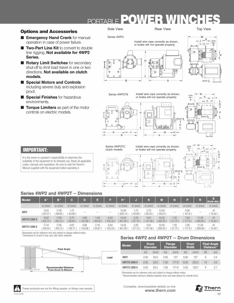
PORTABLE POWER WINCHESOptions and Accessories
Emergency Hand Crankfor manual operation incase of power failure.Does not include handle.
Two Part Line Kit to convert to double line rigging. Not available for4WP2 Series.
Rotary Limit Switchesfor secondary shut-off tolimit load travel in one ortwo directions. Not avail-able on clutch models.
Special Motors andControls including severeduty and explosion proof.
Special Finishes for haz-ardous environments.
Torque Limiters as partof the motor controls onelectric models.
Series 4WP2 and 4WP2T – Dimensions (in) model number A 1 B 1 C D E F H 1 J K M N P R S (hole dia.)4WP2 15.63 17.28 1.72 – – – 12.84 1.72 3.75 13.50 – 4.00 – .414WP2T8-2000-8 16.62 17.80 2.75 4.88 1.44 6.43 14.25 2.25 5.81 10.25 1.25 7.00 11.38 .414WP2TC-2000-8 17.34 17.80 4.02 4.88 2.16 6.43 14.25 2.25 5.81 10.25 1.25 7.00 11.38 .41Dimensions are for reference only and subject to change without notice.1 Dimensions A, B and H may vary with motor selection.
Series 4WP2 and 4WP2T – Drum Dimensionsmodel drum flange drum fleet angleextension diameter diameter width distance 2
4WP2 2.50 in 5.00 in 5.00 in 8 ft4WP2T8-2000-8 2.50 in 7.00 in 8.00 in 13 ft4WP2TC-2000-8 2.50 in 7.00 in 5.50 in 9 ftDimensions are for reference only and subject to change without notice.2 Recommended minimum distance between drum and lead sheave for
smooth drum.
Recommended DistanceFrom Drum to Sheave
Fleet Angle
Load
B A
M
H
S
drum CL
P
K
C(holedia.)
JSeries 4WP2
Install wire rope correctly as shown,or brake will not operate properly.
Side View Rear View Top View
R FB
M EA
M
H
S
drum CLdrum CL
P
N
D
KC
J(holedia.)
R FB
M
H drum CL
P
N
M EA
drum CL
D
KC
JS
(holedia.)
Important: It is the owner's or operator'sresponsibility to determine thesuitability of the equipment toits intended use. Study allapplicable codes, manuals, andregulations. Be sure to readthe Owner's Manual suppliedwith the equipment beforeoperating it.
Series 4WP2T8
Series 4WP2TCclutch models
Install wire rope correctly as shown,or brake will not operate properly.
Install wire rope correctly as shown,or brake will not operate properly.
Options and Accessories■ Emergency Hand Crank for manual
operation in case of power failure.■ Two-Part Line Kit to convert to double
line rigging. Not available for 4WP2 Series.
■ Rotary Limit Switches for secondary shut-off to limit load travel in one or two directions. Not available on clutch models.
■ Special Motors and Controls including severe duty and explosion proof.
■ Special Finishes for hazardous environments.
■ Torque Limiters as part of the motor controls on electric models.
IMPORTANT:It is the owner or operator’s responsibility to determine the suitability of the equipment to its intended use. Study all applicable codes, manuals and regulations. Be sure to read the Owner’s Manual supplied with the equipment before operating it.
Series 4WP2 and 4WP2T — DimensionsModel A 1 B 1 C D E F H 1 J K M N P R S
(hole dia.)
in (mm) in (mm) in (mm) in (mm) in (mm) in (mm) in (mm) in (mm) in (mm) in (mm) in (mm) in (mm) in (mm) in (mm)
4WP2 15.63( 397.01 )
17.28( 438.92 )
1.72( 43.69 ) — — — 12.84
( 326.14 )1.72
( 43.69 )3.75
( 95.25 )13.50
( 342.9 ) — 4.00( 101.6 ) — .41
( 10.42 )
4WP2T8-2000-8 16.62( 422.15 )
17.80( 452.12 )
2.75( 69.85 )
4.88( 123.96 )
1.44( 36.58 )
6.43( 163.33 )
14.25( 361.95 )
2.25( 57.15 )
5.81( 147.58 )
10.25( 260.35 )
1.25( 31.75 )
7.00( 177.8 )
11.38( 289.06 )
.41( 10.42 )
4WP2TC-2000-8 17.34 ( 440.44 )
17.80( 452.12 )
4.02( 102.11 )
4.88( 123.96 )
2.16( 54.87 )
6.43( 163.33 )
14.25( 361.95 )
2.25( 57.15 )
5.81( 147.58 )
10.25( 260.35 )
1.25( 31.75 )
7.00( 177.8 )
11.38( 289.06 )
.41( 10.42 )
Dimensions are for reference only and subject to change without notice.1 Dimensions A, B and H may vary with motor selection.
Series 4WP2 and 4WP2T — Drum Dimensions
Model Drum Diameter
Flange Diameter
Drum Width
Fleet Angle Distance 2
(in) (mm) (in) (mm) (in) (mm) (ft) (m)
4WP2 2.50 63.5 5.00 127 5.00 127 8 2.4
4WP2T8-2000-8 2.50 63.5 7.00 177.8 8.00 203.2 13 4.0
4WP2TC-2000-8 2.50 63.5 7.00 177.8 5.50 139.7 9 2.7
Dimensions are for reference only and subject to change without notice.2 Recommended minimum distance between drum and lead sheave for smooth drum.
ThernWinches & Cranes
18
Complete, downloadable details on linewww.thern.com
FLCL-0318
These products are not for lifting people, or things over people.
POWER WINCHES PORTABLE
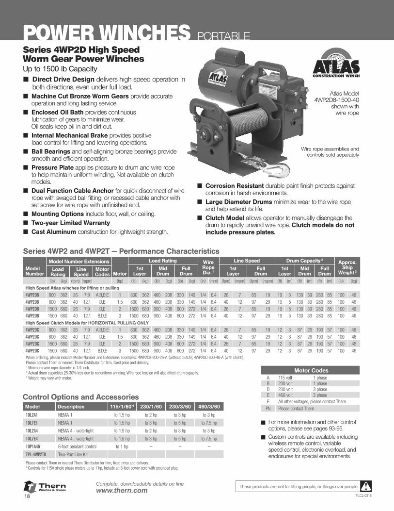
Atlas Model 4WP2D8-1500-40
shown with wire rope
Wire rope assemblies and controls sold separately
■ For more information and other control options, please see pages 93-95.
■ Custom controls are available including wireless remote control, variable speed control, electronic overload, and enclosures for special environments.
Series 4WP2D High Speed Worm Gear Power WinchesUp to 1500 lb Capacity■ Direct Drive Design delivers high speed operation in
both directions, even under full load.■ Machine Cut Bronze Worm Gears provide accurate
operation and long lasting service.■ Enclosed Oil Bath provides continuous
lubrication of gears to minimize wear. Oil seals keep oil in and dirt out.
■ Internal Mechanical Brake provides positive load control for lifting and lowering operations.
■ Ball Bearings and self-aligning bronze bearings provide smooth and efficient operation.
■ Pressure Plate applies pressure to drum and wire rope to help maintain uniform winding. Not available on clutch models.
■ Dual Function Cable Anchor for quick disconnect of wire rope with swaged ball fitting, or recessed cable anchor with set screw for wire rope with unfinished end.
■ Mounting Options include floor, wall, or ceiling.■ Two-year Limited Warranty■ Cast Aluminum construction for lightweight strength.
■ Corrosion Resistant durable paint finish protects against corrosion in harsh environments.
■ Large Diameter Drums minimize wear to the wire rope and help extend its life.
■ Clutch Model allows operator to manually disengage the drum to rapidly unwind wire rope. Clutch models do not include pressure plates.
Series 4WP2 and 4WP2T — Performance Characteristics
ModelNumber
Model Number Extensions
Motor
Load Rating Wire Rope Dia. 1
Line Speed Drum Capacity 2Approx.
ShipWeight 3
1stLayer
MidDrum
FullDrum
1stLayer
FullDrum
1stLayer
MidDrum
FullDrum
Load Rating
Line Speed
Motor Codes
(lb) (kg) (fpm) (mpm) (hp) (lb) (kg) (lb) (kg) (lb) (kg) (in) (mm) (fpm) (mpm) (fpm) (mpm) (ft) (m) (ft) (m) (ft) (m) (lb) (kg)
High Speed Atlas winches for lifting or pulling
4WP2D8 800 362 26 7.9 A,B,D,E 1 800 362 460 208 330 149 1/4 6.4 26 7 65 19 19 5 130 39 280 85 100 464WP2D8 800 362 40 12.1 D,E 1.5 800 362 460 208 330 149 1/4 6.4 40 12 97 29 19 5 130 39 280 85 100 464WP2D8 1500 680 26 7.9 D,E 2 1500 680 900 408 600 272 1/4 6.4 26 7 65 19 19 5 130 39 280 85 100 464WP2D8 1500 680 40 12.1 B,D,E 3 1500 680 900 408 600 272 1/4 6.4 40 12 97 29 19 5 130 39 280 85 100 46High Speed Clutch Models for HORIZONTAL PULLING ONLY
4WP2DC 800 362 26 7.9 A,B,D,E 1 800 362 460 208 330 149 1/4 6.4 26 7 65 19 12 3 87 26 190 57 100 464WP2DC 800 362 40 12.1 D,E 1.5 800 362 460 208 330 149 1/4 6.4 40 12 97 29 12 3 87 26 190 57 100 464WP2DC 1500 680 26 7.9 D,E 2 1500 680 900 408 600 272 1/4 6.4 26 7 65 19 12 3 87 26 190 57 100 464WP2DC 1500 680 40 12.1 B,D,E 3 1500 680 900 408 600 272 1/4 6.4 40 12 97 29 12 3 87 26 190 57 100 46When ordering, please indicate Model Number and Extensions. Examples: 4WP2D8-800-26-A (without clutch); 4WP2DC-800-40-A (with clutch).Please contact Thern or nearest Thern Distributor for firm, fixed price and delivery.1 Minimum wire rope diameter is 1/4 inch.2 Actual drum capacities 25-30% less due to nonuniform winding. Wire rope tension will also affect drum capacity.3 Weight may vary with motor.
Motor CodesA 115 volt 1 phaseB 230 volt 1 phaseD 230 volt 3 phaseE 460 volt 3 phaseF All other voltages, please contact Thern.
PN Please contact Thern
Control Options and Accessories Model Description 115/1/60 4 230/1/60 230/3/60 460/3/60
10L2A1 NEMA 1 to 1.5 hp to 2 hp to 3 hp to 3 hp
10L7E1 NEMA 1 to 1.5 hp to 3 hp to 5 hp to 7.5 hp
10L2A4 NEMA 4 - watertight to 1.5 hp to 2 hp to 3 hp to 3 hp
10L7E4 NEMA 4 - watertight to 1.5 hp to 3 hp to 5 hp to 7.5 hp
10P1A46 6-foot pendant control to 1 hp — — —
TPL-4WP2T8 Two-Part Line Kit
Please contact Thern or nearest Thern Distributor for firm, fixed price and delivery.4 Controls for 115V single phase motors up to 1 hp, include an 8-foot power cord with grounded plug.
ThernWinches & Cranes
19FLCL-0318
Complete, downloadable details on linewww.thern.comThese products are not for lifting people, or things over people.
PORTABLE POWER WINCHES
M
D
EA
B
H
R F
P
KS
N
C(holedia.)
MJ
drum CL
drum CL
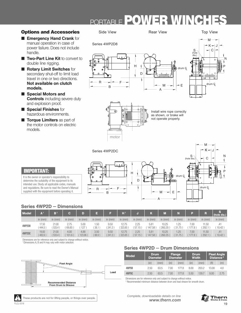
Side View Rear View Top View
Series 4WP2D8
RB
H P
NK
CS
A
M
D
EF
(hole dia.)
K J
drum CL
drum CL
M
Series 4WP2D – Drum Dimensionsmodel drum flange drum fleet angleextension diameter diameter width distance2
4WPD8 2.50 in 7.00 in 8.00 in 13 ft4WPDC 2.50 in 7.00 in 5.50 in 9 ftDimensions are for reference only and subject to change without notice.2 Recommended minimum distance between drum and lead sheave for
smooth drum.Recommended Distance
From Drum to Sheave
Fleet Angle
Load
Options and AccessoriesEmergency Hand Crankfor manual operation incase of power failure.Does not include handle.
Two Part Line Kit to con-vert to double line rigging.
Rotary Limit Switchesfor secondary shut-off tolimit load travel in one ortwo directions. Not avail-able on clutch models.
Special Motors andControls including severeduty and explosion proof.
Special Finishes for hazardous environments.
Torque Limiters as partof the motor controls onelectric models.
Series 4WP2D – Dimensions (in) series A 1 B 1 C D E F H 1 J K M N P R S (hole dia.)4WP2D8 17.50 21.00 2.75 5.00 1.50 9.50 12.75 2.25 5.81 10.25 1.25 7.00 11.50 .414WP2DC 19.00 21.00 4.00 5.00 3.50 9.50 12.75 2.25 5.81 10.25 1.25 7.00 11.50 .41Dimensions are for reference only and subject to change without notice.1 Dimensions A, B and H may vary with motor selection.
Series 4WP2DC
motor
Install wire rope correctlyas shown, or brake willnot operate properly.
Important: It is the owner's or operator'sresponsibility to determine thesuitability of the equipment toits intended use. Study allapplicable codes, manuals,and regulations. Be sure toread the Owner's Manual supplied with the equipmentbefore operating it.
Options and Accessories■ Emergency Hand Crank for
manual operation in case of power failure. Does not include handle.
■ Two-Part Line Kit to convert to double line rigging.
■ Rotary Limit Switches for secondary shut-off to limit load travel in one or two directions. Not available on clutch models.
■ Special Motors and Controls including severe duty and explosion proof.
■ Special Finishes for hazardous environments.
■ Torque Limiters as part of the motor controls on electric models.
IMPORTANT:It is the owner or operator’s responsibility to determine the suitability of the equipment to its intended use. Study all applicable codes, manuals and regulations. Be sure to read the Owner’s Manual supplied with the equipment before operating it.
Series 4WP2D — DimensionsModel A 1 B 1 C D E F H 1 J K M N P R S
(hole dia.)
in (mm) in (mm) in (mm) in (mm) in (mm) in (mm) in (mm) in (mm) in (mm) in (mm) in (mm) in (mm) in (mm) in (mm)
4WP2D8 17.50( 444.5 )
21.00( 533.4 )
2.75( 69.85 )
5.00 ( 127 )
1.50( 38.1 )
9.50( 241.3 )
12.75( 323.85 )
2.25( 57.15 )
5.81( 147.58 )
10.25( 260.35 )
1.25( 31.75 )
7.00( 177.8 )
11.50( 292.1 )
.41( 10.42 )
4WP2DC 19.00( 482.6 )
21.00( 533.4 )
4.00( 101.6 )
4.88( 123.96 )
3.50( 88.9 )
9.50( 241.3 )
12.75( 323.85 )
2.25( 57.15 )
5.81( 147.58 )
10.25( 260.35 )
1.25( 31.75 )
7.00( 177.8 )
11.50( 292.1 )
.41( 10.42 )
Dimensions are for reference only and subject to change without notice.1 Dimensions A, B and H may vary with motor selection.
Series 4WP2D — Drum Dimensions
Model Drum Diameter
Flange Diameter
Drum Width
Fleet Angle Distance 2
(in) (mm) (in) (mm) (in) (mm) (ft) (m)
4WPD8 2.50 63.5 7.00 177.8 8.00 203.2 13.00 4.0
4WPDC 2.50 63.5 7.00 177.8 5.50 139.7 9.00 2.75
Dimensions are for reference only and subject to change without notice.2 Recommended minimum distance between drum and lead sheave for smooth drum.
ThernWinches & Cranes
20
Complete, downloadable details on linewww.thern.com
FLCL-0318
These products are not for lifting people, or things over people.
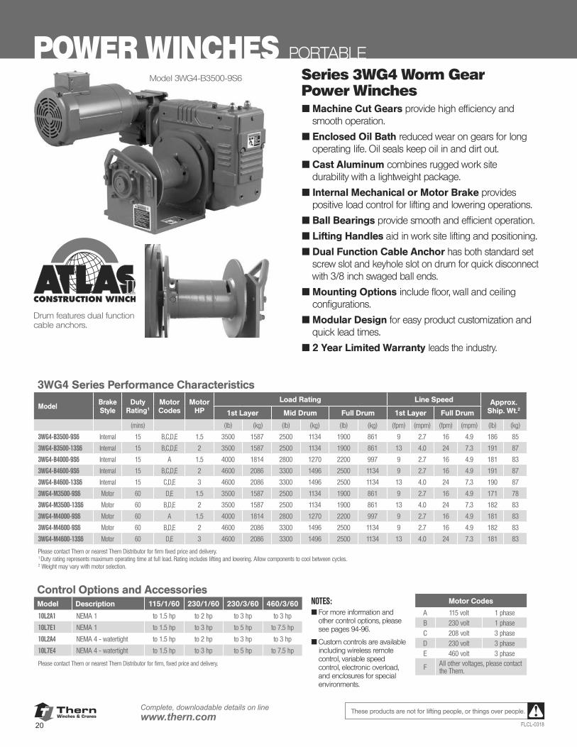
POWER WINCHES PORTABLESeries 3WG4 Worm Gear Power Winches■ Machine Cut Gears provide high efficiency and
smooth operation.
■ Enclosed Oil Bath reduced wear on gears for long operating life. Oil seals keep oil in and dirt out.
■ Cast Aluminum combines rugged work site durability with a lightweight package.
■ Internal Mechanical or Motor Brake provides positive load control for lifting and lowering operations.
■ Ball Bearings provide smooth and efficient operation.
■ Lifting Handles aid in work site lifting and positioning.
■ Dual Function Cable Anchor has both standard set screw slot and keyhole slot on drum for quick disconnect with 3/8 inch swaged ball ends.
■ Mounting Options include floor, wall and ceiling configurations.
■ Modular Design for easy product customization and quick lead times.
■ 2 Year Limited Warranty leads the industry.
Drum features dual function cable anchors.
Model 3WG4-B3500-9S6
3WG4 Series Performance Characteristics
Model Brake Style
Duty Rating1
Motor Codes
Motor HP
Load Rating Line Speed Approx.Ship. Wt.21st Layer Mid Drum Full Drum 1st Layer Full Drum
(mins) (lb) (kg) (lb) (kg) (lb) (kg) (fpm) (mpm) (fpm) (mpm) (lb) (kg)
3WG4-B3500-9S6 Internal 15 B,C,D,E 1.5 3500 1587 2500 1134 1900 861 9 2.7 16 4.9 186 85
3WG4-B3500-13S6 Internal 15 B,C,D,E 2 3500 1587 2500 1134 1900 861 13 4.0 24 7.3 191 87
3WG4-B4000-9S6 Internal 15 A 1.5 4000 1814 2800 1270 2200 997 9 2.7 16 4.9 181 83
3WG4-B4600-9S6 Internal 15 B,C,D,E 2 4600 2086 3300 1496 2500 1134 9 2.7 16 4.9 191 87
3WG4-B4600-13S6 Internal 15 C,D,E 3 4600 2086 3300 1496 2500 1134 13 4.0 24 7.3 190 87
3WG4-M3500-9S6 Motor 60 D,E 1.5 3500 1587 2500 1134 1900 861 9 2.7 16 4.9 171 78
3WG4-M3500-13S6 Motor 60 B,D,E 2 3500 1587 2500 1134 1900 861 13 4.0 24 7.3 182 83
3WG4-M4000-9S6 Motor 60 A 1.5 4000 1814 2800 1270 2200 997 9 2.7 16 4.9 181 83
3WG4-M4600-9S6 Motor 60 B,D,E 2 4600 2086 3300 1496 2500 1134 9 2.7 16 4.9 182 83
3WG4-M4600-13S6 Motor 60 D,E 3 4600 2086 3300 1496 2500 1134 13 4.0 24 7.3 181 83
Please contact Thern or nearest Thern Distributor for firm fixed price and delivery. 1 Duty rating represents maximum operating time at full load. Rating includes lifting and lowering. Allow components to cool between cycles. 2 Weight may vary with motor selection.
Motor Codes
A 115 volt 1 phaseB 230 volt 1 phaseC 208 volt 3 phaseD 230 volt 3 phaseE 460 volt 3 phase
F All other voltages, please contact the Thern.
NOTES:■ For more information and
other control options, please see pages 94-96.
■ Custom controls are available including wireless remote control, variable speed control, electronic overload, and enclosures for special environments.
Control Options and Accessories Model Description 115/1/60 230/1/60 230/3/60 460/3/60
10L2A1 NEMA 1 to 1.5 hp to 2 hp to 3 hp to 3 hp
10L7E1 NEMA 1 to 1.5 hp to 3 hp to 5 hp to 7.5 hp
10L2A4 NEMA 4 - watertight to 1.5 hp to 2 hp to 3 hp to 3 hp
10L7E4 NEMA 4 - watertight to 1.5 hp to 3 hp to 5 hp to 7.5 hp
Please contact Thern or nearest Thern Distributor for firm, fixed price and delivery.
ThernWinches & Cranes
21FLCL-0318
Complete, downloadable details on linewww.thern.comThese products are not for lifting people, or things over people.
PORTABLE POWER WINCHES
H
20 9/32
N
S
R
BA
P
JKM
C
drum CL
drum CL
D
E
B SeriesM Series
A A
T
G
FF
M Series
3WG4 Series
3WG4 Series Drum Capacities 4
Model Wire RopeDiameter
BreakingStrength
Drum Layer
1st Layer Mid Drum Full Drum
(in) (mm) (lb) (kg) (ft) (m) (ft) (m) (ft) (m)
3WG4-B/M 5/16 1.9 9800 5 4445.2 18 5.4 91 27.7 200 60.9
3WG4-B/M 3/8 9.5 15,100 6 6849.0 14 4.2 65 19.8 140 42.64 Actual drum capacities may be 25-30% less, due to nonuniform winding. Tension in wire rope will also affect drum capacity. 5 Values based on 7x19 Galvanized Aircraft cable. 6 Values based on 6x37 EIPS wire rope.
3WG4 Options and Accessories■ Emergency Hand Crank for manual
operation in power loss situations.
■ Rotary Limit Winches provide secondary shut-off for load travel in one or two directions.
■ Internal Mechanical Brake available for motor brake models to provide dual braking.
■ Special Finishes for harsh or hazardous environments.
■ Special Motors and Controls are available in a wide range of standard and custom configurations for single or variable speed.
■ Torque Limiters as part of the motor controls.
■ Extreme Temperature Option available with special seals and motors for high temperature environments - up to 65° C (149° F).
H
20 9/32
N
S
R
BA
P
JKM
C
drum CL
drum CL
D
E
B SeriesM Series
A A
T
G
FF
M Series
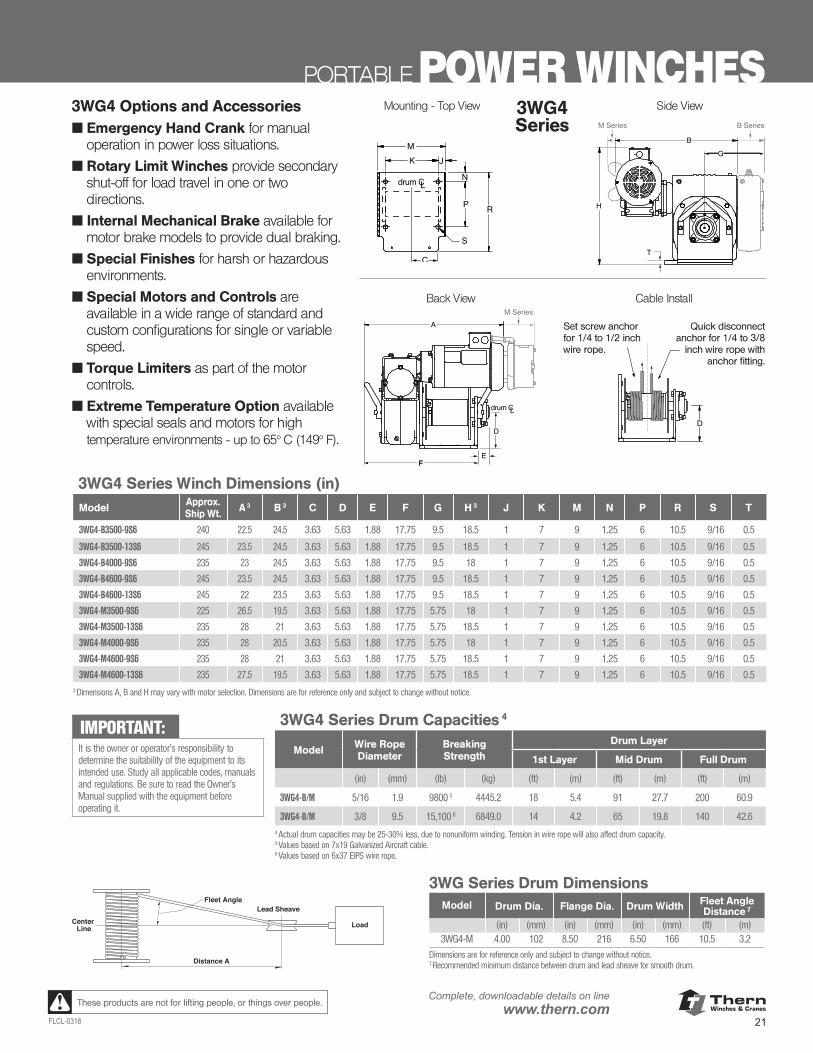
Mounting - Top View
Cable Install
3WG4 Series Winch Dimensions (in)Model Approx.
Ship Wt. A 3 B 3 C D E F G H 3 J K M N P R S T
3WG4-B3500-9S6 240 22.5 24.5 3.63 5.63 1.88 17.75 9.5 18.5 1 7 9 1.25 6 10.5 9/16 0.5
3WG4-B3500-13S6 245 23.5 24.5 3.63 5.63 1.88 17.75 9.5 18.5 1 7 9 1.25 6 10.5 9/16 0.5
3WG4-B4000-9S6 235 23 24.5 3.63 5.63 1.88 17.75 9.5 18 1 7 9 1.25 6 10.5 9/16 0.5
3WG4-B4600-9S6 245 23.5 24.5 3.63 5.63 1.88 17.75 9.5 18.5 1 7 9 1.25 6 10.5 9/16 0.5
3WG4-B4600-13S6 245 22 23.5 3.63 5.63 1.88 17.75 9.5 18.5 1 7 9 1.25 6 10.5 9/16 0.5
3WG4-M3500-9S6 225 26.5 19.5 3.63 5.63 1.88 17.75 5.75 18 1 7 9 1.25 6 10.5 9/16 0.5
3WG4-M3500-13S6 235 28 21 3.63 5.63 1.88 17.75 5.75 18.5 1 7 9 1.25 6 10.5 9/16 0.5
3WG4-M4000-9S6 235 28 20.5 3.63 5.63 1.88 17.75 5.75 18 1 7 9 1.25 6 10.5 9/16 0.5
3WG4-M4600-9S6 235 28 21 3.63 5.63 1.88 17.75 5.75 18.5 1 7 9 1.25 6 10.5 9/16 0.5
3WG4-M4600-13S6 235 27.5 19.5 3.63 5.63 1.88 17.75 5.75 18.5 1 7 9 1.25 6 10.5 9/16 0.53 Dimensions A, B and H may vary with motor selection. Dimensions are for reference only and subject to change without notice.
Distance A
Fleet Angle
Load
Lead Sheave
Center Line
3WG Series Drum DimensionsModel Drum Dia. Flange Dia. Drum Width Fleet Angle
Distance 7
(in) (mm) (in) (mm) (in) (mm) (ft) (m)3WG4-M 4.00 102 8.50 216 6.50 166 10.5 3.2
Dimensions are for reference only and subject to change without notice.7 Recommended minimum distance between drum and lead sheave for smooth drum.
Back View
D
Set screw anchor for 1/4 to 1/2 inch wire rope.
Quick disconnect anchor for 1/4 to 3/8
inch wire rope with anchor fitting.
Side View
H
20 9/32
N
S
R
BA
P
JKM
C
drum CL
drum CL
D
E
B SeriesM Series
A A
T
G
FF
M Series
IMPORTANT:It is the owner or operator’s responsibility to determine the suitability of the equipment to its intended use. Study all applicable codes, manuals and regulations. Be sure to read the Owner’s Manual supplied with the equipment before operating it.
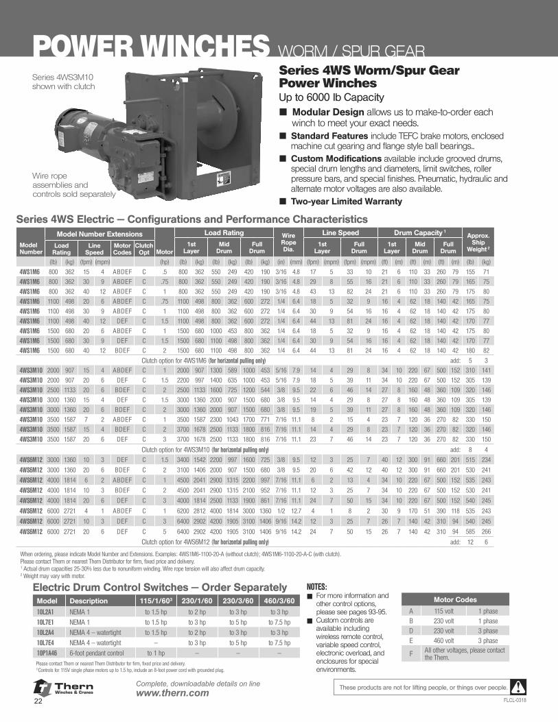
ThernWinches & Cranes
22
Complete, downloadable details on linewww.thern.com
FLCL-0318
These products are not for lifting people, or things over people.
Series 4WS3M10 shown with clutch
Wire rope assemblies and controls sold separately
POWER WINCHES WORM / SPUR GEARSeries 4WS Worm/Spur Gear Power WinchesUp to 6000 lb Capacity■ Modular Design allows us to make-to-order each
winch to meet your exact needs.■ Standard Features include TEFC brake motors, enclosed
machine cut gearing and flange style ball bearings..■ Custom Modifications available include grooved drums,
special drum lengths and diameters, limit switches, roller pressure bars, and special finishes. Pneumatic, hydraulic and alternate motor voltages are also available.
■ Two-year Limited Warranty
Series 4WS Electric — Configurations and Performance Characteristics
ModelNumber
Model Number Extensions
Motor
Load Rating Wire Rope Dia.
Line Speed Drum Capacity 1Approx.
ShipWeight 2
1stLayer
MidDrum
FullDrum
1stLayer
FullDrum
1stLayer
MidDrum
FullDrum
Load Rating
Line Speed
Motor Codes
Clutch Opt
(lb) (kg) (fpm) (mpm) (hp) (lb) (kg) (lb) (kg) (lb) (kg) (in) (mm) (fpm) (mpm) (fpm) (mpm) (ft) (m) (ft) (m) (ft) (m) (lb) (kg)
4WS1M6 800 362 15 4 ABDEF C .5 800 362 550 249 420 190 3/16 4.8 17 5 33 10 21 6 110 33 260 79 155 71
4WS1M6 800 362 30 9 ABDEF C .75 800 362 550 249 420 190 3/16 4.8 29 8 55 16 21 6 110 33 260 79 165 75
4WS1M6 800 362 40 12 ABDEF C 1 800 362 550 249 420 190 3/16 4.8 43 13 82 24 21 6 110 33 260 79 175 80
4WS1M6 1100 498 20 6 ABDEF C .75 1100 498 800 362 600 272 1/4 6.4 18 5 32 9 16 4 62 18 140 42 165 75
4WS1M6 1100 498 30 9 ABDEF C 1 1100 498 800 362 600 272 1/4 6.4 30 9 54 16 16 4 62 18 140 42 175 80
4WS1M6 1100 498 40 12 DEF C 1.5 1100 498 800 362 600 272 1/4 6.4 44 13 81 24 16 4 62 18 140 42 170 77
4WS1M6 1500 680 20 6 ABDEF C 1 1500 680 1000 453 800 362 1/4 6.4 18 5 32 9 16 4 62 18 140 42 175 80
4WS1M6 1500 680 30 9 DEF C 1.5 1500 680 1100 498 800 362 1/4 6.4 30 9 54 16 16 4 62 18 140 42 170 77
4WS1M6 1500 680 40 12 BDEF C 2 1500 680 1100 498 800 362 1/4 6.4 44 13 81 24 16 4 62 18 140 42 180 82
Clutch option for 4WS1M6 (for horizontal pulling only) add: 5 3
4WS3M10 2000 907 15 4 ABDEF C 1 2000 907 1300 589 1000 453 5/16 7.9 14 4 29 8 34 10 220 67 500 152 310 141
4WS3M10 2000 907 20 6 DEF C 1.5 2200 997 1400 635 1000 453 5/16 7.9 18 5 39 11 34 10 220 67 500 152 305 139
4WS3M10 2500 1133 20 6 BDEF C 2 2500 1133 1600 725 1200 544 3/8 9.5 22 6 46 14 27 8 160 48 360 109 320 146
4WS3M10 3000 1360 15 4 DEF C 1.5 3000 1360 2000 907 1500 680 3/8 9.5 14 4 29 8 27 8 160 48 360 109 305 139
4WS3M10 3000 1360 20 6 BDEF C 2 3000 1360 2000 907 1500 680 3/8 9.5 19 5 39 11 27 8 160 48 360 109 320 146
4WS3M10 3500 1587 7 2 ABDEF C 1 3500 1587 2300 1043 1700 771 7/16 11.1 8 2 15 4 23 7 120 36 270 82 330 150
4WS3M10 3500 1587 15 4 BDEF C 2 3700 1678 2500 1133 1800 816 7/16 11.1 14 4 29 8 23 7 120 36 270 82 320 146
4WS3M10 3500 1587 20 6 DEF C 3 3700 1678 2500 1133 1800 816 7/16 11.1 23 7 46 14 23 7 120 36 270 82 330 150
Clutch option for 4WS3M10 (for horizontal pulling only) add: 8 4
4WS6M12 3000 1360 10 3 DEF C 1.5 3400 1542 2200 997 1600 725 3/8 9.5 12 3 25 7 40 12 300 91 660 201 515 234
4WS6M12 3000 1360 20 6 BDEF C 2 3100 1406 2000 907 1500 680 3/8 9.5 20 6 42 12 40 12 300 91 660 201 530 241
4WS6M12 4000 1814 6 2 ABDEF C 1 4500 2041 2900 1315 2200 997 7/16 11.1 6 2 13 4 34 10 220 67 500 152 535 243
4WS6M12 4000 1814 10 3 BDEF C 2 4500 2041 2900 1315 2100 952 7/16 11.1 12 3 25 7 34 10 220 67 500 152 530 241
4WS6M12 4000 1814 20 6 DEF C 3 4000 1814 2500 1133 1900 861 7/16 11.1 24 7 50 15 34 10 220 67 500 152 540 245
4WS6M12 6000 2721 4 1 ABDEF C 1 6200 2812 4000 1814 3000 1360 1/2 12.7 4 1 8 2 30 9 170 51 390 118 535 243
4WS6M12 6000 2721 10 3 DEF C 3 6400 2902 4200 1905 3100 1406 9/16 14.2 12 3 25 7 26 7 140 42 310 94 540 245
4WS6M12 6000 2721 20 6 DEF C 5 6400 2902 4200 1905 3100 1406 9/16 14.2 24 7 50 15 26 7 140 42 310 94 585 266
Clutch option for 4WS6M12 (for horizontal pulling only) add: 12 6
When ordering, please indicate Model Number and Extensions. Examples: 4WS1M6-1100-20-A (without clutch); 4WS1M6-1100-20-A-C (with clutch).Please contact Thern or nearest Thern Distributor for firm, fixed price and delivery.1 Actual drum capacities 25-30% less due to nonuniform winding. Wire rope tension will also affect drum capacity.2 Weight may vary with motor.
NOTES:■ For more information and
other control options, please see pages 93-95.
■ Custom controls are available including wireless remote control, variable speed control, electronic overload, and enclosures for special environments.
Motor Codes
A 115 volt 1 phaseB 230 volt 1 phaseD 230 volt 3 phaseE 460 volt 3 phase
F All other voltages, please contact the Thern.
Electric Drum Control Switches — Order Separately Model Description 115/1/603 230/1/60 230/3/60 460/3/60
10L2A1 NEMA 1 to 1.5 hp to 2 hp to 3 hp to 3 hp
10L7E1 NEMA 1 to 1.5 hp to 3 hp to 5 hp to 7.5 hp
10L2A4 NEMA 4 — watertight to 1.5 hp to 2 hp to 3 hp to 3 hp
10L7E4 NEMA 4 — watertight — to 3 hp to 5 hp to 7.5 hp
10P1A46 6-foot pendant control to 1 hp — — —Please contact Thern or nearest Thern Distributor for firm, fixed price and delivery.3 Controls for 115V single phase motors up to 1.5 hp, include an 8-foot power cord with grounded plug.
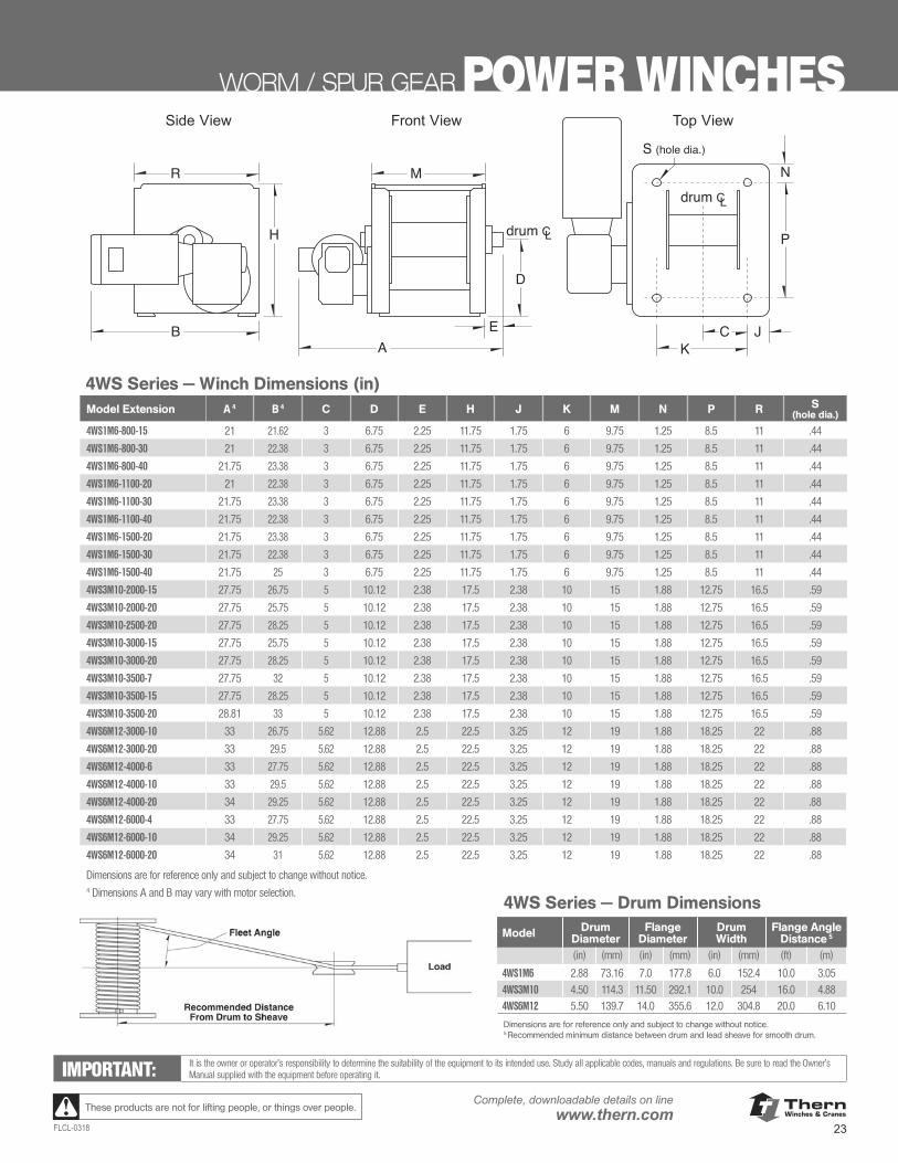
ThernWinches & Cranes
23FLCL-0318
Complete, downloadable details on linewww.thern.comThese products are not for lifting people, or things over people.
Series 4WS – Winch Dimensions (in)model extensio A1 B1 C D E H J K M N P R S (hole dia.)4WS1M6-800-15 21.00 21.62 3.00 6.75 2.25 11.75 1.75 6.00 9.75 1.25 8.50 11.00 .444WS1M6-800-30 21.00 22.38 3.00 6.75 2.25 11.75 1.75 6.00 9.75 1.25 8.50 11.00 .444WS1M6-800-40 21.75 23.38 3.00 6.75 2.25 11.75 1.75 6.00 9.75 1.25 8.50 11.00 .444WS1M6-1100-20 21.00 22.38 3.00 6.75 2.25 11.75 1.75 6.00 9.75 1.25 8.50 11.00 .444WS1M6-1100-30 21.75 23.38 3.00 6.75 2.25 11.75 1.75 6.00 9.75 1.25 8.50 11.00 .444WS1M6-1100-40 21.75 22.38 3.00 6.75 2.25 11.75 1.75 6.00 9.75 1.25 8.50 11.00 .444WS1M6-1500-20 21.75 23.38 3.00 6.75 2.25 11.75 1.75 6.00 9.75 1.25 8.50 11.00 .444WS1M6-1500-30 21.75 22.38 3.00 6.75 2.25 11.75 1.75 6.00 9.75 1.25 8.50 11.00 .444WS1M6-1500-40 21.75 25.00 3.00 6.75 2.25 11.75 1.75 6.00 9.75 1.25 8.50 11.00 .444WS3M10-2000-15 27.75 26.75 5.00 10.12 2.38 17.50 2.38 10.00 15.00 1.88 12.75 16.50 .594WS3M10-2000-20 27.75 25.75 5.00 10.12 2.38 17.50 2.38 10.00 15.00 1.88 12.75 16.50 .594WS3M10-2500-20 27.75 28.25 5.00 10.12 2.38 17.50 2.38 10.00 15.00 1.88 12.75 16.50 .594WS3M10-3000-15 27.75 25.75 5.00 10.12 2.38 17.50 2.38 10.00 15.00 1.88 12.75 16.50 .594WS3M10-3000-20 27.75 28.25 5.00 10.12 2.38 17.50 2.38 10.00 15.00 1.88 12.75 16.50 .594WS3M10-3500-7 27.75 32.00 5.00 10.12 2.38 17.50 2.38 10.00 15.00 1.88 12.75 16.50 .594WS3M10-3500-15 27.75 28.25 5.00 10.12 2.38 17.50 2.38 10.00 15.00 1.88 12.75 16.50 .594WS3M10-3500-20 28.81 33.00 5.00 10.12 2.38 17.50 2.38 10.00 15.00 1.88 12.75 16.50 .594WS6M12-3000-10 33.00 26.75 5.62 12.88 2.50 22.50 3.25 12.00 19.00 1.88 18.25 22.00 .884WS6M12-3000-20 33.00 29.50 5.62 12.88 2.50 22.50 3.25 12.00 19.00 1.88 18.25 22.00 .884WS6M12-4000-10 33.00 29.50 5.62 12.88 2.50 22.50 3.25 12.00 19.00 1.88 18.25 22.00 .884WS6M12-4000-20 34.00 29.25 5.62 12.88 2.50 22.50 3.25 12.00 19.00 1.88 18.25 22.00 .884WS6M12-6000-4 33.00 27.75 5.62 12.88 2.50 22.50 3.25 12.00 19.00 1.88 18.25 22.00 .884WS6M12-6000-10 34.00 29.25 5.62 12.88 2.50 22.50 3.25 12.00 19.00 1.88 18.25 22.00 .884WS6M12-6000-20 34.00 31.00 5.62 12.88 2.50 22.50 3.25 12.00 19.00 1.88 18.25 22.00 .88Dimensions are for reference only and subject to change without notice.1 Dimensions A, B and H may vary with motor selection. Series 4WS – Drum Dimensions
model drum flange drum fleet angleextension diameter diameter width distance1
4WS1M6 2.88 in 7.00 in 6.00 in 10 ft4WS3M10 4.50 in 11.50 in 10.00 in 16 ft4WS6M12 5.50 in 14.00 in 12.00 in 20 ftDimensions are for reference only and subject to changewithout notice.1 Recommended minimum distance between drum and lead
sheave for smooth drum.
H
S (hole dia.)
drum C
D
N
P
B
R M
AE
KC J
drum CL
L
Side View Front View Top View
Recommended DistanceFrom Drum to Sheave
Fleet Angle
Load
WORM / SPUR GEAR POWER WINCHES
IMPORTANT: It is the owner or operator’s responsibility to determine the suitability of the equipment to its intended use. Study all applicable codes, manuals and regulations. Be sure to read the Owner’s Manual supplied with the equipment before operating it.
4WS Series — Winch Dimensions (in)Model Extension A 4 B 4 C D E H J K M N P R S
(hole dia.)
4WS1M6-800-15 21 21.62 3 6.75 2.25 11.75 1.75 6 9.75 1.25 8.5 11 .44
4WS1M6-800-30 21 22.38 3 6.75 2.25 11.75 1.75 6 9.75 1.25 8.5 11 .44
4WS1M6-800-40 21.75 23.38 3 6.75 2.25 11.75 1.75 6 9.75 1.25 8.5 11 .44
4WS1M6-1100-20 21 22.38 3 6.75 2.25 11.75 1.75 6 9.75 1.25 8.5 11 .44
4WS1M6-1100-30 21.75 23.38 3 6.75 2.25 11.75 1.75 6 9.75 1.25 8.5 11 .44
4WS1M6-1100-40 21.75 22.38 3 6.75 2.25 11.75 1.75 6 9.75 1.25 8.5 11 .44
4WS1M6-1500-20 21.75 23.38 3 6.75 2.25 11.75 1.75 6 9.75 1.25 8.5 11 .44
4WS1M6-1500-30 21.75 22.38 3 6.75 2.25 11.75 1.75 6 9.75 1.25 8.5 11 .44
4WS1M6-1500-40 21.75 25 3 6.75 2.25 11.75 1.75 6 9.75 1.25 8.5 11 .44
4WS3M10-2000-15 27.75 26.75 5 10.12 2.38 17.5 2.38 10 15 1.88 12.75 16.5 .59
4WS3M10-2000-20 27.75 25.75 5 10.12 2.38 17.5 2.38 10 15 1.88 12.75 16.5 .59
4WS3M10-2500-20 27.75 28.25 5 10.12 2.38 17.5 2.38 10 15 1.88 12.75 16.5 .59
4WS3M10-3000-15 27.75 25.75 5 10.12 2.38 17.5 2.38 10 15 1.88 12.75 16.5 .59
4WS3M10-3000-20 27.75 28.25 5 10.12 2.38 17.5 2.38 10 15 1.88 12.75 16.5 .59
4WS3M10-3500-7 27.75 32 5 10.12 2.38 17.5 2.38 10 15 1.88 12.75 16.5 .59
4WS3M10-3500-15 27.75 28.25 5 10.12 2.38 17.5 2.38 10 15 1.88 12.75 16.5 .59
4WS3M10-3500-20 28.81 33 5 10.12 2.38 17.5 2.38 10 15 1.88 12.75 16.5 .59
4WS6M12-3000-10 33 26.75 5.62 12.88 2.5 22.5 3.25 12 19 1.88 18.25 22 .88
4WS6M12-3000-20 33 29.5 5.62 12.88 2.5 22.5 3.25 12 19 1.88 18.25 22 .88
4WS6M12-4000-6 33 27.75 5.62 12.88 2.5 22.5 3.25 12 19 1.88 18.25 22 .88
4WS6M12-4000-10 33 29.5 5.62 12.88 2.5 22.5 3.25 12 19 1.88 18.25 22 .88
4WS6M12-4000-20 34 29.25 5.62 12.88 2.5 22.5 3.25 12 19 1.88 18.25 22 .88
4WS6M12-6000-4 33 27.75 5.62 12.88 2.5 22.5 3.25 12 19 1.88 18.25 22 .88
4WS6M12-6000-10 34 29.25 5.62 12.88 2.5 22.5 3.25 12 19 1.88 18.25 22 .88
4WS6M12-6000-20 34 31 5.62 12.88 2.5 22.5 3.25 12 19 1.88 18.25 22 .88
Dimensions are for reference only and subject to change without notice.4 Dimensions A and B may vary with motor selection.
4WS Series — Drum Dimensions
Model Drum Diameter
Flange Diameter
Drum Width
Flange Angle Distance 5
(in) (mm) (in) (mm) (in) (mm) (ft) (m)
4WS1M6 2.88 73.16 7.0 177.8 6.0 152.4 10.0 3.05
4WS3M10 4.50 114.3 11.50 292.1 10.0 254 16.0 4.884WS6M12 5.50 139.7 14.0 355.6 12.0 304.8 20.0 6.10
Dimensions are for reference only and subject to change without notice.5 Recommended minimum distance between drum and lead sheave for smooth drum.
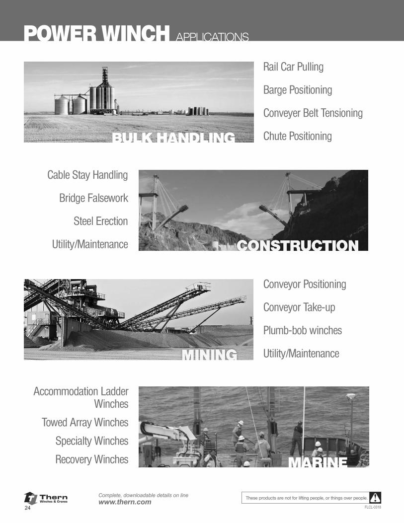
ThernWinches & Cranes
24
Complete, downloadable details on linewww.thern.com
FLCL-0318
These products are not for lifting people, or things over people.
POWER WINCH APPLICATIONS
Rail Car Pulling
Barge Positioning
Conveyer Belt Tensioning
Chute Positioning
Cable Stay Handling
Bridge Falsework
Steel Erection
Utility/Maintenance
Conveyor Positioning
Conveyor Take-up
Plumb-bob winches
Utility/Maintenance
Accommodation Ladder Winches
Towed Array Winches
Specialty Winches
Recovery Winches MARINE
BULK HANDLING
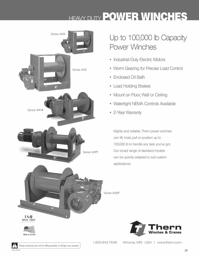
25FLCL-0318
These products are not for lifting people, or things over people.
HEAVY DUTY POWER WINCHES
Up to 100,000 lb Capacity Power Winches
• Industrial-Duty Electric Motors
• Worm Gearing for Precise Load Control
• Enclosed Oil Bath
• Load Holding Brakes
• Mount on Floor, Wall or Ceiling
• Watertight NEMA Controls Available
• 2-Year Warranty
Mighty and reliable, Thern power winches
can lift, hoist, pull or position up to
100,000 lb to handle any task you’ve got.
Our broad range of standard models
can be quickly adapted to suit custom
applications.
Series 4HWFSeries 4HWF
Series 4HS
Series 4HPF
Series 4WS
Series 4HBP
Made in the USA
ThernWinches & Cranes
1.800.843.7648 Winona, MN USA | www.thern.com
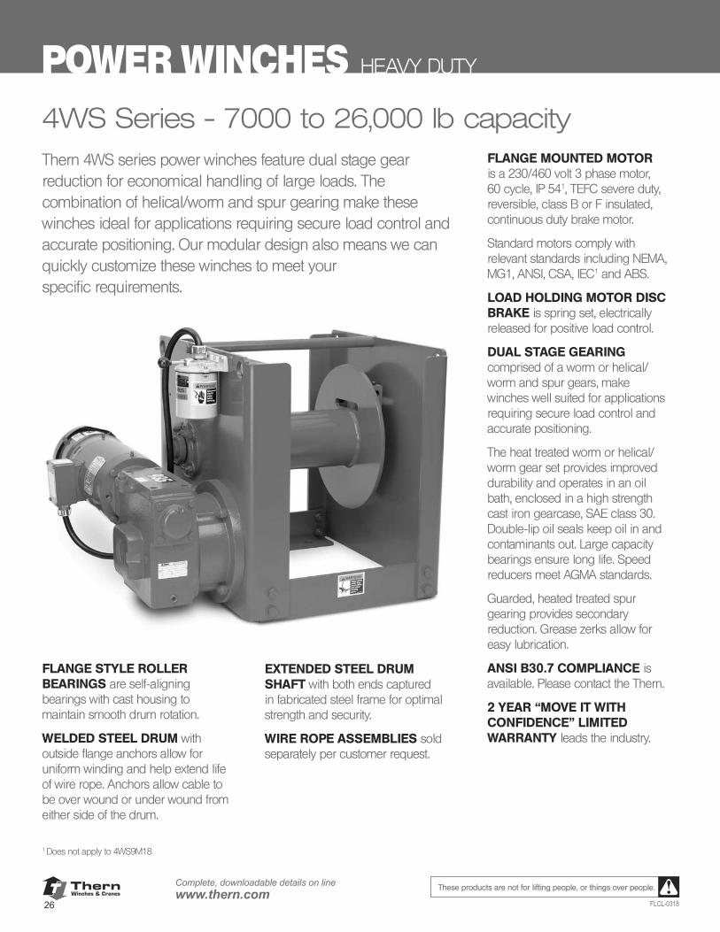
ThernWinches & Cranes
26
Complete, downloadable details on linewww.thern.com
FLCL-0318
These products are not for lifting people, or things over people.
POWER WINCHES HEAVY DUTY
Thern 4WS series power winches feature dual stage gear reduction for economical handling of large loads. The combination of helical/worm and spur gearing make these winches ideal for applications requiring secure load control and accurate positioning. Our modular design also means we can quickly customize these winches to meet your specific requirements.
4WS Series - 7000 to 26,000 lb capacity
FLANGE STYLE ROLLER BEARINGS are self-aligning bearings with cast housing to maintain smooth drum rotation.
WELDED STEEL DRUM with outside flange anchors allow for uniform winding and help extend life of wire rope. Anchors allow cable to be over wound or under wound from either side of the drum.
EXTENDED STEEL DRUM SHAFT with both ends captured in fabricated steel frame for optimal strength and security.
WIRE ROPE ASSEMBLIES sold separately per customer request.
FLANGE MOUNTED MOTOR is a 230/460 volt 3 phase motor, 60 cycle, IP 541, TEFC severe duty, reversible, class B or F insulated, continuous duty brake motor.
Standard motors comply with relevant standards including NEMA, MG1, ANSI, CSA, IEC1 and ABS.
LOAD HOLDING MOTOR DISC BRAKE is spring set, electrically released for positive load control.
DUAL STAGE GEARING comprised of a worm or helical/worm and spur gears, make winches well suited for applications requiring secure load control and accurate positioning.
The heat treated worm or helical/worm gear set provides improved durability and operates in an oil bath, enclosed in a high strength cast iron gearcase, SAE class 30. Double-lip oil seals keep oil in and contaminants out. Large capacity bearings ensure long life. Speed reducers meet AGMA standards.
Guarded, heated treated spur gearing provides secondary reduction. Grease zerks allow for easy lubrication.
ANSI B30.7 COMPLIANCE is available. Please contact the Thern.
2 YEAR “MOVE IT WITH CONFIDENCE” LIMITED WARRANTY leads the industry.
1 Does not apply to 4WS9M18
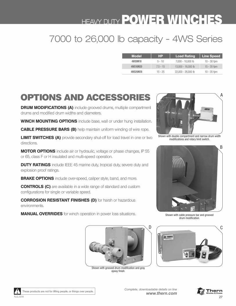
ThernWinches & Cranes
27FLCL-0318
Complete, downloadable details on linewww.thern.comThese products are not for lifting people, or things over people.
www.thern.com 1.800.843.7648
DRUM MODIFICATIONS (A) include grooved drums, multiple compartment drums and modifi ed drum widths and diameters.
WINCH MOUNTING OPTIONS include base, wall or under hung installation.
CABLE PRESSURE BARS (B) help maintain uniform winding of wire rope.
LIMIT SWITCHES (A) provide secondary shut-off for load travel in one or two directions.
MOTOR OPTIONS include air or hydraulic, voltage or phase changes, IP 55 or 65, class F or H insulated and multi-speed operation.
DUTY RATINGS include IEEE 45 marine duty, tropical duty, severe duty and explosion proof ratings.
BRAKE OPTIONS include over-speed, caliper style, band, and more.
CONTROLS (C) are available in a wide range of standard and custom confi gu-rations for single or variable speed.
CORROSION RESISTANT FINISHES (D) for harsh or hazardous environments.
MANUAL OVERRIDES for winch operation in power loss situations.
OPTIONS AND ACCESSORIES
4WS SERIES
A
B
C
Shown with double compartment and narrow drum width modi cations and rotary limit switch.
Shown with cable pressure bar and grooved drum modi cation.
D
Shown with grooved drum modi cation and gray epoxy nish.
HEAVY DUTY POWER WINCHES
Model HP Load Rating Line Speed
4WS9M18 5 - 10 7,000 - 10,000 lb 10 - 30 fpm
4WS16M20 7.5 - 15 13,000 - 16,000 lb 15 - 35 fpm
4WS26M26 15 - 25 22,000 - 26,000 lb 10 - 35 fpm
7000 to 26,000 lb capacity - 4WS Series
OPTIONS AND ACCESSORIESDRUM MODIFICATIONS (A) include grooved drums, multiple compartment drums and modified drum widths and diameters.
WINCH MOUNTING OPTIONS include base, wall or under hung installation.
CABLE PRESSURE BARS (B) help maintain uniform winding of wire rope.
LIMIT SWITCHES (A) provide secondary shut-off for load travel in one or two directions.
MOTOR OPTIONS include air or hydraulic, voltage or phase changes, IP 55 or 65, class F or H insulated and multi-speed operation.
DUTY RATINGS include IEEE 45 marine duty, tropical duty, severe duty and explosion proof ratings.
BRAKE OPTIONS include over-speed, caliper style, band, and more.
CONTROLS (C) are available in a wide range of standard and custom configurations for single or variable speed.
CORROSION RESISTANT FINISHES (D) for harsh or hazardous environments.
MANUAL OVERRIDES for winch operation in power loss situations.
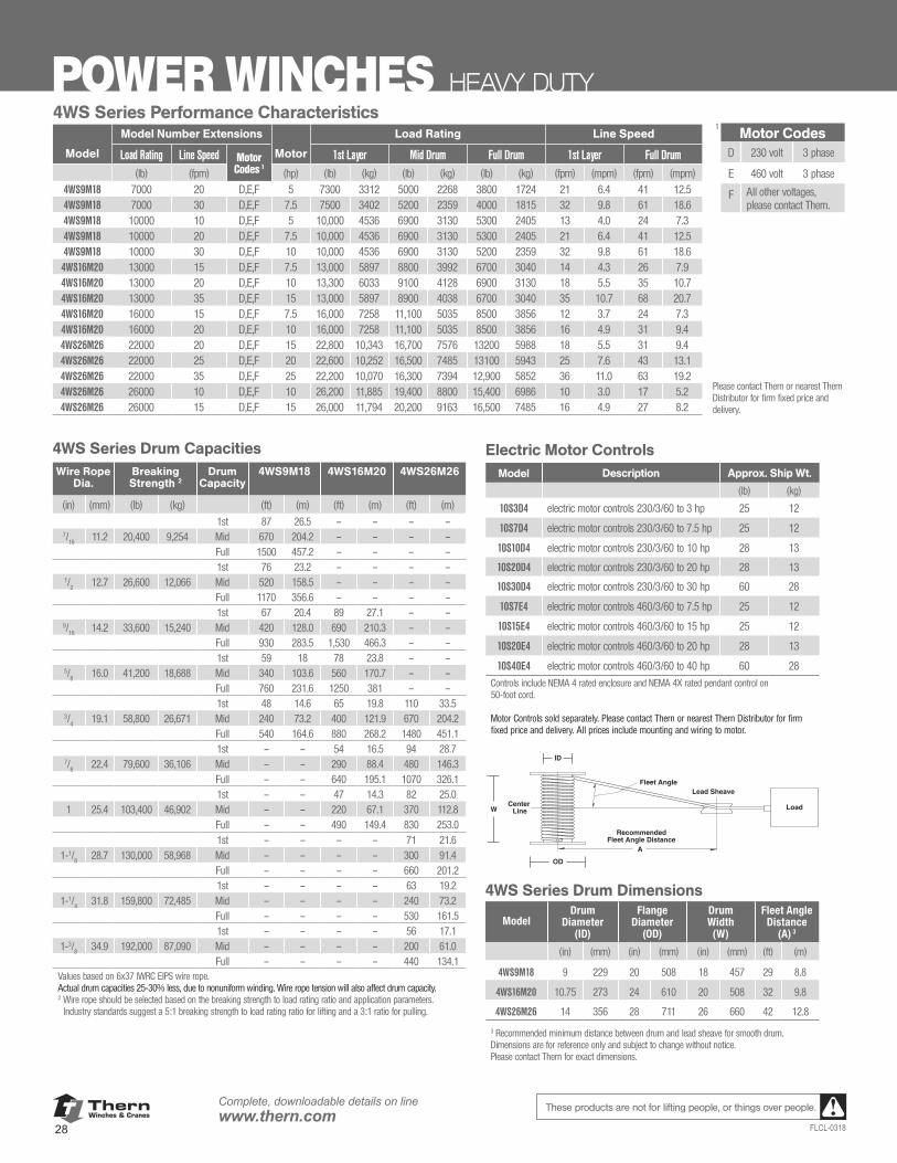
ThernWinches & Cranes
28
Complete, downloadable details on linewww.thern.com
FLCL-0318
These products are not for lifting people, or things over people.
www.thern.com 1.800.843.76
4WS SERIES POWER WINCHES 4WS Series Performance Characteristics
Model Number Extensions Motor hp Load Rating Line Speed
Load Rating
Line Speed
Motor Codes¹
hp ¹st Layer Mid Drum Full Drum ¹st Layer Full Drum
(lb) (fpm) (lb) (kg) (lb) (kg) (lb) (kg) (fpm) (mpm) (fpm) (mpm)
4WS9M18 7000 20 D,E,F 5 7,300 3,312 5,000 2,268 3,800 1,724 21 6.4 41 12.5
4WS9M18 7000 30 D,E,F 7.5 7,500 3,402 5,200 2,359 4,000 1,815 32 9.8 61 18.6
4WS9M18 10000 10 D,E,F 5 10,000 4,536 6,900 3,130 5,300 2,405 13 4.0 24 7.3
4WS9M18 10000 20 D,E,F 7.5 10,000 4,536 6,900 3,130 5,300 2,405 21 6.4 41 12.5
4WS9M18 10000 30 D,E,F 10 10,000 4,536 6,900 3,130 5,200 2,359 32 9.8 61 18.6
4WS16M20 13000 15 D,E,F 7.5 13,000 5,897 8,800 3,992 6,700 3,040 14 4.3 26 7.9
4WS16M20 13000 20 D,E,F 10 13,300 6,033 9,100 4,128 6,900 3,130 18 5.5 35 10.7
4WS16M20 13000 35 D,E,F 15 13,000 5,897 8,900 4,038 6,700 3,040 35 10.7 68 20.7
4WS16M20 16000 15 D,E,F 7.5 16,000 7,258 11,100 5,035 8,500 3,856 12 3.7 24 7.3
4WS16M20 16000 20 D,E,F 10 16,000 7,258 11,100 5,035 8,500 3,856 16 4.9 31 9.4
4WS26M26 22000 20 D,E,F 15 22,800 10,343 16,700 7,576 13,200 5,988 18 5.5 31 9.4
4WS26M26 22000 25 D,E,F 20 22,600 10,252 16,500 7,485 13,100 5,943 25 7.6 43 13.1
4WS26M26 22000 35 D,E,F 25 22,200 10,070 16,300 7,394 12,900 5,852 36 11.0 63 19.2
4WS26M26 26000 10 D,E,F 10 26,200 11,885 19,400 8,800 15,400 6,986 10 3.0 17 5.2
4WS26M26 26000 15 D,E,F 15 26,000 11,794 20,200 9,163 16,500 7,485 16 4.9 27 8.2
Motor Codes
D 230 volt 3 phase
E 460 volt 3 phase
F All other voltagesplease contact factory
1
4WS Series Drum CapacitiesWire Rope
Dia.Breaking Strength2
Drum Capacity
4WS9M18 4WS16M20 4WS26M26
(in) (mm) (lb) (kg) (ft) (m) (ft) (m) (ft) (m)1st 87 26.5 – – – –
7/16 11.2 20,400 9,254 Mid 670 204.2 – – – –Full 1,500 457.2 – – – –1st 76 23.2 – – – –
1/2 12.7 26,600 12,066 Mid 520 158.5 – – – –Full 1,170 356.6 – – – –1st 67 20.4 89 27.1 – –
9/16 14.2 33,600 15,240 Mid 420 128.0 690 210.3 – –Full 930 283.5 1,530 466.3 – –1st 59 18.0 78 23.8 – –
5/8 16.0 41,200 18,688 Mid 340 103.6 560 170.7 – –Full 760 231.6 1,250 381.0 – –1st 48 14.6 65 19.8 110 33.5
3/4 19.1 58,800 26,671 Mid 240 73.2 400 121.9 670 204.2Full 540 164.6 880 268.2 1,480 451.11st – – 54 16.5 94 28.7
7/8 22.4 79,600 36,106 Mid – – 290 88.4 480 146.3Full – – 640 195.1 1,070 326.11st – – 47 14.3 82 25.0
1 25.4 103,400 46,902 Mid – – 220 67.1 370 112.8Full – – 490 149.4 830 253.01st – – – – 71 21.6
1-1/8 28.7 130,000 58,968 Mid – – – – 300 91.4Full – – – – 660 201.21st – – – – 63 19.2
1-1/4 31.8 159,800 72,485 Mid – – – – 240 73.2Full – – – – 530 161.51st – – – – 56 17.1
1-3/8 34.9 192,000 87,090 Mid – – – – 200 61.0Full – – – – 440 134.1
Values based on 6x37 IWRC EIPS wire rope. Actual drum capacities 25-30% less, due to nonuniform winding. Wire rope tension will also affect drum capacity.Wire rope should be selected based on the breaking strength to load rating ratio and application parameters. Industry standards suggest a 5:1 breaking strength to load rating ratio for lifting and a 3:1 ratio for pulling. Recommended
Fleet Angle Distance
Fleet Angle
Load
Lead Sheave
Center Line
ID
OD
W
A
Electric Motor ControlsDescription Approx. Ship Wt.
(lb) (kg)
10S3D4 electric motor controls 230/3/60 to 3 hp 25 12
10S7D4 electric motor controls 230/3/60 to 7.5 hp 25 12
10S10D4 electric motor controls 230/3/60 to 10 hp 28 13
10S20D4 electric motor controls 230/3/60 to 20 hp 28 13
10S30D4 electric motor controls 230/3/60 to 30 hp 60 28
10S7E4 electric motor controls 460/3/60 to 7.5 hp 25 12
10S15E4 electric motor controls 460/3/60 to 15 hp 25 12
10S20E4 electric motor controls 460/3/60 to 20 hp 28 13
10S40E4 electric motor controls 460/3/60 to 40 hp 60 28
Controls include NEMA 4 rated enclosure, and NEMA 4x rated pendant control on 50 foot cord.Motor Controls sold separately.Please contact factory or nearest Thern Distributor for fi rm fi xed price and delivery. All prices include mounting and wiring to motor.
4WS Series Drum DimensionsDrum
Diameter (ID)
FlangeDiameter
(OD)
DrumWidth(W)
Fleet Angle Dist(A)3
(in) (mm) (in) (mm) (in) (mm) (ft) (m)
4WS9M18 9.00 229 20.00 508 18.00 457 29 8.8
4WS16M20 10.75 273 24.00 610 20.00 508 32 9.8
4WS26M26 14.00 356 28.00 711 26.00 660 42 12.8
Recommended minimum distance between drum and lead sheave for smooth drum.Dimensions are for reference only and subject to change without notice. Please contact factory for exact dimensions.
3
Please contact factory or nearest Thern Distributor for rm xed price and delivery.
2
POWER WINCHES HEAVY DUTY4WS Series Performance Characteristics
Model Number Extensions Load Rating Line Speed
Model Load Rating Line Speed Motor Codes 1
Motor 1st Layer Mid Drum Full Drum 1st Layer Full Drum(lb) (fpm) (hp) (lb) (kg) (lb) (kg) (lb) (kg) (fpm) (mpm) (fpm) (mpm)
4WS9M18 7000 20 D,E,F 5 7300 3312 5000 2268 3800 1724 21 6.4 41 12.54WS9M18 7000 30 D,E,F 7.5 7500 3402 5200 2359 4000 1815 32 9.8 61 18.64WS9M18 10000 10 D,E,F 5 10,000 4536 6900 3130 5300 2405 13 4.0 24 7.34WS9M18 10000 20 D,E,F 7.5 10,000 4536 6900 3130 5300 2405 21 6.4 41 12.54WS9M18 10000 30 D,E,F 10 10,000 4536 6900 3130 5200 2359 32 9.8 61 18.6
4WS16M20 13000 15 D,E,F 7.5 13,000 5897 8800 3992 6700 3040 14 4.3 26 7.94WS16M20 13000 20 D,E,F 10 13,300 6033 9100 4128 6900 3130 18 5.5 35 10.74WS16M20 13000 35 D,E,F 15 13,000 5897 8900 4038 6700 3040 35 10.7 68 20.74WS16M20 16000 15 D,E,F 7.5 16,000 7258 11,100 5035 8500 3856 12 3.7 24 7.34WS16M20 16000 20 D,E,F 10 16,000 7258 11,100 5035 8500 3856 16 4.9 31 9.44WS26M26 22000 20 D,E,F 15 22,800 10,343 16,700 7576 13200 5988 18 5.5 31 9.44WS26M26 22000 25 D,E,F 20 22,600 10,252 16,500 7485 13100 5943 25 7.6 43 13.14WS26M26 22000 35 D,E,F 25 22,200 10,070 16,300 7394 12,900 5852 36 11.0 63 19.24WS26M26 26000 10 D,E,F 10 26,200 11,885 19,400 8800 15,400 6986 10 3.0 17 5.24WS26M26 26000 15 D,E,F 15 26,000 11,794 20,200 9163 16,500 7485 16 4.9 27 8.2
1Motor Codes
D 230 volt 3 phase
E 460 volt 3 phase
F All other voltages, please contact Thern.
Please contact Thern or nearest Thern Distributor for firm fixed price and delivery.
4WS Series Drum CapacitiesWire Rope
Dia.Breaking Strength 2
Drum Capacity
4WS9M18 4WS16M20 4WS26M26
(in) (mm) (lb) (kg) (ft) (m) (ft) (m) (ft) (m)1st 87 26.5 – – – –
7/16
11.2 20,400 9,254 Mid 670 204.2 – – – –Full 1500 457.2 – – – –1st 76 23.2 – – – –
1/2
12.7 26,600 12,066 Mid 520 158.5 – – – –Full 1170 356.6 – – – –1st 67 20.4 89 27.1 – –
9/16
14.2 33,600 15,240 Mid 420 128.0 690 210.3 – –Full 930 283.5 1,530 466.3 – –1st 59 18 78 23.8 – –
5/8
16.0 41,200 18,688 Mid 340 103.6 560 170.7 – –Full 760 231.6 1250 381 – –1st 48 14.6 65 19.8 110 33.5
3/4
19.1 58,800 26,671 Mid 240 73.2 400 121.9 670 204.2Full 540 164.6 880 268.2 1480 451.11st – – 54 16.5 94 28.7
7/8
22.4 79,600 36,106 Mid – – 290 88.4 480 146.3Full – – 640 195.1 1070 326.11st – – 47 14.3 82 25.0
1 25.4 103,400 46,902 Mid – – 220 67.1 370 112.8Full – – 490 149.4 830 253.01st – – – – 71 21.6
1-1/8
28.7 130,000 58,968 Mid – – – – 300 91.4Full – – – – 660 201.21st – – – – 63 19.2
1-1/4
31.8 159,800 72,485 Mid – – – – 240 73.2Full – – – – 530 161.51st – – – – 56 17.1
1-3/8
34.9 192,000 87,090 Mid – – – – 200 61.0Full – – – – 440 134.1
Values based on 6x37 IWRC EIPS wire rope. Actual drum capacities 25-30% less, due to nonuniform winding. Wire rope tension will also affect drum capacity.2 Wire rope should be selected based on the breaking strength to load rating ratio and application parameters.
Industry standards suggest a 5:1 breaking strength to load rating ratio for lifting and a 3:1 ratio for pulling.
Electric Motor ControlsModel Description Approx. Ship Wt.
(lb) (kg)
10S3D4 electric motor controls 230/3/60 to 3 hp 25 12
10S7D4 electric motor controls 230/3/60 to 7.5 hp 25 12
10S10D4 electric motor controls 230/3/60 to 10 hp 28 13
10S20D4 electric motor controls 230/3/60 to 20 hp 28 13
10S30D4 electric motor controls 230/3/60 to 30 hp 60 28
10S7E4 electric motor controls 460/3/60 to 7.5 hp 25 12
10S15E4 electric motor controls 460/3/60 to 15 hp 25 12
10S20E4 electric motor controls 460/3/60 to 20 hp 28 13
10S40E4 electric motor controls 460/3/60 to 40 hp 60 28
Controls include NEMA 4 rated enclosure and NEMA 4X rated pendant control on 50-foot cord.
Motor Controls sold separately. Please contact Thern or nearest Thern Distributor for firm fixed price and delivery. All prices include mounting and wiring to motor.
4WS Series Drum Dimensions
ModelDrum
Diameter (ID)
Flange Diameter
(OD)
Drum Width (W)
Fleet Angle Distance
(A) 3
(in) (mm) (in) (mm) (in) (mm) (ft) (m)
4WS9M18 9 229 20 508 18 457 29 8.8
4WS16M20 10.75 273 24 610 20 508 32 9.8
4WS26M26 14 356 28 711 26 660 42 12.8
3 Recommended minimum distance between drum and lead sheave for smooth drum.Dimensions are for reference only and subject to change without notice. Please contact Thern for exact dimensions.
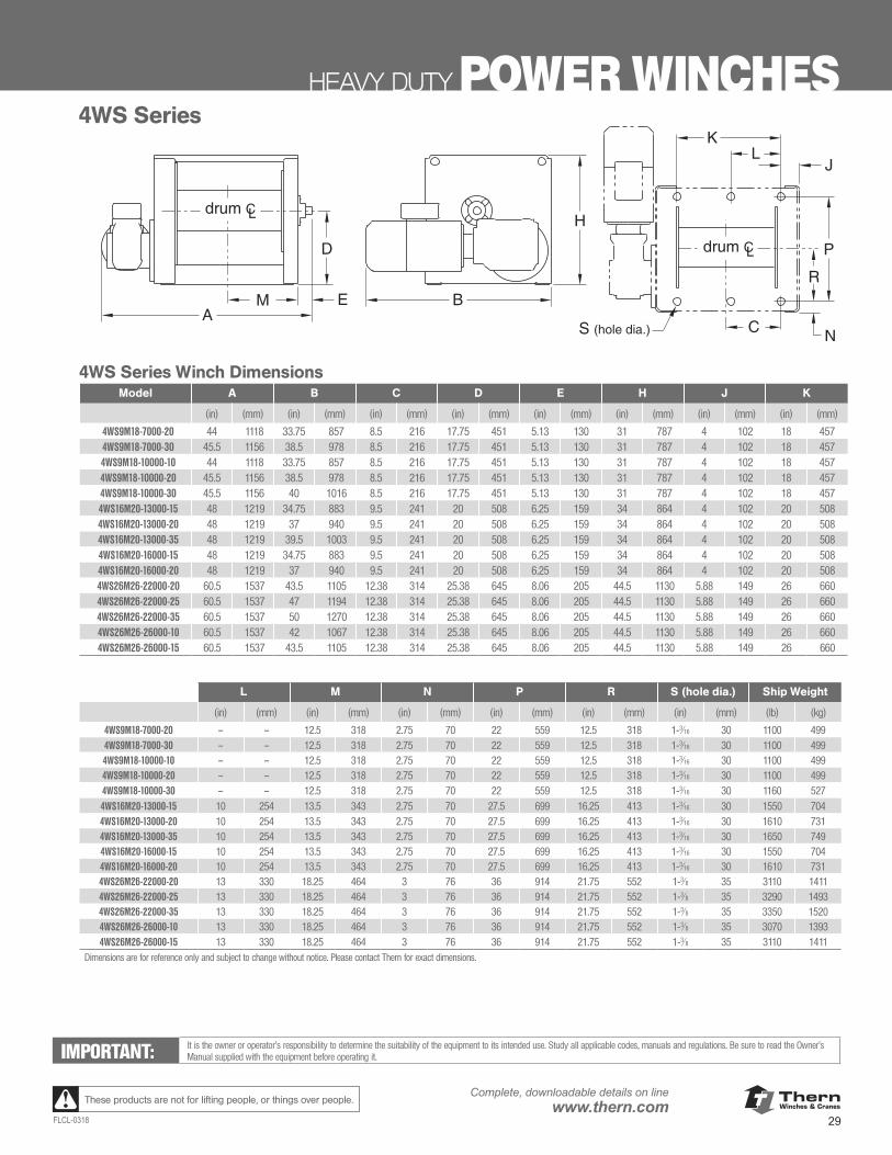
ThernWinches & Cranes
29FLCL-0318
Complete, downloadable details on linewww.thern.comThese products are not for lifting people, or things over people.
HEAVY DUTY POWER WINCHES
www.thern.com 1.800.843.7648
4WS SERIES POWER WINCHES
4WS Series Winch DimensionsA B C D E H J K
(in) (mm) (in) (mm) (in) (mm) (in) (mm) (in) (mm) (in) (mm) (in) (mm) (in) (mm)
4WS9M18-7000-20 44.00 1,118 33.75 857 8.50 216 17.75 451 5.13 130 31.00 787 4.00 102 18.00 457
4WS9M18-7000-30 45.50 1,156 38.50 978 8.50 216 17.75 451 5.13 130 31.00 787 4.00 102 18.00 457
4WS9M18-10000-10 44.00 1,118 33.75 857 8.50 216 17.75 451 5.13 130 31.00 787 4.00 102 18.00 457
4WS9M18-10000-20 45.50 1,156 38.50 978 8.50 216 17.75 451 5.13 130 31.00 787 4.00 102 18.00 457
4WS9M18-10000-30 45.50 1,156 40.00 1,016 8.50 216 17.75 451 5.13 130 31.00 787 4.00 102 18.00 457
4WS16M20-13000-15 48.00 1,219 34.75 883 9.50 241 20.00 508 6.25 159 34.00 864 4.00 102 20.00 508
4WS16M20-13000-20 48.00 1,219 37.00 940 9.50 241 20.00 508 6.25 159 34.00 864 4.00 102 20.00 508
4WS16M20-13000-35 48.00 1,219 39.50 1,003 9.50 241 20.00 508 6.25 159 34.00 864 4.00 102 20.00 508
4WS16M20-16000-15 48.00 1,219 34.75 883 9.50 241 20.00 508 6.25 159 34.00 864 4.00 102 20.00 508
4WS16M20-16000-20 48.00 1,219 37.00 940 9.50 241 20.00 508 6.25 159 34.00 864 4.00 102 20.00 508
4WS26M26-22000-20 60.50 1,537 43.50 1,105 12.38 314 25.38 645 8.06 205 44.50 1,130 5.88 149 26.00 660
4WS26M26-22000-25 60.50 1,537 47.00 1,194 12.38 314 25.38 645 8.06 205 44.50 1,130 5.88 149 26.00 660
4WS26M26-22000-35 60.50 1,537 50.00 1,270 12.38 314 25.38 645 8.06 205 44.50 1,130 5.88 149 26.00 660
4WS26M26-26000-10 60.50 1,537 42.00 1,067 12.38 314 25.38 645 8.06 205 44.50 1,130 5.88 149 26.00 660
4WS26M26-26000-15 60.50 1,537 43.50 1,105 12.38 314 25.38 645 8.06 205 44.50 1,130 5.88 149 26.00 660
A
RB
H
M E
D
J
P
NC
KL
S (hole dia.)
drum CL
drum CL
4WS Series
L M N P R S (Hole Dia.) Ship Wt.
(in) (mm) (in) (mm) (in) (mm) (in) (mm) (in) (mm) (in) (mm) (lb) (kg)
4WS9M18-7000-20 – – 12.50 318 2.75 70 22.00 559 12.50 318 1-316 30 1,100 499
4WS9M18-7000-30 – – 12.50 318 2.75 70 22.00 559 12.50 318 1-316 30 1,100 499
4WS9M18-10000-10 – – 12.50 318 2.75 70 22.00 559 12.50 318 1-316 30 1,100 499
4WS9M18-10000-20 – – 12.50 318 2.75 70 22.00 559 12.50 318 1-316 30 1,100 499
4WS9M18-10000-30 – – 12.50 318 2.75 70 22.00 559 12.50 318 1-316 30 1,160 527
4WS16M20-13000-15 10.00 254 13.50 343 2.75 70 27.50 699 16.25 413 1-316 30 1,550 704
4WS16M20-13000-20 10.00 254 13.50 343 2.75 70 27.50 699 16.25 413 1-316 30 1,610 731
4WS16M20-13000-35 10.00 254 13.50 343 2.75 70 27.50 699 16.25 413 1-316 30 1,650 749
4WS16M20-16000-15 10.00 254 13.50 343 2.75 70 27.50 699 16.25 413 1-316 30 1,550 704
4WS16M20-16000-20 10.00 254 13.50 343 2.75 70 27.50 699 16.25 413 1-316 30 1,610 731
4WS26M26-22000-20 13.00 330 18.25 464 3.00 76 36.00 914 21.75 552 1-38 35 3,110 1,411
4WS26M26-22000-25 13.00 330 18.25 464 3.00 76 36.00 914 21.75 552 1-38 35 3,290 1,493
4WS26M26-22000-35 13.00 330 18.25 464 3.00 76 36.00 914 21.75 552 1-38 35 3,350 1,520
4WS26M26-26000-10 13.00 330 18.25 464 3.00 76 36.00 914 21.75 552 1-38 35 3,070 1,393
4WS26M26-26000-15 13.00 330 18.25 464 3.00 76 36.00 914 21.75 552 1-38 35 3,110 1,411
Dimensions are for reference only and subject to change without notice. Please contact factory for exact dimensions.
IMPORTANT:It is the owner’s or op-erator’s responsibility to determine the suit-ability of the equipment to its intended use. Study all applicable codes, manuals, and regulations. Be sure to read the Owner’s Manual supplied with the equipment before operating it.
4WS Series
L M N P R S (hole dia.) Ship Weight
(in) (mm) (in) (mm) (in) (mm) (in) (mm) (in) (mm) (in) (mm) (lb) (kg)
4WS9M18-7000-20 – – 12.5 318 2.75 70 22 559 12.5 318 1-3⁄16 30 1100 4994WS9M18-7000-30 – – 12.5 318 2.75 70 22 559 12.5 318 1-3⁄16 30 1100 4994WS9M18-10000-10 – – 12.5 318 2.75 70 22 559 12.5 318 1-3⁄16 30 1100 4994WS9M18-10000-20 – – 12.5 318 2.75 70 22 559 12.5 318 1-3⁄16 30 1100 4994WS9M18-10000-30 – – 12.5 318 2.75 70 22 559 12.5 318 1-3⁄16 30 1160 5274WS16M20-13000-15 10 254 13.5 343 2.75 70 27.5 699 16.25 413 1-3⁄16 30 1550 7044WS16M20-13000-20 10 254 13.5 343 2.75 70 27.5 699 16.25 413 1-3⁄16 30 1610 7314WS16M20-13000-35 10 254 13.5 343 2.75 70 27.5 699 16.25 413 1-3⁄16 30 1650 7494WS16M20-16000-15 10 254 13.5 343 2.75 70 27.5 699 16.25 413 1-3⁄16 30 1550 7044WS16M20-16000-20 10 254 13.5 343 2.75 70 27.5 699 16.25 413 1-3⁄16 30 1610 7314WS26M26-22000-20 13 330 18.25 464 3 76 36 914 21.75 552 1-3⁄8 35 3110 14114WS26M26-22000-25 13 330 18.25 464 3 76 36 914 21.75 552 1-3⁄8 35 3290 14934WS26M26-22000-35 13 330 18.25 464 3 76 36 914 21.75 552 1-3⁄8 35 3350 15204WS26M26-26000-10 13 330 18.25 464 3 76 36 914 21.75 552 1-3⁄8 35 3070 13934WS26M26-26000-15 13 330 18.25 464 3 76 36 914 21.75 552 1-3⁄8 35 3110 1411
Dimensions are for reference only and subject to change without notice. Please contact Thern for exact dimensions.
4WS Series Winch DimensionsModel A B C D E H J K
(in) (mm) (in) (mm) (in) (mm) (in) (mm) (in) (mm) (in) (mm) (in) (mm) (in) (mm)
4WS9M18-7000-20 44 1118 33.75 857 8.5 216 17.75 451 5.13 130 31 787 4 102 18 457 4WS9M18-7000-30 45.5 1156 38.5 978 8.5 216 17.75 451 5.13 130 31 787 4 102 18 457 4WS9M18-10000-10 44 1118 33.75 857 8.5 216 17.75 451 5.13 130 31 787 4 102 18 457 4WS9M18-10000-20 45.5 1156 38.5 978 8.5 216 17.75 451 5.13 130 31 787 4 102 18 457 4WS9M18-10000-30 45.5 1156 40 1016 8.5 216 17.75 451 5.13 130 31 787 4 102 18 457 4WS16M20-13000-15 48 1219 34.75 883 9.5 241 20 508 6.25 159 34 864 4 102 20 508 4WS16M20-13000-20 48 1219 37 940 9.5 241 20 508 6.25 159 34 864 4 102 20 508 4WS16M20-13000-35 48 1219 39.5 1003 9.5 241 20 508 6.25 159 34 864 4 102 20 508 4WS16M20-16000-15 48 1219 34.75 883 9.5 241 20 508 6.25 159 34 864 4 102 20 508 4WS16M20-16000-20 48 1219 37 940 9.5 241 20 508 6.25 159 34 864 4 102 20 508 4WS26M26-22000-20 60.5 1537 43.5 1105 12.38 314 25.38 645 8.06 205 44.5 1130 5.88 149 26 660 4WS26M26-22000-25 60.5 1537 47 1194 12.38 314 25.38 645 8.06 205 44.5 1130 5.88 149 26 660 4WS26M26-22000-35 60.5 1537 50 1270 12.38 314 25.38 645 8.06 205 44.5 1130 5.88 149 26 660 4WS26M26-26000-10 60.5 1537 42 1067 12.38 314 25.38 645 8.06 205 44.5 1130 5.88 149 26 660 4WS26M26-26000-15 60.5 1537 43.5 1105 12.38 314 25.38 645 8.06 205 44.5 1130 5.88 149 26 660
IMPORTANT: It is the owner or operator’s responsibility to determine the suitability of the equipment to its intended use. Study all applicable codes, manuals and regulations. Be sure to read the Owner’s Manual supplied with the equipment before operating it.
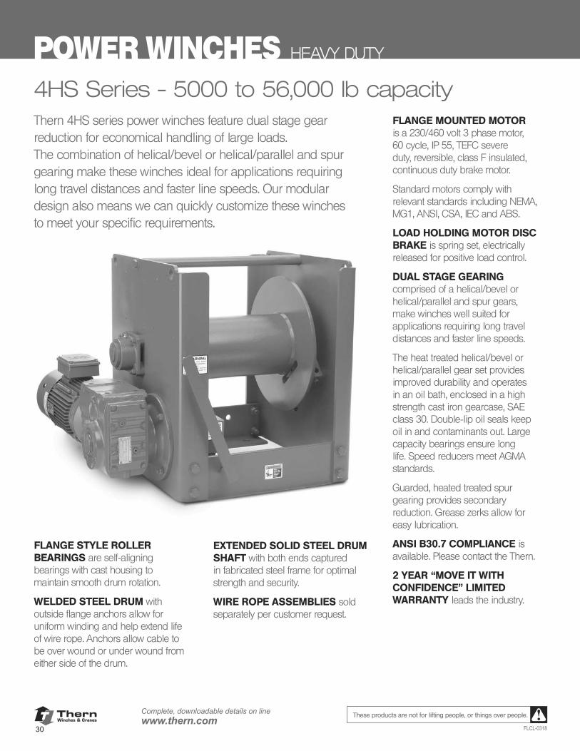
ThernWinches & Cranes
30
Complete, downloadable details on linewww.thern.com
FLCL-0318
These products are not for lifting people, or things over people.
POWER WINCHES HEAVY DUTY
4HS Series - 5000 to 56,000 lb capacityThern 4HS series power winches feature dual stage gear reduction for economical handling of large loads. The combination of helical/bevel or helical/parallel and spur gearing make these winches ideal for applications requiring long travel distances and faster line speeds. Our modular design also means we can quickly customize these winches to meet your specific requirements.
FLANGE STYLE ROLLER BEARINGS are self-aligning bearings with cast housing to maintain smooth drum rotation.
WELDED STEEL DRUM with outside flange anchors allow for uniform winding and help extend life of wire rope. Anchors allow cable to be over wound or under wound from either side of the drum.
EXTENDED SOLID STEEL DRUM SHAFT with both ends captured in fabricated steel frame for optimal strength and security.
WIRE ROPE ASSEMBLIES sold separately per customer request.
FLANGE MOUNTED MOTOR is a 230/460 volt 3 phase motor, 60 cycle, IP 55, TEFC severe duty, reversible, class F insulated, continuous duty brake motor.
Standard motors comply with relevant standards including NEMA, MG1, ANSI, CSA, IEC and ABS.
LOAD HOLDING MOTOR DISC BRAKE is spring set, electrically released for positive load control.
DUAL STAGE GEARING comprised of a helical/bevel or helical/parallel and spur gears, make winches well suited for applications requiring long travel distances and faster line speeds.
The heat treated helical/bevel or helical/parallel gear set provides improved durability and operates in an oil bath, enclosed in a high strength cast iron gearcase, SAE class 30. Double-lip oil seals keep oil in and contaminants out. Large capacity bearings ensure long life. Speed reducers meet AGMA standards.
Guarded, heated treated spur gearing provides secondary reduction. Grease zerks allow for easy lubrication.
ANSI B30.7 COMPLIANCE is available. Please contact the Thern.
2 YEAR “MOVE IT WITH CONFIDENCE” LIMITED WARRANTY leads the industry.
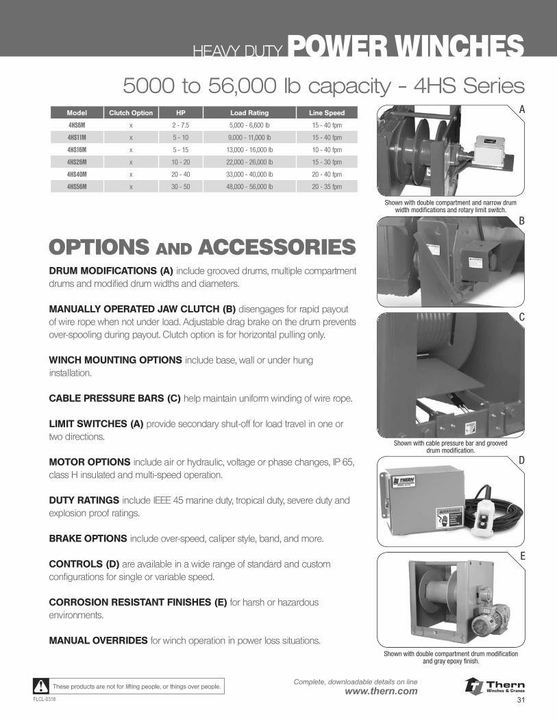
ThernWinches & Cranes
31FLCL-0318
Complete, downloadable details on linewww.thern.comThese products are not for lifting people, or things over people.
HEAVY DUTY POWER WINCHES5000 to 56,000 lb capacity - 4HS Series
OPTIONS AND ACCESSORIES
Model Clutch Option HP Load Rating Line Speed
4HS6M x 2 - 7.5 5,000 - 6,600 lb 15 - 40 fpm
4HS11M x 5 - 10 9,000 - 11,000 lb 15 - 40 fpm
4HS16M x 5 - 15 13,000 - 16,000 lb 10 - 40 fpm
4HS26M x 10 - 20 22,000 - 26,000 lb 15 - 30 fpm
4HS40M x 20 - 40 33,000 - 40,000 lb 20 - 40 fpm
4HS56M x 30 - 50 48,000 - 56,000 lb 20 - 35 fpm
B
A
Shown with double compartment and narrow drum width modifications and rotary limit switch.
C
Shown with cable pressure bar and grooved drum modification.
D
E
Shown with double compartment drum modification and gray epoxy finish.
DRUM MODIFICATIONS (A) include grooved drums, multiple compartment drums and modified drum widths and diameters.
MANUALLY OPERATED JAW CLUTCH (B) disengages for rapid payout of wire rope when not under load. Adjustable drag brake on the drum prevents over-spooling during payout. Clutch option is for horizontal pulling only.
WINCH MOUNTING OPTIONS include base, wall or under hung installation.
CABLE PRESSURE BARS (C) help maintain uniform winding of wire rope.
LIMIT SWITCHES (A) provide secondary shut-off for load travel in one or two directions.
MOTOR OPTIONS include air or hydraulic, voltage or phase changes, IP 65, class H insulated and multi-speed operation.
DUTY RATINGS include IEEE 45 marine duty, tropical duty, severe duty and explosion proof ratings.
BRAKE OPTIONS include over-speed, caliper style, band, and more.
CONTROLS (D) are available in a wide range of standard and custom configurations for single or variable speed.
CORROSION RESISTANT FINISHES (E) for harsh or hazardous environments.
MANUAL OVERRIDES for winch operation in power loss situations.
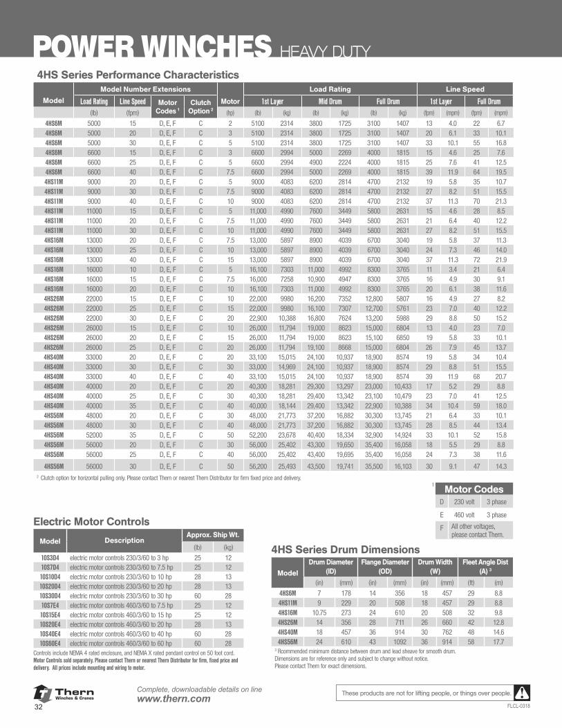
ThernWinches & Cranes
32
Complete, downloadable details on linewww.thern.com
FLCL-0318
These products are not for lifting people, or things over people.
POWER WINCHES HEAVY DUTY4HS Series Performance Characteristics
Model Number Extensions Load Rating Line Speed
Model Load Rating Line Speed Motor Codes 1
Clutch Option 2
Motor 1st Layer Mid Drum Full Drum 1st Layer Full Drum(lb) (fpm) (hp) (lb) (kg) (lb) (kg) (lb) (kg) (fpm) (mpm) (fpm) (mpm)
4HS6M 5000 15 D, E, F C 2 5100 2314 3800 1725 3100 1407 13 4.0 22 6.74HS6M 5000 20 D, E, F C 3 5100 2314 3800 1725 3100 1407 20 6.1 33 10.14HS6M 5000 30 D, E, F C 5 5100 2314 3800 1725 3100 1407 33 10.1 55 16.84HS6M 6600 15 D, E, F C 3 6600 2994 5000 2269 4000 1815 15 4.6 25 7.64HS6M 6600 25 D, E, F C 5 6600 2994 4900 2224 4000 1815 25 7.6 41 12.54HS6M 6600 40 D, E, F C 7.5 6600 2994 5000 2269 4000 1815 39 11.9 64 19.54HS11M 9000 20 D, E, F C 5 9000 4083 6200 2814 4700 2132 19 5.8 35 10.74HS11M 9000 30 D, E, F C 7.5 9000 4083 6200 2814 4700 2132 27 8.2 51 15.54HS11M 9000 40 D, E, F C 10 9000 4083 6200 2814 4700 2132 37 11.3 70 21.34HS11M 11000 15 D, E, F C 5 11,000 4990 7600 3449 5800 2631 15 4.6 28 8.54HS11M 11000 20 D, E, F C 7.5 11,000 4990 7600 3449 5800 2631 21 6.4 40 12.24HS11M 11000 30 D, E, F C 10 11,000 4990 7600 3449 5800 2631 27 8.2 51 15.54HS16M 13000 20 D, E, F C 7.5 13,000 5897 8900 4039 6700 3040 19 5.8 37 11.34HS16M 13000 25 D, E, F C 10 13,000 5897 8900 4039 6700 3040 24 7.3 46 14.04HS16M 13000 40 D, E, F C 15 13,000 5897 8900 4039 6700 3040 37 11.3 72 21.94HS16M 16000 10 D, E, F C 5 16,100 7303 11,000 4992 8300 3765 11 3.4 21 6.44HS16M 16000 15 D, E, F C 7.5 16,000 7258 10,900 4947 8300 3765 16 4.9 30 9.14HS16M 16000 20 D, E, F C 10 16,100 7303 11,000 4992 8300 3765 20 6.1 38 11.64HS26M 22000 15 D, E, F C 10 22,000 9980 16,200 7352 12,800 5807 16 4.9 27 8.24HS26M 22000 25 D, E, F C 15 22,000 9980 16,100 7307 12,700 5761 23 7.0 40 12.24HS26M 22000 30 D, E, F C 20 22,900 10,388 16,800 7624 13,200 5988 29 8.8 50 15.24HS26M 26000 15 D, E, F C 10 26,000 11,794 19,000 8623 15,000 6804 13 4.0 23 7.04HS26M 26000 20 D, E, F C 15 26,000 11,794 19,000 8623 15,100 6850 19 5.8 33 10.14HS26M 26000 25 D, E, F C 20 26,000 11,794 19,100 8668 15,000 6804 26 7.9 45 13.74HS40M 33000 20 D, E, F C 20 33,100 15,015 24,100 10,937 18,900 8574 19 5.8 34 10.44HS40M 33000 30 D, E, F C 30 33,000 14,969 24,100 10,937 18,900 8574 29 8.8 51 15.54HS40M 33000 40 D, E, F C 40 33,100 15,015 24,100 10,937 18,900 8574 39 11.9 68 20.74HS40M 40000 20 D, E, F C 20 40,300 18,281 29,300 13,297 23,000 10,433 17 5.2 29 8.84HS40M 40000 25 D, E, F C 30 40,300 18,281 29,400 13,342 23,100 10,479 23 7.0 41 12.54HS40M 40000 35 D, E, F C 40 40,000 18,144 29,400 13,342 22,900 10,388 34 10.4 59 18.04HS56M 48000 20 D, E, F C 30 48,000 21,773 37,200 16,882 30,300 13,745 21 6.4 33 10.14HS56M 48000 30 D, E, F C 40 48,000 21,773 37,200 16,882 30,300 13,745 28 8.5 44 13.44HS56M 52000 35 D, E, F C 50 52,200 23,678 40,400 18,334 32,900 14,924 33 10.1 52 15.84HS56M 56000 20 D, E, F C 30 56,000 25,402 43,300 19,650 35,400 16,058 18 5.5 29 8.84HS56M 56000 25 D, E, F C 40 56,000 25,402 43,400 19,695 35,400 16,058 24 7.3 38 11.6
4HS56M 56000 30 D, E, F C 50 56,200 25,493 43,500 19,741 35,500 16,103 30 9.1 47 14.32 Clutch option for horizontal pulling only. Please contact Thern or nearest Thern Distributor for firm fixed price and delivery.
1Motor Codes
D 230 volt 3 phase
E 460 volt 3 phase
F All other voltages, please contact Thern.
Electric Motor Controls
Model DescriptionApprox. Ship Wt.
(lb) (kg)
10S3D4 electric motor controls 230/3/60 to 3 hp 25 1210S7D4 electric motor controls 230/3/60 to 7.5 hp 25 1210S10D4 electric motor controls 230/3/60 to 10 hp 28 1310S20D4 electric motor controls 230/3/60 to 20 hp 28 1310S30D4 electric motor controls 230/3/60 to 30 hp 60 2810S7E4 electric motor controls 460/3/60 to 7.5 hp 25 1210S15E4 electric motor controls 460/3/60 to 15 hp 25 1210S20E4 electric motor controls 460/3/60 to 20 hp 28 1310S40E4 electric motor controls 460/3/60 to 40 hp 60 2810S60E4 electric motor controls 460/3/60 to 60 hp 60 28
Controls include NEMA 4 rated enclosure, and NEMA X rated pendant control on 50 foot cord. Motor Controls sold separately. Please contact Thern or nearest Thern Distributor for firm, fixed price and delivery. All prices include mounting and wiring to motor.
4HS Series Drum Dimensions
Model
Drum Diameter (ID)
Flange Diameter (OD)
Drum Width (W)
Fleet Angle Dist (A) 3
(in) (mm) (in) (mm) (in) (mm) (ft) (m)
4HS6M 7 178 14 356 18 457 29 8.84HS11M 9 229 20 508 18 457 29 8.84HS16M 10.75 273 24 610 20 508 32 9.84HS26M 14 356 28 711 26 660 42 12.84HS40M 18 457 36 914 30 762 48 14.64HS56M 24 610 43 1092 36 914 58 17.7
3 Rcommended minimum distance between drum and lead sheave for smooth drum. Dimensions are for reference only and subject to change without notice. Please contact Thern for exact dimensions.
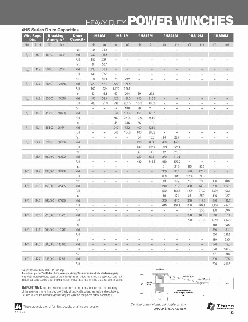
ThernWinches & Cranes
33FLCL-0318
Complete, downloadable details on linewww.thern.comThese products are not for lifting people, or things over people.
HEAVY DUTY POWER WINCHES4HS Series Drum Capacities
Wire Rope Dia.
Breaking Strength 4
Drum Capacity
4HS6M 4HS11M 4HS16M 4HS26M 4HS40M 4HS56M
(in) (mm) (lb) (kg) (ft) (m) (ft) (m) (ft) (m) (ft) (m) (ft) (m) (ft) (m)
1st 80 24.4 – – – – – – – – – –3/
8 9.7 15,100 6849 Mid 380 115.8 – – – – – – – – – –
Full 850 259.1 – – – – – – – – – –
1st 68 20.7 – – – – – – – – – –7/
16 11.2 20,400 9254 Mid 290 88.4 – – – – – – – – – –
Full 640 195.1 – – – – – – – – – –
1st 60 18.3 76 23.2 – – – – – – – –1/
2 12.7 26,600 12,066 Mid 220 67.1 520 158.5 – – – – – – – –
Full 500 152.4 1,170 356.6 – – – – – – – –
1st 53 16.2 67 20.4 89 27.1 – – – – – –9/
16 14.2 33,600 15,240 Mid 180 54.9 420 128.0 690 210.3 – – – – – –
Full 400 121.9 930 283.5 1,530 466.3 – – – – – –
1st – – 59 18.0 78 23.8 – – – – – –5/
8 16.0 41,200 18,688 Mid – – 340 103.6 560 170.7 – – – – – –
Full – – 760 231.6 1,250 381.0 – – – – – –
1st – – 48 14.6 65 19.8 – – – – – –3/
4 19.1 58,800 26,671 Mid – – 240 73.2 400 121.9 – – – – – –
Full – – 540 164.6 880 268.2 – – – – – –
1st – – – – 54 16.5 94 28.7 – – – –7/
8 22.4 79,600 36,106 Mid – – – – 290 88.4 480 146.3 – – – –
Full – – – – 640 195.1 1,070 326.1 – – – –
1st – – – – 47 14.3 82 25.0 – – – –
1 25.4 103,400 46,902 Mid – – – – 220 67.1 370 112.8 – – – –
Full – – – – 490 149.4 830 253.0 – – – –
1st – – – – – – 71 21.6 110 33.5 – –
1-1/8 28.7 130,000 58,968 Mid – – – – – – 300 91.4 580 176.8 – –
Full – – – – – – 660 201.2 1,290 393.2 – –
1st – – – – – – 63 19.2 95 29.0 160 48.8
1-1/4 31.8 159,800 72,485 Mid – – – – – – 240 73.2 460 140.2 730 222.5
Full – – – – – – 530 161.5 1,030 313.9 1,630 496.8
1st – – – – – – 56 17.1 85 25.9 140 42.7
1-3/8 34.9 192,000 87,090 Mid – – – – – – 200 61.0 390 118.9 610 185.9
Full – – – – – – 440 134.1 860 262.1 1,360 414.5
1st – – – – – – – – 77 23.5 130 39.6
1-1/2 38.1 228,000 103,420 Mid – – – – – – – – 330 100.6 510 155.4
Full – – – – – – – – 720 219.5 1,140 347.5
1st – – – – – – – – – – 110 33.5
1-5/8 41.3 264,000 119,750 Mid – – – – – – – – – – 430 131.1
Full – – – – – – – – – – 950 289.6
1st – – – – – – – – – – 110 33.5
1-3/4 44.5 306,000 138,800 Mid – – – – – – – – – – 370 112.8
Full – – – – – – – – – – 820 249.9
1st – – – – – – – – – – 97 29.6
1-7/8 47.7 348,000 157,851 Mid – – – – – – – – – – 320 97.5
Full – – – – – – – – – – 720 219.5 4 Values based on 6x37 IWRC EIPS wire rope. Actual drum capacities 25-30% less, due to nonuniform winding. Wire rope tension will also affect drum capacity.Wire rope should be selected based on the breaking strength to load rating ratio and application parameters. Industry standards suggest a 5:1 breaking strength to load rating ratio for lifting and a 3:1 ratio for pulling.
RecommendedFleet Angle Distance
Fleet Angle
Load
Lead Sheave
Center Line
ID
OD
W
A
IMPORTANT: It is the owner or operator’s responsibility to determine the suitability of the equipment to its intended use. Study all applicable codes, manuals and regulations. Be sure to read the Owner’s Manual supplied with the equipment before operating it.
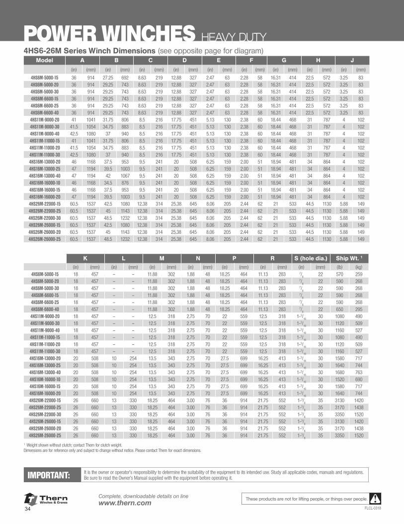
ThernWinches & Cranes
34
Complete, downloadable details on linewww.thern.com
FLCL-0318
These products are not for lifting people, or things over people.
POWER WINCHES HEAVY DUTY
IMPORTANT: It is the owner or operator’s responsibility to determine the suitability of the equipment to its intended use. Study all applicable codes, manuals and regulations. Be sure to read the Owner’s Manual supplied with the equipment before operating it.
4HS6-26M Series Winch Dimensions (see opposite page for diagram)Model A B C D E F G H J
(in) (mm) (in) (mm) (in) (mm) (in) (mm) (in) (mm) (in) (mm) (in) (mm) (in) (mm) (in) (mm)
4HS6M-5000-15 36 914 27.25 692 8.63 219 12.88 327 2.47 63 2.28 58 16.31 414 22.5 572 3.25 834HS6M-5000-20 36 914 29.25 743 8.63 219 12.88 327 2.47 63 2.28 58 16.31 414 22.5 572 3.25 83 4HS6M-5000-30 36 914 29.25 743 8.63 219 12.88 327 2.47 63 2.28 58 16.31 414 22.5 572 3.25 834HS6M-6600-15 36 914 29.25 743 8.63 219 12.88 327 2.47 63 2.28 58 16.31 414 22.5 572 3.25 834HS6M-6600-25 36 914 29.25 743 8.63 219 12.88 327 2.47 63 2.28 58 16.31 414 22.5 572 3.25 834HS6M-6600-40 36 914 29.25 743 8.63 219 12.88 327 2.47 63 2.28 58 16.31 414 22.5 572 3.25 834HS11M-9000-20 41 1041 31.75 806 8.5 216 17.75 451 5.13 130 2.38 60 18.44 468 31 787 4 1024HS11M-9000-30 41.5 1054 34.75 883 8.5 216 17.75 451 5.13 130 2.38 60 18.44 468 31 787 4 1024HS11M-9000-40 42.5 1080 37 940 8.5 216 17.75 451 5.13 130 2.38 60 18.44 468 31 787 4 1024HS11M-11000-15 41 1041 31.75 806 8.5 216 17.75 451 5.13 130 2.38 60 18.44 468 31 787 4 1024HS11M-11000-20 41.5 1054 34.75 883 8.5 216 17.75 451 5.13 130 2.38 60 18.44 468 31 787 4 1024HS11M-11000-30 42.5 1080 37 940 8.5 216 17.75 451 5.13 130 2.38 60 18.44 468 31 787 4 1024HS16M-13000-20 46 1168 37.5 953 9.5 241 20 508 6.25 159 2.00 51 18.94 481 34 864 4 1024HS16M-13000-25 47 1194 39.5 1003 9.5 241 20 508 6.25 159 2.00 51 18.94 481 34 864 4 1024HS16M-13000-40 47 1194 42 1067 9.5 241 20 508 6.25 159 2.00 51 18.94 481 34 864 4 1024HS16M-16000-10 46 1168 34.5 876 9.5 241 20 508 6.25 159 2.00 51 18.94 481 34 864 4 1024HS16M-16000-15 46 1168 37.5 953 9.5 241 20 508 6.25 159 2.00 51 18.94 481 34 864 4 1024HS16M-16000-20 47 1194 39.5 1003 9.5 241 20 508 6.25 159 2.00 51 18.94 481 34 864 4 1024HS26M-22000-15 60.5 1537 42.5 1080 12.38 314 25.38 645 8.06 205 2.44 62 21 533 44.5 1130 5.88 1494HS26M-22000-25 60.5 1537 45 1143 12.38 314 25.38 645 8.06 205 2.44 62 21 533 44.5 1130 5.88 149 4HS26M-22000-30 60.5 1537 48.5 1232 12.38 314 25.38 645 8.06 205 2.44 62 21 533 44.5 1130 5.88 1494HS26M-26000-15 60.5 1537 42.5 1080 12.38 314 25.38 645 8.06 205 2.44 62 21 533 44.5 1130 5.88 1494HS26M-26000-20 60.5 1537 45 1143 12.38 314 25.38 645 8.06 205 2.44 62 21 533 44.5 1130 5.88 1494HS26M-26000-25 60.5 1537 48.5 1232 12.38 314 25.38 645 8.06 205 2.44 62 21 533 44.5 1130 5.88 149
K L M N P R S (hole dia.) Ship Wt. 1
(in) (mm) (in) (mm) (in) (mm) (in) (mm) (in) (mm) (in) (mm) (in) (mm) (lb) (kg)4HS6M-5000-15 18 457 – – 11.88 302 1.88 48 18.25 464 11.13 283 7/
822 570 259
4HS6M-5000-20 18 457 – – 11.88 302 1.88 48 18.25 464 11.13 283 7/8
22 590 268 4HS6M-5000-30 18 457 – – 11.88 302 1.88 48 18.25 464 11.13 283 7/
822 590 268
4HS6M-6600-15 18 457 – – 11.88 302 1.88 48 18.25 464 11.13 283 7/8
22 590 268 4HS6M-6600-25 18 457 – – 11.88 302 1.88 48 18.25 464 11.13 283 7/
822 590 268
4HS6M-6600-40 18 457 – – 11.88 302 1.88 48 18.25 464 11.13 283 7/8
22 650 295 4HS11M-9000-20 18 457 – – 12.5 318 2.75 70 22 559 12.5 318 1-3/
1630 1080 490
4HS11M-9000-30 18 457 – – 12.5 318 2.75 70 22 559 12.5 318 1-3/16
30 1120 5094HS11M-9000-40 18 457 – – 12.5 318 2.75 70 22 559 12.5 318 1-3/
1630 1160 527
4HS11M-11000-15 18 457 – – 12.5 318 2.75 70 22 559 12.5 318 1-3/16
30 1080 4904HS11M-11000-20 18 457 – – 12.5 318 2.75 70 22 559 12.5 318 1-3/
1630 1120 509
4HS11M-11000-30 18 457 – – 12.5 318 2.75 70 22 559 12.5 318 1-3/16
30 1160 5274HS16M-13000-20 20 508 10 254 13.5 343 2.75 70 27.5 699 16.25 413 1-3/
1630 1580 717
4HS16M-13000-25 20 508 10 254 13.5 343 2.75 70 27.5 699 16.25 413 1-3/16
30 1640 7444HS16M-13000-40 20 508 10 254 13.5 343 2.75 70 27.5 699 16.25 413 1-3/
1630 1680 763
4HS16M-16000-10 20 508 10 254 13.5 343 2.75 70 27.5 699 16.25 413 1-3/16
30 1520 6904HS16M-16000-15 20 508 10 254 13.5 343 2.75 70 27.5 699 16.25 413 1-3/
1630 1580 717
4HS16M-16000-20 20 508 10 254 13.5 343 2.75 70 27.5 699 16.25 413 1-3/16
30 1640 7444HS26M-22000-15 26 660 13 330 18.25 464 3.00 76 36 914 21.75 552 1-3/
835 3130 1420
4HS26M-22000-25 26 660 13 330 18.25 464 3.00 76 36 914 21.75 552 1-3/8
35 3170 14384HS26M-22000-30 26 660 13 330 18.25 464 3.00 76 36 914 21.75 552 1-3/
835 3350 1520
4HS26M-26000-15 26 660 13 330 18.25 464 3.00 76 36 914 21.75 552 1-3/8
35 3130 1420 4HS26M-26000-20 26 660 13 330 18.25 464 3.00 76 36 914 21.75 552 1-3/
835 3170 1438
4HS26M-26000-25 26 660 13 330 18.25 464 3.00 76 36 914 21.75 552 1-3/8
35 3350 1520
1 Weight shown without clutch; contact Thern for clutch weight. Dimensions are for reference only and subject to change without notice. Please contact Thern for exact dimensions.
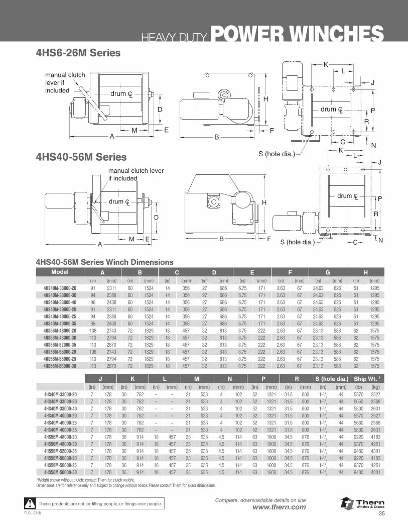
ThernWinches & Cranes
35FLCL-0318
Complete, downloadable details on linewww.thern.comThese products are not for lifting people, or things over people.
HEAVY DUTY POWER WINCHES
www.thern.com 1.800.843.7648
4HS40-56M Series Winch DimensionsA B C D E F G H
(in) (mm) (in) (mm) (in) (mm) (in) (mm) (in) (mm) (in) (mm) (in) (mm) (in) (mm)4HS40M-33000-20 91.00 2,311 60.00 1,524 14.00 356 27.00 686 6.75 171 2.63 67 24.63 626 51.00 1,2954HS40M-33000-30 94.00 2,388 60.00 1,524 14.00 356 27.00 686 6.75 171 2.63 67 24.63 626 51.00 1,2954HS40M-33000-40 96.00 2,438 60.00 1,524 14.00 356 27.00 686 6.75 171 2.63 67 24.63 626 51.00 1,2954HS40M-40000-20 91.00 2,311 60.00 1,524 14.00 356 27.00 686 6.75 171 2.63 67 24.63 626 51.00 1,2954HS40M-40000-25 94.00 2,388 60.00 1,524 14.00 356 27.00 686 6.75 171 2.63 67 24.63 626 51.00 1,2954HS40M-40000-35 96.00 2,438 60.00 1,524 14.00 356 27.00 686 6.75 171 2.63 67 24.63 626 51.00 1,2954HS56M-48000-20 108.00 2,743 72.00 1,829 18.00 457 32.00 813 8.75 222 2.63 67 23.13 588 62.00 1,5754HS56M-48000-30 110.00 2,794 72.00 1,829 18.00 457 32.00 813 8.75 222 2.63 67 23.13 588 62.00 1,5754HS56M-52000-35 113.00 2,870 72.00 1,829 18.00 457 32.00 813 8.75 222 2.63 67 23.13 588 62.00 1,5754HS56M-56000-20 108.00 2,743 72.00 1,829 18.00 457 32.00 813 8.75 222 2.63 67 23.13 588 62.00 1,5754HS56M-56000-25 110.00 2,794 72.00 1,829 18.00 457 32.00 813 8.75 222 2.63 67 23.13 588 62.00 1,5754HS56M-56000-30 113.00 2,870 72.00 1,829 18.00 457 32.00 813 8.75 222 2.63 67 23.13 588 62.00 1,575
AB F
H
M E
D
J
P
NS (hole dia.) C
KL
drum CLdrum CL
R
manual clutch leverif included
4HS40-56M Series
A
R
BF
H
M E
D
J
P
NS (hole dia.)
C
KL
drum CL
drum CL
4HS6-26M Series
J K L M N P R S (Hole Dia.) Ship Wt.1
(in) (mm) (in) (mm) (in) (mm) (in) (mm) (in) (mm) (in) (mm) (in) (mm) (in) (mm) (lb) (kg)
4HS40M-33000-20 7.00 178 30.00 762 – – 21.00 533 4.00 102 52.00 1,321 31.50 800 1-3/4 44 5,570 2,5274HS40M-33000-30 7.00 178 30.00 762 – – 21.00 533 4.00 102 52.00 1,321 31.50 800 1-3/4 44 5,660 2,5684HS40M-33000-40 7.00 178 30.00 762 – – 21.00 533 4.00 102 52.00 1,321 31.50 800 1-3/4 44 5,800 2,6314HS40M-40000-20 7.00 178 30.00 762 – – 21.00 533 4.00 102 52.00 1,321 31.50 800 1-3/4 44 5,570 2,5274HS40M-40000-25 7.00 178 30.00 762 – – 21.00 533 4.00 102 52.00 1,321 31.50 800 1-3/4 44 5,660 2,5684HS40M-40000-35 7.00 178 30.00 762 – – 21.00 533 4.00 102 52.00 1,321 31.50 800 1-3/4 44 5,800 2,6314HS56M-48000-20 7.00 178 36.00 914 18.00 457 25.00 635 4.50 114 63.00 1,600 34.50 876 1-3/4 44 9,220 4,1834HS56M-48000-30 7.00 178 36.00 914 18.00 457 25.00 635 4.50 114 63.00 1,600 34.50 876 1-3/4 44 9,370 4,2514HS56M-52000-35 7.00 178 36.00 914 18.00 457 25.00 635 4.50 114 63.00 1,600 34.50 876 1-3/4 44 9,480 4,3014HS56M-56000-20 7.00 178 36.00 914 18.00 457 25.00 635 4.50 114 63.00 1,600 34.50 876 1-3/4 44 9,220 4,1834HS56M-56000-25 7.00 178 36.00 914 18.00 457 25.00 635 4.50 114 63.00 1,600 34.50 876 1-3/4 44 9,370 4,2514HS56M-56000-30 7.00 178 36.00 914 18.00 457 25.00 635 4.50 114 63.00 1,600 34.50 876 1-3/4 44 9,480 4,301
Weight shown without clutch; contact factory for clutch weight. Dimensions are for reference only and subject to change without notice. Please contact factory for exact dimensions.
4HS SERIES POWER WINCHES
1
4HS40-56M Series Winch DimensionsModel A B C D E F G H
(in) (mm) (in) (mm) (in) (mm) (in) (mm) (in) (mm) (in) (mm) (in) (mm) (in) (mm)4HS40M-33000-20 91 2311 60 1524 14 356 27 686 6.75 171 2.63 67 24.63 626 51 12954HS40M-33000-30 94 2388 60 1524 14 356 27 686 6.75 171 2.63 67 24.63 626 51 12954HS40M-33000-40 96 2438 60 1524 14 356 27 686 6.75 171 2.63 67 24.63 626 51 12954HS40M-40000-20 91 2311 60 1524 14 356 27 686 6.75 171 2.63 67 24.63 626 51 12954HS40M-40000-25 94 2388 60 1524 14 356 27 686 6.75 171 2.63 67 24.63 626 51 12954HS40M-40000-35 96 2438 60 1524 14 356 27 686 6.75 171 2.63 67 24.63 626 51 12954HS56M-48000-20 108 2743 72 1829 18 457 32 813 8.75 222 2.63 67 23.13 588 62 15754HS56M-48000-30 110 2794 72 1829 18 457 32 813 8.75 222 2.63 67 23.13 588 62 15754HS56M-52000-35 113 2870 72 1829 18 457 32 813 8.75 222 2.63 67 23.13 588 62 15754HS56M-56000-20 108 2743 72 1829 18 457 32 813 8.75 222 2.63 67 23.13 588 62 15754HS56M-56000-25 110 2794 72 1829 18 457 32 813 8.75 222 2.63 67 23.13 588 62 15754HS56M-56000-30 113 2870 72 1829 18 457 32 813 8.75 222 2.63 67 23.13 588 62 1575
J K L M N P R S (hole dia.) Ship Wt. 1
(in) (mm) (in) (mm) (in) (mm) (in) (mm) (in) (mm) (in) (mm) (in) (mm) (in) (mm) (lb) (kg)
4HS40M-33000-20 7 178 30 762 – – 21 533 4 102 52 1321 31.5 800 1-3/4
44 5570 25274HS40M-33000-30 7 178 30 762 – – 21 533 4 102 52 1321 31.5 800 1-3/
444 5660 2568
4HS40M-33000-40 7 178 30 762 – – 21 533 4 102 52 1321 31.5 800 1-3/4
44 5800 26314HS40M-40000-20 7 178 30 762 – – 21 533 4 102 52 1321 31.5 800 1-3/
444 5570 2527
4HS40M-40000-25 7 178 30 762 – – 21 533 4 102 52 1321 31.5 800 1-3/4
44 5660 25684HS40M-40000-35 7 178 30 762 – – 21 533 4 102 52 1321 31.5 800 1-3/
444 5800 2631
4HS56M-48000-20 7 178 36 914 18 457 25 635 4.5 114 63 1600 34.5 876 1-3/4
44 9220 41834HS56M-48000-30 7 178 36 914 18 457 25 635 4.5 114 63 1600 34.5 876 1-3/
444 9370 4251
4HS56M-52000-35 7 178 36 914 18 457 25 635 4.5 114 63 1600 34.5 876 1-3/4
44 9480 43014HS56M-56000-20 7 178 36 914 18 457 25 635 4.5 114 63 1600 34.5 876 1-3/
444 9220 4183
4HS56M-56000-25 7 178 36 914 18 457 25 635 4.5 114 63 1600 34.5 876 1-3/4
44 9370 42514HS56M-56000-30 7 178 36 914 18 457 25 635 4.5 114 63 1600 34.5 876 1-3/
444 9480 4301
1 Weight shown without clutch; contact Thern for clutch weight. Dimensions are for reference only and subject to change without notice. Please contact Thern for exact dimensions.
4HS6-26M Series
4HS40-56M Series
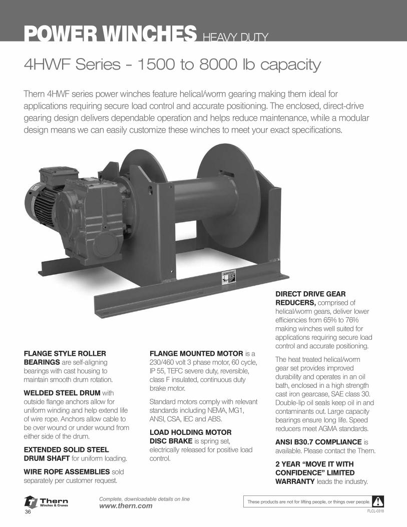
ThernWinches & Cranes
36
Complete, downloadable details on linewww.thern.com
FLCL-0318
These products are not for lifting people, or things over people.
POWER WINCHES HEAVY DUTY
4HWF Series - 1500 to 8000 lb capacity
Thern 4HWF series power winches feature helical/worm gearing making them ideal for applications requiring secure load control and accurate positioning. The enclosed, direct-drive gearing design delivers dependable operation and helps reduce maintenance, while a modular design means we can easily customize these winches to meet your exact specifications.
FLANGE STYLE ROLLER BEARINGS are self-aligning bearings with cast housing to maintain smooth drum rotation.
WELDED STEEL DRUM with outside flange anchors allow for uniform winding and help extend life of wire rope. Anchors allow cable to be over wound or under wound from either side of the drum.
EXTENDED SOLID STEEL DRUM SHAFT for uniform loading.
WIRE ROPE ASSEMBLIES sold separately per customer request.
FLANGE MOUNTED MOTOR is a 230/460 volt 3 phase motor, 60 cycle, IP 55, TEFC severe duty, reversible, class F insulated, continuous duty brake motor.
Standard motors comply with relevant standards including NEMA, MG1, ANSI, CSA, IEC and ABS.
LOAD HOLDING MOTOR DISC BRAKE is spring set, electrically released for positive load control.
DIRECT DRIVE GEAR REDUCERS, comprised of helical/worm gears, deliver lower efficiencies from 65% to 76% making winches well suited for applications requiring secure load control and accurate positioning.
The heat treated helical/worm gear set provides improved durability and operates in an oil bath, enclosed in a high strength cast iron gearcase, SAE class 30. Double-lip oil seals keep oil in and contaminants out. Large capacity bearings ensure long life. Speed reducers meet AGMA standards.
ANSI B30.7 COMPLIANCE is available. Please contact the Thern.
2 YEAR “MOVE IT WITH CONFIDENCE” LIMITED WARRANTY leads the industry.
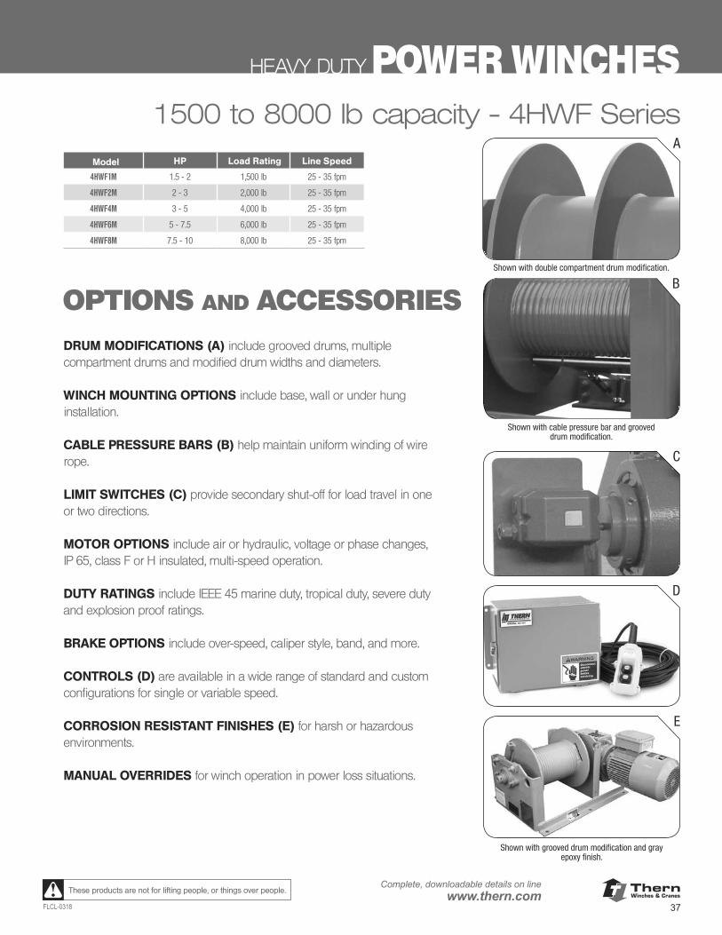
ThernWinches & Cranes
37FLCL-0318
Complete, downloadable details on linewww.thern.comThese products are not for lifting people, or things over people.
HEAVY DUTY POWER WINCHES1500 to 8000 lb capacity - 4HWF Series
OPTIONS AND ACCESSORIES
Model HP Load Rating Line Speed
4HWF1M 1.5 - 2 1,500 lb 25 - 35 fpm
4HWF2M 2 - 3 2,000 lb 25 - 35 fpm
4HWF4M 3 - 5 4,000 lb 25 - 35 fpm
4HWF6M 5 - 7.5 6,000 lb 25 - 35 fpm
4HWF8M 7.5 - 10 8,000 lb 25 - 35 fpm
DRUM MODIFICATIONS (A) include grooved drums, multiple compartment drums and modified drum widths and diameters.
WINCH MOUNTING OPTIONS include base, wall or under hung installation.
CABLE PRESSURE BARS (B) help maintain uniform winding of wire rope.
LIMIT SWITCHES (C) provide secondary shut-off for load travel in one or two directions.
MOTOR OPTIONS include air or hydraulic, voltage or phase changes, IP 65, class F or H insulated, multi-speed operation.
DUTY RATINGS include IEEE 45 marine duty, tropical duty, severe duty and explosion proof ratings.
BRAKE OPTIONS include over-speed, caliper style, band, and more.
CONTROLS (D) are available in a wide range of standard and custom configurations for single or variable speed.
CORROSION RESISTANT FINISHES (E) for harsh or hazardous environments.
MANUAL OVERRIDES for winch operation in power loss situations.
C
A
Shown with double compartment drum modification.
B
Shown with cable pressure bar and grooved drum modification.
D
E
Shown with grooved drum modification and gray epoxy finish.
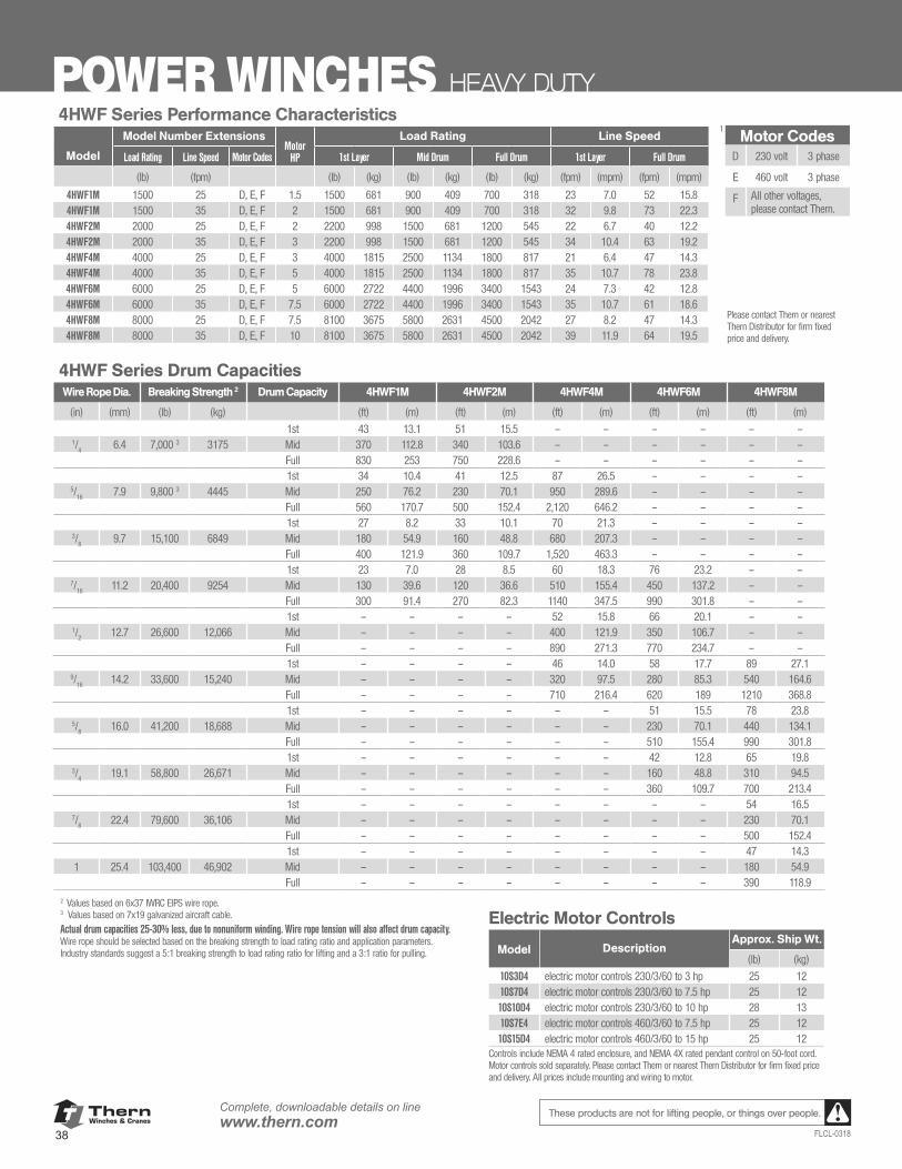
ThernWinches & Cranes
38
Complete, downloadable details on linewww.thern.com
FLCL-0318
These products are not for lifting people, or things over people.
POWER WINCHES HEAVY DUTY4HWF Series Performance Characteristics
Model Number ExtensionsMotor
HP
Load Rating Line Speed
Model Load Rating Line Speed Motor Codes 1st Layer Mid Drum Full Drum 1st Layer Full Drum
(lb) (fpm) (lb) (kg) (lb) (kg) (lb) (kg) (fpm) (mpm) (fpm) (mpm)
4HWF1M 1500 25 D, E, F 1.5 1500 681 900 409 700 318 23 7.0 52 15.84HWF1M 1500 35 D, E, F 2 1500 681 900 409 700 318 32 9.8 73 22.34HWF2M 2000 25 D, E, F 2 2200 998 1500 681 1200 545 22 6.7 40 12.24HWF2M 2000 35 D, E, F 3 2200 998 1500 681 1200 545 34 10.4 63 19.24HWF4M 4000 25 D, E, F 3 4000 1815 2500 1134 1800 817 21 6.4 47 14.34HWF4M 4000 35 D, E, F 5 4000 1815 2500 1134 1800 817 35 10.7 78 23.84HWF6M 6000 25 D, E, F 5 6000 2722 4400 1996 3400 1543 24 7.3 42 12.84HWF6M 6000 35 D, E, F 7.5 6000 2722 4400 1996 3400 1543 35 10.7 61 18.64HWF8M 8000 25 D, E, F 7.5 8100 3675 5800 2631 4500 2042 27 8.2 47 14.34HWF8M 8000 35 D, E, F 10 8100 3675 5800 2631 4500 2042 39 11.9 64 19.5
1Motor Codes
D 230 volt 3 phase
E 460 volt 3 phase
F All other voltages, please contact Thern.
4HWF Series Drum CapacitiesWire Rope Dia. Breaking Strength 2 Drum Capacity 4HWF1M 4HWF2M 4HWF4M 4HWF6M 4HWF8M
(in) (mm) (lb) (kg) (ft) (m) (ft) (m) (ft) (m) (ft) (m) (ft) (m)
1st 43 13.1 51 15.5 – – – – – –1/
46.4 7,000 3 3175 Mid 370 112.8 340 103.6 – – – – – –
Full 830 253 750 228.6 – – – – – –1st 34 10.4 41 12.5 87 26.5 – – – –
5/16
7.9 9,800 3 4445 Mid 250 76.2 230 70.1 950 289.6 – – – –Full 560 170.7 500 152.4 2,120 646.2 – – – –1st 27 8.2 33 10.1 70 21.3 – – – –
3/8
9.7 15,100 6849 Mid 180 54.9 160 48.8 680 207.3 – – – – Full 400 121.9 360 109.7 1,520 463.3 – – – – 1st 23 7.0 28 8.5 60 18.3 76 23.2 – –
7/16
11.2 20,400 9254 Mid 130 39.6 120 36.6 510 155.4 450 137.2 – –Full 300 91.4 270 82.3 1140 347.5 990 301.8 – –1st – – – – 52 15.8 66 20.1 – –
1/2
12.7 26,600 12,066 Mid – – – – 400 121.9 350 106.7 – –Full – – – – 890 271.3 770 234.7 – –1st – – – – 46 14.0 58 17.7 89 27.1
9/16
14.2 33,600 15,240 Mid – – – – 320 97.5 280 85.3 540 164.6Full – – – – 710 216.4 620 189 1210 368.81st – – – – – – 51 15.5 78 23.8
5/8
16.0 41,200 18,688 Mid – – – – – – 230 70.1 440 134.1Full – – – – – – 510 155.4 990 301.81st – – – – – – 42 12.8 65 19.8
3/4
19.1 58,800 26,671 Mid – – – – – – 160 48.8 310 94.5 Full – – – – – – 360 109.7 700 213.41st – – – – – – – – 54 16.5
7/8
22.4 79,600 36,106 Mid – – – – – – – – 230 70.1 Full – – – – – – – – 500 152.41st – – – – – – – – 47 14.3
1 25.4 103,400 46,902 Mid – – – – – – – – 180 54.9 Full – – – – – – – – 390 118.9
2 Values based on 6x37 IWRC EIPS wire rope. 3 Values based on 7x19 galvanized aircraft cable.
Actual drum capacities 25-30% less, due to nonuniform winding. Wire rope tension will also affect drum capacity. Wire rope should be selected based on the breaking strength to load rating ratio and application parameters. Industry standards suggest a 5:1 breaking strength to load rating ratio for lifting and a 3:1 ratio for pulling.
Electric Motor Controls
Model DescriptionApprox. Ship Wt.
(lb) (kg)
10S3D4 electric motor controls 230/3/60 to 3 hp 25 1210S7D4 electric motor controls 230/3/60 to 7.5 hp 25 1210S10D4 electric motor controls 230/3/60 to 10 hp 28 1310S7E4 electric motor controls 460/3/60 to 7.5 hp 25 1210S15D4 electric motor controls 460/3/60 to 15 hp 25 12
Controls include NEMA 4 rated enclosure, and NEMA 4X rated pendant control on 50-foot cord. Motor controls sold separately. Please contact Thern or nearest Thern Distributor for firm fixed price and delivery. All prices include mounting and wiring to motor.
Please contact Thern or nearest Thern Distributor for firm fixed price and delivery.
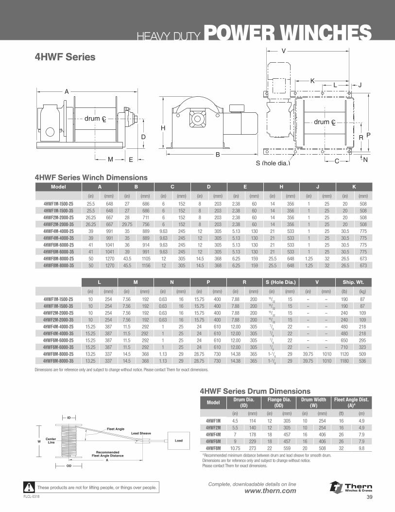
ThernWinches & Cranes
39FLCL-0318
Complete, downloadable details on linewww.thern.comThese products are not for lifting people, or things over people.
HEAVY DUTY POWER WINCHES
A
B
H
M E
D
J
PR
NS (hole dia.) C
V
LK
drum CL drum CL
4HWF Series
L M N P R S (Hole Dia.) V Ship. Wt.
(in) (mm) (in) (mm) (in) (mm) (in) (mm) (in) (mm) (in) (mm) (in) (mm) (lb) (kg)
4HWF1M-1500-25 10.00 254 7.56 192 0.63 16 15.75 400 7.88 200 19/32 15 – – 190 874HWF1M-1500-35 10.00 254 7.56 192 0.63 16 15.75 400 7.88 200 19/32 15 – – 190 874HWF2M-2000-25 10.00 254 7.56 192 0.63 16 15.75 400 7.88 200 19/32 15 – – 240 1094HWF2M-2000-35 10.00 254 7.56 192 0.63 16 15.75 400 7.88 200 19/32 15 – – 240 1094HWF4M-4000-25 15.25 387 11.50 292 1.00 25 24.00 610 12.00 305 7/8 22 – – 480 2184HWF4M-4000-35 15.25 387 11.50 292 1.00 25 24.00 610 12.00 305 7/8 22 – – 480 2184HWF6M-6000-25 15.25 387 11.50 292 1.00 25 24.00 610 12.00 305 7/8 22 – – 650 2954HWF6M-6000-35 15.25 387 11.50 292 1.00 25 24.00 610 12.00 305 7/8 22 – – 710 3234HWF8M-8000-25 13.25 337 14.50 368 1.13 29 28.75 730 14.38 365 1-1/8 29 39.75 1,010 1,120 5094HWF8M-8000-35 13.25 337 14.50 368 1.13 29 28.75 730 14.38 365 1-1/8 29 39.75 1,010 1,180 536
Dimensions are for reference only and subject to change without notice. Please contact factory for exact dimensions.
4HWF Series Winch DimensionsA B C D E H J K
(in) (mm) (in) (mm) (in) (mm) (in) (mm) (in) (mm) (in) (mm) (in) (mm) (in) (mm)
4HWF1M-1500-25 25.50 648 27.00 686 6.00 152 8.00 203 2.38 60 14.00 356 1.00 25 20.00 5084HWF1M-1500-35 25.50 648 27.00 686 6.00 152 8.00 203 2.38 60 14.00 356 1.00 25 20.00 5084HWF2M-2000-25 26.25 667 28.00 711 6.00 152 8.00 203 2.38 60 14.00 356 1.00 25 20.00 5084HWF2M-2000-35 26.25 667 29.75 756 6.00 152 8.00 203 2.38 60 14.00 356 1.00 25 20.00 5084HWF4M-4000-25 39.00 991 35.00 889 9.63 245 12.00 305 5.13 130 21.00 533 1.00 25 30.50 7754HWF4M-4000-35 39.00 991 35.00 889 9.63 245 12.00 305 5.13 130 21.00 533 1.00 25 30.50 7754HWF6M-6000-25 41.00 1,041 36.00 914 9.63 245 12.00 305 5.13 130 21.00 533 1.00 25 30.50 7754HWF6M-6000-35 41.00 1,041 39.00 991 9.63 245 12.00 305 5.13 130 21.00 533 1.00 25 30.50 7754HWF8M-8000-25 50.00 1,270 43.50 1,105 12.00 305 14.50 368 6.25 159 25.50 648 1.25 32 26.50 6734HWF8M-8000-35 50.00 1,270 45.50 1,156 12.00 305 14.50 368 6.25 159 25.50 648 1.25 32 26.50 673
RecommendedFleet Angle Distance
Fleet Angle
Load
Lead Sheave
Center Line
ID
OD
W
A
4HWF Series Drum Dimensions
Drum Diameter
(ID) Flange Diameter
(OD)Drum Width (W) Fleet Angle Dist
(A)4
(in) (mm) (in) (mm) (in) (mm) (ft) (m)
4HWF1M 4.50 114 12.00 305 10.00 254 16 4.94HWF2M 5.50 140 12.00 305 10.00 254 16 4.94HWF4M 7.00 178 18.00 457 16.00 406 26 7.94HWF6M 9.00 229 18.00 457 16.00 406 26 7.94HWF8M 10.75 273 22.00 559 20.00 508 32 9.8
Recommended minimum distance between drum and lead sheave for smooth drum.Dimensions are for reference only and subject to change without notice. Please contact factory for exact dimensions.
4
A
B
H
M E
D
J
PR
NS (hole dia.) C
V
LK
drum CL drum CL
4HWF Series
L M N P R S (Hole Dia.) V Ship. Wt.
(in) (mm) (in) (mm) (in) (mm) (in) (mm) (in) (mm) (in) (mm) (in) (mm) (lb) (kg)
4HWF1M-1500-25 10.00 254 7.56 192 0.63 16 15.75 400 7.88 200 19/32 15 – – 190 874HWF1M-1500-35 10.00 254 7.56 192 0.63 16 15.75 400 7.88 200 19/32 15 – – 190 874HWF2M-2000-25 10.00 254 7.56 192 0.63 16 15.75 400 7.88 200 19/32 15 – – 240 1094HWF2M-2000-35 10.00 254 7.56 192 0.63 16 15.75 400 7.88 200 19/32 15 – – 240 1094HWF4M-4000-25 15.25 387 11.50 292 1.00 25 24.00 610 12.00 305 7/8 22 – – 480 2184HWF4M-4000-35 15.25 387 11.50 292 1.00 25 24.00 610 12.00 305 7/8 22 – – 480 2184HWF6M-6000-25 15.25 387 11.50 292 1.00 25 24.00 610 12.00 305 7/8 22 – – 650 2954HWF6M-6000-35 15.25 387 11.50 292 1.00 25 24.00 610 12.00 305 7/8 22 – – 710 3234HWF8M-8000-25 13.25 337 14.50 368 1.13 29 28.75 730 14.38 365 1-1/8 29 39.75 1,010 1,120 5094HWF8M-8000-35 13.25 337 14.50 368 1.13 29 28.75 730 14.38 365 1-1/8 29 39.75 1,010 1,180 536
Dimensions are for reference only and subject to change without notice. Please contact factory for exact dimensions.
4HWF Series Winch DimensionsA B C D E H J K
(in) (mm) (in) (mm) (in) (mm) (in) (mm) (in) (mm) (in) (mm) (in) (mm) (in) (mm)
4HWF1M-1500-25 25.50 648 27.00 686 6.00 152 8.00 203 2.38 60 14.00 356 1.00 25 20.00 5084HWF1M-1500-35 25.50 648 27.00 686 6.00 152 8.00 203 2.38 60 14.00 356 1.00 25 20.00 5084HWF2M-2000-25 26.25 667 28.00 711 6.00 152 8.00 203 2.38 60 14.00 356 1.00 25 20.00 5084HWF2M-2000-35 26.25 667 29.75 756 6.00 152 8.00 203 2.38 60 14.00 356 1.00 25 20.00 5084HWF4M-4000-25 39.00 991 35.00 889 9.63 245 12.00 305 5.13 130 21.00 533 1.00 25 30.50 7754HWF4M-4000-35 39.00 991 35.00 889 9.63 245 12.00 305 5.13 130 21.00 533 1.00 25 30.50 7754HWF6M-6000-25 41.00 1,041 36.00 914 9.63 245 12.00 305 5.13 130 21.00 533 1.00 25 30.50 7754HWF6M-6000-35 41.00 1,041 39.00 991 9.63 245 12.00 305 5.13 130 21.00 533 1.00 25 30.50 7754HWF8M-8000-25 50.00 1,270 43.50 1,105 12.00 305 14.50 368 6.25 159 25.50 648 1.25 32 26.50 6734HWF8M-8000-35 50.00 1,270 45.50 1,156 12.00 305 14.50 368 6.25 159 25.50 648 1.25 32 26.50 673
RecommendedFleet Angle Distance
Fleet Angle
Load
Lead Sheave
Center Line
ID
OD
W
A
4HWF Series Drum Dimensions
Drum Diameter
(ID) Flange Diameter
(OD)Drum Width (W) Fleet Angle Dist
(A)4
(in) (mm) (in) (mm) (in) (mm) (ft) (m)
4HWF1M 4.50 114 12.00 305 10.00 254 16 4.94HWF2M 5.50 140 12.00 305 10.00 254 16 4.94HWF4M 7.00 178 18.00 457 16.00 406 26 7.94HWF6M 9.00 229 18.00 457 16.00 406 26 7.94HWF8M 10.75 273 22.00 559 20.00 508 32 9.8
Recommended minimum distance between drum and lead sheave for smooth drum.Dimensions are for reference only and subject to change without notice. Please contact factory for exact dimensions.
4
L M N P R S (Hole Dia.) V Ship. Wt.
(in) (mm) (in) (mm) (in) (mm) (in) (mm) (in) (mm) (in) (mm) (in) (mm) (lb) (kg)
4HWF1M-1500-25 10 254 7.56 192 0.63 16 15.75 400 7.88 200 19/32
15 – – 190 874HWF1M-1500-35 10 254 7.56 192 0.63 16 15.75 400 7.88 200 19/
3215 – – 190 87
4HWF2M-2000-25 10 254 7.56 192 0.63 16 15.75 400 7.88 200 19/32
15 – – 240 1094HWF2M-2000-35 10 254 7.56 192 0.63 16 15.75 400 7.88 200 19/
3215 – – 240 109
4HWF4M-4000-25 15.25 387 11.5 292 1 25 24 610 12.00 305 7/8
22 – – 480 2184HWF4M-4000-35 15.25 387 11.5 292 1 25 24 610 12.00 305 7/
822 – – 480 218
4HWF6M-6000-25 15.25 387 11.5 292 1 25 24 610 12.00 305 7/8
22 – – 650 2954HWF6M-6000-35 15.25 387 11.5 292 1 25 24 610 12.00 305 7/
822 – – 710 323
4HWF8M-8000-25 13.25 337 14.5 368 1.13 29 28.75 730 14.38 365 1-1/8
29 39.75 1010 1120 5094HWF8M-8000-35 13.25 337 14.5 368 1.13 29 28.75 730 14.38 365 1-1/
829 39.75 1010 1180 536
Dimensions are for reference only and subject to change without notice. Please contact Thern for exact dimensions.
4HWF Series Winch DimensionsModel A B C D E H J K
(in) (mm) (in) (mm) (in) (mm) (in) (mm) (in) (mm) (in) (mm) (in) (mm) (in) (mm)
4HWF1M-1500-25 25.5 648 27 686 6 152 8 203 2.38 60 14 356 1 25 20 5084HWF1M-1500-35 25.5 648 27 686 6 152 8 203 2.38 60 14 356 1 25 20 5084HWF2M-2000-25 26.25 667 28 711 6 152 8 203 2.38 60 14 356 1 25 20 5084HWF2M-2000-35 26.25 667 29.75 756 6 152 8 203 2.38 60 14 356 1 25 20 5084HWF4M-4000-25 39 991 35 889 9.63 245 12 305 5.13 130 21 533 1 25 30.5 7754HWF4M-4000-35 39 991 35 889 9.63 245 12 305 5.13 130 21 533 1 25 30.5 7754HWF6M-6000-25 41 1041 36 914 9.63 245 12 305 5.13 130 21 533 1 25 30.5 7754HWF6M-6000-35 41 1041 39 991 9.63 245 12 305 5.13 130 21 533 1 25 30.5 7754HWF8M-8000-25 50 1270 43.5 1105 12 305 14.5 368 6.25 159 25.5 648 1.25 32 26.5 6734HWF8M-8000-35 50 1270 45.5 1156 12 305 14.5 368 6.25 159 25.5 648 1.25 32 26.5 673
4HWF Series Drum Dimensions Model Drum Dia.
(ID) Flange Dia.
(OD)Drum Width
(W)Fleet Angle Dist.
(A)4
(in) (mm) (in) (mm) (in) (mm) (ft) (m)
4HWF1M 4.5 114 12 305 10 254 16 4.94HWF2M 5.5 140 12 305 10 254 16 4.94HWF4M 7 178 18 457 16 406 26 7.94HWF6M 9 229 18 457 16 406 26 7.94HWF8M 10.75 273 22 559 20 508 32 9.8
4 Recommended minimum distance between drum and lead sheave for smooth drum.Dimensions are for reference only and subject to change without notice. Please contact Thern for exact dimensions.
4HWF Series
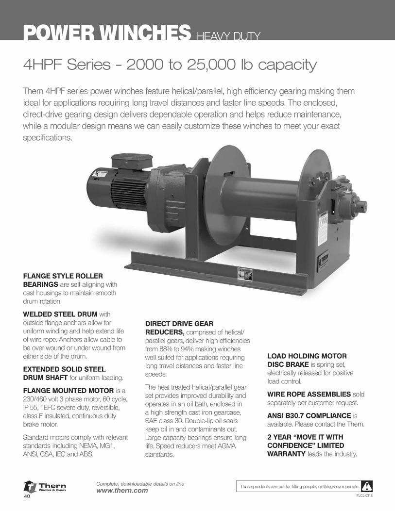
ThernWinches & Cranes
40
Complete, downloadable details on linewww.thern.com
FLCL-0318
These products are not for lifting people, or things over people.
POWER WINCHES HEAVY DUTY
4HPF Series - 2000 to 25,000 lb capacity
LOAD HOLDING MOTOR DISC BRAKE is spring set, electrically released for positive load control.
WIRE ROPE ASSEMBLIES sold separately per customer request.
ANSI B30.7 COMPLIANCE is available. Please contact the Thern.
2 YEAR “MOVE IT WITH CONFIDENCE” LIMITED WARRANTY leads the industry.
Thern 4HPF series power winches feature helical/parallel, high efficiency gearing making them ideal for applications requiring long travel distances and faster line speeds. The enclosed, direct-drive gearing design delivers dependable operation and helps reduce maintenance, while a modular design means we can easily customize these winches to meet your exact specifications.
FLANGE STYLE ROLLER BEARINGS are self-aligning with cast housings to maintain smooth drum rotation.
WELDED STEEL DRUM with outside flange anchors allow for uniform winding and help extend life of wire rope. Anchors allow cable to be over wound or under wound from either side of the drum.
EXTENDED SOLID STEEL DRUM SHAFT for uniform loading.
FLANGE MOUNTED MOTOR is a 230/460 volt 3 phase motor, 60 cycle, IP 55, TEFC severe duty, reversible, class F insulated, continuous duty brake motor.
Standard motors comply with relevant standards including NEMA, MG1, ANSI, CSA, IEC and ABS.
DIRECT DRIVE GEAR REDUCERS, comprised of helical/parallel gears, deliver high efficiencies from 88% to 94% making winches well suited for applications requiring long travel distances and faster line speeds.
The heat treated helical/parallel gear set provides improved durability and operates in an oil bath, enclosed in a high strength cast iron gearcase, SAE class 30. Double-lip oil seals keep oil in and contaminants out. Large capacity bearings ensure long life. Speed reducers meet AGMA standards.
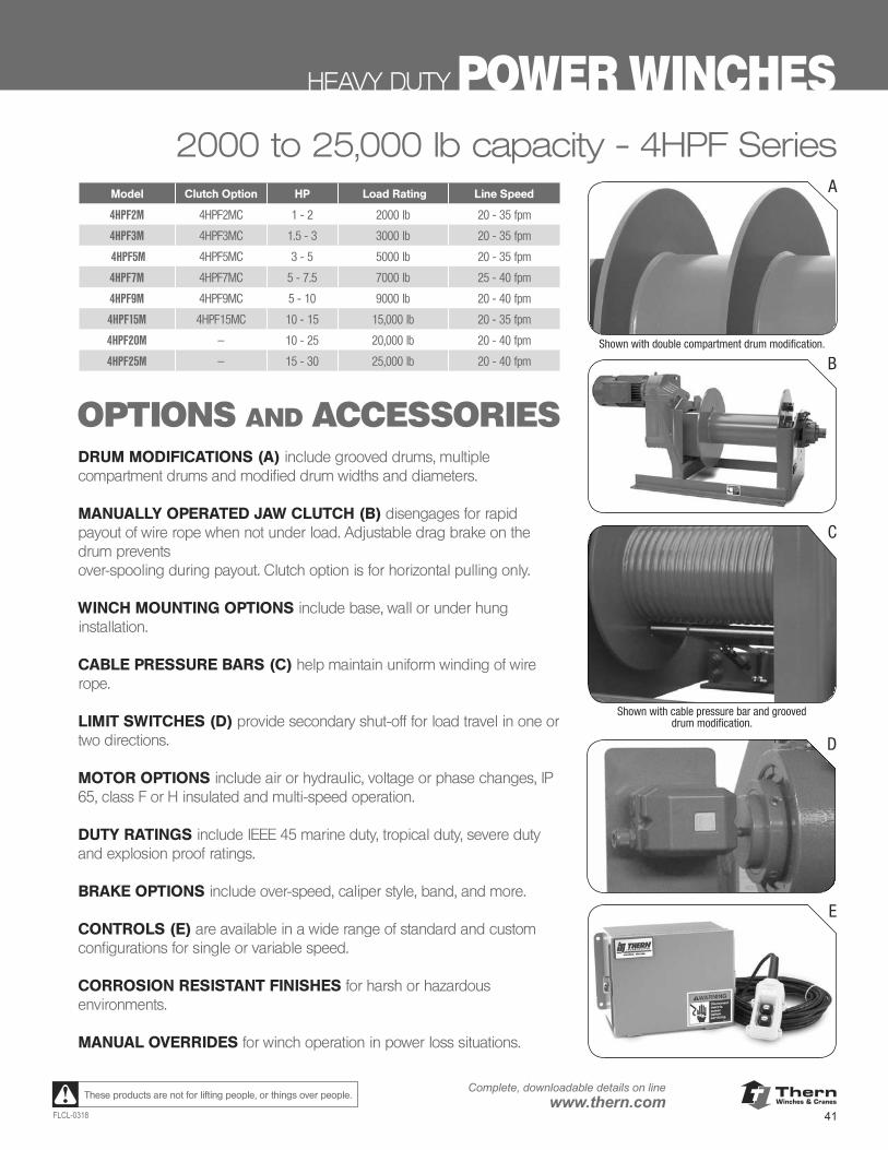
ThernWinches & Cranes
41FLCL-0318
Complete, downloadable details on linewww.thern.comThese products are not for lifting people, or things over people.
HEAVY DUTY POWER WINCHES2000 to 25,000 lb capacity - 4HPF Series
OPTIONS AND ACCESSORIES
Model Clutch Option HP Load Rating Line Speed
4HPF2M 4HPF2MC 1 - 2 2000 lb 20 - 35 fpm
4HPF3M 4HPF3MC 1.5 - 3 3000 lb 20 - 35 fpm
4HPF5M 4HPF5MC 3 - 5 5000 lb 20 - 35 fpm
4HPF7M 4HPF7MC 5 - 7.5 7000 lb 25 - 40 fpm
4HPF9M 4HPF9MC 5 - 10 9000 lb 20 - 40 fpm
4HPF15M 4HPF15MC 10 - 15 15,000 lb 20 - 35 fpm
4HPF20M — 10 - 25 20,000 lb 20 - 40 fpm
4HPF25M — 15 - 30 25,000 lb 20 - 40 fpm
A
B
C
D
E
Shown with double compartment drum modification.
Shown with cable pressure bar and grooved drum modification.
DRUM MODIFICATIONS (A) include grooved drums, multiple compartment drums and modified drum widths and diameters.
MANUALLY OPERATED JAW CLUTCH (B) disengages for rapid payout of wire rope when not under load. Adjustable drag brake on the drum prevents over-spooling during payout. Clutch option is for horizontal pulling only.
WINCH MOUNTING OPTIONS include base, wall or under hung installation.
CABLE PRESSURE BARS (C) help maintain uniform winding of wire rope.
LIMIT SWITCHES (D) provide secondary shut-off for load travel in one or two directions.
MOTOR OPTIONS include air or hydraulic, voltage or phase changes, IP 65, class F or H insulated and multi-speed operation.
DUTY RATINGS include IEEE 45 marine duty, tropical duty, severe duty and explosion proof ratings.
BRAKE OPTIONS include over-speed, caliper style, band, and more.
CONTROLS (E) are available in a wide range of standard and custom configurations for single or variable speed.
CORROSION RESISTANT FINISHES for harsh or hazardous environments.
MANUAL OVERRIDES for winch operation in power loss situations.
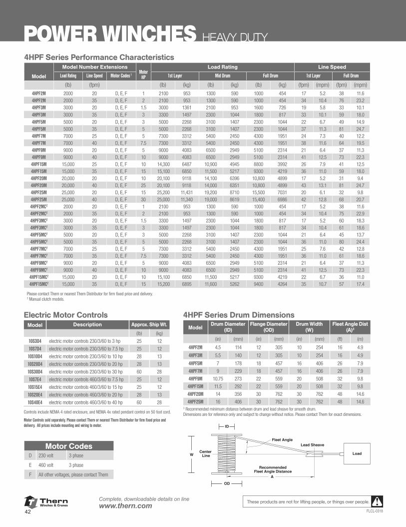
ThernWinches & Cranes
42
Complete, downloadable details on linewww.thern.com
FLCL-0318
These products are not for lifting people, or things over people.
POWER WINCHES HEAVY DUTY
4HPF Series Performance CharacteristicsModel Number Extensions
Motor HP
Load Rating Line Speed
Model Load Rating Line Speed Motor Codes 1 1st Layer Mid Drum Full Drum 1st Layer Full Drum
(lb) (fpm) (lb) (kg) (lb) (kg) (lb) (kg) (fpm) (mpm) (fpm) (mpm)
4HPF2M 2000 20 D, E, F 1 2100 953 1300 590 1000 454 17 5.2 38 11.64HPF2M 2000 35 D, E, F 2 2100 953 1300 590 1000 454 34 10.4 76 23.24HPF3M 3000 20 D, E, F 1.5 3000 1361 2100 953 1600 726 19 5.8 33 10.14HPF3M 3000 35 D, E, F 3 3300 1497 2300 1044 1800 817 33 10.1 59 18.04HPF5M 5000 20 D, E, F 3 5000 2268 3100 1407 2300 1044 22 6.7 49 14.94HPF5M 5000 35 D, E, F 5 5000 2268 3100 1407 2300 1044 37 11.3 81 24.74HPF7M 7000 25 D, E, F 5 7300 3312 5400 2450 4300 1951 24 7.3 40 12.24HPF7M 7000 40 D, E, F 7.5 7300 3312 5400 2450 4300 1951 38 11.6 64 19.54HPF9M 9000 20 D, E, F 5 9000 4083 6500 2949 5100 2314 21 6.4 37 11.34HPF9M 9000 40 D, E, F 10 9000 4083 6500 2949 5100 2314 41 12.5 73 22.34HPF15M 15,000 25 D, E, F 10 14,300 6487 10,900 4945 8800 3992 26 7.9 41 12.54HPF15M 15,000 35 D, E, F 15 15,100 6850 11,500 5217 9300 4219 36 11.0 59 18.04HPF20M 20,000 20 D, E, F 10 20,100 9118 14,100 6396 10,800 4899 17 5.2 31 9.44HPF20M 20,000 40 D, E, F 25 20,100 9118 14,000 6351 10,800 4899 43 13.1 81 24.74HPF25M 25,000 20 D, E, F 15 25,200 11,431 19,200 8710 15,500 7031 20 6.1 32 9.84HPF25M 25,000 40 D, E, F 30 25,000 11,340 19,000 8619 15,400 6986 42 12.8 68 20.74HPF2MC2 2000 20 D, E, F 1 2100 953 1300 590 1000 454 17 5.2 38 11.64HPF2MC2 2000 35 D, E, F 2 2100 953 1300 590 1000 454 34 10.4 75 22.94HPF3MC2 3000 20 D, E, F 1.5 3300 1497 2300 1044 1800 817 17 5.2 60 18.34HPF3MC2 3000 35 D, E, F 3 3300 1497 2300 1044 1800 817 34 10.4 61 18.64HPF5MC2 5000 20 D, E, F 3 5000 2268 3100 1407 2300 1044 21 6.4 45 13.74HPF5MC2 5000 35 D, E, F 5 5000 2268 3100 1407 2300 1044 36 11.0 80 24.44HPF7MC2 7000 25 D, E, F 5 7300 3312 5400 2450 4300 1951 25 7.6 42 12.84HPF7MC2 7000 35 D, E, F 7.5 7300 3312 5400 2450 4300 1951 36 11.0 61 18.64HPF9MC2 9000 20 D, E, F 5 9000 4083 6500 2949 5100 2314 21 6.4 37 11.34HPF9MC2 9000 40 D, E, F 10 9000 4083 6500 2949 5100 2314 41 12.5 73 22.34HPF15MC2 15,000 20 D, E, F 10 15,100 6850 11,500 5217 9300 4219 22 6.7 36 11.04HPF15MC2 15,000 35 D, E, F 15 15,200 6895 11,600 5262 9400 4264 35 10.7 57 17.4
Please contact Thern or nearest Thern Distributor for firm fixed price and delivery. 2 Manual clutch models.
Electric Motor ControlsModel Description Approx. Ship Wt.
(lb) (kg)
10S3D4 electric motor controls 230/3/60 to 3 hp 25 12
10S7D4 electric motor controls 230/3/60 to 7.5 hp 25 12
10S10D4 electric motor controls 230/3/60 to 10 hp 28 13
10S20D4 electric motor controls 230/3/60 to 20 hp 28 13
10S30D4 electric motor controls 230/3/60 to 30 hp 60 28
10S7E4 electric motor controls 460/3/60 to 7.5 hp 25 12
10S15E4 electric motor controls 460/3/60 to 15 hp 25 12
10S20E4 electric motor controls 460/3/60 to 20 hp 28 13
10S40E4 electric motor controls 460/3/60 to 40 hp 60 28
Controls include NEMA 4 rated enclosure, and NEMA 4x rated pendant control on 50 foot cord.
Motor Controls sold separately. Please contact Thern or nearest Thern Distributor for firm fixed price and delivery. All prices include mounting and wiring to motor.
4HPF Series Drum Dimensions
ModelDrum Diameter
(ID)Flange Diameter
(OD)Drum Width
(W)Fleet Angle Dist
(A)3
(in) (mm) (in) (mm) (in) (mm) (ft) (m)
4HPF2M 4.5 114 12 305 10 254 16 4.9
4HPF3M 5.5 140 12 305 10 254 16 4.9
4HPF5M 7 178 18 457 16 406 26 7.9
4HPF7M 9 229 18 457 16 406 26 7.9
4HPF9M 10.75 273 22 559 20 508 32 9.8
4HPF15M 11.5 292 22 559 20 508 32 9.8
4HPF20M 14 356 30 762 30 762 48 14.6
4HPF25M 16 406 30 762 30 762 48 14.63 Recommended minimum distance between drum and lead sheave for smooth drum. Dimensions are for reference only and subject to change without notice. Please contact Thern for exact dimensions.
RecommendedFleet Angle Distance
Fleet Angle
Load
Lead Sheave
Center Line
ID
OD
W
A
Motor CodesD 230 volt 3 phase
E 460 volt 3 phase
F All other voltages, please contact Thern
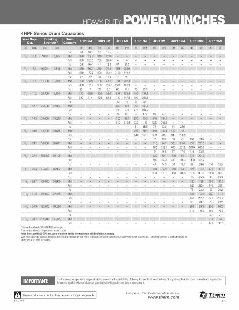
ThernWinches & Cranes
43FLCL-0318
Complete, downloadable details on linewww.thern.comThese products are not for lifting people, or things over people.
HEAVY DUTY POWER WINCHES
IMPORTANT: It is the owner or operator’s responsibility to determine the suitability of the equipment to its intended use. Study all applicable codes, manuals and regulations. Be sure to read the Owner’s Manual supplied with the equipment before operating it.
4HPF Series Drum CapacitiesWire Rope
Dia.Breaking Strength 4
Drum Capacity 4HPF2M 4HPF3M 4HPF5M 4HPF7M 4HPF9M 4HPF15M 4HPF20M 4HPF25M
(in) (mm) (lb) (kg) (ft) (m) (ft) (m) (ft) (m) (ft) (m) (ft) (m) (ft) (m) (ft) (m) (ft) (m) 1st 43 13.1 51 15.5 – – – – – – – – – – – –
1/4
6.4 7,0005 3,175 Mid 370 112.8 340 103.6 – – – – – – – – – – – –Full 830 253.0 750 228.6 – – – – – – – – – – – – 1st 34 10.4 41 12.5 87 26.5 – – – – – – – – – –
5/16
7.9 9,8005 4,445 Mid 250 76.2 230 70.1 950 289.6 – – – – – – – – – – Full 560 170.7 500 152.4 2120 646.2 – – – – – – – – – –1st 27 8.2 33 10.1 70 21.3 – – – – – – – – – –
3/8
9.7 15,100 6,849 Mid 180 54.9 160 48.8 680 207.3 – – – – – – – – – – Full 400 121.9 360 109.7 1520 463.3 – – – – – – – – – –1st 23 7 28 8.5 60 18.3 76 23.2 – – – – – – – –
7/16
11.2 20,400 9,254 Mid 130 39.6 120 36.6 510 155.4 450 137.2 – – – – – – – –Full 300 91.4 270 82.3 1140 347.5 990 301.8 – – – – – – – –1st – – – – 52 15 66 20.1 – – – – – – – –
1/2
12.7 26,600 12,066 Mid – – – – 400 121 350 106.7 – – – – – – – –Full – – – – 890 271 770 234.7 – – – – – – – –1st – – – – 46 14.0 58 17.7 89 27.1 – – – – – –
9/16
14.2 33,600 15,240 Mid – – – – 320 97.5 280 85.3 540 164.6 – – – – – –Full – – – – 710 216.4 620 189 1210 368.8 – – – – – –1st – – – – – – 51 15.5 78 23.8 84 25.6 – – – –
5/8
16.0 41,200 18,688 Mid – – – – – – 230 70.1 440 134.1 420 128 – – – –Full – – – – – – 510 155.5 990 301.8 940 286.5 – – – –1st – – – – – – – – 65 19.8 69 21 130 39.6 – –
3/4
19.1 58,800 26,671 Mid – – – – – – – – 310 94.5 300 91.4 930 283.5 – –Full – – – – – – – – 700 213.4 660 201.2 2070 630.9 – –1st – – – – – – – – 54 16.5 57 17.4 110 33.5 – –
7/8
22.4 79,6 00 36,106 Mid – – – – – – – – 230 70.1 210 64 670 204.2 – –Full – – – – – – – – 500 152.4 480 146.3 1490 454.2 – –
1st – – – – – – – – 47 14.3 57 17.4 97 29.6 110 33.5
1 25.4 103,400 46,902 Mid – – – – – – – – 180 54.9 210 64 520 158.5 470 143.3Full – – – – – – – – 390 118.9 480 146.3 1160 353.6 1050 320 1st – – – – – – – – – – – – 85 25.9 96 29.3
1-1/8
28.7 130,000 58,968 Mid – – – – – – – – – – – – 420 128 380 115.8 Full – – – – – – – – – – – – 920 280.4 840 256 1st – – – – – – – – – – – – 76 23.2 86 26.2
1-1/4
31.8 159,800 72,485 Mid – – – – – – – – – – – – 330 100.6 300 91.4 Full – – – – – – – – – – – – 740 225.6 670 204.21st – – – – – – – – – – – – 68 20.7 76 23.2
1-3/8
34.9 192,000 87,090 Mid – – – – – – – – – – – – 280 85.3 250 76.2 Full – – – – – – – – – – – – 610 185.9 560 170.71st – – – – – – – – – – – – – – 69 21
1-1/2
38.1 228,000 103,420 Mid – – – – – – – – – – – – – – 210 64Full – – – – – – – – – – – – – – 470 143.3
4 Values based on 6x37 IWRC EIPS wire rope. 5 Values based on 7x19 galvanized aircraft cable. Actual drum capacities 25-30% less, due to nonuniform winding. Wire rope tension will also affect drum capacity. Wire rope should be selected based on the breaking strength to load rating ratio and application parameters. Industry standards suggest a 5:1 breaking strength to load rating ratio for lifting and a 3:1 ratio for pulling.
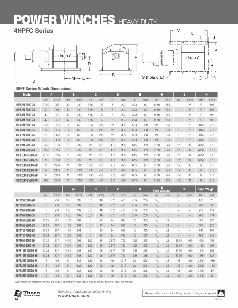
ThernWinches & Cranes
44
Complete, downloadable details on linewww.thern.com
FLCL-0318
These products are not for lifting people, or things over people.
POWER WINCHES HEAVY DUTY
www.thern.com 1.800.843.7648
4HPF SERIES POWER WINCHES
4HPF Series Winch DimensionsA B C D E H J K
(in) (mm) (in) (mm) (in) (mm) (in) (mm) (in) (mm) (in) (mm) (in) (mm) (in) (mm)
4HPF2M-2000-20 37.50 953 17.00 432 6.56 167 8.00 203 2.38 60 14.50 368 1.00 25 20.00 5084HPF2M-2000-35 39.00 991 17.00 432 6.56 167 8.00 203 2.38 60 14.50 368 1.00 25 20.00 5084HPF3M-3000-20 42.00 1,067 17.00 432 6.56 167 8.00 203 2.38 60 14.25 362 1.00 25 20.00 5084HPF3M-3000-35 42.00 1,067 17.00 432 6.56 167 8.00 203 2.38 60 14.25 362 1.00 25 20.00 5084HPF5M-5000-20 54.50 1,384 26.00 660 9.63 245 12.00 305 5.13 130 21.00 533 1.00 25 30.50 7754HPF5M-5000-35 54.50 1,384 26.00 660 9.63 245 12.00 305 5.13 130 21.00 533 1.00 25 30.50 7754HPF7M-7000-25 56.00 1,422 26.00 660 9.63 245 12.00 305 5.13 130 21.00 533 1.00 25 30.50 7754HPF7M-7000-40 59.00 1,499 26.00 660 9.63 245 12.00 305 5.13 130 21.00 533 1.00 25 30.50 7754HPF9M-9000-20 64.50 1,638 31.00 787 12.00 305 14.50 368 6.25 159 25.50 648 1.25 32 26.50 6734HPF9M-9000-40 69.50 1,765 31.00 787 12.00 305 14.50 368 6.25 159 25.50 648 1.25 32 26.50 673
4HPF15M-15000-25 71.50 1,816 31.00 787 12.00 305 14.50 368 6.25 159 25.50 648 1.25 32 26.50 6734HPF15M-15000-35 74.00 1,880 31.00 787 12.00 305 14.50 368 6.25 159 25.50 648 1.25 32 26.50 6734HPF20M-20000-20 90.00 2,286 43.00 1,092 18.88 480 19.50 495 6.75 171 34.50 876 1.50 38 32.00 8134HPF20M-20000-40 97.00 2,464 43.00 1,092 18.88 480 19.50 495 6.75 171 34.50 876 1.50 38 32.00 8134HPF25M-25000-20 94.00 2,388 43.00 1,092 18.88 480 19.50 495 6.75 171 34.50 876 1.50 38 32.00 8134HPF25M-25000-40 100.00 2,540 43.00 1,092 18.88 480 19.50 495 6.75 171 34.50 876 1.50 38 32.00 813
L M N P R S (Hole Dia.) V Ship Wt.
(in) (mm) (in) (mm) (in) (mm) (in) (mm) (in) (mm) (in) (mm) (in) (mm) (lb) (kg)
4HPF2M-2000-20 10.00 254 7.56 192 0.63 16 15.75 400 7.86 200 19/32 15 – – 170 78 4HPF2M-2000-35 10.00 254 7.56 192 0.63 16 15.75 400 7.86 200 19/32 15 – – 200 91 4HPF3M-3000-20 10.00 254 7.56 192 0.63 16 15.75 400 7.86 200 19/32 15 – – 250 114 4HPF3M-3000-35 10.00 254 7.56 192 0.63 16 15.75 400 7.86 200 19/32 15 – – 260 118 4HPF5M-5000-20 15.25 387 11.50 292 1.00 25 24.00 610 12.00 305 7/8 22 – – 500 227 4HPF5M-5000-35 15.25 387 11.50 292 1.00 25 24.00 610 12.00 305 7/8 22 – – 500 227 4HPF7M-7000-25 15.25 387 11.50 292 1.00 25 24.00 610 12.00 305 7/8 22 – – 650 295 4HPF7M-7000-40 15.25 387 11.50 292 1.00 25 24.00 610 12.00 305 7/8 22 – – 760 345 4HPF9M-9000-20 13.25 337 14.50 368 1.13 29 28.75 730 14.38 365 1 1/8 29 39.75 1,010 1,000 454 4HPF9M-9000-40 13.25 337 14.50 368 1.13 29 28.75 730 14.38 365 1 1/8 29 39.75 1,010 1,120 509
4HPF15M-15000-25 13.25 337 14.50 368 1.13 29 28.75 730 14.38 365 1 1/8 29 39.75 1,010 1,340 608 4HPF15M-15000-35 13.25 337 14.50 368 1.13 29 28.75 730 14.38 365 1 1/8 29 39.75 1,010 1,370 622 4HPF20M-20000-20 16.00 406 21.00 533 1.50 38 40.00 1,016 20.00 508 1 3/8 35 48.00 1,219 2,400 1,089 4HPF20M-20000-40 16.00 406 21.00 533 1.50 38 40.00 1,016 20.00 508 1 3/8 35 48.00 1,219 2,620 1,189 4HPF25M-25000-20 16.00 406 21.00 533 1.50 38 40.00 1,016 20.00 508 1 3/8 35 48.00 1,219 3,190 1,447 4HPF25M-25000-40 16.00 406 21.00 533 1.50 38 40.00 1,016 20.00 508 1 3/8 35 48.00 1,219 3,440 1,561
Dimensions are for reference only and subject to change without notice. Please contact factory for exact dimensions.
4HPF Series
A
B
H
M E
D
J
P
NS (hole dia.) C
V
LK
drum CL drum CL
R
L M N P R S (hole diameter) V Ship Weight
(in) (mm) (in) (mm) (in) (mm) (in) (mm) (in) (mm) (in) (mm) (in) (mm) (lb) (kg)
4HPF2M-2000-20 10 254 7.56 192 0.63 16 15.75 400 7.86 200 19/32
15 — — 170 78
4HPF2M-2000-35 10 254 7.56 192 0.63 16 15.75 400 7.86 200 19/32
15 – – 200 91
4HPF3M-3000-20 10 254 7.56 192 0.63 16 15.75 400 7.86 200 19/32
15 – – 250 114
4HPF3M-3000-35 10 254 7.56 192 0.63 16 15.75 400 7.86 200 19/32
15 – – 260 118
4HPF5M-5000-20 15.25 387 11.50 292 1 25 24 610 12 305 7/8
22 – – 500 227
4HPF5M-5000-35 15.25 387 11.50 292 1 25 24 610 12 305 7/8
22 – – 500 227
4HPF7M-7000-25 15.25 387 11.50 292 1 25 24 610 12 305 7/8
22 – – 650 295
4HPF7M-7000-40 15.25 387 11.50 292 1 25 24 610 12 305 7/8
22 – – 760 345
4HPF9M-9000-20 13.25 337 14.50 368 1.13 29 28.75 730 14.38 365 1 1/8
29 39.75 1010 1000 454
4HPF9M-9000-40 13.25 337 14.50 368 1.13 29 28.75 730 14.38 365 1 1/8
29 39.75 1010 1120 509
4HPF15M-15000-25 13.25 337 14.50 368 1.13 29 28.75 730 14.38 365 1 1/8
29 39.75 1010 1340 608
4HPF15M-15000-35 13.25 337 14.50 368 1.13 29 28.75 730 14.38 365 1 1/8
29 39.75 1010 1370 622
4HPF20M-20000-20 16 406 21 533 1.50 38 40 1016 20 508 1 3/8
35 48 1219 2400 1089
4HPF20M-20000-40 16 406 21 533 1.50 38 40 1016 20 508 1 3/8
35 48 1219 2620 1189
4HPF25M-25000-20 16 406 21 533 1.50 38 40 1016 20 508 1 3/8
35 48 1219 3190 1447
4HPF25M-25000-40 16 406 21 533 1.50 38 40 1016 20 508 1 3/8
35 48 1219 3440 1561
Dimensions are for reference only and subject to change without notice. Please contact Thern for exact dimensions.
4HPF Series Winch DimensionsModel A B C D E H J K
(in) (mm) (in) (mm) (in) (mm) (in) (mm) (in) (mm) (in) (mm) (in) (mm) (in) (mm)
4HPF2M-2000-20 37.50 953 17 432 6.56 167 8 203 2.38 60 14.50 368 1 25 20 508
4HPF2M-2000-35 39 991 17 432 6.56 167 8 203 2.38 60 14.50 368 1 25 20 508
4HPF3M-3000-20 42 1067 17 432 6.56 167 8 203 2.38 60 14.50 368 1 25 20 508
4HPF3M-3000-35 42 1067 17 432 6.56 167 8 203 2.38 60 14.50 368 1 25 20 508
4HPF5M-5000-20 54.50 1384 26 660 9.63 245 12 305 5.13 130 21 533 1 25 30.50 775
4HPF5M-5000-35 54.50 1384 26 660 9.63 245 12 305 5.13 130 21 533 1 25 30.50 775
4HPF7M-7000-25 56 1422 26 660 9.63 245 12 305 5.13 130 21 533 1 25 30.50 775
4HPF7M-7000-40 59 1499 26 660 9.63 245 12 305 5.13 130 21 533 1 25 30.50 775
4HPF9M-9000-20 64.50 1638 31 787 12 305 14.50 368 6.25 159 25.50 648 1.25 32 26.50 673
4HPF9M-9000-40 69.50 1765 31 787 12 305 14.50 368 6.25 159 25.50 648 1.25 32 26.50 673
4HPF15M-15000-25 71.50 1816 31 787 12 305 14.50 368 6.25 159 25.50 648 1.25 32 26.50 673
4HPF15M-15000-35 74 1880 31 787 12 305 14.50 368 6.25 159 25.50 648 1.25 32 26.50 673
4HPF20M-20000-20 90 2286 43 1092 18.88 480 19.50 495 6.75 171 34.50 876 1.50 38 32 813
4HPF20M-20000-40 97 2464 43 1092 18.88 480 19.50 495 6.75 171 34.50 876 1.50 38 32 813
4HPF25M-25000-20 94 2388 43 1092 18.88 480 19.50 495 6.75 171 34.50 876 1.50 38 32 813
4HPF25M-25000-40 100 2540 43 1092 18.88 480 19.50 495 6.75 171 34.50 876 1.50 38 32 813
4HPFC Series
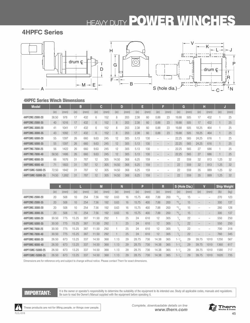
ThernWinches & Cranes
45FLCL-0318
Complete, downloadable details on linewww.thern.comThese products are not for lifting people, or things over people.
HEAVY DUTY POWER WINCHES
www.thern.com 1.800.843.7648
4HPF SERIES POWER WINCHES
AB
F
G
H
M E
DP
NS (hole dia.) C
JV
LK
drum CLdrum CL
R
4HPFC Series
4HPFC Series Winch DimensionsA B C D E F G H J
(in) (mm) (in) (mm) (in) (mm) (in) (mm) (in) (mm) (in) (mm) (in) (mm) (in) (mm) (in) (mm)
4HPF2MC-2000-20 38.50 978 17.00 432 6.00 152 8.00 203 2.38 60 0.88 23 19.88 505 17.00 432 1.00 254HPF2MC-2000-35 40.00 1,016 17.00 432 6.00 152 8.00 203 2.38 60 0.88 23 19.88 505 17.00 432 1.00 254HPF3MC-3000-20 41.00 1,041 17.00 432 6.00 152 8.00 203 2.38 60 0.88 23 19.88 505 18.25 464 1.00 254HPF3MC-3000-35 43.00 1,092 17.00 432 6.00 152 8.00 203 2.38 60 0.88 23 19.88 505 18.25 464 1.00 254HPF5MC-5000-20 55.00 1,397 26.00 660 9.63 245 12.00 305 5.13 130 – – 22.25 565 24.25 616 1.00 254HPF5MC-5000-35 55.00 1,397 26.00 660 9.63 245 12.00 305 5.13 130 – – 22.25 565 24.25 616 1.00 254HPF7MC-7000-25 56.00 1,422 26.00 660 9.63 245 12.00 305 5.13 130 – – 22.25 565 27.00 686 1.00 254HPF7MC-7000-40 58.50 1,486 26.00 660 9.63 245 12.00 305 5.13 130 – – 22.25 565 27.00 686 1.00 254HPF9MC-9000-20 66.00 1,676 31.00 787 12.00 305 14.50 368 6.25 159 – – 22.00 559 32.00 813 1.25 324HPF9MC-9000-40 71.00 1,803 31.00 787 12.00 305 14.50 368 6.25 159 – – 22.00 559 32.00 813 1.25 32
4HPF15MC-15000-25 72.50 1,842 31.00 787 12.00 305 14.50 368 6.25 159 – – 22.00 559 35.00 889 1.25 324HPF15MC-15000-35 74.50 1,892 31.00 787 12.00 305 14.50 368 6.25 159 – – 22.00 559 35.00 889 1.25 32
K L M N P R S (Hole Dia.) V Ship Wt.
(in) (mm) (in) (mm) (in) (mm) (in) (mm) (in) (mm) (in) (mm) (in) (mm) (in) (mm) (lb) (kg)
4HPF2MC-2000-20 20.00 508 10.00 254 7.56 192 0.63 16 15.75 400 7.88 200 19/32 15 – – 270 1234HPF2MC-2000-35 20.00 508 10.00 254 7.56 192 0.63 16 15.75 400 7.88 200 19/32 15 – – 300 1374HPF3MC-3000-20 20.00 508 10.00 254 7.56 192 0.63 16 15.75 400 7.88 200 19/32 15 – – 280 1284HPF3MC-3000-35 20.00 508 10.00 254 7.56 192 0.63 16 15.75 400 7.88 200 19/32 15 – – 300 1374HPF5MC-5000-20 30.50 775 15.25 387 11.50 292 1.00 25 24.00 610 12.00 305 7/8 22 – – 550 2504HPF5MC-5000-35 30.50 775 15.25 387 11.50 292 1.00 25 24.00 610 12.00 305 7/8 22 – – 550 2504HPF7MC-7000-25 30.50 775 15.25 387 11.50 292 1.00 25 24.00 610 12.00 305 7/8 22 – – 700 3184HPF7MC-7000-40 30.50 775 15.25 387 11.50 292 1.00 25 24.00 610 12.00 305 7/8 22 – – 760 3454HPF9MC-9000-20 26.50 673 13.25 337 14.50 368 1.13 29 28.75 730 14.38 365 1-1/8 29 39.75 1,010 1,250 5674HPF9MC-9000-40 26.50 673 13.25 337 14.50 368 1.13 29 28.75 730 14.38 365 1-1/8 29 39.75 1,010 1,360 617
4HPF15MC-15000-25 26.50 673 13.25 337 14.50 368 1.13 29 28.75 730 14.38 365 1-1/8 29 39.75 1,010 1,580 7174HPF15MC-15000-35 26.50 673 13.25 337 14.50 368 1.13 29 28.75 730 14.38 365 1-1/8 29 39.75 1,010 1,620 735
Dimensions are for reference only and subject to change without notice. Please contact factory for exact dimensions.
IMPORTANT:It is the owner’s or operator’s responsibility to determine the suitability of the equipment to its intended use. Study all applicable codes, manuals, and regulations. Be sure to read the Owner’s Manual supplied with the equipment before operating it.
IMPORTANT: It is the owner or operator’s responsibility to determine the suitability of the equipment to its intended use. Study all applicable codes, manuals and regulations. Be sure to read the Owner’s Manual supplied with the equipment before operating it.
4HPFC Series Winch DimensionsModel A B C D E F G H J
(in) (mm) (in) (mm) (in) (mm) (in) (mm) (in) (mm) (in) (mm) (in) (mm) (in) (mm) (in) (mm)
4HPF2MC-2000-20 38.50 978 17 432 6 152 8 203 2.38 60 0.88 23 19.88 505 17 432 1 25
4HPF2MC-2000-35 40 1016 17 432 6 152 8 203 2.38 60 0.88 23 19.88 505 17 432 1 25
4HPF3MC-3000-20 41 1041 17 432 6 152 8 203 2.38 60 0.88 23 19.88 505 18.25 464 1 25
4HPF3MC-3000-35 43 1092 17 432 6 152 8 203 2.38 60 0.88 23 19.88 505 18.25 464 1 25
4HPF5MC-5000-20 55 1397 26 660 9.63 245 12 305 5.13 130 – – 22.25 565 24.25 616 1 25
4HPF5MC-5000-35 55 1397 26 660 9.63 245 12 305 5.13 130 – – 22.25 565 24.25 616 1 25
4HPF7MC-7000-25 56 1422 26 660 9.63 245 12 305 5.13 130 – – 22.25 565 27 686 1 25
4HPF7MC-7000-40 58.50 1486 26 660 9.63 245 12 305 5.13 130 – – 22.25 565 27 686 1 25
4HPF9MC-9000-20 66 1676 31 787 12 305 14.50 368 6.25 159 – – 22 559 32 813 1.25 32
4HPF9MC-9000-40 71 1803 31 787 12 305 14.50 368 6.25 159 – – 22 559 32 813 1.25 32
4HPF15MC-15000-25 72.50 1842 31 787 12 305 14.50 368 6.25 159 – – 22 559 35 889 1.25 32
4HPF15MC-15000-35 74.50 1,892 31 787 12 305 14.50 368 6.25 159 – – 22 559 35 889 1.25 32
K L M N P R S (Hole Dia.) V Ship Weight(in) (mm) (in) (mm) (in) (mm) (in) (mm) (in) (mm) (in) (mm) (in) (mm) (in) (mm) (lb) (kg)
4HPF2MC-2000-20 20 508 10 254 7.56 192 0.63 16 15.75 400 7.88 200 19/32
15 — – 270 123
4HPF2MC-2000-35 20 508 10 254 7.56 192 0.63 16 15.75 400 7.88 200 19/32
15 — – 300 137
4HPF3MC-3000-20 20 508 10 254 7.56 192 0.63 16 15.75 400 7.88 200 19/32
15 — – 280 128
4HPF3MC-3000-35 20 508 10 254 7.56 192 0.63 16 15.75 400 7.88 200 19/32
15 — – 300 137
4HPF5MC-5000-20 30.50 775 15.25 387 11.50 292 1 25 24 610 12 305 7/8 22 – – 550 250
4HPF5MC-5000-35 30.50 775 15.25 387 11.50 292 1 25 24 610 12 305 7/8 22 – – 550 250
4HPF7MC-7000-25 30.50 775 15.25 387 11.50 292 1 25 24 610 12 305 7/8 22 – – 700 318
4HPF7MC-7000-40 30.50 775 15.25 387 11.50 292 1 25 24 610 12 305 7/8 22 – – 760 345
4HPF9MC-9000-20 26.50 673 13.25 337 14.50 368 1.13 29 28.75 730 14.38 365 1-1/8 29 39.75 1010 1250 567
4HPF9MC-9000-40 26.50 673 13.25 337 14.50 368 1.13 29 28.75 730 14.38 365 1-1/8 29 39.75 1010 1360 617
4HPF15MC-15000-25 26.50 673 13.25 337 14.50 368 1.13 29 28.75 730 14.38 365 1-1/8 29 39.75 1010 1580 717
4HPF15MC-15000-35 26.50 673 13.25 337 14.50 368 1.13 29 28.75 730 14.38 365 1-1/8 29 39.75 1010 1620 735
Dimensions are for reference only and subject to change without notice. Please contact Thern for exact dimensions.
4HPFC Series
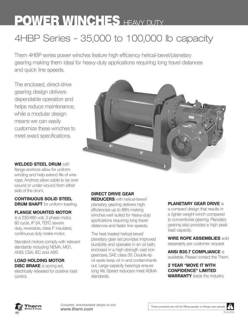
ThernWinches & Cranes
46
Complete, downloadable details on linewww.thern.com
FLCL-0318
These products are not for lifting people, or things over people.
POWER WINCHES HEAVY DUTY
4HBP Series - 35,000 to 100,000 lb capacity
Thern 4HBP series power winches feature high efficiency helical-bevel/planetary gearing making them ideal for heavy-duty applications requiring long travel distances and quick line speeds.
The enclosed, direct-drive gearing design delivers dependable operation and helps reduce maintenance, while a modular design means we can easily customize these winches to meet exact specifications.
PLANETARY GEAR DRIVE is a compact design that results in a lighter weight winch compared to conventional gearing. Planetary gearing also provides a high peak load capacity.
WIRE ROPE ASSEMBLIES sold separately per customer request.
ANSI B30.7 COMPLIANCE is available. Please contact the Thern.
2 YEAR “MOVE IT WITH CONFIDENCE” LIMITED WARRANTY leads the industry.
WELDED STEEL DRUM with flange anchors allow for uniform winding and help extend life of wire rope. Anchors allow cable to be over wound or under wound from either side of the drum.
CONTINUOUS SOLID STEEL DRUM SHAFT for uniform loading.
FLANGE MOUNTED MOTOR is a 230/460 volt, 3 phase motor, 60 cycle, IP 54, TEFC severe duty, reversible, class F insulated, continuous duty brake motor.
Standard motors comply with relevant standards including NEMA, MG1, ANSI, CSA, IEC and ABS.
LOAD HOLDING MOTOR DISC BRAKE is spring set, electrically released for positive load control.
DIRECT DRIVE GEAR REDUCERS with helical-bevel/planetary gearing delivers high efficiencies up to 88% making winches well suited for heavy-duty applications requiring long travel distances and faster line speeds.
The heat treated helical-bevel/planetary gear set provides improved durability and operates in an oil bath, enclosed in a high strength cast iron gearcase, SAE class 30. Double-lip oil seals keep oil in and contaminants out. Large capacity bearings ensure long life. Speed reducers meet AGMA standards.
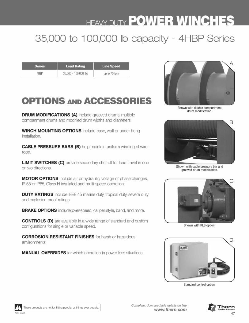
ThernWinches & Cranes
47FLCL-0318
Complete, downloadable details on linewww.thern.comThese products are not for lifting people, or things over people.
HEAVY DUTY POWER WINCHES35,000 to 100,000 lb capacity - 4HBP Series
OPTIONS AND ACCESSORIESDRUM MODIFICATIONS (A) include grooved drums, multiple compartment drums and modified drum widths and diameters.
WINCH MOUNTING OPTIONS include base, wall or under hung installation.
CABLE PRESSURE BARS (B) help maintain uniform winding of wire rope.
LIMIT SWITCHES (C) provide secondary shut-off for load travel in one or two directions.
MOTOR OPTIONS include air or hydraulic, voltage or phase changes,IP 55 or IP65, Class H insulated and multi-speed operation.
DUTY RATINGS include IEEE 45 marine duty, tropical duty, severe duty and explosion proof ratings.
BRAKE OPTIONS include over-speed, caliper style, band, and more.
CONTROLS (D) are available in a wide range of standard and custom configurations for single or variable speed.
CORROSION RESISTANT FINISHES for harsh or hazardous environments.
MANUAL OVERRIDES for winch operation in power loss situations.
A
C
B
D
Shown with double compartmentdrum modification.
Shown with cable pressure bar and grooved drum modification.
Shown with RLS option.
Standard control option.
Series Load Rating Line Speed
4HBP 35,000 - 100,000 lbs up to 70 fpm
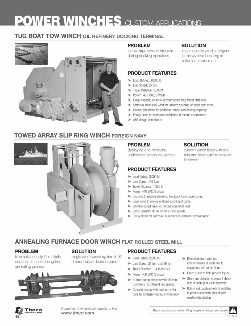
ThernWinches & Cranes
48
Complete, downloadable details on linewww.thern.com
FLCL-0318
These products are not for lifting people, or things over people.
POWER WINCHES CUSTOM APPLICATIONS
PRODUCT FEATURES➤ Load Rating: 3,000 lb➤ Line Speed: 190 fpm➤ Travel Distance: 1,300 ft➤ Power: 440 VAC, 3 phase➤ Slip ring to receive electronic feedback from towed array.➤ Level wind to ensure uniform spooling of cable.➤ Variable speed drive for precise control of load.➤ Large diameter drum for faster line speeds.➤ Epoxy finish for corrosion resistance in saltwater environment.
TUG BOAT TOW WINCH OIL REFINERY DOCKING TERMINAL
PROBLEMto tow large vessels into port during docking operatons
SOLUTIONlarge capacity winch designed for heavy load handling in saltwater environment
PRODUCT FEATURES➤ Load Rating: 50,000 lb➤ Line Speed: 25 fpm➤ Travel Distance: 1,500 ft➤ Power: 408 VAC, 3 Phase➤ Large capacity drum to accommodate long travel distances.➤ Stainless steel level wind for uniform spooling of cable onto drum.➤ Double disc brake for additional static load holding capacity.➤ Epoxy finish for corrosion resistance in marine environment.➤ ABS design compliance
TOWED ARRAY SLIP RING WINCH FOREIGN NAVY
ANNEALING FURNACE DOOR WINCH FLAT ROLLED STEEL MILL
PROBLEMto simultaneously lift multiple doors on furnace during the annealing process
SOLUTIONsingle drum winch system to lift different sized doors in unison
PRODUCT FEATURES➤ Load Rating: 2,000 lb
➤ Line Speed: 28 fpm and 56 fpm
➤ Travel Distance: 14 ft and 6 ft
➤ Power: 460 VAC, 3 phase
➤ 4-drum compartments with different diameters for different line speeds.
➤ Grooved drums with pressure roller bars for uniform winding of wire rope.
PROBLEMdeploying and retrieving underwater sensor equipment
SOLUTIONcustom winch fitted with slip ring and level wind to receive feedback
➤ Extended drum with two compartments at each end to separate cable center lines.
➤ Drum guard to help prevent injury.
➤ Slack line detector to prevent shock load if doors jam while lowering.
➤ Rotary and paddle style limit switches to provide automatic shut off with overtravel protection.
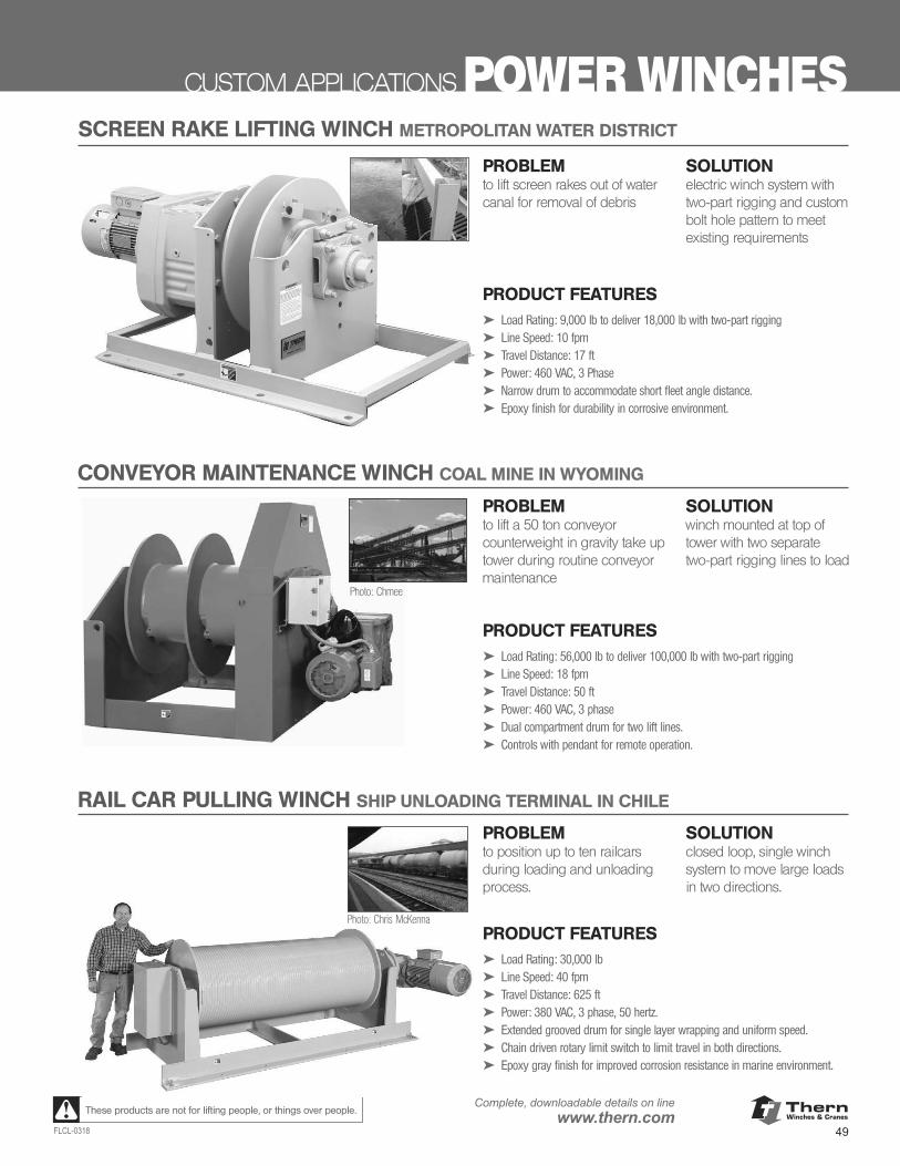
ThernWinches & Cranes
49FLCL-0318
Complete, downloadable details on linewww.thern.comThese products are not for lifting people, or things over people.
CUSTOM APPLICATIONS POWER WINCHES
PROBLEMto lift screen rakes out of water canal for removal of debris
SOLUTIONelectric winch system with two-part rigging and custom bolt hole pattern to meet existing requirements
PRODUCT FEATURES➤ Load Rating: 56,000 lb to deliver 100,000 lb with two-part rigging➤ Line Speed: 18 fpm➤ Travel Distance: 50 ft➤ Power: 460 VAC, 3 phase➤ Dual compartment drum for two lift lines.➤ Controls with pendant for remote operation.
SCREEN RAKE LIFTING WINCH METROPOLITAN WATER DISTRICT
PRODUCT FEATURES➤ Load Rating: 9,000 lb to deliver 18,000 lb with two-part rigging➤ Line Speed: 10 fpm➤ Travel Distance: 17 ft➤ Power: 460 VAC, 3 Phase➤ Narrow drum to accommodate short fleet angle distance.➤ Epoxy finish for durability in corrosive environment.
CONVEYOR MAINTENANCE WINCH COAL MINE IN WYOMING
Photo: Chmee
RAIL CAR PULLING WINCH SHIP UNLOADING TERMINAL IN CHILE
PRODUCT FEATURES➤ Load Rating: 30,000 lb➤ Line Speed: 40 fpm➤ Travel Distance: 625 ft➤ Power: 380 VAC, 3 phase, 50 hertz.➤ Extended grooved drum for single layer wrapping and uniform speed.➤ Chain driven rotary limit switch to limit travel in both directions.➤ Epoxy gray finish for improved corrosion resistance in marine environment.
Photo: Chris McKenna
PROBLEMto lift a 50 ton conveyor counterweight in gravity take up tower during routine conveyor maintenance
SOLUTIONwinch mounted at top of tower with two separate two-part rigging lines to load
PROBLEMto position up to ten railcars during loading and unloading process.
SOLUTIONclosed loop, single winch system to move large loads in two directions.
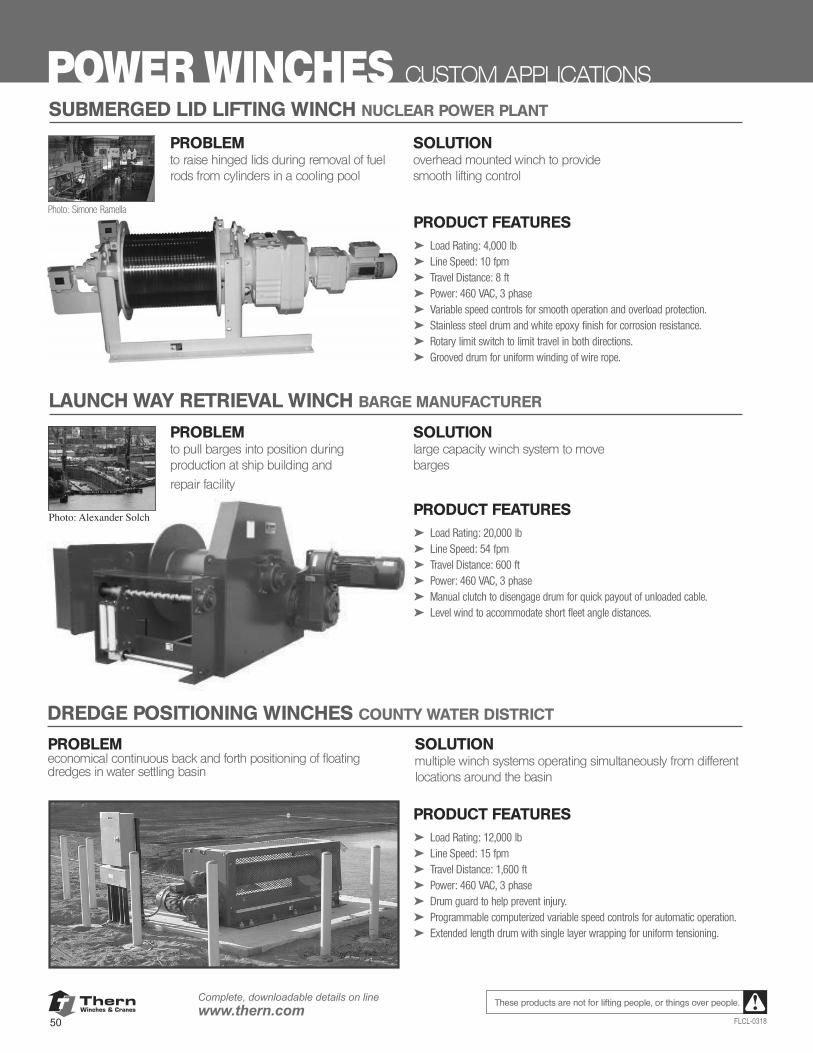
ThernWinches & Cranes
50
Complete, downloadable details on linewww.thern.com
FLCL-0318
These products are not for lifting people, or things over people.
POWER WINCHES CUSTOM APPLICATIONSSUBMERGED LID LIFTING WINCH NUCLEAR POWER PLANT
LAUNCH WAY RETRIEVAL WINCH BARGE MANUFACTURER
DREDGE POSITIONING WINCHES COUNTY WATER DISTRICT
PROBLEMto raise hinged lids during removal of fuel rods from cylinders in a cooling pool
SOLUTIONoverhead mounted winch to provide smooth lifting control
PRODUCT FEATURES➤ Load Rating: 4,000 lb➤ Line Speed: 10 fpm➤ Travel Distance: 8 ft➤ Power: 460 VAC, 3 phase➤ Variable speed controls for smooth operation and overload protection.➤ Stainless steel drum and white epoxy finish for corrosion resistance.➤ Rotary limit switch to limit travel in both directions.➤ Grooved drum for uniform winding of wire rope.
Photo: Simone Ramella
PROBLEMto pull barges into position during production at ship building and
repair facility
SOLUTIONlarge capacity winch system to move barges
PRODUCT FEATURES➤ Load Rating: 20,000 lb➤ Line Speed: 54 fpm➤ Travel Distance: 600 ft➤ Power: 460 VAC, 3 phase➤ Manual clutch to disengage drum for quick payout of unloaded cable.➤ Level wind to accommodate short fleet angle distances.
Photo: Alexander Solch
PROBLEMeconomical continuous back and forth positioning of floating dredges in water settling basin
SOLUTIONmultiple winch systems operating simultaneously from different locations around the basin
PRODUCT FEATURES➤ Load Rating: 12,000 lb➤ Line Speed: 15 fpm➤ Travel Distance: 1,600 ft➤ Power: 460 VAC, 3 phase➤ Drum guard to help prevent injury.➤ Programmable computerized variable speed controls for automatic operation.➤ Extended length drum with single layer wrapping for uniform tensioning.
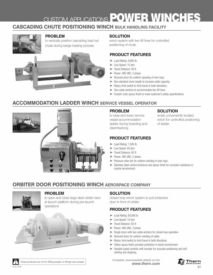
ThernWinches & Cranes
51FLCL-0318
Complete, downloadable details on linewww.thern.comThese products are not for lifting people, or things over people.
CUSTOM APPLICATIONS POWER WINCHES
PROBLEMto raise and lower service vessel accommodation ladder during boarding and disembarking
SOLUTIONsmall, conveniently located winch for controlled positioning of ladder
CASCADING CHUTE POSITIONING WINCH BULK HANDLING FACILITY
ACCOMMODATION LADDER WINCH SERVICE VESSEL OPERATOR
PRODUCT FEATURES➤ Load Rating: 1,500 lb➤ Line Speed: 65 fpm➤ Travel Distance: 65 ft➤ Power: 460 VAC, 3 phase➤ Pressure roller bar for uniform winding of wire rope.➤ Stainless steel control enclosure and epoxy finish for corrosion resistance in
marine environment.
ORBITER DOOR POSITIONING WINCH AEROSPACE COMPANY
PRODUCT FEATURES➤ Load Rating: 65,000 lb➤ Line Speed: 13 fpm➤ Travel Distance: 63 ft➤ Power: 460 VAC, 3 phase➤ Single drum with two cable anchors for closed loop operation.➤ Grooved drum for uniform winding of cable.➤ Rotary limit switch to limit travel in both directions.➤ Yellow epoxy finish provides protection in harsh environment.➤ Variable speed controls with encoder for accurate positioning and soft
starting and stopping.
PRODUCT FEATURES➤ Load Rating: 9,800 lb➤ Line Speed: 15 fpm➤ Travel Distance: 40 ft➤ Power: 460 VAC, 3 phase➤ Grooved drum for uniform spooling of wire rope.➤ Non-standard drum length to increase cable capacity.➤ Rotary limit switch to limit travel in both directions.➤ Two cable anchors to accommodate two lift lines.➤ Custom color epoxy finish to meet customer’s safety specifications.
PROBLEMto vertically position cascading load out
chute during barge loading process
SOLUTIONwinch system with two lift lines for controlled positioning of chute
PROBLEMto open and close large steel orbiter door at launch platform during pre-launch operations
SOLUTIONclosed loop winch system to pull protective door in front of orbiter
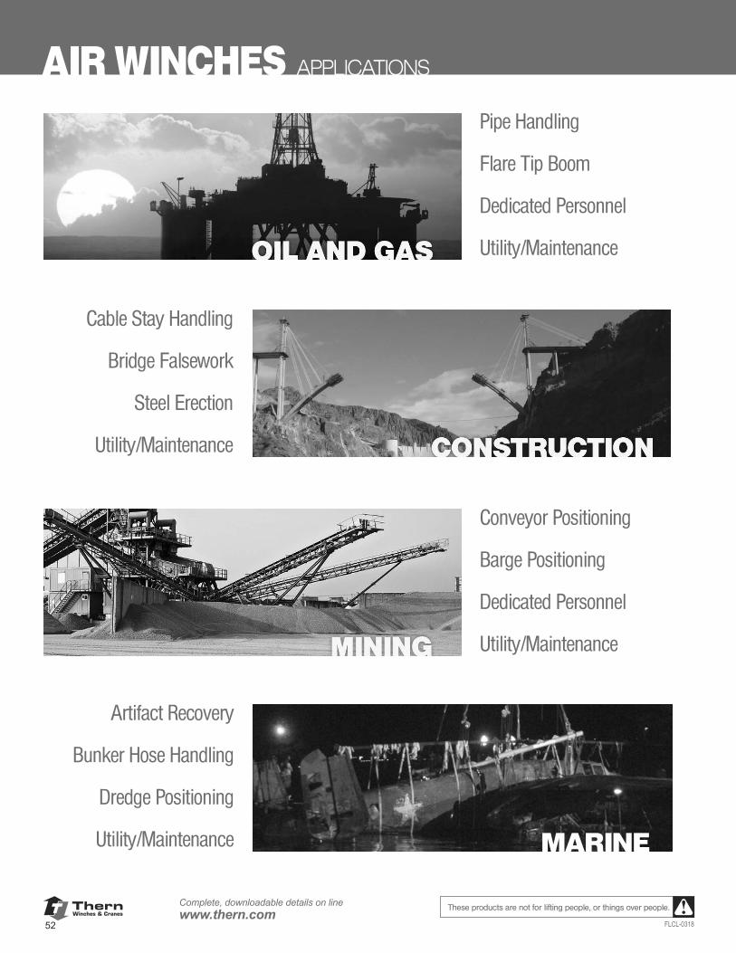
ThernWinches & Cranes
52
Complete, downloadable details on linewww.thern.com
FLCL-0318
These products are not for lifting people, or things over people.
AIR WINCHES APPLICATIONS
Pipe Handling
Flare Tip Boom
Dedicated Personnel
Utility/Maintenance
Cable Stay Handling
Bridge Falsework
Steel Erection
Utility/Maintenance
Conveyor Positioning
Barge Positioning
Dedicated Personnel
Utility/Maintenance
Artifact Recovery
Bunker Hose Handling
Dredge Positioning
Utility/Maintenance MARINE
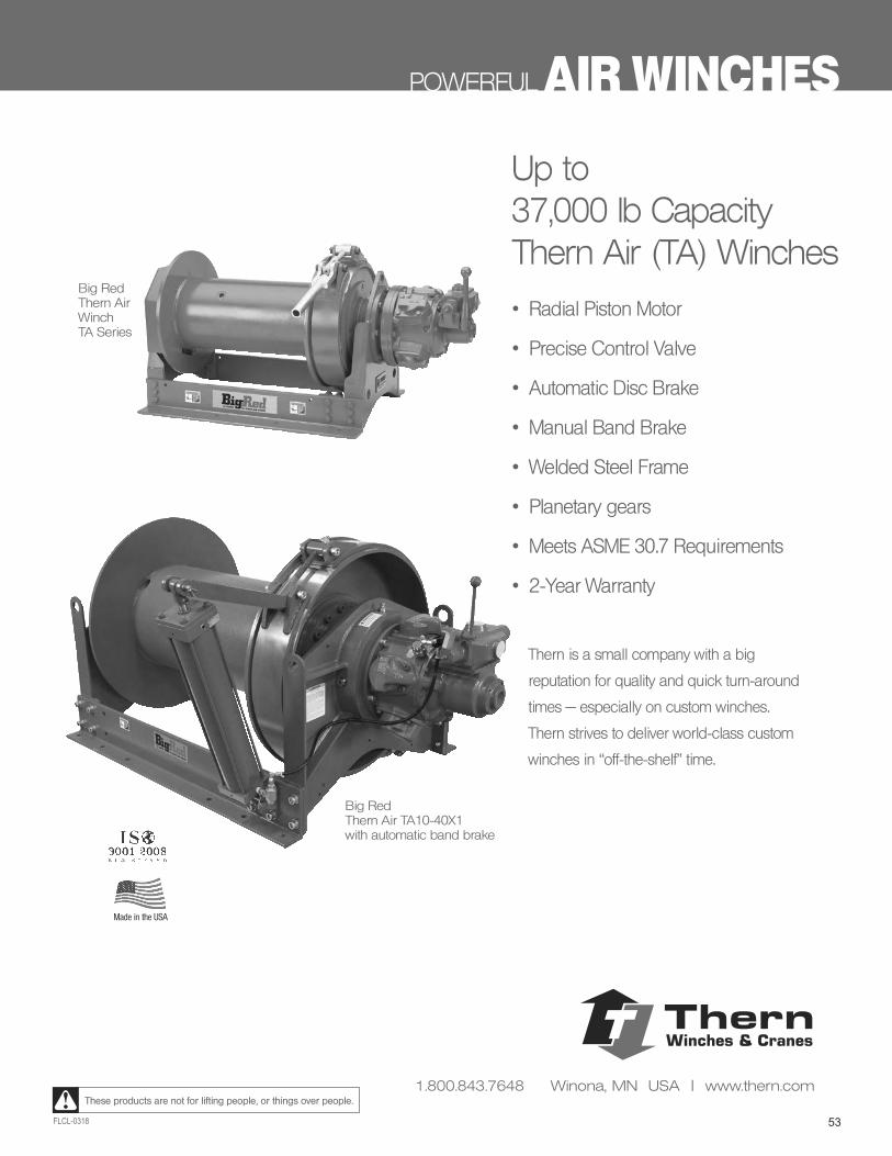
53FLCL-0318
These products are not for lifting people, or things over people.
POWERFUL AIR WINCHES
Up to 37,000 lb CapacityThern Air (TA) Winches
• Radial Piston Motor
• Precise Control Valve
• Automatic Disc Brake
• Manual Band Brake
• Welded Steel Frame
• Planetary gears
• Meets ASME 30.7 Requirements
• 2-Year Warranty
Thern is a small company with a big
reputation for quality and quick turn-around
times — especially on custom winches.
Thern strives to deliver world-class custom
winches in “off-the-shelf” time.
Big RedThern Air WinchTA Series
Big Red Thern Air TA10-40X1with automatic band brake
Made in the USA
ThernWinches & Cranes
1.800.843.7648 Winona, MN USA | www.thern.com
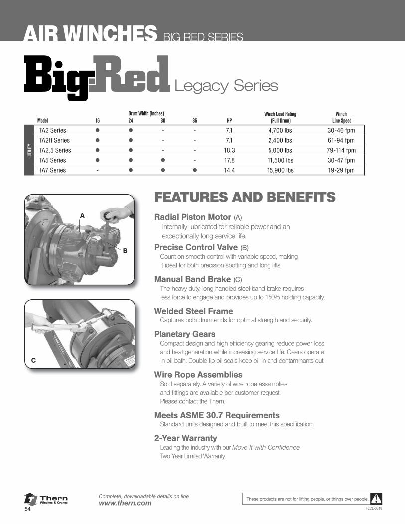
ThernWinches & Cranes
54
Complete, downloadable details on linewww.thern.com
FLCL-0318
These products are not for lifting people, or things over people.
AIR WINCHES BIG RED SERIES
Legacy Series
FEATURES AND BENEFITSRadial Piston Motor (A) Internally lubricated for reliable power and an
exceptionally long service life.
Precise Control Valve (B) Count on smooth control with variable speed, making it ideal for both precision spotting and long lifts.
Manual Band Brake (C)The heavy duty, long handled steel band brake requires less force to engage and provides up to 150% holding capacity.
Welded Steel FrameCaptures both drum ends for optimal strength and security.
Planetary GearsCompact design and high efficiency gearing reduce power loss and heat generation while increasing service life. Gears operate in oil bath. Double lip oil seals keep oil in and contaminants out.
Wire Rope AssembliesSold separately. A variety of wire rope assemblies and fittings are available per customer request. Please contact the Thern.
Meets ASME 30.7 RequirementsStandard units designed and built to meet this specification.
2-Year Warranty Leading the industry with our Move It with Confidence Two Year Limited Warranty.
A
B
C
Winch Load Rating Winch Model 16 24 30 36 HP (Full Drum) Line Speed
TA2 Series • • - - 7.1 4,700 lbs 30-46 fpm
TA2H Series • • - - 7.1 2,400 lbs 61-94 fpm
TA2.5 Series • • - - 18.3 5,000 lbs 79-114 fpm
TA5 Series • • • - 17.8 11,500 lbs 30-47 fpm
TA7 Series - • • • 14.4 15,900 lbs 19-29 fpm
Drum Width (inches)
UTIL
ITY

ThernWinches & Cranes
55FLCL-0318
Complete, downloadable details on linewww.thern.comThese products are not for lifting people, or things over people.
BIG RED SERIES AIR WINCHES
Legacy Series
D
E
F
H
Every job is different, so we allow you to build the Thern BIG RED TA Series air winches to suit your specific needs using our extensive line of accessories and options. The better suited the winch, the better completed the task.
J
OPTIONS AND ACCESSORIESAu tomatic Disc Brake (D)
Spring engaged, air pressure released and oil cooled for extended duty cycles and long life.
Automatic Band Brake (E) Spring engaged, air pressure released, with heavy-duty construction that provides up to 150% holding capacity (replaces manual brake).
Mufflers (F)Attached to the exhaust ports to reduce noise.
Control Options (G)Winch mounted, full flow remote pendant control valve.
Marine Grade EpoxyApplied with a zinc primer for ultimate protection in harsh environments.
Drum Guard (H)Heavy-duty steel mesh helps to protect operators. Adjusts for different rope payout angles.
Filter, Regulator and Lubricator (I) Maintains air quality to the winch. Required for warranty compliance.
Line Guide (J)Steel construction and hand operated to help wire rope unwind uniformly.
Stackable Construction Winch CageProtects motor and winch during operation. Movable with forklift.
I
G
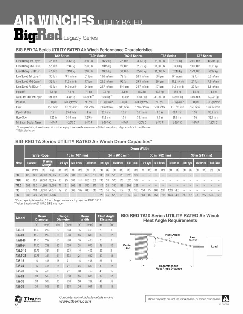
ThernWinches & Cranes
56
Complete, downloadable details on linewww.thern.com
FLCL-0318
These products are not for lifting people, or things over people.
AIR WINCHES UTILITY RATED
BIG RED TA Series UTILITY RATED Air Winch Drum Capacities*
Drum Width 16 in (407 mm) 24 in (610 mm) 30 in (762 mm) 36 in (915 mm)
Rope Breaking 1st Mid Full 1st Mid Full 1st Mid Full 1st Mid Full Diameter Strength**
Layer Drum Drum Layer Drum Drum Layer Drum Drum Layer Drum Drum
(in) (mm) (lb) (kg) (ft) (m) (ft) (m) (ft) (m) (ft) (m) (ft) (m) (ft) (m) (ft) (m) (ft) (m) (ft) (m) (ft) (m) (ft) (m) (ft) (m)TA2 Series 0.5 12.7 26,600 12,065 83 25 380 115 850 259 130 39 570 173 1,270 387 - - - - - - - - - - - -TA2H Series 0.5 12.7 26,600 12,065 83 25 380 115 850 259 130 39 570 173 1,270 387 - - - - - - - - - - - -TA2.5 Series 0.63 16.0 41,200 18,688 71 21 260 79 580 176 110 33 390 118 860 262 - - - - - - - - - - - -TA5 Series 0.75 19.1 58,800 26,671 72 21 360 109 810 246 120 36 550 167 1,210 368 150 45 680 207 1,520 463 - - - - - -TA7 Series 0.88 22.4 79,600 36,106 - - - - - - 120 36 520 158 1,150 350 160 48 650 198 1,440 438 190 57 780 237 1,730 527
* Drum capacity is based on 0.5 inch ange clearance at top layer per ASME B30.7. ** Values based on 6x37 IWRC EIPS wire rope.
Drum Flange Drum Fleet Diameter Diameter Width Angle Dist.
Series (in) (mm) (in) (mm) (in) (mm) (ft) (m)TA2-16 11.50 292 20.00 508 16.00 406 26 8TA2-24 11.50 292 20.00 508 24.00 610 39 12TA2H-16 11.50 292 20.00 508 16.00 406 26 8TA2H-24 11.50 292 20.00 508 24.00 610 39 12TA2.5-16 12.75 324 21.00 533 16.00 406 26 8TA2.5-24 12.75 324 21.00 533 24.00 610 39 12TA5-16 16.00 406 28.00 711 16.00 406 26 8TA5-24 16.00 406 28.00 711 24.00 610 39 12TA5-30 16.00 406 28.00 711 30.00 762 48 15TA7-24 20.00 508 33.00 838 24.00 610 39 12TA7-30 20.00 508 33.00 838 30.00 762 48 15TA7-36 20.00 508 33.00 838 36.00 914 58 18
BIG RED TA Series UTILITY RATED Air Winch Performance Characteristics TA2 Series TA2H Series TA2.5 Series TA5 Series TA7 Series
Load Rating 1st Layer 7,200 lb 3,265 kg 3,600 lb 1,632 kg 7,200 lb 3,265 kg 18,000 lb 8,164 kg 23,600 lb 10,704 kg
Load Rating Mid-Drum 5,700 lb 2,585 kg 2,900 lb 1,315 kg 5,900 lb 2,676 kg 14,000 lb 6,350 kg 19,000 lb 8,618 kg
Load Rating Full Drum 4,700 lb 2,131 kg 2,400 lb 1,088 kg 5,000 lb 2,268 kg 11,500 lb 5,216 kg 15,900 lb 7,212 kg
Line Speed 1st Layer * 30 fpm 9.1 m/min 61 fpm 18.6 m/min 79 fpm** 24.1 m/min** 30 fpm** 9.1 m/min** 19 fpm 5.8 m/min
Line Speed Mid-Drum* 38 fpm 11.6 m/min 77 fpm 23.5 m/min 96 fpm** 29.3 m/min** 39 fpm** 11.9 m/min** 24 fpm 7.3 m/min
Line Speed Full Drum* 46 fpm 14.0 m/min 94 fpm 28.7 m/min 114 fpm** 34.7 m/min** 47 fpm** 14.3 m/min** 29 fpm 8.8 m/min
Input HP 7.1 hp 7.1 hp 7.1 hp 7.1 hp 18.3 hp 18.3 hp 17.8 hp 17.8 hp 14.4 hp 14.4 hp
Max. Stall Pull 1st Layer 9,000 lb 4,082 kg 4,500 lb *** 2,041kg *** 11,000 lb 4,989 kg 33,000 lb 14,968 kg 38,000 lb 17,236 kg
Pressure 90 psi 6.3 kgf/cm2 90 psi 6.3 kgf/cm2 90 psi 6.3 kgf/cm2 90 psi 6.3 kgf/cm2 90 psi 6.3 kgf/cm2
Flow 250 scfm 7.0 m3/min 250 scfm 7.0 m3/min 600 scfm 17.0 m3/min 550 scfm 15.6 m3/min 550 scfm 15.6 m3/min
Pipe Inlet Size 1 in 25.4 mm 1 in 25.4 mm 1.5 in 38.1 mm 1.5 in 38.1 mm 1.5 in 38.1 mm
Hose Size 1.25 in 31.8 mm 1.25 in 31.8 mm 1.5 in 38.1 mm 1.5 in 38.1 mm 1.5 in 38.1 mm
Minimum Design Temp (-4°) F (-20°)C (-4°)F (-20°)C (-4°)F (-20°)C (-4°)F (-20°)C (-4°)F (-20°)C
* Line speeds vary based on conditions of air supply. ** ABS certi cations may specify slower line speeds than those published due to variances in air ow at time of actual test. *** Estimated Value.
RecommendedFleet Angle Distance
CenterLine Load
LeadSleeve
Fleet Angle
Legacy Series
BIG RED TA Series UTILITY RATED Air Winch Performance CharacteristicsTA2 Series TA2H Series TA2.5 Series TA5 Series TA7 Series
Load Rating 1st Layer 7200 lb 3265 kg 3600 lb 1632 kg 7200 lb 3265 kg 18,000 lb 8164 kg 23,600 lb 10,704 kg
Load Rating Mid-Drum 5700 lb 2585 kg 2900 lb 1315 kg 5900 lb 2676 kg 14,000 lb 6350 kg 19,000 lb 8618 kg
Load Rating Full Drum 4700 lb 2131 kg 2400 lb 1088 kg 5000 lb 2268 kg 11,500 lb 5216 kg 15,900 lb 7212 kg
Line Speed 1st Layer * 30 fpm 9.1 m/min 61 fpm 18.6 m/min 79 fpm 24.1 m/min 30 fpm 9.1 m/min 19 fpm 5.8 m/min
Line Speed Mid-Drum * 38 fpm 11.6 m/min 77 fpm 23.5 m/min 96 fpm 29.3 m/min 39 fpm 11.9 m/min 24 fpm 7.3 m/min
Line Speed Full Drum * 46 fpm 14.0 m/min 94 fpm 28.7 m/min 114 fpm 34.7 m/min 47 fpm 14.3 m/min 29 fpm 8.8 m/min
Input HP 7.1 hp 7.1 hp 7.1 hp 7.1 hp 18.3 hp 18.3 hp 17.8 hp 17.8 hp 14.4 hp 14.4 hp
Max Stall Pull 1st Layer 9000 lb 4082 kg 4500 lb ** 2041kg ** 11,000 lb 4,989 kg 33,000 lb 14,968 kg 38,000 lb 17,236 kg
Pressure 90 psi 6.3 kgf/cm2 90 psi 6.3 kgf/cm2 90 psi 6.3 kgf/cm2 90 psi 6.3 kgf/cm2 90 psi 6.3 kgf/cm2
Flow 250 scfm 7.0 m3/min 250 scfm 7.0 m3/min 600 scfm 17.0 m3/min 550 scfm 15.6 m3/min 550 scfm 15.6 m3/min
Pipe Inlet Size 1 in 25.4 mm 1 in 25.4 mm 1.5 in 38.1 mm 1.5 in 38.1 mm 1.5 in 38.1 mm
Hose Size 1.25 in 31.8 mm 1.25 in 31.8 mm 1.5 in 38.1 mm 1.5 in 38.1 mm 1.5 in 38.1 mm
Minimum Design Temp (-4º) F (-20º) C (-4º) F (-20º) C (-4º) F (-20º) C (-4º) F (-20º) C (-4º) F (-20º) C** Line speeds vary based on conditions of air supply. Line speeds may run up to 20% slower when configured with auto band brakes.** Estimated value.
BIG RED TA Series UTILITY RATED Air Winch Drum Capacities*Drum Width
Wire Rope 16 in (407 mm) 24 in (610 mm) 30 in (762 mm) 36 in (915 mm)
Model Diameter Breaking Strength** 1st Layer Mid Drum Full Drum 1st Layer Mid Drum Full Drum 1st Layer Mid Drum Full Drum 1st Layer Mid Drum Full Drum
(in) (mm) (lb) (kg) (ft) (m) (ft) (m) (ft) (m) (ft) (m) (ft) (m) (ft) (m) (ft) (m) (ft) (m) (ft) (m) (ft) (m) (ft) (m) (ft) (m)
TA2 0.5 12.7 26,600 12,065 83 25 380 115 850 259 130 39 570 173 1270 387 — — — — — — — — — — — —
TA2H 0.5 12.7 26,600 12,065 83 25 380 115 850 259 130 39 570 173 1270 387 — — — — — — — — — — — —
TA2.5 0.63 16.0 41,200 18,688 71 21 260 79 580 176 110 33 390 118 860 262 — — — — — — — — — — — —
TA5 0.75 19.1 58,800 26,671 72 21 360 109 810 246 120 36 550 167 1210 368 150 45 680 207 1520 463 — — — — — —
TA7 0.88 22.4 79,600 36,106 — — — — — — 120 36 520 158 1150 350 160 48 650 198 1440 438 190 57 780 237 1730 527
** Drum capacity is based on 0.5 inch flange clearance at top layer per ASME B30.7. ** Values based on 6x37 IWRC EIPS wire rope.
Model Drum Diameter
Flange Diameter
Drum Width
Fleet Angle Distance
(in) (mm) (in) (mm) (in) (mm) (ft) (m)
TA2-16 11.50 292 20 508 16 406 26 8
TA2-24 11.50 292 20 508 24 610 39 12
TA2H-16 11.50 292 20 508 16 406 26 8
TA2H-24 11.50 292 20 508 24 610 39 12
TA2.5-16 12.75 324 21 533 16 406 26 8
TA2.5-24 12.75 324 21 533 24 610 39 12
TA5-16 16 406 28 711 16 406 26 8
TA5-24 16 406 28 711 24 610 39 12
TA5-30 16 406 28 711 30 762 48 15
TA7-24 20 508 33 838 24 610 39 12
TA7-30 20 508 33 838 30 762 48 15
TA7-36 20 508 33 838 36 914 58 18
BIG RED TA10 Series UTILITY RATED Air Winch Fleet Angle Requirements
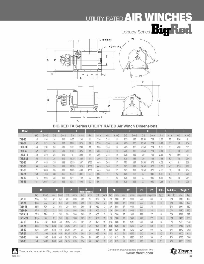
ThernWinches & Cranes
57FLCL-0318
Complete, downloadable details on linewww.thern.comThese products are not for lifting people, or things over people.
UTILITY RATED AIR WINCHES
www.thern.com 1.800.843.7648
UTILITY RATED
D
T
EA
M
H Y2
Y1
Z2
Z1F
B P
NL
JL
L
S (hole dia)
C (drum C)L
BIG RED TA Series UTILITY RATED Air Winch Dimensions A B C D E F H J L M N
Series (in) (mm) (in) (mm) (in) (mm) (in) (mm) (in) (mm) (in) (mm) (in) (mm) (in) (mm) (in) (mm) (in) (mm) (in) (mm)TA2-16 44.00 1,118 24.00 610 9.06 230 14.00 356 0.54 14 5.25 133 28.50 724 2.88 73 7.50 191 28.50 724 2.00 51TA2-24 52.00 1,321 24.00 610 12.81 325 14.00 356 0.54 14 5.25 133 28.50 724 3.13 80 10.00 254 36.50 927 2.00 51TA2H-16 44.00 1,118 24.00 610 9.06 230 14.00 356 0.54 14 5.25 133 28.50 724 2.88 73 7.50 191 28.50 724 2.00 51TA2H-24 52.00 1,321 24.00 610 12.81 325 14.00 356 0.54 14 5.25 133 28.50 724 3.13 80 10.00 254 36.50 927 2.00 51TA2.5-16 50.00 1,270 24.00 610 9.00 229 14.00 356 0.73 19 5.25 133 30.00 762 2.88 73 7.50 191 28.50 724 2.00 51TA2.5-24 58.00 1,473 24.00 610 12.75 324 14.00 356 0.73 19 5.25 133 30.00 762 3.13 80 10.00 254 36.50 927 2.00 51TA5-16 57.00 1,448 35.00 889 10.53 267 17.50 445 0.68 17 7.75 197 34.50 876 4.03 102 9.00 229 35.50 902 1.88 48TA5-24 65.00 1,651 35.00 889 12.78 325 17.50 445 0.68 17 7.75 197 34.50 876 5.78 147 10.50 267 43.50 1,105 1.88 48TA5-30 71.00 1,803 35.00 889 17.03 433 17.50 445 0.68 17 7.75 197 34.50 876 4.53 115 10.00 254 49.50 1,257 1.88 48TA7-24 69.00 1,753 38.00 965 15.41 391 20.00 508 1.00 25 9.25 235 37.00 940 5.38 137 9.00 229 47.00 1,194 1.88 48TA7-30 75.00 1,905 38.00 965 17.41 442 20.00 508 1.00 25 9.25 235 37.00 940 6.38 162 10.00 254 53.00 1,346 1.88 48TA7-36 81.00 2,057 38.00 965 19.41 493 20.00 508 1.00 25 9.25 235 37.00 940 7.38 187 11.00 279 59.00 1,499 1.88 48
S # P (hole diameter) T Y1 Y2 Z1 Z2 Bolts Bolt Size Weight
Series (in) (mm) (in) (mm) (in) (mm) (in) (mm) (in) (mm) (Degrees) (Degrees) - - (lb) (kg) TA2-16 20.00 508 0.69 18 0.50 13 20.00 508 37.00 940 223 34 8 5 / 8 in - G8 990 450TA2-24 20.00 508 0.69 18 0.50 13 20.00 508 37.00 940 223 34 8 5 / 8 in - G8 1,080 490TA2H-16 20.00 508 0.69 18 0.50 13 20.00 508 37.00 940 223 34 8 5 / 8 in - G8 990 450TA2H-24 20.00 508 0.69 18 0.50 13 20.00 508 37.00 940 223 34 8 5 / 8 in - G8 1,080 490TA2.5-16 20.00 508 0.69 18 0.50 13 20.00 508 37.00 940 228 27 8 5 / 8 in - G8 1,315 597TA2.5-24 20.00 508 0.69 18 0.50 13 20.00 508 37.00 940 228 27 8 5 / 8 in - G8 1,400 636TA5-16 31.45 794 0.81 21 0.75 19 32.50 826 48.00 1,219 224 50 8 3 / 4 in - G8 2,585 1,173TA5-24 31.45 794 0.81 21 0.75 19 32.50 826 48.00 1,219 224 50 8 3 / 4 in - G8 2,745 1,246TA5-30 31.45 794 0.81 21 0.75 19 32.50 826 48.00 1,219 224 50 10 3 / 4 in - G8 2,870 1,302TA7-24 34.25 870 0.94 24 0.75 19 32.00 813 51.00 1,295 210 39 10 7 / 8 in - G8 3,600 1,633TA7-30 34.25 870 0.94 24 0.75 19 32.00 813 51.00 1,295 210 39 10 7 / 8 in - G8 3,765 1,708TA7-36 34.25 870 0.94 24 0.75 19 32.00 813 51.00 1,295 210 39 10 7 / 8 in - G8 3,965 1,799
Legacy Series
M N P S (hole diameter) T Y1 Y2 Z1 Z2 Bolts Bolt Size Weight *
(in) (mm) (in) (mm) (in) (mm) (in) (mm) (in) (mm) (in) (mm) (in) (mm) (degrees) (degrees) (qty) (in - G8) (lb) (kg)
TA2-16 28.5 724 2 51 20 508 0.69 18 0.50 13 20 508 37 940 223 34 8 5/8 990 450
TA2-24 36.5 927 2 51 20 508 0.69 18 0.50 13 20 508 37 940 223 34 8 5/8 1080 490
TA2H-16 28.5 724 2 51 20 508 0.69 18 0.50 13 20 508 37 940 223 34 8 5/8 990 450
TA2H-24 36.5 927 2 51 20 508 0.69 18 0.50 13 20 508 37 940 223 34 8 5/8 1080 490
TA2.5-16 28.5 724 2 51 20 508 0.69 18 0.50 13 20 508 37 940 228 27 8 5/8 1315 597
TA2.5-24 36.5 927 2 51 20 508 0.69 18 0.50 13 20 508 37 940 228 27 8 5/8 1400 636
TA5-16 35.5 902 1.88 48 31.25 794 0.81 21 0.75 19 32.5 826 48 1219 224 50 8 3/4 2585 1173
TA5-24 43.5 1105 1.88 48 31.25 794 0.81 21 0.75 19 32.5 826 48 1219 224 50 8 3/4 2745 1246
TA5-30 49.5 1257 1.88 48 31.25 794 0.81 21 0.75 19 32.5 826 48 1219 224 50 10 3/4 2870 1302
TA7-24 47 1194 1.88 48 34.25 870 0.94 24 0.75 19 32 813 51 1295 210 39 10 7/8 3600 1633
TA7-30 53 1346 1.88 48 34.25 870 0.94 24 0.75 19 32 813 51 1295 210 39 10 7/8 3765 1708
TA7-36 59 1499 1.88 48 34.25 870 0.94 24 0.75 19 32 813 51 1295 210 39 10 7/8 3965 1799
BIG RED TA Series UTILITY RATED Air Winch DimensionsModel A B C D E F H J L
(in) (mm) (in) (mm) (in) (mm) (in) (mm) (in) (mm) (in) (mm) (in) (mm) (in) (mm) (in) (mm)
TA2-16 44 1118 24 610 9.06 230 14 356 0.54 14 5.25 133 28.50 724 2.88 73 7.50 191
TA2-24 52 1321 24 610 12.81 325 14 356 0.54 14 5.25 133 28.50 724 3.13 80 10 254
TA2H-16 44 1118 24 610 9.06 230 14 356 0.54 14 5.25 133 28.50 724 2.88 73 7.50 191
TA2H-24 52 1321 24 610 12.81 325 14 356 0.54 14 5.25 133 28.50 724 3.13 80 10 254
TA2.5-16 50 1270 24 610 9 229 14 356 0.73 19 5.25 133 30 762 2.88 73 7.50 191
TA2.5-24 58 1473 24 610 12.75 324 14 356 0.73 19 5.25 133 30 762 3.13 80 10 254
TA5-16 57 1448 35 889 10.53 267 17.50 445 0.68 17 7.75 197 34.50 876 4.03 102 9 229
TA5-24 65 1651 35 889 12.78 325 17.50 445 0.68 17 7.75 197 34.50 876 5.78 147 10.5 267
TA5-30 71 1803 35 889 17.03 433 17.50 445 0.68 17 7.75 197 34.50 876 4.53 115 10 254
TA7-24 69 1753 38 965 15.41 391 20 508 1 25 9.25 235 37 940 5.38 137 9 229
TA7-30 75 1905 38 965 17.41 442 20 508 1 25 9.25 235 37 940 6.38 162 10 254
TA7-36 81 2057 38 965 19.41 493 20 508 1 25 9.25 235 37 940 7.38 187 11 279
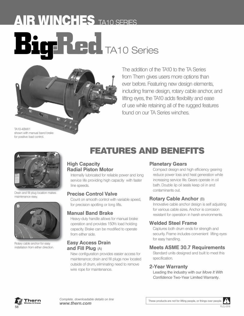
ThernWinches & Cranes
58
Complete, downloadable details on linewww.thern.com
FLCL-0318
These products are not for lifting people, or things over people.
AIR WINCHES TA10 SERIES
TA10 Series
High Capacity Radial Piston Motor
Internally lubricated for reliable power and long service life providing high capacity with faster line speeds.
Precise Control ValveCount on smooth control with variable speed, for precision spotting or long lifts.
Manual Band BrakeHeavy-duty handle allows for manual brake operation and provides 150% load holding capacity. Brake can be modified to operate from either side.
Easy Access Drain and Fill Plug (A)
New configuration provides easier access for maintenance; drain and fill plugs now located outside of drum, eliminating need to remove wire rope for maintenance.
Planetary GearsCompact design and high efficiency gearing reduce power loss and heat generation while increasing service life. Gears operate in oil bath. Double lip oil seals keep oil in and contaminants out.
Rotary Cable Anchor (B)Innovative cable anchor design is self adjusting for various cable sizes. Anchor is corrosion resistant for operation in harsh environments.
Welded Steel FrameCaptures both drum ends for strength and security. Frame includes convenient lifting eyes for easy handling.
Meets ASME 30.7 RequirementsStandard units designed and built to meet this specification.
2-Year WarrantyLeading the industry with our Move It With Confidence Two-Year Limited Warranty.
The addition of the TA10 to the TA Series from Thern gives users more options than ever before. Featuring new design elements, including frame design, rotary cable anchor, and lifting eyes, the TA10 adds flexibility and ease of use while retaining all of the rugged features found on our TA Series winches.
FEATURES AND BENEFITS
Drain and fill plug location makes maintenance easy.
Rotary cable anchor for easy installation from either direction.
TA10-40MX1shown with manual band brakefor positive load control.
A
B
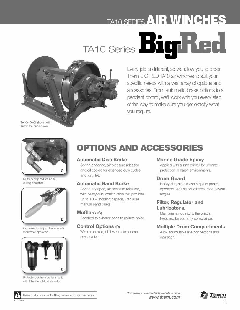
ThernWinches & Cranes
59FLCL-0318
Complete, downloadable details on linewww.thern.comThese products are not for lifting people, or things over people.
TA10 SERIES AIR WINCHES
TA10 Series
Automatic Disc BrakeSpring engaged, air pressure released and oil cooled for extended duty cycles and long life.
Automatic Band BrakeSpring engaged, air pressure released, with heavy-duty construction that provides up to 150% holding capacity (replaces manual band brake).
Mufflers (C)Attached to exhaust ports to reduce noise.
Control Options (D)Winch mounted, full flow remote pendant control valve.
Marine Grade EpoxyApplied with a zinc primer for ultimate protection in harsh environments.
Drum GuardHeavy-duty steel mesh helps to protect operators. Adjusts for different rope payout angles.
Filter, Regulator and Lubricator (E)
Maintains air quality to the winch. Required for warranty compliance.
Multiple Drum CompartmentsAllow for multiple line connections and operation.
OPTIONS AND ACCESSORIES
Mufflers help reduce noiseduring operation.
Convenience of pendant controlsfor remote operation.
Protect motor from contaminants with Filter-Regulator-Lubricator.
TA10-40AX1 shown withautomatic band brake.
Every job is different, so we allow you to order Thern BIG RED TA10 air winches to suit your specific needs with a vast array of options and accessories. From automatic brake options to a pendant control, we'll work with you every step of the way to make sure you get exactly what you require.
C
D
E
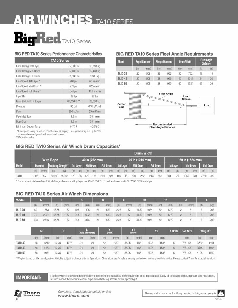
ThernWinches & Cranes
60
Complete, downloadable details on linewww.thern.com
FLCL-0318
These products are not for lifting people, or things over people.
AIR WINCHES TA10 SERIES
TA10 Series
BIG RED TA10 Series Performance CharacteristicsTA10 Series
Load Rating 1st Layer 37,000 lb 16,783 kg
Load Rating Mid-Drum 27,400 lb 12,428 kg
Load Rating Full Drum 21,800 lb 9,888 kg
Line Speed 1st Layer * 20 fpm 6.1 m/min
Line Speed Mid-Drum * 27 fpm 8.2 m/min
Line Speed Full Drum * 34 fpm 10.4 m/min
Input HP 27 hp 27 hp
Max Stall Pull 1st Layer 63,000 lb ** 28,576 kg
Pressure 90 psi 6.3 kgf/cm2
Flow 900 scfm 25 m3/min
Pipe Inlet Size 1.5 in 38.1 mm
Hose Size 1.5 in 38.1 mm
Minimum Design Temp (-4º) F (-20º) C** Line speeds vary based on conditions of air supply. Line speeds may run up to 20%
slower when configured with auto band brakes.** Estimated value.
M P S (hole diameter)
Y1 (man)
Y1 (auto) Y2 # Bolts Bolt Size Weight *
(in) (mm) (in) (mm) (in) (mm) (in) (mm) (in) (mm) (in) (mm) (in) (lb) (kg)
TA10-30 48 1219 42.25 1073 .94 24 42 1067 35.25 895 62.5 1588 12 7/8 - G8 3220 1461
TA10-40 58 1473 42.25 1073 .94 24 42 1067 35.25 895 62.5 1588 12 7/8 - G8 3515 1595
TA10-60 78 1981 42.25 1073 .94 24 42 1067 35.25 895 62.5 1588 12 7/8 - G8 4105 1862
* Weights based on MX1 configuration. Weights subject to change with configurations. Dimensions are for reference only and subject to change without notice. Please contact Thern for exact dimensions.
BIG RED TA10 Series Air Winch DimensionsModel A B C D E H1 H2 J L
(in) (mm) (in) (mm) (in) (mm) (in) (mm) (in) (mm) (in) (mm) (in) (mm) (in) (mm) (lb) (kg)
TA10-30 69 1753 45.75 1162 19.5 495 21 533 2.25 57 41.50 1054 50 1270 2 51 8 203
TA10-40 79 2007 45.75 1162 24.5 622 21 533 2.25 57 41.50 1054 50 1270 2 51 8 203
TA10-60 998 2515 45.75 1162 34.5 876 21 533 2.25 57 41.50 1054 50 1270 2 51 8 203
IMPORTANT: It is the owner or operator’s responsibility to determine the suitability of the equipment to its intended use. Study all applicable codes, manuals and regulations. Be sure to read the Owner’s Manual supplied with the equipment before operating it.
BIG RED TA10 Series Air Winch Drum Capacities*Drum Width
Wire Rope 30 in (762 mm) 40 in (1016 mm) 60 in (1524 mm)
Model Diameter Breaking Strength** 1st Layer Mid Drum Full Drum 1st Layer Mid Drum Full Drum 1st Layer Mid Drum Full Drum
(in) (mm) (lb) (kg) (ft) (m) (ft) (m) (ft) (m) (ft) (m) (ft) (m) (ft) (m) (ft) (m) (ft) (m) (ft) (m)
TA10 1-1/8 28.7 130,000 58,968 120 36 620 188 1390 423 160 48 830 252 1850 563 260 79 1250 381 2780 847
* Drum capacity is based on 0.5 inch flange clearance at top layer per ASME B30.7. ** Values based on 6x37 IWRC EIPS wire rope.
BIG RED TA10 Series Fleet Angle Requirements
Model Rope Diameter Flange Diameter Drum Width Fleet Angle Distance
(in) (mm) (in) (mm) (in) (mm) (ft) (m)
TA10-30 20 508 38 965 30 762 48 15
TA10-40 20 508 38 965 40 1016 64 20
TA10-60 20 508 38 965 60 1524 95 29
RecommendedFleet Angle Distance
CenterLine Load
LeadSleeve
Fleet Angle
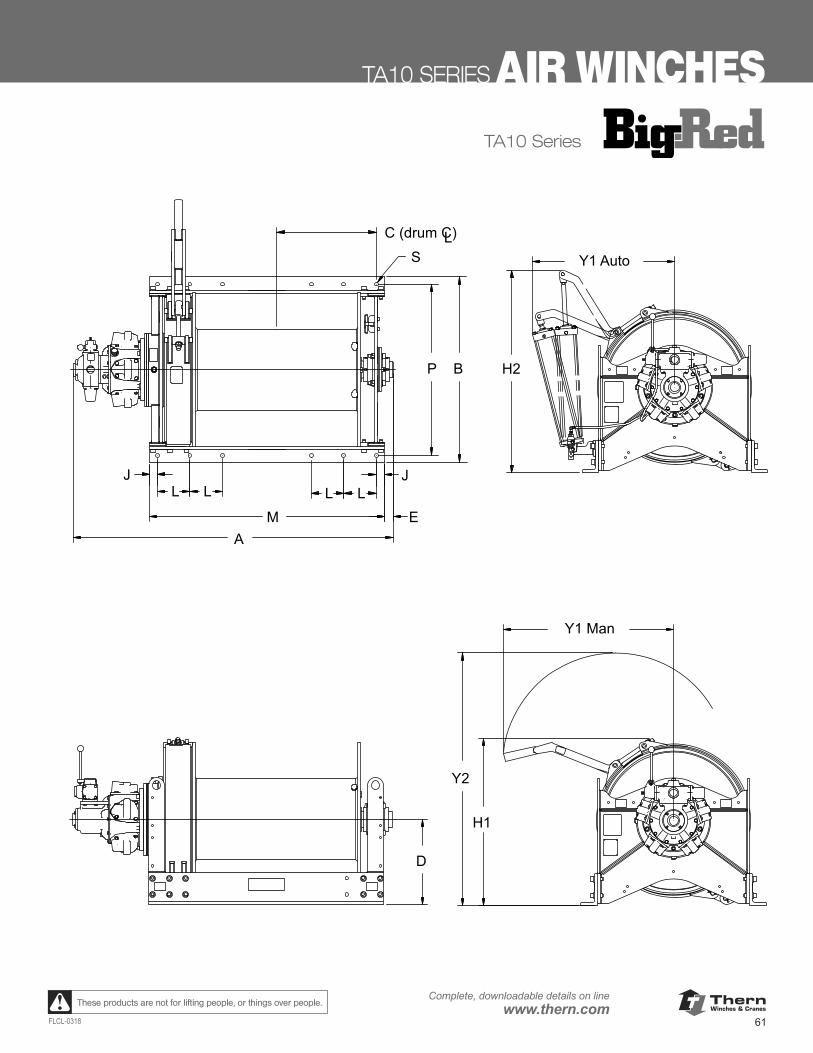
ThernWinches & Cranes
61FLCL-0318
Complete, downloadable details on linewww.thern.comThese products are not for lifting people, or things over people.
TA10 SERIES AIR WINCHES
Y1 Auto
H2
Y2
Y1 Man
H1
D
L
E M
J L L L
J
A
C (drum C)
S
P B
L
TA10 Series
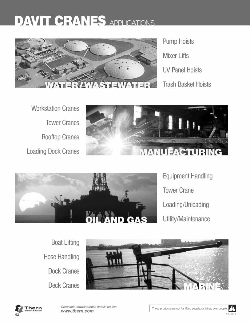
ThernWinches & Cranes
62
Complete, downloadable details on linewww.thern.com
FLCL-0318
These products are not for lifting people, or things over people.
DAVIT CRANES APPLICATIONS
Pump Hoists
Mixer Lifts
UV Panel Hoists
Trash Basket Hoists
Equipment Handling
Tower Crane
Loading/Unloading
Utility/Maintenance
Workstation Cranes
Tower Cranes
Rooftop Cranes
Loading Dock Cranes
Boat Lifting
Hose Handling
Dock Cranes
Deck Cranes MARINE
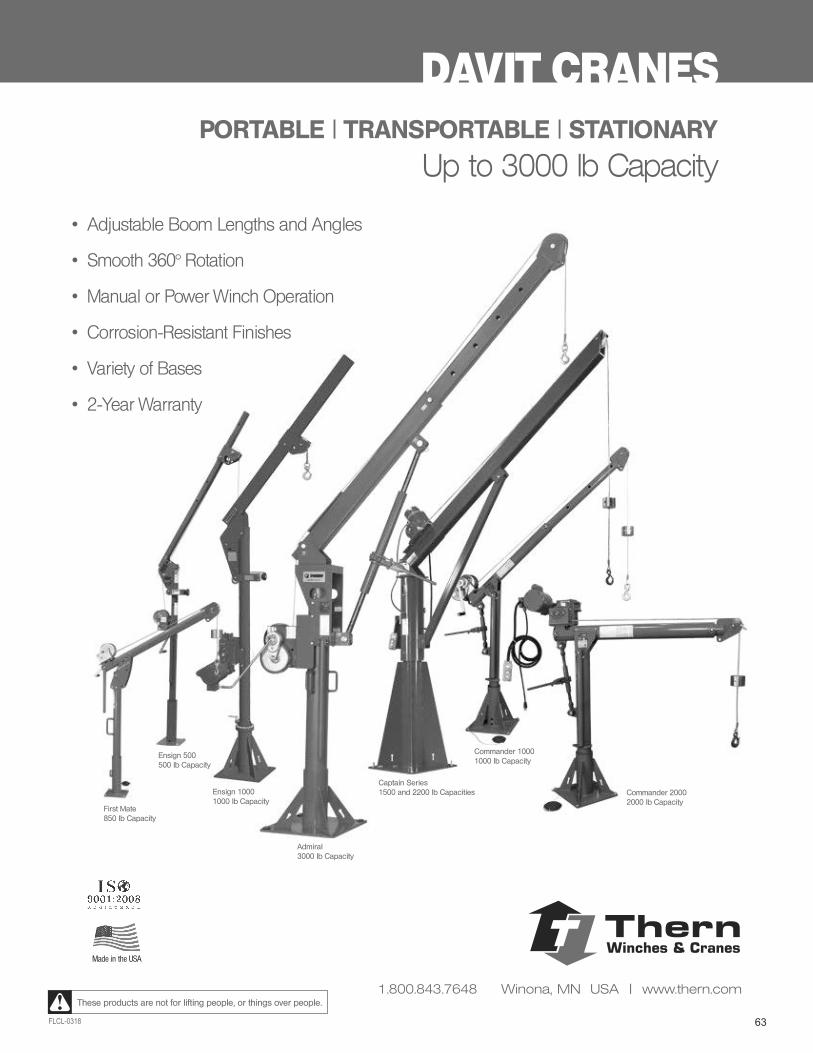
63FLCL-0318
These products are not for lifting people, or things over people.
First Mate850 lb Capacity
Ensign 500500 lb Capacity
Ensign 10001000 lb Capacity
Admiral3000 lb Capacity
Captain Series1500 and 2200 lb Capacities
Commander 10001000 lb Capacity
Commander 20002000 lb Capacity
DAVIT CRANES
Made in the USA
PORTABLE | TRANSPORTABLE | STATIONARY
Up to 3000 lb Capacity
• Adjustable Boom Lengths and Angles
• Smooth 360° Rotation
• Manual or Power Winch Operation
• Corrosion-Resistant Finishes
• Variety of Bases
• 2-Year Warranty
ThernWinches & Cranes
1.800.843.7648 Winona, MN USA | www.thern.com
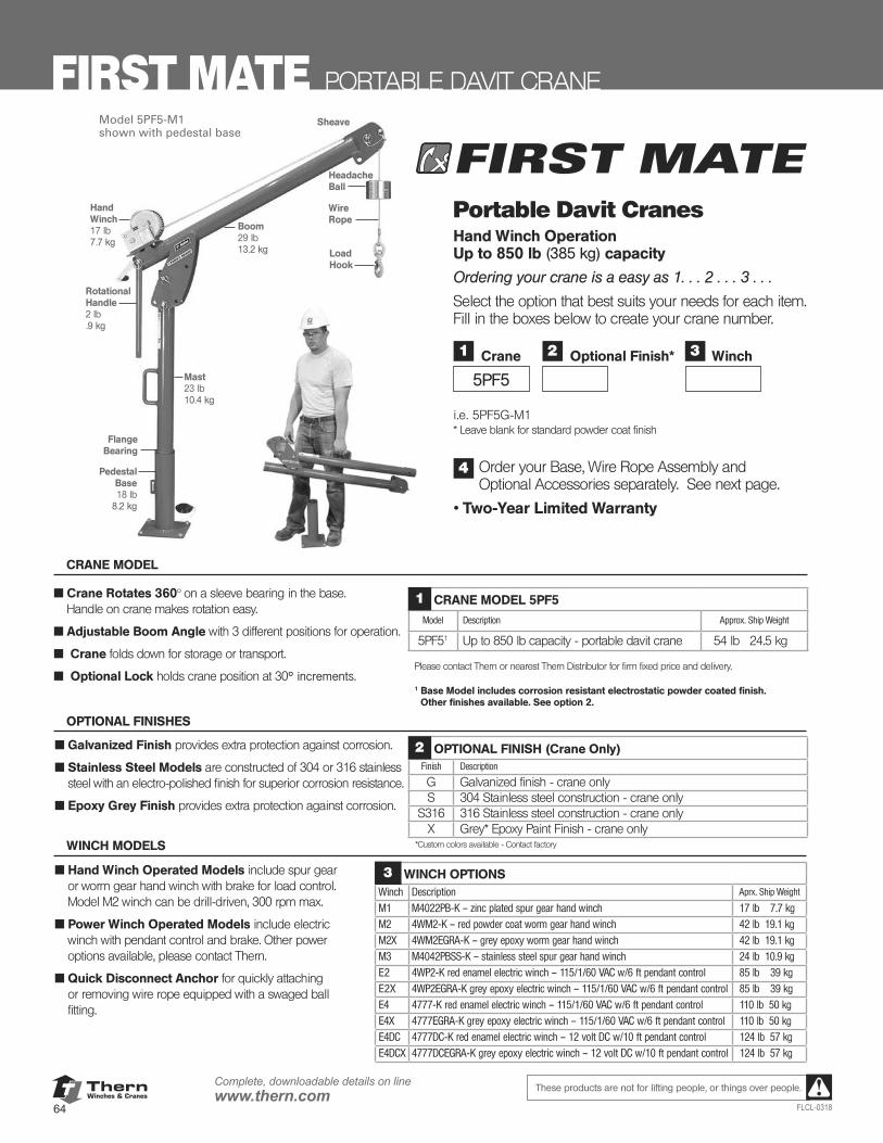
ThernWinches & Cranes
64
Complete, downloadable details on linewww.thern.com
FLCL-0318
These products are not for lifting people, or things over people.
Hand Winch17 lb7.7 kg
Sheave
Wire Rope
HeadacheBall
Load Hook
Mast23 lb10.4 kg
Flange Bearing
Boom29 lb13.2 kg
Pedestal Base18 lb
8.2 kg
Model 5PF5-M1shown with pedestal base
Portable Davit CranesHand Winch Operation Up to 850 lb (385 kg) capacity
Ordering your crane is a easy as 1. . . 2 . . . 3 . . .
Select the option that best suits your needs for each item. Fill in the boxes below to create your crane number.
i.e. 5PF5G-M1 * Leave blank for standard powder coat finish
Order your Base, Wire Rope Assembly and Optional Accessories separately. See next page.
• Two-Year Limited Warranty
1
5PF5
Crane 3 Winch2 Optional Finish*
4
FIRST MATE PORTABLE DAVIT CRANE
■ Crane Rotates 360° on a sleeve bearing in the base. Handle on crane makes rotation easy.
■ Adjustable Boom Angle with 3 different positions for operation.
■ Crane folds down for storage or transport.
■ Optional Lock holds crane position at 30° increments.
CRANE MODEL 5PF5
Model Description Approx. Ship Weight
5PF51 Up to 850 lb capacity - portable davit crane 54 lb 24.5 kg
Please contact Thern or nearest Thern Distributor for firm fixed price and delivery.
1 Base Model includes corrosion resistant electrostatic powder coated finish. Other finishes available. See option 2.
1
CRANE MODEL
WINCH OPTIONSWinch Description Aprx. Ship Weight
M1 M4022PB-K – zinc plated spur gear hand winch 17 lb 7.7 kgM2 4WM2-K – red powder coat worm gear hand winch 42 lb 19.1 kg
M2X 4WM2EGRA-K – grey epoxy worm gear hand winch 42 lb 19.1 kg
M3 M4042PBSS-K – stainless steel spur gear hand winch 24 lb 10.9 kgE2 4WP2-K red enamel electric winch – 115/1/60 VAC w/6 ft pendant control 85 lb 39 kgE2X 4WP2EGRA-K grey epoxy electric winch – 115/1/60 VAC w/6 ft pendant control 85 lb 39 kg
E4 4777-K red enamel electric winch – 115/1/60 VAC w/6 ft pendant control 110 lb 50 kg
E4X 4777EGRA-K grey epoxy electric winch – 115/1/60 VAC w/6 ft pendant control 110 lb 50 kgE4DC 4777DC-K red enamel electric winch – 12 volt DC w/10 ft pendant control 124 lb 57 kgE4DCX 4777DCEGRA-K grey epoxy electric winch – 12 volt DC w/10 ft pendant control 124 lb 57 kg
3■ Hand Winch Operated Models include spur gear or worm gear hand winch with brake for load control. Model M2 winch can be drill-driven, 300 rpm max.
■ Power Winch Operated Models include electric winch with pendant control and brake. Other power options available, please contact Thern.
■ Quick Disconnect Anchor for quickly attaching or removing wire rope equipped with a swaged ball fitting.
WINCH MODELS
■ Galvanized Finish provides extra protection against corrosion.
■ Stainless Steel Models are constructed of 304 or 316 stainless steel with an electro-polished finish for superior corrosion resistance.
■ Epoxy Grey Finish provides extra protection against corrosion.
OPTIONAL FINISH (Crane Only)Finish Description
G Galvanized finish - crane onlyS 304 Stainless steel construction - crane only
S316 316 Stainless steel construction - crane onlyX Grey* Epoxy Paint Finish - crane only
*Custom colors available - Contact factory
2
OPTIONAL FINISHES
RotationalHandle2 lb.9 kg
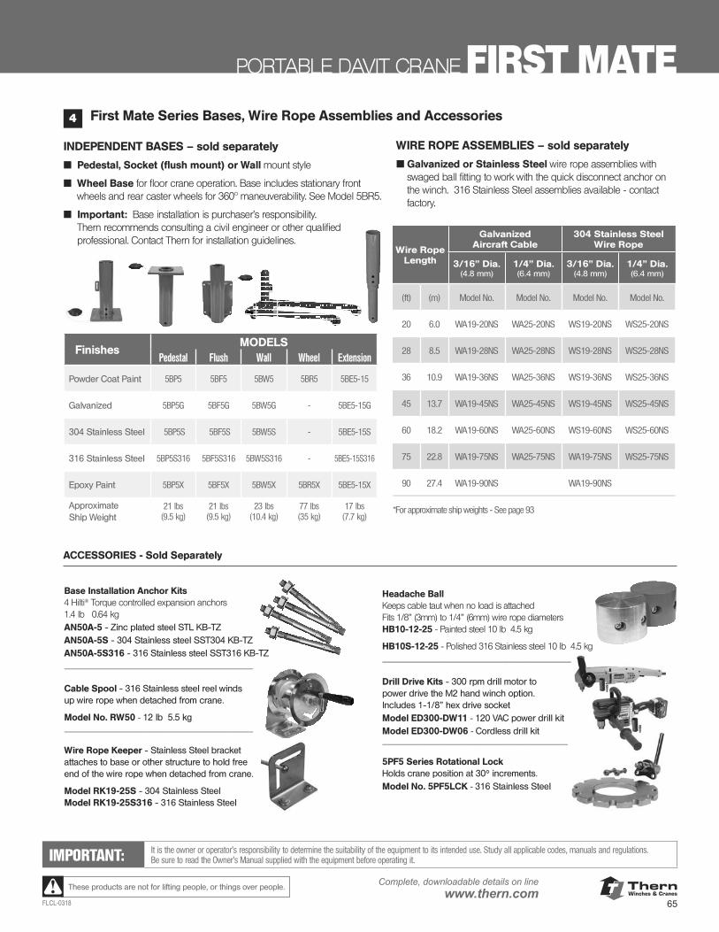
ThernWinches & Cranes
65FLCL-0318
Complete, downloadable details on linewww.thern.comThese products are not for lifting people, or things over people.
PORTABLE DAVIT CRANE FIRST MATE
INDEPENDENT BASES – sold separately
■ Pedestal, Socket (flush mount) or Wall mount style
■ Wheel Base for floor crane operation. Base includes stationary front wheels and rear caster wheels for 360º maneuverability. See Model 5BR5.
■ Important: Base installation is purchaser’s responsibility. Thern recommends consulting a civil engineer or other qualified professional. Contact Thern for installation guidelines.
WIRE ROPE ASSEMBLIES – sold separately
■ Galvanized or Stainless Steel wire rope assemblies with swaged ball fitting to work with the quick disconnect anchor on the winch. 316 Stainless Steel assemblies available - contact factory.
First Mate Series Bases, Wire Rope Assemblies and Accessories4
Base Installation Anchor Kits 4 Hilti® Torque controlled expansion anchors 1.4 lb 0.64 kgAN50A-5 - Zinc plated steel STL KB-TZ AN50A-5S - 304 Stainless steel SST304 KB-TZ AN50A-5S316 - 316 Stainless steel SST316 KB-TZ ____________________________________ Cable Spool - 316 Stainless steel reel winds up wire rope when detached from crane.
Model No. RW50 - 12 lb 5.5 kg ____________________________________ Wire Rope Keeper - Stainless Steel bracket attaches to base or other structure to hold free end of the wire rope when detached from crane.
Model RK19-25S - 304 Stainless Steel Model RK19-25S316 - 316 Stainless Steel
IMPORTANT: It is the owner or operator’s responsibility to determine the suitability of the equipment to its intended use. Study all applicable codes, manuals and regulations. Be sure to read the Owner’s Manual supplied with the equipment before operating it.
FinishesMODELS
Pedestal Flush Wall Wheel Extension
Powder Coat Paint 5BP5 5BF5 5BW5 5BR5 5BE5-15
Galvanized 5BP5G 5BF5G 5BW5G - 5BE5-15G
304 Stainless Steel 5BP5S 5BF5S 5BW5S - 5BE5-15S
316 Stainless Steel 5BP5S316 5BF5S316 5BW5S316 - 5BE5-15S316
Epoxy Paint 5BP5X 5BF5X 5BW5X 5BR5X 5BE5-15X
ApproximateShip Weight
21 lbs (9.5 kg)
21 lbs (9.5 kg)
23 lbs (10.4 kg)
77 lbs (35 kg)
17 lbs (7.7 kg)
Headache Ball Keeps cable taut when no load is attached Fits 1/8” (3mm) to 1/4” (6mm) wire rope diameters HB10-12-25 - Painted steel 10 lb 4.5 kg
HB10S-12-25 - Polished 316 Stainless steel 10 lb 4.5 kg ____________________________________ Drill Drive Kits - 300 rpm drill motor to power drive the M2 hand winch option. Includes 1-1/8” hex drive socket Model ED300-DW11 - 120 VAC power drill kit Model ED300-DW06 - Cordless drill kit ____________________________________ 5PF5 Series Rotational Lock Holds crane position at 30° increments. Model No. 5PF5LCK - 316 Stainless Steel
____________________________________
ACCESSORIES - Sold Separately
Wire RopeLength
Galvanized Aircraft Cable
304 Stainless Steel Wire Rope
3/16” Dia. (4.8 mm)
1/4” Dia.(6.4 mm)
3/16” Dia. (4.8 mm)
1/4” Dia.(6.4 mm)
(ft) (m) Model No. Model No. Model No. Model No.
20 6.0 WA19-20NS WA25-20NS WS19-20NS WS25-20NS
28 8.5 WA19-28NS WA25-28NS WS19-28NS WS25-28NS
36 10.9 WA19-36NS WA25-36NS WS19-36NS WS25-36NS
45 13.7 WA19-45NS WA25-45NS WS19-45NS WS25-45NS
60 18.2 WA19-60NS WA25-60NS WS19-60NS WS25-60NS
75 22.8 WA19-75NS WA25-75NS WA19-75NS WS25-75NS
90 27.4 WA19-90NS WA19-90NS
*For approximate ship weights - See page 93
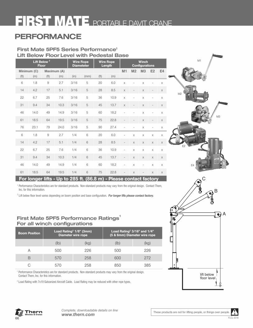
ThernWinches & Cranes
66
Complete, downloadable details on linewww.thern.com
FLCL-0318
These products are not for lifting people, or things over people.
FIRST MATE PORTABLE DAVIT CRANE
M1
First Mate 5PF5 Series Performance1
Lift Below Floor Level with Pedestal BaseLift Below 2
FloorWire Rope Diameteter
Wire Rope Length
Winch Configurations
Minimum (C) Maximum (A) M1 M2 M3 E2 E4(ft) (m) (ft) (m) (in) (mm) (ft) (m)
6 1.8 9 2.7 3/16 5 20 6.0 x - x - x
14 4.2 17 5.1 3/16 5 28 8.5 x - x - x
22 6.7 25 7.6 3/16 5 36 10.9 x - x - x
31 9.4 34 10.3 3/16 5 45 13.7 x - x - x
46 14.0 49 14.9 3/16 5 60 18.2 - - x - x
61 18.5 64 19.5 3/16 5 75 22.8 - - x - x
76 23.1 79 24.0 3/16 5 90 27.4 - - x - x
6 1.8 9 2.7 1/4 6 20 6.0 - x x x x
14 4.2 17 5.1 1/4 6 28 8.5 - x x x x
22 6.7 25 7.6 1/4 6 36 10.9 - x x x x
31 9.4 34 10.3 1/4 6 45 13.7 - x x x x
46 14.0 49 14.9 1/4 6 60 18.2 - x - x x
61 18.5 64 19.5 1/4 6 75 22.8 - x - x x
For longer lifts - Up to 285 ft. (86.8 m) - Please contact factory1 Performance Characteristics are for standard products. Non-standard products may vary from the original design. Contact Thern,
Inc. for this information.2 Lift below floor level varies depending on boom position and base configuration. For longer lifts please contact factory.
E4
M3
E2
M2
First Mate 5PF5 Performance Ratings1
For all winch configurations
Boom Position Load Rating2 1/8" (3mm) Diameter wire rope
Load Rating2 3/16" and 1/4" (5 & 6mm) Diameter wire rope
(lb) (kg) (lb) (kg)
A 500 226 500 226
B 570 258 600 272
C 570 258 850 3851 Performance Characteristics are for standard products. Non-standard products may vary from the original design.
Contact Thern, Inc. for this information.
2 Load Rating with 7x19 Galvanized Aircraft Cable. Load Rating may be reduced with other rope types.
lift belowfloor level
A
B
C
PERFORMANCE
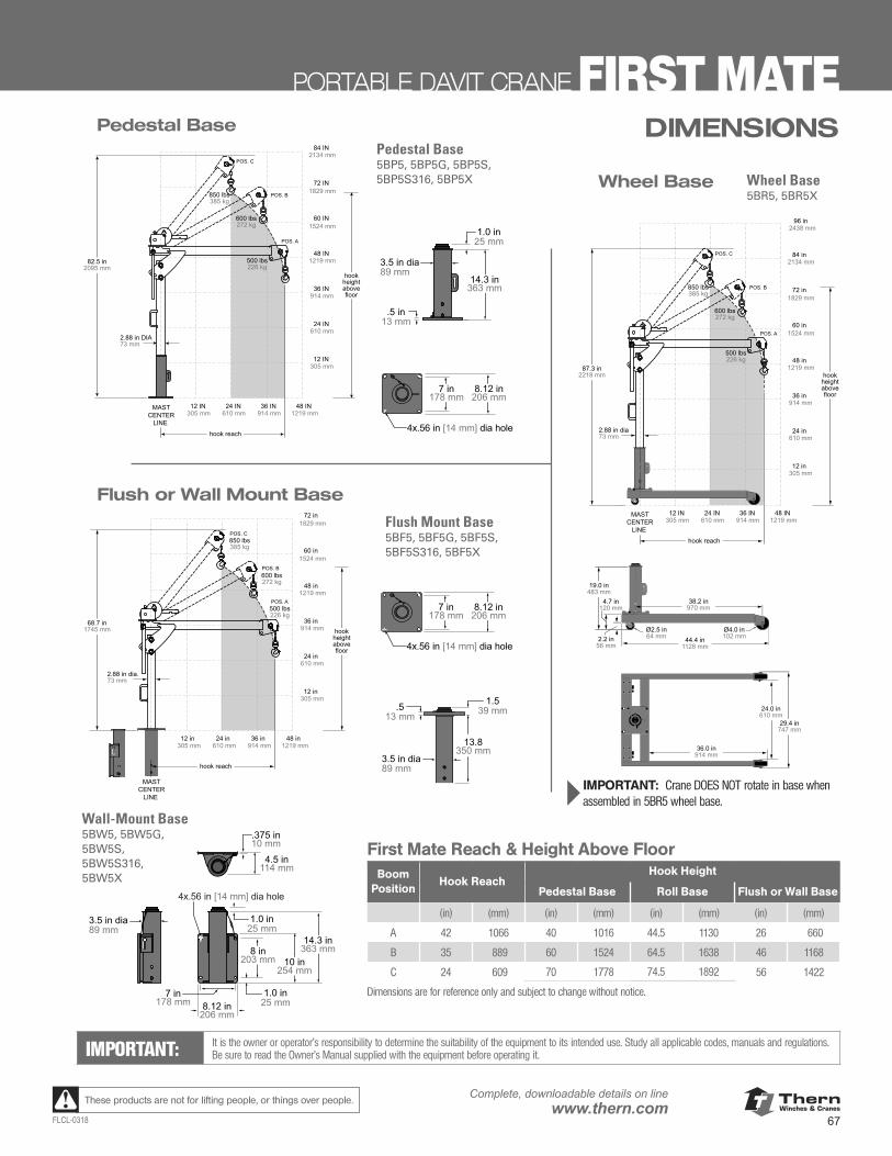
ThernWinches & Cranes
67FLCL-0318
Complete, downloadable details on linewww.thern.comThese products are not for lifting people, or things over people.
PORTABLE DAVIT CRANE FIRST MATE
IMPORTANT: It is the owner or operator’s responsibility to determine the suitability of the equipment to its intended use. Study all applicable codes, manuals and regulations. Be sure to read the Owner’s Manual supplied with the equipment before operating it.
12 IN 305 mm
36 IN 914 mm
24 IN 610 mm
48 IN 1219 mm
48 in 1219 mm
36 in 914 mm
24 in 610 mm
12 in 305 mm
60 in 1524 mm
84 in 2134 mm
72 in 1829 mm
MASTCENTER
LINE
hook reach
hookheightabovefloor
87.3 in2218 mm
2.88 in dia73 mm
500 lbs226 kg
POS. C
POS. B
POS. A
600 lbs272 kg
850 lbs385 kg
96 in 2438 mm
} IMPORTANT: Crane DOES NOT rotate in base when assembled in 5BR5 wheel base.
Ø4.0 in102 mm
Ø2.5 in64 mm2.2 in
56 mm
4.7 in120 mm
36.0 in914 mm
24.0 in610 mm
29.4 in747 mm
44.4 in1128 mm
38.2 in970 mm
19.0 in483 mm
Ø4.0 in102 mm
Ø2.5 in64 mm2.2 in
56 mm
4.7 in120 mm
36.0 in914 mm
24.0 in610 mm
29.4 in747 mm
44.4 in1128 mm
38.2 in970 mm
19.0 in483 mm
Wheel Base
12 IN 305 mm
36 IN 914 mm
24 IN 610 mm
48 IN 1219 mm
48 IN 1219 mm
36 IN 914 mm
24 IN 610 mm
12 IN 305 mm
60 IN 1524 mm
84 IN 2134 mm
72 IN 1829 mm
MASTCENTER
LINE
hook reach
hookheightabovefloor
82.5 in2095 mm
2.88 in DIA73 mm
500 lbs226 kg
POS. C
POS. B
POS. A
600 lbs272 kg
850 lbs385 kg
.5 in13 mm
3.5 in dia89 mm
1.0 in25 mm
8.12 in206 mm
7 in178 mm
4x.56 in [14 mm] dia hole
14.3 in363 mm
Pedestal Base
12 in 305 mm
36 in 914 mm
24 in 610 mm
48 in 1219 mm
48 in 1219 mm
36 in 914 mm
24 in 610 mm
12 in 305 mm
60 in 1524 mm
72 in 1829 mm
MASTCENTER
LINE
hook reach
hookheightabovefloor
68.7 in1745 mm
2.88 in dia.73 mm
500 lbs226 kg
POS. C
POS. B
POS. A
600 lbs272 kg
850 lbs385 kg
3.5 in dia89 mm
1.0 in25 mm
4x.56 in [14 mm] dia hole
14.3 in363 mm
.375 in10 mm
4.5 in114 mm
8.12 in206 mm
7 in178 mm
10 in254 mm
8 in203 mm
1.0 in25 mm
13.8350 mm
.513 mm
3.5 in dia89 mm
1.539 mm
8.12 in206 mm
7 in178 mm
4x.56 in [14 mm] dia hole
First Mate Reach & Height Above FloorBoom
PositionHook Reach
Hook Height
Pedestal Base Roll Base Flush or Wall Base
(in) (mm) (in) (mm) (in) (mm) (in) (mm)
A 42 1066 40 1016 44.5 1130 26 660
B 35 889 60 1524 64.5 1638 46 1168
C 24 609 70 1778 74.5 1892 56 1422
Dimensions are for reference only and subject to change without notice.
Flush or Wall Mount Base
.5 in13 mm
3.5 in dia89 mm
1.0 in25 mm
8.12 in206 mm
7 in178 mm
4x.56 in [14 mm] dia hole
14.3 in363 mm
13.8350 mm
.513 mm
3.5 in dia89 mm
1.539 mm
8.12 in206 mm
7 in178 mm
4x.56 in [14 mm] dia hole
DIMENSIONSPedestal Base5BP5, 5BP5G, 5BP5S, 5BP5S316, 5BP5X
Wall-Mount Base5BW5, 5BW5G, 5BW5S, 5BW5S316, 5BW5X
Flush Mount Base5BF5, 5BF5G, 5BF5S, 5BF5S316, 5BF5X
Wheel Base5BR5, 5BR5X
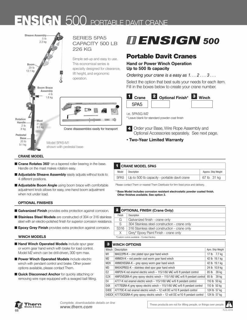
ThernWinches & Cranes
68
Complete, downloadable details on linewww.thern.com
FLCL-0318
These products are not for lifting people, or things over people.
12
4
3
Mast21 lb9.5 kg
Rotation Handle
2 lb.9 kg
Boom29 lb
13.1 kg
500SERIES 5PA5CAPACITY 500 LB 226 KG
Simple set-up and easy to use.This economical series is specially designed for clearance, lift height, and ergonomic operation.
Pedestal Base20 lb
9.1 kg
Boom Brace Assembly
4 lb1.8 kg
Sheave Assembly5 lb
2.3 kg
Portable Davit Cranes Hand or Power Winch Operation Up to 500 lb capacity
Ordering your crane is a easy as 1. . . 2 . . . 3 . . .
Select the option that best suits your needs for each item. Fill in the boxes below to create your crane number.
i.e. 5PA5G-M2 * Leave blank for standard powder coat finish
Order your Base, Wire Rope Assembly and Optional Accessories separately. See next page.
• Two-Year Limited Warranty
4Crane disassembles easily for transport
■ Crane Rotates 360° on a tapered roller bearing in the base. Handle on the mast makes rotation easy.
■ Adjustable Sheave Assembly easily adjusts without tools to 4 different positions.
■ Adjustable Boom Angle using boom brace with comfortable adjustment knob allows for easy, one-hand boom adjustment when not under load.
CRANE MODEL 5PA5
Model Description Approx. Ship Weight
5PA5 Up to 500 lb capacity - portable davit crane 67 lb 31 kg
Please contact Thern or nearest Thern Distributor for firm fixed price and delivery.
1 Base Model includes corrosion resistant electrostatic powder coated finish. Other finishes available. See option 2.
1
CRANE MODEL
■ Hand Winch Operated Models include spur gear or worm gear hand winch with brake for load control. Model M2 winch can be drill-driven, 300 rpm max.
■ Power Winch Operated Models include electric winch with pendant control and brake. Other power options available, please contact Thern.
■ Quick Disconnect Anchor for quickly attaching or removing wire rope equipped with a swaged ball fitting.
WINCH MODELS
OPTIONAL FINISHES
Model 5PA5-M1shown with pedestal base
ENSIGN 500 PORTABLE DAVIT CRANE
1
5PA5
Crane 3 Winch2 Optional Finish*
■ Galvanized Finish provides extra protection against corrosion.
■ Stainless Steel Models are constructed of 304 or 316 stainless steel with an electro-polished finish for superior corrosion resistance.
■ Epoxy Grey Finish provides extra protection against corrosion.
OPTIONAL FINISH (Crane Only)Finish Description
G Galvanized finish - crane onlyS 304 Stainless steel construction - crane only
S316 316 Stainless steel construction - crane onlyX Grey* Epoxy Paint Finish - crane only
*Custom colors available - Contact factory
2
WINCH OPTIONSWinch Description Aprx. Ship Weight
M1 M4022PB-K – zinc plated spur gear hand winch 17 lb 7.7 kg
M2 4WM2V-K – red powder coat worm gear hand winch 42 lb 19.1 kgM2X 4WM2VEGRA-K – grey epoxy worm gear hand winch 42 lb 19.1 kg
M3 M4042PBSS-K – stainless steel spur gear hand winch 24 lb 10.9 kgE2 4WP2V-K red enamel electric winch – 115/1/60 VAC w/6 ft pendant control 85 lb 39 kg
E2X 4WP2VEGRA-K grey epoxy electric winch – 115/1/60 VAC w/6 ft pendant control 85 lb 39 kgE4 4777-K red enamel electric winch – 115/1/60 VAC w/6 ft pendant control 110 lb 50 kg
E4X 4777EGRA-K grey epoxy electric winch – 115/1/60 VAC w/6 ft pendant control 110 lb 50 kgE4DC 4777DC-K red enamel electric winch – 12 volt DC w/10 ft pendant control 124 lb 57 kg
E4DCX 4777DCEGRA-K grey epoxy electric winch – 12 volt DC w/10 ft pendant control 124 lb 57 kg
3
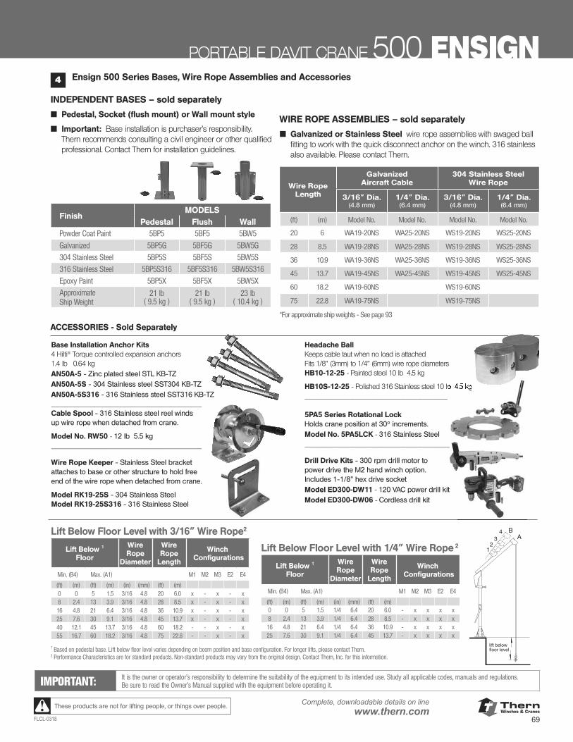
ThernWinches & Cranes
69FLCL-0318
Complete, downloadable details on linewww.thern.comThese products are not for lifting people, or things over people.
PORTABLE DAVIT CRANE 500 ENSIGN
FinishMODELS
Pedestal Flush WallPowder Coat Paint 5BP5 5BF5 5BW5
Galvanized 5BP5G 5BF5G 5BW5G
304 Stainless Steel 5BP5S 5BF5S 5BW5S
316 Stainless Steel 5BP5S316 5BF5S316 5BW5S316
Epoxy Paint 5BP5X 5BF5X 5BW5XApproximateShip Weight
21 lb ( 9.5 kg )
21 lb ( 9.5 kg )
23 lb ( 10.4 kg )
INDEPENDENT BASES – sold separately
■ Pedestal, Socket (flush mount) or Wall mount style
■ Important: Base installation is purchaser’s responsibility. Thern recommends consulting a civil engineer or other qualified professional. Contact Thern for installation guidelines.
WIRE ROPE ASSEMBLIES – sold separately
■ Galvanized or Stainless Steel wire rope assemblies with swaged ball fitting to work with the quick disconnect anchor on the winch. 316 stainless also available. Please contact Thern.
Wire RopeLength
Galvanized Aircraft Cable
304 Stainless Steel Wire Rope
3/16” Dia. (4.8 mm)
1/4” Dia.(6.4 mm)
3/16” Dia. (4.8 mm)
1/4” Dia.(6.4 mm)
(ft) (m) Model No. Model No. Model No. Model No.
20 6 WA19-20NS WA25-20NS WS19-20NS WS25-20NS
28 8.5 WA19-28NS WA25-28NS WS19-28NS WS25-28NS
36 10.9 WA19-36NS WA25-36NS WS19-36NS WS25-36NS
45 13.7 WA19-45NS WA25-45NS WS19-45NS WS25-45NS
60 18.2 WA19-60NS WS19-60NS
75 22.8 WA19-75NS WS19-75NS
*For approximate ship weights - See page 93
12
34 B
A
lift belowfloor level
IMPORTANT: It is the owner or operator’s responsibility to determine the suitability of the equipment to its intended use. Study all applicable codes, manuals and regulations. Be sure to read the Owner’s Manual supplied with the equipment before operating it.
Lift Below Floor Level with 3/16” Wire Rope2
Lift Below 1 Floor
Wire Rope
Diameter
Wire Rope
Length
Winch Configurations
Min. (B4) Max. (A1) M1 M2 M3 E2 E4
(ft) (m) (ft) (m) (in) (mm) (ft) (m)0 0 5 1.5 3/16 4.8 20 6.0 x - x - x8 2.4 13 3.9 3/16 4.8 28 8.5 x - x - x16 4.8 21 6.4 3/16 4.8 36 10.9 x - x - x25 7.6 30 9.1 3/16 4.8 45 13.7 x - x - x40 12.1 45 13.7 3/16 4.8 60 18.2 - - x - x55 16.7 60 18.2 3/16 4.8 75 22.8 - - x - x
Lift Below Floor Level with 1/4” Wire Rope 2
Lift Below 1 Floor
Wire Rope
Diameter
Wire Rope
Length
Winch Configurations
Min. (B4) Max. (A1) M1 M2 M3 E2 E4
(ft) (m) (ft) (m) (in) (mm) (ft) (m)0 0 5 1.5 1/4 6.4 20 6.0 - x x x x8 2.4 13 3.9 1/4 6.4 28 8.5 - x x x x16 4.8 21 6.4 1/4 6.4 36 10.9 - x x x x25 7.6 30 9.1 1/4 6.4 45 13.7 - x x x x
1 Based on pedestal base. Lift below floor level varies depending on boom position and base configuration. For longer lifts, please contact Thern.2 Performance Characteristics are for standard products. Non-standard products may vary from the original design. Contact Thern, Inc. for this information.
Ensign 500 Series Bases, Wire Rope Assemblies and Accessories4
Base Installation Anchor Kits 4 Hilti® Torque controlled expansion anchors 1.4 lb 0.64 kgAN50A-5 - Zinc plated steel STL KB-TZ AN50A-5S - 304 Stainless steel SST304 KB-TZ AN50A-5S316 - 316 Stainless steel SST316 KB-TZ ____________________________________ Cable Spool - 316 Stainless steel reel winds up wire rope when detached from crane.
Model No. RW50 - 12 lb 5.5 kg ____________________________________
Wire Rope Keeper - Stainless Steel bracket attaches to base or other structure to hold free end of the wire rope when detached from crane.
Model RK19-25S - 304 Stainless Steel Model RK19-25S316 - 316 Stainless Steel
Headache Ball Keeps cable taut when no load is attached Fits 1/8” (3mm) to 1/4” (6mm) wire rope diameters HB10-12-25 - Painted steel 10 lb 4.5 kg
HB10S-12-25 - Polished 316 Stainless steel 10 lb 4.5 kg ____________________________________ 5PA5 Series Rotational Lock Holds crane position at 30° increments. Model No. 5PA5LCK - 316 Stainless Steel ____________________________________
Drill Drive Kits - 300 rpm drill motor to power drive the M2 hand winch option. Includes 1-1/8” hex drive socket Model ED300-DW11 - 120 VAC power drill kit Model ED300-DW06 - Cordless drill kit
____________________________________
- Polished 316 Stainless steel 10 lb 4.5 kg____________________________________
ACCESSORIES - Sold Separately
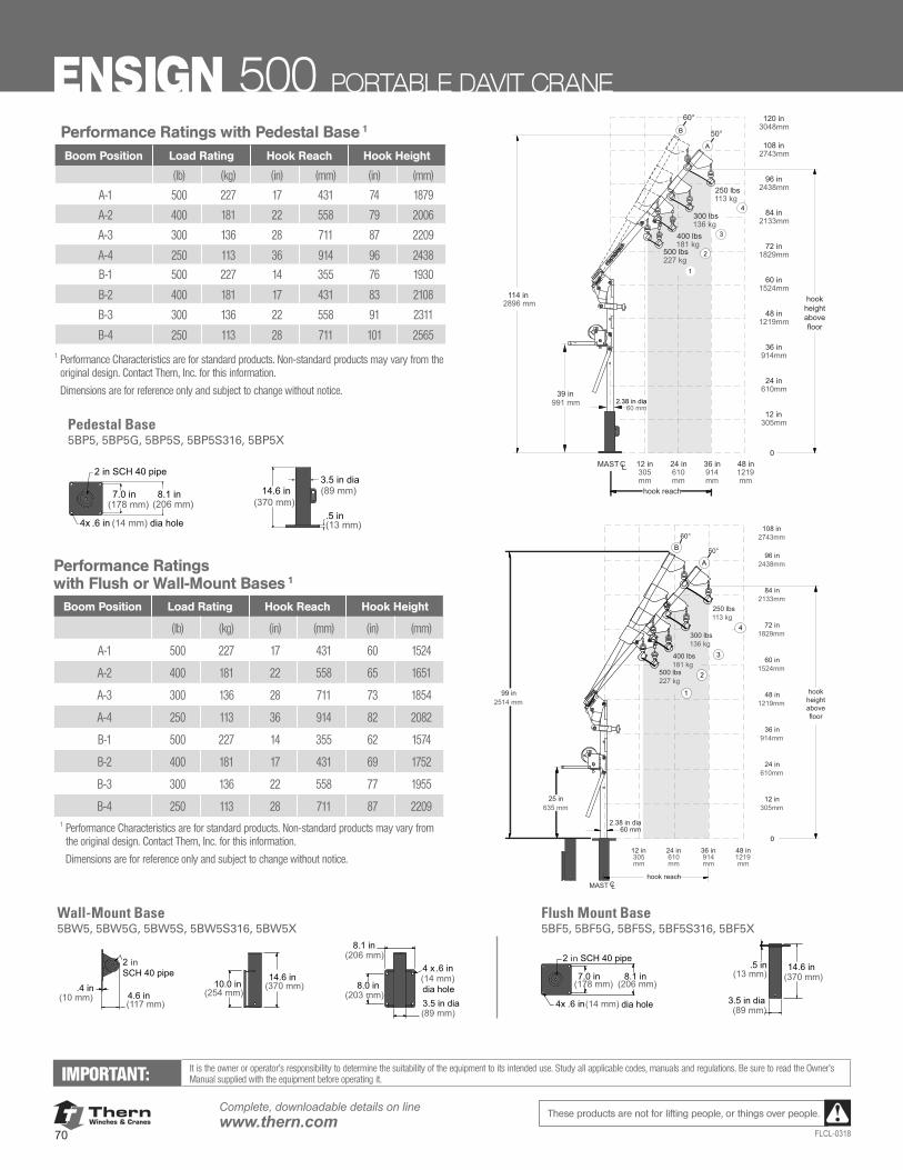
ThernWinches & Cranes
70
Complete, downloadable details on linewww.thern.com
FLCL-0318
These products are not for lifting people, or things over people.
12 in305mm
24 in610mm
36 in914mm
48 in1219mm
12 in
0
305mm
24 in610mm
36 in914mm
48 in1219mm
60 in1524mm
114 in2896 mm
72 in1829mm
84 in2133mm
96 in2438mm
108 in2743mm
120 in3048mm
MAST CL
500 lbs227 kg
400 lbs181 kg
300 lbs136 kg
250 lbs113 kg
60°
50°
hook reach
hookheightabovefloor
39 in991 mm 2.38 in dia
60 mm
A
B
1
2
3
4
12 in305mm
24 in610mm
36 in914mm
48 in1219mm
12 in
0
305mm
24 in610mm
36 in914mm
48 in1219mm
60 in1524mm
72 in1829mm
84 in2133mm
96 in2438mm
108 in2743mm
500 lbs227 kg
400 lbs181 kg
300 lbs136 kg
250 lbs113 kg
60°
A
B
1
2
3
4
MAST CL
50°
2.38 in dia60 mm
hookheightabovefloor
25 in635 mm
99 in2514 mm
hook reach
Performance Ratings with Flush or Wall-Mount Bases 1
Boom Position Load Rating Hook Reach Hook Height
(lb) (kg) (in) (mm) (in) (mm)
A-1 500 227 17 431 60 1524
A-2 400 181 22 558 65 1651
A-3 300 136 28 711 73 1854
A-4 250 113 36 914 82 2082
B-1 500 227 14 355 62 1574
B-2 400 181 17 431 69 1752
B-3 300 136 22 558 77 1955
B-4 250 113 28 711 87 22091 Performance Characteristics are for standard products. Non-standard products may vary from
the original design. Contact Thern, Inc. for this information. Dimensions are for reference only and subject to change without notice.
Wall-Mount Base5BW5, 5BW5G, 5BW5S, 5BW5S316, 5BW5X
Flush Mount Base5BF5, 5BF5G, 5BF5S, 5BF5S316, 5BF5X
7.0 in(178 mm)
8.1 in(206 mm)
2 in SCH 40 pipe 2 in SCH 40 pipe
14.6 in(370 mm)
.5 in(13 mm)
3.5 in dia(89 mm)
14.6 in(370 mm)10.0 in
(254 mm)
.4 in(10 mm) 4.6 in
(117 mm)
8.0 in(203 mm)
3.5 in dia(89 mm)
8.1 in(206 mm)
4 x .6 in(14 mm)dia hole
4x .6 in(14 mm) dia hole
7.0 in(178 mm)
8.1 in(206 mm)
2 in SCH 40 pipe 2 in SCH 40 pipe
14.6 in(370 mm)
.5 in(13 mm)
3.5 in dia(89 mm)
14.6 in(370 mm)10.0 in
(254 mm)
.4 in(10 mm) 4.6 in
(117 mm)
8.0 in(203 mm)
3.5 in dia(89 mm)
8.1 in(206 mm)
4 x .6 in(14 mm)dia hole
4x .6 in(14 mm) dia hole7.0 in
(178 mm)8.1 in
(206 mm)
2 in SCH 40 pipe 2 in SCH 40 pipe
14.6 in(370 mm)
.5 in(13 mm)
3.5 in dia(89 mm)
14.6 in(370 mm)10.0 in
(254 mm)
.4 in(10 mm) 4.6 in
(117 mm)
8.0 in(203 mm)
3.5 in dia(89 mm)
8.1 in(206 mm)
4 x .6 in(14 mm)dia hole
4x .6 in(14 mm) dia hole
7.0 in(178 mm)
8.1 in(206 mm)
2 in SCH 40 pipe 2 in SCH 40 pipe
14.6 in(370 mm)
.5 in(13 mm)
3.5 in dia(89 mm)
14.6 in(370 mm)10.0 in
(254 mm)
.4 in(10 mm) 4.6 in
(117 mm)
8.0 in(203 mm)
3.5 in dia(89 mm)
8.1 in(206 mm)
4 x .6 in(14 mm)dia hole
4x .6 in(14 mm) dia hole
7.0 in(178 mm)
8.1 in(206 mm)
2 in SCH 40 pipe 2 in SCH 40 pipe
14.6 in(370 mm)
.5 in(13 mm)
3.5 in dia(89 mm)
14.6 in(370 mm)10.0 in
(254 mm)
.4 in(10 mm) 4.6 in
(117 mm)
8.0 in(203 mm)
3.5 in dia(89 mm)
8.1 in(206 mm)
4 x .6 in(14 mm)dia hole
4x .6 in(14 mm) dia hole
Performance Ratings with Pedestal Base 1
Boom Position Load Rating Hook Reach Hook Height
(lb) (kg) (in) (mm) (in) (mm)
A-1 500 227 17 431 74 1879
A-2 400 181 22 558 79 2006
A-3 300 136 28 711 87 2209
A-4 250 113 36 914 96 2438
B-1 500 227 14 355 76 1930
B-2 400 181 17 431 83 2108
B-3 300 136 22 558 91 2311
B-4 250 113 28 711 101 25651 Performance Characteristics are for standard products. Non-standard products may vary from the
original design. Contact Thern, Inc. for this information. Dimensions are for reference only and subject to change without notice.
7.0 in(178 mm)
8.1 in(206 mm)
3.5 in dia(89 mm)
.5 in(13 mm)
14.6 in(370 mm)
4x dia hole.6 in (14 mm)
2 in SCH 40 pipe
7.0 in(178 mm)
8.1 in(206 mm)
3.5 in dia(89 mm)
.5 in(13 mm)
14.6 in(370 mm)
4x dia hole.6 in (14 mm)
2 in SCH 40 pipe
Pedestal Base5BP5, 5BP5G, 5BP5S, 5BP5S316, 5BP5X
ENSIGN 500 PORTABLE DAVIT CRANE
IMPORTANT: It is the owner or operator’s responsibility to determine the suitability of the equipment to its intended use. Study all applicable codes, manuals and regulations. Be sure to read the Owner’s Manual supplied with the equipment before operating it.
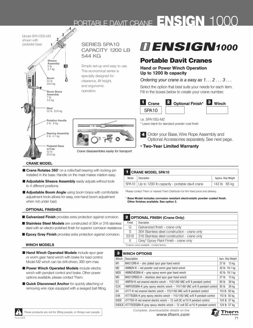
ThernWinches & Cranes
71FLCL-0318
Complete, downloadable details on linewww.thern.comThese products are not for lifting people, or things over people.
PORTABLE DAVIT CRANE ENSIGN 10001
4
23
1000
Mast52 lb 23.6 kg
Rotation Handle2 lb .9 kg
Boom53 lb 24.0 kg
Pedestal Base w/Cap52 lb23.6 kg
Boom Brace Assembly7 lb3.2 kg
Sheave Assembly6 lb2.7 kg
Bearing Assembly9 lb 4.1 kg
Model 5PA10SS-M3shown with pedestal base
Portable Davit Cranes Hand or Power Winch Operation Up to 1200 lb capacity
Ordering your crane is a easy as 1. . . 2 . . . 3 . . .
Select the option that best suits your needs for each item. Fill in the boxes below to create your crane number.
i.e. 5PA10G-M2 * Leave blank for standard powder coat finish
Order your Base, Wire Rope Assembly and Optional Accessories separately. See next page.
• Two-Year Limited Warranty
4
SERIES 5PA10CAPACITY 1200 LB 544 KG
Simple set-up and easy to use.This economical series is specially designed for clearance, lift height, and ergonomic operation.
Crane disassembles easily for transport
■ Crane Rotates 360° on a roller/ball bearing with locking pin installed in the base. Handle on the mast makes rotation easy.
■ Adjustable Sheave Assembly easily adjusts without tools to 4 different positions.
■ Adjustable Boom Angle using boom brace with comfortable adjustment knob allows for easy, one-hand boom adjustment when not under load.
CRANE MODEL 5PA10
Model Description Approx. Ship Weight
5PA10 Up to 1200 lb capacity - portable davit crane 143 lb 65 kg
Please contact Thern or nearest Thern Distributor for firm fixed price and delivery.
1 Base Model includes corrosion resistant electrostatic powder coated finish. Other finishes available. See option 2.
1
CRANE MODEL
■ Hand Winch Operated Models include spur gear or worm gear hand winch with brake for load control. Model M2 winch can be drill-driven, 300 rpm max.
■ Power Winch Operated Models include electric winch with pendant control and brake. Other power options available, please contact Thern.
■ Quick Disconnect Anchor for quickly attaching or removing wire rope equipped with a swaged ball fitting.
WINCH MODELS
OPTIONAL FINISHES
1
5PA10
Crane 3 Winch2 Optional Finish*
■ Galvanized Finish provides extra protection against corrosion.
■ Stainless Steel Models are constructed of 304 or 316 stainless steel with an electro-polished finish for superior corrosion resistance.
■ Epoxy Grey Finish provides extra protection against corrosion.
OPTIONAL FINISH (Crane Only)Finish Description
G Galvanized finish - crane onlyS 304 Stainless steel construction - crane only
S316 316 Stainless steel construction - crane onlyX Grey* Epoxy Paint Finish - crane only
*Custom colors available - Contact factory
2
WINCH OPTIONSWinch Description Aprx. Ship Weight
M1 M4312PB-K – zinc plated spur gear hand winch 27 lb 13 kgM2 4WM2V-K – red powder coat worm gear hand winch 42 lb 19.1 kg
M2X 4WM2VEGRA-K – grey epoxy worm gear hand winch 42 lb 19.1 kg
M3 M4312PBSS-K – stainless steel spur gear hand winch 27 lb 13 kgE2 4WP2V-K red enamel electric winch – 115/1/60 VAC w/6 ft pendant control 85 lb 39 kgE2X 4WP2VEGRA-K grey epoxy electric winch – 115/1/60 VAC w/6 ft pendant control 85 lb 39 kg
E4 4777-K red enamel electric winch – 115/1/60 VAC w/6 ft pendant control 110 lb 50 kg
E4X 4777EGRA-K grey epoxy electric winch – 115/1/60 VAC w/6 ft pendant control 110 lb 50 kgE4DC 4777DC-K red enamel electric winch – 12 volt DC w/10 ft pendant control 124 lb 57 kgE4DCX 4777DCEGRA-K grey epoxy electric winch – 12 volt DC w/10 ft pendant control 124 lb 57 kg
3
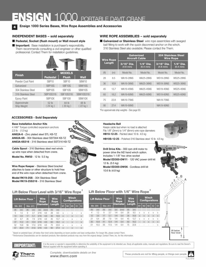
ThernWinches & Cranes
72
Complete, downloadable details on linewww.thern.com
FLCL-0318
These products are not for lifting people, or things over people.
INDEPENDENT BASES – sold separately■ Pedestal, Socket (flush mount) or Wall mount style
■ Important: Base installation is purchaser’s responsibility. Thern recommends consulting a civil engineer or other qualified professional. Contact Thern for installation guidelines.
WIRE ROPE ASSEMBLIES – sold separately■ Galvanized or Stainless Steel wire rope assemblies with swaged
ball fitting to work with the quick disconnect anchor on the winch. 316 Stainless Steel also available. Please contact the Thern.
12
34 B
A
lift belowfloor level
IMPORTANT: It is the owner or operator’s responsibility to determine the suitability of the equipment to its intended use. Study all applicable codes, manuals and regulations. Be sure to read the Owner’s Manual supplied with the equipment before operating it.
Lift Below Floor Level with 3/16” Wire Rope 2
Lift Below Floor 1 Wire Rope
Diameter
Wire Rope
Length
Winch Configurations
Min. (B4) Max. (A1) M1 M2 M3 E2 E4
(ft) (m) (ft) (m) (in) (mm) (ft) (m)5 1.5 9 2.7 3/16 4.8 28 8.5 x - x - x13 3.9 17 5.1 3/16 4.8 36 10.9 x - x - x22 6.7 26 7.9 3/16 4.8 45 13.7 x - x - x37 11.2 41 12.4 3/16 4.8 60 18.2 x - x - x52 15.8 56 17.0 3/16 4.8 75 22.8 x - x - x67 20.4 71 21.6 3/16 4.8 90 27.4 x - x - x
Lift Below Floor with 1/4” Wire Rope 2
Lift Below Floor 1 Wire Rope
Diameter
Wire Rope
Length
Winch Configurations
Min. (B4) Max. (A1) M1 M2 M3 E2 E4
(ft) (m) (ft) (m) (in) (mm) (ft) (m)4 1.2 9 2.7 1/4 6.4 28 8.5 x x x x x12 3.6 17 5.1 1/4 6.4 36 10.9 x x x x x21 6.4 26 7.9 1/4 6.4 45 13.7 x x x x x36 10.9 41 12.4 1/4 6.4 60 18.2 - x x x x51 15.5 56 17.0 1/4 6.4 75 22.8 - - - - x
1 Based on pedestal base. Lift below floor level varies depending on boom position and base configuration. For longer lifts, please contact Thern.2 Performance Characteristics are for standard products. Non-standard products may vary from the original design. Contact Thern, Inc. for this information.
Wire RopeLength
Galvanized Aircraft Cable
304 Stainless Steel Wire Rope
3/16” Dia. (4.8 mm)
1/4” Dia.(6.4 mm)
3/16” Dia. (4.8 mm)
1/4” Dia.(6.4 mm)
(ft) (m) Model No. Model No. Model No. Model No.
28 8.5 WA19-28NS WA25-28NS WS19-28NS WS25-28NS
36 10.9 WA19-36NS WA25-36NS WS19-36NS WS25-36NS
45 13.7 WA19-45NS WA25-45NS WS19-45NS WS25-45NS
60 18.2 WA19-60NS WA25-60NS WS19-60NS WS25-60NS
75 22.8 WA19-75NS WA19-75NS
90 27.4 WA19-90NS WA19-90NS
*For approximate ship weights - See page 93
Ensign 1000 Series Bases, Wire Rope Assemblies and Accessories4
ENSIGN 1000 PORTABLE DAVIT CRANE
FinishMODELS
Pedestal Flush WallPowder Coat Paint 5BP10 5BF10 5BW10
Galvanized 5BP10G 5BF10G 5BW10G
304 Stainless Steel 5BP10S 5BF10S 5BW10S
316 Stainless Steel 5BP10S316 5BF10S316 5BW10S316
Epoxy Paint 5BP10X 5BF10X 5BW10XApproximateShip Weight
52 lb ( 24 kg )
44 lb ( 20 kg )
48 lb ( 22 kg )
Base Installation Anchor Kits 4 Hilti® Torque controlled expansion anchors 2.3 lb (1.0 kg)AN62A-6 - Zinc plated steel STL KB-TZ AN62A-6S - 304 Stainless steel SST304 KB-TZ AN63A-6S316 - 316 Stainless steel SST316 KB-TZ ____________________________________ Cable Spool - 316 Stainless steel reel winds up wire rope when detached from crane.
Model No. RW50 - 12 lb 5.5 kg ____________________________________
Wire Rope Keeper - Stainless Steel bracket attaches to base or other structure to hold free end of the wire rope when detached from crane.
Model RK19-25S - 304 Stainless Steel Model RK19-25S316 - 316 Stainless Steel
Headache Ball Keeps cable taut when no load is attached Fits 1/8” (3mm) to 1/4” (6mm) wire rope diameters HB10-12-25 - Painted steel 10 lb 4.5 kg
HB10S-12-25 - Polished 316 Stainless steel 10 lb 4.5 kg ____________________________________ Drill Drive Kits - 300 rpm drill motor to power drive the M2 hand winch option. Includes 1-1/8” hex drive socket Model ED300-DW11 - 120 VAC power drill kit 12 lb. (5.5 kg) Model ED300-DW06 - Cordless drill kit 10.6 lb (4.8 kg)
____________________________________
4 B
ACCESSORIES - Sold Separately
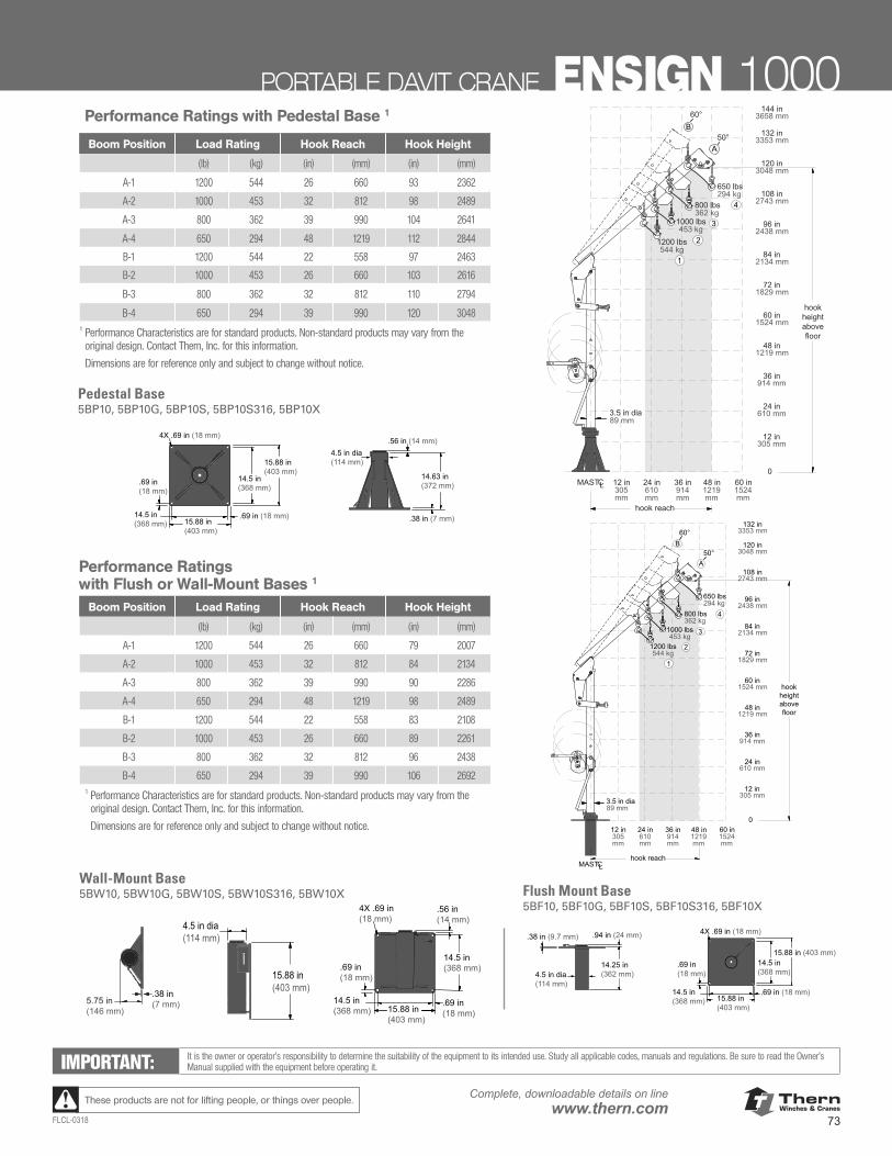
ThernWinches & Cranes
73FLCL-0318
Complete, downloadable details on linewww.thern.comThese products are not for lifting people, or things over people.
Pedestal Base5BP10, 5BP10G, 5BP10S, 5BP10S316, 5BP10X
Performance Ratings with Flush or Wall-Mount Bases 1
Boom Position Load Rating Hook Reach Hook Height
(lb) (kg) (in) (mm) (in) (mm)
A-1 1200 544 26 660 79 2007
A-2 1000 453 32 812 84 2134
A-3 800 362 39 990 90 2286
A-4 650 294 48 1219 98 2489
B-1 1200 544 22 558 83 2108
B-2 1000 453 26 660 89 2261
B-3 800 362 32 812 96 2438
B-4 650 294 39 990 106 26921 Performance Characteristics are for standard products. Non-standard products may vary from the
original design. Contact Thern, Inc. for this information. Dimensions are for reference only and subject to change without notice.
Performance Ratings with Pedestal Base 1
Boom Position Load Rating Hook Reach Hook Height
(lb) (kg) (in) (mm) (in) (mm)
A-1 1200 544 26 660 93 2362
A-2 1000 453 32 812 98 2489
A-3 800 362 39 990 104 2641
A-4 650 294 48 1219 112 2844
B-1 1200 544 22 558 97 2463
B-2 1000 453 26 660 103 2616
B-3 800 362 32 812 110 2794
B-4 650 294 39 990 120 30481 Performance Characteristics are for standard products. Non-standard products may vary from the
original design. Contact Thern, Inc. for this information. Dimensions are for reference only and subject to change without notice.
12 in305 mm
0
24 in610 mm
36 in914 mm
48 in1219 mm
72 in1829 mm
84 in2134 mm
96 in2438 mm
108 in2743 mm
144 in3658 mm
60 in1524 mm
120 in3048 mm
132 in3353 mm
48 in1219mm
36 in914mm
24 in610mm
12 in305mm
60 in1524mm
MAST CL
hookheightabovefloor
hook reach
650 lbs294 kg
800 lbs362 kg
1000 lbs453 kg
1200 lbs544 kg
1
2
3
4
3.5 in dia89 mm
60°
50°A
B
14.5 in (368 mm)
.69 in (18 mm)15.88 in (403 mm)
4X .69 in (18 mm)
15.88 in (403 mm)
14.5 in (368 mm)
.69 in (18 mm)
4.5 in dia (114 mm)
.56 in (14 mm)
.38 in (7 mm)
14.63 in (372 mm)
14.5 in (368 mm)
.69 in (18 mm)15.88 in (403 mm)
4X .69 in (18 mm)
15.88 in (403 mm)
14.5 in (368 mm)
.69 in (18 mm)
4.5 in dia (114 mm)
.56 in (14 mm)
.38 in (7 mm)
14.63 in (372 mm)
12 in305 mm
0
24 in610 mm
36 in914 mm
48 in1219 mm
72 in1829 mm
84 in2134 mm
96 in2438 mm
108 in2743 mm
60 in1524 mm
120 in3048 mm
132 in3353 mm
48 in1219mm
36 in914mm
24 in610mm
12 in305mm
60 in1524mm
MAST CL
hookheightabovefloor
hook reach
650 lbs294 kg
800 lbs362 kg
1000 lbs453 kg
1200 lbs544 kg
1
2
3
4
60°
50°A
B
3.5 in dia89 mm
Wall-Mount Base5BW10, 5BW10G, 5BW10S, 5BW10S316, 5BW10X Flush Mount Base
5BF10, 5BF10G, 5BF10S, 5BF10S316, 5BF10X
4.5 in dia (114 mm)
14.25 in (362 mm)
.38 in (9.7 mm) .94 in (24 mm)
14.5 in (368 mm) 15.88 in
(403 mm)
4X .69 in (18 mm)
.69 in (18 mm)
15.88 in (403 mm).69 in (18 mm)
14.5 in (368 mm)4.5 in dia
(114 mm)
14.25 in (362 mm)
.38 in (9.7 mm) .94 in (24 mm)
14.5 in (368 mm) 15.88 in
(403 mm)
4X .69 in (18 mm)
.69 in (18 mm)
15.88 in (403 mm).69 in (18 mm)
14.5 in (368 mm)
14.5 in (368 mm)
.69 in (18 mm)15.88 in
(403 mm)
14.5 in (368 mm)
15.88 in (403 mm)
.56 in (14 mm)
4.5 in dia (114 mm)
4X .69 in (18 mm)
5.75 in (146 mm)
.38 in (7 mm)
.69 in (18 mm)
14.5 in (368 mm)
.69 in (18 mm)15.88 in
(403 mm)
14.5 in (368 mm)
15.88 in (403 mm)
.56 in (14 mm)
4.5 in dia (114 mm)
4X .69 in (18 mm)
5.75 in (146 mm)
.38 in (7 mm)
.69 in (18 mm)
14.5 in (368 mm)
.69 in (18 mm)15.88 in
(403 mm)
14.5 in (368 mm)
15.88 in (403 mm)
.56 in (14 mm)
4.5 in dia (114 mm)
4X .69 in (18 mm)
5.75 in (146 mm)
.38 in (7 mm)
.69 in (18 mm)
IMPORTANT: It is the owner or operator’s responsibility to determine the suitability of the equipment to its intended use. Study all applicable codes, manuals and regulations. Be sure to read the Owner’s Manual supplied with the equipment before operating it.
PORTABLE DAVIT CRANE ENSIGN 1000
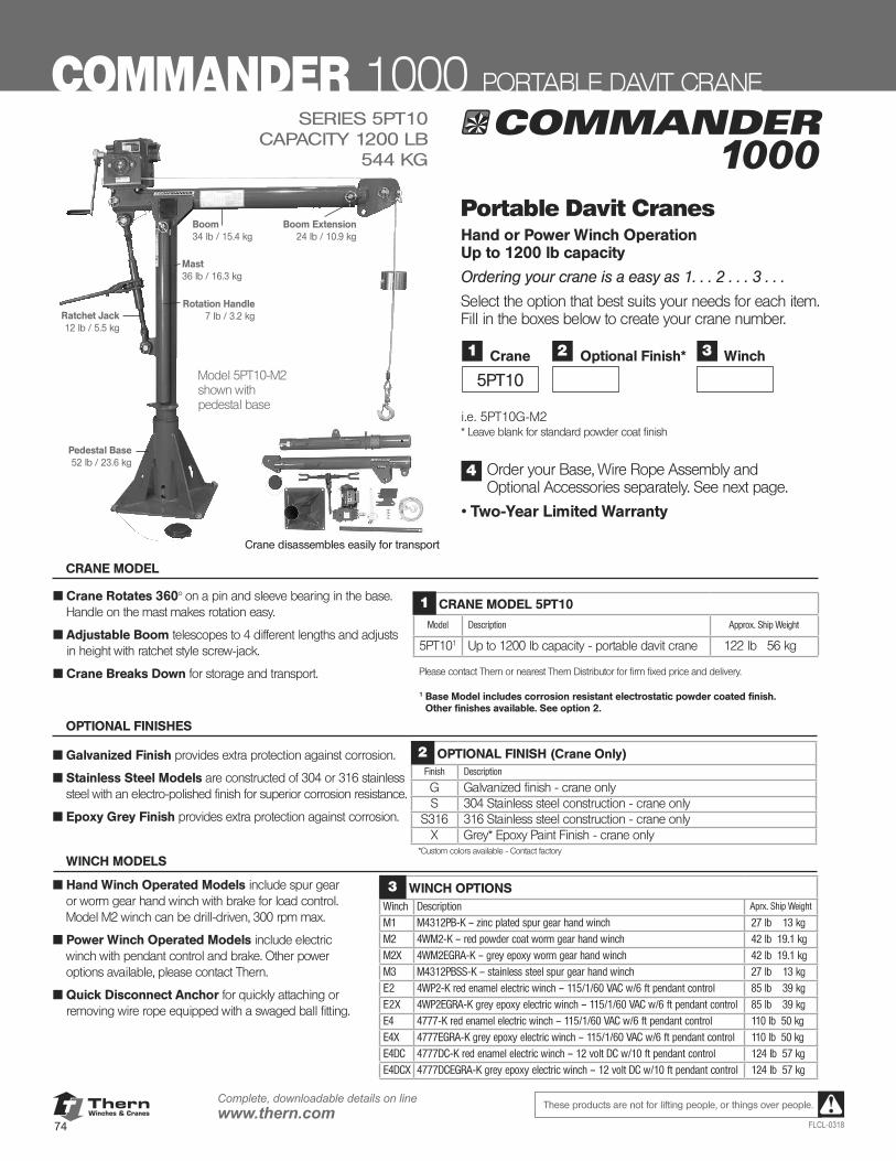
ThernWinches & Cranes
74
Complete, downloadable details on linewww.thern.com
FLCL-0318
These products are not for lifting people, or things over people.
1000SERIES 5PT10
CAPACITY 1200 LB 544 KG
Crane disassembles easily for transport
Mast36 lb / 16.3 kg
Ratchet Jack12 lb / 5.5 kg
Rotation Handle7 lb / 3.2 kg
Pedestal Base52 lb / 23.6 kg
Boom34 lb / 15.4 kg
Boom Extension24 lb / 10.9 kg
Model 5PT10-M2shown with pedestal base
■ Crane Rotates 360° on a pin and sleeve bearing in the base. Handle on the mast makes rotation easy.
■ Adjustable Boom telescopes to 4 different lengths and adjusts in height with ratchet style screw-jack.
■ Crane Breaks Down for storage and transport.
CRANE MODEL 5PT10
Model Description Approx. Ship Weight
5PT101 Up to 1200 lb capacity - portable davit crane 122 lb 56 kg
Please contact Thern or nearest Thern Distributor for firm fixed price and delivery.
1 Base Model includes corrosion resistant electrostatic powder coated finish. Other finishes available. See option 2.
1
CRANE MODEL
WINCH MODELS
OPTIONAL FINISHES
Portable Davit Cranes Hand or Power Winch Operation Up to 1200 lb capacity
Ordering your crane is a easy as 1. . . 2 . . . 3 . . .
Select the option that best suits your needs for each item. Fill in the boxes below to create your crane number.
i.e. 5PT10G-M2 * Leave blank for standard powder coat finish
Order your Base, Wire Rope Assembly and Optional Accessories separately. See next page.
• Two-Year Limited Warranty
4
COMMANDER 1000 PORTABLE DAVIT CRANE
■ Galvanized Finish provides extra protection against corrosion.
■ Stainless Steel Models are constructed of 304 or 316 stainless steel with an electro-polished finish for superior corrosion resistance.
■ Epoxy Grey Finish provides extra protection against corrosion.
1
5PT10
Crane 3 Winch2 Optional Finish*
OPTIONAL FINISH (Crane Only)Finish Description
G Galvanized finish - crane onlyS 304 Stainless steel construction - crane only
S316 316 Stainless steel construction - crane onlyX Grey* Epoxy Paint Finish - crane only
*Custom colors available - Contact factory
2
■ Hand Winch Operated Models include spur gear or worm gear hand winch with brake for load control. Model M2 winch can be drill-driven, 300 rpm max.
■ Power Winch Operated Models include electric winch with pendant control and brake. Other power options available, please contact Thern.
■ Quick Disconnect Anchor for quickly attaching or removing wire rope equipped with a swaged ball fitting.
WINCH OPTIONSWinch Description Aprx. Ship Weight
M1 M4312PB-K – zinc plated spur gear hand winch 27 lb 13 kgM2 4WM2-K – red powder coat worm gear hand winch 42 lb 19.1 kg
M2X 4WM2EGRA-K – grey epoxy worm gear hand winch 42 lb 19.1 kg
M3 M4312PBSS-K – stainless steel spur gear hand winch 27 lb 13 kgE2 4WP2-K red enamel electric winch – 115/1/60 VAC w/6 ft pendant control 85 lb 39 kgE2X 4WP2EGRA-K grey epoxy electric winch – 115/1/60 VAC w/6 ft pendant control 85 lb 39 kg
E4 4777-K red enamel electric winch – 115/1/60 VAC w/6 ft pendant control 110 lb 50 kg
E4X 4777EGRA-K grey epoxy electric winch – 115/1/60 VAC w/6 ft pendant control 110 lb 50 kgE4DC 4777DC-K red enamel electric winch – 12 volt DC w/10 ft pendant control 124 lb 57 kgE4DCX 4777DCEGRA-K grey epoxy electric winch – 12 volt DC w/10 ft pendant control 124 lb 57 kg
3
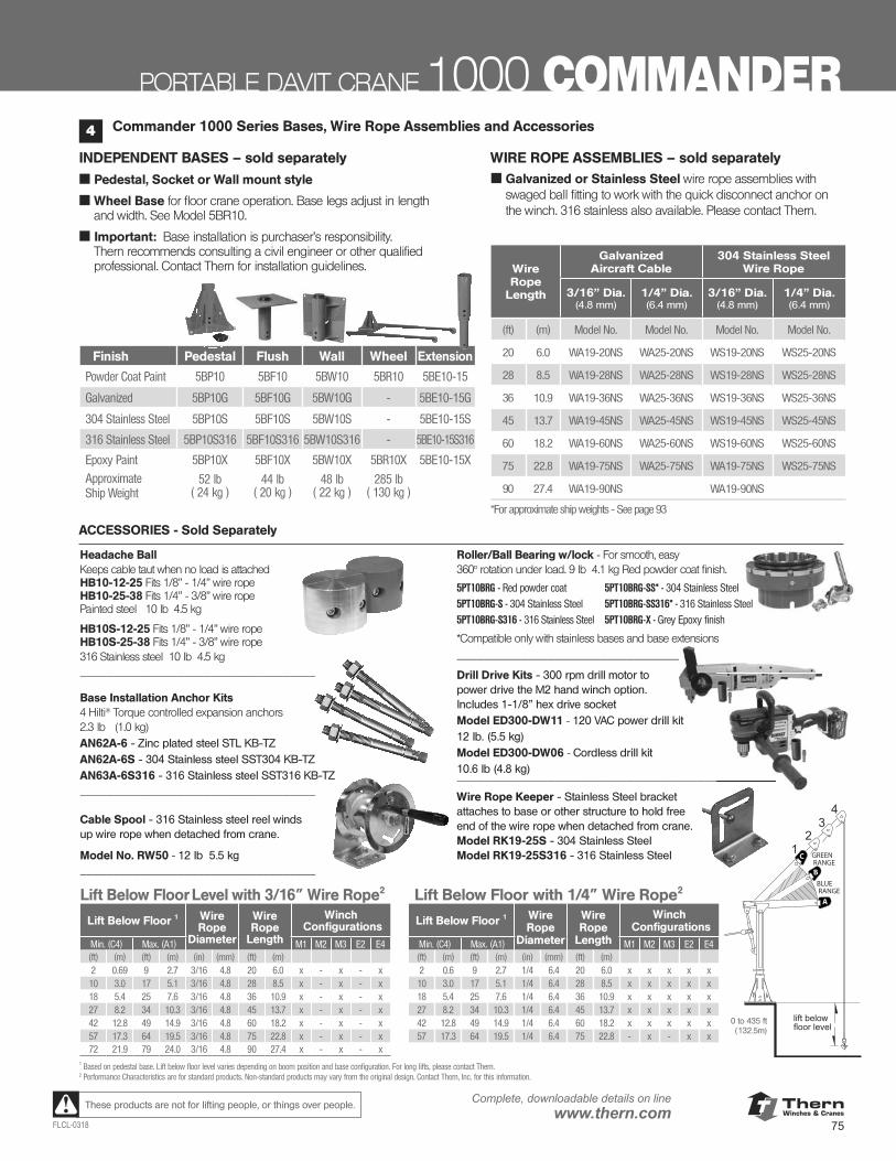
ThernWinches & Cranes
75FLCL-0318
Complete, downloadable details on linewww.thern.comThese products are not for lifting people, or things over people.
PORTABLE DAVIT CRANE 1000 COMMANDER
Lift Below Floor Level with 3/16” Wire Rope2
Lift Below Floor 1 Wire Rope
Diameter
Wire Rope
Length
Winch Configurations
Min. (C4) Max. (A1) M1 M2 M3 E2 E4(ft) (m) (ft) (m) (in) (mm) (ft) (m)2 0.69 9 2.7 3/16 4.8 20 6.0 x - x - x10 3.0 17 5.1 3/16 4.8 28 8.5 x - x - x18 5.4 25 7.6 3/16 4.8 36 10.9 x - x - x27 8.2 34 10.3 3/16 4.8 45 13.7 x - x - x42 12.8 49 14.9 3/16 4.8 60 18.2 x - x - x57 17.3 64 19.5 3/16 4.8 75 22.8 x - x - x72 21.9 79 24.0 3/16 4.8 90 27.4 x - x - x
Lift Below Floor with 1/4” Wire Rope2
Lift Below Floor 1 Wire Rope
Diameter
Wire Rope
Length
Winch Configurations
Min. (C4) Max. (A1) M1 M2 M3 E2 E4(ft) (m) (ft) (m) (in) (mm) (ft) (m)2 0.6 9 2.7 1/4 6.4 20 6.0 x x x x x10 3.0 17 5.1 1/4 6.4 28 8.5 x x x x x18 5.4 25 7.6 1/4 6.4 36 10.9 x x x x x27 8.2 34 10.3 1/4 6.4 45 13.7 x x x x x42 12.8 49 14.9 1/4 6.4 60 18.2 x x x x x57 17.3 64 19.5 1/4 6.4 75 22.8 - x - x x
1 Based on pedestal base. Lift below floor level varies depending on boom position and base configuration. For long lifts, please contact Thern.2 Performance Characteristics are for standard products. Non-standard products may vary from the original design. Contact Thern, Inc. for this information.
Commander 1000 Series Bases, Wire Rope Assemblies and Accessories4
INDEPENDENT BASES – sold separately
■ Pedestal, Socket or Wall mount style
■ Wheel Base for floor crane operation. Base legs adjust in length and width. See Model 5BR10.
■ Important: Base installation is purchaser’s responsibility. Thern recommends consulting a civil engineer or other qualified professional. Contact Thern for installation guidelines.
WIRE ROPE ASSEMBLIES – sold separately■ Galvanized or Stainless Steel wire rope assemblies with
swaged ball fitting to work with the quick disconnect anchor on the winch. 316 stainless also available. Please contact Thern.
Wire Rope
Length
Galvanized Aircraft Cable
304 Stainless Steel Wire Rope
3/16” Dia. (4.8 mm)
1/4” Dia.(6.4 mm)
3/16” Dia. (4.8 mm)
1/4” Dia.(6.4 mm)
(ft) (m) Model No. Model No. Model No. Model No.
20 6.0 WA19-20NS WA25-20NS WS19-20NS WS25-20NS
28 8.5 WA19-28NS WA25-28NS WS19-28NS WS25-28NS
36 10.9 WA19-36NS WA25-36NS WS19-36NS WS25-36NS
45 13.7 WA19-45NS WA25-45NS WS19-45NS WS25-45NS
60 18.2 WA19-60NS WA25-60NS WS19-60NS WS25-60NS
75 22.8 WA19-75NS WA25-75NS WA19-75NS WS25-75NS
90 27.4 WA19-90NS WA19-90NS
*For approximate ship weights - See page 93
Finish Pedestal Flush Wall Wheel Extension
Powder Coat Paint 5BP10 5BF10 5BW10 5BR10 5BE10-15
Galvanized 5BP10G 5BF10G 5BW10G - 5BE10-15G
304 Stainless Steel 5BP10S 5BF10S 5BW10S - 5BE10-15S
316 Stainless Steel 5BP10S316 5BF10S316 5BW10S316 - 5BE10-15S316
Epoxy Paint 5BP10X 5BF10X 5BW10X 5BR10X 5BE10-15X
ApproximateShip Weight
52 lb ( 24 kg )
44 lb ( 20 kg )
48 lb ( 22 kg )
285 lb ( 130 kg )
A
C
BBLUE RANGE
GREEN RANGE
0 to 435 ft (132.5m)
Headache Ball Keeps cable taut when no load is attached HB10-12-25 Fits 1/8” - 1/4” wire rope HB10-25-38 Fits 1/4” - 3/8” wire rope Painted steel 10 lb 4.5 kg
HB10S-12-25 Fits 1/8” - 1/4” wire rope HB10S-25-38 Fits 1/4” - 3/8” wire rope 316 Stainless steel 10 lb 4.5 kg ____________________________________
Base Installation Anchor Kits 4 Hilti® Torque controlled expansion anchors 2.3 lb (1.0 kg)AN62A-6 - Zinc plated steel STL KB-TZ AN62A-6S - 304 Stainless steel SST304 KB-TZ AN63A-6S316 - 316 Stainless steel SST316 KB-TZ ____________________________________ Cable Spool - 316 Stainless steel reel winds up wire rope when detached from crane.
Model No. RW50 - 12 lb 5.5 kg ____________________________________
Roller/Ball Bearing w/lock - For smooth, easy 360° rotation under load. 9 lb 4.1 kg Red powder coat finish.
*Compatible only with stainless bases and base extensions _________________________________________________
Drill Drive Kits - 300 rpm drill motor to power drive the M2 hand winch option. Includes 1-1/8” hex drive socket Model ED300-DW11 - 120 VAC power drill kit 12 lb. (5.5 kg) Model ED300-DW06 - Cordless drill kit 10.6 lb (4.8 kg) _________________________________________________
Wire Rope Keeper - Stainless Steel bracket attaches to base or other structure to hold free end of the wire rope when detached from crane.Model RK19-25S - 304 Stainless Steel Model RK19-25S316 - 316 Stainless Steel
_________________________________________________
_________________________________________________
ACCESSORIES - Sold Separately
5PT10BRG - Red powder coat
5PT10BRG-S - 304 Stainless Steel
5PT10BRG-S316 - 316 Stainless Steel
5PT10BRG-SS* - 304 Stainless Steel
5PT10BRG-SS316* - 316 Stainless Steel
5PT10BRG-X - Grey Epoxy finish
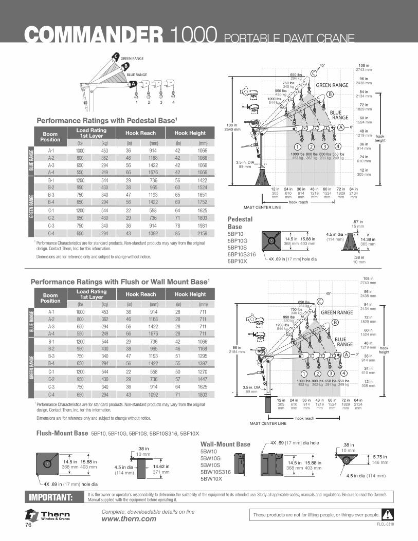
ThernWinches & Cranes
76
Complete, downloadable details on linewww.thern.com
FLCL-0318
These products are not for lifting people, or things over people.
14.62 in371 mm
.38 in10 mm
.38 in10 mm
5.75 in146 mm
4.5 in dia (114 mm)
4X .69 [17 mm] dia hole
4.5 in dia (114 mm)
12 in305mm
12 in305 mm
24 in610mm
24 in610 mm
36 in914mm
36 in914 mm
48 in1219mm
48 in1219 mm
60 in1524mm
60 in1524 mm
72 in1829mm
72 in1829 mm
84 in2134mm
84 in2134 mm
96 in2438 mm
108 in2743 mm
MAST CENTER LINE
86 in2184 mm
3.5 in. DIA89 mm
hook reach
hookheight
14.5 in368 mm
15.88 in403 mm
14.5 in368 mm
15.88 in403 mm
4X .69 in (17 mm) hole dia
A
1 2 3 4
C
1000 lbs453 kg
800 lbs362 kg
650 lbs294 kg
550 lbs249 kg
1200 lbs544 kg
950 lbs430 kg
750 lbs340 kg
650 lbs294 kg
B
BLUE RANGE
GREEN RANGE
A
1 2 3 4
C
1200 lbs544 kg
950 lbs430 kg
750 lbs340 kg
650 lbs294 kg
BLUE RANGE
GREEN RANGE
1000 lbs453 kg
800 lbs362 kg
650 lbs294 kg
550 lbs249 kg
B
12 in305mm
12 in305 mm
24 in610mm
24 in610 mm
36 in914mm
36 in914 mm
48 in1219mm
48 in1219 mm
60 in1524mm
60 in1524 mm
72 in1829mm
72 in1829 mm
84 in2134mm
84 in2134 mm
96 in2438 mm
108 in2743 mm
MAST CENTER LINE
100 in2540 mm
.38 in10 mm
14.38 in365 mm
14.5 in368 mm
15.88 in403 mm
.57 in4.5 in sch 40 pipe
4X .69 in [17 mm] hole dia
15 mm
3.5 in. DIA89 mm
hook reach
hookheight
A
1 2 3 4
B
1000 lbs453 kg
800 lbs362 kg
650 lbs294 kg
550 lbs249 kg
1200 lbs544 kg
950 lbs430 kg
750 lbs340 kg
650 lbs294 kg
12 in305mm
12 in305 mm
24 in610mm
24 in610 mm
36 in914mm
36 in914 mm
48 in1219mm
48 in1219 mm
60 in1524mm
60 in1524 mm
72 in1829mm
72 in1829 mm
84 in2134mm
84 in2134 mm
96 in2438 mm
108 in2743 mm
MASTCENTER
LINE
100 in2540 mm
.38 in10 mm
14.38 in365 mm
14.5 in368 mm
15.88 in403 mm
.57 in
4X .69 in [17 mm] hole dia
15 mm
3.5 in. DIA89 mm
hook reach
hookheight
4.5 in dia (114 mm)
Flush-Mount Base 5BF10, 5BF10G, 5BF10S, 5BF10S316, 5BF10X
Wall-Mount Base5BW105BW10G5BW10S5BW10S3165BW10X
14.62 in371 mm
.38 in10 mm
.38 in10 mm
5.75 in146 mm
4.5 in dia (114 mm)
4X .69 [17 mm] dia hole
4.5 in dia (114 mm)
12 in305mm
12 in305 mm
24 in610mm
24 in610 mm
36 in914mm
36 in914 mm
48 in1219mm
48 in1219 mm
60 in1524mm
60 in1524 mm
72 in1829mm
72 in1829 mm
84 in2134mm
84 in2134 mm
96 in2438 mm
108 in2743 mm
MAST CENTER LINE
86 in2184 mm
3.5 in. DIA89 mm
hook reach
hookheight
14.5 in368 mm
15.88 in403 mm
14.5 in368 mm
15.88 in403 mm
4X .69 in (17 mm) hole dia
A
1 2 3 4
C
1000 lbs453 kg
800 lbs362 kg
650 lbs294 kg
550 lbs249 kg
1200 lbs544 kg
950 lbs430 kg
750 lbs340 kg
650 lbs294 kg
B
BLUE RANGE
GREEN RANGE
Performance Ratings with Pedestal Base1
Boom Position
Load Rating1st Layer Hook Reach Hook Height
(lb) (kg) (in) (mm) (in) (mm)
BLUE
RAN
GE A-1 1000 453 36 914 42 1066
A-2 800 362 46 1168 42 1066 A-3 650 294 56 1422 42 1066 A-4 550 249 66 1676 42 1066
GREE
N RA
NGE
B-1 1200 544 29 736 56 1422B-2 950 430 38 965 60 1524B-3 750 340 47 1193 65 1651B-4 650 294 56 1422 69 1752
C-1 1200 544 22 558 64 1625 C-2 950 430 29 736 71 1803
C-3 750 340 36 914 78 1981
C-4 650 294 43 1092 85 2159 1 Performance Characteristics are for standard products. Non-standard products may vary from the original
design. Contact Thern, Inc. for this information. Dimensions are for reference only and subject to change without notice.
GREEN RANGE
BLUE RANGE
A
C
B
Pedestal Base5BP10 5BP10G 5BP10S5BP10S3165BP10X
IMPORTANT: It is the owner or operator’s responsibility to determine the suitability of the equipment to its intended use. Study all applicable codes, manuals and regulations. Be sure to read the Owner’s Manual supplied with the equipment before operating it.
COMMANDER 1000 PORTABLE DAVIT CRANE
Performance Ratings with Flush or Wall Mount Base1
Boom Position
Load Rating1st Layer Hook Reach Hook Height
(lb) (kg) (in) (mm) (in) (mm)
BLUE
RAN
GE A-1 1000 453 36 914 28 711
A-2 800 362 46 1168 28 711 A-3 650 294 56 1422 28 711 A-4 550 249 66 1676 28 711
GREE
N RA
NGE
B-1 1200 544 29 736 42 1066B-2 950 430 38 965 46 1168B-3 750 340 47 1193 51 1295B-4 650 294 56 1422 55 1397
C-1 1200 544 22 558 50 1270 C-2 950 430 29 736 57 1447
C-3 750 340 36 914 64 1625
C-4 650 294 43 1092 71 1803 1 Performance Characteristics are for standard products. Non-standard products may vary from the original
design. Contact Thern, Inc. for this information. Dimensions are for reference only and subject to change without notice.
14.62 in371 mm
.38 in10 mm
.38 in10 mm
5.75 in146 mm
4.5 in dia (114 mm)
4X .69 [17 mm] dia hole
4.5 in dia (114 mm)
12 in305mm
12 in305 mm
24 in610mm
24 in610 mm
36 in914mm
36 in914 mm
48 in1219mm
48 in1219 mm
60 in1524mm
60 in1524 mm
72 in1829mm
72 in1829 mm
84 in2134mm
84 in2134 mm
96 in2438 mm
108 in2743 mm
MAST CENTER LINE
86 in2184 mm
3.5 in. DIA89 mm
hook reach
hookheight
14.5 in368 mm
15.88 in403 mm
14.5 in368 mm
15.88 in403 mm
4X .69 in (17 mm) hole dia
A
1 2 3 4
C
1000 lbs453 kg
800 lbs362 kg
650 lbs294 kg
550 lbs249 kg
1200 lbs544 kg
950 lbs430 kg
750 lbs340 kg
650 lbs294 kg
B
BLUE RANGE
GREEN RANGE
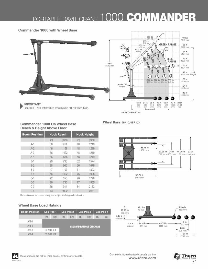
ThernWinches & Cranes
77FLCL-0318
Complete, downloadable details on linewww.thern.comThese products are not for lifting people, or things over people.
PORTABLE DAVIT CRANE 1000 COMMANDER
3 in dia76 mm
6 in dia152 mm27.25 in
692 mm5.88 in
150 mm
B
1 2 3 4
A
B
1000 lbs453 kg
800 lbs362 kg
650 lbs294 kg
550 lbs249 kg
1200 lbs544 kg
950 lbs430 kg
750 lbs340 kg
650 lbs294 kg
A
1 2 3 4
C
1000 lbs453 kg
800 lbs362 kg
650 lbs294 kg
550 lbs249 kg
1200 lbs544 kg
950 lbs430 kg
750 lbs340 kg
650 lbs294 kg
12 in305mm
12 in305 mm
24 in610mm
24 in610 mm
36 in914mm
36 in914 mm
48 in1219mm
48 in1219 mm
60 in1524mm
60 in1524 mm
72 in1829mm
72 in1829 mm
84 in2134mm
84 in2134 mm
96 in2438 mm
108 in2743 mm
MAST CENTER LINE
27.25 in692 mm
34 in863 mm
44.25 in1124 mm
51 in1295 mm
35.75 in908 mm
57.75 in1467 mm
20 in508 mm
8 in203 mm
30 in762 mm
43.75 in1111 mm
14 in354 mm
2.5 in64 mm
106 in2692 mm
3.5 in. DIA89 mm
hook reach
hookheight
BLUE RANGE
GREEN RANGE
Wheel Base Load Ratings
Boom Position Leg Pos 1 Leg Pos 2 Leg Pos 3 Leg Pos 4
(lb) (kg) (lb) (kg) (lb) (kg) (lb) (kg)
A/B-1
SEE LOAD RATINGS ON CRANE A/B-2
A/B-3 DO NOT USE
A/B-4 DO NOT USE
3 in dia76 mm
6 in dia152 mm27.25 in
692 mm5.88 in
150 mm
B
1 2 3 4
A
B
1000 lbs453 kg
800 lbs362 kg
650 lbs294 kg
550 lbs249 kg
1200 lbs544 kg
950 lbs430 kg
750 lbs340 kg
650 lbs294 kg
A
1 2 3 4
C
1000 lbs453 kg
800 lbs362 kg
650 lbs294 kg
550 lbs249 kg
1200 lbs544 kg
950 lbs430 kg
750 lbs340 kg
650 lbs294 kg
12 in305mm
12 in305 mm
24 in610mm
24 in610 mm
36 in914mm
36 in914 mm
48 in1219mm
48 in1219 mm
60 in1524mm
60 in1524 mm
72 in1829mm
72 in1829 mm
84 in2134mm
84 in2134 mm
96 in2438 mm
108 in2743 mm
MAST CENTER LINE
27.25 in692 mm
34 in863 mm
44.25 in1124 mm
51 in1295 mm
35.75 in908 mm
57.75 in1467 mm
20 in508 mm
8 in203 mm
30 in762 mm
43.75 in1111 mm
14 in354 mm
2.5 in64 mm
106 in2692 mm
3.5 in. DIA89 mm
hook reach
hookheight
BLUE RANGE
GREEN RANGE
} IMPORTANT: Crane DOES NOT rotate when assembled in 5BR10 wheel base.
3 in dia76 mm
6 in dia152 mm27.25 in
692 mm5.88 in
150 mm
B
1 2 3 4
A
B
1000 lbs453 kg
800 lbs362 kg
650 lbs294 kg
550 lbs249 kg
1200 lbs544 kg
950 lbs430 kg
750 lbs340 kg
650 lbs294 kg
A
1 2 3 4
C
1000 lbs453 kg
800 lbs362 kg
650 lbs294 kg
550 lbs249 kg
1200 lbs544 kg
950 lbs430 kg
750 lbs340 kg
650 lbs294 kg
12 in305mm
12 in305 mm
24 in610mm
24 in610 mm
36 in914mm
36 in914 mm
48 in1219mm
48 in1219 mm
60 in1524mm
60 in1524 mm
72 in1829mm
72 in1829 mm
84 in2134mm
84 in2134 mm
96 in2438 mm
108 in2743 mm
MAST CENTER LINE
27.25 in692 mm
34 in863 mm
44.25 in1124 mm
51 in1295 mm
35.75 in908 mm
57.75 in1467 mm
20 in508 mm
8 in203 mm
30 in762 mm
43.75 in1111 mm
14 in354 mm
2.5 in64 mm
106 in2692 mm
3.5 in. DIA89 mm
hook reach
hookheight
BLUE RANGE
GREEN RANGE
Commander 1000 with Wheel Base
Commander 1000 On Wheel BaseReach & Height Above Floor
Boom Position Hook Reach Hook Height
(in) (mm) (in) (mm)A-1 36 914 48 1219 A-2 46 1168 48 1219 A-3 56 1422 48 1219 A-4 66 1676 48 1219
B-1 29 736 62 1574B-2 38 965 66 1676B-3 47 1193 71 1803B-4 56 1422 75 1905
C-1 22 558 70 1778 C-2 29 736 77 1955 C-3 36 914 84 2133C-4 43 1092 91 2311
Dimensions are for reference only and subject to change without notice.
Wheel Base 5BR10, 5BR10X
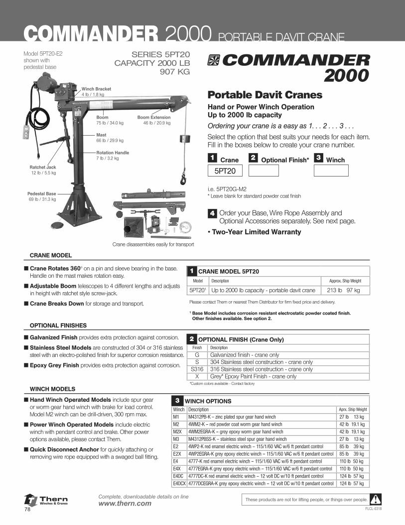
ThernWinches & Cranes
78
Complete, downloadable details on linewww.thern.com
FLCL-0318
These products are not for lifting people, or things over people.
Mast66 lb / 29.9 kg
Ratchet Jack12 lb / 5.5 kg
Rotation Handle7 lb / 3.2 kg
Pedestal Base69 lb / 31.3 kg
Boom75 lb / 34.0 kg
Boom Extension46 lb / 20.9 kg
Winch Bracket4 lb / 1.8 kg
2000SERIES 5PT20
CAPACITY 2000 LB 907 KG
Crane disassembles easily for transport
Model 5PT20-E2shown with pedestal base
■ Crane Rotates 360° on a pin and sleeve bearing in the base. Handle on the mast makes rotation easy.
■ Adjustable Boom telescopes to 4 different lengths and adjusts in height with ratchet style screw-jack.
■ Crane Breaks Down for storage and transport.
1 CRANE MODEL 5PT20
Model Description Approx. Ship Weight
5PT201 Up to 2000 lb capacity - portable davit crane 213 lb 97 kg
Please contact Thern or nearest Thern Distributor for firm fixed price and delivery.
1 Base Model includes corrosion resistant electrostatic powder coated finish. Other finishes available. See option 2.
CRANE MODEL
Portable Davit Cranes Hand or Power Winch Operation Up to 2000 lb capacity
Ordering your crane is a easy as 1. . . 2 . . . 3 . . .
Select the option that best suits your needs for each item. Fill in the boxes below to create your crane number.
i.e. 5PT20G-M2 * Leave blank for standard powder coat finish
Order your Base, Wire Rope Assembly and Optional Accessories separately. See next page.
• Two-Year Limited Warranty
4
OPTIONAL FINISHES
COMMANDER 2000 PORTABLE DAVIT CRANE
1
5PT20
Crane 3 Winch2 Optional Finish*
■ Galvanized Finish provides extra protection against corrosion.
■ Stainless Steel Models are constructed of 304 or 316 stainless steel with an electro-polished finish for superior corrosion resistance.
■ Epoxy Grey Finish provides extra protection against corrosion.
OPTIONAL FINISH (Crane Only)Finish Description
G Galvanized finish - crane onlyS 304 Stainless steel construction - crane only
S316 316 Stainless steel construction - crane onlyX Grey* Epoxy Paint Finish - crane only
*Custom colors available - Contact factory
2
WINCH MODELS
■ Hand Winch Operated Models include spur gear or worm gear hand winch with brake for load control. Model M2 winch can be drill-driven, 300 rpm max.
■ Power Winch Operated Models include electric winch with pendant control and brake. Other power options available, please contact Thern.
■ Quick Disconnect Anchor for quickly attaching or removing wire rope equipped with a swaged ball fitting.
WINCH OPTIONSWinch Description Aprx. Ship Weight
M1 M4312PB-K – zinc plated spur gear hand winch 27 lb 13 kg
M2 4WM2-K – red powder coat worm gear hand winch 42 lb 19.1 kg
M2X 4WM2EGRA-K – grey epoxy worm gear hand winch 42 lb 19.1 kgM3 M4312PBSS-K – stainless steel spur gear hand winch 27 lb 13 kgE2 4WP2-K red enamel electric winch – 115/1/60 VAC w/6 ft pendant control 85 lb 39 kg
E2X 4WP2EGRA-K grey epoxy electric winch – 115/1/60 VAC w/6 ft pendant control 85 lb 39 kg
E4 4777-K red enamel electric winch – 115/1/60 VAC w/6 ft pendant control 110 lb 50 kgE4X 4777EGRA-K grey epoxy electric winch – 115/1/60 VAC w/6 ft pendant control 110 lb 50 kgE4DC 4777DC-K red enamel electric winch – 12 volt DC w/10 ft pendant control 124 lb 57 kg
E4DCX 4777DCEGRA-K grey epoxy electric winch – 12 volt DC w/10 ft pendant control 124 lb 57 kg
3
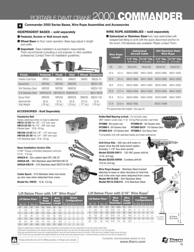
ThernWinches & Cranes
79FLCL-0318
Complete, downloadable details on linewww.thern.comThese products are not for lifting people, or things over people.
PORTABLE DAVIT CRANE 2000 COMMANDER
Lift Below Floor with 5/16” Wire Rope2
Lift Below Floor 1 Wire Rope
Diameter
Wire Rope3 Length
Winch Configurations
Min. (C4) Max. (A1) M1 M2 M3 E2 E4(ft) (m) (ft) (m) (in) (mm) (ft) (m)0 0.0 8 2.5 5/16 7.9 20 6.0 x4 x4 x4 x4 x8 2.4 16 4.8 5/16 7.9 28 8.5 x4 x4 x4 x4 x16 4.8 24 7.3 5/16 7.9 36 10.9 x4 x4 x4 x4 x25 7.6 33 10.0 5/16 7.9 45 13.7 x4 x4 x4 x4 x40 12.1 48 14.6 5/16 7.9 60 18.2 - - - - x
Lift Below Floor with 1/4” Wire Rope2
Lift Below Floor 1 Wire Rope
Diameter
Wire Rope3 Length
Winch Configurations
Min. (C4) Max. (A1) M1 M2 M3 E2 E4(ft) (m) (ft) (m) (in) (mm) (ft) (m)0 0.0 8 2.4 1/4 6.4 20 6.0 x x x x x8 2.4 16 4.8 1/4 6.4 28 8.5 x x x x x16 4.8 24 7.3 1/4 6.4 36 10.9 x x x x x25 7.6 33 10.0 1/4 6.4 45 13.7 x x x x x40 12.1 48 14.6 1/4 6.4 60 18.2 x x x x x55 16.7 63 19.2 1/4 6.4 75 22.8 - x - x x
1 Based on pedestal base. Lift below floor level varies depending on boom position and base configuration. For long lifts, please contact Thern.2 Performance Characteristics are for standard products. Non-standard products may vary from the original design. Contact Thern, Inc. for this information.3 Wire rope assemblies include a hook and a swaged ball fitting to work with quick disconnect anchor on the winch. 316SS wire rope is available. Please contact the factory.4 5/16” (8 mm) wire rope assemblies with swaged ball fitting do not fit the winch quick disconnect anchor. - Contact the factory to specify wire rope with an unfinished end.
Commander 2000 Series Bases, Wire Rope Assemblies and Accessories4
INDEPENDENT BASES – sold separately
■ Pedestal, Socket or Wall mount style
■ Wheel Base for floor crane operation. Base legs adjust in length and width.
■ Important: Base installation is purchaser’s responsibility. Thern recommends consulting a civil engineer or other qualified professional. Contact Thern for installation guidelines.
WIRE ROPE ASSEMBLIES – sold separately■ Galvanized or Stainless Steel wire rope assemblies with
swaged ball fitting to work with the quick disconnect anchor on the winch. 316 stainless also available. Please contact Thern.
Wire RopeLength
Galvanized Aircraft Cable
304 Stainless Steel Wire Rope
1/4” Dia.(6.4 mm)
5/16” Dia.(7.9 mm)
1/4” Dia.(6.4 mm)
5/16” Dia.(7.9 mm)
(ft) (m) Model No. Model No. Model No. Model No.
20 ft 6.0 m WA25-20NS WA31-20DS WS25-20NS WA31-20DS
28 ft 8.5 m WA25-28NS WA31-28DS WS25-28NS WA31-28DS
36 ft 10.9 m WA25-36NS WA31-36DS WS25-36NS WA31-36DS
45 ft 13.7 m WA25-45NS WA31-45DS WS25-45NS WA31-45DS
60 ft 18.2 m WA25-60NS WA31-60DS WS25-60NS WA31-60DS
75 ft 22.8 m WA25-75NS WS25-750NE
*For approximate ship weights - See page 93
A
C
BBLUE RANGE
GREEN RANGE
0 to 435 ft (132.5m)
Headache Ball Keeps cable taut when no load is attached HB10-12-25 Fits 1/8” - 1/4” wire rope HB10-25-38 Fits 1/4” - 3/8” wire rope Painted steel 10 lb 4.5 kg
HB10S-12-25 Fits 1/8” - 1/4” wire rope HB10S-25-38 Fits 1/4” - 3/8” wire rope 316 Stainless steel 10 lb 4.5 kg ____________________________________
Base Installation Anchor Kits 4 Hilti® Torque controlled expansion anchors 2.3 lb (1.0 kg)AN62A-6 - Zinc plated steel STL KB-TZ AN62A-6S - 304 Stainless steel SST304 KB-TZ AN63A-6S316 - 316 Stainless steel SST316 KB-TZ ____________________________________ Cable Spool - 316 Stainless steel reel winds up wire rope when detached from crane.
Model No. RW50 - 12 lb 5.5 kg ____________________________________
Roller/Ball Bearing w/lock - For smooth, easy 360° rotation under load. 11 lb 5.0 kg Red powder coat finish.
*Compatible only with stainless bases and base extensions _________________________________________________
Drill Drive Kits - 300 rpm drill motor to power drive the M2 hand winch option. Includes 1-1/8” hex drive socket Model ED300-DW11 - 120 VAC power drill kit 12 lb. (5.5 kg) Model ED300-DW06 - Cordless drill kit 10.6 lb (4.8 kg) _________________________________________________
Wire Rope Keeper - Stainless Steel bracket attaches to base or other structure to hold free end of the wire rope when detached from crane.Model RK19-25S - 304 Stainless Steel Model RK19-25S316 - 316 Stainless Steel
_________________________________________________
_________________________________________________
ACCESSORIES - Sold Separately
5PT20BRG - Red powder coat
5PT20BRG-S - 304 Stainless Steel
5PT20BRG-S316 - 316 Stainless Steel
5PT20BRG-SS* - 304 Stainless Steel
5PT20BRG-SS316* - 316 Stainless Steel
5PT20BRG-X - Grey Epoxy finish
Finish Pedestal Flush Wall Wheel Extension
Powder Coat Paint 5BP20 5BF20 5BW20 5BR20 5BE20-15
Galvanized 5BP20G 5BF20G 5BW20G - 5BE20-15G
304 Stainless Steel 5BP20S 5BF20S 5BW20S - 5BE20-15S
316 Stainless Steel 5BP20S316 5BF20S316 5BW20S316 - 5BE10-15S316
Epoxy Paint 5BP20X 5BF20X 5BW20X 5BR20X 5BE20-15X
ApproximateShip Weight
66 lb ( 30 kg )
57 lb ( 26 kg )
64 lb ( 30 kg )
375 lb ( 171 kg )
53 lb ( 25 kg )
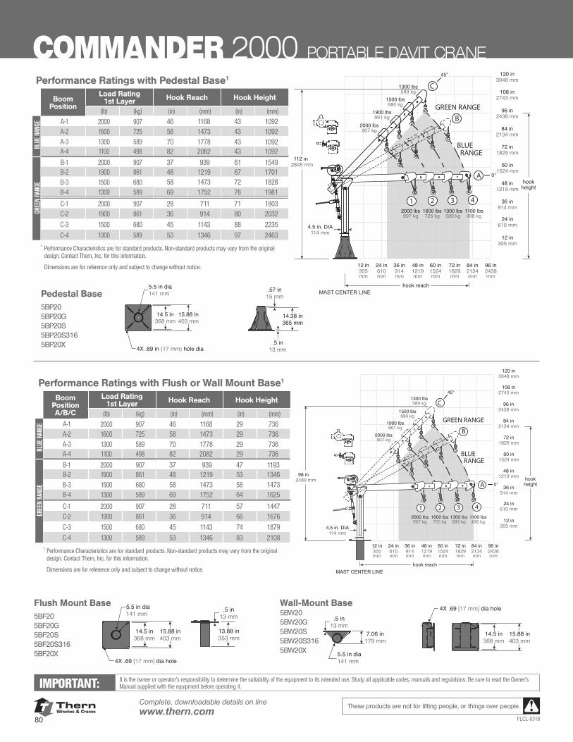
ThernWinches & Cranes
80
Complete, downloadable details on linewww.thern.com
FLCL-0318
These products are not for lifting people, or things over people.
BLUE RANGE
GREEN RANGE
12 in305mm
12 in305 mm
24 in610mm
24 in610 mm
36 in914mm
36 in914 mm
48 in1219mm
48 in1219 mm
60 in1524mm
60 in1524 mm
72 in1829mm
72 in1829 mm
84 in2134mm
96 in2438mm
84 in2134 mm
96 in2438 mm
108 in2743 mm
120 in3048 mm
MAST CENTER LINE
98 in2489 mm
4.5 in. DIA114 mm
hook reach
hookheight
.5 in13 mm
7.06 in179 mm15.88 in
403 mm14.5 in
368 mm
5.5 in dia141 mm
4X .69 [17 mm] dia hole
13.88 in353 mm
.5 in13 mm
15.88 in403 mm
14.5 in368 mm
4X .69 [17 mm] dia hole
A
1 2 3 4
C
2000 lbs907 kg
1600 lbs725 kg
1300 lbs589 kg
1100 lbs498 kg
2000 lbs907 kg
1900 lbs861 kg
1500 lbs680 kg
1300 lbs589 kg
B
5.5 in dia141 mm
12 in305mm
12 in305 mm
24 in610mm
24 in610 mm
36 in914mm
36 in914 mm
48 in1219mm
48 in1219 mm
60 in1524mm
60 in1524 mm
72 in1829mm
72 in1829 mm
84 in2134mm
96 in2438mm
84 in2134 mm
96 in2438 mm
108 in2743 mm
120 in3048 mm
MAST CENTER LINE
A
1 2 3 4
C
2000 lbs907 kg
1600 lbs725 kg
1300 lbs589 kg
1100 lbs498 kg
2000 lbs907 kg
1900 lbs861 kg
1500 lbs680 kg
1300 lbs589 kg
B
BLUE RANGE
GREEN RANGE
112 in2845 mm
4.5 in. DIA114 mm
hook reach
hookheight
15.88 in403 mm
4X .69 in (17 mm) hole dia
14.5 in368 mm
.57 in15 mm
.5 in13 mm
14.38 in365 mm
5.5 in dia141 mm
Flush Mount Base 5BF205BF20G5BF20S5BF20S3165BF20X
Wall-Mount Base5BW205BW20G5BW20S5BW20S3165BW20X
Pedestal Base5BP20 5BP20G 5BP20S5BP20S3165BP20X
12 in305mm
12 in305 mm
24 in610mm
24 in610 mm
36 in914mm
36 in914 mm
48 in1219mm
48 in1219 mm
60 in1524mm
60 in1524 mm
72 in1829mm
72 in1829 mm
84 in2134mm
96 in2438mm
84 in2134 mm
96 in2438 mm
108 in2743 mm
120 in3048 mm
MAST CENTER LINE
A
1 2 3 4
C
2000 lbs907 kg
1600 lbs725 kg
1300 lbs589 kg
1100 lbs498 kg
2000 lbs907 kg
1900 lbs861 kg
1500 lbs680 kg
1300 lbs589 kg
B
BLUE RANGE
GREEN RANGE
112 in2845 mm
4.5 in. DIA114 mm
hook reach
hookheight
15.88 in403 mm
4X .69 in (17 mm) hole dia
14.5 in368 mm
.57 in15 mm
.5 in13 mm
14.38 in365 mm
5.5 in dia141 mm
BLUE RANGE
GREEN RANGE
12 in305mm
12 in305 mm
24 in610mm
24 in610 mm
36 in914mm
36 in914 mm
48 in1219mm
48 in1219 mm
60 in1524mm
60 in1524 mm
72 in1829mm
72 in1829 mm
84 in2134mm
96 in2438mm
84 in2134 mm
96 in2438 mm
108 in2743 mm
120 in3048 mm
MAST CENTER LINE
98 in2489 mm
4.5 in. DIA114 mm
hook reach
hookheight
.5 in13 mm
7.06 in179 mm15.88 in
403 mm14.5 in
368 mm
5.5 in dia141 mm
4X .69 [17 mm] dia hole
13.88 in353 mm
.5 in13 mm
15.88 in403 mm
14.5 in368 mm
4X .69 [17 mm] dia hole
A
1 2 3 4
C
2000 lbs907 kg
1600 lbs725 kg
1300 lbs589 kg
1100 lbs498 kg
2000 lbs907 kg
1900 lbs861 kg
1500 lbs680 kg
1300 lbs589 kg
B
5.5 in dia141 mm
IMPORTANT: It is the owner or operator’s responsibility to determine the suitability of the equipment to its intended use. Study all applicable codes, manuals and regulations. Be sure to read the Owner’s Manual supplied with the equipment before operating it.
COMMANDER 2000 PORTABLE DAVIT CRANE
BLUE RANGE
GREEN RANGE
12 in305mm
12 in305 mm
24 in610mm
24 in610 mm
36 in914mm
36 in914 mm
48 in1219mm
48 in1219 mm
60 in1524mm
60 in1524 mm
72 in1829mm
72 in1829 mm
84 in2134mm
96 in2438mm
84 in2134 mm
96 in2438 mm
108 in2743 mm
120 in3048 mm
MAST CENTER LINE
98 in2489 mm
4.5 in. DIA114 mm
hook reach
hookheight
.5 in13 mm
7.06 in179 mm15.88 in
403 mm14.5 in
368 mm
5.5 in dia141 mm
4X .69 [17 mm] dia hole
13.88 in353 mm
.5 in13 mm
15.88 in403 mm
14.5 in368 mm
4X .69 [17 mm] dia hole
A
1 2 3 4
C
2000 lbs907 kg
1600 lbs725 kg
1300 lbs589 kg
1100 lbs498 kg
2000 lbs907 kg
1900 lbs861 kg
1500 lbs680 kg
1300 lbs589 kg
B
5.5 in dia141 mm
Performance Ratings with Pedestal Base1
Boom Position
Load Rating1st Layer Hook Reach Hook Height
(lb) (kg) (in) (mm) (in) (mm)
BLUE
RAN
GE A-1 2000 907 46 1168 43 1092
A-2 1600 725 58 1473 43 1092A-3 1300 589 70 1778 43 1092A-4 1100 498 82 2082 43 1092
GREE
N RA
NGE
B-1 2000 907 37 939 61 1549B-2 1900 861 48 1219 67 1701B-3 1500 680 58 1473 72 1828B-4 1300 589 69 1752 78 1981
C-1 2000 907 28 711 71 1803C-2 1900 861 36 914 80 2032
C-3 1500 680 45 1143 88 2235
C-4 1300 589 53 1346 97 24631 Performance Characteristics are for standard products. Non-standard products may vary from the original
design. Contact Thern, Inc. for this information. Dimensions are for reference only and subject to change without notice.
Performance Ratings with Flush or Wall Mount Base1
Boom PositionA/B/C
Load Rating1st Layer Hook Reach Hook Height
(lb) (kg) (in) (mm) (in) (mm)
BLUE
RAN
GE A-1 2000 907 46 1168 29 736
A-2 1600 725 58 1473 29 736A-3 1300 589 70 1778 29 736A-4 1100 498 82 2082 29 736
GREE
N RA
NGE
B-1 2000 907 37 939 47 1193B-2 1900 861 48 1219 53 1346B-3 1500 680 58 1473 58 1473B-4 1300 589 69 1752 64 1625
C-1 2000 907 28 711 57 1447C-2 1900 861 36 914 66 1676
C-3 1500 680 45 1143 74 1879
C-4 1300 589 53 1346 83 21081 Performance Characteristics are for standard products. Non-standard products may vary from the original
design. Contact Thern, Inc. for this information. Dimensions are for reference only and subject to change without notice.
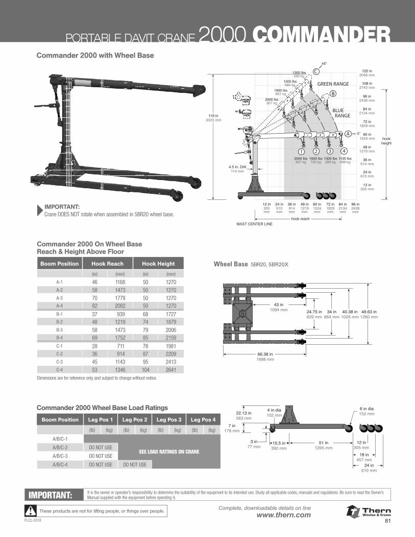
ThernWinches & Cranes
81FLCL-0318
Complete, downloadable details on linewww.thern.comThese products are not for lifting people, or things over people.
PORTABLE DAVIT CRANE 2000 COMMANDER
B
BLUE RANGE
GREEN RANGE
12 in305mm
12 in305 mm
24 in610mm
24 in610 mm
36 in914mm
36 in914 mm
48 in1219mm
48 in1219 mm
60 in1524mm
60 in1524 mm
72 in1829mm
72 in1829 mm
84 in2134mm
96 in2438mm
84 in2134 mm
96 in2438 mm
108 in2743 mm
120 in3048 mm
hook reach
hookheight
119 in3023 mm
4.5 in. DIA114 mm
MAST CENTER LINE
24.75 in629 mm
34 in864 mm
40.38 in1026 mm
49.63 in1260 mm
43 in1094 mm
66.38 in1688 mm
6 in dia152 mm
18 in457 mm
12 in305 mm
24 in610 mm
51 in1295 mm
4 in dia102 mm22.13 in
563 mm
7 in178 mm
15.5 in392 mm
3 in77 mm
A
1 2 3 4
C
2000 lbs907 kg
1600 lbs725 kg
1300 lbs589 kg
1100 lbs498 kg
2000 lbs907 kg
1900 lbs861 kg
1500 lbs680 kg
1300 lbs589 kg
Commander 2000 Wheel Base Load Ratings
Boom Position Leg Pos 1 Leg Pos 2 Leg Pos 3 Leg Pos 4
(lb) (kg) (lb) (kg) (lb) (kg) (lb) (kg)
A/B/C-1
A/B/C-2 DO NOT USESEE LOAD RATINGS ON CRANE
A/B/C-3 DO NOT USE
A/B/C-4 DO NOT USE DO NOT USE
B
BLUE RANGE
GREEN RANGE
12 in305mm
12 in305 mm
24 in610mm
24 in610 mm
36 in914mm
36 in914 mm
48 in1219mm
48 in1219 mm
60 in1524mm
60 in1524 mm
72 in1829mm
72 in1829 mm
84 in2134mm
96 in2438mm
84 in2134 mm
96 in2438 mm
108 in2743 mm
120 in3048 mm
hook reach
hookheight
119 in3023 mm
4.5 in. DIA114 mm
MAST CENTER LINE
24.75 in629 mm
34 in864 mm
40.38 in1026 mm
49.63 in1260 mm
43 in1094 mm
66.38 in1688 mm
6 in dia152 mm
18 in457 mm
12 in305 mm
24 in610 mm
51 in1295 mm
4 in dia102 mm22.13 in
563 mm
7 in178 mm
15.5 in392 mm
3 in77 mm
A
1 2 3 4
C
2000 lbs907 kg
1600 lbs725 kg
1300 lbs589 kg
1100 lbs498 kg
2000 lbs907 kg
1900 lbs861 kg
1500 lbs680 kg
1300 lbs589 kg
} IMPORTANT: Crane DOES NOT rotate when assembled in 5BR20 wheel base.
B
BLUE RANGE
GREEN RANGE
12 in305mm
12 in305 mm
24 in610mm
24 in610 mm
36 in914mm
36 in914 mm
48 in1219mm
48 in1219 mm
60 in1524mm
60 in1524 mm
72 in1829mm
72 in1829 mm
84 in2134mm
96 in2438mm
84 in2134 mm
96 in2438 mm
108 in2743 mm
120 in3048 mm
hook reach
hookheight
119 in3023 mm
4.5 in. DIA114 mm
MAST CENTER LINE
24.75 in629 mm
34 in864 mm
40.38 in1026 mm
49.63 in1260 mm
43 in1094 mm
66.38 in1688 mm
6 in dia152 mm
18 in457 mm
12 in305 mm
24 in610 mm
51 in1295 mm
4 in dia102 mm22.13 in
563 mm
7 in178 mm
15.5 in392 mm
3 in77 mm
A
1 2 3 4
C
2000 lbs907 kg
1600 lbs725 kg
1300 lbs589 kg
1100 lbs498 kg
2000 lbs907 kg
1900 lbs861 kg
1500 lbs680 kg
1300 lbs589 kg
Commander 2000 with Wheel Base
IMPORTANT: It is the owner or operator’s responsibility to determine the suitability of the equipment to its intended use. Study all applicable codes, manuals and regulations. Be sure to read the Owner’s Manual supplied with the equipment before operating it.
Commander 2000 On Wheel BaseReach & Height Above Floor
Boom Position Hook Reach Hook Height
(in) (mm) (in) (mm)
A-1 46 1168 50 1270A-2 58 1473 50 1270A-3 70 1778 50 1270A-4 82 2082 50 1270B-1 37 939 68 1727B-2 48 1219 74 1879B-3 58 1473 79 2006B-4 69 1752 85 2159C-1 28 711 78 1981C-2 36 914 87 2209C-3 45 1143 95 2413C-4 53 1346 104 2641
Dimensions are for reference only and subject to change without notice.
Wheel Base 5BR20, 5BR20X
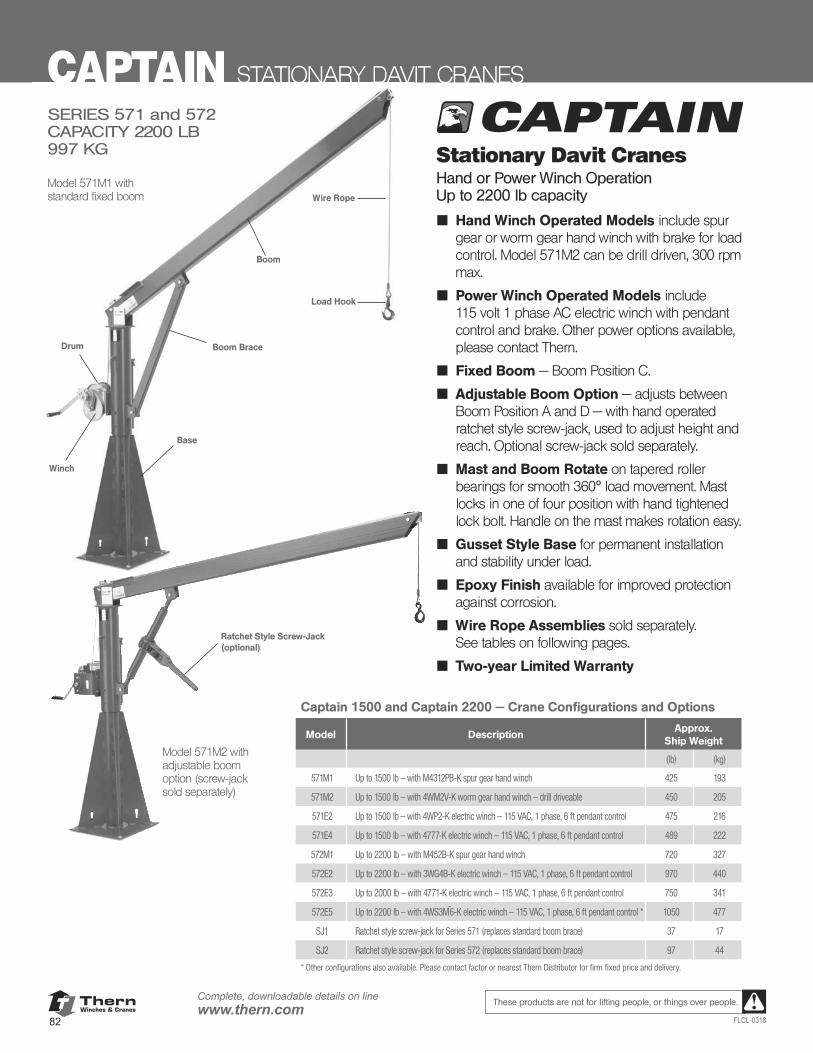
ThernWinches & Cranes
82
Complete, downloadable details on linewww.thern.com
FLCL-0318
These products are not for lifting people, or things over people.
Boom
Model 571M1 with standard fixed boom Wire Rope
Load Hook
Boom BraceDrum
Winch
Base
SERIES 571 and 572CAPACITY 2200 LB 997 KG Stationary Davit Cranes
Hand or Power Winch Operation Up to 2200 lb capacity
■ Hand Winch Operated Models include spur gear or worm gear hand winch with brake for load control. Model 571M2 can be drill driven, 300 rpm max.
■ Power Winch Operated Models include 115 volt 1 phase AC electric winch with pendant control and brake. Other power options available, please contact Thern.
■ Fixed Boom — Boom Position C.
■ Adjustable Boom Option — adjusts between Boom Position A and D — with hand operated ratchet style screw-jack, used to adjust height and reach. Optional screw-jack sold separately.
■ Mast and Boom Rotate on tapered roller bearings for smooth 360º load movement. Mast locks in one of four position with hand tightened lock bolt. Handle on the mast makes rotation easy.
■ Gusset Style Base for permanent installation and stability under load.
■ Epoxy Finish available for improved protection against corrosion.
■ Wire Rope Assemblies sold separately. See tables on following pages.
■ Two-year Limited Warranty
Model 571M2 with adjustable boom option (screw-jack sold separately)
Ratchet Style Screw-Jack (optional)
Captain 1500 and Captain 2200 — Crane Configurations and Options
Model DescriptionApprox.
Ship Weight
(lb) (kg)
571M1 Up to 1500 lb — with M4312PB-K spur gear hand winch 425 193
571M2 Up to 1500 lb — with 4WM2V-K worm gear hand winch — drill driveable 450 205
571E2 Up to 1500 lb — with 4WP2-K electric winch — 115 VAC, 1 phase, 6 ft pendant control 475 216
571E4 Up to 1500 lb — with 4777-K electric winch — 115 VAC, 1 phase, 6 ft pendant control 489 222
572M1 Up to 2200 lb — with M452B-K spur gear hand winch 720 327
572E2 Up to 2200 lb — with 3WG4B-K electric winch — 115 VAC, 1 phase, 6 ft pendant control 970 440
572E3 Up to 2000 lb — with 4771-K electric winch — 115 VAC, 1 phase, 6 ft pendant control 750 341
572E5 Up to 2200 lb — with 4WS3M^6-K electric winch — 115 VAC, 1 phase, 6 ft pendant control * 1050 477
SJ1 Ratchet style screw-jack for Series 571 (replaces standard boom brace) 37 17
SJ2 Ratchet style screw-jack for Series 572 (replaces standard boom brace) 97 44
* Other configurations also available. Please contact factor or nearest Thern Distributor for firm fixed price and delivery.
CAPTAIN STATIONARY DAVIT CRANES
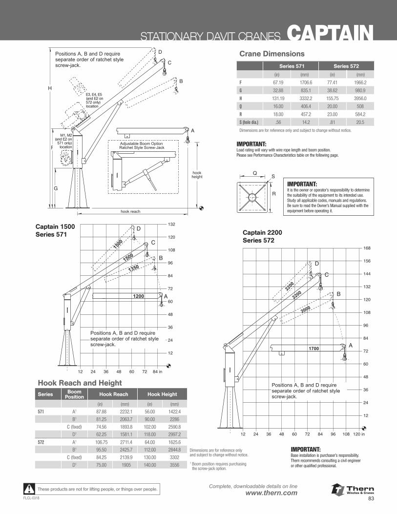
ThernWinches & Cranes
83FLCL-0318
Complete, downloadable details on linewww.thern.comThese products are not for lifting people, or things over people.
STATIONARY DAVIT CRANES CAPTAIN
Important:Load rating will vary with wire rope length and boomposition. Please see Performance Characteristicstable on the following page.
Series 571 and 572 Crane DimensionsSeries 571 Series 572
F 67.19 in 77.41 inG 32.88 in 38.62 inH 131.19 in 155.75 inQ 16.00 in 20.00 inR 18.00 in 23.00 inS (hole dia.) .56 in .81 inDimensions are for reference only and subject to changewithout notice.
Series 571 and 572 – Height and Reachboom hook hook
series position reach height571 A1 87.88 in 56.00 in
B1 81.25 in 90.00 inC (fixed) 74.56 in 102.00 in
D1 62.25 in 118.00 in572 A1 106.75 in 64.00 in
B1 95.50 in 112.00 inC (fixed) 84.25 in 130.00 in
D1 75.00 in 140.00 inDimensions are for reference only and subject to changewithout notice.1 Boom position requires purchasing the screw-jack option.
Important:Base installation is purchaser’s responsibility. Thernrecommends consulting a civil engineer or other qualified professional.
M1, M2and E2location
E3, E4 and E5location
Adjustable Boom OptionRatchet Style Screw-Jack
A
B
C
D
hookheight
hook reach
G
F
H
Q S
R
96
84
72
60
48
36
24
132
120
108
12
12 24 36 48 60 72 84 in
A
B
C
D
1200
13501500
1500
1200
13501500
1500
96
84
72
60
48
36
24
168
156
144
132
120
108
12
12 24 36 48 60 72 9684 108 120 in
A
B
C
D
1700
2000
220022
00
1700
2000
220022
00
Series 572
Series 571
Positions A, B and D requireseparate order of ratchet stylescrew-jack.
Positions A, B and D requireseparate order of ratchet stylescrew-jack.
Positions A, B and D requireseparate order of ratchet stylescrew-jack.
IMPORTANT:It is the owner or operator’s responsibility to determine the suitability of the equipment to its intended use. Study all applicable codes, manuals and regulations. Be sure to read the Owner’s Manual supplied with the equipment before operating it.
Captain 2200Series 572
Important:Load rating will vary with wire rope length and boomposition. Please see Performance Characteristicstable on the following page.
Series 571 and 572 Crane DimensionsSeries 571 Series 572
F 67.19 in 77.41 inG 32.88 in 38.62 inH 131.19 in 155.75 inQ 16.00 in 20.00 inR 18.00 in 23.00 inS (hole dia.) .56 in .81 inDimensions are for reference only and subject to changewithout notice.
Series 571 and 572 – Height and Reachboom hook hook
series position reach height571 A1 87.88 in 56.00 in
B1 81.25 in 90.00 inC (fixed) 74.56 in 102.00 in
D1 62.25 in 118.00 in572 A1 106.75 in 64.00 in
B1 95.50 in 112.00 inC (fixed) 84.25 in 130.00 in
D1 75.00 in 140.00 inDimensions are for reference only and subject to changewithout notice.1 Boom position requires purchasing the screw-jack option.
Important:Base installation is purchaser’s responsibility. Thernrecommends consulting a civil engineer or other qualified professional.
M1, M2and E2location
E3, E4 and E5location
Adjustable Boom OptionRatchet Style Screw-Jack
A
B
C
D
hookheight
hook reach
G
F
H
Q S
R
96
84
72
60
48
36
24
132
120
108
12
12 24 36 48 60 72 84 in
A
B
C
D
1200
13501500
1500
1200
13501500
1500
96
84
72
60
48
36
24
168
156
144
132
120
108
12
12 24 36 48 60 72 9684 108 120 in
A
B
C
D
1700
2000
2200
2200
1700
2000
2200
2200
Series 572
Series 571
Positions A, B and D requireseparate order of ratchet stylescrew-jack.
Positions A, B and D requireseparate order of ratchet stylescrew-jack.
Positions A, B and D requireseparate order of ratchet stylescrew-jack.
Captain 1500Series 571
M1, M2 (and E2 on
571 only) location
E3, E4, E5(and E2 on 572 only) location
Crane Dimensions
Series 571 Series 572
(in) (mm) (in) (mm) F 67.19 1706.6 77.41 1966.2
G 32.88 835.1 38.62 980.9
H 131.19 3332.2 155.75 3956.0
Q 16.00 406.4 20.00 508
R 18.00 457.2 23.00 584.2
S (hole dia.) .56 14.2 .81 20.5
Dimensions are for reference only and subject to change without notice.
IMPORTANT:Load rating will vary with wire rope length and boom position. Please see Performance Characteristics table on the following page.
IMPORTANT:Base installation is purchaser’s responsibility. Thern recommends consulting a civil engineer or other qualified professional.
Hook Reach and Height Series Boom
Position Hook Reach Hook Height
(in) (mm) (in) (mm) 571 A1 87.88 2232.1 56.00 1422.4
B1 81.25 2063.7 90.00 2286
C (fixed) 74.56 1893.8 102.00 2590.8
D1 62.25 1581.1 118.00 2997.2
572 A1 106.75 2711.4 64.00 1625.6
B1 95.50 2425.7 112.00 2844.8
C (fixed) 84.25 2139.9 130.00 3302
D1 75.00 1905 140.00 3556
Dimensions are for reference only and subject to change without notice.
1 Boom position requires purchasing the screw-jack option.
Important:Load rating will vary with wire rope length and boomposition. Please see Performance Characteristicstable on the following page.
Series 571 and 572 Crane DimensionsSeries 571 Series 572
F 67.19 in 77.41 inG 32.88 in 38.62 inH 131.19 in 155.75 inQ 16.00 in 20.00 inR 18.00 in 23.00 inS (hole dia.) .56 in .81 inDimensions are for reference only and subject to changewithout notice.
Series 571 and 572 – Height and Reachboom hook hook
series position reach height571 A1 87.88 in 56.00 in
B1 81.25 in 90.00 inC (fixed) 74.56 in 102.00 in
D1 62.25 in 118.00 in572 A1 106.75 in 64.00 in
B1 95.50 in 112.00 inC (fixed) 84.25 in 130.00 in
D1 75.00 in 140.00 inDimensions are for reference only and subject to changewithout notice.1 Boom position requires purchasing the screw-jack option.
Important:Base installation is purchaser’s responsibility. Thernrecommends consulting a civil engineer or other qualified professional.
M1, M2and E2location
E3, E4 and E5location
Adjustable Boom OptionRatchet Style Screw-Jack
A
B
C
D
hookheight
hook reach
G
F
H
Q S
R
96
84
72
60
48
36
24
132
120
108
12
12 24 36 48 60 72 84 in
A
B
C
D
1200
13501500
1500
1200
13501500
1500
96
84
72
60
48
36
24
168
156
144
132
120
108
12
12 24 36 48 60 72 9684 108 120 in
A
B
C
D
1700
2000
220022
00
1700
2000
220022
00
Series 572
Series 571
Positions A, B and D requireseparate order of ratchet stylescrew-jack.
Positions A, B and D requireseparate order of ratchet stylescrew-jack.
Positions A, B and D requireseparate order of ratchet stylescrew-jack.

ThernWinches & Cranes
84
Complete, downloadable details on linewww.thern.com
FLCL-0318
These products are not for lifting people, or things over people.
Series 571 Performance Characteristicswire load rating for 571M1, 571M2 and 571E2 load rating for 571E4 1 lift belowrope wire rope position A position B position C position D position A position B position C position D �oor leveldia. length (min – max) 2
1/4 in 28 ft 1200 lb 1350 lb 1500 lb 1500 lb 1200 lb 1350 lb 1500 lb 1500 lb 4 – 9 ft1/4 in 36 ft 1200 lb 1350 lb 1500 lb 1500 lb 1200 lb 1350 lb 1500 lb 1500 lb 12 – 17 ft1/4 in 45 ft 1200 lb 1350 lb 1400 lb 1400 lb 1200 lb 1350 lb 1500 lb 1500 lb 21 – 26 ft1/4 in 60 ft 1200 lb 1300 lb 1300 lb 1300 lb 1200 lb 1350 lb 1400 lb 1400 lb 36 – 41 ft1/4 in 75 ft – – – – 1200 lb 1300 lb 1300 lb 1300 lb 51 – 56 ft1 Add 2 ft to lift below floor level for Model 571E4. 2 Lift below floor level varies depending on boom position and winch configuration. For longer lifts contact factory.
Series 572 Performance Characteristicswire load rating for 572M1 and 572E5 1 load rating for 572E3 1 lift belowrope wire rope position A position B position C position D position A position B position C position D �oor leveldia. length (min – max) 2
5/16 in 28 ft 1700 lb 2000 lb 2200 lb 2200 lb 1700 lb 1700 lb 1700 lb 1700 lb -1 – 5 ft5/16 in 36 ft 1700 lb 2000 lb 2200 lb 2200 lb 1700 lb 1700 lb 1700 lb 1700 lb 7 – 13 ft5/16 in 45 ft 1700 lb 2000 lb 2200 lb 2200 lb 1500 lb 1500 lb 1500 lb 1500 lb 16 – 22 ft5/16 in 60 ft 1700 lb 2000 lb 2200 lb 2200 lb 1300 lb 1300 lb 1300 lb 1300 lb 31 – 37 ft5/16 in 75 ft 1700 lb 2000 lb 2200 lb 2200 lb 1300 lb 1300 lb 1300 lb 1300 lb 46 – 52 ft1 Add 3 ft to lift below floor level for Model 572E3 and 572E5. 2 Lift below floor level varies depending on boom position and winch configuration. For longer lifts contact factory.
Wire Rope Assembliesmodel wire rope approx. number diameter x length ship weight
galvanized aircraft cable with swivel hook and swaged ball fittingWA25-28NS 1/4 in x 28 ft 5 lbWA25-36NS 1/4 in x 36 ft 6 lbWA25-45NS 1/4 in x 45 ft 7 lbWA25-60NS 1/4 in x 60 ft 9 lbWA25-75NS 1/4 in x 75 ft 10 lb
304 stainless steel wire rope with SS eye hook and swaged ball fitting - swivel hook also available please contact factory
WS25-28NE 1/4 in x 28 ft 5 lbWS25-36NE 1/4 in x 36 ft 6 lbWS25-45NE 1/4 in x 45 ft 7 lbWS25-60NE 1/4 in x 60 ft 8 lbWS25-75NE 1/4 in x 75 ft 10 lb
galvanized aircraft cable with swivel hook and unfinished endWA31-28DS 5/16 in x 28 ft 7 lbWA31-36DS 5/16 in x 36 ft 9 lbWA31-45DS 5/16 in x 45 ft 10 lbWA31-60DS 5/16 in x 60 ft 13 lbWA31-75DS 5/16 in x 75 ft 15 lb
304 stainless steel wire rope with SS eye hook and unfinished end - swivel hook also available please contact factory
WS31-28DE 5/16 in x 28 ft 7 lbWS31-36DE 5/16 in x 36 ft 9 lbWS31-45DE 5/16 in x 45 ft 11 lbWS31-60DE 5/16 in x 60 ft 14 lbWS31-75DE 5/16 in x 75 ft 17 lb
Please contact factory or nearest Thern Distributor for firm fixed price anddelivery.
WIRE ROPE ASSEMBLIES – sold separatelyGalvanized or Stainless Steel wire rope assemblies.
lift belowfloor level
B
CD
A
Important:It is the owner's or operator's responsibility todetermine the suitability of the equipment toits intended use. Study all applicable codes,manuals, and regulations. Be sure to read theOwner's Manual supplied with the equipmentbefore operating it.
Positions A, B and D requireseparate order of ratchet stylescrew-jack.
CAPTAIN STATIONARY DAVIT CRANESWire Rope AssembliesModel Number Wire Rope
Diameter x LengthApprox.
Ship Weight
(lb) (kg)
Galvanized aircraft cable with swivel hook and swaged ball fitting.
WA25-28NS 1/4 in x 28 ft 5 2.3
WA25-36NS 1/4 in x 36 ft 6 2.7
WA25-45NS 1/4 in x 45 ft 7 3.2
WA25-60NS 1/4 in x 60 ft 9 4.1
WA25-75NS 1/4 in x 75 ft 11 5.0
304 Stainless steel wire rope with SS swivel hook and swaged ball fitting. Swivel hook also available. Please call Thern.
WS25-28NS 1/4 in x 28 ft 5 2.3
WS25-36NS 1/4 in x 36 ft 6 2.7
WS25-45NS 1/4 in x 45 ft 7 3.2
WS25-60NS 1/4 in x 60 ft 8 3.6
WS25-75NS 1/4 in x 75 ft 11 5.0
Galvanized aircraft cable with swivel hook and unfinished end.
WA31-28DS 5/16 in x 28 ft 7 3.2
WA31-36DS 5/16 in x 36 ft 8 3.6
WA31-45DS 5/16 in x 45 ft 10 4.5
WA31-60DS 5/16 in x 60 ft 12 5.4
WA31-75DS 5/16 in x 75 ft 15 6.8
304 Stainless steel wire rope with SS swivel hook and unfinished end. Swivel hook also available. Please call Thern.
WS31-28DS 5/16 in x 28 ft 7 3.2
WS31-36DS 5/16 in x 36 ft 9 4.1
WS31-45DS 5/16 in x 45 ft 11 5.0
WS31-60DS 5/16 in x 60 ft 14 6.4
WS31-75DS 5/16 in x 75 ft 17 7.7
Please contact Thern or nearest Thern Distributor for firm, fixed price and delivery.
WIRE ROPE ASSEMBLIES sold separately■ Galvanized or Stainless Steel
wire rope assemblies.
IMPORTANT:It is the owner or operator’s responsibility to determine the suitability of the equipment to its intended use. Study all applicable codes, manuals and regulations. Be sure to read the Owner’s Manual supplied with the equipment before operating it.
Captain 1500 Performance Characteristics
Wire Rope Load Ratings for 571M1, 571M2 and 571E2 Load Ratings for 571E4 1 Lift Below Floor
Level 2
Dia. Length Pos A Pos B Pos C Pos D Pos A Pos B Pos C Pos D Min Max
(in) (mm) (ft) (m) (lb) (kg) (lb) (kg) (lb) (kg) (lb) (kg) (lb) (kg) (lb) (kg) (lb) (kg) (lb) (kg) (ft) (m) (ft) (m)
1/4 6.35 28 8.53 1200 544 1350 612 1500 680 1500 680 1200 544 1350 612 1500 680 1500 680 4 1.21 9 2.74
1/4 6.35 36 10.97 1200 544 1350 612 1500 680 1500 680 1200 544 1350 612 1500 680 1500 680 12 3.65 17 5.18
1/4 6.35 45 13.71 1200 544 1350 612 1400 635 1400 635 1200 544 1350 612 1500 680 1500 680 21 6.40 26 7.92
1/4 6.35 60 18.28 1200 544 1300 589 1300 589 1300 589 1200 544 1350 612 1400 635 1400 635 36 10.97 41 12.49
1/4 6.35 75 22.86 — — — — — — — — 1200 544 1300 589 1300 589 1300 589 51 15.54 56 17.061 Add 2 feet to lift below floor level for Model 571E4.2 Lift below floor level varies depending on boom position and winch configuration. For longer lifts, contact Thern.
Captain 2200 Performance Characteristics
Wire Rope Load Ratings for 572M1, 572E2 and 572E5 1 Load Ratings for 572E3 1 Lift Below Floor
Level 2
Dia. Length Pos A Pos B Pos C Pos D Pos A Pos B Pos C Pos D Min Max
(in) (mm) (ft) (m) (lb) (kg) (lb) (kg) (lb) (kg) (lb) (kg) (lb) (kg) (lb) (kg) (lb) (kg) (lb) (kg) (ft) (m) (ft) (m)
5/16 7.93 28 8.53 1700 771 2000 907 2200 997 2200 997 1700 771 1700 771 1700 771 1700 771 <1 < 0.30 5 1.52
5/16 7.93 36 10.97 1700 771 2000 907 2200 997 2200 997 1700 771 1700 771 1700 771 1700 771 7 2.13 13 3.96
5/16 7.93 45 13.71 1700 771 2000 907 2200 997 2200 997 1500 680 1500 680 1500 680 1500 680 16 4.87 22 6.70
5/16 7.93 60 18.28 1700 771 2000 907 2200 997 2200 997 1300 589 1300 589 1300 589 1300 589 31 9.44 37 11.27
5/16 7.93 75 22.86 1700 771 2000 907 2200 997 2200 997 1300 589 1300 589 1300 589 1300 589 46 14.02 52 15.841 Add 3 feet to lift below floor level for Model 572E2, 572E3 and 572E5.2 Lift below floor level varies depending on boom position and winch configuration. For longer lifts, contact Thern.
Positions A, B and D require separate order of ratchet style screw-jack.
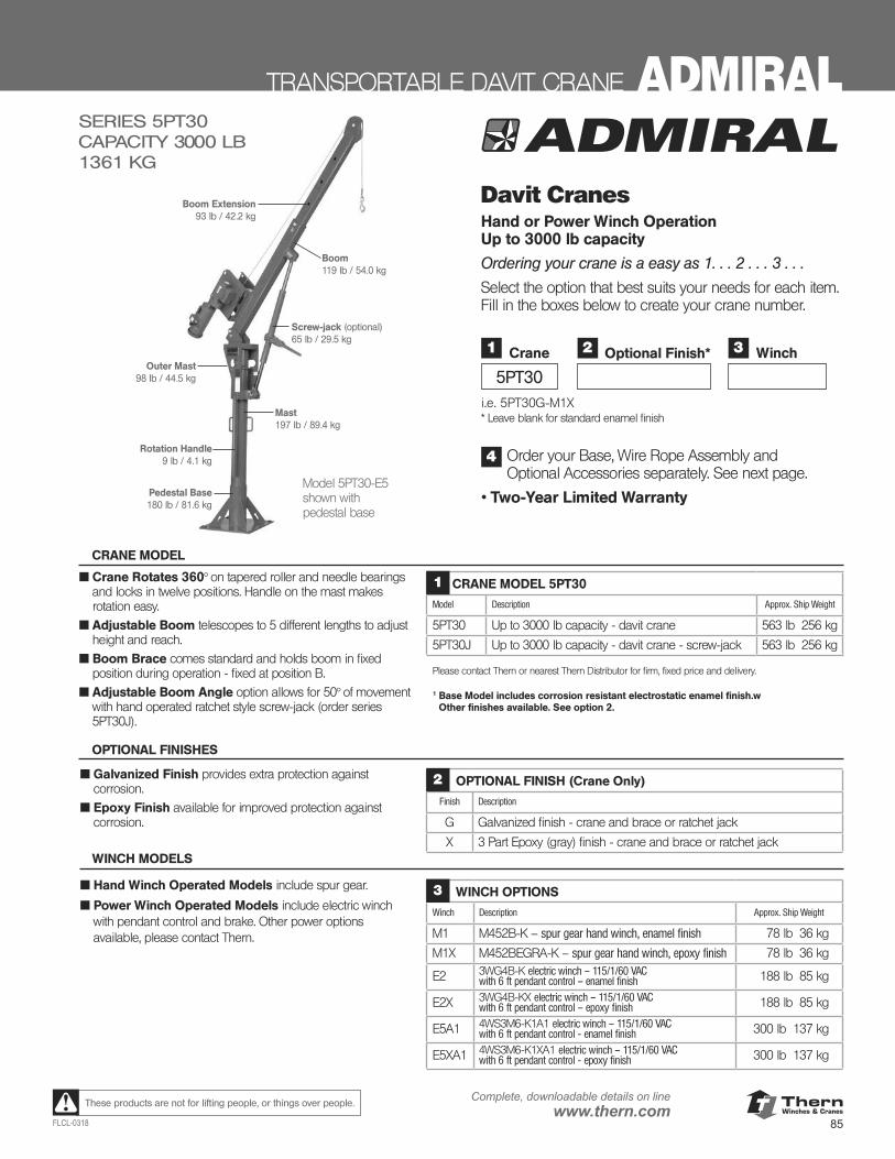
ThernWinches & Cranes
85FLCL-0318
Complete, downloadable details on linewww.thern.comThese products are not for lifting people, or things over people.
TRANSPORTABLE DAVIT CRANE ADMIRAL
Mast197 lb / 89.4 kg
Outer Mast98 lb / 44.5 kg
Screw-jack (optional)65 lb / 29.5 kg
Rotation Handle9 lb / 4.1 kg
Pedestal Base180 lb / 81.6 kg
Boom119 lb / 54.0 kg
Boom Extension93 lb / 42.2 kg
Model 5PT30-E5shown with pedestal base
SERIES 5PT30CAPACITY 3000 LB 1361 KG
CRANE MODEL
■ Crane Rotates 360° on tapered roller and needle bearings and locks in twelve positions. Handle on the mast makes rotation easy.
■ Adjustable Boom telescopes to 5 different lengths to adjust height and reach.
■ Boom Brace comes standard and holds boom in fixed position during operation - fixed at position B.
■ Adjustable Boom Angle option allows for 50° of movement with hand operated ratchet style screw-jack (order series 5PT30J).
CRANE MODEL 5PT30
Model Description Approx. Ship Weight
5PT30 Up to 3000 lb capacity - davit crane 563 lb 256 kg
5PT30J Up to 3000 lb capacity - davit crane - screw-jack 563 lb 256 kg
Please contact Thern or nearest Thern Distributor for firm, fixed price and delivery.
1 Base Model includes corrosion resistant electrostatic enamel finish.w Other finishes available. See option 2.
1
■ Hand Winch Operated Models include spur gear.
■ Power Winch Operated Models include electric winch with pendant control and brake. Other power options available, please contact Thern.
WINCH MODELS
WINCH OPTIONS
Winch Description Approx. Ship Weight
M1 M452B-K – spur gear hand winch, enamel finish 78 lb 36 kg
M1X M452BEGRA-K – spur gear hand winch, epoxy finish 78 lb 36 kg
E2 3WG4B-K electric winch – 115/1/60 VAC with 6 ft pendant control – enamel finish 188 lb 85 kg
E2X 3WG4B-KX electric winch – 115/1/60 VAC with 6 ft pendant control – epoxy finish 188 lb 85 kg
E5A1 4WS3M6-K1A1 electric winch – 115/1/60 VAC with 6 ft pendant control - enamel finish 300 lb 137 kg
E5XA1 4WS3M6-K1XA1 electric winch – 115/1/60 VAC with 6 ft pendant control - epoxy finish 300 lb 137 kg
3
■ Galvanized Finish provides extra protection against corrosion.
■ Epoxy Finish available for improved protection against corrosion.
OPTIONAL FINISHES
OPTIONAL FINISH (Crane Only)
Finish Description
G Galvanized finish - crane and brace or ratchet jack
X 3 Part Epoxy (gray) finish - crane and brace or ratchet jack
2
Davit Cranes Hand or Power Winch Operation Up to 3000 lb capacity
Ordering your crane is a easy as 1. . . 2 . . . 3 . . .
Select the option that best suits your needs for each item. Fill in the boxes below to create your crane number.
i.e. 5PT30G-M1X * Leave blank for standard enamel finish
Order your Base, Wire Rope Assembly and Optional Accessories separately. See next page.
• Two-Year Limited Warranty
1
5PT30
Crane 2 Optional Finish* 3 Winch
4
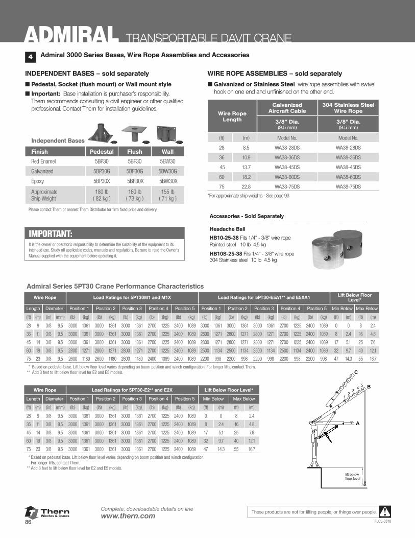
ThernWinches & Cranes
86
Complete, downloadable details on linewww.thern.com
FLCL-0318
These products are not for lifting people, or things over people.
INDEPENDENT BASES – sold separately
■ Pedestal, Socket (flush mount) or Wall mount style
■ Important: Base installation is purchaser’s responsibility. Thern recommends consulting a civil engineer or other qualified professional. Contact Thern for installation guidelines.
WIRE ROPE ASSEMBLIES – sold separately
■ Galvanized or Stainless Steel wire rope assemblies with swivel hook on one end and unfinished on the other end.
Admiral Series 5PT30 Crane Performance Characteristics
Wire Rope Load Ratings for 5PT30M1 and M1X Load Ratings for 5PT30-E5A1** and E5XA1 Lift Below Floor Level*
Length Diameter Position 1 Position 2 Position 3 Position 4 Position 5 Position 1 Position 2 Position 3 Position 4 Position 5 Min Below Max Below
(ft) (m) (in) (mm) (lb) (kg) (lb) (kg) (lb) (kg) (lb) (kg) (lb) (kg) (lb) (kg) (lb) (kg) (lb) (kg) (lb) (kg) (lb) (kg) (ft) (m) (ft) (m)
28 9 3/8 9.5 3000 1361 3000 1361 3000 1361 2700 1225 2400 1089 3000 1361 3000 1361 3000 1361 2700 1225 2400 1089 0 0 8 2.4
36 11 3/8 9.5 3000 1361 3000 1361 3000 1361 2700 1225 2400 1089 2800 1271 2800 1271 2800 1271 2700 1225 2400 1089 8 2.4 16 4.8
45 14 3/8 9.5 3000 1361 3000 1361 3000 1361 2700 1225 2400 1089 2800 1271 2800 1271 2800 1271 2700 1225 2400 1089 17 5.1 25 7.6
60 19 3/8 9.5 2800 1271 2800 1271 2800 1271 2700 1225 2400 1089 2500 1134 2500 1134 2500 1134 2500 1134 2400 1089 32 9.7 40 12.1
75 23 3/8 9.5 2600 1180 2600 1180 2600 1180 2400 1089 2400 1089 2200 998 2200 998 2200 998 2200 998 2200 998 47 14.3 55 16.7
** Based on pedestal base. Lift below floor level varies depending on boom position and winch configuration. For longer lifts, contact Thern.** Add 3 feet to lift below floor level for E2 and E5 models.
Wire Rope Load Ratings for 5PT30-E2** and E2X Lift Below Floor Level*
Length Diameter Position 1 Position 2 Position 3 Position 4 Position 5 Min Below Max Below
(ft) (m) (in) (mm) (lb) (kg) (lb) (kg) (lb) (kg) (lb) (kg) (lb) (kg) (ft) (m) (ft) (m)
28 9 3/8 9.5 3000 1361 3000 1361 3000 1361 2700 1225 2400 1089 0 0 8 2.4
36 11 3/8 9.5 3000 1361 3000 1361 3000 1361 2700 1225 2400 1089 8 2.4 16 4.8
45 14 3/8 9.5 3000 1361 3000 1361 3000 1361 2700 1225 2400 1089 17 5.1 25 7.6
60 19 3/8 9.5 3000 1361 3000 1361 3000 1361 2700 1225 2400 1089 32 9.7 40 12.1
75 23 3/8 9.5 3000 1361 3000 1361 3000 1361 2700 1225 2400 1089 47 14.3 55 16.7
** Based on pedestal base. Lift below floor level varies depending on boom position and winch configuration. For longer lifts, contact Thern.
** Add 3 feet to lift below floor level for E2 and E5 models.
Admiral 3000 Series Bases, Wire Rope Assemblies and Accessories4
Wire RopeLength
Galvanized Aircraft Cable
304 Stainless Steel Wire Rope
3/8” Dia.(9.5 mm)
3/8” Dia.(9.5 mm)
(ft) (m) Model No. Model No.
28 8.5 WA38-28DS WA38-28DS
36 10.9 WA38-36DS WA38-36DS
45 13.7 WA38-45DS WA38-45DS
60 18.2 WA38-60DS WA38-60DS
75 22.8 WA38-75DS WA38-75DS
*For approximate ship weights - See page 93
Independent Bases
Finish Pedestal Flush Wall
Red Enamel 5BP30 5BF30 5BW30
Galvanized 5BP30G 5BF30G 5BW30G
Epoxy 5BP30X 5BF30X 5BW30X
ApproximateShip Weight
180 lb ( 82 kg )
160 lb ( 73 kg )
155 lb ( 71 kg )
Please contact Thern or nearest Thern Distributor for firm fixed price and delivery.
Accessories - Sold Separately ____________________________________________________
Headache Ball
HB10-25-38 Fits 1/4” - 3/8” wire rope Painted steel 10 lb 4.5 kg
HB10S-25-38 Fits 1/4” - 3/8” wire rope 304 Stainless steel 10 lb 4.5 kg
ADMIRAL TRANSPORTABLE DAVIT CRANE
A
12
34 5
C
B
lift belowfloor level
IMPORTANT:It is the owner or operator’s responsibility to determine the suitability of the equipment to its intended use. Study all applicable codes, manuals and regulations. Be sure to read the Owner’s Manual supplied with the equipment before operating it.
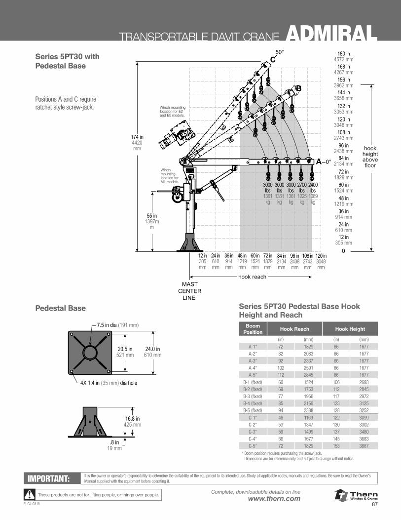
ThernWinches & Cranes
87FLCL-0318
Complete, downloadable details on linewww.thern.comThese products are not for lifting people, or things over people.
TRANSPORTABLE DAVIT CRANE ADMIRAL50°
0°
B
C
A
174 in4420 mm
55 in1397m
m
MASTCENTER
LINE
hook reach
hook height above floor
7.5 in dia (191 mm)
4X 1.4 in (35 mm) dia hole
.8 in19 mm
20.5 in521 mm
24.0 in610 mm
16.8 in425 mm
0
108 in2743 mm
120 in3048 mm
96 in2438 mm
84 in2134 mm
72 in1829 mm
168 in4267 mm
180 in4572 mm
156 in3962 mm
144 in3658 mm
132 in3353 mm
60 in1524 mm
48 in1219 mm
84 in2134 mm
96 in2438 mm
108 in2743 mm
120 in3048 mm
72 in1829 mm
60 in1524 mm
48 in1219 mm
36 in914 mm
36 in914 mm
24 in610 mm
24 in610 mm
12 in305 mm
12 in305 mm
2700 lbs
1225 kg
2400 lbs
1089 kg
3000 lbs
1361 kg
3000 lbs
1361 kg
3000 lbs
1361 kg
50°
0°
B
C
A
174 in4420 mm
55 in1397m
m
MASTCENTER
LINE
hook reach
hook height above floor
7.5 in dia (191 mm)
4X 1.4 in (35 mm) dia hole
.8 in19 mm
20.5 in521 mm
24.0 in610 mm
16.8 in425 mm
0
108 in2743 mm
120 in3048 mm
96 in2438 mm
84 in2134 mm
72 in1829 mm
168 in4267 mm
180 in4572 mm
156 in3962 mm
144 in3658 mm
132 in3353 mm
60 in1524 mm
48 in1219 mm
84 in2134 mm
96 in2438 mm
108 in2743 mm
120 in3048 mm
72 in1829 mm
60 in1524 mm
48 in1219 mm
36 in914 mm
36 in914 mm
24 in610 mm
24 in610 mm
12 in305 mm
12 in305 mm
2700 lbs
1225 kg
2400 lbs
1089 kg
3000 lbs
1361 kg
3000 lbs
1361 kg
3000 lbs
1361 kg
Pedestal Base
Series 5PT30 with Pedestal Base
IMPORTANT: It is the owner or operator’s responsibility to determine the suitability of the equipment to its intended use. Study all applicable codes, manuals and regulations. Be sure to read the Owner’s Manual supplied with the equipment before operating it.
Series 5PT30 Pedestal Base Hook Height and Reach
Boom Position
Hook Reach Hook Height
(in) (mm) (in) (mm)A-1* 72 1829 66 1677A-2* 82 2083 66 1677A-3* 92 2337 66 1677A-4* 102 2591 66 1677A-5* 112 2845 66 1677
B-1 (fixed) 60 1524 106 2693B-2 (fixed) 69 1753 112 2845B-3 (fixed) 77 1956 117 2972B-4 (fixed) 85 2159 123 3125B-5 (fixed) 94 2388 128 3252
C-1* 46 1169 122 3099C-2* 53 1347 130 3302C-3* 59 1499 137 3480C-4* 66 1677 145 3683C-5* 72 1829 153 3887
* Boom position requires purchasing the screw jack. Dimensions are for reference only and subject to change without notice.
Winch mounting location for E2 and E5 models.
Winch mounting location for M1 models.
Positions A and C require ratchet style screw-jack.
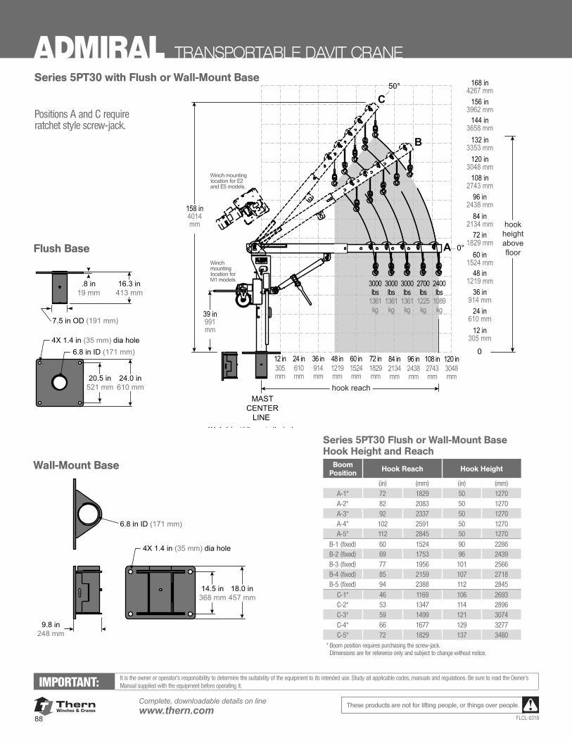
ThernWinches & Cranes
88
Complete, downloadable details on linewww.thern.com
FLCL-0318
These products are not for lifting people, or things over people.
ADMIRAL TRANSPORTABLE DAVIT CRANE
Flush Base
Series 5PT30 with Flush or Wall-Mount Base
IMPORTANT: It is the owner or operator’s responsibility to determine the suitability of the equipment to its intended use. Study all applicable codes, manuals and regulations. Be sure to read the Owner’s Manual supplied with the equipment before operating it.
Series 5PT30 Flush or Wall-Mount Base Hook Height and Reach
Boom Position Hook Reach Hook Height
(in) (mm) (in) (mm)A-1* 72 1829 50 1270A-2* 82 2083 50 1270A-3* 92 2337 50 1270A-4* 102 2591 50 1270A-5* 112 2845 50 1270
B-1 (fixed) 60 1524 90 2286B-2 (fixed) 69 1753 96 2439B-3 (fixed) 77 1956 101 2566B-4 (fixed) 85 2159 107 2718B-5 (fixed) 94 2388 112 2845
C-1* 46 1169 106 2693C-2* 53 1347 114 2896C-3* 59 1499 121 3074C-4* 66 1677 129 3277C-5* 72 1829 137 3480
* Boom position requires purchasing the screw-jack. Dimensions are for reference only and subject to change without notice.
50°
0°
B
C
A
MASTCENTER
LINE
0
108 in2743 mm
120 in3048 mm
96 in2438 mm
84 in2134 mm
72 in1829 mm
168 in4267 mm
156 in3962 mm
144 in3658 mm
132 in3353 mm
60 in1524 mm
48 in1219 mm
84 in2134 mm
96 in2438 mm
108 in2743 mm
120 in3048 mm
72 in1829 mm
60 in1524 mm
48 in1219 mm
36 in914 mm
36 in914 mm
24 in610 mm
24 in610 mm
12 in305 mm
12 in305 mm
hook reach
hook height above floor
6.8 in ID (171 mm)
6.8 in ID (171 mm)
4X 1.4 in (35 mm) dia hole
20.5 in521 mm
24.0 in610 mm
.8 in19 mm
9.8 in248 mm
4X 1.4 in (35 mm) dia hole
18.0 in457 mm
14.5 in368 mm
16.3 in413 mm
158 in4014 mm
39 in991 mm
2700 lbs
1225 kg
2400 lbs
1089 kg
3000 lbs
1361 kg
3000 lbs
1361 kg
3000 lbs
1361 kg
7.5 in OD (191 mm)
Wall-Mount Base
Positions A and C require ratchet style screw-jack.
Winch mounting location for E2 and E5 models.
Winch mounting location for M1 models.
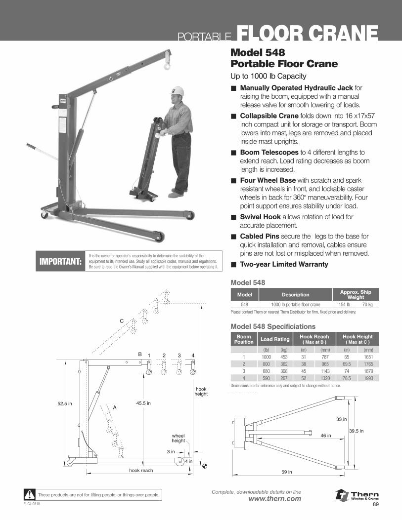
ThernWinches & Cranes
89FLCL-0318
Complete, downloadable details on linewww.thern.comThese products are not for lifting people, or things over people.
PORTABLE FLOOR CRANEModel 548Portable Floor CraneUp to 1000 lb Capacity
■ Manually Operated Hydraulic Jack for raising the boom, equipped with a manual release valve for smooth lowering of loads.
■ Collapsible Crane folds down into 16 x17x57 inch compact unit for storage or transport. Boom lowers into mast, legs are removed and placed inside mast uprights.
■ Boom Telescopes to 4 different lengths to extend reach. Load rating decreases as boom length is increased.
■ Four Wheel Base with scratch and spark resistant wheels in front, and lockable caster wheels in back for 360° maneuverability. Four point support ensures stability under load.
■ Swivel Hook allows rotation of load for accurate placement.
■ Cabled Pins secure the legs to the base for quick installation and removal, cables ensure pins are not lost or misplaced when removed.
■ Two-year Limited WarrantyIMPORTANT:It is the owner or operator’s responsibility to determine the suitability of the equipment to its intended use. Study all applicable codes, manuals and regulations. Be sure to read the Owner’s Manual supplied with the equipment before operating it.
Model 548Portable Floor CraneUp to 1000 lb Capacity
Manually Operated Hydraulic Jack for raising the boom, equipped with a controlknob for smooth lowering of loads.Collapsible Crane folds down into 16 x 17 x 57 inch compact unit for storage or transport. Boom lowers into mast, legs areremoved and placed inside mast uprights.Boom Telescopes to 4 different lengths to extend reach. Load rating decreases as boom length is increased.Overload Relief Valve helps prevent overload damage by releasing hydraulic pressure when too large a load is placed on the crane.Four Wheel Base with scratch and spark resistant wheels in front, and caster wheels in back for 360° maneuverability. Four point support ensures stability under load.Swivel Hook allows rotation of load for accurate placement.Cabled Pins secure the legs to the base for quick installation and removal, cablesensure pins are not lost or misplaced when removed.Two-year Limited Warranty
Model 548 Speci�cationsload max. hook max. hook
rating reach (at B) height (at C)
boom position 1 1000 lb 31.00 in 65.00 inboom position 2 800 lb 38.00 in 69.50 inboom position 3 680 lb 45.00 in 74.00 inboom position 4 590 lb 52.00 in 78.50 inDimensions are for reference only and subject to change without notice.
Model 548 model description approx. ship wt.
548 1000 lb portable floor crane 154 lbPlease contact factory or nearest Thern Distributor for firm fixedprice and delivery.
3 in
4 in
hookheight
wheelheight
hook reach
C
A
B 1 2 3 4
45.5 in52.5 in
59 in
46 in
33 in
39.5 in
Model 548
Model 548
Model Description Approx. Ship Weight
548 1000 lb portable floor crane 154 lb 70 kgPlease contact Thern or nearest Thern Distributor for firm, fixed price and delivery.
Model 548 SpecificiationsBoom
Position Load Rating Hook Reach ( Max at B )
Hook Height( Max at C )
(lb) (kg) (in) (mm) (in) (mm)1 1000 453 31 787 65 16512 800 362 38 965 69.5 17653 680 308 45 1143 74 18794 590 267 52 1320 78.5 1993
Dimensions are for reference only and subject to change without notice.
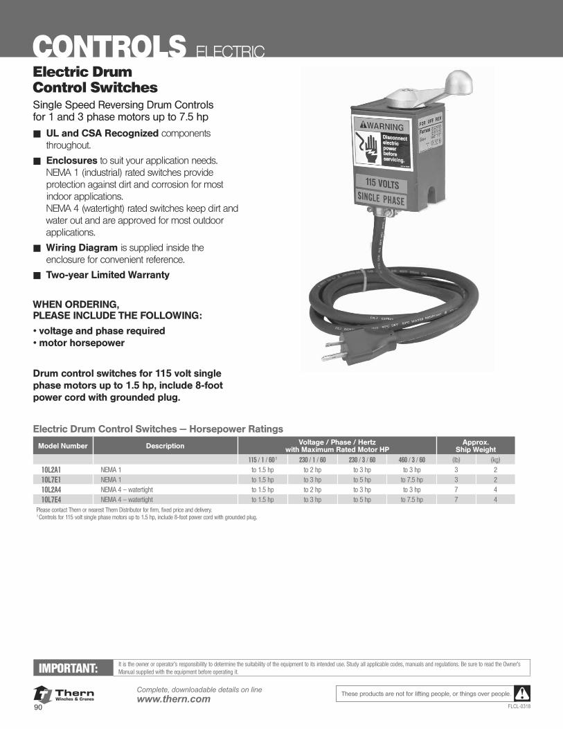
ThernWinches & Cranes
90
Complete, downloadable details on linewww.thern.com
FLCL-0318
These products are not for lifting people, or things over people.
Electric Drum Control SwitchesSingle Speed Reversing Drum Controls for 1 and 3 phase motors up to 7.5 hp
UL and CSA Recognized components throughout.Enclosures to suit your application needs.NEMA 1 (industrial) rated switches provide protec-tion against dirt and corrosion for most indoorapplications.NEMA 4 (watertight) rated switches keep dirt andwater out, and are approved for most outdoor appli-cations.Wiring Diagram is supplied inside the enclosure forconvenient reference.Two-Year Limited Warranty
WHEN ORDERING PLEASE INCLUDE THE FOLLOWING:voltage and phase required, and motor horsepower.
Electric Drum Control Switches – Horsepower Ratingsmodel Voltage/Phase/Hertz with maximum rated motor hp approx. number description 115/1/601 230/1/60 230/3/60 460/3/60 ship wt.10L2A1 NEMA 1 to 1.5 hp to 2 hp to 3 hp to 3 hp 3 lb10L7E1 NEMA 1 to 1.5 hp to 3 hp to 5 hp to 7.5 hp 3 lb10L2A4 NEMA 4 – watertight to 1.5 hp to 2 hp to 3 hp to 3 hp 7 lb10L7E4 NEMA 4 – watertight to 1.5 hp to 3 hp to 5 hp to 7.5 hp 7 lbPlease contact factory or nearest Thern Distributor for firm fixed price and delivery.1 Controls for 115 volt single phase motors up to 1.5 hp, include 8 foot power cord with grounded plug.
Drum control switches for 115 volt single phase motors up to 1.5 hp, include 8 ft power cord with grounded plug.
Important:It is the owner's or operator's responsibility to determinethe suitability of the equipment to its intended use. Studyall applicable codes, manuals, and regulations. Be sure toread the Owner's Manual supplied with the equipmentbefore operating it.
CONTROLS ELECTRIC
IMPORTANT: It is the owner or operator’s responsibility to determine the suitability of the equipment to its intended use. Study all applicable codes, manuals and regulations. Be sure to read the Owner’s Manual supplied with the equipment before operating it.
Electric DrumControl SwitchesSingle Speed Reversing Drum Controls for 1 and 3 phase motors up to 7.5 hp
■ UL and CSA Recognized components throughout.
■ Enclosures to suit your application needs. NEMA 1 (industrial) rated switches provide protection against dirt and corrosion for most indoor applications. NEMA 4 (watertight) rated switches keep dirt and water out and are approved for most outdoor applications.
■ Wiring Diagram is supplied inside the enclosure for convenient reference.
■ Two-year Limited Warranty
WHEN ORDERING, PLEASE INCLUDE THE FOLLOWING:
• voltage and phase required • motor horsepower
Drum control switches for 115 volt single phase motors up to 1.5 hp, include 8-foot power cord with grounded plug.
Electric Drum Control Switches — Horsepower Ratings
Model Number Description Voltage / Phase / Hertz with Maximum Rated Motor HP
Approx. Ship Weight
115 / 1 / 60 1 230 / 1 / 60 230 / 3 / 60 460 / 3 / 60 (lb) (kg)
10L2A1 NEMA 1 to 1.5 hp to 2 hp to 3 hp to 3 hp 3 2
10L7E1 NEMA 1 to 1.5 hp to 3 hp to 5 hp to 7.5 hp 3 2
10L2A4 NEMA 4 — watertight to 1.5 hp to 2 hp to 3 hp to 3 hp 7 4
10L7E4 NEMA 4 — watertight to 1.5 hp to 3 hp to 5 hp to 7.5 hp 7 4Please contact Thern or nearest Thern Distributor for firm, fixed price and delivery.1 Controls for 115 volt single phase motors up to 1.5 hp, include 8-foot power cord with grounded plug.
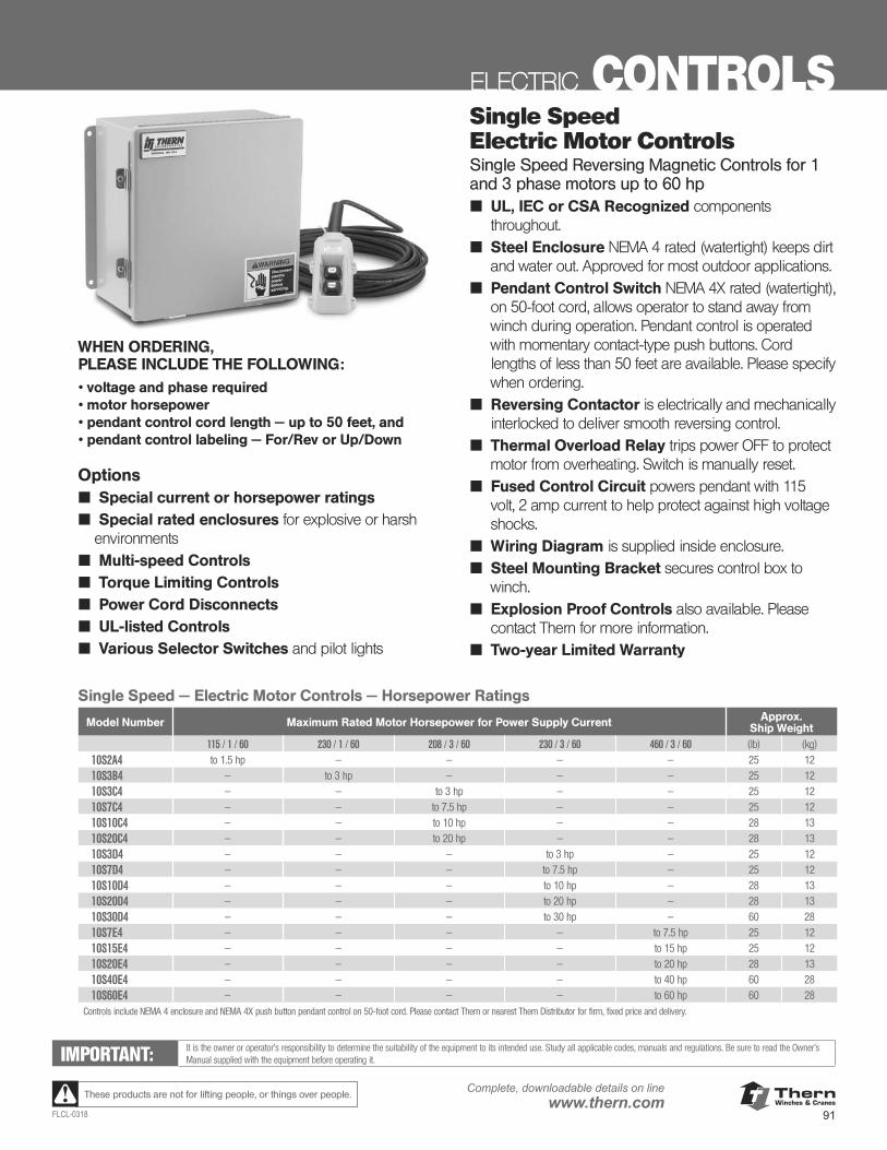
ThernWinches & Cranes
91FLCL-0318
Complete, downloadable details on linewww.thern.comThese products are not for lifting people, or things over people.
ELECTRIC CONTROLS
IMPORTANT: It is the owner or operator’s responsibility to determine the suitability of the equipment to its intended use. Study all applicable codes, manuals and regulations. Be sure to read the Owner’s Manual supplied with the equipment before operating it.
Single Speed Electric Motor ControlsSingle Speed Reversing Magnetic Controls for 1 and 3 phase motors up to 60 hp■ UL, IEC or CSA Recognized components
throughout.■ Steel Enclosure NEMA 4 rated (watertight) keeps dirt
and water out. Approved for most outdoor applications.■ Pendant Control Switch NEMA 4X rated (watertight),
on 50-foot cord, allows operator to stand away from winch during operation. Pendant control is operated with momentary contact-type push buttons. Cord lengths of less than 50 feet are available. Please specify when ordering.
■ Reversing Contactor is electrically and mechanically interlocked to deliver smooth reversing control.
■ Thermal Overload Relay trips power OFF to protect motor from overheating. Switch is manually reset.
■ Fused Control Circuit powers pendant with 115 volt, 2 amp current to help protect against high voltage shocks.
■ Wiring Diagram is supplied inside enclosure.■ Steel Mounting Bracket secures control box to
winch.■ Explosion Proof Controls also available. Please
contact Thern for more information.■ Two-year Limited Warranty
WHEN ORDERING, PLEASE INCLUDE THE FOLLOWING:• voltage and phase required • motor horsepower• pendant control cord length — up to 50 feet, and• pendant control labeling — For/Rev or Up/Down
Options■ Special current or horsepower ratings■ Special rated enclosures for explosive or harsh
environments■ Multi-speed Controls■ Torque Limiting Controls■ Power Cord Disconnects■ UL-listed Controls■ Various Selector Switches and pilot lights
Single Speed — Electric Motor Controls — Horsepower Ratings
Model Number Maximum Rated Motor Horsepower for Power Supply Current Approx. Ship Weight
115 / 1 / 60 230 / 1 / 60 208 / 3 / 60 230 / 3 / 60 460 / 3 / 60 (lb) (kg)
10S2A4 to 1.5 hp — — — — 25 12
10S3B4 — to 3 hp — — — 25 12
10S3C4 — — to 3 hp — — 25 12
10S7C4 — — to 7.5 hp — — 25 12
10S10C4 — — to 10 hp — — 28 13
10S20C4 — — to 20 hp — — 28 13
10S3D4 — — — to 3 hp — 25 12
10S7D4 — — — to 7.5 hp — 25 12
10S10D4 — — — to 10 hp — 28 13
10S20D4 — — — to 20 hp — 28 13
10S30D4 — — — to 30 hp — 60 28
10S7E4 — — — — to 7.5 hp 25 12
10S15E4 — — — — to 15 hp 25 12
10S20E4 — — — — to 20 hp 28 13
10S40E4 — — — — to 40 hp 60 28
10S60E4 — — — — to 60 hp 60 28Controls include NEMA 4 enclosure and NEMA 4X push button pendant control on 50-foot cord. Please contact Thern or nearest Thern Distributor for firm, fixed price and delivery.
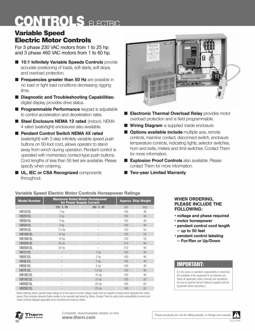
ThernWinches & Cranes
92
Complete, downloadable details on linewww.thern.com
FLCL-0318
These products are not for lifting people, or things over people.
CONTROLS ELECTRICVariable Speed Electric Motor ControlsFor 3 phase 230 VAC motors from 1 to 25 hp and 3 phase 460 VAC motors from 1 to 60 hp.
■ 10:1 Infinitely Variable Speeds Controls provide accurate positioning of loads, soft starts, soft stops, and overload protection.
■ Frequencies greater than 50 Hz are possible in no load or light load conditions decreasing rigging time.
■ Diagnostic and Troubleshooting Capabilities: digital display provides drive status.
■ Programmable Performance keypad is adjustable to control acceleration and deceleration rates.
■ Steel Enclosure NEMA 12 rated (indoor). NEMA 4 rated (watertight) enclosures also available.
■ Pendant Control Switch NEMA 4X rated (watertight) with 3 step infinitely variable speed push buttons on 50-foot cord, allows operator to stand away from winch during operation. Pendant control is operated with momentary contact-type push buttons. Cord lengths of less than 50 feet are available. Please specify when ordering.
■ UL, IEC or CSA Recognized components throughout.
■ Electronic Thermal Overload Relay provides motor overload protection and is field programmable.
■ Wiring Diagram is supplied inside enclosure.
■ Options available include multiple axis, remote controls, mainline contact, disconnect switch, enclosure temperature controls, indicating lights, selector switches, horn and bells, meters and limit switches. Contact Thern for more information.
■ Explosion Proof Controls also available. Please contact Thern for more information.
■ Two-year Limited Warranty
Variable Speed Electric Motor Controls Horsepower Ratings
Model Number Maximum Rated Motor Horsepower for Power Supply Current Approx. Ship Weight
230 / 3 / 60 460 / 3 / 60 (lb) (kg)
10V1D12L 1 hp — 100 46
10V2D12L 2 hp — 100 46
10V3D12L 3 hp — 100 46
10V5D12L 5 hp — 100 46
10V7D12L 7.5 hp — 120 55
10V10D12L 10 hp — 120 55
10V15D12L 15 hp — 120 55
10V20D12L 20 hp — 210 96
10V25D12L 25 hp — 210 96
10V1E12L — 1 hp 100 46
10V2E12L — 2 hp 100 46
10V3E12L — 3 hp 100 46
10V5E12L — 5 hp 100 46
10V7E12L — 7.5 hp 100 46
10V10E12L — 10 hp 100 46
10V15E12L — 15 hp 120 55
10V20E12L — 20 hp 180 82
10V25E12L — 25 hp 180 82When ordering winch, specify brake voltage to be the same as motor voltage, leads must be capable of being wired separate from motor power. Price includes dynamic brake resistor to be mounted and wired by others. Contact Thern to verify drive compatibility to winch and motor. Controls shipped separately to be mounted and wired by others.
WHEN ORDERING, PLEASE INCLUDE THE FOLLOWING:• voltage and phase required • motor horsepower• pendant control cord length
— up to 50 feet• pendant control labeling
— For/Rev or Up/Down
IMPORTANT:It is the owner or operator’s responsibility to determine the suitability of the equipment to its intended use. Study all applicable codes, manuals and regulations. Be sure to read the Owner’s Manual supplied with the equipment before operating it.
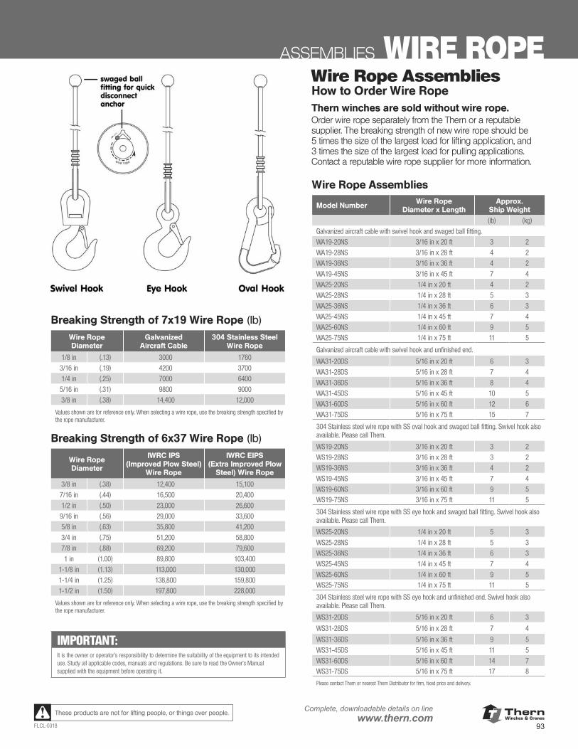
ThernWinches & Cranes
93FLCL-0318
Complete, downloadable details on linewww.thern.comThese products are not for lifting people, or things over people.
ASSEMBLIES WIRE ROPEWire Rope AssembliesHow to Order Wire RopeThern winches are sold without wire rope.Order wire rope separately from the Thern or a reputable supplier. The breaking strength of new wire rope should be 5 times the size of the largest load for lifting application, and 3 times the size of the largest load for pulling applications. Contact a reputable wire rope supplier for more information.
Wire Rope Assemblies
Model Number Wire Rope Diameter x Length
Approx. Ship Weight
(lb) (kg)
Galvanized aircraft cable with swivel hook and swaged ball fitting.
WA19-20NS 3/16 in x 20 ft 3 2
WA19-28NS 3/16 in x 28 ft 4 2
WA19-36NS 3/16 in x 36 ft 4 2
WA19-45NS 3/16 in x 45 ft 7 4
WA25-20NS 1/4 in x 20 ft 4 2
WA25-28NS 1/4 in x 28 ft 5 3
WA25-36NS 1/4 in x 36 ft 6 3
WA25-45NS 1/4 in x 45 ft 7 4
WA25-60NS 1/4 in x 60 ft 9 5WA25-75NS 1/4 in x 75 ft 11 5
Galvanized aircraft cable with swivel hook and unfinished end.
WA31-20DS 5/16 in x 20 ft 6 3
WA31-28DS 5/16 in x 28 ft 7 4
WA31-36DS 5/16 in x 36 ft 8 4
WA31-45DS 5/16 in x 45 ft 10 5
WA31-60DS 5/16 in x 60 ft 12 6WA31-75DS 5/16 in x 75 ft 15 7
304 Stainless steel wire rope with SS oval hook and swaged ball fitting. Swivel hook also available. Please call Thern.
WS19-20NS 3/16 in x 20 ft 3 2
WS19-28NS 3/16 in x 28 ft 3 2
WS19-36NS 3/16 in x 36 ft 4 2
WS19-45NS 3/16 in x 45 ft 7 4
WS19-60NS 3/16 in x 60 ft 9 5WS19-75NS 3/16 in x 75 ft 11 5
304 Stainless steel wire rope with SS eye hook and swaged ball fitting. Swivel hook also available. Please call Thern.
WS25-20NS 1/4 in x 20 ft 5 3
WS25-28NS 1/4 in x 28 ft 5 3
WS25-36NS 1/4 in x 36 ft 6 3
WS25-45NS 1/4 in x 45 ft 7 4
WS25-60NS 1/4 in x 60 ft 9 5WS25-75NS 1/4 in x 75 ft 11 5
304 Stainless steel wire rope with SS eye hook and unfinished end. Swivel hook also available. Please call Thern.
WS31-20DS 5/16 in x 20 ft 6 3
WS31-28DS 5/16 in x 28 ft 7 4
WS31-36DS 5/16 in x 36 ft 9 5
WS31-45DS 5/16 in x 45 ft 11 5
WS31-60DS 5/16 in x 60 ft 14 7WS31-75DS 5/16 in x 75 ft 17 8
Please contact Thern or nearest Thern Distributor for firm, fixed price and delivery.
IMPORTANT:It is the owner or operator’s responsibility to determine the suitability of the equipment to its intended use. Study all applicable codes, manuals and regulations. Be sure to read the Owner’s Manual supplied with the equipment before operating it.
Breaking Strength of 7x19 Wire Rope (lb)
Wire Rope Diameter
Galvanized Aircraft Cable
304 Stainless Steel Wire Rope
1/8 in (.13) 3000 1760
3/16 in (.19) 4200 3700
1/4 in (.25) 7000 6400
5/16 in (.31) 9800 9000
3/8 in (.38) 14,400 12,000
Values shown are for reference only. When selecting a wire rope, use the breaking strength specified by the rope manufacturer.
Breaking Strength of 6x37 Wire Rope (lb)
Wire Rope Diameter
IWRC IPS (Improved Plow Steel)
Wire Rope
IWRC EIPS (Extra Improved Plow
Steel) Wire Rope
3/8 in (.38) 12,400 15,100
7/16 in (.44) 16,500 20,400
1/2 in (.50) 23,000 26,600
9/16 in (.56) 29,000 33,600
5/8 in (.63) 35,800 41,200
3/4 in (.75) 51,200 58,800
7/8 in (.88) 69,200 79,600
1 in (1.00) 89,800 103,400
1-1/8 in (1.13) 113,000 130,000
1-1/4 in (1.25) 138,800 159,800
1-1/2 in (1.50) 197,800 228,000
Values shown are for reference only. When selecting a wire rope, use the breaking strength specified by the rope manufacturer.
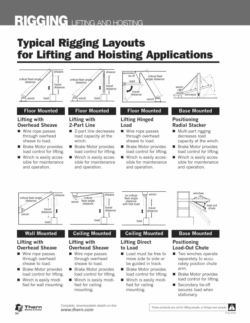
ThernWinches & Cranes
94
Complete, downloadable details on linewww.thern.com
FLCL-0318
These products are not for lifting people, or things over people.
RIGGING LIFTING AND HOISTING
Typical Rigging Layoutsfor Lifting and Hoisting Applications
loadwinch
sheave
traveldistance
critical fleet angledistance
loadwinch
sheave
traveldistance
critical fleet angledistance load
winch
traveldistance
critical fleetangle distance
secondarytie-off
winch
conveyor
Lifting withOverhead Sheave
Wire rope passesthrough overheadsheave to load.Brake Motor providesload control for lifting.Winch is easily acces-sible for maintenanceand operation.
Lifting with2-Part Line
2-part line decreasesload capacity at thewinch.Brake Motor providesload control for lifting.Winch is easily acces-sible for maintenanceand operation.
Lifting Hinged Load
Wire rope passesthrough overheadsheave to load.Brake Motor providesload control for lifting.Winch is easily acces-sible for maintenanceand operation.
Positioning Radial Stacker
Multi-part riggingdecreases loadcapacity at the winch.Brake Motor providesload control for lifting.Winch is easily acces-sible for maintenanceand operation.
load
winch
sheave
traveldistance
critical fleet angledistance
load
winch
sheave
traveldistance
criticalfleet angledistance
load
winch
traveldistance
no criticalfleet angledistance
with free load
winches
load outchute
Lifting withOverhead Sheave
Wire rope passesthrough overheadsheave to load.Brake Motor providesload control for lifting.Winch is easily modi-fied for wall mounting.
Lifting withOverhead Sheave
Wire rope passesthrough overheadsheave to load.Brake Motor providesload control for lifting.Winch is easily modi-fied for ceilingmounting.
Lifting Direct to Load
Load must be free tomove side to side orbe guided in track.Brake Motor providesload control for lifting.Winch is easily modi-fied for ceilingmounting.
PositioningLoad-Out Chute
Two winches operateseparately to accu-rately position chutearm.Brake Motor providesload control for lifting.Secondary tie-offsecures load whenstationary.
Floor Mounted
Wall Mounted Ceiling Mounted Ceiling Mounted Base Mounted
Floor Mounted Floor Mounted Base Mounted
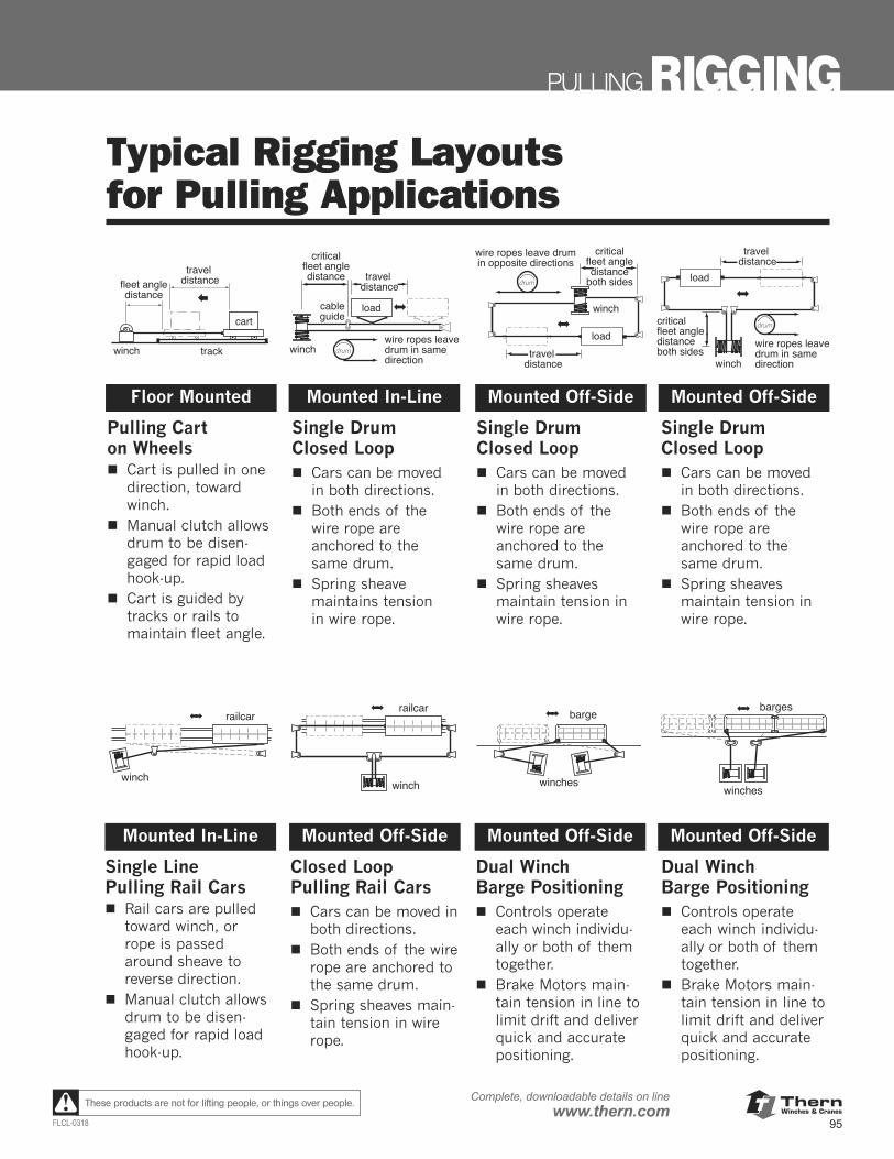
ThernWinches & Cranes
95FLCL-0318
Complete, downloadable details on linewww.thern.comThese products are not for lifting people, or things over people.
Typical Rigging Layoutsfor Pulling Applications
Loadcart
trackwinch
traveldistancefleet angle
distance
wire ropes leavedrum in samedirection
load
winch
cableguide
traveldistance
criticalfleet angledistance
wire ropes leave drumin opposite directions
load
winch
traveldistance
criticalfleet angledistance
both sides
wire ropes leavedrum in samedirection
load
winch
traveldistance
criticalfleet angledistanceboth sides
Pulling Carton Wheels
Cart is pulled in onedirection, towardwinch.Manual clutch allowsdrum to be disen-gaged for rapid loadhook-up.Cart is guided bytracks or rails tomaintain fleet angle.
Single Drum Closed Loop
Cars can be movedin both directions.Both ends of thewire rope areanchored to thesame drum.Spring sheave maintains tension in wire rope.
Single Drum Closed Loop
Cars can be movedin both directions.Both ends of thewire rope areanchored to thesame drum.Spring sheaves maintain tension inwire rope.
Single Drum Closed Loop
Cars can be movedin both directions.Both ends of thewire rope areanchored to thesame drum.Spring sheaves maintain tension inwire rope.
railcar
winch
railcar
winch
barge
winches
barges
winches
Single Line Pulling Rail Cars
Rail cars are pulledtoward winch, orrope is passedaround sheave toreverse direction.Manual clutch allowsdrum to be disen-gaged for rapid loadhook-up.
Closed Loop Pulling Rail Cars
Cars can be moved inboth directions.Both ends of the wirerope are anchored tothe same drum.Spring sheaves main-tain tension in wirerope.
Dual WinchBarge Positioning
Controls operateeach winch individu-ally or both of themtogether.Brake Motors main-tain tension in line tolimit drift and deliverquick and accuratepositioning.
Dual WinchBarge Positioning
Controls operateeach winch individu-ally or both of themtogether.Brake Motors main-tain tension in line tolimit drift and deliverquick and accuratepositioning.
Floor Mounted
Mounted In-Line Mounted Off-Side Mounted Off-Side Mounted Off-Side
Mounted In-Line Mounted Off-Side Mounted Off-Side
PULLING RIGGING
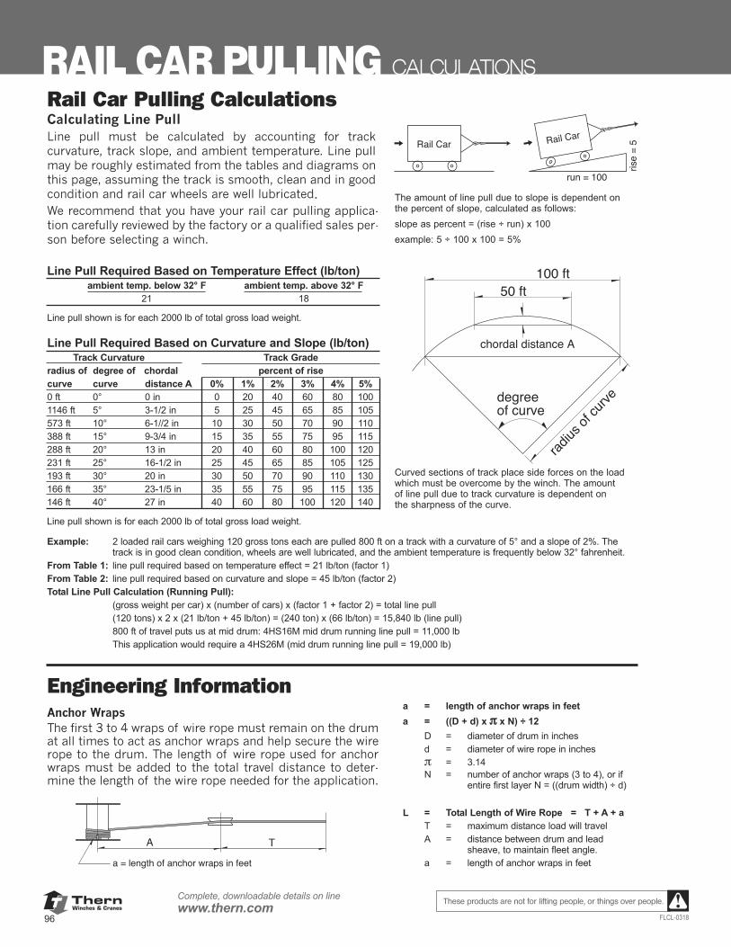
ThernWinches & Cranes
96
Complete, downloadable details on linewww.thern.com
FLCL-0318
These products are not for lifting people, or things over people.
RAIL CAR PULLING CALCULATIONS
Rail Car Pulling CalculationsCalculating Line PullLine pull must be calculated by accounting for track curvature, track slope, and ambient temperature. Line pullmay be roughly estimated from the tables and diagrams onthis page, assuming the track is smooth, clean and in goodcondition and rail car wheels are well lubricatedWe recommend that you have your rail car pulling applica-tion carefully reviewed by the factory or a qualified sales per-son before selecting a winch.
Line Pull Required Based on Temperature Effect (lb/ton)ambient temp. below 32° F ambient temp. above 32° F
21 18
Line pull shown is for each 2000 lb of total gross load weight.
Line Pull Required Based on Curvature and Slope (lb/ton)Track Curvature Track Grade
radius of degree of chordal percent of risecurve curve distance A 0% 1% 2% 3% 4% 5%0 ft 0° 0 in 0 20 40 60 80 1001146 ft 5° 3-1/2 in 5 25 45 65 85 105573 ft 10° 6-1//2 in 10 30 50 70 90 110388 ft 15° 9-3/4 in 15 35 55 75 95 115288 ft 20° 13 in 20 40 60 80 100 120231 ft 25° 16-1/2 in 25 45 65 85 105 125193 ft 30° 20 in 30 50 70 90 110 130166 ft 35° 23-1/5 in 35 55 75 95 115 135146 ft 40° 27 in 40 60 80 100 120 140
Line pull shown is for each 2000 lb of total gross load weight.
The amount of line pull due to slope is dependent onthe percent of slope, calculated as follows:slope as percent = (rise ÷ run) x 100example: 5 ÷ 100 x 100 = 5%
Curved sections of track place side forces on the loadwhich must be overcome by the winch. The amountof line pull due to track curvature is dependent onthe sharpness of the curve.
Rail Car Rail Car
run = 100
rise
= 5
Example: 2 loaded rail cars weighing 120 gross tons each are pulled 800 ft on a track with a curvature of 5° and a slope of 2%. The track is in good clean condition, wheels are well lubricated, and the ambient temperature is frequently below 32° fahrenheit.
From Table 1: line pull required based on temperature effect = 21 lb/ton (factor 1)From Table 2: line pull required based on curvature and slope = 45 lb/ton (factor 2)Total Line Pull Calculation (Running Pull):
(gross weight per car) x (number of cars) x (factor 1 + factor 2) = total line pull(120 tons) x 2 x (21 lb/ton + 45 lb/ton) = (240 ton) x (66 lb/ton) = 15,840 lb (line pull)800 ft of travel puts us at mid drum: 4HS16M mid drum running line pull = 11,000 lbThis application would require a 4HS26M (mid drum running line pull = 19,000 lb)
chordal distance A
50 ft100 ft
radius
of cu
rvedegreeof curve
Engineering InformationAnchor WrapsThe first 3 to 4 wraps of wire rope must remain on the drumat all times to act as anchor wraps and help secure the wirerope to the drum. The length of wire rope used for anchorwraps must be added to the total travel distance to deter-mine the length of the wire rope needed for the application.
a = length of anchor wraps in feeta = ((D + d) x π x N) ÷ 12
D = diameter of drum in inchesd = diameter of wire rope in inchesπ = 3.14N = number of anchor wraps (3 to 4), or if
entire first layer N = ((drum width) ÷ d)
L = Total Length of Wire Rope = T + A + aT = maximum distance load will travelA = distance between drum and lead
sheave, to maintain fleet angle.a = length of anchor wraps in feet
A T
a = length of anchor wraps in feet
.
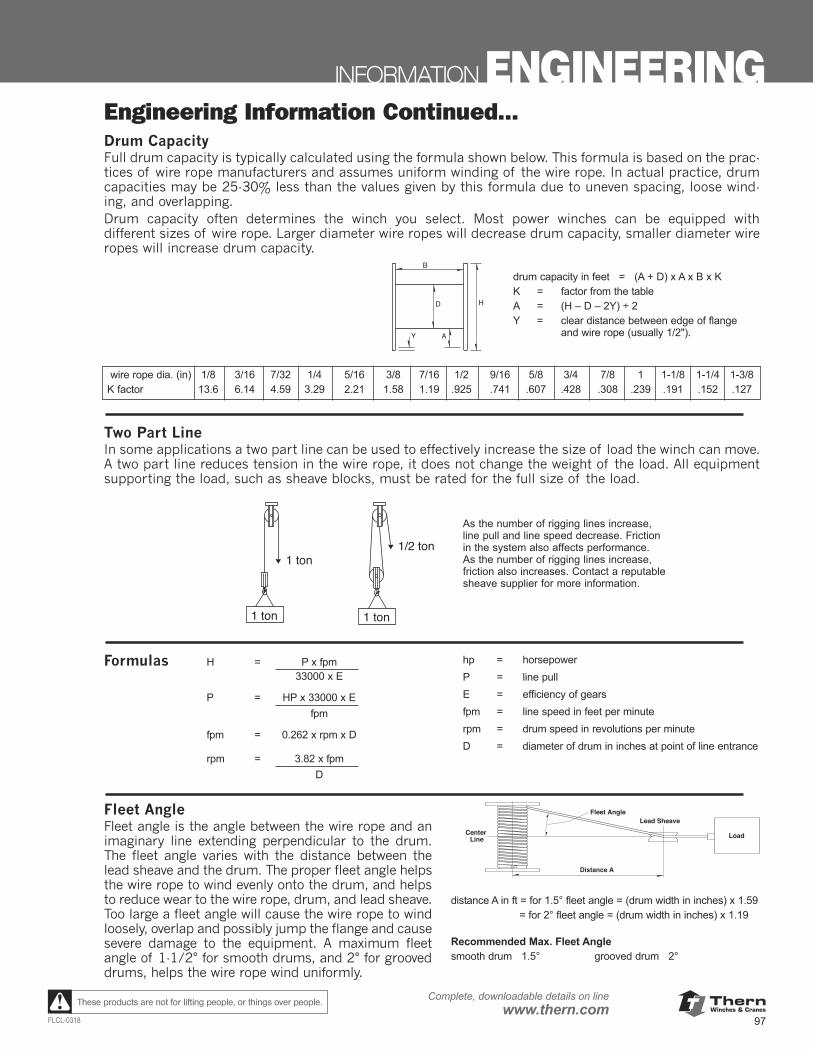
ThernWinches & Cranes
97FLCL-0318
Complete, downloadable details on linewww.thern.comThese products are not for lifting people, or things over people.
drum capacity in feet = (A + D) x A x B x KK = factor from the tableA = (H – D – 2Y) ÷ 2Y = clear distance between edge of flange
and wire rope (usually 1/2").
wire rope dia. (in) 1/8 3/16 7/32 1/4 5/16 3/8 7/16 1/2 9/16 5/8 3/4 7/8 1 1-1/8 1-1/4 1-3/8K factor 13.6 6.14 4.59 3.29 2.21 1.58 1.19 .925 .741 .607 .428 .308 .239 .191 .152 .127
Formulas H = P x fpm33000 x E
P = HP x 33000 x Efpm
fpm = 0.262 x rpm x D
rpm = 3.82 x fpmD
Two Part LineIn some applications a two part line can be used to effectively increase the size of load the winch can move.A two part line reduces tension in the wire rope, it does not change the weight of the load. All equipmentsupporting the load, such as sheave blocks, must be rated for the full size of the load.
Engineering Information Continued...Drum CapacityFull drum capacity is typically calculated using the formula shown below. This formula is based on the prac-tices of wire rope manufacturers and assumes uniform winding of the wire rope. In actual practice, drumcapacities may be 25-30% less than the values given by this formula due to uneven spacing, loose wind-ing, and overlapping.Drum capacity often determines the winch you select. Most power winches can be equipped with different sizes of wire rope. Larger diameter wire ropes will decrease drum capacity, smaller diameter wireropes will increase drum capacity.
AY
D H
B
1 ton
1 ton
1/2 ton
1 ton
As the number of rigging lines increase,line pull and line speed decrease. Frictionin the system also affects performance. As the number of rigging lines increase,friction also increases. Contact a reputablesheave supplier for more information.
hp = horsepowerP = line pullE = efficiency of gearsfpm = line speed in feet per minuterpm = drum speed in revolutions per minuteD = diameter of drum in inches at point of line entrance
Fleet AngleFleet angle is the angle between the wire rope and animaginary line extending perpendicular to the drum.The fleet angle varies with the distance between thelead sheave and the drum. The proper fleet angle helpsthe wire rope to wind evenly onto the drum, and helpsto reduce wear to the wire rope, drum, and lead sheave.Too large a fleet angle will cause the wire rope to windloosely, overlap and possibly jump the flange and causesevere damage to the equipment. A maximum fleetangle of 1-1/2° for smooth drums, and 2° for grooveddrums, helps the wire rope wind uniformly.
distance A in ft = for 1.5° fleet angle = (drum width in inches) x 1.59= for 2° fleet angle = (drum width in inches) x 1.19
Recommended Max. Fleet Anglesmooth drum 1.5° grooved drum 2°
Distance A
Fleet Angle
Load
Lead SheaveCenter
Line
INFORMATION ENGINEERING
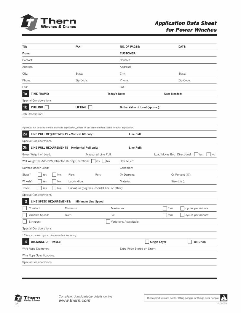
ThernWinches & Cranes
98
Complete, downloadable details on linewww.thern.com
FLCL-0318
These products are not for lifting people, or things over people.
88 Thern products are not for lifting people or things over people. Form FF10-0910
Application Data Sheet for Power Winches
TO: FAX: NO. OF PAGES: DATE:
From: CUSTOMER:
Contact: Contact:
Address: Address:
City: State: City: State:
Phone: Zip Code: Phone: Zip Code:
FAX: FAX:
TIME FRAME: Today’s Date: Date Needed:
Special Considerations:
PULLING LIFTING Dollar Value of Load (approx.):
Job Description:
If product will be used in more than one application, please fill out separate data sheets for each application.
LINE PULL REQUIREMENTS – Vertical lift only: Line Pull:
Special Considerations:
LINE PULL REQUIREMENTS – Horizontal Pull only: Line Pull:
Gross Weight of Load: Measured Line Pull: Load Moves Both Directions? Yes No
Will Weight be Added/Subtracted During Operation? Yes No How Much:
Surface Under Load: Condition:
Slope? Yes No Rise: Run: Or Degrees: Or Percent (%):
Wheels? Yes No Lubrication: Material: Size (dia.):
Track? Yes No Curvature (degrees, chordal line, or other):
Special Considerations:
LINE SPEED REQUIREMENTS: Minimum Line Speed:
Constant Minimum: Maximum: fpm cycles per minute
Variable Speed† From: To: fpm cycles per minute
Stringent Variations Acceptable:
Special Considerations:
† This is a complex option, please contact the factory.
DISTANCE OF TRAVEL: Single Layer Full Drum
Wire Rope Diameter: Extra Rope Stored on Drum:
Wire Rope Specifications:
Special Considerations:
1a
1b
2a
2b
3
4
Thern, Inc. • 5712 Industrial Park RoadPO Box 347 • Winona, MN 55987
800-843-7648 • 507-454-2996 • Fax 507-454-5282e-mail: [email protected] • www.thern.com
ThernWinches & Cranes
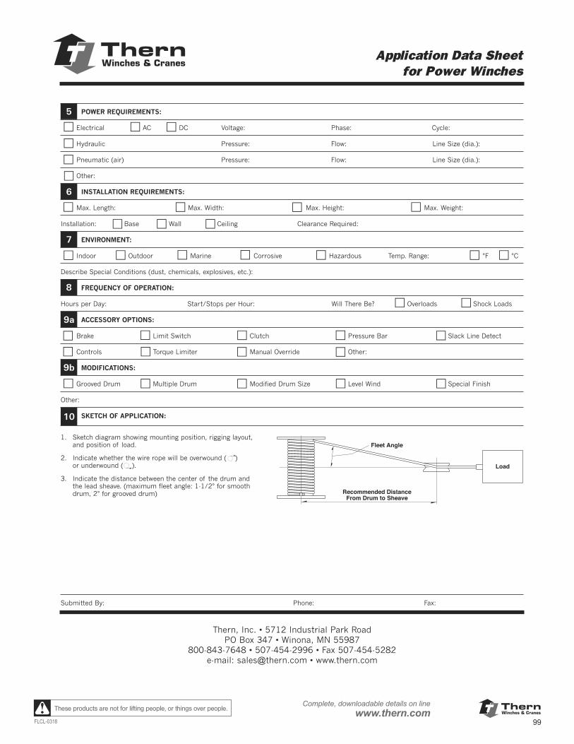
ThernWinches & Cranes
99FLCL-0318
Complete, downloadable details on linewww.thern.comThese products are not for lifting people, or things over people.
Form FF10-0910 Thern products are not for lifting people or things over people. 89
Application Data Sheet for Power Winches
POWER REQUIREMENTS:
Electrical AC DC Voltage: Phase: Cycle:
Hydraulic Pressure: Flow: Line Size (dia.):
Pneumatic (air) Pressure: Flow: Line Size (dia.):
Other:
INSTALLATION REQUIREMENTS:
Max. Length: Max. Width: Max. Height: Max. Weight:
Installation: Base Wall Ceiling Clearance Required:
ENVIRONMENT:
Indoor Outdoor Marine Corrosive Hazardous Temp. Range: °F °C
Describe Special Conditions (dust, chemicals, explosives, etc.):
FREQUENCY OF OPERATION:
Hours per Day: Start/Stops per Hour: Will There Be? Overloads Shock Loads
ACCESSORY OPTIONS:
Brake Limit Switch Clutch Pressure Bar Slack Line Detect
Controls Torque Limiter Manual Override Other:
MODIFICATIONS:
Grooved Drum Multiple Drum Modified Drum Size Level Wind Special Finish
Other:
SKETCH OF APPLICATION:
1. Sketch diagram showing mounting position, rigging layout,and position of load.
2. Indicate whether the wire rope will be overwound ( ) or underwound ( ).
3. Indicate the distance between the center of the drum and the lead sheave. (maximum fleet angle: 1-1/2° for smooth drum, 2° for grooved drum)
Submitted By: Phone: Fax:
5
6
7
8
9a
9b
Thern, Inc. • 5712 Industrial Park RoadPO Box 347 • Winona, MN 55987
800-843-7648 • 507-454-2996 • Fax 507-454-5282e-mail: [email protected] • www.thern.com
Recommended DistanceFrom Drum to Sheave
Fleet Angle
Load
10
ThernWinches & Cranes
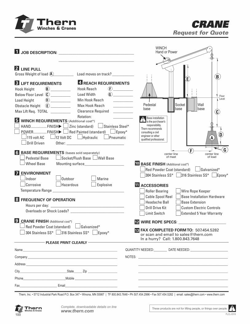
ThernWinches & Cranes
100
Complete, downloadable details on linewww.thern.com
FLCL-0318
These products are not for lifting people, or things over people.
ThernWinches & Cranes CRANE
Request for Quote
JOB DESCRIPTION: ______________________________________
______________________________________ LINE PULLGross Weight of load ___________ Load moves on track? ___________
LIFT REQUIREMENTSHook Height __________Below Floor Level __________Load Height __________Obstacle Height __________Max Lift Req. TOTAL __________
WINCH REQUIREMENTS (Additional cost*) HAND.................. FINISHu Zinc (standard) ___ Stainless Steel* POWER ............... FINISHu __ Red Painted (standard) ___ Epoxy* ___115 volt AC ___12 Volt DC ___Hydraulic ___Pneumatic ___Drill Driven ___Other: _____________________________
BASE REQUIREMENTS (bases sold separately) Pedestal Base Socket/Flush Base Wall Base Wheel Base Mounting surface____________________ ENVIRONMENT Indoor Outdoor Marine Corrosive Hazardous Explosive Temperature Range ____________________________________ FREQUENCY OF OPERATION Hours per day: _____________________________________ Overloads or Shock Loads? ___________________________
CRANE FINISH (Additional cost*)
Red Powder Coat (standard) Galvanized* 304 Stainless SS* 316 Stainless SS* Epoxy*
Thern, Inc. • 5712 Industrial Park Road P.O. Box 347 • Winona, MN 55987 | TF 800.843.7648 • Ph 507.454.2996 • Fax 507.454.5282 | email: [email protected] • www.thern.com
5
PLEASE PRINT CLEARLY
Name __________________________________________________________
Company _______________________________________________________
Address ________________________________________________________
City_____________________________State_____ Zip __________________
Phone__________________________Mobile __________________________
Fax_______________________ Email ________________________________
QUANTITY NEEDED:________ DATE NEEDED: _______________________
NOTES: _______________________________________________________
_______________________________________________________
_______________________________________________________
_______________________________________________________
_______________________________________________________
center lineof mast
center lineof load
A
B
C
D
E
F G
Pedestal base
Socket base
Wall base
FAX COMPLETED FORM TO: 507.454.5282or scan and email to [email protected] a hurry? Call: 1.800.843.7648
13
WINCH Hand or Power
BASE FINISH (Additional cost*)
Red Powder Coat (standard) Galvanized* 304 Stainless SS* 316 Stainless SS* Epoxy*
ACCESSORIES Roller Bearing Wire Rope Keeper Cable Spool Reel Base Installation Hardware Headache Ball Base Extension Drill Drive Kit Custom Electric Controls Limit Switch Extended 5 Year Warranty WIRE ROPE SPECS: ________________________
11
10
Base installation is the purchaser’s responsibility. Thern recommends consulting a civil engineer or other qualified professional.
6
7
8
A
1
2
3BC D
E
9
REACH REQUIREMENTSHook Reach __________Load Width __________Min Hook Reach __________Max Hook Reach __________Clearance Required __________Rotation: __________
4FG
12
Floor Level

ThernWinches & Cranes
101FLCL-0318
Complete, downloadable details on linewww.thern.comThese products are not for lifting people, or things over people.
NOTES:

ThernWinches & Cranes
102
Complete, downloadable details on linewww.thern.com
FLCL-0318
These products are not for lifting people, or things over people.
NOTES:
Best Source. Thern, Inc. sells through a nationwide network of industrial and specialty distributors. For the name of a Thern Distributor near you, call Thern Customer Service at 1-800-843-7648 or visit us online at www.thern.com.
Account. Orders can ship to open accounts upon Credit Department approval.
Credit Card. Thern, Inc. accepts MasterCard, VISA and American Express. All credit card orders are processed immediately upon authorization. Your account will not be charged until we have processed your order for shipment. Thern, Inc. reserves the right to charge a surcharge of up to 2.85% on orders paid by credit card.
COD. Thern, Inc. can ship your order cash-on-delivery.
Freight. To minimize any shipping delays, Thern, Inc. reserves the right to use the carrier of its choice. For separate freight charge invoices, terms are net 15 days. Thern, Inc. reserves the right to apply a shipping and handling fee to all freight charges. We do not supply copies of original freight invoices. Thern, Inc. will attempt to comply with specific routing instructions, designated as the purchaser’s responsibility, only when provided on each individual phone, fax or mail order at time of order. Blanket instructions are not acceptable unless specified on each order.
Small Package Service. Shipments routed via United Parcel Service (UPS) or Federal Express will have a $5.00 handling charge.
Claims. On all Ex Works factory shipments, title to the merchandise passes to the purchaser at the time the merchandise leaves Thern, Inc.’s factory dock. The purchaser should inspect the merchandise thoroughly when received for damage or shortages and should not sign for the merchandise until satisfied that all merchandise has arrived in good condition. Any claim for loss or damage by the purchaser must be settled with the carrier. Thern, Inc. accepts no responsibility for losses or delays in transit.
Minimum Billing. The minimum billing is $25.00 per order, plus freight charges.
Conditions. Possession of this catalog is not to be construed as an offer to sell by Thern, Inc. Products may be discontinued or changed (modified and/or improved) with-out notice. All orders are subject to prices established by Thern, Inc. at the time of shipment and prices are subject to change without notice. Please contact Thern, Inc. for current pricing.
Returns. Thern, Inc.’s prior approval is required before any merchandise is returned. Approved returned merchandise must have an RGA# (Returned Goods Authorization Num-ber) issued by Thern, Inc. No returns will be accepted by Thern, Inc. without an RGA#. Approved returned merchandise will have a minimum applied charge of 25% of original cost, subject to condi-tion upon receipt. Thern does not accept collect shipments. Non-standard or modified products are non-returnable. Any approved merchandise returned to Thern, Inc. will be reviewed by Thern, Inc. and the purchaser shall be notified of the cost for reconditioning within 30 days. The purchaser shall have 30 days after notification by Thern, Inc. to either authorize reconditioning of the merchandise or otherwise direct the disposition of the merchandise. In the event the purchaser does not notify Thern, Inc. within the 30 day period, Thern, Inc. shall consider the merchandise abandoned and shall dispose of the merchandise.
Certificates. There is a minimum $25.00 charge for a Quality Assurance Certification.
Cancellation. Orders may be cancelled only with written approval from Thern, Inc. and with terms that will indemnify Thern, Inc. against all loss.
Documents. Thern, Inc. will supply up to two (2) owner’s manuals and two (2) assembly drawings at no charge. Additional manuals and drawings are $5.00 each.
All orders are subject to Credit Department
approval and are Ex Works, Winona, MN TERMS
PAYMENT OPTIONS

An innovator providing
world-class solutions
to lifting, lowering, pulling and
positioning challenges
all over the World
New YorkTimes Square Ball
BC Place StadiumReduction SystemBC Place StadiumLand Based and
Off Shore Oil RigsHoover Dam
Bypass BridgeIvanpah World’s
Largest Solar GENOne World
Trade CenterWashington DC
Aquaduct ProjectNASA Space Shuttle
Launch Pad Land Based and Mining District
In Australia
Small Company - Big Reputation