qualitative approach for selection of systems structures and
TRANSCRIPT
EUR23446EN 2008
Qualitative approach for selection of Systems Structures and Components to be considered in Ageing PSA.
EC JRC Network on Use of Probabilistic Safety Assessments (PSA) for Evaluation of Ageing Effects to the Safety of Energy Facilities.
A Case Study on Task 3.
M. Nitoi, A. Rodionov

1
The Institute for Energy provides scientific and technical support for the conception, development, implementation and monitoring of community policies related to energy. Special emphasis is given to the security of energy supply and to sustainable and safe energy production. European Commission Joint Research Centre Institute for Energy Contact information Address: PO Box 2, NL-1755 ZG Petten E-mail: [email protected] Tel.: 0224 56 54 57 Fax: 0224 56 56 21 http://ie.jrc.ec.europa.eu http://www.jrc.ec.europa.eu Legal Notice Neither the European Commission nor any person acting on behalf of the Commission is responsible for the use which might be made of this publication. A great deal of additional information on the European Union is available on the Internet. It can be accessed through the Europa server http://europa.eu/ EUR 23446 EN ISSN 1018-5593 Luxembourg: Office for Official Publications of the European Communities © European Communities, 2008 Reproduction is authorised provided the source is acknowledged Printed in Netherlands
1
Qualitative approach for selection of Systems Structures and Components to be considered in Ageing PSA.
EC JRC Network on Use of Probabilistic Safety Assessments (PSA) for Evaluation of Ageing
Effects to the Safety of Energy Facilities. A Case Study on Task 3.
M. Nitoi, A. Rodionov
2
Abstract
This report presents a qualitative approach for selection of Systems, Structures and Components (SSC) sensitive to ageing. The purpose of selection is to model and evaluate SSC ageing effects on the overall NPP safety by applying Probabilistic Safety Assessment tool. The report was prepared by Institute for Nuclear Research, Pitesti, Romania in cooperation with Institute for Energy, EC Joint Research Center, Petten, Netherlands in the frame of EC JRC Ageing PSA Network Task 3 activities. The goal of the work is to demonstrate the feasibility of qualitative assessment in selection of components sensitive for ageing and to develop a viable guideline for selection of components susceptible to ageing. An overview of the available approaches for selection of ageing components was performed, and the methods are briefly presented. Their advantages and disadvantages, as their limitation are also specified. Applicability of the approach for qualitative selection of SSC susceptible to ageing was demonstrated by a case study which uses as an example SSC of NRI TRIGA research reactor. A list of ageing mechanisms, as their favorable factors for occurrence is provided in appendices of the report.
Acknowledgements The authors would like to thank to all EC JRC Ageing PSA Network Task 3 participants for the review and valuable comments.
3
CONTENTS 1. INTRODUCTION 4 1.1 Objective 4 1.2 Scope 4 2. METHODS FOR SELECTION OF SSC SUSCEPTIBLE TO AGEING 5 2.1 Analysis of operating experience 5 2.1.1 Graphical method 6 2.1.2 Statistical analysis of data 6 2.2 Probabilistic Techniques 7 2.3 Expert Judgment 9 2.3.1 Expert panel 9 2.3.2 Ageing Failure Mode and Effect Analysis (AFMEA) 10 3. APPROACH FOR QUALITATIVE SELECTION OF COMPONENTS SUSCEPTIBLE TO AGEING 14 3.1 Necessary information 14 3.2 Gradual screening approach 15 4. CASE STUDY 20 4.1 TRIGA reactor – general considerations 20 4.2 Primary cooling circuit 24 4.3 Secondary cooling circuit 28 4.4 Analysis 31 4.4.1 PSA analysis considerations 31 4.4.2 AFMEA considerations 33 5. CONCLUSIONS 42 6. REFERENCES 43 Appendix 1 – Definitions 45 Appendix 2 - Ageing Mechanisms 47 Appendix 3 – Basic Event Labelling scheme 58 Appendix 4 – TRIGA reactor characteristics 61 Appendix 5 – Primary coolant SCRAM and reactor related interlocks 63 Appendix 6 – Figures 66 Figure A6.1 – TRIGA reactor 67 Figure A6.2 - Primary circuit diagram 68 Figure A6.3 – Secondary circuit diagram 69 Appendix 7 - Primary coolant agent characteristics 70 Appendix 8 – Analysis results 71 A8.1 Risk importance results 72 A8.2 AFMEA results 77
4
1 INTRODUCTION
Ageing represents a concern phenomenon since any degradation that may occur in time could lower the component performance and so reduce its reliability. If the phenomenon is left unchecked and unmitigated, the ageing could increase the risk associated with the facility operation. In the effort of managing the degradation impact in a proper manner, is important to assess the effects of age-related degradation of facility structure, systems and components (SSC). [8], [9], [11] Because of the large number of NPP components, the variety of their applications, the complexity of ageing processes, limited knowledge and limited resources, there is a need to concentrate the effort on the understanding and managing the safety impact of ageing on key components.
The methods which can be used in determining safety significant components which are susceptible to ageing degradation are the following:
• analysis of operating experience • expert judgments • probabilistic techniques.
The methods are complementary and for the best results they should be used in combination. The purpose of this report is to propose a practical qualitative approach for investigating
ageing problems, more specific, for determining, on the basis of existing knowledge, the components and systems susceptible to ageing degradation whose failures could have a significant adverse effect on facility safety.
This report will provide the analyst with a useful tool in performing the selection process, for reaching the objective proposed, the selection of components both susceptible to ageing and important for safety. The approach intends to ensure that the selection process will be carried out and documented in a uniform and consistent manner.
1.1 Objective
The goal of the report is to provide a feasible approach for selection of SSC, as a case study for task 3 of APSA Network.
1.2 Scope
The report will briefly describe the methods that can be used in the SSC selection, will present the proposed steps of SSC selection approach as the results of selection of SSC important from safety and from ageing sensitivity point of view (component prioritization) performed for two systems of TRIGA reactor.
5
2 METHODS FOR SELECTION OF SSC SUSCEPTIBLE TO AGEING
The methods taken into consideration for selection and prioritization of safety significant
components susceptible for ageing were the following: analysis of operating experience, expert judgment and probabilistic techniques.
2.1 Analysis of operating experience [8]
Analysis of operating experience data is a valuable method for identification of key components and systems susceptible to ageing degradation. The review of operating experience can be used to identify, correct and mitigate system and component failures caused by the effects of ageing degradation.
On average, ageing can be considered as one of the important causes of operating events reported.
The analysis of operating experience data permits: o to identify the extent to which the performance of systems and components has been
affected by ageing, and the ageing mechanisms responsible o to identify methods of failure detection and the severity of the failures o to identify specific ageing failure causes for selected systems and components
Periodic assessment of databases can yield information on increasing component failure rates (sign of ageing), thereby giving vital information for focusing maintenance and surveillance activities. This information should be supplemented by personnel interviews on: - equipment problems and possible root causes related to ageing, - anticipated equipment performance or reliability problems, - historical ageing problems, in such manner that important operating information can be collected and significant safety component can be identified. Comments:
• Since the operational data is scattered in a wide range of reporting systems, the determination of the accuracy and quality of data requires consultation of a large volume of technical documents;
• Most of available databases were not designed to provide the data needed for the proper evaluation of ageing effects (they do not include data on equipment age, service life or service conditions, maintenance histories of the failed components, or records related to incipient failures);
• While the volume of technical data on operating experience can be considerable, the quality of the data may be very different. Some reports contain detailed root cause analysis insights and results, while the others have small (and sometimes conflicting) information on the causes and consequences. The determination of root cause of the failure can be very difficult;
• Database analysis may yield different results, depending on the period of time over which the database is sampled, especially for those components with moderately long lifetimes. As plants get older, these types of components may become more prominent in the population of failures occurring owing to ageing;
• The operating experience information should be periodic analyzed, and databases should be periodically up-dated to ensure that data (materials, service conditions and their interactions) needed to evaluate the effects of the ageing of an actual system and component performance are collected.
6
2.1.1 Graphical method
For a simple ageing trend investigation, either simple graphs can be constructed, or simple tests of hypotheses can be performed. [1], [12] The type of graph depends on the type of data, either data for the individual failures or binned data. A complete description of performing the analysis using graphical method is made in [12]. Comments:
• Graphs are easy and comfortable methods for evidence of trends. Visual assessment of data could help to identify easily potential issues, but they don’t give any quantitative estimation about the size of the trends;
• A formal statistical test will be needed to measure the strength of the evidence against the hypothesis of constant event frequency.
2.1.2 Statistical analysis of data
In the simplest way, the task of statistical analysis consists in checking the hypothesis that SSC failure rate is constant.
According to the statistical model construction, statistical tests can be divided into two groups: parametrical and non-parametrical.
In the application of parametrical methods, is assumed the law of random value distribution, and the accepted hypothesis is checked on the basis of the received data.
To make the assumption on the distribution law and to inspect the accepted hypothesis it is necessary to have a large statistic, and unfortunately, this is not always available. Sometimes, this difficulty can be bypassed using non-parametrical tests, which don’t apply any assumptions concerning the type of random value distribution.
The hypothesis can give a quantitative answer to the question of whether ageing appears to be present, by measuring the strength of the evidence against the hypothesis H0: no ageing occurs.
The various statistical tests could be used to validate or to refuse this assumption. Some of them are discussed in [1], and we will specify only the cases when they are used. When the data contain information on the individual failures, we can use for analysis the Laplace test, Inversion criteria test, Kendall test, Chi-Squared test. When the data are aggregated in bins, we can use Centroid test, or the Wilcoxon-Mann-Whitney test. Comments:
• non -parametrical tests are very simple to apply, and they provide exact info about level of significance, without applying any assumptions concerning the type of random value distribution
• results have to be always interpreted taking into account engineering considerations and qualitative assessment of data
• other assumption for binomial data is that the outcomes of different demands be independent — a success or failure on one demand does not influence the probability of failure on a subsequent demand. In practice, this is not true always, there can be many dependences. The analyst should consider possible common-cause mechanisms, and examine the data to see if many common cause failures occurred. If common-cause failures form a noticeable fraction of all the failures, the analyst should divide the independent failures and the common-cause failures into separate data sets, and separately estimate the probabilities of each kind of failure.
If the evidence justifies further work, a model for the data and for the trend should be assumed. Modeling a trend normally involves some detailed mathematics usually performed by computer software.
7
It can be assumed that the data come from a Poisson process, with a failure rate λ that may be a function of age (several functional forms have been assumed in the literature for λ(t)). [12] Comments:
• Parametrical tests are more complex but more powerful then non -parametrical ones
• Any model must be checked for goodness of fit (fitting the model with the data test) before drawing any conclusion about trend
• Data homogeneity have to be verified (units, systems, environment, operating conditions) if possible
• Burning-in failures, maintenance renewal, performed modifications could change the component reliability and impact significantly on data
• Some of the models which are widely used, are chosen mainly for their simplicity and convenience, not for their theoretical validity
• All conclusions are valuable in case of large statistic, if not the method is not recommended to be used.
Lack of statistically significant evidence against a hypothesis does not prove that the hypothesis is true (lack of strong evidence for ageing does not prove that no ageing is occurring), there may just not be enough data to draw firm conclusions. The analyst should keep in mind that any statistical findings must be interpreted carefully and thoughtfully.
2.2 Probabilistic Techniques
A standard probabilistic safety assessment (PSA) does not include time dependent effects, and in the process of determining the risk level at a plant, it generally use a time averaged unavailability which limits the utility of the information that can be extracted from a PSA (ageing is a time dependent phenomenon). More information would be available if ageing effects were included and such an adaptation of PSA results will enable an identification of the components that have the greatest effect on risk if their failure rates increase owing to ageing or service wear effects. Although ageing is not usually considered in the PSA calculations, the safety importance of assumed increases in the components failure probabilities can be evaluated. It is considered that if an increase in failure rate of certain components does not have any considerable effect, ageing analysis of such components are known to be of little importance. [10] We can evaluate the change in the plant risk due to the assumed increase in failure probability because of component ageing, assuming the same ageing rate for all components, or different ageing rate. Depending on the objectives of the ageing analysis, it is possible to evaluate the significance of ageing either at component, system and core-melt frequency level, or even on the level of accident consequences. The prioritization of components requires a system-level analysis, where results of probabilistic safety analyses can be used. The component importance may be evaluated by applying risk-importance measures, which express the influence of a basic event on the total plant risk. [2], [3] Bellow we will specify the most commonly used risk-importance measures. [4] Risk Achievement Worth
The risk achievement worth (the risk increase factor) (RAW or RIR) represents the
relative increase of the risk given the basic event occurs.
8
Considering:
R+i = the increased risk level assuming the occurrence of the event,
Ro = the present risk level, then on a ratio scale the risk achievement worth IRIR of event i is defined as: IRIR = R+
i /Ro (1) The features risk achievement worth is useful for prioritizing features which are most
important in reliability assurance and maintenance activities. Fussel-Vesely Importance
The fractional contribution of a basic event to risk, Fussel-Vesely importance measure, expresses the relative improvement potential when it is assumed that the basic event never occurs.
The fractional contribution of event i to the risk, or the Fussel-Vesely measure of
importance, IFV, can be expressed as: IFV = (R0 – Ri
- )/ R0 (2) where the numerator represents the risk due to contributor i. Comments:
In order to be usable for the selection and prioritization of components, the PSA model must be detailed enough to describe the impact of single components (or groups of components) on the plant safety;
Most current PSA analyses are level 1 PSA, and consequently, components (especially passive) that may be important to containment response or consequence reduction are not modelled. The importance to risk of components that mitigate accident consequences is not easy to be determined (large uncertainties associated with the phenomenology and fission product behavior of severe accidents);
The analysis is limited to the effects of complete failure (loss of function); the effects-of degradation (incipient failures) are not specifically addressed;
The particular PSA utilized to determine the component results may not include treatment of all aspects of risk such as external event analysis;
Investigation of components that do not appear in PSA dominant cut-sets is also necessary (components believed as being non-dominant in PSA can become major contributors to risk when they are susceptible to significant ageing);
The results are subject to the uncertainties inherent in PSA including component failure data uncertainties, modeling uncertainties, and uncertainties in human actions and response. Sensitivity analysis can be used to identify the importance of assumptions and areas where more in-depth analysis is needed. Since the methodology only relies on importance measures to provide a “go/no-go” answer to the question on screening, it can be considered that general importance measure limitations are not critical;
A necessary complement to the risk ageing sensitivity measure is a description of the time-dependent effects of ageing on component failure rates. Initial estimates of these effects could possibly be estimated from older plant operating history and component failure data. A complete description will include:
-identification of component types that are susceptible to ageing -the environmental conditions and system applications that influence component ageing -time-dependent functions defining component failure rates
These factors should be investigated first for the components that have high potential risk impact as determined by the risk ageing sensitivity measure.
9
2.3 Expert Judgment
Another method for identification of safety significant systems and components which may be subject to age related degradation is to consult plant personnel, engineers and scientists working in the nuclear power research and regulatory organizations who have a deep knowledge and experience of NPP performance and behaviour. Their opinions on ageing matter should be reflected in the final results.
2.3.1 Expert panel
An expert panel can be used: [2]
o to assess the ageing of plants o to incorporate an understanding of ageing and its effects (e.g., define the list of
components susceptible to ageing and the contribution of SSC ageing to plant risk) o to assess the adequacy of current practices for managing component ageing within
acceptable levels of risk o to determine the importance of SSC ageing of individual components/ component
groups on plant risk o to prioritize the components taking into account their risk significance of ageing
The panel membership should represent expertise in a full spectrum of relevant
technical areas: PSA, structures, electrical and mechanical components, component reliability, materials behavior and failure analyses, in-service inspection, operations and maintenance, as well as safety, regulatory, ageing and life extension issues.
The expert panel should be supplied with all the necessary information for a clear judgment (list of components, prioritization criteria, prioritization methodologies, and technical support material). The panel can use judgments and a specific criterion to rank the SSC relative to one another.
The following risk-based criteria can be used in the assessment process: the potential increase in plant risk from component ageing; the adequacy of current ageing management practices for maintaining risk at acceptable
levels. Comments:
• Expert panels represent an useful approach for identifying ageing problems to be addressed, if the participants have a good knowledge of reactor safety and findings from the analysis of operating experience
• A proper expert judgment treatment requires the efforts of many experts from varying fields of science, and takes a lot of time to carry out. Thus it appears that a reasonable combination of statistical, structural reliability and expert panel methods would be an appropriate approach in the failure probability assessments
• If adequate data are not currently available, the expert opinion process is the only way in which ageing issues assessment can be accomplished
2.3.2 Ageing Failure Mode and Effect Analysis (AFMEA)
The ageing failure mode and effects analysis (AFMEA) is a method that may be used to evaluate risk priorities for mitigating known threat-vulnerabilities to ageing. AFMEA is used to identify potential ageing failure modes, determine their effect on the operation, and identify actions to mitigate the failures. While anticipating every failure mode
10
caused by ageing is not possible, should be formulated a list of potential failure modes as possible.
The purpose of the AFMEA is to study the results or effects of item failure caused by ageing, on system operation and to classify each potential failure according to its severity. There are two primary approaches for accomplishing the technique: Hardware approach [5]
The hardware approach lists individual hardware items and analyzes their possible ageing failure modes; it is normally used when hardware items can be uniquely identified from schematics, drawings, and other engineering and design data. The hardware approach is normally utilized in a part level up fashion (bottom-up approach), but it can be initiated at any level of indenture and progress in either direction, until the process is complete. Each identified failure mode caused by ageing shall be assigned a severity classification which will be utilized to establish priorities for corrective actions. Functional approach [5]
The functional approach lists a number of functions which should be performed by every item, and analyze their failure modes. This approach is normally used when hardware items cannot be uniquely identified or when system complexity requires analysis from the initial indenture level downward through succeeding indenture levels. The functional approach is normally utilized in an initial indenture level down fashion (top-down approach), but it can be initiated at any level of indenture and progress in either direction, until the process is complete. Each identified failure mode shall be assigned a severity classification which will be utilized to establish priorities for corrective actions.
The technique may be performed as a hardware analysis, a functional analysis, or a combination of both.
The analyst could make the selection in two ways: A. he can perform a classical FMEA [5], and after that he can select only the failure modes which are caused by ageing. In this case, the most probable causes associated with the postulated failure mode shall be identified and described. Since a failure mode may have more than one cause, all probable independent causes for each failure mode shall be identified and described. Each failure mode and output function shall, as a minimum, be examined in relation to the following typical failure conditions: a. Failure to operate at demand b. Spurious operation c. Loss of output or failure during operation d. Degraded output or operational capability e. Other unique failure conditions, as applicable, based upon system characteristics and operational requirements or constraints B. he can perform from the begging of the analysis a selection of failure modes caused by ageing which are possible to appear (this mode requires a carefully selection, for completeness and accuracy of the results), and to evaluate only their effect on the immediate level, on the system, and on the function needed to be performed.
For each system element, AFMEA provides answers to the following questions:
What are the ageing failure modes for a particular component? What will happen to the system and its environment if this element does fail due to
ageing (failure effects caused by ageing)? The qualitative report will identify also the modalities in which the ageing failure can be
detected and will specify (if any) the safeguards against significant failures caused by ageing.
The following discrete steps shall be used in performing an AFMEA:
11
1. The definition of system to be analyzed [5] Complete system definition includes drawings, charts, descriptions, diagrams,
component lists, identification of internal and interface functions, expected performance at all indenture levels, system restraints, and failure definitions. Functional narratives of the system should include system and part descriptions of each mission in terms of functions which identify tasks to be performed for each mission and operational mode. Narratives should describe the environmental profiles, expected mission times and equipment utilization, and the functions and outputs of each item, and conditions which constitute system and part failure.
Anticipated environmental conditions shall be defined.
2. The development of block diagrams [5] A functional block diagram illustrates the operation and interrelationships between
functional entities of a system as defined in engineering data and schematics. A reliability block diagram defines the series dependence or independence of all functions of a system or functional group for each event. Functional and reliability block diagrams which illustrate the operation, interrelationships, and interdependencies of functional entities should be obtained or constructed for each item configuration involved in the systems use. All system interfaces shall be indicated.
3. The identification of stress factors for each component and associated ageing mechanism
The analyst should consider all information related to operating conditions, component design and qualification, material and manufacturer, and to identify the possible ageing mechanisms.
4. The identification of all potential item and interface failure modes caused by ageing and specification of their effect on the immediate function or item, on the system, and on the mission to be performed
Potential ageing failure modes shall be determined by examination of item outputs and functional outputs identified in applicable block diagrams and schematics. 5. The evaluation of each ageing failure mode in terms of the potential consequences
The basic process is to take a description of the parts of a system, and list the consequences if each part fails. Failure effects shall also consider the mission objectives, maintenance requirements and personnel and system safety.
A description of the methods by which occurrence of the ageing failure mode is detected by the operator shall be recorded (visual or audible warning devices, automatic sensing devices, sensing instrumentation, other unique indications, or none shall be identified). The consequences can be evaluated by three criteria and associated risk indices: [5]
• severity of potential ageing failure (S),
• probability of occurrence of a potential ageing failure (O),
• probability of detection (D) Each index ranges from 1 (lowest risk) to 10 (highest risk). The overall risk of each failure is called Risk Priority Number (RPN) and represents the product of Severity (S), Occurrence (O), and Detection (D) rankings: RPN = S × O × D (3) The RPN (ranging from 1 to 1000) is used to prioritize all potential ageing failures to decide upon actions leading to reduce the risk, usually by reducing likelihood of occurrence and improving controls for detecting the failure.
12
The consequences of each assumed failure mode on item operation, function, or status shall be identified, evaluated, and recorded. The consequences of each postulated failure affecting the item shall be described along with any second-order effects which result. 6. The prioritization of components and providing recommendation to reduce ageing failure risk
A prioritization of components based on RPN value obtained can be performed. This step should determine recommended actions to address potential failures that have
a high RPN (new specific inspection, testing or quality procedures; recommendation of different components or materials; limiting environmental stresses or operating range; monitoring mechanisms; performing preventative maintenance). 7. Documentation of analysis
The results of the AFMEA and other related analyses shall be documented in a report that identifies the level of analysis, summarizes the results, documents the data sources and techniques used in performing the analysis, and includes the system description, resultant analysis data, and worksheets.
The worksheets shall be organized to first display the highest indenture level of analysis and then proceed down through decreasing indenture levels of the system. The ground rules, analysis assumptions, and block diagrams shall be included, as applicable, for each indenture level analyzed.
The final AFMEA worksheet will contain the following information for each component which was analyzed:
• General administrative / heading information (system, analyst) • Item name • Ageing failure mode • Failure cause/ ageing mechanism • Ageing failure effect • Risk assessment (RPN) • Remarks
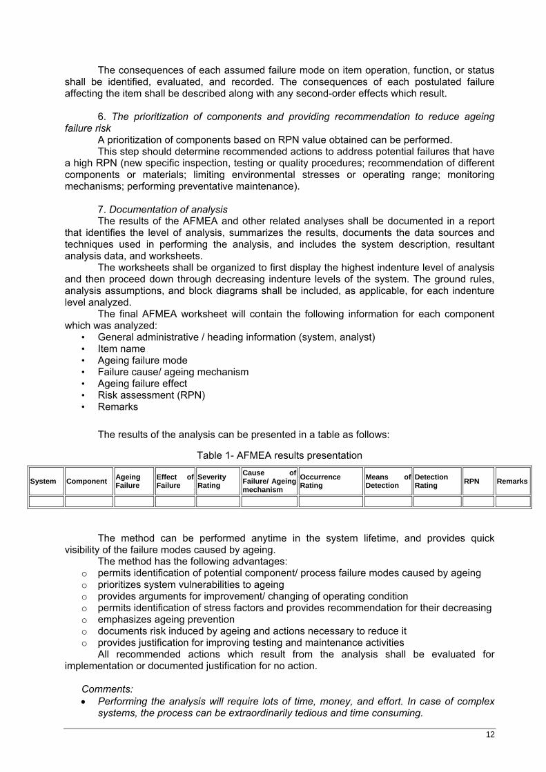
The results of the analysis can be presented in a table as follows:
Table 1- AFMEA results presentation
System Component Ageing Failure
Effect of Failure
Severity Rating
Cause of Failure/ Ageing mechanism
Occurrence Rating
Means of Detection
Detection Rating RPN Remarks
The method can be performed anytime in the system lifetime, and provides quick visibility of the failure modes caused by ageing.
The method has the following advantages: o permits identification of potential component/ process failure modes caused by ageing o prioritizes system vulnerabilities to ageing o provides arguments for improvement/ changing of operating condition o permits identification of stress factors and provides recommendation for their decreasing o emphasizes ageing prevention o documents risk induced by ageing and actions necessary to reduce it o provides justification for improving testing and maintenance activities
All recommended actions which result from the analysis shall be evaluated for implementation or documented justification for no action.
Comments: • Performing the analysis will require lots of time, money, and effort. In case of complex
systems, the process can be extraordinarily tedious and time consuming.

13
• The method doesn’t take into considerations the human errors or the passive elements located in non-hostile environments, as well as static or non-loaded elements.
• AFMEA is useful mostly as a survey method to identify major failure modes in a system. It is not able to discover complex failure modes involving multiple failures or subsystems, or to discover expected failure intervals of particular failure modes. For these, fault tree analysis is used.
14
3 APPROACH FOR QUALITATIVE SELECTION OF COMPONENTS SUSCEPTIBLE TO AGEING
3.1 Necessary information
Every study should begin with the identification, review and assessment of relevant existing information and documentation of the findings.
To understand the ageing degradation of a component, it is first necessary to identify and understand the ageing processes, and to do that is necessary to know the design, materials, service conditions, performance requirements and operating experience (operation, surveillance and maintenance histories) for the component of interest.
Below are specified the sources of information that can be used to acquire the necessary knowledge. [6], [7], [8], [13] Component design and specifications The required knowledge of the components design can be obtained from design documents and technical specifications. Additional information should be obtained, as appropriate, from vendor surveys, utilities, published reports and expert opinion. The analyst should consult a large amount of information, as design documentation, technical specifications, standards, operating and maintenance manuals. Materials properties Material properties information are usually provided by the vendor. A list of all significant parts and materials judged most susceptible to ageing should be identified. Service conditions The age related degradation of a component is a time dependent phenomenon and depends, among other things, on service conditions, including the operating environment, and the operating history. The service conditions impose stresses on a component which lead to its degradation through various physical and chemical processes (temperature, electrical and mechanical loadings, radiation, chemicals, contaminants, atmospheric humidity and system chemistry). The service conditions that should be identified and investigated include environmental, loading and power conditions resulting from normal operating requirements, including expected operational transients, and also those conditions that prevail during testing, shutdown and storage. Performance requirements The performance requirements of the component should be reviewed to assess whether or not ageing may degrade its ability to perform the required safety function in normal, abnormal and, where applicable, accident conditions. The functional and conditional indicators that could be monitored to provide an indication of age related degradation and future performance of the component should be identified, as possible. Operating experience The failure rate history, identified failure and degradation mechanisms, age related failure modes and causes that have been experienced should be identified, by reviewing facility surveillance, maintenance, in-service inspection, design change and reliability records, and significant event and reliability databases available. When the desired information is not directly available from the existing records, limited analyses of the available records and interrogation of facility personnel may be performed to uncover missing information.
15
Component degradation may be identified from failure descriptions, or surveillance, maintenance and in-service inspection records. Most components are not uniformly susceptible to ageing degradation, as certain locations exhibit more deterioration than others and for many components degradation is limited to a specific location only. An understanding of the ageing degradation of a specific component requires knowledge of the locations where degradation occurs, its mechanisms and its rate. Research
Research on ageing mechanisms of the selected component should focus on determining the ageing mechanisms causing significant degradation of the component, and quantifying the effect of relevant factors (ambient environment, operating requirements and conditions) on the rate of degradation.
The approach for the selection of SSC should consider all types of components, as:
• Short-lived, active components (relay, controller, transmitter) • Medium lived, active and passive components (valves, pumps) • Long lived, passive components (pipes, cables, structures)
For short lived, more easily replaceable and repairable components, ageing information
is usually obtained from operating experience, including both failure and maintenance information. Qualitative analyses are used to differentiate ageing-related failures from other failures that are due to such problems as maintenance errors, wrong operation or unexpected events. The elementary form of a qualitative analysis is the study of failure reports. The participation of facility personnel in qualitative analyses is important, because it can reveal a common cause of maintenance error that is not an age-related phenomenon.
Degradation of such components is usually adequately addressed by existing surveillance and maintenance programs.
For medium life components, test and inspection frequency is relatively low, so effectiveness of ageing management may be questionable. Age-dependent reliability models for such components can be based both on statistic methods and reliability physics. [8], [10]
For structural parts and passive components, there is no planned preventive or corrective maintenance, they are originally designed to reach the end of facility life with an adequate safety margin, and ageing information is typically in the form of degradation data from condition monitoring. Inspections are costly, their frequency is low, there are no corrective or preventive maintenance, and consequences of single failure are very significant or catastrophic. [8], [10]
3.2 Gradual screening approach
To evaluate each of facility components in terms of its susceptibility to ageing and its contribution to facility safety would be a difficult task, and the process of evaluation and quantification of ageing degradation of the many thousand of individual components is not practicable nor is it necessary. Components should be carefully selected and prioritized to maximize the effective use of limited resources and to prioritize the work.
Taking into account the following facts: there are many components in a nuclear facility, ageing mechanisms, which result in the reduction of functional capabilities of
components and systems, are operative to different degrees throughout facility (depending on many stressors),
16
some of the safety related components contribute more than others towards ensuring facility safety,
all facilities have a large variety of testing, maintenance and inspection programs, which can mitigate more or less the effects of ageing,
we can conclude that it is essential to assess the effects of age-related degradation on the key SSC of the facility.
Since we are interested only in finding components which are both sensitive for ageing and important from risk point of view, we will use as prioritization criteria the following ones:
the potential increase in facility risk from component ageing; the adequacy of current ageing management practices for maintaining risk at
acceptable levels
The proposed approach uses two screenings: • the first screening is related to system or structure level • the second one is performed at component level (evaluation of all component within the
selected systems and structures)
The approach should go through the following steps: [6], [30] Step 1: collection of necessary information The necessary data for performing the ageing analysis are the following: baseline information, operation history data and maintenance history data. Baseline information is useful in defining a component, its system, in describing initial material condition and functional capability, design service conditions and operating limits. Example of baseline information:
component ID, type and location expected degradation mechanisms design specifications (service conditions, service life cycles) environmental qualification specifications (qualified life, normal and DBE service
conditions, operation and maintenance requirements) manufacturer data (materials data) commissioning data design modification information
Operating history data enable identification of age related failures, and related ageing mechanisms, tracking of failure rates and correlation to service conditions, assessment of maintenance effectiveness, early identification of ageing phenomena. Example of history data:
environment information (temperature, humidity, radiation) dates and profiles of component loading, cycling operation mode (continuous, standby, intermittent) downtime periods
Maintenance history data facilitate evaluation of maintenance effectiveness in preventing component failures, and adjustments of the timing and type of maintenance actions. Example of maintenance history data:
type of maintenance (corrective/ preventive) date and duration work description (repair, refurbishment, replacement) modifications of maintenance methods and intervals
Step 2: screening after the contribution of system or structure to facility safety
17
In order to do this selection, the entire list of facility system and structures will be reviewed, and in the screening, the safety classification system (which already exist), and the results of PSA study will be used. A way of setting priorities is to class the different systems of a facility by identifying the systems important for safety and important for availability. A system which does not belong to any of the above mentioned, it will be removed from the list for further analyses. As a result, it is obtained a shorter list of systems and structures (important from the safety or availability point of view) to be evaluated at component level. Step 3: ranking of SSC which are important for safety (using PSA results, risk importance measures, or other arguments including expert judgment) This step performs a screening after the impact of aged component failure to system function. For ranking the components, using SSC risk importance measures, we will assume the following indices: 3 –for SSC important to risk 2 –for all other risk important related SSC 1 –for non-critical SSC SSC will be considered as risk important if their calculated risk importance measure are above some specified values (RAW >2, FV>0.005), and they will have allocated the index 3. If the component is support component for the operation of a component which was considered as risk important, the experts will allocate it the index 2. The events with low risk importance measures values will be considered as being related to non risk-significant components (index 1). The previous steps are related to the identification of which component needs to be assessed. This is obvious an important step since it determines the scope of the study. This includes the delineation of boundaries between the component or system to be assessed and interfacing systems. It determines what is and what is not included in the analysis. Step 4: indication of ageing mechanism, potential ageing effects for the selected components; specification of effectiveness of maintenance activities; identification of detection techniques (using AFMEA). This step is related to performing a screening after the component susceptibility to age related failure. This step evaluates the potential of ageing degradation to cause component failure, taking into account:
• significance of known ageing mechanisms • all applicable operating experience
The stresses acting on the components and/ or systems determine what ageing mechanism may be present to cause degradation. Stresses can be due to normal operation, such as wear of motors, or they can be due to the environment, such as excessive humidity or heat. The identification of the stresses acting on a component requires the review of the design, operating conditions, and environment for the particular component.
This step involves another screening process, related to ageing mechanism, and requires knowledge of material degradation properties and operating stressors for a specific component.
A generic list, with information about generic applicable degradation mechanisms and their effect on SSC performance is provided in Appendix 3. An understanding of the effects of various factors on degradation is needed, and knowledge of actual environmental conditions is essential for performing a good assessment.
18
The adequacy of current maintenance practices should be evaluated for their potential in maintaining the risk contribution of these aged components within the acceptable value. Existing methods for inspection, surveillance and monitoring should be evaluated to determine whether they are effective for timely detection of ageing degradation before loss of safety function. Methods to be reviewed include testing, periodic inspection (both visual and instrument aided), on-line monitoring and data evaluation methods. Since the degree of degradation is not recorded, maintenance records will need additive interviews with personnel and interpretation. After the screening process, it will be obtained a list of SSC which are sensitive for ageing and important from risk point of view. Final ranking (prioritization) of the SSC will incorporate both the risk significance of ageing and the effectiveness of practices in maintaining ageing within an acceptable risk level. The AFMEA will be performed in the following steps:
o Getting an overview of the system: –Determination of component function -Identification of stress factors for each component and associated ageing mechanism
o Identification of relevant information for potential ageing failure modes of each component
-Specification of ageing failure mode effect on the immediate function or item, on the system, and on the mission to be performed -Determination of occurrence probability –Determination of failure detection methods
o Evaluation of each ageing failure mode in terms of the potential consequences, probability of occurrence, probability of detection (allocating indices)
o Prioritization of components, recommend actions o Documentation of analysis
Step 5: rank the components which remains susceptible to ageing degradation, despite the safeguard measures (using AFMEA results and expert judgment) The RPN value will be used to quantify the remaining sensitivity to ageing of the component (considering all the mitigation ageing measures). For remaining sensitivity to ageing, we will use the following indices: HIGH – for high RPN value - very sensitive component - very high impact of ageing (high degradation rate) MEDIUM – for medium RPN value - ageing has a moderate impact on component operability LOW – for low RPN value - ageing has a minimum impact For the components which are not modelled in the PSA study, mainly for large structures, taking into account that their damage could have catastrophic consequences, and that there are no related maintenance activities, we recommend using the 3 for risk importance, and LOW related to remaining ageing sensitivity after consideration of maintenance effects.
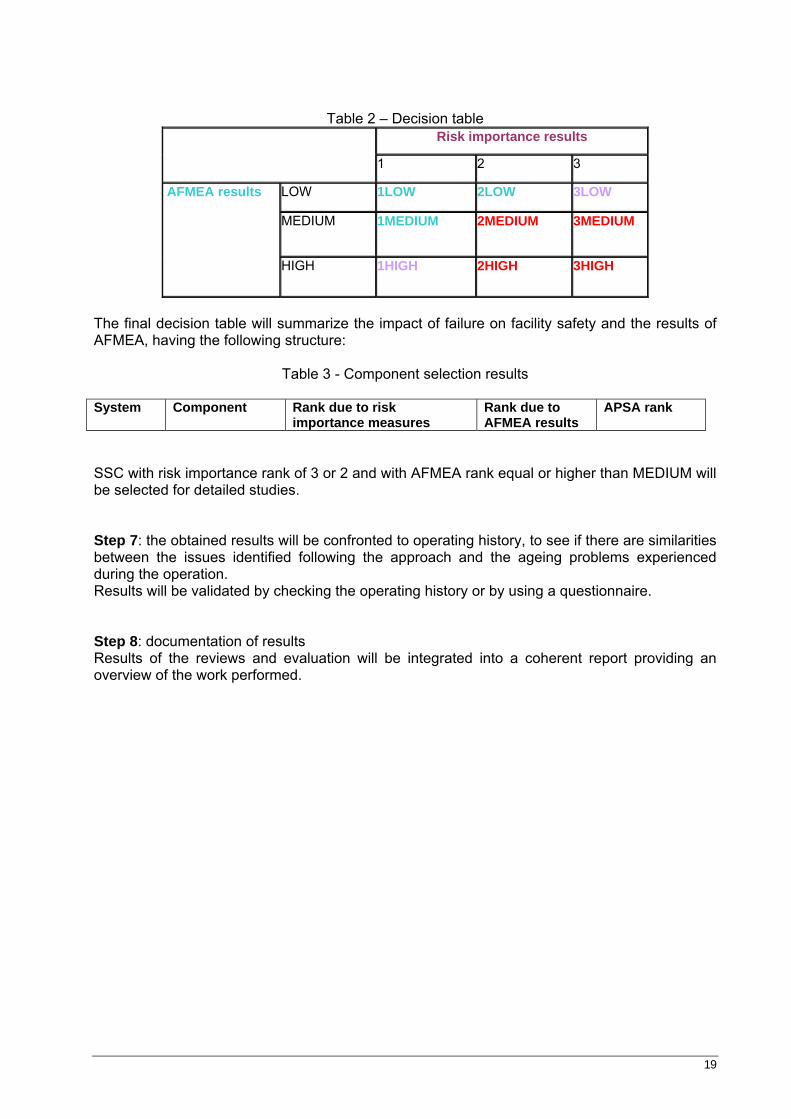
Step 6: using decision table, rank the components which are both susceptible to ageing and important for safety (using results from step 5 and step 3). This step identifies SSC candidates for further APSA analysis (using expert judgment).
19
Table 2 – Decision table
Risk importance results
1 2 3
LOW 1LOW 2LOW 3LOW
MEDIUM 1MEDIUM 2MEDIUM 3MEDIUM
AFMEA results
HIGH 1HIGH 2HIGH 3HIGH
The final decision table will summarize the impact of failure on facility safety and the results of AFMEA, having the following structure:
Table 3 - Component selection results
System Component Rank due to risk
importance measures Rank due to AFMEA results
APSA rank
SSC with risk importance rank of 3 or 2 and with AFMEA rank equal or higher than MEDIUM will be selected for detailed studies. Step 7: the obtained results will be confronted to operating history, to see if there are similarities between the issues identified following the approach and the ageing problems experienced during the operation. Results will be validated by checking the operating history or by using a questionnaire. Step 8: documentation of results Results of the reviews and evaluation will be integrated into a coherent report providing an overview of the work performed.
20
4 CASE STUDY
4.1 TRIGA reactor – general considerations [21], [22], [23], [26], [27], [28]
The dual core concept involves the operation of a TRIGA high-flux, steady-state research and materials testing reactor (TRIGA-SSR) at one end of a large pool, and the independent operation of an annular-core pulsing reactor (TRIGA-ACPR) at the other end of the pool. The steady-state reactor is used in long-term testing of power reactor fuel components (pellets, pins, subassemblies, and fuel assemblies). The annular core pulsing reactor is used for transient testing of power reactor fuel specimens.
Both reactors are supplied with beam tubes. Both reactors may be operated separately or at the same time. The two reactors are completely independent of each other with two exceptions; both share a common reactor pool, and both share the same cooling and water purification systems.
The scheme of TRIGA reactor is provided in Figure A6.1. The 14-MW TRIGA fuel has an expected reactivity life of about 7000-MW days. This
lifetime is realized by using fully enriched uranium and incorporating erbium, which functions as a burnable poison and contributes to the prompt negative temperature coefficient. Reactor operation objectives:
o Technical support for irradiation tests on structural materials and nuclear fuel for CANDU type nuclear power plants
o Irradiated and non-irradiated nuclear fuel behaviour analysis in transient regime o Radioisotopes and irradiated materials production with applications in health, industry
and environment areas
The technical safety systems for TRIGA reactor have the role to maintain the temperature for the fuel under admissible safety limits, to avoid fuel damage and corresponding release of fission products, in case of accidents that involve total loss of flow in the primary circuit and rupture of the main pipe of coolant agent, in any point of the circuit. There are two safety systems:
• emergency coolant system for the SSR core • antisiphon system
The forced-flow coolant system consists of two loops: the main coolant loop for normal
cooling requirements of the operating core, and the emergency coolant loop to provide adequate cooling upon loss of flow from the main pumps. A low-flow signal in either loop will initiate a reactor scram. If the main cooling is lost, the emergency cooling pump provides sufficient flow to remove the stored heat in the core and the after-heat produced following the scram. A timer will prevent the emergency pump from being turned off for a period of time up to 2hr after reactor shutdown.
TRIGA reactor has the following support systems: Electrical power system - provide electrical power to all systems. Instrumental air system provides instrumental air for primary circuit valves, purification system valves. Demineralized water system provides additional water for primary circuit, when necessary. Purification system maintains the chemical quality of water at requested level in primary circuit. Liquid radioactive waste collection system collects water losses from primary circuit. Ventilation system - recirculates air in all reactor rooms. Removes air through evacuation tower. Raw water system - supplies with water secondary circuit and instrumental air system
21
Fuel store and manipulation system - provides support for fuel manipulation and spent fuel storage.
4.1.1 Operating modes
The 14MW steady-state TRIGA reactor is designated for two modes of operation. A mode switch is provided on the control console to allow either mode of operation.
1. Forced flow will allow zero to full-power operation with forced downflow through the reactor core and through water-to water heat exchangers which transfer heat from the reactor primary loop to a secondary loop containing cooling towers. The switch mode has two positions in the forced flow mode: Zero to 7 MW power and 0 to 14 MW power. This allows operation with one or two primary pumps.
2. Natural circulation flow allows low-power operation with convective upflow through the reactor core. There are no heat exchangers in operation in this mode.
Primary cooling loop The primary cooling loop in the forced downflow cooling mode consists of the reactor pool, the core, an inverted loop and siphon break system embedded in concrete, reactor isolation valves, a nitrogen-16 delay tank, main circulating pumps, heat exchangers and return lines to the reactor pool. Flow monitors, temperature monitors, and radiation monitors are provided to indicate proper operation and performance of the loop. The instrumentation and control for reactor cooling system is specified in table A 4.2. The primary coolant system is designated to allow use of any two of the loops, and to allow use of any pump with any heat exchangers. When the primary cooling loop or loops are in operation, a parallel emergency loop is also in operation, with the function to serve as an emergency cooling loop in the event of loss of flow in the primary loop. Flow through this loop is monitored to ensure the loop is operating properly. The decay heat removal pump operates at 19 l/s when the primary pumps are shut down. Primary coolant SCRAM and reactor related interlocks, alarm set-points and sensors are presented in Appendix 5. Normal forced flow Normal forced flow operation of the 14 MW reactor will be through the primary loop, with one or more primary pumps in operation. The flow will be down through the reactor and into an 820mm diameter main coolant line. The main coolant line from the reactor core contains an antisiphon loop with float valves located inside the reactor tank. The float valves are normally closed and open only upon loss of pool water below a preset limit. The purpose of the antisiphon loop and float valves is to allow air into the coolant system piping to prevent the complete loss of pool water. With the exception of the float valves, the antisiphon loop is completely embedded in the reactor shield concrete. Large isolation valves are located in the primary coolant exit and return lines, as close as possible to the reactor shield concrete. These isolation valves are motor-operated and are normally fully open. The valves will be equipped with limit switches to indicate when the valves are completely open. The valves will close on loss of electrical power. The reactor will alarm during normal forced-flow operation upon a signal indicating that either isolation valve is no longer completely open. Immediately adjacent to the isolation valves are two sets of two flow monitoring devices. Flow monitoring is an essential part of the reactor safety system, and in accordance with normal procedures, a redundant system is provided. Two flow monitors are provided on each of the primary coolant exit and return lines, and the reactor will scram on a 20% difference between the exit flow and the return flow monitors. The scram will also turn off the primary pumps and close the isolation valves. The water temperature in the main coolant lines exiting from the core is also monitored with a redundant set of temperature indicators. These temperature indicators are connected to the
22
reactor safety system, and the reactor will alarm and then scram upon high reactor core exit water temperatures or upon a high differential between the bulk pool water temperature and the reactor exit water temperature. A large delay tank with a volume of approximately 100m3 is installed in the main coolant exit line to provide a sufficient time period for decay of the N-16 generated as the water passes through the reactor core. The use of a delay tank has the advantage of eliminating the need to shield the remainder of the water system; that is, no shielding is required around the primary water pumps or the heat exchangers. An off-line radiation monitor is located in the main coolant line exiting from the delay tank. It is the purpose of this monitor to detect any radioactive materials which may be contained or introduced into the primary coolant. The system is designated to sound an alarm upon excessive radioactivity. No reactor scram is associated with the monitor since there may be times when the reactor operator may desire to continue reactor operations, even though the primary coolant radioactivity level is higher than normal. The radiation monitor is located downstream from the delay tank since the delay tank itself is an intensely active source due to the N-16 activity. The 820mm main line terminated in a manifold with smaller 521 mm diameter lines leading to each pumps. Valves in each of the smaller lines allow the system to operate on one, two, or three pumps. The pump discharge lines are connected to another 820mm manifold. The inlet line to each of the heat exchangers is also connected to the same manifold. The valves arrangement is such that any combination of heat exchangers can be used with any combination of pumps. Instrumentation is provided to read the primary coolant inlet and outlet temperature on both sides of the group of heat exchangers. The outlet lines from the three heat exchangers are again connected to an 820mm manifold leading back to the reactor tank. This return line also contains an isolation valve and an antisiphon loop connected to two float valves located in the tank so that both the tank exit line and the tank return line contain the antisiphon provisions. Normal shutdown of the reactor would consist of inserting all control rods and shutting off the reactor. The primary system coolant pumps and the emergency pump will continue to operate for a period of up to 120 minute after shutdown to remove the reactor decay heat. Each pump circuit will contain a time delay to ensure that the pumps remain on for the prescribed period of time after the reactor is shutdown. The time delay is armed when the control console key switch is turned on and is activated by turning the key switch off. Thus, any time the reactor is on the forced flow mode and the pumps are on, the pumps will continue to operate for a preset period of time after the reactor is shutdown. Abnormal conditions The abnormal conditions which affect the safe operation of the reactor coolant system are power failures, pump failures, line breaks, and valve malfunctions, or operator errors in operating any of the system valves. Power or pump failure Any of the primary pumps may be lost due to either a loss of electrical power, or a failure in some component of the pump and motor set. The primary coolant pumps are on building power and the loss of power to the primary pumps will cause a reactor scram. Due to the emergency power connections, the emergency pump will continue to operate to remove the decay heat. In the event of loss of one of the primary coolant pumps due to mechanical failure, which would be evidenced by a reduction in flow, the standby pump could be brought into operation.
Line breaks The first protection system is a redundant set of pool level switches contained in the reactor pool. These switches will sound an alarm upon a 0.2m reduction in the pool level and will cause a reactor scram upon loss of 0.5m of reactor pool water. At the same time the level switches scram the reactor, they will also close the isolation valves and turn off the main coolant pumps. Since these float level switches are a part of the reactor safety system, they must be redundant. The ultimate protection against line breaks in the primary coolant loop, or in the natural circulation loop, is the antisiphon provision built into the primary coolant system. The antisiphon provision consists of a U-shaped loop installed in the reactor shield structure concrete. A vent
23
line is located at the apex of each loop. There is a separate loop for the exit line from the pool and for the return line to the pool. Each vent line terminates in two float valves which are installed in the reactor pool. Upon a reduction in the reactor pool water level of approximately 7 m, the float valves, which are normally closed, will open (the float valves are normally kept closed due to the buoyancy of the large float attached to the valve operating mechanism). When the valves are opened, they will allow air into the primary water system, and the primary system will no longer be able to siphon water out of the reactor pool, and the reactor pool level will cease to fall. Even in case of reduction of pool level of approximately 7 m, 60 cm of water will remain over the top of the reactor fuel pins. This amount of water will be sufficient to allow continued operation of the emergency pump and to allow natural convection cooling of the core after the emergency pump is shut-off. Failure of the primary coolant line on the tank side of the antisiphon valves is not possible, since these lines are welded to the tank bottom and are encased in a reinforced concrete structure. Since the emergency pump suction line is also embedded in the reactor tank, the failure of this line is incredible. Failure of the emergency pump discharge line will not affect the safety of the reactor. Valve malfunction Antisiphon valves – the antisiphon valves are provided in a redundant set, and separate antisiphon loops are provided on the suction side of the system and on the discharge side of the system. Separate antisiphon provisions are required in order that the flow in either direction from a line break can be prevented. The use of a common antisiphon line for both sides of the coolant system would result in a by-pass loop which would not provide full flow through the reactor core. The proper operation of the antisiphon float valves is routinely checked. The operation can be checked by manually depressing the ball float and determining whether water is being sucked in through the valve or being discharged through the valve, depending on which side of the system is being inspected. The failure of the redundant set of float valves simultaneously is considered to be incredible. The float valve and the vent lines are sized to enable the antisiphon provision to operate properly, even if only one valve opens. The pool level switches will scram the reactor before the need arises to activate the float valves. The safety of the system is enhanced by the existence of both pool level switches and float valves. Isolation valves – the primary loop isolation valves close on low pool level and upon a difference in flow between the pool exit and pool return flow monitors. These valves are designated to close slowly to ensure that a severe water hammer does not result within the primary cooling loop. The valves are equipped with limit switches which indicate their full-open position. If the primary valves begin to close due to malfunction or operator error, the reactor will scram on low flow and also upon valve movement. Additionally, since the valve operates slowly, flow would continue even after the reactor scram and continue to remove decay heat from the system. If the valves receive a signal to close, but do not close, a loss of pool water would result down to the level where the antisiphon loops become effective. In all events, the reactor core is protected. When the reactor is operated in the natural circulation mode, the isolation valves on the primary coolant system can remain open or to be closed, at the option of the operator. Improper operation of other valves in the system will result in either increased flow through the core, which is not a safety hazard, or if valves are closed, it would result in a reduced flow through the system which would be detected by the flow monitors and cause a reactor scram. The reactor control system operates for three operating modes: natural convection, low power, and high power. Automatic power control is available in all three operating modes. The measure and control instrumentation is measuring the following parameters:
• coolant agent flow passing through core
24
• temperature at the inlet and outlet of the pool • temperature at the inlet and outlet of the heat exchangers • pressure in coolant system in the most important point (inlet and outlet of the pumps,
inlet and outlet of heat exchangers, inlet and outlet of the pool) • water level in pool • flow for cooling water of emergency pump • coolant agent quality, as pH, organic purity, chemical conductivity • water level in the drain vat (detection of leak in inaccessible points)
All instrumentation is in redundant system.
4.2 Primary cooling circuit [15], [16], [21], [24], [27], [29]
Primary circuit of the reactor has the capacity to transfer the corresponding heat, to remove the heat from the reactor core during reactor operation at nominal power as when the reactor is subcritical or during shutdown The transfer capacity of heat from the core, during transitional regime from natural circulation provides the maintainability of integrity and temperature limits corresponding to fuel elements cladding. Primary circuit contains a number of subsystems, with the following safety functions:
o purification circuit - with the role to maintain the water quality from cooling system and to retain through filtration the particles which can lead to increase of activity level over the admissible limits. This system is connected to primary circuit through reactor pool.
o antisiphon circuit –is connected directly to primary circuit. It function is to fight against any rupture occurred in the primary circuit pipes.
The elevation of -7.1 of antisiphon loop provides a 1,5m of water above the core, in case of emergency. o emergency circuit, is a by-pass circuit for the core. It is completely submerged on the
reactor pool. His safety function is to provide cooling of the core of SSR, in case when all the main pumps have failed. In order to achieve that, the electrical supply is made from an automatic redundant system.
o drain circuit, directly connected to primary circuit, in the points which necessitate venting, draining, bleeding. Its safety function is to provide an optimal operation of the system, from hydraulic point of view.
Design and operating characteristics for primary circuit components are presented in table A4.1. and in table A4.3. The diagram of primary circuit is provided in figure A6.2.
4.2.1 Main component description
Reactor tank provides the volume of water necessary for biological protection for both reactor cores Working pressure – atmospheric Regime temperature – 600C Working medium – demineralized water Capacity – 317 000 l, maximum level 9 m Net mass – 8900 kg Length – 9m Width – 4m Height – 9,75 m Delay tank – horizontal cylinder tank, with diameter of 3,4 m and 11 m length, situated at elevation of -12,20m. Water volume is 105 m3, material is stainless steel, W4301.
25
Delay tank provides biological protection by increasing the time necessary for water to pass, in order to achieve the activity level requested. It contains some cross walls, in order to increase the time of path, between reactor tank outlet and inlet of main circuit pumps, for reducing N16 particles activity, particles contained in primary coolant agent. It is necessary a time of path of 120s, because T1/2 for N-16 is 7,2s. In the superior part, the tank has a collector of H2 (produced in water radiolysis). The hydrogen has a small overpressure and is removed in the ventilator chimney. The wall of delay tank room has 2m thick, and presence of N-16 lead to interdiction of access in the room during reactor operation. p=1,75 kgf/cm2 σ=210 kgf/cm2 Delay tank can be prevented to properly function by a vertical cross wall rupture, which leads to contamination of water and decreasing of delay time. Cross walls have been designed for bending stress and for preventing vibrations have been reinforced with horizontal and vertical arch ribs. The delay tank is sustained by 2 supports, one fixed type, and the other one mobile, cylindrical role type, which permit the axial moving of tank. The support has parallel guidance with longitudinal ax and blockages for vertical moving Heat exchangers are vertical type, U tube, made from stainless steel. The transfer surface for heat is 910m2, diameter 1600mm, and length 8295 mm. σ=210 kgf/cm2 On the primary side the heat exchanger has a water volume of 6,1 m3, and on the secondary side the volume is 9,2m3. Heat exchanger – transfer the heat from the primary circuit to the secondary circuit.
Table 4 – Heat exchanger operating parameters Shroud Pipe Fluid Industrial water Demineralized water Flow 860 m3/h 910 m3/h Inlet temperature 300C 43,50C
Outlet temperature 370C 370C Working pressure 4 Kgf/cm2 3 Kgf/m2 No.of passing 2 4 Each heat exchanger is fixed with 4 screws in supports. The heat exchangers are fixed points for pipes. The heat exchanger was designed to work in vertical position. It has 2 passing through shroud and 4 passing through pipe, with stubs for inlet, outlet, venting and drain. In case of accident, the higher pressure from secondary circuit prevents the impurification of secondary circuit. The heat exchangers are equipped with the following joints:
• primary circuit side venting • heat exchanger collector bleeding • secondary side bleeding • secondary circuit side venting • sampling for outlet of primary
Main Pumps Coolant agent pumps provide cooling agent necessary for removing heat from the core Design characteristics: Pressure – 7 kgf/cm2 Temperature – 10 to 600C Case and rotor –stainless steel Working temperature - 43,50C
26
Bearing seal – mechanical type Flow – 906 m3/h Nominal pumping high -35mCA Total pumping high – 42 mCA Nominal rotative speed – 1475 rot/min Efficiency - 0,86 The electromotors have the following characteristics:
• power 200kW • rotative speed 1500 rot/min • supply voltage 6kV
The main coolant pumps are centrifugal type, single stage, with body made from austenitic stainless steel. The case has a horizontal suction joint and vertical discharge ones. The pumps provide coolant agent flow for core in all operating modes, with forced flow. They have a plate characteristic, to have smaller flow variation. On the pump discharge lines, the valves are electrically actuated, having a minimal closure time of 120 seconds. The pumps are considered fixed points related to pipes. Pipes have supports, which had been verified for resistance. Primary circuit has the following types of valves: -automatic type -isolation valves, 2, Dn800, pneumatic type -pump discharge valves, 4, Dn350, motorized -non-return valves, 4, Dn350, pneumatic type -self-actuated valves -floating type, 4, Dn300 -manual valves -heat exchangers valves, 6, Dn350 -suction pump line valves, 4, Dn500
-isolation valves, 2, Dn800 P=7kgf/cm2 P=4kgf/cm2 for floating type valves All the valves are sliding type, and assemblies are made using neck flanges. Material used for valves is steel, except the floating valves, which have aluminium body. Floating valves are located in the pool, and are self-actuation type (passive); they are more like a safety valve. Non-return valves, located on pumps lines, are special type of check valves, which are pneumatically actuated. To avoid hydraulic shocks, the automatic valves are designed to close in minimum 10s and maximum 120s. The closing of isolation valves in 120s is required also by the necessity to provide the flow for decreasing the fuel temperature to permit reactor shutdown. Rupture of pipes between valves and protection wall constitutes an accident which cannot be resolved by valve closure but only by operation of antisiphon system. In case of malfunction of pneumatic valves, the pool isolation is made by manual valves Dn800. Primary circuit pipes maintain the pressure and temperature for normal operation and prevent or limit the loss of coolant agent and radioactivity. Closure of isolation valve from the tour or return, diameter 500mm, leads to decrease of flow and to rapid shutdown of the reactor. Incomplete closure of floating valve, diameter 300mm, leads to manual actuation of the operator. This event can occur in case of pipe rupture between isolation valves and protection wall of the pool.
27
4.2.2 Detection of leaks
In case of leaks from connecting point of pipe located at the reactor vessel outlet and from 2 inlet pipes Dn500, has been designed 3 independent pipes which collects leaks and will discharge them in one vat. For all the rest of the pipes and system equipments, the detection is made through visual periodical method. In the areas with difficult access, the leaks will be detected through their effects (spots, drops). The leaks from the connection points below the reactor vessel will be announced in control room. The indication is settled for two positions, minimum and maximum. For the others areas, the leaks will be collected in another vat and the annunciation is made for maximum level. There are no limits related to the leaks from coolant system, if they are below the additional flow of demineralized water in the pool. The leaks from below the reactor vessel should be equal to zero. In case when the additional water system is not working, the maximum limit for total leak is 32 m3 water for reactor trip or 16 m3 for annunciation. Test and inspections The pneumatic and manual valves with Dn800 are tested at opening and closing. The opening position is tested only with the facility shutdown. All the valves from the discharge valves are tested for opening and closing (Dn350), with the facility in operation. The floating valve Dn300 from the pool will be tested only for opening position. The test is performed with at least one pump in operation. The following tests are made:
o ultrasound control for plate, pipe o hydraulic test for pipe before mounting o inspection with penetration liquid of pipes after bending o hardness determination, after bending and thermal treatment o control of welds pipe-tubular plate using the penetrating liquid, ultrasound
or magnetic procedure o X ray control for head to head joints o sealing test with He for sealing flange of shroud o hydraulic test with 10,5 daN/cm2
During operation the following inspections are made: o welds inspection o flange leaking inspection o pipe sediments o visual inspections (using visitation holes).
Flange with Dn bigger then 500 are neck type, to prevent the stress in the weld area. All the welds are tested for both Al pipes and stainless steel. During sealing tests the flange assemblies will be controlled for leak detection. This control is made periodically and during reactor operation. The access for primary circuit control is possible during the reactor operation, excepting the delay tank room, where the inspection is made only during the reactor shutdown. A part of the pump hall system pipes can be inspected only from distance. If a rigorous inspection is necessary, the metallic access platform can be used. Primary coolant agent parameters, their admitted range and the scheduled time for parameter control are specified in Appendix 7. After inspection with penetrating liquid, all the faults bigger then 1,5mm have been excluded, as no holes or no incomplete fusion or incomplete penetration of the weld have been permitted.
28
4.3 Secondary cooling circuit [17], [18], [21], [25]
The secondary cooling circuit function is to transport the heat from the primary cooling circuit – by means of transfer surfaces of the heat exchangers – to cooling towers, where is dissipated into the atmosphere. The location of cooling towers has been made outside of the reactor building, at approximate 50 meters. Design characteristics for secondary circuit components are presented in table A4.3. The diagram of secondary circuit is provided in figure A6.3. The heat exchangers are connected to the cold water main line (turn, 300 C), with Dn 800 and to the hot water main line (return, 370 C), with Dn 600. All internal pipes are located under elevation ± 0,00 and supports catchings are anchored on the beams support or on the rooms walls. Both on turn and return, the heat exchangers connecting pipes are provided with slide valves Dn350, manually actuated. The passing of main lines through the room walls was made using elastic penetrations, in order to assure a free expansion of the pipes. The pipes greater or equal with Dn500, are made from helical welded pipe, with plate 14 G, having the thickness of 8 and 10 mm. The other pipes are made from steel OLT 35. The valves having the diameter 350, 400 and 500 mm are from grey cast iron, the valves with small diameters are made from steel. The valves house is an underground construction, located between pumps station and cooling tower. In order to avoid the secondary circuit contamination, at transfer surface level of the heat exchangers, was required that the pressure at the outlet of secondary circuit heat exchanger to be higher with1 Kgf/cm2 than the pressure at the inlet in primary circuit heat exchanger. For these reason, the pressure at the inlet in cooling tower remains higher than return pressure of a regular secondary circuit. Reducing of excess pressure from 28 mCA to 16 mCA is made for a good operation of the cooling towers. The pressure reducing system was designed to assure a constant flow for any operating mode (1; 2 or 3 loops of 7 MWt). To reduce the pressure, the diaphragm, doubled by a manual slide valve (for fine adjustment) was chosen, by using a bypass loop, equipped upstream and downstream of the diaphragm with differential pressure gauges, with local indication. The draining of Dn 800 will be made into the valves house, in a tube provided with dumping to duct. Cooling water external networks connect the secondary circuit from the reactor building with valves house, secondary circuit pumps station and cooling towers. The cooling towers The cooling towers have 7 cooling cells, operating independently, each of cells having a cooling flow of 430 m3/h. The walls of cells are made from concrete. The tower is an induced draught type, each cell having an axial fan. For each 7 MWt loop, there are necessary 2 cooling cells, because the cooling water flow on secondary circuit part is Q = 860 m3/h. The cell number 1 is designed to cool some circuits from irradiation loops installations. The other cells (2 to 7) can satisfy the cooling requirements. The maximum temperature of cooling water is 300 C. When the temperature of exterior air exceeds the calculation parameters, the reactor will operate with low power. The exchange of heat inside tower is made by water recirculation and by direct contact of water with atmospheric air. In order to assure an air flow rate in cooling process, it is necessary that fans to be available all the time, by an adequate maintenance. When the oil from fan reducer is changed, will be avoided the oil leakages, in order to avoid the cooling water greasing. The oil deposit on heat exchanger surfaces and tower cooling system, leads to the transfer coefficient decreasing, this influencing in a negative way the cooling process.
29
The design codes are ASME, ASTM and ANSI. The basic scheme of the system was established by Romanian people, and the scheme respected the following technical conditions:
- design pressure : 7 Kgf/cm2 - test pressure: 10 Kgf/cm2 - design temperature: 600 C - heat exchanger inlet temperature: 300 C - heat exchanger outlet temperature: 370 C - maximum speed in pipes: 3,7 m/s
On the return main line Dn600, before the exit of reactor building, a PITOT tube for flow measuring was installed on the straight part of the pipe, giving signals in control room. Each main line is equipped with 3 lenticular compensators. By installing the lenticular compensators, the efforts in heat exchangers stubs are bellow σ = 210 Kgf/cm2. The connecting pipes from valves house or pumps station are built like loops, in this way advantaging the free dilatation, than is no more than Δ l = 5mm for t = 600 C. All pipes superior points are provided with venting joints with 2 taps. The inferior points are provided with drainings and 2 taps. Secondary circuit pumps station On each pumps suction line (Dn350) is installed a fine filter with removable cartridge, periodically cleaned. The role of valves installed upstream of filters, is to isolate the main lines during intervention on filters, without draining of large quantities of water. The superior points of discharge connecting pipes and superior points of pumps body have venting stubs. The inferior points of the main lines and pumps body have draining connecting pipes. Each connecting pipe has 2 closing taps. The pumps station comprises 3 pumps, quadratic disposed. The suction and discharge connecting pipes are connected to the chilled water main line Dn 800, located into a concrete channel that crosses the pump room.
The pumps characteristics are the following: - nominal flow - 860 m3/h - pumping height – 33mCA - number of rotations – 960rot/min
The pumps are single-stage pumps, with closed radial rotor in double flux, assembled between bearings. The pump shaft is supported by two oscillating ball bearings and the pump is hydraulic symmetrical. At the outlet of shaft from the case, the pump is provided with seal fittings, supplied with lubricant, with water from the discharge of pump, by means of interior circuit. The pump is made from grey cast iron and the shaft, from steel used in construction. The characteristics of electrical motor:
- power - 200 kW - rotative speed – 1000 rot/min - supply voltage – 6kV
The command of secondary circuit is performed from secondary circuit pumps house; the operator realizes the control in accordance with indications given by the main operator from the reactor control room. The pressure regulating valves house The pressure control (after pressure reduction), must be performed for 3 operating modes (for 1, 2 or 3 loops, each of them having 7 MW). The regulating connecting pipes are installed in parallel and have the diameters taking into account the number of loops with which the reactor will operate. For a loop the diameter is Dn300, for 2 loops the diameter is Dn400 and for 3 loops the diameter is Dn500.
30
The bypass loops of the fine adjustment valves R1, R2, R3, are made from steel pipe. External networks and the connecting pipes to the tower The inlet connecting pipes in cells (water at 370 C), independently operate in each cells to have no influence on design thermal hydraulic regime. The rest of connecting pipes are common for two cooling cells of a 7 MWt thermal loop, with flow 2 x 430 = 860 m3/h. The secondary circuit has the followings connecting pipes:
- addition water for compensating the leakages from the cooling tower - cold water outlet to the pump station, located on the bottom of the tank, to use the
reserve from the tank for 15 minutes - the draining of water tank of the two cells to the duct - the bypass connecting pipe for heating the cooling tank during the winter time,
connected to the hot water that goes in tower with 370 C System safety evaluation There is no redundancy for control system of secondary circuit flow. The secondary circuit pumps pressure was established so that the heat exchanger outlet pressure to be higher with 1Kgf/cm2 than the heat exchanger inlet pressure on primary circuit. The scope of this requirement is to eliminate the possibility of secondary circuit contamination when a pipe from the transfer surface cracks. All the failures that can appear in secondary circuit, lead to indirect influences on reactor protection. The influence can be demonstrated by primary circuit temperature rising; this cause could lead to reactor shutdown and experiment interruption. The fine filters with removable cartridge will be periodically cleaned, in a very short time, by isolating with 2 valves, in that way avoiding the main line Dn800 draining. The regulating system from the valves house can create secondary circuit flow decreasing, by exaggerate closing of valves R1, R2, R3 or by incorrect calibration of pressure reducer diaphragms. The pressure variation downstream of regulating system, over the admitted limits do not goes to failures on construction part of cooling tower, but to an incorrect operation, hydrothermally speaking. The influence of temperature rising (especially during summer time) on the core safety is not directly, because only the forbidden variation of temperature are captured by the SCRAM transducers. The water frost prevention from the cooling water tanks is made with hot return water (t = 370 C), by opening the valve located on Dn100 bypass pipe.The adjustment of addition water in tanks will be assured by ball valves, installed inside the tank in end pipes of addition water. All draining and venting taps from secondary circuit have redundancy. The secondary circuit test was done at p = 10 Kgf/cm2 and the seals assurance were done taking into account the norms required for operation. For measure and control, the secondary circuit has adequate equipment that measure:
- heat exchangers and cooling tower outlet/ inlet temperature - pressure at secondary circuit pump discharge - circuit flow, measured before and after cooling tower, in order to detect the additional
flow necessary for leakages compensation - additional flow, measured using a measure diaphragm
The valves from pumps discharge lines are manually actuated, because it is no need for an automatic interlocking. It is necessary to mention that none of the measured parameters in the secondary circuit give signal to the reactor protection system. When an important failure appears in secondary circuit, it leads to temperature rising in the primary circuit, and to initiation of trip signals in reactor protection scheme. When a failure appears at one of the tower fans, the cells are interchangeable so the reactor operation is possible with any cell. During winter time, to prevent ice deposit on exchange surfaces, on the lateral walls of tower, the rotational blinds were provided. They will be closed at low temperature and the ice deposit leads to air flow blockage.
31
The leaves and other things that are in protection zone around the tower will be permanently cleaned because they can be actuated by the wind and introduced in water tanks of the cooling cells, even to the heat exchangers. The non operating cells will be maintained in standby, to be able to operate whenever a cell becomes unavailable. Tests and inspections To prevent secondary circuit contamination, will be performed tests (2-3 times on shift), using samples taken from circuit. In order to show the level of water radioactivity, many tests will be performed, before evacuation to duct of a large quantity of water from secondary circuit. The following tests and inspections will be done:
- the welds tests on pipes assembling and seal tests will be done in accordance with available norms for pipes under pressure
- the secondary circuit inspection will be done using a schedule issued by the reactor department, in accordance with all regular operation norms for a district heating pipes system
- before the secondary circuit operation, the close positions of all venting and draining taps will be controlled
- to track down abnormal leaks, all the assemblings with flanges will be periodically and during the shift controlled
- after start, an immediate venting of circuits will be done - the filters will be cleaned as it is necessary - the water tests from secondary circuit will be periodically done, after a schedule, to
avoid the greasing of heat exchangers pipes - the cooling towers water tanks will be successively cleaned and the dirt or the slime
will be evacuated to the duct.
4.4 Analysis
The selection process was performed following the steps from proposed approach for selection of components sensitive for ageing (presented in 3.2). The screening of SSC was performed in two steps, first one based upon the ageing mechanisms that may be applicable or of interest and the second based upon risk insights provided via a probabilistic risk model. The expert panel summarized the results obtained in those previous screenings. Limits The analysis is limited by the available information (see references). Complete maintenance histories are not available, and the existing information are not systematized. The analysis doesn’t include the support systems for the analyzed systems. Related to PSA model, inherent uncertainties in PSA are limiting factors in identifying the most important components (component failure data uncertainties, modelling uncertainties, uncertainties in human response). The analysis is limited to the effect as complete failure; the effects of degradation are not specifically addressed. Common-cause failures are not specifically addressed. The structural components were not modelled in PSA model, but they were included in the scope of the study.
4.4.1 PSA analysis considerations
For research reactors, there are three groups of accidents, which can occur alone or in connection with others, including fault function of equipments or operators errors: [19], [20]
32
radioactivity release from the irradiated fuel, from coolant agent or from activation of materials (steel, Al, fuel handling tools)
radioactivity release from irradiation samples, experiments and experiments facilities direct irradiation of personnel due to an inadequate protection in normal and abnormal
operation The analysis was performed for two selected system of TRIGA reactor. The failures from both selected circuits could lead to occurrence of initiating events for TRIGA reactor: [19], [20]
- IE example 1 - unavailable forced flow • failure of main pumps • loss of coolant agent (ruptures) • reducing of coolant flow from primary circuit due to valves failure, heat
exchangers blocking • inadequate handling during experiments
- IE example 2 - available forced flow • fuel channel plugging • inadequate power distribution • reducing coolant due to reactor by-pass • erroneous control of power • loss of heat removal (failures in secondary circuit)
The level of screening is based upon risk insights provided via a probabilistic risk model, using component importance measures. To start the selection of potential important SSC, we use cut-sets from PSA model developed for those two systems (primary circuit and secondary circuit). The basic events were labelled using an internal labelling scheme, provided in Appendix 3. Data used in the analysis were specific ones, results of IAEA research contract 11609RO, Contribution of TRIGA 14MW reactor to the reliability database for research reactors PSAs, responsible D. Mladin (2001-2005). Systems were modelled both as functional event tree and as IE, in order to have considerations from both contributions (from occurrence frequency and from unavailability point of view) in process of judging the event risk importance. Risk importance measures calculation was performed on the level of fault trees. The basic events were labelled using a labelling scheme and a computer code similar to CAFTA, developed in INR Pitesti, EDFT, designed for:
• the editing of INPUT files in text format • the reliability data allocation for basic events • fault trees qualitative and quantitative analyses • fault trees drawings
The qualitative and quantitative assessments were also performed using EDFT code. We developed F/T for primary circuit (107 BE for functional F/T) and for secondary circuit (#BE=200 for functional F/T and 158 for I/E modelling). The truncation value for cut-sets estimation was 1.E-05 for system unavailability and 1.E-03 for IE occurrence frequency estimation. The success criteria for selected systems are the following: For primary circuit: 2 out of 4 pumps lines available
2 out of 3 HX lines available For secondary circuit: 2 out of 3 pumps lines available
33
2 out of 3 HX lines available 2 out of 6 cooling cells available For these cut-sets, the basic event importance measures (Fussel-Vesely) and the risk achievement worth were calculated. The thresholds that define an event as being important were considered either FV >0.005 or RAW >2. Passive components Generally speaking, if the PSA study incorporates the effects of external events, the basic events related to passive components and structures will be included in the model, so the risk importance measure could be calculated. Otherwise, based on subjective judgment, the experts could allocate indices for risk-importance values (1, 2 or 3). In case of IE modelling, the RAW calculated for passive components is high (ex. pipes), as it can be seen in Appendix A8.1. The experts have assigned indices of risk importance for each component, based on risk importance measures values obtained. [3], [4] For SSC risk importance, there were assumed the following indices: 3 –for SSC important to risk 2 –for all other risk important related SSC 1 –for non-critical SSC SSC were considered as risk important if their calculated risk importance measure are above some specified values (RAW >2, FV>0.005), and experts have allocated in this case index 3. If the component was support component for the operation of a component which was considered as risk important, the experts allocated it the index 2. For those events with low risk importance measures values, the implication is that the component is not risk-significant (index 1). The results of risk importance measure analysis are shown in Appendix A8.1.
4.4.2 AFMEA considerations
Each component of the primary and secondary circuit has been analyzed using AFMEA. Expert panel was used to define SSC groups (component boundaries), operating conditions as ageing mechanisms for individual SSC. In performing AFMEA, experts answered for each component, to the following questions:
• Which are the stress factors? • What are the corresponding ageing mechanisms? • What failure modes are induced by these ageing mechanisms? • What are the failure effects? • Can the failure jeopardize an entire safety function? • Can the failure occur with little or no warning (alarms or annunciators)? • Can the failure be detected during current T&M practices?
The summary of information taken into consideration in AFMEA is presented below: [21] Primary circuit pipes are class 3 components ASME. All pipes are made from stainless steel, except those which are embedded, which are made from warm laminated Al sheet. All the pipes and equipment have a thickness below 50mm.
34
In all the primary circuit equipment (delay tank, pumps, heat exchangers, valves) is established a low level of tensile stress, achieved by limiting of loads for pipe at 210kgf/cm2 with some exceptions:
o joints on pumps discharge line lead to a medium tensile of 350kgf/cm2 o joints from heat exchangers inlet lead to a tensile of 290kgf/cm2
The primary circuit doesn’t experience any overpressure cases, because the main pumps are discharging into an open tank (reactor pool). Overpressure which could appear in case of water hammer is avoided because through design conception isolation valve and valve from discharge pumps have a delayed closure of 120s. The water hammer appears at a closure time of 0,1s. Main material used for primary circuit components:
o aluminium of nuclear purity used for: pool, core, transfer channel, embedded pipes o stainless steel of austenitic type, used for: delay tank, primary circuit pipes, heat
exchangers, purification circuit. Those construction materials, Al and stainless steel, are compatible at temperature over 1000C, optimum being at 1500C. Because the cooling water parameters are not fall into this area, the following measures have been taken:
• removal of iron from Al surfaces • removal of microcracks bigger then 0,1mm • maintaining of purity for thermal agent through continuous removal of suspension
and nuclides from demineralized water for avoiding erosion, corrosion, radioactivity transport and circuit contamination.
All the pipes have exterior isolation made from ground (one layer) and 3 layers of epoxidical paint, in order to provide decontamination and to avoid initiation of corrosion points. The coolant agent chemistry is determined by the composition of construction materials from primary circuit and by parameters of operation of reactor. To maintain the chemical regime of primary circuit the following issues have been considered:
• limitation of erosion and corrosion phenomena • pH influence • water purity influence • temperature influence • radiation influence
Corrosion influence The main corrosion types which can occur during operation are the following:
direct thermochemical corrosion electrochemical corrosion localized corrosion (points) stress corrosion biochemical corrosion
Those types appear either independent or simultaneously, according to operating modes of reactor. In order to avoid the production of those corrosion types, some measure have been implemented: 1. in the pool is maintained the lack of reduction medium, through continuous removal of hydrogen (result of hydrolyze). The continuous contact of water with atmosphere and water circulation in the pool provide the development of protection layers of Al2O3. The stainless steel is continuously passivized due to chrome presence in concentration larger then 16%. Added Ni is improving the steel properties, increasing polarity and resistance to corrosion. 2. to avoid electrochemical corrosion of Al (anodic potential – 1,67 at 250C) is necessary the removal of any contact with other materials. That is the reason of Fe removal from Al surfaces,
35
verification being done by feroxil test. The stainless steel is less subjected to electrochemical attack having a high cathodic potential due to Ni. 3. local corrosion is removed at 1000C, stainless steel and Al being compatible at 1500C. To avoid this type of corrosion, the following have been provided:
o removal of holes bigger then 0,1 mm from Al surfaces o removal of Fe from Al surfaces o maintaining the pH in acid or neutru domain o continuous removal of impurities and especially Cl anions
4. in order to remove stress corrosion, the thermal treatment has been made for pieces subjected to this kind of stress (elbows, T-s). 5. to avoid biochemical corrosion caused by sulffuricaus bacterias (active on ferrous metal) and clodosporium resinal (active on Al), a periodical filtration has been provided. The working speed has been selected under the solicitation of materials (under 15m/s) to avoid combined erosion-corrosion (material fatigue). To remove the danger of corrosion of stainless steel caused by simultaneously presence of chlorine and oxygen has been provided the periodical control of Cl content. pH influence In order to be suitable for stainless steel, the pH is used between 6,5-7, and is maintained in this domain by continuous purification. The OH- and Cl- should be removed because they increase the alkalinity. To avoid accidental intrusion of Cl anions from demineralized water, this water is filtrated by purification system of reactor. Water purity influence The coolant agent should have a high purity, because through decomposition of dissolved in water materials or those from suspension, are obtained high speed of corrosion, increased by radiolize and activation processes. As in the primary circuit and purification circuit are used organic lubricants, by irradiation are produced free organic radicals which react with aluminium and form organimetalic compounds which destroy the protective layer of Al2O3, encouraging corrosion. Dissolved N in water through irradiation leads to azotic acid. The products obtained through corrosion of Al dissolved in water are becoming more aggressive in time, making favourable the local corrosion. Stainless steel is attacked through dissolution of protective oxide layers by corrosive agents which are activated continuously. To eliminate those processes is necessary to achieve a continuously purification of coolant agent with such flow as to ensure continuously elimination of impurities from primary circuit. The purification circuit is activated to a low value for conductivity (maximum conductivity allowed for primary coolant agent is 2 μs/cm). Water circulation influence In case of dynamic system, when water is continuously recirculated, a large part of protective layer is removed continuously from Al surfaces. To avoid this process, is assured continuously purification of coolant and speed limitation under the critical corrosion limit (15m/s) in the reactor core. Temperature influence Near to fuel elements, water is warmer then in the rest of the pool, which cause the speed increase for dissolution of Al, being almost equal with corrosion speed. Corrosion force is minim between 100 and 1500C, but this domain is not specific to TRIGA reactor operation. Besides the reactor core, the Al surfaces are subject to corrosion effects, but are protected from dissolution phenomena.
36
Radiation influence The presence of impurities in coolant agent (from accidental leaks from heat exchangers) can lead to Al corrosion. The control of chemical parameters and measuring, continuously purification of flow of approximately 10% of pool volume provide removal of impurities intruded accidentally in coolant agent. During operation the following faults can occur:
o the loss of sealing of primary circuit versus secondary circuit (rupture or leaks, failure of weld, cracks or pits in the pipe walls due to corrosion), which leads to impurification of primary circuit
o loss of sealing of primary circuit versus exterior, through decrease of quality of sealing fitting
o decrease of efficiency of cooling due to sediments on exterior of the pipe The last fault is prevented by operating with 5% of pipe plugged, and by maintaining water quality from secondary circuit and cleaning of pipe with water jet to avoid pipe plugging. Three types of failures were considered in the analysis:
loss of function of the component spurious operation failure to function on demand
For active equipments the critical failure considered are the following: - failure while running - no output - spurious: -start/stop -actuation -response -opening -closing - failure to: -start -stop -actuate -respond to command -open -close For active equipments the degraded failures considered are the following: -erratic output -output above or below specified requirements -locked in one mode of operation -slow operation -improper response -partially open/close -oscillation (failure to assume a fixed position) For active equipments the incipient failures are discovered through:
local inspection (case of overheating, leaks, contamination, noise, vibration, cracks) testing (case of output above or below specified limits while in standby mode of
operation) monitoring
For a passive component, the critical failures considered are the following:
o breach of pressure or static fluid boundary (major leaks, explosions, implosions)
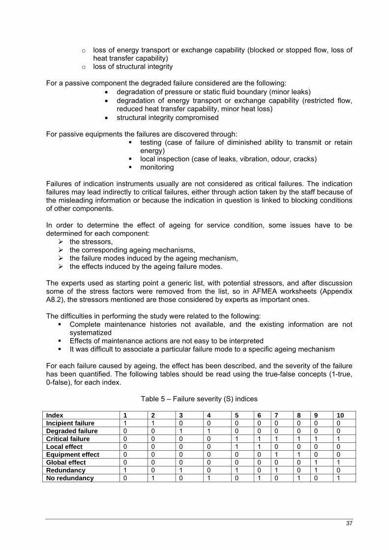
37
o loss of energy transport or exchange capability (blocked or stopped flow, loss of heat transfer capability)
o loss of structural integrity For a passive component the degraded failure considered are the following:
• degradation of pressure or static fluid boundary (minor leaks) • degradation of energy transport or exchange capability (restricted flow,
reduced heat transfer capability, minor heat loss) • structural integrity compromised
For passive equipments the failures are discovered through:
testing (case of failure of diminished ability to transmit or retain energy)
local inspection (case of leaks, vibration, odour, cracks) monitoring
Failures of indication instruments usually are not considered as critical failures. The indication failures may lead indirectly to critical failures, either through action taken by the staff because of the misleading information or because the indication in question is linked to blocking conditions of other components. In order to determine the effect of ageing for service condition, some issues have to be determined for each component:
the stressors, the corresponding ageing mechanisms, the failure modes induced by the ageing mechanism, the effects induced by the ageing failure modes.
The experts used as starting point a generic list, with potential stressors, and after discussion some of the stress factors were removed from the list, so in AFMEA worksheets (Appendix A8.2), the stressors mentioned are those considered by experts as important ones. The difficulties in performing the study were related to the following:
Complete maintenance histories not available, and the existing information are not systematized
Effects of maintenance actions are not easy to be interpreted It was difficult to associate a particular failure mode to a specific ageing mechanism
For each failure caused by ageing, the effect has been described, and the severity of the failure has been quantified. The following tables should be read using the true-false concepts (1-true, 0-false), for each index.
Table 5 – Failure severity (S) indices
Index 1 2 3 4 5 6 7 8 9 10 Incipient failure 1 1 0 0 0 0 0 0 0 0 Degraded failure 0 0 1 1 0 0 0 0 0 0 Critical failure 0 0 0 0 1 1 1 1 1 1 Local effect 0 0 0 0 1 1 0 0 0 0 Equipment effect 0 0 0 0 0 0 1 1 0 0 Global effect 0 0 0 0 0 0 0 0 1 1 Redundancy 1 0 1 0 1 0 1 0 1 0 No redundancy 0 1 0 1 0 1 0 1 0 1
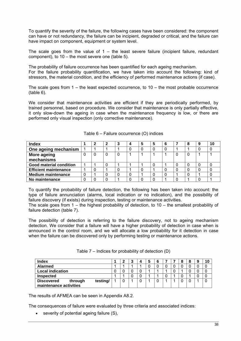
38
To quantify the severity of the failure, the following cases have been considered: the component can have or not redundancy, the failure can be incipient, degraded or critical, and the failure can have impact on component, equipment or system level. The scale goes from the value of 1 – the least severe failure (incipient failure, redundant component), to 10 – the most severe one (table 5). The probability of failure occurrence has been quantified for each ageing mechanism. For the failure probability quantification, we have taken into account the following: kind of stressors, the material condition, and the efficiency of performed maintenance actions (if case). The scale goes from 1 – the least expected occurrence, to 10 – the most probable occurrence (table 6). We consider that maintenance activities are efficient if they are periodically performed, by trained personnel, based on procedure. We consider that maintenance is only partially effective, it only slow-down the ageing in case when the maintenance frequency is low, or there are performed only visual inspection (only corrective maintenance).
Table 6 – Failure occurrence (O) indices Index 1 2 2 3 4 5 5 6 7 8 9 10 One ageing mechanism 1 1 1 1 0 0 0 0 1 1 0 0 More ageing mechanisms
0 0 0 0 1 1 1 1 0 0 1 1
Good material condition 1 1 0 1 1 1 0 1 0 0 0 0 Efficient maintenance 1 0 1 0 1 0 1 0 0 0 0 0 Medium maintenance 0 1 0 0 0 1 0 0 1 0 1 0 No maintenance 0 0 0 1 0 0 0 1 0 1 0 1 To quantify the probability of failure detection, the following has been taken into account: the type of failure annunciation (alarms, local indication or no indication), and the possibility of failure discovery (if exists) during inspection, testing or maintenance activities. The scale goes from 1 – the highest probability of detection, to 10 – the smallest probability of failure detection (table 7). The possibility of detection is referring to the failure discovery, not to ageing mechanism detection. We consider that a failure will have a higher probability of detection in case when is announced in the control room, and we will allocate a low probability for it detection in case when the failure can be discovered only by performing testing or maintenance actions.
Table 7 – Indices for probability of detection (D)
Index 1 2 3 4 5 6 7 7 8 8 9 10 Alarmed 1 1 1 1 0 0 0 0 0 0 0 0 Local indication 0 0 0 0 1 1 1 0 1 0 0 0 Inspected 1 1 0 0 1 1 0 1 0 1 0 0 Discovered through testing/ maintenance activities
1 0 1 0 1 0 1 1 0 0 1 0
The results of AFMEA can be seen in Appendix A8.2. The consequences of failure were evaluated by three criteria and associated indices:
• severity of potential ageing failure (S),
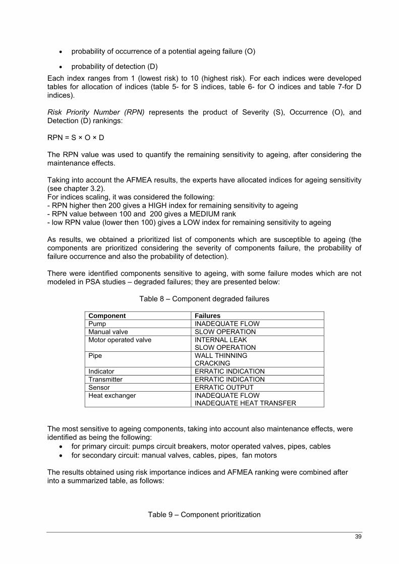
39
• probability of occurrence of a potential ageing failure (O)
• probability of detection (D) Each index ranges from 1 (lowest risk) to 10 (highest risk). For each indices were developed tables for allocation of indices (table 5- for S indices, table 6- for O indices and table 7-for D indices). Risk Priority Number (RPN) represents the product of Severity (S), Occurrence (O), and Detection (D) rankings: RPN = S × O × D The RPN value was used to quantify the remaining sensitivity to ageing, after considering the maintenance effects. Taking into account the AFMEA results, the experts have allocated indices for ageing sensitivity (see chapter 3.2). For indices scaling, it was considered the following: - RPN higher then 200 gives a HIGH index for remaining sensitivity to ageing - RPN value between 100 and 200 gives a MEDIUM rank - low RPN value (lower then 100) gives a LOW index for remaining sensitivity to ageing As results, we obtained a prioritized list of components which are susceptible to ageing (the components are prioritized considering the severity of components failure, the probability of failure occurrence and also the probability of detection). There were identified components sensitive to ageing, with some failure modes which are not modeled in PSA studies – degraded failures; they are presented below:
Table 8 – Component degraded failures
Component Failures Pump INADEQUATE FLOW Manual valve SLOW OPERATION Motor operated valve INTERNAL LEAK
SLOW OPERATION Pipe WALL THINNING
CRACKING Indicator ERRATIC INDICATION Transmitter ERRATIC INDICATION Sensor ERRATIC OUTPUT Heat exchanger INADEQUATE FLOW
INADEQUATE HEAT TRANSFER The most sensitive to ageing components, taking into account also maintenance effects, were identified as being the following:
• for primary circuit: pumps circuit breakers, motor operated valves, pipes, cables • for secondary circuit: manual valves, cables, pipes, fan motors
The results obtained using risk importance indices and AFMEA ranking were combined after into a summarized table, as follows:
Table 9 – Component prioritization
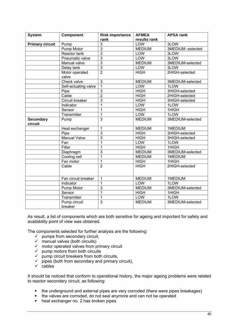
40
System Component Risk importance
rank AFMEA results rank
APSA rank
Primary circuit Pump 3 LOW 3LOW Pump Motor 3 MEDIUM 3MEDIUM -selected Reactor tank 3 LOW 3LOW Pneumatic valve 3 LOW 3LOW Manual valve 3 MEDIUM 3MEDIUM-selected Delay tank 3 LOW 3LOW Motor operated
valve 2 HIGH 2HIGH-selected
Check valve 3 MEDIUM 3MEDIUM-selected Self-actuating valve 1 LOW 1LOW Pipe 3 HIGH 3HIGH-selected Cable 2 HIGH 2HIGH-selected Circuit breaker 3 HIGH 3HIGH-selected Indicator 1 LOW 1LOW Sensor 1 HIGH 1HIGH Transmitter 1 LOW 1LOW Secondary circuit
Pump 3 MEDIUM 3MEDIUM-selected
Heat exchanger 1 MEDIUM 1MEDIUM Pipe 3 HIGH 3HIGH-selected Manual Valve 3 HIGH 3HIGH-selected Fan 1 LOW 1LOW Filter 1 HIGH 1HIGH Diaphragm 3 MEDIUM 3MEDIUM-selected Cooling cell 1 MEDIUM 1MEDIUM Fan motor 1 HIGH 1HIGH Cable 2 HIGH 2HIGH-selected
Fan circuit breaker 1 MEDIUM 1MEDIUM Indicator 1 LOW 1LOW Pump Motor 3 MEDIUM 3MEDIUM-selected Sensor 1 HIGH 1HIGH Transmitter 1 LOW 1LOW Pump circuit
breaker 3 MEDIUM 3MEDIUM-selected
As result, a list of components which are both sensitive for ageing and important for safety and availability point of view was obtained. The components selected for further analysis are the following:
pumps from secondary circuit, manual valves (both circuits) motor operated valves from primary circuit pump motors from both circuits pump circuit breakers from both circuits, pipes (both from secondary and primary circuit), cables
It should be noticed that conform to operational history, the major ageing problems were related to reactor secondary circuit, as following:
the underground and external pipes are very corroded (there were pipes breakages) the valves are corroded, do not seal anymore and can not be operated heat exchanger no. 2 has broken pipes
41
the circulation pumps have leaks and start very difficult because aspirate false air the heat exchangers have deposits on the pipes and the necessary heat transfer is not
performed in an appropriate way the cooling towers resistance structure is affected (there are large vibrations of the
construction when many fans operate) lateral walls of cooling cells are made from asbestos cement plates and are damaged,
the walls aspirate false air, in this case the cooling being not efficient the most important part of blinds doesn’t exist anymore because have been destroyed
by corrosion the spray system is very corroded the filling mass located under spray system is very damaged, in this way the cooling is
not efficiently performed anymore the protection balustrades are corroded and do not provide protection for working in
safety conditions the lighting system is totally destroyed by corrosion and during night time the tower
operation is made on dark
42
5 CONCLUSIONS
the selection using both risk importance and ageing sensitivity criteria is necessary,
because it can be seen from the results that some of the components are important for safety but not so ageing sensitive (pneumatic valve from primary circuit), as others are not so safety important but since they are very sensitive to ageing (cable) should be selected for further analysis
there are some components which even are very sensitive to ageing, due to
maintenance efficiency and easily detection of ageing signs (performance monitoring), are not critical, as the pumps from primary circuit, comparing to those from secondary circuit
maintenance is very important issue to be taken into account, even if not always
preventive maintenance programs are sufficient to control the kinetic of ageing mechanism
more research is needed to assess the ageing of passive equipments
it will be interested to perform this kind of analysis at the level of an accident sequence
or at the level of a whole PSA model
for a credible APSA results, additional data collection and research studies may be necessary (existing data can supply only relative information regarding which systems and components have been significantly affected by ageing and the root or underlying cause of that ageing)
43
6 REFERENCES
[1] NUREG/CR-6823 - Handbook of Parameter Estimation for Probabilistic Risk Assessment, US NRC, Washington DC, USA, September 2003 [2] NUREG/CR-5248 – Prioritization of TIRGALEX- Recommended Components for Further Aging Research, US NRC, Washington DC, October 1988 [3] NUREG/CR-4144 – Importance Ranking Based on Aging Considerations of Components Included in Probabilistic Risk Assessments, US NRC, Washington DC, April 1985 [4] Nureg/ CR-3385 – Measures of Risk Importance and Their Applications, Washington DC, USA, July 1983 [5] MIL-STD-1629A – Procedures for performing a failure mode, effects and criticality analysis, Washington DC, USA, June 1977 [6] IAEA, TRS no.338 – Methodology for the Management of Ageing of NPP Components Important to safety, Vienna, 1992 [7] Hiromitsu Kumamoto, Ernest J. Henley- Probabilistic Risk Assessment and Management for Engineers and Scientists, second edition, IEEE Press, Institute of Electrical and Electronics Engineers, New York, 1996 [8] IAEA-TECDOC-540 – Safety Aspects of Nuclear Power Plant Ageing, Vienna, January 1990 [9] EUR19843En - Safe Management of NPP Ageing in the European Union, May 2001 [10] K. Simola - Reliability methods in nuclear power plant ageing management, VTT 379, 1999 [11] IAEA, TECDOC-792 - Management of research reactor ageing, Vienna, March 1995 [12] Andrei Rodionov, Dana Kelly - Guidelines for Analysis of Data Related to Aging of Nuclear Power Plant Components and Systems, November 2007 [13] NUREG/CR-5848 - Record keeping Needs to Mitigate the Impact of Aging Degradation, US NRC, Washington DC, October 1992 [14] ICN F/T Procedure, PL-01.07-EPSN-024, rev4, Pitesti, Romania, March 2000 [15] Steady State Reactor primary circuit pneumatic valves operating instructions: EO-307-8.6 / 01.04.1981 [16] Reactor primary circuit heat exchangers operating instructions, EO-307-8.8/01.04.1981 [17] Automatization circuit – Reactor secondary circuit heat exchangers monitoring, CMSCR01-06/MP [18] Automatization circuit – Reactor secondary circuit cooling tower, 02 TC T02-06/MP [19] D. Mladin, Preliminary study for TRIGA-SSR model realization, INR internal report, RI 6134/ 2001 [20] D. Mladin, TRIGA SSR Level 1 Probabilistic Safety Evaluation, INR internal report, RI6751, 10.12.2003 [21] Safety Analysis Report of the TRIGA Steady-State Research Materials and Testing volum III, (E-117-323)-General Atomic, 1979 [22] Procedure EO-TH-174T – Maintenance, review, calibration, debugging and inspection of TRIGA SSR-14MW Steady State Reactor console instrumentation
44
[23] Procedure EO-TH-167T - Reactor normal shutdown or by SCRAM [24] Procedure EO-TH-211T –Primary circuit operation of TRIGA SSR-14MW Steady State Reactor [25] Procedure EO-TH-216T – Secondary circuit operation of TRIGA SSR-14MW Steady State Reactor [26] Limits and operating technical conditions of TRIGA SSR-14MW Steady State Reactor [27] Procedure EO-TH-213T - TRIGA SSR-14MW Steady State Reactor primary circuit pumps operation [28] Procedure EO-TH-166T - TRIGA SSR-14MW reactor restarting, after miscellaneous shutdown types [29] Procedure EO-TH-215T -TRIGA SSR-14MW Steady State Reactor primary circuit heat exchangers operation [30] Proceedings of EC Enlargement and Integration Workshop on Use of PSA for Evaluation of Impact of Ageing Effects on the Safety of NPPs, November 2007, Budapest, Hungary, EUR 23078 EN [31] IAEA-TECDOC-670 - Pilot studies on management of ageing of nuclear power plant components Results of Phase I, Vienna, October 1992 [32] IAEA-TECDOC-1147 - Management of ageing of I&C equipment in nuclear power plants, Vienna, June 2000 [33] IAEA-TECDOC-1188 - Assessment and management of ageing of major nuclear power plant components important to safety: In-containment instrumentation and control cable, Volume I, Vienna, December 2000 [34] IAEA-TECDOC-1197 - Assessment and management of ageing of major nuclear power plant components important to safety: CANDU reactor assemblies, Vienna, February 2001
45
APPENDIX 1 – DEFINITIONS
Ageing is defined as general process in which characteristics of a structure, system or component (SSC) gradually change with time or use (definition according to EPRI Common Aging Terminology). Ageing degradation - Ageing effects that could impair the ability of a SSC to function within the acceptance criteria. Component - An assembly of interconnected parts with specific boundaries, which constitutes an identifiable device, instrument or piece of equipment. A component is a physical entity which performs a clearly defined function and is a constituent of a system. A component can be disconnected, removed as a unit and replaced with a spare. It has a definable performance characteristic which permits it to be tested as a unit. Component groups - Aggregation of components having similarities. Failure - Termination of the ability of a component to perform its required function. Failures may be unannounced and not detected until the next test or demand (unannounced failure), or they may be announced and detected by any number of methods at the moment of occurrence (announced failure). Ageing failure is a failure whose root cause is ageing Failure Mode - The manner in which a fault occurs, i.e. the manner in which a component, subsystem, system, process, etc. could potentially fail to meet the design intent Fault - Inability to function in a desired manner, or operation in an undesired manner, regardless of cause Failure Effect - The consequences of a failure mode on an operation, function, status of a system/ process/ activity/ environment. The effect may range from relatively harmless impairment of performance to multiple fatalities, major equipment loss, and environmental damage, for example. Ageing mechanism - Specific process that gradually changes characteristics of an SSC with time. Ageing effects - Net changes in characteristics of an SSC that occur with time or use due to ageing mechanisms. Detection mechanism - The means or methods by which a failure can be discovered by an operator under normal system operation or can be discovered by the maintenance crew by some diagnostic action Failure cause - The physical or chemical processes, design defects, quality defects, part misapplication, or other processes which are the basic reason for failure or which initiate the physical process by which deterioration proceeds to failure Critical failures - Any failure that stops the function of the component. The critical failure is a failure which is both sudden and complete. This failure causes cessation of one or more fundamental functions. Critical failures always lead to repairs.
46
In general, the critical failures can be divided into different groups depending on the location of failure: - power supply failure, - control equipment failure, - mechanical failure. Degraded failures - The component in question is still working but certain properties not crucial to the function have been degraded. Component operates below its specific performance level. The degraded failure is a failure which is gradual, partial or both. Such a failure does not cease all function, but compromises a function. The function may be compromised by any combination of reduced, increased, or erratic outputs. In time, such a failure may develop into critical failure. These failures do not always lead to repairs and are often postponed until reactor shut down or when convenient. Incipient failures - An imperfection in the state or condition of an equipment, so that a degraded or critical failure can be expected to result if corrective action is not taken. Component performs within its design envelope but exhibits indications that, if left unattended, it would probably undergo a degraded or catastrophic failure Examples: vibrations of pumps, internal leakage in valves, binding valves or loss of lubricant. When motivated, an incipient failure might be classified as degraded failure. Operating state - State in which an item performs its required function Standby state - State in which an item is expected to be in a satisfactory condition to perform its required function immediately when called upon to do so. Stressor - Agent or stimulus that stems from preservice and service conditions and can produce ageing degradation of an SSC Failure mode and effects analysis (FMEA) - A procedure by which each potential failure mode in a system is analyzed to determine the effects on the system and to classify each potential failure mode according to its severity Ageing Failure Mode and Effect Analysis (AFMEA) - An inductive analysis that systematically details, on a component-by-component basis, all possible failure modes caused by ageing and identifies their resulting effects on the plant. Possible single modes of failure or malfunction caused by ageing of each component in a plant are identified and analyzed to determine their effect on surrounding components and the plant. Parametric - In parametric inference, the data are assumed to come from a known distributional form, with only the parameters unknown. Parametric statistical inference is concerned with learning the values of unknown parameters (and their associated properties) from sample data for a given or assumed family of distributions. Nonparametric - In nonparametric inference, no distributional form is assumed. The values of the parameters are unknown, as well as the form of the distribution. Hypothesis - A statement about the model that generated the data. If the evidence against the null hypothesis, H0, is strong, H0 is rejected in favor of the alternative hypothesis, H1. If the evidence against H0 is not strong, H0 is “accepted”; that means it is not necessarily believed, but it is given the benefit of the doubt and is not rejected.
47
APPENDIX 2 - AGEING MECHANISMS
All components are ageing, but the importance of ageing with regard to failure is determined by its significance and the rate of degradation. Ageing degradation mechanisms:
o affect the internal microstructure or chemical composition of the material and thereby change its intrinsic properties (thermal ageing, creep, irradiation etc.),
o impose physical damage on the component either by metal loss (corrosion, wear) or by cracking or deformation (stress-corrosion, deformation or cracking).
These phenomena have to be studied and understood, and in several cases, adequate understanding of the mechanisms can only be gained through supporting laboratory tests research programs. There are a large number of degradation mechanisms operating in the major components of NPP. Some of the potential ageing mechanisms and the resulting degradation effects on components are specified below. [8], [11], [31], [32], [33], [34] The ageing mechanisms of the structure – such as fatigue resistance – depend on environment. Various ageing mechanisms may also act simultaneously, like fatigue and creep, for example. Concrete SSC may be affected by several ageing mechanisms resulting in an alteration of the mechanical properties or the physical form of the concrete structural integrity of the SSC (e.g. aggressive environment can increased porosity, permeability, and reduced concrete strength; flowing water over concrete surfaces can remove significant amount of concrete). Deterioration of concrete results primarily from cracking, aggressive environments (freezing and thawing, wetting and drying, chemical attack), corrosion of embedment or extreme environment exposure (elevated temperature, pressure, humidity).
Irradiation Embrittlement
Neutrons from the fissions process which cover an energy range up to 15 MeV interact
with the material which results in the formation of atomic displacements and, depending on the energy of the neutrons/ in the formation of displacement cascades. This creates areas of low atomic density (high vacancy concentration) and of high atomic density (interstitial atoms). The contribution of the associated gamma irradiation to the ageing phenomena amounts to less than 2%. At service temperature some of the lattice damage created can anneal in a diffusion process, with the result that the residual damage tends to equilibrium between the creation of new defects and annealing (recovery). In addition to the lattice defects caused by the interaction of fast (high energy) neutrons with the material atoms, helium is produced as a result of nuclear [n, alpha] reactions. Helium diffuses under elevated temperature easily and forms voids. Accompanied by the high temperature irradiation, irradiation assisted creep and microstructural changes like precipitation can occur. The effect of neutron irradiation on metals is mainly to increase the yield and the ultimate strength and to reduce the toughness. Helium production not only leads to a change in material properties but is also combined with an increase in volume (swelling), caused by bubble of gas of foreign atoms internal to material. The ageing sensitivity of the materials depends among other things on:
• type of material • material chemical composition
48
• heat treatment • initial mechanical properties.
Examples of materials used in areas where they are exposed to neutron irradiation are:
zirconium alloys for fuel cladding and CANDU pressure tubes austenitic stainless steel for reactor pressure vessel internals and reactor
pressure vessel cladding fine grained high strength carbon steel for the reactor pressure vessel shell and
CANDU feeder pipes. Neutron irradiation is considered to be a significant ageing factor for metals only at fluence exceeding 1017 cm-2, and high temperatures usually above 400°C. The reactor pressure vessel, made by Low Alloy Steel, is subjected to neutron irradiation in the core region, which results in progressive embrittlement. This embrittlement results macrostructurally as hardness and yield stress increase, and a fracture toughness decrease. Fracture toughness is the property that governs the material resistance to fast fracture, which, for ferritic steels, is small at low temperature, where the material behaves in a brittle manner, and increases with the temperature until the material becomes ductile. It is generally accepted that the effect of irradiation is to shift this curve to higher temperatures, the shape of the curve being only slightly affected, with a small decrease of the upper shelf toughness in the ductile regime. Also organic materials (e.g. electrical cables) degrade due to irradiation embrittlement. Irradiation embrittlement depends on irradiation energy and time of exposure of material. Strong irradiation and long exposure are favorable for occurrence of embrittlement. Materials exposed to neutron radiation undergo changes in microstructure and properties. The extent of the changes depends on the type of material, the neutron flux, the flux spectrum, the fluence, and the irradiation temperature.
Thermal ageing
Thermal ageing refers to gradual and progressive changes in the microstructure and properties of a material exposed at an elevated temperature for an extended period of time. The mechanisms occurring in the micro structure are of the following types:
• precipitation of particles transformation of phases growth of precipitated phases and the grains of the matrix
• dissolution of precipitates. Some of the thermal ageing processes like temper embrittlement and recrystallization, are of the short time range type and only controlled by temperature. Thermal ageing effects of advanced steels are to be expected only after an extremely long period of time. A prerequisite for steels to be unsusceptible to thermal embrittlement is a stable precipitation state and e.g. for ferritic steels an adequate annealing treatment at temperatures higher than the service temperature prior to the application in service. The dominating parameters responsible for these ageing processes are:
level of temperature material state (micro-structure) time.
In addition to these parameters the environment can have effect on the changes in material state in case of superimposed oxidation and de-oxidation processes. Thermal ageing in general is a degrading process commonly causing decrease in strength properties, hardness, ductility and toughness. Under certain conditions, however, an increase in
49
ductility can be observed, too. One of the dominating factors is the chemical composition of the material and its thermo-mechanical pre-service treatment. For Ferritic Steels, the effect of thermal ageing results mainly from intergranular segregation of residual impurity elements (e.g. Phosphorous). This leads to a hardening of the material and a reduction of the fracture toughness. Cast Austenitic-Ferritic Stainless Steels (duplex structures) and Martensitic Stainless Steels are susceptible to thermal ageing in the normal operating temperature range of PWRs, by "unmixing" of chromium from its solid solution in the ferrite of the duplex structure and in martensite. Organic materials (e.g. electrical cables) degrade due thermal ageing leading to changes in mechanical properties (e.g. hardening) and cracks initiation. All ageing mechanisms are based on diffusion, important parameters being high temperature and long exposure time. Diffusion speed is higher for a central cube structure (ferritic steel) then for cube structure with central faces (austenitic steel), so the first structure is more susceptible to ageing. Usually, thermal ageing occur at temperature between 400 and 6000C. In case of excessive temperature, metal can be overwarmed and perturbation or even cracks could appear in microstructure.
Creep
Creep is defined as a time and load dependent plastic deformation of the material. Creep is an ageing process because, in addition to changes in dimensional stability, changes in material properties can occur which lead to a decrease in loadability and remaining toughness. For metallic materials creep becomes a matter of technical concern when the operating temperature exceeds about 40% of the absolute melting temperature of the material. The parameters affecting creep depend on the material itself and also on characteristics of loading such as the temperature and the mechanical load. Creep is a potentially significant ageing mechanism for pre-stressed or post-tensioned structures. The following mechanisms can occur in metallic materials and are responsible for the deformation and material damage process:
• movement of dislocations • diffusion processes • grain boundary slip processes.
These three mechanisms usually occur simultaneously and leads to nucleation of voids and pores. The process which is finally dominant depends on a variety of factors such as stress, time, temperature, grain size, impurities, precipitations, secondary phases, etc. Basically, two processes occur in the microstructure that affects the material properties:
o plastic deformation processes o changes in the microstructure.
Both these processes are time dependent and they show certain interactions. The changes in microstructure can be caused by high temperatures alone, since they are the consequence of thermally activated mechanisms. Changes in the microstructure can be characterized by changes in the structure due to precipitation or dissolution of foreign atoms, coagulation of carbides and oxides, or grain growth, and for some materials by internal oxidation processes.
50
Fatigue
Fatigue is the progressive localized permanent structural change that occurs in a material subjected to repeat or fluctuating strains at stresses having a maximum value less than the tensile strength of the material. Fatigue may culminate in cracks or fracture after a sufficient number of fluctuations. The key parameters are the range of stress variation and the number of its occurrences. Technological conditions (i.e. surface roughness and residual stresses) and environmental conditions (presence of deleterious chemical species) may also play a role. Fatigue fractures are caused by the simultaneous action of cyclic stress, tensile stress and plastic strain. If any one of these is not present, fatigue cracking will not initiate and propagate. The cyclic stress starts the crack; the tensile stress produces crack growth. The process may be considered as consisting of three stages:
• Initial fatigue damage leading to crack initiation • Crack propagation until the remaining uncracked cross section of a part becomes too
weak to carry the loads imposed • Sudden fracture of the remaining cross section.
The damage process is initiated by locally limited plastic deformation in the microrange of individual crystallites at low nominal net stresses. Depending on the lattice orientation and the dislocation configuration, slip bands can be activated causing irreversible slip processes. Repeated loading leads to microdamage accumulation (fatigue). After a saturation of energy accumulation has occurred at which no further slip process can take place in the crystallite, microcracks are produced. With an increasing number of cycles these microcracks grow and additional regions undergo the microdamage process. The combination of a more intense stress field around the microcrack and the progressive local decrease in the ability of the material to respond by plastic deformation, the microcracks grow into predamaged regions and finally reach macroscopic size. As the crack grows the stress intensity at the crack tip usually increases so that crack growth is accelerated until the remaining ligament can no longer bear the load peak and complete failure occurs. The behaviour of a material under fatigue loading is described by the Woehler Diagram that represents correlation between applied stress amplitude and the number of load cycles to failure. The lower the macroscopic stress peaks, the higher is the number of cycles to failure. According to the number of cycles after which failure occurs, two type of fatigue are distinguished:
• Low cycle fatigue (number of cycles before rupture N < 104 cycles, plastic macroscopic deformation following each cycle )
• High cycle fatigue (N > 104 cycles, elastic macroscopic deformation) Low cycle fatigue In the low cycle regime machine parts are designed for a limited number of cycles and individual load peaks may be applied that exceed locally the yield strength of the material. Such conditions can occur as a result of transients who cause inhomogeneous mechanical and thermal stresses and strains. In the low cycle regime with load peaks exceeding the yield strength there is not a linear correlation between stress and strain. High cycle thermal fatigue, caused by local thermal fluctuation loads as stratification interface fluctuations, vortex and cold leaks at valve level, is considered a realistic damage for the piping nozzles, mixing tees and elbows. Low cycle fatigue, usually induced by mechanical and thermal loads, is distinguished from high cycle fatigue which is mainly associated with vibration or high number of small thermal fluctuations.
51
Vibrations can cause mechanical high cycle fatigue, but also wear, or a number of other ageing mechanisms. Fatigue is controlled by two main parameters:
• Amplitude of alternating stresses and mean stresses • Number of alternating stress cycles
Besides the level of stress and the number of cycles, the following parameters are of influence for the fatigue behaviour:
• Loading situation: o mode of loading - tension, compression, torsion o level of loading - mean stress, stress amplitude
• Material: o with increasing ultimate strength the fatigue strength increases o welds and other material non - homogenized, internal imperfections surface flaws
cause a decrease in fatigue strength • Design and surface quality:
o absolute dimensions of the cross-section have to be considered with regard to technological effects and stresses and constraints;
o local structural discontinuities, cracks and notches act as stress concentrators and reduce the fatigue strength
o surface roughness reduces the fatigue strength. • Residual stresses:
o compression stresses have a positive effect on the fatigue strength, tension stresses have a negative effect
• Environment: o temperature affects the fatigue strength as the tensile properties (yield and
ultimate strength) decrease; o corrosion gases or liquids can drastically reduce the fatigue strength
Kinetics of fatigue mechanism is generally described by standard design curves that represent a function of main parameters: limit stress amplitude on the allowable number of cycles for the specific class of steels. For the steels of nuclear pressure boundary components the design fatigue S-N curves describes initial stage of fatigue microcracks initiation and growing into the macroscopic size (with some safety margin). It does not cover the effect of corrosive environment. Second stage - the macroscopic crack growth under the cyclically applied load is depending on the stress intensity factor amplitude ΔK /MPa. m / at the form of a “Paris Law”. The crack growth can be described by a power law in the form da/dN = C.(ΔK) n, where da/dN is the crack growth during one load cycle and C, n are material constants depending on the materials state and temperature. The environment can have a strong effect on the cyclic crack growth rate that can be increased by environmental effects by an order of magnitude or even more. Fatigue can be induced by stressors of mechanical, thermic, vibrational type and could appear in the same time with other degradation mechanisms. Corrosion fatigue is different from corrosion because the stressors are cyclic type, not static.
Vibration
The vibration may be described as the dynamic deformation of a component or structure about a mean position, in response to a time varying loading.
52
The dynamic response is conditioned by: • Systems natural frequencies (fundamental & harmonics), which depend upon its
stiffness and inertia mass • Systems damping characteristics, which depend upon material properties, presence of
sliding or impacting interfaces (gaps), amount of plastic strain and other sources of energy dissipation.
Resonance occurs when the frequency content of the input signal matches with natural frequencies of the system. At resonance, the amplification may become very large over time and would theoretically tend to infinity if damping is not present. Vibrations does not normally constitute a failure by themselves, however it may be the cause of failure of a component via fatigue, wear, corrosion or a number of other mechanisms.
Corrosion
Corrosion is the reaction of a metal with its environment that causes a detectable change in the material and can lead to deterioration in the function of a component or of a complete system. In most cases this reaction is of an electrochemical nature. In some cases, it can also be of a chemical (but not an electrochemical) or of a metal physical nature. Most of the technical corrosion processes, however, are electrochemical in nature and are accompanied by hydrogen production. A variety of chemical and physical variables of environments and materials leads to a large number of types and appearance of corrosion. It can be subdivided into:
• Corrosion without mechanical loading: o uniform corrosion attack; o local corrosion attack; o selective corrosion attack, especially intergranular corrosion.
• Corrosion with additional mechanical loading: o stress/strain corrosion cracking; o corrosion fatigue.
• Corrosion erosion.
When mechanical stresses or strains are acting in addition to the corrosion impact, the anodic dissolution of the metal can be stimulated, protection layers can rupture or hydrogen absorption can be promoted. The combined effect of a corrosive environment and mechanical stressors can cause cracking even, when under either the chemical or the mechanical stressors alone, no material degradation would occur. Ageing effects through corrosion are not only of concern with regard to material dissolution and cracking but also if the function of a machine part is affected by the build-up of reaction products. Corrosion without mechanical loading Corrosion without mechanically superimposed loading can commonly lead to uniform material loss, shallow pit formation, pitting or selective attack at the surface. Corrosion reduces the component wall thickness, either uniformly or locally. Uniform corrosion General corrosion refers to a uniform attack over surfaces of the material and results in thinning of the material. (e. g. Corrosion of Carbon or Low Alloy Steels exposed to boric acid leakage). General corrosion rates vary with fluid oxygen content, temperature, flow rate. Local corrosion
53
In case of inhomogenities at the metal surface and/or local differences in the electrochemical reactivity of the environment the creation of local cells is possible which results mostly in local corrosion attack. This causes locally different corrosion rates or corrosion attack only at certain locations. Localized corrosion includes pitting, crevice corrosion, etc. Pitting is commonly caused by the breakdown of the passive film on a metal, in local areas, by species such as chlorides. Crevice corrosion results from local environment conditions in the restricted region of a crevice being different and more aggressive than the bulk environment. Pitting may occur at critical location such as tube-to-tube sheet joints of the Steam Generators, SG, where fluid velocities are stagnant or low (i.e. impurity concentration can occur). Galvanic corrosion represents a type of local corrosion, which occurs when two metal with different electric potential are in contact. Gold is a noble metal, is not sensitive to galvanic corrosion. The highest the electrochemical potential, the stable related to corrosion galvanic is the material. Factors which can affect galvanic corrosion processes are:
• Type, surface state and material composition
• Solution pH
• Electric potential at metal - electrolyte boundary
• Aggressive chemical species (Cl- - see water)
• Temperature – at high temperature, mechanism kinetics is rapid
Selective corrosion In selective corrosion the attack is concentrated on distinct material phases/ regions adjacent to the grain boundaries or specific alloying elements. The corrosion proceeds into the depth of the material without changing the shape or geometry of the part. As long as the selective corrosion attack is limited to a certain depth, usually no material loss from the surface occurs. This type of corrosion is characteristic to multi-phases structure, e.g. Cu-Al alloys in contact to polluted or see water. Corrosion with additional mechanical loading If there are static or cyclical mechanical stresses or strains in addition to the corrosive environment the corrosion attack can be enhanced owing to local disruption of the protection layer, and crack formation and crack growth can be accelerated. Degradation induces by this type of mechanism causes two phenomena:
- local reduction of material plasticity, which can cause cracks - increase of material plasticity on some area, which cause local cracks
Both cases have initial a microscopic crack which can lead to macroscopic ones. Ni alloys (inconel 600) are sensitive to this type of degradation. This type is specific to inoxidable alloy in contact with primary environment. The temperature should be higher then 80/100°C for occurrence of the mechanism.
Factors which can affect processes are: - environment temperature
- aggressive environment from chemical point of view (water pH)
- intense mechanical stressors
- intense neutronic irradiation
- Ni composition in alloy
Corrosion with additional mechanical loading has an intergranular character, and occurs if the following conditions are present in the same time:
54
o stressors
o material microstructure sensible
o high temperature for increase the reaction kinetic
Stress Corrosion Cracking Stress Corrosion Cracking (SCC) is a localized non-ductile failure which occurs only under the combination of three factors: tensile stress, aggressive environment, and susceptible material. The Stress Corrosion Cracking failure mode can be Intergranular, IGSCC, or Transgranular, TGSCC. In a NPP, Primary Water Stress Corrosion Cracking, PWSCC, and Irradiation Assisted Stress Corrosion Cracking, IASCC, are also defined. Intergranular Stress Corrosion Cracking is associated with a sensitized material (e.g. Sensitized Austenitic Stainless Steels are susceptible to IGSCC in an oxidizing environment). Sensitization of unstabilised austenitic Stainless Steels is characterized by a precipitation of a network of chromium carbides with depletion of chromium at the grain boundaries, making these boundaries vulnerable to corrosive attack. Factors which can affect intergranular-corrosion processes are:
• Sensitivity of material function of his composition and structure
• Environment pH and composition (oxygen, clorure content can be in favor of the phenomenon)
• Temperature and exposure time
Concerning the corrosion mechanism, the electrolytic (anodic) and the metal physical (hydrogen induced) cracking processes must be distinguished. The special case of anodic stress corrosion cracking occurs as a combination of the material, the environment and mechanical loading, in critical boundary conditions: - the material must be sensitive to SCC; - tension stresses must be sufficiently high; - the environment must lead to a specific material reaction as follows:
o carbon steel with nitrides or sulphide stringers o austenitic steel with chlorides brass with ammonia.
Transgranular Stress Corrosion Cracking is caused by aggressive chemical species especially if coupled with oxygen and combined with high stresses. Primary Water Stress Corrosion Cracking is a form of IGSCC and is defined as intergranular cracking in primary water within specification limits (i.e. no need for additional aggressive species). Stress corrosion cracking occurs in systems that usually have good resistance to uniform corrosion, such as austenitic stainless steel with passive layers. Nevertheless/ SCC can be observed in such steels in combination with pitting. Irradiation Assisted Stress Corrosion Cracking refers to intergranular cracking of materials exposed to ionizing radiation. As with SCC, IASCC requires stress, aggressive environment and a susceptible material. However in the case of IASCC, a normally non-susceptible material is rendered susceptible by exposure to neutron irradiation. IASCC is a plausible ageing mechanism for PWR internal components (e.g. baffle bolts). Strain induced corrosion cracking (SICC) This type of environmental assisted cracking can occur under monotonously increasing load or low cyclic load, causing plastic deformation at low strain rate. This mechanism comes into action particularly under a critical strain rate and the presence of an electrochemical environment. Transgranular cracking with only a small amount of deformation is the typical manifestation of this mechanism.
55
Strain induced corrosion cracking was found in piping and vessels of unalloyed or low alloyed ferritic steels in high purity water and water in boiling water reactors. Cracking occurs under the simultaneous action of:
o temperatures above 150°C o an oxygen content in the water greater than 50 ppb o a strain rate of the order of 10-4 s-1.
Corrosion fatigue According to the corrosion conditions, two types of corrosion fatigue have to be distinguished:
• corrosion fatigue under active conditions in combination with a detectable surface corrosion attack, mainly in the form of pitting and the formation of corrosion products;
• corrosion fatigue under passive conditions where no corrosion attack at the surface or in the crack channel is to be detected.
Since the corrosion mechanism is mainly time dependent and the fatigue mechanism is controlled by the number of cycles, a complex interaction of both mechanisms occurs in the regime of corrosion fatigue which leads to the frequency dependence. A decreasing frequency can drastically reduce the number of cycles to crack initiation and failure. The crack growth rate may be influenced by the following:
- characteristics of the corrosive environment, such as the pH value, the temperature, the electrochemical potential or the oxygen content in water;
- the loading frequency and wave form; - the mean load and the load amplitude as expressed by the R ratio (R =
Kmin/Kmax); - sulphur content of steel.
Regions of concern with regard to reduced lifetimes in corrosive environments under high and low cycle fatigue or cyclic crack growth are parts in motion, such as the shaft of the main coolant pump; piping affected by motional parts or flow vibration; structures subjected to thermal transients caused by start-up and shut-down, cold water, etc. Corrosion erosion Corrosion erosion is a material removal process resulting from a corrosive process supported by a mechanical component (flowing liquid or gas) whereby the flow removes the passivity layer or prevents the buildup of such layers. The corrosion process would not occur or would take place at a significantly lower rate if the mechanical component (erosion) was not acting. Corrosion -Erosion can be named also Flow Accelerated Corrosion (FAC). Carbon and Low-Alloy Steels are susceptible to FAC. Consequences of corrosion erosion processes in nuclear power plant systems are thinning of walls until leakage or rupture occurs, depending on the total stress as well as the deposition of the eroded particles at locations where there is a low flow velocity (wastage). Another erosion process usually experienced on pump impellers is cavitation. Cavitation is a process that occurs when the local pressure in a flowing liquid is reduced without a change in temperature. Hence, vapor-bubbles form within the flowing liquid. When these bubbles pass into a region of higher pressure, they collapse, producing high-localized fluid velocities and causing damage to material surface. Factors which can affect corrosion erosion processes are:
o Material: unalloyed carbon steels are sensitive; steels with chromium content greater than 2% are most resistant.
o Water chemistry: in alkaline water the corrosion erosion process is less severe than in acidic water. At pH values greater than 9.5 practically no corrosion erosion occurs. If this pH value is reached by means of ammonia dosage, secondary effects have to be considered, such as stress corrosion cracking in condensate tubes made of copper alloys.
56
o Temperature: a maximum susceptibility has been observed at a temperature of about 150°C. Under 3000C, the phenomenon can be considered null.
o Flow velocity: the material removal process increases exponentially with increasing flow velocity. The design and fabrication have great influence on the micropattern of flow and thus on the local increase on the critical threshold velocity.
Microbiologically Influenced Corrosion Microbiologically Influenced Corrosion, MIC, is the accelerated corrosion of materials resulting from surface microbiological activity. MIC is characterized by the formation of microbial colonies and associated scale and debris on the surface of the metal. MIC affects Carbon Steels and, to a lesser extent, Stainless Steels and Nickel alloys. Any buried system or system using untreated water is susceptible to MIC. The major factors influencing the growth of MIC are temperature, pressure, pH, water content, and oxygen. Factors which can affect bio-corrosion processes are:
• high temperature of the environment, and a long exposure time of material in corrosive environment
• environment chemistry and oxygen presence
• sediments presence.
Many metals are sensitive to this type of corrosion (Fe, steels, stainless steels, Al alloy). Ti, Zr, Tn are resistant to this type of degradation. Presence of Mb or Cr into steel composition decrease considerable the corrosion kinetic.
Wear
Wear is defined as a loss of material as a result of mechanical contact between two solid surfaces under relative motion - due to vibration (e.g. wear was experienced on SG tubes due to contact with anti-vibration bars), sliding, or due to the presence of loose/foreign objects. The wear is progressive and generally gradual in nature. It is referred as Fretting Wear if the surfaces are in the presence of a corrosive environment. The types of motion can be: sliding, rolling, impinging, and flowing. Adhesive wear occurs when two surfaces slide against each other under pressure. The two surfaces bond to each other at the microscopic level. Adhesive wear is thus due to friction, so it can never be entirely eliminated. Additionally, this process may result in the formation of loose wear particles, which may contribute to the following wear type: abrasive wear. The wear rate of adhesive wear can be increased with increasing pressure of one surface against the other. Abrasive wear occurs when hard particles slide or roll under pressure across a surface. This type of wear is the displacement of material from a surface by means of contact with hard projections on another surface, or with hard particles that are moving relative to the surface. The particles may be trapped between the two surfaces or they may be embedded in one of the surfaces. The wear rate of abrasive wear can be increased with the number, size, and hardness of the particles, and with the pressure and speed of movement between the two surfaces. Erosive wear occurs when a surface is in contact with a fluid in relative motion to the surface that may contain particles. This type of wear most often involves solid particles, though one variation of this type, liquid-impingement erosion, is caused by liquid droplets that are carried in a rapidly moving stream of gas.
57
The wear rate of erosive wear can be increased with the force of the particles on the surface and with the speed of movement of the fluid. Surface fatigue wear occurs when particles of metal are detached from a surface that is experiencing high cyclic contact stresses. These contact stresses lead to fatigue on the surface level of the component. The wear rate of surface fatigue wear can be increased with the force, frequency, and duration of the contact forces. Fretting, or vibration wear occurs when two surfaces in contact are subjected to repeated, extremely small amplitude sliding, especially in the presence of oxygen. Fretting differs from other types of wear in that the bulk of debris produced is retained at the site of fretting. Under fretting conditions, fatigue cracks may be initiated at very low stresses, well below the fatigue limit of non-fretted regions. The wear rate of fretting can be increased with the force, frequency, and duration of vibration. Any of the above mechanisms in conjunction with a chemical corrosive fluid enhance the resulting wear (corrosive wear). Corrosive wear occurs when a chemical or electrochemical reaction with the environment significantly contributes to the wear rate. In some cases, the chemical reaction precedes the mechanical action; in other cases, the chemical reaction follows the mechanical action. Even when the chemical reaction is very mild, when it is combined with a mechanical action, the resulting combination can result in a much enhanced wear rate. The wear rate of corrosive wear can be increased with the severity of the chemical or electrochemical reaction, and with the synergistic effect of that reaction with the mechanical action. In a nuclear power plant almost all wear mechanisms can occur with various materials such as plastics, steels, non-ferrous metals, hard metals, ceramics and various coatings. Areas of concern are those with the following conditions: - Designed relative motion (sliding, rolling), e.g.: - guiding tubes - valves - engine parts of different types - electrical relays and contacts - Flowing liquids, gases or two phase flows with or without abrasive contaminants, e.g.: - pipes, tubes - valves - steam turbine blades and casings - Vibration of fitted parts: - sleeves - steam generator tubes - turbine blades The damaging consequences of wear could lead to
• loss of material and increase clearances and leakage • functional failure caused by increased friction
58
APPENDIX 3 – BASIC EVENT LABELLING SCHEME [14]
In the fault trees the analyst must label the events legibly, in order to avoid possible confusion. Particular care must be taken when certain characters that have been used could easily be mistaken for others (the symbols used must be clearly differentiated). Analyst should not include any special characters in the event labels, other than slashes and hyphens.
a. Component failure event Basic event label should be composed of alphabetical or numerical characters divided by slashes into six fields as follows: /Field 1/Field 2/Field 3/Field 4/Field 5/Field 6/ Only alpha-numerical characters and slashed are permitted for labels. Generally, the label includes the component BSI, the device code and number which appear on the applicable flowsheet, elementary wiring diagram, or control diagram. Fields Description: Field 1 - contains the BSI (Basic Subject Index) of the components that belong to the system of interest. It consists of five digits, which are used to identify the system in which is included the component of interest. Components from the instrumentation and control system are identified using five digits with a 6 as the first digit. Field 2, Field 3, Field 4 - are used to uniquely identify the system component. Field 2 - identifies the related component of the component of interest The related component is an alpha-numerical field which may be used where appropriate, along with the component type and number, to make a unique identification of the component. The related component will sometimes be the parent component for the component of interest, or it may identify the component by its location, such as the panel which on it is located. E.g. /53420/PL765/FU/21/.. - fuse 21 from panel PL765. /53240/RL179/CT/1011/...- contacts 10-11 of the relay RL179. Field 3 - identifies the component type The component type consists of a code of alphanumerical characters, which are used to designate the component by an established component name. A short component label should be used in order to make possible a unique automatic assignment of data to identical components with identical failure modes. This label is included between brackets and should contain 5 fields which are: the component type code, the component subtype 1 code, the component subtype 2 code, the component class code and the code corresponding to the component failure mode. Field 4 - the component number The component number is a combination of numbers and/or letters which uniquely identify the component. E.g. /34320//MV/11/... - motorized valve MV11
59
Field 5 - the calculation identifier This field contains different codes for the automatic selection of the proper calculation module. The following table presents these codes:
********** Unrepairabled component
Monitored component
Tested component
DORMANT Failure
Q D T
RUNNING Failure
N M -----
Field 6 - describes the failure (the symptom of the failure). It will be utilized the failure mode codification for the failure which does not include the operator contribution, and for the human error the code “HE”. For the failure of a component with position OPEN/CLOSE (valve, contacts), the following codification will be used:
Component initial position
Failure in open position Failure in close position
- FO FC CLOSE FOC
(transfer opened, spuriously opens, fails to remain closed)
FCC (fails to open, fails to function)
OPEN FOO (fails to close, fails to function)
FCO (transfer closed, spuriously closes, fails to remain open)
If the normal or the safety position (the position in which the component remains when its actuation is lost) is known, another character will be added (ex. FOOC - failure in open position, initial position open; safety position close). b. Human error When the event is a human error, Field 5 - contains 5 characters: XYZ - AA, where: (human errors made in time of test, maintenance and calibration are exception) X - human error type, and it can be: O - omission error C - commission error R - recovery error Z - the time when the error appears (is made). Z can be:
B - before the accident D - after the accident
Y - the place where the error is made, and it can be: P - human error on handswitch from main control room S - human error on handswitch from secondary control room L - human error on local handswitch
60
M - human error on manual component (the components do not have command key) Y - human error for the components which have a handswitch, but there is no information where the handswitch is placed) and AA is the failed position/state of the component of interest. Field 6 - use HE, as a code to identify the human error type event E.g. /34710/V/HS/1/ODP-FC/HE/ omission human error on manual valve - the operator forget to actuate the valve handswitch, from the main control room, so the valve remains closed For the label of human errors performed during test/ maintenance and calibration 2 characters are used in the field 5, as follows: (until now we are taken into account only the operator action which in test or maintenance period left the component in a wrong position) TS - human error made in time of test and/or maintenance CL - human error made in time of calibration A short component label should be used in order to make possible a unique automatic assignment of data to identical human errors. Human errors modelling and labelling should be done according to Human Error modelling procedure.
c. Undeveloped event For the basic event undeveloped (for which is allocate direct the value), it will be used the following label: Field 1 - System identifier Field 2, 4, 6 - Event description Field 3 - empty Field 5 - calculation code special from this kind of event, or nothing.
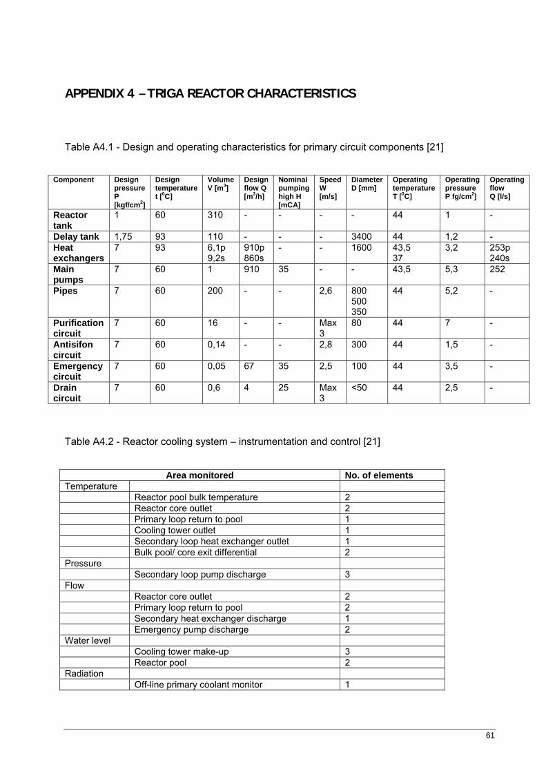
61
APPENDIX 4 – TRIGA REACTOR CHARACTERISTICS
Table A4.1 - Design and operating characteristics for primary circuit components [21]
Component Design pressure P [kgf/cm2]
Design temperature t [0C]
Volume V [m3]
Design flow Q [m3/h]
Nominal pumping high H [mCA]
Speed W [m/s]
Diameter D [mm]
Operating temperature T [0C]
Operating pressure P fg/cm2]
Operating flow Q [l/s]
Reactor tank
1 60 310 - - - - 44 1 -
Delay tank 1,75 93 110 - - - 3400 44 1,2 - Heat exchangers
7 93 6,1p 9,2s
910p 860s
- - 1600 43,5 37
3,2 253p 240s
Main pumps
7 60 1 910 35 - - 43,5 5,3 252
Pipes 7 60 200 - - 2,6 800 500 350
44 5,2 -
Purification circuit
7 60 16 - - Max 3
80 44 7 -
Antisifon circuit
7 60 0,14 - - 2,8 300 44 1,5 -
Emergency circuit
7 60 0,05 67 35 2,5 100 44 3,5 -
Drain circuit
7 60 0,6 4 25 Max 3
<50 44 2,5 -
Table A4.2 - Reactor cooling system – instrumentation and control [21]
Area monitored No. of elements Temperature Reactor pool bulk temperature 2 Reactor core outlet 2 Primary loop return to pool 1 Cooling tower outlet 1 Secondary loop heat exchanger outlet 1 Bulk pool/ core exit differential 2 Pressure Secondary loop pump discharge 3 Flow Reactor core outlet 2 Primary loop return to pool 2 Secondary heat exchanger discharge 1 Emergency pump discharge 2 Water level Cooling tower make-up 3 Reactor pool 2 Radiation Off-line primary coolant monitor 1
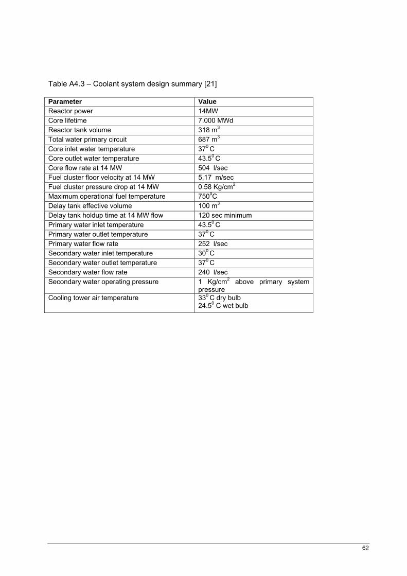
62
Table A4.3 – Coolant system design summary [21]
Parameter Value Reactor power 14MW Core lifetime 7.000 MWd Reactor tank volume 318 m3 Total water primary circuit 687 m3 Core inlet water temperature 370 C Core outlet water temperature 43.50 C Core flow rate at 14 MW 504 l/sec Fuel cluster floor velocity at 14 MW 5.17 m/sec Fuel cluster pressure drop at 14 MW 0.58 Kg/cm2
Maximum operational fuel temperature 7500C Delay tank effective volume 100 m3
Delay tank holdup time at 14 MW flow 120 sec minimum Primary water inlet temperature 43.50 C Primary water outlet temperature 370 C Primary water flow rate 252 l/sec Secondary water inlet temperature 300 C Secondary water outlet temperature 370 C Secondary water flow rate 240 l/sec Secondary water operating pressure 1 Kg/cm2 above primary system
pressure Cooling tower air temperature 330 C dry bulb
24.50 C wet bulb
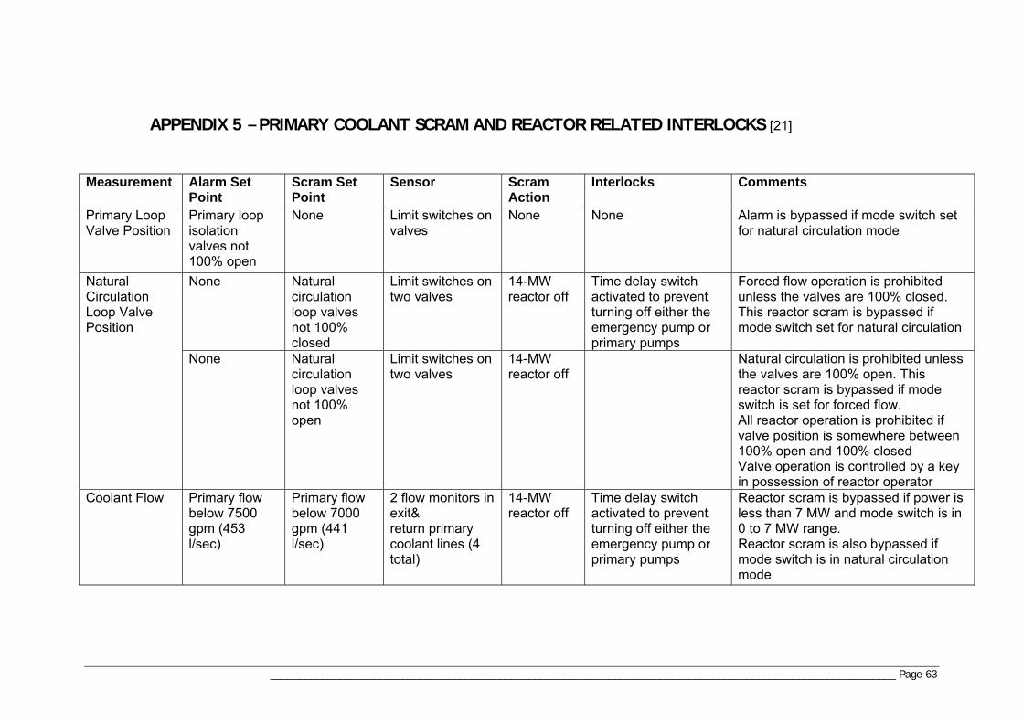
_____________________________________________________________________________________________________________ Page 63
APPENDIX 5 – PRIMARY COOLANT SCRAM AND REACTOR RELATED INTERLOCKS [21]
Measurement Alarm Set Point
Scram Set Point
Sensor Scram Action
Interlocks Comments
Primary Loop Valve Position
Primary loop isolation valves not 100% open
None Limit switches on valves
None None Alarm is bypassed if mode switch set for natural circulation mode
None Natural circulation loop valves not 100% closed
Limit switches on two valves
14-MW reactor off
Time delay switch activated to prevent turning off either the emergency pump or primary pumps
Forced flow operation is prohibited unless the valves are 100% closed. This reactor scram is bypassed if mode switch set for natural circulation
Natural Circulation Loop Valve Position
None Natural circulation loop valves not 100% open
Limit switches on two valves
14-MW reactor off
Natural circulation is prohibited unless the valves are 100% open. This reactor scram is bypassed if mode switch is set for forced flow. All reactor operation is prohibited if valve position is somewhere between 100% open and 100% closed Valve operation is controlled by a key in possession of reactor operator
Coolant Flow Primary flow below 7500 gpm (453 l/sec)
Primary flow below 7000 gpm (441 l/sec)
2 flow monitors in exit& return primary coolant lines (4 total)
14-MW reactor off
Time delay switch activated to prevent turning off either the emergency pump or primary pumps
Reactor scram is bypassed if power is less than 7 MW and mode switch is in 0 to 7 MW range. Reactor scram is also bypassed if mode switch is in natural circulation mode
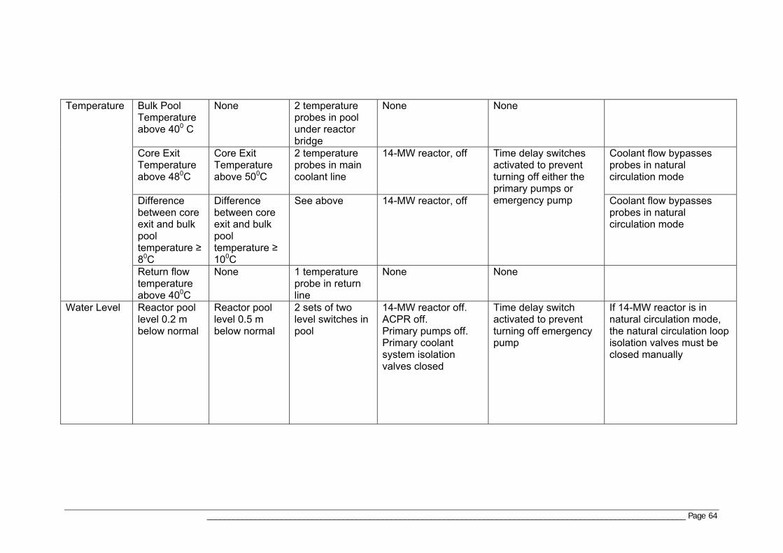
_____________________________________________________________________________________________________________ Page 64
Bulk Pool Temperature above 400 C
None 2 temperature probes in pool under reactor bridge
None None
Core Exit Temperature above 480C
Core Exit Temperature above 500C
2 temperature probes in main coolant line
14-MW reactor, off Coolant flow bypasses probes in natural circulation mode
Difference between core exit and bulk pool temperature ≥ 80C
Difference between core exit and bulk pool temperature ≥ 100C
See above 14-MW reactor, off
Time delay switches activated to prevent turning off either the primary pumps or emergency pump Coolant flow bypasses
probes in natural circulation mode
Temperature
Return flow temperature above 400C
None 1 temperature probe in return line
None None
Water Level Reactor pool level 0.2 m below normal
Reactor pool level 0.5 m below normal
2 sets of two level switches in pool
14-MW reactor off. ACPR off. Primary pumps off. Primary coolant system isolation valves closed
Time delay switch activated to prevent turning off emergency pump
If 14-MW reactor is in natural circulation mode, the natural circulation loop isolation valves must be closed manually
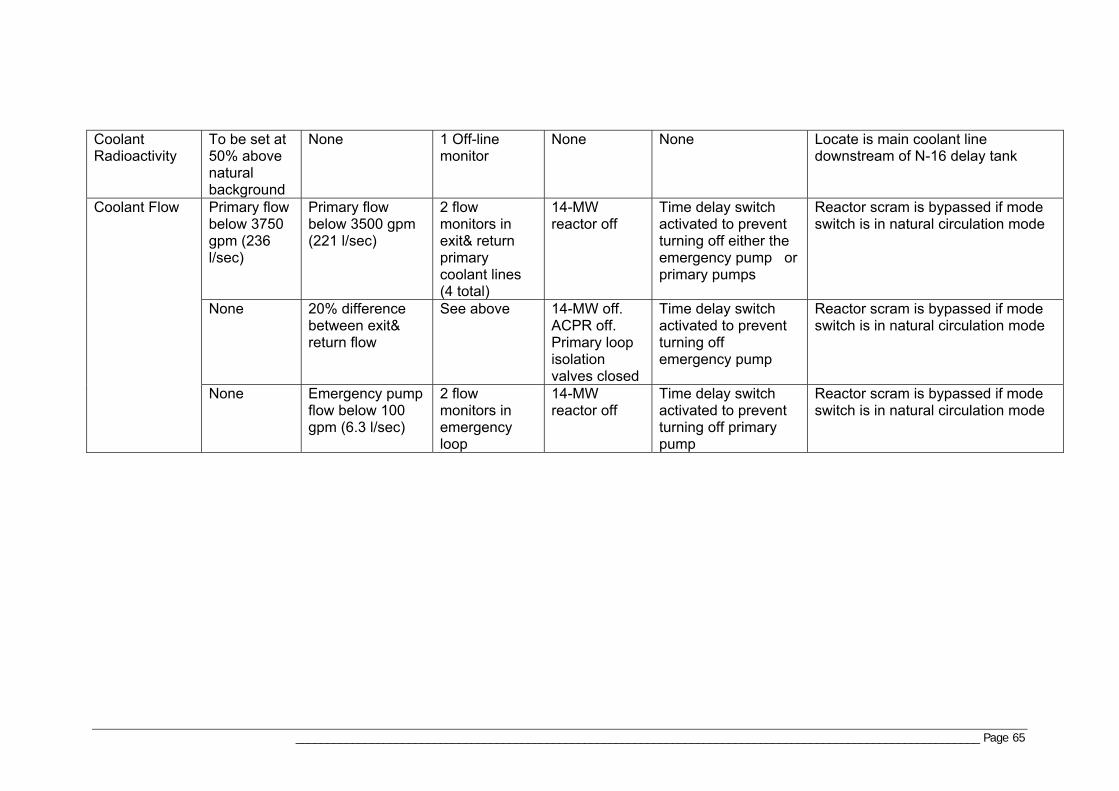
_____________________________________________________________________________________________________________ Page 65
Coolant Radioactivity
To be set at 50% above natural background
None 1 Off-line monitor
None None Locate is main coolant line downstream of N-16 delay tank
Primary flow below 3750 gpm (236 l/sec)
Primary flow below 3500 gpm (221 l/sec)
2 flow monitors in exit& return primary coolant lines (4 total)
14-MW reactor off
Time delay switch activated to prevent turning off either the emergency pump or primary pumps
Reactor scram is bypassed if mode switch is in natural circulation mode
None 20% difference between exit& return flow
See above 14-MW off. ACPR off. Primary loop isolation valves closed
Time delay switch activated to prevent turning off emergency pump
Reactor scram is bypassed if mode switch is in natural circulation mode
Coolant Flow
None Emergency pump flow below 100 gpm (6.3 l/sec)
2 flow monitors in emergency loop
14-MW reactor off
Time delay switch activated to prevent turning off primary pump
Reactor scram is bypassed if mode switch is in natural circulation mode
_______________________________________________________________________ Page 66
APPENDIX 6 – FIGURES
Figure A6.1 – TRIGA reactor [21] Figure A6.2 – Primary circuit diagram [21] Figure A6.3 – Secondary circuit diagram [21]
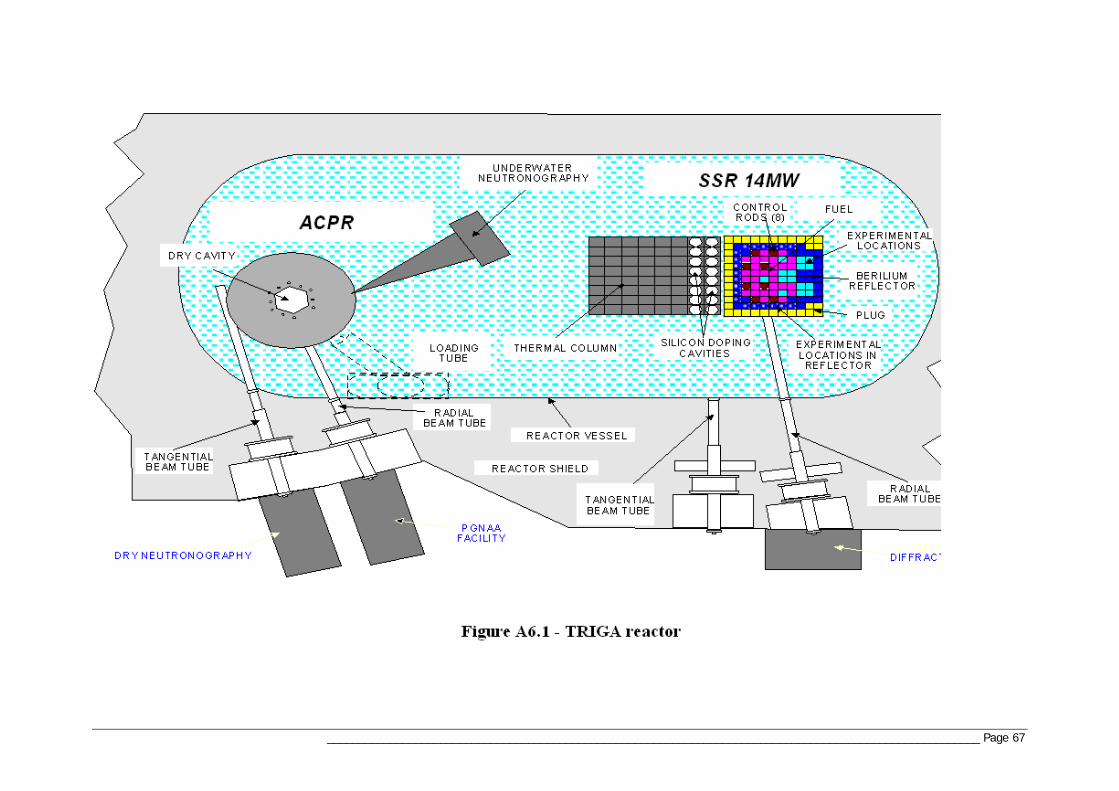
________________________________________________________________________________________________________ Page 67
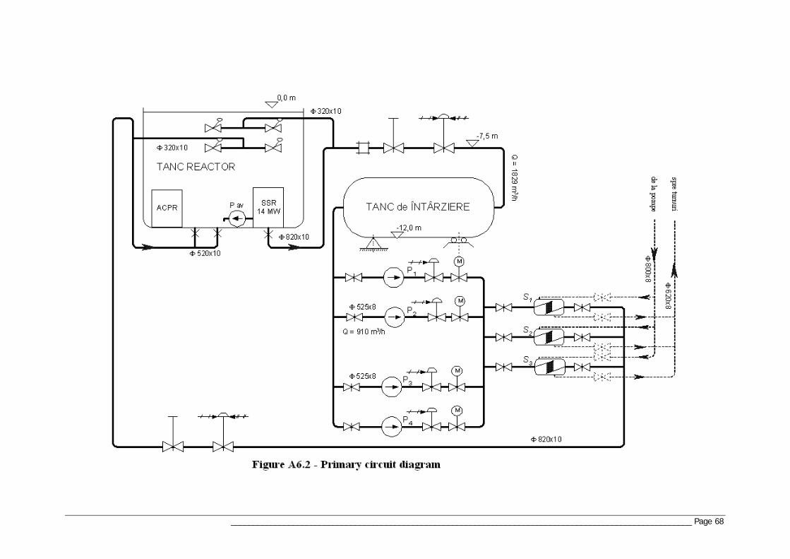
________________________________________________________________________________________________________ Page 68
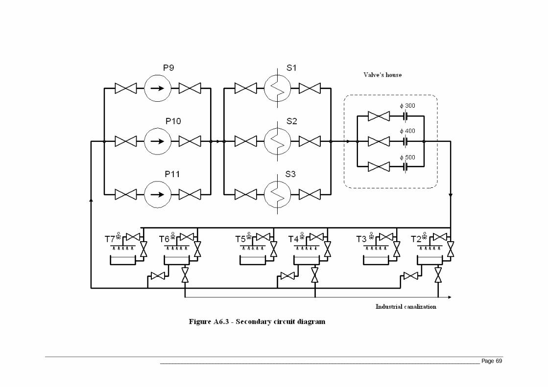
________________________________________________________________________________________________________ Page 69
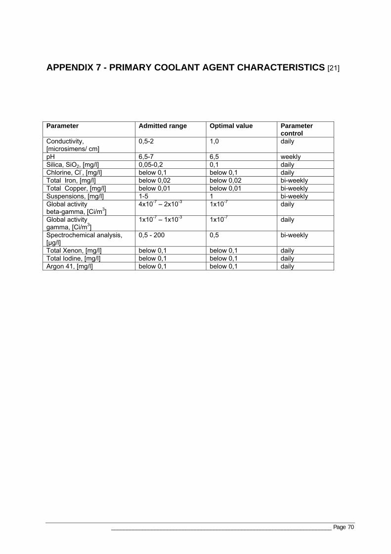
_______________________________________________________________________ Page 70
APPENDIX 7 - PRIMARY COOLANT AGENT CHARACTERISTICS [21]
Parameter Admitted range Optimal value Parameter
control Conductivity, [microsimens/ cm]
0,5-2 1,0 daily
pH 6,5-7 6,5 weekly Silica, SiO2, [mg/l] 0,05-0,2 0,1 daily Chlorine, Cl-, [mg/l] below 0,1 below 0,1 daily Total Iron, [mg/l] below 0,02 below 0,02 bi-weekly Total Copper, [mg/l] below 0,01 below 0,01 bi-weekly Suspensions, [mg/l] 1-5 1 bi-weekly Global activity beta-gamma, [Ci/m3]
4x10⁻⁷ – 2x10⁻³ 1x10⁻⁷ daily
Global activity gamma, [Ci/m3]
1x10⁻⁷ – 1x10⁻³ 1x10⁻⁷ daily
Spectrochemical analysis, [µg/l]
0,5 - 200 0,5 bi-weekly
Total Xenon, [mg/l] below 0,1 below 0,1 daily Total Iodine, [mg/l] below 0,1 below 0,1 daily Argon 41, [mg/l] below 0,1 below 0,1 daily

_______________________________________________________________________ Page 71
APPENDIX 8 – ANALYSIS RESULTS
A8.1 Risk importance results A8.2 AFMEA results
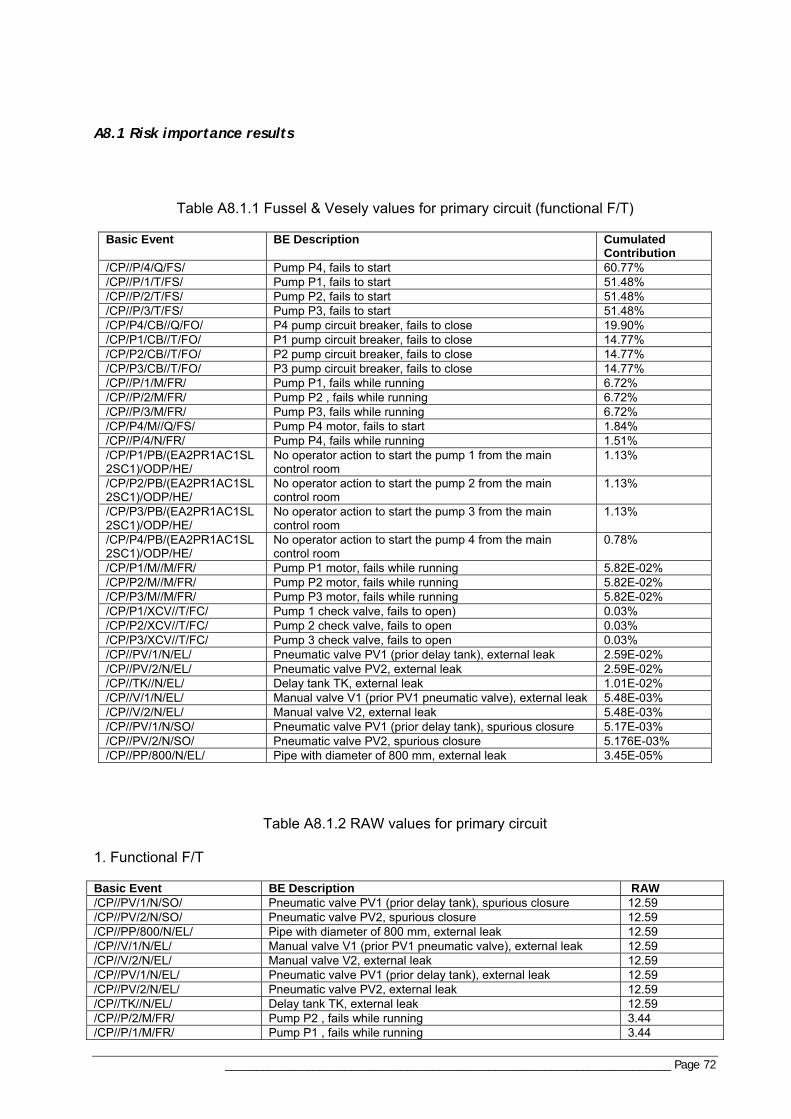
_______________________________________________________________________ Page 72
A8.1 Risk importance results
Table A8.1.1 Fussel & Vesely values for primary circuit (functional F/T)
Basic Event BE Description Cumulated Contribution
/CP//P/4/Q/FS/ Pump P4, fails to start 60.77% /CP//P/1/T/FS/ Pump P1, fails to start 51.48% /CP//P/2/T/FS/ Pump P2, fails to start 51.48% /CP//P/3/T/FS/ Pump P3, fails to start 51.48% /CP/P4/CB//Q/FO/ P4 pump circuit breaker, fails to close 19.90% /CP/P1/CB//T/FO/ P1 pump circuit breaker, fails to close 14.77% /CP/P2/CB//T/FO/ P2 pump circuit breaker, fails to close 14.77% /CP/P3/CB//T/FO/ P3 pump circuit breaker, fails to close 14.77% /CP//P/1/M/FR/ Pump P1, fails while running 6.72% /CP//P/2/M/FR/ Pump P2 , fails while running 6.72% /CP//P/3/M/FR/ Pump P3, fails while running 6.72% /CP/P4/M//Q/FS/ Pump P4 motor, fails to start 1.84% /CP//P/4/N/FR/ Pump P4, fails while running 1.51% /CP/P1/PB/(EA2PR1AC1SL2SC1)/ODP/HE/
No operator action to start the pump 1 from the main control room
1.13%
/CP/P2/PB/(EA2PR1AC1SL2SC1)/ODP/HE/
No operator action to start the pump 2 from the main control room
1.13%
/CP/P3/PB/(EA2PR1AC1SL2SC1)/ODP/HE/
No operator action to start the pump 3 from the main control room
1.13%
/CP/P4/PB/(EA2PR1AC1SL2SC1)/ODP/HE/
No operator action to start the pump 4 from the main control room
0.78%
/CP/P1/M//M/FR/ Pump P1 motor, fails while running 5.82E-02% /CP/P2/M//M/FR/ Pump P2 motor, fails while running 5.82E-02% /CP/P3/M//M/FR/ Pump P3 motor, fails while running 5.82E-02% /CP/P1/XCV//T/FC/ Pump 1 check valve, fails to open) 0.03% /CP/P2/XCV//T/FC/ Pump 2 check valve, fails to open 0.03% /CP/P3/XCV//T/FC/ Pump 3 check valve, fails to open 0.03% /CP//PV/1/N/EL/ Pneumatic valve PV1 (prior delay tank), external leak 2.59E-02% /CP//PV/2/N/EL/ Pneumatic valve PV2, external leak 2.59E-02% /CP//TK//N/EL/ Delay tank TK, external leak 1.01E-02% /CP//V/1/N/EL/ Manual valve V1 (prior PV1 pneumatic valve), external leak 5.48E-03% /CP//V/2/N/EL/ Manual valve V2, external leak 5.48E-03% /CP//PV/1/N/SO/ Pneumatic valve PV1 (prior delay tank), spurious closure 5.17E-03% /CP//PV/2/N/SO/ Pneumatic valve PV2, spurious closure 5.176E-03% /CP//PP/800/N/EL/ Pipe with diameter of 800 mm, external leak 3.45E-05%
Table A8.1.2 RAW values for primary circuit
1. Functional F/T Basic Event BE Description RAW /CP//PV/1/N/SO/ Pneumatic valve PV1 (prior delay tank), spurious closure 12.59 /CP//PV/2/N/SO/ Pneumatic valve PV2, spurious closure 12.59 /CP//PP/800/N/EL/ Pipe with diameter of 800 mm, external leak 12.59 /CP//V/1/N/EL/ Manual valve V1 (prior PV1 pneumatic valve), external leak 12.59 /CP//V/2/N/EL/ Manual valve V2, external leak 12.59 /CP//PV/1/N/EL/ Pneumatic valve PV1 (prior delay tank), external leak 12.59 /CP//PV/2/N/EL/ Pneumatic valve PV2, external leak 12.59 /CP//TK//N/EL/ Delay tank TK, external leak 12.59 /CP//P/2/M/FR/ Pump P2 , fails while running 3.44 /CP//P/1/M/FR/ Pump P1 , fails while running 3.44
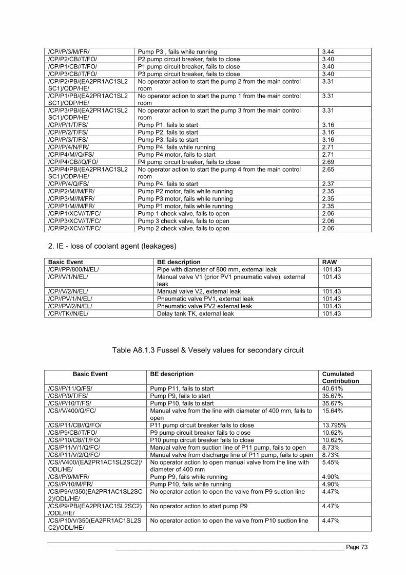
_______________________________________________________________________ Page 73
/CP//P/3/M/FR/ Pump P3 , fails while running 3.44 /CP/P2/CB//T/FO/ P2 pump circuit breaker, fails to close 3.40 /CP/P1/CB//T/FO/ P1 pump circuit breaker, fails to close 3.40 /CP/P3/CB//T/FO/ P3 pump circuit breaker, fails to close 3.40 /CP/P2/PB/(EA2PR1AC1SL2SC1)/ODP/HE/
No operator action to start the pump 2 from the main control room
3.31
/CP/P1/PB/(EA2PR1AC1SL2SC1)/ODP/HE/
No operator action to start the pump 1 from the main control room
3.31
/CP/P3/PB/(EA2PR1AC1SL2SC1)/ODP/HE/
No operator action to start the pump 3 from the main control room
3.31
/CP//P/1/T/FS/ Pump P1, fails to start 3.16 /CP//P/2/T/FS/ Pump P2, fails to start 3.16 /CP//P/3/T/FS/ Pump P3, fails to start 3.16 /CP//P/4/N/FR/ Pump P4, fails while running 2.71 /CP/P4/M//Q/FS/ Pump P4 motor, fails to start 2.71 /CP/P4/CB//Q/FO/ P4 pump circuit breaker, fails to close 2.69 /CP/P4/PB/(EA2PR1AC1SL2SC1)/ODP/HE/
No operator action to start the pump 4 from the main control room
2.65
/CP//P/4/Q/FS/ Pump P4, fails to start 2.37 /CP/P2/M//M/FR/ Pump P2 motor, fails while running 2.35 /CP/P3/M//M/FR/ Pump P3 motor, fails while running 2.35 /CP/P1/M//M/FR/ Pump P1 motor, fails while running 2.35 /CP/P1/XCV//T/FC/ Pump 1 check valve, fails to open 2.06 /CP/P3/XCV//T/FC/ Pump 3 check valve, fails to open 2.06 /CP/P2/XCV//T/FC/ Pump 2 check valve, fails to open 2.06 2. IE - loss of coolant agent (leakages) Basic Event BE description RAW /CP//PP/800/N/EL/ Pipe with diameter of 800 mm, external leak 101.43 /CP//V/1/N/EL/ Manual valve V1 (prior PV1 pneumatic valve), external
leak 101.43
/CP//V/2/N/EL/ Manual valve V2, external leak 101.43 /CP//PV/1/N/EL/ Pneumatic valve PV1, external leak 101.43 /CP//PV/2/N/EL/ Pneumatic valve PV2 external leak 101.43 /CP//TK//N/EL/ Delay tank TK, external leak 101.43
Table A8.1.3 Fussel & Vesely values for secondary circuit Basic Event BE description Cumulated
Contribution /CS//P/11/Q/FS/ Pump P11, fails to start 40.61% /CS//P/9/T/FS/ Pump P9, fails to start 35.67% /CS//P/10/T/FS/ Pump P10, fails to start 35.67% /CS//V/400/Q/FC/ Manual valve from the line with diameter of 400 mm, fails to
open 15.64%
/CS/P11/CB//Q/FO/ P11 pump circuit breaker fails to close 13.795% /CS/P9/CB//T/FO/ P9 pump circuit breaker fails to close 10.62% /CS/P10/CB//T/FO/ P10 pump circuit breaker fails to close 10.62% /CS/P11/V/1/Q/FC/ Manual valve from suction line of P11 pump, fails to open 8.73% /CS/P11/V/2/Q/FC/ Manual valve from discharge line of P11 pump, fails to open 8.73% /CS//V400/(EA2PR1AC1SL2SC2)/ODL/HE/
No operator action to open manual valve from the line with diameter of 400 mm
5.45%
/CS//P/9/M/FR/ Pump P9, fails while running 4.90% /CS//P/10/M/FR/ Pump P10, fails while running 4.90% /CS/P9/V/350(EA2PR1AC1SL2SC2)/ODL/HE/
No operator action to open the valve from P9 suction line 4.47%
/CS/P9/PB/(EA2PR1AC1SL2SC2)/ODL/HE/
No operator action to start pump P9 4.47%
/CS/P10/V/350(EA2PR1AC1SL2SC2)/ODL/HE/
No operator action to open the valve from P10 suction line 4.47%
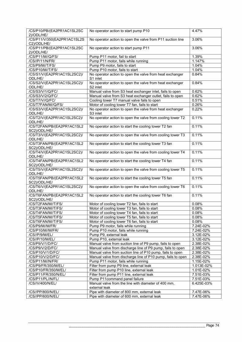
_______________________________________________________________________ Page 74
/CS/P10/PB/(EA2PR1AC1SL2SC2)/ODL/HE/
No operator action to start pump P10 4.47%
/CS/P11/V/350(EA2PR1AC1SL2SC2)/ODL/HE/
No operator action to open the valve from P11 suction line 3.06%
/CS/P11/PB/(EA2PR1AC1SL2SC2)/ODL/HE/
No operator action to start pump P11 3.06%
/CS/P11/M//Q/FS/ Pump P11 motor, fail to start 1.39% /CS//P/11/N/FR/ Pump P11 motor, fails while running 1.147% /CS/P9/M//T/FS/ Pump P9 motor, fails to start 1.04% /CS/P10/M//T/FS/ Pump P10 motor, fails to start 1.04% /CS/S1/V/(EA2PR1AC1SL2SC2)/ODL/HE/
No operator action to open the valve from heat exchanger S1 inlet
0.84%
/CS/S2/V/(EA2PR1AC1SL2SC2)/ODL/HE/
No operator action to open the valve from heat exchanger S2 inlet
0.84%
/CS/S3/V/1/Q/FC/ Manual valve from S3 heat exchanger inlet, fails to open 0.62% /CS/S3/V/2/Q/FC/ Manual valve from S3 heat exchanger outlet, fails to open 0.62% /CS/T7/V//Q/FC/ Cooling tower T7 manual valve fails to open 0.51% /CS/T7FAN/M//Q/FS/ Motor of cooling tower T7 fan, fails to start 0.26% /CS/S3/V/(EA2PR1AC1SL2SC2)/ODL/HE/
No operator action to open the valve from heat exchanger S3 inlet
0.22%
/CS/T2/V/(EA2PR1AC1SL2SC2)/ODL/HE/
No operator action to open the valve from cooling tower T2 0.11%
/CS/T2FAN/PB/(EA2PR1AC1SL2SC2)/ODL/HE/
No operator action to start the cooling tower T2 fan 0.11%
/CS/T3/V/(EA2PR1AC1SL2SC2)/ODL/HE/
No operator action to open the valve from cooling tower T3 0.11%
/CS/T3FAN/PB/(EA2PR1AC1SL2SC2)/ODL/HE/
No operator action to start the cooling tower T3 fan 0.11%
/CS/T4/V/(EA2PR1AC1SL2SC2)/ODL/HE/
No operator action to open the valve from cooling tower T4 0.11%
/CS/T4FAN/PB/(EA2PR1AC1SL2SC2)/ODL/HE/
No operator action to start the cooling tower T4 fan 0.11%
/CS/T5/V/(EA2PR1AC1SL2SC2)/ODL/HE/
No operator action to open the valve from cooling tower T5 0.11%
/CS/T5FAN/PB/(EA2PR1AC1SL2SC2)/ODL/HE/
No operator action to start the cooling tower T5 fan 0.11%
/CS/T6/V/(EA2PR1AC1SL2SC2)/ODL/HE/
No operator action to open the valve from cooling tower T6 0.11%
/CS/T6FAN/PB/(EA2PR1AC1SL2SC2)/ODL/HE/
No operator action to start the cooling tower T6 fan 0.11%
/CS/T2FAN/M//T/FS/ Motor of cooling tower T2 fan, fails to start 0.08% /CS/T3FAN/M//T/FS/ Motor of cooling tower T3 fan, fails to start 0.08% /CS/T4FAN/M//T/FS/ Motor of cooling tower T4 fan, fails to start 0.08% /CS/T5FAN/M//T/FS/ Motor of cooling tower T5 fan, fails to start 0.08% /CS/T6FAN/M//T/FS/ Motor of cooling tower T6 fan, fails to start 0.08% /CS/P9/M//M/FR/ Pump P9 motor, fails while running 7.24E-02% /CS/P10/M//M/FR/ Pump P10 motor, fails while running 7.24E-02% /CS//P/9/M/EL/ Pump P9, external leak 3.12E-02% /CS//P/10/M/EL/ Pump P10, external leak 3.12E-02% /CS/P9/V/1/D/FC/ Manual valve from suction line of P9 pump, fails to open 2.38E-02% /CS/P9/V/2/D/FC/ Manual valve from discharge line of P9 pump, fails to open 2.38E-02% /CS/P10/V/1/D/FC/ Manual valve from suction line of P10 pump, fails to open 2.38E-02% /CS/P10/V/2/D/FC/ Manual valve from discharge line of P10 pump, fails to open 2.38E-02% /CS/P11/M//N/FR/ Pump P11 motor, fails while running 1.15E-02% /CS/P9/FR/350/M/EL/ Filter from pump P9 line, external leak 1.013E-02% /CS/P10/FR/350/M/EL/ Filter from pump P10 line, external leak 1.01E-02% /CS/P11/FR/350/N/EL/ Filter from pump P11 line, external leak 7.51E-03% /CS/P11/PL//N/FL/ Pump P11command panel failure 7.51E-03% /CS//V/400/N/EL/ Manual valve from the line with diameter of 400 mm,
external leak 6.425E-03%
/CS//PP/800/N/EL/ Pipe with diameter of 800 mm, external leak 7.47E-06% /CS//PP/600/N/EL/ Pipe with diameter of 600 mm, external leak 7.47E-06%
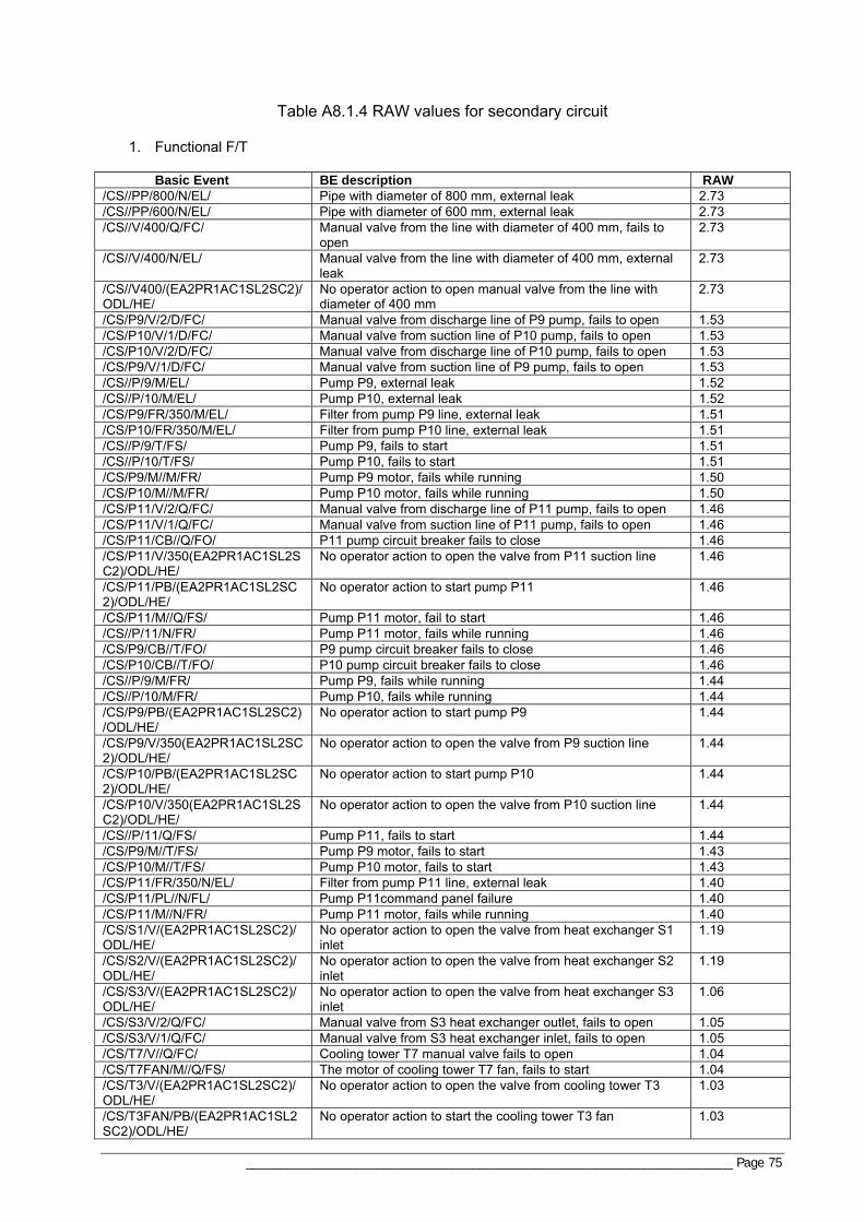
_______________________________________________________________________ Page 75
Table A8.1.4 RAW values for secondary circuit
1. Functional F/T Basic Event BE description RAW /CS//PP/800/N/EL/ Pipe with diameter of 800 mm, external leak 2.73 /CS//PP/600/N/EL/ Pipe with diameter of 600 mm, external leak 2.73 /CS//V/400/Q/FC/ Manual valve from the line with diameter of 400 mm, fails to
open 2.73
/CS//V/400/N/EL/ Manual valve from the line with diameter of 400 mm, external leak
2.73
/CS//V400/(EA2PR1AC1SL2SC2)/ODL/HE/
No operator action to open manual valve from the line with diameter of 400 mm
2.73
/CS/P9/V/2/D/FC/ Manual valve from discharge line of P9 pump, fails to open 1.53 /CS/P10/V/1/D/FC/ Manual valve from suction line of P10 pump, fails to open 1.53 /CS/P10/V/2/D/FC/ Manual valve from discharge line of P10 pump, fails to open 1.53 /CS/P9/V/1/D/FC/ Manual valve from suction line of P9 pump, fails to open 1.53 /CS//P/9/M/EL/ Pump P9, external leak 1.52 /CS//P/10/M/EL/ Pump P10, external leak 1.52 /CS/P9/FR/350/M/EL/ Filter from pump P9 line, external leak 1.51 /CS/P10/FR/350/M/EL/ Filter from pump P10 line, external leak 1.51 /CS//P/9/T/FS/ Pump P9, fails to start 1.51 /CS//P/10/T/FS/ Pump P10, fails to start 1.51 /CS/P9/M//M/FR/ Pump P9 motor, fails while running 1.50 /CS/P10/M//M/FR/ Pump P10 motor, fails while running 1.50 /CS/P11/V/2/Q/FC/ Manual valve from discharge line of P11 pump, fails to open 1.46 /CS/P11/V/1/Q/FC/ Manual valve from suction line of P11 pump, fails to open 1.46 /CS/P11/CB//Q/FO/ P11 pump circuit breaker fails to close 1.46 /CS/P11/V/350(EA2PR1AC1SL2SC2)/ODL/HE/
No operator action to open the valve from P11 suction line 1.46
/CS/P11/PB/(EA2PR1AC1SL2SC2)/ODL/HE/
No operator action to start pump P11 1.46
/CS/P11/M//Q/FS/ Pump P11 motor, fail to start 1.46 /CS//P/11/N/FR/ Pump P11 motor, fails while running 1.46 /CS/P9/CB//T/FO/ P9 pump circuit breaker fails to close 1.46 /CS/P10/CB//T/FO/ P10 pump circuit breaker fails to close 1.46 /CS//P/9/M/FR/ Pump P9, fails while running 1.44 /CS//P/10/M/FR/ Pump P10, fails while running 1.44 /CS/P9/PB/(EA2PR1AC1SL2SC2)/ODL/HE/
No operator action to start pump P9 1.44
/CS/P9/V/350(EA2PR1AC1SL2SC2)/ODL/HE/
No operator action to open the valve from P9 suction line 1.44
/CS/P10/PB/(EA2PR1AC1SL2SC2)/ODL/HE/
No operator action to start pump P10 1.44
/CS/P10/V/350(EA2PR1AC1SL2SC2)/ODL/HE/
No operator action to open the valve from P10 suction line 1.44
/CS//P/11/Q/FS/ Pump P11, fails to start 1.44 /CS/P9/M//T/FS/ Pump P9 motor, fails to start 1.43 /CS/P10/M//T/FS/ Pump P10 motor, fails to start 1.43 /CS/P11/FR/350/N/EL/ Filter from pump P11 line, external leak 1.40 /CS/P11/PL//N/FL/ Pump P11command panel failure 1.40 /CS/P11/M//N/FR/ Pump P11 motor, fails while running 1.40 /CS/S1/V/(EA2PR1AC1SL2SC2)/ODL/HE/
No operator action to open the valve from heat exchanger S1 inlet
1.19
/CS/S2/V/(EA2PR1AC1SL2SC2)/ODL/HE/
No operator action to open the valve from heat exchanger S2 inlet
1.19
/CS/S3/V/(EA2PR1AC1SL2SC2)/ODL/HE/
No operator action to open the valve from heat exchanger S3 inlet
1.06
/CS/S3/V/2/Q/FC/ Manual valve from S3 heat exchanger outlet, fails to open 1.05 /CS/S3/V/1/Q/FC/ Manual valve from S3 heat exchanger inlet, fails to open 1.05 /CS/T7/V//Q/FC/ Cooling tower T7 manual valve fails to open 1.04 /CS/T7FAN/M//Q/FS/ The motor of cooling tower T7 fan, fails to start 1.04 /CS/T3/V/(EA2PR1AC1SL2SC2)/ODL/HE/
No operator action to open the valve from cooling tower T3 1.03
/CS/T3FAN/PB/(EA2PR1AC1SL2SC2)/ODL/HE/
No operator action to start the cooling tower T3 fan 1.03
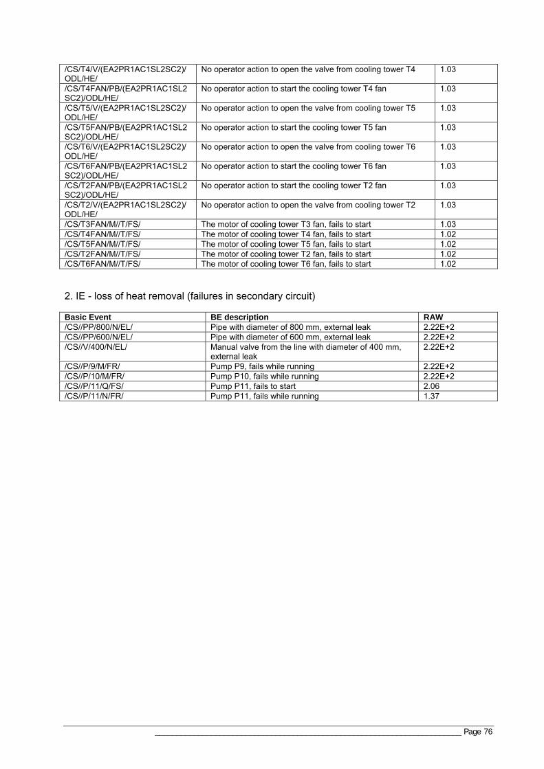
_______________________________________________________________________ Page 76
/CS/T4/V/(EA2PR1AC1SL2SC2)/ODL/HE/
No operator action to open the valve from cooling tower T4 1.03
/CS/T4FAN/PB/(EA2PR1AC1SL2SC2)/ODL/HE/
No operator action to start the cooling tower T4 fan 1.03
/CS/T5/V/(EA2PR1AC1SL2SC2)/ODL/HE/
No operator action to open the valve from cooling tower T5 1.03
/CS/T5FAN/PB/(EA2PR1AC1SL2SC2)/ODL/HE/
No operator action to start the cooling tower T5 fan 1.03
/CS/T6/V/(EA2PR1AC1SL2SC2)/ODL/HE/
No operator action to open the valve from cooling tower T6 1.03
/CS/T6FAN/PB/(EA2PR1AC1SL2SC2)/ODL/HE/
No operator action to start the cooling tower T6 fan 1.03
/CS/T2FAN/PB/(EA2PR1AC1SL2SC2)/ODL/HE/
No operator action to start the cooling tower T2 fan 1.03
/CS/T2/V/(EA2PR1AC1SL2SC2)/ODL/HE/
No operator action to open the valve from cooling tower T2 1.03
/CS/T3FAN/M//T/FS/ The motor of cooling tower T3 fan, fails to start 1.03 /CS/T4FAN/M//T/FS/ The motor of cooling tower T4 fan, fails to start 1.02 /CS/T5FAN/M//T/FS/ The motor of cooling tower T5 fan, fails to start 1.02 /CS/T2FAN/M//T/FS/ The motor of cooling tower T2 fan, fails to start 1.02 /CS/T6FAN/M//T/FS/ The motor of cooling tower T6 fan, fails to start 1.02 2. IE - loss of heat removal (failures in secondary circuit) Basic Event BE description RAW /CS//PP/800/N/EL/ Pipe with diameter of 800 mm, external leak 2.22E+2 /CS//PP/600/N/EL/ Pipe with diameter of 600 mm, external leak 2.22E+2 /CS//V/400/N/EL/ Manual valve from the line with diameter of 400 mm,
external leak 2.22E+2
/CS//P/9/M/FR/ Pump P9, fails while running 2.22E+2 /CS//P/10/M/FR/ Pump P10, fails while running 2.22E+2 /CS//P/11/Q/FS/ Pump P11, fails to start 2.06 /CS//P/11/N/FR/ Pump P11, fails while running 1.37

_______________________________________________________________________ Page 77
A8.2 AFMEA results
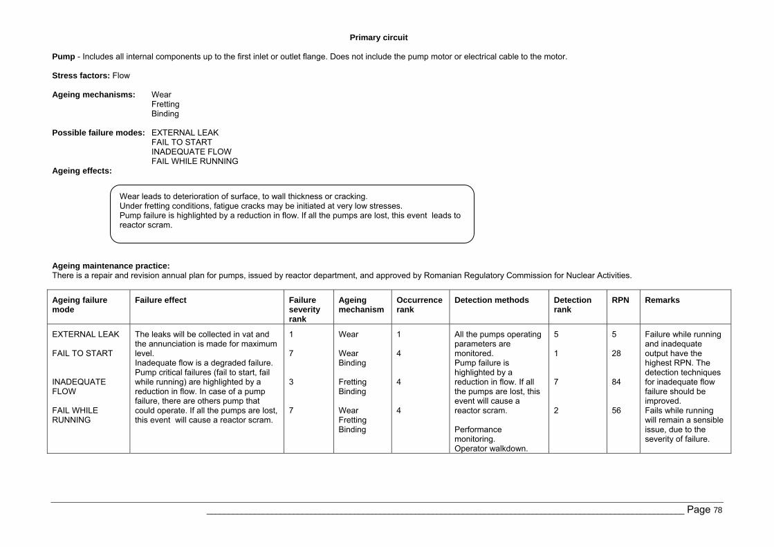
Primary circuit
______________________________________________________________________________________________________________ Page 78
Pump - Includes all internal components up to the first inlet or outlet flange. Does not include the pump motor or electrical cable to the motor. Stress factors: Flow Ageing mechanisms: Wear
Fretting Binding
Possible failure modes: EXTERNAL LEAK
FAIL TO START INADEQUATE FLOW FAIL WHILE RUNNING
Ageing effects:
Ageing maintenance practice: There is a repair and revision annual plan for pumps, issued by reactor department, and approved by Romanian Regulatory Commission for Nuclear Activities.
Ageing failure mode
Failure effect Failure severity rank
Ageing mechanism
Occurrence rank
Detection methods Detection rank
RPN Remarks
EXTERNAL LEAK FAIL TO START INADEQUATE FLOW FAIL WHILE RUNNING
The leaks will be collected in vat and the annunciation is made for maximum level. Inadequate flow is a degraded failure. Pump critical failures (fail to start, fail while running) are highlighted by a reduction in flow. In case of a pump failure, there are others pump that could operate. If all the pumps are lost, this event will cause a reactor scram.
1 7 3 7
Wear Wear Binding Fretting Binding Wear Fretting Binding
1 4 4 4
All the pumps operating parameters are monitored. Pump failure is highlighted by a reduction in flow. If all the pumps are lost, this event will cause a reactor scram. Performance monitoring. Operator walkdown.
5 1 7 2
5 28 84 56
Failure while running and inadequate output have the highest RPN. The detection techniques for inadequate flow failure should be improved. Fails while running will remain a sensible issue, due to the severity of failure.
Wear leads to deterioration of surface, to wall thickness or cracking. Under fretting conditions, fatigue cracks may be initiated at very low stresses. Pump failure is highlighted by a reduction in flow. If all the pumps are lost, this event leads to reactor scram.
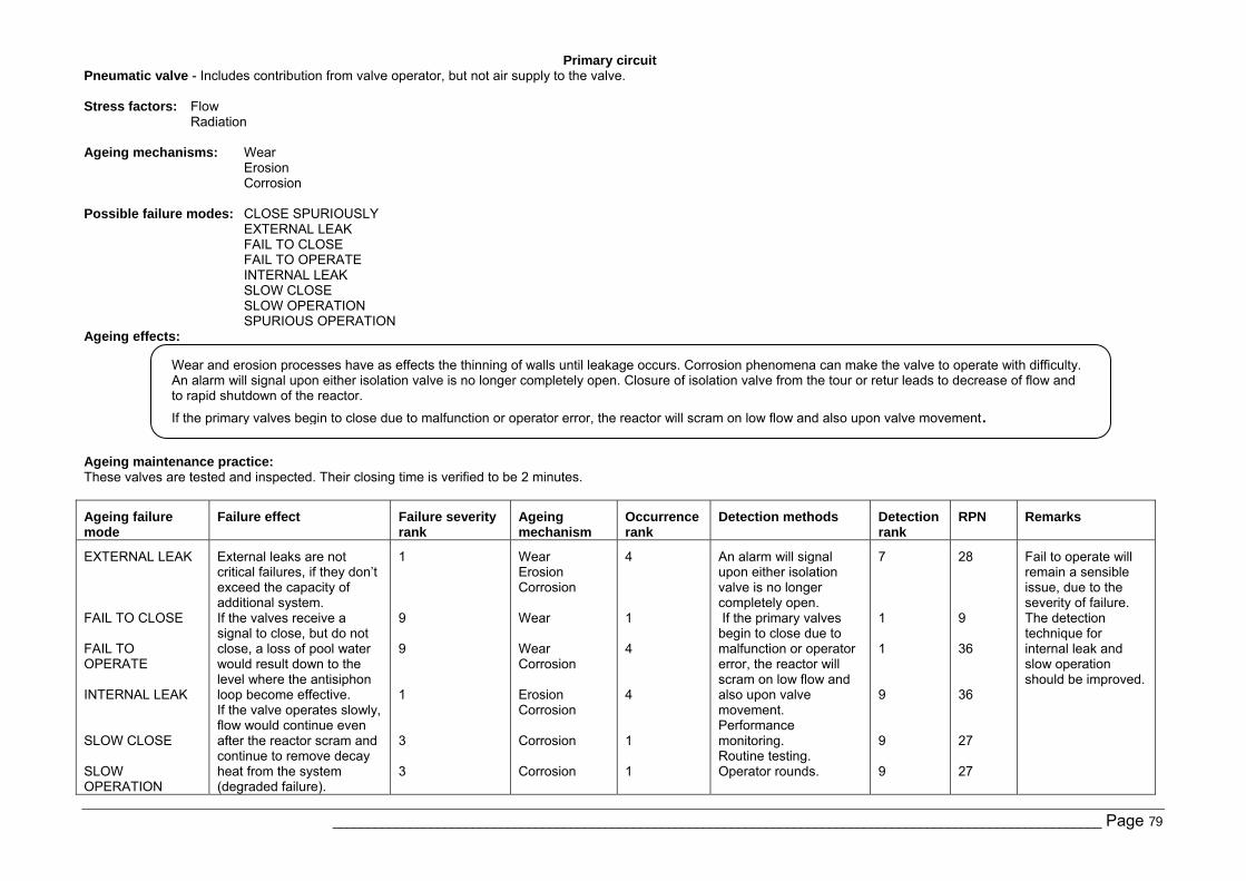
Primary circuit
______________________________________________________________________________________________________________ Page 79
Pneumatic valve - Includes contribution from valve operator, but not air supply to the valve. Stress factors: Flow
Radiation Ageing mechanisms: Wear
Erosion Corrosion
Possible failure modes: CLOSE SPURIOUSLY EXTERNAL LEAK FAIL TO CLOSE FAIL TO OPERATE INTERNAL LEAK SLOW CLOSE SLOW OPERATION SPURIOUS OPERATION
Ageing effects:
Ageing maintenance practice: These valves are tested and inspected. Their closing time is verified to be 2 minutes.
Ageing failure mode
Failure effect Failure severity rank
Ageing mechanism
Occurrence rank
Detection methods Detection rank
RPN Remarks
EXTERNAL LEAK FAIL TO CLOSE FAIL TO OPERATE INTERNAL LEAK SLOW CLOSE SLOW OPERATION
External leaks are not critical failures, if they don’t exceed the capacity of additional system. If the valves receive a signal to close, but do not close, a loss of pool water would result down to the level where the antisiphon loop become effective. If the valve operates slowly, flow would continue even after the reactor scram and continue to remove decay heat from the system (degraded failure).
1 9 9 1 3 3
Wear Erosion Corrosion Wear Wear Corrosion Erosion Corrosion Corrosion Corrosion
4 1 4 4 1 1
An alarm will signal upon either isolation valve is no longer completely open. If the primary valves begin to close due to malfunction or operator error, the reactor will scram on low flow and also upon valve movement. Performance monitoring. Routine testing. Operator rounds.
7 1 1 9 9 9
28 9 36 36 27 27
Fail to operate will remain a sensible issue, due to the severity of failure. The detection technique for internal leak and slow operation should be improved.
Wear and erosion processes have as effects the thinning of walls until leakage occurs. Corrosion phenomena can make the valve to operate with difficulty. An alarm will signal upon either isolation valve is no longer completely open. Closure of isolation valve from the tour or retur leads to decrease of flow and to rapid shutdown of the reactor.
If the primary valves begin to close due to malfunction or operator error, the reactor will scram on low flow and also upon valve movement.
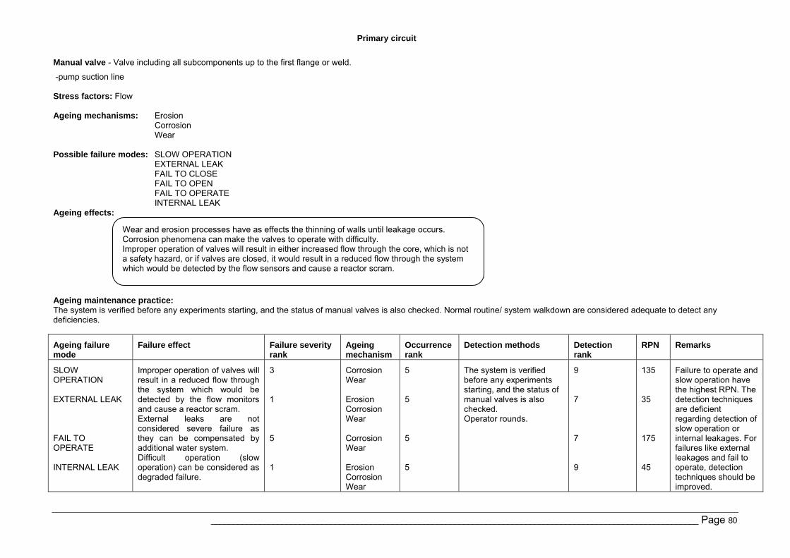
Primary circuit
______________________________________________________________________________________________________________ Page 80
Manual valve - Valve including all subcomponents up to the first flange or weld.
-pump suction line Stress factors: Flow Ageing mechanisms: Erosion
Corrosion Wear
Possible failure modes: SLOW OPERATION
EXTERNAL LEAK FAIL TO CLOSE FAIL TO OPEN FAIL TO OPERATE INTERNAL LEAK
Ageing effects:
Ageing maintenance practice: The system is verified before any experiments starting, and the status of manual valves is also checked. Normal routine/ system walkdown are considered adequate to detect any deficiencies.
Ageing failure mode
Failure effect Failure severity rank
Ageing mechanism
Occurrence rank
Detection methods Detection rank
RPN Remarks
SLOW OPERATION EXTERNAL LEAK FAIL TO OPERATE INTERNAL LEAK
Improper operation of valves will result in a reduced flow through the system which would be detected by the flow monitors and cause a reactor scram. External leaks are not considered severe failure as they can be compensated by additional water system. Difficult operation (slow operation) can be considered as degraded failure.
3 1 5 1
Corrosion Wear Erosion Corrosion Wear Corrosion Wear Erosion Corrosion Wear
5 5 5 5
The system is verified before any experiments starting, and the status of manual valves is also checked. Operator rounds.
9 7 7 9
135 35 175 45
Failure to operate and slow operation have the highest RPN. The detection techniques are deficient regarding detection of slow operation or internal leakages. For failures like external leakages and fail to operate, detection techniques should be improved.
Wear and erosion processes have as effects the thinning of walls until leakage occurs. Corrosion phenomena can make the valves to operate with difficulty. Improper operation of valves will result in either increased flow through the core, which is not a safety hazard, or if valves are closed, it would result in a reduced flow through the system which would be detected by the flow sensors and cause a reactor scram.
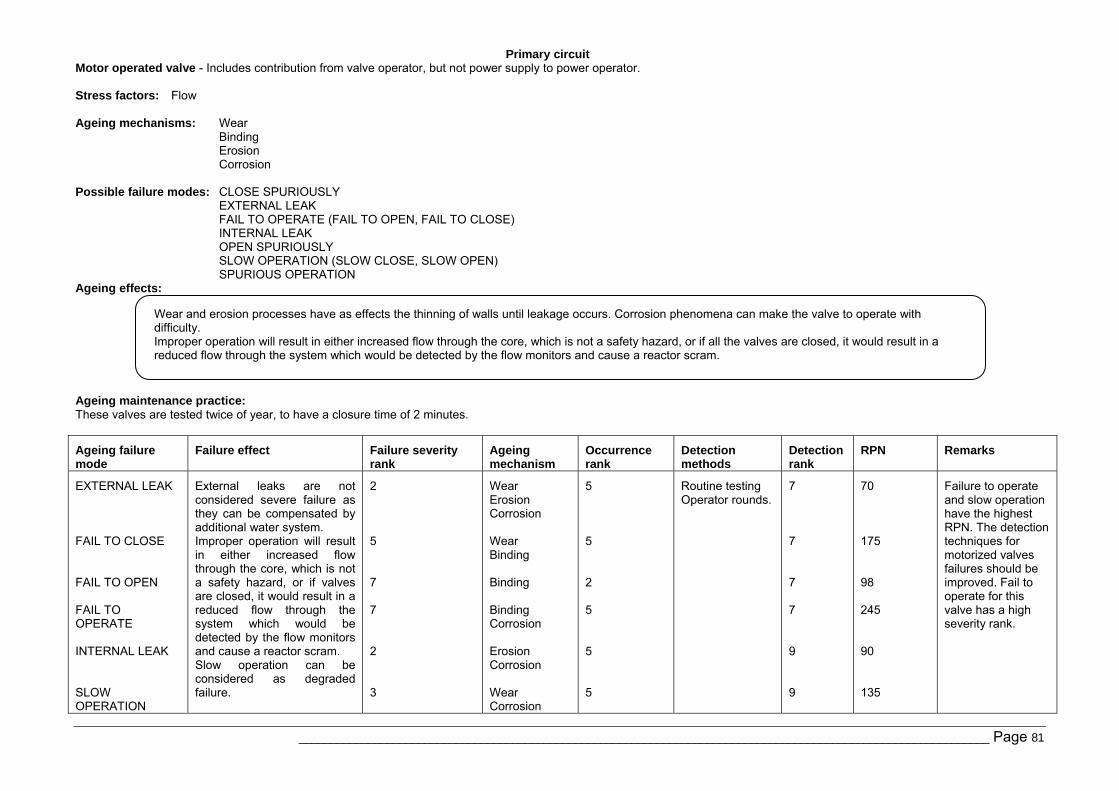
Primary circuit
______________________________________________________________________________________________________________ Page 81
Motor operated valve - Includes contribution from valve operator, but not power supply to power operator. Stress factors: Flow Ageing mechanisms: Wear
Binding Erosion Corrosion
Possible failure modes: CLOSE SPURIOUSLY EXTERNAL LEAK FAIL TO OPERATE (FAIL TO OPEN, FAIL TO CLOSE) INTERNAL LEAK OPEN SPURIOUSLY SLOW OPERATION (SLOW CLOSE, SLOW OPEN) SPURIOUS OPERATION
Ageing effects:
Ageing maintenance practice: These valves are tested twice of year, to have a closure time of 2 minutes.
Ageing failure mode
Failure effect Failure severity rank
Ageing mechanism
Occurrence rank
Detection methods
Detection rank
RPN Remarks
EXTERNAL LEAK FAIL TO CLOSE FAIL TO OPEN FAIL TO OPERATE INTERNAL LEAK SLOW OPERATION
External leaks are not considered severe failure as they can be compensated by additional water system. Improper operation will result in either increased flow through the core, which is not a safety hazard, or if valves are closed, it would result in a reduced flow through the system which would be detected by the flow monitors and cause a reactor scram. Slow operation can be considered as degraded failure.
2 5 7 7 2 3
Wear Erosion Corrosion Wear Binding Binding Binding Corrosion Erosion Corrosion Wear Corrosion
5 5 2 5 5 5
Routine testing Operator rounds.
7 7 7 7 9 9
70 175 98 245 90 135
Failure to operate and slow operation have the highest RPN. The detection techniques for motorized valves failures should be improved. Fail to operate for this valve has a high severity rank.
Wear and erosion processes have as effects the thinning of walls until leakage occurs. Corrosion phenomena can make the valve to operate with difficulty. Improper operation will result in either increased flow through the core, which is not a safety hazard, or if all the valves are closed, it would result in a reduced flow through the system which would be detected by the flow monitors and cause a reactor scram.
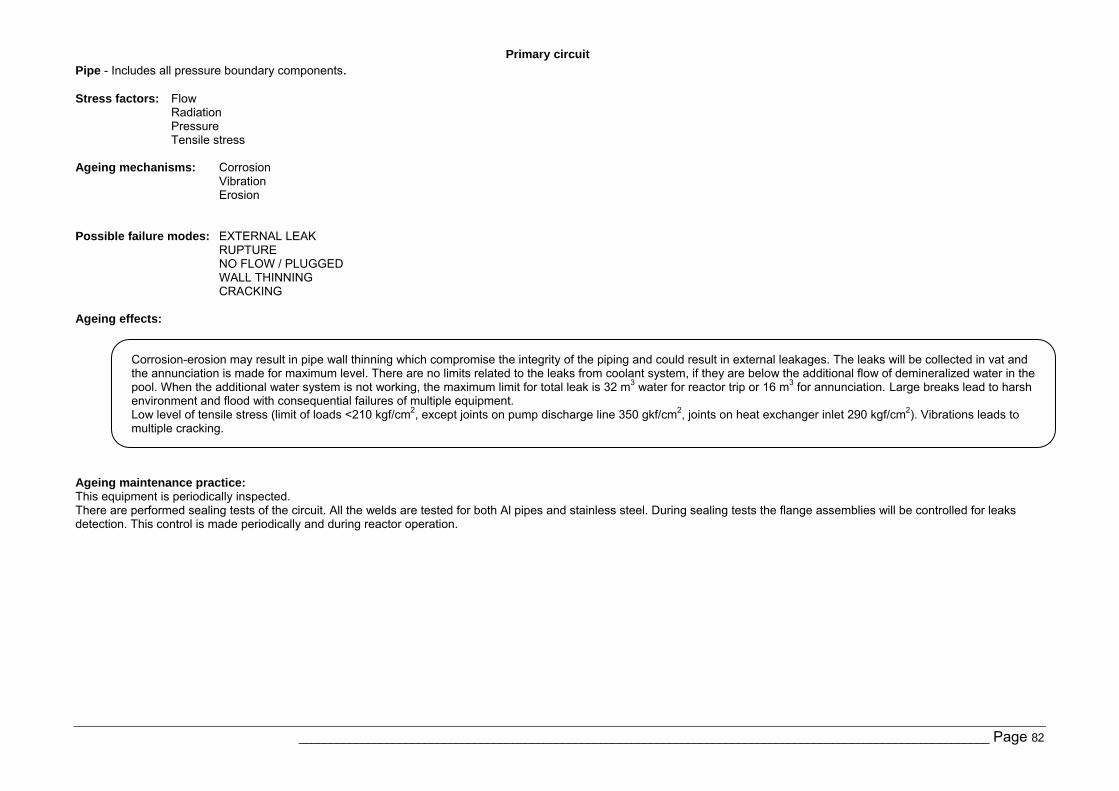
Primary circuit
______________________________________________________________________________________________________________ Page 82
Pipe - Includes all pressure boundary components. Stress factors: Flow
Radiation Pressure Tensile stress
Ageing mechanisms: Corrosion
Vibration Erosion
Possible failure modes: EXTERNAL LEAK RUPTURE NO FLOW / PLUGGED WALL THINNING CRACKING
Ageing effects:
Ageing maintenance practice: This equipment is periodically inspected. There are performed sealing tests of the circuit. All the welds are tested for both Al pipes and stainless steel. During sealing tests the flange assemblies will be controlled for leaks detection. This control is made periodically and during reactor operation.
Corrosion-erosion may result in pipe wall thinning which compromise the integrity of the piping and could result in external leakages. The leaks will be collected in vat and the annunciation is made for maximum level. There are no limits related to the leaks from coolant system, if they are below the additional flow of demineralized water in the pool. When the additional water system is not working, the maximum limit for total leak is 32 m3 water for reactor trip or 16 m3 for annunciation. Large breaks lead to harsh environment and flood with consequential failures of multiple equipment. Low level of tensile stress (limit of loads <210 kgf/cm2, except joints on pump discharge line 350 gkf/cm2, joints on heat exchanger inlet 290 kgf/cm2). Vibrations leads to multiple cracking.
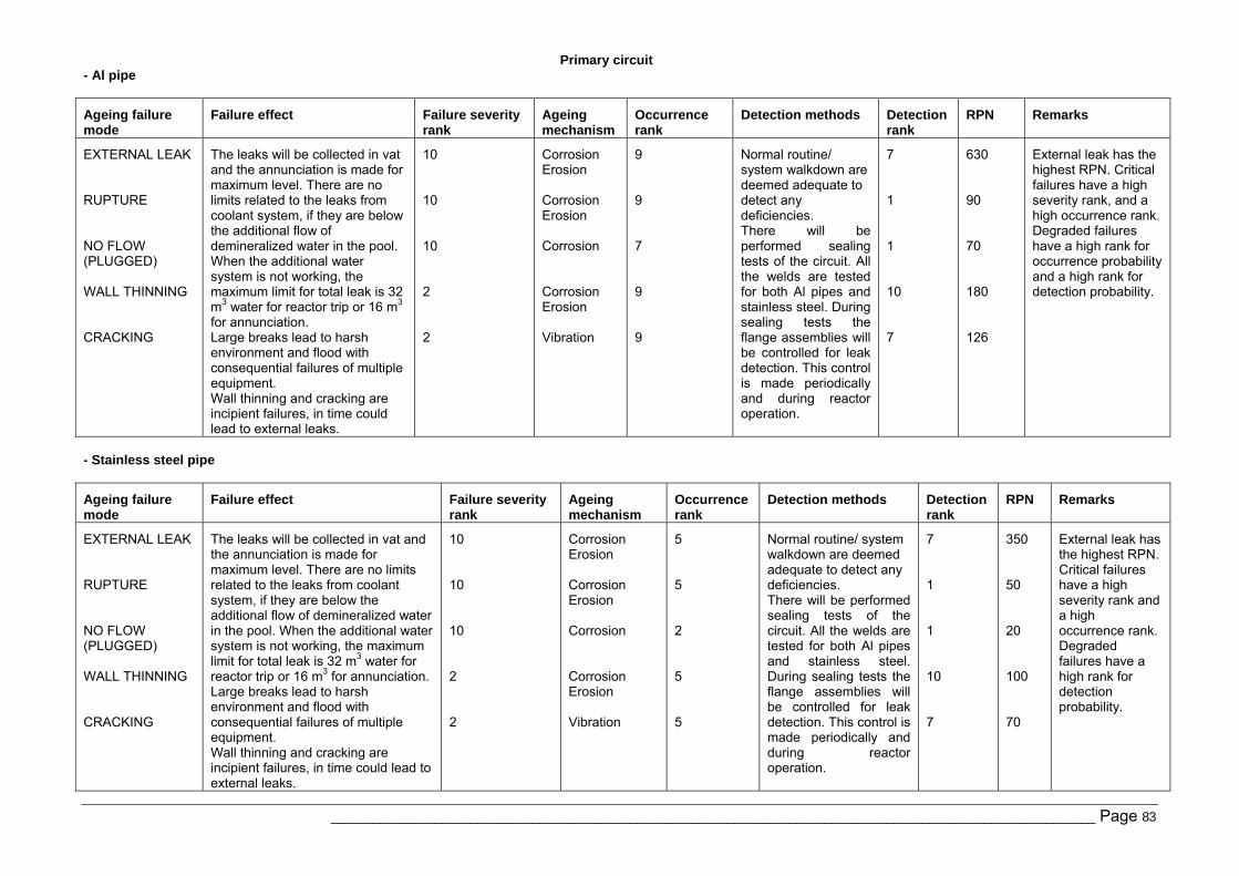
Primary circuit
______________________________________________________________________________________________________________ Page 83
- Al pipe
Ageing failure mode
Failure effect Failure severity rank
Ageing mechanism
Occurrence rank
Detection methods Detection rank
RPN Remarks
EXTERNAL LEAK RUPTURE NO FLOW (PLUGGED) WALL THINNING CRACKING
The leaks will be collected in vat and the annunciation is made for maximum level. There are no limits related to the leaks from coolant system, if they are below the additional flow of demineralized water in the pool. When the additional water system is not working, the maximum limit for total leak is 32 m3 water for reactor trip or 16 m3 for annunciation. Large breaks lead to harsh environment and flood with consequential failures of multiple equipment. Wall thinning and cracking are incipient failures, in time could lead to external leaks.
10 10 10 2 2
Corrosion Erosion Corrosion Erosion Corrosion Corrosion Erosion Vibration
9 9 7 9 9
Normal routine/ system walkdown are deemed adequate to detect any deficiencies. There will be performed sealing tests of the circuit. All the welds are tested for both Al pipes and stainless steel. During sealing tests the flange assemblies will be controlled for leak detection. This control is made periodically and during reactor operation.
7 1 1 10 7
630 90 70 180 126
External leak has the highest RPN. Critical failures have a high severity rank, and a high occurrence rank. Degraded failures have a high rank for occurrence probability and a high rank for detection probability.
- Stainless steel pipe
Ageing failure mode
Failure effect Failure severity rank
Ageing mechanism
Occurrence rank
Detection methods Detection rank
RPN Remarks
EXTERNAL LEAK RUPTURE NO FLOW (PLUGGED) WALL THINNING CRACKING
The leaks will be collected in vat and the annunciation is made for maximum level. There are no limits related to the leaks from coolant system, if they are below the additional flow of demineralized water in the pool. When the additional water system is not working, the maximum limit for total leak is 32 m3 water for reactor trip or 16 m3 for annunciation. Large breaks lead to harsh environment and flood with consequential failures of multiple equipment. Wall thinning and cracking are incipient failures, in time could lead to external leaks.
10 10 10 2 2
Corrosion Erosion Corrosion Erosion Corrosion Corrosion Erosion Vibration
5 5 2 5 5
Normal routine/ system walkdown are deemed adequate to detect any deficiencies. There will be performed sealing tests of the circuit. All the welds are tested for both Al pipes and stainless steel. During sealing tests the flange assemblies will be controlled for leak detection. This control is made periodically and during reactor operation.
7 1 1 10 7
350 50 20 100 70
External leak has the highest RPN. Critical failures have a high severity rank and a high occurrence rank. Degraded failures have a high rank for detection probability.
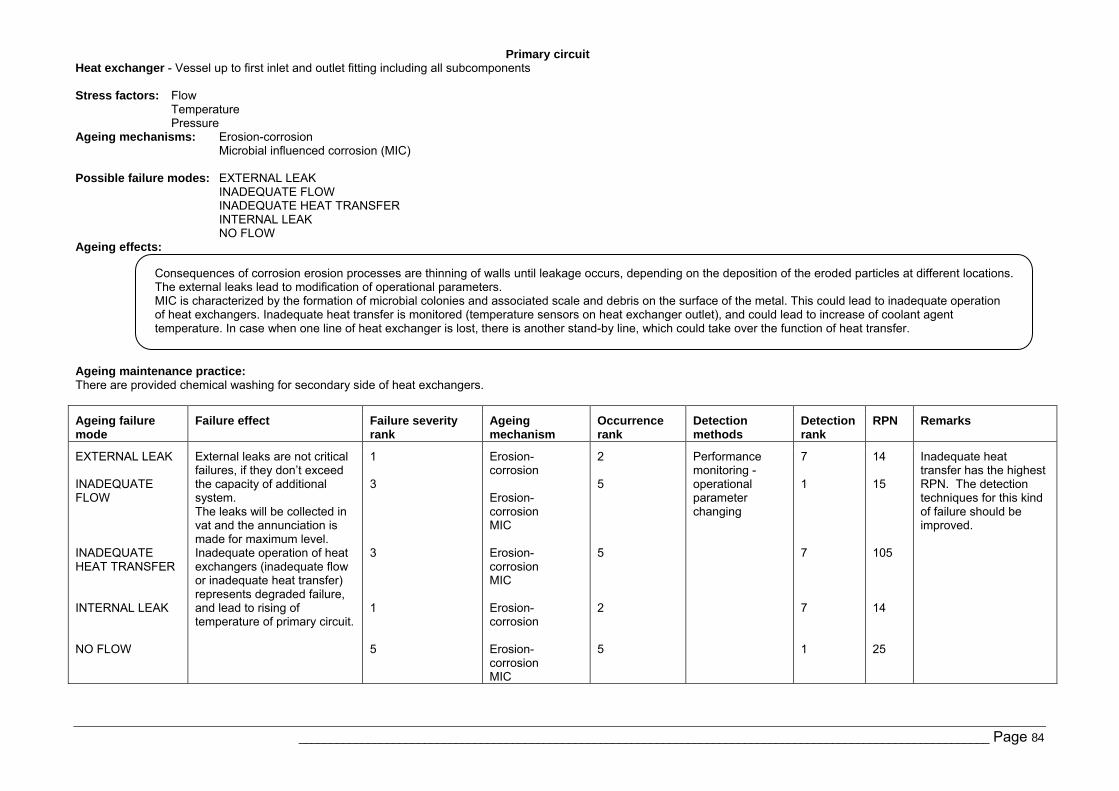
Primary circuit
______________________________________________________________________________________________________________ Page 84
Heat exchanger - Vessel up to first inlet and outlet fitting including all subcomponents Stress factors: Flow
Temperature Pressure
Ageing mechanisms: Erosion-corrosion Microbial influenced corrosion (MIC)
Possible failure modes: EXTERNAL LEAK INADEQUATE FLOW INADEQUATE HEAT TRANSFER INTERNAL LEAK NO FLOW
Ageing effects:
Ageing maintenance practice: There are provided chemical washing for secondary side of heat exchangers.
Ageing failure mode
Failure effect Failure severity rank
Ageing mechanism
Occurrence rank
Detection methods
Detection rank
RPN Remarks
EXTERNAL LEAK INADEQUATE FLOW INADEQUATE HEAT TRANSFER INTERNAL LEAK NO FLOW
External leaks are not critical failures, if they don’t exceed the capacity of additional system. The leaks will be collected in vat and the annunciation is made for maximum level. Inadequate operation of heat exchangers (inadequate flow or inadequate heat transfer) represents degraded failure, and lead to rising of temperature of primary circuit.
1 3 3 1 5
Erosion-corrosion Erosion-corrosion MIC Erosion-corrosion MIC Erosion-corrosion Erosion-corrosion MIC
2 5 5 2 5
Performance monitoring - operational parameter changing
7 1 7 7 1
14 15 105 14 25
Inadequate heat transfer has the highest RPN. The detection techniques for this kind of failure should be improved.
Consequences of corrosion erosion processes are thinning of walls until leakage occurs, depending on the deposition of the eroded particles at different locations. The external leaks lead to modification of operational parameters. MIC is characterized by the formation of microbial colonies and associated scale and debris on the surface of the metal. This could lead to inadequate operation of heat exchangers. Inadequate heat transfer is monitored (temperature sensors on heat exchanger outlet), and could lead to increase of coolant agent temperature. In case when one line of heat exchanger is lost, there is another stand-by line, which could take over the function of heat transfer.
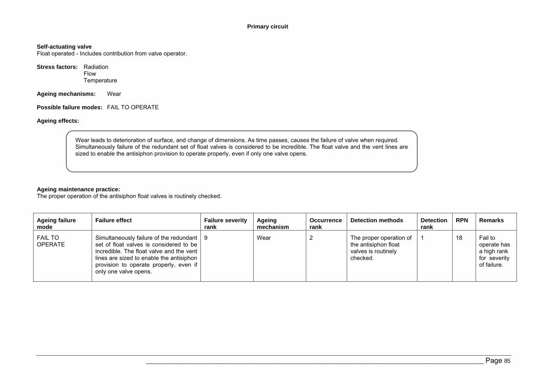
Primary circuit
______________________________________________________________________________________________________________ Page 85
Self-actuating valve Float operated - Includes contribution from valve operator. Stress factors: Radiation
Flow Temperature
Ageing mechanisms: Wear Possible failure modes: FAIL TO OPERATE Ageing effects:
Ageing maintenance practice: The proper operation of the antisiphon float valves is routinely checked.
Ageing failure mode
Failure effect Failure severity rank
Ageing mechanism
Occurrence rank
Detection methods Detection rank
RPN Remarks
FAIL TO OPERATE
Simultaneously failure of the redundant set of float valves is considered to be incredible. The float valve and the vent lines are sized to enable the antisiphon provision to operate properly, even if only one valve opens.
9 Wear 2 The proper operation of the antisiphon float valves is routinely checked.
1 18 Fail to operate has a high rank for severity of failure.
Wear leads to deterioration of surface, and change of dimensions. As time passes, causes the failure of valve when required. Simultaneously failure of the redundant set of float valves is considered to be incredible. The float valve and the vent lines are sized to enable the antisiphon provision to operate properly, even if only one valve opens.
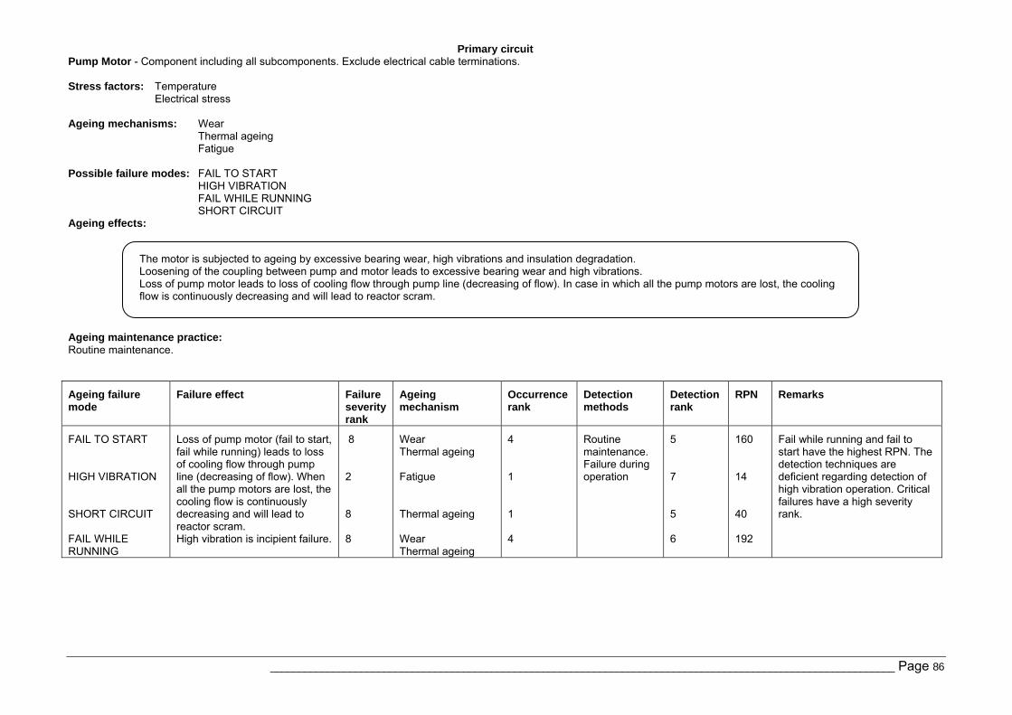
Primary circuit
______________________________________________________________________________________________________________ Page 86
Pump Motor - Component including all subcomponents. Exclude electrical cable terminations. Stress factors: Temperature
Electrical stress
Ageing mechanisms: Wear Thermal ageing Fatigue
Possible failure modes: FAIL TO START HIGH VIBRATION FAIL WHILE RUNNING SHORT CIRCUIT
Ageing effects:
Ageing maintenance practice: Routine maintenance.
Ageing failure mode
Failure effect Failure severity rank
Ageing mechanism
Occurrence rank
Detection methods
Detection rank
RPN Remarks
FAIL TO START HIGH VIBRATION SHORT CIRCUIT FAIL WHILE RUNNING
Loss of pump motor (fail to start, fail while running) leads to loss of cooling flow through pump line (decreasing of flow). When all the pump motors are lost, the cooling flow is continuously decreasing and will lead to reactor scram. High vibration is incipient failure.
8 2 8 8
Wear Thermal ageing Fatigue Thermal ageing Wear Thermal ageing
4 1 1 4
Routine maintenance. Failure during operation
5 7 5 6
160 14 40 192
Fail while running and fail to start have the highest RPN. The detection techniques are deficient regarding detection of high vibration operation. Critical failures have a high severity rank.
The motor is subjected to ageing by excessive bearing wear, high vibrations and insulation degradation. Loosening of the coupling between pump and motor leads to excessive bearing wear and high vibrations. Loss of pump motor leads to loss of cooling flow through pump line (decreasing of flow). In case in which all the pump motors are lost, the cooling flow is continuously decreasing and will lead to reactor scram.
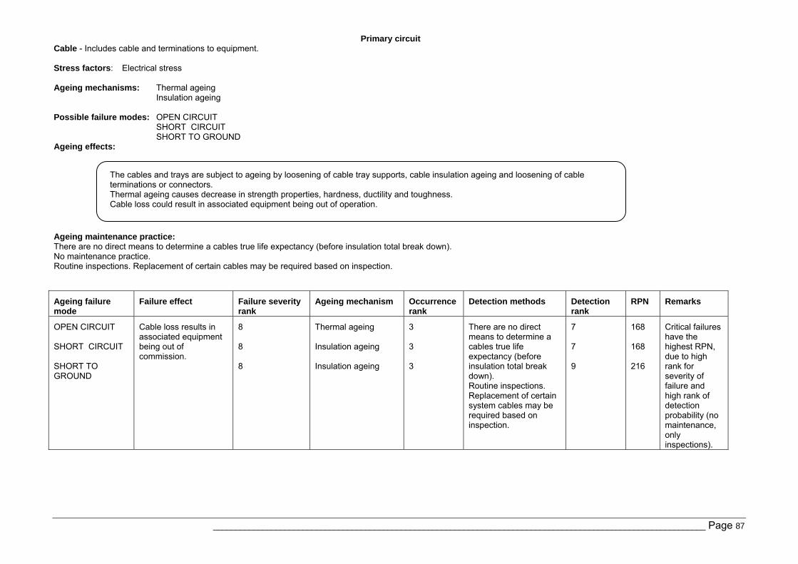
Primary circuit
______________________________________________________________________________________________________________ Page 87
Cable - Includes cable and terminations to equipment. Stress factors: Electrical stress Ageing mechanisms: Thermal ageing
Insulation ageing Possible failure modes: OPEN CIRCUIT
SHORT CIRCUIT SHORT TO GROUND
Ageing effects:
Ageing maintenance practice: There are no direct means to determine a cables true life expectancy (before insulation total break down). No maintenance practice. Routine inspections. Replacement of certain cables may be required based on inspection.
Ageing failure mode
Failure effect Failure severity rank
Ageing mechanism Occurrence rank
Detection methods Detection rank
RPN Remarks
OPEN CIRCUIT SHORT CIRCUIT SHORT TO GROUND
Cable loss results in associated equipment being out of commission.
8 8 8
Thermal ageing Insulation ageing Insulation ageing
3 3 3
There are no direct means to determine a cables true life expectancy (before insulation total break down). Routine inspections. Replacement of certain system cables may be required based on inspection.
7 7 9
168 168 216
Critical failures have the highest RPN, due to high rank for severity of failure and high rank of detection probability (no maintenance, only inspections).
The cables and trays are subject to ageing by loosening of cable tray supports, cable insulation ageing and loosening of cable terminations or connectors. Thermal ageing causes decrease in strength properties, hardness, ductility and toughness. Cable loss could result in associated equipment being out of operation.
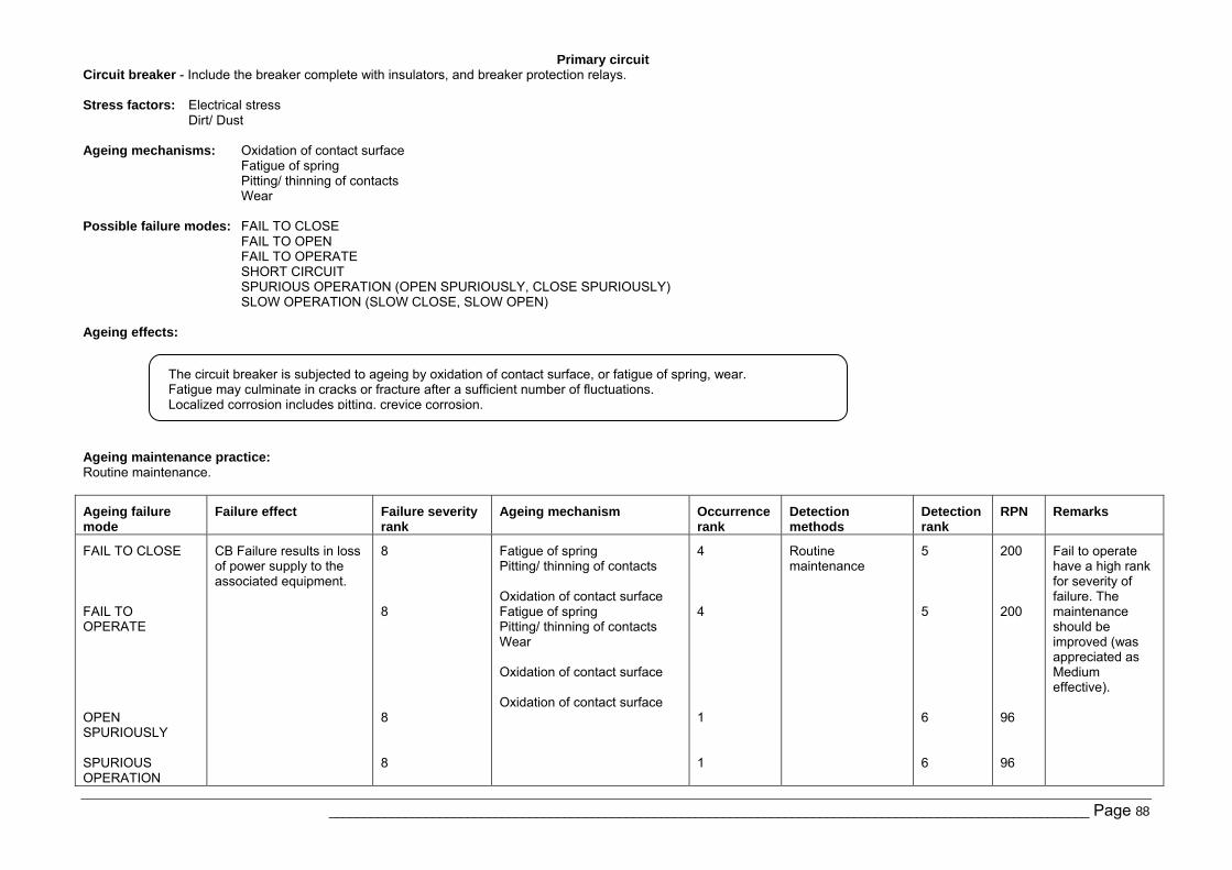
Primary circuit
______________________________________________________________________________________________________________ Page 88
Circuit breaker - Include the breaker complete with insulators, and breaker protection relays. Stress factors: Electrical stress
Dirt/ Dust Ageing mechanisms: Oxidation of contact surface
Fatigue of spring Pitting/ thinning of contacts Wear
Possible failure modes: FAIL TO CLOSE
FAIL TO OPEN FAIL TO OPERATE SHORT CIRCUIT SPURIOUS OPERATION (OPEN SPURIOUSLY, CLOSE SPURIOUSLY) SLOW OPERATION (SLOW CLOSE, SLOW OPEN)
Ageing effects:
Ageing maintenance practice: Routine maintenance.
Ageing failure mode
Failure effect Failure severity rank
Ageing mechanism Occurrence rank
Detection methods
Detection rank
RPN Remarks
FAIL TO CLOSE FAIL TO OPERATE OPEN SPURIOUSLY SPURIOUS OPERATION
CB Failure results in loss of power supply to the associated equipment.
8 8 8 8
Fatigue of spring Pitting/ thinning of contacts Oxidation of contact surface Fatigue of spring Pitting/ thinning of contacts Wear Oxidation of contact surface Oxidation of contact surface
4 4 1 1
Routine maintenance
5 5 6 6
200 200 96 96
Fail to operate have a high rank for severity of failure. The maintenance should be improved (was appreciated as Medium effective).
The circuit breaker is subjected to ageing by oxidation of contact surface, or fatigue of spring, wear. Fatigue may culminate in cracks or fracture after a sufficient number of fluctuations. Localized corrosion includes pitting, crevice corrosion.
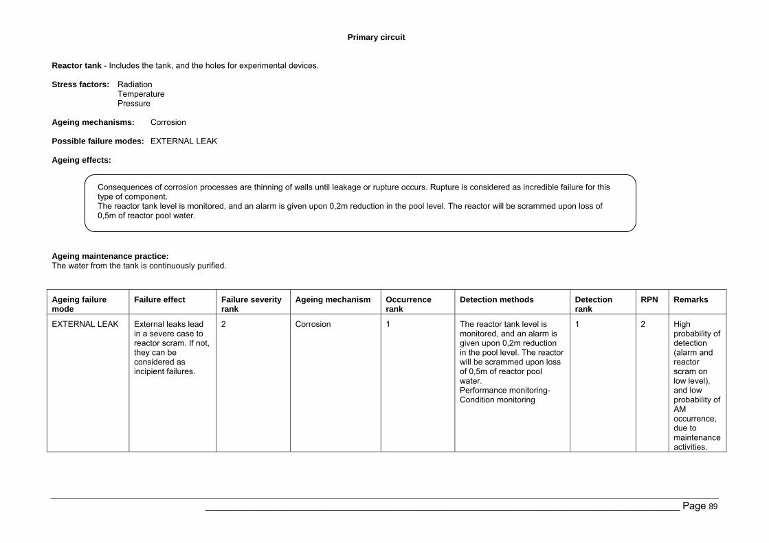
Primary circuit
______________________________________________________________________________________________________________ Page 89
Reactor tank - Includes the tank, and the holes for experimental devices. Stress factors: Radiation
Temperature Pressure
Ageing mechanisms: Corrosion Possible failure modes: EXTERNAL LEAK Ageing effects:
Ageing maintenance practice: The water from the tank is continuously purified.
Ageing failure mode
Failure effect Failure severity rank
Ageing mechanism Occurrence rank
Detection methods Detection rank
RPN Remarks
EXTERNAL LEAK External leaks lead in a severe case to reactor scram. If not, they can be considered as incipient failures.
2 Corrosion 1 The reactor tank level is monitored, and an alarm is given upon 0,2m reduction in the pool level. The reactor will be scrammed upon loss of 0,5m of reactor pool water. Performance monitoring- Condition monitoring
1 2 High probability of detection (alarm and reactor scram on low level), and low probability of AM occurrence, due to maintenance activities.
Consequences of corrosion processes are thinning of walls until leakage or rupture occurs. Rupture is considered as incredible failure for this type of component. The reactor tank level is monitored, and an alarm is given upon 0,2m reduction in the pool level. The reactor will be scrammed upon loss of 0,5m of reactor pool water.
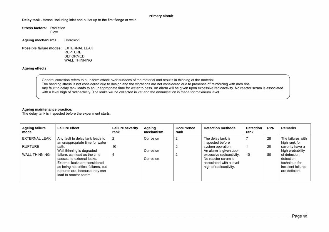
Primary circuit
______________________________________________________________________________________________________________ Page 90
Delay tank - Vessel including inlet and outlet up to the first flange or weld. Stress factors: Radiation
Flow Ageing mechanisms: Corrosion Possible failure modes: EXTERNAL LEAK
RUPTURE DEFORMED WALL THINNING
Ageing effects:
Ageing maintenance practice: The delay tank is inspected before the experiment starts.
Ageing failure mode
Failure effect Failure severity rank
Ageing mechanism
Occurrence rank
Detection methods Detection rank
RPN Remarks
EXTERNAL LEAK RUPTURE WALL THINNING
Any fault to delay tank leads to an unappropriate time for water path. Wall thinning is degraded failure, can lead as the time passes, to external leaks. External leaks are considered as being not critical failures, but ruptures are, because they can lead to reactor scram.
2 10 4
Corrosion Corrosion Corrosion
2 2 2
The delay tank is inspected before system operation. An alarm is given upon excessive radioactivity. No reactor scram is associated with a level high of radioactivity.
7 1 10
28 20 80
The failures with high rank for severity have a high probability of detection; detection technique for incipient failures are deficient.
General corrosion refers to a uniform attack over surfaces of the material and results in thinning of the material The bending stress is not considered due to design and the vibrations are not considered due to presence of reinforcing with arch ribs. Any fault to delay tank leads to an unappropriate time for water to pass. An alarm will be given upon excessive radioactivity. No reactor scram is associated with a level high of radioactivity. The leaks will be collected in vat and the annunciation is made for maximum level.
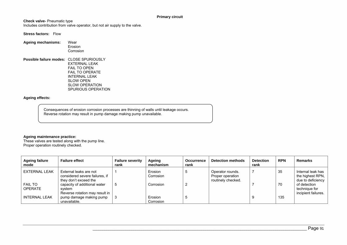
Primary circuit
______________________________________________________________________________________________________________ Page 91
Check valve- Pneumatic type Includes contribution from valve operator, but not air supply to the valve. Stress factors: Flow Ageing mechanisms: Wear
Erosion Corrosion
Possible failure modes: CLOSE SPURIOUSLY
EXTERNAL LEAK FAIL TO OPEN FAIL TO OPERATE INTERNAL LEAK SLOW OPEN SLOW OPERATION SPURIOUS OPERATION
Ageing effects:
Ageing maintenance practice: These valves are tested along with the pump line. Proper operation routinely checked.
Ageing failure mode
Failure effect Failure severity rank
Ageing mechanism
Occurrence rank
Detection methods Detection rank
RPN Remarks
EXTERNAL LEAK FAIL TO OPERATE INTERNAL LEAK
External leaks are not considered severe failures, if they don’t exceed the capacity of additional water system Reverse rotation may result in pump damage making pump unavailable.
1 5 3
Erosion Corrosion Corrosion Erosion Corrosion
5 2 5
Operator rounds. Proper operation routinely checked.
7 7 9
35 70 135
Internal leak has the highest RPN, due to deficiency of detection technique for incipient failures.
Consequences of erosion corrosion processes are thinning of walls until leakage occurs. Reverse rotation may result in pump damage making pump unavailable.
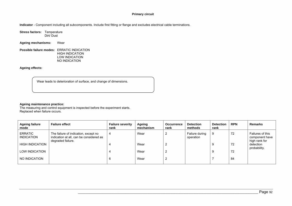
Primary circuit
______________________________________________________________________________________________________________ Page 92
Indicator - Component including all subcomponents. Include first fitting or flange and excludes electrical cable terminations. Stress factors: Temperature
Dirt/ Dust Ageing mechanisms: Wear Possible failure modes: ERRATIC INDICATION
HIGH INDICATION LOW INDICATION NO INDICATION
Ageing effects:
Ageing maintenance practice: The measuring and control equipment is inspected before the experiment starts. Replaced when failure occurs.
Ageing failure mode
Failure effect Failure severity rank
Ageing mechanism
Occurrence rank
Detection methods
Detection rank
RPN Remarks
ERRATIC INDICATION HIGH INDICATION LOW INDICATION NO INDICATION
The failure of indication, except no indication at all, can be considered as degraded failure.
4 4 4 6
Wear Wear Wear Wear
2 2 2 2
Failure during operation
9 9 9 7
72 72 72 84
Failures of this component have high rank for detection probability.
Wear leads to deterioration of surface, and change of dimensions.
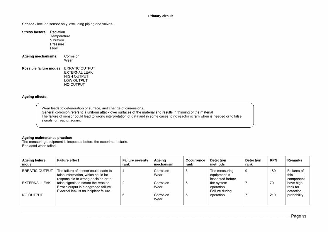
Primary circuit
______________________________________________________________________________________________________________ Page 93
Sensor - Include sensor only, excluding piping and valves. Stress factors: Radiation
Temperature Vibration Pressure Flow
Ageing mechanisms: Corrosion
Wear Possible failure modes: ERRATIC OUTPUT
EXTERNAL LEAK HIGH OUTPUT LOW OUTPUT NO OUTPUT
Ageing effects:
Ageing maintenance practice: The measuring equipment is inspected before the experiment starts. Replaced when failed.
Ageing failure mode
Failure effect Failure severity rank
Ageing mechanism
Occurrence rank
Detection methods
Detection rank
RPN Remarks
ERRATIC OUTPUT EXTERNAL LEAK NO OUTPUT
The failure of sensor could leads to false information, which could be responsible to wrong decision or to false signals to scram the reactor. Erratic output is a degraded failure. External leak is an incipient failure.
4 2 6
Corrosion Wear Corrosion Wear Corrosion Wear
5 5 5
The measuring equipment is inspected before the system operation. Failure during operation.
9 7 7
180 70 210
Failures of this component have high rank for detection probability.
Wear leads to deterioration of surface, and change of dimensions. General corrosion refers to a uniform attack over surfaces of the material and results in thinning of the material The failure of sensor could lead to wrong interpretation of data and in some cases to no reactor scram when is needed or to false signals for reactor scram.
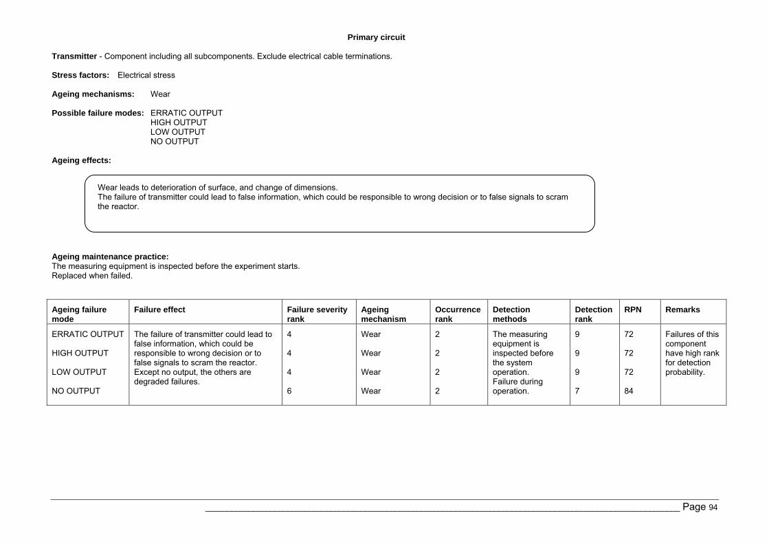
Primary circuit
______________________________________________________________________________________________________________ Page 94
Transmitter - Component including all subcomponents. Exclude electrical cable terminations. Stress factors: Electrical stress Ageing mechanisms: Wear Possible failure modes: ERRATIC OUTPUT
HIGH OUTPUT LOW OUTPUT NO OUTPUT
Ageing effects:
Ageing maintenance practice: The measuring equipment is inspected before the experiment starts. Replaced when failed.
Ageing failure mode
Failure effect Failure severity rank
Ageing mechanism
Occurrence rank
Detection methods
Detection rank
RPN Remarks
ERRATIC OUTPUT HIGH OUTPUT LOW OUTPUT NO OUTPUT
The failure of transmitter could lead to false information, which could be responsible to wrong decision or to false signals to scram the reactor. Except no output, the others are degraded failures.
4 4 4 6
Wear Wear Wear Wear
2 2 2 2
The measuring equipment is inspected before the system operation. Failure during operation.
9 9 9 7
72 72 72 84
Failures of this component have high rank for detection probability.
Wear leads to deterioration of surface, and change of dimensions. The failure of transmitter could lead to false information, which could be responsible to wrong decision or to false signals to scram the reactor.
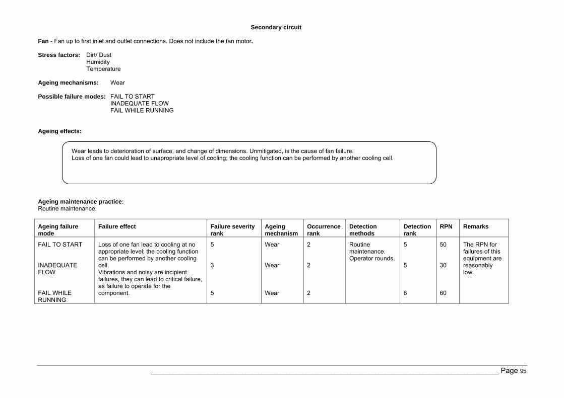
Secondary circuit
______________________________________________________________________________________________________________ Page 95
Fan - Fan up to first inlet and outlet connections. Does not include the fan motor. Stress factors: Dirt/ Dust
Humidity Temperature
Ageing mechanisms: Wear Possible failure modes: FAIL TO START
INADEQUATE FLOW FAIL WHILE RUNNING
Ageing effects:
Ageing maintenance practice: Routine maintenance.
Ageing failure mode
Failure effect Failure severity rank
Ageing mechanism
Occurrence rank
Detection methods
Detection rank
RPN Remarks
FAIL TO START INADEQUATE FLOW FAIL WHILE RUNNING
Loss of one fan lead to cooling at no appropriate level; the cooling function can be performed by another cooling cell. Vibrations and noisy are incipient failures, they can lead to critical failure, as failure to operate for the component.
5 3 5
Wear Wear Wear
2 2 2
Routine maintenance. Operator rounds.
5 5 6
50 30 60
The RPN for failures of this equipment are reasonably low.
Wear leads to deterioration of surface, and change of dimensions. Unmitigated, is the cause of fan failure. Loss of one fan could lead to unapropriate level of cooling; the cooling function can be performed by another cooling cell.
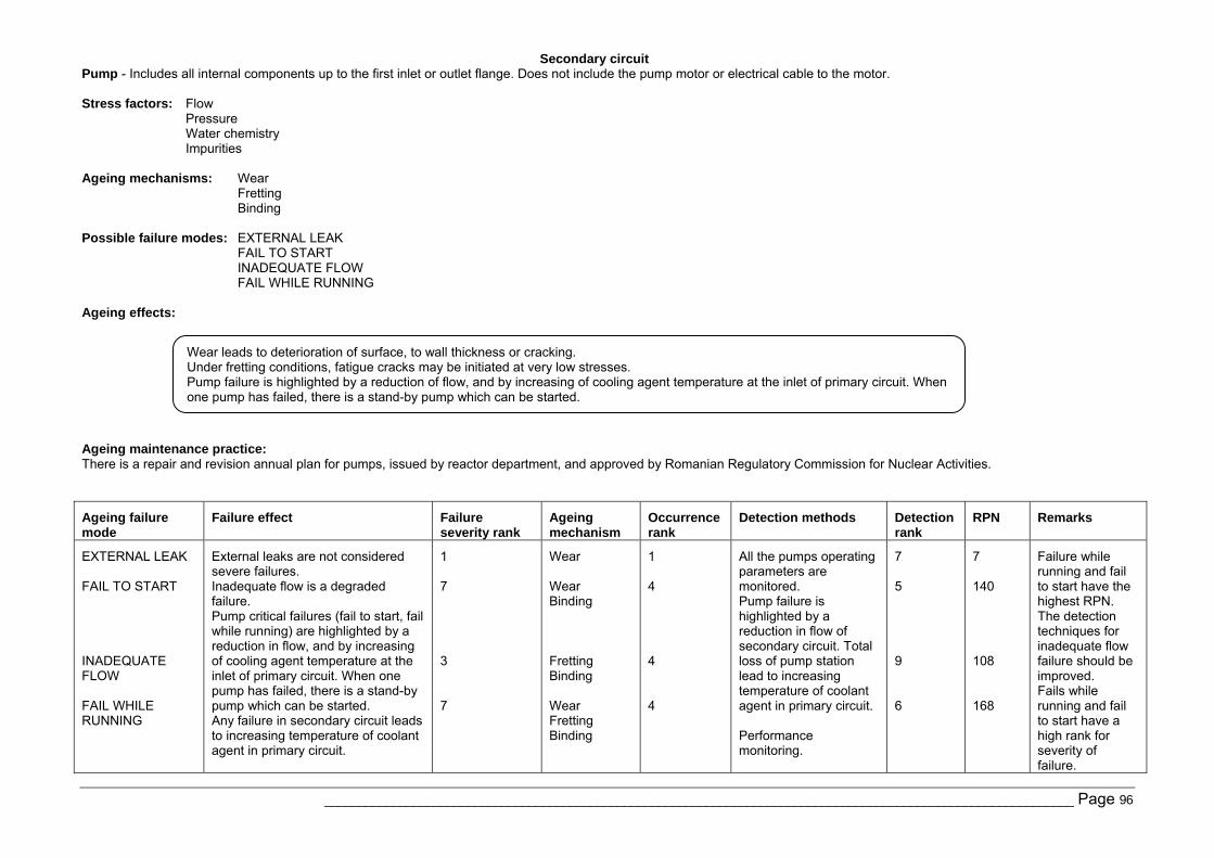
Secondary circuit
______________________________________________________________________________________________________________ Page 96
Pump - Includes all internal components up to the first inlet or outlet flange. Does not include the pump motor or electrical cable to the motor. Stress factors: Flow
Pressure Water chemistry Impurities
Ageing mechanisms: Wear
Fretting Binding
Possible failure modes: EXTERNAL LEAK
FAIL TO START INADEQUATE FLOW FAIL WHILE RUNNING
Ageing effects:
Ageing maintenance practice: There is a repair and revision annual plan for pumps, issued by reactor department, and approved by Romanian Regulatory Commission for Nuclear Activities.
Ageing failure mode
Failure effect Failure severity rank
Ageing mechanism
Occurrence rank
Detection methods Detection rank
RPN Remarks
EXTERNAL LEAK FAIL TO START INADEQUATE FLOW FAIL WHILE RUNNING
External leaks are not considered severe failures. Inadequate flow is a degraded failure. Pump critical failures (fail to start, fail while running) are highlighted by a reduction in flow, and by increasing of cooling agent temperature at the inlet of primary circuit. When one pump has failed, there is a stand-by pump which can be started. Any failure in secondary circuit leads to increasing temperature of coolant agent in primary circuit.
1 7 3 7
Wear Wear Binding Fretting Binding Wear Fretting Binding
1 4 4 4
All the pumps operating parameters are monitored. Pump failure is highlighted by a reduction in flow of secondary circuit. Total loss of pump station lead to increasing temperature of coolant agent in primary circuit. Performance monitoring.
7 5 9 6
7 140 108 168
Failure while running and fail to start have the highest RPN. The detection techniques for inadequate flow failure should be improved. Fails while running and fail to start have a high rank for severity of failure.
Wear leads to deterioration of surface, to wall thickness or cracking. Under fretting conditions, fatigue cracks may be initiated at very low stresses. Pump failure is highlighted by a reduction of flow, and by increasing of cooling agent temperature at the inlet of primary circuit. When one pump has failed, there is a stand-by pump which can be started.
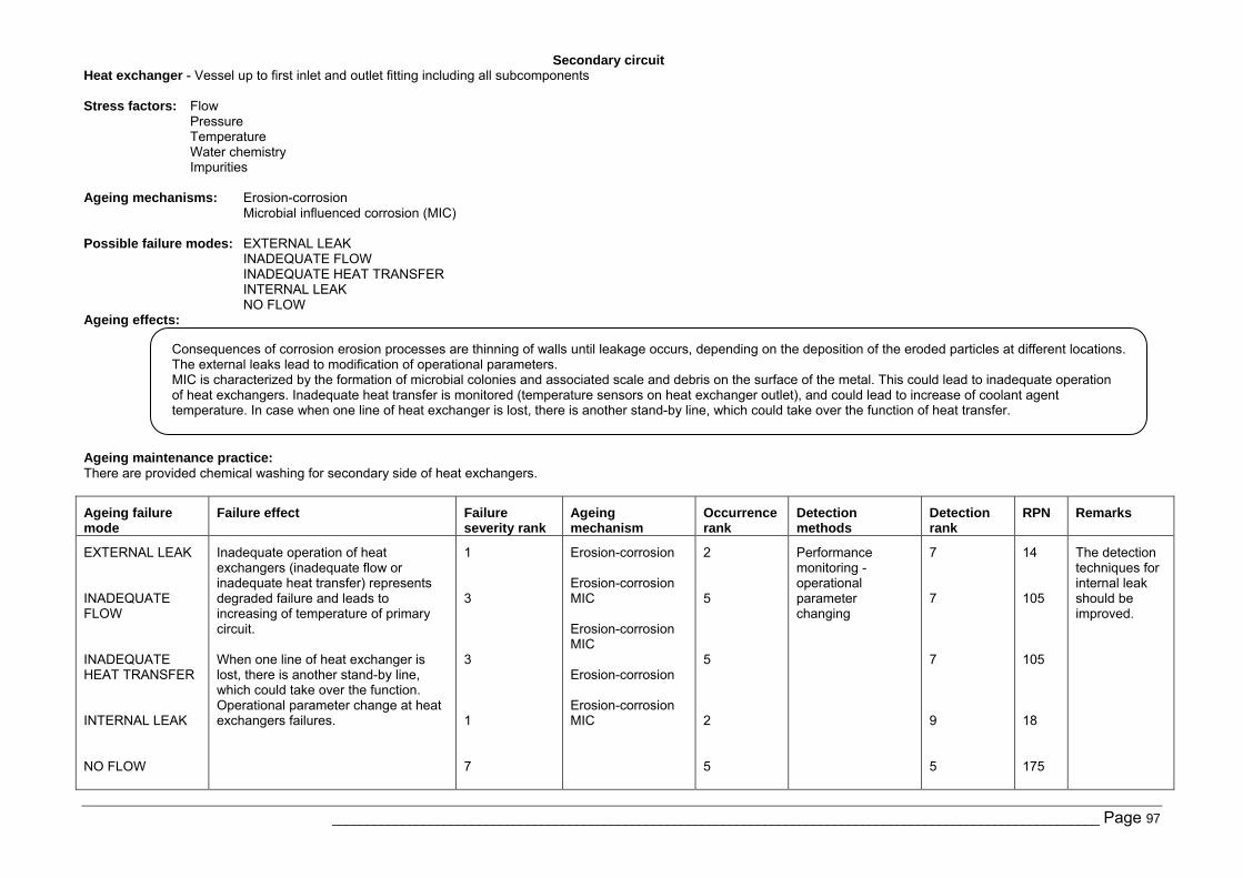
Secondary circuit
______________________________________________________________________________________________________________ Page 97
Heat exchanger - Vessel up to first inlet and outlet fitting including all subcomponents Stress factors: Flow
Pressure Temperature Water chemistry Impurities
Ageing mechanisms: Erosion-corrosion
Microbial influenced corrosion (MIC) Possible failure modes: EXTERNAL LEAK
INADEQUATE FLOW INADEQUATE HEAT TRANSFER INTERNAL LEAK NO FLOW
Ageing effects:
Ageing maintenance practice: There are provided chemical washing for secondary side of heat exchangers.
Ageing failure mode
Failure effect Failure severity rank
Ageing mechanism
Occurrence rank
Detection methods
Detection rank
RPN Remarks
EXTERNAL LEAK INADEQUATE FLOW INADEQUATE HEAT TRANSFER INTERNAL LEAK NO FLOW
Inadequate operation of heat exchangers (inadequate flow or inadequate heat transfer) represents degraded failure and leads to increasing of temperature of primary circuit. When one line of heat exchanger is lost, there is another stand-by line, which could take over the function. Operational parameter change at heat exchangers failures.
1 3 3 1 7
Erosion-corrosion Erosion-corrosion MIC Erosion-corrosion MIC Erosion-corrosion Erosion-corrosion MIC
2 5 5 2 5
Performance monitoring - operational parameter changing
7 7 7 9 5
14 105 105 18 175
The detection techniques for internal leak should be improved.
Consequences of corrosion erosion processes are thinning of walls until leakage occurs, depending on the deposition of the eroded particles at different locations. The external leaks lead to modification of operational parameters. MIC is characterized by the formation of microbial colonies and associated scale and debris on the surface of the metal. This could lead to inadequate operation of heat exchangers. Inadequate heat transfer is monitored (temperature sensors on heat exchanger outlet), and could lead to increase of coolant agent temperature. In case when one line of heat exchanger is lost, there is another stand-by line, which could take over the function of heat transfer.
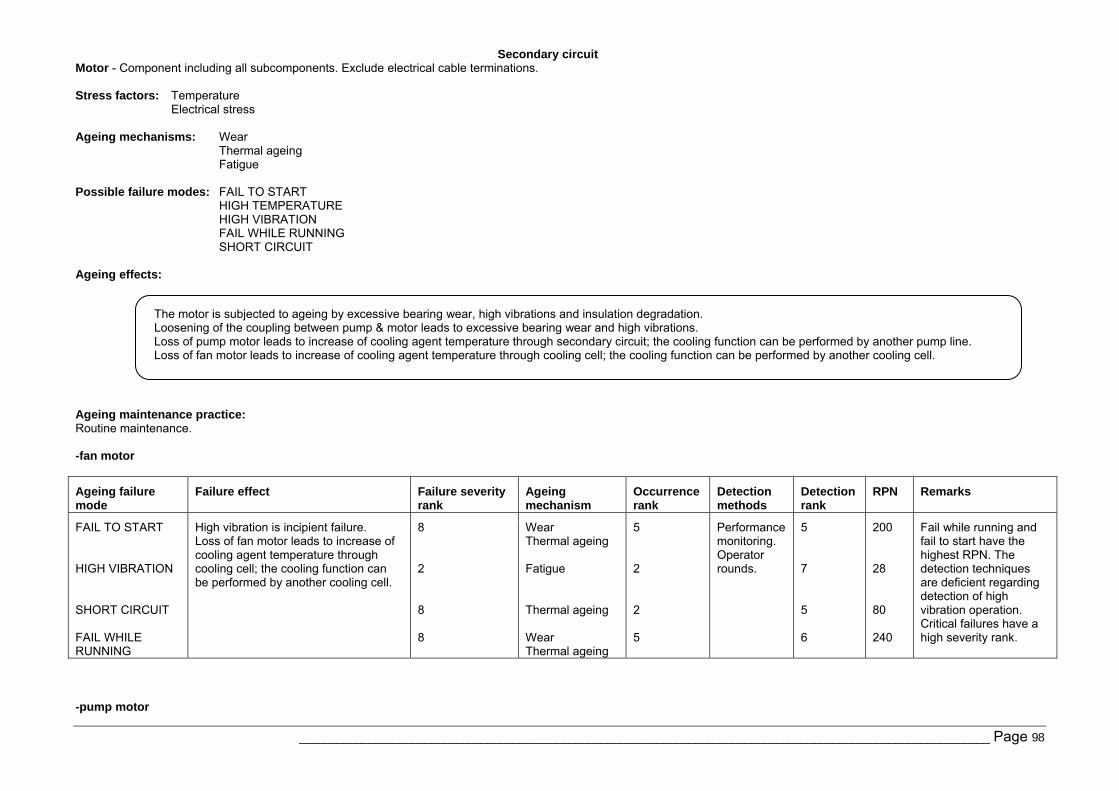
Secondary circuit
______________________________________________________________________________________________________________ Page 98
Motor - Component including all subcomponents. Exclude electrical cable terminations. Stress factors: Temperature
Electrical stress Ageing mechanisms: Wear
Thermal ageing Fatigue
Possible failure modes: FAIL TO START
HIGH TEMPERATURE HIGH VIBRATION FAIL WHILE RUNNING SHORT CIRCUIT
Ageing effects:
Ageing maintenance practice: Routine maintenance. -fan motor
Ageing failure mode
Failure effect Failure severity rank
Ageing mechanism
Occurrence rank
Detection methods
Detection rank
RPN Remarks
FAIL TO START HIGH VIBRATION SHORT CIRCUIT FAIL WHILE RUNNING
High vibration is incipient failure. Loss of fan motor leads to increase of cooling agent temperature through cooling cell; the cooling function can be performed by another cooling cell.
8 2 8 8
Wear Thermal ageing Fatigue Thermal ageing Wear Thermal ageing
5 2 2 5
Performance monitoring. Operator rounds.
5 7 5 6
200 28 80 240
Fail while running and fail to start have the highest RPN. The detection techniques are deficient regarding detection of high vibration operation. Critical failures have a high severity rank.
-pump motor
The motor is subjected to ageing by excessive bearing wear, high vibrations and insulation degradation. Loosening of the coupling between pump & motor leads to excessive bearing wear and high vibrations. Loss of pump motor leads to increase of cooling agent temperature through secondary circuit; the cooling function can be performed by another pump line. Loss of fan motor leads to increase of cooling agent temperature through cooling cell; the cooling function can be performed by another cooling cell.
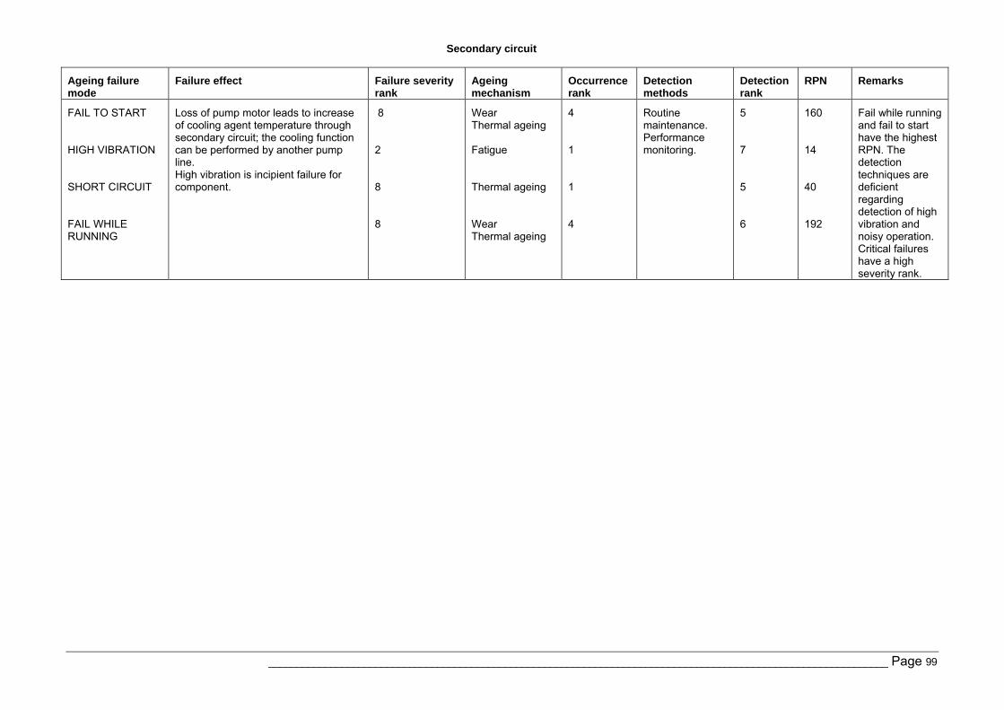
Secondary circuit
______________________________________________________________________________________________________________ Page 99
Ageing failure mode
Failure effect Failure severity rank
Ageing mechanism
Occurrence rank
Detection methods
Detection rank
RPN Remarks
FAIL TO START HIGH VIBRATION SHORT CIRCUIT FAIL WHILE RUNNING
Loss of pump motor leads to increase of cooling agent temperature through secondary circuit; the cooling function can be performed by another pump line. High vibration is incipient failure for component.
8 2 8 8
Wear Thermal ageing Fatigue Thermal ageing Wear Thermal ageing
4 1 1 4
Routine maintenance. Performance monitoring.
5 7 5 6
160 14 40 192
Fail while running and fail to start have the highest RPN. The detection techniques are deficient regarding detection of high vibration and noisy operation. Critical failures have a high severity rank.
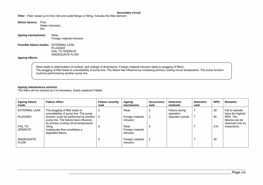
Secondary circuit
______________________________________________________________________________________________________________ Page 100
Filter - Filter vessel up to first inlet and outlet flange or fitting. Includes the filter element. Stress factors: Flow
Water chemistry Dirt
Ageing mechanisms: Wear
Foreign material intrusion Possible failure modes: EXTERNAL LEAK
PLUGGED FAIL TO OPERATE INADEQUATE FLOW
Ageing effects:
Ageing maintenance practice: The filters will be cleaned as it is necessary. Easily replaced if failed.
Ageing failure mode
Failure effect Failure severity rank
Ageing mechanism
Occurrence rank
Detection methods
Detection rank
RPN Remarks
EXTERNAL LEAK PLUGGED FAIL TO OPERATE INADEQUATE FLOW
The plugging of filter leads to unavailability of pump line. The pump function could be performed by another pump line. The failure have influence by primary cooling circuit temperature rising. Inadequate flow constitutes a degraded failure.
2 6 6 4
Wear Foreign material intrusion Wear Foreign material intrusion Foreign material intrusion
2 2 5 2
Failure during operation. Operator rounds.
7 7 7 7
28 84 210 56
Fail to operate have the highest RPN. The failures can be observed only by inspections.
Wear leads to deterioration of surface, and change of dimensions. Foreign material intrusion leads to plugging of filters. The plugging of filter leads to unavailability of pump line. The failure has influence by increasing primary cooling circuit temperature. The pump function could be performed by another pump line.
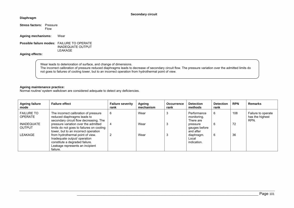
Secondary circuit
______________________________________________________________________________________________________________ Page 101
Diaphragm Stress factors: Pressure
Flow Ageing mechanisms: Wear Possible failure modes: FAILURE TO OPERATE
INADEQUATE OUTPUT LEAKAGE
Ageing effects:
Ageing maintenance practice: Normal routine/ system walkdown are considered adequate to detect any deficiencies.
Ageing failure mode
Failure effect Failure severity rank
Ageing mechanism
Occurrence rank
Detection methods
Detection rank
RPN Remarks
FAILURE TO OPERATE INADEQUATE OUTPUT LEAKAGE
The incorrect calibration of pressure reduced diaphragms leads to secondary circuit flow decreasing. The pressure variation over the admitted limits do not goes to failures on cooling tower, but to an incorrect operation from hydrothermal point of view. Inadequate output/ operation constitute a degraded failure. Leakage represents an incipient failure.
6 4 2
Wear Wear Wear
3 3 3
Performance monitoring. There are pressure gauges before and after diaphragm. Local indication.
6 6 6
108 72 36
Failure to operate has the highest RPN.
Wear leads to deterioration of surface, and change of dimensions. The incorrect calibration of pressure reduced diaphragms leads to decrease of secondary circuit flow. The pressure variation over the admitted limits do not goes to failures of cooling tower, but to an incorrect operation from hydrothermal point of view.
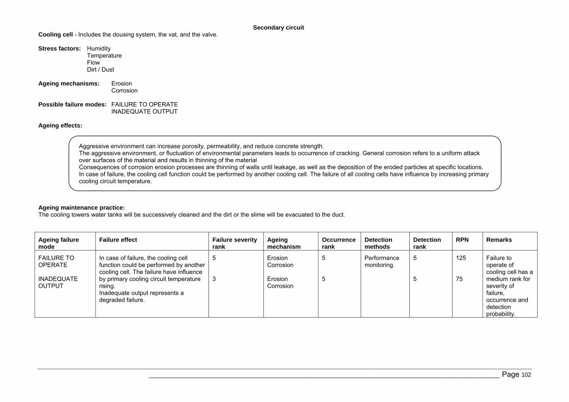
Secondary circuit
______________________________________________________________________________________________________________ Page 102
Cooling cell - Includes the dousing system, the vat, and the valve. Stress factors: Humidity
Temperature Flow Dirt / Dust
Ageing mechanisms: Erosion
Corrosion Possible failure modes: FAILURE TO OPERATE
INADEQUATE OUTPUT Ageing effects:
Ageing maintenance practice: The cooling towers water tanks will be successively cleaned and the dirt or the slime will be evacuated to the duct.
Ageing failure mode
Failure effect Failure severity rank
Ageing mechanism
Occurrence rank
Detection methods
Detection rank
RPN Remarks
FAILURE TO OPERATE INADEQUATE OUTPUT
In case of failure, the cooling cell function could be performed by another cooling cell. The failure have influence by primary cooling circuit temperature rising. Inadequate output represents a degraded failure.
5 3
Erosion Corrosion Erosion Corrosion
5 5
Performance monitoring.
5 5
125 75
Failure to operate of cooling cell has a medium rank for severity of failure, occurrence and detection probability.
Aggressive environment can increase porosity, permeability, and reduce concrete strength. The aggressive environment, or fluctuation of environmental parameters leads to occurrence of cracking. General corrosion refers to a uniform attack over surfaces of the material and results in thinning of the material Consequences of corrosion erosion processes are thinning of walls until leakage, as well as the deposition of the eroded particles at specific locations. In case of failure, the cooling cell function could be performed by another cooling cell. The failure of all cooling cells have influence by increasing primary cooling circuit temperature.
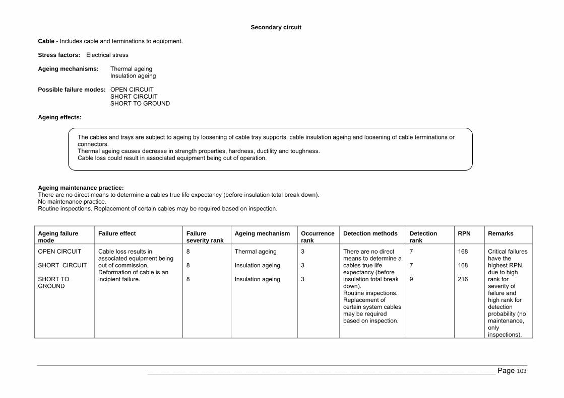
Secondary circuit
______________________________________________________________________________________________________________ Page 103
Cable - Includes cable and terminations to equipment. Stress factors: Electrical stress Ageing mechanisms: Thermal ageing
Insulation ageing Possible failure modes: OPEN CIRCUIT
SHORT CIRCUIT SHORT TO GROUND
Ageing effects:
Ageing maintenance practice: There are no direct means to determine a cables true life expectancy (before insulation total break down). No maintenance practice. Routine inspections. Replacement of certain cables may be required based on inspection.
Ageing failure mode
Failure effect Failure severity rank
Ageing mechanism Occurrence rank
Detection methods Detection rank
RPN Remarks
OPEN CIRCUIT SHORT CIRCUIT SHORT TO GROUND
Cable loss results in associated equipment being out of commission. Deformation of cable is an incipient failure.
8 8 8
Thermal ageing Insulation ageing Insulation ageing
3 3 3
There are no direct means to determine a cables true life expectancy (before insulation total break down). Routine inspections. Replacement of certain system cables may be required based on inspection.
7 7 9
168 168 216
Critical failures have the highest RPN, due to high rank for severity of failure and high rank for detection probability (no maintenance, only inspections).
The cables and trays are subject to ageing by loosening of cable tray supports, cable insulation ageing and loosening of cable terminations or connectors. Thermal ageing causes decrease in strength properties, hardness, ductility and toughness. Cable loss could result in associated equipment being out of operation.
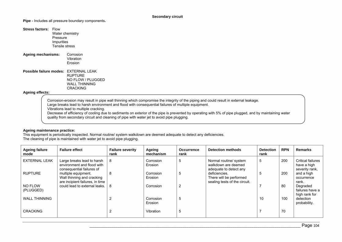
Secondary circuit
______________________________________________________________________________________________________________ Page 104
Pipe - Includes all pressure boundary components. Stress factors: Flow
Water chemistry Pressure Impurities Tensile stress
Ageing mechanisms: Corrosion
Vibration Erosion
Possible failure modes: EXTERNAL LEAK
RUPTURE NO FLOW / PLUGGED WALL THINNING CRACKING
Ageing effects:
Ageing maintenance practice: This equipment is periodically inspected. Normal routine/ system walkdown are deemed adequate to detect any deficiencies. The cleaning of pipe is maintained with water jet to avoid pipe plugging.
Ageing failure mode
Failure effect Failure severity rank
Ageing mechanism
Occurrence rank
Detection methods Detection rank
RPN Remarks
EXTERNAL LEAK RUPTURE NO FLOW (PLUGGED) WALL THINNING CRACKING
Large breaks lead to harsh environment and flood with consequential failures of multiple equipment. Wall thinning and cracking are incipient failures, in time could lead to external leaks.
8 8 8 2 2
Corrosion Erosion Corrosion Erosion Corrosion Corrosion Erosion Vibration
5 5 2 5 5
Normal routine/ system walkdown are deemed adequate to detect any deficiencies. There will be performed sealing tests of the circuit.
5 5 7 10 7
200 200 80 100 70
Critical failures have a high severity rank, and a high occurrence rank. Degraded failures have a high rank for detection probability.
Corrosion-erosion may result in pipe wall thinning which compromise the integrity of the piping and could result in external leakage. Large breaks lead to harsh environment and flood with consequential failures of multiple equipment. Vibrations lead to multiple cracking. Decrease of efficiency of cooling due to sediments on exterior of the pipe is prevented by operating with 5% of pipe plugged, and by maintaining water quality from secondary circuit and cleaning of pipe with water jet to avoid pipe plugging.
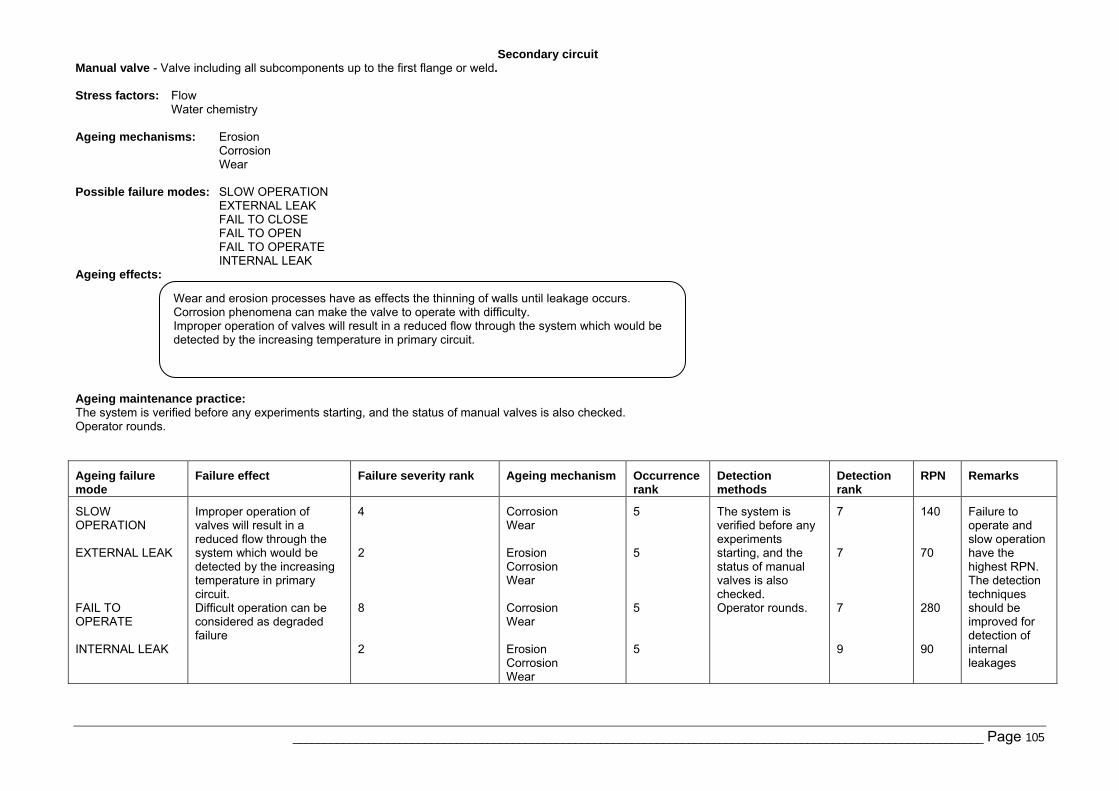
Secondary circuit
______________________________________________________________________________________________________________ Page 105
Manual valve - Valve including all subcomponents up to the first flange or weld. Stress factors: Flow
Water chemistry Ageing mechanisms: Erosion
Corrosion Wear
Possible failure modes: SLOW OPERATION
EXTERNAL LEAK FAIL TO CLOSE FAIL TO OPEN FAIL TO OPERATE INTERNAL LEAK
Ageing effects:
Ageing maintenance practice: The system is verified before any experiments starting, and the status of manual valves is also checked. Operator rounds.
Ageing failure mode
Failure effect Failure severity rank Ageing mechanism Occurrence rank
Detection methods
Detection rank
RPN Remarks
SLOW OPERATION EXTERNAL LEAK FAIL TO OPERATE INTERNAL LEAK
Improper operation of valves will result in a reduced flow through the system which would be detected by the increasing temperature in primary circuit. Difficult operation can be considered as degraded failure
4 2 8 2
Corrosion Wear Erosion Corrosion Wear Corrosion Wear Erosion Corrosion Wear
5 5 5 5
The system is verified before any experiments starting, and the status of manual valves is also checked. Operator rounds.
7 7 7 9
140 70 280 90
Failure to operate and slow operation have the highest RPN. The detection techniques should be improved for detection of internal leakages
Wear and erosion processes have as effects the thinning of walls until leakage occurs. Corrosion phenomena can make the valve to operate with difficulty. Improper operation of valves will result in a reduced flow through the system which would be detected by the increasing temperature in primary circuit.
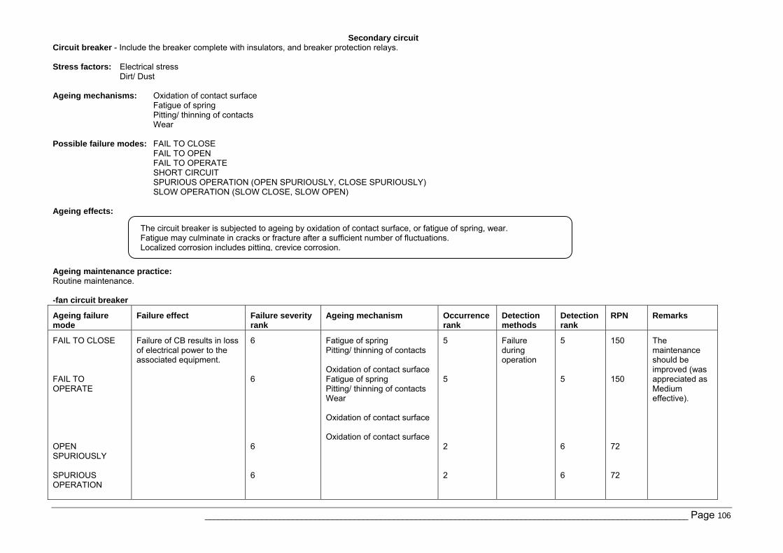
Secondary circuit
______________________________________________________________________________________________________________ Page 106
Circuit breaker - Include the breaker complete with insulators, and breaker protection relays. Stress factors: Electrical stress
Dirt/ Dust Ageing mechanisms: Oxidation of contact surface
Fatigue of spring Pitting/ thinning of contacts Wear
Possible failure modes: FAIL TO CLOSE
FAIL TO OPEN FAIL TO OPERATE SHORT CIRCUIT SPURIOUS OPERATION (OPEN SPURIOUSLY, CLOSE SPURIOUSLY) SLOW OPERATION (SLOW CLOSE, SLOW OPEN)
Ageing effects:
Ageing maintenance practice: Routine maintenance. -fan circuit breaker
Ageing failure mode
Failure effect Failure severity rank
Ageing mechanism Occurrence rank
Detection methods
Detection rank
RPN Remarks
FAIL TO CLOSE FAIL TO OPERATE OPEN SPURIOUSLY SPURIOUS OPERATION
Failure of CB results in loss of electrical power to the associated equipment.
6 6 6 6
Fatigue of spring Pitting/ thinning of contacts Oxidation of contact surface Fatigue of spring Pitting/ thinning of contacts Wear Oxidation of contact surface Oxidation of contact surface
5 5 2 2
Failure during operation
5 5 6 6
150 150 72 72
The maintenance should be improved (was appreciated as Medium effective).
The circuit breaker is subjected to ageing by oxidation of contact surface, or fatigue of spring, wear. Fatigue may culminate in cracks or fracture after a sufficient number of fluctuations. Localized corrosion includes pitting, crevice corrosion.
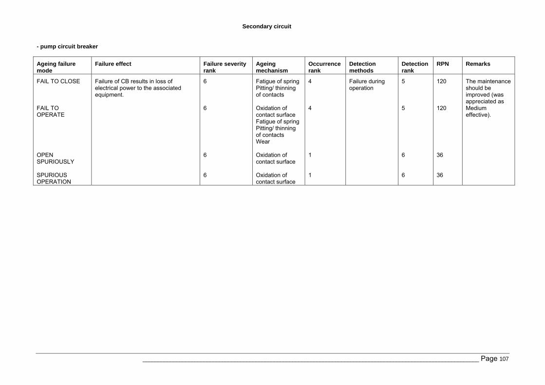
Secondary circuit
______________________________________________________________________________________________________________ Page 107
- pump circuit breaker
Ageing failure mode
Failure effect Failure severity rank
Ageing mechanism
Occurrence rank
Detection methods
Detection rank
RPN Remarks
FAIL TO CLOSE FAIL TO OPERATE OPEN SPURIOUSLY SPURIOUS OPERATION
Failure of CB results in loss of electrical power to the associated equipment.
6 6 6 6
Fatigue of spring Pitting/ thinning of contacts Oxidation of contact surface Fatigue of spring Pitting/ thinning of contacts Wear Oxidation of contact surface Oxidation of contact surface
4 4 1 1
Failure during operation
5 5 6 6
120 120 36 36
The maintenance should be improved (was appreciated as Medium effective).
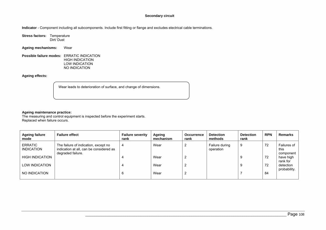
Secondary circuit
______________________________________________________________________________________________________________ Page 108
Indicator - Component including all subcomponents. Include first fitting or flange and excludes electrical cable terminations. Stress factors: Temperature
Dirt/ Dust Ageing mechanisms: Wear Possible failure modes: ERRATIC INDICATION
HIGH INDICATION LOW INDICATION NO INDICATION
Ageing effects:
Ageing maintenance practice: The measuring and control equipment is inspected before the experiment starts. Replaced when failure occurs.
Ageing failure mode
Failure effect Failure severity rank
Ageing mechanism
Occurrence rank
Detection methods
Detection rank
RPN Remarks
ERRATIC INDICATION HIGH INDICATION LOW INDICATION NO INDICATION
The failure of indication, except no indication at all, can be considered as degraded failure.
4 4 4 6
Wear Wear Wear Wear
2 2 2 2
Failure during operation
9 9 9 7
72 72 72 84
Failures of this component have high rank for detection probability.
Wear leads to deterioration of surface, and change of dimensions.
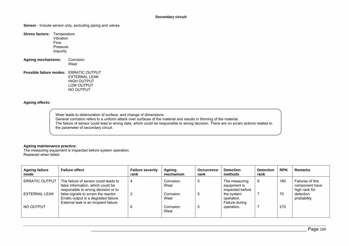
Secondary circuit
______________________________________________________________________________________________________________ Page 109
Sensor - Include sensor only, excluding piping and valves. Stress factors: Temperature
Vibration Flow Pressure Impurity
Ageing mechanisms: Corrosion
Wear Possible failure modes: ERRATIC OUTPUT
EXTERNAL LEAK HIGH OUTPUT LOW OUTPUT NO OUTPUT
Ageing effects:
Ageing maintenance practice: The measuring equipment is inspected before system operation. Replaced when failed.
Ageing failure mode
Failure effect Failure severity rank
Ageing mechanism
Occurrence rank
Detection methods
Detection rank
RPN Remarks
ERRATIC OUTPUT EXTERNAL LEAK NO OUTPUT
The failure of sensor could leads to false information, which could be responsible to wrong decision or to false signals to scram the reactor. Erratic output is a degraded failure. External leak is an incipient failure.
4 2 6
Corrosion Wear Corrosion Wear Corrosion Wear
5 5 5
The measuring equipment is inspected before the system operation. Failure during operation.
9 7 7
180 70 210
Failures of this component have high rank for detection probability.
Wear leads to deterioration of surface, and change of dimensions. General corrosion refers to a uniform attack over surfaces of the material and results in thinning of the material. The failure of sensor could lead to wrong data, which could be responsible to wrong decision. There are no scram actions related to the parameter of secondary circuit.
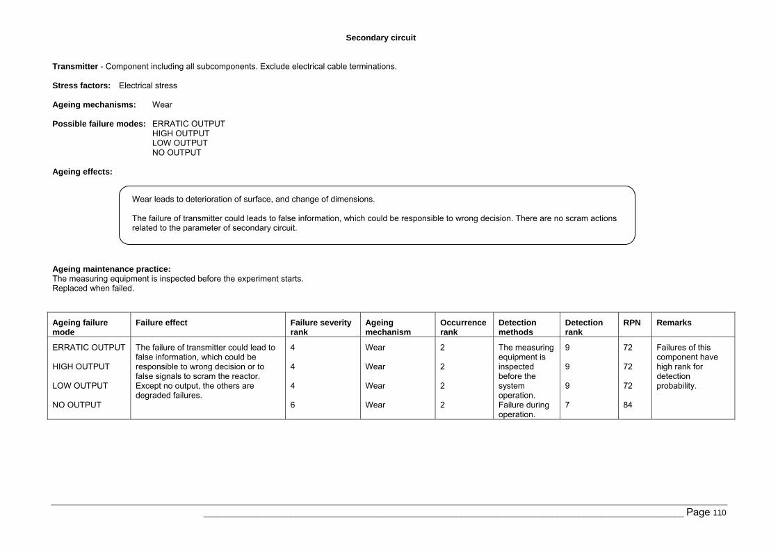
Secondary circuit
______________________________________________________________________________________________________________ Page 110
Transmitter - Component including all subcomponents. Exclude electrical cable terminations. Stress factors: Electrical stress Ageing mechanisms: Wear Possible failure modes: ERRATIC OUTPUT
HIGH OUTPUT LOW OUTPUT NO OUTPUT
Ageing effects:
Ageing maintenance practice: The measuring equipment is inspected before the experiment starts. Replaced when failed.
Ageing failure mode
Failure effect Failure severity rank
Ageing mechanism
Occurrence rank
Detection methods
Detection rank
RPN Remarks
ERRATIC OUTPUT HIGH OUTPUT LOW OUTPUT NO OUTPUT
The failure of transmitter could lead to false information, which could be responsible to wrong decision or to false signals to scram the reactor. Except no output, the others are degraded failures.
4 4 4 6
Wear Wear Wear Wear
2 2 2 2
The measuring equipment is inspected before the system operation. Failure during operation.
9 9 9 7
72 72 72 84
Failures of this component have high rank for detection probability.
Wear leads to deterioration of surface, and change of dimensions. The failure of transmitter could leads to false information, which could be responsible to wrong decision. There are no scram actions related to the parameter of secondary circuit.
European Commission EUR 23446 EN – Joint Research Centre – Institute for Energy Title: Qualitative approach for selection of Systems Structures and Components to be considered in Ageing PSA.. EC JRC Network on Use of Probabilistic Safety Assessments (PSA) for Evaluation of Ageing Effects to the Safety of Energy Facilities. A Case Study on Task 3. Author(s): M.Nitoi, A.Rodionov Luxembourg: Office for Official Publications of the European Communities 2008 – 110 pp. – 21 x 29.7 cm EUR – Scientific and Technical Research series – ISSN 1018-5593 Abstract This report presents a qualitative approach for selection of Systems, Structures and Components (SSC) sensitive to ageing. The purpose of selection is to model and evaluate SSC ageing effects on the overall NPP safety by applying Probabilistic Safety Assessment tool. The report was prepared by Institute for Nuclear Research, Pitesti, Romania in cooperation with Institute for Energy, EC Joint Research Center, Petten, Netherlands in the frame of EC JRC Ageing PSA Network Task 3 activities. The goal of the work is to demonstrate the feasibility of qualitative assessment in selection of components sensitive for ageing and to develop a viable guideline for selection of components susceptible to ageing. An overview of the available approaches for selection of ageing components was performed, and the methods are briefly presented. Their advantages and disadvantages, as their limitation are also specified. Applicability of the approach for qualitative selection of SSC susceptible to ageing was demonstrated by a case study which use as an example SSC of NRI TRIGA research reactor. A list of ageing mechanisms, as their favourable factors for occurrence is provided in appendices of the report.

The mission of the JRC is to provide customer-driven scientific and technical support for the conception, development, implementation and monitoring of EU policies. As a service of the European Commission, the JRC functions as a reference centre of science and technology for the Union. Close to the policy-making process, it serves the common interest of the Member States, while being independent of special interests, whether private or national.