provably correct systems
TRANSCRIPT

Provably Correct Systems�Jifeng He and C. A. R. Hoare1Martin Fr�anzle and Markus M�uller-Olm2Ernst-R�udiger Olderog and Michael Schenke3Michael R. Hansen, Anders P. Ravn and Hans Rischel41 Oxford University Computing LaboratoryWolfson Building, Parks Road, Oxford OX1 3QD, UK2 Christian-Albrechts-Universit�at zu KielInstitut f�ur Informatik und Praktische MathematikPreu�erstra�e 1{9, D-24105 Kiel, Germany3 FB Informatik, Universit�at OldenburgPostfach 2503, D-26111 Oldenburg, Germany4 Department of Computer ScienceTechnical University of Denmark, bldg. 344DK-2800 Lyngby, DenmarkAbstract. The goal of the Provably Correct Systems project (ProCoS)is to develop a mathematical basis for development of embedded, real-time, computer systems. This survey paper introduces the speci�cationlanguages and veri�cation techniques for four levels of development: Re-quirements de�nition and control design; Transformation to a systemsarchitecture with program designs and their transformation to programs;Compilation of real-time programs to conventional processors, and Com-pilation of programs to hardware.1 IntroductionAn embedded computer system is part of a total system that is a physical pro-cess, a plant, characterized by a state that changes over real time. The role ofthe computer is to monitor this state through sensors and to change the statethrough actuators. The computer is simply a convenient device that can be in-structed to manipulate a mathematical model of the physical system and state.Correctness means that the program and the hardware faithfully implement thecontrol formulas of the mathematical model for the total system, and nothingelse. However, the opportunities o�ered by the development of computer tech-nology have resulted in large, complex programs which are hard to relate to theobjective of systems control.� This work is partially funded by the Commission of the European Communities(CEC) under the ESPRIT programme in the �eld of Basic Research Project No.7071: \ProCoSII: Provably Correct Systems". The hardware compilation work ispartially funded by the UK Science and Engineering Research Council (SERC) underthe Information Engineering Directorate SAFEMOS project (IED3/1/1036).

Activity Documents LanguageConcept Expectations Natural(informal)Requirements Requirements RLanalysisSystem design System specs SLProgram design Program source PLEither:Hardware synthesis Circuit diagram NetlistOr:Compilation Machine code MLFig. 1. Languages in ProCoS.In the following, we describe a particular approach to mastering the complex-ities of such systems. The approach is the result of over 5 years of work withinthe ProCoS project, and represents a collection of techniques which have beensuccessfully applied to the di�erent aspects of development of real-time computersystems.First of all there is a need for a short and precise speci�cation of the desiredcontrol requirements, independent of the actual hardware and software system.For that purpose ProCoS has investigated a real-time logic, Duration Calculus[82, 22, 81, 80], that formalizes dynamic systems properties. This logic alsoprovides a calculus such that a speci�cation of controlling state machines can beveri�ed to be a re�nement of the requirements [66, 71, 67, 17, 31].In order to use the logic as a speci�cation language for requirements anddesign, we need a module concept and notations for standard concepts of discretemathematics. Here we have decided to adapt the Z language [73] and embed theDuration Calculus [12] such that the type checking facilities and other tools ofZ are available after expansion of the special Duration Calculus symbols. Theresulting requirements language o�ers an interface to control theory [83], but itis not intended in any way to replace well known notations and procedures ofcontrol engineering.A speci�cation of controlling state machines is a step towards an implementedprogram. However, it neither de�nes the communication protocols among thestate machines nor does it de�ne the structure of the sequential programs. Here,ProCoS has chosen to build on the paradigm of synchronous communicationand transform the state machines to a network of communicating processes [70].The speci�cation language SL [58, 59, 60] is used to specify such a network ina constraint oriented style, where protocols are de�ned through trace assertionsthat are regular expressions over communication channels; computations arespeci�ed by communication assertions that de�ne the relation between the preand post state of a program component and a communicated value; and timingassertions that constrain the time between communications. The SL language

also supports transformations [57, 69] to an occam-like programming languagePL with real-time facilities.These programs are then the basis for compilation to hardware or machinecode, cf. [11].Each step has to be correct, and unless we have blind faith in the developer,we expect to see documents for a rational development process, cf. [63]. Using afairly standard division of a development into major activities, these documentscan be organized as shown in Figure 1.Each major activity layer uses its own specially tailored languages and veri-�cation techniques. It shall also link to the next lower layer. The inspiration forsuch a layered approach has been the CLIinc. \stack", see e.g. [8, 21]. A detailedtechnical account of work during the �rst 3 years of ProCoS is given in [5] anda previous survey of the results up till early 1993 is found in [9].Overview. The following sections focus on central topics of each of the layers.In section 2 we use one of the ProCoS case studies to introduce requirementsanalysis and speci�cation of a top level design. This design is used in section 3 toillustrate transformations to a systems architecture with program speci�cationsand transformations to programs. Section 4 surveys work on developing a com-piler for the real-time programming language that guarantees timing constraintsfor the generated machine code. Section 5 outlines some work on deriving ahardware description from a program.In a �nal section 6, the underlying mathematical structures and the generalapproaches of the project are discussed and put into the perspective of a scienceof programming.2 Requirements and Control DesignThe �rst step in formalizing the requirements of a system is to construct asystem model. Our basis is the well-known time-domain model, where a system isdescribed by a collection of states which are functions of time (the real numbers).Example: We illustrate the state concept through our running example: a ver-sion of a computer controlled gas burner [67].The gas burner is controlled through a thermostat, and can directly controla gas valve and monitor the ame. This physical system or plant is illustratedby the diagram in Figure 2. For the gas burner we use the following discrete(Boolean valued) states Heatreq , Gas and Flame to model the state of the ther-mostat, the gas valve and the ame. In illustrations we assume that Booleanvalues are represented by 0 (false) and 1 (true). 2States or other quantities might be introduced informally as usually done inmathematics by phrases like `let Gas denote : : :and let 0 denote the Booleanvalue false'. This works very well for a small set of quantities used in a delimitedcontext; but in development of a larger system with a modular structure and

` ���@@@Gas Valve Flame sensor((((hhhh-Thermo-statFig. 2. Physical components { plant { for the gas burner.going through several stages of re�nement it is essential to be able to struc-ture declarations corresponding to the speci�cations of systems and subsystems.Therefore we use a concrete syntax for speci�cations based on the Z-schemanotation [73].A state is a function from time to some value domain, but we do not want torefer to time explicitly. Thus state is used in front of a type of a name whichdenotes a state.Example: The states for the gas burner example can thus be introduced asfollows:GBHeatreq : state BoolFlame;Gas : state Boolwhere state Bool is an abbreviation for Time ! Bool with Time denotingthe set of non-negative reals. The input state Heatreq thus denotes a Booleanfunction of time. The controlled states are Flame and Gas. 22.1 From Expectations to RequirementsProperties of systems are expressed by constraining the states over time. Forthat purpose we use the Duration Calculus [82].Example: We introduce the logic while formalizing the following expectationsfor the gas burner.Safe: Gas must not leak for more than 4 seconds5 in any 30 second period.Stop: The gas must not burn when heat request has been o� for 40 seconds.Start: The gas must burn when heat request has been on for 40 seconds, pro-vided the gas ignites and burns satisfactorily.5 We shall use second as a unit of time throughout the example.

Safe. We assume that a leak occurs whenever the state assertionLeak == Gas ^ :Flameholds.When we consider some bounded interval [b; e] of time, we can measure theduration of Leak within the interval by R eb Leak(t)dt , cf. the following timingdiagram: -TimeGas 10Flame 10 b eleak leakThe symbol RLeak denotes the duration of Leak ; for each particular intervalit is a real number. An atomic duration formula is a predicate over intervalsbuilt from durations and real valued constants by a relation on real numbers.E.g. the 4 second constraint on leaks is the atomic formula R Leak � 4.The duration of the constant state 1 will be the length of the interval underconsideration, and we abbreviate` == R 1Thus the fact that an interval is not longer than 30 seconds is speci�ed by` � 30. Formulas can now be generated from atomic formulas using the logicalconnectives. The safety expectation is thus` � 30) R Leak � 4i.e. if the given interval is not longer than 30 seconds then the duration of Leakin that interval is less than 4 seconds.Start. For this expectation, consider a non-point interval where Heatreq holds;such an interval is described bydHeatreqe == (RHeatreq = `) ^ (` > 0)A counterexample for Start is, for a given interval, expressed with the binary\chop" operator [53](dHeatreqe ^ ` = 40) ; d:FlameeThe formula F1 ; F2 (which reads F1 \chop" F2) holds on the interval [b; e]just when this interval can be divided into an initial subinterval [b;m] whereF1 holds and a �nal subinterval [m; e] where F2 holds. The \chop" operator isassociative and monotone in both arguments. We assign it a priority higher thanimplication and lower than conjunction and disjunction.

The \somewhere" modality (3 ), de�ned by 3F == true ; F ; true, canexpress the commitmentStart == :3 ((dHeatreqe ^ ` = 40) ; d:Flamee)I.e. there is not an interval that starts with Heatreq for 40 seconds and continueswith d:Flamee.Note that \always" (2 ) as usual can be de�ned in terms of \somewhere"(and thus \chop") by 2F , :3 (:F).Stop. The last expectation is analogous to Start , so it can be given by the com-mitmentStop == :3 ((d:Heatreqe ^ ` = 40) ; dFlamee) 2Standard forms In principle, commitments can be formulated using the fullgenerality of Duration Calculus, but for the purpose of design some standardforms are useful [45].Progress can be de�ned in terms of an elementary operator, called \leads-to"which expresses that a system which is in some initial region of its state space,speci�ed by a formula F for some time t will continue to a goal state, speci�edby a state formula dPe.De�nition 2.1 (Leads-to)F t�! dPe == 2 ((F ^ ` = t) ; ` > 0) ` = t ; dPe ; true)The following law gives the relation to speci�cation by counterexamples:(F t�! dPe), 3 ((F ^ ` = t) ; d:Pe)The leads-to operator has the monotonicity properties of an implication,distributes over conjunction, and is monotone with respect to time for stateassertions, i.e. when t � t 0(dP1e t�! dP2e)) (dP1e t 0�! dP2e)Leads-to is also transitive in the following sense(dP1e t1�! dP2e) ^ (dP2e t2�! dP3e)) (dP1e t1+t2�! dP2 ^ P3e)It is easy to check that both the Stop and the Start commitments can beexpressed using leads-to.Stop == d:Heatreqe 40�! d:FlameeStart == dHeatreqe 40�! dFlameeTwo derived forms will be used later, but are introduced here for convenience.In the \followed-by" form, the initial region does not have to be stable for aparticular period of time.
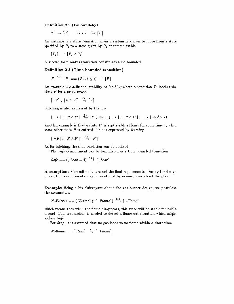
De�nition 2.2 (Followed-by)F �! dPe == 8r � F r�! dPeAn instance is a state transition when a system is known to move from a statespeci�ed by P1 to a state given by P2 or remain stabledP1e �! dP1 _ P2eA second form makes transition constraints time bounded.De�nition 2.3 (Time bounded transition)F �t�! dPe == (F ^ ` � t) �! dPeAn example is conditional stability or latching where a condition P 0 latches thestate P for a given periodd:Pe ; dP ^ P 0e �t�! dPeLatching is also expressed by the law(d:Pe ; dP ^P 0e �t�! dPe) , 2 (d:Pe ; dP ^ P 0e ; d:Pe ) ` > t)Another example is that a state P 0 is kept stable at least for some time t , whensome other state P is entered. This is expressed by framing(d:Pe ; dP ^P 0e) �t�! dP 0eAs for latching, the time condition can be omitted.The Safe commitment can be formulated as a time bounded transitionSafe == (R Leak = 4) �30�! d:LeakeAssumptions Commitments are not the �nal requirements. During the designphase, the commitments may be weakened by assumptions about the plant.Example: Being a bit clairvoyant about the gas burner design, we postulatethe assumptionNoFlicker == (dFlamee ; d:Flamee) 0:5�! d:Flameewhich means that when the ame disappears, this state will be stable for half asecond. This assumption is needed to detect a ame out situation which mightviolate Safe.For Stop, it is assumed that no gas leads to no ame within a short timeNo ame == d:Gase 1�! d:Flamee
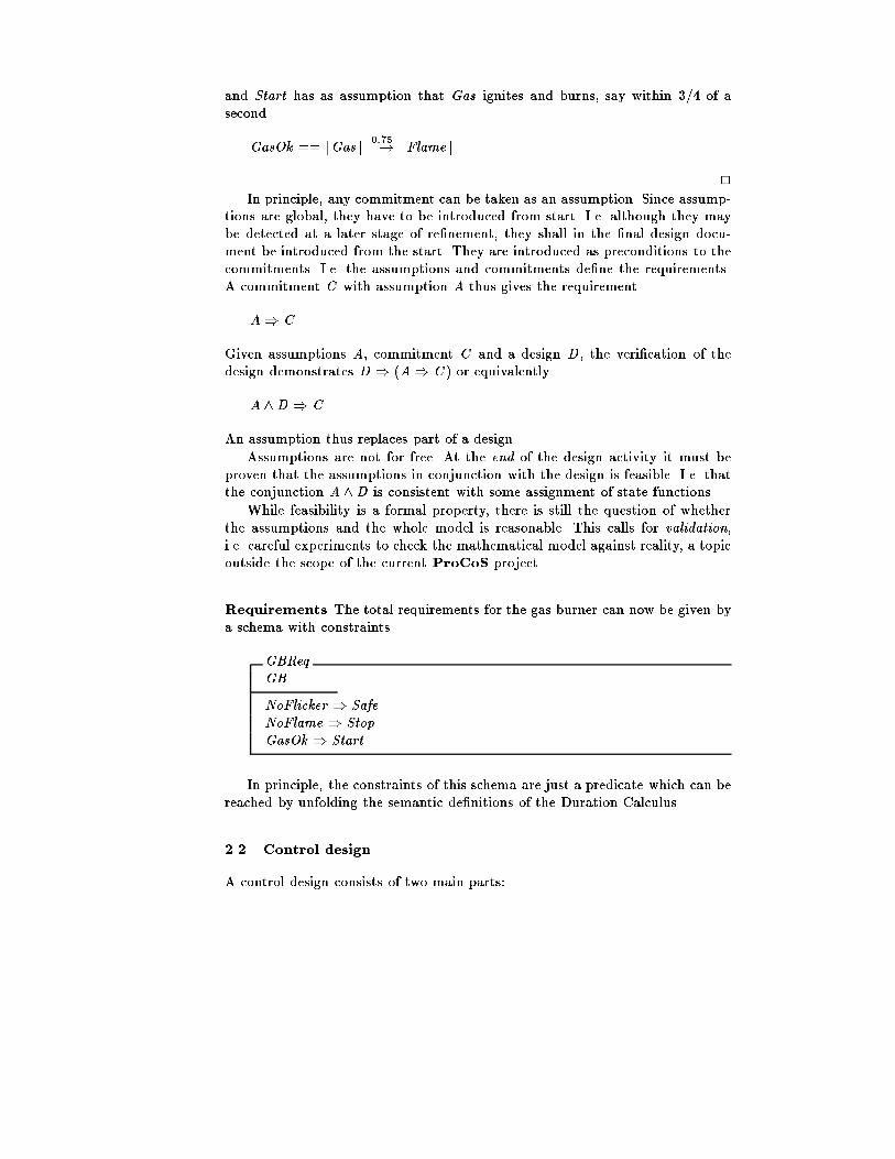
and Start has as assumption that Gas ignites and burns, say within 3/4 of asecondGasOk == dGase 0:75�! dFlamee 2In principle, any commitment can be taken as an assumption. Since assump-tions are global, they have to be introduced from start. I.e. although they maybe detected at a later stage of re�nement, they shall in the �nal design docu-ment be introduced from the start. They are introduced as preconditions to thecommitments. I.e. the assumptions and commitments de�ne the requirements.A commitment C with assumption A thus gives the requirementA) CGiven assumptions A, commitment C and a design D , the veri�cation of thedesign demonstrates D ) (A) C ) or equivalentlyA ^D ) CAn assumption thus replaces part of a design.Assumptions are not for free. At the end of the design activity it must beproven that the assumptions in conjunction with the design is feasible. I.e. thatthe conjunction A ^D is consistent with some assignment of state functions.While feasibility is a formal property, there is still the question of whetherthe assumptions and the whole model is reasonable. This calls for validation,i.e. careful experiments to check the mathematical model against reality, a topicoutside the scope of the current ProCoS project.Requirements The total requirements for the gas burner can now be given bya schema with constraintsGBReqGBNoFlicker ) SafeNoFlame ) StopGasOk ) StartIn principle, the constraints of this schema are just a predicate which can bereached by unfolding the semantic de�nitions of the Duration Calculus.2.2 Control designA control design consists of two main parts:
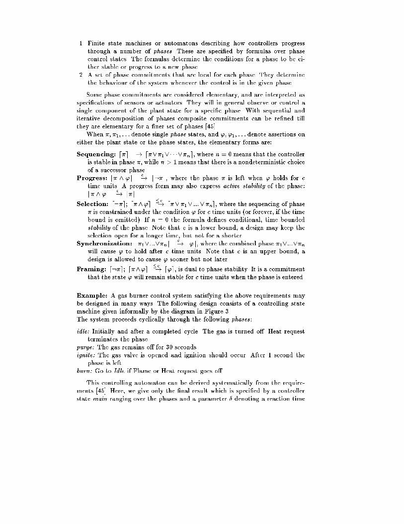
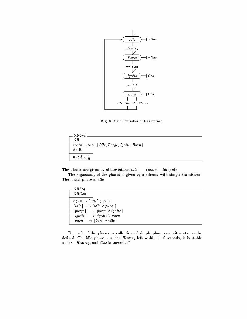
1. Finite state machines or automatons describing how controllers progressthrough a number of phases. These are speci�ed by formulas over phasecontrol states. The formulas determine the conditions for a phase to be ei-ther stable or progress to a new phase.2. A set of phase commitments that are local for each phase. They determinethe behaviour of the system whenever the control is in the given phase.Some phase commitments are considered elementary, and are interpreted asspeci�cations of sensors or actuators. They will in general observe or control asingle component of the plant state for a speci�c phase. With sequential anditerative decomposition of phases composite commitments can be re�ned tillthey are elementary for a �ner set of phases [45].When �; �1; : : : denote single phase states, and '; '1; : : : denote assertions oneither the plant state or the phase states, the elementary forms are:Sequencing: d�e �! d�_�1_� � �_�ne, where n = 0 means that the controlleris stable in phase �, while n > 1 means that there is a nondeterministic choiceof a successor phase.Progress: d� ^ 'e c�! d:�e, where the phase � is left when ' holds for ctime units. A progress form may also express active stability of the phase:d� ^ 'e c�! d�e.Selection: d:�e; d�^'e �c�! d�_�1_ :::_�ne, where the sequencing of phase� is constrained under the condition ' for c time units (or forever, if the timebound is omitted). If n = 0 the formula de�nes conditional, time boundedstability of the phase. Note that c is a lower bound, a design may keep theselection open for a longer time, but not for a shorter.Synchronization: d�1_:::_�ne c�! d'e, where the combined phase �1_:::_�nwill cause ' to hold after c time units. Note that c is an upper bound, adesign is allowed to cause ' sooner but not later.Framing: d:�e; d�^'e �c�! d'e, is dual to phase stability. It is a commitmentthat the state ' will remain stable for c time units when the phase is entered.Example: A gas burner control system satisfying the above requirements maybe designed in many ways. The following design consists of a controlling statemachine given informally by the diagram in Figure 3.The system proceeds cyclically through the following phases:idle: Initially and after a completed cycle. The gas is turned o�. Heat requestterminates the phase.purge: The gas remains o� for 30 seconds.ignite: The gas valve is opened and ignition should occur. After 1 second thephase is left.burn: Go to Idle if Flame or Heat request goes o�.This controlling automaton can be derived systematically from the require-ments [45]. Here, we give only the �nal result which is speci�ed by a controllerstate main ranging over the phases and a parameter � denoting a reaction time
?Idle� � f:GasHeatreq?Purge� � f:Gaswait 30?Ignite� � fGaswait 1?Burn� � fGas:HeatReq _ :Flame-
Fig. 3. Main controller of Gas burner.GBConGBmain : state fIdle;Purge; Ignite;Burng� : R0 < � < 19The phases are given by abbreviations idle == (main = Idle) etc.The sequencing of the phases is given by a schema with simple transitions.The initial phase is idle.GBSeqGBCon` > 0) didlee ; truedidlee �! didle _ purgeedpurgee �! dpurge _ igniteedignitee �! dignite _ burnedburne �! dburn _ idleeFor each of the phases, a collection of simple phase commitments can bede�ned. The idle phase is under Heatreq left within 2 � � seconds, it is stableunder :Heatreq , and Gas is turned o�.

GBIdleGBCondidle ^Heatreqe 2���! d:idleed:idlee ; didle ^:Heatreqe �! didleedidlee 2���! d:GaseThe purge phase is stable for 30 and left after 30+ � seconds. Gas is turned o�.GBPurgeGBCon(d:purgee ; dpurgee) �30�! dpurgeedpurgee 30+��! d:purgeedpurgee 2���! d:GaseThe ignite phase turns on the gas and is stable for 1 second before it is left forthe burn phase.GBIgniteGBCon(d:ignitee ; dignitee) �1�! digniteedignitee 1+��! d:igniteedignitee 2���! dGaseThe burn phase is under :Flame left within the no icker period (2 � � � 0:5);under :Heatreq it is left within 38 � 5 � � seconds; it is stable under Heatreq ^Flame; and �nally, Gas is kept on.GBBurnGBCondburn ^ :Flamee 2���! didleedburn ^ :Heatreqe 38�5���! didleed:burne ; dburn ^Heatreq ^ Flamee �! dburne(d:burne ; dburn ^Gase) �! dGaseIt can be veri�ed using laws for combination of phases [45] thatGBSeq ^GBIdle ^GBPurge ^GBIgnite ^GBBurn ) GBReq 2

2.3 Re�nement towards an architectureThe above design does not consider a particular technology or architecture. How-ever, for a program implementation with distribution it is necessary to formulatethe design in terms of control states only, as pointed out by Schenke [70]. Theplant states are mapped to control states by simple sensors and actuators (A/Dand D/A converters) of the following shapes.Example:GBConP� : Rhr ; ; gas : state Boolmain : state fIdle;Purge; Ignite;Burng0 < � < 19hr , and gas are the phase states of the simple sensors and actuator.GBHeatGBConPHeatreq : state BooldHeatreqe ��! dhred:Heatreqe ��! d:hreGBFlameGBConPFlame : state BooldFlamee ��! d ed:Flamee ��! d: eGBGasGBConPGas : state Booldgase ��! dGased:gase ��! d:GaseThe requirement can be re�ned using transitivity to communicate throughthese components. This reduces the allowed reaction times by �. The phaseconstraints are reduced similarly, and are presented below, rearranged accordingto the elementary forms.
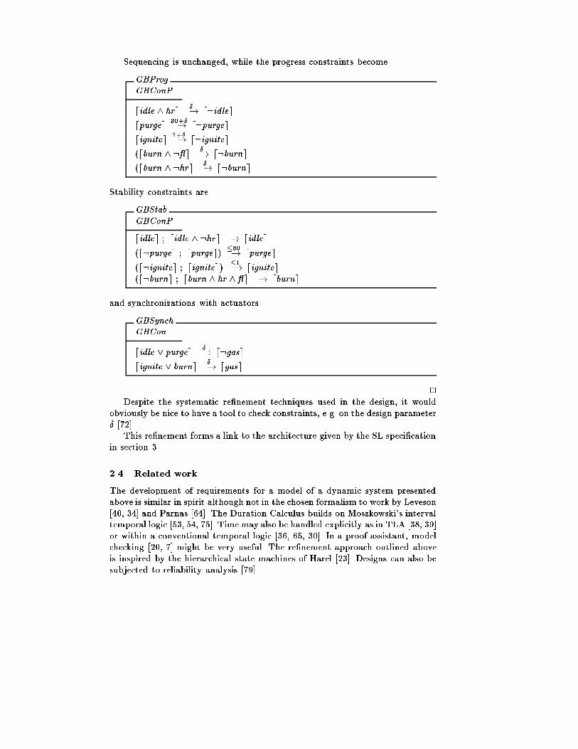
Sequencing is unchanged, while the progress constraints becomeGBProgGBConPdidle ^ hre ��! d:idleedpurgee 30+��! d:purgeedignitee 1+��! d:ignitee(dburn ^ : e ��! d:burne(dburn ^ :hre ��! d:burneStability constraints areGBStabGBConPdidlee ; didle ^ :hre �! didlee(d:purgee ; dpurgee) �30�! dpurgee(d:ignitee ; dignitee) �1�! dignitee(d:burne ; dburn ^ hr ^ e �! dburneand synchronizations with actuatorsGBSynchGBCondidle _ purgee ��! d:gasedignite _ burne ��! dgase 2Despite the systematic re�nement techniques used in the design, it wouldobviously be nice to have a tool to check constraints, e.g. on the design parameter� [72].This re�nement forms a link to the architecture given by the SL speci�cationin section 3.2.4 Related workThe development of requirements for a model of a dynamic system presentedabove is similar in spirit although not in the chosen formalism to work by Leveson[40, 34] and Parnas [64]. The Duration Calculus builds on Moszkowski's intervaltemporal logic [53, 54, 75]. Time may also be handled explicitly as in TLA [38, 39]or within a conventional temporal logic [36, 65, 30]. In a proof assistant, modelchecking [20, 7] might be very useful. The re�nement approach outlined aboveis inspired by the hierarchical state machines of Harel [23]. Designs can also besubjected to reliability analysis [79].

3 Architecture and ProgramsThe formalisms of duration calculus, even in the rather restricted standard forms,and programs in an occam-like [32] language PL are on very distant abstractlevels. In particular at some step the description must change from the statebased world of the duration calculus to the event based world of PL. That iswhere an intermediate stage comes in, the speci�cation language SL [61] for reac-tive systems with real-time constraints. This language will be described now. Weoutline the transformation of an RL architectural design to an SL speci�cationand outline a transformational approach for the systematic design of programsin the programming language PL.The purpose of a reactive system is to react to stimuli from its environmentso that this is kept in a certain desirable condition. To this end, the systemmay communicate with its environment via directed channels. As our runningexample we use the gas burner introduced in the previous section.For reactive systems a variety of speci�cation formalisms have been devel-oped, among them Temporal Logic [42], iterative programs like action systems[1] or UNITY programs [16], input/output automata [41], process algebra [48, 2],and stream processing functions [14]. However, it remains a di�cult task to de-sign correct programs from such speci�cations.In our approach we formulate transformation rules for the stepwise designand implementation of both sequential and concurrent systems.3.1 Speci�cation language SLAn SL speci�cation begins with the description of an interface declaring thecommunication channels ch of the component, for exampleINPUT OF type chThen the desired behaviour of the system components is described. This descrip-tion is split into a trace part, a state part and a timing part.Trace part The trace part speci�es the sequencing constraints on the systemchannels but ignores the communication values. This is done by means of traceassertions. Each trace assertion is a regular expression over a communicationalphabet. The trace part thus uses ideas from path expressions [15] and regulartrace logic [84, 57].The syntactical form of a trace assertion ta isTRACE � IN rewhere the alphabet � is a subset of the interface channels and re is a regularexpression over these channels. Informally, ta describes the order in which thechannels in � can occur in the sequences or traces of communications betweencomponent and environment: at any moment this order must correspond to aword in the language denoted by the regular expression re, the set of possiblesequences of channel communications. If there are several trace assertions, all ofthem must be satis�ed simultaneously.

Example: Consider the speci�cation of a simple controller for the gas burner,cf. �gure 3 and the schemas of section 2.3.A systematic transformation introduces channels corresponding to all phasechanges of the architecture and synchronizations, cf. schema GBConP . This isthe interface for the main controller, one of several parallel components.INPUT OF Signal yesheat, noheat, noflameOUTPUT OF Signal idle, purge, ignite, burn,gason, gasoffThe sequencing constraints on the phase automaton are recorded in a traceassertion of the main controllerTRACE alphabet IN pref cycle*with cycle = gasoff.yesheat.purge.ignite.gason.burn.(noheat+noflame).idleThe alphabet here is the set of all events appearing in the regular expres-sion. In regular expressions . and + and * are the usual operators that denoteconcatenation, choice and Kleene star. The operator pref denotes pre�x closure;it speci�es the stepwise evolution of a system where one communication occursafter the other.For the heat and the ame controller we get the trace assertionsTRACE heaton, yesheat, heatoff,noheatIN pref (heaton.yesheat.heatoff.(noheat+"))*TRACE flon, floff, noflameIN pref (flon.floff.(noflame+"))*The choices with the empty word re ect the fact that in the main controllerthe burn phase can be left either with normal end of a heat request or a amefailure. In the �rst case the signal noheat will occur, but the signal noflame hasto be dropped in the ame controller. In case of a ame failure it is the otherway round. 2The trace part de�nes the control behaviour of a system without considera-tion of any internal state, communicated values or timing.State part The state part speci�es the communication values that can be ex-changed over the interface channels. To this end local state variables may beintroduced. Changes of these variables are recorded by a set of communicationassertions in a pre-post style assertional speci�cation. In the communicationassertions the values and channels are linked together.A variable x is declared as follows:VAR type x INIT eThe expression e represents the initial value of x . The local variables constitutethe state space of the speci�cation but need not appear in an implementation ofthe speci�ed system nor necessarily mirror the states of an RL speci�cation.
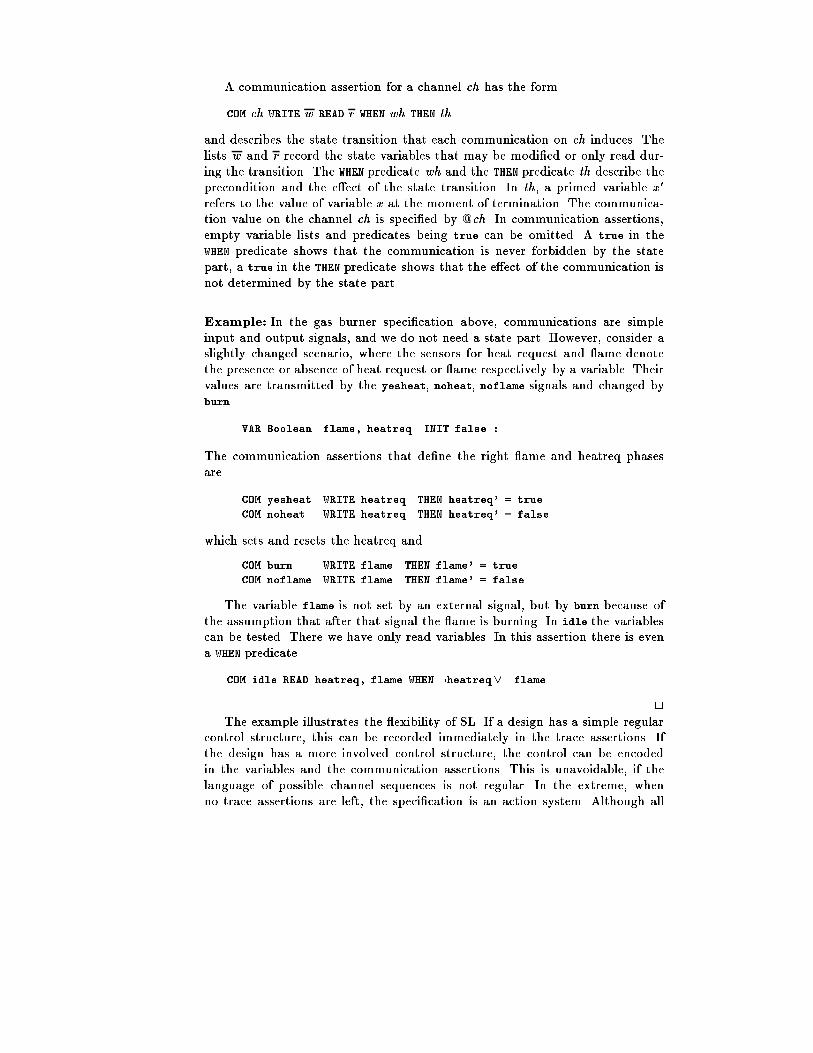
A communication assertion for a channel ch has the formCOM ch WRITE w READ r WHEN wh THEN thand describes the state transition that each communication on ch induces. Thelists w and r record the state variables that may be modi�ed or only read dur-ing the transition. The WHEN predicate wh and the THEN predicate th describe theprecondition and the e�ect of the state transition. In th, a primed variable x 0refers to the value of variable x at the moment of termination. The communica-tion value on the channel ch is speci�ed by @ch. In communication assertions,empty variable lists and predicates being true can be omitted. A true in theWHEN predicate shows that the communication is never forbidden by the statepart, a true in the THEN predicate shows that the e�ect of the communication isnot determined by the state part.Example: In the gas burner speci�cation above, communications are simpleinput and output signals, and we do not need a state part. However, consider aslightly changed scenario, where the sensors for heat request and ame denotethe presence or absence of heat request or ame respectively by a variable. Theirvalues are transmitted by the yesheat, noheat, noflame signals and changed byburn VAR Boolean flame, heatreq INIT false :The communication assertions that de�ne the right ame and heatreq phasesare COM yesheat WRITE heatreq THEN heatreq' = trueCOM noheat WRITE heatreq THEN heatreq' = falsewhich sets and resets the heatreq andCOM burn WRITE flame THEN flame' = trueCOM noflame WRITE flame THEN flame' = falseThe variable flame is not set by an external signal, but by burn because ofthe assumption that after that signal the ame is burning. In idle the variablescan be tested. There we have only read variables. In this assertion there is evena WHEN predicate.COM idle READ heatreq, flame WHEN :heatreq_ :flame 2The example illustrates the exibility of SL. If a design has a simple regularcontrol structure, this can be recorded immediately in the trace assertions. Ifthe design has a more involved control structure, the control can be encodedin the variables and the communication assertions. This is unavoidable, if thelanguage of possible channel sequences is not regular. In the extreme, whenno trace assertions are left, the speci�cation is an action system. Although all
information can be encoded in the communication assertions, the trace assertionsare useful for the task of developing implementations in a methodological way.How to cope with a system which has in�nitely many states, is shown in thespeci�cation of a railway crossing in [70].3.2 Timing partIn the timing part it is speci�ed when channels are ready for communication.Lower bounds are expressed byAFTER re WAIT ch rwhich means that after communication of a trace belonging to the languagede�ned by the regular expression re, the system will not communicate on chbefore time r has elapsed.Upper bounds are expressed byAFTER re READY ch rwhich means that after communication of a trace in re, the system becomesready to communicate on ch within time r .In order to guarantee the timing restrictions we shall assume that for eachchannel ch there is a latency lat(ch) with the property that, if both commu-nication partners are ready for a communication via ch for lat(ch) time units,the communication takes place. These latency constants will be used in our in-termediate step, the SL speci�cation. We do not assume maximal progress sincethis would prohibit implementation on real hardware.Example: For the gas burner we get the following time restrictions:AFTER cycle*.gasoff.yesheat.purge WAIT ignite 30AFTER cycle*.gasoff.yesheat.purge.ignite WAIT burn 1for the main controller. The heat controller has the time restrictionAFTER cycle1*.heaton.purge.heatoff WAIT heaton lat(noheat)with cycle1 = heaton.purge.heatoff.(noheat+").This requirement is necessary to enable a noheat signal, if such a signal is re-quired. Otherwise the main controller would not necessarily get this informationif a heaton follows too quickly. Then the main controller could not communicateon purge, and a system deadlock would only be prevented by a ame failure! Sothe heatonmust be delayed for this extremely short time and the communicationon noheat will be performed, if it becomes necessary.The ame controller has the time restrictionAFTER cycle2*.flon.floff WAIT flon lat(noflame)with cycle2 = flon.floff.(noflame+").This requirement is similar to the heat requirement. 2With the timing assertions, the timing constraint part allows tight control ofreal-time properties of a component.
3.3 System speci�cationsComponent speci�cations can be named in SL as illustrated by the followingaggregation of the example for the main controller.Example:SPEC GBMaincontrolINPUT OF Signal yesheat, noheat, noflameOUTPUT OF Signal idle, purge, ignite, burn,gason, gasoffTRACE alphabet IN pref (gasoff.yesheat.purge.ignite.gason.burn.(noheat+noflame).idle)*AFTER cycle*.gasoff.yesheat.purge WAIT ignite 30AFTER cycle*.gasoff.yesheat.purge.ignite WAIT burn 1ENDwith alphabet and cycle as above.The speci�cations GBHeat and GBFlame for the heat and the ame controllerare even simpler and omitted here. 2Component speci�cations can in SL be combined with other components ina parallel construct denoted by the operator SYN and channels can be hidden bya HIDE operator.Example:SYSTEM GBHIDE yesheat, noheat, noflameSYNGBMaincontrolGBHeatGBFlameENDThis interplay between SYN and HIDE is also called PAR in the programming lan-guage. 2Altogether SL is a speci�cation language that is close to the programminglevel. As such it extends Z speci�cations [73], UNITY programs [16] or actionsystems [1] by explicit communications and regular expressions to control theiroccurrence.3.4 Programming language PLWe consider an occam-like [32] programming language PL where parallelism isallowed at the outermost level only. Programs are constructed using programmingoperators like

{ PAR for the parallel composition of sequential components,{ SKIP to continue immediately (the neutral element of sequential composi-tion),{ assignment x := e, input ch?x and output ch!e, and{ WHILE, SEQ, IF, ALT for loops, sequential, conditional, and alternative compo-sition.In inputs and outputs the input destination x or output value e are omitted ifthe channel value type is Signal.An upper bound on the computation time of a program segment is speci�edby pre�xing the segment withUPPERBOUND rwhere r is a non-negative real constant. This applies only for the time neededfor active computations. Times which are spent in a passive state during a delayare not included.The wait time of a program segment is speci�ed by an exact delay statementof the formDELAY rwhere r is a non-negative real constant.3.5 Compilation of SL to PLThe simple structure of SL can be exploited in the development of PL programs.The trace part is transformed into a communication skeleton and the state partcompletes this skeleton to a program by adding purely sequential parts. Usingthis idea a large subset of SL speci�cations can be transformed fully automati-cally into PL by the so-called syntax-directed transformation SDT [69, 61]. Thename \SDT-rule" refers to the idea to guide the development of the controlstructure by the syntactic structure of regular expressions. SDT is applicable tospeci�cations containing only one trace assertion with a regular expression rewhich is of the formPi wi :(Pj xi;j )� + Pk ykwith words wi ; xi;j ; yk over the channel alphabet such that certain conditionson the initial events are ful�lled. Then the program construction proceeds byinduction on this structure:- every letter is transformed into an input or output,- every . is transformed into a SEQ construct,- every + is transformed into an ALT construct,- every � is transformed into a WHILE true loop,where we have to take the time restrictions into consideration.

In order to apply the SDT-rule, in general we have to apply a number oftransformations to the SL speci�cation before. For instance the trace assertionshave to be merged into a single assertion. This can be done because the semanticsof trace assertions depends not on their particular form but on the languagede�ned by them.Example: Now the main controller of our above SL speci�cation translates tothe PL programCHANNEL OF Signal gason, gasoff, yesheat, noheat, noflame,idle, purge, ignite, burn :WHILE trueSEQgasoff_u !yesheat_u ?purge_u !DELAY 30ignite_u !gason_u !DELAY 1burn_u !ALT MAXDELAY min(lat(noheat),lat(noflame))noheat ?idle_u !noflame ?idle_u !For a communication com the expression com u ? is an abbreviation forUPPERBOUND lat(com)com ?and analogously for com !. The MAXDELAY value (the minimum of the two latencyconstants) is a uniform upper bound for all initial actions of the ALT. 2More sophisticated concurrent programs can be developed using transforma-tions on the full SL language mixed with PL so-called mixed terms [58]. These areconstructs that mix the programming and speci�cation notation. The individualtransformations represent re�nement steps from speci�cations via mixed termsto programs. This is an extension of re�nement calculi devised for sequentialprograms [51].3.6 Related workIn general we pursue a transformational approach where a given speci�cation istransformed stepwise into a program. Our work is in the tradition of Dijkstra'sapproach to re�nement, and the work originated by Burstall and Darlingtonand pursued further to practical application in projects like CIP (standing for

Computer-aided Intuition-guided Programming) [3] and PROSPECTRA (stand-ing for PROgram development by SPECi�cation and TRAnsformation) [37] butour emphasis is on concurrency and communication, as in [1].In speci�c cases, several transformation rules can be combined to strategies,i.e. recipes how to apply them systematically or even automatically. SDT is onesuch strategy. More widely applicable is an expansion strategy [61]. Both SDTand expansion yield only sequential programs, i.e. without any concurrent com-position. No �xed strategy is given for designing concurrent implementations.It is an \intuition-guided" activity where transformation rules are selected andapplied [60]. A strategy by which parallelism can be introduced in the timedsetting at some stage between the standard forms of duration calculus and SLis given in [70].The correctness of all transformations and hence of the resulting occam-likeprograms is ultimately based on a combined state-trace-readiness model [61] forreactive systems which has been extended to a timed semantics. However, a userof the transformations will not be concerned with such semantic details, but willdeal only with the syntactic rules.4 Programs to Machine CodeDefective development software, in particular compilers, can result in incorrectmachine code, even when a correct high-level program has been developed withthe methods shown in the previous section. Inspection of generated machinecode is a possible solution but is tedious and error-prone. It can be avoided byconstructing reliable compilers.The traditional approach to increase con�dence in a compiler is to validateit by compiling test suites, and inspecting the results of executing the objectprograms. It is questionable whether this can replace target code inspection insafety-critical software development, as test programs normally exhibit rathersimple behaviour and will not catch most of the timing and synchronizationerrors. Hence, development of a reliable compiler for a real-time programminglanguage should include formal veri�cation of its vital constituents, in particularof its code generator.In order to verify a code generator one has to show that it maps source pro-grams to semantically adequate target programs. The intricacy about this ver-i�cation process is that syntactically and semantically di�erent layers must berelated, namely a structured source program and a at list of machine languageinstructions. A correctness proof may thus easily become monolithic, aimed ata narrow source language with a speci�c code generator for a given target pro-cessor. Such a proof would have little interest beyond the particular application,and might still require a large e�ort. In ProCoS we have pursued a modularapproach that should adapt to modi�cations of both the source and the target,and thus justify the e�ort. The approach [27] is based on de�ning the e�ectof machine programs in terms of the high-level language and using algebraicreasoning in verifying code generation. Assuming that code generators adhere
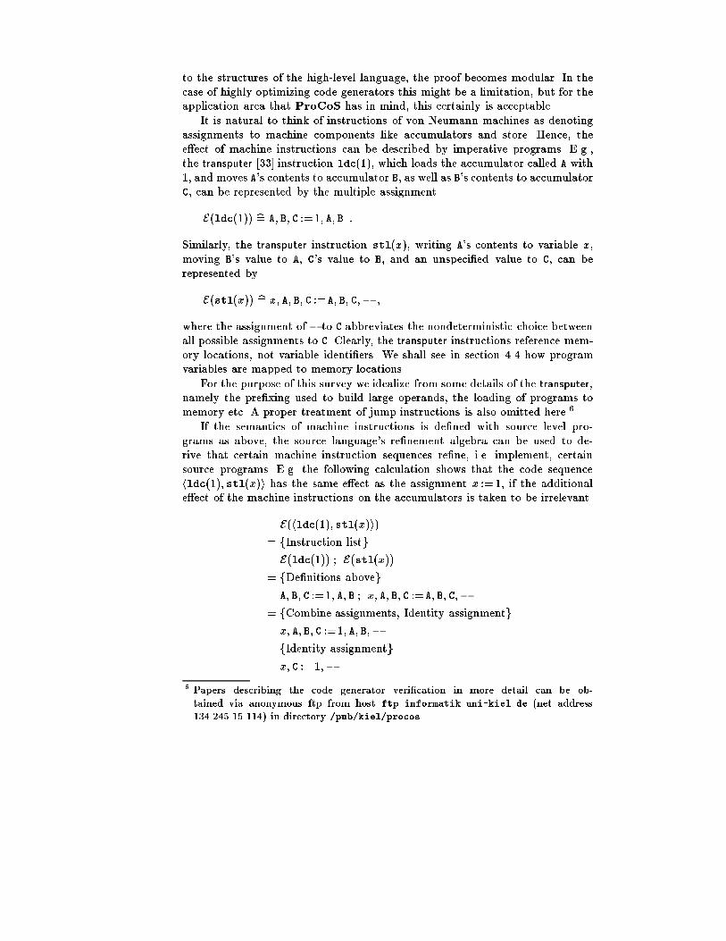
to the structures of the high-level language, the proof becomes modular. In thecase of highly optimizing code generators this might be a limitation, but for theapplication area that ProCoS has in mind, this certainly is acceptable.It is natural to think of instructions of von Neumann machines as denotingassignments to machine components like accumulators and store. Hence, thee�ect of machine instructions can be described by imperative programs. E.g.,the transputer [33] instruction ldc(1), which loads the accumulator called A with1, and moves A's contents to accumulator B, as well as B's contents to accumulatorC, can be represented by the multiple assignmentE(ldc(1)) b= A; B; C :=1; A; B :Similarly, the transputer instruction stl(x ), writing A's contents to variable x ,moving B's value to A, C's value to B, and an unspeci�ed value to C, can berepresented byE(stl(x )) b= x ; A; B; C :=A; B; C;? ;where the assignment of ? to C abbreviates the nondeterministic choice betweenall possible assignments to C. Clearly, the transputer instructions reference mem-ory locations, not variable identi�ers. We shall see in section 4.4 how programvariables are mapped to memory locations.For the purpose of this survey we idealize from some details of the transputer,namely the pre�xing used to build large operands, the loading of programs tomemory etc. A proper treatment of jump instructions is also omitted here.6If the semantics of machine instructions is de�ned with source level pro-grams as above, the source language's re�nement algebra can be used to de-rive that certain machine instruction sequences re�ne, i.e. implement, certainsource programs. E.g. the following calculation shows that the code sequencehldc(1); stl(x )i has the same e�ect as the assignment x := 1, if the additionale�ect of the machine instructions on the accumulators is taken to be irrelevant.E(hldc(1); stl(x )i)= fInstruction listgE(ldc(1)) ; E(stl(x ))= fDe�nitions abovegA; B; C :=1; A; B ; x ; A; B; C :=A; B; C;?= fCombine assignments, Identity assignmentgx ; A; B; C :=1; A; B;?= fIdentity assignmentgx ; C :=1;?6 Papers describing the code generator veri�cation in more detail can be ob-tained via anonymous ftp from host ftp.informatik.uni-kiel.de (net address134.245.15.114) in directory /pub/kiel/procos.

We have used the assignment laws(x := e) = (x ; y := e; y) (Identity assignment)(x := e ; x := f ) = (x := f [e=x ]) (Combine assignments)where f [e=x ] denotes substitution of e for x in expression f , and the propertyE(hi1; : : : ; ini) = E(i1) ; : : : ; E(in) (Instruction list)of machine code sequences without jump instructions.The little calculation above is a proof that hldc(1); stl(x )i is correct targetcode for x := 1 when timing is not taken into account. But of course executiontimes of the source and target processes must be related in a proof of correctimplementation of a real-time program. Therefore, we will now take a look at themechanisms provided by PL, the programming language used in the ProCoS-project, to control execution times.4.1 Real-time in programsA PL program is a parallel composition of sequential programs. As in occam [32]an environment can observe a PL program only through communications on itsexternal channels. Internal actions like assignments, particularly their executiontimes, can only indirectly be observed by their e�ect on succeeding communica-tions. Semantically, the value of a program variable is not an observable of theentire programs [19, 56]. It is only visible inside sequential programs. Therefore,for sequential programs convenient abstractions about the timing of actions canbe used since they need not be re ected directly by the corresponding machinecode. Only the timing of communications must be preserved. More speci�callythe following abstractions have been built into the semantics of PL.{ The atomic internal actions are immediate, taking no execution time. Thisconvention applies to assignments and the process SKIP.{ The control structures (sequential composition, conditional and loops) donot spend time beyond the time spent by their component processes.{ In contrast, communications spends time. Their time consumption is dividedinto two di�erent classes: Active time is the time used by preceding internalactions preparing for the communication, while waiting time is time spentwaiting for its communication partner to also engage into the communica-tion. The amount of real time consumed by a communication command isalways the sum of the two. The reason for distinguishing the two portions ofreal-time is compilability: Only the active time can be checked by a compilerwhereas the waiting time depends on the synchronization structure of thealgorithm.These assumptions greatly simplify reasoning about sequential processes sincethey result in a number of powerful and general laws facilitating algebraic cal-culation. But they imply a task for a compiler: The execution time of machine

code implementing internal processes and control structures must be shifted tosucceeding communication commands. This technique is described in section 4.3.Basically, the active time consumption of external processes is unconstrained.For real-time programming, PL o�ers an upper-bound construct to constrain theactive time. In this section we use the notation jP j � t instead of the occam-style notation used in section 3. jP j � t con�nes the enclosed sequential processP to spend at most t units of active time.In order to reason about active time spent by internal activity of the machinewe extend the programming notation by an active delay: � d . It is a process thatneither communicates nor changes the state and terminates after at most d unitsof active time.4.2 Adding timing information to the e�ect processesThe description of the untimed meaning of an instruction has been given bydescribing its e�ect on the transputer state by a source language-like process.The additional description of the instruction timing can be done by addingappropriate delays to these e�ect processes. For simplicity, we ignore in thissurvey the dependencies of instruction timing on the length of operands and onthe latencies of di�erent memory devices.Assuming that c is the duration of one processor cycle we can describe thee�ect of a load-constant instruction, which takes one cycle, byE(ldc(n)) b= � c ; A; B; C :=n; A; B :Similarly, E(stl(x )) b= � c ; x ; A; B; C :=A; B; C;?E(ldl(x )) b= � 2 c ; A; B; C :=x ; A; BE(outword) b= � 25 c ;if B = MinInt + 0! Link0 !!A...B = MinInt + 3! Link3 !!Afi ;A; B; C :=?;?;?where channel !! expression abbreviates j channel ! expression j � 0, i.e. a com-munication that spends no active time.4.3 Meeting hard real-time constraints with compiled codeSince timing is mirrored in the semantics it is clearly reasonable to considera machine program m an implementation of source process P i� the (timed)e�ect of the generated machine code re�nes the source process, i.e. i� P vE(m). Unfortunately, this is much too restrictive. As described in section 4.1the compiler must distribute the execution time of machine code corresponding
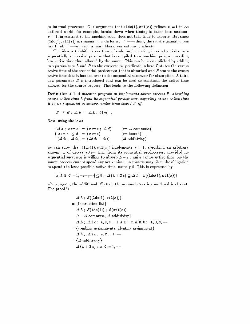
to internal processes. Our argument that hldc(1); stl(x )i re�nes x :=1 in anuntimed world, for example, breaks down when timing is taken into account.x := 1, in contrast to the machine code, does not take time to execute. But sincehldc(1); stl(x )i is reasonable code for x := 1 | indeed, the most reasonable onecan think of | we need a more liberal correctness predicate.The idea is to shift excess time of code implementing internal activity to asequentially successive process that is compiled to a machine program needingless active time than allowed by the source. This can be accomplished by addingtwo parameters L and R to the correctness predicate, where L states the excessactive time of the sequential predecessor that is absorbed and R states the excessactive time that is handed over to the sequential successor for absorption. A thirdnew parameter E is introduced that can be used to constrain the active timeallowed for the source process. This leads to the following de�nition.De�nition 4.1 A machine program m implements source process P, absorbingexcess active time L from its sequential predecessor, exporting excess active timeR to its sequential successor, under time bound E i�jP j � E ; �R v �L ; E(m) :Now, using the laws(� d ; x := e) = (x := e ; � d) (:=-�-commute)(j x := e j � d) = (x := e) (:=-bound)(�d1 ; �d2) = (�(d1 + d2)) (�-additivity)we can show that hldc(1); stl(x )i implements x := 1, absorbing an arbitraryamount L of excess active time from its sequential predecessor, provided itssequential successor is willing to absorb L+ 2 c units excess active time. As thesource process cannot spend any active time, its context may place the obligationto spend the least possible active time, namely 0. This is expressed byj x ; A; B; C :=1;?;?;?j� 0 ; � (L+ 2 c) v �L ; E(hldc(1); stl(x )i)where, again, the additional e�ect on the accumulators is considered irrelevant.The proof is �L ; E(hldc(1); stl(x )i)= fInstruction listg�L ; E(ldc(1)) ; E(stl(x ))= f:=-�-commute, �-additivityg�L ; � 2 c ; A; B; C :=1; A; B ; x ; A; B; C :=A; B; C;?= fcombine assignments, identity assignmentg�L ; � 2 c ; x ; C :=1;?= f�-additivityg� (L+ 2 c) ; x ; C :=1;?

= f:=-�-commutegx ; C :=1;? ; � (L+ 2 c)= f:=-boundgj x ; C := 1;? j � 0 ; � (L+ 2 c)w fnondeterminismgj x ; A; B; C :=1;?;?;?j� 0 ; � (L+ 2 c) :Note that the excess active time L of the sequential predecessor is simply handedthrough to the sequential successor.A similar calculation shows that hldc(MinInt ); ldl(x ); outwordi correctlyimplements Link0 ! x and absorbs all excess time coming from its sequentialpredecessor if the source process is placed into a context that allows to spendL + 28 c units of active time, i.e.j Link0 ! x ; A; B; C :=?;?;? j� (L+ 28 c) ; � 0v �L ; E(hldc(MinInt); ldl(x ); outwordi) :Note that this illustrates that excess execution time can be absorbed by unusedactive time of sequentially following communication commands. The inequalityis proved by �L ; E(hldc(MinInt); ldl(x ); outwordi)= fInstruction listg�L ; E(ldc(MinInt)) ; E(ldl(x )) ; E(outword)w f:=-�-commute, �-additivity, combine assignmentsg�L ; � 28 c ; Link0 !! x ; A; B; C :=?;?;?= f�-additivityg� (L+ 28 c) ; Link0 !! x ; A; B; C :=?;?;?w f!-boundgjLink0 ! x j � (L+ 28 c) ; A; B; C :=?;?;?= fInternal actions may be moved across boundsgjLink0 ! x ; A; B; C :=?;?;? j� (L+ 28 c) ;using the law(� d ; c !! e) w (j c ! e j � d) : (!-bound)Clearly, the most interesting question when compiling a real-time programminglanguage is how the compiler is going to ensure that every deadline stated inthe source program is met at run-time. E.g. consider an upper bound jP j � tin the source process to be compiled, constraining the active time available tothe enclosed process P and thus demanding a certain execution speed of thecompiled code. Then from the law(jP j � t1) w (jP j � t2) ; if t1 � t2 ; (Bound-re�nement)

we get that jP j � t is implemented by machine code m, absorbing excesstime L from its predecessor and exporting excess time R to its successor (i.e.jP j � t ; �R v �L ; E(m)), if there is E � t with jP j � E ; �R v �L ;E(m). Therefore a compiler encountering an upper bound operator in the sourceprogram must only check whether the required time bound is more liberal thanthe one asserted upon the code generated for the enclosed process. If it is, thenno further action is necessary, as the real-time requirement expressed by thebound is met. If it is less liberal, on the other hand, then this indicates thatthe source process cannot be adequately compiled for the given target hardwarewith the given code generation strategy, and it should be rejected (or perhapsanother code generator should be activated).4.4 Representing source program state by memory locationsIn the previous examples, variables have been addressed by their name. Thishas allowed us to use simple re�nement formulas when illustrating correctnessof code generation. Clearly, the actual transputer can only access storage lo-cations instead of named variables. As the environment only interacts with aprogram through its external channels whereas variables and internal channelsof the program are completely hidden, the latter components can be arbitrarilyrepresented.But it would be too liberal just to forget about variables and internal chan-nels as we want a compositional code generator veri�cation that can deducecorrectness of code for a sequential composition from correctness of code forits components. The approach is to ensure that an encoding of the state of theadditional components is always available on the machine.The well-known standard technique in code generation is to establish a sym-bol table assigning locations in the machine store to variable names of the sourceprocess. Suppose that x ; : : : ; z are the variables of the source process and that is a symbol table that maps each variable name of the source program to theworkspace, M, location allocated to hold its value, so M[ x ] is the value of x .Clearly it is necessary to insist that is a total injection. We de�ne a symbolicdump ; it assigns to each high level variable the value in the correspondinglocation [29], thus retrieving the source process state from the machine state. def= var x ; : : : ; z ;x ; : : : ; z := M[ x ]; : : : ; M[ z ] ;end A; B; C; MHere, var x ; : : : ; z introduces the variables x ; : : : ; z of type integer. The corre-sponding end A; B; C; M forgets, i.e. ends the scope of variables A, B, C and M.Vice versa, the part of the machine store which is allocated by the symboltable can be initialized such that it re ects the current values of x ; : : : ; z byreverse dumping with�1 def= var A; B; C; M ;M[ x ]; : : : ; M[ z ] := x ; : : : ; z ;end x ; : : : ; z

A notable di�erence between and �1 is that the dump determines thecomplete state of the source process, whereas the reverse dump �1 only deter-mines part of the machine state. Therefore, they are not inverses, but an easycalculation shows that the pair ( ; �1) is a simulation [29], i.e. that ; �1 v SKIP and SKIP v �1 ; :Now, using the dumps as a means of understanding state representation withrespect to a symbol table , one can de�nea source process P is implemented by machine program m relative to asymbol table , i� ; P v E(m) ; ,which closely corresponds to the well-known notion of a commutative diagramformalizing state representation. Note that by ending the scope of A, B and C atthe end of we also have formally expressed that the e�ect on the accumulatorsis irrelevant.The above implementation condition is only half of the story, as it doesnot cover absorption of excess time as demonstrated in the previous section.Combining both state representation via symbolic dumps and move of excesstime, we arrive at the following implementation conditionDe�nition 4.2 A machine program m implements source process P with respectto the symbol table , absorbing excess active time L from its sequential predeces-sor, exporting excess active time R to its sequential successor, under time boundE, i� ; (jP j � E ) ; �R v �L ; E(m) ; :For brevity, this property is denoted T (P ;m; ;L;R;E ).As T expresses correctness of machine code fragmentm relative to source processP it is the implicit code generator speci�cation for process compilation used inthe ProCoS II project.4.5 Towards explicit code generator speci�cationsThe simplest reasonable speci�cation of a code generator, but also the most im-plicit, is to say that it assigns correct machine code fragments to source objects.Aiming at a compositional code generator speci�cation that proceeds along thesyntactic structure of source programs, it is furthermore desirable to state addi-tional implementation properties for program components that imply correctnessof code assigned to full programs when satis�ed on all program components. Thatis exactly what has been done when de�ning the implementation property T inthe previous section. Hence, T quali�es as a reasonable implicit speci�cation ofcode generation for processes.Now, the task of code generator design is to develop a complying explicit codegenerator speci�cation from the implicit one. We accomplish this by proving the-orems about the implicit speci�cation T in the calculational style demonstrated

in the introduction to this section and in section 4.3. There we have showntheorems for special cases of assignment and output. For compound constructsop(P1; : : : ;Pn ) the theorems take the form of an implication that establishesthe correctness of code for the compound construct from correctness of code forthe components P1; : : : ;Pn and syntactic conditions on the surrounding code.Taking a slightly di�erent view, such a theorem describes how to construct cor-rect code for a larger process if correct code for all its components is known.Thus, the collection of these theorems induces a syntactically de�ned compilingrelation C that is a sub-relation of the correctness relation T , i.e. an explicitspeci�cation of a correct code generator. If necessary C is further specialized toa function. This corresponds to code selection. More speci�cally, the specializedC is a function depending on the source process P the symbol table and theabsorption capacity L.In the framework of the ProCoS-project we develop a prototype compilerwritten in the functional language Standard ML [49, 76]. The code generator issimply given by expressing C in Standard ML syntax.4.6 Related WorkThe idea of specifying a machine by a high level program is old and is presentalready in the idea of micro-programming [77]. Alain Martin and others [43, 13,25] use such descriptions as a starting point for hardware design (see also section5). One of the contributions of Hoare et al. [27, 29] on which our work is based isthe proposal to use such a description together with a re�nement algebra relatedto the source language [28, 50] for the reasoning about compilers. From moreclassical work about compiler correctness [47, 52, 74, 35] we are distinguishedby aiming at code for an actual processor and not for idealized hardware, a goalshared with E. B�orger et. al. [6], who are also concerned with proving correctcompilation of occam. We try to accurately re ect the restrictions imposed bythe hardware. The additional complexity of aiming at actual hardware requiresmodularity to split the veri�cation in relatively small independent steps. Anotherdi�erence to classical methods is that we use re�nement as the correctness notioninstead of semantic equivalence (this is also borrowed from [29]). This allows aproper treatment of under-speci�cation in the source language's semantics (e.g.of uninitialized variables) and accommodates modularization. We treat real-timeand communication [55, 18]. Like the work at CLInc [4] on the `veri�ed stack'we try to interface to higher and lower levels of abstraction.5 Programs to HardwareIn this section we outline a technique to compile programs written in PL directlyinto hardware via provably correct transformations. A PL program de�nes whata hardware circuit should achieve, while a hardware description language, onthe other hand, provides a way to express the components of a hardware circuitand their interconnections. Hardware description languages are widely used in

many computer-aided systems, allowing libraries of standard checked hardwaremodules to be assembled.Here a simple description language for globally clocked circuits will be givenan observation-oriented semantics based on the states of the wires of a device. Al-gebraic laws based on this semantics permit circuit descriptions to be expressedin a hardware normal form. This form is designed to guarantee absence of sucherrors as combinational cycles and con icts. The necessary link with the higherabstraction level of the programming language is provided by an interpreterwritten in the programming language itself.A hardware normal form is a correct translation of a source program if its in-terpretation is a re�nement of the source program. For the primitive componentsof the source language this is proved directly by giving corresponding circuits;and then a series of theorems shows how a correct circuit for a composite pro-gram can be constructed from circuits that implements its components. Suchtheorems can be interpreted as transformation rules, which can be used directlyor indirectly in the design of an automatic compiler.The hardware normal form is fairly close to the typical notation of a hard-ware netlist language describing the interconnection of basic digital components.These netlists can be implemented in hardware in many ways. Currently, weuse FPGAs (Field Programmable Gate Arrays) which can be dynamically re-con�gured by software. This enables us to build hardware implementations ofmodest-sized programs entirely by a software process. A signi�cant feature ofsuch a hardware implementation is that a global clock synchronizes the activityof subcomponents; i.e., updates on latches can only take place at the end of eachclock cycle.5.1 Programming languageThe programming language used in this section is close to both occam andPL, as introduced in section 3. Here we only consider variables of type BOOL forsimplicity, but more complicated data types can and have been handled [62]. Atthe target hardware level, communication is implemented using a synchronoushandshaking protocol at discrete clock cycle time steps. Veri�cation of the targethardware assigned to PL programs takes advantage of the source language'sre�nement calculus. The basic algebraic laws for occam programs are given in[68]. In [24] we have presented some algebraic laws speci�cally concerned withreal-time properties of programs.In order to model the behaviour of a clocked circuit we add the generalizedassignment to the PL language.Let R(v ; v 0) be a predicate relating the �nal value v 0 of the program variablev to its initial value v . For simplicity we assume that R is feasible, i.e. 8 v9 v 0�R.The notationv :2 Ris a generalized assignment which assigns v a value such that the post-conditionR holds at its termination.

The following laws illustrate the relation between a generalized assignmentand ordinary ones:v := e = v :2 (v 0 = e)(x := e; y := f ) = x ; y :2 ((x 0 = e) ^ (y 0 = f [x 0=x ]))5.2 Synchronous CircuitsA digital circuit has one or more input and output wires. Its behaviour is de-scribed by a predicate on the values of these wires. There are only two stablevalues for a wire: either 0 standing for connection to the ground, or 1 standingfor the presence of electrical potential. A synchronous circuit is equipped witha global clock which runs slow enough such that all inputs of the circuit be-come stable before being latched at the end of each clock cycle. The unspeci�edduration of each cycle is here taken as the unit of time.Digital Elements Let W be a Boolean expression, and w be a wire name notused in the expression W . The notation w :Comb(W ) describes a combinationalcircuit where the value of the output wire w is de�ned by the value of W .This relationship holds only at the end of each clock cycle. Let wt and Wtrepresent the values at time t of w and W respectively. Since only the statesthat devices assume at the ends of clock cycles are of interest, the behaviour ofthe combinational circuit w :Comb(W ) is described byw :Comb(W ) b= 8t � (wt = Wt )where the range of t is the natural numbers, denoting clock cycles.Another elementary circuit is the latch x :Latch(B ; E ) where on each clockcycle, the output wire x takes the value of the expression E of the previous clockcycle when the condition B is true; otherwise the value of x remains unchanged.Initially x is 0.x :Latch(B ; E ) b= (x0 = 0 ^ 8 t � xt+1 = (Et < Bt > xt)A variation of a latch is the delay element l :Delay(E ) = l :Latch(1; E ), whereon each clock cycle, the output wire l takes the value of the expression E on theprevious clock cycle.Input and Output Let D be a Boolean expression and d a wire name notmentioned in D . The notation d :Out(D) stands for the combinational circuitd :Comb(D), where the output wire d is used to connect the circuit with itsenvironment.Similarly, the notation c:In represents an input wire c whose value is solelydetermined by the environment. Since the value of an input wire is arbitrary,the behaviour of c:In is described by the following nondeterministic assignment:c:In b= 8t � (ct = 0 _ ct = 1)

Composition Circuit components can be connected by parallel composition toform larger circuits. Internal wires of such assemblies can be made invisible tothe environment using hiding.A pair of components (C1; C2) with distinct output wires can be assembledby connecting like-named wires, making sure that any cycle of connection is cutby a latch. Since the value observed on the input end of a wire is the same asthat produced on the output end, the combinational behaviour of an assemblycan then be described by the conjunction of their descriptions as follows:C1&C2 b= C1 ^C2To explain hiding, let w be a wire used in a circuit C . If the environmentdoes not use w , we can hide w by existential quanti�cation9w �C :5.3 Hardware Normal FormLet w be a list of wire names and W a list of Boolean expressions of the samelength as w . We will use the notation w :Comb(W ) to represent the network ofcombinational circuitsw1:Comb(W1)& ::&w#w :Comb(W#W )where #w is the length of the list w . Later we will adopt the same conventionfor networks of Delay elements and latches.Let B and E be lists of Boolean expressions with the same length as the listx of latch names. For notational simplicity, we use the notation E < B > x tostand for the list of conditionalsf(E1 < B1 > x1); ::: ; (E#x < B#x > x#x )gSince we are aiming at a circuit structure where circuit activity is triggeredby the environment through a signal on a start wire named s and terminationof its activity is signalled to the environment through a signal on a �nish wirenamed f , and where only input and output terminals and latch states are visibleto the environment, we are interested in circuits of the following special form.Let c be a list of input wire names with s 2 c, and d a list of output wire nameswith f 2 d . Let x be a list of latch names, l a list of Delay names, and w a listof combinational gate names. The circuitC (s; f ) b= 9 l1; : : : ; l#l ; w1; : : : ;w#w �0BBBBBB@ l :Delay(L)& w :Comb(W )& x :Latch(B ; E )& c:In& d :Out(D )& f :Delay(F ) 1CCCCCCAis a network where s 2 c is an input wire by which the environment triggersthe circuit and f 2 d is an output wire where the circuit signals the end of itsoperation.

De�nition 5.1 (Normal Form) The circuit C (s; f ) is a hardware normalform if it satis�es the following conditions:(NF-1) : The output wire f is not used as input by any component.(NF-2) : All the latches xi :Latch(Bi ; Ei )(NF-3) : None of the Boolean expressions L; W ; D ; B and F is true in thecase when all wires l, w and s have the value 0.The �rst condition states that the wire f acts only as a link between the circuitC with its environment. The second condition is technical, but can easily belifted by adding circuitry. It is necessary for non-interference between parallelcomponents sharing a latch. Condition 3 characterizes a speci�c kind of `one-hot'synchronous circuit [62] where control signals are used to initiate activities.Multiplexor When the circuits resulting from software translation are put to-gether, we need some method of allowing them to share their latches, input wiresand output wires. Let Ci (i = 1; 2) be a networkCi b= 9 v i �0@ w i :Comb(Wi )& l i :Delay(Li)& x i :Latch(B i ; E i )& ci :In& d i :Out(D i ) 1Awhere v i � (w i [ l i ). Assume that C1 and C2 do not share wire names exceptlatches, input and output devices, and also avoid combinational cycles. Thenotation Merge(C1; C2) represents a network produced by using multiplexors tomerge the latches and outputs in C1 and C2, namelyMerge(C1; C2) b=9 v1; v2 � 0BBBB@ w1:Comb(W 1)&w2:Comb(W 2)& l1:Delay(L1)& l2:Delay(L2)& x :Latch(B ; E )& c:In& d :Out(D) 1CCCCAwherex :Latch(B ; E ) b=0@ fx :Latch(B1; E1) j x 2 x1 n x2g& fx :Latch((B1 _B2); (E1 _ E2)) j x 2 x 1 \ x 2g& fx :Latch(B2; E2) j x 2 x2 n x1g 1Aand c represents the union of c1 and c2, andd :Out(D) b= 0@ fd :Out(D1) j d 2 d1 n d2g& fd :Out(D1 _D2) j d 2 d1 \ d2g& fd :Out(D2) j d 2 d2 n d1g 1AFrom the de�nition it is easy to check that Merge is commutative and associative,allowing us to treat Merge as a unary operator with a set of networks as itsargument.

One can also prove that whenC1(s; h) and C2(h; f ) are normal forms withoutshared wires except data latches and outputs, then the network9 h � Merge(C1; C2)is also a normal form.5.4 SimulatorThe normal form C (s; f ) described in the previous section starts its operationafter being triggered by an input signal from the wire s 2 c. Initially, all itsDelay elements are reset to 0, and the combinational components enter theirstable states immediately afterward. The initialization phase of C (s; f ) can thusbe described by a generalized assignmentInit b=l ;w; c; d ; f :2 (s 0 = 1)& (l = 0)& (w 0 = W 0)& (d 0 = D 0)& (f 0 = 0)The activity of the normal form in one clock cycle is described by a delay and ageneralized assignmentStep b=� 1 ; l ; w ; x ; c; d ; f :2(s0 = 0)& (f 0 = F )&(l 0 = L)& (w 0 =W 0)& (x 0 = E < B > x )& (d 0 = D 0)where the delay statement � 1 takes one clock cycle. The operation of C canthen be modelled by iterating Step while :f .The circuit C signals completion on the wire f . In order to do so, condition 3of the normal form requires that the values of the wires w and l become 0 whenf becomes active. This requirement is represented by an assertion FinalFinal b= (:w &:l)?When both l and w are empty lists Final = (true)? = SKIP.In summary the behaviour of the normal form C (s; f ) can be described bythe following simulator:< s; C ; f >b= VAR s; f ; l ; w :SEQInitWHILE :fStepFinalEND s; f ; l ; wwhere the start and �nish wires s and f are the only control wire connections tothe outside world.C (s; f ) is a correct implementation of a program P ifP v < s; C ; f >In what follows we will only deal with hardware normal forms.
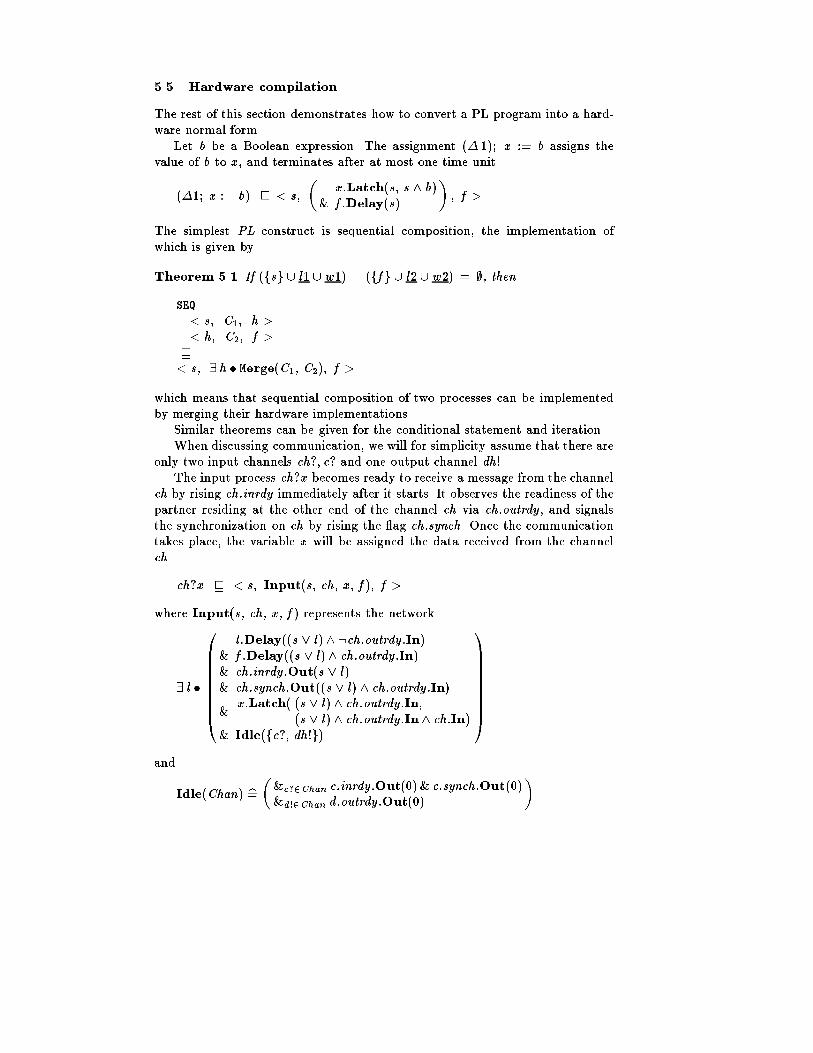
5.5 Hardware compilationThe rest of this section demonstrates how to convert a PL program into a hard-ware normal form.Let b be a Boolean expression. The assignment (� 1); x := b assigns thevalue of b to x , and terminates after at most one time unit.(�1; x := b) v < s; � x :Latch(s; s ^ b)& f :Delay(s) � ; f >The simplest PL construct is sequential composition, the implementation ofwhich is given byTheorem 5.1 If (fsg [ l1 [ w1) \ (ff g [ l2 [ w2) = ;, thenSEQ< s; C1; h >< h; C2; f >v< s; 9 h � Merge(C1; C2); f >which means that sequential composition of two processes can be implementedby merging their hardware implementations.Similar theorems can be given for the conditional statement and iteration.When discussing communication, we will for simplicity assume that there areonly two input channels ch?; c? and one output channel dh!.The input process ch?x becomes ready to receive a message from the channelch by rising ch:inrdy immediately after it starts. It observes the readiness of thepartner residing at the other end of the channel ch via ch:outrdy , and signalsthe synchronization on ch by rising the ag ch:synch. Once the communicationtakes place, the variable x will be assigned the data received from the channelch. ch?x v < s; Input(s; ch; x ; f ); f >where Input(s; ch; x ; f ) represents the network9 l � 0BBBBBBBB@ l :Delay((s _ l) ^ :ch:outrdy :In)& f :Delay((s _ l) ^ ch:outrdy :In)& ch:inrdy :Out(s _ l)& ch:synch:Out((s _ l) ^ ch:outrdy :In)& x :Latch( (s _ l) ^ ch:outrdy :In;(s _ l) ^ ch:outrdy :In^ ch:In)& Idle(fc?; dh!g) 1CCCCCCCCAandIdle(Chan) b= �&c?2Chan c:inrdy :Out(0)& c:synch:Out(0)&d !2Chan d :outrdy :Out(0) �
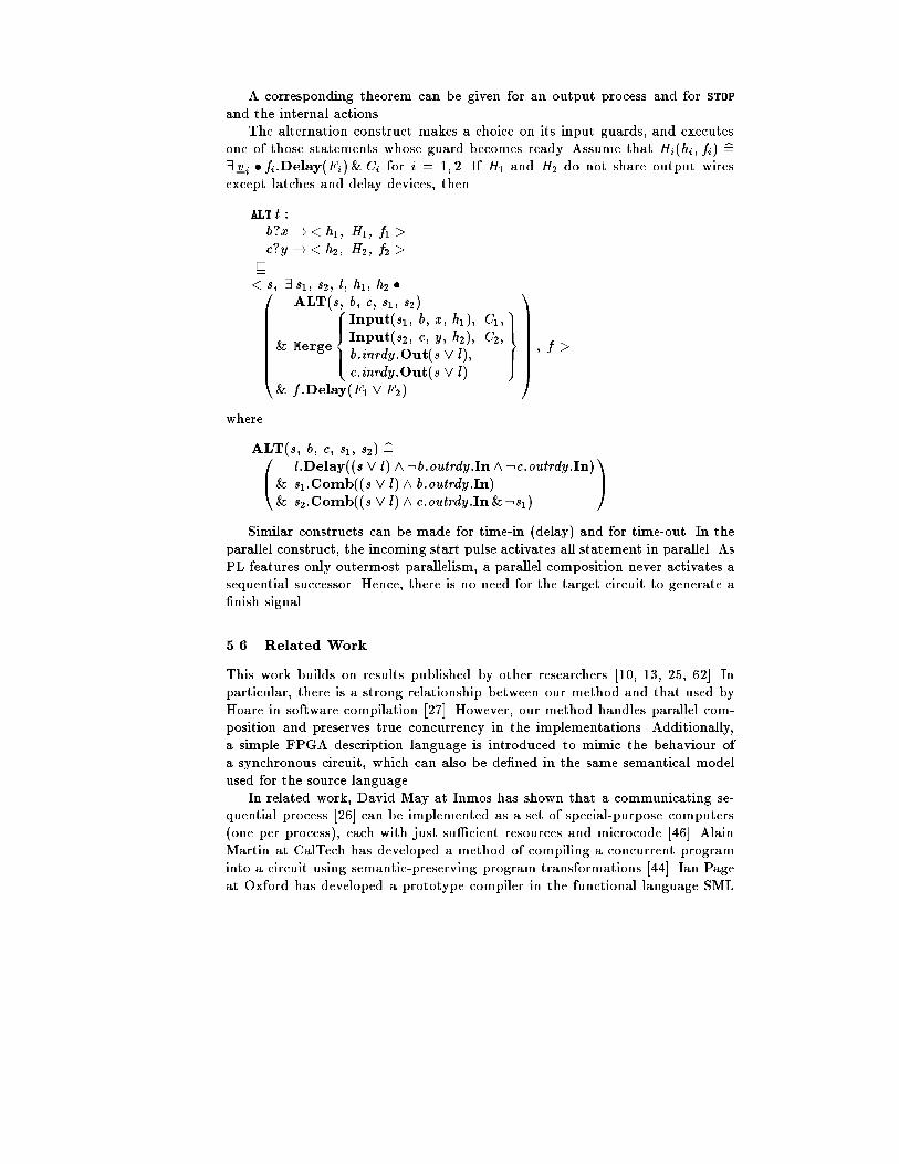
A corresponding theorem can be given for an output process and for STOPand the internal actions.The alternation construct makes a choice on its input guards, and executesone of those statements whose guard becomes ready. Assume that Hi(hi ; fi) b=9 v i � fi :Delay(Fi )&Ci for i = 1; 2. If H1 and H2 do not share output wiresexcept latches and delay devices, thenALT t :b?x !< h1; H1; f1 >c?y !< h2; H2; f2 >v< s; 9 s1; s2; l ; h1; h2 �0BBBBBB@ ALT(s; b; c; s1; s2)& Merge8>><>>: Input(s1; b; x ; h1); C1;Input(s2; c; y ; h2); C2;b:inrdy :Out(s _ l);c:inrdy :Out(s _ l) 9>>=>>;& f :Delay(F1 _ F2) 1CCCCCCA ; f >whereALT(s; b; c; s1; s2) b=0@ l :Delay((s _ l) ^:b:outrdy :In^ :c:outrdy :In)& s1:Comb((s _ l) ^ b:outrdy :In)& s2:Comb((s _ l) ^ c:outrdy :In&:s1) 1ASimilar constructs can be made for time-in (delay) and for time-out. In theparallel construct, the incoming start pulse activates all statement in parallel. AsPL features only outermost parallelism, a parallel composition never activates asequential successor. Hence, there is no need for the target circuit to generate a�nish signal.5.6 Related WorkThis work builds on results published by other researchers [10, 13, 25, 62]. Inparticular, there is a strong relationship between our method and that used byHoare in software compilation [27]. However, our method handles parallel com-position and preserves true concurrency in the implementations. Additionally,a simple FPGA description language is introduced to mimic the behaviour ofa synchronous circuit, which can also be de�ned in the same semantical modelused for the source language.In related work, David May at Inmos has shown that a communicating se-quential process [26] can be implemented as a set of special-purpose computers(one per process), each with just su�cient resources and microcode [46]. AlainMartin at CalTech has developed a method of compiling a concurrent programinto a circuit using semantic-preserving program transformations [44]. Ian Pageat Oxford has developed a prototype compiler in the functional language SML

which converts an Occam-like language [32], somewhat more expressive than theone presented here, to a netlist. After further processing by vendor software thenetlist can be loaded into Xilinx FPGA chips [62, 78]. However, the algebraicapproach presented here o�ers the signi�cant advantages of providing a prov-ably correct compiling method, and it is also expected to support a wide rangeof design optimization strategies.6 Mathematical FoundationsThe preceding sections have illustrated a top-down approach to the design ofa simple real-time process control system. For complex embedded and safetycritical systems, it is even more important to decompose the project into sucha progression of related phases. These should start with an investigation of theproperties and behaviour of the process evolving within its environment, and ananalysis of requirements for its optimal or satisfactory performance, or at leastfor its safety. From these is derived a speci�cation of the electronic or program-controlled components of the system. The project then may pass through anappropriate series of design phases, culminating in a program expressed in ahigh level language. After translation into the machine code of the chosen com-puter, it is loaded into memory and executed at high speed by electronic circuitry.Additional application-speci�c hardware may be needed to embed the computerinto the system which it controls. Each of these phases relies on theories, con-cepts, and notations particularly suited to that phase. But the conceptual gapsbetween the phases present at least an equal challenge, since reliability of thedelivered system requires that all the gaps be closed. Reliability is achieved notjust by testing, but by the quality of thought and meticulous care exercised byanalysts, designers, programmers and engineers in all phases of the design.This has been a description of an ideal that is rarely achieved in any �eld ofengineering practice. Nevertheless, an ideal forms the best basis for long-termresearch into engineering technology. The goal of this research is to discoverand formalize methods which reduce the risks and simplify the routines of thedesign task, and give fuller scope for the exercise of human skill and inventionin meeting product requirements at low cost and in good time. The goal of thissurvey has been to convey an impression of the methods and intermediate resultsof just one such research project.In principle, the transition between one design phase and the next is markedby delivery of a document, expressed in some more or less formal notation. Eachphase starts with study and acceptance of the document produced by the previ-ous phase; and ends with the delivery of another document, usually formulatedat a lower level of abstraction, closer to the details of the eventual implemen-tation. Each designer seeks high e�ciency at low cost; but is constrained by anabsolute obligation that the �nal document must be totally correct with respectto the initial document for this design phase. Thus the requirements must befaithfully re ected in the speci�cation, the speci�cation must be fully achievedby the design, the design must be correctly implemented by the program, the
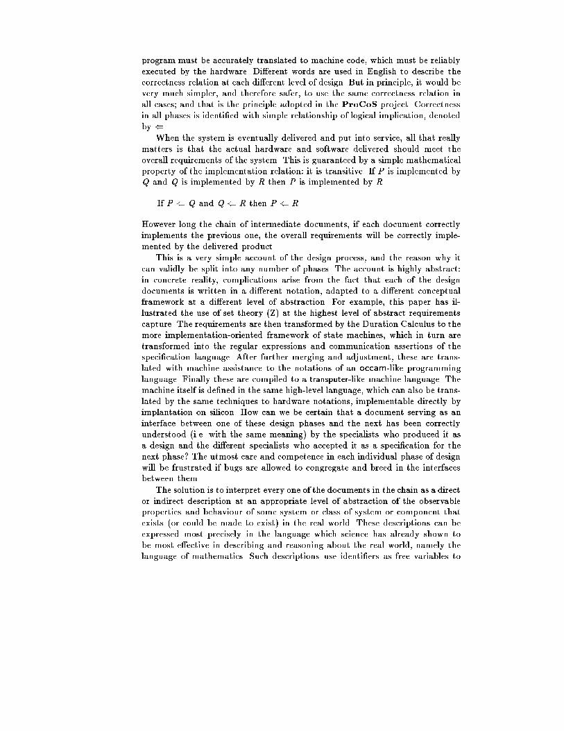
program must be accurately translated to machine code, which must be reliablyexecuted by the hardware. Di�erent words are used in English to describe thecorrectness relation at each di�erent level of design. But in principle, it would bevery much simpler, and therefore safer, to use the same correctness relation inall cases; and that is the principle adopted in the ProCoS project. Correctnessin all phases is identi�ed with simple relationship of logical implication, denotedby (.When the system is eventually delivered and put into service, all that reallymatters is that the actual hardware and software delivered should meet theoverall requirements of the system. This is guaranteed by a simple mathematicalproperty of the implementation relation: it is transitive. If P is implemented byQ and Q is implemented by R then P is implemented by RIf P ( Q and Q ( R then P ( RHowever long the chain of intermediate documents, if each document correctlyimplements the previous one, the overall requirements will be correctly imple-mented by the delivered product.This is a very simple account of the design process, and the reason why itcan validly be split into any number of phases. The account is highly abstract:in concrete reality, complications arise from the fact that each of the designdocuments is written in a di�erent notation, adapted to a di�erent conceptualframework at a di�erent level of abstraction. For example, this paper has il-lustrated the use of set theory (Z) at the highest level of abstract requirementscapture. The requirements are then transformed by the Duration Calculus to themore implementation-oriented framework of state machines, which in turn aretransformed into the regular expressions and communication assertions of thespeci�cation language. After further merging and adjustment, these are trans-lated with machine assistance to the notations of an occam-like programminglanguage. Finally these are compiled to a transputer-like machine language. Themachine itself is de�ned in the same high-level language, which can also be trans-lated by the same techniques to hardware notations, implementable directly byimplantation on silicon. How can we be certain that a document serving as aninterface between one of these design phases and the next has been correctlyunderstood (i.e. with the same meaning) by the specialists who produced it asa design and the di�erent specialists who accepted it as a speci�cation for thenext phase? The utmost care and competence in each individual phase of designwill be frustrated if bugs are allowed to congregate and breed in the interfacesbetween them.The solution is to interpret every one of the documents in the chain as a director indirect description at an appropriate level of abstraction of the observableproperties and behaviour of some system or class of system or component thatexists (or could be made to exist) in the real world. These descriptions can beexpressed most precisely in the language which science has already shown tobe most e�ective in describing and reasoning about the real world, namely thelanguage of mathematics. Such descriptions use identi�ers as free variables to

stand for observations or measurements that could in principle be made of thereal world system.The Z notation used in section 2 gives the most direct examples in the in-troduction of the free variables Heatreq, Flame, and Gas, and their use in pred-icates to describe the actual and desired behaviour of the gas burner. The othernotations used in the project can be regarded as more specialized and more ab-breviated descriptions of the behaviour of the ultimate product. For example thebehaviour of a computer program can be described in terms of the initial and�nal values of global variables before and after a typical run of the program; forreactive systems, this is accompanied by a trace of its intermediate interactionswith its environment; and for time-critical systems, these traces must be timed.The use of free variables to stand for observations or measurements of timedtrajectories lies at the basis of all reasoning in science and engineering. Considerfor example the simplest mechanical system, involving movement of a physicalpoint, say a plotter pen or a ship or a projectile. A simple requirement may bethat its motion remain steady during a certain interval after its start. Let xtbe its displacement on the x axis at time t , and let a be the desired velocity.Then within some desired interval the di�erence between the actual and desiredposition should, within the relevant period, always be less than some permittedtolerancej xt � at � x0 j � 0:4for all t 2 (3 : : :5). If we also want steady motion on the y-axis, this is statedseparatelyj yt � bt � y0 j � 0:4for all t 2 (3 : : :5): The additional requirement is just conjoined by \and" tothe original requirement. The use of conjunction to compose complex require-ments from simple descriptions is a crucial advantage of the direct use of logicalnotations at the earliest stage of a design project.In this example, the requirements formalize the permitted tolerances on theaccuracy of implementation. Of course an implementation is permitted to achieveeven greater accuracy. For example, suppose the behaviour of a particular im-plementation is described by(xt � at � x0)2 + (yt � bt � y0)2 < 0:1for all t � 5. This implies both of the requirements displayed above; consequentlythe implementation correctly ful�lls its speci�cation.This notion of correctness is perfectly general. Suppose a design document Pand a speci�cation S use consistent naming conventions for variables to describeobservations of the same class of system; and suppose that P logically implies S .This means that every observation of any system described by P is also describedby S , and therefore satis�es S as a speci�cation. Certainly, no observation ofthe system described by P can violate the speci�cation S . That is the basis ofour claim that the relationship of correct implementation is nothing other than
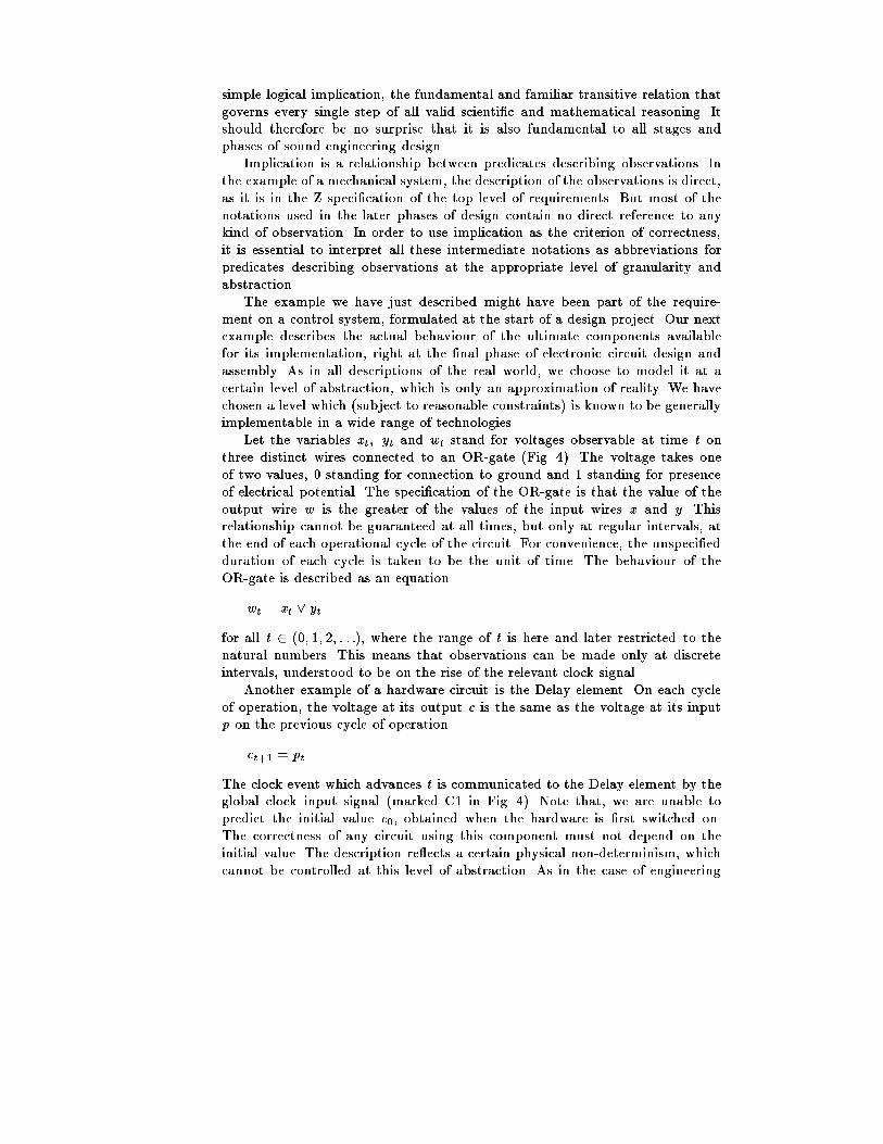
simple logical implication, the fundamental and familiar transitive relation thatgoverns every single step of all valid scienti�c and mathematical reasoning. Itshould therefore be no surprise that it is also fundamental to all stages andphases of sound engineering design.Implication is a relationship between predicates describing observations. Inthe example of a mechanical system, the description of the observations is direct,as it is in the Z speci�cation of the top level of requirements. But most of thenotations used in the later phases of design contain no direct reference to anykind of observation. In order to use implication as the criterion of correctness,it is essential to interpret all these intermediate notations as abbreviations forpredicates describing observations at the appropriate level of granularity andabstraction.The example we have just described might have been part of the require-ment on a control system, formulated at the start of a design project. Our nextexample describes the actual behaviour of the ultimate components availablefor its implementation, right at the �nal phase of electronic circuit design andassembly. As in all descriptions of the real world, we choose to model it at acertain level of abstraction, which is only an approximation of reality. We havechosen a level which (subject to reasonable constraints) is known to be generallyimplementable in a wide range of technologies.Let the variables xt ; yt and wt stand for voltages observable at time t onthree distinct wires connected to an OR-gate (Fig. 4). The voltage takes oneof two values, 0 standing for connection to ground and 1 standing for presenceof electrical potential. The speci�cation of the OR-gate is that the value of theoutput wire w is the greater of the values of the input wires x and y . Thisrelationship cannot be guaranteed at all times, but only at regular intervals, atthe end of each operational cycle of the circuit. For convenience, the unspeci�edduration of each cycle is taken to be the unit of time. The behaviour of theOR-gate is described as an equationwt = xt _ ytfor all t 2 (0; 1; 2; : : :); where the range of t is here and later restricted to thenatural numbers. This means that observations can be made only at discreteintervals, understood to be on the rise of the relevant clock signal.Another example of a hardware circuit is the Delay element. On each cycleof operation, the voltage at its output c is the same as the voltage at its inputp on the previous cycle of operationct+1 = ptThe clock event which advances t is communicated to the Delay element by theglobal clock input signal (marked C1 in Fig. 4). Note that, we are unable topredict the initial value c0, obtained when the hardware is �rst switched on.The correctness of any circuit using this component must not depend on theinitial value. The description re ects a certain physical non-determinism, whichcannot be controlled at this level of abstraction. As in the case of engineering

c
p1D
C1x
w
p
C1
1D
EN
Delay ConditionalLatch
OR gate
x
yw
Fig. 4. Circuit elements.tolerance, the speci�cation must also allow for a range of possible outcomes;otherwise correctness will not be provable.A useful variation of the Delay element is the Conditional Latch element (inengineering terms this is an edge-triggered ip- op with a clock enable input).Here, the value of the output is changed only when a clock event occurs and theinput control wire p is high; and then the new value of x is taken from the otherinput wire w . Otherwise the value of x remains unchanged. This behaviour isformally describedxt+1 = (wt < pt > xt)where a < b > c is read as \a if b else c".A pair of hardware components is assembled by connecting like-named wiresof each of them, making sure that no two outputs become connected and thatany cycle of connections is cut by a Delay. Electrical conduction ensures thatthe value observed at the input ends of each wire will be the same as thatproduced at the output end. As a result, the combined behaviour of an assemblyof hardware components is described surprisingly but exactly by a conjunction ofthe descriptions of their separate behaviours. Imagine this done for the circuitsof Fig. 4In principle, the conjunction of the descriptions of all the hardware compo-nents of the system should imply the conjunction of all the requirements orig-inally placed upon the system as a whole. In a simple system, this implicationmay be proved directly; otherwise it is proved through a series of intermediatedesign documents, perhaps including a program expressed in a high level lan-guage. A program also must be interpreted as an indirect description of its ownbehaviour when executed. We therefore need names to describe its observablefeatures, and for reasons of our own we have chosen to reuse the names of thehardware wires.

Let pt be an assertion true at just those times t when execution of theprogram starts, and let ct 0 be true at just those times t 0 at which it terminates.Let xt be the value of a program variable x at time t , so xt 0 is the �nal value.With a slight simpli�cation, the assignment statementx := x OR ycan now be de�ned as an abbreviation forpt ) 9t 0 � t � (xt 0 = xt _ yt) and ct 0If the program starts at time t , then it stops at some later time t 0; and atthat time the �nal value of x is the disjunction of the initial values of x andy. Note that the execution delay (t 0 � t) has been left deliberately unspeci�ed.This gives design freedom for implementation in a variety of technologies, frominstantaneous execution (achieved by compile time optimization) to the arbitrary�nite delays that may be interposed by an operating system in execution of atimeshared program.Now we confess why we have chosen the same names for the software variablesas the hardware wires. It demonstrates immediately that our example hardwareassembly is also a valid implementation of the software assignment: the descrip-tion of one of them implies the description of the other. The proof is equallysimple: take the software termination time as exactly one hardware cycle afterthe start. It is the translation of both hardware and software notations into acommon framework of timed observations that permits a proof of the correctnessof this design step as a simple logical implication, thereby closing the intellectualand notational gap between the levels of hardware and software.Our example has been arti�cially simpli�ed by use of exactly the same ob-servation names at both levels. In general, it may be necessary to introduce acoordinate transformation to establish the link between them. The coordinatetransformation is also a predicate, describing the relationship between the ob-servations or measurements made at one level of abstraction and those made atthe other. Its free variables therefore include those relevant at both levels; oneof the levels can then be abstracted by quanti�cation. A good example is thetransformation ( ) used in a compiler (4.4) to correlate the observations of ini-tial and �nal values of the abstract program variables x ; : : : ; z with the concretelocations M[ x ]; : : : ; M[ z ], where their values may be observed in the store ofthe machine.In principle, proof of correctness of a design step can always be achieved,as we have shown, by expanding the abbreviation of the relevant notations andconstructing a proof in the predicate calculus. But for a large system this wouldbe impossibly laborious. What we need is a useful collection of proven equationsand other theorems expressed wholly in the abbreviated notations; it is thesethat should be used to calculate, manipulate, and transform the abbreviatedformulae, without any temptation or need to expand them. For example, thepower of matrix algebra lies in the collection of equational laws which expressassociative and distributive properties of the operators:

A� (B � C ) = (A � B) �C(A+ B) �C = (A �C ) + (B �C )The mathematician who proves these laws has to expand the abbreviations, intoa confusing clutter of subscripts and sigmasPj Aij (Pk BjkCkl) =Pk (Pj AijBjk )CklBut the engineer who uses the laws just does not want to know.This survey article has given many examples of the informal use of algebraicreasoning within each design phase and in making the transition between them.For ultimate reliability, each of these transitions must be justi�ed by explicitappeal to some valid mathematical law, preferably expressed as an equation, orpossibly an inequation using logical implication. But how can the engineer becertain of the validity of the laws? That is a question that can be answered,not by an engineer but by a mathematician, who thereby makes an essentialcontribution to the success of the entire development and the reliability of thedeveloped product.This contribution starts with the design of a semantics for all the notationsinvolved. Each formula is identi�ed with a predicate, with free variables describ-ing all the observations directly or indirectly relevant to its meaning. Now allthat is needed is to prove the validity of all the laws within the rather tedious,low-level reasoning methods of the predicate calculus. The goal of the mathe-matician is to prove su�cient laws for all engineering purposes, so that neveragain will there be any need to expand the de�nitions in terms of predicates, orto use predicate level reasoning in carrying out the design task.The �nal goal of research is to close all the gaps between all the conceptuallevels and phases of a real-time engineering project. For ultimate security, itseems desirable to construct a single reference model of all the kinds of observa-tions that may be relevant at any phase of the project. Then all the more spe-cialized theories can be mathematically embedded in the single model, therebyensuring identity of interpretation particularly at the interfaces between thephases and the theories.The research reported in this survey concentrates on a very particular para-digm of parallel computing and synchronized communication, with its associatedlanguage and machine code, all based on the occam/transputer tradition. Thecase study used to illustrate the research is even more particular. So it is im-portant to remind ourselves that the goals of any research project, especially abasic research action, are much more general than that; they are nothing lessthan an increase in scienti�c understanding and engineering skills, which can becommunicated by education and enhanced by further research, with an accu-mulation of bene�ts into the inde�nite future. These bene�ts are most highlyconcentrated in the formulation of the mathematical foundations within whicha range of related theories can be embedded, and the proof of the mathematicallaws as a secure foundation for engineering technology. It is these that we willpass on to the industrial bene�ciaries of the research, so that they can be applied
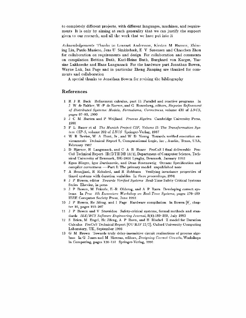
to completely di�erent projects, with di�erent languages, machines, and require-ments. It is only by aiming at such generality that we can justify the supportgiven to our research, and all the work that we have put into it.Acknowledgements. Thanks to Lennart Andersson, Kirsten M. Hansen, Zhim-ing Liu, Paulo Masiero, Jens U. Skakkeb�k, E. V. S�rensen and Chaochen Zhoufor collaboration on requirements and design. For collaboration and commentson compilation Bettina Buth, Karl-Heinz Buth, Burghard von Karger, Yas-sine Lakhneche and Hans Langmaack. For the hardware part Jonathan Bowen,Wayne Luk, Ian Page and in particular Zheng Jianping are thanked for com-ments and collaboration.A special thanks to Jonathan Bowen for revising the bibliography.References1. R. J. R. Back. Re�nement calculus, part II: Parallel and reactive programs. InJ. W. de Bakker, W.-P. de Roever, and G. Rozenberg, editors, Stepwise Re�nementof Distributed Systems: Models, Formalisms, Correctness, volume 430 of LNCS,pages 67{93, 1990.2. J. C. M. Baeten and P. Weijland. Process Algebra. Cambridge University Press,1980.3. F. L. Bauer et al. The Munich Project CIP, Volume II: The Transformation Sys-tem CIP-S, volume 292 of LNCS. Springer-Verlag, 1987.4. W. R. Bevier, W. A. Hunt, Jr., and W. D. Young. Towards veri�ed execution en-vironments. Technical Report 5, Computational Logic, Inc., Austin, Texas, USA,February 1987.5. D. Bj�rner, H. Langmaack, and C. A. R. Hoare. ProCoS I �nal deliverable. Pro-CoS Technical Report [ID/DTH DB 13/1], Department of Computer Science, Tech-nical University of Denmark, DK-2800 Lyngby, Denmark, January 1993.6. Egon B�orger, Igor Durdanovic, and Dean Rosenzweig. Occam: Speci�cation andcompiler correctness | Part I: The primary model. unpublished note.7. A. Bouajjani, R. Echahed, and R. Robbana. Verifying invariance properties oftimed systems with duration variables. In these proceedings, 1994.8. J. P. Bowen, editor. Towards Veri�ed Systems. Real-Time Safety Critical SystemsSeries. Elsevier, in press.9. J. P. Bowen, M. Fr�anzle, E.-R. Olderog, and A. P. Ravn. Developing correct sys-tems. In Proc. 5th Euromicro Workshop on Real-Time Systems, pages 176{189.IEEE Computer Society Press, June 1993.10. J. P. Bowen, He Jifeng, and I. Page. Hardware compilation. In Bowen [8], chap-ter 10, pages 193{207.11. J. P. Bowen and V. Stavridou. Safety-critical systems, formal methods and stan-dards. IEE/BCS Software Engineering Journal, 8(4):189{209, July 1993.12. S. Brien, M. Engel, He Jifeng, A. P. Ravn, and H. Rischel. Z model for DurationCalculus. ProCoS Technical Report [OU HJF 12/2], Oxford University ComputingLaboratory, UK, September 1993.13. G. M. Brown. Towards truly delay-insensitive circuit realizations of process alge-bras. In G. Jones and M. Sheeran, editors, Designing Correct Circuits, Workshopsin Computing, pages 120{131. Springer-Verlag, 1991.

14. M. Broy. Speci�cation and top-down design of distributed systems. J. Comput.System Sci., 34:236{265, 1987.15. R. H. Campbell and A. N. Habermann. The speci�cation of process synchroni-sation by path expressions. In E. Gelenbe and C. Kaiser, editors, Operating Sys-tems, International Symposium, Rocquencourt 1974, volume 16 of LNCS. Springer-Verlag, 1974.16. K. M. Chandy and J. Misra. Parallel Program Design: A Foundation. Addison-Wesley, 1988.17. M. Engel et al. A formal approach to computer systems requirements documenta-tion. In R. L. Grossman, A. Nerode, A. P. Ravn, and H. Rischel, editors, HybridSystems, volume 736 of LNCS, pages 452{474, 1993.18. M. Fr�anzle and M. M�uller-Olm. Towards provably correct code generation for ahard real-time programming language. In P. A. Fritzson, editor, Compiler Con-struction '94, 5th International Conference, Edinburgh, UK, volume 786 of LNCS,pages 294{308, 1994.19. M. Fr�anzle and B. von Karger. Proposal for a programming language core for Pro-CoS II. ProCoS Technical Report [Kiel MF 11/3], Christian-Albrechts-Universit�atKiel, Germany, August 1993.20. C. Ghezzi, D. Mandrioli, and A. Morzenti. TRIO: A logic language for executablespeci�cations of real-time systems. Journal of Systems and Software, May 1990.21. D. I. Good and W. D. Young. Mathematical methods for digital system devel-opment. In S. Prehn and W. J. Toetenel, editors, VDM '91, Formal SoftwareDevelopment Methods: Volume 2, volume 552 of LNCS, pages 406{430, 1991.22. M. R. Hansen and Zhou Chaochen. Semantics and completeness of the DurationCalculus. In J. W. de Bakker, K. Huizing, W.-P. de Roever, and G. Rozenberg,editors, Real-Time: Theory in Practice, volume 600 of LNCS, pages 209{225, 1992.23. D. Harel. Statecharts: A visual formalism for complex systems. Science of Com-puter Programming, 8:231{274, 1987.24. He Jifeng and J. P. Bowen. Time interval semantics and implementation of areal-time programming language. In Proc. 4th Euromicro Workshop on Real-TimeSystems, pages 110{115. IEEE Computer Society Press, 1992.25. He Jifeng, I. Page, and J. P. Bowen. Towards a provably correct hardware im-plementation of Occam. In G. J. Milne and L. Pierre, editors, Correct HardwareDesign and Veri�cation Methods, volume 683 of LNCS, pages 214{225. Springer-Verlag, 1993.26. C. A. R. Hoare. Communicating Sequential Processes. Prentice Hall InternationalSeries in Computer Science, 1985.27. C. A. R. Hoare. Re�nement algebra proves correctness of compiling speci�cations.In C. C. Morgan and J. C. P. Woodcock, editors, 3rd Re�nementWorkshop, Work-shops in Computer Science, pages 33{48. Springer-Verlag, 1991.28. C. A. R. Hoare, I. J. Hayes, He Jifeng, C. C. Morgan, A. W. Roscoe, J. W. Sanders,I. H. S�rensen, J. M. Spivey, and B. A. Sufrin. Laws of programming. Communi-cations of the ACM, 30(8):672{687, 1987.29. C. A. R. Hoare, He Jifeng, and A. Sampaio. Normal form approach to compilerdesign. Acta Informatica, 30:701{739, 1993.30. J. Hooman and J. Widom. A temporal-logic based compositional proof system forreal-time message passing. In PARLE '89, Parallel Architectures and LanguagesEurope: Volume II, volume 366 of LNCS, pages 424{441. Springer, 1989.31. R. Inal. Modular speci�cation of real-time systems. In Proc. 6th Euromicro Work-shop on Real-Time Systems, pages 16{21. IEEE Computer Society Press, 1994.

32. INMOS Limited. Occam 2 Reference Manual. Prentice Hall, 1988.33. INMOS limited. Transputer Instruction Set: A Compiler Writer's Guide. PrenticeHall, �rst edition, 1988.34. M. S. Ja�e, N. G. Leveson, M. P. Heimdahl, and B. E. Melhart. Software require-ments analysis for real-time process-control systems. IEEE Trans. Software Engi-neering, 17(3):241{258, March 1991.35. J. J. Joyce. Totally veri�ed systems: Linking veri�ed software to veri�ed hard-ware. In M. Leeser and G. Brown, editors, Hardware Speci�cation, Veri�cationand Synthesis: Mathematical Aspects, volume 408 of LNCS, pages 277{201, 1990.36. R. Koymans. Specifying real-time properties with metric temporal logic. Real-Time Systems, 2(4):255{299, November 1990.37. B. Krieg-Br�uckner. Algebraic speci�cation and functionals for transformationalprogram and meta program development. In J. Diaz and F. Orejas, editors, Proc.TAPSOFT '89: Volume 2, volume 352 of LNCS, 1989.38. L. Lamport. The temporal logic of actions. Technical report, Digital Systems Re-search Center, 130 Lytton Avenue, Palo Alto, California 94301, USA, 25 December1991.39. L. Lamport. Hybrid systems in TLA+. In R. L. Grossman, A. Nerode, A. P. Ravn,and H. Rischel, editors, Hybrid Systems, volume 736 of LNCS, pages 77{102, 1993.40. N. Leveson. Software safety in embedded computer systems. Communications ofthe ACM, 34(2):34{46, February 1991.41. N. A. Lynch and M. R. Tuttle. Hierarchical correctness proofs for distributedalgorithms. In Proc. 6th PODC, pages 137{151, 1987.42. Z. Manna and A. Pnueli. The Temporal Logic of Reactive and Concurrent Systems.Springer-Verlag, 1992.43. A. J. Martin. The design of a delay-insensitive microprocessor: An example ofcircuit synthesis by program transformation. In M. Leeser and G. Brown, editors,Hardware Speci�cation, Veri�cation and Synthesis: Mathematical Aspects, volume408 of LNCS, pages 244{259, 1990.44. A. J. Martin. Programming in VLSI: From communicating processes into delay-insensitive circuits. In C. A. R. Hoare, editor, Developments in Concurrency andCommunication, University of Texas at Austin Year of Programming Series, chap-ter 1. Addison-Wesley, 1990.45. P. C. Masiero, A. P. Ravn, and H. Rischel. Re�nement of real-time speci�cations.ProCoS Technical Report [ID/DTH PCM 1/1], Department of Computer Science,Technical University of Denmark, DK-2800 Lyngby, Denmark, July 1993.46. D. May. Occam and the Transputer. In C. A. R. Hoare, editor, Developments inConcurrency and Communication, University of Texas at Austin Year of Program-ming Series, chapter 2. Addison-Wesley, 1990.47. J. McCarthy and J. Painter. Correctness of a compiler for arithmetic expressions.In J. Schwarz, editor, Proc. Symp. Applied Mathematics, pages 33{41. AmericanMathematical Society, 1967.48. R. Milner. Communication and Concurrency. Prentice Hall International Seriesin Computer Science, 1989.49. Robin Milner, Mads Tofte, and Robert Harper. The De�nition of Standard ML.The MIT Press, 1990.50. C. C. Morgan. Data re�nement by miracles. Information Processing Letters,26:243{246, 1988.51. C. C. Morgan. Programming From Speci�cations. Prentice Hall International Se-ries in Computer Science, 1990.
52. F. Lockwood Morris. Advice on structuring compilers and proving them correct.In Proc. ACM Symp. Principles of Programming Languages, Boston, Mass., pages144{152, 1973.53. B. Moszkowski. A temporal logic for multi-level reasoning about hardware. IEEEComputer, 18(2):10{19, 1985.54. B. Moszkowski. Executing Temporal Logic Programs. Cambridge University Press,1986.55. M. M�uller-Olm. On translation of TimedPL and capture of machine instruc-tion timing. ProCoS Technical Report [Kiel MMO 6/2], Christian-Albrechts-Universit�at Kiel, Germany, August 1993.56. Markus M�uller-Olm. A new proposal for TimedPL's semantics. ProCoS TechnicalReport Kiel MMO 10/1, Christian-Albrechts-Universit�at Kiel, Germany, May 1994.57. E.-R. Olderog. Nets, Terms and Formulas. Cambridge University Press, 1991.58. E.-R. Olderog. Towards a design calculus for communicating programs. In J. C. M.Baeten and J. F. Groote, editors, Proc. CONCUR '91, volume 527 of LNCS, pages61{72, 1991.59. E.-R. Olderog. Interfaces between languages for communicating systems. InW. Kuich, editor, Automata, Languages and Programming, volume 623 of LNCS,1992.60. E.-R. Olderog and S. R�ossig. A case study in transformational design of concurrentsystems. In M.-C. Gaudel and J.-P. Jouannaud, editors, TAPSOFT '93: Theoryand Practice of Software Development, volume 668 of LNCS, pages 90{104, 1993.61. E.-R. Olderog, S. R�ossig, J. Sander, and M. Schenke. ProCoS at Oldenburg: Theinterface between speci�cation language and Occam-like programming language.Technical Report Bericht 3/92, Univ. Oldenburg, Fachbereich Informatik, Ger-many, 1992.62. I. Page and W. Luk. Compiling Occam into �eld programmable gate arrays. InFPGAs, Oxford Workshop on Field Programmable Logic and Applications, pages271{284, 15 Harcourt Way, Abingdon OX14 1NV, UK, 1991. Abingdon EE&CSBooks.63. D. L. Parnas and P. C. Clements. A rational design process: How and why to fakeit. IEEE Trans. Software Engineering, 12(2):251{257, February 1986.64. D. L. Parnas and J. Madey. Functional documentation for computer systems en-gineering (version 2). Technical Report CRL 237, TRIO, McMaster University,Hamilton, Canada, September 1991.65. A. Pnueli and E. Harel. Applications of temporal logic to the speci�cation ofreal-time systems (extended abstract). In M. Joseph, editor, Formal Techniquesin Real-Time and Fault-Tolerant Systems, volume 331 of LNCS, pages 84{98.Springer, 1988.66. A. P. Ravn and H. Rischel. Requirements capture for embedded real-time systems.In Proc. IMACS-MCTS'91 Symp. on Modelling and Control of Technological Sys-tems, volume 2, pages 147{152. IMACS, May 1991.67. A. P. Ravn, H. Rischel, and K. M. Hansen. Specifying and verifying requirementsof real-time systems. IEEE Trans. Software Engineering, 19(1):41{55, January1993.68. A. W. Roscoe and C. A. R. Hoare. Laws of Occam programming. TheoreticalComputer Science, 60:177{229, 1988.69. S. R�ossig and M. Schenke. Speci�cation and stepwise development of communicat-ing systems. In S. Prehn and W. J. Toetenel, editors, VDM '91, Formal SoftwareDevelopment Methods: Volume 1, volume 551 of LNCS, pages 149{163, 1991.

70. M. Schenke. Speci�cation and transformation of reactive systems with time re-strictions and concurrency. In these proceedings, 1994.71. J. U. Skakkeb�k, A. P. Ravn, H. Rischel, and Zhou Chaochen. Speci�cation ofembedded, real-time systems. In Proc. 4th Euromicro Workshop on Real-TimeSystems, pages 116{121. IEEE Computer Society Press, 1992.72. J. U. Skakkeb�k and N. Shankar. Towards a Duration Calculus proof assistant inPVS. In these proceedings, 1994.73. J. M. Spivey. The Z Notation: A Reference Manual. Prentice Hall InternationalSeries in Computer Science, 2nd edition, 1992.74. J. W. Thatcher, E. G. Wagner, and J. B. Wright. More on advice on structuringcompilers and proving them correct. Theoretical Computer Science, 15:223{245,1981.75. Y. Venema. A modal logic for chopping intervals. J. Logic of Computation,1(4):453{476, 1991.76. A. Wikstr�om. Functional Programming using Standard ML. Prentice Hall Inter-national Series in Computer Science, �rst edition, 1987.77. M. W. Wilkes and J. B. Stringer. Micro-programming and the design of the controlcircuits in an electronic digital computer. Proc. Cambridge Phil. Soc., 49:230{238,1953. also Annals of Hist. Comp. 8, 2 (1986) 121{126.78. Xilinx Inc. The programmable gate array data book. Technical report, Xilinx Inc.,San Jose, California, USA, 1991.79. Zhiming Liu, A. P. Ravn, E. V. S�rensen, and Zhou Chaochen. Towards a calculusof systems dependability. High Integrity Systems, 1(1):49{75, January 1994.80. Zhou Chaochen. Duration Calculi: An overview. In D. Bj�rner, M. Broy, and I. V.Pottosin, editors, Formal Methods in Programming and their Application, volume735 of LNCS, pages 256{266, 1993.81. Zhou Chaochen, M. R. Hansen, and P. Sestoft. Decidability results for DurationCalculus. In P. Enjalbert, A. Finkel, and K. W. Wagner, editors, Proc. STACS 93,volume 665 of LNCS, pages 58{68, 1993.82. Zhou Chaochen, C. A. R. Hoare, and A. P. Ravn. A calculus of durations. Infor-mation Processing Letters, 40(5), December 1991.83. Zhou Chaochen, A. P. Ravn, and M. R. Hansen. An extended Duration Calculusfor hybrid real-time systems. In R. L. Grossman, A. Nerode, A. P. Ravn, andH. Rischel, editors, Hybrid Systems, volume 736 of LNCS, pages 36{59, 1993.84. J. Zwiers. Compositionality,Concurrency, and Partial Correctness: Proof Theoriesfor Networks of Processes and their Relationship, volume 321 of LNCS. Springer-Verlag, 1989.