prosthetics socket that incorporates an air splint system focusing on dynamic interface pressure
TRANSCRIPT

Razak et al. BioMedical Engineering OnLine 2014, 13:108http://www.biomedical-engineering-online.com/content/13/1/108
RESEARCH Open Access
Prosthetics socket that incorporates an air splintsystem focusing on dynamic interface pressureNasrul Anuar Abd Razak*, Noor Azuan Abu Osman, Hossein Gholizadeh and Sadeeq Ali
* Correspondence:[email protected] of BiomedicalEngineering, Faculty of Engineering,University of Malaya, 50603 KualaLumpur, Malaysia
Abstract
Background: The interface pressure between the residual limb and prosthetic sockethas a significant effect on an amputee’s satisfaction and comfort. This paper presentsthe design and performance of a new prosthetic socket that uses an air splintsystem.
Methods: The air splint prosthetic socket system was implemented by combiningthe air splint with a pressure sensor that the transhumeral user controls through theuse of a microcontroller. The modular construction of the system developed allowsthe FSR pressure sensors that are placed inside the air splint socket to determine therequired size and fitting for the socket used. Fifteen transhumeral amputeesparticipated in the study.
Results: The subject’s dynamic pressure on the socket that’s applied while wearingthe air splint systems was recorded using F-socket transducers and microcontrolleranalysis. The values collected by the F-socket sensor for the air splint prostheticsocket system were determined accordingly by comparing the dynamic pressureapplied using statically socket. The pressure volume of the air splint fluctuated andwas recorded at an average of 38 kPa (2.5) to 41 kPa (1.3) over three hours.
Conclusion: The air splint socket might reduce the pressure within the interface ofresidual limb. This is particularly important during the daily life activities and mayreduce the pain and discomfort at the residual limb in comparison to the staticsocket. The potential development of an auto-adjusted socket that uses an air splintsystem as the prosthetic socket will be of interest to researchers involved inrehabilitation engineering, prosthetics and orthotics.
BackgroundIt is generally widely known and accepted between amputees and prosthetists that a
poor socket fit will entail that the stump loses volume on a daily basis [1]. The ampu-
tee’s socket interface plays a major role in defining the comfort level of the user. The
method by which the socket is attached to the residual limb is extremely important
[2]. Upper-extremity prostheses socket must be suspended throughout the entire range
of motion as well as being able to tolerate loading during normal use [3].
From a clinical point of view, amputees need to undergo pre-post prosthetic proce-
dures before they are provided with a permanent prosthesis socket [4]. From time to
time this rehabilitation involves changes in the socket and ongoing consultation with
Certify Prosthetics and Orthotics (CPOs) [4]. The amputation site has a certain volume
and shape to begin with, but changes occur as the body heals and reaches a kind
© 2014 Razak et al.; licensee BioMed Central Ltd. This is an Open Access article distributed under the terms of the Creative CommonsAttribution License (http://creativecommons.org/licenses/by/4.0), which permits unrestricted use, distribution, and reproduction inany medium, provided the original work is properly credited. The Creative Commons Public Domain Dedication waiver (http://creativecommons.org/publicdomain/zero/1.0/) applies to the data made available in this article, unless otherwise stated.
Razak et al. BioMedical Engineering OnLine 2014, 13:108 Page 2 of 13http://www.biomedical-engineering-online.com/content/13/1/108
stability. Furthermore, the amputees may need to change the socket in response to
changes in body weight or alterations to the structure of the residual limb [1,4,5].
Among the different types of prosthetic socket that can be implemented, are the har-
ness socket [6,7], self suspending technique [8,9], and silicon liners [10], all of which
utilize hybrid material engineering technologies within a prosthetic device. Socket ma-
terials and fabrication have changed over the years from leather and wood, to rigid
polyester laminates, to flexible thermoplastics, and composite reinforced frames [2,11].
The static socket, which was normally fabricated and custom made by referring to guide-
lines from the International Committee of the Red Cross (ICRC) [12]. The ICRC preferred
to develop its own technique instead of buying ready-made orthopaedic components,
which are generally too expensive and unsuited to the contexts in which the organization
works. The cost of the materials used in static socket devices is lower than that of the ma-
terials used in appliances assembled from commercial ready-made components [13].
The process of socket making involves; casting, polypropylene draping, assemble and
shaping. The casting, rectification and alignment methods used to correspond to inter-
national prosthetic and orthotic (P&O) standards of practice and are therefore not de-
scribed in the ICRC manufacturing guidelines. The measurement process involves
several tools such as length calliper, universal anterior-posterior-medial-lateral calliper,
standard tape, spring tape, circumferential tape, and weight scale which need to be ac-
curately measured.
In this study, we examine the interface pressure at the socket interface. Either this
finding could determine the comfort level or not is a subjective matters, but somehow,
the interface pressure could related on why some amputees not comfortable and feel
pain using the static socket [14]. However it could be related with the structure and
weight of the residual limb. In a study by John M. Miguelez et al. [15], the authors did
mention the relationship between the bones and residual contact with the socket sur-
face whenever the load is applied. The Transradial Anatomically Contoured (TRAC)
interface incorporates design elements from both the Muenster and Northwestern in-
terfaces with more aggressive contouring of the anatomy to maximize load tolerant
areas of the residual limb, as demonstrated by the radiologic analysis. In the medial/
lateral plane, the interface focuses the compression anterior and slightly inferior to the
epicondyles, specifically on the radial head on the lateral aspect. In addition, on the an-
terior/posterior plane, suspension is achieved by precisely directed compression into
the cubital fold and supra-olecranon region.
The weight of the prosthetics also contributed to the impact of the pressure. Increas-
ing the weight, which would increase the force applied, would increase the pressure. Al-
though the study by Robert J. Dodson and Bridget Jowid [16], not formally studied,
clinical observation has shown that people wearing static socket that incorporates a
custom silicone interface gain greater range of motion at the elbow and wrist, report
increased comfort and better tolerances of the aggressive socket design, and experience
greater protection of fragile skin. A recent case study within the clinical setting high-
lights the positive effects of a custom silicone interface of a chronic wound and pro-
vides real observation of the benefits that the addition of this material to the prosthetic
design can have on this patient population. Again, the research did mention about the
comfort of socket design, but it is just in a feedback response of the user instead of ex-
perimental evidence such as interface pressure applied at the socket.
Razak et al. BioMedical Engineering OnLine 2014, 13:108 Page 3 of 13http://www.biomedical-engineering-online.com/content/13/1/108
Although a few devices and techniques for socket interface have been discussed in
existing literature [14,17], no researchers has previously examined the interface pres-
sure of a biomechatronics system that incorporates the use of an air splint system
within the amputee’s socket. This paper presents the new development of a prosthetic
socket that implements an air splint system that can allow transhumeral users to make
adjustments that improve the comfort level, size and fit of the socket. Firstly, the paper
will discuss about condition and characteristics of commonly static socket and pre-post
prosthetic socket (Figure 1). Secondly, the paper will discuss possible methods of in-
corporating the system between the air splint and the FSR pressure sensor, and the vol-
ume of air needed to produce by the oscillometric pump to the desired fit with the
socket. Finally, the experimental performance using F-socket sensor to determine the
interface pressure of the air splint socket that counters the needed for general static
socket and pre-post prosthetic rehabilitation procedures.
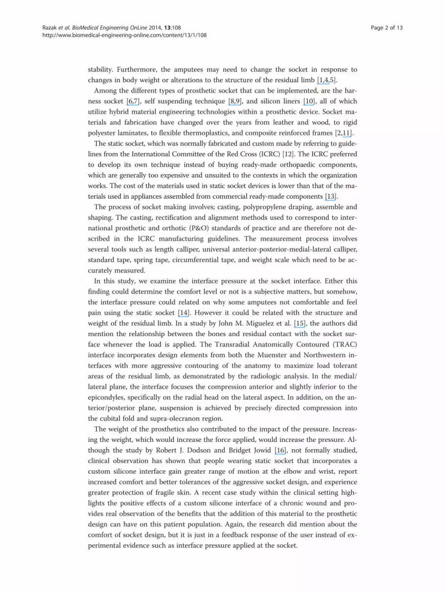
Figure 1 Flowchart of pre-post prosthetic and rehabilitation procedure [1].
Razak et al. BioMedical Engineering OnLine 2014, 13:108 Page 4 of 13http://www.biomedical-engineering-online.com/content/13/1/108
MethodsPre-post prosthetic and rehabilitation procedures are common before the amputee is
provided with a permanent prosthesis [1,4]. Generally, at the beginning, amputees are
provided with information pertaining to the expected condition and timings of the re-
habilitation procedure. After the surgery is finalized and the amputees have been for-
warded to the occupational therapists, the pre-post prosthetic process begins [1,4].
The amputees are provided with a temporary prosthesis and are required to perform
common simple tasks before proceeding with general tasks such as picking items up,
opening a door, zipping a shirt [3,8]. This procedure is required to train the remaining
muscle that is still active and allows sufficient time for the residual limb to become well
shaped, which usually takes up to 6 weeks [1,4].
The amputees are then provided with a permanent prosthesis and the rehabilitation
of common daily task activities will continue for up to six weeks. Within the period,
the amputees need to continue to perform general rehabilitation activities. It is com-
mon for amputees to revisit their therapist complaining of uncomfortable fitting within
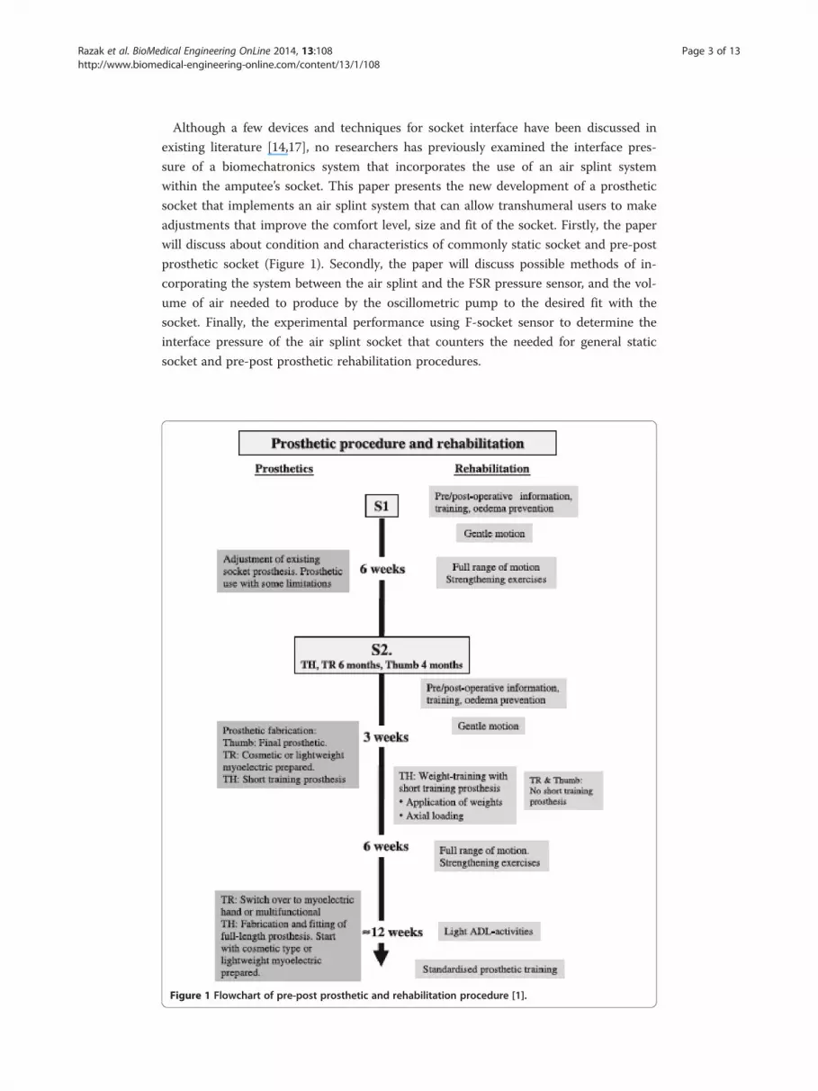
the first six to twelve months [4]. This problem usually occurs as a result of changes in
the size and condition of the residual limb, which occur as a result of increases/
decreases in the amputee’s body weight and height (Figure 2).
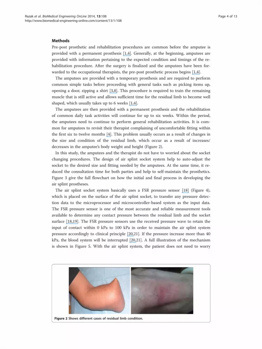
In this study, the amputees and the therapist do not have to worried about the socket
changing procedures. The design of air splint socket system help to auto-adjust the
socket to the desired size and fitting needed by the amputees. At the same time, it re-
duced the consultation time for both parties and help to self-maintain the prosthetics.
Figure 3 give the full flowchart on how the initial and final process in developing the
air splint prostheses.
The air splint socket system basically uses a FSR pressure sensor [18] (Figure 4),
which is placed on the surface of the air splint socket, to transfer any pressure detec-
tion data to the microprocessor and microcontroller-based system as the input data.
The FSR pressure sensor is one of the most accurate and reliable measurement tools
available to determine any contact pressure between the residual limb and the socket
surface [18,19]. The FSR pressure sensors use the received pressure wave to retain the
input of contact within 0 kPa to 100 kPa in order to maintain the air splint system
pressure accordingly to clinical principle [20,21]. If the pressure increase more than 40
kPa, the blood system will be interrupted [20,21]. A full illustration of the mechanism
is shown in Figure 5. With the air splint system, the patient does not need to worry
Figure 2 Shows different cases of residual limb condition.
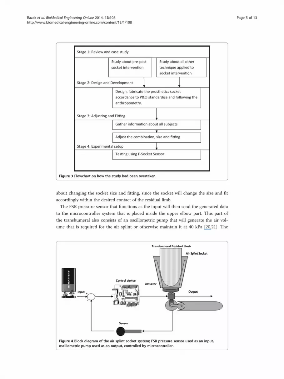
Figure 3 Flowchart on how the study had been overtaken.
Razak et al. BioMedical Engineering OnLine 2014, 13:108 Page 5 of 13http://www.biomedical-engineering-online.com/content/13/1/108
about changing the socket size and fitting, since the socket will change the size and fit
accordingly within the desired contact of the residual limb.
The FSR pressure sensor that functions as the input will then send the generated data
to the microcontroller system that is placed inside the upper elbow part. This part of
the transhumeral also consists of an oscillometric pump that will generate the air vol-
ume that is required for the air splint or otherwise maintain it at 40 kPa [20,21]. The
Figure 4 Block diagram of the air splint socket system; FSR pressure sensor used as an input,oscillometric pump used as an output, controlled by microcontroller.
Normal Size Size Decrease Size Increase
B. Horizontal cross sectional area
Pressure Mapping
Prosthetic Connection
Air Splint Socket
Electronic Components
A. Air splint testing
D. Vertical cross sectional
C. Air splint structure
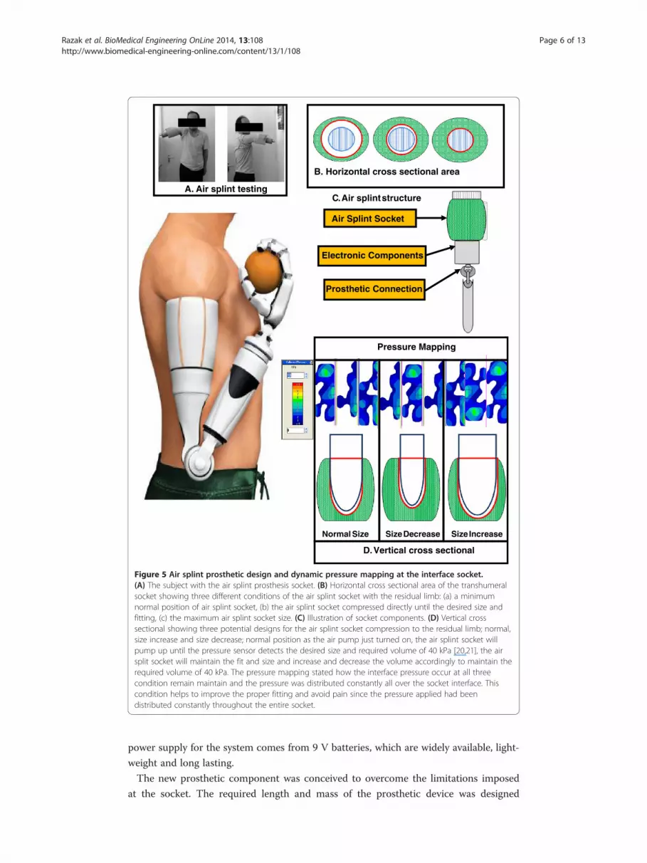
Figure 5 Air splint prosthetic design and dynamic pressure mapping at the interface socket.(A) The subject with the air splint prosthesis socket. (B) Horizontal cross sectional area of the transhumeralsocket showing three different conditions of the air splint socket with the residual limb: (a) a minimumnormal position of air splint socket, (b) the air splint socket compressed directly until the desired size andfitting, (c) the maximum air splint socket size. (C) Illustration of socket components. (D) Vertical crosssectional showing three potential designs for the air splint socket compression to the residual limb; normal,size increase and size decrease; normal position as the air pump just turned on, the air splint socket willpump up until the pressure sensor detects the desired size and required volume of 40 kPa [20,21], the airsplit socket will maintain the fit and size and increase and decrease the volume accordingly to maintain therequired volume of 40 kPa. The pressure mapping stated how the interface pressure occur at all threecondition remain maintain and the pressure was distributed constantly all over the socket interface. Thiscondition helps to improve the proper fitting and avoid pain since the pressure applied had beendistributed constantly throughout the entire socket.
Razak et al. BioMedical Engineering OnLine 2014, 13:108 Page 6 of 13http://www.biomedical-engineering-online.com/content/13/1/108
power supply for the system comes from 9 V batteries, which are widely available, light-
weight and long lasting.
The new prosthetic component was conceived to overcome the limitations imposed
at the socket. The required length and mass of the prosthetic device was designed

Razak et al. BioMedical Engineering OnLine 2014, 13:108 Page 7 of 13http://www.biomedical-engineering-online.com/content/13/1/108
according to Drill’s and Contini’s anthropometry theorem [22]. The development mech-
anism is the result of a rigorous approach, which made it possible to optimize the func-
tionality of the socket. The articulation consisted of the air splint, which replaced the
thermoplastic as the main socket part (Figure 5). The air splint incorporated a silicon
liner surface in order to provide the residual limb with increased gripping force. For
their own comfort and satisfaction, the amputees can use a stocking net or add another
silicon liner to the residual limb; this depends on the user themselves, since the air
splint socket system will adjust the size according to the required size and fitting. The
electronic parts were placed at the bottom part of the air splint socket. The microcon-
troller, the power supply and the motor controller were placed together at a convenient
joint that could be readily accessed in the event that there was a need for service or re-
boot. The socket was also fitted with an USB cable port that could allow the user to re-
start or reboot the system in the event of any problems.
The minor part of the device consisted of an oscillometric air pump. The oscillo-
metric air pump was lightweight and integrated in the upper elbow part. The weight
and size of all the devices were designed according to the exact measurements of the
normal hand [22]. This was intended to counter any advance force that was applied if
the amputee used a prosthetic hand. The current body-powered prostheses eliminate
this factor and cause a major defect to the shoulder size [6-9].
Ethics
The experimental protocol for this work was approved by the Ethical Community of
the University Malaya Medical Centre (UMMC), Kuala Lumpur Malaysia. Written in-
formed consent was granted by the participants from the authors for the publication.
Approval ID: 829:15. One registered prosthetist fabricated all the prostheses to avoid al-
terations due to manufacturing, alignment and fitting. All the procedure of socket mak-
ing and fitting involves the Certified Prosthetics and Orthotics (CPO) which had been
recognized by International Society of Prosthetics and Orthotics (ISPO).
Experimental setup
The experiment had been conducted to discover and compare the dynamic interface
pressure using static socket and air splint socket. The experimental setup used the
Tekscan F-Socket sensor (9811E). The reason of using the F-Socket was to determine
the pressure surface for its flexibility, rectangular printed, and the lowest thickness.
Tekscan pressure mapping systems and measurement systems were used in this experi-
ment to provide tactile pressure mapping and force data. The pressure mapping reacts
as an input was first calibrated by using the Tekscan bladder. The applied pressure will
then appear in the measurement system in the computer, and all related data, such as
pressure, force, and time, will be calculated. The printed circuit with a thickness just
about 0.18 mm made the sensor to easily fit in the gap between the socket and the sur-
face of the amputation level. Figure 5 shows the the F-Socket which attached to the re-
sidual limb. For the transhumeral part, only two F-Socket needed to cover almost the
entire socket surface attached to the residual limb. F-Socket sensor used the F-Scan
software to operate and be connected to the rear of the PC via 762 mm long cable and
a cuff unit (98 mm × 64 mm × 29 mm). The cable functioned as the converter of the

Razak et al. BioMedical Engineering OnLine 2014, 13:108 Page 8 of 13http://www.biomedical-engineering-online.com/content/13/1/108
analogue signal to digital signal so that the data may be read by the PC. In order to
have the most accurate and reliable results, some precautions were considered such as
by verifying all the connections were well-organised. The cable wire was tightened to
the amputee’s body part to make sure that the surface of the sensor was not disrupted.
F-socket sensor calibrations
In this study, it was noted that every time the trial was done, the sensor was not chan-
ged, nor that a calibration was made out. For the transition between the socket and the
amputation limit, the sensors that were already on the residual limb were only removed
if any of the sensors was found to be defective. Before the F-Socket was fitted with the
prostheses, the sensor was equilibrated and calibrated. The process of equilibrating the
sensor is where the whole sensor point shares the equal amount of pressure to ensure
that all 96 senses have a common output. The F-Socket was put into a pressure bladder
in order to ensure that each area on the F-Socket had the similar criteria. The sensor
was placed in the middle of the bladder and then was subjected to a pressure of 100
kPa by taking the specifications from the manufacturer.
Experimental procedure
After the process was completed, the sensor was then attached to the amputee residual
limb so that the position of the sensor was stable (Figure 6). Silicone liners were used
for both sockets, which require no reattachment when changing the socket. The sensor
was attached by using the spray adhesive, a type of strong glue. As mentioned earlier,
only two sensors were required to cover the area of the residual limb. The F-Socket at-
tached only at the part of the humerus bones that were still left. During the installation
of the F-socket to the amputee’s upper elbow, the main part was to confirm that the
humerus of the upper elbow was well-attached to each sensor. Since the amputation
part was only 40% left, the F-Socket sensor was trimmed horizontally to reduce the
length of the sensor. This step was done to accommodate the subjects with shorter
limb in order to obtain a tidier sensor placement, as well as to ensure there was no
overlapped sensor. After the stockinet was fully fitted into the residual limb, then the
socket was fitted into the stockinet. However, the position and the liner of the sensor
stability must be validated so that the data collection was not interrupted.
Figure 6 The F-socket sensor attach to the subject residual limb.
Razak et al. BioMedical Engineering OnLine 2014, 13:108 Page 9 of 13http://www.biomedical-engineering-online.com/content/13/1/108
After the amputee was comfortable with the fitting of the socket, the F-socket sensor
connects to the portable to collect some data. The value recording has a vulnerable
due to the external noise that may occur. This was due to the sensitivity of the sensor
and the dimensions that were physically thin but to be fitted into a small interface
space. Some unwanted noises usually occurred because of the bending position for the
sensor itself. There were several methods to reduce the noise distraction. The first
method is by setting up the noise reduction threshold in the Tekscan’s F-Scan. The
value was set up to level 3 so that any values or data below or at this level will be fil-
tered automatically. The second method is by removing any data that were collected
without applying the pressure to the sensor. When the F-Scan detected the presence of
any data of unmoving pressure, the data may be diminished and the calibration of the
sensor was set to zero at that level. The third way to handle this problem is by applying
individual measurement to each point of the sensor. Sometimes, one of the sensors
gave a high pressure and surrounded by lower pressure points. To make it stable, all of
the points can detect using the F-Scan and assigned to be in a level position to each
other. Therefore, the data of pressure on the interface socket can be collected precisely
and correctly.
ResultsA total of fifteen transhumeral amputees (10 males, 5 females) participated in this
study. All the subjects were selected from the University Malaya Medical Centre
(UMMC), Kuala Lumpur and Industrial Training and Rehabilitation Centre (known as
PLPP), Bangi, Malaysia. The inclusion criteria consisted of a minimum 12 cm residual
limb length (from the shoulder-transhumeral bone until end of residual limb), no
wound and ulcers in the residual limb, and the ability to flexion/extension shoulder
without the use of assistive devices. The subjects were also considered for participation
if they had used prosthesis in the last 6 months.
Even though there are many transhumeral amputees who registered to use the pros-
thetic hands, the majority of them had never completed the full rehabilitation training
and some of them did not turn up at all. The PLPP informed that most of them did
not show up because they no longer used the Body-Powered prosthetic hand due to
the limitation of motion and discomfort of the prosthetic hand’s socket [3]. The sub-
jects who participated in the study did so voluntarily and were given prior written con-
sent letter.
The participants’ demographic information is shown in Table 1. The mean age of the
subjects was (mean = 41.55, SD = 15.25). The FSR pressure sensor wave was pro-
grammed to detect any applied pressure within the range of 0–100 kPa and was placed
on the surface of the air splint socket. Any pressure contact applied between the re-
sidual limb and the air splint socket could be detected by the pressure sensor. Gener-
ally, the pressure sensor detects about 0–100 kPa range according to the way in which
the microcontroller has been programmed. The range increases immediately following
any pressure signal and will continue to increase until the range is about 100 kPa. The
air splint socket will continue to pump up until the detection reaches 100 kPa. Only
then, the air splint will stop pumping and retain the pressure volume inside the air split
at 40 kPa [20,21].

Table 1 Demographic characteristics of the participants
Gender (%) Male 10 (66.67%)
Female 5 (33.33%)
Weight (SD) 73.63 (12.5)
Height (SD) 170.62 (6.7)
Age (SD) 41.55 (15.25)
Side of amputation (%) Right 10 (66.67%)
Left 5 (33.33%)
Cause of amputation (%) Trauma 15 (100%)
A total of fifteen transhumeral amputees (10 males, 5 females) participated in this study. The mean age of the subjectswas (mean = 41.55, SD = 15.25).
Razak et al. BioMedical Engineering OnLine 2014, 13:108 Page 10 of 13http://www.biomedical-engineering-online.com/content/13/1/108
It was not possible to stabilize and maintain the pressure that was required within
the air splint socket during the average of the first three trials (Table 2). The pressure
volume of the air splint fluctuated and was recorded at an average of 38 kPa (2.5) to 41
kPa (1.3) over three hours. The pressure of holding the socket to the residual limb
should have been retained at 40 kPa by considering the skin and blood flow through
the limb [20,21]. Maintaining a good fit is difficult with the total surface bearing socket
because the pressure that provides a good fit causes daily volume loss in the stump [1].
For the first three hours, the contact between the skin and the socket did not stabilize
(1st hour; Average Pressure sensor: 101 kPa (10.3), Average Air Splint: 38 kPa (2.5), 2nd
hour; Average Pressure sensor: 105 kPa (14.5), Average Air Splint: 41 kPa (4.2), 3rd
hour; Average Pressure sensor: 107 kPa (15.6), Average Air Splint: 41 kPa (1.3)); however,
after that period the pressure volume of the air splint was retained at 40 kPa per hours.
DiscussionIn order for the air splint socket to maintain the pressure of 40 kPa [20,21], the pres-
sure sensor was set up to detect any signal between the range of 0–100 kPa. If the sys-
tem achieved a signal more that 100 kPa, the input data would be sent to the
microcontroller to stop pumping the air split and maintain the volume of air. This sen-
sor played a major part in defining the comfort level of the socket. As with the first
three hours, the pressure sensor kept changing in the range of 101 kPa (10.3)-107 kPa
(15.6. The results were directly proportional to the air splint socket results changing, as
Table 2 Average pressure required within the air splint socket
Time (hour) Average FSR pressure sensor, kPa (SD) Average air splint, kPa (SD)
1 101 (10.3) 38 (2.5)
2 105 (14.5) 41 (4.2)
3 107 (15.6) 41 (1.3)
4 107 (23.4) 40 (2.9)
5 111 (7.8) 40 (5.8)
6 112 (5.6) 40 (3.3)
7 112 (4.7) 40 (2.8)
(N = 15). For the first three hours, the contact between the skin and the socket did not stabilize (1st hour; Average FSRPressure sensor: 101kPa (10.3), Average Air Splint: 38 kPa (2.5), 2nd hour; Average FSR Pressure sensor: 105 kPa (14.5),Average Air Splint: 41 kPa (4.2), 3rd hour; Average FSR Pressure sensor: 107 kPa (15.6), Average Air Splint: 41 kPa (1.3);however, after that period the pressure volume of the air splint was retained at 40 kPa per hours.
Razak et al. BioMedical Engineering OnLine 2014, 13:108 Page 11 of 13http://www.biomedical-engineering-online.com/content/13/1/108
the stabilizer of the residual limb size and the socket still changed accordingly. Under
the normal condition, the limb lost an average of 6.5% of its volume while doing daily
life activities [1,4]. This daily volume loss occurred as a result of pressure and shear be-
tween the limb and socket [23].
The volume and condition of the residual limb plays a major part in determining the
socket installation [5]. The volume of the residual limb, the bones that are left and the
muscle condition play an important role in determining the type of prosthesis that
should be worn by the amputee. The pre-post prosthetic user usually considers the best
volume and condition of the amputated level [1]. Currently osseintegration, or the
process of rehealing the bones, plays a major part if the condition of the residual limb
does not meet the desired measurements to wear the prosthesis4. When an extremity
of the body is amputated, a cascade of events takes place that impacts the already un-
stable system. The muscles, nerves, bones and scar tissue will not behave in the same
way as they did before and even the osseintegration can not eliminate this matter
[1,4,5]. After therapy, amputees might still experience pain in their residual limb as a
result of neuromas and scar tissue and this can make wearing the prosthesis uncom-
fortable [15,16]. However, with the air splint socket system, as long as there is sufficient
residual limb to wear the socket, the amputee’s comfort level will increase, regardless of
the scar, muscle or bone condition.
Only a small adjustment is required via the microcontroller in the event that there
are problems regards the system, otherwise the socket maintains flexibility and accu-
rateness automatically. In cases where the residual limb reduced in size, the patients re-
ported discomfort and swelling [6-9,15,16]. These problems would be expected in all
kinds of prosthetic socket including silicon liners [10] and suction sockets [24]. These
problems were corrected by using air splint socket that flexibly auto-adjusts the size of
the socket according to the condition of the limb. The surface of the air splint socket
incorporates silicone liners and the user can also use these together with stocking liners
if they wish to eliminate the swelling problem.
In comparison to the other type of prosthesis [5-10], the harness socket can create
discomfort, frustration, or difficulty in donning, restriction in range of motion [3], and
contralateral brachial plexus pressure, which can potentially lead to deviate wearing the
prosthetic. In externally powered prosthesis, without the socks, more aggressive ana-
tomical contouring of the socket is needed to provide stability and control.
Other factors that can impact the socket size are control diet, hydration and activity
levels [25]. Hence inappropriate diet and hydration may increase or decrease the body
weight and length, which will directly change the size that is most suitable for the pros-
thetic. Volume loss of the residual limb ranges from 4 to 10%, with approximately 90%
of this loss occurring within the first two hours of the workday [26]. This shows how
the relationship between changes in socket and the rehabilitation needs to maintained
on an hourly basis. Frequent changes to the socket might be too expensive to be viable
and consultation with the rehabilitation unit may not be easy to maintain on a regular
basis; almost 80% of prosthesis users do not attend appointments and are lost to
follow-up [27]. However, the air splint socket system eliminates most of the problems
that need to be considered. As long as the socket is well bonded with the amputee’s
residual limb, it will maintain the desired size and fit, even when the amputee engages
in daily life activities. No matter how sophisticated the device, if the patient feels

Razak et al. BioMedical Engineering OnLine 2014, 13:108 Page 12 of 13http://www.biomedical-engineering-online.com/content/13/1/108
uncomfortable and cannot control the placement of the terminal device, the result will
be the rejection of the prosthesis.
ConclusionThis paper presented the design and development of a new technique that uses the air
splint system as a prosthetic socket replacement. Proper socket fit is crucial to the
comfort of the amputee, the health of the skin and the performance of the prosthesis.
The design size and measurement depends on the weight and size of each sensor, actu-
ator and microcontroller that is incorporated in the prosthetic hand. By using a com-
bination of a pressure sensor and an air splint system, this proposed device may
overcome the problem of pre-post prosthetic rehabilitation procedure, reduce the
CPOs consultation requirements and overcome the need to change the socket. The
intelligence of the air splint socket system works to automatically adjust the size and fit
of the socket needed. Maintaining a good fit is the main objective of the air splint
socket system. However, this system cannot be applied to amputees that have a low vol-
ume, short residual limb; although this problem can be resolved by performing osseio-
tegration surgery on the remaining bones.
Competing interestThe authors declare that they have no competing interest.
Authors’ contributionsNAAR and HG designed the system and the protocol, fabricated the prostheses, conducted the experiments, collectedand analysed the data, discussed the results and drafted the manuscript. NAA0 supervised the overall project, andhelped in revising the manuscript. SA collected and analysed the data, discussed the results, wrote a part of themanuscript and helped in prosthetic fabrication. All the authors read reviewed the manuscript. All authors read andapproved the final manuscript.
AcknowledgmentsThis study was supported by the Malaysia UM/MOHE/HIR (project number: D000014-16001).
Received: 27 June 2014 Accepted: 22 July 2014Published: 1 August 2014
References
1. Jönsson S, Caine-Winterberger K, Brånemark R: Osseointegration amputation prostheses on the upper limbs:methods, prosthetics and rehabilitation. Prosthetics Orthot Int 2011, 35:190–200.2. Alley RD, Williams TW III, Albuquerque MJ, Altobelli DE: Prosthetic sockets stabilized by alternating areas of
compression and release. J Rehabil Res Dev 2011, 48:679–696.3. Brenner CD, Joseph KB: The use of preparatory/evaluation/training prostheses in developing evidenced-based
practice in upper limb prosthetics. J Prosthet Orthot 2008, 20(3):70–82.4. Antfolk C, Balkenius C, Rosén B, Lundborg G, Sebelius F: SmartHand tactile display: a new concept for providing
sensory feedback in hand prostheses. J Plast Surg Hand Surg 2010, 44:50–53.5. Meier R, Atkins D: Functional Restoration of Adults and Children with Upper Extremity Amputation. Res Trends
for the Twenty-First Century 30, 30:353–360.6. Troncossi M, Gruppioni E, Chiossi M, Cutti AG, Davalli A: A novel electromechanical shoulder articulation for
upper-limb prostheses: from the design to the first clinical application. J Prosthet Orthot 2009, 21:79–90.7. Khanra D, Sudesh S: Below elbow upper limb prosthetic for amputees and paralyzed patients. J Comp Appl
2011, 16:5.8. Thomas AJ: Transhumeral and elbow disarticulation anatomically contoured socket considerations. J Prosthet
Orthot 2008, 20(3):107–117.9. Brenner R, Meucci MR, Lieberman-Klinger S, Fantini C, Kelty DL, Disla R, Sasson N: Advanced upper limb
prosthetic devices: implications for upper limb prosthetic rehabilitation. Arch Phys Med Rehabil 2012, 93:710–717.10. Hanson WJ: Conductive inserts to acquire myoelectric signals through silicone liners, Proceedings of the MyoElectric
Controls/Powered Prosthetics Symposium. New Brunswick, Canada: 2008.11. Biddiss EA, Chau TT: Upper limb prosthesis use and abandonment: a survey of the last 25 years. Prosthet
Orthot Int 2007, 31:236–257.12. O’Connell C, Ingersoll A: Upper limb prosthetic services post Haiti earthquake: experiences and
recommendations of Haiti-based rehabilitation program. J Prosthet Orthot 2012, 24:77–79.13. Ikeda AJ, Grabowski AM, Lindsley A, Sadeghi-Demneh E, Reisinger KD: A scoping literature review of the
provision of orthoses and prostheses in resource-limited environments 2000–2010. Part one: considerationsfor success. Prosthetics Orthot Int 2013, 0309364613500690.
Razak et al. BioMedical Engineering OnLine 2014, 13:108 Page 13 of 13http://www.biomedical-engineering-online.com/content/13/1/108
14. Razak NA A, Abu Osman NA: Comparison study of the transradial prosthetics and body powered prostheticsusing pressure distribution approach. In 5th Kuala Lumpur International Conference on Biomedical Engineering 2011.Berlin Heidelberg: Springer; 2011:743–746.
15. Miguelez JM, Lake C, Conyers D, Zenie J: The transradial anatomically contoured (TRAC) interface: designprinciples and methodology. J Prosthet Orthot 2003, 15:148–157.
16. Dodson RJ, Jowid B: The clinical application of an upper limb custom silicone interface: observations of a casestudy. J Prosthet Orthot 2009, 21:120–124.
17. Daly W, Liming V, Teri Rosenbaum C, David W, David B: Skin-socket interface pressure of an upper limbprosthesis: preliminary findings. J Prosthet Orthot 2010.
18. Li N, Yang D, Jiang L, Liu H, Cai H: Combined use of FSR sensor array and SVM classifier for finger motionrecognition based on pressure distribution map. J Bionic Eng 2012, 9:39–47.
19. Abd Razak NA, Abu Osman NA, Wan Abas WAB: Development of an alternative cuff oscillometric socket system: apreliminary study, Proceedings of the Asean Prosthetics and Orthotics Scientific Meeting (APOSM). Kobe, Japan:2012.
20. Pinheiro EC: Oscillometric blood pressure monitor modeling, Engineering in Medicine and Biology Society, 2008, EMBS2008. 30th Annual International Conference of the IEEE. 2008.
21. Amoore JN: Can simulators evaluate systematic differences between oscillometric non-invasive blood-pressure monitors? Blood Pressure Monitoring 2000, 5:81–89.
22. Drillis R, Contini R, M. M. E. Maurice Bluestein: Body segment parameters. Artificial limbs 1964, 8(1):44–66.23. Abu Osman NA, Spence WD, Solomonidis SE, Paul JP, Weir AM: Transducers for the determination of the
pressure and shear stress distribution at the stump—socket interface of trans-tibial amputees. Proc. IMechE,Part B: J. Engineering Manufacture 2010, 224:1239–1250.
24. Board WJ, Street GM, Caspers C: A comparison of trans-tibial amputee suction and vacuum socket conditions.Prosthet Orthot Int 2001, 25:202–209.
25. Kooijman CM, Dijkstra PU, Geertzen JH, Elzinga A, van der Schans CP: Phantom pain and phantom sensations inupper limb amputees: an epidemiological study. Pain 2000, 87:33–41.
26. Beil TL, Street GM, Covey SJ: Interface pressures during ambulation using suction and vacuum-assistedprosthetic sockets. J Rehabil Res Dev 2002, 39:693–700.
27. Abd Razak NA, Abu Osman NA, Wan Abas WAB: Kinematic comparison of the wrist movements that arepossible with a biomechatronics wrist prosthesis and a body-powered prosthesis. Disabil Rehab Assist Tech2012, 8:255–260.
doi:10.1186/1475-925X-13-108Cite this article as: Razak et al.: Prosthetics socket that incorporates an air splint system focusing on dynamicinterface pressure. BioMedical Engineering OnLine 2014 13:108.
Submit your next manuscript to BioMed Centraland take full advantage of:
• Convenient online submission
• Thorough peer review
• No space constraints or color figure charges
• Immediate publication on acceptance
• Inclusion in PubMed, CAS, Scopus and Google Scholar
• Research which is freely available for redistribution
Submit your manuscript at www.biomedcentral.com/submit