proline cubemass c 100 hart - instrumart
TRANSCRIPT
Products Solutions Services
Operating InstructionsProline Cubemass C 100HARTCoriolis flowmeter
BA01188D/06/EN/02.1471254046
Valid as of version01.00.zz (Device firmware)

Proline Cubemass C 100 HART
2 Endress+Hauser
• Make sure the document is stored in a safe place such that it is always available whenworking on or with the device.
• To avoid danger to individuals or the facility, read the "Basic safety instructions" sectioncarefully, as well as all other safety instructions in the document that are specific toworking procedures.
• The manufacturer reserves the right to modify technical data without prior notice. YourEndress+Hauser Sales Center will supply you with current information and updates tothese Instructions.

Proline Cubemass C 100 HART Table of contents
Endress+Hauser 3
Table of contents
1 Document information . . . . . . . . . . . . . . 51.1 Document function . . . . . . . . . . . . . . . . . . . . . 51.2 Symbols used . . . . . . . . . . . . . . . . . . . . . . . . . . 5
1.2.1 Safety symbols . . . . . . . . . . . . . . . . . . 51.2.2 Electrical symbols . . . . . . . . . . . . . . . . 51.2.3 Tool symbols . . . . . . . . . . . . . . . . . . . . 61.2.4 Symbols for certain types of
information . . . . . . . . . . . . . . . . . . . . 61.2.5 Symbols in graphics . . . . . . . . . . . . . . . 6
1.3 Documentation . . . . . . . . . . . . . . . . . . . . . . . . 71.3.1 Standard documentation . . . . . . . . . . . 71.3.2 Supplementary device-dependent
documentation . . . . . . . . . . . . . . . . . . 71.4 Registered trademarks . . . . . . . . . . . . . . . . . . . 7
2 Basic safety instructions . . . . . . . . . . . . 82.1 Requirements for the personnel . . . . . . . . . . . . 82.2 Designated use . . . . . . . . . . . . . . . . . . . . . . . . 82.3 Workplace safety . . . . . . . . . . . . . . . . . . . . . . . 92.4 Operational safety . . . . . . . . . . . . . . . . . . . . . . 92.5 Product safety . . . . . . . . . . . . . . . . . . . . . . . . . 92.6 IT security . . . . . . . . . . . . . . . . . . . . . . . . . . . 10
3 Product description . . . . . . . . . . . . . . . . 113.1 Product design . . . . . . . . . . . . . . . . . . . . . . . . 11
3.1.1 Device version with HARTcommunication type . . . . . . . . . . . . . 11
4 Incoming acceptance and productidentification . . . . . . . . . . . . . . . . . . . . . 12
4.1 Incoming acceptance . . . . . . . . . . . . . . . . . . . 124.2 Product identification . . . . . . . . . . . . . . . . . . . 12
4.2.1 Transmitter nameplate . . . . . . . . . . . 134.2.2 Sensor nameplate . . . . . . . . . . . . . . . 144.2.3 Symbols on measuring device . . . . . . 15
5 Storage and transport . . . . . . . . . . . . . 165.1 Storage conditions . . . . . . . . . . . . . . . . . . . . . 165.2 Transporting the product . . . . . . . . . . . . . . . . 165.3 Packaging disposal . . . . . . . . . . . . . . . . . . . . . 17
6 Installation . . . . . . . . . . . . . . . . . . . . . . . 186.1 Installation conditions . . . . . . . . . . . . . . . . . . 18
6.1.1 Mounting position . . . . . . . . . . . . . . . 186.1.2 Requirements from environment and
process . . . . . . . . . . . . . . . . . . . . . . . 206.1.3 Special mounting instructions . . . . . . 22
6.2 Mounting the measuring device . . . . . . . . . . . 246.2.1 Required tools . . . . . . . . . . . . . . . . . . 246.2.2 Preparing the measuring device . . . . . 256.2.3 Mounting the measuring device . . . . . 25
6.3 Post-installation check . . . . . . . . . . . . . . . . . . 25
7 Electrical connection . . . . . . . . . . . . . . 267.1 Connection conditions . . . . . . . . . . . . . . . . . . 26
7.1.1 Required tools . . . . . . . . . . . . . . . . . . 267.1.2 Requirements for connecting cable . . . 267.1.3 Terminal assignment . . . . . . . . . . . . . 277.1.4 Pin assignment, device plug . . . . . . . . 287.1.5 Preparing the measuring device . . . . . 28
7.2 Connecting the measuring device . . . . . . . . . . 287.2.1 Connecting the transmitter . . . . . . . . 28
7.3 Special connection instructions . . . . . . . . . . . . 307.3.1 Connection examples . . . . . . . . . . . . . 30
7.4 Ensuring the degree of protection . . . . . . . . . . 307.5 Post-connection check . . . . . . . . . . . . . . . . . . 30
8 Operation options . . . . . . . . . . . . . . . . . 328.1 Overview of operation options . . . . . . . . . . . . 328.2 Structure and function of the operating
menu . . . . . . . . . . . . . . . . . . . . . . . . . . . . . . 338.2.1 Structure of the operating menu . . . . 338.2.2 Operating philosophy . . . . . . . . . . . . 34
8.3 Access to the operating menu via the Webbrowser . . . . . . . . . . . . . . . . . . . . . . . . . . . . . 348.3.1 Function range . . . . . . . . . . . . . . . . . 348.3.2 Prerequisites . . . . . . . . . . . . . . . . . . . 358.3.3 Establishing a connection . . . . . . . . . 358.3.4 Logging on . . . . . . . . . . . . . . . . . . . . 368.3.5 User interface . . . . . . . . . . . . . . . . . . 368.3.6 Disabling the Web server . . . . . . . . . . 378.3.7 Logging out . . . . . . . . . . . . . . . . . . . . 38
8.4 Access to the operating menu via theoperating tool . . . . . . . . . . . . . . . . . . . . . . . . 388.4.1 Connecting the operating tool . . . . . . 388.4.2 Field Xpert SFX350, SFX370 . . . . . . . 398.4.3 FieldCare . . . . . . . . . . . . . . . . . . . . . 398.4.4 AMS Device Manager . . . . . . . . . . . . 418.4.5 SIMATIC PDM . . . . . . . . . . . . . . . . . . 418.4.6 Field Communicator 475 . . . . . . . . . . 42
9 System integration . . . . . . . . . . . . . . . . 439.1 Overview of device description files . . . . . . . . . 43
9.1.1 Current version data for the device . . . 439.1.2 Operating tools . . . . . . . . . . . . . . . . . 43
9.2 Measured variables via HART protocol . . . . . . 439.3 Other settings . . . . . . . . . . . . . . . . . . . . . . . . 45
9.3.1 Burst mode functionality inaccordance with HART 7Specification . . . . . . . . . . . . . . . . . . . 45
10 Commissioning . . . . . . . . . . . . . . . . . . . . 4810.1 Function check . . . . . . . . . . . . . . . . . . . . . . . 48

Table of contents Proline Cubemass C 100 HART
4 Endress+Hauser
10.2 Configuring the measuring device . . . . . . . . . . 4810.2.1 Defining the tag name . . . . . . . . . . . . 4810.2.2 Setting the system units . . . . . . . . . . 4810.2.3 Selecting and setting the medium . . . 5110.2.4 Configuring the current output . . . . . 5210.2.5 Configuring the pulse/frequency/
switch output . . . . . . . . . . . . . . . . . . 5410.2.6 Configuring the local display . . . . . . . 5810.2.7 Configuring the HART input . . . . . . . 5910.2.8 Configuring the output
conditioning . . . . . . . . . . . . . . . . . . . 6010.2.9 Configuring the low flow cut off . . . . . 6310.2.10 Configuring the partial filled pipe
detection . . . . . . . . . . . . . . . . . . . . . 6410.3 Advanced settings . . . . . . . . . . . . . . . . . . . . . 65
10.3.1 Calculated values . . . . . . . . . . . . . . . . 6510.3.2 Carrying out a sensor adjustment . . . . 6610.3.3 Configuring the totalizer . . . . . . . . . . 6710.3.4 Carrying out additional display
configurations . . . . . . . . . . . . . . . . . . 6810.4 Simulation . . . . . . . . . . . . . . . . . . . . . . . . . . . 7010.5 Protecting settings from unauthorized
access . . . . . . . . . . . . . . . . . . . . . . . . . . . . . . 7210.5.1 Write protection via access code . . . . . 7210.5.2 Write protection via write protection
switch . . . . . . . . . . . . . . . . . . . . . . . . 73
11 Operation . . . . . . . . . . . . . . . . . . . . . . . . . 7411.1 Reading device locking status . . . . . . . . . . . . . 7411.2 Reading measured values . . . . . . . . . . . . . . . . 74
11.2.1 Process variables . . . . . . . . . . . . . . . . 7411.2.2 Totalizer . . . . . . . . . . . . . . . . . . . . . . 7511.2.3 Output values . . . . . . . . . . . . . . . . . . 75
11.3 Adapting the measuring device to the processconditions . . . . . . . . . . . . . . . . . . . . . . . . . . . 76
11.4 Performing a totalizer reset . . . . . . . . . . . . . . 76
12 Diagnostics and troubleshooting . . . 7812.1 General troubleshooting . . . . . . . . . . . . . . . . . 7812.2 Diagnostic information via light emitting
diodes . . . . . . . . . . . . . . . . . . . . . . . . . . . . . . 7912.2.1 Transmitter . . . . . . . . . . . . . . . . . . . . 79
12.3 Diagnostic information in FieldCare . . . . . . . . 7912.3.1 Diagnostic options . . . . . . . . . . . . . . . 7912.3.2 Calling up remedy information . . . . . . 80
12.4 Adapting the diagnostic information . . . . . . . 8112.4.1 Adapting the diagnostic behavior . . . . 8112.4.2 Adapting the status signal . . . . . . . . . 81
12.5 Overview of diagnostic information . . . . . . . . 8212.6 Pending diagnostic events . . . . . . . . . . . . . . . 8412.7 Diagnostic list . . . . . . . . . . . . . . . . . . . . . . . . 8512.8 Event logbook . . . . . . . . . . . . . . . . . . . . . . . . 85
12.8.1 Event history . . . . . . . . . . . . . . . . . . . 8512.8.2 Filtering the event logbook . . . . . . . . 8612.8.3 Overview of information events . . . . . 86
12.9 Resetting the measuring device . . . . . . . . . . . 8712.10 Device information . . . . . . . . . . . . . . . . . . . . 8712.11 Firmware history . . . . . . . . . . . . . . . . . . . . . . 89
13 Maintenance . . . . . . . . . . . . . . . . . . . . . . 9113.1 Maintenance tasks . . . . . . . . . . . . . . . . . . . . . 91
13.1.1 Exterior cleaning . . . . . . . . . . . . . . . . 9113.1.2 Interior cleaning . . . . . . . . . . . . . . . . 91
13.2 Measuring and test equipment . . . . . . . . . . . . 9113.3 Endress+Hauser services . . . . . . . . . . . . . . . . 91
14 Repair . . . . . . . . . . . . . . . . . . . . . . . . . . . . 9214.1 General notes . . . . . . . . . . . . . . . . . . . . . . . . 9214.2 Spare parts . . . . . . . . . . . . . . . . . . . . . . . . . . 9214.3 Endress+Hauser services . . . . . . . . . . . . . . . . 9214.4 Return . . . . . . . . . . . . . . . . . . . . . . . . . . . . . . 9214.5 Disposal . . . . . . . . . . . . . . . . . . . . . . . . . . . . 92
14.5.1 Removing the measuring device . . . . . 9214.5.2 Disposing of the measuring device . . . 93
15 Accessories . . . . . . . . . . . . . . . . . . . . . . . 9415.1 Communication-specific accessories . . . . . . . . 9415.2 Service-specific accessories . . . . . . . . . . . . . . . 9415.3 System components . . . . . . . . . . . . . . . . . . . . 95
16 Technical data . . . . . . . . . . . . . . . . . . . . 9616.1 Application . . . . . . . . . . . . . . . . . . . . . . . . . . 9616.2 Function and system design . . . . . . . . . . . . . . 9616.3 Input . . . . . . . . . . . . . . . . . . . . . . . . . . . . . . . 9616.4 Output . . . . . . . . . . . . . . . . . . . . . . . . . . . . . 9716.5 Power supply . . . . . . . . . . . . . . . . . . . . . . . . . 9916.6 Performance characteristics . . . . . . . . . . . . . 10016.7 Installation . . . . . . . . . . . . . . . . . . . . . . . . . 10416.8 Environment . . . . . . . . . . . . . . . . . . . . . . . . 10416.9 Process . . . . . . . . . . . . . . . . . . . . . . . . . . . . 10516.10 Mechanical construction . . . . . . . . . . . . . . . 10716.11 Operability . . . . . . . . . . . . . . . . . . . . . . . . . 10916.12 Certificates and approvals . . . . . . . . . . . . . . 11116.13 Application packages . . . . . . . . . . . . . . . . . . 11216.14 Accessories . . . . . . . . . . . . . . . . . . . . . . . . . 11316.15 Documentation . . . . . . . . . . . . . . . . . . . . . . 113
17 Appendix . . . . . . . . . . . . . . . . . . . . . . . . 11517.1 Overview of the operating menu . . . . . . . . . . 115
17.1.1 Main menu . . . . . . . . . . . . . . . . . . . 11517.1.2 "Operation" menu . . . . . . . . . . . . . . . 11517.1.3 "Setup" menu . . . . . . . . . . . . . . . . . . 11517.1.4 "Diagnostics" menu . . . . . . . . . . . . . . 12017.1.5 "Expert" menu . . . . . . . . . . . . . . . . . 123
Index . . . . . . . . . . . . . . . . . . . . . . . . . . . . . . . . . 138
Proline Cubemass C 100 HART Document information
Endress+Hauser 5
1 Document information
1.1 Document functionThese Operating Instructions contain all the information that is required in various phasesof the life cycle of the device: from product identification, incoming acceptance andstorage, to mounting, connection, operation and commissioning through totroubleshooting, maintenance and disposal.
1.2 Symbols used
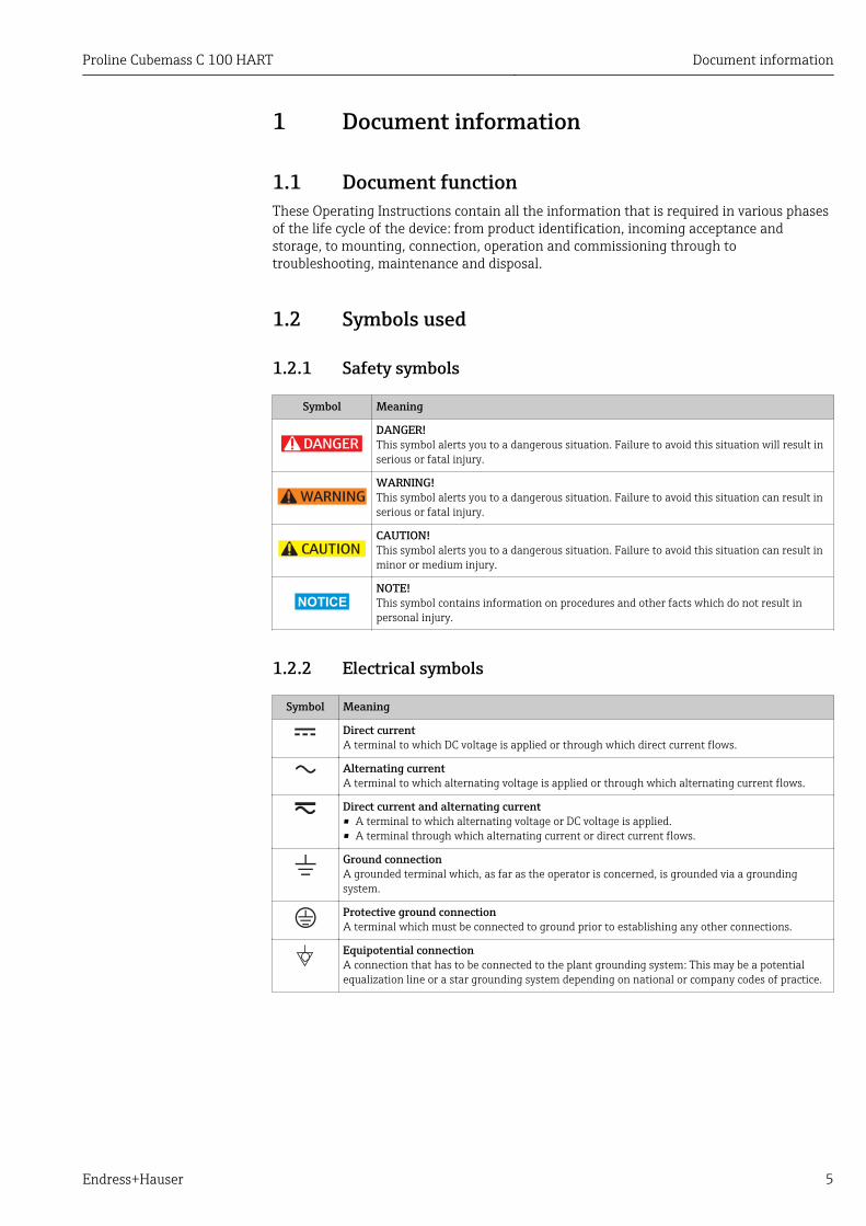
1.2.1 Safety symbols
Symbol Meaning
DANGER
DANGER!This symbol alerts you to a dangerous situation. Failure to avoid this situation will result inserious or fatal injury.
WARNING
WARNING!This symbol alerts you to a dangerous situation. Failure to avoid this situation can result inserious or fatal injury.
CAUTION
CAUTION!This symbol alerts you to a dangerous situation. Failure to avoid this situation can result inminor or medium injury.
NOTICE
NOTE!This symbol contains information on procedures and other facts which do not result inpersonal injury.
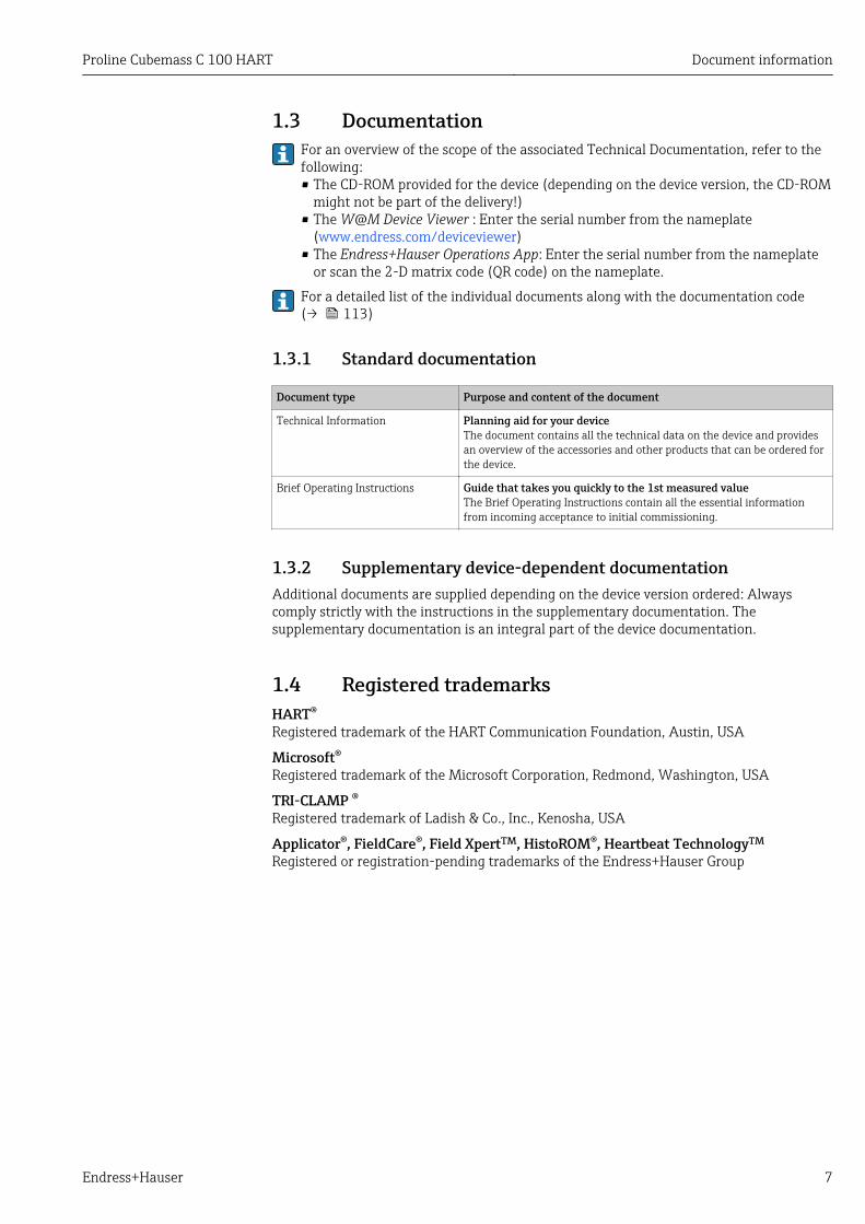
1.2.2 Electrical symbols
Symbol Meaning
Direct currentA terminal to which DC voltage is applied or through which direct current flows.
Alternating currentA terminal to which alternating voltage is applied or through which alternating current flows.
Direct current and alternating current• A terminal to which alternating voltage or DC voltage is applied.• A terminal through which alternating current or direct current flows.
Ground connectionA grounded terminal which, as far as the operator is concerned, is grounded via a groundingsystem.
Protective ground connectionA terminal which must be connected to ground prior to establishing any other connections.
Equipotential connectionA connection that has to be connected to the plant grounding system: This may be a potentialequalization line or a star grounding system depending on national or company codes of practice.

Document information Proline Cubemass C 100 HART
6 Endress+Hauser
1.2.3 Tool symbols
Symbol Meaning
Allen key
Open-ended wrench
1.2.4 Symbols for certain types of information
Symbol Meaning
PermittedIndicates procedures, processes or actions that are permitted.
PreferredIndicates procedures, processes or actions that are preferred.
ForbiddenIndicates procedures, processes or actions that are forbidden.
TipIndicates additional information.
Reference to documentationRefers to the corresponding device documentation.
Reference to pageRefers to the corresponding page number.
Reference to graphicRefers to the corresponding graphic number and page number.
, …, Series of steps
Result of a sequence of actions
Help in the event of a problem
Visual inspection
1.2.5 Symbols in graphics
Symbol Meaning
1, 2, 3,... Item numbers
, …, Series of steps
A, B, C, ... Views
A-A, B-B, C-C, ... Sections
Flow direction
-Hazardous areaIndicates a hazardous area.
.Safe area (non-hazardous area)Indicates the non-hazardous area.
Proline Cubemass C 100 HART Document information
Endress+Hauser 7
1.3 DocumentationFor an overview of the scope of the associated Technical Documentation, refer to thefollowing:• The CD-ROM provided for the device (depending on the device version, the CD-ROM
might not be part of the delivery!)• The W@M Device Viewer : Enter the serial number from the nameplate
(www.endress.com/deviceviewer)• The Endress+Hauser Operations App: Enter the serial number from the nameplate
or scan the 2-D matrix code (QR code) on the nameplate.
For a detailed list of the individual documents along with the documentation code(→ 113)
1.3.1 Standard documentation
Document type Purpose and content of the document
Technical Information Planning aid for your deviceThe document contains all the technical data on the device and providesan overview of the accessories and other products that can be ordered forthe device.
Brief Operating Instructions Guide that takes you quickly to the 1st measured valueThe Brief Operating Instructions contain all the essential informationfrom incoming acceptance to initial commissioning.
1.3.2 Supplementary device-dependent documentationAdditional documents are supplied depending on the device version ordered: Alwayscomply strictly with the instructions in the supplementary documentation. Thesupplementary documentation is an integral part of the device documentation.
1.4 Registered trademarksHART®
Registered trademark of the HART Communication Foundation, Austin, USA
Microsoft®
Registered trademark of the Microsoft Corporation, Redmond, Washington, USA
TRI-CLAMP ®Registered trademark of Ladish & Co., Inc., Kenosha, USA
Applicator®, FieldCare®, Field XpertTM, HistoROM®, Heartbeat TechnologyTM
Registered or registration-pending trademarks of the Endress+Hauser Group
Basic safety instructions Proline Cubemass C 100 HART
8 Endress+Hauser
2 Basic safety instructions
2.1 Requirements for the personnelThe personnel for installation, commissioning, diagnostics and maintenance must fulfillthe following requirements:‣ Trained, qualified specialists must have a relevant qualification for this specific function
and task‣ Are authorized by the plant owner/operator‣ Are familiar with federal/national regulations‣ Before beginning work, the specialist staff must have read and understood the
instructions in the Operating Instructions and supplementary documentation as well asin the certificates (depending on the application)
‣ Following instructions and basic conditions
The operating personnel must fulfill the following requirements:‣ Being instructed and authorized according to the requirements of the task by the
facility's owner-operator‣ Following the instructions in these Operating Instructions
2.2 Designated useApplication and mediaThe measuring device described in these Instructions is intended only for flowmeasurement of liquids and gases.
Depending on the version ordered, the measuring device can also measure potentiallyexplosive, flammable, poisonous and oxidizing media.
Measuring devices for use in hazardous areas, in hygienic applications or in applicationswhere there is an increased risk due to process pressure, are labeled accordingly on thenameplate.
To ensure that the measuring device remains in proper condition for the operation time:‣ Only use the measuring device in full compliance with the data on the nameplate and
the general conditions listed in the Operating Instructions and supplementarydocumentation.
‣ Based on the nameplate, check whether the ordered device is permitted for theintended use in the hazardous area (e.g. explosion protection, pressure vessel safety).
‣ Use the measuring device only for media against which the process-wetted materialsare adequately resistant.
‣ If the measuring device is not operated at atmospheric temperature, compliance withthe relevant basic conditions specified in the associated device documentation isabsolutely essential: "Documentation" section (→ 7).
Incorrect useNon-designated use can compromise safety. The manufacturer is not liable for damagecaused by improper or non-designated use.
!WARNINGDanger of breakage of the measuring tube due to corrosive or abrasive fluids.Housing breakage due to mechanical overload possible!‣ Verify the compatibility of the process fluid with the measuring tube material.‣ Ensure the resistance of all fluid-wetted materials in the process.‣ Observe the specified pressure and temperature range.
Verification for borderline cases:‣ For special fluids and fluids for cleaning, Endress+Hauser is glad to provide assistance
in verifying the corrosion resistance of fluid-wetted materials, but does not accept any
Proline Cubemass C 100 HART Basic safety instructions
Endress+Hauser 9
warranty or liability as minute changes in the temperature, concentration or level ofcontamination in the process can alter the corrosion resistance properties.
Residual risks
!WARNINGDanger of housing breaking due to measuring tube breakage!‣ In the event of a measuring tube breakage for a device version without rupture disk it is
possible for the pressure loading capacity of the sensor housing to be exceeded. Thiscan lead to rupture or failure of the sensor housing.
The external surface temperature of the housing can increase by max. 20 K due to thepower consumption of the electronic components. Hot process fluids passing through themeasuring device will further increase the surface temperature of the housing. The surfaceof the sensor, in particular, can reach temperatures which are close to the fluidtemperature.
Possible burn hazard due to fluid temperatures!‣ For elevated fluid temperature, ensure protection against contact to prevent burns.
2.3 Workplace safetyFor work on and with the device:‣ Wear the required personal protective equipment according to federal/national
regulations.
For welding work on the piping:‣ Do not ground the welding unit via the measuring device.
If working on and with the device with wet hands:‣ It is recommended to wear gloves on account of the higher risk of electric shock.
2.4 Operational safetyRisk of injury.‣ Operate the device in proper technical condition and fail-safe condition only.‣ The operator is responsible for interference-free operation of the device.
Conversions to the deviceUnauthorized modifications to the device are not permitted and can lead to unforeseeabledangers.‣ If, despite this, modifications are required, consult with Endress+Hauser.
RepairTo ensure continued operational safety and reliability,‣ Carry out repairs on the device only if they are expressly permitted.‣ Observe federal/national regulations pertaining to repair of an electrical device.‣ Use original spare parts and accessories from Endress+Hauser only.
2.5 Product safetyThis measuring device is designed in accordance with good engineering practice to meetstate-of-the-art safety requirements, has been tested, and left the factory in a condition inwhich it is safe to operate.
It meets general safety standards and legal requirements. It also complies with the ECdirectives listed in the device-specific EC Declaration of Conformity. Endress+Hauserconfirms this by affixing the CE mark to the device.

Basic safety instructions Proline Cubemass C 100 HART
10 Endress+Hauser
2.6 IT securityWe only provide a warranty if the device is installed and used as described in theOperating Instructions. The device is equipped with security mechanisms to protect itagainst any inadvertent changes to the device settings.
IT security measures in line with operators' security standards and designed to provideadditional protection for the device and device data transfer must be implemented by theoperators themselves.

Proline Cubemass C 100 HART Product description
Endress+Hauser 11
3 Product description
3.1 Product design
3.1.1 Device version with HART communication type
3
2
1
4
5
6
7
A0023153
1 Important components of a measuring device
1 Sensor2 Transmitter housing3 Main electronics module4 Transmitter housing cover5 Transmitter housing cover (version for optional onsite display)6 Onsite display (optional)7 Main electronics module (with bracket for optional onsite display)

Incoming acceptance and product identification Proline Cubemass C 100 HART
12 Endress+Hauser
4 Incoming acceptance and productidentification
4.1 Incoming acceptance
1+
2
1+
2
Are the order codes on thedelivery note (1) and theproduct sticker (2)identical?
Are the goods undamaged?
Do the nameplate datamatch the orderinginformation on the deliverynote?
Is the CD-ROM with theTechnical Documentation(depends on deviceversion) and documentspresent?
• If one of the conditions is not satisfied, contact your Endress+Hauser Sales Center.• Depending on the device version, the CD-ROM might not be part of the delivery! In
such cases, the technical documentation is available via the Internet or via theEndress+Hauser Operations App, see the "Product identification" section(→ 13).
4.2 Product identificationThe following options are available for identification of the measuring device:• Nameplate specifications• Order code with breakdown of the device features on the delivery note• Enter serial numbers from nameplates in W@M Device Viewer
(www.endress.com/deviceviewer): All information about the measuring device isdisplayed.
• Enter the serial number from the nameplates into the Endress+Hauser Operations Appor scan the 2-D matrix code (QR code) on the nameplate with the Endress+HauserOperations App: all the information for the measuring device is displayed.

Proline Cubemass C 100 HART Incoming acceptance and product identification
Endress+Hauser 13
For an overview of the scope of the associated Technical Documentation, refer to thefollowing:• The chapters "Additional standard documentation on the device" (→ 7) and
"Supplementary device-dependent documentation" (→ 7)• The W@M Device Viewer: Enter the serial number from the nameplate
(www.endress.com/deviceviewer)• The Endress+Hauser Operations App: Enter the serial number from the nameplate or
scan the 2-D matrix code (QR code) on the nameplate.
4.2.1 Transmitter nameplate
i
12
345
6
7
8
9
101112
Order code:
Ext. ord. cd.:
Ser. no.:
13
A0017520
2 Example of a transmitter nameplate
1 Manufacturing location2 Name of the transmitter3 Order code4 Serial number5 Extended order code6 Electrical connection data, e.g. available inputs and outputs, supply voltage7 Permitted ambient temperature range (Ta)8 Degree of protection9 2-D matrix code10 Document number of safety-related supplementary documentation (→ 113)11 Manufacturing date: year-month12 CE mark, C-Tick13 Firmware version (FW)

Incoming acceptance and product identification Proline Cubemass C 100 HART
14 Endress+Hauser
4.2.2 Sensor nameplate
Date:
Size:
Material:
Tm:
Patents i
Ptest =
i
Order code:
Ext. ord. cd.:
Ser. no.:
322541-0000
0044
11
1
2
3 4 5 6 7
12
8
9
13 14 15
16
17
1918
10
A0013907
3 Example of a sensor nameplate
1 Manufacturing location2 Name of the sensor3 Order code4 Serial number (Ser. no.)5 Extended order code (Ext. ord. cd.)6 Nominal diameter of sensor7 Test pressure of the sensor8 Flange nominal diameter/nominal pressure9 Material of measuring tube and manifold10 Fluid temperature range11 CE mark, C-Tick12 Additional information on version: certificates, approvals13 Manufacturing date: year-month14 Flow direction15 2-D matrix code16 Degree of protection17 Approval information for explosion protection and Pressure Equipment Directive18 Permitted ambient temperature (Ta)19 Document number of safety-related supplementary documentation (→ 113)
Order codeThe measuring device is reordered using the order code.
Extended order code• The device type (product root) and basic specifications (mandatory features) are
always listed.• Of the optional specifications (optional features), only the safety and approval-
related specifications are listed (e.g. LA). If other optional specifications are alsoordered, these are indicated collectively using the # placeholder symbol (e.g. #LA#).
• If the ordered optional specifications do not include any safety and approval-relatedspecifications, they are indicated by the + placeholder symbol (e.g. XXXXXX-ABCDE+).

Proline Cubemass C 100 HART Incoming acceptance and product identification
Endress+Hauser 15
4.2.3 Symbols on measuring device
Symbol Meaning
WARNING!This symbol alerts you to a dangerous situation. Failure to avoid this situation can result in seriousor fatal injury.
A0011194
Reference to documentationRefers to the corresponding device documentation.
A0011199
Protective ground connectionA terminal which must be connected to ground prior to establishing any other connections.
Storage and transport Proline Cubemass C 100 HART
16 Endress+Hauser
5 Storage and transport
5.1 Storage conditionsObserve the following notes for storage:• Store in the original packaging to ensure protection from shock.• Do not remove protective covers or protective caps installed on process connections.
They prevent mechanical damage to the sealing surfaces and fouling in the measuringtube.
• Protect from direct sunlight to avoid unacceptably high surface temperatures.• Storage temperature: –40 to +80 °C (–40 to +176 °F), preferable for +20 °C (+68 °F)• Store in a dry and dust-free place.• Do not store outdoors.
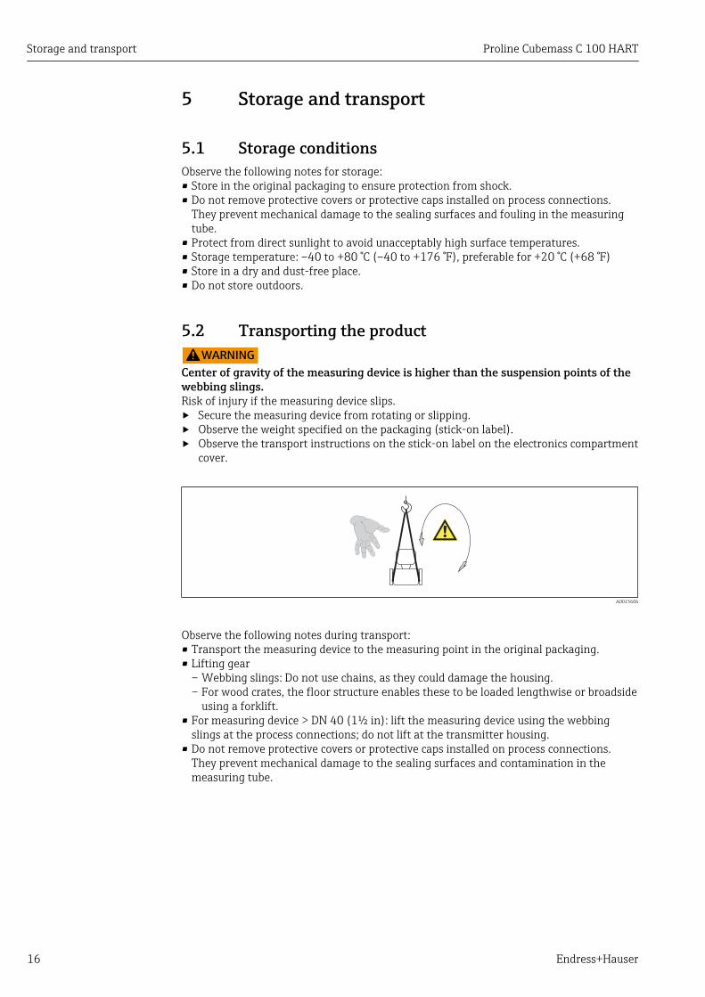
5.2 Transporting the product!WARNING
Center of gravity of the measuring device is higher than the suspension points of thewebbing slings.Risk of injury if the measuring device slips.‣ Secure the measuring device from rotating or slipping.‣ Observe the weight specified on the packaging (stick-on label).‣ Observe the transport instructions on the stick-on label on the electronics compartment
cover.
A0015606
Observe the following notes during transport:• Transport the measuring device to the measuring point in the original packaging.• Lifting gear
– Webbing slings: Do not use chains, as they could damage the housing.– For wood crates, the floor structure enables these to be loaded lengthwise or broadside
using a forklift.• For measuring device > DN 40 (1½ in): lift the measuring device using the webbing
slings at the process connections; do not lift at the transmitter housing.• Do not remove protective covers or protective caps installed on process connections.
They prevent mechanical damage to the sealing surfaces and contamination in themeasuring tube.

Proline Cubemass C 100 HART Storage and transport
Endress+Hauser 17
5.3 Packaging disposalAll packaging materials are environmentally friendly and 100% recyclable:• Measuring device secondary packaging: polymer stretch film that conforms to EC
Directive 2002/95/EC (RoHS).• Packaging:
– Wood crate, treated in accordance with ISPM 15 standard, which is confirmed by theaffixed IPPC logo.or
– Carton in accordance with European Packaging Directive 94/62EC; recyclability isconfirmed by the affixed RESY symbol.
• Seaworthy packaging (optional): Wood crate, treated in accordance with ISPM 15standard, which is confirmed by the affixed IPPC logo.
• Carrying and mounting hardware:– Disposable plastic pallet– Plastic straps– Plastic adhesive strips
• Dunnage: Paper cushion

Installation Proline Cubemass C 100 HART
18 Endress+Hauser
6 Installation
6.1 Installation conditionsNo special measures such as supports are necessary. External forces are absorbed by theconstruction of the device.
6.1.1 Mounting position
Mounting locationTo prevent measuring errors arising from accumulation of gas bubbles in the measuringtube, avoid the following mounting locations in the pipe:• Highest point of a pipeline.• Directly upstream of a free pipe outlet in a down pipe.
A0023344
Installation in down pipes
However, the following installation suggestion allows for installation in an open verticalpipeline. Pipe restrictions or the use of an orifice with a smaller cross-section than thenominal diameter prevent the sensor running empty while measurement is in progress.
1
2
3
4
5
A0015596
4 Installation in a down pipe (e.g. for batching applications)
1 Supply tank2 Sensor3 Orifice plate, pipe restriction4 Valve5 Batching tank

Proline Cubemass C 100 HART Installation
Endress+Hauser 19
DN Ø orifice plate, pipe restriction
[mm] [in] [mm] [in]
1 ¹⁄₂₄ 0.8 0.03
2 ¹⁄₁₂ 1.5 0.06
4 ¹⁄₈ 3.0 0.12
6 ¹⁄₄ 5.0 0.20
OrientationThe direction of the arrow on the sensor nameplate helps you to install the sensoraccording to the flow direction (direction of medium flow through the piping).
Orientation Recommendation
A Vertical orientation
A0015591
B Horizontal orientation, transmitterhead up
A0015589
1)
Exception:
C Horizontal orientation, transmitterhead down
A0015590
2)
Exception:
D Horizontal orientation, transmitterhead at side
A0015592
1) Applications with low process temperatures may reduce the ambient temperature. To maintain theminimum ambient temperature for the transmitter, this orientation is recommended.
2) Applications with high process temperatures may increase the ambient temperature. To maintain themaximum ambient temperature for the transmitter, this orientation is recommended.
Inlet and outlet runsNo special precautions need to be taken for fittings which create turbulence, such asvalves, elbows or T-pieces, as long as no cavitation occurs (→ 20).
A0015597 A0015598
Installation dimensions
For the dimensions and installation lengths of the device, see the "TechnicalInformation" document, "Mechanical construction" section

Installation Proline Cubemass C 100 HART
20 Endress+Hauser
6.1.2 Requirements from environment and process
Ambient temperature range
Measuring device Non-Ex –40 to +60 °C (–40 to +140 °F)
Ex na, NI version –40 to +60 °C (–40 to +140 °F)
Ex ia, IS version • –40 to +60 °C (–40 to +140 °F)• –50 to +60 °C (–58 to +140 °F) (Order code for "Test, certificate",
option JM
Local display –20 to +60 °C (–4 to +140 °F)The readability of the display may be impaired at temperatures outsidethe temperature range.
‣ If operating outdoors:Avoid direct sunlight, particularly in warm climatic regions.
System pressureIt is important that cavitation does not occur, or that gases entrained in the liquids do notoutgas.
Cavitation is caused if the pressure drops below the vapor pressure:• In liquids that have a low boiling point (e.g. hydrocarbons, solvents, liquefied gases)• In suction lines
‣ Ensure the system pressure is sufficiently high to prevent cavitation and outgassing.
For this reason, the following mounting locations are recommended:• At the lowest point in a vertical pipe• Downstream from pumps (no danger of vacuum)
A0015594
Thermal insulationIn the case of some fluids, it is important that the heat radiated from the sensor to thetransmitter is kept to a minimum. A wide range of materials can be used for the requiredinsulation.
NOTICEElectronics overheating on account of thermal insulation!‣ Observe maximum permitted insulation height of the transmitter neck so that the
transmitter head is completely free.

Proline Cubemass C 100 HART Installation
Endress+Hauser 21
t
a
A0019919
a Minimum distance to insulationt Insulation thickness
The minimum distance between the transmitter housing and the insulation is10 mm (0.39 in) so that the transmitter head remains completely exposed.
0
10
30
20
40[mm][in]
80 90 100 110 [°C]
[°F]200 250 290
0.5
1.0
1.5
0
T40 (104)
T60 (140)
t
120 130 140Tm
A0023173
5 Recommended insulation thicknesses depending on the medium and ambient temperature
t Insulation thickness
Tm Medium temperature
T40(104) Insulation thickness with ambient temperature of Ta = 40 °C (104 °F)
T60(140) Insulation thickness with ambient temperature of Ta = 60 °C (140 °F)
NOTICEThe insulation can also be thicker than the recommended insulation thickness.Prerequisite:‣ The temperature at the lower end of the transmitter housing does not exceed
80 °C (176 °F)‣ Ensure that convection takes place on a sufficiently large scale at the transmitter neck.‣ Ensure that a sufficiently large area of the housing support remains exposed. The
uncovered part serves as a radiator and protects the electronics from overheating andexcessive cooling.
HeatingNOTICE
Electronics can overheat due to elevated ambient temperature!‣ Observe maximum permitted ambient temperature for the transmitter (→ 20).‣ Depending on the fluid temperature, take the device orientation requirements into
account .

Installation Proline Cubemass C 100 HART
22 Endress+Hauser
Heating options
If a fluid requires that no heat loss should occur at the sensor, users can avail of thefollowing heating options:• Electrical heating, e.g. with electric band heaters• Via pipes carrying hot water or steam• Via heating jackets
Using an electrical trace heating system
If heating is regulated via phase angle control or pulse packages, magnetic fields can affectthe measured values (= for values that are greater than the values approved by the ENstandard (sine 30 A/m)).
For this reason, the sensor must be magnetically shielded: the housing can be shieldedwith tin plates or electric sheets without a privileged direction (e.g. V330-35A).
The sheet must have the following properties:• Relative magnetic permeability µr ≥ 300• Plate thickness d ≥ 0.35 mm (d ≥ 0.014 in)
VibrationsThe high oscillation frequency of the measuring tubes ensures that the correct operation ofthe measuring system is not influenced by plant vibrations.
6.1.3 Special mounting instructions
Rupture diskMake sure that the function and operation of the rupture disk is not impeded through theinstallation of the device. The position of the rupture disk is indicated by an adhesive labelaffixed beside the disk (version with defined medium exit) or by an adhesive label affixedover the disk (version with undefined medium exit). In the version with the label affixedover the disk, the sticker is destroyed when the rupture disk is triggered. The disk cantherefore be visually monitored. For additional information that is relevant to the process(→ 106).
The existing connecting nozzles are not designed for a rinse or pressure monitoringfunction.
RUPTURE DISK
i
1
32
A B
C
D
A0019637
6 Sensor housing with rupture disk for defined medium exit
1 Rupture disk label2 Rupture disk with 1/2" NPT internal thread with 1" width across flat3 Transport protection

Proline Cubemass C 100 HART Installation
Endress+Hauser 23
DN A B C D
[mm] [in] [mm] [in] [mm] [in] [in] [in]
1…6 ½₄ to ¹⁄₄ 33 1.3 Approx.42 Approx.1.65 ½ NPT AF 1
2
1
RUPTURE DISK
i
A0019638
7 Sensor housing with rupture disk without defined medium exit
1 Rupture disk label2 Rupture disk
!WARNINGLimited functional reliability of the rupture disk.Danger to persons from escaping fluids!‣ Do not remove the rupture disk.‣ When using a rupture disk, do not use a heating jacket.‣ Make sure that the function and operation of the rupture disk is not impeded through
the installation of the device.‣ Take precautions to prevent damage and danger to persons if the rupture disk is
actuated.‣ Observe information on the rupture disk sticker.
Wall mounting
!WARNINGIncorrect sensor mountingRisk of injury if measuring tube breaks‣ The sensor should never be installed in a pipe in a way that it is freely suspended‣ Using the base plate, mount the sensor directly on the floor, wall or ceiling.‣ Support the sensor on a securely mounted support base (e.g. angle bracket).
The following mounting versions are recommended for the installation.
Vertical• Mounted directly on a wall using the base plate, or• Device supported on an angle bracket mounted on the wall
A0019631
Installation Proline Cubemass C 100 HART
24 Endress+Hauser
HorizontalDevice standing on a solid support base
A0019632
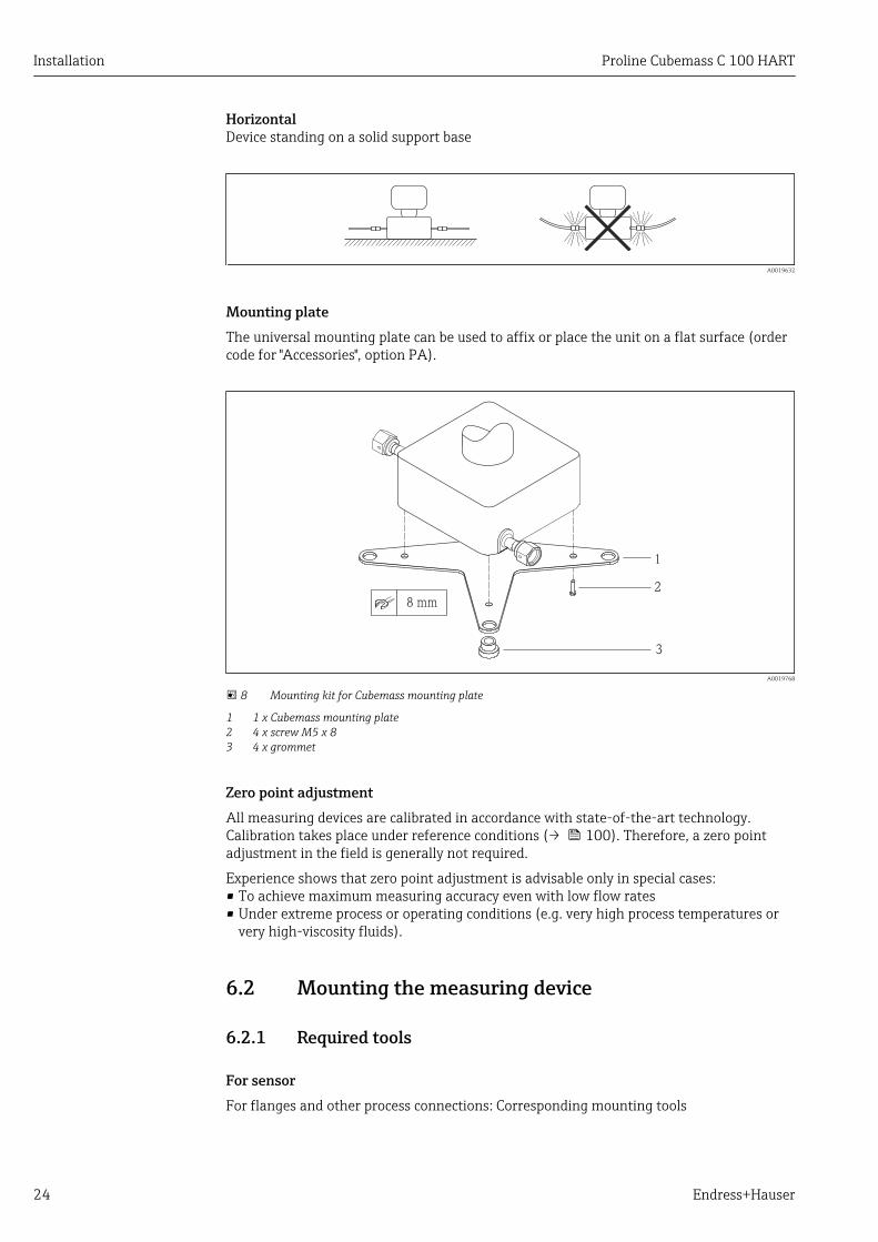
Mounting plateThe universal mounting plate can be used to affix or place the unit on a flat surface (ordercode for "Accessories", option PA).
2
3
1
8 mm
A0019768
8 Mounting kit for Cubemass mounting plate
1 1 x Cubemass mounting plate2 4 x screw M5 x 83 4 x grommet
Zero point adjustmentAll measuring devices are calibrated in accordance with state-of-the-art technology.Calibration takes place under reference conditions (→ 100). Therefore, a zero pointadjustment in the field is generally not required.
Experience shows that zero point adjustment is advisable only in special cases:• To achieve maximum measuring accuracy even with low flow rates• Under extreme process or operating conditions (e.g. very high process temperatures or
very high-viscosity fluids).
6.2 Mounting the measuring device
6.2.1 Required tools
For sensorFor flanges and other process connections: Corresponding mounting tools

Proline Cubemass C 100 HART Installation
Endress+Hauser 25
6.2.2 Preparing the measuring device1. Remove all remaining transport packaging.
2. Remove any protective covers or protective caps present from the sensor.
3. Remove stick-on label on the electronics compartment cover.
6.2.3 Mounting the measuring device!WARNING
Danger due to improper process sealing!‣ Ensure that the inside diameters of the gaskets are greater than or equal to that of the
process connections and piping.‣ Ensure that the gaskets are clean and undamaged.‣ Install the gaskets correctly.
1. Ensure that the direction of the arrow on the nameplate of the sensor matches theflow direction of the fluid.
2. Install the measuring device or turn the transmitter housing so that the cable entriesdo not point upwards.
A0013964
6.3 Post-installation check
Is the device undamaged (visual inspection)?
Does the measuring device conform to the measuring point specifications?
For example:• Process temperature (→ 105)• Process pressure (refer to the chapter on "Pressure-temperature ratings" of the "Technical
Information" document)• Ambient temperature (→ 20)• Measuring range (→ 96)
Has the correct orientation for the sensor been selected ?
• According to sensor type• According to medium temperature• According to medium properties (outgassing, with entrained solids)
Does the arrow on the sensor nameplate match the direction of flow of the fluid through thepiping (→ 19)?
Are the measuring point identification and labeling correct (visual inspection)?
Is the device adequately protected from precipitation and direct sunlight?
Are the securing screw and securing clamp tightened securely?
Electrical connection Proline Cubemass C 100 HART
26 Endress+Hauser
7 Electrical connectionThe measuring device does not have an internal circuit breaker. For this reason,assign the measuring device a switch or power-circuit breaker so that the powersupply line can be easily disconnected from the mains.
7.1 Connection conditions
7.1.1 Required tools• For cable entries: Use corresponding tools• For securing clamp (on aluminum housing): Allen screw3 mm• For securing screw (for stainless steel housing): open-ended wrench 8 mm• Wire stripper• When using stranded cables: crimping tool for ferrule
7.1.2 Requirements for connecting cableThe connecting cables provided by the customer must fulfill the following requirements.
Electrical safetyIn accordance with applicable federal/national regulations.
Permitted temperature range• –40 °C (–40 °F) to +80 °C (+176 °F)• Minimum requirement: cable temperature range ≥ ambient temperature +20 K
Power supply cableStandard installation cable is sufficient.
Signal cable
Current output
For 4-20 mA HART: Shielded cable recommended. Observe grounding concept of theplant.
Pulse/frequency/switch output
Standard installation cable is sufficient.
Cable diameter• Cable glands supplied:
M20 × 1.5 with cable 6 to 12 mm (0.24 to 0.47 in)• Spring terminals:
Wire cross-sections 0.5 to 2.5 mm2 (20 to 14 AWG)

Proline Cubemass C 100 HART Electrical connection
Endress+Hauser 27
7.1.3 Terminal assignment
Transmitter
Connection version 4-20 mA HART with pulse/frequency/switch output
Order code for "Output", option BDepending on the housing version, the transmitters can be ordered with terminals ordevice plugs.
Order code for"Housing"
Connection methods availablePossible options for order code
"Electrical connection"Outputs Powersupply
OptionsA, B
Terminals Terminals • Option A: coupling M20x1• Option B: thread M20x1• Option C: thread G ½"• Option D: thread NPT ½"
OptionsA, B
Device plug Terminals • Option L: plug M12x1 + thread NPT ½"• Option N: plug M12x1 + coupling M20• Option P: plug M12x1 + thread G ½"• Option U: plug M12x1 + thread M20
OptionsA, B, C
Device plug Device plug Option Q: 2 x plug M12x1
Order code for "Housing":• Option A: compact, coated aluminum• Option B: compact, hygienic, stainless• Option C: ultra compact, hygienic, stainless, M12 device plug
L
L
26
27
+_
24
25
1
2
+_
+_ 1
2
3
A0016888
9 Terminal assignment 4-20 mA HART with pulse/frequency/switch output
1 Power supply: DC 24 V2 Output 1: 4-20 mA HART (active)3 Output 2: pulse/frequency/switch output (passive)
Order code for"Output"
Terminal number
Power supply Output 1 Output 2
2 (L-) 1 (L+) 27 (–) 26 (+) 25 (–) 24 (+)
Option B DC 24 V 4-20 mA HART (active) Pulse/frequency/switchoutput (passive)
Order code for "Output":Option B: 4-20 mA HART with pulse/frequency/switch output
Electrical connection Proline Cubemass C 100 HART
28 Endress+Hauser
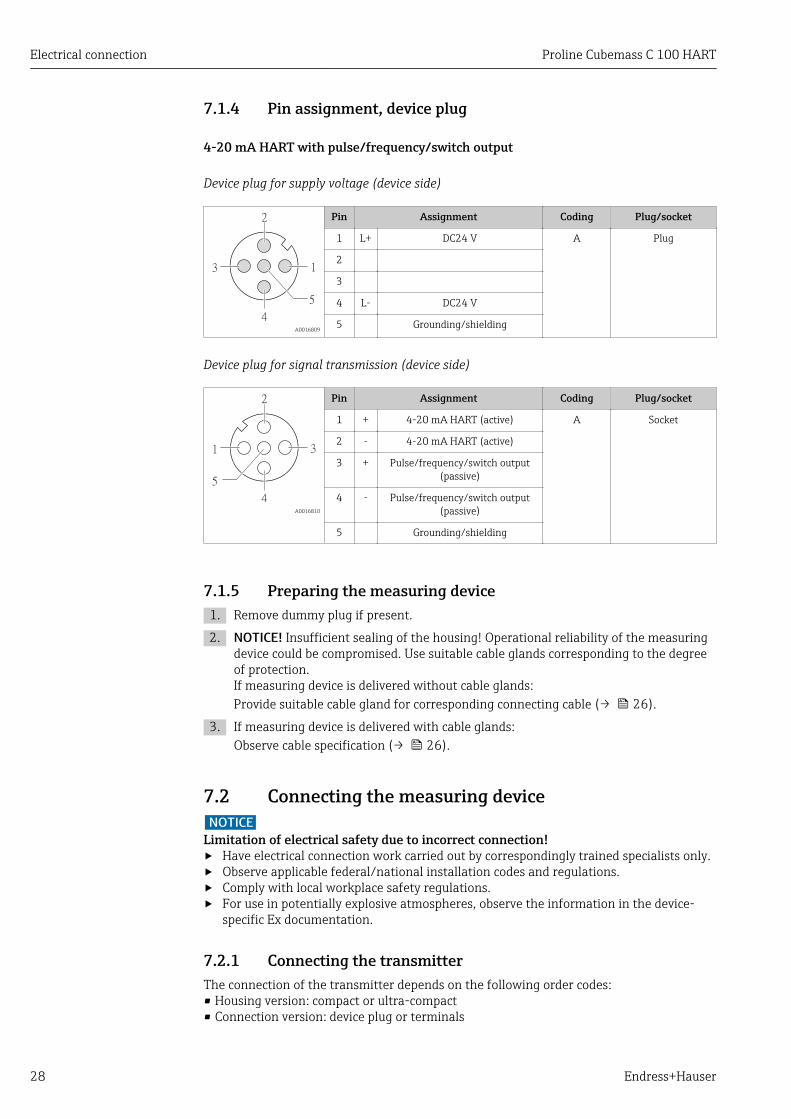
7.1.4 Pin assignment, device plug
4-20 mA HART with pulse/frequency/switch output
Device plug for supply voltage (device side)
1
2
4
3
5
A0016809
Pin Assignment Coding Plug/socket
1 L+ DC24 V A Plug
2
3
4 L- DC24 V
5 Grounding/shielding
Device plug for signal transmission (device side)
3
2
4
1
5
A0016810
Pin Assignment Coding Plug/socket
1 + 4-20 mA HART (active) A Socket
2 - 4-20 mA HART (active)
3 + Pulse/frequency/switch output(passive)
4 - Pulse/frequency/switch output(passive)
5 Grounding/shielding
7.1.5 Preparing the measuring device1. Remove dummy plug if present.
2. NOTICE! Insufficient sealing of the housing! Operational reliability of the measuringdevice could be compromised. Use suitable cable glands corresponding to the degreeof protection.If measuring device is delivered without cable glands:Provide suitable cable gland for corresponding connecting cable (→ 26).
3. If measuring device is delivered with cable glands:Observe cable specification (→ 26).
7.2 Connecting the measuring deviceNOTICE
Limitation of electrical safety due to incorrect connection!‣ Have electrical connection work carried out by correspondingly trained specialists only.‣ Observe applicable federal/national installation codes and regulations.‣ Comply with local workplace safety regulations.‣ For use in potentially explosive atmospheres, observe the information in the device-
specific Ex documentation.
7.2.1 Connecting the transmitterThe connection of the transmitter depends on the following order codes:• Housing version: compact or ultra-compact• Connection version: device plug or terminals
Proline Cubemass C 100 HART Electrical connection
Endress+Hauser 29
1 2 1 2 3 4
A B C
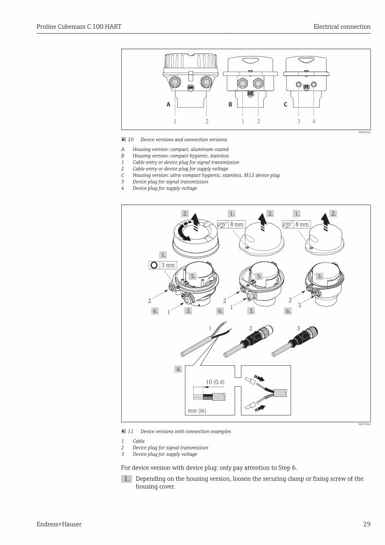
A0016924
10 Device versions and connection versions
A Housing version: compact, aluminum coatedB Housing version: compact hygienic, stainless1 Cable entry or device plug for signal transmission2 Cable entry or device plug for supply voltageC Housing version: ultra-compact hygienic, stainless, M12 device plug3 Device plug for signal transmission4 Device plug for supply voltage
10 (0.4)
mm (in)
1 2 3
2
1
21
23
8 mm
3 mm
8 mm
A0017844
11 Device versions with connection examples
1 Cable2 Device plug for signal transmission3 Device plug for supply voltage
For device version with device plug: only pay attention to Step 6.
1. Depending on the housing version, loosen the securing clamp or fixing screw of thehousing cover.

Electrical connection Proline Cubemass C 100 HART
30 Endress+Hauser
2. Depending on the housing version, unscrew or open the housing cover anddisconnect the local display from the main electronics module where necessary(→ 109).
3. Push the cable through the cable entry . To ensure tight sealing, do not remove thesealing ring from the cable entry.
4. Strip the cable and cable ends. In the case of stranded cables, also fit ferrules.
5. Connect the cable in accordance with the terminal assignment or the device plug pinassignment .
6. Depending on the device version: tighten the cable glands or plug in the device plugand tighten .
7. WARNING! Housing degree of protection may be voided due to insufficient sealing ofthe housing. Screw in the screw without using any lubricant. The threads on thecover are coated with a dry lubricant.Reverse the removal procedure to reassemble the transmitter.
7.3 Special connection instructions
7.3.1 Connection examples
7.4 Ensuring the degree of protectionThe measuring device fulfills all the requirements for the IP66/67 degree of protection,Type 4X enclosure.
To guarantee IP66/67 degree of protection, Type 4X enclosure, carry out the followingsteps after the electrical connection:
1. Check that the housing seals are clean and fitted correctly. Dry, clean or replace theseals if necessary.
2. Tighten all housing screws and screw covers.
3. Firmly tighten the cable glands.
4. To ensure that moisture does not enter the cable entry, route the cable so that itloops down before the cable entry ("water trap").
A0013960
5. Insert dummy plugs into unused cable entries.
7.5 Post-connection check
Are cables or the device undamaged (visual inspection)?
Do the cables comply with the requirements (→ 26)?
Do the cables have adequate strain relief?
Are all the cable glands installed, firmly tightened and leak-tight? Cable run with "water trap"(→ 30) ?

Proline Cubemass C 100 HART Electrical connection
Endress+Hauser 31
Depending on the device version: are all the device plugs firmly tightened (→ 28)?
Does the supply voltage match the specifications on the transmitter nameplate (→ 100)?
Is the terminal assignment or the pin assignment of the device plug correct?
If supply voltage is present, is the power LED on the electronics module of the transmitter lit green(→ 11)?
Depending on the device version, is the securing clamp or fixing screw firmly tightened?
Operation options Proline Cubemass C 100 HART
32 Endress+Hauser
8 Operation options
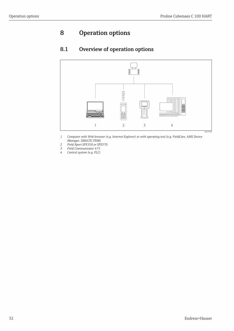
8.1 Overview of operation options
1 2 3 4
A0019598
1 Computer with Web browser (e.g. Internet Explorer) or with operating tool (e.g. FieldCare, AMS DeviceManager, SIMATIC PDM)
2 Field Xpert SFX350 or SFX3703 Field Communicator 4754 Control system (e.g. PLC)

Proline Cubemass C 100 HART Operation options
Endress+Hauser 33
8.2 Structure and function of the operating menu
8.2.1 Structure of the operating menuFor an overview of the operating menu with menus and parameters (→ 115)
!
Expert
System
Sensor
Communication
Application
Diagnostics
Access status display
Output
Operating menu for experts
Language
Operatation Language
Parameter 1
Setup
Submenu 1
Submenu n
Device tag
Advanced setup Enter access code
Parameter 1
Parameter n
Submenu 1
Submenu n
Diagnostics Parameter 1
Parameter n
Submenu 1
Submenu n
Operating menu for operators and maintenances
Parameter n
Op
era
tor
Ma
inte
na
nce
Ta
sk-o
rie
nte
dF
un
ctio
n-o
rie
nte
d
Ex
pe
rt
Wizard 1 / Parameter 1
Wizard n / Parameter n
Parameter n
Intput
A0018237-EN
12 Schematic structure of the operating menu

Operation options Proline Cubemass C 100 HART
34 Endress+Hauser
8.2.2 Operating philosophyThe individual parts of the operating menu are assigned to certain user roles. Each userrole corresponds to typical tasks within the device lifecycle.
Menu User role and tasks Content/meaning
Language task-oriented Role "Operator", "Maintenance"Tasks during operation:• Configuring the operational display• Reading measured values
Defining the operating language
Operation • Configuring the operational display (e.g. display format,display contrast)
• Resetting and controlling totalizers
Setup "Maintenance" roleCommissioning:• Configuration of the measurement• Configuration of the inputs and
outputs
"Advanced setup" submenu:• For more customized configuration of the measurement
(adaptation to special measuring conditions)• Configuration of totalizers• Administration (define access code, reset measuring device)
Diagnostics "Maintenance" roleFault elimination:• Diagnostics and elimination of
process and device errors• Measured value simulation
Contains all parameters for error detection and analyzingprocess and device errors:• "Diagnostic list" submenu
Contains up to 5 currently pending diagnostic messages.• "Event logbook" submenu
Contains up to 20 or 100 (order option " ExtendedHistoROM") event messages that have occurred.
• "Device information" submenuContains information for identifying the device.
• "Measured values" submenuContains all current measured values.
• "Data logging" submenu (order option "ExtendedHistoROM")Storage and visualization of up to 1000 measured values
• "Heartbeat Technology" submenuThe functionality of the device is checked on demand and theverification results are documented.
• "Simulation" submenuIs used to simulate measured values or output values.
Expert function-oriented Tasks that require detailed knowledgeof the function of the device:• Commissioning measurements under
difficult conditions• Optimal adaptation of the
measurement to difficult conditions• Detailed configuration of the
communication interface• Error diagnostics in difficult cases
Contains all the parameters of the device and makes it possibleto access these parameters directly using an access code. Thestructure of this menu is based on the function blocks of thedevice:• "System" submenu
Contains all higher-order device parameters that do notpertain either to measurement or the measured valuecommunication.
• "Sensor" submenuConfiguration of the measurement.
• "Application" submenuConfiguration of the functions that go beyond the actualmeasurement (e.g. totalizer).
• "Diagnostics" submenuError detection and analysis of process and device errors andfor device simulation and Heartbeat Technology.
8.3 Access to the operating menu via the Web browser
8.3.1 Function rangeThanks to the integrated Web server the device can be operated and configured via a Webbrowser. In addition to the measured values, status information on the device is alsodisplayed and allows the user to monitor the status of the device. Furthermore the devicedata can be managed and the network parameters can be configured.

Proline Cubemass C 100 HART Operation options
Endress+Hauser 35
8.3.2 Prerequisites
Hardware
Connecting cable Standard Ethernet cable with RJ45 connector
Computer RJ45 interface
Measuring device: Web server must be enabled; factory setting: ON
For information on enabling the Web server (→ 37)
Software of the computer
Web browsers supported • Microsoft Internet Explorer (min. 8.x)• Mozilla Firefox• Google chrome
Recommended operatingsystems
• Windows XP• Windows 7
User rights for TCP/IP settings User rights required for TCP/IP settings (e.g. for changes to IP address, subnetmask)
Computer configuration • JavaScript is enabled• If JavaScript cannot be enabled, enter http://XXX.XXX.X.XXX/basic.html in
the address line of the Web browser, e.g. http://192.168.1.212/basic.html.A fully functional but simplified version of the operating menu structurestarts in the Web browser.
When installing a new firmware version:To enable correct data display, clear the temporary memory (cache) of the Webbrowser under Internet options.
8.3.3 Establishing a connection
Configuring the Internet protocol of the computerThe following information refers to the default Ethernet settings of the device.
IP address of the device: 192.168.1.212 (factory setting)
IP address 192.168.1.XXX; for XXX all numerical values except: 0, 212 and 255 → e.g.192.168.1.213
Subnet mask 255.255.255.0
Default gateway 192.168.1.212 or leave cells empty
1. Switch on the measuring device and connect to the computer via the cable(→ 39).
2. If a 2nd network card is not used: all the applications on the notebook should beclosed, or all the applications that require the Internet or network, such as e-mail,SAP applications, Internet or Windows Explorer, i.e. close all open Internet browsers.
3. Configure the properties of the Internet protocol (TCP/IP) as defined in the tableabove.
Starting the Web browser1. Start the Web browser on the computer.
2. Enter the IP address of the Web server in the address line of the Web browser:192.168.1.212

Operation options Proline Cubemass C 100 HART
36 Endress+Hauser
The login page appears.
Device tag
Webserv.language English
Ent. access code
Access stat.tool Maintenance
12
OK
A0017362
1 Device tag (→ 48)2 Picture of device
If a login page does not appear, or if the page is incomplete (→ 78)
8.3.4 Logging on1. Select the preferred operating language for the Web browser.
2. Enter the access code.
3. Press OK to confirm your entry.
Access code 0000 (factory setting); can be changed by customer (→ 72)
If no action is performed for 10 minutes, the Web browser automatically returns tothe login page.
8.3.5 User interface
2 4
6 5
1 32 4
6 5
1 32 4
6 5
1 32 4
6 5
1 32 4
6 5
1 3
A0017757-EN
123456
Picture of deviceFunction row with 6 functionsDevice tagHeaderWorking areaNavigation area

Proline Cubemass C 100 HART Operation options
Endress+Hauser 37
HeaderThe following information appears in the header:• Device tag (→ 48)• Device status with status signal (→ 80)• Current measured values
Function row
Functions Meaning
Measured values The measured values of the device are displayed
Menu Access to the operating menu structure of the device, same as for the operating tool
Device status Displays the diagnostic messages currently pending, listed in order of priority
Data management
Data exchange between PC and measuring device:– Upload the configuration from the device (XML format, create configuration back-up)– Save the configuration to the device (XML format, restore configuration)– Export the event list (.csv file)– Export parameter settings (.csv file, create documentation of the measuring point
configuration)– Export the Heartbeat verification log (PDF file, only available with the "Heartbeat
Verification" application package)
Networkconfiguration
Configuration and checking of all the parameters required for establishing the connectionto the device:• Network settings (e.g. IP address, MAC address)• Device information (e.g. serial number, firmware version)
Logout End the operation and call up the login page
Navigation areaIf a function is selected in the function bar, the submenus of the function open in thenavigation area. The user can now navigate through the menu structure.
Working areaDepending on the selected function and the related submenus, various actions can beperformed in this area:• Configuring parameters• Reading measured values• Calling up help text• Starting an upload/download
8.3.6 Disabling the Web serverThe Web server for the measuring device can enabled and disabled as required via theWeb server functionality parameter.
Navigation"Expert" menu → Communication → Web server
Parameter overview with brief description
Parameter Description Selection Factory setting
Web server functionality Switch the Web server on and off. • Off• On
On
Operation options Proline Cubemass C 100 HART
38 Endress+Hauser
Enabling the Web serverIf the Web server is disabled it can only be re-enabled with the Web server functionalityparameter via the following operating options:Via "FieldCare" operating tool
8.3.7 Logging outBefore logging out, perform a data backup via the Data management function(upload configuration from device) if necessary.
1. Select the Logout entry in the function row. The home page with the Login box appears.
2. Close the Web browser.
3. Reset the modified properties of the Internet protocol (TCP/IP) if they are no longerneeded (→ 35).
8.4 Access to the operating menu via the operating tool
8.4.1 Connecting the operating tool
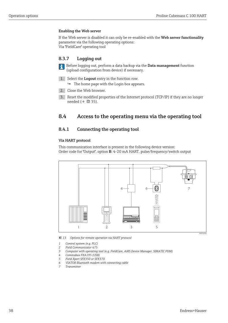
Via HART protocolThis communication interface is present in the following device version:Order code for "Output", option B: 4-20 mA HART, pulse/frequency/switch output
1 2 3 5
74 6
A0016948
13 Options for remote operation via HART protocol
1 Control system (e.g. PLC)2 Field Communicator 4753 Computer with operating tool (e.g. FieldCare, AMS Device Manager, SIMATIC PDM)4 Commubox FXA195 (USB)5 Field Xpert SFX350 or SFX3706 VIATOR Bluetooth modem with connecting cable7 Transmitter
Proline Cubemass C 100 HART Operation options
Endress+Hauser 39
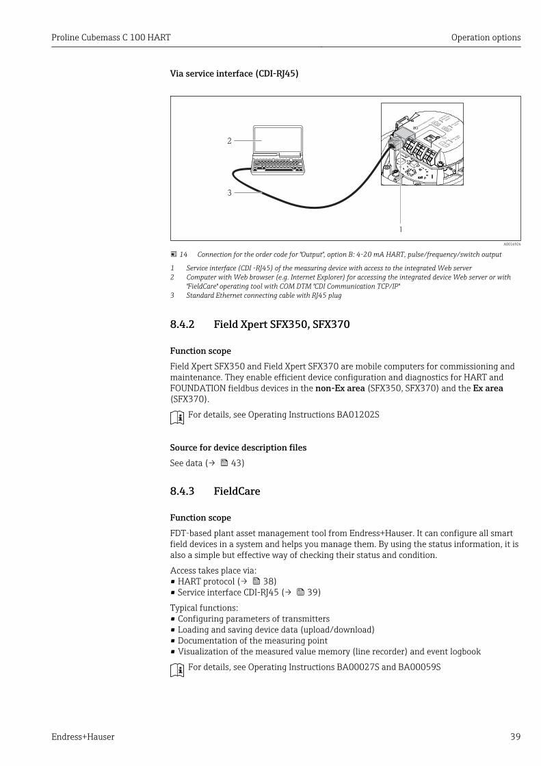
Via service interface (CDI-RJ45)
1
2
3
A0016926
14 Connection for the order code for "Output", option B: 4-20 mA HART, pulse/frequency/switch output
1 Service interface (CDI -RJ45) of the measuring device with access to the integrated Web server2 Computer with Web browser (e.g. Internet Explorer) for accessing the integrated device Web server or with
"FieldCare" operating tool with COM DTM "CDI Communication TCP/IP"3 Standard Ethernet connecting cable with RJ45 plug
8.4.2 Field Xpert SFX350, SFX370
Function scopeField Xpert SFX350 and Field Xpert SFX370 are mobile computers for commissioning andmaintenance. They enable efficient device configuration and diagnostics for HART andFOUNDATION fieldbus devices in the non-Ex area (SFX350, SFX370) and the Ex area(SFX370).
For details, see Operating Instructions BA01202S
Source for device description filesSee data (→ 43)
8.4.3 FieldCare
Function scopeFDT-based plant asset management tool from Endress+Hauser. It can configure all smartfield devices in a system and helps you manage them. By using the status information, it isalso a simple but effective way of checking their status and condition.
Access takes place via:• HART protocol (→ 38)• Service interface CDI-RJ45 (→ 39)
Typical functions:• Configuring parameters of transmitters• Loading and saving device data (upload/download)• Documentation of the measuring point• Visualization of the measured value memory (line recorder) and event logbook
For details, see Operating Instructions BA00027S and BA00059S
Operation options Proline Cubemass C 100 HART
40 Endress+Hauser
Source for device description filesSee data (→ 43)
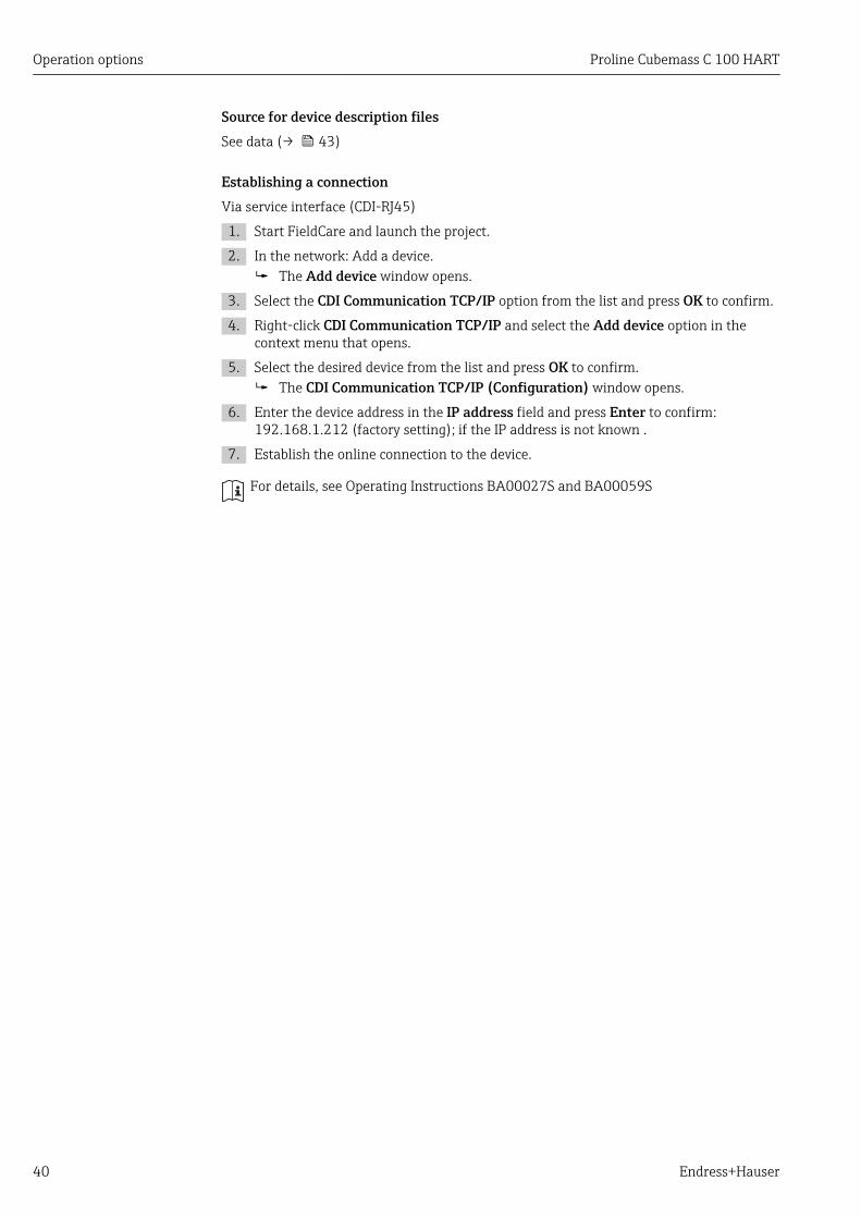
Establishing a connectionVia service interface (CDI-RJ45)
1. Start FieldCare and launch the project.
2. In the network: Add a device. The Add device window opens.
3. Select the CDI Communication TCP/IP option from the list and press OK to confirm.
4. Right-click CDI Communication TCP/IP and select the Add device option in thecontext menu that opens.
5. Select the desired device from the list and press OK to confirm. The CDI Communication TCP/IP (Configuration) window opens.
6. Enter the device address in the IP address field and press Enter to confirm:192.168.1.212 (factory setting); if the IP address is not known .
7. Establish the online connection to the device.
For details, see Operating Instructions BA00027S and BA00059S

Proline Cubemass C 100 HART Operation options
Endress+Hauser 41
User interface
6532
1
Xxxxxx/…/…/
7
P
P
+
–
P
–
P
+
+
+
+
+
+
4
8 9
10 11
Xxxxxxx
GoodStatus:
Device tag:
XxxxxxxDevice name: Mass flow: 12.34 kg/h
Volume flow: 12.34 m /h³
Mass flow unit:
Volume flow unit:
kg/h
m /h³Access status tooling
Operation
Setup
Xxxxxx
Mass flow unitVolume flow unit
Select medium
Device tag
…
…
Advanced setup
Diagnostics
Expert
Maintenance
kg/hm /h³
Xxxxxx
System units
A0021051-EN
1 Header2 Picture of device3 Device name4 Device tag (→ 48)5 Status area with status signal (→ 80)6 Display area for current measured values (→ 74)7 Event list with additional functions such as save/load, events list and document creation8 Navigation area with operating menu structure9 Operating range10 Range of action11 Status area
8.4.4 AMS Device Manager
Function scopeProgram from Emerson Process Management for operating and configuring measuringdevices via HART protocol.
Source for device description filesSee data (→ 43)
8.4.5 SIMATIC PDM
Function scopeSIMATIC PDM is a standardized, manufacturer-independent program from Siemens forthe operation, configuration, maintenance and diagnosis of intelligent field devices viaHART protocol.
Source for device description filesSee data (→ 43)

Operation options Proline Cubemass C 100 HART
42 Endress+Hauser
8.4.6 Field Communicator 475
Function scopeIndustrial handheld terminal from Emerson Process Management for remoteconfiguration and measured value display via HART protocol.
Source for device description filesSee data (→ 43)

Proline Cubemass C 100 HART System integration
Endress+Hauser 43
9 System integration
9.1 Overview of device description files
9.1.1 Current version data for the device
Firmware version 01.01.zz • On the title page of the Operating instructions• On transmitter nameplate (→ 13)• Parameter firmware version
Diagnostics → Device info → Firmware version
Release date of firmware version 06.2014 ---
Manufacturer ID 0x11 Manufacturer ID parameterDiagnostics → Device info→ Manufacturer ID
Device type ID 0x4A Device type parameterDiagnostics → Device info → Device type
HART protocol revision 7 ---
Device revision 2 • On transmitter nameplate (→ 13)• Device revision parameter
Diagnostics → Device info → Device revision
9.1.2 Operating toolsThe suitable device description file for the individual operating tools is listed in the tablebelow, along with information on where the file can be acquired.
Operating tool via HART protocol Sources for obtaining device descriptions
• Field Xpert SFX350• Field Xpert SFX370
Use update function of handheld terminal
FieldCare • www.endress.com → Download Area• CD–ROM (contact Endress+Hauser)• DVD (contact Endress+Hauser)
AMS Device Manager(Emerson Process Management)
www.endress.com → Download Area
SIMATIC PDM(Siemens)
www.endress.com → Download Area
Field Communicator 475(Emerson Process Management)
Use update function of handheld terminal
9.2 Measured variables via HART protocolThe following measured variables (HART device variables) are assigned to the dynamicvariables at the factory:
Dynamic variables Measured variables(HART device variables)
Primary dynamic variable (PV) Mass flow
Secondary dynamic variable (SV) Totalizer 1
Tertiary dynamic variable (TV) Density
Quaternary dynamic variable (QV) Temperature

System integration Proline Cubemass C 100 HART
44 Endress+Hauser
The assignment of the measured variables to the dynamic variables can be modified andassigned as desired via local operation and the operating tool using the followingparameters:
• Expert → Communication → HART output → Assign PV• Expert → Communication → HART output → Assign SV• Expert → Communication → HART output → Assign TV• Expert → Communication → HART output → Assign QV
The following measured variables can be assigned to the dynamic variables:
Measured variables for PV (primary dynamic variable)• Mass flow• Volume flow• Corrected volume flow• Density• Reference density• Temperature
Measured variables for SV, TV, QV (secondary, tertiary and quaternary dynamicvariable)• Mass flow• Volume flow• Corrected volume flow• Density• Reference density• Temperature• Totalizer 1• Totalizer 2• Totalizer 3
The range of options increases if the measuring device has one or more applicationpackages.
Heartbeat Technology Application PackageAdditional measured variables are available with the Heartbeat Technology applicationpackage:• Carrier pipe temperature• Oscillation amplitude
Device variablesThe device variables are permanently assigned. A maximum of 8 device variables can betransmitted:• 0 = mass flow• 1 = volume flow• 2 = corrected volume flow• 3 = density• 4 = reference density• 5 = temperature• 6 = totalizer 1• 7 = totalizer 2• 8 = totalizer 3• 9 = dynamic viscosity• 10 = kinematic viscosity• 11 = temp. compensated dynamic viscosity• 12 = temp. compensated kinematic viscosity• 13 = target mass flow• 14 = carrier mass flow• 15 = concentration
Proline Cubemass C 100 HART System integration
Endress+Hauser 45
9.3 Other settings
9.3.1 Burst mode functionality in accordance with HART 7Specification
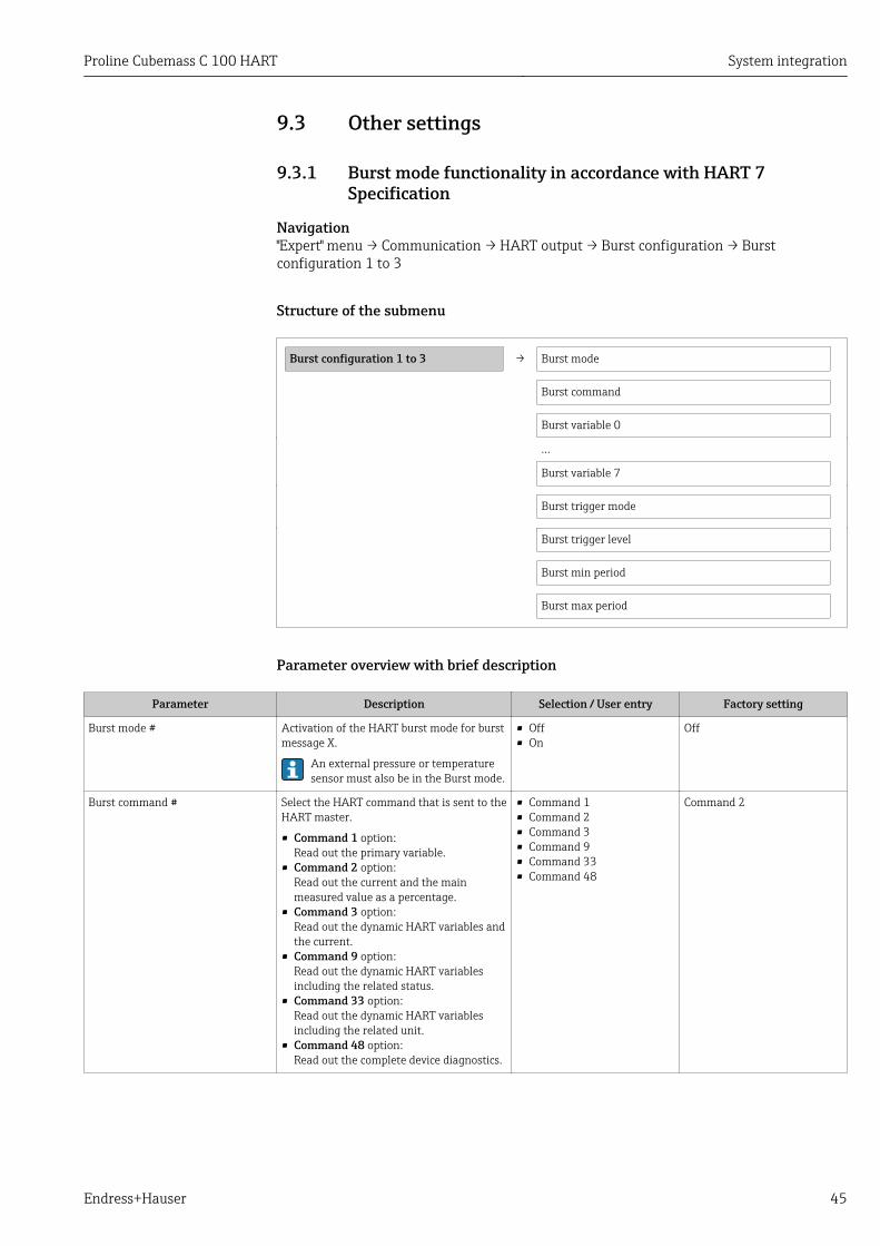
Navigation"Expert" menu → Communication → HART output → Burst configuration → Burstconfiguration 1 to 3
Structure of the submenu
Burst configuration 1 to 3 → Burst mode
Burst command
Burst variable 0
…
Burst variable 7
Burst trigger mode
Burst trigger level
Burst min period
Burst max period
Parameter overview with brief description
Parameter Description Selection / User entry Factory setting
Burst mode # Activation of the HART burst mode for burstmessage X.
An external pressure or temperaturesensor must also be in the Burst mode.
• Off• On
Off
Burst command # Select the HART command that is sent to theHART master.
• Command 1 option:Read out the primary variable.
• Command 2 option:Read out the current and the mainmeasured value as a percentage.
• Command 3 option:Read out the dynamic HART variables andthe current.
• Command 9 option:Read out the dynamic HART variablesincluding the related status.
• Command 33 option:Read out the dynamic HART variablesincluding the related unit.
• Command 48 option:Read out the complete device diagnostics.
• Command 1• Command 2• Command 3• Command 9• Command 33• Command 48
Command 2

System integration Proline Cubemass C 100 HART
46 Endress+Hauser
Parameter Description Selection / User entry Factory setting
Burst variable 0 Assignment of the individual HARTvariables (PV, SV, TV, QV) and assignmentof the process variables available in thedevice to the HART command.
• Mass flow• Volume flow• Corrected volume flow• Target mass flow• Carrier mass flow• Density• Reference density• Concentration• Dynamic viscosity• Kinematic viscosity• Temp. compensated
dynamic viscosity• Temp. compensated
kinematic viscosity• Temperature• Totalizer 1• Totalizer 2• Totalizer 3• Sensor integrity• Pressure• HART input• Percent Of Range• Measured current• Primary variable (PV)• Secondary variable (SV)• Tertiary variable (TV)• Quaternary variable (QV)• Not used
Volume flow
Burst variable 1 See burst variable 0. See burst variable 0. Not used
Burst variable 2 See burst variable 0. See burst variable 0. Not used
Burst variable 3 See burst variable 0. See burst variable 0. Not used
Burst variable 4 See burst variable 0. See burst variable 0. Not used
Burst variable 5 See burst variable 0. See burst variable 0. Not used
Burst variable 6 See burst variable 0. See burst variable 0. Not used
Burst variable 7 See burst variable 0. See burst variable 0. Not used
Burst trigger mode Use this function to select the event thattriggers burst message X.
• Continuous option:The message is triggered in a time-controlled manner, at least observing thetime interval defined in the Burst minperiod parameter.
• Window option:The message is triggered if the specifiedmeasured value has changed by the valuein the Burst trigger level parameter.
• Rising option:The message is triggered if the specifiedmeasured value exceeds the value in theBurst trigger level parameter.
• Falling option:The message is triggered if the specifiedmeasured value drops below the value inthe Burst trigger level parameter.
• On change option:The message is triggered if the measuredvalue changes.
• Continuous• Window• Rising• Falling• On change
Continuous
Burst trigger level For entering the burst trigger value.
Together with the option selected in theBurst trigger mode parameter the bursttrigger value determines the time of burstmessage X.
Positive floating-point number 2.0E-38

Proline Cubemass C 100 HART System integration
Endress+Hauser 47
Parameter Description Selection / User entry Factory setting
Min. update period Use this function to enter the minimum timespan between two burst commands of burstmessage X.
Positive integer 1 000 ms
Max. update period Use this function to enter the maximumtime span between two burst commands ofburst message X.
Positive integer 2 000 ms

Commissioning Proline Cubemass C 100 HART
48 Endress+Hauser
10 Commissioning
10.1 Function checkBefore commissioning the device, make sure that the post-installation and post-connection checks have been performed.
• "Post-installation check" checklist (→ 25)• "Post-connection check" checklist (→ 30)
10.2 Configuring the measuring deviceThe Setup menu with its submenus contains all the parameters needed for standardoperation.
Structure of the "Setup" menu
Setup → Select medium (→ 51)
Current output 1 (→ 52)
Pulse/frequency/switch output (→ 54)
Output conditioning (→ 60)
Low flow cut off (→ 63)
Partially filled pipe detection (→ 64)
HART input (→ 59)
Advanced setup (→ 65)
10.2.1 Defining the tag nameTo enable fast identification of the measuring point within the system, you can enter aunique designation using the Device tag parameter and thus change the factory setting.
The number of characters displayed depends on the characters used.
For information on the tag name in the "FieldCare" operating tool (→ 41)
Navigation"Setup" menu → Device tag
Parameter overview with brief description
Parameter Description User entry Factory setting
Device tag Enter tag for measuring point. Max. 32 characters, such asletters, numbers or specialcharacters (e.g. @, %, /).
Promass
10.2.2 Setting the system unitsIn the System units submenu the units of all the measured values can be set.
Proline Cubemass C 100 HART Commissioning
Endress+Hauser 49
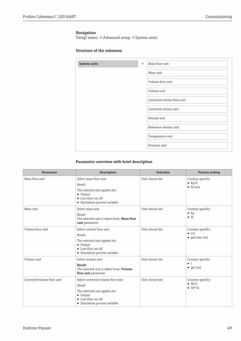
Navigation"Setup" menu → Advanced setup → System units
Structure of the submenu
System units → Mass flow unit
Mass unit
Volume flow unit
Volume unit
Corrected volume flow unit
Corrected volume unit
Density unit
Reference density unit
Temperature unit
Pressure unit
Parameter overview with brief description
Parameter Description Selection Factory setting
Mass flow unit Select mass flow unit.
Result
The selected unit applies for:• Output• Low flow cut off• Simulation process variable
Unit choose list Country-specific:• kg/h• lb/min
Mass unit Select mass unit.
ResultThe selected unit is taken from: Mass flowunit parameter
Unit choose list Country-specific:• kg• lb
Volume flow unit Select volume flow unit.
Result
The selected unit applies for:• Output• Low flow cut off• Simulation process variable
Unit choose list Country-specific:• l/h• gal/min (us)
Volume unit Select volume unit.
ResultThe selected unit is taken from: Volumeflow unit parameter
Unit choose list Country-specific:• l• gal (us)
Corrected volume flow unit Select corrected volume flow unit.
Result
The selected unit applies for:• Output• Low flow cut off• Simulation process variable
Unit choose list Country-specific:• Nl/h• Sft³/h

Commissioning Proline Cubemass C 100 HART
50 Endress+Hauser
Parameter Description Selection Factory setting
Corrected volume unit Select corrected volume unit.
ResultThe selected unit is taken from: Correctedvolume flow unit parameter
Unit choose list Country-specific:• Nl• Sft³
Density unit Select density unit.
Result
The selected unit applies for:• Output• Simulation process variable• Density adjustment (in Expert menu)
Unit choose list Country-specific:• kg/l• lb/ft³
Reference density unit Select reference density unit. Unit choose list kg/Nl
Temperature unit Select temperature unit.
Result
The selected unit applies for:• Output• Reference temperature• Simulation process variable
Unit choose list Country-specific:• °C (Celsius)• °F (Fahrenheit)
Pressure unit Select process pressure unit. Unit choose list Country-specific:• bar• psi

Proline Cubemass C 100 HART Commissioning
Endress+Hauser 51
10.2.3 Selecting and setting the mediumThe Medium selection submenu contains parameters that have to be configured forselecting and setting the medium.
Navigation"Setup" menu → Select medium
Select medium → Select medium
Select gas type
Reference sound velocity
Temperature coefficient sound velocity
Pressure compensation
Pressure value
External pressure
Parameter overview with brief description
Parameter Prerequsite Description Selection / Userentry / User
interface
Factory setting
Select medium – Select medium type. Gas Liquid
Select gas type The following option isselected in the Mediumselection parameter:Gas
Select measured gas type. Gas type choose list Methane CH4
Reference sound velocity The following option isselected in the Select gas typeparameter:Others
Enter sound velocity of gas at 0°C (32 °F).
1 to99 999.9999 m/s
0 m/s
Temperature coefficient soundvelocity
The following option isselected in the Select gas typeparameter:Others
Enter temperature coefficientfor the gas sound velocity.
Positive floating-point number
0 (m/s)/K
Pressure compensation The following option isselected in the Mediumselection parameter:Gas
Select pressure compensationtype.
• Off• Fixed value• External value
Off
Pressure value The following option isselected in the Pressurecompensation parameter:Fixed value
Enter process pressure to beused for pressure correction.
Positive floating-point number
0 bar
External pressure The following option isselected in the Pressurecompensation parameter:External value
Positive floating-point number
0 bar

Commissioning Proline Cubemass C 100 HART
52 Endress+Hauser
10.2.4 Configuring the current outputThe "Current output 2" submenu contains all the parameters that must be configured forthe configuration of the current output.
Navigation"Setup" menu → Current output 1 to 2
Structure of the submenu
Current output 1 to 2 → Assign current output
Current span
4 mA value
20 mA value
Failure mode
Failure current

Proline Cubemass C 100 HART Commissioning
Endress+Hauser 53
Parameter overview with brief description
Parameter Description Selection / User entry Factory setting
Assign current output Select process variable for current output. • Off• Mass flow• Volume flow• Corrected volume flow• Target mass flow• Carrier mass flow• Density• Reference density• Concentration• Dynamic viscosity• Kinematic viscosity• Temp. compensated
dynamic viscosity• Temp. compensated
kinematic viscosity• Temperature• Carrier pipe temperature• Electronic temperature• Oscillation frequency 0• Oscillation frequency 1• Oscillation amplitude 0• Oscillation amplitude 1• Frequency fluctuation 0• Frequency fluctuation 1• Oscillation damping 0• Oscillation damping 1• Tube damping fluctuation 0• Tube damping fluctuation 1• Signal asymmetry• Exciter current 0• Exciter current 1• Sensor integrity
Mass flow
Mass flow unit Select mass flow unit.
Result
The selected unit applies for:• Output• Low flow cut off• Simulation process variable
Unit choose list Country-specific:• kg/h• lb/min
Volume flow unit Select volume flow unit.
Result
The selected unit applies for:• Output• Low flow cut off• Simulation process variable
Unit choose list Country-specific:• l/h• gal/min (us)
Current span Select current range for process value outputand upper/lower level for alarm signal.
• 4...20 mA NAMUR• 4...20 mA US• 4...20 mA• 0...20 mA• Fixed current
4...20 mA NAMUR
4 mA value Enter 4 mA value. Signed floating-point number 0 kg/h
20 mA value Enter 20 mA value. Signed floating-point number 2.5 kg/h
Failure mode Define output behavior in alarm condition. • Min.• Max.• Last valid value• Actual value• Defined value
Max.
Failure current Enter current output value in alarmcondition.
3.59-3 to 22.5-3 mA 22.5 mA

Commissioning Proline Cubemass C 100 HART
54 Endress+Hauser
10.2.5 Configuring the pulse/frequency/switch outputThe Pulse/frequency/switch output 1 submenu contains all the parameters that must beconfigured for the configuration of the selected output type.
Pulse output
Navigation"Setup" menu → Pulse/frequency/switch output
Structure of the submenu for the pulse output
Pulse/frequency/switch output → Operating mode
Assign pulse output
Value per pulse
Pulse width
Failure mode
Invert output signal
Parameter overview with brief description
Parameter Description Selection / User entry Factory setting
Operating mode Define the output as a pulse, frequency orswitch output.
• Pulse• Frequency• Switch
Pulse
Assign pulse output Select process variable for pulse output. • Off• Mass flow• Volume flow• Corrected volume flow• Target mass flow• Carrier mass flow
Off
Mass unit Select mass unit.
ResultThe selected unit is taken from: Mass flowunit parameter
Unit choose list Country-specific:• kg• lb
Volume unit Select volume unit.
ResultThe selected unit is taken from: Volumeflow unit parameter
Unit choose list Country-specific:• l• gal (us)
Value per pulse Enter measured value at which a pulse isoutput.
Signed floating-point number 0
Pulse width Define time width of the output pulse. 0.05 to 2 000 ms 100 ms
Failure mode Define output behavior in alarm condition. • Actual value• No pulses
No pulses
Invert output signal Invert the output signal. • No• Yes
No
Frequency output
Navigation"Setup" menu → Pulse/frequency/switch output

Proline Cubemass C 100 HART Commissioning
Endress+Hauser 55
Structure of the submenu for the frequency output
Pulse/frequency/switch output → Operating mode
Assign frequency output
Minimum frequency value
Maximum frequency value
Measuring value at minimum frequency
Measuring value at maximum frequency
Failure mode
Failure frequency
Invert output signal
Parameter overview with brief description
Parameter Description Selection / User entry Factory setting
Operating mode Define the output as a pulse, frequency orswitch output.
• Pulse• Frequency• Switch
Pulse
Assign frequency output Select process variable for frequency output. • Off• Mass flow• Volume flow• Corrected volume flow• Target mass flow• Carrier mass flow• Density• Reference density• Concentration• Dynamic viscosity• Kinematic viscosity• Temp. compensated
dynamic viscosity• Temp. compensated
kinematic viscosity• Temperature• Carrier pipe temperature• Electronic temperature• Oscillation frequency 0• Oscillation frequency 1• Frequency fluctuation 0• Frequency fluctuation 1• Oscillation amplitude 0• Oscillation amplitude 1• Oscillation damping 0• Oscillation damping 1• Tube damping fluctuation 0• Tube damping fluctuation 1• Signal asymmetry• Exciter current 0• Exciter current 1
Off

Commissioning Proline Cubemass C 100 HART
56 Endress+Hauser
Parameter Description Selection / User entry Factory setting
Mass flow unit Select mass flow unit.
Result
The selected unit applies for:• Output• Low flow cut off• Simulation process variable
Unit choose list Country-specific:• kg/h• lb/min
Volume flow unit Select volume flow unit.
Result
The selected unit applies for:• Output• Low flow cut off• Simulation process variable
Unit choose list Country-specific:• l/h• gal/min (us)
Minimum frequency value Enter minimum frequency. 0.0 to 10 000.0 Hz 0.0 Hz
Maximum frequency value Enter maximum frequency. 0.0 to 10 000.0 Hz 10 000.0 Hz
Measuring value at minimumfrequency
Enter measured value for minmumfrequency.
Signed floating-point number 0
Measuring value at maximumfrequency
Enter measured value for maximumfrequency.
Signed floating-point number 0
Failure mode Define output behavior in alarm condition. • Actual value• Defined value• 0 Hz
0 Hz
Failure frequency Enter frequency output value in alarmcondition.
0.0 to 12 500.0 Hz 0.0 Hz
Invert output signal Invert the output signal. • No• Yes
No
Switch output
Navigation"Setup" menu → Pulse/frequency/switch output
Structure of the submenu for the switch output
Pulse/frequency/switch output → Operating mode
Switch output function
Assign diagnostic behavior
Assign limit
Assign flow direction check
Assign status
Switch-on value
Switch-off value
Failure mode
Invert output signal
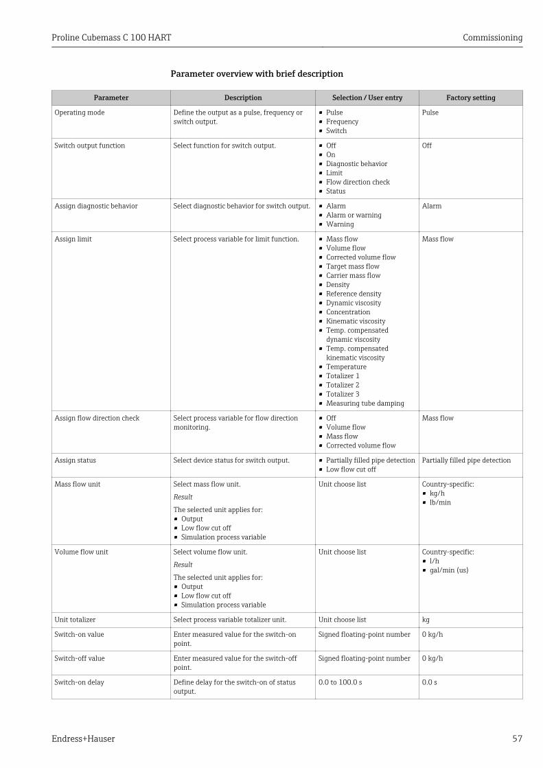
Proline Cubemass C 100 HART Commissioning
Endress+Hauser 57
Parameter overview with brief description
Parameter Description Selection / User entry Factory setting
Operating mode Define the output as a pulse, frequency orswitch output.
• Pulse• Frequency• Switch
Pulse
Switch output function Select function for switch output. • Off• On• Diagnostic behavior• Limit• Flow direction check• Status
Off
Assign diagnostic behavior Select diagnostic behavior for switch output. • Alarm• Alarm or warning• Warning
Alarm
Assign limit Select process variable for limit function. • Mass flow• Volume flow• Corrected volume flow• Target mass flow• Carrier mass flow• Density• Reference density• Dynamic viscosity• Concentration• Kinematic viscosity• Temp. compensated
dynamic viscosity• Temp. compensated
kinematic viscosity• Temperature• Totalizer 1• Totalizer 2• Totalizer 3• Measuring tube damping
Mass flow
Assign flow direction check Select process variable for flow directionmonitoring.
• Off• Volume flow• Mass flow• Corrected volume flow
Mass flow
Assign status Select device status for switch output. • Partially filled pipe detection• Low flow cut off
Partially filled pipe detection
Mass flow unit Select mass flow unit.
Result
The selected unit applies for:• Output• Low flow cut off• Simulation process variable
Unit choose list Country-specific:• kg/h• lb/min
Volume flow unit Select volume flow unit.
Result
The selected unit applies for:• Output• Low flow cut off• Simulation process variable
Unit choose list Country-specific:• l/h• gal/min (us)
Unit totalizer Select process variable totalizer unit. Unit choose list kg
Switch-on value Enter measured value for the switch-onpoint.
Signed floating-point number 0 kg/h
Switch-off value Enter measured value for the switch-offpoint.
Signed floating-point number 0 kg/h
Switch-on delay Define delay for the switch-on of statusoutput.
0.0 to 100.0 s 0.0 s
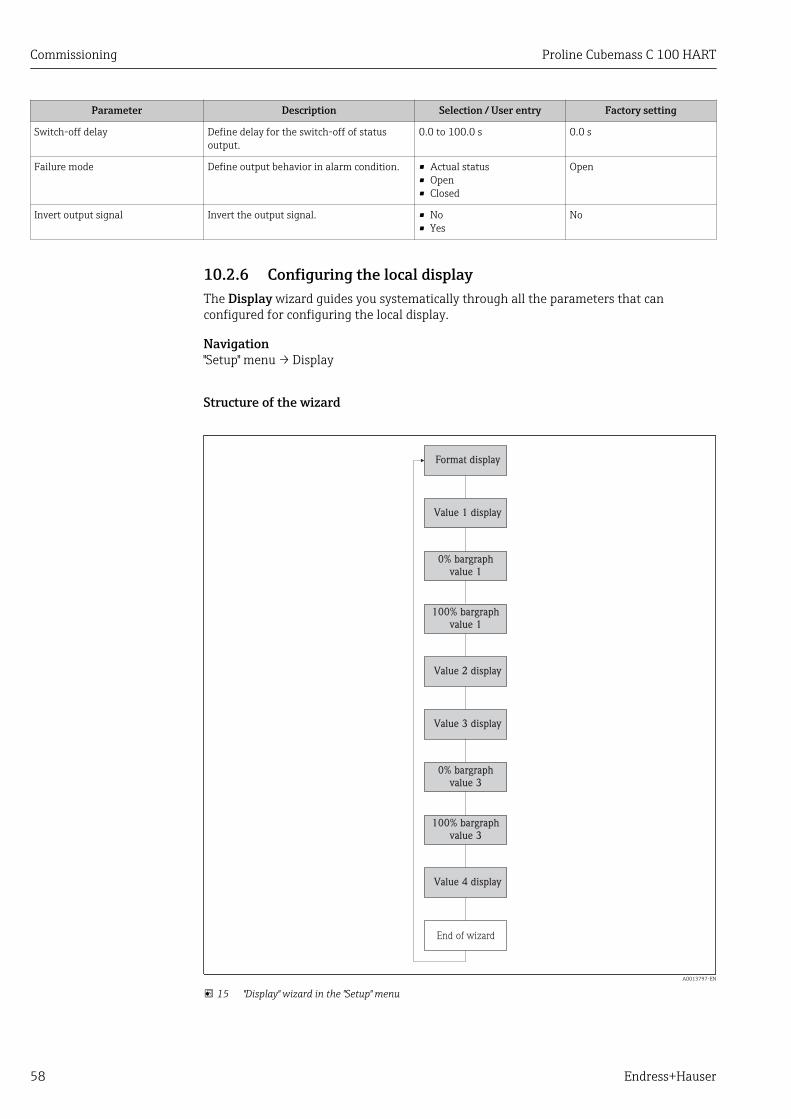
Commissioning Proline Cubemass C 100 HART
58 Endress+Hauser
Parameter Description Selection / User entry Factory setting
Switch-off delay Define delay for the switch-off of statusoutput.
0.0 to 100.0 s 0.0 s
Failure mode Define output behavior in alarm condition. • Actual status• Open• Closed
Open
Invert output signal Invert the output signal. • No• Yes
No
10.2.6 Configuring the local displayThe Display wizard guides you systematically through all the parameters that canconfigured for configuring the local display.
Navigation"Setup" menu → Display
Structure of the wizard
Format display
Value 1 display
0% bargraph
value 1
100% bargraph
value 1
Value 2 display
Value 3 display
0% bargraph
value 3
100% bargraph
value 3
Value 4 display
End of wizard
A0013797-EN
15 "Display" wizard in the "Setup" menu

Proline Cubemass C 100 HART Commissioning
Endress+Hauser 59
Parameter overview with brief description
Parameter Description Selection / User entry Factory setting
Format display Select how measured values are shown onthe display.
• 1 value, max. size• 1 bargraph + 1 value• 2 values• 1 value large + 2 values• 4 values
1 value, max. size
Value 1 display Select the measured value that is shown onthe local display.
• Mass flow• Volume flow• Corrected volume flow• Target mass flow• Carrier mass flow• Density• Reference density• Concentration• Dynamic viscosity• Kinematic viscosity• Temp. compensated
dynamic viscosity• Temp. compensated
kinematic viscosity• Temperature• Carrier pipe temperature• Electronic temperature• Oscillation frequency 0• Oscillation frequency 1• Oscillation amplitude 0• Oscillation amplitude 1• Frequency fluctuation 0• Frequency fluctuation 1• Oscillation damping 0• Oscillation damping 1• Tube damping fluctuation 0• Tube damping fluctuation 1• Signal asymmetry• Exciter current 0• Exciter current 1• Sensor integrity• None• Totalizer 1• Totalizer 2• Totalizer 3• Current output 1
Mass flow
0% bargraph value 1 Enter 0% value for bar graph display. Signed floating-point number 0 kg/h
100% bargraph value 1 Enter 100% value for bar graph display. Signed floating-point number 2.5 kg/h
Value 2 display Select the measured value that is shown onthe local display.
Picklist (see 1st display value) None
Value 3 display Select the measured value that is shown onthe local display.
Picklist (see 1st display value) None
0% bargraph value 3 Enter 0% value for bar graph display. Signed floating-point number 0
100% bargraph value 3 Enter 100% value for bar graph display. Signed floating-point number 0
Value 4 display Select the measured value that is shown onthe local display.
Picklist (see 1st display value) None
10.2.7 Configuring the HART inputThe HART input submenu contains all the parameters that must be configured for theconfiguration of the HART input.
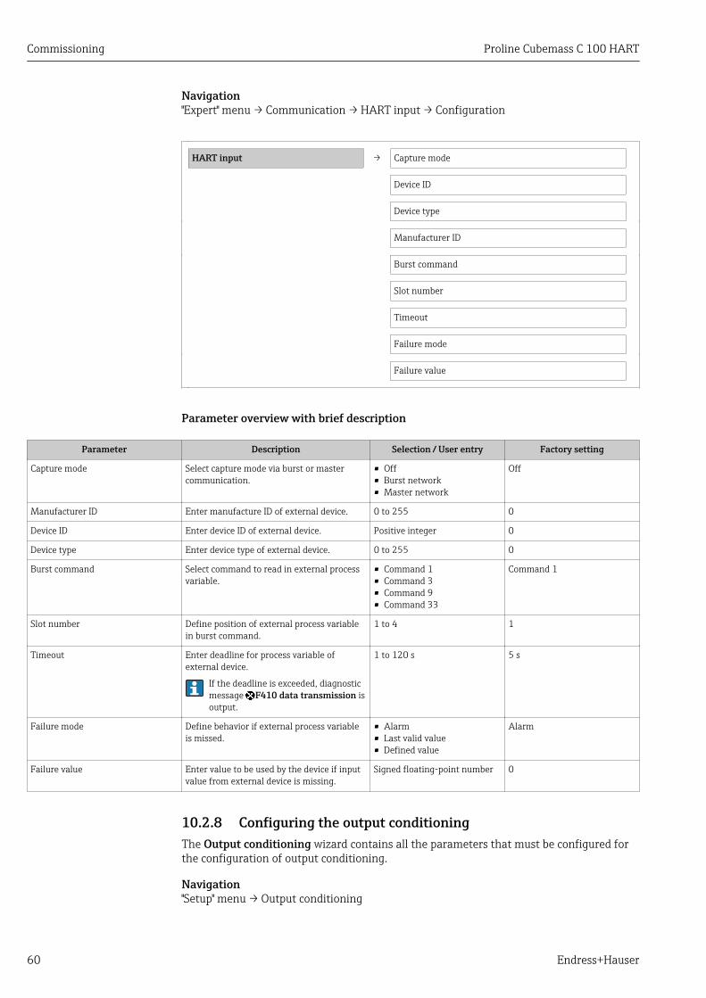
Commissioning Proline Cubemass C 100 HART
60 Endress+Hauser
Navigation"Expert" menu → Communication → HART input → Configuration
HART input → Capture mode
Device ID
Device type
Manufacturer ID
Burst command
Slot number
Timeout
Failure mode
Failure value
Parameter overview with brief description
Parameter Description Selection / User entry Factory setting
Capture mode Select capture mode via burst or mastercommunication.
• Off• Burst network• Master network
Off
Manufacturer ID Enter manufacture ID of external device. 0 to 255 0
Device ID Enter device ID of external device. Positive integer 0
Device type Enter device type of external device. 0 to 255 0
Burst command Select command to read in external processvariable.
• Command 1• Command 3• Command 9• Command 33
Command 1
Slot number Define position of external process variablein burst command.
1 to 4 1
Timeout Enter deadline for process variable ofexternal device.
If the deadline is exceeded, diagnosticmessage F410 data transmission isoutput.
1 to 120 s 5 s
Failure mode Define behavior if external process variableis missed.
• Alarm• Last valid value• Defined value
Alarm
Failure value Enter value to be used by the device if inputvalue from external device is missing.
Signed floating-point number 0
10.2.8 Configuring the output conditioningThe Output conditioning wizard contains all the parameters that must be configured forthe configuration of output conditioning.
Navigation"Setup" menu → Output conditioning

Proline Cubemass C 100 HART Commissioning
Endress+Hauser 61
Structure of the submenu for output conditioning
Output conditioning → Assign current output
Damping output
Measuring mode output
Assign frequency output
Damping output
Measuring mode output
Assign pulse output
Measuring mode output
Operating mode totalizer
Parameter overview with brief description
Parameter Description Selection / User entry Factory setting
Assign current output Select process variable for current output. • Off• Mass flow• Volume flow• Corrected volume flow• Target mass flow• Carrier mass flow• Density• Reference density• Concentration• Dynamic viscosity• Kinematic viscosity• Temp. compensated
dynamic viscosity• Temp. compensated
kinematic viscosity• Temperature• Carrier pipe temperature• Electronic temperature• Oscillation frequency 0• Oscillation frequency 1• Oscillation amplitude 0• Oscillation amplitude 1• Frequency fluctuation 0• Frequency fluctuation 1• Oscillation damping 0• Oscillation damping 1• Tube damping fluctuation 0• Tube damping fluctuation 1• Signal asymmetry• Exciter current 0• Exciter current 1• Sensor integrity
Mass flow
Damping output # Set reaction time for output signal tofluctuations in the measured value.
0 to 999.9 s 1 s
Measuring mode output # Select measuring mode for output. • Forward flow• Forward/Reverse flow• Reverse flow compensation
Forward flow

Commissioning Proline Cubemass C 100 HART
62 Endress+Hauser
Parameter Description Selection / User entry Factory setting
Assign frequency output Select process variable for frequency output. • Off• Mass flow• Volume flow• Corrected volume flow• Target mass flow• Carrier mass flow• Density• Reference density• Concentration• Dynamic viscosity• Kinematic viscosity• Temp. compensated
dynamic viscosity• Temp. compensated
kinematic viscosity• Temperature• Carrier pipe temperature• Electronic temperature• Oscillation frequency 0• Oscillation frequency 1• Frequency fluctuation 0• Frequency fluctuation 1• Oscillation amplitude 0• Oscillation amplitude 1• Oscillation damping 0• Oscillation damping 1• Tube damping fluctuation 0• Tube damping fluctuation 1• Signal asymmetry• Exciter current 0• Exciter current 1
Off
Damping output # Set reaction time for output signal tofluctuations in the measured value.
0 to 999.9 s 1 s
Measuring mode output # Select measuring mode for output. • Forward flow• Forward/Reverse flow• Reverse flow• Reverse flow compensation
Forward flow
Assign pulse output Select process variable for pulse output. • Off• Mass flow• Volume flow• Corrected volume flow• Target mass flow• Carrier mass flow
Off
Measuring mode output # Select measuring mode for output. • Forward flow• Forward/Reverse flow• Reverse flow• Reverse flow compensation
Forward flow
Operating mode totalizer # Select totalizer calculation mode. • Net flow total• Forward flow total• Reverse flow total
Net flow total
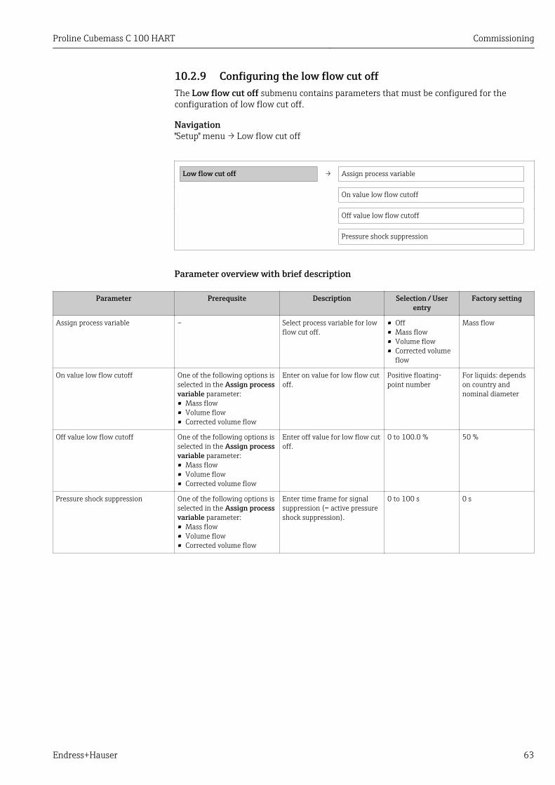
Proline Cubemass C 100 HART Commissioning
Endress+Hauser 63
10.2.9 Configuring the low flow cut offThe Low flow cut off submenu contains parameters that must be configured for theconfiguration of low flow cut off.
Navigation"Setup" menu → Low flow cut off
Low flow cut off → Assign process variable
On value low flow cutoff
Off value low flow cutoff
Pressure shock suppression
Parameter overview with brief description
Parameter Prerequsite Description Selection / Userentry
Factory setting
Assign process variable – Select process variable for lowflow cut off.
• Off• Mass flow• Volume flow• Corrected volume
flow
Mass flow
On value low flow cutoff One of the following options isselected in the Assign processvariable parameter:• Mass flow• Volume flow• Corrected volume flow
Enter on value for low flow cutoff.
Positive floating-point number
For liquids: dependson country andnominal diameter
Off value low flow cutoff One of the following options isselected in the Assign processvariable parameter:• Mass flow• Volume flow• Corrected volume flow
Enter off value for low flow cutoff.
0 to 100.0 % 50 %
Pressure shock suppression One of the following options isselected in the Assign processvariable parameter:• Mass flow• Volume flow• Corrected volume flow
Enter time frame for signalsuppression (= active pressureshock suppression).
0 to 100 s 0 s

Commissioning Proline Cubemass C 100 HART
64 Endress+Hauser
10.2.10 Configuring the partial filled pipe detectionThe Partially filled pipe detection submenu contains parameters that have to be set forconfiguring empty pipe detection.
Navigation"Setup" menu → Partially filled pipe detection
Partially filled pipe detection → Assign process variable
Low value partial filled pipe detection
High value partial filled pipe detection
Response time part. filled pipe detect.
Parameter overview with brief description
Parameter Prerequsite Description Selection / Userentry
Factory setting
Assign process variable – Select process variable forpartially filled pipe detection.
• Off• Density• Reference density
Off
Low value partial filled pipedetection
One of the following options isselected in the Assign processvariable parameter:• Density• Reference density
Enter lower limit value fordeactivating partialy filled pipedetection.
Signed floating-pointnumber
Country-dependent:• 0.2 kg/l• 12.5 lb/ft³
High value partial filled pipedetection
One of the following options isselected in the Assign processvariable parameter:• Density• Reference density
Enter upper limit value fordeactivating partialy filled pipedetection.
Signed floating-pointnumber
Country-dependent:• 6 kg/l• 374.6 lb/ft³
Response time part. filled pipedetect.
One of the following options isselected in the Assign processvariable parameter:• Density• Reference density
Enter time before diagnosticmessage is displayed forpartially filled pipe detection.
0 to 100 s 1 s
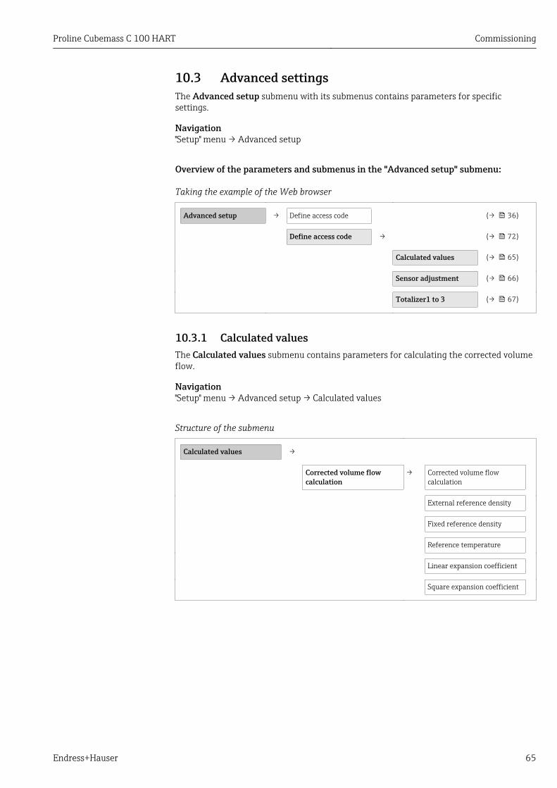
Proline Cubemass C 100 HART Commissioning
Endress+Hauser 65
10.3 Advanced settingsThe Advanced setup submenu with its submenus contains parameters for specificsettings.
Navigation"Setup" menu → Advanced setup
Overview of the parameters and submenus in the "Advanced setup" submenu:
Taking the example of the Web browser
Advanced setup → Define access code (→ 36)
Define access code → (→ 72)
Calculated values (→ 65)
Sensor adjustment (→ 66)
Totalizer1 to 3 (→ 67)
10.3.1 Calculated valuesThe Calculated values submenu contains parameters for calculating the corrected volumeflow.
Navigation"Setup" menu → Advanced setup → Calculated values
Structure of the submenu
Calculated values →
Corrected volume flowcalculation
→ Corrected volume flowcalculation
External reference density
Fixed reference density
Reference temperature
Linear expansion coefficient
Square expansion coefficient

Commissioning Proline Cubemass C 100 HART
66 Endress+Hauser
Parameter overview with brief description
Parameter Prerequsite Description Selection / Userentry
Factory setting
Corrected volume flow calculation – Select reference density forcalculating the correctedvolume flow.
• Fixed referencedensity
• Calculatedreference density
• Reference densityby API table 53
Calculated referencedensity
External reference density – Shows external referencedensity.
Floating pointnumber with sign
0 kg/Nl
Fixed reference density The following option isselected in the Correctedvolume flow calculationparameter:Fixed reference density
Enter fixed value for referencedensity.
Positive floating-point number
1 kg/Nl
Reference temperature The following option isselected in the Correctedvolume flow calculationparameter:Calculated reference density
Enter reference temperaturefor calculating the referencedensity.
–273.15 to 99 999 °C 20 °C
Linear expansion coefficient The following option isselected in the Correctedvolume flow calculationparameter:Calculated reference density
Enter linear, medium-specificexpansion coefficient forcalculating the referencedensity.
Signed floating-pointnumber
0.0
Square expansion coefficient – For media with a non-linearexpansion pattern: enter thequadratic, medium-specificexpansion coefficient forcalculating the referencedensity.
Signed floating-pointnumber
0.0
10.3.2 Carrying out a sensor adjustmentThe Sensor adjustment submenu contains parameters that pertain to the functionality ofthe sensor.
Navigation"Setup" menu → Advanced setup → Sensor adjustment
Structure of the submenu
Sensor adjustment → Installation direction →
Zero point adjustment → Zero point adjustment control
Progress
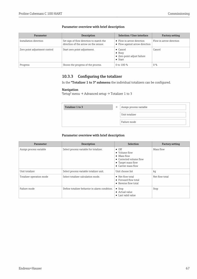
Proline Cubemass C 100 HART Commissioning
Endress+Hauser 67
Parameter overview with brief description
Parameter Description Selection / User interface Factory setting
Installation direction Set sign of flow direction to match thedirection of the arrow on the sensor.
• Flow in arrow direction• Flow against arrow direction
Flow in arrow direction
Zero point adjustment control Start zero point adjustment. • Cancel• Busy• Zero point adjust failure• Start
Cancel
Progress Shows the progress of the process. 0 to 100 % 0 %
10.3.3 Configuring the totalizerIn the "Totalizer 1 to 3" submenu the individual totalizers can be configured.
Navigation"Setup" menu → Advanced setup → Totalizer 1 to 3
Totalizer 1 to 3 → Assign process variable
Unit totalizer
Failure mode
Parameter overview with brief description
Parameter Description Selection Factory setting
Assign process variable Select process variable for totalizer. • Off• Volume flow• Mass flow• Corrected volume flow• Target mass flow• Carrier mass flow
Mass flow
Unit totalizer Select process variable totalizer unit. Unit choose list kg
Totalizer operation mode Select totalizer calculation mode. • Net flow total• Forward flow total• Reverse flow total
Net flow total
Failure mode Define totalizer behavior in alarm condition. • Stop• Actual value• Last valid value
Stop

Commissioning Proline Cubemass C 100 HART
68 Endress+Hauser
10.3.4 Carrying out additional display configurationsIn the "Display" submenu you can set all the parameters involved in the configuration ofthe local display.
Navigation"Setup" menu → Advanced setup → Display
Structure of the submenu
Display → Format display
Value 1 display
0% bargraph value 1
100% bargraph value 1
Decimal places 1
Value 2 display
Decimal places 2
Value 3 display
0% bargraph value 3
100% bargraph value 3
Decimal places 3
Value 4 display
Decimal places 4
Display language
Display interval
Display damping
Header
Header text
Separator
Backlight
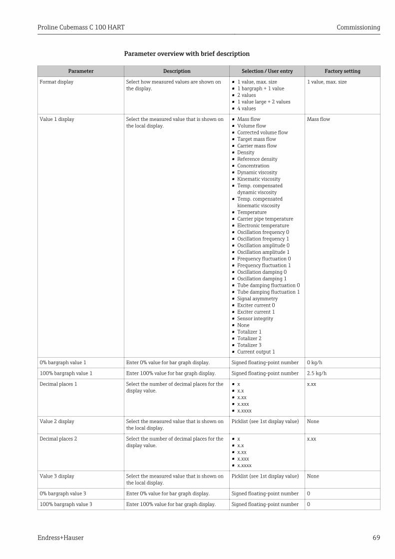
Proline Cubemass C 100 HART Commissioning
Endress+Hauser 69
Parameter overview with brief description
Parameter Description Selection / User entry Factory setting
Format display Select how measured values are shown onthe display.
• 1 value, max. size• 1 bargraph + 1 value• 2 values• 1 value large + 2 values• 4 values
1 value, max. size
Value 1 display Select the measured value that is shown onthe local display.
• Mass flow• Volume flow• Corrected volume flow• Target mass flow• Carrier mass flow• Density• Reference density• Concentration• Dynamic viscosity• Kinematic viscosity• Temp. compensated
dynamic viscosity• Temp. compensated
kinematic viscosity• Temperature• Carrier pipe temperature• Electronic temperature• Oscillation frequency 0• Oscillation frequency 1• Oscillation amplitude 0• Oscillation amplitude 1• Frequency fluctuation 0• Frequency fluctuation 1• Oscillation damping 0• Oscillation damping 1• Tube damping fluctuation 0• Tube damping fluctuation 1• Signal asymmetry• Exciter current 0• Exciter current 1• Sensor integrity• None• Totalizer 1• Totalizer 2• Totalizer 3• Current output 1
Mass flow
0% bargraph value 1 Enter 0% value for bar graph display. Signed floating-point number 0 kg/h
100% bargraph value 1 Enter 100% value for bar graph display. Signed floating-point number 2.5 kg/h
Decimal places 1 Select the number of decimal places for thedisplay value.
• x• x.x• x.xx• x.xxx• x.xxxx
x.xx
Value 2 display Select the measured value that is shown onthe local display.
Picklist (see 1st display value) None
Decimal places 2 Select the number of decimal places for thedisplay value.
• x• x.x• x.xx• x.xxx• x.xxxx
x.xx
Value 3 display Select the measured value that is shown onthe local display.
Picklist (see 1st display value) None
0% bargraph value 3 Enter 0% value for bar graph display. Signed floating-point number 0
100% bargraph value 3 Enter 100% value for bar graph display. Signed floating-point number 0
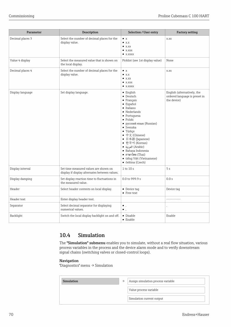
Commissioning Proline Cubemass C 100 HART
70 Endress+Hauser
Parameter Description Selection / User entry Factory setting
Decimal places 3 Select the number of decimal places for thedisplay value.
• x• x.x• x.xx• x.xxx• x.xxxx
x.xx
Value 4 display Select the measured value that is shown onthe local display.
Picklist (see 1st display value) None
Decimal places 4 Select the number of decimal places for thedisplay value.
• x• x.x• x.xx• x.xxx• x.xxxx
x.xx
Display language Set display language. • English• Deutsch• Français• Español• Italiano• Nederlands• Portuguesa• Polski• русский язык (Russian)• Svenska• Türkçe• 中文 (Chinese)• 日本語 (Japanese)• 한국어 (Korean)• (Arabic) العربية• Bahasa Indonesia• ภาษาไทย (Thai)• tiếng Việt (Vietnamese)• čeština (Czech)
English (alternatively, theordered language is preset inthe device)
Display interval Set time measured values are shown ondisplay if display alternates between values.
1 to 10 s 5 s
Display damping Set display reaction time to fluctuations inthe measured value.
0.0 to 999.9 s 0.0 s
Header Select header contents on local display. • Device tag• Free text
Device tag
Header text Enter display header text. ------------
Separator Select decimal separator for displayingnumerical values.
• .• ,
.
Backlight Switch the local display backlight on and off. • Disable• Enable
Enable
10.4 SimulationThe "Simulation" submenu enables you to simulate, without a real flow situation, variousprocess variables in the process and the device alarm mode and to verify downstreamsignal chains (switching valves or closed-control loops).
Navigation"Diagnostics" menu → Simulation
Simulation → Assign simulation process variable
Value process variable
Simulation current output

Proline Cubemass C 100 HART Commissioning
Endress+Hauser 71
Value current output
Frequency simulation
Frequency value
Pulse simulation
Pulse value
Switch output simulation
Switch status
Simulation device alarm
Simulation diagnostic event
Parameter overview with brief description
Parameter Prerequsite Description Selection / Userentry
Factory setting
Assign simulation process variable – Select a process variable forthe simulation process that isactivated.
• Off• Mass flow• Volume flow• Corrected volume
flow• Density• Reference density• Temperature• Dynamic viscosity• Kinematic viscosity• Temp.
compensateddynamic viscosity
• Temp.compensatedkinematic viscosity
• Concentration• Target mass flow• Carrier mass flow
Off
Value process variable A process variable is selectedin the Assign simulationprocess variable parameter.
Enter the simulation value forthe selected process variable.
Signed floating-pointnumber
0
Simulation current output 1 – Switch simulation of thecurrent output on and off.
• Off• On
Off
Value current output 1 The On option is selected inthe Current outputsimulation parameter.
Enter the current value forsimulation.
3.59-3 to 22.5-3 mA 3.59 mA
Frequency simulation 1 – Switch simulation of thefrequency output on and off.
• Off• On
Off
Frequency value 1 The On option is selected inthe Frequency outputsimulation parameter.
Enter the frequency value forsimulation.
0.0 to 12 500.0 Hz 0.0 Hz
Pulse simulation 1 The Down-count. val. optionis selected in the Simulationpulse output parameter.
Switch simulation of the pulseoutput on and off.
If the Fixed value optionis selected, the Pulsewidth parameter definesthe pulse width of thepulses output.
• Off• Fixed value• Down-counting
value
Off
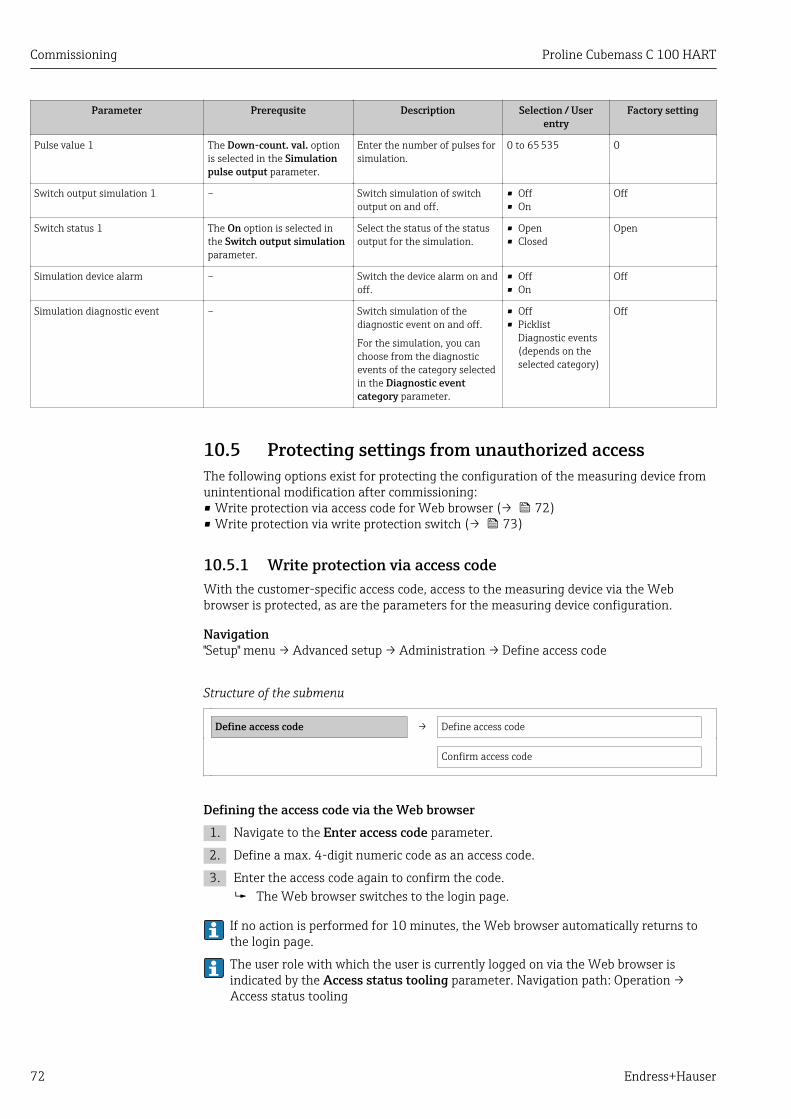
Commissioning Proline Cubemass C 100 HART
72 Endress+Hauser
Parameter Prerequsite Description Selection / Userentry
Factory setting
Pulse value 1 The Down-count. val. optionis selected in the Simulationpulse output parameter.
Enter the number of pulses forsimulation.
0 to 65 535 0
Switch output simulation 1 – Switch simulation of switchoutput on and off.
• Off• On
Off
Switch status 1 The On option is selected inthe Switch output simulationparameter.
Select the status of the statusoutput for the simulation.
• Open• Closed
Open
Simulation device alarm – Switch the device alarm on andoff.
• Off• On
Off
Simulation diagnostic event – Switch simulation of thediagnostic event on and off.
For the simulation, you canchoose from the diagnosticevents of the category selectedin the Diagnostic eventcategory parameter.
• Off• Picklist
Diagnostic events(depends on theselected category)
Off
10.5 Protecting settings from unauthorized accessThe following options exist for protecting the configuration of the measuring device fromunintentional modification after commissioning:• Write protection via access code for Web browser (→ 72)• Write protection via write protection switch (→ 73)
10.5.1 Write protection via access codeWith the customer-specific access code, access to the measuring device via the Webbrowser is protected, as are the parameters for the measuring device configuration.
Navigation"Setup" menu → Advanced setup → Administration → Define access code
Structure of the submenu
Define access code → Define access code
Confirm access code
Defining the access code via the Web browser1. Navigate to the Enter access code parameter.
2. Define a max. 4-digit numeric code as an access code.
3. Enter the access code again to confirm the code. The Web browser switches to the login page.
If no action is performed for 10 minutes, the Web browser automatically returns tothe login page.
The user role with which the user is currently logged on via the Web browser isindicated by the Access status tooling parameter. Navigation path: Operation →Access status tooling
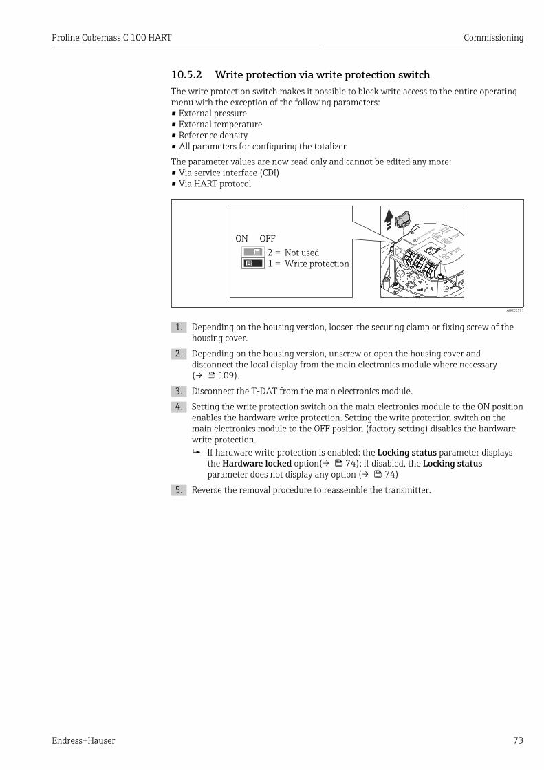
Proline Cubemass C 100 HART Commissioning
Endress+Hauser 73
10.5.2 Write protection via write protection switchThe write protection switch makes it possible to block write access to the entire operatingmenu with the exception of the following parameters:• External pressure• External temperature• Reference density• All parameters for configuring the totalizer
The parameter values are now read only and cannot be edited any more:• Via service interface (CDI)• Via HART protocol
ON OFF
1 = Write protection
2 = Not used
A0022571
1. Depending on the housing version, loosen the securing clamp or fixing screw of thehousing cover.
2. Depending on the housing version, unscrew or open the housing cover anddisconnect the local display from the main electronics module where necessary(→ 109).
3. Disconnect the T-DAT from the main electronics module.
4. Setting the write protection switch on the main electronics module to the ON positionenables the hardware write protection. Setting the write protection switch on themain electronics module to the OFF position (factory setting) disables the hardwarewrite protection. If hardware write protection is enabled: the Locking status parameter displays
the Hardware locked option(→ 74); if disabled, the Locking statusparameter does not display any option (→ 74)
5. Reverse the removal procedure to reassemble the transmitter.
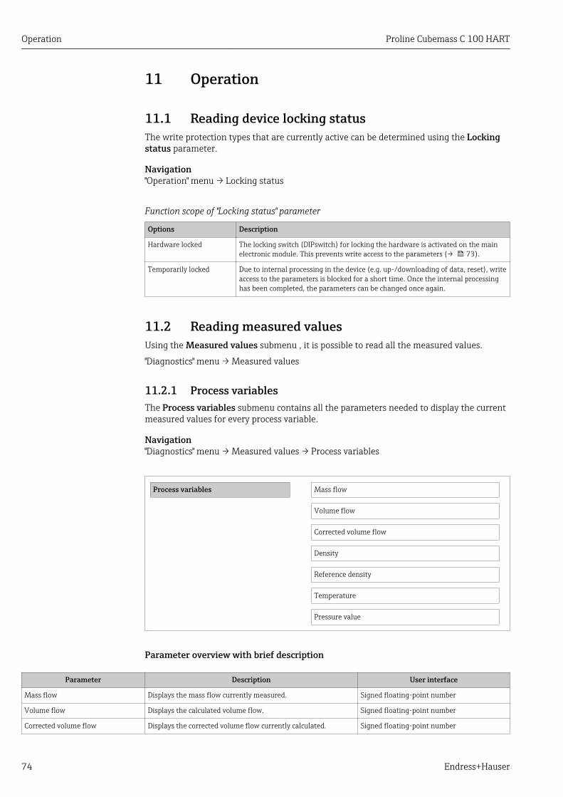
Operation Proline Cubemass C 100 HART
74 Endress+Hauser
11 Operation
11.1 Reading device locking statusThe write protection types that are currently active can be determined using the Lockingstatus parameter.
Navigation"Operation" menu → Locking status
Function scope of "Locking status" parameter
Options Description
Hardware locked The locking switch (DIPswitch) for locking the hardware is activated on the mainelectronic module. This prevents write access to the parameters (→ 73).
Temporarily locked Due to internal processing in the device (e.g. up-/downloading of data, reset), writeaccess to the parameters is blocked for a short time. Once the internal processinghas been completed, the parameters can be changed once again.
11.2 Reading measured valuesUsing the Measured values submenu , it is possible to read all the measured values.
"Diagnostics" menu → Measured values
11.2.1 Process variablesThe Process variables submenu contains all the parameters needed to display the currentmeasured values for every process variable.
Navigation"Diagnostics" menu → Measured values → Process variables
Process variables Mass flow
Volume flow
Corrected volume flow
Density
Reference density
Temperature
Pressure value
Parameter overview with brief description
Parameter Description User interface
Mass flow Displays the mass flow currently measured. Signed floating-point number
Volume flow Displays the calculated volume flow. Signed floating-point number
Corrected volume flow Displays the corrected volume flow currently calculated. Signed floating-point number

Proline Cubemass C 100 HART Operation
Endress+Hauser 75
Parameter Description User interface
Density Displays the density currently measured. Signed floating-point number
Reference density Displays the reference density currently calculated. Signed floating-point number
Temperature Displays the temperature currently measured. Signed floating-point number
Pressure value Displays either a fixed or external pressure value. Signed floating-point number
11.2.2 TotalizerThe "Totalizer" submenu contains all the parameters needed to display the currentmeasured values for every totalizer.
Navigation"Diagnostics" menu → Measured values → Totalizer
Structure of the submenu
Totalizer → Totalizer value
Totalizer overflow
Parameter overview with brief description
Parameter Prerequsite Description User interface Factory setting
Totalizer value 1 In the Assign process variableparameter of Totalizer 1 to 3submenu one of the followingoptions is selected:• Volume flow• Mass flow• Corrected volume flow
Displays the current totalizercounter value.
Signed floating-pointnumber
0 kg
Totalizer overflow 1 In the Assign process variableparameter of Totalizer 1 to 3submenu one of the followingoptions is selected:• Volume flow• Mass flow• Corrected volume flow
Displays the current totalizeroverflow.
–32 000.0 to32 000.0
0
11.2.3 Output valuesThe "Output values" submenu contains all the parameters needed to display the currentmeasured values for every output.
Navigation"Diagnostics" menu → Measured values → Output values
Structure of the submenu
Output values → Output current 1
Measured current 1
Pulse output 1

Operation Proline Cubemass C 100 HART
76 Endress+Hauser
Output frequency 1
Switch status 1
Parameter overview with brief description
Parameter Description User interface Factory setting
Output current 1 Displays the current value currentlycalculated for the current output.
3.59 to 22.5 mA 3.59 mA
Measured current 1 Displays the current value currentlymeasured for the current output.
0 to 30 mA 0 mA
Pulse output 1 Displays the value currently measured forthe pulse output.
Positive floating-point number 0 Hz
Output frequency 1 Displays the value currently measured forthe frequency output.
0.0 to 12 500.0 Hz 0.0 Hz
Switch status 1 Displays the current switch output status. • Open• Closed
Open
11.3 Adapting the measuring device to the processconditions
The following are available for this purpose:• Basic settings using the Setup menu(→ 48)• Advanced settings using the Advanced setup submenu(→ 65)
11.4 Performing a totalizer resetIn the Operation submenu the totalizers are reset:• Control Totalizer• Reset all totalizers
Function scope of "Control Totalizer " parameter
Options Description
Totalize The totalizer is started.
Stop Totalizing is stopped.
Reset + hold The totaling process is stopped and the totalizer is reset to 0.
Preset + hold The totaling process is stopped and the totalizer is set to its defined start valuefrom the Preset value parameter.
Reset + totalize The totalizer is reset to 0 and the totaling process is restarted.
Preset + totalize The totalizer is set to the defined start value in Preset value parameterand thetotaling process is restarted.
Function scope of "Reset all totalizers" parameter
Options Description
Reset + totalize Resets all totalizers to 0 and restarts the totaling process. This deletes all the flowvalues previously totalized.
Navigation"Operation" menu → Operation

Proline Cubemass C 100 HART Operation
Endress+Hauser 77
Structure of the submenu
Operation → Control Totalizer
Preset value
Reset all totalizers
Parameter overview with brief description
Parameter Description Selection / User entry Factory setting
Control Totalizer # Control totalizer value. • Totalize• Reset + hold• Preset + hold• Reset + totalize• Preset + totalize
Totalize
Preset value # Specify start value for totalizer. Signed floating-point number 0 kg
Reset all totalizers Reset all totalizers to 0 and start. • Cancel• Reset + totalize
Cancel

Diagnostics and troubleshooting Proline Cubemass C 100 HART
78 Endress+Hauser
12 Diagnostics and troubleshooting
12.1 General troubleshooting
For output signals
Problem Possible causes Remedy
Green power LED on the mainelectronics module of thetransmitter is dark
Supply voltage does not match thatspecified on the nameplate.
Apply the correct supply voltage(→ 28).
Device measures incorrectly. Configuration error or device isoperated outside the application.
1. Check and correct parameterconfiguration.2. Observe limit values specified inthe "Technical Data".
For access
Problem Possible causes Remedy
No write access to parameters Hardware write protection enabled Set the write protection switch onthe main electronics module to theOFF position (→ 73).
No connection via HART protocol Missing or incorrectly installedcommunication resistor.
Install the communication resistor(250 Ω) correctly. Observe themaximum load (→ 97).
No connection via HART protocol Commubox• Connected incorrectly• Configured incorrectly• Drivers not installed correctly• USB interface on computer
configured incorrectly
Observe the documentation for theCommubox.
FXA195 HART: Document"Technical Information"TI00404F
Not connecting to Web server Incorrect setting for the Ethernetinterface of the computer
1. Check the properties of theInternet protocol (TCP/IP)(→ 35).2. Check the network settings withthe IT manager.
Not connecting to Web server Web server disabled Via the "FieldCare" operating toolcheck whether the Web server ofthe measuring device is enabledand enable it if necessary(→ 37).
No or incomplete display ofcontents in the Web browser
• JavaScript not enabled• JavaScript cannot be enabled
1. Enable JavaScript.2. Enter http://XXX.XXX.X.XXX/basic.html as the IP address.
Web browser frozen and operationno longer possible
Data transfer active Wait until data transfer or currentaction is finished.
Web browser frozen and operationno longer possible
Connection lost 1. Check cable connection andpower supply.2. Refresh the Web browser andrestart if necessary.
Content of Web browserincomplete or difficult to read
Not using optimum version of Webserver.
1. Use the correct Web browserversion (→ 35).2. Clear the Web browser cache andrestart the Web browser.
Content of Web browserincomplete or difficult to read
Unsuitable view settings. Change the font size/display ratioof the Web browser.

Proline Cubemass C 100 HART Diagnostics and troubleshooting
Endress+Hauser 79
12.2 Diagnostic information via light emitting diodes
12.2.1 TransmitterVarious light emitting diodes (LEDs) on the main electronics module of the transmitterprovide information on device status.
LED Color Meaning
Power Off Supply voltage is off or too low
Green Supply voltage is ok
Link/Activity Orange Link available but no activity
Flashing orange Activity present
Communication Flashing white HART communication is active.
12.3 Diagnostic information in FieldCare
12.3.1 Diagnostic optionsAny faults detected by the measuring device are displayed on the home page of theoperating tool once the connection has been established.
Xxxxxx/…/…/
Xxxxxx
P
P
P
+
+
+
+Diagnostics 1:
Remedy information:
Failure (F)
Function check (C)
Out of spezification (S)
Maintenance required (M)
C485 Simulation measured vari...
Deactivate Simulation (Service...
Diagnostics 1: C485 Simu...
Remedy information: Deactivate...
Access status tooling: Mainenance
Operation
Setup
Diagnostics
Expert
Function check (C)Status signal:
Device tag:
Device name: Mass flow:
Volume flow:Xxxxxxx
12.34 kg/h
12.34 m /h³
Xxxxxxx
1
2
3
A0021799-EN
1 Status area with status signal2 Diagnostic information (→ 80)3 Remedial measures with Service ID
Furthermore, diagnostic events that have occurred can be viewed in the Diagnosticsmenu:• Via parameters (→ 84)• Via submenu (→ 85)

Diagnostics and troubleshooting Proline Cubemass C 100 HART
80 Endress+Hauser
Status signalsThe status signals provide information on the state and reliability of the device bycategorizing the cause of the diagnostic information (diagnostic event).
Symbol Meaning
A0017271
FailureA device error has occurred. The measured value is no longer valid.
A0017278
Function checkThe device is in service mode (e.g. during a simulation).
A0017277
Out of specificationThe device is operated:• Outside its technical specification limits (e.g. outside the process temperature range)• Outside of the configuration carried out by the user (e.g. maximum flow in parameter
20 mA value)
A0017276
Maintenance requiredMaintenance is required. The measured value is still valid.
The status signals are categorized in accordance with VDI/VDE 2650 and NAMURRecommendation NE 107.
Diagnostic informationThe fault can be identified using the diagnostic information. The short text helps you byproviding information about the fault.
Diagnostic information
Diagnostic code
Status signal Diagnostic number Short text
↓ ↓ ↓
Example A0013958
842 Process limit
3-digit number
12.3.2 Calling up remedy informationRemedy information is provided for every diagnostic event to ensure that problems can berectified quickly:• On the home page
Remedy information is displayed in a separate field below the diagnostics information.• In the Diagnostics menu
Remedy information can be called up in the working area of the user interface.
The user is in the Diagnostics menu.
1. Call up the desired parameter.
2. On the right in the working area, mouse over the parameter. A tool tip with remedy information for the diagnostic event appears.

Proline Cubemass C 100 HART Diagnostics and troubleshooting
Endress+Hauser 81
12.4 Adapting the diagnostic information
12.4.1 Adapting the diagnostic behaviorEach item of diagnostic information is assigned a specific diagnostic behavior at thefactory. The user can change this assignment for certain diagnostics information in theDiagnostic behavior submenu .
"Expert" menu → System → Diagnostic handling → Diagnostic behavior
You can assign the following options to the diagnostic number as the diagnostic behavior:
Options Description
Alarm Measurement is interrupted. Signal outputs and totalizers assume the defined alarmcondition. A diagnostic message is generated.
Warning Measurement is resumed. The signal outputs and totalizers are not affected. Adiagnostic message is generated.
Logbook entry only The device continues to measure. The diagnostic message is entered in the Eventlogbook (events list) submenu only and is not displayed in alternation with the measuredvalue display.
Off The diagnostic event is ignored, and no diagnostic message is generated or entered.
12.4.2 Adapting the status signalEach item of diagnostic information is assigned a specific status signal at the factory. Theuser can change this assignment for certain diagnostic information in the Diagnosticevent category submenu .
"Expert" menu → Communication → Diagnostic event category
Available status signalsConfiguration as per HART 7 Specification (Condensed Status), in accordance withNAMUR NE107.
Symbol Meaning
A0013956
FailureA device error has occurred. The measured value is no longer valid.
A0013959
Function checkThe device is in service mode (e.g. during a simulation).
A0013958
Out of specificationThe device is being operated:• Outside its technical specification limits (e.g. outside the process temperature range)• Outside of the configuration carried out by the user (e.g. maximum flow in parameter
20 mA value)
A0013957
Maintenance requiredMaintenance is required. The measured value is still valid.
A0023076
Has no effect on the condensed status.
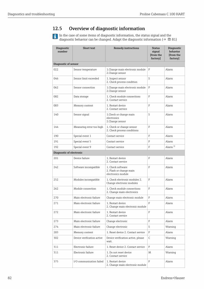
Diagnostics and troubleshooting Proline Cubemass C 100 HART
82 Endress+Hauser
12.5 Overview of diagnostic information In the case of some items of diagnostic information, the status signal and thediagnostic behavior can be changed. Adapt the diagnostic information (→ 81)
Diagnosticnumber
Short text Remedy instructions Statussignal
[from thefactory]
Diagnosticbehavior[from thefactory]
Diagnostic of sensor
022 Sensor temperature 1.Change main electronic module2.Change sensor
F Alarm
046 Sensor limit exceeded 1. Inspect sensor2. Check process condition
S Alarm
062 Sensor connection 1.Change main electronic module2.Change sensor
F Alarm
082 Data storage 1. Check module connections2. Contact service
F Alarm
083 Memory content 1. Restart device2. Contact service
F Alarm
140 Sensor signal 1.Check or change mainelectronics2.Change sensor
S Alarm
144 Measuring error too high 1. Check or change sensor2. Check process conditions
F Alarm
190 Special event 1 Contact service F Alarm
191 Special event 5 Contact service F Alarm
192 Special event 9 Contact service F Alarm 1)
Diagnostic of electronic
201 Device failure 1. Restart device2. Contact service
F Alarm
242 Software incompatible 1. Check software2. Flash or change mainelectronics module
F Alarm
252 Modules incompatible 1. Check electronic modules 2.Change electronic modules
F Alarm
262 Module connection 1. Check module connections2. Change main electronics
F Alarm
270 Main electronic failure Change main electronic module F Alarm
271 Main electronic failure 1. Restart device2. Change main electronic module
F Alarm
272 Main electronic failure 1. Restart device2. Contact service
F Alarm
273 Main electronic failure Change electronic F Alarm
274 Main electronic failure Change electronic S Warning
283 Memory content 1. Reset device 2. Contact service F Alarm
302 Device verification active Device verification active, pleasewait.
C Warning
311 Electronic failure 1. Reset device 2. Contact service F Alarm
311 Electronic failure 1. Do not reset device2. Contact service
M Warning
375 I/O communication failed 1. Restart device2. Change main electronic module
F Alarm
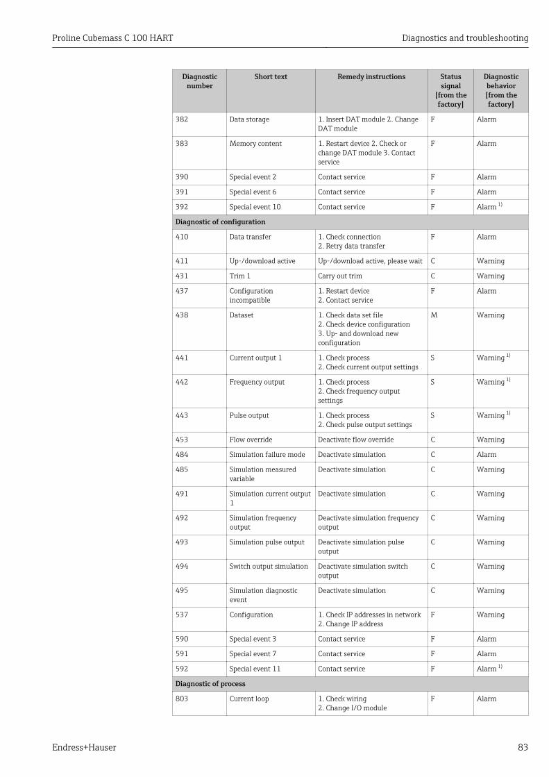
Proline Cubemass C 100 HART Diagnostics and troubleshooting
Endress+Hauser 83
Diagnosticnumber
Short text Remedy instructions Statussignal
[from thefactory]
Diagnosticbehavior[from thefactory]
382 Data storage 1. Insert DAT module 2. ChangeDAT module
F Alarm
383 Memory content 1. Restart device 2. Check orchange DAT module 3. Contactservice
F Alarm
390 Special event 2 Contact service F Alarm
391 Special event 6 Contact service F Alarm
392 Special event 10 Contact service F Alarm 1)
Diagnostic of configuration
410 Data transfer 1. Check connection2. Retry data transfer
F Alarm
411 Up-/download active Up-/download active, please wait C Warning
431 Trim 1 Carry out trim C Warning
437 Configurationincompatible
1. Restart device2. Contact service
F Alarm
438 Dataset 1. Check data set file2. Check device configuration3. Up- and download newconfiguration
M Warning
441 Current output 1 1. Check process2. Check current output settings
S Warning 1)
442 Frequency output 1. Check process2. Check frequency outputsettings
S Warning 1)
443 Pulse output 1. Check process2. Check pulse output settings
S Warning 1)
453 Flow override Deactivate flow override C Warning
484 Simulation failure mode Deactivate simulation C Alarm
485 Simulation measuredvariable
Deactivate simulation C Warning
491 Simulation current output1
Deactivate simulation C Warning
492 Simulation frequencyoutput
Deactivate simulation frequencyoutput
C Warning
493 Simulation pulse output Deactivate simulation pulseoutput
C Warning
494 Switch output simulation Deactivate simulation switchoutput
C Warning
495 Simulation diagnosticevent
Deactivate simulation C Warning
537 Configuration 1. Check IP addresses in network2. Change IP address
F Warning
590 Special event 3 Contact service F Alarm
591 Special event 7 Contact service F Alarm
592 Special event 11 Contact service F Alarm 1)
Diagnostic of process
803 Current loop 1. Check wiring2. Change I/O module
F Alarm
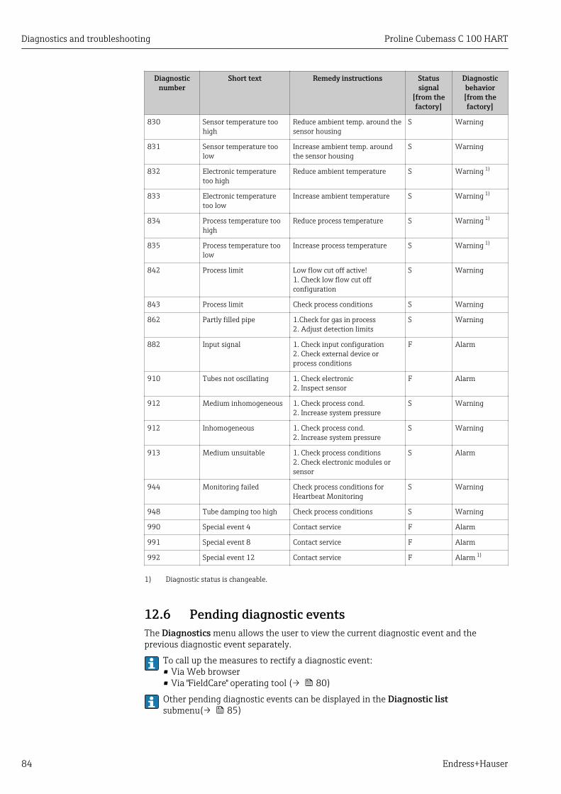
Diagnostics and troubleshooting Proline Cubemass C 100 HART
84 Endress+Hauser
Diagnosticnumber
Short text Remedy instructions Statussignal
[from thefactory]
Diagnosticbehavior[from thefactory]
830 Sensor temperature toohigh
Reduce ambient temp. around thesensor housing
S Warning
831 Sensor temperature toolow
Increase ambient temp. aroundthe sensor housing
S Warning
832 Electronic temperaturetoo high
Reduce ambient temperature S Warning 1)
833 Electronic temperaturetoo low
Increase ambient temperature S Warning 1)
834 Process temperature toohigh
Reduce process temperature S Warning 1)
835 Process temperature toolow
Increase process temperature S Warning 1)
842 Process limit Low flow cut off active!1. Check low flow cut offconfiguration
S Warning
843 Process limit Check process conditions S Warning
862 Partly filled pipe 1.Check for gas in process2. Adjust detection limits
S Warning
882 Input signal 1. Check input configuration2. Check external device orprocess conditions
F Alarm
910 Tubes not oscillating 1. Check electronic2. Inspect sensor
F Alarm
912 Medium inhomogeneous 1. Check process cond.2. Increase system pressure
S Warning
912 Inhomogeneous 1. Check process cond.2. Increase system pressure
S Warning
913 Medium unsuitable 1. Check process conditions2. Check electronic modules orsensor
S Alarm
944 Monitoring failed Check process conditions forHeartbeat Monitoring
S Warning
948 Tube damping too high Check process conditions S Warning
990 Special event 4 Contact service F Alarm
991 Special event 8 Contact service F Alarm
992 Special event 12 Contact service F Alarm 1)
1) Diagnostic status is changeable.
12.6 Pending diagnostic eventsThe Diagnostics menu allows the user to view the current diagnostic event and theprevious diagnostic event separately.
To call up the measures to rectify a diagnostic event:• Via Web browser• Via "FieldCare" operating tool (→ 80)
Other pending diagnostic events can be displayed in the Diagnostic listsubmenu(→ 85)
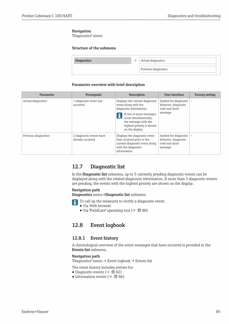
Proline Cubemass C 100 HART Diagnostics and troubleshooting
Endress+Hauser 85
Navigation"Diagnostics" menu
Structure of the submenu
Diagnostics → Actual diagnostics
Previous diagnostics
Parameter overview with brief description
Parameter Prerequsite Description User interface Factory setting
Actual diagnostics 1 diagnostic event hasoccurred.
Displays the current diagnosticevent along with thediagnostic information.
If two or more messagesoccur simultaneously,the message with thehighest priority is shownon the display.
Symbol for diagnosticbehavior, diagnosticcode and shortmessage.
–
Previous diagnostics 2 diagnostic events havealready occurred.
Displays the diagnostic eventthat occurred prior to thecurrent diagnostic event alongwith the diagnosticinformation.
Symbol for diagnosticbehavior, diagnosticcode and shortmessage.
–
12.7 Diagnostic listIn the Diagnostic list submenu, up to 5 currently pending diagnostic events can bedisplayed along with the related diagnostic information. If more than 5 diagnostic eventsare pending, the events with the highest priority are shown on the display.
Navigation pathDiagnostics menu→Diagnostic list submenu
To call up the measures to rectify a diagnostic event:• Via Web browser• Via "FieldCare" operating tool (→ 80)
12.8 Event logbook
12.8.1 Event historyA chronological overview of the event messages that have occurred is provided in theEvents list submenu.
Navigation path"Diagnostics" menu → Event logbook → Events list
The event history includes entries for:• Diagnostic events (→ 82)• Information events (→ 86)

Diagnostics and troubleshooting Proline Cubemass C 100 HART
86 Endress+Hauser
In addition to the operation time of its occurrence, each event is also assigned a symbolthat indicates whether the event has occurred or is ended:• Diagnostic event
– : Event has occurred– : Event has ended
• Information event: Event has occurred
To call up the measures to rectify a diagnostic event:• Via Web browser• Via "FieldCare" operating tool (→ 80)
For filtering the displayed event messages (→ 86)
12.8.2 Filtering the event logbookUsing the Filter options parameter, you can define which category of event messages isdisplayed in the Events list submenu.
Navigation path"Diagnostics" menu → Event logbook → Filter options
Filter categories• All• Failure (F)• Function check (C)• Out of specification (S)• Maintenance required (M)• Information (I)
12.8.3 Overview of information eventsUnlike a diagnostic event, an information event is displayed in the event logbook only andnot in the diagnostic list.
Info number Info name
I1000 --------(Device ok)
I1089 Power on
I1090 Configuration reset
I1091 Configuration changed
I1110 Write protection switch changed
I1111 Density adjust failure
I1137 Electronic changed
I1151 History reset
I1155 Reset electronic temperature
I1157 Memory error event list
I1185 Display backup done
I1186 Restore via display done
I1187 Settings downloaded with display
I1188 Display data cleared
I1189 Backup compared
I1209 Density adjustment ok
I1221 Zero point adjust failure
I1222 Zero point adjustment ok
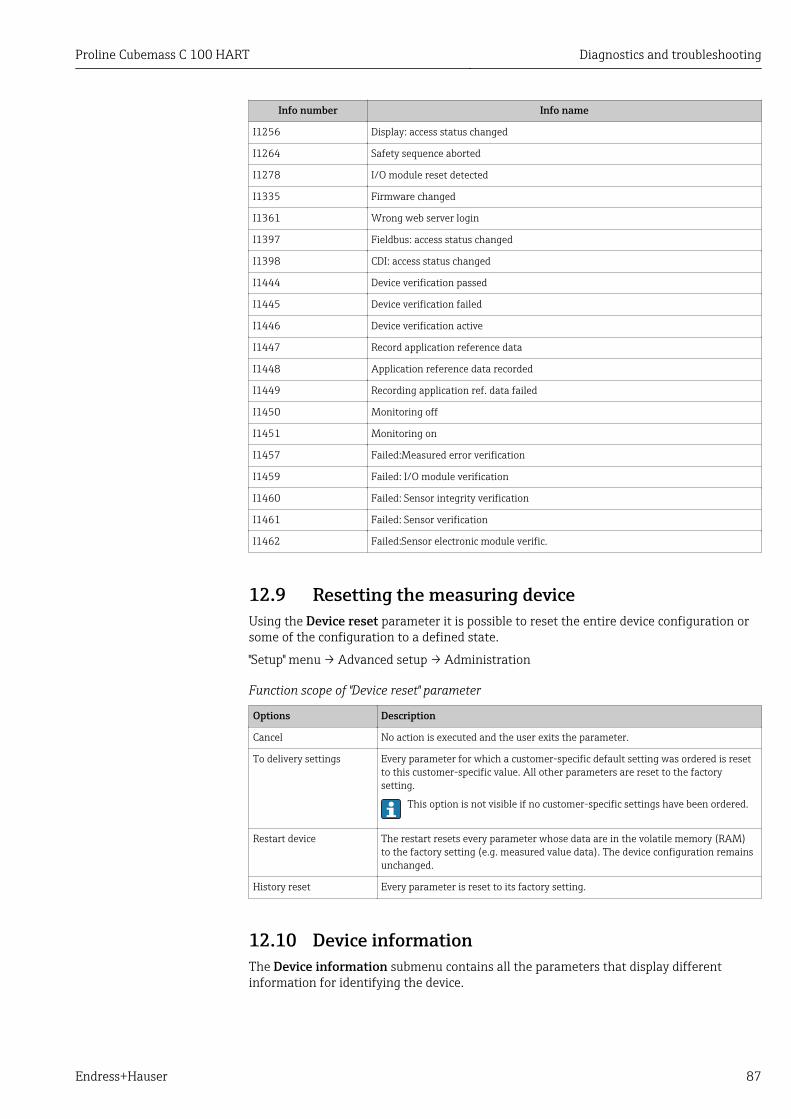
Proline Cubemass C 100 HART Diagnostics and troubleshooting
Endress+Hauser 87
Info number Info name
I1256 Display: access status changed
I1264 Safety sequence aborted
I1278 I/O module reset detected
I1335 Firmware changed
I1361 Wrong web server login
I1397 Fieldbus: access status changed
I1398 CDI: access status changed
I1444 Device verification passed
I1445 Device verification failed
I1446 Device verification active
I1447 Record application reference data
I1448 Application reference data recorded
I1449 Recording application ref. data failed
I1450 Monitoring off
I1451 Monitoring on
I1457 Failed:Measured error verification
I1459 Failed: I/O module verification
I1460 Failed: Sensor integrity verification
I1461 Failed: Sensor verification
I1462 Failed:Sensor electronic module verific.
12.9 Resetting the measuring deviceUsing the Device reset parameter it is possible to reset the entire device configuration orsome of the configuration to a defined state.
"Setup" menu → Advanced setup → Administration
Function scope of "Device reset" parameter
Options Description
Cancel No action is executed and the user exits the parameter.
To delivery settings Every parameter for which a customer-specific default setting was ordered is resetto this customer-specific value. All other parameters are reset to the factorysetting.
This option is not visible if no customer-specific settings have been ordered.
Restart device The restart resets every parameter whose data are in the volatile memory (RAM)to the factory setting (e.g. measured value data). The device configuration remainsunchanged.
History reset Every parameter is reset to its factory setting.
12.10 Device informationThe Device information submenu contains all the parameters that display differentinformation for identifying the device.

Diagnostics and troubleshooting Proline Cubemass C 100 HART
88 Endress+Hauser
Navigation"Diagnostics" menu → Device information
Device information → Device tag
Serial number
Firmware version
Device name
Order code
Extended order code 1
Extended order code 2
Extended order code 3
ENP version
Device revision
Device ID
Device type
Manufacturer ID
IP address
Subnet mask
Default gateway
Parameter overview with brief description
Parameter Description User interface Factory setting
Device tag Enter tag for measuring point. Max. 32 characters, such asletters, numbers or specialcharacters (e.g. @, %, /)
Promass 100
Serial number Displays the serial number of the measuringdevice.
Max. 11-digit character stringcomprising letters andnumbers.
79AFFF16000
Firmware version Displays the device firmware versioninstalled.
Character string with thefollowing format:xx.yy.zz
01.01
Device name Displays the name of the transmitter. Character string composed ofletters, numbers and certainpunctuation marks.
Promass 100
Order code Displays the device order code. Character string composed ofletters, numbers and certainpunctuation marks
–
Extended order code 1 Displays the 1st part of the extended ordercode.
Character string –
Extended order code 2 Displays the 2nd part of the extended ordercode.
Character string -

Proline Cubemass C 100 HART Diagnostics and troubleshooting
Endress+Hauser 89
Parameter Description User interface Factory setting
Extended order code 3 Displays the 3rd part of the extended ordercode.
Character string -
ENP version Displays the version of the electronicnameplate.
Character string in the formatxx.yy.zz
2.02.00
Device revision Displays the device revision with which thedevice is registered with the HARTCommunication Foundation.
0 to 255 2
Device ID Displays the device ID for identifying thedevice in a HART network.
Positive integer 6-digit hexadecimal number
Device type Displays the device type with which themeasuring device is registered with theHART Communication Foundation.
0 to 255 74
Manufacturer ID Displays the manufacturer ID with which themeasuring device is registered with theHART Communication Foundation.
0 to 255 17
IP address Displays the IP address of the Web server ofthe measuring device.
4 octet: 0 to 255 (in theparticular octet)
192.168.1.212
Subnet mask Displays the subnet mask. 4 octet: 0 to 255 (in theparticular octet)
255.255.255.0
Default gateway Displays the default gateway. 4 octet: 0 to 255 (in theparticular octet)
0.0.0.0
12.11 Firmware history
Releasedate
Firmwareversion
Order codefor
"Firmwareversion"
Firmwarechanges
Documentationtype
Documentation
04.2013 01.00.00 Option 76 Original firmware OperatingInstructions
BA01188D/06/EN/01.13
06.2014 01.01.zz Option 70 • In accordance withHART 7Specification
• Integration ofoptional onsitedisplay
• New unit "BeerBarrel (BBL)"
• Monitoring ofmeasuring tubedamping
• Simulation ofdiagnostic events
• Externalverification of thecurrent and PFSoutput via theHeartbeatapplication package
• Fixed value forsimulation pulses
OperatingInstructions
BA01188D/06/EN/02.14
Flashing the firmware to the current version or to the previous version is possible viathe service interface (CDI) .
For the compatibility of the firmware version with the previous version, the installeddevice description files and operating tools, observe the information about the devicein the "Manufacturer's information" document.

Diagnostics and troubleshooting Proline Cubemass C 100 HART
90 Endress+Hauser
The manufacturer's information is available:• In the Download Area of the Endress+Hauser Internet site: www.endress.com →
Download• Specify the following details:
– Product root, e.g. 8E1B– Text search: Manufacturer's information– Search range: documentation

Proline Cubemass C 100 HART Maintenance
Endress+Hauser 91
13 Maintenance
13.1 Maintenance tasksNo special maintenance work is required.
13.1.1 Exterior cleaningWhen cleaning the exterior of measuring devices, always use cleaning agents that do notattack the surface of the housing or the seals.
13.1.2 Interior cleaningObserve the following points for CIP and SIP cleaning:• Use only cleaning agents to which the process-wetted materials are adequately resistant.• Observe the maximum permitted medium temperature for the measuring device
(→ 105).
13.2 Measuring and test equipmentEndress+Hauser offers a wide variety of measuring and test equipment, such as W@M ordevice tests.
Your Endress+Hauser Sales Center can provide detailed information on the services.
For a list of some of the measuring and test equipment, refer to the "Accessories"chapter of the "Technical Information" document for the device.
13.3 Endress+Hauser servicesEndress+Hauser offers a wide variety of services for maintenance such as recalibration,maintenance service or device tests.
Your Endress+Hauser Sales Center can provide detailed information on the services.

Repair Proline Cubemass C 100 HART
92 Endress+Hauser
14 Repair
14.1 General notesRepair and conversion conceptThe Endress+Hauser repair and conversion concept provides for the following:• The measuring devices have a modular design.• Spare parts are grouped into logical kits with the associated Installation Instructions.• Repairs are carried out by Endress+Hauser Service or by correspondingly trained
customers.• Certified devices can be converted into other certified devices by Endress+Hauser Service
or at the factory only.
Notes for repair and conversionFor repair and modification of a measuring device, observe the following notes:• Use only original Endress+Hauser spare parts.• Carry out the repair according to the Installation Instructions.• Observe the applicable standards, federal/national regulations, Ex documentation (XA)
and certificates.• Document every repair and each conversion and enter them into the W@M life cycle
management database.
14.2 Spare partsMeasuring device serial number:• Is located on the nameplate of the device.• Can be read out via the Serial number parameter in the Device information
submenu (→ 87).
14.3 Endress+Hauser servicesContact your Endress+Hauser Sales Center for information on services and spareparts.
14.4 ReturnThe measuring device must be returned if repairs or a factory calibration are required, or ifthe wrong measuring device has been ordered or delivered. According to legal regulations,Endress+Hauser, as an ISO-certified company, is required to follow certain procedureswhen handling returned products that are in contact with medium.
To ensure swift, safe and professional device returns, please read the return proceduresand conditions on the Endress+Hauser website atwww.services.endress.com/return-material
14.5 Disposal
14.5.1 Removing the measuring device1. Switch off the device.
2. WARNING! Danger to persons from process conditions. Beware of hazardous processconditions such as pressure in the measuring device, high temperatures or aggressivefluids.

Proline Cubemass C 100 HART Repair
Endress+Hauser 93
Carry out the mounting and connection steps from the chapters "Mounting themeasuring device" and "Connecting the measuring device" in the logically reversesequence. Observe the safety instructions.
14.5.2 Disposing of the measuring device!WARNING
Danger to personnel and environment from fluids that are hazardous to health.‣ Ensure that the measuring device and all cavities are free of fluid residues that are
hazardous to health or the environment, e.g. substances that have permeated intocrevices or diffused through plastic.
Observe the following notes during disposal:• Observe valid federal/national regulations.• Ensure proper separation and reuse of the device components.

Accessories Proline Cubemass C 100 HART
94 Endress+Hauser
15 AccessoriesVarious accessories, which can be ordered with the device or subsequently from Endress+Hauser, are available for the device. Detailed information on the order code in question isavailable from your local Endress+Hauser sales center or on the product page of theEndress+Hauser website: www.endress.com.
15.1 Communication-specific accessories
Accessories Description
Commubox FXA195HART
For intrinsically safe HART communication with FieldCare via the USB interface.
For details, see "Technical Information" TI00404F
HART Loop ConverterHMX50
Is used to evaluate and convert dynamic HART process variables to analog currentsignals or limit values.
For details, see "Technical Information" TI00429F and Operating InstructionsBA00371F
Wireless HART adapterSWA70
Is used for the wireless connection of field devices.The WirelessHART adapter can be easily integrated into field devices and existinginfrastructures, offers data protection and transmission safety and can be operatedin parallel with other wireless networks with minimum cabling complexity.
For details, see Operating Instructions BA00061S
Fieldgate FXA320 Gateway for the remote monitoring of connected 4-20 mA measuring devices via aWeb browser.
For details, see "Technical Information" TI00025S and Operating InstructionsBA00053S
Fieldgate FXA520 Gateway for the remote diagnostics and remote configuration of connected HARTmeasuring devices via a Web browser.
For details, see "Technical Information" TI00025S and Operating InstructionsBA00051S
Field Xpert SFX350 Field Xpert SFX350 is a mobile computer for commissioning and maintenance. Itenables efficient device configuration and diagnostics for HART and FOUNDATIONFieldbus devices in the non-Ex area.
For details, see Operating Instructions BA01202S
Field Xpert SFX370 Field Xpert SFX370 is a mobile computer for commissioning and maintenance. Itenables efficient device configuration and diagnostics for HART and FOUNDATIONFieldbus devices in the non-Ex area and the Ex area.
For details, see Operating Instructions BA01202S
15.2 Service-specific accessories
Accessories Description
Applicator Software for selecting and sizing Endress+Hauser measuring devices:• Calculation of all the necessary data for identifying the optimum flowmeter: e.g.
nominal diameter, pressure loss, accuracy or process connections.• Graphic illustration of the calculation results
Administration, documentation and access to all project-related data andparameters over the entire life cycle of a project.
Applicator is available:• Via the Internet: https://wapps.endress.com/applicator• On CD-ROM for local PC installation.
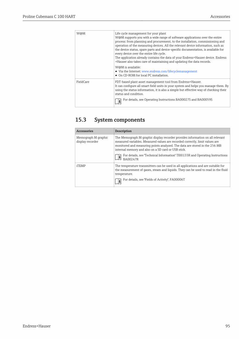
Proline Cubemass C 100 HART Accessories
Endress+Hauser 95
W@M Life cycle management for your plantW@M supports you with a wide range of software applications over the entireprocess: from planning and procurement, to the installation, commissioning andoperation of the measuring devices. All the relevant device information, such asthe device status, spare parts and device-specific documentation, is available forevery device over the entire life cycle.The application already contains the data of your Endress+Hauser device. Endress+Hauser also takes care of maintaining and updating the data records.
W@M is available:• Via the Internet: www.endress.com/lifecyclemanagement• On CD-ROM for local PC installation.
FieldCare FDT-based plant asset management tool from Endress+Hauser.It can configure all smart field units in your system and helps you manage them. Byusing the status information, it is also a simple but effective way of checking theirstatus and condition.
For details, see Operating Instructions BA00027S and BA00059S
15.3 System components
Accessories Description
Memograph M graphicdisplay recorder
The Memograph M graphic display recorder provides information on all relevantmeasured variables. Measured values are recorded correctly, limit values aremonitored and measuring points analyzed. The data are stored in the 256 MBinternal memory and also on a SD card or USB stick.
For details, see "Technical Information" TI00133R and Operating InstructionsBA00247R
iTEMP The temperature transmitters can be used in all applications and are suitable forthe measurement of gases, steam and liquids. They can be used to read in the fluidtemperature.
For details, see "Fields of Activity", FA00006T
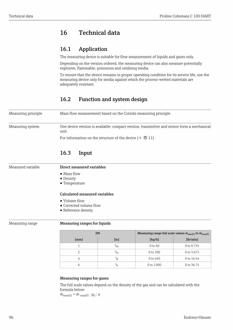
Technical data Proline Cubemass C 100 HART
96 Endress+Hauser
16 Technical data
16.1 ApplicationThe measuring device is suitable for flow measurement of liquids and gases only.
Depending on the version ordered, the measuring device can also measure potentiallyexplosive, flammable, poisonous and oxidizing media.
To ensure that the device remains in proper operating condition for its service life, use themeasuring device only for media against which the process-wetted materials areadequately resistant.
16.2 Function and system design
Measuring principle Mass flow measurement based on the Coriolis measuring principle
Measuring system One device version is available: compact version, transmitter and sensor form a mechanicalunit.
For information on the structure of the device (→ 11)
16.3 Input
Measured variable Direct measured variables• Mass flow• Density• Temperature
Calculated measured variables• Volume flow• Corrected volume flow• Reference density
Measuring range Measuring ranges for liquids
DN Measuring range full scale values min(F) to max(F)
[mm] [in] [kg/h] [lb/min]
1 ¹⁄₂₄ 0 to 20 0 to 0.735
2 ¹⁄₁₂ 0 to 100 0 to 3.675
4 ¹⁄₈ 0 to 450 0 to 16.54
6 ¹⁄₄ 0 to 1 000 0 to 36.75
Measuring ranges for gases The full scale values depend on the density of the gas and can be calculated with theformula below:max(G) = max(F) · ρG : x

Proline Cubemass C 100 HART Technical data
Endress+Hauser 97
max(G) Maximum full scale value for gas [kg/h]
max(F) Maximum full scale value for liquid [kg/h]
max(G) < max(F) max(G) can never be greater than max(F)
ρG Gas density in [kg/m³] at operating conditions
DN x
[mm] [in] [kg/m3]
1 ¹⁄₂₄ 32
2 ¹⁄₁₂ 32
4 ¹⁄₈ 32
6 ¹⁄₄ …
Recommended measuring range"Flow limit" section (→ 106)
Operable flow range Over 1000 : 1.
Flow rates above the preset full scale value are not overridden by the electronics unit, withthe result that the totalizer values are registered correctly.
16.4 Output
Output signal Current output
Current output 4-20 mA HART (active)
Maximum output values • DC 24 V (no flow)• 22.5 mA
Load 0 to 700 Ω
Resolution 0.38 µA
Damping Adjustable: 0.07 to 999 s
Assignable measuredvariables
• Mass flow• Volume flow• Corrected volume flow• Density• Reference density• Temperature
The range of options increases if the measuring device has one or moreapplication packages.
Pulse/frequency/switch output
Function Can be set to pulse, frequency or switch output
Version Passive, open collector
Maximum input values • DC 30 V• 25 mA
Voltage drop For 25 mA: ≤ DC 2 V
Pulse output
Pulse width Adjustable: 0.05 to 2 000 ms
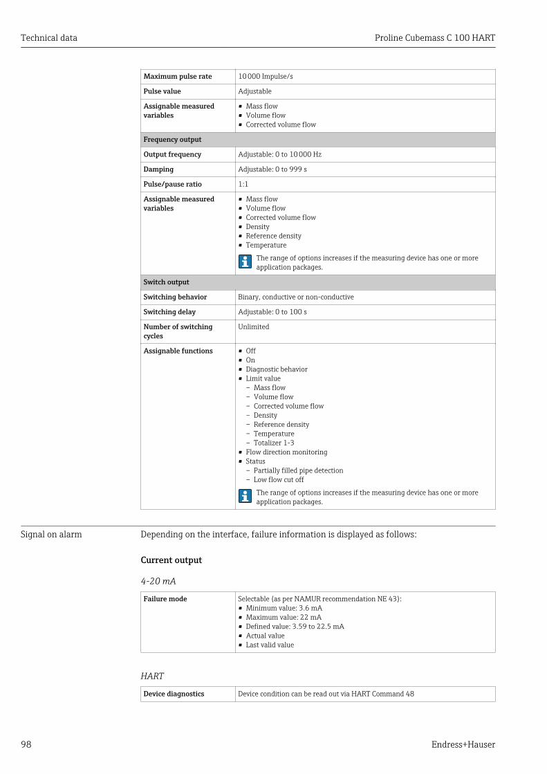
Technical data Proline Cubemass C 100 HART
98 Endress+Hauser
Maximum pulse rate 10 000 Impulse/s
Pulse value Adjustable
Assignable measuredvariables
• Mass flow• Volume flow• Corrected volume flow
Frequency output
Output frequency Adjustable: 0 to 10 000 Hz
Damping Adjustable: 0 to 999 s
Pulse/pause ratio 1:1
Assignable measuredvariables
• Mass flow• Volume flow• Corrected volume flow• Density• Reference density• Temperature
The range of options increases if the measuring device has one or moreapplication packages.
Switch output
Switching behavior Binary, conductive or non-conductive
Switching delay Adjustable: 0 to 100 s
Number of switchingcycles
Unlimited
Assignable functions • Off• On• Diagnostic behavior• Limit value
– Mass flow– Volume flow– Corrected volume flow– Density– Reference density– Temperature– Totalizer 1-3
• Flow direction monitoring• Status
– Partially filled pipe detection– Low flow cut off
The range of options increases if the measuring device has one or moreapplication packages.
Signal on alarm Depending on the interface, failure information is displayed as follows:
Current output
4-20 mA
Failure mode Selectable (as per NAMUR recommendation NE 43):• Minimum value: 3.6 mA• Maximum value: 22 mA• Defined value: 3.59 to 22.5 mA• Actual value• Last valid value
HART
Device diagnostics Device condition can be read out via HART Command 48
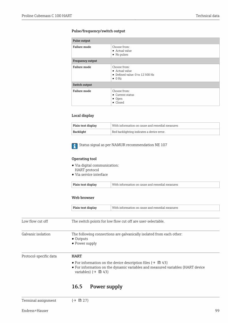
Proline Cubemass C 100 HART Technical data
Endress+Hauser 99
Pulse/frequency/switch output
Pulse output
Failure mode Choose from:• Actual value• No pulses
Frequency output
Failure mode Choose from:• Actual value• Defined value: 0 to 12 500 Hz• 0 Hz
Switch output
Failure mode Choose from:• Current status• Open• Closed
Local display
Plain text display With information on cause and remedial measures
Backlight Red backlighting indicates a device error.
Status signal as per NAMUR recommendation NE 107
Operating tool• Via digital communication:
HART protocol• Via service interface
Plain text display With information on cause and remedial measures
Web browser
Plain text display With information on cause and remedial measures
Low flow cut off The switch points for low flow cut off are user-selectable.
Galvanic isolation The following connections are galvanically isolated from each other:• Outputs• Power supply
Protocol-specific data HART• For information on the device description files (→ 43)• For information on the dynamic variables and measured variables (HART device
variables) (→ 43)
16.5 Power supply
Terminal assignment (→ 27)

Technical data Proline Cubemass C 100 HART
100 Endress+Hauser
Pin assignment, device plug (→ 28)
Supply voltage TransmitterFor device version with all communication types except Modbus RS485 intrinsically safe:DC 20 to 30 V
The power unit must be tested to ensure it meets safety requirements (e.g. PELV, SELV).
Power consumption Transmitter
Order code for"Output"
MaximumPower consumption
Option B: 4-20mA HART, pulse/frequency/switch output 3.5 W
Current consumption Transmitter
Order code for"Output"
MaximumCurrent consumption
Maximumswitch-on current
Option B: 4-20mA HART, pul./freq./switch output 145 mA 18 A (<0.125 ms)
Power supply failure • Totalizers stop at the last value measured.• Depending on the device version, the configuration is retained in the device memory or
in the plug-in memory (HistoROM DAT).• Error messages (incl. total operated hours) are stored.
Electrical connection (→ 28)
Potential equalization No special measures for potential equalization are required.
Terminals TransmitterSpring terminals for wire cross-sections0.5 to 2.5 mm2 (20 to 14 AWG)
Cable entries • Cable gland: M20 × 1.5 with cable 6 to 12 mm (0.24 to 0.47 in)• Thread for cable entry:
– NPT ½"– G ½"– M20
Cable specification (→ 26)
16.6 Performance characteristics
Reference operatingconditions
• Error limits based on ISO 11631• Water with +15 to +45 °C (+59 to +113 °F) at2 to 6 bar (29 to 87 psi)• Specifications as per calibration protocol• Accuracy based on accredited calibration rigs that are traced to ISO 17025.

Proline Cubemass C 100 HART Technical data
Endress+Hauser 101
To obtain measured errors, use the Applicator sizing tool (→ 113)
Maximum measured error o.r. = of reading; 1 g/cm³ = 1 kg/l; T = medium temperature
Base accuracyMass flow and volume flow (liquids)±0.10 %
Mass flow (gases)±0.50 % o.r.
Design fundamentals (→ 103)
Density (liquids)• Reference conditions:±0.0005 g/cm³• Standard density calibration:±0.02 g/cm³
(valid over the entire temperature range and density range )• Wide-range density specification (order code for "Application package", option EF "Special
density and concentration ") : ±0.002 g/cm³ (valid range for special density calibration:0.0 to 2 g/cm³, +5 to +80 °C (+41 to +176 °F))
Temperature±0.5 °C ± 0.005 · T °C (±0.9 °F ± 0.003 · (T – 32) °F)
Zero point stability
DN Zero point stability
[mm] [in] [kg/h] [lb/min]
1 ¹⁄₂₄ 0.0008 0.00003
2 ¹⁄₁₂ 0.002 0.00007
4 ¹⁄₈ 0.014 0.0005
6 ¹⁄₄ 0.02 0.0007
Flow valuesFlow values as turndown parameter depending on nominal diameter.
SI units
DN 1:1 1:10 1:20 1:50 1:100 1:500
[mm] [kg/h] [kg/h] [kg/h] [kg/h] [kg/h] [kg/h]
1 20 2 1 0.4 0.2 0.04
2 100 10 5 2 1 0.2
4 450 45 22.5 9 4.5 0.9
6 1 000 100 50 20 10 2
US units
DN 1:1 1:10 1:20 1:50 1:100 1:500
[inch] [lb/min] [lb/min] [lb/min] [lb/min] [lb/min] [lb/min]
¹⁄₂₄ 0.735 0.074 0.037 0.015 0.007 0.001
¹⁄₁₂ 3.675 0.368 0.184 0.074 0.037 0.007
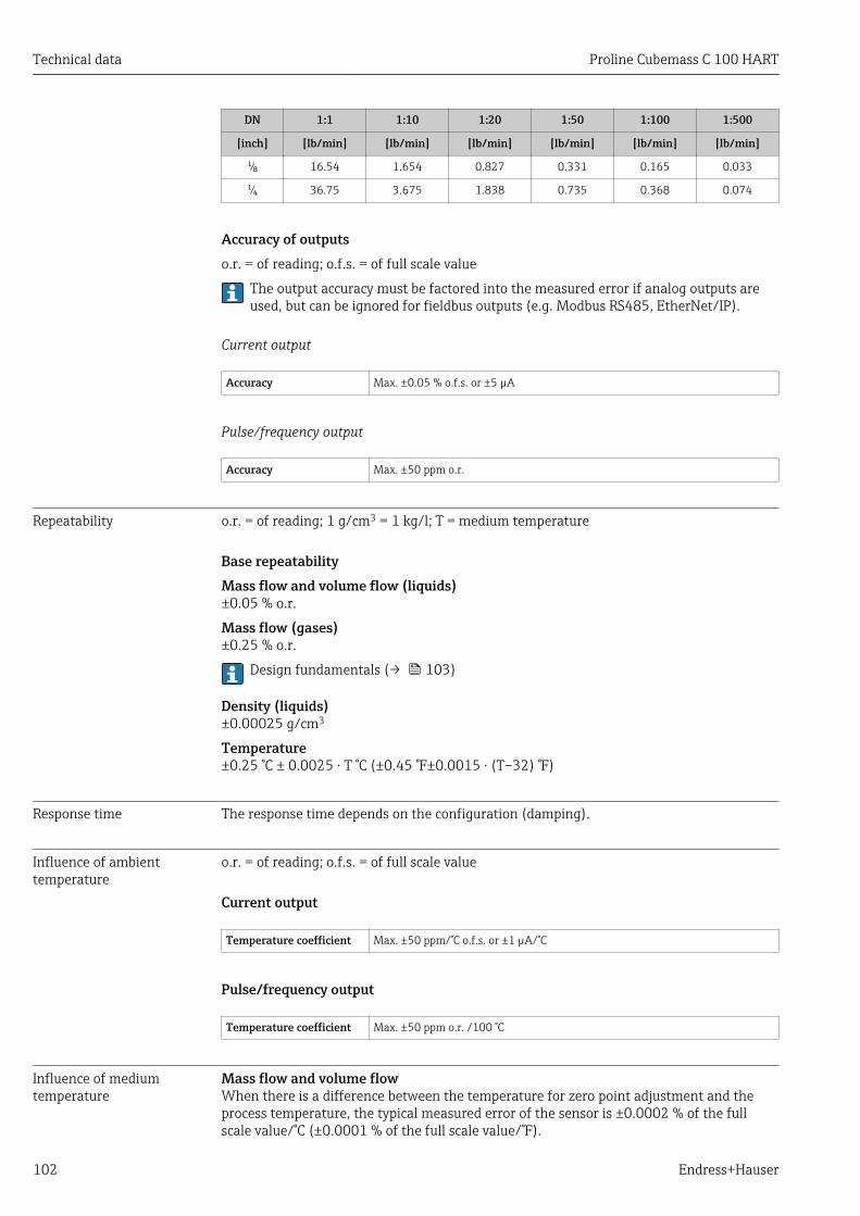
Technical data Proline Cubemass C 100 HART
102 Endress+Hauser
DN 1:1 1:10 1:20 1:50 1:100 1:500
[inch] [lb/min] [lb/min] [lb/min] [lb/min] [lb/min] [lb/min]
¹⁄₈ 16.54 1.654 0.827 0.331 0.165 0.033
¹⁄₄ 36.75 3.675 1.838 0.735 0.368 0.074
Accuracy of outputso.r. = of reading; o.f.s. = of full scale value
The output accuracy must be factored into the measured error if analog outputs areused, but can be ignored for fieldbus outputs (e.g. Modbus RS485, EtherNet/IP).
Current output
Accuracy Max. ±0.05 % o.f.s. or ±5 µA
Pulse/frequency output
Accuracy Max. ±50 ppm o.r.
Repeatability o.r. = of reading; 1 g/cm3 = 1 kg/l; T = medium temperature
Base repeatabilityMass flow and volume flow (liquids)±0.05 % o.r.
Mass flow (gases)±0.25 % o.r.
Design fundamentals (→ 103)
Density (liquids)±0.00025 g/cm3
Temperature±0.25 °C ± 0.0025 · T °C (±0.45 °F±0.0015 · (T–32) °F)
Response time The response time depends on the configuration (damping).
Influence of ambienttemperature
o.r. = of reading; o.f.s. = of full scale value
Current output
Temperature coefficient Max. ±50 ppm/°C o.f.s. or ±1 µA/°C
Pulse/frequency output
Temperature coefficient Max. ±50 ppm o.r. /100 °C
Influence of mediumtemperature
Mass flow and volume flowWhen there is a difference between the temperature for zero point adjustment and theprocess temperature, the typical measured error of the sensor is ±0.0002 % of the fullscale value/°C (±0.0001 % of the full scale value/°F).
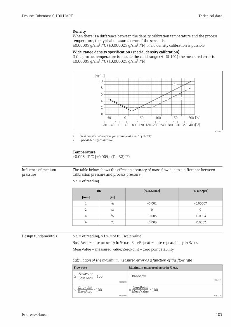
Proline Cubemass C 100 HART Technical data
Endress+Hauser 103
DensityWhen there is a difference between the density calibration temperature and the processtemperature, the typical measured error of the sensor is±0.00005 g/cm3 /°C (±0.000025 g/cm3 /°F). Field density calibration is possible.
Wide-range density specification (special density calibration)If the process temperature is outside the valid range (→ 101) the measured error is±0.00005 g/cm3 /°C (±0.000025 g/cm3 /°F)
[kg/m ]3
[°C]
-40 0-80 40 80 120 160 200 240 280 320 360 400 [°F]
-50 0 50 100 150 2000
2
4
6
8
10
2
1
A0016617
1 Field density calibration, for example at +20 °C (+68 °F)2 Special density calibration
Temperature±0.005 · T °C (±0.005 · (T – 32) °F)
Influence of mediumpressure
The table below shows the effect on accuracy of mass flow due to a difference betweencalibration pressure and process pressure.
o.r. = of reading
DN [% o.r./bar] [% o.r./psi]
[mm] [in]
1 ¹⁄₂₄ –0.001 –0.00007
2 ¹⁄₁₂ 0 0
4 ¹⁄₈ –0.005 –0.0004
6 ¹⁄₄ –0.003 –0.0002
Design fundamentals o.r. = of reading, o.f.s. = of full scale value
BaseAccu = base accuracy in % o.r., BaseRepeat = base repeatability in % o.r.
MeasValue = measured value; ZeroPoint = zero point stability
Calculation of the maximum measured error as a function of the flow rate
Flow rate Maximum measured error in % o.r.
ZeroPoint
BaseAccu⋅ 100³
A0021332
± BaseAccu
A0021339
ZeroPoint
BaseAccu⋅ 100<
A0021333
ZeroPoint
MeasValue⋅ 100±
A0021334
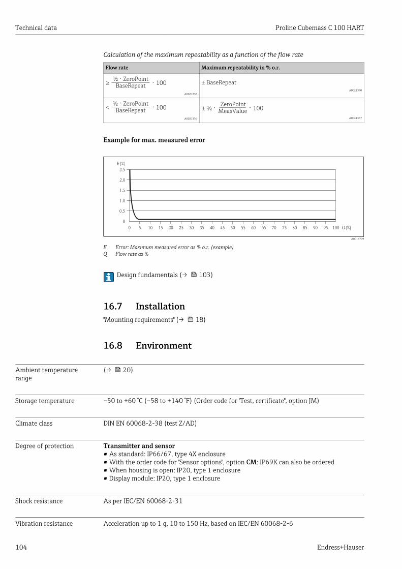
Technical data Proline Cubemass C 100 HART
104 Endress+Hauser
Calculation of the maximum repeatability as a function of the flow rate
Flow rate Maximum repeatability in % o.r.
½ ⋅ ZeroPointBaseRepeat ⋅ 100³
A0021335 A0021340
½ ⋅ ZeroPointBaseRepeat ⋅ 100<
A0021336
ZeroPoint
MeasValue⋅ 100½ ⋅±
A0021337
Example for max. measured error
E [%]
Q [%]0 5 10 15 20 25 30 35 40 45 50 60 6555
0
0.5
1.0
1.5
2.0
2.5
70 75 80 85 90 95 100
A0016709
E Error: Maximum measured error as % o.r. (example)Q Flow rate as %
Design fundamentals (→ 103)
16.7 Installation"Mounting requirements" (→ 18)
16.8 Environment
Ambient temperaturerange
(→ 20)
Storage temperature –50 to +60 °C (–58 to +140 °F) (Order code for "Test, certificate", option JM)
Climate class DIN EN 60068-2-38 (test Z/AD)
Degree of protection Transmitter and sensor• As standard: IP66/67, type 4X enclosure• With the order code for "Sensor options", option CM: IP69K can also be ordered• When housing is open: IP20, type 1 enclosure• Display module: IP20, type 1 enclosure
Shock resistance As per IEC/EN 60068-2-31
Vibration resistance Acceleration up to 1 g, 10 to 150 Hz, based on IEC/EN 60068-2-6
Proline Cubemass C 100 HART Technical data
Endress+Hauser 105
Interior cleaning • Sterilization in place (SIP)• Cleaning in place (CIP)
Electromagneticcompatibility (EMC)
• As per IEC/EN 61326 and NAMUR Recommendation 21 (NE 21)• Complies with emission limits for industry as per EN 55011 (Class A)
For details refer to the Declaration of Conformity.
16.9 Process
Medium temperature range Sensor• –50 to +150 °C (–58 to +302 °F)• –50 to +200 °C (–58 to +392 °F) with extended temperature (order code for "Measuring
tube mat.", option SD)
SealsFor mounting sets with screwed-on connections:– Viton:–15 to +200 °C (–5 to +392 °F)– EPDM:–40 to +160 °C (–40 to +320 °F)– Silicon:–60 to +200 °C (–76 to +392 °F)– Kalrez:–20 to +275 °C (–4 to +527 °F)
Density 0 to 5 000 kg/m3 (0 to 312 lb/cf)
Pressure-temperatureratings
An overview of the pressure-temperature ratings for the process connections isprovided in the "Technical Information" document
Secondary containmentpressure rating
The sensor housing is filled with dry nitrogen and protects the electronics and mechanicsinside.
DN Secondary containmentnominal pressure
(designed with a safety factor≥ 4)
Secondary containment burst pressure
[mm] [in] [bar] [psi] [bar] [psi]
1 ¹⁄₂₄ 40 580 190 2780
2 ¹⁄₁₂ 40 580 190 2780
4 ¹⁄₈ 40 580 190 2780
6 ¹⁄₄ 40 580 190 2780

Technical data Proline Cubemass C 100 HART
106 Endress+Hauser
If there is a risk of measuring tube failure due to process characteristics, e.g. withcorrosive process fluids, we recommend the use of sensors whose secondarycontainment is equipped with special pressure monitoring connections (order code for"Purge connection", option CH).
With the help of these connections, the fluid collected in the secondary containmentcan be bled off in the event of tube failure. This is especially important in high-pressure gas applications. These connections can also be used for gas purging (gasdetection).
Do not open the purge connections unless the containment can be filled immediatelywith a dry, inert gas. Use only low gauge pressure to purge. Maximum pressure: 5 bar(72.5 psi).
If a device fitted with purge connections is connected to the purge system, themaximum nominal pressure is determined by the purge system itself or by the device,depending on which component has the lower nominal pressure.
If, on the other hand, the device is fitted with a rupture disk, the rupture disk isdecisive for the maximum nominal pressure (→ 106).
For the dimensions and installation lengths of the device, see the "TechnicalInformation" document, "Mechanical construction" section
Rupture disk To increase the level of safety, a device version with a rupture disk with a triggeringpressure of 10 to 15 bar (145 to 217.5 psi) can be used. Special mounting instructions:(→ 22)
Flow limit Select the nominal diameter by optimizing between the required flow range andpermissible pressure loss.
For an overview of the measuring range full scale values, see the "Measuring range"section (→ 96)
• The minimum recommended full scale value is approx. 1/20 of the maximum full scalevalue
• In most applications, 20 to 50 % of the maximum full scale value can be considered ideal• Select a lower full scale value for abrasive substances (such as liquids with entrained
solids): flow velocity <1 m/s (<3 ft/s).• For gas measurement the following rules apply:
– The flow velocity in the measuring tubes should not exceed half the sonic velocity(0.5 Mach).
– The maximum mass flow depends on the density of the gas: formula (→ 96)
Pressure loss To calculate the pressure loss, use the Applicator sizing tool (→ 113)

Proline Cubemass C 100 HART Technical data
Endress+Hauser 107
16.10 Mechanical construction
Design, dimensions For the dimensions and installation lengths of the device, see the "TechnicalInformation" document, "Mechanical construction" section
Weight Compact version
Weight in SI units
All values (weight) refer to devices with EN/DIN PN 40 flanges. Weight information in[kg].
DN[mm]
Weight [kg]
1 3.5
2 3.5
4 3.5
6 3.5
Weight in US units
All values (weight) refer to devices with EN/DIN PN 40 flanges. Weight information in[lbs].
DN[in]
Weight [lbs]
1/24 8
1/12 8
1/8 8
1/4 8
Materials Transmitter housing• Order code for "Housing", option A "Compact, aluminum coated":
Aluminum, AlSi10Mg, coated• Order code for "Housing", option B "Compact, hygienic, stainless":
Hygienic version, stainless steel 1.4301 (304)• Order code for "Housing", option C "Ultra compact, hygienic, stainless":
Hygienic version, stainless steel 1.4301 (304)

Technical data Proline Cubemass C 100 HART
108 Endress+Hauser
Cable entries/cable glands
1
2
3
A0020640
16 Possible cable entries/cable glands
1 Cable entry in transmitter housing, wall-mount housing or connection housing with internal thread M20 x1.5
2 Cable gland M20 x 1.53 Adapter for cable entry with internal thread G ½" or NPT ½"
Order code for "Housing", option A "Compact, coated aluminum"
The various cable entries are suitable for hazardous and non-hazardous areas.
Cable entry/cable gland Material
Cable gland M20 × 1.5 Nickel-plated brass
Adapter for cable entry with internal thread G ½"
Adapter for cable entry with internal thread NPT ½"
Order code for "Housing", option B "Compact, hygienic, stainless"
The various cable entries are suitable for hazardous and non-hazardous areas.
Cable entry/cable gland Material
Cable gland M20 × 1.5 Stainless steel, 1.4404 (316L)
Adapter for cable entry with internal thread G ½"
Adapter for cable entry with internal thread NPT ½"
Device plug
Electrical connection Material
Plug M12x1 • Socket: Stainless steel, 1.4404 (316L)• Contact housing: Polyamide• Contacts: Gold-plated brass
Sensor housing• Acid and alkali-resistant outer surface• Stainless steel 1.4301 (304)
Measuring tubes• Stainless steel, 1.4539 (904L)• Surface quality: Not polished
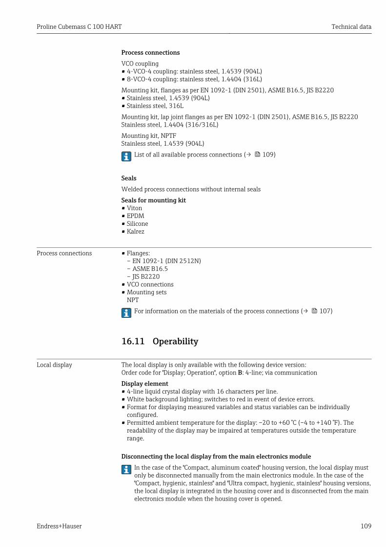
Proline Cubemass C 100 HART Technical data
Endress+Hauser 109
Process connectionsVCO coupling• 4-VCO-4 coupling: stainless steel, 1.4539 (904L)• 8-VCO-4 coupling: stainless steel, 1.4404 (316L)
Mounting kit, flanges as per EN 1092-1 (DIN 2501), ASME B16.5, JIS B2220• Stainless steel, 1.4539 (904L)• Stainless steel, 316L
Mounting kit, lap joint flanges as per EN 1092-1 (DIN 2501), ASME B16.5, JIS B2220Stainless steel, 1.4404 (316/316L)
Mounting kit, NPTFStainless steel, 1.4539 (904L)
List of all available process connections (→ 109)
SealsWelded process connections without internal seals
Seals for mounting kit• Viton• EPDM• Silicone• Kalrez
Process connections • Flanges:– EN 1092-1 (DIN 2512N)– ASME B16.5– JIS B2220
• VCO connections• Mounting sets
NPT
For information on the materials of the process connections (→ 107)
16.11 Operability
Local display The local display is only available with the following device version:Order code for "Display; Operation", option B: 4-line; via communication
Display element• 4-line liquid crystal display with 16 characters per line.• White background lighting; switches to red in event of device errors.• Format for displaying measured variables and status variables can be individually
configured.• Permitted ambient temperature for the display: –20 to +60 °C (–4 to +140 °F). The
readability of the display may be impaired at temperatures outside the temperaturerange.
Disconnecting the local display from the main electronics moduleIn the case of the "Compact, aluminum coated" housing version, the local display mustonly be disconnected manually from the main electronics module. In the case of the"Compact, hygienic, stainless" and "Ultra compact, hygienic, stainless" housing versions,the local display is integrated in the housing cover and is disconnected from the mainelectronics module when the housing cover is opened.
Technical data Proline Cubemass C 100 HART
110 Endress+Hauser
"Compact, aluminum coated" housing version
The local display is plugged onto the main electronics module. The electronic connectionbetween the local display and main electronics module is established via a connectingcable.
For some work performed on the measuring device (e.g. electrical connection), it isadvisable to disconnect the local display from the main electronics module:
1. Press in the side latches of the local display.
2. Remove the local display from the main electronics module. Pay attention to thelength of the connecting cable when doing so.
Once the work is completed, plug the local display back on.
Remote operation Via HART protocolThis communication interface is present in the following device version:Order code for "Output", option B: 4-20 mA HART, pulse/frequency/switch output
1 2 3 5
74 6
A0016948
17 Options for remote operation via HART protocol
1 Control system (e.g. PLC)2 Field Communicator 4753 Computer with operating tool (e.g. FieldCare, AMS Device Manager, SIMATIC PDM)4 Commubox FXA195 (USB)5 Field Xpert SFX350 or SFX3706 VIATOR Bluetooth modem with connecting cable7 Transmitter
Service interface Service interface (CDI-RJ45)

Proline Cubemass C 100 HART Technical data
Endress+Hauser 111
HART
1
2
3
A0016926
18 Connection for the order code for "Output", option B: 4-20 mA HART, pulse/frequency/switch output
1 Service interface (CDI -RJ45) of the measuring device with access to the integrated Web server2 Computer with Web browser (e.g. Internet Explorer) for accessing the integrated device Web server or with
"FieldCare" operating tool with COM DTM "CDI Communication TCP/IP"3 Standard Ethernet connecting cable with RJ45 plug
Languages Can be operated in the following languages:• Via "FieldCare" operating tool:
English, German, French, Spanish, Italian, Chinese, Japanese• Via Web browser
English, German, French, Spanish, Italian, Dutch, Portuguese, Polish, Russian, Turkish,Chinese, Japanese, Bahasa (Indonesian), Vietnamese, Czech
16.12 Certificates and approvals
CE mark The measuring system is in conformity with the statutory requirements of the applicableEC Directives. These are listed in the corresponding EC Declaration of Conformity alongwith the standards applied.
Endress+Hauser confirms successful testing of the device by affixing to it the CE mark.
C-Tick symbol The measuring system meets the EMC requirements of the "Australian Communicationsand Media Authority (ACMA)".
Ex approval The devices are certified for use in hazardous areas and the relevant safety instructions areprovided in the separate "Safety Instructions" (XA) document. Reference is made to thisdocument on the nameplate.
Other standards andguidelines
• EN 60529Degrees of protection provided by enclosures (IP code)
• IEC/EN 60068-2-6Environmental influences: Test procedure - Test Fc: vibrate (sinusoidal).
• IEC/EN 60068-2-31Environmental influences: Test procedure - Test Ec: shocks due to rough handling,primarily for devices.
• EN 61010-1Safety requirements for electrical equipment for measurement, control and laboratoryuse

Technical data Proline Cubemass C 100 HART
112 Endress+Hauser
• IEC/EN 61326Emission in accordance with Class A requirements. Electromagnetic compatibility (EMCrequirements).
• NAMUR NE 21Electromagnetic compatibility (EMC) of industrial process and laboratory controlequipment
• NAMUR NE 32Data retention in the event of a power failure in field and control instruments withmicroprocessors
• NAMUR NE 43Standardization of the signal level for the breakdown information of digital transmitterswith analog output signal.
• NAMUR NE 53Software of field devices and signal-processing devices with digital electronics
• NAMUR NE 105Specifications for integrating fieldbus devices in engineering tools for field devices
• NAMUR NE 107Self-monitoring and diagnosis of field devices
• NAMUR NE 131Requirements for field devices for standard applications
• NAMUR NE 132Coriolis mass meter
16.13 Application packagesMany different application packages are available to enhance the functionality of thedevice. Such packages might be needed to address safety aspects or specific applicationrequirements.
The application packages can be ordered from Endress+Hauser either directly with thedevice or subsequently. Detailed information on the order code in question is availablefrom your local Endress+Hauser sales center or on the product page of the Endress+Hauserwebsite: www.endress.com.
Heartbeat Technology Package Description
Heartbeat Verification+Monitoring
Heartbeat Monitoring:Continuously supplies monitoring data, which are characteristic of the measuringprinciple, for an external condition monitoring system. This makes it possible to:• Draw conclusions - using these data and other information - about the impact
the measuring application has on the measuring performance over time.• Schedule servicing in time.• Monitor the product quality, e.g. gas pockets.
Heartbeat Verification:Makes it possible to check the device functionality on demand when the device isinstalled, without having to interrupt the process.• Access via onsite operation or other operating interfaces, such as FieldCare for
instance.• Documentation of device functionality within the framework of manufacturer
specifications, for proof testing for instance.• End-to-end, traceable documentation of the verification results, including report.• Makes it possible to extend calibration intervals in accordance with operator's
risk assessment.
Proline Cubemass C 100 HART Technical data
Endress+Hauser 113
Concentration Package Description
Concentrationmeasurement and specialdensity
Calculation and outputting of fluid concentrationsMany applications use density as a key measured value for monitoring quality orcontrolling processes. The device measures the density of the fluid as standard andmakes this value available to the control system.The "Special Density" application package offers high-precision densitymeasurement over a wide density and temperature range particularly forapplications subject to varying process conditions.
With the help of the "Concentration Measurement" application package, themeasured density is used to calculate other process parameters:• Temperature-compensated density (reference density).• Percentage mass of the individual substances in a two-phase fluid.
(Concentration in %).• Fluid concentration is output with special units (°Brix, °Baumé, °API, etc.) for
standard applications.
The measured values are output via the digital and analog outputs of the device.
16.14 AccessoriesOverview of accessories available for order (→ 94)
16.15 DocumentationFor an overview of the scope of the associated Technical Documentation, refer to thefollowing:• The CD-ROM provided for the device (depending on the device version, the CD-ROM
might not be part of the delivery!)• The W@M Device Viewer : Enter the serial number from the nameplate
(www.endress.com/deviceviewer)• The Endress+Hauser Operations App: Enter the serial number from the nameplate
or scan the 2-D matrix code (QR code) on the nameplate.
Standard documentation Brief Operating Instructions
Measuring device Documentation code
Cubemass C 100 KA01145D
Technical Information
Measuring device Documentation code
Cubemass C 100 TI01105D
Supplementary device-dependent documentation
Safety Instructions
Contents Documentation code
ATEX/IECEx Ex i XA01030D
ATEX/IECEx Ex nA XA01143D
cCSAus IS XA01142D
INMETRO Ex i XA01221D
INMETRO Ex nA XA01222D
Technical data Proline Cubemass C 100 HART
114 Endress+Hauser
Contents Documentation code
NEPSI Ex i XA01261D
NEPSI Ex nA XA01263D
Special Documentation
Contents Documentation code
Information on the Pressure Equipment Directive SD00142D
Concentration Measurement SD01152D
Heartbeat Technology SD01153D
Installation Instructions
Contents Documentation code
Installation Instructions for spare part sets Specified for each individual accessory(→ 94)
Overview of accessories available fororder (→ 94)
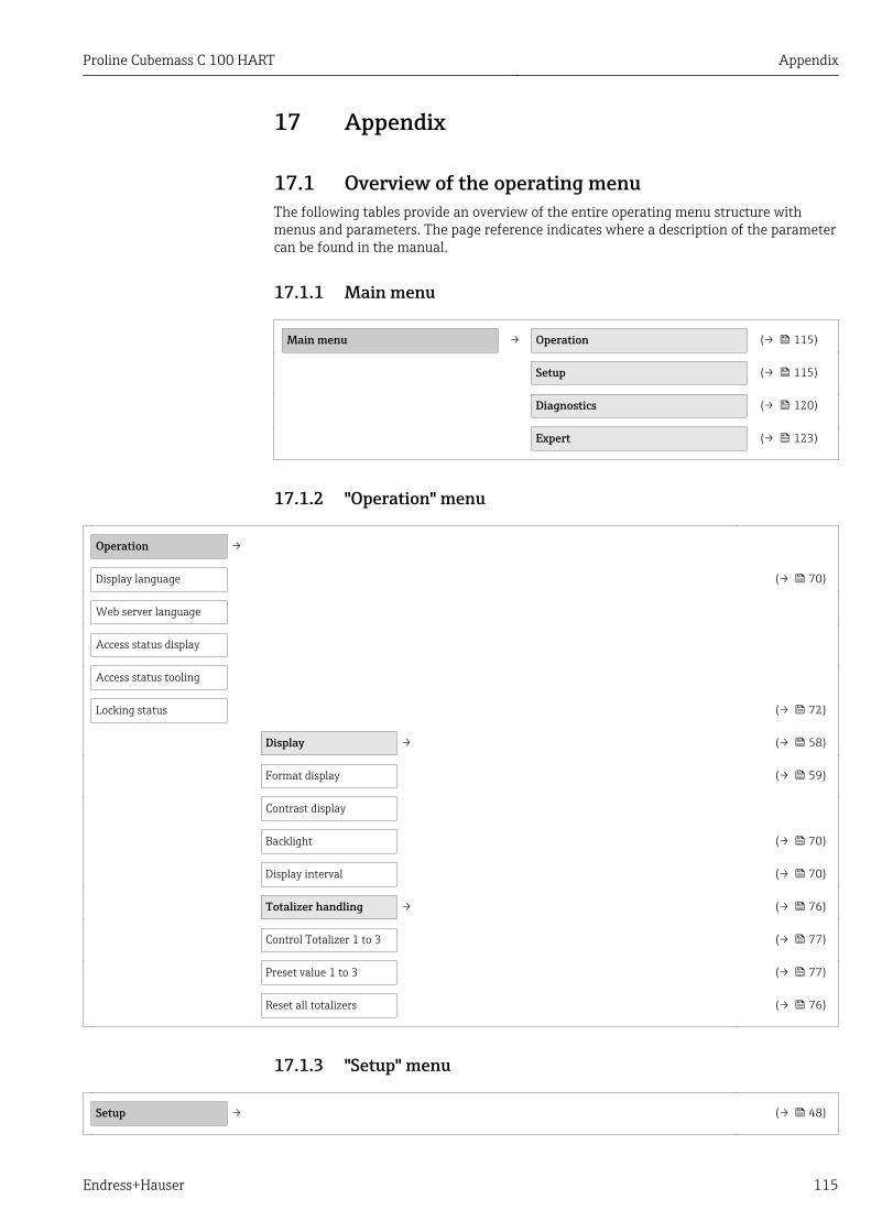
Proline Cubemass C 100 HART Appendix
Endress+Hauser 115
17 Appendix
17.1 Overview of the operating menuThe following tables provide an overview of the entire operating menu structure withmenus and parameters. The page reference indicates where a description of the parametercan be found in the manual.
17.1.1 Main menu
Main menu → Operation (→ 115)
Setup (→ 115)
Diagnostics (→ 120)
Expert (→ 123)
17.1.2 "Operation" menu
Operation →
Display language (→ 70)
Web server language
Access status display
Access status tooling
Locking status (→ 72)
Display → (→ 58)
Format display (→ 59)
Contrast display
Backlight (→ 70)
Display interval (→ 70)
Totalizer handling → (→ 76)
Control Totalizer 1 to 3 (→ 77)
Preset value 1 to 3 (→ 77)
Reset all totalizers (→ 76)
17.1.3 "Setup" menu
Setup → (→ 48)
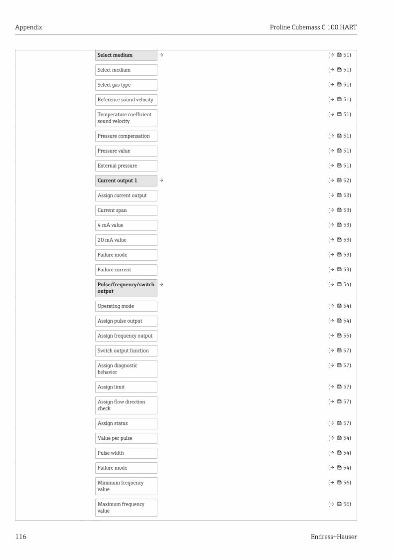
Appendix Proline Cubemass C 100 HART
116 Endress+Hauser
Select medium → (→ 51)
Select medium (→ 51)
Select gas type (→ 51)
Reference sound velocity (→ 51)
Temperature coefficientsound velocity
(→ 51)
Pressure compensation (→ 51)
Pressure value (→ 51)
External pressure (→ 51)
Current output 1 → (→ 52)
Assign current output (→ 53)
Current span (→ 53)
4 mA value (→ 53)
20 mA value (→ 53)
Failure mode (→ 53)
Failure current (→ 53)
Pulse/frequency/switchoutput
→ (→ 54)
Operating mode (→ 54)
Assign pulse output (→ 54)
Assign frequency output (→ 55)
Switch output function (→ 57)
Assign diagnosticbehavior
(→ 57)
Assign limit (→ 57)
Assign flow directioncheck
(→ 57)
Assign status (→ 57)
Value per pulse (→ 54)
Pulse width (→ 54)
Failure mode (→ 54)
Minimum frequencyvalue
(→ 56)
Maximum frequencyvalue
(→ 56)
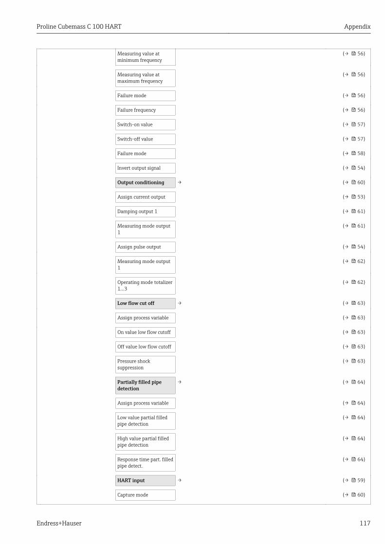
Proline Cubemass C 100 HART Appendix
Endress+Hauser 117
Measuring value atminimum frequency
(→ 56)
Measuring value atmaximum frequency
(→ 56)
Failure mode (→ 56)
Failure frequency (→ 56)
Switch-on value (→ 57)
Switch-off value (→ 57)
Failure mode (→ 58)
Invert output signal (→ 54)
Output conditioning → (→ 60)
Assign current output (→ 53)
Damping output 1 (→ 61)
Measuring mode output1
(→ 61)
Assign pulse output (→ 54)
Measuring mode output1
(→ 62)
Operating mode totalizer1…3
(→ 62)
Low flow cut off → (→ 63)
Assign process variable (→ 63)
On value low flow cutoff (→ 63)
Off value low flow cutoff (→ 63)
Pressure shocksuppression
(→ 63)
Partially filled pipedetection
→ (→ 64)
Assign process variable (→ 64)
Low value partial filledpipe detection
(→ 64)
High value partial filledpipe detection
(→ 64)
Response time part. filledpipe detect.
(→ 64)
HART input → (→ 59)
Capture mode (→ 60)

Appendix Proline Cubemass C 100 HART
118 Endress+Hauser
Device ID (→ 60)
Device type (→ 60)
Manufacturer ID (→ 60)
Burst command (→ 60)
Slot number (→ 60)
Timeout (→ 60)
Failure mode (→ 60)
Failure value (→ 60)
Advanced setup → (→ 65)
Enter access code (→ 72)
System units → (→ 48)
Mass flow unit (→ 49)
Mass unit (→ 49)
Volume flow unit (→ 49)
Volume unit (→ 49)
Corrected volume flowunit
(→ 49)
Corrected volume unit (→ 50)
Density unit (→ 50)
Reference density unit (→ 50)
Temperature unit (→ 50)
Pressure unit (→ 50)
Calculated values → (→ 65)
Corrected volume flowcalculation
→ (→ 65)
Corrected volume flowcalculation
(→ 66)
External referencedensity
(→ 66)
Fixed reference density (→ 66)
Reference temperature (→ 66)
Linear expansioncoefficient
(→ 66)
Square expansioncoefficient
(→ 66)

Proline Cubemass C 100 HART Appendix
Endress+Hauser 119
Sensor adjustment →
Installation direction (→ 67)
Zero point adjustment →
Zero point adjustmentcontrol
(→ 67)
Progress (→ 67)
Totalizer 1 to 3 → (→ 67)
Assign process variable (→ 67)
Unit totalizer (→ 57)
Totalizer operation mode (→ 67)
Failure mode (→ 67)
Display → (→ 68)
Format display (→ 59)
Value 1 display (→ 59)
0% bargraph value 1 (→ 59)
100% bargraph value 1 (→ 59)
Decimal places 1 (→ 69)
Value 2 display (→ 59)
Decimal places 2 (→ 69)
Value 3 display (→ 59)
0% bargraph value 3 (→ 59)
100% bargraph value 3 (→ 59)
Decimal places 3 (→ 70)
Value 4 display (→ 59)
Decimal places 4 (→ 70)
Display language (→ 70)
Display interval (→ 70)
Display damping (→ 70)
Header (→ 70)
Header text (→ 70)
Separator (→ 70)
Backlight (→ 70)
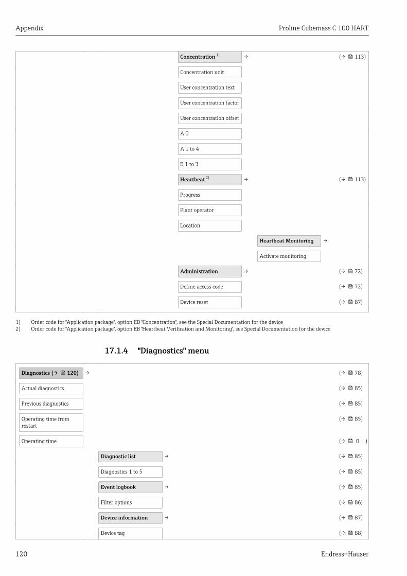
Appendix Proline Cubemass C 100 HART
120 Endress+Hauser
Concentration 1) → (→ 113)
Concentration unit
User concentration text
User concentration factor
User concentration offset
A 0
A 1 to 4
B 1 to 3
Heartbeat 2) → (→ 113)
Progress
Plant operator
Location
Heartbeat Monitoring →
Activate monitoring
Administration → (→ 72)
Define access code (→ 72)
Device reset (→ 87)
1) Order code for "Application package", option ED "Concentration", see the Special Documentation for the device2) Order code for "Application package", option EB "Heartbeat Verification and Monitoring", see Special Documentation for the device
17.1.4 "Diagnostics" menu
Diagnostics (→ 120) → (→ 78)
Actual diagnostics (→ 85)
Previous diagnostics (→ 85)
Operating time fromrestart
(→ 85)
Operating time (→ 0 )
Diagnostic list → (→ 85)
Diagnostics 1 to 5 (→ 85)
Event logbook → (→ 85)
Filter options (→ 86)
Device information → (→ 87)
Device tag (→ 88)
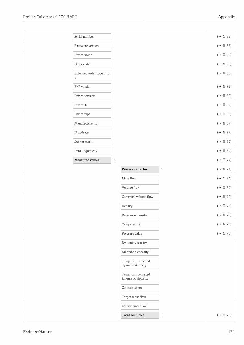
Proline Cubemass C 100 HART Appendix
Endress+Hauser 121
Serial number (→ 88)
Firmware version (→ 88)
Device name (→ 88)
Order code (→ 88)
Extended order code 1 to3
(→ 88)
ENP version (→ 89)
Device revision (→ 89)
Device ID (→ 89)
Device type (→ 89)
Manufacturer ID (→ 89)
IP address (→ 89)
Subnet mask (→ 89)
Default gateway (→ 89)
Measured values → (→ 74)
Process variables → (→ 74)
Mass flow (→ 74)
Volume flow (→ 74)
Corrected volume flow (→ 74)
Density (→ 75)
Reference density (→ 75)
Temperature (→ 75)
Pressure value (→ 75)
Dynamic viscosity
Kinematic viscosity
Temp. compensateddynamic viscosity
Temp. compensatedkinematic viscosity
Concentration
Target mass flow
Carrier mass flow
Totalizer 1 to 3 → (→ 75)

Appendix Proline Cubemass C 100 HART
122 Endress+Hauser
Totalizer value 1 to 3 (→ 75)
Totalizer overflow 1 to 3 (→ 75)
Output values → (→ 75)
Output current (→ 76)
Measured current (→ 76)
Pulse output (→ 76)
Output frequency (→ 76)
Switch status (→ 76)
Heartbeat 1) → (→ 113)
→ Performing verification →
Year
Month
Day
Hour
AM/PM
Minute
Verification mode
External deviceinformation
Start verification
Progress
Measured values
Output values
Status
Overall result
Verification results →
Date/time
Verification ID
Operating time
Overall result
Sensor
Sensor integrity

Proline Cubemass C 100 HART Appendix
Endress+Hauser 123
Sensor electronic module
I/O module
Monitoring results →
Sensor integrity
Simulation →
Assign simulationprocess variable
(→ 71)
Value process variable (→ 71)
Simulation currentoutput
(→ 71)
Value current output (→ 71)
Frequency simulation (→ 71)
Frequency value (→ 71)
Pulse simulation (→ 71)
Pulse value (→ 72)
Switch output simulation (→ 72)
Switch status (→ 72)
Simulation device alarm (→ 72)
Simulation diagnosticevent
(→ 72)
1) Order code for "Application package", option EB "Heartbeat Verification and Monitoring", see Special Documentation for the device
17.1.5 "Expert" menu
Overview "Expert" menu
Expert → (→ 34)
Locking status (0004) (→ 74)
Access status display (0091)
Access status tooling (→ 73)
Enter access code (0092) (→ 72)
System (→ 124)
Sensor (→ 125)
Output (→ 129)
Communication (→ 131)

Appendix Proline Cubemass C 100 HART
124 Endress+Hauser
Application (→ 134)
Diagnostics (→ 134)
"System" submenu
System →
Display → (→ 68)
Display language (0104) (→ 70)
Format display (0098) (→ 59)
Value 1 display (0107) (→ 59)
0% bargraph value 1(0123)
(→ 59)
100% bargraph value 1(0125)
(→ 59)
Decimal places 1 (0095) (→ 69)
Value 2 display (0108) (→ 59)
Decimal places 2 (0117) (→ 69)
Value 3 display (0110) (→ 59)
0% bargraph value 3(0124)
(→ 59)
100% bargraph value 3(0126)
(→ 59)
Decimal places 3 (0118) (→ 70)
Value 4 display (0109) (→ 59)
Decimal places 4 (0119) (→ 70)
Display interval (0096) (→ 70)
Display damping (0094) (→ 70)
Header (0097) (→ 70)
Header text (0112) (→ 70)
Separator (0101) (→ 70)
Backlight (0111) (→ 70)
Diagnostic handling → (→ 78)
Alarm delay
Diagnostic behavior

Proline Cubemass C 100 HART Appendix
Endress+Hauser 125
Assign behavior ofdiagnostic no. 044
Assign behavior ofdiagnostic no. 046
Assign behavior ofdiagnostic no. 144
Assign behavior ofdiagnostic no. 832
Assign behavior ofdiagnostic no. 833
Assign behavior ofdiagnostic no. 834
Assign behavior ofdiagnostic no. 835
Assign behavior ofdiagnostic no. 912
Assign behavior ofdiagnostic no. 913
Assign behavior ofdiagnostic no. 944
Assign behavior ofdiagnostic no. 192
Assign behavior ofdiagnostic no. 274
Assign behavior ofdiagnostic no. 835(0678)
Assign behavior ofdiagnostic no. 392
Assign behavior ofdiagnostic no. 592
Assign behavior ofdiagnostic no. 992
Administration → (→ 72)
Define access code (→ 72)
Device reset (→ 87)
Activate SW option
Software option overview
"Sensor" submenu
Sensor →

Appendix Proline Cubemass C 100 HART
126 Endress+Hauser
Measured values → (→ 74)
Process variables → (→ 74)
Mass flow (→ 74)
Volume flow (→ 74)
Corrected volume flow (→ 74)
Density (→ 75)
Reference density (→ 75)
Temperature (→ 75)
Pressure value (→ 75)
Concentration
Target mass flow
Carrier mass flow
Totalizer 1 to 3 → (→ 67)
Totalizer value 1 to 3 (→ 75)
Totalizer overflow 1 to 3
Output values → (→ 75)
Output current(0361–1 to #)
(→ 76)
Measured current(0366–1 to #)
(→ 76)
Pulse output (0456) (→ 76)
Output frequency (0471) (→ 76)
Switch status (0461) (→ 76)
System units → (→ 48)
Mass flow unit (→ 49)
Mass unit (→ 49)
Volume flow unit (→ 49)
Volume unit (→ 49)
Corrected volume flowunit
(→ 49)
Corrected volume unit (→ 50)
Density unit (→ 50)
Reference density unit (→ 50)

Proline Cubemass C 100 HART Appendix
Endress+Hauser 127
Temperature unit (→ 50)
Pressure unit (→ 50)
Date/time format
User-specific units →
User mass text (0560)
User mass offset (0562)
User mass factor (0561)
User volume text (0567)
User volume offset(0569)
User volume factor(0568)
User corrected volumetext (0592)
User corrected volumeoffset (0602)
User corrected volumefactor (0590)
User density text (0570)
User density offset(0571)
User density factor(0572)
User pressure text(0581)
User pressure offset(0580)
User pressure factor(0579)
Process parameters → (→ 48)
Flow damping
Density damping
Temperature damping
Flow override
Low flow cut off → (→ 63)
Assign process variable (→ 63)
On value low flow cutoff (→ 63)

Appendix Proline Cubemass C 100 HART
128 Endress+Hauser
Off value low flow cutoff (→ 63)
Pressure shocksuppression
(→ 63)
Partially filled pipedetection
→ (→ 64)
Assign process variable (→ 64)
Low value partial filledpipe detection
(→ 64)
High value partial filledpipe detection
(→ 64)
Response time part. filledpipe detect.
(→ 64)
Maximum dampingpartial filled pipe det.
Measurement mode → (→ 51)
Select medium (→ 51)
Select gas type (→ 51)
Reference sound velocity (→ 51)
Temperature coefficientsound velocity
(→ 51)
External compensation → (→ 51)
Pressure compensation (→ 51)
Pressure value (→ 51)
External pressure (→ 51)
External temperature
Calculated values →
Corrected volume flowcalculation
→
Corrected volume flowcalculation
(→ 66)
External referencedensity
(→ 66)
Fixed reference density (→ 66)
Reference temperature (→ 66)
Linear expansioncoefficient
(→ 66)
Square expansioncoefficient
(→ 66)
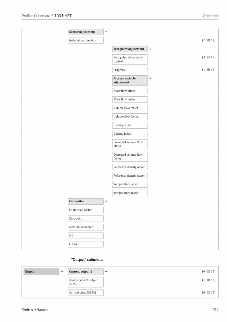
Proline Cubemass C 100 HART Appendix
Endress+Hauser 129
Sensor adjustment →
Installation direction (→ 67)
Zero point adjustment →
Zero point adjustmentcontrol
(→ 67)
Progress (→ 67)
Process variableadjustment
→
Mass flow offset
Mass flow factor
Volume flow offset
Volume flow factor
Density offset
Density factor
Corrected volume flowoffset
Corrected volume flowfactor
Reference density offset
Reference density factor
Temperature offset
Temperature factor
Calibration →
Calibration factor
Zero point
Nominal diameter
C 0
C 1 to 5
"Output" submenu
Output → Current output 1 → (→ 52)
Assign current output(0359)
(→ 53)
Current span (0353) (→ 53)

Appendix Proline Cubemass C 100 HART
130 Endress+Hauser
Fixed current (0365)
0/4 mA value (0367) (→ 53)
20 mA value (0372) (→ 53)
Measuring mode (0351)
Damping output (0363) (→ 61)
Response time (0378)
Failure mode (0364) (→ 53)
Failure current (0352) (→ 53)
Output current 1 (0361) (→ 76)
Measured current 1(0366)
(→ 76)
Pulse/frequency/switchoutput 1
→ (→ 54)
Operating mode (0469) (→ 54)
Assign pulse output(0460)
(→ 54)
Value per pulse (0455) (→ 54)
Pulse width (0452) (→ 54)
Measuring mode (0351)
Failure mode (0480) (→ 54)
Pulse output 1 (0456) (→ 76)
Assign frequency output(0478)
(→ 55)
Minimum frequencyvalue (0453)
(→ 56)
Maximum frequencyvalue (0454)
(→ 56)
Measuring value atminimum frequency(0476)
(→ 56)
Measuring value atmaximum frequency(0475)
(→ 56)
Measuring mode (0479)
Damping output
Response time (0491)
Failure mode (0451) (→ 56)

Proline Cubemass C 100 HART Appendix
Endress+Hauser 131
Failure frequency (0474) (→ 56)
Output frequency 1(0471)
(→ 76)
Switch output function(0481)
(→ 57)
Assign diagnosticbehavior (0482)
(→ 57)
Assign limit (0483) (→ 57)
Switch-on value (0466) (→ 57)
Switch-off value (0464) (→ 57)
Assign status (0485) (→ 57)
Switch-on delay (0467) (→ 57)
Switch-off delay (0465) (→ 58)
Failure mode (0486) (→ 58)
Switch status 1 (0461) (→ 76)
Invert output signal(0470)
(→ 54)
"Communication" submenu
Communication →
HART input →
Configuration →
Capture mode (7001)
Device ID (7007)
Device type (7008)
Manufacturer ID (7009)
Burst command (7006)
Slot number (7010)
Timeout (7005)
Failure mode (7011)
Failure value (7012)
Input
Value (7003)
Status (7004)
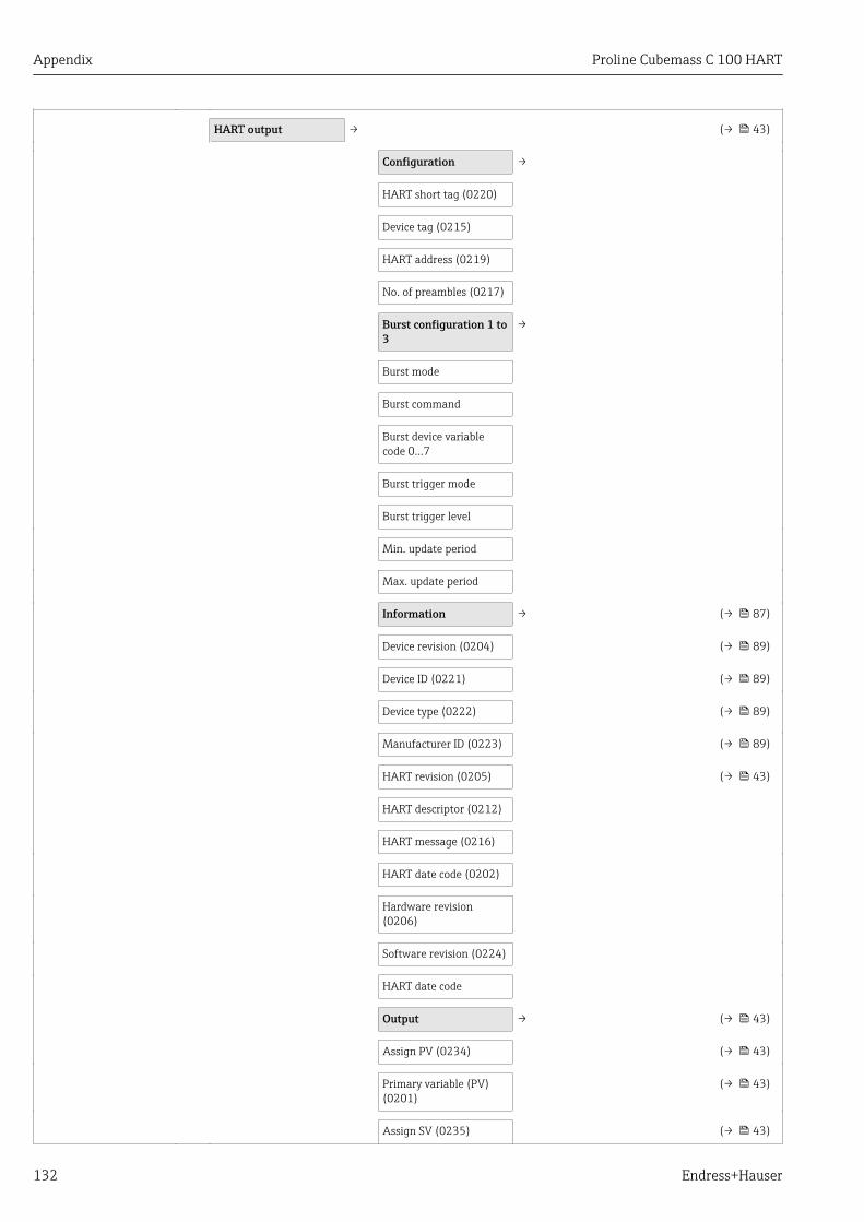
Appendix Proline Cubemass C 100 HART
132 Endress+Hauser
HART output → (→ 43)
Configuration →
HART short tag (0220)
Device tag (0215)
HART address (0219)
No. of preambles (0217)
Burst configuration 1 to3
→
Burst mode
Burst command
Burst device variablecode 0…7
Burst trigger mode
Burst trigger level
Min. update period
Max. update period
Information → (→ 87)
Device revision (0204) (→ 89)
Device ID (0221) (→ 89)
Device type (0222) (→ 89)
Manufacturer ID (0223) (→ 89)
HART revision (0205) (→ 43)
HART descriptor (0212)
HART message (0216)
HART date code (0202)
Hardware revision(0206)
Software revision (0224)
HART date code
Output → (→ 43)
Assign PV (0234) (→ 43)
Primary variable (PV)(0201)
(→ 43)
Assign SV (0235) (→ 43)

Proline Cubemass C 100 HART Appendix
Endress+Hauser 133
Secondary variable (SV)(0226)
(→ 43)
Assign TV (0236) (→ 43)
Tertiary variable (TV)(0228)
(→ 43)
Assign QV (0237) (→ 43)
Quaternary variable (QV)(0203)
(→ 43)
Web server →
Web server language
MAC address
IP address
Subnet mask
Default gateway
Web server functionality
Diagnostic eventcategory
→
Event category 046
Event category 140
Event category 274
Event category 441
Event category 442
Event category 443
Event category 830
Event category 831
Event category 832
Event category 833
Event category 834
Event category 835
Event category 862
Event category 912
Event category 913
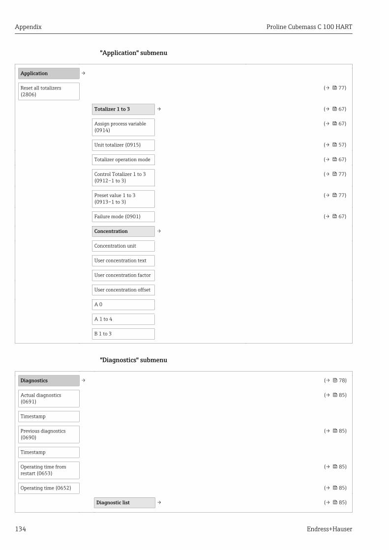
Appendix Proline Cubemass C 100 HART
134 Endress+Hauser
"Application" submenu
Application →
Reset all totalizers(2806)
(→ 77)
Totalizer 1 to 3 → (→ 67)
Assign process variable(0914)
(→ 67)
Unit totalizer (0915) (→ 57)
Totalizer operation mode (→ 67)
Control Totalizer 1 to 3(0912–1 to 3)
(→ 77)
Preset value 1 to 3(0913–1 to 3)
(→ 77)
Failure mode (0901) (→ 67)
Concentration →
Concentration unit
User concentration text
User concentration factor
User concentration offset
A 0
A 1 to 4
B 1 to 3
"Diagnostics" submenu
Diagnostics → (→ 78)
Actual diagnostics(0691)
(→ 85)
Timestamp
Previous diagnostics(0690)
(→ 85)
Timestamp
Operating time fromrestart (0653)
(→ 85)
Operating time (0652) (→ 85)
Diagnostic list → (→ 85)
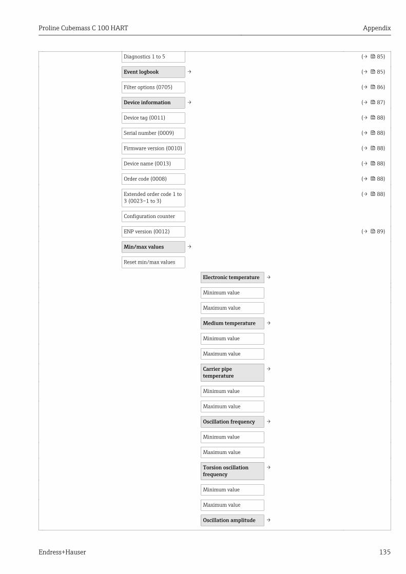
Proline Cubemass C 100 HART Appendix
Endress+Hauser 135
Diagnostics 1 to 5 (→ 85)
Event logbook → (→ 85)
Filter options (0705) (→ 86)
Device information → (→ 87)
Device tag (0011) (→ 88)
Serial number (0009) (→ 88)
Firmware version (0010) (→ 88)
Device name (0013) (→ 88)
Order code (0008) (→ 88)
Extended order code 1 to3 (0023–1 to 3)
(→ 88)
Configuration counter
ENP version (0012) (→ 89)
Min/max values →
Reset min/max values
Electronic temperature →
Minimum value
Maximum value
Medium temperature →
Minimum value
Maximum value
Carrier pipetemperature
→
Minimum value
Maximum value
Oscillation frequency →
Minimum value
Maximum value
Torsion oscillationfrequency
→
Minimum value
Maximum value
Oscillation amplitude →
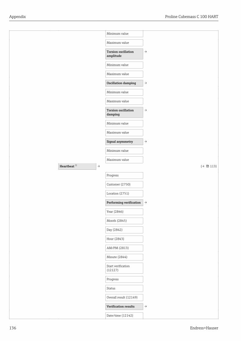
Appendix Proline Cubemass C 100 HART
136 Endress+Hauser
Minimum value
Maximum value
Torsion oscillationamplitude
→
Minimum value
Maximum value
Oscillation damping →
Minimum value
Maximum value
Torsion oscillationdamping
→
Minimum value
Maximum value
Signal asymmetry →
Minimum value
Maximum value
Heartbeat 1) → (→ 113)
Progress
Customer (2750)
Location (2751)
Performing verification →
Year (2846)
Month (2845)
Day (2842)
Hour (2843)
AM/PM (2813)
Minute (2844)
Start verification(12127)
Progress
Status
Overall result (12149)
Verification results →
Date/time (12142)

Proline Cubemass C 100 HART Appendix
Endress+Hauser 137
Verification ID (12141)
Operating time (12126)
Overall result (12149)
Sensor (12152)
Sensor integrity
Sensor electronic module
I/O module (12145)
Heartbeat Monitoring →
Activate monitoring
Monitoring results →
Sensor integrity
Simulation →
Assign simulationprocess variable (1810)
(→ 71)
Value process variable(1811)
(→ 71)
Simulation device alarm(0654)
(→ 72)
1) Order code for "Application package", option EB "Heartbeat Verification and Monitoring", see the Special Documentation for the device
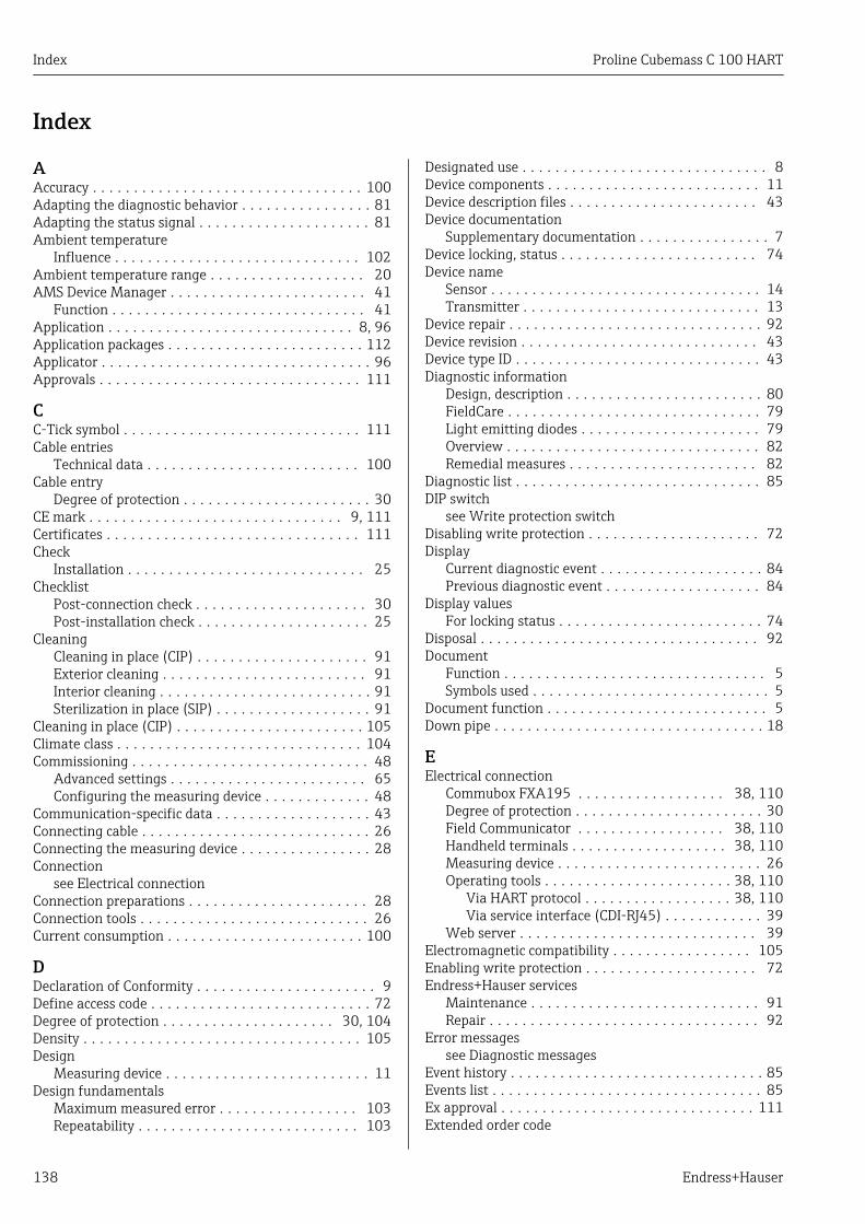
Index Proline Cubemass C 100 HART
138 Endress+Hauser
Index
AAccuracy . . . . . . . . . . . . . . . . . . . . . . . . . . . . . . . . . 100Adapting the diagnostic behavior . . . . . . . . . . . . . . . . 81Adapting the status signal . . . . . . . . . . . . . . . . . . . . . 81Ambient temperature
Influence . . . . . . . . . . . . . . . . . . . . . . . . . . . . . . 102Ambient temperature range . . . . . . . . . . . . . . . . . . . 20AMS Device Manager . . . . . . . . . . . . . . . . . . . . . . . . 41
Function . . . . . . . . . . . . . . . . . . . . . . . . . . . . . . . 41Application . . . . . . . . . . . . . . . . . . . . . . . . . . . . . . 8, 96Application packages . . . . . . . . . . . . . . . . . . . . . . . . 112Applicator . . . . . . . . . . . . . . . . . . . . . . . . . . . . . . . . . 96Approvals . . . . . . . . . . . . . . . . . . . . . . . . . . . . . . . . 111
CC-Tick symbol . . . . . . . . . . . . . . . . . . . . . . . . . . . . . 111Cable entries
Technical data . . . . . . . . . . . . . . . . . . . . . . . . . . 100Cable entry
Degree of protection . . . . . . . . . . . . . . . . . . . . . . . 30CE mark . . . . . . . . . . . . . . . . . . . . . . . . . . . . . . . 9, 111Certificates . . . . . . . . . . . . . . . . . . . . . . . . . . . . . . . 111Check
Installation . . . . . . . . . . . . . . . . . . . . . . . . . . . . . 25Checklist
Post-connection check . . . . . . . . . . . . . . . . . . . . . 30Post-installation check . . . . . . . . . . . . . . . . . . . . . 25
CleaningCleaning in place (CIP) . . . . . . . . . . . . . . . . . . . . . 91Exterior cleaning . . . . . . . . . . . . . . . . . . . . . . . . . 91Interior cleaning . . . . . . . . . . . . . . . . . . . . . . . . . . 91Sterilization in place (SIP) . . . . . . . . . . . . . . . . . . . 91
Cleaning in place (CIP) . . . . . . . . . . . . . . . . . . . . . . . 105Climate class . . . . . . . . . . . . . . . . . . . . . . . . . . . . . . 104Commissioning . . . . . . . . . . . . . . . . . . . . . . . . . . . . . 48
Advanced settings . . . . . . . . . . . . . . . . . . . . . . . . 65Configuring the measuring device . . . . . . . . . . . . . 48
Communication-specific data . . . . . . . . . . . . . . . . . . . 43Connecting cable . . . . . . . . . . . . . . . . . . . . . . . . . . . . 26Connecting the measuring device . . . . . . . . . . . . . . . . 28Connection
see Electrical connectionConnection preparations . . . . . . . . . . . . . . . . . . . . . . 28Connection tools . . . . . . . . . . . . . . . . . . . . . . . . . . . . 26Current consumption . . . . . . . . . . . . . . . . . . . . . . . . 100
DDeclaration of Conformity . . . . . . . . . . . . . . . . . . . . . . 9Define access code . . . . . . . . . . . . . . . . . . . . . . . . . . . 72Degree of protection . . . . . . . . . . . . . . . . . . . . . 30, 104Density . . . . . . . . . . . . . . . . . . . . . . . . . . . . . . . . . . 105Design
Measuring device . . . . . . . . . . . . . . . . . . . . . . . . . 11Design fundamentals
Maximum measured error . . . . . . . . . . . . . . . . . 103Repeatability . . . . . . . . . . . . . . . . . . . . . . . . . . . 103
Designated use . . . . . . . . . . . . . . . . . . . . . . . . . . . . . . 8Device components . . . . . . . . . . . . . . . . . . . . . . . . . . 11Device description files . . . . . . . . . . . . . . . . . . . . . . . 43Device documentation
Supplementary documentation . . . . . . . . . . . . . . . . 7Device locking, status . . . . . . . . . . . . . . . . . . . . . . . . 74Device name
Sensor . . . . . . . . . . . . . . . . . . . . . . . . . . . . . . . . . 14Transmitter . . . . . . . . . . . . . . . . . . . . . . . . . . . . . 13
Device repair . . . . . . . . . . . . . . . . . . . . . . . . . . . . . . . 92Device revision . . . . . . . . . . . . . . . . . . . . . . . . . . . . . 43Device type ID . . . . . . . . . . . . . . . . . . . . . . . . . . . . . . 43Diagnostic information
Design, description . . . . . . . . . . . . . . . . . . . . . . . . 80FieldCare . . . . . . . . . . . . . . . . . . . . . . . . . . . . . . . 79Light emitting diodes . . . . . . . . . . . . . . . . . . . . . . 79Overview . . . . . . . . . . . . . . . . . . . . . . . . . . . . . . . 82Remedial measures . . . . . . . . . . . . . . . . . . . . . . . 82
Diagnostic list . . . . . . . . . . . . . . . . . . . . . . . . . . . . . . 85DIP switch
see Write protection switchDisabling write protection . . . . . . . . . . . . . . . . . . . . . 72Display
Current diagnostic event . . . . . . . . . . . . . . . . . . . . 84Previous diagnostic event . . . . . . . . . . . . . . . . . . . 84
Display valuesFor locking status . . . . . . . . . . . . . . . . . . . . . . . . . 74
Disposal . . . . . . . . . . . . . . . . . . . . . . . . . . . . . . . . . . 92Document
Function . . . . . . . . . . . . . . . . . . . . . . . . . . . . . . . . 5Symbols used . . . . . . . . . . . . . . . . . . . . . . . . . . . . . 5
Document function . . . . . . . . . . . . . . . . . . . . . . . . . . . 5Down pipe . . . . . . . . . . . . . . . . . . . . . . . . . . . . . . . . . 18
EElectrical connection
Commubox FXA195 . . . . . . . . . . . . . . . . . . 38, 110Degree of protection . . . . . . . . . . . . . . . . . . . . . . . 30Field Communicator . . . . . . . . . . . . . . . . . . 38, 110Handheld terminals . . . . . . . . . . . . . . . . . . . 38, 110Measuring device . . . . . . . . . . . . . . . . . . . . . . . . . 26Operating tools . . . . . . . . . . . . . . . . . . . . . . . 38, 110
Via HART protocol . . . . . . . . . . . . . . . . . . 38, 110Via service interface (CDI-RJ45) . . . . . . . . . . . . 39
Web server . . . . . . . . . . . . . . . . . . . . . . . . . . . . . 39Electromagnetic compatibility . . . . . . . . . . . . . . . . . 105Enabling write protection . . . . . . . . . . . . . . . . . . . . . 72Endress+Hauser services
Maintenance . . . . . . . . . . . . . . . . . . . . . . . . . . . . 91Repair . . . . . . . . . . . . . . . . . . . . . . . . . . . . . . . . . 92
Error messagessee Diagnostic messages
Event history . . . . . . . . . . . . . . . . . . . . . . . . . . . . . . . 85Events list . . . . . . . . . . . . . . . . . . . . . . . . . . . . . . . . . 85Ex approval . . . . . . . . . . . . . . . . . . . . . . . . . . . . . . . 111Extended order code

Proline Cubemass C 100 HART Index
Endress+Hauser 139
Sensor . . . . . . . . . . . . . . . . . . . . . . . . . . . . . . . . . 14Transmitter . . . . . . . . . . . . . . . . . . . . . . . . . . . . . 13
Exterior cleaning . . . . . . . . . . . . . . . . . . . . . . . . . . . . 91
FField Communicator
Function . . . . . . . . . . . . . . . . . . . . . . . . . . . . . . . 42Field Communicator 475 . . . . . . . . . . . . . . . . . . . . . . 42Field of application
Residual risks . . . . . . . . . . . . . . . . . . . . . . . . . . . . . 9Field Xpert
Function . . . . . . . . . . . . . . . . . . . . . . . . . . . . . . . 39Field Xpert SFX350 . . . . . . . . . . . . . . . . . . . . . . . . . . 39FieldCare . . . . . . . . . . . . . . . . . . . . . . . . . . . . . . . . . 39
Device description file . . . . . . . . . . . . . . . . . . . . . . 43Establishing a connection . . . . . . . . . . . . . . . . . . . 40Function . . . . . . . . . . . . . . . . . . . . . . . . . . . . . . . 39User interface . . . . . . . . . . . . . . . . . . . . . . . . . . . 41
Filtering the event logbook . . . . . . . . . . . . . . . . . . . . 86Firmware
Release date . . . . . . . . . . . . . . . . . . . . . . . . . . . . . 43Version . . . . . . . . . . . . . . . . . . . . . . . . . . . . . . . . 43
Firmware history . . . . . . . . . . . . . . . . . . . . . . . . . . . . 89Flow direction . . . . . . . . . . . . . . . . . . . . . . . . . . . 19, 25Flow limit . . . . . . . . . . . . . . . . . . . . . . . . . . . . . . . . 106Function check . . . . . . . . . . . . . . . . . . . . . . . . . . . . . 48Function scope
AMS Device Manager . . . . . . . . . . . . . . . . . . . . . . 41Field Communicator . . . . . . . . . . . . . . . . . . . . . . 42Field Communicator 475 . . . . . . . . . . . . . . . . . . . 42Field Xpert . . . . . . . . . . . . . . . . . . . . . . . . . . . . . . 39SIMATIC PDM . . . . . . . . . . . . . . . . . . . . . . . . . . . 41
Functionssee Parameter
GGalvanic isolation . . . . . . . . . . . . . . . . . . . . . . . . . . . 99
HHardware write protection . . . . . . . . . . . . . . . . . . . . . 73HART input
Settings . . . . . . . . . . . . . . . . . . . . . . . . . . . . . . . . 59HART protocol
Device variables . . . . . . . . . . . . . . . . . . . . . . . . . . 43Measured variables . . . . . . . . . . . . . . . . . . . . . . . 43
II/O electronics module . . . . . . . . . . . . . . . . . . . . . 11, 28Identifying the measuring device . . . . . . . . . . . . . . . . 12Incoming acceptance . . . . . . . . . . . . . . . . . . . . . . . . . 12Influence
Ambient temperature . . . . . . . . . . . . . . . . . . . . . 102Medium pressure . . . . . . . . . . . . . . . . . . . . . . . . 103Medium temperature . . . . . . . . . . . . . . . . . . . . . 102
Information on the document . . . . . . . . . . . . . . . . . . . 5Inlet runs . . . . . . . . . . . . . . . . . . . . . . . . . . . . . . . . . 19Input . . . . . . . . . . . . . . . . . . . . . . . . . . . . . . . . . . . . . 96Inspection
Received goods . . . . . . . . . . . . . . . . . . . . . . . . . . . 12Inspection check
Connection . . . . . . . . . . . . . . . . . . . . . . . . . . . . . . 30Installation . . . . . . . . . . . . . . . . . . . . . . . . . . . . . . . . 18Installation conditions
Down pipe . . . . . . . . . . . . . . . . . . . . . . . . . . . . . . 18Mounting location . . . . . . . . . . . . . . . . . . . . . . . . 18Orientation . . . . . . . . . . . . . . . . . . . . . . . . . . . . . 19Rupture disk . . . . . . . . . . . . . . . . . . . . . . . . . . . . . 22Sensor heating . . . . . . . . . . . . . . . . . . . . . . . . . . . 21System pressure . . . . . . . . . . . . . . . . . . . . . . . . . . 20Thermal insulation . . . . . . . . . . . . . . . . . . . . . . . . 20Vibrations . . . . . . . . . . . . . . . . . . . . . . . . . . . . . . 22
Installation dimensions . . . . . . . . . . . . . . . . . . . . . . . 19Interior cleaning . . . . . . . . . . . . . . . . . . . . . . . . 91, 105
LLanguages, operation options . . . . . . . . . . . . . . . . . 111Low flow cut off . . . . . . . . . . . . . . . . . . . . . . . . . . . . 99
MMain electronics module . . . . . . . . . . . . . . . . . . . . . . 11Maintenance tasks . . . . . . . . . . . . . . . . . . . . . . . . . . 91Manufacturer ID . . . . . . . . . . . . . . . . . . . . . . . . . . . . 43Manufacturing date . . . . . . . . . . . . . . . . . . . . . . . 13, 14Materials . . . . . . . . . . . . . . . . . . . . . . . . . . . . . . . . 107Maximum measured error . . . . . . . . . . . . . . . . . . . . 101Measured variables
see Process variablesMeasuring and test equipment . . . . . . . . . . . . . . . . . 91Measuring device
Configuring . . . . . . . . . . . . . . . . . . . . . . . . . . . . . 48Conversion . . . . . . . . . . . . . . . . . . . . . . . . . . . . . . 92Design . . . . . . . . . . . . . . . . . . . . . . . . . . . . . . . . . 11Disposal . . . . . . . . . . . . . . . . . . . . . . . . . . . . . . . . 93Integrating via HART protocol . . . . . . . . . . . . . . . . 43Mounting the sensor . . . . . . . . . . . . . . . . . . . . . . 25Preparing for electrical connection . . . . . . . . . . . . 28Preparing for mounting . . . . . . . . . . . . . . . . . . . . 25Removing . . . . . . . . . . . . . . . . . . . . . . . . . . . . . . . 92Repair . . . . . . . . . . . . . . . . . . . . . . . . . . . . . . . . . 92
Measuring principle . . . . . . . . . . . . . . . . . . . . . . . . . 96Measuring range
For gases . . . . . . . . . . . . . . . . . . . . . . . . . . . . . . . 96For liquids . . . . . . . . . . . . . . . . . . . . . . . . . . . . . . 96
Measuring range, recommended . . . . . . . . . . . . . . . 106Measuring system . . . . . . . . . . . . . . . . . . . . . . . . . . . 96Media . . . . . . . . . . . . . . . . . . . . . . . . . . . . . . . . . . . . . 8Medium pressure
Influence . . . . . . . . . . . . . . . . . . . . . . . . . . . . . . 103Medium temperature
Influence . . . . . . . . . . . . . . . . . . . . . . . . . . . . . . 102menu
Diagnostics . . . . . . . . . . . . . . . . . . . . . . . . . . . . . 84Operation . . . . . . . . . . . . . . . . . . . . . . . . . . . . . . 74Setup . . . . . . . . . . . . . . . . . . . . . . . . . . . . . . . . . . 48
MenusFor measuring device configuration . . . . . . . . . . . . 48For specific settings . . . . . . . . . . . . . . . . . . . . . . . 65
Mounting dimensionssee Installation dimensions
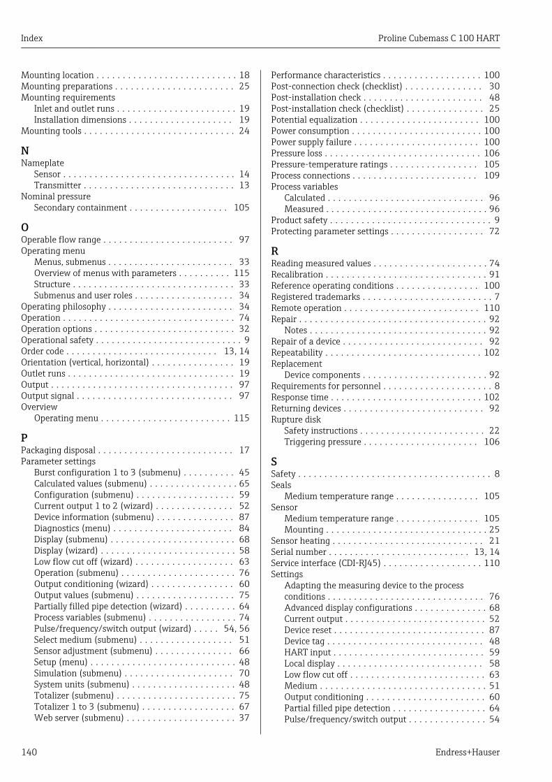
Index Proline Cubemass C 100 HART
140 Endress+Hauser
Mounting location . . . . . . . . . . . . . . . . . . . . . . . . . . . 18Mounting preparations . . . . . . . . . . . . . . . . . . . . . . . 25Mounting requirements
Inlet and outlet runs . . . . . . . . . . . . . . . . . . . . . . . 19Installation dimensions . . . . . . . . . . . . . . . . . . . . 19
Mounting tools . . . . . . . . . . . . . . . . . . . . . . . . . . . . . 24
NNameplate
Sensor . . . . . . . . . . . . . . . . . . . . . . . . . . . . . . . . . 14Transmitter . . . . . . . . . . . . . . . . . . . . . . . . . . . . . 13
Nominal pressureSecondary containment . . . . . . . . . . . . . . . . . . . 105
OOperable flow range . . . . . . . . . . . . . . . . . . . . . . . . . 97Operating menu
Menus, submenus . . . . . . . . . . . . . . . . . . . . . . . . 33Overview of menus with parameters . . . . . . . . . . 115Structure . . . . . . . . . . . . . . . . . . . . . . . . . . . . . . . 33Submenus and user roles . . . . . . . . . . . . . . . . . . . 34
Operating philosophy . . . . . . . . . . . . . . . . . . . . . . . . 34Operation . . . . . . . . . . . . . . . . . . . . . . . . . . . . . . . . . 74Operation options . . . . . . . . . . . . . . . . . . . . . . . . . . . 32Operational safety . . . . . . . . . . . . . . . . . . . . . . . . . . . . 9Order code . . . . . . . . . . . . . . . . . . . . . . . . . . . . . 13, 14Orientation (vertical, horizontal) . . . . . . . . . . . . . . . . 19Outlet runs . . . . . . . . . . . . . . . . . . . . . . . . . . . . . . . . 19Output . . . . . . . . . . . . . . . . . . . . . . . . . . . . . . . . . . . 97Output signal . . . . . . . . . . . . . . . . . . . . . . . . . . . . . . 97Overview
Operating menu . . . . . . . . . . . . . . . . . . . . . . . . . 115
PPackaging disposal . . . . . . . . . . . . . . . . . . . . . . . . . . 17Parameter settings
Burst configuration 1 to 3 (submenu) . . . . . . . . . . 45Calculated values (submenu) . . . . . . . . . . . . . . . . . 65Configuration (submenu) . . . . . . . . . . . . . . . . . . . 59Current output 1 to 2 (wizard) . . . . . . . . . . . . . . . 52Device information (submenu) . . . . . . . . . . . . . . . 87Diagnostics (menu) . . . . . . . . . . . . . . . . . . . . . . . 84Display (submenu) . . . . . . . . . . . . . . . . . . . . . . . . 68Display (wizard) . . . . . . . . . . . . . . . . . . . . . . . . . . 58Low flow cut off (wizard) . . . . . . . . . . . . . . . . . . . 63Operation (submenu) . . . . . . . . . . . . . . . . . . . . . . 76Output conditioning (wizard) . . . . . . . . . . . . . . . . 60Output values (submenu) . . . . . . . . . . . . . . . . . . . 75Partially filled pipe detection (wizard) . . . . . . . . . . 64Process variables (submenu) . . . . . . . . . . . . . . . . . 74Pulse/frequency/switch output (wizard) . . . . . 54, 56Select medium (submenu) . . . . . . . . . . . . . . . . . . 51Sensor adjustment (submenu) . . . . . . . . . . . . . . . 66Setup (menu) . . . . . . . . . . . . . . . . . . . . . . . . . . . . 48Simulation (submenu) . . . . . . . . . . . . . . . . . . . . . 70System units (submenu) . . . . . . . . . . . . . . . . . . . . 48Totalizer (submenu) . . . . . . . . . . . . . . . . . . . . . . . 75Totalizer 1 to 3 (submenu) . . . . . . . . . . . . . . . . . . 67Web server (submenu) . . . . . . . . . . . . . . . . . . . . . 37
Performance characteristics . . . . . . . . . . . . . . . . . . . 100Post-connection check (checklist) . . . . . . . . . . . . . . . 30Post-installation check . . . . . . . . . . . . . . . . . . . . . . . 48Post-installation check (checklist) . . . . . . . . . . . . . . . 25Potential equalization . . . . . . . . . . . . . . . . . . . . . . . 100Power consumption . . . . . . . . . . . . . . . . . . . . . . . . . 100Power supply failure . . . . . . . . . . . . . . . . . . . . . . . . 100Pressure loss . . . . . . . . . . . . . . . . . . . . . . . . . . . . . . 106Pressure-temperature ratings . . . . . . . . . . . . . . . . . 105Process connections . . . . . . . . . . . . . . . . . . . . . . . . 109Process variables
Calculated . . . . . . . . . . . . . . . . . . . . . . . . . . . . . . 96Measured . . . . . . . . . . . . . . . . . . . . . . . . . . . . . . . 96
Product safety . . . . . . . . . . . . . . . . . . . . . . . . . . . . . . . 9Protecting parameter settings . . . . . . . . . . . . . . . . . . 72
RReading measured values . . . . . . . . . . . . . . . . . . . . . . 74Recalibration . . . . . . . . . . . . . . . . . . . . . . . . . . . . . . . 91Reference operating conditions . . . . . . . . . . . . . . . . 100Registered trademarks . . . . . . . . . . . . . . . . . . . . . . . . . 7Remote operation . . . . . . . . . . . . . . . . . . . . . . . . . . 110Repair . . . . . . . . . . . . . . . . . . . . . . . . . . . . . . . . . . . . 92
Notes . . . . . . . . . . . . . . . . . . . . . . . . . . . . . . . . . . 92Repair of a device . . . . . . . . . . . . . . . . . . . . . . . . . . . 92Repeatability . . . . . . . . . . . . . . . . . . . . . . . . . . . . . . 102Replacement
Device components . . . . . . . . . . . . . . . . . . . . . . . . 92Requirements for personnel . . . . . . . . . . . . . . . . . . . . . 8Response time . . . . . . . . . . . . . . . . . . . . . . . . . . . . . 102Returning devices . . . . . . . . . . . . . . . . . . . . . . . . . . . 92Rupture disk
Safety instructions . . . . . . . . . . . . . . . . . . . . . . . . 22Triggering pressure . . . . . . . . . . . . . . . . . . . . . . 106
SSafety . . . . . . . . . . . . . . . . . . . . . . . . . . . . . . . . . . . . . 8Seals
Medium temperature range . . . . . . . . . . . . . . . . 105Sensor
Medium temperature range . . . . . . . . . . . . . . . . 105Mounting . . . . . . . . . . . . . . . . . . . . . . . . . . . . . . . 25
Sensor heating . . . . . . . . . . . . . . . . . . . . . . . . . . . . . 21Serial number . . . . . . . . . . . . . . . . . . . . . . . . . . . 13, 14Service interface (CDI-RJ45) . . . . . . . . . . . . . . . . . . . 110Settings
Adapting the measuring device to the processconditions . . . . . . . . . . . . . . . . . . . . . . . . . . . . . . 76Advanced display configurations . . . . . . . . . . . . . . 68Current output . . . . . . . . . . . . . . . . . . . . . . . . . . . 52Device reset . . . . . . . . . . . . . . . . . . . . . . . . . . . . . 87Device tag . . . . . . . . . . . . . . . . . . . . . . . . . . . . . . 48HART input . . . . . . . . . . . . . . . . . . . . . . . . . . . . . 59Local display . . . . . . . . . . . . . . . . . . . . . . . . . . . . 58Low flow cut off . . . . . . . . . . . . . . . . . . . . . . . . . . 63Medium . . . . . . . . . . . . . . . . . . . . . . . . . . . . . . . . 51Output conditioning . . . . . . . . . . . . . . . . . . . . . . . 60Partial filled pipe detection . . . . . . . . . . . . . . . . . . 64Pulse/frequency/switch output . . . . . . . . . . . . . . . 54

Proline Cubemass C 100 HART Index
Endress+Hauser 141
Resetting the totalizer . . . . . . . . . . . . . . . . . . . . . 76Sensor adjustment . . . . . . . . . . . . . . . . . . . . . . . . 66Simulation . . . . . . . . . . . . . . . . . . . . . . . . . . . . . . 70System units . . . . . . . . . . . . . . . . . . . . . . . . . . . . 48Totalizer . . . . . . . . . . . . . . . . . . . . . . . . . . . . . . . 67Totalizer reset . . . . . . . . . . . . . . . . . . . . . . . . . . . 76
Shock resistance . . . . . . . . . . . . . . . . . . . . . . . . . . . 104Signal on alarm . . . . . . . . . . . . . . . . . . . . . . . . . . . . . 98SIMATIC PDM . . . . . . . . . . . . . . . . . . . . . . . . . . . . . . 41
Function . . . . . . . . . . . . . . . . . . . . . . . . . . . . . . . 41Software release . . . . . . . . . . . . . . . . . . . . . . . . . . . . 43Spare part . . . . . . . . . . . . . . . . . . . . . . . . . . . . . . . . . 92Spare parts . . . . . . . . . . . . . . . . . . . . . . . . . . . . . . . . 92Special connection instructions . . . . . . . . . . . . . . . . . 30Standards and guidelines . . . . . . . . . . . . . . . . . . . . . 111Status signals . . . . . . . . . . . . . . . . . . . . . . . . . . . . . . 80Sterilization in place (SIP) . . . . . . . . . . . . . . . . . . . . 105Storage conditions . . . . . . . . . . . . . . . . . . . . . . . . . . . 16Storage temperature . . . . . . . . . . . . . . . . . . . . . . . . . 16Structure
Operating menu . . . . . . . . . . . . . . . . . . . . . . . . . . 33submenu
Advanced setup . . . . . . . . . . . . . . . . . . . . . . . . . . 65Burst configuration 1 to 3 . . . . . . . . . . . . . . . . . . . 45Calculated values . . . . . . . . . . . . . . . . . . . . . . . . . 65Configuration . . . . . . . . . . . . . . . . . . . . . . . . . . . . 59Device information . . . . . . . . . . . . . . . . . . . . . . . . 87Display . . . . . . . . . . . . . . . . . . . . . . . . . . . . . . . . . 68Operation . . . . . . . . . . . . . . . . . . . . . . . . . . . . . . 76Output values . . . . . . . . . . . . . . . . . . . . . . . . . . . . 75Process variables . . . . . . . . . . . . . . . . . . . . . . . . . 74Select medium . . . . . . . . . . . . . . . . . . . . . . . . . . . 51Sensor adjustment . . . . . . . . . . . . . . . . . . . . . . . . 66Simulation . . . . . . . . . . . . . . . . . . . . . . . . . . . . . . 70System units . . . . . . . . . . . . . . . . . . . . . . . . . . . . 48Totalizer . . . . . . . . . . . . . . . . . . . . . . . . . . . . . . . 75Totalizer 1 to 3 . . . . . . . . . . . . . . . . . . . . . . . . . . . 67Web server . . . . . . . . . . . . . . . . . . . . . . . . . . . . . 37
SubmenuDefine access code . . . . . . . . . . . . . . . . . . . . . . . . 72Events list . . . . . . . . . . . . . . . . . . . . . . . . . . . . . . 85Overview . . . . . . . . . . . . . . . . . . . . . . . . . . . . . . . 34Process variables . . . . . . . . . . . . . . . . . . . . . . . . . 65
Supply voltage . . . . . . . . . . . . . . . . . . . . . . . . . . . . . 100System design
Measuring system . . . . . . . . . . . . . . . . . . . . . . . . 96see Measuring device design
System integration . . . . . . . . . . . . . . . . . . . . . . . . . . 43System pressure . . . . . . . . . . . . . . . . . . . . . . . . . . . . 20
TTechnical data, overview . . . . . . . . . . . . . . . . . . . . . . 96Temperature range
Medium temperature . . . . . . . . . . . . . . . . . . . . . 105Storage temperature . . . . . . . . . . . . . . . . . . . . . . . 16
Terminal assignment . . . . . . . . . . . . . . . . . . . . . . 27, 28Terminals . . . . . . . . . . . . . . . . . . . . . . . . . . . . . . . . 100Thermal insulation . . . . . . . . . . . . . . . . . . . . . . . . . . 20Tools
Electrical connection . . . . . . . . . . . . . . . . . . . . . . 26Installation . . . . . . . . . . . . . . . . . . . . . . . . . . . . . 24Transport . . . . . . . . . . . . . . . . . . . . . . . . . . . . . . . 16
TransmitterConnecting the signal cables . . . . . . . . . . . . . . . . . 28
Transporting the measuring device . . . . . . . . . . . . . . 16Troubleshooting
General . . . . . . . . . . . . . . . . . . . . . . . . . . . . . . . . 78
UUse of the measuring device
Borderline cases . . . . . . . . . . . . . . . . . . . . . . . . . . . 8Incorrect use . . . . . . . . . . . . . . . . . . . . . . . . . . . . . 8see Designated use
User roles . . . . . . . . . . . . . . . . . . . . . . . . . . . . . . . . . 34
VVersion data for the device . . . . . . . . . . . . . . . . . . . . 43Vibration resistance . . . . . . . . . . . . . . . . . . . . . . . . 104Vibrations . . . . . . . . . . . . . . . . . . . . . . . . . . . . . . . . . 22
WW@M . . . . . . . . . . . . . . . . . . . . . . . . . . . . . . . . 91, 92W@M Device Viewer . . . . . . . . . . . . . . . . . . . . . 12, 92Weight
SI units . . . . . . . . . . . . . . . . . . . . . . . . . . . . . . . 107Transport (notes) . . . . . . . . . . . . . . . . . . . . . . . . . 16US units . . . . . . . . . . . . . . . . . . . . . . . . . . . . . . . 107
wizardCurrent output 1 to 2 . . . . . . . . . . . . . . . . . . . . . . 52Define access code . . . . . . . . . . . . . . . . . . . . . . . . 72Display . . . . . . . . . . . . . . . . . . . . . . . . . . . . . . . . . 58Low flow cut off . . . . . . . . . . . . . . . . . . . . . . . . . . 63Output conditioning . . . . . . . . . . . . . . . . . . . . . . . 60Partially filled pipe detection . . . . . . . . . . . . . . . . . 64Pulse/frequency/switch output . . . . . . . . . . . . 54, 56
Workplace safety . . . . . . . . . . . . . . . . . . . . . . . . . . . . 9Write protection
Via access code . . . . . . . . . . . . . . . . . . . . . . . . . . . 72Via write protection switch . . . . . . . . . . . . . . . . . . 73
Write protection switch . . . . . . . . . . . . . . . . . . . . . . . 73

www.addresses.endress.com