project: 01-encrypted data transfer
TRANSCRIPT

Project: 01- Encrypted Data Transfer
Our project deals with the demonstration of modern days’ technology of transmitting
data through high security encryption in commercial and military use. We have used a
very simple system of Transmitter and receiver module and chipper software for the
project. This project gives an outline to a layman about how the modern systems
handles and secures electronic data transfers.
HISTORY, DEVELOPMENT & APPLICATIONS -
Cryptography has a long and fascinating history. The most complete non-technical
account
of the subject is Kahn’s The Codebreakers. This book traces cryptography from its
initial and limited use by the Egyptians some 4000 years ago, to the twentieth century
where it played a crucial role in the outcome of both world wars. Completed in 1963,
Kahn’s book covers those aspects of the history which were most significant (up to that
time) to the developmentof the subject. The predominant practitioners of the art were
those associated with the military, the diplomatic service and government in general.
Cryptography was used as a tool to protect national secrets and strategies.
The proliferation of computers and communications systems in the 1960s brought with
it a demand from the private sector for means to protect information in digital form
and to provide security services. Beginning with the work of Feistel at IBMin the early
1970s and culminating in 1977 with the adoption as a U.S. Federal Information
Processing Standard for encrypting unclassified information, DES, the Data Encryption
Standard, is the most well-known cryptographic mechanism in history. It remains the
standard means for securing electronic commerce for many financial institutions
around the world.
In 1978 Rivest, Shamir, and Adleman discovered the first practical public-key
encryption and signature scheme, now referred to as RSA. The RSA scheme is based
on another hard mathematical problem, the intractability of factoring large integers.
This application of a hard mathematical problem to cryptography revitalized efforts
to find more efficient methods to factor. The 1980s saw major advances in this area
but nonewhich rendered the RSA systeminsecure. Another class of powerful and
practical public-key schemes was found by ElGamal in 1985. These are also based on
the discrete logarithm problem.
One of the most significant contributions provided by public-key cryptography is the
digital signature. In 1991 the first international standard for digital signatures (ISO/IEC

9796) was adopted. It is based on the RSA public-key scheme. In 1994 the U.S.
Government
adopted the Digital Signature Standard, a mechanism based on the ElGamal publickey
scheme. The search for new public-key schemes, improvements to existing
cryptographicmechanisms, and proofs of security continues at a rapid pace. Various
standards and infrastructures involving cryptography are being put in place. Security
products are being developed
to address the security needs of an information intensive society.
The way information is recorded has not changed dramatically over time.
Whereas information was typically stored and transmitted on paper, much of it now
resides on magnetic media and is transmitted via telecommunications systems, some
wireless.
What has changed dramatically is the ability to copy and alter information. One can
make thousands of identical copies of a piece of information stored electronically and
each is indistinguishable from the original. With information on paper, this is much
more difficult.
SCADA (Supervisory Control And Data Acquisition) is a system for remote
monitoring and control that operates with coded signals over communication channels
(using typically one communication channel per remote station). The control system
may be combined with a data acquisition system by adding the use of coded signals
over communication channels to acquire information about the status of the remote
equipment for display or for recording functions.[1] It is a type of industrial control
system (ICS). Industrial control systems are computer-based systems that monitor and
control industrial processes that exist in the physical world. SCADA systems historically
distinguish themselves from other ICS systems by being large-scale processes that can
include multiple sites, and large distances.[2] These processes include industrial,
infrastructure, and facility-based processes, as described below:
Industrial processes include those of manufacturing, production, power
generation, fabrication, and refining, and may run in continuous, batch, repetitive,
or discrete modes.
Infrastructure processes may be public or private, and include water treatment and
distribution, wastewater collection and treatment, oil and gas pipelines, electrical
power transmission and distribution, wind farms, civil defense siren systems, and
large communication systems.

Facility processes occur both in public facilities and private ones, including
buildings, airports, ships, and space stations. They monitor and control heating,
ventilation, and air conditioning systems (HVAC), access, and energy consumption.
What is needed then for a society where information is mostly stored and transmitted
in electronic form is a means to ensure information security which is independent of
the physical medium recording or conveying it and such that the objectives of
information security rely solely on digital information itself.
Project details
This project has two parts; they are the Software part and the Hardware part. While the
software part is used for encrypting the message to be sent in the transmitter side and
decrypting it in the receiver side of the system, the hardware part is there for
transmitting and receiving the message using the Morse code. In today’s world though
Morse has almost no significance but the easiest way to transmit data in this simple
model can only be done using the code. We have slightly modified it according to our
use as we will be having LEDs for the data transmission so the ‘Dot’ in is the blinking of
the ‘Red’ LED and the ‘Dash’ is the blinking of the ‘Yellow’ LED. As we can transmit 4
bits of data simultaneously, we can use four LEDs for different purpose.

Software-
We have used two softwares for the encoding and decoding purpose which will be used
in series with each other. First we will put the message in the first software and then the
encoded data will be put into the second software. The result of it will be transmitted
and will be decoded similarly using the same software in the receiving side. The
softwares with .exe extension is available with this pdf.

Hardware-
Description This radio frequency (RF) transmission system employs Amplitude Shift
Keying (ASK) with transmitter/receiver (Tx/Rx) pair operating at 434 MHz. The
transmitter module takes serial input and transmits these signals through RF. The
transmitted signals are received by the receiver module placed away from the source of
transmission.
The system allows one way communication between two nodes, namely, transmission
and reception. The RF module has been used in conjunction with a set of four channel
encoder/decoder ICs. Here HT12E & HT12D have been used as encoder and
decoder respectively. The encoder converts the parallel inputs (from the remote
switches) into serial set of signals. These signals are serially transferred through RF to
the reception point. The decoder is used after the RF receiver to decode the serial
format and retrieve the original signals as outputs. These outputs can be observed on
corresponding LEDs.
Encoder IC (HT12E) receives parallel data in the form of address bits and control bits.
The control signals from remote switches along with 8 address bits constitute a set of 12
parallel signals. The encoder HT12E encodes these parallel signals into serial bits.

Transmission is enabled by providing ground to pin14 which is active low. The control
signals are given at pins 10-13 of HT12E. The serial data is fed to the RF transmitter
through pin17 of HT12E.
Transmitter, upon receiving serial data from encoder IC (HT12E), transmits it
wirelessly to the RF receiver. The receiver, upon receiving these signals, sends them to
the decoder IC (HT12D) through pin2. The serial data is received at the data pin
(DIN, pin14) of HT12D. The decoder then retrieves the original parallel format from
the received serial data.

When no signal is received at data pin of HT12D, it remains in standby mode and
consumes very less current (less than 1μA) for a voltage of 5V. When signal is received
by receiver, it is given to DIN pin (pin14) of HT12D. On reception of signal, oscillator
of HT12D gets activated. IC HT12D then decodes the serial data and checks the
address bits three times. If these bits match with the local address pins (pins 1-8) of
HT12D, then it puts the data bits on its data pins (pins 10-13) and makes the VT pin
high. An LED is connected to VT pin (pin17) of the decoder. This LED works as an
indicator to indicate a valid transmission. The corresponding output is thus generated at
the data pins of decoder IC. A signal is sent by lowering any or all the pins 10-13 of
HT12E and corresponding signal is received at receiver’s end (at HT12D). Address
bits are configured by using the by using the first 8 pins of both encoder and decoder
ICs. To send a particular signal, address bits must be same at encoder and decoder
ICs. By configuring the address bits properly, a single RF transmitter can also be used
to control different RF receivers of same frequency.
To summarize, on each transmission, 12 bits of data is transmitted consisting of 8
address bits and 4 data bits. The signal is received at receiver’s end which is then fed
into decoder IC. If address bits get matched, decoder converts it into parallel data and
the corresponding data bits get lowered which could be then used to drive the LEDs.
The outputs from this system can either be used in negative logic or NOT gates (like
74LS04) can be incorporated at data pins.


COMPONENTS USED
1. HT12D DECODER
HT12D IC comes from HolTek Company. HT12D is a decoder integrated circuit that
belongs to 212 series of decoders. This series of decoders are mainly used for remote
control system applications, like burglar alarm, car door controller, security system etc.
It is mainly provided to interface RF and infrared circuits. They are paired with 212
series of encoders. The chosen pair of encoder/decoder should have same number of
addresses and data format. In simple terms, HT12D converts the serial input into
parallel outputs. It decodes the serial addresses and data received by, say, an RF
receiver, into parallel data and sends them to output data pins. The serial input data is
compared with the local addresses three times continuously. The input data code is
decoded when no error or unmatched codes are found. A valid transmission in
indicated by a high signal at VT pin. HT12D is capable of decoding 12 bits, of which 8
are address bits and 4 are data bits. The data on 4 bit latch type output pins remain
unchanged until new is received.

Pin Diagram


Pin Description
Pin Number
Function
Name
1 8 BIT ADDRESS PINS
FOR INPUT
A0
2 A1
3 A2
4 A3
5 A4
6 A5
7 A6
8 A7
9 GROUND (0V) GROUND
10 4 BIT DATA/ADDRESS
PINS FOR OUTPUT
D0
11 D1
12 D2
13 D3
14 SERIAL DATA INPUT INPUT
15 OSCILLATOR OUTPUT OSC 2
16 OSCILLATOR INPUT OSC 1
17 VALID
TRANSMISSION,
ACTIVE HIGH
VT
18 SUPPLY VOLTAGE; 5V
(2.4 – 12V)
Vcc
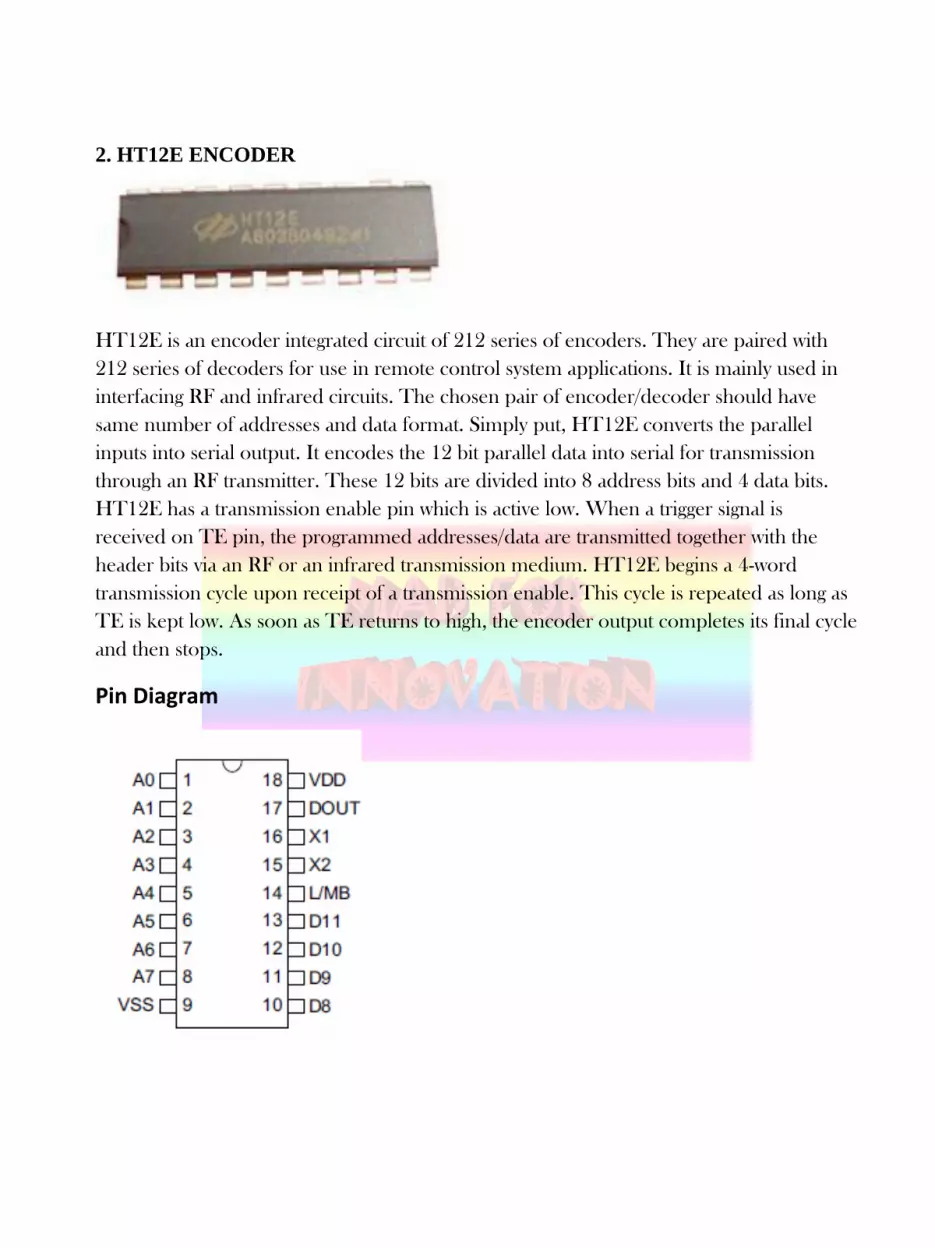
2. HT12E ENCODER
HT12E is an encoder integrated circuit of 212 series of encoders. They are paired with
212 series of decoders for use in remote control system applications. It is mainly used in
interfacing RF and infrared circuits. The chosen pair of encoder/decoder should have
same number of addresses and data format. Simply put, HT12E converts the parallel
inputs into serial output. It encodes the 12 bit parallel data into serial for transmission
through an RF transmitter. These 12 bits are divided into 8 address bits and 4 data bits.
HT12E has a transmission enable pin which is active low. When a trigger signal is
received on TE pin, the programmed addresses/data are transmitted together with the
header bits via an RF or an infrared transmission medium. HT12E begins a 4-word
transmission cycle upon receipt of a transmission enable. This cycle is repeated as long as
TE is kept low. As soon as TE returns to high, the encoder output completes its final cycle
and then stops.
Pin Diagram

Pin Description
Pin Number
Function
Name
1 8 BIT ADDRESS PINS
FOR INPUT
A0
2 A1
3 A2
4 A3
5 A4
6 A5
7 A6
8 A7
9 GROUND (0V) GROUND
10 4 BIT DATA/ADDRESS
PINS FOR INPUT
D0
11 D1
12 D2
13 D3
14 TRANSMISSION
ENABLE (ACTIVE
LOW)
TE
15 OSCILLATOR
OUTPUT
OSC 2
16 OSCILLATOR INPUT OSC 1
17 VALID
TRANSMISSION,
ACTIVE HIGH
VT
18 SUPPLY VOLTAGE;
5V (2.4 – 12V)
Vcc

3. RF MODULES (434MHz)
The RF module, as the name suggests, operates at Radio Frequency. The
corresponding frequency range varies between 30 kHz & 300 GHz. In this RF system,
the digital data is represented as variations in the amplitude of carrier wave. This kind
of modulation is known as Amplitude Shift Keying (ASK). Transmission through RF
is better than IR (infrared) because of many reasons. Firstly, signals through RF can
travel through larger distances making it suitable for long range applications. Also,
while IR mostly operates in line-of-sight mode, RF signals can travel even when there
is an obstruction between transmitter & receiver. Next, RF transmission is more
strong and reliable than IR transmission. RF communication uses a specific frequency
unlike IR signals which are affected by other IR emitting sources. This RF module
comprises of an RF Transmitter and an RF Receiver. The transmitter/receiver
(Tx/Rx) pair operates at a frequency of 434 MHz. An RF transmitter receives serial
data and transmits it wirelessly through RF through its antenna connected at pin4. The
transmission occurs at the rate of 1Kbps - 10Kbps.The transmitted data is received by
an RF receiver operating at the same frequency as that of the transmitter.

The RF module is often used along with a pair of encoder/decoder. The encoder is
used for encoding parallel data for transmission feed while reception is decoded by a
decoder. HT12E-HT12D, HT640-HT648, etc. are some commonly used
encoder/decoder pair ICs.
Pin Diagram
Receiver Module
Transmitter Module

Transmitter
Module
Pin Number
Function
Name 1 Ground (0V) GND
2 Serial Data Input Pin DATA
3 Supply Voltage (5V) VCC
4 Antenna Output Pin ANT

Receiver Module
Pin Number
Function
Name
1 Ground (0V) GND
2 Serial Data Output
Pin
DATA
3 Linear Output Pin;
Not Connected
NC
4 Supply Voltage (5V) VCC
5 Supply Voltage (5V) VCC
6 Ground (0V) GND
7 Ground (0V) GND
8 Antenna Input Pin ANT
Stills-

THANK YOU
For more information please go to our facebook page https://www.facebook.com/madforinnovation/
Or subscribe us at youtube https://www.youtube.com/channel/UChCFjx2EEMRlgRLcRUgljyg