programming - rapidonline
TRANSCRIPT
Full range of Programming products available at:
www.rapidonline.com
Adafruit Feather 34
Adafruit FONA 34
Adafruit NeoPixel LED 31
Adafruit Trinket 30
Arduino 26
BBC Micro:Bit 8
Breakout Sensor Boards 35
Flowol 9
Genie Microcontrollers 23
Makey Makey 9
Microcontroller Project Kits 26
Orangepip 29
Raspberry Pi 10
Pi Breakout & Proto Boards 11
Pi Books 17
Pi Cases 17
Pi Camera Modules 12
Pi Controller Boards 13
Pi Kits 10
Pi Light, Sound & Displays add on Boards 14
Pi Motor & Power Driver Boards 16
Pi Robots 14
Pi Power Supplies & Heat Management 16
Pi Touch Sensing 16
PICAXE 18
RFID / NFC 35
Wearables 32
Programming
6 Tel: 01206 751166 Fax: 01206 751188
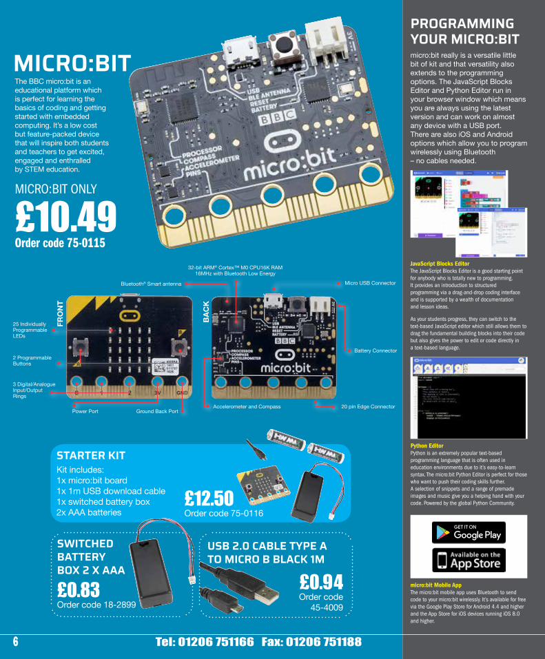
The BBC micro:bit is an educational platform which is perfect for learning the basics of coding and getting started with embedded computing. It’s a low cost but feature-packed device that will inspire both students and teachers to get excited, engaged and enthralled by STEM education.
£0.83 Order code 18-2899
£0.94 Order code
45-4009
MICRO:BIT
SWITCHED BATTERY BOX 2 X AAA
USB 2.0 CABLE TYPE A TO MICRO B BLACK 1M
STARTER KITKit includes:1x micro:bit board1x 1m USB download cable1x switched battery box2x AAA batteries
£12.50 Order code 75-0116
MICRO:BIT ONLY
£10.49Order code 75-0115
Battery Connector2 Programmable Buttons
Power Port
FRO
NT
BAC
K
Ground Back Port
25 Individually Programmable LEDs
3 Digital/Analogue Input/Output Rings
Micro USB Connector
20 pin Edge ConnectorAccelerometer and Compass
Bluetooth® Smart antenna
32-bit ARM® Cortex™ M0 CPU16K RAM 16MHz with Bluetooth Low Energy
PROGRAMMING YOUR MICRO:BITmicro:bit really is a versatile little bit of kit and that versatility also extends to the programming options. The JavaScript Blocks Editor and Python Editor run in your browser window which means you are always using the latest version and can work on almost any device with a USB port.There are also iOS and Android options which allow you to program wirelessly using Bluetooth – no cables needed.
JavaScript Blocks EditorThe JavaScript Blocks Editor is a good starting point for anybody who is totally new to programming. It provides an introduction to structured programming via a drag-and-drop coding interface and is supported by a wealth of documentation and lesson ideas.
As your students progress, they can switch to the text-based JavaScript editor which still allows them to drag the fundamental building blocks into their code but also gives the power to edit or code directly in a text-based language.
Python EditorPython is an extremely popular text-based programming language that is often used in education environments due to it’s easy-to-learn syntax. The micro:bit Python Editor is perfect for those who want to push their coding skills further. A selection of snippets and a range of premade images and music give you a helping hand with your code. Powered by the global Python Community.
micro:bit Mobile AppThe micro:bit mobile app uses Bluetooth to send code to your micro:bit wirelessly. It’s available for free via the Google Play Store for Android 4.4 and higher and the App Store for iOS devices running iOS 8.0 and higher.
7 www.rapidonline.com [email protected]
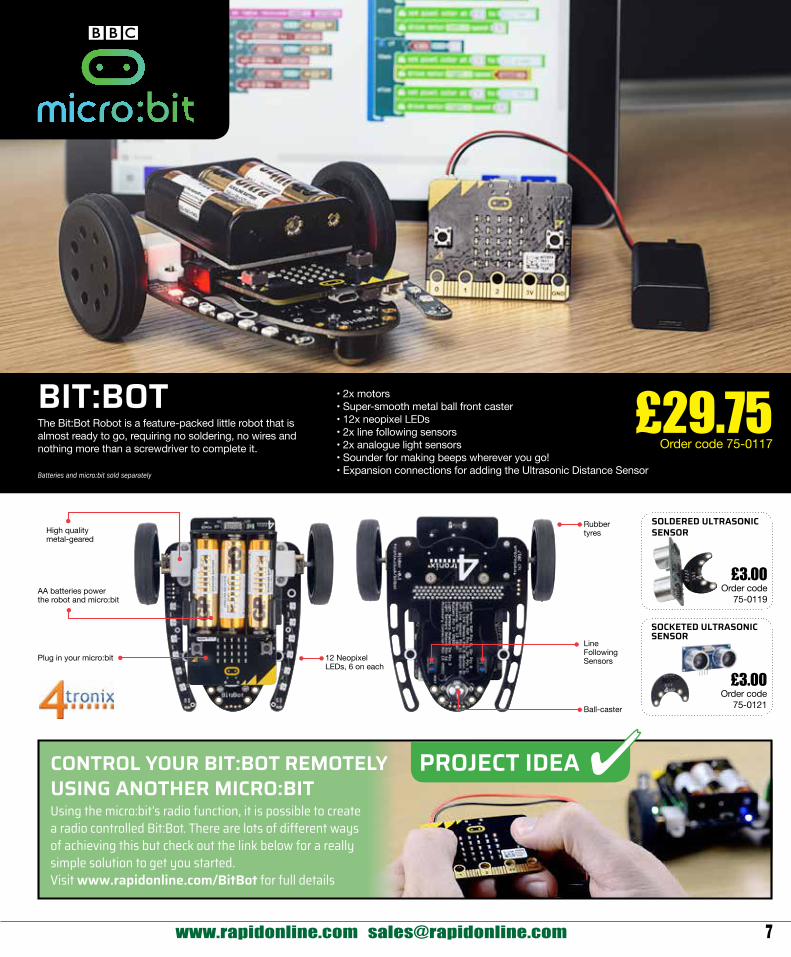
£3.00 Order code
75-0121
£3.00 Order code
75-0119
SOCKETED ULTRASONIC SENSOR
SOLDERED ULTRASONIC SENSOR
BIT:BOT
AA batteries power the robot and micro:bit
High quality metal-geared
Plug in your micro:bit 12 Neopixel LEDs, 6 on each
Rubber tyres
Ball-caster
Line Following Sensors
The Bit:Bot Robot is a feature-packed little robot that is almost ready to go, requiring no soldering, no wires and nothing more than a screwdriver to complete it.
Batteries and micro:bit sold separately
• 2x motors• Super-smooth metal ball front caster• 12x neopixel LEDs• 2x line following sensors• 2x analogue light sensors • Sounder for making beeps wherever you go!• Expansion connections for adding the Ultrasonic Distance Sensor
£29.75 Order code 75-0117
PROJECT IDEACONTROL YOUR BIT:BOT REMOTELY USING ANOTHER MICRO:BITUsing the micro:bit’s radio function, it is possible to create a radio controlled Bit:Bot. There are lots of different ways of achieving this but check out the link below for a really simple solution to get you started.Visit www.rapidonline.com/BitBot for full details
8
Programming8Ed
ucat
ion
2
Tel: 01206 751166 Fax: 01206 751188
Prog
ram
min
g
• Designed and manufactured in the UKNote: Neither Arduino nor BBC micro:bit are included.
Type Order code 1+Shield base 75-0261 4.75
565685
RKUB PT2 Prototyping Board for BBC micro:bitThe RKub PT2 is a powered prototype edge connector breakout board for the BBC micro:bit. Supplied as a self-build kit that is easy to assemble, with surface mount voltage regulators that are easy to solder. The professional standard, double sided PCB features a large prototyping area that has high quality, plated through holes. The assembly has a power switch and a 2.1mm DC power socket (12V DC recommended), powering the board and the micro:bit.
• Self-build kit• Very easy to use• Power circuitry with a 3.3V and 5V voltage regulator• Designed and manufactured in the UKNote: The BBC micro:bit is not included.
Type Order code 1+Prototyping board 75-0262 4.75
565686
RKUB2 Powered Breakout Board for BBC micro:bitThe RKub2 is a powered edge connector breakout board solder kit for the BBC micro:bit. Supplied as a self-build kit that is easy to assemble, with surface mount voltage regulators that are easy to solder. The assembly has a power switch and a 2.1mm DC power socket (12V DC recommended), powering the board and the micro:bit.
• Self-build kit• Allows you to breakout the BBC micro:bit• Very easy to use• Power circuitry with a 3.3V and 5V voltage regulator• Designed and manufactured in the UKNote: The BBC micro:bit is not included.
Type Order code 1+Breakout board 75-0263 3.75
565687
RKUB1 Breakout Board for BBC micro:bitThe RKub1 is an edge connector breakout board solder kit designed for use with the BBC micro:bit. Supplied as a self-build kit that is easy to construct and very easy to use.
• Self-build kit• Allows you to breakout the BBC micro:bit• Includes a 2mm JST header for power pack• Onboard power switch• Designed and manufactured in the UKNote: The BBC micro:bit is not included.
Type Order code 1+Breakout board 75-0264 2.50
565688
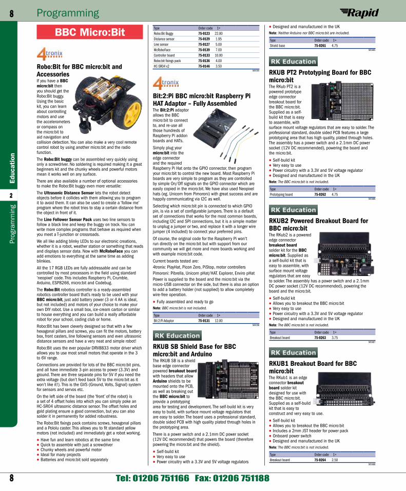
Type Order code 1+Robo:Bit Buggy 75-0123 22.00Distance sensor 75-0129 1.95Line sensor 75-0127 5.00McRoboFace 75-0139 7.00Controller board 75-0133 10.00Robo:bit fixings pack 75-0136 4.00HC-SR04 v2 75-0146 3.50
565005
Bit:2:Pi BBC micro:bit Raspberry Pi HAT Adaptor – Fully AssembledThe Bit:2:Pi adaptor allows the BBC micro:bit to connect to, and re-use all those hundreds of Raspberry Pi addon boards and HATs.
Simply plug your micro:bit into the edge connector and the required Raspberry Pi Hat onto the GPIO connector, then program your micro:bit to control the new board. Most Raspberry Pi boards are very simple to program as they are controlled by simple On/Off signals on the GPIO connector which are easily copied in the micro:bit. We have also used Neopixel hats (eg. Unicorn from Pimoroni) with great success and are happily communicating via I2C as well.
Selecting which micro:bit pin is connected to which GPIO pin, is via a set of configurable jumpers. There is a default set of connections that works for the most common boards, including I2C and SPI connections, but it is a simple matter to unplug a jumper or two, and replace it with a longer wire jumper (4 included) to connect your preferred pins.
Of course, the original code for the Raspberry Pi won’t run directly on the micro:bit but with support from our community we will get more and more boards working and with example micro:bit code.
Current boards tested are:4tronix: PlayHat, Picon Zero, PiStop, motor controllersPimoroni: Pibrella, Unicorn pHat/HAT. Explorer, Enviro pHatPower is supplied to the board and the micro:bit via the micro-USB connector on the side, but there is also an option to add a battery holder (not supplied) to allow completely wire-free operation.
• Fully assembled and ready to goNote: BBC micro:bit is not included.
Type Order code 1+Bit:2:Pi Adaptor 75-0131 12.00
565006
RKUB SB Shield Base for BBC micro:bit and ArduinoThe RKUB SB is a shield base edge connector powered breakout board with headers that allow Arduino shields to be mounted onto the PCB, as well as breaking out the BBC micro:bit to provide a prototyping area for testing and development. The self-build kit is very easy to build, with surface mount voltage regulators that are easy to solder. The board uses a professional standard, double sided PCB with high quality plated through holes in the prototyping area.
There is a power switch and a 2.1mm DC power socket (12V DC recommended) that powers the board (therefore powering the micro:bit and the shield).
• Self-build kit• Very easy to use• Power circuitry with a 3.3V and 5V voltage regulators
BBC Micro:Bit
Robo:Bit for BBC micro:bit and AccessoriesIf you have a BBC micro:bit then you should get the Robo:Bit buggy. Using the basic kit, you can learn about controlling motors and use the accelerometers or compass on the micro:bit to aid navigation and collision detection. You can also make a very cool remote control robot by using another micro:bit and the radio function.
The Robo:Bit buggy can be assembled very quickly using only a screwdriver. No soldering is required making it a great beginners kit and the chunky wheels and powerful motors mean it works well on any surface.
There are also available a number of optional accessories to make the Robo:Bit buggy even more versatile:
The Ultrasonic Distance Sensor lets the robot detect objects before it collides with them allowing you to program it to avoid them. It can also be used to create a ‘follow me’ program where the robot tries to stay a certain distance from the object in front of it.
The Line Follower Sensor Pack uses two line sensors to follow a black line and keep the buggy on track. You can write more complex programs that behave as required when you meet a T-junction or crossroads.
We all like adding blinky LEDs to our electronic creations, whether it is a robot, weather station or something that reads and displays sensor data. Now with McRoboFace you can add emotions to everything at the same time as adding blinkies.
All the 17 RGB LEDs are fully addressable and can be controlled by most processors in the field using standard ‘neopixel’ code. This includes Raspberry Pi, Crumble, Arduino, ESP8266, micro:bit and Codebug.
The Robo:Bit robotics controller is a ready-assembled robotics controller board that’s ready to be used with your BBC micro:bit, just add battery power (3 or 4 AA is ideal, but not included) and motors of your choice to make your own DIY robot. Use a small box, ice-cream carton or similar to house everything and you can build a really affordable robot for your school, coding club or home.
Robo:Bit has been cleverly designed so that with a few hexagonal pillars and screws, you can fit the motors, battery box, front casters, line following sensors and even ultrasonic distance sensors and have a very neat and simple robot!
Robo:Bit uses the ever popular DRV8833 motor driver which allows you to use most small motors that operate in the 3 to 6V range.
Connections are provided for lots of the BBC micro:bit pins, and all have immediate 3-pin access to power (3.3V) and ground. There are three separate pins for 5V if you need the extra voltage (but don’t feed back 5V to the micro:bit as it won’t like it!). This is the GVS (Ground, Volts, Signal) system for sensors and servos etc.
On the left side of the board (the ‘front’ of the robot) is a set of 4 offset holes into which you can simply poke an HC-SR04 ultrasonic distance sensor. The offset holes and gold plating ensure a good connection, but you can also solder it in permanently for added robustness.
The Robo:Bit fixings pack contains screws, hexagonal pillars and a Pololu caster. This allows you to fit standard yellow motors (not included) and immediately get a robot working.
• Have fun and learn robotics at the same time• Quick to assemble with just a screwdriver• Chunky wheels and powerful motor• Ideal for many projects• Batteries and micro:bit sold separately
9
Programming 9Education
2
www.rapidonline.com [email protected]
Programm
ing
Primary 3D Mimic Pack 1 for Flowol 4Mimics are on-screen simulations of real-life situations that can be controlled by your Flowol program as if they were real machines. The Primary Mimic Pack 1 is available as a Single-User licence or a School Site licence.
• The Horse Ride Mimic is controlled by two independent motors so the type of ride can be varied. Virtual inputs can be used to stop the ride in its lowest position
• The Pirate Ship Mimic uses motors to control the motion of the ship and the sliding doors on its side. Virtual inputs are also available to detect the ship in its mid position and to indicate when the doors are shut
• The Teacup Ride Mimic uses motors to control the rotation of the ride, the spin of the cups and the opening of gates. Lights on the rim of the base can be illuminated and a virtual input detects the position of the ride
• The Grabber Game Mimic allows the user to win a teddy bear by controlling the four motors needed to manipulate the grab
Type Order code 1+Pri. Mimic Pk1 Single 70-0296 10.30Pri. Mimic Pk1 School 70-0297 49.44
519523
Secondary 3D Mimic Pack 1 for Flowol 4Mimics are on-screen simulations of real-life situations that can be controlled by your Flowol program as if they were real machines. The Secondary 3D Mimic Pack 1 is available as a Single-User licence or a School Site licence.
• The Car Park Mimic gives students the opportunity to explore the control features of car park barriers. Input switches on the ticket posts and pressure mats can be used to operate the articulated barrier. A variable can be used to count the cars in and out, control the Full sign and illuminate the seven segment display to indicate the available spaces
• The Bridge Mimic gives students the opportunity to explore the operation and safety features of a lifting road bridge. The beacons and road signals can be controlled and the left and right road barriers operated separately. The main bridge and barriers each have virtual input switches to detect when they are fully open or closed
• The Lift Mimic gives students the opportunity to explore the control features of a lift. The position of the lift is detected by virtual sensors on each floor. These can be used to stop the lift accurately and operate the floor indicator lights. By combining the inputs from the call buttons and position sensors, the lift’s movement can be controlled. When the doors operate, warning messages can be added by using the sound files included with the mimic
• The Flume Mimic gives students the opportunity to explore and control the excitement and safety of a theme park ride. The sign, camera and fountain can be activated by the virtual inputs tripped by the moving logs. The log movements can be controlled by gates and feedback switches. (Initially choose one log with two gates and then introduce two logs with three gates)
Type Order code 1+Sec. Mimic Pk1 Single 70-0298 10.72Sec. Mimic Pk1 School 70-0299 62.13
519524
Find music programs, games on the internet and let your imagination run away as you design a custom controller for them. Try drawing a game controller in pencil, hook up the alligator clips and the drawing IS the controller.
The kit comes with 5 alligator clips and 6 connector wires as well as a USB cable. No extra purchases are necessary to get the thing to work, not even fruit. For the dedicated inventor you can plug in two or more boards at once and create an orchestra of Makey Makeys! (tested with up to 3, but could work for more).
Tthe software is Open Source so you can find it on the internet and modify to it to really experiment. MaKey MaKey is compatible with the Arduino development environment (IDE).
• Arduino compatible• Simple USB connection• Challenge your imagination• Invent ways to experiment and play• Expand your imagination• Almost anything can be used as a keyboard
Type Order code 1+Inventors Kit 73-5500 36.06
539085
Flowol
Licences and Licence UpgradesFlowol 4 allows students of all ages to develop logical reasoning and problem solving talents, develop programming skills and explore the world of automatic, autonomous systems and robots.
Programming visually with a flowchart allows the student to focus on the logic of their solution rather than the syntax of a written program.
The Flowol 4 software is distributed as an internet download. Your purchase will include full download and installation instructions and a license key for either the Windows PC or Apple Mac version of Flowol 4.
• Supports numerous pieces of well known hardware including: VEX Robotics
• PICAXE• Arduino• Fischertechnik … and more• Flowol supports many programming elements:
Sequences of instructions• Branching using decisions• Loops (infinite, or based on a condition or count)• Variables and simple variable manipulation• Sub-procedures (parameters optional)• Multiple parallel threads• System Requirements for Windows PC: Microsoft
Windows XP, Vista, Windows 7 or Windows 8 (both 32bit and 64bit supported)
• 512 MB of RAM• 120 MB of available hard-disk space• Internet connection to download and activate the software
(Flowol 4 includes an MSI for installation on networks)• System Requirements for Apple Mac: Apple Mac
computer with Intel processor• Mac OS X 10.8 (Mountain Lion), 10.7 (Lion),
10.6 (Snow Leopard) or 10.5 (Leopard)• 512 MB of RAM• 100 MB of available hard-disk space• Internet connection to download and activate the software
Type Order code 1+Flowol 4 Single 70-0290 30.90Flowol 4 Primary 70-0291 160.68Flowol 4 Middle 70-0292 226.60Flowol 4 Secondary 70-0293 321.36Flowol 2 to 4 Upgrade 70-0294 95.34
519522
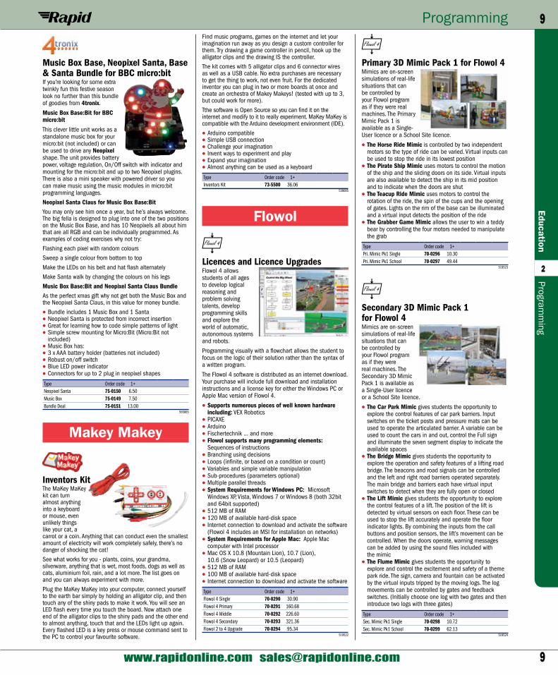
Music Box Base, Neopixel Santa, Base & Santa Bundle for BBC micro:bitIf you’re looking for some extra twinkly fun this festive season look no further than this bundle of goodies from 4tronix.
Music Box Base:Bit for BBC micro:bit
This clever little unit works as a standalone music box for your micro:bit (not included) or can be used to drive any Neopixel shape. The unit provides battery power, voltage regulation, On/Off switch with indicator and mounting for the micro:bit and up to two Neopixel plugins. There is also a mini speaker with powered driver so you can make music using the music modules in micro:bit programming languages.
Neopixel Santa Claus for Music Box Base:BitYou may only see him once a year, but he’s always welcome. The big fella is designed to plug into one of the two positions on the Music Box Base, and has 10 Neopixels all about him that are all RGB and can be individually programmed. As examples of coding exercises why not try:
Flashing each pixel with random colours
Sweep a single colour from bottom to top
Make the LEDs on his belt and hat flash alternately
Make Santa walk by changing the colours on his legs
Music Box Base:Bit and Neopixel Santa Claus BundleAs the perfect xmas gift why not get both the Music Box and the Neopixel Santa Claus, in this value for money bundle.
• Bundle includes 1 Music Box and 1 Santa• Neopixel Santa is protected from incorrect insertion• Great for learning how to code simple patterns of light• Simple screw mounting for Micro:Bit (Micro:Bit not
included)• Music Box has:• 3 x AAA battery holder (batteries not included)• Robust on/off switch• Blue LED power indicator• Connectors for up to 2 plug in neopixel shapes
Type Order code 1+Neopixel Santa 75-0150 6.50Music Box 75-0149 7.50Bundle Deal 75-0151 13.00
565865
Makey Makey
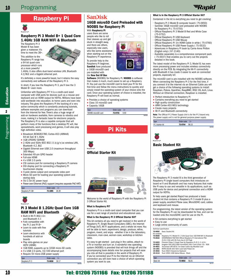
Inventors KitThe MaKey MaKey kit can turn almost anything into a keyboard or mouse, even unlikely things like your cat, a carrot or a coin. Anything that can conduct even the smallest amount of electricity will work completely safely, there’s no danger of shocking the cat!
See what works for you - plants, coins, your grandma, silverware, anything that is wet, most foods, dogs as well as cats, aluminium foil, rain, and a lot more. The list goes on and you can always experiment with more.
Plug the MaKey MaKey into your computer, connect yourself to the earth bar simply by holding an alligator clip, and then touch any of the shiny pads to make it work. You will see an LED flash every time you touch the board. Now attach one end of the alligator clips to the shiny pads and the other end to almost anything, touch that and the LEDs light up again. Every flashed LED is a key press or mouse command sent to the PC to control your favourite software.
10
Programming10Ed
ucat
ion
2
Tel: 01206 751166 Fax: 01206 751188
Prog
ram
min
g
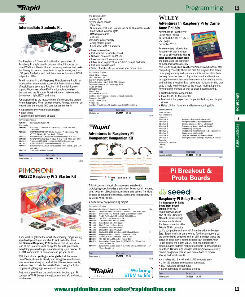
What is in the Raspberry Pi 3 Official Starter Kit?Contained in the kit is everything you need to get cracking:
• Raspberry Pi 3 Model B computer board ( 75-0650)• SanDisk 16GB microSD card preloaded with NOOBS
for Raspberry Pi ( 75-0755)• Official Raspberry Pi 3 Model B Red and White Case
(75-0752)• Official Raspberry Pi USB Keyboard• Official Raspberry Pi USB Mouse• Official Raspberry Pi 1m HDMI Cable in white ( 75-0760)• Official Raspberry Pi USB Power Supply ( 75-0532)• Adventures in Raspberry Pi book by Carrie-Anne Philbin
(English only) ( 97-2140)• Available separately is a comprehensive component pack
( 75-0037) that enables you to carry out the projects detailed in the book.
The latest model of the Raspberry Pi 3, Model B, has even more processing power and includes wireless connectivity directly on the PCB. By integrating the Wi-Fi connectivity with Bluetooth it has made it easier to work on connected projects, especially IoT.
The microSD card is pre-installed with the NOOBS software. When connecting the Raspberry Pi 3 for the first time, if you connect it to the internet via an Ethernet Cable you will get a choice of the following operating systems to install: Raspbian, Pidora, OpenElec, RaspBMC, RISC OS, Arch, Linux. Without an Ethernet connection, Raspbian is installed.
• Perfect introduction to Raspberry Pi• Contains everything you need to get started• High quality construction• ARM Cortex-A53 MCU technology• Create many projects• Wi-Fi and Bluetooth connectivityNote: The Official Pi 3 Power Supply Unit is for the Pi 3 board only. The power supply unit is not for general purpose power supply.
Type Order code 1+Pi 3 starter kit 75-0764 96.53
564952
Basic Student Kit
The Raspberry Pi 3 model B is the third generation of Raspberry Pi single board computers that introduces on-board wi-fi and Bluetooth and has many features that make the Pi easy to use and versatile in its applications, such as USB ports for device and peripheral connection and a HDMI output for HDTVs.
To help users get started Rapid has produced a basic student kit that contains a Raspberry Pi 3 model B plus a power supply, excellent Pibow case, MicroSDHC card, cables and keyboard and mouse.
For programming, the latest version of the operating system for the Raspberry Pi can be downloaded for free, and can be loaded onto the microSDHC card for use on the Pi.
• Kit contains everything to get started• Easy to use• Large online community of usersTechnical specification75-0692 Basic Student KitKit contents:75-0650 Raspberry Pi 3 Model B 1.2 GHz Quad Core 1GB RAM WiFi & Bluetooth75-0532 STONTRONICS T5875DV Official Raspberry Pi International PSU
(5.2V, 2.5A) with UK, Euro, Aus & US Plugs73-5423 Pimoroni Pibow 3 Coupé Case for Raspberry Pi (Pi 3, 2, & B+)19-9222 Kingston SDC10G2/8GB microSDHC UHS-I Card (Class 10) - 8GB19-4921 TruConnect URT-601G 1m Green Cat5e Utp Moulded Lead16-1361 RVFM CDLHD-303 Hdmi Lead Gold Plated 3m19-4042 Trust 20623 ClassicLine Keyboard19-4114 Trust 16591 USB Optical Mouse - Black
Type Order code 1+Basic kit 75-0692 58.81
563707
16GB microSD Card Preloaded with NOOBS for Raspberry PiWith Raspberry Pi users there are some people who like to roll their sleeves up and get stuck in straight away, and there are others, especially new users, who like some assistance when starting out on the Raspberry Pi experience.
To provide help to the Raspberry Pi beginner, Sandisk have produced a 16GB microSD card pre-installed with the New Out Of Box Software (NOOBS) for Raspberry Pi. NOOBS is software that makes it much, much easier to set up a Raspberry Pi. You just use the microSD card to boot your Pi for the first time and follow the menu instructions to quickly and simply install the operating system of your choice onto the card. Once your operating system of choice is installed, the Raspberry Pi will boot as normal.
• Provides a choice of operating systems• Class 10 microSD card• Capacity 16GB
Type Order code 1+NOOBS microSD card 75-0755 9.90
564949
Pi Kits
Official Starter Kit
Welcome to the world of Raspberry Pi with the Raspberry Pi 3 Official Starter Kit.
What is Raspberry Pi?Raspberry Pi is a credit-card sized computer that you can use for a vast range of practical and educational uses.
What is the Raspberry Pi 3 Official Starter Kit?This kit contains all you need to get involved in the world of Raspberry Pi, Single Board Computers (SBC), the Internet of Things (IoT), Wi-Fi applications, and a whole lot more. You will be able to learn, experiment, design, produce, refine, program, invent, and enjoy - whether it be in the laboratory, classroom, man-cave, woman-cave, workshop or kitchen table.
It’s easy to get started - just plug in the cables, attach to a TV or monitor and turn on. A wonderful new operating system (NOOBS) is provided that will kick things off and the accompanying book details nine fun projects that will ease you into all that is possible in the world of Raspberry Pi. If you’ve connected your Pi to the Internet via an Ethernet connection you will even have a choice of which operating system you want to use.
Raspberry Pi
Raspberry Pi 3 Model B+ 1 Quad Core 1.4GHz 1GB RAM WiFi & BluetoothThe Raspberry Pi 3 Model B has been given a makeover. It’s time to meet the 3B+.
This addition to the Raspberry Pi range has a 64-bit quad-core processor which runs at a more powerful 1.4GHz. It also offers dual-band wireless LAN, Bluetooth 4.2/BLE and a Gigabit ethernet port.
It’s definitely a more powerful beast, but it retains the easy connectivity and software of the Raspberry Pi 3.
In short, if you love the Raspberry Pi 3, you’ll love the 3 Model B+ even more.
Unfamiliar with Raspberry Pi? It is a credit-card sized computer with USB ports for devices such as a mouse and keyboard and an HDMI output for HDTVs. Millions have been sold worldwide into education, to home users and even into industry. This gives the Raspberry Pi the backing of a very active community which is constantly producing tutorials, software examples and programs you can download from the Internet for free. There’s also a huge range of add-on hardware available, from cameras to robotics and more, making it a fantastic base for electronic projects. The Raspberry Pi is also a capable computer that will perform many of the functions that a desktop PC will, like spreadsheets, word processing and games, it will also play high definition video.
• Broadcom BCM2837B0, Cortex-A53 (ARMv8) 64-bit SoC @ 1.4GHz
• 1GB LPDDR2 SDRAM• 2.4GHz and 5GHz IEEE 802.11.b/g/n/ac wireless LAN,
Bluetooth 4.2, BLE• Gigabit Ethernet over USB 2.0 (maximum throughput
300 Mbps)• Extended 40-pin GPIO header• Full-size HDMI• 4 x USB 2.0 ports• CSI camera port for connecting a Raspberry Pi camera• DSI display port for connecting a Raspberry Pi
touchscreen display• 4-pole stereo output and composite video port• Micro SD port for loading your operating system and
storing data• 5V/2.5A DC power input• Power-over-Ethernet (PoE) support (requires separate PoE HAT)
Type Order code 1+Raspberry Pi 3B+ 75-1005 28.39
566563
Pi 3 Model B 1.2GHz Quad Core 1GB RAM WiFi and Bluetooth• Built-in Wi-Fi 802.11n
and Bluetooth 4.1• Fully compatible with
the Pi 2 and Pi B+• Learn to code with free
tutorials• Learn electronics with
hundreds of add-on boards
• Play retro-games on your HDTV (HDMI)
• 1GB RAM, supports up to 32GB micro-SD cards• 4 x USB 2.0 ports, 10/100 ethernet port• Require 5V micro-USB power supply
Type Order code 1+Raspberry Pi 3 75-0650 28.17
561535
11
Programming 11Education
2
www.rapidonline.com [email protected]
Programm
ing
Adventures In Raspberry Pi by Carrie Anne PhilbinAdventures In Raspberry PiCarrie Anne PhilbinISBN: 978-1-118-75125-1256 pagesDecember 2013
An elementary guide to the Raspberry Pi that is written for 11 to 15-year olds with no prior computing knowledge. The book uses the extremely popular and successful, low-cost, credit card-sized Raspberry Pi to explain fundamental computing concepts. There are nine fun projects that teach basic programming and system administration skills - from the very basics of how to plug in the board and turn it on through to more advanced adventures such as coding music and building a jukebox. Each adventure includes a video that adds a lively reinforcement to the lesson, making it perfect for young self-learners as well as class-based teaching.
• Written by Carrie Anne Philbin• Ideal for 11- to 15-year-olds• Features 9 fun projects accompanied by lively and helpful
videos• Helps children have fun and learn computing skillsTable of ContentsAbout the AuthorAcknowledgmentsIntroductionAdventure 1 You Have a Raspberry Pi. Now What?Adventure 2 Taking Command of Your Raspberry PiAdventure 3 Creating Stories and Games with ScratchAdventure 4 Programming Shapes with Turtle GraphicsAdventure 5 Programming with PythonAdventure 6 Programming Minecraft Worlds on the Raspberry PiAdventure 7 Coding Music with Sonic PiAdventure 8 Using the GPIO Pins on the Raspberry PiAdventure 9 The Big Adventure: Building a Raspberry Pi JukeboxAppendixWhere to Go from HereGlossaryIndex
Type Order code 1+Adventures In Pi 97-2140 17.99
559343
Pi Breakout & Proto Boards
Raspberry Pi Relay BoardThe Raspberry Pi Relay Board from Seeed Studio gives you 4 relays that will switch 15A at 30V DC/250V AC each, easily enough for most applications. The board uses the older 26-pin GPIO connector so it’s compatible with every Pi from the old A to the new Zero. Screw terminals are provided for the connections to the device being switched and an LED indicator shows the status of each relay’s normally open (NO) contacts. Your Pi can control the board via I2C and each board has a programmable address making it possible to drive multiple boards. PCBs with high voltages including mains electricity can be dangerous, please take precautions to prevent shocks and short circuits.
• 4 x relays with 1 x NO and 1 x NC contacts each• 3-bit I2C address selection (8 addresses)• LED indicators on each relay• Screw terminals for switched devices
Type Order code 1+Relay board 75-0396 18.55
560356
The kit includes:Raspberry Pi 3Keyboard and mousePibow caseOS with Minecraft and Scratch (on an 8GB microSD card)Blinkt! with 8 rainbow lightsHDMI display cableHeat sinkWorldwide power supplyGetting started guideSticker sheet with 11 stickers
• Easy to assemble• Includes mouse and keyboard• Onboard Bluetooth and Wi-Fi• Easy to connect to a computer• Pibow case to protect your Pi from bumps and falls• Includes microSD card• Sheet of stickers to personalise your Pibow caseTechnical specification1.2GHz 64-bit quad-coreARM Cortex-A53 CPU1GB RAM (LPDDR2 SDRAM)On-board wireless LAN - 2.4 GHz 802.11 b/g/nOn-board Bluetooth 4.1 HS low-energy (BLE)4x USB 2.0 ports10/100 Ethernet40 GPIO pinsFull-size HDMI 1.3a portCombined 3.5mm analog audio and composite video jackCamera interface (CSI)Display interface (DSI)microSD slotVideoCore IV multimedia/3D graphics core @ 400MHz/300MHz
Type Order code 1+Pi starter kit 75-0783 70.99
565811
Adventures in Raspberry Pi Component Companion Kit
This kit contains a host of components suitable for prototyping work. Includes a solderless breadboard, headers, pots, switches, LEDs, buttons, resistors and cables. The kit is an ideal companion to the book ‘Adventures In Raspberry Pi’ by Carrie Anne Philbin.
• Suitable for any prototyping projectTechnical specificationAdventures in Raspberry Pi Component Companion Kit Qty50-5441 Solderless Breadboard EIC-102 830 Point 165 x 55 x 8.5mm 157-2224 Compatible 16x2 3V3 LCD Display (pre-soldered header) 150-8082 1 x 20 Pin Header 2.54mm Pitch 3A Gold Plated 168-0242 10K 3/8 1-turn Finger Adjust Pot 178-0640 7.3mm Square 12x12 Tact.switch 478-1186 Green Button 12x12mm Square 178-1185 Black Button 12x12mm Square 178-1184 Ivory Button 12x12mm Square 178-1182 Blue Button 12x12mm Square 155-0868 Kingbright L-53GD 5mm Green LED Diffused 30mcd 255-0864 Kingbright L-53ID 5mm Red LED Diffused 50mcd 262-0358 330r Cr25 0.25w Cf Resistor - Pack of 100 162-0394 10k Cr25 0.25w Cf Resistor - Pack of 100 134-0679 Jumper Wires Dupont Cable M-F 26AWG 1 Pin 2.54mm Pitch -
15cm - Pack Of 102
34-0677 Jumper Wires Dupont Cable M-M 26AWG 1 Pin 2.54mm Pitch - 15cm - Pack Of 10
2
Type Order code 1+Companion kit 75-0037 12.88
559345
Intermediate Students Kit
The Raspberry Pi 3 model B is the third generation of Raspberry Pi single board computers that introduces on-board Wi-Fi and Bluetooth and has many features that make the Pi easy to use and versatile in its applications, such as USB ports for device and peripheral connection and a HDMI output for HDTVs.
To aid students in their Raspberry Pi explorations Rapid has produced an intermediate student kit that contains a host of useful items such as a Raspberry Pi 3 model B, power supply, Pibow case, MicroSDHC card, cabling, wireless deskset, and the Pimoroni Pibrella that can make sounds, drive motors, light LEDS, and more.
For programming, the latest version of the operating system for the Raspberry Pi can be downloaded for free, and can be loaded onto the microSDHC card for use on the Pi.
• Kit contains everything to get started• Easy to use• Large online community of usersTechnical specification75-0693 Intermediate Student KitKit contents:75-0650 Raspberry Pi 3 Model B 1.2 GHz Quad Core 1GB RAM WiFi
& Bluetooth75-0532 STONTRONICS T5875DV Official Raspberry Pi International PSU
(5.2V, 2.5A) with UK, Euro, Aus & US Plugs73-5423 Pimoroni Pibow 3 Coupé Case for Raspberry Pi (Pi 3, 2, & B+)19-9222 Kingston SDC10G2/8GB microSDHC UHS-I Card (Class 10) - 8GB19-4921 TruConnect URT-601G 1m Green Cat5e Utp Moulded Lead16-1361 RVFM CDLHD-303 Hdmi Lead Gold Plated 3m73-6044 Pimoroni Pibrella Add-On Makes Sounds, Drives Motors, Lights LEDs
and More!19-4116 Trust 16594 Wireless Deskset
Type Order code 1+Intermediate kit 75-0693 68.79
563708
PIM222 Raspberry Pi 3 Starter Kit
If you want to get into the world of computing, programming, app development, etc. you should look no further than the Pimoroni Raspberry Pi 3 starter kit. The kit is a whole load of fun in a very small computer, but with practically everything you need to get up and running - just connect to a HDMI compatible TV or monitor and get your Pi on!
With the included getting started guide it all becomes clear! You’re shown, in friendly and straightforward fashion, how to set everything up, add all the different components, and even how to code the twinkly Blinkt!, using the Python programming language to create an animation!
Pretty soon you’ll have the confidence to boot up your Pi, connect to Wi-Fi, browse the web, play Minecraft, and much, much more.
We bring STEM to life
12
Programming12Ed
ucat
ion
2
Tel: 01206 751166 Fax: 01206 751188
Prog
ram
min
g
Pi Camera Modules
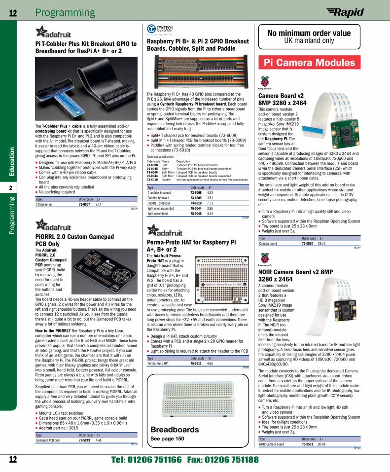
Camera Board v2 8MP 3280 x 2464This camera module add-on board version 2 features a high quality 8 megapixel Sony IMX219 image sensor that is custom designed for the Raspberry Pi. The camera sensor has a fixed focus lens and the sensor is capable of producing images of 3280 x 2464 and capturing video at resolutions of 1080p30, 720p60 and 640 x 480p90. Connection between the module and board is via the dedicated Camera Serial Interface (CSI) which is specifically designed for interfacing to cameras, with attachment via a short ribbon cable.
The small size and light weight of this add-on board make it perfect for mobile or other applications where size and weight are important. Suitable applications include CCTV security camera, motion detection, time lapse photography, etc.
• Turn a Raspberry Pi into a high quality still and video camera
• Software supported within the Raspbian Operating System• Tiny board is just 25 x 23 x 9mm• Weighs just over 3g
Type Order code 1+Camera board 75-0530 19.75
563384
NOIR Camera Board v2 8MP 3280 x 2464A camera module add-on board version 2 that features a HD 8 megapixel Sony IMX219 image sensor that is custom designed for use with the Raspberry Pi. The NOIR (no infrared) module omits the infrared filter from the lens, increasing sensitivity to the infrared band for IR and low light photography. A fixed focus lens and sensitive sensor gives the capability of taking still images of 3280 x 2464 pixels as well as capturing HD videos of 1080p30, 720p60 and 640x480p60/90.
The module connects to the Pi using the dedicated Camera Serial Interface (CSI) with attachment via a short ribbon cable from a socket on the upper surface of the camera module. The small size and light weight of this module make it perfect for mobile applications and for IR photography, low light photography, monitoring plant growth, CCTV security camera, etc.
• Turn a Raspberry Pi into an IR and low light HD still and video camera
• Software supported within the Raspbian Operating System• Ideal for twilight conditions• Tiny board is just 25 x 23 x 9mm• Weighs just over 3g
Type Order code 1+NOIR Camera board 75-0531 20.49
563385
Raspberry Pi B+ & Pi 2 GPIO Breakout Boards, Cobbler, Split and Paddle
The Raspberry Pi B+ has 40 GPIO pins compared to the Pi B’s 26. Take advantage of the increased number of pins using a Cyntech Raspberry Pi breakout board. Each board carries the GPIO signals from the Pi to either a breadboard or spring loaded terminal blocks for prototyping. The Split+ and SplitMini+ are supplied as a kit of parts and require soldering before use. The Paddle+ is supplied fully assembled and ready to go.
• Split+ T shaped pcb for breakout boards (73-6008)• Split Mini+ I shaped PCB for breakout boards (73-6009)• Paddle+ with spring loaded terminal blocks for tool free
connections (73-6010)Technical specificationOrder code Name Description73-6008 Split+ T shaped PCB for breakout boards75-0045 Split+ T shaped PCB for breakout boards assembled73-6009 Split Mini+ I shaped PCB for breakout boards75-0044 Split Mini+ I shaped PCB for breakout boards assembled73-6010 Paddle+ with spring loaded terminal blocks for tool free connections
Type Order code 1+T-cobbler breakout 73-6008 4.53Cobbler breakout 73-6009 3.61Paddle+ breakout 73-6010 7.73Split mini assembled 75-0044 3.86Split assembled 75-0045 4.43
547707
Perma-Proto HAT for Raspberry Pi A+, B+ or 2The Adafruit Perma-Proto HAT is a plug-in daughterboard that is compatible with the Raspberry Pi A+, B+ and Pi 2. The board has a grid of 0.1” prototyping solder holes for attaching chips, resistors, LEDs, potentiometers, etc. to create a versatile and easy to use protoyping area. The holes are connected underneath with traces to mimic solderless breadboards and there are long power strips for +3V, +5V and earth connections. There is also an area where there is broken out nearly every pin on the Raspberry Pi.
• Design a Pi HAT, attach custom circuitry• Comes with a PCB and a single 2 x 20 GPIO header for
Raspberry Pi• Light soldering is required to attach the header to the PCB
Type Order code 1+Perma-Proto HAT 75-0511 4.65
559293
Pi T-Cobbler Plus Kit Breakout GPIO to Breadboard for RasPi A+ B+ or 2
The T-Cobbler Plus + cable is a fully assembled add-on prototyping board kit that is specifically designed for use with the Raspberry Pi B+ and Pi 2 and is also compatible with the A+ model. The breakout board is T-shaped, making it easier to read the labels and a 40-pin ribbon cable is supplied that connects between the Pi and the T-Cobbler, giving access to the power, GPIO, I²C and SPI pins on the Pi.
• Designed for use with Raspberry Pi Model A+/B+/Pi 2/Pi 3• Makes ‘cobbling together’ prototypes with the Pi very easy• Comes with a 40-pin ribbon cable• Can plug into any solderless breadboard or prototyping
board• All the pins conveniently labelled• No soldering required
Type Order code 1+T-Cobbler kit 75-0507 7.14
559290
PiGRRL 2.0 Custom Gamepad PCB OnlyThe Adafruit PiGRRL 2.0 Custom Gamepad PCB powers up your PiGRRL build by removing the need for point to point wiring for the buttons and switches. The board needs a 40-pin header cable to connect all the GPIO signals, 2 x wires for the power and 4 x wires for the left and right shoulder buttons. That’s all the wiring you need to connect 12 x switches! As you’ll see from the tutorial there’s still quite a bit to do, but the Gamepad PCB takes away a lot of tedious soldering.
New to the PiGRRL? The Raspberry Pi is a tiny Linux computer which can run a number of emulators of classic game systems such as the 8-bit NES and MAME. These have proved so popular that there’s a complete distribution aimed at retro gaming, and that’s the RetroPie project. If you can think of an 8-bit game, the chances are that it will run on the Raspberry Pi. The PiGRRL project brings these great old games, with their blocky graphics and plinky 8-bit ‘music’ into a small, hand-held, battery powered, full colour console. Retro games are always a big hit with kids and adults so bring some more retro into your life and build a PiGRRL.
Supplied as a bare PCB, you will need to source the rest of the components required to build a working PiGRRL. Adafruit supply a free and very detailed tutorial to guide you through the whole process of building your very own hand-held retro gaming console.
• Mounts 10 x tact switches• Get a head start on your PiGRRL game console build• Dimensions 85 x 48 x 1.6mm (3.35 x 1.9 x 0.06in.)• Adafruit part no.: 3015
Type Order code 1+Gamepad PCB only 73-5249 4.45
563226
BreadboardsSee page 150
No minimum order valueUK mainland only
13
Programming 13Education
2
www.rapidonline.com [email protected]
Programm
ing
Included in the kit are the ready assembled PZM Shim, 3x screw terminals, 3 x 2 male header, 3 x 2 female header. The board can be powered from an external 3 to 11V supply or, if you are using low power motors, you can use 5V from the Pi. The pzm.py library module provides basic functions for forward, reverse, spin left, spin right, turn left/right forward, turn left/right reverse. Download library and examples from the 4tronix website.
• PZM Shim supplied ready assembled• Mount with supplied headers• OR solder directly to bottom of Pi header• Reverse polarity protectionNote: Raspberry Pi not included.
Type Order code 1+PZM Motor controller 75-0286 5.00
565329
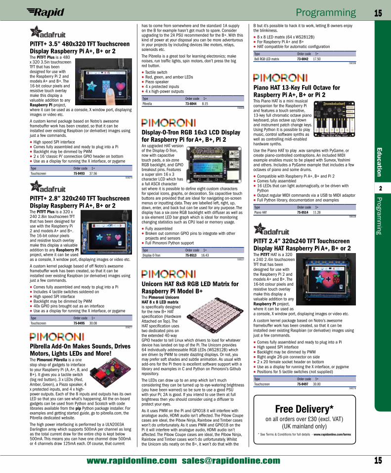
PiStep2 Dual/Quad Stepper Motor Controllers for Raspberry PiThese stepper motor control boards are designed for use with all versions of the Raspberry Pi with the 40-pin GPIO connector. The boards are available in dual (2 steppers) or quad (4 steppers) versions. This neat little board plugs directly into the Raspberry Pi GPIO header and provides 2 or 4 connectors for stepper motors. There are various power options - powered from the Raspberry Pi 5V, micro-USB 5V, from the 2-pin terminal (voltage dependent on motor requirements).
• Fully assembled - no soldering required• Raspberry Pi Zero form factor• Each pin has an associated LED to see stepper signalsNote: Stepper motors not included.
Note: Raspberry Pi not included.
Type Order code 1+DualStepper cont. 75-0288 8.00Quad Stepper cont. 75-0289 10.50
565331
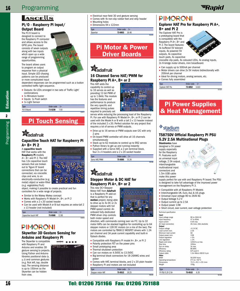
to add a battery holder (not supplied) to allow completely wire-free operation.
• Fully assembled and ready to goNote: BBC micro:bit is not included.
Type Order code 1+Bit:2:Pi Adaptor 75-0131 12.00
565006
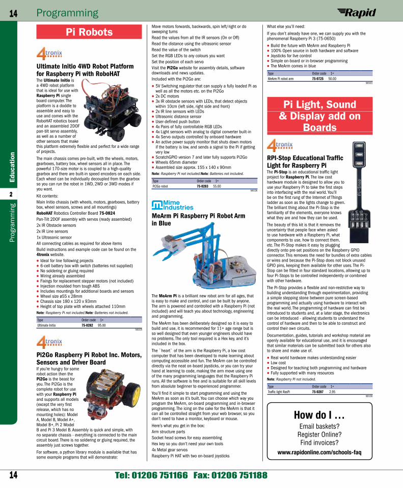
RoboHAT Robotics Controller Board for Raspberry PiThe RoboHAT is the complete robotics controller for your Raspberry Pi based mobile robot. The board supports all models of Raspberry Pi that have the 40-pin connector (Model A+/B+, as well as Pi 2 and 3 Model B).
The controller board comes fully assembled, no soldering or gluing is required. There are 2x mounting pillars and fixings supplied so it can be easily and securely mounted to your Raspberry Pi.
Amongst the many features of this board are:5V Switching regulator to safely power the robot and the Pi from 7V to 10V batteries (not supplied)LED Indication of 5V power statusHigh efficiency, dual H-Bridge driver that drives 2 DC motors (or 2 sets of 2 if using paired motors on each side of the robot)6, 5V level shifted GPIO inputs with GVS 3-pin connectors (ground, volts, signal)4, 5V level shifted GPIO outputs with GVS 3-pin connectors4-pin Male header to directly plug in an ultrasonic distance sensor (not supplied)I2C Breakout connector (standard 4tronix I2C port)Output connectors can be used directly to drive servosSee the Blog entry on the 4tronix website for more information, software and examples.
• Fully HAT specification compliant• Replacement for the Pirocon• Programming is fully supported in both Python and
Scratch GPIO• Python library module and examples freely availableNote: Raspberry Pi not included.Note: Batteries not included.
Type Order code 1+RoboHAT control board 75-0284 19.95
565327
PZM Motor Controller Shim for Raspberry Pi Zero
The PZM Pi Zero Motor Shim is a brilliant way to adding motor control to (almost) any Raspberry Pi project. Although specifically designed for use with the Raspberry Pi Zero, the board can be used with any other Pi. When fitted, the board provides dual H-Bridge control of two DC motors. The board is so small (38 x 16 x 0.8mm) that it can be soldered onto the bottom of the connector (assuming you have added one to your Pi Zero), or you can solder on the female or male headers included in the kit so you can connect and remove it, however you have configured your Pi Zero.
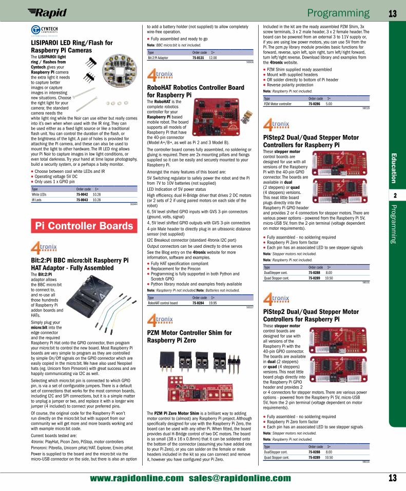
LISIPAROI LED Ring/Flash for Raspberry Pi CamerasThe LISIPAROI light ring / flashes from Cyntech gives your Raspberry Pi camera the extra light it needs to capture better images or capture images in interesting new situations. Choose the right light for your camera; the standard camera needs the white light ring while the Noir can use either but really comes into it’s own when when used with the IR ring. They can be used either as a fixed light source or like a traditional flash unit. You can control the duration of the flash, or the brightness of the light. A pair of holes is provided for attaching the Pi camera, and these can also be used to mount the light to other hardware. The IR LED ring allows your Pi Noir to capture images in low light conditions, or even total darkness. Try your hand at time lapse photography, build a security system, or a perhaps a baby monitor.
• Choose between cool white LEDs and IR• Operating voltage 5V DC• Only uses 1 x GPIO pin
Type Order code 1+White LEDs 75-0042 10.28IR Leds 75-0043 10.28
560444
Pi Controller Boards
Bit:2:Pi BBC micro:bit Raspberry Pi HAT Adaptor - Fully AssembledThe Bit:2:Pi adaptor allows the BBC micro:bit to connect to, and re-use all those hundreds of Raspberry Pi addon boards and HATs.
Simply plug your micro:bit into the edge connector and the required Raspberry Pi Hat onto the GPIO connector, then program your micro:bit to control the new board. Most Raspberry Pi boards are very simple to program as they are controlled by simple On/Off signals on the GPIO connector which are easily copied in the micro:bit. We have also used Neopixel hats (eg. Unicorn from Pimoroni) with great success and are happily communicating via I2C as well.
Selecting which micro:bit pin is connected to which GPIO pin, is via a set of configurable jumpers. There is a default set of connections that works for the most common boards, including I2C and SPI connections, but it is a simple matter to unplug a jumper or two, and replace it with a longer wire jumper (4 included) to connect your preferred pins.
Of course, the original code for the Raspberry Pi won’t run directly on the micro:bit but with support from our community we will get more and more boards working and with example micro:bit code.
Current boards tested are:4tronix: PlayHat, Picon Zero, PiStop, motor controllersPimoroni: Pibrella, Unicorn pHat/HAT. Explorer, Enviro pHatPower is supplied to the board and the micro:bit via the micro-USB connector on the side, but there is also an option
14
Programming14Ed
ucat
ion
2
Tel: 01206 751166 Fax: 01206 751188
Prog
ram
min
g
What else you’ll need:
If you don’t already have one, we can supply you with the phenomenal Raspberry Pi 3 (75-0650)
• Build the future with MeArm and Raspberry Pi• 100% Open source in both hardware and software• Joysticks for live control• Simple on-board or in-browser programming• The MeArm comes in blue
Type Order code 1+MeArm Pi robot arm 75-0725 50.00
565031
Pi Light, Sound & Display add on
Boards
RPI-Stop Educational Traffic Light for Raspberry PiThe Pi-Stop is an educational traffic light project for Raspberry Pi. The low cost hardware module is designed to allow you to use your Raspberry Pi to take the first steps into interfacing with the real world. You’ll be on the first rung of the Internet of Things ladder as soon as the lights change to green. The brilliant thing about the Pi-Stop is the familiarity of the elements, everyone knows what they are and how they can be used.
The beauty of this kit is that it removes the uncertainty that people face when asked to use hardware with a Raspberry Pi, what components to use, how to connect them, etc. The Pi-Stop makes it easy by plugging directly onto pre-set positions on the Raspberry GPIO connector. This removes the need for bundles of extra cables or wires and because the Pi-Stop does not block unused GPIO pins, keeping them available for other uses. The Pi-Stop can be fitted in four standard locations, allowing up to four Pi-Stops to be controlled independently or combined with other hardware.
The Pi-Stop provides a flexible and non-restrictive way to building understanding through experimentation, providing a simple stepping stone between pure screen-based programming and actually using hardware to interact with the real world. The programming of hardware can first be introduced to students and, at a later stage, the electronics can be introduced - allowing students to understand the control of hardware and then to be able to construct and control their own circuits.
Documentation, guides, tutorials and workshop material are openly available for educational use, and it is encouraged that similar materials can be submitted back for others also to share and make use of.
• Real world hardware makes understanding easier• Low cost• Designed for teaching both programming and hardware• Fully supported with many resourcesNote: Raspberry Pi not included.
Type Order code 1+Traffic light RasPi 75-0287 2.95
565330
Move motors forwards, backwards, spin left/right or do sweeping turnsRead the values from all the IR sensors (On or Off)Read the distance using the ultrasonic sensorRead the value of the switchSet the RGB LEDs to any colours you wantSet the position of each servoVisit the Pi2Go website for assembly details, software downloads and news updates.Included with the Pi2Go are:
• 5V Switching regulator that can supply a fully loaded Pi as well as all the motors etc. on the Pi2Go
• 2x DC motors• 3x IR obstacle sensors with LEDs, that detect objects
within 10cm (left side, right side and front)• 2x IR line sensors with LEDs• Ultrasonic distance sensor• User-defined push button• 4x Pairs of fully controllable RGB LEDs• 4x Light sensors with analog to digital converter built-in• 4x Servo outputs controlled by onboard hardware• An active power supply monitor that shuts down motors
if the battery is low, and sends a signal to the Pi if getting very low
• ScratchGPIO version 7 and later fully supports Pi2Go• Wheels 65mm diameter• Assembled size approx. 155 x 140 x 90mmNote: Raspberry Pi not included.Note: Batteries not included.
Type Order code 1+Pi2Go robot 75-0283 55.00
565326
MeArm Pi Raspberry Pi Robot Arm in Blue
The MeArm Pi is a brilliant new robot arm for all ages, that is easy to make and control, and can be built by anyone. The arm is powered and controlled with a Raspberry Pi (not included) and will teach you about technology, engineering and programming.
The MeArm has been deliberately designed so it is easy to build and use, it is recommended for 11+ age range but is so well designed that even younger engineers should have no problems. The only tool required is a Hex key, and it’s included in the box.
The `heart` of the arm is the Raspberry Pi, a low cost computer that has been developed to make learning about computing accessible and fun. The MeArm can be controlled directly via the neat on-board joysticks, or you can try your hand at learning to code, making the arm move using one of the many programming languages that the Raspberry Pi runs. All the software is free and is suitable for all skill levels from absolute beginner to experienced programmer.
You’ll find it simple to start programming and using the MeArm as soon as it’s built. You can choose which way you program the MeArm, on-board programming and in-browser programming. The icing on the cake for the MeArm is that it can all be controlled straight from your web browser, so you don’t need to have a monitor, keyboard or mouse.
Here’s what you get in the box:Arm structure partsSocket head screws for easy assemblingHex key so you don’t need your own tools4x Metal gear servosRaspberry Pi HAT with two on-board joysticks
Pi Robots
Ultimate Initio 4WD Robot Platform for Raspberry Pi with RoboHATThe Ultimate Initio is a 4WD robot platform that is ideal for use with Raspberry Pi single board computer. The platform is a doddle to assemble and easy to use and comes with the RoboHAT robotics board and an assembled 2DOF pan-tilt servo assembly, as well as a number of other sensors that make this platform extremely flexible and perfect for a wide range of projects.
The main chassis comes pre-built, with the wheels, motors, gearboxes, battery box, wheel sensors all in place. The powerful 170-size motor is is coupled to a high-quality gearbox and there are built-in speed encoders on each side. Each wheel can be individually decoupled from the gearbox so you can run the robot in 1WD, 2WD or 3WD modes if you want.
Kit contents:Main Initio chassis (with wheels, motors, gearboxes, battery box, wheel sensors, screws and all mountings)RoboHAT Robotics Controller Board 75-0824Pan-Tilt 2DOF assembly with servos (ready assembled)2x IR Obstacle sensors2x IR Line sensors1x Ultrasonic sensorAll connecting cables as required for above itemsBuild instructions and example code can be found on the 4tronix website.
• Ideal for line following projects• 6-cell battery box with switch (batteries not supplied)• No soldering or gluing required• Wiring already assembled• Fixings for replacement stepper motors (not included)• Injection moulded from tough ABS• Includes mountings for additional boards and sensors• Wheel size ø55 x 28mm• Chassis size 180 x 120 x 93mm• Height of top plate with wheels attached 110mmNote: Raspberry Pi not included.Note: Batteries not included.
Type Order code 1+Ultimate Initio 75-0282 95.00
565325
Pi2Go Raspberry Pi Robot Inc. Motors, Sensors and Driver BoardIf you’re hungry for some robot action then the Pi2Go is the beast for you. The Pi2Go is the complete robot for use with your Raspberry Pi and supports all models (except the very first release, which has no mounting holes): Model A, Model B, Model A+, Model B+, Pi 2 Model B and Pi 3 Model B. Assembly is quick and simple, with no separate chassis - everything is connected to the main circuit board. There is no soldering or gluing required, the assembly just screws together.
For software, a python library module is available that has some example programs that will demonstrate:
How do I …Email baskets?
Register Online?Find invoices?
www.rapidonline.com/schools-faq
15
Programming 15Education
2
www.rapidonline.com [email protected]
Programm
ing
B but it’s possible to hack it to work, letting B owners enjoy the blinkiness.
• 8 x 8 LED matrix (64 x WS2812B)• For Raspberry Pi A+ and B+• HAT compatible for automatic configuration
Type Order code 1+8x8 RGB LED matrix 73-6042 17.50
550306
Piano HAT 13-Key Full Octave for Raspberry Pi A+, B+ or Pi 2This Piano HAT is a mini musical companion for the Raspberry Pi and features a touch sensitive, 13-key full chromatic octave piano keyboard, plus octave up/down and instrument patch change keys. Using Python it is possible to play music, control software synths as well as controlling midi-enabled hardware synths.
Use the Piano HAT to play .wav samples with PyGame, or create piano-controlled contraptions. An included MIDI example enables music to be played with Sunvox, Yoshimi and others. Includes a PyGame example that includes a few octaves of piano and some drums.
• Compatible with Raspberry Pi A+, B+ and Pi 2• Comes fully assembled• 16 LEDs that can light automagically, or be driven with
Python• Output regular MIDI commands via a USB to MIDI adaptor• Full Python library, documentation and examples
Type Order code 1+Piano HAT 75-0514 11.28
559328
PiTFT 2.4” 320x240 TFT Touchscreen Display HAT Raspberry Pi A+, B+ or 2The PiTFT HAT is a 320 x 240 2.4in touchscreen TFT that has been designed for use with the Raspberry Pi 2 and models A+ and B+. The 16-bit colour pixels and resistive touch overlay make this display a valuable addition to any Raspberry Pi project, where it can be used as a console, X window port, displaying images or video etc.
A custom kernel package based on Notro’s awesome framebuffer work has been created, so that it can be installed over existing Raspbian (or derivative) images using just a few commands.
• Comes fully assembled and ready to plug into a Pi• High speed SPI interface• Backlight may be dimmed by PWM• Right angle 26-pin connector on side• 2 x 20 female socket header on bottom• Use as a display for running the X interface, or pygame• Positions for 5 tactile switches (not supplied)
Type Order code 1+Touchscreen 75-0497 30.00
559278
has to come from somewhere and the standard 1A supply on the B for example hasn’t got much to spare. Consider upgrading to the 2A PSU recommended for the B+. With this kind of power at your disposal you can be more adventurous in your projects by including devices like motors, relays, solenoids etc.
The Pibrella is a great tool for learning electronics; make noises, run traffic lights, spin motors, don’t press the big red button.
• Tactile switch• Red, green, and amber LEDs• Piezo speaker• 4 x protected inputs• 4 x high-power outputs
Type Order code 1+Pibrella 73-6044 8.15
550308
Display-O-Tron RGB 16x3 LCD Display for Raspberry Pi for A+, B+, Pi 2An upgraded HAT version of the Display-O-Tron, now with capacitive touch pads, a six-zone RGB backlight, and GPIO breakout pins. Features a super slim 16 x 3 character LCD which has a full ASCII character set where it is possible to define eight custom characters for special icons, graphs, or decoration. Six capacitive touch buttons are provided that are ideal for navigating on-screen menus or inputting data. They are labelled left, right, up, down, enter, and back but can be used for any purpose. The display has a six-zone RGB backlight with diffuser as well as a six-element LED bar graph which is ideal for monitoring changing statistics such as CPU load or memory usage.
• Fully assembled• Broken out common GPIO pins to integrate with other
projects and sensors• Full Pimoroni Python support
Type Order code 1+Display-O-Tron 75-0513 16.43
559327
Unicorn HAT 8x8 RGB LED Matrix for Raspberry Pi Model B+The Pimoroni Unicorn HAT 8 x 8 LED matrix is specifically designed for the new B+ HAT specification (Hardware Attached on Top). The HAT specification uses two dedicated pins on the extended 40-way GPIO header to tell Linux which drivers to load for whatever device has landed on top of the Pi. The Unicorn provides 64 individually addressable RGB LEDs (WS2812B) which are driven by PWM to create dazzling displays. Or not, you may prefer soft shades and subtle animation. As usual with add-ons for the Pi there is excellent software support with a library and examples in C and Python on Pimoroni’s Github repository.
The LEDs can draw up to an amp which isn’t much considering they can be turned up to eye-watering brightness (you have been warned) so be sure to use a good PSU with your Pi; 2A is good. If you intend to use them at full brightness then you should consider using a diffuser to protect your eyes.
As it uses PWM on the Pi and GPIO18 it will interfere with analogue audio, HDMI audio isn’t affected. The Pibow Coupe cases are ideal, the Pibow Ninja, Rainbow and Timber cases won’t do unfortunately. As it uses PWM and GPIO18 on the Pi it will interfere with analogue audio, HDMI audio isn’t affected. The Pibow Coupe cases are ideal, the Pibow Ninja, Rainbow and Timber cases won’t do unfortunately. Whilst the Unicorn sits neatly on the B+, it won’t do that with the
PiTFT+ 3.5” 480x320 TFT Touchscreen Display Raspberry Pi A+, B+ or 2The PiTFT Plus is a 480 x 320 3.5in touchscreen TFT that has been designed for use with the Raspberry Pi 2 and models A+ and B+. The 16-bit colour pixels and resistive touch overlay make this display a valuable addition to any Raspberry Pi project, where it can be used as a console, X window port, displaying images or video etc.
A custom kernel package based on Notro’s awesome framebuffer work has been created, so that it can be installed over existing Raspbian (or derivative) images using just a few commands.
• High speed SPI interface• Comes fully assembled and ready to plug into a Pi• Backlight may be dimmed by PWM• 2 x 16 ‘classic Pi’ connection GPIO header on bottom• Use as a display for running the X interface, or pygame
Type Order code 1+Touchscreen 75-0493 37.56
559276
PiTFT+ 2.8” 320x240 TFT Touchscreen Display Raspberry Pi A+, B+ or 2The PiTFT Plus is a 320 x 240 2.8in touchscreen TFT that has been designed for use with the Raspberry Pi 2 and models A+ and B+. The 16-bit colour pixels and resistive touch overlay make this display a valuable addition to any Raspberry Pi project, where it can be used as a console, X window port, displaying images or video etc.
A custom kernel package based of off Notro’s awesome framebuffer work has been created, so that it can be installed over existing Raspbian (or derivative) images using just a few commands.
• Comes fully assembled and ready to plug into a Pi• Includes 4 tactile switches soldered on• High speed SPI interface• Backlight may be dimmed by PWM• 40x GPIO pins brought out as an interface• Use as a display for running the X interface, or pygame
Type Order code 1+Touchscreen 75-0495 30.08
559277
Pibrella Add-On Makes Sounds, Drives Motors, Lights LEDs and More!The Pimoroni Pibrella is a one stop shop of gadgets to interface to your Raspberry Pi (A, A+, B, and B+). It gives you a tactile switch (big red button), 3 x LEDs (Red, Amber, Green), a Piezo speaker, 4 x protected inputs, and 4 x high-power outputs. Each of the 8 inputs and outputs has its own LED so that you can see what’s happening. All the on-board gadgets can be used from Python and Scratch with code libraries available from the pip Python package installer. For examples and getting started guide, go to pibrella.com, the Pibrella dedicated website.
The high power interfacing is performed by a ULN2003A Darlington array which supports 500mA per channel as long as the total current draw for the entire chip is kept below 500mA. This means you can have one channel draw 500mA or 4 channels draw 125mA each. Of course, that current
Free Delivery*on all orders over £30 (excl. VAT)
(UK mainland only)* See Terms & Conditions for full details - www.rapidonline.com/terms
16
Programming16Ed
ucat
ion
2
Tel: 01206 751166 Fax: 01206 751188
Prog
ram
min
g
Explorer HAT Pro for Raspberry Pi A+, B+ and Pi 2The Explorer HAT Pro is a prototyping board that is compatible with the Raspberry Pi A+, B+ and Pi 2. The board features: 4x buffered 5V tolerant inputs, 4x powered 5V outputs, 4x capacitive touch pads, 4x capacitive crocodile clip pads, 4x coloured LEDs, 4x analog inputs, 2x H-bridge motor drivers, mini breadboard.
• Can supply up to 500mA per channel• Motor drivers can drive 2x 5V motors bidirectionally with
200mA per channel• Ideal for driving motors, analog sensors, etc.• Comes fully assembled
Type Order code 1+Explorer HAT Pro 73-6052 14.83
553924
Pi Power Supplies & Heat Management
T5875DV Official Raspberry Pi PSU 5.2V 2.5A Multinational PlugsStontronics have designed a 5V power supply especially for the Raspberry Pi. Features such as universal input voltage, 2.5A output, interchangeable multinational input connectors and 1.5m USB cable make this power supply perfect for use with and Raspberry Pi board. The PSU is designed to take full advantage of the improved power management on the Raspberry Pi 3.
• Compatible with all Raspberry Pi Models• Interchangeable UK, Euro, Aus & US plugs• Universal input voltage 90 to 264V AC• Output Voltage 5.2 V• Output current up to 2.5A• Output power 13W• Short circuit, over current, over voltage protectionTechnical specificationInputInput voltage range 90 to 264V ACInput frequency 47 to 63HzInput current 0.5A max.AC Input connectors UK, Euro, USA, AustraliaOutputOutput voltage +5.1V DCLoad current nom. 2.5AMinimum load current 0AOutput power nom. 13WOutput regulation ± 5%Line regulation ± 2%Ripple and noise 120mV p-p max.Rise time 100msTurn-on delay 3s max.Efficiency 80.86%Efficiency rating ErP Level 6Output cable 1.5m Micro USB B 5-pinOtherMTBF 50,000 hoursOperating temperature 0°C to +40°CDimensions 73.2 x 45.1 x 35.1mmWeight 150g
Type Order code 1+Pi PSU 5.2V 2.5A 75-0532 6.35
563386
• Electrical near-field 3D and gesture sensing• Comes with 4x non-slip rubber feet and strip header• Mounting holes• Dimensions 94 x 122mm
Type Order code 1+Skywriter 73-6053 16.48
553925
Pi Motor & Power Driver Boards
16 Channel Servo HAT/PWM for Raspberry Pi A+, B+ or 2This HAT adds the capability to control up to 16 servos as well as providing 12-bit PWM of up to 1.6kHz. The module has the features and performance to produce the very specific and repetitive timing pulses required to precisely set servos while reducing the processing load of the Raspberry Pi. For use with Raspberry Pi Model A+, B+, or Pi 2 can be used with the Model A or B with a tall 2 x 13 header instead of the included 2 x 20. Perfect solution for any project that requires a lot of servos or PWM outputs.
• Drive up to 16 servos or PWM outputs over I2C with only 2 pins
• On-board PWM controller will drive all 16 channels simultaneously
• Stack up to 62 modules to control up to 992 servos• Python library to get up and running instantly• Supplied with a Servo HAT, a 2-pin terminal block,
four 3 x 4 headers and a 2 x 20 socket header
Type Order code 1+Servo HAT/PWM 75-0505 15.26
559288
Stepper Motor & DC HAT for Raspberry Pi A+, B+ or 2This new DC+Stepper Motor HAT from Adafruit is a Raspberry Pi add-on that is perfect for any motion project, being able to drive up to 4x DC or 2x stepper motors with full PWM speed control. An onboard fully-dedicated PWM driver chip controls both motor speed and direction, with commands coming over via I²C. Up to 32 motor HATs can be stacked together for controlling up to 64 stepper motors or 128 DC motors (or a mix of the two). The motors are controlled by TB6612 MOSFET drivers with 1.2A per channel and 3A peak current capability and built-in flyback diodes.
• Compatible with Raspberry Pi model A+, B+, or Pi 2• Polarity protection FET on the power pins• Small prototyping area• Thermal shutdown protection• Can run motors on 4.5VDC to 13.5VDC• Big terminal block connectors for 18-26AWG wires and
power• Comes with HAT, terminal blocks, and 2 x 20 plain header• Raspberry Pi and motors are not included
Type Order code 1+Stepper motor HAT 75-0512 19.25
559294
Pi/O - Raspberry Pi Input/ Output BoardThe Pi/O board is designed to connect to the Raspberry Pi computer and allows access to the GPIO pins. The board consists of seven outputs along with two inputs which open up a wide range of programming opportunities.
The board allows users to program an output response from a physical input. Simple LED chasing patterns can be produced or more complicated input dependent responses can be programmed such as a button controlled traffic light sequence.
• Outputs: 6x LEDs arranged in two sets of ‘Traffic Light’ combinations
• 1x Miniature buzzer• Inputs: 1x Push switch• 1x Light Sensor
Type Order code 1+Pi/O Board 73-5230 7.50
525417
Pi Touch Sensing
Capacitive Touch HAT for Raspberry Pi A+ B+ Pi 2A capacitive touch HAT that works with the Raspberry Pi models A+, B+ and Pi 2. The HAT has 12x capacitive touch sensors that are broken out to ‘figure 8’ board connections that can be connected, via crocodile clips and wire, to an electrically-conductive (e.g. metal) object or water-filled (e.g. vegetables/fruit) object, making it possible to create practical and fun controllers for a wide range of projects.
• Similar to the Makey Makey concept• Works with Raspberry Pi Model A+, B+, or Pi 2• Comes with a 2 x 20 socket header• Can be used with Model A or B but requires an extra-tall 2
x 13 header (not included)
Type Order code 1+Capacitive touch HAT 75-0508 12.85
559291
Skywriter 3D Gesture Sensing for Arduino and Raspberry PiThe Skywriter is compatible with Raspberry Pi and Arduino and enables 3D gesture sensing to projects. Using Python and Arduino libraries positional data (x, y, z) and common gestures (e.g. flick left, tap, double tap). The sensing distance is up to 150mm so the Skywriter can be hidden from view.
17
Programming 17Education
2
www.rapidonline.com [email protected]
Programm
ing
There are nine fun projects that teach basic programming and system administration skills - from the very basics of how to plug in the board and turn it on through to more advanced adventures such as coding music and building a jukebox. Each adventure includes a video that adds a lively reinforcement to the lesson, making it perfect for young self-learners as well as class-based teaching.
• Written by Carrie Anne Philbin• Ideal for 11- to 15-year-olds• Features 9 fun projects accompanied by lively and helpful
videos• Helps children have fun and learn computing skillsTable of ContentsAbout the AuthorAcknowledgmentsIntroductionAdventure 1 You Have a Raspberry Pi. Now What?Adventure 2 Taking Command of Your Raspberry PiAdventure 3 Creating Stories and Games with ScratchAdventure 4 Programming Shapes with Turtle GraphicsAdventure 5 Programming with PythonAdventure 6 Programming Minecraft Worlds on the Raspberry PiAdventure 7 Coding Music with Sonic PiAdventure 8 Using the GPIO Pins on the Raspberry PiAdventure 9 The Big Adventure: Building a Raspberry Pi JukeboxAppendixWhere to Go from HereGlossaryIndex
Type Order code 1+Adventures In Pi 97-2140 17.99
559343
Pi Cases
Cyntech Raspberry Pi Model B+ Case in Black or ClearThe Cyntech Raspberry Pi model B+, Pi 2 and Pi 3 cases have a wear resistant matt finish while the centre top is highly polished allowing you an excellent view of your Pi with the clear case. The cases include a set of light pipes which transfer the light from the Pi’s activity LEDS to the outside of the case so that you always know what the Pi is doing. Available in clear or black.
• Compatible with the Raspberry Pi 3 model• Raspberry Pi B+ clip fit with optional screw locking
(screws included)• Positive and secure case locking via screws (screws
included)• Available in clear or black• GPIO 40-pin ribbon cable slot• CSI camera cable slot • DSI LCD video cable slot• Strong and durable ABS plastic• 50mm VESA mount and wall mount features
Type Order code 1+Clear Pi B+/2/3 case 73-6004 4.95Black Pi B+/2/3 case 73-6017 4.95
547699
Pi Books
Adventures in Minecraft: 9 Awesome Projects Compatible with Raspberry PiAdventures in MinecraftDavid Whale, Martin O’HanlonISBN: 978-1-118-94691-6320 pagesNovember 2014Anyone that enjoys Minecraft will love this book as it adds a whole new dimension to the game. Build fantastic structures, write your own games and use real electronic circuits to manipulate the Minecraft world. The possibilities are limited only by your imagination. It teaches coding in Python while playing one of the most popular computer games on the market. And Python isn’t just any programming language; it’s widely used by websites and in industry because it’s an easy language to learn but has enormous power. Coding is becoming a must have skill and what better way to learn than while you’re having fun.
The book takes you step by step through setting up your PC, Mac or Raspberry Pi with all the necessary software. There’s a companion website with handy videos, a Python quick reference guide, a bonus chapter and more.
Did you know that the Minecraft Pi Edition is completely free?
• Written by David Whale, Martin O’Hanlon• Ideal introduction to coding for 11 to 15-year-olds• Features 9 fun projects accompanied by lively and helpful
videos• Helps children have fun and learn computing skills• PC, Mac and Raspberry Pi compatibleTechnical specificationTable of ContentsIntroductionAdventure 1 Hello Minecraft WorldAdventure 2 Tracking Your Players as They MoveAdventure 3 Building Anything AutomaticallyAdventure 4 Interacting with BlocksAdventure 5 Interacting with Electronic CircuitsAdventure 6 Using Data FilesAdventure 7 Building 2D and 3D StructuresAdventure 8 Giving Blocks a Mind of Their OwnAdventure 9 The Big Adventure: Crafty CrossingAppendix A Where to Go from HereWebsitesMinecraftPythonBukkitOther Ways to Make Things Happen AutomaticallyProjects and TutorialsVideosBooksIndex
Type Order code 1+Minecraft book 97-2141 14.00
561873
Adventures In Raspberry Pi by Carrie Anne PhilbinAdventures In Raspberry PiCarrie Anne PhilbinISBN: 978-1-118-75125-1256 pagesDecember 2013An elementary guide to the Raspberry Pi that is written for 11 to 15-year olds with no prior computing knowledge. The book uses the extremely popular and successful, low-cost, credit card-sized Raspberry Pi to explain fundamental computing concepts.
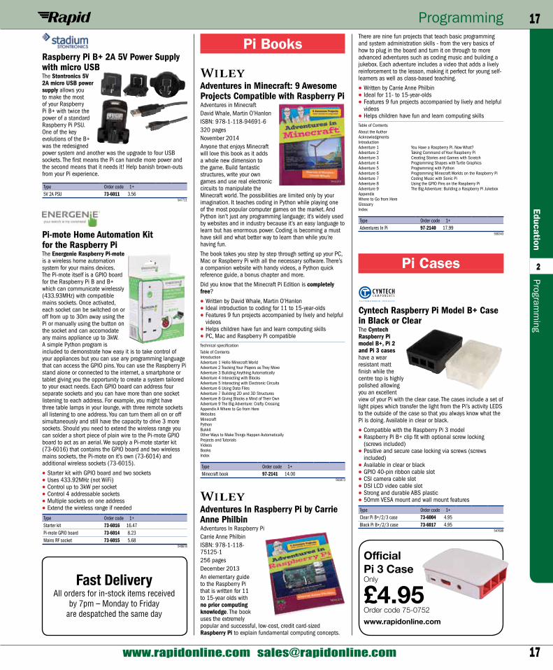
Raspberry Pi B+ 2A 5V Power Supply with micro USBThe Stontronics 5V 2A micro USB power supply allows you to make the most of your Raspberry Pi B+ with twice the power of a standard Raspberry Pi PSU. One of the key evolutions of the B+ was the redesigned power system and another was the upgrade to four USB sockets. The first means the Pi can handle more power and the second means that it needs it! Help banish brown-outs from your Pi experience.
Type Order code 1+5V 2A PSU 73-6011 3.56
547711
Pi-mote Home Automation Kit for the Raspberry PiThe Energenie Raspberry Pi-mote is a wireless home automation system for your mains devices. The Pi-mote itself is a GPIO board for the Raspberry Pi B and B+ which can communicate wirelessly (433.93MHz) with compatible mains sockets. Once activated, each socket can be switched on or off from up to 30m away using the Pi or manually using the button on the socket and can accomodate any mains appliance up to 3kW. A simple Python program is included to demonstrate how easy it is to take control of your appliances but you can use any programming language that can access the GPIO pins. You can use the Raspberry Pi stand alone or connected to the internet, a smartphone or tablet giving you the opportunity to create a system tailored to your exact needs. Each GPIO board can address four separate sockets and you can have more than one socket listening to each address. For example, you might have three table lamps in your lounge, with three remote sockets all listening to one address. You can turn them all on or off simultaneously and still have the capacity to drive 3 more sockets. Should you need to extend the wireless range you can solder a short piece of plain wire to the Pi-mote GPIO board to act as an aerial. We supply a Pi-mote starter kit (73-6016) that contains the GPIO board and two wireless mains sockets, the Pi-mote on it’s own (73-6014) and additional wireless sockets (73-6015).
• Starter kit with GPIO board and two sockets• Uses 433.92MHz (not WiFi)• Control up to 3kW per socket• Control 4 addressable sockets• Multiple sockets on one address• Extend the wireless range if needed
Type Order code 1+Starter kit 73-6016 16.47Pi-mote GPIO board 73-6014 8.23Mains RF socket 73-6015 5.68
548678
Fast DeliveryAll orders for in-stock items received
by 7pm – Monday to Friday are despatched the same day
Official Pi 3 CaseOnly
£4.95Order code 75-0752www.rapidonline.com
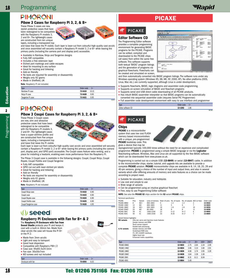
18
Programming18Ed
ucat
ion
2
Tel: 01206 751166 Fax: 01206 751188
Prog
ram
min
g
PICAXE
Editor Software CDThe Programming Editor software provides a complete programming environment for generating BASIC programs for the PICAXE. Programs can be edited, compiled and downloaded to the PICAXE chips (all sizes) from within the same free software. This software supports both textual ‘BASIC’ program listings and the generation of programs via graphical flowcharts. Flowcharts can be created and simulated on screen, and then automatically converted into BASIC program listings. The software runs under any Windows operating system (Windows 95, 98, ME, NT, 2000, XP). No other platforms (DOS, Linux, Mac etc.) are currently supported, although Linux is under development.
• Supports flowcharts, BASIC, logic diagrams and assembler code programming.• Supports on-screen simulation of BASIC and flowchart programs• Supports serial and USB direct cable downloading of all PICAXE products.• Has inbuilt BASIC-assembler interpreter so that BASIC programs can be automatically
converted into sequential assembler code (requires Serial PIC Programmer)• Full assembler code development environment with easy to use interface and programmer
Type Order code 1+Editor software CD 13-1262 1.86
061483
ChipsPICAXE is a microcontroller system that uses low cost FLASH memory based microcontrollers with a unique, pre-programmed PICAXE bootstrap code. This gives a device that may be reprogrammed typically 100,000 times without the need for an expensive and complicated programmer. PICAXE is programmed using a simple BASIC language or via the Logicator flowcharting software. Windows, Mac and Linux are all supported by the free BASIC software which can be downloaded from www.picaxe.co.uk.
Programming is carried out via a simple USB (13-0849) or serial (13-0847) cable. In addition to the microcontroller chips, starter, tutorial, and upgrade kits are available to provide a complete PICAXE solution. PICAXE microcontroller chips are available in 8, 14, 18, 20, 28 and 40-pin versions, giving a choice of the number of input and output lines, and also in several variants which offer differing amounts of memory and extra features so a choice can be made according to project need.
• Suitable for education, industry and hobbyists• Low cost and simple to use• Wide range of variants• Can be programmed using an intuitive graphical flowchart• Free, easy to use Programming Editor softwareNOTE: See also the PICAXE X2 chips section for the X2 variant PICAXE chips.
Technical specificationPICAXE Pins Variant Lines of memory Total I/O pins No. of inputs No. of outputs ADC (L=low) Order codePICAXE-08M2 8 M2+ 800-1800 5 1-4 1-4 3 13-5022PICAXE-14M2 14 M2 800-1800 11 5 6 7 13-5024PICAXE-18M2 18 M2+ 600-1800 16 1-8 1-8 10 13-5026PICAXE-20M2 20 M2 80-1800 18 8 8 11 13-5028PICAXE-28X1 28 X1 1000-2200 22 0-12 9-17 4 13-0862PICAXE-40X1 40 X1 1000-2200 33 8-20 9-17 7 13-0864
Variant feature highlights:M2 variants Infra red, servo and ring tone music features
Greater memory and RAMTouch sensor supportParallel task processing
X/X1 variants Greater memory and RAMScratchpad RAM areaI²C, SPI, EUSART interfacesHigher baud rateEnhanced maths capabilities
Type Order code 1+ 25+ 100+ 250+PICAXE-08M2 13-5022 2.75 2.64 2.24 2.09PICAXE-14M2 13-5024 3.46 3.10 3.00 2.91PICAXE-18M2 13-5026 4.00 3.74 3.55 3.29PICAXE-20M2 13-5028 3.64 3.39 3.30PICAXE-28X1 13-0862 8.31 8.11 8.04PICAXE-40X1 13-0864 5.49
079671
Pibow 3 Cases for Raspberry Pi 3, 2, & B+These Pibow 3 cases are new, stylish protective cases that have been redesigned to be compatible with the Raspberry Pi models 3, 2 and B+. The lightweight cases are constructed from ten unique layers, including a transparent top and base that leave the Pi visible. Each layer is laser-cut from colourful high-quality cast acrylic and once assembled will securely contain a Raspberry Pi model 3, 2 or B+ while leaving the primary ports (including the camera port and display port) accessible.
• Available in Rainbow, Ninja and Tangerine designs• Fully HAT compatible• Includes a free extension layer• Etched port markings and cable escapes• Ideal for mounting to any surface• Great for hacking and tinkering• Add-on friendly• No tools are required for assembly or disassembly• Weighs only 92 grams• Made in Sheffield, UKNote: Raspberry Pi not included.
Type Order code 1+Rainbow Pi case 73-5419 10.21Ninja Pi case 73-5420 9.95Tangerine Pi case 73-5421 9.95
563027
Pibow 3 Coupé Cases for Raspberry Pi 3, 2, & B+These Pibow 3 Coupé cases are new, slim and attractive protective cases that have been redesigned to be compatible with the Raspberry Pi models 3, 2 and B+. The lightweight cases have a super-slimline profile and are constructed from five unique layers, including a transparent top and base that leave the Pi visible. Each layer is laser-cut from colourful high-quality cast acrylic and once assembled will securely contain a Raspberry Pi model 3, 2 or B+ while leaving the primary ports (including the camera port, display port, and GPIO port) accessible. The Coupé cases feature extra venting, and a place for installing a heatsink, enabling even more performance from the Raspberry Pi.
The Pibow 3 Coupé case is available in the following designs: Coupé, Coupé Ninja, Coupé Royale, Coupé Flotilla and Coupé Tangerine• Fully HAT compatible• GPIO cut-out with laser-etched pin labels• Great for hacking and tinkering• Add-on friendly• No tools are required for assembly or disassembly• Weighs only 61 grams• Made in Sheffield, UKNote: Raspberry Pi not included.
Type Order code 1+Coupé Ninja case 73-5422 6.90Coupé case 73-5423 6.90Coupé Royale case 73-5424 6.90Coupé Flotilla case 73-5425 6.90Coupé Tangerine case 73-5426 4.95
563028
Raspberry Pi Enclosure with Fan for B+ & 2The Raspberry Pi Enclosure with Fan from Seeed Studio protects your Pi and keeps it cool with a built-in 30mm fan. Made from clear acrylic the case will house the Pi B+ or the Pi 2.
• Made from 3mm acrylic• Light and easy to transport• Good heat dispersion• Compatible with Raspberry PiB+/2• Case size: 95x65.5x34.5mm• Fan size: 30x30x7mm• M3 screws and nut included
Type Order code 1+Enclosure with fan 75-0393 6.03
560357
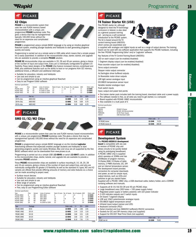
19
Programming 19Education
2
www.rapidonline.com [email protected]
Programm
ing
T4 Trainer Starter Kit (USB)This PICAXE starter kit, although designed to meet the T4 technology curriculum in Ireland, is also ideal as a general purpose training aid - serving as a self-contained introduction to the PICAXE system. The kit is based around the T4 control training board (AXE055) which comes pre-assembled and is supplied with analogue and digital inputs as well as a range of output devices. The training board can be used with any software application that supports the PICAXE hardware, including the free ‘PICAXE Programming Editor’ and/or ‘Logicator’ software.
Key features of the T4 Control Training Board (AXE055):LED on each output (can be enabled/disabled)7-Segment display output (can be enabled/disabled)Piezo sounder output (can be enabled/disabled)Servo output connectorStepper motor output connector4x Darlington driver buffered outputs2x Reversible motor driver outputsLDR light sensor analogue inputDS18B20 temperature sensor inputVariable resistor analogue inputPush switch inputsInput, output and power test points
• The trainer starter pack includes both the training board, download cable and a power supply• The software needed is free, so all extra you need to get started, is a computer• Board supplied with PICAXE-18M2 microcontroller• Also available in a bulk pack of 5Technical specificationKit contents:AXE055 PICAXE T4 TrainerAXE015 PICAXE-18X MicrocontrollerPWR009A UK 9V Power SupplyAXE027 USB Download Cable
Type Order code 1+T4 PICAXE trainer 13-1548 74.29T4 PICAXE trainer x5 13-1546 288.00
526212
Development SystemThe PICAXE AXE091U development board is compatible with any size or revision of PICAXE chip and allows circuits to be quickly tested using its prototyping breadboard. A PICAXE 18M2 chip is supplied which operates at 32MHz and has 2048bytes of program memory, 512bytes RAM, 512bytes of table memory, 2 PWM channels, I2C, SPI and an internal temperature sensor. The development board provides connectors for computer downloads and power, as well as simple input, output devices, such as LEDs and switches to get you started faster. Supplied with a PICAXE 18M2 chip, a USB download cable, battery holder, and a CDROM containg software and manuals.
• Supports all 8/14/18/20/28 and 40-pin PICAXE chips• Large breadboard area (300 holes + 100 power supply holes)• Regulated power supply or battery powered, with LED power indicator• 3 LED indicator outputs and 3 switch inputs• On-board 7-segment display• LDR and 10kΩ potentiometer analogue inputs• DS18B20 digital temperature sensor• Infrared input/output (sensor and LED)• Keyboard connector (PS2)• Serial (inverted and true (MAX202 buffered)) RS232 connectors• Sockets for I2C and SPI memory chips (not supplied)• Support for DS1307 Real Time Clock (not supplied)
Type Order code 1+PICAXE dev kit 13-1550 78.00
547654
X2 ChipsPICAXE is a microcontroller system that uses low cost FLASH memory based microcontrollers with a unique, pre-programmed PICAXE bootstrap code. This gives a device that may be reprogrammed typically 100,000 times without the need for an expensive and complicated programmer.
PICAXE is programmed using a simple BASIC language or by using an intuitive graphical flowchart system, enabling younger students and hobbyists to start generating programs quickly and easily.
Programming is carried out via a simple serial or USB cable which means that a simple project kit is easily assembled. In addition to the microcontroller chips, starter, tutorial, and upgrade kits are available to provide a complete PICAXE solution.
PICAXE X2 microcontroller chips are available in 20, 28 and 40-pin versions, giving a choice of the number of input and output lines. Every pin is individually configurable for greater I/O flexibility. These latest designs of the PICAXE chip feature increased memory, scratchpad and RAM, plus additional features such as the ability to boot or run programs from I2C memory, additional timers, a SRLatch and additional interrupts.
• Suitable for education, industry and hobbyists• Low cost and simple to use• Can be programmed using an intuitive graphical flowchart• Easy to use Program Editor softwareTechnical specificationType Pins Variant Lines of memory Total I/O pins No. of inputs No. of outputs ADC Order codePICAXE-20X2 20 X2 2000 to 3200 13 1 – 16 1 – 16 11 13-5000PICAXE-28X2 28 X2 4x 2000 to 3200 22 1 – 1 – 11 13-5002PICAXE-40X2 40 X2 4x 2000 to 3200 33 1 – 1 – 12 13-5004
Type Part no. Order code 1+ 25+ 100+20-Pin chip AXE012X2 13-5000 5.45 5.29 5.2028-Pin Chip AXE010X2 13-5002 9.05 8.89 8.7940-Pin chip AXE014X2 13-5004 9.05 8.89 8.79
180699
SMD X1/X2/M2 Chips
PICAXE is a microcontroller system that uses low cost FLASH memory based microcontrollers with a unique, pre-programmed PICAXE bootstrap code. This gives a device that may be reprogrammed typically 100,000 times without the need for an expensive and complicated programmer.
PICAXE is programmed using a simple BASIC language or via the intuitive Logicator flowcharting software that especially enables younger students and hobbyists to start generating programs quickly and easily. Windows, Mac and Linux are all supported by the free BASIC software which can be downloaded from www.picaxe.co.uk.
Programming is carried out via a simple USB (13-0849) or serial (13-0847) cable. In addition to the microcontroller chips, starter, tutorial, and upgrade kits are available to provide a complete PICAXE solution.
These PICAXE microcontroller chips are available in surface mounting 8, 14, 18, 20, 28 and 44-pin versions, giving a choice of the number of input and output lines, and pins are individually configurable for greater I/O flexibility. As well as the standard X1 types, M2 and X2 variants are offered that provide differing amounts of memory and extra features so a choice can be made according to project need.
• Surface mount devices• Suitable for education, industry and hobbyists• Low cost and simple to use• Wide range of variants• Can be programmed using an intuitive graphical flowchart• Free, easy to use Programming Editor softwareTechnical specificationType Pins Variant Lines of memory Total I/O pins No. of inputs No. of outputs ADC Order codePICAXE-08M2 8 M2 800-1800 5 1-4 1-4 3 13-5036PICAXE-14M2 14 M2 800-1800 11 5 6 7 13-5052PICAXE-18M2 18 M2 600-1800 16 1-8 1-8 10 13-5050PICAXE-20M2 20 M2 80-1800 16 8 8 11 13-5042PICAXE-28X2 28 X2 4x 2000 to 3200 22 21 21 16 13-5040
Type Package Order code 1+ 25+ 100+PICAXE-08M2 SO-8 13-5036 2.91 2.86 2.81PICAXE-14M2 SO-14 13-5052 3.44 3.35 3.19PICAXE-18M2 SO-18 13-5050 3.60 3.51 3.35PICAXE-20M2 SO-20 13-5042 3.60 3.51 3.35PICAXE-28X2 SO-28 13-5040 8.10 7.91 7.74
519054
20
Programming20Ed
ucat
ion
2
Tel: 01206 751166 Fax: 01206 751188
Prog
ram
min
g
Technical specificationPICAXE-20M microcontroller20-pin Project board and instruction leafletUSB download cable4.5V Battery box for 3x AA batteries
Type Order code 1+PICAXE-20 Starter kit 13-0874 33.59
081641
PICAXE-28 Starter Kit
These starter kits contain everything required to gain familiarity with the PICAXE-28 system, using the PICAXE-28 microcontroller.
The kits include a PICAXE microcontroller, PICAXE project board, serial or USB download cable and battery box.
• Kits are pre-assembled• Low cost and simple to use• Program using BASIC or by graphical flowcharts• Easy to use Program Editor software• Extensive online documentation and online support forumRequires either 3x AA alkaline batteries (not included), or a regulated 5V DC supply.
Technical specificationPICAXE 28–pin microcontroller on pre–assembled project boardPICAXE serial or USB download cableInput and output ribbon cables4.5V Battery box for 3x AA batteries
Type Order code 1+PICAXE-28 USB kit 13-5016 26.68
079667
PICAXE-08 Project BoardThe project board PCB is a professional quality PCB that provides a convenient solution for students who wish to use a microcontroller for control in their project work.
• The PCB has 4 outputs and 1 input
• Space for the PICAXE-08 chip, download socket and 4 transistors for driving output devices such as motors and buzzers
• The high quality PCB has a solder-resist layer, which assists those less experienced in soldering to produce good results
• The PCBs are supplied as a set of 5 PCBs and 5 kits of components for self-assembly
Type Order code 1+PICAXE-08 Project board 70-1206 20.37
061444
PICAXE-18 Trainer Starter Pack
These Picaxe starter packs contain everything required to gain familiarity with the PICAXE-18 system, using the PICAXE-18 microcontroller.
An ideal starter pack for UK development, the kits include a PICAXE microcontroller, PICAXE project board, serial or USB download cable and a battery box. The project board can be used with any of the software applications that support the PICAXE hardware, including the Logicator for PIC Micros software and / or the free PICAXE Programming Editor.
The training board comes pre-assembled and is ready for use with all the PICAXE-18M2’s analogue and digital inputs and outputs. Wires can be soldered directly onto the board, or used with screw terminal blocks.
• Picaxe Kits are pre-assembled• Low cost and simple to use• Program using BASIC or by graphical flowcharts• Easy to use Program Editor software• Extensive manuals and online support forumRequires either 3x AA alkaline batteries (not included), or a regulated 5V DC supply.
Technical specificationPICAXE–18 microcontrollerStandard project board and instruction leafletSerial or USB download cable4.5V Battery box for 3x AA batteriesBattery clip
Type Order code 1+PICAXE-18 USB kit 13-5018 43.61
079665
PICAXE-20 USB Starter Kit
This starter kit contains everything required to gain familiarity with the PICAXE-20 system, which features the PICAXE-20M microcontroller.
The kit includes a project board (unassembled), PICAXE-20M microcontrolle USB download cable, and battery box.
• USB to serial interface• Low cost and simple to use• Program using BASIC or by graphical flowcharts• Easy to use Program Editor software• Extensive online documentation and online support forumRequires either 3x AA alkaline batteries (not included), or a regulated 5V DC supply.
PICAXE-08 Starter Kits
These starter kits contain everything required to gain familiarity with the PICAXE-08 system, using the PICAXE-08 microcontroller.
The kits include a PICAXE microcontroller, PICAXE project board, serial or USB download cable and battery box.
• Low cost and simple to use• Program using BASIC or by graphical flowcharts• Easy to use Program Editor software• Extensive online documentation and online support forumTechnical specificationPICAXE–08M microcontrollerProto board and instruction leafletSerial (13-1200) or USB (13-5020) download cable4.5V Battery box for 3x AA batteries
Type Order code 1+ 10+PICAXE-08 USB kit 13-5020 31.30 29.26
080318
PICAXE-14 USB Starter Kit
This starter kit contains everything required to gain familiarity with the PICAXE-14 system, using the PICAXE-14 microcontroller.
The kit includes a project board (un-assembled), which has a number of separate input and output connections.
• USB to serial interface• Low cost and simple to use• Program using BASIC or by graphical flowcharts• Easy to use Program Editor software• Extensive online documentation and online support forumRequires either 3x AA alkaline batteries (not included), or a regulated 5V DC supply.
Technical specificationPICAXE-14M microcontrollerProject board and instruction leafletUSB download cable4.5V Battery box for 3x AA batteries
Type Order code 1+PICAXE-14 Starter kit 13-0868 17.41
079670
USB Download CableOnly
£22.46Order code 13-0849See page 23
Fast DeliveryAll orders for in-stock items received
by 7pm – Monday to Friday are despatched the same day
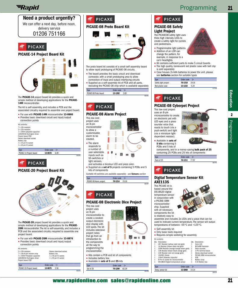
21
Programming 21Education
2
www.rapidonline.com [email protected]
Programm
ing
PICAXE-08 Safety Light ProjectThe PICAXE08 safety light uses three high intensity LEDs to create a safety light for cyclists and pedestrians.
• Programmable light patterns• Addition of an LDR can
change the pattern, for example, in response to a car’s headlights
• Kit contains sufficient parts to make 5 circuit boards• The high quality, translucent red plastic case with belt clip
is sold separately• Case houses 2x AAA batteries to power the unit, please
see batteries section for suitable types
Type Order code 1+Safety light project 70-1218 19.16Red plastic case 13-1222 5.24
077548
PICAXE-08 Cyberpet ProjectThis low-cost project uses an 8-pin microcontroller to create an electronic pet with LED eyes and a piezo sounder voice that reacts to touch (via a push-switch) and light (via a miniature light-dependent resistor).
• Available in sets of 5 kits containing 5 PCBs and 5 kits of components, and in a money–saving bulk pack of 25 containing 25 PCBs and 25 kits of components
Type Order code 1+Pack of 25 70-1211 77.97
061445
Digital Temperature Sensor Kit AXE113SThis PICAXE kit is based around the DS18S20 digital temperature sensor in conjunction with a PICAXE-08M microcontroller chip. Supplied with all necessary components the kit is relatively easy to assemble and includes 2x LEDs and a piezo that can be used to indicate current temperature. The sensor will output temperatures of between –55°C and +125°C.
• Self-assembly kit• Only basic tools required• Requires simple soldering for assemblyKit contents:Qty Description Qty Description1 4K7 Resistor (yellow violet red gold) 1 5mm LED1 1K Resistor (brown black red gold) 1 BC548B Transistor1 330R Resistor (orange orange brown gold) 1 Piezo sounder2 10K Resistor (brown black orange gold) 2 2-Pin terminal block1 22K Resistor (red red orange gold) 1 Stereo download socket1 1N4001 Diode 1 PICAXE-08M microcontroller1 100nF Polyester capacitor 1 PCB1 8-Pin IC socket for microcontroller 1 Battery snap1 DS18B20 Digital temperature sensor 1 4.5V Battery box
Type Order code 1+Temp. sensor kit 13-5060 14.14
526219
PICAXE-08 Proto Board Kit
The proto board kit consists of a small self-assembly board to allow rapid prototyping of PICAXE-08 circuits.
• The board provides the basic circuit and download connector, with a small prototyping area to allow connection of input and output interfacing circuits
• Supplied as a self-assembly kit of PCB and all parts, excluding the PICAXE-08 chip which is available separately
Type Order code 1+PICAXE-08 Proto board 13-1202 2.69
061441
PICAXE-08 Alarm ProjectThis low-cost project uses an 8-pin microcontroller to allow a customisable alarm to be created.
• The alarm responds to a number of user selectable inputs such as tilt–switches or light sensors, and activates a bicolour LED and piezo siren
• Supplied as a set of 5 projects containing 5 PCBs and 5 kits of components
Suitable tilt-switches are available separately - see Sensors section
Type Order code 1+PICAXE-08 Alarm project 70-1214 19.16
061447
PICAXE-08 Electronic Dice ProjectThis low-cost project uses an 8-pin microcontroller to create a random output electronic dice display with LED spots. The kit includes extensive project notes that go from an introduction to the components all the way to programming the microcontroller.
• Kits contain a PCB and kit of components• Includes battery box• Available in sets of 5 and 25 kits
Type Order code 1+Set of 25 70-1209 82.29
061449
PICAXE-14 Project Board Kit
The PICAXE-14 project board kit provides a quick and simple method of developing applications for the PICAXE-14M microcontroller.
The kit is self-assembly, and includes a PCB and the associated circuitry required to assemble one project board.
• For use with PICAXE-14M microcontroller 13-0866• Provides basic download circuit and input/output
connection pointsKit contents:7 x 10k resistors2 x 22k resistors1 x 100nf polyester capacitorULN2003A Darlington driverProject board PCBStereo download socketBattery clip1 x 14-pin IC socket1 x 16-pin IC socket
Type Order code 1+PICAXE-14 Project board 13-0878 6.09
081642
PICAXE-20 Project Board Kit
The PICAXE-20 project board kit provides a quick and simple method of developing applications for the PICAXE-20M microcontroller. The kit is self-assembly, and includes a PCB and the associated circuitry required to assemble one project board.
• For use with PICAXE-20M microcontroller 13-0876• Provides basic download circuit and input/output
connection pointsKit contents:2 x 10k resistors Stereo download socket7 x 10k 8-pin resistor array Battery clip1 x 100nF Polyester capacitor 1 x 18-pin IC socketULN2803A Darlington driver 1 x 20-pin IC socketProject board PCB
Type Order code 1+PICAXE-20 Project board 13-0879 5.56
081643
Need a product urgently?We can offer a next day, before noon,
delivery service
01206 751166
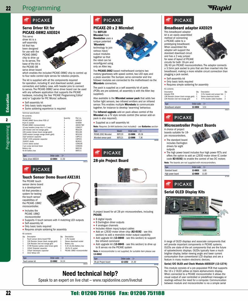
22
Programming22Ed
ucat
ion
2
Tel: 01206 751166 Fax: 01206 751188
Prog
ram
min
g
Breadboard adaptor AXE029This breadboard adaptor kit is an easily-assembled method of connecting a PICAXE cable to a prototyping breadboard. When assembled the adaptor will support the standard download circuit and has a 2-way jumper for ease of layout of PICAXE circuits for both 18-pin and 28/40 pin PICAXE mocrocontrollers. The adaptor connects a 3.5mm jack socket to pins that are then inserted into the breadboard, making a more reliable circuit connection than plugging a jack socket.
• Self-assembly kit• Only basic tools required• Requires simple soldering for assemblyKit contents:Description Qty Description QtyAdapter PCB 1 3-Pin header and jumper link 110K Resistor (brown black orange gold) 1 Stereo download socket 122K Resistor (red red orange gold 1 4-Pin double sided headers 2
Type Order code 1+Breadboard adapter 13-5056 3.51
526217
Microcontroller Project BoardsA choice of project boards suitable for 18-pin microcontrollers.
• The standard board includes Darlington drivers for eight outputs
• The high power board includes four high power FETs and offers the option to add an L293D motor driver IC (order code 82-0192) to enable the control of two DC motors
Note: The boards are not supplied with microcontrollers.
Type Order code 1+Standard board 13-0855 8.89High power board 13-0860 11.00
077547
Serial OLED Display Kits
A range of OLED displays and associate components that will provide important components in PICAXE systems. OLEDs are state-of-the-art components that are the future of optoelectronic displays. OLEDs typically have a much brighter display, better viewing angle and lower current consumption than conventional LCD displays and are a feature in many modern electronic devices.
Serial/I2C OLED and Clock Module AXE033Y (13-1274)This module consists of a pre-populated PCB that supports the 16 x 2 OLED yellow on black alphanumeric display. When connected to a PICAXE microcontroller it allows the visual output of user controlled or predefined messages or readings without the need for a computer. Communication between module and microcontroller is via a simple serial
PICAXE-20 x 2 MicrobotThe BOT120 Microbot from Revolution uses a unique patented ‘Microbric’ technology to join various input/output modules together so that the robot can be reconfigured using only an Allen key.
The PICAXE-20X2 based motherboard contains two motors/gearboxes with speed control, two LED eyes and a piezo sounder. The bumper, servo connector and line follower modules are connected to the motherboard via the Microbric connectors.
The pack is supplied as a self-assembly kit of parts (PCBs are pre-soldered, all assembly is with the Allen key supplied).
Also available is the Microbot sensor pack that adds two further light sensors, two infrared emitters and an infrared sensor. This enables multiple Microbots to communicate together, for instance to develop ‘swarming’ behaviour.
The Infrared upgrade add-on pack allows control of the Microbot via a TV style remote control (the sensor add-on pack is also required).
• Supplied as a self-assembly kitNote: Requires 3x AAA batteries (not included) - see Batteries section
Type Model Order code 1+PICAXE-20X2 Microbot BOT120 13-5006 65.36Microbot sensor pack BOT121 13-5008 7.36
180808
28-pin Project Board
A project board for all 28-pin microcontrollers, including PICAXE.
• 8 digital inputs• 8 Darlington driver outputs• 4 analogue channels• Includes ribbon input/output cables• Add an L293D motor driver chip (82-0192 - see this
section) to add a reversible motor output capability• Add upgrade kit (13-0840 - see this section) to support
the infrared command• Add upgrade kit (13-0845 - see this section) to drive up
to 8 servos via the PICAXE systemNote: A microcontroller is not supplied, for suitable item please see 13-0862
Type Order code 1+28-pin Project board 13-1252 21.30
061482
Servo Driver Kit for PICAXE-08M2 AXE024This servo driver kit is a self-assembly kit that has been designed for use with the PICAXE-08M2 chip to drive up to 4x servos. The base of the kit is the PICAXE-08 servo driver board which enables the included PICAXE-08M2 chip to control up to four radio control style servos for robotics projects.
The kit is supplied with all the components required for operation, including IC and download socket, power connectors and battery case, with header pins to connect to servos. The PICAXE-08M2 servo driver board can be used with any software application that supports the PICAXE hardware, including the free ‘PICAXE Programming Editor’ and/or ‘Logicator for PIC Micros’ software.
• Self-assembly kit• Only basic tools required• Some soldering experience is requiredTechnical specificationKit contents:Description Quantity Part no.PICAXE-08M2 Servo driver PCB v2 1 AXE0248-pin IC socket 1 ICH008PICAXE-08M2 microcontroller 1 AXE007M210-way headers (snap into 4 x 3 way) 4 CON03722K resistor (red red orange gold) 1 RES22K10K resistor (brown black orange gold) 2 RES10K330R resistor (orange orange brown gold) 4 RES33033µF tantalum capacitor 1 CAP012100nF (104) polyester capacitor 1 CAP0011N4001 diode 1 RES0413.5mm stereo socket 1 CON0392-pin screw terminal block 1 CON005Battery clip 1 BAT0164x AA battery box 1 BAT011
Type Order code 1+Servo driver AXE024 13-5054 11.50
526216
Touch Sensor Demo Board AXE181The PICAXE touch sensor demo board is a development kit that provides a system for testing the touch sensor capabilities of the PICAXE-18M2 microcontroller.
• Includes the PICAXE-18M2 microcontroller
• Supports 4 touch sensors with 4 matching LED outputs• Self-assembly kit• Only basic tools required• Requires simple soldering for assemblyKit contents:Qty Description Qty Description1 Touch sensor demo board PCB 1 3-Pin header1 10K Resistor (brown black orange gold) 1 Stereo download socket1 22K Resistor (red red orange gold 1 Battery clip4 470R Resistor (yellow violet brown gold) 1 4.5V (3x AA) Battery box1 100nF Polyester capacitor 1 18-Pin IC socket1 100µF Electrolytic capacitor 1 PICAXE-18M2 microcontroller4 3mm Yellow LED
Type Order code 1+Touch sensor kit 13-5062 14.14
526220
Need technical help?Speak to an expert on live chat – www.rapidonline.com/livechat
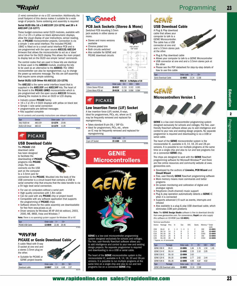
23
Programming 23Education
2
www.rapidonline.com [email protected]
Programm
ing
USB Download CableA Plug & Play download cable that allows your computer to talk to a GENIE Microcontroller. The cable has a USB connector at one end and a 3.5mm stereo jack at the other.
• Plug & Play download cable• Allows your computer to talk to a GENIE Microcontroller• USB connector at one end and a 3.5mm stereo jack at
the other• Please see the PDF datasheet for step-by-step details of
how to use this cable
Type Order code 1+ 15+Genie Download Cable 13-6023 13.34 12.88
501700
Microcontrollers Version 1
GENIE is a low-cost microcontroller programming system designed exclusively for schools and colleges. The free, user-friendly flowchart software allows you to add intelligence and control to your new and existing design projects. No separate programmer is required and downloading is via a USB or serial cable.
The heart of the GENIE microcontroller system is the microcontoller IC, available in 8, 14, 18, 20 and 28-pin versions. It is possible to run multiple programs at the same time on a single chip and also to run and test programs live on a connected GENIE chip.
The chips are designed to work with the GENIE flowchart programming software for Microsoft Windows™ and there are free online resources and community website at www.genieonline.com.
• Developed by the authors of Livewire, PCB Wizard and Circuit Wizard
• Free, user-friendly GENIE flowchart programming software• More memory means more commands and better
programs• On-screen monitoring and calibration of digital and
analogue signals• Polyphonic (multi-channel) music support• Plug & play operation automatically detects a GENIE IC
when it is connected• Supports advanced I/O such as events, interrupts and
infrared• Also available is a plug & play USB download cable, which
eliminates COM port problemsNote: The GENIE Design Studio software is free to download directly from www.genieonline.com. For convenience, Rapid can also supply this software on CD-ROM (see 13-6024).
Technical specificationDevice Package Pins In Out ADC Starts Memory * Order
codeC08 DIL-8 8 1 - 4 1 - 4 3 2 160 13-6001C14 DIL-14 14 5 6 2 2 160 13-6002E18 DIL-18 18 5 9 3 4 2200 13-6004C20 DIL-20 20 8 9 4 2 160 13-6003E28 DIL-28 28 8 9 4 4 2200 13-6005* Approx. no. of commands
Type Package Order code 1+ 25+ 100+ 250+GENIE C08 IC DIL-8 13-6001 1.84 1.76 1.50 1.40GENIE C14 IC DIL-14 13-6002 2.35 2.10 2.05GENIE E18 IC DIL-18 13-6004 2.63GENIE C20 IC DIL-20 13-6003 2.77 2.62 2.44GENIE E28 IC DIL-28 13-6005 4.99 4.87 4.82Type Package Order code 1+ 15+GENIE USB Download cable 13-6023 13.34 12.88
082990
(1-wire) connection or via a I2C connection. Additionally, the small footprint of this device makes it suitable for a wide range of projects. Some soldering and assembly is required
Serial OLED Kits 16 x 2 AXE133Y (13-1276) and 20 x 4 AXE134Y (13-1277)These budget-conscious serial OLED modules, available with 16 x 2 or 20 x 4 yellow on black alphanumeric displays, allow the visual display of user instructions, sensor reading, etc. of PICAXE microcontroller projects. Connection is via a simple 1-wire serial interface. The included PICAXE-18M2 is fitted on to a small serial interface PCB and is pre-programmed with the open source AXE133/AXE134 firmware that allows the microcontroller to act as a ‘slave’ serial driver for the OLED display. This allows the main project to display text on the OLED voa simple ‘serout’ commands.
The control codes that are used in these kits are identical to those used in the AXE033 module, enabling the kits to be used as an alternative to the AXE033. The 18M2 microcontroller can also be reprogrammed, e.g. to change the power-up welcome message. The kits are self-assembly that require some simple soldering.
Serial OLED/LCD Driver Kit AXE132 (13-1270)The AXE132 is the same serial interface board that is supplied in the AXE133Y and AXE134Y kits. The heart of the board is the PICAXE-18M2 microcontroller which is pre-programmed with the open source AXE133 firmware, allowing the module to drive an OLED or LCD display.
• Industry proven PICAXE family• 16 x 2 or 20 x 4 OLED displays with yellow on black text• Simple 1-wire serial connection• programmable pre-defined messages• Kits supplied completeFor kit contents and assembly instructions see relevant datasheets.
Type Device Order code 1+16x2 OLED kit AXE133Y 13-1276 23.66OLED/LCD Driver AXE132 13-1270 11.85
503102
USB Download CableThe PICAXE USB download cable has been designed to facilitate the downloading of PICAXE programs into PICAXE chips. The cable connects via the USB port on the computer to a 3.5mm jack for connection to the PICAXE. Moulded into the body of the USB connector is a circuit board that contains a USB to serial convertor chip that ensures that the data transfer is via a 5V logic level serial connection.
• For use on computers without a serial port• High quality connectors with 1.8m cable• Can be used with any PICAXE chip or project board• Compatible with any software application that supports
the programming of PICAXE chips• Software drivers for the cable assembly are downloadable
for free from www.picaxe.co.uk• Driver versions for Windows XP, XP (64-bit edition), 2003,
2000, ME, 98SE, Vista and Windows 7Note: There is no operating system support for Windows 95 or NT.
Type Order code 1+ 15+PICAXE USB Cable 13-0849 22.46 20.46
077630
PICAXE or Genie Download CableA cable fitted with 9-way D socket at one end and a stereo 3.5mm plug on the other.
• Suitable for PICAXE or GENIE project boards
Type Order code 1+ 20+ 50+Download cable 13-0847 5.34 4.46 3.57
061479
PCB Jack Sockets (Stereo & Mono)Switched PCB mounting 3.5mm jack sockets in either stereo or mono.
• Stereo and mono versions available
• Chrome plated trim• Both circuits switched • Also suitable for GENIE and
PICAXE download circuits
MOQ 10 – In Multiples of 10Type Order code 10+ 100+ 500+3.5mm Stereo PCB skt 20-0137 0.153 0.102 0.0933.5mm Mono PCB skt 20-0138 0.138 0.098 0.084
063492
Low Insertion Force (LIF) SocketA low insertion force (LIF) socket, 8 ways, ideal for programmers, PICs, etc, where an IC may be frequently removed and replaced for reprogramming.
• Takes standard 8-pin DIL / DIP ICs• Ideal for programmers, PICs, etc., where
an IC may be frequently removed and replaced for reprogramming
Type Order code 1+8-pin LIF Socket 22-1480 6.94
061490
GENIE Microcontrollers
GENIE is a low-cost microcontroller programming system designed exclusively for schools and colleges. The free, user-friendly flowchart software allows you to add intelligence and control to your new and existing design projects. No separate programmer is required and downloading is via a USB or serial cable.
The heart of the GENIE microcontroller system is the microcontoller IC, available in 8, 14, 18, 20 and 28-pin versions. It is possible to run multiple programs at the same time on a single chip and also to run and test programs live on a connected GENIE chip.
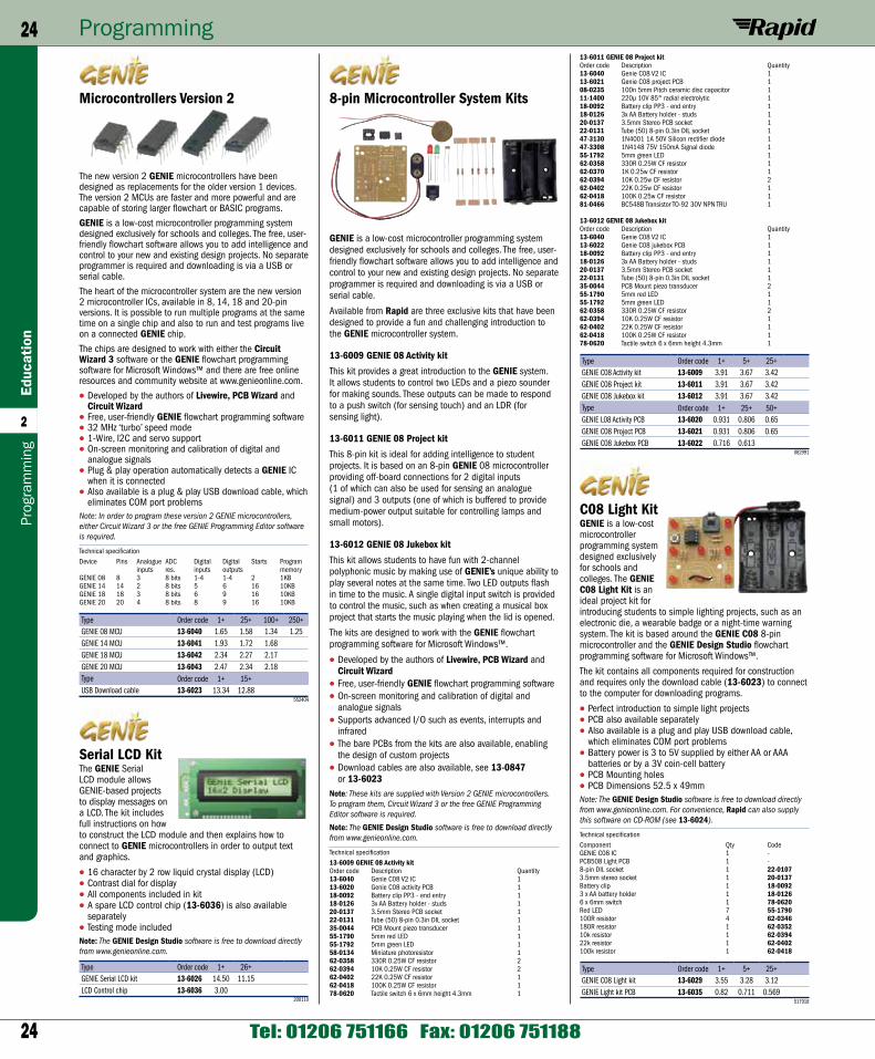
24
Programming24Ed
ucat
ion
2
Tel: 01206 751166 Fax: 01206 751188
Prog
ram
min
g
13-6011 GENIE 08 Project kitOrder code Description Quantity13-6040 Genie C08 V2 IC 113-6021 Genie C08 project PCB 108-0235 100n 5mm Pitch ceramic disc capacitor 111-1400 220µ 10V 85° radial electrolytic 118-0092 Battery clip PP3 - end entry 118-0126 3x AA Battery holder - studs 120-0137 3.5mm Stereo PCB socket 122-0131 Tube (50) 8-pin 0.3in DIL socket 147-3130 1N4001 1A 50V Silicon rectifier diode 147-3308 1N4148 75V 150mA Signal diode 155-1792 5mm green LED 162-0358 330R 0.25W CF resistor 162-0370 1K 0.25w CF resistor 162-0394 10K 0.25w CF resistor 262-0402 22K 0.25w CF resistor 162-0418 100K 0.25w CF resistor 181-0466 BC548B Transistor TO-92 30V NPN TRU 1
13-6012 GENIE 08 Jukebox kitOrder code Description Quantity13-6040 Genie C08 V2 IC 113-6022 Genie C08 jukebox PCB 118-0092 Battery clip PP3 - end entry 118-0126 3x AA Battery holder - studs 120-0137 3.5mm Stereo PCB socket 122-0131 Tube (50) 8-pin 0.3in DIL socket 135-0044 PCB Mount piezo transducer 255-1790 5mm red LED 155-1792 5mm green LED 162-0358 330R 0.25W CF resistor 262-0394 10K 0.25W CF resistor 162-0402 22K 0.25W CF resistor 162-0418 100K 0.25W CF resistor 178-0620 Tactile switch 6 x 6mm height 4.3mm 1
Type Order code 1+ 5+ 25+GENIE C08 Activity kit 13-6009 3.91 3.67 3.42GENIE C08 Project kit 13-6011 3.91 3.67 3.42GENIE C08 Jukebox kit 13-6012 3.91 3.67 3.42Type Order code 1+ 25+ 50+GENIE L08 Activity PCB 13-6020 0.931 0.806 0.65GENIE C08 Project PCB 13-6021 0.931 0.806 0.65GENIE C08 Jukebox PCB 13-6022 0.716 0.613
082991
C08 Light KitGENIE is a low-cost microcontroller programming system designed exclusively for schools and colleges. The GENIE C08 Light Kit is an ideal project kit for introducing students to simple lighting projects, such as an electronic die, a wearable badge or a night-time warning system. The kit is based around the GENIE C08 8-pin microcontroller and the GENIE Design Studio flowchart programming software for Microsoft Windows™.
The kit contains all components required for construction and requires only the download cable (13-6023) to connect to the computer for downloading programs.
• Perfect introduction to simple light projects• PCB also available separately• Also available is a plug and play USB download cable,
which eliminates COM port problems• Battery power is 3 to 5V supplied by either AA or AAA
batteries or by a 3V coin-cell battery• PCB Mounting holes• PCB Dimensions 52.5 x 49mmNote: The GENIE Design Studio software is free to download directly from www.genieonline.com. For convenience, Rapid can also supply this software on CD-ROM (see 13-6024).
Technical specificationComponent Qty CodeGENIE C08 IC 1 -PCB508 Light PCB 1 -8-pin DIL socket 1 22-01073.5mm stereo socket 1 20-0137Battery clip 1 18-00923 x AA battery holder 1 18-01266 x 6mm switch 1 78-0620Red LED 7 55-1790100R resistor 4 62-0346180R resistor 1 62-035210k resistor 1 62-039422k resistor 1 62-0402100k resistor 1 62-0418
Type Order code 1+ 5+ 25+GENIE C08 Light kit 13-6029 3.55 3.28 3.12GENIE Light kit PCB 13-6035 0.82 0.711 0.569
517918
8-pin Microcontroller System Kits
GENIE is a low-cost microcontroller programming system designed exclusively for schools and colleges. The free, user-friendly flowchart software allows you to add intelligence and control to your new and existing design projects. No separate programmer is required and downloading is via a USB or serial cable.
Available from Rapid are three exclusive kits that have been designed to provide a fun and challenging introduction to the GENIE microcontroller system.
13-6009 GENIE 08 Activity kit
This kit provides a great introduction to the GENIE system. It allows students to control two LEDs and a piezo sounder for making sounds. These outputs can be made to respond to a push switch (for sensing touch) and an LDR (for sensing light).
13-6011 GENIE 08 Project kit
This 8-pin kit is ideal for adding intelligence to student projects. It is based on an 8-pin GENIE 08 microcontroller providing off-board connections for 2 digital inputs (1 of which can also be used for sensing an analogue signal) and 3 outputs (one of which is buffered to provide medium-power output suitable for controlling lamps and small motors).
13-6012 GENIE 08 Jukebox kit
This kit allows students to have fun with 2-channel polyphonic music by making use of GENIE’s unique ability to play several notes at the same time. Two LED outputs flash in time to the music. A single digital input switch is provided to control the music, such as when creating a musical box project that starts the music playing when the lid is opened.
The kits are designed to work with the GENIE flowchart programming software for Microsoft Windows™.
• Developed by the authors of Livewire, PCB Wizard and Circuit Wizard
• Free, user-friendly GENIE flowchart programming software• On-screen monitoring and calibration of digital and
analogue signals• Supports advanced I/O such as events, interrupts and
infrared• The bare PCBs from the kits are also available, enabling
the design of custom projects• Download cables are also available, see 13-0847
or 13-6023Note: These kits are supplied with Version 2 GENIE microcontrollers. To program them, Circuit Wizard 3 or the free GENIE Programming Editor software is required.
Note: The GENIE Design Studio software is free to download directly from www.genieonline.com.
Technical specification13-6009 GENIE 08 Activity kitOrder code Description Quantity13-6040 Genie C08 V2 IC 113-6020 Genie C08 activity PCB 118-0092 Battery clip PP3 - end entry 118-0126 3x AA Battery holder - studs 120-0137 3.5mm Stereo PCB socket 122-0131 Tube (50) 8-pin 0.3in DIL socket 135-0044 PCB Mount piezo transducer 155-1790 5mm red LED 155-1792 5mm green LED 158-0134 Miniature photoresistor 162-0358 330R 0.25W CF resistor 262-0394 10K 0.25W CF resistor 262-0402 22K 0.25W CF resistor 162-0418 100K 0.25W CF resistor 178-0620 Tactile switch 6 x 6mm height 4.3mm 1
Microcontrollers Version 2
The new version 2 GENIE microcontrollers have been designed as replacements for the older version 1 devices. The version 2 MCUs are faster and more powerful and are capable of storing larger flowchart or BASIC programs.
GENIE is a low-cost microcontroller programming system designed exclusively for schools and colleges. The free, user-friendly flowchart software allows you to add intelligence and control to your new and existing design projects. No separate programmer is required and downloading is via a USB or serial cable.
The heart of the microcontroller system are the new version 2 microcontroller ICs, available in 8, 14, 18 and 20-pin versions. It is possible to run multiple programs at the same time on a single chip and also to run and test programs live on a connected GENIE chip.
The chips are designed to work with either the Circuit Wizard 3 software or the GENIE flowchart programming software for Microsoft Windows™ and there are free online resources and community website at www.genieonline.com.
• Developed by the authors of Livewire, PCB Wizard and Circuit Wizard
• Free, user-friendly GENIE flowchart programming software• 32 MHz ‘turbo’ speed mode• 1-Wire, I2C and servo support• On-screen monitoring and calibration of digital and
analogue signals• Plug & play operation automatically detects a GENIE IC
when it is connected• Also available is a plug & play USB download cable, which
eliminates COM port problemsNote: In order to program these version 2 GENIE microcontrollers, either Circuit Wizard 3 or the free GENIE Programming Editor software is required.
Technical specificationDevice Pins Analogue ADC Digital Digital Starts Program
inputs res. inputs outputs memoryGENIE 08 8 3 8 bits 1-4 1-4 2 1KBGENIE 14 14 2 8 bits 5 6 16 10KBGENIE 18 18 3 8 bits 6 9 16 10KBGENIE 20 20 4 8 bits 8 9 16 10KB
Type Order code 1+ 25+ 100+ 250+GENIE 08 MCU 13-6040 1.65 1.58 1.34 1.25GENIE 14 MCU 13-6041 1.93 1.72 1.68GENIE 18 MCU 13-6042 2.34 2.27 2.17GENIE 20 MCU 13-6043 2.47 2.34 2.18Type Order code 1+ 15+USB Download cable 13-6023 13.34 12.88
552404
Serial LCD KitThe GENIE Serial LCD module allows GENIE-based projects to display messages on a LCD. The kit includes full instructions on how to construct the LCD module and then explains how to connect to GENIE microcontrollers in order to output text and graphics.
• 16 character by 2 row liquid crystal display (LCD)• Contrast dial for display• All components included in kit• A spare LCD control chip (13-6036) is also available
separately• Testing mode includedNote: The GENIE Design Studio software is free to download directly from www.genieonline.com.
Type Order code 1+ 26+GENIE Serial LCD kit 13-6026 14.50 11.15LCD Control chip 13-6036 3.00
200110
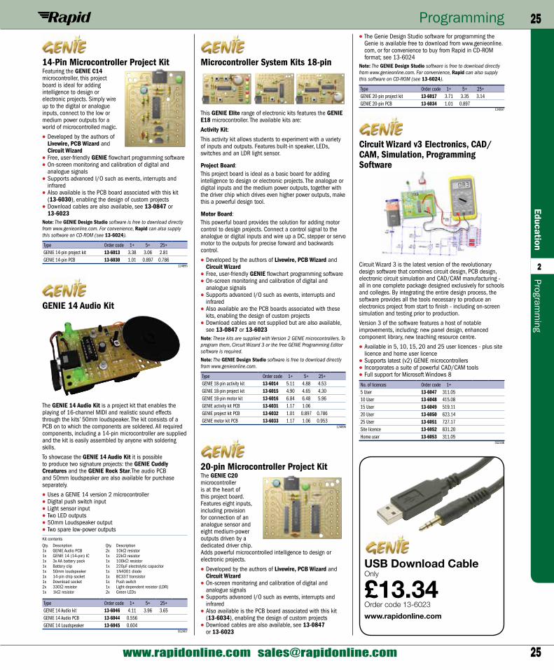
25
Programming 25Education
2
www.rapidonline.com [email protected]
Programm
ing
• The Genie Design Studio software for programming the Genie is available free to download from www.genieonline.com, or for convenience to buy from Rapid in CD-ROM format; see 13-6024
Note: The GENIE Design Studio software is free to download directly from www.genieonline.com. For convenience, Rapid can also supply this software on CD-ROM (see 13-6024).
Type Order code 1+ 5+ 25+GENIE 20-pin project kit 13-6017 3.71 3.35 3.14GENIE 20-pin PCB 13-6034 1.01 0.897
124897
Circuit Wizard v3 Electronics, CAD/CAM, Simulation, Programming Software
Circuit Wizard 3 is the latest version of the revolutionary design software that combines circuit design, PCB design, electronic circuit simulation and CAD/CAM manufacturing - all in one complete package designed exclusively for schools and colleges. By integrating the entire design process, the software provides all the tools necessary to produce an electronics project from start to finish - including on-screen simulation and testing prior to production.
Version 3 of the software features a host of notable improvements, including: new panel design, enhanced component library, new teaching resource centre.
• Available in 5, 10, 15, 20 and 25 user licences - plus site licence and home user licence
• Supports latest (v2) GENIE microcontrollers• Incorporates a suite of powerful CAD/CAM tools• Full support for Microsoft Windows 8
No. of licences Order code 1+5 User 13-6047 311.0510 User 13-6048 415.0815 User 13-6049 519.1120 User 13-6050 623.1425 User 13-6051 727.17Site licence 13-6052 831.20Home user 13-6053 311.05
552306
Microcontroller System Kits 18-pin
This GENIE Elite range of electronic kits features the GENIE E18 microcontroller. The available kits are:
Activity Kit:
This activity kit allows students to experiment with a variety of inputs and outputs. Features built-in speaker, LEDs, switches and an LDR light sensor.
Project Board:This project board is ideal as a basic board for adding intelligence to design or electronic projects. The analogue or digital inputs and the medium power outputs, together with the driver chip which drives even higher power outputs, make this a powerful design tool.
Motor Board:This powerful board provides the solution for adding motor control to design projects. Connect a control signal to the analogue or digital inputs and wire up a DC, stepper or servo motor to the outputs for precise forward and backwards control.
• Developed by the authors of Livewire, PCB Wizard and Circuit Wizard
• Free, user-friendly GENIE flowchart programming software• On-screen monitoring and calibration of digital and
analogue signals• Supports advanced I/O such as events, interrupts and
infrared• Also available are the PCB boards associated with these
kits, enabling the design of custom projects• Download cables are not supplied but are also available,
see 13-0847 or 13-6023Note: These kits are supplied with Version 2 GENIE microcontrollers. To program them, Circuit Wizard 3 or the free GENIE Programming Editor software is required.
Note: The GENIE Design Studio software is free to download directly from www.genieonline.com.
Type Order code 1+ 5+ 25+GENIE 18-pin activity kit 13-6014 5.11 4.88 4.53GENIE 18-pin project kit 13-6015 4.90 4.65 4.30GENIE 18-pin motor kit 13-6016 6.84 6.48 5.96GENIE activity kit PCB 13-6031 1.17 1.06GENIE project kit PCB 13-6032 1.01 0.897 0.786GENIE motor kit PCB 13-6033 1.17 1.06 0.953
124896
20-pin Microcontroller Project KitThe GENIE C20 microcontroller is at the heart of this project board. Features eight inputs, including provision for connection of an analogue sensor and eight medium-power outputs driven by a dedicated driver chip. Adds powerful microcontrolled intelligence to design or electronic projects.
• Developed by the authors of Livewire, PCB Wizard and Circuit Wizard
• On-screen monitoring and calibration of digital and analogue signals
• Supports advanced I/O such as events, interrupts and infrared
• Also available is the PCB board associated with this kit (13-6034), enabling the design of custom projects
• Download cables are also available, see 13-0847 or 13-6023
14-Pin Microcontroller Project KitFeaturing the GENIE C14 microcontroller, this project board is ideal for adding intelligence to design or electronic projects. Simply wire up to the digital or analogue inputs, connect to the low or medium power outputs for a world of microcontrolled magic.
• Developed by the authors of Livewire, PCB Wizard and Circuit Wizard
• Free, user-friendly GENIE flowchart programming software• On-screen monitoring and calibration of digital and
analogue signals• Supports advanced I/O such as events, interrupts and
infrared• Also available is the PCB board associated with this kit
(13-6030), enabling the design of custom projects• Download cables are also available, see 13-0847 or
13-6023Note: The GENIE Design Studio software is free to download directly from www.genieonline.com. For convenience, Rapid can also supply this software on CD-ROM (see 13-6024).
Type Order code 1+ 5+ 25+GENIE 14-pin project kit 13-6013 3.38 3.06 2.81GENIE 14-pin PCB 13-6030 1.01 0.897 0.786
124895
GENIE 14 Audio Kit
The GENIE 14 Audio Kit is a project kit that enables the playing of 16-channel MIDI and realistic sound effects through the kits’ 50mm loudspeaker. The kit consists of a PCB on to which the components are soldered. All required components, including a 14-pin microcontroller are supplied and the kit is easily assembled by anyone with soldering skills.
To showcase the GENIE 14 Audio Kit it is possible to produce two signature projects: the GENIE Cuddly Creatures and the GENIE Rock Star.The audio PCB and 50mm loudspeaker are also available for purchase separately.
• Uses a GENIE 14 version 2 microcontroller• Digital push switch input• Light sensor input• Two LED outputs• 50mm Loudspeaker output• Two spare low-power outputsKit contentsQty. Description Qty. Description1x GENIE Audio PCB 2x 10kΩ resistor1x GENIE 14 (14-pin) IC 1x 22kΩ resistor1x 3x AA battery pack 1x 100kΩ resistor1x Battery clip 1x 220µF electrolytic capacitor1x 50mm loudspeaker 1x 1N4001 diode1x 14-pin chip socket 1x BC337 transistor1x Download socket 1x Push switch2x 330Ω resistor 1x Light-dependent resistor (LDR)1x 1kΩ resistor 2x Green LEDs
Type Order code 1+ 5+ 25+GENIE 14 Audio kit 13-6046 4.11 3.96 3.65GENIE 14 Audio PCB 13-6044 0.556GENIE 14 Loudspeaker 13-6045 0.604
552407
USB Download CableOnly
£13.34Order code 13-6023www.rapidonline.com
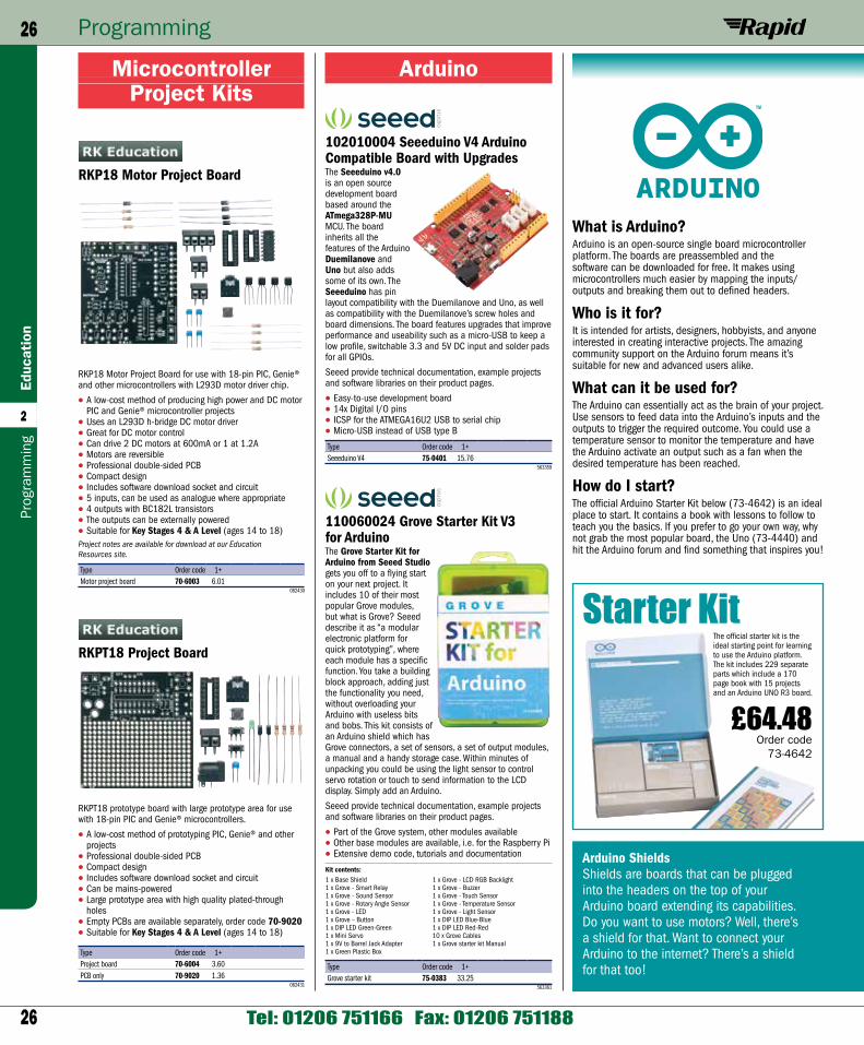
26
Programming26Ed
ucat
ion
2
Tel: 01206 751166 Fax: 01206 751188
Prog
ram
min
g
Arduino
102010004 Seeeduino V4 Arduino Compatible Board with UpgradesThe Seeeduino v4.0 is an open source development board based around the ATmega328P-MU MCU. The board inherits all the features of the Arduino Duemilanove and Uno but also adds some of its own. The Seeeduino has pin layout compatibility with the Duemilanove and Uno, as well as compatibility with the Duemilanove’s screw holes and board dimensions. The board features upgrades that improve performance and useability such as a micro-USB to keep a low profile, switchable 3.3 and 5V DC input and solder pads for all GPIOs.
Seeed provide technical documentation, example projects and software libraries on their product pages.
• Easy-to-use development board• 14x Digital I/O pins• ICSP for the ATMEGA16U2 USB to serial chip• Micro-USB instead of USB type B
Type Order code 1+Seeeduino V4 75-0401 15.76
563359
110060024 Grove Starter Kit V3 for ArduinoThe Grove Starter Kit for Arduino from Seeed Studio gets you off to a flying start on your next project. It includes 10 of their most popular Grove modules, but what is Grove? Seeed describe it as “a modular electronic platform for quick prototyping”, where each module has a specific function. You take a building block approach, adding just the functionality you need, without overloading your Arduino with useless bits and bobs. This kit consists of an Arduino shield which has Grove connectors, a set of sensors, a set of output modules, a manual and a handy storage case. Within minutes of unpacking you could be using the light sensor to control servo rotation or touch to send information to the LCD display. Simply add an Arduino.
Seeed provide technical documentation, example projects and software libraries on their product pages.
• Part of the Grove system, other modules available• Other base modules are available, i.e. for the Raspberry Pi• Extensive demo code, tutorials and documentation
Kit contents:1 x Base Shield 1 x Grove - LCD RGB Backlight1 x Grove - Smart Relay 1 x Grove - Buzzer1 x Grove - Sound Sensor 1 x Grove - Touch Sensor1 x Grove - Rotary Angle Sensor 1 x Grove - Temperature Sensor1 x Grove - LED 1 x Grove - Light Sensor1 x Grove – Button 1 x DIP LED Blue-Blue1 x DIP LED Green-Green 1 x DIP LED Red-Red1 x Mini Servo 10 x Grove Cables1 x 9V to Barrel Jack Adapter 1 x Grove starter kit Manual1 x Green Plastic Box
Type Order code 1+Grove starter kit 75-0383 33.25
563361
Microcontroller Project Kits
RKP18 Motor Project Board
RKP18 Motor Project Board for use with 18-pin PIC, Genie® and other microcontrollers with L293D motor driver chip.
• A low-cost method of producing high power and DC motor PIC and Genie® microcontroller projects
• Uses an L293D h-bridge DC motor driver• Great for DC motor control• Can drive 2 DC motors at 600mA or 1 at 1.2A• Motors are reversible• Professional double-sided PCB• Compact design• Includes software download socket and circuit• 5 inputs, can be used as analogue where appropriate• 4 outputs with BC182L transistors• The outputs can be externally powered• Suitable for Key Stages 4 & A Level (ages 14 to 18)Project notes are available for download at our Education Resources site.
Type Order code 1+Motor project board 70-6003 6.01
082430
RKPT18 Project Board
RKPT18 prototype board with large prototype area for use with 18-pin PIC and Genie® microcontrollers.
• A low-cost method of prototyping PIC, Genie® and other projects
• Professional double-sided PCB• Compact design• Includes software download socket and circuit• Can be mains-powered• Large prototype area with high quality plated-through
holes• Empty PCBs are available separately, order code 70-9020• Suitable for Key Stages 4 & A Level (ages 14 to 18)
Type Order code 1+Project board 70-6004 3.60PCB only 70-9020 1.36
082431
What is Arduino? Arduino is an open-source single board microcontroller platform. The boards are preassembled and the software can be downloaded for free. It makes using microcontrollers much easier by mapping the inputs/outputs and breaking them out to defined headers.
Who is it for? It is intended for artists, designers, hobbyists, and anyone interested in creating interactive projects. The amazing community support on the Arduino forum means it’s suitable for new and advanced users alike.
What can it be used for?The Arduino can essentially act as the brain of your project. Use sensors to feed data into the Arduino’s inputs and the outputs to trigger the required outcome. You could use a temperature sensor to monitor the temperature and have the Arduino activate an output such as a fan when the desired temperature has been reached.
How do I start? The official Arduino Starter Kit below (73-4642) is an ideal place to start. It contains a book with lessons to follow to teach you the basics. If you prefer to go your own way, why not grab the most popular board, the Uno (73-4440) and hit the Arduino forum and find something that inspires you!
£64.48 Order code
73-4642
The official starter kit is the ideal starting point for learning to use the Arduino platform. The kit includes 229 separate parts which include a 170 page book with 15 projects and an Arduino UNO R3 board.
Starter Kit
Arduino ShieldsShields are boards that can be plugged into the headers on the top of your Arduino board extending its capabilities. Do you want to use motors? Well, there’s a shield for that. Want to connect your Arduino to the internet? There’s a shield for that too!
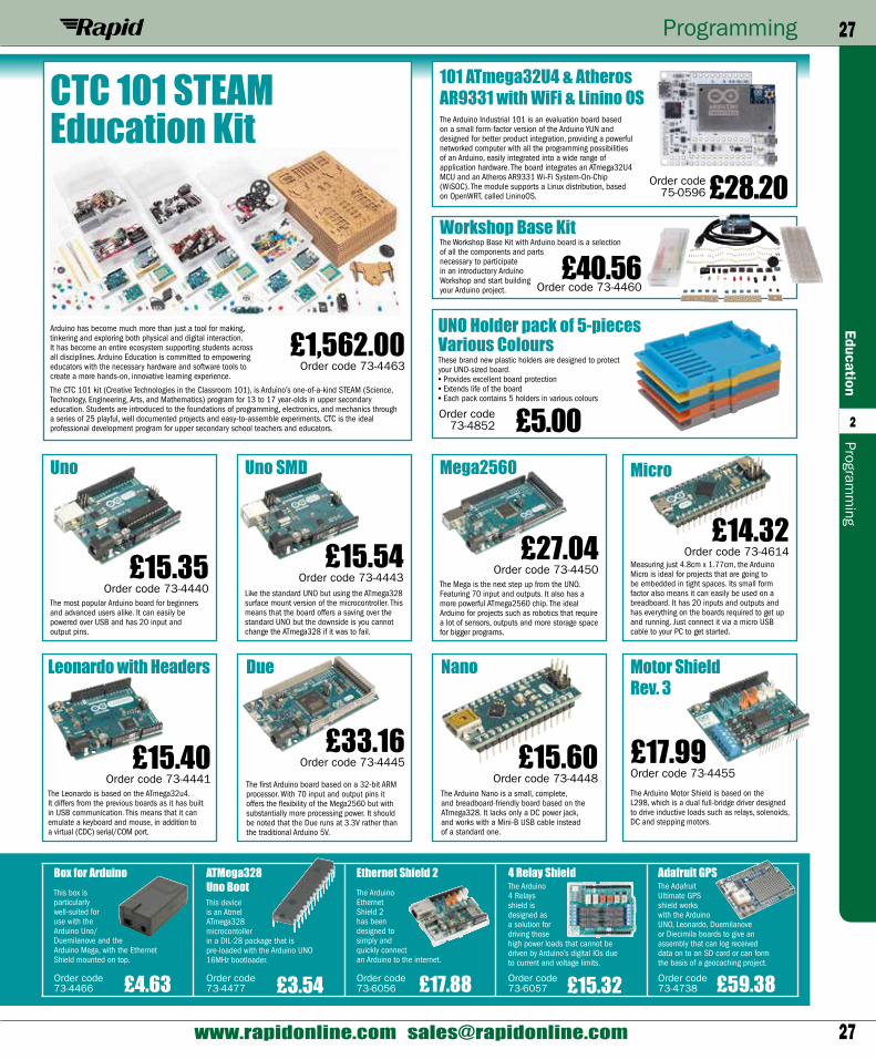
27
Programming 27Education
2
www.rapidonline.com [email protected]
Programm
ing
Uno SMD
£15.54Order code 73-4443
Uno Uno SMD
£15.35Order code 73-4440
The most popular Arduino board for beginners and advanced users alike. It can easily be powered over USB and has 20 input and output pins.
Like the standard UNO but using the ATmega328 surface mount version of the microcontroller. This means that the board offers a saving over the standard UNO but the downside is you cannot change the ATmega328 if it was to fail.
Mega2560
DueLeonardo with Headers
£27.04Order code 73-4450
£33.16Order code 73-4445£15.40
Order code 73-4441
The Mega is the next step up from the UNO. Featuring 70 input and outputs. It also has a more powerful ATmega2560 chip. The ideal Arduino for projects such as robotics that require a lot of sensors, outputs and more storage space for bigger programs.
The Leonardo is based on the ATmega32u4. It differs from the previous boards as it has built in USB communication. This means that it can emulate a keyboard and mouse, in addition to a virtual (CDC) serial/COM port.
The first Arduino board based on a 32-bit ARM processor. With 70 input and output pins it offers the flexibility of the Mega2560 but with substantially more processing power. It should be noted that the Due runs at 3.3V rather than the traditional Arduino 5V.
Nano
£15.60Order code 73-4448
The Arduino Nano is a small, complete, and breadboard-friendly board based on the ATmega328. It lacks only a DC power jack, and works with a Mini-B USB cable instead of a standard one.
Motor Shield Rev. 3
101 ATmega32U4 & Atheros AR9331 with WiFi & Linino OS
£14.32 Order code 73-4614
£17.99Order code 73-4455
Order code 75-0596 £28.20
Measuring just 4.8cm x 1.77cm, the Arduino Micro is ideal for projects that are going to be embedded in tight spaces. Its small form factor also means it can easily be used on a breadboard. It has 20 inputs and outputs and has everything on the boards required to get up and running. Just connect it via a micro USB cable to your PC to get started.
The Arduino Motor Shield is based on the L298, which is a dual full-bridge driver designed to drive inductive loads such as relays, solenoids, DC and stepping motors.
The Arduino Industrial 101 is an evaluation board based on a small form-factor version of the Arduino YUN and designed for better product integration, providing a powerful networked computer with all the programming possibilities of an Arduino, easily integrated into a wide range of application hardware. The board integrates an ATmega32U4 MCU and an Atheros AR9331 Wi-Fi System-On-Chip (WiSOC). The module supports a Linux distribution, based on OpenWRT, called LininoOS.
Workshop Base Kit
£40.56Order code 73-4460
The Workshop Base Kit with Arduino board is a selection of all the components and parts necessary to participate in an introductory Arduino Workshop and start building your Arduino project.
Micro
CTC 101 STEAM Education Kit
Arduino has become much more than just a tool for making, tinkering and exploring both physical and digital interaction. It has become an entire ecosystem supporting students across all disciplines. Arduino Education is committed to empowering educators with the necessary hardware and software tools to create a more hands-on, innovative learning experience.
The CTC 101 kit (Creative Technologies in the Classroom 101), is Arduino’s one-of-a-kind STEAM (Science, Technology, Engineering, Arts, and Mathematics) program for 13 to 17 year-olds in upper secondary education. Students are introduced to the foundations of programming, electronics, and mechanics through a series of 25 playful, well documented projects and easy-to-assemble experiments. CTC is the ideal professional development program for upper secondary school teachers and educators.
£1,562.00 Order code 73-4463
Box for Arduino
£4.63Order code 73-4466
ATMega328 Uno Boot
Ethernet Shield 2
£3.54 £17.88Order code 73-4477
Order code 73-6056
4 Relay Shield
£15.32Order code 73-6057
Adafruit GPS
£59.38Order code 73-4738
UNO Holder pack of 5-pieces Various Colours
Order code 73-4852 £5.00
These brand new plastic holders are designed to protect your UNO-sized board.• Provides excellent board protection• Extends life of the board• Each pack contains 5 holders in various colours
This device is an Atmel ATmega328 microcontoller in a DIL-28 package that is pre-loaded with the Arduino UNO 16MHz bootloader.
This box is particularly well-suited for use with the Arduino Uno/ Duemilanove and the Arduino Mega, with the Ethernet Shield mounted on top.
The Arduino Ethernet Shield 2 has been designed to simply and quickly connect an Arduino to the internet.
The Arduino 4 Relays shield is designed as a solution for driving those high power loads that cannot be driven by Arduino’s digital IOs due to current and voltage limits.
The Adafruit Ultimate GPS shield works with the Arduino UNO, Leonardo, Duemilanove or Diecimila boards to give an assembly that can log received data on to an SD card or can form the basis of a geocaching project.
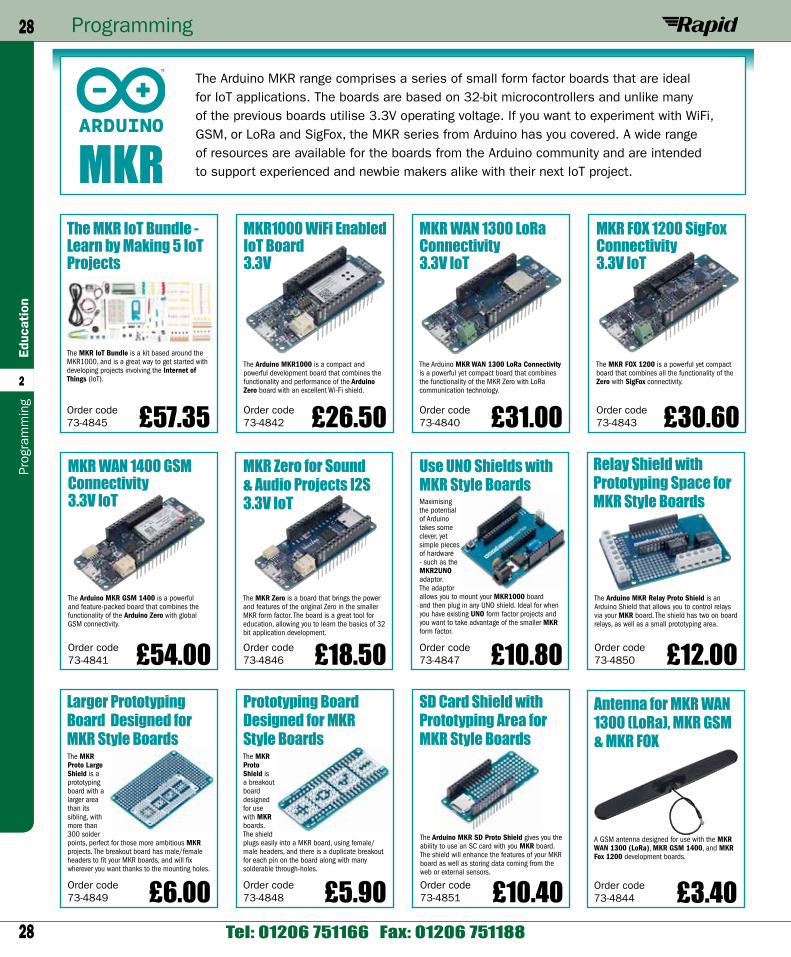
28
Programming28Ed
ucat
ion
2
Tel: 01206 751166 Fax: 01206 751188
Prog
ram
min
g
The Arduino MKR range comprises a series of small form factor boards that are ideal for IoT applications. The boards are based on 32-bit microcontrollers and unlike many of the previous boards utilise 3.3V operating voltage. If you want to experiment with WiFi, GSM, or LoRa and SigFox, the MKR series from Arduino has you covered. A wide range of resources are available for the boards from the Arduino community and are intended to support experienced and newbie makers alike with their next IoT project.MKR
MKR WAN 1400 GSM Connectivity 3.3V IoT
Larger Prototyping Board Designed for MKR Style Boards
MKR Zero for Sound & Audio Projects I2S 3.3V IoT
Relay Shield with Prototyping Space for MKR Style Boards
Use UNO Shields with MKR Style Boards
SD Card Shield with Prototyping Area for MKR Style Boards
Antenna for MKR WAN 1300 (LoRa), MKR GSM & MKR FOX
£3.40£5.90
£54.00
£6.00
£18.50 £12.00£10.80
£10.40 Order code 73-4844
Order code 73-4848
Order code 73-4841
Order code 73-4849
Order code 73-4846
Order code 73-4850
Order code 73-4847
Order code 73-4851
MKR WAN 1300 LoRa Connectivity 3.3V IoT
£31.00Order code 73-4840
The Arduino MKR WAN 1300 LoRa Connectivity is a powerful yet compact board that combines the functionality of the MKR Zero with LoRa communication technology.
A GSM antenna designed for use with the MKR WAN 1300 (LoRa), MKR GSM 1400, and MKR Fox 1200 development boards.
The MKR Proto Shield is a breakout board designed for use with MKR boards. The shield plugs easily into a MKR board, using female/male headers, and there is a duplicate breakout for each pin on the board along with many solderable through-holes.
The Arduino MKR GSM 1400 is a powerful and feature-packed board that combines the functionality of the Arduino Zero with global GSM connectivity.
The MKR IoT Bundle - Learn by Making 5 IoT Projects
£57.35Order code 73-4845
The MKR IoT Bundle is a kit based around the MKR1000, and is a great way to get started with developing projects involving the Internet of Things (IoT).
The MKR Proto Large Shield is a prototyping board with a larger area than its sibling, with more than 300 solder points, perfect for those more ambitious MKR projects. The breakout board has male/female headers to fit your MKR boards, and will fix wherever you want thanks to the mounting holes.
MKR1000 WiFi Enabled IoT Board 3.3V
£26.50Order code 73-4842
The Arduino MKR1000 is a compact and powerful development board that combines the functionality and performance of the Arduino Zero board with an excellent Wi-Fi shield.
The MKR Zero is a board that brings the power and features of the original Zero in the smaller MKR form factor. The board is a great tool for education, allowing you to learn the basics of 32 bit application development.
The Arduino MKR Relay Proto Shield is an Arduino Shield that allows you to control relays via your MKR board. The shield has two on board relays, as well as a small prototyping area.
MKR FOX 1200 SigFox Connectivity 3.3V IoT
£30.60Order code 73-4843
The MKR FOX 1200 is a powerful yet compact board that combines all the functionality of the Zero with SigFox connectivity.
Maximising the potential of Arduino takes some clever, yet simple pieces of hardware - such as the MKR2UNO adaptor. The adaptor allows you to mount your MKR1000 board and then plug in any UNO shield. Ideal for when you have existing UNO form factor projects and you want to take advantage of the smaller MKR form factor.
The Arduino MKR SD Proto Shield gives you the ability to use an SC card with you MKR board. The shield will enhance the features of your MKR board as well as storing data coming from the web or external sensors.
Prototyping Board Designed for MKR Style Boards
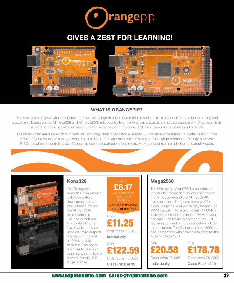
29 www.rapidonline.com [email protected]
GIVES A ZEST FOR LEARNING!
Only
£20.58Order code 75-0551Individually
Only
£178.78Order code 75-0593Class Pack of 10
Only
£11.25Order code 75-0550Individually
Only
£122.59Order code 75-0592Class Pack of 15
The Orangepip Mega2560 is an Arduino Mega2560 compatible development board that is based around the ATmega2560 microcontroller. The board features 54x digital I/O pins (14 of which may be used as PWM outputs), 16 analog inputs, 4x UARTs (hardware serial ports) and a 16MHz crystal oscillator. The board is simple to use, just requiring connection to a computer via USB to get started. The Orangepip Mega2560 is also compatible with shields designed for the Arduino Mega2560.
The Orangepip Kona328 is an Arduino UNO compatible development board that is based around the ATmega328 microcontroller. The board features 14x digital I/O pins (six of which may be used as PWM outputs), 6 analog inputs and a 16MHz crystal oscillator. The board is simple to use, just requiring connection to a computer via USB to get started.
Kona328 Mega2560
WHAT IS ORANGEPIP?See your projects grow with Orangepip – a distinctive range of open source boards which offer a colourful introduction to coding and
prototyping. Based on the ATmega328 and ATmega2560 microcontrollers, the Orangepip boards are fully compatible with Arduino shields, sensors, accessories and software – giving users access to the global Arduino community of makers and projects.
The boards themselves are rich with features, including 16MHz oscillator, ATmega16u2 for serial conversion, 14 digital GPIO I/O pins (Kona328) and 54 I/O pins (Mega2560), quick reset buttons and machine screw holes. The high performance ATmega 8-bit AVR RISC-based microcontrollers give Orangepip users enough power and memory to store and run multiple lines of complex code.
Only
£8.17per board when
bought in a classpack
Almost half the price of an Arduino Uno!
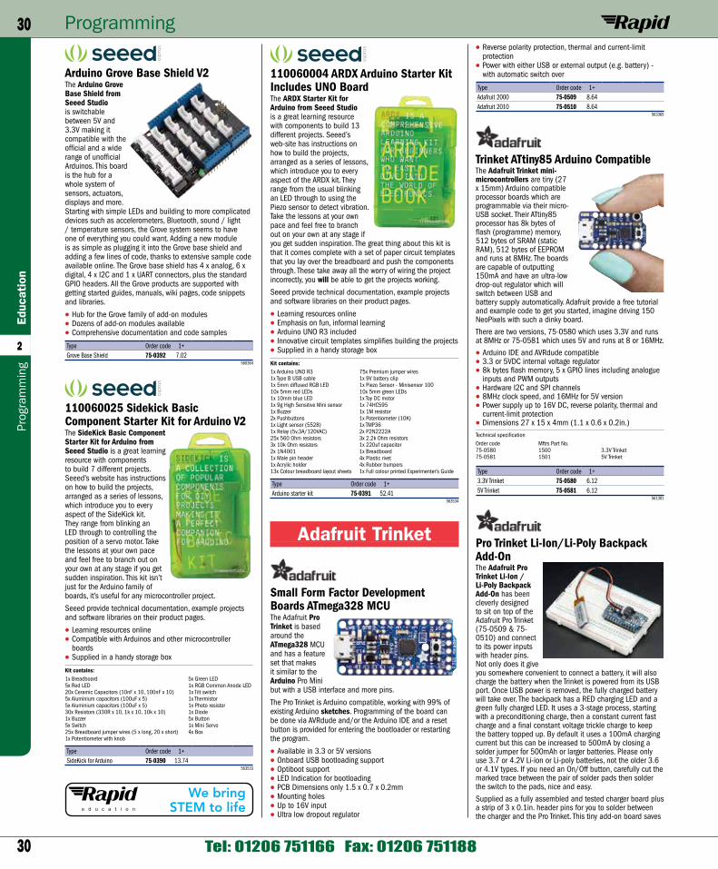
30
Programming30Ed
ucat
ion
2
Tel: 01206 751166 Fax: 01206 751188
Prog
ram
min
g
• Reverse polarity protection, thermal and current-limit protection
• Power with either USB or external output (e.g. battery) - with automatic switch over
Type Order code 1+Adafruit 2000 75-0509 8.64Adafruit 2010 75-0510 8.64
563365
Trinket ATtiny85 Arduino CompatibleThe Adafruit Trinket mini-microcontrollers are tiny (27 x 15mm) Arduino compatible processor boards which are programmable via their micro-USB socket. Their ATtiny85 processor has 8k bytes of flash (programme) memory, 512 bytes of SRAM (static RAM), 512 bytes of EEPROM and runs at 8MHz. The boards are capable of outputting 150mA and have an ultra-low drop-out regulator which will switch between USB and battery supply automatically. Adafruit provide a free tutorial and example code to get you started, imagine driving 150 NeoPixels with such a dinky board.
There are two versions, 75-0580 which uses 3.3V and runs at 8MHz or 75-0581 which uses 5V and runs at 8 or 16MHz.
• Arduino IDE and AVRdude compatible• 3.3 or 5VDC internal voltage regulator• 8k bytes flash memory, 5 x GPIO lines including analogue
inputs and PWM outputs• Hardware I2C and SPI channels• 8MHz clock speed, and 16MHz for 5V version• Power supply up to 16V DC, reverse polarity, thermal and
current-limit protection• Dimensions 27 x 15 x 4mm (1.1 x 0.6 x 0.2in.)Technical specificationOrder code Mftrs Part No.75-0580 1500 3.3V Trinket75-0581 1501 5V Trinket
Type Order code 1+3.3V Trinket 75-0580 6.125V Trinket 75-0581 6.12
561301
Pro Trinket Li-Ion/Li-Poly Backpack Add-OnThe Adafruit Pro Trinket Li-Ion / Li-Poly Backpack Add-On has been cleverly designed to sit on top of the Adafruit Pro Trinket (75-0509 & 75-0510) and connect to its power inputs with header pins. Not only does it give you somewhere convenient to connect a battery, it will also charge the battery when the Trinket is powered from its USB port. Once USB power is removed, the fully charged battery will take over. The backpack has a RED charging LED and a green fully charged LED. It uses a 3-stage process, starting with a preconditioning charge, then a constant current fast charge and a final constant voltage trickle charge to keep the battery topped up. By default it uses a 100mA charging current but this can be increased to 500mA by closing a solder jumper for 500mAh or larger batteries. Please only use 3.7 or 4.2V Li-ion or Li-poly batteries, not the older 3.6 or 4.1V types. If you need an On/Off button, carefully cut the marked trace between the pair of solder pads then solder the switch to the pads, nice and easy.
Supplied as a fully assembled and tested charger board plus a strip of 3 x 0.1in. header pins for you to solder between the charger and the Pro Trinket. This tiny add-on board saves
110060004 ARDX Arduino Starter Kit Includes UNO BoardThe ARDX Starter Kit for Arduino from Seeed Studio is a great learning resource with components to build 13 different projects. Seeed’s web-site has instructions on how to build the projects, arranged as a series of lessons, which introduce you to every aspect of the ARDX kit. They range from the usual blinking an LED through to using the Piezo sensor to detect vibration. Take the lessons at your own pace and feel free to branch out on your own at any stage if you get sudden inspiration. The great thing about this kit is that it comes complete with a set of paper circuit templates that you lay over the breadboard and push the components through. These take away all the worry of wiring the project incorrectly, you will be able to get the projects working.
Seeed provide technical documentation, example projects and software libraries on their product pages.
• Learning resources online• Emphasis on fun, informal learning• Arduino UNO R3 included• Innovative circuit templates simplifies building the projects• Supplied in a handy storage box
Kit contains:1x Arduino UNO R3 75x Premium jumper wires1x Type B USB cable 1x 9V battery clip1x 5mm diffused RGB LED 1x Piezo Sensor - Minisensor 10010x 5mm red LEDs 10x 5mm green LEDs1x 10mm blue LED 1x Toy DC motor1x 9g High Sensitive Mini sensor 1x 74HC5951x Buzzer 1x 1M resistor2x Pushbuttons 1x Potentiometer (10K)1x Light sensor (5528) 1x TMP361x Relay (5v,3A/120VAC) 2x P2N2222A25x 560 Ohm resistors 3x 2.2k Ohm resistors3x 10k Ohm resistors 1x 220uf capacitor2x 1N4001 1x Breadboard1x Male pin header 4x Plastic rivet1x Acrylic holder 4x Rubber bumpers13x Colour breadboard layout sheets 1x Full colour printed Experimenter’s Guide
Type Order code 1+Arduino starter kit 75-0391 52.41
563534
Adafruit Trinket
Small Form Factor Development Boards ATmega328 MCUThe Adafruit Pro Trinket is based around the ATmega328 MCU and has a feature set that makes it similar to the Arduino Pro Mini but with a USB interface and more pins.
The Pro Trinket is Arduino compatible, working with 99% of existing Arduino sketches. Programming of the board can be done via AVRdude and/or the Arduino IDE and a reset button is provided for entering the bootloader or restarting the program.
• Available in 3.3 or 5V versions• Onboard USB bootloading support• Optiboot support• LED Indication for bootloading• PCB Dimensions only 1.5 x 0.7 x 0.2mm• Mounting holes• Up to 16V input• Ultra low dropout regulator
Arduino Grove Base Shield V2The Arduino Grove Base Shield from Seeed Studio is switchable between 5V and 3.3V making it compatible with the official and a wide range of unofficial Arduinos. This board is the hub for a whole system of sensors, actuators, displays and more. Starting with simple LEDs and building to more complicated devices such as accelerometers, Bluetooth, sound / light / temperature sensors, the Grove system seems to have one of everything you could want. Adding a new module is as simple as plugging it into the Grove base shield and adding a few lines of code, thanks to extensive sample code available online. The Grove base shield has 4 x analog, 6 x digital, 4 x I2C and 1 x UART connectors, plus the standard GPIO headers. All the Grove products are supported with getting started guides, manuals, wiki pages, code snippets and libraries.
• Hub for the Grove family of add-on modules• Dozens of add-on modules available• Comprehensive documentation and code samples
Type Order code 1+Grove Base Shield 75-0392 7.02
560364
110060025 Sidekick Basic Component Starter Kit for Arduino V2The SideKick Basic Component Starter Kit for Arduino from Seeed Studio is a great learning resource with components to build 7 different projects. Seeed’s website has instructions on how to build the projects, arranged as a series of lessons, which introduce you to every aspect of the SideKick kit. They range from blinking an LED through to controlling the position of a servo motor. Take the lessons at your own pace and feel free to branch out on your own at any stage if you get sudden inspiration. This kit isn’t just for the Arduino family of boards, it’s useful for any microcontroller project.
Seeed provide technical documentation, example projects and software libraries on their product pages.
• Learning resources online• Compatible with Arduinos and other microcontroller
boards• Supplied in a handy storage box
Kit contains:1x Breadboard 5x Green LED5x Red LED 1x RGB Common Anode LED20x Ceramic Capacitors (10nF x 10, 100nF x 10) 1x Tilt switch5x Aluminium capacitors (100uF x 5) 1x Thermistor5x Aluminium capacitors (100uF x 5) 1x Photo resistor30x Resistors (330R x 10, 1k x 10, 10k x 10) 1x Diode1x Buzzer 5x Button5x Switch 1x Mini Servo25x Breadboard jumper wires (5 x long, 20 x short) 4x Box1x Potentiometer with knob
Type Order code 1+SideKick for Arduino 75-0390 13.74
563533
We bring STEM to life
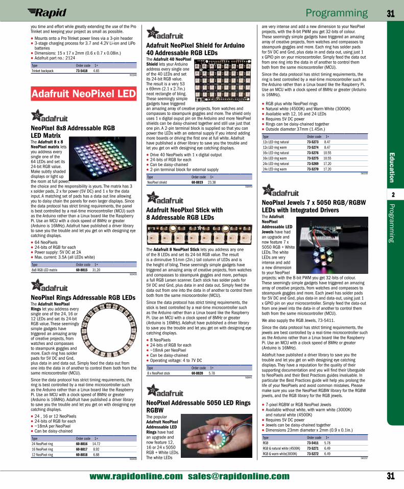
31
Programming 31Education
2
www.rapidonline.com [email protected]
Programm
ing
are very intense and add a new dimension to your NeoPixel projects, with the 8-bit PWM you get 32-bits of colour. These seemingly simple gadgets have triggered an amazing array of creative projects, from watches and compasses to steampunk goggles and more. Each ring has solder pads for 5V DC and Gnd, plus data in and data out, using just 1 x GPIO pin on your microcontroller. Simply feed the data out from one ring into the data in of another to control them both from the same microcontroller (MCU).
Since the data protocol has strict timing requirements, the ring is best controlled by a real-time microcontroller such as the Arduino rather than a Linux board like the Raspberry Pi. Use an MCU with a clock speed of 8MHz or greater (Arduino is 16MHz).
• RGB plus white NeoPixel rings• Natural white (4500K) and Warm White (3000K)• Available with 12, 16 and 24 LEDs• Requires 5V DC power• Rings can be daisy-chained together• Outside diameter 37mm (1.45in.)
Type Order code 1+12x LED ring natural 73-5273 8.4712x LED ring warm 73-5274 8.4716x LED ring natural 73-5276 10.5516x LED ring warm 73-5275 10.5524x LED ring natural 73-5269 17.2024x LED ring warm 73-5270 17.20
563205
NeoPixel Jewels 7 x 5050 RGB/RGBW LEDs with Integrated DriversThe Adafruit NeoPixel Addressable LED Jewels have had an upgrade and now feature 7 x 5050 RGB + White LEDs. The white LEDs are very intense and add a new dimension to your NeoPixel projects; with the 8-bit PWM you get 32-bits of colour. These seemingly simple gadgets have triggered an amazing array of creative projects, from watches and compasses to steampunk goggles and more. Each jewel has solder pads for 5V DC and Gnd, plus data-in and data-out, using just 1 x GPIO pin on your microcontroller. Simply feed the data-out from one jewel into the data-in of another to control them both from the same microcontroller (MCU).
We also supply the RGB Jewels, 73-5411.
Since the data protocol has strict timing requirements, the jewels are best controlled by a real-time microcontroller such as the Arduino rather than a Linux board like the Raspberry Pi. Use an MCU with a clock speed of 8MHz or greater (Arduino is 16MHz).
Adafruit have published a driver library to save you the trouble and let you get on with designing eye catching displays. They have a reputation for the quality of their supporting documentation and you will find their Uberguide to NeoPixels and their Best Practices guides invaluable. In particular the Best Practices guide will help you prolong the life of your NeoPixels and avoid common mistakes. Please make sure you use the NeoPixel RGBW library for the RGBW jewels, and the RGB library for the RGB jewels.
• 7-pixel RGBW or RGB NeoPixel Jewels• Available without white, with warm white (3000K)
and natural white (4500K) • Requires 5V DC power• Jewels can be daisy-chained together• Dimensions 23mm diameter x 2mm (0.9 x 0.1in.)
Type Order code 1+RGB 73-5411 5.78RGB & natural white (4500K) 73-5271 6.49RGB & warm white(3000K) 73-5272 6.49
563207
Adafruit NeoPixel Shield for Arduino 40 Addressable RGB LEDsThe Adafruit 40 NeoPixel Shield lets your Arduino address every single one of the 40 LEDs and set its 24-bit RGB value. The result is a very 53 x 69mm (2.1 x 2.7in.) neat rectangle of bling. These seemingly simple gadgets have triggered an amazing array of creative projects, from watches and compasses to steampunk goggles and more. The shield only uses 1 x digital ouput pin on the Arduino and more NeoPixel shields can be daisy-chained together and still use just that one pin. A 2-pin terminal block is supplied so that you can power the LEDs with an external supply if you intend adding more boards or driving the first one at full white. Adafruit have published a driver library to save you the trouble and let you get on with designing eye catching displays.
• Drive 40 NeoPixels with 1 x digital output• 24-bits of RGB for each• Can be daisy-chained• 2-pin terminal block for external supply
Type Order code 1+NeoPixel shield 60-8819 23.38
560440
Adafruit NeoPixel Stick with 8 Addressable RGB LEDs
The Adafruit 8 NeoPixel Stick lets you address any one of the 8 LEDs and set its 24-bit RGB value. The result is a diminutive 51mm (2in.) tall column of LEDs and is the height of bling. These seemingly simple gadgets have triggered an amazing array of creative projects, from watches and compasses to steampunk goggles and more, perhaps a full RGB Larsen scanner. Each stick has solder pads for 5V DC and Gnd, plus data in and data out. Simply feed the data out from one into the data in of another to control them both from the same microcontroller (MCU).
Since the data protocol has strict timing requirements, the stick is best controlled by a real-time microcontroller such as the Arduino rather than a Linux board like the Raspberry Pi. Use an MCU with a clock speed of 8MHz or greater (Arduino is 16MHz). Adafruit have published a driver library to save you the trouble and let you get on with designing eye catching displays.
• 8 NeoPixels• 24-bits of RGB for each• ~18mA per NeoPixel• Can be daisy-chained• Operating voltage: 4 to 7V DC
Type Order code 1+8 x NeoPixel stick 60-8820 5.78
560441
NeoPixel Addressable 5050 LED Rings RGBWThe popular Adafruit NeoPixel Addressable LED Rings have had an upgrade and now feature 12, 16 or 24 x 5050 RGB + White LEDs. The white LEDs
you time and effort while greatly extending the use of the Pro Trinket and keeping your project as small as possible.
• Mounts onto a Pro Trinket power lines via a 3-pin header• 3-stage charging process for 3.7 and 4.2V Li-ion and LiPo
batteries• Dimensions: 15 x 17 x 2mm (0.6 x 0.7 x 0.08in.)• Adafruit part no.: 2124
Type Order code 1+Trinket backpack 73-5418 4.65
563240
Adafruit NeoPixel LED
NeoPixel 8x8 Addressable RGB LED MatrixThe Adafruit 8 x 8 NeoPixel matrix lets you address every single one of the 64 LEDs and set its 24-bit RGB value. Make subtly shaded displays or light up the room at full power, the choice and the responsibility is yours. The matrix has 3 x solder pads, 2 x for power (5V DC) and 1 x for the data input. A matching set of pads has a data out line allowing you to daisy chain the panels for even larger displays. Since the data protocol has strict timing requirements, the panel is best controlled by a real-time microcontroller (MCU) such as the Arduino rather than a Linux board like the Raspberry Pi. Use an MCU with a clock speed of 8MHz or greater (Arduino is 16MHz). Adafruit have published a driver library to save you the trouble and let you get on with designing eye catching displays.
• 64 NeoPixels• 24-bits of RGB for each• Power supply: 5V DC at 2A• Max. current: 3.5A (all LEDs white)
Type Order code 1+8x8 RGB LED matrix 60-8815 31.20
560438
NeoPixel Rings Addressable RGB LEDsThe Adafruit NeoPixel Rings let you address every single one of the 24, 16 or 12 LEDs and set its 24-bit RGB value. These seemingly simple gadgets have triggered an amazing array of creative projects, from watches and compasses to steampunk goggles and more. Each ring has solder pads for 5V DC and Gnd, plus data in and data out. Simply feed the data out from one into the data in of another to control them both from the same microcontroller (MCU).
Since the data protocol has strict timing requirements, the ring is best controlled by a real-time microcontroller such as the Arduino rather than a Linux board like the Raspberry Pi. Use an MCU with a clock speed of 8MHz or greater (Arduino is 16MHz). Adafruit have published a driver library to save you the trouble and let you get on with designing eye catching displays.
• 24 , 16 or 12 NeoPixels• 24-bits of RGB for each• ~18mA per NeoPixel• Can be daisy-chained
Type Order code 1+24 NeoPixel ring 60-8816 14.7216 NeoPixel ring 60-8817 8.9212 NeoPixel ring 60-8818 6.88
560439
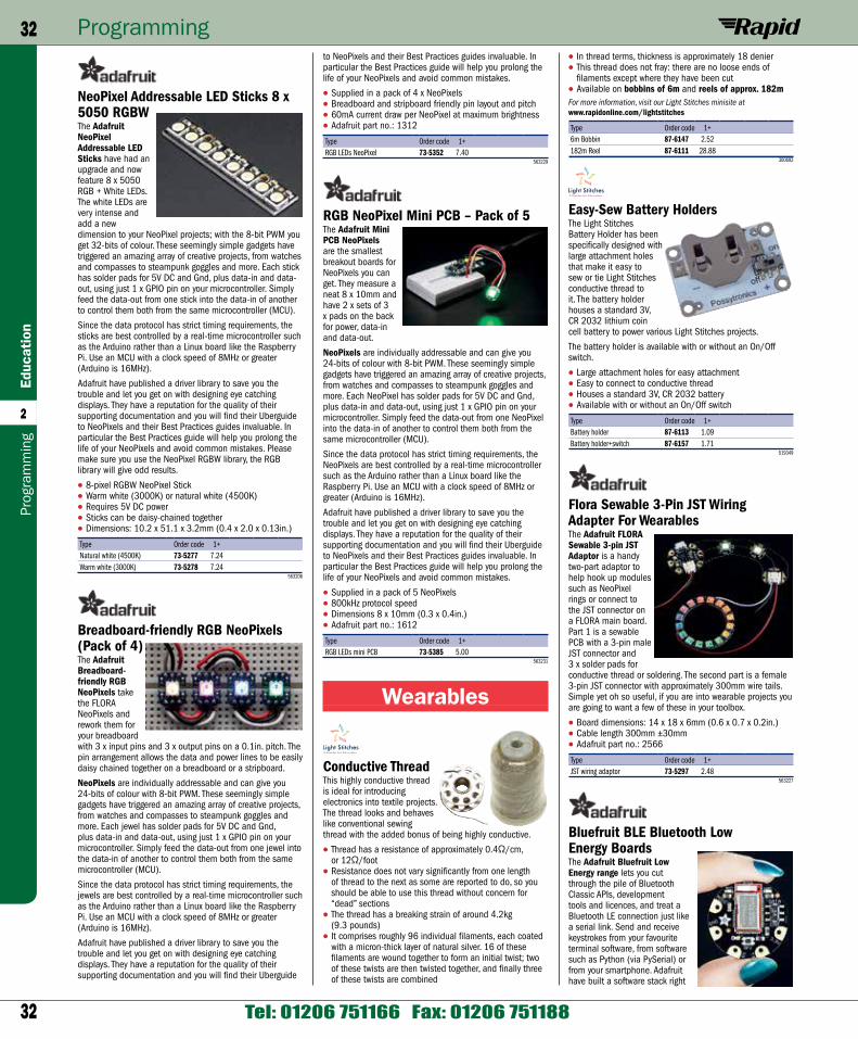
32
Programming32Ed
ucat
ion
2
Tel: 01206 751166 Fax: 01206 751188
Prog
ram
min
g
• In thread terms, thickness is approximately 18 denier• This thread does not fray: there are no loose ends of
filaments except where they have been cut• Available on bobbins of 6m and reels of approx. 182mFor more information, visit our Light Stitches minisite at www.rapidonline.com/lightstitches
Type Order code 1+6m Bobbin 87-6147 2.52182m Reel 87-6111 28.88
300692
Easy-Sew Battery HoldersThe Light Stitches Battery Holder has been specifically designed with large attachment holes that make it easy to sew or tie Light Stitches conductive thread to it. The battery holder houses a standard 3V, CR 2032 lithium coin cell battery to power various Light Stitches projects.
The battery holder is available with or without an On/Off switch.
• Large attachment holes for easy attachment• Easy to connect to conductive thread• Houses a standard 3V, CR 2032 battery• Available with or without an On/Off switch
Type Order code 1+Battery holder 87-6113 1.09Battery holder+switch 87-6157 1.71
519349
Flora Sewable 3-Pin JST Wiring Adapter For WearablesThe Adafruit FLORA Sewable 3-pin JST Adaptor is a handy two-part adaptor to help hook up modules such as NeoPixel rings or connect to the JST connector on a FLORA main board. Part 1 is a sewable PCB with a 3-pin male JST connector and 3 x solder pads for conductive thread or soldering. The second part is a female 3-pin JST connector with approximately 300mm wire tails. Simple yet oh so useful, if you are into wearable projects you are going to want a few of these in your toolbox.
• Board dimensions: 14 x 18 x 6mm (0.6 x 0.7 x 0.2in.)• Cable length 300mm ±30mm• Adafruit part no.: 2566
Type Order code 1+JST wiring adaptor 73-5297 2.48
563227
Bluefruit BLE Bluetooth Low Energy BoardsThe Adafruit Bluefruit Low Energy range lets you cut through the pile of Bluetooth Classic APIs, development tools and licences, and treat a Bluetooth LE connection just like a serial link. Send and receive keystrokes from your favourite terminal software, from software such as Python (via PySerial) or from your smartphone. Adafruit have built a software stack right
to NeoPixels and their Best Practices guides invaluable. In particular the Best Practices guide will help you prolong the life of your NeoPixels and avoid common mistakes.
• Supplied in a pack of 4 x NeoPixels• Breadboard and stripboard friendly pin layout and pitch• 60mA current draw per NeoPixel at maximum brightness• Adafruit part no.: 1312
Type Order code 1+RGB LEDs NeoPixel 73-5352 7.40
563229
RGB NeoPixel Mini PCB – Pack of 5The Adafruit Mini PCB NeoPixels are the smallest breakout boards for NeoPixels you can get. They measure a neat 8 x 10mm and have 2 x sets of 3 x pads on the back for power, data-in and data-out.
NeoPixels are individually addressable and can give you 24-bits of colour with 8-bit PWM. These seemingly simple gadgets have triggered an amazing array of creative projects, from watches and compasses to steampunk goggles and more. Each NeoPixel has solder pads for 5V DC and Gnd, plus data-in and data-out, using just 1 x GPIO pin on your microcontroller. Simply feed the data-out from one NeoPixel into the data-in of another to control them both from the same microcontroller (MCU).
Since the data protocol has strict timing requirements, the NeoPixels are best controlled by a real-time microcontroller such as the Arduino rather than a Linux board like the Raspberry Pi. Use an MCU with a clock speed of 8MHz or greater (Arduino is 16MHz).
Adafruit have published a driver library to save you the trouble and let you get on with designing eye catching displays. They have a reputation for the quality of their supporting documentation and you will find their Uberguide to NeoPixels and their Best Practices guides invaluable. In particular the Best Practices guide will help you prolong the life of your NeoPixels and avoid common mistakes.
• Supplied in a pack of 5 NeoPixels• 800kHz protocol speed• Dimensions 8 x 10mm (0.3 x 0.4in.)• Adafruit part no.: 1612
Type Order code 1+RGB LEDs mini PCB 73-5385 5.00
563231
Wearables
Conductive ThreadThis highly conductive thread is ideal for introducing electronics into textile projects. The thread looks and behaves like conventional sewing thread with the added bonus of being highly conductive.
• Thread has a resistance of approximately 0.4Ω/cm, or 12Ω/foot
• Resistance does not vary significantly from one length of thread to the next as some are reported to do, so you should be able to use this thread without concern for “dead” sections
• The thread has a breaking strain of around 4.2kg (9.3 pounds)
• It comprises roughly 96 individual filaments, each coated with a micron-thick layer of natural silver. 16 of these filaments are wound together to form an initial twist; two of these twists are then twisted together, and finally three of these twists are combined
NeoPixel Addressable LED Sticks 8 x 5050 RGBWThe Adafruit NeoPixel Addressable LED Sticks have had an upgrade and now feature 8 x 5050 RGB + White LEDs. The white LEDs are very intense and add a new dimension to your NeoPixel projects; with the 8-bit PWM you get 32-bits of colour. These seemingly simple gadgets have triggered an amazing array of creative projects, from watches and compasses to steampunk goggles and more. Each stick has solder pads for 5V DC and Gnd, plus data-in and data-out, using just 1 x GPIO pin on your microcontroller. Simply feed the data-out from one stick into the data-in of another to control them both from the same microcontroller (MCU).
Since the data protocol has strict timing requirements, the sticks are best controlled by a real-time microcontroller such as the Arduino rather than a Linux board like the Raspberry Pi. Use an MCU with a clock speed of 8MHz or greater (Arduino is 16MHz).
Adafruit have published a driver library to save you the trouble and let you get on with designing eye catching displays. They have a reputation for the quality of their supporting documentation and you will find their Uberguide to NeoPixels and their Best Practices guides invaluable. In particular the Best Practices guide will help you prolong the life of your NeoPixels and avoid common mistakes. Please make sure you use the NeoPixel RGBW library, the RGB library will give odd results.
• 8-pixel RGBW NeoPixel Stick• Warm white (3000K) or natural white (4500K)• Requires 5V DC power• Sticks can be daisy-chained together• Dimensions: 10.2 x 51.1 x 3.2mm (0.4 x 2.0 x 0.13in.)
Type Order code 1+Natural white (4500K) 73-5277 7.24Warm white (3000K) 73-5278 7.24
563206
Breadboard-friendly RGB NeoPixels (Pack of 4)The Adafruit Breadboard-friendly RGB NeoPixels take the FLORA NeoPixels and rework them for your breadboard with 3 x input pins and 3 x output pins on a 0.1in. pitch. The pin arrangement allows the data and power lines to be easily daisy chained together on a breadboard or a stripboard.
NeoPixels are individually addressable and can give you 24-bits of colour with 8-bit PWM. These seemingly simple gadgets have triggered an amazing array of creative projects, from watches and compasses to steampunk goggles and more. Each jewel has solder pads for 5V DC and Gnd, plus data-in and data-out, using just 1 x GPIO pin on your microcontroller. Simply feed the data-out from one jewel into the data-in of another to control them both from the same microcontroller (MCU).
Since the data protocol has strict timing requirements, the jewels are best controlled by a real-time microcontroller such as the Arduino rather than a Linux board like the Raspberry Pi. Use an MCU with a clock speed of 8MHz or greater (Arduino is 16MHz).
Adafruit have published a driver library to save you the trouble and let you get on with designing eye catching displays. They have a reputation for the quality of their supporting documentation and you will find their Uberguide
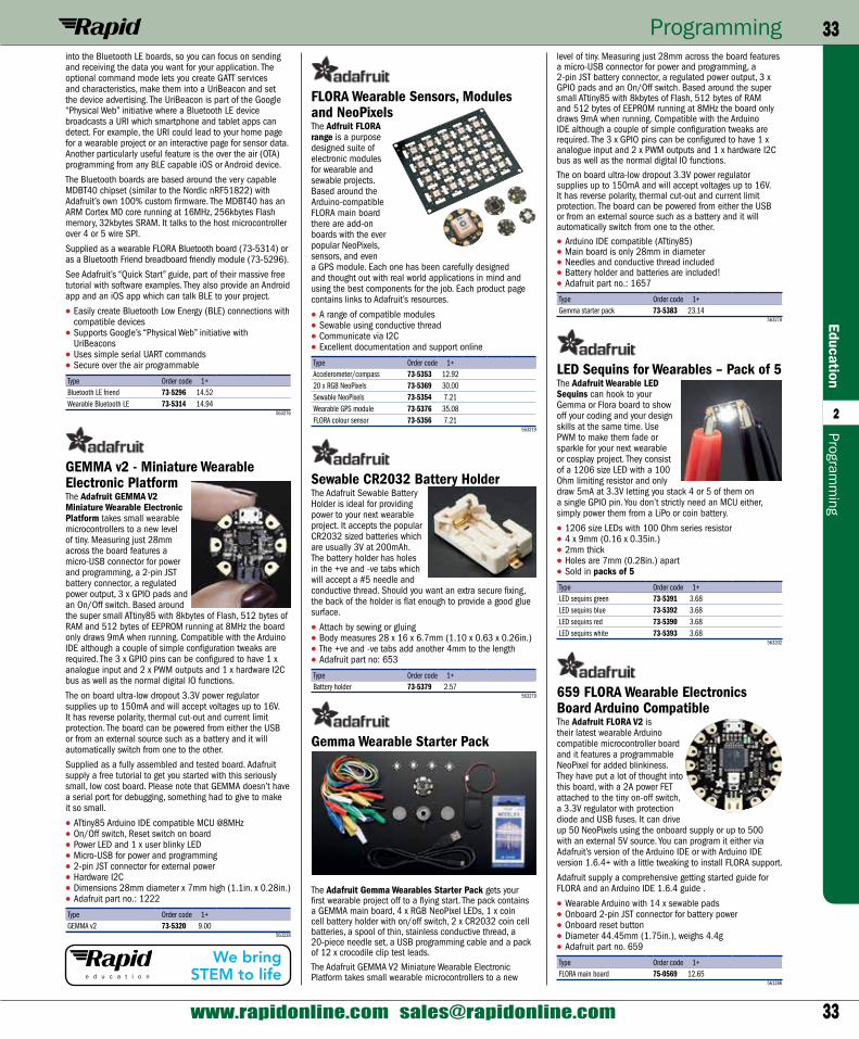
33
Programming 33Education
2
www.rapidonline.com [email protected]
Programm
ing
level of tiny. Measuring just 28mm across the board features a micro-USB connector for power and programming, a 2-pin JST battery connector, a regulated power output, 3 x GPIO pads and an On/Off switch. Based around the super small ATtiny85 with 8kbytes of Flash, 512 bytes of RAM and 512 bytes of EEPROM running at 8MHz the board only draws 9mA when running. Compatible with the Arduino IDE although a couple of simple configuration tweaks are required. The 3 x GPIO pins can be configured to have 1 x analogue input and 2 x PWM outputs and 1 x hardware I2C bus as well as the normal digital IO functions.
The on board ultra-low dropout 3.3V power regulator supplies up to 150mA and will accept voltages up to 16V. It has reverse polarity, thermal cut-out and current limit protection. The board can be powered from either the USB or from an external source such as a battery and it will automatically switch from one to the other.
• Arduino IDE compatible (ATtiny85)• Main board is only 28mm in diameter• Needles and conductive thread included• Battery holder and batteries are included!• Adafruit part no.: 1657
Type Order code 1+Gemma starter pack 73-5383 23.14
563278
LED Sequins for Wearables – Pack of 5The Adafruit Wearable LED Sequins can hook to your Gemma or Flora board to show off your coding and your design skills at the same time. Use PWM to make them fade or sparkle for your next wearable or cosplay project. They consist of a 1206 size LED with a 100 Ohm limiting resistor and only draw 5mA at 3.3V letting you stack 4 or 5 of them on a single GPIO pin. You don’t strictly need an MCU either, simply power them from a LiPo or coin battery.
• 1206 size LEDs with 100 Ohm series resistor• 4 x 9mm (0.16 x 0.35in.)• 2mm thick • Holes are 7mm (0.28in.) apart• Sold in packs of 5
Type Order code 1+LED sequins green 73-5391 3.68LED sequins blue 73-5392 3.68LED sequins red 73-5390 3.68LED sequins white 73-5393 3.68
563202
659 FLORA Wearable Electronics Board Arduino CompatibleThe Adafruit FLORA V2 is their latest wearable Arduino compatible microcontroller board and it features a programmable NeoPixel for added blinkiness. They have put a lot of thought into this board, with a 2A power FET attached to the tiny on-off switch, a 3.3V regulator with protection diode and USB fuses. It can drive up 50 NeoPixels using the onboard supply or up to 500 with an external 5V source. You can program it either via Adafruit’s version of the Arduino IDE or with Arduino IDE version 1.6.4+ with a little tweaking to install FLORA support.
Adafruit supply a comprehensive getting started guide for FLORA and an Arduino IDE 1.6.4 guide .
• Wearable Arduino with 14 x sewable pads• Onboard 2-pin JST connector for battery power• Onboard reset button• Diameter 44.45mm (1.75in.), weighs 4.4g • Adafruit part no. 659
Type Order code 1+FLORA main board 75-0569 12.65
561286
FLORA Wearable Sensors, Modules and NeoPixelsThe Adfruit FLORA range is a purpose designed suite of electronic modules for wearable and sewable projects. Based around the Arduino-compatible FLORA main board there are add-on boards with the ever popular NeoPixels, sensors, and even a GPS module. Each one has been carefully designed and thought out with real world applications in mind and using the best components for the job. Each product page contains links to Adafruit’s resources.
• A range of compatible modules• Sewable using conductive thread• Communicate via I2C• Excellent documentation and support online
Type Order code 1+Accelerometer/compass 73-5353 12.9220 x RGB NeoPixels 73-5369 30.00Sewable NeoPixels 73-5354 7.21Wearable GPS module 73-5376 35.08FLORA colour sensor 73-5356 7.21
563219
Sewable CR2032 Battery HolderThe Adafruit Sewable Battery Holder is ideal for providing power to your next wearable project. It accepts the popular CR2032 sized batteries which are usually 3V at 200mAh. The battery holder has holes in the +ve and -ve tabs which will accept a #5 needle and conductive thread. Should you want an extra secure fixing, the back of the holder is flat enough to provide a good glue surface.
• Attach by sewing or gluing• Body measures 28 x 16 x 6.7mm (1.10 x 0.63 x 0.26in.)• The +ve and -ve tabs add another 4mm to the length• Adafruit part no: 653
Type Order code 1+Battery holder 73-5379 2.57
563279
Gemma Wearable Starter Pack
The Adafruit Gemma Wearables Starter Pack gets your first wearable project off to a flying start. The pack contains a GEMMA main board, 4 x RGB NeoPixel LEDs, 1 x coin cell battery holder with on/off switch, 2 x CR2032 coin cell batteries, a spool of thin, stainless conductive thread, a 20-piece needle set, a USB programming cable and a pack of 12 x crocodile clip test leads.
The Adafruit GEMMA V2 Miniature Wearable Electronic Platform takes small wearable microcontrollers to a new
into the Bluetooth LE boards, so you can focus on sending and receiving the data you want for your application. The optional command mode lets you create GATT services and characteristics, make them into a UriBeacon and set the device advertising. The UriBeacon is part of the Google “Physical Web” initiative where a Bluetooth LE device broadcasts a URI which smartphone and tablet apps can detect. For example, the URI could lead to your home page for a wearable project or an interactive page for sensor data. Another particularly useful feature is the over the air (OTA) programming from any BLE capable iOS or Android device.
The Bluetooth boards are based around the very capable MDBT40 chipset (similar to the Nordic nRF51822) with Adafruit’s own 100% custom firmware. The MDBT40 has an ARM Cortex M0 core running at 16MHz, 256kbytes Flash memory, 32kbytes SRAM. It talks to the host microcontroller over 4 or 5 wire SPI.
Supplied as a wearable FLORA Bluetooth board (73-5314) or as a Bluetooth Friend breadboard friendly module (73-5296).
See Adafruit’s “Quick Start” guide, part of their massive free tutorial with software examples. They also provide an Android app and an iOS app which can talk BLE to your project.
• Easily create Bluetooth Low Energy (BLE) connections with compatible devices
• Supports Google’s “Physical Web” initiative with UriBeacons
• Uses simple serial UART commands • Secure over the air programmable
Type Order code 1+Bluetooth LE friend 73-5296 14.52Wearable Bluetooth LE 73-5314 14.94
563276
GEMMA v2 - Miniature Wearable Electronic PlatformThe Adafruit GEMMA V2 Miniature Wearable Electronic Platform takes small wearable microcontrollers to a new level of tiny. Measuring just 28mm across the board features a micro-USB connector for power and programming, a 2-pin JST battery connector, a regulated power output, 3 x GPIO pads and an On/Off switch. Based around the super small ATtiny85 with 8kbytes of Flash, 512 bytes of RAM and 512 bytes of EEPROM running at 8MHz the board only draws 9mA when running. Compatible with the Arduino IDE although a couple of simple configuration tweaks are required. The 3 x GPIO pins can be configured to have 1 x analogue input and 2 x PWM outputs and 1 x hardware I2C bus as well as the normal digital IO functions.
The on board ultra-low dropout 3.3V power regulator supplies up to 150mA and will accept voltages up to 16V. It has reverse polarity, thermal cut-out and current limit protection. The board can be powered from either the USB or from an external source such as a battery and it will automatically switch from one to the other.
Supplied as a fully assembled and tested board. Adafruit supply a free tutorial to get you started with this seriously small, low cost board. Please note that GEMMA doesn’t have a serial port for debugging, something had to give to make it so small.
• ATtiny85 Arduino IDE compatible MCU @8MHz• On/Off switch, Reset switch on board• Power LED and 1 x user blinky LED• Micro-USB for power and programming• 2-pin JST connector for external power• Hardware I2C• Dimensions 28mm diameter x 7mm high (1.1in. x 0.28in.)• Adafruit part no.: 1222
Type Order code 1+GEMMA v2 73-5320 9.00
563228
We bring STEM to life
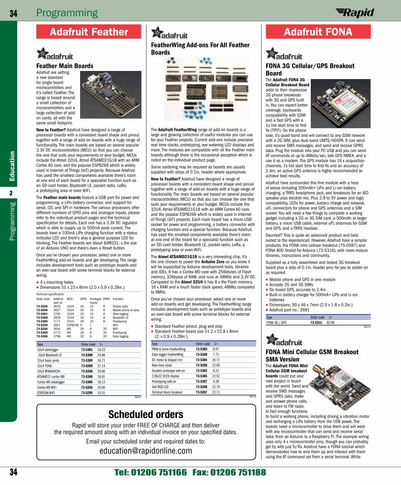
34
Programming34Ed
ucat
ion
2
Tel: 01206 751166 Fax: 01206 751188
Prog
ram
min
g
Adafruit FONA
FONA 3G Cellular/GPS Breakout BoardThe Adafruit FONA 3G Cellular Breakout Board adds to their impressive 2G phone breakouts with 3G and GPS built in. You can expect better coverage, backwards compatibility with GSM and a fast GPS with a 1s hot start time to first fix (TTFF). On the phone side, it’s quad-band and will connect to any GSM network with a 2G SIM, plus dual-band UMTS/HDSPA. It can send and receive SMS messages, and send and receive GPRS data. Plug the module into your PC USB and you can send AT commands at up to 4Mbits/sec, talk GPS NMEA, and a use it as a modem. The GPS module has 16 x acquisition channels, 1s hot start time to first fix and an accuracy of 2.4m; an active GPS antenna is highly recommended to achieve best results.
Adafruit have surrounded this fine module with a host of extras including 500mAh+ LiPo and Li-ion battery charging, a TRRS headphone jack, and breakouts for an 8Ω speaker plus electret mic. Plus 2.8 to 5V power and logic compatibility, LEDs for power, battery charge and network, uFL connectors for phone and GPS antennas and a SIM socket. You will need a few things to complete a working gadget including a 2G or 3G SIM card, a 500mAh or larger battery, a micro USB cable, external uFL antennas for GSM and GPS, and a TRRS headset.
Daunted? This is quite an advanced product and best suited to the experienced. However, Adafruit have a simpler products, the FONA mini cellular breakout (75-0587) and FONA 800 Shield for Arduino (73-5316), with more mature libraries, instructions and community.
Supplied as a fully assembled and tested 3G breakout board plus a strip of 0.1in. header pins for you to solder on as required.
• Mobile phone and GPS in one module• Accepts 2G and 3G SIMs• On board GPS, accurate to 2.4m• Built-in battery charger for 500mA+ LiPo and Li-ion
batteries• Dimensions: 50 x 46 x 7mm (2.0 x 1.8 x 0.3in.)• Adafruit part no.: 2691
Type Order code 1+FONA 3G / GPS 73-5311 62.06
563272
FONA Mini Cellular GSM Breakout SMA VersionThe Adafruit FONA Mini Cellular GSM breakout boards could put your next project in touch with the world. Send and receive SMS messages and GPRS data, make and answer phone calls, and listen to FM radio. In fact enough functions to build a working phone, including driving a vibration motor and recharging a LiPo battery from the USB power. The boards need a microcontroller to drive them and will work with any microcontroller that can send and receive serial data, from an Arduino to a Raspberry Pi. The example wiring uses only 4 x microcontroller pins, though you can probably get by with just Tx/Rx. Adafruit have a FONA tutorial which demonstrates how to wire them up and interact with them using the AT command set from a serial terminal. While
FeatherWing Add-ons For All Feather Boards
The Adafruit FeatherWing range of add-on boards is a large and growing collection of useful modules you can use for your Feather projects. Current add-ons include precision real-time clocks, prototyping, eye-watering LED displays and more. The modules are compatible with all the Feather main boards although there is the occasional exception which is noted on the individual product page.
Some soldering may be required as boards are usually supplied with strips of 0.1in. header where appropriate.
New to Feather? Adafruit have designed a range of processor boards with a consistent board shape and pinout together with a range of add-on boards with a huge range of functionality. The main boards are based on several popular microcontrollers (MCU) so that you can choose the one that suits your requirements or your budget. MCUs include the 32U4, Atmel ATSAMD21G18 with an ARM Cortex A0 core, and the popular ESP8266 which is widely used in Internet of Things (IoT) projects. Each main board has a micro-USB socket for power and programming, a battery connector with charging function and a special function. Because Adafruit has used the smallest components available there’s room at one end of the board for a specialist function such as an SD-card holder, Bluetooth LE, packet radio, LoRa, a prototyping area or even WiFi.
The Atmel ATSAMD21G18 is a very interesting chip, it’s the one chosen to power the Arduino Zero so you know it will be supported by Arduino development tools, libraries and IDEs. It has a Cortex M0 core with 256kbytes of Flash memory, 32Kbytes of RAM, and runs at 48MHz and 3.3V DC. Compared to the Atmel 32U4 it has 8 x the Flash memory, 16 x RAM and a much faster clock speed, 48Mhz compared to 8MHz.
Once you’ve chosen your processor, select one or more add-on boards and get developing. The FeatherWing range includes development tools such as prototype boards and an over-size board with screw terminal blocks for external wiring.
• Standard Feather pinout, plug and play• Standard Feather board size 51.2 x 22.8 x 8mm
(2. x 0.9 x 0.28in.)
Type Order code 1+PWM & Servo FeatherWing 73-5303 8.57Data logger FeatherWing 73-5268 7.71DC motor & stepper ctrl. 73-5304 16.71Real-time clock 73-5258 12.05Doubler prototype add-on 73-5302 6.21128x32 OLED display 73-5305 12.52Prototyping add-on 73-5307 4.394x8 RGB LED 73-5298 12.79Terminal block breakout 73-5267 12.71
563216
Adafruit Feather
Feather Main BoardsAdafruit are setting a new standard for single board microcontrollers and it’s called Feather. The range is based around a small collection of microcontrollers and a large collection of add-on cards, all with the same small footprint.
New to Feather? Adafruit have designed a range of processor boards with a consistent board shape and pinout together with a range of add-on boards with a huge range of functionality. The main boards are based on several popular 3.3V DC microcontrollers (MCU) so that you can choose the one that suits your requirements or your budget. MCUs include the Atmel 32U4, Atmel ATSAMD21G18 with an ARM Cortex A0 core, and the popular ESP8266 which is widely used in Internet of Things (IoT) projects. Because Adafruit has used the smallest components available there’s room at one end of each board for a specialist function such as an SD-card holder, Bluetooth LE, packet radio, LoRa, a prototyping area or even WiFi.
The Feather main boards feature a USB port for power and programming, a LiPo battery connector, and support for serial, I2C and SPI in hardware. The various processors offer different numbers of GPIO pins and analogue inputs, please refer to the individual product pages and the technical specification for details. Each one has a 3.3V DC regulator which is able to supply up to 500mA peak current. The boards have a 100mA LiPo charging function with a status indicator LED and there’s also a general purpose LED for blinking. The Feather boards are about ⅓ x the size of an Arduino UNO and there’s even a Reset button.
Once you’ve chosen your processor, select one or more FeatherWing add-on boards and get developing. The range includes development tools such as prototype boards and an over-size board with screw terminal blocks for external wiring.
• 4 x mounting holes• Dimensions 51 x 23 x 8mm (2.0 x 0.9 x 0.28in.)Technical specificationOrder code Adafruit
part no.MCU GPIO Analogue
InputsPWM Function
73-5250 3076 32U4 20 10 8 Packet radio73-5260 3027 32U4 20 10 8 Mobile phone & data73-5301 2795 32U4 20 10 8 Data logging73-5308 2829 32U4 20 10 8 Bluetooth LE73-5309 2771 32U4 20 10 8 Prototyping73-5299 2821 ESP8266 9 1 - WiFi73-5256 3061 M0 20 6 20 WiFi73-5300 2772 M0 20 6 20 Prototyping73-5306 2796 M0 20 6 20 Data logging
Type Order code 1+32u4 datalogger 73-5301 18.23 32u4 Bluetooth LE 73-5308 24.8632u4 basic proto 73-5309 16.7132u4 FONA 73-5260 37.1432u4 RFM69HCW 73-5250 20.86ATSAMD21 cortex M0 73-5300 16.81Cortex M0 datalogger 73-5306 18.12Cortex M0 WiFi 73-5256 29.00ESP8266 WiFi 73-5299 15.51
563217
Scheduled ordersRapid will store your order FREE OF CHARGE and then deliver
the required amount along with an individual invoice on your specified dates.Email your scheduled order and required dates to:
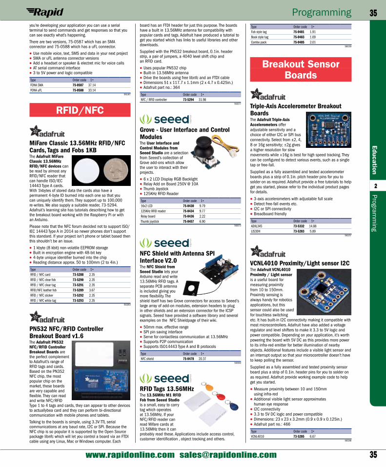
35
Programming 35Education
2
www.rapidonline.com [email protected]
Programm
ing
Type Order code 1+Fob style tag 75-0481 1.91Book style tag 75-0483 1.09Combo pack 75-0485 2.01
560359
Breakout Sensor Boards
Triple-Axis Accelerometer Breakout BoardsThe Adafruit Triple-Axis Accelerometers offer adjustable sensitivity and a choice of either I2C or SPI bus connectivity. Select from ±2, 4, 8 or 16g sensitivity; ±2g gives a higher resolution for slow movements while ±16g is best for high speed tracking. They can be configured to detect various events, such as a single tap or free-fall.
Supplied as a fully assembled and tested accelerometer boards plus a strip of 0.1in. pitch header pins for you to solder on as required. Adafruit provide a free tutorials to help get you started, please refer to the individual product pages for details.
• 3-axis accelerometers with adjustable full scale• Detect free-fall events etc.• I2C or SPI connectivity• Breadboard friendly
Type Order code 1+ADXL345 73-5332 14.88LIS3DH 73-5283 5.89
563257
VCNL4010 Proximity/Light sensor I2CThe Adafruit VCNL4010 Proximity / Light sensor is a useful board for measuring proximity from 10 to 150mm. Proximity sensing is always handy for robotics applications, but this sensor could also be used for touchless switching etc. It has built-in I2C connectivity making it compatible with most microcontrollers. Adafruit have also added a voltage regulator and level shifters to make it 3.3 to 5V logic and power compatible. Depending on your application, it’s worth powering the board with 5V DC as this provides more power to its infra-red emitter for better illumination of nearby objects. Additional features include a visible light sensor and an interrupt output so that your microcontroller doesn’t have to keep polling the sensor.
Supplied as a fully assembled and tested proximity sensor board plus a strip of 0.1in. header pins for you to solder on as required. Adafruit provide working example code to help get you started.
• Measure proximity between 10 and 150mm using infra-red
• Additional visible light sensor approximates human eye response
• I2C connectivity• 3.3 to 5V DC logic and power compatible• Dimensions: 23 x 23 x 3.2mm (0.9 x 0.9 x 0.125in.)• Adafruit part no.: 466
Type Order code 1+VCNL4010 73-5285 6.67
563266
board has an FTDI header for just this purpose. The boards have a built in 13.56MHz antenna for compatibility with popular cards and tags. Adafruit have produced a tutorial to get you started which has links to useful libraries and other downloads.
Supplied with the PN532 breakout board, 0.1in. header strip, a pair of jumpers, a 4040 level shift chip and an RFID card.
• Uses popular PN532 chip• Built-in 13.56MHz antenna• Drive the boards using free libnfc and an FTDI cable• Dimensions 51 x 117.7 x 1.1mm (2 x 4.7 x 0.425in.)• Adafruit part no.: 364
Type Order code 1+NFC / RFID controller 73-5294 31.98
563277
Grove - User Interface and Control ModulesThe User Interface and Control Modules from Seeed Studio are a selection from Seeed’s collection of Grove add-ons which allow the user to interact with their projects.
• 6 x 2 LCD Display RGB Backlight• Relay Add on Board 250V @ 10A• Thumb Joystick• 125KHz RFID Reader
Type Order code 1+16x2 LCD 75-0430 9.79125KHz RFID reader 75-0434 9.77Relay board 75-0436 2.22Thumb joystick 75-0457 6.90
560373
NFC Shield with Antenna SPI Interface V2.0The NFC Shield from Seeed Studio lets your Arduino read and write 13.56MHz RFID tags. A separate PCB antenna is included giving you more flexibility. The shield itself has two Grove connectors for access to Seeed’s large array of add-on modules, extension headers to plug in other shields and an extension connector for the ICSP signals. Seeed have provided a software library and several examples on the NFC Shieldpage of their wiki.
• 50mm max. effective range• SPI pin saving interface• Serve for contactless communication at 13.56MHz• Supports P2P communication• Supports ISO14443 Type A and B protocols
Type Order code 1+NFC shield 75-0478 20.37
560360
RFID Tags 13.56MHzThe 13.56MHz M1 RFID Fob from Seeed Studio is a small, easy to carry tag which operates at 13.56MHz. If your NFC/RFID reader can read Mifare cards at 13.56MHz then it can probably read these. Applications include access control, customer identification , object tracking and others.
you’re developing your application you can use a serial terminal to send commands and get responses so that you can see exactly what’s happening.
There are two versions, 75-0587 which has an SMA connector and 75-0588 which has a uFL connector.
• Use mobile voice, text, SMS and data in your next project• SMA or uFL antenna connector versions• Add a headset or speaker & electret mic for voice calls• AT serial command interface• 3 to 5V power and logic compatible
Type Order code 1+FONA SMA 75-0587 37.14FONA uFL 75-0588 33.14
561307
RFID/NFC
MiFare Classic 13.56MHz RFID/NFC Cards, Tags and Fobs 1KBThe Adafruit MiFare Classic 13.56MHz RFID/NFC devices can be read by almost any RFID/NFC reader that can handle ISO/IEC 14443 Type A cards. With 1kbytes of stored data the cards also have a permanent 4-byte ID burned into each one so that you can uniquely identify them. They support up to 100,000 re-writes. We also supply a suitable reader, 73-5294. Adafruit’s learning site has tutorials describing how to get the breakout board working with the Raspberry Pi or with an Arduino.
Please note that the NFC forum decided not to support ISO/IEC 14443 Type A in 2014 so newer phones don’t support this standard. If your project isn’t phone or tablet based then this shouldn’t be an issue.
• 1 kbyte (8 kbit) non-volatile EEPROM storage• Built in encryption engine with 48-bit key• 4-byte unique identifier burned into the chip• Reading distance approx. 50 to 100mm (2 to 4in.)
Type Order code 1+RFID / NFC card 73-5288 2.35RFID / NFC clear fob 73-5290 2.35RFID / NFC clear tag 73-5291 2.35RFID/NFC leather fob 73-5289 3.67RFID / NFC sticker 73-5292 2.35RFID / NFC white tag 73-5293 2.35
563203
PN532 NFC/RFID Controller Breakout Board v1.6The Adafruit PN532 NFC/RFID Controller Breakout Boards are the perfect complement to Adafruit’s range of RFID tags and cards. Based on the PN352 NFC chip, the most popular chip on the market, these boards are very capable and flexible. They can read and write NFC/RFID Type 1 to 4 tags and cards, they can appear to other devices to actuallybea card and they can perform bi-directional communication with mobile phones and tablets.
Talking to the boards is simple, using 3.3V TTL serial communications at any baud rate, I2C or SPI. Because the NFC chip is so popular it is supported by the Open Source package libnfc which will let you control a board via an FTDI cable using any Linux, Mac or Windows computer. Each
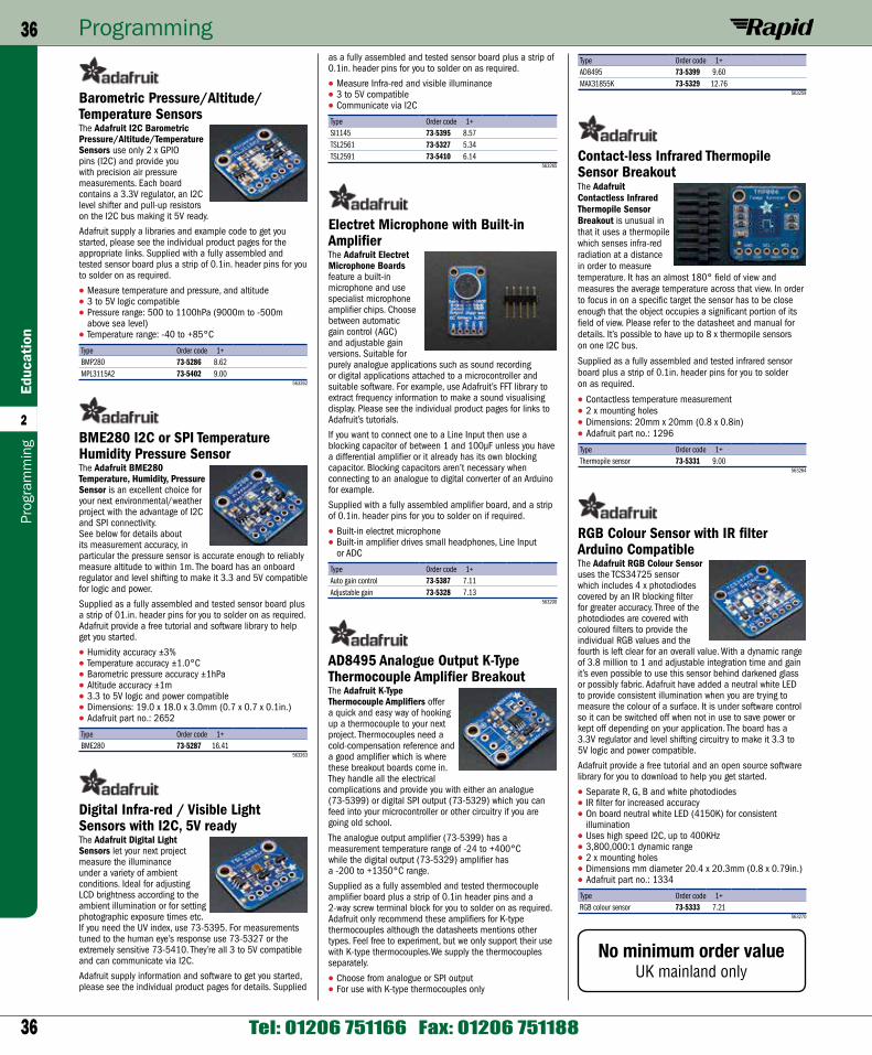
36
Programming36Ed
ucat
ion
2
Tel: 01206 751166 Fax: 01206 751188
Prog
ram
min
g
Type Order code 1+AD8495 73-5399 9.60MAX31855K 73-5329 12.76
563259
Contact-less Infrared Thermopile Sensor BreakoutThe Adafruit Contactless Infrared Thermopile Sensor Breakout is unusual in that it uses a thermopile which senses infra-red radiation at a distance in order to measure temperature. It has an almost 180° field of view and measures the average temperature across that view. In order to focus in on a specific target the sensor has to be close enough that the object occupies a significant portion of its field of view. Please refer to the datasheet and manual for details. It’s possible to have up to 8 x thermopile sensors on one I2C bus.
Supplied as a fully assembled and tested infrared sensor board plus a strip of 0.1in. header pins for you to solder on as required.
• Contactless temperature measurement• 2 x mounting holes• Dimensions: 20mm x 20mm (0.8 x 0.8in)• Adafruit part no.: 1296
Type Order code 1+Thermopile sensor 73-5331 9.00
563264
RGB Colour Sensor with IR filter Arduino CompatibleThe Adafruit RGB Colour Sensor uses the TCS34725 sensor which includes 4 x photodiodes covered by an IR blocking filter for greater accuracy. Three of the photodiodes are covered with coloured filters to provide the individual RGB values and the fourth is left clear for an overall value. With a dynamic range of 3.8 million to 1 and adjustable integration time and gain it’s even possible to use this sensor behind darkened glass or possibly fabric. Adafruit have added a neutral white LED to provide consistent illumination when you are trying to measure the colour of a surface. It is under software control so it can be switched off when not in use to save power or kept off depending on your application. The board has a 3.3V regulator and level shifting circuitry to make it 3.3 to 5V logic and power compatible.
Adafruit provide a free tutorial and an open source software library for you to download to help you get started.
• Separate R, G, B and white photodiodes• IR filter for increased accuracy• On board neutral white LED (4150K) for consistent
illumination• Uses high speed I2C, up to 400KHz• 3,800,000:1 dynamic range• 2 x mounting holes• Dimensions mm diameter 20.4 x 20.3mm (0.8 x 0.79in.)• Adafruit part no.: 1334
Type Order code 1+RGB colour sensor 73-5333 7.21
563270
as a fully assembled and tested sensor board plus a strip of 0.1in. header pins for you to solder on as required.
• Measure Infra-red and visible illuminance• 3 to 5V compatible• Communicate via I2C
Type Order code 1+SI1145 73-5395 8.57TSL2561 73-5327 5.34TSL2591 73-5410 6.14
563265
Electret Microphone with Built-in AmplifierThe Adafruit Electret Microphone Boards feature a built-in microphone and use specialist microphone amplifier chips. Choose between automatic gain control (AGC) and adjustable gain versions. Suitable for purely analogue applications such as sound recording or digital applications attached to a microcontroller and suitable software. For example, use Adafruit’s FFT library to extract frequency information to make a sound visualising display. Please see the individual product pages for links to Adafruit’s tutorials.
If you want to connect one to a Line Input then use a blocking capacitor of between 1 and 100µF unless you have a differential amplifier or it already has its own blocking capacitor. Blocking capacitors aren’t necessary when connecting to an analogue to digital converter of an Arduino for example.
Supplied with a fully assembled amplifier board, and a strip of 0.1in. header pins for you to solder on if required.
• Built-in electret microphone• Built-in amplifier drives small headphones, Line Input
or ADC
Type Order code 1+Auto gain control 73-5387 7.11Adjustable gain 73-5328 7.13
563200
AD8495 Analogue Output K-Type Thermocouple Amplifier BreakoutThe Adafruit K-Type Thermocouple Amplifiers offer a quick and easy way of hooking up a thermocouple to your next project. Thermocouples need a cold-compensation reference and a good amplifier which is where these breakout boards come in. They handle all the electrical complications and provide you with either an analogue (73-5399) or digital SPI output (73-5329) which you can feed into your microcontroller or other circuitry if you are going old school.
The analogue output amplifier (73-5399) has a measurement temperature range of -24 to +400°C while the digital output (73-5329) amplifier has a -200 to +1350°C range.
Supplied as a fully assembled and tested thermocouple amplifier board plus a strip of 0.1in header pins and a 2-way screw terminal block for you to solder on as required. Adafruit only recommend these amplifiers for K-type thermocouples although the datasheets mentions other types. Feel free to experiment, but we only support their use with K-type thermocouples.We supply the thermocouples separately.
• Choose from analogue or SPI output• For use with K-type thermocouples only
Barometric Pressure/Altitude/ Temperature SensorsThe Adafruit I2C Barometric Pressure/Altitude/Temperature Sensors use only 2 x GPIO pins (I2C) and provide you with precision air pressure measurements. Each board contains a 3.3V regulator, an I2C level shifter and pull-up resistors on the I2C bus making it 5V ready.
Adafruit supply a libraries and example code to get you started, please see the individual product pages for the appropriate links. Supplied with a fully assembled and tested sensor board plus a strip of 0.1in. header pins for you to solder on as required.
• Measure temperature and pressure, and altitude • 3 to 5V logic compatible • Pressure range: 500 to 1100hPa (9000m to -500m
above sea level) • Temperature range: -40 to +85°C
Type Order code 1+BMP280 73-5286 8.62MPL3115A2 73-5402 9.00
563262
BME280 I2C or SPI Temperature Humidity Pressure SensorThe Adafruit BME280 Temperature, Humidity, Pressure Sensor is an excellent choice for your next environmental/weather project with the advantage of I2C and SPI connectivity. See below for details about its measurement accuracy, in particular the pressure sensor is accurate enough to reliably measure altitude to within 1m. The board has an onboard regulator and level shifting to make it 3.3 and 5V compatible for logic and power.
Supplied as a fully assembled and tested sensor board plus a strip of 01.in. header pins for you to solder on as required. Adafruit provide a free tutorial and software library to help get you started.
• Humidity accuracy ±3%• Temperature accuracy ±1.0°C• Barometric pressure accuracy ±1hPa• Altitude accuracy ±1m• 3.3 to 5V logic and power compatible• Dimensions: 19.0 x 18.0 x 3.0mm (0.7 x 0.7 x 0.1in.) • Adafruit part no.: 2652
Type Order code 1+BME280 73-5287 16.41
563263
Digital Infra-red / Visible Light Sensors with I2C, 5V readyThe Adafruit Digital Light Sensors let your next project measure the illuminance under a variety of ambient conditions. Ideal for adjusting LCD brightness according to the ambient illumination or for setting photographic exposure times etc. If you need the UV index, use 73-5395. For measurements tuned to the human eye’s response use 73-5327 or the extremely sensitive 73-5410. They’re all 3 to 5V compatible and can communicate via I2C.
Adafruit supply information and software to get you started, please see the individual product pages for details. Supplied
No minimum order valueUK mainland only