product specification - irb 1100/crb 1100
TRANSCRIPT
ROBOTICS
Product specificationIRB 1100/CRB 1100

Trace back information:Workspace RW 7-4 version a8Checked in 2021-11-01Skribenta version 5.4.005
Product specificationIRB 1100-4/0.475IRB 1100-4/0.58
CRB 1100-4/0.475CRB 1100-4/0.58
OmniCore
Document ID: 3HAC064993-001Revision: H
© Copyright 2019-2021 ABB. All rights reserved.Specifications subject to change without notice.
The information in this manual is subject to change without notice and should notbe construed as a commitment by ABB. ABB assumes no responsibility for any errorsthat may appear in this manual.Except as may be expressly stated anywhere in this manual, nothing herein shall beconstrued as any kind of guarantee or warranty by ABB for losses, damage to personsor property, fitness for a specific purpose or the like.In no event shall ABB be liable for incidental or consequential damages arising fromuse of this manual and products described herein.This manual and parts thereof must not be reproduced or copied without ABB'swritten permission.Keep for future reference.Additional copies of this manual may be obtained from ABB.
Original instructions.
© Copyright 2019-2021 ABB. All rights reserved.Specifications subject to change without notice.
Table of contents7Overview of this specification ..........................................................................................................
91 Description91.1 Structure .........................................................................................................91.1.1 Introduction ............................................................................................
131.1.2 Different robot versions ............................................................................141.1.3 Definition of version designations ...............................................................141.1.3.1 Technical data ............................................................................221.2 Standards ........................................................................................................221.2.1 Applicable standards ...............................................................................241.3 Installation .......................................................................................................241.3.1 Introduction to installation .........................................................................251.3.2 Assembling the manipulator ......................................................................261.3.3 Installation the lead-through device ............................................................281.3.4 Installation the laser scanner .....................................................................301.3.5 Indicator lamp .........................................................................................321.4 Calibration and references ..................................................................................321.4.1 Calibration methods .................................................................................341.4.2 Synchronization marks and synchronization position for axes .........................351.4.3 Fine calibration .......................................................................................371.4.4 Absolute Accuracy calibration ...................................................................391.5 Load diagrams ..................................................................................................391.5.1 Introduction ............................................................................................401.5.2 Diagrams ...............................................................................................
441.5.3 Maximum load and moment of inertia for full and limited axis 5 (center line down)
movement ..............................................................................................461.5.4 Wrist torque ...........................................................................................471.5.5 Maximum TCP acceleration .......................................................................481.6 Fitting equipment to the robot ..............................................................................511.7 Maintenance and troubleshooting .........................................................................521.8 Robot motion ....................................................................................................521.8.1 Working range .......................................................................................571.8.2 Axes with restricted working range .............................................................571.8.2.1 Adjusting the working range ..........................................................581.8.2.2 Mechanically restricting the working range .......................................591.8.3 Performance according to ISO 9283 ............................................................601.8.4 Velocity .................................................................................................611.8.5 Robot stopping distances and times ...........................................................621.9 Customer connections .......................................................................................
652 Specification of variants and options652.1 Introduction to variants and options ......................................................................662.2 Manipulator ......................................................................................................702.3 Floor cables .....................................................................................................
713 Accessories
73Index
Product specification - IRB 1100/CRB 1100 53HAC064993-001 Revision: H
© Copyright 2019-2021 ABB. All rights reserved.
Table of contents

This page is intentionally left blank
Overview of this specificationAbout this product specification
This product specification describes the performance of the manipulator or acomplete family of manipulators in terms of:
• The structure and dimensional prints• The fulfilment of standards, safety, and operating equipment• The load diagrams, mounting or extra equipment, the motion, and the robot
reach• The specification of available variants and options
The specification covers the manipulator using the OmniCore controller.
UsageProduct specifications are used to find data and performance about the product,for example to decide which product to buy. How to handle the product is describedin the product manual.The specification is intended for:
• Product managers and product personnel• Sales and marketing personnel• Order and customer service personnel
ReferencesDocumentation referred to in the manual, is listed in the table below.
Document IDDocument name
3HAC065034-001Product specification - OmniCore C line
3HAC079823-001Product specification - OmniCore E line
3HAC060860-001Product manual - OmniCore C30
3HAC073706-001Product manual - OmniCore C90XT
3HAC079399-001Product manual - OmniCore E10
3HAC065036-001Operating manual - OmniCore
3HAC066554-001Application manual - Controller software OmniCore
3HAC064992-001Product manual - IRB 1100
3HAC078007-001Product manual - CRB 1100
3HAC064994-001Product manual, spare parts - IRB 1100
3HAC078009-001Product manual, spare parts - CRB 1100
3HAC066314-009Circuit diagram - IRB 1100
3HAC076518-003Circuit diagram - CRB 1100
RevisionsDescriptionRevision
First edition.A
Continues on next pageProduct specification - IRB 1100/CRB 1100 73HAC064993-001 Revision: H
© Copyright 2019-2021 ABB. All rights reserved.
Overview of this specification
DescriptionRevision
Published in release 19D. The following updates are done in this revision:• Minor changes.• Change the description of 3308-1 and 3350-400.
B
Published in release 20B. The following updates are done in this revision:• Change the product data of Absolute Accuracy calibration.• Supported controller OmniCore C90XT is added.
C
Published in release 20C. The following updates are done in this revision:• Protection class IP67 (option 3350-670) and protection type Clean
Room (option 3351-4) added.• 209-2 ABB white standard added.
D
Published in release 20D. The following updates are done in this revision:• Safety Lamp 3308-1 removed.• Max Armload added.• Warranty section updated.
E
Published in release 21A. The following updates are done in this revision:• Added CRB 1100.• Minor changes.• Maximum TCP acceleration added.• Performance according to ISO 9283 updated.• Updated diameter value of the air hoses inside the robot.
F
Published in release 21B. The following updates are done in this revision:• Text regarding fastener quality is updated.• Updated the description of IP67 protection.• Added a note to remind users that mechanical stop locations
cannot be adjusted. See Adjusting the working range on page57.• Removed Axis resolution.• Added a note in manipulator protection chapter.
G
Published in release 21C. The following updates are done in this revision:• Updated the description for 3300-20/21.• Updated the description for 3203-x.• Supported controller OmniCore E10 is added.
H
8 Product specification - IRB 1100/CRB 11003HAC064993-001 Revision: H
© Copyright 2019-2021 ABB. All rights reserved.
Overview of this specificationContinued
1 Description1.1 Structure
1.1.1 Introduction
General introduction for IRB 1100The IRB 1100 is one of ABB Robotics latest generation of 6-axis industrial robot,with a payload of 4 kg, designed specifically for manufacturing industries that useflexible robot-based automation, e.g. 3C industry. The robot has an open structurethat is especially adapted for flexible use, and can communicate extensively withexternal systems.
General introduction for CRB 1100SWIFTI™CRB 1100 is a collaborative robot based on the IRB 1100 industrial robotplatform. It bridges the gap between collaborative and industrial robots, enablingsafe collaborative operation in applications demanding industrial-level speed andlifting capabilities. Combining ABB’s SafeMove speed and safety separationtechnology with a safety laser scanner, SWIFTI™ CRB 1100 ensures workers arenever inside its working envelope while it is moving. Offering both lead-throughprogramming via the clip-on lead through device and Wizard easy programmingsoftware, SWIFTI™ CRB 1100 can be configured with no specialized training.
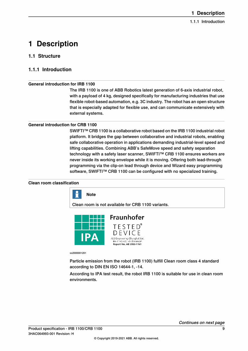
Clean room classification
Note
Clean room is not available for CRB 1100 variants.
xx2000001201
Particle emission from the robot (IRB 1100) fulfill Clean room class 4 standardaccording to DIN EN ISO 14644-1, -14.According to IPA test result, the robot IRB 1100 is suitable for use in clean roomenvironments.
Continues on next pageProduct specification - IRB 1100/CRB 1100 93HAC064993-001 Revision: H
© Copyright 2019-2021 ABB. All rights reserved.
1 Description1.1.1 Introduction
Classification of airborne molecular contamination, see below:
Test environment parameters
Relative humidityTemperatureAirflow patternAirflow velocityCleanroom AirCleanlinessClass(According toISO 14644-1)
45% ± 0.5%22°C ± 0.5°Cvertical laminarflow
0.45 m/sISO 1
Test procedure parameters
Operation of each axisAttached payloadCapacity
separately4 kg50% and 100%
Test result/Classification:When operated under the specified test conditions, the IRB 1100 including gripperand suction cup is suitable for use in cleanrooms fulfilling the specifications of thefollowing Air Cleanliness Classes according to ISO 14644-1.
Air Cleanliness ClassTest parameter(s)
2Capacity=50%
4Capacity=100%
4Overall result
IP67 protection
Note
IP67 is not available for CRB 1100 variants.
IRB 1100 has IP67 as an option. The option will add sealing, machining parts andgasket.And IRB 1100 fulfill Clean room class 5 standard according to DIN EN ISO 14644-1,-14.
Software product rangeWe have added a range of software products - all falling under the umbrelladesignation of Active Safety - to protect not only personnel in the unlikely eventof an accident, but also robot tools, peripheral equipment and the robot itself.
Operating systemThe IRB 1100 is equipped with the OmniCore C30/C90/E10 controller and robotcontrol software, RobotWare. RobotWare supports every aspect of the robot system,such as motion control, development and execution of application programs,communication etc. See Operating manual - OmniCore.For CRB 1100, it is not supported with E10 controller.
Continues on next page10 Product specification - IRB 1100/CRB 1100
3HAC064993-001 Revision: H© Copyright 2019-2021 ABB. All rights reserved.
1 Description1.1.1 IntroductionContinued
SafetySafety standards valid for complete robot, manipulator and controller.
Collaborative Safety
Note
This chapter is only available for CRB 1100.
Combining ABB’s SafeMove comprehensive safety functionality with a safety laserscanner, SWIFTI™ can be installed without physical fencing and still collaboratesafely with people. If a worker is detected within its working area, SWIFTI™ willautomatically slow down or halt to allow them to approach safely. An interactionlight provides a visual indication of SWIFTI™’s status. It signals human co-workerswhen people are inside SWIFTI™’s working zone.Note that a Safety PLC is required for connection with the laser scanner.
Additional functionalityFor additional functionality, the robot can be equipped with optional software forapplication support - for example communication features - network communication- and advanced functions such as multitasking, sensor control etc. For a completedescription on optional software, see the Product specification - OmniCore C lineand Product specification - OmniCore E line.
Continues on next pageProduct specification - IRB 1100/CRB 1100 113HAC064993-001 Revision: H
© Copyright 2019-2021 ABB. All rights reserved.
1 Description1.1.1 Introduction
Continued
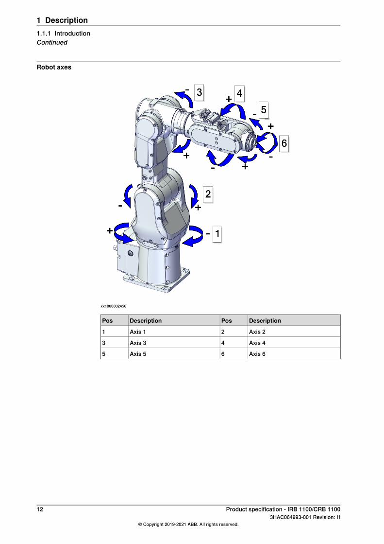
Robot axes
xx1800002456
DescriptionPosDescriptionPos
Axis 22Axis 11
Axis 44Axis 33
Axis 66Axis 55
12 Product specification - IRB 1100/CRB 11003HAC064993-001 Revision: H
© Copyright 2019-2021 ABB. All rights reserved.
1 Description1.1.1 IntroductionContinued
1.1.2 Different robot versions
GeneralThe IRB 1100/CRB 1100 is available in four versions.
Robot typesThe following robot versions are available.
Reach (m)Handling capacity (kg)Robot type
0.475 m4 kgIRB 1100-4/0.475
0.58 m4 kgIRB 1100-4/0.58
0.475 m4 kgCRB 1100-4/0.475
0.58 m4 kgCRB 1100-4/0.58
Product specification - IRB 1100/CRB 1100 133HAC064993-001 Revision: H
© Copyright 2019-2021 ABB. All rights reserved.
1 Description1.1.2 Different robot versions
1.1.3 Definition of version designations
1.1.3.1 Technical data
Weight, robotThe table shows the weight of the robot.
WeightRobot model
21.1 kgIRB 1100/CRB 1100
Note
The weight does not include tools and other equipment fitted on the robot!
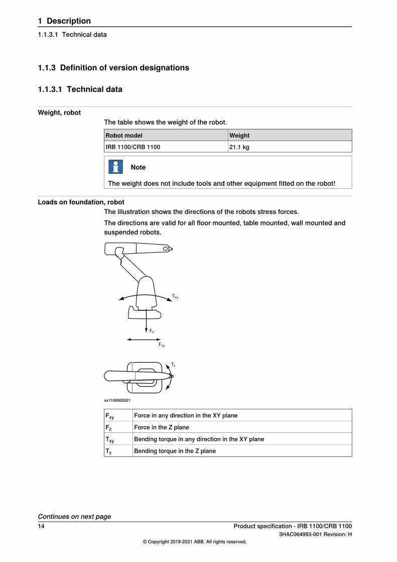
Loads on foundation, robotThe illustration shows the directions of the robots stress forces.The directions are valid for all floor mounted, table mounted, wall mounted andsuspended robots.
xy
xy
z
z
T
F
F
T
xx1100000521
Force in any direction in the XY planeFxyForce in the Z planeFzBending torque in any direction in the XY planeTxyBending torque in the Z planeTz
Continues on next page14 Product specification - IRB 1100/CRB 1100
3HAC064993-001 Revision: H© Copyright 2019-2021 ABB. All rights reserved.
1 Description1.1.3.1 Technical data
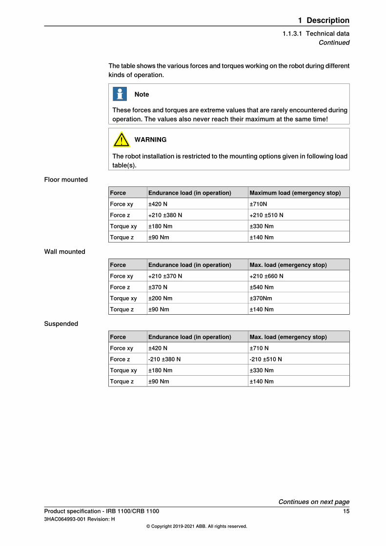
The table shows the various forces and torquesworking on the robot during differentkinds of operation.
Note
These forces and torques are extreme values that are rarely encountered duringoperation. The values also never reach their maximum at the same time!
WARNING
The robot installation is restricted to the mounting options given in following loadtable(s).
Floor mounted
Maximum load (emergency stop)Endurance load (in operation)Force
±710N±420 NForce xy
+210 ±510 N+210 ±380 NForce z
±330 Nm±180 NmTorque xy
±140 Nm±90 NmTorque z
Wall mounted
Max. load (emergency stop)Endurance load (in operation)Force
+210 ±660 N+210 ±370 NForce xy
±540 Nm±370 NForce z
±370Nm±200 NmTorque xy
±140 Nm±90 NmTorque z
Suspended
Max. load (emergency stop)Endurance load (in operation)Force
±710 N±420 NForce xy
-210 ±510 N-210 ±380 NForce z
±330 Nm±180 NmTorque xy
±140 Nm±90 NmTorque z
Continues on next pageProduct specification - IRB 1100/CRB 1100 153HAC064993-001 Revision: H
© Copyright 2019-2021 ABB. All rights reserved.
1 Description1.1.3.1 Technical data
Continued
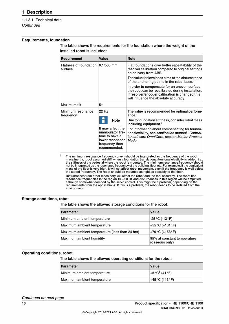
Requirements, foundationThe table shows the requirements for the foundation where the weight of theinstalled robot is included:
NoteValueRequirement
Flat foundations give better repeatability of theresolver calibration compared to original settingson delivery from ABB.
0.1/500 mmFlatness of foundationsurface
The value for levelness aims at the circumstanceof the anchoring points in the robot base.In order to compensate for an uneven surface,the robot can be recalibrated during installation.If resolver/encoder calibration is changed thiswill influence the absolute accuracy.
5°Maximum tilt
The value is recommended for optimal perform-ance.
22 Hz
Note
It may affect themanipulator life-time to have alower resonancefrequency thanrecommended.
Minimum resonancefrequency
Due to foundation stiffness, consider robot massincluding equipment. iFor information about compensating for founda-tion flexibility, see Application manual - Control-ler software OmniCore, sectionMotion ProcessMode.
i The minimum resonance frequency given should be interpreted as the frequency of the robotmass/inertia, robot assumed stiff, when a foundation translational/torsional elasticity is added, i.e.,the stiffness of the pedestal where the robot is mounted. Theminimum resonance frequency shouldnot be interpreted as the resonance frequency of the building, floor etc. For example, if the equivalentmass of the floor is very high, it will not affect robot movement, even if the frequency is well belowthe stated frequency. The robot should be mounted as rigid as possibly to the floor.Disturbances from other machinery will affect the robot and the tool accuracy. The robot hasresonance frequencies in the region 10 – 20 Hz and disturbances in this region will be amplified,although somewhat damped by the servo control. This might be a problem, depending on therequirements from the applications. If this is a problem, the robot needs to be isolated from theenvironment.
Storage conditions, robotThe table shows the allowed storage conditions for the robot:
ValueParameter
-25°C (-13°F)Minimum ambient temperature
+55°C (+131°F)Maximum ambient temperature
+70°C (+158°F)Maximum ambient temperature (less than 24 hrs)
95% at constant temperature(gaseous only)
Maximum ambient humidity
Operating conditions, robotThe table shows the allowed operating conditions for the robot:
ValueParameter
+5°C i (41°F)Minimum ambient temperature
+45°C (113°F)Maximum ambient temperature
Continues on next page16 Product specification - IRB 1100/CRB 1100
3HAC064993-001 Revision: H© Copyright 2019-2021 ABB. All rights reserved.
1 Description1.1.3.1 Technical dataContinued
ValueParameter
95% at constant temperatureMaximum ambient humidityi At low environmental temperature (below 10° C) a warm-up phase is recommended to be run with
the robot. Otherwise there is a risk that the robot stops or runs with lower performance due totemperature dependent oil and grease viscosity.
Protection classes, robotThe table shows the available protection types of the robot, with the correspondingprotection class.The CRB 1100 variants are only available for IP40.
Protection classProtection type
IP40Manipulator, protection type StandardIP67 (option 3350-670)
ISO 4Manipulator, protection type Clean Room
Other technical data
NoteDescriptionData
< 65 dB(A) Leq (acc. to ma-chinery directive 2006/42/EC)
The sound pressure level out-side the working space.
Airborne noise level
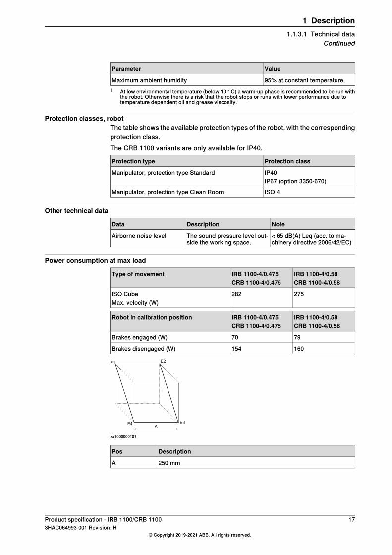
Power consumption at max load
IRB 1100-4/0.58CRB 1100-4/0.58
IRB 1100-4/0.475CRB 1100-4/0.475
Type of movement
275282ISO CubeMax. velocity (W)
IRB 1100-4/0.58CRB 1100-4/0.58
IRB 1100-4/0.475CRB 1100-4/0.475
Robot in calibration position
7970Brakes engaged (W)
160154Brakes disengaged (W)
E1
E4 E3
E2
A
xx1000000101
DescriptionPos
250 mmA
Product specification - IRB 1100/CRB 1100 173HAC064993-001 Revision: H
© Copyright 2019-2021 ABB. All rights reserved.
1 Description1.1.3.1 Technical data
Continued
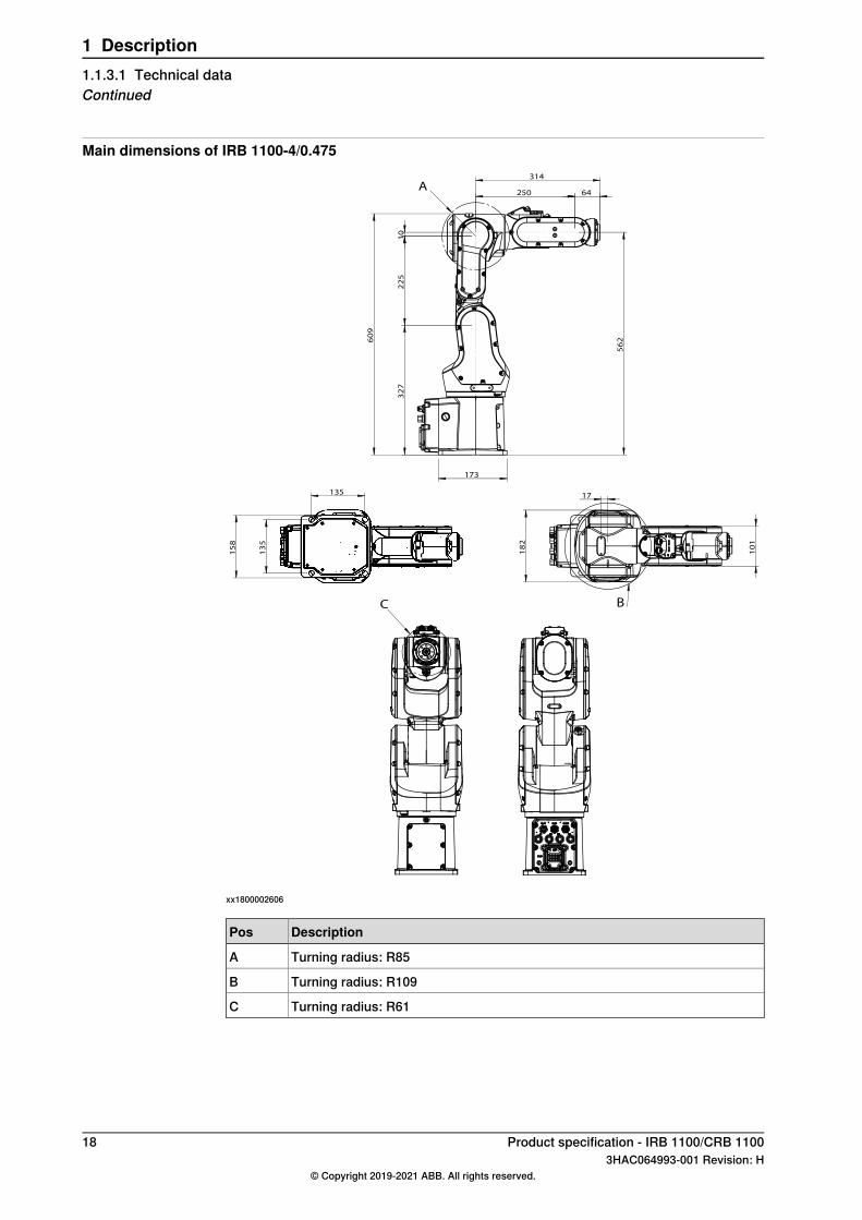
Main dimensions of IRB 1100-4/0.475
173
60
9
32
7
22
5
10
250 64
314
56
2
A
18
2
10
1
17 135
13
5
15
8
C B
xx1800002606
DescriptionPos
Turning radius: R85A
Turning radius: R109B
Turning radius: R61C
18 Product specification - IRB 1100/CRB 11003HAC064993-001 Revision: H
© Copyright 2019-2021 ABB. All rights reserved.
1 Description1.1.3.1 Technical dataContinued
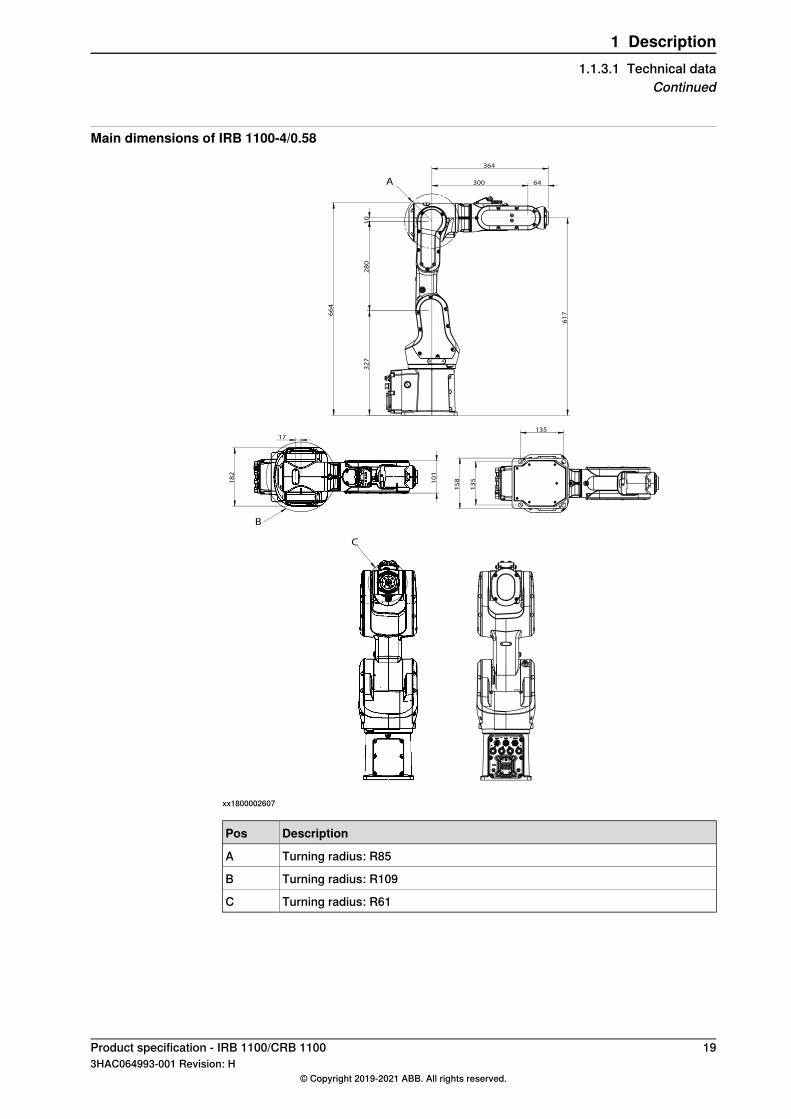
Main dimensions of IRB 1100-4/0.58
66
4
32
7
28
0
10
300 64
364
61
7
A
10
1
18
2
17
13
5
135
15
8
C
B
xx1800002607
DescriptionPos
Turning radius: R85A
Turning radius: R109B
Turning radius: R61C
Product specification - IRB 1100/CRB 1100 193HAC064993-001 Revision: H
© Copyright 2019-2021 ABB. All rights reserved.
1 Description1.1.3.1 Technical data
Continued
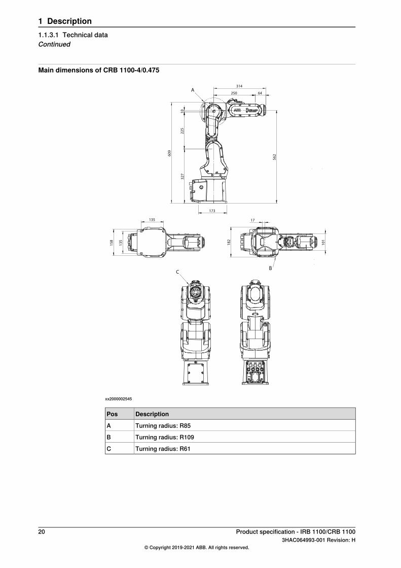
Main dimensions of CRB 1100-4/0.475
173
60
9
64
32
7
22
5
10
250
56
2
A 314
10
1
18
2
17
B
135
13
5
15
8
C
xx2000002545
DescriptionPos
Turning radius: R85A
Turning radius: R109B
Turning radius: R61C
20 Product specification - IRB 1100/CRB 11003HAC064993-001 Revision: H
© Copyright 2019-2021 ABB. All rights reserved.
1 Description1.1.3.1 Technical dataContinued
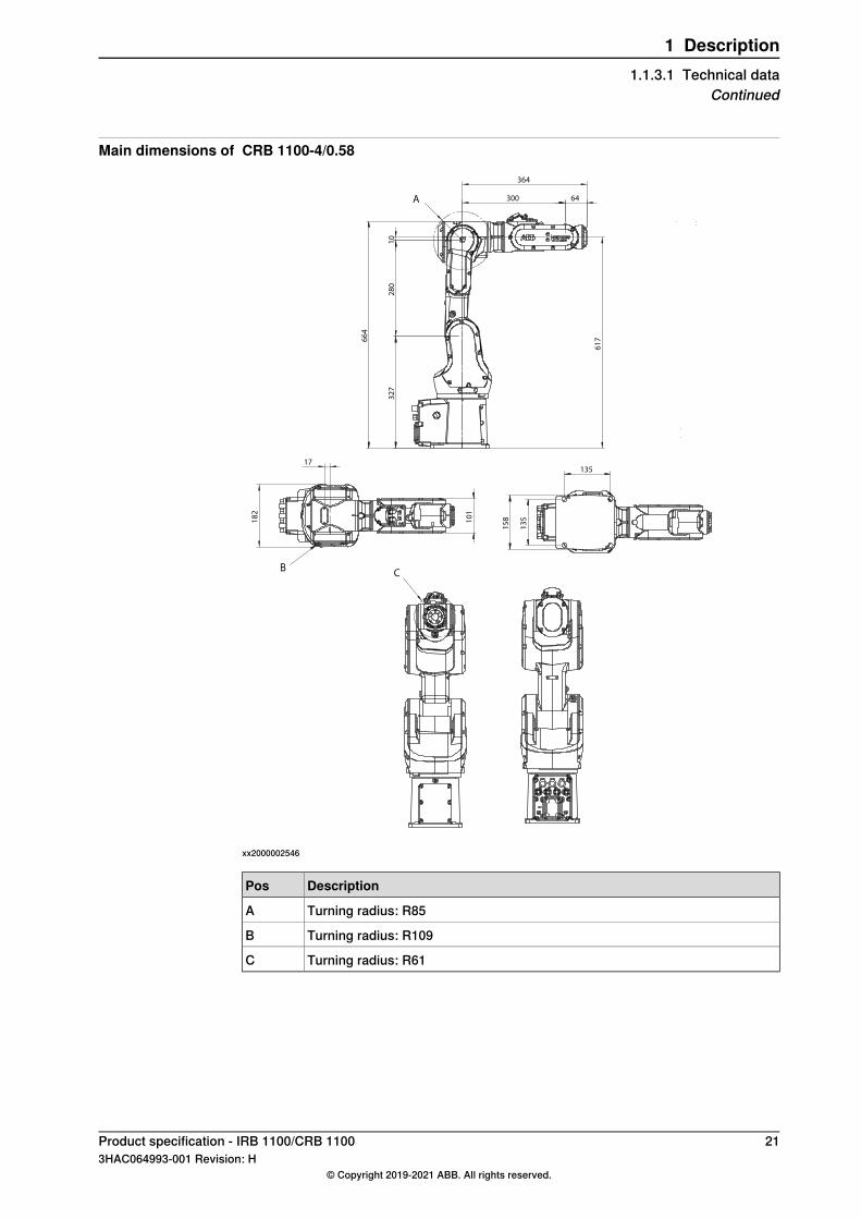
Main dimensions of CRB 1100-4/0.58
C
66
4
32
7
28
0
10
300 64
364
61
7
A
10
1
18
2
17
B
135
13
5
15
8
xx2000002546
DescriptionPos
Turning radius: R85A
Turning radius: R109B
Turning radius: R61C
Product specification - IRB 1100/CRB 1100 213HAC064993-001 Revision: H
© Copyright 2019-2021 ABB. All rights reserved.
1 Description1.1.3.1 Technical data
Continued
1.2 Standards
1.2.1 Applicable standards
Note
The listed standards are valid at the time of the release of this document. Phasedout or replaced standards are removed from the list when needed.
GeneralThe product is designed in accordance with ISO 10218-1:2011, Robots for industrialenvironments - Safety requirements -Part 1 Robots, and applicable parts in thenormative references, as referred to from ISO 10218-1:2011. In case of deviationsfrom ISO 10218-1:2011, these are listed in the declaration of incorporation whichis part of the product delivery.
Normative standards as referred to from ISO 10218-1
DescriptionStandard
Manipulating industrial robots - Performance criteria and relatedtest methods
ISO 9283:1998
Robots and robotic devices - Safety requirements for industrialrobots - Part 2: Robot systems and integration
ISO 10218-2
Safety of machinery - General principles for design - Risk as-sessment and risk reduction
ISO 12100
Safety of machinery - Safety related parts of control systems- Part 1: General principles for design
ISO 13849-1:2006
Safety of machinery - Emergency stop - Principles for designISO 13850
Safety of machinery - Electrical equipment of machines - Part1: General requirements
IEC 60204-1:2005
Safety of machinery - Functional safety of safety-related elec-trical, electronic and programmable electronic control systems
IEC 62061:2005
Region specific standards and regulations
DescriptionStandard
Safety requirements for industrial robots and robot systemsANSI/RIA R15.06
Safety standard for robots and robotic equipmentANSI/UL 1740
Industrial robots and robot Systems - General safety require-ments
CAN/CSA Z 434-14
Other standards used in design
DescriptionStandard
Robots and robotic devices -- Coordinate systems and motionnomenclatures
ISO 9787:2013
Electromagnetic compatibility (EMC) – Part 6-2: Genericstandards – Immunity standard for industrial environments
IEC 61000-6-2
Continues on next page22 Product specification - IRB 1100/CRB 1100
3HAC064993-001 Revision: H© Copyright 2019-2021 ABB. All rights reserved.
1 Description1.2.1 Applicable standards
DescriptionStandard
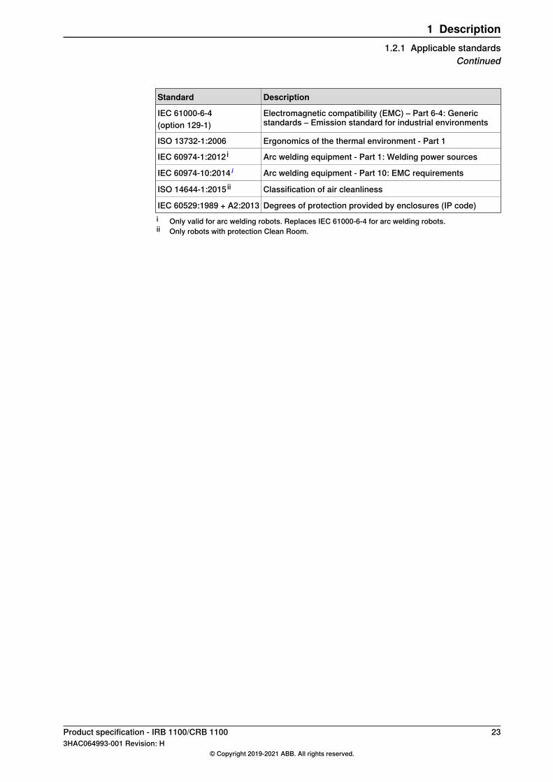
Electromagnetic compatibility (EMC) – Part 6-4: Genericstandards – Emission standard for industrial environments
IEC 61000-6-4(option 129-1)
Ergonomics of the thermal environment - Part 1ISO 13732-1:2006
Arc welding equipment - Part 1: Welding power sourcesIEC 60974-1:2012 i
Arc welding equipment - Part 10: EMC requirementsIEC 60974-10:2014 i
Classification of air cleanlinessISO 14644-1:2015 ii
Degrees of protection provided by enclosures (IP code)IEC 60529:1989 + A2:2013i Only valid for arc welding robots. Replaces IEC 61000-6-4 for arc welding robots.ii Only robots with protection Clean Room.
Product specification - IRB 1100/CRB 1100 233HAC064993-001 Revision: H
© Copyright 2019-2021 ABB. All rights reserved.
1 Description1.2.1 Applicable standards
Continued
1.3 Installation
1.3.1 Introduction to installation
GeneralIRB 1100 / CRB 1100 is available in two variants and all variants can be floormounted, inverted/suspended, wall mounted, or tilted mounted (any angle).Depending on the robot variant, an end effector with max. weight of 4 kg includingpayload, can bemounted on the tool flange (axis 6). See Load diagrams on page39.
Extra loadsThe upper arm can handle an additional load of 0.5 kg.See Fitting equipment to the robot on page 48.
Working range limitationThe working range of axes 1 can be limited by mechanical stops as option. SeeWorking range on page 56.
24 Product specification - IRB 1100/CRB 11003HAC064993-001 Revision: H
© Copyright 2019-2021 ABB. All rights reserved.
1 Description1.3.1 Introduction to installation
1.3.2 Assembling the manipulator
Attachment screwsThe table below specifies the type of securing screws and washers to be used forsecuring the robot to the base plate/foundation.
M12x25 (robot installation directly on foundation)Suitable screws
4 pcsQuantity
8.8Quality
IRB 1100: 24 x 13 x 2.5, steel hardness class 200HVSuitable washerCRB 1100: 4 pcs, 24 x 13 x 2.5
IRB 1100: 2 pcs, D6x20, ISO 2338 - 6m6x20 - A1Guide pinsCRB 1100: 2 pcs, article number 3HNP00449-1
50 Nm±5 NmTightening torque
0.1/500 mmLevel surface requirements
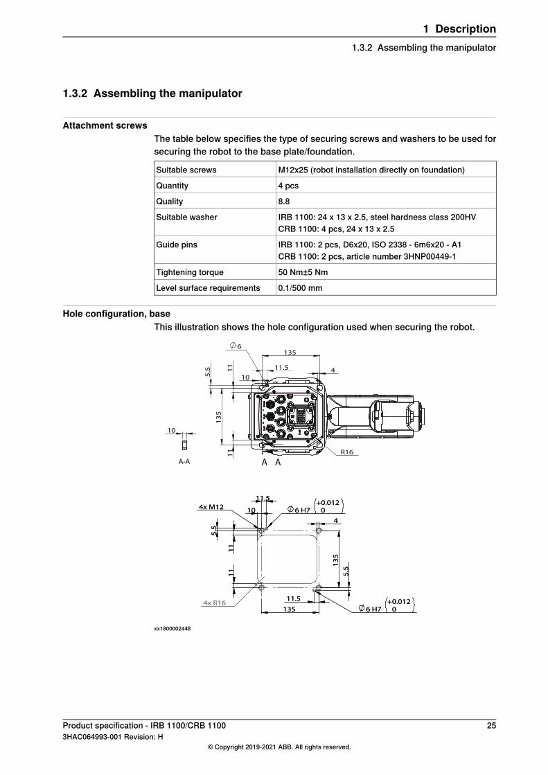
Hole configuration, baseThis illustration shows the hole configuration used when securing the robot.
4x M12
11
1
1
10
4
135
13
5
6 H7
+
0.012
0
5.5
11.5
11.5
5.5
6 H7
+
0.012
0
4x R16
135
13
5
11
1
1
10
4
R16
11.5
5.5
6
A A
10
A-A
4x M12
11
1
1
10
4
135
13
5
6 H7
+
0.012
0
5.5
11.5
11.5
5.5
6 H7
+
0.012
0
4x R16
xx1800002448
Product specification - IRB 1100/CRB 1100 253HAC064993-001 Revision: H
© Copyright 2019-2021 ABB. All rights reserved.
1 Description1.3.2 Assembling the manipulator
1.3.3 Installation the lead-through device
Note
This section is only available for the CRB 1100.
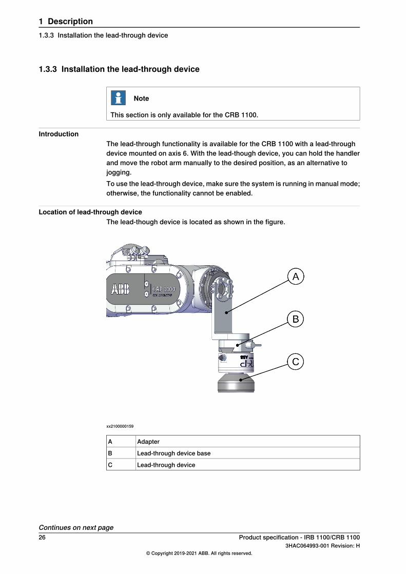
IntroductionThe lead-through functionality is available for the CRB 1100 with a lead-throughdevice mounted on axis 6. With the lead-though device, you can hold the handlerand move the robot arm manually to the desired position, as an alternative tojogging.To use the lead-through device, make sure the system is running in manual mode;otherwise, the functionality cannot be enabled.
Location of lead-through deviceThe lead-though device is located as shown in the figure.
xx2100000159
AdapterA
Lead-through device baseB
Lead-through deviceC
Continues on next page26 Product specification - IRB 1100/CRB 1100
3HAC064993-001 Revision: H© Copyright 2019-2021 ABB. All rights reserved.
1 Description1.3.3 Installation the lead-through device
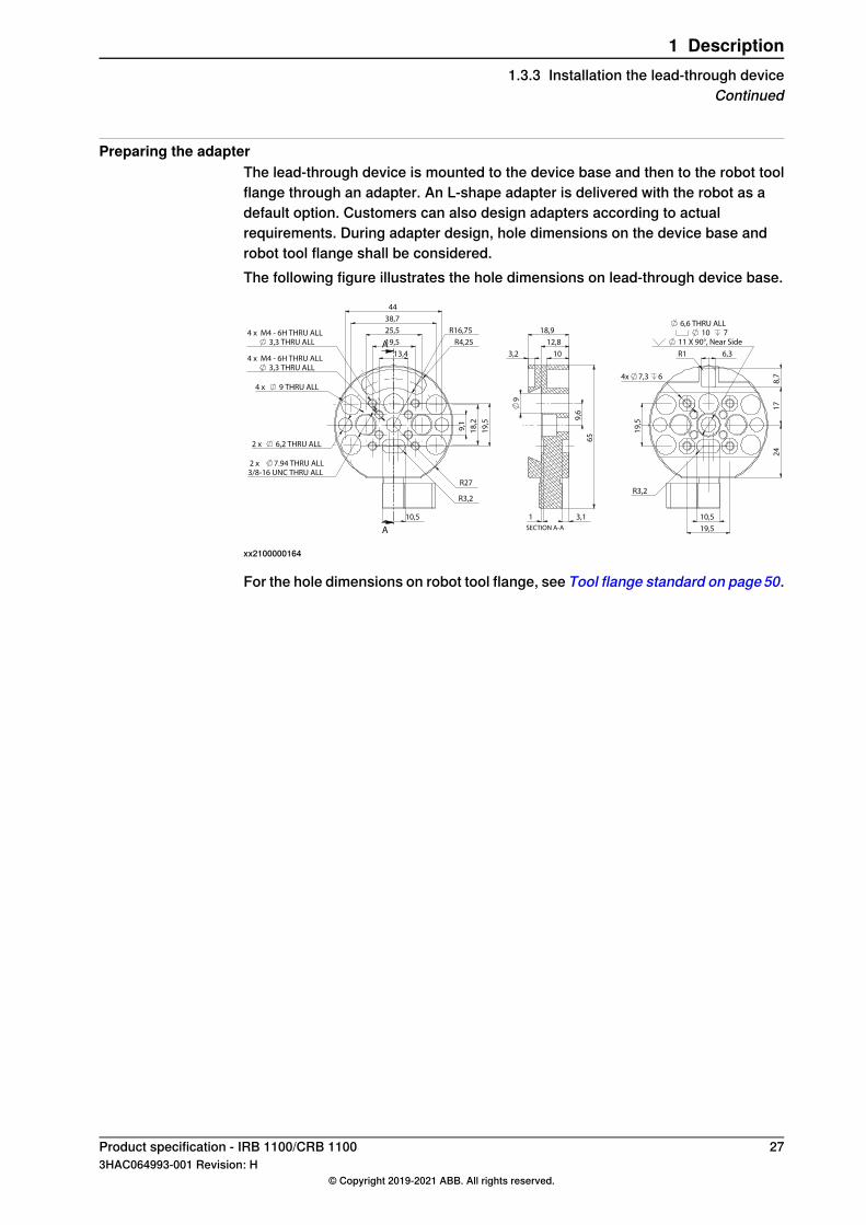
Preparing the adapterThe lead-through device is mounted to the device base and then to the robot toolflange through an adapter. An L-shape adapter is delivered with the robot as adefault option. Customers can also design adapters according to actualrequirements. During adapter design, hole dimensions on the device base androbot tool flange shall be considered.The following figure illustrates the hole dimensions on lead-through device base.
13,4
19,5
25,5
38,7
44
9,1
19
,5
18
,2
R16,75
R4,25
10,5
R3,2
4 x M4 - 6H THRU ALL
3,3 THRU ALL
4 x M4 - 6H THRU ALL
3,3 THRU ALL
2 x 6,2 THRU ALL
2 x 7.94 THRU ALL
3/8-16 UNC THRU ALL
4 x 9 THRU ALL
R27
A
A
10 3,2
18,9
12,8
65
1 3,1
9,6
9
SECTION A-A 19,5
19
,5
10,5
R3,2
4x 7,3 6
6,3
8,7
R1
17
6,6 THRU ALL
10 7
11 X 90°, Near Side
24
xx2100000164
For the hole dimensions on robot tool flange, see Tool flange standard on page50.
Product specification - IRB 1100/CRB 1100 273HAC064993-001 Revision: H
© Copyright 2019-2021 ABB. All rights reserved.
1 Description1.3.3 Installation the lead-through device
Continued
1.3.4 Installation the laser scanner
Note
This section is only available for the CRB 1100.
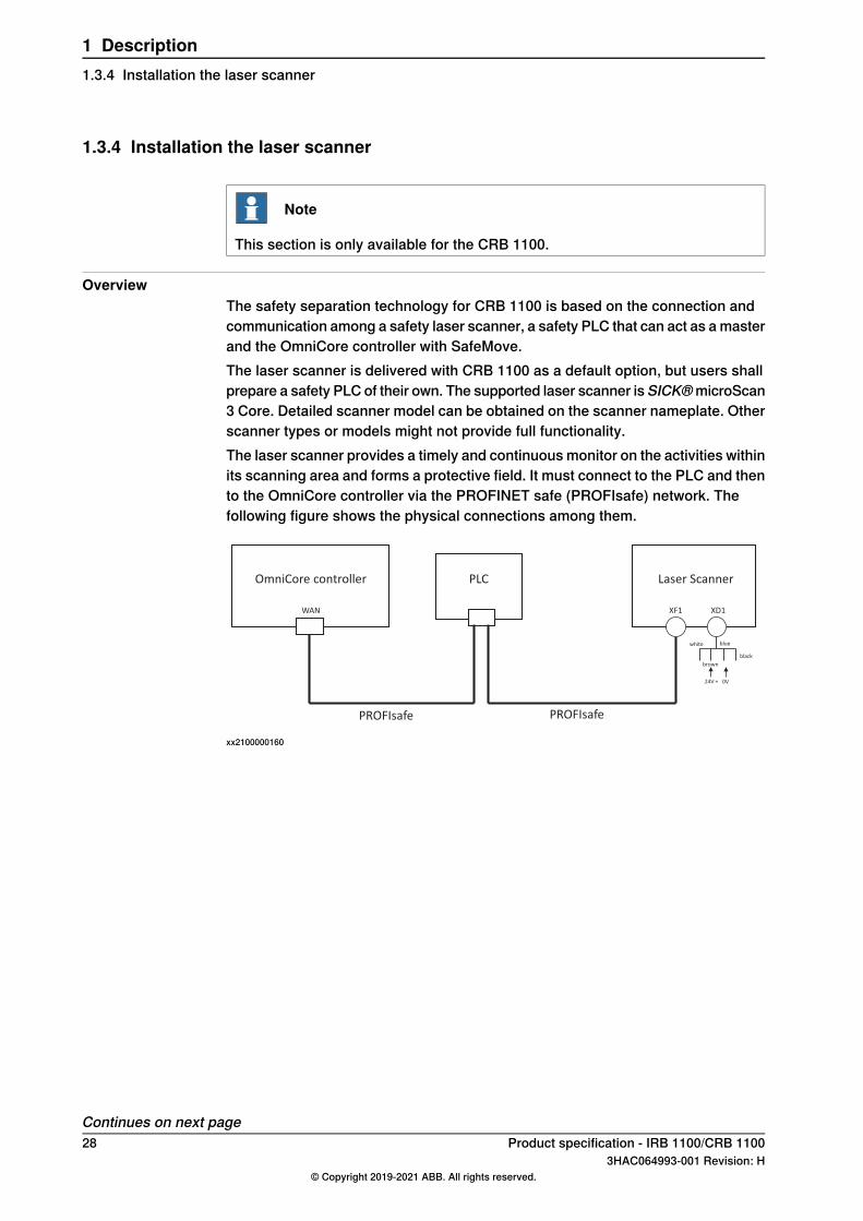
OverviewThe safety separation technology for CRB 1100 is based on the connection andcommunication among a safety laser scanner, a safety PLC that can act as amasterand the OmniCore controller with SafeMove.The laser scanner is delivered with CRB 1100 as a default option, but users shallprepare a safety PLC of their own. The supported laser scanner isSICK®microScan3 Core. Detailed scanner model can be obtained on the scanner nameplate. Otherscanner types or models might not provide full functionality.The laser scanner provides a timely and continuousmonitor on the activities withinits scanning area and forms a protective field. It must connect to the PLC and thento the OmniCore controller via the PROFINET safe (PROFIsafe) network. Thefollowing figure shows the physical connections among them.
WAN
OmniCore controller Laser Scanner
XF1 XD1
PLC
white
brown
blue
black
24V + 0V
PROFIsafePROFIsafe
xx2100000160
Continues on next page28 Product specification - IRB 1100/CRB 1100
3HAC064993-001 Revision: H© Copyright 2019-2021 ABB. All rights reserved.
1 Description1.3.4 Installation the laser scanner
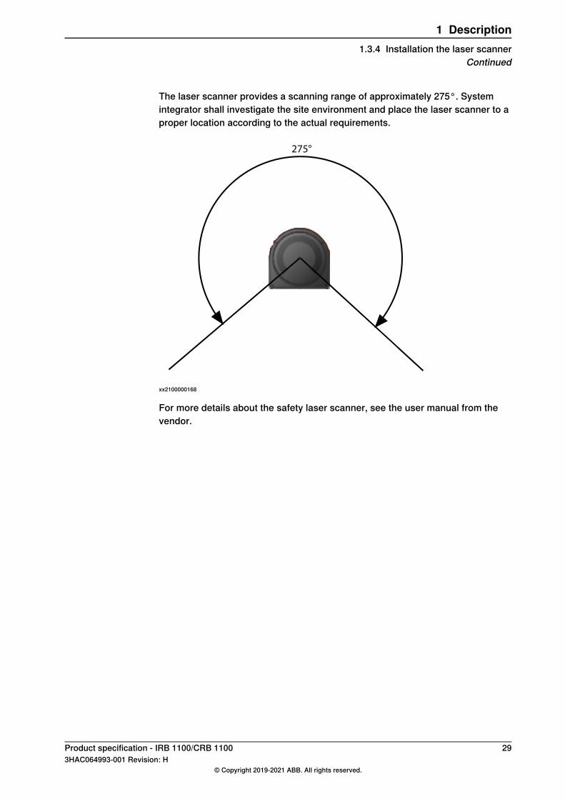
The laser scanner provides a scanning range of approximately 275°. Systemintegrator shall investigate the site environment and place the laser scanner to aproper location according to the actual requirements.
275°
xx2100000168
For more details about the safety laser scanner, see the user manual from thevendor.
Product specification - IRB 1100/CRB 1100 293HAC064993-001 Revision: H
© Copyright 2019-2021 ABB. All rights reserved.
1 Description1.3.4 Installation the laser scanner
Continued
1.3.5 Indicator lamp
Note
This section is only available for the CRB 1100.
DescriptionThe lamp unit on process hub of CRB 1100 indicates robot status in four colors.Operators should always be aware of the indicator color and handle the situationcorrespondingly.
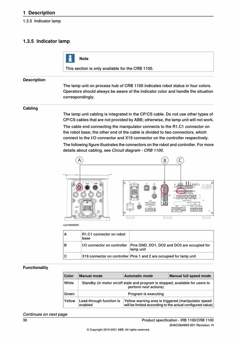
CablingThe lamp unit cabling is integrated in the CP/CS cable. Do not use other types ofCP/CS cables that are not provided by ABB; otherwise, the lamp unit will not work.The cable end connecting the manipulator connects to the R1.C1 connector onthe robot base; the other end of the cable is divided to two connectors, whichconnect to the I/O connector and X19 connector on the controller respectively.The following figure illustrates the connectors on the robot and controller. For moredetails about cabling, see Circuit diagram - CRB 1100.
CBA
xx2100000291
R1.C1 connector on robotbase
A
Pins GND, DO1, DO2 and DO3 are occupied forlamp unit
I/O connector on controllerB
Pins 1 and 2 are occupied for lamp unitX19 connector on controllerC
Functionality
Manual full speed modeAutomatic modeManual modeColor
Standby (in motor on/off state and program is stopped, available for users toperform next actions)
White
Program is executingGreen
Yellow warning area is triggered (manipulator speedwill be limited according to the actual configured value)
Lead-through function isenabled
Yellow
Continues on next page30 Product specification - IRB 1100/CRB 1100
3HAC064993-001 Revision: H© Copyright 2019-2021 ABB. All rights reserved.
1 Description1.3.5 Indicator lamp
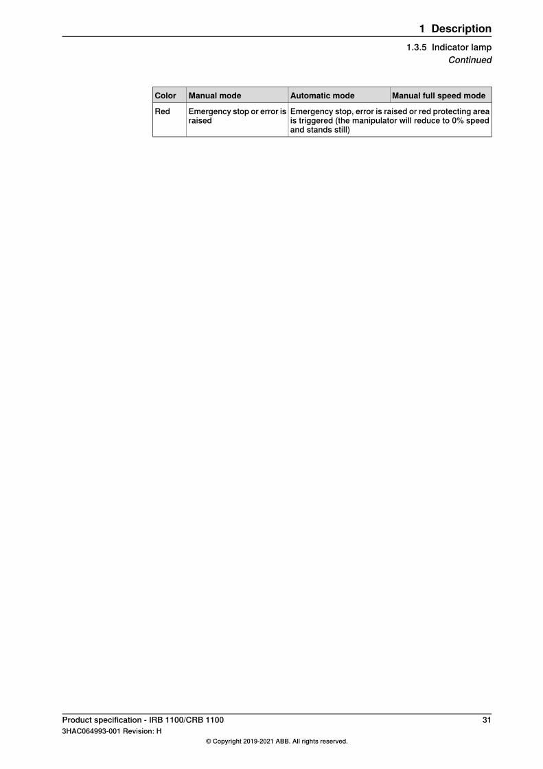
Manual full speed modeAutomatic modeManual modeColor
Emergency stop, error is raised or red protecting areais triggered (the manipulator will reduce to 0% speedand stands still)
Emergency stop or error israised
Red
Product specification - IRB 1100/CRB 1100 313HAC064993-001 Revision: H
© Copyright 2019-2021 ABB. All rights reserved.
1 Description1.3.5 Indicator lamp
Continued
1.4 Calibration and references
1.4.1 Calibration methods
OverviewThis section specifies the different types of calibration and the calibrationmethodsthat are supplied by ABB.The original calibration data delivered with the robot is generated when the robotis floor mounted. If the robot is not floor mounted, then the robot accuracy couldbe affected. The robot needs to be calibrated after it is mounted.More information is available in the product manual.
Types of calibration
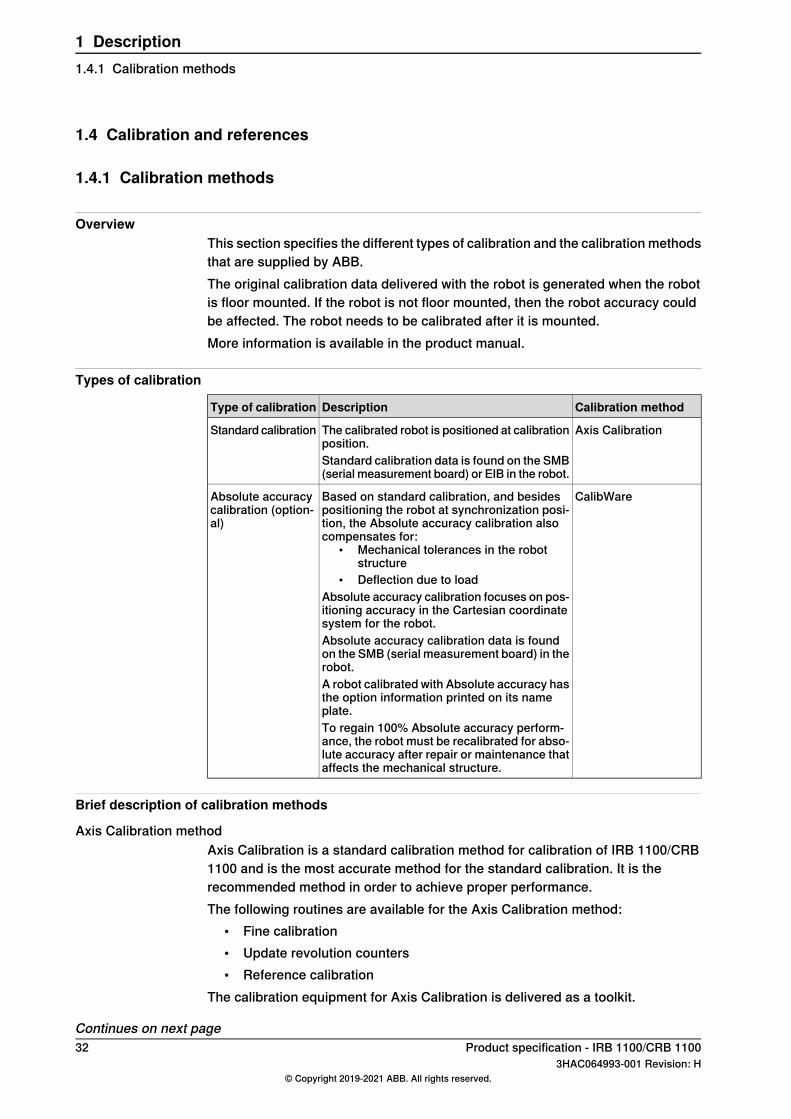
Calibration methodDescriptionType of calibration
Axis CalibrationThe calibrated robot is positioned at calibrationposition.
Standard calibration
Standard calibration data is found on the SMB(serial measurement board) or EIB in the robot.
CalibWareBased on standard calibration, and besidespositioning the robot at synchronization posi-tion, the Absolute accuracy calibration alsocompensates for:
• Mechanical tolerances in the robotstructure
• Deflection due to loadAbsolute accuracy calibration focuses on pos-itioning accuracy in the Cartesian coordinatesystem for the robot.
Absolute accuracycalibration (option-al)
Absolute accuracy calibration data is foundon the SMB (serial measurement board) in therobot.A robot calibrated with Absolute accuracy hasthe option information printed on its nameplate.To regain 100% Absolute accuracy perform-ance, the robot must be recalibrated for abso-lute accuracy after repair or maintenance thataffects the mechanical structure.
Brief description of calibration methods
Axis Calibration methodAxis Calibration is a standard calibration method for calibration of IRB 1100/CRB1100 and is the most accurate method for the standard calibration. It is therecommended method in order to achieve proper performance.The following routines are available for the Axis Calibration method:
• Fine calibration• Update revolution counters• Reference calibration
The calibration equipment for Axis Calibration is delivered as a toolkit.
Continues on next page32 Product specification - IRB 1100/CRB 1100
3HAC064993-001 Revision: H© Copyright 2019-2021 ABB. All rights reserved.
1 Description1.4.1 Calibration methods
The actual instructions of how to perform the calibration procedure and what todo at each step is given on the FlexPendant. You will be guided through thecalibration procedure, step by step.
CalibWare - Absolute Accuracy calibrationThe CalibWare tool guides through the calibration process and calculates newcompensation parameters. This is further detailed in the Applicationmanual - CalibWare Field.If a service operation is done to a robot with the option Absolute Accuracy, a newabsolute accuracy calibration is required in order to establish full performance.For most cases after replacements that do not include taking apart the robotstructure, standard calibration is sufficient.The Absolute Accuracy option varies according to the robot mounting position.This is printed on the robot name plate for each robot. The robot must be in thecorrect mounting position when it is recalibrated for absolute accuracy.
Product specification - IRB 1100/CRB 1100 333HAC064993-001 Revision: H
© Copyright 2019-2021 ABB. All rights reserved.
1 Description1.4.1 Calibration methods
Continued
1.4.2 Synchronization marks and synchronization position for axes
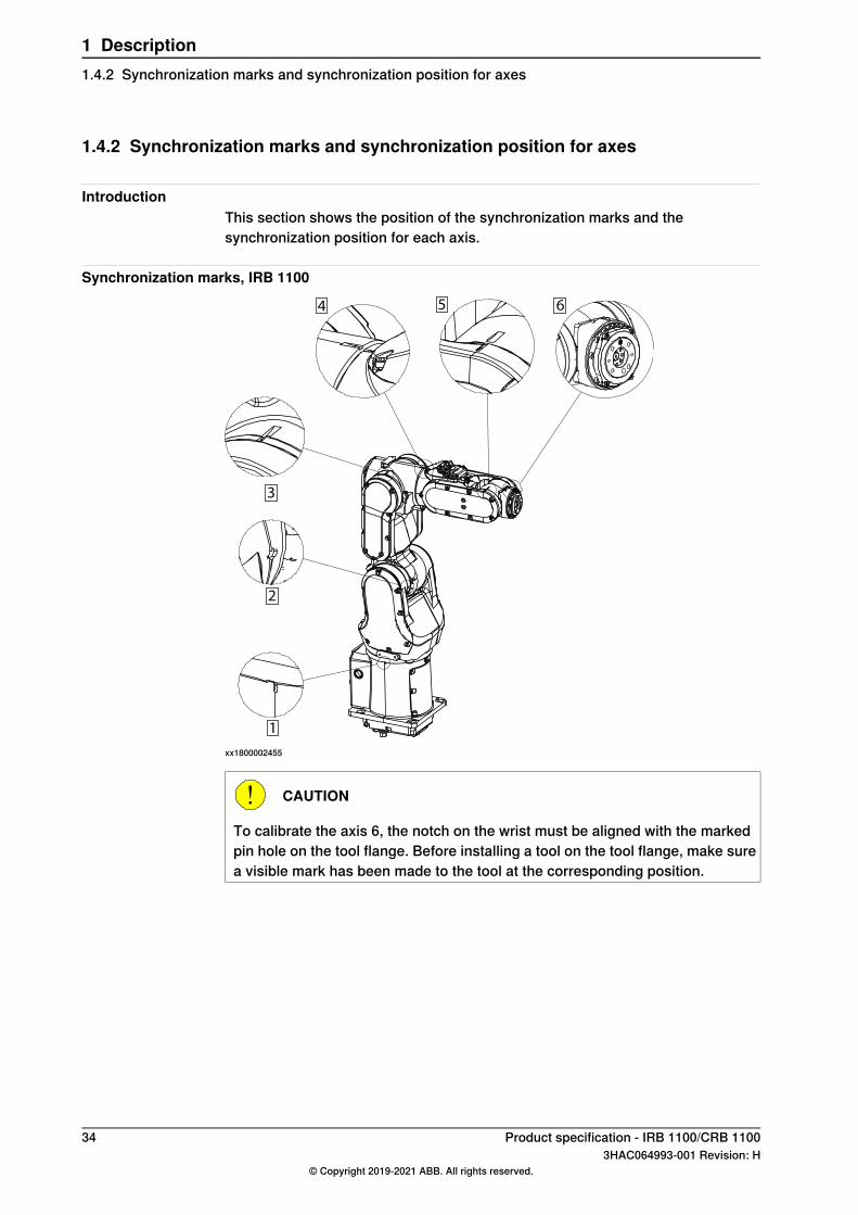
IntroductionThis section shows the position of the synchronization marks and thesynchronization position for each axis.
Synchronization marks, IRB 1100
1
2
5 64
3
xx1800002455
CAUTION
To calibrate the axis 6, the notch on the wrist must be aligned with the markedpin hole on the tool flange. Before installing a tool on the tool flange, make surea visible mark has been made to the tool at the corresponding position.
34 Product specification - IRB 1100/CRB 11003HAC064993-001 Revision: H
© Copyright 2019-2021 ABB. All rights reserved.
1 Description1.4.2 Synchronization marks and synchronization position for axes
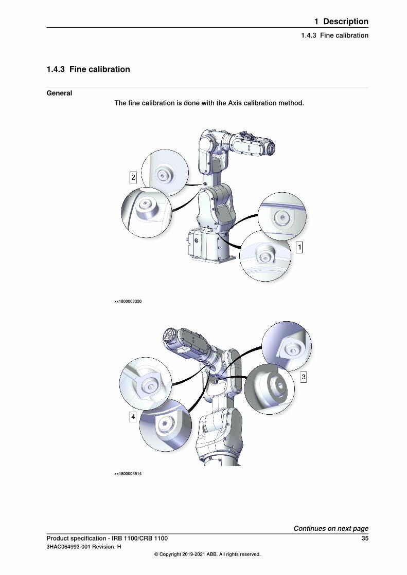
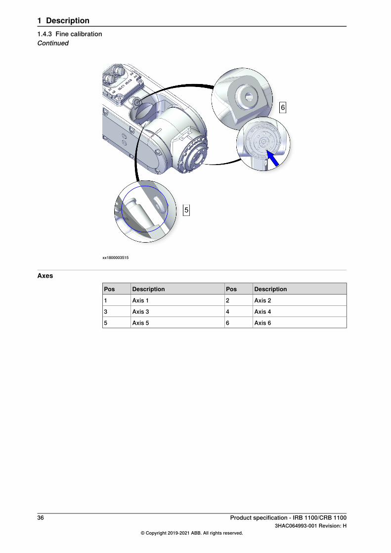
1.4.3 Fine calibration
GeneralThe fine calibration is done with the Axis calibration method.
xx1800003320
xx1800003514
Continues on next pageProduct specification - IRB 1100/CRB 1100 353HAC064993-001 Revision: H
© Copyright 2019-2021 ABB. All rights reserved.
1 Description1.4.3 Fine calibration
xx1800003515
Axes
DescriptionPosDescriptionPos
Axis 22Axis 11
Axis 44Axis 33
Axis 66Axis 55
36 Product specification - IRB 1100/CRB 11003HAC064993-001 Revision: H
© Copyright 2019-2021 ABB. All rights reserved.
1 Description1.4.3 Fine calibrationContinued
1.4.4 Absolute Accuracy calibration
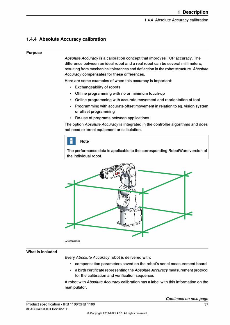
PurposeAbsolute Accuracy is a calibration concept that improves TCP accuracy. Thedifference between an ideal robot and a real robot can be several millimeters,resulting frommechanical tolerances and deflection in the robot structure.AbsoluteAccuracy compensates for these differences.Here are some examples of when this accuracy is important:
• Exchangeability of robots• Offline programming with no or minimum touch-up• Online programming with accurate movement and reorientation of tool• Programming with accurate offset movement in relation to eg. vision system
or offset programming• Re-use of programs between applications
The option Absolute Accuracy is integrated in the controller algorithms and doesnot need external equipment or calculation.
Note
The performance data is applicable to the corresponding RobotWare version ofthe individual robot.
xx1800002701
What is includedEvery Absolute Accuracy robot is delivered with:
• compensation parameters saved on the robot’s serial measurement board• a birth certificate representing the Absolute Accuracymeasurement protocol
for the calibration and verification sequence.A robot with Absolute Accuracy calibration has a label with this information on themanipulator.
Continues on next pageProduct specification - IRB 1100/CRB 1100 373HAC064993-001 Revision: H
© Copyright 2019-2021 ABB. All rights reserved.
1 Description1.4.4 Absolute Accuracy calibration
Absolute Accuracy supports floor mounted, wall mounted and ceiling mountedinstallations. Compensation parameters saved in the robot’s serial measurementboard differ depending on which Absolute Accuracy option is selected.
When is Absolute Accuracy being usedAbsolute Accuracy works on a robot target in Cartesian coordinates, not on theindividual joints. Therefore, joint based movements (e.g. MoveAbsJ) will not beaffected.If the robot is inverted, the Absolute Accuracy calibration must be performed whenthe robot is inverted.
Absolute Accuracy activeAbsolute Accuracy will be active in the following cases:
• Any motion function based on robtargets (e.g. MoveL) and ModPos onrobtargets
• Reorientation jogging• Linear jogging• Tool definition (4, 5, 6 point tool definition, room fixed TCP, stationary tool)• Work object definition
Absolute Accuracy not activeThe following are examples of when Absolute Accuracy is not active:
• Any motion function based on a jointtarget (MoveAbsJ)• Independent joint• Joint based jogging• Additional axes• Track motion
Note
In a robot system with, for example, an additional axis or track motion, theAbsolute Accuracy is active for the manipulator but not for the additional axis ortrack motion.
RAPID instructionsThere are no RAPID instructions included in this option.
Production dataTypical production data regarding calibration are:
Positioning accuracy (mm)Robot
% Within 1 mmMaxAverage
1000.250.08IRB 1100-4/0.475 andCRB 1100-4/0.475
1000.250.10IRB 1100-4/0.58 andCRB 1100-4/0.58
38 Product specification - IRB 1100/CRB 11003HAC064993-001 Revision: H
© Copyright 2019-2021 ABB. All rights reserved.
1 Description1.4.4 Absolute Accuracy calibrationContinued
1.5 Load diagrams
1.5.1 Introduction
WARNING
It is very important to always define correct actual load data and correct payloadof the robot. Incorrect definitions of load data can result in overloading of therobot.If incorrect load data is used, and/or if loads outside the load diagram are used,the following parts can be damaged due to overload:• motors• gearboxes• mechanical structure
WARNING
In RobotWare, the service routine LoadIdentify can be used to determine correctload parameters. The routine automatically defines the tool and the load. SeeOperating manual - OmniCore, for detailed information.
WARNING
Robots running with incorrect load data and/or with loads outside the loaddiagram, will not be covered by robot warranty.
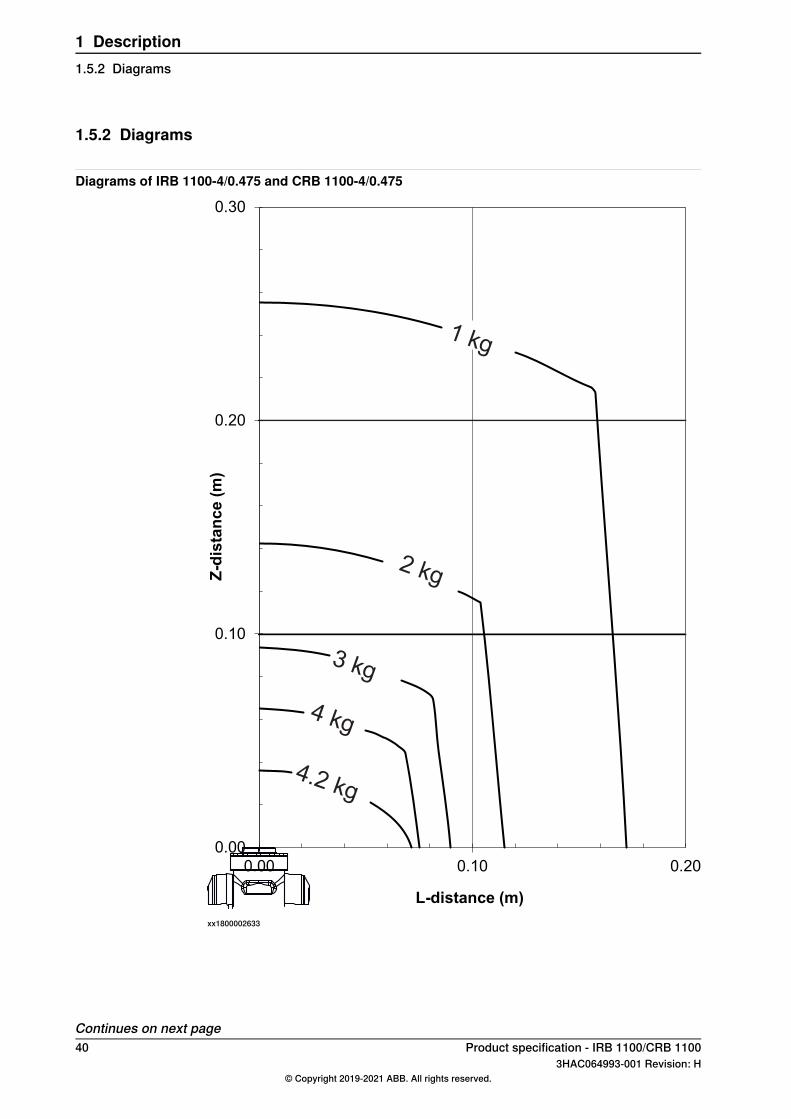
GeneralThe load diagrams include a nominal payload inertia, J0 of 0.012 kgm2 , and anextra load of 0.5 kg at the upper arm housing.At different moment of inertia the load diagram will be changed. For robots thatare allowed tilted, wall or inverted mounted, the load diagrams as given are validand thus it is also possible to use RobotLoad within those tilt and axis limits.
Control of load case with RobotLoadTo verify a specific load case, use the RobotStudio add-in RobotLoad.The result from RobotLoad is only valid within the maximum loads and tilt angles.There is no warning if the maximum permitted arm load is exceeded. For over-loadcases and special applications, contact ABB for further analysis.
Product specification - IRB 1100/CRB 1100 393HAC064993-001 Revision: H
© Copyright 2019-2021 ABB. All rights reserved.
1 Description1.5.1 Introduction
1.5.2 Diagrams
Diagrams of IRB 1100-4/0.475 and CRB 1100-4/0.475
0.00
0.10
0.20
0.30
0.00 0.10 0.20
Z-d
ista
nce (
m)
L-distance (m)
1 kg
2 kg
3 kg
4 kg
4.2 kg
xx1800002633
Continues on next page40 Product specification - IRB 1100/CRB 1100
3HAC064993-001 Revision: H© Copyright 2019-2021 ABB. All rights reserved.
1 Description1.5.2 Diagrams
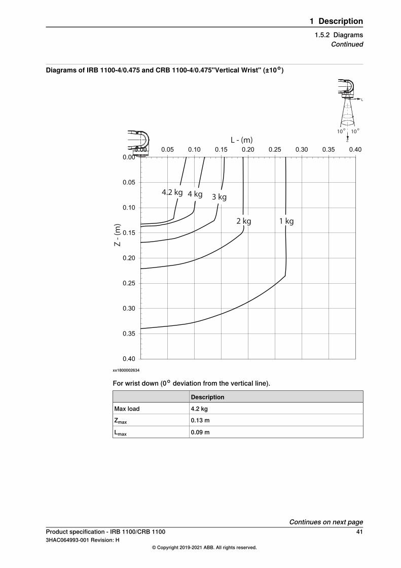
Diagrams of IRB 1100-4/0.475 and CRB 1100-4/0.475"Vertical Wrist" (±10o)
0.00
0.05
0.10
0.15
0.20
0.25
0.30
0.35
0.40
0.00 0.05 0.10 0.15 0.20 0.25 0.30 0.35 0.40
Z
L
10o
10o
4.2 kg 4 kg 3 kg
2 kg 1 kg
Z -
(m
)
L - (m)
xx1800002634
For wrist down (0o deviation from the vertical line).
Description
4.2 kgMax load
0.13 mZmax
0.09 mLmax
Continues on next pageProduct specification - IRB 1100/CRB 1100 413HAC064993-001 Revision: H
© Copyright 2019-2021 ABB. All rights reserved.
1 Description1.5.2 Diagrams
Continued
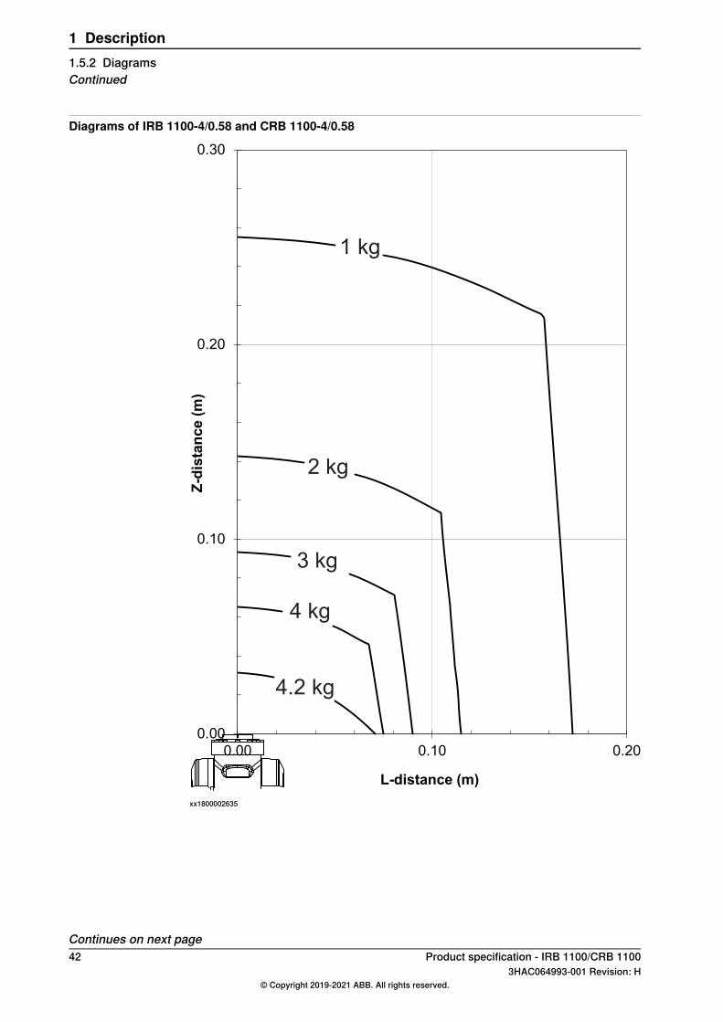
Diagrams of IRB 1100-4/0.58 and CRB 1100-4/0.58
0.00
0.10
0.20
0.30
0.00 0.10 0.20
Z-d
ista
nce (
m)
L-distance (m)
1 kg
2 kg
3 kg
4 kg
4.2 kg
xx1800002635
Continues on next page42 Product specification - IRB 1100/CRB 1100
3HAC064993-001 Revision: H© Copyright 2019-2021 ABB. All rights reserved.
1 Description1.5.2 DiagramsContinued
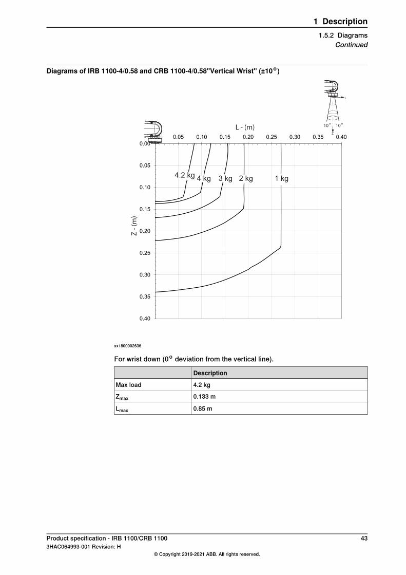
Diagrams of IRB 1100-4/0.58 and CRB 1100-4/0.58"Vertical Wrist" (±10o)
0.00
0.05
0.10
0.15
0.20
0.25
0.30
0.35
0.40
0.00 0.05 0.10 0.15 0.20 0.25 0.30 0.35 0.40Z
L
10o
10o
4.2 kg 4 kg 3 kg 2 kg 1 kg
L - (m)Z
- (
m)
xx1800002636
For wrist down (0o deviation from the vertical line).
Description
4.2 kgMax load
0.133 mZmax
0.85 mLmax
Product specification - IRB 1100/CRB 1100 433HAC064993-001 Revision: H
© Copyright 2019-2021 ABB. All rights reserved.
1 Description1.5.2 Diagrams
Continued
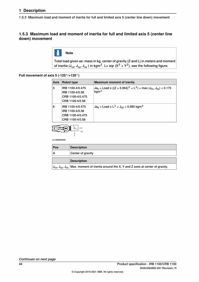
1.5.3 Maximum load and moment of inertia for full and limited axis 5 (center linedown) movement
Note
Total load given as: mass in kg, center of gravity (Z and L) in meters andmomentof inertia (Jox, Joy, Joz ) in kgm2 . L= sqr (X2 + Y2), see the following figure.
Full movement of axis 5 (-125°/+120°)
Maximum moment of inertiaRobot typeAxis
Ja5 = Load x ((Z + 0.064)2 + L2 ) + max (J0x, J0y) ≤ 0.175kgm2
IRB 1100-4/0.475IRB 1100-4/0.58
5
CRB 1100-4/0.475CRB 1100-4/0.58
Ja6 = Load x L2 + J0Z ≤ 0.085 kgm2IRB 1100-4/0.475IRB 1100-4/0.58
6
CRB 1100-4/0.475CRB 1100-4/0.58
xx1400002028
DescriptionPos
Center of gravityA
Description
Max. moment of inertia around the X, Y and Z axes at center of gravity.Jox, Joy, Joz
Continues on next page44 Product specification - IRB 1100/CRB 1100
3HAC064993-001 Revision: H© Copyright 2019-2021 ABB. All rights reserved.
1 Description1.5.3 Maximum load and moment of inertia for full and limited axis 5 (center line down) movement
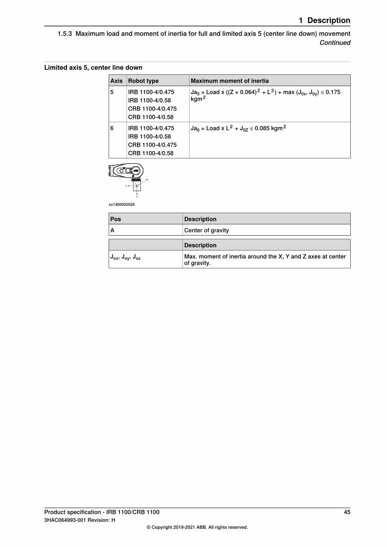
Limited axis 5, center line down
Maximum moment of inertiaRobot typeAxis
Ja5 = Load x ((Z + 0.064)2 + L2 ) + max (J0x, J0y) ≤ 0.175kgm2
IRB 1100-4/0.475IRB 1100-4/0.58
5
CRB 1100-4/0.475CRB 1100-4/0.58
Ja6 = Load x L2 + J0Z ≤ 0.085 kgm2IRB 1100-4/0.475IRB 1100-4/0.58
6
CRB 1100-4/0.475CRB 1100-4/0.58
xx1400002029
DescriptionPos
Center of gravityA
Description
Max. moment of inertia around the X, Y and Z axes at centerof gravity.
Jox, Joy, Joz
Product specification - IRB 1100/CRB 1100 453HAC064993-001 Revision: H
© Copyright 2019-2021 ABB. All rights reserved.
1 Description1.5.3 Maximum load and moment of inertia for full and limited axis 5 (center line down) movement
Continued
1.5.4 Wrist torque
Note
The wrist torque values are for reference only, and should not be used forcalculating permitted load offset (position of center of gravity) within the loaddiagram, since those also are limited by main axes torques as well as dynamicloads. Furthermore, arm loads will influence the permitted load diagram. To findthe absolute limits of the load diagram, use the RobotStudio add-in RobotLoad.
TorqueThe table below shows the maximum permissible torque due to payload.
Max torque valid atload
Max wrist torqueaxis 6
Max wrist torqueaxis 4 and 5
Robot type
4 kg2.9 Nm5.0 NmIRB 1100-4/0.475 and CRB1100-4/0.475
4 kg2.9 Nm5.0 NmIRB 1100-4/0.58 and CRB1100-4/0.58
46 Product specification - IRB 1100/CRB 11003HAC064993-001 Revision: H
© Copyright 2019-2021 ABB. All rights reserved.
1 Description1.5.4 Wrist torque
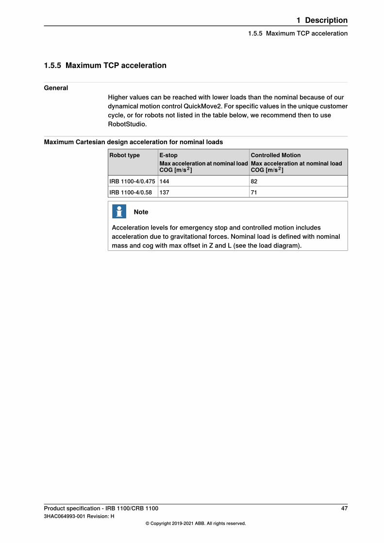
1.5.5 Maximum TCP acceleration
GeneralHigher values can be reached with lower loads than the nominal because of ourdynamical motion control QuickMove2. For specific values in the unique customercycle, or for robots not listed in the table below, we recommend then to useRobotStudio.
Maximum Cartesian design acceleration for nominal loads
Controlled MotionMax acceleration at nominal loadCOG [m/s2 ]
E-stopMax acceleration at nominal loadCOG [m/s2 ]
Robot type
82144IRB 1100-4/0.475
71137IRB 1100-4/0.58
Note
Acceleration levels for emergency stop and controlled motion includesacceleration due to gravitational forces. Nominal load is defined with nominalmass and cog with max offset in Z and L (see the load diagram).
Product specification - IRB 1100/CRB 1100 473HAC064993-001 Revision: H
© Copyright 2019-2021 ABB. All rights reserved.
1 Description1.5.5 Maximum TCP acceleration
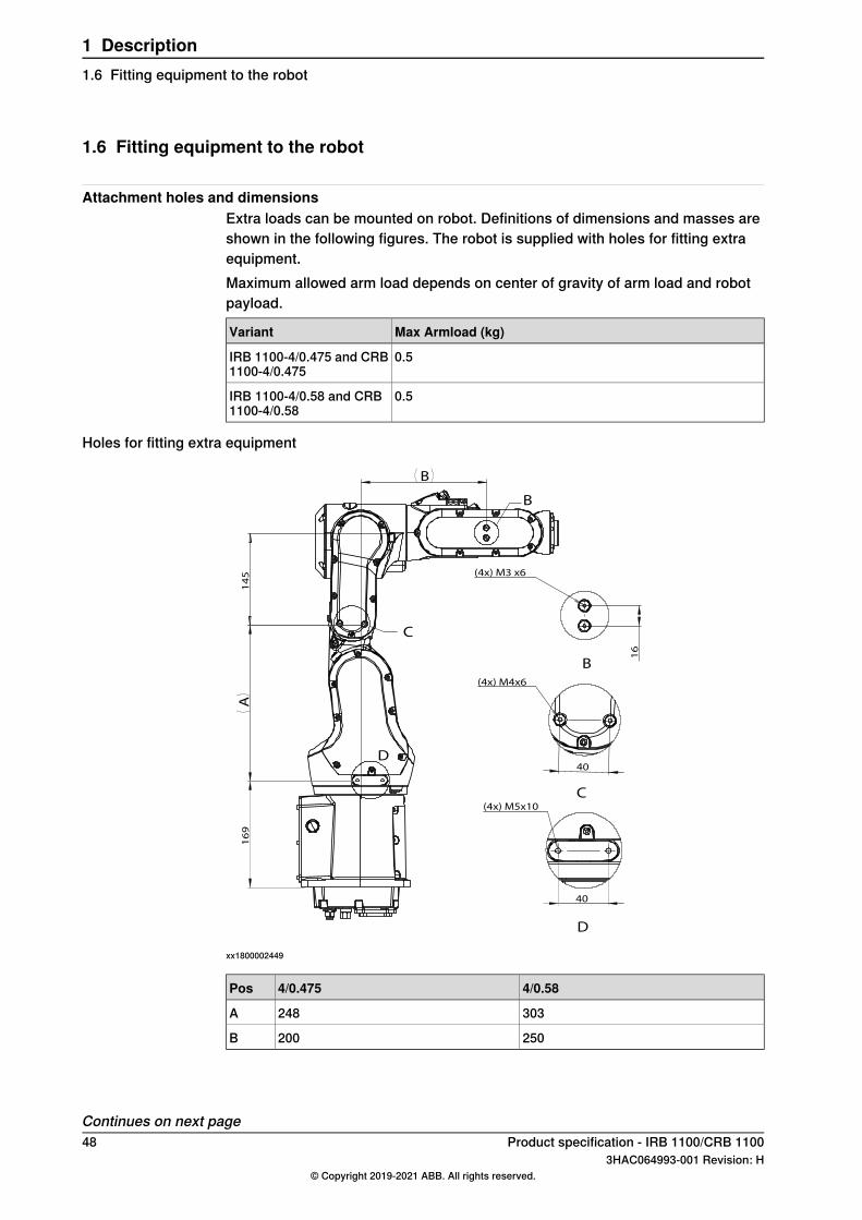
1.6 Fitting equipment to the robot
Attachment holes and dimensionsExtra loads can be mounted on robot. Definitions of dimensions and masses areshown in the following figures. The robot is supplied with holes for fitting extraequipment.Maximum allowed arm load depends on center of gravity of arm load and robotpayload.
Max Armload (kg)Variant
0.5IRB 1100-4/0.475 and CRB1100-4/0.475
0.5IRB 1100-4/0.58 and CRB1100-4/0.58
Holes for fitting extra equipment
B
C
D
16
(4x) M3 x6
40
(4x) M5x10
(4x) M4x6
40
B
C
D
16
9
A
14
5
B
xx1800002449
4/0.584/0.475Pos
303248A
250200B
Continues on next page48 Product specification - IRB 1100/CRB 1100
3HAC064993-001 Revision: H© Copyright 2019-2021 ABB. All rights reserved.
1 Description1.6 Fitting equipment to the robot
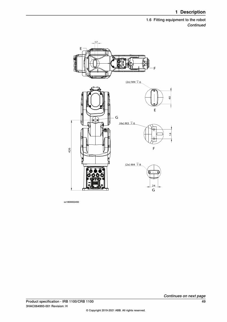
G
17
E
F
40
(2x) M4 6
14
(4x) M3 6
24
(2x) M4 8
G
42
6
E
F
xx1800002450
Continues on next pageProduct specification - IRB 1100/CRB 1100 493HAC064993-001 Revision: H
© Copyright 2019-2021 ABB. All rights reserved.
1 Description1.6 Fitting equipment to the robot
Continued
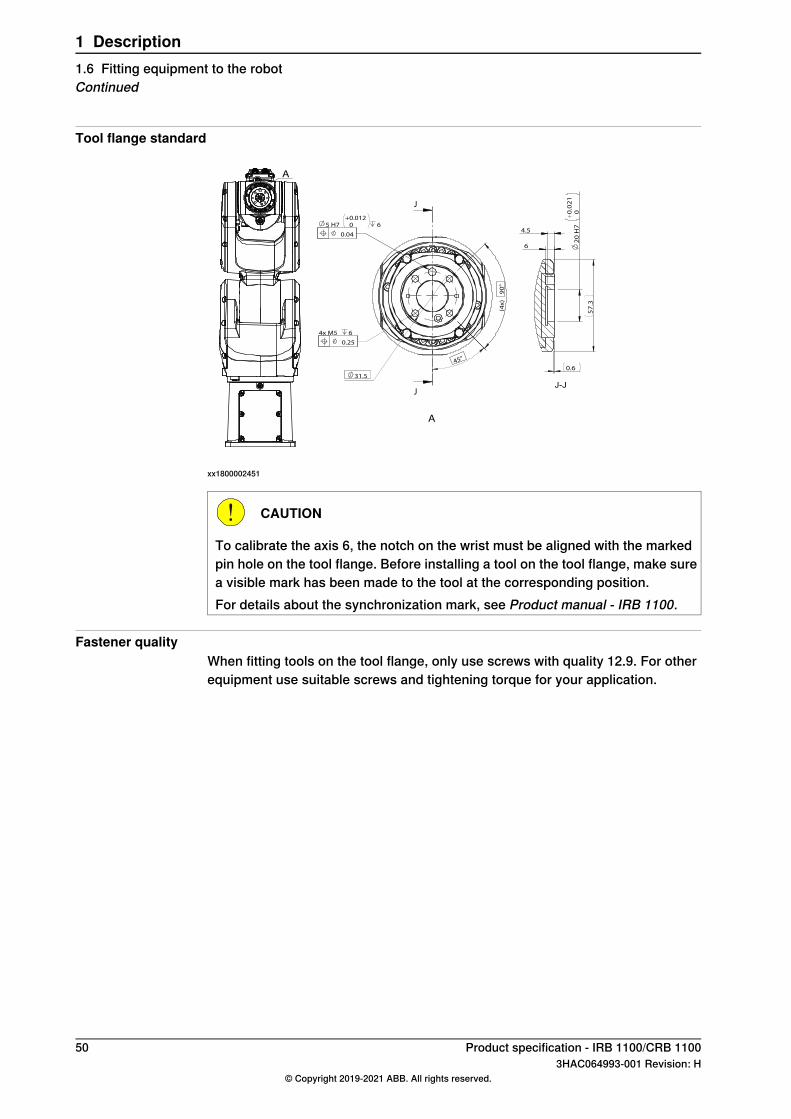
Tool flange standard
5 H7
+
0.012
0 6
4x M5 6
31.5
(4x
) 9
0°
45°
J
J
0.04
0.25
2
0 H
7
+
0.0
21
0
0.6
57
.3
4.5
6
J-J
A
A
xx1800002451
CAUTION
To calibrate the axis 6, the notch on the wrist must be aligned with the markedpin hole on the tool flange. Before installing a tool on the tool flange, make surea visible mark has been made to the tool at the corresponding position.For details about the synchronization mark, see Product manual - IRB 1100.
Fastener qualityWhen fitting tools on the tool flange, only use screws with quality 12.9. For otherequipment use suitable screws and tightening torque for your application.
50 Product specification - IRB 1100/CRB 11003HAC064993-001 Revision: H
© Copyright 2019-2021 ABB. All rights reserved.
1 Description1.6 Fitting equipment to the robotContinued
1.7 Maintenance and troubleshooting
GeneralThe robot requires only minimum maintenance during operation. It has beendesigned to make it as easy to service as possible:
• Maintenance-free AC motors are used.• Grease is used for the gearboxes.• The cabling is routed for longevity, and in the unlikely event of a failure, its
modular design makes it easy to change.
MaintenanceThe maintenance intervals depend on the use of the robot. The requiredmaintenance activities also depend on the selected options. For detailed informationonmaintenance procedures, see themaintenance section in Product manual - IRB1100 or Product manual - CRB 1100.
Product specification - IRB 1100/CRB 1100 513HAC064993-001 Revision: H
© Copyright 2019-2021 ABB. All rights reserved.
1 Description1.7 Maintenance and troubleshooting
1.8 Robot motion
1.8.1 Working range
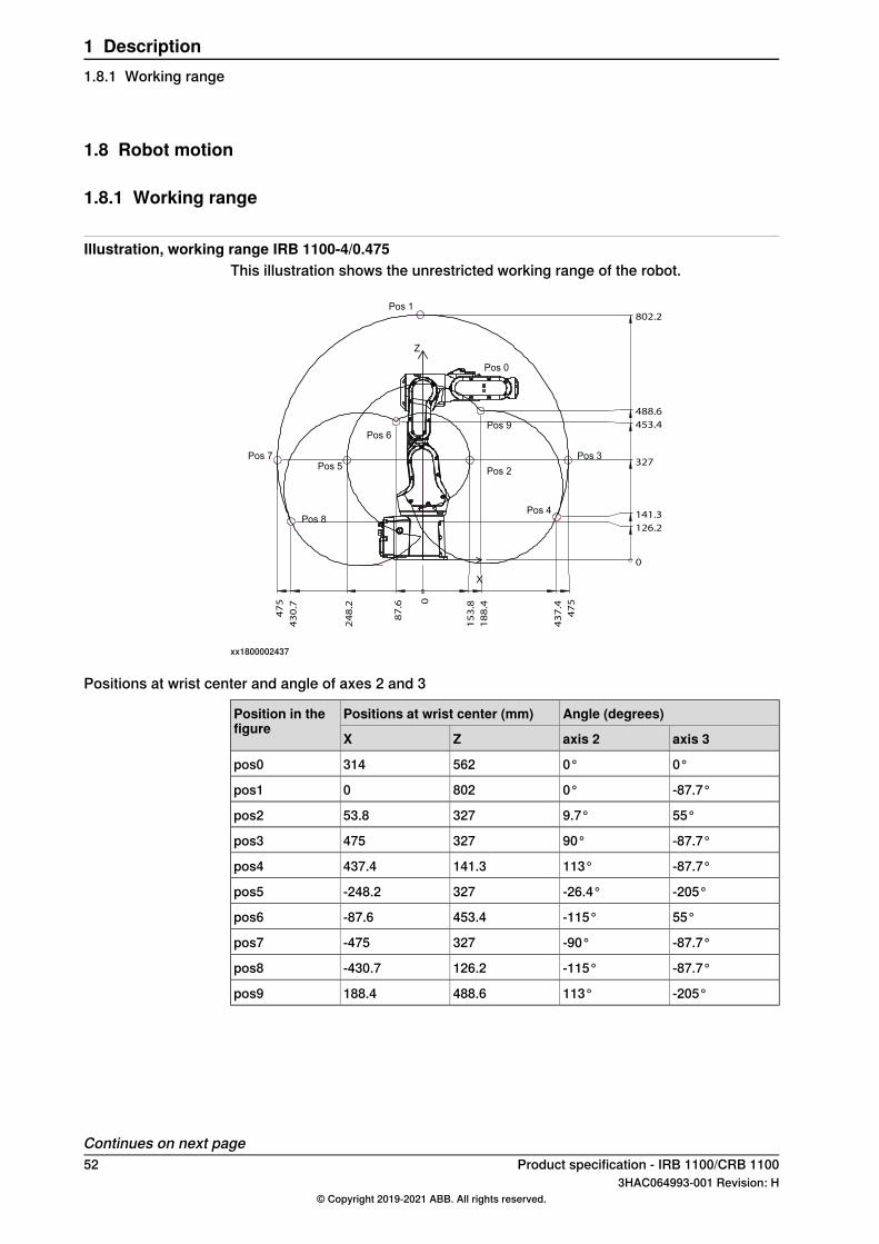
Illustration, working range IRB 1100-4/0.475This illustration shows the unrestricted working range of the robot.
0
15
3.8
18
8.4
47
5
43
7.4
87
.6
24
8.2
43
0.7
47
5
0
126.2
141.3
327
453.4
488.6
802.2
Z
X
Pos 1
Pos 7
Pos 8
Pos 5
Pos 6
Pos 2
Pos 9
Pos 3
Pos 4
Pos 0
xx1800002437
Positions at wrist center and angle of axes 2 and 3
Angle (degrees)Positions at wrist center (mm)Position in thefigure
axis 3axis 2ZX
0°0°562314pos0
-87.7°0°8020pos1
55°9.7°32753.8pos2
-87.7°90°327475pos3
-87.7°113°141.3437.4pos4
-205°-26.4°327-248.2pos5
55°-115°453.4-87.6pos6
-87.7°-90°327-475pos7
-87.7°-115°126.2-430.7pos8
-205°113°488.6188.4pos9
Continues on next page52 Product specification - IRB 1100/CRB 1100
3HAC064993-001 Revision: H© Copyright 2019-2021 ABB. All rights reserved.
1 Description1.8.1 Working range
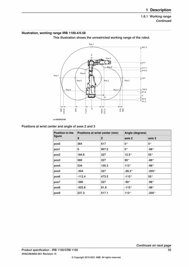
Illustration, working range IRB 1100-4/0.58This illustration shows the unrestricted working range of the robot.
0
30
4
11
2.4
52
5.8
58
0
18
4.6
23
7.3
53
4
58
0
0
81.8
100.3
327
473.5
517.1
907.2
617
82.6
91.5
Z
X
Pos 0
Pos 1
Pos 4
Pos 2
Pos 9
Pos 6
Pos 5
Pos 8
Pos 7
Pos 3
xx1800002438
Positions at wrist center and angle of axes 2 and 3
Angle (degrees)Positions at wrist center (mm)Position in thefigure
axis 3axis 2ZX
0°0°617364pos0
-88°0°907.20pos1
55°12.5°327184.6pos2
-88°90°327580pos3
-88°113°100.3534pos4
-205°-28.3°327-304pos5
55°-115°473.5-112.4pos6
-88°-90°327-580pos7
-88°-115°81.8-525.8pos8
-205°113°517.1237.3pos9
Continues on next pageProduct specification - IRB 1100/CRB 1100 533HAC064993-001 Revision: H
© Copyright 2019-2021 ABB. All rights reserved.
1 Description1.8.1 Working range
Continued
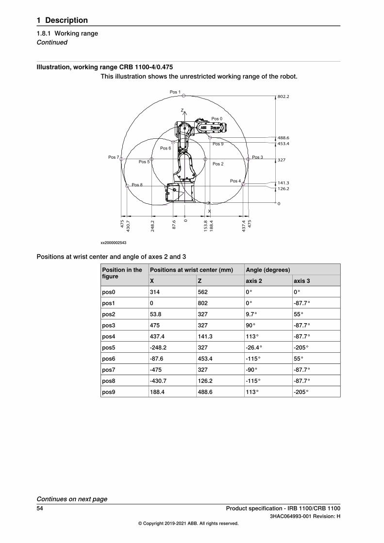
Illustration, working range CRB 1100-4/0.475This illustration shows the unrestricted working range of the robot.
0
15
3.8
18
8.4
47
5
43
7.4
87
.6
24
8.2
43
0.7
47
5
0
126.2
141.3
327
453.4
488.6
802.2
Z
X
Pos 1
Pos 7
Pos 8
Pos 5
Pos 6
Pos 2
Pos 9
Pos 3
Pos 4
Pos 0
xx2000002543
Positions at wrist center and angle of axes 2 and 3
Angle (degrees)Positions at wrist center (mm)Position in thefigure
axis 3axis 2ZX
0°0°562314pos0
-87.7°0°8020pos1
55°9.7°32753.8pos2
-87.7°90°327475pos3
-87.7°113°141.3437.4pos4
-205°-26.4°327-248.2pos5
55°-115°453.4-87.6pos6
-87.7°-90°327-475pos7
-87.7°-115°126.2-430.7pos8
-205°113°488.6188.4pos9
Continues on next page54 Product specification - IRB 1100/CRB 1100
3HAC064993-001 Revision: H© Copyright 2019-2021 ABB. All rights reserved.
1 Description1.8.1 Working rangeContinued
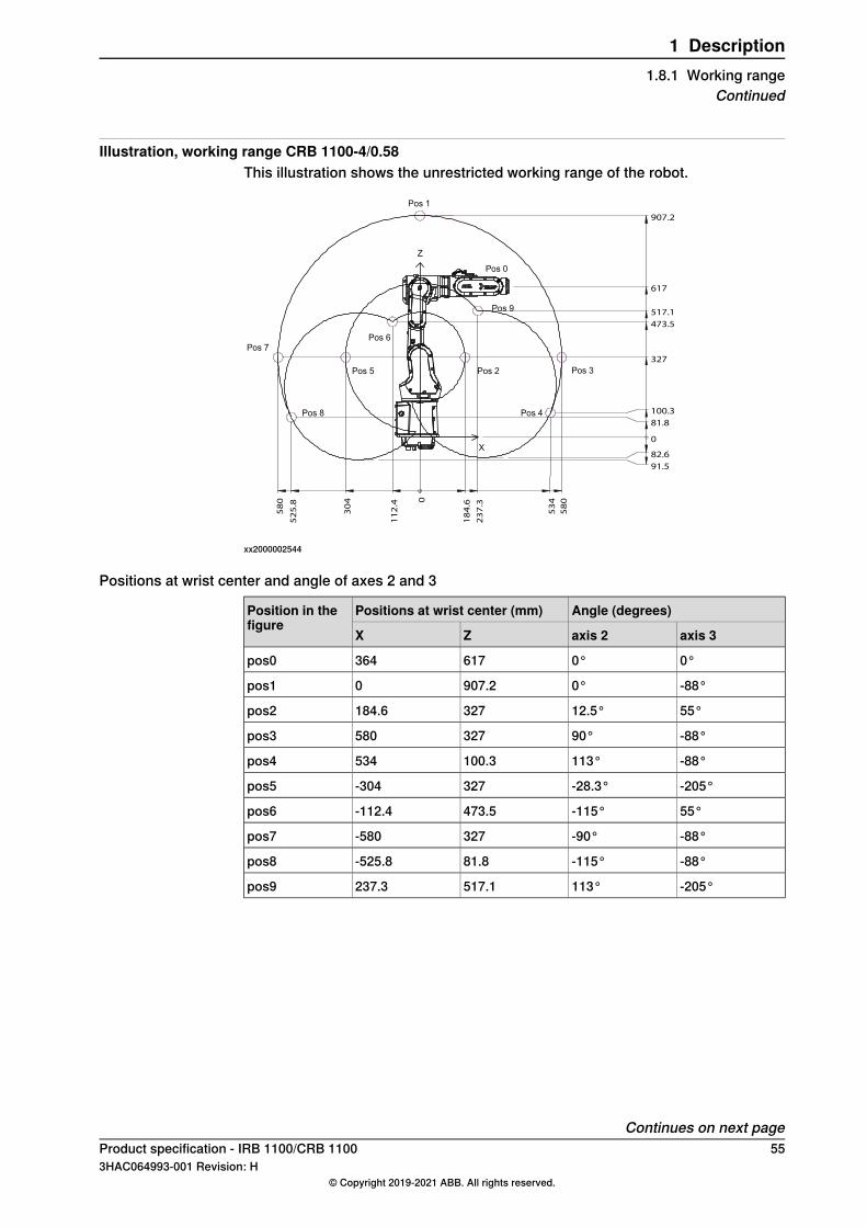
Illustration, working range CRB 1100-4/0.58This illustration shows the unrestricted working range of the robot.
0
30
4
11
2.4
52
5.8
58
0
18
4.6
23
7.3
53
4
58
0
0
81.8
100.3
327
473.5
517.1
907.2
617
82.6
91.5
Z
X
Pos 0
Pos 1
Pos 4
Pos 2
Pos 9
Pos 6
Pos 5
Pos 8
Pos 7
Pos 3
xx2000002544
Positions at wrist center and angle of axes 2 and 3
Angle (degrees)Positions at wrist center (mm)Position in thefigure
axis 3axis 2ZX
0°0°617364pos0
-88°0°907.20pos1
55°12.5°327184.6pos2
-88°90°327580pos3
-88°113°100.3534pos4
-205°-28.3°327-304pos5
55°-115°473.5-112.4pos6
-88°-90°327-580pos7
-88°-115°81.8-525.8pos8
-205°113°517.1237.3pos9
Continues on next pageProduct specification - IRB 1100/CRB 1100 553HAC064993-001 Revision: H
© Copyright 2019-2021 ABB. All rights reserved.
1 Description1.8.1 Working range
Continued
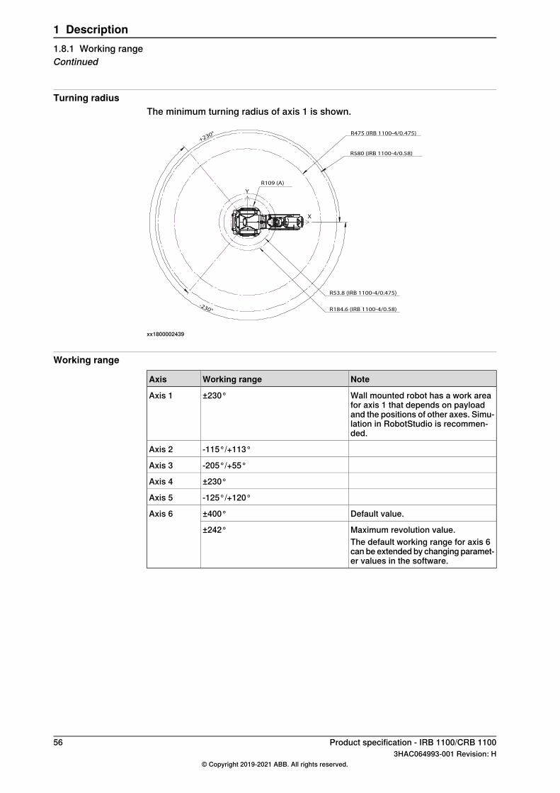
Turning radiusThe minimum turning radius of axis 1 is shown.
R184.6 (IRB 1100-4/0.58)
R53.8 (IRB 1100-4/0.475)
R580 (IRB 1100-4/0.58)
R475 (IRB 1100-4/0.475)
-230°
+230°
X
Y
R109 (A)
xx1800002439
Working range
NoteWorking rangeAxis
Wall mounted robot has a work areafor axis 1 that depends on payloadand the positions of other axes. Simu-lation in RobotStudio is recommen-ded.
±230°Axis 1
-115°/+113°Axis 2
-205°/+55°Axis 3
±230°Axis 4
-125°/+120°Axis 5
Default value.±400°Axis 6
Maximum revolution value.±242°The default working range for axis 6can be extendedby changing paramet-er values in the software.
56 Product specification - IRB 1100/CRB 11003HAC064993-001 Revision: H
© Copyright 2019-2021 ABB. All rights reserved.
1 Description1.8.1 Working rangeContinued
1.8.2 Axes with restricted working range
1.8.2.1 Adjusting the working range
Reasons for adjusting the manipulator working rangeThe working range of each manipulator axis is configured in the software. If thereis a risk that the manipulator may collide with other objects at installation site, itsworking space should be limited. The manipulator must always be able to movefreely within its entire working space.
Working range configurationsThe parameter values for the axes working range can be altered within the allowedworking range and according to available options for the robot, either to limit or toextend a default working range. Allowed working ranges and available options foreach manipulator axis are specified inWorking range on page 56.
Mechanical stops on the manipulatorMechanical stops are and can be installed on the manipulator as limiting devicesto ensure that the manipulator axis does not exceed the working range values setin the software parameters.
Note
The mechanical stops are only installed as safety precaution to physically stopthe robot from exceeding the working range set. A collision with a mechanicalstop always requires actions for repair and troubleshooting.
Movable mechanical stop iiFixed mechanical stop iAxis
noyesAxis 1
noyesAxis 2
noyesAxis 3
nonoAxis 4
noyesAxis 5
nonoAxis 6i Part of the casting or fixed on the casting and can not /should not be removed.ii Can be installed in one or more than one position, to ensure a reducedworking range, or be removed
to allow extended working range.
Product specification - IRB 1100/CRB 1100 573HAC064993-001 Revision: H
© Copyright 2019-2021 ABB. All rights reserved.
1 Description1.8.2.1 Adjusting the working range
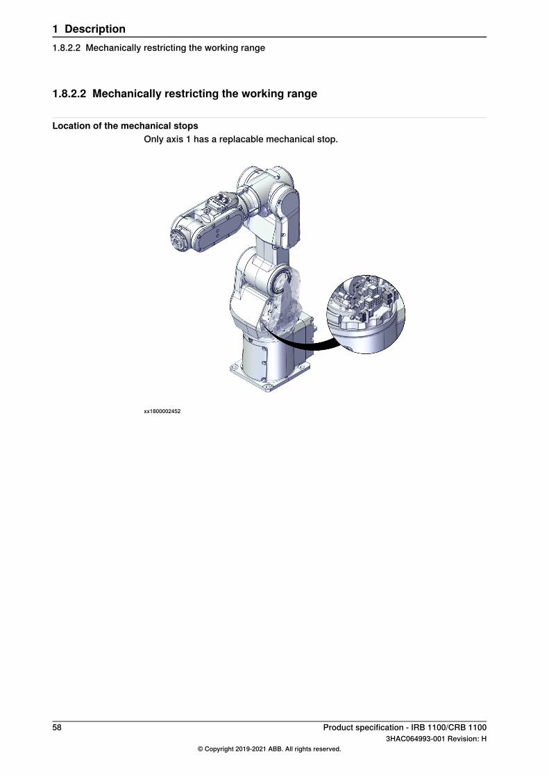
1.8.2.2 Mechanically restricting the working range
Location of the mechanical stopsOnly axis 1 has a replacable mechanical stop.
xx1800002452
58 Product specification - IRB 1100/CRB 11003HAC064993-001 Revision: H
© Copyright 2019-2021 ABB. All rights reserved.
1 Description1.8.2.2 Mechanically restricting the working range
1.8.3 Performance according to ISO 9283
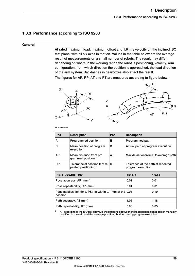
GeneralAt rated maximum load, maximum offset and 1.6 m/s velocity on the inclined ISOtest plane, with all six axes in motion. Values in the table below are the averageresult of measurements on a small number of robots. The result may differdepending on where in the working range the robot is positioning, velocity, armconfiguration, from which direction the position is approached, the load directionof the arm system. Backlashes in gearboxes also affect the result.The figures for AP, RP, AT and RT are measured according to figure below.
xx0800000424
DescriptionPosDescriptionPos
Programmed pathEProgrammed positionA
Actual path at program executionDMean position at programexecution
B
Max deviation from E to average pathATMean distance from pro-grammed position
AP
Tolerance of the path at repeatedprogram execution
RTTolerance of position B at re-peated positioning
RP
4/0.584/0.475IRB 1100/CRB 1100
0.010.01Pose accuracy, AP i (mm)
0.010.01Pose repeatability, RP (mm)
0.190.08Pose stabilization time, PSt (s) within 0.1 mm of theposition
1.181.03Path accuracy, AT (mm)
0.050.05Path repeatability, RT (mm)i AP according to the ISO test above, is the difference between the teached position (positionmanually
modified in the cell) and the average position obtained during program execution.
Product specification - IRB 1100/CRB 1100 593HAC064993-001 Revision: H
© Copyright 2019-2021 ABB. All rights reserved.
1 Description1.8.3 Performance according to ISO 9283
1.8.4 Velocity
Maximum axis speed
Axis 6Axis 5Axis 4Axis 3Axis 2Axis 1Robot type
750 °/s420 °/s560 °/s280 °/s380 °/s460 °/sIRB 1100-4/0.475 and CRB1100-4/0.475
750 °/s420 °/s560 °/s280 °/s360 °/s460 °/sIRB 1100-4/0.58 and CRB 1100-4/0.58
There is a supervision function to prevent overheating in applications with intensiveand frequent movements (high duty cycle).
60 Product specification - IRB 1100/CRB 11003HAC064993-001 Revision: H
© Copyright 2019-2021 ABB. All rights reserved.
1 Description1.8.4 Velocity
1.8.5 Robot stopping distances and times
IntroductionThe stopping distances and times for category 0 and category 1 stops, as requiredby EN ISO 10218-1 Annex B, are listed in Product specification - Robot stoppingdistances according to ISO 10218-1 (3HAC048645-001).
Product specification - IRB 1100/CRB 1100 613HAC064993-001 Revision: H
© Copyright 2019-2021 ABB. All rights reserved.
1 Description1.8.5 Robot stopping distances and times
1.9 Customer connections
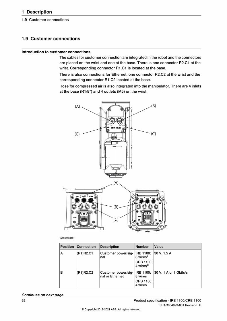
Introduction to customer connectionsThe cables for customer connection are integrated in the robot and the connectorsare placed on the wrist and one at the base. There is one connector R2.C1 at thewrist. Corresponding connector R1.C1 is located at the base.There is also connections for Ethernet, one connector R2.C2 at the wrist and thecorresponding connector R1.C2 located at the base.Hose for compressed air is also integrated into the manipulator. There are 4 inletsat the base (R1/8”) and 4 outlets (M5) on the wrist.
(A)
(B)
(C)
(A) (B)
(C) (C)
xx1900000131
ValueNumberDescriptionConnectionPosition
30 V, 1.5 AIRB 1100:8 wires i
Customer power/sig-nal
(R1)R2.C1A
CRB 1100:4 wires ii
30 V, 1 A or 1 Gbits/sIRB 1100:8 wires
Customer power/sig-nal or Ethernet
(R1)R2.C2B
CRB 1100:4 wires
Continues on next page62 Product specification - IRB 1100/CRB 1100
3HAC064993-001 Revision: H© Copyright 2019-2021 ABB. All rights reserved.
1 Description1.9 Customer connections
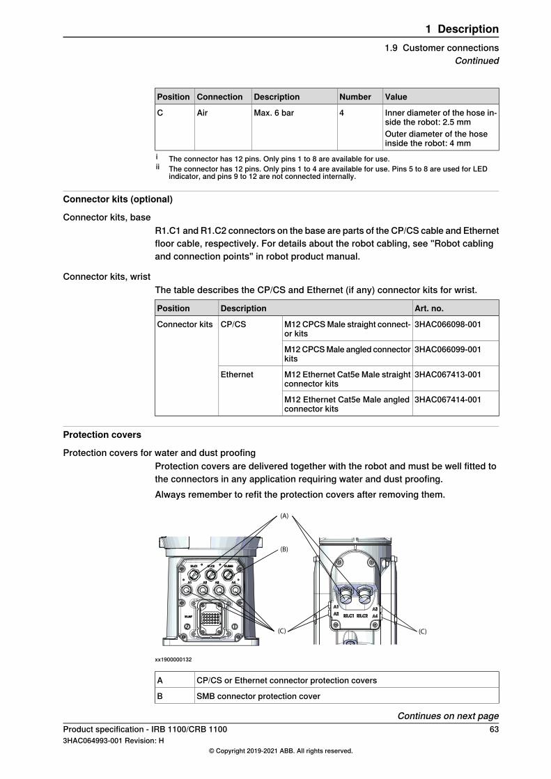
ValueNumberDescriptionConnectionPosition
Inner diameter of the hose in-side the robot: 2.5 mm
4Max. 6 barAirC
Outer diameter of the hoseinside the robot: 4 mm
i The connector has 12 pins. Only pins 1 to 8 are available for use.ii The connector has 12 pins. Only pins 1 to 4 are available for use. Pins 5 to 8 are used for LED
indicator, and pins 9 to 12 are not connected internally.
Connector kits (optional)
Connector kits, baseR1.C1 and R1.C2 connectors on the base are parts of the CP/CS cable and Ethernetfloor cable, respectively. For details about the robot cabling, see "Robot cablingand connection points" in robot product manual.
Connector kits, wristThe table describes the CP/CS and Ethernet (if any) connector kits for wrist.
Art. no.DescriptionPosition
3HAC066098-001M12 CPCSMale straight connect-or kits
CP/CSConnector kits
3HAC066099-001M12CPCSMale angled connectorkits
3HAC067413-001M12 Ethernet Cat5e Male straightconnector kits
Ethernet
3HAC067414-001M12 Ethernet Cat5e Male angledconnector kits
Protection covers
Protection covers for water and dust proofingProtection covers are delivered together with the robot and must be well fitted tothe connectors in any application requiring water and dust proofing.Always remember to refit the protection covers after removing them.
(A)
(C) (C)
(B)
xx1900000132
CP/CS or Ethernet connector protection coversA
SMB connector protection coverB
Continues on next pageProduct specification - IRB 1100/CRB 1100 633HAC064993-001 Revision: H
© Copyright 2019-2021 ABB. All rights reserved.
1 Description1.9 Customer connections
Continued
Air hose connector protection coversC
64 Product specification - IRB 1100/CRB 11003HAC064993-001 Revision: H
© Copyright 2019-2021 ABB. All rights reserved.
1 Description1.9 Customer connectionsContinued
2 Specification of variants and options2.1 Introduction to variants and options
GeneralThe different variants and options for the IRB 1100/CRB 1100 are described in thefollowing sections. The same option numbers are used here as in the specificationform.The variants and options related to the robot controller are described in the productspecification for the controller.
Product specification - IRB 1100/CRB 1100 653HAC064993-001 Revision: H
© Copyright 2019-2021 ABB. All rights reserved.
2 Specification of variants and options2.1 Introduction to variants and options
2.2 Manipulator
Manipulator variants
Reach (m)Handling capacity(kg)
TypeOption
0.4754IRB 11003300-1
0.584IRB 11003300-2
0.4754CRB 11003300-20Compatible with: 3063-1Collaborative package
0.584CRB 11003300-21Compatible with: 3063-1Collaborative package
Manipulator color
DescriptionOption
ABB Graphite White standard209-202
ABB white standard (Not available for CRB 1100 Variants andrequired 3351-4 clean room)
209-2
Note
Notice that delivery time for painted spare parts will increase for none standardcolors.
Manipulator protection
DescriptionOption
Base 40,IP403350-400
Base 67,IP67, not available for CRB 1100 Variants3350-670
Clean Room 4, not available for CRB 1100 Variants3351-4
Note
Base 40 includes IP40, according to standard IEC 60529.Base 67 includes IP67, according to standard IEC 60529.Clean Room class 4 includes ISO class 4 standard, according to DIN EN ISO14644-1, -14.
Signs on manipulator
DescriptionOption
ABB3302-1
ABB collaborative, only available for CRB 1100 Variants3302-2
Continues on next page66 Product specification - IRB 1100/CRB 1100
3HAC064993-001 Revision: H© Copyright 2019-2021 ABB. All rights reserved.
2 Specification of variants and options2.2 Manipulator
Note
This option is released from RobotWare 6.03 as IRB1200FGL-5/0.9 andIRB1200FGL-7/0.7.
Media & CommunicationWhen 3303-1 Parallel & Air is selected then 3304-1 and 3305-1 options are activatedfor selecting.When 3303-2 Ethernet, Parallel, Air is selected then 3304-1,3305-1,3306-1 and3307-1 are activated for selecting.
DescriptionTypeOption
Includes customer power CP and customer signalsCS + air.
Parallel & Air3303-1
Includes CP, CS + air + Ethernet (PROFINET).Ethernet, Parallel, Air3303-2
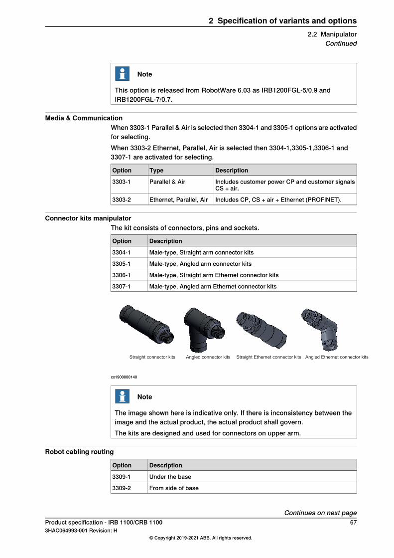
Connector kits manipulatorThe kit consists of connectors, pins and sockets.
DescriptionOption
Male-type, Straight arm connector kits3304-1
Male-type, Angled arm connector kits3305-1
Male-type, Straight arm Ethernet connector kits3306-1
Male-type, Angled arm Ethernet connector kits3307-1
Straight connector kits Angled connector kitsits Straight Ethernet connector kits kits Angled Ethernet connector kits
xx1900000140
Note
The image shown here is indicative only. If there is inconsistency between theimage and the actual product, the actual product shall govern.The kits are designed and used for connectors on upper arm.
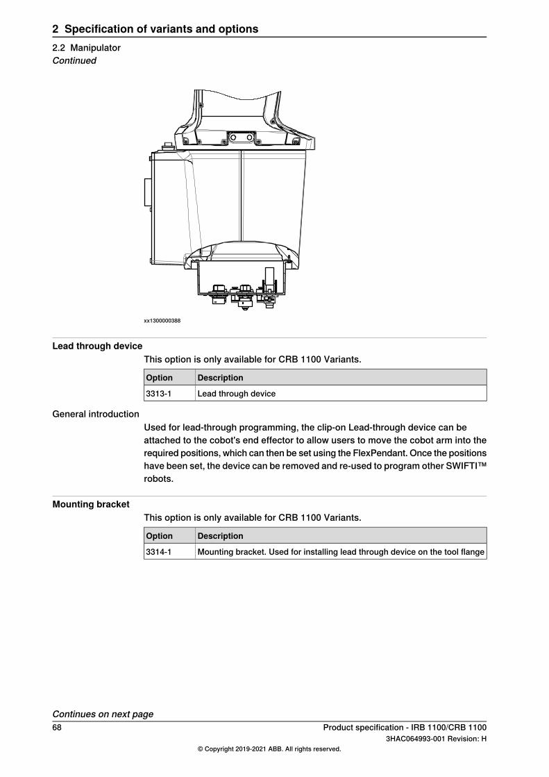
Robot cabling routing
DescriptionOption
Under the base3309-1
From side of base3309-2
Continues on next pageProduct specification - IRB 1100/CRB 1100 673HAC064993-001 Revision: H
© Copyright 2019-2021 ABB. All rights reserved.
2 Specification of variants and options2.2 Manipulator
Continued
xx1300000388
Lead through deviceThis option is only available for CRB 1100 Variants.
DescriptionOption
Lead through device3313-1
General introductionUsed for lead-through programming, the clip-on Lead-through device can beattached to the cobot's end effector to allow users to move the cobot arm into therequired positions, which can then be set using the FlexPendant. Once the positionshave been set, the device can be removed and re-used to program other SWIFTI™robots.
Mounting bracketThis option is only available for CRB 1100 Variants.
DescriptionOption
Mounting bracket. Used for installing lead through device on the tool flange3314-1
Continues on next page68 Product specification - IRB 1100/CRB 1100
3HAC064993-001 Revision: H© Copyright 2019-2021 ABB. All rights reserved.
2 Specification of variants and options2.2 ManipulatorContinued
WarrantyFor the selected period of time, ABB will provide spare parts and labour to repairor replace the non-conforming portion of the equipment without additional charges.During that period, it is required to have a yearly Preventative Maintenanceaccording to ABB manuals to be performed by ABB. If due to customer restrainsno data can be analyzed in the ABB Ability service Condition Monitoring &Diagnostics for robots with OmniCore controllers, and ABB has to travel to site,travel expenses are not covered. The Extended Warranty period always starts onthe day of warranty expiration. Warranty Conditions apply as defined in the Terms& Conditions.
Note
This description above is not applicable for option Stock warranty [438-8]
DescriptionTypeOption
Standard warranty is 12months fromCustomer DeliveryDate or latest 18 months after Factory Shipment Date,whichever occurs first. Warranty terms and conditionsapply.
Standard warranty438-1
Standard warranty extended with 12 months from enddate of the standard warranty. Warranty terms and con-ditions apply. Contact Customer Service in case of otherrequirements.
Standard warranty + 12months
438-2
Standard warranty extended with 18 months from enddate of the standard warranty. Warranty terms and con-ditions apply. Contact Customer Service in case of otherrequirements.
Standard warranty + 18months
438-4
Standard warranty extended with 24 months from enddate of the standard warranty. Warranty terms and con-ditions apply. Contact Customer Service in case of otherrequirements.
Standard warranty + 24months
438-5
Standard warranty extended with 6 months from enddate of the standard warranty. Warranty terms and con-ditions apply.
Standard warranty + 6months
438-6
Standard warranty extended with 30 months from enddate of the standard warranty. Warranty terms and con-ditions apply.
Standard warranty + 30months
438-7
Maximum 6 months postponed start of standard war-ranty, starting from factory shipment date. Note that noclaims will be accepted for warranties that occurred be-fore the end of stock warranty. Standard warranty com-mences automatically after 6 months from FactoryShipment Date or from activation date of standard war-ranty in WebConfig.
Note
Special conditions are applicable, seeRoboticsWarrantyDirectives.
Stock warranty438-8
Product specification - IRB 1100/CRB 1100 693HAC064993-001 Revision: H
© Copyright 2019-2021 ABB. All rights reserved.
2 Specification of variants and options2.2 Manipulator
Continued
2.3 Floor cables
Manipulator cable - Straight
LengthsOption
3 m3200-1
7 m3200-2
15 m3200-3
Mains cableRequired 3063-1 Collaborative package and only available for CRB 1100 variants.
DescriptionLengthsOption
Cable assembly with CEE7/VII line-side plugEU mains cable, 3m3203-1
Cable assembly with CPCS-CCC line-sideplug
CN mains cable, 3m3203-5
Cable assembly with AS/NZS 3112 line-sideAU mains cable, 3m3203-6
Connection of parallell communicationRequired 3303-1 Parallel & Air or 3303-2 Ethernet, Parallel, Air.
LengthsOption
3 m3201-1
7 m3201-2
15 m3201-3
Connection of EthernetRequired 3303-2 Ethernet, Parallel, Air and occupies 1 Ethernet port.
LengthsOption
7 m3202-2
15 m3202-3
70 Product specification - IRB 1100/CRB 11003HAC064993-001 Revision: H
© Copyright 2019-2021 ABB. All rights reserved.
2 Specification of variants and options2.3 Floor cables
3 AccessoriesGeneral
There is a range of tools and equipment available.
Basic software and software options for robot and PCFor more information, see Application manual - Controller software OmniCore,Product specification - OmniCore C line and Product specification - OmniCore Eline.
Product specification - IRB 1100/CRB 1100 713HAC064993-001 Revision: H
© Copyright 2019-2021 ABB. All rights reserved.
3 Accessories

This page is intentionally left blank
IndexAAbsolute Accuracy, 37Absolute Accuracy, calibration, 33ambient humidity
operation, 16storage, 16
ambient temperatureoperation, 16storage, 16
Ccalibration
Absolute Accuracy type, 32standard type, 32
calibration, Absolute Accuracy, 33calibration marks, 34calibration position
scales, 34calibration scales, 34CalibWare, 32category 0 stop, 61category 1 stop, 61compensation parameters, 37
Ffoundation
requirements, 16
Hhumidity
operation, 16storage, 16
Lloads on foundation, 14
Mmechanical stop
axis 1, 58mechanical stop location, 58
Ooperating conditions, 16options, 65
Pproduct standards, 22protection classes, 17protection type, 17
Rreplacing
mechanical stopaxis 1, 58
requirements on foundation, 16robot
protection class, 17protection types, 17working range, 52
Ssafety standards, 22scales on robot, 34securing the robot to foundation, attachment screws, 25standards, 22
ANSI, 22CAN, 22EN IEC, 22EN ISO, 22
standard warranty, 69stock warranty, 69stopping distances, 61stopping times, 61storage conditions, 16sync marks, 34
Ttemperatures
operation, 16storage, 16
torques on foundation, 14turning radius, 56
Vvariants, 65
Wwarranty, 69weight, 14working range, 56
robot, 52
Product specification - IRB 1100/CRB 1100 733HAC064993-001 Revision: H
© Copyright 2019-2021 ABB. All rights reserved.
Index


ABB ABRobotics & Discrete AutomationS-721 68 VÄSTERÅS, SwedenTelephone +46 (0) 21 344 400
ABB ASRobotics & Discrete AutomationNordlysvegen 7, N-4340 BRYNE, NorwayBox 265, N-4349 BRYNE, NorwayTelephone: +47 22 87 2000
ABB Engineering (Shanghai) Ltd.Robotics & Discrete AutomationNo. 4528 Kangxin HighwayPuDong DistrictSHANGHAI 201319, ChinaTelephone: +86 21 6105 6666
ABB Inc.Robotics & Discrete Automation1250 Brown RoadAuburn Hills, MI 48326USATelephone: +1 248 391 9000
abb.com/robotics
3HAC064993-001,Rev
H,en
© Copyright 2019-2021 ABB. All rights reserved.Specifications subject to change without notice.