processing semi-conductor wafers and other substrates - european
TRANSCRIPT
Europaisches Patentamt
European Patent Office
Dffice europeen des brevets
© Publication number: 0 3 7 2 8 8 4
EUROPEAN PATENT A P P L I C A T I O N
© Application number: 89312617.7
© Date of filing: 04.12.89
© Intel.': H01L 2 1 / 0 0
§) Priority: 05.12.88 US 279844 © Applicant: CRYCO TWENTY-TWO, INC. 8107 Altoga
«) Date of publication of application: Austin Texas(US) 13.06.90 Bulletin 90/24
© Inventor: Yates, Cleon R. g> Designated Contracting States: 13018 Travis View Loop
CH DE FR GB IT LI NL Austin Texas 78732(US)
© Representative: Parr, Ronald Edward R.E. Parr &Co. Colman House Station Road Knowle Solihull West Midlands B93 OHL(GB)
© Processing semi-conductor wafers and other substrates.
© A movable cantilevered purge system providing for a wafer load position, a wafer purge position, and a wafer process position. The movable cantilevered purge system includes an elephant carrier vehicle for movement of a movable quartz elephant tube. The movable quartz elephant tube includes a purge injector and a return exhaust tube. A cantilevered paddle clamping vehicle moves behind the movable quartz elephant carrier vehicle and holds a silicon carbide or ceramic paddle. The elephant carrier ve- hicle includes a quartz sealing ring and a stainless steel sealing ring carrier on pivotable adjusting blocks, and are supported by a plurality of cylindrical tubes. The quartz sealing ring concentrically posi- tions about the process tube of the furnace and a metal ring position about a scavenger face. The
^return exhaust tube connects back into the scaven- . ger area of the furnace.
00 00 r 2
» /J°°"20n ? J r-3 W I / / f e a r t e a
0 . LU
F1G.1
90 S2 82n
Xerox copy centre
I :P 0 372 884 A2
PROCESSING SEMI-CONDUCTOR WAFERS AND OTHER SUBSTRATES
This invention relates to the processing of semi-conductor wafers or other substrates.
3ACKGROUND OF THE INVENTION
1. Field of the Invention -
The present invention pertains to semiconduc- tor processing systems, and more particularly, per- tains to a movable cantilevered purge system in- cluding a movable quartz elephant tube with a paddle for use between a wafer load position, a wafer purge position, and a wafer process position for a substrate processing furnace.
2. Description of the Prior Art -
Prior art systems have either provided a wafer load position or a wafer process position, but have not provided for an adequate purging position be- tween the other two positions.
U.S. Patent No. 4,459,104 to Wollmann, en- titled "Cantilevered Diffusion Tube Apparatus and Method"; and U.S. Patent No. 4,526,534 to Woll- mann, entitled "Cantilevered Diffusion Tube Ap- paratus and Method" each have slots in the bottom of the process tubes.
U.S. Patent No. 4,543,059 to Whang et al., entitled "Slotted Cantilevered Diffusion Tube Sys- tem and Method and Apparatus for Loading" de- scribes a diffusion tube apparatus. The reference discloses a large quartz tube with a slot in the bottom. There is one glass sleeve inside the pro- cess tube. There are no bellows to support a paddle. The glass sleeve is supported on a single runaway and in close proximity to the process tube.
The present invention overcomes the disadvan- tages of the prior art by providing a movable ele- phant tube for use in a wafer load purge and process position, and can include a purge injector and a return exhaust tube in the elephant tube. The moveable elephant tube provides for access to wafer loads and purging of the process tube includ- ing accelerated cooling cycles.
SUMMARY OF THE INVENTION
The general purpose of the present invention is
to provide a movable cantilevered purge system including the use of a movable quartz elephant tube with sealing ring assembly, which seals a movable quartz elephant tube into a wafer process-
5 ing diffusion or other furnace and about scavenger faces of the furnace.
According to one embodiment of the present invention, there is provided a movable cantilevered purge system including a movable quartz elephant
70 tube positioned on bearing blocks on stainless steel shafts. A silicon carbide or ceramic paddle is supported in a cantilevered paddle clamping ve- hicle, also mounted on the stainless steel shafts. The stainless steel shaft assembly is positioned
75 adjacent to a processing furnace and in alignment with a quartz process tube. The movable quartz elephant tube moves between a wafer load posi- tion, a wafer purge position, and a wafer process- ing position. The particular sealing arrangement of
20 the quartz ring to the process tube and the stain- less steel ring to the scavenger face, provide for a system in that the rings are provided with three degrees of movement and concentricity between the movable quartz elephant tube, the process
25 tube, and the furnace by the doors. Significant aspects and features of the present
invention include a movable cantilevered purge system with a movable quartz elephant tube which includes a quartz door sealing against a wafer
30 processing tube, and a metal door sealing against the scavenger face where the doors are sealed with concentricity with respect to the tubes. There is also a seal made between the scavenger face and the return exhaust for venting of any gases. This
35 also provides a workable system preventing back- streaming of gases.
Another significant aspect and feature of the present invention is an elephant tube which slides between a wafer load position, a wafer purge posi-
40 tion, and a wafer process position. The elephant tube and supporting structure also provides for venting and expedited cooling and/or purging of gases through a return scavenger exhaust tube. Based on the sealing arrangements, there is no, or
45 very minimal, back-streaming of atmospheric gases from the room into the elephant tube.
A further significant aspect and feature of the present invention is a movable cantilevered purge system which provides for an atmospheric con-
so trolled environment such as for vapor deposition processes. The atmosphere can also be purged such as with an inert gas.
Having thus described principal embodiments of the present invention, it is a principal object hereof to provide a movable cantilevered purge
2
-stem including the use or an eiepnant tuDe wren least one, preferably two, injector nozzles riding
i a track or rail system. One object of the present invention is a mov-
)le elephant tube between various positions and ong the shaft of a paddle handle such as a orton paddle.
Another object of the present invention is an ephant tube assembly which forms an airtight sal about the surrounding structure to prevent the scape of gases and prevent the back-streaming of ases. Depending upon the operational parameters, imperatures and pressures, there may be a very linute amount of gas escaping or back-streaming, ut if so, such is very minimal.
BRIEF DESCRIPTION OF THE DRAWINGS
Other objects of the present invention ana nany of the attendant advantages of the present nvention will be readily appreciated as the same jecomes better understood by reference to the ollowing detailed description when considered in :onnection with the accompanying drawings, in vhich like reference numerals designate like parts hroughout the figures thereof and wherein:
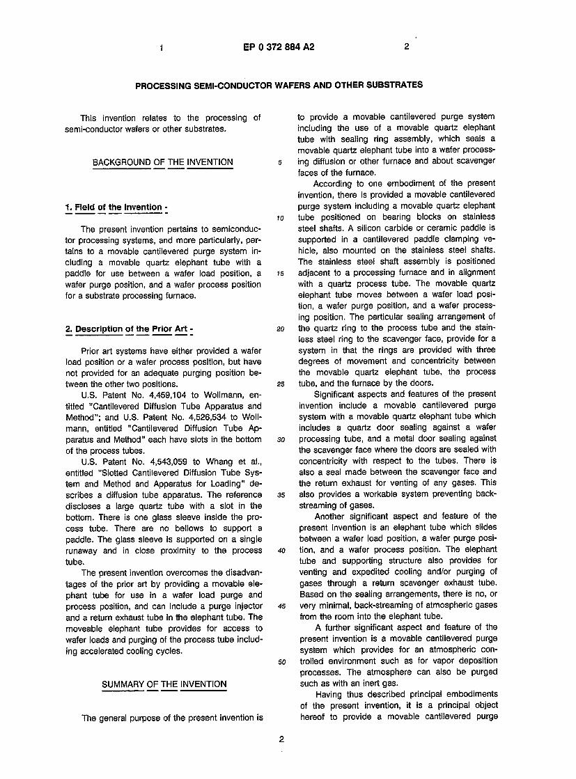
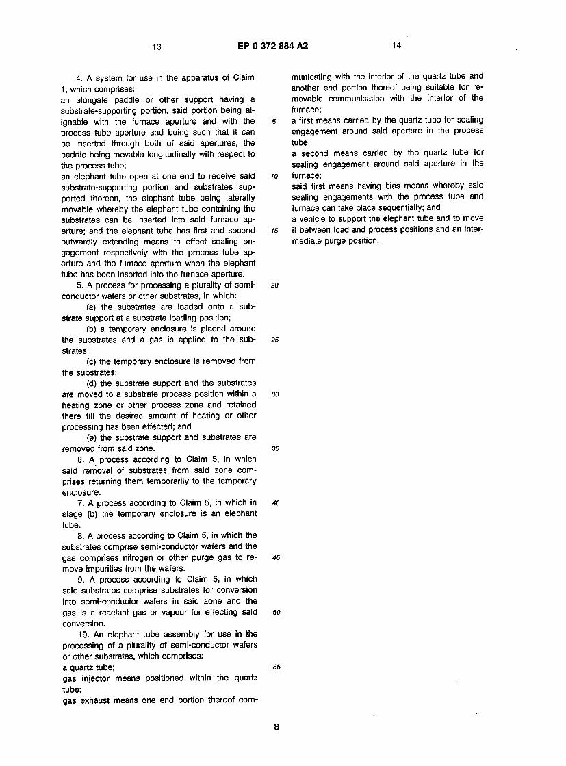
FIG.1 illustrates a side view of a movable ;antilevered purge system of the present invention;
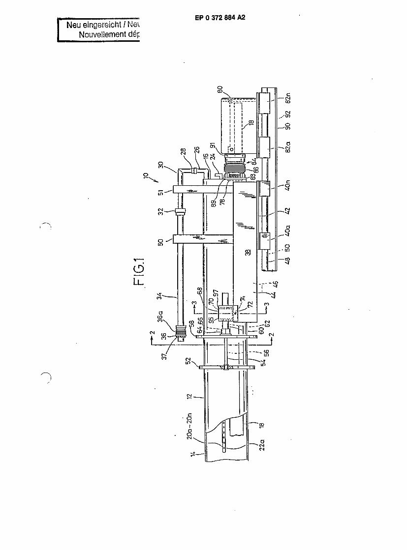
FIG. 2 illustrates an end view in cross sec- ion of the movable cantilevered purge system tak- sn along line 2-2 of FIG. 1 ;
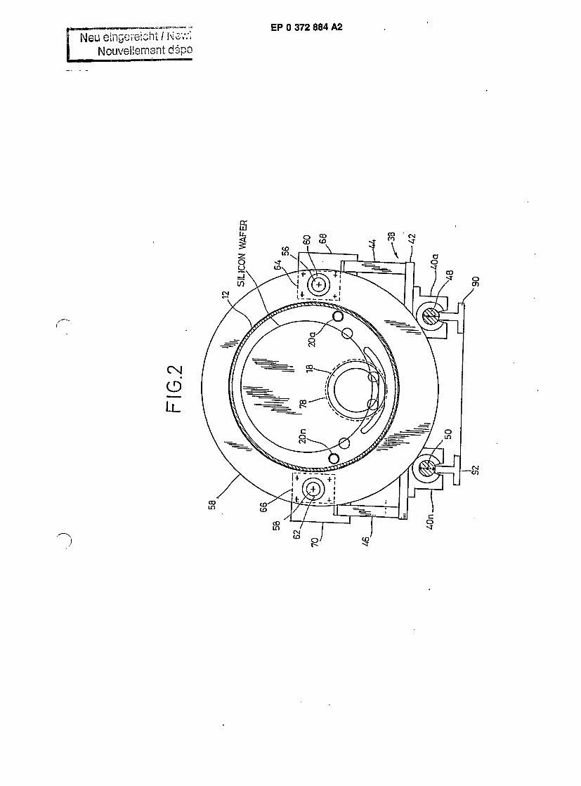
FIG. 3 illustrates an end view in cross sec- ion of the movable cantilevered purge system tak- 3n along line 3-3 of Fig. 1;
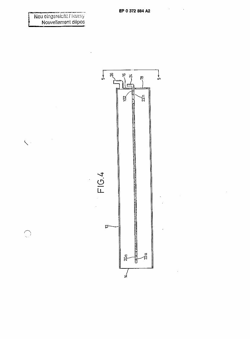
FIG. 4 illustrates a vertical cross section of a ■novable quartz elephant tube;
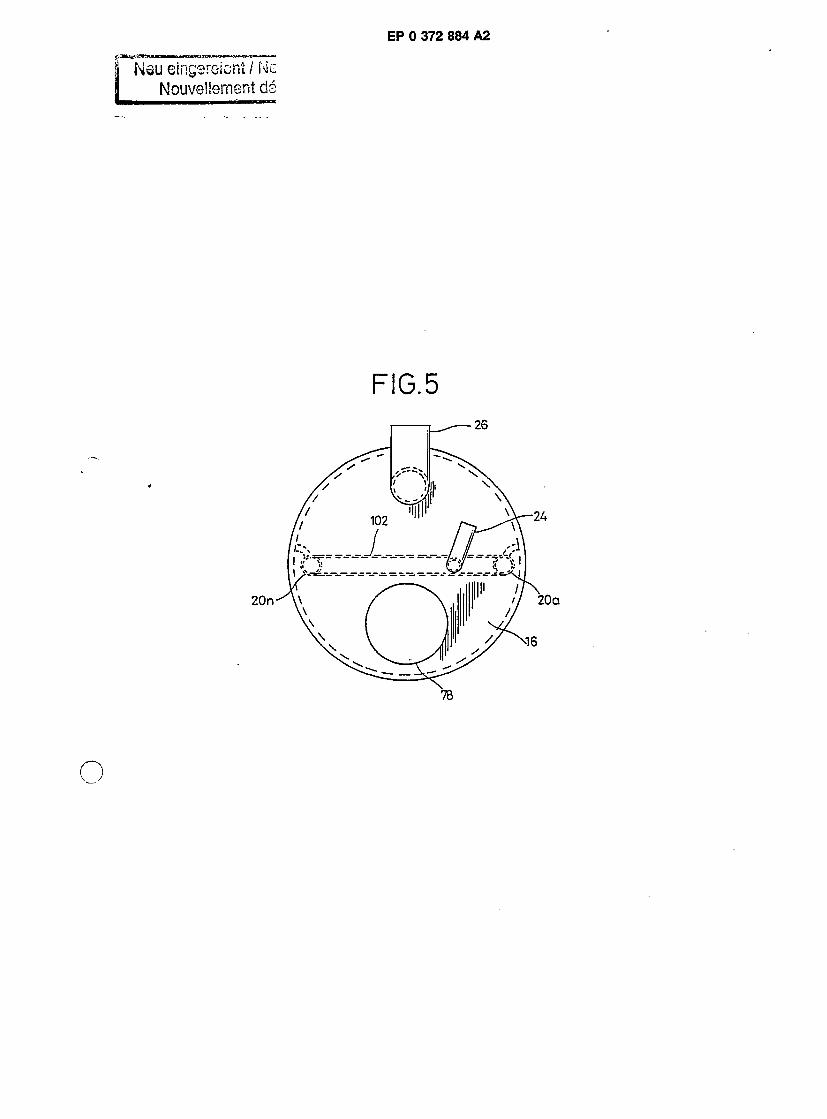
FIG. 5 illustrates an end view of the movable quartz elephant tube;
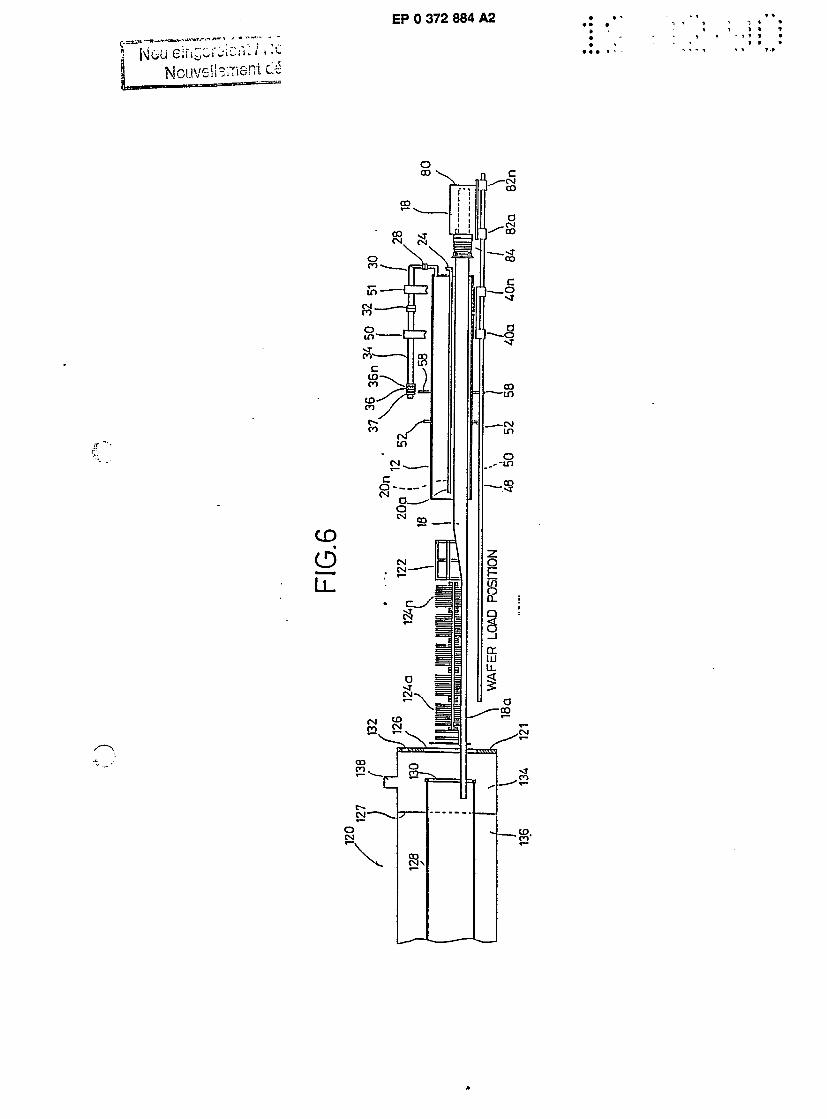
FIG. 6 illustrates the mode of operation of the wafer load position of the movable cantilevered purge system in partial cross section;
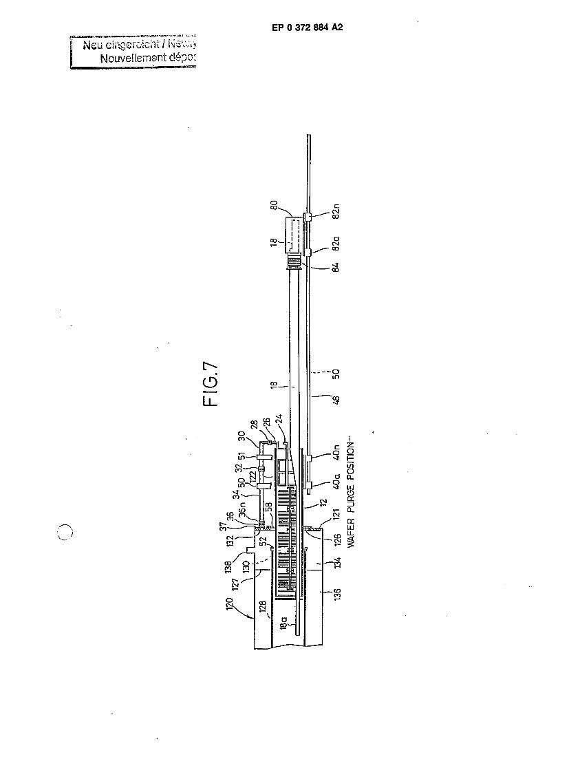
FIG. 7 illustrates the mode of operation of the wafer purge position;
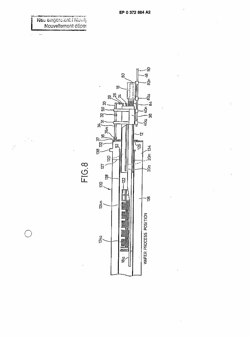
FIG. 8 illustrates the mode of operation of the wafer process position;
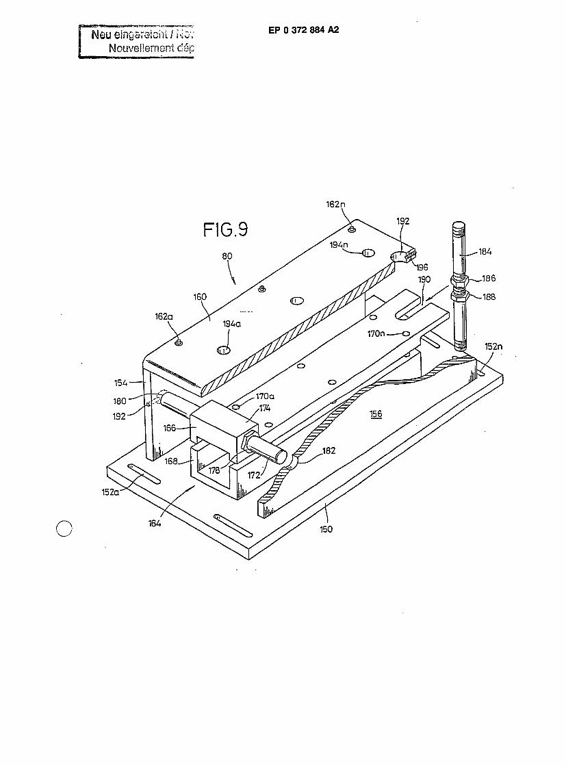
FIG. 9 illustrates a perspective view of the cantilevered paddle clamping vehicle;
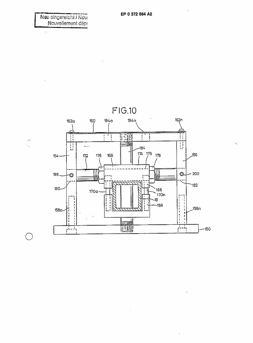
FIG. 10 illustrates an end view of the cantile- vered paddle clamping vehicle; and
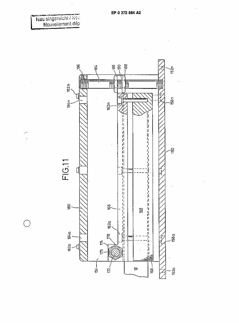
FIG. 11 illustrates a cross-sectional view of the cantilevered paddle clamping vehicle.
DESCRIPTION OF THE PREFERRED EMHUUi- MENTS
cantilevered purge system 10 including a movable quartz elephant tube 12. The movable quartz ele- phant tube 12 can be of varying diameters and lengths according to specific load requirements and wafer size. The movable quartz elephant tube 12 includes one open end 14, and an opposing end 16 which can be partially closed with an opening in the partially closed end 16 of sufficient size and
> shape to allow a silicon carbide or other ceramic paddle support shaft or handle 18 to pass through the minimal clearance of about 70 thousands of an inch and in a range of 10-100 thousands of an inch. Also, the movable quartz elephant tube 12 can
5 include a plurality of one or more nitrogen purge injectors 20a-20n located and fixed to the inner wail of the movable quartz elephant tube 12 at strategic points so as to pass nitrogen or other gases across wafer surfaces for such purposes as removing oxy-
3 gen from the atmosphere. The movable quartz elephant tube 12 can also have a plurality of one or more connecting nipples for the purpose of attach- ing gas passing apparatus structure. A plurality of one or more holes 22a-22n of varying sizes and
5 center-to-center spacings are located in the nitro-
gen purge injectors 20a-20n for the purpose of passing nitrogen or other gases across the surface of silicon wafers as illustrated in FIG. 2. A quartz (exhaust) nipple 24 positions on the partially closed
o end 16 of the movable quartz elephant tube 12 onto which a gas source can be attached. The quartz exhaust nipple 24 connects to the purge injector tubes 20a-20n. A quartz exhaust nipple 26 is constructed of quartz tubing and seals directly to
is the interior of the movable quartz elephant tube 12 for the purpose of attaching an airtight O'ring com- pression connector and flange assembly 28. A stainless steel connector elbow 30 connects to the other end of the airtight O'ring compression con-
to nector 28 and to airtight O'ring compression con- nector 32. The stainless steel connector elbow 30 is constructed of stainless steel or other like ma- terials, and provides a vacuum-tight connection be- tween the movable quartz elephant tube 12 via the
« quartz exhaust nipple 26, the airtight O'ring com- pression connectors 28 and 32, and a straight section of stainless steel return scavenger exhaust tube 34. This provides the piping for which to route exhaust gases that may exit from the furnace scav-
50 enger area. A closure door 36 for the return scav- enger exhaust tube 34 is constructed of stainless steel or other like materials, combines a stainless steel flexible joint 36a in cooperation with stainless steel sealing door 58, and attaches to the stainless
55 steel scavenger exhaust tube 34. The closure door 36 provides a substantially airtight sealing between the scavenger face 121 and the stainless steel return scavenger exhaust tube 34 when in the
o
> :P 0 372 884 A2
Durge or wafer process position (Figures 7 and 8). \ compression type airtight O'ring 37 positions adjacent to the end of the closure door 36 to subsequently seal over return scavenger exhaust lole 132 of the scavenger face 121 as illustrated in FIG. 6. A quartz sealing door 52 of sufficient inner and outer diameter and thickness is located con- centrically over and about the movable quartz ele- phant tube 12. The quartz sealing door 52 is sup- ported by two or more horizontally aligned quartz slide rods on opposing sides of the elephant carrier vehicle 38, and provides a tight seal between the movable quartz elephant tube 12 and the process tube when the movable quartz elephant tube 12 is in the purge or wafer process position. A stainless steel sealing door 58, constructed of stainless steel or other like material of sufficient inner and outer diameter and thickness, is located concentrically over and about the movable quartz elephant tube 12, is supported by two or more horizontally aligned cylindrical tubes 60 and 62, and provides a seal between the movable quartz elephant tube 12 and external portion of the scavenger exhaust area when the movable quartz elephant tube 12 is in the purge position or wafer process position. Mounting flanges 64 and 66, constructed of stainless steel or other like material, are located concentrically on cylindrical tubes 60 and 62 for the purpose of attaching and securing stainless steel sealing door 58. Pivotal adjusting blocks 68 and 70, made of stainless steel or other like material, are located and attached to opposing sides of the elephant carrier vehicle 38, and provide support means for the quartz slide rods 54 and 56 and cylindrical tubes 60 and 62 while offering both vertical and angular pivotal adjustments to the quartz sealing door 52 and the stainless steel scavenger sealing door 58. The cylindrical tubes 60 and 62, made of stainless steel or other like material, are located and attached to the pivotal adjusting blocks 68 and 70, have one end open and the other end closed providing an enclosed housing for stainless steel springs, and one or more Teflon concentric cylin- drical spacers. Teflon spacers maintain concentric- ity between quartz slide rods 54 and 56 and cylin- drical tubes 60 and 62, respectively, and also pro- vide slidability when the quartz sealing door 52 concentrically contacts the process tube during the purge or wafer process cycles. The stainless steel springs allow flexibility of quartz slide rods 54 and 56, assuring proper engagement and tension of quartz sealing door 52 during the purge or wafer process cycles. Pivotal pins 72 and 74 provide axis to pivotal adjusting blocks 68 and 70 located on opposing sides of the elephant carrier vehicle 38 and above opposing sides of the movable quartz elephant tube 12 when adjustments are made so as to achieve concentricity between quartz sealing
door 52 and movable quartz elephant tube tne stainless steel sealing door 58, and movable quartz elephant tube 12.
A paddle hole 78 is located in partially closed 5 end 16 of movable quartz elephant tube 12 and
provides a passageway through which the silicon carbide paddle support shaft 18 passes. The size and configuration of partially closed hole 16 varies according to the particular silicon carbide paddle
m size. A cantilevered paddle clamping vehicle 80 is constructed of aluminum which can be hard stain- less steel or other like materials, and is supported by a plurality of one or more bearing blocks 82a- 82n which provides smooth travel on the parallel
f5 stainless steel shafts 48 and 50. The cantilevered paddle clamping vehicle 80 secures and supports the silicon carbide paddle support shaft 18. The cantilevered paddle clamping vehicle 80 also pro- vides for alignment of the paddle with respect to
10 the process tube and other components. The can- tilevered paddle clamping vehicle 80 also provides adjustments, both vertical and lateral, to the silicon carbide paddle support shaft 1 8 assuring alignment between the silicon carbide paddle support shaft
35 18, the movable quartz elephant tube 12 and pro- cess tube as previously referenced in the co-pend- ing patent application. A closure door 84 for the movable quartz elephant tube 12 is constructed of stainless steel or other like materials, and attaches
30 directly to silicon carbide paddle support shaft 18 via a compression type airtight O'ring type seal 91 of suitable material. The closure door 84 is com- prised of stainless steel flexible bellows 86 at- tached to a sealing plate 88 which may have an
35 optional compression type airtight O'ring 89 of a suitable material, which engages with end 1 6 of the movable quartz elephant tube 12, and assures a substantially airtight sealing between the silicon carbide paddle support shaft 18 and the movable
40 quartz elephant tube 12 when in the purge or the wafer process position. Shaft supports 90 and 92, constructed of stainless steel or other like materi- als, provide structure for securing and supporting the stainless steel shafts 48 and 50 so that the
45 bearing blocks 40a-40n and 82a-82n can ride smoothly along the shaft supports 90 and 92. An O'ring 89 seals the sealing plate 88 and the ele- phant tube end 16. Another O'ring 91 seals the closure door 84 about the silicon carbide paddle
50 support shaft 18. FIG. 2 illustrates an end view in cross section
of the movable cantilevered purge system 10 taken along line 2-2 of FIG. 1 where all numerals cor- respond to those elements previously described.
55 Shown in particular is the stainless steel sealing door 58 concentric to and over and about the movable quartz elephant tube 12. The plurality of purge injectors 20a-20n are located as to provide
4
P 0 372 884
ar desired purging across substrate fronts, by way if example, of the inner side wall of the movable luartz elephant tube 12. Additional numbers of mrge injectors 20a-20n can also be incorporated ito the system. The purge injectors 20a-20n can >e placed at other positions on the inner side walls han the positions illustrated, and can be manifol- led together as illustrated in FIG. 4.
FIG. 3 illustrates an end view in cross section >f the movable cantilevered purge system 10 taken tlong line 3-3 of FIG. 1 where all numerals cor- espond to those elements previously described, .ongitudinal support members 94 and 96 extend vertically from the mounting plate 42 of the ele- ihant carrier vehicle 38 to support the sides of the novable quartz elephant tube 12. The elephant :arrier vehicle 38, including the movable quartz jlephant tube 12, traverses on the plurality of bear- ng blocks 40a-40n and along the shafts 48 and 50. Shafts 48 and 50 are supported along the top Dortion of the shaft supports 90 and 92.
Pivotal pins 72 and 74 are illustrated in the jivotal adjusting blocks 68 and 70. Adjustment screws 95 and 97 in the pivotal adjusting block 68 and adjustment screws 98 and 100 in the pivotal adjusting block 70, as also illustrated partially in =IG. 1 , adjust to pivot the pivotal adjusting blocks 38 and 70 about the pivotal pins 72 and 74 so as to Horizontally align the cylindrical tubes 60 and 62, the quartz slide rods 54 and 56 and stainless steel and quartz sealing doors 58 and 52. The sealing doors 52 and 58 act as concentric doors against the process tube and the scavenger face.
FIG. 4 illustrates a vertical cross section of the inovable quartz elephant tube 12 where all nu- merals correspond to those elements previously described. Illustrated in particular is one of the purge injectors 20a secured to the inner wall of the movable quartz elephant tube 12. A manifold 102 connects the ends of the purge injector tubes 20a- 20n adjacent to hole 22n of each injector tube as further illustrated in FIG. 5.
FIG. 5 illustrates an end view of the movable quartz elephant tube 12 along line 5-5 of FIG. 5 where all numerals correspond to those elements previously described. Manifold 102 is illustrated across the interior of the movable quartz elephant tube 12 connecting the nitrogen purge injectors 20a and 20n.
MODE OF OPERATION
FIG. 6-8 best illustrate the mode of operation ot the movable cantilevered purge system in conjunc- tion with a wafer processing furnace.
FIG. 6 illustrates the movable cantilevered
purge system iu in partial cross sbuuum aujaooni to a wafer processing furnace 120 in the wafer load position. All numerals correspond to those ele- ments previously described. A wafer load zone 1 8a
i of the paddle extends from a midpoint of the pad- dle to one end of the silicon carbide paddle sup- port shaft 18. A wafer boat 122, ready for process- ing, contains a plurality of wafers 124a-124n resid- ing on the loading zone 18a and is illustrated prior
o to processing. The wafer processing furnace 120 includes a scavenger face 121, a scavenger hole 126 in the scavenger face 121, a quartz process tube 128 and a process tube orifice 130. A scaven- ger wall 127 in the wafer processing furnace 120
5 separates the scavenger area 134 from the process area 136 within the process furnace 120. The diam- eter of the scavenger hole 126 is of a larger dimension than the diameter of the process tube orifice 130 to allow passage of the quartz sealing
o door 52 through the scavenger hole 1 26 to subse- quently seal against the process tube orifice 130. The scavenger hole 126 aligns axially with and subsequently seals against the stainless steel seal door 58. In a like manner, the process tube orifice
s 130 aligns axially with and subsequently seals against the quartz sealing door 52. A return scav- enger exhaust hole 132 in the scavenger face 121 of the wafer processing furnace 120 aligns with the return scavenger exhaust tube 34, the closure door
io 36 and flexible joint 36a. The return scavenger exhaust hole 132 can be optionally added to the scavenger hole 126. A scavenger exhaust hole 138 is located on the wafer processing furnace 120 adjacent to the scavenger area 134.
!5 FIG. 7 illustrates the wafer purge position where all numerals correspond to those elements previously described. The elephant carrier vehicle 38, illustrated in FIG. 1 , and the cantilevered pad- dle clamping vehicle 80 slidingly position along the
to stainless steel shafts 48 and 50 in a coordinated fashion so that the movable quartz elephant tube 12 and associated members are positioned partially within and seal against the wafer processing fur- nace 120 and the quartz process tube 128 for
45 purging. As previously described, the wafer pro- cessing furnace 120 is sealed by the mating and engagement of the stainless steel sealing door 58 with the furnace scavenger face 121. The quartz process tube 128 is sealed by the mating and
50 engagement of the quartz sealing door 52 with the process tube orifice 130. The closure door 36, including the flexible joint 36a, seals the return scavenger exhaust tube 34 projecting through the return scavenger exhaust hole 132 and thus with
55 the furnace scavenger area 134 of the wafer pro- cessing furnace 120. The quartz sealing door 52 and the stainless steel sealing door 58 seal in a sequenced manner to seal the movable quartz ele-
g EP 0 372 884 A2 10
phant tube 12 to the scavenger face 121 and the quartz process tube 128. Initially, the spring cush- ioned quartz sealing door 52 mates with process tube orifice 1 30 of the process tube 1 28 and com- presses internal springs in the pivotal adjusting blocks 68 and 70. Subsequently, the stainless steel sealing door 58 positions against the scavenger face 121 of the wafer processing furnace 120 as the elephant carrier vehicle 38, illustrated in FIG. 1 , is moved further to the left. Pressurized nitrogen or other gas is introduced into the quartz exhaust nipple 24, and enters the interior of the sealed movable quartz elephant tube 12 through the purge injectors 20a-20n illustrated in FIGS. 1,2,4 and 5. Spent gases are purged from the sealed movable quartz elephant tube 12 through the quartz exhaust nipple 26, through the airtight O'ring compression connector 28, the stainless steel connecter elbow 30, the airtight O'ring compression connector 32, and through the return scavenger exhaust tube 34 into the furnace process area 136 of the wafer processing furnace 120.
FIG. 8 illustrates the wafer processing position where all numerals correspond to those elements previously described. After purging of the movable quartz elephant tube 12, the cantilevered paddle clamping vehicle 80 is further positioned to the left and toward the elephant carrier vehicle 38 to posi- tion the wafer loading zone 18a containing the wafers 124a-124n fully into the interior of the quartz process tube 128 for wafer processing. The ele- phant carrier vehicle 38 and its associated compo- nents remain stationary as the silicon carbide pad- dle support shaft 18 passes to the left through the paddle hole 78 illustrated in FIG. 2.
After processing of the wafers 124a-124n in the quartz process tube 128, the wafer loading zone 18a and the movable quartz elephant tube 12 are withdrawn in reverse order from the quartz process tube 128 and the wafer processing furnace 120 by the sequenced movement of the elephant carrier vehicle 38 and the cantilevered paddle clamping vehicle 80 along the parallel stainless steel shafts 48 and 50.
FIG. 9 illustrates a perspective view of the cantilevered paddle clamping vehicle 80 where all numerals correspond to those elements previously described. A rectangular base plate 150 includes a plurality of slotted adjustment holes 152a-152n and secures to the bearing blocks 82a-82n of FIG. 1 by appropriate machine screw fasteners through the slotted adjustment' holes 152a-152n. Parallel verti- cal side members 154 and 156 extend perpendicu- larly from the base plate 150 and are secured thereto by fasteners 158a-158n as illustrated in FIG. 10. A top plate 160 is secured to the vertical side member 154 and 156 by a plurality of fasten- ers 162a-162n A pivoting clamp assembly 164 in-
cludes an upper channeled clamp member 166 and a lower channeled clamp member 168. The upper and lower channeled clamp members 166 and 168 are aligned with their channeled sides
5 facing each other and are secured together over the silicon carbide paddle support shaft 18 by a plurality of fasteners 170a-170n as illustrated in FIG. 10. A pivotal shaft 172 secures through a hole 175 in a raised rectangular solid member 174 of
70 the upper channeled clamp member 166 and is adjusted and secured thereto by jam nuts 176 and 178 illustrated in FIG. 10. The pivotal shaft 172 aligns in and pivots within holes 180 and 182 in side members 154 and 156. A vertically aligned
75 threaded adjustment rod 184, including jam nuts 186 and 188, aligns in an open slotted hole 190 in one end of the upper channeled clamp member 166 and also aligns in a hole 192 in the top plate 160 as also illustrated in FIG. 11. A plurality of
20 access holes 194a-194n align with the fasteners 170a-170n as illustrated in FIG. 11 to provide tool access to the fasteners 170a-170n so that upper and lower channeled clamp members 166 and 168 may be tightened over and about the silicon car-
25 bide paddle support shaft 18. A set screw 196 aligns horizontally with hole 192 in the top plate 1 60 to secure the upper end of the adjustment rod 184 within the hole 192. Lateral adjustment of the upper and lower channeled clamp members 166
30 and 168 with a silicon carbide paddle support shaft 18 secured therein is made by adjusting jam nuts 176 and 178 horizontally along the pivotal shaft 172 and against the sides of the raised rectangular solid member 174. Vertical elevational adjustment
35 of the silicon carbide paddle support shaft 18 is provided by adjusting jam nuts 186 and 188 verti- cally along the adjustment rod 184 to cause the pivoting clamp assembly 164, including the upper and lower channeled clamp members 166 and 168
40 and the contained silicon carbide paddle support shaft 18 to pivot about the pivotal shaft 172. Upon attaining proper lateral and vertical elevational alignment of the silicon carbide paddle support shaft 18, set screw 196 is tightened against the
45 upper portion of the adjustment rod 184, and the pivotal shaft 172 is secured in position by set screws 198 and 200 aligned horizontally in side members 154 and 156. Set screws 198 and 200 tighten perpendicularly against the end of the piv-
50 otal shaft 172 in holes 180 and 182. FIG. 10 illustrates an end view of the cantile-
vered paddle clamping vehicle 80 clamped over the silicon carbide paddle support shaft 18. All numerals correspond to those elements previously
55 described. Illustrated in particular are the jam nuts 176 and 178 which laterally position the pivoting clamp assembly 164.
FIG. 11 illustrates a side view in cross section
6
1 P 0 372 884 A2 i.
>f cantilevered paddle clamping vehicle 80. wus- rated in particular are the jam nuts 186 and 188 vhich elevationally position the pivoting clamp as- lembly 164 and the engaged silicon carbide pad- ile support shaft 18.
Various modifications can be made to the jresent invention without departing from the appar- jnt scope hereof.
By way of further example various aspects of he present invention can be stated as follows:
A process for processing of substrates in a jrocess tube of a furnace comprising the steps of:
(a) loading a plurality of substrates onto a Daddie at a substrate loading position;
(b) positioning the substrates from a sub- strate loading position to a substrate purging posi- ion;
(c) surrounding the paddle and substrates ivith an elephant tube with a sealable door;
(d) processing the substrates in a process :ube of a process furnace; and
( e) repeating steps (a) to (d) in a reverse jrder.
Processing of substrates in a wafer carrier sup- Dorted on a paddle comprising the steps of:
(a) loading a plurality of substrates in a sup- port means onto a paddle;
(b) purging an elephant tube with gas; (c) moving the elephant tube and a paddle
into a purge position; (d) purging at a process tube of a process-
ing furnace and at the elephant tube end; (e) moving the paddle with the substrates
From a purge position into said process tube and moving said elephant tube into said process tube;
(f) processing said substrates; (g) moving said paddle and said elephant
tube backwards into a purge position; and (h) moving said elephant tube and said pad-
dle back into a substrate loading position. An elephant tube for processing of substrates
for positioning between a substrate processing fur- nace and a cantilevered paddle clamping vehicle comprising:
(a) a movable quartz elephant tube; (b) gas purge injector means positioned
within said injector tube; (c) exhaust means connected to said ele-
phant tube and for plug in and removable connec- tion to said substrate processing furnace;
(d) a first sealing door means for engaging against a substrate processing tube; and
(e) a second door means for engaging against said substrate processing furnace, whereby said first door means is supported on biased mem- bersand said second door means is fixedly secured about said elephant tube.
A system for processing substrates comprising:
(a) suDStrate processing Turnaue mwiuumy a process tube;
(b) paddle carrier for carrying a silicon car- bide or ceramic bellows surrounding a shaft of said
i paddle; and (c) an elephant tube including purging
means therein supported on a track means. A purge system comprising:
(a) elephant tube including a hole at one end o for accommodating a shaft of a paddle;
(b) vehicle means for movement of said ele- phant tube between a load position, a purge posi- tion, and a process position;
(c) process ring means mounted on oppos- 5 ing spaced rods, said rods supported in a tubular
means and supported about said elephant tube; and
(d) scavenger ring fixed on said tubular means and supported about said elephant tube.
!0
Claims
1. An apparatus for processing a plurality of »5 semi-conductor wafers or other substrates, which
comprises: a diffusion or other furnace having a furnace ap- erture in one wall thereof, the aperture being such that it can pass said substrates;
jo a process tube disposed within the furnace and having an aperture in one end thereof, the aperture being aligned with the furnace aperture and being such that it can pass said substrates; an elongate paddle or other support having a
35 substrate-supporting portion, said portion being aligned with the furnace aperture and with the process tube aperture and being such that it can be inserted into both of said apertures, the paddle being movable longitudinally with respect to the
40 process tube; an elephant tube open at one end to receive said substrate-supporting portion and substrates sup- ported thereon, the elephant tube being laterally movable whereby the elephant tube containing the
45 substrates can be inserted into said furnace ap- erture; and the elephant tube has first and second outwardly extending means to effect sealing en- gagement respectively with the process tube ap- erture and the furnace aperture when the elephant
50 tube has been inserted into the furnace aperture. 2. An apparatus according to Claim 1 , in which
the end of the elephant tube distant from said open end has an end closure, and the paddle is slidably and substantially sealingly located in the end clo-
55 sure. 3. An apparatus according to Claim 1 , in which
the paddle and the elephant tube are slidably mounted on a common slide.
13 EP 0 372 884 A2 4
4. A system for use in the apparatus of Claim 1 , which comprises: an elongate paddle or other support having a substrate-supporting portion, said portion being al- ignable with the furnace aperture and with the process tube aperture and being such that it can be inserted through both of said apertures, the paddle being movable longitudinally with respect to the process tube; an elephant tube open at one end to receive said substrate-supporting portion and substrates sup- ported thereon, the elephant tube being laterally movable whereby the elephant tube containing the substrates can be inserted into said furnace ap- erture; and the elephant tube has first and second outwardly extending means to effect sealing en- gagement respectively with the process tube ap- erture and the furnace aperture when the elephant tube has been inserted into the furnace aperture.
5. A process for processing a plurality of semi- conductor wafers or other substrates, in which:
(a) the substrates are loaded onto a sub- strate support at a substrate loading position;
(b) a temporary enclosure is placed around the substrates and a gas is applied to the sub- strates;
(c) the temporary enclosure is removed from the substrates;
(d) the substrate support and the substrates are moved to a substrate process position within a heating zone or other process zone and retained there till the desired amount of heating or other processing has been effected; and
(e) the substrate support and substrates are removed from said zone.
6. A process according to Claim 5, in which said removal of substrates from said zone com- prises returning them temporarily to the temporary enclosure.
7. A process according to Claim 5, in which in stage (b) the temporary enclosure is an elephant tube.
8. A process according to Claim 5, in which the substrates comprise semi-conductor wafers and the gas comprises nitrogen or other purge gas to re- move impurities from the wafers.
9. A process according to Claim 5, in which said substrates comprise substrates for conversion into semi-conductor wafers in said zone and the gas is a reactant gas or vapour for effecting said conversion.
10. An elephant tube assembly for use in the processing of a plurality of semi-conductor wafers or other substrates, which comprises: a quartz tube; gas injector means positioned within the quartz tube; gas exhaust means one end portion thereof com-
municating with the interior of the quartz tube and another end portion thereof being suitable for re- movable communication with the interior of the furnace;
5 a first means carried by the quartz tube for sealing engagement around said aperture in the process tube; a second means carried by the quartz tube for sealing engagement around said aperture in the
>o furnace; said first means having bias means whereby said sealing engagements with the process tube and furnace can take place sequentially; and a vehicle to support the elephant tube and to move
f5 it between load and process positions and an inter- mediate purge position.
8
\ \ \ „
L t r — CO
EP 0 372 884 A2
Heu Gingerelcht / i\«ev Nouvellement d e p
eu eingsreicui / N@wiy Nouvellement d e p o s
Li .
r—
EP 0 372 884 A2
j Neu eingsreiont / Ne I Nouvellement d a
F I G . 5
78
O
EP 0 372 884 A2
EP 0 372 884 A2
Nouvellement clepo;
sfeu eingereicftt / New Nouveliement dap ;
EP 0 372 884 A2