présentation areva filiale - cern indico
TRANSCRIPT


CWRF 2010
6th Workshop on CW and High Average Power RF
4 – 7 May 2010
CELLS - ALBA, Barcelona
Jean-Paul ABADIE : [email protected] Alain CAUHEPE : [email protected]

This document is the property of
ELTA and shall not be reproduced or
communicated without its prior
authorization.
CWRF 2010 - 150 kW Power Amplifier JP Abadie – A. Cauhepe p.3
Short Presentation of ELTA - AREVA
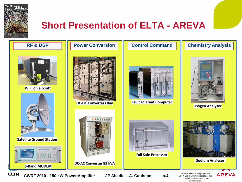
ELTA is an AREVA Subsidiary specialized in Electronics for Harsh
Environments, located in Toulouse (France).
ELTA is a 230 employees company with 30 years Heritage in :
Radio-Frequency for Aeronautic, Space & Scientific applications
Instrumention and Control (I&C) for Defence and Transportation markets
High Power Supplies for Defence and Aeronautic markets
Water Analysers for Nuclear market
From Design to Customer Support :
Design tools : RF, Analog, Digital simulation, 3D CAD, PCB Design Software,
Test Equipments up to 40 GHz
Customer Support up to 30 years for Nuclear, Aeronautic, Defense domains
This document is the property of
ELTA and shall not be reproduced or
communicated without its prior
authorization.
CWRF 2010 - 150 kW Power Amplifier JP Abadie – A. Cauhepe p.4
Power Conversion Control Command Chemistry Analysis
Short Presentation of ELTA - AREVA
RF & DSP
WIFI on aircraft
Satellite Ground Station
S-Band MODEM
DC-DC Converters Bay
DC-AC Converter 83 kVA
Fault Tolerant Computer
Fail Safe Processor
Oxygen Analyser
Sodium Analyser

This document is the property of
ELTA and shall not be reproduced or
communicated without its prior
authorization.
CWRF 2010 - 150 kW Power Amplifier JP Abadie – A. Cauhepe p.5
LIL (Laser Integration Line) : CEA
Featuring LMJ (Laser Mega Joule)
Signal conditionning
Very fast transient acquisition
Instrumentation & Control
UHF Transponders for Martian Programs : NASA
Mars Observer, Mars Global Surveyor
Russian mission MARS 94
Successful Relaying of Martian Rovers in 2004
Equipments for Stratospheric Ballons : CNES
Onboard equipments
L-Band or S-Band Transceivers
Telemetry & Telecommand Ground Station
ELTA in Scientific Programs

This document is the property of
ELTA and shall not be reproduced or
communicated without its prior
authorization.
CWRF 2010 - 150 kW Power Amplifier JP Abadie – A. Cauhepe p.6
Partnership with SOLEIL Synchrotron
2009 : Agreement between ELTA and SOLEIL for transferring the
« SSA » technology of high RF Power Amplifier, developed and set in
operation by SOLEIL since several years
Feb 2010 : Development by SOLEIL of a new Amplifier Module
Doubling of the power of the elementary module up to 700 W
Improvement of Gain and Efficiency
Specification and Industrialization of the Amplifier Module driven by ELTA
June 2010 : Test of the 1st assembly of 16 Amplifier Modules (10kW)
Qualification & Test will be performed by ELTA and SOLEIL teams
Nov 2010 : Test of the first 75 kW Tower

This document is the property of
ELTA and shall not be reproduced or
communicated without its prior
authorization.
CWRF 2010 - 150 kW Power Amplifier JP Abadie – A. Cauhepe p.7
June 2009 : Contract with ESRF for providing seven 150 kW PA
for Booster and Storage Ring
Design of the overall 150kW Power Amplifier and of some
specific equipments
Industrialization of the Amplifier Module designed by SOLEIL
Validation – Qualification Tests of the Sub-assemblies and of the
overall 150 kW Power Amplifier (with SOLEIL support for High
Power Tests)
ESRF Project : 150 kW Power Amplifier

This document is the property of
ELTA and shall not be reproduced or
communicated without its prior
authorization.
CWRF 2010 - 150 kW Power Amplifier JP Abadie – A. Cauhepe p.8
150 kW Power Amplifier for ESRF Synchrotron
RF Architecture of the 150 kW SSA Power Amplifier
100 mW
5 kW
38 kW
38 kW
75 kW
75 kW
150 kWPre-Driver
Driver
1 Control Box
per 16 modules
Assembly
Amplifier Modules

This document is the property of
ELTA and shall not be reproduced or
communicated without its prior
authorization.
CWRF 2010 - 150 kW Power Amplifier JP Abadie – A. Cauhepe p.9
Mechanical Presentation
150 kW Power Amplifier for ESRF Synchrotron
Electrical Box
Cold Plate Assembly
16 Amplifier Modules
16 DC-DC Converters
« Core »
Combiner Assembly
150kW output
WR2300 Control
Mux-Box

This document is the property of
ELTA and shall not be reproduced or
communicated without its prior
authorization.
CWRF 2010 - 150 kW Power Amplifier JP Abadie – A. Cauhepe p.10
High Beam Availability (full performance with up to 6 failed Amplifier modules)
Computed MTBF of the overall 150kW Amplifier : 20 000 Hours
Computed Failure rate of Amplifier Module : less than 0,7% per year
Distributed Heat Dissipation
No need for High Voltage Power Supply
No need for High Power Circulator at RF Output
No need for Warm-up sequence
Very low Phase Noise (< 0.05° RMS up to 8 kHz)
Easy Maintenance : MTTR < 15 min
Flexibilty to fit to different RF Output Power
Reduced number of Spare Parts
150 kW Power Amplifier Advantages of the Modular SSA Architecture
This document is the property of
ELTA and shall not be reproduced or
communicated without its prior
authorization.
CWRF 2010 - 150 kW Power Amplifier JP Abadie – A. Cauhepe p.11
Main RF Characteristics :
150 kW RF Power
Bandwidth : 352,2 +/- 0,5 MHz
Overall Efficiency better than 55% at nominal RF power (expected >60%)
Operation on very high mismatch at all phases conditions :
- full reverse power at 150 kW during interlocking time (typ 20 usec)
- full reverse power at Pnom/2 during long duration,
CW, Ramped (booster), Pulsed modes (cavity conditionning)
Electrical Circuits
280 V dc +/- 20V
Power Consumption less than 300 kW
Water Cooling
Less than 440 liters / mn (target 220 liters/mn)
Inlet water temperature between around 23°C
150 kW Power Amplifier for ESRF Synchrotron

This document is the property of
ELTA and shall not be reproduced or
communicated without its prior
authorization.
CWRF 2010 - 150 kW Power Amplifier JP Abadie – A. Cauhepe p.12
RF Monitorings, Protections, Interlocking :
Mismatch handling (circulator)
P_fwd, P_rev at 5kW stage and at 75 kW Tower output
RF over-power detection on the LLRF input (20dBm) : fast hardware detection (< 150 nsec)
RF over-power detection on the 75 kW RF output : slow detection < 1 sec
Reverse RF protection on the 75 kW RF output in case of severe reverse power (fast detection < 10 usec)
Reverse RF protection on the 5 kW stage : slow detection < 1 sec
Electrical Monitoring and Protections :
Current consumption of each Amplifier Module
ON/OF control of each Amplifier Module
Thermal and Hydraulic protections :
Thermal Interlocking on each Cold Plate
Water Flow Interlocking on each Cold Plate
Internal Temperatures (2) inside each Amplifier Module
150 kW Power Amplifier for Monitoring & Protections

This document is the property of
ELTA and shall not be reproduced or
communicated without its prior
authorization.
CWRF 2010 - 150 kW Power Amplifier JP Abadie – A. Cauhepe p.13
650 W Power Amplifier Module
Developped by SOLEIL in tight coordination with ELTA for industrialization and process topics
RF Characteristics :
Power Output : 650 W at P_1dB
Frequency : 352,2 MHz
Gain : 20, 3 dB
Efficiency : > 70 %
Gain Dispersion : +/- 0, 2 dB max
Phase Dispersion : +/- 5° max
Transistor Technology : LDMOS 6th Generation
Protected by internal circulator for severe mismatch conditions and for RF power stability versus cavity mismatch (any phases)
Monitoring :
Drain Current
Temperatures of the Power Transistor Flange and of the Circulator Load
This document is the property of
ELTA and shall not be reproduced or
communicated without its prior
authorization.
CWRF 2010 - 150 kW Power Amplifier JP Abadie – A. Cauhepe p.14
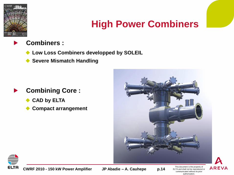
High Power Combiners
Combiners :
Low Loss Combiners developped by SOLEIL
Severe Mismatch Handling
Combining Core :
CAD by ELTA
Compact arrangement

This document is the property of
ELTA and shall not be reproduced or
communicated without its prior
authorization.
CWRF 2010 - 150 kW Power Amplifier JP Abadie – A. Cauhepe p.15
Control (Mux-Box) and Pre-Driver
Design of a specific Control Box (ELTA) :
Monitoring the Amplifier Modules and their associated Power Supplies
Monitoring the Cold Plate Interlockings (Temperature and Water Flow)
Control the ON/OFF of each Amplifier Modules (Power supply switch-off)
Interface with Amplifier / DC-DC Modules by I2C bus
Interface with the Supervisor : ModBus / RTU 1 Mb/sec
Design of a specific Pre-Driver (ELTA) :
Amplification of the input low level signal (20 dBm) up to 2 x 15W
Internal Band Pass Filter for Time Delay purpose and RF Filtering
Internal Interlocking on RF Input level (<150 nsec) before applying the excessive input level to the Amplifier Modules
Internal Interlocking on Reverse Output level (< 10 usec)

This document is the property of
ELTA and shall not be reproduced or
communicated without its prior
authorization.
CWRF 2010 - 150 kW Power Amplifier JP Abadie – A. Cauhepe p.16
Cold Plate
Thermal Simulation performed on the Cold Plate
Mixed simulation : Thermal & Fluidic (takes into account turbulence)
Simulation takes into account heat flux through the dissipative
component flanges and through the Amplifier package
Thermal Simulation gives :
A global thermal cartography of the Cold Plate
Flange temperatures of main dissipative components (transistor, load,
circulator, DC-DC converter), in order to estimate junction temperatures

This document is the property of
ELTA and shall not be reproduced or
communicated without its prior
authorization.
CWRF 2010 - 150 kW Power Amplifier JP Abadie – A. Cauhepe p.17
Distributed Power Amplifiers
for Linear Accelerator
Example of 2 x 20 kW at 88 MHz
based on 850 W Amplifier Module
with 83 % efficiency
Amplifier module with integrated circulator in order :
to insure constant RF Power level for any phase conditions
to avoid excessive stress of the transistors and associated degradation of the MTBF
to avoid extra RF level increase (with resulting efficiency loss)
Versatility of the Modular SSA Architecture
65 kW - 380V_AC / 50V DC Power Supply
Cold Plate Assembly
RF Combiners
This document is the property of
ELTA and shall not be reproduced or
communicated without its prior
authorization.
CWRF 2010 - 150 kW Power Amplifier JP Abadie – A. Cauhepe p.18
Conclusion
Conclusion :
This SSA architecture permits a high level of availability of the 150 kW
Power Amplifier, thanks to the large number of modules in parallel
Protections and Monitoring implemented inside the Control Box and
the Pre-Driver permit safe operation and detection of failed module.
Transferring this technology at 500 MHz is straight forward :
The 500 MHz amplifier module was recently validated at 700 W
Other possible applications from FM to L-Band can be envisaged.

This document is the property of
ELTA and shall not be reproduced or
communicated without its prior
authorization.
CWRF 2010 - 150 kW Power Amplifier JP Abadie – A. Cauhepe p.19
Thank you for your attention