present problems with building performance simulation of green roofs
TRANSCRIPT

Heriot-Watt University Research Gateway
Heriot-Watt University
Present problems with building performance simulation of green roofs
Tubsuwan, Kantitut; Banfill, Phillip Frank Gower
Published in:ICBEST 2014
Publication date:2014
Document VersionPeer reviewed version
Link to publication in Heriot-Watt Research Gateway
Citation for published version (APA):Tubsuwan, K., & Banfill, P. F. G. (2014). Present problems with building performance simulation of green roofs.In ICBEST 2014: Proceedings of the International Conference on Building Envelope Systems. (pp. 1-10).Aachen, Germany.
General rightsCopyright and moral rights for the publications made accessible in the public portal are retained by the authors and/or other copyright ownersand it is a condition of accessing publications that users recognise and abide by the legal requirements associated with these rights.
If you believe that this document breaches copyright please contact us providing details, and we will remove access to the work immediatelyand investigate your claim.

ICBEST 2014 June 09-12, 2014, Aachen, Germany
Present problems with building performance simulation of green roofs
Kantitut Tubsuwan1 and Phil Banfill1
1Centre of Excellence in Sustainable Building Design, School of the Built Environment, Heriot-Watt University, Edinburgh, United Kingdom
Abstract
Green roofs are increasingly popular with designers and performance simulation is necessary to ensure a building’s energy efficiency but there are some problems with present theories that support green roof modelling. For example, it is assumed that a substrate layer is continuously saturated, which is not true in practice. Most models ignore the drainage layer, which is an important service layer integrated with current green roof systems. Where included, models have used an inappropriate mechanism. In a substrate layer, the liquid absorbs into the soil by capillary attraction, and the contact surface is saturated first, while soil underneath remains dry and requires some time to reach saturation. Sharp Front Theory can be used to understand this situation and the rate of liquid absorption by the material is called its sorptivity. This can be used with the one-dimensional conduction heat transfer. In the drainage layer, the theory of conduction of porous material is applied by using Hadley's weighted average of Maxwell upper bound method to estimate the effective thermal conductivity. This varies with porosity and can be used to calculate the transient conduction heat transfer. A concept for improved performance simulation models is presented.
1 Introduction
Green roofs are a sustainable construction that satisfies the current world energy and thermal crisis. With a history dating back to Babylon’s hanging gardens ([2], Ascione et al., 2013), it was used for energy considerations by German engineers during the 19th century ([3], Newton, 2007). The modern green roof can withstand various climates and has increased durability resulting from its service layers such as waterproofing and drainage layers.
The environmental benefits of green roofs include improved storm water management, reduced noise and air pollution, and reduced carbon footprint from the land used ([3], Newton, 2007). However, the unique feature of green roofs is enhanced building energy saving from heat transfer through the roof. It reduces solar heat gain by shading the roof structure from sunlight with the foliage canopy, and also provides passive cooling from transpiration. In addition, increased roof thermal mass due to the soil layer reduces heat loss in winter.
Most large buildings are subjected to a building performance simulation, using appropriate software, at the design stage, usually to confirm compliance with performance criteria, but simulation of green roof thermal behaviour is complex and some important factors have been ignored in the interests of simplicity. However, this may result in an inaccuracy in some situations. Furthermore, due to developments in the technology of green roofs, some service layers have been added, but are not included in the simulation. This paper will discuss alternative solutions to improve the thermal simulation of a green roof.

Tubsuwan and Banfill Present problems with building performance simulation of green roof 2/10
2 Literature review
Research investigations into the thermal performance of green roofs can be divided into three types: experimental measurements in laboratory or field, theoretical analysis, and combination of the two. Despite their relative advantages and disadvantages there are some problems.
At first, experimental thermal performance was measured by heat flux reduction from the reference roof (normally a bare concrete roof) compared with the green roof in a same situation. As a result, the thermal resistance (R-value) was calculated by deducing the green roof's R-value from the layers in another roof assembly ([4], Sonne, 2006, [5], Wonget al., 2003). In Wonget al. (2003) [5] study, they found that the green roof with higher Leaf Area Index (LAI) reduced the cooling energy required and this factor became important for green roof simulation. The growing substrate is also important because they found that a green roof with wet soil had lower cooling efficiency than dry soil because it has a lower R-value ([5], Wonget al., 2003). However, this model did not consider the effect of evaporation from wet soil, which could result in more heat loss from the roof. For this reason, researchers have been studying this important phenomenon and trying to explain it by numerical methods.
The plant respiration and soil evaporation are unique features of a green roof which affect thermal transfer by latent heat removal on foliage and substrate surfaces. It was studied by Balicket al. (1981) [6] and Deardorff (1978) [7] to evaluate ground surface temperature when vegetation is present. These models were developed by Frankenstein and Koenig (2004) [8] into the FASST soil and vegetation model using the energy balance method. After the development of building energy simulation software, those theories were applied in EnergyPlus simulation software, and included effects of short and long-wave solar radiation, interlayer long-wave emission, sensible heat flux from wind, and finally latent heat flux from plant respiration in an unsteady state condition ([9], Sailor, 2008).
The evapotranspiration calculation in former green roof models were calculated by using the Bowen ratio or a convective mass transfer coefficient ignoring stomata and substrate resistance ([10], Nayaket al., 1982, [11], Gaffinet al., 2005, [12], Gaffinet al., 2006, [13], He and Jim, 2010). This ratio is very convenient to use in any green roofs model, but it is useable only if evapotranspiration is not directly related to water content. To satisfy this requirement it is assumed that the green roof is well irrigated ([1], Tabares-Velasco, 2009).
On the other hand, most modern evapotranspiration models use the Vapour Pressure Deficit (VPD) method ([9], Sailor, 2008, [14], Barrio, 1998, [15], Lazzarinet al., 2005, [16], Alexandri and Jones, 2007). This takes the difference between the moisture present in the air and the amount that the air can hold when saturated. Nevertheless, each model uses a different function of the resistance in order to calculate evapotranspiration of a plant layer, such as wind correlation and vapour resistance. This method was applied to the latent heat flux calculation. In order to calculate thermal transfer in unsteady state condition of green roofs, some assumptions are needed to reduce difficulties in modelling ([1], Tabares-Velasco, 2009).
• A green roof vegetation and growing medium layer are horizontally homogeneous • The horizontal length of green roof is much greater than its vertical depth and horizontal heat
transfer is negligible in order to simplify the models into one-dimensional heat transfer • The air under the stomata (vegetation layer) is always saturated • Any heat flux during biochemical photosynthesis reactions is negligible • Conduction heat transfer does not occur in the foliage layer • A vegetation layer is irrigated, fully grown and completely covers the substrate layer • There is homogenous distribution of water in the canopy • A green roof is free from mulch
These assumptions were applied to most of green roof simulations to simplify the equations and computer processing. Furthermore, some assumptions such as photosynthetic reaction and green roof mulch are difficult to estimate due to their complicated behaviour, but the energy used can be ignored. However, the assumption of well irrigated plants means that the substrate, as a result, is always saturated, which does not correspond to reality.
Tubsuwan and Banfill Present problems with building performance simulation of green roof 3/10
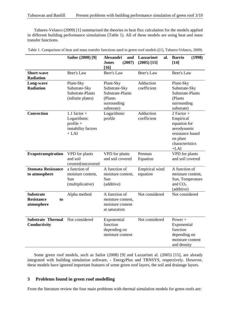
Tabares-Velasco (2009) [1] summarised the theories in heat flux calculation for the models applied in different building performance simulations (Table 1). All of these models are using heat and mass transfer functions.
Table 1. Comparison of heat and mass transfer functions used in green roof models ([1], Tabares-Velasco, 2009)
Sailor (2008) [9] Alexandri and Jones (2007) [16]
Lazzarinet al. (2005) [15]
Barrio (1998) [14]
Short-wave Radiation
Beer's Law Beer's Law Beer's Law Beer's Law
Long-wave Radiation
Plant-Sky Substrate-Sky Substrate-Plants (infinite plates)
Plant-Sky Substrate-Sky Substrate-Plants (Plants surrounding substrate)
Adduction coefficient
Plant-Sky Substrate-Sky Substrate-Plants (Plants surrounding substrate)
Convection 1.1 factor + Logarithmic profile + instability factors + LAI
Logarithmic profile
Adduction coefficient
2 Factor + Empirical equation for aerodynamic resistance based on plant characteristics +LAI
Evapotranspiration VPD for plants and soil covered/uncovered
VPD for plants and soil covered
Penman Equation
VPD for plants and soil covered
Stomata Resistance to atmosphere
a function of moisture content, Sun (multiplicative)
A function of moisture content, Sun (additive)
Empirical wind equation
A function of moisture content, Sun, Temperature and CO2 (additive)
Substrate Resistance to atmosphere
Alpha method A function of moisture content, moisture content at saturation
Not considered Not considered
Substrate Thermal Conductivity
Not considered Exponential function depending on moisture content
Not considered Power + Exponential function depending on moisture content and density
Some green roof models, such as Sailor (2008) [9] and Lazzarinet al. (2005) [15], are already
integrated with building simulation software, - EnergyPlus and TRNSYS, respectively. However, these models have ignored important features of some green roof layers, the soil and drainage layers.
3 Problems found in green roof modelling
From the literature review the four main problems with thermal simulation models for green roofs are:
Tubsuwan and Banfill Present problems with building performance simulation of green roof 4/10
• The soil in the growing medium or substrate layer is assumed to be saturated at all times but this is not necessarily so in practice because of the variability in weather over time in arid and semi-arid regions. Also with climate change northern regions are expected to experience more extreme weather events in the future, so soil moisture content will vary with time. The thermal conductivity of soil varies by a factor of ten between dry and saturated.
• The dynamics of variations in soil moisture content are not considered in the models. • The thermal conductivity of the drainage layer is not considered in any model. • The effect of convection heat transfer as water flows through the drainage layer is not
considered.
3.1 Problems in substrate layer
Most of the assumptions made for green roof modellings aim to reduce complication in the heat and mass transfer calculation. Others have very small energy contributions compared to overall thermal transfer energy, but there is one key assumption about roof moisture and irrigation behaviour. It assumed that a green roof vegetation layer is always well irrigated, and consequently, a substrate layer (beneath the vegetation) is also always saturated.I In reality, a roof can be well irrigated only in the pre-installation period in order to allow the plant to settle down. In service period, it is almost impossible to maintain saturation on a roof.
The problem is that the properties of the green roof substrate or soil are influenced by water content. According to Johansen and the De Vries methods, the thermal conductivity of soil depends on its density, porosity, degree of saturation, quartz content, and thermal conductivity of contained minerals ([17], Farouki, 1986). Whilst quartz content and thermal conductivity of minerals are constant, density and porosity can be controlled and measured. In contrast, the degree of saturation depends only on the amount of water absorbed from irrigation or precipitation. As a result, the effect of moisture changes in soil is very important for thermal conductivity and overall heat transfer.
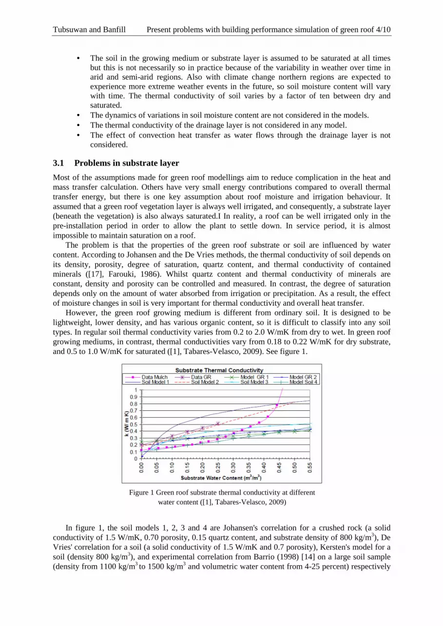
However, the green roof growing medium is different from ordinary soil. It is designed to be lightweight, lower density, and has various organic content, so it is difficult to classify into any soil types. In regular soil thermal conductivity varies from 0.2 to 2.0 W/mK from dry to wet. In green roof growing mediums, in contrast, thermal conductivities vary from 0.18 to 0.22 W/mK for dry substrate, and 0.5 to 1.0 W/mK for saturated ([1], Tabares-Velasco, 2009). See figure 1.
In figure 1, the soil models 1, 2, 3 and 4 are Johansen's correlation for a crushed rock (a solid
conductivity of 1.5 W/mK, 0.70 porosity, 0.15 quartz content, and substrate density of 800 kg/m3), De Vries' correlation for a soil (a solid conductivity of 1.5 W/mK and 0.7 porosity), Kersten's model for a soil (density 800 kg/m3), and experimental correlation from Barrio (1998) [14] on a large soil sample (density from 1100 kg/m3 to 1500 kg/m3 and volumetric water content from 4-25 percent) respectively
Figure 1 Green roof substrate thermal conductivity at different water content ([1], Tabares-Velasco, 2009)

Tubsuwan and Banfill Present problems with building performance simulation of green roof 5/10
([17], Farouki, 1986). For green roof substrates, the data GR, GR-1, and GR-2 are plotted beneath ordinary substrates conductivity. It confirms that substrate water content significantly affects thermal conductivity, and that the assumption of constant thermal conductivity is unjustified.
When water is absorbed by unsaturated soil, the contact surface is wetted first but points underneath remain dry. Capillary attraction brings a moisture front into the soil until it is completely saturated. This mechanism is similar to absorption of water in concrete or brick, which can be described by "Sharp Front Theory" ([18], Hall and Hoff, 2009), as described later.
3.2 Thermal conductivity of the drainage layer
The drainage layer is used to retain moisture inside the green roof, but also provide drainage for excess water in case of heavy rainfall. It uses either granular material or plastic drainage modules ([19], Dunnett and Kingsbury, 2004). Despite becoming increasingly common, this service layer has been ignored in building performance simulation models. As a result, an appropriate model for thermal conduction is needed.
Only ([2], Ascione et al., 2013, [15], Lazzarinet al., 2005) included a drainage layer in their calculation but used a constant R-value for the materials in the drainage layer in order to calculate heat conduction. However, this assumption cannot be true for a porous material. Its thermal conductivity depends on the porosity, which varies by the inflow and drained water. For this reason, the thermal conductivity value requires a dynamic calculation, based on porous material conduction theory.
3.3 Convection in the drainage layer
The drainage layer facilitates flow of excess water which removes some heat by convection. This mechanism is not mentioned in any green roof models.
The convection of water drained on a roof surface and its coefficient depend on the flow mechanism and velocity of liquid. In a flat green roof, convection does not have a significant effect on heat removal since the flow velocity is low, but on a sloping green roof the higher velocity increases convection heat transfer. This may be significant in a large building and for this reason, it should be included in any green roof model.
4 Suggestions for improvement
4.1 Substrate layer
Water transport in the soil must be better quantified. The Sharp Front Theory, according to Hall and Hoff (2009) [18], explains the liquid absorption into an unsaturated porous solid over time. The moisture content versus distance profile maintains a constant shape and advances in proportion to t1/2. The sorptivity is the proportionality constant, the tendency of a material to absorb and transmit water or other liquid by capillarity. It depends on the microscopic structure of the material, and is influenced by the capillary suction and hydraulic conductivity. It is readily determined experimentally.
4.2 Soil and Sharp Front Theory
Water transport in porous materials is mainly caused by capillary forces. Consequently, a porous material is able to absorb the liquid in contact with capillaries in its surface. According to Hall and Hoff (2009) [18], the capillary rise in a capillary tube in contact with a liquid reservoir caused by surface tension (σ) creates a pressure deficit arising from meniscus curvature. This pressure is balanced by the hydrostatic pressure of the liquid column (Figure 2).

Tubsuwan and Banfill Present problems with building performance simulation of green roof 6/10
Figure 2 Force balance in a capillary tube
2��� � ����� (1) Then,
���
� � (2)
Equation 2 shows that the radius of the capillary tube has a significant effect on the capillary rise. It can be applied to porous media where a smaller particle size, such as clay, can raise water higher than larger particles like sand. This basic theory of capillary rise does not explain the rate of absorption: this requires unsaturated flow theory.
When the porous material dries in the initial state, after exposure to liquid, liquid is drawn to the material’s surface by capillary forces. This flow is described by extended Darcy equation (3) ([18], Hall and Hoff, 2009).
� � ����� (3)
Where u is a vector flow velocity, � is a ratio of liquid volume to bulk volume (volume fraction saturation), ���� is an unsaturated permeability at given liquid content (��, and F is the capillary force that can be identified with the negative gradient of capillary potential Ψ. Thus, the extended Darcy equation is transformed to equation 4.
� � ������Ψ (4)
Ψ is the capillary potential per unit weight of liquid has dimension (L), which is the energy required to transfer unit weight of liquid from the porous material to a reservoir of the same liquid at the same temperature and elevation ([18], Hall and Hoff, 2009). This unsaturated flow mechanism is depicted in figure 3.
Figure 3. Unsaturated flow in porous materials ([18], Hall and Hoff, 2009)
However, the function of velocity is not suitable for determining moisture gradient so this equation is converted by combining with the continuity equation and transformed by Boltzmann transformation into a function of moisture content and time. The extended Darcy equation is transformed into the one dimensional horizontal flow equation (5).

Tubsuwan and Banfill Present problems with building performance simulation of green roof 7/10
���, �� � ∅�����/� (5)
This equation shows a key point of unsaturated flow theory. As liquid is absorbed into a porous material, the liquid content against distance profile advances as t1/2 and maintains a constant shape∅���. In other words, at t > 0, the liquid content at a distance x from the liquid entrance is��, whereas beyond this point, the liquid content remains dry� . This concept is fundamental for the Sharp Front Theory.
The Sharp Front Theory has been confirmed by many experiments for inorganic construction materials, such as gypsum plaster, Portland limestone, and cement mortar ([18], Hall and Hoff, 2009). The typical water content profiles of these materials are shown in figure 4. Sorptivity can be used to estimate the time taken for the substrate to achieve saturation.
Figure 4. (a) Water content profiles according to time and distance (b) Master curve ∅�!�" for the same material ([18], Hall and Hoff, 2009)
If the unsaturated flow equation is integrated, the total amount of liquid absorbed in time t is given by equation 6.
# �$�%&%'
� ��/� # ∅���$�%&%'
� (��/� (6)
In this equation, Sorptivity (S), which is the most important property of unsaturated flow in porous material, is defined. It was first introduced by Philip in the field of soil physics and hydrology ([20], Philip, 1957).
The sorptivity is the property which expresses the tendency of a material to absorb and transmit water and other liquids by capillarity. In contrast to saturated permeability (Ks), it is sensitive both to the hydraulic conductivity (K) and the suction characteristic of a material ([18], Hall and Hoff, 2009).
Sharp Front Theory is suitable to estimate the thickness of the saturated layer according to the time t1/2. This layer has a known thermal conductivity. Additionally, the thermal conductivity of the dry layer beneath is known, so it is possible to combine Sharp Front Theory and these thermal conductivities to calculate the overall thermal conductivity at each time step. Sorptivity is easily measured for the growing medium and the overall soil thermal conductivity simply depends on the relative thickness of the two layers (dry and saturated), each of which is known.
4.3 Drainage layer
The drainage layer differs from a substrate layer because there is no capillary suction. For this reason, the Sharp Front Theory cannot be applied here. In general porous materials, the thermal conductivity of the solid (ks) phase is greater than the liquid (kf). Nevertheless, the behaviour of the solid that interconnects with liquid influences the heat conduction significantly. The effective thermal conductivity is defined to estimate conduction heat transfer of a porous material, but this depends on the thermal conductivity of each phase (solid and fluid), the structure of solid matrix, and the contact resistance between the nonconsolidated particle ([21], Kaviany, 1991). This value had been studied by many researchers and those theories were compared with experimental data by Nozad et al. (1985) [22], which is shown in figure 5.

Tubsuwan and Banfill Present problems with building performance simulation of green roof 8/10
Figure 5. Effective thermal conductivity of beds of spherical particles predicted by various theories compared with experimental data ([22], Nozad et al., 1985)
From figure 5, the method that is closest to the experimental data is Hadley's weighted average of Maxwell upper bound method. This uses thermal diffusivity (αo) with an expression obtained by introduction of an adjustable function (fo) into a weighted averaged expression ([21], Kaviany, 1991). The effective thermal conductivity can be calculated by equation 7.
)*)+� �1 � -.�
/0123& 3+�⁄ �5/01�
�5/��501�23& 3+6/��501�7⁄+ -.
��3& 3+�⁄ 9��5/�2��2�/�3& 3+⁄
��2/�3& 3+2�5/⁄ (7)
Where;
:;�-. � �4.898@, 0 ≤ @ ≤ 0.0827
:;�-. = −0.405 − 3.158(@ − 0.0827), 0.0827 ≤ @ ≤ 0.298 :;�-. = −1.084 − 6.778(@ − 0.298), 0.298 ≤ @ ≤ 0.580
@ = G;�;HI�J
�K = �ℎM�NO: P;Q$RP�ISI�J ;T H;:I$
�0 = �ℎM�NO: P;Q$RP�ISI�J ;T T:RI$ � = MTTMP�ISM �ℎM�NO: P;Q$RP�ISI�J
T. = 0.8 + 0.1@
From the equation 5, the thermal conductivity of both liquid and solid is constant, and as a result, the equation is influenced by porosity, which is a ratio of the void space volume to the total volume of porous material. In a drainage layer, the void space volume is varied by the amount of drained water from a substrate layer. That directly affects the porosity and the effective thermal conductivity. Because porosity varies with time, the effective thermal conductivity is considered to be a dynamic value. For this reason, the transient conduction of a drainage layer must be calculated by using the theory of porous material conductivity.
4.4 Discussion
From these suggestions, the research will combine these theories to create a complete green roof thermal model. This could be then be integrated with building energy simulation software. However, before going to that stage, the concept of this model must be verified.
First of all, on the foliage layer and the surface of the substrate layer it is reasonable to use the energy budget theory from Sailor (2008) [9] since his model produced an average deviation from experimental results equal to 2.9oC, which is acceptable prediction. However, the conduction heat

Tubsuwan and Banfill Present problems with building performance simulation of green roof 9/10
transfer of this model will not be used since it assumes an unsaturated soil. Then to calculate the surface temperature on a substrate layer, the conduction of a substrate layer will calculated by using a one-dimensional finite difference calculation with time variation with saturated and unsaturated thermal conductivity values. The transient conduction model will be incorporated with Sharp Front Theory by dividing a substrate layer into two layers, one saturated with a saturated thermal conductivity and one unsaturated layer with a different thermal conductivity. This calculation will continue until the substrate is fully saturated after which a normal conduction calculation can be used.
For the drainage layer, it is important to define the value of porosity since it contributes to an effective thermal conductivity, which the weighted average of the Maxwell upper bound is used to calculate. At each time step a single value of porosity is calculated from the amount of water transported into the layer from which an effective conductivity is calculated. Finally, the conduction through drainage layer is evaluated by knowing the temperature at the top of drainage layer, thermal conductivity, then temperature at the bottom of drainage layer can be estimated.
5 Conclusion
Previous green roof models and theories have dealt with radiation heat transfer in foliage layer, sensible heat gain or loss by convection between foliage and substrate layer, latent heat from evapotranspiration of vegetation and soil, and conduction through substrate into the room beneath. However, those theories share similar assumptions to simplify calculations and this results in some errors.
The assumption that vegetation is well irrigated requires that saturated thermal conductivity is used for a simulation. In reality, this is not so and the Sharp Front Theory presented in this paper offers an alternative approach by dividing the substrate layer into one saturated and one dry layer with appropriate thermal conductivities. By this means it is anticipated that green roof thermal models will be improved.
References
[1] Tabares-Velasco PC.(2009). Predictive heat and mass transfer model of plant-based roofing materials for assessment of energy savings: The Pennsylvania State University.
[2] Ascione F, Bianco N, de’Rossi F, Turni G, Vanoli GP.(2013). Green roofs in European climates. Are effective solutions for the energy savings in air-conditioning? Applied Energy. 104, 845-59.
[3] Newton J.(2007). Building Greener: Guidance on the Use of Green Roofs, Greens Walls and Complementary Features on Buildings. Construction Industry Research & Information Association (CIRIA).
[4] Sonne J.(2006). Evaluating Green Roof Energy Performance. ASHRAE Journal. 48, 59-61.
[5] Wong NH, Cheong DKW, Yan H, Soh J, Ong CL, Sia A.(2003). The effects of rooftop garden on energy consumption of a commercial building in Singapore. Energ Buildings. 35, 353-64.
[6] Balick LK, Scoggins RK, Link LE.(1981). Inclusion of a Simple Vegetation Layer in Terrain Temperature Models for Thermal IR Signature Prediction. Geoscience and Remote Sensing, IEEE Transactions on. GE-19, 143-52.
[7] Deardorff J.(1978). Efficient prediction of ground surface temperature and moisture, with inclusion of a layer of vegetation. J geophys Res. 83, 1889-903.
[8] Frankenstein S, Koenig G. (2004). FASST vegetation models. ENGINEER RESEARCH AND DEVELOPMENT CENTER HANOVER NH COLD REGIONS RESEARCH AND ENGINEERING LAB: DTIC Document; p.

Tubsuwan and Banfill Present problems with building performance simulation of green roof 10/10
[9] Sailor DJ.(2008). A green roof model for building energy simulation programs. Energ Buildings. 40, 1466-78.
[10] Nayak J, Srivastava A, Singh U, Sodha M.(1982). The relative performance of different approaches to the passive cooling of roofs. Building and Environment. 17, 145-61.
[11] Gaffin S, Rosenzweig C, Parshall L, Beattie D, Berghage R, O’Keefe G, et al. (2005). Energy balance modeling applied to a comparison of white and green roof cooling efficiency. Presentation at Greening Rooftops for Sustainable Communities. Third Annual International Conference.
[12] Gaffin S, Rosenzweig C, Parshall L, Hillel D, Eichenbaum-Pikser J, Greenbaum A, et al. (2006). Quantifying evaporative cooling from green roofs and comparison to other land surfaces. Fourth Annual Greening Rooftops for Sustainable Communities Conference, Awards and Trade Show11-2.
[13] He HM, Jim CY.(2010). Simulation of thermodynamic transmission in green roof ecosystem. Ecol Model. 221, 2949-58.
[14] Barrio EPD.(1998). Analysis of the green roofs cooling potential in buildings. Energ Buildings. 27, 179-93.
[15] Lazzarin RM, Castellotti F, Busato F.(2005). Experimental measurements and numerical modelling of a green roof. Energ Buildings. 37, 1260-7.
[16] Alexandri E, Jones P.(2007). Developing a one-dimensional heat and mass transfer algorithm for describing the effect of green roofs on the built environment: Comparison with experimental results. Building and Environment. 42, 2835-49.
[17] Farouki O.(1986). Thermal Properties of Soils (Series on Rock and Soil Mechanics vol 11)(Clausthal-Zellerfeld, Germany. Trans Tech Publications.
[18] Hall C, Hoff WD.(2009). Water transport in brick, stone and concrete. CRC PressI Llc.
[19] Dunnett N, Kingsbury N.(2004). Planting green roofs and living walls. Timber, Portland, OR [etc.].
[20] Philip JR.(1957). The theory of infiltration: 4. Sorptivity and algebraic infiltration equations. Soil science. 84, 257-64.
[21] Kaviany.(1991). Principles of heat transfer in porous media / by M. Kaviany. Springer, 1991.
[22] Nozad I, Carbonell R, Whitaker S.(1985). Heat conduction in multiphase systems—I: theory and experiment for two-phase systems. Chemical Engineering Science. 40, 843-55.