power master plus user's manual - software download
TRANSCRIPT
Power Master Plus user’s manual
I
Power Master Plus User’s Manual
Rev. 1.0.2
Power Master Plus user’s manual
i
Table of Contents Table of Contents ..................................................................................................... i
1 Introduction ............................................................................................ 1
1.1 Local .................................................................................................................. 2
1.2 Remote ............................................................................................................. 2
2 Getting Started ....................................................................................... 3
2.1 Prerequisites ..................................................................................................... 3
2.1.1 Hardware Limitation ......................................................................................................................... 3
2.1.2 Operating System ............................................................................................................................. 3
2.1.3 Web Browser .................................................................................................................................... 4
2.2 Installation ........................................................................................................ 4
2.2.1 Installation on Windows ................................................................................................................... 4
2.2.2 Installation on Mac ........................................................................................................................... 7
2.2.3 Installation on Linux ......................................................................................................................... 9
2.2.4 Installation on VMware ESXi and ESX ............................................................................................. 12
2.3 Accessing Power Master Plus .......................................................................... 19
2.3.1 Login ............................................................................................................................................... 19
3 Using Power Master Plus ...................................................................... 21
3.1 DASHBOARD .................................................................................................... 21
3.1.1 UPS Information ............................................................................................................................. 22
3.1.2 UPS Status .................................................................................................... 23
3.1.3 Power Supply Information .............................................................................................................. 27
3.2 UPS SETTING ................................................................................................... 29
3.2.1 Diagnostics ...................................................................................................................................... 29
3.2.2 Configuration .................................................................................................................................. 31
3.2.3 Connected Equipment .................................................................................................................... 37
Power Master Plus user’s manual
ii
3.2.4 Scheduled Shutdown ...................................................................................................................... 38
3.2.5 Energy Wise .................................................................................................................................... 40
3.3 POWER CONFIGURATION ................................................................................ 41
3.3.1 How to Configure Proper Power Connection ................................................................................. 43
3.3.2 Troubleshooting Communication Problems ................................................................................... 45
3.4 SETTING .......................................................................................................... 45
3.4.1 Remote Host ................................................................................................................................... 45
3.4.2 Shutdown Events ............................................................................................................................ 46
3.4.3 Notifications ................................................................................................................................... 48
3.4.4 Notification Channels ..................................................................................................................... 49
3.4.5 Recipients ....................................................................................................................................... 54
3.4.6 SNMP .............................................................................................................................................. 55
3.4.7 SNMPv3 Profiles ............................................................................................................................. 56
3.4.8 Security ........................................................................................................................................... 58
3.4.9 Advanced ........................................................................................................................................ 61
3.4.10 Network Configuration ................................................................................................................. 65
3.4.11 Event Details ................................................................................................................................. 65
3.5 REPORTING ..................................................................................................... 70
3.5.1 Event Logs ....................................................................................................................................... 70
3.5.2 Data Logs ........................................................................................................................................ 71
3.5.3 Energy Use ...................................................................................................................................... 72
3.6 Web Browser Info ........................................................................................... 74
3.6.1 Power Master+ Installation Location ............................................................................................. 74
3.6.2 Account Information....................................................................................................................... 74
3.6.3 Language ......................................................................................................................................... 75
3.7 Help ................................................................................................................. 75
3.7.1 Power Master+ ............................................................................................................................... 75
3.7.2 Content ........................................................................................................................................... 75

Power Master Plus user’s manual
iii
4 Technical Support ................................................................................. 77
4.1 Troubleshooting .............................................................................................. 77
4.2 FAQ ................................................................................................................. 84
5 Glossary ................................................................................................ 93
Power Master Plus user’s manual
1
1 Introduction
Power Master+ software provides comprehensive advanced power management for UPS/PDU/ATS systems.
It controls unattended shutdowns, scheduled shutdowns, and notifications for computers powered by the
UPS (Uninterruptible Power Supply), PDU (Power Distribution Unit), or the ATS (Automatic Transfer Switch).
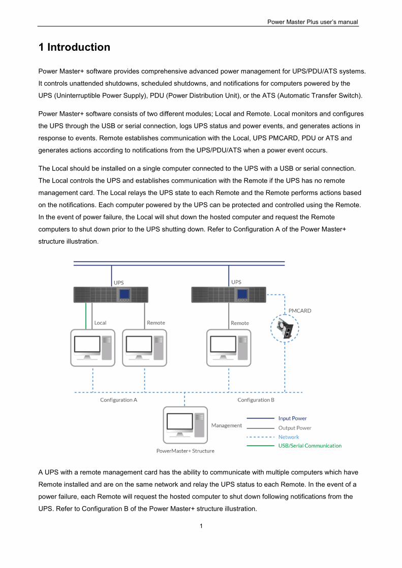
Power Master+ software consists of two different modules; Local and Remote. Local monitors and configures
the UPS through the USB or serial connection, logs UPS status and power events, and generates actions in
response to events. Remote establishes communication with the Local, UPS PMCARD, PDU or ATS and
generates actions according to notifications from the UPS/PDU/ATS when a power event occurs.
The Local should be installed on a single computer connected to the UPS with a USB or serial connection.
The Local controls the UPS and establishes communication with the Remote if the UPS has no remote
management card. The Local relays the UPS state to each Remote and the Remote performs actions based
on the notifications. Each computer powered by the UPS can be protected and controlled using the Remote.
In the event of power failure, the Local will shut down the hosted computer and request the Remote
computers to shut down prior to the UPS shutting down. Refer to Configuration A of the Power Master+
structure illustration.
A UPS with a remote management card has the ability to communicate with multiple computers which have
Remote installed and are on the same network and relay the UPS status to each Remote. In the event of a
power failure, each Remote will request the hosted computer to shut down following notifications from the
UPS. Refer to Configuration B of the Power Master+ structure illustration.
Power Master Plus user’s manual
2
1.1 Local
Aside from the primary function of shutting systems down in the event of an outage, the Local also provides
the following functions:
Unattended shutdown in response to various power conditions.
User notification of power conditions.
Flexible configuration of actions for each event and notifications via E-mail, Instant Message, and SMS.
Run command files for custom applications.
Historical logs of events and power conditions.
Detailed load management for all powered equipment.
Scheduled shutdown and restart.
Status monitoring of the UPS and utility power.
UPS configuration.
Quick view system summary.
1.2 Remote
The Remote provides unattended shutdown for the hosted computer following a notification from the
UPS/PDU/ATS. The Remote also provides the following functions:
Unattended shutdown in response to various power conditions.
User notification of power conditions.
Flexible configuration of actions for each specific event and notifications via E-mail, Instant Message,
and SMS.
Historical logs of power events.
Quick view system summary.
Power Master Plus user’s manual
3
2 Getting Started
2.1 Prerequisites
2.1.1 Hardware Limitation
Minimum Core 2 – Compatible CPU.
1 gigabytes (GB) of RAM recommended minimum; more memory generally improves responsiveness.
Minimum of 1 GB of free space of hard disk.
Serial port or USB port. (Required by the Local)
Network interface.
2.1.2 Operating System
Power Master+ software can be installed and is supported on the following operating systems:
32-Bit Versions:
Windows 10
Windows 8
Windows 7
Centos 7+
Debian 10.1
Ubuntu 18.04 LTS
Citrix XenServer 7.2
Citrix Hypervisor 8.0 Express Edition (formerly XenServer)
VMware ESXi6.0+ (ESXi Free Edition is not supported)
64-Bit Versions:
Windows Server 2019
Windows Server 2012
Windows Server 2012 R2
Windows Server 2016
Windows Hyper-V Server 2012
Windows Hyper-V Server 2012 R2
Windows 10
Windows 8
Windows 7
macOS10.14
macOS 10.15
Centos 7+
Debian 10.1
Debian9
Ubuntu 18.04 LTS
Power Master Plus user’s manual
4
Red Hat Enterprise 8
Red Hat Enterprise 7
Citrix XenServer 7.2
Citrix Hypervisor 8.0 Express Edition (formerly XenServer)
VMware ESXi6+ (ESXi Free Edition is not supported)
Note: Because of the abundance of different Linux builds, not all builds are tested with Power Master+ but
most builds will be able to run the program.
2.1.3 Web Browser
Power Master+ software is accessed using a web browser and is compatible with the following browsers:
Microsoft Edge
Firefox
Google Chrome
Safari
2.2 Installation
2.2.1 Installation on Windows
A pop-up window will be displayed automatically when inserting the Power Master+ installation CD. Users
can click the Install Power Master+ shortcut on the pop-up window to initiate the installation procedure. If the
pop-up window is not displayed when inserting the CD, browse to the CD drive and open the folder which
locates at/Software/Windows, and then double click the file named Setup.exe to start the installation
procedure.
Use the Power Master+ installation CD to complete the installation on the target computer. To install follow
these steps:
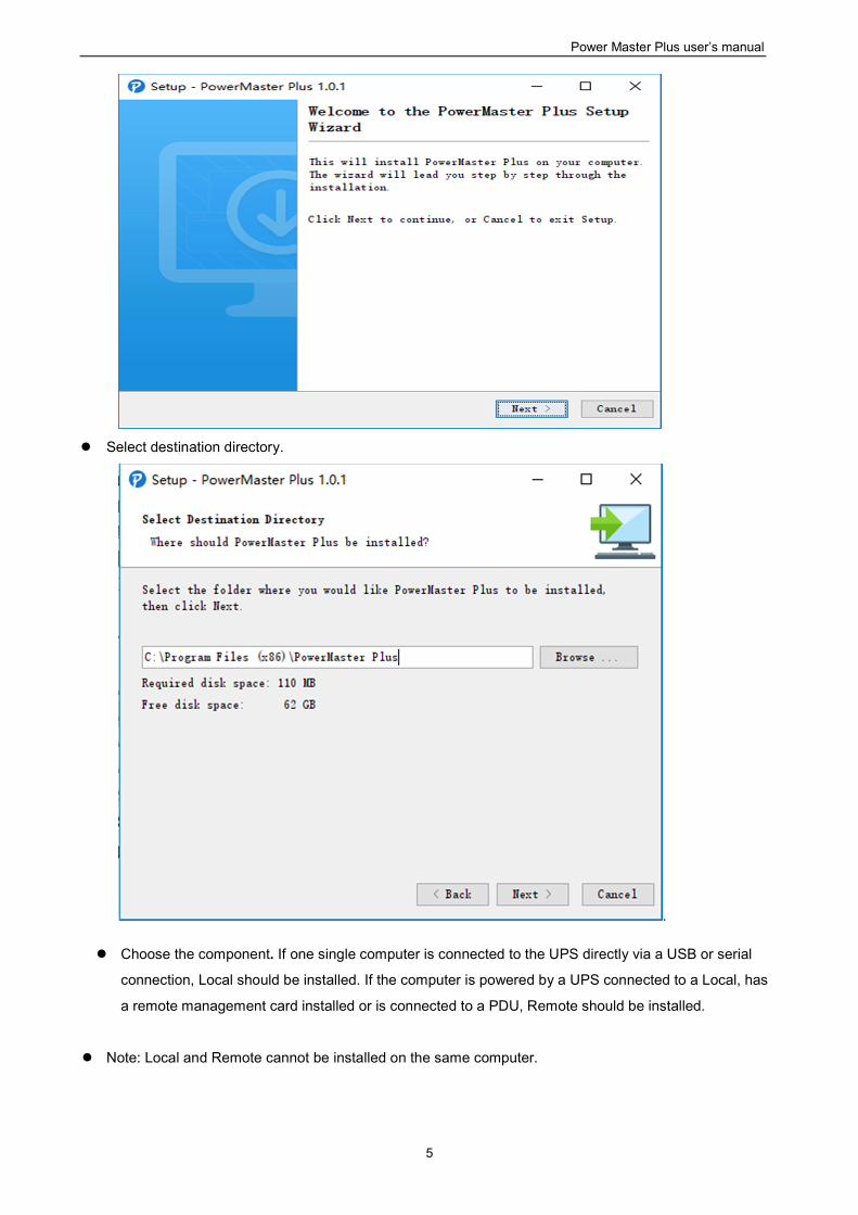
Click the Next button to start an installation.
Power Master Plus user’s manual
5
Select destination directory.
.
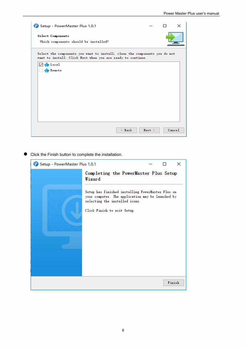
Choose the component. If one single computer is connected to the UPS directly via a USB or serial
connection, Local should be installed. If the computer is powered by a UPS connected to a Local, has
a remote management card installed or is connected to a PDU, Remote should be installed.
Note: Local and Remote cannot be installed on the same computer.
Power Master Plus user’s manual
6
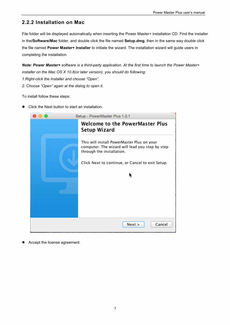
Click the Finish button to complete the installation.
Power Master Plus user’s manual
7
2.2.2 Installation on Mac
File folder will be displayed automatically when inserting the Power Master+ installation CD. Find the installer
in the/Software/Mac folder, and double click the file named Setup.dmg, then in the same way double click
the file named Power Master+ Installer to initiate the wizard. The installation wizard will guide users in
completing the installation.
Note: Power Master+ software is a third-party application. At the first time to launch the Power Master+
installer on the Mac OS X 10.8(or later version), you should do following:
1.Right-click the Installer and choose “Open”.
2. Choose “Open” again at the dialog to open it.
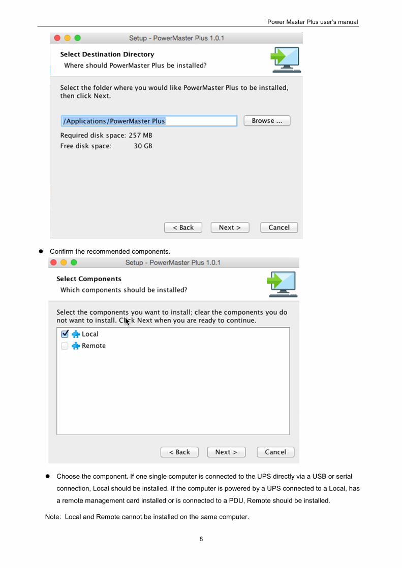
To install follow these steps:
Click the Next button to start an installation.
Accept the license agreement.
Power Master Plus user’s manual
8
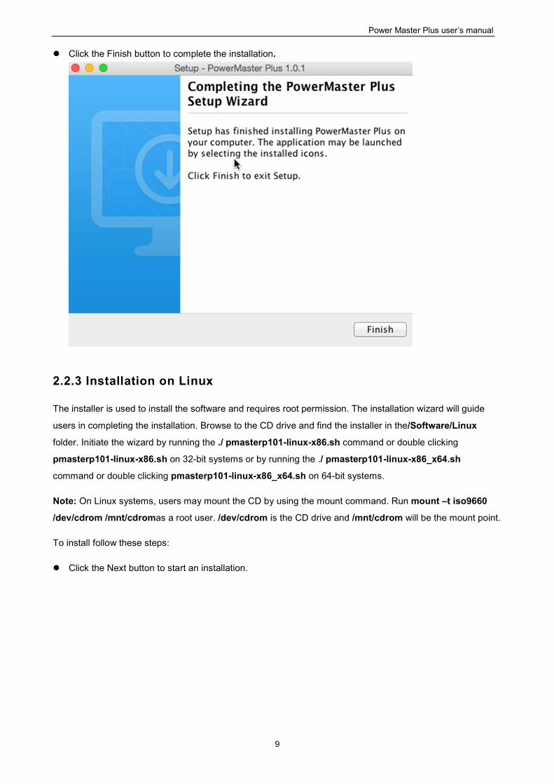
Confirm the recommended components.
Choose the component. If one single computer is connected to the UPS directly via a USB or serial
connection, Local should be installed. If the computer is powered by a UPS connected to a Local, has
a remote management card installed or is connected to a PDU, Remote should be installed.
Note: Local and Remote cannot be installed on the same computer.
Power Master Plus user’s manual
9
Click the Finish button to complete the installation.
2.2.3 Installation on Linux
The installer is used to install the software and requires root permission. The installation wizard will guide
users in completing the installation. Browse to the CD drive and find the installer in the/Software/Linux
folder. Initiate the wizard by running the ./ pmasterp101-linux-x86.sh command or double clicking
pmasterp101-linux-x86.sh on 32-bit systems or by running the ./ pmasterp101-linux-x86_x64.sh
command or double clicking pmasterp101-linux-x86_x64.sh on 64-bit systems.
Note: On Linux systems, users may mount the CD by using the mount command. Run mount –t iso9660
/dev/cdrom /mnt/cdromas a root user. /dev/cdrom is the CD drive and /mnt/cdrom will be the mount point.
To install follow these steps:
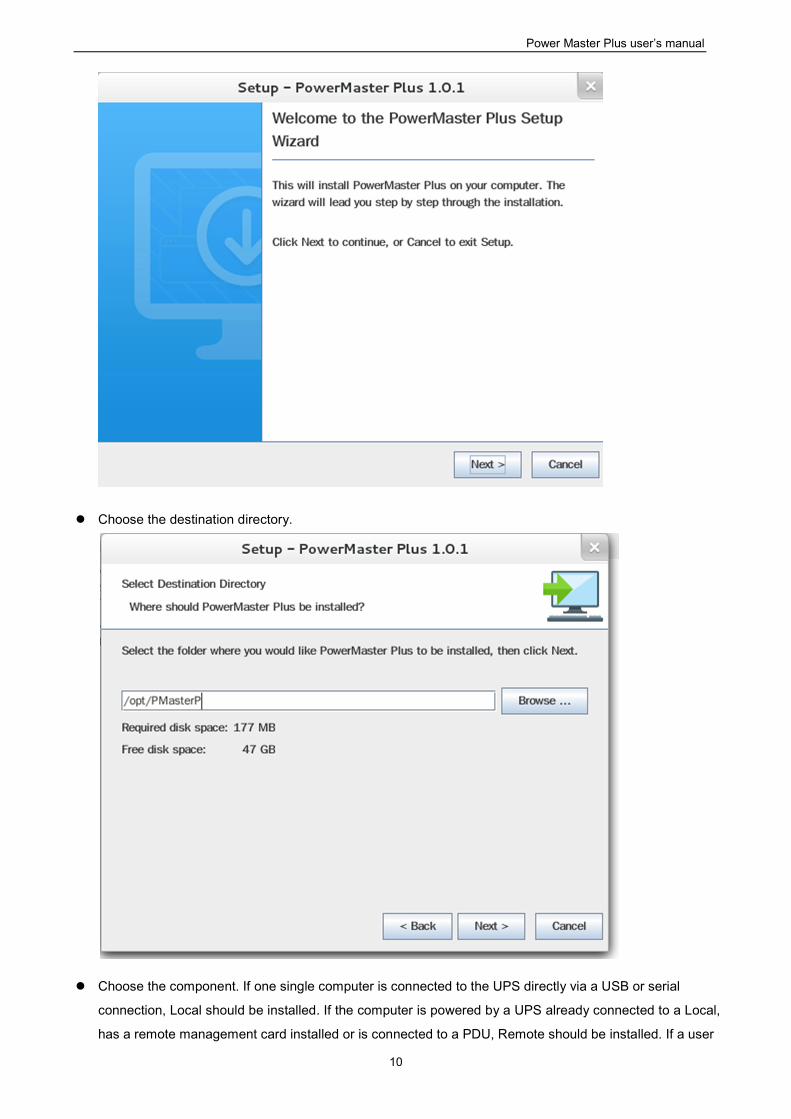
Click the Next button to start an installation.
Power Master Plus user’s manual
10
Choose the destination directory.
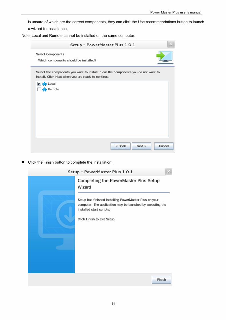
Choose the component. If one single computer is connected to the UPS directly via a USB or serial
connection, Local should be installed. If the computer is powered by a UPS already connected to a Local,
has a remote management card installed or is connected to a PDU, Remote should be installed. If a user
Power Master Plus user’s manual
11
is unsure of which are the correct components, they can click the Use recommendations button to launch
a wizard for assistance.
Note: Local and Remote cannot be installed on the same computer.
Click the Finish button to complete the installation.
Power Master Plus user’s manual
12
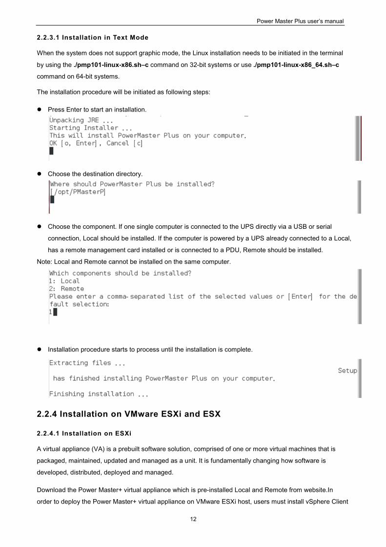
2.2.3.1 Installation in Text Mode
When the system does not support graphic mode, the Linux installation needs to be initiated in the terminal
by using the ./pmp101-linux-x86.sh–c command on 32-bit systems or use ./pmp101-linux-x86_64.sh–c
command on 64-bit systems.
The installation procedure will be initiated as following steps:
Press Enter to start an installation.
Choose the destination directory.
Choose the component. If one single computer is connected to the UPS directly via a USB or serial
connection, Local should be installed. If the computer is powered by a UPS already connected to a Local,
has a remote management card installed or is connected to a PDU, Remote should be installed.
Note: Local and Remote cannot be installed on the same computer.
Installation procedure starts to process until the installation is complete.
2.2.4 Installation on VMware ESXi and ESX
2.2.4.1 Installation on ESXi
A virtual appliance (VA) is a prebuilt software solution, comprised of one or more virtual machines that is
packaged, maintained, updated and managed as a unit. It is fundamentally changing how software is
developed, distributed, deployed and managed.
Download the Power Master+ virtual appliance which is pre-installed Local and Remote from website.In
order to deploy the Power Master+ virtual appliance on VMware ESXi host, users must install vSphere Client
Power Master Plus user’s manual
13
tool on another remote computer first. To download vSphere Client tool, users can enter the ESXi host IP
address to access web page of ESXi host
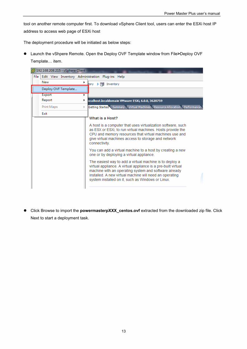
The deployment procedure will be initiated as below steps:
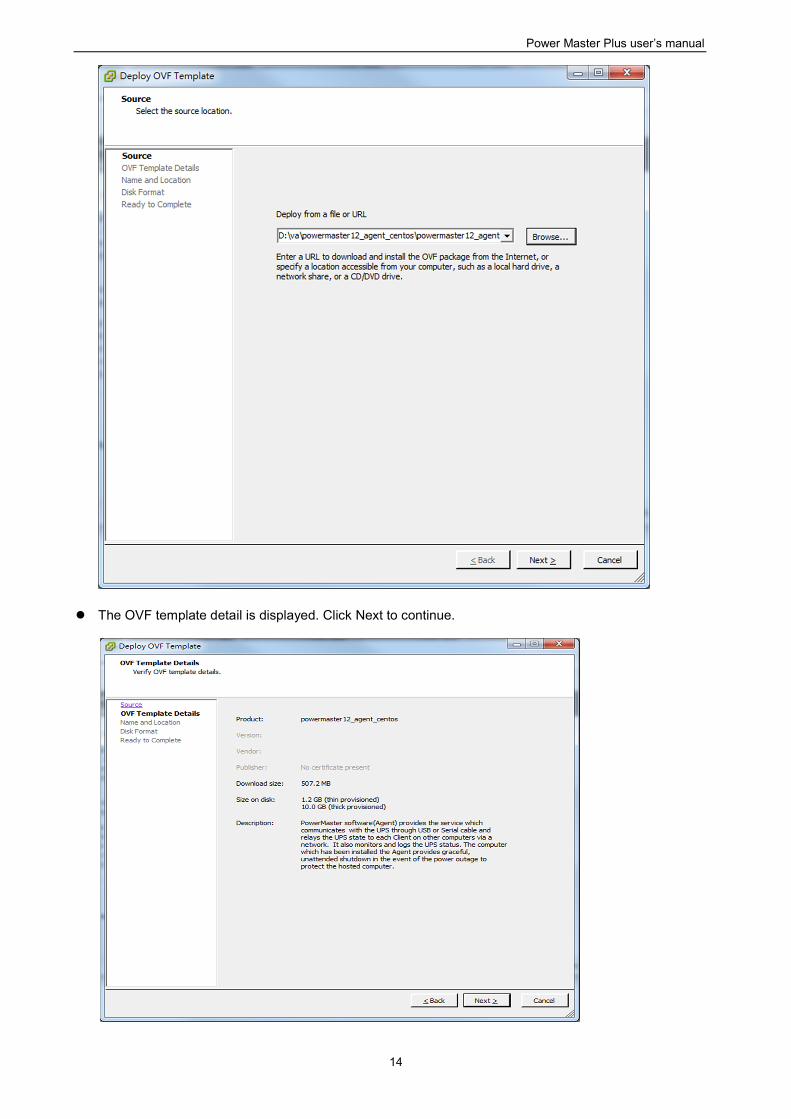
Launch the vShpere Remote. Open the Deploy OVF Template window from File>Deploy OVF
Template… item.
Click Browse to import the powermasterpXXX_centos.ovf extracted from the downloaded zip file. Click
Next to start a deployment task.
Power Master Plus user’s manual
14
The OVF template detail is displayed. Click Next to continue.
Power Master Plus user’s manual
15
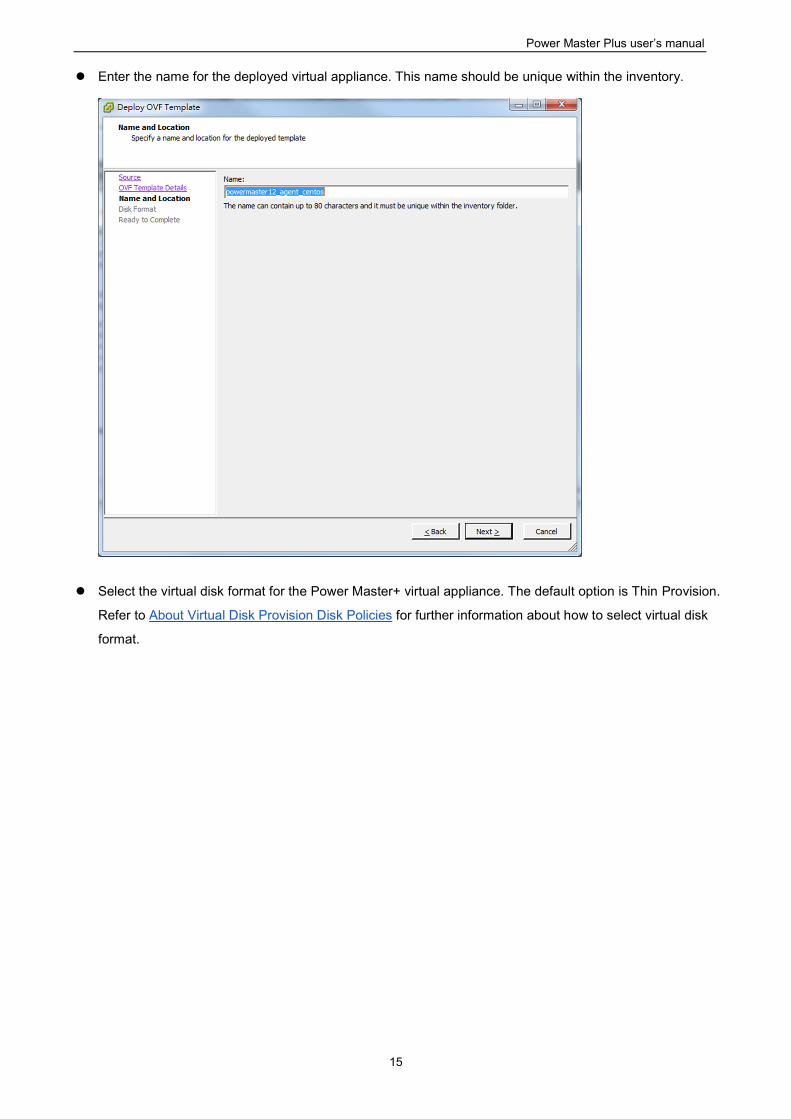
Enter the name for the deployed virtual appliance. This name should be unique within the inventory.
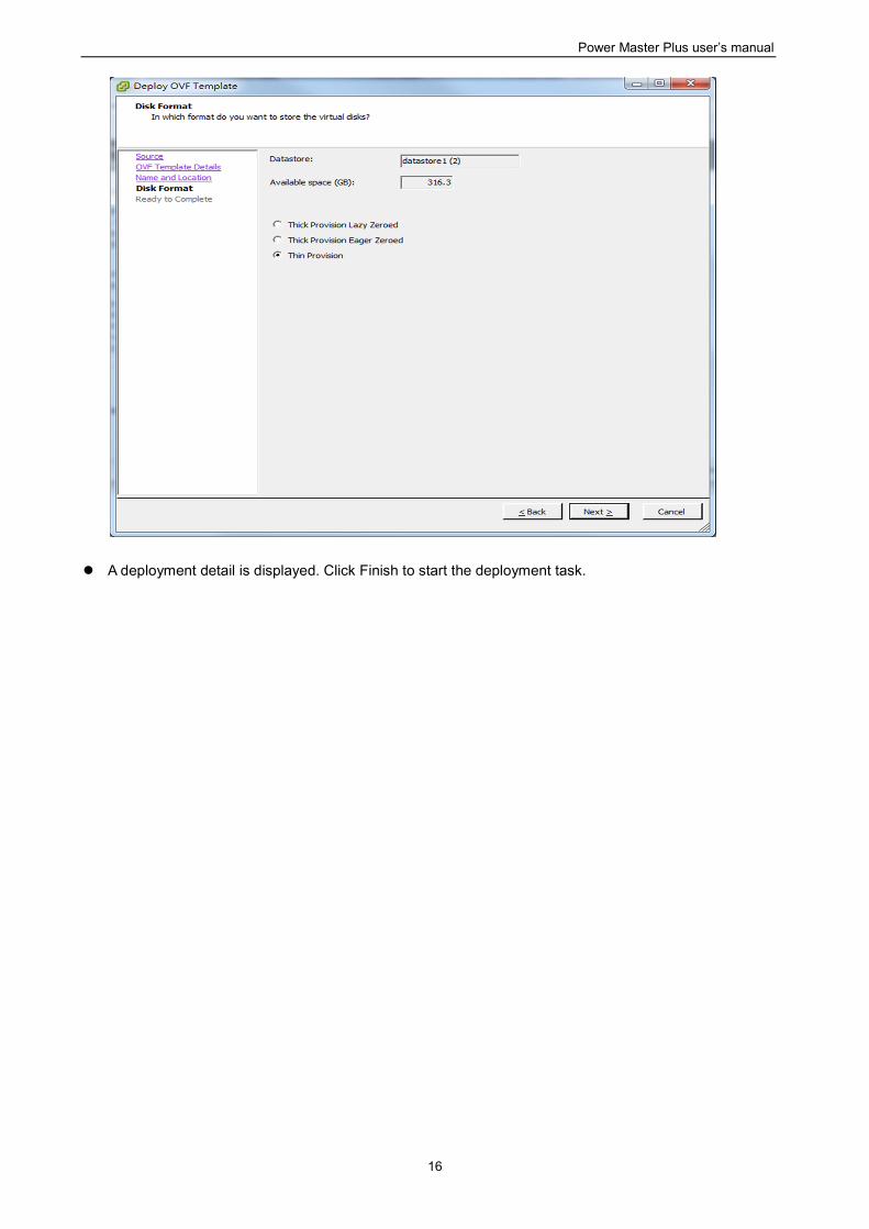
Select the virtual disk format for the Power Master+ virtual appliance. The default option is Thin Provision.
Refer to About Virtual Disk Provision Disk Policies for further information about how to select virtual disk
format.
Power Master Plus user’s manual
16
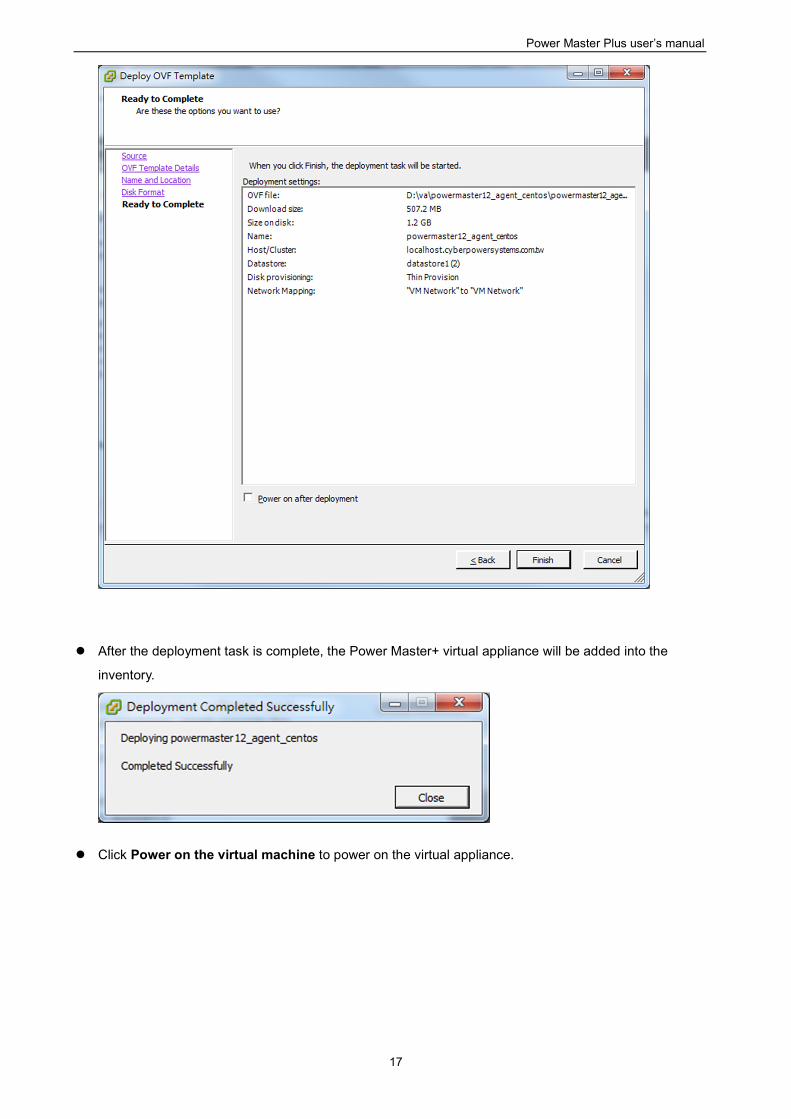
A deployment detail is displayed. Click Finish to start the deployment task.
Power Master Plus user’s manual
17
After the deployment task is complete, the Power Master+ virtual appliance will be added into the
inventory.
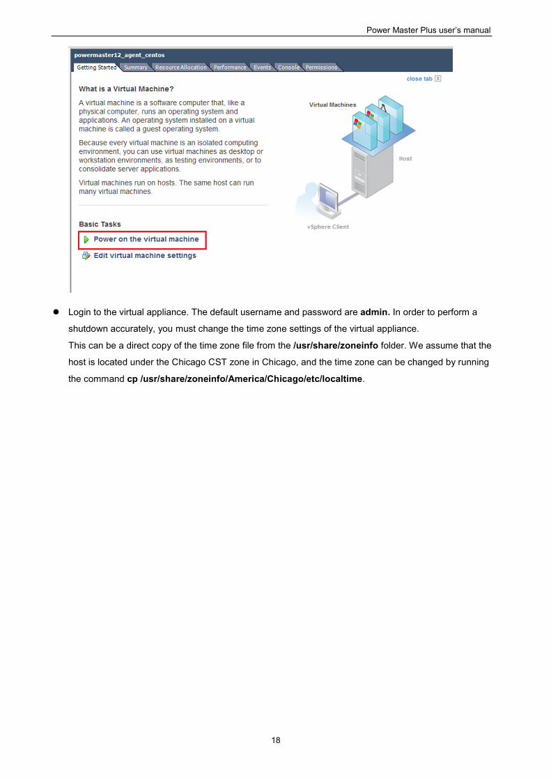
Click Power on the virtual machine to power on the virtual appliance.
Power Master Plus user’s manual
18
Login to the virtual appliance. The default username and password are admin. In order to perform a
shutdown accurately, you must change the time zone settings of the virtual appliance.
This can be a direct copy of the time zone file from the /usr/share/zoneinfo folder. We assume that the
host is located under the Chicago CST zone in Chicago, and the time zone can be changed by running
the command cp /usr/share/zoneinfo/America/Chicago/etc/localtime.
Power Master Plus user’s manual
19
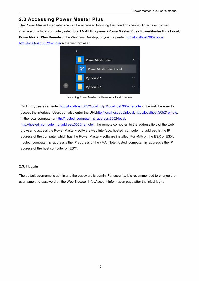
2.3 Accessing Power Master Plus The Power Master+ web interface can be accessed following the directions below. To access the web
interface on a local computer, select Start > All Programs >PowerMaster Plus> PowerMaster Plus Local,
PowerMaster Plus Remote in the Windows Desktop, or you may enter http://localhost:3052/local,
http://localhost:3052/remoteon the web browser.
Launching Power Master+ software on a local computer
On Linux, users can enter http://localhost:3052/local, http://localhost:3052/remoteon the web browser to
access the interface. Users can also enter the URLhttp://localhost:3052/local, http://localhost:3052/remote,
in the local computer or http://hosted_computer_ip_address:3052/local,
http://hosted_computer_ip_address:3052/remotein the remote computer, to the address field of the web
browser to access the Power Master+ software web interface. hosted_computer_ip_address is the IP
address of the computer which has the Power Master+ software installed. For vMA on the ESX or ESXi,
hosted_computer_ip_addressis the IP address of the vMA (Note:hosted_computer_ip_addressis the IP
address of the host computer on ESX).
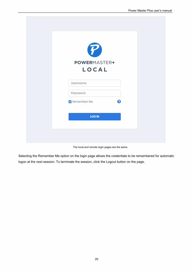
2.3.1 Login
The default username is admin and the password is admin. For security, it is recommended to change the
username and password on the Web Browser Info /Account Information page after the initial login.
Power Master Plus user’s manual
20
The local and remote login pages are the same.
Selecting the Remember Me option on the login page allows the credentials to be remembered for automatic
logon at the next session. To terminate the session, click the Logout button on the page.
Power Master Plus user’s manual
21
3 Using Power Master Plus
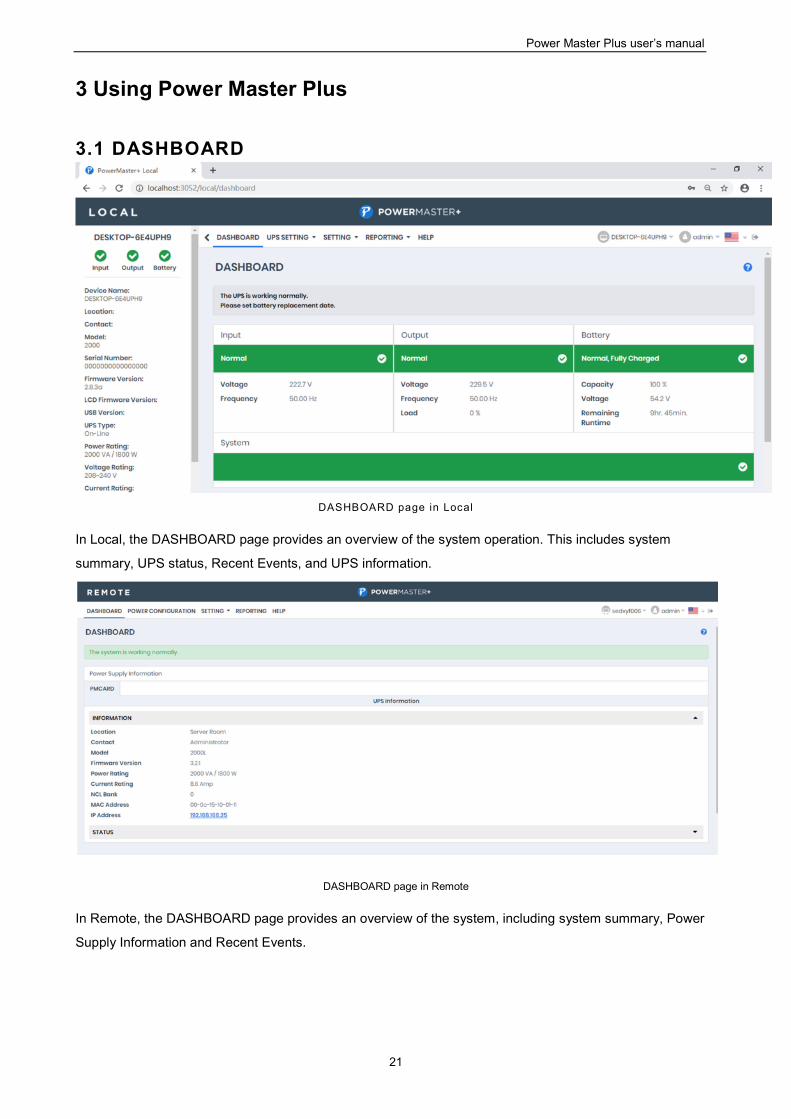
3.1 DASHBOARD
DASHBOARD page in Local
In Local, the DASHBOARD page provides an overview of the system operation. This includes system
summary, UPS status, Recent Events, and UPS information.
DASHBOARD page in Remote
In Remote, the DASHBOARD page provides an overview of the system, including system summary, Power
Supply Information and Recent Events.
Power Master Plus user’s manual
22
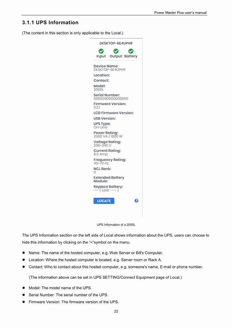
3.1.1 UPS Information
(The content in this section is only applicable to the Local.)
UPS Information of a 2000L
The UPS Information section on the left side of Local shows information about the UPS, users can choose to
hide this information by clicking on the “<”symbol on the menu.
Name: The name of the hosted computer, e.g. Web Server or Bill's Computer.
Location: Where the hosted computer is located, e.g. Server room or Rack A.
Contact: Who to contact about this hosted computer, e.g. someone's name, E-mail or phone number.
(The information above can be set in UPS SETTING/Connect Equipment page of Local.)
Model: The model name of the UPS.
Serial Number: The serial number of the UPS.
Firmware Version: The firmware version of the UPS.
Power Master Plus user’s manual
23
LCD Firmware Version: The firmware version of the LCD screen on the UPS.
USB Version: The version of the USB chipset on the UPS.
UPS Type: The type of the UPS. e.g. On-Line, Line Interactive or Sine wave Line Interactive.
Power Rating: The Volt-Amp rating and power rating (Watts) of the UPS.
Voltage Rating: The input voltage range (Volts) of the UPS.
Current Rating: The output current rating (Amps)of the UPS.
Frequency Rating: The input frequency range (Hz) of the UPS.
NCL Bank: The amount of the Non-Critical Load banks.
Extended Battery Module: The amount of extended battery modules connected to the UPS.
Next Battery Replacement Date: The next date that the batteries should be replaced. This date only
changes based on the Battery Replacement Date. Battery Replacement Date is the date that batteries
have been replaced. This date should be changed immediately after the battery replacement or when the
unit is first purchased. The battery lifetime varies by UPS models. Once battery replacement date is
changed, the software will alert the customer when the battery age has reached the lifetime.
LOCATE: Clicking the LOCATE button will ask alarm to beep or indicators to blind in order to inform
users of the location. This helps users to identify the specific UPS at installation sites with multiple UPS
units.
Note: Not all models provide the same information. The information displayed will vary by model.
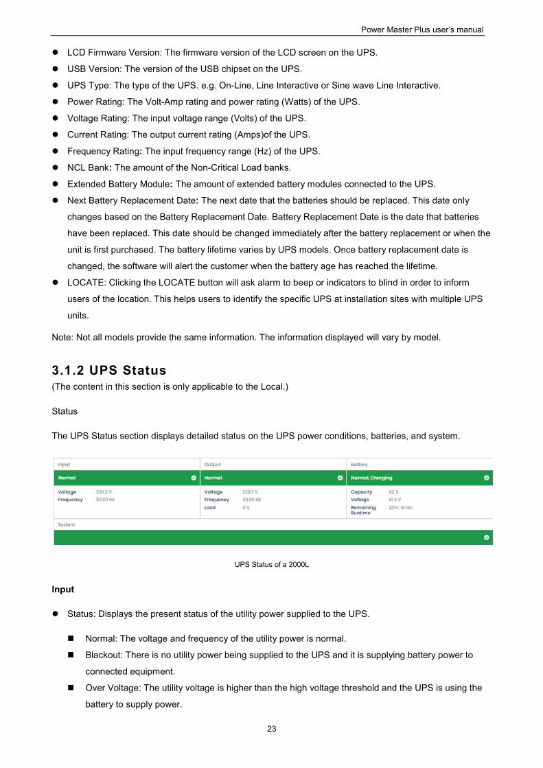
3.1.2 UPS Status (The content in this section is only applicable to the Local.)
Status
The UPS Status section displays detailed status on the UPS power conditions, batteries, and system.
UPS Status of a 2000L
Input
Status: Displays the present status of the utility power supplied to the UPS.
Normal: The voltage and frequency of the utility power is normal.
Blackout: There is no utility power being supplied to the UPS and it is supplying battery power to
connected equipment.
Over Voltage: The utility voltage is higher than the high voltage threshold and the UPS is using the
battery to supply power.
Power Master Plus user’s manual
24
Under Voltage: The utility voltage is lower than the low voltage threshold and the UPS is using the
battery to supply power.
Frequency Failure: The frequency of the utility power is out of tolerance and the UPS is supplying
battery power with a fixed frequency.
Wiring Fault: The UPS has detected a wiring fault in the outlet it is plugged into.
No Neutral: The neutral wire is not connected properly.
Generator Detected: UPS is being supplying power by generator.
Power Failure: The utility power being supplied to the UPS is not within spec due to other power
noise and distorted conditions.
Voltage: The voltage of the utility power supplied to the UPS.
Frequency: The frequency of the utility power supplied to the UPS.
Current: The current of the utility power supplied to the UPS.
Power Factor: The ratio of the real power flowing to the UPS, to the apparent power of utility power. In an
UPS system, a UPS with a low power factor draws more current than a UPS with a high power factor for
the same amount of useful power transferred.
Bypass
Status: Displays the present status of bypass circuit. In bypass mode, the UPS will provide the power
from bypass input to the connected equipment directly.
Normal: The power quality of bypass circuit is normal.
Blackout: There is no input power being supplied in bypass circuit.
Over Voltage: The input voltage of bypass is higher than an acceptable threshold.
Under Voltage: The input voltage of bypass is lower than an acceptable threshold.
Frequency Failure: The frequency of bypass is out of tolerance.
Power Failure: The power of bypass is not qualify due to other power noise and distorted conditions.
Wrong Phase Sequence: The phase sequence of the bypass circuit is different from utility power.
Overload: Output power consumption exceeds the power rating of UPS.
Extended Overload: The duration of the overload is too long, UPS will shut down soon.
Voltage: The voltage of the bypass supplied to the UPS.
Current: The current of the bypass supplied to the UPS.
Frequency: The frequency of the bypass supplied to the UPS.
Power Factor: The ratio of the real power flowing to the bypass, to the apparent power of bypass. In a
UPS system, a load with a low power factor draws more current than a load with a high power factor for
the same amount of useful power transferred.
Output
Status: Displays the present status of the output power the UPS is supplying to connected equipment.
Normal: The output power is normal.
Bypass: The UPS has switched to bypass mode and the utility power is being supplied directly to the
connected equipment bypassing the UPS circuitry.
Note: Bypass mode is only applicable in Online Series UPS units.
Power Master Plus user’s manual
25
No Output: There is no output from the UPS. The UPS is switched off.
Short Circuit: There is a short circuit on the UPS output. This causes the UPS to stop supplying
output power.
Boost: The utility voltage is below the regular voltage range. The UPS is increasing the output
voltage closer to normal.
Buck: The utility voltage is beyond the regular voltage range. The UPS is decreasing the output
voltage closer to normal.
Note: The Boost and Buck function are only available on a UPS with AVR; only high-end units with
AVR have a Buck feature. The UPS uses the AVR function to improve the utility voltage and
supplies the power to its connected equipment within a narrow range.
Overload: The present load exceeds the load threshold of the UPS. Remove some equipment from
the UPS to reduce the load.
ECO Mode: On-line UPS enters Economy mode. The UPS will enter bypass mode according to
thresholds for input voltage. Once the utility voltage exceeds thresholds, the UPS will supply battery
power to its loads. Users can configure exclusive days and exclusive time to for UPS when to not
enter ECO mode.
Manual Bypass: The Online UPS enters Manual Bypass mode due the Manual option being enabled.
The UPS will be forced to provide utility power to its equipment.
Insufficient Inverter Power: There is no enough capacity of the inverter’s power. UPS cannot back to
line mode from bypass mode.
Redundancy Lost: The quantity of UPS modules has no enough power to be complete redundancy;
UPS has no complete fault-tolerant ability.
EPO: The function of EPO (Emergency Power Off) has been activated; UPS output power was
turned off.
Voltage: The output voltage that the UPS is supplying to the connected equipment.
Frequency: The output frequency that the UPS is supplying to the connected equipment.
Load: The power draw of the connected equipment expressed as a percentage of the total load capacity.
This is displayed as watts on some UPS models.
Current: The output current of the UPS which is supplying to connected equipment.
Active Power: The capacity of the circuit for performing work in a particular time.
Reactive Power: Reactive power is needed in an alternating-current transmission system to support the
transfer of real power over the network. In alternating current circuits, energy is stored temporarily in
inductive and capacitive elements, which can result in the periodic reversal of the direction of energy flow.
The portion of power flow remaining, after being averaged over a complete AC waveform, is the real
power; that is, energy that can be used to do work. On the other hand, the portion of power flow that is
temporarily stored in the form of magnetic or electric fields, due to inductive and capacitive network
elements, and then returned to source, is known as reactive power.
Apparent Power: The product of the current and voltage of the circuit.
Power Factor: The radio of the active power flowing to the load, to the apparent power in the circuit. In an
electric power systems, a load with a low power factor draws more current than a load with a high power
factor for the same amount of useful power transferred.
Power Master Plus user’s manual
26
NCL Outlet: Displays the present status of the NCL outlet.
On: This outlet is turned on and supplying power to the connected equipment.
Off: This outlet is turned off and is not supplying power to the connected equipment.
Pending On: This outlet is going to turn on following an action such as a scheduled turn on.
Pending Off: This outlet is going to turn off following an action such as a scheduled turn off.
Battery
Status: Displays the present status of the battery packs.
Fully Charged: The batteries are at 100% capacity.
Discharging: The UPS is supplying battery power to support the load. This is caused by a utility
power failure or battery test.
Charging: The batteries are charging.
Boost Charging: Boost charging involves a high current for a short period of time to charge the
battery. Boost charger enables the quick charging of depleted batteries.
Float Charging: The float charger starts charging the battery by exerting a charging voltage. As the
battery is charged, its charging current reduces gradually. The float charger senses the reduction in
charging current and reduces the charging voltage.
Exhausted: Batteries are exhausted; UPS stops the output power.
Reversed Connection:Connection between UPS and batteries is wrong on electrical polarity.
Capacity Critically Low: The battery capacity is too low and the UPS may shut down immediately.
Not Present: There are no batteries present in the UPS.
Testing: The UPS is performing a battery diagnostic test. See the UPS/Diagnostics page for more
details about the test results.
Normal: The batteries are working normally.
Voltage: The present voltage supplied by the batteries.
Remaining Runtime: The amount of time that the UPS can supply power to its load.
Remaining Charge Time: The remaining time the batteries required to be fully charged.
Capacity: The present capacity of the batteries expressed as a percentage of full charge.
System
Status: Displays the present operating status of the UPS.
Normal: The operating status is normal.
Fault: The UPS is in fault state due to an internal malfunction.
Overheat: The temperature exceeds the normal temperature threshold.
Bypass Fault: The bypass module of UPS has been malfunctioned.
Bypass Fan Fault: The fan of the bypass module has been malfunctioned.
Module Failure: One of UPS modules is no more normal and offline.
Unable Recover: UPS fails to recover to line mode from bypass on occurred overload condition in
past one hour.
Temperature: The present internal temperature of the UPS. It is displayed in both Celsius (°C) and
Fahrenheit (°F).
Power Master Plus user’s manual
27
Maintenance Break: Displays the present operating status of maintenance break.
Note: When the UPS needs maintenance or repair, the load can be transferred to maintenance bypass
without interruption and the power module can be removed for maintenance.
Opened: The UPS is in maintenance bypass mode.
Closed: The UPS is not in maintenance bypass mode.
Module Status: Displays the present operating status of each UPS module.
Normal: The module is operating normally.
Offline: The module is not installed.
Rectifier Fault: The module rectifier is faulty and stops output power.
Inverter Fault: The module inverter is faulty and stops output power.
Inverter Protected: The module inverter has been protected and stops operating.
Rectifier Overheat: The internal temperature of module rectifier exceeds the normal rating.
Inverter Overheat: The internal temperature of module inverter exceeds the normal rating.
Inverter Overload: The module inverter is overloaded.
Inverter Extended Overload: The module’s inverter has been overloaded for intolerable duration; the
UPS will stop output power soon.
Fan Fault: The module fan is faulty. It may cause overheat in module.
Shutdown: The module has been shut down and stopped its output power.
Note: Not all models provide the same information. The information displayed will vary by model.
3.1.3 Power Supply Information
(The content in this section is only applicable to the Remote.)
The Remote can interact with a UPS or a PDU through a network interface. If the UPS has no remote
management card, the Local can be installed on a single computer which is using a USB or a serial
connection directly to the UPS in order to establish the network connection to the Remote.
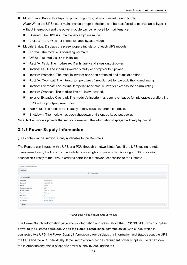
Power Supply Information page of Remote
The Power Supply Information page shows information and status about the UPS/PDU/ATS which supplies
power to the Remote computer. When the Remote establishes communication with a PDU which is
connected to a UPS, the Power Supply Information page displays the information and status about the UPS,
the PUD and the ATS individually. If the Remote computer has redundant power supplies, users can view
the information and status of specific power supply by clicking the tab.
Power Master Plus user’s manual
28
Information
Name: The name of the UPS/PDU/ATS.
Location: Where the UPS/PDU/ATS is located.
Contact: Who to contact about the UPS/PDU/ATS.
Model: The model name of the UPS/PDU/ATS.
Firmware Version: The firmware version of the UPS/PDU/ATS.
Serial Number: The serial number of the UPS/PDU/ATS.
Device Type: The type of the UPS/PDU/ATS, e.g. UPS/PDU/ATS.
UPS Type: The type of the UPS. e.g. On-Line or Line Interactive.
PDU Type: The type of the PDU. e.g. Monitored or Switched.
ATS Type: The type of the ATS. e.g. Monitored or Switched.
Power Rating: The Volt-Amp rating and power rating (Watts) of the UPS.
Current Rating: The output current rating (Amps) of the UPS/PDU/ATS.
Voltage Rating: The output voltage rating (Volts) of the UPS/PDU/ATS.
Frequency Rating: The output frequency rating (Hz) of the UPS.
Battery Replacement Date: The date that the batteries were last replaced.
NCL Bank: The amount of NCL (Non-Critical Load) outlets in the UPS.
Extended Battery Pack: The number of extended battery packs connected to the UPS.
Outlet: The number of outlets of the devices.
MAC Address: The MAC address of the UPS PMCARD, PDU or Local’s network interface.
IP Address: The IP address of the UPS PMCARD, PDU or Local’s network interface. Click the hyperlink
to open the web interface of the UPS PMCARD, PDU or Local.
UPS on Source A: Indicates which UPS connects to input source A of ATS.
UPS on Source B: Indicates which UPS connects to input source B of ATS.
Environment Sensor: Indicates whether the environment sensor has been installed on the
UPS/PDU/ATS.
Note: When the sensor cannot be detected anymore, it will be annotated No Response. Users must click
the Uninstall option if the sensor has been physically removed from the UPS/PDU/ATS.
Low Battery Threshold (%):The low battery threshold in terms of the percentage of the remaining
capacity.
Low Battery Threshold (mins): The low battery threshold in terms of the remaining runtime.
Delay: The delay time is set for each outlet of the PDU/ATS. It includes On/Off delay and Reboot
Duration.
Note: Not all models provide the same information. The information displayed will vary by model.
Status
The Status section displays the details of the UPS/PDU/ATS status from the UPS/PDU/ATS Remote
Management for users to quickly review the system.
Note: Not all models provide the same status. The status displayed will vary by model.
Power Master Plus user’s manual
29
3.2 UPS SETTING
3.2.1 Diagnostics
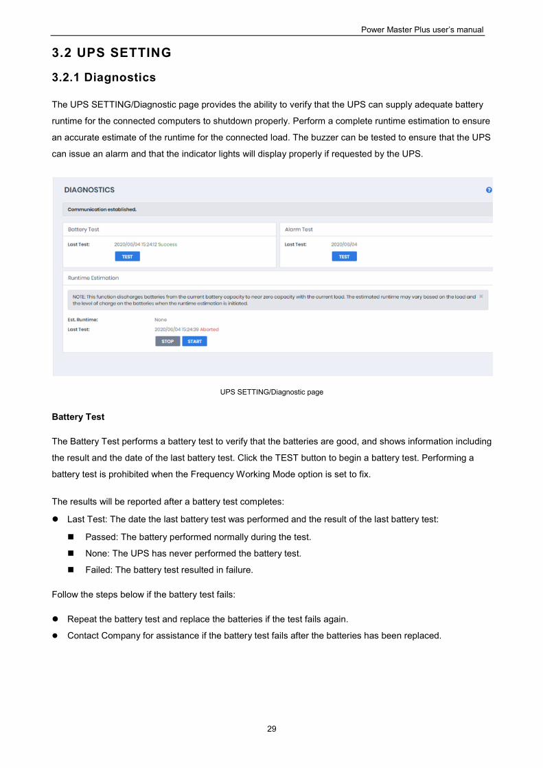
The UPS SETTING/Diagnostic page provides the ability to verify that the UPS can supply adequate battery
runtime for the connected computers to shutdown properly. Perform a complete runtime estimation to ensure
an accurate estimate of the runtime for the connected load. The buzzer can be tested to ensure that the UPS
can issue an alarm and that the indicator lights will display properly if requested by the UPS.
UPS SETTING/Diagnostic page
Battery Test
The Battery Test performs a battery test to verify that the batteries are good, and shows information including
the result and the date of the last battery test. Click the TEST button to begin a battery test. Performing a
battery test is prohibited when the Frequency Working Mode option is set to fix.
The results will be reported after a battery test completes:
Last Test: The date the last battery test was performed and the result of the last battery test:
Passed: The battery performed normally during the test.
None: The UPS has never performed the battery test.
Failed: The battery test resulted in failure.
Follow the steps below if the battery test fails:
Repeat the battery test and replace the batteries if the test fails again.
Contact Company for assistance if the battery test fails after the batteries has been replaced.
Power Master Plus user’s manual
30
Indicator Test
Indicators on the front panel or on the LCD screen are used to present the UPS status. Once the indicators
are malfunctioning, users won’t know the current UPS status. The Indicator Test allows users to ensure
whether indicators blink normally. Click TEST button to begin an indicator test
The details will be reported after an indicator test is complete:
Last Test: The date the last indicator test was performed.
Alarm Test
The Alarm Test allows users to verify that the alarm can beep normally and shows the date of the last test.
Click the TEST button to begin an alarm test.
The details will be reported after an alarm test is complete:
Last Test: The date the last alarm test was performed.
Runtime Estimation
The Runtime Estimation function discharges batteries from the current battery capacity to near zero capacity
with the current load. The results of the runtime estimation show the runtime, status of estimation, and the
date of the last estimation. When the runtime estimation is initiated, the connected equipment will be run on
battery power until the batteries are discharged to near zero capacity. Please note that this estimated
runtime may vary based on the load and the level of charge on the batteries when the runtime estimation is
initiated. The batteries will be recharged then automatically after the estimation is done.
Users can click the START button to initiate the runtime estimation. Click the STOP button to interrupt the
runtime estimation. The result will be reported after the runtime estimation is finished or canceled:
Est. Runtime: The estimated runtime of the batteries.
Last Test: The date and the results of the last runtime estimation performed.
Passed: The runtime estimation was completed and the batteries are good.
None: The UPS has not performed a runtime estimation.
Failed: The UPS failed during the runtime estimation.
Canceled: The runtime estimation was interrupted.
Note: A complete runtime estimation depletes the battery capacity. Ensure the UPS is recharged completely
after performing runtime estimation.
Power Master Plus user’s manual
31
3.2.2 Configuration
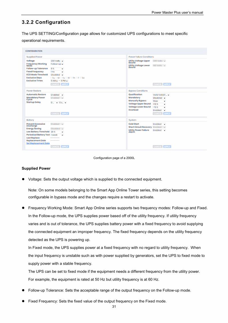
The UPS SETTING/Configuration page allows for customized UPS configurations to meet specific
operational requirements.
Configuration page of a 2000L
Supplied Power
Voltage: Sets the output voltage which is supplied to the connected equipment.
Note: On some models belonging to the Smart App Online Tower series, this setting becomes
configurable in bypass mode and the changes require a restart to activate.
Frequency Working Mode: Smart App Online series supports two frequency modes: Follow-up and Fixed.
In the Follow-up mode, the UPS supplies power based off of the utility frequency. If utility frequency
varies and is out of tolerance, the UPS supplies battery power with a fixed frequency to avoid supplying
the connected equipment an improper frequency. The fixed frequency depends on the utility frequency
detected as the UPS is powering up.
In Fixed mode, the UPS supplies power at a fixed frequency with no regard to utility frequency. When
the input frequency is unstable such as with power supplied by generators, set the UPS to fixed mode to
supply power with a stable frequency.
The UPS can be set to fixed mode if the equipment needs a different frequency from the utility power.
For example, the equipment is rated at 50 Hz but utility frequency is at 60 Hz.
Follow-up Tolerance: Sets the acceptable range of the output frequency on the Follow-up mode.
Fixed Frequency: Sets the fixed value of the output frequency on the Fixed mode.
Power Master Plus user’s manual
32
Caution: The wrong frequency settings may damage the connected equipment. Make sure the selected
frequency is correct for the connected equipment. An alert warning message will remind you of the
following conditions:
The frequency mode has changed from the Follow-up mode to the Fixed mode, and the fixed
frequency is not equal to the utility frequency.
The frequency mode is Fixed mode and the fixed frequency is going to be changed.
ECO Mode: The UPS will enter bypass mode according to the utility voltage if it is in range of thresholds
or the utility frequency is within 3Hz of the utility frequency. If the utility voltage or the utility frequency
exceeds thresholds, the UPS will supply battery power to its loads.
If this threshold is set to 10% and the current utility voltage is 220 V, the UPS will enter bypass mode as
long as the utility voltage within the range of 198 V ~ 242 V. Once the voltage threshold is exceeded, the
UPS will supply battery power to its loads.
Caution: Once the UPS is set to enter Fixed mode, Generator Mode or Manual Bypass when the UPS is
in the ECO mode, the UPS will exit from ECO mode.
Users can configure Exclusive Days and Exclusive Time to tell the UPS when not to enter ECO mode.
Exclusive Days: Sets the days for UPS not to enter ECO mode.
Exclusive Time: Sets the time period for UPS not to enter ECO mode.
Power Failure Condition
When the utility power exceeds specific thresholds, the UPS will supply battery power to the connected
equipment.
Utility Voltage Upper/Lower Bound: Before utility power is provided to the UPS, the UPS will detect
whether utility voltage exceeds the threshold. If utility voltage exceeds the threshold, the UPS will supply
battery power to the connected equipment.
Output Voltage Upper/Lower Bound: Before the UPS uses utility power as its output power, the UPS will
detect whether utility voltage exceeds the threshold. If the utility voltage exceeds the threshold, the UPS
will supply battery power to connected equipment.
Note: High/Low Utility Voltage Threshold High/Low Output Voltage Threshold settings only come into
effect after a restart of the UPS.
Frequency Upper/Lower Bound: When the utility frequency exceeds the threshold, the UPS will supply
battery power at a fixed frequency to the connected equipment.
Detected Sensitivity: When the UPS detects that utility voltage is out of range, the UPS will switch to
battery mode to protect the equipment plugged into the UPS. Low sensitivity has a wider voltage range
Power Master Plus user’s manual
33
and the supplied power may vary more. The UPS switches to battery mode rarely and also saves more
battery power. The power from a fuel generator may cause the UPS to switch to battery mode more
frequently, and low sensitivity is recommended. High sensitivity allows the UPS to supply more stable
power to equipment but switches to battery mode frequently.
Power Restore
When a utility power failure occurs, Power Master+ software may order the computer to shut down and
power off after the specified remaining runtime is met or if the battery capacity is low. After the utility power is
restored the UPS turns on automatically and supplies power to the computer. If the computer BIOS is set to
boot when power is restored the computer will automatically restart.
The following settings are used to configure the UPS restore behavior:
Automatic Restore: When this option is enabled, the UPS will restore output immediately when the utility
power is restored. When this option is disabled, the UPS will not restore output at that moment and users
have to turn it on manually.
Mandatory Power Cycle: When a shutdown sequence is initiated due to a power failure, the connected
computers may be ordered to shut down and the UPS will be also ordered to turn off after a time delay. If
the utility power is restored prior to the UPS shutting off, the UPS will still turn itself off. In this
circumstance, the utility power has restored, but the connected computers have shut down and the UPS
has turned off.
If the Mandatory Power Cycle option is enabled, the UPS will also turn off after a time delay, but it will
turn on again about 10 seconds later. The UPS has restarted and then all connected computers will boot.
Note: Most computers have the ability to boot when utility power is restored. Make sure this function is
supported and enabled in the system BIOS.
Recharged Delay: When the utility power is restored, the UPS will start to recharge until the specified
delay is expired before restoring output power.
Recharged Capacity: When the utility power is restored, the UPS will start to recharge until the specified
battery capacity is met before restoring output power.
Startup Delay: When the utility power is restored, the UPS will delay the restoration of output power. This
option can be used to stagger the startup time of multiple UPS to avoid overloading the utility power
circuit or power source. The Startup Delay option will take effect every time when the UPS is about to
restore power. This also includes the scheduling task.
Stable Utility Delay: When the utility power is restored, the UPS will delay switching to normal operation
from using battery power. If the battery capacity is lower than the Low Battery Threshold as power is
restored, the UPS will switch to normal operation immediately. This option can be used to prevent
frequent outage due to unstable utility power.
Restore Action: Sets the operating mode after utility power restores. If the Bypass option is selected, the
UPS will enter to bypass mode and supply power from the bypass module to connected equipment when
utility power restores. If the Online option is selected, the UPS will supply power from the UPS modules
to connected equipment when utility power restores. If the Standby option is selected, the UPS will be off
when utility power restores.
Power Master Plus user’s manual
34
Bypass Condition
The Online UPS series supports the bypass function. When the UPS is in bypass mode, the utility power is
supplied directly to the connected equipment. To configure whether the UPS is allowed to enter or remain in
bypass mode in select from the following:
Qualification: This configures the qualifications the UPS uses to determine if it will enter bypass mode
when a UPS fault or overload occurs.
Valid Volt. & Freq: If the utility voltage is in range of the voltage thresholds and the utility frequency
is in range of the frequency tolerance, the UPS will enter bypass mode. Otherwise the UPS will stop
supplying output power.
Valid Voltage: If the utility voltage is in range of the voltage thresholds, the UPS will enter bypass
mode. Otherwise the UPS will stop supplying output power.
Never Bypass: If this option is selected, the UPS will not enter bypass mode and will stop supplying
output power.
Mandatory: If this option is enabled, the UPS will enter bypass mode due to a fault or overload, even if
the utility voltage is outside of the normal range. Otherwise the UPS will stop supplying output power.
Caution: Bad utility voltage while in bypass mode may damage the connected equipment.
Manually Execution: Determines whether to allow the UPS to enter Manual Bypass mode. If this Start
option is selected, the UPS will be forced to enter bypass mode.
Caution: Make sure that the UPS is not using generator power or converted power. When the UPS enters
bypass mode, the UPS will use input power to supply to equipment. The unstable frequency of the input
power may damage connected equipment.
Caution: If this option is enabled, the UPS can’t function in Generator mode.
Voltage Upper/Lower Bound: When a UPS fault or overload occurs, the UPS will determine whether to
enter bypass mode according to the utility power threshold range. If the utility voltage exceeds thresholds,
the UPS will be forbidden to enter bypass mode and will stop supplying output power.
Overload: This configures the ability of the UPS to switch to bypass mode and supply utility power when
the output is overloaded. Without this enabled the UPS will stop supplying power when overloaded.
Bypass at Power Off: This determines whether the UPS will switch to bypass mode and supply utility
power when the UPS is switched off.
Bypass Frequency Tolerance: If the UPS tries entering bypass mode due to an overload or fault, the
UPS will compare the frequency with the Bypass Frequency Tolerance. If the frequency is out of range,
the UPS will stop supplying output power.
Power Master Plus user’s manual
35
Battery
Prevent Excessive Discharge: When the UPS uses the battery to supply power for output, a deep
discharge with a low load can shorten the battery life. If this option is enabled, the UPS will stop
supplying power after discharging for 4 hours to avoid a deep battery discharge.
Energy Saving: When the utility power fails, the batteries will start discharging. If this option is enabled
and there is no output load, the UPS will shut down to save battery power after discharging for 5 minutes.
The UPS will restart automatically and restore output after the utility power is restored.
Low Battery Threshold: When the UPS supplies battery power and the remaining capacity or running
time slower than this threshold, the UPS will sound an alarm.
Battery Pack Type: Sets the type of extended battery packs. When the UPS is installed with standard
battery packs, Local has capability of measurement the runtime according to the capacity of the battery
packs. The option should be set Standard. When the UPS is installed with customized battery packs, the
option should be set Customization.
Periodical Battery Test: The UPS will periodically perform the battery test to ensure the batteries are fully
functional.
Note: Only online double conversion UPS models (OL series) support the Smart Battery Management
(SBM) feature. SBM carries out battery tests when certain operating conditions are met in order to verify
the batteries are healthy. This occurs regardless of the Periodical Battery Test setting, even if it is
disabled. To disable the SBM setting, please refer to the respective UPS User Manual for details.
Extended Module Setting: Sets the mode of Extended Battery Module detection, could be auto detect or
manual. If auto detect is selected, the UPS will detect the number of Extended Battery Module
automatically.
Extended Battery Pack: Sets the amount of extended battery packs. This allows for an accurate runtime
estimate based upon the total number of batteries.
Boost Charge Period: Sets the period for UPS batteries being boost charged automatically and
periodically.
Discharge Duration Limit: Sets the duration to limit the battery discharging to avoid a deep discharge
excessively.
System
Cold Start: Sets the ability of the UPS to start in the absence of input power. When this option is enabled
the UPS can be turned on without having input power.
Short Circuit Recovery Detect: When the output of the UPS causes a short circuit, the output will turn off
immediately. If this option is enabled, the UPS will inspect the circumstance of the short circuit3 times in
30 seconds. If the short circuit is no longer present, the UPS will restore power. If the circumstances of
the short circuit still remain, the UPS will not supply power.
Utility Power Failure Alarm: If this option is enabled, the UPS will issue an audible alarm when the utility
power fails.
Overload Alarm Threshold: When the output load exceeds this threshold, the UPS will issue an audible
alarm.
Power Master Plus user’s manual
36
Generator Mode: If the UPS is using a generator for its input power, this option should be enabled for
UPS to function normally. If this option is enabled, the UPS will be forbidden to enter bypass mode to
protect the powered equipment.
Caution: If this option is enabled, the UPS can’t function in Manual Bypass mode.
LCD Back-light Saving: When no UPS button is pressed or no power event occurs during this delay, the
LCD screen will be turned off.
Wiring Fault Detecting: If this option is enabled, the UPS will detect if the UPS wiring is not grounded or
reversed. It is recommended to assure the UPS wiring has ground connection first. This option should be
enabled if the UPS wiring has ground connection.
Dry Relay Function: This configures the power condition for the UPS dry relay to function when the
selected condition occurs. Refer to UPS manual for further information about advanced UPS dry relay
utilization. The Dry Relay Function provides the following power conditions:
Utility Failure: The utility power fails and the UPS is using the battery power.
Low Battery: The battery capacity is low and cannot support the connected computers if they require
a shutdown.
Alarm: The UPS is issuing an audible alarm due to a warning event, such as Overload
Bypass: The UPS has switched to bypass mode due to an overload or UPS fault.
UPS Fault: The UPS may be malfunctioning due to an internal problem, such as an inverter fault,
bus fault or overheating.
Redundant Quantity: Sets the quantity of UPS modules to be power redundancy. This power redundancy
can provide the fault-tolerant protection against failures of equivalent UPS modules. UPS should avoid
exceeding output load from whom deducted the power redundancy; otherwise UPS cannot afford the
equivalent fault-tolerant protection as user’s desire.
NCL Outlet
NCL stands for Non-Critical Load. Under the following conditions, the UPS will turn off the NCL outlet to
conserve battery power and maximize battery runtime for the remaining outlets:
Turn Off Threshold: When supplying battery power, the UPS will power off this NCL outlet if the
remaining battery capacity is lower than this threshold.
Turn Off Runtime Threshold: When supplying battery power, the UPS will power off this NCL outlet if the
remaining battery runtime is lower than this threshold.
Turn Off Delay: When supplying battery power, the UPS will power off this NCL outlet after this delay
time is met.
Turn On Delay: When the utility power is restored, the UPS will restore the output of this NCL outlet after
the delay time is met. This prevents excessive power consumption caused by all the connected
equipment starting at the same time.
Note: Not all models provide the same configurations. These configurations will vary by model.
Power Master Plus user’s manual
37
3.2.3 Connected Equipment
The UPS supplies power to generic equipment and shutdown-protected computers that connect to native
outlet sockets of UPS or extended PDU. The UPS SETTING/Connected Equipment page provides detailed
information about connected equipment and the extended PDU.
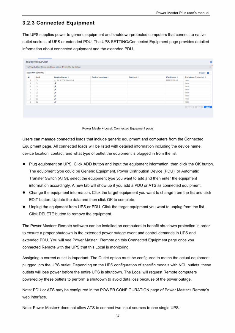
Power Master+ Local: Connected Equipment page
Users can manage connected loads that include generic equipment and computers from the Connected
Equipment page. All connected loads will be listed with detailed information including the device name,
device location, contact, and what type of outlet the equipment is plugged in from the list.
Plug equipment on UPS. Click ADD button and input the equipment information, then click the OK button.
The equipment type could be Generic Equipment, Power Distribution Device (PDU), or Automatic
Transfer Switch (ATS), select the equipment type you want to add and then enter the equipment
information accordingly. A new tab will show up if you add a PDU or ATS as connected equipment.
Change the equipment information. Click the target equipment you want to change from the list and click
EDIT button. Update the data and then click OK to complete.
Unplug the equipment from UPS or PDU. Click the target equipment you want to unplug from the list.
Click DELETE button to remove the equipment.
The Power Master+ Remote software can be installed on computers to benefit shutdown protection in order
to ensure a proper shutdown in the extended power outage event and control demands in UPS and
extended PDU. You will see Power Master+ Remote on this Connected Equipment page once you
connected Remote with the UPS that this Local is monitoring.
Assigning a correct outlet is important. The Outlet option must be configured to match the actual equipment
plugged into the UPS outlet. Depending on the UPS configuration of specific models with NCL outlets, these
outlets will lose power before the entire UPS is shutdown. The Local will request Remote computers
powered by these outlets to perform a shutdown to avoid data loss because of the power outage.
Note: PDU or ATS may be configured in the POWER CONFIGURATION page of Power Master+ Remote’s
web interface.
Note: Power Master+ does not allow ATS to connect two input sources to one single UPS.
Power Master Plus user’s manual
38
The details in list are described as following:
#: Indicates which power outlet of the UPS or PDU is supplying power to the connected equipment.
Bank: The bank type of the power outlet on the UPS, e.g. NCL, CL or Surge.
Device Name: The name of the power equipment.
Device Location: Where the power equipment is located.
Contact: Who to contact about this power equipment.
IP Address: The IP address of the computer that installed Power Master+ Remote software. In UPS tab,
a PDU with network function also shows its own IP address.
3.2.4 Scheduled Shutdown
In the Local, an active schedule will cause the computer to shut down or hibernate, and then ask the UPS to
completely power off the output or turn the specific outlets off at a specified date and time. It also allows
users to specify the date and the time to turn on output or turn the specific outlets on. The UPS will turn on
the specific outlets and begin supplying power which causes the computer to restart or wake from the
hibernation.
Before the Local shuts down because of a schedule shutdown, Remote computers running Power Master+
Remote will be shut down or hibernated to prevent data loss.
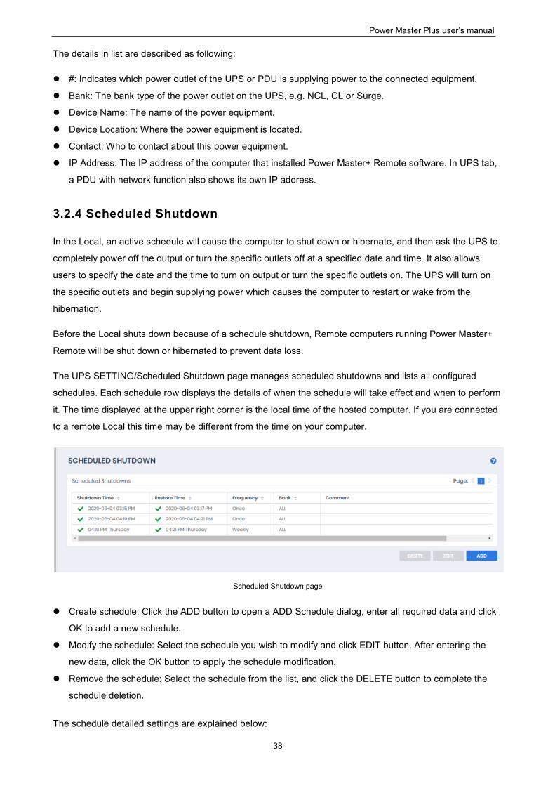
The UPS SETTING/Scheduled Shutdown page manages scheduled shutdowns and lists all configured
schedules. Each schedule row displays the details of when the schedule will take effect and when to perform
it. The time displayed at the upper right corner is the local time of the hosted computer. If you are connected
to a remote Local this time may be different from the time on your computer.
Scheduled Shutdown page
Create schedule: Click the ADD button to open a ADD Schedule dialog, enter all required data and click
OK to add a new schedule.
Modify the schedule: Select the schedule you wish to modify and click EDIT button. After entering the
new data, click the OK button to apply the schedule modification.
Remove the schedule: Select the schedule from the list, and click the DELETE button to complete the
schedule deletion.
The schedule detailed settings are explained below:
Power Master Plus user’s manual
39
Active: Check this check box to activate this schedule effective. If the check box is unchecked, the
schedule will be ignored.
Bank: There are two conditions for this option.
Power off the output completely. When users choose the Master Power option, all equipment
connected to the outlets labeled both SURGE and BATTERY, or all the outlets on the UPS includes
labeled CL, NCL, NCL 1, NCL 2 will be turned off. Only the UPS with NCL support the NCL outlets
are available, and if there are two NCL outlets on the UPS, the NCL 1, NCL 2 outlets are available.
Caution: Surge protected outlets provide surge protection to the connected equipment but does not
provide battery power once a power outage occurs. When utility power fails, computers on the surge
outlets will shutdown immediately due to power loss.
Turn off the NCL outlet. If the NCL option is chosen, users can assign a scheduled shutdown to
particular outlets on the UPS with NCL support. If there are two NCL outlets on the UPS, the NCL 1
and NCL 2 outlet can be assigned individual schedules.
Frequency: There are three frequencies that can be assigned Once, Daily and Weekly. Daily and Weekly
schedules will be repeated.
Shutdown Date: Configures what date to perform the schedule and when to shut down computers.
Shutdown Time: Configures what time to perform the schedule and when to shut down computers.
Restore: Configures whether to restore the controlled outlet power. If the check box is checked, the UPS
will restore the power or power on the NCL outlet at the time specified in the Restore Time option.
Otherwise the UPS output will stay powered off.
Restore Date: The date to restore the output or to turn on the NCL outlet.
Restore Time: The time to restore the output or to turn on the NCL outlet. The shutdown time must occur
prior to the restore time. The maximum duration between the turn off and turn on must depends on UPS
model. Returned Delay in the UPS SETTING/Configuration page will affects Restore Time. If a schedule
is set to restore power at 6:00 PM and the Returned Delay is set 5 minutes, the schedule will actually
restore power at 6:05 PM.
Comment: Sets the user-defined comments for this schedule.
Note: If the computer bios is set to boot when power restores, the computer will automatically restart when
the power is restored. Consult your motherboard documentation or PC/Server supplier for additional
details.
Note: An active schedule may have an insufficient duration to support a complete shutdown. If the active
schedule has insufficient shutdown duration, the active schedule will be set inactive.
Note: The scheduled shutdown is functioned only for Local with UPS.
Power Master Plus user’s manual
40
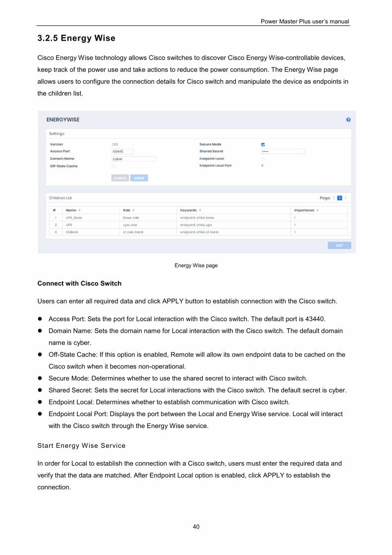
3.2.5 Energy Wise
Cisco Energy Wise technology allows Cisco switches to discover Cisco Energy Wise-controllable devices,
keep track of the power use and take actions to reduce the power consumption. The Energy Wise page
allows users to configure the connection details for Cisco switch and manipulate the device as endpoints in
the children list.
Energy Wise page
Connect with Cisco Switch
Users can enter all required data and click APPLY button to establish connection with the Cisco switch.
Access Port: Sets the port for Local interaction with the Cisco switch. The default port is 43440.
Domain Name: Sets the domain name for Local interaction with the Cisco switch. The default domain
name is cyber.
Off-State Cache: If this option is enabled, Remote will allow its own endpoint data to be cached on the
Cisco switch when it becomes non-operational.
Secure Mode: Determines whether to use the shared secret to interact with Cisco switch.
Shared Secret: Sets the secret for Local interactions with the Cisco switch. The default secret is cyber.
Endpoint Local: Determines whether to establish communication with Cisco switch.
Endpoint Local Port: Displays the port between the Local and Energy Wise service. Local will interact
with the Cisco switch through the Energy Wise service.
Start Energy Wise Service
In order for Local to establish the connection with a Cisco switch, users must enter the required data and
verify that the data are matched. After Endpoint Local option is enabled, click APPLY to establish the
connection.
Power Master Plus user’s manual
41
Children List
The Local that has joined into the Energy Wise network will become the endpoint member and can be
divided into several nodes in children list. Each node has individual attributes for Cisco switches to manage
the power usage.
These attributes describes as following:
Name: Defines the device identity for which query results are filtered.
Role: Defines the function which is based on the business or deployment context.
Keywords: Defines the description for this device for which query results are filtered.
Importance: The device rating which is based on the business or deployment context.
Local is annotated as the UPS_Base node and UPS node indicates the UPS unit. According to the outlet
function of the UPS, the outlet bank will be managed as CL Bank node and NCL Bank node. Due to
limitation of the UPS, Cisco switches can only turn on or turn off an NCL Bank node.
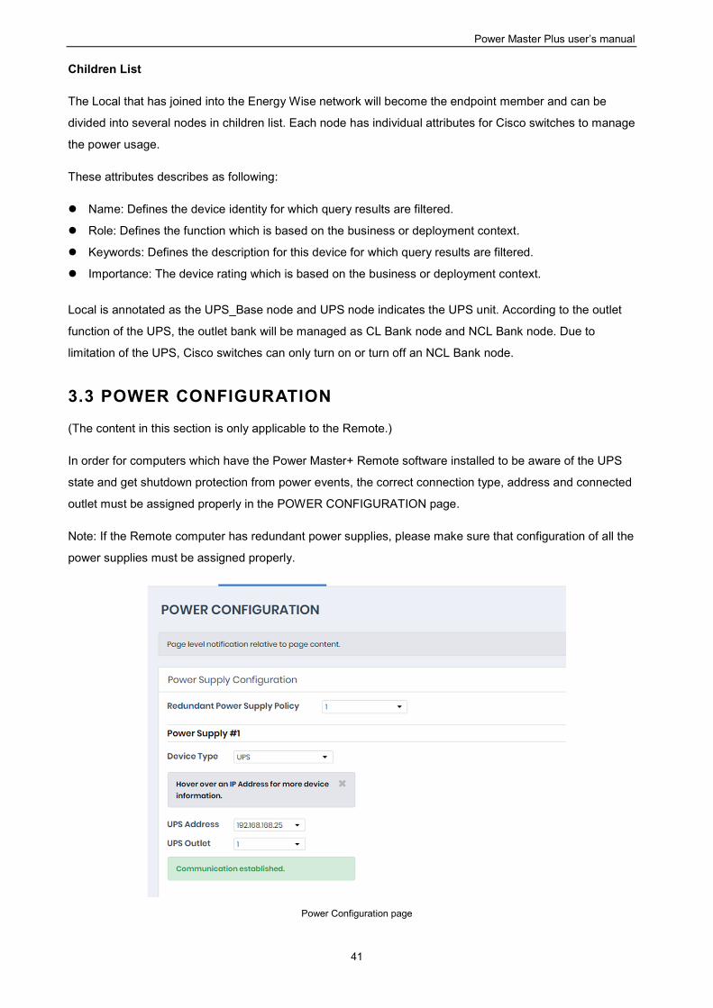
3.3 POWER CONFIGURATION
(The content in this section is only applicable to the Remote.)
In order for computers which have the Power Master+ Remote software installed to be aware of the UPS
state and get shutdown protection from power events, the correct connection type, address and connected
outlet must be assigned properly in the POWER CONFIGURATION page.
Note: If the Remote computer has redundant power supplies, please make sure that configuration of all the
power supplies must be assigned properly.
Power Configuration page
Power Master Plus user’s manual
42
Network communication between a computer and UPS or PDU can be established by assigning the correct
power connection, address of UPS or PDU, and a computer connected outlet of UPS or PDU. The details
are described as following:
Redundant Power Supply Policy: Configure the computer’s power supply redundancy policy. Supported
policies are described below:
1: Indicates the computer only has one power supply, this is the most common case.
2 (1 + 1): Indicates the computer has two power supplies, one for redundancy. The computer
needs at least one power supply to operate.
3 (2 + 1): Indicates the computer has three power supplies, one for redundancy. The computer
needs at least two power supplies to operate.
4 (3 + 1): Indicates the computer has four power supplies, one for redundancy. The computer
needs at least three power supplies to operate.
4 (2 + 2): Indicates the computer has four power supplies, two for redundancy. The computer
needs at least two power supplies to operate.
Note: If the Remote computer has redundant power supplies, events about power supply status will only be
triggered when redundant power supplies are lost. Please refer to Events section for details.
Device Type: Assign the actual UPS or PDU power connection supporting the computer. Power
connection options are:
UPS: Indicates the computer is plugged directly into a UPS.
ATS: Indicates the computer is plugged into an ATS PDU.
Network PDU: Indicates the computer is plugged into a PDU with network connection.
UPS with Network PDU: Indicates the computer is plugged into a network PDU, which is a powered
by a UPS.
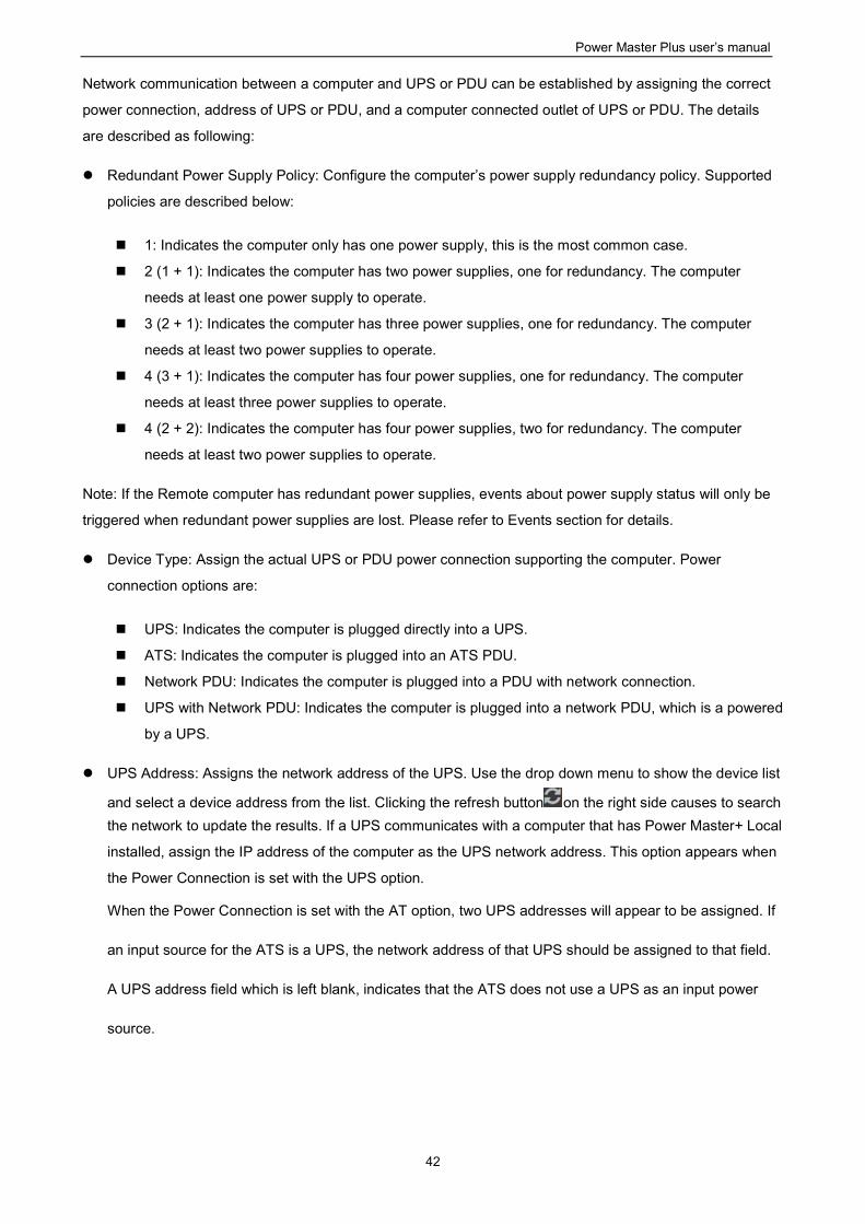
UPS Address: Assigns the network address of the UPS. Use the drop down menu to show the device list
and select a device address from the list. Clicking the refresh button on the right side causes to search
the network to update the results. If a UPS communicates with a computer that has Power Master+ Local
installed, assign the IP address of the computer as the UPS network address. This option appears when
the Power Connection is set with the UPS option.
When the Power Connection is set with the AT option, two UPS addresses will appear to be assigned. If
an input source for the ATS is a UPS, the network address of that UPS should be assigned to that field.
A UPS address field which is left blank, indicates that the ATS does not use a UPS as an input power
source.
Power Master Plus user’s manual
43
Move the cursor over the target address to display details about the device
The computer searches the network and uses the device with the least uptime as the default device after an
installation. One available outlet will automatically be assigned as powering the connected computer. If no
outlet is available, the first critical-load outlet will be assigned as being used by the computer.
The uptime of the devices indicates the length of time that the device has been functioning without
interruption.
If the target device is not available in the device list, change scanning range on the SETTING/Remote Host
page by setting Custom Scan Model in Auto-Discover Range section.
PDU Address: Assigns the network address of the PDU. Enter the IP address or use the drop down
menu to show the device list and select a device address from the list. Clicking the refresh button causes
to search the network to update the results. This option appears when Power Connection is set with the
Network PDU option.
ATS Address: This option appears when Power Connection is set with the ATS option.
UPS Outlet, PDU Outlet and ATS Outlet: Indicates which power outlet of the UPS/PDU/ATS is supplying
power to the computer that has Power Master+ Remote software installed. The outlet list will be updated
after entering the network address of the UPS/PDU/ATS. An outlet preview will be shown so users may
verify whether the computer is connected to the proper outlet.
3.3.1 How to Configure Proper Power Connection
If Remote only connects with a single UPS or single PDU, the Device Type should be set UPS or PDU.
Choose the required IP address and assign the correct outlet. Click CONNECT to establish
communication.
Note: The UPS must have a PMCARD installed or be controlled by a computer which has Local installed;
the PDU must have network functionality.
If Remote connects with a network PDU that is plugged into a UPS, the Device Type should be set UPS
with network PDU. Enter the IP address of UPS. Select the IP address of the PDU and assign the
correct PDU outlet. Click CONNECT to establish the communication.
If a computer with Remote installed is connected to an ATS, the Device Type should be set to ATS.
Select the IP address of the ATS and assign the outlet. Users should know whether or not the ATS is
using a UPS as an input power source before the following configuration:
Power Master Plus user’s manual
44
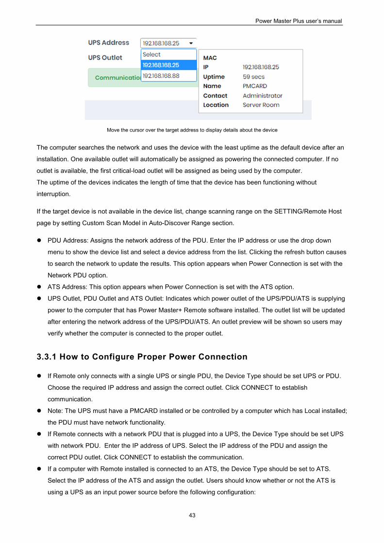
If the ATS is using a UPS for both input power sources, enter the IP address of UPS individually.
Click OK to establish the communication.
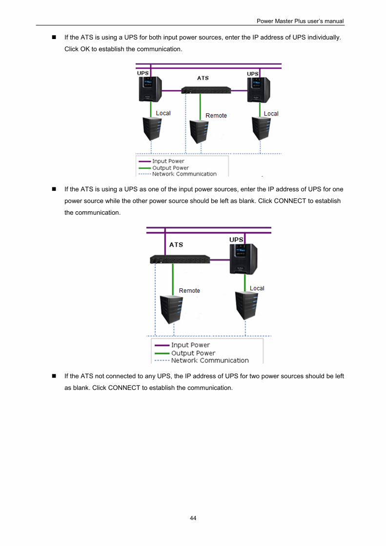
If the ATS is using a UPS as one of the input power sources, enter the IP address of UPS for one
power source while the other power source should be left as blank. Click CONNECT to establish
the communication.
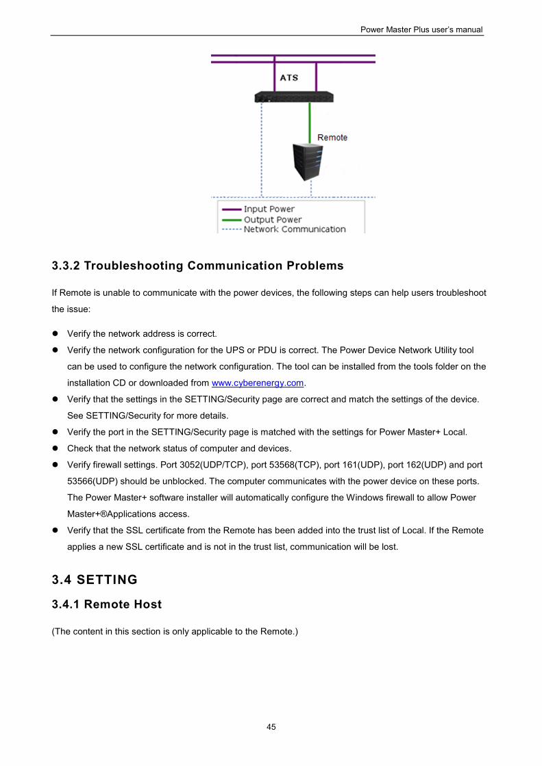
If the ATS not connected to any UPS, the IP address of UPS for two power sources should be left
as blank. Click CONNECT to establish the communication.
Power Master Plus user’s manual
45
3.3.2 Troubleshooting Communication Problems
If Remote is unable to communicate with the power devices, the following steps can help users troubleshoot
the issue:
Verify the network address is correct.
Verify the network configuration for the UPS or PDU is correct. The Power Device Network Utility tool
can be used to configure the network configuration. The tool can be installed from the tools folder on the
installation CD or downloaded from www.cyberenergy.com.
Verify that the settings in the SETTING/Security page are correct and match the settings of the device.
See SETTING/Security for more details.
Verify the port in the SETTING/Security page is matched with the settings for Power Master+ Local.
Check that the network status of computer and devices.
Verify firewall settings. Port 3052(UDP/TCP), port 53568(TCP), port 161(UDP), port 162(UDP) and port
53566(UDP) should be unblocked. The computer communicates with the power device on these ports.
The Power Master+ software installer will automatically configure the Windows firewall to allow Power
Master+®Applications access.
Verify that the SSL certificate from the Remote has been added into the trust list of Local. If the Remote
applies a new SSL certificate and is not in the trust list, communication will be lost.
3.4 SETTING
3.4.1 Remote Host
(The content in this section is only applicable to the Remote.)
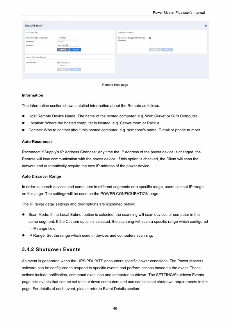
Power Master Plus user’s manual
46
Remote Host page
Information
The Information section shows detailed information about the Remote as follows.
Host Remote Device Name: The name of the hosted computer, e.g. Web Server or Bill's Computer.
Location: Where the hosted computer is located, e.g. Server room or Rack A.
Contact: Who to contact about this hosted computer, e.g. someone's name, E-mail or phone number.
Auto-Reconnect
Reconnect if Supply’s IP Address Changes: Any time the IP address of the power device is changed, the
Remote will lose communication with the power device. If this option is checked, the Client will scan the
network and automatically acquire the new IP address of the power device.
Auto Discover Range
In order to search devices and computers in different segments or a specific range, users can set IP range
on this page. The settings will be used on the POWER CONFIGURATION page.
The IP range detail settings and descriptions are explained below:
Scan Mode: If the Local Subnet option is selected, the scanning will scan devices or computer in the
same segment. If the Custom option is selected, the scanning will scan a specific range which configured
in IP range field.
IP Range: Set the range which used in devices and computers scanning.
3.4.2 Shutdown Events
An event is generated when the UPS/PDU/ATS encounters specific power conditions. The Power Master+
software can be configured to respond to specific events and perform actions based on the event. These
actions include notification, command execution and computer shutdown. The SETTING/Shutdown Events
page lists events that can be set to shut down computers and use can also set shutdown requirements in this
page. For details of each event, please refer to Event Details section.
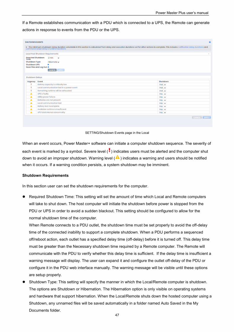
Power Master Plus user’s manual
47
If a Remote establishes communication with a PDU which is connected to a UPS, the Remote can generate
actions in response to events from the PDU or the UPS.
SETTING/Shutdown Events page in the Local
When an event occurs, Power Master+ software can initiate a computer shutdown sequence. The severity of
each event is marked by a symbol. Severe level ( ) indicates users must be alerted and the computer shut
down to avoid an improper shutdown. Warning level ( ) indicates a warning and users should be notified
when it occurs. If a warning condition persists, a system shutdown may be imminent.
Shutdown Requirements
In this section user can set the shutdown requirements for the computer.
Required Shutdown Time: This setting will set the amount of time which Local and Remote computers
will take to shut down. The host computer will initiate the shutdown before power is stopped from the
PDU or UPS in order to avoid a sudden blackout. This setting should be configured to allow for the
normal shutdown time of the computer.
When Remote connects to a PDU outlet, the shutdown time must be set properly to avoid the off-delay
time of the connected inability to support a complete shutdown. When a PDU performs a sequenced
off/reboot action, each outlet has a specified delay time (off-delay) before it is turned off. This delay time
must be greater than the Necessary shutdown time required by a Remote computer. The Remote will
communicate with the PDU to verify whether this delay time is sufficient. If the delay time is insufficient a
warning message will display. The user can expand it and configure the outlet off-delay of the PDU or
configure it in the PDU web interface manually. The warning message will be visible until these options
are setup properly.
Shutdown Type: This setting will specify the manner in which the Local/Remote computer is shutdown.
The options are Shutdown or Hibernation. The Hibernation option is only visible on operating systems
and hardware that support hibernation. When the Local/Remote shuts down the hosted computer using a
Shutdown, any unnamed files will be saved automatically in a folder named Auto Saved in the My
Documents folder.
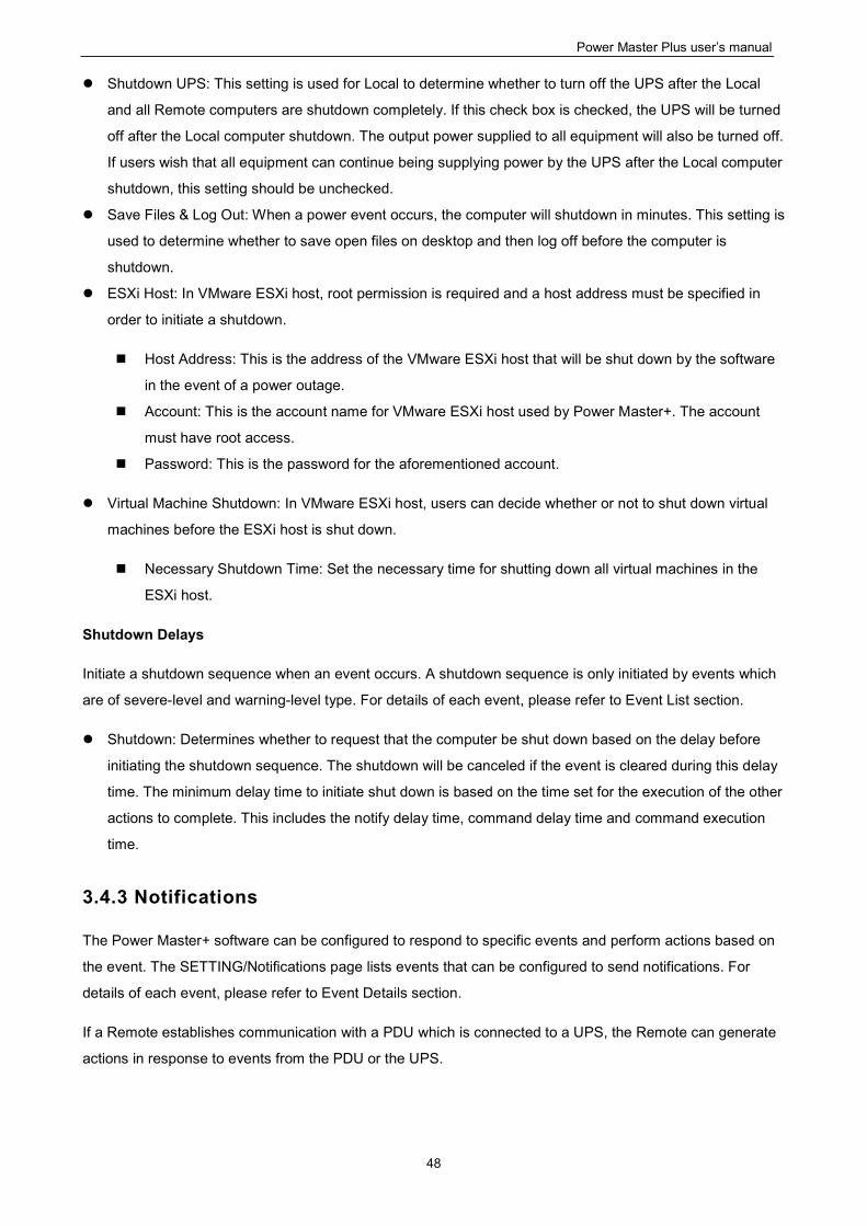
Power Master Plus user’s manual
48
Shutdown UPS: This setting is used for Local to determine whether to turn off the UPS after the Local
and all Remote computers are shutdown completely. If this check box is checked, the UPS will be turned
off after the Local computer shutdown. The output power supplied to all equipment will also be turned off.
If users wish that all equipment can continue being supplying power by the UPS after the Local computer
shutdown, this setting should be unchecked.
Save Files & Log Out: When a power event occurs, the computer will shutdown in minutes. This setting is
used to determine whether to save open files on desktop and then log off before the computer is
shutdown.
ESXi Host: In VMware ESXi host, root permission is required and a host address must be specified in
order to initiate a shutdown.
Host Address: This is the address of the VMware ESXi host that will be shut down by the software
in the event of a power outage.
Account: This is the account name for VMware ESXi host used by Power Master+. The account
must have root access.
Password: This is the password for the aforementioned account.
Virtual Machine Shutdown: In VMware ESXi host, users can decide whether or not to shut down virtual
machines before the ESXi host is shut down.
Necessary Shutdown Time: Set the necessary time for shutting down all virtual machines in the
ESXi host.
Shutdown Delays
Initiate a shutdown sequence when an event occurs. A shutdown sequence is only initiated by events which
are of severe-level and warning-level type. For details of each event, please refer to Event List section.
Shutdown: Determines whether to request that the computer be shut down based on the delay before
initiating the shutdown sequence. The shutdown will be canceled if the event is cleared during this delay
time. The minimum delay time to initiate shut down is based on the time set for the execution of the other
actions to complete. This includes the notify delay time, command delay time and command execution
time.
3.4.3 Notifications
The Power Master+ software can be configured to respond to specific events and perform actions based on
the event. The SETTING/Notifications page lists events that can be configured to send notifications. For
details of each event, please refer to Event Details section.
If a Remote establishes communication with a PDU which is connected to a UPS, the Remote can generate
actions in response to events from the PDU or the UPS.
Power Master Plus user’s manual
49
SETTING/Notifications page in the Local
When an event occurs, Power Master+ software can initiate a computer shutdown sequence. The severity of
each event is marked by a symbol. Severe level ( ) indicates users must be alerted and the computer shut
down to avoid an improper shutdown. Warning level ( ) indicates a warning and users should be notified
when it occurs. If a warning condition persists, a system shutdown may be imminent. Information level ( )
indicates the state of the UPS or that the utility power condition has changed.
Notifications
The administrator can be notified when an event occurs. See SETTING/Notification Channelspage for more
details about the notification methods and recipient assignment.
Send: Determines whether to send a notification or not and sets the notification delay. If the event is
cleared within the notification delay, the notification of the occurrence and the event cleared notification
will not be sent.
Repeat: Determines whether to send one additional notification after the initial notification.
3.4.4 Notification Channels
The administrator can be notified when an event occurs. In SETTING/Notification Channelspage use can
configure several notification methods.
Service provider is Gmail:
Select the Gmail option at the Provider field. Click the CONNECT button to ask Google to authorize the
Gmail account for an authorization to send an email notification. Fill the sender name and click Apply to
save the settings.
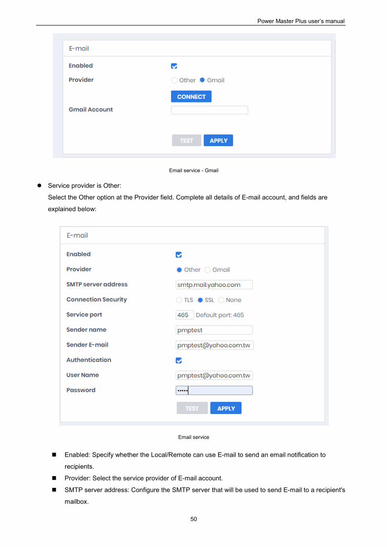
Power Master Plus user’s manual
50
Email service - Gmail
Service provider is Other:
Select the Other option at the Provider field. Complete all details of E-mail account, and fields are
explained below:
Email service
Enabled: Specify whether the Local/Remote can use E-mail to send an email notification to
recipients.
Provider: Select the service provider of E-mail account.
SMTP server address: Configure the SMTP server that will be used to send E-mail to a recipient's
mailbox.
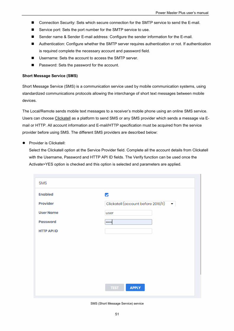
Power Master Plus user’s manual
51
Connection Security: Sets which secure connection for the SMTP service to send the E-mail.
Service port: Sets the port number for the SMTP service to use.
Sender name & Sender E-mail address: Configure the sender information for the E-mail.
Authentication: Configure whether the SMTP server requires authentication or not. If authentication
is required complete the necessary account and password field.
Username: Sets the account to access the SMTP server.
Password: Sets the password for the account.
Short Message Service (SMS)
Short Message Service (SMS) is a communication service used by mobile communication systems, using
standardized communications protocols allowing the interchange of short text messages between mobile
devices.
The Local/Remote sends mobile text messages to a receiver’s mobile phone using an online SMS service.
Users can choose Clickatell as a platform to send SMS or any SMS provider which sends a message via E-
mail or HTTP. All account information and E-mail/HTTP specification must be acquired from the service
provider before using SMS. The different SMS providers are described below:
Provider is Clickatell:
Select the Clickatell option at the Service Provider field. Complete all the account details from Clickatell
with the Username, Password and HTTP API ID fields. The Verify function can be used once the
Activate>YES option is checked and this option is selected and parameters are applied.
SMS (Short Message Service) service
Power Master Plus user’s manual
52
Provider accepts HTTP POST to send messages:
This specification from an SMS provider is required before using the HTTP POST method to deliver
messages to SMS providers. Select the Using HTTP POST option at the Service Provider field. Insert
EVENT_ACTION_PHONE_NUMBER as recipient's mobile phone number and
EVENT_ACTION_MESSAGE as the event message content described in the specification, and fill in
the URL and POST BODY fields. The expressions will be replaced by the relevant content before the
Local/Remote sends a notification to the SMS provider.
e.g.
URL:http://send-sms-company.com/sms
POST Body: user=xxxxxx&password=xxxxxx&to=EVENT_ACTION_PHONE_NUMBER
&text=EVENT_ACTION_MESSAGE
Provider accepts HTTP GET to sends messages:
This specification from the SMS provider is required before using the HTTP GET method. Select the
Using HTTP GET option at the Service Provider field. Insert the EVENT_ACTION_PHONE_NUMBER
as recipient's mobile phone number and the EVENT_ACTION_MESSAGE as event message's content
described in the specification, and fill in the URL field. The expressions will be replaced by relevant
content before the Local/Remote sends a notification to SMS provider.
e.g.
URL:http://send-sms-
company.com/sms?user=xxxxxx&password=xxxxxx&to=EVENT_ACTION_PHONE_NUMBER&text=EVENT_A
CTION_MESSAGE
Provider accepts E-mail to send messages:
This specification from an SMS provider is required before using the E-mail to deliver the messages to
SMS providers. Select the Using E-mail option at the Service Provider field. Insert
EVENT_ACTION_PHONE_NUMBER as recipient's mobile phone number and the
EVENT_ACTION_MESSAGE as event message content described in the specification. Fill in the
Address, Subject and Content fields. The expressions will be replaced with relevant content before the
Local/Remote sends a notification to the SMS provider.
e.g.
Address: [email protected]
Subject: xxxxxx
Content: user:xxxxxx
password:xxxxxx
to:EVENT_ACTION_PHONE_NUMBER
text:EVENT_ACTION_MESSAGE
Note: Each message sent by the SMS system through the SMS provider will be subject to the SMS
provider fee.
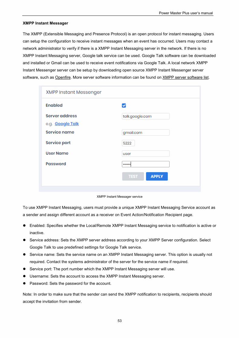
Power Master Plus user’s manual
53
XMPP Instant Messager
The XMPP (Extensible Messaging and Presence Protocol) is an open protocol for instant messaging. Users
can setup the configuration to receive instant messages when an event has occurred. Users may contact a
network administrator to verify if there is a XMPP Instant Messaging server in the network. If there is no
XMPP Instant Messaging server, Google talk service can be used. Google Talk software can be downloaded
and installed or Gmail can be used to receive event notifications via Google Talk. A local network XMPP
Instant Messenger server can be setup by downloading open source XMPP Instant Messenger server
software, such as Openfire. More server software information can be found on XMPP server software list.
XMPP Instant Messager service
To use XMPP Instant Messaging, users must provide a unique XMPP Instant Messaging Service account as
a sender and assign different account as a receiver on Event Action/Notification Recipient page.
Enabled: Specifies whether the Local/Remote XMPP Instant Messaging service to notification is active or
inactive.
Service address: Sets the XMPP server address according to your XMPP Server configuration. Select
Google Talk to use predefined settings for Google Talk service.
Service name: Sets the service name on an XMPP Instant Messaging server. This option is usually not
required. Contact the systems administrator of the server for the service name if required.
Service port: The port number which the XMPP Instant Messaging server will use.
Username: Sets the account to access the XMPP Instant Messaging server.
Password: Sets the password for the account.
Note: In order to make sure that the sender can send the XMPP notification to recipients, recipients should
accept the invitation from sender.
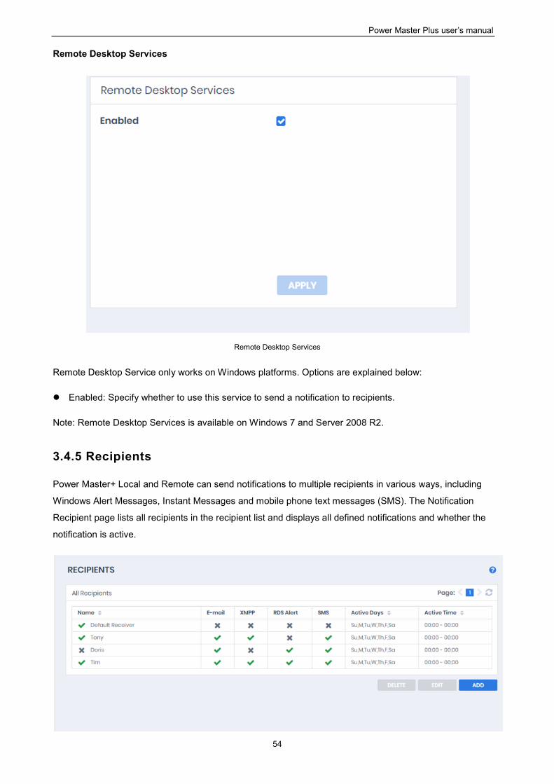
Power Master Plus user’s manual
54
Remote Desktop Services
Remote Desktop Services
Remote Desktop Service only works on Windows platforms. Options are explained below:
Enabled: Specify whether to use this service to send a notification to recipients.
Note: Remote Desktop Services is available on Windows 7 and Server 2008 R2.
3.4.5 Recipients
Power Master+ Local and Remote can send notifications to multiple recipients in various ways, including
Windows Alert Messages, Instant Messages and mobile phone text messages (SMS). The Notification
Recipient page lists all recipients in the recipient list and displays all defined notifications and whether the
notification is active.
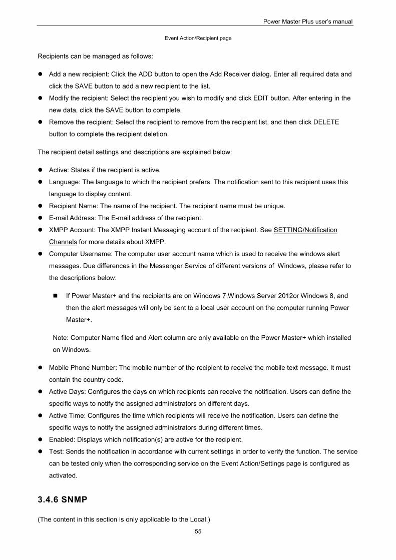
Power Master Plus user’s manual
55
Event Action/Recipient page
Recipients can be managed as follows:
Add a new recipient: Click the ADD button to open the Add Receiver dialog. Enter all required data and
click the SAVE button to add a new recipient to the list.
Modify the recipient: Select the recipient you wish to modify and click EDIT button. After entering in the
new data, click the SAVE button to complete.
Remove the recipient: Select the recipient to remove from the recipient list, and then click DELETE
button to complete the recipient deletion.
The recipient detail settings and descriptions are explained below:
Active: States if the recipient is active.
Language: The language to which the recipient prefers. The notification sent to this recipient uses this
language to display content.
Recipient Name: The name of the recipient. The recipient name must be unique.
E-mail Address: The E-mail address of the recipient.
XMPP Account: The XMPP Instant Messaging account of the recipient. See SETTING/Notification
Channels for more details about XMPP.
Computer Username: The computer user account name which is used to receive the windows alert
messages. Due differences in the Messenger Service of different versions of Windows, please refer to
the descriptions below:
If Power Master+ and the recipients are on Windows 7,Windows Server 2012or Windows 8, and
then the alert messages will only be sent to a local user account on the computer running Power
Master+.
Note: Computer Name filed and Alert column are only available on the Power Master+ which installed
on Windows.
Mobile Phone Number: The mobile number of the recipient to receive the mobile text message. It must
contain the country code.
Active Days: Configures the days on which recipients can receive the notification. Users can define the
specific ways to notify the assigned administrators on different days.
Active Time: Configures the time which recipients will receive the notification. Users can define the
specific ways to notify the assigned administrators during different times.
Enabled: Displays which notification(s) are active for the recipient.
Test: Sends the notification in accordance with current settings in order to verify the function. The service
can be tested only when the corresponding service on the Event Action/Settings page is configured as
activated.
3.4.6 SNMP
(The content in this section is only applicable to the Local.)
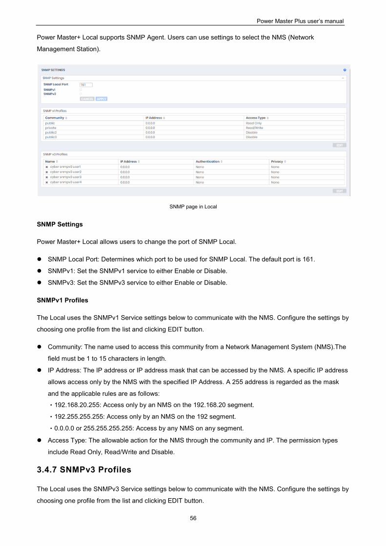
Power Master Plus user’s manual
56
Power Master+ Local supports SNMP Agent. Users can use settings to select the NMS (Network
Management Station).
SNMP page in Local
SNMP Settings
Power Master+ Local allows users to change the port of SNMP Local.
SNMP Local Port: Determines which port to be used for SNMP Local. The default port is 161.
SNMPv1: Set the SNMPv1 service to either Enable or Disable.
SNMPv3: Set the SNMPv3 service to either Enable or Disable.
SNMPv1 Profiles
The Local uses the SNMPv1 Service settings below to communicate with the NMS. Configure the settings by
choosing one profile from the list and clicking EDIT button.
Community: The name used to access this community from a Network Management System (NMS).The
field must be 1 to 15 characters in length.
IP Address: The IP address or IP address mask that can be accessed by the NMS. A specific IP address
allows access only by the NMS with the specified IP Address. A 255 address is regarded as the mask
and the applicable rules are as follows:
‧192.168.20.255: Access only by an NMS on the 192.168.20 segment.
‧192.255.255.255: Access only by an NMS on the 192 segment.
‧0.0.0.0 or 255.255.255.255: Access by any NMS on any segment.
Access Type: The allowable action for the NMS through the community and IP. The permission types
include Read Only, Read/Write and Disable.
3.4.7 SNMPv3 Profiles
The Local uses the SNMPv3 Service settings below to communicate with the NMS. Configure the settings by
choosing one profile from the list and clicking EDIT button.
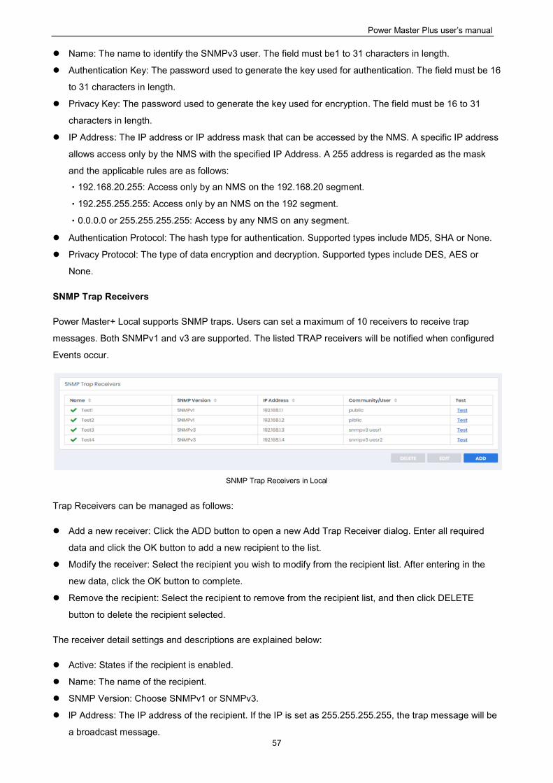
Power Master Plus user’s manual
57
Name: The name to identify the SNMPv3 user. The field must be1 to 31 characters in length.
Authentication Key: The password used to generate the key used for authentication. The field must be 16
to 31 characters in length.
Privacy Key: The password used to generate the key used for encryption. The field must be 16 to 31
characters in length.
IP Address: The IP address or IP address mask that can be accessed by the NMS. A specific IP address
allows access only by the NMS with the specified IP Address. A 255 address is regarded as the mask
and the applicable rules are as follows:
‧192.168.20.255: Access only by an NMS on the 192.168.20 segment.
‧192.255.255.255: Access only by an NMS on the 192 segment.
‧0.0.0.0 or 255.255.255.255: Access by any NMS on any segment.
Authentication Protocol: The hash type for authentication. Supported types include MD5, SHA or None.
Privacy Protocol: The type of data encryption and decryption. Supported types include DES, AES or
None.
SNMP Trap Receivers
Power Master+ Local supports SNMP traps. Users can set a maximum of 10 receivers to receive trap
messages. Both SNMPv1 and v3 are supported. The listed TRAP receivers will be notified when configured
Events occur.
SNMP Trap Receivers in Local
Trap Receivers can be managed as follows:
Add a new receiver: Click the ADD button to open a new Add Trap Receiver dialog. Enter all required
data and click the OK button to add a new recipient to the list.
Modify the receiver: Select the recipient you wish to modify from the recipient list. After entering in the
new data, click the OK button to complete.
Remove the recipient: Select the recipient to remove from the recipient list, and then click DELETE
button to delete the recipient selected.
The receiver detail settings and descriptions are explained below:
Active: States if the recipient is enabled.
Name: The name of the recipient.
SNMP Version: Choose SNMPv1 or SNMPv3.
lP Address: The IP address of the recipient. If the IP is set as 255.255.255.255, the trap message will be
a broadcast message.
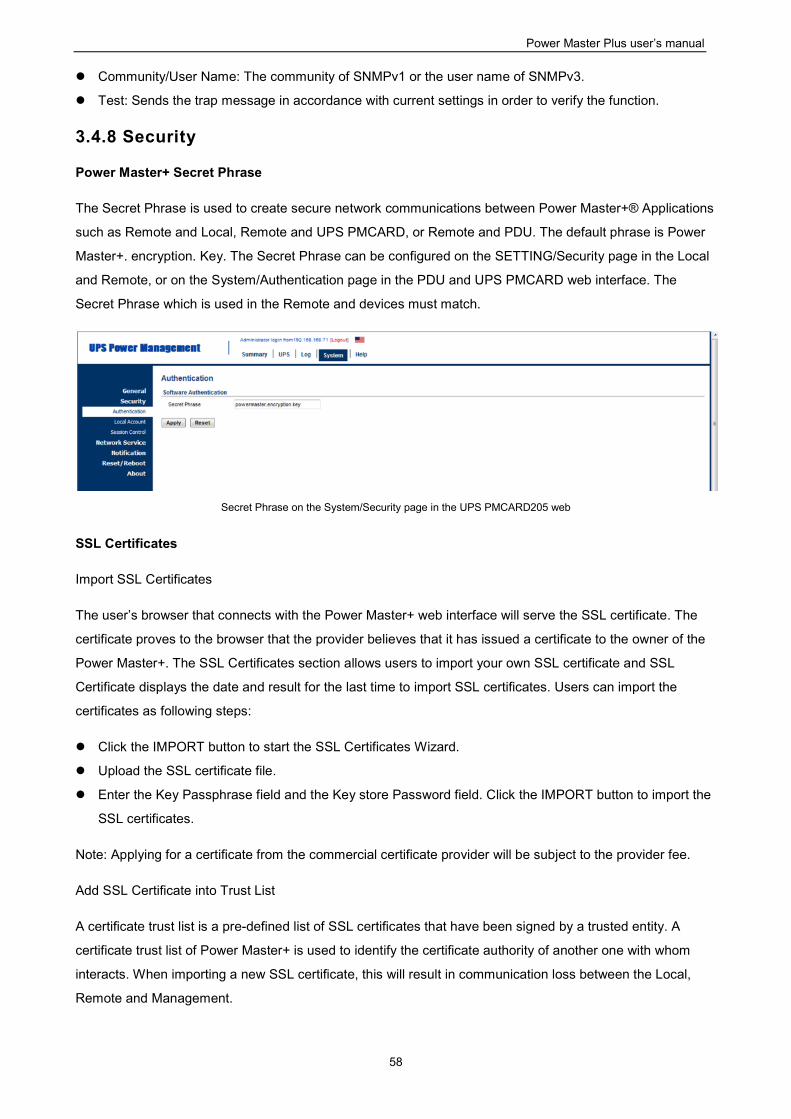
Power Master Plus user’s manual
58
Community/User Name: The community of SNMPv1 or the user name of SNMPv3.
Test: Sends the trap message in accordance with current settings in order to verify the function.
3.4.8 Security
Power Master+ Secret Phrase
The Secret Phrase is used to create secure network communications between Power Master+® Applications
such as Remote and Local, Remote and UPS PMCARD, or Remote and PDU. The default phrase is Power
Master+. encryption. Key. The Secret Phrase can be configured on the SETTING/Security page in the Local
and Remote, or on the System/Authentication page in the PDU and UPS PMCARD web interface. The
Secret Phrase which is used in the Remote and devices must match.
Secret Phrase on the System/Security page in the UPS PMCARD205 web
SSL Certificates
Import SSL Certificates
The user’s browser that connects with the Power Master+ web interface will serve the SSL certificate. The
certificate proves to the browser that the provider believes that it has issued a certificate to the owner of the
Power Master+. The SSL Certificates section allows users to import your own SSL certificate and SSL
Certificate displays the date and result for the last time to import SSL certificates. Users can import the
certificates as following steps:
Click the IMPORT button to start the SSL Certificates Wizard.
Upload the SSL certificate file.
Enter the Key Passphrase field and the Key store Password field. Click the IMPORT button to import the
SSL certificates.
Note: Applying for a certificate from the commercial certificate provider will be subject to the provider fee.
Add SSL Certificate into Trust List
A certificate trust list is a pre-defined list of SSL certificates that have been signed by a trusted entity. A
certificate trust list of Power Master+ is used to identify the certificate authority of another one with whom
interacts. When importing a new SSL certificate, this will result in communication loss between the Local,
Remote and Management.
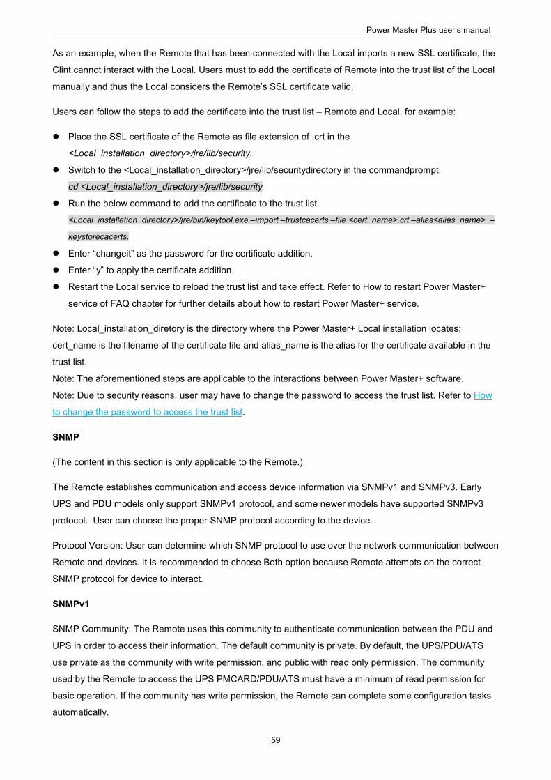
Power Master Plus user’s manual
59
As an example, when the Remote that has been connected with the Local imports a new SSL certificate, the
Clint cannot interact with the Local. Users must to add the certificate of Remote into the trust list of the Local
manually and thus the Local considers the Remote’s SSL certificate valid.
Users can follow the steps to add the certificate into the trust list – Remote and Local, for example:
Place the SSL certificate of the Remote as file extension of .crt in the
<Local_installation_directory>/jre/lib/security.
Switch to the <Local_installation_directory>/jre/lib/securitydirectory in the commandprompt.
cd <Local_installation_directory>/jre/lib/security
Run the below command to add the certificate to the trust list.
<Local_installation_directory>/jre/bin/keytool.exe –import –trustcacerts –file <cert_name>.crt –alias<alias_name> –
keystorecacerts.
Enter “changeit” as the password for the certificate addition.
Enter “y” to apply the certificate addition.
Restart the Local service to reload the trust list and take effect. Refer to How to restart Power Master+
service of FAQ chapter for further details about how to restart Power Master+ service.
Note: Local_installation_diretory is the directory where the Power Master+ Local installation locates;
cert_name is the filename of the certificate file and alias_name is the alias for the certificate available in the
trust list.
Note: The aforementioned steps are applicable to the interactions between Power Master+ software.
Note: Due to security reasons, user may have to change the password to access the trust list. Refer to How
to change the password to access the trust list.
SNMP
(The content in this section is only applicable to the Remote.)
The Remote establishes communication and access device information via SNMPv1 and SNMPv3. Early
UPS and PDU models only support SNMPv1 protocol, and some newer models have supported SNMPv3
protocol. User can choose the proper SNMP protocol according to the device.
Protocol Version: User can determine which SNMP protocol to use over the network communication between
Remote and devices. It is recommended to choose Both option because Remote attempts on the correct
SNMP protocol for device to interact.
SNMPv1
SNMP Community: The Remote uses this community to authenticate communication between the PDU and
UPS in order to access their information. The default community is private. By default, the UPS/PDU/ATS
use private as the community with write permission, and public with read only permission. The community
used by the Remote to access the UPS PMCARD/PDU/ATS must have a minimum of read permission for
basic operation. If the community has write permission, the Remote can complete some configuration tasks
automatically.
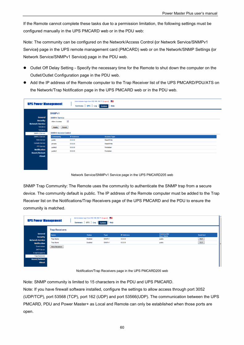
Power Master Plus user’s manual
60
If the Remote cannot complete these tasks due to a permission limitation, the following settings must be
configured manually in the UPS PMCARD web or in the PDU web:
Note: The community can be configured on the Network/Access Control (or Network Service/SNMPv1
Service) page in the UPS remote management card (PMCARD) web or on the Network/SNMP Settings (or
Network Service/SNMPv1 Service) page in the PDU web.
Outlet Off Delay Setting - Specify the necessary time for the Remote to shut down the computer on the
Outlet/Outlet Configuration page in the PDU web.
Add the IP address of the Remote computer to the Trap Receiver list of the UPS PMCARD/PDU/ATS on
the Network/Trap Notification page in the UPS PMCARD web or in the PDU web.
Network Service/SNMPv1 Service page in the UPS PMCARD205 web
SNMP Trap Community: The Remote uses the community to authenticate the SNMP trap from a secure
device. The community default is public. The IP address of the Remote computer must be added to the Trap
Receiver list on the Notifications/Trap Receivers page of the UPS PMCARD and the PDU to ensure the
community is matched.
Notification/Trap Receivers page in the UPS PMCARD205 web
Note: SNMP community is limited to 15 characters in the PDU and UPS PMCARD.
Note: If you have firewall software installed, configure the settings to allow access through port 3052
(UDP/TCP), port 53568 (TCP), port 162 (UDP) and port 53566(UDP). The communication between the UPS
PMCARD, PDU and Power Master+ as Local and Remote can only be established when those ports are
open.
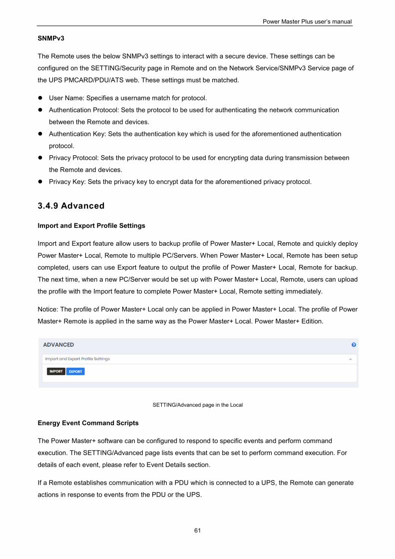
Power Master Plus user’s manual
61
SNMPv3
The Remote uses the below SNMPv3 settings to interact with a secure device. These settings can be
configured on the SETTING/Security page in Remote and on the Network Service/SNMPv3 Service page of
the UPS PMCARD/PDU/ATS web. These settings must be matched.
User Name: Specifies a username match for protocol.
Authentication Protocol: Sets the protocol to be used for authenticating the network communication
between the Remote and devices.
Authentication Key: Sets the authentication key which is used for the aforementioned authentication
protocol.
Privacy Protocol: Sets the privacy protocol to be used for encrypting data during transmission between
the Remote and devices.
Privacy Key: Sets the privacy key to encrypt data for the aforementioned privacy protocol.
3.4.9 Advanced
Import and Export Profile Settings
Import and Export feature allow users to backup profile of Power Master+ Local, Remote and quickly deploy
Power Master+ Local, Remote to multiple PC/Servers. When Power Master+ Local, Remote has been setup
completed, users can use Export feature to output the profile of Power Master+ Local, Remote for backup.
The next time, when a new PC/Server would be set up with Power Master+ Local, Remote, users can upload
the profile with the Import feature to complete Power Master+ Local, Remote setting immediately.
Notice: The profile of Power Master+ Local only can be applied in Power Master+ Local. The profile of Power
Master+ Remote is applied in the same way as the Power Master+ Local. Power Master+ Edition.
SETTING/Advanced page in the Local
Energy Event Command Scripts
The Power Master+ software can be configured to respond to specific events and perform command
execution. The SETTING/Advanced page lists events that can be set to perform command execution. For
details of each event, please refer to Event Details section.
If a Remote establishes communication with a PDU which is connected to a UPS, the Remote can generate
actions in response to events from the PDU or the UPS.
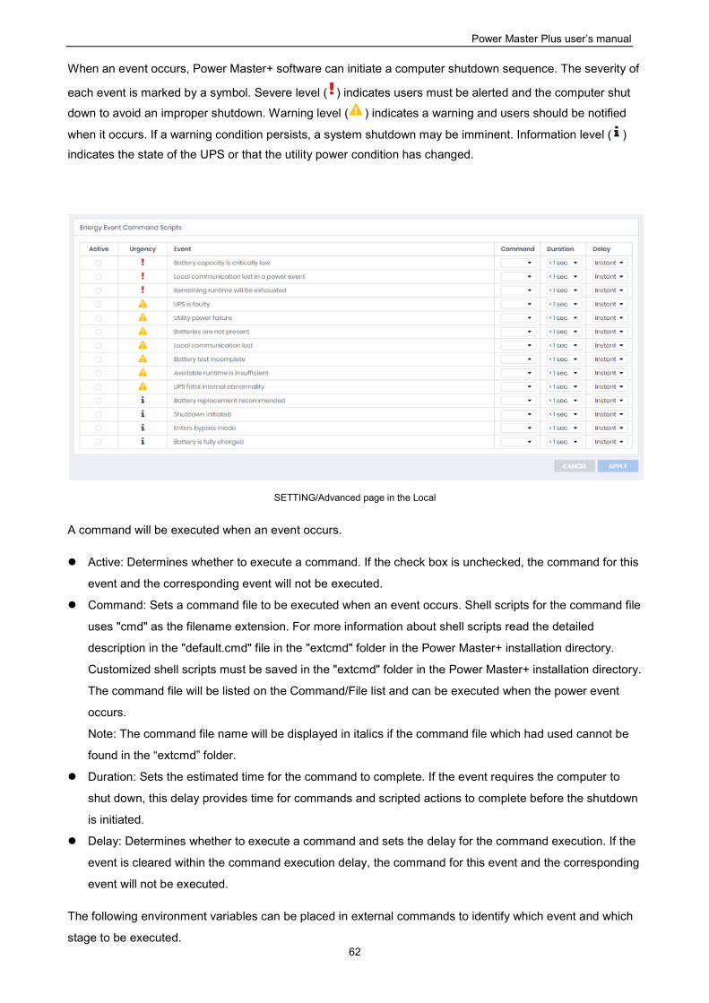
Power Master Plus user’s manual
62
When an event occurs, Power Master+ software can initiate a computer shutdown sequence. The severity of
each event is marked by a symbol. Severe level ( ) indicates users must be alerted and the computer shut
down to avoid an improper shutdown. Warning level ( ) indicates a warning and users should be notified
when it occurs. If a warning condition persists, a system shutdown may be imminent. Information level ( )
indicates the state of the UPS or that the utility power condition has changed.
SETTING/Advanced page in the Local
A command will be executed when an event occurs.
Active: Determines whether to execute a command. If the check box is unchecked, the command for this
event and the corresponding event will not be executed.
Command: Sets a command file to be executed when an event occurs. Shell scripts for the command file
uses "cmd" as the filename extension. For more information about shell scripts read the detailed
description in the "default.cmd" file in the "extcmd" folder in the Power Master+ installation directory.
Customized shell scripts must be saved in the "extcmd" folder in the Power Master+ installation directory.
The command file will be listed on the Command/File list and can be executed when the power event
occurs.
Note: The command file name will be displayed in italics if the command file which had used cannot be
found in the “extcmd” folder.
Duration: Sets the estimated time for the command to complete. If the event requires the computer to
shut down, this delay provides time for commands and scripted actions to complete before the shutdown
is initiated.
Delay: Determines whether to execute a command and sets the delay for the command execution. If the
event is cleared within the command execution delay, the command for this event and the corresponding
event will not be executed.
The following environment variables can be placed in external commands to identify which event and which
stage to be executed.
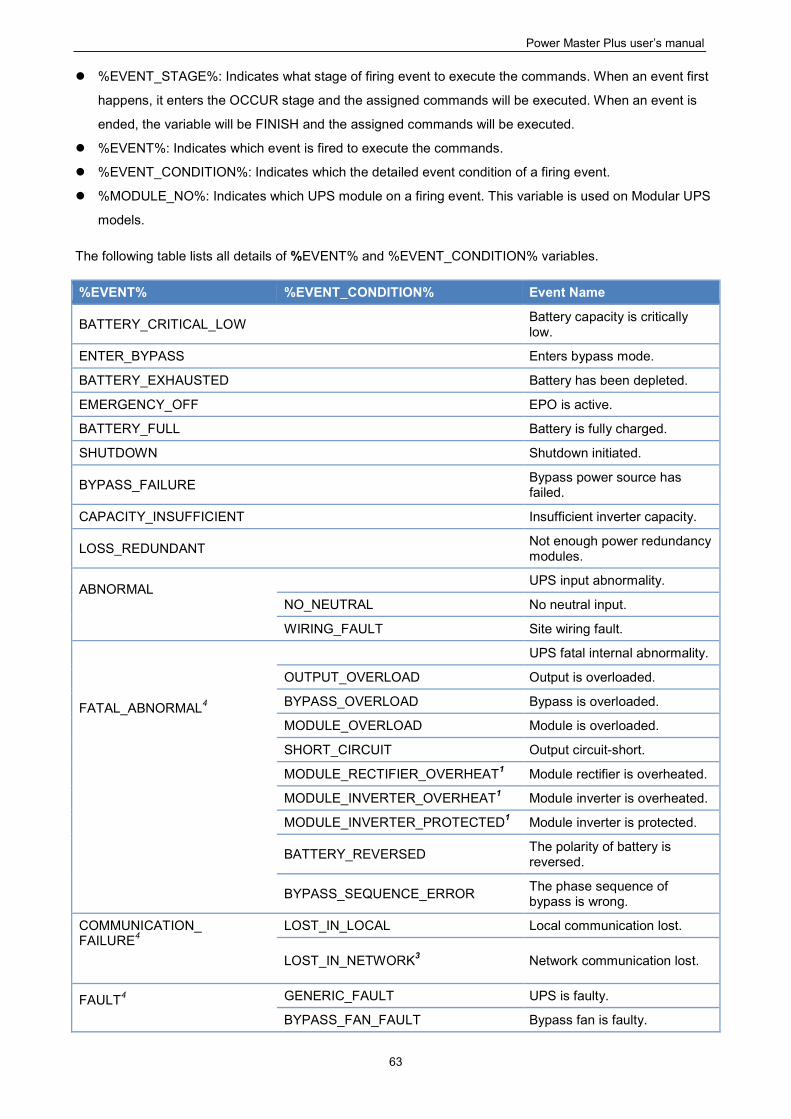
Power Master Plus user’s manual
63
%EVENT_STAGE%: Indicates what stage of firing event to execute the commands. When an event first
happens, it enters the OCCUR stage and the assigned commands will be executed. When an event is
ended, the variable will be FINISH and the assigned commands will be executed.
%EVENT%: Indicates which event is fired to execute the commands.
%EVENT_CONDITION%: Indicates which the detailed event condition of a firing event.
%MODULE_NO%: Indicates which UPS module on a firing event. This variable is used on Modular UPS
models.
The following table lists all details of %EVENT% and %EVENT_CONDITION% variables.
%EVENT% %EVENT_CONDITION% Event Name
BATTERY_CRITICAL_LOW Battery capacity is critically low.
ENTER_BYPASS Enters bypass mode.
BATTERY_EXHAUSTED Battery has been depleted.
EMERGENCY_OFF EPO is active.
BATTERY_FULL Battery is fully charged.
SHUTDOWN Shutdown initiated.
BYPASS_FAILURE Bypass power source has failed.
CAPACITY_INSUFFICIENT Insufficient inverter capacity.
LOSS_REDUNDANT Not enough power redundancy modules.
ABNORMAL
UPS input abnormality.
NO_NEUTRAL No neutral input.
WIRING_FAULT Site wiring fault.
FATAL_ABNORMAL4
UPS fatal internal abnormality.
OUTPUT_OVERLOAD Output is overloaded.
BYPASS_OVERLOAD Bypass is overloaded.
MODULE_OVERLOAD Module is overloaded.
SHORT_CIRCUIT Output circuit-short.
MODULE_RECTIFIER_OVERHEAT1 Module rectifier is overheated.
MODULE_INVERTER_OVERHEAT1 Module inverter is overheated.
MODULE_INVERTER_PROTECTED1 Module inverter is protected.
BATTERY_REVERSED The polarity of battery is reversed.
BYPASS_SEQUENCE_ERROR The phase sequence of bypass is wrong.
COMMUNICATION_ FAILURE4
LOST_IN_LOCAL Local communication lost.
LOST_IN_NETWORK3 Network communication lost.
FAULT4
GENERIC_FAULT UPS is faulty.
BYPASS_FAN_FAULT Bypass fan is faulty.
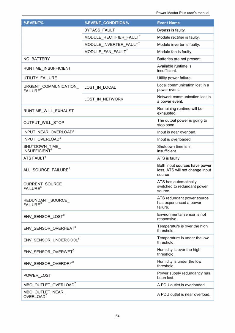
Power Master Plus user’s manual
64
%EVENT% %EVENT_CONDITION% Event Name
BYPASS_FAULT Bypass is faulty.
MODULE_RECTIFIER_FAULT1 Module rectifier is faulty.
MODULE_INVERTER_FAULT1 Module inverter is faulty.
MODULE_FAN_FAULT1 Module fan is faulty.
NO_BATTERY Batteries are not present.
RUNTIME_INSUFFICIENT Available runtime is insufficient.
UTILITY_FAILURE Utility power failure.
URGENT_COMMUNICATION_FAILURE4
LOST_IN_LOCAL Local communication lost in a power event.
LOST_IN_NETWORK Network communication lost in a power event.
RUNTIME_WILL_EXHAUST Remaining runtime will be exhausted.
OUTPUT_WILL_STOP The output power is going to stop soon.
INPUT_NEAR_OVERLOAD2 Input is near overload.
INPUT_OVERLOAD2 Input is overloaded.
SHUTDOWN_TIME_ INSUFFICIENT2
Shutdown time is in insufficient.
ATS FAULT5 ATS is faulty.
ALL_SOURCE_FAILURE5 Both input sources have power loss, ATS will not change input source
CURRENT_SOURCE_ FAILURE5
ATS has automatically switched to redundant power source.
REDUNDANT_SOURCE_ FAILURE5
ATS redundant power source has experienced a power failure.
ENV_SENSOR_LOST6 Environmental sensor is not responsive.
ENV_SENSOR_OVERHEAT6 Temperature is over the high threshold.
ENV_SENSOR_UNDERCOOL6 Temperature is under the low threshold.
ENV_SENSOR_OVERWET6 Humidity is over the high threshold.
ENV_SENSOR_OVERDRY6 Humidity is under the low threshold.
POWER_LOST Power supply redundancy has been lost.
MBO_OUTLET_OVERLOAD7 A PDU outlet is overloaded.
MBO_OUTLET_NEAR_ OVERLOAD7
A PDU outlet is near overload.
Power Master Plus user’s manual
65
1This event only occurs for the Modular UPS in Local. 2This event only occurs for the PDU in Remote. 3 This event only occurs in Remote. 4This %EVENT% variable must come with a %EVENT_CONDITION% variable. 5This event only occurs for the ATS in Remote. 6 This event only occurs for the environmental sensor for UPS/PDU/ATS in Remote. 7This event only occurs for the Metered by Outlet PDU in Remote.
3.4.10 Network Configuration
Host IP Configuration
According to chapter 2.3, users can access Power Master+ through the default URL and can assign an IP to
Power Master+ web browser in Host IP Configuration.
Host IP: when the computer installed with Power Master+ has multiple IPs, users can choose one of the
IPs for the web browser.
HTTPS
Power Master+ allows users to change the secure level and port explained below:
HTPPS Secure: Enable this option for web access to be over the HTTPS connections.
HTTPS Port: Determines which port to be used over the HTTPS connections. The default port is 53568.
Once the secure level is changed, the new secure level will be taken effect. All pages can’t be displayed
during the duration to restart server.
When HTTPS secure is enabled, the browser warning will be presented after the new level is taken effect.
This indicates that the user’s browser considers the connection is risky. Users can ignore the warning page
and continue the web access, or provide a SSL certificate which is produced by the commercial certificate
providers or any trusted certificate authority.
If the user has his own SSL certificate, refer to Import SSL Certificates section for further details how to
import the new certificate.
3.4.11 Event Details
The events displayed vary depending on whether they are listed in Local or Remote and which
UPS/PDU/ATS is providing the events.
Note: If a Remote computer has redundant power supplies, the events related to power supply will only be
triggered when power supply redundancy is lost. Please refer to “Remaining runtime will be exhausted” event
for example.
Battery capacity is critically low. Battery capacity is critically low; power could be lost immediately. The
Low Battery Threshold can be set in page UPS SETTING->Configuration.
Power Master Plus user’s manual
66
Local communication lost in a power event. Communication with device has been lost during a power
event.
Communication between the Local and the UPS using the USB or serial cable has been lost during a
power failure.
Batteries are not present. Batteries are not present; the UPS cannot provide battery power in this
condition.
Available runtime is insufficient. There is not sufficient runtime for Power Master+ to perform a complete
shutdown based on current configuration even if the battery is 100% charged.
An excessive load or long shutdown time may cause this event. Reduce some UPS load or set a more
accurate shutdown time to avoid this event.
Enters bypass mode. Entering bypass mode, battery power protection will no longer be provided.
Utility power failure. Utility power failure, battery power will be supplied.
Remaining runtime will be exhausted. Based on current configuration settings, the remaining battery
runtime will be insufficient unless a shutdown of the connected computer(s) is affected immediately.
Please save your work and power down immediately.
When the UPS switches to battery mode due to a power event, the battery power will be supplied to
Local computer and all Remote computers in order to shut down completely. If battery power
consumption continues, the remaining runtime will be exhausted. Local and all Remote computers
should start a shutdown procedure immediately.
The Local postpones the shutdown until the Remotes computers completes the shutdowns; if the
remaining runtime is insufficient for Local to perform a complete shutdown prior to the UPS turning off,
the Remotes will shut down first to ensure sufficient time for Local to shut down completely.
Note: This event usually indicates that the Local and Remote risk losing battery power, they will have a
shutdown window of 2 minutes to avoid crashing due to a UPS turning off.
Note: If the Remote computer has redundant power, this event will only be triggered after the computer
loses all redundant power supplies and is running on non-redundant power. For example, if a Remote
computer has a redundant power policy of 1+1, then this event will only happen when only one power
supply is operating and its remaining runtime will be exhausted.
Battery test is processing. A battery test is active in order to verify that battery power can be provided
normally.
Output voltage is being boosted. Output voltage is being boosted from a lower level.
The UPS is receiving utility power with low voltage and raising the voltage to a proper level for operating
the connected equipment.
Output voltage is being bucked. Output voltage is being bucked from a higher level.
The UPS is receiving utility power with high voltage and is lowering the voltage to a proper level for
operating the connected equipment.
Estimation initiated. Estimation was initiated; the battery runtime will be evaluated. This process will last
until battery power is exhausted.
A schedule has initiated. A schedule has been initiated, the system may be shutdown.
Battery is fully charged. Battery is fully charged.
Shutdown initiated. Shutdown process initiated, the system will shut down or hibernate soon.
Power Master Plus user’s manual
67
ECO Mode is active. The UPS has entered ECO mode.
The UPS switches to bypass and starts to monitor whether the utility voltage and utility frequency is in
range of the thresholds.
Battery has been depleted. Battery charge is depleted, output power will stop.
EPO is active. EPO was activated; the UPS output power was turned off immediately.
EPO (Emergency Power Off) is intended to allow the administrator to have a method of immediately
turning off output power from the UPS.
Bypass power source has failed. Power input from the bypass source is out of regular range or is
experiencing a black out. UPS will shutdown, Bypass mode will not be activated.
Insufficient inverter capacity. There was not enough capacity in the inverter for the UPS to switch from
bypass mode to line mode.
Not enough power redundancy modules. The internal modules used for redundancy in this UPS have
either exceeded their capacity or have failed. The fault-tolerance of this UPS has been reduced or
eliminated.
Power redundancy provides additional protection against failures of UPS modules. If one module has a
fault, the other module will take over. This event will occur when the load consumption are exceeded to
use extra power that belong to redundant power, some UPS modules are faulty or manual shutdown.
UPS input abnormality. UPS is working abnormally due to one or more power conditions below:
No neutral input. There is no neutral wire connected.
Site wiring fault. The wiring is reversed or not grounded.
UPS fatal internal abnormality. The UPS is experiencing one or more of the following fatal abnormalities;
UPS may shut down or stop output power unexpectedly.
Output overload. Power consumption exceeds the power rating of UPS. If the overload is sustained,
the UPS will shut off.
Bypass overload. Output is overloaded in bypass mode.
Module overload. One of the UPS modules has overloaded. If the UPS module overload is
sustained, the UPS module will be shut down for protection.
Output short circuit. Output has short circuited, the UPS will stop supplying power.
Module rectifier overheating. The internal temperature of one rectifier module has exceeded the
normal rating.
Module inverter overheating. The internal temperature of one inverter module has exceeded the
normal rating.
Module inverter protected. A module inverter has been stopped for protection. The module inverter
may be faulty or abnormal.
Reversed battery connection. The connection between UPS and battery has a reversed connection.
Bypass phase sequence error. The sequence of phases is different between utility and bypass.
Communication lost. Communication between the UPS and computer has been lost:
Power Master Plus user’s manual
68
Local communication lost. Communication between the UPS and computer via USB or serial cable
cannot be established or was lost.
Network communication Lost. Software cannot establish communication with UPS or PDU on the
network or established network communication has been interrupted.
UPS is faulty. UPS has an internal malfunction. The UPS may not be operating properly and will not be
able to affect a proper shutdown. Causes include:
Bypass Fan fault.
Bypass Fault.
Module Rectifier Fault. A rectifier module is faulty; this module will stop supplying output power.
Module Inverter Fault. An inverter module is faulty; this module will stop supplying output power.
Module Fan Fault. A fan module has malfunctioned.
Note: Batteries are not present and A schedule has initiated events are only available in Local.
More events are available for Remote:
The output power is going to stop soon. Output power will stop due to power event or user command.
The Remote will shut down the host computer.
Cannot establish network communication with Power Device. Communication with the Power Device has
been lost.
The Remote cannot establish communication with the UPS/PDU/ATS on the network or established
communication has been interrupted.
Network communication lost with UPS in a power event. Communication with the UPS has been lost
during a power event.
When the utility power becomes abnormal and the UPS is using the battery to supply power, loss of
network communication between the Remote and the UPS causes the Remote to generate a critical
priority event because it cannot respond to changes in the status of utility and battery power.
Power supply redundancy lost. Power supply has been lost; computer can't be protected by redundant
power.
The Remote computer has redundant power supplies and all the redundant power supplies have become
abnormal or network communication with the Remote has been lost.
More events are available for a PDU in Remote:
Input is near overload. A PDU is near an overload condition.
The load level is near the maximum safe load for the PDU.
Input is overloaded. A PDU is in an overload condition.
The maximum safe load has been exceeded and the PDU is in an overload condition.
Shutdown time is insufficient. System shutdown time is insufficient based on the shutdown delay time as
configured in the 'output power is going to stop soon' event.
After communication with the PDU is established and the outlet assignment is set up, the Remote will
detect whether the connected outlet has sufficient time to allow for a shutdown. A sufficient shutdown
Power Master Plus user’s manual
69
time for the Remote computer requires at least the sum of the Necessary shutdown time option and
shutdown delay time as configured in the “output power is going to stop soon” event.
A PDU outlet is overloaded. An outlet of Metered by Outlet PDU is in overload condition.
The maximum safe load has been exceeded and the outlet is in an overload condition.
A PDU outlet is near overload. An outlet of Metered by Outlet PDU is near overload condition.
The load level is near the maximum safe load for the PDU outlet.
More events are available for an ATS in Remote:
Both input sources have power loss, ATS will not change input source. ATS will not switch from one input
source to another because both are experiencing power failures.
When the current source of ATS is power failure, ATS attempts to switch to another source which is
functioning well. If both sources of ATS are power failure at the same time, the ATS cannot switch to
another source.
ATS has automatically switched to redundant power source. The primary power source has failed or is
experiencing a power event, the ATS has automatically switched to the redundant power source.
ATS redundant power source has experienced a power failure. The primary ATS power source is
functioning but the redundant source is experiencing a power failure or power event. If the primary power
source fails, the ATS will not switch to the redundant power source.
ATS is faulty. ATS has an internal malfunction and may not operate properly.
More events are available for the environment sensor within UPS/PDU/ATS in Remote:
Environmental sensor is not responsive. Environmental sensor of the UPS/PDU/ATS is not responding.
The sensor may be malfunctioning or has been removed from the UPS/PDU/ATS.
Temperature is over the high threshold. The temperature measured by the sensor has crossed the high
threshold.
Temperature is under the low threshold. The temperature measured by the sensor has crossed the low
threshold.
Humidity is over the high threshold. The relative humidity measured by the sensor has crossed the high
threshold.
Humidity is under the low threshold. The relative humidity measured by the sensor has crossed the low
threshold.
Principles for Remote Firing Events
If both input power sources for the ATS are UPS units, failure events will only fire if both UPS units are
affected. If there is a single UPS as an input power source (or no UPS), failure events will fire in the case of a
power failure.
Note: In Remote, events will be divided into categories according to its power connection. Each event has
individual settings for each category.
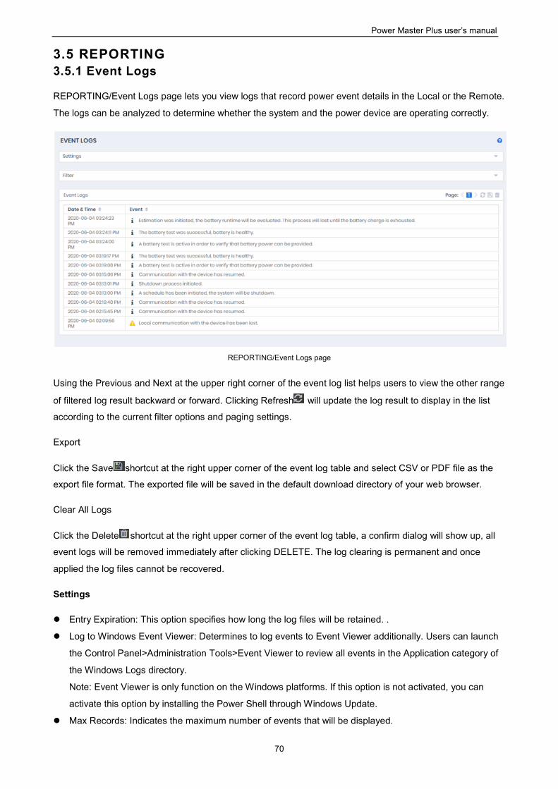
Power Master Plus user’s manual
70
3.5 REPORTING 3.5.1 Event Logs
REPORTING/Event Logs page lets you view logs that record power event details in the Local or the Remote.
The logs can be analyzed to determine whether the system and the power device are operating correctly.
REPORTING/Event Logs page
Using the Previous and Next at the upper right corner of the event log list helps users to view the other range
of filtered log result backward or forward. Clicking Refresh will update the log result to display in the list
according to the current filter options and paging settings.
Export
Click the Save shortcut at the right upper corner of the event log table and select CSV or PDF file as the
export file format. The exported file will be saved in the default download directory of your web browser.
Clear All Logs
Click the Delete shortcut at the right upper corner of the event log table, a confirm dialog will show up, all
event logs will be removed immediately after clicking DELETE. The log clearing is permanent and once
applied the log files cannot be recovered.
Settings
Entry Expiration: This option specifies how long the log files will be retained. .
Log to Windows Event Viewer: Determines to log events to Event Viewer additionally. Users can launch
the Control Panel>Administration Tools>Event Viewer to review all events in the Application category of
the Windows Logs directory.
Note: Event Viewer is only function on the Windows platforms. If this option is not activated, you can
activate this option by installing the Power Shell through Windows Update.
Max Records: Indicates the maximum number of events that will be displayed.
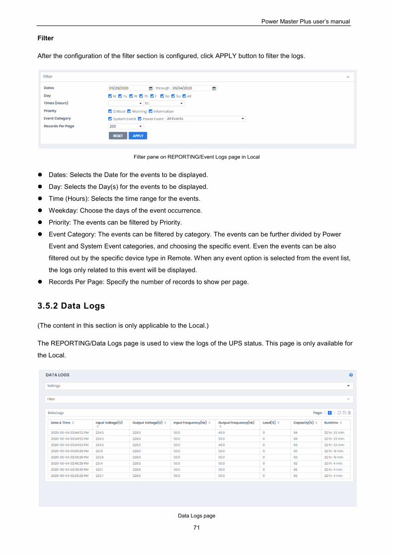
Power Master Plus user’s manual
71
Filter
After the configuration of the filter section is configured, click APPLY button to filter the logs.
Filter pane on REPORTING/Event Logs page in Local
Dates: Selects the Date for the events to be displayed.
Day: Selects the Day(s) for the events to be displayed.
Time (Hours): Selects the time range for the events.
Weekday: Choose the days of the event occurrence.
Priority: The events can be filtered by Priority.
Event Category: The events can be filtered by category. The events can be further divided by Power
Event and System Event categories, and choosing the specific event. Even the events can be also
filtered out by the specific device type in Remote. When any event option is selected from the event list,
the logs only related to this event will be displayed.
Records Per Page: Specify the number of records to show per page.
3.5.2 Data Logs
(The content in this section is only applicable to the Local.)
The REPORTING/Data Logs page is used to view the logs of the UPS status. This page is only available for
the Local.
Data Logs page
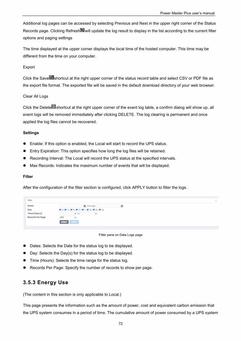
Power Master Plus user’s manual
72
Additional log pages can be accessed by selecting Previous and Next in the upper right corner of the Status
Records page. Clicking Refresh will update the log result to display in the list according to the current filter
options and paging settings
The time displayed at the upper corner displays the local time of the hosted computer. This time may be
different from the time on your computer.
Export
Click the Save shortcut at the right upper corner of the status record table and select CSV or PDF file as
the export file format. The exported file will be saved in the default download directory of your web browser.
Clear All Logs
Click the Delete shortcut at the right upper corner of the event log table, a confirm dialog will show up, all
event logs will be removed immediately after clicking DELETE. The log clearing is permanent and once
applied the log files cannot be recovered.
Settings
Enable: If this option is enabled, the Local will start to record the UPS status.
Entry Expiration: This option specifies how long the log files will be retained.
Recording Interval: The Local will record the UPS status at the specified intervals.
Max Records: Indicates the maximum number of events that will be displayed.
Filter
After the configuration of the filter section is configured, click APPLY button to filter the logs.
Filter pane on Data Logs page
Dates: Selects the Date for the status log to be displayed.
Day: Selects the Day(s) for the status log to be displayed.
Time (Hours): Selects the time range for the status log.
Records Per Page: Specify the number of records to show per page.
3.5.3 Energy Use
(The content in this section is only applicable to Local.)
This page presents the information such as the amount of power, cost and equivalent carbon emission that
the UPS system consumes in a period of time. The cumulative amount of power consumed by a UPS system
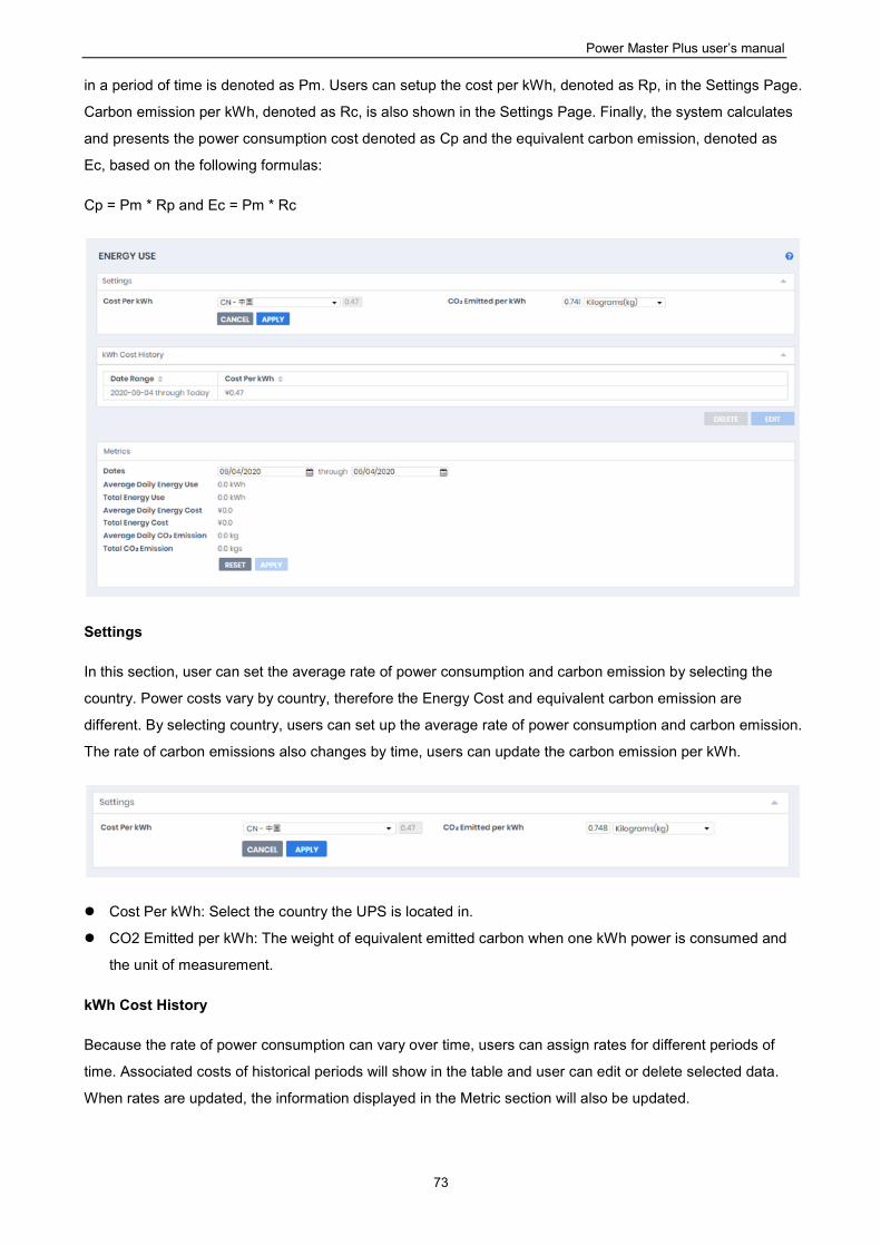
Power Master Plus user’s manual
73
in a period of time is denoted as Pm. Users can setup the cost per kWh, denoted as Rp, in the Settings Page.
Carbon emission per kWh, denoted as Rc, is also shown in the Settings Page. Finally, the system calculates
and presents the power consumption cost denoted as Cp and the equivalent carbon emission, denoted as
Ec, based on the following formulas:
Cp = Pm * Rp and Ec = Pm * Rc
Settings
In this section, user can set the average rate of power consumption and carbon emission by selecting the
country. Power costs vary by country, therefore the Energy Cost and equivalent carbon emission are
different. By selecting country, users can set up the average rate of power consumption and carbon emission.
The rate of carbon emissions also changes by time, users can update the carbon emission per kWh.
Cost Per kWh: Select the country the UPS is located in.
CO2 Emitted per kWh: The weight of equivalent emitted carbon when one kWh power is consumed and
the unit of measurement.
kWh Cost History
Because the rate of power consumption can vary over time, users can assign rates for different periods of
time. Associated costs of historical periods will show in the table and user can edit or delete selected data.
When rates are updated, the information displayed in the Metric section will also be updated.
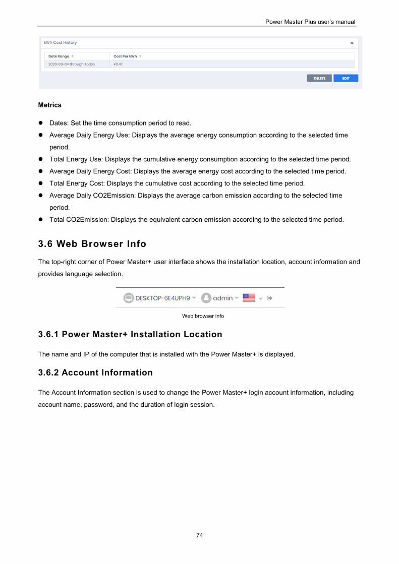
Power Master Plus user’s manual
74
Metrics
Dates: Set the time consumption period to read.
Average Daily Energy Use: Displays the average energy consumption according to the selected time
period.
Total Energy Use: Displays the cumulative energy consumption according to the selected time period.
Average Daily Energy Cost: Displays the average energy cost according to the selected time period.
Total Energy Cost: Displays the cumulative cost according to the selected time period.
Average Daily CO2Emission: Displays the average carbon emission according to the selected time
period.
Total CO2Emission: Displays the equivalent carbon emission according to the selected time period.
3.6 Web Browser Info
The top-right corner of Power Master+ user interface shows the installation location, account information and
provides language selection.
Web browser info
3.6.1 Power Master+ Installation Location
The name and IP of the computer that is installed with the Power Master+ is displayed.
3.6.2 Account Information
The Account Information section is used to change the Power Master+ login account information, including
account name, password, and the duration of login session.
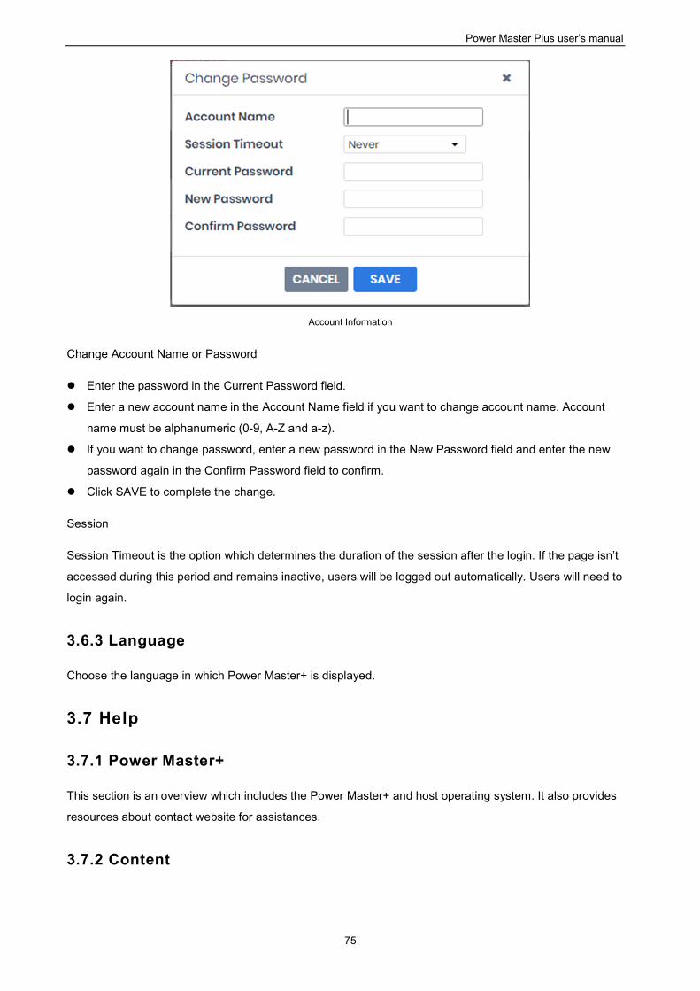
Power Master Plus user’s manual
75
Account Information
Change Account Name or Password
Enter the password in the Current Password field.
Enter a new account name in the Account Name field if you want to change account name. Account
name must be alphanumeric (0-9, A-Z and a-z).
If you want to change password, enter a new password in the New Password field and enter the new
password again in the Confirm Password field to confirm.
Click SAVE to complete the change.
Session
Session Timeout is the option which determines the duration of the session after the login. If the page isn’t
accessed during this period and remains inactive, users will be logged out automatically. Users will need to
login again.
3.6.3 Language
Choose the language in which Power Master+ is displayed.
3.7 Help
3.7.1 Power Master+
This section is an overview which includes the Power Master+ and host operating system. It also provides
resources about contact website for assistances.
3.7.2 Content

Power Master Plus user’s manual
76
The Content page provides an overview which introduces the brief functions of what Local or Remote do and
indicates how to get related online-help content for current function page. It indicates a button to access to
online-help directly.
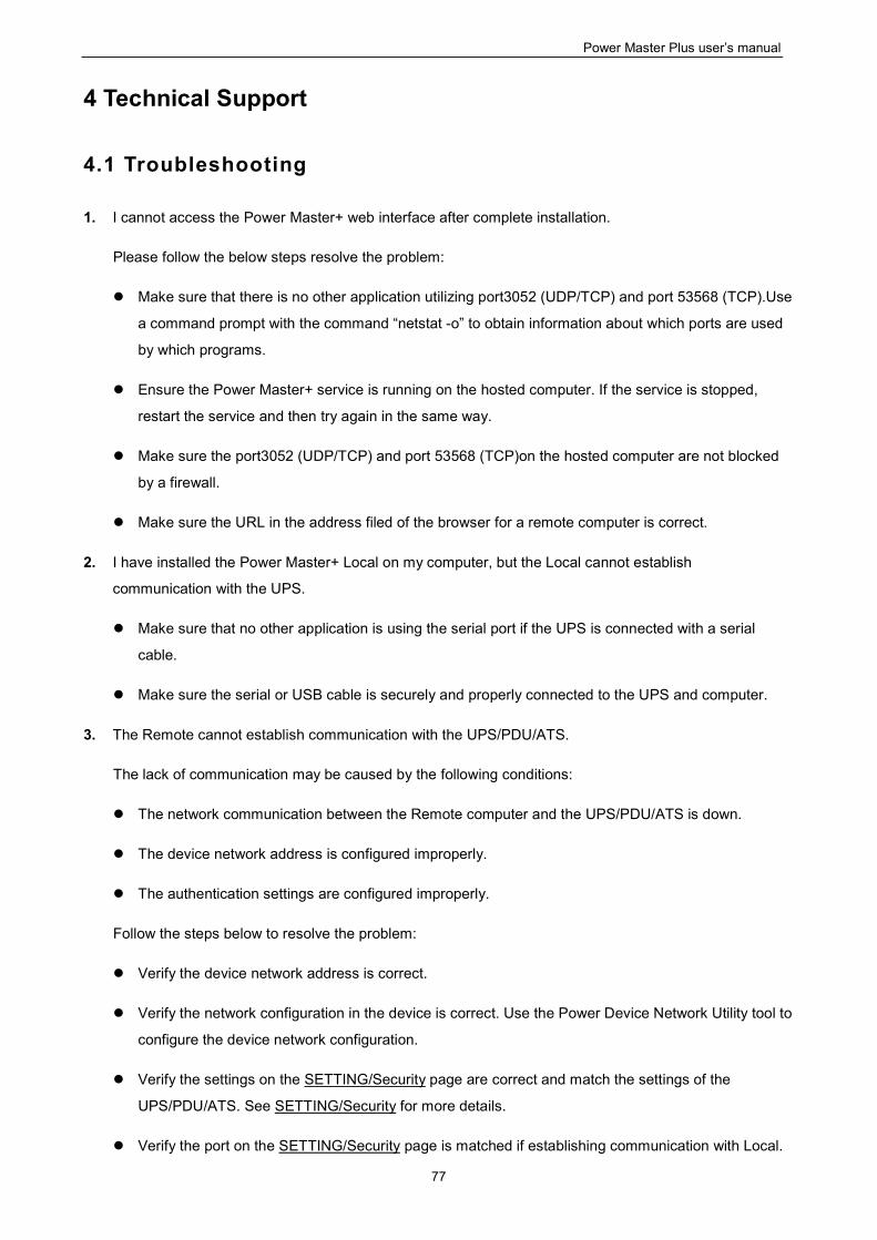
Power Master Plus user’s manual
77
4 Technical Support
4.1 Troubleshooting
1. I cannot access the Power Master+ web interface after complete installation.
Please follow the below steps resolve the problem:
Make sure that there is no other application utilizing port3052 (UDP/TCP) and port 53568 (TCP).Use
a command prompt with the command “netstat -o” to obtain information about which ports are used
by which programs.
Ensure the Power Master+ service is running on the hosted computer. If the service is stopped,
restart the service and then try again in the same way.
Make sure the port3052 (UDP/TCP) and port 53568 (TCP)on the hosted computer are not blocked
by a firewall.
Make sure the URL in the address filed of the browser for a remote computer is correct.
2. I have installed the Power Master+ Local on my computer, but the Local cannot establish
communication with the UPS.
Make sure that no other application is using the serial port if the UPS is connected with a serial
cable.
Make sure the serial or USB cable is securely and properly connected to the UPS and computer.
3. The Remote cannot establish communication with the UPS/PDU/ATS.
The lack of communication may be caused by the following conditions:
The network communication between the Remote computer and the UPS/PDU/ATS is down.
The device network address is configured improperly.
The authentication settings are configured improperly.
Follow the steps below to resolve the problem:
Verify the device network address is correct.
Verify the network configuration in the device is correct. Use the Power Device Network Utility tool to
configure the device network configuration.
Verify the settings on the SETTING/Security page are correct and match the settings of the
UPS/PDU/ATS. See SETTING/Security for more details.
Verify the port on the SETTING/Security page is matched if establishing communication with Local.
Power Master Plus user’s manual
78
Check the network status of the UPS/PDU/ATS and Remotes.
Verify firewall settings. Port 3052(UDP/TCP), port 53568(TCP),port 161(UDP), port 162(UDP) and
port 53566(UDP) should be unblocked. The Remote communicates with UPS/PDU/ATS and Locals
using these ports.
4. The battery test failed.
Replace the batteries if the batteries have used over 3 years.
Contact company for assistance and replace the batteries if the battery test still fails.
5. The Power Master+ installation failed.
If the installation file is from company web site, it may have downloaded incompletely or become
corrupt. Download the installation file again.
6. I failed to extend the off-delay time of Necessary shutdown time option.
The communities on the SETTING/Security page in the Remote and on the Network/Access of
Control page in the PDU may be not matched. Confirm that the communities with the write
permission are matched.
The Remote may use the community without write permission to access the PDU. Please promote
the permission of the community which is used by the Remote to access the PDU.
7. The shutdown occurs earlier than expected time.
It may be caused by the following conditions:
When batteries have been used for a long time, they are unable to reach a full charge. Check to see
if the output load is too high. A high load on the UPS will cause the batteries to discharge faster and
the remaining runtime quickly decrease. Disconnect some load from the UPS to reduce the load in
order to extend the runtime.
Verify that the batteries are fully-charged. If the capacity is too low, please charge the batteries to full
capacity.
8. Pages cannot be displayed after I set up another port number in the Security/Network page.
The port that was set up in the SETTING/Security page may be occupied by other applications or
services. This indicates that the pages can’t be accessed through the assigned port.
9. The host name and IP address at the Local’s banner on the vMA of the VMware ESXi host displays
Unknown.
Follow below steps to correct this condition:
Run the command ‘sudo vi /etc/hosts’ with root permission.
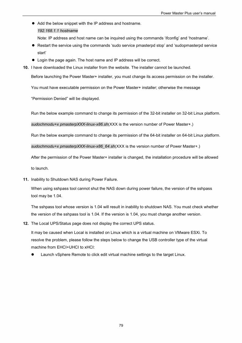
Power Master Plus user’s manual
79
Add the below snippet with the IP address and hostname.
192.168.1.1 hostname
Note: IP address and host name can be inquired using the commands ‘ifconfig’ and ‘hostname’.
Restart the service using the commands ‘sudo service pmasterpd stop’ and ‘sudopmasterpd service
start’
Login the page again. The host name and IP address will be correct.
10. I have downloaded the Linux installer from the website. The installer cannot be launched.
Before launching the Power Master+ installer, you must change its access permission on the installer.
You must have executable permission on the Power Master+ installer; otherwise the message
“Permission Denied” will be displayed.
Run the below example command to change its permission of the 32-bit installer on 32-bit Linux platform.
sudochmodu+x pmasterpXXX-linux-x86.sh(XXX is the version number of Power Master+.)
Run the below example command to change its permission of the 64-bit installer on 64-bit Linux platform.
sudochmodu+x pmasterpXXX-linux-x86_64.sh(XXX is the version number of Power Master+.)
After the permission of the Power Master+ installer is changed, the installation procedure will be allowed
to launch.
11. Inability to Shutdown NAS during Power Failure.
When using sshpass tool cannot shut the NAS down during power failure, the version of the sshpass
tool may be 1.04.
The sshpass tool whose version is 1.04 will result in inability to shutdown NAS. You must check whether
the version of the sshpass tool is 1.04. If the version is 1.04, you must change another version.
12. The Local UPS/Status page does not display the correct UPS status.
It may be caused when Local is installed on Linux which is a virtual machine on VMware ESXi. To
resolve the problem, please follow the steps below to change the USB controller type of the virtual
machine from EHCI+UHCI to xHCI:
Launch vSphere Remote to click edit virtual machine settings to the target Linux.
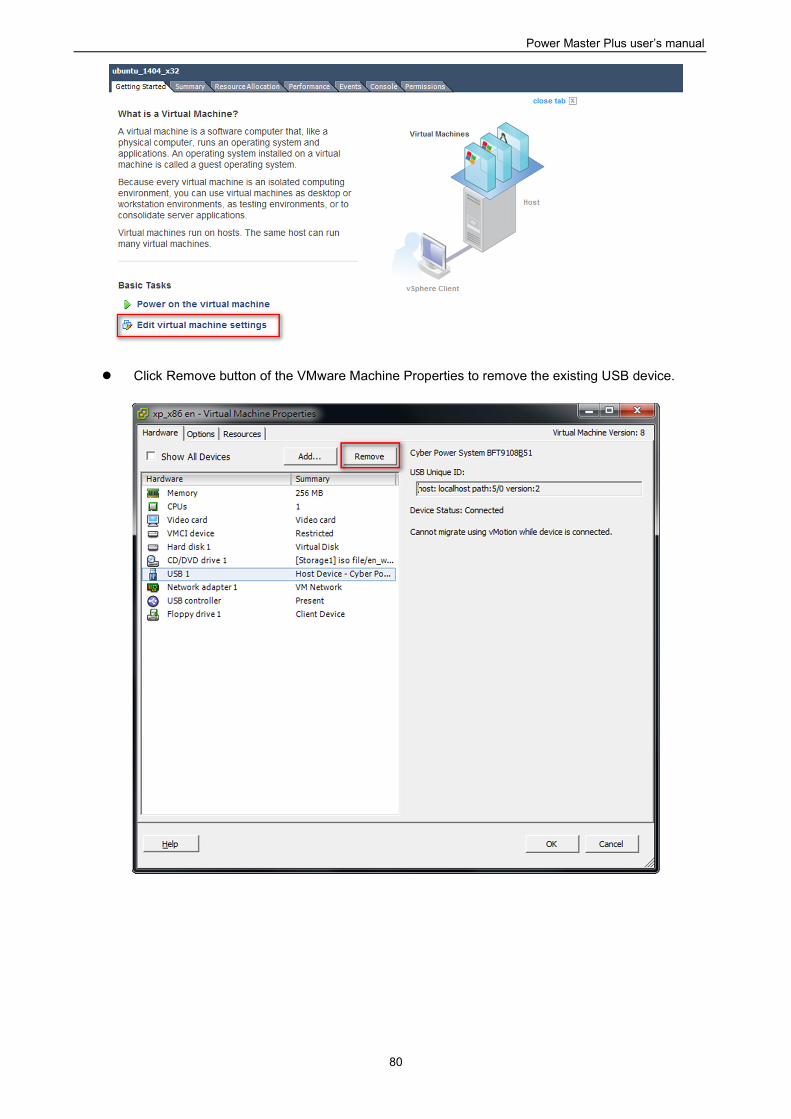
Power Master Plus user’s manual
80
Click Remove button of the VMware Machine Properties to remove the existing USB device.
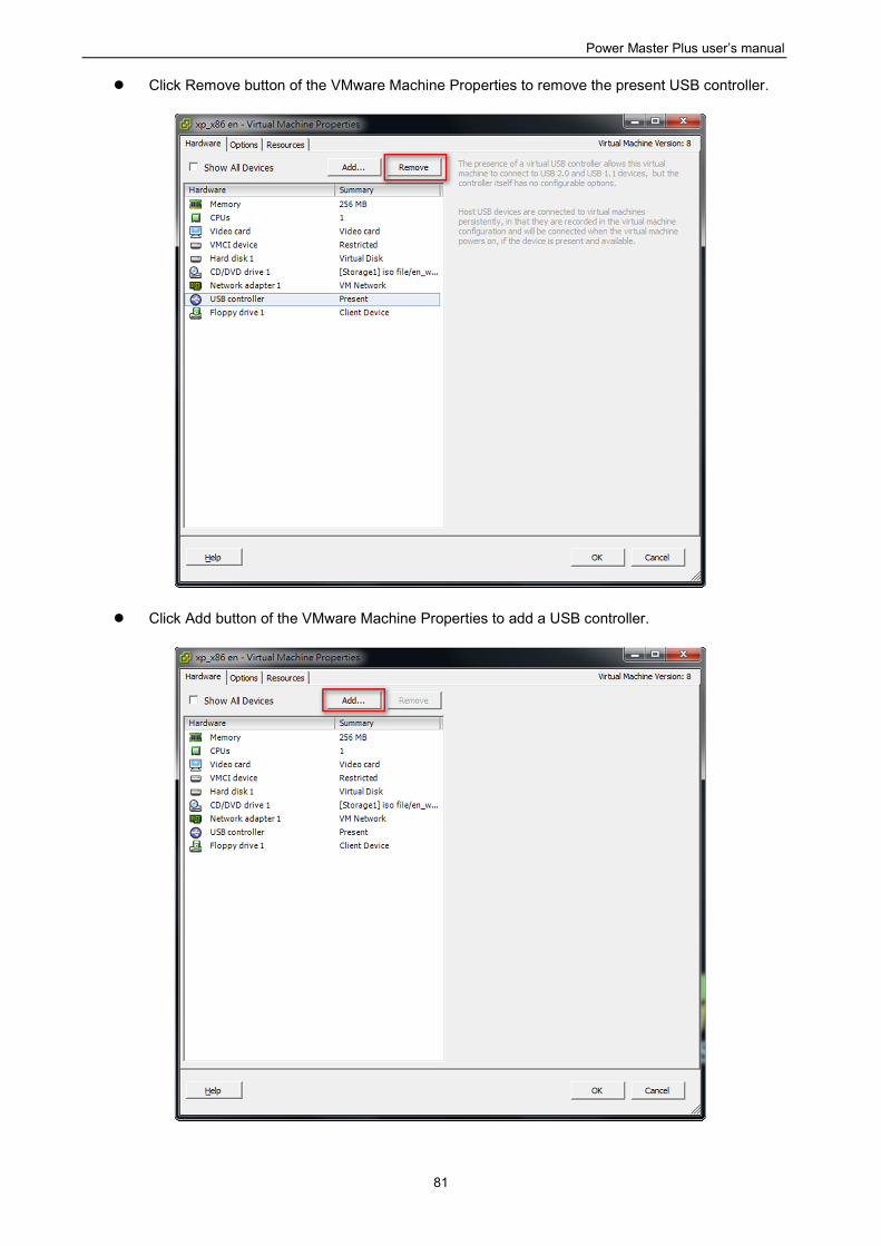
Power Master Plus user’s manual
81
Click Remove button of the VMware Machine Properties to remove the present USB controller.
Click Add button of the VMware Machine Properties to add a USB controller.
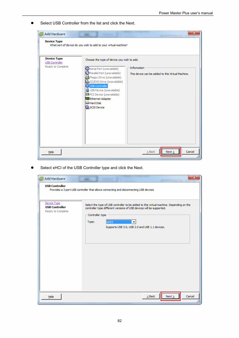
Power Master Plus user’s manual
82
Select USB Controller from the list and click the Next.
Select xHCI of the USB Controller type and click the Next.
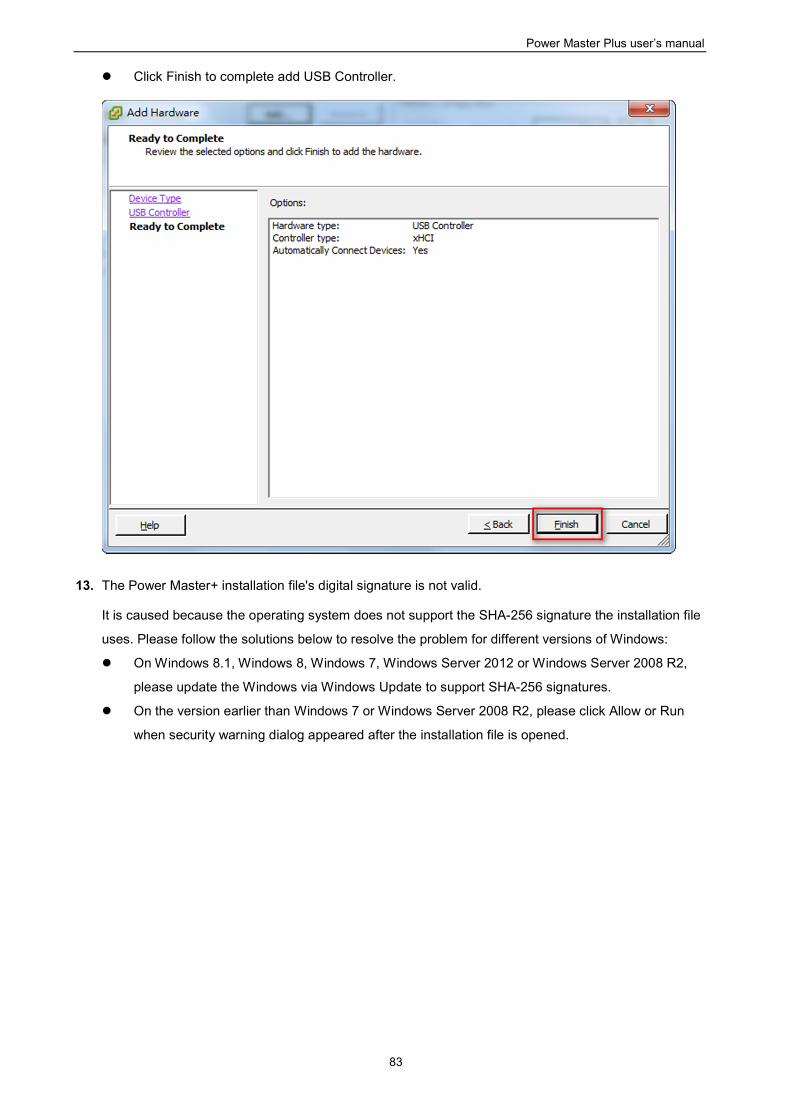
Power Master Plus user’s manual
83
Click Finish to complete add USB Controller.
13. The Power Master+ installation file's digital signature is not valid.
It is caused because the operating system does not support the SHA-256 signature the installation file
uses. Please follow the solutions below to resolve the problem for different versions of Windows:
On Windows 8.1, Windows 8, Windows 7, Windows Server 2012 or Windows Server 2008 R2,
please update the Windows via Windows Update to support SHA-256 signatures.
On the version earlier than Windows 7 or Windows Server 2008 R2, please click Allow or Run
when security warning dialog appeared after the installation file is opened.
Power Master Plus user’s manual
84
4.2 FAQ
1. If multiple computers are connected to a single UPS, how do I determine which computer to install the
Local or the Remote on to ensure each computer can be shut down gracefully in event of power outage?
The computer that is connected to the UPS with a serial or USB cable should install the Local, and the
remaining ones should install the Remote.
2. After the Power Master+ installation is complete, how do I access the web interface?
On Windows, you can select the Start>All programs> Power Master+ > Power Master+ Local(or Power
Master+ Remote/ Power Master+ Management) for local use. You can also enter the
URL, http://hosted_computer_IP_address:3052/local, http://hosted_computer_IP_address:3052/remote,
in the address filed of the web browser from a remote computer.
On Linux, you only enter the URL, http://localhost:3052/local,http://localhost:3052/remote, the address
field of the web browser from a remote computer for a local access. You can also enter the URL,
http://hosted_computer_IP_address:3052/local, http://hosted_computer_IP_address:3052/remote, in the
address filed of the web browser from a remote computer.
3. Which operation systems are supported by Power Master+ software? And which browser supports them?
Refer to the Getting Started/Prerequisites for more details.
4. My Remote computer connects to a PDU. How do I ensure the IP address assigned on the
Power/Configuration page matches the actual PDU IP address? How do I ensure the outlet configured
on the Power/Configuration page matches with the actual connection?
Click the Identify button at the Outlet block screen. The PDU LCD screen will blink the outlet number on
the connected PDU. The PDU IP address can be verified by pressing the select button on the PDU until
the IP address displays on the LCD.
5. What is the difference of the NCL (Non-Critical Load) outlet and CL (Critical Load) outlet? Which
equipment should connect to NCL outlet or CL outlets?
The NCL outlets are only available on specific UPS models and are designed to be powered off early to
maximize the battery runtime for the CL outlets. Non-critical equipment such as redundant equipment,
monitors, or other non-critical equipment should be connect to the NCL outlets to be powered off early.
This will maximize the battery runtime for critical equipment such as servers on the CL outlets.
6. The UPS/Load page allows users to establish communication with the Remote by assigning the
Remote's IP address. Are there other ways to establish communication?
Communication can be established by assigning the Local's IP address on the Device Network
Address section on the POWER CONFIGURATION page in the Remote.
Power Master Plus user’s manual
85
7. How can I make Power Master+ run a program when a particular event has occurred?
Create a .cmd file and save it into the extcmd folder of Power Master+ installation folder. Then write a
command to run your own programs into this script file. Please refer to the default.cmd in the extcmd
folder to write your own script.
8. I am not sure what the IP address of the UPS/PDU/ATS is. How can I obtain the correct IP address?
Use the Power Device Network Utility tool to help you to find the correct IP address of UPS/PDU/ATS.
This device list will list the all company device’s IP address on the local network.
9. How do I uninstall Power Master+?
On Windows, go to Start>Control Panel>Add or Remove Programs. Click the Change/Remove button of
Power Master+ to uninstall the program.
On Linux and VMware ESXi, only Power Master+ Remote can be installed. The default installation
directory is /usr/local/PMasterP on the Linux platforms and/opt/PMasterP on VMware ESXi. Execute the
uninstall.sh command in the installation directory to uninstall the program.
10. How can I get a notice when a power condition has cleared?
When a power condition is clear, it will broadcast a notification and also run the command file. A custom
script can be created for events. The script can utilize the environment variable EVENT_STAGE to
compare the key OCCUR to identify an event that has occurred or FINISH to identify an event that has
cleared.
11. What network protocol is used in Power Master+?
SNMP is used on communications between Remote, Management, PDU or UPS with remote
management card. HTTP and HTTPS are used between the Local and the Remote.
12. What the network ports are used by Power Master+?
Port 3052 (UDP/TCP), port 53568 (TCP),port 161(UDP), port 162 (UDP) and port 53566(UDP)
13. How do I ensure that the SNMP settings between the Remote and UPS/PDU/ATS are properly setup?
To receive the trap notification from the UPS/PDU/ATS all the time, follow steps to verify the SNMP
settings:
Open the Network/Trap Notification page on the UPS/PDU/ATS web and the SETTING/Security
page on the Remote.
Confirm that the IP address of the Remote can be found on the Network/Trap Notification page of the
UPS/PDU/ATS web. If the IP address can be searched, skip the step 3.
If the IP address of the Remote could not be found, click the Trap Receiver shortcut of the
Network/Trap Notification page to enter the Trap Configuration page. Enter the required data to add
a new trap receiver.
If the IP address of the Remote could be found, verify the SNMP settings are matched.
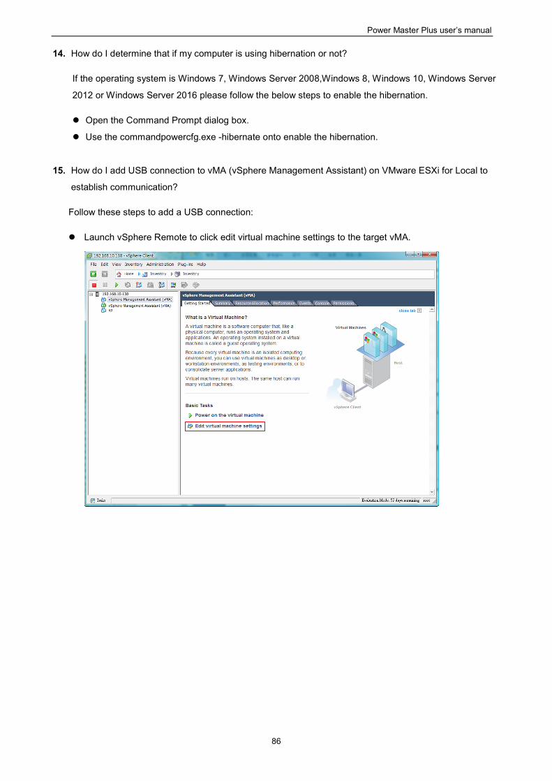
Power Master Plus user’s manual
86
14. How do I determine that if my computer is using hibernation or not?
If the operating system is Windows 7, Windows Server 2008,Windows 8, Windows 10, Windows Server
2012 or Windows Server 2016 please follow the below steps to enable the hibernation.
Open the Command Prompt dialog box.
Use the commandpowercfg.exe -hibernate onto enable the hibernation.
15. How do I add USB connection to vMA (vSphere Management Assistant) on VMware ESXi for Local to
establish communication?
Follow these steps to add a USB connection:
Launch vSphere Remote to click edit virtual machine settings to the target vMA.
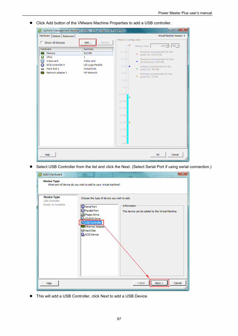
Power Master Plus user’s manual
87
Click Add button of the VMware Machine Properties to add a USB controller.
Select USB Controller from the list and click the Next. (Select Serial Port if using serial connection.)
This will add a USB Controller, click Next to add a USB Device.
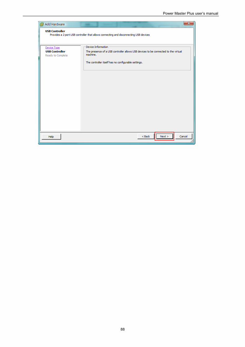
Power Master Plus user’s manual
88
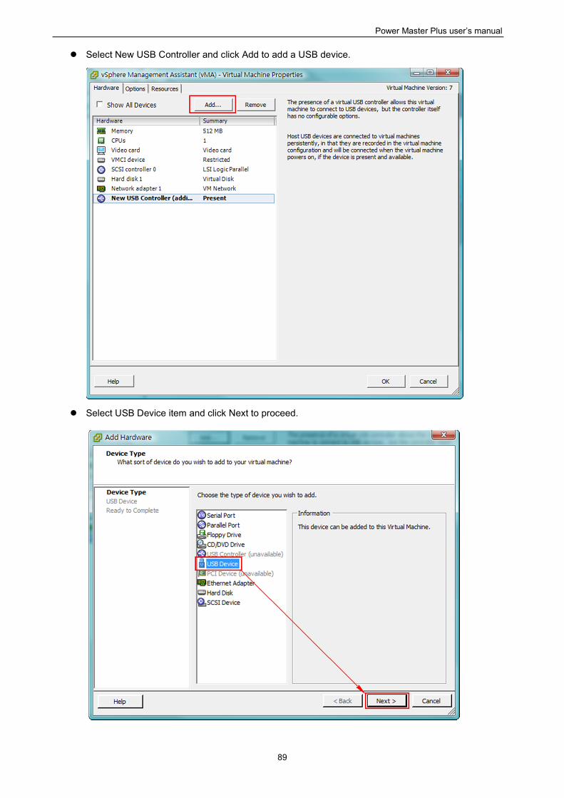
Power Master Plus user’s manual
89
Select New USB Controller and click Add to add a USB device.
Select USB Device item and click Next to proceed.
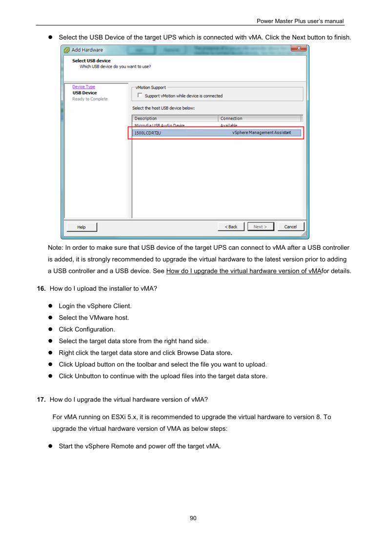
Power Master Plus user’s manual
90
Select the USB Device of the target UPS which is connected with vMA. Click the Next button to finish.
Note: In order to make sure that USB device of the target UPS can connect to vMA after a USB controller
is added, it is strongly recommended to upgrade the virtual hardware to the latest version prior to adding
a USB controller and a USB device. See How do I upgrade the virtual hardware version of vMAfor details.
16. How do I upload the installer to vMA?
Login the vSphere Client.
Select the VMware host.
Click Configuration.
Select the target data store from the right hand side.
Right click the target data store and click Browse Data store.
Click Upload button on the toolbar and select the file you want to upload.
Click Unbutton to continue with the upload files into the target data store.
17. How do I upgrade the virtual hardware version of vMA?
For vMA running on ESXi 5.x, it is recommended to upgrade the virtual hardware to version 8. To
upgrade the virtual hardware version of VMA as below steps:
Start the vSphere Remote and power off the target vMA.
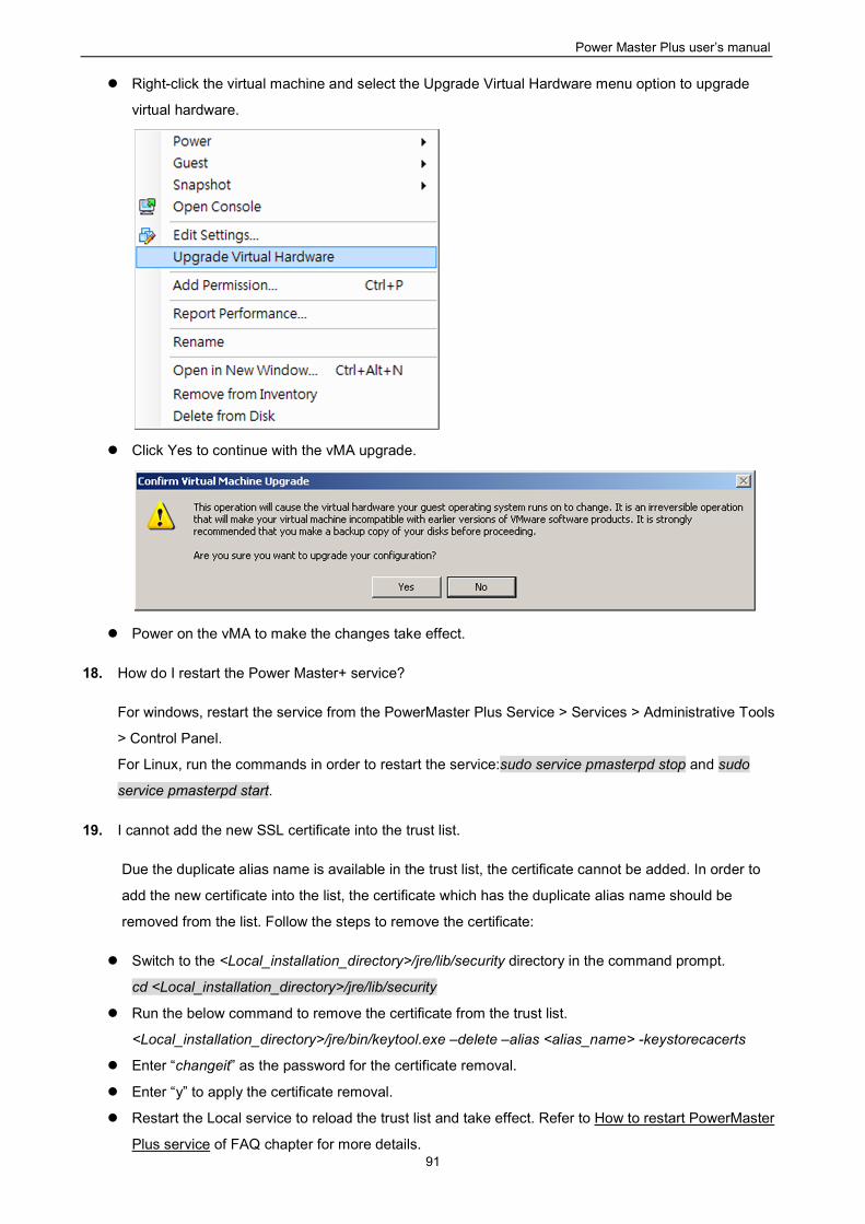
Power Master Plus user’s manual
91
Right-click the virtual machine and select the Upgrade Virtual Hardware menu option to upgrade
virtual hardware.
Click Yes to continue with the vMA upgrade.
Power on the vMA to make the changes take effect.
18. How do I restart the Power Master+ service?
For windows, restart the service from the PowerMaster Plus Service > Services > Administrative Tools
> Control Panel.
For Linux, run the commands in order to restart the service:sudo service pmasterpd stop and sudo
service pmasterpd start.
19. I cannot add the new SSL certificate into the trust list.
Due the duplicate alias name is available in the trust list, the certificate cannot be added. In order to
add the new certificate into the list, the certificate which has the duplicate alias name should be
removed from the list. Follow the steps to remove the certificate:
Switch to the <Local_installation_directory>/jre/lib/security directory in the command prompt.
cd <Local_installation_directory>/jre/lib/security
Run the below command to remove the certificate from the trust list.
<Local_installation_directory>/jre/bin/keytool.exe –delete –alias <alias_name> -keystorecacerts
Enter “changeit” as the password for the certificate removal.
Enter “y” to apply the certificate removal.
Restart the Local service to reload the trust list and take effect. Refer to How to restart PowerMaster
Plus service of FAQ chapter for more details.

Power Master Plus user’s manual
92
20. I cannot successfully upload the profiles of Power Master+ Edition to Power Master+.
Please compress the etc and extcmd folders in the Power Master+ Edition installation directory into a zip
file as the file to be imported to the Power Master+.
Power Master+ Edition Agent corresponds to Power Master+ Local.
Power Master+ Edition Client corresponds to Power Master+ Remote.
Power Master Plus user’s manual
93
5 Glossary
Citrix XenServer: A virtual-machine monitor allows several guest operating systems to execute on the
same computer hardware concurrently. XenServer is supported by Citrix systems, Inc.
IP address: An IP address is a series of numbers that identifies a particular computer or NIC on a
network. IP is an abbreviation for Internet Protocol.
HTTPS:Abbreviation for HTTP Secure. It provides encryption and secure identification of servers by
using HTTP with SSL/TLS protocol. HTTPS connection is usually used for the sensitive transaction.
Power Device Network Utility: Is an easy to use tool to setup network configurations of the UPS
PMCARD/PDU/ATS. This includes setting the IP address, subnet mask, or gateway of UPS
PMCARD/PDU/ATS.
PDU:A PDU is a device which provides power output controls for individual outlets and connected
equipment. PDU is an abbreviation for Power Distribution Unit.
SNMP: The simple network management protocol. It is used by network management systems for
monitoring network-attached devices for conditions that warrant administrative attention.
SSL: Abbreviation for Secure Sockets Layer. SSL is a transaction security standard that provides data
encryption, server authentication, and message integrity.
TCP/UDP: Family of protocols for the transport and network layers.
TLS: Abbreviation for Transport Layer Security. TLS is a cryptographic protocol which provides
communication security over the internet. TLS and SSL provide data encryption and server
authentication for message reliability.
vMA: Abbreviation for vSphere Management Assistant. A virtual machine that includes prepackaged
software and supported by the VMware, Inc. allows administrators to run scripts and Locals to manage
ESXi hosts.
VMware ESXi: An enterprise-level computer virtualization product offered by VMware, Inc. It is a
component of VMware’s larger offering, VMware Infrastructure, and adds management and reliability
services to the core server products.
Virtual Appliance: A virtual machine image is designed to run on a virtualization platform developed by
VMware, Inc. It is intended to eliminate the installation, configuration and maintenance costs associated
with running complex stacks of software.
VMware vCenter: A vSphere’s centralized tool that allows for the management of multiple ESXi servers
and virtual machines from different ESXi servers through a single console application.
Microsoft Hyper-V Server: A native hypervisor-based server virtualization product being offered by
Microsoft Corporation.
ATS: ATS is an electrical switch that switches a load between two sources. It can switches power
automatically to a generator or other standby power source after a power outage. ATS is an abbreviation
for Automatic Transfer Switch.
Environment Sensor: A sensor accessory that can be installed on UPS/PDU/ATS for monitoring
environment condition and obtaining information about the temperature and humidity.