pocahontas county public service district regional sewer project
TRANSCRIPT

POCAHONTAS COUNTY PUBLIC SERVICE DISTRICT
REGIONAL SEWER PROJECT
WEST VIRGINIA DEPT. OF AIR QUALITY
GENERAL PERMIT G65-C APPLICATION
Location 01 – Linwood Pump Station 2nd Submission: 03-03-2017
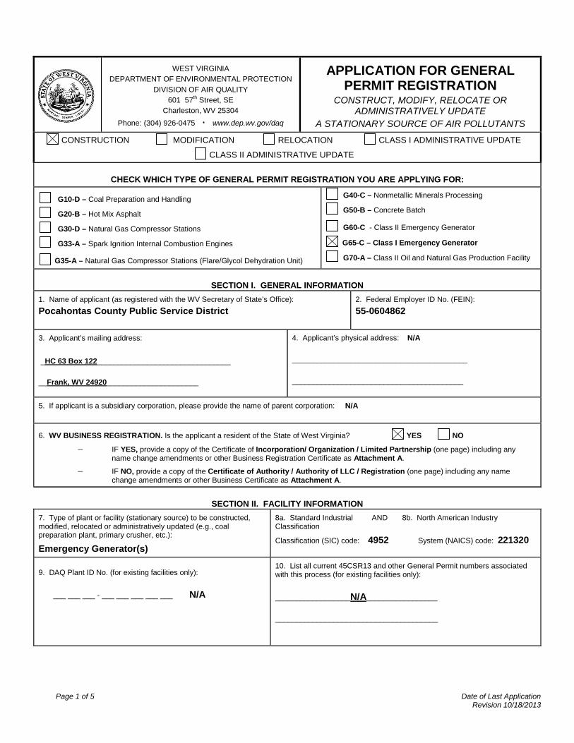
TABLE OF CONTENTS The following checked items are included in this application package:
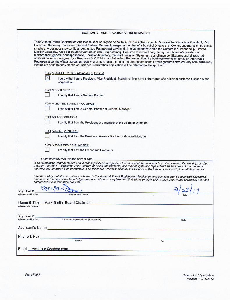
APPLICATION FOR GENERAL PERMIT REGISTRATION
ATTACHMENT A : CURRENT BUSINESS CERTIFICATE
ATTACHMENT B: PROCESS DESCRIPTION
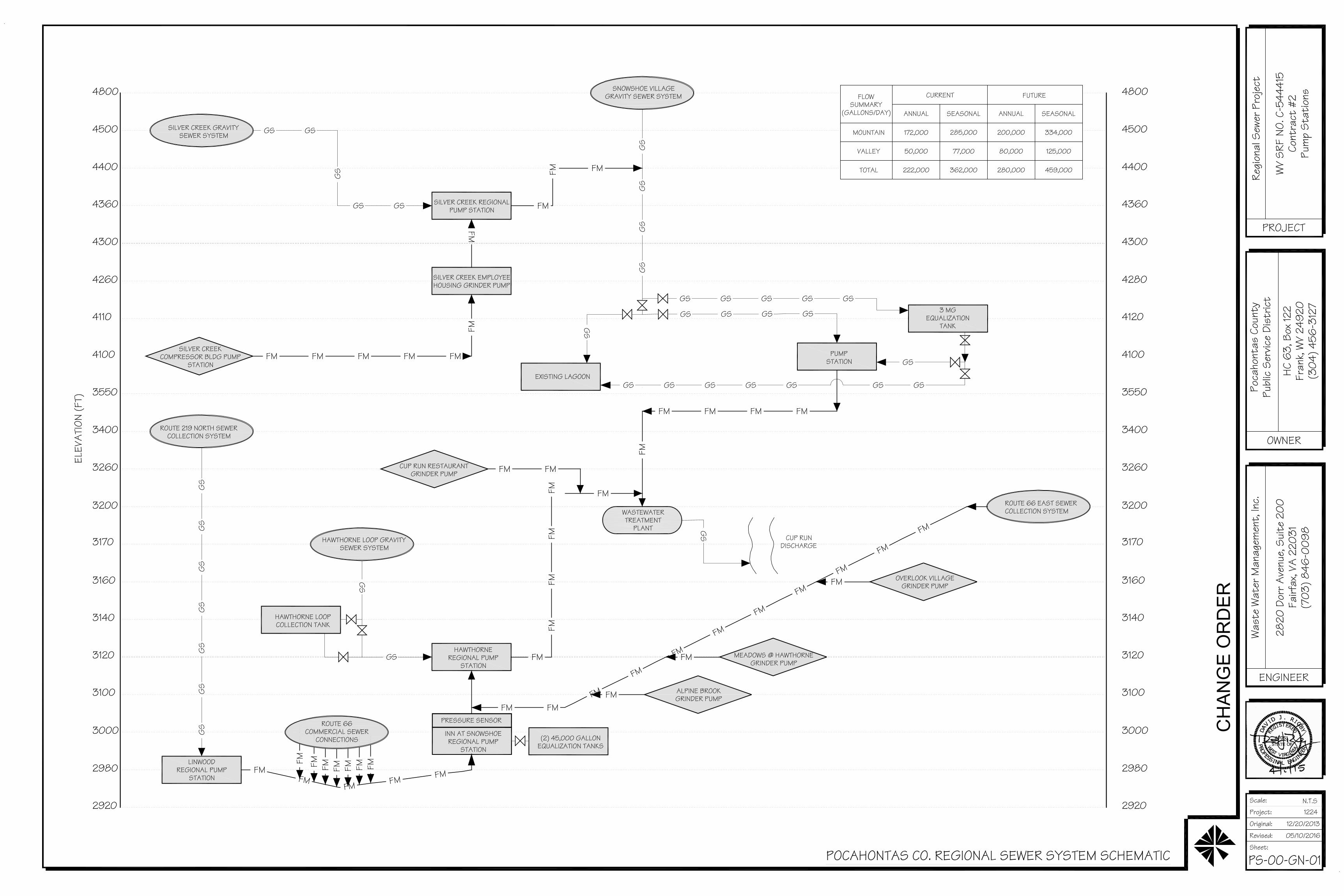
ATTACHMENT C: DESCRIPTION OF FUGITIVE EMISSIONS ATTACHMENT D: PROCESS FLOW DIAGRAM
ATTACHMENT E: PLOT PLAN ATTACHMENT F: AREA MAP ATTACHMENT G: EQUIPMENT DATA SHEETS AND REGISTRATION SECTION APPLICABILITY FORM ATTACHMENT H: AIR POLLUTION CONTROL DEVICE SHEETS
ATTACHMENT I: EMISSIONS CALCULATIONS
ATTACHMENT J: CLASS I LEGAL ADVERTISEMENT
ATTACHMENT K: ELECTRONIC SUBMITTAL
ATTACHMENT L: GENERAL PERMIT REGISTRATION APPLICATION FEE
ATTACHMENT M: SITING CRITERIA WAIVER
ATTACHMENT N: MATERIAL SAFETY DATA SHEETS (MSDS)
ATTACHMENT O: EMISSIONS SUMMARY SHEETS
OTHER SUPPORTING DOCUMENTATION NOT DESCRIBED ABOVE (Equipment Drawings, Aggregation Discussion, etc.)

Page 1 of 5 Date of Last Application
Revision 10/18/2013
WEST VIRGINIA DEPARTMENT OF ENVIRONMENTAL PROTECTION
DIVISION OF AIR QUALITY 601 57th Street, SE
Charleston, WV 25304 Phone: (304) 926-0475 ۰ www.dep.wv.gov/daq
APPLICATION FOR GENERAL PERMIT REGISTRATION
CONSTRUCT, MODIFY, RELOCATE OR ADMINISTRATIVELY UPDATE
A STATIONARY SOURCE OF AIR POLLUTANTS CONSTRUCTION MODIFICATION RELOCATION CLASS I ADMINISTRATIVE UPDATE
CLASS II ADMINISTRATIVE UPDATE
CHECK WHICH TYPE OF GENERAL PERMIT REGISTRATION YOU ARE APPLYING FOR:
G10-D – Coal Preparation and Handling
G20-B – Hot Mix Asphalt
G30-D – Natural Gas Compressor Stations
G33-A – Spark Ignition Internal Combustion Engines
G35-A – Natural Gas Compressor Stations (Flare/Glycol Dehydration Unit)
G40-C – Nonmetallic Minerals Processing
G50-B – Concrete Batch
G60-C - Class II Emergency Generator G65-C – Class I Emergency Generator
G70-A – Class II Oil and Natural Gas Production Facility
SECTION I. GENERAL INFORMATION 1. Name of applicant (as registered with the WV Secretary of State’s Office): Pocahontas County Public Service District
2. Federal Employer ID No. (FEIN): 55-0604862
3. Applicant’s mailing address: _HC 63 Box 122________________________________ __Frank, WV 24920______________________
4. Applicant’s physical address: N/A __________________________________________ _________________________________________
5. If applicant is a subsidiary corporation, please provide the name of parent corporation: N/A
6. WV BUSINESS REGISTRATION. Is the applicant a resident of the State of West Virginia? YES NO
− IF YES, provide a copy of the Certificate of Incorporation/ Organization / Limited Partnership (one page) including any name change amendments or other Business Registration Certificate as Attachment A.
− IF NO, provide a copy of the Certificate of Authority / Authority of LLC / Registration (one page) including any name change amendments or other Business Certificate as Attachment A.
SECTION II. FACILITY INFORMATION
7. Type of plant or facility (stationary source) to be constructed, modified, relocated or administratively updated (e.g., coal preparation plant, primary crusher, etc.):
Emergency Generator(s)
8a. Standard Industrial AND 8b. North American Industry Classification
Classification (SIC) code: 4952 System (NAICS) code: 221320
9. DAQ Plant ID No. (for existing facilities only): ___ ___ ___ - ___ ___ ___ ___ ___ N/A
10. List all current 45CSR13 and other General Permit numbers associated with this process (for existing facilities only): __________________N/A_________________ _______________________________________
Page 2 of 5 Date of Last Application
Revision 10/18/2013
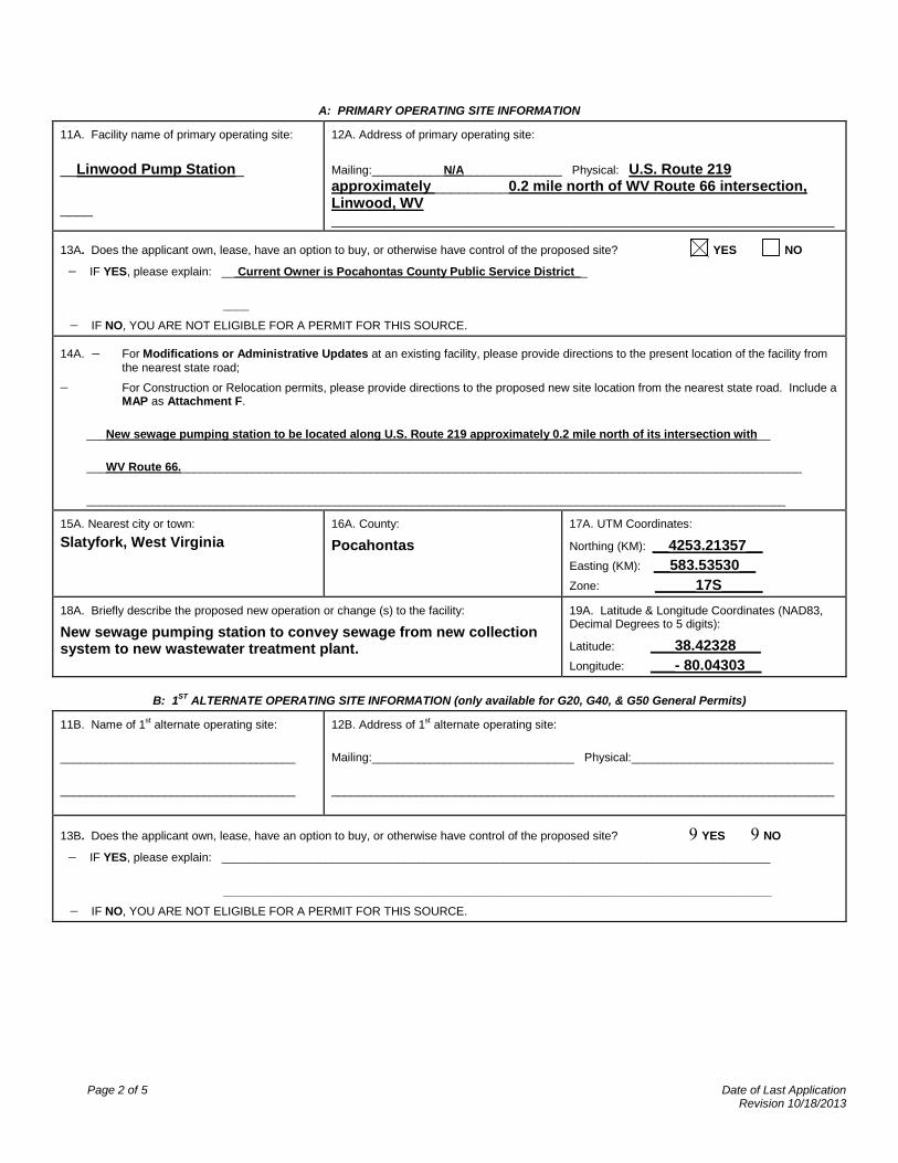
A: PRIMARY OPERATING SITE INFORMATION
11A. Facility name of primary operating site: __Linwood Pump Station_ ____
12A. Address of primary operating site: Mailing:___________N/A_______________ Physical: U.S. Route 219 approximately _________0.2 mile north of WV Route 66 intersection, Linwood, WV _____________________________________________________________________________
13A. Does the applicant own, lease, have an option to buy, or otherwise have control of the proposed site? YES NO − IF YES, please explain: __ Current Owner is Pocahontas County Public Service District _ ____
− IF NO, YOU ARE NOT ELIGIBLE FOR A PERMIT FOR THIS SOURCE.
14A. − For Modifications or Administrative Updates at an existing facility, please provide directions to the present location of the facility from the nearest state road;
− For Construction or Relocation permits, please provide directions to the proposed new site location from the nearest state road. Include a MAP as Attachment F.
___New sewage pumping station to be located along U.S. Route 219 approximately 0.2 mile north of its intersection with__ ___WV Route 66._______________________________________________________________________________________________ ___________________________________________________________________________________________________________
15A. Nearest city or town: Slatyfork, West Virginia
16A. County:
Pocahontas 17A. UTM Coordinates:
Northing (KM): __4253.21357__ Easting (KM): __583.53530__ Zone: _____17S_____
18A. Briefly describe the proposed new operation or change (s) to the facility:
New sewage pumping station to convey sewage from new collection system to new wastewater treatment plant.
19A. Latitude & Longitude Coordinates (NAD83, Decimal Degrees to 5 digits):
Latitude: ___38.42328___ Longitude: ___- 80.04303__
B: 1ST ALTERNATE OPERATING SITE INFORMATION (only available for G20, G40, & G50 General Permits)
11B. Name of 1st alternate operating site: ____________________________________ ____________________________________
12B. Address of 1st alternate operating site: Mailing:_______________________________ Physical:_______________________________ _____________________________________________________________________________
13B. Does the applicant own, lease, have an option to buy, or otherwise have control of the proposed site? 9 YES 9 NO − IF YES, please explain: ____________________________________________________________________________________ ____________________________________________________________________________________
− IF NO, YOU ARE NOT ELIGIBLE FOR A PERMIT FOR THIS SOURCE.
Page 3 of 5 Date of Last Application
Revision 10/18/2013
14B. − For Modifications or Administrative Updates at an existing facility, please provide directions to the present location of the facility from the nearest state road;
− For Construction or Relocation permits, please provide directions to the proposed new site location from the nearest state road. Include a MAP as Attachment F.
___________________________________________________________________________________________________________ ___________________________________________________________________________________________________________ ___________________________________________________________________________________________________________ 15B. Nearest city or town:
16B. County: 17B. UTM Coordinates: Northing (KM): ___________________ Easting (KM): ___________________ Zone: ___________________
18B. Briefly describe the proposed new operation or change (s) to the facility:
19B. Latitude & Longitude Coordinates (NAD83, Decimal Degrees to 5 digits): Latitude: ___________________ Longitude: ___________________
C: 2ND ALTERNATE OPERATING SITE INFORMATION (only available for G20, G40, & G50 General Permits):
11C. Name of 2nd alternate operating site: ____________________________________ ____________________________________
12C. Address of 2nd alternate operating site: Mailing:_______________________________ Physical:_______________________________ _____________________________________________________________________________
13C. Does the applicant own, lease, have an option to buy, or otherwise have control of the proposed site? 9 YES 9 NO − IF YES, please explain: ____________________________________________________________________________________ ____________________________________________________________________________________
− IF NO, YOU ARE NOT ELIGIBLE FOR A PERMIT FOR THIS SOURCE.
14C. − For Modifications or Administrative Updates at an existing facility, please provide directions to the present location of the facility from the nearest state road;
− For Construction or Relocation permits, please provide directions to the proposed new site location from the nearest state road. Include a MAP as Attachment F.
___________________________________________________________________________________________________________ ___________________________________________________________________________________________________________ ___________________________________________________________________________________________________________ 15C. Nearest city or town:
16C. County: 17C. UTM Coordinates: Northing (KM): ___________________ Easting (KM): ___________________ Zone: ___________________
18C. Briefly describe the proposed new operation or change (s) to the facility:
19C. Latitude & Longitude Coordinates (NAD83, Decimal Degrees to 5 digits): Latitude: ___________________ Longitude: ___________________
Page 4 of 5 Date of Last Application
Revision 10/18/2013
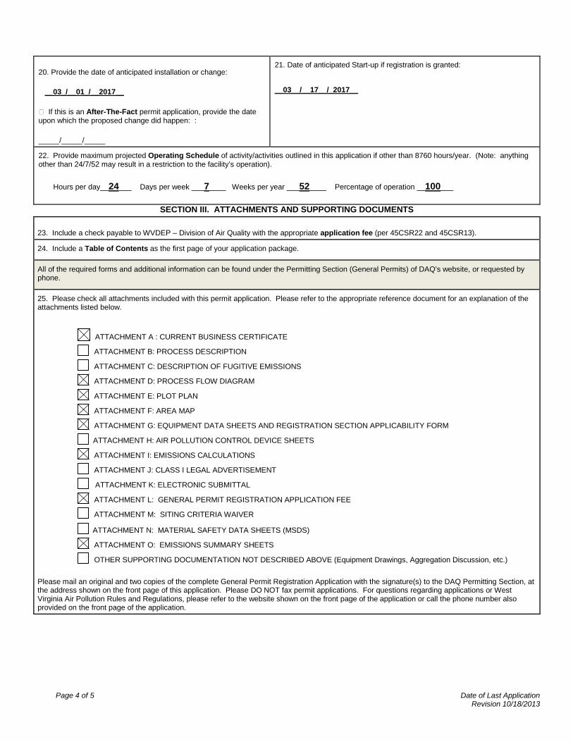
20. Provide the date of anticipated installation or change:
__03_/__01_/__2017__
If this is an After-The-Fact permit application, provide the date upon which the proposed change did happen: :
_____/_____/_____
21. Date of anticipated Start-up if registration is granted: __03__/__17__/_2017__
22. Provide maximum projected Operating Schedule of activity/activities outlined in this application if other than 8760 hours/year. (Note: anything other than 24/7/52 may result in a restriction to the facility’s operation). Hours per day__24___ Days per week ___7____ Weeks per year ___52____ Percentage of operation __100___
SECTION III. ATTACHMENTS AND SUPPORTING DOCUMENTS
23. Include a check payable to WVDEP – Division of Air Quality with the appropriate application fee (per 45CSR22 and 45CSR13).
24. Include a Table of Contents as the first page of your application package.
All of the required forms and additional information can be found under the Permitting Section (General Permits) of DAQ’s website, or requested by phone.
25. Please check all attachments included with this permit application. Please refer to the appropriate reference document for an explanation of the attachments listed below.
ATTACHMENT A : CURRENT BUSINESS CERTIFICATE
ATTACHMENT B: PROCESS DESCRIPTION
ATTACHMENT C: DESCRIPTION OF FUGITIVE EMISSIONS ATTACHMENT D: PROCESS FLOW DIAGRAM
ATTACHMENT E: PLOT PLAN ATTACHMENT F: AREA MAP ATTACHMENT G: EQUIPMENT DATA SHEETS AND REGISTRATION SECTION APPLICABILITY FORM ATTACHMENT H: AIR POLLUTION CONTROL DEVICE SHEETS
ATTACHMENT I: EMISSIONS CALCULATIONS
ATTACHMENT J: CLASS I LEGAL ADVERTISEMENT
ATTACHMENT K: ELECTRONIC SUBMITTAL
ATTACHMENT L: GENERAL PERMIT REGISTRATION APPLICATION FEE
ATTACHMENT M: SITING CRITERIA WAIVER
ATTACHMENT N: MATERIAL SAFETY DATA SHEETS (MSDS)
ATTACHMENT O: EMISSIONS SUMMARY SHEETS
OTHER SUPPORTING DOCUMENTATION NOT DESCRIBED ABOVE (Equipment Drawings, Aggregation Discussion, etc.)
Please mail an original and two copies of the complete General Permit Registration Application with the signature(s) to the DAQ Permitting Section, at the address shown on the front page of this application. Please DO NOT fax permit applications. For questions regarding applications or West Virginia Air Pollution Rules and Regulations, please refer to the website shown on the front page of the application or call the phone number also provided on the front page of the application.


ATTACHMENT A
CURRENT BUSINESS CERTIFICATE
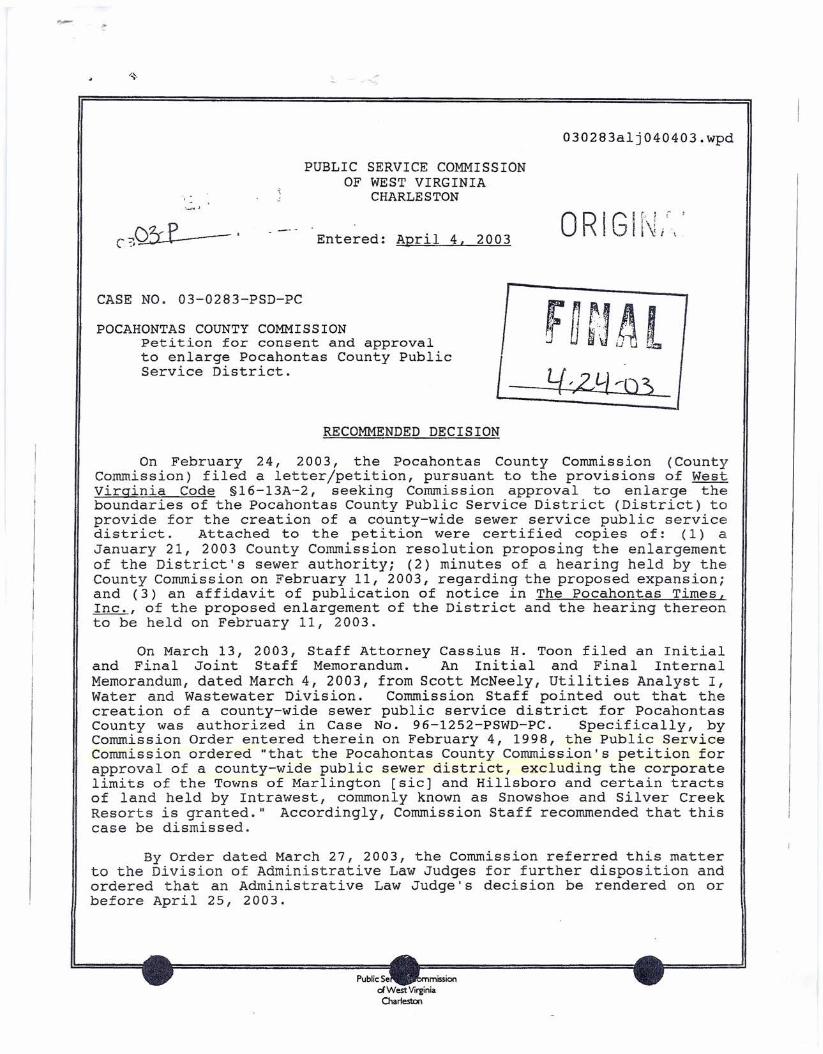
030283alj040403.wpd
PUBLIC SERVICE COMMISSIONOF WEST VIRGINIA
CHARLESTON-'_,.J
Entered: April 4, 2003
ICASE NO. 03-0283-PSD-PC
POCAHONTAS COUNTY COMMISSIONPetition for consent and approvalto enlarge Pocahontas County PublicService District. Lf ',2J-l '--0 3>I
RECOMMENDED DECISION
On February 24, 2003, the Pocahontas County Commission (Countycommission) filed a letter/petition, pursuant to the provisions of Westvirginia Code §16-13A-2, seeking Commission approval to enlarge theboundaries of the Pocahontas County Public Service District (District) toprovide for the creation of a county-wide sewer service public servicedistrict. Attached to the petition were certified copies of: (1) aJanuary 21, 2003 County Commission resolution proposing the enlargementof the District's sewer authority; (2) minutes of a hearing held by theCounty Commission on February 11, 2003, regarding the proposed expansion;and (3) an affidavit of pUblication of notice in The Pocahontas Times,Inc., of the proposed enlargement of the District and the hearing thereonto be held on February 11, 2003.
On March 13, 2003, Staff Attorney Cassius H. Toon filed an Initialand Final Joint Staff Memorandum. An Initial and Final InternalMemorandum, dated March 4, 2003, from Scott McNeely, Utilities Analyst I,Water and Wastewater Division. Commission Staff pointed out that thecreation of a county-wide sewer public service district for PocahontasCounty was authorized in Case No. 96-1252-PSWD-PC. Specifically, byCommission Order entered therein on February 4, 1998, the Public ServiceCommission ordered "that the Pocahontas County Commission's petition forapproval of a county-wide public sewer district, excluding the corporatelimits of the Towns of Marlington [sic] and Hillsboro and certain tractsof land held by Intrawest, commonly known as Snowshoe and Silver CreekResorts is granted." Accordingly, Commission Staff recommended that thiscase be dismissed.
By Order dated March 27, 2003, the Commission referred this matterto the Division of Administrative Law Judges for further disposition andordered that an Administrative Law Judge's decision be rendered on orbefore April 25, 2003.
Public Se mISSIondWest VirginiaCharleston
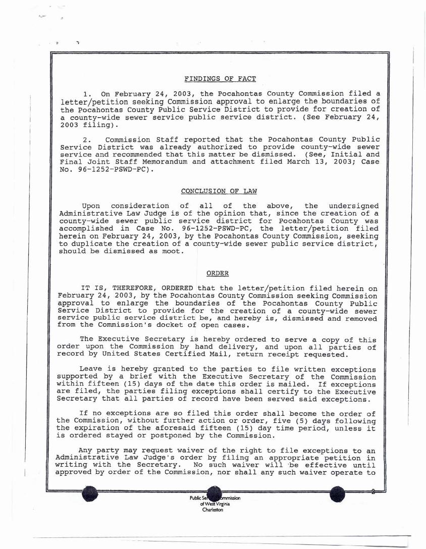
FINDINGS OF FACT
1. On February 24, 2003, the Pocahontas County Commission filed aletter/petition seeking Commission approval to enlarge the boundaries ofthe Pocahontas County Public Service District to provide for creation ofa county-wide sewer service public service district. (See February 24,2003 filing).
2. Commission Staff reported that the Pocahontas County PublicService District was already authorized to provide county-wide sewerservice and recommended that this matter be dismissed. (See, Initial andFinal Joint Staff Memorandum and attachment filed March 13, 2003; CaseNo. 96-1252-PSWD-PC).
CONCLUSION OF LAW
Upon consideration of all of the above, the undersignedAdministrative Law Judge is of the opinion that, since the creation of acounty-wide s~wer public service district for Pocahontas County wasaccomplished an Case No. 96-1252-PSWD-PC, the letter/petition filedherein on February 24, 2003, by the Pocahontas County Commission, seekingto duplicate the creation of a county-wide sewer public service district,should be dismissed as moot.
ORDER
IT IS, THEREFORE, ORDERED that the letter/petition filed herein onFebruary 24, 2003, by the Pocahontas County Commission seeking Commissionapproval to enlarge the boundaries of the Pocahontas County PublicService District to provide for the creation of a county-wide sewerservice public service district be, and hereby is, dismissed and removedfrom the Commission's docket of open cases.
The Executive Secretary is hereby ordered to serve a copy of thisorder upon the Commission by hand delivery, and upon all parties ofrecord by United States Certified Mail, return receipt requested.
Leave is hereby granted to the parties to file written exceptionssupported by a brief with the Executive Secretary of the Commissionwithin fifteen (15) days of the date this order is mailed. If exceptionsare filed, the parties filing exceptions shall certify to the ExecutiveSecretary that all parties of record have been served said exceptions.
If no exceptions are so filed this order shall become the order ofthe Commission, without further action or order, five (5) days followingthe expiration of the aforesaid fifteen (15) day time period, unless itis ordered stayed or postponed by the Commission.
Any party may request waiver of the right to file exceptions to anAdministrative Law Judge's order by filing an appropriate petition inwriting with the Secretary. No such waiver will "be effective untilapproved by order of the Commission, nor shall any such waiver operate to
PublicSe rnssoncJWest VirginiaCharleston
make any Administrative Law Judge's Order or Decision the order of theCommission sooner than five (5) days after approval of such waiver by theCommission.
Melissa K. MarlandChief Administrative Law Judge
MKM/JPC:mal030283a.wpd
..-
040273aljl01904.wpdPUBLIC SERVICE COMMISSION
OF WEST VIRGINIACHARLESTON
Entered: October 19, 2004CASE NO. 04-0273-PSD-PCPOCAHONTAS COUNTY COMMISSION
Petition for consent and approval of theenlargement of the sewer authority of thePocahontas County Public Service District.
~ On May 25, 2004, Thomas R. Michael, Esquire, counsel for the~ l!:=:=p=o=c=a=h=ontasCounty Public Service District, filed a moti;=o=n==f=o=r=:::!J
RECOMMENDED DECISIONOn February 24, 2004, the Pocahontas County Cormnission (County
Cormnission) filed an Order dated February 17, 2004, to enlarge theboundaries of the Pocahontas County Public Service District (District),pursuant to West Virginia Code §16-13A-2.
By Order dated March 23, 2004, this matter was referred to theDivision of Administrative Law Judges for a decision to be rendered on orbefore September 21, 2004.
On April 28, 2004, Staff Attorney Cassius H. Toon filed a FinalJoint Staff Memorandum, to which was attached the Final InternalMemorandum, prepared by Mr. Scott McNeely, Utilities Analyst II, Waterand Wastewater Division. The County Commission seeks to expand theboundaries of the District to provide sewer services to certain tracts ofland held by Intrawest, commonly known as Snowshoe and Silver CreekResorts. Currently, the District has county-wide sewer authority,excluding the corporate limits of the Towns of Durbin, Marlinton,Hillsboro and the proposed Intrawest land. The proposed adjustment ofthe boundaries would allow expansion of the District's system to providesewer service to a number of customers within the Snowshoe and SilverCreek Resorts and surrounding areas. The District will be filing acertificate application for a sewer plant project to serve Snowshoe,Silver Creek and the surrounding areas. Staff recommended that the Orderof the County Commission be approved, after the statutorily requiredPublic Service Commission hearing is held.
By Order dated May 5, 2004, this matter was set for hearing to beheld in the Marlinton City Building, Council Chambers, 209 2nd Avenue,Marlinton, West Virginia, on May 28, 2004. Said Order required thePocahontas County Commission to give notice of the hearing to be held onMay 28, 2004, by publishing a Notice of Hearing once, in a newspaper dulyqualified by the Secretary of State, published and of general circulationin Pocahontas County.
Publicommissionci IrginiaCharleston
cancellation of the hearing set for May 28, 2004, and requesting a 90-dayextension of the Administrative Law Judge's decision due date, citingthat the Notice of Hearing had not been published as required by theOrder of May 5, 2004.
By order dated May 26, 2004, the Administrative Law Judge's decisiondue date of September 21, 2004, was extended until December 20, 2004.
By Order dated August 24, 2004, this matter was set for hearing tobe held in the Pocahontas County, on September 14, 2004. Said Order alsorequired the Pocahontas County Commission to give notice of the hearingto be held on September 14, 2004, by publishing a Notice of Hearing, oncein a newspaper, duly qualified by the Secretary of State, published andof general circulation in Pocahontas County.
The hearing was held as scheduled. The Pocahontas County Commissionwas represented by its counsel, Thomas Michael, Esquire. CommissionStaff was represented by Staff Attorney Cassius H. Toon. At the hearing,a proper affidavit of publication was submitted by the Pocahontas CountyCommission reflecting that publication of the Notice of Hearing had beenmade in accordance with the Commission's requirements in The PocahontasTimes, Inc., on September 2, 2004. (Tr., p. 6).
No one appeared at the hearing in protest to the petition.Tr., p. 6).
(See,
Commission Staff moved into evidence, as Staff Exhibit No.1, itsFinal Joint Staff Memorandum dated April 28, 2004. The County Commissionstipulated to Staff's recommendation for approval of the petition toenlarge the boundaries of the Pocahontas County Public Service District.(See, Staff Exhibit No.1; Tr., p. 7).
No further evidence was presented in the case and the matter wassubmitted as an unprotested application.
FINDINGS OF FACT
1. The Pocahontas County Commission filed with the Commission anOrder dated February 17, 2004, to enlarge the boundaries of thePocahontas County Public Service District, pursuant to West Virginia Code§16-13A-2. (See, petition filed February 24, 2004).
2. Commission Staff recommended that the petition be approved afterthe conduct of the statutorily required hearing was held. The proposedadjustment of the boundaries would allow expansion of I the District'ssystem to provide sewer service to a number of customers within theSnowshoe and Silver Creek Resorts and surrounding areas, and that theDistrict will be filing a certificate application for a sewer plantproject to serve Snowshoe, Silver Creek and the surrounding areas. (See,Staff Exhibit No.1).
3. A hearing was scheduled to be held in this matter, in accordancewith West Virginia Code §16-13A-2, on September 14, 2004, in PocahontasCounty. (See, Order dated August 24, 2004).
Public ' ommissionof VirginiaCharleston
-2-
4. The Pocahontas County Conunission gave proper notice of thehearing to be held on September 14, 2004, as required by the Order ofAugust 24, 2004. (See, affidavit of publication; case file).
5. No one appeared at the hearing in protest to the Pocahontaspeti tion. (See, Tr., p , 7).
CONCLUSION OF LAW
Since the Pocahontas County Conunission gave proper notice of thehearing to be held in this case on September 14, 2004, and no oneappeared in protest to the petition, the February 17, 2004 Order of thePocahontas County Conunission to enlarge the boundaries of the PocahontasCounty Public Service District can be approved in accordance with WestVirginia Code §16-13A-2.
ORDER
IT IS, THEREFORE, ORDERED that the Pocahontas County Conunission'sOrder of February 17, 2004, to enlarge the boundaries of the PocahontasCounty Public Service District be, and the same hereby is, approved.
The Executive Secretary is hereby ordered to serve a copy of thisorder upon the Conunission by hand delivery, and upon all parties ofrecord by United States Certified Mail, return receipt requested.
Leave is hereby granted to the parties to file written exceptionssupported by a brief with the Executive Secretary of the Conunissionwithin fifteen (15) days of the date this order is mailed. If exceptionsare filed, the parties filing exceptions shall certify to the ExecutiveSecretary that all parties of record have been served said exceptions.
If no exceptions are so filed this order shall become the order ofthe Commission, without further action or order, five (5) days followingthe expiration of the aforesaid fifteen (15) day time period, unless itis ordered s~ayed or postponed by the Conunission.
Any party may request waiver of the right to file exceptions to anAdministrative Law Judge's' Order by filing an appropriate petition inwriting with the Secretary. No such waiver will be effective until ap-proved by order of the Commission, nor shall any such waiver operate tomake any Administrative Law Judge's Order or Decision the order of theCommission sooner than five (5) days after approval of such waiver by theCommission.
RWG:pst040273ac.wpd
. rf1tf/ld~~,t~~it ~~~Administrative Law Judge
Public 'ommissionci IrginiaCharleston
-3-
., .~
PUBLIC SERVICE COMMISSION _.F" . INAL· .OF WEST VIRGINIA "_ _.CHARLESTON -------
\~
~~~==============================~
Novanber 19, 1'E7Entered:CASE NO. 96-12S2-PSWO-PCPOCAHONTAS COUNTY COMMISSION
Petition for consent and approval to,inter alia, expand the boundaries ofthe Upper Greenbrier Public Service District.
RECOMMENDED DECISIONOn October I, 1996, April 24, 1997, and May 6, 1997, the-Pocahontas
County Commission issued orders taking various actions regarding the UpperGreenbrier Public Service District, the Little Levels Public ServiceDistrict and the Cheat Mountain Public Service District.
By Order dated November 18, 1996, tha s matter was referred to' theDivision of Administrqtive Law Judges for a decision to be'rendered on orbefore May 5, 1997. By Order dated Apri'l Ii, ;1.997,the decision due datewas extended until August 4, 1997. By subsequent,_Qt:Q..§r_aatedJuly 21, 1997,the decis±on-due date was further extended until ~~cember 3, 1997.
On September 9, 1997, Staff Attorney Ronald E. Robertson, Jr., Esquire,filed the Final Joint Staff Memorandum, to which was attached the FurtherFinal Internal Memorandum of Mr. James W. Boggess, Utilities Analyst II,Water and Wastewater Division. Messrs. Robertson and Boggess explainedthat, in its petition in this case, the Pocahontas County Commission seeksconsent and approval for (1) the expansion of the Upper 'Greenbrier PublicService District into a county-wide public sewer and water district, to beknown as the Pocahontas County Public.Service District, and to include allof Pocahontas County, excluding the corporate limits of the Towns ofMarlinton and Hillsboro and certain tracts of land held by Intrawest,commonly known as Snowshoe and Silver Creek Resorts; (2) the PocahontasCounty Commission's nunc pro tunc creation of the Upper Greenbrier PublicService District and the expansion of its boundaries to include the Town ofDurbin; and (3) the dissolution of the Little Levels and Cheat MountainPublic Service Districts.
After setting forth a lengthy chronology of events occurring in thiscase, Staff set forth its recommendations in this case to be as follows:,
1) Approval of a county-wide district for water service,excluding the corporate limits of the Towns of Marlinton and~illsboro and certain tracts of land---rreTd---byIntrawest,commonly known as Snowshoe and Silver Gr~ek Resorts;
2) Approval of a sewer district, limited to the East Cass areaj
- PUBLIC SERVICE COMMISSION
0" WEST VIRGINIA_TO'" -
3) Approval to change the name of Upper Greenbrier PublicService District to Pocahontas County Public ServiceDistrict, subject to bondholder approval;
4} Approval for the dissolution of the Little Levels and CheatMountain Public Service Districts;
5) Approval of the nunc pro tunc creation of the UpperGreenbrier public Service District and the nunc pro tuncexpansion of the District to include the Town of Durbin; and
6) A public hearing be held as required by West Virginia Code§16-13A-2 in Pocahontas County, ..
.•.- ..-By Order dated September 11, 1997, this matter·~~s-set for a hearing to
be held in the Council Room, Marlinton; West Virginia, on Septembe,r 29',1997. In a letter received September 12, 1997, the Pocahontas Commissionrequested that the hearing scheduled for the Council Room be changed to thePocahontas County Commission Room, Pocahontas County Courthouse. .
By Order dated September 16, 1997, the hearing in this matter wasscheduled to be held in the Pocahontas County Commission Room,' PocahontasCounty Courthouse, 900 10th Avenue, Marlinton, West Virginia, on September29, 1997. Said Order also required that the Pocahontas County Commissiongive notice of the hearing to be held on September 29, 1997, by publishinga copy of a Notice of Hearing, once in a newspaper, duly qualified by theSecretary of State, published and of general circulation in PocahontasCounty.
The hearing was h,eldas scheduled on September 29, 1997, in Marlinton.The Pocahontas County Commission appeared by Walter Weiford, Esquire. Staffwas represented by Staff Attorney Ronald E. Robertson, Jr. One InterVenor,Mr. John Leyzorek, appeared at the hearing. Prior to the receipt ofevidence, the County Commission provided the affidavit of publication givingnotice of the hearing. The affidavit was marked as Petitioner's Exhibit No.1.
EVIDENCE ---, -- - -_.----- .'
Mr. Dana Moyers, President of the Pocahontas County CornmissiQn (CountyCommission), explained that the Pocahontas County Commission decided that itwas important for the County Commission to have the ability to be able toexpand the infrastructure of Pocahontas County to address the inadequacy ofwater and sewer service in certain areas of Pocahontas County. In August1996, the Pocahontas County Commission first proposed to expand the UpperGreenbrier Public Service District (Upper Greenbrier). Publication was madeand notice given of the hearing to be held for this purpose on August 20,1996. At the hearing held on August 20, 1996, public comment was receivedconcerning the expansion. After receiving the public's comments, the CountyCommission decided to proceed, but, in September 1996, the Pocahontas CountyCommission voted to hold additional hearings. Since Pocahontas County is arural county, it wanted to make sure that everyone was given an opportunityto express themselves concerning this proposal. At a meeting held inSeptember 1996, further comments were received both pro and con to the
- PUBLIC SEItVICE COMMISSION0' WEST VIRGINIA_TON - 2
-----
,proposal. Qn October 1, 1996, the PocahontaR_County-eommission adoptedproposal f6r the expansion of the Upper Greenbri~~~Public Service Distri~tinto a county-wide water and sewer public service district and filed itspetition with the Public Service Commission, in accordance. with theprovisions of West Virginia Code §16-13A-2.· (See, Tr., pp. 5-10).
Mr. Moyers explained that the Little Levels and Cheat Mountain PublicService Districts had been created, but were never activated nor held anproperty. Therefore, it was decided that, since these 11paper " publicservice districts do not have board members, they should be dissolved. IApril 1996, after correspondence between bond counsel for the ·UppeGreenbrier Public Service District and Ithe Public Service Commission, thePocahontas County Commission took action to expand the boundaries of theUpper Greenbrier Public Service District to include the Town of Durbin .Also, in May of 1996, the Pocahontas County Commission further ordered thatthe name be changed to the Pocahontas County Public Service District. Theboard members of the Upper Greenbrier Public Service District are Mr.William Kisner, Ms. June Elliott and Mr. William Rexroad. The UpperGreenbrier Public Service District provides both water and sewer service toits customers. (See, Tr., pp. 10-19).
With the testimony of Mr. Moyers, the Petitioner had no furtherevidence to present and Commission Staff pres~nted its evidence in thiscase.
Mr. James Boggess, Utilities Analyst, water'~~nd Wastewater Division,prepared the Further Internal Memorandum which was marked as Staff ExhibitNO.1. In its petition, Mr. Boggess indicated that the Pocahontas CountyCommission proposes creating both county-wide water and sewer public servicedistricts. After reviewing ,the proposal of the Pocahontas CountyCommission, Staff recommended that a county-wide public service district beapproved for water service to include the entire county, excluding thoseareas that are currently being served by existing wate~ utilities, includingthe Town of Marlinton, which actually provides service outside of itscorporate limits to a hospital. The hospital has its own sewer packageplant. In making Staff's recommendation concerning sewer service, Mr.Boggess explained that Staff was reluctant to incorporate an area withinthe boundaries of the sewer district that could possibly create a liabilityfor the public service district in the future if the West VirginiaDepartment of Environmental Protection (DEP) or the United StatesEnvironmental Protection Agency (USEPA) would order improvements orcorrections and the county-wide sewer district would have to make thechanges. (Tr., pp. 19-24).
The Staff's recommendation for the sewer district was to limit it tothe East Cass area. Mr. Boggess testified that he was informed that thereis a preliminary application for a sewer project ,for this area. Mr. Boggesshad been tol.§by the President of the Pocahontas--Cotmty--Comrnissionthat, dueto recent ·-flooding, the Federal Emergency Mana~ent Agency (FEMA) isproposing some action to either raise the homes in the East Cass area ormove the entire community to higher ground which would directly impact thesewer service. At a meeting that Staff had with the Pocahontas CountyCommission, the County Commission was advised of the procedure to expanddistricts under West Virginia Code §~6-~3A-2, and for the dissolution of
3- PUSLIC SERVICE COMMISSIONOf WEST VIRGINIA_TON -
"paper" public service districts. Mr. Boggess did not wish to change theStaff's recommendation about limiting sewer service to the East Cass area ofPocahontas County. (See, Tr., pp. 24-26).
Mr. Boggess indicated that most county-wide public service districtsare named for the county. The reason for Staff's recommendation to changethe name is that it removes any confusion,as in this case, where the UpperGreenbrier Public Service District actually includes all of PocahontasCounty. The Little Levels and Cheat Mountain Public Service Districts hadbeen created by the Pocahontas County Corrunission,but never activated.These districts never held any property and ~Y~!:..__1!~d-_aproject or boardmembers .-S'ince these were pure "paper" public s~rvice districts, theyshould be dissolved since there would be no impact'--6ncustomers. (Tr., PP".26-27) .
Concerning Staff recorrunertdationsfive and six, Mr. Boggess explainedthat, since the Pocahontas County Corrunissioncould not find the orderscreating the Upper Greenbrier Public Service District and its subsequentexpansion to include the Town of Durbin, the Pocahontas County Commissioncreated documents nunc pro tunc to reflect these actions. Art affidavitindicated that the original documents had been seen by Mr. Walt Helmick, anearlier President of the Pocahontas County Commission, who si.qried theaffidavit. Mr. Boggess indicated that there are facilities in place in thecurrent Upper Greenbrier Public Service District for providing waterservice, but he did not know if the present or any proposed facilities areadequate to serve the entire county. He was aware of a proposed upgrade ofthe plant facility to provide expanded service. The East Cass area doesn'thave any sewer service now. (Tr., pp. 27-34).
The only indebtedness that the Upper Greenbrier Public Service Districthas consists of two notes with the Bank of Marlinton, totaling $12,000. Hewasn't aware of any bonds that might be outstanding. Mr. Boggess indicatedthat the Upper Greenbrier Public Service District does not have anyprefi1ings presently at the Commission. He was,not aware of the number ofwater custqroers served by the Upper Greenbri-e=r--Pub1:-:i:c'Service District.Staff At t'oz'neyRonald Robertson stated that the.__Upper Greenbrier PubLLcService District has incurred long-term indebtedness with the Rural EconomicCommunity Development Service (RECD) to fund line replacement and otherimprovements. This indebtedness was approved in P.S.C. Case No. 94-0775-PWD-CN. (See, Tr., pp. 34-37).
Mr. Dana Moyers further testified t.hat the County Commission has noobjection to the change in the public service district's name. However, thePocahontas County Commission has some reservations about Staff'srecommendation regarding limiting sewer service to the East Cass area, asthe Pocahontas County Corrunissionwants to have the ability to provide sewerservice throughout the county where it is necessary and it can meet theengineering, financial and statutory requirements. Mr. Moyers explainedthat the East Cass area consists of approximately 40 residents andapproximately half of these are in the flood plain, which recentlyexperienced a flood. This area has been affected by the two floods thathave hit the region. Mr. Moyers explained that FEMA has informed thePocahontas County Commission about a mitigation program and the PocahontasCounty Commission is completing the application for an East Cass mitigation
- PUBLIC SERVICE COMMISSION
0' WEST VIRGINIA_TON 4
_____ 0- -
---program. Under such a program, one of the available options is relocation,where the individual residents would be bought out and would be relocated,either in mass to keep the community together or the individual could movto any number of areas that are flood proof. In addition, the residents 0East Cass could raise the foundations of their homes and stay where they aror do nothing. Since the application deadline isn't until November 30,1997, the Pocahontas County Connnission doesn't know what will be thultimate fate for this community. (Tr., pp. 38-41).
The County Commission has offered to assist the East Cass residents bproviding property, either giving property that it owns or trying to find asuitable parcel of land so that the community could stay together. However,Mr. Moyers did not feel that the County Commission could find thirty piecesof property. Even if·it could, it would be difficult through the existinfunding sources to put in thirty septic systems or thirty wells. The UppeGreenbrier Public Service District does provide sewer service to thecommunity of Frank and the Town of Durbin and it is the Pocahontas CountyCommission's desire to be able to provide sewer service to the East Cassarea, in addition to these other serviced areas. Therefore, Mr. Moyerstestified that the Pocahontas County Commission opposes the Staffrecommendation to limit its ability to provide' sewer service to the EastCass area,-as it does not want to limit itselr-'oecause--there may be otherareas of the county that perhaps could be in the sat!t~"positionas East· cass,conSidering flooding situations and the growing tourism-based economy. ThePocahontas County COmmlssion does not know what the demands are going to bein that area or the area of the ski resort and resort community, as well asother communities. He pointed out that there is a community in Buckeye,where there is a need for water and sewer service. Mr. Moyers believes thatother communities will also step forward, at which time the CountyCommission will have to look at the numbers to see if there are enoughpeople to pay for such a system. (See, Tr., pp. 41-45).
Mr. John Leyzorek made a sworn statement as an Intervenor in thisaction. Mr. Leyzorek represented that, at the hearings held on this matter,the public comment has been overwhelming opposed to the idea, although therewere some who testified in favor. He did not believe that it is a good ideato create a public entity with powers such as eminent domain without apressing immediate need, although he admitted that, in some areas; there maybe a need. He did not believe that it was good to cover the entire county,which is lightly populated, with a "bureaucratic umbrella" and this seemedto him to be potentially dangerous and certainly unnecessary. Mr. Leyzorek.pointed out that West Virginia Code §16-13A-2(g) provides that no expansionof a public service district may occur if existing or proposed facilitiesare not adequate to serve the proposed area . He believed that theimplication of the law is that, if an area for _~ pub~ic-·service district isproposed, t-rfereneeds to be facilities which can se~ice the entire area andhe did not see that there were such facilities ox, to his knowledge, anyplans to build any facilities to serve the entire county area. Intervenor'sExhibit No.1 was received and introduced into evidence. (Tr., pp. 45-52).
With the testimony of Mr. Leyzorek, no further evidence was presentedand the case was submitted for a decision.
- PUBLIC SERVICE ee••••,SSION
OF WEST VINcaINI •••_TON 5-
A procedural schedule was established for the submission of briefs andreply briefs by the parties. No briefs were submitted by the parties inthis case. (See, Tr., pp. 37-55; case file generally).
DISCUSSION
In its petition submitted for Public Servtce Commission approval, inaccordance with West Virqinia Code §16-13A=-~I- the-··-Pocahontas CountyCommission-requested that its following actions b~.approved:
1. The expansion of the Upper Greenbrier Public Service Districtinto a county-wide public sewer and water district to includeall of Pocahontas County, excluding the corporate limits ofthe Towns of Marlinton and Hillsboro, and certain tracts ofland held by Intrawest, commonly known as Snowshoe and SilverCreek Resorts;
2. The nunc pro tunc creation of the Upper Greenbrier PublicService District and its subsequent expansion to include theTown of Durbin;
3. The dissolution of the Little Levels and Cheat MountainPublic Service Districts; and
4. The change of the name of the Upper Greenbrier Public ServiceDistrict to the Pocahontas County Public Service District.
After a review of this petition, CorrunissionStaff recommended (1)approval of a county-wide district for water service, excluding thecorporate limits of the Towns of Marlinton and Hillsboro and the Snowshoeand Silver Creek Resorts; (2) that the sewer distrrictbe limited to the EastCass area ..o.fPocahontas County; (3) appr'ova L'of ·the--cnanqe in the name ofthe Upper Greenbrier Public Service District to th@"P'ocahontasCounty PublicService District; (4) the dissolution of the Little Creek and Cheat MountainPublic Service Districts; and (5) approval of the nunc pro tunc creation ofthe Upper Greenbrier Public Service District and its subsequent expansion toinclude the Town of Durbin. .
Mr. Dana Moyers, President of the Pocahontas County Commission,expressed the County Commission's objection to the sewer district beinglimited to the East Cass area. He explained that this area has ab~ut 40residents and has been recently flooded. Because of the flooding, thePocahontas County Commission is applying to FEMA for a mitigation programfor the East Cass area, which could result in this community being moved toa new location out of the flood plain. The Pocahontas County Commissiontook the action to create county-wide water and sewer districts in order togive it the flexibility to meet the needs of Pocahontas County, which has adynamic tourism-based economy. This action would enable the PocahontasCounty Commission to expand the infrastructure to provide water and sewerservice to those areas in which the service is now inadequate.
Upon consideration of all of the above, the Administrative Law Judge isof the opinion that, although the County Commission objects to being limitedto only providing sewer service to the East Cass area, the Staff
- PUBLIC SItItVICIt COIU(fSSION
Of WIEST VIRGINIA_TON .6-
------
reconnnendation has the best interests of the County Connnission in mind,since Staff is reluctant to reconnnend creation of a large sewer districtthat gives more exposure for possible action by the DEP or USEPA that couldexpose the Pocahontas County Commission to potential liability to correctproblems that might develop in the future. Although the future of the EastCass area may be in doubt, since this area does not have sewer service, itis reasonable to agree with Staff as to this limitation. If, in the future,other areas of need develop for sewer service, the County Connnission canseek authority to serve these areas and keep the potential liability to onlythe areas of actual need. The creation of the county-wide water districtdoes not pose the same.liability problems as sewer and it will be approved.Therefore, different treatment of the two requests is appropriate.
In this present case, since there is not a metes and bounds descriptionof the sewer district proposed by Staff, the expansion of the sewer districtmust be disapproved until the Pocahontas County Commission has anappropriate description of the sewer district proposed for the East Cassarea and approved by separate Pocahontas County'Connnission order.
_.-, -.-~ ..- - -.--.~.
The Administrative Law Judge is of the opiniGn~'that, since the LittleLevels and Cheat Mountain Public Service Districts were never activated 'anddo not have customers, it is reasonable to approve the dissolution of thesetwo public service districts.
Since a former president of the Pocahontas County Commission, Mr. WaltHelmick, signed an affidavit that he had seen the missing documents creatingthe Upper Greenbrier Public Service District and its subsequent inclusion ofthe Town of Durbin, the Pocahontas County Connnission's nunc pro tunccreation of these documents should be approved to provide a record of theseactions.
The Staff recommendation for approval of the name change of the UpperGreenbrier Public Service District to become the Pocahontas County PublicService District is reasonable to eliminate confusion, since the UpperGreenbrier Public Service District water utility will include all ofPocahontas County. Also, now is the time to change the name when thecounty-wide public service district is created and new invoices will need tobe printed by the District to bill its customers.
FINDINGS OF FACT1. On October I, 1996, April 24, 1997, an<!-M.~6,.-1997, the Pocahontas
County Commission issued orders taking various actiqris regarding the'UpperGreenbrier Public Service District, the Little~~Levels Public ServiceDistrict and the Cheat Mountain Public Service District. (See, petition).
2. On September 9, 1997, Staff Attorney Ronald E. Robertson filed theFinal Joint Staff Memorandum, to which was attached the Further FinalInternal Memorandum of Mr. James W. Boggess, Utilities Analyst II, Water andWastewater Division, in which Staff recommended: 1) approval of a county-wide public service district for water to exclude th~ corporate limits ofMarlinton, Hillsboro and the Snowshoe area; 2) approval of a sewer publicservice district limited to the East Cass area; 3) that the name of theUpper Greenbrier Public Service District be changed to Pocahontas County
- PUBLIC SERVICE COMMIS810N
0' WEST VIRGINIA
~OH - 7
Public Service District; 4) that the Little Levels and Cheat Mountain PublicService Districts be dissolvedj 5} and that approval be granted to the nuncpro tunc creation of the Upper Greenbrier Public Service District and itssubsequent expansion to include the Town of Durbin. (See, Final Joint StaffMemorandum filed September 9, 1997).
------, --- _.---""3. Mr. Dana Moyers, President of the Pocah~ntas County Commission;
testified that the Pocahontas County Commission decided that it needed toexpand the boundaries of the Upper Greenbrier Public Service District togive it the ability to expand the Pocahontas County infrastructure in orderto address the inadequacies in the water and sewer service being provided incertain areas. (See, Tr., pp. 5-11).
4. The East Cass area consists of 40 residents and one-half of theselive in a flood plain. The East Cass area has no sewer service at thistime. (See, Tr., pp. 34, 40).
5. The Pocahontas County Commission has applied to FEMA for amitigation program for the East Cass area, which, if approved, would providetwo options of either flood proofing the houses in the area or completerelocation of the community, to a new location out of the flood plain inPocahontas County. (See, Tr., p. 40).
6. Mr. James Boggess testified that Staff was reluctant to recommenda county-wide sewer authority and incorporate a large area within the sewerboundaries which could possibly create a liability for the public servicedistrict in the future if the DEP or USEPA should order improvements, sincea county-wide sewer district would be the legal entity to make the changes.(See, Tr., pp. 24, 36). .-: ----CONCLUSIONS OF LAW ..----
."" I·
The Administrative Law Judge is of the opinion and finds that:1. Since the Little Levels and Cheat Mountain Public Service
Districts were never activated by the Pocahontas County Commission and haveno board members or customers, it is reasonable to dissolve these publicservice districts.
2 . Due to the potential future liability of the Pocahontas CountyConnnissionarising from action by the DEP or USEPA, it is reasonable to denythe Pocahontas County's request to create a county-wide sewer district andto adopt the Staff recommendation that the expansion of the sewer districtbe limited to the East Cass area. However, since there is no metes andbounds or other legal description of the sewer district proposed by Staff,the current order of the Pocahontas County Commission creating the county-wide sewer district should be disapproved and the Pocahontas CountyCommission should have a metes and bounds or other legal description of theStaff's proposed sewer district prepared and approved by separate· CountyCommission order.
3. Since the original documents creating the Upper Greenbrier PublicService District and expanding it to include the town of Durbin wereobserved by. Mr. Walt Helmick, the nunc pro tunc act.Len of the Pocahontas
. ~--
- PUBLIC SERVICE CO•••• ISSION0' WEST VIRGINIA_TON 8-
---- ---" "j
County Commission creating the Upper Greenbrier Public Service District andits subsequent inclusion of the Town of Durbin should be approved. .
4. Since the Pocahontas County Commission has determined that thereare areas of need for water service throughout Pocahontas County, it isreasonable to approve a county-wide water district to give the PocahontasCounty Commission the ability to meet these needs ..
ORDERIT IS, THEREFORE, ORDERED that the October I, 1996, April 24, 1997, and
May 6, 1997 orders of the Pocahontas County Commission, be, and the samehereby are, approved, insofar as they provide for: 1) the expansion of theUpper Greenbrier Public Service District to include a county-wide publicwater district, excluding the corporate limits ot the Town of Marlinton andHillsboro and certain tracts of land held by _Irltraw~s.t'i-commonly known asSnowshoe and Silver Creek Reso.rt.s r the change ~U. .t.he name of the UpperGreenbrier Public Service District to the Pocahontas County Public ServiceDistrict; the nunc pro tunc creation of the Upper Greenbrier Public ServiceDistrict and its subsequent expansion to include the Town of Durbin; and thedissolution of the Little Levels and Cheat Mountain Public ServiceDistricts.
IT IS FURTHER ORDERED that the October I, 1996, and May 6, 1997 ordersof the Pocahontas County Commission, creating a county-wide public sewerdistrict, be, and the same hereby are, disapproved.
The Executive Secretary is hereby ordered to serve a copy of this orderupon the Commission by hand delivery, and upon all parties of record byUnited States Certified Mail, return receipt requested.
Leave is hereby. granted to the parties to file written exceptionssupported by a brief with the Executive Secretary of the Commission withinfifteen (15) days of the date this order· is mailed. If exceptions arefiled, the parties filing exceptions shall certify to the Executive Secre-tary that all parties of record have been served said exceptions.
If no exceptions are so filed this order shall become the order of theCommission, without further action or order, five (5) .days following theexpLr-at.Lon.c.of the aforesaid fifteen (15) day- ti.me'··period,unless it isordered stayed or postponed by the Commission. •••,.
Any party may request waiver of the right to file exceptions to anAdministrative Law Judge's Order by filing an appropriate petition inwriting with the Secretary. No such waiver will be effective until approvedby order of the Commission, nor shall any such waiver operate to make anyAdministrative Law Judge's Order or Decision the order of the Commissionsooner than five (5) days after approval of such waiver by the Commission.
RWG:pst Administrative Law Judge
- PUBLIC SERVice COMMISSION
0' WEST VIRGIINIA_TON 9-
ATTACHMENT D
PROCESS FLOW DIAGRAM


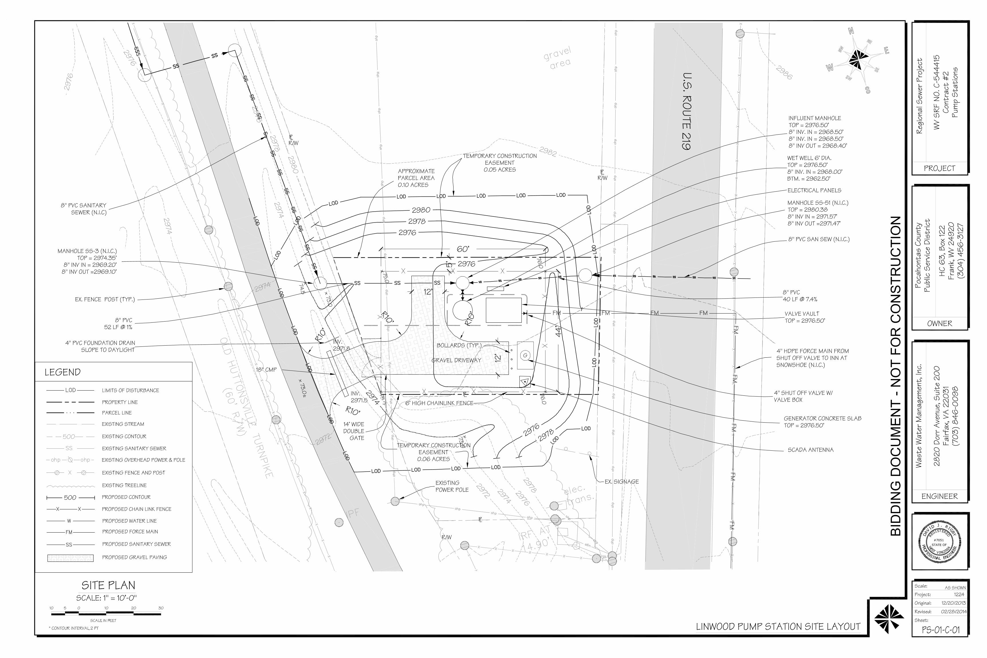
ATTACHMENT E
PLOT PLAN


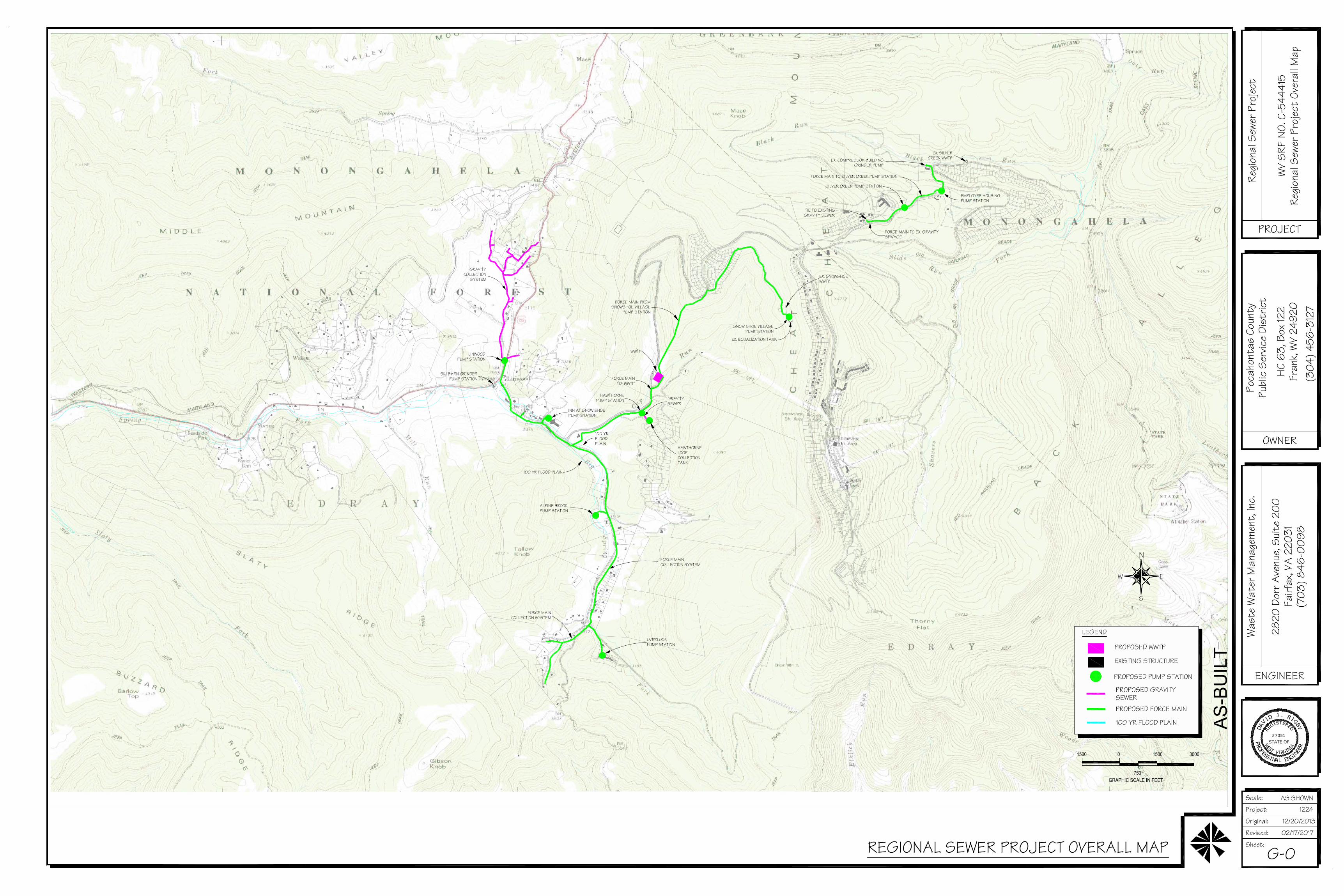
ATTACHMENT F
AREA MAP


ATTACHMENT G
EQUIPMENT DATA SHEETS AND
REGISTRATION SECTION APPLICABILITY FORM
G65-C 1 of 5 Emergency Generator
West Virginia Department of Environmental Protection • Division of Air Quality
G65-C REGISTRATION APPLICATION FORMS
Location 01 – Linwood Pump Station
G65-C 2 of 5 Emergency Generator
West Virginia Department of Environmental Protection • Division of Air Quality
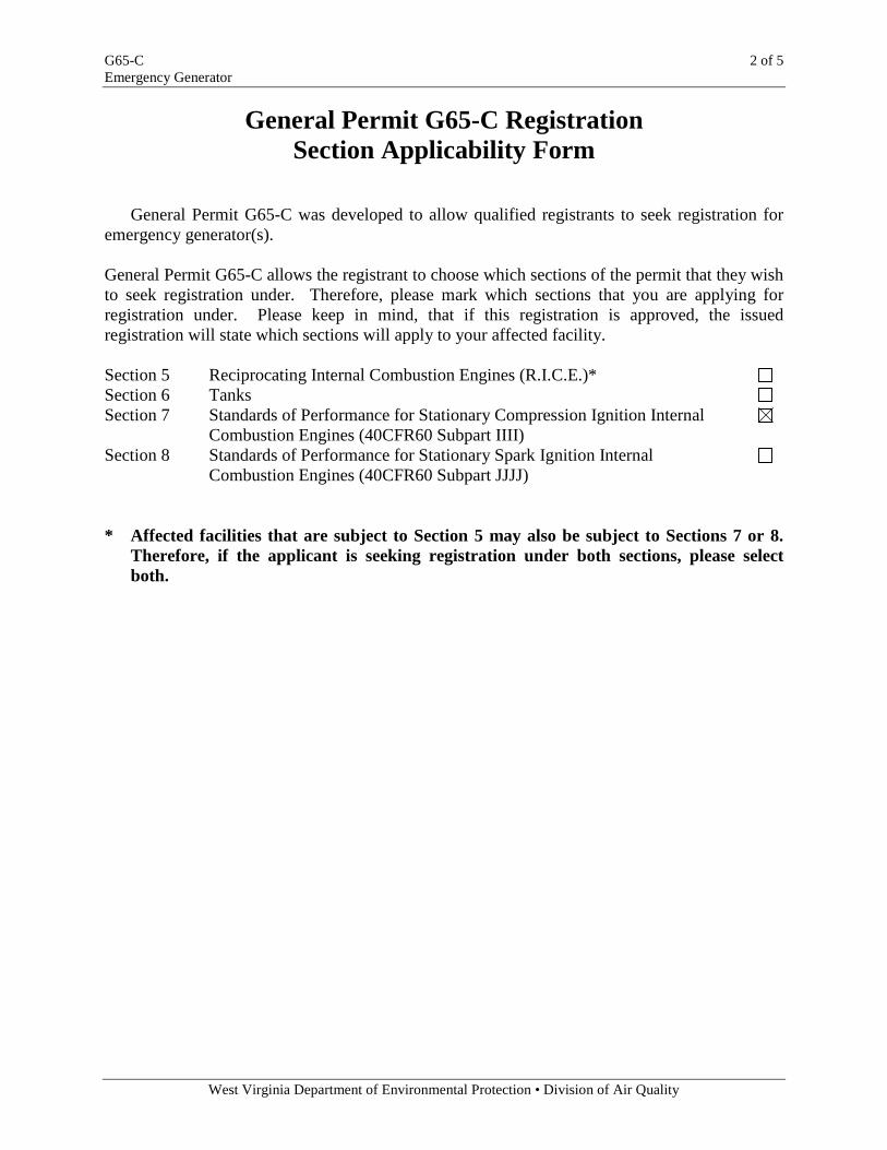
General Permit G65-C Registration Section Applicability Form
General Permit G65-C was developed to allow qualified registrants to seek registration for emergency generator(s).
General Permit G65-C allows the registrant to choose which sections of the permit that they wish to seek registration under. Therefore, please mark which sections that you are applying for registration under. Please keep in mind, that if this registration is approved, the issued registration will state which sections will apply to your affected facility. Section 5 Reciprocating Internal Combustion Engines (R.I.C.E.)* Section 6 Tanks Section 7 Standards of Performance for Stationary Compression Ignition Internal Combustion Engines (40CFR60 Subpart IIII) Section 8 Standards of Performance for Stationary Spark Ignition Internal Combustion Engines (40CFR60 Subpart JJJJ) * Affected facilities that are subject to Section 5 may also be subject to Sections 7 or 8.
Therefore, if the applicant is seeking registration under both sections, please select both.
G65-C 3 of 5 Emergency Generator
West Virginia Department of Environmental Protection • Division of Air Quality
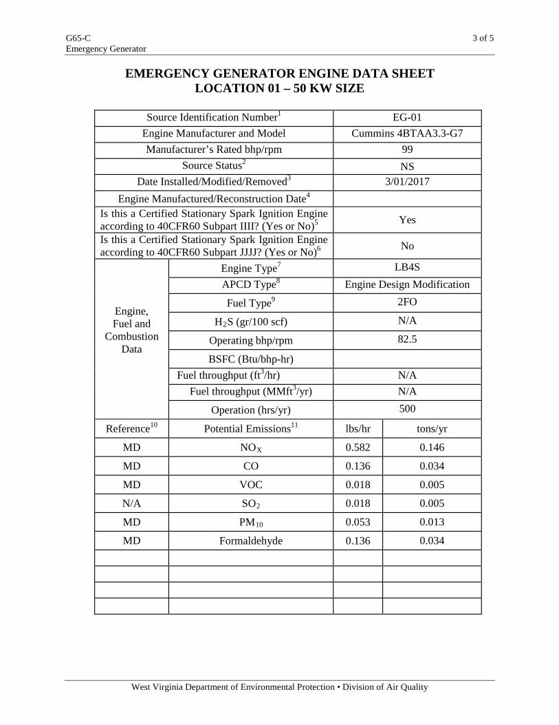
EMERGENCY GENERATOR ENGINE DATA SHEET LOCATION 01 – 50 KW SIZE
Source Identification Number1 EG-01
Engine Manufacturer and Model Cummins 4BTAA3.3-G7 Manufacturer’s Rated bhp/rpm 99
Source Status2 NS Date Installed/Modified/Removed3 3/01/2017
Engine Manufactured/Reconstruction Date4 Is this a Certified Stationary Spark Ignition Engine according to 40CFR60 Subpart IIII? (Yes or No)5 Yes
Is this a Certified Stationary Spark Ignition Engine according to 40CFR60 Subpart JJJJ? (Yes or No)6 No
Engine, Fuel and
Combustion Data
Engine Type7 LB4S APCD Type8 Engine Design Modification
Fuel Type9 2FO
H2S (gr/100 scf) N/A
Operating bhp/rpm 82.5
BSFC (Btu/bhp-hr)
Fuel throughput (ft3/hr) N/A Fuel throughput (MMft3/yr) N/A
Operation (hrs/yr) 500
Reference10
Potential Emissions11
lbs/hr
tons/yr
MD
NOX 0.582 0.146
MD
CO 0.136 0.034
MD
VOC 0.018 0.005
N/A
SO2 0.018 0.005
MD
PM10 0.053 0.013
MD
Formaldehyde 0.136 0.034
G65-C 4 of 5 Emergency Generator
West Virginia Department of Environmental Protection • Division of Air Quality
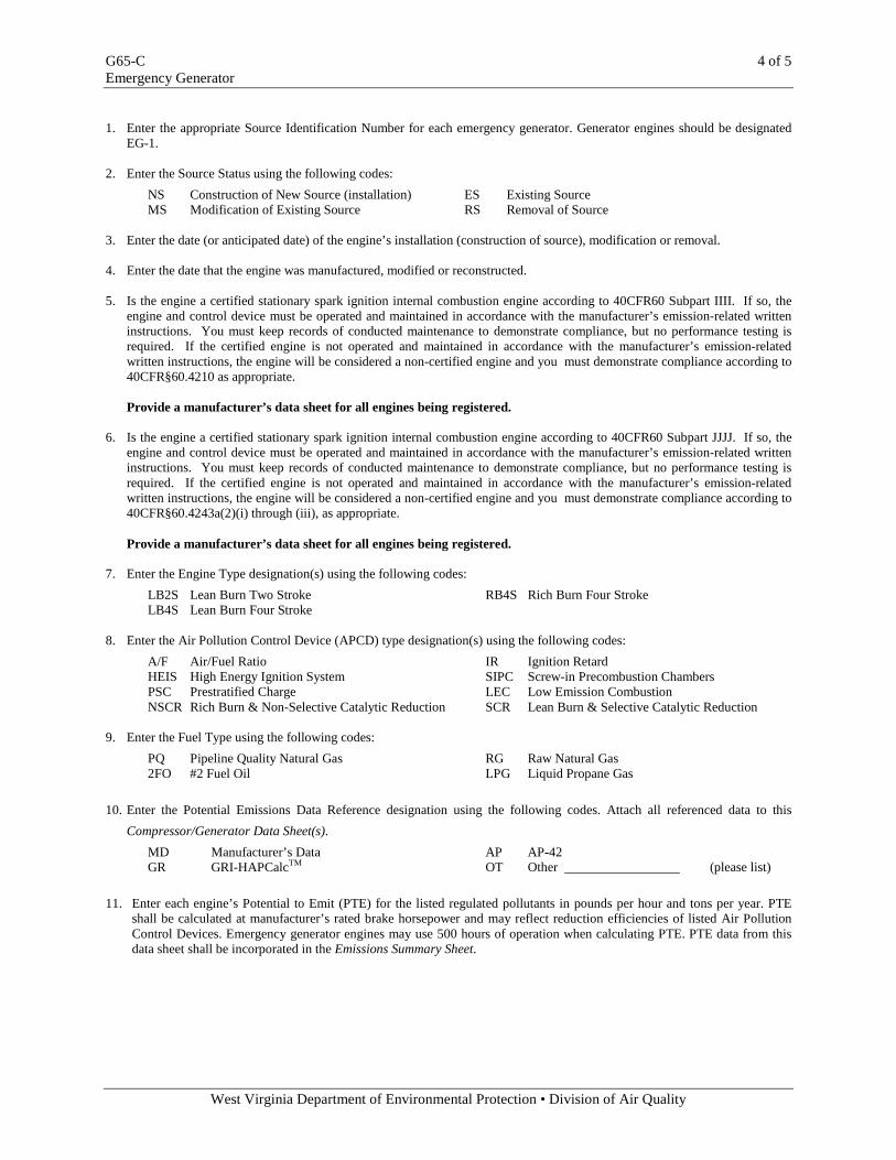
1. Enter the appropriate Source Identification Number for each emergency generator. Generator engines should be designated
EG-1. 2. Enter the Source Status using the following codes: NS Construction of New Source (installation) ES Existing Source MS Modification of Existing Source RS Removal of Source 3. Enter the date (or anticipated date) of the engine’s installation (construction of source), modification or removal. 4. Enter the date that the engine was manufactured, modified or reconstructed. 5. Is the engine a certified stationary spark ignition internal combustion engine according to 40CFR60 Subpart IIII. If so, the
engine and control device must be operated and maintained in accordance with the manufacturer’s emission-related written instructions. You must keep records of conducted maintenance to demonstrate compliance, but no performance testing is required. If the certified engine is not operated and maintained in accordance with the manufacturer’s emission-related written instructions, the engine will be considered a non-certified engine and you must demonstrate compliance according to 40CFR§60.4210 as appropriate.
Provide a manufacturer’s data sheet for all engines being registered. 6. Is the engine a certified stationary spark ignition internal combustion engine according to 40CFR60 Subpart JJJJ. If so, the
engine and control device must be operated and maintained in accordance with the manufacturer’s emission-related written instructions. You must keep records of conducted maintenance to demonstrate compliance, but no performance testing is required. If the certified engine is not operated and maintained in accordance with the manufacturer’s emission-related written instructions, the engine will be considered a non-certified engine and you must demonstrate compliance according to 40CFR§60.4243a(2)(i) through (iii), as appropriate.
Provide a manufacturer’s data sheet for all engines being registered. 7. Enter the Engine Type designation(s) using the following codes: LB2S Lean Burn Two Stroke RB4S Rich Burn Four Stroke LB4S Lean Burn Four Stroke 8. Enter the Air Pollution Control Device (APCD) type designation(s) using the following codes: A/F Air/Fuel Ratio IR Ignition Retard HEIS High Energy Ignition System SIPC Screw-in Precombustion Chambers PSC Prestratified Charge LEC Low Emission Combustion NSCR Rich Burn & Non-Selective Catalytic Reduction SCR Lean Burn & Selective Catalytic Reduction 9. Enter the Fuel Type using the following codes: PQ Pipeline Quality Natural Gas RG Raw Natural Gas 2FO #2 Fuel Oil LPG Liquid Propane Gas 10. Enter the Potential Emissions Data Reference designation using the following codes. Attach all referenced data to this
Compressor/Generator Data Sheet(s). MD Manufacturer’s Data AP AP-42 GR GRI-HAPCalcTM OT Other (please list) 11. Enter each engine’s Potential to Emit (PTE) for the listed regulated pollutants in pounds per hour and tons per year. PTE
shall be calculated at manufacturer’s rated brake horsepower and may reflect reduction efficiencies of listed Air Pollution Control Devices. Emergency generator engines may use 500 hours of operation when calculating PTE. PTE data from this data sheet shall be incorporated in the Emissions Summary Sheet.
power.cummins.com ©2015 Cummins Power Generation Inc. | NAS-5873b-EN (10/15)
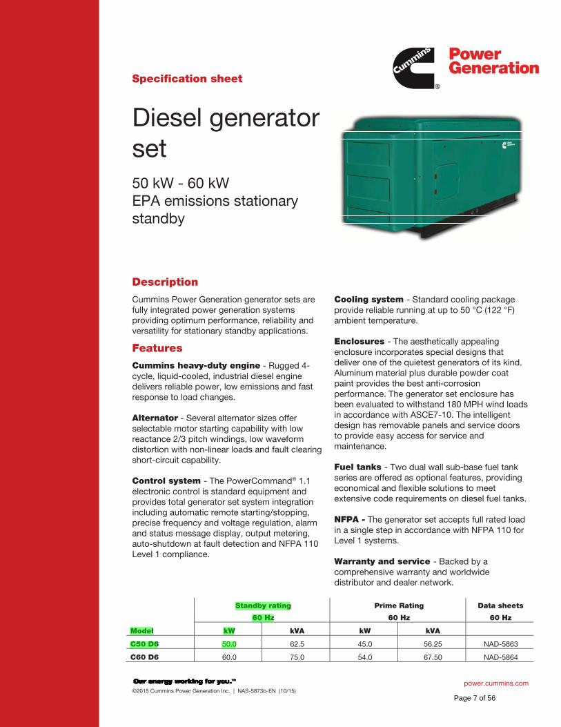
Specification sheet
Diesel generator set 50 kW - 60 kW EPA emissions stationary standby
Description
Cummins Power Generation generator sets are fully integrated power generation systems providing optimum performance, reliability and versatility for stationary standby applications.
Features Cummins heavy-duty engine - Rugged 4-cycle, liquid-cooled, industrial diesel engine delivers reliable power, low emissions and fast response to load changes. Alternator - Several alternator sizes offer selectable motor starting capability with low reactance 2/3 pitch windings, low waveform distortion with non-linear loads and fault clearing short-circuit capability. Control system - The PowerCommand® 1.1 electronic control is standard equipment and provides total generator set system integration including automatic remote starting/stopping, precise frequency and voltage regulation, alarm and status message display, output metering, auto-shutdown at fault detection and NFPA 110 Level 1 compliance.
Cooling system - Standard cooling package provide reliable running at up to 50 °C (122 °F) ambient temperature. Enclosures - The aesthetically appealing enclosure incorporates special designs that deliver one of the quietest generators of its kind. Aluminum material plus durable powder coat paint provides the best anti-corrosion performance. The generator set enclosure has been evaluated to withstand 180 MPH wind loads in accordance with ASCE7-10. The intelligent design has removable panels and service doors to provide easy access for service and maintenance. Fuel tanks - Two dual wall sub-base fuel tank series are offered as optional features, providing economical and flexible solutions to meet extensive code requirements on diesel fuel tanks. NFPA - The generator set accepts full rated load in a single step in accordance with NFPA 110 for Level 1 systems. Warranty and service - Backed by a comprehensive warranty and worldwide distributor and dealer network.
Standby rating Prime Rating Data sheets
60 Hz 60 Hz 60 Hz
Model kW kVA kW kVA
C50 D6 50.0 62.5 45.0 56.25 NAD-5863
C60 D6 60.0 75.0 54.0 67.50 NAD-5864
Page 7 of 56
power.cummins.com ©2015 Cummins Power Generation Inc. | NAS-5873b-EN (10/15)
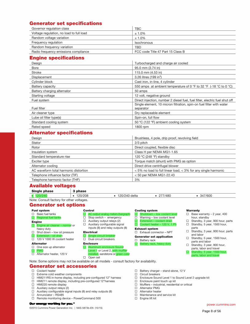
Generator set specifications Governor regulation class TBC
Voltage regulation, no load to full load ± 1.0%
Random voltage variation ± 1.0%
Frequency regulation Isochronous
Random frequency variation TBD
Radio frequency emissions compliance FCC code Title 47 Part 15 Class B
Engine specifications Design Turbocharged and charge air cooled
Bore 95.0 mm (3.74 in)
Stroke 115.0 mm (4.53 in)
Displacement 3.26 litres (199 in3)
Cylinder block Cast iron, in-line, 4 cylinder
Battery capacity 550 amps at ambient temperature of 0 °F to 32 °F (-18 °C to 0 °C)
Battery charging alternator 50 amps
Starting voltage 12 volt, negative ground
Fuel system Direct injection, number 2 diesel fuel, fuel filter, electric fuel shut off
Fuel filter Single element, 10 micron filtration, spin-on fuel filter with water separator
Air cleaner type Dry replaceable element
Lube oil filter type(s) Spin-on, full flow
Standard cooling system 50 ºC (122 ºF) ambient cooling system
Rated speed 1800 rpm
Alternator specifications Design Brushless, 4 pole, drip proof, revolving field
Stator 2/3 pitch
Rotor Direct coupled, flexible disc
Insulation system Class H per NEMA MG1-1.65
Standard temperature rise 120 ºC (248 °F) standby
Exciter type Torque match (shunt) with PMG as option
Alternator cooling Direct drive centrifugal blower
AC waveform total harmonic distortion < 5% no load to full linear load, < 3% for any single harmonic
Telephone influence factor (TIF) < 50 per NEMA MG1-22.43
Telephone harmonic factor (THF) 3%
Available voltages Single phase 3 phase
120/240 120/208 120/240 delta 277/480 347/600
Note: Consult factory for other voltages.
Generator set options Fuel system
Basic fuel tanks Regional fuel tanks
Engine Engine air cleaner – normal or heavy duty Shut down – low oil pressure Extension – oil drain 120 V 1000 W coolant heater
Alternator One size up alternator PMG Alternator heater, 120 V
Control AC output analog meters (bargraph) Stop switch – emergency Auxiliary output relays (2) Auxiliary configurable signal inputs (8) and relay outputs (8)
Electrical Single circuit breaker Dual circuit breakers
Enclosure Aluminum enclosure Sound Level 1 or Level 2, with muffler installed, sandstone or green color Open set
Cooling system Shutdown – low coolant level Warning – low coolant level Extension – coolant drain Coolant heater – 120 V, 1 Ph
Exhaust system Exhaust connector – NPT
Generator set application Battery rack Battery rack, heavy duty
Warranty Base warranty – 2 year, 400 hour, standby Standby, 3 year, 900 hour, parts Standby, 5 year, 1500 hour, parts Standby, 3 year, 900 hour, parts and labor Standby, 5 year, 1500 hour, parts and labor Standby, 3 year, 900 hour, parts, labor and travel Standby, 5 year, 1500 hour, parts, labor and travel
Note: Some options may not be available on all models - consult factory for availability.
Generator set accessories Coolant heater Extreme cold weather components HMI211RS in-home display, including pre-configured 12” harness HMI211 remote display, including pre-configured 12”harness HMI220 remote display Auxiliary output relays (2) Auxiliary configurable signal inputs (8) and relay outputs (8) Annunciator – RS485 Remote monitoring device – PowerCommand 500
Battery charger – stand-alone, 12 V Circuit breakers Enclosure Sound Level 1 to Sound Level 2 upgrade kit Enclosure paint touch up kit Mufflers – industrial, residential or critical Alternator PMG Alternator heater Maintenance and service kit Engine lift kit
Page 8 of 56
power.cummins.com ©2015 Cummins Power Generation Inc. | NAS-5873b-EN (10/15)
Various fuel tanks and accessories
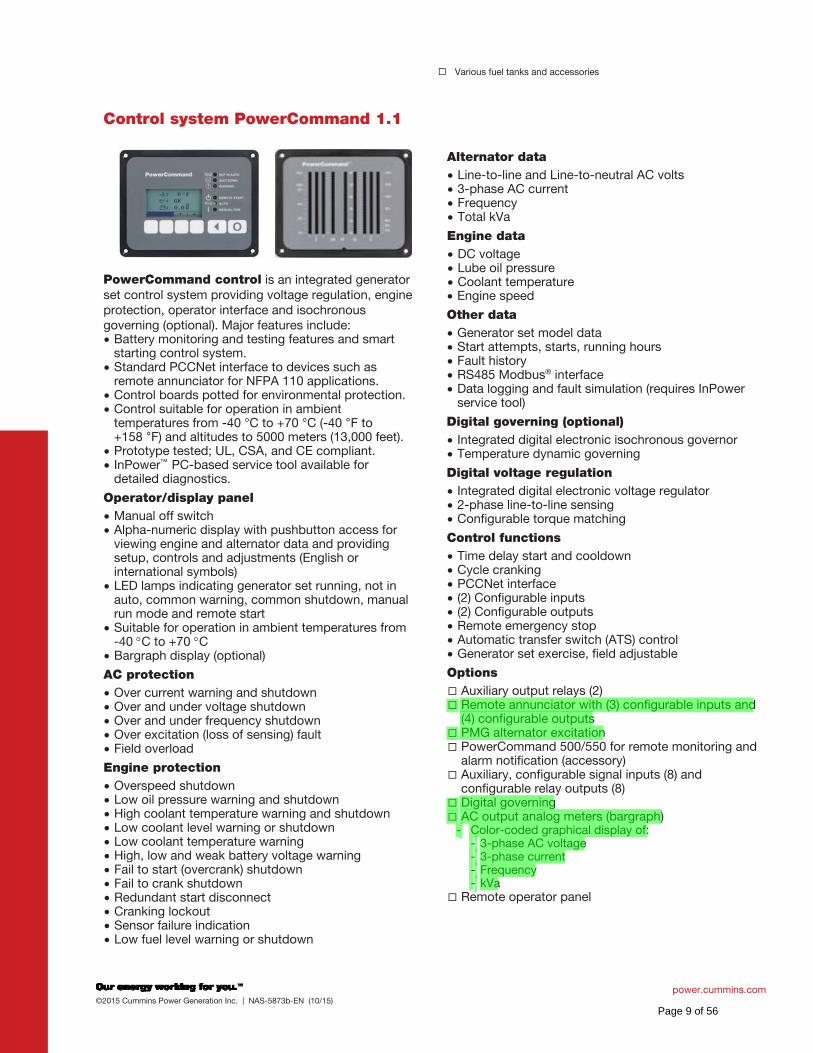
Control system PowerCommand 1.1
PowerCommand control is an integrated generator set control system providing voltage regulation, engine protection, operator interface and isochronous governing (optional). Major features include:
Battery monitoring and testing features and smart starting control system. Standard PCCNet interface to devices such as remote annunciator for NFPA 110 applications. Control boards potted for environmental protection. Control suitable for operation in ambient temperatures from -40 °C to +70 °C (-40 F to +158 F) and altitudes to 5000 meters (13,000 feet). Prototype tested; UL, CSA, and CE compliant. InPower™ PC-based service tool available for detailed diagnostics.
Operator/display panel
Manual off switch Alpha-numeric display with pushbutton access for viewing engine and alternator data and providing setup, controls and adjustments (English or international symbols) LED lamps indicating generator set running, not in auto, common warning, common shutdown, manual run mode and remote start Suitable for operation in ambient temperatures from -40 C to +70 C Bargraph display (optional)
AC protection
Over current warning and shutdown Over and under voltage shutdown Over and under frequency shutdown Over excitation (loss of sensing) fault Field overload
Engine protection
Overspeed shutdown Low oil pressure warning and shutdown High coolant temperature warning and shutdown Low coolant level warning or shutdown Low coolant temperature warning High, low and weak battery voltage warning Fail to start (overcrank) shutdown Fail to crank shutdown Redundant start disconnect Cranking lockout Sensor failure indication Low fuel level warning or shutdown
Alternator data
Line-to-line and Line-to-neutral AC volts 3-phase AC current Frequency Total kVa
Engine data
DC voltage Lube oil pressure Coolant temperature Engine speed
Other data
Generator set model data Start attempts, starts, running hours Fault history RS485 Modbus® interface Data logging and fault simulation (requires InPower service tool)
Digital governing (optional)
Integrated digital electronic isochronous governor Temperature dynamic governing
Digital voltage regulation
Integrated digital electronic voltage regulator 2-phase line-to-line sensing Configurable torque matching
Control functions
Time delay start and cooldown Cycle cranking PCCNet interface (2) Configurable inputs (2) Configurable outputs Remote emergency stop Automatic transfer switch (ATS) control Generator set exercise, field adjustable
Options
Auxiliary output relays (2) Remote annunciator with (3) configurable inputs and (4) configurable outputs PMG alternator excitation PowerCommand 500/550 for remote monitoring and alarm notification (accessory) Auxiliary, configurable signal inputs (8) and configurable relay outputs (8) Digital governing AC output analog meters (bargraph)
- Color-coded graphical display of: - 3-phase AC voltage - 3-phase current - Frequency - kVa
Remote operator panel
Page 9 of 56
North America 1400 73rd Avenue N.E. Minneapolis, MN 55432 USA
Phone 763 574 5000
Fax 763 574 5298
©2015 Cummins Power Generation Inc. All rights reserved.
Cummins Power Generation and Cummins are registered trademarks of Cummins Inc. PowerCommand, AmpSentry, InPower
and “Our energy working for you.” are trademarks of Cummins Power Generation. Other company, product, or service names
may be trademarks or service marks of others. Specifications are subject to change without notice.
NAS-5873b-EN (10/15)
power.cummins.com
Ratings definitions Emergency standby power (ESP): Applicable for supplying power to varying electrical load for the duration of power interruption of a reliable utility source. Emergency Standby Power (ESP) is in accordance with ISO 8528. Fuel Stop power in accordance with ISO 3046, AS 2789, DIN 6271 and BS 5514.
Limited-time running power (LTP): Applicable for supplying power to a constant electrical load for limited hours. Limited Time Running Power (LTP) is in accordance with ISO 8528.
Prime power (PRP): Applicable for supplying power to varying electrical load for unlimited hours. Prime Power (PRP) is in accordance with ISO 8528. Ten percent overload capability is available in accordance with ISO 3046, AS 2789, DIN 6271 and BS 5514.
Base load (continuous) power (COP): Applicable for supplying power continuously to a constant electrical load for unlimited hours. Continuous Power (COP) in accordance with ISO 8528, ISO 3046, AS 2789, DIN 6271 and BS 5514.
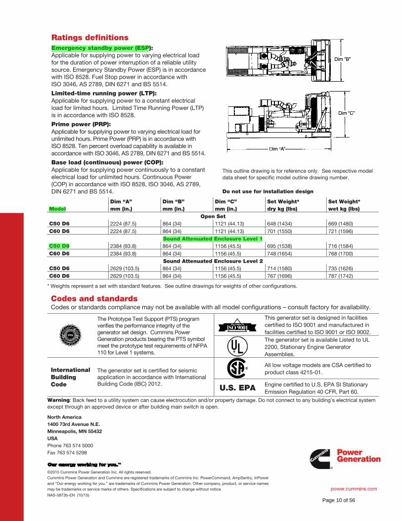
This outline drawing is for reference only. See respective model
data sheet for specific model outline drawing number.
Do not use for installation design
Model
Dim “A”
mm (in.)
Dim “B”
mm (in.)
Dim “C”
mm (in.)
Set Weight*
dry kg (lbs)
Set Weight*
wet kg (lbs)
Open Set
C50 D6 2224 (87.5) 864 (34) 1121 (44.13) 648 (1434) 669 (1480)
C60 D6 2224 (87.5) 864 (34) 1121 (44.13) 701 (1550) 721 (1596)
Sound Attenuated Enclosure Level 1
C50 D6 2384 (93.8) 864 (34) 1156 (45.5) 695 (1538) 716 (1584)
C60 D6 2384 (93.8) 864 (34) 1156 (45.5) 748 (1654) 768 (1700)
Sound Attenuated Enclosure Level 2
C50 D6 2629 (103.5) 864 (34) 1156 (45.5) 714 (1580) 735 (1626)
C60 D6 2629 (103.5) 864 (34) 1156 (45.5) 767 (1696) 787 (1742)
* Weights represent a set with standard features. See outline drawings for weights of other configurations.
Codes and standards
Codes or standards compliance may not be available with all model configurations – consult factory for availability.
The Prototype Test Support (PTS) program verifies the performance integrity of the generator set design. Cummins Power Generation products bearing the PTS symbol meet the prototype test requirements of NFPA 110 for Level 1 systems.
This generator set is designed in facilities
certified to ISO 9001 and manufactured in
facilities certified to ISO 9001 or ISO 9002.
The generator set is available Listed to UL
2200, Stationary Engine Generator
Assemblies.
International Building Code
The generator set is certified for seismic application in accordance with International Building Code (IBC) 2012.
All low voltage models are CSA certified to
product class 4215-01.
U.S. EPA Engine certified to U.S. EPA SI Stationary
Emission Regulation 40 CFR, Part 60.
Warning: Back feed to a utility system can cause electrocution and/or property damage. Do not connect to any building’s electrical system
except through an approved device or after building main switch is open.
Page 10 of 56
cumminspower.com ©2014 Cummins Power Generation Inc. | NAD-5864b-EN (2/16)
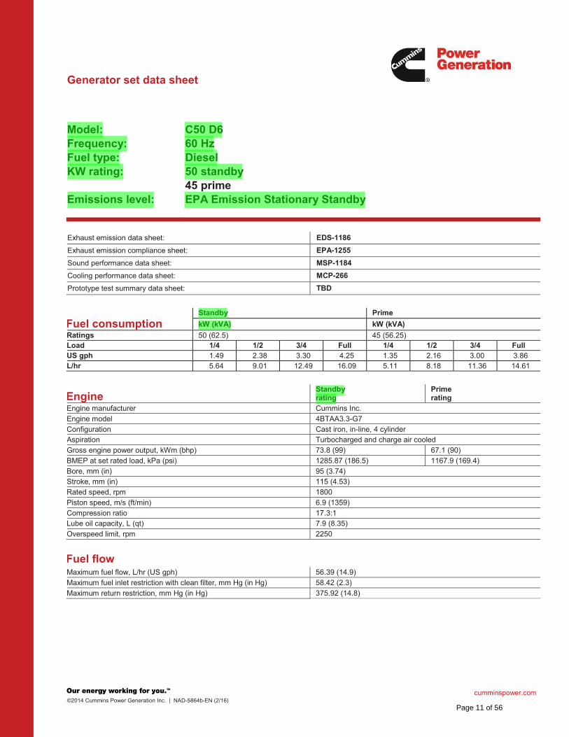
Generator set data sheet
Model: Frequency: Fuel type: KW rating: Emissions level:
C50 D6 60 Hz Diesel 50 standby 45 prime EPA Emission Stationary Standby
Exhaust emission data sheet: EDS-1186
Exhaust emission compliance sheet: EPA-1255
Sound performance data sheet: MSP-1184
Cooling performance data sheet: MCP-266
Prototype test summary data sheet: TBD
Fuel consumption Standby Prime
kW (kVA) kW (kVA)
Ratings 50 (62.5) 45 (56.25) Load 1/4 1/2 3/4 Full 1/4 1/2 3/4 Full US gph 1.49 2.38 3.30 4.25 1.35 2.16 3.00 3.86 L/hr 5.64 9.01 12.49 16.09 5.11 8.18 11.36 14.61
Engine Standby rating
Prime rating
Engine manufacturer Cummins Inc.
Engine model 4BTAA3.3-G7
Configuration Cast iron, in-line, 4 cylinder Aspiration Turbocharged and charge air cooled
Gross engine power output, kWm (bhp) 73.8 (99) 67.1 (90)
BMEP at set rated load, kPa (psi) 1285.87 (186.5) 1167.9 (169.4)
Bore, mm (in) 95 (3.74) Stroke, mm (in) 115 (4.53)
Rated speed, rpm 1800
Piston speed, m/s (ft/min) 6.9 (1359)
Compression ratio 17.3:1 Lube oil capacity, L (qt) 7.9 (8.35)
Overspeed limit, rpm 2250
Fuel flow Maximum fuel flow, L/hr (US gph) 56.39 (14.9)
Maximum fuel inlet restriction with clean filter, mm Hg (in Hg) 58.42 (2.3)
Maximum return restriction, mm Hg (in Hg) 375.92 (14.8)
Page 11 of 56
cumminspower.com ©2014 Cummins Power Generation Inc. | NAD-5864b-EN (2/16)
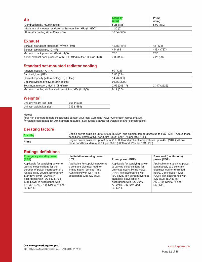
Air Standbyrating
Prime rating
Combustion air, m3/min (scfm) 5.26 (186) 5.09 (180)
Maximum air cleaner restriction with clean filter, kPa (in H2O) 1.25 (5)
Alternator cooling air, m3/min (cfm) 16.84 (595)
Exhaust
Exhaust flow at set rated load, m3/min (cfm) 12.85 (454) 12 (424)
Exhaust temperature, C ( F) 444 (831) 419.4 (787)
Maximum back pressure, kPa (in H2O) TBD TBD
Actual exhaust back pressure with CPG fitted muffler, kPa (in H2O) 7.8 (31.3) 7.23 (29)
Standard set-mounted radiator cooling
Ambient design, C ( F) 50 (122)
Fan load, kWm (HP) 2.83 (3.8)
Coolant capacity (with radiator), L (US Gal) 14.76 (3.9)
Cooling system air flow, m3/min (scfm) 93.16 (3290)
Total heat rejection, MJ/min (Btu/min) 2.56 (2431.7) 2.347 (2225)
Maximum cooling air flow static restriction, kPa (in H2O) 0.12 (0.5)
Weights2
Unit dry weight kgs (lbs) 698 (1538)
Unit wet weight kgs (lbs) 719 (1584)
Notes: 1 For non-standard remote installations contact your local Cummins Power Generation representative. 2 Weights represent a set with standard features. See outline drawing for weights of other configurations.
Derating factors
Standby Engine power available up to 1600m (5,512ft) and ambient temperatures up to 50C (122F). Above these conditions, derate at 6% per 300m (985ft) and 10% per 10C (18F).
Prime Engine power available up to 3050m (10,000ft) and ambient temperatures up to 40C (104F). Above these conditions, derate at 6% per 300m (985ft) and 11% per 10C (18F).
Ratings definitions
Emergency standby power (ESP):
Limited-time running power (LTP): Prime power (PRP):
Base load (continuous) power (COP):
Applicable for supplying power to varying electrical load for the duration of power interruption of a reliable utility source. Emergency Standby Power (ESP) is in accordance with ISO 8528. Fuel Stop power in accordance with ISO 3046, AS 2789, DIN 6271 and BS 5514.
Applicable for supplying power to a constant electrical load for limited hours. Limited Time Running Power (LTP) is in accordance with ISO 8528.
Applicable for supplying power to varying electrical load for unlimited hours. Prime Power (PRP) is in accordance with ISO 8528. Ten percent overload capability is available in accordance with ISO 3046, AS 2789, DIN 6271 and BS 5514.
Applicable for supplying power continuously to a constant electrical load for unlimited hours. Continuous Power (COP) is in accordance with ISO 8528, ISO 3046, AS 2789, DIN 6271 and BS 5514.
Page 12 of 56
North America 1400 73rd Avenue N.E. Minneapolis, MN 55432 USA
Phone 763 574 5000 Fax 763 574 5298
©2014 Cummins Power Generation Inc. All rights reserved. Cummins Power Generation and Cummins are registered trademarks of Cummins Inc. PowerCommand, AmpSentry, InPower and “Our energy working for you.” are trademarks of Cummins Power Generation. Other company, product, or service names may be trademarks or service marks of others. Specifications are subject to change without notice.
NAD-5864b-EN (2/16)
cumminspower.com
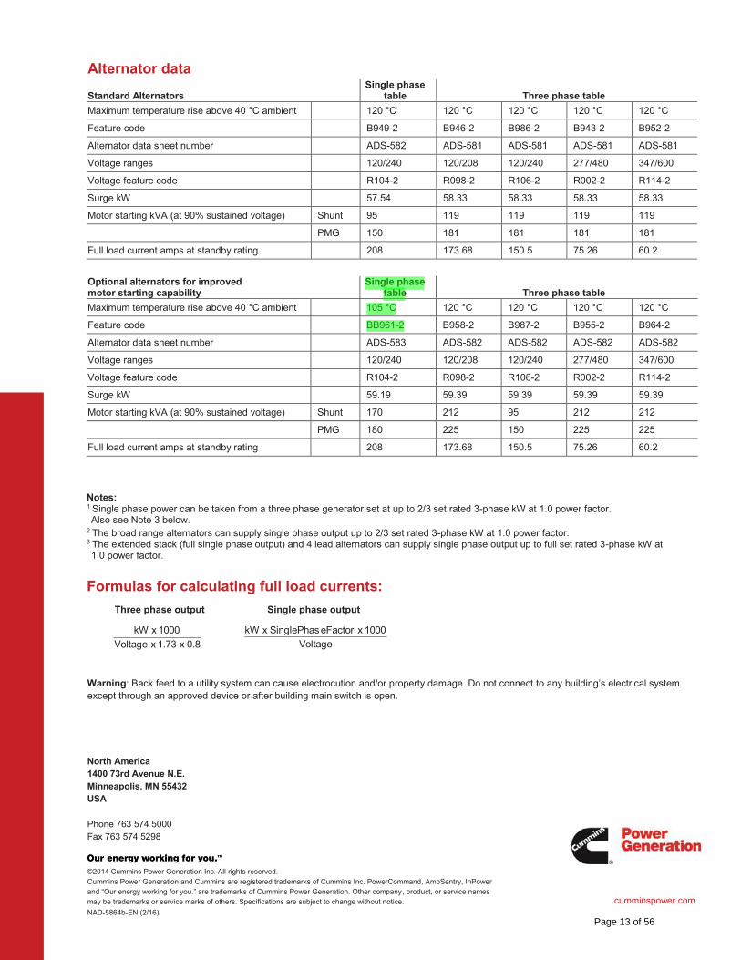
Alternator data
Standard Alternators Single phase
table Three phase table
Maximum temperature rise above 40 °C ambient 120 °C 120 °C 120 °C 120 °C 120 °C
Feature code B949-2 B946-2 B986-2 B943-2 B952-2
Alternator data sheet number ADS-582 ADS-581 ADS-581 ADS-581 ADS-581
Voltage ranges 120/240 120/208 120/240 277/480 347/600
Voltage feature code R104-2 R098-2 R106-2 R002-2 R114-2
Surge kW 57.54 58.33 58.33 58.33 58.33
Motor starting kVA (at 90% sustained voltage) Shunt 95 119 119 119 119
PMG 150 181 181 181 181
Full load current amps at standby rating 208 173.68 150.5 75.26 60.2
Optional alternators for improved motor starting capability
Single phase table Three phase table
Maximum temperature rise above 40 °C ambient 105 °C 120 °C 120 °C 120 °C 120 °C
Feature code BB961-2 B958-2 B987-2 B955-2 B964-2
Alternator data sheet number ADS-583 ADS-582 ADS-582 ADS-582 ADS-582
Voltage ranges 120/240 120/208 120/240 277/480 347/600
Voltage feature code R104-2 R098-2 R106-2 R002-2 R114-2
Surge kW 59.19 59.39 59.39 59.39 59.39
Motor starting kVA (at 90% sustained voltage) Shunt 170 212 95 212 212
PMG 180 225 150 225 225
Full load current amps at standby rating 208 173.68 150.5 75.26 60.2
Notes: 1 Single phase power can be taken from a three phase generator set at up to 2/3 set rated 3-phase kW at 1.0 power factor. Also see Note 3 below.
2 The broad range alternators can supply single phase output up to 2/3 set rated 3-phase kW at 1.0 power factor. 3 The extended stack (full single phase output) and 4 lead alternators can supply single phase output up to full set rated 3-phase kW at 1.0 power factor.
Formulas for calculating full load currents:
Three phase output Single phase output
Warning: Back feed to a utility system can cause electrocution and/or property damage. Do not connect to any building’s electrical system except through an approved device or after building main switch is open.
Voltage
1000 x eFactorSinglePhas x kW
0.8 x 1.73 x Voltage
1000 x kW
Page 13 of 56
Our energy working for you.™
www.cumminspower.com
2014 Cummins Power Generation Inc. All rights reserved. Cummins Power Generation and Cummins are registered trademarks of Cummins Inc. PowerCommand, InPower and “Our energy working for you.” are trademarks of Cummins Power Generation. Other company, product, or service names may be trademarks or service marks of others. Specifications are subject to change without notice. S-1566d (1/14) Page 1 of 7
PowerCommand®
1.1 control system
Control system description
Features
The PowerCommand® control system is a microprocessor-based generator set monitoring, metering and control system designed to meet the demands of today’s engine driven generator sets. The integration of all control functions into a single control system provides enhanced reliability and performance compared to conventional generator set control systems. These control systems have been designed and tested to meet the harsh environment in which gensets are typically applied.
Easy to view: HMI 211RS for residential use. 128x64 pixel graphic LED backlight LCD.
Easy to use: Tactile buttons for generator set start/stop. Residential standby display for convenient use.
Modbus interface: Eliminates need for MODLON.
Progressive protective functions: Advanced Overcurrent Protection – Generator set monitoring & protection.
Digital voltage regulation: Single phase full wave SCR type regulator compatible with either shunt or PMSG systems.
Digital engine speed governing: Provides isochronous frequency regulation.
12 and 24 VDC battery operation.
Automatic mains failure: Smooth & automatic transfer and re-transfer of load from utility to generator set & vice-versa.
Exerciser clock: Runs generator set exerciser routines for dependability of operation.
Warranty and service: Backed by a comprehensive warranty and worldwide distributor service network.
Certification: Suitable for us on generator sets that are designed, manufactured, tested and certified to relevant UL, NFPA, ISO, IEC Mil Std., CE and CSA standards.
Page 14 of 56
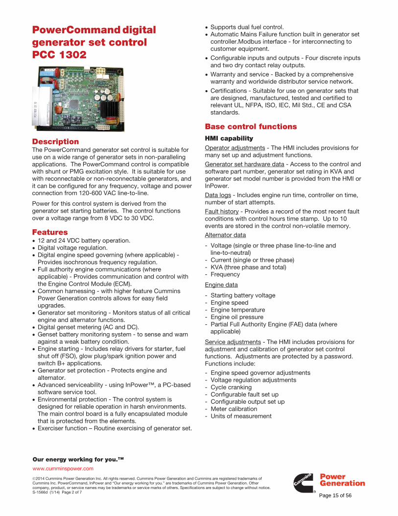
Our energy working for you.™
www.cumminspower.com
2014 Cummins Power Generation Inc. All rights reserved. Cummins Power Generation and Cummins are registered trademarks of Cummins Inc. PowerCommand, InPower and “Our energy working for you.” are trademarks of Cummins Power Generation. Other company, product, or service names may be trademarks or service marks of others. Specifications are subject to change without notice. S-1566d (1/14) Page 2 of 7
PowerCommand digital generator set control PCC 1302
Description The PowerCommand generator set control is suitable for use on a wide range of generator sets in non-paralleling applications. The PowerCommand control is compatible with shunt or PMG excitation style. It is suitable for use with reconnectable or non-reconnectable generators, and it can be configured for any frequency, voltage and power connection from 120-600 VAC line-to-line.
Power for this control system is derived from the generator set starting batteries. The control functions over a voltage range from 8 VDC to 30 VDC.
Features 12 and 24 VDC battery operation. Digital voltage regulation. Digital engine speed governing (where applicable) - Provides isochronous frequency regulation.
Full authority engine communications (where applicable) - Provides communication and control with the Engine Control Module (ECM).
Common harnessing - with higher feature Cummins Power Generation controls allows for easy field upgrades.
Generator set monitoring - Monitors status of all critical engine and alternator functions.
Digital genset metering (AC and DC). Genset battery monitoring system - to sense and warn against a weak battery condition.
Engine starting - Includes relay drivers for starter, fuel shut off (FSO), glow plug/spark ignition power and switch B+ applications.
Generator set protection - Protects engine and alternator.
Advanced serviceability - using InPower™, a PC-based software service tool.
Environmental protection - The control system is designed for reliable operation in harsh environments. The main control board is a fully encapsulated module that is protected from the elements.
Exerciser function – Routine exercising of generator set.
Supports dual fuel control. Automatic Mains Failure function built in generator set controller.Modbus interface - for interconnecting to customer equipment.
Configurable inputs and outputs - Four discrete inputs and two dry contact relay outputs.
Warranty and service - Backed by a comprehensive warranty and worldwide distributor service network.
Certifications - Suitable for use on generator sets that are designed, manufactured, tested and certified to relevant UL, NFPA, ISO, IEC, Mil Std., CE and CSA standards.
Base control functions HMI capability Operator adjustments - The HMI includes provisions for many set up and adjustment functions. Generator set hardware data - Access to the control and software part number, generator set rating in KVA and generator set model number is provided from the HMI or InPower.
Data logs - Includes engine run time, controller on time, number of start attempts.
Fault history - Provides a record of the most recent fault conditions with control hours time stamp. Up to 10 events are stored in the control non-volatile memory.
Alternator data
- Voltage (single or three phase line-to-line and line-to-neutral)
- Current (single or three phase) - KVA (three phase and total) - Frequency
Engine data
- Starting battery voltage - Engine speed - Engine temperature - Engine oil pressure - Partial Full Authority Engine (FAE) data (where
applicable)
Service adjustments - The HMI includes provisions for adjustment and calibration of generator set control functions. Adjustments are protected by a password. Functions include:
- Engine speed governor adjustments - Voltage regulation adjustments - Cycle cranking - Configurable fault set up - Configurable output set up - Meter calibration - Units of measurement
Page 15 of 56
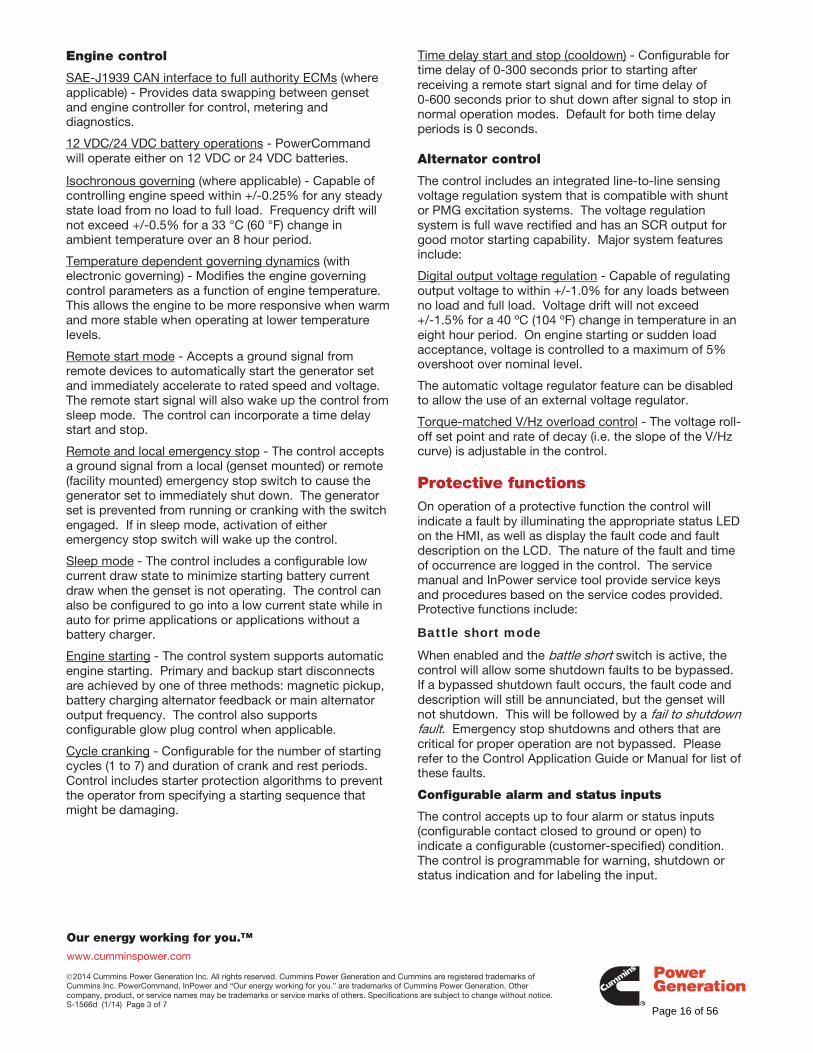
Our energy working for you.™
www.cumminspower.com
2014 Cummins Power Generation Inc. All rights reserved. Cummins Power Generation and Cummins are registered trademarks of Cummins Inc. PowerCommand, InPower and “Our energy working for you.” are trademarks of Cummins Power Generation. Other company, product, or service names may be trademarks or service marks of others. Specifications are subject to change without notice. S-1566d (1/14) Page 3 of 7
Engine control
SAE-J1939 CAN interface to full authority ECMs (where applicable) - Provides data swapping between genset and engine controller for control, metering and diagnostics.
12 VDC/24 VDC battery operations - PowerCommand will operate either on 12 VDC or 24 VDC batteries. Isochronous governing (where applicable) - Capable of controlling engine speed within +/-0.25% for any steady state load from no load to full load. Frequency drift will not exceed +/-0.5% for a 33 °C (60 °F) change in ambient temperature over an 8 hour period.
Temperature dependent governing dynamics (with electronic governing) - Modifies the engine governing control parameters as a function of engine temperature. This allows the engine to be more responsive when warm and more stable when operating at lower temperature levels.
Remote start mode - Accepts a ground signal from remote devices to automatically start the generator set and immediately accelerate to rated speed and voltage. The remote start signal will also wake up the control from sleep mode. The control can incorporate a time delay start and stop.
Remote and local emergency stop - The control accepts a ground signal from a local (genset mounted) or remote (facility mounted) emergency stop switch to cause the generator set to immediately shut down. The generator set is prevented from running or cranking with the switch engaged. If in sleep mode, activation of either emergency stop switch will wake up the control.
Sleep mode - The control includes a configurable low current draw state to minimize starting battery current draw when the genset is not operating. The control can also be configured to go into a low current state while in auto for prime applications or applications without a battery charger.
Engine starting - The control system supports automatic engine starting. Primary and backup start disconnects are achieved by one of three methods: magnetic pickup, battery charging alternator feedback or main alternator output frequency. The control also supports configurable glow plug control when applicable.
Cycle cranking - Configurable for the number of starting cycles (1 to 7) and duration of crank and rest periods. Control includes starter protection algorithms to prevent the operator from specifying a starting sequence that might be damaging.
Time delay start and stop (cooldown) - Configurable for time delay of 0-300 seconds prior to starting after receiving a remote start signal and for time delay of 0-600 seconds prior to shut down after signal to stop in normal operation modes. Default for both time delay periods is 0 seconds.
Alternator control
The control includes an integrated line-to-line sensing voltage regulation system that is compatible with shunt or PMG excitation systems. The voltage regulation system is full wave rectified and has an SCR output for good motor starting capability. Major system features include:
Digital output voltage regulation - Capable of regulating output voltage to within +/-1.0% for any loads between no load and full load. Voltage drift will not exceed +/-1.5% for a 40 ºC (104 ºF) change in temperature in an eight hour period. On engine starting or sudden load acceptance, voltage is controlled to a maximum of 5% overshoot over nominal level.
The automatic voltage regulator feature can be disabled to allow the use of an external voltage regulator.
Torque-matched V/Hz overload control - The voltage roll-off set point and rate of decay (i.e. the slope of the V/Hz curve) is adjustable in the control.
Protective functions On operation of a protective function the control will indicate a fault by illuminating the appropriate status LED on the HMI, as well as display the fault code and fault description on the LCD. The nature of the fault and time of occurrence are logged in the control. The service manual and InPower service tool provide service keys and procedures based on the service codes provided. Protective functions include:
Battle short mode
When enabled and the battle short switch is active, the control will allow some shutdown faults to be bypassed. If a bypassed shutdown fault occurs, the fault code and description will still be annunciated, but the genset will not shutdown. This will be followed by a fail to shutdown fault. Emergency stop shutdowns and others that are critical for proper operation are not bypassed. Please refer to the Control Application Guide or Manual for list of these faults.
Configurable alarm and status inputs
The control accepts up to four alarm or status inputs (configurable contact closed to ground or open) to indicate a configurable (customer-specified) condition. The control is programmable for warning, shutdown or status indication and for labeling the input.
Page 16 of 56
Our energy working for you.™
www.cumminspower.com
2014 Cummins Power Generation Inc. All rights reserved. Cummins Power Generation and Cummins are registered trademarks of Cummins Inc. PowerCommand, InPower and “Our energy working for you.” are trademarks of Cummins Power Generation. Other company, product, or service names may be trademarks or service marks of others. Specifications are subject to change without notice. S-1566d (1/14) Page 4 of 7
Emergency stop
Annunciated whenever either emergency stop signal is received from external switch.
General engine protection
Low and high battery voltage warning - Indicates status of battery charging system (failure) by continuously monitoring battery voltage.
Weak battery warning - The control system will test the battery each time the generator set is signaled to start and indicate a warning if the battery indicates impending failure.
Fail to start (overcrank) shutdown - The control system will indicate a fault if the generator set fails to start by the completion of the engine crack sequence.
Fail to crank shutdown - Control has signaled starter to crank engine but engine does not rotate.
Cranking lockout - The control will not allow the starter to attempt to engage or to crank the engine when the engine is rotating.
Hydro mechanical fuel system engine protection
Overspeed shutdown - Default setting is 115% of nominal.
Low lube oil pressure warning/shutdown - Level is preset (configurable with InPower) to match the capabilities of the engine used. Control includes time delays to prevent nuisance alarms.
High lube oil temperature warning/shutdown - Level is preset (configurable with InPower) to match the capabilities of the engine used. Control includes time delays to prevent nuisance alarms.
High engine temperature warning/shutdown - Level is preset (configurable with InPower) to match the capabilities of the engine used. Control includes time delays to prevent nuisance alarms.
Low coolant temperature warning – Indicates that engine temperature may not be high enough for a 10 second start or proper load acceptance.
Sensor failure indication - Logic is provided on the base control to detect analog sensor or interconnecting wiring failures.
Full authority electronic engine protection
Engine fault detection is handled inside the engine ECM. Fault information is communicated via the SAE-J1939 data link for annunciation in the HMI.
Alternator protection
High AC voltage shutdown (59) - Output voltage on any phase exceeds preset values. Time to trip is inversely proportional to amount above threshold. Values adjustable from 105-130% of nominal voltage, with time delay adjustable from 0.1-10 seconds. Default value is 110% for 10 seconds.
Low AC voltage shutdown (27) - Voltage on any phase has dropped below a preset value. Adjustable over a range of 50-95% of reference voltage, time delay 2-20 seconds. Default value is 85% for 10 seconds.
Overcurrent warning/shutdown - Implementation of the thermal damage curve with instantaneous trip level calculated based on current transformer ratio and application power rating.
Under frequency shutdown (81 u) - Generator set output frequency cannot be maintained. Settings are adjustable from 2-10 Hz below nominal governor set point, for a 5-20 second time delay. Default: 6 Hz, 10 seconds.
Over frequency shutdown/warning (81o) - Generator set is operating at a potentially damaging frequency level. Settings are adjustable from 2-10 Hz above nominal governor set point for a 1-20 second time delay. Default: 6 Hz, 10 seconds, enabled.
Loss of sensing voltage shutdown - Shutdown of generator set will occur on loss of voltage sensing inputs to the control.
Field overload shutdown - Uses field voltage to shutdown generator set when a field overload condition occurs.
Page 17 of 56
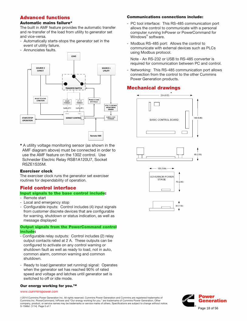
Our energy working for you.™
www.cumminspower.com
2014 Cummins Power Generation Inc. All rights reserved. Cummins Power Generation and Cummins are registered trademarks of Cummins Inc. PowerCommand, InPower and “Our energy working for you.” are trademarks of Cummins Power Generation. Other company, product, or service names may be trademarks or service marks of others. Specifications are subject to change without notice. S-1566d (1/14) Page 5 of 7
Advanced functions Automatic mains failure*The built in AMF feature provides the automatic transfer and re-transfer of the load from utility to generator set and vice-versa. - Automatically starts-stops the generator set in the
event of utility failure. - Annunciates faults.
* A utility voltage monitoring sensor (as shown in the AMF diagram above) must be connected in order to use the AMF feature on the 1302 control. Use Schneider Electric Relay RSB1A120U7, Socket RSZE1S35M.
Exerciser clock The exerciser clock runs the generator set exerciser routines for dependability of operation.
Field control interface Input signals to the base control include: - Remote start - Local and emergency stop - Configurable inputs: Control includes (4) input signals
from customer discrete devices that are configurable for warning, shutdown or status indication, as well as message displayed
Output signals from the PowerCommand control include: - Configurable relay outputs: Control includes (2) relay
output contacts rated at 2 A. These outputs can be configured to activate on any control warning or shutdown fault as well as ready to load, not in auto, common alarm, common warning and common shutdown.
- Ready to load (generator set running) signal: Operates when the generator set has reached 90% of rated speed and voltage and latches until generator set is switched to off or idle mode.
Communications connections include:
- PC tool interface: This RS-485 communication port allows the control to communicate with a personal computer running InPower or PowerCommand for Windows® software.
- Modbus RS-485 port: Allows the control to communicate with external devices such as PLCs using Modbus protocol.
Note - An RS-232 or USB to RS-485 converter is required for communication between PC and control.
- Networking: This RS-485 communication port allows connection from the control to the other Cummins Power Generation products.
Mechanical drawings
Page 18 of 56
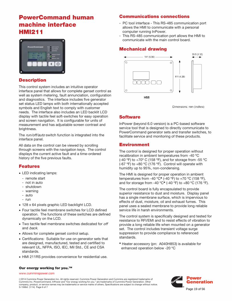
Our energy working for you.™
www.cumminspower.com
2014 Cummins Power Generation Inc. All rights reserved. Cummins Power Generation and Cummins are registered trademarks of Cummins Inc. PowerCommand, InPower and “Our energy working for you.” are trademarks of Cummins Power Generation. Other company, product, or service names may be trademarks or service marks of others. Specifications are subject to change without notice. S-1566d (1/14) Page 6 of 7
PowerCommand human machine interface HMI211
Description This control system includes an intuitive operator interface panel that allows for complete genset control as well as system metering, fault annunciation, configuration and diagnostics. The interface includes five generator set status LED lamps with both internationally accepted symbols and English text to comply with customer needs. The interface also includes an LED backlit LCD display with tactile feel soft-switches for easy operation and screen navigation. It is configurable for units of measurement and has adjustable screen contrast and brightness.
The run/off/auto switch function is integrated into the interface panel.
All data on the control can be viewed by scrolling through screens with the navigation keys. The control displays the current active fault and a time-ordered history of the five previous faults.
Features LED indicating lamps:
- remote start - not in auto - shutdown - warning - auto - run
128 x 64 pixels graphic LED backlight LCD.
Four tactile feel membrane switches for LCD defined operation. The functions of these switches are defined dynamically on the LCD.
Two tactile feel membrane switches dedicated for off and back.
Allows for complete genset control setup.
Certifications: Suitable for use on generator sets that are designed, manufactured, tested and certified to relevant UL, NFPA, ISO, IEC, Mil Std., CE and CSA standards.
HMI 211RS provides convenience for residential use.
Communications connections - PC tool interface - This RS-485 communication port
allows the HMI to communicate with a personal computer running InPower.
- This RS-485 communication port allows the HMI to communicate with the main control board.
Mechanical drawing
Software InPower (beyond 6.0 version) is a PC-based software service tool that is designed to directly communicate to PowerCommand generator sets and transfer switches, to facilitate service and monitoring of these products.
Environment The control is designed for proper operation without recalibration in ambient temperatures from -40 ºC (-40 ºF) to +70º C (158 ºF), and for storage from -55 ºC (-67 ºF) to +80 ºC (176 ºF). Control will operate with humidity up to 95%, non-condensing.
The HMI is designed for proper operation in ambient temperatures from -40 ºC* (-40 ºF) to +70 ºC (158 ºF), and for storage from -40 ºC* (-40 ºF) to +80 ºC (176 ºF).
The control board is fully encapsulated to provide superior resistance to dust and moisture. Display panel has a single membrane surface, which is impervious to effects of dust, moisture, oil and exhaust fumes. This panel uses a sealed membrane to provide long reliable service life in harsh environments.
The control system is specifically designed and tested for resistance to RFI/EMI and to resist effects of vibration to provide a long reliable life when mounted on a generator set. The control includes transient voltage surge suppression to provide compliance to referenced standards.
* Heater accessory (pn: A040H853) is available for enhanced operation below -20 ºC
Page 19 of 56
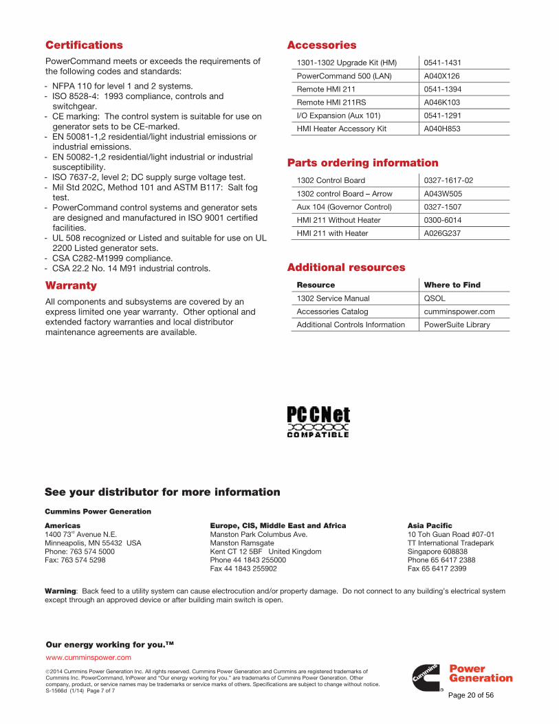
Our energy working for you.™
www.cumminspower.com
2014 Cummins Power Generation Inc. All rights reserved. Cummins Power Generation and Cummins are registered trademarks of Cummins Inc. PowerCommand, InPower and “Our energy working for you.” are trademarks of Cummins Power Generation. Other company, product, or service names may be trademarks or service marks of others. Specifications are subject to change without notice. S-1566d (1/14) Page 7 of 7
Certifications
PowerCommand meets or exceeds the requirements of the following codes and standards:
- NFPA 110 for level 1 and 2 systems. - ISO 8528-4: 1993 compliance, controls and
switchgear. - CE marking: The control system is suitable for use on
generator sets to be CE-marked. - EN 50081-1,2 residential/light industrial emissions or
industrial emissions. - EN 50082-1,2 residential/light industrial or industrial
susceptibility. - ISO 7637-2, level 2; DC supply surge voltage test. - Mil Std 202C, Method 101 and ASTM B117: Salt fog
test. - PowerCommand control systems and generator sets
are designed and manufactured in ISO 9001 certified facilities.
- UL 508 recognized or Listed and suitable for use on UL 2200 Listed generator sets.
- CSA C282-M1999 compliance. - CSA 22.2 No. 14 M91 industrial controls.
Warranty All components and subsystems are covered by an express limited one year warranty. Other optional and extended factory warranties and local distributor maintenance agreements are available.
Accessories
1301-1302 Upgrade Kit (HM) 0541-1431
PowerCommand 500 (LAN) A040X126
Remote HMI 211 0541-1394
Remote HMI 211RS A046K103
I/O Expansion (Aux 101) 0541-1291
HMI Heater Accessory Kit A040H853
Parts ordering information
1302 Control Board 0327-1617-02
1302 control Board – Arrow A043W505
Aux 104 (Governor Control) 0327-1507
HMI 211 Without Heater 0300-6014
HMI 211 with Heater A026G237
Additional resources
Resource Where to Find
1302 Service Manual QSOL
Accessories Catalog cumminspower.com
Additional Controls Information PowerSuite Library
See your distributor for more information Cummins Power Generation Americas 1400 73rd Avenue N.E. Minneapolis, MN 55432 USA Phone: 763 574 5000 Fax: 763 574 5298
Europe, CIS, Middle East and Africa Manston Park Columbus Ave. Manston Ramsgate Kent CT 12 5BF United Kingdom Phone 44 1843 255000 Fax 44 1843 255902
Asia Pacific 10 Toh Guan Road #07-01 TT International Tradepark Singapore 608838 Phone 65 6417 2388 Fax 65 6417 2399
Warning: Back feed to a utility system can cause electrocution and/or property damage. Do not connect to any building’s electrical system except through an approved device or after building main switch is open.
Page 20 of 56
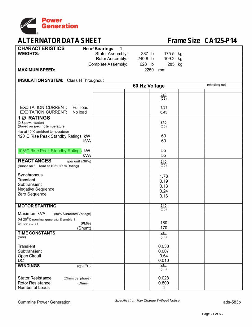
ALTERNATOR DATA SHEET Frame Size CA125-P14CHARACTERISTICS No of Bearings 1WEIGHTS: Stator Assembly: 387 lb 175.5 kg
Rotor Assembly: 240.8 lb 109.2 kgComplete Assembly: 628 lb 285 kg
MAXIMUM SPEED: 2250 rpm
INSULATION SYSTEM: Class H Throughout60 Hz Voltage (winding no)
240(06)
EXCITATION CURRENT: Full load 1.31EXCITATION CURRENT: No load 0.45
1 RATINGS (0.8 power factor)(Based on specific temperature
rise at 40 C ambient temperature)
240(06)
120 C Rise Peak Standby Ratings kW 60kVA 60
105 C Rise Peak Standby Ratings kW 55kVA 55
REACTANCES (per unit 30%)
(Based on full load at 105 C Rise Rating)
SynchronousTransientSubtransientNegative SequenceZero Sequence
240(06)
1.780.190.130.240.16
MOTOR STARTING 240(06)
Maximum kVA (90% Sustained Voltage)
(At 20 C nominal generator & ambient temperature) (PMG)
(Shunt)180170
TIME CONSTANTS (Sec)
240(06)
Transient 0.038Subtransient 0.007Open Circuit 0.64DC 0.010WINDINGS (@20 C) 240
(06)
Stator Resistance (Ohms per phase) 0.0280.800Rotor Resistance (Ohms)
Number of Leads 4
Cummins Power Generation Specification May Change Without Notice ads-583b
Page 21 of 56
Page 22 of 56
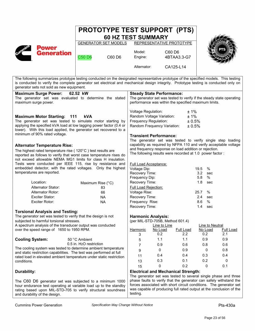
PROTOTYPE TEST SUPPORT (PTS)60 HZ TEST SUMMARY
GENERATOR SET MODELS REPRESENTATIVE PROTOTYPE
Model: C60 D6C50 D6 C60 D6 Engine: 4BTAA3.3-G7
Alternator: CA125-L14
The following summarizes prototype testing conducted on the designated representative prototype of the specified models. This testing is conducted to verify the complete generator set electrical and mechanical design integrity. Prototype testing is conducted only on generator sets not sold as new equipment.
Maximum Surge Power: 62.52 kW Steady State Performance:The generator set was evaluated to determine the stated maximum surge power.
The generator set was tested to verify if the steady state operating performance was within the specified maximum limits.
Voltage Regulation: ± 1%Maximum Motor Starting: 111 kVA Random Voltage Variation: ± 1%The generator set was tested to simulate motor starting by applying the specified kVA load at low lagging power factor (0.4 or lower). With this load applied, the generator set recovered to a minimum of 90% rated voltage.
Frequency Regulation: ± 0.5%Random Frequency Variation: ± 0.5%
Transient Performance:The generator set was tested to verify single step loading capability as required by NFPA 110 and verify acceptable voltage and frequency response on load addition or rejection. The following results were recorded at 1.0 power factor :
Alternator Temperature Rise:The highest rated temperature rise ( 120 C ) test results are reported as follows to verify that worst case temperature rises do not exceed allowable NEMA MG1 limits for class H insulation. Tests were conducted per IEEE 115, rise by resistance and embedded detector, with the rated voltages. Only the highest temperatures are reported.
Full Load Acceptance:Voltage Dip: 19.5 %Recovery Time: 3.2 secFrequency Dip: 5.8 %
Location: Maximum Rise ( C) Recovery Time: 1.8 secAlternator Stator: 83 Full Load Rejection:Alternator Rotor: 66 Voltage Rise: 25.7 %Exciter Stator: NA Recovery Time: 2.4 secExciter Rotor: NA Frequency Rise: 8.6 %
Recovery Time: 1.4 secTorsional Analysis and Testing:The generator set was tested to verify that the design is not Harmonic Analysis:subjected to harmful torsional stresses. (per MIL-STD-705B, Method 601.4)A spectrum analysis of the transducer output was conducted Line to Line Line to Neutralover the speed range of 1650 to 1950 RPM. Harmonic No Load Full Load No Load Full Load
Cooling System: 50 C Ambient 0.5 in. H2O restrictionThe cooling system was tested to determine ambient temperature and static restriction capabilities. The test was performed at full rated load in elevated ambient temperature under static restriction conditions.
3 0.2 2.2 0.2 2.1
5 1.1 1.1 0.9 0.9
7 0.9 0.6 0.8 0.6
9 0 0.9 0 0.8
11 0.4 0.4 0.3 0.4
13 0.3 0.1 0.2 0
15 0 0.2 0 0.1
Durability: Electrical and Mechanical Strength:The generator set was tested to several single phase and three phase faults to verify that the generator can safely withstand the forces associated with short circuit conditions. The generator set was capable of producing full rated output at the conclusion of the testing.
The C60 D6 generator set was subjected to a minimum 1000hour endurance test operating at variable load up to the standby rating based upon MIL-STD-705 to verify structural soundness and durability of the design.
Cummins Power Generation Specification May Change Without Notice Pts-430a
Page 23 of 56
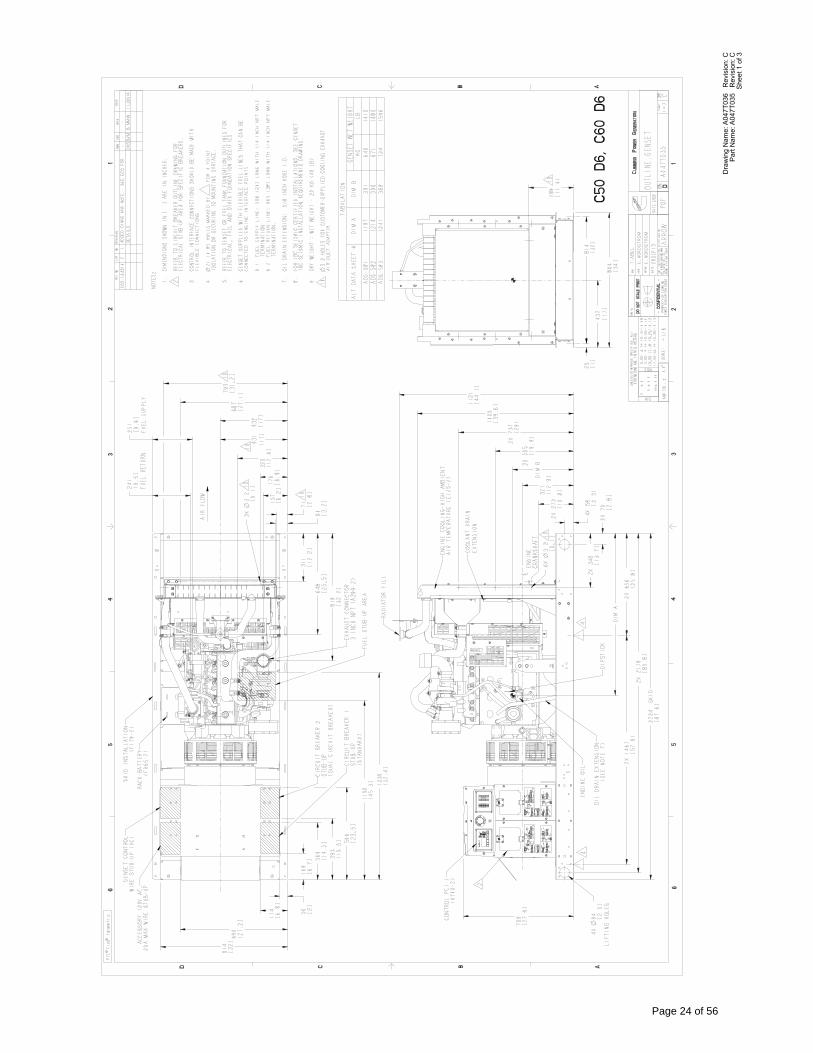
She
et 1
of 3
Par
t Nam
e: A
047T
035
Rev
isio
n: C
Dra
win
g N
ame:
A04
7T03
6 R
evis
ion:
C
Page 24 of 56
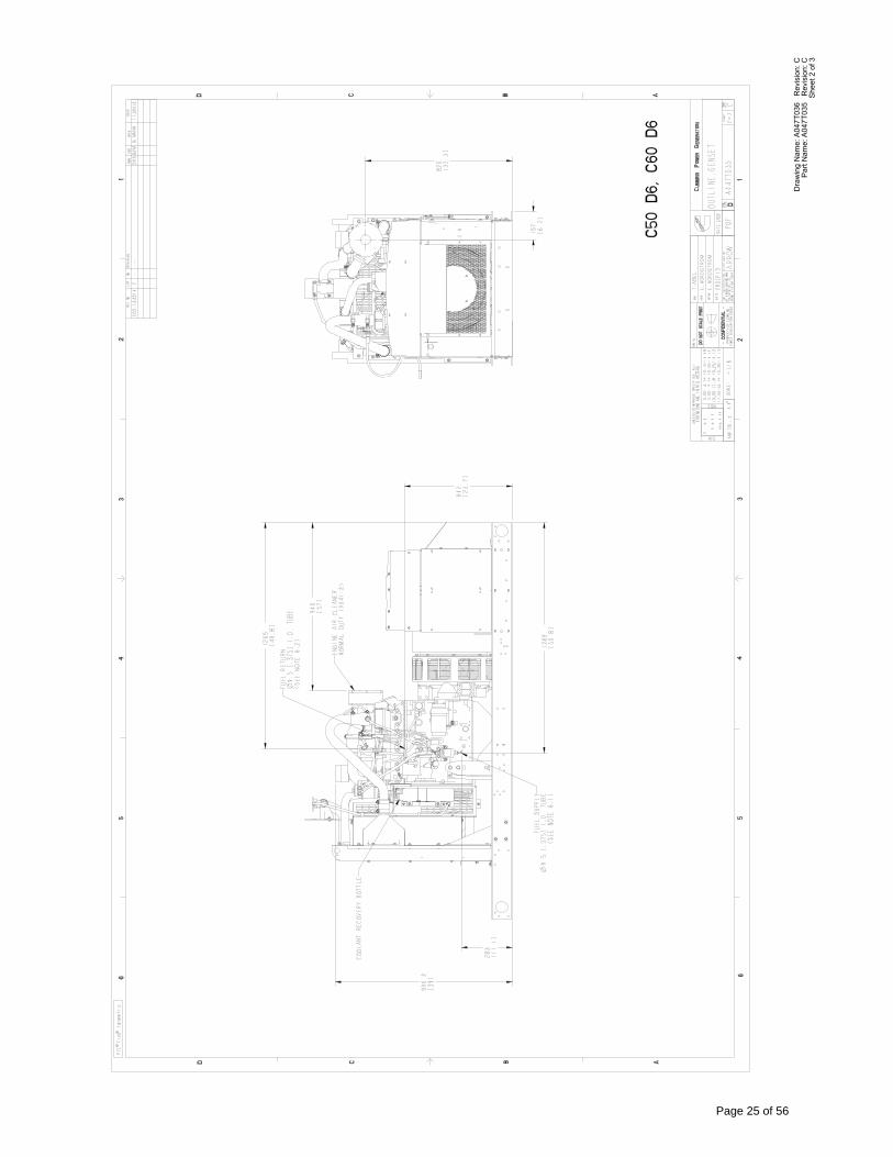
She
et 2
of 3
Par
t Nam
e: A
047T
035
Rev
isio
n: C
Dra
win
g N
ame:
A04
7T03
6 R
evis
ion:
C
Page 25 of 56
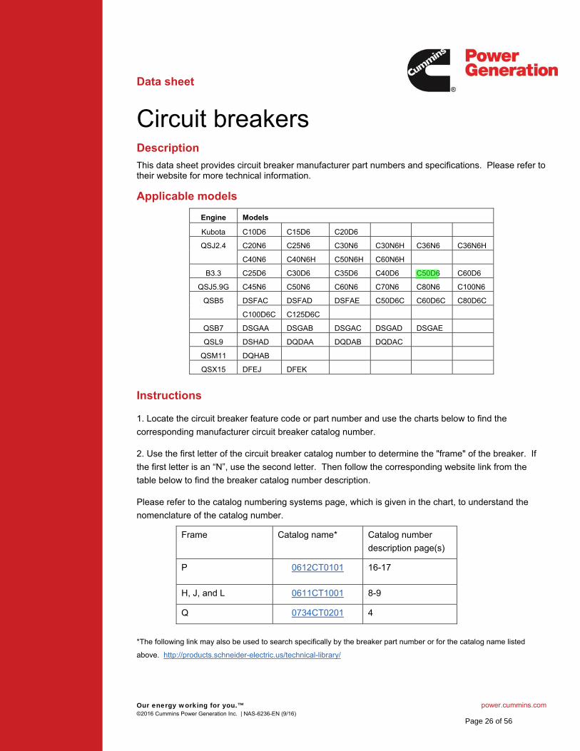
Our energy working for you.™ power.cummins.com©2016 Cummins Power Generation Inc. | NAS-6236-EN (9/16)
Data sheet
Circuit breakersDescription
This data sheet provides circuit breaker manufacturer part numbers and specifications. Please refer to their website for more technical information.
Applicable models
Engine Models
Kubota C10D6 C15D6 C20D6
QSJ2.4 C20N6 C25N6 C30N6 C30N6H C36N6 C36N6H
C40N6 C40N6H C50N6H C60N6H
B3.3 C25D6 C30D6 C35D6 C40D6 C50D6 C60D6
QSJ5.9G C45N6 C50N6 C60N6 C70N6 C80N6 C100N6
QSB5 DSFAC DSFAD DSFAE C50D6C C60D6C C80D6C
C100D6C C125D6C
QSB7 DSGAA DSGAB DSGAC DSGAD DSGAE
QSL9 DSHAD DQDAA DQDAB DQDAC
QSM11 DQHAB
QSX15 DFEJ DFEK
Instructions
1. Locate the circuit breaker feature code or part number and use the charts below to find the
corresponding manufacturer circuit breaker catalog number.
2. Use the first letter of the circuit breaker catalog number to determine the "frame" of the breaker. If
the first letter is an “N”, use the second letter. Then follow the corresponding website link from the
table below to find the breaker catalog number description.
Please refer to the catalog numbering systems page, which is given in the chart, to understand the
nomenclature of the catalog number.
Frame Catalog name* Catalog number
description page(s)
P 0612CT0101 16-17
H, J, and L 0611CT1001 8-9
Q 0734CT0201 4
*The following link may also be used to search specifically by the breaker part number or for the catalog name listed
above. http://products.schneider-electric.us/technical-library/
Page 26 of 56
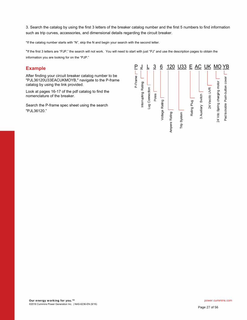
Our energy working for you.™ power.cummins.com©2016 Cummins Power Generation Inc. | NAS-6236-EN (9/16)
3. Search the catalog by using the first 3 letters of the breaker catalog number and the first 5 numbers to find information
such as trip curves, accessories, and dimensional details regarding the circuit breaker.
*If the catalog number starts with “N”, skip the N and begin your search with the second letter.
*If the first 3 letters are “PJP,” the search will not work. You will need to start with just “PJ” and use the description pages to obtain the
information you are looking for on the “PJP.”
Example
After finding your circuit breaker catalog number to be "PJL36120U33EACUKMOYB," navigate to the P-frame catalog by using the link provided.
Look at pages 16-17 of the pdf catalog to find the nomenclature of the breaker.
Search the P-frame spec sheet using the search
"PJL36120.”
Page 27 of 56
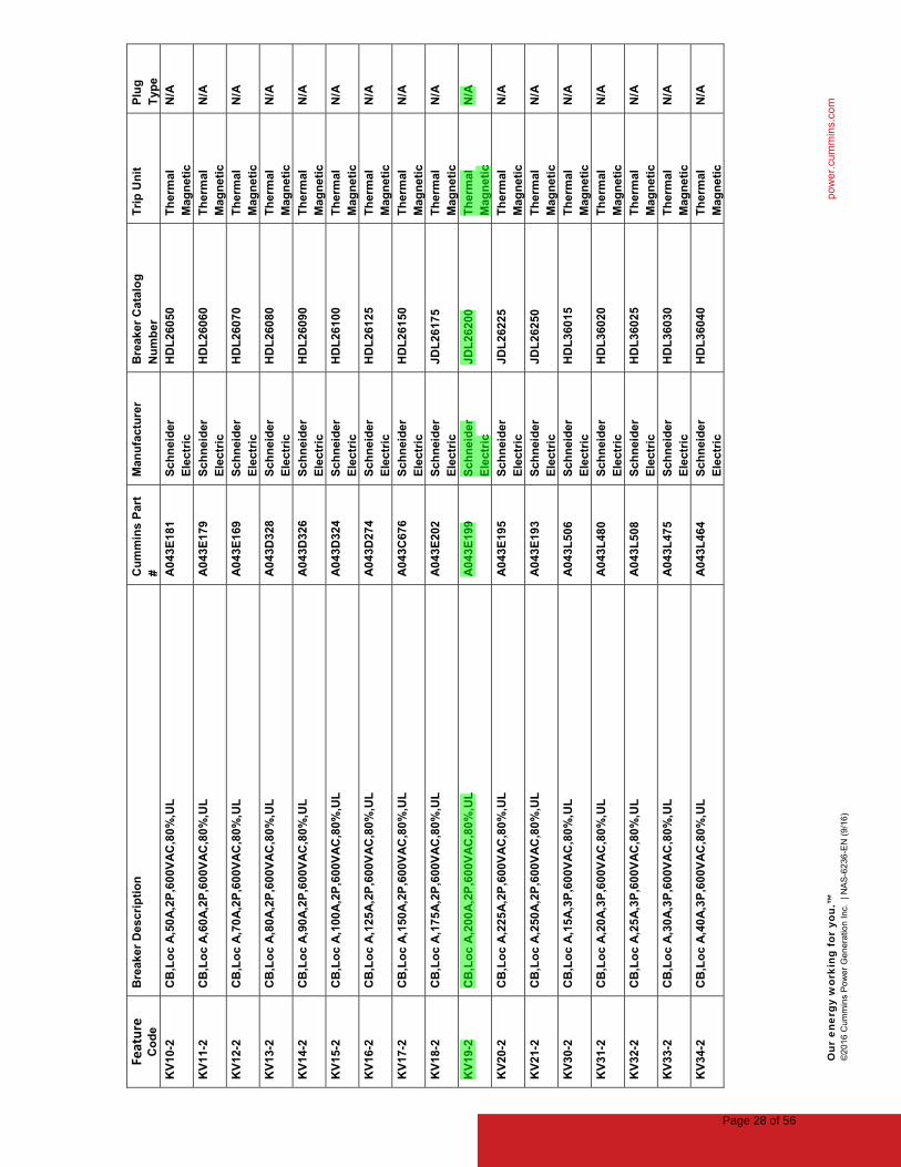
Our
ene
rgy
wor
king
for
you
.™
po
we
r.cu
mm
ins.
com
©2
016
Cum
min
s P
ow
er
Ge
nera
tion
In
c.
| NA
S-6
236
-EN
(9
/16
)
Feature
Co
de
Bre
aker
Des
crip
tio
nC
um
min
s P
art
#M
anu
fact
ure
rB
reak
er C
ata
log
N
um
ber
Tri
p U
nit
Plu
g
Typ
e
KV
10-2
CB
,Lo
c A
,50
A,2
P,6
00V
AC
,80
%,U
LA
04
3E18
1S
chn
eid
er
Ele
ctri
cH
DL
260
50T
her
mal
M
agn
eti
cN
/A
KV
11-2
CB
,Lo
c A
,60
A,2
P,6
00V
AC
,80
%,U
LA
04
3E17
9S
chn
eid
er
Ele
ctri
cH
DL
260
60T
her
mal
M
agn
eti
cN
/A
KV
12-2
CB
,Lo
c A
,70
A,2
P,6
00V
AC
,80
%,U
LA
04
3E16
9S
chn
eid
er
Ele
ctri
cH
DL
260
70T
her
mal
M
agn
eti
cN
/A
KV
13-2
CB
,Lo
c A
,80
A,2
P,6
00V
AC
,80
%,U
LA
04
3D32
8S
chn
eid
er
Ele
ctri
cH
DL
260
80T
her
mal
M
agn
eti
cN
/A
KV
14-2
CB
,Lo
c A
,90
A,2
P,6
00V
AC
,80
%,U
LA
04
3D32
6S
chn
eid
er
Ele
ctri
cH
DL
260
90T
her
mal
M
agn
eti
cN
/A
KV
15-2
CB
,Lo
c A
,100
A,2
P,6
00V
AC
,80
%,U
LA
04
3D32
4S
chn
eid
er
Ele
ctri
cH
DL
261
00T
her
mal
M
agn
eti
cN
/A
KV
16-2
CB
,Lo
c A
,125
A,2
P,6
00V
AC
,80
%,U
LA
04
3D27
4S
chn
eid
er
Ele
ctri
cH
DL
261
25T
her
mal
M
agn
eti
cN
/A
KV
17-2
CB
,Lo
c A
,150
A,2
P,6
00V
AC
,80
%,U
LA
04
3C67
6S
chn
eid
er
Ele
ctri
cH
DL
261
50T
her
mal
M
agn
eti
cN
/A
KV
18-2
CB
,Lo
c A
,175
A,2
P,6
00V
AC
,80
%,U
LA
04
3E20
2S
chn
eid
er
Ele
ctri
cJD
L26
175
Th
erm
al
Mag
ne
tic
N/A
KV
19-2
CB
,Lo
c A
,200
A,2
P,6
00V
AC
,80
%,U
LA
04
3E19
9S
chn
eid
er
Ele
ctri
cJD
L26
200
Th
erm
al
Mag
ne
tic
N/A
KV
20-2
CB
,Lo
c A
,225
A,2
P,6
00V
AC
,80
%,U
LA
04
3E19
5S
chn
eid
er
Ele
ctri
cJD
L26
225
Th
erm
al
Mag
ne
tic
N/A
KV
21-2
CB
,Lo
c A
,250
A,2
P,6
00V
AC
,80
%,U
LA
04
3E19
3S
chn
eid
er
Ele
ctri
cJD
L26
250
Th
erm
al
Mag
ne
tic
N/A
KV
30-2
CB
,Lo
c A
,15
A,3
P,6
00V
AC
,80
%,U
LA
04
3L50
6S
chn
eid
er
Ele
ctri
cH
DL
360
15T
her
mal
M
agn
eti
cN
/A
KV
31-2
CB
,Lo
c A
,20
A,3
P,6
00V
AC
,80
%,U
LA
04
3L48
0S
chn
eid
er
Ele
ctri
cH
DL
360
20T
her
mal
M
agn
eti
cN
/A
KV
32-2
CB
,Lo
c A
,25
A,3
P,6
00V
AC
,80
%,U
LA
04
3L50
8S
chn
eid
er
Ele
ctri
cH
DL
360
25T
her
mal
M
agn
eti
cN
/A
KV
33-2
CB
,Lo
c A
,30
A,3
P,6
00V
AC
,80
%,U
LA
04
3L47
5S
chn
eid
er
Ele
ctri
cH
DL
360
30T
her
mal
M
agn
eti
cN
/A
KV
34-2
CB
,Lo
c A
,40
A,3
P,6
00V
AC
,80
%,U
LA
04
3L46
4S
chn
eid
er
Ele
ctri
cH
DL
360
40T
her
mal
M
agn
eti
cN
/A
Page 28 of 56
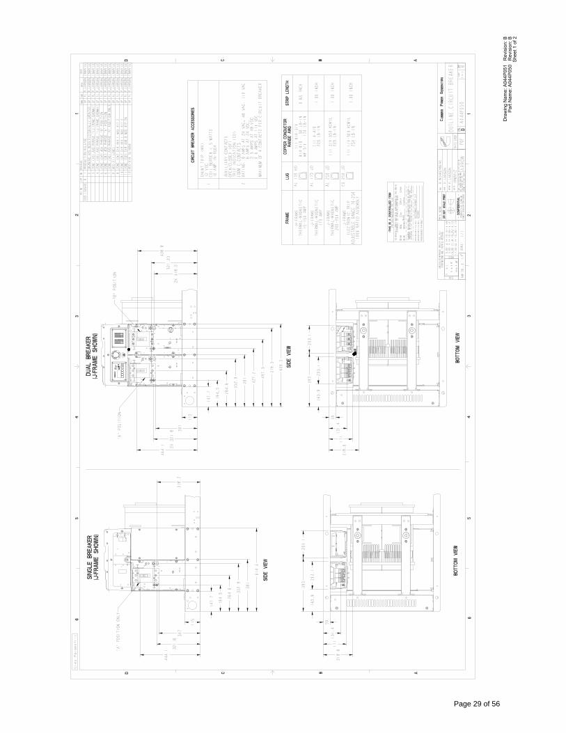
She
et 1
of 2
Par
t Nam
e: A
044P
050
Rev
isio
n: B
Dra
win
g N
ame:
A04
4P05
1 R
evis
ion:
B
Page 29 of 56
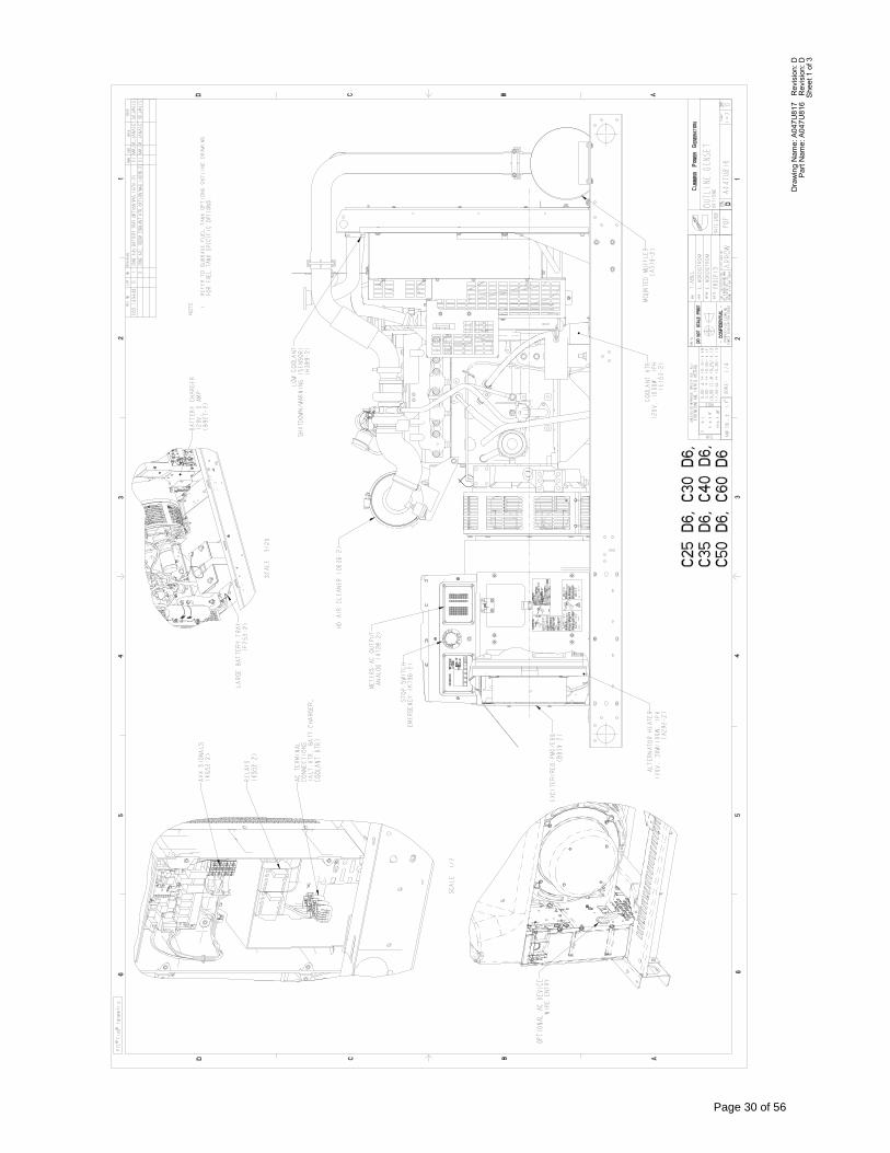
She
et 1
of 3
Par
t Nam
e: A
047U
816
Rev
isio
n: D
Dra
win
g N
ame:
A04
7U81
7 R
evis
ion:
D
Page 30 of 56
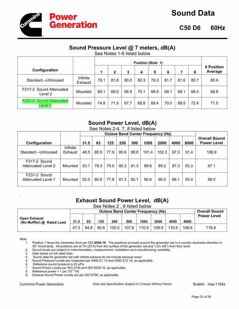
Sound Data
C50 D6 60Hz
Sound Pressure Level @ 7 meters, dB(A)See Notes 1-6 listed below
Configuration
Position (Note 1)8 PositionAverage1 2 3 4 5 6 7 8
Standard –UnhousedInfinite
Exhaust79.1 81.6 80.0 82.3 79.3 81.7 81.6 80.7 80.9
F217-2 Sound AttenuatedLevel 2
Mounted 69.1 69.0 66.9 70.1 68.9 69.1 68.1 68.4 68.8
F231-2 Sound Attenuated Level 1
Mounted 74.8 71.5 67.7 68.8 68.4 70.0 69.5 72.4 71.0
Sound Power Level, dB(A)See Notes 2-4, 7, 8 listed below
Configuration
Octave Band Center Frequency (Hz)Overall Sound Power Level31.5 63 125 250 500 1000 2000 4000 8000
Standard –UnhousedInfinite
Exhaust 48.5 68.9 77.9 95.6 98.8 101.4 102.3 97.3 91.4 106.9
F217-2 Sound Attenuated Level 2 Mounted 53.1 79.3 79.0 90.3 91.3 89.6 89.2 87.3 83.3 97.1
F231-2 Sound Attenuated Level 1 Mounted 52.0 80.8 77.8 91.3 92.1 90.6 90.5 88.1 83.4 98.0
.
Exhaust Sound Power Level, dB(A)See Notes 2 , 9 listed below
Open Exhaust(No Muffler) @ Rated Load
Octave Band Center Frequency (Hz) Overall SoundPower Level
31.5 63 125 250 500 1000 2000 4000 8000
47.3 84.8 90.8 100.0 107.6 110.9 109.9 110.5 108.6 116.9
Note:1. Position 1 faces the Generator front per ISO 8528-10. The positions proceed around the generator set in a counter-clockwise direction in
45° increments. All positions are at 7m (23 ft) from the surface of the generator set and 1.2m (48”) from floor level.2. Sound levels are subject to instrumentation, measurement, installation and manufacturing variability.3. Data based on full rated load. 4. Sound data for generator set with infinite exhaust do not include exhaust noise.5. Sound Pressure Levels are measured per ANSI S1.13 and ANSI S12.18, as applicable.6. Reference sound pressure is 20 μPa.7. Sound Power Levels per ISO 3744 and ISO 8528-10, as applicable.8. Reference power = 1 pw (10-12 W)9. Exhaust Sound Power Levels are per ISO 6798, as applicable.
Cummins Power Generation Data and Specification Subject to Change Without Notice Bulletin msp-1184a
Page 31 of 56
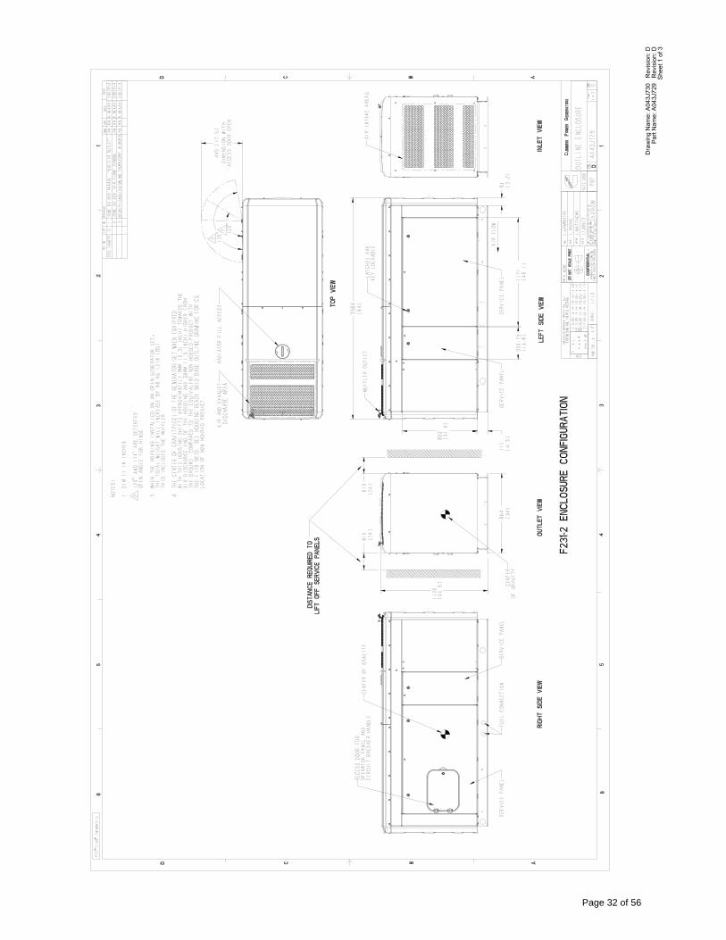
She
et 1
of 3
Par
t Nam
e: A
043J
729
Rev
isio
n: D
Dra
win
g N
ame:
A04
3J73
0 R
evis
ion:
D
Page 32 of 56
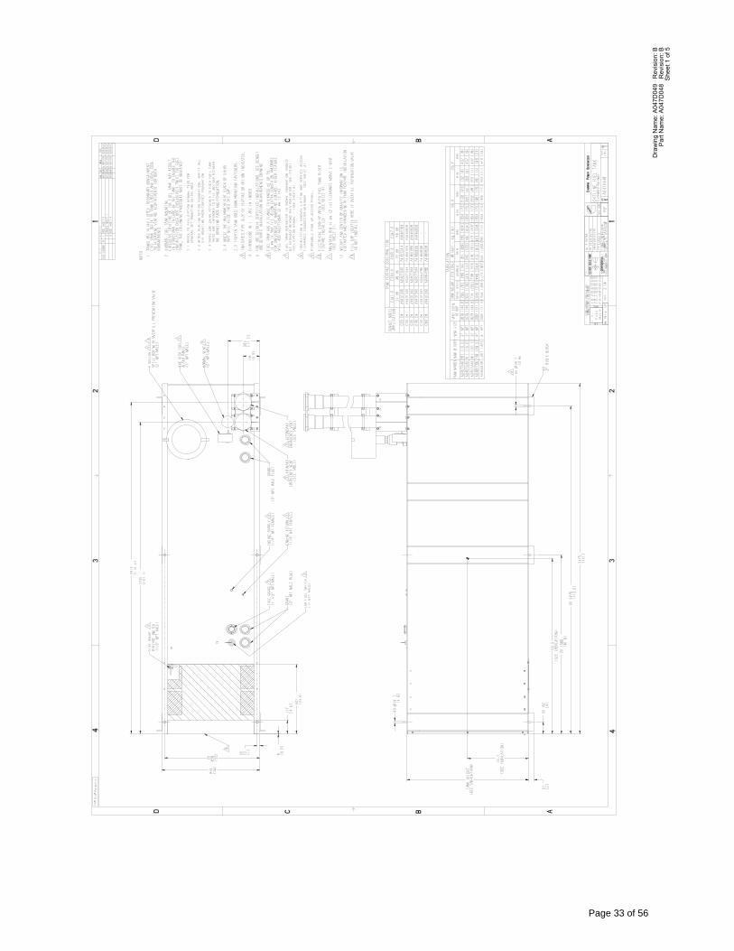
She
et 1
of 5
Par
t Nam
e: A
047D
048
Rev
isio
n: B
Dra
win
g N
ame:
A04
7D04
9 R
evis
ion:
B
Page 33 of 56
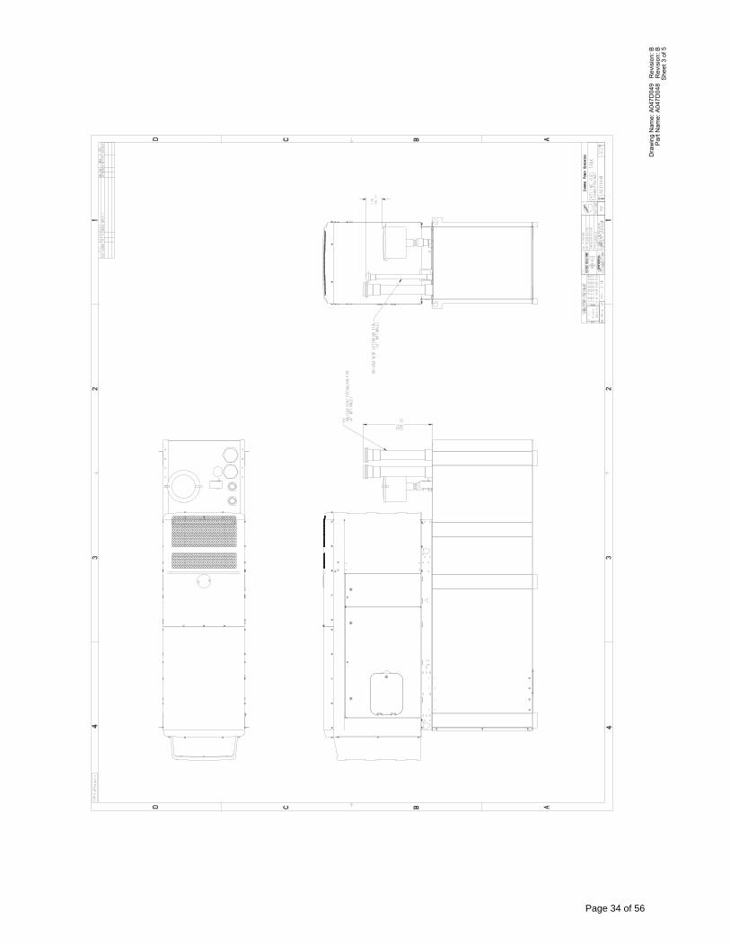
She
et 3
of 5
Par
t Nam
e: A
047D
048
Rev
isio
n: B
Dra
win
g N
ame:
A04
7D04
9 R
evis
ion:
B
Page 34 of 56
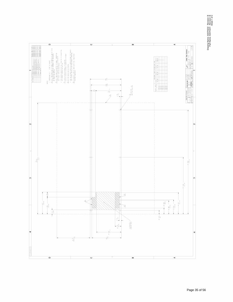
She
et 1
of 2
Par
t Nam
e: A
047H
231
Rev
isio
n: B
Dra
win
g N
ame:
A04
7H23
2 R
evis
ion:
B
Page 35 of 56
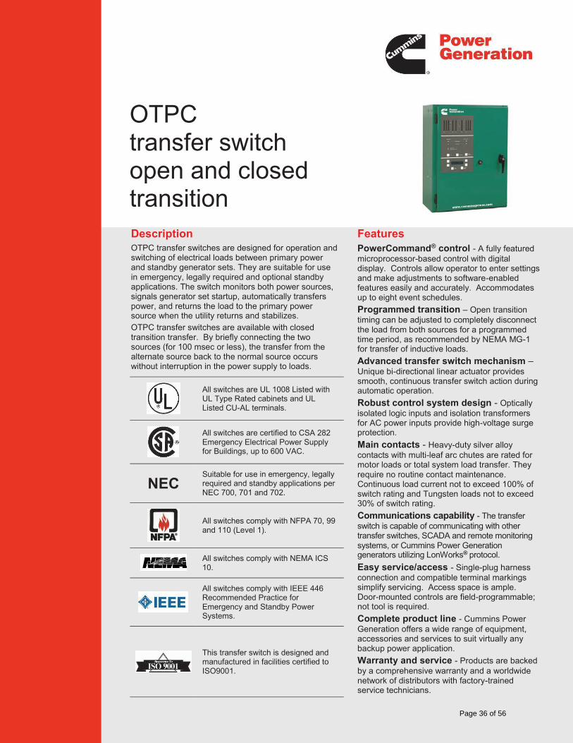
Description Features OTPC transfer switches are designed for operation and switching of electrical loads between primary power and standby generator sets. They are suitable for use in emergency, legally required and optional standby applications. The switch monitors both power sources, signals generator set startup, automatically transfers power, and returns the load to the primary power source when the utility returns and stabilizes. OTPC transfer switches are available with closed transition transfer. By briefly connecting the two sources (for 100 msec or less), the transfer from the alternate source back to the normal source occurs without interruption in the power supply to loads.
PowerCommand® control - A fully featured microprocessor-based control with digital display. Controls allow operator to enter settings and make adjustments to software-enabled features easily and accurately. Accommodates up to eight event schedules.
Programmed transition – Open transition timing can be adjusted to completely disconnect the load from both sources for a programmed time period, as recommended by NEMA MG-1 for transfer of inductive loads.
Advanced transfer switch mechanism – Unique bi-directional linear actuator provides smooth, continuous transfer switch action during automatic operation.
Robust control system design - Optically isolated logic inputs and isolation transformers for AC power inputs provide high-voltage surge protection.
Main contacts - Heavy-duty silver alloy contacts with multi-leaf arc chutes are rated for motor loads or total system load transfer. They require no routine contact maintenance. Continuous load current not to exceed 100% of switch rating and Tungsten loads not to exceed 30% of switch rating.
Communications capability - The transfer switch is capable of communicating with other transfer switches, SCADA and remote monitoring systems, or Cummins Power Generation generators utilizing LonWorks® protocol.
Easy service/access - Single-plug harness connection and compatible terminal markings simplify servicing. Access space is ample. Door-mounted controls are field-programmable; not tool is required.
Complete product line - Cummins Power Generation offers a wide range of equipment, accessories and services to suit virtually any backup power application.
Warranty and service - Products are backed by a comprehensive warranty and a worldwide network of distributors with factory-trained service technicians.
All switches are UL 1008 Listed with UL Type Rated cabinets and UL Listed CU-AL terminals.
All switches are certified to CSA 282 Emergency Electrical Power Supply for Buildings, up to 600 VAC.
NEC Suitable for use in emergency, legally required and standby applications per NEC 700, 701 and 702.
All switches comply with NFPA 70, 99 and 110 (Level 1).
All switches comply with NEMA ICS 10.
All switches comply with IEEE 446 Recommended Practice for Emergency and Standby Power Systems.
This transfer switch is designed and manufactured in facilities certified to ISO9001.
OTPC transfer switch open and closed transition
Page 36 of 56
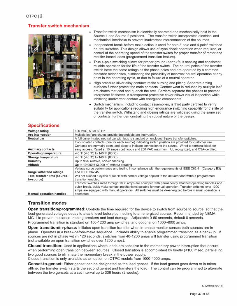
OTPC | 2
S-1270ag (04/16)
Transfer switch mechanism
Transfer switch mechanism is electrically operated and mechanically held in the Source 1 and Source 2 positions. The transfer switch incorporates electrical and mechanical interlocks to prevent inadvertent interconnection of the sources.
Independent break-before-make action is used for both 3-pole and 4-pole/ switched neutral switches. This design allows use of sync check operation when required, or control of the operating speed of the transfer switch for proper transfer of motor and rectifier-based loads (programmed transition feature).
True 4-pole switching allows for proper ground (earth) fault sensing and consistent, reliable operation for the life of the transfer switch. The neutral poles of the transfer switch have the same ratings as the phase poles and are operated by a common crossbar mechanism, eliminating the possibility of incorrect neutral operation at any point in the operating cycle, or due to failure of a neutral operator.
High pressure silver alloy contacts resist burning and pitting. Separate arcing surfaces further protect the main contacts. Contact wear is reduced by multiple leaf arc chutes that cool and quench the arcs. Barriers separate the phases to prevent interphase flashover. A transparent protective cover allows visual inspection while inhibiting inadvertent contact with energized components.
Switch mechanism, including contact assemblies, is third party certified to verify suitability for applications requiring high endurance switching capability for the life of the transfer switch. Withstand and closing ratings are validated using the same set of contacts, further demonstrating the robust nature of the design.
Specifications Voltage rating 600 VAC, 50 or 60 Hz. Arc interruption Multiple leaf arc chutes provide dependable arc interruption. Neutral bar A full current-rated neutral bar with lugs is standard on enclosed 3-pole transfer switches.
Auxiliary contacts
Two isolated contacts (one for each source) indicating switch position are provided for customer use. Contacts are normally open, and close to indicate connection to the source. Wired to terminal block for easy access. Rated at 10 amps continuous and 250 VAC maximum. UL recognized, and CSA-certified.
Operating temperature -40 F (-40 C) to 140 F (60 C) Storage temperature -40 F (-40 C) to 140 F (60 C) Humidity Up to 95% relative, non-condensing Altitude Up to 10,000 ft (3,000 m) without derating
Surge withstand ratings Voltage surge performance and testing in compliance with the requirements of IEEE C62.41 (Category B3) and IEEE C62.45.
Total transfer time (source-to-source)
Will not exceed 6 cycles at 60 Hz with normal voltage applied to the actuator and without programmed transition enabled.
Manual operation handles
Transfer switches rated through 1000 amps are equipped with permanently attached operating handles and quick-break, quick-make contact mechanisms suitable for manual operation. Transfer switches over 1000 amps are equipped with manual operators. All switches must be de-energized before manual operation is attempted.
Transition modes Open transition/programmed: Controls the time required for the device to switch from source to source, so that the load-generated voltages decay to a safe level before connecting to an energized source. Recommended by NEMA MG-1 to prevent nuisance-tripping breakers and load damage. Adjustable 0-60 seconds, default 0 seconds. Programmed transition is standard on 150-1200 amp switches, and optional on 1600-4000 amps.
Open transition/in-phase: Initiates open transition transfer when in-phase monitor senses both sources are in phase. Operates in a break-before-make sequence. Includes ability to enable programmed transition as a back-up. If sources are not in phase within 120 seconds, switches from 40-1200 amps will transfer using programmed transition (not available on open transition switches over 1200 amps).
Closed transition: Used in applications where loads are sensitive to the momentary power interruption that occurs when performing open transition between sources. Closed transition is accomplished by briefly (<100 msec) paralleling two good sources to eliminate the momentary break in the power supply. Closed transition is only available as an option on OTPC models from 1000-4000 amps.
Genset-to-genset: Either genset can be designated as the lead genset. If the lead genset goes down or is taken offline, the transfer switch starts the second genset and transfers the load. The control can be programmed to alternate between the two gensets at a set interval up to 336 hours (2 weeks).
Page 37 of 56
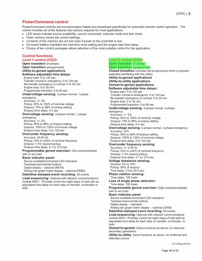
OTPC | 3
S-1270ag (04/16)
PowerCommand control PowerCommand controls are microprocessor based and developed specifically for automatic transfer switch operation. The control includes all of the features and options required for most applications. LED lamps indicate source availability, source connected, exercise mode and test mode. Flash memory stores the control settings. Contents of the memory are not lost even if power to the controller is lost. On-board battery maintains the real-time clock setting and the engine start time delay. Choice of two control packages allows selection of the most suitable control for the application.
Control functions Level 1 control (C023) Level 2 control (C024) Open transition (in-phase) Open transition (programmed) Utility-to-genset applications Software adjustable time delays: Engine start: 0 to 120 sec Transfer normal to emergency: 0 to 120 sec Re-transfer emergency to normal: 0 to 30 min Engine stop: 0 to 30 min Programmed transition: 0 to 60 sec
Undervoltage sensing: 3-phase normal, 1-phase emergency Accuracy: =/- 2% Pickup: 85% to 100% of nominal voltage Dropout: 75% to 98% of pickup setting Dropout time delay: 0-4 sec
Overvoltage sensing: 3-phase normal, 1-phase emergency Accuracy: =/- 2% Pickup: 95% to 99% of dropout setting Dropout: 105% to 135% of nominal voltage Dropout time delay: 0 to 120 sec
Over/under frequency sensing: Accuracy: ±0.05 Hz Pickup: ±5% to ±20% of nominal frequency Dropout: 1-5% beyond pickup Dropout time delay: 0.1 to 15.0 sec
Programmable genset exerciser: One event/schedule with or w/o load Basic indicator panel: Source available/connected LED indicators Test/exercise/override buttons Digital display – optional (M018) Analog bar graph meter display – optional (D009)
Date/time-stamped event recording: 50 events Load sequencing: Optional with network communications module M031. Provides control for eight steps of load with an adjustable time delay for each step on transfer, re-transfer or both.
Open transition (in-phase) Open transition (programmed) Closed transition (includes fail-to-disconnect timer to prevent extended paralleling with the utility) Utility-to-genset applications Utility-to-utility applications Genset-to-genset applications Software adjustable time delays: Engine start: 0 to 120 sec Transfer normal to emergency: 0 to 120 sec Re-transfer emergency to normal: 0 to 30 min Engine stop: 0 to 30 min Programmed transition: 0 to 60 sec
Undervoltage sensing: 3-phase normal, 3-phase emergency Accuracy: +/- 2% Pickup: 85% to 100% of nominal voltage Dropout: 75% to 98% of pickup setting Dropout time delay: 0-4 sec
Overvoltage sensing: 3-phase normal, 3-phase emergency Accuracy: ±2% Pickup: 95% to 99% of dropout setting Dropout: 105% to 135% of nominal voltage Dropout time delay: 0 to 120 sec
Over/under frequency sensing: Accuracy: =/- 0.05 Hz Pickup: ±5% to ±20% of nominal frequency Dropout: 1-5% beyond pickup Dropout time delay: 0.1 to 15.0 sec
Voltage imbalance sensing: Dropout: 2% to 10% Pickup: 90% of dropout Time delay: 2.0 to 20.0 sec
Phase rotation sensing: Time delay: 100 msec
Loss of single phase detection: Time delay: 100 msec
Programmable genset exerciser: Eight events/schedules with or w/o load Basic indicator panel: Source available/connected LED indicators Test/exercise/override buttons Digital display – standard Analog bar graph meter display – optional (D009)
Date/time-stamped event recording: 50 events Load sequencing: Optional with network communications module M031. Provides control for eight steps of load with an adjustable time delay for each step on transfer, re-transfer, or both. Genset-to-genset: Same functions as above, for lead and secondary generators. Utility-to-utility: Same functions as above, for preferred and alternate source.
Page 38 of 56
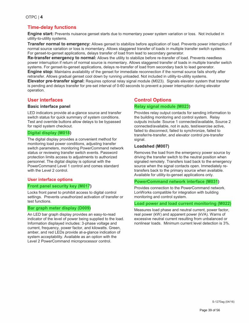
OTPC | 4
S-1270ag (04/16)
Time-delay functions Engine start: Prevents nuisance genset starts due to momentary power system variation or loss. Not included in utility-to-utility systems.
Transfer normal to emergency: Allows genset to stabilize before application of load. Prevents power interruption if normal source variation or loss is momentary. Allows staggered transfer of loads in multiple transfer switch systems. For genset-to-genset applications, delays transfer of load from lead to secondary generator. Re-transfer emergency to normal: Allows the utility to stabilize before re-transfer of load. Prevents needless power interruption if return of normal source is momentary. Allows staggered transfer of loads in multiple transfer switch systems. For genset-to-genset applications, delays re-transfer of load from secondary back to lead generator. Engine stop: Maintains availability of the genset for immediate reconnection if the normal source fails shortly after retransfer. Allows gradual genset cool down by running unloaded. Not included in utility-to-utility systems. Elevator pre-transfer signal: Requires optional relay signal module (M023). Signals elevator system that transfer is pending and delays transfer for pre-set interval of 0-60 seconds to prevent a power interruption during elevator operation. User interfaces Basic interface panel
LED indicators provide at-a-glance source and transfer switch status for quick summary of system conditions. Test and override buttons allow delays to be bypassed for rapid system checkout.
Digital display (M018)
The digital display provides a convenient method for monitoring load power conditions, adjusting transfer switch parameters, monitoring PowerCommand network status or reviewing transfer switch events. Password protection limits access to adjustments to authorized personnel. The digital display is optional with the PowerCommand Level 1 control and comes standard with the Level 2 control. User interface options
Front panel security key (M017)
Locks front panel to prohibit access to digital control settings. Prevents unauthorized activation of transfer or test functions.
Bar graph meter display (D009)
An LED bar graph display provides an easy-to-read indicator of the level of power being supplied to the load. Information displayed includes: 3-phase voltage and current, frequency, power factor, and kilowatts. Green, amber, and red LEDs provide at-a-glance indication of system acceptability. Available as an option with the Level 2 PowerCommand microprocessor control.
Control Options Relay signal module (M023)
Provides relay output contacts for sending information to the building monitoring and control system. Relay outputs include: Source 1 connected/available, Source 2 connected/available, not in auto, test/exercise active, failed to disconnect, failed to synchronize, failed to transfer/re-transfer, and elevator control pre-transfer signal.
Loadshed (M007)
Removes the load from the emergency power source by driving the transfer switch to the neutral position when signaled remotely. Transfers load back to the emergency source when the signal contacts open. Immediately re-transfers back to the primary source when available. Available for utility-to-genset applications only.
PowerCommand network interface (M031)
Provides connection to the PowerCommand network. LonWorks compatible for integration with building monitoring and control system.
Load power and load current monitoring (M022)
Measures load phase and neutral current, power factor, real power (kW) and apparent power (kVA). Warns of excessive neutral current resulting from unbalanced or nonlinear loads. Minimum current level detection is 3%.
Page 39 of 56
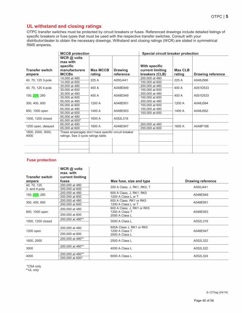
OTPC | 5
S-1270ag (04/16)
UL withstand and closing ratings OTPC transfer switches must be protected by circuit breakers or fuses. Referenced drawings include detailed listings of specific breakers or fuse types that must be used with the respective transfer switches. Consult with your distributor/dealer to obtain the necessary drawings. Withstand and closing ratings (WCR) are stated in symmetrical RMS amperes. MCCB protection Special circuit breaker protection
Transfer switch ampere
WCR @ volts max with specific manufacturers MCCBs
Max MCCB rating
Drawing reference
With specific current limiting breakers (CLB)
Max CLB rating Drawing reference
40, 70, 125 3-pole 14,000 at 480
225 A A050J441 200,000 at 480
225 A A048J566 14,000 at 600 100,000 at 600
40, 70, 125 4-pole 30,000 at 480
400 A A048E949 200,000 at 480
400 A A051D533 30,000 at 600 100,000 at 600
150, 225, 260 30,000 at 480
400 A A048E949 200,000 at 480
400 A A051D533 30,000 at 600 100,000 at 600
300, 400, 600 65,000 at 480
1200 A A048E951 200,000 at 480
1200 A A048J564 65,000 at 600 100,000 at 600
800, 1000 open 65,000 at 480
1400 A A048E953 150,000 at 480
1400 A A048J562 50,000 at 600 100,000 at 600
1000, 1200 closed 85,000 at 480
1600 A A052L319
65,000 at 600*
1200 open, delayed 85,000 at 480
1600 A A048E947 200,000 at 480
1600 A A048P186 65,000 at 600 200,000 at 600
1600, 2000, 3000, 4000
These amperages don’t have specific circuit breaker ratings. See 3 cycle ratings table.
Fuse protection
Transfer switch ampere
WCR @ volts max. with current limiting fuses Max fuse, size and type Drawing reference
40, 70, 125 3- and 4-pole
200,000 at 480 200 A Class, J, RK1, RK5, T A050J441
200,000 at 600
150, 225, 260 200,000 at 480 600 A Class, J, RK1, RK5
1200 A Class L or T A048E949
200,000 at 600
300, 400, 600 200,000 at 480 600 A Class, RK1 or RK5
1200 A Class L or T A048E951
200,000 at 600
800, 1000 open 200,000 at 480 600 A Class, J, RK1 or RK5
1200 A Class T 2000 A Class L
A048E953 200,000 at 600
1000, 1200 closed 200,000 at 480**
3000 A Class L A052L319
1200 open 200,000 at 480 600A Class J, RK1 or RK5
1200 A Class T 2000 A Class L
A048E947 200,000 at 600
1600, 2000 200,000 at 480**
2500 A Class L A052L322
3000 200,000 at 480**
4000 A Class L A052L322
4000 200,000 at 480**
6000 A Class L A052L324 200,000 at 600*
*CSA only **UL only
Page 40 of 56
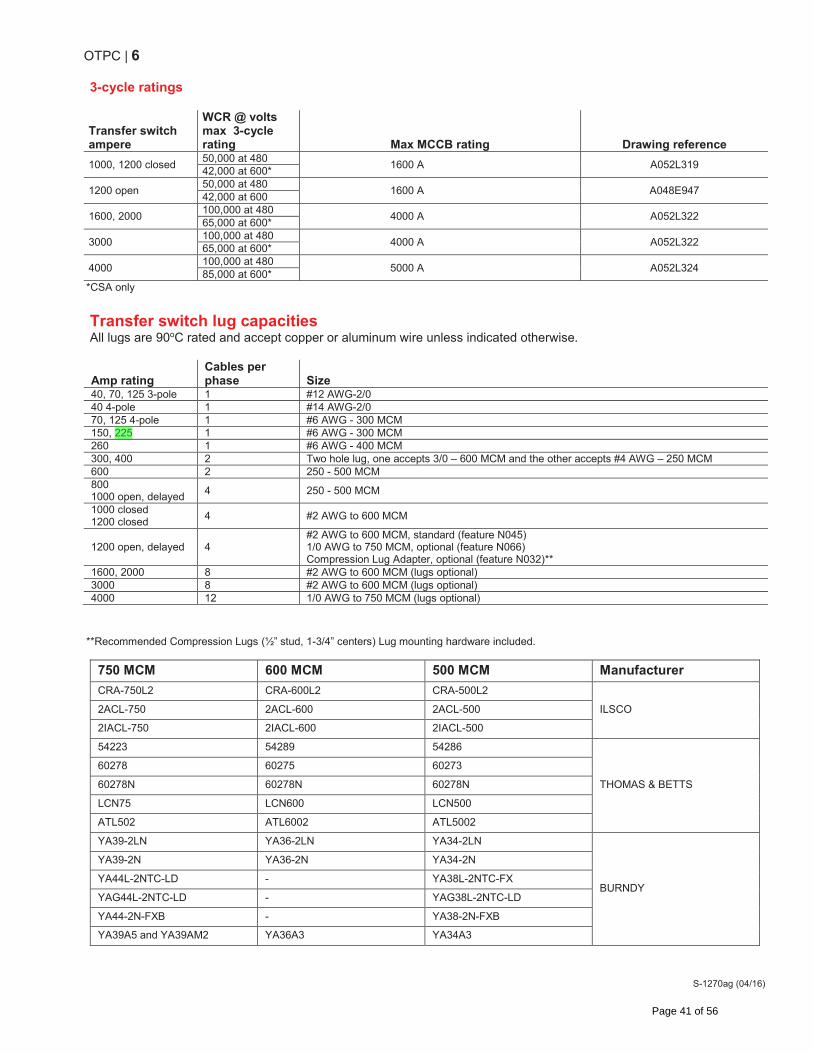
OTPC | 6
S-1270ag (04/16)
3-cycle ratings
Transfer switch ampere
WCR @ volts max 3-cycle rating Max MCCB rating Drawing reference
1000, 1200 closed 50,000 at 480
1600 A A052L319 42,000 at 600*
1200 open 50,000 at 480
1600 A A048E947 42,000 at 600
1600, 2000 100,000 at 480
4000 A A052L322 65,000 at 600*
3000 100,000 at 480
4000 A A052L322 65,000 at 600*
4000 100,000 at 480
5000 A A052L324 85,000 at 600*
*CSA only
Transfer switch lug capacities All lugs are 90oC rated and accept copper or aluminum wire unless indicated otherwise.
Amp rating Cables per phase Size
40, 70, 125 3-pole 1 #12 AWG-2/0 40 4-pole 1 #14 AWG-2/0 70, 125 4-pole 1 #6 AWG - 300 MCM 150, 225 1 #6 AWG - 300 MCM 260 1 #6 AWG - 400 MCM 300, 400 2 Two hole lug, one accepts 3/0 – 600 MCM and the other accepts #4 AWG – 250 MCM 600 2 250 - 500 MCM 800 1000 open, delayed
4 250 - 500 MCM
1000 closed 1200 closed
4 #2 AWG to 600 MCM
1200 open, delayed 4 #2 AWG to 600 MCM, standard (feature N045) 1/0 AWG to 750 MCM, optional (feature N066) Compression Lug Adapter, optional (feature N032)**
1600, 2000 8 #2 AWG to 600 MCM (lugs optional) 3000 8 #2 AWG to 600 MCM (lugs optional) 4000 12 1/0 AWG to 750 MCM (lugs optional)
**Recommended Compression Lugs (½” stud, 1-3/4” centers) Lug mounting hardware included.
750 MCM 600 MCM 500 MCM Manufacturer
CRA-750L2 CRA-600L2 CRA-500L2
ILSCO 2ACL-750 2ACL-600 2ACL-500
2IACL-750 2IACL-600 2IACL-500
54223 54289 54286
THOMAS & BETTS
60278 60275 60273
60278N 60278N 60278N
LCN75 LCN600 LCN500
ATL502 ATL6002 ATL5002
YA39-2LN YA36-2LN YA34-2LN
BURNDY
YA39-2N YA36-2N YA34-2N
YA44L-2NTC-LD - YA38L-2NTC-FX
YAG44L-2NTC-LD - YAG38L-2NTC-LD
YA44-2N-FXB - YA38-2N-FXB
YA39A5 and YA39AM2 YA36A3 YA34A3
Page 41 of 56
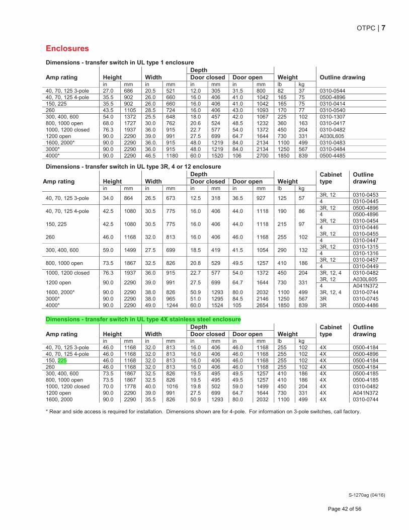
OTPC | 7
S-1270ag (04/16)
Enclosures Dimensions - transfer switch in UL type 1 enclosure
Amp rating Height Width Depth
Weight Outline drawing Door closed Door open in mm in mm in mm in mm lb kg 40, 70, 125 3-pole 27.0 686 20.5 521 12.0 305 31.5 800 82 37 0310-0544 40, 70, 125 4-pole 35.5 902 26.0 660 16.0 406 41.0 1042 165 75 0500-4896 150, 225 35.5 902 26.0 660 16.0 406 41.0 1042 165 75 0310-0414 260 43.5 1105 28.5 724 16.0 406 43.0 1093 170 77 0310-0540 300, 400, 600 54.0 1372 25.5 648 18.0 457 42.0 1067 225 102 0310-1307 800, 1000 open 68.0 1727 30.0 762 20.6 524 48.5 1232 360 163 0310-0417 1000, 1200 closed 76.3 1937 36.0 915 22.7 577 54.0 1372 450 204 0310-0482 1200 open 90.0 2290 39.0 991 27.5 699 64.7 1644 730 331 A030L605 1600, 2000* 90.0 2290 36.0. 915 48.0 1219 84.0 2134 1100 499 0310-0483 3000* 90.0 2290 36.0 915 48.0 1219 84.0 2134 1250 567 0310-0484 4000* 90.0 2290 46.5 1180 60.0 1520 106 2700 1850 839 0500-4485
Dimensions - transfer switch in UL type 3R, 4 or 12 enclosure
Amp rating Height Width Depth
Weight Cabinet type
Outline drawing Door closed Door open
in mm in mm in mm in mm lb kg
40, 70, 125 3-pole 34.0 864 26.5 673 12.5 318 36.5 927 125 57 3R, 12 0310-0453 4 0310-0445
40, 70, 125 4-pole 42.5 1080 30.5 775 16.0 406 44.0 1118 190 86 3R, 12 0500-4896 4 0500-4896
150, 225 42.5 1080 30.5 775 16.0 406 44.0 1118 215 97 3R, 12 0310-0454 4 0310-0446
260 46.0 1168 32.0 813 16.0 406 46.0 1168 255 102 3R, 12 0310-0455 4 0310-0447
300, 400, 600 59.0 1499 27.5 699 18.5 419 41.5 1054 290 132 3R, 12 0310-1315 4 0310-1316
800, 1000 open 73.5 1867 32.5 826 20.8 529 49.5 1257 410 186 3R, 12 0310-0457 4 0310-0449
1000, 1200 closed 76.3 1937 36.0 915 22.7 577 54.0 1372 450 204 3R, 12, 4 0310-0482
1200 open 90.0 2290 39.0 991 27.5 699 64.7 1644 730 331 3R, 12 A030L605 4 A041N372
1600, 2000* 90.0 2290 38.0 826 50.9 1293 80.0 2032 1100 499 3R, 12, 4 0310-0744 3000* 90.0 2290 38.0 965 51.0 1295 84.5 2146 1250 567 3R 0310-0745 4000* 90.0 2290 49.0 1244 60.0 1524 105 2654 1850 839 3R 0500-4486
Dimensions - transfer switch in UL type 4X stainless steel enclosure
Amp rating Height Width Depth
Weight Cabinet type
Outline drawing Door closed Door open
in mm in mm in mm in mm lb kg 40, 70, 125 3-pole 46.0 1168 32.0 813 16.0 406 46.0 1168 255 102 4X 0500-4184 40, 70, 125 4-pole 46.0 1168 32.0 813 16.0 406 46.0 1168 255 102 4X 0500-4896 150, 225 46.0 1168 32.0 813 16.0 406 46.0 1168 255 102 4X 0500-4184 260 46.0 1168 32.0 813 16.0 406 46.0 1168 255 102 4X 0500-4184 300, 400, 600 73.5 1867 32.5 826 19.5 495 49.5 1257 410 186 4X 0500-4185 800, 1000 open 73.5 1867 32.5 826 19.5 495 49.5 1257 410 186 4X 0500-4185 1000, 1200 closed 70.0 1778 40.0 1016 19.8 502 59.0 1499 450 204 4X 0310-0482 1200 open 90.0 2290 39.0 991 27.5 699 64.7 1644 730 331 4X A041N372 1600, 2000 90.0 2290 35.5 826 50.9 1293 80.0 2032 1100 499 4X 0310-0744
* Rear and side access is required for installation. Dimensions shown are for 4-pole. For information on 3-pole switches, call factory.
Page 42 of 56
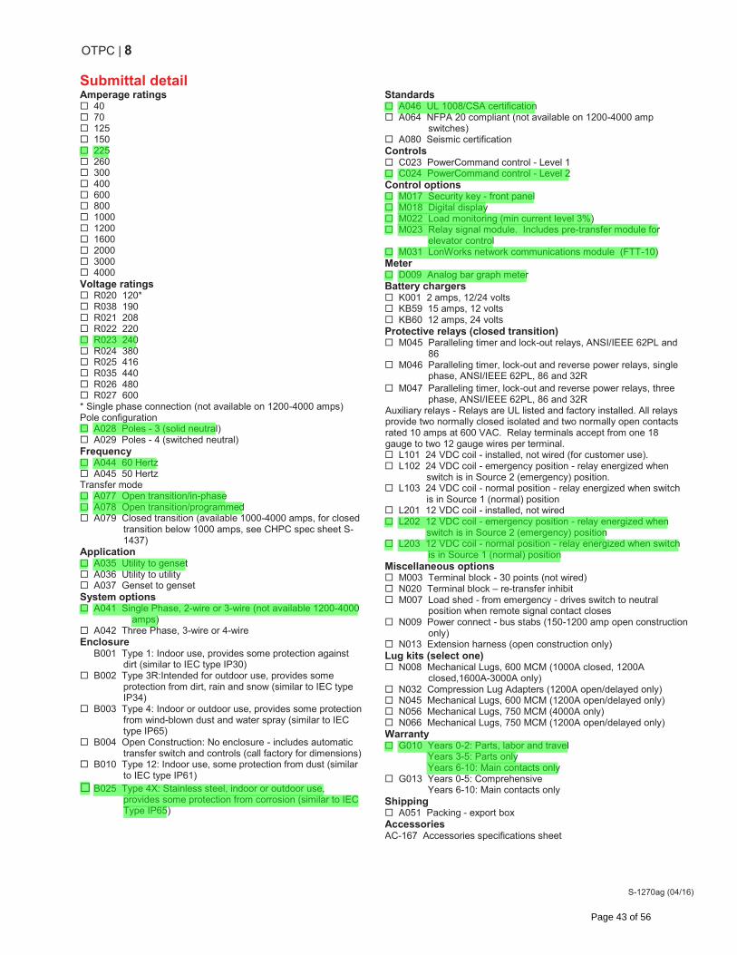
OTPC | 8
S-1270ag (04/16)
Submittal detail Amperage ratings
40 70 125 150 225 260 300 400 600 800 1000 1200 1600 2000 3000 4000
Voltage ratings R020 120* R038 190 R021 208 R022 220 R023 240 R024 380 R025 416 R035 440 R026 480 R027 600
* Single phase connection (not available on 1200-4000 amps) Pole configuration
A028 Poles - 3 (solid neutral) A029 Poles - 4 (switched neutral)
Frequency A044 60 Hertz A045 50 Hertz
Transfer mode A077 Open transition/in-phase A078 Open transition/programmed A079 Closed transition (available 1000-4000 amps, for closed
transition below 1000 amps, see CHPC spec sheet S-1437)
Application A035 Utility to genset A036 Utility to utility A037 Genset to genset
System options A041 Single Phase, 2-wire or 3-wire (not available 1200-4000
amps) A042 Three Phase, 3-wire or 4-wire
Enclosure B001 Type 1: Indoor use, provides some protection against
dirt (similar to IEC type IP30) B002 Type 3R:Intended for outdoor use, provides some
protection from dirt, rain and snow (similar to IEC type IP34)
B003 Type 4: Indoor or outdoor use, provides some protection from wind-blown dust and water spray (similar to IEC type IP65)
B004 Open Construction: No enclosure - includes automatic transfer switch and controls (call factory for dimensions)
B010 Type 12: Indoor use, some protection from dust (similar to IEC type IP61)
B025 Type 4X: Stainless steel, indoor or outdoor use, provides some protection from corrosion (similar to IEC Type IP65)
Standards A046 UL 1008/CSA certification A064 NFPA 20 compliant (not available on 1200-4000 amp
switches) A080 Seismic certification
Controls C023 PowerCommand control - Level 1 C024 PowerCommand control - Level 2
Control options M017 Security key - front panel M018 Digital display M022 Load monitoring (min current level 3%) M023 Relay signal module. Includes pre-transfer module for
elevator control M031 LonWorks network communications module (FTT-10)
Meter D009 Analog bar graph meter
Battery chargers K001 2 amps, 12/24 volts KB59 15 amps, 12 volts KB60 12 amps, 24 volts
Protective relays (closed transition) M045 Paralleling timer and lock-out relays, ANSI/IEEE 62PL and
86 M046 Paralleling timer, lock-out and reverse power relays, single
phase, ANSI/IEEE 62PL, 86 and 32R M047 Paralleling timer, lock-out and reverse power relays, three
phase, ANSI/IEEE 62PL, 86 and 32R Auxiliary relays - Relays are UL listed and factory installed. All relays provide two normally closed isolated and two normally open contacts rated 10 amps at 600 VAC. Relay terminals accept from one 18 gauge to two 12 gauge wires per terminal.
L101 24 VDC coil - installed, not wired (for customer use). L102 24 VDC coil - emergency position - relay energized when
switch is in Source 2 (emergency) position. L103 24 VDC coil - normal position - relay energized when switch
is in Source 1 (normal) position L201 12 VDC coil - installed, not wired L202 12 VDC coil - emergency position - relay energized when
switch is in Source 2 (emergency) position L203 12 VDC coil - normal position - relay energized when switch
is in Source 1 (normal) position Miscellaneous options
M003 Terminal block - 30 points (not wired) N020 Terminal block – re-transfer inhibit M007 Load shed - from emergency - drives switch to neutral
position when remote signal contact closes N009 Power connect - bus stabs (150-1200 amp open construction
only) N013 Extension harness (open construction only)
Lug kits (select one) N008 Mechanical Lugs, 600 MCM (1000A closed, 1200A
closed,1600A-3000A only) N032 Compression Lug Adapters (1200A open/delayed only) N045 Mechanical Lugs, 600 MCM (1200A open/delayed only) N056 Mechanical Lugs, 750 MCM (4000A only) N066 Mechanical Lugs, 750 MCM (1200A open/delayed only)
Warranty G010 Years 0-2: Parts, labor and travel
Years 3-5: Parts only Years 6-10: Main contacts only
G013 Years 0-5: Comprehensive Years 6-10: Main contacts only Shipping
A051 Packing - export box Accessories AC-167 Accessories specifications sheet
Page 43 of 56
OTPC | 9
S-1270ag (04/16)
North America 1400 73rd Avenue N.E. Minneapolis, MN 55432 USA Phone 763 574 5000 Fax 763 574 5298 Asia Pacific 10 Toh Guan Road #07-01 TT International Tradepark Singapore 608838 Phone 65 6417 2388 Fax 65 6417 2399 Brazil Rua Jati, 310 Guarulhos – Sao Paulo CEP – 07180-140 Phone 55 11 2186 4195 Fax 55 11 2186 4729 Europe, CIS, Middle East & Africa Manston Park Columbus Ave. Manston Ramsgate Kent CT 12 5BF United Kingdom Phone 44 1843 255000 Fax 44 1843 255902
www.cumminspower.com
Specifications are subject to change without notice. ©2015 Cummins Power Generation. All rights reserved. Cummins Power Generation and Cummins are registered trademarks of Cummins Inc. PowerCommand, InPower and “Our energy working for you.” are trademarks of Cummins Power Generation.
Page 44 of 56
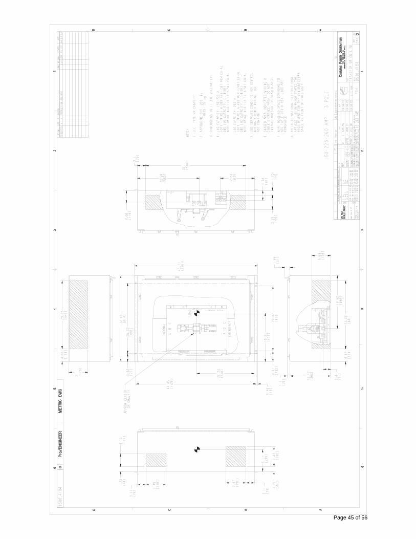
Page 45 of 56
�2009 Cummins Power Generation Inc. All rights reserved. Cummins Power Generationand Cummins are registered trademarks of Cummins Inc. PowerCommand and “Our energy working for you.” are trademarks of Cummins Power Generation. Other company, product, or service names may be trademarks or service marks of others. Specifications are subject to change without notice. S-1472e (8/09)
PowerCommand® Annunciator Discrete Input or PCCNet
Description Features
The Universal Annunciator Module provides visual and audible indication of up to 20 separate alarm or status conditions, based on discrete (relay) inputs or network inputs. Each LED can be controlled by either a discrete wire input or by a signal on the PCCNet network sent from an external device, such as a PCC1301 or PCC2100 (version 2.4 or later) control.
In addition to the LEDs, the annunciator can control four custom relays based on signals received over the PCCNet. When one of the annunciator’s discrete inputs is activated, the annunciator will broadcast that information over the network. By taking advantage of the network, discrete inputs and custom relays, the annunciator can be used as expanded I/O for a genset controller.
Easily installed in a location to give immediate notification of an alarm or warning status. Designed to give operating/monitoring personnel quick-glance status information. The module directly senses battery voltage to provide green/yellow/red alarm and status information for that parameter.
Genset controller complies with NFPA level two requirements when used with the display but without the annunciator panel. When used with the annunciator it meets NFPA level one requirements (emergency and standby power systems). The annunciator module can also be used for monitoring of transfer switch or other equipment status.
� Visual and audible warnings of up to 20 separate alarm or status conditions.
� LEDs can be controlled either via PCCNet or discrete input.
� Status of discrete inputs is broadcast on network. � Four custom relays can be controlled over the PCCNet
network. � Configurable LED color (red, yellow or green) and
selectable horn operation allows maximum flexibility. � Standard NFPA 110 label, field configurable for other
alarm status and conditions. � Each audible alarm is annunciated, regardless of the
number of existing alarm conditions displayed. � Sealed membrane panel design provides environmental
protection for internal components and is easy to clean. � Configurable for negative (ground) input or positive
input.� Integral DC voltage sensing. � Flush or surface mount provisions. � UL Listed and labeled; CSA certified; CE marked.
Page 46 of 56
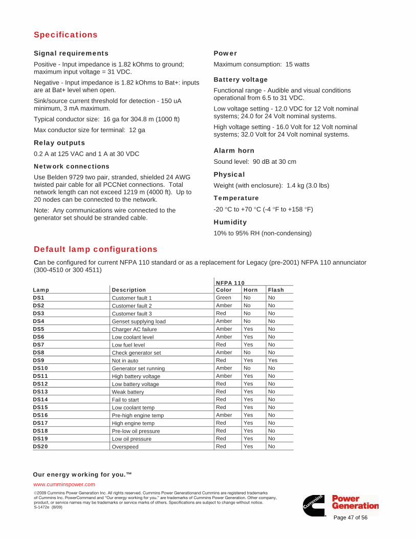
Our energy working for you.™www.cumminspower.com �2009 Cummins Power Generation Inc. All rights reserved. Cummins Power Generationand Cummins are registered trademarks of Cummins Inc. PowerCommand and “Our energy working for you.” are trademarks of Cummins Power Generation. Other company, product, or service names may be trademarks or service marks of others. Specifications are subject to change without notice. S-1472e (8/09)
Specifications
Signal requirements Positive - Input impedance is 1.82 kOhms to ground; maximum input voltage = 31 VDC.
Negative - Input impedance is 1.82 kOhms to Bat+: inputs are at Bat+ level when open.
Sink/source current threshold for detection - 150 uA minimum, 3 mA maximum.
Typical conductor size: 16 ga for 304.8 m (1000 ft)
Max conductor size for terminal: 12 ga
Relay outputs 0.2 A at 125 VAC and 1 A at 30 VDC
Network connections Use Belden 9729 two pair, stranded, shielded 24 AWG twisted pair cable for all PCCNet connections. Totalnetwork length can not exceed 1219 m (4000 ft). Up to 20 nodes can be connected to the network.
Note: Any communications wire connected to the generator set should be stranded cable.
PowerMaximum consumption: 15 watts
Battery voltage Functional range - Audible and visual conditions operational from 6.5 to 31 VDC.
Low voltage setting - 12.0 VDC for 12 Volt nominal systems; 24.0 for 24 Volt nominal systems.
High voltage setting - 16.0 Volt for 12 Volt nominal systems; 32.0 Volt for 24 Volt nominal systems.
Alarm horn Sound level: 90 dB at 30 cm
Physical Weight (with enclosure): 1.4 kg (3.0 lbs)
Temperature
-20 �C to +70 �C (-4 �F to +158 �F)
Humidity10% to 95% RH (non-condensing)
Default lamp configurations
Can be configured for current NFPA 110 standard or as a replacement for Legacy (pre-2001) NFPA 110 annunciator (300-4510 or 300 4511)
NFPA 110Lamp Description Color Horn FlashDS1 Customer fault 1 Green No No DS2 Customer fault 2 Amber No No DS3 Customer fault 3 Red No No DS4 Genset supplying load Amber No No DS5 Charger AC failure Amber Yes No DS6 Low coolant level Amber Yes No DS7 Low fuel level Red Yes No DS8 Check generator set Amber No No DS9 Not in auto Red Yes Yes DS10 Generator set running Amber No No DS11 High battery voltage Amber Yes No DS12 Low battery voltage Red Yes No DS13 Weak battery Red Yes No DS14 Fail to start Red Yes No DS15 Low coolant temp Red Yes No DS16 Pre-high engine temp Amber Yes No DS17 High engine temp Red Yes No DS18 Pre-low oil pressure Red Yes No DS19 Low oil pressure Red Yes No DS20 Overspeed Red Yes No
Page 47 of 56
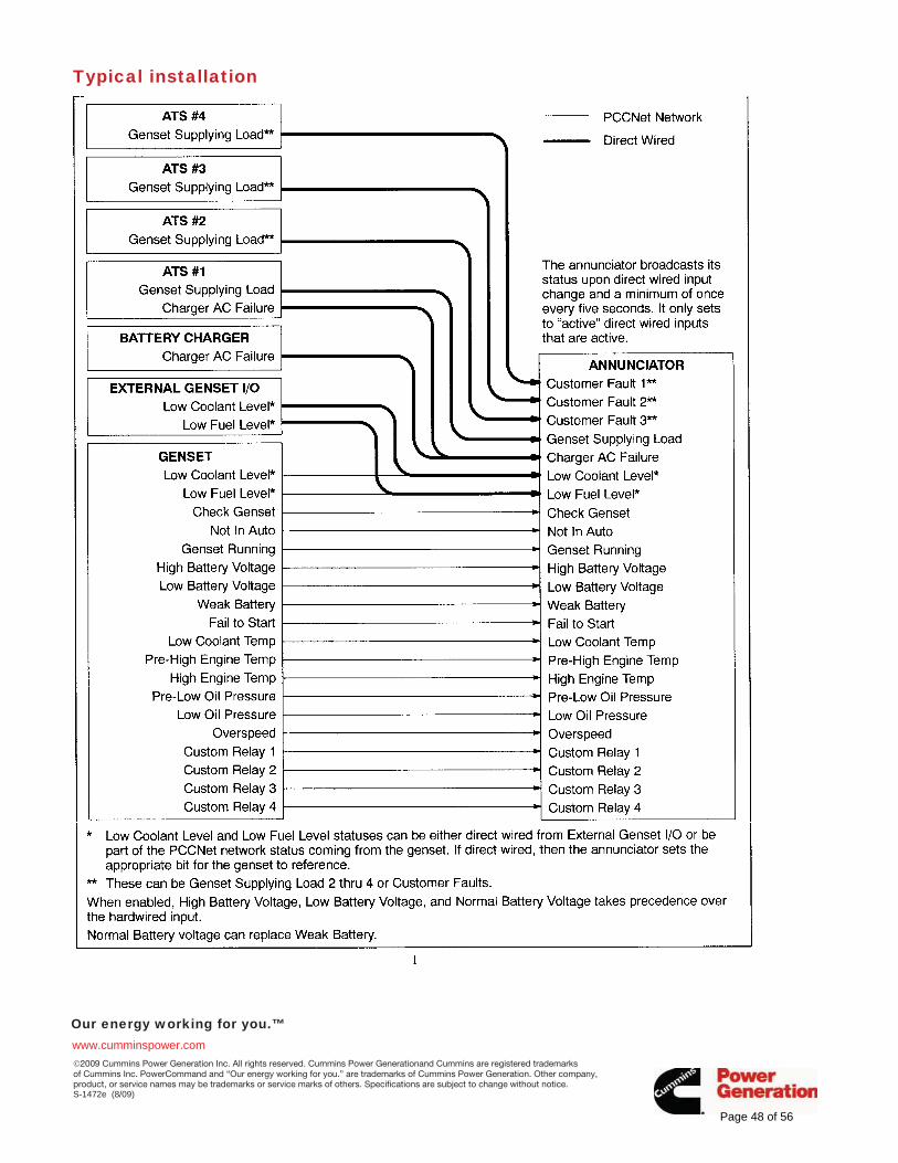
Our energy working for you.™www.cumminspower.com �2009 Cummins Power Generation Inc. All rights reserved. Cummins Power Generationand Cummins are registered trademarks of Cummins Inc. PowerCommand and “Our energy working for you.” are trademarks of Cummins Power Generation. Other company, product, or service names may be trademarks or service marks of others. Specifications are subject to change without notice. S-1472e (8/09)
Typical installation
Page 48 of 56
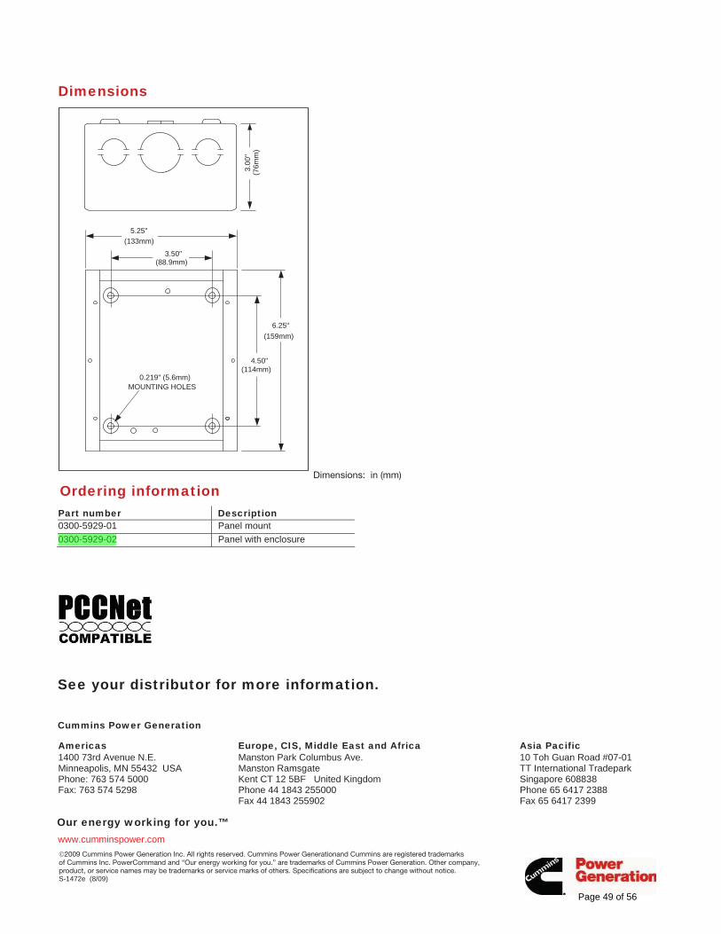
Our energy working for you.™www.cumminspower.com �2009 Cummins Power Generation Inc. All rights reserved. Cummins Power Generationand Cummins are registered trademarks of Cummins Inc. PowerCommand and “Our energy working for you.” are trademarks of Cummins Power Generation. Other company, product, or service names may be trademarks or service marks of others. Specifications are subject to change without notice. S-1472e (8/09)
Dimensions
6.25"(159mm)
4.50"(114mm)
3.50"(88.9mm)
5.25"(133mm)
3.00
"(7
6mm
)
0.219" (5.6mm)MOUNTING HOLES
Dimensions: in (mm)
Ordering informationPart number Description 0300-5929-01 Panel mount 0300-5929-02 Panel with enclosure
See your distributor for more information.
Cummins Power Generation
Americas 1400 73rd Avenue N.E. Minneapolis, MN 55432 USA Phone: 763 574 5000 Fax: 763 574 5298
Europe, CIS, Middle East and Africa Manston Park Columbus Ave. Manston Ramsgate Kent CT 12 5BF United Kingdom Phone 44 1843 255000 Fax 44 1843 255902
Asia Pacific 10 Toh Guan Road #07-01 TT International Tradepark Singapore 608838 Phone 65 6417 2388 Fax 65 6417 2399
Page 49 of 56
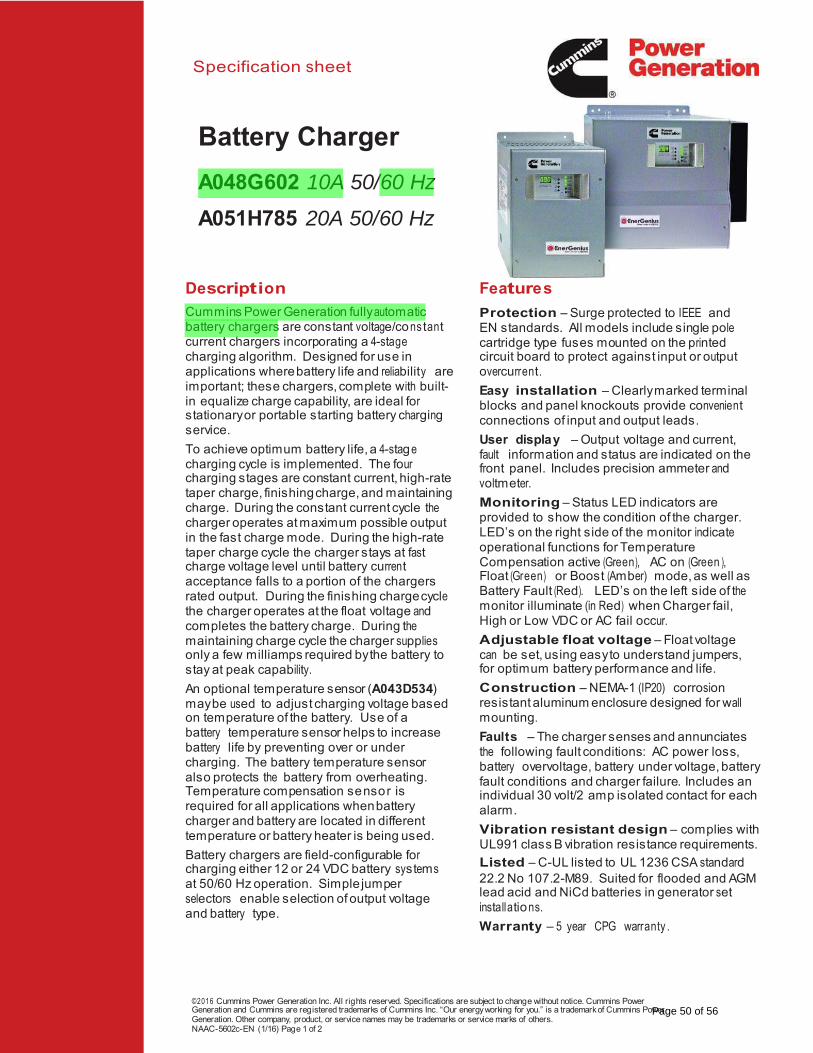
Specification sheet
Description Features
Cummins Power Generation fully automatic battery chargers are constant voltage/constant current chargers incorporating a 4-stage charging algorithm. Designed for use in applications where battery life and reliability are important; these chargers, complete with built-in equalize charge capability, are ideal for stationary or portable starting battery charging service.
To achieve optimum battery life, a 4-stage charging cycle is implemented. The four charging stages are constant current, high-rate taper charge, finishing charge, and maintaining charge. During the constant current cycle the charger operates at maximum possible output in the fast charge mode. During the high-rate taper charge cycle the charger stays at fast charge voltage level until battery current acceptance falls to a portion of the chargers rated output. During the finishing charge cycle the charger operates at the float voltage and completes the battery charge. During the maintaining charge cycle the charger supplies only a few milliamps required by the battery to stay at peak capability.
An optional temperature sensor (A043D534) may be used to adjust charging voltage based on temperature of the battery. Use of a battery temperature sensor helps to increase battery life by preventing over or under charging. The battery temperature sensor also protects the battery from overheating. Temperature compensation sensor is required for all applications when battery charger and battery are located in different temperature or battery heater is being used.
Battery chargers are field-configurable for charging either 12 or 24 VDC battery systems at 50/60 Hz operation. Simple jumper selectors enable selection of output voltage and battery type.
Protection – Surge protected to IEEE and EN standards. All models include single pole cartridge type fuses mounted on the printed circuit board to protect against input or output overcurrent.
Easy installation – Clearly marked terminal blocks and panel knockouts provide convenient connections of input and output leads.
User display – Output voltage and current, fault information and status are indicated on the front panel. Includes precision ammeter and voltmeter.
Monitoring – Status LED indicators are provided to show the condition of the charger. LED’s on the right side of the monitor indicate operational functions for Temperature Compensation active (Green), AC on (Green ), Float (Green) or Boost (Amber) mode, as well as Battery Fault (Red). LED’s on the left side of the monitor illuminate (in Red) when Charger fail, High or Low VDC or AC fail occur.
Adjustable float voltage – Float voltage can be set, using easy to understand jumpers, for optimum battery performance and life.
Construction – NEMA-1 (IP20) corrosion resistant aluminum enclosure designed for wall mounting.
Faults – The charger senses and annunciates the following fault conditions: AC power loss, battery overvoltage, battery under voltage, battery fault conditions and charger failure. Includes an individual 30 volt/2 amp isolated contact for each alarm.
Vibration resistant design – complies with UL991 class B vibration resistance requirements.
Listed – C-UL listed to UL 1236 CSA standard 22.2 No 107.2-M89. Suited for flooded and AGM lead acid and NiCd batteries in generator set installations.
Warranty – 5 year CPG warranty .
©2016 Cummins Power Generation Inc. All rights reserved. Specifications are subject to change without notice. Cummins Power Generation and Cummins are registered trademarks of Cummins Inc. “Our energy working for you.” is a trademark of Cummins Power Generation. Other company, product, or service names may be trademarks or service marks of others. NAAC-5602c-EN (1/16) Page 1 of 2
Battery Charger
A048G602 10A 50/60 Hz
A051H785 20A 50/60 Hz
Page 50 of 56
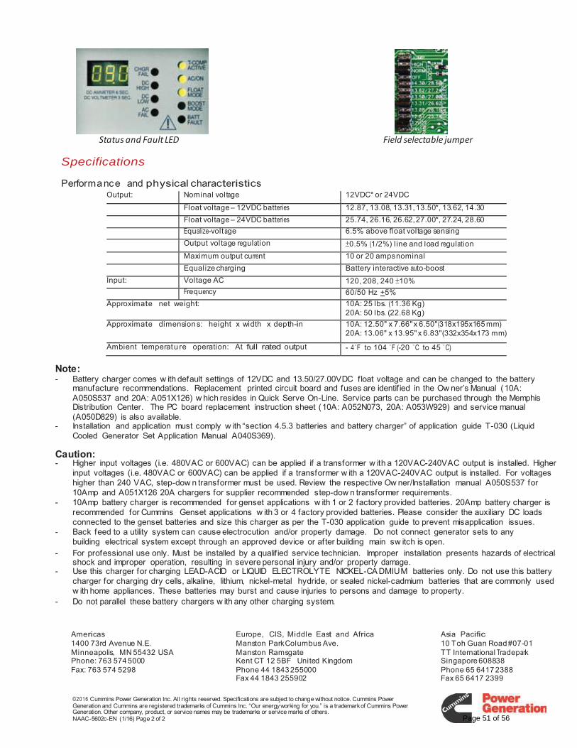
Status and Fault LED Field selectable jumper
Specifications
Performance and physical characteristics
Note: - Battery charger comes w ith default settings of 12VDC and 13.50/27.00VDC float voltage and can be changed to the battery
manufacture recommendations. Replacement printed circuit board and fuses are identif ied in the Ow ner’s Manual (10A: A050S537 and 20A: A051X126) w hich resides in Quick Serve On-Line. Service parts can be purchased through the Memphis Distribution Center. The PC board replacement instruction sheet (10A: A052N073, 20A: A053W929) and service manual (A050D829) is also available.
- Installation and application must comply w ith “section 4.5.3 batteries and battery charger” of application guide T-030 (Liquid Cooled Generator Set Application Manual A040S369).
Caution: - Higher input voltages (i.e. 480VAC or 600VAC) can be applied if a transformer w ith a 120VAC-240VAC output is installed. Higher
input voltages (i.e. 480VAC or 600VAC) can be applied if a transformer w ith a 120VAC-240VAC output is installed. For voltages higher than 240 VAC, step-dow n transformer must be used. Review the respective Ow ner/Installation manual A050S537 for 10Amp and A051X126 20A chargers for supplier recommended step-dow n transformer requirements.
- 10Amp battery charger is recommended for genset applications w ith 1 or 2 factory provided batteries. 20Amp battery charger is recommended for Cummins Genset applications w ith 3 or 4 factory provided batteries. Please consider the auxiliary DC loads connected to the genset batteries and size this charger as per the T-030 application guide to prevent misapplication issues.
- Back feed to a utility system can cause electrocution and/or property damage. Do not connect generator sets to any building electrical system except through an approved device or after building main sw itch is open.
- For professional use only. Must be installed by a qualif ied service technician. Improper installation presents hazards of electrical shock and improper operation, resulting in severe personal injury and/or property damage.
- Use this charger for charging LEAD-ACID or LIQUID ELECTROLYTE NICKEL-CA DMIUM batteries only. Do not use this battery charger for charging dry cells, alkaline, lithium, nickel-metal hydride, or sealed nickel-cadmium batteries that are commonly used w ith home appliances. These batteries may burst and cause injuries to persons and damage to property.
- Do not parallel these battery chargers w ith any other charging system.
©2016 Cummins Power Generation Inc. All rights reserved. Specifications are subject to change without notice. Cummins Power Generation and Cummins are registered trademarks of Cummins Inc. “Our energy working for you.” is a trademark of Cummins Power Generation. Other company, product, or service names may be trademarks or service marks of others. NAAC-5602c-EN (1/16) Page 2 of 2
Output: Nominal voltage 12VDC* or 24VDC
Float voltage – 12VDC batteries 12.87, 13.08, 13.31, 13.50*, 13.62, 14.30
Float voltage – 24VDC batteries 25.74, 26.16, 26.62, 27.00*, 27.24, 28.60
Equalize-volt age 6.5% above float voltage sensing
Output voltage regulation 0.5% (1/2%) line and load regulation
Maximum output current 10 or 20 amps nominal
Equalize charging Battery interactive auto-boost
Input: Voltage AC 120, 208, 240 10%
Frequency 60/50 Hz +5%
Approximate net weight: 10A: 25 lbs. (11.36 Kg) 20A: 50 lbs. (22.68 Kg)
Approximate dimension s: height x width x depth-in 10A: 12.50" x 7.66" x 6.50"(318x195x165 mm) 20A: 13.06" x 13.95" x 6.83"(332x354x173 mm)
Ambient temperatu re operation: At full rated output - 4 F to 104 F (-20 C to 45 C)
Americas 1400 73rd Avenue N.E. Minneapolis, MN 55432 USA Phone: 763 574 5000 Fax: 763 574 5298
Europe, CIS, Middle East and Africa Manston Park Columbus Ave. Manston Ramsgate Kent CT 12 5BF United Kingdom Phone 44 1843 255000 Fax 44 1843 255902
Asia Pacific 10 Toh Guan Road #07-01 TT International Tradepark Singapore 608838 Phone 65 6417 2388 Fax 65 6417 2399
Page 51 of 56
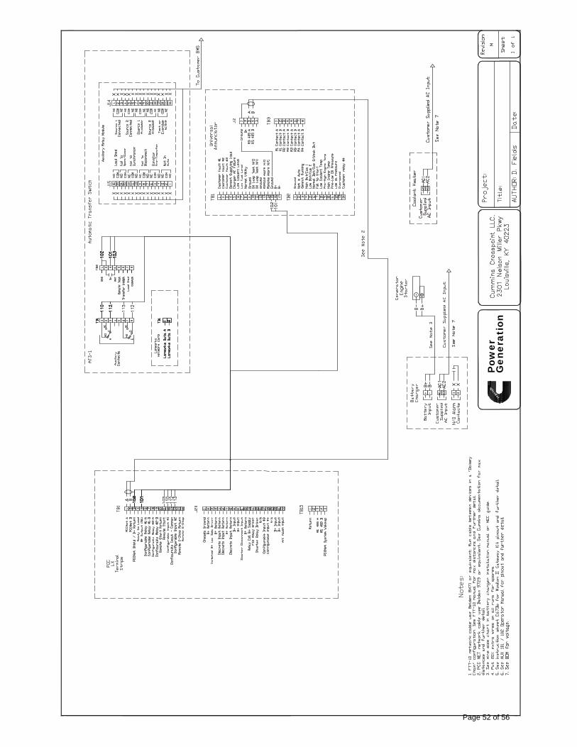
Pow
erG
ener
atio
n
Page 52 of 56
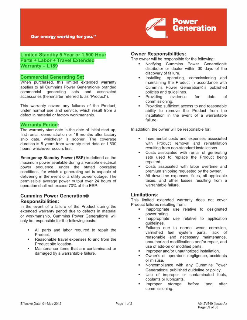
Effective Date: 01-May-2012 Page 1 of 2 A042V549 (Issue A)
Limited Standby 5 Year or 1,500 Hour Parts + Labor + Travel Extended Warranty – L189 Commercial Generating Set When purchased, this limited extended warranty applies to all Cummins Power Generation branded commercial generating sets and associated accessories (hereinafter referred to as "Product"). This warranty covers any failures of the Product, under normal use and service, which result from a defect in material or factory workmanship. Warranty Period: The warranty start date is the date of initial start up, first rental, demonstration or 18 months after factory ship date, whichever is sooner. The coverage duration is 5 years from warranty start date or 1,500 hours, whichever occurs first. Emergency Standby Power (ESP) is defined as the maximum power available during a variable electrical power sequence, under the stated operating conditions, for which a generating set is capable of delivering in the event of a utility power outage. The permissible average power output over 24 hours of operation shall not exceed 70% of the ESP.
Cummins Power Generation Responsibilities: In the event of a failure of the Product during the extended warranty period due to defects in material or workmanship, Cummins Power Generation will only be responsible for the following costs:
All parts and labor required to repair the Product.
Reasonable travel expenses to and from the Product site location.
Maintenance items that are contaminated or damaged by a warrantable failure.
Owner Responsibilities: The owner will be responsible for the following:
Notifying Cummins Power Generation distributor or dealer within 30 days of the discovery of failure.
Installing, operating, commissioning and maintaining the Product in accordance with Cummins Power Generation ’s published policies and guidelines.
Providing evidence for date of commissioning.
Providing sufficient access to and reasonable ability to remove the Product from the installation in the event of a warrantable failure.
In addition, the owner will be responsible for:
Incremental costs and expenses associated with Product removal and reinstallation resulting from non-standard installations.
Costs associated with rental of generating sets used to replace the Product being repaired.
Costs associated with labor overtime and premium shipping requested by the owner.
All downtime expenses, fines, all applicable taxes, and other losses resulting from a warrantable failure.
Limitations: This limited extended warranty does not cover Product failures resulting from:
Inappropriate use relative to designated power rating.
Inappropriate use relative to application guidelines.
Failures due to normal wear, corrosion, varnished fuel system parts, lack of reasonable and necessary maintenance, unauthorized modifications and/or repair, and use of add-on or modified parts.
Improper and/or unauthorized installation. Owner’s or operator’s negligence, accidents
or misuse. Noncompliance with any Cummins Power
Generation published guideline or policy. Use of improper or contaminated fuels,
coolants or lubricants. Improper storage before and after
commissioning.
Page 53 of 56
Effective Date: 01-May-2012 Page 2 of 2 A042V549 (Issue A)
Limitations Continued:
Owner’s delay in making Product available after notification of potential Product problem.
Replacement parts and accessories not authorized by Cummins Power Generation .
Use of Battle Short Mode Owner or operator abuse or neglect such as:
operation without adequate coolant or lubricants; overfueling; overspeeding; lack of maintenance to lubricating, cooling or air intake systems; late servicing and maintenance; improper storage, starting, warm-up, run-in or shutdown practices, or for progressive damage resulting from a defective shutdown or warning device.
Damage to parts, fixtures, housings, attachments and accessory items that are not part of the generating set.
This limited extended warranty does not cover costs resulting from:
Difficulty in gaining access to the Product. Damage to customer property. Repair of cosmetic damage to enclosures.
Items not covered by this limited extended warranty:
Batteries Enclosures Coolant heaters Exhaust systems and aftertreatment
components Maintenance items
www.cumminspower.com
CUMMINS POWER GENERATION RIGHT TO FAILED COMPONENTS: Failed components claimed under warranty remain the property of Cummins Power Generation . Cummins Power Generation has the right to reclaim any failed component that has been replaced under warranty. THE WARRANTIES SET FORTH HEREIN ARE THE SOLE WARRANTIES MADE BY CUMMINS POWER GENERATION IN REGARD TO THE PRODUCT. CUMMINS POWER GENERATION MAKES NO OTHER WARRANTIES, EXPRESS OR IMPLIED, OR OF MERCHANTABILITY OR FITNESS FOR A PARTICULAR PURPOSE. IN NO EVENT IS CUMMINS POWER GENERATION LIABLE FOR INCIDENTAL OR CONSEQUENTIAL DAMAGES. This limited extended warranty shall be enforced to the maximum extent permitted by applicable law. This limited extended warranty gives the owner specific rights that may vary from state to state or from jurisdiction to jurisdiction. Product Model Number:_______________________ Product Serial Number:________________________ Date in Service:______________________________
Page 54 of 56
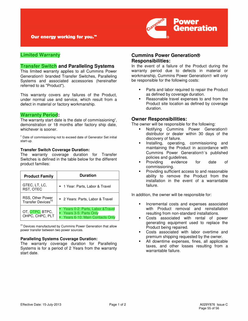
Effective Date: 15-July-2013 Page 1 of 2 A029Y876 Issue C
Limited Warranty Transfer Switch and Paralleling Systems This limited warranty applies to all Cummins Power Generation branded Transfer Switches, Paralleling Systems and associated accessories (hereinafter referred to as "Product"). This warranty covers any failures of the Product, under normal use and service, which result from a defect in material or factory workmanship. Warranty Period: The warranty start date is the date of commissioning†, demonstration or 18 months after factory ship date, whichever is sooner.
† Date of commissioning not to exceed date of Generator Set initial start-up. Transfer Switch Coverage Duration: The warranty coverage duration for Transfer Switches is defined in the table below for the different product families:
Product Family Duration
GTEC, LT, LC, RST, OTEC
1 Year: Parts, Labor & Travel
RSS, Other Power Transfer Devices††
2 Years: Parts, Labor & Travel
OT, OTPC, BTPC, OHPC, CHPC, PLT
Years 0-2: Parts, Labor &Travel Years 3-5: Parts Only Years 6-10: Main Contacts Only
†† Devices manufactured by Cummins Power Generation that allow power transfer between two power sources. Paralleling Systems Coverage Duration: The warranty coverage duration for Paralleling Systems is for a period of 2 Years from the warranty start date.
Cummins Power Generation Responsibilities: In the event of a failure of the Product during the warranty period due to defects in material or workmanship, Cummins Power Generation will only be responsible for the following costs:
Parts and labor required to repair the Product as defined by coverage duration.
Reasonable travel expenses to and from the Product site location as defined by coverage duration.
Owner Responsibilities: The owner will be responsible for the following:
Notifying Cummins Power Generation distributor or dealer within 30 days of the discovery of failure.
Installing, operating, commissioning and maintaining the Product in accordance with Cummins Power Generation ’s published policies and guidelines.
Providing evidence for date of commissioning.
Providing sufficient access to and reasonable ability to remove the Product from the installation in the event of a warrantable failure.
In addition, the owner will be responsible for:
Incremental costs and expenses associated with Product removal and reinstallation resulting from non-standard installations.
Costs associated with rental of power generating equipment used to replace the Product being repaired.
Costs associated with labor overtime and premium shipping requested by the owner.
All downtime expenses, fines, all applicable taxes, and other losses resulting from a warrantable failure.
Page 55 of 56
Effective Date: 15-July-2013 Page 2 of 2 A029Y876 Issue C
Limitations: This limited warranty does not cover Product failures resulting from:
Inappropriate use relative to designated power rating.
Inappropriate use relative to application guidelines.
Non-conformance to applicable industry standards for installation
Normal wear and tear. Improper and/or unauthorized installation. Negligence, accidents or misuse. Lack of maintenance or unauthorized repair. Noncompliance with any Cummins Power
Generation published guideline or policy. Improper storage before and after
commissioning. Owner’s delay in making Product available
after notification of potential Product problem. Replacement parts and accessories not
authorized by Cummins Power Generation . Owner or operator abuse or neglect such as:
late servicing and maintenance and improper storage.
Damage to parts, fixtures, housings, attachments and accessory items that are not part of the transfer switch or paralleling system.
This limited warranty does not cover costs resulting from:
Difficulty in gaining access to the Product. Damage to customer property.
Please contact your local Cummins Power Generation Distributor for clarification concerning these limitations.
CUMMINS POWER GENERATION RIGHT TO FAILED COMPONENTS: Failed components claimed under warranty remain the property of Cummins Power Generation . Cummins Power Generation has the right to reclaim any failed component that has been replaced under warranty. Extended Warranty: Cummins Power Generation offers several levels of Extended Warranty Coverage. Please contact your local Cummins Power Generation Distributor for details. www.cumminspower.com THE WARRANTIES SET FORTH HEREIN ARE THE SOLE WARRANTIES MADE BY CUMMINS POWER GENERATION IN REGARD TO THE PRODUCT. CUMMINS POWER GENERATION MAKES NO OTHER WARRANTIES, EXPRESS OR IMPLIED, OR OF MERCHANTABILITY OR FITNESS FOR A PARTICULAR PURPOSE. IN NO EVENT IS CUMMINS POWER GENERATION LIABLE FOR INCIDENTAL OR CONSEQUENTIAL DAMAGES. This limited warranty shall be enforced to the maximum extent permitted by applicable law. This limited warranty gives the owner specific rights that may vary from state to state or from jurisdiction to jurisdiction. Product Model Number:_______________________ Product Serial Number:________________________ Date in Service:______________________________
Page 56 of 56

ATTACHMENT I
EMISSIONS CALCULATIONS

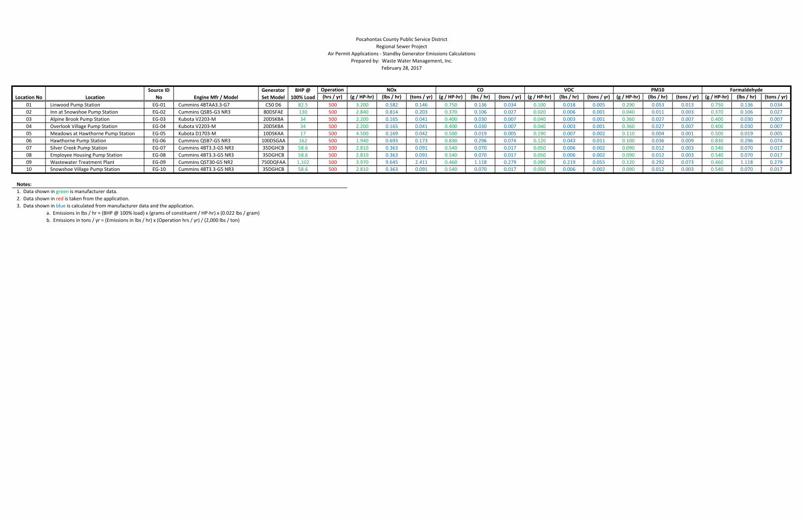
Operation
(hrs / yr) (g / HP-hr) (lbs / hr) (tons / yr) (g / HP-hr) (lbs / hr) (tons / yr) (g / HP-hr) (lbs / hr) (tons / yr) (g / HP-hr) (lbs / hr) (tons / yr) (g / HP-hr) (lbs / hr) (tons / yr)
01 Linwood Pump Station EG-01 Cummins 4BTAA3.3-G7 C50 D6 82.5 500 3.200 0.582 0.146 0.750 0.136 0.034 0.100 0.018 0.005 0.290 0.053 0.013 0.750 0.136 0.034
02 Inn at Snowshoe Pump Station EG-02 Cummins QSB5-G3 NR3 80DSFAE 130 500 2.840 0.814 0.203 0.370 0.106 0.027 0.020 0.006 0.001 0.040 0.011 0.003 0.370 0.106 0.027
03 Alpine Brook Pump Station EG-03 Kubota V2203-M 20DSKBA 34 500 2.200 0.165 0.041 0.400 0.030 0.007 0.040 0.003 0.001 0.360 0.027 0.007 0.400 0.030 0.007
04 Overlook Village Pump Station EG-04 Kubota V2203-M 20DSKBA 34 500 2.200 0.165 0.041 0.400 0.030 0.007 0.040 0.003 0.001 0.360 0.027 0.007 0.400 0.030 0.007
05 Meadows at Hawthorne Pump Station EG-05 Kubota D1703-M 10DSKAA 17 500 4.500 0.169 0.042 0.500 0.019 0.005 0.190 0.007 0.002 0.110 0.004 0.001 0.500 0.019 0.005
06 Hawthorne Pump Station EG-06 Cummins QSB7-G5 NR3 100DSGAA 162 500 1.940 0.693 0.173 0.830 0.296 0.074 0.120 0.043 0.011 0.100 0.036 0.009 0.830 0.296 0.074
07 Silver Creek Pump Station EG-07 Cummins 4BT3.3-G5 NR3 35DGHCB 58.6 500 2.810 0.363 0.091 0.540 0.070 0.017 0.050 0.006 0.002 0.090 0.012 0.003 0.540 0.070 0.017
08 Employee Housing Pump Station EG-08 Cummins 4BT3.3-G5 NR3 35DGHCB 58.6 500 2.810 0.363 0.091 0.540 0.070 0.017 0.050 0.006 0.002 0.090 0.012 0.003 0.540 0.070 0.017
09 Wastewater Treatment Plant EG-09 Cummins QST30-G5 NR2 750DQFAA 1,102 500 3.970 9.645 2.411 0.460 1.118 0.279 0.090 0.219 0.055 0.120 0.292 0.073 0.460 1.118 0.279
10 Snowshoe Village Pump Station EG-10 Cummins 4BT3.3-G5 NR3 35DGHCB 58.6 500 2.810 0.363 0.091 0.540 0.070 0.017 0.050 0.006 0.002 0.090 0.012 0.003 0.540 0.070 0.017
Notes:
1. Data shown in green is manufacturer data.
2. Data shown in red is taken from the application.
3. Data shown in blue is calculated from manufacturer data and the application.
a. Emissions in lbs / hr = (BHP @ 100% load) x (grams of constituent / HP-hr) x (0.022 lbs / gram)
b. Emissions in tons / yr = (Emissions in lbs / hr) x (Operation hrs / yr) / (2,000 lbs / ton)
VOC PM10 Formaldehyde
Engine Mfr / ModelLocation No Location
BHP @
100% Load
Generator
Set Model
Source ID
No
NOx CO
Pocahontas County Public Service District
Regional Sewer Project
Air Permit Applications - Standby Generator Emissions Calculations
Prepared by: Waste Water Management, Inc.
February 28, 2017

ATTACHMENT L
GENERAL PERMIT REGISTRATION
APPLICATION FEE


ATTACHMENT O
EMISSIONS SUMMARY SHEETS

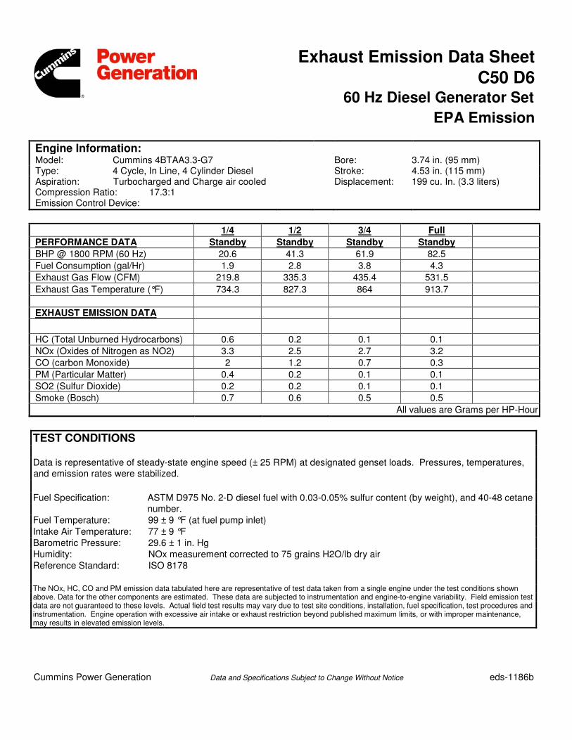
Exhaust Emission Data Sheet
C50 D6 60 Hz Diesel Generator Set
EPA Emission
Engine Information: Model: Cummins 4BTAA3.3-G7
Bore: 3.74 in. (95 mm) Type: 4 Cycle, In Line, 4 Cylinder Diesel Stroke: 4.53 in. (115 mm) Aspiration: Turbocharged and Charge air cooled Compression Ratio: 17.3:1 Emission Control Device:
Displacement: 199 cu. In. (3.3 liters)
1/4 1/2 3/4 Full
PERFORMANCE DATA Standby Standby Standby Standby
BHP @ 1800 RPM (60 Hz) 20.6 41.3 61.9 82.5
Fuel Consumption (gal/Hr) 1.9 2.8 3.8 4.3
Exhaust Gas Flow (CFM) 219.8 335.3 435.4 531.5
Exhaust Gas Temperature (°F) 734.3 827.3 864 913.7
EXHAUST EMISSION DATA
HC (Total Unburned Hydrocarbons) 0.6 0.2 0.1 0.1
NOx (Oxides of Nitrogen as NO2) 3.3 2.5 2.7 3.2
CO (carbon Monoxide) 2 1.2 0.7 0.3
PM (Particular Matter) 0.4 0.2 0.1 0.1
SO2 (Sulfur Dioxide) 0.2 0.2 0.1 0.1
Smoke (Bosch) 0.7 0.6 0.5 0.5
All values are Grams per HP-Hour
TEST CONDITIONS Data is representative of steady-state engine speed (± 25 RPM) at designated genset loads. Pressures, temperatures, and emission rates were stabilized. Fuel Specification: ASTM D975 No. 2-D diesel fuel with 0.03-0.05% sulfur content (by weight), and 40-48 cetane
number. Fuel Temperature: 99 ± 9 °F (at fuel pump inlet) Intake Air Temperature: 77 ± 9 °F Barometric Pressure: 29.6 ± 1 in. Hg Humidity: NOx measurement corrected to 75 grains H2O/lb dry air Reference Standard: ISO 8178 The NOx, HC, CO and PM emission data tabulated here are representative of test data taken from a single engine under the test conditions shown above. Data for the other components are estimated. These data are subjected to instrumentation and engine-to-engine variability. Field emission test data are not guaranteed to these levels. Actual field test results may vary due to test site conditions, installation, fuel specification, test procedures and instrumentation. Engine operation with excessive air intake or exhaust restriction beyond published maximum limits, or with improper maintenance, may results in elevated emission levels.
Cummins Power Generation Data and Specifications Subject to Change Without Notice
eds-1186b
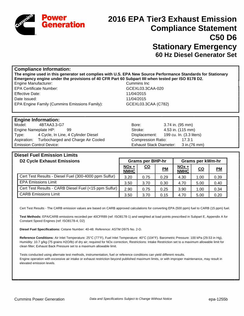
14
2016 EPA Tier3 Exhaust Emission Compliance Statement
C50 D6 Stationary Emergency
60 Hz Diesel Generator Set Compliance Information: The engine used in this generator set complies with U.S. EPA New Source Performance Standards for Stationary Emergency engine under the provisions of 40 CFR Part 60 Subpart IIII when tested per ISO 8178 D2. Engine Manufacturer: Cummins Inc EPA Certificate Number: GCEXL03.3CAA-020 Effective Date: 11/04/2015 Date Issued: 11/04/2015 EPA Engine Family (Cummins Emissions Family): GCEXL03.3CAA (C782)
Engine Information: Model: 4BTAA3.3-G7 Bore: 3.74 in. (95 mm) Engine Nameplate HP: 99 Stroke: 4.53 in. (115 mm) Type: 4 Cycle, In Line, 4 Cylinder Diesel Displacement: 199 cu. In. (3.3 liters) Aspiration: Turbocharged and Charge Air Cooled Compression Ratio: 17.3:1 Emission Control Device: Exhaust Stack Diameter: 3 in.(76 mm)
Diesel Fuel Emission Limits D2 Cycle Exhaust Emissions Grams per BHP-hr Grams per kWm-hr NOx +
NMHC CO PM NOx +
NMHC CO PM
Cert Test Results - Diesel Fuel (300-4000 ppm Sulfur) 3.20 0.75 0.29 4.30 1.00 0.39 EPA Emissions Limit 3.50 3.70 0.30 4.70 5.00 0.40
Cert Test Results - CARB Diesel Fuel (<15 ppm Sulfur) 2.90 0.75 0.25 3.90 1.00 0.34 CARB Emissions Limit 3.50 3.70 0.15 4.70 5.00 0.20
Cert Test Results - The CARB emission values are based on CARB approved calculations for converting EPA (500 ppm) fuel to CARB (15 ppm) fuel.
Test Methods: EPA/CARB emissions recorded per 40CFR89 (ref. ISO8178-1) and weighted at load points prescribed in Subpart E, Appendix A for Constant Speed Engines (ref. ISO8178-4, D2)
Diesel Fuel Specifications: Cetane Number: 40-48. Reference: ASTM D975 No. 2-D.
Reference Conditions: Air Inlet Temperature: 25°C (77°F), Fuel Inlet Temperature: 40°C (104°F). Barometric Pressure: 100 kPa (29.53 in Hg), Humidity: 10.7 g/kg (75 grains H2O/lb) of dry air; required for NOx correction, Restrictions: Intake Restriction set to a maximum allowable limit for clean filter; Exhaust Back Pressure set to a maximum allowable limit. Tests conducted using alternate test methods, instrumentation, fuel or reference conditions can yield different results. Engine operation with excessive air intake or exhaust restriction beyond published maximum limits, or with improper maintenance, may result in elevated emission levels.
Cummins Power Generation Data and Specifications Subject to Change Without Notice epa-1255b
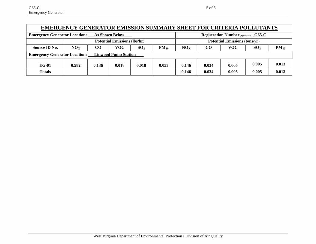
G65-C 5 of 5 Emergency Generator
West Virginia Department of Environmental Protection • Division of Air Quality
EMERGENCY GENERATOR EMISSION SUMMARY SHEET FOR CRITERIA POLLUTANTS Emergency Generator Location: As Shown Below Registration Number (Agency Use) G65-C
Potential Emissions (lbs/hr) Potential Emissions (tons/yr) Source ID No. NOX CO VOC SO2 PM10 NOX CO VOC SO2 PM10
Emergency Generator Location: Linwood Pump Station
EG-01
0.582
0.136
0.018
0.018
0.053
0.146
0.034
0.005
0.005
0.013
Totals 0.146 0.034 0.005 0.005 0.013