pna-x series microwave network analyzers - am technologies
TRANSCRIPT
Keysight TechnologiesPNA-X Series Microwave Network Analyzers

Industry’s Most Advanced RF Test Solution
Reach for unrivaled excellence
All of the PNA-X’s powerful measurement
applications can be used for on-wafer devices.
– Conversion gain/loss
– True-differential stimulus
– Nonlinear waveform and
X-parameter* characterization
– Antenna test
Build your optimal test system by selecting the frequency range for your speciic device-test needs without paying for functionality you don’t need.
10 MHz to 13.5 GHz
10 MHz to 26.5 GHz
10 MHz to 43.5 GHz
10 MHz to 50 GHz
N5241A
N5242A
N5244A
N5245A
10 MHz to 67 GHzN5247A
PNA-X with mm-wave modules 10 MHz to 1.05 THz
10 MHz to 8.5 GHzN5249A
Choose the leader in network analysis
The PNA-X Series of microwave network analyzers are the culmination of Keysight
Technologies, Inc. 40-year legacy of technical leadership and innovation in radio
frequency (RF) network analysis. More than just a vector network analyzer, the PNA-X
is the world’s most integrated and lexible microwave test engine for measuring active devices like ampliiers, mixers, and frequency converters.
The combination of two internal signal sources, a signal combiner, S-parameter and
noise receivers, pulse modulators and generators, and a lexible set of switches and RF access points provide a powerful hardware core for a broad range of linear and nonlin-
ear measurements, all with a single set of connections to your device-under-test (DUT).
When you’re characterizing active devices, the right mix of speed and performance
gives you an edge. In R&D, the PNA family provides a level of measurement integrity
that helps you transform deeper understanding into better designs. On the production
line, our PNAs deliver the throughput and repeatability you need to transform great
designs into competitive products. Every Keysight VNA is the ultimate expression of
our expertise in linear and nonlinear device characterization. Choose a PNA --and
reach for unrivaled excellence in your measurements and your designs.
World´s widest range of measurement applications
PNA-X applications bring speed, accuracy, and ease-of-use to common RF
measurements, in coaxial, ixtured, and on-wafer environments. Applications include:
– S-parameters (CW and pulsed)
– Noise igure – Gain compression
– Intermodulation and
harmonic distortion
Network analysis technology down to the nanoscale
The PNA-X is also compatible with these Keysight measurement solutions:
– Physical layer test system (PLTS) software to calibrate, measure, and analyze
linear passive interconnects, such as cables, connectors, backplanes, and printed
circuit boards.
– Materials test equipment and accessories to help determine how your materials
interact with electromagnetic ields, by calculating permittivity and permeability. – Award-winning scanning microwave microscope to create a powerful and unique
combination for topography measurements of calibrated capacitance and dopant
densities at nanoscale dimensions.
The right frequency for your application
02 | Keysight | PNA-X Series Microwave Network Analyzers - Brochure
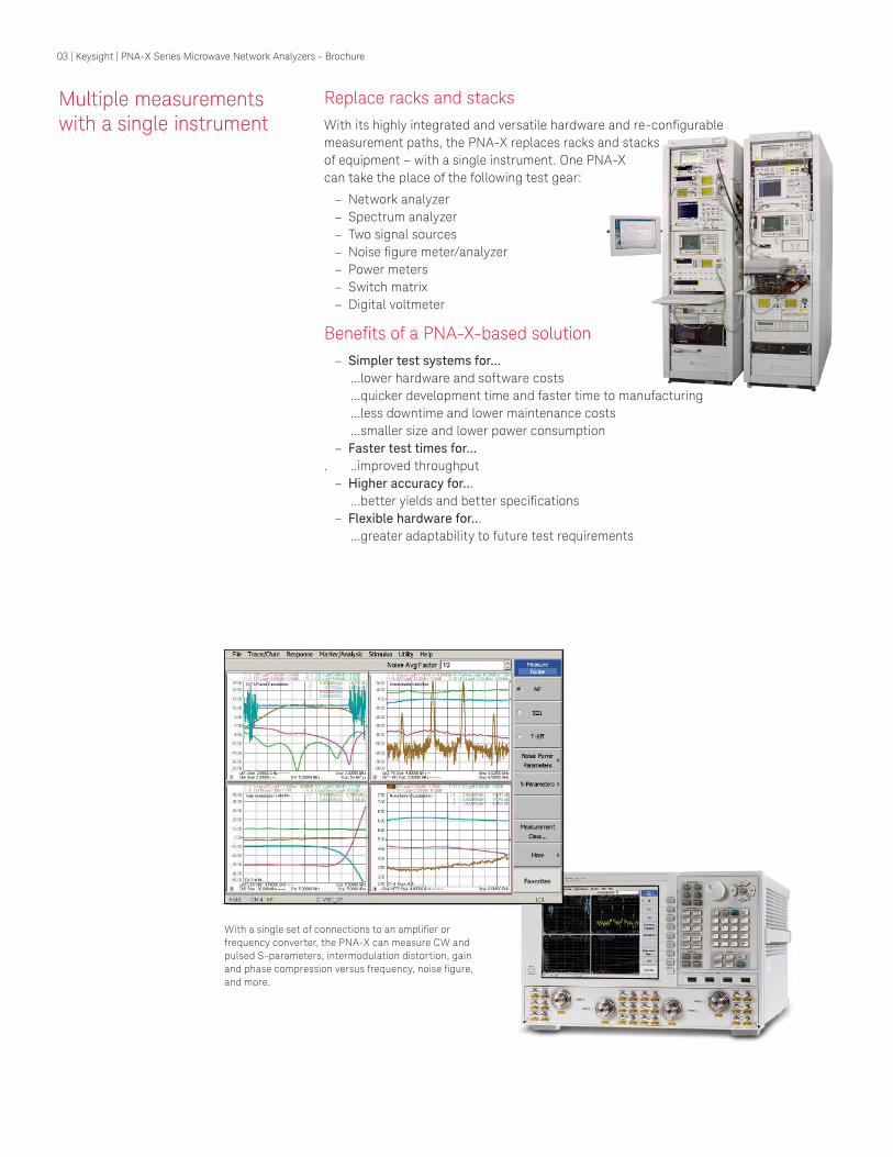
Multiple measurements with a single instrument
Replace racks and stacks
With its highly integrated and versatile hardware and re-conigurable measurement paths, the PNA-X replaces racks and stacks
of equipment – with a single instrument. One PNA-X
can take the place of the following test gear:
– Network analyzer
– Spectrum analyzer
– Two signal sources
– Noise igure meter/analyzer – Power meters
– Switch matrix
– Digital voltmeter
Beneits of a PNA-X-based solution – Simpler test systems for...
...lower hardware and software costs
...quicker development time and faster time to manufacturing
...less downtime and lower maintenance costs
...smaller size and lower power consumption
– Faster test times for...
. ..improved throughput
– Higher accuracy for...
...better yields and better speciications – Flexible hardware for...
...greater adaptability to future test requirements
With a single set of connections to an ampliier or frequency converter, the PNA-X can measure CW and
pulsed S-parameters, intermodulation distortion, gain
and phase compression versus frequency, noise igure, and more.
03 | Keysight | PNA-X Series Microwave Network Analyzers - Brochure

Bottom Line Results – PNA-X Case Studies
Challenges
This customer manufacturers over 4600 RF components, with typically 1000 devices in
the manufacturing process at any given time. Devices included ilters, multipliers, ampliiers, and switches, from 10 MHz to 60 GHz. They needed to simplify the test system for one particular multiport device, so they set out to develop an operator-
independent automated test system (ATS). Key challenges included: – Complicated and expensive test systems with multiple racks of equipment
and miles of test cables
– Multiple cable swaps and recalibrations required with extensive operator
intervention and downtime
– Signiicant retesting of devices and high system downtime
Results
The PNA-X’s ability to incorporate more active measurements into a single
instrument than any other product on the market provided:
– Faster test times: Reduced test times from four hours per temperature to
24 minutes when compared to the prior ATS, resulting in a test-time reduction of 95%
– Reduced equipment count: Replaced nine racks of equipment with three,
12-port PNA-X network analyzers
– Increased operator productivity: Enabled operators to monitor four test stations
simultaneously and eliminated the need for single-operator test stations
– Reduced re-testing and cable swaps
Case Study 1
Aerospace/defense component supplier reduces test time by 95%
Challenges
This aerospace company was conducting a speciic panel-level test and wanted to modernize its test systems and improve its test productivity and throughput.
Its legacy satellite payload test systems utilized a large amount of rack and stack
equipment accompanied by a big test overhead. The company was required to
exert a great deal of time and effort to program and maintain the test systems.
Results
Initially the aerospace company purchased four PNA-Xs (26.5 and 50 GHz mod-
els). They were so impressed with the throughput and test productivity results,
that they purchased eight more analyzers. In one test case, the level of improve-
ment exceeded expectations—taking a 20-minute gain-transfer test to just under
a minute. Replacing their test system with the PNA-X effectively modernized and
simpliied their test system which enabled:
– Faster test times: Complete test suite cut measurement times from
three hours to three minutes
– Reduced equipment count: Replaced a two-rack payload test system
with a single four-port PNA-X
– Smaller test system: Reduced the amount of equipment space and
power consumption
Case Study 2
Satellite designer and manufacturer reduces test time from three hours to three minutes
“We selected Keysight’s PNA-X
because it eliminated unnec-
essary cable swaps between
measurements and it makes more
active measurements than any
other network analyzer out there.
We used to make S-parameter,
vector-signal, and noise-igure measurements with separate test
equipment—and now with the
PNA-X, we can perform all of our
active measurements in one box.”
Test Engineering Manager
04 | Keysight | PNA-X Series Microwave Network Analyzers - Brochure

Challenges
The manufacturer was developing a new broadband wireless network system and
needed a faster test system. Its existing test system consisted of two sources, a
spectrum analyzer, and power meters. Using this system, they estimated their new
product would take 30 minutes to test; however their speed goal was 15 minutes.
In addition to needing a faster test solution, the company also needed better noise
igure and distortion measurements, and it required single-connection measure-
ments on both up and down converters.
Results
Replacing their existing multi-instrument test system with a single four-port
50 GHz PNA-X enabled the company to realize:
– Faster test times: Complete test suite cut test throughput from an estimated
30 minutes to under ten minutes
– Less downtime and reduced maintenance costs: Reducing the equipment
count reduced the setup time, as well as the headaches associated with
multiple equipment faults, and resulted in lowered annual calibration costs
– Cost savings on equipment: The cost of a four-port PNA-X was substantially
less expensive than the legacy multi-instrument test system.
Case Study 3
Wireless networking systems manufacturer reduces throughput from 30 to 10 minutes
Challenges
The company needed to upgrade its legacy test systems, which consisted of large
switch matrices with network analyzers. They required technicians to keep connect-
ing and disconnecting the device-under-test (DUT) to multiple instruments to make
a range of different measurements. This approach was slow, costly, prone to inac-
curacy, and required a good deal of user intervention and additional hardware. The
company sought a solution that was easy to set up and use, decreased test time and
cost, minimized measurement inaccuracy, and offered a smaller footprint
Results
The company decided to purchase PNA-Xs rather than simply upgrade to newer,
code-compatible, drop-in instruments offered by the provider of its legacy test
equipment. This decision was made despite the fact that it meant signiicant rewrite of legacy software. The company saved time over their existing test solutions and
realized:
– Easy setup and use: Technicians were able to easily connect to a DUT and
measure all different parameters in one pass—without additional hardware
– Faster and more accurate tests: Using just one instrument technicians were able
to conduct their required tests in signiicantly less time and improve accuracy – Smaller test system: A single four-port PNA-X reduced their initial capital
expense, equipment count, loor space, and power consumption, which resulted in lower overall test costs
Case Study 4
Global security company speeds test and improves measurement accuracy “We chose the PNA-X for its
unique single-connection,
multiple-measurement capabil-
ity. The PNA-X is also the only
solution we found that can make
accurate nonlinear measure-
ments by using its extended
NVNA software option. This
saves us an amazing amount of
design time because it means
we can quickly and accurately
characterize the nonlinear
behavior of our devices even at
crazy high power levels.”
Test Engineering Manager
05 | Keysight | PNA-X Series Microwave Network Analyzers - Brochure
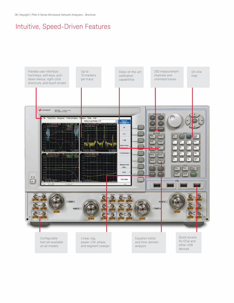
Intuitive, Speed-Driven Features
Flexible user interface: hard keys, soft keys, pull-down menus, right-click shortcuts, and touch screen
Up to 10 markers per trace
State-of-the-art calibration capabilities
On-line help
200 measurement channels and unlimited traces
Conigurable test set available on all models
Linear, log, power, CW, phase,and segment sweeps
Equation editor and time-domain analysis
Quick access for ECal and other USB devices
06 | Keysight | PNA-X Series Microwave Network Analyzers - Brochure
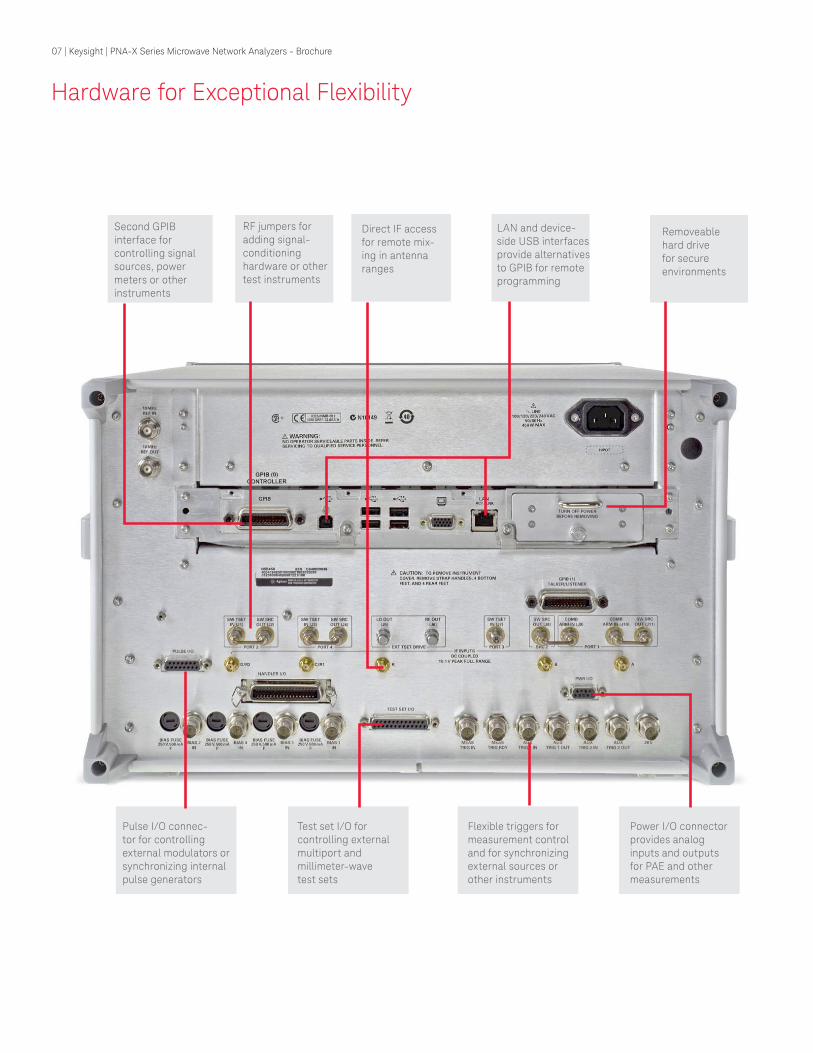
Hardware for Exceptional Flexibility
Second GPIB interface for controlling signal sources, power meters or other instruments
Pulse I/O connec-tor for controlling external modulators or synchronizing internal pulse generators
Flexible triggers for measurement control and for synchronizing external sources or other instruments
Power I/O connector provides analog inputs and outputs for PAE and other measurements
Test set I/O for controlling external multiport and millimeter-wave test sets
Direct IF access for remote mix-ing in antenna ranges
RF jumpers for adding signal-conditioning hardware or other test instruments
LAN and device-side USB interfaces provide alternatives to GPIB for remote programming
Removeable hard drive for secure environments
07 | Keysight | PNA-X Series Microwave Network Analyzers - Brochure
C R3
Test port 1 Test port 3
R1
A
Rear panel
Source 1
OUT 1 OUT 2
Pulsemodulator
Pulsemodulator
Source 2 OUT 1 OUT 2
+28 V
Signalcombiner +
–
J9 J10 J11 J8 J7
1
2
3
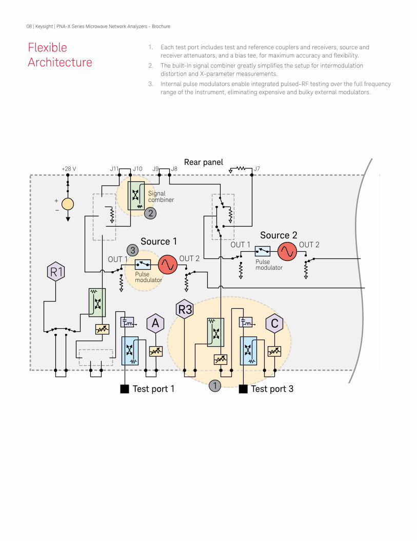
Flexible Architecture
1. Each test port includes test and reference couplers and receivers, source and
receiver attenuators, and a bias tee, for maximum accuracy and lexibility.
2. The built-in signal combiner greatly simpliies the setup for intermodulation distortion and X-parameter measurements.
3. Internal pulse modulators enable integrated pulsed-RF testing over the full frequency
range of the instrument, eliminating expensive and bulky external modulators.
08 | Keysight | PNA-X Series Microwave Network Analyzers - Brochure
Test port 4
R4 D
Rear panel
1
2
3
4
Test port 2
R2
B
Noise receiver
8.5/ 13.5/26.543.5/50 GHz
To receivers
LO
J2 J1 J4 J3 3
6
4
5
Pulse generators
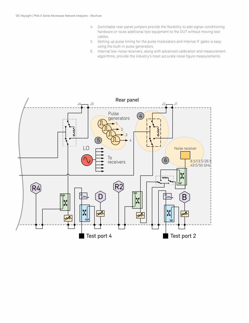
4. Switchable rear-panel jumpers provide the lexibility to add signal-conditioning hardware or route additional test equipment to the DUT without moving test
cables.
5. Setting up pulse timing for the pulse modulators and internal IF gates is easy
using the built-in pulse generators.
6. Internal low-noise receivers, along with advanced calibration and measurement
algorithms, provide the industry’s most accurate noise igure measurements.
09 | Keysight | PNA-X Series Microwave Network Analyzers - Brochure
Pulsed-RF measurement challenges
– Pulse generators and modulators required for pulsed-RF measurements add
complexity in test setups
– For narrow pulses: – Maximum IF bandwidth of analyzer is often too small for wideband detection
– Narrowband detection is slow, and measurements are noisy for low-duty-cycle
pulses
PNA-X pulsed-RF measurements provide: – A simple user interface for full control of two internal pulse modulators (Option 021
and 022), and four internal independent pulse generators (Option 025)
– Point-in-pulse measurements with 20 ns minimum pulse width, and pulse proile measurements with 10 ns minimum resolution (Option 008)
– Improved measurement speed and accuracy for narrowband detection using
hardware ilters and patented spectral-nulling and software IF-gating techniques
– Measurements using wideband detection with pulse widths as narrow as 100 ns
– Pulse I/O connector on rear panel for synchronization
with external equipment and DUT
– Accurate active-component
characterization using unique
application measurement
classes for gain compression,
swept-frequency/power IMD,
and noise igure
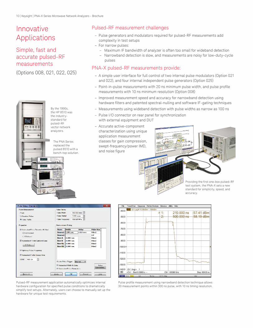
Pulsed-RF measurement application automatically optimizes internal
hardware coniguration for speciied pulse conditions to dramatically simplify test setups. Alternately, users can choose to manually set up the
hardware for unique test requirements.
Pulse proile measurement using narrowband detection technique allows 30 measurement points within 300 ns pulse, with 10 ns timing resolution.
Providing the irst one-box pulsed-RF test system, the PNA-X sets a new
standard for simplicity, speed, and
accuracy.
By the 1990s,
the HP 8510 was the industry-
standard for
pulsed-RF
vector network
analyzers.
The PNA Series
replaced the
pulsed 8510 with a
bench-top solution.
Innovative Applications
Simple, fast and accurate pulsed-RF measurements
(Options 008, 021, 022, 025)
10 | Keysight | PNA-X Series Microwave Network Analyzers - Brochure
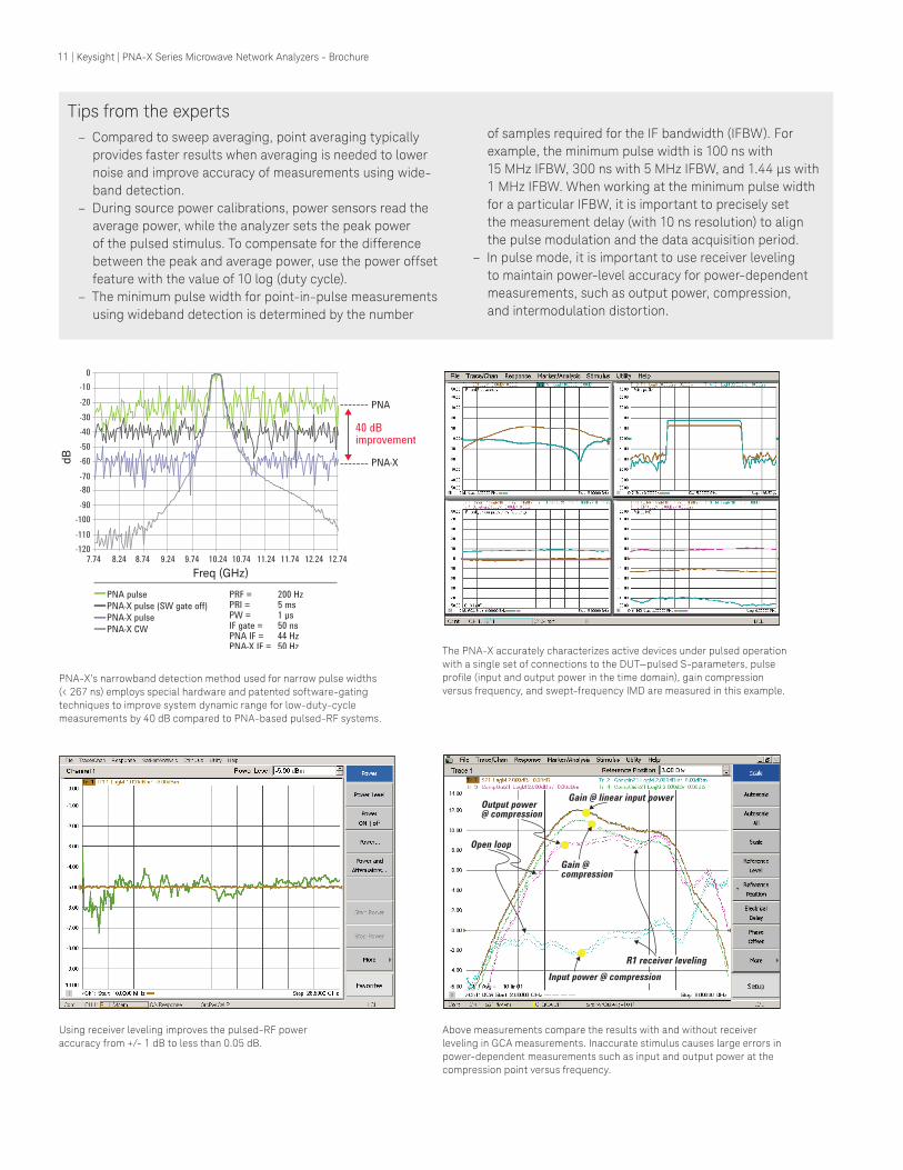
PNA-X’s narrowband detection method used for narrow pulse widths
(< 267 ns) employs special hardware and patented software-gating
techniques to improve system dynamic range for low-duty-cycle
measurements by 40 dB compared to PNA-based pulsed-RF systems.
Using receiver leveling improves the pulsed-RF power
accuracy from +/- 1 dB to less than 0.05 dB.
Above measurements compare the results with and without receiver
leveling in GCA measurements. Inaccurate stimulus causes large errors in
power-dependent measurements such as input and output power at the
compression point versus frequency.
The PNA-X accurately characterizes active devices under pulsed operation
with a single set of connections to the DUT—pulsed S-parameters, pulse
proile (input and output power in the time domain), gain compression versus frequency, and swept-frequency IMD are measured in this example.
Tips from the experts
– Compared to sweep averaging, point averaging typically
provides faster results when averaging is needed to lower
noise and improve accuracy of measurements using wide-
band detection.
– During source power calibrations, power sensors read the
average power, while the analyzer sets the peak power
of the pulsed stimulus. To compensate for the difference
between the peak and average power, use the power offset
feature with the value of 10 log (duty cycle).
– The minimum pulse width for point-in-pulse measurements
using wideband detection is determined by the number
of samples required for the IF bandwidth (IFBW). For
example, the minimum pulse width is 100 ns with
15 MHz IFBW, 300 ns with 5 MHz IFBW, and 1.44 μs with 1 MHz IFBW. When working at the minimum pulse width for a particular IFBW, it is important to precisely set
the measurement delay (with 10 ns resolution) to align
the pulse modulation and the data acquisition period.
– In pulse mode, it is important to use receiver leveling
to maintain power-level accuracy for power-dependent
measurements, such as output power, compression,
and intermodulation distortion.
Freq (GHz)
dB
Output power@ compression
Input power @ compression
R1 receiver leveling
Gain @ linear input power
Gain @ compression
Open loop
11 | Keysight | PNA-X Series Microwave Network Analyzers - Brochure
Innovative Applications
Fast and accurate noise igure measurements
(Options 028, 029)
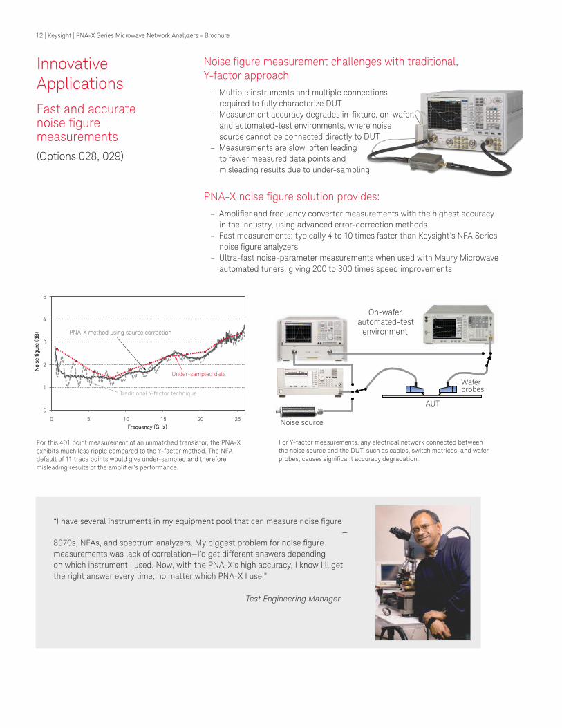
Noise igure measurement challenges with traditional, Y-factor approach
– Multiple instruments and multiple connections
required to fully characterize DUT
– Measurement accuracy degrades in-ixture, on-wafer, and automated-test environments, where noise
source cannot be connected directly to DUT
– Measurements are slow, often leading
to fewer measured data points and
misleading results due to under-sampling
PNA-X noise igure solution provides: – Ampliier and frequency converter measurements with the highest accuracy
in the industry, using advanced error-correction methods
– Fast measurements: typically 4 to 10 times faster than Keysight’s NFA Series noise igure analyzers
– Ultra-fast noise-parameter measurements when used with Maury Microwave
automated tuners, giving 200 to 300 times speed improvements
0
1
2
3
4
5
0 5 10 15 20 25
Frequency (GHz)
PNA-X method using source correction
Traditional Y-factor technique
Under-sampled data
Noi
se fi
gure
(dB
)
On-wafer automated-test
environment
Noise source
AUT
Wafer probes
For Y-factor measurements, any electrical network connected between
the noise source and the DUT, such as cables, switch matrices, and wafer
probes, causes signiicant accuracy degradation.
For this 401 point measurement of an unmatched transistor, the PNA-X
exhibits much less ripple compared to the Y-factor method. The NFA
default of 11 trace points would give under-sampled and therefore
misleading results of the ampliier’s performance.
“I have several instruments in my equipment pool that can measure noise igure —
8970s, NFAs, and spectrum analyzers. My biggest problem for noise igure measurements was lack of correlation—I’d get different answers depending on which instrument I used. Now, with the PNA-X’s high accuracy, I know I’ll get the right answer every time, no matter which PNA-X I use.”
Test Engineering Manager
12 | Keysight | PNA-X Series Microwave Network Analyzers - Brochure
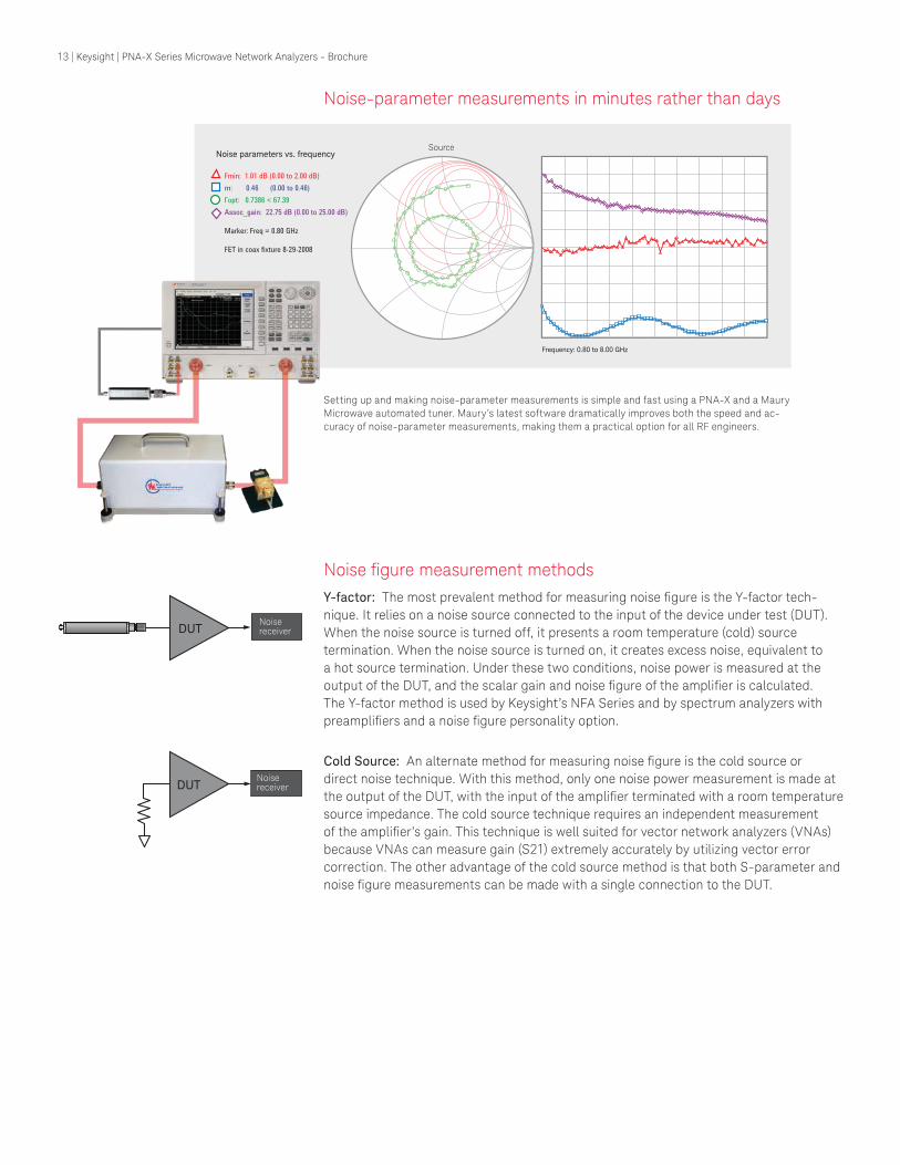
Noise-parameter measurements in minutes rather than days
Noise igure measurement methodsY-factor: The most prevalent method for measuring noise igure is the Y-factor tech-
nique. It relies on a noise source connected to the input of the device under test (DUT).
When the noise source is turned off, it presents a room temperature (cold) source
termination. When the noise source is turned on, it creates excess noise, equivalent to
a hot source termination. Under these two conditions, noise power is measured at the
output of the DUT, and the scalar gain and noise igure of the ampliier is calculated. The Y-factor method is used by Keysight’s NFA Series and by spectrum analyzers with
preampliiers and a noise igure personality option.
Cold Source: An alternate method for measuring noise igure is the cold source or direct noise technique. With this method, only one noise power measurement is made at
the output of the DUT, with the input of the ampliier terminated with a room temperature source impedance. The cold source technique requires an independent measurement
of the ampliier’s gain. This technique is well suited for vector network analyzers (VNAs) because VNAs can measure gain (S21) extremely accurately by utilizing vector error
correction. The other advantage of the cold source method is that both S-parameter and
noise igure measurements can be made with a single connection to the DUT.
SourceNoise parameters vs. frequency
Frequency: 0.80 to 8.00 GHz
Setting up and making noise-parameter measurements is simple and fast using a PNA-X and a Maury
Microwave automated tuner. Maury’s latest software dramatically improves both the speed and ac-
curacy of noise-parameter measurements, making them a practical option for all RF engineers.
Noise receiver DUT
Noise receiver DUT
13 | Keysight | PNA-X Series Microwave Network Analyzers - Brochure
Frequency
Innovative Applications
Fast and accurate noise igure measurements
(Option 028, 029) (continued)
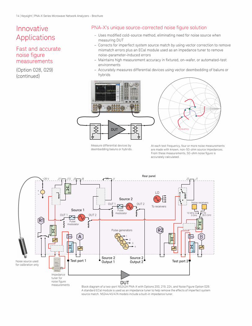
PNA-X’s unique source-corrected noise igure solution – Uses modiied cold-source method, eliminating need for noise source when
measuring DUT
– Corrects for imperfect system source match by using vector correction to remove
mismatch errors plus an ECal module used as an impedance tuner to remove
noise-parameter-induced errors
– Maintains high measurement accuracy in ixtured, on-wafer, or automated-test environments
– Accurately measures differential devices using vector deembedding of baluns or
hybrids
DUT
Measure differential devices by
deembedding baluns or hybrids.At each test frequency, four or more noise measurements
are made with known, non-50-ohm source impedances.
From these measurements, 50-ohm noise igure is accurately calculated.
DUT
Test port 1
R1
Test port 2
R2
A B
To receivers
LO
Source 2 Output 1
Source 2 Output 2
Pulse generators
1
2
3
4
+28 V
Noise receivers
10 MHz to 3 GHz
3 to26.5 GHz
Source 1
OUT 1 OUT 2
Pulse modulator
Source 2
OUT 1 OUT 2
Pulse modulator
Noise source used for calibration only
J9 J10 J11 J8 J7 J2 J1
Impedance tuner for noise figuremeasurements
+ –
Rear panel
Block diagram of a two-port N5242A PNA-X with Options 200, 219, 224, and Noise Figure Option 029.
A standard ECal module is used as an impedance tuner to help remove the effects of imperfect system
source match. N5244/45/47A models include a built-in impedance tuner.
14 | Keysight | PNA-X Series Microwave Network Analyzers - Brochure
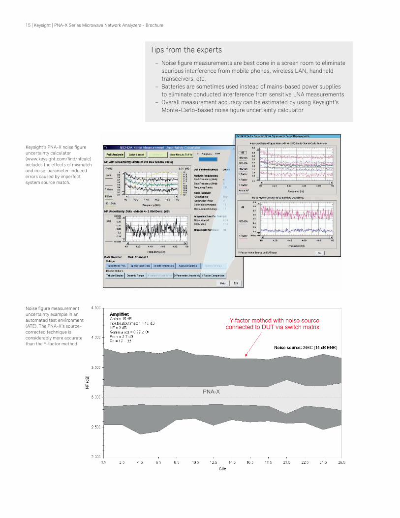
Tips from the experts
– Noise igure measurements are best done in a screen room to eliminate spurious interference from mobile phones, wireless LAN, handheld
transceivers, etc.
– Batteries are sometimes used instead of mains-based power supplies
to eliminate conducted interference from sensitive LNA measurements
– Overall measurement accuracy can be estimated by using Keysight’s
Monte-Carlo-based noise igure uncertainty calculator
Keysight’s PNA-X noise igure uncertainty calculator
(www.keysight.com/ind/nfcalc) includes the effects of mismatch
and noise-parameter-induced
errors caused by imperfect
system source match.
Noise igure measurement uncertainty example in an
automated test environment
(ATE). The PNA-X’s source-
corrected technique is
considerably more accurate
than the Y-factor method.
15 | Keysight | PNA-X Series Microwave Network Analyzers - Brochure
Innovative Applications
Fast and accurate gain compression versus frequency measurements of ampliiers and converters
(Option 086)
Gain compression measurement challenges
– Characterizing ampliier or frequency converter compression over its operating frequency range requires measurements at many frequency and power points, so
setting up the measurements, calibration, and data manipulation takes a lot of time
and effort
– A variety of errors degrade measurement accuracy, such as mismatch between the
test port and the power sensor and DUT during absolute power measurements, and
using linear S-parameter error correction in nonlinear compression measurements
PNA-X gain compression application (GCA) provides: – Fast and convenient measurements with SMART Sweep
– Highly accurate results using a guided calibration that provides power and mismatch correction
– Complete device characterization with two-dimensional (2D) sweeps, with the
choice of sweeping power per frequency, or sweeping frequency per power
– Flexibility with a variety of compression methods—compression from linear gain,
maximum gain, X/Y compression, compression from back-off, or compression from
saturation
Pin
Frequency
Gain Compression point
Pin
Frequency
Gain Compression point Iteration point
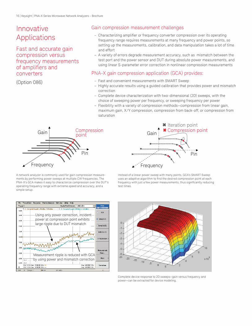
A network analyzer is commonly used for gain compression measure-
ments by performing power sweeps at multiple CW frequencies. The
PNA-X’s GCA makes it easy to characterize compression over the DUT’s
operating frequency range with extreme speed and accuracy, and a
simple setup.
Instead of a linear power sweep with many points, GCA’s SMART Sweep
uses an adaptive algorithm to ind the desired compression point at each frequency with just a few power measurements, thus signiicantly reducing test times.
Complete device response to 2D sweeps—gain versus frequency and
power—can be extracted for device modeling.
Using only power correction, incident power at compression point exhibits large ripple due to DUT mismatch
Measurement ripple is reduced with GCA by using power and mismatch correction
16 | Keysight | PNA-X Series Microwave Network Analyzers - Brochure
Tips from the experts
Pin Freq.
Gain Compression
Pin Freq.
Gain Compression
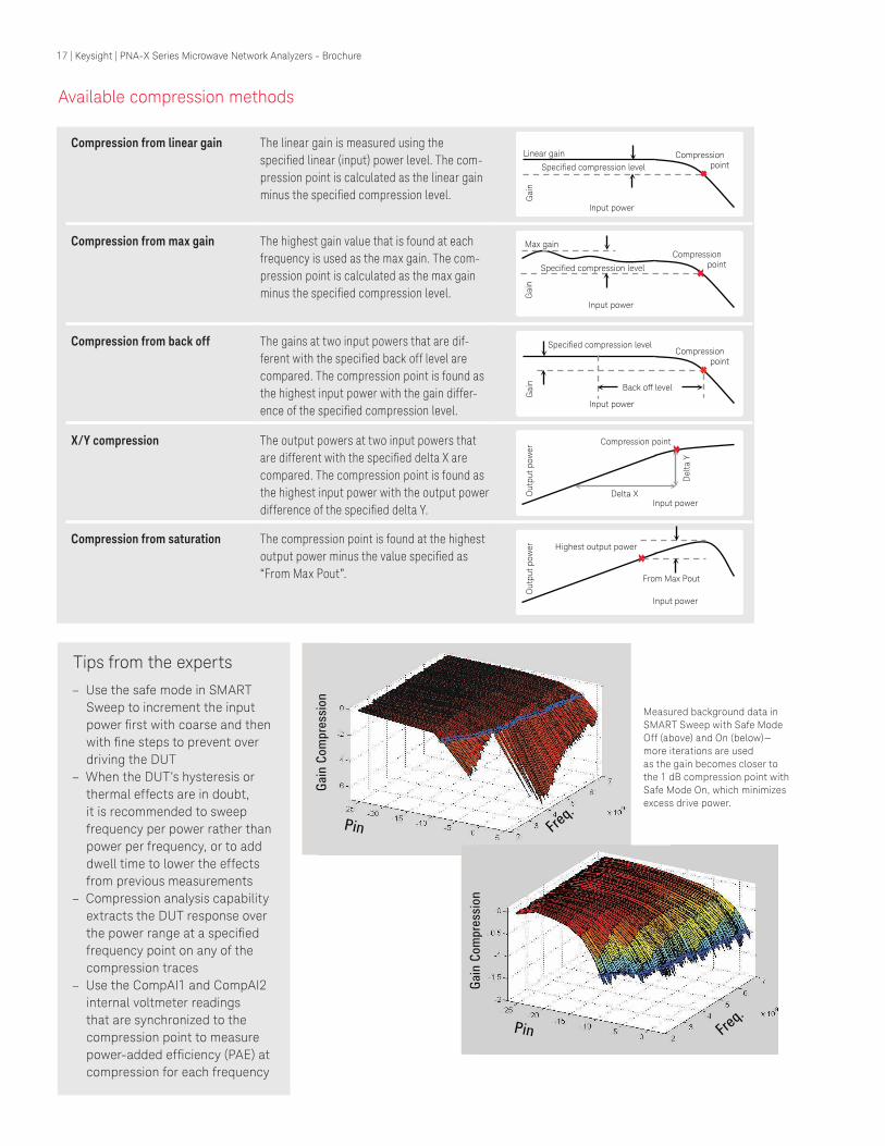
Available compression methods
– Use the safe mode in SMART
Sweep to increment the input
power irst with coarse and then with ine steps to prevent over driving the DUT
– When the DUT’s hysteresis or
thermal effects are in doubt,
it is recommended to sweep
frequency per power rather than
power per frequency, or to add
dwell time to lower the effects
from previous measurements
– Compression analysis capability
extracts the DUT response over
the power range at a speciied frequency point on any of the
compression traces
– Use the CompAI1 and CompAI2
internal voltmeter readings
that are synchronized to the
compression point to measure
power-added eficiency (PAE) at compression for each frequency
Measured background data in
SMART Sweep with Safe Mode
Off (above) and On (below)—
more iterations are used
as the gain becomes closer to
the 1 dB compression point with
Safe Mode On, which minimizes
excess drive power.
Compression from linear gain The linear gain is measured using the
speciied linear (input) power level. The com-
pression point is calculated as the linear gain minus the speciied compression level.
Compression from max gain The highest gain value that is found at each frequency is used as the max gain. The com-
pression point is calculated as the max gain minus the speciied compression level.
Compression from back off The gains at two input powers that are dif-ferent with the speciied back off level are compared. The compression point is found as the highest input power with the gain differ-ence of the speciied compression level.
X/Y compression The output powers at two input powers that are different with the speciied delta X are compared. The compression point is found as the highest input power with the output power difference of the speciied delta Y.
Compression from saturation The compression point is found at the highest output power minus the value speciied as “From Max Pout”.
Input power
Gain
Linear gain
Specified compression level
Compression point
Input power
Gain
Specified compression level
Compression point
Max gain
Input power
Gain
Back off level
Specified compression level Compression
point
Input power
Ou
tpu
t p
ow
er
Delta X
Compression point
Delt
a Y
Input power
Ou
tpu
t p
ow
er
From Max Pout
Highest output power
17 | Keysight | PNA-X Series Microwave Network Analyzers - Brochure
Innovative Applications
Fast two-tone intermodulation distortion (IMD) measurements with simple setup
(Option 087)
IMD measurement challenges
– Two signal generators, a spectrum
analyzer, and an external combiner are
most commonly used, requiring manual
setup of all instruments and accessories
– Test times are slow when swept-frequency
or swept-power IMD is measured
– Instruments and test setups often
cause signiicant measurement errors due to source-generated harmonics,
cross-modulation, and phase noise, plus
receiver compression and noise loor
PNA-X with IMD application provides:
– Fast swept IMD measurements
of ampliiers and frequency con-
verters, using internal combiner
and two internal sources
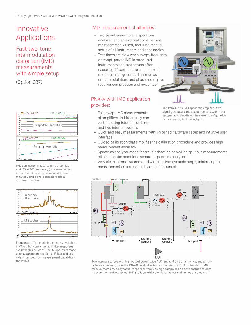
The PNA-X with IMD application replaces two
signal generators and a spectrum analyzer in the
system rack, simplifying the system coniguration and increasing test throughput.
IMD application measures third order IMD
and IP3 at 201 frequency (or power) points
in a matter of seconds, compared to several
minutes using signal generators and a
spectrum analyzer.
Frequency-offset mode is commonly available
in VNA’s, but conventional IF ilter responses exhibit high side lobes. The IM Spectrum mode
employs an optimized digital IF ilter and pro-
vides true spectrum measurement capability in
the PNA-X. Two internal sources with high output power, wide ALC range, -60 dBc harmonics, and a high-
isolation combiner, make the PNA-X an ideal instrument to drive the DUT for two-tone IMD
measurements. Wide dynamic-range receivers with high compression points enable accurate
measurements of low-power IMD products while the higher power main tones are present.
DUT
Test port 1
R1
Test port 2
R2
A B
To receivers
LO
Source 2 Output 1
Source 2 Output 2
Rear panel
Source 1 OUT 1 OUT 2
Pulse modulator
Source 2
OUT 1 OUT 2
Pulse modulator
J9 J10 J11 J8 J7 J2 J1
Swept-frequency IMD
Swept-power IMD
Frequencyoffset mode
IM Spectrum
– Quick and easy measurements with simpliied hardware setup and intuitive user interface
– Guided calibration that simpliies the calibration procedure and provides high measurement accuracy
– Spectrum analyzer mode for troubleshooting or making spurious measurements,
eliminating the need for a separate spectrum analyzer
– Very clean internal sources and wide receiver dynamic range, minimizing the
measurement errors caused by other instruments
18 | Keysight | PNA-X Series Microwave Network Analyzers - Brochure
Tips from the experts
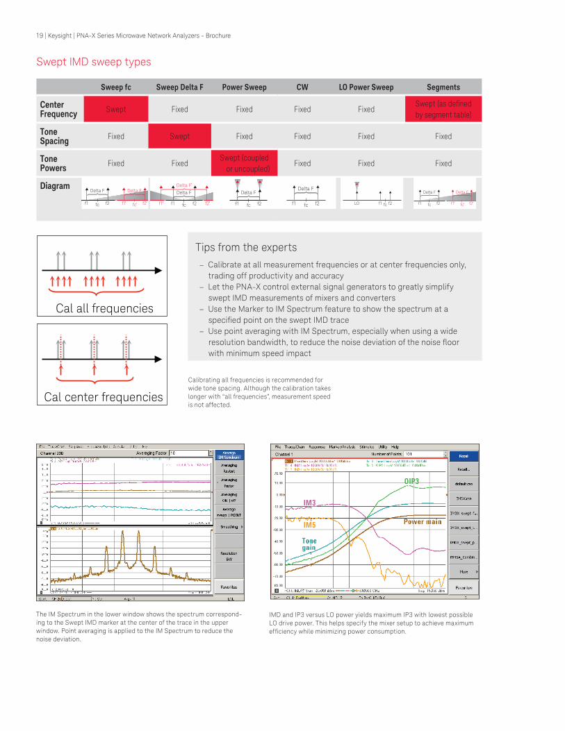
Swept IMD sweep types
– Calibrate at all measurement frequencies or at center frequencies only,
trading off productivity and accuracy
– Let the PNA-X control external signal generators to greatly simplify
swept IMD measurements of mixers and converters
– Use the Marker to IM Spectrum feature to show the spectrum at a
speciied point on the swept IMD trace – Use point averaging with IM Spectrum, especially when using a wide
resolution bandwidth, to reduce the noise deviation of the noise loor with minimum speed impact
Calibrating all frequencies is recommended for
wide tone spacing. Although the calibration takes
longer with “all frequencies”, measurement speed
is not affected.
The IM Spectrum in the lower window shows the spectrum correspond-
ing to the Swept IMD marker at the center of the trace in the upper
window. Point averaging is applied to the IM Spectrum to reduce the
noise deviation.
IMD and IP3 versus LO power yields maximum IP3 with lowest possible
LO drive power. This helps specify the mixer setup to achieve maximum
eficiency while minimizing power consumption.
Sweep fc Sweep Delta F Power Sweep CW LO Power Sweep Segments
Center Frequency
Swept Fixed Fixed Fixed FixedSwept (as deined by segment table)
Tone Spacing
Fixed Swept Fixed Fixed Fixed Fixed
Tone Powers
Fixed FixedSwept (coupled
or uncoupled)Fixed Fixed Fixed
Diagram
Cal all frequencies
Cal center frequencies
Delta F
f1 f2fc
Delta F
f1 f2fc
Delta F
f1 f2fc
Delta F
f1 f2
Delta F
f1 f2fc
Delta F
f1 f2fc f1LO f2fc
Delta F
f1 f2fc
Delta F
f1 f2fc
19 | Keysight | PNA-X Series Microwave Network Analyzers - Brochure
DUT
Referencemixer
Calibrationmixer/filter
Innovative Applications
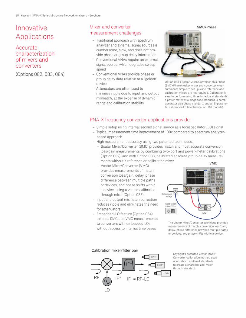
Accurate characterization of mixers and converters
(Options 082, 083, 084)
Mixer and converter measurement challenges
– Traditional approach with spectrum
analyzer and external signal sources is
cumbersome, slow, and does not pro-
vide phase or group delay information
– Conventional VNAs require an external
signal source, which degrades sweep
speed
– Conventional VNAs provide phase or
group delay data relative to a “golden”
device
– Attenuators are often used to
minimize ripple due to input and output
mismatch, at the expense of dynamic
range and calibration stability
Option 083’s Scalar Mixer/Converter plus Phase
(SMC+Phase) makes mixer and converter mea-
surements simple to set up since reference and
calibration mixers are not required. Calibration is
easy to perform using three broadband standards: a power meter as a magnitude standard, a comb
generator as a phase standard, and an S-parame-
ter calibration kit (mechanical or ECal module).
The Vector Mixer/Converter technique provides
measurements of match, conversion loss/gain,
delay, phase difference between multiple paths
or devices, and phase shifts within a device.
Keysight’s patented Vector Mixer/
Converter calibration method uses
open, short, and load standards
to create a characterized-mixer
through standard.
SMC+Phase
LO
IF
IF+ RF IF = RF-LO
OPEN
SHORT
LOAD
Calibration mixer/filter pair
--
--
PNA-X frequency converter applications provide: – Simple setup using internal second signal source as a local oscillator (LO) signal
– Typical measurement time improvement of 100x compared to spectrum analyzer-
based approach
– High measurement accuracy using two patented techniques: – Scalar Mixer/Converter (SMC) provides match and most accurate conversion
loss/gain measurements by combining two-port and power-meter calibrations
(Option 082), and with Option 083, calibrated absolute group delay measure-
ments without a reference or calibration mixer
– Vector Mixer/Converter (VMC)
provides measurements of match,
conversion loss/gain, delay, phase
difference between multiple paths
or devices, and phase shifts within
a device, using a vector-calibrated
through mixer (Option 083)
– Input and output mismatch correction
reduces ripple and eliminates the need
for attenuators
– Embedded-LO feature (Option 084)
extends SMC and VMC measurements
to converters with embedded LOs
without access to internal time bases
VMC
20 | Keysight | PNA-X Series Microwave Network Analyzers - Brochure
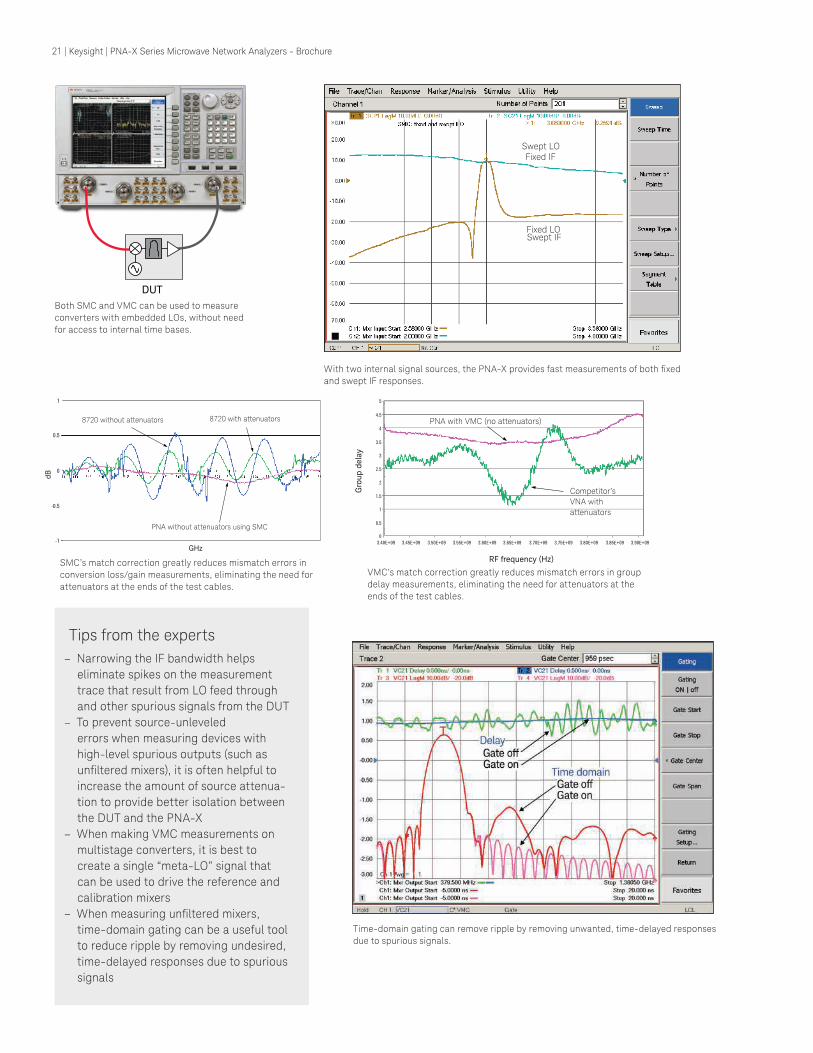
With two internal signal sources, the PNA-X provides fast measurements of both ixed and swept IF responses.
Time-domain gating can remove ripple by removing unwanted, time-delayed responses
due to spurious signals.
DUT
Both SMC and VMC can be used to measure
converters with embedded LOs, without need
for access to internal time bases.
Swept LO Fixed IF
Fixed LO Swept IF
Tips from the experts
– Narrowing the IF bandwidth helps
eliminate spikes on the measurement
trace that result from LO feed through
and other spurious signals from the DUT
– To prevent source-unleveled
errors when measuring devices with
high-level spurious outputs (such as
uniltered mixers), it is often helpful to increase the amount of source attenua-
tion to provide better isolation between
the DUT and the PNA-X
– When making VMC measurements on
multistage converters, it is best to
create a single “meta-LO” signal that
can be used to drive the reference and
calibration mixers
– When measuring uniltered mixers, time-domain gating can be a useful tool
to reduce ripple by removing undesired,
time-delayed responses due to spurious
signals
SMC’s match correction greatly reduces mismatch errors in
conversion loss/gain measurements, eliminating the need for
attenuators at the ends of the test cables.
VMC’s match correction greatly reduces mismatch errors in group
delay measurements, eliminating the need for attenuators at the
ends of the test cables.
8720 without attenuators 8720 with attenuators
PNA without attenuators using SMC
GHz
dB
Competitor’s
VNA with
attenuators
PNA with VMC (no attenuators)
RF frequency (Hz)
Gro
up
dela
y
21 | Keysight | PNA-X Series Microwave Network Analyzers - Brochure
Innovative Applications
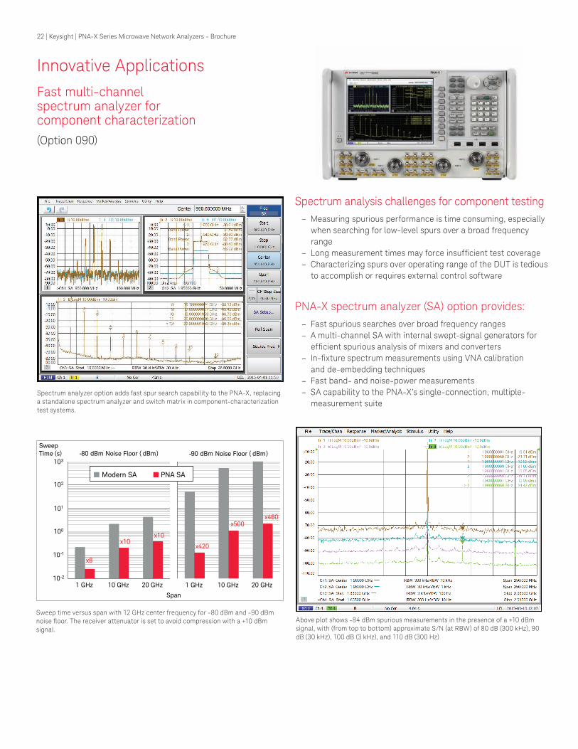
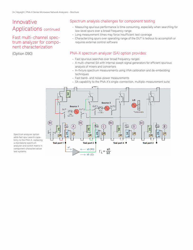
Fast multi-channel spectrum analyzer for component characterization
(Option 090)
Spectrum analysis challenges for component testing
– Measuring spurious performance is time consuming, especially
when searching for low-level spurs over a broad frequency
range
– Long measurement times may force insuficient test coverage – Characterizing spurs over operating range of the DUT is tedious
to accomplish or requires external control software
PNA-X spectrum analyzer (SA) option provides: – Fast spurious searches over broad frequency ranges
– A multi-channel SA with internal swept-signal generators for
eficient spurious analysis of mixers and converters – In-ixture spectrum measurements using VNA calibration
and de-embedding techniques
– Fast band- and noise-power measurements
– SA capability to the PNA-X’s single-connection, multiple-
measurement suite
Spectrum analyzer option adds fast spur search capability to the PNA-X, replacing
a standalone spectrum analyzer and switch matrix in component-characterization
test systems.
Above plot shows -84 dBm spurious measurements in the presence of a +10 dBm
signal, with (from top to bottom) approximate S/N (at RBW) of 80 dB (300 kHz), 90 dB (30 kHz), 100 dB (3 kHz), and 110 dB (300 Hz)
Sweep time versus span with 12 GHz center frequency for -80 dBm and -90 dBm noise loor. The receiver attenuator is set to avoid compression with a +10 dBm signal.
10-2
10-1
100
101
102
Sweep Time (s) -80 dBm Noise Floor ( dBm)
103
-90 dBm Noise Floor ( dBm)
1 GHz 10 GHz 20 GHz 1 GHz 10 GHz 20 GHz
Span
x8
x10x10
x420
x500x460
Modern SA PNA SA
22 | Keysight | PNA-X Series Microwave Network Analyzers - Brochure
Tips from the experts
– Choose different levels of software-image rejection to
trade-off measurement speed with thoroughness, based
on the spectral density of the measurement
– For harmonics measurements, add a separate SA channel
for each harmonic with a narrow frequency span and
RBW to optimize speed and sensitivity, and with enough
receiver attenuation to avoid internally-generated
harmonics
– To help identify spurious signals that might be interfering
with a measurement, use the Marker-to-SA feature to
easily create a spectrum display with the same stimulus
conditions at the marker position in SMC, swept-IMD, or
standard channels
– When using de-embedding to measure in-ixture or on-wafer devices, use the power-compensation feature
to overcome the loss of the ixture or probes, thereby delivering a known stimulus power to the DUTVNA calibration and ixture de-embedding remove cable and ixture effects and
correct receiver response errors, providing calibrated in-ixture spectrum analysis.
Unlock true performance with VNA calibration
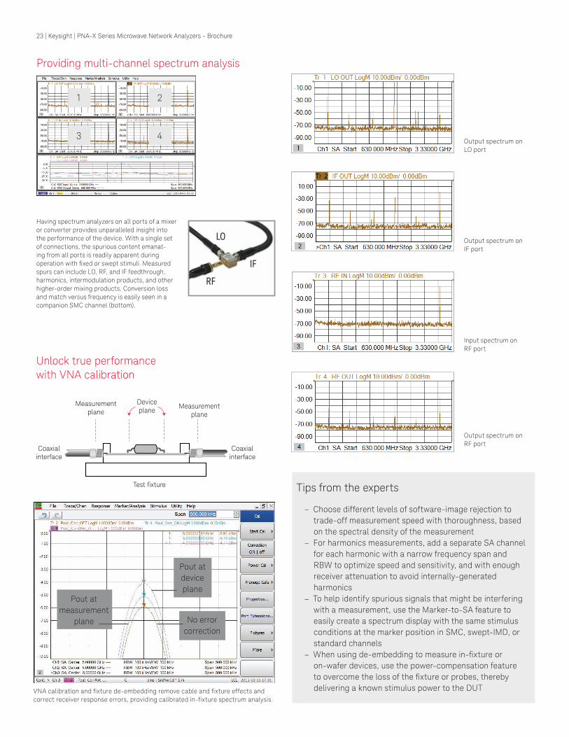
Having spectrum analyzers on all ports of a mixer or converter provides unparalleled insight into
the performance of the device. With a single set
of connections, the spurious content emanat-
ing from all ports is readily apparent during
operation with ixed or swept stimuli. Measured spurs can include LO, RF, and IF feedthrough,
harmonics, intermodulation products, and other
higher-order mixing products. Conversion loss
and match versus frequency is easily seen in a
companion SMC channel (bottom).
Output spectrum on
IF port
Output spectrum on
RF port
Input spectrum on
RF port
Output spectrum on
LO port
Measurementplane
Deviceplane
Coaxialinterface
Coaxialinterface
Measurementplane
Test fixture
LO
RF
IF
1 2
3 4
Providing multi-channel spectrum analysis
Pout at
measurement
plane
Pout at
device
plane
No error
correction
23 | Keysight | PNA-X Series Microwave Network Analyzers - Brochure
Innovative Applications continued
Fast multi-channel spec-trum analyzer for compo-nent characterization
(Option 090)
Spectrum analysis challenges for component testing
– Measuring spurious performance is time consuming, especially when searching for
low-level spurs over a broad frequency range
– Long measurement times may force insuficient test coverage – Characterizing spurs over operating range of the DUT is tedious to accomplish or
requires external control software
PNA-X spectrum analyzer (SA) option provides: – Fast spurious searches over broad frequency ranges
– A multi-channel SA with internal swept-signal generators for eficient spurious analysis of mixers and converters
– In-ixture spectrum measurements using VNA calibration and de-embedding techniques
– Fast band- and noise-power measurements
– SA capability to the PNA-X’s single-connection, multiple-measurement suite
Spectrum analyzer option
adds fast spur search capa-
bility to the PNA-X, replacing
a standalone spectrum
analyzer and switch matrix in
component-characterization
test systems.
24 | Keysight | PNA-X Series Microwave Network Analyzers - Brochure
Innovative Applications continued
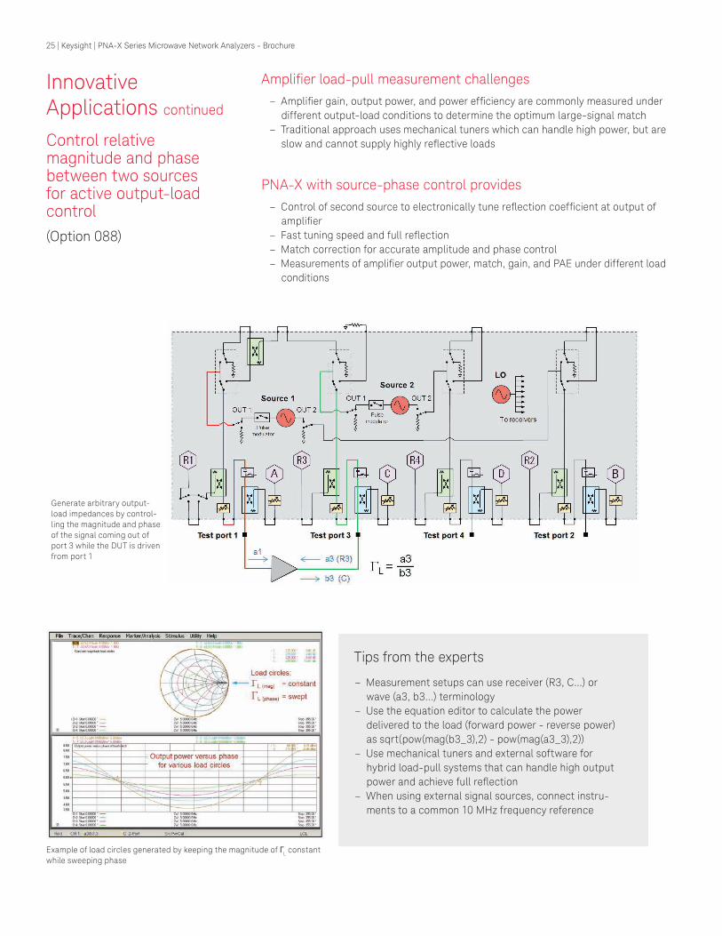
Control relative magnitude and phase between two sources for active output-load control
(Option 088)
Ampliier load-pull measurement challenges – Ampliier gain, output power, and power eficiency are commonly measured under
different output-load conditions to determine the optimum large-signal match
– Traditional approach uses mechanical tuners which can handle high power, but are
slow and cannot supply highly relective loads
PNA-X with source-phase control provides
– Control of second source to electronically tune relection coeficient at output of ampliier
– Fast tuning speed and full relection – Match correction for accurate amplitude and phase control
– Measurements of ampliier output power, match, gain, and PAE under different load conditions
Example of load circles generated by keeping the magnitude of ΓL constant
while sweeping phase
Generate arbitrary output-
load impedances by control-
ling the magnitude and phase
of the signal coming out of
port 3 while the DUT is driven
from port 1
Tips from the experts
– Measurement setups can use receiver (R3, C...) or
wave (a3, b3…) terminology
– Use the equation editor to calculate the power
delivered to the load (forward power - reverse power)
as sqrt(pow(mag(b3_3),2) - pow(mag(a3_3),2))
– Use mechanical tuners and external software for
hybrid load-pull systems that can handle high output
power and achieve full relection – When using external signal sources, connect instru-
ments to a common 10 MHz frequency reference
25 | Keysight | PNA-X Series Microwave Network Analyzers - Brochure
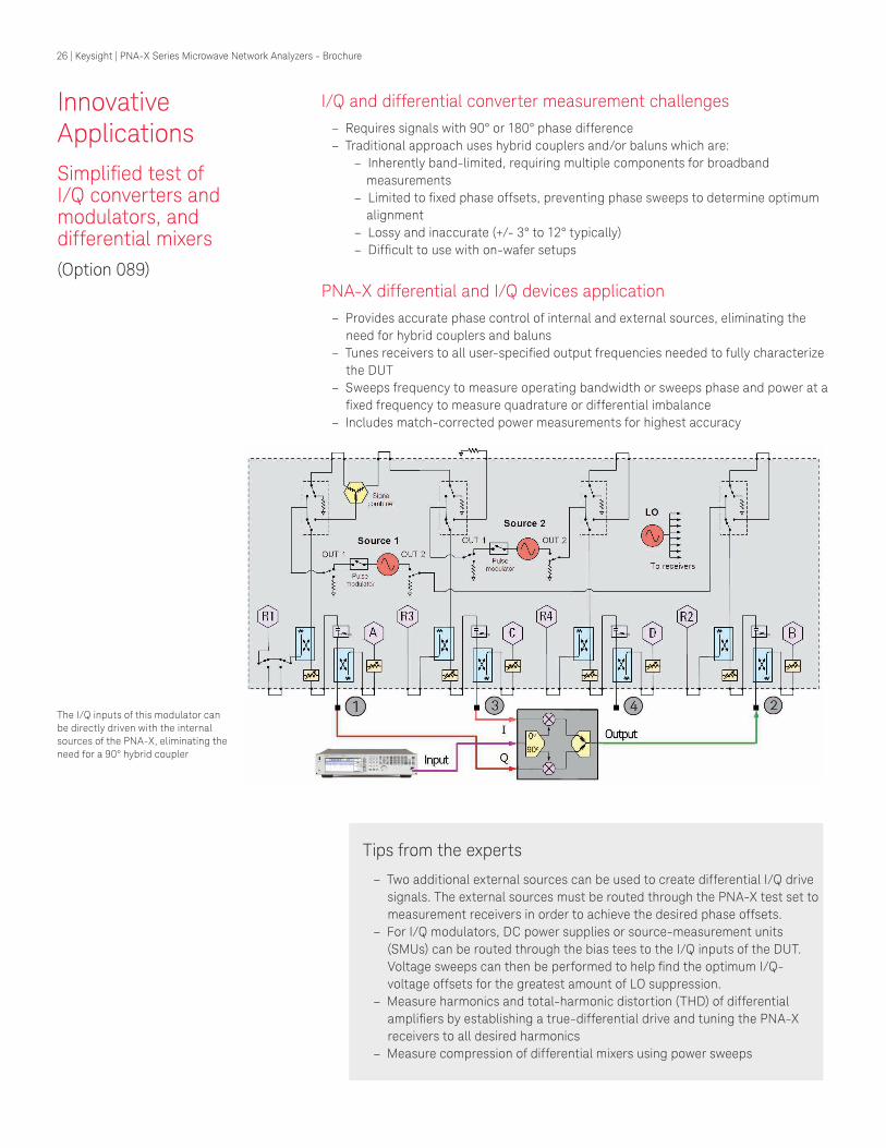
Innovative Applications
Simpliied test of I/Q converters and modulators, and differential mixers
(Option 089)
I/Q and differential converter measurement challenges
– Requires signals with 90° or 180° phase difference
– Traditional approach uses hybrid couplers and/or baluns which are: – Inherently band-limited, requiring multiple components for broadband
measurements
– Limited to ixed phase offsets, preventing phase sweeps to determine optimum alignment
– Lossy and inaccurate (+/- 3° to 12° typically)
– Dificult to use with on-wafer setups
PNA-X differential and I/Q devices application
– Provides accurate phase control of internal and external sources, eliminating the
need for hybrid couplers and baluns
– Tunes receivers to all user-speciied output frequencies needed to fully characterize the DUT
– Sweeps frequency to measure operating bandwidth or sweeps phase and power at a
ixed frequency to measure quadrature or differential imbalance – Includes match-corrected power measurements for highest accuracy
The I/Q inputs of this modulator can
be directly driven with the internal
sources of the PNA-X, eliminating the
need for a 90° hybrid coupler
Tips from the experts
– Two additional external sources can be used to create differential I/Q drive
signals. The external sources must be routed through the PNA-X test set to
measurement receivers in order to achieve the desired phase offsets.
– For I/Q modulators, DC power supplies or source-measurement units
(SMUs) can be routed through the bias tees to the I/Q inputs of the DUT.
Voltage sweeps can then be performed to help ind the optimum I/Q-
voltage offsets for the greatest amount of LO suppression.
– Measure harmonics and total-harmonic distortion (THD) of differential ampliiers by establishing a true-differential drive and tuning the PNA-X receivers to all desired harmonics
– Measure compression of differential mixers using power sweeps
26 | Keysight | PNA-X Series Microwave Network Analyzers - Brochure
Innovative Applications
Testing differential ampliiers under real operating conditions
(Option 460)
Differential ampliier measurement challenges
– Conventional two-port VNAs with
baluns do not provide common-mode,
differential to common-mode,
and common to differential-mode
responses
– Baluns are inherently band-limited
devices, which forces multiple test
setups for broad frequency coverage
– Phase errors of baluns provide inac-
curate differential responses
– Modern four-port VNAs provide
mixed-mode S-parameter measure-
ments with single-ended stimulus, but
differential ampliiers may respond differently when in compression during
real operating environments
PNA-X integrated true-mode stimulus application (iTMSA) provides:
– Mixed-mode S-parameters of
differential ampliiers driven by true differential and common-mode signals
– Mismatch correction at the DUT input
to minimize phase errors between two
sources
– Input-only drive mode that prevents
damage on ampliiers caused by stimulus on the output port
– In-ixture arbitrary phase offset and phase-offset sweeps to optimize
input matching network for maximum
ampliier gain
2 1
4 3
Differential (180 out-of-phase)
Common (in-phase)
Using the PNA-X’s two internal sources, iTMSA
drives the differential ampliier under real world conditions, providing accurate mixed-mode S-
parameters in all operating environments.
Mixed-mode S-parameters.
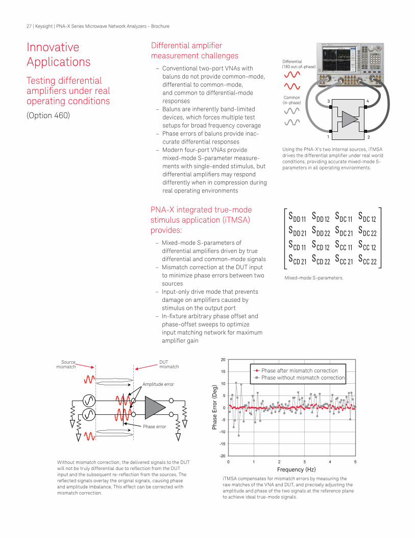
Without mismatch correction, the delivered signals to the DUT
will not be truly differential due to relection from the DUT input and the subsequent re-relection from the sources. The relected signals overlay the original signals, causing phase and amplitude imbalance. This effect can be corrected with
mismatch correction.
iTMSA compensates for mismatch errors by measuring the
raw matches of the VNA and DUT, and precisely adjusting the
amplitude and phase of the two signals at the reference plane
to achieve ideal true-mode signals.
Phase error
Amplitude error
DUT mismatch
Source mismatch
Phase after mismatch correction
Phase without mismatch correction
Frequency (Hz)
Ph
ase
Err
or
(Deg
)
27 | Keysight | PNA-X Series Microwave Network Analyzers - Brochure
2 1
4 3
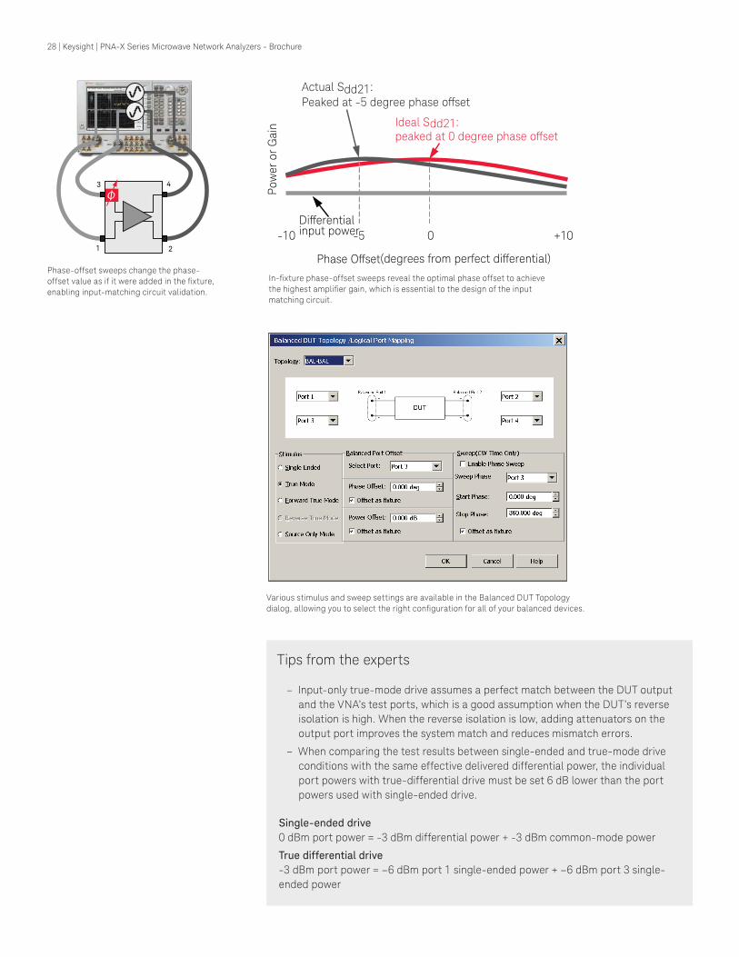
Phase-offset sweeps change the phase-
offset value as if it were added in the ixture, enabling input-matching circuit validation.
Po
wer
or
Gain
Phase Offset (degrees from perfect differential)
+10 -10
Actual Sdd21:
Peaked at -5 degree phase offset
Ideal Sdd21: peaked at 0 degree phase offset
Differential input power -5 0
Various stimulus and sweep settings are available in the Balanced DUT Topology
dialog, allowing you to select the right coniguration for all of your balanced devices.
Tips from the experts
– Input-only true-mode drive assumes a perfect match between the DUT output
and the VNA’s test ports, which is a good assumption when the DUT’s reverse
isolation is high. When the reverse isolation is low, adding attenuators on the
output port improves the system match and reduces mismatch errors.
– When comparing the test results between single-ended and true-mode drive
conditions with the same effective delivered differential power, the individual
port powers with true-differential drive must be set 6 dB lower than the port
powers used with single-ended drive.
Single-ended drive
0 dBm port power = -3 dBm differential power + -3 dBm common-mode power
True differential drive
-3 dBm port power = –6 dBm port 1 single-ended power + –6 dBm port 3 single-
ended power
In-ixture phase-offset sweeps reveal the optimal phase offset to achieve the highest ampliier gain, which is essential to the design of the input matching circuit.
28 | Keysight | PNA-X Series Microwave Network Analyzers - Brochure
Innovative Applications
Powerful, fast and accurate automatic ixture removal (AFR)
(Option 007)
Powerful AFR features can handle a variety of measurement needs
– Single ended and differential devices
– Left and right side of ixture can be asymmetrical – Thru lengths can be speciied or determined from open or short measurements – Band-pass time-domain mode for band-limited devices
– Extrapolation to match DUT frequency range
– Power correction compensates for ixture loss versus frequency – De-embed iles can be saved in a variety of formats for later use in PNA, ADS, and
PLTS
AFR is the fastest way to de-embed a ixture from the measurement
Measurement Challenge: Many of today’s devices do not
have coaxial connectors and are
put in ixtures in order to mea-
sure them in a coaxial environ-
ment. Accurately removing the
effects of the ixture is required to get a good measurement of
the device under test (DUT).
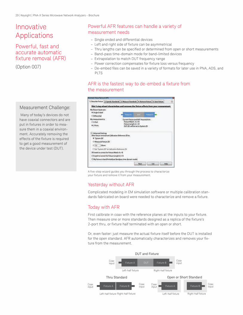
A ive-step wizard guides you through the process to characterize your ixture and remove it from your measurement.
DUT and Fixture
Thru Standard Open or Short Standard
Coax input
Coax input
Coax input
Coax input
Coax input
Coax input
Right-half fixtureRight-half ixture
Right-half ixture
Left-half fixtureLeft-half fixture
Left-half ixture
Fixture A DUT Fixture B
Fixture A Fixture B Fixture A Fixture B
Yesterday without AFR
Complicated modeling in EM simulation software or multiple calibration stan-
dards fabricated on board were needed to characterize and remove a ixture.
Today with AFR
First calibrate in coax with the reference planes at the inputs to your ixture. Then measure one or more standards designed as a replica of the ixture’s 2-port thru, or ixture half terminated with an open or short.
Or, even faster: just measure the actual ixture itself before the DUT is installed for the open standard. AFR automatically characterizes and removes your ix-
ture from the measurement.
29 | Keysight | PNA-X Series Microwave Network Analyzers - Brochure
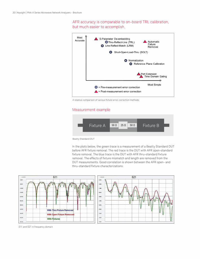
AFR accuracy is comparable to on-board TRL calibration, but much easier to accomplish.
Measurement example
In the plots below, the green trace is a measurement of a Beatty Standard DUT
before AFR ixture removal. The red trace is the DUT with AFR open-standard ixture removal. The blue trace is the DUT with AFR thru-standard ixture removal. The effects of ixture mismatch and length are removed from the DUT measurements. Good correlation is shown between the AFR open- and
thru-standard ixture characterizations.
A relative comparison of various ixture error-correction methods
Fixture A DUT Fixture B
Beatty Standard DUT
S11 and S21 in frequency domain
30 | Keysight | PNA-X Series Microwave Network Analyzers - Brochure

Innovative Applications
Extending the PNA-X to millimeter-wave frequencies
PNA-X’s unique hardware architecture provides: – Two- and four-port solutions for measurements on a wide variety of single-ended
and balanced millimeter-wave devices
– True-mode differential measurements at millimeter-wave frequencies using two
internal sources
– Fully integrated solution for millimeter-wave pulse measurements using built-in pulse
modulators, pulse generators, and receiver gates
– Accurate leveled power at millimeter-wave frequencies with advanced source-power
calibration methods
– Direct connection of terahertz modules driven by a 50 GHz PNA-X – Single-sweep network analysis from 10 MHz to 110 GHz with full power-level control,
using the 67 GHz PNA-X and millimeter-wave extension modules
Two- and four-port conigurations
Four-port system architecture
Four-port single-sweep 10 MHz to 110 GHz
The N5262A millimeter-wave test-set control-
ler connects four millimeter-wave test modules
to the PNA-X. For two-port measurements, the
N5261A millimeter-wave test-set controller is
available.
Block diagram of a 4-port millimeter-
wave system with coherent source
control of OML modules using the N5262A
millimeter-wave test-set controller.
PNA-X-based 110 GHz systems come in two- and four-port versions, with power-level con-
trol, true-differential stimulus, and the ability
to measure frequency converters with SMC.
These systems are table-top replacements for
8510XF systems, with superior performance.
Direct connection of VDI modules to a 50 GHz PNA-X enables S-parameter measurements to
1.05 THz.
Test port 3
C
R3
Test port 1
R1
Test port 4
R4
Test port 2
R2 A D B
LO
Pulse generators
1
2
3
4
Source 1 OUT 1 OUT 2
Source 2 OUT 1 OUT 2
ALC
+
-
Module Power IF Multiplexer
R A B C D
IF outputs
R A B C D
IF inputs
ALC
M1 M2 M3 M4
ALC
LO
M1 M2 M3 M4
M1
M3
M2
M4
R1 T1 R2 R3 R4 T2 T3 T4
RF RF
Test Set Interface
Terahertz measurements
31 | Keysight | PNA-X Series Microwave Network Analyzers - Brochure
Tips from the experts
Millimeter-wave applications with the PNA-X
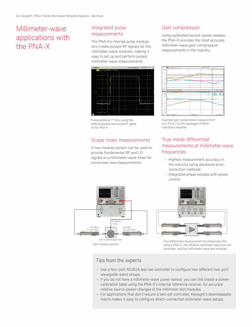
Integrated pulse measurements
The PNA-X’s internal pulse modula-
tors create pulsed-RF signals for the
millimeter-wave modules, making it
easy to set up and perform pulsed
millimeter-wave measurements.
Scalar mixer measurements
A two-module system can be used to
provide fundamental RF and LO
signals to a millimeter-wave mixer for
conversion loss measurements.
Gain compression
Using calibrated source-power sweeps,
the PNA-X provides the most accurate
millimeter-wave gain-compression
measurements in the industry.
True-mode differential measurements at millimeter-wave frequencies
– Highest measurement accuracy in the industry using advanced error-
correction methods
– Integrated phase sweeps with power
control
Pulse proile at 77 GHz using the internal pulsed source and IF gates
of the PNA-X.
Two-module system.
Example gain compression measurement
of a 75 to 110 GHz packaged PHEMT transistor ampliier.
True differential measurement of a balanced LNA
using a PNA-X, the N5262A millimeter-wave test-set
controller, and four millimeter-wave test modules.
RF Input77 to 81 GHz
DUT fundamental mixer
LO Input78 to 82 GHz
IF Output1 GHz
1 2
3 4
– Use a four-port N5262A test-set controller to conigure two different two-port waveguide-band setups.
– If you do not have a millimeter-wave power sensor, you can still create a power-
calibration table using the PNA-X’s internal reference receiver, for accurate
relative source-power changes of the millimeter test modules.
– For applications that don’t require a test-set controller, Keysight’s downloadable
macro makes it easy to conigure direct-connection millimeter-wave setups.
32 | Keysight | PNA-X Series Microwave Network Analyzers - Brochure

Innovative Applications
Nonlinear waveform and X-parameter characterization
(Options 510, 514, 518, and 520)
High-power design challenges – Active devices are commonly driven into nonlinear regions, often by design to
increase power eficiency, information capacity, and output power – Under large-signal drive conditions, active devices distort time-domain waveforms,
generating harmonics, intermodulation distortion, and spectral regrowth
– Current circuit simulation tools that rely on S-parameters and limited nonlinear
behavioral models are no longer suficient to fully analyze and predict nonlinear behavior of devices and systems
– Fewer design iterations are required to meet current time-to-market demands
S-parameters in a nonlinear world
In the past, when designing systems with high-power ampliiers (HPAs), designers measured ampliier S-parameters using a vector network analyzer, loaded the results into an RF simulator, added other measured or modeled circuit elements, and then ran a
simulation to predict system performance such as gain and power-eficiency under vari-ous loads.
Since S-parameters assume that all elements in the system are linear, this approach
does not work well when attempting to simulate performance when the ampliier is in compression or saturation, as real-world HPAs often are. The errors are particularly ap-
parent when simulating the combined performance of two cascaded devices that exhibit
nonlinear behavior. While engineers may live with this inaccuracy, it invariably results in
extensive and costly empirical-based iterations of the design, adding substantial time
and cost to the design and veriication process.
33 | Keysight | PNA-X Series Microwave Network Analyzers - Brochure
Keysight’s award-winning NVNA goes beyond S-parameters to: – Eficiently and accurately analyze and design active devices and systems under
real-world operating conditions, to reduce design cycles by as much as 50%
– Gain valuable insight into device behavior with full nonlinear component
characterization (Option 510)
– Display calibrated time-domain waveforms of incident, relected, and trans-
mitted waves of the DUT in coaxial, in-ixture, or on-wafer environments – Show the amplitude and phase of all harmonic and distortion spectral
products to design optimal matching circuits
– Create user-deined displays such as dynamic load lines – Measure with full traceability to the National Institute of Science and
Technology (NIST)
– Provide fast and powerful measurements of DUT nonlinear behavior using
X-parameters (Option 514)
– Extend linear S-parameters into nonlinear operating regions for accurate
predictions of cascaded nonlinear device behavior using measurement-based
data
– Easily import the NVNA’s X-parameters into Keysight’s Advanced Design
System (ADS) to quickly and accurately simulate and design nonlinear com-
ponents, modules and systems
– Measure memory effects such as self heating and signal-dependent bias
changes (Option 518)
– Capture complete load-dependent nonlinear component behavior with
X-parameters and external impedance tuners (Option 520)
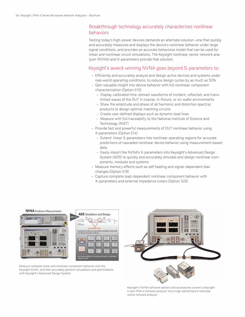
Breakthrough technology accurately characterizes nonlinear behaviors
Testing today’s high-power devices demands an alternate solution—one that quickly
and accurately measures and displays the device’s nonlinear behavior under large
signal conditions, and provides an accurate behavioral model that can be used for
linear and nonlinear circuit simulations. The Keysight nonlinear vector network ana-
lyzer (NVNA) and X-parameters provide that solution.
Measure complete linear and nonlinear component behavior with the
Keysight NVNA, and then accurately perform simulations and optimizations
with Keysight’s Advanced Design System.
Keysight’s NVNA software options and accessories convert a Keysight
4-port PNA-X network analyzer into a high-performance nonlinear
vector network analyzer.
34 | Keysight | PNA-X Series Microwave Network Analyzers - Brochure
Gating
Isolation housing
Isolation housing
Simplified transceiver
LNA
Gating
Controller
RF cable
RF cable
RF cable
Customerfurnishedantenna
PA
TR
Innovative Applications
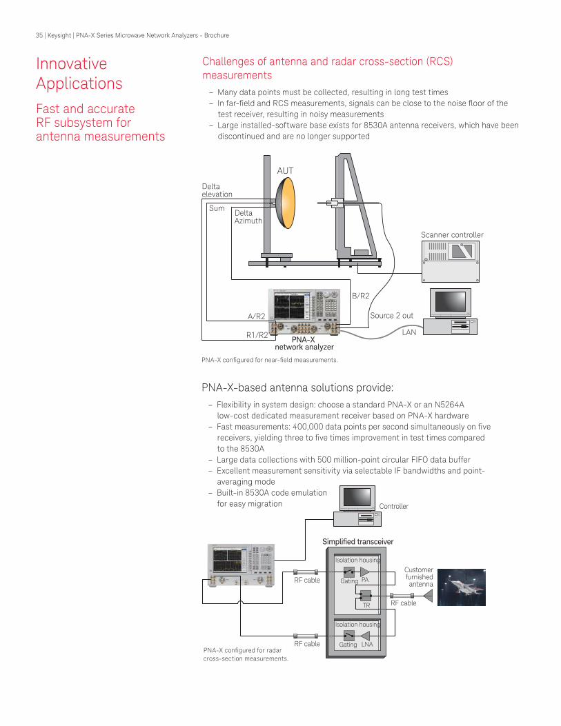
Fast and accurate RF subsystem for antenna measurements
Challenges of antenna and radar cross-section (RCS) measurements
– Many data points must be collected, resulting in long test times
– In far-ield and RCS measurements, signals can be close to the noise loor of the test receiver, resulting in noisy measurements
– Large installed-software base exists for 8530A antenna receivers, which have been
discontinued and are no longer supported
PNA-X-based antenna solutions provide: – Flexibility in system design: choose a standard PNA-X or an N5264A
low-cost dedicated measurement receiver based on PNA-X hardware
– Fast measurements: 400,000 data points per second simultaneously on ive receivers, yielding three to ive times improvement in test times compared to the 8530A
– Large data collections with 500 million-point circular FIFO data buffer
– Excellent measurement sensitivity via selectable IF bandwidths and point-
averaging mode
– Built-in 8530A code emulation
for easy migration
AUT
Scanner controller
LANPNA-X
network analyzer
Source 2 out
B/R2
A/R2
Deltaelevation
DeltaAzimuth
Sum
R1/R2
PNA-X conigured for radar cross-section measurements.
PNA-X conigured for near-ield measurements.
35 | Keysight | PNA-X Series Microwave Network Analyzers - Brochure
PSG or MXGsignal source
85309BLO/IFdistributionunit
85320Breference mixer
85320Atest mixer
Sourceantenna
Optionalamplifier
Trigger in/out
10 MHz
N5264A Opt. 108
7.606MHz
LO out (Opt. 108)
Router hub
LO in
Trig
ger
in/o
ut
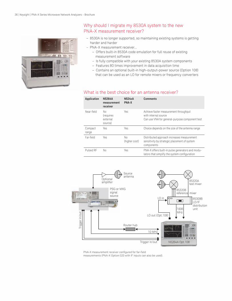
PNA-X measurement receiver conigured for far-ield measurements (PNA-X Option 020 with IF inputs can also be used).
Why should I migrate my 8530A system to the new PNA-X measurement receiver?
– 8530A is no longer supported, so maintaining existing systems is getting
harder and harder
– PNA-X measurement receiver…
– Offers built-in 8530A code emulation for full reuse of existing
measurement software
– Is fully compatible with your existing 8530A system components
– Features 80 times improvement in data acquisition time
– Contains an optional built-in high-output-power source (Option 108)
that can be used as an LO for remote mixers or frequency converters
What is the best choice for an antenna receiver?
Application N5264A
measurement
receiver
N524xA
PNA-X
Comments
Near-ield No (requires external source)
Yes Achieve faster measurement throughput with internal sourceCan use VNA for general-purpose component test
Compact range
Yes Yes Choice depends on the size of the antenna range
Far-ield Yes No (higher cost)
Distributed approach increases measurement sensitivity by strategic placement of system components
Pulsed RF No Yes PNA-X offers built-in pulse generators and modu-
lators that simplify the system coniguration
36 | Keysight | PNA-X Series Microwave Network Analyzers - Brochure
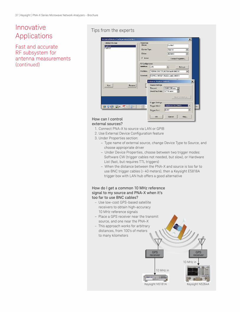
Tips from the experts
GPSreceiver
10 MHz in
GPSreceiver
10 MHz in
Keysight N5181A Keysight N5264A
How do I get a common 10 MHz reference signal to my source and PNA-X when it’s too far to use BNC cables?
– Use low-cost GPS-based satellite
receivers to obtain high-accuracy
10 MHz reference signals – Place a GPS receiver near the transmit
source, and one near the PNA-X
– This approach works for arbitrary
distances, from 100’s of meters
to many kilometers
How can I control external sources?
1. Connect PNA-X to source via LAN or GPIB
2. Use External Device Coniguration feature3. Under Properties section:
– Type name of external source, change Device Type to Source, and
choose appropriate driver
– Under Device Properties, choose between two trigger modes: Software CW (trigger cables not needed, but slow), or Hardware List (fast, but requires TTL triggers)
– When the distance between the PNA-X and source is too far to
use BNC trigger cables (> 40 meters), then a Keysight E5818A
trigger box with LAN hub offers a good alternative
Innovative Applications
Fast and accurate RF subsystem for antenna measurements (continued)
37 | Keysight | PNA-X Series Microwave Network Analyzers - Brochure
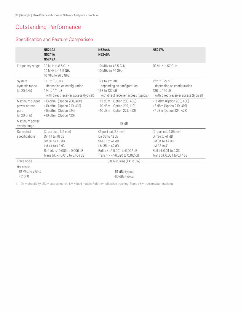
N5249A
N5241A
N5242A
N5244A
N5245A
N5247A
Frequency range 10 MHz to 8.5 GHz10 MHz to 13.5 GHz
10 MHz to 26.5 GHz
10 MHz to 43.5 GHz10 MHz to 50 GHz
10 MHz to 67 GHz
System dynamic range (at 20 GHz)
121 to 130 dB depending on coniguration124 to 141 dB with direct receiver access (typical)
121 to 125 dB
depending on coniguration
133 to 137 dB
with direct receiver access (typical)
122 to 129 dB depending on coniguration
136 to 140 dB with direct receiver access (typical)
Maximum output power at test port(at 20 GHz)
+13 dBm (Option 200, 400)+10 dBm (Option 219, 419) +15 dBm (Option 224) +10 dBm (Option 423)
+13 dBm (Option 200, 400)+10 dBm (Option 219, 419)+10 dBm (Option 224, 423)
+11 dBm (Option 200, 400) +8 dBm (Option 219, 419) +7 dBm (Option 224, 423)
Maximum power sweep range
38 dB
Corrected speciications1
(2-port cal, 3.5 mm)Dir 44 to 48 dBSM 31 to 40 dBLM 44 to 48 dBRel trk +/-0.003 to 0.006 dBTrans trk +/-0.015 to 0.104 dB
(2-port cal, 2.4 mm)Dir 36 to 42 dBSM 31 to 41 dBLM 35 to 42 dBRel trk +/-0.001 to 0.027 dBTrans trk +/-0.020 to 0.182 dB
(2-port cal, 1.85 mm) Dir 34 to 41 dB
SM 34 to 44 dB
LM 33 to 41
Rel trk 0.01 to 0.33
Trans trk 0.061 to 0.17 dB
Trace noise 0.002 dB rms (1 kHz BW)
Harmonics
10 MHz to 2 GHz > 2 GHz
-51 dBc typical -60 dBc typical
Speciication and Feature Comparison
Outstanding Performance
1. Dir = directivity; SM = source match; LM = load match; Rel trk= relection tracking; Trans trk = transmission tracking
38 | Keysight | PNA-X Series Microwave Network Analyzers - Brochure
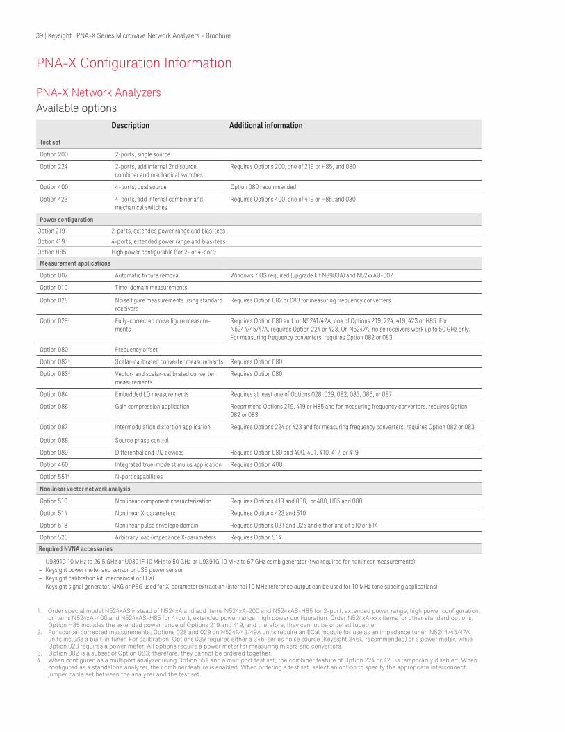
PNA-X Network Analyzers
PNA-X Coniguration Information
Description Additional information
Test set
Option 200 2-ports, single source
Option 224 2-ports, add internal 2nd source, combiner and mechanical switches
Requires Options 200, one of 219 or H85, and 080
Option 400 4-ports, dual source Option 080 recommended
Option 423 4-ports, add internal combiner and mechanical switches
Requires Options 400, one of 419 or H85, and 080
Power coniguration
Option 219 2-ports, extended power range and bias-tees
Option 419 4-ports, extended power range and bias-tees
Option H851 High power conigurable (for 2- or 4-port)
Measurement applications
Option 007 Automatic ixture removal Windows 7 OS required (upgrade kit N8983A) and N52xxAU-007
Option 010 Time-domain measurements
Option 0282 Noise igure measurements using standard receivers
Requires Option 082 or 083 for measuring frequency converters
Option 0292 Fully-corrected noise igure measure-
ments
Requires Option 080 and for N5241/42A, one of Options 219, 224, 419, 423 or H85. For N5244/45/47A, requires Option 224 or 423. On N5247A, noise receivers work up to 50 GHz only. For measuring frequency converters, requires Option 082 or 083.
Option 080 Frequency offset
Option 0823 Scalar-calibrated converter measurements Requires Option 080
Option 0833 Vector- and scalar-calibrated converter measurements
Requires Option 080
Option 084 Embedded LO measurements Requires at least one of Options 028, 029, 082, 083, 086, or 087
Option 086 Gain compression application Recommend Options 219, 419 or H85 and for measuring frequency converters, requires Option 082 or 083
Option 087 Intermodulation distortion application Requires Options 224 or 423 and for measuring frequency converters, requires Option 082 or 083
Option 088 Source phase control
Option 089 Differential and I/Q devices Requires Option 080 and 400, 401, 410, 417, or 419
Option 460 Integrated true-mode stimulus application Requires Option 400
Option 5514 N-port capabilities
Nonlinear vector network analysis
Option 510 Nonlinear component characterization Requires Options 419 and 080, or 400, H85 and 080
Option 514 Nonlinear X-parameters Requires Options 423 and 510
Option 518 Nonlinear pulse envelope domain Requires Options 021 and 025 and either one of 510 or 514
Option 520 Arbitrary load-impedance X-parameters Requires Option 514
Required NVNA accessories
– U9391C 10 MHz to 26.5 GHz or U9391F 10 MHz to 50 GHz or U9391G 10 MHz to 67 GHz comb generator (two required for nonlinear measurements) – Keysight power meter and sensor or USB power sensor – Keysight calibration kit, mechanical or ECal – Keysight signal generator, MXG or PSG used for X-parameter extraction (internal 10 MHz reference output can be used for 10 MHz tone spacing applications)
1. Order special model N524xAS instead of N524xA and add items N524xA-200 and N524xAS-H85 for 2-port, extended power range, high power coniguration, or items N524xA-400 and N524xAS-H85 for 4-port, extended power range, high power coniguration. Order N524xA-xxx items for other standard options. Option H85 includes the extended power range of Options 219 and 419, and therefore, they cannot be ordered together.
2. For source-corrected measurements, Options 028 and 029 on N5241/42/49A units require an ECal module for use as an impedance tuner. N5244/45/47A units include a built-in tuner. For calibration, Options 029 requires either a 346-series noise source (Keysight 346C recommended) or a power meter, while Option 028 requires a power meter. All options require a power meter for measuring mixers and converters.
3. Option 082 is a subset of Option 083; therefore, they cannot be ordered together.4. When conigured as a multiport analyzer using Option 551 and a multiport test set, the combiner feature of Option 224 or 423 is temporarily disabled. When
conigured as a standalone analyzer, the combiner feature is enabled. When ordering a test set, select an option to specify the appropriate interconnect jumper cable set between the analyzer and the test set.
Available options
39 | Keysight | PNA-X Series Microwave Network Analyzers - Brochure
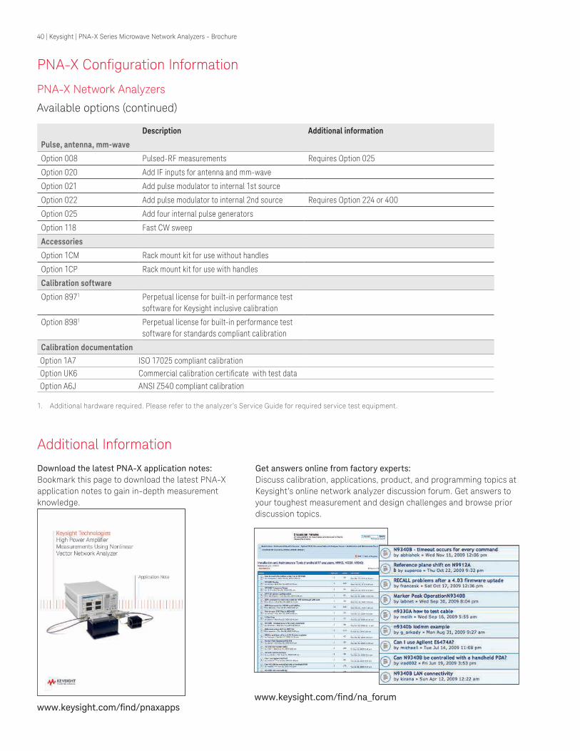
PNA-X Network Analyzers
PNA-X Coniguration Information
Description Additional information
Pulse, antenna, mm-wave
Option 008 Pulsed-RF measurements Requires Option 025
Option 020 Add IF inputs for antenna and mm-wave
Option 021 Add pulse modulator to internal 1st source
Option 022 Add pulse modulator to internal 2nd source Requires Option 224 or 400
Option 025 Add four internal pulse generators
Option 118 Fast CW sweep
Accessories
Option 1CM Rack mount kit for use without handles
Option 1CP Rack mount kit for use with handles
Calibration software
Option 8971 Perpetual license for built-in performance test software for Keysight inclusive calibration
Option 8981 Perpetual license for built-in performance test software for standards compliant calibration
Calibration documentation
Option 1A7 ISO 17025 compliant calibration
Option UK6 Commercial calibration certiicate with test data
Option A6J ANSI Z540 compliant calibration
Additional Information
Download the latest PNA-X application notes:
Bookmark this page to download the latest PNA-X
application notes to gain in-depth measurement
knowledge.
Get answers online from factory experts:
Discuss calibration, applications, product, and programming topics at
Keysight’s online network analyzer discussion forum. Get answers to
your toughest measurement and design challenges and browse prior
discussion topics.
Available options (continued)
1. Additional hardware required. Please refer to the analyzer’s Service Guide for required service test equipment.
www.keysight.com/ind/pnaxappswww.keysight.com/ind/na_forum
40 | Keysight | PNA-X Series Microwave Network Analyzers - Brochure

*X-parameters is a trademark and registered trademark of Keysight Technologies in the US, EU, JP, and elsewhere. The X-parameter format and underlying equations are open and documented. For more information, visit; http://www.keysight.com/find/eesof-x-parameters-info
myKeysight
www.keysight.com/find/mykeysight
A personalized view into the information most relevant to you.
www.lxistandard.org
LAN eXtensions for Instruments puts the power of Ethernet and the
Web inside your test systems. Keysight is a founding member of the LXI
consortium.
Three-Year Warranty
www.keysight.com/find/ThreeYearWarranty
Keysight’s commitment to superior product quality and lower total cost
of ownership. The only test and measurement company with three-year
warranty standard on all instruments, worldwide.
Keysight Assurance Plans
www.keysight.com/find/AssurancePlans
Up to five years of protection and no budgetary surprises to ensure your
instruments are operating to specification so you can rely on accurate
measurements.
www.keysight.com/go/quality
Keysight Technologies, Inc.
DEKRA Certified ISO 9001:2008 Quality Management System
Keysight Channel Partners
www.keysight.com/find/channelpartners
Get the best of both worlds: Keysight’s measurement expertise and product breadth, combined with channel partner convenience.
www.keysight.com/find/pna
www.keysight.com/find/pnaxapps
www.keysight.com/find/na_forum
41 | Keysight | PNA-X Series Microwave Network Analyzers - Brochure
This information is subject to change without notice.© Keysight Technologies, 2010 - 2015Published in USA, May 7, 20155990-4592ENwww.keysight.com
Protect your software investment:Keysight protects your 8753, 8720 and 8510
software investment by providing migration
tools to reduce your code-conversion effort.
www.keysight.com/find/nadisco
For more information on Keysight
Technologies’ products, applications or
services, please contact your local Keysight
office. The complete list is available at:www.keysight.com/find/contactus
Americas
Canada (877) 894 4414Brazil 55 11 3351 7010Mexico 001 800 254 2440United States (800) 829 4444
Asia PaciicAustralia 1 800 629 485China 800 810 0189Hong Kong 800 938 693India 1 800 11 2626Japan 0120 (421) 345Korea 080 769 0800Malaysia 1 800 888 848Singapore 1 800 375 8100Taiwan 0800 047 866Other AP Countries (65) 6375 8100
Europe & Middle East
Austria 0800 001122Belgium 0800 58580Finland 0800 523252France 0805 980333Germany 0800 6270999Ireland 1800 832700Israel 1 809 343051Italy 800 599100Luxembourg +32 800 58580Netherlands 0800 0233200Russia 8800 5009286Spain 800 000154Sweden 0200 882255Switzerland 0800 805353
Opt. 1 (DE)Opt. 2 (FR)Opt. 3 (IT)
United Kingdom 0800 0260637
For other unlisted countries:www.keysight.com/find/contactus
(BP-04-23-15)
Gain deeper conidence
Whether you’re testing active or passive devices, the right mix of speed and performance
gives you an edge. In R&D, our vector network analyzers provide a level of measurement
integrity that helps you transform deeper understanding into better designs. On the
production line, our cost-effective VNAs provide the throughput and repeatability you
need to transform parts into competitive components. In the ield, our handheld analyzers deliver high-quality measurements wherever you need to go. Every Keysight VNA is the
ultimate expression of our expertise in linear and nonlinear device characterization. On
the bench, in a rack or in the ield, we can help you gain deeper conidence.