plant layout and materials handling
TRANSCRIPT

PLANT LAYOUT AND MATERIALS HANDLING
FINAL PROJECT REPORT MARCH 14, 1977
PRESENTED TO PROFESSOR ELLER
PREPARED BY:
WILLIAM B. BLADEN
RONALD E. JONES
JAMES F. HARRIS
Southern Technical Institute Marietta, Georgia 30060
Professor Eller Industrial Engineering Department Southern Technical Institute Marietta, Georgia 30060
Reference: Plant Layout and Materials Handling for American Manufacturing Company
Dear Professor Eller:
In January, 1977, you requested a proposed materials handling and assembly procedure for "Pushover Balancers" to facilitate a prodution level of 7,500 Pushover Balancers per year for the American Manufacturing Company of Atlanta, Georgia. This report consists of recommendations that would, if adopted, direct the American Manufacturing Company about layout procedures and materials handling to manufacture the requested amount.
Sincerely,
416LA)N N,Cte124-\
fertaet E. eJ
c7/

TABLE OF CONTENTS'
Page
COMPANY AND PERSONNEL BACKGROUND 1-4
DISCUSSION ANALYSIS 5
APPENDIX
BILL OF MATERIALS 6
MATERIAL REQUIREMENT SCHEDULE 7
DATA ON RECEIVING AND SHIPPING 8
MACHINE CALCULATIONS 9
LAYOUT PLANNING CHART 10
PARTS DESCRIPTION DIAGRAM 11
ASSEMBLY CHART 12
OPERATION PROCESS CHART 13
FINAL LAYOUT. 14
COST DATA 15-17
BREAK EVEN CHART 18
COMPANY AND PERSONNEL
BACKGROUND

BRIEF HISTORY OF LAND INDUSTRIES
d/b/a AMERICAN MANUFACTURING COMPANY
Land Industries, Inc., was started in 1969 by Jim Rones, d/b/a American Manufacturing Company. The Company basically started by purchasing finished goods and repacking and selling them to the janitorial market through distributors located throughout the United States. Sales were approximately $175,000 during the first year of operation and have grown to approximately $3,000,000 during 1976.
During early 1973 supply problems necessitated the decision to begin partial manufacturing of abrasive floor scrubbing pads and other abrasive products. These products were responsible for approxi-mately 50% of sales. With normal start-up problems solved, the American Manufacturing Company was running smoothly until March of 1975 when the warehouse and corporate offices were destroyed by a devastating tornado. With the help of loyal suppliers and personnel of the Company, operations were moved immediately to the present 90,000 sq. ft. location. Shipments began again within two weeks, and with the aid of a SBA Disaster Loan the Company reestablished operations.
A non-woven air lay production line became necessary when the only supplier of one vital raw material was unable to supply the necessary quality and volume to meet their needs. When other suppliers could not be secured the decision was made to commit for the production line. Equipment began arriving January, 1976, and the line was completed by March of this year. Crews have been trained in the operation, and they are now producing on this line. The equipment has allowed American Manufacturing Company to become one of the seven basic suppliers in the county of non-woven abrasive products (which constitutes 50% of their sales volume).
They have recently designed and are now manufacturing for their industry a new concept in barrel stands which seem to have great potential. At present they are also having tooling made for a newly-designed mop wringer which will be in production early in 1977.
Refer to Page 4 for a representation of the Company's present organizational structure.
1
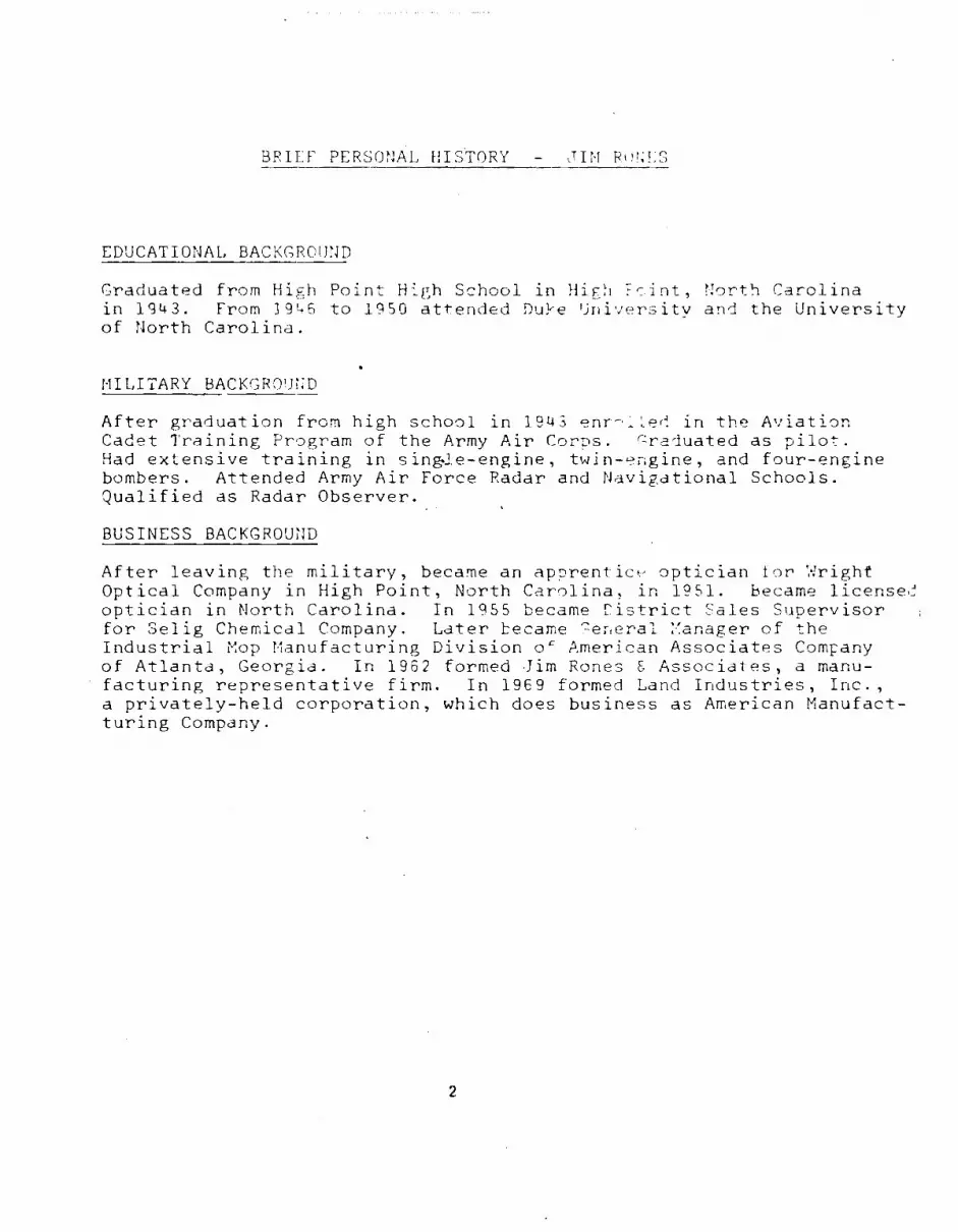
BRIEF' PERSONAL HISTORY - JIM RUNES
EDUCATIONAL BACKGROUND
Graduated from High Point High School in High North Carolina in 1943. From 1945 to 1950 attended Dupe University and the University of North Carolina.
MILITARY BACKGROUND
After graduation from high school in 1943 enr-•;1.ed in the Aviation Cadet Training Program of the Army Air Corps. Graduated as pilot. Had extensive training in sing.le-engine, twin-engine, and four-engine bombers. Attended Army Air Force Radar and Navigational Schools. Qualified as Radar Observer.
BUSINESS BACKGROUND
After leaving the military, became an apprentice optician for Wright Optical Company in High Point, North Carolina, in 1951. became licensed optician in North Carolina. In 1955 became Ristrict Sales Supervisor for Selig Chemical Company. Later became General Manager of the Industrial Mop Manufacturing Division (:)- American Associates Company of Atlanta, Georgia. In 1962 formed Jim Rones & Associates, a manu-facturing representative firm. In 1969 formed Land Industries, Inc., a privately-held corporation, which does business as American Manufact-turing Company.
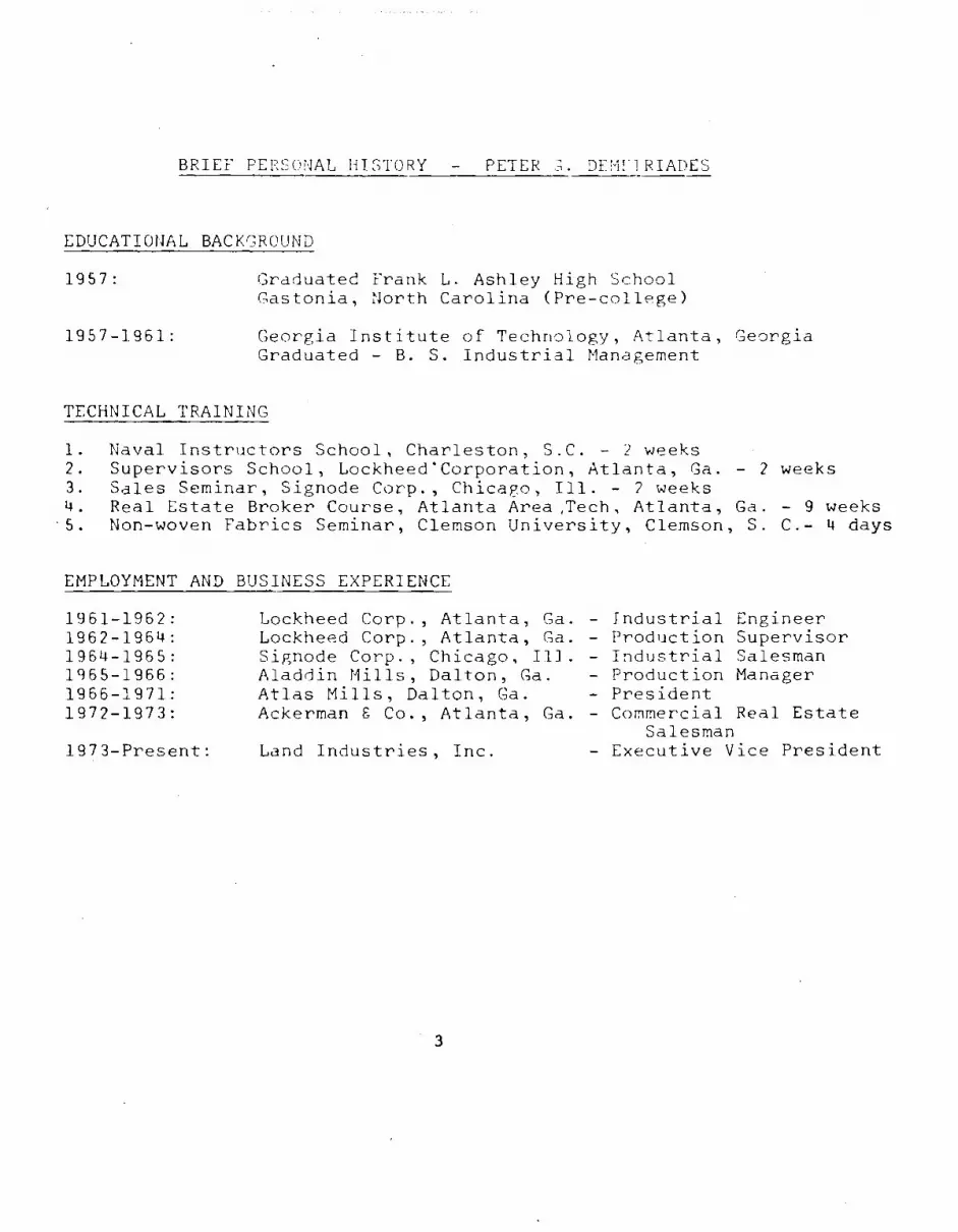
BRIEF PERSONAL HISTORY - PETER DRMI1RIADES
EDUCATIONAL BACKGROUND
1957: Graduated Frank L. Ashley High School Gastonia, North Carolina (Pre-college)
1957-1961:
Georgia Institute of Technology, Atlanta, Georgia Graduated - B. S. Industrial Management
TECHNICAL TRAINING
1. Naval Instructors School, Charleston, S.C. - 2 weeks 2. Supervisors School, Lockheed*Corporation, Atlanta, Ga. - 2 weeks 3. Sales Seminar, Signode Corp., Chicago, Ill. - 2 weeks 4. Real Estate Broker Course, Atlanta Area,Tech, Atlanta, Ga. - 9 weeks 5. Non-woven Fabrics Seminar, Clemson University, Clemson, S. C.- 4 days
EMPLOYMENT AND BUSINESS EXPERIENCE
1961-1962: Lockheed Corp., Atlanta, Ga . - Industrial Engineer 1962-1964: Lockheed Corp., Atlanta, Ga . - Production Supervisor 1964-1965: Signode Corp., Chicago, II.] . - Industrial Salesman 1965-1966: Aladdin Mills, Dalton, Ga. - Production Manager 1966-1971: Atlas Mills, Dalton, Ga. - President 1972-1973: Ackerman 6 Co., Atlanta, Ga . - Commercial Real Estate
Salesman 1973-Present: Land Industries, Inc. - Executive Vice President
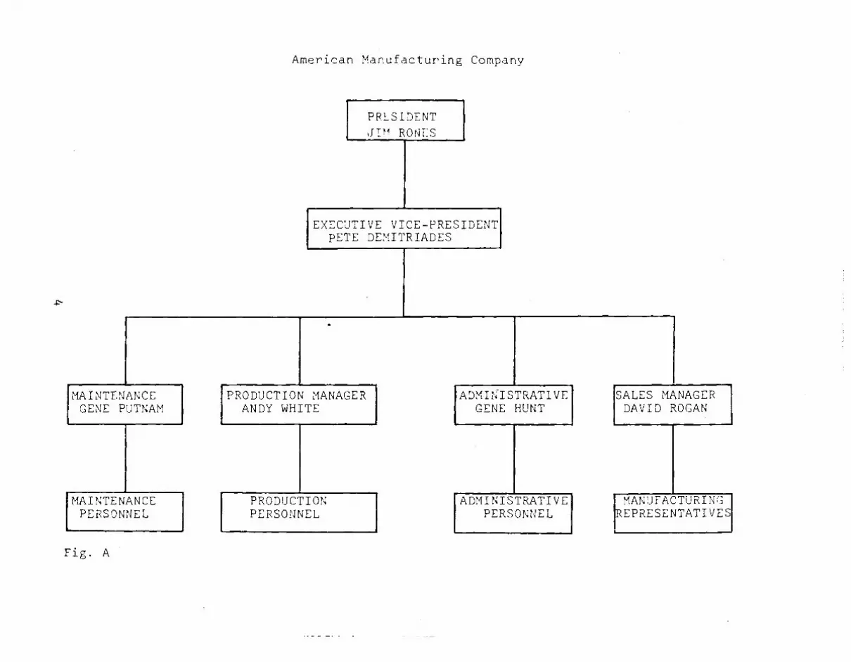
MANUFACTURING EPRESENTATIVES
SALES MANAGER DAVID ROGAN
American Manufacturing Company
PRESIDENT JIM ROVES
EXECUTIVE VICE-PRESIDENT PETE DEMITRIADES
MAINTENANCE GENE PUTNAM
MAINTENANCE PERSONNEL
PRODUCTION PERSONNEL
ADMINISTRATIVE GENE HUNT
ADMINISTRATIVE PERSONNEL
PRODUCTION MANAGER ANDY WHITE
Fig. A
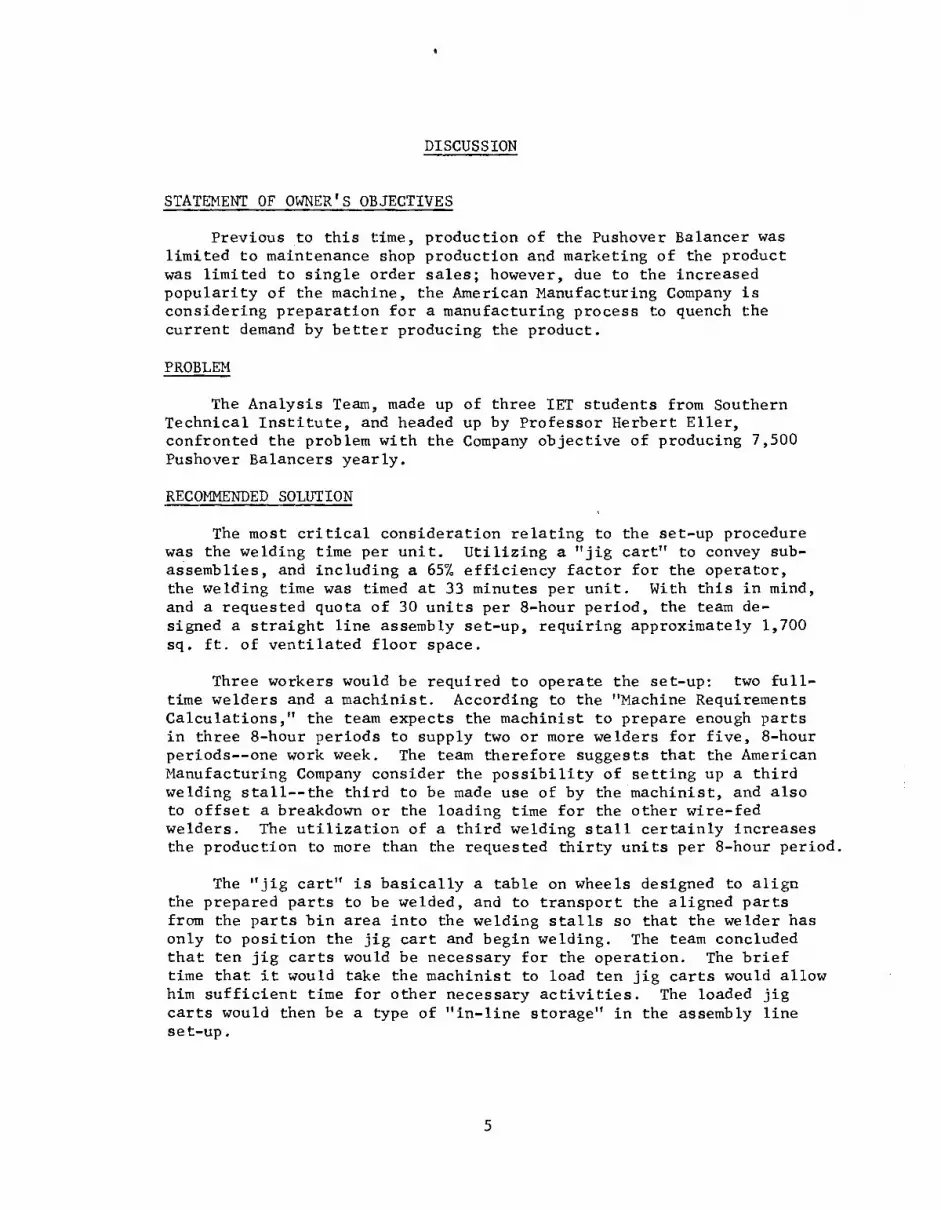
DISCUSSION
STATEMENT OF OWNER'S OBJECTIVES
Previous to this time, production of the Pushover Balancer was limited to maintenance shop production and marketing of the product was limited to single order sales; however, due to the increased popularity of the machine, the American Manufacturing Company is considering preparation for a manufacturing process to quench the current demand by better producing the product.
PROBLEM
The Analysis Team, made up of three IET students from Southern Technical Institute, and headed up by Professor Herbert Eller, confronted the problem with the Company objective of producing 7,500 Pushover Balancers yearly.
RECOMMENDED SOLUTION
The most critical consideration relating to the set-up procedure was the welding time per unit. Utilizing a "jig cart" to convey sub-assemblies, and including a 657 efficiency factor for the operator, the welding time was timed at 33 minutes per unit. With this in mind, and a requested quota of 30 units per 8-hour period, the team de-signed a straight line assembly set-up, requiring approximately 1,700 sq. ft. of ventilated floor space.
Three workers would be required to operate the set-up: two full-time welders and a machinist. According to the "Machine Requirements Calculations," the team expects the machinist to prepare enough parts in three 8-hour periods to supply two or more welders for five, 8-hour periods--one work week. The team therefore suggests that the American Manufacturing Company consider the possibility of setting up a third welding stall--the third to be made use of by the machinist, and also to offset a breakdown or the loading time for the other wire-fed welders. The utilization of a third welding stall certainly increases the production to more than the requested thirty units per 8-hour period.
The "jig cart" is basically a table on wheels designed to align the prepared parts to be welded, and to transport the aligned parts from the parts bin area into the welding stalls so that the welder has only to position the jig cart and begin welding. The team concluded that ten jig carts would be necessary for the operation. The brief time that it would take the machinist to load ten jig carts would allow him sufficient time for other necessary activities. The loaded jig carts would then be a type of "in-line storage" in the assembly line set-up.
5

APPENDIX
FOR:
AMERICAN MANUFACTURING CO.
DRAWING NO:
DATE:March
1
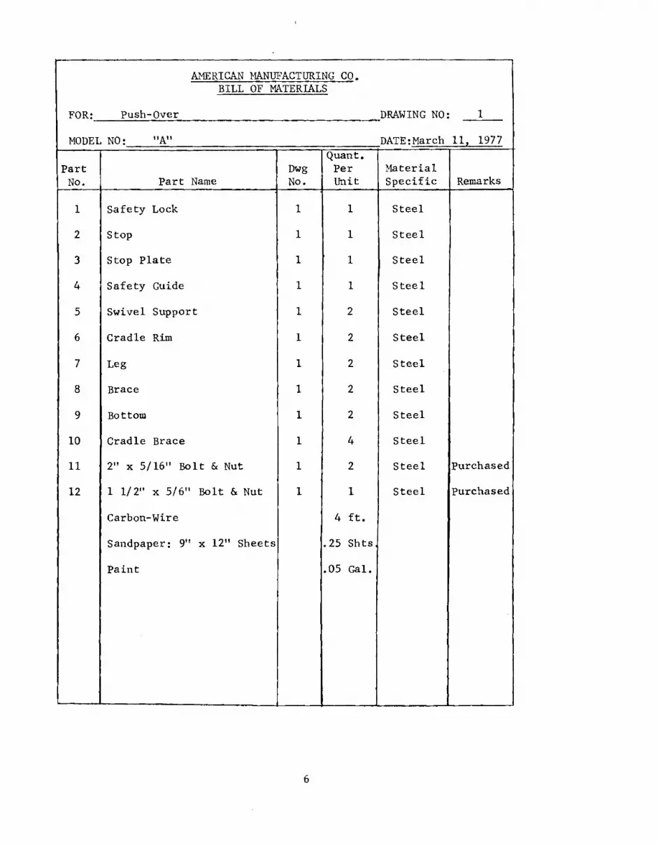
BILL OF MATERIALS
Push-Over
MODEL NO: "A" 11, 1977
Part No. Part Name
Dwg No.
Quant. Per Unit
Material Specific Remarks
1
2
3
4
5
6
7
8
9
10
11
12
Safety Lock
Stop
Stop Plate
Safety Guide
Swivel Support
Cradle Rim
Leg
Brace
Bottom
Cradle Brace
2" x 5/16" Bolt & Nut
1 1/2" x 5/6" Bolt & Nut
Carbon-Wire
Sandpaper: 9" x 12" Sheets
Paint
1
1
1
1
1
1
1
1
1
1
1
1
1
1
r 1
1
2
2
2
2
2
4
2
1
4 ft.
.25 Shts,
.05 Gal.
Steel
Steel
Steel
Steel
Steel
Steel
Steel
Steel
Steel
Steel
Steel
Steel
Purchased
Purchased
6
Problem
Man
ual f or P
lant L
ayout, 2
nd
Ed., 0
1963
, by Th
e Ron
ald P
ress C
o., N
.Y.
DIRECT
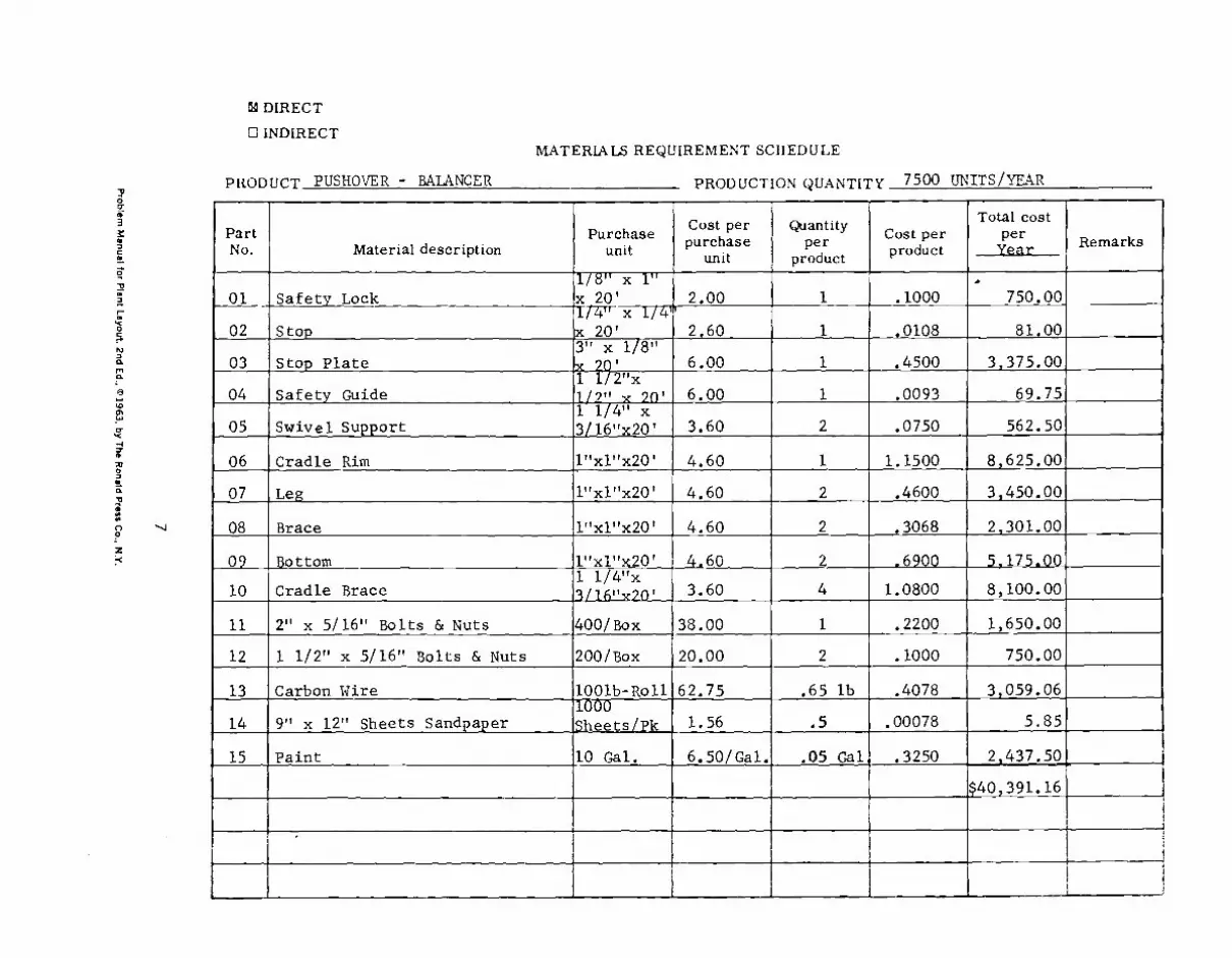
0 INDIRECT MATERIALS REQUIREMENT SCHEDULE
PRODUCT PUSHOVER - BALANCER
PRODUCTION QUANTITY 7500 UNITS/YEAR
Part No. Material description
Purchase unit
Cost per p
uniturchase
Quantity per
product
Cost per product
Total cost
per Year Remarks
01 Safety Lock 1/8" x 1"-x 20' 2.00
2,60
6.00
1
1
1
.1000
.0108
.4500
750.00
81.00
3,375.00
02 Stop 1/4" x 1/4n x 20' 3" x 1/8"
03 Stop Plate
04 Safety Guide U2"x
1/9" x 9n , 6.00 1 .0093 69.75
05 Swivel Support 1 1/4" x 3/16"x20' 3.60 2 .0750 562.50
06 Cradle Rim 1"x1"x20 1 4.60 1 1.1500 8,625.00
07 Leg 1"x1"x20' 4.60 2 .4600 3,450.00
08 Brace 1"x1"x20 1 4.60 2 .3068 2,301.00
09 Bottom 1"xl"x20' 4.60 2 .6900 5,175.00
10 Cradle Brace 1 1/4"x 3L16"Y20 ,
400/Box
3.60
38.00
4
1
1.0800
.2200
8,100.00
1,650.00 11 2" x 5/16" Bolts & Nuts
12 1 1/2" x 5/16" Bolts & Nuts 200/Box 20.00 2 .1000 750.00
13 Carbon Wire 1001b-Roll 62.75 .65 lb .4078 3,059.06
14 9" x 12" Sheets Sandpaper
Paint
1000 Sheets/Pk
10 Gal.
1.56
6.50/Gal.
.5
.05 Gal,
.00078
.3250
5.85
2,437.50 15
$40,391.16

DATA ON RECEIVING AND SHIPPING
A. Material Received:
Part No. Or Item Description Unit Received
1 Safety Lock 1/8" x 1" x 20' Steel Stripping
2 Stop 1/4" x 1/4" x 20' Square Steel Rod
3 Stop Plate 3" x 1/8" x 20' Steel Stripping
4 Safety Guide 1 1/2" x 1/2" x 20' Steel Channeling
5 Swivel Support 1 1/4" x 3/16" x 20' Steel Stripping
6 Cradle Rim 1" x 1" x 20' Square Steel Tubing _
7 Leg 1" x 1" x 20' Square Steel Tubing
8 Brace 1" x 1" x 20' Square Steel Tubing
9 Bottom 1" x 1" x 20' Square Steel Tubing
10 Cradle Brace 1 1/4" x 3/16" x 20' Steel Stripping
11 2"x5/16" B&N 2" x 5/16" Bolts & Nuts @ 400 pieces
12 1 1/2" x 5/16" B&N 1 1/2" x 5/16" Bolts & Nuts @ 200 pieces
13 Carbon Wire (36 in-Dia.) 2-25 lb Rolls
14 9"x12" Sheets Sandpaper 9" x 12" Sheets
15 Paint (1 gal.) Blue Enamel Paint (10 Gallons)
8
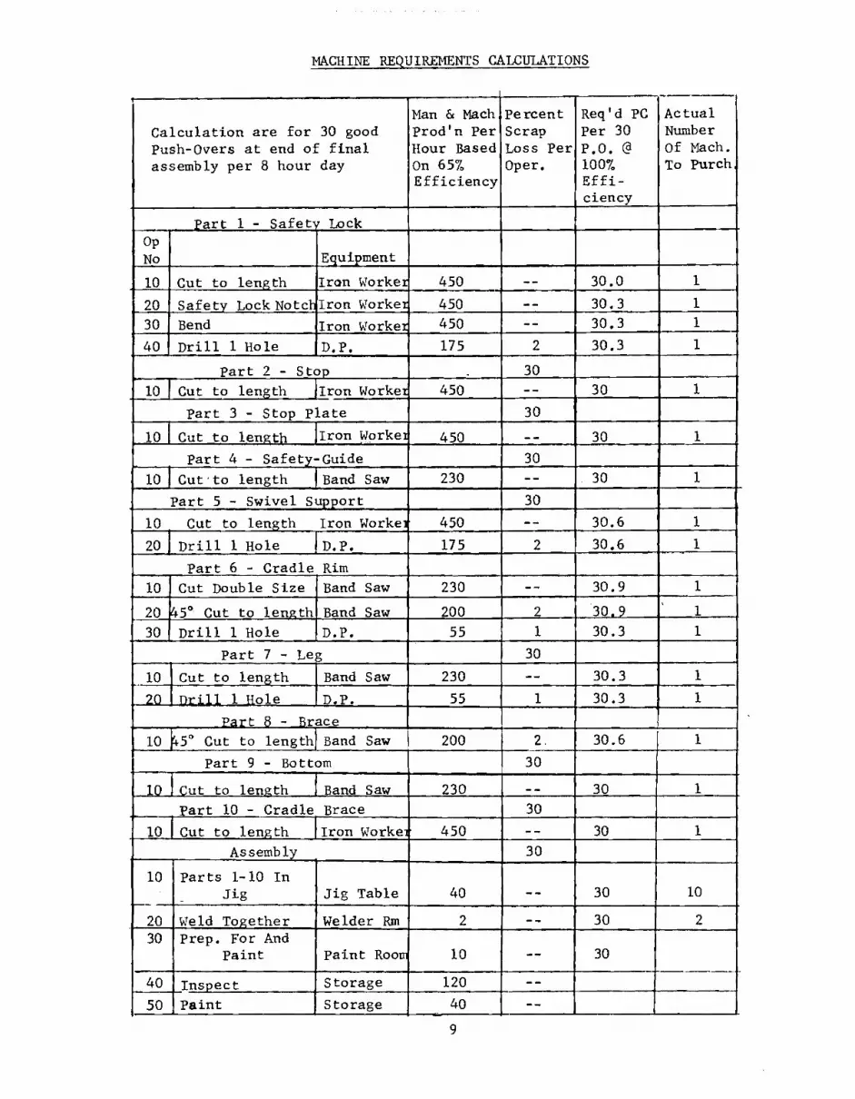
MACHINE REQUIREMENTS CALCULATIONS
Calculation are for 30 good Push-Overs at end of final assembly per 8 hour day
Man & Mach,Percent Prod'n Per Hour Based On 65% Efficiency
Scrap Loss Per Oper.
Req'd PC Per 30 P.O. @ 100% Effi-ciency
Actual Number Of Mach. To Purch
Part 1 - Safety Lock Op No Equipment
10 Cut to length Iron Worker 450 -- 30.0
20 Safety Lock Notchlron Worker 450 -- 30.3 1
30 Bend Iron Worker 450 -- 30.3 1
40 Drill 1 Hole D.P. 175 2 30.3
Part 2 - Stop 30
0 I Cut to length !Iron Worker 450 -- 30
Part 3 - Stop Plate 30
10 Cut to length Iron Workei 450 30
Part 4 - Safety-Guide 30
10 Cut•to length (Band Saw 230 -- 30
Part 5 - Swivel Support 30
10 Cut to length Iron Worker 450 -- 30.6
201 Drill 1 Hole 1 D.P. 175 2 30.6
Part 6 - Cradle Rim 10 Cut Double Size Band Saw 230 -- 30.9
20 45 ° Cut to length Band Saw 200 2 30.9 1
30, Drill 1 Hole D.P. 55 1 30.3
Part 7 - Leg 30
10 Cut to length Band Saw 230 -- 30.3
20 Drill 1 Hole D.P. 55 1 30.3
Part 8 - Brace 10 +̂5 ° Cut to length] Band Saw 200 2. 30.6
Part 9 - Bottom 30
10 Cut to length Band Saw 230 30
Part 10 - Cradle Brace 30
10 Cut to length Iron Worker 450 -- 30
Assembly 30
10 Parts 1-10 In Jig Jig Table 40 -- 30 10
20 Weld Together Welder Rm 2 -- 30 2 30 Prep. For And
Paint Paint Room 10 -- 30
40 Inspect Storage 120 --
50 Paint Storage 40 --
9
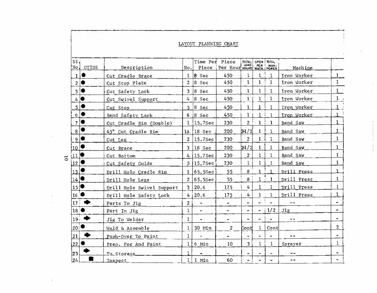
LAYOUT PLANNING CHART
St No OTIDS Description No.
Time Per Piece
Piece Per Hour
TOTAL WAD
HOURS
1
OPER PER
MACK
1
TOTAL MAN-
POWER
1
Machine 1.--- Iron Worker 1 1
2 II Cut Stop Plate 2 8 Sec 450 1 1 1 Iron Worker 1
3 • Cut Safety Lock 3 8 Sec 450 1 1 1 Iron Worker
4 • Cut Swivel Support
Cut Stop
4
5
8 Sec
8 Sec
450
450
1
1
1
1
1
1
Iron Worker
Iron Worker
1 .
1 5 • 6 • Iron Worker 1
7 Band Saw 1
8 • 45° Cut Cradle Rim lA 18 Sec 200 X1/2 1 1 Band Saw 1
9• Band Saw 1
10 Band Saw 1
.11 Band Saw 1
12 Band Saw
13 i 1 nri11 Press
14 Legs Drill Press
15 Support m-•
Drill Press
164/ Drill Hole Safety Lock 4 20.6 i. 175 4 1 1 Drill Press
17 • Parts To Jig 2 - - - - -- -
18 • Part In Jig 1 - - - 1/2 Jig -
19 ---Imb 20
4111' Jig To Welder 1 - - - - __ -
• Weld & Assemble
I -. 30 Min 2 L'on 1 Cont
21J 4 Push-Over To Paint - - - - - -- -
22 411 Prep. For And Paint 1 6 Min 10 3 1 1 Sprayer 1
23_ 24
1610 To Storage —1-, 1
- - - - - __ -
II Tnspe_ct 1 Min 60 - - - -- -
STAND ASSEMBLY 3 LEG BRACE 4-8
SAFETY LOCK
WIRE BRUSH
PAINT
A9
A101
All
CARTON
12
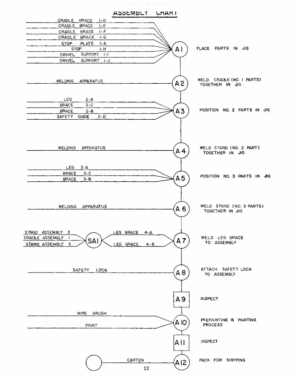
Abt.MbLY UlAtl I CRADLE BRACE I-D CRADLE BRACE I-E
CRADLE BRACE I- F
CRADLE BRACE I-G
STOP PLATE I-A
STOP I-H SWIVEL SUPPORT I-I
SWIVEL SUPPORT I-J
WELDING APPARATUS
LEG 2-A
BRACE 2-C
BRACE 2-B
SAFETY GUIDE 2-D
WELDING APPARATUS
LEG 3-A
BRACE 3-C
BRACE 3-B
WELDING APPARATUS
PLACE PARTS IN JIG
WELD CRADLE (NO. I PARTS) TOGETHER IN JIG
POSITION NO. 2 PARTS IN JIG
WELD STAND (NO. 2 PART) TOGETHER IN JIG
POSITION NO. 3 PARTS IN JIG
WELD STAND (NO. 3 PARTS) TOGETHER IN JIG
STAND ASSEMBLY 2 LEG BRACE 4-A CRADLE ASSEMBLY I WELD LEG BRACE
TO ASSEMBLY
ATTACH SAFETY LOCK TO ASSEMBLY
INSPECT
PREPAINTING B PAINTING PROCESS
INSPECT
PACK FOR SHIPPING
10
1 1
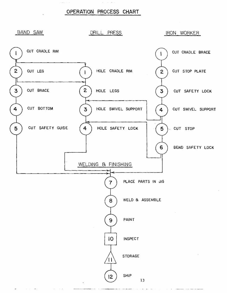
OPERATION PROCESS CHART
BAND SAW DRILL PRESS IRON WORKER
0 0 0 0
0
0 0
0 0 0
0
CUT CRADLE RIM
CUT LEG
CUT BRACE
CUT BOTTOM
CUT SAFETY GUIDE
HOLE CRADLE RIM
HOLE LEGS
HOLE SWIVEL SUPPORT
HOLE SAFETY LOCK
CUT CRADLE BRACE
CUT STOP PLATE
CUT SAFETY LOCK
CUT SWIVEL SUPPORT
CUT STOP
BEND SAFETY LOCK
WELDING & FINISHING
PLACE PARTS IN JIG
WELD & ASSEMBLE
PAINT
INSPECT
STORAGE
SHIP 13

I JIG CARTS
PART BIND v.\
OVERHEAD VENT PAINT ROOM
SPRAYER
14
FINAL LAYOUT
RAW MATERIALS
WELDING ROOMS
OVERHEAD VENT
1
WELDER
STORAGE
STORAGE
FINISHED UNITS
JIG CARTS
z 0
U
0
0 _J

COST DATA
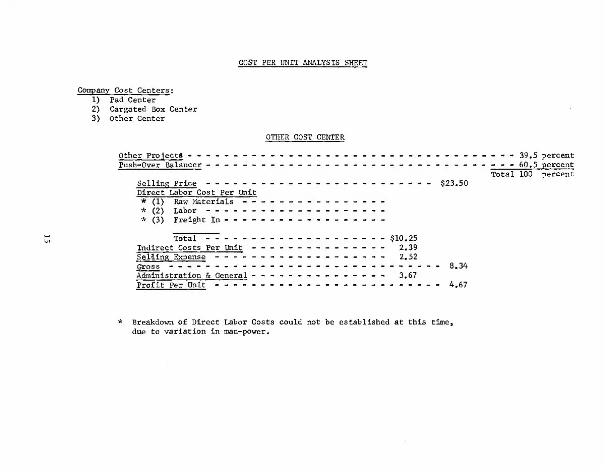
COST PER UNIT ANALYSIS SHEET
Company Cost Centers:
OTHER COST CENTER
1) Pad Center 2) Cargated Box Center 3) Other Center
Other Projects 39.5 percent Push-Over Balancer 60.5 percent
Total 100 percent Selling Price $23.50 Direct Labor Cost Per Unit * (1) Raw Materials * (2) Labor * (3) Freight In
$10.25 Total Indirect Costs Per Unit 2.39 Selling Expense 2.52 Gross 8.34 Administration & General 3.67 Profit Per Unit 4.67
* Breakdown of Direct Labor Costs could not be established at this time, due to variation in man-power.
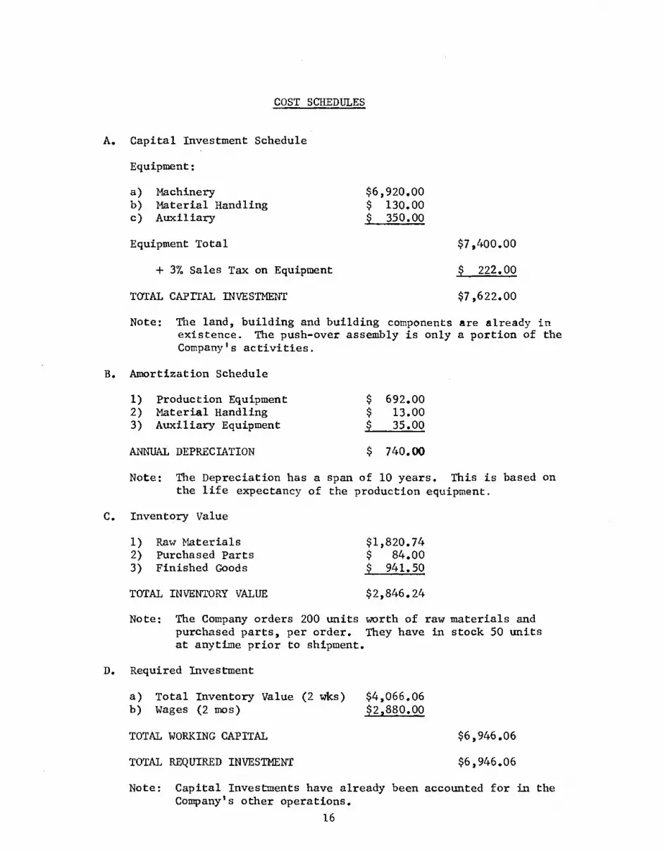
COST SCHEDULES
A. Capital Investment Schedule
Equipment:
a) Machinery b) Material Handling c) Auxiliary
Equipment Total
+ 3% Sales Tax on Equipment
TOTAL CAPITAL INVESTMENT
$6,920.00 $ 130.00 $ 350.00
$7,400.00
$ 222.00
$7,622.00
Note: The land, building and building components are already in existence. The push-over assembly is only a portion of the Company's activities.
B. Amortization Schedule
1) Production Equipment $ 692.00 2) Material Handling $ 13.00 3) Auxiliary Equipment $ 35.00
ANNUAL DEPRECIATION $ 740.00
Note: The Depreciation has a span of 10 years. This is based on the life expectancy of the production equipment.
C. Inventory Value
1) Raw Materials $1,820.74 2) Purchased Parts $ 84.00 3) Finished Goods $ 941.50
TOTAL INVENTORY VALUE $2,846.24
Note: The Company orders 200 units worth of raw materials and purchased parts, per order. They have in stock 50 units at anytime prior to shipment.
D. Required Investment
a) Total Inventory Value (2 wks) $4,066.06 b) Wages (2 mos) $2,880.00
TOTAL WORKING CAPITAL
$6,946.06
TOTAL REQUIRED INVESTMENT
$6,946.06
Note: Capital Investments have already been accounted for in the Company's other operations.
16

Production Equipment
There are three machines to be purchased for the working of parts.
1) Band Saw $1,100.00 Powermatic 1143 2) Drill Press $ 625.00 Powermatic 1150 3) Iron Worker $1,200.00 Trojan
The welding of 30 Push-Overs a day will require two machines.
1) Wire Fed Welder $1,200.00 T.C. = $2,400.00
The painting room will have a Blizzard spraying outfit.
1) Spray Painter $1,595.00
Materials Handling Equipment
There are to be two hand push carts.
1) Hand push carts $65.00 T.C. = $130.00
Auxiliary Equipment
There are to be ten Jig carts.
2) Jig Carts $35.00 T.C. = $350.00
Office Equipment
This is already in existance.
Building and Installed Equipment
This has already been accounted for within the operations of the company.
17

160-
140-
80-
120-
$'00 100-,
1000 2000 3000 5000 6000 8000 4000 7000
180
FTXF iLCOST
1../ V /-111A.•
40.
SALES (1000)
UNITS

MONTHLY LOG

1. Client
Client Company: AMERICAN MANUFACTURING COMPANY
Meeting,s:
Date Time
:;tart Finish
. ,
T-am Members ire..;ent Clent Members Present
Jan 5
Feb 2
Feb 21
2 P.M. 5 P.M.
2 P.M. 5 P.M.
2 P.M. 6 P.M.
All members present incl. Prof. Eller
All members present incl. Prof. Eller
All members present
Peter G. Demetriades
Peter G. Demetriades
Peter G. Demetriades
2. Telephone Contacts:
Date Time
`:tart ' Finish Team Member(s) client Member(s)
3. Team Meetings:
Date Time Start ' Finish Team Members
Jan 10 Jan 12
.Jan 17 Jan 19 Jan 24 Jan 26 Jan 31 Feb 7 Feb 9
2 P.M. , 5 P.M. 2 P.M. 6 P.M. 2 P.M. 5 P.M. 2 P.M. ' 5 P.M. 2 P.M. ' 5 P.M. 2 P.M. : 5 P.M. 2 P.M. 5 P.M. 2 P.M. 5 P.M. 2 P.M. 5 P.M. ,
All members present, including Prof. Eller All members present All members present All members present All members present All members present All members present, including Prof. Eller All members present All members present

1.
Client
Client Meetings:
Company: AMERICAN MANUFACTURING COMPANY
.
Date Time
'itart Finish Team Members Present Client Members Present
,
2. Telephone Contacts: •
Date Time
Start ' Finish am Member Client Member(s)
1 ,
, ,
3. Team Meetings:
Date Time Start ' Finish Team Members
Feb Feb
, Feb Feb Mar Mar Mar Mar Mar
14 16 23 28 2 7 8 9 10
2 P.M., 2 P.M., 2 P.M., 2 P.M., 2 P.M., 1 P.M., 1 P.M., 12 P.M 1
12 P.M.
5 P.M. 6:30 P.M. 6 P.M. 5 P.M. 6 P.M. 6 P.M. 6 P.M. 6 P.M. 6 P.M.
All members present All members present All members present, including Prof. Eller All members present All members present All members present All members present All members present, including Prof. Eller All members present

1. Client
Client Company: AMERICAN MANUFACTURING COMPANY
Meetings:
Date Time
Start ' Finish Team Members Present Client Members Present.
I
2. Telephone Contacts;
Date Time
Start ' Finish Team Member , Client Member( s)
I
I
I
V
I
I
I
I
'Ream Meetings:
Date Time Start ' Finish Team Members
Mar 11 1 P.M. : 5 P.M.
,
f
I
I
All members present, including Prof. Eller

Travel Date Hours Total Miles
Jan 11 2-5:30 3-1/2 44 Professor Eller Jan 27 2-6 4 44 Mar 1 2-5 3 44
10-1/2 Total 132