~perkins® - gogenielift.com
TRANSCRIPT
REFERENCE ONLY
~Perkins®
Operation and Maintenance
Manual 1103 and 1104 Engines
Models ~C, ~O, OJ, OK, RE, RG, RJ, RR, RS, OF, OG
SEBU7833-01 December 2004
REFERENCE ONLY
I
CALIFORNIA Proposition 65 Warning
Diesel engine exhaust and some of its constituents are known to the State of California to cause cancer, birth defects, and other reproductive harm.
REFERENCE ONLY
SEBU7833-01
Table of Contents
Foreword ............................... .. ................................ 4
Safety Section
Safety Messages ..................... ............................... 5
General Hazard Information ................................... 5
Burn Prevention ...................................................... 7
Fire Prevention and Explosion Prevention .............. 7
Crushing Prevention and Cutting Prevention .......... 9
Mounting and Dismounting ..................................... 9
Before Starting Engine ............................................ 9
Engine Starting ..................................................... 10
Engine Stopping ................................................... 10
Electrical System .................................................. 10
Product Information Section
Model Views ......................................................... 12
Product Identification Information ........................ 18
Operation Section
Lifting and Storage ................................................ 21
Gauges and Indicators .......................................... 24
Engine Starting ........... .......................................... 25
Engine Operation .................................................. 28
Engine Stopping ................................................... 29
Cold Weather Operation ....................................... 30
Maintenance Section
Refill Capacities .................... .. ... ........................... 34
Maintenance Interval Schedule ............................ 48
Warranty Section
Warranty Information ............................................ 76
Index Section
Index ..................................................................... 77
3 Table of Contents
REFERENCE ONLY
4 Foreword
Foreword
Literature Information
This manual contains safety, operation instructions, lubrication and maintenance information. This manual should be stored in or near the engine area in a literature holder or literature storage area. Read, study and keep it with the literature and engine information.
English is the primary language for all Perkins publications. The English used facilitates translation and consistency.
Some photographs or illustrations in this manual show details or attachments that may be different from your engine. Guards and covers may have been removed for illustrative purposes. Continuing improvement and advancement of product design may have caused changes to your engine which are not included in this manual. Whenever a question arises regarding your engine, or this manual, please consult with your Perkins dealer or your Perkins distributor for the latest available information.
Safety
This safety section lists basic safety precautions. In addition, this section identifies hazardous, warning situations. Read and understand the basic precautions listed in the safety section before operating or performing lubrication, maintenance and repair on this product.
Operation
Operating techniques outlined in this manual are basic. They assist with developing the skills and techniques required to operate the engine more efficiently and economically. Skill and techniques develop as the operator gains knowledge of the engine and its capabilities.
The operation section is a reference for operators. Photographs and illustrations guide the operator. through procedures of inspecting, starting, operating and stopping the engine. This section also includes a discussion of electronic diagnostic information.
Maintenance
The maintenance section is a guide to engine care. The illustrated, step-by-step instructions are grouped by service hours and/or calendar time maintenance intervals. Items in the maintenance schedule are referenced to detailed instructions that follow.
SEBU7833-01
Recommended service should be performed at the appropriate intervals as indicated in the Maintenance Interval Schedule. The actual operating environment of the engine also governs the Maintenance Interval Schedule. Therefore, under extremely severe, dusty, wet or freezing cold operating conditions, more frequent lubrication and maintenance than is specified in the Maintenance Interval Schedule may be necessary.
The maintenance schedule items are organized for a preventive maintenance management program. If the preventive maintenance program is followed, a periodic tune-up is not required. The implementation of a preventive maintenance management program should minimize operating costs through cost avoidances resulting from reductions in unscheduled downtime and failures.
Maintenance Intervals
Perform maintenance on items at multiples of the original requirement. We recommend that the maintenance schedules be reproduced and displayed near the engine as a convenient reminder. We also recommend that a maintenance record be maintained as part of the engine's permanent record.
Your authorized Perkins dealer or your Perkins distributor can assist you in adjusting your maintenance schedule to meet the needs of your operating environment.
Overhaul
Major engine overhaul details are not covered in the Operation and Maintenance Manual except for the interval and the maintenance items in that interval. Major repairs should only be carried out by Perkins authorized personnel. Your Perkins dealer or your Perkins distributor offers a variety ~f options regarding overhaul programs. If you experience a major engine failure, there are also numerous after failure overhaul options available. Consult with your Perkins dealer or your Perkins distributor for information regarding these options.
California Proposition 65 Warning
Diesel engine exhaust and some of its constituents are known to the State of California to cause cancer, birth defects, and other reproductive harm. Battery posts, terminals and related accessories contain lead and lead compounds. Wash hands after handling.
REFERENCE ONLY
SEBU7833-01
Safety Section
i02206606
Safety Messages
There may be several specific warning signs on an engine. The exact location of the hazards and the description of the hazards are reviewed in this section. Please become familiar with all warning signs.
Ensure that all of the warning signs are legible. Clean the warning signs or replace the warning signs if the words cannot be read or if the pictures are not visible. When the warning signs are cleaned, use a cloth, water, and soap. Do not use solvent, gasoline, or other harsh chemicals to clean the warning signs. Solvents, gasoline, or harsh chemicals could loosen the adhesive that secures the warning signs. The warning signs that are loosened could drop off of the engine.
Replace any damaged warning signs or missing warning signs. If a warning sign is attached to a part of the engine that is replaced, install a new warning sign on the replacement part. Perkins dealers or Perkins distributors can provide new warning signs.
Do not work on the engine and do not operate the engine unless the instructions and warnings in the Operation and Maintenance Manual are understood. Correct care is your responsibility. Failure to follow the instructions or failure to heed the warnings could result in injury or in death.
The warning labels that may be found on the engine are illustrated and described.
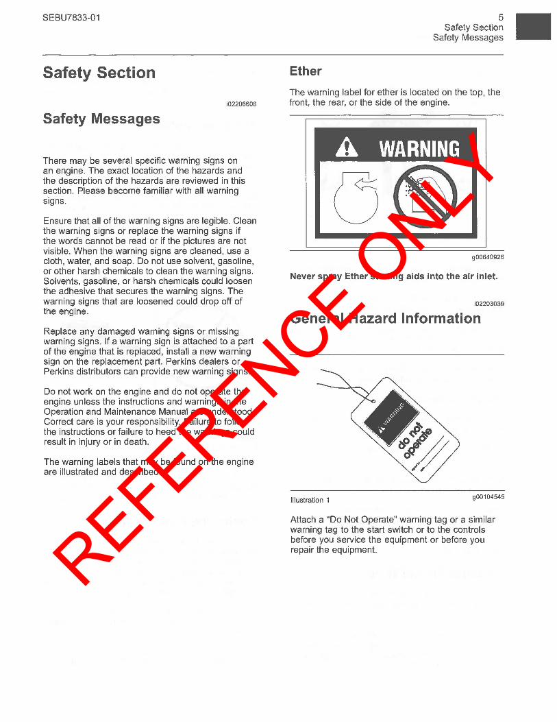
Ether
5 Safety Section
Safety Messages
The warning label for ether is located on the top, the front, the rear, or the side of the engine.
A WARNING
g00640926
Never spray Ether starting aids into the air inlet.
i02203039
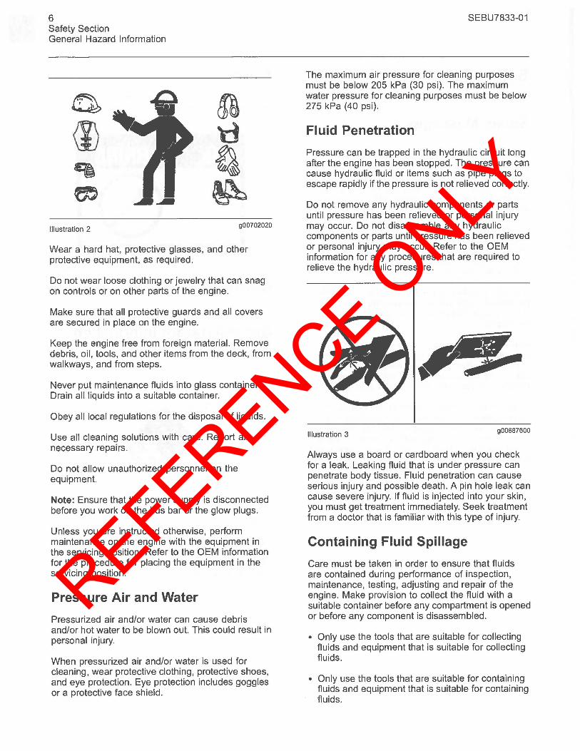
General Hazard Information
Illustration 1 g00104545
Attach a "Do Not Operate" warning tag or a similar warning tag to the start switch or to the controls before you service the equipment or before you repair the equipment.
REFERENCE ONLY
6 Safety Section General Hazard Information
r • 0 ~ \i) tl
~ ~ m ~
Illustration 2 g00702020
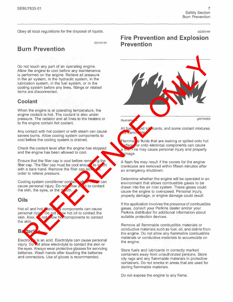
Wear a hard hat, protective glasses, and other protective equipment, as required.
Do not wear loose clothing or jewelry that can snag on controls or on other parts of the engine.
Make sure that all protective guards and all covers are secured in place on the engine.
Keep the engine free from foreign material. Remove debris, oil, tools, and other items from the deck, from walkways, and from steps.
Never put maintenance fluids into glass containers. Drain all liquids into a suitable container.
Obey all local regulations for the disposal of liquids.
Use all cleaning solutions with care. Report all necessary repairs.
Do not allow unauthorized personnel on the equipment.
Note: Ensure that the power supply is disconnected before you work on the bus bar or the glow plugs.
Unless you are instructed otherwise, perform maintenance on the engine with the equipment in the servicing position. Refer to the OEM information for the procedure for placing the equipment in the servicing position.
Pressure Air and Water
Pressurized air and/or water can cause debris and/or hot water to be blown out. This could result in personal injury.
When pressurized air and/or water is used for cleaning, wear protective clothing, protective shoes, and eye protection. Eye protection includes goggles or a protective face shield.
SEBU7833-01
The maximum air pressure for cleaning purposes must be below 205 kPa (30 psi). The maximum water pressure for cleaning purposes must be below 275 kPa (40 psi).
Fluid Penetration
Pressure can be trapped in the hydraulic circuit long after the engine has been stopped. The pressure can cause hydraulic fluid or items such as pipe plugs to escape rapidly if the pressure is not relieved correctly.
Do not remove any hydraulic components or parts until pressure has been relieved or personal injury may occur. Do not disassemble any hydraulic components or parts until pressure has been relieved or personal injury may occur. Refer to the OEM information for any procedures that are required to relieve the hydraulic pressure.
Illustration 3 g00687600
Always use a board or cardboard when you check for a leak. Leaking fluid that is under pressure can penetrate body tissue. Fluid penetration can cause serious injury and possible death. A pin hole leak can cause severe injury. If fluid is injected into your skin, you must get treatment immediately. Seek treatment from a doctor that is familiar with this type of injury.
Containing Fluid Spillage
Care must be taken in order to ensure that fluids are contained during performance of inspection, maintenance, testing, adjusting and repair of the engine. Make provision to collect the fluid with a suitable container before any compartment is opened or before any component is disassembled.
• Only use the tools that are suitable for collecting fluids and equipment that is suitable for collecting fluids.
• Only use the tools that are suitable for containing fluids and equipment that is suitable for containing fluids.
REFERENCE ONLY
SEBU7833-01
Obey all local regulations for the disposal of liquids.
i02143195
Burn Prevention
Do not touch any part of an operating engine. Allow the engine to cool before any maintenance is performed on the engine. Relieve all pressure in the air system, in the hydraulic system, in the lubrication system, in the fuel system, or in the cooling system before any lines, fittings or related items are disconnected.
Coolant
When the engine is at operating temperature, the engine coolant is hot. The coolant is also under pressure. The radiator and all lines to the heaters or to the engine contain hot coolant.
Any contact with hot coolant or with steam can cause severe burns. Allow cooling system components to cool before the cooling system is drained.
Check the coolant level after the engine has stopped and the engine has been allowed to cool.
Ensure that the filler cap is cool before removing the filler cap. The filler cap must be cool enough to touch with a bare hand. Remove the filler cap slowly in order to relieve pressure.
Cooling system conditioner contains alkali. Alkali can cause personal injury. Do not allow alkali to contact the skin, the eyes, or the mouth.
Oils
Hot oil and hot lubricating components can cause personal injury. Do not allow hot oil to contact the skin. Also, do not allow hot components to contact the skin.
Batteries
Electrolyte is an acid. Electrolyte can cause personal injury. Do not allow electrolyte to contact the skin or the eyes. Always wear protective glasses for servicing batteries. Wash hands after touching the batteries and connectors. Use of gloves is recommended.
7 Safety Section
Burn Prevention
i02203164
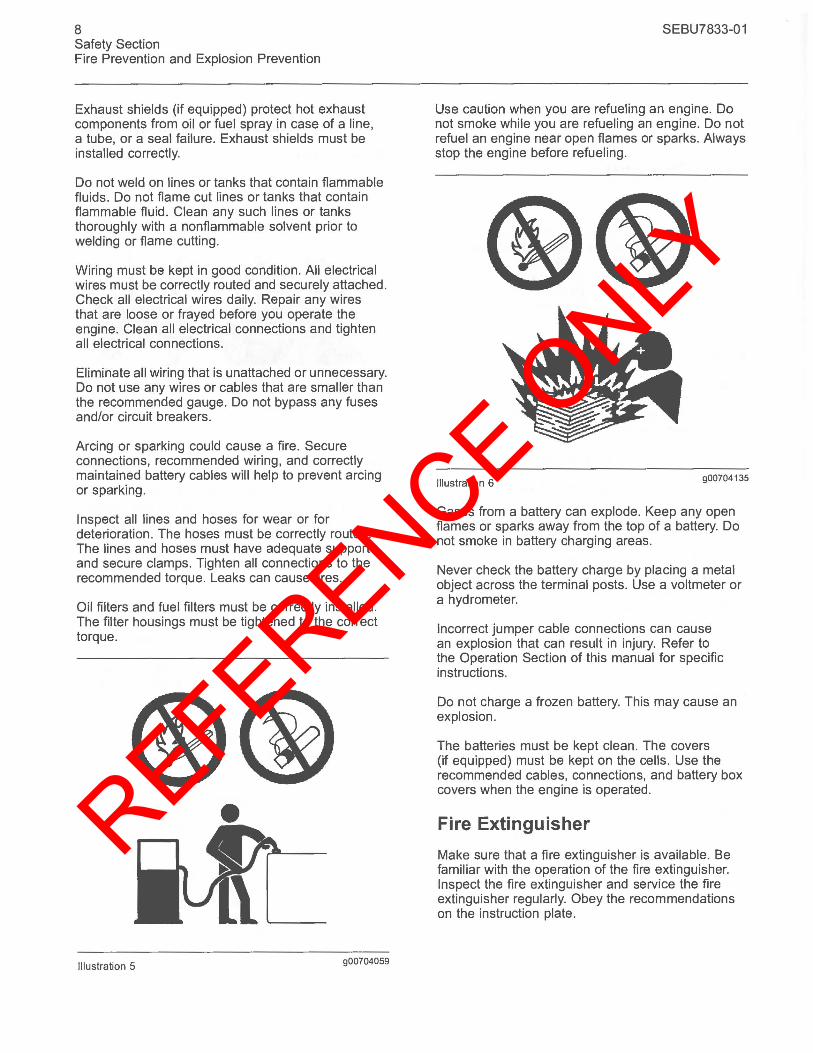
Fire Prevention and Explosion Prevention
Illustration 4 900704000
All fuels, most lubricants, and some coolant mixtures are flammable.
Flammable fluids that are leaking or spilled onto hot surfaces or onto electrical components can cause a fire. Fire may cause personal injury and property damage.
A flash fire may result if the covers for the engine crankcase are removed within fifteen minutes after an emergency shutdown.
Determine whether the engine will be operated in an environment that allows combustible gases to be drawn into the air inlet system. These gases could cause the engine to overspeed. Personal injury, property damage, or engine damage could result.
If the application involves the presence of combustible gases, consult your Perkins dealer and/or your Perkins distributor for additional information about suitable protection devices.
Remove all flammable combustible materials or conductive materials such as fuel, oil, and debris from the engine. Do not allow any flammable combustible materials or conductive materials to accumulate on the engine.
Store fuels and lubricants in correctly marked containers away from unauthorized persons. Store oily rags and any flammable materials in protective containers. Do not smoke in areas that are used for storing flammable materials.
Do not expose the engine to any flame.
REFERENCE ONLY
8 Safety Section Fire Prevention and Explosion Prevention
Exhaust shields (if equipped) protect hot exhaust components from oil or fuel spray in case of a line, a tube, or a seal failure. Exhaust shields must be installed correctly.
Do not weld on lines or tanks that contain flammable fluids. Do not flame cut lines or tanks that contain flammable fluid. Clean any such lines or tanks thoroughly with a nonflammable solvent prior to welding or flame cutting.
Wiring must be kept in good condition. All electrical wires must be correctly routed and securely attached. Check all electrical wires daily. Repair any wires that are loose or frayed before you operate the engine. Clean all electrical connections and tighten all electrical connections.
Eliminate all wiring that is unattached or unnecessary. Do not use any wires or cables that are smaller than the recommended gauge. Do not bypass any fuses and/or circuit breakers.
Arcing or sparking could cause a fire. Secure connections, recommended wiring, and correctly maintained battery cables will help to prevent arcing or sparking.
Inspect all lines and hoses for wear or for deterioration. The hoses must be correctly routed. The lines and hoses must have adequate support and secure clamps. Tighten all connections to the recommended torque. Leaks can cause fires.
Oil filters and fuel filters must be correctly installed. The filter housings must be tightened to the correct torque.
•
Illustration 5 900704059
SEBU7833-01
Use caution when you are refueling an engine. Do not smoke while you are refueling an engine. Do not refuel an engine near open flames or sparks. Always stop the engine before refueling .
Illustration 6 900704135
Gases from a battery can explode. Keep any open flames or sparks away from the top of a battery. Do not smoke in battery charging areas.
Never check the battery charge by placing a metal object across the terminal posts. Use a voltmeter or a hydrometer.
Incorrect jumper cable connections can cause an explosion that can result in injury. Refer to the Operation Section of this manual for specific instructions.
Do not charge a frozen battery. This may cause an explosion.
The batteries must be kept clean. The covers (if equipped) must be kept on the cells. Use the recommended cables, connections, and battery box covers when the engine is operated .
Fire Extinguisher
Make sure that a fire extinguisher is available. Be familiar with the operation of the fire extinguisher. Inspect the fire extinguisher and service the fire extinguisher regularly. Obey the recommendations on the instruction plate.
REFERENCE ONLY
SEBU7833-01
Lines, Tubes and Hoses
Do not bend high pressure lines. Do not strike high pressure lines. Do not install any lines that are bent or damaged.
Repair any lines that are loose or damaged. Leaks can cause fires. Consult your Perkins dealer or your Perkins distributor for repair or for replacement parts.
Check lines, tubes and hoses carefully. Do not use your bare hand to check for leaks. Use a board or cardboard to check for leaks. Tighten all connections to the recommended torque.
Replace the parts if any of the following conditions are present:
• End fittings are damaged or leaking.
• Outer coverings are chafed or cut.
• Wires are exposed.
• Outer coverings are ballooning.
• Flexible part of the hoses are kinked.
• Outer covers have embedded armoring.
• End fittings are displaced.
Make sure that all clamps, guards, and heat shields are installed correctly. During engine operation, this will help to prevent vibration, rubbing against other parts, and excessive heat.
Crushing Prevention and Cutting Prevention
i02143194
Support the component correctly when work beneath the component is performed.
Unless other maintenance instructions are provided, never attempt adjustments while the engine is running.
Stay clear of all rotating parts and of all moving parts. Leave the guards in place until maintenance is performed. After the maintenance is performed, reinstall the guards.
Keep objects away from moving fan blades. The fan blades will throw objects or cut objects.
When objects are struck, wear protective glasses in order to avoid injury to the eyes.
9 Safety Section
Crushing Prevention and Cutting Prevention
Chips or other debris may fly off objects when objects are struck. Before objects are struck, ensure that no one will be injured by flying debris.
i01372247
Mounting and Dismounting
Inspect the steps, the hand holds, and the work area before mounting the engine. Keep these items clean and keep these items in good repair.
Mount the engine and dismount the engine only at locations that have steps and/or hand holds. Do not climb on the engine, and do not jump off the engine.
Face the engine in order to mount the engine or dismount the engine. Maintain a three-point contact with the steps and handholds. Use two feet and one hand or use one foot and two hands. Do not use any controls as hand holds.
Do not stand on components which cannot support your weight. Use an adequate ladder or use a work platform. Secure the climbing equipment so that the equipment will not move.
Do not carry tools or supplies when you mount the engine or when you dismount the engine. Use a hand line to raise and lower tools or supplies.
i02157341
Before Starting Engine
NOTICE For initial start-up of a new or rebuilt engine, and for start-up of an engine that has been serviced, make provision to shut the engine off should an overspeed occur. This may be accomplished by shutting off the air and/or fuel supply to the engine.
Overspeed shutdown should occur automatically. If automatic shutdown does not occur, press the emergency stop button in order to cut the fuel and/or air to the engine.
Inspect the engine for potential hazards.
Before starting the engine, ensure that no one is on, underneath, or close to the engine. Ensure that the area is free of personnel.
If equipped, ensure that the lighting system for the engine is suitable for the conditions. Ensure that all lights work correctly, if equipped.
REFERENCE ONLY
10 Safety Section Engine Starting
All protective guards and all protective covers must be installed if the engine must be started in order to perform service procedures. To help prevent an accident that is caused by parts in rotation, work around the parts carefully.
Do not bypass the automatic shutoff circuits. Do not disable the automatic shutoff circuits . The circuits are provided in order to help prevent personal injury. The circuits are also provided in order to help prevent engine damage.
See the Service Manual for repairs and for adjustments.
Engine Starting
A WARNING
i02207232
Do not use aerosol types of starting aids such as ether. Such use could result in an explosion and personal injury.
If a warning tag is attached to the engine start switch or to the controls, DO NOT start the engine or move the controls. Consult with the person that attached the warning tag before the engine is started.
All protective guards and all protective covers must be installed if the engine must be started in order to perform service procedures. To help prevent an accident that is caused by parts in rotation, work around the parts carefully.
Start the engine from the operator's compartment or from the engine start switch.
Always start the engine according to the procedure that is described in the Operation and Maintenance Manual, "Engine Starting" topic in the Operation Section. Knowing the correct procedure will help to prevent major damage to the engine components. Knowing the procedure will also help to prevent personal injury.
To ensure that the jacket water heater (if equipped) and/or the lube oil heater (if equipped) is working correctly, check the water temperature gauge and the oil temperature gauge during the heater operation.
Engine exhaust contains products of combustion which can be harmful to your health. Always start the engine and operate the engine in a well ventilated area. If the engine is started in an enclosed area, vent the engine exhaust to the outside.
SEBU7833-01
Note: The engine is equipped with an automatic device for cold starting for normal conditions of operation. If the engine will be operated in very cold conditions, then an extra cold starting aid may be required. Normally, the engine will be equipped with the correct type of starting aid for your region of operation.
The engines are equipped with a glow plug starting aid in each individual cylinder that heats the intake air in order to improve starting.
i01928905
Engine Stopping
Stop the engine according to the procedure in the Operation and Maintenance Manual, "Engine Stopping (Operation Section)" in order to avoid overheating of the engine and accelerated wear of the engine components.
Use the Emergency Stop Button (if equipped) ONLY in an emergency situation. Do not use the Emergency Stop Button for normal engine stopping. After an emergency stop, DO NOT start the engine until the problem that caused the emergency stop has been corrected.
Stop the engine if an overs peed condition occurs during the initial start-up of a new engine or an engine that has been overhauled. This may be accomplished by shutting off the fuel supply to the engine and/or shutting off the air supply to the engine.
i02176668
Electrical System
Never disconnect any charging unit circuit or battery circuit cable from the battery when the charging unit is operating. A spark can cause the combustible gases that are produced by some batteries to ignite.
To help prevent sparks from igniting combustible gases that are produced by some batteries, the negative "-" jump start cable should be connected last from the external power source to the negative "-" terminal of the starting motor. If the starting motor is not equipped with a negative "-" terminal, connect the jump start cable to the engine block.
REFERENCE ONLY
SEBU7833-01
Check the electrical wires daily for wires that are loose or frayed. Tighten all loose electrical wires before the engine is started. Repair all frayed electrical wires before the engine is started. See the Operation and Maintenance Manual for specific starting instructions.
Grounding Practices
Correct grounding for the engine electrical system is necessary for optimum engine performance and reliability. Incorrect grounding will result in uncontrolled electrical circuit paths and in unreliable electrical circuit paths.
Uncontrolled electrical circuit paths can result in damage to main bearings, to crankshaft bearing journal surfaces, and to aluminum components.
Engines that are installed without engine-to-frame ground straps can be damaged by electrical discharge.
To ensure that the engine and the engine electrical systems function correctly, an engine-to-frame ground strap with a direct path to the battery must be used. This path may be provided by way of a direct engine ground to the frame.
All grounds should be tight and free of corrosion. The engine alternator must be grounded to the negative "_" battery terminal with a wire that is adequate to handle the full charging current of the alternator.
11 Safety Section
Electrical System
REFERENCE ONLY
12 Product Information Section Model Views
Product Information Section
Model Views
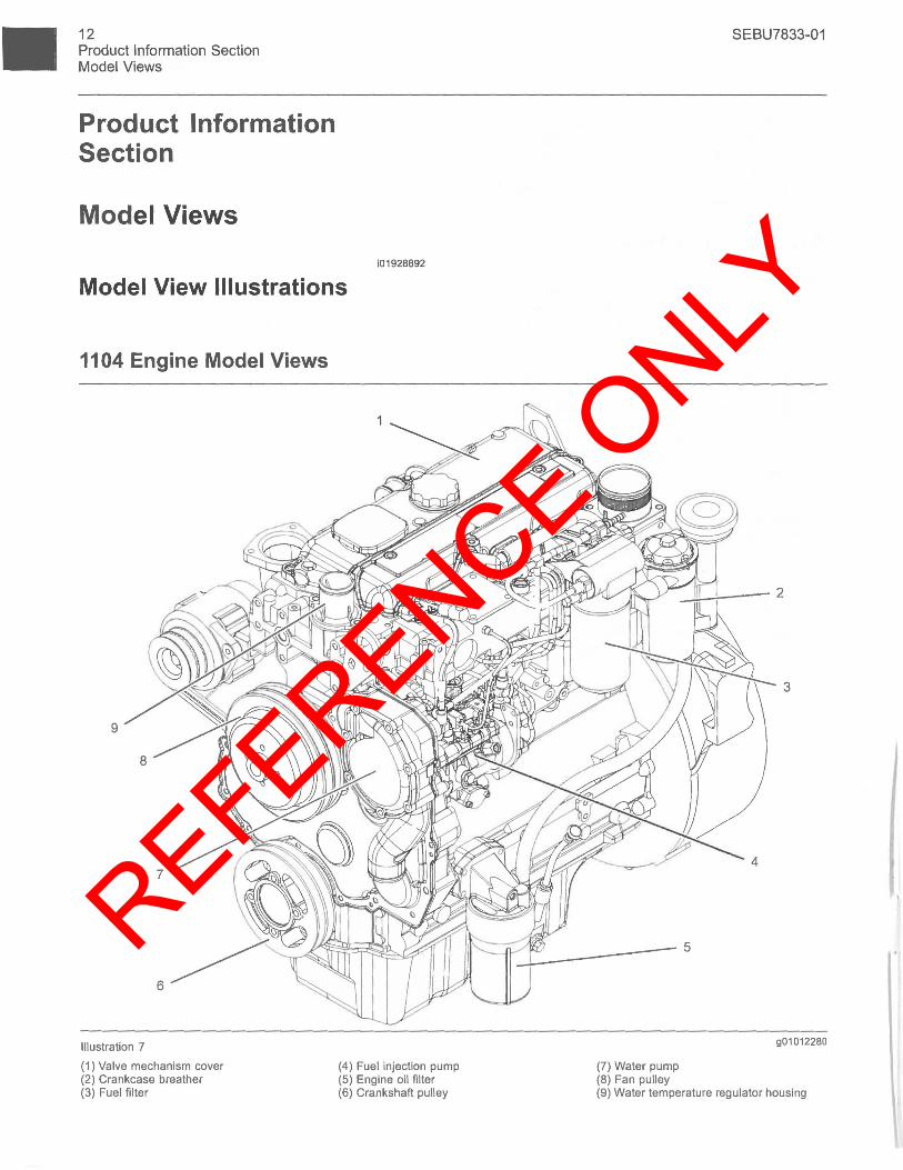
i01928892
Model View Illustrations
1104 Engine Model Views
9
Illustration 7
(1) Valve mechanism cover (2) Crankcase breather (3) Fuel filter
(4) Fuel injection pump (5) Engine oil filter (6) Crankshaft pulley
(7) Water pump (8) Fan pulley
SEBU7833-01
..2~_--2
3
901012280
(9) Water temperature regulator housing
REFERENCE ONLY
SEBU7833-01
8
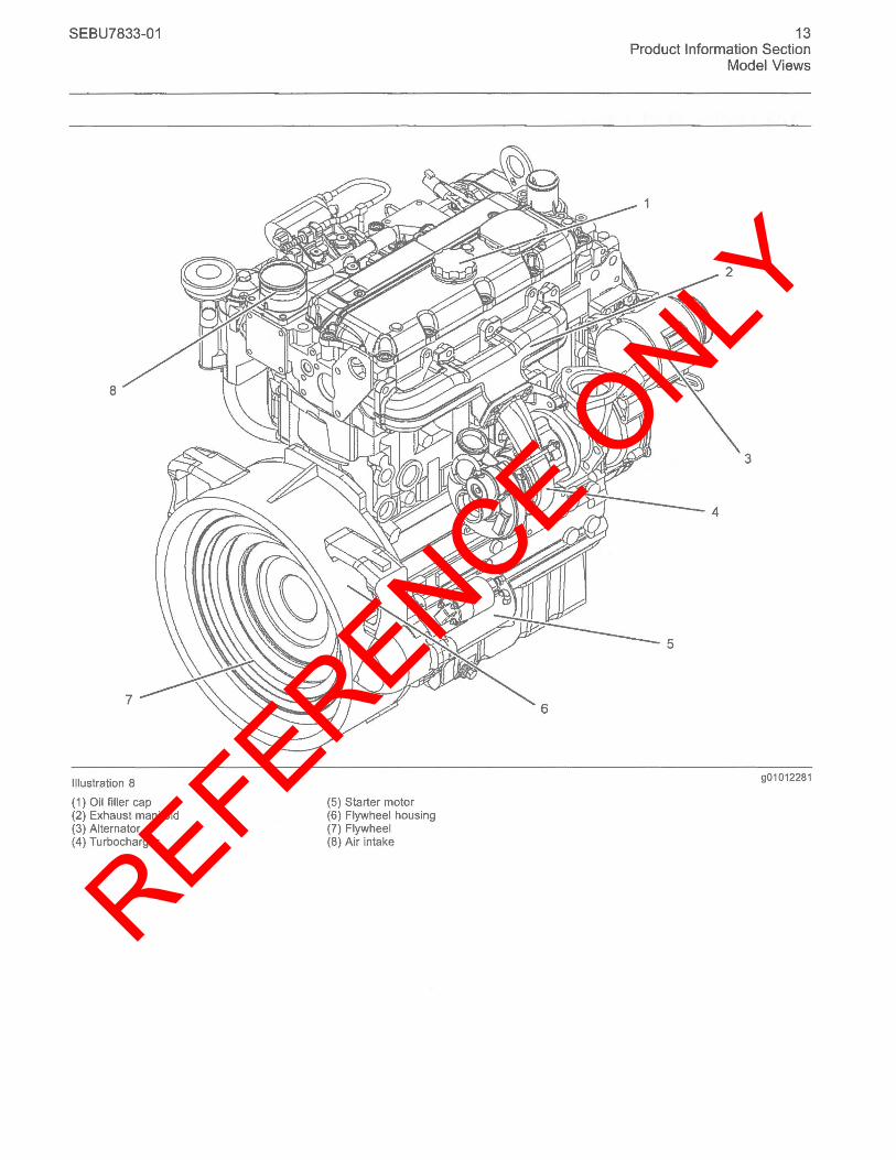
Illustration 8
(1) Oil filler cap (2) Exhaust manifold (3) Alternator (4) Turbocharger
(5) Starter motor (6) Flywheel housing (7) Flywheel (8) Air intake
13 Product Information Section
Model Views
3
901012281
REFERENCE ONLY
14 Product Information Section Model Views
1103 Engine Model Views
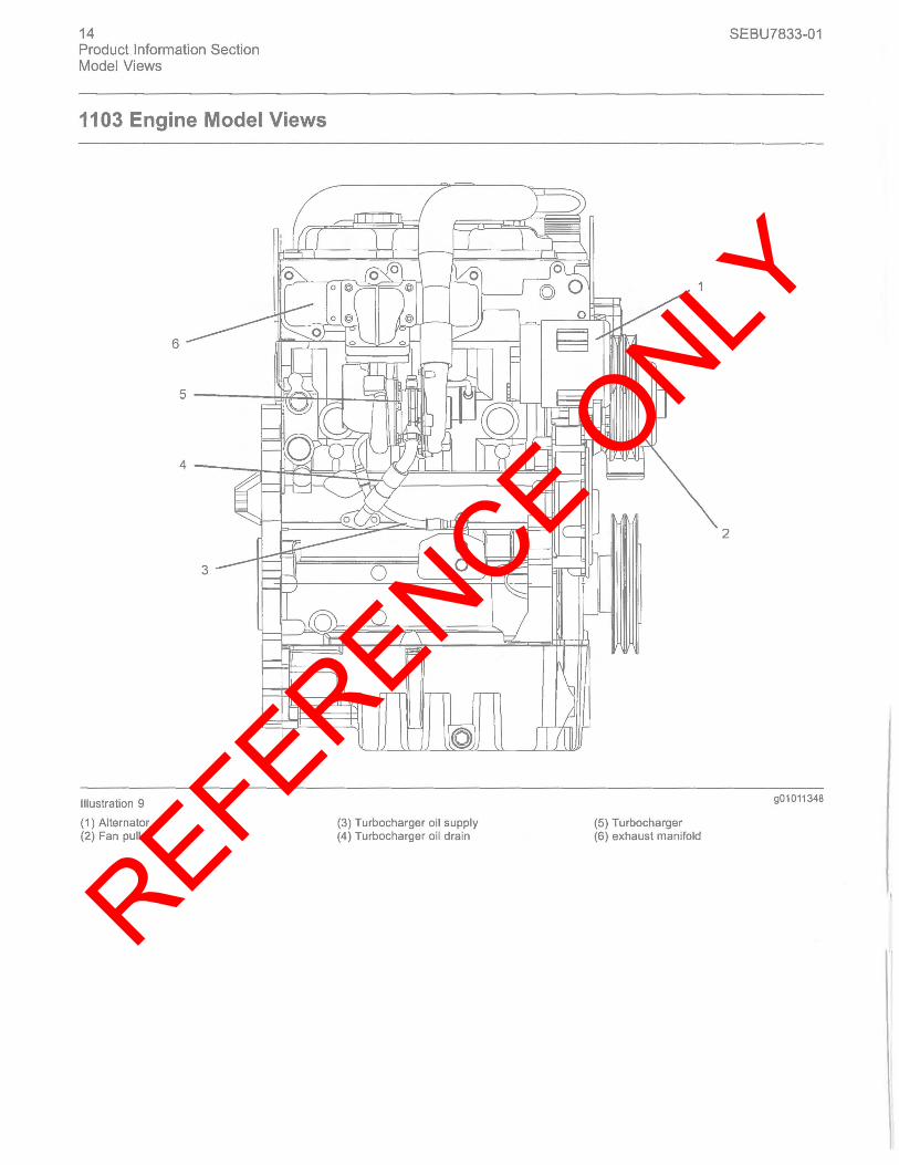
Illustration 9
(1 ) Alternator (2) Fan pulley
(3) Turbocharger oil supply (4) Turbocharger oil drain
SEBU7833-01
2
901011348
(5) Turbocharger (6) exhaust manifold
REFERENCE ONLY
SEBU7833-01
[
./
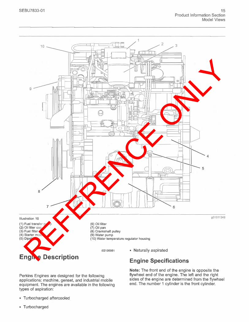
Illustration 10
(1) Fuel transfer pump (2) Oil filler cap (3) Fuel filter
I-- '-----
(6) Oil filter (7) Oil pan (8) Crankshaft pulley (9) Water pump
15 Product Information Section
Model Views
901011349
(4) Starter motor (5) Dipstick (10) Water temperature regulator housing
i02196981
Engine Description
Perkins Engines are designed for the following applications: machine, genset, and industrial mobile equipment. The engines are available in the following types of aspiration:
• Turbocharged aftercooled
• Turbocharged
• Naturally aspirated
Engine Specifications
Note: The front end of the engine is opposite the flywheel end of the engine. The left and the right sides of the engine are determined from the flywheel end . The number 1 cylinder is the front cylinder.
REFERENCE ONLY
16 Product Information Section Model Views
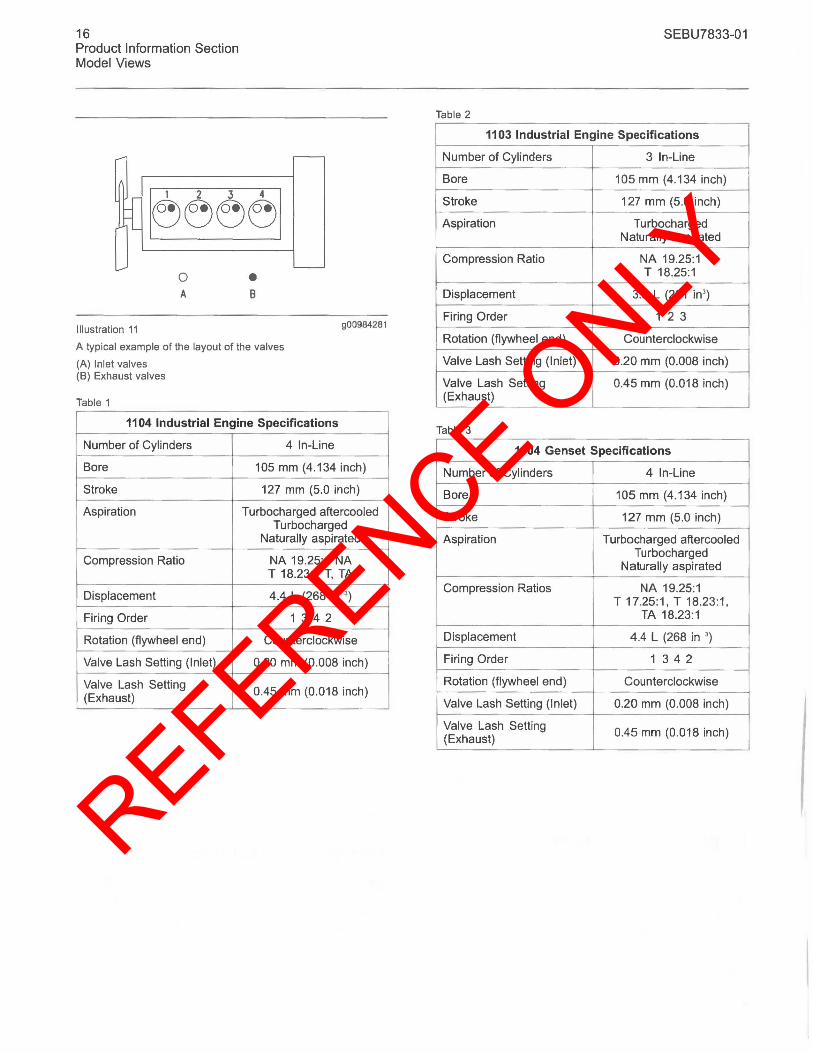
Illustration 11
o A
• B
900984281
A typical example of the layout of the valves
(A) Inlet valves (8) Exhaust valves
Table 1
1104 Industrial Engine Specifications
Number of Cylinders 4 In-Line
Bore 105 mm (4.134 inch)
Stroke 127 mm (5.0 inch)
Aspiration Turbocharged aftercooled Turbocharged
Naturally aspirated
Compression Ratio NA 19.25:1 NA T 18.23:1 T, TA
Displacement 4.4 L (268 in ' )
Firing Order 1 342
Rotation (flywheel end) Counterclockwise
Valve Lash Setting (Inlet) 0.20 mm (0.008 inch)
Valve Lash Setting 0.45 mm (0.018 inch) (Exhaust)
SEBU7833-01
Table 2
1103 Industrial Engine Specifications
Number of Cylinders 3 In-Line
Bore 105 mm (4.134 inch)
Stroke 127 mm (5.0 inch)
Aspiration Turbocharged Naturally aspirated
Compression Ratio NA 19.25:1 T 18.25:1
Displacement 3.3 L (201 in' )
Firing Order 1 2 3
Rotation (flywheel end) Counterclockwise
Valve Lash Setting (Inlet) 0.20 mm (0.008 inch)
Valve Lash Setting 0.45 mm (0.018 inch) (Exhaust)
Table 3
1104 Genset Specifications
Number of Cylinders 4 In-Line
Bore 105 mm (4.134 inch)
Stroke 127 mm (5.0 inch)
Aspiration Turbocharged aftercooled Turbocharged
Naturally aspirated
Compression Ratios NA 19.25:1 T 17.25:1, T 18.23:1,
TA 18.23:1
Displacement 4.4 L (268 in ' )
Firing Order 1 342
Rotation (flywheel end) Counterclockwise
Valve Lash Setting (Inlet) 0.20 mm (0.008 inch)
Valve Lash Setting 0.45 mm (0.018 inch) (Exhaust)
REFERENCE ONLY
SEBU7833-01
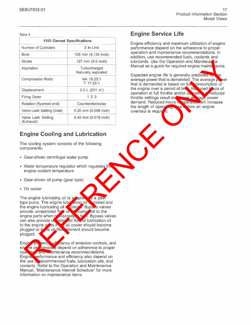
Table 4
1103 Genset Specifications
Number of Cylinders 3 In-Line
Bore 105 mm (4.134 inch)
Stroke 127 mm (5.0 inch)
Aspiration Turbocharged Naturally aspirated
Compression Ratio NA 19.25:1 T 17.25:1
Displacement 3.3 L (201 in' )
Firing Order 123
Rotation (flywheel end) Counterclockwise
Valve Lash Setting (Inlet) 0.20 mm (0.008 inch)
Valve Lash Setting 0.45 mm (0.018 inch) (Exhaust)
Engine Cooling and Lubrication
The cooling system consists of the following components:
• Gear-driven centrifugal water pump
• Water temperature regulator which regulates the engine coolant temperature
• Gear-driven oil pump (gear type)
• Oil cooler
The engine lubricating oil is supplied by a gear type pump. The engine lubricating oil is cooled and the engine lubricating oil is filtered. Bypass valves provide unrestricted flow of lubrication oil to the engine parts when oil viscosity is high. Bypass valves can also provide unrestricted flow of lubrication oil to the engine parts if the oil cooler should become plugged or if the oil filter element should become plugged.
Engine efficiency, efficiency of emission controls, and engine performance depend on adherence to proper operation and maintenance recommendations. Engine performance and efficiency also depend on the use of recommended fuels, lubrication oils, and coolants. Refer to the Operation and Maintenance Manual, "Maintenance Interval Schedule" for more information on maintenance items.
17 Product Information Section
Model Views
Engine Service Life
Engine efficiency and maximum utilization of engine performance depend on the adherence to proper operation and maintenance recommendations. In addition, use recommended fuels, coolants and lubricants. Use the Operation and Maintenance Manual as a guide for required engine maintenance.
Expected engine life is generally predicted by the average power that is demanded. The average power that is demanded is based on fuel consumption of the engine over a period of time. Reduced hours of operation at full throttle and/or operating at reduced throttle settings result in a lower average power demand. Reduced hours of operation will increase the length of operating time before an engine overhaul is required.
REFERENCE ONLY
18 Product Information Section Product Identification Information
Product Identification Information
Engine Identification i01940475
Perkins engines are identified by a serial number. This number is shown on a serial number plate that is mounted on the left hand side of the engine block.
An example of an engine number is REU090001 H.
RE ____________ Type of engine
U ________ Built in the United Kingdom
0900001 _______ Engine Serial Number
H __________ Year of Manufacture
Perkins dealers need these numbers in order to determine the components that were included with the engine. This permits accurate identification of replacement part numbers.
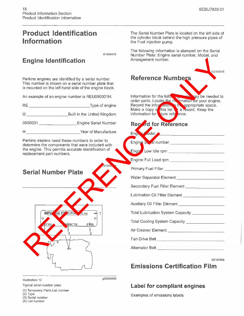
Serial Number Plate
~~'k,nSI ~:t: ~~Ij 1
4 ___ -.
Illustration 12
Typical serial number plate
(1) Temporary Parts List number (2) Type (3) Serial number (4) List number
i01940474
900994966
SEBU7833-01
The Serial Number Plate is located on the left side of the cylinder block behind the high pressure pipes of the Fuel injection pump.
The following information is stamped on the Serial Number Plate: Engine serial number, Model, and Arrangement number.
i02164876
Reference Numbers
Information for the following items may be needed to order parts. Locate the information for your engine. Record the information in the appropriate space. Make a copy of this list for a record. Keep the information for future reference.
Record for Reference
Engine Model ____________ _
Engine Serial number __________ _
Engine Low Idle rpm __________ _
Engine Full Load rpm __________ _
Primary Fuel Filter ___________ _
Water Separator Element ________ _
Secondary Fuel Filter Element _______ _
Lubrication Oil Filter Element _______ _
Auxiliary Oil Filter Element ________ _
Total Lubrication System Capacity _____ _
Total Cooling System Capacity ______ _
Air Cleaner Element __________ _
Fan Drive Belt ____________ _
Alternator Belt ____________ _
i02197956
Emissions Certification Film
Label for compliant engines
Examples of emissions labels
REFERENCE ONLY
SEBU7833-01
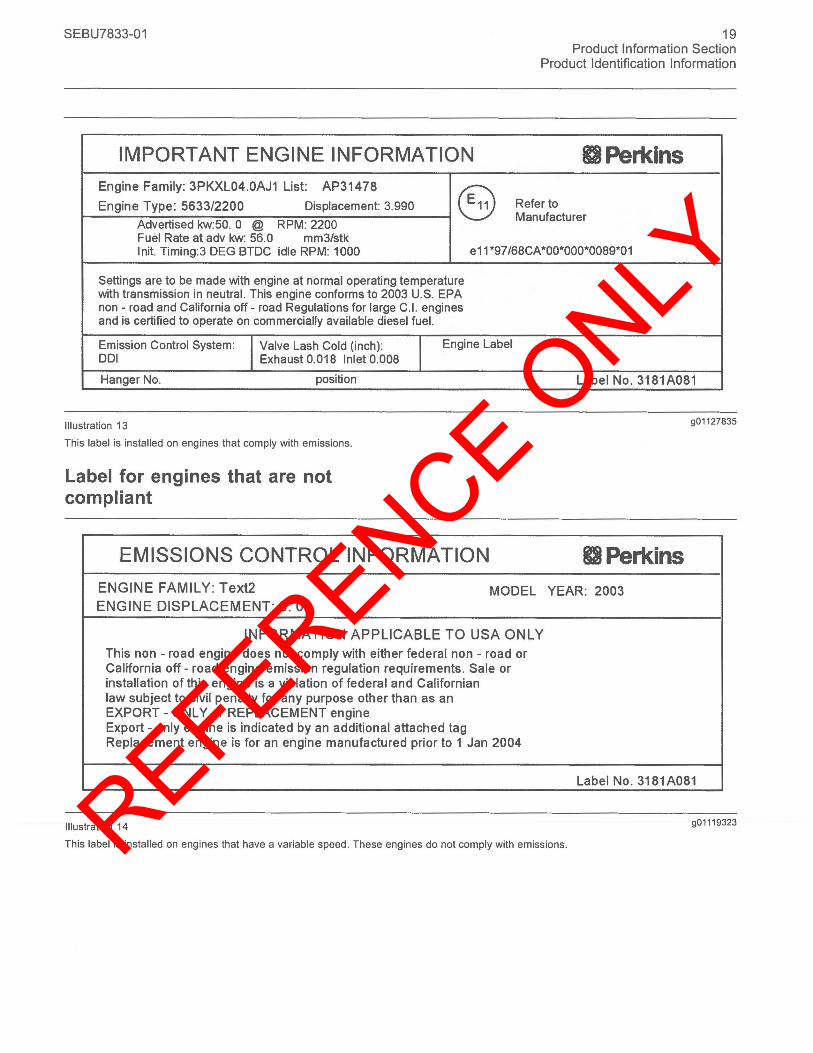
IMPORTANT ENGINE INFORMATION
Engine Family: 3PKXL04.0AJ1 List: AP31478
19 Product Information Section
Product Identification Information
II Perkins
Engine Type: 5633/2200 Displacement: 3.990 (S) Refer to
Advertised kw:50. 0 @ RPM: 2200 Manufacturer
Fuel Rate at adv kw: 56.0 mm3/stk Init. Timing:3 DEG BTDC idle RPM: 1000 e11 *97/68CA ·00*000*0089*01
Settings are to be made with engine at normal operating temperature with transmission in neutral. This engine conforms to 2003 U.S. EPA non - road and California off - road Regulations for large C.1. engines and is certified to operate on commercially available diesel fuel.
Emission Control System: I Valve Lash Cold (inch): I Engine Label 001 Exhaust 0.018 Inlet 0.008
Hanger No. position Label No. 3181A081
Illustration 13
This label is installed on engines that comply with emissions.
Label for engines that are not compliant
EMISSIONS CONTROL INFORMATION
ENGINE FAMILY: Text2
ENGINE DISPLACEMENT: 6. 0 MODEL
INFORMATION APPLICABLE TO USA ONLY
This non - road engine does not comply with either federal non - road or California off - road engine emission regulation requirements . Sale or installation of this engine is a violation of federal and Californian law subject to civil penalty for any purpose other than as an EXPORT - ONLY or REPLACEMENT engine Export - only engine is indicated by an additional attached tag Replacement engine is for an engine manufactured prior to 1 Jan 2004
Illustration 14
901127835
II Perkins YEAR: 2003
Label No. 3181A081
901 119323
This label is installed on engines that have a variable speed . These engines do not comply with emissions.
REFERENCE ONLY
20 Product Information Section Product Identification Information
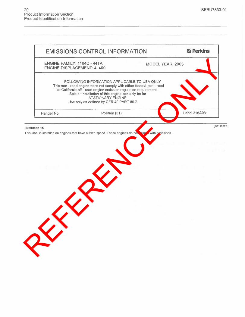
EMISSIONS CONTROL INFORMATION
ENGINE FAMILY: 11 04C - 44TA MODEL YEAR: 2003 ENGINE DISPLACEMENT: 4. 400
FOLLOWING INFORMATION APPLICABLE TO USA ONLY This non - road engine does not comply with either federal non - road
or California off - road engine emission regulation requirement. Sale or installation of this engine can only be for
STATIONARY ENGINE Use only as defined by CFR 40 PART 89.2.
Hanger No Position (B1)
Illustration 15
This label is installed on engines that have a fixed speed. These engines do not comply with emissions.
SEBU7833-01
UPerkins
Label 318AOB1
g01119325
REFERENCE ONLY
SEBU7833-01
Operation Section
Lifting and Storage
i02164186
Engine Lifting
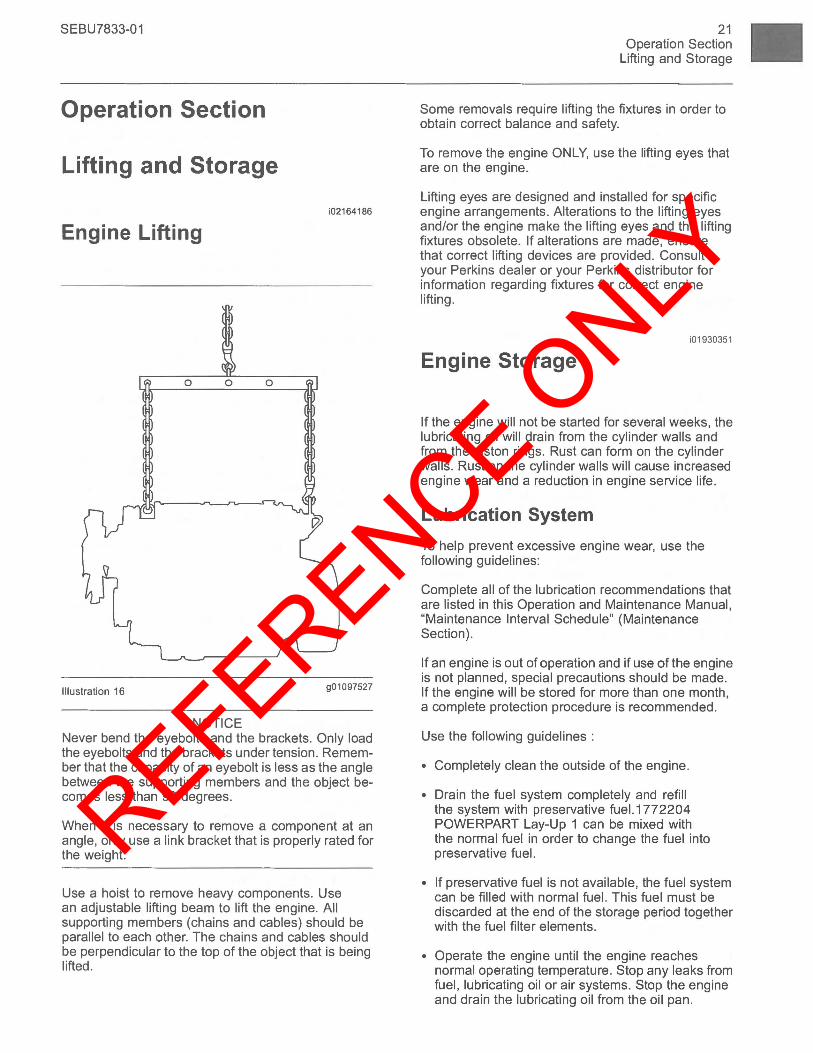
Illustration 16 901097527
NOTICE Never bend the eyebolts and the brackets. Only load the eyebolts and the brackets under tension . Remember that the capacity of an eyebolt is less as the angle between the supporting members and the object becomes less than 90 degrees.
When it is necessary to remove a component at an angle, only use a link bracket that is properly rated for the weight.
Use a hoist to remove heavy components. Use an adjustable lifting beam to lift the engine. All supporting members (chains and cables) should be parallel to each other. The chains and cables should be perpendicular to the top of the object that is being lifted.
21 Operation Section
Lifting and Storage
Some removals require lifting the fixtures in order to obtain correct balance and safety.
To remove the engine ONLY, use the lifting eyes that are on the engine.
Lifting eyes are designed and installed for specific engine arrangements. Alterations to the lifting eyes and/or the engine make the lifting eyes and the lifting fixtures obsolete. If alterations are made, ensure that correct lifting devices are provided. Consult your Perkins dealer or your Perkins distributor for information regarding fixtures for correct engine lifting.
i01930351
Engine Storage
If the engine will not be started for several weeks, the lubricating oil will drain from the cylinder walls and from the piston rings. Rust can form on the cylinder walls. Rust on the cylinder walls will cause increased engine wear and a reduction in engine service life.
Lubrication System
To help prevent excessive engine wear, use the following guidelines:
Complete all of the lubrication recommendations that are listed in this Operation and Maintenance Manual, "Maintenance Interval Schedule" (Maintenance Section).
If an engine is out of operation and if use of the engine is not planned, special precautions should be made. If the engine will be stored for more than one month, a complete protection procedure is recommended.
Use the following guidelines :
• Completely clean the outside of the engine.
• Drain the fuel system completely and refill the system with preservative fue1.1772204 POWERPART Lay-Up 1 can be mixed with the normal fuel in order to change the fuel into preservative fuel.
• If preservative fuel is not available, the fuel system can be filled with normal fuel. This fuel must be discarded at the end of the storage period together with the fuel filter elements.
• Operate the engine until the engine reaches normal operating temperature. Stop any leaks from fuel, lubricating oil or air systems. Stop the engine and drain the lubricating oil from the oil pan.
REFERENCE ONLY
22 Operation Section Lifting and Storage
• Renew the canister(s) of the lubricating oil filter.
• Fill the oil pan to the Full Mark on the dipstick with new, clean lubricating oil. Add 1 762811 POWERPART Lay-Up 2 to the oil in order to protect the engine against corrosion. If 1762811 POWERPART Lay-Up 2 is not available, use a preservative of the correct specification instead of the lubricating oil. If a preservative is used, this must be drained completely at the end of the storage period and the oil pan must be refilled to the correct level with normal lubricating oil.
Cooling System
To help prevent excessive engine wear, use the following guidelines:
NOTICE Do not drain the coolant while the engine is still hot and the system is under pressure because dangerous hot coolant can be discharged.
If freezing temperatures are expected, check the cooling system for adequate protection against freezing. See this Operation and Maintenance Manual, "General Coolant Information" (Maintenance Section).
NOTICE To prevent frost damage, ensure that all the coolant is removed from the engine. This is important if the system is drained after it has been flushed with water, or if an antifreeze solution too weak to protect the system from frost has been used.
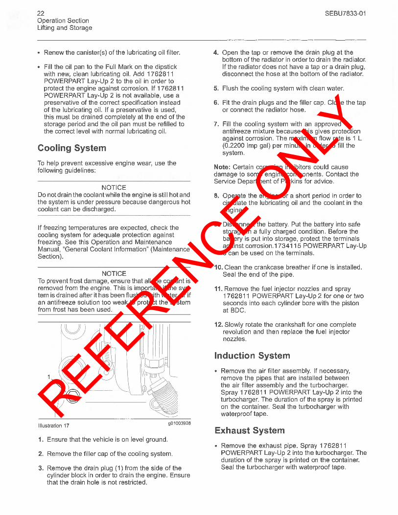
Illustration 17 901003928
1. Ensure that the vehicle is on level ground.
2. Remove the filler cap of the cooling system.
3. Remove the drain plug (1) from the side of the cylinder block in order to drain the engine. Ensure that the drain hole is not restricted.
SEBU7833-01
4. Open the tap or remove the drain plug at the bottom of the radiator in order to drain the radiator. If the radiator does not have a tap or a drain plug, disconnect the hose at the bottom of the radiator.
5. Flush the cooling system with clean water.
6. Fit the drain plugs and the filler cap. Close the tap or connect the radiator hose.
7. Fill the cooling system with an approved antifreeze mixture because this gives protection against corrosion. The maximum flow rate is 1 L (0.2200 Imp gal) per minute in order to fill the system.
Note: Certain corrosion inhibitors could cause damage to some engine components. Contact the Service Department of Perkins for advice.
8. Operate the engine for a short period in order to circulate the lubricating oil and the coolant in the engine.
9. Disconnect the battery. Put the battery into safe storage in a fully charged condition. Before the battery is put into storage, protect the terminals against corrosion.1734115 POWERPART Lay-Up 3 can be used on the terminals.
10. Clean the crankcase breather if one is installed. Seal the end of the pipe.
11. Remove the fuel injector nozzles and spray 1762811 POWERPART Lay-Up 2 for one or two seconds into each cylinder bore with the piston at BDC.
12. Slowly rotate the crankshaft for one complete revolution and then replace the fuel injector nozzles.
Induction System
• Remove the air filter assembly. If necessary, remove the pipes that are installed between the air filter assembly and the turbocharger. Spray 1762811 POWERPART Lay-Up 2 into the turbocharger. The duration of the spray is printed on the container. Seal the turbocharger with waterproof tape.
Exhaust System
• Remove the exhaust pipe. Spray 1762811 POWER PART Lay-Up 2 into the turbocharger. The duration of the spray is printed on the container. Seal the turbocharger with waterproof tape.
REFERENCE ONLY
SEBU7833-01
General Items
• If the lubricating oil filler is installed on the rocker cover, remove the filler cap. If the lubricating oil filler cap is not installed on the rocker cover, remove the rocker cover. Spray 1 762811 POWERPART Lay-Up 2 around the rocker shaft assembly. Replace the filler cap or the rocker cover.
• Seal the vent of the fuel tank or the fuel filler cap with waterproof tape.
• Remove the alternator drive belts and put the drive belts into storage.
• In order to prevent corrosion, spray the engine with 1734115 POWERPART Lay-Up 3. Do not spray the area inside the alternator.
When the engine protection has been completed in accordance with these instructions, this ensures that no corrosion will occur. Perkins are not responsible for damage which may occur when an engine is in storage after a period in service.
Your Perkins dealer or your Perkins distributor can assist in preparing the engine for extended storage periods.
23 Operation Section
Lifting and Storage
REFERENCE ONLY
24 Operation Section Gauges and Indicators
Gauges and Indicators
Gauges and Indicators i02164190
Your engine may not have the same gauges or all of the gauges that are described. For more information about the gauge package, see the OEM information.
Gauges provide indications of engine performance. Ensure that the gauges are in good working order. Determine the normal operating range by observing the gauges over a period of time.
Noticeable changes in gauge readings indicate potential gauge or engine problems. Problems may also be indicated by gauge readings that change even if the readings are within specifications. Determine and correct the cause of any Significant change in the readings. Consult your Perkins dealer or your Perkins distributor for assistance.
NOTICE If no oil pressure is indicated, STOP the engine. If maximum coolant temperature is exceeded, STOP the engine. Engine damage can result.
@ Engine Oil Pressure - The oil pressure ~ should be greatest after a cold engine is
started. The typical engine oil pressure with SAE10W30 is 207 to 413 kPa (30 to 60 psi) at rated rpm.
A lower oil pressure is normal at low idle. If the load is stable and the gauge reading changes, perform the following procedure:
1. Remove the load.
2. Reduce engine speed to low idle.
3. Check and maintain the oil level.
@ Jacket Water Coolant Temperature -~ Typical temperature range is 71 to 96°C
(160 to 205°F). The maximum allowable temperature with the pressurized cooling system at 48 kPa (7 psi) is 110°C (230°F). Higher temperatures may occur under certain conditions. The water temperature reading may vary according to load. The reading should never exceed the boiling point for the pressurized system that is being used.
If the engine is operating above the normal range and steam becomes apparent, perform the following procedure:
SEBU7833-01
1. Reduce the load and the engine rpm.
2. Inspect the cooling system for leaks.
3. Determine if the engine must be shut down immediately or if the engine can be cooled by reducing the load.
Ci) Tachometer - This gauge indicates engine ~ speed (rpm). When the throttle control lever
is moved to the full throttle pOSition without load, the engine is running at high idle. The engine is running at the full load rpm when the throttle control lever is at the full throttle position with maximum rated load.
NOTICE To help prevent engine damage, never exceed the high idle rpm. Overspeeding can result in serious damage to the engine. The engine can be operated at high idle without damage, but should never be allowed to exceed high idle rpm.
(f) Ammeter - This gauge indicates the f amount of charge or discharge in the battery charging circuit. Operation of the
indicator should be to the right side of "0" (zero).
(!)I:l\ Fuel Level - This gauge indicates the fuel .~. level in the fuel tank. The fuel level gauge
operates when the "START/STOP" switch is in the "ON" position.
Service Hour Meter - The gauge indicates operating time of the engine.
REFERENCE ONLY
SEBU7833-01
Engine Starting
i02194223
Before Starting Engine
Before the engine is started, perform the required daily maintenance and any other periodic maintenance that is due. Refer to the Operation and Maintenance Manual, "Maintenance Interval Schedule" for more information.
• For the maximum service life of the engine, make a thorough inspection within the engine compartment before the engine is started. Look for the following items: oil leaks, coolant leaks, loose bolts, and excessive dirt and/or grease. Remove any excess dirt and/or grease buildup. Repair any faults that were identified during the inspection.
• Inspect the cooling system hoses for cracks and for loose clamps.
• Inspect the alternator and accessory drive belts for cracks, breaks, and other damage.
• Inspect the wiring for loose connections and for worn wires or frayed wires.
• Check the fuel supply. Drain water from the water separator (if equipped). Open the fuel supply valve (if equipped).
NOTICE All valves in the fuel return line must be open before and during engine operation to help prevent high fuel pressure. High fuel pressure may cause filter housing failure or other damage.
If the engine has not been started for several weeks, fuel may have drained from the fuel system. Air may have entered the filter housing. Also, when fuel filters have been changed, some air pockets will be trapped in the engine. In these instances, prime the fuel system. Refer to the Operation and Maintenance Manual, "Fuel System - Prime" for more information on priming the fuel system.
A WARNING
Engine exhaust contains products of combustion which may be harmful to your health. Always start and operate the engine in a well ventilated area and, if in an enclosed area, vent the exhaust to the outside.
25 Operation Section
Engine Starting
• Do not start the engine or move any of the controls if there is a "DO NOT OPERATE" warning tag or similar warning tag attached to the start switch or to the controls.
• Ensure that the areas around the rotating parts are clear.
• All of the guards must be put in place. Check for damaged guards or for missing guards. Repair any damaged guards. Replace damaged guards and/or misSing guards.
• Disconnect any battery chargers that are not protected against the high current drain that is created when the electric starting motor is engaged. Check electrical cables and check the battery for poor connections and for corrosion.
• Reset all of the shutoffs or alarm components (if equipped).
• Check the engine lubrication oil level. Maintain the oil level between the "ADD" mark and the "FULL" mark on the engine oil level gauge.
• Check the coolant level. Observe the coolant level in the header tank (if equipped). Maintain the coolant level to the "FULL" mark on the header tank.
• If the engine is not equipped with a header tank maintain the coolant level within 13 mm (0.5 inch) of the bottom of the filler pipe. If the engine is equipped with a sight glass, maintain the coolant level in the sight glass.
• Observe the air cleaner service indicator (if equipped). Service the air cleaner when the yellow diaphragm enters the red zone, or when the red piston locks in the visible position.
• Ensure that any equipment that is driven by the engine has been disengaged from the engine. Minimize electrical loads or remove any electrical loads.
REFERENCE ONLY
26 Operation Section Engine Starting
Starting the Engine
A WARNING
i02198348
Do not use aerosol types of starting aids such as ether. Such use could result in an explosion and personal injury.
Refer to the OMM for your type of controls. Use the following procedure to start the engine.
1. If equipped, move the throttle lever to the full throttle position before you start the engine.
NOTICE Do not crank the engine for more than 30 seconds. Allow the electric starting motor to cool for two minutes before cranking the engine again.
2. Turn the engine start switch to the START position. Hold the engine start switch in the START position and crank the engine.
3. When the engine starts, release the engine start switch.
4. If equipped, slowly move the throttle lever to the low idle position and allow the engine to idle. Refer to the Operation and Maintenance Manual, "After Starting Engine" topic.
5. If the engine does not start, release the engine start switch and allow the electric starting motor to cool. Then, repeat steps 2 through step 4.
6. Turn the engine start switch to the OFF position in order to stop the engine.
i02198092
Cold Weather Starting
A WARNING
Do not use aerosol types of starting aids such as ether. Such use could result in an explosion and personal injury.
Startability will be improved at temperatures below -18°C (0 OF) from the use of a jacket water heater or extra battery capacity.
SEBU7833-01
When Group 2 diesel fuel is used, the following items provide a means of minimizing starting problems and fuel problems in cold weather: engine oil pan heaters, jacket water heaters, fuel heaters, and fuel line insulation.
Use the procedure that follows for cold weather starting.
1. If equipped, move the throttle lever to the full throttle position before you start the engine.
2. If equipped, turn the engine start switch to the HEAT position. Hold the engine start switch in the HEAT position for 6 seconds until the glow plug indicator light illuminates. This will activate the glow plugs and aid in the starting of the engine.
NOTICE Do not crank the engine for more than 30 seconds. Allow the electric starting motor to cool for two minutes before cranking the engine again.
3. While the glow plug indicator light is illuminated, turn the engine start switch to the START position and crank the engine.
Note: If the glow plug indicator light illuminates rapidly for 2 to 3 seconds, or if the glow plug indicator light fails to illuminate, a malfunction exists in the cold start system. Do not use ether or other starting fluids to start the engine.
4. When the engine starts, release the engine start switch key.
5. If the engine does not start, release the engine start switch and allow the starter motor to cool. Then, repeat steps 2 through step 4.
6. If the engine is equipped with a throttle allow the engine to idle for three to five minutes, or allow the engine to idle until the water temperature indicator begins to rise. The engine should run at low idle smoothly until speed is gradually increased to high idle. Allow the white smoke to disperse before proceeding with normal operation.
7. Operate the engine at low load until all systems reach operating temperature. Check the gauges during the warm-up period.
8. Turn the engine start switch to the OFF position in order to stop the engine.
REFERENCE ONLY
SEBU7833-01
Starting with Jump Start Cables
A WARNING
i02177935
Improper jump start cable connections can cause an explosion resulting in personal injury.
Prevent sparks near the batteries. Sparks could cause vapors to explode. Do not allow jump start cable ends to contact each other or the engine.
Note: If it is possible, first diagnose the reason for the starting failure. Make any necessary repairs. If the engine will not start only due to the condition of the battery, either charge the battery, or start the engine with jump start cables. The condition of the battery can be rechecked after the engine has been switched OFF.
NOTICE Using a battery source with the same voltage as the electric starting motor. Use ONLY equal voltage for jump starting. The use of higher voltage will damage the electrical system.
Do not reverse the battery cables. The alternator can be damaged. Attach ground cable last and remove first.
When using an external electrical source to start the engine, turn the generator set control switch to the "OFF" position. Turn all electrical accessories OFF before attaching the jump start cables.
Ensure that the main power switch is in the OFF position before attaching the jump start cables to the engine being started.
1. Turn the start switch to the OFF position. Turn off all the engine's accessories.
2. Connect one positive end of the jump start cable to the positive cable terminal of the discharged battery. Connect the other positive end of the jump start cable to the positive cable terminal of the electrical source.
27 Operation Section
Engine Starting
3. Connect one negative end of the jump start cable to the negative cable terminal of the electrical source. Connect the other negative end of the jump start cable to the engine block or to the chassis ground. This procedure helps to prevent potential sparks from igniting the combustible gases that are produced by some batteries.
4. Start the engine.
5. Immediately after the stalled engine is started, disconnect the jump start cables in reverse order.
After jump starting, the alternator may not be able to fully recharge batteries that are severely discharged. The batteries must be replaced or charged to the correct voltage with a battery charger after the engine is stopped. Many batteries which are considered unusable are still rechargeable. Refer to Operation and Maintenance Manual, "Battery - Replace" and Testing and Adjusting Manual, "Battery - Test".
i01903609
After Starting Engine
Note: In temperatures from a to 60°C (32 to 140°F), the warm-up time is approximately three minutes. In temperatures below O°C (32°F), additional warm-up time may be required.
When the engine idles during warm-up, observe the following conditions:
• Check for any fluid or for any air leaks at idle rpm and at one-half full rpm (no load on the engine) before operating the engine under load. This is not possible in some applications.
• Operate the engine at low idle until all systems achieve operating temperatures. Check all gauges during the warm-up period.
Note: Gauge readings should be observed and the data should be recorded frequently while the engine is operating. Comparing the data over time will help to determine normal readings for each gauge. Comparing data over time will also help detect abnormal operating developments. Significant changes in the readings should be investigated.
REFERENCE ONLY
28 Operation Section Engine Operation
Engine Operation
Engine Operation i02176671
Correct operation and maintenance are key factors in obtaining the maximum life and economy of the engine. If the directions in the Operation and Maintenance Manual are followed, costs can be minimized and engine service life can be maximized.
The engine can be operated at the rated rpm after the engine reaches operating temperature. The engine will reach normal operating temperature sooner during a low engine speed (rpm) and during a low power demand. This procedure is more effective than idling the engine at no load. The engine should reach operating temperature in a few minutes.
Gauge readings should be observed and the data should be recorded frequently while the engine is operating. Comparing the data over time will help to determine normal readings for each gauge. Comparing data over time will also help detect abnormal operating developments. Significant changes in the readings should be investigated.
i01929404
Engine Warm-up
1. Run the engine at low idle for three to five minutes, or run the engine at low idle until the jacket water temperature starts to rise.
More time may be necessary when the temperature is below -18°C (0° F).
2. Check all of the gauges during the warm-up period.
3. Perform a walk-around inspection. Check the engine for fluid leaks and air leaks.
4. Increase the rpm to the rated rpm. Check for fluid leaks and air leaks. The engine may be operated at full rated rpm and at full load when the temperature of the water jacket reaches 60°C (140°F).
SEBU7833-01
i02164252
Fuel Conservation Practices
The efficiency of the engine can affect the fuel economy. Perkins design and technology in manufacturing provides maximum fuel efficiency in all applications. Follow the recommended procedures in order to attain optimum performance for the life of the engine.
• Avoid spilling fuel.
Fuel expands when the fuel is warmed up. The fuel may overflow from the fuel tank. Inspect fuel lines for leaks. Repair the fuel lines, as needed.
• Be aware of the properties of the different fuels. Use only the recommended fuels.
• Avoid unnecessary idling.
Shut off the engine rather than idle for long periods of time.
• Observe the service indicator frequently. Keep the air cleaner elements clean.
• Maintain a good electrical system.
One damaged battery cell will overwork the alternator. This will consume excess power and excess fuel.
• Ensure that the drive belts are correctly adjusted. The drive belts should be in good condition.
• Ensure that all of the connections of the hoses are tight. The connections should not leak.
• Ensure that the driven equipment is in good working order.
• Cold engines consume excess fuel. Utilize heat from the jacket water system and the exhaust system, when possible. Keep cooling system components clean and keep cooling system components in good repair. Never operate the engine without water temperature regulators. All of these items will help maintain operating temperatures.
REFERENCE ONLY
SEBU7833-01
Engine Stopping
i01929389
Stopping the Engine
NOTICE Stopping the engine immediately after it has been working under load can result in overheating and accelerated wear of the engine components.
If the engine has been operating at high rpm and/or high loads, run at low idle for at least three minutes to reduce and stabilize internal engine temperature before stopping the engine.
Avoiding hot engine shutdowns will maximize turbocharger shaft and bearing life.
Prior to stopping an engine that is being operated at low loads, operate the engine at low idle for 30 seconds before stopping. If the engine has been operating at highway speeds and/or at high loads, operate the engine at low idle for at least three minutes. This procedure will cause the internal engine temperature to be reduced and stabilized.
Ensure that the engine stopping procedure is understood. Stop the engine according to the shutoff system on the engine or refer to the instructions that are provided by the OEM.
• To stop the engine, turn the ignition key switch to the OFF position.
i01903586
Emergency Stopping
NOTICE Emergency shutoff controls are for EMERGENCY use ONLY. DO NOT use emergency shutoff devices or controls for normal stopping procedure.
The OEM may have equipped the application with an emergency stop button. For more information about the emergency stop button, refer to the OEM information.
Ensure that any components for the external system that support the engine operation are secured after the engine is stopped.
29 Operation Section
Engine Stopping
i01903608
After Stopping Engine
Note: Before you check the engine oil, do not operate the engine for at least 10 minutes in order to allow the engine oil to return to the oil pan.
• Check the crankcase oil level. Maintain the oil level between the "ADD" mark and the "FULL" mark on the oil level dipstick.
• If necessary, perform minor adjustments. Repair any leaks and tighten any loose bolts.
• Note the required service interval. Perform the maintenance that is in the Operation and Maintenance Manual, "Maintenance Interval Schedule".
• Fill the fuel tank in order to help prevent accumulation of moisture in the fuel. Do not overfill the fuel tank.
NOTICE Only use antifreeze/coolant mixtures recommended in the Coolant Specifications that are in the Operation and Maintenance Manual. Failure to do so can cause engine damage.
• Allow the engine to cool. Check the coolant level.
• If freezing temperatures are expected, check the coolant for the correct antifreeze protection. The cooling system must be protected against freezing to the lowest expected outside temperature. Add the correct coolant/water mixture, if necessary.
• Perform all required periodic maintenance on all driven equipment. This maintenance is outlined in the instructions from the OEM.
REFERENCE ONLY
30 Operation Section Cold Weather Operation
Cold Weather Operation
i02200467
Cold Weather Operation
Perkins Diesel Engines can operate effectively in cold weather. During cold weather, the starting and the operation of the diesel engine is dependent on the following items:
• The type of fuel that is used
• The viscosity of the engine oil
• The operation of the glow plugs or the operation of the air inlet heater
• Optional Cold starting aid
The purpose of this section will cover the following information:
• Explain potential problems that are caused by cold weather operation.
• Suggest steps which can be taken in order to minimize starting problems and operating problems when the ambient air temperature is colder than o to -55°C (32 to -67 OF).
The operation and maintenance of an engine in freezing temperatures is complex. This is because of the following conditions: the unlimited differences in weather conditions, engine applications, and the supplies that are available in your area. These factors and recommendations from your Perkins dealer or your Perkins distributor are based on past proven practices. The information that is contained in this section should be combined in order to provide guidelines for cold weather operations.
Hints for Cold Weather Operation
• If the engine will start, operate the engine until a minimum operating temperature of 71°C (160 OF) is achieved. Achieving operating temperature will help prevent the intake valves and exhaust valves from sticking.
• The cooling system and the lubrication system for the engine do not lose heat immediately upon shutdown. This means that an engine can be shut down for a few hours and the engine can still have the ability to start readily. If the engine is shut down for at least eight hours, the engine should be considered cooled to outside temperature.
SEBU7833-01
• Install the correct lubricant in each compartment before the beginning of cold weather.
• Check all rubber parts (hoses, fan drive belts, etc) weekly.
• Check all electrical wiring and connections for any fraying or damaged insulation.
• Keep all batteries fully charged and warm.
• Fill the fuel tank at the end of each shift.
• Check the air cleaners and the air intake daily. Check the air intake more often when you operate in snow.
A WARNING
Personal injury or property damage can result from alcohol or starting fluids.
Alcohol or starting fluids are highly flammable and toxic and if improperly stored could result in injury or property damage.
A WARNING
Do not use aerosol types of starting aids such as ether. Such use could result in an explosion and personal injury.
• For jump starting with cables in cold weather, refer to the Operation and Maintenance Manual, "Starting with Jump Start Cables." for instructions.
Viscosity of the Engine Lubrication Oil
Correct engine oil viscosity is essential. Oil viscosity affects the amount of torque that is needed to crank the engine. Refer to this Operation and Maintenance Manual, "Fluid Recommendations" for the recommended viscosity of oil.
Recommendations for the Coolant
Provide cooling system protection for the lowest expected outside temperature. Refer to this Operation and Maintenance Manual, "Fluid Recommendations" for the recommended coolant mixture.
In cold weather, check the coolant often for the correct glycol concentration in order to ensure adequate freeze protection.
REFERENCE ONLY
SEBU7833-01
Engine Block Heaters
Engine block heaters (if equipped) heat the engine jacket water that surrounds the combustion chambers. This provides the following functions:
• Startability is improved.
• Warm up time is reduced.
An electric block heater can be activated once the engine is stopped. An effective block heater is typically a 1250/1500 W unit. Consult your Perkins dealer or your Perkins distributor for more information.
Idling the Engine
When idling after the engine is started in cold weather, increase the engine rpm from 1000 to 1200 rpm. This will warm up the engine more quickly. Maintaining an elevated low idle speed for extended periods will be easier with the installation of a hand throttle. The engine should not be "raced" in order to speed up the warm up process.
While the engine is idling, the application of a light load (parasitic load) will assist in maintaining the minimum operating temperature. The minimum operating temperature is 71°C (160 OF).
Recommendations for Coolant Warm Up
Warm up an engine that has cooled below normal operating temperatures due to inactivity. This should be performed before the engine is returned to full operation. During operation in very cold temperature conditions, damage to engine valve mechanisms can result from engine operation for short intervals. This can happen if the engine is started and the engine is stopped many times without being operated in order to warm up completely.
When the engine is operated below normal operating temperatures, fuel and oil are not completely burned in the combustion chamber. This fuel and oil causes soft carbon deposits to form on the valve stems. Generally, the deposits do not cause problems and the deposits are burned off during operation at normal engine operating temperatures.
When the engine is started and the engine is stopped many times without being operated in order to warm up completely, the carbon deposits become thicker. This will cause the following problems:
• Free operation of the valves is prevented.
• Valves become stuck.
• Push rods are bent.
31 Operation Section
Cold Weather Operation
• Other damage to valve train components can result.
For this reason, when the engine is started, the engine must be operated until the coolant temperature is 71°C (160 OF) minimum. Carbon deposits on the valve stems will be kept at a minimum and the free operation of the valves and the valve components will be maintained.
In addition, the engine must be thoroughly warmed in order to keep other engine parts in better condition and the service life of the engine will be generally extended. Lubrication will be improved. There will be less acid and less sludge in the oil. This will provide longer service life for the engine bearings, the piston rings, and other parts. However, limit unnecessary idle time to ten minutes in order to reduce wear and unnecessary fuel consumption .
Purge Valve and Insulated Heater Lines
The engine is equipped with a water temperature regulator in order to allow the engine to reach the correct operating temperature quickly. The water temperature regulator remains in the closed position until the jacket water coolant temperature has reached the engine's operating temperature. The jacket water circulates from the top of the cylinder block, to the water temperature regulator housing, and back to the bottom of the cylinder block via the bypass. The water temperature regulator allows some flow of water and/or air to pass through the water temperature regulator in order to ensure a continuous flow of coolant within the cylinder block. This is achieved via a small "jiggle" valve in the water temperature regulator. The water temperature regulator moves to the open position when the jacket water coolant temperature has reached the correct operating temperature. The water temperature regulator moves to the open position in order to allow the passage of the coolant through the radiator to dissipate excess heat.
The above procedure is good for normal engine operating conditions in temperate climates. During periods of operations in a cold climate with a light engine load, the coolant must bypass the radiator in order to help prevent excessive cooling of the engine. Coolant that passes through the radiator must be minimized in order to maintain the engine operating temperature in cold weather.
Excessive cooling of the engine can be prevented by a valve that allows unnecessary coolant flow to be diverted from the water temperature regulator and back to the bottom of the engine block without passing through the radiator.
REFERENCE ONLY
32 Operation Section Cold Weather Operation
Note: Perkins discourages the use of all airflow restriction devices such as radiator shutters. Restriction of the airflow can result in the following: high exhaust temperatures, power loss, excessive fan usage, and reduction in fuel economy.
Cab heater lines for very cold weather are also beneficial. These lines provide more available heat from the coolant to the cab. The feed from the engine and the return lines from the cab should be insulated in order to reduce heat loss to the outside air.
Insulating the Air Inlet and Engine Compartment
When temperatures below -18°C (-0 OF) will be frequently encountered, an air cleaner inlet that is located in the engine compartment may be specified. An air cleaner that is located in the engine compartment may also minimize the entry of snow into the air cleaner. Also, heat that is rejected by the engine helps to warm the intake air.
Additional heat can be retained around the engine by insulating the engine compartment.
i02237463
Fuel and the Effect from Cold Weather
Note: Only use grades of fuel that are recommended by Perkins. Refer to this Operation and Maintenance Manual, "Fluid Recommendations".
The following fuels can be used in this series of engine.
• Group 1
• Group 2
• Group 3
• Special Fuels
Perkins prefer only Group 1 and Group 2 fuels for use in this series of engines. Group 3 fuels include Low Temperature Fuels and Aviation Kerosene Fuels.
Note: Group 3 fuels reduce the life of the engine. The use of Group 3 fuels is not covered by the Perkins warranty.
Special fuels include Biofuel.
SEBU7833-01
Group 1 fuels are the preferred Group of Fuels for general use by Perkins. Group 1 fuels maximize engine life and engine performance. Group 1 fuels are usually less available than Group 2 fuels. Frequently, Group 1 fuels are not available in colder climates during the winter.
Note: Group 2 fuels must have a maximum wear scar of 650 micrometers (HFRR to ISO 12156-1).
Group 2 fuels are considered acceptable for issues of warranty. This group of fuels may reduce the life of the engine, the engine's maximum power, and the engine's fuel efficiency.
When Group 2 diesel fuels are used the following components provide a means of minimizing problems in cold weather:
• Glow plugs (if equipped)
• Engine coolant heaters, which may be an OEM option
• Fuel heaters, which may be an OEM option
• Fuel line insulation, which may be an OEM option
There are three major differences between Group 1 fuels and Group 2 fuels. Group 1 fuels have the following different characteristics to Group 2 fuels.
• A lower cloud point
• A lower pour point
• A higher rating of kJ (BTU) per unit volume of fuel
The cloud point is the temperature when a cloud of wax crystals begins to form in the fuel. These crystals can cause the fuel filters to plug. The pour point is the temperature when diesel fuel will thicken. The diesel fuel becomes more resistant to flow through fuel pumps and through the fuel lines.
Be aware of these values when diesel fuel is purchased. Consider the average ambient air temperature for the engine's application. Engines that are fueled in one climate may not operate well if the engines are moved to another climate. Problems can result due to changes in temperature.
Before troubleshooting for low power or for poor performance in the winter, check the type of fuel that is being used.
Low temperature fuels may be available for engine operation at temperatures below 0 °C (32 OF). These fuels limit the formation of wax in the fuel at low temperatures. Wax in the fuel may prevent the flow of the fuel through the fuel filters.
REFERENCE ONLY
SEBU7833-01
For more information on cold weather operation, refer to the Operation and Maintenance Manual, "Cold Weather Operation and Fuel Related Components in Cold Weather".
33 Operation Section
Cold Weather Operation
i01903588
Fuel Related Components in Cold Weather
Fuel Tanks Condensation can form in partially filled fuel tanks. Top off the fuel tanks after you operate the engine.
Fuel tanks should contain some provision for draining water and sediment from the bottom of the tanks. Some fuel tanks use supply pipes that allow water and sediment to settle below the end of the fuel supply pipe.
Some fuel tanks use supply lines that take fuel directly from the bottom of the tank. If the engine is equipped with this system, regular maintenance of the fuel system filter is important.
Drain the water and sediment from any fuel storage tank at the following intervals: weekly, oil changes, and refueling of the fuel tank. This will help prevent water and/or sediment from being pumped from the fuel storage tank and into the engine fuel tank.
Fuel Filters
It is possible that a primary fuel filter is installed between the fuel tank and the engine fuel inlet. After you change the fuel filter, always prime the fuel system in order to remove air bubbles from the fuel system. Refer to the Operation and Maintenance Manual in the Maintenance Section for more information on priming the fuel system.
The micron rating and the location of a primary fuel filter is important in cold weather operation. The primary fuel filter and the fuel supply line are the most common components that are affected by cold fuel.
Fuel Heaters
Note: The OEM may equip the application with fuel heaters. If this is the case, disconnect an electric type of fuel heater in warm weather in order to prevent overheating of the fuel. If the type of fuel heater is a heat exchanger, the OEM should have included a bypass for warm weather. Ensure that the bypass is operational during warm weather in order to prevent overheating of the fuel.
For more information about fuel heaters (if equipped), refer to the OEM information.
REFERENCE ONLY
34 Maintenance Section Refill Capacities
Maintenance Section
Refill Capacities
Refill Capacities
Lubrication System
i02198350
The refill capacities for the engine crankcase reflect the approximate capacity of the crankcase or sump plus standard oil filters. Auxiliary oil filter systems will require additional oil. Refer to the OEM specifications for the capacity of the auxiliary oil filter. Refer to the Operation and Maintenance Manual, "Maintenance Section" for more information on Lubricant Specifications.
1104 Engine
Table 5
1104 Engine
Compartment or System Liters Quarts
Standard Oil Sump for the Engine 6.5 7 Crankcase (1)
(1) These values are the approximate capacities for the crankcase oil sump which include the standard factory installed oil filters. Engines with auxiliary oil filters will require additional oil. Refer to the OEM specifications for the capacity of the auxiliary oil filter.
1103 Engine
Table 6
1103 Engine
Compartment or System Liters Quarts
Standard Oil Sump for the Engine 6.5 7 Crankcase (1)
(1) These values are the approximate capacities for the crankcase oil sump which include the standard factory installed oil filters. Engines with auxiliary oil filters will require additional oil. Refer to the OEM specifications for the capacity of the auxiliary oil filter.
SEBU7833-01
Cooling System
To maintain the cooling system, the Total Cooling System capacity must be known. The approximate capacity for the engine cooling system is listed below. External System capacities will vary among applications. Refer to the OEM specifications for the External System capacity. This capacity information will be needed in order to determine the amount of coolant/antifreeze that is required for the Total Cooling System.
1104 Engine
Table 7
1104 Naturally Aspirated Engine
Compartment or System Liters Quarts
Engine Only 10.4 11
External cooling system capacity (OEM recommendation) (1)
Total Cooling System (2)
(1) The external cooling system includes a radiator or an expansion tank with the following components : heat exchanger, aftercooler, and piping. Refer to the OEM specifications. Enter the value for the external system capacity in this row.
(2) The Total Cooling System includes the capacity for the engine cooling system plus the capacity for the external cooling system. Enter the total in this row.
Table 8
1104 Turbocharged Engine
Compartment or System Liters Quarts
Engine Only 11.4 12
External cooling System capacity (OEM recommendation) (1)
Total Cooling System (2)
(1) The external cooling system includes a radiator or an expansion tank with the following components : heat exchanger, aftercooler, and piping. Refer to the OEM specifications. Enter the value for the external cooling system capacity in this row.
(2) The Total Cooling System includes the capacity for the engine cooling system plus the capacity for the external cooling system. Enter the total in this row.
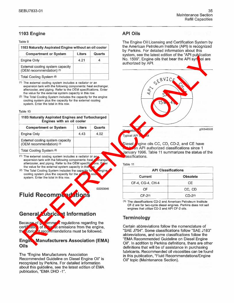
REFERENCE ONLY
SEBU7833-01
1103 Engine
Table 9
1103 Naturally Aspirated Engine without an oil cooler
Compartment or System Liters Quarts
Engine Only 4.21 4
External cooling system capacity (OEM recommendation) (1)
Total Cooling System (2)
(1) The external cooling system includes a radiator or an expansion tank with the following components: heat exchanger, aftercooler, and piping. Refer to the OEM specifications. Enter the value for the external system capacity in this row.
(2) The Total Cooling System includes the capacity for the engine cooling system plus the capacity for the external cooling system. Enter the total in this row.
Table 10
1103 Naturally Aspirated Engines and Turbocharged Engines with an oil cooler
Compartment or System Liters Quarts
Engine Only 4.43 4.02
External cooling system capacity (OEM recommendation) (1)
Total Cooling System (2)
(1) The external cooling system includes a radiator or an expansion tank with the following components: heat exchanger, aftercooler, and piping. Refer to the OEM specifications. Enter the value for the external system capacity in this row.
(2) The Total Cooling System includes the capacity for the engine cooling system plus the capacity for the external cooling system. Enter the total in this row.
i02203046
Fluid Recommendations
General Lubricant Information
Because of government regulations regarding the certification of exhaust emissions from the engine, the lubricant recommendations must be followed.
Engine Manufacturers Association (EMA) Oils
The "Engine Manufacturers Association Recommended Guideline on Diesel Engine Oil" is recognized by Perkins. For detailed information about this guideline, see the latest edition of EMA publication, "EMA DHD -1".
API Oils
35 Maintenance Section
Refill Capacities
The Engine Oil Licensing and Certification System by the American Petroleum Institute (API) is recognized by Perkins. For detailed information about this system, see the latest edition of the "API publication No. 1509". Engine oils that bear the API symbol are authorized by API.
Illustration 18
Typical API symbol
900546535
Diesel engine oils CC, CD, CD-2, and CE have not been API authorized classifications since 1 January 1996. Table 11 summarizes the status of the classifications.
Table 11
API Classifications
Current Obsolete
CF-4, CG-4. CH-4 CE
CF CC, CO
CF-2(1) CO-2(1)
(1) The classifications CO-2 and American Petroleum Institute CF-2 are for two-cycle diesel engines. Perkins does not sell engines that utilize CO-2 and API CF-2 oils.
Terminology
Certain abbreviations follow the nomenclature of "SAE J754". Some classifications follow "SAE J183" abbreviations, and some classifications follow the "EMA Recommended Guideline on Diesel Engine Oil". In addition to Perkins definitions, there are other definitions that will be of assistance in purchasing lubricants. Recommended oil viscosities can be found in this publication, "Fluid Recommendations/Engine Oil" topic (Maintenance Section).
REFERENCE ONLY
36 Maintenance Section Refill Capacities
Engine Oil
Commercial Oils
The performance of commercial diesel engine oRs Is based on American Petroleum Institute (API) classifications. These API classifications are developed in order to provide commercial lubricants for a broad range of diesel engines that operate at various conditions.
Only use commercial oils that meet the following classifications:
• EMA DHD-1 multigrade oil (preferred oil)
• API CH-4 multigrade oil (preferred oil)
• ACEAE3
In order to make the correct choice of a commercial oil, refer to the following explanations:
EMA DHD·1 - The Engine Manufacturers Association (EMA) has developed lubricant recommendations as an alternative to the API oil classification system. DHD-1 is a Recommended Guideline that defines a level of oil performance for these types of diesel engines: high speed, four stroke cycle, heavy-duty, and light duty. DHD-1 oils may be used in Perkins engines when the following oils are recommended: API CH-4, API CG-4, and API CF-4. DHD-1 oils are intended to provide superior performance in comparison to API CG-4 and API CF-4.
DHD·1 oils will meet the needs of high performance Perkins diesel engines that are operating in many applications. The tests and the test limits that are used to define DHD-1 are similar to the new API CH-4 classification. Therefore, these oils will also meet the requirements for diesel engines that require low emissions. DHD-1 oils are designed to control the harmful effects of soot with Improved wear resistance and Improved resistance to plugging of the oil filter. These oils will also provide superior piston deposit control for engines with either two-piece steel pistons or aluminum pistons.
All DHD·1 oils must complete a full test program with the base stock and with the viscosity grade of the finished commercial all. The use of -API Base 011 Interchange Guidelines· are not appropriate for DHD-1 oils. This feature reduces the variation in performance that can occur when base stocks are changed in commercial oil formulations.
SEBU7833-01
DHD-1 oils are recommended for use in extended 011 change interval programs that optimize the life of the oil. These oil change interval programs are based on oil analysis. DHD-1 oils are recommended for conditions that demand a premium oil. Your Perkins dealer or your Perkins distributor has the specific guidelines for optimizing 011 change intervals.
API CH-4 - API CH-4 oils were developed in order to meet the requirements of the new high performance diesel engines. Also, the oil was designed to meet the requirements of the low emissions diesel engines. API CH-4 oils are also acceptable for use in older diesel engines and in diesel engines that use high sulfur diesel fuel. API CH-4 oils may be used in Perkins engines that use API CG-4 and API CF-4 oils. API CH-4 oils will generally exceed the performance of API CG-4 oils in the following criteria: deposits on pistons, control of oil consumption, wear of piston rings, valve train wear, viscosity control, and corrosion.
Three new engine tests were developed for the API CH-4 oil. The first test specifically evaluates deposits on pistons for engines with the two-piece steel piston. This test (piston deposit) also measures the control of oil consumption. A second test is conducted with moderate oil soot. The second test measures the following criteria: wear of piston rings, wear of cylinder liners, and resistance to corrosion. A third new test measures the following characteristics with high levels of soot in the oil: wear of the valve train, resistance of the oil in plugging the oil filter, and control of sludge.
In addition to the new tests, API CH-4 oils have tougher limits for viscosity control in applications that generate high soot. The oils also have improved oxidation resistance. API CH-4 oils must pass an additional test (piston deposit) for engines that use aluminum pistons (single piece). Oil performance is also established for engines that operate in areas with high sulfur diesel fuel.
All of these improvements allow the API CH-4 oil to achieve optimum oil change intervals. API CH-4 oils are recommended for use in extended 011 change intervals. API CH-4 oils are recommended for conditions that demand a premium oil. Your Perkins dealer or your Perkins distributor has specific guidelines for optimizing oil change intervals.
Some commercial oils that meet the API classifications may require reduced oil change intervals. To determine the oil change interval, closely monitor the condition of the oil and perform a wear metal analysis.
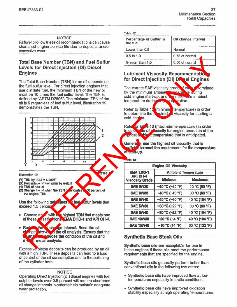
REFERENCE ONLY
SEBU7833-01
NOTICE Failure to follow these oil recommendations can cause shortened engine service life due to deposits and/or excessive wear.
Total Base Number (TBN) and Fuel Sulfur Levels for Direct Injection (01) Diesel Engines
The Total Base Number (TBN) for an oil depends on the fuel sulfur level. For direct injection engines that use distillate fuel, the minimum TBN of the new oil must be 10 times the fuel sulfur level. The TBN is defined by "ASTM 02896". The minimum TBN of the oil is 5 regardless of fuel sulfur level. Illustration 19 demonstrates the TBN.
y
17
15
n
7
3
1/ 1/
I o
/ / / / 1/ / L V ." / /v 1/
" :/ / 1/ V / 1/ / / / 1/ /
" / / / / 1/ / / .r / /
" / /",
'/ / ~ / / ,
~
o.~ u u I
x -------------
1 2
Illustration 19 g00799818
(Y) TBN by"ASTM 02896-(X) Percentage of fuel sulfur by weight (1) TBN of new oil (2) Change the oil when the TBN deteriorates to 50 percent of
tha original TBN.
Use the following guidelines for fuel sulfur levels that exceed 1.5 percent:
• Choose an oil with the highest TBN that meets one of these classifications: EMA DHD-1 and API CH-4.
• Reduce the oil change Interval. Base the all change interval on the 011 analysis. Ensure that the oil analysis includes the condition of the all and a wear metal analysis.
Excessive piston deposits can be produced by an oil with a high TBN. These deposits can lead to a loss of control of the oil consumption and to the polishing of the cylinder bore.
NOTICE Operating Direct Injection (01) diesel engines with fuel sulphur levels over 0.5 percent will require shortened oil change intervals in order to help maintain adequate wear protection.
Table 12
37 Maintenance Section
Refill Capacities
Percentage of Sulfur in Oil change interval the fuel
Lower than 0.5 Normal
0.5 to 1.0 0.75 of normal
Greater than 1.0 0.50 of normal
Lubricant Viscosity Recommendations for Direct Injection (01) Diesel Engines
The correct SAE viscosity grade of oil is determined by the minimum ambient temperature during cold engine start-up. and the maximum ambient temperature during engine operation.
Refer to Table 13 (minimum temperature) in order to determine the required oil viscosity for starting a cold engine.
Refer to Table 13 (maximum temperature) in order to select the all viscosity for engine operation at the highest ambient temperature that is anticipated.
Generally. use the highest oil viscosity that Is available to meet the requirement for the temperature at start-up.
Table 13
Engine 00 Viscosity
EMALRG-1 Ambient Temperature API CH-t
ViSCOSity Gracie Minimum Maximum
SAEOW2O -40 ·C (-40 OF) 10°C (50 oF)
SAEOW3O -40 ·C (-40 OF) 30°C (88 oF)
SAEOW40 -40 ·C (-40 OF) 40°C (104 OF)
SAE5W30 -30 OC (-22 OF) 30°C (88 oF)
SAE&W40 -30 OC (-22 OF) 40°C (104 oF)
SAE 10W30 -20 ·C (-4 OF) 40°C (104 oF)
SAE15W40 -10 ·C (14 oF) 50°C (122 OF)
Synthetic Base Stock Oils
Synthetic base oils are acceptable for use in these engines If these oils meet the performance requirements that are specified for the engine.
Synthetic base oils generally perform better than conventional oils in the following two areas:
• Synthetic base oils have improved flow at low temperatures especially in arctic conditions.
• Synthetic base oils have improved oxidation stability especially at high operating temperatures.
REFERENCE ONLY
38 Maintenance Section Refill Capacities
Some synthetic base oils have performance characteristics that enhance the service life of the oil. Perkins does not recommend the automatic e~ending of the oil change intervals for any type of all.
Re-refined Base Stock Oils
Re-refined base stock oils are acceptable for use in Perkins engines if these oils meet the perf~rmance requirements that are specified by Perkins. Re-refined base stock oils can be used exclusively in finished oil or in a combination with new base stock oils. The US military specifications and the specifications of other heavy equipment manufacturers also allow the use of re-refined base stock oils that meet the same criteria.
The process that is used to make re-refined base stock oil should adequately remove all wear metals that are in the used oil and all the additives that are in the used oil. The process that is used to make re-refined base stock oil generally involves the process of vacuum distillation and hydrotreating the used oil. Filtering is adequate for the production of high quality, re-refined base stock oil.
Lubricants for Cold Weather
When an engine is started and an engine is operated in af!1bient t~mperatures below -20°C (-4 OF), use multigrade Oils that are capable of flowing in low temperatures.
These oils have lubricant viscosity grades of SAE OW or SAE SW.
When an engine is started and operated in ambient temperatures below -30°C (-22 OF), use a synthetic base stock multigrade oil with an OW viscosity grade or with a SW viscosity grade. Use an oil with a pour point that is lower than -SO °C (-S8 OF).
The number of acceptable lubricants is limited in cold weather conditions. Perkins recommends the following lubricants for use in cold weather conditions:
First Choice - Use oil with an EMA DHD-1 Recommended Guideline. Use a CH-4 oil that has an API license. The oil should be either SAE OW20, SAE OW30, SAE OW40, SAE SW30, or SAE SW40 lubricant viscosity grade.
Second Choice - Use an oil that has a CH-4 additive package. Although the oil has not been tested for the requirements of the API license, the oil must be either SAE OW20, SAE OW30, SAE OW40, SAE SW30, or SAE SW40.
SEBU7833-01
NOTICE Shortened engine service life could result if second choice oils are used.
Aftermarket Oil Additives
Perkins does not recommend the use of aftermarket additives in oil. It is not necessary to use aftermarket additives in order to achieve the engine's maximum service life or rated performance. Fully formulated finished oils consist of base oils and of commerci~1 additive packages. These additive packages are blended into the base oils at precise percentages in order to help provide finished oils with performance characteristics that meet industry standards.
There are no industry standard tests that evaluate the performance or the compatibility of aftermarket additives in finished oil. Aftermarket additives may not be compatible with the finished oil's additive package, which could lower the performance of the finished oil. The aftermarket additive could fail to ~ix with the finished oil. This could produce sludge In the crankcase. Perkins discourages the use of aftermarket additives in finished oils.
To achieve the best performance from a Perkins engine, conform to the following guidelines:
• Select the correct oil, or a commercial oil that meets the "EMA Recommended Guideline on Diesel Engine Oil" or the recommended API classification.
• See the appropriate "Lubricant Viscosities" table in ord~r to find the correct oil viscosity grade for your engine.
• At the specified interval, service the engine. Use new oil and install a new oil filter.
• Perform maintenance at the intervals that are specified in the Operation and Maintenance Manual, "Maintenance Interval Schedule".
5·0·5 Oil analysis
Some engines may be equipped with an oil sampling valve. If S·0·5 oil analysis is required the oil sampling valve is used to obtain samples of the engine oil. The 5·0·5 oil analysis will complement the preventive maintenance program.
The 5·0·S oil analysis is a diagnostic tool that is used to determine oil performance and component wear rates. Contamination can be identified and measured through the use of the S·O·S oil analysis. The 5·0·5 oil analysiS includes the following tests:
REFERENCE ONLY
SEBU7833-01
• The Wear Rate Analysis monitors the wear of the engine's metals. The amount of wear metal and type of wear metal that is in the oil is analyzed. The increase in the rate of engine wear metal in the oil is as important as the quantity of engine wear metal in the oil.
• Tests are conducted in order to detect contamination of the oil by water, glycol or fuel.
• The Oil Condition Analysis determines the loss of the oil's lubricating properties. An infrared analysis is used to compare the properties of new oil to the properties of the used oil sample. This analysis allows technicians to determine the amount of deterioration of the oil during use. This analysis also allows technicians to verify the performance of the oil according to the specification during the entire oil change interval.
Fuel Specifications
Fuel Recommendations
To get the correct power and performance from the engine, use a fuel of the correct quality. The recommended fuel specification for Perkins engines is shown below:
• Cetane number ________ 45 minimum
• Viscosity ____ 2,0 to 4.5 cSt at 40°C (104 OF)
• Density _______ O.835 to 0.855 Kg/liter
• Sulfur _______ 0.2% of mass, maximum
• Distillation, ______ 85% at 350°C (662 OF)
• Lubricity 460 micrometers maximum wear scar on "ISO 12156 - 1"
Cetane number
This indicates the properties of ignition of the fuel. Fuel with a low cetane number can be the root cause of problems during cold start. This will affect combustion.
Viscosity
This is the resistance to flow of a fluid. If this resistance is outside the limits, the engine and the engine starting performance in particular can be affected.
Sulfur
39 Maintenance Section
Refill Capacities
High sulfur content of the fuel is not normally found in Europe, North America or Australasia. This can cause engine wear. When only high sulfur fuels are available, it will be necessary that high alkaline lubricating oil is used in the engine or that the lubricating oil change interval is reduced .
Distillation
This is an indication of the mixture of different hydrocarbons in the fuel. A high ratio of light weight hydrocarbons can affect the characteristics of combustion.
Lubricity
This is the capability of the fuel to prevent pump wear.
Diesel engines have the ability to burn a wide variety of fuels. These fuels are divided into four general groups:
• Group 1 (preferred fuels)
• Group 2 (permissible fuels)
• Group 3 (aviation kerosene fuels)
• Other fuels
Group 1 (preferred fuels): Specification
"DERV to EN590"
Note: Only use Arctic fuels when the temperature is below ° °C (32 OF). Do not use Arctic fuels when the ambient temperature is above ° °C (32 OF). To ensure that the time period between cranking the engine and first fire is kept to a minimum, only use fuel of the correct viSCOSity and at the correct temperature.
Gas oil to "BS2869 Class A2"
"ASTM D975 - 91 Class 2D" This can only be used if the fuel has the correct specification of lubricity.
"JIS K2204 (1992) Grades 1,2,3 and Special Grade 3" This can only be used if the fuel has the correct specification of lubricity.
Note: If low sulfur or low sulfur aromatic fuels are used, then fuel additives can be used to increase lubricity.
Group 2 (permissible fuels): Specification
These fuel specifications are considered acceptable for issues of warranty. However, these fuels may reduce the life of the engine, the engine's maximum power and the engine's fuel efficiency.
REFERENCE ONLY
40 Maintenance Section Refill Capacities
"ASTM D975 - 91 Class 1 D"
"JP7, Mil T38219"
"NATO F63"
NOTICE These fuels should have a wear scar value of 650 micrometers maximum *HFRR to ISO 12156 - 1.*
Group 3 (aviation kerosene fuels): Specification
These fuels need additives to achieve lubricity of 650 micrometers wear scar and the reliability of the fuel injection pump will be reduced. The fuel injection pump is not covered by a warranty, even when the additives are included.
"JP5 MIL T5624 (Avcat FSII, NATO F44"
"JP8 T83133 (Avtur FSII, NATO F34"
"Jet A"
"Jet A1, NATO F35, XF63"
Low temperature fuels
Special fuels for use in cold weather may be available for engine operation at temperatures below 0 °C (32 OF). These fuels limit the formation of wax in the fuel oil at low temperatures. If wax forms in the fuel oil, this could stop the flow of fuel oil through the filter.
Note: These fuels that lack lubricity may cause the following problems:
• Low engine power
• Difficult starting in hot conditions or in cold conditions
• White smoke
• Deterioration of emissions and misfire at certain operating conditions
Biofuel: Specification
Biofuel: A 5% mix of RME to EN14214 in conventional fuel is permitted.
NOTICE Water emulsion fuels: These fuels are not permitted
Refer to the following fuel specifications for North America.
SEBU7833-01
The preferred fuels provide maximum engine service life and performance. The preferred fuels are distillate fuels. These fuels are commonly called diesel fuel or gas oil.
The permissible fuels are crude oils or blended fuels. Use of these fuels can result in higher maintenance costs and in reduced engine service life.
Diesel fuels that meet the specifications in Table 14 will help to provide maximum engine service life and performance. In North America, diesel fuel that is identified as No. 2-D in "ASTM D975" generally meets the specifications. Table 14 is for diesel fuels that are distilled from crude oil. Diesel fuels from other sources could exhibit detrimental properties that are not defined or controlled by this specification.
Table 14
Perkins Specifications for Distillate Diesel Fuel
Specifications Requirements ASTM Test
Aromatics 35% maximum "01319"
Ash 0.02% maximum "0482" (weight)
Carbon Residue 0.35% maximum "0524" on 10% Bottoms (weight)
Cetane Number 40 minimum (01
"0613" engines)
The cloud point must not
Cloud Point exceed the -lowest expected ambient temperature.
(continued)
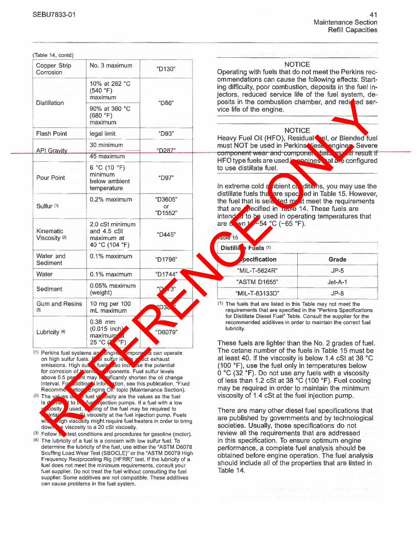
REFERENCE ONLY
SEBU7833-01
(Table 14, contd)
Copper Strip No. 3 maximum "D130" Corrosion
10% at 282 °C (540 OF) maximum
Distillation "D86" 90% at 360°C (680 OF) maximum
Flash Point legal limit "D93"
30 minimum API Gravitv nn?A7"
45 maximum
6 °C (10 OF)
Pour Point minimum "D97" below ambient temperature
0.2% maximum "D3605" Sulfur (1) or
"D1552"
2.0 cSt minimum Kinematic and 4.5 cSt "D445" Viscosity (2) maximum at
40 °C (104 OF)
Water and 0.1 % maximum "D1796" Sediment
Water 0.1% maximum "D1744"
0.05% maximum Sediment (weight) "D473"
Gum and Resins 10 mg per 100 "D381" (3) mL maximum
0.38 mm
Lubricity (4) (0.015 inch) "D6079" maximum at 25 °C (77 OF)
(I ) Perkins fuel systems and engine components can operate on high sulfur fuels. Fuel sulfur levels affect exhaust emissions. High sulfur fuels also increase the potential for corrosion of internal components. Fuel sulfur levels above 0.5 percent may significantly shorten the oil change interval. For additional information, see this publication, "Fluid Recommendations/Engine Oil" topic (Maintenance Section).
(2) The values of the fuel viscosity are the values as the fuel is delivered to the fuel injection pumps. If a fuel with a low viscosity is used, cooling of the fuel may be required to maintain a 1.4 cSt viscosity at the fuel injection pump. Fuels with a high viscosity might require fuel heaters in order to bring down the viscosity to a 20 cSt viscosity.
(3) Follow the test conditions and procedures for gasoline (motor). (4) The lubricity of a fuel is a concern with low sulfur fuel. To
determine the lubricity of the fuel, use either the "ASTM 06078 Scuffing load Wear Test (SBOClE)" or the "ASTM 06079 High Frequency Reciprocating Rig (HFRR)" test. If the lubricity of a fuel does not meet the minimum requirements, consult your fuel supplier. Do not treat the fuel without consulting the fuel supplier. Some additives are not compatible. These additives can cause problems in the fuel system.
NOTICE
41 Maintenance Section
Refill Capacities
Operating with fuels that do not meet the Perkins rec-ommendations can cause the following effects: Start-ing difficulty, poor combustion, deposits in the fuel in-jectors, reduced service life of the fuel system, de-posits in the combustion chamber, and reduced ser-vice life of the engine.
NOTICE Heavy Fuel Oil (HFO), Residual fuel, or Blended fuel must NOT be used in Perkins diesel engines. Severe . . . uVII~"'VIlt#II' VYeo, OIlU uVII'..,Vllelll ,ollu,e;:, VYII' ,e;:,ull II
HFO type fuels are used in engines that are configured to use distillate fuel.
In extreme cold ambient conditions, you may use the distillate fuels that are specified in Table 15. However, the fuel that is selected must meet the requirements that are specified in Table 14. These fuels are intended to be used in operating temperatures that are down to -54°C (-65 OF).
Table 15
Distillate Fuels (1)
Specification Grade
"MIL-T-5624R" JP-5
"ASTM D 1655" Jet-A-1
"MIL-T-83133D" JP-8
(1) The fuels that are listed in this Table may not meet the requirements that are specified in the "Perkins Specifications for Distillate Diesel Fuel" Table. Consult the supplier for the recommended additives in order to maintain the correct fuel lubricity.
These fuels are lighter than the No.2 grades of fuel. The cetane number of the fuels In Table 15 must be at least 40. If the viscosity is below 1.4 cSt at 38 DC (100 OF), use the fuel only in temperatures below o DC (32 OF). Do not use any fuels with a viscosity of less than 1.2 cSt at 38 DC (100 OF). Fuel cooling may be required in order to maintain the minimum viscosity of 1.4 cSt at the fuel injection pump.
There are many other diesel fuel specifications that are published by governments and by technological societies. Usually, those specifications do not review all the requirements that are addressed in this specification. To ensure optimum engine performance, a complete fuel analysis should be obtained before engine operation. The fuel analysis should include all of the properties that are listed in Table 14.
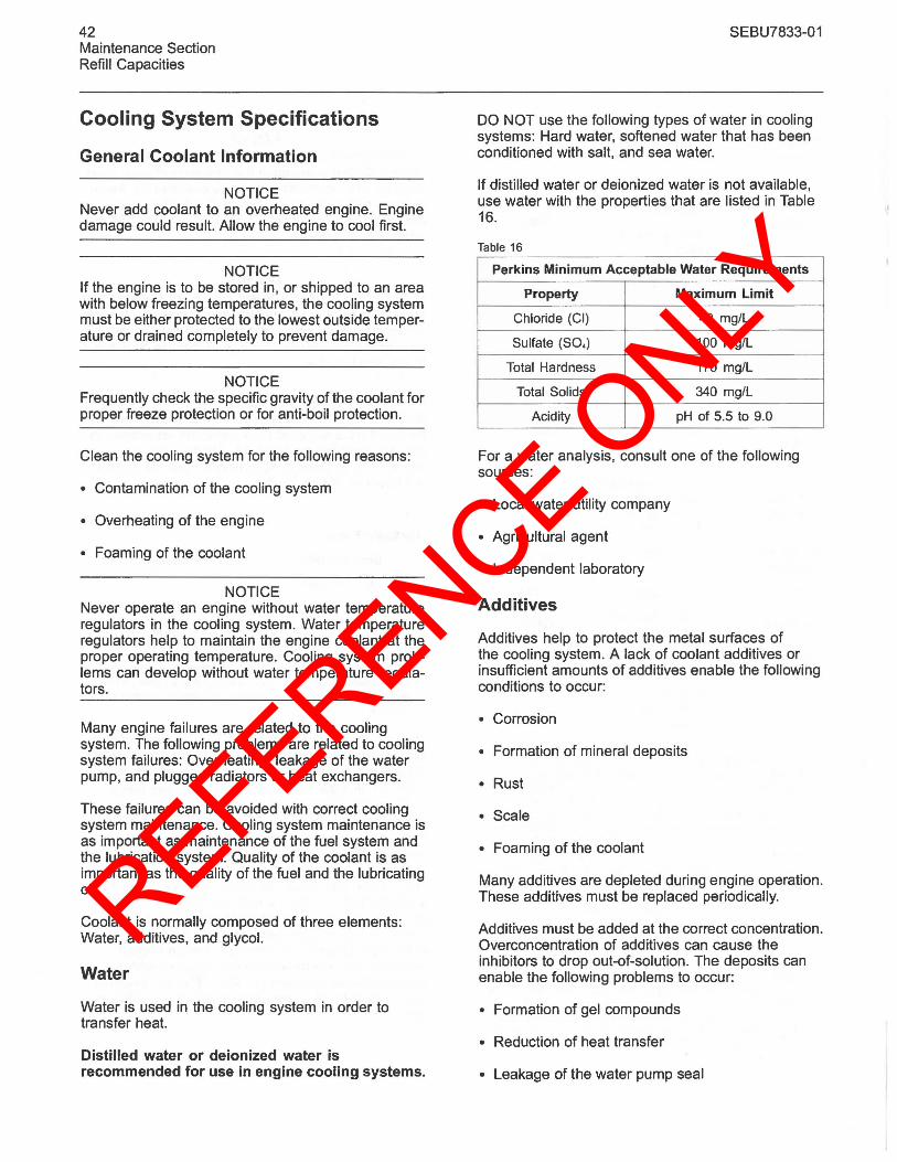
REFERENCE ONLY
42 Maintenance Section Refill Capacities
Cooling System Specifications
General Coolant Information
NOTICE Never add coolant to an overheated engine. Engine damage could result. Allow the engine to cool first.
NOTICE If the engine is to be stored in, or shipped to an area with below freezing temperatures, the cooling system must be either protected to the lowest outside temperature or drained completely to prevent damage.
NOTICE Frequently check the specific gravity of the coolant for proper freeze protection or for anti-boil protection.
Clean the cooling system for the following reasons:
• Contamination of the cooling system
• Overheating of the engine
• Foaming of the coolant
NOTICE Never operate an engine without water temperature regulators in the cooling system. Water temperature regulators help to maintain the engine coolant at the proper operating temperature. Cooling system problems can develop without water temperature regulators.
Many engine failures are related to the cooling system. The following problems are related to cooling system failures: Overheating, leakage of the water pump, and plugged radiators or heat exchangers.
These failures can be avoided with correct cooling system maintenance. Cooling system maintenance is as important as maintenance of the fuel system and the lubrication system. Quality of the coolant is as important as the quality of the fuel and the lubricating oil.
Coolant is normally composed of three elements: Water, additives, and glycol.
Water
Water is used in the cooling system in order to transfer heat.
Distilled water or deionized water is recommended for use in engine cooling systems.
SEBU7833-01
DO NOT use the following types of water in cooling systems: Hard water, softened water that has been conditioned with salt, and sea water.
If distilled water or deionized water is not available, use water with the properties that are listed in Table 16.
Table 16
Perkins Minimum Acceptable Water Requirements
Property Maximum Limit
Chloride (CI) 40 mg/L
Sulfate (SO.) 100 mg/L
Total Hardness 170 mg/L
Total Solids 340 mg/L
Acidity pH of 5.5 to 9.0
For a water analysis, consult one of the following sources:
• Local water utility company
• Agricultural agent
• Independent laboratory
Additives
Additives help to protect the metal surfaces of the cooling system. A lack of coolant additives or insufficient amounts of additives enable the following conditions to occur:
• Corrosion
• Formation of mineral deposits
• Rust
• Scale
• Foaming of the coolant
Many additives are depleted during engine operation. These additives must be replaced periodically.
Additives must be added at the correct concentration. Overconcentration of additives can cause the inhibitors to drop out-of-solution. The deposits can enable the following problems to occur:
• Formation of gel compounds
• Reduction of heat transfer
• Leakage of the water pump seal
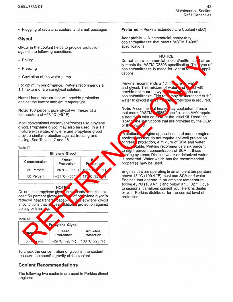
REFERENCE ONLY
SEBU7833-01
• Plugging of radiators, coolers, and small passages
Glycol
Glycol in the coolant helps to provide protection against the following conditions:
• Boiling
• Freezing
• Cavitation of the water pump
For optimum performance, Perkins recommends a 1:1 mixture of a water/glycol solution.
Note: Use a mixture that will provide protection against the lowest ambient temperature.
Note: 100 percent pure glycol will freeze at a temperature of -23°C (-9 OF).
Most conventional coolanUantifreezes use ethylene glycol. Propylene glycol may also be used. In a 1:1 mixture with water, ethylene and propylene glycol provide similar protection against freezing and boiling. See Tables 17 and 18.
Table 17
Ethylene Glycol
Concentration Freeze Boil Protection Protection
50 Percent -36°C (-33 OF) 106°C (223 OF)
60 Percent -51 °C (-60 OF) 111°C (232 OF)
NOTICE Do not use propylene glycol in concentrations that exceed 50 percent glycol because of propylen~ glycol's reduced heat transfer capability. Use ethylene glycol in conditions that require additional protection against boiling or freezing.
Table 18
Propylene Glycol
Concentration Freeze Anti-Boil Protection Protection
50 Percent -29°C (-20 OF) 106°C (223 OF)
To check the concentration of glycol in the coolant, measure the specific gravity of the coolant.
Coolant Recommendations
The following two coolants are used in Perkins diesel engines:
43 Maintenance Section
Refill Capacities
Preferred - Perkins Extended Life Coolant (ELC)
Acceptable - A commercial heavy-duty coolanUantifreeze that meets "ASTM 04985" specifications
NOTICE Do not use a commercial coolanUantifreeze that only meets the ASTM 03306 specification. This type of coolanUantifreeze is made for light automotive applications.
Perkins recommends a 1:1 mixture of water and glycol. This mixture of water and glycol will provide optimum heavy-duty performance as a coolanUantifreeze. This ratio may be increased to 1:2 water to glycol if extra freezing protection is required.
Note: A commercial heavy-duty coolanUantifreeze that meets "ASTM 04985" specifications MAY require a treatment with an SCA at the initial fill. Read the label or the instructions that are provided by the OEM of the product.
In stationary engine applications and marine engine applications that do not require anti-boil protection or freeze protection, a mixture of SCA and water is acceptable. Perkins recommends a six percent to eight percent concentration of SCA in those cooling systems. Distilled water or deionized water is preferred. Water which has the recommended properties may be used.
Engines that are operating in an ambient temperature above 43°C (109.4 OF) must use SCA and water. Engines that operate in an ambient temperature above 43°C (109.4 OF) and below 0 °C (32 OF) due to seasonal variations consult your Perkins dealer or your Perkins distributor for the correct level of protection.
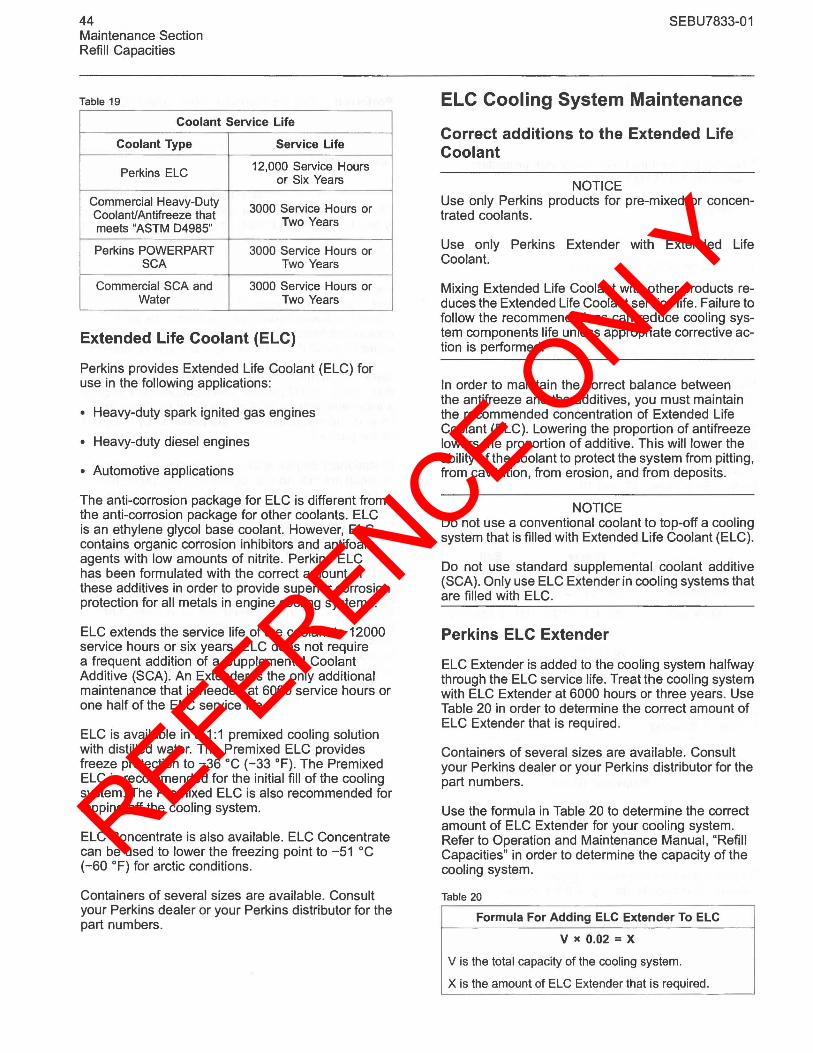
REFERENCE ONLY
44 Maintenance Section Refill Capacities
Table 19
Coolant Service Life
Coolant Type Service Life
Perkins ELC 12,000 Service Hours or Six Years
Commercial Heavy-Duty 3000 Service Hours or CoolanUAntifreeze that
Two Years meets "ASTM 04985"
Perkins POWERPART 3000 Service Hours or SCA Two Years
Commercial SCA and 3000 Service Hours or Water Two Years
Extended Life Coolant (ELC)
Perkins provides Extended Life Coolant (ELC) for use in the following applications:
• Heavy-duty spark ignited gas engines
• Heavy-duty diesel engines
• Automotive applications
The anti-corrosion package for ELC is different from the anti-corrosion package for other coolants. ELC is an ethylene glycol base coolant. However, ELC contains organic corrosion inhibitors and antifoam agents with low amounts of nitrite. Perkins ELC has been formulated with the correct amount of these additives in order to provide superior corrosion protection for all metals in engine cooling systems.
ELC extends the service life of the coolant to 12000 service hours or six years. ELC does not require a frequent addition of a Supplemental Coolant Additive (SCA). An Extender is the only additional maintenance that is needed at 6000 service hours or one half of the ELC service life.
ELC is available in a 1:1 premixed cooling solution with distilled water. The Premixed ELC provides freeze protection to -36°C (-33 OF). The Premixed ELC is recommended for the initial fill of the cooling system. The Premixed ELC is also recommended for topping off the cooling system.
ELC Concentrate is also available. ELC Concentrate can be used to lower the freezing point to -51°C (-60 OF) for arctic conditions.
Containers of several sizes are available. Consult your Perkins dealer or your Perkins distributor for the part numbers.
SEBU7833-01
ELC Cooling System Maintenance
Correct additions to the Extended Life Coolant
NOTICE Use only Perkins products for pre-mixed or concentrated coolants.
Use only Perkins Extender with Extended Life Coolant.
Mixing Extended Life Coolant with other products reduces the Extended Life Coolant service life. Failure to follow the recommendations can reduce cooling system components life unless appropriate corrective action is performed.
In order to maintain the correct balance between the antifreeze and the additives, you must maintain the recommended concentration of Extended Life Coolant (ELC). Lowering the proportion of antifreeze lowers the proportion of additive. This will lower the ability of the coolant to protect the system from pitting, from cavitation, from erosion, and from deposits.
NOTICE Do not use a conventional coolant to top-off a cooling system that is filled with Extended Life Coolant (ELC).
Do not use standard supplemental coolant additive (SCA). Only use ELC Extender in cooling systems that are filled with ELC.
Perkins ELC Extender
ELC Extender is added to the cooling system halfway through the ELC service life. Treat the cooling system with ELC Extender at 6000 hours or three years. Use Table 20 in order to determine the correct amount of ELC Extender that is required.
Containers of several sizes are available. Consult your Perkins dealer or your Perkins distributor for the part numbers.
Use the formula in Table 20 to determine the correct amount of ELC Extender for your cooling system. Refer to Operation and Maintenance Manual, "Refill Capacities" in order to determine the capacity of the cooling system.
Table 20
Formula For Adding ELC Extender To ELC
v )( 0.02 = X
V is the total capacity of the cooling system.
X is the amount of ELC Extender that is required.
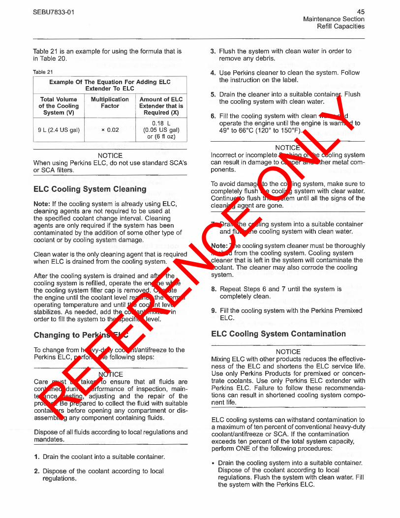
REFERENCE ONLY
SEBU7833-01
Table 21 is an example for using the formula that is in Table 20.
Table 21
Example Of The Equation For Adding ELC Extender To ELC
Total Volume Multiplication Amount of ELC of the Cooling Factor Extender that is
System (V) Required (X)
0.18 L 9 L (2.4 US gal) x 0.02 (0.05 US gal)
or (6 fI oz)
NOTICE When using Perkins ELC, do not use standard SCA's or SCA filters.
ELC Cooling System Cleaning
Note: If the cooling system is already using ELC, cleaning agents are not required to be used at the specified coolant change interval. Cleaning agents are only required if the system has been contaminated by the addition of some other type of coolant or by cooling system damage.
Clean water is the only cleaning agent that is required when ELC is drained from the cooling system.
After the cooling system is drained and after the cooling system is refilled, operate the engine while the cooling system filler cap is removed. Operate the engine until the coolant level reaches the normal operating temperature and until the coolant level stabilizes. As needed, add the coolant mixture in order to fill the system to the specified level.
Changing to Perkins ELC
To change from heavy-duty coolant/antifreeze to the Perkins ELC, perform the following steps:
NOTICE Care must be taken to ensure that all fluids are contained during performance of inspection, maintenance, testing, adjusting and the repair of the product. Be prepared to collect the fluid with suitable containers before opening any compartment or disassembling any component containing fluids.
Dispose of all fluids according to local regulations and mandates.
1. Drain the coolant into a suitable container.
2. Dispose of the coolant according to local regulations.
45 Maintenance Section
Refill Capacities
3. Flush the system with clean water in order to remove any debris.
4. Use Perkins cleaner to clean the system. Follow the instruction on the label.
5. Drain the cleaner into a suitable container. Flush the cooling system with clean water.
6. Fill the cooling system with clean water and operate the engine until the engine is warmed to 49° to 66°C (120° to 150°F).
NOTICE Incorrect or incomplete flushing of the cooling system can result in damage to copper and other metal components.
To avoid damage to the cooling system, make sure to completely flush the cooling system with clear water. Continue to flush the system until all the signs of the cleaning agent are gone.
7. Drain the cooling system into a suitable container and flush the cooling system with clean water.
Note: The cooling system cleaner must be thoroughly flushed from the cooling system. Cooling system cleaner that is left in the system will contaminate the coolant. The cleaner may also corrode the cooling system.
8. Repeat Steps 6 and 7 until the system is completely clean.
9. Fill the cooling system with the Perkins Premixed ELC.
ELC Cooling System Contamination
NOTICE Mixing ELC with other products reduces the effectiveness of the ELC and shortens the ELC service life. Use only Perkins Products for premixed or concentrate coolants. Use only Perkins ELC extender with Perkins ELC. Failure to follow these recommendations can result in shortened cooling system component life.
ELC cooling systems can withstand contamination to a maximum of ten percent of conventional heavy-duty coolant/antifreeze or SCA. If the contamination exceeds ten percent of the total system capacity, perform ONE of the following procedures:
• Drain the cooling system into a suitable container. Dispose of the coolant according to local regulations. Flush the system with clean water. Fill the system with the Perkins ELC.
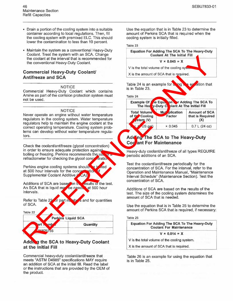
REFERENCE ONLY
46 Maintenance Section Refill Capacities
• Drain a portion of the cooling system into a suitable container according to local regulations. Then, fill the cooling system with premixed ELC. This should lower the contamination to less than 10 percent.
• Maintain the system as a conventional Heavy-Duty Coolant. Treat the system with an SCA. Change the coolant at the interval that is recommended for the conventional Heavy-Duty Coolant.
Commercial Heavy-Duty Coolant! Antifreeze and SCA
NOTICE Commercial Heavy-Duty Coolant which contains Amine as part of the corrision protection system must not be used.
NOTICE Never operate an engine without water temperature regulators in the cooling system. Water temperature regulators help to maintain the engine coolant at the correct operating temperature. Cooling system problems can develop without water temperature regulators.
Check the coolant/antifreeze (glycol concentration) in order to ensure adequate protection against boiling or freezing. Perkins recommends the use of a refractometer for checking the glycol concentration.
Perkins engine cooling systems should be tested at 500 hour intervals for the concentration of Supplemental Coolant Additive (SCA).
Additions of SCA are based on the results of the test. An SCA that is liquid may be needed at 500 hour intervals.
Refer to Table 22 for part numbers and for quantities of SCA.
Table 22
Perkins Liquid SCA
Part Number Quantity
21825755
Adding the SCA to Heavy-Duty Coolant at the Initial Fill
Commercial heavy-duty coolant/antifreeze that meets "ASTM 04985" specifications MAY require an addition of SCA at the initial fill. Read the label or the instructions that are provided by the OEM of the product.
SEBU7833-01
Use the equation that is in Table 23 to determine the amount of Perkins SCA that is required when the cooling system is initially filled.
Table 23
Equation For Adding The SCA To The Heavy-Duty Coolant At The Initial Fill
v )( 0.045 = X
V is the total volume of the cooling system.
X is the amount of SCA that is required.
Table 24 is an example for using the equation that is in Table 23.
Table 24
Example Of The Equation For Adding The SCA To The Heavy-Duty Coolant At The Initial Fill
Total Volume Multiplication Amount of SCA of the Cooling Factor that is Required
System (V) (X)
15 L (4 US gal) x 0.045 0.7 L (24 oz)
Adding The SCA to The Heavy-Duty Coolant For Maintenance
Heavy-duty coolant/antifreeze of all types REQUIRE periodic additions of an SCA.
Test the coolant/antifreeze periodically for the concentration of SCA. For the interval, refer to the Operation and Maintenance Manual, "Maintenance Interval Schedule" (Maintenance Section). Test the concentration of SCA.
Additions of SCA are based on the results of the test. The size of the cooling system determines the amount of SCA that is needed.
Use the equation that is in Table 25 to determine the amount of Perkins SeA that is required, if necessary:
Table 25
Equation For Adding The SCA To The Heavy-Duty Coolant For Maintenance
v )( 0.014 = X
V is the total volume of the cooling system.
X is the amount of SCA that is required.
Table 26 is an example for using the equation that is in Table 25.
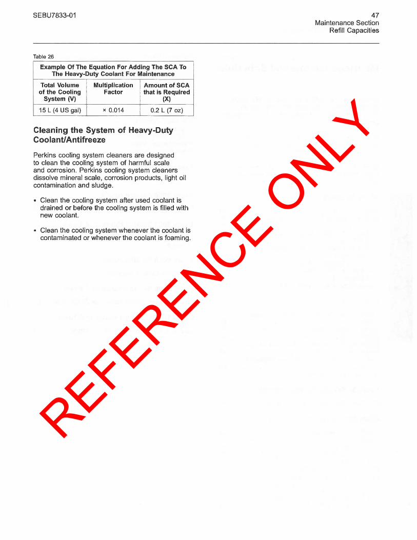
REFERENCE ONLY
SEBU7833-01
Table 26
Example Of The Equation For Adding The SCA To The Heavy-Duty Coolant For Maintenance
Total Volume Multiplication Amount of SCA of the Cooling Factor that is Required
System (V) (X)
15 L (4 US gal) x 0.014 0.2 L (7 oz)
Cleaning the System of Heavy-Duty Coolant/Antifreeze
Perkins cooling system cleaners are designed to clean the cooling system of harmful scale and corrosion. Perkins cooling system cleaners dissolve mineral scale, corrosion products, light oil contamination and sludge.
• Clean the cooling system after used coolant is drained or before the COOling system is filled with new coolant.
• Clean the cooling system whenever the coolant is contaminated or whenever the coolant is foaming.
47 Maintenance Section
Refill Capacities
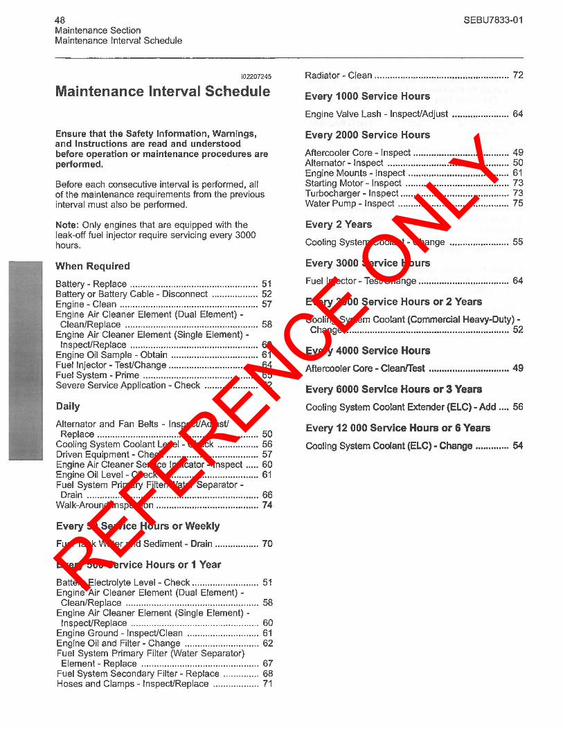
REFERENCE ONLY
48 Maintenance Section Maintenance Interval Schedule
i02207245
Maintenance Interval Schedule
Ensure that the Safety Information, Warnings, and Instructions are read and understood before operation or maintenance procedures are performed.
Before each consecutive interval is performed, all of the maintenance requirements from the previous interval must also be performed.
Note: Only engines that are equipped with the leak-off fuel injector require servicing every 3000 hours.
When Required
Battery - Replace .................................................. 51 Battery or Battery Cable - Disconnect .................. 52 Engine - Clean ...................................................... 57 Engine Air Cleaner Element (Dual Element) -Clean/Replace ......................................... ........... 58
Engine Air Cleaner Element (Single Element) -Inspect/Replace .................................................. 60
Engine Oil Sample - Obtain .................................. 61 Fuel Injector - Test/Change ................................... 64 Fuel System - Prime ............................................. 65 Severe Service Application - Check ..................... 72
Daily
Alternator and Fan Belts - Inspect/Adjust/ Replace ............................................................... 50
Cooling System Coolant Level - Check ................ 56 Driven Equipment - Check .................................... 57 Engine Air Cleaner Service Indicator - Inspect ..... 60 Engine Oil Level- Check ...................................... 61 Fuel System Primary Filter/Water Separator -Drain ................................................................... 66
Walk-Around Inspection ........................................ 74
Every 50 Service Hours or Weekly
Fuel Tank Water and Sediment - Drain ................. 70
Every 500 Service Hours or 1 Year
Battery Electrolyte Level - Check .......................... 51 Engine Air Cleaner Element (Dual Element) -Clean/Replace .................................................... 58
Engine Air Cleaner Element (Single Element) -Inspect/Replace .................................................. 60
Engine Ground - Inspect/Clean ............................ 61 Engine Oil and Filter - Change ............................. 62 Fuel System Primary Filter (Water Separator) Element - Replace .............................................. 67
Fuel System Secondary Filter - Replace .............. 68 Hoses and Clamps - Inspect/Replace .................. 71
SEBU7833-01
Radiator - Clean .................................................... 72
Every 1000 Service Hours
Engine Valve Lash - Inspect/Adjust ...................... 64
Every 2000 Service Hours
Aftercooler Core - Inspect ..................................... 49 Alternator - Inspect ............................................... 50 Engine Mounts -Inspect ....................................... 61 Starting Motor - Inspect ........................................ 73 Turbocharger - Inspect .......................................... 73 Water Pump - Inspect ........................................... 75
Every 2 Years
Cooling System Coolant - Change ....................... 55
Every 3000 Service Hours
Fuel Injector - Test/Change ................................... 64
Every 3000 Service Hours or 2 Years
Cooling System Coolant (Commercial Heavy-Duty) -Change ............................................................... 52
Every 4000 Service Hours
Aftercooler Core - Cleanfrest ............................... 49
Every 6000 Service Hours or 3 Years
Cooling System Coolant Extender (ELC) - Add .... 56
Every 12 000 Service Hours or 6 Years
Cooling System Coolant (ELC) - Change ............. 54
REFERENCE ONLY
SEBU7833-01
101853891
Aftercooler Core - CleanlTest
1. Remove the core. Refer to the OEM information for the correct procedure.
2. Tum the aftercooler core upside-down in order to remove debris.
NOTICE Do not use a high concentration of caustic cleaner to clean the core. A high concentration of caustic cleaner can attack the internal metals of the core and cause leakage. Only use the recommended concentration of cleaner.
3. Back flush the core with a suitable cleaner.
4. Steam clean the core in order to remove any residue. Flush the fins of the aftercooler core. Remove any other trapped debris.
5. Wash the core with hot, soapy water. Rinse the core thoroughly with clean water.
A WARNING
Personal injury can result from air pressure.
Personal injury can result without following proper procedure. When using pressure air, wear a protective face shield and protective clothing.
Maximum air pressure at the nozzle must be less than 205 kPa (30 psi) for cleaning purposes.
6. Dry the core with compressed air. Direct the air in the reverse direction of the normal flow.
7. Inspect the core in order to ensure cleanliness. Pressure test the core. If necessary, repair the core.
8. Install the core. Refer to the OEM information for the correct procedure.
101841503
Aftercooler Core - Inspect
Note: Adjust the frequency of cleaning according to the effects of the operating environment.
49 Maintenance Section
Aftercooler Core - Clean/Test
Inspect the aftercooler for these items: damaged fins, corrosion, dirt, grease, insects, leaves, oil, and other debris. Clean the aftercooler, if necessary.
For air-to-air aftercoolers, use the same methods that are used for cleaning radiators.
A WARNING
Personal injury can result from air pressure.
Personal injury can result without following proper procedure. When using pressure air, wear a protective face shield and protective clothing.
Maximum air pressure at the nozzle must be less than 205 kPa (30 psi) for cleaning purposes.
Pressurized air is the preferred method for removing loose debris. Direct the air in the opposite direction of the fan's air flow. Hold the nozzle approximately 6 mm (.25 inch) away from the fins. Slowly move the air nozzle in a direction that is parallel with the tubes. This will remove debris that is between the tubes.
Pressurized water may also be used for cleaning. The maximum water pressure for cleaning purposes must be less than 275 kPa (40 psi). Use pressurized water in order to soften mud. Clean the core from both sides.
Use a degreaser and steam for removal of oil and grease. Clean both sides of the core. Wash the core with detergent and hot water. Thoroughly rinse the core with clean water.
After cleaning, start the engine and accelerate the engine to high idle rpm. This will help in the removal of debris and drying of the core. Stop the engine. Use a light bulb behind the core in order to inspect the core for cleanliness. Repeat the cleaning, if necessary.
Inspect the fins for damage. Bent fins may be opened with a "comb".
Note: If parts of the aftercooler system are repaired or replaced, a leak test is highly recommended.
Inspect these items for good condition: Welds, mounting brackets, air lines, connections, clamps, and seals. Make repairs, if necessary.
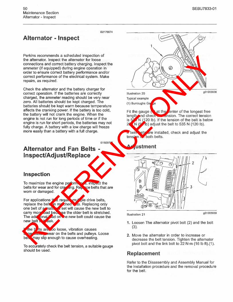
REFERENCE ONLY
50 Maintenance Section Alternator - Inspect
Alternator - Inspect i02176674
Perkins recommends a scheduled inspection of the alternator. Inspect the alternator for loose connections and correct battery charging. Inspect the ammeter (if equipped) during engine operation in order to ensure correct battery performance and/or correct performance of the electrical system. Make repairs, as required.
Check the alternator and the battery charger for correct operation. If the batteries are correctly charged, the ammeter reading should be very near zero. All batteries should be kept charged. The batteries should be kept warm because temperature affects the cranking power. If the battery is too cold, the battery will not crank the engine. When the engine is not run for long periods of time or if the engine is run for short periods, the batteries may not fully charge. A battery with a low charge will freeze more easily than a battery with a full charge.
Alternator and Fan Belts -Inspect/Adjust/Replace
Inspection
i01929797
To maximize the engine performance, inspect the belts for wear and for cracking. Replace belts that are worn or damaged.
For applications that require multiple drive belts, replace the belts in matched sets. Replacing only one belt of a matched set will cause the new belt to carry more load because the older belt is stretched. The additional load on the new belt could cause the new belt to break.
If the belts are too loose, vibration causes unnecessary wear on the belts and pulleys. Loose belts may slip enough to cause overheating.
To accurately check the belt tension, a suitable gauge should be used.
Illustration 20
Typical example
(1) Burroughs Gauge
SEBU7833-01
901003936
Fit the gauge (1) at the center of the longest free length and check the tension. The correct tension is 535 N (120 Ib). If the tension of the belt is below 250 N (56 Ib) adjust the belt to 535 N (120 Ib).
If twin belts are installed , check and adjust the tension on both belts.
Adjustment
Illustration 21 901003939
1. Loosen The alternator pivot bolt (2) and the bolt (3).
2. Move the alternator in order to increase or decrease the belt tension. Tighten the alternator pivot bolt and the link bolt to 22 N·m (161b ft).(1).
Replacement
Refer to the Disassembly and Assembly Manual for the installation procedure and the removal procedure for the belt.
REFERENCE ONLY
SEBU7833·01
i02150857
Battery - Replace
A WARNING
Batteries give off combustible gases which can explode. A spark can cause the combustible gases to ignite. This can result in severe personal injury or death.
Ensure proper ventilation for batteries that are in an enclosure. Follow the proper procedures in order to help prevent electrical arcs and/or sparks near batteries. Do not smoke when batteries are serviced.
A WARNING
The battery cables or the batteries should not be removed with the battery cover in place. The battery cover should be removed before any servicing is attempted.
Removing the battery cables or the batteries with the cover in place may cause a battery explosion resulting in personal injury.
1. Switch the engine to the OFF position. Remove all electrical loads.
2. Turn off any battery chargers. Disconnect any battery chargers.
3. The NEGATIVE "." cable connects the NEGATIVE "." battery terminal to the NEGATIVE "." terminal on the starting motor. Disconnect the cable from the NEGATIVE "." battery terminal.
4. The POSITIVE "+" cable connects the POSITIVE "+" battery terminal to the POSITIVE "+" terminal on the starting motor. Disconnect the cable from the POSITIVE "+" battery terminal.
Note: Always recycle a battery. Never discard a battery. Return used batteries to an appropriate recycling facility.
5. Remove the used battery.
6. Install the new battery.
Note: Before the cables are connected, ensure that the engine start switch is OFF.
7. Connect the cable from the starting motor to the POSITIVE "+" battery terminal.
51 Maintenance Section
Battery· Replace
8. Connect the cable from the NEGATIVE "." terminal on the starting motor to the NEGATIVE "." battery terminal.
Battery Electrolyte Level -Check
i02177936
When the engine is not run for long periods of time or when the engine is run for short periods, the batteries may not fully recharge. Ensure a full charge in order to help prevent the battery from freezing. If batteries are correctly charged, ammeter reading should be very near zero.
A WARNING
All lead-acid batteries contain sulfuric acid which can burn the skin and clothing. Always wear a face shield and protective clothing when working on or near batteries.
1. Remove the filler caps. Maintain the electrolyte level to the "FULL" mark on the battery.
If the addition of water is necessary, use distilled water. If distilled water is not available use clean water that is low in minerals. Do not use artificially softened water.
2. Check the condition of the electrolyte with a suitable battery tester.
3. Keep the batteries clean.
Clean the battery case with one of the following cleaning solutions:
• A mixture of 0.1 kg (0.2 Ib) of baking soda and 1 L (1 qt) of clean water
• A mixture of 0.1 L (0.11 qt) of ammonia and 1 L (1 qt) of clean water
Thoroughly rinse the battery case with clean water.
Use a fine grade of sandpaper to clean the terminals and the cable clamps. Clean the items until the surfaces are bright or shiny. DO NOT remove material excessively. Excessive removal of material can cause the clamps to not fit correctly. Coat the clamps and the terminals with a suitable silicone lubricant or petroleum jelly.
REFERENCE ONLY
52 Maintenance Section Battery or Battery Cable - Disconnect
Battery or Battery Cable -Disconnect
A WARNING
i02150865
The battery cables or the batteries should not be removed with the battery cover in place. The battery cover should be removed before any servicing is attempted.
Removing the battery cables or the batteries with the cover in place may cause a battery explosion resulting in personal injury.
1. Turn the start switch to the OFF position. Turn the ignition switch (if equipped) to the OFF position and remove the key and all electrical loads.
2. Disconnect the negative battery terminal at the battery that goes to the start switch. Ensure that the cable cannot contact the terminal. When four 12 volt batteries are involved, the negative side of two batteries must be disconnected.
3. Tape the leads in order to help prevent accidental starting.
4. Proceed with necessary system repairs. Reverse the steps in order to reconnect all of the cables.
i02203590
Cooling System Coolant (Commercial Heavy-Duty) -Change
NOTICE Care must be taken to ensure that fluids are contained during performance of inspection, maintenance, testing, adjusting and repair ofthe product. Be prepared to collect the fluid with suitable containers before opening any compartment or disassembling any component containing fluids.
Dispose of all fluids according to Local regulations and mandates.
SEBU7833-01
NOTICE Keep all parts clean from contaminants.
Contaminants may cause rapid wear and shortened component life.
Clean the cooling system and flush the cooling system before the recommended maintenance interval if the following conditions exist:
• The engine overheats frequently.
• Foaming is observed.
• The oil has entered the cooling system and the coolant is contaminated.
• The fuel has entered the cooling system and the coolant is contaminated.
Note: When the cooling system is cleaned, only clean water is needed.
Note: Inspect the water pump and the water temperature regulator after the cooling system has been drained. This is a good opportunity to replace the water pump, the water temperature regulator and the hoses, if necessary.
Drain
A WARNING
Pressurized System: Hot coolant can cause serious burns. To open the cooling system filler cap, stop the engine and wait until the cooling system components are cool. Loosen the cooling system pressure cap slowly in order to relieve the pressure.
1. Stop the engine and allow the engine to cool. Loosen the cooling system filler cap slowly in order to relieve any pressure. Remove the cooling system filler cap.
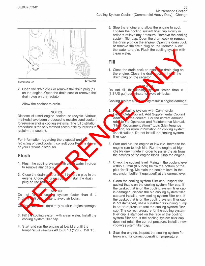
REFERENCE ONLY
SEBU7833-01
u
Illustration 22 g01003928
2. Open the drain cock or remove the drain plug (1) on the engine. Open the drain cock or remove the drain plug on the radiator.
Allow the coolant to drain.
NOTICE Dispose of used engine coolant or recycle. Various methods have been proposed to reclaim used coolant for reuse in engine cooling systems. The full distillation procedure is the only method acceptable by Perkins to reclaim the coolant.
For information regarding the disposal and the recycling of used coolant, consult your Perkins dealer or your Perkins distributor.
Flush
1. Flush the cooling system with clean water in order to remove any debris.
2. Close the drain cock or install the drain plug in the engine. Close the drain cock or install the drain plug on the radiator.
NOTICE Do not fill the cooling system faster than 5 L (1.3 US gal) per minute to avoid air locks.
Cooling system air locks may result in engine damage.
3. Fill the cooling system with clean water. Install the cooling system filler cap.
4. Start and run the engine at low idle until the temperature reaches 49 to 66°C (120 to 150 OF).
53 Maintenance Section
Cooling System Coolant (Commercial Heavy-Duty) - Change
5. Stop the engine and allow the engine to cool. Loosen the cooling system filler cap slowly in order to relieve any pressure. Remove the cooling system filler cap. Open the drain cock or remove the drain plug on the engine. Open the drain cock or remove the drain plug on the radiator. Allow the water to drain. Flush the cooling system with clean water.
Fill
1. Close the drain cock or install the drain plug on the engine. Close the drain cock or install the drain plug on the radiator.
NOTICE Do not fill the cooling system faster than 5 L (1.3 US gal) per minute to avoid air locks.
Cooling system air locks may result in engine damage.
2. Fill the cooling system with Commercial Heavy-Duty Coolant. Add Supplemental Coolant Additive to the coolant. For the correct amount, refer to the Operation and Maintenance Manual, "Fluid Recommendations" topic (Maintenance Section) for more information on cooling system specifications. Do not install the cooling system filler cap.
3. Start and run the engine at low idle. Increase the engine rpm to high idle. Run the engine at high idle for one minute in order to purge the air from the cavities of the engine block. Stop the engine.
4. Check the coolant level. Maintain the coolant level within 13 mm (0.5 inch) below the bottom of the pipe for filling. Maintain the coolant level in the expansion bottle (if equipped) at the correct level.
5. Clean the cooling system filler cap. Inspect the gasket that is on the cooling system filler cap. If the gasket that is on the cooling system filler cap is damaged, discard the old cooling system filler cap and install a new cooling system filler cap. If the gasket that is on the cooling system filler cap is not damaged, use a suitable pressurizing pump in order to pressure test the cooling system filler cap. The correct pressure for the cooling system filler cap is stamped on the face of the cooling system filler cap. If the cooling system filler cap does not retain the correct pressure, install a new cooling system filler cap.
6. Start the engine. Inspect the cooling system for leaks and for correct operating temperature.
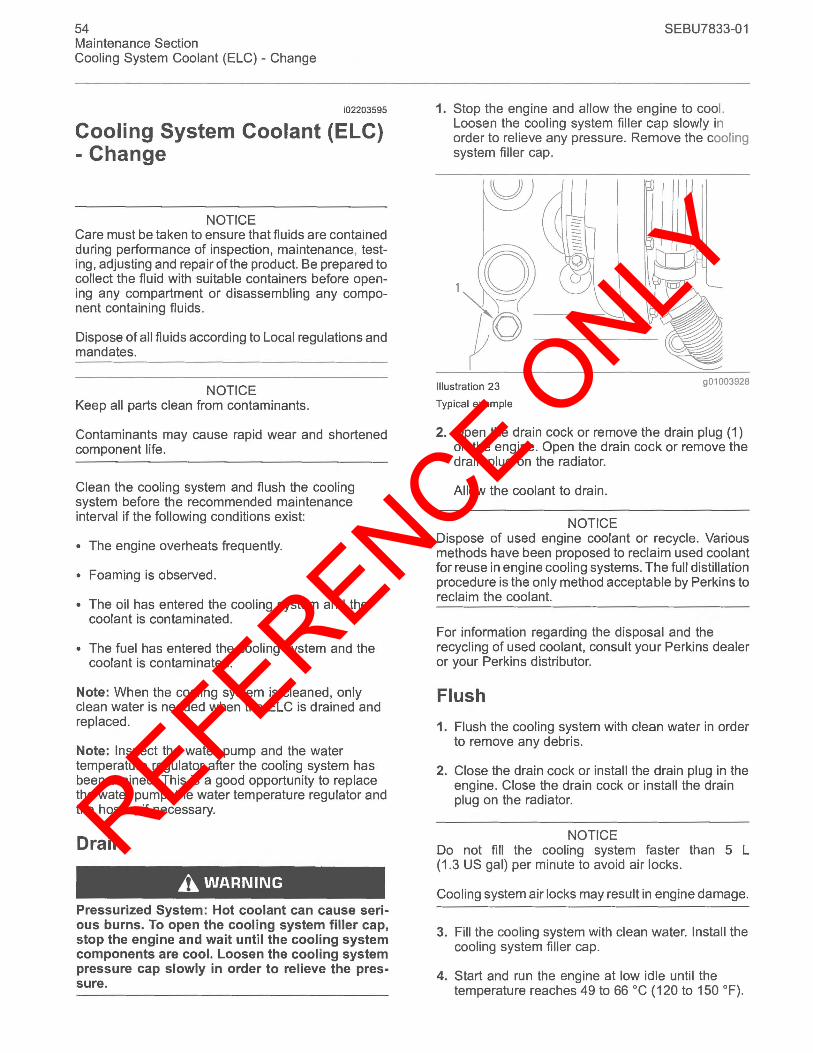
REFERENCE ONLY
54 Maintenance Section Cooling System Coolant (ELC) - Change
i02203595
Cooling System Coolant (ELC) - Change
NOTICE Care must be taken to ensure that fluids are contained during performance of inspection, maintenance, testing, adjusting and repair ofthe product. Be prepared to collect the fluid with suitable containers before opening any compartment or disassembling any component containing fluids.
Dispose of all fluids according to Local regulations and mandates.
NOTICE Keep all parts clean from contaminants.
Contaminants may cause rapid wear and shortened component life.
Clean the cooling system and flush the cooling system before the recommended maintenance interval if the following conditions exist:
• The engine overheats frequently.
• Foaming is observed.
• The oil has entered the cooling system and the coolant is contaminated.
• The fuel has entered the cooling system and the coolant is contaminated.
Note: When the cooling system is cleaned, only clean water is needed when the ELC is drained and replaced .
Note: Inspect the water pump and the water temperature regulator after the cooling system has been drained. This is a good opportunity to replace the water pump, the water temperature regulator and the hoses, if necessary.
Drain
A WARNING
Pressurized System: Hot coolant can cause serious burns. To open the cooling system filler cap, stop the engine and wait until the COOling system components are cool. Loosen the cooling system pressure cap slowly in order to relieve the pressure.
SEBU7833-01
1. Stop the engine and allow the engine to cool. Loosen the cooling system filler cap slowly in order to relieve any pressure. Remove the cooling system filler cap.
Illustration 23
Typical example
901003928
2. Open the drain cock or remove the drain plug (1) on the engine. Open the drain cock or remove the drain plug on the radiator.
Allow the coolant to drain.
NOTICE Dispose of used engine coolant or recycle. Various methods have been proposed to reclaim used coolant for reuse in engine cooling systems. The full distillation procedure is the only method acceptable by Perkins to reclaim the coolant.
For information regarding the disposal and the recycling of used coolant, consult your Perkins dealer or your Perkins distributor.
Flush
1. Flush the cooling system with clean water in order to remove any debris.
2. Close the drain cock or install the drain plug in the engine. Close the drain cock or install the drain plug on the radiator.
NOTICE Do not fill the cooling system faster than 5 L (1.3 US gal) per minute to avoid air locks.
Cooling system air locks may result in engine damage.
3. Fill the cooling system with clean water. Install the cooling system filler cap.
4. Start and run the engine at low idle until the temperature reaches 49 to 66°C (120 to 150 OF).
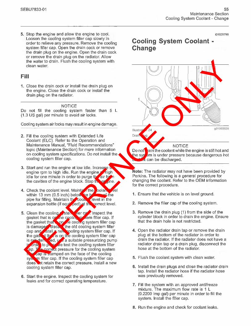
REFERENCE ONLY
SEBU7833-01
5. Stop the engine and allow the engine to cool. Loosen the cooling system filler cap slowly in order to relieve any pressure. Remove the cooling system filler cap. Open the drain cock or remove the drain plug on the engine. Open the drain cock or remove the drain plug on the radiator. Allow the water to drain. Flush the cooling system with clean water.
Fill
1. Close the drain cock or install the drain plug on the engine. Close the drain cock or install the drain plug on the radiator.
NOTICE Do not fill the cooling system faster than 5 L (1.3 US gal) per minute to avoid air locks.
Cooling system air locks may result in engine damage.
2. Fill the cooling system with Extended Life Coolant (ELC). Refer to the Operation and Maintenance Manual, "Fluid Recommendations" topic (Maintenance Section) for more information on cooling system specifications. Do not install the cooling system filler cap.
3. Start and run the engine at low idle. Increase the engine rpm to high idle. Run the engine at high idle for one minute in order to purge the air from the cavities of the engine block. Stop the engine.
4. Check the coolant level. Maintain the coolant level within 13 mm (0.5 inch) below the bottom of the pipe for filling. Maintain the coolant level in the expansion bottle (if equipped) at the correct level.
5. Clean the cooling system filler cap. Inspect the gasket that is on the cooling system filler cap. If the gasket that is on the cooling system filler cap is damaged, discard the old cooling system filler cap and install a new cooling system filler cap. If the gasket that is on the cooling system filler cap is not damaged, use a suitable pressurizing pump in order to pressure test the cooling system filler cap. The correct pressure for the cooling system filler cap is stamped on the face of the cooling system filler cap. If the cooling system filler cap does not retain the correct pressure, install a new cooling system filler cap.
6. Start the engine. Inspect the cooling system for leaks and for correct operating temperature.
55 Maintenance Section
Cooling System Coolant - Change
Cooling System Coolant -Change
i01929799
Illustration 24
Drain plug
901003928
NOTICE Do not drain the coolant while the engine is still hot and the system is under pressure because dangerous hot coolant can be discharged.
Note: The radiator may not have been provided by Perkins. The following is a general procedure for changing the coolant. Refer to the OEM information for the correct procedure.
1. Ensure that the vehicle is on level ground.
2. Remove the filler cap of the cooling system.
3. Remove the drain plug (1) from the side of the cylinder block in order to drain the engine. Ensure that the drain hole is not restricted.
4. Open the radiator drain tap or remove the drain plug at the bottom of the radiator in order to drain the radiator. If the radiator does not have a radiator drain tap or a drain plug, disconnect the hose at the bottom of the radiator.
5. Flush the coolant system with clean water.
6. Install the drain plugs and close the radiator drain tap. Install the radiator hose if the radiator hose was previously removed.
7. Fill the system with an approved antifreeze mixture. The maximum flow rate is 1 L (0.2200 Imp gal) per minute in order to fill the system. Install the filler cap.
8. Run the engine and check for coolant leaks.
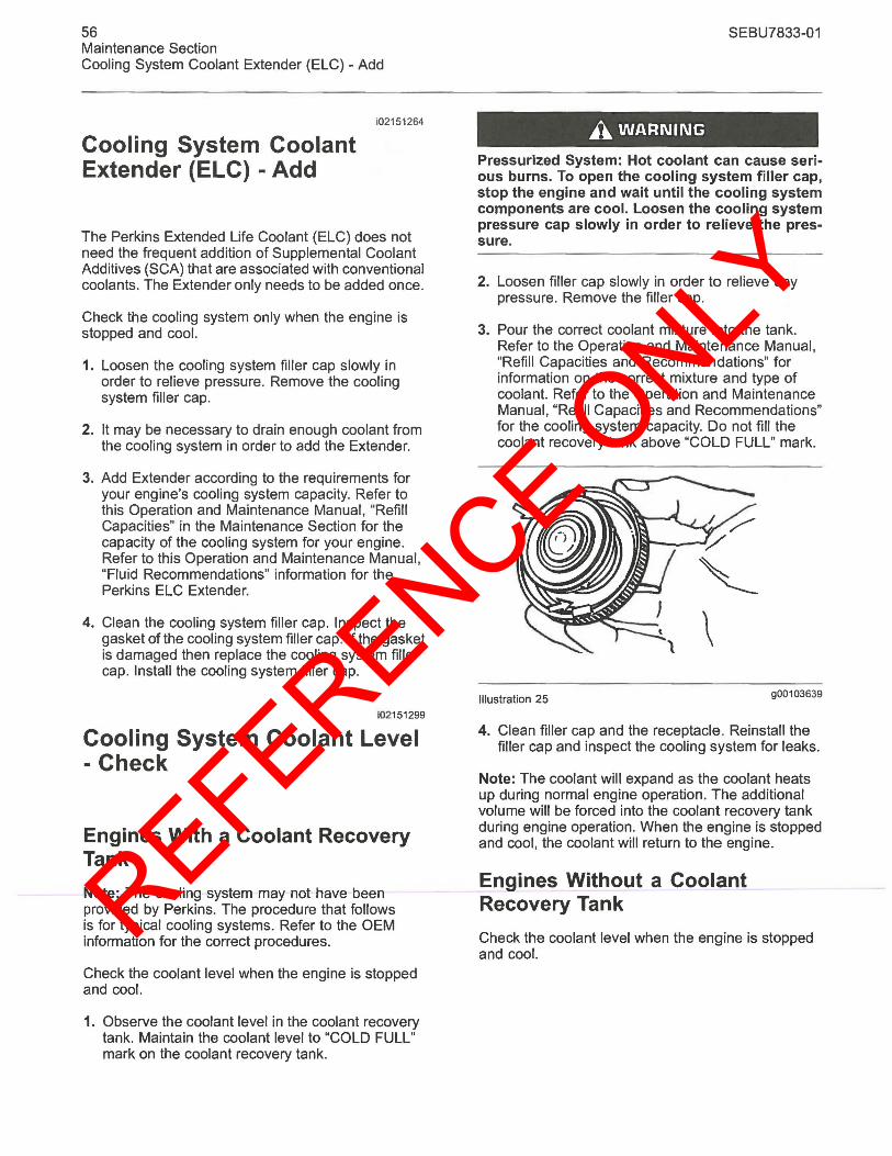
REFERENCE ONLY
56 Maintenance Section Cooling System Coolant Extender (ELC) - Add
Cooling System Coolant Extender (ELC) - Add
i02151264
The Perkins Extended Life Coolant (ELC) does not need the frequent addition of Supplemental Coolant Additives (SCA) that are associated with conventional coolants. The Extender only needs to be added once.
Check the cooling system only when the engine is stopped and cool.
1. Loosen the cooling system filler cap slowly in order to relieve pressure. Remove the cooling system filler cap.
2. It may be necessary to drain enough coolant from the cooling system in order to add the Extender.
3. Add Extender according to the requirements for your engine's cooling system capacity. Refer to this Operation and Maintenance Manual, "Refill Capacities" in the Maintenance Section for the capacity of the cooling system for your engine. Refer to this Operation and Maintenance Manual, "Fluid Recommendations" information for the Perkins ELC Extender.
4. Clean the cooling system filler cap. Inspect the gasket of the cooling system filler cap. If the gasket is damaged then replace the cooling system filler cap. Install the cooling system filler cap.
i02151299
Cooling System Coolant Level - Check
Engines With a Coolant Recovery Tank
Note: The cooling system may not have been provided by Perkins. The procedure that follows is for typical cooling systems. Refer to the OEM information for the correct procedures.
Check the coolant level when the engine is stopped and cool.
1. Observe the coolant level in the coolant recovery tank. Maintain the coolant level to "COLD FULL" mark on the coolant recovery tank.
SEBU7833-01
A WARNING
Pressurized System: Hot coolant can cause serious burns. To open the cooling system filler cap, stop the engine and wait until the cooling system components are cool. Loosen the cooling system pressure cap slowly in order to relieve the pressure.
2. Loosen filler cap slowly in order to relieve any pressure. Remove the filler cap.
3. Pour the correct coolant mixture into the tank. Refer to the Operation and Maintenance Manual, "Refill Capacities and Recommendations" for information on the correct mixture and type of coolant. Refer to the Operation and Maintenance Manual, "Refill Capacities and Recommendations" for the cooling system capacity. Do not fill the coolant recovery tank above "COLD FULL" mark.
Illustration 25 900103639
4. Clean filler cap and the receptacle. Reinstall the filler cap and inspect the cooling system for leaks.
Note: The coolant will expand as the coolant heats up during normal engine operation. The additional volume will be forced into the coolant recovery tank during engine operation. When the engine is stopped and cool, the coolant will return to the engine.
Engines Without a Coolant Recovery Tank
Check the coolant level when the engine is stopped and cool.
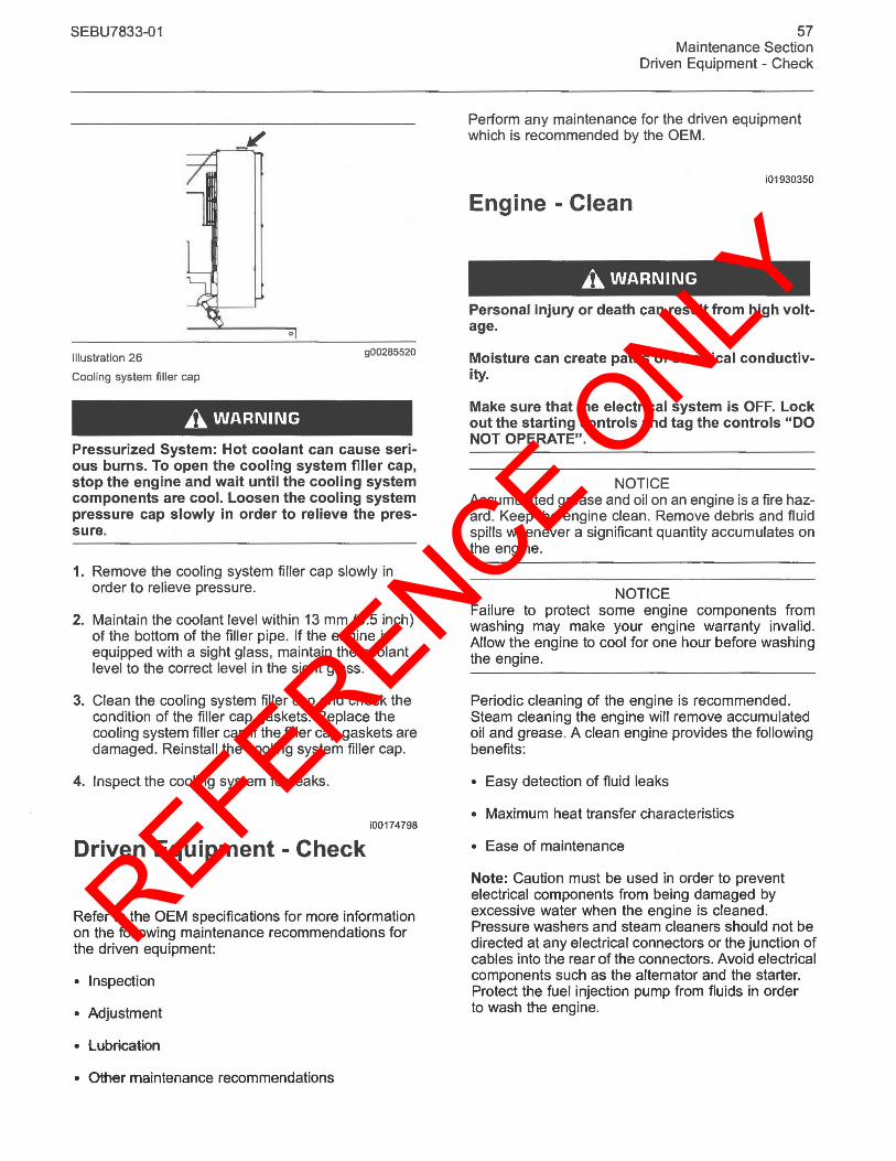
REFERENCE ONLY
SEBU7833-01
Illustration 26 g00285520
Cooling system filler cap
A WARNING
Pressurized System: Hot coolant can cause serious burns. To open the cooling system filler cap, stop the engine and wait until the COOling system components are cool. Loosen the COOling system pressure cap slowly in order to relieve the pressure.
1. Remove the cooling system filler cap slowly in order to relieve pressure.
2. Maintain the coolant level within 13 mm (0.5 inch) of the bottom of the filler pipe. If the engine is equipped with a sight glass, maintain the coolant level to the correct level in the sight glass.
3. Clean the cooling system filler cap and check the condition of the filler cap gaskets. Replace the cooling system filler cap if the filler cap gaskets are damaged. Reinstall the cooling system filler cap.
4. Inspect the cooling system for leaks.
i00174798
Driven Equipment - Check
Refer to the OEM specifications for more information on the following maintenance recommendations for the driven equipment:
• Inspection
• Adjustment
• lubrication
• Other maintenance recommendations
57 Maintenance Section
Driven Equipment - Check
Perform any maintenance for the driven equipment which is recommended by the OEM.
i01930350
Engine - Clean
A WARNING
Personal injury or death can result from high voltage.
Moisture can create paths of electrical conductivity.
Make sure that the electrical system is OFF. Lock out the starting controls and tag the controls "DO NOT OPERATE".
NOTICE Accumulated grease and oil on an engine is a fire hazard. Keep the engine clean. Remove debris and fluid spills whenever a significant quantity accumulates on the engine.
NOTICE Failure to protect some engine components from washing may make your engine warranty invalid. Allow the engine to cool for one hour before washing the engine.
Periodic cleaning of the engine is recommended. Steam cleaning the engine will remove accumulated oil and grease. A clean engine provides the following benefits:
• Easy detection of fluid leaks
• Maximum heat transfer characteristics
• Ease of maintenance
Note: Caution must be used in order to prevent electrical components from being damaged by excessive water when the engine is cleaned. Pressure washers and steam cleaners should not be directed at any electrical connectors or the junction of cables into the rear of the connectors. Avoid electrical components such as the alternator and the starter. Protect the fuel injection pump from fluids in order to wash the engine.
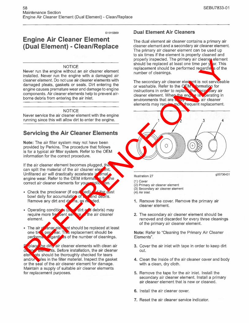
REFERENCE ONLY
58 Maintenance Section Engine Air Cleaner Element (Dual Element) - Clean/Replace
i01915869
Engine Air Cleaner Element (Dual Element) - Clean/Replace
NOTICE Never run the engine without an air cleaner element installed. Never run the engine with a damaged air cleaner element. Do not use air cleaner elements with damaged pleats, gaskets or seals. Dirt entering the engine causes premature wear and damage to engine components. Air cleaner elements help to prevent airborne debris from entering the air inlet.
NOTICE Never service the air cleaner element with the engine running since this will allow dirt to enter the engine.
Servicing the Air Cleaner Elements
Note: The air filter system may not have been provided by Perkins. The procedure that follows is for a typical air filter system. Refer to the OEM information for the correct procedure.
If the air cleaner element becomes plugged, the air can split the material of the air cleaner element. Unfiltered air will drastically accelerate internal engine wear. Refer to the OEM information for the correct air cleaner elements for your application.
• Check the precleaner (if equipped) and the dust bowl daily for accumulation of dirt and debris. Remove any dirt and debris, as needed.
• Operating conditions (dust, dirt and debris) may require more frequent service of the air cleaner element.
• The air cleaner element should be replaced at least one time per year. This replacement should be performed regardless of the number of cleanings.
Replace the dirty air cleaner elements with clean air cleaner elements. Before installation, the air cleaner elements should be thoroughly checked for tears and/or holes in the filter material. Inspect the gasket or the seal of the air cleaner element for damage. Maintain a supply of suitable air cleaner elements for replacement purposes.
SEBU7833-01
Dual Element Air Cleaners
The dual element air cleaner contains a primary air cleaner element and a secondary air cleaner element. The primary air cleaner element can be used up to six times if the element is properly cleaned and properly inspected. The primary air cleaner element should be replaced at least one time per year. This replacement should be performed regardless of the number of cleanings.
The secondary air cleaner element is not serviceable or washable. Refer to the OEM information for instructions in order to replace the secondary air cleaner element. When the engine is operating in environments that are dusty or dirty, air cleaner elements may require more frequent replacement.
Illustration 27
(1) Cover (2) Primary air cleaner element (3) Secondary air cleaner element (4) Air inlet
900736431
1. Remove the cover. Remove the primary air cleaner element.
2. The secondary air cleaner element should be removed and discarded for every three cleanings of the primary air cleaner element.
Note: Refer to "Cleaning the Primary Air Cleaner Elements".
3. Cover the air inlet with tape in order to keep dirt out.
4. Clean the inside of the air cleaner cover and body with a clean, dry cloth.
5. Remove the tape for the air inlet. Install the secondary air cleaner element. Install a primary air cleaner element that is new or cleaned.
6. Install the air cleaner cover.
7. Reset the air cleaner service indicator.
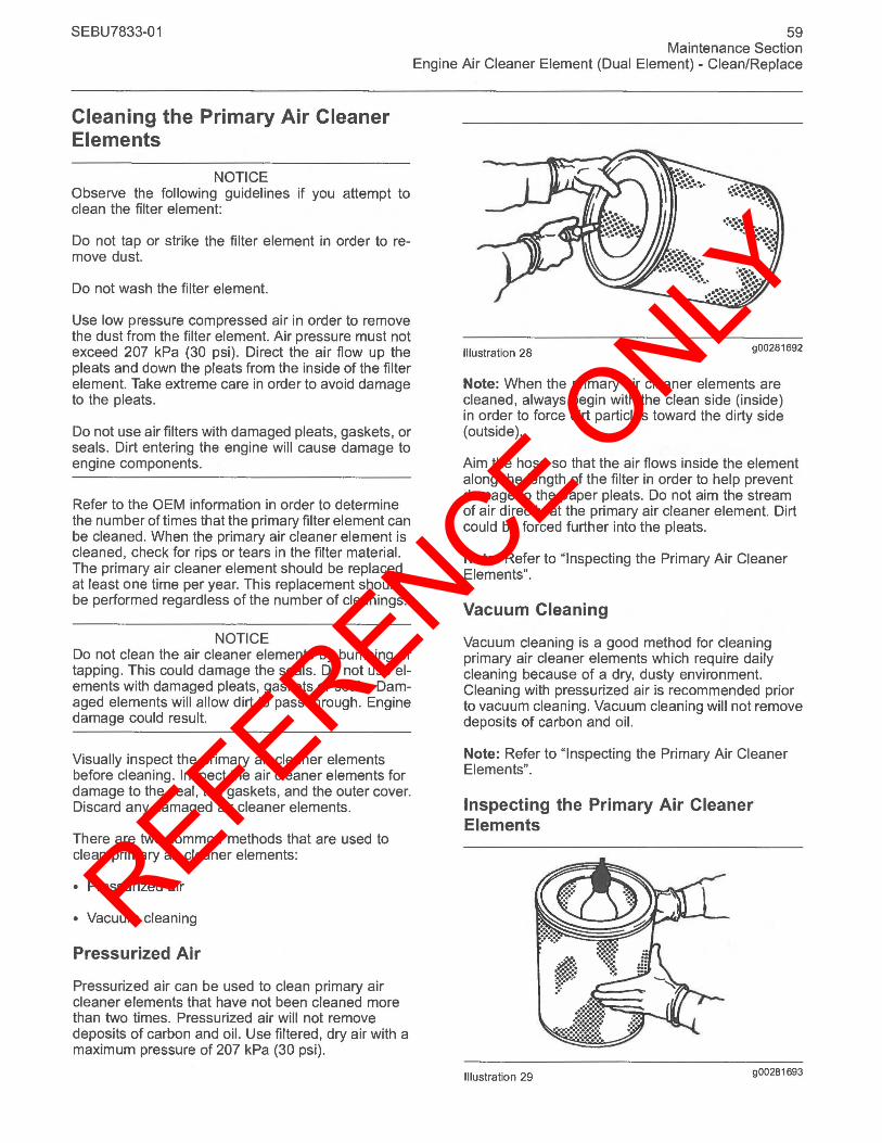
REFERENCE ONLY
SEBU7833-01
Cleaning the Primary Air Cleaner Elements
NOTICE Observe the following guidelines if you attempt to clean the filter element:
Do not tap or strike the filter element in order to remove dust.
Do not wash the filter element.
Use low pressure compressed air in order to remove the dust from the filter element. Air pressure must not exceed 207 kPa (30 psi). Direct the air flow up the pleats and down the pleats from the inside of the filter element. Take extreme care in order to avoid damage to the pleats.
Do not use air filters with damaged pleats, gaskets, or seals. Dirt entering the engine will cause damage to engine components.
Refer to the OEM information in order to determine the number of times that the primary filter element can be cleaned. When the primary air cleaner element is cleaned, check for rips or tears in the filter material. The primary air cleaner element should be replaced at least one time per year. This replacement should be performed regardless of the number of cleanings.
NOTICE Do not clean the air cleaner elements by bumping or tapping. This could damage the seals. Do not use elements with damaged pleats, gaskets or seals. Damaged elements will allow dirt to pass through. Engine damage could result.
Visually inspect the primary air cleaner elements before cleaning. Inspect the air cleaner elements for damage to the seal, the gaskets, and the outer cover. Discard any damaged air cleaner elements.
There are two common methods that are used to clean primary air cleaner elements:
• Pressurized air
• Vacuum cleaning
Pressurized Air
Pressurized air can be used to clean primary air cleaner elements that have not been cleaned more than two times. Pressurized air will not remove deposits of carbon and oil. Use filtered, dry air with a maximum pressure of 207 kPa (30 psi).
59 Maintenance Section
Engine Air Cleaner Element (Dual Element) - Clean/Replace
Illustration 28 900281692
Note: When the primary air cleaner elements are cleaned, always begin with the clean side (inside) in order to force dirt particles toward the dirty side (outside).
Aim the hose so that the air flows inside the element along the length of the filter in order to help prevent damage to the paper pleats. Do not aim the stream of air directly at the primary air cleaner element. Dirt could be forced further into the pleats.
Note: Refer to "Inspecting the Primary Air Cleaner Elements".
Vacuum Cleaning
Vacuum cleaning is a good method for cleaning primary air cleaner elements which require daily cleaning because of a dry, dusty environment. Cleaning with pressurized air is recommended prior to vacuum cleaning. Vacuum cleaning will not remove deposits of carbon and oil.
Note: Refer to "Inspecting the Primary Air Cleaner Elements".
Inspecting the Primary Air Cleaner Elements
Illustration 29 900281693
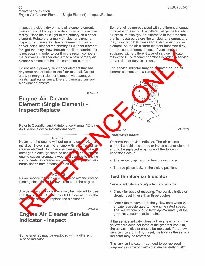
REFERENCE ONLY
60 SEBU7833-01 Maintenance Section Engine Air Cleaner Element (Single Element) - Inspect/Replace
Inspect the clean, dry primary air cleaner element. Use a 60 watt blue light in a dark room or in a similar facility. Place the blue light in the primary air cleaner element. Rotate the primary air cleaner element. Inspect the primary air cleaner element for tears and/or holes. Inspect the primary air cleaner element for light that may show through the filter material. If it is necessary in order to confirm the result, compare the primary air cleaner element to a new primary air cleaner element that has the same part number.
Do not use a primary air cleaner element that has any tears and/or holes in the filter material. Do not use a primary air cleaner element with damaged pleats, gaskets or seals. Discard damaged primary air cleaner elements.
i02152042
Engine Air Cleaner Element (Single Element) -Inspect/Replace
Refer to Operation and Maintenance Manual, "Engine Air Cleaner Service Indicator-Inspect".
NOTICE Never run the engine without an air cleaner element installed. Never run the engine with a damaged air cleaner element. Do not use air cleaner elements with damaged pleats, gaskets or seals. Dirt entering the engine causes premature wear and damage to engine components. Air cleaner elements help to prevent airborne debris from entering the air inlet.
NOTICE Never service the air cleaner element with the engine running since this will allow dirt to enter the engine.
A wide variety of air cleaners may be installed for use with this engine. Consult the OEM information for the correct procedure to replace the air cleaner.
i01909507
Engine Air Cleaner Service Indicator - Inspect
Some engines may be equipped with a different service indicator.
Some engines are equipped with a differential gauge for inlet air pressure. The differential gauge for inlet air pressure displays the difference in the pressure that is measured before the air cleaner element and the pressure that is measured after the air cleaner element. As the air cleaner element becomes dirty, the pressure differential rises. If your engine is equipped with a different type of service indicator, follow the OEM recommendations in order to service the air cleaner service indicator.
The service indicator may be mounted on the air cleaner element or in a remote location.
Illustration 30
Typical service indicator
30 25 20 15
900103777
Observe the service indicator. The air cleaner element should be cleaned or the air cleaner element should be replaced when one of the following conditions occur:
• The yellow diaphragm enters the red zone.
• The red piston locks in the visible position.
Test the Service Indicator
Service indicators are important instruments.
• Check for ease of resetting. The service indicator should reset in less than three pushes.
• Check the movement of the yellow core when the engine is accelerated to the engine rated speed. The yellow core should latch approximately at the greatest vacuum that is attained.
If the service indicator does not reset easily, or if the yellow core does not latch at the greatest vacuum, the service indicator should be replaced. If the new service indicator will not reset, the hole for the service indicator may be restricted .
The service indicator may need to be replaced frequently in environments that are severely dusty.
REFERENCE ONLY
SEBU7833-01
i01941505
Engine Ground - Inspect/Clean
Inspect the wiring harness for good connections.
Perkins use the starter motor in order to ground the engine. Check the connection on the starter motor at every oil change. Ground wires and straps should be combined at engine grounds. All grounds should be tight and free of corrosion.
• Clean the grounding stud on the starter motor and the terminals with a clean cloth.
• If the connections are corroded, clean the connections with a solution of baking soda and water.
• Keep the grounding stud and the strap clean and coated with suitable grease or petroleum jelly.
i02177938
Engine Mounts - Inspect
Note: The engine mounts may not have been supplied for this installation by Perkins. Refer to the OEM information for further information on the engine mounts and the correct bolt torque.
Inspect the engine mounts for deterioration and for correct bolt torque. Engine vibration can be caused by the following conditions:
• Incorrect mounting of the engine
• Deterioration of the engine mounts
Any engine mount that shows deterioration should be replaced. Refer to the OEM information for the recommended torques.
i01907673
Engine Oil Level - Check
A WARNING
Hot oil and hot components can cause personal injury. Do not allow hot oil or hot components to contact the skin.
Illustration 31
61 Maintenance Section
Engine Ground - InspecUClean
g00998024
(Y) "ADD" mark. (X) "FULL" mark.
NOTICE Perform this maintenance with the engine stopped.
Note: Ensure that the engine is either level or that the engine is in the normal operating position in order to obtain a true level indication.
Note: After the engine has been switched OFF, allow the engine oil to drain to the oil pan before checking the oil level.
1. Maintain the oil level between the "ADD" mark (Y) and the "FULL" mark (X) on the engine oil dipstick. Do not fill the crankcase above the "FULL" mark (X).
NOTICE Operating your engine when the oil level is above the "FULL" mark could cause your crankshaft to dip into the oil. The air bubbles created from the crankshaft dipping into the oil reduces the oil's lubricating characteristics and could result in the loss of power.
2. Remove the oil filler cap and add oil, if necessary. Clean the oil filler cap. Install the oil filler cap.
i02202699
Engine Oil Sample - Obtain
The condition of the engine lubricating oil may be checked at regular intervals as part of a preventive maintenance program. Perkins include an oil sampling valve as an option. The oil sampling valve (if equipped) is included in order to regularly sample the engine lubricating oil. The oil sampling valve is positioned on the oil filter head or the oil sampling valve is positioned on the cylinder block.
Perkins recommends using a sampling valve in order to obtain oil samples. The quality and the consistency of the samples are better when a sampling valve is used. The location of the sampling valve allows oil that is flowing under pressure to be obtained during normal engine operation.
REFERENCE ONLY
62 Maintenance Section Engine Oil and Filter - Change
Obtain the Sample and the Analysis
A WARNING
Hot oil and hot components can cause personal injury. Do not allow hot oil or hot components to contact the skin.
In order to help obtain the most accurate analysis, record the following information before an oil sample is taken:
• The date of the sample
• Engine model
• Engine number
• Service hours on the engine
• The number of hours that have accumulated since the last oil change
• The amount of oil that has been added since the last oil change
Ensure that the container for the sample is clean and dry. Also ensure that the container for the sample is clearly labelled.
To ensure that the sample is representative of the oil in the crankcase, obtain a warm, well mixed oil sample.
To avoid contamination of the oil samples, the tools and the supplies that are used for obtaining oil samples must be clean.
The sample can be checked for the following : the quality of the oil, the existence of any coolant in the oil , the existence of any ferrous metal particles in the oil, and the existence of any nonferrous metal particles in the oil.
i01929323
Engine Oil and Filter - Change
A WARNING
Hot oil and hot components can cause personal injury. Do not allow hot oil or hot components to contact the skin.
SEBU7833-01
Do not drain the oil when the engine is cold. As the oil cools, suspended waste particles settle on the bottom of the oil pan. The waste particles are not removed with the draining cold oil. Drain the crankcase with the engine stopped . Drain the crankcase with the oil warm. This draining method allows the waste particles that are suspended in the oil to be drained properly.
Failure to follow this recommended procedure will cause the waste particles to be recirculated through the engine lubrication system with the new oil.
Drain the Engine Oil
---1~ \ (
---.------.--1 ~==::::,'S(@~r---=::: @C
Illustration 32
Oil drain plug
901003623
After the engine has been run at the normal operating temperature, stop the engine. Use one of the following methods to drain the engine crankcase oil:
• If the engine is equipped with a drain valve, turn the drain valve knob counterclockwise in order to drain the oil. After the oil has drained, turn the drain valve knob clockwise in order to close the drain valve.
• If the engine is not equipped with a drain valve, remove the oil drain plug (1) in order to allow the oil to drain. If the engine is equipped with a shallow sump, remove the bottom oil drain plugs from both ends of the oil pan.
After the oil has drained, the oil drain plugs should be cleaned and installed. If necessary, renew the 0 ring seal on the drain plug.
Some types of oil pans have oil drain plugs that are on both sides of the oil pan, because of the shape of the pan. This type of oil pan requires the engine oil to be drained from both plugs.
REFERENCE ONLY
SEBU7833-01
Replace the Spin-on Oil Filter
NOTICE Perkins oil filters are manufactured to Perkins specifications. Use of an oil filter that is not recommended by Perkins could result in severe damage to the engine bearings, crankshaft, etc., as a result of the larger waste particles from unfiltered oil entering the engine lubricating system. Only use oil filters recommended by Perkins.
1. Remove the oil filter with a suitable tool.
Note: The following actions can be carried out as part of the preventive maintenance program.
2. Cut the oil filter open with a suitable tool. Break apart the pleats and inspect the oil filter for metal debris. An excessive amount of metal debris in the oil filter may indicate early wear or a pending failure.
Use a magnet to differentiate between the ferrous metals and the nonferrous metals that are found in the oil filter element. Ferrous metals may indicate wear on the steel and cast iron parts of the engine.
Nonferrous metals may indicate wear on the aluminum parts, brass parts or bronze parts of the engine. Parts that may be affected include the following items: main bearings, rod bearings, turbocharger bearings, and cylinder heads.
Due to normal wear and friction, it is not uncommon to find small amounts of debris in the oil filter.
Illustration 33
(2) Filter head (3) 0 ring seal
g01003628
3. Clean the sealing surface of the oil filter head (2). Ensure that the union (not shown) in the oil filter head is secure.
4. Apply clean engine oil to the 0 ring seal (3) on the oil filter.
63 Maintenance Section
Engine Oil and Filter - Change
NOTICE Do not fill the oil filters with oil before installing them. This oil would not be filtered and could be contaminated. Contaminated oil can cause accelerated wear to engine components.
5. Install the oil filter. Tighten the oil filter by hand according to the instructions that are shown on the oil filter. Do not overtighten the oil filter.
Replace the Element for the Oil Filter
Illustration 34
(1) Drain plug (2) Square hole (3) Filter bowl
g01003662
1. Place a suitable container under the oil filter. Remove the drain plug (1) and the seal, from the oil filter.
2. Locate a suitable wrench into the square hole (2) in order to remove the filter bowl (3).
3. Remove the filter bowl (3) and remove the element from the filter bowl. Clean the filter bowl.
6
5--__ .r::.::--r--.--
Illustration 35
(4) 0 ring seal (5) Element (6) Filter head
g01003675
REFERENCE ONLY
64 Maintenance Section Engine Valve Lash - Inspect/Adjust
4. Install a new 0 ring (4) onto the filter bowl and lubricate the 0 ring with clean engine oil. Install the filter element (5) into the filter bowl.
5. Install the filter bowl into the oil filter head (6). Tighten the filter bowl to the following torque 25 N'm (181b ft).
6. Install a new seal onto the drain plug (1) and install the drain plug into the oil filter. Tighten the drain plug to the following torque 12 N'm (8 Ib ft) .
Note: Some engines may have a horizontally mounted oil filter. This oil filter has a drain plug that is located in the oil filter head.
Fill the Engine Crankcase
1. Remove the oil filler cap. Refer to the Operation and Maintenance Manual for more information on lubricant specifications. Fill the crankcase with the proper amount of oil. Refer to the Operation and Maintenance Manual for more information on refill capacities.
NOTICE If equipped with an auxiliary oil filter system or a remote oil filter system, follow the OEM or filter manufacturer's recommendations. Under filling or overfilling the crankcase with oil can cause engine damage.
NOTICE To prevent crankshaft bearing damage, crank the engine with the fuel OFF. This will fill the oil filters before starting the engine. Do not crank the engine for more than 30 seconds.
2. Start the engine and run the engine at "LOW IDLE" for two minutes. Perform this procedure in order to ensure that the lubrication system has oil and that the oil filters are filled . Inspect the oil filter for oil leaks.
3. Stop the engine and allow the oil to drain back to the sump for a minimum of ten minutes.
Illustration 36 900998024
(Yl "ADD" mark. (Xl "FULL" mark.
4. Remove the oil level gauge in order to check the oil level. Maintain the oil level between the "ADD" and "FULL" marks on the engine oil dipstick.
Engine Valve Lash -Inspect/Adjust
SEBU7833-01
i02171102
This maintenance is recommended by Perkins as part of a lubrication and preventive maintenance schedule in order to help provide maximum engine life.
NOTICE Only qualified service personel should perform this maintenance. Refer to the Service Manual or your authorized Perkins dealer or your Perkins distributor for the complete valve lash adjustment procedure.
Operation of Perkins engines with incorrect valve lash can reduce engine efficiency, and also reduce engine component life.
A WARNING
Ensure that the engine can not be started while this maintenance is being performed. To help prevent possible injury, do not use the starting motor to turn the flywheel.
Hot engine components can cause burns. Allow additional time for the engine to cool before measuring/adjusting valve lash clearance.
Ensure that the engine is stopped before measuring the valve lash. The engine valve lash can be inspected and adjusted when the temperature of the engine is hot or cold .
Refer to Systems Operation/Testing and Adjusting, "Engine Valve Lash - Inspect/Adjust" for more information.
i02198352
Fuel Injector - Test/Change
A WARNING
Fuel leaked or spilled onto hot surfaces or electrical components can cause a fire.
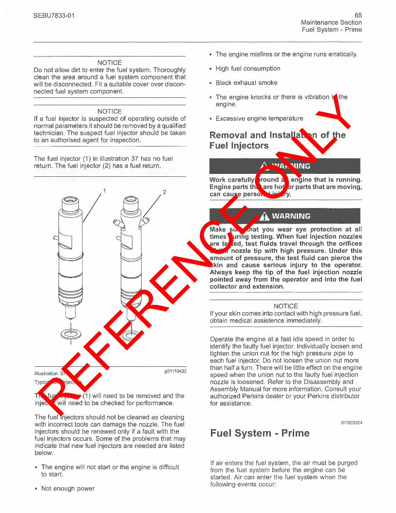
REFERENCE ONLY
SEBU7833-01
NOTICE Do not allow dirt to enter the fuel system. Thoroughly clean the area around a fuel system component that will be disconnected. Fit a suitable cover over disconnected fuel system component.
NOTICE If a fuel injector is suspected of operating outside of normal parameters it should be removed by a qualified technician. The suspect fuel injector should be taken to an authorised agent for inspection.
The fuel injector (1) in illustration 37 has no fuel return. The fuel injector (2) has a fuel return.
© I
Illustration 37
Typical fuel Injectors
© I
90111 0422
The fuel injector (1) will need to be removed and the injector will need to be checked for performance.
The fuel injectors should not be cleaned as cleaning with incorrect tools can damage the nozzle. The fuel injectors should be renewed only if a fault with the fuel injectors occurs. Some of the problems that may indicate that new fuel injectors are needed are listed below:
• The engine will not start or the engine is difficult to start.
• Not enough power
65 Maintenance Section Fuel System - Prime
• The engine misfires or the engine runs erratically.
• High fuel consumption
• Black exhaust smoke
• The engine knocks or there is vibration in the engine.
• Excessive engine temperature
Removal and Installation of the Fuel Injectors
A WARNING
Work carefully around an engine that is running. Engine parts that are hot, or parts that are moving, can cause personal injury.
A WARNING
Make sure that you wear eye protection at all times during testing. When fuel injection nozzles are tested, test fluids travel through the orifices of the nozzle tip with high pressure. Under this amount of pressure, the test fluid can pierce the skin and cause serious injury to the operator. Always keep the tip of the fuel injection nozzle pointed away from the operator and into the fuel collector and extension.
NOTICE If your skin comes into contact with high pressure fuel, obtain medical assistence immediately.
Operate the engine at a fast idle speed in order to identify the faulty fuel injector. Individually loosen and tighten the union nut for the high pressure pipe to each fuel injector. Do not loosen the union nut more than half a turn. There will be little effect on the engine speed when the union nut to the faulty fuel injection nozzle is loosened. Refer to the Disassembly and Assembly Manual for more information. Consult your authorized Perkins dealer or your Perkins distributor for assistance.
i01929324
Fuel System - Prime
If air enters the fuel system, the air must be purged from the fuel system before the engine can be started. Air can enter the fuel system when the following events occur:
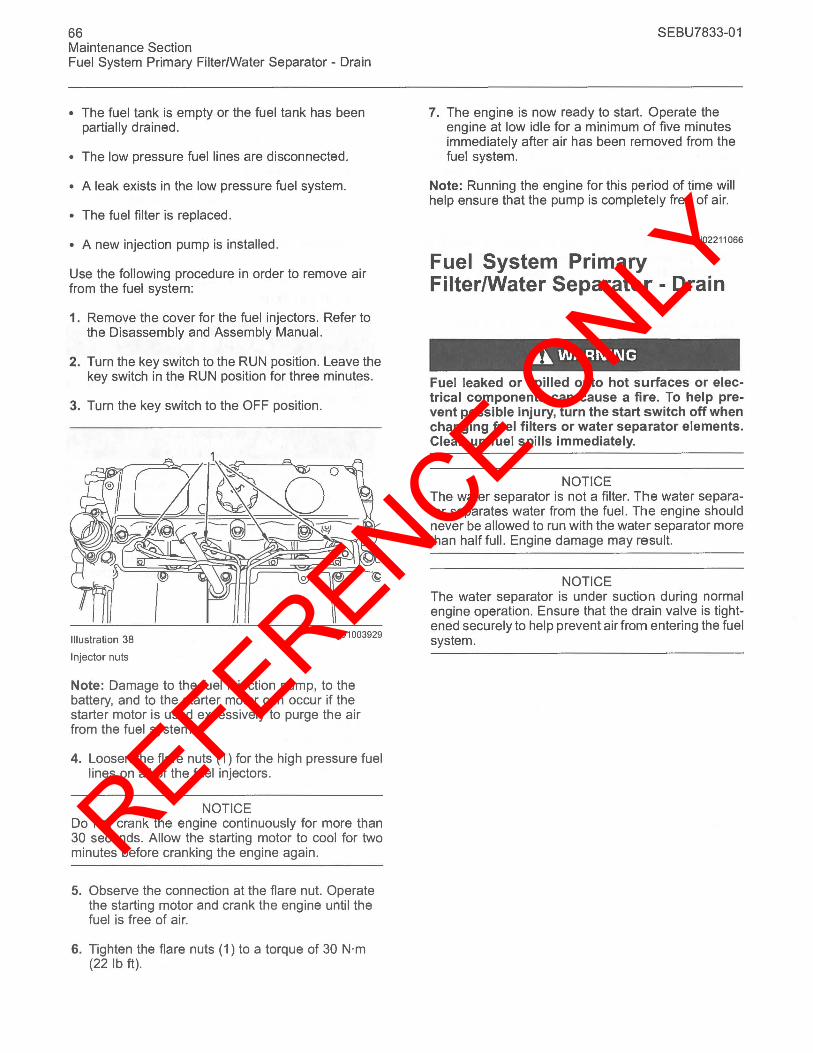
REFERENCE ONLY
66 Maintenance Section Fuel System Primary Filter/Water Separator - Drain
• The fuel tank is empty or the fuel tank has been partially drained.
• The low pressure fuel lines are disconnected.
• A leak exists in the low pressure fuel system.
• The fuel filter is replaced.
• A new injection pump is installed.
Use the following procedure in order to remove air from the fuel system:
1. Remove the cover for the fuel injectors. Refer to the Disassembly and Assembly Manual.
2. Turn the key switch to the RUN position. Leave the key switch in the RUN position for three minutes.
3. Turn the key switch to the OFF position.
Illustration 38
Injector nuts
901003929
Note: Damage to the fuel injection pump, to the battery, and to the starter motor can occur if the starter motor is used excessively to purge the air from the fuel system.
4. Loosen the flare nuts (1) for the high pressure fuel lines on all of the fuel injectors.
NOTICE Do not crank the engine continuously for more than 30 seconds. Allow the starting motor to cool for two minutes before cranking the engine again.
5. Observe the connection at the flare nut. Operate the starting motor and crank the engine until the fuel is free of air.
6. Tighten the flare nuts (1) to a torque of 30 N·m (22 Ib ft).
SEBU7833-01
7. The engine is now ready to start. Operate the engine at low idle for a minimum of five minutes immediately after air has been removed from the fuel system.
Note: Running the engine for this period of time will help ensure that the pump is completely free of air.
i02211066
Fuel System Primary FilterlWater Separator - Drain
A WARNING
Fuel leaked or spilled onto hot surfaces or electrical components can cause a fire. To help prevent possible injury, turn the start switch off when changing fuel filters or water separator elements. Clean up fuel spills immediately.
NOTICE The water separator is not a filter. The water separator separates water from the fuel. The engine should never be allowed to run with the water separator more than half full. Engine damage may result.
NOTICE The water separator is under suction during normal engine operation. Ensure that the drain valve is tightened securely to help prevent air from entering the fuel system.
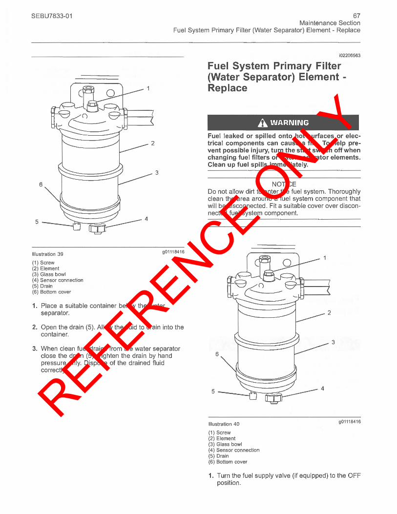
REFERENCE ONLY
SEBU7833-01 67 Maintenance Section
Fuel System Primary Filter (Water Separator) Element - Replace
Illustration 39
(1) Screw (2) Element (3) Glass bowl (4) Sensor connection (5) Drain (6) Bottom cover
3
901 118416
1. Place a suitable container below the water separator.
2. Open the drain (5). Allow the fluid to drain into the container.
3. When clean fuel drains from the water separator close the drain (5). Tighten the drain by hand pressure only. Dispose of the drained fluid correctly.
i02206563
Fuel System Primary Filter (Water Separator) Element -Replace
A WARNING
Fuel leaked or spilled onto hot surfaces or electrical components can cause a fire. To help prevent possible injury, tum the start switch off when changing fuel filters or water separator elements. Clean up fuel spills immediately.
NOTICE Do not allow dirt to enter the fuel system. Thoroughly clean the area around a fuel system component that will be disconnected. Fit a suitable cover over disconnected fuel system component.
6
5
Illustration 40
(1) Screw (2) Element (3) Glass bowl (4) Sensor connection (5) Drain (6) Bottom cover
3
901118416
1. Turn the fuel supply valve (if equipped) to the OFF position.
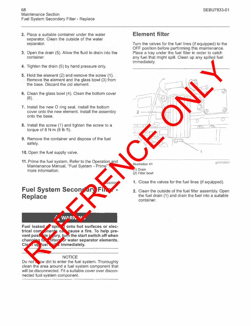
REFERENCE ONLY
68 Maintenance Section Fuel System Secondary Filter - Replace
2. Place a suitable container under the water separator. Clean the outside of the water separator.
3. Open the drain (5). Allow the fluid to drain into the container.
4. Tighten the drain (5) by hand pressure only.
5. Hold the element (2) and remove the screw (1). Remove the element and the glass bowl (3) from the base. Discard the old element.
6. Clean the glass bowl (4). Clean the bottom cover (6).
7. Install the new 0 ring seal. Install the bottom cover onto the new element. Install the assembly onto the base.
8. Install the screw (1) and tighten the screw to a torque of 8 N·m (6 Ib ft).
9. Remove the container and dispose of the fuel safely.
10. Open the fuel supply valve.
11. Prime the fuel system. Refer to the Operation and Maintenance Manual, "Fuel System - Prime" for more information.
i02223550
Fuel System Secondary Filter -Replace
A WARNING
Fuel leaked or spilled onto hot surfaces or electrical components can cause a fire. To help prevent possible injury, turn the start switch off when changing fuel filters or water separator elements. Clean up fuel spills immediately.
NOTICE Do not allow dirt to enter the fuel system. Thoroughly clean the area around a fuel system component that will be disconnected. Fit a suitable cover over disconnected fuel system component.
SEBU7833-01
Element filter
Turn the valves for the fuel lines (if equipped) to the OFF position before performing this maintenance. Place a tray under the fuel filter in order to catch any fuel that might spill. Clean up any spilled fuel immediately.
Illustration 41
(1) Drain (2) Filter bowl
II 901010637
1. Close the valves for the fuel lines (if equipped).
2. Clean the outside of the fuel filter assembly. Open the fuel drain (1) and drain the fuel into a suitable container.
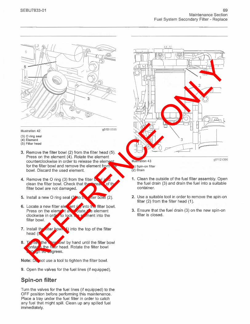
REFERENCE ONLY
SEBU7833-01
Illustration 42
(3) 0 ring seal (4) Element (5) Filter head
901010595
3. Remove the filter bowl (2) from the filter head (5). Press on the element (4). Rotate the element counterclockwise in order to release the element for the filter bowl and remove the element from the bowl. Discard the used element.
4. Remove the 0 ring (3) from the filter bowl and clean the filter bowl. Check that the threads of the filter bowl are not damaged.
5. Install a new 0 ring seal (3) to the filter bowl (2).
6. Locate a new filter element (4) into the filter bowl. Press on the element and rotate the element clockwise in order to lock the element into the filter bowl.
7. Install the filter bowl (4) into the top of the filter head (5).
8. Tighten the filter bowl by hand until the filter bowl contacts the filter head . Rotate the filter bowl through 90 degrees.
Note: Do not use a tool to tighten the filter bowl.
9. Open the valves for the fuel lines (if equipped).
Spin-on filter
Turn the valves for the fuel lines (if equipped) to the OFF position before performing this maintenance. Place a tray under the fuel filter in order to catch any fuel that might spill. Clean up any spilled fuel immediately.
69 Maintenance Section
Fuel System Secondary Filter - Replace
Illustration 43
(1) Spin-on filter (2) Drain
901121396
1. Clean the outside of the fuel filter assembly. Open the fuel drain (3) and drain the fuel into a suitable container.
2. Use a suitable tool in order to remove the spin-on filter (2) from the filter head (1).
3. Ensure that the fuel drain (3) on the new spin-on filter is closed.
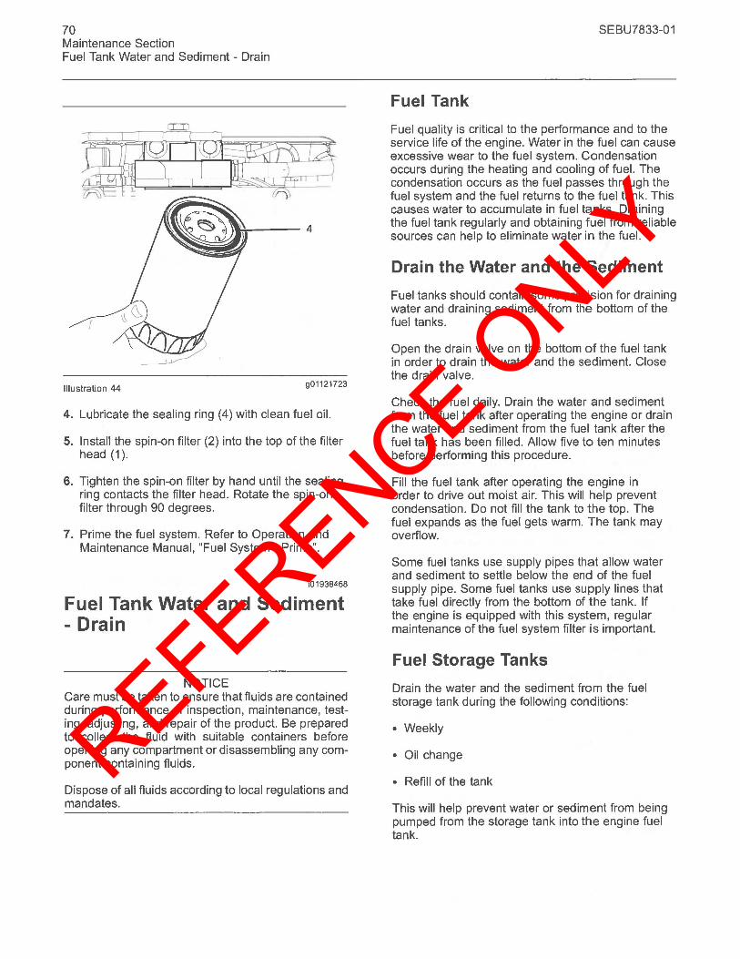
REFERENCE ONLY
70 Maintenance Section Fuel Tank Water and Sediment - Drain
::".....---4
Illustration 44 901121723
4. Lubricate the sealing ring (4) with clean fuel oil.
5. Install the spin-on filter (2) into the top of the filter head (1).
6. Tighten the spin-on filter by hand until the sealing ring contacts the filter head. Rotate the spin-on filter through 90 degrees.
7. Prime the fuel system. Refer to Operation and Maintenance Manual, "Fuel System - Prime".
i01938468
Fuel Tank Water and Sediment - Drain
NOTICE Care must be taken to ensure that fluids are contained during performance of inspection, maintenance, testing, adjusting, and repair of the product. Be prepared to collect the fluid with suitable containers before opening any compartment or disassembling any component containing fluids.
Dispose of all fluids according to local regulations and mandates.
SEBU7833-01
Fuel Tank
Fuel quality is critical to the performance and to the service life of the engine. Water in the fuel can cause excessive wear to the fuel system. Condensation occurs during the heating and cooling of fuel. The condensation occurs as the fuel passes through the fuel system and the fuel returns to the fuel tank. This causes water to accumulate in fuel tanks. Draining the fuel tank regularly and obtaining fuel from reliable sources can help to eliminate water in the fuel.
Drain the Water and the Sediment
Fuel tanks should contain some provision for draining water and draining sediment from the bottom of the fuel tanks.
Open the drain valve on the bottom of the fuel tank in order to drain the water and the sediment. Close the drain valve.
Check the fuel daily. Drain the water and sediment from the fuel tank after operating the engine or drain the water and sediment from the fuel tank after the fuel tank has been filled. Allow five to ten minutes before performing this procedure.
Fill the fuel tank after operating the engine in order to drive out moist air. This will help prevent condensation. Do not fill the tank to the top. The fuel expands as the fuel gets warm. The tank may overflow.
Some fuel tanks use supply pipes that allow water and sediment to settle below the end of the fuel supply pipe. Some fuel tanks use supply lines that take fuel directly from the bottom of the tank. If the engine is equipped with this system, regular maintenance of the fuel system filter is important.
Fuel Storage Tanks
Drain the water and the sediment from the fuel storage tank during the following conditions:
• Weekly
• Oil change
• Refill of the tank
This will help prevent water or sediment from being pumped from the storage tank into the engine fuel tank.
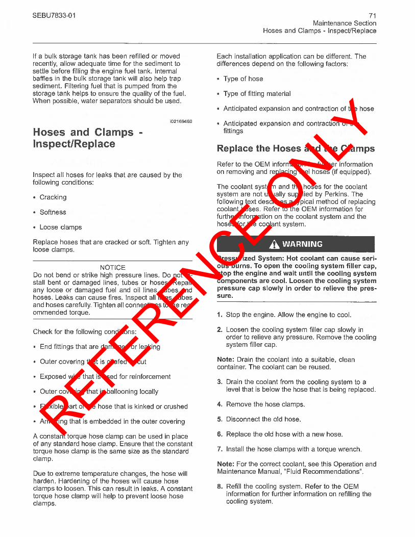
REFERENCE ONLY
SEBU7833-01
If a bulk storage tank has been refilled or moved recently, allow adequate time for the sediment to settle before filling the engine fuel tank. Internal baffles in the bulk storage tank will also help trap sediment. Filtering fuel that is pumped from the storage tank helps to ensure the quality of the fuel. When possible, water separators should be used.
Hoses and Clamps -Inspect/Replace
i02169460
Inspect all hoses for leaks that are caused by the following conditions:
• Cracking
• Softness
• Loose clamps
Replace hoses that are cracked or soft. Tighten any loose clamps.
NOTICE Do not bend or strike high pressure lines. Do not install bent or damaged lines, tubes or hoses. Repair any loose or damaged fuel and oil lines, tubes and hoses. Leaks can cause fires. Inspect all lines, tubes and hoses carefully. Tighten all connections to the recommended torque.
Check for the following conditions:
• End fittings that are damaged or leaking
• Outer covering that is chafed or cut
• Exposed wire that is used for reinforcement
• Outer covering that is ballooning locally
• Flexible part of the hose that is kinked or crushed
• Armoring that is embedded in the outer covering
A constant torque hose clamp can be used in place of any standard hose clamp. Ensure that the constant torque hose clamp is the same size as the standard clamp.
Due to extreme temperature changes, the hose will harden. Hardening of the hoses will cause hose clamps to loosen. This can result in leaks. A constant torque hose clamp will help to prevent loose hose clamps.
71 Maintenance Section
Hoses and Clamps - Inspect/Replace
Each installation application can be different. The differences depend on the following factors:
• Type of hose
• Type of fitting material
• Anticipated expansion and contraction of the hose
• Anticipated expansion and contraction of the fittings
Replace the Hoses and the Clamps
Refer to the OEM information for further information on removing and replacing fuel hoses (if equipped).
The coolant system and the hoses for the coolant system are not usually supplied by Perkins. The following text describes a typical method of replacing coolant hoses. Refer to the OEM information for further information on the coolant system and the hoses for the coolant system.
A WARNING
Pressurized System: Hot coolant can cause serious burns. To open the cooling system filler cap, stop the engine and wait until the cooling system components are cool. Loosen the cooling system pressure cap slowly in order to relieve the pressure.
1. Stop the engine. Allow the engine to cool.
2. Loosen the cooling system filler cap slowly in order to relieve any pressure. Remove the cooling system filler cap.
Note: Drain the coolant into a suitable, clean container. The coolant can be reused.
3. Drain the coolant from the cooling system to a level that is below the hose that is being replaced.
4. Remove the hose clamps.
5. Disconnect the old hose.
6. Replace the old hose with a new hose.
7. Install the hose clamps with a torque wrench.
Note: For the correct coolant, see this Operation and Maintenance Manual, "Fluid Recommendations".
8. Refill the cooling system. Refer to the OEM information for further information on refilling the cooling system.
REFERENCE ONLY
72 Maintenance Section Radiator - Clean
9. Clean the cooling system filler cap. Inspect the cooling system filler cap's seals. Replace the cooling system filler cap if the seals are damaged. Install the cooling system filler cap.
10. Start the engine. Inspect the cooling system for leaks.
i01907732
Radiator - Clean
The radiator is not usually supplied by Perkins. The following text describes a typical cleaning procedure for the radiator. Refer to the OEM information for further information on cleaning the radiator.
Note: Adjust the frequency of cleaning according to the effects of the operating environment.
Inspect the radiator for these items: Damaged fins, corrosion, dirt, grease, insects, leaves, oil, and other debris. Clean the radiator, if necessary.
A WARNING
Personal injury can result from air pressure.
Personal injury can result without following proper procedure. When using pressure air, wear a protective face shield and protective clothing.
Maximum air pressure at the nozzle must be less than 205 kPa (30 psi) for cleaning purposes.
Pressurized air is the preferred method for removing loose debris. Direct the air in the opposite direction to the fan's air flow. Hold the nozzle approximately 6 mm (0.25 inch) away from the radiator fins. Slowly move the air nozzle in a direction that is parallel with the radiator tube assembly. This will remove debris that is between the tubes.
Pressurized water may also be used for cleaning. The maximum water pressure for cleaning purposes must be less than 275 kPa (40 psi). Use pressurized water in order to soften mud. Clean the core from both sides.
Use a degreaser and steam for removal of oil and grease. Clean both sides of the core. Wash the core with detergent and hot water. Thoroughly rinse the core with clean water.
If the radiator is blocked internally, refer to the OEM Manual for information regarding flushing the cooling system.
SEBU7833-01
After cleaning, start the engine and accelerate the engine to high idle rpm. This will help in the removal of debris and the drying of the core. Stop the engine. Use a light bulb behind the core in order to inspect the core for cleanliness. Repeat the cleaning, if necessary.
Inspect the fins for damage. Bent fins may be opened with a "comb". Inspect these items for good condition: Welds, mounting brackets, air lines, connections, clamps, and seals. Make repairs, if necessary.
i02176881
Severe Service Application -Check
Severe service is the application of an engine that exceeds the current published standards for that engine. Perkins maintains standards for the following engine parameters:
• Performance such as power range, speed range, and fuel consumption
• Fuel quality
• Operational Altitude
• Maintenance intervals
• Oil selection and maintenance
• Coolant type and maintenance
• Environmental qualities
• Installation
Refer to the standards for the engine or consult your Perkins dealer or your Perkins distributor in order to determine if the engine is operating within the defined parameters.
Severe service operation can accelerate component wear. Engines that operate under severe conditions may need more frequent maintenance intervals in order to ensure maximum reliability and retention of full service life.
Due to individual applications, it is not possible to identify all of the factors which can contribute to severe service operation. Consult your Perkins dealer or your Perkins distributor for the unique maintenance that is necessary for the engine.
REFERENCE ONLY
SEBU7833-01
The operating environment, incorrect operating procedures and incorrect maintenance procedures can be factors which contribute to a severe service application.
Environmental Factors
Ambient temperatures - The engine may be exposed to extended operation in extremely cold environments or hot environments. Valve components can be damaged by carbon buildup if the engine is frequently started and stopped in very cold temperatures. Extremely hot intake air reduces engine performance.
Quality of the air - The engine may be exposed to extended operation in an environment that is dirty or dusty, unless the equipment is cleaned regularly. Mud, dirt and dust can encase components. Maintenance can be very difficult. The buildup can contain corrosive chemicals.
Buildup - Compounds, elements, corrosive chemicals and salt can damage some components.
Altitude - Problems can arise when the engine is operated at altitudes that are higher than the intended settings for that application. Necessary adjustments should be made.
Incorrect Operating Procedures
• Extended operation at low idle
• Frequent hot shutdowns
• Operating at excessive loads
• Operating at excessive speeds
• Operating outside the intended application
Incorrect Maintenance Procedures
• Extending the maintenance intervals
• Failure to use recommended fuel, lubricants and coolant/antifreeze
i02177969
Starting Motor - Inspect
Perkins recommends a scheduled inspection of the starting motor. If the starting motor fails, the engine may not start in an emergency situation.
73 Maintenance Section
Starting Motor - Inspect
Check the starting motor for correct operation. Check the electrical connections and clean the electrical connections. Refer to the Systems Operation, Testing and Adjusting Manual, "Electric Starting System -Test" for more information on the checking procedure and for specifications or consult your Perkins dealer or your Perkins distributor for assistance.
Turbocharger - Inspect (If Equipped)
i02184788
A regular visual inspection of the turbocharger is recommended. Any fumes from the crankcase are filtered through the air inlet system. Therefore, by-products from oil and from combustion can collect in the turbocharger compressor housing. Over time, this buildup can contribute to loss of engine power, increased black smoke and overall loss of engine efficiency.
If the turbocharger fails during engine operation, damage to the turbocharger compressor wheel and/or to the engine may occur. Damage to the turbocharger compressor wheel can cause additional damage to the pistons, the valves, and the cylinder head.
NOTICE Turbocharger bearing failures can cause large quantities of oil to enter the air intake and exhaust systems. Loss of engine lubricant can result in serious engine damage.
Minor leakage of oil into a turbocharger under extended low idle operation should not cause problems as long as a turbocharger bearing failure has not occured.
When a turbocharger bearing failure is accompanied by a significant engine performance loss (exhaust smoke or engine rpm up at no load), do not continue engine operation until the turbocharger is renewed.
A visual inspection of the turbocharger can minimize unscheduled downtime. A visual inspection of the turbocharger can also reduce the chance for potential damage to other engine parts.
Removal and Installation
Note: The turbochargers that are supplied are nonserviceable.
REFERENCE ONLY
74 Maintenance Section Walk-Around Inspection
For options regarding the removal, installation, and replacement, consult your Perkins dealer or your Perkins distributor. Refer to the Disassembly and Assembly Manual, "Turbocharger - Remove and Turbocharger - Install" for further information.
Inspecting
NOTICE The compressor housing for the turbocharger must not be removed from the turbocharger for cleaning.
The actuator linkage is connected to the compressor housing. If the actuator linkage is moved or disturbed the engine may not comply with emmissions legislation .
1. Remove the pipe from the turbocharger exhaust outlet and remove the air intake pipe to the turbocharger. Visually inspect the piping for the presence of oil. Clean the interior of the pipes in order to prevent dirt from entering during reassembly.
2. Check for the presence of oil. If oil is leaking from the back side of the compressor wheel, there is a possibility of a failed turbocharger oil seal.
The presence of oil may be the result of extended engine operation at low idle. The presence of oil may also be the result of a restriction of the line for the intake air (clogged air filters), which causes the turbocharger to slobber.
3. Inspect the bore of the housing of the turbine outlet for corrosion .
4. Fasten the air intake pipe and the exhaust outlet pipe to the turbocharger housing .
i02177973
Walk-Around Inspection
Inspect the Engine for Leaks and for Loose Connections
A walk-around inspection should only take a few minutes. When the time is taken to perform these checks, costly repairs and accidents can be avoided.
For maximum engine service life, make a thorough inspection of the engine compartment before starting the engine. Look for items such as oil leaks or coolant leaks, loose bolts, worn belts, loose connections and trash buildup. Make repairs, as needed:
SEBU7833-01
• The guards must be in the correct place. Repair damaged guards or replace missing guards.
• Wipe all caps and plugs before the engine is serviced in order to reduce the chance of system contamination .
NOTICE For any type of leak (coolant, lube, or fuel) clean up the fluid. If leaking is observed, find the source and correct the leak. If leaking is suspected, check the fluid levels more often than recommended until the leak is found or fixed, or until the suspicion of a leak is proved to be unwarranted.
NOTICE Accumulated grease and/or oil on an engine is a fire hazard. Remove the accumulated grease and oil. Refer to this Operation and Maintenance Manual, "Engine - Clean" for more information.
• Ensure that the cooling system hoses are correctly clamped and that the cooling system hoses are tight. Check for leaks. Check the condition of all pipes.
• Inspect the water pump for coolant leaks.
Note: The water pump seal is lubricated by the coolant in the cooling system. It is normal for a small amount of leakage to occur as the engine cools down and the parts contract.
Excessive coolant leakage may indicate the need to replace the water pump seal. For the removal of the water pump and the installation of water pump and/or seal, refer to the Disassembly and Assembly Manual, "Water Pump - Remove and Install" for more information or consult your Perkins dealer or your Perkins distributor.
• Inspect the lubrication system for leaks at the front crankshaft seal, the rear crankshaft seal, the oil pan, the oil filters and the rocker cover.
• Inspect the fuel system for leaks. Look for loose fuel line clamps and/or tie-wraps.
• Inspect the piping for the air intake system and the elbows for cracks and for loose clamps. Ensure that hoses and tubes are not contacting other hoses, tubes, wiring harnesses, etc.
• Inspect the alternator belts and any accessory drive belts for cracks, breaks or other damage.
REFERENCE ONLY
SEBU7833-01
Belts for multiple groove pulleys must be replaced as matched sets. If only one belt is replaced, the belt will carry more load than the belts that are not replaced. The older belts are stretched. The additional load on the new belt could cause the belt to break.
• Drain the water and the sediment from the fuel tank on a daily basis in order to ensure that only clean fuel enters the fuel system.
• Inspect the wiring and the wiring harnesses for loose connections and for worn wires or frayed wires.
• Inspect the ground strap for a good connection and for good condition.
• Disconnect any battery chargers that are not protected against the current drain of the starting motor. Check the condition and the electrolyte level of the batteries, unless the engine is equipped with a maintenance free battery.
• Check the condition of the gauges. Replace any gauges that are cracked. Replace any gauge that can not be calibrated.
i01907756
Water Pump - Inspect
A failed water pump may cause severe engine overheating problems that could result in the following conditions:
• Cracks in the cylinder head
• A piston seizure
• Other potential damage to the engine
Note: The water pump seal is lubricated by the coolant in the cooling system. It is normal for a small amount of leakage to occur as the engine cools down and parts contract.
Visually inspect the water pump for leaks. Renew the water pump seal or the water pump if there is an excessive leakage of coolant. Refer to the Disassembly and Assembly Manual, "Water Pump - Remove and Install" for the disassembly and assembly procedure.
75 Maintenance Section
Water Pump - Inspect
REFERENCE ONLY
76 Warranty Section Warranty Information
Warranty Section
Warranty Information
Emissions Warranty Information
i01903596
This engine may be certified to comply with exhaust emission standards and gaseous emission standards that are prescribed by the law at the time of manufacture, and this engine may be covered by an Emissions Warranty. Consult your authorized Perkins dealer or your authorized Perkins distributor in order to determine if your engine is emissions certified and if your engine is subject to an Emissions Warranty.
SEBU7833-01
REFERENCE ONLY
SEBU7833-01
Index
A
After Starting Engine .............. ......... ...................... 27 After Stopping Engine .... ...... ... ........ .... ....... ............ 29 Aftercooler Core - CleanITest ... .... .. .... ...... .... ........ . 49 Aftercooler Core - Inspect... ......... .. .... ... ............... .. 49 Alternator - Inspect ... ....... ...... ... .. ... ..... ...... .. ... ..... ... 50 Alternator and Fan Belts - Inspect/Adjust/ Replace ... ................... ............ .. ............................ 50 Adjustment ................ .. ...... ... .... ... ... .................... 50 Inspection ........................................................... 50 Replacement .................... ... ..... .......................... 50
B
Battery - Replace ...... .. ....... ...... .... ... .... .... ... ..... ... .... 51 Battery Electrolyte Level - Check ... ...... ..... ... ......... 51 Battery or Battery Cable - Disconnect .. .... .... .. ..... .. 52 Before Starting Engine ........... ...... .. ........ .. ... ...... 9, 25 Burn Prevention ........... ...... .............. ........................ 7
Batteries................................. .............................. 7 Coolant. .......................... .... ... ............................... 7 Oils ..................................................... .................. 7
c
Cold Weather Operation ... ......... ..... .... .. ... ....... .. .... . 30 Hints for Cold Weather Operation ......... .. ........ ... 30 Idling the Engine .... .... .......... .. .. .. .... ... .............. ... 31 Recommendations for Coolant Warm Up .......... 31 Recommendations for the Coolant .................... 30 Viscosity of the Engine Lubrication OiL .............. 30
Cold Weather Starting ..... ... ......... .......................... 26 Cooling System Coolant - Change ........................ 55 Cooling System Coolant (Commercial Heavy-Duty) -Change ...... ............. .... .... .. ...... ........ ... .. ................ 52
Drain .... ......... .... ... ..... .... .... .. .. ... ..... .... ..... ...... ... ... 52 Fill ............. .... ... ... ....... .. .. ............. ... .... .. .... .. .... .... 53 Flush .... ... ...... .... .... ..... ..... .... ... .. .... ..... ... ...... .... ... . 53
Cooling System Coolant (ELC) - Change ... ... ... ... .. 54 Drain ...................... ....... ......... ... .. ....................... 54 Fill ... ................................ .... ... .. .. ........................ 55 Flush ............................ ... ................................... 54
Cooling System Coolant Extender (ELC) - Add ..... 56 Cooling System Coolant Level - Check ................. 56
Engines With a Coolant Recovery Tank ............. 56 Engines Without a Coolant Recovery Tank ........ 56
Crushing Prevention and Cutting Prevention ..... ... .. 9
D
Driven Equipment - Check ....... .. ...... .. .................... 57
E
77 Index Section
Electrical System .... ..... ........... ................... ........... . 10 Grounding Practices ... ..... ... .... .................. ...... .. .. 11
Emergency Stopping ..... ... ........ .... .. .... .. .. .... .. .. ... .... 29 Emissions Certification Film ..... ... ......... .... . .......... .. 18
Label for compliant engines ... ......... ... ..... .. .. .. .. ... 18 Label for engines that are not compliant...... ... .. . 19
Emissions Warranty Information .................... .. ...... 76 Engine - Clean ...... .. .. ... .. ... ................................. .... 57 Engine Air Cleaner Element (Dual Element) -Clean/Replace ........ ..... ... .................................. .. . 58 Cleaning the Primary Air Cleaner Elements .. .... 59 Servicing the Air Cleaner Elements ................... 58
Engine Air Cleaner Element (Single Element) -Inspect/Replace .. ..... ..... .... ..... .............................. 60
Engine Air Cleaner Service Indicator - Inspect... .. . 60 Test the Service Indicator. .... ... ...... ........... .. .... .... 60
Engine Description .. ... ....... ...... ..... ..... ... ..... ... .. .. .. ... 15 Engine Cooling and Lubrication .... ....... ... ..... ..... . 17 Engine Service Life .. ..... .............................. ..... .. 17 Engine Specifications ... ..... ........................... ...... 15
Engine Ground - Inspect/Clean ............................ . 61 Engine Identification .... .......................................... 18 Engine Lifting ............. .. .... ... .. ................................. 21 Engine Mounts - Inspect... ................................... .. 61 Engine Oil and Filter - Change .. ... ........ ... ... ...... .. .. . 62
Drain the Engine Oil. ... ............ .. ..... ....... .. .... ...... . 62 Fill the Engine Crankcase .. ..... .. ..... ....... ... .. .. ...... 64 Replace the Element for the Oil Filter ... ...... .. ... .. 63 Replace the Spin-on Oil Filter ................ .. ....... .. 63
Engine Oil Level - Check ... ............................. ...... . 61 Engine Oil Sample - Obtain ... ............................. .. . 61
Obtain the Sample and the Analysis ................ .. 62 Engine Operation ..... .... .. .. ...................................... 28 Engine Starting ........ .... ...... .............................. 10, 25 Engine Stopping ... .... .... ....... .. ... ...................... . 10, 29 Engine Storage ... ....... .... ... ...... .... .... ...... .. .... .. .... ..... 21
Cooling System .... ..... ........ .... ..... .. .. .... ....... ... .... .. 22 Exhaust System .......... ... ...... ... .. .... ......... ... .. ... .... 22 General Items. .... .......... ......... .... ......... .. ... .. ..... .. . 23 Induction System .. ........ .. ....... .. .................. .. ..... . 22 Lubrication System ............................................ 21
Engine Valve Lash - Inspect/Adjust.. ..................... 64 Engine Warm-up ................................................... . 28
F
Fire Prevention and Explosion Prevention .... .. ..... ... 7 Fire Extinguisher .................. .. ................ ... .. .. ... .... 8 Lines, Tubes and Hoses ... .. ... ... .... .... ...... .. ... ........ 9
Fluid Recommendations ..... .. .. ...... .... ... .. .. .... .. ... ... .. 35 Cooling System Specifications .... ............ .... .. .... . 42 ELC Cooling System Maintenance ........... .. .... ... 44 Engine Oil .......... .. ..... ..... .. .. ........................... ..... 36 Fuel Specifications ........... ... ..................... ...... ... . 39 General Lubricant Information ........................ ... 35
REFERENCE ONLY
78 SEBU7833-01 I ndex Section
Foreword ................................................................. 4 Model View Illustrations ......................................... 12 California Proposition 65 Warning ....................... 4 1103 Engine Model Views .................................. 14 Literature Information ........................................... 4 1104 Engine Model Views .................................. 12 Maintenance ........................................................ 4 Model Views.................... ............. ......................... 12 Maintenance Intervals .......................................... 4 Mounting and Dismounting ...................................... 9 Operation ............................................................. 4 Overhaul .............................................................. 4 Safety ................................................................... 4 o
Fuel and the Effect from Cold Weather ................. 32 Fuel Conservation Practices .................................. 28 Operation Section.................................................. 21 Fuel Injector - Test/Change ................................... 64
Removal and Installation of the Fuel Injectors ... 65 Fuel Related Components in Cold Weather .......... 33 p
Fuel Filters ......................................................... 33 Fuel Heaters ...................................................... 33 Product Identification Information .......................... 18 Fuel Tanks .......................................................... 33 Product Information Section .................................. 12
Fuel System - Prime .............................................. 65 Fuel System Primary Filter (Water Separator) Element - Replace .... ........................................... 67 R
Fuel System Primary FilterlWater Separator -Drain .................................................................... 66 Radiator - Clean .................... ................................ 72
Fuel System Secondary Filter - Replace .... ........... 68 Reference Numbers .............................................. 18 Element filter ...................................................... 68 Record for Reference ......................................... 18 Spin-on filter ....................................................... 69 Refill Capacities .. ................................................... 34
Fuel Tank Water and Sediment - Drain ................. 70 Cooling System .................. ................................ 34 Drain the Water and the Sediment.. ................... 70 Lubrication System ............................................ 34 Fuel Storage Tanks ............................................ 70 Fuel Tank ........................................................... 70
s
G Safety Messages ..................................... ................ 5 Safety Section ......................................................... 5
Gauges and Indicators .......................................... 24 Serial Number Plate .............................................. 18 General Hazard Information .................................... 5 Severe Service Application - Check ...................... 72
Containing Fluid Spillage ..................................... 6 Environmental Factors ....................................... 73 Fluid Penetration .................................................. 6 Incorrect Maintenance Procedures .. .................. 73 Pressure Air and Water. ....................................... 6 Incorrect Operating Procedures ......................... 73
Starting Motor - Inspect ......................................... 73 Starting the Engine .......... ...................................... 26
H Starting with Jump Start Cables ............................ 27 Stopping the Engine .............................................. 29
Hoses and Clamps - Inspect/Replace ................... 71 Replace the Hoses and the Clamps .................. 71
T
Table of Contents ..................................................... 3 Turbocharger - Inspect (If Equipped) ..................... 73
Important Safety Information ................................... 2 Inspecting ........................................................... 74 Removal and Installation .................................... 73
L w
Lifting and Storage ................................................ 21 Walk-Around Inspection ........................................ 74
Inspect the Engine for Leaks and for Loose M Connections ..................................................... 74
Warranty Information ................ ............................. 76 Maintenance Interval Schedule ............................. 48 Warranty Section ................................................... 76 Maintenance Section ... .......................................... 34 Water Pump - Inspect.. .... ...................................... 75
REFERENCE ONLY
Product and Dealer Information Note: For product identification plate locations, see the section "Product Identification Information" in the Operation and Maintenance Manual.
Delivery Date: ________ _
Product Information Model: __________________________________________________________________ ___
Engine Serial Number: __________________________________________________________ __
Generator Serial Number: _______________________________________________________ _
Attachment Serial Numbers: ____________________________________________________ _
Attachment Information: ______________________________________________________ _
Dealer Equipment Number: ____________________________________________________ _
Dealer Information
Name: Branch: _________________________ _
Address:
Dealer Contact Phone Number
Sales:
Parts:
Service:

REFERENCE ONLY
REFERENCE ONLY
Asia Perkins Engines (Asia Pacific) Pte Ltd 7 Tractor Road Singapore 627968 Telephone +65 6828 7469 Fax +65 6828 7414
Europe, Middle East and Africa Perkins Engines Company Limited Peterborough PE1 5NA United Kingdom Telephone +44 (0)1733 583000 Fax +44 (0)1733 582240
North America Perkins Engines Inc N4 AC 6160 PO Box 610 Mossville, IL 61552-0610, USA 1-888-PERK-ENG Telephone +1 309 578 7364 Fax + 1 309 578 7329
Latin America Perkins Motores do Brasil Ltda Rua Alexandre Dumas, 1711 Ed. Birman 11, 9° andar Chacara Santo Antonio Sao Paulo / SP - Brasil Cep: 04717-004 Telephone +55 11 21092038 Fax +55 11 2109 2089
www.perkins.com
All information in this document is substantially correct at time of printing and may be altered subsequently by the company
,