performance optimization and mechanical modeling of uniaxial piezoresistive microaccelerometers
TRANSCRIPT
TECHNICAL PAPER
Performance optimization and mechanical modeling of uniaxialpiezoresistive microaccelerometers
Angel R. Cortes-Perez • Agustin Leobardo Herrera-May • Luz A. Aguilera-Cortes •
Max A. Gonzalez-Palacios • Miguel Torres-Cisneros
Received: 23 July 2009 / Accepted: 21 October 2009 / Published online: 17 November 2009
� Springer-Verlag 2009
Abstract The acceleration measurements in automotive,
navigation, biomedical and consumer applications demand
high-performance microaccelerometers. This paper pre-
sents an optimization model to maximize the bandwidth of
uniaxial piezoresistive microaccelerometers based on can-
tilever-type beams. The proposed model provides a high
sensitivity as well as normal stress levels lower than the
material rupture stress of these microaccelerometers. This
model uses the Rayleigh method to determine the objective
function of the bandwidth and the maximum-normal-stress
failure theory to obtain a stress constraint that guarantees
safe operation for the microaccelerometer structure. The
Box-Complex optimization method is used to solve the
optimization model due to its easy programming algorithm.
Finite element models (FE) are developed to determine the
mechanical behavior of the optimized piezoresistive mic-
roaccelerometers. The results of the FE models agree well
with those of the optimization model. The optimization
model can be easily used by designers to find the optimum
geometrical dimensions of piezoresistive microaccelerom-
eters to maximize their performance.
1 Introduction
Bulk and surface micromachining techniques have allowed
the development of efficient sensors able to measure
physical parameters such as acceleration (Herrera-May
et al. 2008), magnetic field (Herrera-May et al. 2009a), and
pressure (Herrera-May et al. 2009b). This has been stim-
ulated by the advantages offered by micromachining
techniques, including: miniaturization, low power con-
sumption, high sensitivity, and low sensor price. Among
these devices, microaccelerometers have obtained great
success commercially mainly in the automotive industry,
where they are used to activate safety systems, for example
in air bags, vehicle stability systems, and electronic sus-
pensions (Yazdi et al. 1998). In addition, other applications
demanding high-performance microaccelerometers include
navigation, biomedical activity monitoring, seismology,
and consumer applications such as headsets for virtual
reality and computer peripherals (Beeby et al. 2004; Fedder
et al. 2005). Two main requirements for these microac-
celerometers include high sensitivity and large bandwidth.
Thus, an ideally designed microaccelerometer should have
optimum performance to achieve these requirements.
Unfortunately, the requirements conflict each other, so if
the sensitivity is increased then the bandwidth is decreased
and vice versa (Roylance and Angell 1979). Therefore,
designers have an important challenge to determine opti-
mum values of the sensitivity and bandwidth for each
particular application. Seidel and Csepregi (1984) reported
a design optimization procedure to maximize one of the
requirements with a specific value for the other. In addi-
tion, the performance optimization of the accelerometers
must guarantee safe operation (i.e., the stress caused by the
accelerations should be less than the material rupture stress
of the microaccelerometer).
A. R. Cortes-Perez � A. L. Herrera-May (&) �L. A. Aguilera-Cortes � M. A. Gonzalez-Palacios �M. Torres-Cisneros
Depto. Ingenierıa Mecanica, Campus Irapuato-Salamanca,
Universidad de Guanajuato, Carretera Salamanca-Valle de
Santiago km 3.5?1.8 km, Salamanca, Guanajuato, Mexico
e-mail: [email protected]
L. A. Aguilera-Cortes
e-mail: [email protected]
A. L. Herrera-May
Centro de Investigacion en Micro y Nanotecnologıa,
Universidad Veracruzana, 94292 Boca del Rıo, Veracruz,
Mexico
123
Microsyst Technol (2010) 16:461–476
DOI 10.1007/s00542-009-0942-y

During the last three decades various microacceler-
ometers have been investigated based on piezoresistive
(Amarasinghe et al. 2007; Sankar et al. 2009), capacitance
(Chae et al. 2005), piezoelectric (Hindrichsen et al. 2009),
thermal (Dauderstadt et al. 1998), tunneling (Liu and
Kenny 2001), and optical (Lee and Cho 2004) sensing
principles. Each approach has its own inherent advantages
and drawbacks. For example, piezoelectric microacceler-
ometers have a fast response, minimum power con-
sumption, and good linearity, but do not respond to
constant acceleration (Zhu et al. 2004). Thermal micro-
accelerometers do not need a solid proof mass and are
based on thermal convection, although, they have offset
variations for long term operation conditions caused by
changes in the environment temperature (Kaltsas et al.
2006). Tunneling microaccelerometers present a high
sensitivity, but they require a complex fabrication process
and have stability problems (Liu et al. 1998). Novel
designs include optical microaccelerometers that have
immunity to electromagnetic interference (EMI) and
reduce electronic circuitry and total weight; though, they
present intrinsic losses due to structural imperfections and
require difficult fabrication processes (Llobera et al.
2007). Capacitive microaccelerometers have a little
dependence on the temperature, but they have parasitic
capacitances of the connecting leads that complicate the
measurements of the signal; in addition, they require com-
plicated electronics and the narrow air gap over a relatively
large area increases the damping (Zou et al. 2008). Piezo-
resistive microaccelerometers are fabricated using an easy
and mature process, require simple readout circuits, have
low cost and high sensitivity, but they suffer from thermal
influences that can be controlled with careful packaging,
trimming, and compensation circuits (Partridge et al. 2000;
Huang et al. 2005). Piezoresistive microaccelerometers are
an important alternative for use in conventional and new
applications of acceleration measurements.
Although the research and fabrication of piezoresistive
microaccelerometers have been very extensive, few
studies about of their performance optimization have
been realized. Seidel and Csepregi (1984) reported a
design optimization procedure of a piezoresistive micro-
accelerometer to maximize its sensitivity while its
bandwidth maintained a specific value, but without con-
sidering the stress caused by the accelerations. Joshi et al.
(2005) proposed a technique for optimizing performance
of a cantilever-type microaccelerometer based on finite
element method (FEM) models through Coventoreware
MEMSCAD software; however, this technique analyzes
only the bandwidth variation and stresses caused by
the changes in the dimensions of the cantilever. In
addition, this technique requires much computation time
to evaluate the performance of the FEM models. Kovacs
and Vızvary (2001) reported analytical models to esti-
mate the bandwidth and sensitivity of piezoresistive
microaccelerometers due to the change of geometrical
parameters. However, Kovacs and Vızvary (2001) do not
developed optimization models to evaluate the optimum
performance of the microaccelerometer and do not con-
sidered stress effect on the structure. Coultate et al.
(2008) reported an optimum and robust design on a
capacitive microaccelerometer using the genetic algo-
rithm technique. Although, this technique is complicated
and it is only used to maximize the full-scale range
(FSR). These models have not been able to predict the
optimal performance of a piezoresistive microacceler-
ometer. Nor is the method capable of determining the
optimum dimensions of the structure to achieve a high
sensitivity and high bandwidth. In addition, they neglect
the structural stress generated by the accelerations. We
propose an optimization model to find the optimum
performance of piezoresitive microaccelerometers based
on cantilever-type beams, which consider the maximum-
normal-stress failure theory to guarantee safe operation of
the microaccelerometer structure. This model finds the
optimum geometrical dimensions of the cantilever-type
microaccelerometers to achieve a maximum bandwidth
and a high sensitivity. The model is solved using an
algorithm based on the Box-Complex method, which is
very easy to use. In addition, we utilized FEM models
with ANSYS software to model the mechanical behavior
(i.e., resonant frequencies and stress of the microaccel-
erometer structure) of the optimum microaccelerometer.
Also, these models can be modified and adapted to other
piezoresistive microaccelerometers that use other canti-
lever-type structures (e.g., double clamped cantilever).
The Rayleigh method is used to determine the objective
function (bandwidth of the microaccelerometer) of the
optimization model. This model can be easily used by
designers to determine the optimum dimensions of pi-
ezoresistive microaccelerometers which are based on
cantilever-type structures. The proposed optimization
model is adapted to a piezoresistive microaccelerometer
developed by Plaza et al. (2002).
Following the introduction, the paper is organized as
follows. Section 2 presents the description of the band-
width, sensitivity and stress models of the piezoresistive
microaccelerometer based on cantilever-type beams.
Section 3 shows the variations of the bandwidth, sensitiv-
ity, and maximum normal stress of the piezoresistive
microaccelerometer as a function of its geometrical
parameters. Section 4 describes the proposed optimization
model and Section 5 reports the results and discusses the
results of the optimization model and the FE models. The
462 Microsyst Technol (2010) 16:461–476
123

paper ends with the concluding discussion and a proposal
for further work.
2 Description of the device models
A description of the bandwidth, sensitivity and stress
models of a piezoresistive microaccelerometer is necessary
to find its optimum performance for a specific application.
These models are applied to the structural configuration of
a piezoresistive microaccelerometer fabricated by Plaza
et al. (2002). The models find the required geometrical
dimensions of the microaccelerometer for an optimum
bandwidth, a high sensitivity and a stress level less than the
material rupture stress of its structure.
2.1 Structural model
Figure 1a and b shows the structural configuration of a
piezoresistive microaccelerometer based on cantilever-type
beams. The microaccelerometer consists of two supporting
beams, a proof mass, a fixed frame, and four piezoresistors
in a Wheatstone bridge configuration. An optimization
model is used on this microaccelerometer to find the
optimum dimensions that improve its bandwidth without
exceeding the material rupture stress, while maintaining a
high sensitivity. Thus, the proposed optimization model
will guarantee safe operation of this kind of microaccel-
erometer for each specific application.
Figure 2 shows the geometrical parameters used to
optimize the dimensions of the structural configuration of
the piezoresistive microaccelerometer. Its structural con-
figuration is divided into three elastic beams with three
different lengths (L1, L2, and L3), two thicknesses (s1 and
s2), and two widths (v1 and v2). To simplify the optimiza-
tion model, we propose neglecting the slopes of the proof
mass due to anisotropic etching and consider the ends of
the supporting beams as clamped ends. In addition, the
Fig. 1 A 3D schematic view of the (a) upper and (b) lower parts of
the piezoresistive microaccelerometer
Fig. 2 Geometrical parameters of the structure of the piezoresistive
microaccelerometer
Fig. 3 Localization of the piezoresistive Wheatstone bridge on the
structure of the piezoresistive microaccelerometer
Microsyst Technol (2010) 16:461–476 463
123
thickness of the proof mass is much larger than that of the
supporting beams.
When a normal acceleration is applied to the piezo-
resistive microaccelerometer, its proof mass experiences a
vertical deflection that causes transversal and longitudinal
strains on the ends of the supporting beams. These strains
produce a change in the resistances (R1, R2, R3, and R4)
of each piezoresistor placed on the supporting beams.
Thus, these variations cause a change in the output
voltage (DVout) of the Wheatstone bridge (see Fig. 3). In
this configuration, the acceleration magnitude is measured
as a function of the output voltage of the Wheatstone
bridge.
2.2 Bandwidth modeling
The optimization of bandwidth is needed to widen
the application range of the microaccelerometers. This
optimization must be achieved while maintaining a
suitable sensitivity and low stress level in order to
guarantee an efficient and safe operation of the
microaccelerometers.
The bandwidth of a microaccelerometer is determined
at the first resonant frequency of its structural system
(Fraden 1996). The fundamental resonant frequency of a
continuous structural system can be obtained using the
Rayleigh method. This method is very simple and easier
to use than exact analysis for systems with varying dis-
tributions of mass and stiffness (Rao 2004). The Rayleigh
method calculates the fundamental resonant frequency of
a continuous system through the ratio of the expression
for potential energy to the expression for kinetic energy in
the system (Beards 1995). We use this method to deter-
mine the first resonant frequency of the structure of the
piezoresistive microaccelerometer. In addition, we con-
sider unit acceleration (1g) perpendicular to the normal
plane of the structure. This acceleration causes a deflec-
tion in the structure of the microaccelerometer, which can
be obtained using the Euler–Bernoulli beam theory. Based
on this theory, we obtain the following expressions for the
bending moments on the microaccelerometer structure
(Rao 2004).
2EI1
o2z1ðxÞox2
¼ �M1ðxÞ; 0� x� L1; ð1Þ
2EI2
o2z2ðxÞox2
¼ �M2ðxÞ; L1� x� L2; ð2Þ
EI3
o2z3ðxÞox2
¼ �M3ðxÞ; L2� x� L3; ð3Þ
where Ii is the moment of inertia of the i-th beam cross
section about the y-axis, I1 ¼ s1v31=12; I2 ¼ s1v3
2=12; I3 ¼
s2v32=12; E is the elastic modulus, Mi(x) are bending
moment functions on the i-th beam, and zi(x) are the
deflection functions of the i-th beam.
The boundary conditions for each beam are given by:
z1ð0Þ ¼ 0;oz1
oxð0Þ ¼ 0;
z2ð0Þ ¼ z1ðL1Þ;oz2
oxð0Þ ¼ oz1
oxðL1Þ;
z3ð0Þ ¼ z2ðL2Þ;oz3
oxð0Þ ¼ oz2
oxðL2Þ: ð4Þ
With a unit acceleration g, the bending moment
functions of each beam are as follows
M1ðxÞ ¼ gqs1v1x2 � gqs2v2L2x
� 2gqs1v2L2x� 2gqs1v1L2x
þ 1
2gqs2v2L2
3 þ gqs2v2L2L3
þ gqs2v2L1L3 þ gqs1v2L22
þ 2gqs1v2L1L2 þ gqs1v1L21
0� x� L1; ð5Þ
M2ðxÞ¼ gqs1v2x2�gqs2v2L3x�2gqs1v2L2x
þ1
2gqs2v2L2
3þgqs2v2L2L3þgqs1v2L22
L1�x�L2;
ð6Þ
M3ðxÞ ¼1
2gqs2v2x2 � gqs2v2L3xþ 1
2gqs2v2L2
3 L2� x�L3:
ð7Þ
Using the Rayleigh method, the first resonant frequency
of the microaccelerometer is determined by the following
expression (Rao 2004)
fres ¼1
2p
ffiffiffiffiffiffiffiffiffiffi
Umax
Tmax
r
; ð8Þ
where Umax is the maximum potential energy of the
microaccelerometer structure and Tmax is the maximum
kinetic energy of the microaccelerometer structure.
Umax ¼Z
L1
0
I1Eo2z1ðxÞ
ox2
� �2
dxþZ
L2
L1
I2Eo2z2ðxÞ
ox2
� �2
dx
þ 1
2
Z
L3
L2
I3Eo2z3ðxÞ
ox2
� �2
dx; ð9Þ
Tmax ¼Z
L1
0
qA1z21ðxÞdxþ
Z
L2
L1
qA2z22ðxÞdxþ 1
2
Z
L3
L2
qA3z23ðxÞdx;
ð10Þwhere Ai is the cross-section area of the i-th beam.
464 Microsyst Technol (2010) 16:461–476
123

The functions of deflection z1(x), z2(x) and z3(x) are
obtained substituting the Eqs. 1–3 into the boundary con-
ditions given by Eq. 4 (Cortes-Perez 2008).
z1 xð Þ ¼ � gq
2s1v31Eðs1v1x4 � 2s2v2L3x3 � 4s1v2L2x3
� 4s1v1L1x3 þ 3s2v2L23x2 þ 6s2v2L2L3x2
þ 6s1v2L22x2 þ 12s1v2L1L2x2 þ 6s2v2L1L3x2
þ 6s1v1L21x2Þ; ð11Þ
z2 xð Þ ¼ � gq
2s1v31v2
2Eðs1v3
1x4 � 4s1v31L2x3 � 2v3
1s2L3x3
þ 6s1v31L2
2x2 þ 6s2v31L2L3x2 þ 3s2v3
1L23x2
þ 4s1v1v22L3
1xþ 12s1v32L2
1L2xþ 12s1v32L1L2
2x
þ 6s2v32L2
1L3xþ 12s2v32L1L2L3xþ 6s2v3
2L1L23x
þ 4s2v32L3
1L3 þ 3s1v1v22L4
1 þ 8s1v32L3
1L2
þ 6s1v32L2
1L22 þ 6s2v3
2L21L2L3 þ 3s2v3
2L21L2
3Þ; ð12Þ
z3 xð Þ ¼ � gq
2s1v31v2
2Eðs1v3
1x4 � 4s1v31L3x3 þ 6s1v3
1L23x2
þ 4s1v31L3
2xþ 12s1v32L1L2
2xþ 12s1v32L2
1L2x
þ 4s1v1v22L3
1xþ 6s2v31L2L2
3xþ 6s2v32L1L2
3x
þ 6s2v32L2
1L3xþ 6s2v31L2
2L3xþ 12s2v32L1L2L3x
þ 3s1v1v22L4
1 þ 18s1v32L2
1L22 þ 4s1v1v2
2L31L2
þ 4s2v31L3
2L3 þ 3s2v31L2
2L23 þ 3s1v3
1L42 þ 4s2v3
2L31L3
þ 12s2v32L2
1L2L3 þ 8s1v32L3
1L2 þ 12s2v32L1L2
2L3
þ 6s2v32L1L2L2
3 þ 3s2v32L2
1L23 þ 12s1v3
2L1L32Þ: ð13Þ
To simplify the operations, we propose the following
dimensionless geometrical parameters:
s ¼ s2
s1
; v ¼ v2
v1
; L ¼ L2
L1
; w ¼ L3
L1
; ð14Þ
Using Eqs. 8–10 and 14, we determined the first
resonant frequency or bandwidth of the piezoresistive
microaccelerometer (Cortes-Perez 2008):
fres ¼1
2p
ffiffiffiffiffiffiffiffiffiffiffiffiffiffiffiffiffiffiffiffi
126 v2v21E
qL4
s
ffiffiffiffiffiffiffiffiffiffiffiffiffiffiffiffiffiffiffiffiffiffiffiffiffiffiffi
A
B1 þ B2 þ B3
r
; ð15Þ
where
A ¼ 60L2s2v3w2 þ 60Ls2v3w3 þ 15s2v3w4 þ 120L3sv3w
þ 30L2s3w3 þ 60L2sv3w2 þ 60Ls2v3w2 þ 30s2v3w3
þ 60L4v3 þ 20L3s2w2 þ 20L3sw3 þ 180L2sv3w
þ 15Ls2w4 þ 60Lsv3w2 þ 20s2v3w2 þ 30L4sw
þ 120L3v3 þ 80Lsv3wþ 6sw5 þ 12L5 þ 80L2v3
þ 40Lsv2wþ 20sv2w2 þ 40L2v2
þ 30sv2wþ 60Lv2 þ 12v
B1 ¼ 15120s3v6w4 þ 9936s2v5w2 þ 1456L9 þ 1456v3
þ 3780L2w7s3 þ 5040L4w5s2 þ 3276Lw8s2
þ 2268L4w5sþ 6336L7sw2 þ 3024L3w6s2
þ 1680L6w3sþ 15624L5s2w4 þ 9936L7s2w2
þ 15120L5s3w4 þ 13230L3w6s3 þ 2184L3w6s
þ 19845L4s3w5 þ 5544L2w7s2 þ 6552L8sw
þ 19656L6s2w3 þ 728sw9 þ 13104L8v3 þ 22176L7v3
þ 30240L7v6 þ 4368L6v2 þ 105840L6v6 þ 12096L6v3
þ 158760L5v6 þ 4536L5v2 þ 20160L5v5
þ 120960L4v6 þ 62496L4v5 þ 40320L3v6
þ 78624L3v5 þ 3360L3v4 þ 39744L2v5
þ 12672L2v4 þ 13104Lv4 þ 5040L6s3w3
þ 52416L7v3swþ 69552L6v3s2w2 þ 105840L6v6sw
þ 44352L6v3sw2 þ 77616L6v3swþ 75600L5v6sw2
þ 36288L5v3swþ 317520L5v6swþ 10080L5w3sv3
þ 87696L5v3s2w2 þ 57456L5v3sw2
þ 117936L5v3s2w3 þ 120960L5v6s2w2
þ 13104L5v2swþ 30240L5s3v3w3
þ 12600L4v2sw2 þ 78120L4v3s2w4 þ 30240L4s3v3w3
þ 396900L4v6swþ 10080L4w3sv3 þ 10080L4s2v2w2
þ 11340L4v2swþ 75600L4s3v3w4 þ 166320L4v6s2w3
B2¼128520L4v3s2w3þ302400L4v6s2w2þ15120L4w3sv6
þ189000L4v6sw2þ50400L4v5swþ45360L4s3v6w3
þ20160L4v3sw2þ35280L4v3s2w2þ20160L3s2v2w3
þ9072L3w5sv3þ90720L3s3v6w4þ40320L3v5sw2
þ30240L3s2v5w2þ20160L3w5v3s2þ79380L3s3v3w5
þ3360L3w3sv2þ83160L3v6s2w4þ10080L3s3v3w3
þ40320L3v3s2w3þ309960L3v6s2w2þ241920L3v6sw
þ173880L3v6sw2þ332640L3v6s2w3þ124992L3v5sw
þ90720L3s3v6w3þ30240L3w3sv6þ7560L3v2sw2
þ73080L3v3s2w4þ60480L3s3v3w4þ7560L3s2v2w2
þ11340L2s2v2w3þ13608L2w5sv3þ136080L2s3v6w4
þ72576L2v5sw2þ57456L2s2v5w2þ15120L2w5v3s2
þ47250L2s3v3w5þ16380L2s2w4v2þ39690L2w6s3v3
þ15120L2w5v6s2þ124740L2v6s2w4þ151200L2v6s2w2
þ60480L2v6swþ60480L2v6sw2þ238140L2v6s2w3
þ117936L2v5swþ75600L2s3v6w3þ15120L2w3sv6
þ15120L2v3s2w4þ15120L2s3v3w4þ71820L2s3v6w5
Microsyst Technol (2010) 16:461–476 465
123

B3 ¼ 45360L2s2v5w3 þ 9072L2w6s2v3 þ 10080L2w3sv5
þ 5040L2sv4wþ 6552L2w6sv3 þ 6048Lw5sv3
þ 75600Ls3v6w4 þ 39312Lv5sw2 þ 39312Ls2v5w2
þ 7560Ls3v3w5 þ 5670Ls2w4v2 þ 13230Lw6s3v3
þ 15120Lw5v6s2 þ 47250Lv6s2w4 þ 30240Lv6s2w2
þ 60480Lv6s2w3 þ 39744Lv5swþ 30240Ls3v6w3
þ 5040Lsv4w2 þ 71820Ls3v6w5 þ 57456Ls2v5w3
þ 9072Lw6s2v3 þ 10080Lw3sv5 þ 12672Lsv4w
þ 6552Lw6sv3 þ 11088Lw7s2v3 þ 26460Lw6s3v6
þ 5040Lw5s2v2 þ 25200Ls2v5w4 þ 7560Lw7s3v3
þ 3024Lw5sv2 þ 5040s3v6w3 þ 5040w5s2v5
þ 6336sv4w2 þ 3780w7s3v6 þ 2184w6sv2
þ 3276w8s2v3 þ 1680w3sv4 þ 19845s3v6w5
þ 19656s2v5w3 þ 3024w6s2v3 þ 6552sv4w
þ 5544w7s2v3 þ 13230w6s3v6 þ 15624s2v5w4
þ 2268w5sv2
Therefore, the bandwidth of the piezoresistive micro-
accelerometer can be determined through Eq. 15.
2.3 Sensitivity modeling
The sensitivity of a piezoresistive microaccelerometer is
here defined as the relative change of resistance, R, of
the piezoresistors per unit of acceleration g (Seidel and
Csepregi 1984):
S ¼ DR
Rg; ð16Þ
where DR is the change of resistance of the piezoresistors.
Assuming uniform stresses within the piezoresistor, the
resistance change due to biaxial stress is given by (Senturia
2002):
DR
R¼ plrl þ ptrt; ð17Þ
where pl and pt are the longitudinal and the transverse
piezoresistance coefficients, and rl and rt are the longitu-
dinal and the transverse stresses, respectively.
In Eq. 17 the shear effects are neglected due to their
small contribution compared to the longitudinal and
transverse stresses. The longitudinal direction is parallel to
the current flow in the piezoresistor, while the transverse is
orthogonal to it. The two coefficients are dependent on the
crystal orientation and doping (p-type or n-type), and
concentration of the piezoresistors. For p-type [110] ori-
ented piezoresistors and deposited on a silicon h100i wafer,
the piezoresistive coefficients p11 and p12 are much smaller
than p44 (Senturia 2002). Thus in this case, an approxi-
mation for the change of resistance is obtained as:
DR
Rffi p44
2rl � rtð Þ; ð18Þ
where p44 is the shear piezoresistance coefficient.
Substituting Eq. 18 into 16, the sensitivity of piezore-
sistive microaccelerometers as a function of the longitu-
dinal and transverse stresses is determined by:
S ffi p44
2grl � rtð Þ: ð19Þ
For thin cantilever-type beams with small deflections,
the transverse stress can be neglected to simplify the
sensitivity equation (Duc et al. 2006). Therefore,
S ffi p44
2grl; ð20Þ
where the maximum longitudinal stress is closed to the
clamped end of cantilever, which is determined by
rl ¼Mc
I; ð21Þ
where M is the bending moment, c is the distance between
the neutral plane of the beam to the position of the piez-
oresistor, and I is the moment of inertia of the beam cross
section about the y axis.
For the beam end (x = 0), the bending moment is cal-
culated with Eq. 5. Substituting it into Eqs. 20, 21 and
considering the dimensionless geometrical parameters, we
obtain the sensitivity in terms of L, s, v, w, L1 and v1.
S ffi p44
2
3gqL21
2v1
ð2þ 4vLþ 2vL2 þ 2svwþ 2svwLþ svw2Þ:
ð22Þ
This equation is very important in the calculation of the
approximate sensitivity of the piezoresistive microaccel-
erometer with two cantilever-type beams and a proof mass.
2.4 Stress modeling
Most piezoresistive microaccelerometers have a structural
configuration based on silicon, which is a brittle material.
Therefore, a failure criterion of this material must be based
on brittle materials. Thus, we propose to use the maximum-
normal-stress failure theory to predict the mechanical
failure of the silicon structure of the piezoresistive micro-
accelerometer. This theory assumes that a brittle material
will fail when the principal stresses (ri) are higher than the
rupture stress (ru) of the material (Norton 2006).
For the proposed microaccelerometer, a normal accelera-
tion of n-times g causes a maximum longitudinal stress on the
supporting beams ends, which is n times larger than Eq. 21.
The maximum bending moment on the supporting beam is
466 Microsyst Technol (2010) 16:461–476
123

obtained substituting x = 0 into Eq. 5. Thus, the principal
stress can be approximated to the maximum longitudinal
stress, which is determined by (Cortes-Perez 2008):
rmax ¼3ngq
2v31
s2v2L23 þ 2s2v2L2L3 þ 2s2v2L1L3 þ 2s1v2L2
2
�
þ 4s1v2L1L2 þ s1v1L21
�
: ð23Þ
Substituting Eq. 23 into equation of maximum-normal-
stress failure theory (Norton 2006) and considering the
safety factor, F, of the structure, we obtained the constraint
of the maximum stress in terms of the geometrical
parameters of the piezoresistive microaccelerometer.
3ngq
2v31
s2v2L23 þ 2s2v2L2L3 þ 2s2v2L1L3
�
þ 2s1v2L22 þ 4s1v2L1L2 þ s1v1L2
1
�
� ru
F: ð24Þ
Substituting Eq. 14 into 23, we obtain the maximum
normal stress as a function of L, s, v, w, L1 and v1.
rmax ¼3ngqL2
1
2v1
ð2þ 4vLþ 2vL2 þ 2svw þ 2svwL þ svw2Þ:
ð25Þ
3 Structural parameter sensitivity
In this section, the variations of the bandwidth, sensitivity,
and maximum normal stress of the piezoresistive micro-
accelerometer in terms of its geometrical parameters are
studied. The end result of this study is to find the geo-
metrical parameters that have the most influence on the
bandwidth, sensitivity, and the maximum normal stress of
the microaccelerometer. Thus, this study helps designers to
predict the effect on the microaccelerometer performance
when the structural dimensions are modified. Therefore, we
considered four geometrical parameters (L, s, v, and w) and
derived the bandwidth, sensitivity, and maximum normal
stress with respect to each parameter. In case of the
bandwidth, its variation in relation to each geometrical
parameter is given by:
fP �of
oP¼ 1
2p
ffiffiffiffiffiffiffiffiffiffiffiffiffiffiffi
126v21E
q
s
FP L; s; v;wð Þ; ð26Þ
where P represents each geometrical parameter (L, s, v, and
w), and FP(L, s, v, and w) is the mathematical expression
that contain the terms L, s, v, and w, which is obtained
taking partial derivative of the bandwidth with respect to
each geometrical parameter.
The variations of the sensitivity as a function of each
dimensionless geometrical parameter are obtained deriving
the equation of sensitivity (Eq. 22) with respect to each
dimensionless geometrical parameter: L, s, v, and w
(Cortes-Perez 2008).
In addition, the variations of the maximum normal stress
in relation to each dimensionless geometrical parameter are
calculated deriving the equation of maximum longitudinal
stress (Eq. 25) with respect to each dimensionless geo-
metrical parameter: L, s, v, and w (Cortes-Perez 2008).
We considered a piezoresistive microaccelerometer
based on silicon with the following properties: elasticity
modulus of 130 GPa, Poisson ratio of 0.28, and density of
2300 kg/m3. Thus, the dimensionless geometrical parameter
L is a significant parameter for the bandwidth expressions,
sensitivity and maximum normal stress of the piezoresistive
microaccelerometer. The variations of the bandwidth with
respect to each dimensionless geometrical parameter (L, s, v,
and w) are showed in Fig. 4. These responses are obtained
using Eq. 26 and where fL : qf/qL, fs : qf/qs, fv : qf/qv,
and fw : qf/qw. We observed that the responses of the
derivatives of the bandwidth with respect to w and L present
significant changes when L is increased.
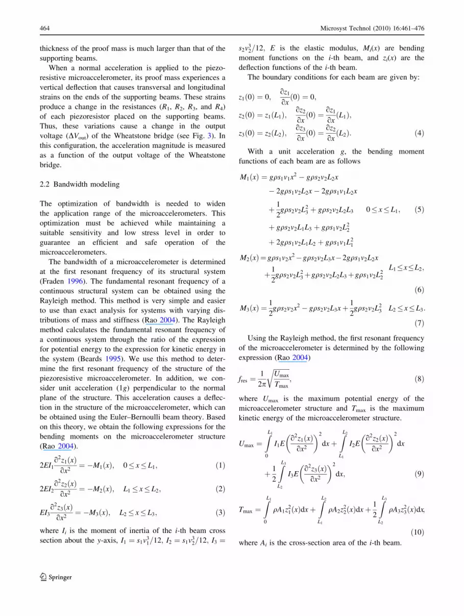
Figure 5 shows the response of the partial derivatives of
the sensitivity with respect to each dimensionless geo-
metrical parameter (L, s, v, and w), when the parameter L is
increased. For this condition, the responses of the deriva-
tives of the sensitivity with respect to s and w have the
greatest variations. Also, Fig. 6 shows the response of
the partial derivatives of the maximum normal stress
based on each dimensionless geometrical parameter (i.e.,
EsfL : qrmax/qL, Esfs : qrmax/qs, Esfv : qrmax/qv, and
Esfw : qrmax/qw). For the case of a maximum value L, the
derivates of the maximum normal stress with respect to s
and w have the greatest variations.
Fig. 4 Variations of the bandwidth as a function of the dimensionless
geometrical dimensions L, s, v and w
Microsyst Technol (2010) 16:461–476 467
123
4 Optimization model
The optimization model of the piezoresistive microaccel-
erometer has the bandwidth as the objective function and
the geometrical parameters as the design variables. Their
constraints include performance parameters such as the
sensitivity and the maximum normal stress of the micro-
accelerometer. In addition, this model considers constraints
defined by geometrical parameters that depend of the
structural configuration and the fabrication process. Two
structural configurations of piezoresistive microacceler-
ometers are optimized to support 10g and 50g accelerations.
4.1 Design variables
The design variables are defined by the structural config-
uration of the piezoresistive microaccelerometer. For this
case, Fig. 2 shows the design variables of the optimization
model that includes the geometrical parameters such as s1,
s2, v1, v2, L1, L2, and L3.
4.2 Limitations–constraints
The constraints may be classified as explicit and implicit
constraints. The explicit constraints restrict the range of the
design variables and the implicit constraints consider the
performance requirements. For this case, the implicit con-
straints are integrated by the sensitivity and normal stress
of the piezoresistive microaccelerometer. Moreover, the
explicit constraints are given by the bounds of the dimen-
sions (s1, s2, v1, v2, L1, L2, and L3) of the piezoresistive
microaccelerometer, as shown in Table 1.
The performance requirements (implicit constraints)
include sensitivity compared with that of the microac-
celerometer reported by Plaza et al. (2002) and a model
JTF commercial accelerometer fabricated by the Honeywell
Company (http://content.honeywell.com/sensing/sensotec/pdf_
catalog08/008727-1-EN_Model_JTF_Gen_Pur.pdf acces-
sed 16 July 2009). In addition, these requirements consider a
maximum normal stress given by the silicon rupture stress
divided by a safety factor of 1.5. Table 2 shows the per-
formance requirements of the proposed optimization
model for two structural configurations of piezoresistive
microaccelerometers.
4.3 Problem formulation
The mathematical representation of the optimization
problem is the maximization of the objective function
Fig. 6 Variations of the normal stress as a function of the dimen-
sionless geometrical dimensions L, s, v and w
Table 1 Explicit constraints for the proposed optimization model
Bounds s1
(lm)
v1
(lm)
L1
(lm)
s2
(lm)
v2
(lm)
L2
(lm)
L3
(lm)
Lower 200 10 200 2500 350 500 1000
Upper 1200 45 1200 3500 450 1200 2500
Table 2 Performance requirements for the proposed optimization
model
Performance requirements Structure 1 (10g) Structure 2 (50g)
Smin (mV/Vg) 1.03 0.16
rmax ¼ ru
F (GPa) 0.44 0.44
Fig. 5 Variations of the sensitivity as a function of the dimensionless
geometrical dimensions L, s, v and w
468 Microsyst Technol (2010) 16:461–476
123

denoted as F(x). In this case, the objective function is the
bandwidth of the piezoresistive microaccelerometer. As the
Box-Complex method finds the minimum of an objective
function, we change the sign of the objective function to
maximize it through this method. Hence the optimization
problem is given by:
Minimize F(x) = -fres
such that
3qg
2v31
p44
2s2v2L2
3 þ 2s2v2L2L3 þ 2s2v2L1L3 þ 2s1v2L22
�
þ 4s1v2L1L2 þ s1v1L21
�
� Sa
Fig. 7 Flow diagram of the
Box-Complex method used to
solve the proposed optimization
model
Microsyst Technol (2010) 16:461–476 469
123

3ngq
2v31
s2v2L23 þ 2s2v2L2L3 þ 2s2v2L1L3 þ 2s1v2L2
2
�
þ4s1v2L1L2 þ s1v1L21
�
� ru
F
200� s1� 1200
10� v2� 45
200� L1� 1200
2500� s2� 3500
350� v2� 450
500� L2� 1200
1000� L3� 2500;
ð27Þ
where fres is the bandwidth of the piezoresistive microac-
celerometer, Sa is the adequate value of the sensitivity of
the microaccelerometer for an specific application (this
magnitude must be chosen high for optimum performance),
ru is the rupture stress of the material of the micro-
accelerometer.
4.4 Box-Complex method implementation
The Box-Complex method is used to maximize the band-
width of the piezoresistive microaccelerometer. This
method takes advantages of being an easy algorithm and
considers implicit and explicit constraints. In addition, this
method is a constrained minimization technique that uses a
random search and does not require derivatives of the
objective function (Farkas and Jarmai 1997). The method is
applied to nonlinear programming problems with inequal-
ity constraints. Here the Box-Complex method was used to
determine the optimum dimensions of the piezoresistive
microaccelerometer to maximize its bandwidth keeping
high sensitivity and a normal stress less than the rupture
stress of the silicon. An algorithm, based on the Box-
Complex method was developed using the Matlab software
for a maximum error of 0.1%. Figure 7 shows the flow
diagram of the Box-Complex method used in this work.
The Box-Complex method uses a polyhedron (called
complex) with more than (n ? 1) vertices, being n the
number of design variables. This complex moves around
the solution space through expansion and contraction. In
the first iteration cycle an original complex is generated,
where the complex contains K C n ? 1 feasible points or
vertices in an n-dimensional design space. It considered
that at least one initial feasible point exists, which is called
the starting point and the remaining (K-1) points are
generated randomly. Next, the algorithm examines whether
the initial point satisfies the explicit constraints. If not, it is
moved a small distance b inside the constraining limit.
Now, the algorithm checks whether the point satisfies the
implicit constraints. If an implicit constraint is violated, the
Table 3 Design variables and performance requirements optimized for two structures of piezoresistive microaccelerometers
Microaccelerometer s1
(lm)
v1
(lm)
L1
(lm)
s2
(lm)
v2
(lm)
L2
(lm)
L3
(lm)
Normal stress
(MPa)
Sensitivity
(mV/Vg)
Bandwidth
(Hz)
1 805 15 200 3305 450 1090 1570 20.31 1.58 569.23
2 800 45 200 3500 450 1000 1595 11.54 0.18 2959.33
Table 4 Comparison of the sensitivity and bandwidth of the micro-
accelerometer developed by Plaza et al. (2002) and the model JTF
accelerometer (code GN) of Honeywell Company (http://content.
honeywell.com/sensing/sensotec/pdf_catalog08/008727-1-EN_Model_
JTF_Gen_Pur.pdf, accessed 16 July 2009) with those obtained using the
proposed optimization model
Performance parameters 10g 50g
Microaccelerometer
Plaza et al. (2002)
Optimized
microaccelerometer 1
Accelerometer
(model JTF) Honeywell
Optimized
microaccelerometer 2
Sensitivity (mV/Vg) 1.03 1.58 0.16 0.18
Bandwidth (Hz) 326 569.23 2,000 2,959.33
Table 5 Geometrical dimensions of the two microaccelerometers used in the FE models
Microaccelerometer Geometrical dimensions
s1 (lm) v1 (lm) L1 (lm) s2 (lm) v2 (lm) L2 (lm) L3 (lm)
1 805 15 200 3305 450 1090 1570
2 800 45 200 3500 450 1000 1595
470 Microsyst Technol (2010) 16:461–476
123
point is moved halfway towards the centroid of the previ-
ous points, and the explicit and implicit constraints are
evaluated again. Later, the objective function (bandwidth
of the microaccelerometer) is evaluated at each of the
previous points. Thus, the points with the worst and the
best function are determined. After that, if the difference
between the worst and best function is less than a tolerance
previously established, the solution is found. If this con-
dition is not satisfied, the worst point is rejected from the
centroid and replaced with a new one. This new point is
examined to determine if it satisfies the explicit constraints.
If these explicit constraints are satisfied then the algorithm
checks the other implicit constraints. If the new point sat-
isfies the implicit constraints and the objective function
value is less than the worst value, then this new point is
considered as an improvement.
In the next iteration, if either the function value of the
new point is larger than the worst value or any of the
implicit constraints are violated, then the algorithm moves
this point halfway towards the centroid of the previous
points. If this point satisfies the explicit and implicit con-
straints, but it remains as the worst, then another point must
be determined. For this, the algorithm moves the point
halfway towards the centroid of the previous points. This
process continues until the convergence criterion is
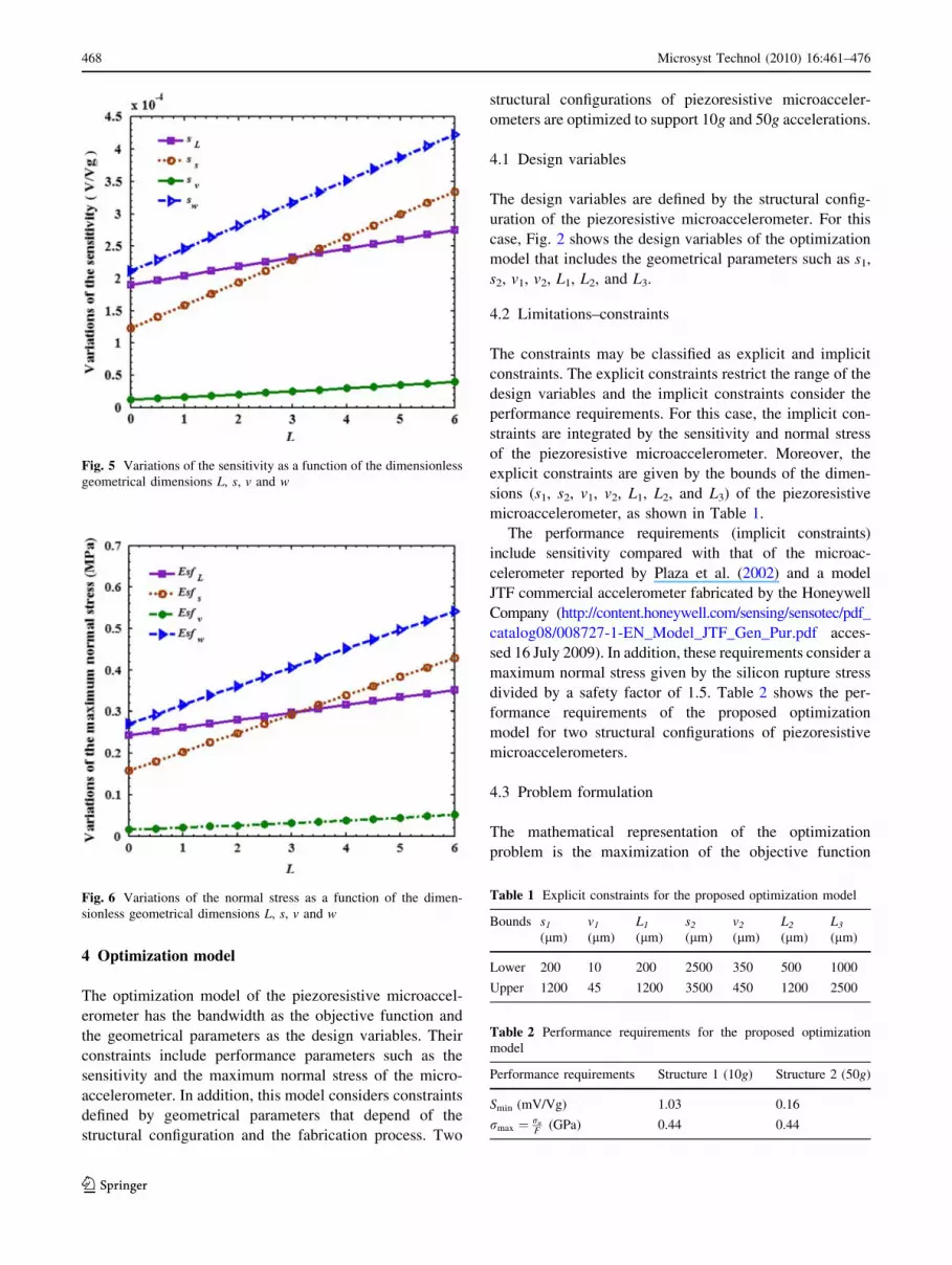
Fig. 8 FE models of the (a) first and (b) second optimized
piezoresistive microaccelerometer
Table 6 First five resonant frequencies of the two FE models of the
piezoresistive microaccelerometers
Mode shapes Microaccelerometer
1 2
Resonant frequency (Hz)
1 660.9 3119
2 23407 53027
3 53480 95242
4 70634 161190
5 173301 248950 Fig. 9 First mode shape of the (a) first and (b) second optimized
piezoresistive microaccelerometer
Microsyst Technol (2010) 16:461–476 471
123

satisfied (i.e., the difference between the worst and best
function is less than a given tolerance).
In the Box-Complex method, the expansion and con-
traction of the complex permits it to move closer to the
optimal values of the objective function.
5 Results and discussions
Table 3 shows the results of the proposed optimization
model using the Box-Complex method for the two struc-
tures of the piezoresistive microaccelerometers. The first
and second structures were optimized for 10g and 50g
accelerations, respectively. The two structures operate
safety for these accelerations since the normal stresses are
less than the rupture stress of the silicon, which is pre-
sumed to be 360 MPa in silicon h100i wafer (Borky 1997).
Table 4 shows the comparison of the structures optimized
against the microaccelerometer proposed by Plaza et al.
(2002) and the model JTF accelerometer (code GN)
of Honeywell Company (http://content.honeywell.com/
sensing/sensotec/pdf_catalog08/008727-1-EN_Model_JTF_
Gen_Pur.pdf, accessed 16 July 2009).
For the first optimized microaccelerometer, the band-
width was increased 74.6% and the sensitivity was
improved by 53.4% with respect to the microaccelerometer
developed by Plaza et al. (2002). In addition, the second
optimized microaccelerometer presented an improvement
in the bandwidth and sensitivity of 48.0 and 12.5%,
respectively, compared to the model JFT accelerometer
fabricated by Honeywell Company (http://content.
honeywell.com/sensing/sensotec/pdf_catalog08/008727-1-
EN_Model_JTF_ Gen_Pur.pdf, accessed 16 July 2009).
Through the optimization model proposed in this work, the
results of the bandwidth, sensitivity and normal stress of the
piezoresistive microaccelerometer based on cantilever-type
beams can be significantly improved. In addition, this model
can be easily solved using the Box-Complex method.
In addition, we developed two FE models using ANSYS
software. These FE models help to understand the band-
width, sensitivity and maximum normal stress of the two
piezoresistive microaccelerometers. In these models we
considered a horizontal angle of 54.7� on the beams as
obtained by the etching process of the microaccelerometer.
Table 5 shows the optimum dimensions of the two micro-
accelerometers used in the FE models.
Fig. 10 (a) Second, (b) third, (c) fourth, and (d) fifth modal shapes of the first optimized piezoresistive microaccelerometer
472 Microsyst Technol (2010) 16:461–476
123

Figure 8 shows the FE models of the first and second
structure of the microaccelerometers, respectively. In the
first and second structure 8,792 and 8,496 finite elements
respectively were used. In the supporting beams a fine
mesh was used since these zones can be subjected to high
stresses. Later, the first five resonant frequencies of each
structure were obtained, as shown in Table 6. The first
resonance frequency defines the bandwidth of each struc-
ture. Figure 9 shows the first mode shape of the two mic-
roaccelerometers, with a bandwidth of 660.9 and 3,119 Hz,
respectively. These bandwidths have a relative difference
of 16.1 and 5.4% with respect to those of the optimization
model. These differences are probably caused because the
FE models consider the slope of the beams, which are the
result of the etching process of the microaccelerometer. In
addition, Fig. 10 shows the second, third, fourth and fifth
modal shapes of the first microaccelerometer. The first
Fig. 12 3D View of the (a) longitudinal and (b) transverse stress
distribution on the first optimized piezoresistive microaccelerometer
Fig. 13 3D View of the (a) longitudinal and (b) transverse stress
distribution on the supporting beams of the first optimized piezore-
sistive microaccelerometer
Fig. 11 Deflection distributions (lm) of the first optimized piezore-
sistive microaccelerometer
Microsyst Technol (2010) 16:461–476 473
123

mode shape is a bending mode, the second mode is twist-
ing, and the third mode is a lateral type mode.
Next, 10g acceleration was applied in the normal
direction to the first microaccelerometer. The maximum
deflection of this microaccelerometer (7.99 lm) is located
at the end of its proof mass, as shown in Fig. 11. This
deflection is less than the minimum dimension of the
structure of the first microaccelerometer. In addition, the
longitudinal and transverse stress distribution on the first
microaccelerometer is shown in Fig. 12. Also, Fig. 13
shows the longitudinal and transverse stress distribution on
the supporting beams where the piezoresistors (elements
3355 and 3408) will be placed. The maximum transverse
and longitudinal stress (on the elements 3355 and 3408)
registered 1.69 MPa and 17.61 MPa, respectively. The
longitudinal stress obtained with the FE model has aFig. 14 Deflection distributions (lm) of the second optimized
piezoresistive microaccelerometer
Fig. 15 3D View of the (a) transverse and (b) longitudinal stress
distribution on the second optimized piezoresistive microacce-
lerometer
Fig. 16 3D View of the (a) transverse and (b) longitudinal stress
distribution on the supporting beams of the second optimized
piezoresistive microaccelerometer
474 Microsyst Technol (2010) 16:461–476
123

relative difference of -13.3% with respect to that obtained
using the optimization model.
The second microaccelerometer was subjected to 50g
acceleration and it had a maximum deflection of 1.8 lm
(see Fig. 14). In addition, Figs. 15 and 16 show the trans-
verse and longitudinal stress distribution on the structure
and supporting beams of the second microaccelerometer. In
the locations where the piezoresistors (elements 8953 and
9040) will be located, the highest transverse and longitu-
dinal stress (on the elements 8953 and 9040) was 0.27 and
9.94 MPa, respectively. The maximum transverse stress
represents 2.7% of the highest longitudinal stress. These
values are less than the rupture stress of a silicon h100iwafer (Borky 1997). This longitudinal stress represents a
relative difference of -13.9% with respect to that of the
optimization model. The two FE models indicated results
close to those of the optimization model. In addition, the
results of the FE models show that the transverse stresses
are much less with respect to the longitudinal stresses.
These FE models predict the mechanical behavior of the
piezoresistive microaccelerometers.
6 Conclusions
An optimization model to maximize the bandwidth of
uniaxial piezoresistive microaccelerometers based on can-
tilever-type beams was presented. This model used the
sensitivity and the maximum normal stress as implicit
constraints, which were obtained using the Euler–Bernoulli
beam and maximum-normal-stress failure theories. The
objective function of the microaccelerometer bandwidth
was determined using the Rayleigh method and maximized
through an algorithm based on the Box-Complex method.
The optimization model was used on a silicon piezoresis-
tive microaccelerometer reported in the literature and
subjected to 10g and 50g accelerations, respectively. This
model determined the optimum geometrical dimensions of
the microaccelerometer that maximize the bandwidth
keeping a high sensitivity and normal stress less than the
silicon rupture stress. The results of the optimization model
showed a significant increment in the bandwidth and sen-
sitivity of the microaccelerometer, and with normal stress
levels that guarantee a safe behavior of its structure. In
addition, FE models using the ANSYS software were built
to evaluate the mechanical behavior of the optimized
microaccelerometers. The results of the FE models agreed
well with respect those of the optimization model.
Microaccelerometers with optimum performance are
needed in new applications such as biomedical activity
monitoring, headsets for virtual reality, computer periph-
erals and navigation. Future research directions will
include minimization of the thermal noise on piezoresistive
microaccelerometers. Also, the effect of the residual
stress on the structure of the microaccelerometer will be
considered.
Acknowledgments This work was supported by the University of
Guanajuato (UG DAIP project 099/2008) and CONACYT through
project 84605. The valuable discussions and contributions by Pro-
fessor Jerry Hemmye of Western Michigan University are gratefully
acknowledged.
References
Amarasinghe R, Dao DV, Toriyama T, Sugiyama S (2007) Devel-
opment of miniaturized 6-axis accelerometer utilizing piezore-
sistive sensing elements. Sens Actuators A 134:310–320. doi:
10.1016/j.sna.2006.05.044
Beards CF (1995) Engineering vibration analysis with application to
control systems. Edward Arnold, UK
Beeby S, Ensell G, Kraf M, White N (2004) MEMS mechanical
sensors. Artech House Inc., Norwood
Borky JM (1997) Silicon diaphragm pressure sensors with integrated
electronics. Ph.D. dissertation, University of Michigan, Ann
Arbor
Chae J, Kulah H, Najafi K (2005) A monolithic three-axis micro-g
micromachined silicon capacitive accelerometer. J Microelec-
tromech Syst 14:235–242. doi:10.1109/JMEMS.2004.839347
Cortes-Perez AR (2008) Design and optimization of uniaxial
microaccelerometer. Master thesis, Guanajuato University,
Guanajuato, Mexico (Translation of Spanish thesis)
Coultate JK, Fox CHJ, McWilliam S, Malvern AR (2008) Application
of optimal and robust design methods to a MEMS accelerometer.
Sens Actuators A 142:88–96. doi:10.1016/j.sna.2007.04.033
Dauderstadt UA, Sarro PM, French PJ (1998) Temperature depen-
dence and drift of a thermal accelerometer. Sens Actuators A
66:244–249
Duc TC, Creemer JF, Sarro PM (2006) Lateral nano-Newton force-
sensing piezoresistive cantilever for microparticle handling.
J Micromech Microeng 16:S102–S106. doi:10.1088/0960-1317/
16/6/S16
Farkas J, Jarmai K (1997) Analysis and optimum design of metal
structures. Balkema Publishers, Rotterdam
Fedder GK, Chae J, Kulah H, Najafi K, Denison T, Kuang J, Lewis S
(2005) Monolithically integrated inertial sensors. In: Baltes H,
Brand O, Fedder GK, Hierold C, Korvink J, Tabata O (eds)
Advanced Micro & Nanosystems, vol 2. CMOS-MEMS. Wiley-
VCH, Weinheim, pp 137–192
Fraden J (1996) Handbook of modern sensors. Springer, New York
Herrera-May AL, Cortes-Perez AR, Aguilera-Cortes LA (2008)
Microaccelerometers: present. Acta Universitaria 18:24–32
Translation of Spanish paper
Herrera-May AL, Garcıa-Ramırez PJ, Aguilera-Cortes LA, Martınez-
Castillo J, Sauceda-Carvajal A, Garcıa-Gonzalez L, Figueras-
Costa E (2009a) A resonant magnetic field with high quality
factor at atmospheric pressure. J Micromech Microeng
19:15016. doi:10.1088/0960-1317/19/1/015016
Herrera-May AL, Soto-Cruz BS, Lopez-Huerta F, Aguilera-Cortes
LA (2009b) Electromechanical analysis of a piezoresistive
pressure microsensor for low-pressure biomedical applications.
Rev Mex Fis 55:14–24
Hindrichsen CC, Almind NS, Brodersen SH, Hansen O, Thomsen EV
(2009) Analytical model of a PZT thick-film triaxial acceler-
ometer for optimum design. IEEE Sens J 9:419–429. doi:
10.1109/JSEN.2009.2014412
Microsyst Technol (2010) 16:461–476 475
123

Huang S, Li X, Song Z, Wang Y, Yang H, Che L, Jiao J (2005) A
high-performance micromachined piezoresistive accelerometer
with axially stressed tiny beams. J Micromech Microeng
15:993–1000. doi:10.1088/0960-1317/15/5/014
Kaltsas G, Goustouridis D, Nassiopoulou AG (2006) A thermal
convective accelerometer system based on a silicon sensor-study
and packaging. Sens Actuators A 132:147–153. doi:10.1016/
j.sna.2006.04.026
Kovacs A, Vızvary Z (2001) Structural parameter sensitivity analysis
of cantilever-and bridge-type accelerometers. Sens Actuators A
89:197–205. doi:10.1016/S0924-4247(00)00553-7
Lee SJ, Cho DW (2004) Development of a micro-opto-mechanical
accelerometer based on intensity modulation. Microsyst Technol
10:147–154. doi:10.1007/s00542-003-0324-9
Liu CH, Kenny TW (2001) A high-precision, wide-bandwidth
micromachined tunneling accelerometer. J Microelectromech
Syst 10:425–433. doi:10.1109/84.946800
Liu CH, Barzilai AM, Reynolds JK, Partridge A, Kenny TW, Grade
JD, Rockstad HK (1998) Characterization of a high-sensitivity
micromachined tunneling accelerometer with micro-g resolution.
J Microelectromech Syst 7:235–244. doi:10.1109/84.679388
Llobera A, Seidemann V, Plaza JA, Cadarso VJ, Buttgenbach S
(2007) SU-8 optical accelerometers. J Microelectromech Syst
16:111–121. doi:10.1109/JMEMS.2006.885845
Norton RL (2006) Machine design: an integrated approach, 3rd edn.
Pearson Prentice Hall, New Jersey
Partridge A et al (2000) A high-performance planar piezoresistive
accelerometer. J Microelectromech Syst 9:58–66. doi:10.1109/
84.825778
Plaza JA, Collado A, Cabruja E, Steve J (2002) Piezoresistive
accelerometers for MCM package. J Microelectromech Syst
11:794–801. doi:10.1109/JMEMS.2002.805213
Rao SS (2004) Mechanical Vibrations, 4th edn. Pearson Education
Inc., Upper Saddle River
Roylance LM, Angell JB (1979) A batch-fabricated silicon acceler-
ometer. IEEE Trans Electron Dev 26:1911–1917
Sankar AR, Lahiri SK, Das S (2009) Performance enhancement of a
silicon MEMS piezoresistive single axis accelerometer with
electroplated gold on a proof mass. J Micromech Microeng
19:025008. doi:10.1088/0960-1317/19/2/025008
Seidel H, Csepregi (1984) Design optimization for cantilever-type
accelerometer. Sens Actuators 6:81–92
Senturia SD (2002) Microsystem design. Kluwer, Boston
Joshi BP, Chaware AS, Gangal SA (2005) Performance optimization
of a cantilever-type micro-accelerometer. In: Proceedings of
ISSS 2005, Bangalore, SB, pp 115–122
Yazdi N, Ayazi F, Najafi K (1998) Micromachined inertial sensors.
In: Proceedings of the IEEE micro electro mechanical systems
conference (MEMS’99), pp 1640–1659
Zhu M, Kirby P, Lim MY (2004) Lagrange’s formalism for modeling
of a triaxial microaccelerometer with piezoelectric thin-film
sensing. IEEE Sens J 4:455–463. doi:10.1109/JSEN.2004.
830948
Zou Q, Tan W, Kim ES, Loeb GE (2008) Single-and triaxis
piezoelectric-bimorph accelerometers. J Microelectromech Syst
17:45–57. doi:10.1109/JMEMS.2007.909100
476 Microsyst Technol (2010) 16:461–476
123