pax2s - red lion - audin
TRANSCRIPT
1
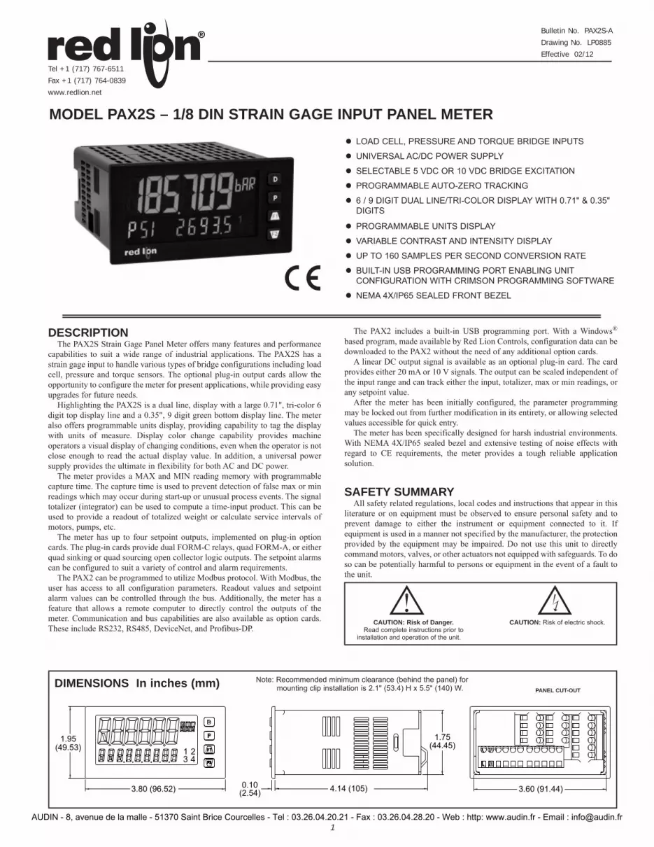
3.80 (96.52)
(49.53)
(2.54)
(44.45)
3.60 (91.44)4.14 (105)
1.95
0.10
1.75
13
24
LOAD CELL, PRESSURE AND TORQUE BRIDGE INPUTS
UNIVERSAL AC/DC POWER SUPPLY
SELECTABLE 5 VDC OR 10 VDC BRIDGE EXCITATION
PROGRAMMABLE AUTO-ZERO TRACKING
6 / 9 DIGIT DUAL LINE/TRI-COLOR DISPLAY WITH 0.71" & 0.35" DIGITS
PROGRAMMABLE UNITS DISPLAY
VARIABLE CONTRAST AND INTENSITY DISPLAY
UP TO 160 SAMPLES PER SECOND CONVERSION RATE
BUILT-IN USB PROGRAMMING PORT ENABLING UNIT CONFIGURATION WITH CRIMSON PROGRAMMING SOFTWARE
NEMA 4X/IP65 SEALED FRONT BEZEL
DESCRIPTIONThe PAX2S Strain Gage Panel Meter offers many features and performance
capabilities to suit a wide range of industrial applications. The PAX2S has a strain gage input to handle various types of bridge configurations including load cell, pressure and torque sensors. The optional plug-in output cards allow the opportunity to configure the meter for present applications, while providing easy upgrades for future needs.
Highlighting the PAX2S is a dual line, display with a large 0.71", tri-color 6 digit top display line and a 0.35", 9 digit green bottom display line. The meter also offers programmable units display, providing capability to tag the display with units of measure. Display color change capability provides machine operators a visual display of changing conditions, even when the operator is not close enough to read the actual display value. In addition, a universal power supply provides the ultimate in flexibility for both AC and DC power.
The meter provides a MAX and MIN reading memory with programmable capture time. The capture time is used to prevent detection of false max or min readings which may occur during start-up or unusual process events. The signal totalizer (integrator) can be used to compute a time-input product. This can be used to provide a readout of totalized weight or calculate service intervals of motors, pumps, etc.
The meter has up to four setpoint outputs, implemented on plug-in option cards. The plug-in cards provide dual FORM-C relays, quad FORM-A, or either quad sinking or quad sourcing open collector logic outputs. The setpoint alarms can be configured to suit a variety of control and alarm requirements.
The PAX2 can be programmed to utilize Modbus protocol. With Modbus, the user has access to all configuration parameters. Readout values and setpoint alarm values can be controlled through the bus. Additionally, the meter has a feature that allows a remote computer to directly control the outputs of the meter. Communication and bus capabilities are also available as option cards. These include RS232, RS485, DeviceNet, and Profibus-DP.
The PAX2 includes a built-in USB programming port. With a Windows® based program, made available by Red Lion Controls, configuration data can be downloaded to the PAX2 without the need of any additional option cards.
A linear DC output signal is available as an optional plug-in card. The card provides either 20 mA or 10 V signals. The output can be scaled independent of the input range and can track either the input, totalizer, max or min readings, or any setpoint value.
After the meter has been initially configured, the parameter programming may be locked out from further modification in its entirety, or allowing selected values accessible for quick entry.
The meter has been specifically designed for harsh industrial environments. With NEMA 4X/IP65 sealed bezel and extensive testing of noise effects with regard to CE requirements, the meter provides a tough reliable application solution.
SAFETY SUMMARYAll safety related regulations, local codes and instructions that appear in this
literature or on equipment must be observed to ensure personal safety and to prevent damage to either the instrument or equipment connected to it. If equipment is used in a manner not specified by the manufacturer, the protection provided by the equipment may be impaired. Do not use this unit to directly command motors, valves, or other actuators not equipped with safeguards. To do so can be potentially harmful to persons or equipment in the event of a fault to the unit.
MODEL PAX2S – 1/8 DIN STRAIN GAGE INPUT PANEL METER
DIMENSIONS In inches (mm) Note: Recommended minimum clearance (behind the panel) for mounting clip installation is 2.1" (53.4) H x 5.5" (140) W. PANEL CUT-OUT
Bulletin No. PAX2S-A
Drawing No. LP0885
Effective 02/12
Tel +1 (717) 767-6511
Fax +1 (717) 764-0839
www.redlion.net
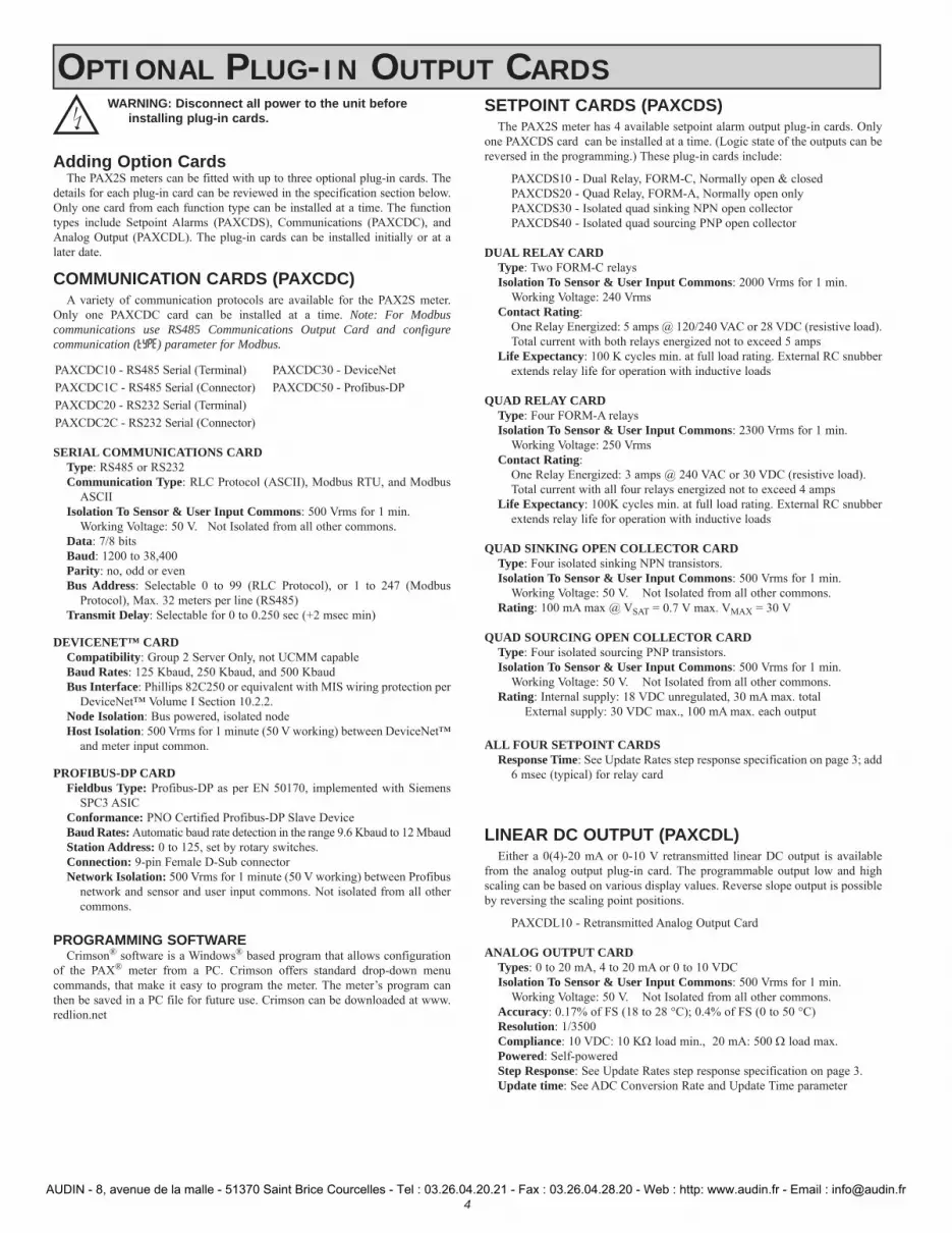
CAUTION: Risk of Danger.Read complete instructions prior to
installation and operation of the unit.
CAUTION: Risk of electric shock.
AUDIN - 8, avenue de la malle - 51370 Saint Brice Courcelles - Tel : 03.26.04.20.21 - Fax : 03.26.04.28.20 - Web : http: www.audin.fr - Email : [email protected]

2
Ordering Information . . . . . . . . . . . . . . . . . . . 2General Meter Specifications . . . . . . . . . . . . . 3Optional Plug-In Output Cards . . . . . . . . . . . . 4Installing the Meter . . . . . . . . . . . . . . . . . . . . . 5Setting the Jumpers . . . . . . . . . . . . . . . . . . . . 5Installing Plug-In Cards . . . . . . . . . . . . . . . . . 6Wiring the Meter . . . . . . . . . . . . . . . . . . . . . . . 6Front Panel Keys and Display Overview . . . . . 8
Line 2 Display Loops . . . . . . . . . . . . . . . . . . . . 8Programming the PAX2S . . . . . . . . . . . . . . . . 9PAX2S Modbus Register Table . . . . . . . . . . 24Factory Service Operations . . . . . . . . . . . . . 28Troubleshooting Guide . . . . . . . . . . . . . . . . . 29Parameter Value Chart . . . . . . . . . . . . . . . . . 30Programming Overview . . . . . . . . . . . . . . . . . 34
TABLE OF CONTENTS
ORDERING INFORMATIONMeter Part Numbers
MODEL NO. DESCRIPTION PART NUMBER
PAX2S Strain Gage Input Panel Meter PAX2S000
Option Card and Accessories Part NumbersTYPE MODEL NO. DESCRIPTION PART NUMBER
OptionalPlug-InCards
PAXCDS
Dual Setpoint Relay Output Card PAXCDS10
Quad Setpoint Relay Output Card PAXCDS20
Quad Setpoint Sinking Open Collector Output Card PAXCDS30
Quad Setpoint Sourcing Open Collector Output Card PAXCDS40
PAXCDC 1
RS485 Serial Communications Card with Terminal Block PAXCDC10
Extended RS485 Serial Communications Card with Dual RJ11 Connector PAXCDC1C
RS232 Serial Communications Card with Terminal Block PAXCDC20
Extended RS232 Serial Communications Card with 9 Pin D Connector PAXCDC2C
DeviceNet Communications Card PAXCDC30
Profibus-DP Communications Card PAXCDC50
PAXCDL Analog Output Card PAXCDL10
AccessoriesSFCRD2 Crimson PC Configuration Software for Windows 2000, XP and Windows 7 SFCRD200
CBLUSB USB Programming Cable Type A-Mini B CBLUSB01
Notes:1. For Modbus communications use RS485 Communications Output Card and configure communication (tYPE) parameter for Modbus.2. Crimson software is available for free download from http://www.redlion.net/
AUDIN - 8, avenue de la malle - 51370 Saint Brice Courcelles - Tel : 03.26.04.20.21 - Fax : 03.26.04.28.20 - Web : http: www.audin.fr - Email : [email protected]

3
GENERAL METER SPECIFICATIONS1. DISPLAY: Positive image LCD
Top Line - 6 digit, 0.71" (18 mm), with tri-color backlight (red, green or orange), display range: -199,999 to 999,999;
Bottom Line - 9 digit, 0.35" (8.9 mm), with green backlight, display range: - 199,999,999 to 999,999,999
2. POWER:AC Power: 40 to 250 VAC, 50/60 Hz, 14 VADC Power: 21.6 to 250 VDC, 8 WIsolation: 2300 Vrms for 1 min. to all inputs and outputs.
3. ANNUNCIATORS: Backlight color: Red1 - setpoint alarm 1 3 - setpoint alarm 32 - setpoint alarm 2 4 - setpoint alarm 4Line 1 Units Label – programmable 3 digit units annunciator with tri-color
backlight (red, green or orange)4. KEYPAD: 2 programmable function keys, 4 keys total5. A/D CONVERTER: 24 bit resolution6. UPDATE RATES:
A/D conversion rate: programmable 5 to 160 readings/sec.Step response:
Input Rate 5 10 20 40 80 160 Readings/Sec
Response Time * 600 400 200 100 50 30msec
response time *
* - max. to within 99% of final readout value (digital filter disabled)Display update rate: 1 to 20 updates/sec.Setpoint output on/off delay time: 0 to 3275 sec.Analog output update rate: 0 to 10 secMax./Min. capture delay time: 0 to 3275 sec.
7. DISPLAY MESSAGES:“OLOL” - Appears when measurement exceeds + signal range.“ULUL” - Appears when measurement exceeds - signal range“. . . . .” - Appears when display values exceed + display range.“- . . . . .” - Appears when display values exceed - display range.
8. INPUT:Connection Type: 4-wire bridge (differential); 2-wire (single-ended)Common Mode Range (with respect to input common): 0 to +5 VDC
Rejection: 80 dB (DC to 120 Hz)INPUT
RANGEACCURACY* (18 to 28ºC)
ACCURACY* (0 to 50ºC)
IMPEDANCE/ COMPLIANCE
MAX CONT. OVERLOAD
** RESOLUTION
± 24 mVDC
0.02% of rdg + 3 μV
0.07% of rdg + 4 μV
100 Mohm 30 V 1 μV
± 240 mVDC
0.02% of rdg + 30 μV
0.07% of rdg + 40 μV
100 Mohm 30 V 10 μV
* After 20 minute warm-up. Accuracy is specified in two ways: Accuracy over an 18 to 28°C and 10 to 75% RH environment; and accuracy over a 0 to 50°C and 0 to 85% RH (non-condensing environment). Accuracy over the 0 to 50°C range includes the temperature coefficient effect of the meter.
** Higher resolution can be achieved via input scaling 9. EXCITATION POWER: Jumper selectable
+5 VDC @ 65 mADC max., +/-2%+10 VDC @ 125 mADC max., +/-2%Temperature Coefficient (ratio metric): 20 ppm/ºC max.
10. USER INPUTS: Three programmable user inputsMax. Continuous Input: 30 VDCIsolation To Sensor Input Common: Not isolated.Response Time: 12 msec. max.Logic State: User programmable (USrACt) for sink/source (LO/HI) logic
INPUT STATE (USrACt) LO/SINK HI/SOURCE
20 K pull-up to +3.3 V 20 K pull-downActive VIN < 1.1 VDC VIN > 2.2 VDCInactive VIN > 2.2 VDC VIN < 1.1 VDC
11. TOTALIZER:Time Base: second, minute, hour, or dayBatch: Can accumulate (gate) input display from a user inputTime Accuracy: 0.01% typicalDecimal Point: 0 to 0.0000Scale Factor: 0.001 to 65.000Low Signal Cut-out: -199,999 to 999,999Total: 6 digits on Line 1; 9 digits on Line 2
12. CUSTOM LINEARIZATION:Data Point Pairs: Selectable from 2 to 16Display Range: -199,999 to 999,999Decimal Point: 0 to 0.0000
13. MEMORY: Nonvolatile memory retains all programmable parameters and display values.
14. ENVIRONMENTAL CONDITIONS:Operating Temperature Range: 0 to 50 °CStorage Temperature Range: -40 to 60 °CVibration According to IEC 68-2-6: Operational 5 to 150 Hz, in X, Y, Z
direction for 1.5 hours, 2 g.Shock According to IEC 68-2-27: Operational 25 g (10 g relay), 11 msec in 3
directions.Operating and Storage Humidity: 0 to 85% max. RH non-condensingAltitude: Up to 2000 meters
15. CERTIFICATIONS AND COMPLIANCES:SAFETY
IEC 61010-1, EN 61010-1: Safety requirements for electrical equipment for measurement, control, and laboratory use, Part 1.
IP65 Enclosure rating (Face only), IEC 529IP20 Enclosure rating (Rear of unit), IEC 529
Type 4X Indoor Enclosure rating (Face only), UL50ELECTROMAGNETIC COMPATIBILITYEmissions and Immunity to EN 61326:2006: Electrical Equipment for
Measurement, Control and Laboratory use.Immunity to Industrial Locations:Electrostatic discharge EN 61000-4-2 Criterion A
4 kV contact discharge8 kV air discharge
Electromagnetic RF fields EN 61000-4-3 Criterion A4
10 V/m (80 MHz to 1 GHz)3 V/m (1.4 GHz to 2 GHz)1 V/m (2 GHz to 2.7 GHz)
Fast transients (burst) EN 61000-4-4 Criterion Apower 2 kV
I/O signal 1 kVI/O signal connected to power 2 kV
Surge EN 61000-4-5 Criterion Apower 1 kV L to L, 2 kV L to Gsignal 1 kV
RF conducted interference EN 61000-4-6 Criterion A3 Vrms
Power freq magnetic fields EN 61000-4-8 Criterion A30 A/m
AC power EN 61000-4-11Voltage dip Criterion A
0% during 1 cycle40% during 10/12 cycle70% during 25/30 cycle
Short interruptions Criterion C0% during 250/300 cycles
Emissions:Emissions EN 55011 Class ANotes:
1. Criterion A: Normal operation within specified limits.2. Criterion B: Temporary loss of performance from which the unit self-
recovers.3. Criterion C: Temporary loss of function where system reset occurs.4. Self-recoverable loss of performance during EMI disturbance:
Measurement input signal may deviate during EMI disturbance. For operation without loss of performance: Unit is mounted in a metal enclosure I/O and power cables are routed in metal conduit connected to earth ground.
Refer to EMC Installation Guidelines section of the bulletin for additional information.
16. CONNECTIONS: High compression cage-clamp terminal blockWire Strip Length: 0.3" (7.5 mm)Wire Gauge Capacity: One 14 AWG (2.55 mm) solid, two 18 AWG (1.02
mm) or four 20 AWG (0.61 mm)17. CONSTRUCTION: This unit is rated for NEMA 4X/IP65 indoor use. IP20
Touch safe. Installation Category II, Pollution Degree 2. One piece bezel/ case. Flame resistant. Synthetic rubber keypad. Panel gasket and mounting clip included.
18. WEIGHT: 8 oz. (226.8 g)
AUDIN - 8, avenue de la malle - 51370 Saint Brice Courcelles - Tel : 03.26.04.20.21 - Fax : 03.26.04.28.20 - Web : http: www.audin.fr - Email : [email protected]
4
WARNING: Disconnect all power to the unit before installing plug-in cards.
Adding Option CardsThe PAX2S meters can be fitted with up to three optional plug-in cards. The
details for each plug-in card can be reviewed in the specification section below. Only one card from each function type can be installed at a time. The function types include Setpoint Alarms (PAXCDS), Communications (PAXCDC), and Analog Output (PAXCDL). The plug-in cards can be installed initially or at a later date.
COMMUNICATION CARDS (PAXCDC)A variety of communication protocols are available for the PAX2S meter.
Only one PAXCDC card can be installed at a time. Note: For Modbus communications use RS485 Communications Output Card and configure communication (tYPE) parameter for Modbus.
PAXCDC10 - RS485 Serial (Terminal) PAXCDC30 - DeviceNetPAXCDC1C - RS485 Serial (Connector) PAXCDC50 - Profibus-DPPAXCDC20 - RS232 Serial (Terminal)PAXCDC2C - RS232 Serial (Connector)
SERIAL COMMUNICATIONS CARDType: RS485 or RS232Communication Type: RLC Protocol (ASCII), Modbus RTU, and Modbus
ASCIIIsolation To Sensor & User Input Commons: 500 Vrms for 1 min.
Working Voltage: 50 V. Not Isolated from all other commons. Data: 7/8 bitsBaud: 1200 to 38,400Parity: no, odd or evenBus Address: Selectable 0 to 99 (RLC Protocol), or 1 to 247 (Modbus
Protocol), Max. 32 meters per line (RS485)Transmit Delay: Selectable for 0 to 0.250 sec (+2 msec min)
DEVICENET™ CARDCompatibility: Group 2 Server Only, not UCMM capableBaud Rates: 125 Kbaud, 250 Kbaud, and 500 KbaudBus Interface: Phillips 82C250 or equivalent with MIS wiring protection per
DeviceNet™ Volume I Section 10.2.2.Node Isolation: Bus powered, isolated nodeHost Isolation: 500 Vrms for 1 minute (50 V working) between DeviceNet™
and meter input common.
PROFIBUS-DP CARDFieldbus Type: Profibus-DP as per EN 50170, implemented with Siemens
SPC3 ASICConformance: PNO Certified Profibus-DP Slave DeviceBaud Rates: Automatic baud rate detection in the range 9.6 Kbaud to 12 MbaudStation Address: 0 to 125, set by rotary switches.Connection: 9-pin Female D-Sub connectorNetwork Isolation: 500 Vrms for 1 minute (50 V working) between Profibus
network and sensor and user input commons. Not isolated from all other commons.
PROGRAMMING SOFTWARECrimson® software is a Windows® based program that allows configuration
of the PAX® meter from a PC. Crimson offers standard drop-down menu commands, that make it easy to program the meter. The meter’s program can then be saved in a PC file for future use. Crimson can be downloaded at www.redlion.net
SETPOINT CARDS (PAXCDS)The PAX2S meter has 4 available setpoint alarm output plug-in cards. Only
one PAXCDS card can be installed at a time. (Logic state of the outputs can be reversed in the programming.) These plug-in cards include:
PAXCDS10 - Dual Relay, FORM-C, Normally open & closedPAXCDS20 - Quad Relay, FORM-A, Normally open onlyPAXCDS30 - Isolated quad sinking NPN open collectorPAXCDS40 - Isolated quad sourcing PNP open collector
DUAL RELAY CARDType: Two FORM-C relaysIsolation To Sensor & User Input Commons: 2000 Vrms for 1 min.
Working Voltage: 240 VrmsContact Rating:
One Relay Energized: 5 amps @ 120/240 VAC or 28 VDC (resistive load).Total current with both relays energized not to exceed 5 amps
Life Expectancy: 100 K cycles min. at full load rating. External RC snubber extends relay life for operation with inductive loads
QUAD RELAY CARDType: Four FORM-A relaysIsolation To Sensor & User Input Commons: 2300 Vrms for 1 min.
Working Voltage: 250 VrmsContact Rating:
One Relay Energized: 3 amps @ 240 VAC or 30 VDC (resistive load).Total current with all four relays energized not to exceed 4 amps
Life Expectancy: 100K cycles min. at full load rating. External RC snubber extends relay life for operation with inductive loads
QUAD SINKING OPEN COLLECTOR CARDType: Four isolated sinking NPN transistors. Isolation To Sensor & User Input Commons: 500 Vrms for 1 min.
Working Voltage: 50 V. Not Isolated from all other commons. Rating: 100 mA max @ VSAT = 0.7 V max. VMAX = 30 V
QUAD SOURCING OPEN COLLECTOR CARDType: Four isolated sourcing PNP transistors.Isolation To Sensor & User Input Commons: 500 Vrms for 1 min.
Working Voltage: 50 V. Not Isolated from all other commons. Rating: Internal supply: 18 VDC unregulated, 30 mA max. total
External supply: 30 VDC max., 100 mA max. each output
ALL FOUR SETPOINT CARDSResponse Time: See Update Rates step response specification on page 3; add
6 msec (typical) for relay card
LINEAR DC OUTPUT (PAXCDL)Either a 0(4)-20 mA or 0-10 V retransmitted linear DC output is available
from the analog output plug-in card. The programmable output low and high scaling can be based on various display values. Reverse slope output is possible by reversing the scaling point positions.
PAXCDL10 - Retransmitted Analog Output Card
ANALOG OUTPUT CARDTypes: 0 to 20 mA, 4 to 20 mA or 0 to 10 VDCIsolation To Sensor & User Input Commons: 500 Vrms for 1 min.
Working Voltage: 50 V. Not Isolated from all other commons. Accuracy: 0.17% of FS (18 to 28 °C); 0.4% of FS (0 to 50 °C)Resolution: 1/3500Compliance: 10 VDC: 10 K load min., 20 mA: 500 load max. Powered: Self-poweredStep Response: See Update Rates step response specification on page 3.Update time: See ADC Conversion Rate and Update Time parameter
OPTIONAL PLUG-IN OUTPUT CARDS
AUDIN - 8, avenue de la malle - 51370 Saint Brice Courcelles - Tel : 03.26.04.20.21 - Fax : 03.26.04.28.20 - Web : http: www.audin.fr - Email : [email protected]
5
1.0 INSTALLING THE METER
2.0 SETTING THE JUMPERS
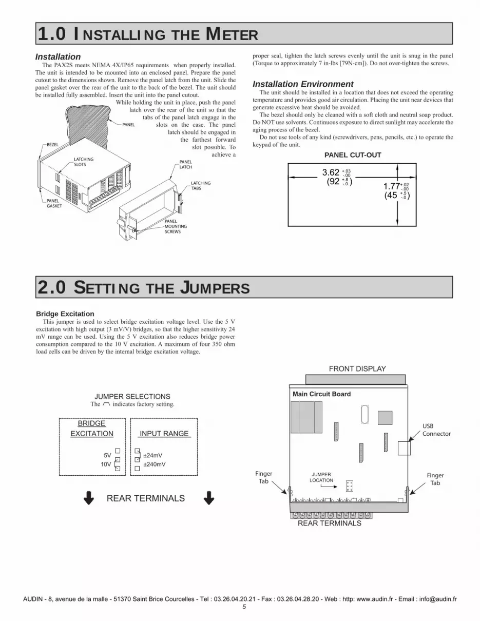
Installation The PAX2S meets NEMA 4X/IP65 requirements when properly installed.
The unit is intended to be mounted into an enclosed panel. Prepare the panel cutout to the dimensions shown. Remove the panel latch from the unit. Slide the panel gasket over the rear of the unit to the back of the bezel. The unit should be installed fully assembled. Insert the unit into the panel cutout.
While holding the unit in place, push the panel latch over the rear of the unit so that the
tabs of the panel latch engage in the slots on the case. The panel
latch should be engaged in the farthest forward
slot possible. To achieve a
proper seal, tighten the latch screws evenly until the unit is snug in the panel (Torque to approximately 7 in-lbs [79N-cm]). Do not over-tighten the screws.
Installation EnvironmentThe unit should be installed in a location that does not exceed the operating
temperature and provides good air circulation. Placing the unit near devices that generate excessive heat should be avoided.
The bezel should only be cleaned with a soft cloth and neutral soap product. Do NOT use solvents. Continuous exposure to direct sunlight may accelerate the aging process of the bezel.
Do not use tools of any kind (screwdrivers, pens, pencils, etc.) to operate the keypad of the unit.
PANEL
LATCHING SLOTS
BEZEL
PANEL GASKET
PANEL LATCH
LATCHING TABS
PANEL MOUNTING SCREWS
-.00
(92 )-.0+.8
3.62 +.03
(45 )1.77
-.0+.5-.00+.02
PANEL CUT-OUT
10V
5V
±240mV
±24mV
INPUT RANGE
BRIDGE
EXCITATION
REAR TERMINALS
JUMPER SELECTIONSThe indicates factory setting.
Bridge ExcitationThis jumper is used to select bridge excitation voltage level. Use the 5 V
excitation with high output (3 mV/V) bridges, so that the higher sensitivity 24 mV range can be used. Using the 5 V excitation also reduces bridge power consumption compared to the 10 V excitation. A maximum of four 350 ohm load cells can be driven by the internal bridge excitation voltage.
Main Circuit Board
REAR TERMINALS
FRONT DISPLAY
JUMPER
LOCATION
FingerTab
FingerTab
USBConnector
AUDIN - 8, avenue de la malle - 51370 Saint Brice Courcelles - Tel : 03.26.04.20.21 - Fax : 03.26.04.28.20 - Web : http: www.audin.fr - Email : [email protected]
6
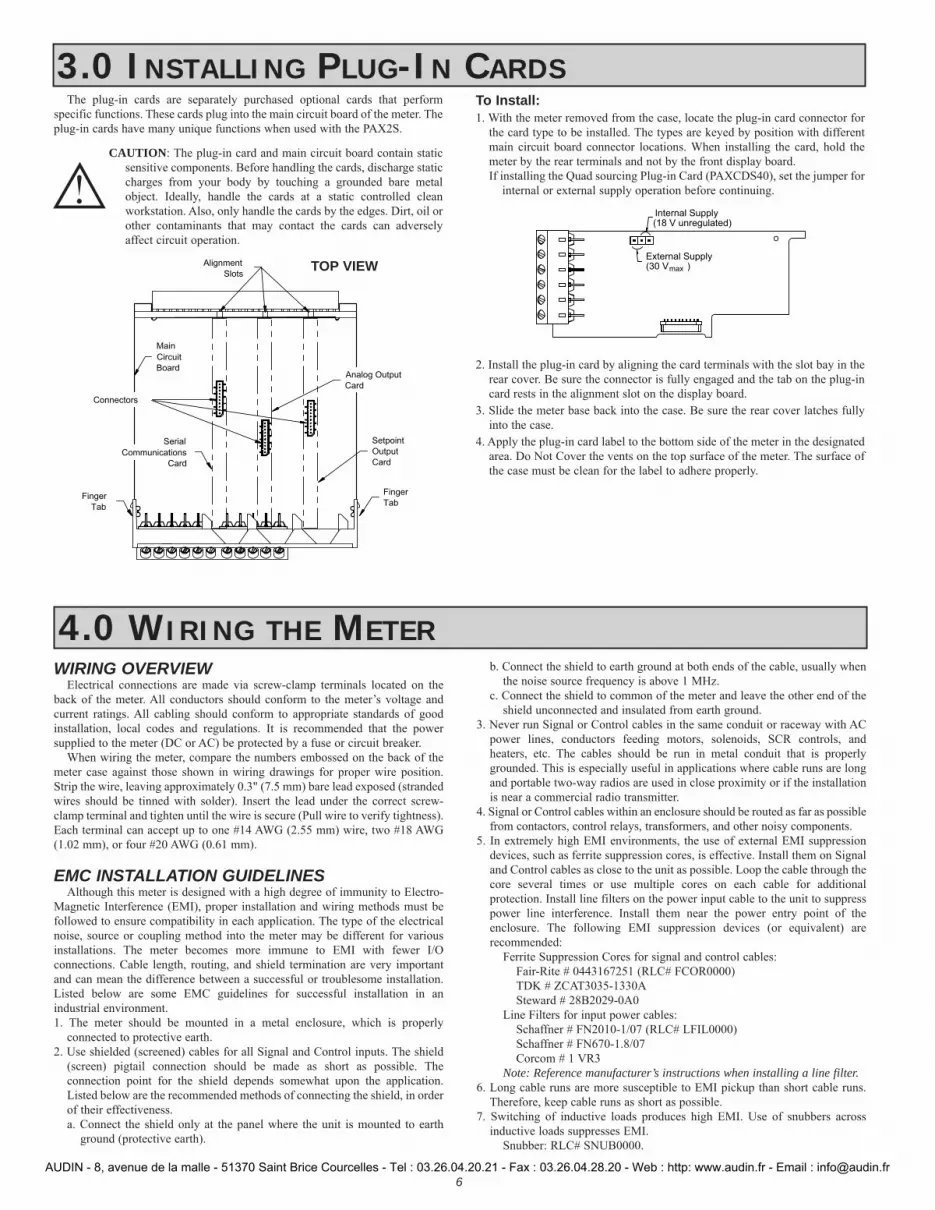
The plug-in cards are separately purchased optional cards that perform specific functions. These cards plug into the main circuit board of the meter. The plug-in cards have many unique functions when used with the PAX2S.
CAUTION: The plug-in card and main circuit board contain static sensitive components. Before handling the cards, discharge static charges from your body by touching a grounded bare metal object. Ideally, handle the cards at a static controlled clean workstation. Also, only handle the cards by the edges. Dirt, oil or other contaminants that may contact the cards can adversely affect circuit operation.
To Install:1. With the meter removed from the case, locate the plug-in card connector for
the card type to be installed. The types are keyed by position with different main circuit board connector locations. When installing the card, hold the meter by the rear terminals and not by the front display board.If installing the Quad sourcing Plug-in Card (PAXCDS40), set the jumper for
internal or external supply operation before continuing.
2. Install the plug-in card by aligning the card terminals with the slot bay in the rear cover. Be sure the connector is fully engaged and the tab on the plug-in card rests in the alignment slot on the display board.
3. Slide the meter base back into the case. Be sure the rear cover latches fully into the case.
4. Apply the plug-in card label to the bottom side of the meter in the designated area. Do Not Cover the vents on the top surface of the meter. The surface of the case must be clean for the label to adhere properly.
Internal Supply(18 V unregulated)
External Supply(30 V ) max
3.0 INSTALLING PLUG-IN CARDS
Finger
TabFinger
Tab
Serial
Communications
Card
Setpoint
Output
Card
Alignment
Slots
Connectors
Analog Output
Card
Main
Circuit
Board
TOP VIEW
WIRING OVERVIEWElectrical connections are made via screw-clamp terminals located on the
back of the meter. All conductors should conform to the meter’s voltage and current ratings. All cabling should conform to appropriate standards of good installation, local codes and regulations. It is recommended that the power supplied to the meter (DC or AC) be protected by a fuse or circuit breaker.
When wiring the meter, compare the numbers embossed on the back of the meter case against those shown in wiring drawings for proper wire position. Strip the wire, leaving approximately 0.3" (7.5 mm) bare lead exposed (stranded wires should be tinned with solder). Insert the lead under the correct screw-clamp terminal and tighten until the wire is secure (Pull wire to verify tightness). Each terminal can accept up to one #14 AWG (2.55 mm) wire, two #18 AWG (1.02 mm), or four #20 AWG (0.61 mm).
EMC INSTALLATION GUIDELINESAlthough this meter is designed with a high degree of immunity to Electro-
Magnetic Interference (EMI), proper installation and wiring methods must be followed to ensure compatibility in each application. The type of the electrical noise, source or coupling method into the meter may be different for various installations. The meter becomes more immune to EMI with fewer I/O connections. Cable length, routing, and shield termination are very important and can mean the difference between a successful or troublesome installation. Listed below are some EMC guidelines for successful installation in an industrial environment.1. The meter should be mounted in a metal enclosure, which is properly
connected to protective earth.2. Use shielded (screened) cables for all Signal and Control inputs. The shield
(screen) pigtail connection should be made as short as possible. The connection point for the shield depends somewhat upon the application. Listed below are the recommended methods of connecting the shield, in order of their effectiveness.a. Connect the shield only at the panel where the unit is mounted to earth
ground (protective earth).
b. Connect the shield to earth ground at both ends of the cable, usually when the noise source frequency is above 1 MHz.
c. Connect the shield to common of the meter and leave the other end of the shield unconnected and insulated from earth ground.
3. Never run Signal or Control cables in the same conduit or raceway with AC power lines, conductors feeding motors, solenoids, SCR controls, and heaters, etc. The cables should be run in metal conduit that is properly grounded. This is especially useful in applications where cable runs are long and portable two-way radios are used in close proximity or if the installation is near a commercial radio transmitter.
4. Signal or Control cables within an enclosure should be routed as far as possible from contactors, control relays, transformers, and other noisy components.
5. In extremely high EMI environments, the use of external EMI suppression devices, such as ferrite suppression cores, is effective. Install them on Signal and Control cables as close to the unit as possible. Loop the cable through the core several times or use multiple cores on each cable for additional protection. Install line filters on the power input cable to the unit to suppress power line interference. Install them near the power entry point of the enclosure. The following EMI suppression devices (or equivalent) are recommended:
Ferrite Suppression Cores for signal and control cables:Fair-Rite # 0443167251 (RLC# FCOR0000)TDK # ZCAT3035-1330ASteward # 28B2029-0A0
Line Filters for input power cables:Schaffner # FN2010-1/07 (RLC# LFIL0000)Schaffner # FN670-1.8/07Corcom # 1 VR3
Note: Reference manufacturer’s instructions when installing a line filter.6. Long cable runs are more susceptible to EMI pickup than short cable runs.
Therefore, keep cable runs as short as possible.7. Switching of inductive loads produces high EMI. Use of snubbers across
inductive loads suppresses EMI. Snubber: RLC# SNUB0000.
4.0 WIRING THE METER
AUDIN - 8, avenue de la malle - 51370 Saint Brice Courcelles - Tel : 03.26.04.20.21 - Fax : 03.26.04.28.20 - Web : http: www.audin.fr - Email : [email protected]

7
4.1 POWER WIRING
1
2
AC/DC
AC/DC
4.2 INPUT SIGNAL WIRING
1
2
AC/DC
AC/DC+
-1
2
AC/DC
AC/DC
+
-OR
AC Power DC Power
EX
C-SIG.
-EXC.
+SIG.
+EXC.C
OM
M
3 4
+S
IG
-SIG
65
4-Wire Bridge Input
3 4 5
+ -
- SIG
+ SI
G
COM
M
2-Wire Single Ended Input
4 653
-EXC.
-SIG.
+SEN
+SIG.
EX
C
-SIG
+S
IG
CO
MM
+EXC.
-SEN
6-Wire Bridge Input
Before connecting signal wires, the Input Range Jumper and Bridge Excitation Jumper should be verified for proper position.
4.3 USER INPUT WIRINGIf not using User Inputs, then skip this section. User Input terminal does not need to be wired in order to remain in inactive state.
Sourcing Logic (USrACt HI)When the USrACt parameter is programmed to HI, the user inputs of the meter are internally pulled down to 0 V with 20 K resistance. The input is active when a voltage greater than 2.2 VDC is applied.
USER INPUTS
USE
R 3
USE
R 2
USE
R 1
USE
R CO
MM
7
USE
R CO
MM
118 9 10
Sinking Logic (USrACt LO)When the USrACt parameter is programmed to LO, the user inputs of the meter are internally pulled up to +3.3 V with 20 K resistance. The input is active when it is pulled low (<1.1 V).
+
(30V max.)SUPPLYV
USE
R 3
USE
R 2
USE
R 1
USE
R CO
MM
87
USE
R CO
MM
11
-
109
USER INPUTS
4.4 SETPOINT (ALARMS) WIRING
4.5 SERIAL COMMUNICATION WIRING
4.6 ANALOG OUTPUT WIRING
See appropriate plug-in card bulletin for wiring details.
AUDIN - 8, avenue de la malle - 51370 Saint Brice Courcelles - Tel : 03.26.04.20.21 - Fax : 03.26.04.28.20 - Web : http: www.audin.fr - Email : [email protected]

8
5.0 FRONT PANEL KEYS AND DISPLAY OVERVIEWProgrammable Units Display
Display Line 1
Display Line 2 13
24
Setpoint Annunciators
KEY DISPLAY MODE OPERATION PROGRAMMING MODE OPERATION
D Index Line 2 through enabled Line 2 display values Return to the previous menu level (momentary press)Quick exit to Display Mode (press and hold)
P Enter full programming mode or access the parameter and hidden display loops; Press and hold to skip parameters and go directly to Code or Programming Menu
Access the programming parameter menu, store selected parameter and index to next parameter
User programmable Function key 1; hold for 3 seconds for user programmable second function 1*
Increment selected parameter value; Hold and momentarily press key to increment next decade or D key to increment by 1000’s
User programmable Function key 2; hold for 3 seconds for user programmable second function 2*
Decrement selected parameter value; Hold and momentarily press key to decrement next decade or D key to decrement by 1000’s
*Factory setting for F1/F2 and second function F1/F2 is no mode
DISPLAY LINE 1Line 1 is the large, 6-digit top line display. Values such as, Input, Gross, Tare,
Max(HI), Min(LO), Total and setpoints, can be shown on Line 1. The 3-digit Units mnemonic characters can be used to indicate which Line 1 display value is shown. Standard or custom mnemonics are available for the Line 1 values. See Line 1 parameters in the Display Parameters programming section for configuration details.
DISPLAY LINE 2Line 2 is the smaller, 9-digit bottom line display. Values such as Input, Gross,
Tare, Max(HI), Min(LO), Total, setpoints, and parameter List A/B status can all be shown on the Line 2 display. The display loops described below are used to view, reset and modify the selected display values, based on the Line 2 Value Access setting programmed for each available value. See Line 2 parameters in the Display Parameters programming section for configuration details.
The PAX2S offers three display loops to allow users quick access to needed information.
Main Display LoopIn the Main display loop, the D key is pressed to sequence through the
selected Line 2 values. A left justified 2, 3 or 4-character mnemonic indicates which Line 2 value is currently shown. When in the Main display loop, the Function keys and perform the user functions programmed in the User Input parameter section.
Parameter and Hidden Parameter Display LoopsDisplay loops provide quick access to selected parameters that can be viewed
and modified on Line 2 without having to enter Full Programming mode. These values include Parameter List A/B selection, setpoints, and display (color, intensity and contrast) settings. To utilize the Parameter or Hidden Parameter display loops, a security code (1-250) must be programmed. (See Programming Security Code in the Display Parameters programming section for details.)
The Parameter display loop is accessed by pressing the P key. The selected Parameter display loop values can be viewed and/or changed per the Line 2 Value Access setting programmed for each available value. The Hidden Parameter display loop follows the Parameter display loop, and can only be accessed when the correct security code is entered at the Code prompt. Combining the two parameter loops provides an area for parameters that require general access and/or protected or secure access depending on the application needs.
While in the Parameter and Hidden Parameter loops, pressing the D key will return the meter to the Main display loop. To directly access the Code prompt, press and hold the P key. This can be done from the Main display loop or at any point during the Parameter display loop. Also, to directly access Full Programming mode while in the Hidden Parameter loop, press and hold the P key to bypass any remaining Hidden Parameter loop values.
LINE 2 DISPLAY LOOPS
ProNO
P
COdE1-250
ProEnd
HIDDEN
PARAMETER
DISPLAY
LOOP
PARAMETER
DISPLAY
LOOP
P
P
P
P P
MAIN DISPLAY LOOP
D
Code 0Code 1-250
P
P
Held
Held
AUDIN - 8, avenue de la malle - 51370 Saint Brice Courcelles - Tel : 03.26.04.20.21 - Fax : 03.26.04.28.20 - Web : http: www.audin.fr - Email : [email protected]

9
6.0 PROGRAMMING THE PAX2S
ProPort
PortUSb
ProdISPLY
ProOUtPUt
ProINPUt
ProNO
ProFACtrY
INPUt ANALOG
INPUtUSEr
P
OUtPUt SEtPNt
OUtPUtANALOG
D
P
dISPLYLINE2
dISPLY tOtAL
D
PortSErIAL
F1 F2
F1 F2
F1 F2
F1 F2
F1 F2
F1 F2
P
D
F1 F2
F1 F2
D
ProEnd
P
D
P D
F1 F2
dISPLYLINE1
F1 F2
Analog Input Setup
Parameters
User Input/Function Key
Parameters
Setpoint Output
Parameters
Analog Output
Parameters
Display Line 1
Parameters
Display Line 2
Parameters
Totalizer Display
Parameters
USB Configuration
Serial Communications
Parameters
D
D
D
D
dISPLYSCNdrY
F1 F2
Secondary Function
Parameters
Factory Service
Operations
*
*
*
*
*
**
**
**
**
**
**
**
**
**
**
(If PAXCDL option card installed).
In Programming Menu:
* - Top line is green to indicate top level programming modules
** - Top line is orange to indicate module menu or sub-menu selection
*** - Top line is red to indicate a changeable parameter.
*
*
Display Loop2 seconds
PROGRAMMING MODE ENTRYThe Programming Mode is entered by pressing the P key. Full
Programming Mode will be accessible unless the meter is programmed to use the Parameter loop or Hidden Parameter display loop on the Line 2 display. In this case, programming access will be limited by a security code and/or a hardware program lock. (Refer to the previous section for details on Line 2 display loops and limited programming access.) Full Programming Mode permits all parameters to be viewed and modified. In this mode, the front panel keys change to Programming Mode Operations and certain user input functions are disabled.
MODULE ENTRYThe Programming Menu is organized into five modules. These
modules group together parameters that are related in function. The and keys are used to select the desired module. The displayed module is entered by pressing the P key.
MODULE MENUUpon entering a module, a parameter selection sub-menu is provided
to choose the specific parameter type for programming. For example, this includes analog and user input under the Input Parameter menu. Use the and keys to select the desired parameter type, and press the P key to enter the parameter menu.
PARAMETER MENUUpon entering the Parameter Menu, the P key is pressed to advance to
a specific parameter to be changed. After completing the parameter menu, or upon pressing the D key, the display returns to the initial entry point for the parameter menu. For each additional press of the D key, the display returns to the previous level within the module until exiting the module entirely.
SELECTION/VALUE ENTRYFor each parameter, the top line display shows the parameter while the
bottom line shows the selections/value for that parameter. The and keys are used to move through the selections/values for the parameter. Pressing the P key, stores and activates the displayed selection/value. This also advances the meter to the next parameter.
Numerical Value EntryIf the parameter is programmed for enter (Entr), the and keys
are used to change the parameter values in any of the display loops.The and keys will increment or decrement the parameter value.
When the or key is pressed and held, the value automatically scrolls. The longer the key is held the faster the value scrolls.
For large value changes, press and hold the or key. While holding that key, momentarily press the opposite arrow key ( or ) to shift decades (10’s 100’s, etc), or momentarily press the D key and the value scrolls by 1000’s as the arrow key is held. Releasing the arrow key removes the decade or 1000’s scroll feature. The arrow keys can then be used to make small value changes as described above.
PROGRAMMING MODE EXITTo exit the Programming Mode, press and hold the D key (from
anywhere in the Programming Mode) or press the P key with Pro NO displayed. This will commit any stored parameter changes to memory and return the meter to the Display Mode. If a parameter was just changed, the P key must be pressed to store the change before pressing the D key. (If power loss occurs before returning to the Display Mode, verify recent parameter changes.)
PROGRAMMING TIPSIt is recommended to start with the Input Parameters and proceed
through each module in sequence. If lost or confused while programming, press and hold the D key to exit programming mode and start over. It is recommended that program settings be recorded as programming is performed. When programming is complete lock out programming with a user input or lock-out code.
Factory Settings may be completely restored in the Factory Service Operations module. This is useful when encountering programming problems.
It is recommended that program settings be recorded as programming is performed. A blank Parameter Value Chart is provided at the end of this bulletin.
AUDIN - 8, avenue de la malle - 51370 Saint Brice Courcelles - Tel : 03.26.04.20.21 - Fax : 03.26.04.28.20 - Web : http: www.audin.fr - Email : [email protected]
10
ProINPUt
ProNO
INPUt ANALOG
rAtE5
INP
Input Update
Rate
dECPNt0.00
INP
Decimal
Resolution
tArE0.00
INP
Display
Tare Value
round0.01
INP
Rounding
Increment
FILtEr1.00
INP
Digital
Filtering
bANd0.10
INP
Filter Band
POINtS2
INP
Scaling
Points
StYLEKEY
INP
Scaling
Style
INPUt0.000
n
Input n
Value
rANgE0.024v
INP
Input Range
dISPLY0.00
n
Display n
Value
F1 F2
P
D
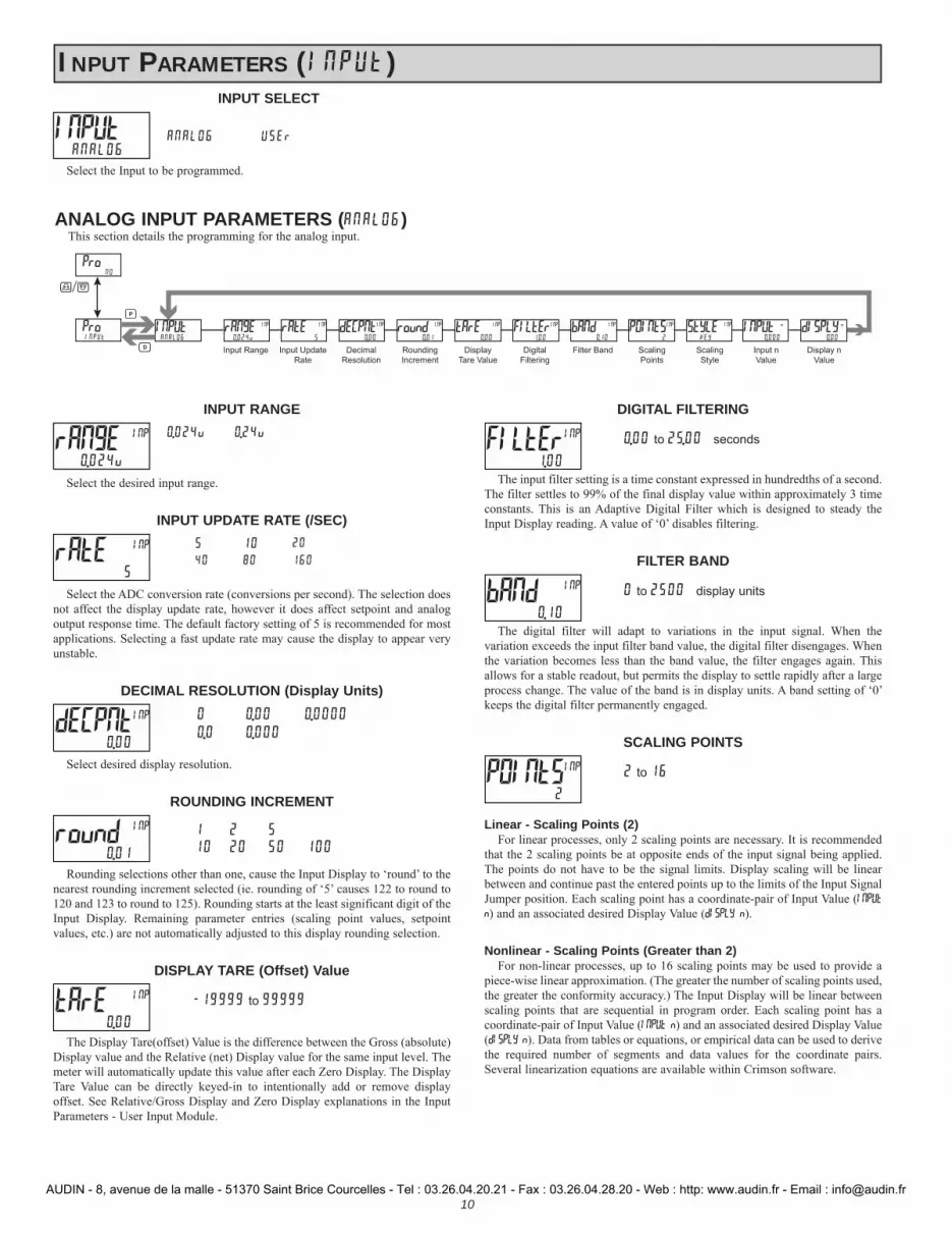
INPUT PARAMETERS (INPUt)
ANALOG INPUT PARAMETERS (ANALOG)This section details the programming for the analog input.
INPUT RANGE0.024u 0.24u
Select the desired input range.
INPUT UPDATE RATE (/SEC)5 10 20
40 80 160
Select the ADC conversion rate (conversions per second). The selection does not affect the display update rate, however it does affect setpoint and analog output response time. The default factory setting of 5 is recommended for most applications. Selecting a fast update rate may cause the display to appear very unstable.
DECIMAL RESOLUTION (Display Units)0 0.00 0.0000
0.0 0.000
Select desired display resolution.
ROUNDING INCREMENT
1 2 510 20 50 100
Rounding selections other than one, cause the Input Display to ‘round’ to the nearest rounding increment selected (ie. rounding of ‘5’ causes 122 to round to 120 and 123 to round to 125). Rounding starts at the least significant digit of the Input Display. Remaining parameter entries (scaling point values, setpoint values, etc.) are not automatically adjusted to this display rounding selection.
DISPLAY TARE (Offset) Value
-19999 to 99999
The Display Tare(offset) Value is the difference between the Gross (absolute) Display value and the Relative (net) Display value for the same input level. The meter will automatically update this value after each Zero Display. The Display Tare Value can be directly keyed-in to intentionally add or remove display offset. See Relative/Gross Display and Zero Display explanations in the Input Parameters - User Input Module.
DIGITAL FILTERING
0.00 to 25.00 seconds
The input filter setting is a time constant expressed in hundredths of a second. The filter settles to 99% of the final display value within approximately 3 time constants. This is an Adaptive Digital Filter which is designed to steady the Input Display reading. A value of ‘0’ disables filtering.
FILTER BAND
0 to 2500 display units
The digital filter will adapt to variations in the input signal. When the variation exceeds the input filter band value, the digital filter disengages. When the variation becomes less than the band value, the filter engages again. This allows for a stable readout, but permits the display to settle rapidly after a large process change. The value of the band is in display units. A band setting of ‘0’ keeps the digital filter permanently engaged.
SCALING POINTS
2 to 16
Linear - Scaling Points (2)For linear processes, only 2 scaling points are necessary. It is recommended
that the 2 scaling points be at opposite ends of the input signal being applied. The points do not have to be the signal limits. Display scaling will be linear between and continue past the entered points up to the limits of the Input Signal Jumper position. Each scaling point has a coordinate-pair of Input Value (INPUt n) and an associated desired Display Value (dISPLY n).
Nonlinear - Scaling Points (Greater than 2)For non-linear processes, up to 16 scaling points may be used to provide a
piece-wise linear approximation. (The greater the number of scaling points used, the greater the conformity accuracy.) The Input Display will be linear between scaling points that are sequential in program order. Each scaling point has a coordinate-pair of Input Value (INPUt n) and an associated desired Display Value (dISPLY n). Data from tables or equations, or empirical data can be used to derive the required number of segments and data values for the coordinate pairs. Several linearization equations are available within Crimson software.
rANgE 0.024u
INP
13
24
rAtE5
INP
13
24
dECPNt0.00
INP
13
24
round0.01
INP
13
24
tArE0.00
INP
13
24
FILtEr1.00
INP
13
24
bANd0.10
INP
13
24
POINtS2
INP
INPUT SELECT
ANALOG USEr
Select the Input to be programmed.
INPUt ANALOG
AUDIN - 8, avenue de la malle - 51370 Saint Brice Courcelles - Tel : 03.26.04.20.21 - Fax : 03.26.04.28.20 - Web : http: www.audin.fr - Email : [email protected]

11
SCALING STYLE
KEY key-in dataAPPLY apply signal
If Input Values and corresponding Display Values are known, the Key-in (KEY) scaling style can be used. This allows scaling without the presence of the input signal. If Input Values have to be derived from the actual input signal source or simulator, the Apply (APPLY) scaling style must be used.
INPUT VALUE FOR SCALING POINT 1
-199999 to 999999
For Key-in (KEY), enter the known first Input Value by using the or arrow keys. (The Input Range selection sets up the decimal location for the Input Value). For Apply (APPLY), the existing programmed value will appear. If this is acceptable, press the P key to save and continue to the next parameter. To update this value, apply the input signal that corresponds to Scaling Point 1, press key and the actual signal value will be displayed. Then press the P key to accept this value and continue to the next parameter.
DISPLAY VALUE FOR SCALING POINT 1
-199999 to 999999
Enter the first coordinating Display Value by using the arrow keys. This is the same for KEY and APPLY scaling styles. The decimal point corresponds to the dECPNt selection.
INPUT VALUE FOR SCALING POINT 2
-199999 to 999999
For Key-in (KEY), enter the known second Input Value by using the or arrow keys. For Apply (APPLY), the existing programmed value will appear. If this is acceptable, press the P key to save and continue to the next parameter. To update this value, apply the input signal that corresponds to Scaling Point 2, press key and the actual signal value will be displayed. Then press the P key to accept this value and continue to the next parameter. (Follow the same procedure if using more than 2 scaling points.)
DISPLAY VALUE FOR SCALING POINT 2
-199999 to 999999
Enter the second coordinating Display Value by using the or arrow keys. This is the same for KEY and APPLY scaling styles. (Follow the same procedure if using more than 2 scaling points.)
13
24
StYLE KEY
INP
INPUt0.00
1
dISPLY0.00
1
INPUt0.00
2
dISPLY100.00
2
USrACtLO
FNC USEr-1NO
FNC USEr-2NO
FNC F1NO
FNC F2NO
FNC SEC-F1NO
FNC SEC-F2NO
FNC
Function KeysUser Inputs
INPUt USEr
USEr-3NO
FNC ProINPUt
ProNO
F1 F2
P
D
USER INPUT ACTIVE STATE
LO HI
Select the desired active state for the User Inputs. Select LO for sink input, active low. Select HI for source input, active high.
NO FUNCTION
No function is performed if activated. This is the factory setting for all user inputs and function keys.
USrACt LO
FNC USEr-n NO
FNC Fn NO
FNC
USER INPUT / FUNCTION KEY PARAMETERS (USEr)This section details the programming for the rear terminal User Inputs and front panel Function Keys. Three user inputs are individually programmable to perform
specific meter control functions. While in the Display Mode, the function is executed when the user input transitions to the active state. (Refer to the user input specifications for response times.) Certain User input functions are disabled in Programming Mode. Two front panel function keys, and , are also individually programmable to perform specific meter control functions. While in the Display Mode, the primary function is executed when the key is pressed. Holding the or function key for three seconds executes a secondary function. It is possible to program a secondary function without a primary function. The front panel key functions are disabled while in Programming Mode.
In most cases, if more than one user input and/or function key is programmed for the same function, the maintained (level trigger) actions will be performed while at least one of those user inputs or function keys are activated. The momentary (edge trigger) actions are performed every time any of those user inputs or function keys transition to the active state.
The List user function has a value assignment sublist, which appears when the P key is pressed and LISt is selected. The function will only be performed for the assignment values selected as YES. If a user input or function key is configured for a function with a sublist, then that sublist will need to be scrolled through each time to access the remaining user inputs or function keys following the sublist.
Note: In the following explanations, not all selections are available for both user inputs and front panel function keys. Displays are shown with each selection. Those selections showing both displays are available for both. If a display is not shown, it is not available for that selection. In the parameter explanations, USEr-n represents all user inputs. Fn represents both function keys and second function keys.
AUDIN - 8, avenue de la malle - 51370 Saint Brice Courcelles - Tel : 03.26.04.20.21 - Fax : 03.26.04.28.20 - Web : http: www.audin.fr - Email : [email protected]

12
PROGRAMMING MODE LOCK-OUT
Programming Mode is locked-out, as long as activated (maintained action). A security code can be configured to allow programming access during lock-out.
ZERO (TARE) DISPLAY
The Zero (Tare) Display provides a way to zero the Input Display value at various input levels, causing future relative input display readings to be offset. This function is useful in weighing applications where the container or material on the scale should not be included in the next measurement value. When activated (momentary action), rESEt flashes and the Display is set to zero. At the same time, the Display value (that was on the display before the Zero Display) is subtracted from the Display Tare Value and is automatically stored as the new Display Tare Value. If another Zero (tare) Display is performed, the display again changes to zero and the Display Tare Value shifts accordingly.
RESET TARE VALUE
The Reset Tare provides a way to zero the Display Tare (offset) value, eliminating the Tare (offset) from the relative display. When activated (momentary action), rESEt flashes and the Display Tare value is set to zero. Following a Reset Tare, the Input display (relative) value will match the Gross (absolute).
RELATIVE/GROSS (ABSOLUTE) VALUE
This function will switch the Input Display between Relative and Gross (Absolute) value. The Relative is a net value that includes the Display Tare (Offset)Value. The Input Display will show the Relative unless switched by this function. The Gross is an absolute value (based on Input (Analog) Module dSP and INP entries) without the Display Tare (Offset) Value. The Gross value is selected as long as the user input is activated (maintained action) or at the transition of the function key (momentary action). When the user input is released, or the function key is pressed again, the input display switches back to Relative value. GrOSS (gross) or rEL (relative) is momentarily displayed at transition to indicate which value is being displayed.
HOLD DISPLAY
The active display is held but all other meter functions continue as long as activated (maintained action).
HOLD ALL FUNCTIONS
The meter disables processing the input, holds all display contents, and locks the state of all outputs as long as activated (maintained action). The serial port continues data transfer.
SYNCHRONIZE METER READING
The meter suspends all functions as long as activated (maintained action). When the user input is released, the meter synchronizes the restart of the A/D converter input sampling with other processes or timing events.
STORE BATCH READING IN TOTALIZER
The Input Display value is added (batched) to the Totalizer when activated (momentary action) and the display flashes bAtCh. The Totalizer retains a running sum of each batch operation until the Totalizer is reset. When this function is selected, the normal operation of the Totalizer is overridden and only batched Input Display values accumulate in the Totalizer.
SELECT TOTALIZER DISPLAY
The Totalizer appears on Line 2 as long as activated (maintained action). When the user input is released, the previously selected display is returned. The D or P keys
override and disable the active user input. The Totalizer continues to function including associated outputs independent of the selected display.
RESET TOTALIZER
When activated (momentary action), rESEt flashes and the Totalizer resets to zero. The Totalizer then continues to operate as it is configured. This selection functions independent of the selected display.
RESET AND ENABLE TOTALIZER
When activated (momentary action), rESEt flashes and the Totalizer resets to zero. The Totalizer continues to operate while active (maintained action). When the user
input is released, the Totalizer stops and holds its value. This selection functions independent of the selected display.
ENABLE TOTALIZER
The Totalizer continues to operate while active (maintained action). When the user input is released, the Totalizer stops and holds its value. This selection functions independent of the selected display.
SELECT MAXIMUM DISPLAY
The Maximum display appears on Line 2 as long as activated (maintained). When the user input is released, the previously selected display is returned. The D or P
keys override and disable the active user input. The Maximum continues to function independent of the selected display.
RESET MAXIMUM DISPLAY
When activated (momentary action), rESEt flashes and the Maximum resets to the present Input Display value. The Maximum function then continues from that value. This selection functions independent of the selected display.
SELECT MINIMUM DISPLAY
The Minimum display appears on Line 2 as long as activated (maintained). When the user input is released, the previously selected display is returned. The D or P
keys override and disable the active user input. The Minimum continues to function independent of the selected display.
USEr-n PLOC
FNC
USEr-n rEL
FNC Fn rEL
FNC
USEr-n r-tArE
FNC Fn r-tArE
FNC
USEr-n d-rEL
FNC Fn d-rEL
FNC
USEr-n d-HLd
FNC
USEr-n A-HLd
FNC
USEr-n SYNC
FNC
USEr-n bAt
FNC Fn bAt
FNC
USEr-n d-tot
FNC
USEr-n r-tot1
FNC Fn r-tot
FNC
USEr-n r-tot2
FNC
USEr-n E-tot
FNC
USEr-n d-HI
FNC
USEr-n r-HI
FNC Fn r-HI
FNC
USEr-n d-LO
FNC
AUDIN - 8, avenue de la malle - 51370 Saint Brice Courcelles - Tel : 03.26.04.20.21 - Fax : 03.26.04.28.20 - Web : http: www.audin.fr - Email : [email protected]
13
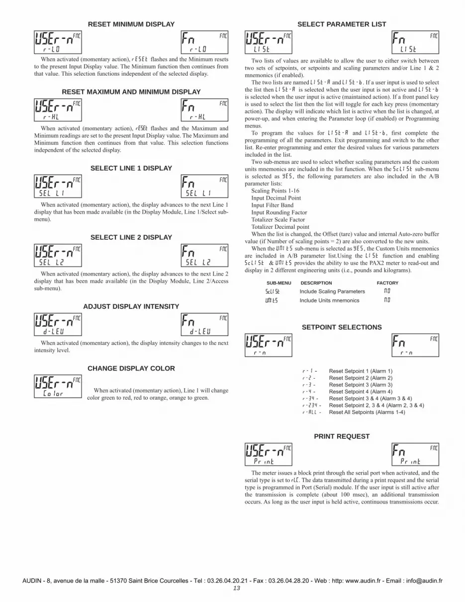
RESET MINIMUM DISPLAY
When activated (momentary action), rESEt flashes and the Minimum resets to the present Input Display value. The Minimum function then continues from that value. This selection functions independent of the selected display.
RESET MAXIMUM AND MINIMUM DISPLAY
When activated (momentary action), rESEt flashes and the Maximum and Minimum readings are set to the present Input Display value. The Maximum and Minimum function then continues from that value. This selection functions independent of the selected display.
SELECT LINE 1 DISPLAY
When activated (momentary action), the display advances to the next Line 1 display that has been made available (in the Display Module, Line 1/Select sub-menu).
SELECT LINE 2 DISPLAY
When activated (momentary action), the display advances to the next Line 2 display that has been made available (in the Display Module, Line 2/Access sub-menu).
ADJUST DISPLAY INTENSITY
When activated (momentary action), the display intensity changes to the next intensity level.
CHANGE DISPLAY COLOR
When activated (momentary action), Line 1 will change color green to red, red to orange, orange to green.
SELECT PARAMETER LIST
Two lists of values are available to allow the user to either switch between two sets of setpoints, or setpoints and scaling parameters and/or Line 1 & 2 mnemonics (if enabled).
The two lists are named LISt-A and LISt-b. If a user input is used to select the list then LISt-A is selected when the user input is not active and LISt-b is selected when the user input is active (maintained action). If a front panel key is used to select the list then the list will toggle for each key press (momentary action). The display will indicate which list is active when the list is changed, at power-up, and when entering the Parameter loop (if enabled) or Programming menus.
To program the values for LISt-A and LISt-b, first complete the programming of all the parameters. Exit programming and switch to the other list. Re-enter programming and enter the desired values for various parameters included in the list.
Two sub-menus are used to select whether scaling parameters and the custom units mnemonics are included in the list function. When the ScLISt sub-menu is selected as YES, the following parameters are also included in the A/B parameter lists:
Scaling Points 1-16Input Decimal PointInput Filter BandInput Rounding FactorTotalizer Scale FactorTotalizer Decimal pointWhen the list is changed, the Offset (tare) value and internal Auto-zero buffer
value (if Number of scaling points = 2) are also converted to the new units.When the UNItS sub-menu is selected as YES, the Custom Units mnemonics
are included in A/B parameter list.Using the LISt function and enabling ScLISt & UNItS provides the ability to use the PAX2 meter to read-out and display in 2 different engineering units (i.e., pounds and kilograms).
SUB-MENU DESCRIPTION FACTORY
ScLISt Include Scaling Parameters NO
UNItS Include Units mnemonics NO
SETPOINT SELECTIONS
r-1 - Reset Setpoint 1 (Alarm 1)r-2 - Reset Setpoint 2 (Alarm 2)r-3 - Reset Setpoint 3 (Alarm 3)r-4 - Reset Setpoint 4 (Alarm 4)r-34 - Reset Setpoint 3 & 4 (Alarm 3 & 4)r-234 - Reset Setpoint 2, 3 & 4 (Alarm 2, 3 & 4)r-ALL - Reset All Setpoints (Alarms 1-4)
PRINT REQUEST
The meter issues a block print through the serial port when activated, and the serial type is set to rLC. The data transmitted during a print request and the serial type is programmed in Port (Serial) module. If the user input is still active after the transmission is complete (about 100 msec), an additional transmission occurs. As long as the user input is held active, continuous transmissions occur.
USEr-n r-LO
FNC Fn r-LO
FNC
USEr-n r-HL
FNC Fn r-HL
FNC
USEr-n SEL L1
FNC Fn SEL L1
FNC
USEr-n SEL L2
FNC Fn SEL L2
FNC
USEr-n d-LEU
FNC Fn d-LEU
FNC
USEr-n Color
FNC
USEr-n LISt
FNC Fn LISt
FNC
USEr-n r-n
FNC Fn r-n
FNC
USEr-n Print
FNC Fn Print
FNC
AUDIN - 8, avenue de la malle - 51370 Saint Brice Courcelles - Tel : 03.26.04.20.21 - Fax : 03.26.04.28.20 - Web : http: www.audin.fr - Email : [email protected]

14
OUtPUt SEtPNt
SELECtS1
SPt
Setpoint
Select
ASSIGNNONE
Sn
Setpoint
Assignment
SEtPNt100
Sn
Setpoint
Value
ACtIONNO
Sn
Setpoint
Action
bn-dEU0
Sn
Band/
Deviation
Value
HYStEr2
Sn
Hysteresis
Value
t-ON0.0
Sn
On Time
Delay
t-OFF0.0
Sn
Off Time
Delay
n = Setpoint Number (1-4)
LOGICnor
Sn
Output
Logic
StndbYNO
Sn
Setpoint
Standby
Operation
rESEtAuto
Sn
Reset
Action
Annunnor
Sn
Setpoint
Annunciator
ColorNO CHG
Sn
Line 1
Change Color
ProOUtPUt
ProNO
F1 F2
P
D
OUTPUT PARAMETERS (OUtPUt)
SETPOINT SELECT
S1 S2 S3 S4
Select the Setpoint output to be programmed. The “Sn” in the following parameters will reflect the chosen setpoint number. After the chosen setpoint is completely programmed, the display returns to the Setpoint Select menu. Repeat steps for each setpoint to be programmed.
The number of outputs available is setpoint output card dependent (2 or 4). If no output card is installed, programming is still available for all 4 setpoints. This allows the Line 1 color change feature to provide a visual indication when a setpoint value has been reached, even if no setpoint output is being used.
SETPOINT ASSIGNMENT
NONE rEL GrOSS tOtAL
Selects the meter value to be used to trigger the Setpoint Alarm. The rEL setting will cause the setpoint to trigger off of the relative (net) input value. The relative input value is the absolute input value plus the Display Tare (Offset) Value. The GrOSS setting will cause the setpoint to trigger off of the gross (absolute) input value. The gross input value is based on the Input (Analog) module dSP and INP entries.
SETPOINT ACTION
NO Ab-HI Ab-LO AU-HI
AU-LO dE-HI dE-LO bANd
bNdIn totLo totHi
Enter the action for the selected setpoint (alarm output). See Setpoint Alarm Figures for a visual detail of each action. The Setpoint Actions that pertains to the total is only active when the Setpoint Assignment is set to tOtAL.
NO = No Setpoint Action
Ab-HI = Absolute high, with balanced hysteresis
Ab-LO = Absolute low, with balanced hysteresis
AU-HI = Absolute high, with unbalanced hysteresis
AU-LO = Absolute low, with unbalanced hysteresis
dE-HI = deviation high, with unbalanced hysteresis
dE-LO = deviation low, with unbalanced hysteresis
bANd = Outside band, with unbalanced hysteresis
bNdIn = Inside band, with unbalanced hysteresis
totLo = Lower 6 digits of 9 digit Totalizer, with unbalanced hysteresis
totHi = Upper 6 digits of 9 digit Totalizer, with unbalanced hysteresis
SETPOINT VALUE
-199999 to 999999
Enter desired setpoint alarm value. Setpoint values can also be entered in the Display Mode during Program Lockout when the setpoint is programmed as Entr in the Display (Line 2) Access parameters. The decimal point position is determined by the Setpoint Assignment value.
BAND/DEVIATION VALUE
-199999 to 999999
This parameter is only available in band and deviation setpoint actions. Enter desired setpoint band or deviation value. When the Setpoint Action is programmed for Band, this value can only be a positive value.
HYSTERESIS VALUE
1 to 65000
Enter desired hysteresis value. See Setpoint Alarm Figures for visual explanation of how setpoint alarm actions (balanced and unbalanced) are affected by the hysteresis. When the setpoint is a control output, usually balanced hysteresis is used. For alarm applications, usually unbalanced hysteresis is used. For unbalanced hysteresis modes, the hysteresis functions on the low side for high acting setpoints and functions on the high side for low acting setpoints. Note: Hysteresis eliminates output chatter at the switch point, while time delay can be used to prevent false triggering during process transient events.
SELECt S1
SPt
ASSIGN NONE
Sn
ACtION NO
Sn
SEtPNt100
Sn
bn-dEV0
dn
HYStEr2
Sn
SETPOINT OUTPUT PARAMETERS (SEtPNt)This section details the programming for the setpoints. To have output capabilities, a setpoint Plug-in card needs to be installed into the PAX2S (see Ordering
Information). Depending on the card installed, there will be two or four setpoint outputs available. If no output card is installed, programming for the setpoints is still available. An Exchange Parameter Lists feature for setpoint values is explained in User Input programming.
The Setpoint Assignment and Setpoint Output Action determine certain setpoint feature availability. The Setpoint Parameter Availability chart illustrates this.
OUTPUT SELECT
SEtPNt ANALOG
Select the Setpoint or Analog output to be programmed. The Analog output selection only appears if an analog output plug-in card is installed in the meter.
OUtPUt SEtPNt
Setpoint Action dependent
AUDIN - 8, avenue de la malle - 51370 Saint Brice Courcelles - Tel : 03.26.04.20.21 - Fax : 03.26.04.28.20 - Web : http: www.audin.fr - Email : [email protected]
15
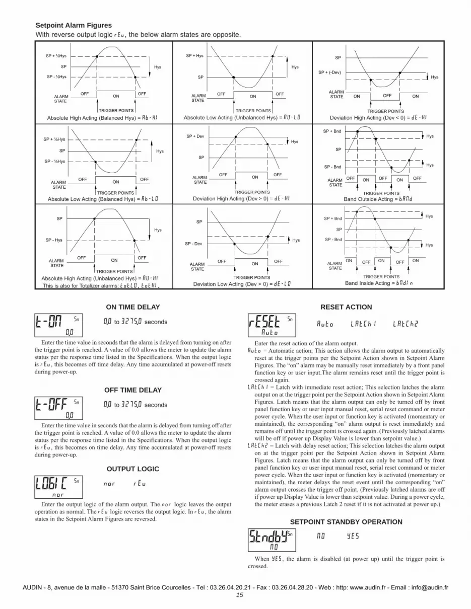
ON TIME DELAY
0.0 to 3275.0 seconds
Enter the time value in seconds that the alarm is delayed from turning on after the trigger point is reached. A value of 0.0 allows the meter to update the alarm status per the response time listed in the Specifications. When the output logic is rEv, this becomes off time delay. Any time accumulated at power-off resets during power-up.
OFF TIME DELAY
0.0 to 3275.0 seconds
Enter the time value in seconds that the alarm is delayed from turning off after the trigger point is reached. A value of 0.0 allows the meter to update the alarm status per the response time listed in the Specifications. When the output logic is rEv, this becomes on time delay. Any time accumulated at power-off resets during power-up.
OUTPUT LOGIC
nor rEv
Enter the output logic of the alarm output. The nor logic leaves the output operation as normal. The rEv logic reverses the output logic. In rEv, the alarm states in the Setpoint Alarm Figures are reversed.
RESET ACTION
Auto LAtCh1s LAtCh2
Enter the reset action of the alarm output.Auto = Automatic action; This action allows the alarm output to automatically
reset at the trigger points per the Setpoint Action shown in Setpoint Alarm Figures. The “on” alarm may be manually reset immediately by a front panel function key or user input.The alarm remains reset until the trigger point is crossed again.
LAtCh1 = Latch with immediate reset action; This selection latches the alarm output on at the trigger point per the Setpoint Action shown in Setpoint Alarm Figures. Latch means that the alarm output can only be turned off by front panel function key or user input manual reset, serial reset command or meter power cycle. When the user input or function key is activated (momentary or maintained), the corresponding “on” alarm output is reset immediately and remains off until the trigger point is crossed again. (Previously latched alarms will be off if power up Display Value is lower than setpoint value.)
LAtCh2 = Latch with delay reset action; This selection latches the alarm output on at the trigger point per the Setpoint Action shown in Setpoint Alarm Figures. Latch means that the alarm output can only be turned off by front panel function key or user input manual reset, serial reset command or meter power cycle. When the user input or function key is activated (momentary or maintained), the meter delays the reset event until the corresponding “on” alarm output crosses the trigger off point. (Previously latched alarms are off if power up Display Value is lower than setpoint value. During a power cycle, the meter erases a previous Latch 2 reset if it is not activated at power up.)
SETPOINT STANDBY OPERATION
NO YES
When YES, the alarm is disabled (at power up) until the trigger point is crossed.
t-ON0.0
Sn
t-OFF0.0
Sn
LOGIC nor
Sn
rESEt Auto
Sn
StndbY NO
Sn
Setpoint Alarm FiguresWith reverse output logic rEv, the below alarm states are opposite.
ALARMSTATE
OFFON
Hys
SP + Hys
SP
OFF
TRIGGER POINTS
ALARMSTATE
OFF ON
Hys
SP - Bnd
SP
OFF
SP + Bnd
ON OFF
Hys
TRIGGER POINTS
Absolute Low Acting (Unbalanced Hys) = AU-LO
Band Outside Acting = bANd
ALARMSTATE
OFFON
Hys
SP + ½Hys
SP
SP - ½Hys
OFF
TRIGGER POINTS
ALARMSTATE
OFFON
Hys
SP + Dev
SP
OFF
TRIGGER POINTS
ALARMSTATE
ON OFF
Hys
SP - Bnd
SP
ON
SP + Bnd
OFF ON
Hys
TRIGGER POINTS
Absolute Low Acting (Balanced Hys) = Ab-LO Deviation High Acting (Dev > 0) = dE-HI
Band Inside Acting = bNdIn
ALARMSTATE
OFFON
Hys
SP
SP - Hys
OFF
TRIGGER POINTS
ALARMSTATE
OFFON
HysSP - Dev
SP
OFF
TRIGGER POINTS
ALARMSTATE ON OFF
HysSP + (-Dev)
SP
ON
TRIGGER POINTS
Absolute High Acting (Unbalanced Hys) = AU-HIThis is also for Totalizer alarms: totLO, totHI Deviation Low Acting (Dev > 0) = dE-LO
Deviation High Acting (Dev < 0) = dE-HI
ALARM STATE
OFFON
Hys
SP + ½Hys
SP
SP - ½Hys
OFF
TRIGGER POINTS
Absolute High Acting (Balanced Hys) = Ab-HI
AUDIN - 8, avenue de la malle - 51370 Saint Brice Courcelles - Tel : 03.26.04.20.21 - Fax : 03.26.04.28.20 - Web : http: www.audin.fr - Email : [email protected]

16
SETPOINT ANNUNCIATOR
nor rEv FLASH OFF
The nor mode displays the corresponding setpoint annunciators of “on” alarm outputs. The rEv mode displays the corresponding setpoint annunciators of “off” alarms outputs. The FLASH mode flashes the corresponding setpoint annunciators of “on” alarm outputs. The OFF mode disables display setpoint annunciators.
LINE 1 CHANGE COLOR
NO CHG GrEEN OrANGE rEd
GrnOrG rEdOrG rEdGrn LINE 1
This parameter allows the Line 1 Display to change color, or alternate between two colors, when the alarm is activated. When multiple alarms are programmed to change color, the highest numbered active alarm (S4-S1) determines the display color.
The NO CHG selection will maintain the color displayed prior to the alarm activation. The LINE 1 selection sets the display to the Display (Line 1) Color (Color).
Annun nor
Sn Color NO CHG
Sn
tYPE4-20
AnL ASSIGNNONE
AnL ANALOG0
LO ANALOG10000
HI
Analog
Output Type
Analog Output
Assignment
Analog Low
Scale Value
Analog High
Scale Value
OUtPUtANALOG
UPdAtE0.0
AnL
Analog Update
Time
ProOUtPUt
ProNO
F1 F2
P
D
ANALOG OUTPUT PARAMETERS (ANALOG)This section is only accessible with the optional PAXCDL Analog card installed (see Ordering Information).
ANALOG OUTPUT TYPE
4-20 0-10 0-20
Enter the analog output type. For 0-20 mA or 4-20 mA use terminals 18 and 19. For 0-10 V use terminals 16 and 17. Only one range can be used at a time.
ANALOG OUTPUT ASSIGNMENT
NONE rEL GrOSS tOtAL HI
LO S1 S2 S3 S4
Enter the source for the analog output to retransmit:
NONE = Manual Mode operation. (See Serial RLC Protocol in the Communications Port module).
rEL = Relative (net) Input Value. The Relative Input Value is the Gross (Absolute) Input Value that includes the Display Tare (Offset) Value.
GrOSS = Gross (Absolute) Input Value. The Gross Input Value is based on the Input (Analog) module dSP and INP entries.
tOtAL = Totalizer Value
HI = Maximum Display Value
LO = Minimum Display Value
S1-S4 = Setpoint Values
ANALOG LOW SCALE VALUE
-199999 to 999999
Enter the Display Value that corresponds to 0 mA (0-20 mA) , 4 mA (4-20 mA) or 0 VDC (0-10 VDC).
ANALOG HIGH SCALE VALUE
-199999 to 999999
Enter the Display Value that corresponds to 20 mA (0-20 mA) , 20 mA (4-20 mA) or 10 VDC (0-10 VDC).
ANALOG UPDATE TIME
0.0 to 10.0
Enter the analog output update rate in seconds. A value of 0.0 allows the meter to update the analog output at the ADC Conversion Rate.
tYPE4-20
AnL
ASSIGNNONE
AnL
ANALOG0
LO
ANALOG10000
HI
UPdAtE0.0
AnL
AUDIN - 8, avenue de la malle - 51370 Saint Brice Courcelles - Tel : 03.26.04.20.21 - Fax : 03.26.04.28.20 - Web : http: www.audin.fr - Email : [email protected]

17
LINE 1 DISPLAY COLOR
GrEEN rEd OrANGE
Enter the desired Display Line 1 and programmable Units Display color.
DISPLAY INTENSITY LEVEL
0 to 4
Enter the desired Display Intensity Level (0-4) by using the arrow keys. The display will actively dim or brighten as the levels are changed. This parameter can also be accessed in the Parameter display loop when enabled.
DISPLAY CONTRAST LEVEL
0 to 15
Enter the desired Display Contrast Level (0-15) by using the arrow keys. The display contrast / viewing angle will actively adjust up or down as the levels are changed. This parameter can also be accessed in the Parameter display loop when enabled.
LINE 1 DISPLAY VALUE SELECT/ENABLE
NO YES
Enter YES to select which values will be shown on the Line 1 display. A sub-menu provides Yes/No selection for each available Line 1 value. Values set to YES in the sub-menu will be displayable on Line 1.
DISPLAY DESCRIPTION FACTORY INPUt Input YES
GrOSS Gross (absolute) NO
tArE Tare NO
tOtAL Total NO
HI Max value NO
LO Min value NO
S1 Setpoint 1 NO
S2 Setpoint 2 NO
S3 Setpoint 3 NO
S4 Setpoint 4 NO
LINE 1 DISPLAY SCROLL ENABLE/TIME
NO 1 to 15 seconds
If Line 1 Display Scrolling is desired, set the scroll time in seconds.
LINE 1 UNITS MNEMONIC(S)
OFF LAbEL CUSt FACt
Select the mode for Line 1 Units Mnemonic(s). See LINE 1 UNITS MNEMONIC DIAGRAM for programming details.
SELECTION MODE DESCRIPTION
OFF OFF No Line 1 mnemonic shown.LAbEL LABEL Single programmable mnemonic
shown for all Line 1 values.CUSt CUSTOM Custom programmable mnemonics
shown for each Line 1 value.FACt FACTORY Factory default mnemonics shown for
each Line 1 value.
The characters available for the programmable modes include:A b C d E F G H I J K L M N O P Q R S t U V W Y Z 0 1
2 3 4 5 6 7 8 9 a c e g h i m n o q r u w - = [ ] / ° _ blank
Color GrEEN
Ln1
d-LEV4
dSP
d-Cont7
dSP
SELECt NO
Ln1
ScroLL NO
Ln1
UNItS OFF
Ln1
Two character spaces are required to display this character.
DISPLAY PARAMETERS (dISPLY)
LINE 1 PARAMETERS (LINE 1)This section details programming for the Line 1 (Top Line) Display. The Input, Gross, Tare, Total, Maximum (HI) and Minimum (LO) capture values and setpoints
can be shown on the Line 1 display. The 3-digit Units mnemonic characters can be used to indicate which Line 1 display value is shown. Standard mnemonics are available for Setpoints 1-4. Standard or custom mnemonics are available for all other Line 1 values.
Main Display LoopIn the Main display loop, the selected values can be consecutively read on Line 1 by activating a user input or function key programmed as SEL L1. Each time the
user input/function key is activated, Line 1 display will change to the next enabled Line 1 display value. Line 1 can also be programmed for Scroll, which will cause Line 1 to automatically scroll through all of the selected Line 1 display values.
DISPLAY SELECT
LINE 1 LINE 2 SCNdrY tOtAL
Select the Display to be programmed.
dISPLY LINE 1
ColorGrEEN
Ln1
Line 1 Display
Color
d-LEV4
dSP
Display
Intensity
SELECtNO
Ln1
Line 1
Display Values
d-Cont7
dSP
Display
Contrast
ScroLLNO
Ln1
Line 1 Scroll
Enable/Time
UNItSOFF
Ln1
Line 1 Units
Mnemonics
dISPLYLINE 1
Selected Line 1 Color Displayed
ProdISPLY
ProNO
F1 F2
P
D
P
LINE 1 UNITS MNEMONIC DIAGRAM (3-DIGITS)
Edit 123
NO
P Edit Ln1
NO
P
123 = Current Units Mnemonic
PUNItS Ln1
OFFdISPLY LINE 1
UNItS Ln1
LAbEL
Edit 123
YES
UNItS Ln1
CUSt
UNItS Ln1
FACt
Edit 123
INPUtUnit 1123
1Unit 2123
2
Unit 3123
3
Edit 123
LO
P P P P
Unit 1123
1Unit 2123
2
Unit 3123
3
P P P P
P
P
Unit 1123
1Unit 2123
2
Unit 3123
3
P P P P
(returns to currently selected value)
F1 F2
F1 F2
F1 F2
GrOSS
tArE
tOtAL
HI
AUDIN - 8, avenue de la malle - 51370 Saint Brice Courcelles - Tel : 03.26.04.20.21 - Fax : 03.26.04.28.20 - Web : http: www.audin.fr - Email : [email protected]
18
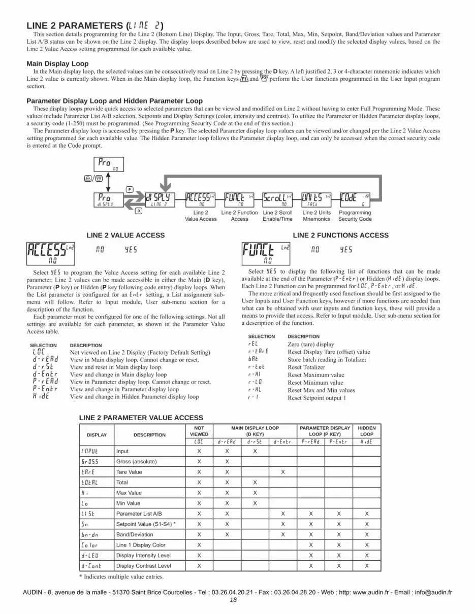
LINE 2 PARAMETERS (LINE 2)This section details programming for the Line 2 (Bottom Line) Display. The Input, Gross, Tare, Total, Max, Min, Setpoint, Band/Deviation values and Parameter
List A/B status can be shown on the Line 2 display. The display loops described below are used to view, reset and modify the selected display values, based on the Line 2 Value Access setting programmed for each available value.
Main Display LoopIn the Main display loop, the selected values can be consecutively read on Line 2 by pressing the D key. A left justified 2, 3 or 4-character mnemonic indicates which
Line 2 value is currently shown. When in the Main display loop, the Function keys and perform the User functions programmed in the User Input program section.
Parameter Display Loop and Hidden Parameter LoopThese display loops provide quick access to selected parameters that can be viewed and modified on Line 2 without having to enter Full Programming Mode. These
values include Parameter List A/B selection, Setpoints and Display Settings (color, intensity and contrast). To utilize the Parameter or Hidden Parameter display loops, a security code (1-250) must be programmed. (See Programming Security Code at the end of this section.)
The Parameter display loop is accessed by pressing the P key. The selected Parameter display loop values can be viewed and/or changed per the Line 2 Value Access setting programmed for each available value. The Hidden Parameter loop follows the Parameter display loop, and can only be accessed when the correct security code is entered at the Code prompt.
dISPLY LINE 2
ACCESSNO
Ln2
Line 2
Value Access
FUNCtNO
Ln2
Line 2 Function
Access
ScroLLNO
Ln2
Line 2 Scroll
Enable/Time
UNItS FACt
Ln2
Line 2 Units
Mnemonics
COdE0
dSP
Programming
Security Code
ProdISPLY
ProNO
F1 F2
P
D
LINE 2 PARAMETER VALUE ACCESS
DISPLAY DESCRIPTIONNOT
VIEWEDMAIN DISPLAY LOOP
(D KEY)PARAMETER DISPLAY
LOOP (P KEY)HIDDEN LOOP
LOC d-rEAd d-rSt d-Entr P-rEAd P-Entr HidE
INPUt Input X X X
GrOSS Gross (absolute) X X
tArE Tare Value X X X
tOtAL Total X X X
Hi Max Value X X X
Lo Min Value X X X
LISt Parameter List A/B X X X X X X
Snx Setpoint Value (S1-S4) * X X X X X X
bn-dn Band/Deviation X X X X X X
Color Line 1 Display Color X X X X
d-LEU Display Intensity Level X X X X
d-Cont Display Contrast Level X X X X
* Indicates multiple value entries.
LINE 2 VALUE ACCESS
NO YES
Select YES to program the Value Access setting for each available Line 2 parameter. Line 2 values can be made accessible in either the Main (D key), Parameter (P key) or Hidden (P key following code entry) display loops. When the List parameter is configured for an Entr setting, a List assignment sub-menu will follow. Refer to Input module, User sub-menu section for a description of the function.
Each parameter must be configured for one of the following settings. Not all settings are available for each parameter, as shown in the Parameter Value Access table.
SELECTION DESCRIPTIONLOC Not viewed on Line 2 Display (Factory Default Setting)d-rEAd View in Main display loop. Cannot change or reset.d-rSt View and reset in Main display loop.d-Entr View and change in Main display loopP-rEAd View in Parameter display loop. Cannot change or reset.P-Entr View and change in Parameter display loopHidE View and change in Hidden Parameter display loop
LINE 2 FUNCTIONS ACCESS
NO YES
Select YES to display the following list of functions that can be made available at the end of the Parameter (P-Entr) or Hidden (HidE) display loops. Each Line 2 Function can be programmed for LOC, P-Entr, or HidE.
The more critical and frequently used functions should be first assigned to the User Inputs and User Function keys, however if more functions are needed than what can be obtained with user inputs and function keys, these will provide a means to provide that access. Refer to Input module, User sub-menu section for a description of the function.
SELECTION DESCRIPTIONrEL Zero (tare) displayr-tArE Reset Display Tare (offset) valuebAt Store batch reading in Totalizerr-tot Reset Totalizerr-HI Reset Maximum valuer-LO Reset Minimum valuer-HL Reset Max and Min valuesr-1 Reset Setpoint output 1
ACCESS NO
Ln2 FUNCt NO
Ln2
AUDIN - 8, avenue de la malle - 51370 Saint Brice Courcelles - Tel : 03.26.04.20.21 - Fax : 03.26.04.28.20 - Web : http: www.audin.fr - Email : [email protected]
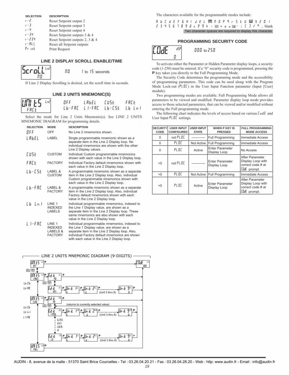
19
SELECTION DESCRIPTIONr-2 Reset Setpoint output 2r-3 Reset Setpoint output 3r-4 Reset Setpoint output 4r-34 Reset Setpoint outputs 3 & 4r-234 Reset Setpoint outputs 2, 3 & 4r-ALL Reset all Setpoint outputsPrint Print Request
LINE 2 DISPLAY SCROLL ENABLE/TIME
NO 1 to 15 seconds
If Line 2 Display Scrolling is desired, set the scroll time in seconds.
LINE 2 UNITS MNEMONIC(S)
OFF LAbEL CUSt FACt
Lb-FAC L1-FAC Lb-CSt Lb Ln1
Select the mode for Line 2 Units Mnemonic(s). See LINE 2 UNITS MNEMONIC DIAGRAM for programming details.
SELECTION MODE DESCRIPTION
OFF OFF No Line 2 mnemonics shown.
LAbEL LABEL Single programmable mnemonic shown as a separate item in the Line 2 Display loop. No individual mnemonics are shown with the other Line 2 Display values.
CUSt CUSTOM Individual Custom programmable mnemonics shown with each value in the Line 2 Display loop.
FACt FACTORY Individual Factory default mnemonics shown with each value in the Line 2 Display loop.
Lb-CSt LABEL & CUSTOM
A programmable mnemonic shown as a separate item in the Line 2 Display loop. Also, individual Custom programmable mnemonics shown with each value in the Line 2 Display loop.
Lb-FAC LABEL & FACTORY
A programmable mnemonic shown as a separate item in the Line 2 Display loop. Also, individual Factory default mnemonics shown with each value in the Line 2 Display loop.
Lb Ln1 LINE 1 INDEXED LABELS
Individual programmable mnemonics, indexed to the Line 1 Display value, are shown as a separate item in the Line 2 Display loop. These same mnemonics are also shown with each value in the Line 2 Display loop.
L1-FAC LINE 1 INDEXED LABELS & FACTORY
Individual programmable mnemonics, indexed to the Line 1 Display value, are shown as a separate item in the Line 2 Display loop. Also, individual Factory default mnemonics are shown with each value in the Line 2 Display loop.
The characters available for the programmable modes include:
A b C d E F G H I J k L M N O P q r S t U W Y Z 0 1
2 3 4 5 6 7 8 9 a c e g h i m n o u w - = [ ] / ° _ blank
PROGRAMMING SECURITY CODE
000 to 250
To activate either the Parameter or Hidden Parameter display loops, a security code (1-250) must be entered. If a “0” security code is programmed, pressing the P key takes you directly to the Full Programming Mode.
The Security Code determines the programming mode and the accessibility of programming parameters. This code can be used along with the Program Mode Lock-out (PLOC) in the User Input Function parameter (Input [User] module).
Two programming modes are available. Full Programming Mode allows all parameters to be viewed and modified. Parameter display loop mode provides access to those selected parameters, that can be viewed and/or modified without entering the Full programming mode.
The following chart indicates the levels of access based on various CodE and User Input PLOC settings.
SECURITYCODE
USER INPUT CONFIGURED
USER INPUTSTATE
WHEN P KEY IS PRESSED
FULL PROGRAMMING MODE ACCESS
0 not PLOC ———— Full Programming Immediate Access
0 PLOC Not Active Full Programming Immediate Access
0 PLOC Active Enter Parameter Display Loop No Access
>0 not PLOC ———— Enter Parameter Display Loop
After Parameter Display Loop with correct code # at COdE prompt.
>0 PLOC Not Active Full Programming Immediate Access
>0 PLOC Active Enter Parameter Display Loop
After Parameter Display Loop with correct code # at COdE prompt.
ScroLL NO
Ln2
UNItS FACt
Ln2
Two character spaces are required to display this character.
COdE0
dSP
P
LINE 2 UNITS MNEMONIC DIAGRAM (9-DIGITS)
Edit NO
P Edit CSt
NO
PUNItS Ln2
OFFCOdE Ln2
000
UNItS Ln2
LAbEL
Edit YES
UNItS Ln2
CUSt
Edit INPUt
Unit 11
Unit 2 2
Unit 9 9
Edit LO
P P P P
Unit 11
Unit 2 2
Unit 9 9
P P P P
P
P
Unit 11
Unit 2 2
Unit 9 9
P P P P
Lb
Lb Lb Lb Lb
CSt
CSt
INP INP INP
Lo Lo Lo
(Unit 3 thru 8)
(Unit 3 thru 8)
(Unit 3 thru 8)
(returns to currently selected value)
PUNItS Ln2
FACt
Lb-CSt
Lb-CSt
Lb-FAC
Lb Ln1
L1-FAC
F1 F2
F1 F2
F1 F2
GrOSS
tArE
tOtAL
HI
AUDIN - 8, avenue de la malle - 51370 Saint Brice Courcelles - Tel : 03.26.04.20.21 - Fax : 03.26.04.28.20 - Web : http: www.audin.fr - Email : [email protected]
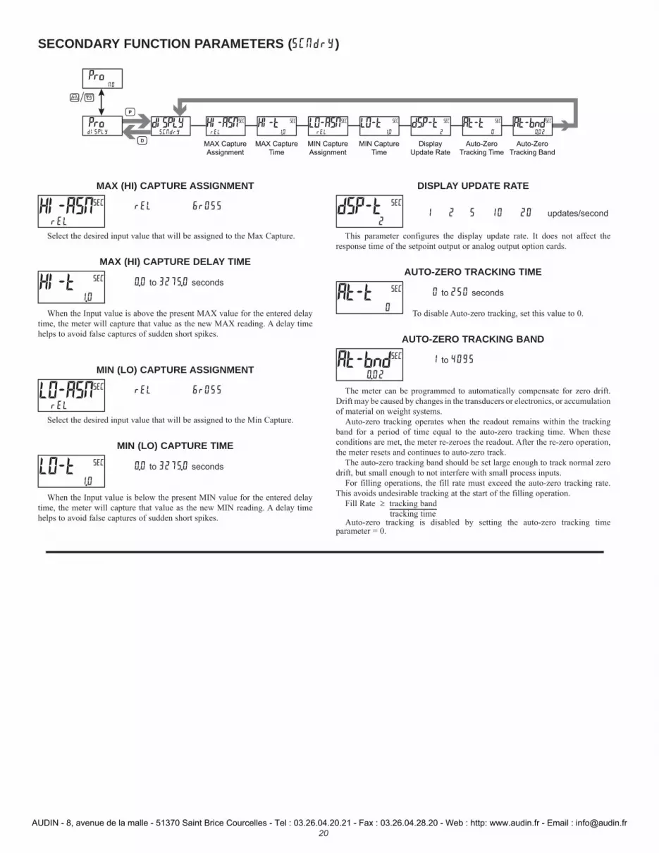
20
MAX (HI) CAPTURE ASSIGNMENT
rEL GrOSS
Select the desired input value that will be assigned to the Max Capture.
MAX (HI) CAPTURE DELAY TIME
0.0 to 3275.0 seconds
When the Input value is above the present MAX value for the entered delay time, the meter will capture that value as the new MAX reading. A delay time helps to avoid false captures of sudden short spikes.
MIN (LO) CAPTURE ASSIGNMENT
rEL GrOSS
Select the desired input value that will be assigned to the Min Capture.
MIN (LO) CAPTURE TIME
0.0 to 3275.0 seconds
When the Input value is below the present MIN value for the entered delay time, the meter will capture that value as the new MIN reading. A delay time helps to avoid false captures of sudden short spikes.
DISPLAY UPDATE RATE
1 2 5 10 20 updates/second
This parameter configures the display update rate. It does not affect the response time of the setpoint output or analog output option cards.
AUTO-ZERO TRACKING TIME
0 to 250 seconds
To disable Auto-zero tracking, set this value to 0.
AUTO-ZERO TRACKING BAND
1 to 4095
The meter can be programmed to automatically compensate for zero drift. Drift may be caused by changes in the transducers or electronics, or accumulation of material on weight systems.
Auto-zero tracking operates when the readout remains within the tracking band for a period of time equal to the auto-zero tracking time. When these conditions are met, the meter re-zeroes the readout. After the re-zero operation, the meter resets and continues to auto-zero track.
The auto-zero tracking band should be set large enough to track normal zero drift, but small enough to not interfere with small process inputs.
For filling operations, the fill rate must exceed the auto-zero tracking rate. This avoids undesirable tracking at the start of the filling operation.
Fill Rate tracking band tracking timeAuto-zero tracking is disabled by setting the auto-zero tracking time
parameter = 0.
HI-ASN rEL
SEC
HI-t1.0
SEC
LO-ASN rEL
SEC
LO-t1.0
SEC
dSP-t 2
SEC
At-t0
SEC
At-bnd 0.02
SEC
HI-ASNrEL
SEC HI-t1.0
SEC LO-ASNrEL
SEC LO-t1.0
SEC
MAX Capture
Assignment
MAX Capture
Time
MIN Capture
Assignment
MIN Capture
Time
dISPLYSCNdrY
At-t0
SECdSP-t2
SEC
Display
Update Rate
Auto-Zero
Tracking Time
At-bnd0.02
SEC
Auto-Zero
Tracking Band
ProdISPLY
ProNO
F1 F2
P
D
SECONDARY FUNCTION PARAMETERS (SCNdrY)
AUDIN - 8, avenue de la malle - 51370 Saint Brice Courcelles - Tel : 03.26.04.20.21 - Fax : 03.26.04.28.20 - Web : http: www.audin.fr - Email : [email protected]

21
dECPNt0.000
tOt t bASEMIN
tOt SCLFAC1.000
tOt Lo Cut-1999.99
tOt
Decimal
Point
Time Base Scale Factor Low Cut
Value
dISPLYtOtAL
PWrUPN0
tOt
Power Up
Reset
ProdISPLY
ProNO
F1 F2
P
D
TOTALIZER (INTEGRATOR) PARAMETERS (tOtAL)
The totalizer accumulates (integrates) the Relative Input Display value using one of two modes. The first is using a time base. This can be used to provide an indication of total flow, usage or consumption over time. The second is through a user input or function key programmed for Batch (one time add on demand). This can be used to provide a readout of total weight, useful in weight based filling operations. If the Totalizer is not needed, its display can be locked-out and this module can be skipped during programming.
TOTALIZER DECIMAL POINT
0 0.0 0.00 0.000 0.0000
For most applications, this should match the Input Display Decimal Point (dECPNt). If a different location is desired, refer to Totalizer Scale Factor.
TOTALIZER TIME BASE
SEC-seconds (/1) MIN -minutes (/60)hour-hours (/3600) dAY -days (/86400)
This is the time base used in Totalizer accumulations. If the Totalizer is being accumulated through a user input programmed for Batch, then this parameter does not apply.
TOTALIZER SCALE FACTOR
0.001 to 65.000
For most applications, the Totalizer reflects the same decimal point location and engineering units as the Input Display. In this case, the Totalizer Scale Factor is 1.000. The Totalizer Scale Factor can be used to scale the Totalizer to a value that is different than the Input Display. Common possibilities are:
1. Changing decimal point location (example tenths to whole)2. Average over a controlled time frame.Details on calculating the scale factor are shown later.If the Totalizer is being accumulated through a user input programmed for
Batch, then this parameter does not apply.
TOTALIZER LOW CUT VALUE
-199999 to 999999
A low cut value disables Totalizer when the Input Display value falls below the value programmed.
TOTALIZER POWER UP RESET
NO - do not reset buffer
YES - reset buffer
The Totalizer can be reset to zero on each meter power-up by setting this parameter to YES.
TOTALIZER BATCHINGThe Totalizer Time Base is overridden when a user input or function key is
programmed for store batch (bAt). In this mode, when the user input or function key is activated, the Input Display reading is multiplied by the totalizer scale factor and then one time added to the Totalizer (batch). The Totalizer retains a running sum of each batch operation until the Totalizer is reset. This is useful in weighing operations, when the value to be added is not based on time but after a filling event.
TOTALIZER USING TIME BASETotalizer accumulates as defined by:
Totalizer Scale Factor = Totalizer Display* Input Display*
*Value indicated with decimal and all display units after the decimal; Prior to calculating, “drop” the decimal point leaving all trailing units.
Where:Input Display = Fixed Input Display value.Totalizer Display = Totalized value with Input Display constant during a period of time equal to the Totalizer Time Base.
Example: A PAX2S is monitoring the total weight of material on a 20 ft conveyor. The conveyor operates at a constant rate of 1 ft/sec. The Totalizer will calculate the total weight of material output from the conveyor. Although the PAX2S Input Display indicates lbs in whole units, the Totalizer will be programmed to display tons in 1/10 units. Note that this application requires a User Input to enable the Totalizer when the conveyor is running. Accuracy is dependent on the amount of material and position of material still on the conveyor. For accurate totalizer reading, the conveyor should be allowed to “empty” before taking a totalizer reading.
There are several factors to consider in this example. First, the material that clears the end of the conveyor in 1 second is only 1/20 of the weight being displayed at any given time (20 ft conveyor @ 1 ft/sec). Second, the Totalizer display is in tenths of tons, while the input is in pounds.
In order to calculate the Totalizer Scale Factor, choose a constant Input Display (100) value and then determine the Totalizer Display value that would result after the period of the Totalizer Time Base (1 hour) selected.
100 lb = 5 lb/sec. → With 100 lb on the conveyor, 5 lbs falls off20 sec the end of the conveyor each second.
5 lb/sec x 3600 sec = 18,000 lb → 3600 seconds of material passing the end of the conveyor in an hour.
18,000 lb = 9.0 tons → Conversion of lbs to tons. 2000 lb
Conclusion: Input Display of 100 results in a Totalizer Display of 9.0 after 1 hour of constant and continuous operation. Place these values in the Totalizer Scale Factor formula as follows:
Totalizer Scale Factor = Totalizer Display* / Input Display* Totalizer Scale Factor = 9.0/100Totalizer Scale Factor = 90/100 **Totalizer Scale Factor = 0.9
* This value should include the decimal and all display units after the decimal.** This step requires that the decimal be “dropped”, but all other digits remain.
dECPNt0.000
tOt
t bASE MIN
tOt
SCLFAC1.000
tOt
Lo Cut-1999.99
tOt
PWrUP NO
tOt
AUDIN - 8, avenue de la malle - 51370 Saint Brice Courcelles - Tel : 03.26.04.20.21 - Fax : 03.26.04.28.20 - Web : http: www.audin.fr - Email : [email protected]
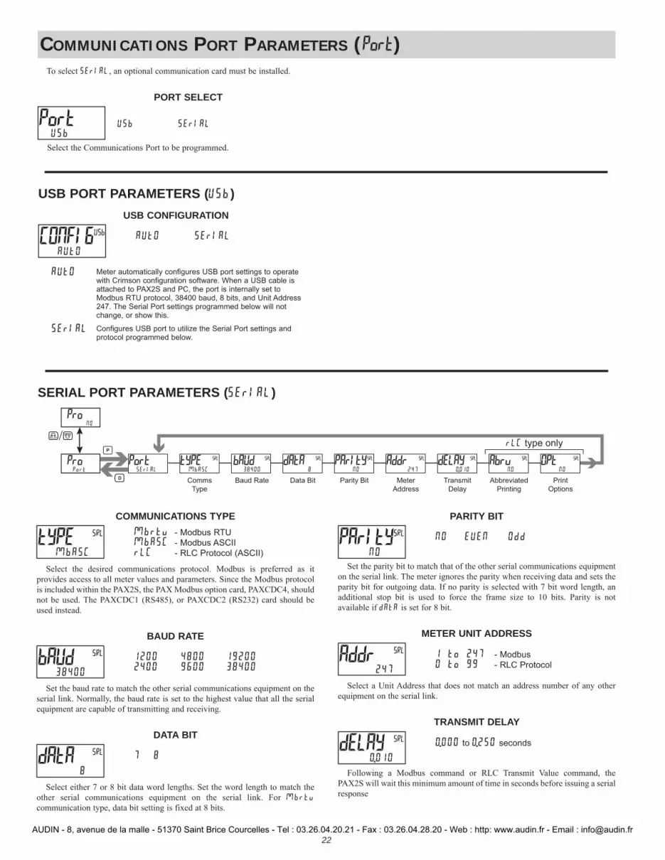
22
COMMUNICATIONS TYPEMbrtu - Modbus RTUMbASC - Modbus ASCIIrLC - RLC Protocol (ASCII)
Select the desired communications protocol. Modbus is preferred as it provides access to all meter values and parameters. Since the Modbus protocol is included within the PAX2S, the PAX Modbus option card, PAXCDC4, should not be used. The PAXCDC1 (RS485), or PAXCDC2 (RS232) card should be used instead.
BAUD RATE
1200 4800 192002400 9600 38400
Set the baud rate to match the other serial communications equipment on the serial link. Normally, the baud rate is set to the highest value that all the serial equipment are capable of transmitting and receiving.
DATA BIT
7 8
Select either 7 or 8 bit data word lengths. Set the word length to match the other serial communications equipment on the serial link. For Mbrtu communication type, data bit setting is fixed at 8 bits.
PARITY BIT
NO EUEN Odd
Set the parity bit to match that of the other serial communications equipment on the serial link. The meter ignores the parity when receiving data and sets the parity bit for outgoing data. If no parity is selected with 7 bit word length, an additional stop bit is used to force the frame size to 10 bits. Parity is not available if dAtA is set for 8 bit.
METER UNIT ADDRESS
1 to 247 - Modbus0 to 99 - RLC Protocol
Select a Unit Address that does not match an address number of any other equipment on the serial link.
TRANSMIT DELAY
0.000 to 0.250 seconds
Following a Modbus command or RLC Transmit Value command, the PAX2S will wait this minimum amount of time in seconds before issuing a serial response
tYPE MbASC
SRL
bAUd 38400
SRL
dAtA 8
SRL
PArItY NO
SRL
Addr247
SRL
dELAY0.010
SRL
COMMUNICATIONS PORT PARAMETERS (Port)
PORT SELECT
USb SErIAL
Select the Communications Port to be programmed.
Port USb
USB PORT PARAMETERS (USb)USB CONFIGURATION
AUtO SErIAL
AUtO Meter automatically configures USB port settings to operate with Crimson configuration software. When a USB cable is attached to PAX2S and PC, the port is internally set to Modbus RTU protocol, 38400 baud, 8 bits, and Unit Address 247. The Serial Port settings programmed below will not change, or show this.
SErIAL Configures USB port to utilize the Serial Port settings and protocol programmed below.
CONFIG AUtO
USb
PortSErIAL
tYPEMbASC
Comms
Type
dAtA8
SRL
Data Bit
bAUd38400
SRL
Baud Rate
PArItYNO
SRL
Parity Bit Meter
Address
Addr247
SRL dELAY0.010
SRL
Transmit
Delay
AbrvNO
SRL
Abbreviated
Printing
SRL OPtNO
Options
SRL ProPort
ProNO
F1 F2
P
D
rLC type only
SERIAL PORT PARAMETERS (SErIAL)
To select SErIAL, an optional communication card must be installed.
AUDIN - 8, avenue de la malle - 51370 Saint Brice Courcelles - Tel : 03.26.04.20.21 - Fax : 03.26.04.28.20 - Web : http: www.audin.fr - Email : [email protected]
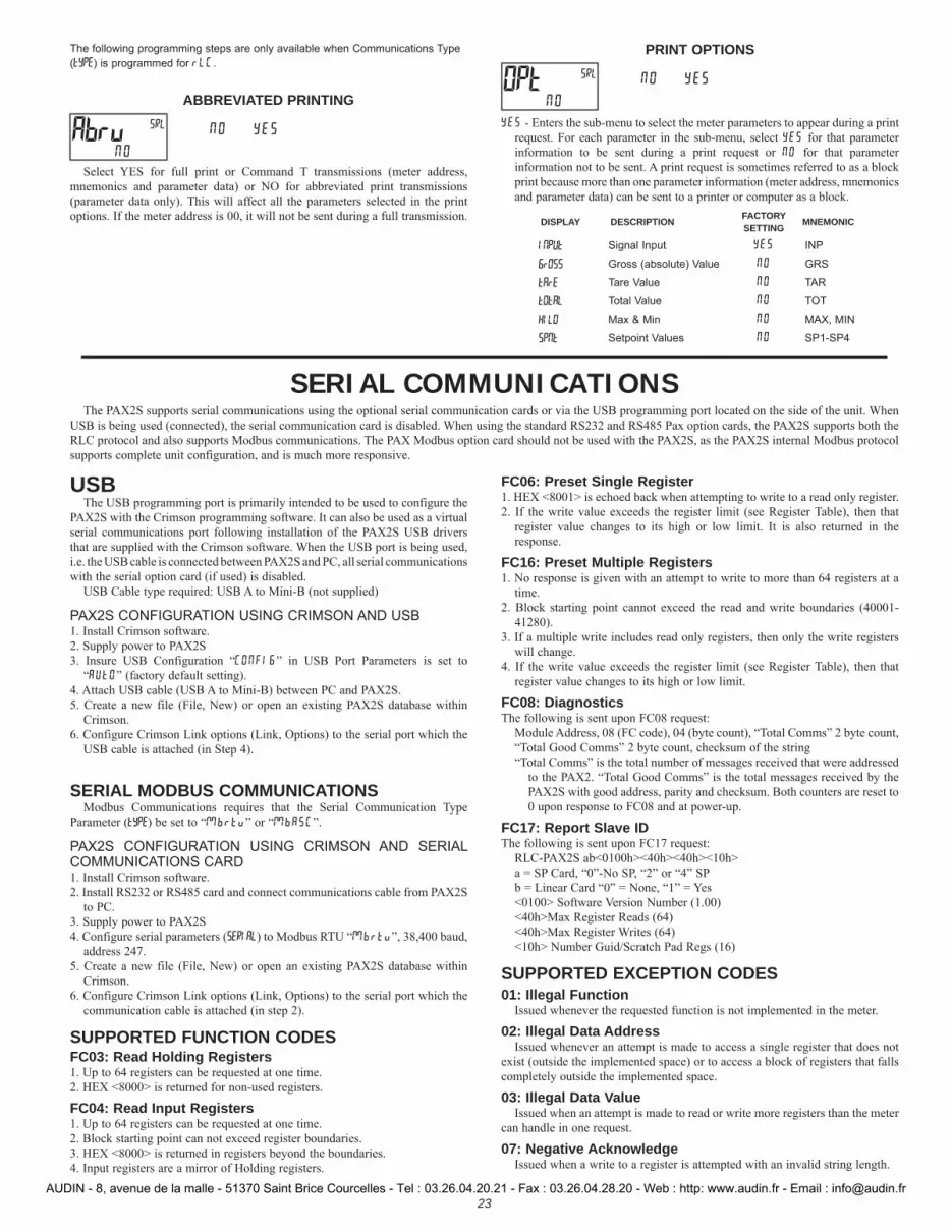
23
USBThe USB programming port is primarily intended to be used to configure the
PAX2S with the Crimson programming software. It can also be used as a virtual serial communications port following installation of the PAX2S USB drivers that are supplied with the Crimson software. When the USB port is being used, i.e. the USB cable is connected between PAX2S and PC, all serial communications with the serial option card (if used) is disabled.
USB Cable type required: USB A to Mini-B (not supplied)
PAX2S CONFIGURATION USING CRIMSON AND USB1. Install Crimson software.2. Supply power to PAX2S3. Insure USB Configuration “CONFIG” in USB Port Parameters is set to
“AUtO” (factory default setting).4. Attach USB cable (USB A to Mini-B) between PC and PAX2S.5. Create a new file (File, New) or open an existing PAX2S database within
Crimson.6. Configure Crimson Link options (Link, Options) to the serial port which the
USB cable is attached (in Step 4).
SERIAL MODBUS COMMUNICATIONSModbus Communications requires that the Serial Communication Type
Parameter (tYPE) be set to “Mbrtu” or “MbASC”.
PAX2S CONFIGURATION USING CRIMSON AND SERIAL COMMUNICATIONS CARD1. Install Crimson software.2. Install RS232 or RS485 card and connect communications cable from PAX2S
to PC.3. Supply power to PAX2S4. Configure serial parameters (SERIAL) to Modbus RTU “Mbrtu”, 38,400 baud,
address 247.5. Create a new file (File, New) or open an existing PAX2S database within
Crimson.6. Configure Crimson Link options (Link, Options) to the serial port which the
communication cable is attached (in step 2).
SUPPORTED FUNCTION CODESFC03: Read Holding Registers1. Up to 64 registers can be requested at one time.2. HEX <8000> is returned for non-used registers.
FC04: Read Input Registers1. Up to 64 registers can be requested at one time.2. Block starting point can not exceed register boundaries.3. HEX <8000> is returned in registers beyond the boundaries.4. Input registers are a mirror of Holding registers.
FC06: Preset Single Register1. HEX <8001> is echoed back when attempting to write to a read only register.2. If the write value exceeds the register limit (see Register Table), then that
register value changes to its high or low limit. It is also returned in the response.
FC16: Preset Multiple Registers1. No response is given with an attempt to write to more than 64 registers at a
time.2. Block starting point cannot exceed the read and write boundaries (40001-
41280).3. If a multiple write includes read only registers, then only the write registers
will change.4. If the write value exceeds the register limit (see Register Table), then that
register value changes to its high or low limit.
FC08: DiagnosticsThe following is sent upon FC08 request:
Module Address, 08 (FC code), 04 (byte count), “Total Comms” 2 byte count,“Total Good Comms” 2 byte count, checksum of the string“Total Comms” is the total number of messages received that were addressed
to the PAX2. “Total Good Comms” is the total messages received by the PAX2S with good address, parity and checksum. Both counters are reset to 0 upon response to FC08 and at power-up.
FC17: Report Slave IDThe following is sent upon FC17 request:
RLC-PAX2S ab<0100h><40h><40h><10h>a = SP Card, “0”-No SP, “2” or “4” SPb = Linear Card “0” = None, “1” = Yes<0100> Software Version Number (1.00)<40h>Max Register Reads (64)<40h>Max Register Writes (64)<10h> Number Guid/Scratch Pad Regs (16)
SUPPORTED EXCEPTION CODES01: Illegal Function
Issued whenever the requested function is not implemented in the meter.
02: Illegal Data AddressIssued whenever an attempt is made to access a single register that does not
exist (outside the implemented space) or to access a block of registers that falls completely outside the implemented space.
03: Illegal Data ValueIssued when an attempt is made to read or write more registers than the meter
can handle in one request.
07: Negative AcknowledgeIssued when a write to a register is attempted with an invalid string length.
SERIAL COMMUNICATIONSThe PAX2S supports serial communications using the optional serial communication cards or via the USB programming port located on the side of the unit. When
USB is being used (connected), the serial communication card is disabled. When using the standard RS232 and RS485 Pax option cards, the PAX2S supports both the RLC protocol and also supports Modbus communications. The PAX Modbus option card should not be used with the PAX2S, as the PAX2S internal Modbus protocol supports complete unit configuration, and is much more responsive.
The following programming steps are only available when Communications Type (tYPE) is programmed for rLC.
ABBREVIATED PRINTING
NO YES
Select YES for full print or Command T transmissions (meter address, mnemonics and parameter data) or NO for abbreviated print transmissions (parameter data only). This will affect all the parameters selected in the print options. If the meter address is 00, it will not be sent during a full transmission.
PRINT OPTIONS
NO YES
YES - Enters the sub-menu to select the meter parameters to appear during a print request. For each parameter in the sub-menu, select YES for that parameter information to be sent during a print request or NO for that parameter information not to be sent. A print request is sometimes referred to as a block print because more than one parameter information (meter address, mnemonics and parameter data) can be sent to a printer or computer as a block.
DISPLAY DESCRIPTION FACTORY SETTING MNEMONIC
INPUt Signal Input YES INP
GrOSS Gross (absolute) Value NO GRS
tArE Tare Value NO TAR
tOtAL Total Value NO TOT
HILO Max & Min NO MAX, MIN
SPNt Setpoint Values NO SP1-SP4
Abrv NO
SRL
OPt NO
SRL
AUDIN - 8, avenue de la malle - 51370 Saint Brice Courcelles - Tel : 03.26.04.20.21 - Fax : 03.26.04.28.20 - Web : http: www.audin.fr - Email : [email protected]

24
REGISTER ADDRESS
TABLE INDEX REGISTER NAME LOW LIMIT HIGH LIMIT FACTORY
SETTING ACCESS COMMENTS
FREQUENTLY USED REGISTERS
40001 0 Input Relative Value (Hi word)-199999 999999 N/A Read Only
Process value of present input level. This value is affected by Input Type, Resolution, Scaling, & Tare (Offset) Value.(Relative Value = Gross (Absolute) Input Value - Tare Value)40002 1 Input Relative Value (Lo word)
40003 2 Maximum Value (Hi word)-199999 999999 N/A Read/Write Maximum Relative Input Capture Value obtained since
having been reset.40004 3 Maximum Value (Lo word)40005 4 Minimum Value (Hi word)
-199999 999999 N/A Read/Write Minimum Relative Input Capture Value obtained since having been reset.40006 5 Minimum Value (Lo word)
40007 6 Total Value (Hi word)-199999 999999 0 Read/Write Totalizer value
40008 7 Total Value (Lo word)40009 8 Setpoint 1 Value (Hi word)
-199999 999999 100 Read/Write Active List (A or B)40010 9 Setpoint 1 Value (Lo word)40011 10 Setpoint 2 Value (Hi word)
-199999 999999 200 Read/Write Active List (A or B)40012 11 Setpoint 2 Value (Lo word)40013 12 Setpoint 3 Value (Hi word)
-199999 999999 300 Read/Write Active List (A or B)40014 13 Setpoint 3 Value (Lo word)40015 14 Setpoint 4 Value (Hi word)
-199999 999999 400 Read/Write Active List (A or B)40016 15 Setpoint 4 Value (Lo word)
40017 16 Setpoint 1 Band/Dev. Value (Hi word)
-199999 999999 0 Read/Write Active List (A or B).Applicable only for Band or Deviation Setpoint Action.
40018 17 Setpoint 1 Band/Dev. Value(Lo word)
40019 18 Setpoint 2 Band/Dev. Value (Hi word)
-199999 999999 0 Read/Write Active List (A or B).Applicable only for Band or Deviation Setpoint Action.
40020 19 Setpoint 2 Band/Dev. Value(Lo word)
40021 20 Setpoint 3 Band/Dev. Value (Hi word)
-199999 999999 0 Read/Write Active List (A or B).Applicable only for Band or Deviation Setpoint Action.
40022 21 Setpoint 3 Band/Dev. Value(Lo word)
40023 22 Setpoint 4 Band/Dev. Value(Hi word)
-199999 999999 0 Read/Write Active List (A or B).Applicable only for Band or Deviation Setpoint Action.
40024 23 Setpoint 4 Band/Dev. Value(Lo word)
40025 24 Setpoint Output Register (SOR) 0 15 0 Read/Write
Status of Setpoint Outputs. Bit State: 0 = Off, 1 = On.Bit 3 = SP1, Bit 2 = SP2, Bit 1 = SP3, Bit 0 = SP4.Outputs can only be activated/reset with this register when the respective bits in the Manual Mode Register (MMR) are set.
40026 25 Manual Mode Register (MMR) 0 31 0 Read/WriteBit State: 0 = Auto Mode, 1 = Manual ModeBit 4 = SP1, Bit 3 = SP2, Bit 2 = SP3, Bit 1 = SP4, Bit 0 = Linear Output
40027 26 Reset Output Register 0 15 0 Read/WriteBit State: 1 = Reset Output, bit is returned to zero following reset processing; Bit 3 = SP1, Bit 2 = SP2, Bit 1 = SP3, Bit 0 = SP4
40028 27 Analog Output Register (AOR) 0 4095 0 Read/Write
Functional only if Linear Output is in Manual Mode.(MMR bit 0 = 1)Linear Output Card written to only if Linear Out (MMR bit 0) is set.
40029 28 Input Gross (Absolute) Value (Hi word)
-199999 999999 N/A Read OnlyGross (absolute) value of present Input level. This value is affected by Input Type, Resolution, Scaling, but not affected by Offset Value40030 29 Input Gross (Absolute) Value
(Lo word)
40031 30 Tare Value (Hi word)-199999 999999 0 Read/Write
Relative Input Value (standard meter value) is the difference between the Gross (absolute) input value and the Tare value, i.e. Relative = Gross - Tare40032 31 Tare Value (Lo word)
PAX2S MODBUS REGISTER TABLEOnly frequently used registers are shown below. The entire Modbus Register Table can be found at www.redlion.net.Values less than 65,535 will be in (LO word). Values greater than 65,535 will continue into (Hi word). Negative values are represented by two’s complement of thecombined (Hi word) and (LO word).Note 1: The PAX2S should not be powered down while parameters are being changed. Doing so may corrupt the non-volatile memory resulting in checksum errors.
AUDIN - 8, avenue de la malle - 51370 Saint Brice Courcelles - Tel : 03.26.04.20.21 - Fax : 03.26.04.28.20 - Web : http: www.audin.fr - Email : [email protected]

25
SERIAL RLC PROTOCOL COMMUNICATIONSRLC Communications requires the Serial Communications Type Parameter
(tYPE) be set to “rLC”.
SENDING SERIAL COMMANDS AND DATA TO THE METERWhen sending commands to the meter, a string containing at least one
command character must be constructed. A command string consists of a command character, a value identifier, numerical data (if writing data to the meter) followed by a command terminator character * or $. The <CR> is also available as a terminator when Counter C is in the SLAVE mode.
Command ChartCOMMAND DESCRIPTION NOTES
N Node (Meter) Address Specifier
Address a specific meter. Must be followed by a two digit node address. Not required when address = 00.
T Transmit Value (read)
Read a register from the meter. Must be followed by register ID character
V Value Change (write)
Write to register of the meter. Must be followed by register ID character and numeric data.
R Reset Reset a register or output. Must be followed by register ID character.
P Block Print Request
Initiates a block print output. Registers are defined in programming.
Command String ConstructionThe command string must be constructed in a specific sequence. The meter
does not respond with an error message to invalid commands. The following procedure details construction of a command string:1. The first characters consist of the Node Address Specifier (N) followed by a
2 character address number. The address number of the meter is programmable. If the node address is 0, this command and the node address itself may be omitted. This is the only command that may be used in conjunction with other commands.
2. After the optional address specifier, the next character is the command character.
3. The next character is the Register ID. This identifies the register that the command affects. The P command does not require a Register ID character. It prints according to the selections made in print options.
4. If constructing a value change command (writing data), the numeric data is sent next.
5. All command strings must be terminated with the string termination characters *, $ or when Counter C is set for slave mode <CR>. The meter does not begin processing the command string until this character is received. See Timing Diagram figure for differences between terminating characters.
Register Identification ChartID VALUE DESCRIPTION MNEMONIC APPLICABLE COMMANDS/COMMENTS
A Input (relative value)
INP T, P, R (Reset command resets input to zero; tares)
B Total TOT T, P, R (Reset command resets total to zero)
C Max Input MAX T, P, R (Reset command resets Max to current reading)
D Min Input MIN T, P, R (Reset command resets Min to current reading)
E Setpoint 1 SP1 T, P, V, R (Reset command resets the setpoint output)F Setpoint 2 SP2
G Setpoint 3 SP3H Setpoint 4 SP4I Band/Deviation 1 BD1 T, VJ Band/Deviation 2 BD2 T, VK Band/Deviation 3 BD3 T, VL Band/Deviation 4 BD4 T, VM Gross (Absolute)
Input valueGRS T, P
O Tare (Offset) Value TAR T, P, R, VU Auto/Manual
RegisterMMR T, V
W Analog Output Register
AOR T, V
X Setpoint Register SOR T, V
Command String Examples:1. Node address = 17, Write 350 to Setpoint 1.
String: N17VE350$2. Node address = 5, Read Input value.
String: N5TA*3. Node address = 0, Reset Setpoint 4 output.
String: RH*
Sending Numeric DataNumeric data sent to the meter must be limited to 6 digits (-199999 to
999999). Leading zeros are ignored. Negative numbers must have a minus sign. The meter ignores any decimal point and conforms the number to the scaled resolution. (For example: the meter’s scaled decimal point position = 0.0 and 25 is written to a register. The value of the register is now 2.5.
Note: Since the meter does not issue a reply to value change commands, follow with a transmit value command for readback verification.
AUDIN - 8, avenue de la malle - 51370 Saint Brice Courcelles - Tel : 03.26.04.20.21 - Fax : 03.26.04.28.20 - Web : http: www.audin.fr - Email : [email protected]

26
RECEIVING DATA FROM THE METERData is transmitted by the meter in response to either a transmit command (T),
a print block command (P) or User Function print request. The response from the meter is either a full field transmission or an abbreviated transmission. The meter response mode is selected in program Module 7 (Abrv).
Full Field Transmission (Address, Mnemonic, Numeric data)Byte Description1, 2 2 byte Node Address field [00-99]3 <SP> (Space)4-6 3 byte Register Mnemonic field7-18 2 byte data field, 10 bytes for number, one byte for sign, one byte for decimal point19 <CR> carriage return20 <LF> line feed21 <SP>* (Space)22 <CR>* carriage return23 <LF>* line feed* These characters only appear in the last line of a block print.
The first two characters transmitted are the node address, unless the node address assigned = 0, in which case spaces are substituted. A space follows the node address field. The next three characters are the register mnemonic.
The numeric data is transmitted next. The numeric field is 12 characters long (to accommodate the 10 digit totalizer), with the decimal point position floating within the data field. Negative values have a leading minus sign. The data field is right justified with leading spaces.
The end of the response string is terminated with a carriage return <CR> and <LF>. When block print is finished, an extra <SP><CR> <LF> is used to provide separation between the blocks.
Abbreviated Transmission (Numeric data only)Byte Description1-12 12 byte data field, 10 bytes for number, one byte for sign, one byte for decimal point13 <CR> carriage return14 <LF> line feed15 <SP>* (Space)16 <CR>* carriage return17 <LF>* line feed* These characters only appear in the last line of a block print.
Meter Response Examples:1. Node address = 17, full field response, Input = 875
17 INP 875 <CR><LF>2. Node address = 0, full field response, Setpoint 2 = -250.5
SP2 -250.5<CR><LF>3. Node address = 0, abbreviated response, Setpoint 2 = 250, last line of block
print250<CR><LF><SP><CR><LF>
Auto/Manual Mode Register (MMR) ID: UThis register sets the controlling mode for the outputs. In Auto Mode (0) the
meter controls the setpoint and analog output. In Manual Mode (1) the outputs are defined by the registers SOR and AOR. When transferring from auto mode to manual mode, the meter holds the last output value (until the register is changed by a write). Each output may be independently changed to auto or manual. In a write command string (VU), any character besides 0 or 1 in a field will not change the corresponding output mode.
U abcde e = Analog Output d = SP4 c = SP3 b = SP2 a = SP1
Example: VU00011 places SP4 and Analog in manual.
Analog Output Register (AOR) ID: WThis register stores the present signal value of the analog output. The range
of values of this register is 0 to 4095, which corresponds to the analog output range per the following chart:
Register Value
Output Signal*0-20 mA 4-20 mA 0-10 V
0 0.00 4.00 0.0001 0.005 4.004 0.0025
2047 10.000 12.000 5.0004094 19.995 19.996 9.99754095 20.000 20.000 10.000
*Due to the absolute accuracy rating and resolution of the output card, the actual output signal may differ 0.15% FS from the table values. The output signal corresponds to the range selected (0-20 mA, 4-20 mA or 0-10 V).Writing to this register (VW) while the analog output is in the Manual Mode
causes the output signal level to update immediately to the value sent. While in the Automatic Mode, this register may be written to, but it has no effect until the analog output is placed in the manual mode. When in the Automatic Mode, the meter controls the analog output signal level. Reading from this register (TW) will show the present value of the analog output signal.
Example: VW2047 will result in an output of 10.000 mA, 12.000 mA or 5.000V depending on the range selected.
Setpoint Output Register (SOR) ID: XThis register stores the states of the setpoint outputs. Reading from this
register (TX) will show the present state of all the setpoint outputs. A “0” in the setpoint location means the output is off and a “1” means the output is on.
X abcd d = SP4 c = SP3 b = SP2 a = SP1
In Automatic Mode, the meter controls the setpoint output state. In Manual Mode, writing to this register (VX) will change the output state. Sending any character besides 0 or 1 in a field or if the corresponding output was not first in manual mode, the corresponding output value will not change. (It is not necessary to send least significant 0s.)
Example: VX10 will result in output 1 on and output 2 off.
AUDIN - 8, avenue de la malle - 51370 Saint Brice Courcelles - Tel : 03.26.04.20.21 - Fax : 03.26.04.28.20 - Web : http: www.audin.fr - Email : [email protected]

27
COMMUNICATION FORMATData is transferred from the meter through a serial communication channel.
In serial communications, the voltage is switched between a high and low level at a predetermined rate (baud rate) using ASCII encoding. The receiving device reads the voltage levels at the same intervals and then translates the switched levels back to a character.
The voltage level conventions depend on the interface standard. The table lists the voltage levels for each standard.
Data is transmitted one byte at a time with a variable idle period between characters (0 to ). Each ASCII character is “framed” with a beginning start bit, an optional parity bit and one or more ending stop bits. The data format and baud rate must match that of other equipment in order for communication to take place. The figures list the data formats employed by the meter.
Start bit and Data bitsData transmission always begins with the start bit. The start bit signals the
receiving device to prepare for reception of data. One bit period later, the least significant bit of the ASCII encoded character is transmitted, followed by the remaining data bits. The receiving device then reads each bit position as they are transmitted. Since the sending and receiving devices operate at the same transmission speed (baud rate), the data is read without timing errors.
Parity bitAfter the data bits, the parity bit is sent. The transmitter sets the parity bit to
a zero or a one, so that the total number of ones contained in the transmission (including the parity bit) is either even or odd. This bit is used by the receiver to detect errors that may occur to an odd number of bits in the transmission. However, a single parity bit cannot detect errors that may occur to an even number of bits. Given this limitation, the parity bit is often ignored by the receiving device. The PAX meter ignores the parity bit of incoming data and sets the parity bit to odd, even or none (mark parity) for outgoing data.
Stop bitThe last character transmitted is the stop bit. The stop bit provides a single bit
period pause to allow the receiver to prepare to re-synchronize to the start of a new transmission (start bit of next byte). The receiver then continuously looks for the occurrence of the start bit. If 7 data bits and no parity is selected, then 2 stop bits are sent from the PAX meter.
Character Frame Figure
LOGIC RS232* RS485*INTERFACE STATE
1 TXD,RXD; -3 to -15 V a-b < -200 mVmark (idle)0 TXD,RXD; +3 to +15 V a-b > +200 mVspace (active)
* Voltage levels at the Receiver
COMMAND RESPONSE TIMEThe meter can only receive data or transmit data at any one time (half-duplex
operation). When sending commands and data to the meter, a delay must be imposed before sending another command. This allows enough time for the meter to process the command and prepare for the next command.
At the start of the time interval t1, the computer program prints or writes the string to the com port, thus initiating a transmission. During t1, the command characters are under transmission and at the end of this period, the command terminating character (*) is received by the meter. The time duration of t1 is dependent on the number of characters and baud rate of the channel.
t1 = (10 * # of characters) / baud rate
At the start of time interval t2, the meter starts the interpretation of the command and when complete, performs the command function. This time interval t2 varies from 2 msec to 15 msec. If no response from the meter is expected, the meter is ready to accept another command.
If the meter is to reply with data, the time interval t2 is controlled by the use of the command terminating character and the (Serial Transmit Delay parameter (dELAY)). The standard command line terminating character is “*”. This terminating character results in a response time window of the Serial Transmit Delay time (dELAY) plus 15 msec. maximum. The dELAY parameter should be programmed to a value that allows sufficient time for the release of the sending driver on the RS485 bus. Terminating the command line with “$” results in a response time window (t2) of 2 msec minimum and 15 msec maximum. The response time of this terminating character requires that sending drivers release within 2 msec after the terminating character is received.
At the beginning of time interval t3, the meter responds with the first character of the reply. As with t1, the time duration of t3 is dependent on the number of characters and baud rate of the channel.
t3 = (10 * # of characters) / baud rate.
At the end of t3, the meter is ready to receive the next command. The maximum serial throughput of the meter is limited to the sum of the times t1, t2 and t3.
NO REPLY FROM METER
RESPONSE FROM METER
Timing Diagrams
AUDIN - 8, avenue de la malle - 51370 Saint Brice Courcelles - Tel : 03.26.04.20.21 - Fax : 03.26.04.28.20 - Web : http: www.audin.fr - Email : [email protected]

28
FACTORY SERVICE OPERATIONS (FACtrY)FACTORY SERVICE CODE
0-250
Enter the Service Code for the desired operation.
RESTORE FACTORY DEFAULTS
Use the and keys to display COdE 66 and press P. The meter will flash rESEt and then return to COdE 50. Press the P key to return to Display Mode. This will overwrite all user settings with the factory settings. The only exception is the User Mnemonics which retain their programmed values (see Code 69).
RESTORE FACTORY DEFAULTS (w/Units Mnemonics)
Same as Code 66, except the User Mnemonics are also returned to the factory default settings (blank).
MODEL AND CODE VERSION
The meter will briefly display the model (P2S) on Line 1, and the current firmware version (UEr x.xx) on Line 2, and then return to COdE 50.
METER CALIBRATION
NO INPUt AnLOut
The meter has been fully calibrated at the factory. Scaling to convert the input signal to a desired display value is performed in Input Parameters. If the meter appears to be indicating incorrectly or inaccurately, refer to Troubleshooting before attempting to calibrate the meter. When recalibration is required (generally every 2 years), it should only be performed by qualified technicians using appropriate equipment. Calibration does not change any user programmed parameters. However, it will affect the accuracy of the input signal and the values previously stored using the Apply (APPLY) Scaling Style.
Preparation for Voltage Input Calibration Warning: Input Calibration of this meter requires a signal source
capable of producing a signal greater than or equal to the range being calibrated with an accuracy of 0.01% or better.
Before starting, verify that the Input Range Jumper is set for the range to be calibrated. Verify that the precision signal source is connected and ready. Allow a 30 minute warm-up period before calibrating the meter. Selecting NO at any calibration step, will cause the unit to maintain the existing calibration parameters for that step. Selecting YES and pressing the P key will cause the unit to store new calibration settings for the range selected. Pressing D at any time will exit programming mode, but any range that has been calibrated will maintain the new settings.
Input Calibration Procedure1. After entering CodE 48, in Factory Service Operations, select the input
(0.020v or 0.20v) to be calibrated.2. Press the P key until the desired range along with 2ER is indicated on Line 1
of the meter.3. Apply the zero input limit of the range indicated on Line 1 of the meter.4. Press to select YES.5. Press P. Display will indicate ---- on Line 2 as the unit reads and stores the
new calibration parameter.6. Display will indicate the desired range along with FUL on Line 1 of the meter.7. Apply the signal level indicated on Line 1 of the meter.8. Press to select YES.9. Press P. Display will indicate ---- on Line 2 as the unit reads and stores the
new calibration parameter.10. Repeat Preparation and Calibration Procedure for the other Input Range if
calibration for the other range is desired.
Analog Output Card CalibrationBefore starting, verify that a precision meter with an accuracy of 0.05% or
better (voltmeter for voltage output and/or current meter for current output) is connected and ready. Using the chart below, step through the five selections to be calibrated. At each prompt, use the PAX2S and keys to adjust the output so that the external meter display matches the selection being calibrated. When the external reading matches, or if the range is not being calibrated, press the P key to advance to the next range. When all the desired ranges have been calibrated, exit programming mode and remove the external meters.
DISPLAY EXTERNAL METER ACTION
0.000A 0.00 mA Adjust if necessary, press P
0.004A 4.00 mA Adjust if necessary, press P
0.020A 20.00 mA Adjust if necessary, press P
0.0v 0.00 V Adjust if necessary, press P
10.0v 10.00 V Adjust if necessary, press P
COdE 5O
FCS
COdE66
FCS rESEt
COdE50
FCSP
COdE69
FCS rESEt
COdE50
FCSP
COdE51
FCS P2-SV Er x.xx
FCS COdE50
FCSP
COdE48
FCS CAL NO
FCSP
AUDIN - 8, avenue de la malle - 51370 Saint Brice Courcelles - Tel : 03.26.04.20.21 - Fax : 03.26.04.28.20 - Web : http: www.audin.fr - Email : [email protected]

29
TROUBLESHOOTINGPROBLEM REMEDIES
No Display At Power-Up Check power level and power connections
No Display After Power-Up Check Display Module: d-LEU, d-Cont, and LINE 1 program settings.
Program Locked-Out Check for Active User Input, programmed for PLOC. Deactivate User Input.
Enter proper access code at COdE 0 prompt. (Universal access code = 222)
No Line 1 Display Check program settings for Line 1 Display Value Select/Enable. Confirm at least one Line 1 Display Value is enabled (YES).
No Line 2 Display Check program settings for Line 2 Value Access. Confirm at least one Line 2 Parameter Value is enabled in Main Display Loop (d-rEAd, d-rSt, d-Entr).
No Line 1 Units Mnemonic Display Check program settings for Line 1 Units Mnemonic(s).
Display of OLOL, ULUL, or “ . . . .” See General Meter Specifications, Display Messages.
Incorrect Input Display Value Check Input Jumper Setting, Input Level, and Input Connections.
Verify Input - Analog program settings.
Contact factory
Modules or Parameters Not Accessible Check for corresponding plug-in option card.
Verify parameter is valid in regard to previous program settings.
Error Code: ErrKEY Keypad is active at power up. Check for depressed or stuck keypad. Press any key to clear Error Code.
Error Code: EE PArError Code: EE Pdn
Parameter Data Checksum Error. Press any key to clear Error Code, verify all program settings and cycle power. Contact factory if Error Code returns at next power-up.
Error Code: ErrPro Parameter Data Validation Error. Press any key to clear Error Code, verify all program settings and cycle power. Contact factory if Error Code returns at next power-up.
Error Code: EE CAL Calibration Data Validation Error. Contact factory.
Error Code: EE Lin Linear Output Card Data Validation Error. Press any key to clear Error Code and cycle power. If Error Code returns at next power-up, replace Linear Option Card or contact factory.
AUDIN - 8, avenue de la malle - 51370 Saint Brice Courcelles - Tel : 03.26.04.20.21 - Fax : 03.26.04.28.20 - Web : http: www.audin.fr - Email : [email protected]

30
ANALOG Analog Output ParametersDISPLAY PARAMETER USER SETTING
tYPE ANALOG TYPE
ASSIGN ANALOG ASSIGNMENT
ANALOG LO ANALOG LOW
ANALOG HI ANALOG HIGH
UPdAtE ANALOG UPDATE TIME
dISPLY DISPLAY PARAMETERSLINE 1 Line 1 ParametersDISPLAY PARAMETER USER SETTING
Color Line 1 Display Color
d-LEV Display Level
d-Cont Display Contrast Level
SELECt Line 1 Display Value Select
INPUt LO
GrOSS S1
tArE S2
tOtAL S3
HI S4
OUtPUt OUTPUT PARAMETERSSEtPNt Setpoint Output ParametersDISPLAY PARAMETER USER SETTING USER SETTING USER SETTING USER SETTING
SELECt SETPOINT SELECTION S1 S2 S3 S4
ASSIGN SETPOINT SOURCE
ACtION ACTION FOR SETPOINT
SEtPNt SETPOINT VALUE
bn-dEV SETPOINT BAND/DEVIATION VALUE
HYStEr HYSTERESIS FOR SETPOINT
t-ON ON TIME DELAY SETPOINT
t-OFF OFF TIME DELAY SETPOINT
LOGIC OUTPUT LOGIC
rESEt RESET ACTION
StndbY STANDYBY OPERATION
Annun OUTPUT ANNUNCIATOR LIGHT
Color CHANGE COLOR
PARAMETER VALUE CHART Programmer ________________ Date ________PAX2S Meter# _____________ Security Code ________
INPUt INPUT SETUP PARAMETERSANALOG Analog Input ParametersDISPLAY PARAMETER USER SETTING
rANgE INPUT RANGE
rAtE INPUT UPDATE RATE
dECPNt DECIMAL RESOLUTION
round ROUNDING INCREMENT
tArE DISPLAY TARE (OFFSET)
FILtEr DIGITAL FILTER
bANd DIGITAL FILTER BAND
POINtS SCALING POINTS
StYLE SCALING STYLE
INPUt 1 INPUT 1 SCALING VALUE
dISPLY 1 DISPLAY 1 VALUE
INPUt 2 INPUT 2 SCALING VALUE
dISPLY 2 DISPLAY 2 VALUE
INPUt 3 INPUT 3 SCALING VALUE
dISPLY 3 DISPLAY 3 VALUE
INPUt 4 INPUT 4 SCALING VALUE
dISPLY 4 DISPLAY 4 VALUE
INPUt 5 INPUT 5 SCALING VALUE
dISPLY 5 DISPLAY 5 VALUE
INPUt 6 INPUT 6 SCALING VALUE
dISPLY 6 DISPLAY 6 VALUE
INPUt 7 INPUT 7 SCALING VALUE
dISPLY 7 DISPLAY 7 VALUE
INPUt 8 INPUT 8 SCALING VALUE
dISPLY 8 DISPLAY 8 VALUE
INPUt 9 INPUT 9 SCALING VALUE
DISPLAY PARAMETER USER SETTING
dISPLY 9 DISPLAY 9 VALUE
INPUt 10 INPUT 10 SCALING VALUE
dISPLY 10 DISPLAY 10 VALUE
INPUt 11 INPUT 11 SCALING VALUE
dISPLY 11 DISPLAY 11 VALUE
INPUt 12 INPUT 12 SCALING VALUE
dISPLY 12 DISPLAY 12 VALUE
INPUt 13 INPUT 13 SCALING VALUE
dISPLY 13 DISPLAY 13 VALUE
INPUt 14 INPUT 14 SCALING VALUE
dISPLY 14 DISPLAY 14 VALUE
INPUt 15 INPUT 15 SCALING VALUE
dISPLY 15 DISPLAY 15 VALUE
INPUt 16 INPUT 16 SCALING VALUE
dISPLY 16 DISPLAY 16 VALUE
USEr User Input ParametersDISPLAY PARAMETER USER SETTING
USrACt USER ACTIVE STATE
USEr-1 USER INPUT 1
USEr-2 USER INPUT 2
USEr-3 USER INPUT 3
F1 FUNCTION KEY 1
F2 FUNCTION KEY 2
SEC-F1 2nd FUNCTION KEY 1
SEC-F2 2nd FUNCTION KEY 2
AUDIN - 8, avenue de la malle - 51370 Saint Brice Courcelles - Tel : 03.26.04.20.21 - Fax : 03.26.04.28.20 - Web : http: www.audin.fr - Email : [email protected]

31
DISPLAY PARAMETER USER SETTING
ScroLL Line 1 Display Scroll Enable/Time
UNItS Line 1 Units Mnemonic(s)LABEL MNEMONIC LABEL
List A List B
Unit 1 Line 1 Units Digit 1 (Left)
Unit 2 Line 1 Units Digit 2 (Center)
Unit 3 Line 1 Units Digit 3 (Right)LIST A CUSTOM MNEMONICS Unit 1 Unit 2 Unit 3
InputGrossTareTotalMax (HI)Min (LO)
LIST B CUSTOM MNEMONICS Unit 1 Unit 2 Unit 3
InputGrossTareTotalMax (HI)Min (LO)
LINE 2 Line 2 ParametersACCESS LINE 2 VALUE ACCESS
INPUt S2
GrOSS b2-d2
tArE S3
tOtAL b3-d3
Hi S4
Lo b4-d4
LISt Color
S1 d-LEV
b1-d1 d-Cont
FUNCt LINE 2 FUNCTIONS ACCESS
rEL r-2
r-tArE r-3
bAt r-4
r-tot r-34
r-HI r-234
r-LO r-ALL
r-HL Print
r-1
ScroLL Line 2 Display Scroll Enable/Time
UNItS Line 2 Units Mnemonic(s)LABEL MNEMONIC LABEL
List A List B
Unit 1 Line 2 Units Digit 1 (Left)Unit 2 Line 2 Units Digit 2Unit 3 Line 2 Units Digit 3Unit 4 Line 2 Units Digit 4Unit 5 Line 2 Units Digit 5Unit 6 Line 2 Units Digit 6Unit 7 Line 2 Units Digit 7Unit 8 Line 2 Units Digit 8Unit 9 Line 2 Units Digit 9 (Right)
LIST A CUSTOM MNEMONICS
1 2 3 4 5 6 7 8 9
Input
Gross
Tare
Total
HI (Max)
LO (Min)
LIST B CUSTOM MNEMONICS
1 2 3 4 5 6 7 8 9
Input
Gross
Tare
Total
HI (Max)
LO (Min)
COdE Security Code
SCNdrY Secondary Function ParametersDISPLAY PARAMETER USER SETTING
HI-ASN MAX ASSIGNMENT
HI-t MAX CAPTURE DELAY TIME
LO-ASN MIN ASSIGNMENT
LO-t MIN CAPTURE DELAY TIME
dSP-t DISPLAY UPDATE TIME
At-t AUTO-ZERO TRACKING TIME
At-bnd AUTO-ZERO TRACKING BAND
tOtAL Totalizer ParametersDISPLAY PARAMETER USER SETTING
dECPNt TOTALIZER DECIMAL POINT
t bASE TOTALIZER TIME BASE
SCLFAC TOTALIZER SCALE FACTOR
LO Cut TOTALIZER LOW CUT VALUE
PWrUP TOTALIZER POWER-UP RESET
Port COMMS. PORT PARAMETERSUSb USB Port ParametersDISPLAY PARAMETER USER SETTING
CONFIG USB Configuration
SErIAL Serial Port ParametersDISPLAY PARAMETER USER SETTING
tYPE Communications Type
bAUd Baud Rate
dAtA Data Bits
PArItY Parity Bit
Addr Meter Unit Address
dELAY Transmit Delay
Abrv Abbreviated Printing
OPt Print Options
INPUt Signal Input (relative)
GrOSS Gross (absolute)
tArE Tare Value
tOtAL Total Value
HI Maximum Value
LO Minimum Value
SEtPNt Setpoint Values
AUDIN - 8, avenue de la malle - 51370 Saint Brice Courcelles - Tel : 03.26.04.20.21 - Fax : 03.26.04.28.20 - Web : http: www.audin.fr - Email : [email protected]

32
This page intentionally left blank.
AUDIN - 8, avenue de la malle - 51370 Saint Brice Courcelles - Tel : 03.26.04.20.21 - Fax : 03.26.04.28.20 - Web : http: www.audin.fr - Email : [email protected]

33
This page intentionally left blank.
AUDIN - 8, avenue de la malle - 51370 Saint Brice Courcelles - Tel : 03.26.04.20.21 - Fax : 03.26.04.28.20 - Web : http: www.audin.fr - Email : [email protected]

34
PA
X2S
PR
OG
RA
MM
ING
QU
ICK
OV
ERV
IEW
ProOUtPUt
USrACt LO
FNC
USEr-1NO
FNC
USEr-2NO
FNC
F1SEL L1
FNC
F2NO
FNC
SEC-F1NO
FNC
SEC-F2NO
FNC
Function K
eys
User
Inputs
ProINPUt
Pro
NO
INPUt
USEr
USEr-3NO
FNC
P
D
F1F2
F1F2
F1F2
F1F2
P
D
PD
INPUt
ANALOG
rAtE
5
INP
Inp
ut U
pd
ate
Ra
te
dECPNt 0.00
INP
De
cim
al
Re
so
lutio
n
tArE
0.00
INP
Dis
pla
y
Ta
re V
alu
e
round 0.01
INP
Ro
un
din
g
Incre
me
nt
FILtEr1.00
INP
Dig
ita
l
Filt
erin
g
bANd
0.10
INP
Filt
er
Ba
nd
POINtS
2
INP
Sca
ling
Po
ints
StYLE
KEY
INP
Sca
ling
Sty
le
INPUt0.000
n
Inp
ut n
Valu
e
rANgE
0.024v
INP
Inp
ut
Ra
ng
e
dISPLY 0.00
n
Dis
pla
y n
Valu
e
PD
OUtPUt
SEtPNt
SELECtS1
SPt
Se
tpo
int
Se
lect
ASSIGN
NONE
Sn
Se
tpo
int
Assig
nm
en
t
SEtPNt100
Sn
Se
tpo
int
Valu
e
ACtIONNO
Sn
Se
tpo
int
Actio
n
bn-dEU
0
Sn
Ba
nd
/
De
via
tio
n
Valu
e
HYStEr
2
Sn
Hyste
resis
Va
lue
t-ON
0.0
Sn
On
Tim
e
De
lay
t-OFF 0
.0
Sn
Off T
ime
De
lay
n = S
etpoin
t Num
ber (
1-4)
LOGIC
nor
Sn
Outp
ut
Lo
gic
StndbYNO
Sn
Se
tpo
int
Sta
nd
by
Op
era
tio
n
rESEt
Auto
Sn
Re
se
t
Actio
n
Annunnor
Sn
Se
tpo
int
An
nu
ncia
tor
Color
NO CHG
Sn
Lin
e 1
Ch
an
ge
Co
lor
PD
tYPE 4
-20
AnL
ASSIGN
NONE
AnL
ANALOG
0
LOANALOG
10000
HI
An
alo
g
Ou
tpu
t T
yp
e
An
alo
g O
utp
ut
Assig
nm
en
t
An
alo
g L
ow
Sca
le V
alu
e
An
alo
g H
igh
Sca
le V
alu
e
OUtPUt
ANALOG
PD
UPdAtE 0
.0
AnL
An
alo
g
Up
da
te T
ime
F1F2
AUDIN - 8, avenue de la malle - 51370 Saint Brice Courcelles - Tel : 03.26.04.20.21 - Fax : 03.26.04.28.20 - Web : http: www.audin.fr - Email : [email protected]

35
ProPort
PortUSb
CONFIG
AUtO
US
B
Configura
tion
USb
ProdISPLY
ProFACtrY
COdE
50
FCS
Facto
ry
Serv
ice C
ode
P
D
PortSErIAL
tYPE MbASC
Com
ms
Type
dAtA
8
SRL
Data
Bit
bAUd 38400
SRL
Baud R
ate
PArItYNO
SRL
Parity
Bit
Mete
r
Addre
ss
Addr
247
SRL
dELAY0.010
SRL
Tra
nsm
it
Dela
y
Abrv
NO
SRL
Abbre
via
ted
Printing
SRL
OPt
NO
Options
SRL
F1F2
F1F2
P
D
P
D
PD
PD
F1F2
dISPLY
LINE 1
Color
GrEEN
Ln1
Lin
e 1
Dis
pla
y
Colo
r
d-LEV
4
dSP
Dis
pla
y
Inte
nsity
SELECtNO
Ln1
Lin
e 1
Dis
pla
y V
alu
es
d-Cont
7
dSP
Dis
pla
y
Contr
ast
ScroLL NO
Ln1
Lin
e 1
Scro
ll
Enable
/Tim
e
UNItS
OFF
Ln1
Lin
e 1
Units
Mnem
onic
s
dISPLY
LINE 2
PD
HI-ASN
rEL
SEC
HI-t
1.0
SEC
LO-ASN
rEL
SEC
LO-t
1.0
SEC
MA
X C
ap
ture
Assig
nm
en
t
MA
X C
ap
ture
Tim
e
MIN
Ca
ptu
re
Assig
nm
en
t
MIN
Ca
ptu
re
Tim
e
dISPLY
SCNdrY
PD
At-t
0
SEC
Au
to-Z
ero
Tra
ckin
g T
ime
dSP-t
2
SEC
Dis
pla
y
Up
da
te R
ate
At-bnd 0.02
SEC
Au
to-Z
ero
Tra
ckin
g B
an
d
dECPNt0.000
tOt
t bASE
MIN
tOt
SCLFAC1.000
tOt
Lo Cut
-1999.99
tOt
De
cim
al
Po
int
Tim
e B
ase
Sca
le F
acto
rL
ow
Cu
t
Va
lue
dISPLY
tOtAL
PD
PWrUP
N0
tOt
Po
we
r U
p
Re
se
t
PD
ACCESSNO
Ln2
Lin
e 2
Va
lue
Acce
ss
FUNCtNO
Ln2
Lin
e 2
Function
Access
ScroLL N
O
Ln2
Lin
e 2
Scro
ll
Enable
/Tim
e
UNItS
FACt
Ln2
Lin
e 2
Units
Mnem
onic
s
COdE
0
dSP
Pro
gra
mm
ing
Security
Code
rLC type o
nly
AUDIN - 8, avenue de la malle - 51370 Saint Brice Courcelles - Tel : 03.26.04.20.21 - Fax : 03.26.04.28.20 - Web : http: www.audin.fr - Email : [email protected]

Red Lion ControlsHeadquarters20 Willow Springs CircleYork PA 17406Tel +1 (717) 767-6511Fax +1 (717) 764-0839
Red Lion ControlsChina
Unit 101, XinAn PlazaBuilding 13, No.99 Tianzhou Road
ShangHai, P.R. China 200223Tel +86 21 6113-3688Fax +86 21 6113-3683
Red Lion ControlsEurope
Printerweg 10NL - 3821 AD AmersfoortTel +31 (0) 334 723 225Fax +31 (0) 334 893 793
Red Lion ControlsIndia
54, Vishvas TenementGST Road, New Ranip,
Ahmedabad-382480 Gujarat, IndiaTel +91 987 954 0503Fax +91 79 275 31 350
LIMITED WARRANTYThe Company warrants the products it manufactures against defects in materials and workmanship for a period limited to two years from the date of shipment, provided the products have been stored, handled, installed, and used under proper conditions. The Company’s liability under this limited warranty shall extend only to the repair or replacement of a defective product, at The Company’s option. The Company disclaims all liability for any affirmation, promise or representation with respect to the products.The customer agrees to hold Red Lion Controls harmless from, defend, and indemnify RLC against damages, claims, and expenses arising out of subsequent sales of RLC products or products containing components manufactured by RLC and based upon personal injuries, deaths, property damage, lost profits, and other matters which Buyer, its employees, or sub-contractors are or may be to any extent liable, including without limitation penalties imposed by the Consumer Product Safety Act (P.L. 92-573) and liability imposed upon any person pursuant to the Magnuson-Moss Warranty Act (P.L. 93-637), as now in effect or as amended hereafter.No warranties expressed or implied are created with respect to The Company’s products except those expressly contained herein. The Customer acknowledges the disclaimers and limitations contained herein and relies on no other warranties or affirmations.
AUDIN - 8, avenue de la malle - 51370 Saint Brice Courcelles - Tel : 03.26.04.20.21 - Fax : 03.26.04.28.20 - Web : http: www.audin.fr - Email : [email protected]