paul o. abbe, inc
TRANSCRIPT
>>>> PAUL O. ABBE, INC. <<<<
LITTLE FALLS, NEW JERSEY 07424
*****************
201-256-4242
INSTALLATION
AND
OPERATING INSTRUCTIONS
FOR
ROTA-CONE BLENDER
PURCHASER:
DATE:
SERIAL NO.:
ORDER NO.:
Fluor Daniel Inc.
September 4,1997
A46665
619930-4-0708
PAUL O. ABBE INC.
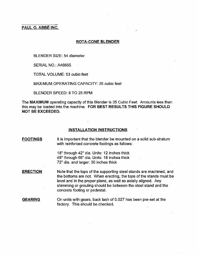
ROTA-CONE BLENDER
BLENDER SIZE: 54 diameter
SERIAL NO.: A46665
TOTAL VOLUME: 53 cubic feet
MAXIMUM OPERATING CAPACITY: 35 cubic feet
BLENDER SPEED: 8 TO 25 RPM
The MAXIMUM operating capacity of this Blender is 35 Cubic Feet. Amounts less thanthis may be loaded into the machine. FOR BEST RESULTS THIS FIGURE SHOULDNOT BE EXCEEDED.
FOOTINGS
ERECTION
GEARING
INSTALLATION INSTRUCTIONS
It is important that the blender be mounted on a solid sub-stratumwith reinforced concrete footings as follows:
18" through 42" dia. Units: 12 inches thick
48" through 66" dia. Units: 18 inches thick72" dia. and larger: 30 inches thick
Note that the tops of the supporting steel stands are machined, andthe bottoms are not. When erecting, the tops of the stands must belevel and in the proper plane, as well as axially aligned. Anyshimming or grouting should be between the steel stand and theconcrete footing or pedestal.
On units with gears, back lash of 0.027 has been pre-set at thefactory. This should be checked.
PAUL O. ABBE INC.
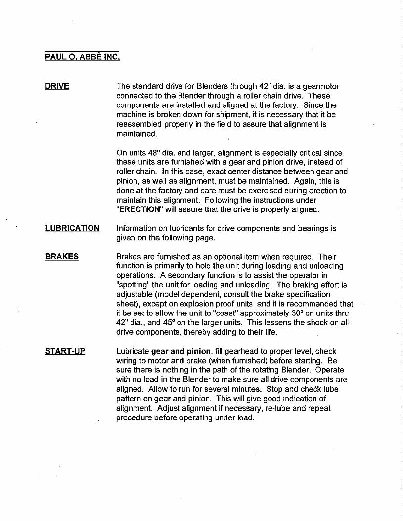
DRIVE
LUBRICATION
BRAKES
START-UP
The standard drive for Blenders through 42" dia. is a gearmotorconnected to the Blender through a roller chain drive. Thesecomponents are installed and aligned at the factory. Since the
machine is broken down for shipment, it is necessary that it bereassembled properly in the field to assure that alignment ismaintained.
On units 48" dia. and larger, alignment is especially critical since
these units are furnished with a gear and pinion drive, instead ofroller chain. In this case, exact center distance between gear andpinion, as well as alignment, must be maintained. Again, this isdone at the factory and care must be exercised during erection tomaintain this alignment. Following the instructions under"ERECTION" will assure that the drive is properly aligned.
Information on lubricants for drive components and bearings isgiven on the following page.
Brakes are furnished as an optional item when required. Theirfunction is primarily to hold the unit during loading and unloadingoperations. A secondary function is to assist the operator in"spotting" the unit for loading and unloading. The braking effort isadjustable (model dependent, consult the brake specificationsheet), except on explosion proof units, and it is recommended thatit be set to allow the unit to "coast" approximately 30° on units thru
42" dia., and 45° on the larger units. This lessens the shock on alldrive components, thereby adding to their life.
Lubricate gear and pinion, fill gearhead to proper level, checkwiring to motor and brake (when furnished) before starting. Be
sure there is nothing in the path of the rotating Blender. Operatewith no load in the Blender to make sure all drive components arealigned. Allow to run for several minutes. Stop and check lubepattern on gear and pinion. This will give good indication ofalignment. Adjust alignment if necessary, re-lube and repeatprocedure before operating under load.

WARRANTY
Seller warrants to buyer that goods sold hereunder are free from defects in design,material or workmanship for a period of twenty-four (24) months from date of shipment.
The foregoing warranty is exclusive and in lieu of all other warranties, express, impliedor statutory, including but not limited to the warranty of merchantability, the warranty ofsuitability of fitness for use and the warranty of fitness for any particular purpose or useand excludes any claims for indirect or consequential losses or damages.
If within twenty four (24) months from the date of shipment any products sold hereundermeets with the warranty specified above, the buyer notifies seller promptly and inwriting, seller shall correct any such defect, at seller's option, by repairing or replacingany defective product or part.
Costs for shipping parts or equipment to and from the installation point of the equipmentshall be born entirely by the buyer.
Seller will make no allowance for repairs or alterations to the products by buyer, unlessmade with the advanced written consent of seller.
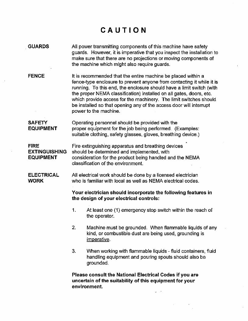
GUARDS
FENCE
SAFETY
EQUIPMENT
CAUTION
All power transmitting components of this machine have safetyguards. However, it is imperative that you inspect the installation tomake sure that there are no projections or moving components ofthe machine which might also require guards.
It is recommended that the entire machine be placed within a
fence-type enclosure to prevent anyone from contacting it while it isrunning. To this end, the enclosure should have a limit switch (withthe proper NEMA classification) installed on all gates, doors, etc.which provide access for the machinery. The limit switches shouldbe installed so that opening any of the access door will interruptpower to the machine.
Operating personnel should be provided with theproper equipment for the job being performed. (Examples:
suitable clothing, safety glasses, gloves, breathing device.)
FIRE Fire extinguishing apparatus and breathing devicesEXTINGUISHING should be determined and implemented, withEQUIPMENT consideration for the product being handled and the NEMA
classification of the environment.
ELECTRICAL
WORK
All electrical work should be done by a licensed electricianwho is familiar with local as well as NEMA electrical codes.
Your electrician should incorporate the following features in
the design of your electrical controls:
1. At least one (1) emergency stop switch within the reach ofthe operator.
2. Machine must be grounded. When flammable liquids of anykind, or combustible dust are being used, grounding isimperative.
3. When working with flammable liquids - fluid containers, fluidhandling equipment and pouring spouts should also begrounded.
Please consult the National Electrical Codes if you are
uncertain of the suitability of this equipment for yourenvironment.
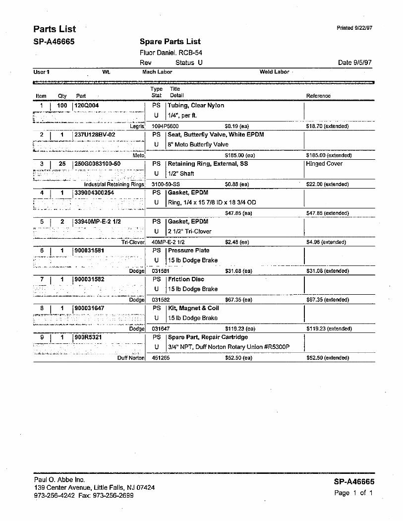
Parts List
SP-A46665
Userl
Item Qty Pad
' 1 100 1200004
Spare Parts List
Fluor Daniel. RCB-54
Rev Status U
Wt. Mach Labor
2 1 237U1288*02
3 25 25OG0083100-50r-•---=- •-- ---- - --- *. --- - -/-
Legris,
Meto
Industrial Retaining Rings
4 1 339004300254
5 _ 2 33940MP-E-2 1/2
6 1 900031581
-7- 1 1 900031582
8 1 900031647
9 1 9OOR5321
Tri-Clover
Dodge
Dodge
Dodge
Duff Norton
Paul 0. Abbe Inc.
139 Center Avenue, Little Falls, NJ 07424
973-256-4242 Fax: 973-256-2699
TypeStat
PS
U
PS
U
Title
Detail
PS Tubing, Clear NylonU | 1/4", per ft.
1094P5600 $0.19 (ea)
Seat, Butterfly Valve, White EPDM
8" Meto Butterfly Valve
5185.00 (ea)Retaining Ring, External, SS
1/2" Shaft
Weld Labor
3100-50-SS $0.88 (ea)
PS Gasket, EPOMU Ring, 1/4x 157/81Dx 18 3/400
$47.85 (ea)
PS Gasket, EPDMU | 21/2" Tri-Clover
40MP-E-2 1/2 $2.48 (ea)
PS Pressure Plate U 15 Ib Dodge Brake031581 $31.08 (ea)
PS Friction DiscU 15 Ib Dodge Brake
$67.35 (ea)031582
PS Kit, Magnet & CoilU | 15 Ib Dodge Brake
031647 $119.23 (ea)
PS Spare Part, Repair CartridgeU 3/4" NPT, Duff Norton Rotary Union #R530OP
451265 $52.50 (ea)
Reference
Printed 9/22/97
Date 9/5/97
$18.70 (extended)
$185.00 (extended)
Hinged Cover
$22.00 (extended)
547.85 (extended)
$4.96 (extended)
$31.08 (extended)
$67.35 (extended)
$119.23 (extended)
$52.50 (extended)
SP-A46665
Page 1 of 1
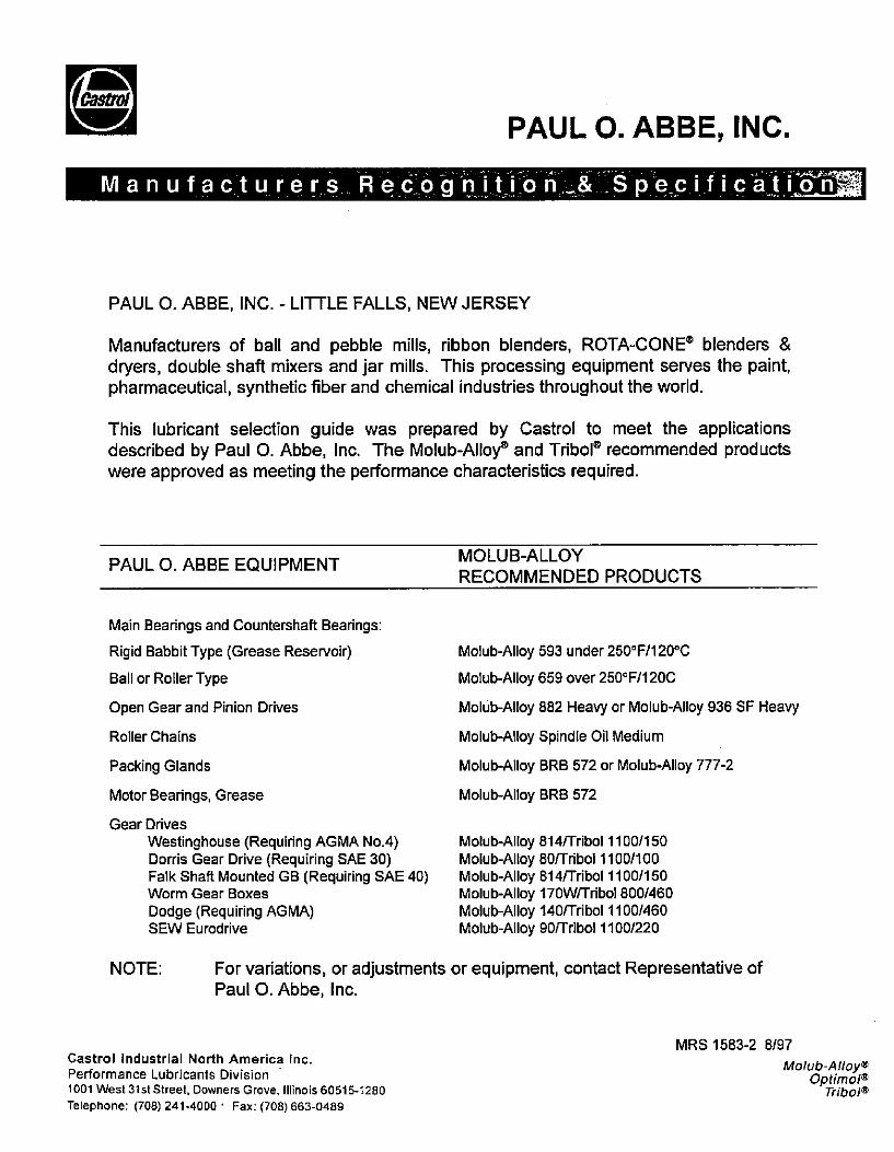
PAUL O. ABBE, INC.
Manufacturers Redogniti o b _& .S pe_cific-at i 2{EES
PAUL O. ABBE, INC. - LITTLE FALLS, NEW JERSEY
Manufacturers of ball and pebble mills, ribbon blenders, ROTA-CONE® blenders &dryers, double shaft mixers and jar mills. This processing equipment serves the paint,pharmaceutical, synthetic fiber and chemical industries throughout the world.
This lubricant selection guide was prepared by Castrol to meet the applicationsdescribed by Paul O. Abbe, Inc. The Molub-Alloy® and Tribol® recommended productswere approved as meeting the performance characteristics required.
PAUL O. ABBE EQUIPMENT
Main Bearings and Countershaft Bearings:
Rigid Babbit Type (Grease Reservoir)
Ball or Roller Type
Open Gear and Pinion Drives
Roller Chains
Packing Glands
Motor Bearings, Grease
Gear Drives
Westinghouse (Requiring AGMA No.4)
Dorris Gear Drive (Requiring SAE 30)Falk Shaft Mounted GB (Requiring SAE 40)Worm Gear Boxes
Dodge (Requiring AGMA)SEW Eurodrive
NOTE:
MOLUB-ALLOY
RECOMMENDED PRODUCTS
Molub-Alloy 593 under 250°F/120°C
Molub-Alloy 659 over 250°F/120C
Molub-Alloy 882 Heavy or Molub-Alloy 936 SF Heavy
Molub-Alloy Spindle Oil Medium
Molub-Alloy BRB 572 or Molub-Alloy 777-2
Molub-Alloy BRB 572
Molub-Alloy 814/'Tribol 1100/150Molub-Alloy 80/Tribol 1100/100Molub-Alloy 814/Tribol 1100/150Molub-Alloy 17OW/Tribol 800/460Molub-Alloy 140/Tribol 1100/460Molub-Alloy 90/Tribol 1100/220
For variations, or adjustments or equipment, contact Representative ofPaul 0. Abbe, Inc.
Castrol Industrial North America Inc.
Performance Lubricants Division
1001 West 31 st Street. Downers Grove, Illinois 60515-1280
Telephone: (708) 241-4000 · Fax: (708) 663-0489
MRS 1583-2 8/97
Molub-Alloy®Optimole
Tribol®

TribolASIA
HONG KONGICI China Ltd.
14th Floor, One Pacific Place88 Queensway CentralG.P.O. Box 107
Hong KongPhone: (852) 843 4888Facsimile: (852) 868 5282
CHINA
Pan China Trade Company
Room 202, Bldg. 59254 Zhongshan Road NorthNanjing, 210003Peoples Republic of ChinaPhone: (86) (25) 334-3143
Facsimile: (86) (25) 334-3143
INDIACastrol India UmitedTribol Division
52, Rajall SalalMadras, 600 001 IndiaPhone: (91) (44) 522-9710Facsimile: (91) (44) 522-2323INDONESIA
P.T. Fadjar Klmia Pratama PrimaJalan Aipda K.S. Tubun 11/7Jakarta, IndonesiaPhone: (62)(21)5493070,
5486319,5485937,514599,5486876
Facsimile: (62) (21) 5485937
JAPANTribal Japanc/o ICI JapanPalace Building, ath. floor, Rm. 8011-1,1-Chome, Marunouchi
Chlyoda-ku, Tokyo 100JapanPhone: (81) (3) 3211-3096Facsimile: (Ill) (3) 3211-7806
REPUBLICOF
SOUTH KOREAKorea Luba-Tech Ltd.
238-16, Sinwol 1 -dongYanchung-kuSeoul 158091, KoreaPhone: 82) (2) 602-6907-8,
82) (2) 607-2491-2Facsimile: 82) (2 6907141,(82) (2) 693-2883
MALAYSIAUniwes Technology SDN. BHD.5 JLNSS 18/6
47500 Subang JayaSelangor, MalaysiaPhone: (60) (3) 7340439Facsimile: (60) (3) 7347875
Uniwes Technology SDN. BHD.4160 JLN Kampung Bengaii12200 Buttemorth
Penang, MalaysiaPhone: (60) (4) 322161/2Facsimile: (60) (4) 324996Uniwes Technology SDN. BHD.59 JLN Persisiran PerlingTaman Perling81200 Johor Bharu
Johor, MalaysiaPhone: (60) (7)368066Facsimile (60) (7) 368061
PHILIPPINESPhilippine Explosives Corp.7/h Floor, City Trust Bldg.Edsa, Mandaluyong, Metro ManilaPhilippinesPhone: (63)(2) 788031 to 34Facsimile: (63)(2) 531-0227
Mailing Address:P.O. Box 330 GreenhillsSan Juan, Metro Manila 1502Philippines
SINGAPOREUniversal Westech (S) Pte Ltd.10 Tanjong PenjuruSingapore 2260Republic of SingaporePhone: (65) 265-8444Facsimile: (65) 265-6409
TAIWAN
Taipel Office (Main Office)Tal-Luba International Corporation7-4, No. 49 Ho-Ping E. RoadSection 3Taipei, Taiwan 10660Phone: (886) (2)703-4795Facsimile: (886) (2)702-6158
Kaohsiung OfficeTai·Lube International Corporation9a Swallow Building A267-143, Lin Sheng 1 st RoadKaohsiung, TaiwanPhone: (886) (7) 251 1462Facsimile: (886) (7) 251 1462
THAILANDPeo Tech Co.. Ltd.
52/81-82 Ramkamhaeng Rd.Huamark BangkapiBangkok 10240Thailand
Phone: (66) (2) 377 67734Facsimile: (66) (2) 375 7753
AUSTRALIA
MELBOURNEMain Oflice
Applied Chemicals Pty. Ltd.121 Lewis Road
Wantlma South, VictoriaMelbourne, Auslralia 3152Phone: (61) 9) 800·1555Facsimile: (61) (3) 800-2876
Mailing Address:Applied Chemicals Pty. Ltd.Ptivate Bag 35Bayswater, Victoria, Australia 3153
PERTHApplied Chemicals Pty. Ltd.62 Collingwood StreetOsborne Park, PerthWestern Australia 6017
Phone: (61)(9)446·6144Facsimile: (61) (9) 4464781
SYDNEYApplied Chemicals Pty. Ltd.14 Hume Road
Smithlield, N.S.W. 2164, AustraliaPhone: (61) (2) 725-2000Telex: (790)21607 APPCHEMFacsimile: (61) (2) 725-2320
Mailing Address:P.O. Box 668
Smithfield, N.S.W. 2169, Auslralia
TAbol
Headquarters21031 Ventura Boulevard. Woodland Hills, California 91364-2297Phone: (818) 888-0808 Facsimile: (818) 884-1885
di,an,UlaaROLCO.*
international Sales Offices & Distributors
BRISBANEApplied Chemicals Pty. Ltd.16 Proprietary StreetTingalpa, QLD 4173, AustraliaPhone: (61) (7) 390-7522Facsimile: (61) (7) 390·8556
Mailing Address:Applied Chemicals Ply. Ltd.P.O. Box 6
Cannon Hill, OLD 4170,Australia
MACKAYApplied Chemicals Pty. Ud.11 McLennan StreetCity GatesMackay, QLD 4740,AustraliaPhone: (61) (79) 522333Facsimile: (61) (79) 523279
Mailing Address:P.O.Box 5452Mackay Mall Centre, QLD. 4741
YEPPOONApplied Chemicals Pl. Ltd.54 James StreetYeppoon, QLD 4703, AustraliaPhone: (61) (79) 395455Facsimile: (61) (79) 395515
NEW ZEALANDApplied Chemicals (NZ)4/390 Rosebank Road
Avondale, Auckland 7, New ZealandPhone: (64) (9) 8282155Facsimile: (64) (9) 8283319
Mailing Address:Applied Chemicals (NZ Ltd.)P.O. Box 71137Avondale, Auckland 7, New Zealand
PUERTO RICO &
CARIBBEANTribo-TecP.O. Box 11596
Caparra Heights StationSan Juan, Puerto Rico 00922-1596Phone: (809)788-6270/788·6200Facsimile: (809) 788-6325Cellular. (809) 385·5856
Horacio A. Montes GilorminiP.O. Box 166
Yauco, P.R. 00698Phone: (809) 821-1397Tel/Facsimile: (809) 821-0804
LATIN AMERICA
BRASILCastrot BrasitAv. Itaaca, 2440InhaOma
CEP 21061-020Rio de Janeiro, RJBrazil
Phone: (55) (21) 598-7222Facsimile: (55) (21) 598-7277CHILETribot, Chile S.A.Fidel Oleiza 1921,01.606Providencia, Santiago, ChilePhone: (56) (2) 2239212Facsimile: (56) (2) 2747431
COLOMBIAIngenieros Quimlcos Asociados (IQA)Calle 108A, No. 17-26Bogota, ColombiaPhone: (57) (1) 619-0968
(57)(1)214-2128(57) (1) 213-4862
Facsimile: (57) (1) 215-2104
Mailing Address:Ingenieros Quimicos AsocladosApartado Aereo 56222Bogota, Colombia
COSTA RICA/
NICARAGUATRITECH
Apartado Postal No. 78041000 San Jose, Costa RicaPhone: (506) 2326186Facsimile: (506) 2327258
EL SALVADORTRITECH
25 Calle Poniente #811San Salvador, El SalvadorCentro America
Phone: (503)226-0775Facsimile: (503) 225-1869
GUATEMALATRITECH
Sa Av. 6 39, Zona 14Guatemala City, GuatemalaPhone: (502) (2) 373013,
373031-36Facsimile: (502) (2) 373041
HONDURAS/BELIZETRITECH
2 Av. 1 y2 Calle N.0.Editicio Paseo del Sol
No. 4-8, San Pedro SulaHonduras, C.A. 2642Phone (504) (52) 1981/1982Facsimile: (504) (52) 1984MEXICOTribol Mexico/ALGC. S. A. de C. V.Norte 45 No. 812
Colonia Industrial VallejoC. P. 02300 Mexico D. F.Phone: (52) (5) 567-4409Facsimile: (52) (5) 567-2674
MEXICO (Southern)TRITECH de Mexico, S. A. de C.V.Calle 15, No. 317Cordoba, Veracruz, 945000Mexico
Phone: (52) (2) 7148879,7120093
Facsimile: (52) (2) 7148970
PANAMALubmetal Panama, S.A.P.O. Box 6-4107
El Dorado, Republic of PanamaPhone: (507) 364322; 364323Facsimile: (507) 361067PERUJ. F. Ingenieros S.R.L.Av. de Las Artes Sur No. 629San Boria SurUma 41, PeruPhone (51) (14) 476-8790Facsimile: (51) (14) 476-3872
OF 365-62 1/95
TribolEUROPE
HEADQUARTERSTdbol GmbH
Tribol EuropeErkelenzer Strasse 20
D-41179 Moenchengladbach
GermanyPhone: (49) (2161)909-30Facsimile'. (49) (2161) 909400
Mailing Address:P. O. Box 500210
0-41172 Moenchengladbach
MANUFACTURING
PLANT/
WAREHOUSE & SHIPPING
Tribol GmbH
Erkelenzer Strasse 20
D-41179 MoenchengladbachGermanyPhone: (49) (2161) 909-30Facsimile: (49) (2161) 909-500
Mailing Address:P. O. Box 500210
D-41172 Moenchengladbach
GERMANYTribol GmbHTribol Deutschland
Erkelenzer Strasse 20
D-41179MoenchengladbachGermanyPhone: (49) (2161) 909-30Facsimile:. (49) (2161) 909-400
Mailing Address:P. O. Box 500210
0-41172 Moenchengladbach
AUSTRIACastrol Austria Gesellschaft m.b.H.Industriezentrum N6-SOdStrasse 6
A-2355 Wr. NeudorfPhone: (43) (2236) 695-0Facsimile: (43) (2236) 695-2129
BELGIUMAgeml S.P.R.L. B.V.B.A.Bisschoppenhoflaan 2328·2100 Deurne, BelgiumPhone: (32) (3) 325-0420Facsimile: (32) (3) 326-0977
DENMARKSquare Oil A/SHattemagerve15DK-9000 Aalborg, DenmarkPhone: (45) 98130300Facsimile: (45) 9812 07 87
FINLANDKaukomarkkinat OY
Lubrication DepartmentP.O. Box 40
SF-02631 Espoo 63, FinlandPhone: (35) (80) 5211Facsimile: (35) (80) 521 -6641
FRANCETrbol SAR.L.
3, rue du TMatre
F-91884 MassyPhone: (33) (1) 69536190Facsimile: (33) (1) 69536199
GREECE
G. Beligiannis & Co. O.E.Praxitelous St. No. 1
Thessaloniki 54641, GreecePhone: (30) (31) 840883, 821795Facsimile: (30) (31)831023
IRELAND
Applied Chemicals (ireland) Ltd.Grand Canal Business CentreJamestown Road
Inchlcore,
Dublin 8, IrelandPhone: (353) (1) 549200 or 546333Facsimile: (353) (1) 549230
ITALYTribol
Divisione Di Castrol Italiana SpAVia Aosta 4a
20155 Milano. ItalyPhone: (39) (2) 33625800,801,802Facsimile: (39) (2) 33625803
NETHERLANDSContivema B.V.
Beuketsdijk 162NL-3022 Rotterdam, HollandPhone: (31) (10)477-4733Facsimile: (31) (10) 477-5726
NORWAY
Square Oil A/SHattemagervej 5DK-9000 Aalborg, DenmarkPhone: (45) 98130300
Facsimile: (45) 98 12 07 87
POLANDMETEX Poland Lid.
ul. Humanska 10
00-789 Warsaw, PolandPhone: (48) (22) 496633Facsimile: (48) (22) 497534
PORTUGALICI Portuguesa, Lda.Rua Filipe Foique, 2-5P-1000 Lisboa, PortugalPhone: (351)(1)3525191Facsimile: (351) (1) 562220
SPAINCastrol Espana, S. A.Tribol Divisione
Poligono Induslrial CongostAvda. San Julgn 260-A
08400 Granoliers, BarcelonaSpainPhone: (34) (3) 8464334
Facsimile: (34) (3) 8463652
Tribol
Headquarters21031 Ventura Boulevard, Woodland Hills, California 91364-2297
Phone: (818) 888-0808 Facsimile: (818) 884-1885diABLRMH<AgROLINAm
International Sales Offices & Distributors
SWEDENMolub-Alloy ABDalbogatan 15431 38 Moindal-Gothenburg, SwedenPhone: (46) (31)815990Facsimile: (46) (31) 208210
SWITZERLANDZier Anlagenbau AG
Haegelerstrasse 3CH-5453 Remelschwil, SwitzerlandPhone: (41) (56) 962217Facsimile: (41) (56) 962216
UNITED KINGDOMApplied Chemicals, Ltd.Applied HouseWilson's Lane
Coventry, England CVB BJAPhone: (44) (203) 368800Direct Ph.: (44) (203) 368926Facsimile: (44) (203) 366639
MIDDLE EAST
ABU DHABI/U.A.E.Boodai Trading CompanyOld Airport RoadP.O. Box 46027
Abu Dhabi, United Arab EmiratesPhone: (971) (2)431581Facsimile: (971) (2) 431671
DUBAl/U.A.E.
Boodal Trading Company Ltd.Salah-Al Din Road
P.O. Box 5108
Deim, Dubal, United Arab EmiratesPhone: (971) (4) 431581
Facsimile: (971) (4) 431671
ISRAELGAD RAM
Industrial Services
Moshav Sateri 73272
P.O. Box 751
Rehovot, Israel 76100Phone: (972) (8) 418788/418501Facsimile: (972) (8) 410486
JORDANAt-Tewfik Automobile &
Equipment Co.Station Road
(P.0. Box 253)Amman, JordanPhone: (962) (6) 656273/4,651591,
656247
Facsimile: (962) (6) 647814
SAUDI ARABIAArab Equipment EstablishmenlP.O. 1660
Damman, 31441 Saudi ArabiaPhone: (966)(3)857-4988,
857-3559
Facsimile: (966) (3) 8574463
AFRICA
ZAMBIA
Cemol Chemicals (Zambia) Ltd.Prescot Road
P.O. Box 22648
Kitwe, ZambiaPhone: (260)211722,211967,
(2) 216068
ZIMBABWECemol Chemicals
(Zimbabwe) (Pvt.) Ltd.
111 Dagenham RoadWillowvale. Zlmbabwe
Phone: (263) (4) 62681/5Facsimile: (263) (4) 63544
Mailing Address:Cemot Chemicals
(Zimbabwe) (Pvt.) LId.P.O. Box 344
Willow-valle, Harare,Zimbabwe
Cemol Chemicals
(Zimbabwe) (Pvt.) Lid.17 Falcon Street
Belmont, Bulawayo, ZimbabwePhone: 66296,66718
Mailing Address:
Cemol Chemicals(Zimbabwe) (Pvt.) Lld.P.O. Box 8129
Belmont, Bulawayo, Zimbabwe
SOUTH AFRICAChemserve Systems (Pty.) Ltd.200 Bergrivier DriveChloorkop, Ext. 24 Kempton ParkRepublic of South AfricaPhone: (27) (11) 976-2162Facsimile: (27) (11) 976-2338
Mailing Address:P.O. Box 12055
Chloorkop 1624South Africa
OF 365-62 1/95

Tribol
ALABAMATribol
4185 Billy Mitchell Road(P.O. Box 705)Addison, T)(75001-0705
Phone: (800)745-0125
ALASKATdbol
Meadow Creek Office Park
22516 SE 64[h Place, Suite 220Issaquah, Washington 98027Phone: (800)328-1902Facsimile: (206) 391-8206
ARIZONATdbol
21031 Ventura Boulevard
Suite 600
Woodland Hills, California 91364Phone: (818) 888-9345
(800) 622- 1258Facsimile: (818) 884-1885
ARKANSASTdbol
4185 Billy Mitchell Road(P.O. Box 705)Addison, Texas 750010705Phone: (214) 387-4606Facsimile: (214) 3864914
CALIFORNIANORTHERN CALIF.
Tribol
P.O. Box 5685
So. San Francisco, California 94083Phone: (800) 622-1258Facsimile: (415) 572-9421
SOUTHERNCALIF.
Tribol
21031 Ventura Boulevard,Suite 600
Woodland Hills, California 91364Phone: (818) 888-9345
(800) 622-1258Facsimile: (818) 884-1885
RESEARCH &DEVELOPMENTLABORATORYTdbol
4801 West 147th Street
Hawthorne, California 9025043791Phone: (310) 679-0271Facsimile: (310) 679-0862
COLORADOTribol
21031 Ventura Boulevard
Woodland Hills, California 91364Phone: (800) 622-1258
(818) 888-9345Facsimile: (818) 884-1885
CONNECTICUTTdbol
Hill Professional Park Office Bldg.115 Water Street
Milford, Massachusetts 01757-3001
Phone: (508) 478-7442Facsimile: (508) 478-7989
DELAWARETribol
101 Southpointe DriveBildgeville, Pennsylvania 16017-1297Phone: (412) 257-1140
(800) 347-1440Facsimile:. (412) 221-1280
DISTRICT OF COLUMBIATribol
101 Southpointe OliveBridgeville, Pennsylvania 15017-1297Phone: (412)257-1140Phone: (800) 347-1440Facsimile: (412)221-1280
FLORIDATAbol
4185 Billy Mitchell Road(P.O. Box 705)Addison, Texas 75001-0705Phone: (214) 387-4606
Facsimile: (214) 386-4914
GEORGIATribot
4185 Billy Mitchell Road(P.O. Box 705)Addison, TX 75001-0705Phone: (800) 745·0125
HAWAIITribol
95-095 Kawau Street
Mitilani, Hawaii 967894097
Phone: (808) 531-1466
IDAHOTribol
Meadow Creek Office Park22516 SE 64th Place, Suite 220Issaquah, Washington 98027Phone: (800) 328-1902Facsimile: (206) 391-8206
ILLINOISTribol
1001 West 31 :st.
Downers Grove, illinois 60515Phone: (708) 663-0482Facsimile: (708) 663-0489
INDIANATribol
1001 West 31 st.
Downers Grove, Illinois 60515Phone: (708) 663-0482Facsimile: (708)6634489
IOWATribol
1001 West 31 st.
Downers Grove, Illinois 60515Phone: (708) 663-0482Facsimile: (708) 663·0489
KANSASTribol
8600 West Shawnee Mission Pkwy.Suite 306
Merriam, Kansas 66202Phone: (913) 362-9590Facsimile: (913) 362-9693
Tribol
Headquarters
21031 Ventura Boulevard, Woodland Hills, California 91364-2297Phone: (818) 888-0808 Facsimile: (818) 884-1885
££1,&0Mt(CASmOLCOME'NE
Sales Offices: United States & Canada
KENTUCKYTnbol
110 S. Huntington StreetMedina, Ohio 44256Phone: (800) 347-1440Facsimile: (216) 723·0852
LOUISIANATribol
4185 Billy Mitchel Road(P.O. Box 705)Addison, TX 75001-0705Phone: (800) 745-0125
MAINETdbol
Hill Professional Park Oflice Bldg.115 WaterStreet
Milford, Massachusetts 01757-3001Phone: (508)478-7442Facsimile: (508) 478-7989MARYLANDTribol
101 Southpointe DriveBridgeville, Pennsylvania 15017-1297Phone: (412)267-1140
{800) 347-1440Facsimile: (412) 221-1280
MASSACHUSETTSTribol
Hill Professional Park Office Bldg.115 Water Street
Milford, Massachusetls 01757-3001Phone: (508) 478-7442
(800) 736-4662Facsimile: (508) 478-7989
MICHIGANTribol
888 West Big BeaverSuite 313
Troy, Michigan 48084Phone: (800) 8294746Phone: (810)362-0979Facsimile: (810) 362-1026
MINNESOTATribol
4815 Burning Tree Road,Suite 210Duluth, Minnesota 55811
Phone: (218)727-4440Phone: (800) 727-3434Facsimile: (218) 727-7051
MISSISSIPPITribol
4185 Billy Mitchell Road(P.O. Box 705)Addison, Texas 75001-0705Phone: (214) 3874606Facsimile: (214) 3864914
MISSOURITdbol
4185 Billy Mitchell Road
(P.O. Box 705)Addison, Texas75001-0705Phone: (214) 3874606Facsimile: (214)3864914
MONTANATribol
Meadow Creek Oftice Park
22516 SEE 64th Place, Suite 220Issaquah, Washington 98027Phone: (800) 328-1902
(206)391-7997Facsimile: (206) 391-8206
NEBRASKATdbol
4185 Billy Mitchell Road
(P.O. Box 705)Addison, Texas 75001-0705Phone: (214)387-4606Facsimile: (214)386-4914
NORTH CAROLINATribol
4185 Billy Mitchell Road(P.O.Box 705)Addison, TX 75001-0705Phone: (800) 745-0125
NEVADATribot
21031 Ventura Boulevard,Suite 600
Woodland Hills, California 91364Phone: (800)622-1258
(818) 888-9345Facsimile:. (818) 884-1885
NEW HAMPSHIRETAbol
Hill Professional Park Oifice Bldg.115 Water Street
Milford, Massachuse!1801757-3001Phone: (508) 478-7442Facsimile:. (508) 478-7989
NEW JERSEYTribol
101 Southpointe DriveBridgeville, Pennsylvania 15017-1297Phone: (412) 257-1140
(800) 347-1440Facsimile: (412)221-1280NEW MEXICOTribol
21031 Ventura Boulevard,Suite 600
Woodland Hills, California 91364Phone: (800) 622-1258
(818) 888-9345Facsimile: (818) 884-1885
OF 366·61 1/95

Tribol
NEW YORKTribol
Hill Professional Park Office Bldg.115Water Street
Millord, Massachusetts 01757-3001Phone: (508) 478-7442Facsimile: (508) 478-7989
NORTH DAKOTATribol
P.O. Box 636
Bismarck,North Dakota 58502-0636Phone: (701) 223-5523Facsimile: (701) 223·9632
OHIOTribol
110 S. Huntington StreetMedina, Ohio 44256Phone: (216) 723-0852Facsimile: (216) 723-0852
OKLAHOMATribal
4185 Billy Mitchell Road(P.O. Box 705)Addison, Texas 75001-0705Phone: (214)387-4606Facsimile: (214)3864914
OREGONTribol
Meadow Creek Office Park
22516 SE 641h Place, Suite 220
Issaquah, Washinglon 98027Phone: (206) 391-7997
(800)328-1902Facsimile: (206) 391-8206
PENNSYLVANIATribol
101 Southpointe Drive
Bridgeville, Pennsylvania 15017-1297Phone: (412)257-1140
(800) 347-1440Facsimile: (412) 221-1280
RHODEISLANDTAbol
Hill Professional Park Office Bldg.115 WaterStreet
Milford, Massachusetts 01757-3001Phone: (508) 478-7442Facsimile: (508) 478-7989
SOUTH CAROLINATribol
4185 Billy Mitchell Road(P.O.Box 705)Addison, TX 75001-0705Phone: (800) 745-0125
SOUTH DAKOTATribol
1001 West 31st.
Downers Grove, Illinois 60515Phone: (708) 663-0482Facsimile: (708) 6634489
TENNESSEETdbol
4185 Billy Mitchell Road(P.O. Box 705)Addison, Texas 75001-0705Phone: (214)387-4606Facsimile: (214) 386-4914
TEXASTribot
4185 Billy Mitchell Road(P.0. Box 705)Addison, Texas 75001 -0705Phone: (214) 387-4606Facsimile: (214) 3864914
UTAHTdbol
21031 Ventura Boulevard,Suite 600
Woodland Hills, California 91364Phone: (800)622-1258
(818) 888-9345Facsimile: (818) 884-1885
VERMONTTribol
Hill Prolessional Park Office Bldg.115Water Streat
Milford, Massachusetts 01757-3001Phone: (508)478-7442Facsimile: (508) 478-7989
Tribol
Headquarters21031 Ventura Boulevard, Woodland Hilis, California 91364-2297Phone: (818) 888-0808 Facsimile: (818) 884-1885
dl aRMVH BSTROLCOMFANY
Sales Offices: United States & Canada
VIRGINIATribol
101 Southpointe DriveBridgeville, Pennsylvania 15017-1297Phone: (412) 257-1140
(800)347-1440
Facsimile: (412) 221-1280
WASHINGTONTribol
Meadow Creek Olfice Park
22516 SE 64th Place, Suite 220
Issaquah, Washington 98027Phone: (206)391-7997
(800)328-1902Facsimile: (206) 391 -8206
WEST VIRGINIATribol
101 Southpointe DriveBridgeville,Pennsylvania 15017-1297Phone: (412)257-1140
(800)347-1440Facsimile: (412) 221-1280
WISCONSINTribol
1001 West 31 : t.
Downers Grove, Illinois 60515Phone: (708)663-0482Facsimile: (708) 663-0489
WYOMINGTdbol
Meadow Creek Office Park
22516 SE 64th Place, Suite 220Issaquah, Washington 98027Phone: (206) 391-7997
(800) 328-1902Facsimile: (206) 391-8206
CANADA
EASTERNTribol Inc.
150 Consumers Road, Suite 403North York, Ontario M2J 1 P9Phone: (416)498-4988Facsimile: <416)498-6660
WESTERNTribol Inc.14627-128111. Avenue
Edmonton, Alberta Canada TSL3H3Phone: (403)452-9908
Facsimile: (403) 451-3340
OF 366-61 1/95
JUL. 9.1997 11:48AM
Sl 8/DP 09 JUL. 1997
Parent
Part Numbar
464610
464619
465378
465379
466380
468381
469382
465383
465386
465390
465399
465632
465639
465661
469758
469765
48706n
SIB/OF
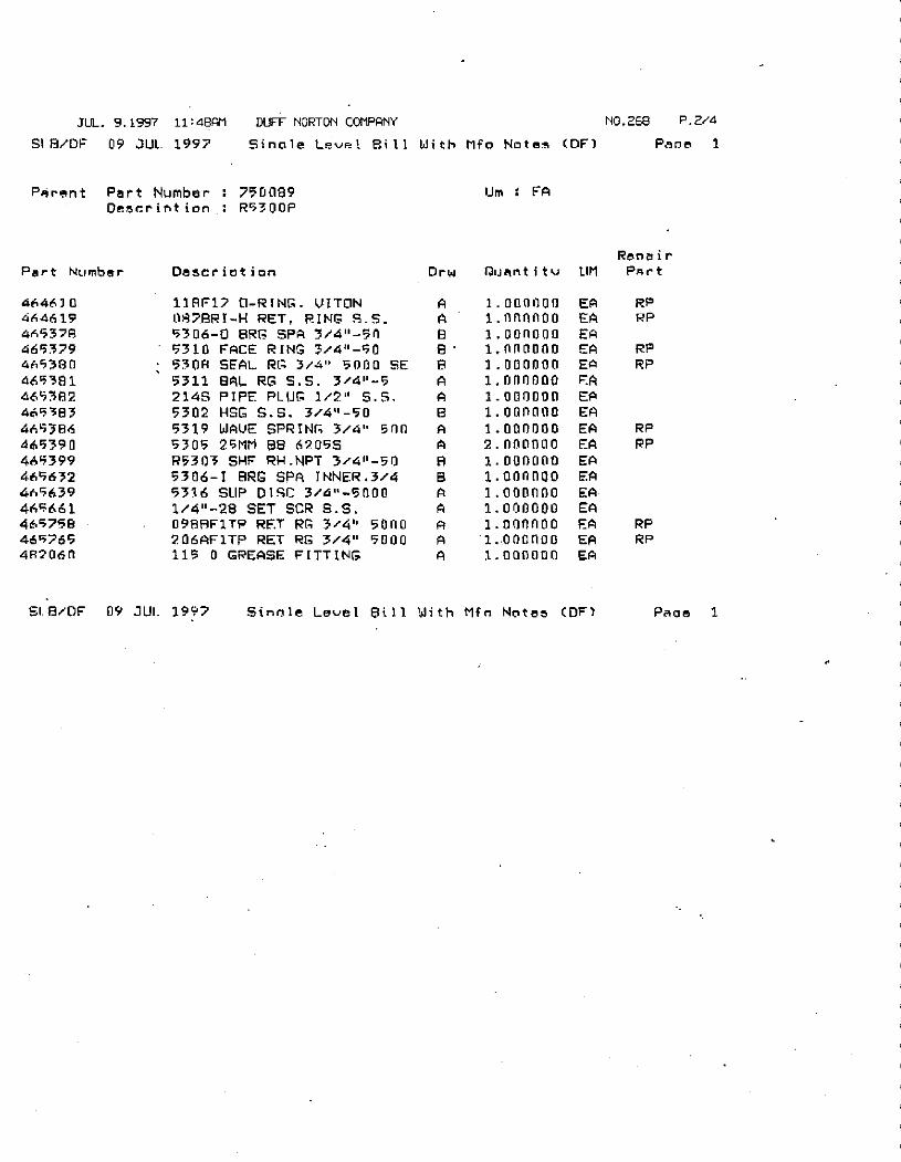
DUFF NORTON COMPANY NO.268 P.2/4
Sinole Leve= 1 Bill With Mfo Notes (DF) Pane 1
Part Number : 750089
Descrintion : R530OP
Descriotion
118917 0-RING. VITON
087BRI-H RET, RING S.S.
5306-0 BRG SPA 3/4"-56
5310 FACE RING 3/4"-50
5308 SEAL RG 3/4" 5000 SE
5311 SAL RG S.S. 3/4"-5
2145 PIPE PLUG 1/2" S.S.5302 HSG S.S. 3/44-50
5319 WAVE SPRING 3/4" 500
5305 26MM 88 62055
R5303 SHF RH.NPT 3/4"-50
5306-I BRG SPA INNER.3/45316 SUP DISC 3/4"-5000
1/4"-28 SET SCR S.S.
0988F1TP RET RG 3/4" 5080
206AFITP RET RG 3/4" 5000
115 0 GREASE FITTING
09 JUI- 1997
Um : FA
Orw Quantit v
A
A
B
B
B
A
A
B
A
A
B
A
A
A
A
A
1.000000
1.nnnAOO1.00n000
1.8800001.000000
1.000000
1.000000
1.000000
1.0000002.000000
1.000000
1.0000001.000000
1.000000
1.00nnoo
1.ooonoo
1.000000
EA
EA
EAEA
EA
EA
EA
EA
EA
EA
EA
EA
EA
EA
EA
EAEA
Sincle Level Bill With Mfrl Notes (OF)
Renair
LIM PArt
RP
RP
RP
RP
RP
RP
RPRP
Pace 1
.
0-
ru
2
Z
b
Ai
1*
3 'R
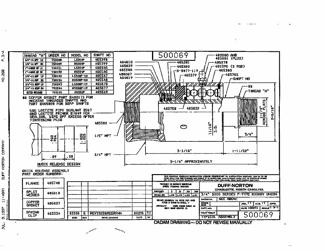
THREAD "A- ORDER NO ' MODEL NO SHAFT NO
314-14 IFT LH 75000/ LBOOP 465398
94 14 IfT 101 15008, R5300P 465399
1.-141*5 Mr Lit 150]51 L532*P , 465545
r-1406 MT Lai 750]52 R5324P 4655463/4--16 Br Lit 750153 l_530(r-20 465547
3/4£118/ RH 750154 RSIOOP-20 465548
U# 14 ES' Ul 750243 l.530©P-19 4GS67G
3/4 14 BEFF M I 750244 RSSOOP-19 465677
alia £EmE , 150155_ 053001' 465549
** COPPER BASKET PART #482173 FORMACHINE THREADED SHAFTS ANDPART #465828 FOR BSPP SHAFTS
USE LOCTITE PIPE SEALANT #567AND LOCTITE PRIMER #7649 FORSEALING. WIPE OFF EXCESS AFTERTIGHTENING PLUG
f 0.e[D
0-0-
1 -3| .89 |. 38
QUICK RELEASE DESIGN
QUICK RELEASE ASSEMBLYPART ORDER NUMBERS:
FLANGE
SPLITWEDGES
COPPERGASKET
SPRING
CLIP
465746
485618
485607
463334 83326
'Sn
00
CY N00
--
E
il,rv
lesne --1/2" NPT
3/4- NPT
REVISED&REDRAWN
Ham CHAGE
464610
465639
465386
488067
464619
092294nye
500069
465758
482060 AND465661 (PLUG)
465381 465378
465380 465390 (2 ROD)
X-6477-119 465383
465379 465765
-SHAFT No
0
465832
e Z
3-1/16"
TT
B¥
5-1/4 APPROXIMATELY
9H
;I
ill----Lar--
3/4
1-11/32"
Mi, Imiwu,8 Coll,NM ImiN e=I /mipiC in DI,40,mll ,HAle Alr 1, m I
010 mY Poly:,S IM,Ul N,I,JI M li,0/mlm. aN: /ullylil il,Au Nal me CIM=»u, INIX
I... MI C= .Rm-,Emuni n.=.0 *- al,NromoN =,AMT.
rmall/E .1 W=.m "//Innnrs; rm,r= s,E·n
DIEsion I =ImDEmMIL- =COO Z.OM 12=065
51[FE Room*[Es rE Eclo IMH %19
rlm= M 99=* st, r#2(L V
JnES** 111;IE COSh,CR 1110* 11
¤El* Ca- am.Min 2
ZOOI
7
l /J
:11--0!0
| DUFF·NORTONCHARLOTTE. NORTH CAROLINA
3/4" 5000 SERIES P-TYPE ROTARY UNION 1
MATERTAL SEE ABOVE
ORMA|| CH, 11 *-ZI
PAT'r. Na -9 102093 mul· 4- i
*£*T9RZAT
500069
11
IT
TYPICAL ASSEELY
6ADAM DRAWING-DO NCT REVISE MANUALLY
SEALM8SIER
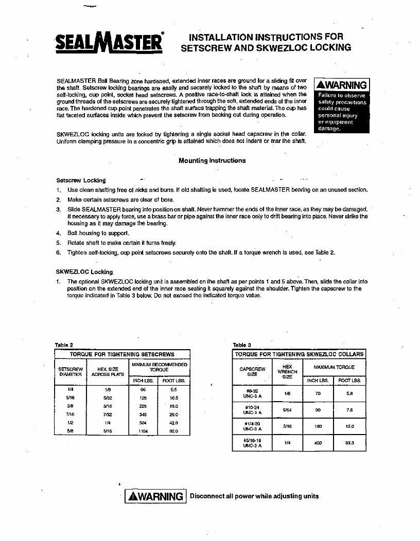
SEALMASTER Ball Bearing zone hardened, extended inner races are ground for a sliding fit overthe shaft. Setscrew locking bearings are easily and securely locked to the shaft by means of twoself-locking, cup point, socket head setscrews. A positive race-to-shaft lock is attained when theground threads of the setscrews are securely tightened through the soft, extended ends of the innerrace. The hardened cup point penetrates the shaft surface trapping the shaft material. The cup hasflat faceted surfaces inside which prevent the setscrew from backing out during operation.
SETSCREW
DIAMETER
HEX SIZE
ACROSS FLATS
66
126
228
348
504
1104
SKWEZLOC locking units are locked by tightening a single socket head capscrew in the collar.Uniform clamping pressure in a concentric grip is attained which does not indent or mar the shaft.
Table 2
TORQUE FOR TIGHTENING SETSCREWS
1/4
5/16
3/8
7/16
1/2
5/8
1S
5/32
3/16
782
1/4
5/16
MINIMUM RECOMMENDED
TORQUE
INCH LBS. FOOT LBS.
AWARNING
5.5
10.5
19.0
29.0
42.0
920
INSTALLATION INSTRUCTIONS FORSETSCREW AND SKWEZLOC LOCKING
Mounting Instructions
AWARNINGFailure to observe
safely precautionscould cause
personal injuryor equipmentdamage
Setscrev Locking -
1. Use clean shafting free of nicks and burrs. If old shafting is used, locate SEALMASTER bearing on an unused section.
2. Make certain setscrews are clear of bore.
3. Slide SEALMASTER bearing into position on shaft. Never hammer the ends of the inner race, as they may be damaged.If necessary to apply force, use a brass bar or pipe againstlhe inner race only 10 drift bearing into place. Never strike thehousing as it may damage the bearing.
4. Bolt housing to support.
5. Rotate shaft to make certain it turns freely.
6. Tighten self-locking, cup point setscrews securely onto the shaft. If a torque wrench is used, see Table 2.
SKWEZLOC Locking
1. The optional SKWEZLOC locking unit is assembled on the shaft as per points 1 and 5 above. Then, slide the collar intoposition on the extended end of the inner race seating it squarely against the shoulder. Tighten the capscrew to thetorque indicated in Table 3 below. Do not exceed the indicated torque value.
Table 3
TORQUE FOR TIGHTENING SKWEZLOC COLLARS
CAPSCREW
SIZE
#8-32
UN03 A
#10-24
UNC-3 A
#1/4-20
UNC-3 A
#916-18
UNC-3 A
HEX
WRENCH
SIZE
1/8
9/64
3/16
1/4
MAXIMUM TORQUE
INCH LBS.
Disconnect all power while adjusting units
70
90
180
400
FOOT LBS.
5.8
7.5
15.0
33.3
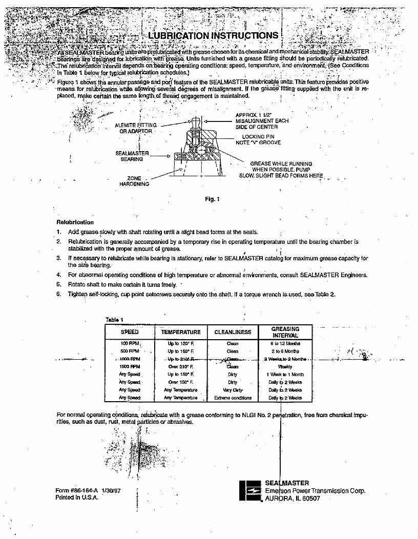
{Sfilt] 446}ES> :s>zi.#.:;,3 6 ... f'.i ; :5·-5/5/33-6 ·< ::]··J . ··,4.8*;*}*33:226,ZI)*.-14UBRIdATION INTRUCTIONS ··:i " =' Zi.71-':4Yir/*4,%-,12.*,2-ir,4,5,·LAi_.·m..:F.'#,t'. t.fries.:, 9 r ., t
i:,6-..1,531'.***.r'-1**il'SE*EmASTER bearing uftits· ate pielubrical OV#6 greasechosen foritachemicaland mecfliniclistability.SEDdMASTER J ':311-83:C'efbt?. f?ff.b*iririgh*re'deSidnect for lubrication:witti'¥reak Units furnished with a grease fitting should be periodicaliyfelubricated.
1'''*; Z.'3 45.55,:JhdreliriEatid;;rintervhl depends orifberirk; ipinling conditions: speed. temperature, and environmelif. (Sed Conditionsi--· :): '-:n, '3 in Table 1 6elow for typical· relubri*on schedules.)
- - -1 . L . 2'1 Figure 1 shdws the annularpassage and pot< feature,of the SEALMASTER relubricable units. This feature provides positive-meanaforrellibrlcation while allowing seveal dogrees of misalignment. If the grea* fitting·supplfed with the unit is re-placed, mpke certain the same [ength.of.th[id engagement is maintained.
-1 -
. APPROX 1 1/2'
ALEMITE FITTING. -fl 4 MISALIGNMENT EACH
. SIDE OFCENTERORADAPTOR AE<trrn
LOCKING PIN
iDLE@9:1 NOTE V GROOVE
SEALMASTER - -1i BEARING
ZONESLOW SLIGHT BEAD FORMS HERE
=-Ri » GREASE WHILE RUNNINGWHEN POSSIBLE. PUMP
HARDENING
Fig. 1
Relubrication
1. Add grease slowly with shaft rotating until a slight bead forms at the seals.
2. Relubrication is generally accompanied by a temporary rise in operating temperature until the bearing chamber isstabilized with the proper amount ot grease. 9
1
3. If necessary to relubricate while bearing is stationary, refer to SEALMASTER catalog for maximum grease capacity forthe size bearing.
4. For abnormal operating conditions of high temperature or abnormal environments, consult SEALMASTER Engineers.
5. Rotate shaft to make certain it turns freely. '
6. Tighten self-locking, cup point setscrews securely onto the shaft. If a torque wrench is used, see Table 2
Tabl/1
SPEED)
100 RPM ,
500 RPM
. 1000.RPM
1500 FFM
Any Speed .
Any Speed
Any Speed
Any Speed
TEMPERATURE
UP b 120° F
Up b 150• E
--UP,t>2101.63=---*
Over 210° R
Up 10 150« F.
Over 150° F.
Any Temperatire
Any Tempgature ,
CLEANLINESS
Clean
Clean
daan
Dilly
Dirty
Very, Crty
Extome conditions
GREASING
INTERVAL
6 10 12 Months
2 to 6 Months
2 ek:1> 2 Monthe-- ·
Weeldy1 Week b 1 Month
L
Daily 9 2 WeeksDaily 6 2 V*ieks 1Daily b 2 Weeks
For normal operating conditions, relubricate with a grease conforming to NLGI No. 2 pei1etrati6n, free from chen*cal impu-rities, such as dust, rust, metal particles or abrasives.
d S
4 ;· AL
.r . i 1 ..i,,5.r-- 4
Form #86-164-A 1/30/97 U9 Eme;son PowerTransmission Corp.Printed in US.A. 1 SEALMASTERI- AURORA, IL 60507
E LINE AC
1·.
1
1
1
1
1
1
1
1
1
1
1
1
1
1
4
1
1
1
1
1
2
1
1
1
1
1
1
2
2
1
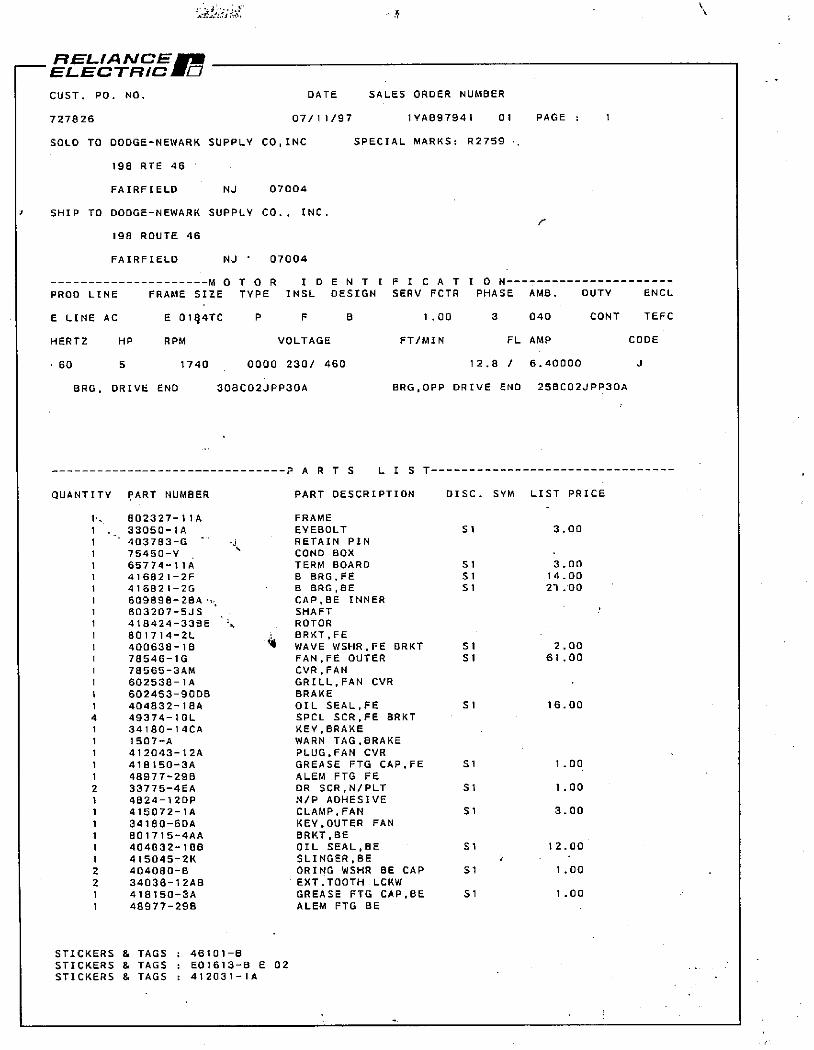
RELIANCESmELECTRIC IE]
CUST. PO. NO. DATE
727826 07/11/97
SOLD TO DODGE-NEWARK SUPPLY CO,INC
198 RTE 46
FAIRFIELD NJ 07004
1 SHIP TO DODGE-NEWARK SUPPLY CO., INC.
198 ROUTE 46
FAIRFIELD NJ ' 07004
PROD LINE
HERTZ HP
60 5
MOTOR ID
FRAME SIZE TYPE INSL
E 014TC P F
RPM
BRG, DRIVE END
1740
QUANTITY PART NUMBER
802327-1!A
33050-l A
403783-G
75450-Y
65774-11A
416821-2F
416821-2G
609898-2BA
603207-SJS
418424-33BE
801714-2L
400638-18
78546-1G
78565-3AM
602538-l A
602453-9008
404832-18A
49374-1OL
34180-14CA
1507-A
412043-12A
418150-3A
48977-298
33775-4EA
4824-12DP
415072-lA
34180-6DA
801715-4AA
404832-188
415045-2K
404080-8
34036-12AB
418150-3A
48977-298
STICKERS & TAGS
STICKERS & TAGS
STICKERS & TAGS
I J
VOLTAGE
0000 230/ 460
308C02JPP30A
46101-8
E01613-8 E 02
412031-IA
PARTS
B
SALES ORDER NUMBER
1 YA897941 01 PAGE : 1
SPECIAL MARKS: R2759
ENTIFICAT
DESIGN SERV FCTR
1.00
FT/MIN
ION
PHASE AMB.
3 040
FL AMP
12.8 / 6.40000
DUTY
CONT
BRG,OPP DRIVE END 258C02JPP30A
LIST
PART DESCRIPTION DISC. SYM LIST PRICE
FRAME
EYEBOLT Sl
RETAIN PINCOND BOX
TERM BOARD Sl
8 BRG,FE 51
8 BRG,BE 51
CAP.BE INNERSHAFT
ROTOR
BRKT,FE
'4 WAVE WSHR,FE BRKT Sl
FAN,FE OUTER Sl
CVR.FAN
GRILL,FAN CVRBRAKE
OIL SEAL,FE Sl
SPCL SCR,FE BRKT
KEY,BRAKE
WARN TAG,BRAKE
PLUG,FAN CVRGREASE FTG CAP,FE Sl
ALEM FTG FE
DR SCR,N/PLT Sl
N/P ADHESIVE
CLAMP,FAN St
KEY,OUTER FAN
BRKT.BE
OIL SEAL,BE Sl
SLINGER,BEORING WSHR BE CAP Sl
EXT.TOOTH LCKW
GREASE FTG CAP.BE Sl
ALEM FTG BE
3.00
3.00
14.00
27.00
2.00
61.00
16.00
1.00
1.00
3.00
12.00
1.00
1.00
ENCL
TEFC
CODE
3
,1
f.4
:. 4,,'t.,ttf. li..
...
Installation, 6 .1
Obaration And Maintenance OfReliance®-Standard
, . . |·1, 814; i,kir.1. i ..,-,ILm;
industrial.jAC 3; 1
- , .tri triq/: br V,A: H -1 :, ' 1 41 « ' 3Induction Motors• 180
• 112
449·Frames-(NEMA)280 Fr*6<(IEC)
, 1, Iii 23•': f .,
"
': 4
. - C ar'1boliitions
AC MOTORS *u CanTrust"
.-. I ' " ... .
Instruction Manual 8-3620-23
March, 1997.,:,r i
.,O, .%.6.1 4,2' 4.
3 9,<' L#S du :2
:"iel 1 1 (.1'. 3,• .
t..:d,:.r'k no n.1, be' ROCIONell Automauon
·· tr:p A444 ' jttf'FRenanbe'E/ecMe f' - .
Table of Contents
3.
RECEIVING AND HANDLING ...
ACCEPTANCE..,.. lt.'..
EXTENDED STORAGE - AC MOTORS, DC MOTORS,'' GENERATORS ANb SHIPBOARD MOTORS ...................
STORAGE CONDITIONS - SHORT TERM ............STORAGE PREPARATION ...................
FOR STORAGE OF EXTENDED PERIODS OF TIME(GREATER THAN i8 MONTHS)......................UNPACKING ...f?.'.
...............
INSTALLATION .
INSPECTION .....
LOCATION ...
LIFTING MEANS ...
MOUNTING ................................
MOUNTING OF 6&8 HOLE MOTOR FRAMES ..DRIVE
ROTATING PARTS .........................
SOME SATISFACTORY METHODS OF GUARDING ......
STARTING
DRAIN PLUGS ..... ...............................
ROTATION
TEST FOR GENERAL CONDITION .................
INITIAL LUBRICATION ........................
OPERATION
MAINTENANCE AND REPAIR ................................................. 8
DISASSEMBLY .8
REMOVING BRACKETS AND ROTOR
REMOVING AND REPLACING BALL BEARINGS ........... .................. 8
REASSEMBLY .......................................
LUBRICATION OF BEARINGS ................................................. 9
GREASE LUBRICATED BEARINGS ....................
RECOMMENDED LUBRICANT
, BALL' BEARING'MOTORS' ROLLER BEARING MOTORS . :r..:......:
,
LUBRICATIONROCEDURE t.... A- LUBRICATION INSTRUCTIONS.............
0
': SERVICE CONDITIONS
LUBRICATION FREQUENCY ........................ ......................10
LUBRICATION VOLUME"..j:.::....
/ 1REPLACEMENT BEARINGS:..........
GENERAL CROSS SECTION AND PARTS IDENTIFICATION DRAWING
TOTAL SERVICE PROGRAMS ................................................12
RENEWAL PARTS
ADDITIONAL LITERATURE................................................ 12
Rellance® Is a trademark of Reliance Electric industrial Company or its subsidiaries.©1997 Rockwell international Corporation
1 ' ·st;Ii.;A?·
3
3
4
4
4
4
4
5
5
5
6
6
6
6
6
1
1
2
2
1
1
1,
4
i
-
]*11$,as::M' 4. j.« .5
DANGER
ONLY QUALIFIED ELECTRICAL PERSONNEL FAMILIAR WITH THE CONSTRUCTI6N AND OPERATION'OFTHIS EQUIPMENT AND THE HAZARDS INVOLVED SHOULD INSTALLi ADJUSI OPERATE, AND/OR SER-VICE THIS EQUIPMENT. READ AND UNDERSTAND THIS MANUAL IN ITS ENTIRETY BEFORE PROCEED-
ING. FAILURE TOOBSERVETHIS PRECAUTIONCOULDRESULT IN SEVEREBODILY INJURY OR LOSS OFLIFE. ,
The products described in this manual are manufactured by or for Reliance Electric Industrial Company.
RECEIVING AND HANDLING
ACCEPTANCE
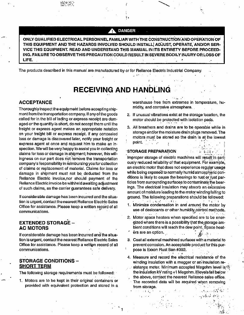
Thoroughly inspect the equipmeht before accepting ship-ment from thetransportationcompany. If anyof thegoodscalled for in the bill of lading or express receipt are dam-aged orthe quantity is short, do not acceptthem until thefreight or express agent makes an appropriate notationon your freiht bill or express receipt. If any concealedloss or damage is discovered later, notify your freight orexpress agent at once and rqquest him to make an in-
spection. We will be very happyto assist you in collecting
claims for loss or damage in shipment; however, this will-ingness on our part does not remove the transportationcompany's fesponsibility in relmbursing you for collectionof claims or replacement of material. Claims for loss ordamage in shipment must not be deducted from the
Reliance Electric invoice,nor should payment of theReliance Electric invoice be withheld awaiting adjustmentof such claims, as the carrier guarantees safe delivery.
If considerable damage has been incurred and the situa-tion is urgent, contact the nearest Reliance Electric Sales
Office for assistance: Please keep a written regord of allcommunications.
*.
EXTENDED STORAGE -
AC MOTORS
If considerable damage has been incurred and the situa-
tion is urgent, contact the nearest Reliance Electric SalesOffice for assistance. Please keep a writtpn record of allcommunications. .,
STORAGE CONDITIONS -
SHORT TERM
The following storage requirements must be followed:
1. Motors are to be kept in their original containers orprovided with equivalent protection and stored in a
warehouse free from extremes in temperature, hu-midity, and corrosive atmosphere.
2. If unusual vibrations exist at the storage location, themotor should be protected with isolation pads.
3. All breathers and drains are to be operable while instorage dnd/or the moisture drain plugs removed. Themotors must be stored so the drain is at the lowest
r point. ., -
STORAGE PREPARATION : h 1-''id 4, 5 I iImproper storage of electric machines will result in seri-ously reduced reliability of that equipment. For example,an electric motor that does not experience regular usagewhile being exposeEI to normally humid atmospheric con-ditions is likely to cause the bearings to rust or rust par-ticles from surrounding surfaces to contaminate the bear-ings. The electrical insulation may absorb an excessiveamountof moisture leadingto the motor winding failing toground. The following preparations should be followed:
1. Minimize condensaton in and around the motor byuse of desiccants or other humidity control methods.
2. Motor space heaters when specified are to be ener-
gized where there is a possibility that the,storage amibient conditions will reach the dew point. Space heat-
' ers are an option. ,
3. Coat all external machined surfaces with a material to
prevent corrosion. An acceptable product for this pur-i pose is Eicxon Rust Ban #392.
+
4. Measure and record the electrical resistancd of the
winding Insulation with a megger or an insulation re-,
, sistanpe meter. Minimum accepted Megohm level ist:ithe insulation ky rating +1 Megohm. If leyels fall below '
, the above, contact the nearest Reliance sales office.
The recorded data will be required when removingfrom storage.
.
-:·,1,·; 21.,
.:1
5.IL>me motors have a shipping bracqattached tp the .0 ' ' shaft to prevent damage during tran®ortation. The .
shipping brace, if.provided, must:be removed and· stored forfuture use. The bra9e must be reinstalled to.
· hold the shaft firmly in place against the bearing be-fore the motor is moved. ..' ., 4. ./ I
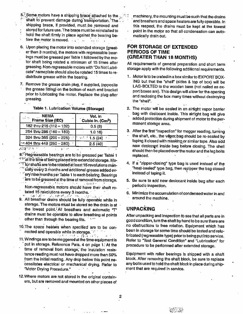
6. Upon placing the motor into extended storage (great-er than 3 months), the motors with regreasable bear-ings must be greased per Table 1 followed by the mo-tor shaft being rotated a minimum of 15 times aftergreasing. Non-regreasable motors with "Do Not Lubri-cate" nameplate should also be rotated 15 times to re-distribute grease within the bearing.
7. Remove the grease drain plug, if supplied, (oppositethe grease fitting) on the bottom of each end bracketprior to lubricating the motor. Replace the plug aftergreasing.
Table 1. Lubrication Volume (Storage)
NEMA . Vol. in
' ' ' Frame Size (IEC) Cubic in. (Cm3)182 thru 215 (112 - 132) 0.5 (8)
254 thru 286 (160- 180) 1.016)
324 thru 365 (200-225) : - r ' 1.5(24) 'r 404 thru 449 (250 - 280) 2.5 (40)
s' ,,•
./ . 01 -
8.''Regreasable bearings are tc; be greased per Tabld 1aillibtir6 of Being pla6ed into extendidstorage. Mo-
+ tdrshaftiareto be rotated at least 15 revolutions man-"' lialli> e06ry 3 rhonths and dditional grease added ev-
erynine months perTable 1 toeach bearing. Bearings41re to bi greased at the time of removal from storage.
Non-regreasable, motors should have their shaft ro-tated 15 revolutions every 5 months.
9. All breather drains should be fully operable while instorage:The motors mlist bd stored so the drain is atthe lowest point. i All breathers and automatic Tdrains must be operable to allow breathing at pointsother than through the bearing fits. ' 8
10.The space hehters when specified are to be con-' nected and operable while in storage. c11. Windings are to be meggered atthe time equipment is
' put in storage. Reference Para. 4 on page 1.'At thetime of removal from storage; the insulation resis-tance reading must not have dropped more than 50%from the initial reading. Any drop below this point ne-cessitates electrical or mechanical drying. Refer to"Motor Drying Procedure."
.
12.Where motors are not stored in the original contain-ers, but are removed and mounted on other pieces of
2
't ' machinery, the mounting must be such that the drains' and breathersand space heatersare fullyoperable. Inthis respect, the drains must be kept at the lowestpoint in the motor so that all condensation can auto-matically drain out.
FOR STORAGE OF EXTENDEDPERIODS OF TIME
(GREATER THAN 18 MONTHS)All requirements of general preparation and short termstorage apply with the following additional requirements.
1. Motoristo becratedinaboxsimilarto EXPORTBOX-
ING but that the "shell" (sides & top of box) will beLAG-BOLTED to the wooden base (not nailed as ex-port boxes are). This design will allow for the openingand reclosing the box many times without destroyingthe "shell".
2. The motor will be sealed in an air-tight vapor barrierbag with desiccant inside. This airtight bag will giveadded protection during shipment of motor to the per-manent storage area.
3. Afterthe first"Inspection" for megger reading, turning- the shaft, etc., the «por. bag should be re-sealed by
taping it closed with maskingior similar tape. Also addnew desiccknt inside bag before closing. The shellshould then 6e placed overthe motor and the lag boltsreplaced.
4. If a "zipper-closing" type bag is used instead of the"heat-sealed" type bag, then rezipper the bag closedinstead of taping it. .
5. Be sure to add new desiccant inside bag after eachperiodic inspection.
6. Minimizethe accumulation of condensed waterin andaround the machine.
UNPACKING
After unpacking and inspection to see that all parts are ingood condition, turn the shaftbyhandtobesurethereareno obstructions to free rotation. Equipment which hasbeen in storage for some time should be tested and relu-bricated (regreasabletype) priorto being put into service.Refer to "Test General Conditioh" and "Lubrication"for
procedure to be performed after extended storage.
Equipment with roller bearings is shipped with a shaftblock. After removing the shaft block, be sure to replaceany bolts usedto hold the shaft block in place during ship-ment that are required in service.
is S f.,:%''
r
3&709*AAFI?,·,1..4,39
, DANGER
ONLY QUALIFIED ELECTRICAL PERSONNEL FAMILIAR WITH THE CONSTRUCTION AND OPERATION OF,THIS EQUIPMENT AND THE HAZARDS INVOLVED SHOULD INSTALL, ADJUST, OPERATE, AND/OR SER-VICE THIS EQUIPMENT. READ AND UNDERSTAND THIS MANUAL IN ITS ENTIRETY BEFORE PROCEED-
ING. FAILURE TO OBSERVETHIS PRECAUTION COULD RESULT IN SEVERE BODILY INJURY OR LOSS OF·
LIFE. '
INSTALLATION
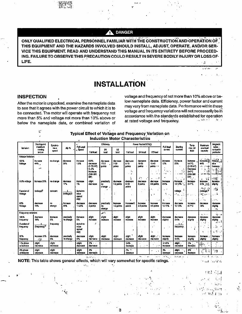
INSPECTION
Afterthemotoris unpacked, examinethe nameplate data
to see that it agrees with the power circuit to which it is to
be connected. The motor will operate with frequency notmore than 5% and voltage not more than 10% above or
below the nameplate data, or combined variation of
Variation
Voltags Variation:
120%
VORage
110% voltage
Function of
Vokage
90%
Voltage
herease
44% .
Sta® 9 andmmnum
runningtorque
**
meass 21%
{,ollage)2
decrease
19%
Fiequency variation:
10516 decrease
frequency 10%
Function 01 1
frequency (fmquenq) 2
Synchro-nous
speed
nochanga
nochange
constant
no
change
Increase
5%
frequency
sEP %
decrease
30%
decrease
17%
#0694 2
Increase
23%
pracall,rodlange
voltage and frequency of not more than 10% above orbe-low nameplate data. Efficiency, power factor and current
may vary from nameplate data. Performance within thesevoltageand frequencyvariations will notnecessarilybe iAaccordance with the standards established for operationat rated voltage and frdquency. . , ...1. , f 1.' .
Typical Effect of Voltage and Frequency Variation oninduction Motor Characteristics
FuR-Load
# Speed
*crease
15%
ncrease
1%
(synchro-nous
speed
decreass
, 1.1/2%
(Vavo-nous
speedSUP)
decrease
5%
sightdmN
hCrBase
5%
decrease
2 p©08
aghtkrease
60%
decrease
(1·75 HP)B.3%
Increase
(100·300
HP)
Ssghtdecrease
FuU-load
3/4
Ellidenc,
decrease
1/2.2 ,poklts
practicallyno
change
INghtIncrease
praaicallyno
change ;
decease
7.20
points
slight61088/8
1/2
load
decrease
1·2 polnts
krease
1-2 points
Full load
slightIncrease
deczease
5-10
pobts
decraase
5-15
points
bcreas,5
90&1ts
powsr FactodCOSe
3/41oad
decraase
10-30
Pohlts
0 .
decrease
5 poh*
ir:c:ease
24 points
*9htIncrease
1/21oad
3
iI
dacriase
15-40
poirds • •
decrnse
5-6 poans,
Increase4-5 poklts
Ughtcrease
Increase
12%
Increase
2-4%
4.
increase
10-11% .
Fufload
current
decrease
slightly
95% increase 11% decrease practically sight SU'1 61101! /110't dght *t r Increasshequency .9 5% nochange decrgase , decrease decrease decrease decrease decrease Slightly
1%phase sight sught 2% 54% , 1.1/2% '
unbalanca decrease decreass decmaza dacraass hor,ase
2% phasa slight slight sOoN 8% 7% " . 3%
unbalance decteass decrease decrease decrease decrBass ' increase
..
NOTE: This table shows general effects, which will vary somewhat for specific ratings.
increase
20%
krease
56%
SigM ,d#Crease
52
voltage
decrease
10-12%
Uea I10-12% L
decr,2130
54%
frequency
anoht' - idecrease
.
Increase 5-6°C.
U-75116Decrease
34°C
(100-300
HP).
#craas 9
34® C.
Tomprise, luU
load
*Base
6-7°C
decrease
reaS"
2% kbcroa50
SM'hclease
Mardmurn
ovefload
cepacity
decrease
6*4
44%
2 4increass
21%,311
6$660.1
decrease
19%
decrease
sightly
.*5
Magneticnoise-
»loadin
par!ar
able .
Increass
-444
*cruse
s¥* 1.*b..
bxrnaSs :slightly
'PA..f :
1 Ii.·'h' f.
: Bl 64.i
decrease
heraase.
5tly
8.
-fl .
4
LOCATION d ' 31'j:,·';:li *.:'r. '.I . :'*3'1'.:' 5.'lipplications. After carefully aligning the motor with theThe 1116t6r should be installed'i a locati-compatibie' driven unit, bolt securely in place.with the motor enclosure and specific ambient. , . When motors, which are normally mounted with the shaft
To allow adequate air flow, the following clearances must . in a horizontal position, are mounted vertically, it may be
be maintained between the motor and any obstruction: · necessary to provide additional guards to prevent foreignobjects from falling into the motor openings and striking
TEFC (IC0141) rotating parts. Such guards may be obtained at the time ofEnclosures purchase or from a local service repair center.Fan Cover Air Intake
Exhaust
r , Ly
Protected Enclosures
Bracket Intake , -
Frame Exhaust
I ..1'91 1.4.. :
1 LIFTING MEANS.
- 180 - 21 OT Frame 1"
250 - 449T Frame 4"
IEC 112 - 132 2.5 cm
IEC 160 - 280 10 cm
- Envelope equal to the "P". dimension on the motordimension sheet
- Same as TEFC
Exhaust out the sides-envelopeaminimum Ofthe"P"dimension
plus 2" (5cm).Exhaust out the end-same asintake. . ,
I i,1 1
;A*£ass,w**imrss". , , ,*Tr· t V,j!11 1 11 = 1 1- ' Ill Alif.ARNING , *, .>_.., ,_ -j ,
WHEN A LIFTING MEANS IS PROVIDED FOR
HANDLING THE MOTOR, IT SHOULD NOT BEUSED TO LIFT THE MOTOR PLUS ADDITIONAL
EQUIPMENT SUCH AS GEARS, PUMPS, COM-PRESSORS, OR OTHER DRIVEN EQUIPMENT.FAILURE TO FOLLOWTHESE PRECAUTIONS
i
COULD RESULr [N BODILY INJURY.:2 - .. jt
'i Z : ':
In the case 6f assemblies on a common base, any liftind vmeans provided on the motor or generatoj should not beused to lift the assembly and base but, rather, the assem-bly should be lifted by a sling around the base or by otherlifting means provided on the base.' In all cases careshould be taken to assure lifting in the direction intendedin the design of the lifting means. Likewise, precautionsshould be taken to prevent hazardous overloads due todeceleration, acceleration or shock forces.
MOUNTING
Mount the motor on a foundation sufficiently rigid to pre-vent excessive vibration. Roller bearing and ball-bearingmotors may be mounted with the shaft at any angle. Roll-er bearing motors are not suitable for coupled duty
Explosion proof motors are shipped from the factorywith the condqik box mounted. If the conduit box is re-moved or rotatdd, a minimum of five (5) full threads of en-gagement on the motor.pipe nipple must be maintainedfor explosion proof integrity, of the conduit box.
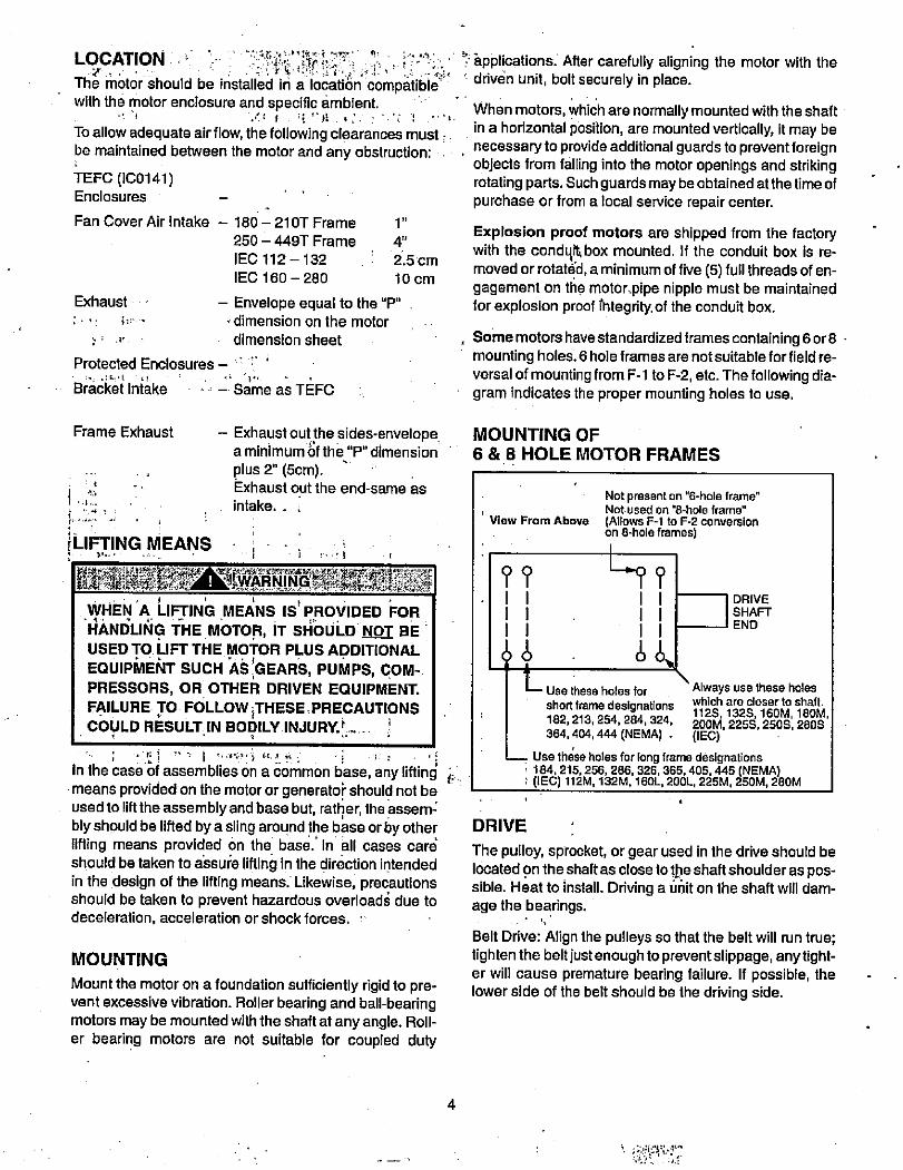
, Some motors have standardized frames containing 6 or8 ·mounting holes. 6 hole frames are notsuitable for field re-versal of mounting from F-1 to F-2, etc. The following dia-gram indicates the proper mounting holes to use.
MOUNTING OF
6 & 8 HOLE MOTOR FRAMES
View From Above
??111111
Not present on "6-hole frame"Not· used on "8-hole frame"
(Allows F-1 to F-2 conversionon 8-hole frames)
11
Use these holes for
short frame designations182,213,254,284,324,364,404,444 (NEMA) .
DRIVE
SHAFT
END
Always use these holeswhich are closer to shaft.
112S, 1325,16OM, 18OM,2OOM, 2255,2505,2805(IEC)
Use these holes for long frame designations184, 215,256, 286, 326,365,405,445 (NEMA)
i (IEC) 112M, 132M, 1601., 20OL, 225M, 250M, 28OM
DRIVE
The pulley, sprocket, or gear used in the drive should belocated on the shaft as close tolbe shaft shoulder as pos-sible. Heat to install. Driving a unit on the shaft will dam-age the bearings.
Belt Drive: Align the pulleys so that the belt will run true;tighten the belt just enough to preventslippage, anytight-er will cause premature bearing failure. If possible, thelower side of the belt should be the driving side.
:. ;:'. i.'.:i...,12.31 :,1
-
Chain Drive: Mount the sprocket on the shaft as close tothe bracket as possible. Align the sprockets so that thechain will run true. Avoid excessive chain tension.
Gear Drive and Direct Connection: Accurate alignment isessential. Secure the motor and driven unit rigidly to thebase.
ROTATING PARTS
t-]-' - L.-- - I T'*i.WAKA':460*ARi>]fff,
ROTATING PARTS, SUCH AS COUPLINGS, PUL-LEYS, EXTERNAL FANS, AND UNUSED SHAFT
EXTENSIONS, SHOULD BE PERMANENTLYGUARDED AGAINST ACCIDENTAL CONTACT
WITH HANDS OR CLOTHING. THIS IS PARTICU-,LARLY IMPORTANT WHERE THE PARTS HAVE
SURFACE IRREGULARITIES SUCH AS KEYS,KEYWAYS OR SET SCREWS. FAILURE TO OB-
SERVE THIS PRECAUTION COULD RESULT IN
BODILY INJURY.
46SOME SATISFACTORY METHODS OF ·
GUARDINGARE:
1. Covering lila. machine and associated rotating partswith structuial or decorative parts of the driven equip-ment.
2. Providing covers for the rotating parts. Covers shouldbe sufficiently rigid to maintain adequate guarding innormal service.
DANGER
THE USER IS RESPONSIBLE FOR CONFORM-ING WITH THE NATIONAL ELECTRICAL cobE
AND ALL OTHER APPLICABLE LOCAL CODES. WIRING PRACTICES, GROUNDING DISCON- ,NECTS AND OVERCURRENT PROTECTION
ARE OF PARTICULAR IMPORTANCE. FAILURE''TO OBSERVE THESE PRECAUTIONS COULD
RESULT IN SEVERE BODILY INJURY bR LOSS.
OF LIFE.
'Lit-.;
5
DANGER
SUBSEQUENT :STEPS'r';REQUIRE i ROTATING'
PARTS AND/OR ELECTRICAL CIRCUITS.TO BE,
EXPOSED. STAY CLEAR IF UNIT MUST BE RUN€
NING OR DISCONNECT AND LOCKOUT OR TAG>
POWER SOURCE IF CONTACT MUST BE MADE.
, .. , I ' .
Connect the mbtor io the p6wer supply according to'thEliagram'on tho motor nameplate. For most 230/460 Ooltmotors, nine leads are brought out from the stator wind-ings sothatthe motor may be connected foreither 230 or460 volts.,. u, ·,·.A , , 0 :· en
,
GROUNDING ; ,„ 11. L: , i r#':1 /1 4:i
In the USA consult the Natiohal Electrical Code, Anic\e430 f6r information on grounding of motors; Article 445 forgrounding of generatorsi'and,Article'250 for general'inlformation on grounding. In mailing the ground bonnecllion, the installer should make certain that there is a solidand permanent metallic connection between ttie ground
-
point, the motor or generator terminal housing, and the
motor or generator frame. In non-USA locatiops consultthe appropriate natiohal or local code applicable. 1.. ,-1 .
i -6.1, 1 e· 3 :1111·:>:ti:sE; SMotors with resilient cushion rings usually-Must bd pro=vided With a bondirig conductor acr6ss the resilient m*miben Some motors are supplied *lth the bondinb conducl
1 1 *,r
torontheconcea16dsideof thecushion ring to protect thd* ie 1 *
bond from damage: Motors with bonded cushion, ripgsshould usually·be grounded at the time of installation inaccordance with the above r666mmendations formakihgground connections.,When motors with bonded cushionrings are used in multimotor -installations emploing
1 group fusin'ggroup protection, the bonding of thecushrion ring should be checked to determine.that -it'is' adelIluatefor the rating of the branch circuit overcurrent prol
.tective device being used. . -." ..!. ,i
*V
There are applicatiohswhere groundingtheexteriorpartsof a motor or generator may result in greater hazard byincreasing the possibility of a peroBiri the area,simulta-neously contacting ground and some oth,9r rle,arby,liveelectrical parti'of'other ungrddnded electrical equipment.In portable equipment it is difficult to be s\.Ird thai 6 dosi-tive ground connection is maintained as the equipment ismoved, and providing a grounding conductor may lead toa false sense of security. . ».1
,
The user must select a motor starter And overcurrent*3,
protection suitable for this motor and its application. Con-suit motor starter application data as well as the Nati6nalElectric Code an4/or other applicable local codes. '*
t''
h, DANGER2 1.14 ... . 4(-IU h'SUM· .'•C''..2.? ... I.- .., .4
WHENICAREFUC¢.CONSIDERATIONCOF .THEHAZARDS INVOLVED' iNFAiPARTICOLAR 'AP-PEICATION INDICATE THE: MACHINE FRAMES
SHOULD NOT, BE. GROUNDED OR.WHEN UNLUSUALLBOPERATING:<CONDITIONSMDICTATE
'THATA GROUNDED FRAME CANNOT BE USED,
,JHE INSTALLERSHOULD,MAKE SURE THE MA-, CHINE,IS PERMANENTLYAND, EFFECTIVELY .INSULATED FROM GROUND. IN THOSE
INSTALLATIONS WHERE , THE · MACHINE ,FRAME IS INSULATED FROM GROUND, IT IS'RECOMMENDED THAT APPROPRIATE WARN-
ING LABELS OR SIGNS BE PLACED ON,pR INTHE ABEA OF THE EQUIPMENT BY THE IN-STALLER. FAILURE TO OBSERVE THESE PRE-
. CAUTIONS COULD RESULT IN SEVEREBODILY, INJURY OR LOSS OF LIFE. ,,
STARTINGf- 1, 13'.1-t ' f
J -1
t----A
BEFORE STARTING MOTOR, REMOVE ALL UN-4 * 4 + •k
*|1SEf,SHAFI -KEYS AND LOOSE ROTATING-,PARTS,Tg PREVEN THEM FROM FLYING OFF.",FAILURE.,TO ' OBSERVE , THIS ' PRECAUTION,*COULD RESULT INBODILY INJURY. '·,, . ,. J.
71·.11*illitta }41 0- .i 6,41 1:. 1:Li·, 1,·'11' "ty Lif'·*04, t": · 'r
--- TAS -f-5 :1*>.EAUERAYFURN#F*frkmuCheck direction of motor rotation before coU-
pling motor to load. Failure to observe this pre-caution could result in damage to or destruction
' of the equipment.- * .....; i':.:'I'-'!=/ -·. 4. i.,
Before starting the motor, check the following items: ,-t·
1„ The rotor should tum freely when disconnected fromthe load.' ; { ¢
.
2. Driven machine should 6e unloaded when first start-ing the motor.
\
t
' .5/
h1
6
The motor should run smoothly with little noise. If the mo-
torshould fail to stat'tand produces a decided hum, it maybe that the load is too great for the motor or that it hasbeen connected improperly. Shutdown immediately andImestigate for tiouble.
DRAIN PLUGS
If motor is totally enclosed fan-cooled or non-venti-lated it is recommended that condensation drain
plugs, if present, be removed. These are located inthe lower portion of the end-shields. Totallyenclosedfan-cooled "XT" motors are normally equipped withautomatic drains which may be left In place as re-ceived.
ROTATION
To reverse the direction of rotation, disconnect from pow-er source and interchange any two of the three line'leadsfor the three-phase motors.
TEST FOR GENERAL CONDITION
If the motor has been in storage for an extensive period orhas been subjected to adverse moisture conditionsi it isbest to check the insulation resistance of the stator wind-
ing with a megohmeter.
I f the resistance is lower than one megohm the windingsshould be dried in one of the two following ways:
1. Bake in oven at temperatures not exceeding 90°C.until insulation resistance becomes constant.
2. With rotor locked, apply low voltage and gradually in-,:T crease current through windings until temperature
measured with thermometer reaches 194°F (90°C).Do not exceed this temperature.
INITIAL LUBRICATION
ir, 1 Reliance motors are shipped from the factory with thebearings properly packed with grease and ready to oper-ate. Where the unit has been subjected to extended stor-age (6 months or more) the bearings should be relubri-cated (regreasable type) prior to starting. When motorsare equipped for oil mist lubrication refer to InstructionManual 8-3654.
OPERATION
9*.*'**j'<4%15:,-I-fLitiv,-4.1SURFACE TEMPERATURES OF MOTOR EN-
CLOSURE MAY REACH TEMPERATURES
WHICH CAN CAUSE DISCOMFORT OR INJURY
TO PERSONNEL ACCIDENTALLY COMING INTO
CONTACT WITH HOT SURFACES. WHEN
INSTALLING, PROTECTION SHOULD BE PRO- ,VIDED BY USER TO PROTECT AGAINST ACCI-
DENTAL CONTACT WITH HOT SURFACE. FAIL-
URE TO OBSERVE THIS PRECAUTION COULD ,RESULT IN BODILY'INJURY.
i'.'*1%,0.·f:..LAIIA -WARNING- =- ,
ROTATING PARTS, SUCH AS COUPLINGS, PUL-LEYS, INTERNAL-EXTERNAL FANS AND UN-USED SHAFT EXTENSIONS SHOULD BE PER-
MANENTLY GUARDED AGAINST ACCIDENTALCONTACT WITH HANDS ORiCLOTHING. FAIL-URE TO OBSERVE THIS PRECAUTION COULD
RESULT IN:BODILY INJURY. ' - . U
Duetothe inherentcharacteristics of insulatingmaterials,abnormally high temperatures shorten the operating lifeof electrical apparatus. The total temprature,'not thetemperature rise, should be the measurZ of safe opera-lion. The class of insulation determines the maximum
safe operating temperature. Aging of insulation occurs atan accelerated rate at abnormally high temperatures. Ageneral rule for gauging the effect of excessive heat isthat for each 10°C. rise in temperature above the' maxi-mum limit for the insulation, the life of the insulation ishalved.
r
-7
V.. r 42f ,
Unbalanced voltage or single-phase operation of poly-fhase machines may cause , excessive heating andultimate failure. It requires onlya slight unbalance of volt-age applied to a polyphase motor to cause large unbal-ance currents and resultant overheating.
feriodic checks of phase voltage, frequency and powerconsumption«of a'moto'while in operationidre recomimended; such checks assure the gorrectness offfequ,encyandvoltage applied tothe motorand yield an indicationof the load offered,by the apparatus which the motodrives.· ' (11 ' InIt' "' r i. , f f'i:· :.:.- 4 FANComparisons of this data with previous no-load and full-load power demands will give an indication of the perfor-mance of the complete machine. Any serious deviationsshould be investigated and corrected.
Statortroubles can usually be traced to one of the followling causes:.r , ;
, Worn bearings ' ' Operating single-phase ' 2Moisture it:. 1 .! Poor insulation 4 5 ·- 11 2 1
Overloading ' Oil and dirt' M;46; tre, 1.,1, 'I.' . 4 '- . *-I / 1/ 4/,/ I '1./ki'' I
Dustand dirt are usually contributing factors. Some formsof dust are highly conductive and contribute materially toinsulation breakdown. ·The effect of dust oq the nlotortemperaturethrough restriction of ventilation isaprindpalreason for keeping the-windings clean. 2 1 "62:f .g,;: :. '
.' Ir//'. 6, .Sqilirrel-cage rotors are rugged and, ingeneral, give littletrouble. The first symptom of a defective rotor is lack oftorque. This may cause a slowing down in speed accom-panied by a growling noise or perhaps failure to start theload.
I ,
This is caused by an open or high resistance joint in therotor bar circuit. Such a condition'ban generally be de-tected by looking for evidence of localized heating. '
.
. ,
../f.
4
1 21"·
A,%. 0
. '5%,4:i - 4.: 1 4.,
4
MAINTENANCE AND REPAIR
-
2TO INSURE THAT THE' DRiVEN EQUIPMENT IS'' NOT UNEXPECTEDLY' STARTED, TURN OFF 1.AND LOCKOUT OR TAG POWER SOURCE BE-
. FORE PROCEEDING. FAILURE.TO OBSERVE
:THJS PRECAUTION COULD RESULT IN BODILYANJURYs,e.. ··· 'r . f
The fundamental principle of electrical maintenance isKEEP THE APPARATUS CLEAN AND DRY. This re-
quires periodic inspection of the motor, the frequency de-pending upon the type of motor and the service.
The following should be checked at regular intervals:
P*pgk,LiffAA-WARNIN-9..,
DO NOT USE GASOLINE OR OTHER FLAM-
MABLE SOLVENTS WHEN CLEANING THE MO-
TOR. FAILURE TO OBSERVE THIS' PRECAU-TION COULD RESULT IN BODILY INJURY. ,
'."
e Windings'should Be dry and free'of du51, grease;'oil,.'·' ?'and'dirt. Windings may be cleaned 64 suction clean-7- 4*rsBY by wiping. Nozzles 6n suctioh type cleanersi-ge;shoOId be n6n-metallic. Gummy deposits of dirt and
grease may be removed by using a commerciallyavailable low volatile solvent.
2. Terminal connections, assembly screws, bolts and' nuts should be tight. They may loosen if motor is notf' securely bolted and tend to vibrate. + 1 .
3. Insulation resistance of motors in service should be
:. 4 checked periodically at approximately the same tem-5 perature and humidity conditionsto determine pos-
sible deterioration of the insulation. When such mea-
surements at regular intervals indicate a wide varia-tion, the cause should be determined. Motor shouldbe reconditioned if the motor has been subjected toexcessive moisture by re-winding or re-insulating ifnecessary. Enclosed motors require very little atten-tion. Be sure that external air chamber of fan-cooled
motors does not become clogged with foreign materi-al which will restrict passage of air.
DISASSEMBLY
if it becomes necessary to disassemble the motor, careshould be taken not to damage the stator windings as theinsulation may be injured by improper or rough handling.
8
Frecautions to keep bearings clean should be exercised.Before removing either end shield:
4. DisconAect motor from power source. Tag the leads to[ 'indure proper reconnection.2., Remove motorfrom mounting base. Remove fan cov-
, ,er and fan if present.3. Mark end brackets relative to position on frame so' ·they can be easily replaced.
iREMOVING BRACKETS AND ROTOR
4. Remove bearing cartridge nuts or screws. (If used)
5. Remove opposite drive end bracket bolts.
6. Pull bracket.
7. Remove drive end bracket in same manner.1
8. ' Remove rotor.
.
REMOVING AND REPLACING BALL
BEARINGS,BEARINGS SHOULD NOT BE REMOVED UNLESS
THEY ARE TO BE REPLACED. WHEN REMOVAL IS
NECESSARY, USE A BEARING PULLER. A BEARING
PULLER MAY BE RIGGED BY USING A METALPLATE,WITH HOLES DRILLED TO MATCH THE TAPPED
HOLES IN THE INNER CAR USE CARE TO KEEP THE
PRESSURE EQUAL TO PREVENT BREAKING THE
CAR
TO INSTALL A BEARING, HEAT THE BEARING IN AN
OVEN AT 250°F (121 °C). THIS WILL EXPAND THE IN-NER RACE, ALLOWING IT TO SLIP OVER THE BEAR-ING SEAT. ALL BEARINGS MUST BE REPLACED
WITH THE IDENTICAL PART USED BY RELIANCE. IN" * MANY CASES SPECIAL BEARINGS ARE USED
WHICH CANNOT BE IDENTIFIED BY MARKINGS ON
BEARING. IN ALL CASES, WHEN REPLACING BEAR-: INGS, USE MARKINGS ON BEARINGS AND MOTOR
IDENTIFICATION NUMBER TO OBTAIN CORRECTREPLACEMENT BEARING.
THE MAJORITY OF BEARINGS USED NOW HAVE A
(3 INTERNAL FIT.
REASSEMBLY
Follow reverse procedure as outlined for Disassembly.Having marked the brackets in the original position, re-place as marked.
jiMi-,fj
LUBRICATION OF BEARINGS
Motors covered by this Instruction Manual are equippedwith several types of bearings. This description covers relgreasable anti-friction hearings only. Non-regreasableball bearings require no periodic maintenance. See 1/M8-3654 for oil mist lubricated anti-friction bearing prdce-dures. 1
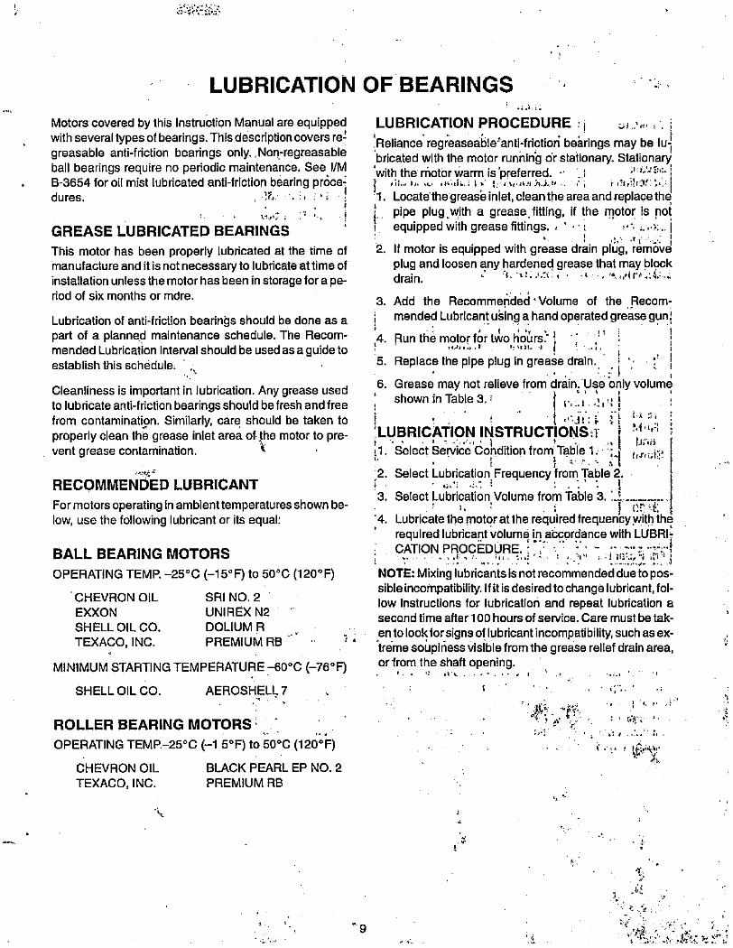
GREASE LUBRICATED BEARINGS
This motor has been properly lubricated at the time ofmanufacture and it is not necessary to lubricate at time ofinstallation unless the motor has been in storage for a pe-riod of six months or mdre.
•4.1.I.
LUBRICATION PROCEDURE ; i 01.:,1'.' I. i
Reliance regreasea6le'anti-friction behrings may be luJbricated with the motor running or stationary. Stationary
with the niotor warm is 'preferred. .1 .1, 0 Di:, 1
6?t,il,Of ' ,;i.; 1. Locate thegrease inlet, clean the area and replace thR Pipe plug -with a grease.litting, if the motor is noti equipped with grease fittings. . ·': :¢.. I, ..> ..1
2. If motor is equipped with grease drain plug, removeplug and loosen any hardened grease that may blockdrain. '1, 'it. bj. i. -1 -. ".,/17.:4. .4
3. Add the Recommended' Volume of the Recom-
Lubrication of anti-friction bearings should be done as a i mended Lubricant u6ing a hand operated grease gunpart of a planned maintenance schedule. The Recom- 4. Run the motor 6 t,bo hoors.- 1 ,' ' ! 1mended Lubrication Interval should be used as a guide to .,/'...., . ': 1
establish this schedule. ' , 5. Replace the pipe plug in grease drain. ' 1 5 '' 1
Cleanliness is important in lubrication. Any grease used ,6. Grease may not relieve from drain. Use only volume
shown in Table 3. i . ,to lubricate anti-friction bearings should be fresh and free ! 1.,„1.21,4 i '
from contaminatipn. Similarly, care should be taken to i i ! , '.''ir; 8 it ' i 5, 1properly clean the grease inlet area of·the motor to pre- 'LUBRICATION INSTRUCTIONST i , r /1.1 ,
.,1 bAHvent grease contamination. 2 · 11. Select Servce Condition from Tabl'e 1. ';4 „#ue1;
,2. Select Lubrication Frequency Tfrom Table 2.RECOMMENDED LUBRICANT
3. Select Lubrication Volume from Table 3.-......--I....
For motors operating in ambienttemperatures shown be- !. : i 1 t'.n.. I.low, use the following lubricant or its equal: '4. Lubricatethe motor atthe re4uired frequency withthd
required lubricant volume irlacg,ordance with LUBRI-
BALL BEARING MOTORS ...., ...EN:. ,11. ...;:··.. t...ilit :.7113:60'1,0··1CATION PROCEDURE.:,
OPERATING TEMP. -25°C (-15°F) to 50°C (120°F) NOTE: Mixing lubricants is notrecommended dueto pos-
sibleincompatibility. If itisdesiredtochange lubricant, fol-CHEVRON OIL SRI NO. 2
low Instructions for lubrication and repeat lubrication aEXXON UNIREX N2
second time after 100 hours of service. Care mustbetak-SHELL OIL CO. DOLIUM R
TEXACO, INC. PREMIUM RB ·· 1 , *entolook. forsignsof lubricantincompatibility, such asex-treme souplness visible from the grease relief drain area,
MINIMUM STARTING TEMPERATURE -60°C (-76°5
SHELLOIL CO. AEROSHELL 7
ROLLER BEARING MOTORS
OPERATING TEMR-25°C el 5°F) to 50°C (120°F)
CHEVRON OIL BLACK PEARL EP NO. 2
TEXACO, INC. PREMIUM RB
t
9
or from the shaft opening.
t
4*C- ,»ff
i S"ty,
i
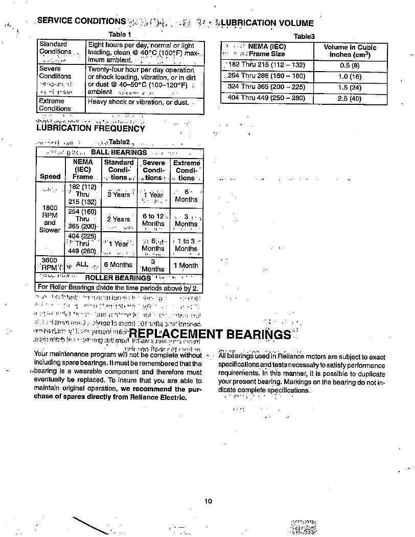
SERVICE CONDITIONS -
+ Table 1: >,Er*, i 4.':i ...0 1 5,·LUBRICATION VOLUME
Table3
Eight hours per day, normal or lightloading, clean @ 40°C,(l OON:) max-imum ambient. ,
Twenty-four hour per day operation,or shock loading, vibration, or in dirior dust @ 40-50°C (100-120°F) iambient ... c.-,·.· r ...
Standard
Conditions, .
Severe
Conditions
·1/'10„/9,·1!
Extreme
Conditions
LUBRICATION FREQUENCY
NEMA
(IEC)Speed Frame
1800
RPM
and
Slower
182 (112)- Thru '
215 (132)
254 (160)Thru '
365 (200).
404 (225)' 1" Thru'
449 (280)
Heavy shock or vibration, or dust.
i /Table2. . &BALL: BEARINGS . , .-
Standard
Condi-'T tions v r
3 YJars j
2 Years
*1 Year' ·
, SevereCondi-
Ltions f
'1 Year
6 to 12'.
Months1.
Months
3
' Months
Extrema
Condi-
tions .
6
Months
Months
i 1.to 3 -
Months,,
' NEMA (IEC),·«Frame Size
182 Thfu 215 (112 -132)
. 254 Thru 286 (160 - 180)
324 Thru 365 (200 - 225)
404 Thru 449 (250 - 280)
Volume in Cubic
inches (cm3)
0.5 (8)
1.0 (16)
1.5 (24)
2.5 (40)
3600
-'RPMY 'b' ALL :.. 6.Months 1 Month
-404. 1 1,1 i.. ROLLER BEARIVGS 'i" '' '
For Roller Bearings divide the time periods above by 2.•s + b"Obbi!· ··'Y ' r.(Mulk);1:'L·.1· ' ·4,3 F ... apic ··
2 ,·: i,,; 1'··i.1 'Ci - 2 48(t 1. 7*···-111(· lit · r- :-·1:2, I !'2115:.. :'1 :a·,tin ;,fs:.).. ih,foi,1,0 270611 :Ori.Hia·w,:E bt.:ir,aa'«2-- 1. f4 fH)Dn·,5:)'REPLACEMENT BEARINGS
, < 5 3 45'< 'tr; h.1 !> ! F, 1 " 98 °4) 111 :31 11 m C),7 ) : d iv f. 1, H} i i' 1" 3 ¢1 5 LATI, Y Itt 1 1 :#0 #E#in r Pit r y(,1 w A..le- . ·.·9/ -:.
Your maintenance program will not be complete without All hearings used In Reliance motors are subject to exactIncluding spare bearings. It must be remembered thatthe specifications and tests necessatytosatisfy performance
*..bearing is a wearable component and therefore must requirements. In this manner, it is possible to duplicateeventually be replaced. To insure that you are able to your present bearing. Markings on the bearing do not in-maintain original operation, we recommend the pur- dicate complete sp,ecifications.chase of spares directly from Reliance Electric.
10
4 ' - ··.1 & k
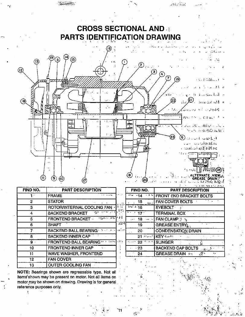
2
3
4
5
6
7
8
9
10
11
12
13
661 . ' .4. t . ;
15
- 43
1 I , .41, ;/
El/991* ' .1 , 177- MI
1 4 111 Z \1. . ': "1 .,'.,.i E E i'/ I
t-3
1 9 1 6-4& -Ilt ./
FIND NO.1
11 ®@
FRAME
1 fl
1.
PART DESCRIPTION
STATOR
ROTOR/INTERNAL COOLING FAN
BACKEND BRACKET ''4' ' '" "./
FRONTEND BRACKET '*- J.'1
SHAFT
BACKEND BALL BEARING a
BACKEND INNER CAP
FRONTEND BALL BEARING "- .,;,«...
FRONTEND INNER CAP
WAVE WASHER, FRONTEND
FAN COVER
OUTER COOLING FAN
NOTE: Bearings shown are regreasable type. Not all, itemsfshown may be present on motor. Not all items on
motor may be shown on drawing. Drawing is for general' reference purposes only.
3f;
4''B
'3 ' a
CROSS SECTIONAL AND i
PARTS IDENTIFICATION DRAWING
4 4.
.
7 19
..1 / '' I .H "
t ' 3 5 ./'Ui' Ed ..
2 , S)21.*·21 1,>.1 :1
23 F>
. 1,
1 ., 1,/. 1/.1
I # · -. ' ·*i #3.idit;
s .,I:, I L. 14&,17: Nr
,., ALTERNATE .VIE¥44' =' GREASE 'DRAIN'#r ,
, 4 ,· 4... 6 i., ;11,.Q .Ij,lilifilFIND NO. PART DESCRIPTION
-14 ' v * FRONT END BRACKET BOLTS
. . 15
"" $-16
'- ' 17
18
19
20
21
·23
24
i 44 '11
t
FAN COVER BOLTS
EYEBOLT 4
TERMINAL BOX '
FAN CLAMP].1 ·,GREASE ENTRYA.CONDENSATION DRAINKEY ':,· i
SLINGER
BACKEND CAP BOLTS f.:.5 .
i GREASEDRAIN -·v, :g··· '-
: %,t tfy:' · '/ It . I
6:.
1-
C ,
:*d 'rt:.-.__64-le
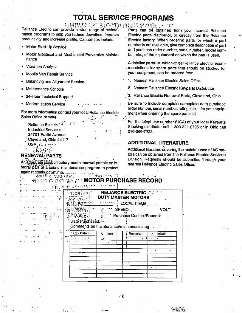
1
TOTAL SERVICE·PROGRAMSCAAft.W!,ir, 1.:f# 1. ir,ty:A
, Reliance Electric can provide a wide range of mainte-. nance programs to help you reduce downtime, improve
productivity and increase profits. Capabilities include:
• Motor Start-Up Service
• Motor Electrical and Mechanical Preventive Mainte-nance
• Vibration Analysis
• Mobile Van Repair Service
• Balancing and Alignment Service
• Maintenance Schools
• 24-Hour Technical Support
• Modernization Service
1 .For more information contact your local Reliance ElectricSales Office or write:
Reliance Electric '· 2 ,
Industrial Services ·
24701 Euclid Avenue . ,Cleveland, Ohio 44117
USA :150 1 V
1, 4f:.,; 15.RENEWAL; PARTSArt'SEIdqi&id ifbckof factory-made renewal parts isan in-tegrdl1;#rfSfii 6und maintenance program to protect,against costly. downtime. ... ,-'.„...." '101:ff:R: ·:30 7;"F'·N ; rt<.1 .....I ':
...
f/ IT' - ./ ,
4-*
r ·.41 I
r
Parts can bi obtained from your nearest RelianceElectric parts distributor, or directly from the RelianceElectric factory. When ordering parts for which a partnumber is not available, give complete description of partand purchase order number, serial number, model num-ber, etc., of the equipment on which the part is used.
A detailed parts list, which gives Reliance Electric recom-. mendations for spare parts that should be stocked foryour equipment, can be ordered from:
1. Nearest Reliance Electric Sales Office
2. Nearest Reliance Electric Keyparts Distributor
3. Reliance Electric Renewal Parts, Cleveland, Ohio
Be sure to include complete nameplate data-purchase' ordernumber, serial number, rating, etc. - foryourequip- '
ment when ordering the spare parts list.
For the telephone number (USA) of your local KeypartsStocking distribotor call 1-800-321-2795 or in Ohio call216-266-7222.
ADDITIONAL LITERATURE
Additional literature covering the maintenance of AC mo-tors can be obtained from the Reliance Electric Services
Division. Requests should be submitted through yournearest Reliance Electric Sales Office.
r
MOTOR PURCHASE RECORD
! 305 i,.1/ RELIANCE ELECTRIC r ,i,.3.TRI.2,] 3 DUTY MASTER MOTORS
' LOCAL ITEM# -1
...1 H P/ .- I.- ... ....,,. „,-5,WiE, 1 · SPEED VOLT
u , Purchase ContacUPhone #Daid POichEisd: t·:Comme,nts on maintenanci/maintenance log . ,' 1 3 u Date 2 F', · Item 1 1 Remarks ./ Initials ' '.
. -# '..1 r'/ '. :tri .../
Ill i.
12
..:PS:*CMJ:.:.94.AS'.d,1.

.4
9
0,1 1
. 2 r,*.,
2 -T -
't .
-
....-
*/7
'lf -17
-
r .,1'1
$4 :..... lf * 1 ' .3, ,,' a: i ... ' ; ' s. 1, ;:. ,,· ...1 ,£11;f 1-1 :, ', 51)1,r -s,(4 bt,-42·.·: , 0 5 61: i J liS!,*:N:3*IRIO . .:· ;' " ' #'1;'•f»:*ca,1•,:.4: 14; ,t:VX--Z. "-,r,2;,'whd.¢•hZhio);4;*.7 VH:44W4' rl·1,2-7**4#GAU,·akr'* t*1144
.r.
, It
.-*-·Sjt;:·i,·. 2 f*' ,-,•A. « , .Y'*Kilpha,t-*43;:
''(51S

ft»e·1
Reliance Electric / 24701 Euclid Avenue / Cleveland, Ohio 44117./ (216) 266-7000
Printed in U.S.A
f
8-3620-23
40 Rocbmel, Adomauon
Reliance Electric
397
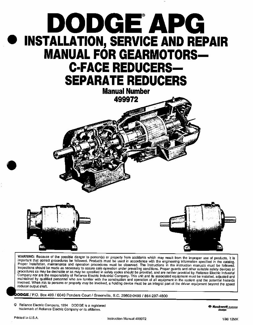
DODGE®APG0 INSTALLATION, SERVICE AND REPAIR
MANUAL FOR GEARMOTORS-C-FACE REDUCERS-
SEPARATE REDUCERSManual Number
499972
I.
WARNING: Because of the possible danger to person(s) or property from accidents which may result from the improper use of products, it isimportant that correct procedures be followed. Products must be used in accordance with the engineering information specified in the catalog.Proper installation, maintenance and operation procedures must be observed. The instructions in the instruction manuals must be followed.Inspections should be made as necessary to assure safe operation under prevailing conditions. Proper guards and other suitable safety devices orprocedures as may be desirable or as may be specified in safety codes should be provided, and are neither provided by Reliance Electric IndustrialCompany nor are the responsibility of Reliance Electric Industrial Company. This unit and its associated equipment must be installed, adjusted andmaintained by qualified personnel who are familiar with the construction and operation of all equipment in the system and the potential hazardsinvolved. When risk to persons or property may be involved, a holding device must be an integral part of the driven equipment beyond the speedreducer output shaft.
ODGE / RO. Box 499 / 6040 Ponders Court / Greenville, S.C. 29602-0499 / 864-297-4800
© Reliance Electric Company, 1994 DODGE is a registeredtrademark of Reliance Electric Company or its affiliates.
Printed in U.S.A. Instruction Manual 499972
0. ROC#n¥eN AuknbonDodge
1/96 12MK
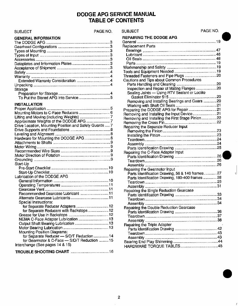
SUBJECT
GENERAL INFORMATION
The DODGE APG
Gearhead ConfigurationsTypes of MountingTypes of InputAccessories
Dataplates and Information PlatesAcceptance of ShipmentSafetyWarranty
Extended Warranty ConsiderationUnpackingStorage
Preparation for StorageTo Put the Stored APG into Service
DODGE APG SERVICE MANUAL
TABLE OF CONTENTS
PAGE NO.
INSTALLATION
Proper Application 5Mounting Motors to C-Face Reducers ...............................Lifting and Moving (including Weights) ....... ......................Approximate Weights of the DODGE APG ......................7Drive Location, Mounting Position and Safety Guards ..... 7Drive Supports and Foundations 8Leveling and Alignment ..8Hardware for Mounting the DODGE APG.. ........................Attachments to Shafts 9Motor Wiring 9Recommended Wire Sizes 9Motor Direction of Rotation 9
Grounding 9Start-Up
Pre-Start Checklist 10
Start-Up Checklist 10Lubrication of the DODGE APG
General Information 10
Operating Temperatures 11Gearcase Vent 11Recommended Gearcase Lubricant
Alternate Gearcase Lubricants 11
Special Instructions:for Separate Reducer Adapters ---„-------„-„-12
for Separate Reducers with Backstops........ ....„12
Grease for Use in Backstops 12NEMA C-Face Adapter Lubrication ---„-„--„-----13
Output Shaft Bearing Lubrication 13Motor Bearing Lubrication 13Mounting Position Diagrams:
for Separate Reducer - S/[)/T Reduction ..............14
for Gearmotor & C-Face - S/D/T Reduction -„„„-15
Interchange (See pages 14& 15)
TROUBLE SHOOTING CHART 16
3
3
..3
..3
3
3
3
4
4
4
4
4
5
2
SUBJECT PAGE NO.
REPAIRING THE DODGE APG
General 19
Replacement PartsBearings , 47Lubricant ....46
Oil Seals ....48
Parts 19
Workmanship and Safety 19Tools and Equipment Needed 19Threaded Fasteners and Pipe Plugs .............................20Cautions and Tips about Common Procedures
Parts Handling and Cleaning 20Inspection and Repair of Mating Flanges...................20Sealing Joints - Using RTV Sealant or LoctiteGasket Eliminator 515 20
Removing and Installing Bearings and Gears ------20
Working with Shaft Oil Seals 21Preparing the DODGE APG for Repair ..........................21
Removing and Installing the Input Device......................21Removing and Installing the First Stage Pinion....... .......22
Removing the Cross Pin 99
Repairing the Separate Reducer InputRemoving the Pinion 93Installing the Pinion PTeardown 94
Assembly . 94Parts Identification Drawing 95
Repairing the C-Face Adapter InputParts Identification Drawing 44/PTeardown
Assembly . 96Repairing the Gearmotor Input
Parts Identification Drawing, 56 & 140 frames... ----„27
Parts Identification Drawing, 180-400 frames.... ----„28
Teardown 99AssemblY 31
Repairing the Single Reduction GearcaseParts Identification DrawingTeardown.. 34Assembly .. 34
Repairing the Double Reduction GearcaseParts Identification DrawingTeardown..
Assembly 98Repairing the Triple Adapter
Parts Identification Drawing 42
Teardown 43
Assembly . 43Bearing End Play Shimming 44HARDWARE TORQUE TABLES .................................. .45
THE DODGE APG
GENERAL INFORMATION
The DODGE APG is a broad line of high power density,helical geared products adaptable to a wide variety ofapplications. The DODGE APG is designed in accordance
with the standards of the American Gear ManufacturersAssociation to give trouble-free performance when proper-ly selected, installed and maintained. This instruction man-ual contains precautions and procedures to observe wheninstalling, operating and maintaining your DODGE APG.Additional information may be obtained from your localDODGE Sales Office, Authorized Distributor or AuthorizedService Center.
GEARHEAD CONFIGURATIONS
The DODGE APG gearhead is produced in three basicconfigurations:
1. The Single Reduction has one pair or "stage" of gears.The Single Reduction unit is available in ratios of 1.2:1through 5:1.
2. The Double Reduction uses two pairs of gears in seriesto provide ratios from 4:1 through 25:1. The DoubleReduction gearcase is different from the Single Reduc-tion gearcase.
3. The Triple Reduction is the Double Reductiongearhead with yet another pair of gears housed in a"Triple Adaptef' added at the input. The Triple Reduc-tion provides ratios from 31:1 through 129:1
TYPES OF MOUNTING
Each of the three gearhead configurations is available intwo types of mounting:
1. Foot Mount is standard. The APG Gearmotor shown on
the cover of this manual is Foot Mounted. Some combi-
nations of motor and gearhead require riser blocksunder the mounting feet if the drive is to be mounted to alarge flat surface and the body of the motor extendsbelow the feet of the gearhead. Suitable riser blocks aresupplied as standard parts where needed.
2. Flange Mount units use the same gearcase as the FootMount units. The output bearing housing is changed toprovide a mounting flange concentric with the outputshaft.
TYPES OF INPUT
The three gearhead configurations in either of thetwo mounting types are each available in three inputconstructions:
1. The Gearmotor uses a special motor designed to pro-duce a compact package of prime mover and reducer.Couplings and exposed rotating parts at the input areeliminated.
2. The C-Face Reducer has a hollow, integral inputcoupling to accept the shaft of a standard NEMA
3
C-Face motor. A clamp collar is provided to lock themotor shaft and the input coupling together to preventfretting corrosion.
3. The Separate Reducer has an extended input shaft tobe coupled to a separately mounted prime mover. Theinput may be through a belt or chain if the input speedrequired is different from standard motor speeds.
ACCESSORIES
The DODGE APG may be equipped with brakes, dutches,backstops or other accessories. Backstops are availableonly in the Separate Reducer input construction and arecovered in detail in this manual. Other accessories are
described in their own manuals.
DATA PLATES AND INFORMATION PLATES
The primary plate is attached to the DODGE APGgearcase. This rectangular stainless steel plate containsvital information about your DODGE APG. Gearmotor andC-face reducer input constructions have an equally im-portant dataplate on the motor. Information plates may beattached to any component to provide operational instruc-tions or precautions. Bolt-on accessories will usually havetheir own data plates. All plates are to be consideredimportant. The information they contain will be of helpto youthroughout the life of the drive. Take care not to damage orpaint over any of the plates.
When ordering parts or service, or asking a question aboutyour DODGE APG, please provide all the informationstamped on both the motor and gearcase dataplates. If
your drive has an accessory, such as a brake, provide thatinformation also.
ACCEPTANCE OF SHIPMENT
Thoroughly inspect the equipment before accepting ship-ment from the transportation company. If any of the goodscalled for in the bill of lading or express receipt are dam-aged or missing, do not accept the shipment until thefreight or express agent makes an appropriate notation onyour freight bill or express receipt. If any concealed loss ordamage is discovered later, notify the agent at once andrequest an inspection. Though DODGE will be happy toassist you with claims for loss or damage in shipment, thetransportation company is responsible for reimbursing youfor such claims. Claims for loss or damage in shipmentmust not be deducted from the DODGE invoice, nor should
payment of the DODGE invoice be withheld awaitingadjustment for such claims. The carrier, not DODGE, guar-antees safe delivery.
If considerable damage or shortage has occurred and thesituation is urgent, contactthe nearest DODGE Sales Officefor assistance.
SAFETY
DANGER
HIGH VOLTAGE AND ROTATING PARTS CAN
CAUSE SERIOUS OR FATAL PERSONAL INJURYAND PROPERTY DAMAGE. THE USE OF ELECTRI-
CAL MACHINERY, LIKE ALL OTHER UTILIZATIONOF CONCENTRATED POWER AND ROTATING
EQUIPMENT, CAN BE HAZARDOUS. INSTALLA-TION, OPERATION AND MAINTENANCE OF ELEC-TRIC MACHINERY SHOULD BE PERFORMED ONLY
BY QUALIFIED ELECTRICAL AND MECHANICALMAINTENANCE PERSONNEL FAMILIAR WITH
NEMA SAFETY STANDARDS, THE NATIONALELECTRICAL CODE AND SOUND LOCAL PRAC-
TICES. THE MANUAL IS TO BE STUDIED THOR-OUGHLY BY PERSONNEL RESPONSIBLE FOR THEINSTALLATION AND MAINTENANCE OF THISEQUIPMENT BEFORE INSTALLATION IS BEGUN.PERSONNEL MUST BE FAMILIAR WITH THEPOTENTIAL HAZARDS INVOLVED. IF THIS WARN-
ING IS NOT OBSERVED, PERSONAL INJURY AND/OR PROPERTY DAMAGE MAY RESULT. KEEP THISMANUAL FOR FUTURE REFERENCE.
Many precautions are inserted in this manual to advisepersonnel of possible hazards. All should be read andunderstood before any work is begun. Adequate instal-lation, maintenance and safety instructions must be givenby the user to personnel responsible for the operation ofthe equipment. The user is also responsible for the instal-lation of proper guards, signs and safety equipmentneeded to protect the operating personnel.
WARRANTY
NOTE: SERVICE AND REPAIR UNDER WARRANTY
SHOULD BE PERFORMED ONLY BY A DODGE
AUTHORIZED SERVICE SHOP. CALL WARRANTYADMINISTRATION AT 812-376-1100 FOR THE
NEAREST LOCATION.
The DODGE APG is warranted under the DODGE
"Standard Terms and Conditions of Sale."
Warranty claims on any such apparatus must be submittedto the company within one year from date of installation orwithin three years from date of manufacture, whichevercomes first. The Seller's Warranty applies insofar as theequipment is operated within the rating and service condi-tions for which it was specifically sold. The warranty doesnot extend to failures induced by misuse, improper storageor handling, abuse or misapplication.For warranty service, contact the nearest DODGE SalesOffice or Authorized Distributor or call Warranty Administra-tion at 812-376-1100.
UNPACKING
After unpacking and inspecting for possible damage, turnthe shafts by hand to be sure there are no obstructions tofree rotation. C-Face input devices have a shipping straparound the input shaft which must be cut and removedbefore the shaft may be turned.
4
WARNING
KEYWAYS IN SHAFTS HAVE SHARP EDGES. USE
APPROPRIATE HAND PROTECTION WHEN
HANDING SHAFTS. FAILURE TO OBSERVE THISPRECAUTION COULD RESULT IN BODILY INJURY.
Check the packing materials. Save any instruction tags,wiring diagrams or accessory parts and hardware. Inspectthe dataplate(s) to verify that the drive matches the intend-ed load, application and power supply. If the drive is to gointo immediate service, see "INSTALLATION," below.If the DODGE APG is to be stored for some time before
going into service, see "STORAGE," below.
STORAGE
NOTE: Unless an extended warranty has been negotiatedprior to sale, time in storage is considered time in serviceforwarranty purposes. If a negotiated extended warranty isin effect, these storage procedures must be followed topermit the submission of a valid warranty claim.
Warranty considerations aside, the following storage pro-cedures should be taken to prevent problems when thedrive is eventually placed in service.
LONG-TERM STORAGE GUIDELINES FOR
GEAR REDUCERS:
Care must be taken to ensure that gear reducers areplaced in service in the best possible condition. Duringperiods of long storage (six months or longer) specialprocedures must be followed which will protect thereducer and make certain that it will be in good condition when ready to be put into service.
By taking special precautions, problems such as sealleakage and reducer failure due to lack of lubrication,improper lubrication quantity, or contamination can beavoided. The following precautions will protect reducersduring periods of long-term storage:
A. Preparation:
1. Select a clean, dry, protected storage area free ofvibration and temperature extremes. Set the drivelevel on its feet with no load on either the input oroutput shafts. Block as needed to keep weightoff the motor fan shroud and motor conduit box
(if unit has a motor).
2. Fill the gearbox to the highest designated oil levelwith a recommended lubricant blended with 2% byvolume of *Daubert Chemical Co. Nox-Rust VCI-
105 oil. Do not fill the gearbox completely full ofoil. Expansion space is needed to avoid pressur-izing the gearbox during temperature variations.Rotate the input shaft at least 60 revolutions toensure a full distribution of the lubricant.
3. All condensate drains and breathers (on motors
so equipped) are to be fully operable to allow breathing through points other than bearing fits.Remove the condensate drain plugs located inthe motor end shield. Position the motor so the
drain is at the lowest point. Totally enclosed fan-
cooled XT motors are equipped with automaticdrains which should be left in place.
4. All units equipped with heaters must have theheaters connected and operational if the storageconditions are in any way like the anticipated serv-ice conditions.
5. Motor windings are to be checked with a meg-ohmeter when the equipment is put into storage.The resistance must be recorded and saved for
future reference. See "to put the stored unit intoservice" for the megohmeter check required uponremoval from storage.
6. Apply a thick coating of chassis-type grease,Cosmoline or equivalent protective coating*(Daubert Chemical Co. Nox-Rust X-110 is a suit-able coating) on all unpainted surfaces includingthreads, bores, keyways and shafts.
7. Apply a thick coating of chassis-type grease to allexposed shaft seals.
8. If the unit must be stored outdoors or in damp orunheated areas indoors, cover the entire exteriorwith a rust preventative. Seal the unit in a moisture-proof containeror in an envelope of heavy polyeth-ylene film with a dessicant inside. Shade theenclosure from direct sunlight.
9. Rotate the input shaft at least 60 revolutions oncea month to redistribute the lubricant and to pre-vent brinelling of bearings and drying of seals.
10. Instruction manuals and tags are paper and mustbe kept dry. Remove these documents and storethem in a safe, dry place for future reference atstart up.
B. To put the stored unit into service:
1. Remove all protective coatings added for storage.
2. Drain and refill the gearbox with a recommendedtype and amount of lubricant. Regreasable assem-blies and bearings must be purged and filledwith new grease.
3. Install the oil level plug in the proper location forthe mounting position to be used. Check the motorcondensate drain locations to assure the motors
will drain properly when mounted in the proposedposition. Rotate the motor on the gearhead orrotate the motor end shields on the motor frame if
necessary to getthe drains in the proper positions.
4. Check all hardware for proper tightness.
5. If the gear unit has been stored for more thanthree years or in an area with high ambient tem-peratures, the oil seals must be replaced beforebeing put into service. See the instruction manualfor directions on oil seal replacement.
6. Check the motor stator insulation resistance with
a megohmeter Resistance less than one megohmor less than 50% of the resistance reading takenwhen the motor was put into storage (whicheveris the higher resistance), requires the motor wind-
5
ing to be dried in one of the two ways describedbelow. If drying does not restore the winding insu-lation resistance to the values listed above, the
motor must be repaired or rewound.
a. Remove the motor from the reducer (see in-struction manual), place the motor in a ven-tilated oven at not more than 90 degreesCelsius (194 degrees F.). Check the insula-tion resistance every 30 minutes. Bake, untilthe resistance becomes constant.
or
b. Lock the motor rotor. Insert a thermocouple inthe winding or set up to measure rise by resis-tance. Apply low voltage, gradually increase thecurrent through the winding until the windingtemperature reaches 90 degrees Celsius (194degrees F.). Do not exceed this temperature.Check the winding insulation resistance with amegohmeter. Repeat if necessary.
After drying, briefly run the motor not connectedto any load to further dry the motor and to checkthe bearings for noise and smooth operation.
7. When stored motors are found to be wet, a moredetailed inspection should be made by removingthe motor end shields and visually inspecting forwater in the grease or rust on the bearings. Ifeither is found, replace the bearings, clean the endshields thoroughly and relubricate.
*Note: Daubert Nox-Rust VCI-105 oil and Nox-Rust
X-110 protective coating can be procured inbulk quantity from:
Daubert Chemical Company, Inc.4700 S. Central Ave. '
Chicago, Illinois 60638Telephone (708) 496-7350
or in 5-gallon pails from their distributor:
Rock Island Lubricants and Chemicals
1320 First Street
Rock Island, Illinois 61204-5015Telephone (309) 788-5631
INSTALLATION
A good installation is essential to get the long life andsuperior performance designed into the DODGE APG.Careful planning and good workmanship at installation willgreatly reduce future maintenance problems.
PROPER APPLICATION
Review the dataplates on the DODGE APG gearcase anddrive motorto verifythatthedrive is correct forthe intendedloads, speeds and electric power supply. The DODGEAPG catalog has detailed rating charts and instructions forapplying proper service factors for various types of appli-cations. Verify that the DODGE APG has the correct enclo-sures for your application. Standard enclosures are notsuitable for explosion proof or washdown applications.
WARNING
THE USE OF ELECTRICAL EQUIPMENT IN HAZARDOUS
LOCATIONS IS RESTRICTED BY THE NATIONAL ELECTRI-
CAL CODE, ARTICLE 500. ORIGINAL EQUIPMENT MANU-FACTURERS AND USER CUSTOMERS MUST READ,UNDERSTAND AND APPLY ARTICLE 500 FOR INSTALLA-
TION AND USE OF ALL EQUIPMENT IN SUCH LOCATIONS
AND CONSULT LOCAL CODE INSPECTION AND
ENFORCEMENT AGENCIES AS NECESSARY TO ENSURE
COMPLIANCE. MOTORS LISTED BY UNDERWRITERS LAB-
ORATORIES, INC. FOR USE IN SPECIFIC LOCATIONSHAVE BEEN DESIGNED, TESTED AND APPROVED FORUSE IN SUCH LOCATIONS ONLY.
Review the application to determine the signs, guards andany special provisions or devices needed to make the instal-
lation safe, practical and legal.
WARNING
MOTORS WITH AUTOMATIC RESET THERMAL PROTEC-
TORS SHOULD BE USED ONLY IN APPLICATIONS WHERE
AN UNEXPECTED RESTART WOULD NOT BE HAZ-
ARDOUS. IF A MOTOR WITH AN AUTOMATIC RESET THER-
MAL PROTECTORS HAS TRIPPED TO "OFF", BE SURE TODISCONNECT AND LOCKOUT THE ELECTRICAL POWER
SUPPLY TO THE MOTOR BEFORE WORKING NEAR THE
MOTOR OR ANY EQUIPMENT DRIVEN BY THE MOTOR. AN
UNEXPECTED AUTOMATIC "RESET" AND MOTOR START
COULD CAUSE SERIOUS BODILY INJURY.
Review the application to assure that any accessories onthe DODGE APG are correct for the intended use and that
the accessories needed are provided. Installations involvingholding or overhauling loads such as hoists or conveyorsshould have a brake or other separate locking deviceinstalled.
WARNING
BACKSTOPS ARE NOT RECOMMENDED FOR APPLICA-
TIONS INVOLVING SHOCK AND/OR TORQUE LOADS IN
EXCESS OF THE GEARBOX RATINGS. BACKSTOPS ARE
NOT RECOMMENDED FOR APPLICATIONS REQUIRING
ENERGY ABSORPTION. BACKSTOPS ARE NOT RECOM-
MENDED ON APPLICATIONS SUCH AS CHAIR LIFTS OR
AMUSEMENT RIDES, NOR ON ANY APPLICATION WHERETHE SAFETY OF PERSONS OR PROPERTY IS DEPENDENT
ON THE BACKSTOP FUNCTION. OTHER SAFETY DEVICES
MUST BE PROVIDED BY THE USER ON SUCH APPLICA-
TIONS.
Review the application for any unusually high or low ambi-ent temperatures and for sources of radiant heat.
Abnormally high temperatures will seriously shorten theoperating life of any machine. For every 10 degrees C (18degrees F) rise in temperature above the maximum ratedthermal limit, the life of motor insulation, shaft seals and
lubricants is reduced by half. The total temperature, not justthe temperature rise, is the measure of safe operation.
The DODGE APG and its motor should be shielded from hot
surfaces, such as ovens or furnaces, and shaded from
direct sunlight to prevent overheating when operating athigh loads. The thermal horsepower rating of the gearcase
6
should be checked as described in the DODGE APG cata-
log. Each motor nameplate carries a maximum ambient
temperature rating. Motors should not be operated at ambi-ents in excess of this rating. Applications with frequent starts
should be reviewed to be sure the thermal rating of thmotor is not exceeded.
Extreme low temperatures require special attention to lubri-cants, as detailed in the "LUBRICATION" section of this
manual. Flexible components such as wiring and lip seals
must also be considered to assure they remain flexible inservice. The drive should be shielded from the direct dis-
charge of freezer air supply ducts.
Questions about DODGE APG applications should be
directed to Applications Engineering at 812-376-1100.
MOUNTING MOTORS TO C-FACE REDUCERS
1. Prepare the reducer by cutting the shipping strap from
the input hub and removing the shipping strap retaining
plug. Loosen the input shaft clamp collar. Check the inputhub bore for dirt or damage which may make assemblydifficult.
2. Prepare motor by checking the motor shaft extension fordirt or damage. Remove any anti-rust coating that maybe on the shaft. Motor frame sizes 56C through 320TChave keys which are pre-installed in the input shaft key-
way. Apply a thin, even coating of the anti-seize com-pound supplied to the entire motor shaft extension ankey. Leave no bare areas. Push the motor shaft into thereducer input shaft.
Motor frame sizes 360TC and larger have a loose key in
the input shaft. Install this key in the motorshaft keyway
flush with the end of the shaft. Lightly stake the shaft key-
way at the motor end of the key to prevent the key fromsliding back as the motor is pushed into the reducer inputshaft. Apply anti-seize compound as listed above.
3. The DODGE APG C-Face reducer should be firmlyanchored to prevent sliding as the motor is mounted. Themotor should be rotated on its axis so the motor flangeholes line up with the reducer input flange holes. Check
to be sure the motor conduit box, grease fittings and con-
densate drains (where fitted) will be oriented as neededby the reducer mounting position. Motor end shields mayhave to be removed and rotated in some installations to
permit proper positioning.
WARNING
KEEP FINGERS CLEAR OF THE MATING FLANGES ON THE
MOTOR AND REDUCER. WHEN ALL PARTS REACH ALIGN-
MENT, THE MOTOR CAN ENGAGE THE REDUCER VERYRAPIDLY AND WITH GREAT FORCE. ANYTHING BETWEEN
THE FLANGES WILL BE SERIOUSLY INJURED.
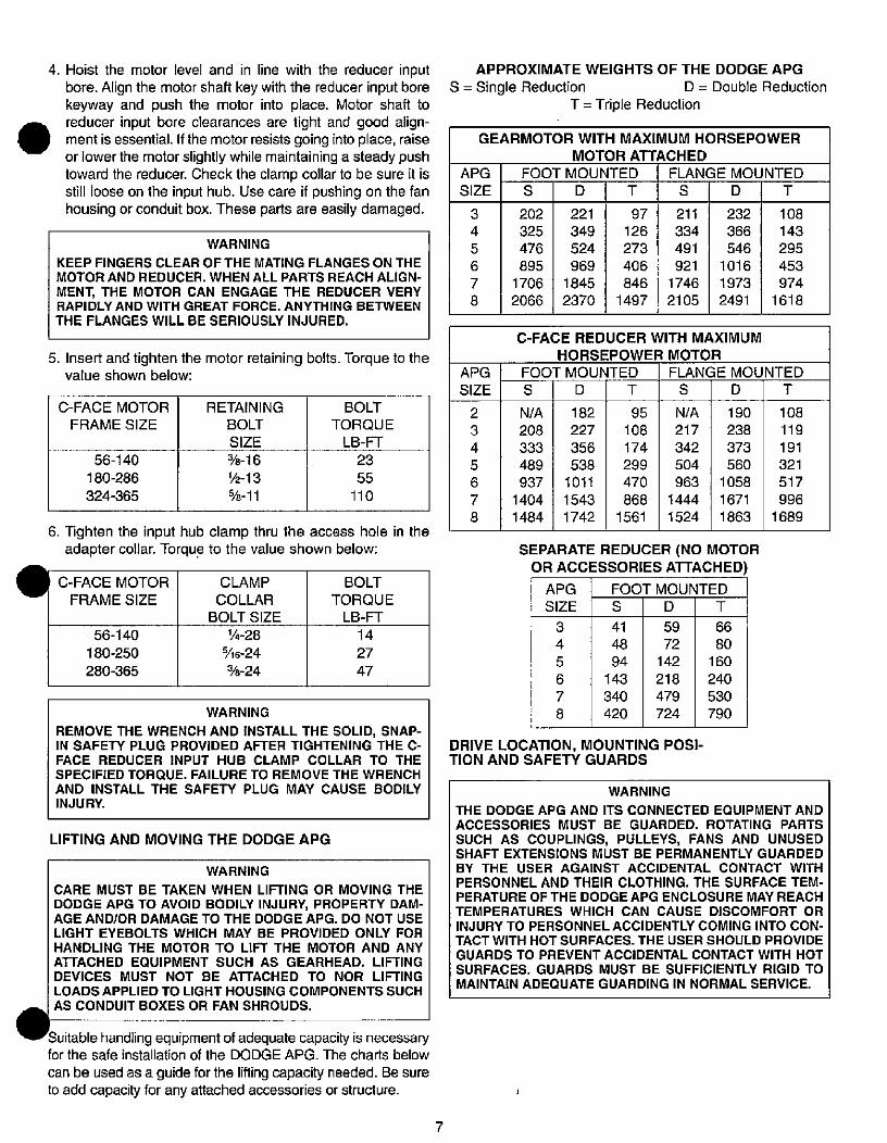
.
4. Hoist the motor level and in line with the reducer input
bore. Align the motor shaft key with the reducer input bore
keyway and push the motor into place. Motor shaft to
reducer input bore clearances are tight and good align-ment is essential. If the motor resists going into place, raise
or lower the motor slightly while maintaining a steady push
toward the reducer. Check the clamp collar to be sure it is
still loose on the input hub. Use care if pushing on the fanhousing or conduit box. These parts are easily damaged.
WARNING
KEEP FINGERS CLEAR OF THE MATING FLANGES ON THE
MOTOR AND REDUCER. WHEN ALL PARTS REACH ALIGN-
MENT, THE MOTOR CAN ENGAGE THE REDUCER VERYRAPIDLY AND WITH GREAT FORCE. ANYTHING BETWEEN
THE FLANGES WILL BE SERIOUSLY INJURED.
5. Insert and tighten the motor retaining bolts. Torque to thevalue shown below:
C-FACE MOTOR
FRAME SIZE
56-140
180-286
324-365
RETAINING
BOLT
SIZE
BOLT
TORQUE
LB-FT
23
55
110
6. Tighten the input hub clamp thru the access hole in the
adapter collar. Torque to the value shown below:
C-FACE MOTOR
FRAME SIZE
56-140
180-250
280-365
%-161/2-13
%-11
CLAMP
COLLAR
BOLT SIZE
1/4-28
5/16-24
%-24
BOLT
TORQUE
LB-FT
14
27
47
WARNING
REMOVE THE WRENCH AND INSTALL THE SOLID, SNAP-IN SAFETY PLUG PROVIDED AFTER TIGHTENING THE C-
FACE REDUCER INPUT HUB CLAMP COLLAR TO THE
SPECIFIED TORQUE. FAILURE TO REMOVE THE WRENCH
AND INSTALL THE SAFETY PLUG MAY CAUSE BODILY
INJURY.
LIFTING AND MOVING THE DODGE APG
WARNING
CARE MUST BE TAKEN WHEN LIFTING OR MOVING THE
DODGE APG TO AVOID BODILY INJURY, PROPERTY DAM-AGE AND/OR DAMAGE TO THE DODGE APG. DO NOT USE
LIGHT EYEBOLTS WHICH MAY BE PROVIDED ONLY FOR
HANDLING THE MOTOR TO LIFT THE MOTOR AND ANY
ATTACHED EQUIPMENT SUCH AS GEARHEAD. LIFTING
DEVICES MUST NOT BE ATTACHED TO NOR LIFTING
LOADS APPLIED TO LIGHT HOUSING COMPONENTS SUCH
AS CONDUIT BOXES OR FAN SHROUDS.
Suitable handling equipment of adequate capacity is necessaryfor the safe installation of the DODGE APG. The charts below
can be used as a guide for the lifting capacity needed. Be sureto add capacity for any attached accessories or structure.
7
3
4
5
6
7
8
202
325
476
895
1706
2066
APPROXIMATE WEIGHTS OF THE DODGE APG
S = Single Reduction D = Double Reduction
T = Triple Reduction
APG
SIZE
2
3
4
5
6
7
8
GEARMOTOR WITH MAXIMUM HORSEPOWER
MOTOR ATTACHED
APG FOOT MOUNTED FLANGE MOUNTED
SIZESDTSDT
N/A
208
333
489
937
1404
1484
3
4
5
6
7
8
221
349
524
969
1845
2370
182
227
356
538
1011
1543
1742
41
48
94
143
340
420
97
126
273
406
846
1497
C-FACE REDUCER WITH MAXIMUM
HORSEPOWER MOTOR
FOOT MOUNTED FLANGE MOUNTED
DTSDT
95
108
174
299
470
868
1561
SEPARATE REDUCER (NO MOTOR
OR ACCESSORIES ATTACHED)
APG FOOT MOUNTED
SIZE S D T
DRIVE LOCATION, MOUNTING POSI-TION AND SAFETY GUARDS
211
334
491
921
1746
2105
N/A
217
342
504
963
1444
1524
66
80
160
240
530
790
232
366
546
1016
1973
2491
108
143
295
453
974
1618
WARNING
THE DODGE APG AND ITS CONNECTED EQUIPMENT AND
ACCESSORIES MUST BE GUARDED. ROTATING PARTS
SUCH AS COUPLINGS, PULLEYS, FANS AND UNUSEDSHAFT EXTENSIONS MUST BE PERMANENTLY GUARDED
BY THE USER AGAINST ACCIDENTAL CONTACT WITH
PERSONNEL AND THEIR CLOTHING. THE SURFACE TEM-
PERATURE OF THE DODGEAPG ENCLOSURE MAY REACH
TEMPERATURES WHICH CAN CAUSE DISCOMFORT OR
INJURY TO PERSONNEL ACCIDENTLY COMING INTO CON-
TACT WITH HOT SURFACES. THE USER SHOULD PROVIDE
GUARDS TO PREVENT ACCIDENTAL CONTACT WITH HOT
SURFACES. GUARDS MUST BE SUFFICIENTLY RIGID TO
MAINTAIN ADEQUATE GUARDING IN NORMAL SERVICE.
59
72
142
218
479
724
190
238
373
560
1058
1671
1863
108
119
191
321
517
996
1689
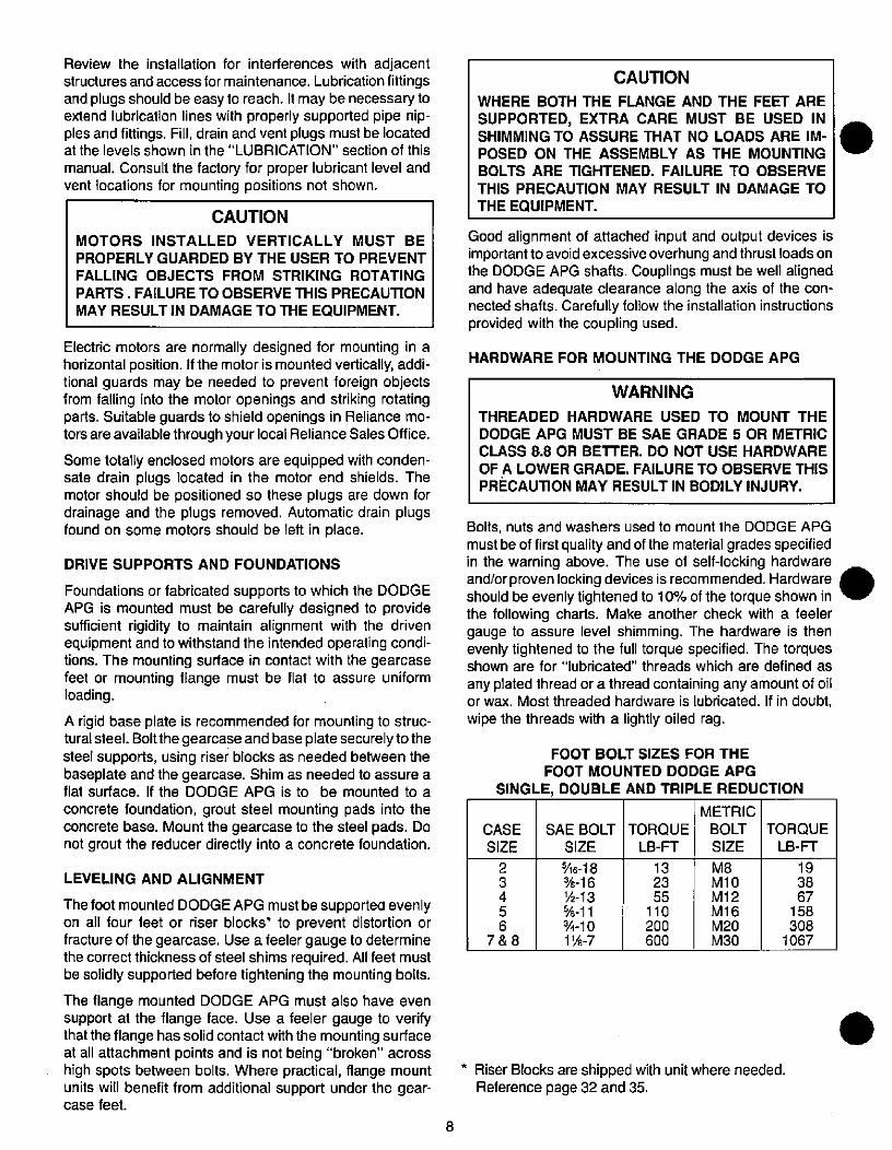
Review the installation for interferences with adjacent
structures and access for maintenance. Lubrication fittingsand plugs should be easy to reach. It may be necessary toextend lubrication lines with properly supported pipe nip-ples and fittings. Fill, drain and vent plugs must be locatedat the levels shown in the "LUBRICATION" section of this
manual. Consult the factory for proper lubricant level andvent locations for mounting positions not shown.
CAUTION
MOTORS INSTALLED VERTICALLY MUST BE
PROPERLY GUARDED BY THE USER TO PREVENT
FALLING OBJECTS FROM STRIKING ROTATING
PARTS. FAILURE TO OBSERVE THIS PRECAUTION
MAY RESULT IN DAMAGE TO THE EQUIPMENT.
Electric motors are normally designed for mounting in ahorizontal position. If the motor is mounted vertically, addi-tional guards may be needed to prevent foreign objectsfrom falling into the motor openings and striking rotatingparts. Suitable guards to shield openings in Reliance mo-tors are available through your local Reliance Sales Office.
Some totally enclosed motors are equipped with conden-sate drain plugs located in the motor end shields. Themotor should be positioned so these plugs are down fordrainage and the plugs removed. Automatic drain plugsfound on some motors should be left in place.
DRIVE SUPPORTS AND FOUNDATIONS
Foundations or fabricated supports to which the DODGEAPG is mounted must be carefully designed to providesufficient rigidity to maintain alignment with the drivenequipment and to withstand the intended operating condi-tions. The mounting surface in contact with the gearcasefeet or mounting flange must be flat to assure uniformloading.
A rigid base plate is recommended for mounting to struc-turalsteel. Boltthegearcase and base plate securelytothe
steel supports, using riser blocks as needed between thebaseplate and the gearcase. Shim as needed to assure aflat surface. If the DODGE APG is to be mounted to a
concrete foundation, grout steel mounting pads into theconcrete base. Mount the gearcase to the steel pads. Donot grout the reducer directly into a concrete foundation.
LEVELING AND ALIGNMENT
The foot mounted DODGE APG must be supported evenlyon all four feet or riser blocks* to prevent distortion orfracture of the gearcase. Use a feeler gauge to determinethe correct thickness of steel shims required. All feet mustbe solidly supported before tightening the mounting bolts.
The flange mounted DODGE APG must also have evensupport at the flange face. Use a feeler gauge to verifythat the flange has solid contact with the mounting surfaceat all attachment points and is not being "broken" acrosshigh spots between bolts. Where practical, flange mountunits will benefit from additional support under the gear-case feet.
8
*16-18%-16
1/2-13%-11%-101 8-7
CAUTION
WHERE BOTH THE FLANGE AND THE FEET ARE
SUPPORTED, EXTRA CARE MUST BE USED INSHIMMING TO ASSURE THAT NO LOADS ARE IM-
POSED ON THE ASSEMBLY AS THE MOUNTING
BOLTS ARE TIGHTENED. FAILURE TO OBSERVE
THIS PRECAUTION MAY RESULT IN DAMAGE TO
THE EQUIPMENT.
Good alignment of attached input and output devices isimportant to avoid excessive overhung and thrust loads onthe DODGE APG shafts. Couplings must be well alignedand have adequate clearance along the axis of the con-nected shafts. Carefully follow the installation instructionsprovided with the coupling used.
HARDWARE FOR MOUNTING THE DODGE APG
WARNING
THREADED HARDWARE USED TO MOUNT THE
DODGE APG MUST BE SAE GRADE 5 OR METRIC
CLASS 8.8 OR BETTER. DO NOT USE HARDWARE
OF A LOWER GRADE. FAILURE TO OBSERVE THIS
PRECAUTION MAY RESULT IN BODILY INJURY.
Bolts, nuts and washers used to mount the DODGE APG
must be of first quality and of the material grades specifiedin the warning above. The use of self-locking hardwareand/orproven locking devices is recommended. Hardwareshould be evenly tightened to 10% of the torque shown inthe following charts. Make another check with a feelergauge to assure level shimming. The hardware is thenevenly tightened to the full torque specified. The torquesshown are for "lubricated" threads which are defined as
any plated thread or a thread containing any amount of oilor wax. Most threaded hardware is lubricated. If in doubt,
wipe the threads with a lightly oiled rag.
FOOT BOLT SIZES FOR THE
FOOT MOUNTED DODGE APG
SINGLE, DOUBLE AND TRIPLE REDUCTION
METRIC
CASE SAE BOLT TORQUE BOLT TORQUE
SIZE SIZE LB-FT SIZE LB-FT
2
3
4
56
7&8
132355
110200
600
* Riser Blocks are shipped with unit where needed.Reference page 32 and 35.
M8
M10M12
M16M20M30
19
3867
158
3081067
.
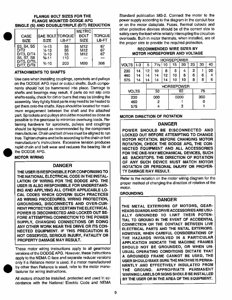
FLANGE BOLT SIZES FOR THE
FLANGE MOUNTED DODGE APG
SINGLE (S) AND DOUBLE/TRIPLE (D/T) REDUCTION
CASE
SIZE
53,54,55D/1-2
D/T3, D/T4S6,57,58D/T5, D/T6,D/17,[)/T8
%-13lk-131/2-13%-11
3/1-10
SAE BOLT TORQUESIZE LB-FT
ATrACHMENTS TO SHAFTS
55
5555
110
200
METRIC
BOLT
SIZE
M12M12M12
M20
TORQUE
LB-FT
308
Use care when installing couplings, sprockets and pulleyson the DODGE APG input or output shafts. Such compo-nents should not be hammered into place. Damage toshafts and bearings may result. If parts do not slip ontoshafts easily, check fordirt or burrsthat may be binding theassembly. Very tightly fitted parts may need to be heated toget them onto the shafts. Keys should be located for maxi-mum engagement between the shaft and the attachedpart. Sprockets and pulleys should be mounted as close aspossible to the gearcase to minimize overhung loads. Re-taining hardware for sprockets, pulleys and couplingsshould be tightened as recommended by the componentmanufacturer. Chain and belt drives must be aligned to runtrue. Tighten chains and belts according to the chain or beltmanufacturer's instructions. Excessive tension producesrapid chain and belt wear and reduces the bearing life ofthe DODGE APG.
MOTOR WIRING
DANGER
THE USER IS RESPONSIBLE FOR CONFORMING TO
THE NATIONAL ELECTRICAL CODE IN THE INSTAL-
LATION OF WIRING FOR THE DODGE APG. THE
USER IS ALSO RESPONSIBLE FOR UNDERSTAND-ING AND APPLYING ALL OTHER APPLICABLE LO-
CAL CODES WHICH GOVERN SUCH PRACTICES
AS WIRING PROCEDURES, WIRING PROTECTION,GROUNDING, DISCONNECTS AND OVER-CUR-RENT PROTECTION. BE CERTAIN THE ELECTRICAL
POWER IS DISCONNECTED AND LOCKED OUT BE-
FORE ATTEMPTING CONNECTION TO THE POWER
SUPPLY, CHANGING CONNECTIONS OR DOINGANY OTHER WORK NEAR THE DRIVE OR ITS CON-
NECTED EQUIPMENT. IF THIS PRECAUTION IS
NOT OBSERVED, SERIOUS INJURY, FATALITY ORPROPERTY DAMAGE MAY RESULT.
These motor wiring instructions apply to all gearmotorversions of the DODGE APG. However, these instructions
apply to the NEMA C-face and separate reducer versionsonly if a Reliance motor is used. If a motor manufacturedby other than Reliance is used, refer to the motor manu-facturer for wiring instructions.
All motors should be installed, protected and used in ac-cordance with the National Electric Code and NEMA
67
6767
9
VOLTS
230
460
575
12
14
14
Standard publication MG-2. Connect the. motor to thepower supply according to the diagram in the conduit boxor on the motor dataplate. Fuses, thermal cutouts andother protective devices should be of the correct size tosafelycarrythe load while reliably interruptinglhe circuitonoverloads. Built-in motor thermals, when installed, are of
the proper size to provide the required protection.
RECOMMENDED WIRE SIZES BYMOTOR HORSEPOWER AND VOLTAGE
1-3
VOLTS
230
460
575
14
14
14
5 71/2
10
14
14
000
2
4
8
12
14
HORSEPOWER
10 15 20
6
10
10
4
8
10
HORSEPOWER
50 60
MOTOR DIRECTION OF ROTATION
25
2
6
8
30
300
0
1
1
6
8
75
DANGER
POWER SHOULD BE DISCONNECTED AND
LOCKED OUT BEFORE ATTEMPTING TO CHANGE
MOTOR ROTATION. BEFORE CHANGING MOTOR
ROTATION, CHECK THE DODGE APG, THE CON-NECTED EQUIPMENT AND ALL ACCESSORIES
FOR THE ONE-WAY MECHANICAL DEVICES, SUCHAS BACKSTOPS. THE DIRECTION OF ROTATIONOF ANY SUCH DEVICE MUST MATCH MOTOR
ROTATION OR PERSONAL INJURY OR PROPER-
TY DAMAGE MAY RESULT.
40
Refer to the notation on the motor wiring diagram for theproper method of changing the direction of rotation of themotor.
GROUNDING
DANGER
THE METAL EXTERIORS OF MOTORS, GEAR-HEADS GUARDS AND DRIVE ACCESSORIES ARE USU-ALLY GROUNDED TO LIMIT THEIR POTEN-TIAL TO GROUND IN THE EVENT OF ACCIDENTAL
CONNECTION OR THE CONTACT BETWEEN LIVEELECTRICAL PARTS AND THE METAL EXTERIORS.
HOWEVER, WHEN CAREFUL CONSIDERATIONS OFTHE HAZARDS INVOLVED IN A PARTICULAR
APPLICATION INDICATE THE MACHINE FRAMES
SHOULD NOT BE GROUNDED, OR WHEN UN-USUAL OPERATING CONDITIONS DICTATE THATA GROUNDED FRAME CANNOT BE USED, THE
USER SHOULD MAKE SURE THE MACHINE IS PERMA-NENTLY AND EFFECTIVELY INSULATED FROMTHE GROUND. APPROPRIATE PERMANENT
WARNING LABELS OR SIGNS SHOULD BE INSTALLED
BY THE USER OR IN THE AREA OF THE EQUIPMENT.
0000
1
3
00
4
6
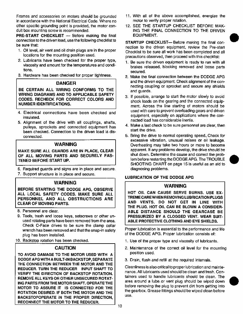
Frames and accessories on motors should be groundedin accordance with the National Electrical Code. Where no
other specific grounding point is provided, the motor con-duit box mounting screw is recommended.
PRE-START CHECKLIST - Before making the finalconnectiontothe driven load, use the following checklisttobe sure that:
1. Oil level, air vent and oil drain plugs are in the properlocations for the mounting position used.
2. Lubricants have been checked for the proper type,
viscosity and amount for the temperatures and condi-tions.
3. Hardware has been checked for proper tightness.
DANGER
BE CERTAIN ALL WIRING CONFORMS TO THE
WIRING DIAGRAMS AND TO APPLICABLE SAFETY
CODES. RECHECK FOR CORRECT COLORS AND
NUMBER IDENTIFICATIONS.
4. Electrical connections have been checked and
insulated.
5. Alignment of the drive with all couplings, shafts,pulleys, sprockets and connected equipment hasbeen checked. Connection to the driven load is dis-
connected.
WARNING
MAKE SURE ALL GUARDS ARE IN PLACE, CLEAROF ALL MOVING PARTS AND SECURELY FAS-
TENED BEFORE START UP.
6. Required guards and signs are in place and secure.
7. Support structure is in place and secure.
WARNING
BEFORE STARTING THE DODGE APG, OBSERVEALL LOCAL SAFETY CODES. MAKE SURE ALL
PERSONNEL AND ALL OBSTRUCTIONS ARE
CLEAR OF MOVING PARTS.
8. Personnel are clear.
9. Tools, trash and loose keys, setscrews or other un-used rotating parts have been removed from the area.Check C-Face drives to be sure the clamp collarwrench has been removed and that the snap-in safetyplug has been installed.
10. Backstop rotation has been checked.
CAUTION
TO AVOID DAMAGE TO THE MOTOR USED WITH A
DODGE APG WITH A BUILT-IN BACKSTOP, SEPARATETHE CONNECTION BETWEEN THE MOTOR AND THE
REDUCER. TURN THE REDUCER INPUT SHAFT TO
VERIFY THE DIRECTION OF BACKSTOP ROTATION.
REMOVE ALL KEYS OR OTHER UNSECURED ROTAT-
ING PARTS FROM THE MOTOR SHAFT. OPERATE THE
MOTOR TO ASSURE IT IS CONNECTED FOR THE
ROTATION DESIRED. IF BOTH THE MOTOR AND THE
BACKSTOPOPERATE IN THE PROPER DIRECTION,RECONNECT THE MOTOR TO THE REDUCER.
10
11. With all of the above accomplished, energize themotor to verify proper rotation.
12. SEE THE STARTUP CHECKLIST BEFORE MAK-
ING THE FINAL CONNECTION TO THE DRIVEN
EQUIPMENT.
STARTUP CHECKLIST- Before making the final con-nection to the driven equipment, review the Pre-startChecklist to be sure all work has been completed and allprecautions observed, then proceed with this checklist:
1. Be sure the driven equipment is ready to run with all
brakes released, blocking removed and loose partssecured.
2. Make the final connection between the DODGE APG
and the driven equipment. Check alignment of the con-necting coupling or sprocket and secure any shieldsand guards.
3. If possible, arrange to start the motor slowly to avoidshock loads on the gearing and the connected equip-ment. Across the line starting of motors should be
used with care to prevent overloading gears and drivenequipment, especially on applications where the con-nected load has considerable inertia.
4. Make a last check to be sure personnel are clear, thenstart the drive.
5. Bring the drive to normal operating speed.. Check forexcessive vibration, unusual noises or oil leakage.Overheating may take two hours or more to becomeapparent. If any problems develop, the drive should be
shut down. Determine the cause and correct the prob-
lem before restarting the DODGE APG. The TROUBLE SHOOTING CHART on page 15 is useful as an aid to
diagnosing problems.
LUBRICATION OF THE DODGE APG
WARNING
HOT OIL CAN CAUSE SERVE BURNS. USE EX-
TREMECAREWHENREMOVINGLUBRICATIONPLUGS
AND VENTS. DO NOT GET IN LINE WITH
THE PLUG. HOT OIL CAN BE BLOWN A CONSIDER-
ABLE DISTANCE SHOULD THE GEARCASE BE
PRESSURIZED BY A CLOGGED VENT. WEAR SUIT-
ABLE PROTECTIVE CLOTHING AND EYE SHIELDS.
Proper lubrication is essential to the performance and lifeof the DODGE APG. Proper lubrication consists of:
1. Use of the proper type and viscosity of lubricants.
2. Maintenance of the correct oil level for the mountingposition used.
3. Drain, flush and refill at the required intervals.
Cleanliness is also critical to proper lubrication and mainte-nance. All lubricants used should be clean and fresh. Con-
tainers used to handle lubricants should be clean. The
area around a lube. or vent plug should be wiped down .before removing the plug to prevent dirt from getting intothe gearbox. Grease fittings should be wiped clean beforeuse.
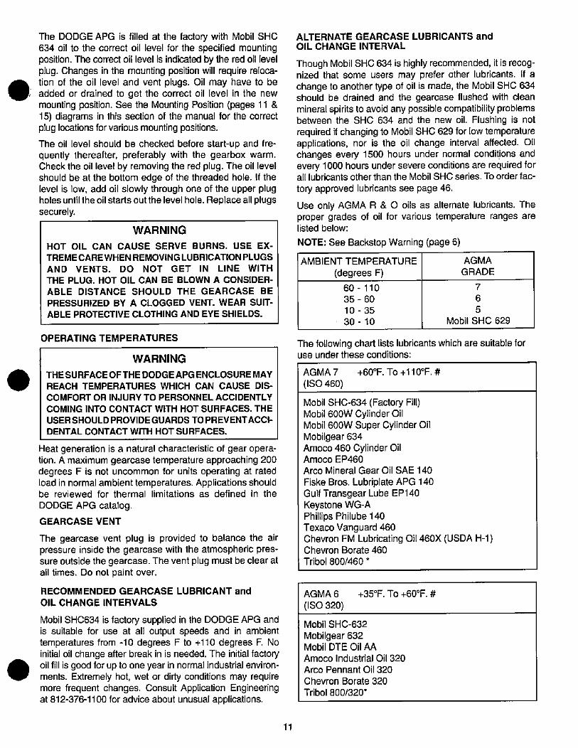
The DODGE APG is filled at the factory with Mobil SHC634 oil to the correct oil level for the specified mountingposition. The correct oil level is indicated by the red oil levelplug. Changes in the mounting position will require reloca-
AIIA tion of the oil level and vent plugs. Oil may have to be, added or drained to get the correct oil level in the new
mounting position. See the Mounting Position (pages 11 &15) diagrams in this section of the manual for the correctplug locations for various mounting positions.
The oil level should be checked before start-up and fre-quently thereafter, preferably with the gearbox warm.Check the oil level by removing the red plug. The oil levelshould be at the bottom edge of the threaded hole. If thelevel is low, add oil slowly through one of the upper plugholes until the oil starts out the level hole. Replace all plugssecurely.
WARNING
HOT OIL CAN CAUSE SERVE BURNS. USE EX-
TREMECAREWHENREMOVINGLUBRICATIONPLUGS
AND VENTS. DO NOT GET IN LINE WITH
THE PLUG. HOT OIL CAN BE BLOWN A CONSIDER-
ABLE DISTANCE SHOULD THE GEARCASE BE
PRESSURIZED BY A CLOGGED VENT. WEAR SUIT-
ABLE PROTECTIVE CLOTHING AND EYE SHIELDS.
OPERATING TEMPERATURES
WARNING
THE SURFACEOFTHE DODGE APG ENCLOSURE MAY
REACH TEMPERATURES WHICH CAN CAUSE DIS-
COMFORT OR INJURY TO PERSONNEL ACCIDENTLY
COMING INTO CONTACT WITH HOT SURFACES. THE
USERSHOULDPROVIDEGUARDS TOPREVENTACCI-
DENTAL CONTACT WITH HOT SURFACES.
Heat generation is a natural characteristic of gear opera-tion. A maximum gearcase temperature approaching 200degrees F is not uncommon for units operating at ratedload in normal ambient temperatures. Applications shouldbe reviewed for thermal limitations as defined in the
DODGE APG catalog.
GEARCASE VENT
The gearcase vent plug is provided to balance the airpressure inside the gearcase with the atmospheric pres-sure outside the gearcase. The vent plug must be clear atall times. Do not paint over.
RECOMMENDED GEARCASE LUBRICANT and
OIL CHANGE INTERVALS
Mobil SHC634 is factory supplied in the DODGE APG andis suitable for use at all output speeds and in ambienttemperatures from -10 degrees F to +110 degrees F. Noinitial oil change after break in is needed. The initial factory
oil fill is good for up to one year in normal industrial environ-ments. Extremely hot, wet or dirty conditions may requiremore frequent changes. Consult Application Engineeringat 812-376-1100 for advice about unusual applications.
11
ALTERNATE GEARCASE LUBRICANTS andOIL CHANGE INTERVAL
Though Mobil SHC 634 is highly recommended, it is recog-nized that some users may prefer other lubricants. If achange to another type of oil is made, the Mobil SHC 634should be drained and the gearcase flushed with cleanmineral spirits to avoid any possible compatibility problemsbetween the SHC 634 and the new oil. Flushing is notrequired if changing to Mobil SHC 629 for low temperatureapplications, nor is the oil change interval affected. Oilchanges every 1500 hours under normal conditions andevery 1000 hours under severe conditions are required forall lubricants other than the Mobil SHC series. To order fac-
tory approved lubricants see page 46.
Use only AGMA R&0 oils as alternate lubricants. Theproper grades of oil for various temperature ranges arelisted below:
NOTE: See Backstop Warning (page 6)
AMBIENT TEMPERATURE
(degrees F)
60-110
35 - 60
10 - 35
-30 - 10
AGMA
GRADE
7
6
5
Mobil SHC 629
The following chart lists lubricants which are suitable foruse under these conditions:
AGMA 7 +60°F. To +110°F. #
(ISO 460)
Mobil SHC-634 (Factory Fill)Mobil 600W Cylinder OilMobil 600W Super Cylinder OilMobilgear 634Amoco 460 Cylinder OilAmoco EP460
Arco Mineral Gear Oil SAE 140
Fiske Bros. Lubriplate APG 140Gulf Transgear Lube EP140Keystone WG-APhillips Philube 140Texaco Vanguard 460Chevron FM Lubricating Oil 460X (USDA H-1)Chevron Borate 460
Tribol 800/460 *
AGMAG +35°F. To +60°F. #
(ISO 320)
Mobil SHC-632
Mobilgear 632Mobil DTE Oil AA
Amoco Industrial Oil 320
Arco Pennant Oil 320
Chevron Borate 320
Tribol 800/320*
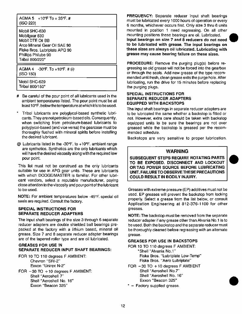
AGMA 5 +10°F To + 35°F. #
(ISO 220)
Mobil SHC-630
Mobilgear 630Mobil DTE Oil BB
Arco Mineral Gear Oil SAE 90
Fiske Bros. Lubriplate APG 90Phillips Philube 90Tribol 800/220*
AGMA 4 -30°F. To +10°F. # @
(ISO 150)
'Mobil SHC-629
Tribol 800/150*
# Be careful of the pour point of all lubricants used in theambient temperatures listed. The pour point must be atleast 10°F. belowthetemperatureatwhich itistobe used.
* Tribol lubricants are polyglycol-based synthetic lubri-cants. They are not petroleum-based oils. Consequently,when switching from petroleum-based lubricants topolyglycol-based (and vice versa) the gearcase must bethoroughly flushed with mineral spirits before installingthe desired lubricant.
@ Lubricants listed in the -30°F. to +10°F. ambient rangeare synthetics. Synthetics are the only lubricants whichwill have the desired viscosity along with the required lowpour point.
This list must not be construed as the only lubricantssuitable for use in APG gear units. These are lubricantswith which DODGE/MASTER is familiar. For other lubri-
cant vendors, select a reputable manufacturer, payingclose attention to the viscosity and pour point of the lubricantto be used.
NOTE: For ambient temperatures below -45°F. special oilseals are required. Consult the factory.
SPECIAL INSTRUCTIONS FOR
SEPARATE REDUCER ADAPTERS
The input shaft bearings of the size 3 through 6 separate
reducer adapters are double shielded ball bearings pre-packed at the factory with a lithium based, mineral oilgrease. Size 7 and 8 separate reducer adapter bearingsare of the tapered roller type and are oil lubricated.
GREASES FOR USE IN
SEPARATE REDUCER INPUT SHAFT BEARINGS:
FOR 10 TO 110 degrees F AMBIENT:Chevron "SRI-2"
Exxon "Unirex N-2"
FOR -30 TO +10 degrees F AMBIENT:Shell "Aeroshell 7"
Shell "Aeroshell No. 16"
Exxon "Beacon 325
12
FREQUENCY: Separate reducer input shaft bearingsmust be lubricated every 1000 hours of operation or every6 months, whichever occurs first. Only size 3 thru 6 unitsmounted in position 1 need regreasing. On all othermounting positions these bearings are oil. Lubricated.Input bearings on size 7 and 8 reducers do not needto be lubricated with grease. The input bearings onthese sizes are always oil lubricated. Lubricating withgrease may cause bearing failure on these sizes.
PROCEDURE: Remove the purging plug(s) before re-greasing so old grease will not be forced into the gearboxor through the seals. Add new grease of the type recom-mended until fresh, clean grease exits the purgehole. Afterlubricating, run the drive for 15 minutes before replacingthe purging plugs.
SPECIAL INSTRUCTIONS FOR
SEPARATE REDUCER ADAPTERS
EQUIPPED WITH BACKSTOPS
The input shaft bearings in separate reducer adapters areto be lubricated the same whether a backstop is fitted ornot. However, extra care should be taken with backstop
equipped units to be sure the bearings are not over
greased while the backstop is greased per the recom-mended schedule.
Backstops are very sensitive to proper lubrication.
WARNING
SUBSEQUENT STEPS REQUIRE ROTATING PARTS
TO BE EXPOSED. DISCONNECT AND LOCKOUT
OR TAG POWER SOURCE BEFORE LUBRICATING
UNIT. FAILURETO OBSERVETHESE PRECAUTIONS
COULD RESULT IN BODILY INJURY.
Greases with extreme pressure (EP) additives must not beused. EP greases will prevent the backstop from lockingproperly. Select a grease from the list below, or consultApplication Engineering at 812-376-1100 for othergreases.
NOTE: The backstop must be removed from the separate
reducer adapter if any grease other than Alvania No.1 is tobe used. Both the backstop and the separate reducer must
be thoroughly cleaned before regreasing with an alternategrease.
GREASES FOR USE IN BACKSTOPS
FOR 10 TO 110 degrees F AMBIENT:*Shell "Alvania No.1"
Fiske Bros. "Lubriplate Low-Temp"Fiske Bros. "Aero Lubriplate"
FOR - 30 TO + 10 degrees F AMBIENTShell "Aeroshell No.7"
Shell "Aeroshell No. 16"
Exxon "Beacon 325"
* = Factory supplied grease.
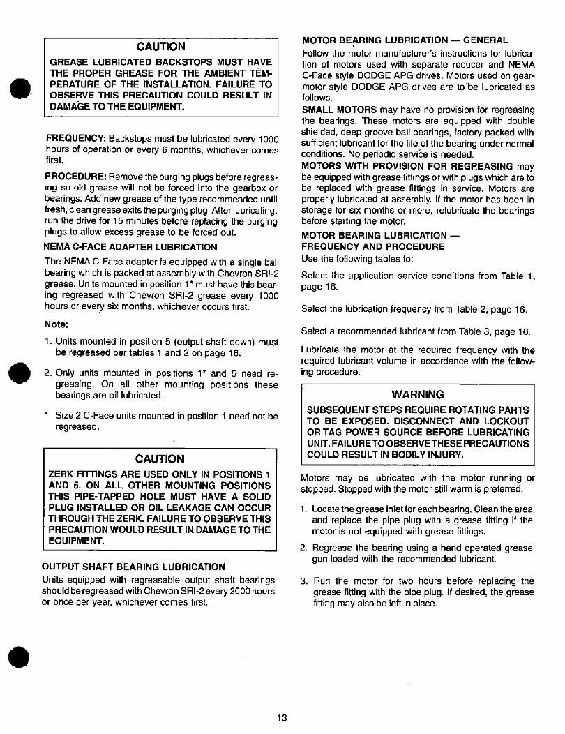
CAUTION
GREASE LUBRICATED BACKSTOPS MUST HAVE
THE PROPER GREASE FOR THE AMBIENT TEM-
PERATURE OF THE INSTALLATION. FAILURE TO
OBSERVE THIS PRECAUTION COULD RESULT IN
DAMAGE TO THE EQUIPMENT.
FREQUENCY: Backstops must be lubricated every 1000hours of operation or every 6 months, whichever comesfirst.
PROCEDURE: Remove the purging plugs before regreas-ing so old grease will not be forced into the gearbox orbearings. Add new grease of the type recommended untilfresh, clean greaseexitsthe purging plug. Afterlubricating,run the drive for 15 minutes before replacing the purgingplugs to allow excess grease to be forced out.NEMA C-FACE ADAPTER LUBRICATION
The NEMA C-Face adapter is equipped with a single ballbearing which is packed at assembly with Chevron SRI-2grease. Units mounted in position 1 * must have this bear-ing regreased with Chevron SRI-2 grease every 1000hours or every six months, whichever occurs first.
Note:
1. Units mounted in position 5 (output shaft down) mustbe regreased per tables 1 and 2 on page 16.
2. Only units mounted in positions 1 * and 5 need re-greasing. On all other mounting positions thesebearings are oil lubricated.
* Size 2 C-Face units mounted in position 1 need not beregreased.
CAUTION
ZERK FITTINGS ARE USED ONLY IN POSITIONS 1
AND 5. ON ALL OTHER MOUNTING POSITIONSTHIS PIPE-TAPPED HOLE MUST HAVE A SOLID
PLUG INSTALLED OR OIL LEAKAGE CAN OCCURTHROUGH THE ZERK. FAILURE TO OBSERVE THIS
PRECAUTION WOULD RESULT IN DAMAGE TO THE
EQUIPMENT.
OUTPUT SHAFT BEARING LUBRICATION
Units equipped with regreasable output shaft bearingsshould be regreased with Chevron SRI-2 every 2006 hoursor once per year, whichever comes first.
13
MOTOR BEARING LUBRICATION - GENERAL
Follow the motor manufacturer's instructions for lubrica-
tion of motors used with separate reducer and NEMAC-Face style DODGE APG drives. Motors used on gear-motor style DODGE APG drives are to'be lubricated asfollows.
SMALL MOTORS may have no provision for regreasing
the bearings. These motors are equipped with doubleshielded, deep groove ball bearings, factory packed withsufficient lubricant for the life of the bearing under normalconditions. No periodic servibe is needed.MOTORS WITH PROVISION FOR REGREASING maybe equipped with grease fittings or with plugs which are tobe replaced with grease fittings in service. Motors areproperly lubricated at assembly. If the motor has been instorage for six months or more, relubricate the bearingsbefore starting the motor.
MOTOR BEARING LUBRICATION -
FREQUENCY AND PROCEDURE
Use the following tables to:
Select the application service conditions from Table 1,page 16.
Select the lubrication frequency from Table 2, page 16.
Select a recommended lubricant from Table 3, page 16.
Lubricate the motor at the required frequency with therequired lubricant volume in accordance with the follow-ing procedure.
WARNING
SUBSEQUENT STEPS REQUIRE ROTATING PARTS
TO BE EXPOSED. DISCONNECT AND LOCKOUT
OR TAG POWER SOURCE BEFORE LUBRICATING
UNIT. FAILURETO OBSERVE THESE PRECAUTIONSCOULD RESULT IN BODILY INJURY.
Motors may be lubricated with the motor running or
stopped. Stopped with the motor still warm is preferred.
1. Locatethe grease inlet for each bearing. Clean the areaand replace the pipe plug with a grease fitting if themotor is not equipped with grease fittings.
2. Regrease the bearing using a hand operated greasegun loaded with the recommended lubricant.
3. Run the motor for two hours before replacing thegrease fitting with the pipe plug. If desired, the greasefitting may also be left in place.
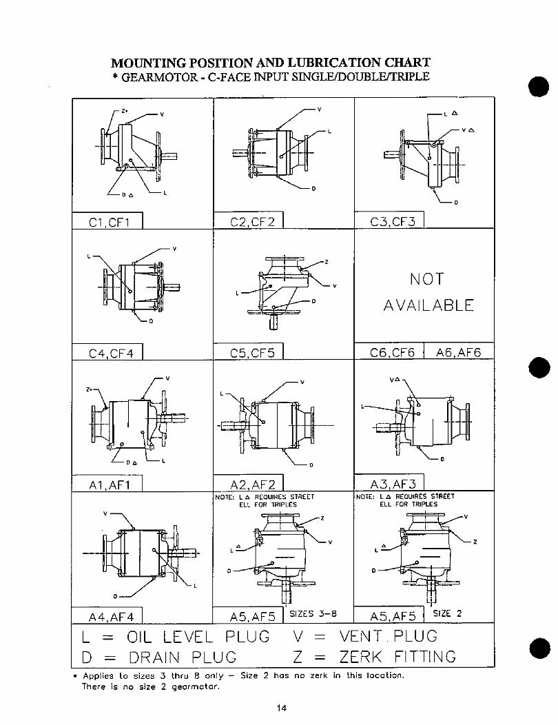
L
Z•
DB
M
L
MOUNTING POSITION AND LUBRICATION CHART
* GEARMOTOR - C-FACE INPUT SINGLE/DOUBLE/TRIPLE
Cl,CF1
C4,CF4
rvZ. In
-4 -4,%%
-_-t' 1 Y#£-Da L-L
Al,AFl
V--\
-EI-4 B
0-
* Applies to sizes 3 thru 8 only
There is no size 2 gearmotor.
V
Fl
3U
L
Iii
1iIIi
V
f --r«-i!.19=-- t_
-D
C2,CF2
L
9-
1
CS,CFS
...re
-V
L k L
-4-1U - \
L-D
D
L-V
A2,AF2NOTE: L a REOUIRES STREET
ELL FOR TRIPLES
%-2
lit. 1 -Va -,rr
L
Uj
A4,AF4 A5,AF5
L = OIL LEVEL PLUG
D = DRAIN PLUG
V
Z
SIZES 3-8
0
L
C3,CF3
La
NOT
AVAILABLE
C6,CF6
va
A6,AF6
va 7
L«1=5 8»-L-
u Lo
A3,AF3NOTE: L 6 REOUIRES STREET
ELL FOR TRIPLES
4
a
AS,AF5 SIZE 2
VENT. PLUG
ZERK FITTING
Size 2 has no zerk in this location.
14
4
J
1
Z
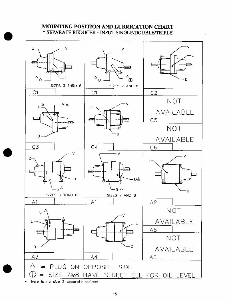
a
D
C1
L
MOUNTING POSITION AND LUBRICATION CHART
* SEPARATE REDUCER - INPUT SINGLE/DOUBLE/TRIPLE
Z-7 -V
1 LL
SIZES 3 THRU 6
C3
a
A1
A3
D
Fv
r 1 -_1=
LaD
SIZES 3 THRU 6
L
-b
V
8 D LLae
SIZES 7 AND 8
C1
r-V
L-7 -
IL-
LD
C4
A1
A4
* There is no size 2 separate reducer.
V
Da
SIZES 7 AND 8
V
-rU D
L
L*
C2
-V
L/'- L
-D
NOT
AVAILABLE
C5
NOT
AVAILABLE
C6
FV
L L---
LD
A2
NOT
AVAILABLE
A5
NOT
AVAILABLE
A6
PLUG ON OPPOSITE SIDE
SIZE 7&8 HAVE STREET ELL FOR OIL LEVEL
15
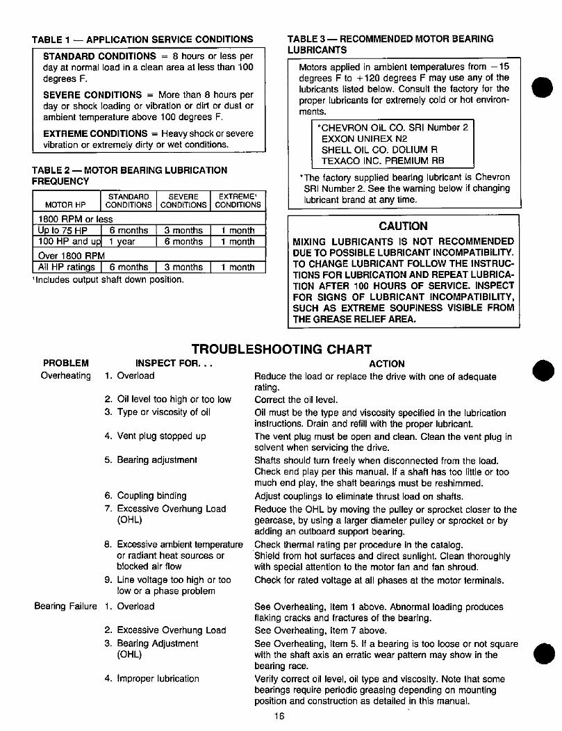
TABLE 1 - APPLICATION SERVICE CONDITIONS
STANDARD CONDITIONS = 8 hours or less perday at normal load in a clean area at less than 100degrees F.
SEVERE CONDITIONS = More than 8 hours perday or shock loading or vibration or dirt or dust orambient temperature above 100 degrees F.
EXTREME CONDITIONS = Heavy shock or severevibration or extremely dirty or wet conditions.
TABLE 2 - MOTOR BEARING LUBRICATION
FREQUENCY
MOTOR HP
STANDARD
CONDITIONS
SEVERE
CONDITIONS
1800 RPM or less
Up to 75 HP 6 months 3 months
100 HP and up 1 year 6 months
Over 1800 RPM
All HP ratings | 6 months 3 months1 Includes output shaft down position.
EXTREMEl
CONDITIONS
1 month
1 month
1 month
TROUBL
PROBLEM INSPECT FOR. . .
Overheating 1. Overload
2. Oil level too high or too low
3. Type or viscosity of oil
4. Vent plug stopped up
5. Bearing adjustment
6. Coupling binding
7. Excessive Overhung Load(OHL)
8. Excessive ambient temperatureor radiant heat sources or
blocked air flow
9. Line voltage too high or toolow or a phase problem
Bearing Failure 1. Overload
2. Excessive Overhung Load
3. Bearing Adjustment(OHL)
4. Improper lubrication
TABLE 3 - RECOMMENDED MOTOR BEARING
LUBRICANTS
Motors applied in ambient temperatures from - 15degrees F to +120 degrees F may use any of thelubricants listed below. Consult the factory for theproper lubricants for extremely cold or hot environ-ments.
*CHEVRON OIL CO. SRI Number 2
EXXON UNIREX N2
SHELL OIL CO. DOLIUM R
TEXACO INC. PREMIUM RB
*The factory supplied bearing lubricant is ChevronSRI Number 2. See the warning below if changinglubricant brand at any time.
CAUTION
MIXING LUBRICANTS IS NOT RECOMMENDED
DUE TO POSSIBLE LUBRICANT INCOMPATIBILITY.TO CHANGE LUBRICANT FOLLOW THE INSTRUC-
TIONS FOR LUBRICATION AND REPEAT LUBRICA-TION AFTER 100 HOURS OF SERVICE. INSPECT
FOR SIGNS OF LUBRICANT INCOMPATIBILITY,SUCH AS EXTREME SOUPINESS VISIBLE FROMTHE GREASE RELIEF AREA.
ESHOOTING CHART
ACTION Reduce the load or replace the drive with one of adequaterating.
Correct the oil level.
Oil must be the type and viscosity specified in the lubricationinstructions. Drain and refill with the proper lubricant.
The vent plug must be open and clean. Clean the vent plug insolvent when servicing the drive.
Shafts should turn freely when disconnected from the load.Check end play per this manual. If a shaft has too little or toomuch end play, the shaft bearings must be reshimmed.Adjust couplings to eliminate thrust load on shafts.Reduce the OHL by moving the pulley or sprocket closer to thegearcase, by using a larger diameter pulley or sprocket or byadding an outboard support bearing.
Check thermal rating per procedure in the catalog.Shield from hot surfaces and direct sunlight. Clean thoroughlywith special attention to the motor fan and fan shroud.
Check for rated voltage at all phases at the motor terminals.
See Overheating, Item 1 above. Abnormal loading producesflaking cracks and fractures of the bearing.
See Overheating, Item 7 above.
See Overheating, Item 5. If a bearing is too loose or not square *„
with the shaft axis an erratic wear pattern may show in thebearing race.
Verify correct oil level, oil type and viscosity. Note that somebearings require periodic greasing depending on mountingposition and construction as detailed in this manual.
16
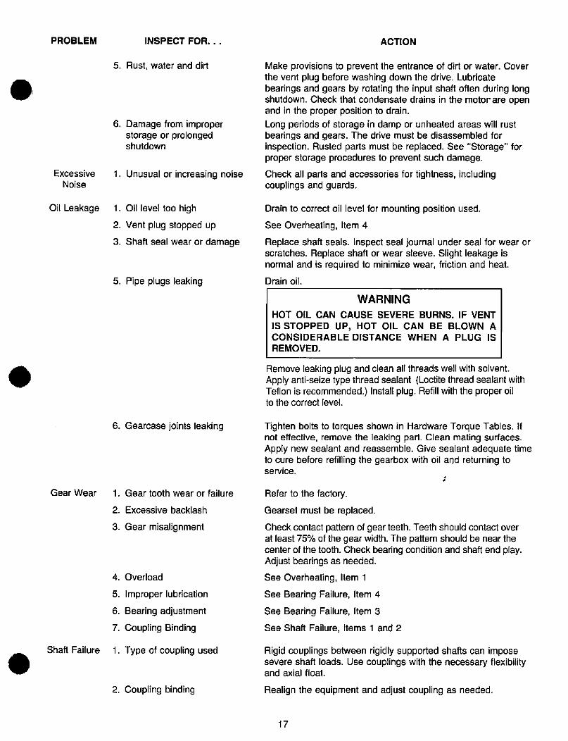
.
PROBLEM
Excessive
Noise
Oil Leakage
Gear Wear
INSPECT FOR. . .
5. Rust, water and dirt
6. Damage from improperstorage or prolongedshutdown
1. Unusual or increasing noise
1. Oil level too high
2. Vent plug stopped up
3. Shaft seal wear or damage
5. Pipe plugs leaking
6. Gearcase joints leaking
1. Gear tooth wear or failure
2. Excessive backlash
3. Gear misalignment
4. Overload
5. Improper lubrication
6. Bearing adjustment
7. Coupling Binding
Shaft Failure 1. Type of coupling used
2. Coupling binding
ACTION
Make provisions to prevent the entrance of dirt or water. Coverthe vent plug before washing down the drive. Lubricatebearings and gears by rotating the input shaft often during longshutdown. Check that condensate drains in the motor are openand in the proper position to drain.
Long periods of storage in damp or unheated areas will rustbearings and gears. The drive must be disassembled forinspection. Rusted parts must be replaced. See "Storage" forproper storage procedures to prevent such damage.
Check all parts and accessories for tightness, includingcouplings and guards.
Drain to correct oil level for mounting position used.
See Overheating, Item 4
Replace shaft seals. Inspect seal journal under seal for wear or
scratches. Replace shaft or wear sleeve. Slight leakage is
normal and is required to minimize wear, friction and heat.
Drain oil.
WARNING
HOT OIL CAN CAUSE SEVERE BURNS. IF VENT
IS STOPPED UP, HOT OIL CAN BE BLOWN ACONSIDERABLE DISTANCE WHEN A PLUG IS
REMOVED.
Remove leaking plug and clean all threads well with solvent.Apply anti-seize type thread sealant (Loctite thread sealant withTeflon is recommended.) Install plug. Refill with the proper oilto the correct level.
Tighten bolts to torques shown in Hardware Torque Tables. Ifnot effective, remove the leaking part. Clean mating surfaces.Apply new sealant and reassemble. Give sealant adequate timeto cure before refilling the gearbox with oil and returning toservice.
Refer to the factory.
Gearset must be replaced.
Check contact pattern of gear teeth. Teeth should contact overat least 75% of the gear width. The pattern should be near thecenter of the tooth. Check bearing condition and shaft end play.Adjust bearings as needed.
See Overheating, Item 1
See Bearing Failure, Item 4
See Bearing Failure, Item 3
See Shaft Failure, Items 1 and 2
Rigid couplings between rigidly supported shafts can imposesevere shaft loads. Use couplings with the necessary flexibilityand axial float.
Realign the equipment and adjust coupling as needed.
17
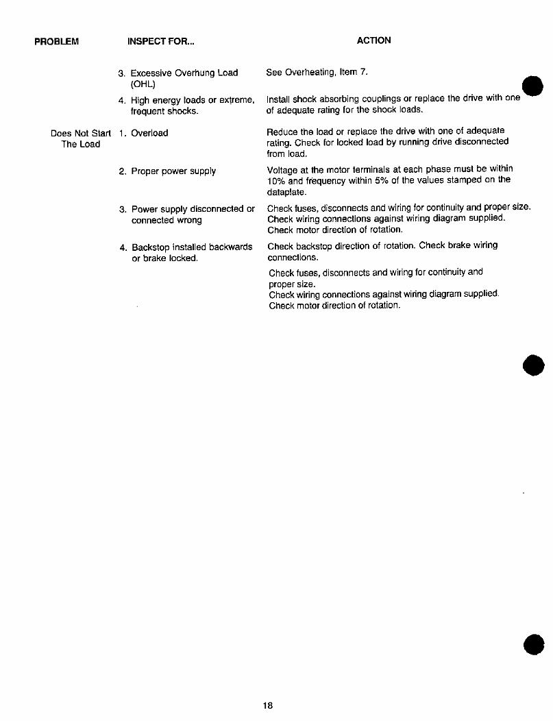
PROBLEM INSPECT FOR...
3. Excessive Overhung Load(OHL)
4. High energy loads or extreme,frequent shocks.
Does Not Start 1. Overload
The Load
2. Proper power supply
3. Power supply disconnected orconnected wrong
4. Backstop installed backwardsor brake locked.
18
ACTION
See Overheating, Item 7.
Install shock absorbing couplings or replace the drive with oneof adequate rating for the shock loads.
Reduce the load or replace the drive with one of adequaterating. Check for locked load by running drive disconnectedfrom load.
Voltage at the motor terminals at each phase must be within10% and frequency within 5% of the values stamped on thedataplate.
Check fuses, disconnects and wiring for continuity and proper size.Check wiring connections against wiring diagram supplied.Check motor direction of rotation.
Check backstop direction of rotation. Check brake wiringconnections.
Check fuses, disconnects and wiring for continuity andproper size.Check wiring connections against wiring diagram supplied.Check motor direction of rotation.
.
REPAIRING THE DODGE APG
REPAIRING THE DODGE APG
Unlikesomehighpowerdensitygearedproducts,the DODGEAPG is designed to be repaired. Lifting, pressing and pullingequipment and tools found in the average maintenance
department aresufficientto repairmostsizes ofthe DODGEAPG. However, many users wisely take advantage of themaintenance and repair assistance available from theirlocal DODGE Authorized Service Shop. The user shouldalso consider whether the drive should be overhauled or
replaced with a new drive. Small drives are often moreeconomically replaced than repaired. Repairs to drives stillunder warranty should be done only by an authorizedrepresentative of DODGE. See "WARRANTY," page 4.
REPLACEMENT PARTS
An adequate stock of renewal parts is an integral part of asound maintenance program to protect against costlydowntime. All parts in the DODGE APG are subject toexact specifications and tests necessary to assure properand safe performance, including many parts usually con-sidered "hardware." We recommend that the parts on thefollowing list be purchased only from Reliance Electric.To assure the continued reliable operation of yourDODGE APG:
1. Bearings 5. Shaft Seals
2. Threaded Fasteners 6. Lockrings3. Dowel Pins 7. Pinion Cross Pins
4. Shaft Keys 8. Clamp Collars
Replacement parts for your DODGE APG may be ob-tained from the nearest DODGE Parts Distributor or
through DODGE Renewal Parts at 803 297-4800. Nev-er attempt to duplicate or rework a part at a local machineshop. To help DODGE get you the parts you need, pleaseput the following information on your order:
1. All data from all nameplates on the drive, including thegearcase, motor and any accessories.
2. The reference numbers and descriptions of the partsbeing ordered as shown on the Parts List and the spe-cific illustration for your drive in this manual. Referenceto this manual number and to page numbers will help.
When selecting parts to replace, keep these suggestionsin mind:
1. If a gear has failed, the mating gear is very likely to bedamaged, though the damage may not be visible.Gears must be replaced in mating pairs. Keys, pins and/or threaded fasteners locking the gears to the shaftsmust be replaced with new parts.
2. Shaft seals should always be replaced with new sealswheneverthe gearbox is torn down for service. The sealjournal or sleeve should be inspected for wear ordamage and replaced if needed.
3. Should a gear or bearing fail, abrasive steel particlesareoftenthrownthroughoutthegearcase. Tremendousseparating forces may be generated, su fficient to bendshafts or fracture the gearcase. All bearings, gears,shafts and housing components should be carefullyinspected for damage.
19
4. Reliance Renewal Parts Department can preparekits including all of the parts likely to be needed toperform basic types of repairs. Inquire when placingyour parts order.
REPAIR PRACTICES
The DODGE APG is a precision device and must be treat-ed as such during repair. The work area should be cleanand free of clutter. Use the proper tools for the job at hand.Adequate lifting and pressing equipment must be availa-ble. Parts as removed should be placed where they will notbe nicked or otherwise damaged. Parts should be carefullyinspected as they are removed and before washing. Sometypes of damage and wear are more easily seen beforewashing. Parts should only be washed in clean solvent.Parts should again be inspected after washing.
WARNING
WHEN USING SOLVENTS, THE USER IS RESPON-SIBLE FOR UNDERSTANDING AND APPLYING ALLAPPLICABLE LOCAL CODES GOVERNING THEIR
USE. DO NOT USE GASOLINE OR OTHER HIGHLY
FLAMMABLE AND/OR TOXIC SOLVENTS. PRE-
CAUTIONS FOR HANDLING CHEMICALS OF THIS
TYPE SHOULD BE OBSERVED. THESE PRECAU-
TIONS INCLUDE: FOLLOW THE MANUFACTURER'SRECOMMENDATIONS.
Gear teeth, keyways in shafts, edges on gearcase parts,etc. can all be very sharp and capable of inflicting seriouscuts. Pressing and hammering operations can produceflying chips. Hot oil can be splashed when the gearcase isdrained. Suitable protective clothing and proper eye andface protection should be worn when working on theDODGE APG or any other machinery.
TOOLS AND EQUIPMENT NEEDED
Tools, equipment and materials needed for repair of theDODGE APG will vary depending on the unitsize andtype,but may include:
1. Magnetic base dial indicator2. Metric and inch size wrenches and sockets
3. Torque wrenches4. Pin punches5. Lockring pliers6. Heavy duty grease gun7. Bearing and gear pullers8. Hydraulic press (10 ton minimum)9. Lifting equipment
10. Pry bars11. Soft faced and hard faced hammers
12. Plastic electrical tape13. Proper Lubricants (See "LUBRICATION,"
page 9)14. Metric and inch hex keys for hex socket bolts.15. RTV Silicone Rubber Sealant or Loctite Gasket
Eliminator 515
16. Wood or plastic blocks or wedges17. 0-1" micrometer and 0-1" depth gauge18. Set of feeler gauges
--
THREADED FASTENERS AND PIPE PLUGS
WARNING
THREADED FASTENERS USED ON THE DODGE
APG ARE CAREFULLY SELECTED FOR TYPE,GRADE AND FEATURES. DO NOT SUBSTITUTE
OTHER THREADED FASTENERS. REPLACE DAM-
AGED THREADED FASTENERS ONLY WITH PARTSOBTAINED FROM DODGE. FAILURE TO OBSERVE
THIS PRECAUTION MAY RESULT IN BODILY
INJURY.
Unless otherwise specifically noted, all threaded fastenersare to be tightened to the torques shown in the HardwareTorque Tables in the back of this manual. Tighten boltsevenly in a crisscross pattern until all are snug, then tightento 50% of the torque shown. Finally, tighten to 100% torque,still using the crisscross pattern. This procedure reducesthe possibility of warping flanges or misaligning parts.
WARNING
THE DODGE APG HAS A MIXTURE OF INCH SIZE
AND METRIC SIZE THREADED HARDWARE. IN
GENERAL, THREADED FASTENERS ON AND IN-SIDE THE GEARCASE ARE METRIC. OTHER
THREADED HARDWARE IS USUALLY INCH SIZE.
TAKE CARE TO SELECT THE PROPER TOOL FOR
THE HARDWARE TO BE LOOSENED OR TIGHT-
ENED. TAKE CARE TO REPLACE HARDWARE IN
THE HOLES FROM WHICH THEY CAME. SERIOUS
PROPERTY DAMAGE AND/OR PERSONAL INJURY
COULD RESULT FROM MISMATCHING THREADED
HARDWARE WITH TAPPED HOLES OR USING THE
WRONG SIZE TOOL.
PRECAUTIONS AND TIPS ABOUT
COMMON REPAIR PROCEDURES
PARTS HANDLING AND CLEANING: Gear teeth and
seal journals are especially prone to damage during repairoperations. Parts must be handled with care, not allowedto bang together or to hit other hard surfaces. Parts fromthe largersizes ofthe DODGE APG are very heavy. Properlifting equipment and practices are necessary to preventpart damage.
With the exception of shielded ball bearings and oil seals,all gearcase, input device and non-electrical motor partscan be washed in a circulating wash tank. Do not washshielded ball bearings in such a tank or flood them in anyother fashion. Such washing removes the grease lubricantin the bearing and leaves behind any dirt or chips whichmay be suspended in the wash solvent. Shielded ballbearings should only be wiped off, taking care to not forcedirt and old grease through the shields. If the bearing issuspected of being contaminated, it should be replaced.Oil seals should be replaced whenever the drive is torndown for any reason.
Inspection and Repair of Mating Flanges and Tenons:After teardown, clean all mating flanges and tenons toremove sealant. The sealant used at the factory is Loctite
20
Gasket Eliminator 515. Also suitable is room temperaturevulcanizing (RTV) silicone rubber. Both can be removedeasily with a sharp scraper or rubbed off with a coarse clothafter softening by soaking with mineral spirits.
Inspect all mating surfaces for any damage resulting from .the teardown procedure. Use a large flat file to smooth anynicks or raised areas back down to the original surface.Check with a good steel straightedge. Failure to properlyprepare mating surfaces for reassembly will cause gearmisalignment and/or oil leakage in the repaired unit.
Sealing Joints - Using RTV Silicone Rubber Sealantor Loctite Gasket Eliminator 515: Loctite Gasket Elimi-nator 515 is available from the Loctite Corporation, an in-dustrial supply house, or an automotive supply store. RTVis available under many brand names, types, and colors.Any such material sold for high temperature automotiveuse is suitable for use on the DODGE APG. Sufficient RTV
is supplied with many DODGE APG parts kits to reseal allthe joints involved in a major overhaul.
RTV or Loctite Gasket Eliminator 515 is best used
sparingly. A W bead issufficienttosealthelargest flangeonthe largest DODGE APG. Flat mating flanges,such as the triple adapter to gearcase joint, are best sealedby applying the bead evenly all around one flange facein the space between the bolt holes and the inside (oilside) edge of the flange. Tenon joints, such as the outputbearing housing joint on the single stage gearcases, aresealed by applying the bead all around the male tenon.Some joints may require a combination of both tech- AI*niques, depending on the specific shape of the flange.
Loctite Gasket Eliminator 515 which squeezes out of ajoint can be wiped off immediately because it will not cureoutside the joint. Joints sealed with Loctite Gasket Elim-inator 515 should be allowed to cure for at least one hour
before being exposed to oil.
RTV which squeezes out of a joint is best left to thorough-ly cure. It can be peeled off or cut away if the appearanceis objectionable. RTV sealed joints should be allowed tocure for at least a half hour before being exposed to oil.This is sufficient time for a skin to form, preventing oil frompenetrating the joint. RTV may also be used as a threadsealant for pipe plugs. A small amount applied to thethreads of the plug before installing will reduce the torquerequired to produce a good seal and will make the plugeasier to remove later.
REMOVING AND INSTALLING BEARINGS AND
GEARS requires the proper tools to prevent damage. Forexample, large sizes of the DODGE APG require over 30tons of press capacity to change the output gear. The usermay wish to contact his local DODGE Service Center forassistance.
Bearings must be removed and installed by pressing only onthe inner race with a pressing tool of the proper size. Bearings removed by pulling on the outer race are to be
. considered scrap. Screw type gear pullers should be usedwith care to avoid damaging the gear teeth. Bearings and
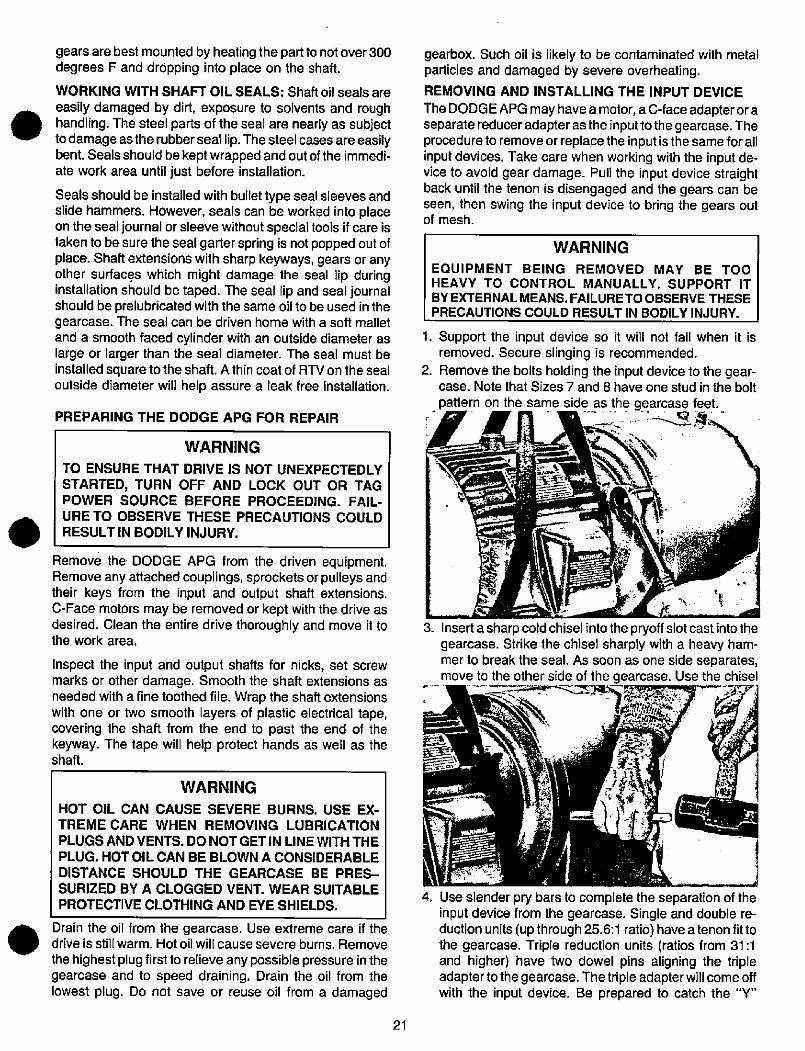
.
.
gears are best mounted by heating the part to not over 300degrees F and dr6pping into place on the shaft.
WORKING WITH SHAFT OIL SEALS: Shaft oil seals are
easily damaged by dirl, exposure to solvents and roughhandling. The steel parts of the seal are nearly as subjectto damage asthe rubberseal lip. The steel cases are easilybent. Seals should be kept wrapped and out of the immedi-ate work area until just before installation.
Seals should be installed with bullet type seal sleeves andslide hammers. However, seals can be worked into placeon the seal journal or sleeve without special tools if care istaken to be sure the seal garter spring is not popped out ofplace. Shaft extensions with sharp keyways, gears or anyother surfaces which might damage the seal lip duringinstallation should be taped. The seal lip and seal journalshould be prelubricated with the same oil to be used in thegearcase. The seal can be driven home with a soft malletand a smooth faced cylinder with an outside diameter aslarge or larger than the seal diameter. The seal must beinstalled square to the shaft. A thin coat of RTV on the sealoutside diameter will help assure a leak free installation.
PREPARING THE DODGE APG FOR REPAIR
WARNING
TO ENSURE THAT DRIVE IS NOT UNEXPECTEDLY
STARTED, TURN OFF AND LOCK OUT OR TAGPOWER SOURCE BEFORE PROCEEDING. FAIL-
URE TO OBSERVE THESE PRECAUTIONS COULDRESULT IN BODILY INJURY.
Remove the DODGE APG from the driven equipment.Remove any attached couplings, sprockets or pulleys andtheir keys from the input and output shaft extensions.C-Face motors may be removed or kept with the drive asdesired. Clean the entire drive thoroughly and move it tothe work area.
gearbox. Such oil is likely to be contaminated with metalparticles and damaged by severe overheating.REMOVING AND INSTALLING THE INPUT DEVICE
The DODGE APG may have a motor, a C-face adapteroraseparate reducer adapteras the inputto the gearcase. Theprocedureto remove or replace the input is the same forallinput devices. Take care when working with the input de-vice to avoid gear damage. Pull the input device straightback until the tenon is disengaged and the gears can beseen, then swing the input device to bring the gears outof mesh.
WARNING
EQUIPMENT BEING REMOVED MAY BE TOOHEAVY TO CONTROL MANUALLY. SUPPORT IT
BY EXTERNALMEANS. FAILURE TOOBSERVE THESEPRECAUTIONS COULD RESULT IN BODILY INJURY.
1. Support the input device so it will not fall when it isremoved. Secure slinging is recommended.
2. Remove the bolts holding the input device to the gear-case. Note that Sizes 7 and 8 have one stud in the bolt
- pattern on the same side_.as _the gearcase feet.
3. Insert a sharp cold chisel into the pryoff slot cast into the
gearcase. Strike the chisel sharply with a heavy ham-mer to break the seal. As soon as one side separates,move to the other side of the gearcase. Use the chisel
--7TF
Inspect the input and output shafts for nicks, set screwmarks or other damage. Smooth the shaft extensions asneeded with a fine toothed file. Wrap the shaft extensionswith one or two smooth layers of plastic electrical tape,covering the shaft from the end to past the end of thekeyway. The tape will help protect hands as well as theshaft. .- \7 «-'.
WARNING
HOT OIL CAN CAUSE SEVERE BURNS. USE EX-
TREME CARE WHEN REMOVING LUBRICATIONPLUGS AND VENTS. DO NOT GET IN LINE WITH THE
PLUG. HOT OIL CAN BE BLOWN A CONSIDERABLEDISTANCE SHOULD THE GEARCASE BE PRES-
SURIZED BY A CLOGGED VENT. WEAR SUITABLE
PROTECTIVE CLOTHING AND EYE SHIELDS.
Drain the oil from the gearcase. Use extreme care if thedrive is still warm. Hot oil will cause severe burns. Remove
the highest plug first to relieve any possible pressure in thegearcase and to speed draining. Drain the oil from thelowest plug. Do not save or reuse oil from a damaged
21
4. Use slender pry bars to complete the separation of theinput device from the gearcase. Single and double re-duction units (upthrough 25.6:1 ratio) have atenon fittothe gearcase. Triple reduction units (ratios from 31 :1and higher) have two dowel pins aligning the tripleadaptertothe gearcase. Thetriple adapter will comeoffwith the input device. Be prepared to catch the "Y"
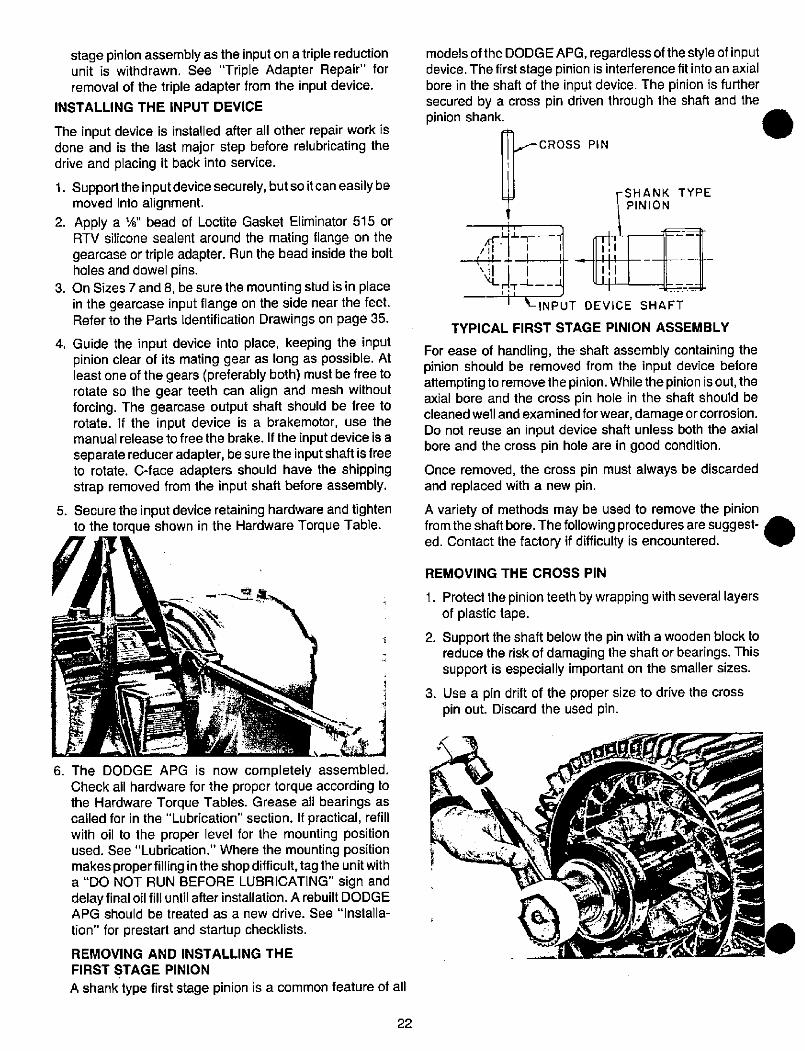
stage pinion assembly as the input on a triple reductionunit is withdrawn. See "Triple Adapter Repair" forremoval of the triple adapter from the input device.
INSTALLING THE INPUT DEVICE
The input device is installed after all other repair work isdone and is the last major step before relubricating thedrive and placing it back into service.
1. Supportthe inputdevice securely, butso itcan easilybemoved into alignment.
2. Apply a W bead of Loctite Gasket Eliminator 515 orRTV silicone sealent around the mating flange on thegearcase or triple adapter. Run the bead inside the boltholes and dowel pins.
3. On Sizes 7 and 8, be sure the mounting stud is in placein the gearcase input flange on the side near the feet.Refer to the Parts Identification Drawings on page 35.
4. Guide the input device into place, keeping the inputpinion clear of its mating gear as long as possible. Atleast one of the gears (preferably both) must be free torotate so the gear teeth can align and mesh withoutforcing. The gearcase output shaft should be free torotate. If the input device is a brakemotor, use themanual release to free the brake. If the input device is aseparate reducer adapter, be sure the input shaft is freeto rotate. C-face adapters should have the shippingstrap removed from the input shaft before assembly.
5. Secure the input device retaining hardware and tightento the torque shown in the Hardware Torque Table.
1
b, 1
6. The DODGE APG is now completely assembled.Check all hardware for the proper torque according tothe Hardware Torque Tables. Grease all bearings ascalled for in the "Lubrication" section. If practical, refillwith oil to the proper level for the mounting positionused. See "Lubrication." Where the mounting positionmakes proper filling in the shop difficult, tag the unit witha "DO NOT RUN BEFORE LUBRICATING" sign anddelay final oil fill until after installation. A rebuilt DODGEAPG should be treated as a new drive. See -Installa-
tion" for prestart and startup checklists.
REMOVING AND INSTALLING THE
FIRST STAGE PINION
A shank type first stage pinion is a common feature of all
22
'1
T
models of the DODGE APG, regardless of the style of inputdevice. The first stage pinion is interference fit into an axialbore in the shaft of the input device. The pinion is furthersecured by a cross pin driven through the shaft and thepinion shank.
7- CROSS PIN
/ It( 11\ 11\LLr
rSHANK
PINION1,I
TYPE
n----f1 1
1 1 - ill-L_-4 lp----=6:EKES-L INPUT DEVICE SHAFT
TYPICAL FIRST STAGE PINION ASSEMBLY
For ease of handling, the shaft assembly containing thepinion should be removed from the input device beforeattemptingto removethe pinion. Whilethe pinion isout, theaxial bore and the cross pin hole in the shaft should becleaned well and examined for wear, damage orcorrosion.Do not reuse an input device shaft unless both the axialbore and the cross pin hole are in good condition.
Once removed, the cross pin must always be discardedand replaced with a new pin.
A variety of methods may be used to remove the pinion
from the shaft bore. The following procedures are suggest- ed. Contact the factory if difficulty is encountered. ./-
REMOVING THE CROSS PIN
1. Protect the pinion teeth by wrapping with several layersof plastic tape.
2. Support the shaft below the pin with a wooden block toreduce the risk of damaging the shaft or bearings. Thissupport is especially important on the smaller sizes.
3. Use a pin drift of the proper size to drive the crosspin out. Discard the used pin.
AL Vi t..t
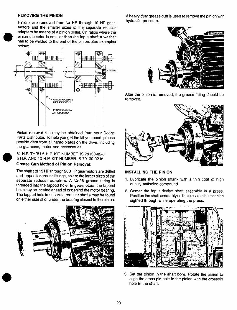
REMOVING THE PINION
Pinions are removed from 1/4 HP through 10 HP gear-motors and the smaller sizes of the separate reduceradapters by means of a pinion puller. On ratios where thepinion diameter is smaller than the input shaft a washerhas to be welded to the end of the pinion. See examplesbelow:
,-=F,2-F-e- ip
*1
i-EXfli
f P»CON PULLER &ARM ASSEMBLY
PINION PULLER &CAP ASSEMBLY
:11
Pinion removal kits may be obtained from your DodgeParts Distributor. To help you get the kit you need, pleaseprovide data from all name-plates on the drive, includingthe gearcase, motor and accessories.
14 H.P. THRU 5 H.R KIT NUMBER IS 79130-02-J
5 H.R AND 10 H.R KIT NUMBER IS 79130-02-M
Grease Gun Method of Pinion Removal:
The shafts of 15 HPthrough 200 HP gearmotors are drilledand tapped forgreaselittings, as are the larger sizes of theseparate reducer adapters. A 1/4-28 grease fitting isthreaded into the tapped hole. In gearmotors, the tappedhole may be located ahead of or behind the motor bearing.The tapped hole in separate reducer shafts may be foundon either side of or under the bearing closest to the pinion.
116"k .»·. .
..
Pi Ii"le'
WELD
23
A heavy duty grease gun is used to remove the pinion withhydraulic pressure.
After the pinion is removed, the grease fitting should beremoved.
INSTALLING THE PINION
T
A
1. Lubricate the pinion shank with a thin coat of highquality antiseize compound.
2. Center the input device shaft assembly in a press.
Positionthe shaftassembly sothecross pin hole can besighted through while operating the press.
If- tl3. Set the pinion in the shaft bore. Rotate the pinion to
align the cross pin hole in the pinion with the crosspinhole in the shaft.
t
4. Press slowly while sighting through the crosspin hole inthe shaft. Press until the pinion bottoms or until thecross pin holes line up. Avoid overpressing.
REPLACING THE CROSS PIN
1. Protect the pinion teeth from a missed hammer blow.
2. Support the shaft opposite the pin.
3. Drive a new pin in place.
REPAIRING THE SEPARATE REDUCER INPUT
NOTE: See "Removing and Installing the Input Device"and "Removing and Installing the First Stage Pinion" be-fore proceeding.
SEPARATE REDUCER ADAPTER TEARDOWN
1. Remove the shaft key (1) and wrap the shaft extensionwith plastic tape. Wrap the pinion (9) teeth with plastictape.
2. Remove the bearing clamp (12) retaining hardware(11). Remove the bearing clamp (12). Use a soft malleton the keyed extension end of the shaft (2) to drive allthe internal parts out the flange end of the housing (16).Work carefully. Remove the backstop key (6 or 18) as itbecomes accessible on units equipped with backstops.On Sizes 7 and 8, remove the bearing cup (21) as soonas it clears the bore.
3. If the bearings or backstop must be replaced, removethe bearing (3 or 27) at the keyed end of the shaft first.Remove the retaining rings (7 and/or 15). Remove thebackstop (5). Remove the pinion (9) end bearing (13 or20) last. If the pinion outside diameter is larger than thebearing inside diameter, the pinion will have to beremoved before the bearing can be removed. See"Removing and Installing the First Stage Pinion"in this manual.
4. Remove the input oil seal (17) from the housing (16).The oil seal should be replaced with a new seal when-ever the unit is torn down for any reason. On Sizes 7and 8, remove the bearing cup (26). Remove all pipeplugs (4, 14, 23).
24
5. Clean and inspect all parts. Be sure the housing iscleaned of all old grease. The backstop should be thor-oughly cleaned& then rinsed in clean solvent. Inspectthe shaft for wear at the seal journal and in the areaunder the backstop.
SEPARATE REDUCER ADAETER ASSEMBLY1. Study the Parts Identification Drawing for the size of
separate reducer adapter you have.
2. Assemble all components on the shaft. Start by press-ing the bearing on the pinion end. Add the other compo-nents and complete the shaft assembly by pressing thebearing on the shaft extension end. Be sure to installthe retaining rings (7 and/or 15) and grease shields(24). Check the direction of rotation of the backstop tobe sure it is installed in the proper direction for yourapplication. If the backstop is not installed properlybefore installing the bearing (3 or 27), the whole unitwill have to be torn down to correct the backstop.
3. Put some stiff grease in the backstop keyway to hold thebackstop key (6 or 18) in place in the backstop keyway.On Sizes 7 and 8, install the bearing cup (26) in thehousing and seat solidly.
4. Slide the shaft assemblyintothe housing, taking caretoalign the backstop key with the keyway in the housing.On Sizes 7 and 8, the grease shield (24) must berotated to aligned with the pipe plug holes (23).
5 . Sizes 3 through 6: Install the bearing clamp (12) andhardware (10 or 11). Tighten the screws to the torquespecified in the Hardware Torque Tables. Spin the shaftto check for smooth rotation with little drag.
Sizes 7 and 8: Install the bearing cup (21), seal (19),bearing clamp (12), and hardware (11). Tighten thescrews to the torque specified in the Hardware TorqueTables. Use a soft mallet to drive the shaft both ways toseatthe bearings. Spin the shaftto be sure the bearingsare seated and square. Use a dial indicator to measurethetotal shaftendplay. Selectashim pack toprovidetheendplay shown in the table below:
SHAFT ENDPLAY CHART FOR
SIZE 7 AND 8 SEPARATE REDUCER ADAPTERS
INPUT RPM
100 - 750
750 - 1800
1800 - 2500
NORMAL
DUTY
(2OF - 11 OF)
.000 - .002
.002 - .004
.003 - .005
LOW TEMP
DUTY'
( - 3OF to + 2OF)
.000 - .002
.001 - .003
.002 - .004
'Also includes operation less than 4 hours per day.
Remove the bearing clamp (12), insert the shims (22)and retorque the bearing clamp screws. Check theendplay. Reshim if needed. Spin the shaft to check forsmooth rotation with little drag.
1
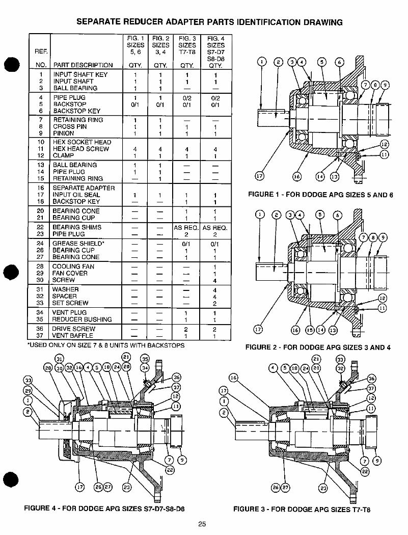
.
36
37
31
32
33
34
35
28
29
30
RER
NO.
24
26
27
22
23
20
21
16
17
18
13
14
15
7
8
9
4
5
6
10
11
12
1
2
3
SEPARATE REDUCER ADAPTER PARTS IDENTIFICATION DRAWING
PART DESCRIPTION
INPUT SHAFT KEYINPUT SHAFT
BALL BEARING
PIPE PLUG
BACKSTOPBACKSTOP KEY
RETAINING RINGCROSS PIN
PINION
HEX SOCKET HEAD
HEX HEAD SCREW
CLAMP
BALL BEARING
PIPE PLUGRETAINING RING
SEPARATE ADAPTER
INPUT OIL SEAL
BACKSTOP KEY
BEARING CONE
BEARING CUP
BEARING SHIMS
PIPE PLUG
GREASE SHIELD*BEARING CUP
BEARING CONE
COOLING FAN
FAN COVER
SCREW
WASHER
SPACER
SET SCREW
VENT PLUGREDUCER BUSHING
DRIVE SCREW
VENT BAFFLE
1
1
0/1
1
1
1
1
1
*USED ONLY ON SIZE 7&8 UNITS WITH BACKSTOPS
2131 35
28 30 32 16 4 5 18 24 20 34
33
29
17 26 27 23
FIGURE 4 - FOR DODGE APG SIZES S7-D7-S8-08
1
1
1
4
1
FIG. 1
SIZES
5,6
QTY.
1
1
1
1
1
1
1
FIG. 2
SIZES
3,4
QTY.
1
0/1
1
1
1
4
1
4I
36
37
12
11
FIG. 3
SIZES
T7-T8
QTY.
1
1
1
1
0/1
1
1
1
1
1
1
4
1
0/2
0/1
1
1
AS REQ.
2
2
1
1
1
1
1
25
0/1
1
1
2
1
4
4
2
1
1
4
1
1
0/20/1
FIG. 4
SIZES
57-D7
58-D8QTY.
1
1
4
1
AS REQ.2
1
1
17
34 5 6
789
--
-
11
- - 11-
16 14 13
rj12
11
FIGURE 1 - FOR DODGE APG SIZES 5 AND 6
17
3 4 5 6
-- 31- - - .1;1 --1- .1
---+J112
11
16 15 14 13
FIGURE 2 - FOR DODGE APG SIZES 3 AND 4
16
17
7
21 33
4 5 18 24 20 32
26 27 23
r
4I
22
FIGURE 3 - FOR DODGE APG SIZES T7-T8
36
37
12
11
7 9
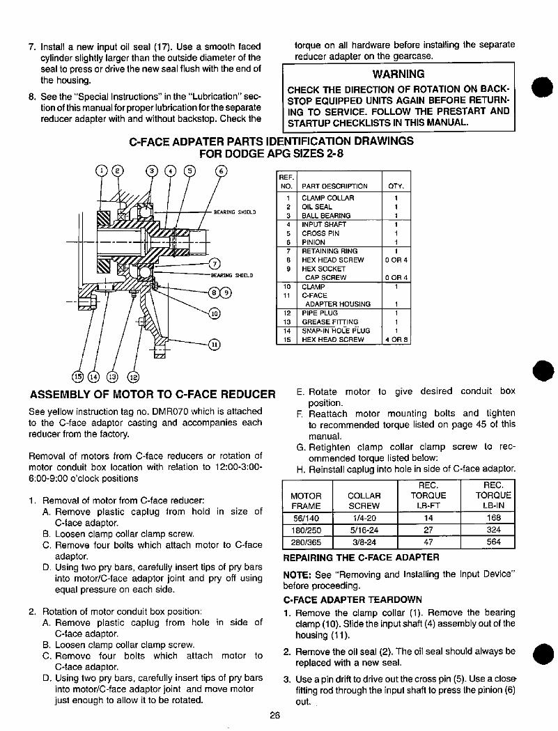
2.
1.
7. Install a new input oil seal (17). Use a smooth facedcylinder slightly larger than the outside diameter of theseal to press or drive the new seal flush with the end ofthe housing.
8. See the "Special Instructions" in the "Lubrication" sec-tion of this manual for proper lubrication for the separatereducer adapter with and without backstop. Check the
1 2
torque on all hardware before installing the separatereducer adapter on the gearcase.
WARNING
CHECK THE DIRECTION OF ROTATION ON BACK-STOP EQUIPPED UNITS AGAIN BEFORE RETURN-ING TO SERVICE. FOLLOW THE PRESTART ANDSTARTUP CHECKLISTS IN THIS MANUAL.
C-FACE ADPATER PARTS IDENTIFICATION DRAWINGSFOR DODGE APG SIZES 2-8
3 4 5
BEARING SHIELD
BEARING SHIELD
9
8 9
15 14 13 12
ASSEMBLY OF MOTOR TO C-FACE REDUCER
See yellow instruction tag no. DMR070 which is attachedto the C-face adaptor casting and accompanies eachreducer from the factory.
Removal of motors from C-face reducers or rotation of
motor conduit box location with relation to 12:00-3:00-
6:00-9:00 o'clock positions
Removal of motor from C-face reducer:
A. Remove plastic caplug from hold in size ofC-face adaptor.
B. Loosen clamp collar clamp screw.C. Remove four bolts which attach motor to C-face
adaptor.
D. Using two pry bars, carefully insert tips of pry barsinto motodC-face adaptor joint and pry off usingequal pressure on each side.
Rotation of motor conduit box position:A. Remove plastic caplug from hole in side of
C-face adaptor.
B. Loosen clamp collar clamp screw.C. Remove four bolts which attach motor to
C-face adaptor.
D. Using two pry bars, carefully insert tips of pry barsinto motor/C-face adaptor joint and move motorjust enough to allow it to be rotated.
26
REF.
NO.
10
11
12
13
14
15
1
2
3
4
5
6
7
8
9
PART DESCRIPTION
CLAMP COLLAR
OIL SEAL
BALL BEARING
INPUT SHAFT
CROSS PIN
PINION
RETAINING RING
HEX HEAD SCREW
HEX SOCKET
CAP SCREW
CLAMP
C-FACE
ADAPTER HOUSING
PIPE PLUG
GREASE FITTING
SNAP-IN HOLE PLUG
HEX HEAD SCREW
QTY.
1
1
1
1
1
1
1
0 OR 4
0 OR 4
1
1
1
1
4 OR 8
E. Rotate motor to give desired conduit boxposition.
F. Reattach motor mounting bolts and tightento recommended torque listed on page 45 of thismanual.
G. Retighten clamp collar clamp screw to rec-ommended torque listed below:
H. Reinstall caplug into hole in side of C-face adaptor.
MOTOR
FRAME
56/140
180/250
280/365
COLLAR
SCREW
1/4-20
5/16-24
3/8-24
REC.
TORQUE
LB-FT
14
27
47
REC.
TORQUE
LB-IN
REPAIRING THE C-FACE ADAPTER
NOTE: See "Removing and Installing the Input Device"before proceeding.
C-FACE ADAPTER TEARDOWN
1. Remove the clamp collar (1). Remove the bearingclamp (10). Slide the input shaft (4) assembly out of thehousing (11).
2. Remove the oil seal (2). The oil seal should always be replaced with a new seal. .....
3. Use a pin drift to drive out the cross pin (5). Use a closefitting rod through the input shaft to press the pinion (6)out.
168
324
564
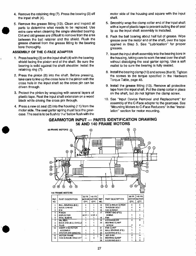
.
4. Remove the retaining ring (7). Press the bearing (3) offthe input shaft (4).
5. Remove the grease fitting (13). Clean and inspect allparts to determine what needs to be replaced. Useextra care when cleaning the single shielded bearing.Dirt and old grease are difficult to remove from the areabetween the ball retainer and the shield. Flush the
grease channel from the grease fitting to the bearingbore thoroughly.
ASSEMBLY OF THE C-FACE ADAPTER
1. Press bearing (3) on the input shaft (4) with the bearingshield facing the pinion end of the shaft. Be sure thebearing is solid against the shaft shoulder. Install theretaining ring (7).
2. Press the pinion (6) into the shaft. Before pressing,take care to line up the cross hole in the pinion with thecross hole in the input shaft so the cross pin can bedriven through.
3. Protect the pinion by wrapping with several layers ofplastic tape. Rest the input shaft extension on a woodblock while driving the cross pin through.
4. Press a new oil seal (2) into the housing (11) from themotor side. The seal garter spring must face the gear-case. The seal isto be flush to 1/16"below flush with the
REF.
NO,
motor side of the housing and square with the inputshaft.
5. Smoothly wrap the clamp collar end of the input shaftwith a layer of plastic tape to prevent cutting the oil seallip as the input shaft assembly is installed.
6. Pack the ball bearing about half full of grease. Wipegrease over the motor end of the shaft, over the tapeapplied in Step 5. See "Lubrication" for propergreases.
7. Insert the input shaft assembly into the bearing bore inthe housing, taking care to work the seal over the shaftwithout dislodging the seal garter spring. Use a softmallet to be sure the bearing is fully seated.
8. Install the bearing clamp (10) and screws (8 or9). Tightenthe screws to the torque specified in the HardwareTorque Table, page 45.
9. Install the grease fitting (13). Remove all protectivetape from the input shaft. Put the clamp collar in placeon the shaft, but do not tighten the clamp screw.
10. See "Input Device Removal and Replacement" forassembly of the C-Face adapter to the gearcase. See"Mounting Motors to C-Face Reducers" in the "Instal-lation" section for motor mounting.
GEARMOTOR INPUT - PARTS IDENTIFICATION DRAWING56 AND 140 FRAME MOTORS
56 FRAME MOTORS H
(E<
0-11- 11= 61-111- 119 1111Ill
140 FRAME MOTORS
1
2
3
4
5
6
7
8
9
10
11
12
13
PART DESCRIPTION
BALL BEARING (B.E.)WAVE SPRING
PIN
PINION
DEFLECTOR
SEAL SLEEVE
OIL SEAL
BACK END (B.E.) SHIELDPLUG
SHAFT AND ROTOR
ASSEMBLY
STATOR AND WINDING
MOTOR FRAME
FAN SHROUD BRACKET
1
1
1
1
0091
1
1
1
1
56 FR.
MOTOR
Qly.
1
1
1
25
140 FR.
MOTOR
QTY.
1
1
1
1
0OR1
1
1
1
1
1
1
1
4
I111111
27
REF.
NO.
14
15
16
17
18
19
20
21
22
23
24
25
26
® (!!) i
*1
26 1
-1
75 ,
PART DESCRIPTION
FAN SHROUD SCREW
THROUGH BOLT
FAN SHROUD
FRONT END (F.E.)SHIELD
FAN
LOCKWASHER
BEARING CLAMP
SCREW
FAN CLAMP
BALL BEARING (F E.)
LOCKRING (F.E.)
.025 SHIMBEARING CLAMP
LOCKRING (B.E)
1 1
56 FR.
MOTOR
QTY.
2
4
1
1
1
2
2
1
1
2
1
1
140 FR.
MOTOR
QTY.
4
4
1
1
2
2
1
1
1
1
0
71
Ill E
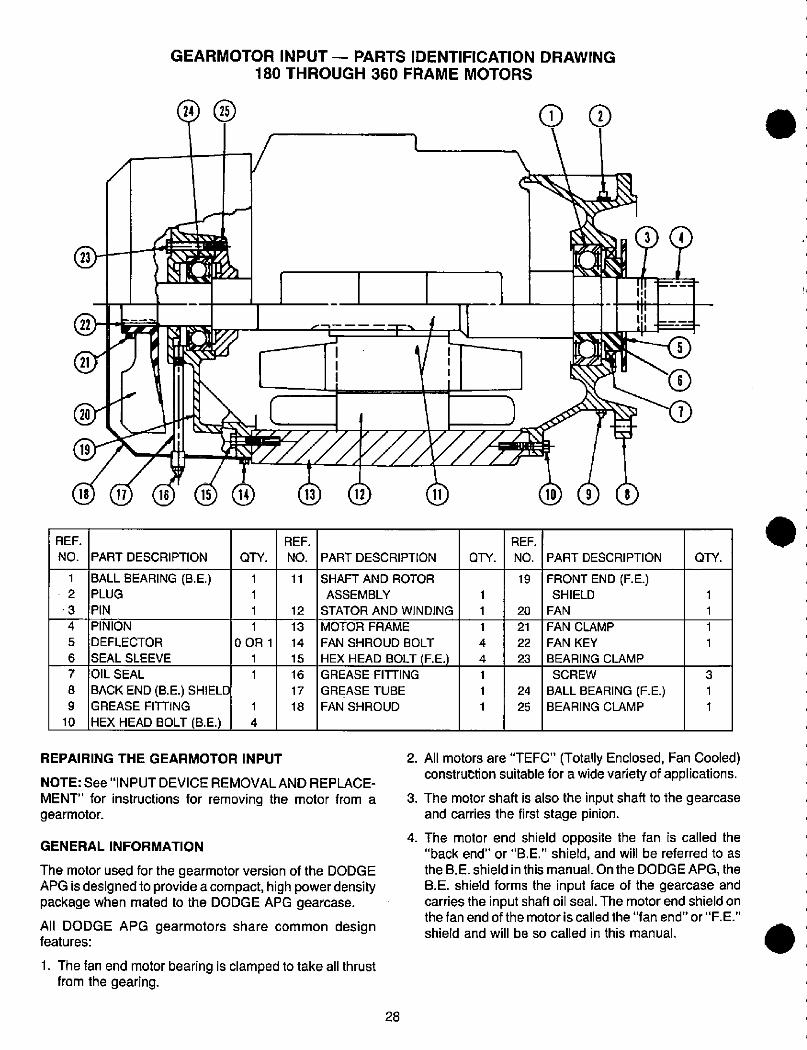
1
2
·3
4
5
6
7
8
9
10
REF.
NO.
18
22
19
23
(jir
GEARMOTOR INPUT - PARTS IDENTIFICATION DRAWING
180 THROUGH 360 FRAME MOTORS
24
17 16 15
PART DESCRIPTION
BALL BEARING (B.E.)PLUG
PIN
PINION
DEFLECTOR
SEAL SLEEVE
OIL SEAL
BACK END (B.E.) SHIELDGREASE FITTING
HEX HEAD BOLT (B.E.)
QTY.
1
1
1
1
0OR1
1
1
1
4
REPAIRING THE GEARMOTOR INPUT
11
12
13
14
15
16
17
18
REF.
NO.
T.
11
PART DESCRIPTION
SHAFT AND ROTOR
ASSEMBLY
STATOR AND WINDING
MOTOR FRAME
FAN SHROUD BOLT
HEX HEAD BOLT (F.E.)GREASE FITTING
GREASE TUBE
FAN SHROUD
NOTE: See"INPUT DEVICE REMOVAL AND REPLACE-
MENT" for instructions for removing the motor from agearmotor.
GENERAL INFORMATION
The motor used for the gearmotor version of the DODGEAPG is designed to provide a compact, high power densitypackage when mated to the DODGE APG gearcase.
All DODGE APG gearmotors share common designfeatures:
1. The fan end motor bearing is clamped to take all thrustfrom the gearing.
28
1
1
1
4
4
1
1
1
QTY.
REF.
NO.
19
20
21
22
23
24
25
CD CD
10 9 8
71
PART DESCRIPTION
FRONT END (F.E.)SHIELD
FAN
FAN CLAMP
FAN KEY
BEARING CLAMP
SCREW
BALL BEARING (F.E.)BEARING CLAMP
5
1
1
1
1
QTY.
3
1
1
2. All motors are "TEFC" (Totally Enclosed, Fan Cooled)construttion suitable for a wide variety of applications.
3. The motor shaft is also the input shaft to the gearcaseand carries the first stage pinion.
4. The motor end shield opposite the fan is called the"back end" or "B.E." shield, and will be referred to as
the B.E. shield in this manual. On the DODGE APG, theB.E. shield forms the input face of the gearcase and
carries the input shaft oil seal. The motor end shield onthe fan end of the motor is called the "fan end" or "F. E."
shield and will be so called in this manual.
.
--
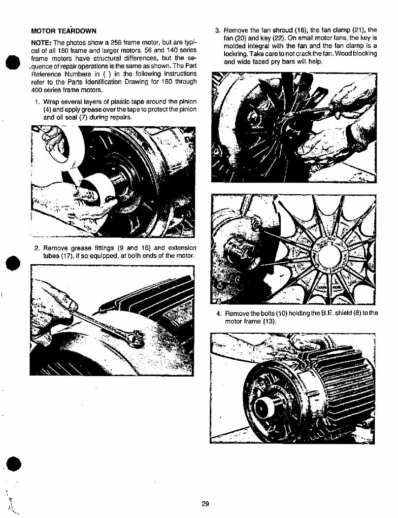
.
MOTOR TEARDOWN
NOTE: The photos show a 256 frame motor, but are typi-cal of all 180 frame and larger motors. 56 and 140 seriesframe motors have structural differences, but the se-
.quence of repair operations is the same as shown. The PartReference Numbers in ( ) in the following instructionsrefer to the Parts Identification Drawing for 180 through400 series frame motors.
1. Wrap several layers of plastic tape around the pinion(4) and applygrease overthetapeto protectthe pinionand oil seal (7) during repairs.
Remove the fan shroud (18), the fan clamp (21), thefan (20) and key (22). On small motor fans, the key ismolded integral with the fan and the fan clamp is alockring. Take care to not crack the fan. Wood blockingand wide faced pry bars will help.
2. Remove grease fittings (9 and 16) and extensiontubes (17), if so equipped, at both ends of the motor.
r
*%?
29
3.
4.
7 15.7.
f
Removethe bolts (10) holding the B.E. shield (8) tothemotor frame (13).
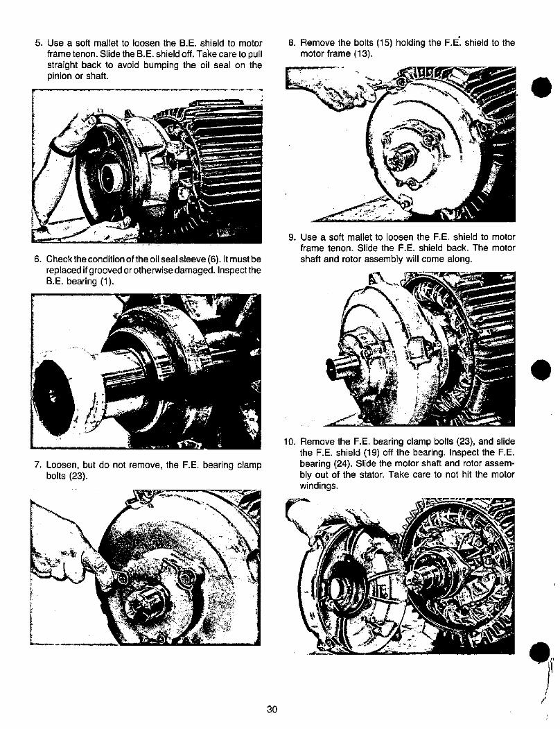
Remove the bolts (15) holding the F.E. shield to themotor frame (13).
5. Use a soft mallet to loosen the B.E. shield to motor 8.
frame tenon. Slide the B. E. shield off. Take care to pullstraight back to avoid bumping the oil seal on thepinion or shaft.
4 454,--*-JL-' 9
6. Checkthecondition of the oilseal sleeve (6). Itmustbereplaced if grooved orotherwise damaged. Inspectthe
B.E. bearing (1).
t
9
7. Loosen, but do not remove, the F.E. bearing clampbolts (23).
9. Use a soft mallet to loosen the F.E. shield to motor
frame tenon. Slide the F.E. shield back. The motor
shaft and rotor assembly will come along.
a=£47-*Ii
i!*r-,'/p...il-
4444£Q-
10. Remove the F.E. bearing clamp bolts (23), and slidethe F.E. shield (19) off the bearing. inspect the F.IE.bearing (24). Slide the motor shaft and rotor assem-bly out of the stator. Take care to not hit the motorwindings.
I I
L ,
'4*, 1 1,
30
t
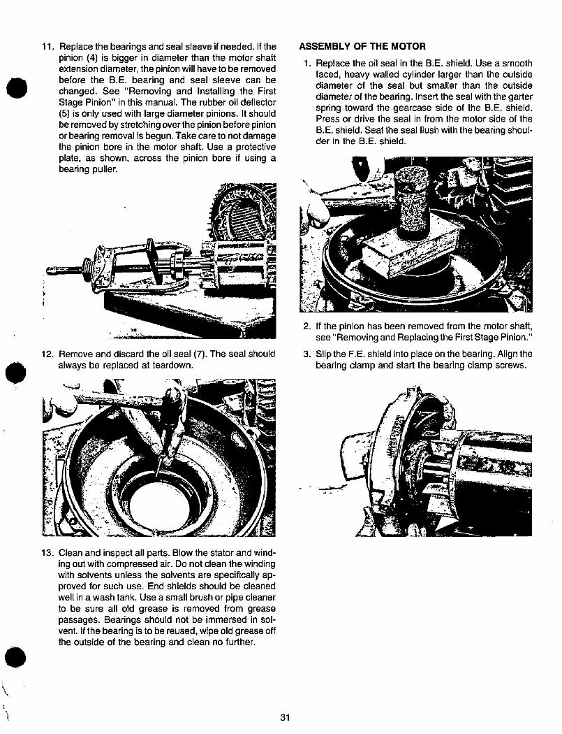
.
.
11.
12.
13.
Replace the bearings and seal sleeve if needed. If thepinion (4) is bigger in diameter than the motor shaftextension diameter, the pinion will have to be removed
before the B.E. bearing and seal sleeve can bechanged. See "Removing and Installing the First
Stage Pinion" in this manual. The rubber oil deflector
(5) is only used with large diameter pinions. It shouldbe removed by stretching over the pinion before pinionor bearing removal is begun. Take care to not damagethe pinion bore in the motor shaft. Use a protective
plate, as shown, across the pinion bore if using abearing puller.
Dr
Remove and discard the oil seal (7). The seal shouldalways be replaced at teardown.
1
Clean and inspect all parts. Blow the stator and wind-ing out with compressed air. Do not clean the windingwith solvents unless the solvents are specifically ap-
proved for such use. End shields should be cleanedwell in a wash tank. Use a small brush or pipe cleaner
to be sure all old grease is removed from greasepassages. Bearings should not be immersed in sol-vent. If the bearing is to be reused, wipe old grease offthe outside of the bearing and clean no further.
31
ASSEMBLY OF THE MOTOR
1. Replace the oil seal in the B.E. shield. Use a smoothfaced, heavy walled cylinder larger than the outsidediameter of the seal but smaller than the outside
diameter of the bearing. Insert the seal with the garter
spring toward the gearcase side of the B.E. shield.Press or drive the seal in from the motor side of the
B.E. shield. Seat the seal flush with the bearing shoul-der in the B.E. shield.
2. If the pinion has been removed from the motor shaft,see"Removing and Replacing the First Stage Pinion."
3. Slip the F.E. shield into place on the bearing. Align thebearing clamp and start the bearing clamp screws.
f
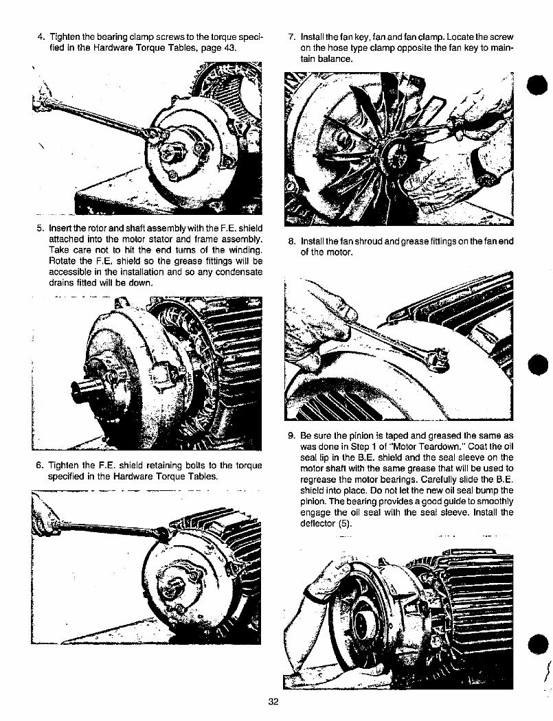
5.
4. Tighten the bearing clamp screws to the torque speci- 7.fied in the Hardware Torque Tables, page 43.
k
4
Insert the rotor and shaft assembly with the F.E. shieldattached into the motor stator and frame assembly. 8.Take care not to hit the end turns of the winding.Rotate the F.E. shield so the grease fittings will beaccessible in the installation and so any condensatedrains fitted will be down.
Install the fan key, fan and fan clamp. Locate the screw
on the hose type clamp opposite the fan key to main-tain balance.
1
Install the fanshroud andgrease fittings on the fan endof the motor.
1
.
4
6. Tighten the F.E. shield retaining bolts to the torque
specified in the Hardware Torque Tables.
0
32
9. Be sure the pinion is taped and greased the same aswas done in Step 1 of "Motor Teardown." Coat the oilseal lip in the B.E. shield and the seal sleeve on themotor shaft with the same grease that will be used toregrease the motor bearings. Carefully slide the B.E.shield into place. Do not let the new oil seal bump thepinion. The bearing provides a good guide to smoothlyengage the oil seal with the seal sleeve. Install thedeflector (5).
j
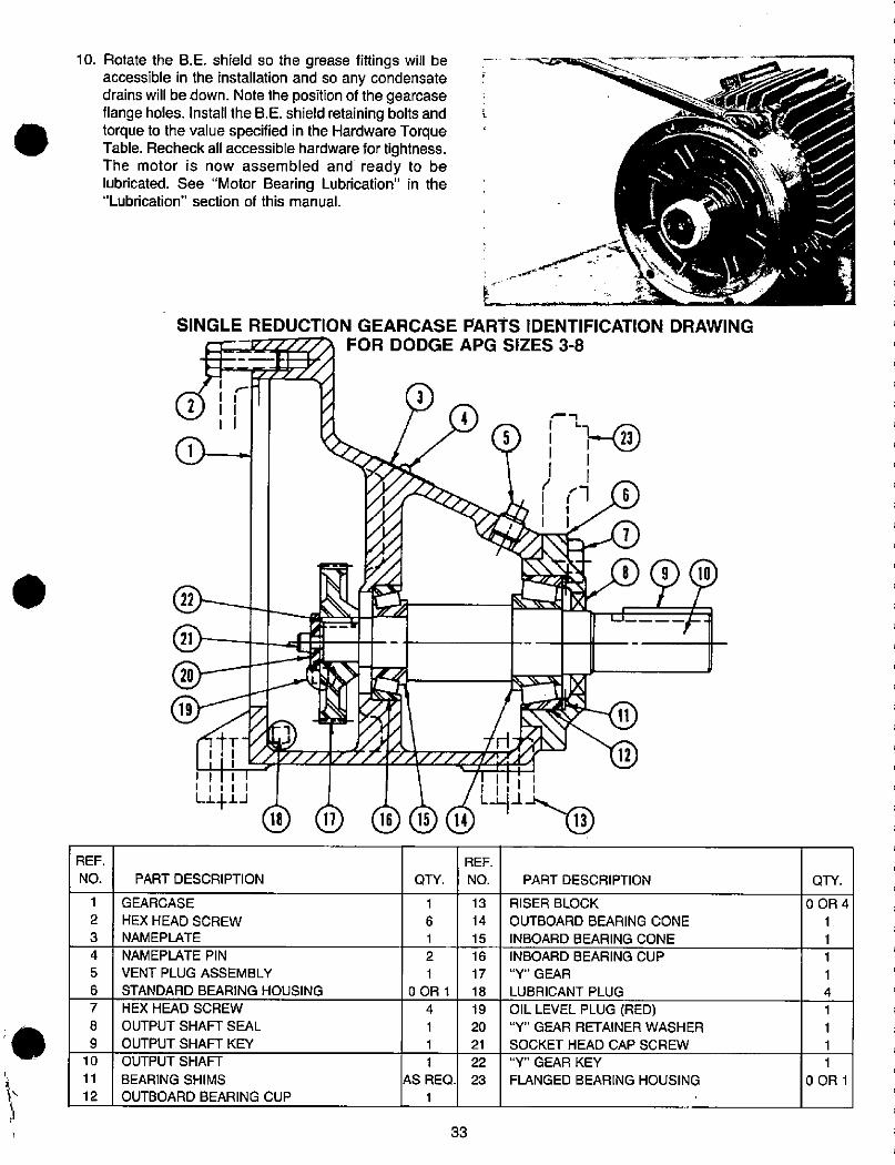
r
.
REF.
NO.
1
2
3
4
5
6
7
8
9
10
11
12
22
21
20
19
10. Rotate the B.E. shield so the grease fittings will beaccessible in the installation and so any condensatedrains will be down. Note the position of the gearcaseflange holes. Install the B.E. shield retaining bolts andtorque to the value specified in the Hardware TorqueTable. Recheck all accessible hardware for tightness.The motor is now assembled and ready to belubricated. See "Motor Bearing Lubrication" in the"Lubrication" section of this manual.
3
SINGLE REDUCTION GEARCASE PARTS IDENTIFICATION DRAWINGFOR DODGE APG SIZES 3-8
REF.
NO.
2 1111
(D--
4
5
1 1
4-1..../ko-41 111 1 '1 /1 111 1L-1413 46 'lilli
®®® Ill)
PART DESCRIPTION
GEARCASE
HEX HEAD SCREW
NAMEPLATE
NAMEPLATE PIN
VENT PLUG ASSEMBLY
STANDARD BEARING HOUSING
HEX HEAD SCREW
OUTPUT SHAFT SEAL
OUTPUT SHAFT KEY
OUTPUT SHAFT
BEARING SHIMS
OUTBOARD BEARING CUP
QTY.
1
6
1
2
1
0OR1
4
1
1
1
AS REQ.
1
33
13
14
15
16
17
18
19
20
21
22
23
RISER BLOCK
OUTBOARD BEARING CONE
INBOARD BEARING CONE
INBOARD BEARING CUP
"Y" GEAR
LUBRICANT PLUG
OIL LEVEL PLUG (RED)"Y" GEAR RETAINER WASHER
SOCKET HEAD CAP SCREW
"Y" GEAR KEY
FLANGED BEARING HOUSING
23
6
1
8 (D®1 1
1--
PART DESCRIPTION QTY.
0OR4
1
1
1
1
4
1
1
1
1
0OR1
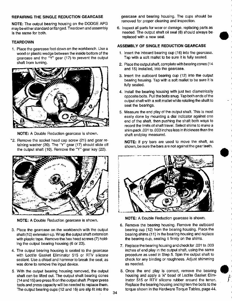
REPAIRING THE SINGLE REDUCTION GEARCASE
NOTE: The output bearing housing on the DODGE APGmay be eitherstandard or flanged. Teardown and assemblyis the same for both.
TEARDOWN
1. Place the gearcase foot down on the workbench. Use awood or plastic wedge between the inside bottom of thegearcase and the "Y" gear (17) to prevent the outputshaft from turning.
Z
NOTE: A Double Reduction gearcase is shown.
*2. Remove the socket head cap screw (21) and gear re-taining washer (20). The "Y" gear (17) should slide offthe output shaft (10). Remove the "Y" gear key (22).
4/3/>4
0
f
NOTE: A Double Reduction gearcase is shown.
3. Place the gearcase on the workbench with the outputshaft (10) extension up. Wrap the output shaft extensionwith plastic tape. Remove the hex head screws (7) hold-ing the output bearing housing (6 or 23).
4. The output bearing housing is sealed to the gearcasewith Loctite Gasket Eliminator 515 or RTV silicone
sealant. Use a chisel and hammer to break the seal, as
was done to remove the input device.
5. With the output bearing housing removed, the outputshaft can be lifted out. The output shaft bearing cones(14 and 15)arepress fitontheoutputshaft. Properpresstools and press capacity will be needed to replace them.The output bearing cups (12 and 16) are slip fit into the
34
f
gearcase and bearing housing. The cups should beremoved for proper cleaning and inspection.
6. Inspect all parts for wear or damage, replacing parts asneeded. The output shaft oil seal (8) should always be.replaced with a new seal.
ASSEMBLY OF SINGLE REDUCTION GEARCASE
1. Insert the inboard bearing cup (16) into the gearcase.Tap with a soft mallet to be sure it is fully seated.
2. Place the output shaft, complete with bearing cones (14and 15) installed, into the gearcase.
3. Insert the outboard bearing cup (12) into the outputbearing housing. Tap with a soft mallet to be sure it isfully seated.
4. Install the bearing housing with just two diametricallyopposite bolts. Pull the bolts snug. Tap both ends of theoutput shaft with a soft mallet while rotating the shaft toseat the bearings.
5. Measure the end play of the output shaft. This is mosteasily done by mounting a dial indicator against oneend of the shaft, then pushing the shaft both ways torecord the limits of shaft travel. Select shims to make a
shim pack.001 to.003 inches less in thickness than theshaft endplay measured.
NOTE: If pry bars are used to move the shaft, asshown, be sure the bars are notagainstthe gear teeth.
1 ir»
NOTE: A Double Reduction gearcase is shown.
6. Remove the bearing housing. Remove the outboardbearing cup (12) from the bearing housing. Place thebearing shims (11) in the bearing housing and replacethe bearing cup, seating it firmly on the shims.
7. Replace the bearing housing and check for.001 to.003inches of end play in the output shaft, using the sameprocedure as used in Step 5. Spin the output shaft tocheck for any binding or roughness. Adjust shimmingas needed.
8. Once the end play is correct, remove the bearinghousing and apply a %" bead of Loctite Gasket Elimiinator 515 or RTV silicone rubber around the tenon.
Replace the bearing housing and tighten the bolts to thetorque shown in the Hardware Torque Tables, page 44.
1
.
*9. Put the gear key (22) in the output shaft. Slip the gearover the shaft and key. Note that the extended hub ofthe gear goes toward the bearing. Install the gear re-tainer washer (20) and socket head cap screw (21).Tighten the screw to the torque specified in the Hard-ware Torque Tables. Turn the shaft slowly through sev-eral revolutions to check for binding or roughness.
10. The output shaft extension should be taped, clean andlubricated with the oil to be used in the gearcase. Lubri-cate the shaft seal (8) lip with more of the same type of
*NOTE: Some reducers with special features may in-clude an interference fit gear (17), ratherthan a slip fit.Inthose cases it will be necessaryto use abearing pullertoremove the gear. Exercise care not to damage gear teethin this process.
35
oil and slide the seal over the shaft. The seal garterspring goes toward the shaft bearing. Gently work theseal lip over the seal journal, taking care to not unseatthe seal garter spring. Drive or press the seal flush to1/ 6 below flush with the output bearing housing, usinga smooth, cylindrical driver against the outside edge ofthe seal. The seal must be installed square with theshaft. The gearcase assembly is complete. See theappropriate sections of this manual for assembly of theinput device and lubrication instructions.
Reinstallation of the gear will require the use of a press.Care must be taken to support the shaft to prevent thepressing load being transmitted thru the bearings.
If you are unsure if your reducer has an interferencefit, contact the factory with the Identification Number ofyour reduce.
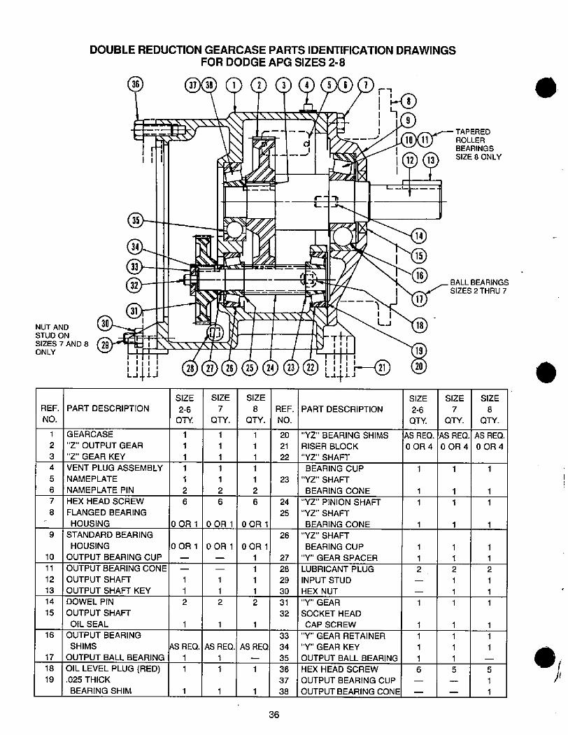
1
2
3
4
5
6
7
8
17
18
19
30NUT ANDSTUD ON
SIZES 7 AND 8 29ONLY
10
11
12
13
14
15
REF.
NO.
16
9
33
32
1
SIZE
2-6
QTY.
1
1
1
1
2
DOUBLE REDUCTION GEARCASE PARTS IDENTIFICATION DRAWINGSFOR DODGE APG SIZES 2-8
31
1 1Ll
37 38 Q * (f * (j)(D 0 -,37/ 1 1 40
1 Jff)clov117-
- --Ula/d
d V1 152*5/I -
16i P1 992::Mir ITL-L.6.---
r-7
C--N\35
PART DESCRIPTION
GEARCASE
"Z" OUTPUT GEAR
"Z" GEAR KEY
VENT PLUG ASSEMBLY
NAMEPLATE
NAMEPLATE PIN
HEX HEAD SCREW
FLANGED BEARING
HOUSING
STANDARD BEARING
HOUSING
OUTPUT BEARING CUP
1
J
1 X\\\
1 3 28 27 26 25 (8) 23 ®
OUTPUT BEARING CONE
OUTPUT SHAFT
OUTPUT SHAFT KEY
DOWEL PIN
OUTPUT SHAFT
OIL SEAL
OUTPUT BEARING
SHIMS
OUTPUT BALL BEARING
OIL LEVEL PLUG (RED).025 THICK
BEARING SHIM
1
1
1
1
1
2
6
0OR1
0OR1
1
1
2
AS REQ.
1
1
1
1
1
1
1
1
2
6
SIZE
7
QTY.
OOR 1
0 OR 1
AS REQ.
1
1
SIZE
8
QTY.
1
1
1
OOR 1
1
1
1
1
1
2
6
0OR1
1
1
1
1
2
AS REQ
36
33
34
35
36
37
38
24
25
REF.
NO.
20
21
22
23
26
27
28
29
30
31
32
Lt4l «5
PART DESCRIPTION
"YZ" BEARING SHIMS
RISER BLOCK
"YZ" SHAFT
BEARING CUP
"YZ" SHAFT
BEARING CONE
"YZ" PINION SHAFT
"YZ" SHAFT
BEARING CONE
"YZ" SHAFT
BEARING CUP
"Y" GEAR SPACER
LUBRICANT PLUG
INPUT STUD
HEX NUT
"Y" GEAR
SOCKET HEAD
CAP SCREW
"Y" GEAR RETAINER
"Y" GEAR KEY
OUTPUT BALL BEARING
HEX HEAD SCREW
OUTPUT BEARING CUP
OUTPUT BEARING CONE
LJ
14
11
SIZE
2-6
QTY.
1
1
1
1
1
1
1
1
6
1
18
AS REQ.
OOR#
1
1
2
SIZE
7
QTY.
TAPERED
ROLLER
BEARINGS
SIZE 8 ONLY
BALL BEARINGS
SIZES 2 THRU 7
AS REQ.
OOR 4
1
1
1
1
1
1
1
1
5
1
1
2
1
1
1
1
1
1
1
1
AS REQ.
0 OR 4
5
1
1
1
1
1
1
2
1
1
1
SIZE
8
QTY.
.j
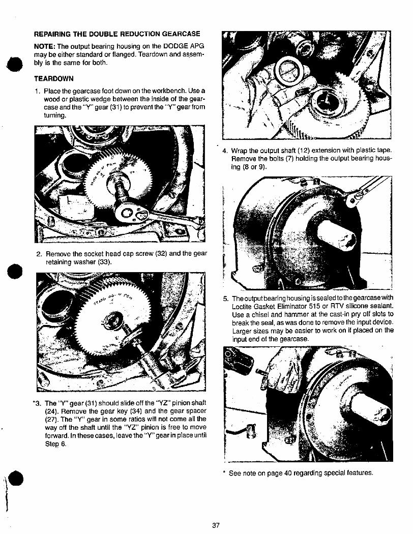
REPAIRING THE DOUBLE REDUCTION GEARCASE
NOTE: The output bearing housing on the DODGE APGmay be either standard or flanged. Teardown and assem-bly is the same for both.
TEARDOWN
1. Place the gearcase foot down on the workbench. Use awood or plastic wedge between the inside of the gear-case and the "Y" gear (31) to prevent the "Y" gear fromturning.
4
.e 9
4. Wrap the output shaft (12) extension with plastic tape.Remove the bolts (7) holding the output bearing hous-ing (8 or 9).
f
hi
2. Remove the socket head cap screw (32) and the gearretaining washer (33).
f
5. Theoutputbearing housing issealedtothegearcase withLoctite Gasket Eliminator 515 or RTV silicone sealant.Use a chisel and hammer at the cast-in pry off slots tobreak the seal, as was done to remove the input device.Larger sizes may be easier to work on if placed on theinput end of the gearcase.
*3. The "Y" gear (31) should slide off the "YZ" pinion shaft '(24). Remove the gear key (34) and the gear spacer(27). The "Y" gear in some ratios will not come all theway off the shaft until the "YZ" pinion is free to move ' JUI 4* -forward. In these cases, leave the "Y" gear in place until .-.13 MStep 6.
37
See note on page 40 regarding special features.
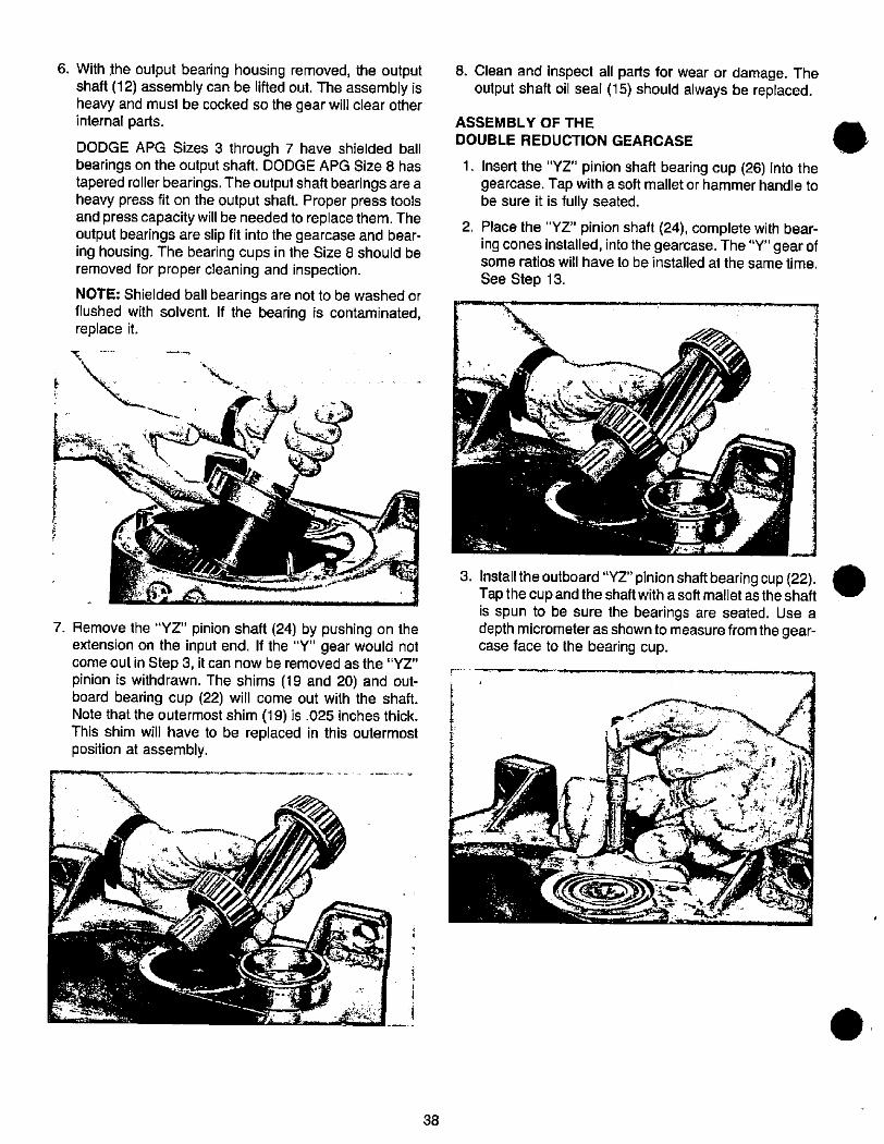
6. With the output bearing housing removed, the outputshaft (12) assembly can be lifted out. The assembly isheavy and must be cocked so the gear will clear otherinternal parts.
DODGE APG Sizes 3 through 7 have shielded ballbearings on the output shaft. DODGE APG Size 8 hastapered roller bearings. The output shaft bearings are aheavy press fit on the output shaft. Proper press toolsand press capacity will be needed to replace them. Theoutput bearings are slip fit into the gearcase and bear-ing housing. The bearing cups in the Size 8 should beremoved for proper cleaning and inspection.
NOTE: Shielded ball bearings are not to be washed orflushed with solvent. If the bearing is contaminated,replace it.
'.
I +
7. Remove the "YZ" pinion shaft (24) by pushing on theextension on the input end. If the "Y" gear would notcome out in Step 3, it can now be removed as the "YZ"pinion is withdrawn. The shims (19 and 20) and out-board bearing cup (22) will come out with the shaft.Note that the outermost shim (19) is .025 inches thick.This shim will have to be replaced in this outermostposition at assembly.
f
1
38
8. Clean and inspect all parts for wear or damage. Theoutput shaft oil seal (15) should always be replaced.
ASSEMBLY OF THE
DOUBLE REDUCTION GEARCASE
1. Insert the "YZ" pinion shaft bearing cup (26) into thegearcase. Tap with a soft mallet or hammer handle tobe sure it is fully seated.
2. Place the "YZ" pinion shaft (24), complete with bear-ing cones installed, into the gearcase. The "Y" gear ofsome ratios will have to be installed at the same time.
See Step 13.
3. Install the outboard "YZ" pinion shaft bearing cup (22).Tap the cup and the shaft with a soft mallet as the shaftis spun to be sure the bearings are seated. Use adepth micrometer as shown to measure from the gear-case face to the bearing cup.
15 +
.
.
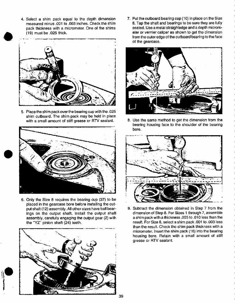
4. Select a shim pack equal to the depth dimension 7. Putthe outboard bearing cup (10) in place on the Sizemeasured minus .001 to .003 inches. Check the shim 8. Tap the shaft and bearings to be sure they are fullypack thickness with a micrometer. One of the shims seated. Use a metal straightedge and a depth microm-(19) must be .025 thick. eter or vernier caliper as shown to get the dimension
from the outeredge of the outboard bearing tothe face
, of the gearcase.
.kt,r
5. Place the shim pack over the bearing cup with the.025shim outboard. The shim pack may be held in placewith a small amount of stiff grease or RTV sealant. 8. Use the same method to get the dimension from the
bearing housing face to the shoulder of the bearingbore.
1 --1
16
6. Only the Size 8 requires the bearing cup (37) to beplaced in the gearcase bore before installing the out-put shaft (12) assembly. All other sizes have ball bear-ings on the output shaft. Install the output shaftassembly, carefully engaging the output gear (2) withthe "YZ" pinion shaft (24) teeth.
39
9. Subtract the dimension obtained in Step 7 from thedimension of Step 8. For Sizes 1 through 7, assemblea shim pack with a thickness.005 to.010 less than theresult. For Size 8, select a shim pack.001 to .003 lessthan the result. Check the shim pack thickness with amicrometer. Insert the shim pack (16) into the bearinghousing bore. Retain with a small amount of stiffgrease or RTV sealant.
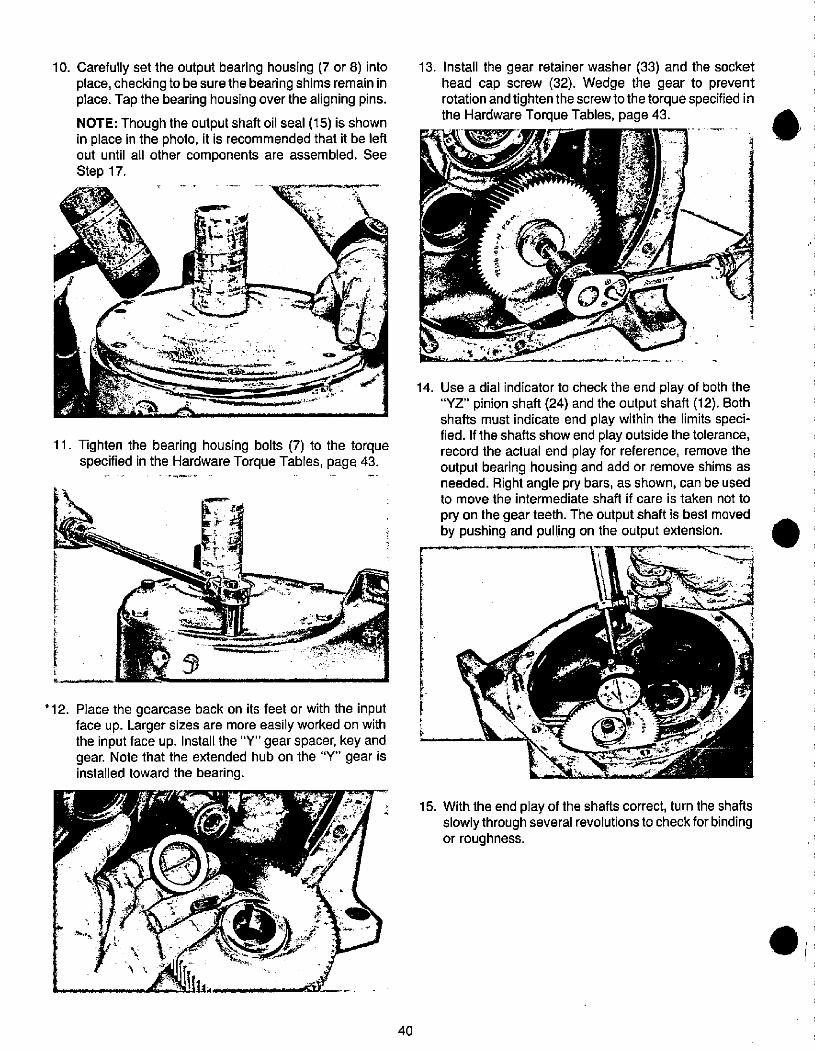
E
10. Carefully set the output bearing housing (7 or 8) intoplace, checking to be sure the bearing shims remain inplace. Tap the bearing housing over the aligning pins.
NOTE: Though the output shaft oil seal (15) is shownin place in the photo, it is recommended that it be leftout until all other components are assembled. SeeStep 17.
Im 1
13. Install the gear retainer washer (33) and the sockethead cap screw (32). Wedge the gear to preventrotation and tighten the screwto the torque specified inthe Hardware Torque Tables, page 43.
2
0
14.
11. Tighten the bearing housing bolts (7) to the torquespecified in the Hardware Torque Tables, page 43.
* 12. Place the gearcase back on its feet or with the inputface up. Larger sizes are more easily worked on withthe input face up. Install the "Y" gear spacer, key andgear. Note that the extended hub on the "Y" gear isinstalled toward the bearing.
Use a dial indicator to check the end play of both the"YZ" pinion shaft (24) and the output shaft (12). Bothshafts must indicate end play within the limits speci-fied. If the shafts show end play outside the tolerance,record the actual end play for reference, remove theoutput bearing housing and add or remove shims asneeded. Right angle pry bars, as shown, can be usedto move the intermediate shaft if care is taken not to
pry on the gear teeth. The output shaft is best movedby pushing and pulling on the output extension.
F
t
& 0
-
15. With the end play of the shafts correct, turn the shaftsslowly through several revolutions to check forbindingor roughness.
r
40
.
.t
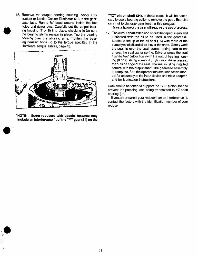
.
16. Remove the output bearing housing. Apply RTVsealant or Locfite Gasket Eliminator 515 to the gear-case face. Run a W' bead around inside the bolt
holes and dowel pins. Carefully set the output bear-ing housing (7 or 8) into place, checking to be surethe bearing shims remain in place. Tap the bearinghousing over the aligning pins. Tighten the bear-ing housing bolts (7) to the torque specified in theHardware Torque Tables, page 45.
1
1
*NOTE:-Some reducers with special features mayinclude an interference fit of the "Y" gear (31) on the
41
"YZ" pinion shaft (24). In those cases, it will be neces-sary to use a bearing puller to remove the gear. Exercisecare not to damage gear teeth in this process.
Reinstallation of the gear will require the use of a press.
17. The output shaft extension should be taped, clean andlubricated with the oil to be used in the gearcase.Lubricate the lip of the oil seal (15) with more of thesame type of oil and slide itoverthe shaft. Gently workthe seal lip over the seal journal, taking care to notunseat the seal garter spring. Drive or press the sealflush to 1/16" below flush with the output bearing hous-ing (8 or 9), using a smooth, cylindrical driver againsttheoutside edgeof theseal. Theseal mustbe installedsquare with the output shaft. The gearcase assemblyis complete. See the appropriate sections of this man-ual for assembly of the input device and triple adapter,and for lubrication instructions.
Care should be taken to support the "YZ" pinion shaft to
prevent the pressing load being transmitted to YZ shaftbearing (23).
If you are unsure if your reducer has an interference fit,
contact the factory with the identification number of yourreducer.
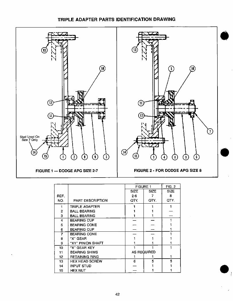
Stud Used On
Size 7 Only
14
13 ll '1\1 1k. 11.1
12
11
10 1
1 2893
FIGURE 1 - DODGE APG SIZE 2-7
REF.
NO.
1
2
3
4
5
6
7
8
9
10
11
12
13
14
15
A
PART DESCRIPTION
TRIPLE ADAPTER
BALL BEARING
BALL BEARING
BEARING CUP
BEARING CONE
BEARING CUP
BEARING CONE
"X" GEAR
"XY" PINION SHAFT
"X" GEAR KEY
BEARING SHIMS
RETAINING RING
HEX HEAD SCREW
INPUT STUD
HEX NUT
19
TRIPLE ADAPTER PARTS IDENTIFICATION DRAWING
42
14
SIZE
2-6
QTY.
1
1
1
15
ff]811 9 1k. 11 1
5 19
148
FIGURE 2 - FOR DODGE APG SIZE 8
FIGURE 1
SIZE
7
QTY.
9 6
1 1
1 1
1 1
AS REQUIRED
1 1
6 5
- 1
- 1
1
1
1
1
FIG. 2
SIZE
8
QTY.
1
1
1
1
1
1
1
1
5
1
1
1
.
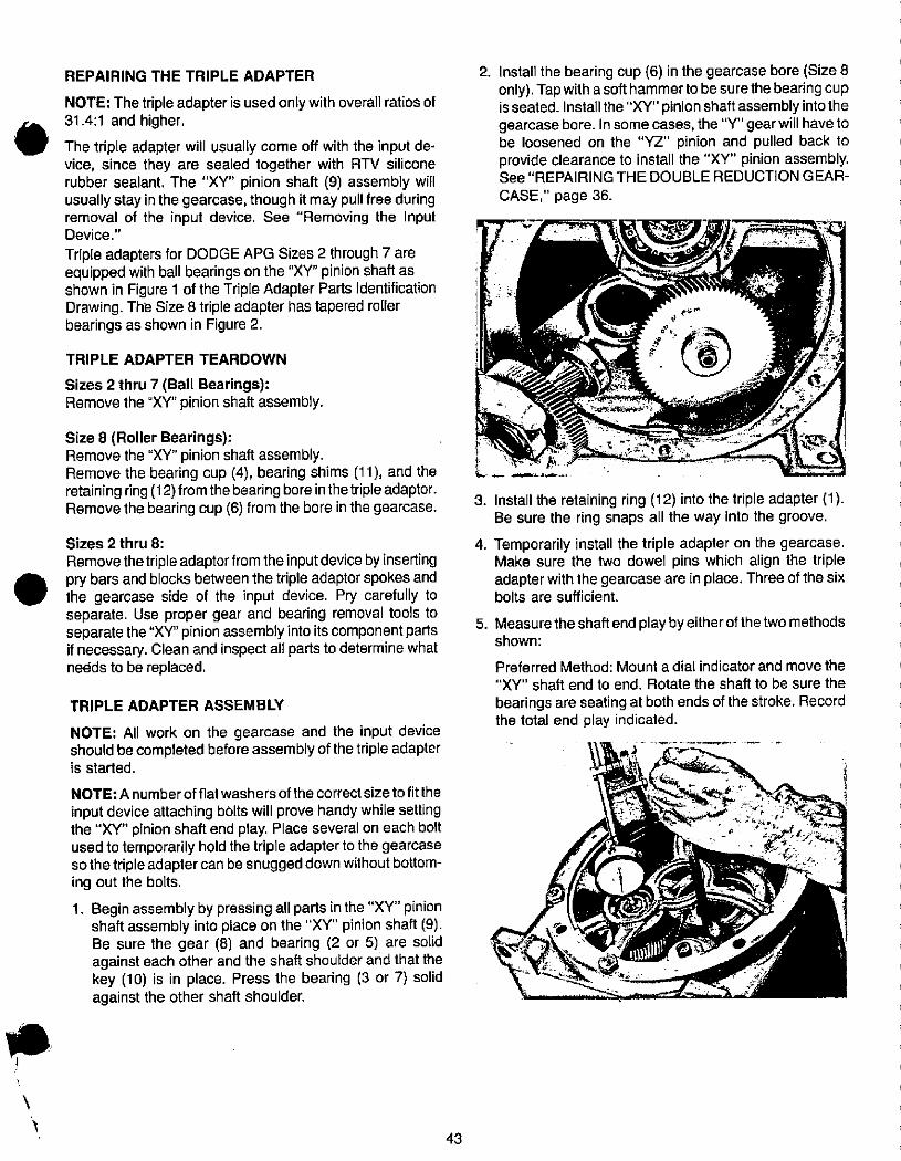
.
.
REPAIRING THE TRIPLE ADAPTER
NOTE: The triple adapter is used only with overall ratios of31.4:1 and higher.
The triple adapter will usually come off with the input de-vice, since they are sealed together with RTV siliconerubber sealant. The "XY" pinion shaft (9) assembly willusually stay in the gearcase, though it may pull free duringremoval of the input device. See "Removing the InputDevice."
Triple adapters for DODGE APG Sizes 2 through 7 areequipped with ball bearings on the "XY" pinion shaft asshown in Figure 1 of the Triple Adapter Parts IdentificationDrawing. The Size 8 triple adapter has tapered rollerbearings as shown in Figure 2.
TRIPLE ADAPTER TEARDOWN
Sizes 2 thru 7 (Ball Bearings):Remove the "XY" pinion shaft assembly.
Size 8 (Roller Bearings):Remove the "XY" pinion shaft assembly.Remove the bearing cup (4), bearing shims (11), and theretaining ring (12) from the bearing bore in thetriple adaptor.Remove the bearing cup (6) from the bore in the gearcase.
Sizes 2 thru 8:
Remove the triple adaptor from the input device by insertingpry bars and blocks between the triple adaptor spokes andthe gearcase side of the input device. Pry carefully toseparate. Use proper gear and bearing removal tools toseparate the "XY" pinion assembly into its component partsif necessary. Clean and inspect all parts to determine whatne6ds to be replaced.
TRIPLE ADAPTER ASSEMBLY
NOTE: All work on the gearcase and the input deviceshould be completed before assembly of the triple adapteris started.
NOTE: A number of flat washers of the correct size to fit the
input device attaching bolts will prove handy while settingthe "XY" pinion shaft end play. Place several on each boltused to temporarily hold the triple adapter to the gearcasesothetriple adaptercan be snugged down without bottom-ing out the bolts.
1. Begin assembly by pressing all parts in the "XY" pinionshaft assembly into place on the "XY" pinion shaft (9).Be sure the gear (8) and bearing (2 or 5) are solidagainst each other and the shaft shoulder and that thekey (10) is in place. Press the bearing (3 or 7) solidagainst the other shaft shoulder.
43
2. Install the bearing cup (6) in the gearcase bore (Size 8only). Tap with a softhammerto besurethe bearing cupisseated. Install the "XY" pinion shaftassembly into thegearcase bore. In some cases, the "Y" gear will have tobe loosened on the "YZ" pinion and pulled back toprovide clearance to install the "XY" pinion assembly.See"REPAIRING THE DOUBLE REDUCTION GEAR-
CASE," page 36.
3. Install the retaining ring (12) into the triple adapter (1).Be sure the ring snaps all the way into the groove.
4. Temporarily install the triple adapter on the gearcase.Make sure the two dowel pins which align the tripleadapter with the gearcase are in place. Three of the sixbolts are sufficient.
5. Measurethe shaft end play byeitherof thetwo methodsshown:
Preferred Method: Mount a dial indicator and move the
"XY" shaft end to end. Rotate the shaft to be sure the
bearings are seating at both ends of the stroke. Recordthe total end play indicated.
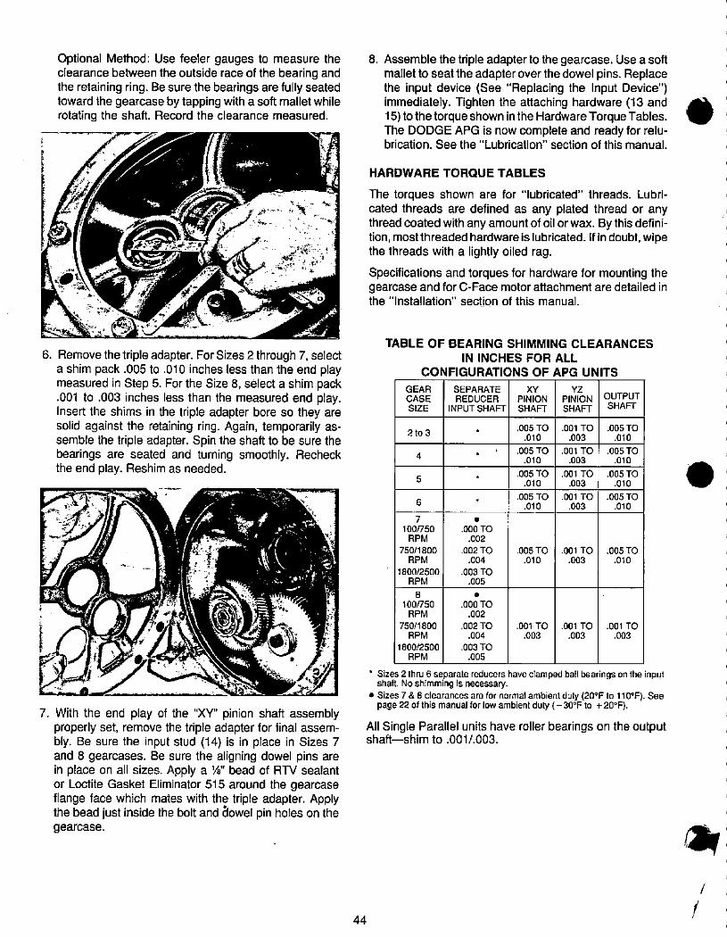
Optional Method: Use feeler gauges to measure theclearance between the outside race of the bearing andthe retaining ring. Be sure the bearings are fully seatedtoward the gearcase by tapping with a soft mallet whilerotating the shaft. Record the clearance measured.
/r=
6. Remove the triple adapter. For Sizes 2 through 7, selecta shim pack .005 to .010 inches less than the end playmeasured in Step 5. For the Size 8, select a shim pack.001 to .003 inches less than the measured end play.Insert the shims in the triple adapter bore so they aresolid against the retaining ring. Again, temporarily as-semble the triple adapter. Spin the shaft to be sure thebearings are seated and turning smoothly. Recheckthe end play. Reshim as needed.
4
1 -
7. With the end play of the "XY" pinion shaft assemblyproperly set, remove the triple adapter for final assem-bly. Be sure the input stud (14) is in place in Sizes 7and 8 gearcases. Be sure the aligning dowel pins arein place on all sizes. Apply a W bead of RTV sealantor Loctite Gasket Eliminator 515 around the gearcaseflange face which mates with the triple adapter. Applythe bead just inside the bolt and 61owel pin holes on thegearcase.
44
GEAR
CASE
SIZE
4
8. Assemble the triple adapter to the gearcase. Use a softmallet to seat the adapter over the dowel pins. Replacethe input device (See "Replacing the Input Device")immediately. Tighten the attaching hardware (13 and15) tothetorque shown inthe Hardware Torque Tables.The DODGE APG is now complete and ready for relu-brication. See the "Lubrication" section of this manual.
HARDWARE TORQUE TABLES
The torques shown are for "lubricated" threads. Lubri-cated threads are defined as any plated thread or anythread coated with any amount of oil or wax. By this defini-tion, most threaded hardware is lubricated. If in doubt, wipethe threads with a lightly oiled rag.
Specifications and torques for hardware for mounting thegearcase and for C-Face motor attachment are detailed inthe "Installation" section of this manual.
TABLE OF BEARING SHIMMING CLEARANCES
IN INCHES FOR ALL
CONFIGURATIONS OF APG UNITS
2 to 3
6
5
7
100/750
RPM
750/1800
RPM
1800/2500
RPM
8
100/750RPM
750/1800
RPM
1800/2500
RPM
SEPARATE
REDUCER
INPUT SHAFT
.000 TO
.002
.002 TO
.004
.003 TO.005
.000 TO
.002
.002 TO
.004
.003 TO
.005
XY
PINION
SHAFT
.005 TO
.010
.005 TO.010
.005 TO.010
.005 TO.010
.005 TO.010
.001 TO.003
YZ
PINION
SHAFT
.001 TO
.003
.001 TO.003
.001 TO
.003
.001 TO.003
.001 TO.003
.001 TO
.003
OUTPUT
SHAFT
.005 TO.010
.005 TO.010
.005 TO
.010
.005 TO.010
.005 TO.010
.001 TO.003
' Sizes 2 thru 6 separate reducers have clamped ball bearings on the inputshaft. No shimming is necessary.
•Sizes 7&8 clearances are for normal ambient duty (20°F to 110°F). Seepage 22 of this manual for low ambient duty ( -30°F to +20°F).
All Single Parallel units have roller bearings on the outputshaft-shim to .001/.003.
.
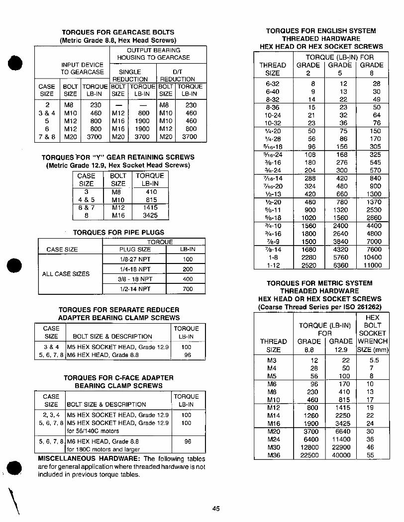
.
CASE
SIZE
2
3&4
5
6
7&8
TORQUES FOR GEARCASE BOLTS
(Metric Grade 8.8, Hex Head Screws)
INPUT DEVICE
TO GEARCASE
BOLT
SIZE
TORQUE
LB-IN
M12
M16
M16
M20
OUTPUT BEARING
HOUSING TO GEARCASE
SINGLE
REDUCTION
BOLT TORQUE
SIZE LB-IN
D/T
REDUCTION
BOLT TORQUE
SIZE LB-IN
CASE SIZE
CASE
SIZE
3&4
5,6,7,8
CASE
SIZE
2,3,4
5,6,7,8
M8
M10
M12
M12
M20
3
4&5
6&7
8
230
460
800
800
3700
TORQUES 'FOR "Y" GEAR RETAINING SCREWS
(Metric Grade 12.9, Hex Socket Head Screws)
CASE BOLT TORQUE
SIZE SIZE LB-IN
M8
M10
M12
M16
TORQUES FOR PIPE PLUGS
ALL CASE SIZES
TORQUE
PLUG SIZE LB-IN
1/8-27 NPT
1/4-18 NPT
3/8 - 18 NPT
1/2-14 NPT
TORQUES FOR SEPARATE REDUCER
ADAPTER BEARING CLAMP SCREWS
BOLT SIZE & DESCRIPTION
M5 HEX SOCKET HEAD, Grade 12.9
M6 HEX HEAD, Grade 8.8
TORQUES FOR C-FACE ADAPTER
BEARING CLAMP SCREWS
BOLT SIZE & DESCRIPTION
M5 HEX SOCKET HEAD, Grade 12.9
M5 HEX SOCKET HEAD, Grade 12.9
for 56/1400 motors
800
1900
1900
3700
410
815
1415
3425
100
200
400
700
TORQUE
LB-IN
100
96
TORQUE
LB-IN
100
100
5,6,7,8 M6 HEX HEAD, Grade 8.8 96for 1800 motors and larger
MISCELLANEOUS HARDWARE: The following tablesare for general application where threaded hardware is notincluded in previous torque tables.
M8
M10
M10
M12
M20
230
460
460
800
3700
45
THREAD
SIZE
6-32
6-40
8-32
8-36
10-24
10-32
1/4-20
1/4-28946-18
SA 6-24
%-16
3/8-24
746-147/16-20
1/243
1/2-20
%-11
%-18
3/4-10
3/4-16
778-9
7/8-14
1-8
1-12
8
9
14
M12
M14
M16
M20
M24
M30
M36
M3
M4
M5
M6
M8
M10
480
900
1020
1560
1800
1500
1680
2280
2520
800
1260
1900
3700
6400
12800
22500
288
324
420
15
21
23
THREAD
SIZE
108
180
204
50
56
96
12
28
56
96
230
460
TORQUES FOR ENGLISH SYSTEM
THREADED HARDWARE
HEX HEAD OR HEX SOCKET SCREWS
TORQUE (LB-IN) FORGRADE GRADE GRADE
258
420
480
660
TORQUES FOR METRIC SYSTEM
THREADED HARDWARE
HEX HEAD OR HEX SOCKET SCREWS
(Coarse Thread Series per ISO 261262)
TORQUE (LB-IN)FOR
GRADE GRADE
8.8 12.9
780
1320
1560
2400
2640
3840
4320
5760
6360
75
86
156
168
276
300
12
13
22
23
32
36
170
410
815
22
50
100
HEX
BOLT
SOCKET
WRENCH
SIZE (mm)
5.5
7
8
10
13
17
19
22
24
840
900
1300
1370
2530
2660
4400
4800
7000
7600
10400
11000
1415
2250
3425
6640
11400
22900
40000
150
170
305
325
545
570
30
36
46
55
28
30
49
50
64
76
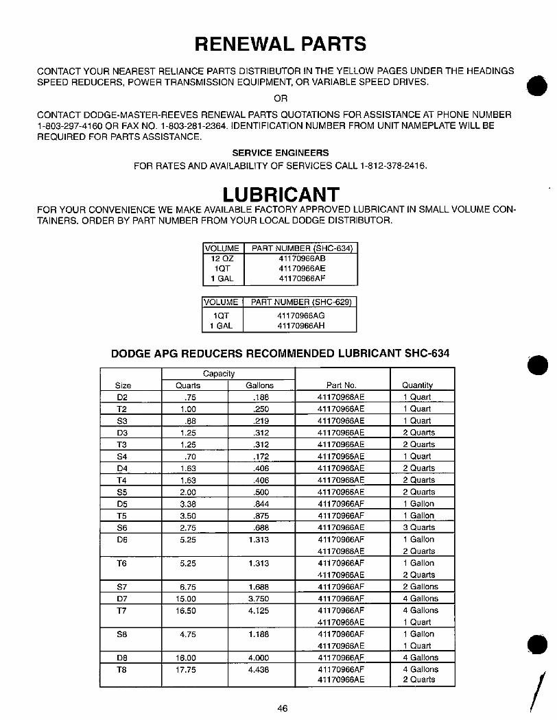
T3
S4
D4
T2
S3
D3
S7
D7
6.75
15.00
16.50
RENEWAL PARTS
CONTACT YOUR NEAREST RELIANCE PARTS DISTRIBUTOR IN THE YELLOW PAGES UNDER THE HEADINGS
SPEED REDUCERS, POWER TRANSMISSION EQUIPMENT, OR VARIABLE SPEED DRIVES.
OR
CONTACT DODGE-MASTER-REEVES RENEWAL PARTS QUOTATIONS FOR ASSISTANCE AT PHONE NUMBER
1-803-297-4160 OR FAX NO. 1-803-281-2364. IDENTIFICATION NUMBER FROM UNIT NAMEPLATE WILL BE
REQUIRED FOR PARTS ASSISTANCE.
SERVICE ENGINEERS
FOR RATES AND AVAILABILITY OF SERVICES CALL 1-812-378-2416.
LUBRICANTFOR YOUR CONVENIENCE WE MAKE AVAILABLE FACTORY APPROVED LUBRICANT IN SMALL VOLUME CON-
TAINERS. ORDER BY PART NUMBER FROM YOUR LOCAL DODGE DISTRIBUTOR.
VOLUME
12 OZ
1 QT
1 GAL
VOLUME
1 QT
1 GAL
PART NUMBER (SHC-634)41170966AB
41170966AE
41170966AF
PART NUMBER SHC-629)
41170966AG
41170966AH
DODGE APG REDUCERS RECOMMENDED LUBRICANT SHC-634
Size
D2
T4
S5
D5
T5
S6
D6
T6
T7
S8
D8
T8
QuaMs
.70
1.63
1.63
2.00
3.38
3.50
2.75
5.25
.75
1.00
.88
1.25
1.25
5.25
4.75
16.00
17.75
CapacityGallons
.188
.250
.219
.312
.312
.172
.406
.406
.500
.844
.875
.688
1.313
1.313
1.688
3.750
4.125
1.188
4.000
4.438
46
Part No.
41170966AE
41170966AE
41170966AE
41170966AE
41170966AE
41170966AE
41170966AE
41170966AE
41170966AE
41170966AF
41170966AF
41170966AE
41170966AF
41170966AE
41170966AF
41170966AE
41170966AF
41170966AF
41170966AF
41170966AE
41170966AF
41170966AE
41170966AF
41170966AF
41170966AE
Quantity
1 Quad
1 Quart
1 Quan
2 Quarts
2 Quarts
1 Quad
2 Quarls
2 Quarts
2 Quarts
1 Gallon
1 Gallon
3 Quarts
1 Gallon
2 Quarts
1 Gallon
2 Quarts
2 Gallons
4 Gallons
4 Gallons
1 Quart
1 Gallon
1 Quart
4 Gallons
4 Gallons
2 Quarts
.
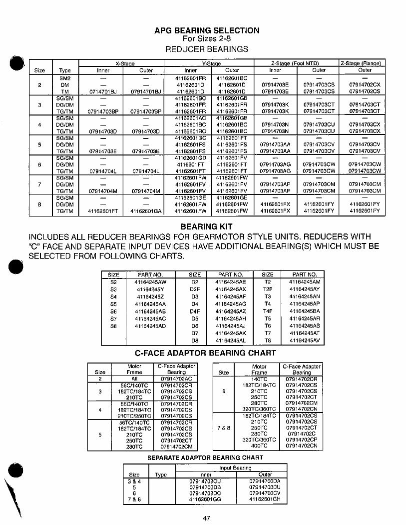
.
7
Size
4
5
6
8
2
3
SG/SM
DG/DM
TG/TM
SG/SM
DG/DM
TGHM
SG/SM
DG/DM
TG/TM
SG/SM
DG/DM
TG/TM
SG/SM
DG/DM
TG/rM
SG/SM
DG/DM
TGHM
Type
SM2
DM
TM
4
Size
2
Inner
0714701 BJ
079147038P
07914703D
07914703E
07914704L
07914704M
41162601 FT
SIZE
S2
S3
S4
S5
S6
S7
S8
X-Stacie
Outer
07914701 BJ
079147038P
07914703D
07914703E
07914704L
07914704M
41162601 GA
APG BEARING SELECTIONFor Sizes 2-8
REDUCER BEARINGS
Inner
41162601 FR
41162601D
41162601D
41162601 BC
41162601 FR
41162601 FR
41162601AC
41162601 BC
411626018C
41162601 GC
41162601 FS
41162601 FS
41162601 GD
4116201 FT
41162601 FT
41162601 FW
41162601 FV
41162601 FV
41162601 GE
41162601 FW
41162601 FW
Y-S'age
6
Outer
411626018C
41162601D
41162601D
41162601 GB
41162601 FR
41162601 FR
41162601 GB
41162601 BC
411626018C
41162601 FT
41162601 FS
41162601 FS
41162601 FV
41162601 FT
41162601 FT
41162601 FW
41162601 FV
41162601 FV
41162601 GE
41162601 FW
41162601 FW
SIZE
T2
T2F
T3
T4
T4F
T5
T6
17
T8
Z-Stage (Foot MTD)Inner Outer
07914703E
07914703E
07914703K
07914703K
07914703N
07914703N
07914703AA
07914703AA
07914703AG
07914703AG
07914703AP
07914703AP
41162601 FX
41162601 FX
07914703CS
07914703CS
07914703CT
07914703CT
07914703CU
07914703CU
07914703CV
07914703CV
07914703CW
07914703CW
07914703CM
07914703CM
41162601 FY
41162601 FY
Z-Stage (Flanqe)Outer
07914702CX
07914702CS
07914703CT
07914703CT
07914703CX
07914703CX
07914703CV
07914703CV
07914703CW
07914703CW
07914703CM
07914703CM
41162601 FY
41162601 FY
BEARING KIT
INCLUDES ALL REDUCER BEARINGS FOR GEARMOTOR STYLE UNITS. REDUCERS WITH
"C" FACE AND SEPARATE INPUT DEVICES HAVE ADDITIONAL BEARING(S) WHICH MUST BESELECTED FROM FOLLOWING CHARTS.
3
5
PART NO.
41164245AW
41164245Y
411642452
41164245AA
41164245AB
41164245AC
41164245AD
SIZE
D2
D2F
D3
D4
D4F
D5
D6
D7
D8
PART NO.
41164245AE
41164245AX
41164245AF
41164245AG
41164245AZ
41164245AH
41164245AJ
41164245AK
41164245AL
C-FACE ADAPTOR BEARING CHART
Motor
Frame
All
56C/140TC
182TC/184TC
210TC
56C/140TC
182TC/184TC
210TC/250TC
56TC/140TC
182TC/184TC
210TC
250TC
280TC
Size
3&4
5
6
7&8
C-Face AdaptorBearing
07914702AC
07914702CR
07914702CS
07914702CS
07914702CR
07914702CS
07914702CS
07914702CR
07914702CS
07914702CS
07914702CT
07914702CM
Size
7&8
Motor
Frame
140TC
182TC/184TC
210TC
250TC
280TC
320TC/360TC
182TC/184TC
210TC
250TC
280TC
320TC/360TC
400TC
SEPARATE ADAPTOR BEARING CHART
Type Inner
07914703CU
07914703DB
07914703DC
41162601GG
47
Input BearingOuter
07914703DA07914703CU
07914703CV
41162601 GH
PART NO.
41164245AM
41164245AY
41164245AN
41164245AP
41164245BA
41164245AR
41164245AS
41164245AT
41164245AV
C-Face Adaptor
Bearing07914702CR
07914702CS
07914702CS
07914702CT
07914702CM
07914702CN
07914702CS
07914702CS
07914702CT
07914702C
07914702CP
07914702CN
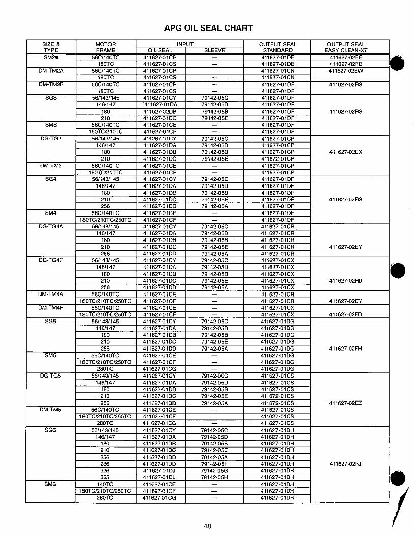
SIZE &
TYPE
SM2•
DM-TM2A
DM-TM2F
SG3
SM3
DG-TG3
DM-TM3
SG4
SM4
DG-TG4A
DG-TG4F
DM-TM4A
DM-TM4F
SG5
SMS
DG-TGS
DM-TMS
SGG
SM6
MOTOR
FRAME
56C/14OTC
180TC
56C/140TC
180TC
56C/14OTC
180TC
56/143/145
146/147
180
210
56C/140TC
180TC/210TC
56/143/145
146/147
180
210
56C/140TC
180TC/210TC
56/143/145
146/147
180
210
256
56C/140TC
180TC/210TC/250TC
56/143/145
146/147
180
210
256
56/143/145
146/147
180
210
256
56C/140TC
180TC/210TC/250TC
560/14OTC
180TC/210TC/250TC
56/143/145
146/147
180
210
256
56C/140TC
180TC/210TC/250TC
280TC
56/143/145
146/147
180
210
256
56C/14OTC
180TC/210TC/250TC
280TC
56/143/145
146/147
180
210
256
286
326
365
140TC
180TC/210TC/250TC
280TC
APG OIL SEAL CHART
OIL SEAL
411627-01 CR
411627-01 CS
411627-01 CR
411627-01 CS
411627-01 CR
411627-01 CS
411627-01 CY
411627-01 DA
411627-02DB
411627-01 DC
411627-01 CE
411627-01 CF
411267-01 CY
411627-01 DA
411627-01 DB
411627-01 DC
411627-01 CE
411627-01CF
411627-01 CY
411627-01 DA
411627-01 DB
411627-01 DC
411627-01 DD
411627-01 CE
411627-01 CF
411627-01 CY
411627-01 DA
411627-01 DB
411627-01 DC
411627-01 DD
411627-01CY
411627-01 DA
411627-01 DB
411627-01 DC
411627-01 DD
411627-01 CE
411627-01 CF
411627-01 CE
411627-01 CF
411627-01 CY
411627-01 DA
411627-01 DB
411627-01 DC
411627-01 DD
411627-01 CE
411627-01 CF
411627-01CG
411267-01 CY
411627-01 DA
411627-01 DB
411627-01 DC
411627-01 DD
411627-01 CE
411627-01 CF
411627-01 CG
411627-01CY
411627-01 DA
411627-01 DB
411627-01 DC
411627-01 DD
411627-01 DD
411627-01 DJ
411 627-01 DL
411627-01 CE
411627-01 CF
411627-01 CG
INPUT
SLEEVE
48
79142-05C
79142-050
79142-058
79142-05E
79142-05C
79142-05D
79142-058
79142-05E
79142-05C
79142-05D
79142-058
79142-05E
79142-05A
79142-OSC
79142-05D
79142-058
79142-05E
79142-05A
79142-05C
79142-05D
79142-058
79142-OSE
79142-05A
79142-05C
79142-05D
79142-058
79142-05E
79142-05A
79142-060
79142-05D
79142-058
79142-OSE
79142-05A
79142-05C
79142-05D
79142-058
79142-05E
79142-05A
79142-05F
79142-05G
79142-05H
OUTPUT SEAL
STANDARD
411627-01 DE
411627-01 DE
411627-01 CN
411627-01 CN
411627-01 DF
411627-01 DF
411627-01 DF
411627-01 DF
411627-01 DF
411627-01 DF
411627-01 DF
411627-01 DF
411627-01 CP
411627-01 CP
411627-01 CP
411672-01 CP
411627-01 CP
411627-01 CP
411627-01 DF
411627-01 DF
411627-01 DF
411627-01 DF
411627-01 DF
411627-01 DF
411627-01 DF
411627-01 CR
411627-01 CR
411627-01 CR
411627-01 CR
411627-01 CR
411627-01 CX
411627-01 CX
411627-01 CX
411627-01 CX
411627-01 CX
411627-01 CR
411627-01 CR
411627-01 CX
411627-01 CX
411627-01 DG
411627-01 DG
411627-01 DG
411627-01 DG
411627-01 DG
411627-01 DG
411627-01 DG
411627-01 DG
411627-01 CS
411627-01 CS
411627-01 CS
411672-01 CS
411672-01 CS
411627-01 CS
411627-01 CS
411627-01 CS
411627-01 DH
411627-01 DH
411627-01 DH
411627-01 DH
411627-01 DH
411627-01 DH
411627-01 DH
411627-01 DH
411627-01 DH
411627-01 DH
411627-01 DH
OUTPUT SEAL
EASY CLEAN-XT
411627-02FE
411627-02FE
411627-02EW
411627-02FG
411627-02FG
411627-02EX
411627-02FG
411627-02EY
411627-02FD
411627-02EY
411627-02FD
411627-02FH
411627-02EZ
411627-02FJ
.
.
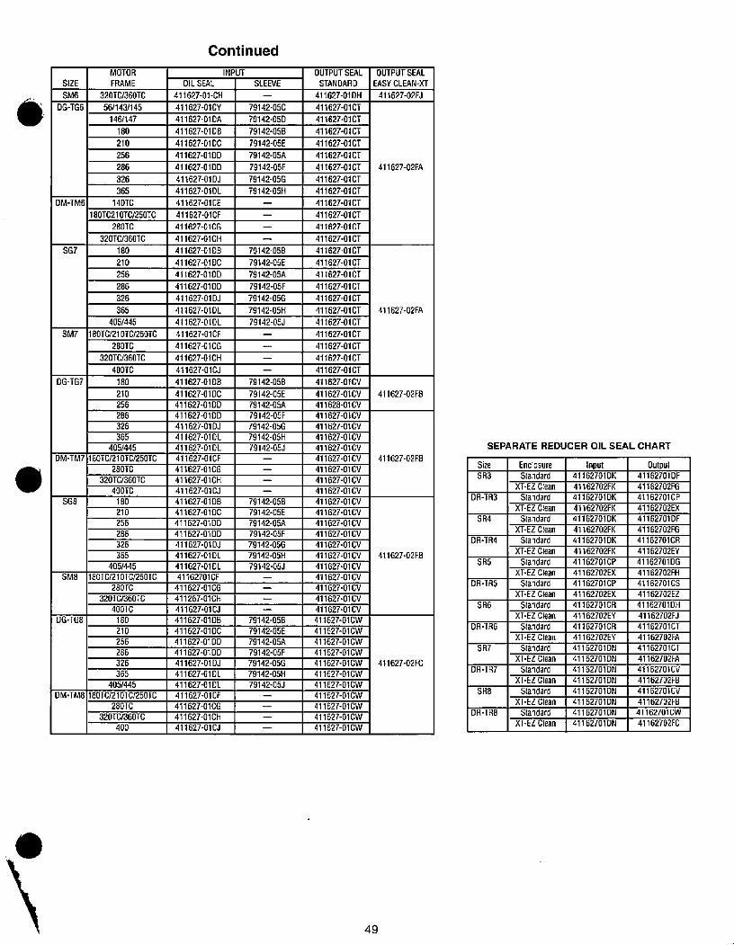
.SIZE
SM6
DG-TGG
DM-TMG
SG7
SM7
DG-TG7
DM-TM7
SG8
SM8
DG-TGB
DM-1-M8
MOTOR
FRAME
320TC/360TC
56/143/145
146/147
180
210
256
286
326
365
140TC
18OT(21016/25OTC
280TC
320TC/360TC
180
210
256
286
326
365
405/445
180TC/210TC/250TC
280TC
320TC/360TC
400TC
180
210
256
286
326
365
405/445
1 BOTC/21OTC/250TC
280TC
320TC/360TC
400TC
180
210
256
286
326
365
405/445
18OTC/21 OTC/250TC
280TC
320TC/360TC
400TC
180
210
256
286
326
365
405/445
180TC/210TC/250TC
280TC
320TC/360TC
400
OILSEAL
411627-01-CH
411627-01CY
411627-01 DA
411627-01 DB
411627-01 DC
411627-01 DD
411627-01 DD
411627-01 DJ
411627-01DL
411627-01 CE
411627-01CF
411627-01CG
411627-01CH
411627-01 DB
411627-01 DC
411627-01 DD
411627-01 DD
411627-01 DJ
411627-01DL
411627-01DL
411627-01CF
411627-01CG
411627-01CH
411627-01CJ
411627-01 DB
411627-01 DC
411627-01 DD
411627-01 DD
411627-01 DJ
411627-01 DL
411627-01 DL
411627-01(F
411627-01 CG
411627-01CH
411627-01CJ
411627·01DB
411627-01[C
411627·01 DD
411627-01 DD
411627-01 DJ
411627-01 DL
411627-01 DL
41162701CF
411627-01 CG
411267-01CH
411627-01 CJ
411627-0108
411627-01 DC
411627-0100
411627-0100
411627-01 DJ
411627-01 DL
411627-01 DL
411627-01 CF
411627-01CG
411627-01 CH
411627-0101
Continued
INPUT
SLEEVE
79142-056
79142-050
79142-058
79142-05E
79142-05A
79142-05F
79142·05G
79142-05H
79142-058
79142-05E
79142-05A
79142-05F
79142-05G
79142-05H
79142-05J
79142-058
79142-05E
79142-05A
79142-05F
79142-05G
79142-05H
79142-053
79142-058
79142-OSE
79142-05A
79142-05F
79142-05G
79142-05H
79142-05J
79142-058
79142-05E
79142-05A
79142-05F
79142-05G
79142-05H
79142-05J
OUTPUT SEAL
STANDARD
411627-01 DH
411627-01CT
411627-01CT
411627-01 CT
411627-01 CT
411627-01 CT
411627-01 CT
411 627-01 CT
411627-01 CT
411627-01 CT
411627-01 CT
411627-01 CT
411627-01 CT
411627-01 CT
411627-01 CT
411627-01 CT
411627-01 CT
411627-01 CT
411627-01 CT
411627-01 CT
411627-01 CT
411627-01CT
411627-01 CT
411627-01 CT
411627-01CV
411627-01CV
411628-01CV
411627-01CV
411627-01CV
411627-01CV
411627-01CV
411627-01 CV
411627-01 CV
411627-01 CV
411627-01 CV
411627-01 CV
411627-01CV
411627-01 CV
411627-01 CV
411627-01 CV
411627-01 CV
411627-01 CV
411627-01 CV
411627-01 CV
411627-01 CV
411627-01 CV
411627-01CW
411627-01CW
411627-01CW
411627-01CW
411627-01CW
411627-01CW
411627-01CW
411627-01CW
411627-01CW
411627-01CW
411627-01CW
49
OUTPUT SEAL
EASY CLEAN-XT
411627-02FJ
411627-02FA
411627-02FA
411627-02FB
411627-02FB
411627-02FB
411627-02FC
Size
SR3
SEPARATE REDUCER OIL SEAL CHART
DR-TR3
SR4
DR-TR4
SR5
DR-TRS
SR6
DR-TRG
SR7
DR-TR7
SRB
DR-TR8
Enclosure
Standard
XT-EZ Clean
Standard
XT-EZ Clean
Standard
XT-EZ Clean
Standard
XT-EZ Clean
Standard
XT-EZ Clean
Standard
XT-EZ Clean
Standard
XT-EZ Clean
Standard
XT-EZ Clean
Standard
XT-EZCIean
Standard
XT-EZCIean
Standard
XT-EZ Clean
Standard
XT·EZ Clean
Input41162701 DK
41162702FK
41162701 DK
41162702FK
41162701 DK
41162702FK
41162701 DK
41162702FK
41162701CP
41162702EX
41162701CP
41162702EX
41162701CR
41162702EY
41162701CR
41162702EY
41162701 DN
41162701DN
41162701 DN
41162701 DN
41162701 DN
41162701 DN
41162701 DN
41162701 DN
Output41162701DF
41162702FG
41162701 CP
41162702EX
41162701 DF
41162702FG
41162701CR
41162702EY
41162701 DG
41162702FH
41162701 CS
41162702EZ
41162701 DH
41162702FJ
41162701 CT
41162702FA
41162701CT
41162702FA
41162701CV
41162702FB
41162701CV
41162702FB
41162701 CW
41162702FC
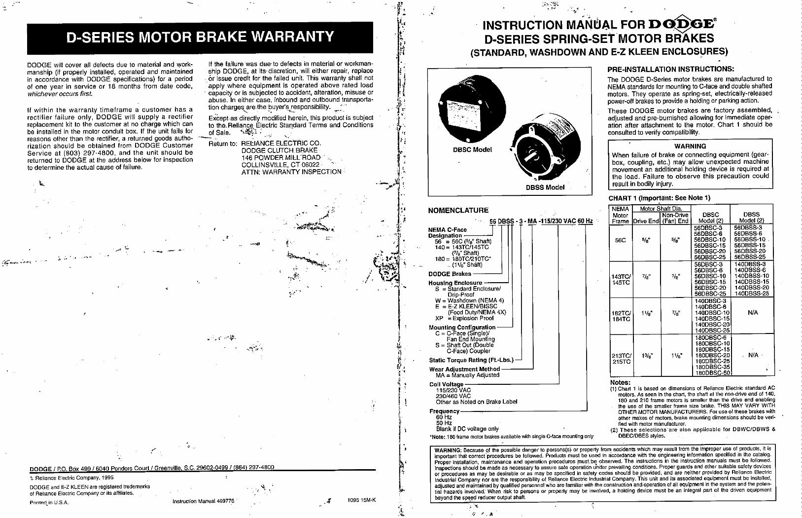
'
D-SERIES MOTOR BRAKE WARRANTY
DODGE will cover all defects due to material and work-
manship (if properly installed, operated and maintainedin accordance with DODGE specifications) for a periodof one year in service or 18 months from date code,whichever occurs first.
If within the warranty timeframe a customer has arectifier failure only, DODGE will supply a rectifierreplacement kit to the customer at no charge which canbe installed in the motor conduit box. If the unit fails for
reasons other than the rectifier, a returned goods autho-rization should be obtained from DODGE CustomerService at (803) 297-4800, and the unit should bereturned to DODGE at the address below for inspectionto determine the actual cause of failure.
If the failure was due· to defects in material or workman-
ship DODGE, at its· discretion, will either repair, replace6r issue credit for the failed unit. This warranty shall notapply where equipment is operated above rated load
' capacity or is subjected to accident, alteration, misuse orabuse. In either case, inbound and outbound transporta-
tion chargesre.the buyer's responsibility. *Ex6ept· as directly modified herein, this product is subjectto the. Reliance,Electric Standard Terms and Conditionsof Sale. 4*1 2Return to: REtIANCE ELECTRIC CO.
DODGE CLUTCH BRAKE
146 POWDER MIELROAD· - .,COLLINSVILLE, CT 06022 -ATTN: WARRANTY INSPECTION -
DODGE / P.O. Box 499 / 6040 Ponders Court / Greenville, S.C. 29602-0499 / (864) 297-4800t Reliance Electric Company, 1995
DODGE and E-Z KLEEN are registered trademarksof Reliance Electric Company or its affiliates.
Printed in US.A. Instruction Manual 499776
'A
Y
14
34
.·
..2 Ii:.fr:
'I ?
I.
./. ft?41.
. . -L
.f 109515M-K
,,
h
1
*
ti
.iy
f.
f
t'
1,
':1 4. 5./.
INSTRUCTION MANUAL FOR DODGEiD-SERIES SPRING-SET MOTOR BRAKES
(STANDARD, WASHDOWN AND E-Z KLEEN ENCLOSURES)
DBSC Model ,
DBSS Model
NOMENCLATURE
56 DBSS - 3NEMA C-Face -- -Designation
56 = 56 (5/8" Shaft)140= 143TC/145TC
(7/8" Shaft)180 = 180TC/210TC*
.(11/8" Shaft)
DODGE Brakes
Housing EnclosureS = Standard Enclosure/
Drip-ProofW = Washdown (NEMA 4)E = E-Z KLEEN/BISSC
(Food Duty/NEMA 4)0XP = Explosion Proof
Mounting ConfigurationC = C-Face (Single)/
Fan End MountingS = Shaft Out (Double
C-Face) Coupler
Static Torque Rating (Ft.-Lbs.)
p Wear Adjustment MethodMA = Manually Adjusted
Coll Voltagc115/230 VAC230/460 VAC
1 Other as Noted on Brake Label
- MA -115/230 VAC 60 Hz
Frequency60 Hz50 Hz
Blank if DC voltage only
'Note: 180 frame motor brakes available with single C-face mounting only
PRE-INSTALLATION INSTRUCTIONS:
The DODGE D-Series motor brakes are manufactured toNEMA standards for mounting to C-face and double shaftedmotors. They operate as spring-set, electrically-releasedpower-off brakes to provide a holding or parking action.These DODGE motor brakes are factory assembled,adjusted and pre-bumished allowing for immediate oper-ation after attachment to the motor. Chart 1 should beconsulted to verify compatibility.
WARNING
When failure of brake or connecting equipment (gear-box, coupling, etc.) may allow unexpected machinemovement an additional holding device is required atthe load. Failure to observe this precaution couldresult in bodily injury.
CHART 1 (Important: See Note 1)
NEMA Motor E haft Dia.
Motor Non-Drive
Frame Drive End (Fan) End
56C
143TC/
145TC
182TCY184TC
213TC/215TC
7/8'
11/8"
13/8"
5/8"
7/8"
11/8"
DBSC
Model (2)56DBSC-3
56DBSC-656DBSC-1056DBSC-1556DBSC-2056DBSC-25
56DBSC-356DBSC-656DBSC-10
56DBSC-1556DBSC-2056DBSC-25
140DBSC-3140DBSC-6
140DBSC-10140DBSC-15140DBSC-20
140DBSC-25
180DBSC-6180DBSC-10180DBSC-15180DBSC-20180DBSC-25180DBSC-35180DBSC-50
DBSS
Model (2)56DBSS-356DBSS-656DBSS-10
56DBSS-15
56DBSS-2056DBSS-25
140DBSS-3
140DBSS-6140DBSS-10140DBSS-15140DBSS-20140DBSS-25
N/A
N/A
Notes:
(1) Chart 1 is based on dimensions of Reliance Electric standard ACmotors. As seen in the chart, the shaft at the non-drive end of 140,180 and 210 frame motors is smaller than the drive end enablingthe use of the smaller frame size brake. THIS MAY VARY WITHOTHER MOTOR MANUFACTURERS. For use ol these brakes with
other makes of motors, brake mounting dimensions should be veri-fied with motor manufacturer.
(2) These selectionsare also applicable for DBWC/DBWS &DBEC/DBES styles.
WARNING: Because qf the possible danger to persons(s) or property from accidents which may result from the improper use of products, it isimportant thatcorrect procedures be followed. Products must be used in accordance with the engineering information specified in the catalog.Proper installation, maintenance and operation procedures must.·bq observed. The instructions in the instruction manuals must be followed.Inspections should be made as necessary to assure safe operati6n under prevailing conditions. Proper guards and other suitable safety devicesor procedures as may be desirable or as may be specified in safety codes should be provided, and are neither provided by Reliance ElectricIndustrial Company nor are the responsibility of Reliance Electric Industrial Company. This unit and its associated equipment must be installed,adjusted and maintained by qualified personnel who bre familiar with the construction and operation of all equipment in the system and the poten-tial hazards involved.- When risk to persons or property may be involved, a holding device must be an integral part of the driven equipmentbeyond the speed reducer output shaft.
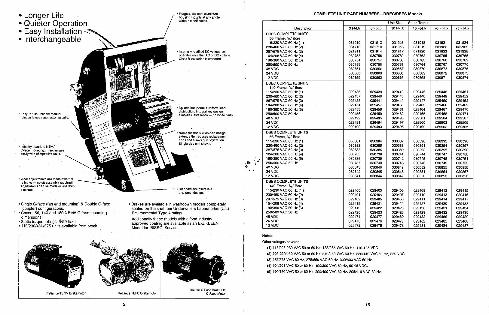
.
.
.
Longer LifeQuieter OperationEasy Installation -<:301Interchangeable
• Easy-to-use, reliable manualrelease levers reset automatically.
• Industry standard NEMAC-face mounting. Interchangeseasily with competitive units.
• Wear adjustments are made externalto brake - no disassembly required!Adjustments can be made in less thana minute.
sa"i
l
• Single C-face (fan end mounting) & Double C-face(coupler) configurations.
• Covers 56, 140 dind 180 NEMA C-face mountingdimensions.
• Static torque ratings: 3-50 lb.-ft.• 115/230/460/575 units available from stock.
-'.8812,01/11--
G*r'
Reliance TENV Brakemotor
2
• Rugged, die-cast aluminumhousing mounts at any anglewithout modification.
• Internally rectified DC voltage coiloperates on either AC or DC voltage.Class B insulation is standard.
• Splined hub permits uniform loaddistribution. Integral key designsimplifies installation - no loose parts.
• Non-asbestos friction disc designextends life, reduces replacementparts and allows quiet operation.Single disc unit shown.
- •Standard enclosure is a
drip-proof design.
• Brakes are available in washdown models completelysealed on the shaft per Underwriters Laboratories (U/L)Environmental Type 4 rating.
Additionally these models with a food industryapproved coating are available as an E-Z KLEENModel for 'BISSC' Service.
-t
22.2/*-:" <.
I .
14. .'4
Reliance TEFC Brakemotor
811"44#A
Double C-Face Brake On
C-Face Motor
*
4
1
.06 i'
Description
DBEC COMPLETE UNITS
56 Frame, 5/8" Bore
115/230 VAC 60 Hz (1 )230/460 VAC 60 Hz (2)
287/575 VAC 60 Hz (3)104/208 VAC 60 Hz (4)
190/380 VAC 50 Hz (5)250/500 VAC 50 Hz
48 VDC
24 VDC12 VDC
DBEC COMPLETE UNITS
140 Frame, 5/8" Bore
115/230 VAC 60 Hz (1)
230/460 yAC 60 Hz (2)
287/575 VAC 60 Hz (3)104/208 VAC 60 Hz (4)190/380 VAC 50 Hz (5)
250/500 VAC 50 Hz
48 VDC
24 VDC
12 VDC
DBES COMPLETE UNITS
56 Frame, %" Bore
115/230 VAC 60 Hz (1)
230/460 VAC 60 Hz (2)287/575 VAC 60 Hz (3)104/208 VAC 60 Hz (4)190/380 VAC 50 Hz (5)250/500 VAC 50 Hz
48 VDC
24 VDC12 VDC
DBES COMPLETE UNITS
140 Frame, 5/8 Bore
115/230 VAC 60 Hz (1 )
230/460 VAC 60 Hz (2)287/575 VAC 60 Hz (3)104/208 VAC 60 Hz (4)
190/380 VAC 50 Hz (5)250/500 VAC 50 Hz
48 VDC
24 VDC
12 VDC
COMPLETE UNIT PART NUMBERS-DBEC/DBES Models
3 Ft-Lb
031910
031716
031911
030753
030754
030755
030861
030860
030859
029436
029437
029438
029454
029455
029456
029492
029491
029490
030381
030382
030383
030735
030736
030737
030843
030842
030841
029400
029401
029402
029418
029419
029420
029474
029473
029472
6 Ft-Lb
031913
031718
031914
030756
030757
030758
030864
030863
030862
029439
029440
029441
029457
029458
029459
029495
029494
029493
030384
030385
030386
030738
030739
030740
030846
030845
030844
029403
029404
029405
029421
029422
029423
029477
029476
029475
Unit Size
10 Ft-Lb
031915
031916
031917
030759
030760
030761
030867
030866
030865
029442
029443
029444
029460
029461
029462
029498
029497
029496
030387
030388
030389
030741
030742
030743
030849
030848
030847
029406
029407
029408
029424
029425
029426
029480
029479
029478
Notes:
Other voltages covered
(1) 115/208-230 VAC 50 or 60 Hz, 133/265 VAC 60 Hz, 110-125 VDC.
(2) 208-230/460 VAC 50 or 60 Hz, 240/480 VAC 60 Hz, 220/440 VAC 50 Hz, 230 VDC.
(3) 287/575 VAC 60 Hz, 275/550 VAC 60 Hz, 300/600 VAC 60 Hz.
(4) 104/208 VAC 50 or 60 Hz, 100/200 VAC 60 Hz, 90-95 VDC.
(5) 190/380 VAC 50 or 60 Hz, 200/400 VAC 60 Hz, 208/416 VAC 50 Hz.
15
Static Torque
15 Ft-Lb
031918
031919
031920
030762
030763
030764
030870
030869
030868
029445
029446
029447
029463
029464
029465
029501
029500
029499
030390
030391
030392
030744
030745
030746
030852
030851
030850
029409
029410
029411
029427
029428
029429
029483
029482
029481
20 Ft-Lb
031921
031922
031923
030765
030766
030767
030873
030872
030871
029448
029449
029450
029466
029467
029468
029504
029503
029502
030393
030394
030395
030747
030748
030749
030855
030854
030853
029412
029413
029414
029430
029431
029432
029486
029485
029484
25 Ft-Lb
031924
031925
031926
030768
030769
030770
030876
030875
030874
029451
029452
029453
029469
029470
029471
029507
029506
029505
030396
030397
030398
030750
030751
030752
030858
030857
030856
029415
029416
029417
029433
029434
029435
029489
029488
029487
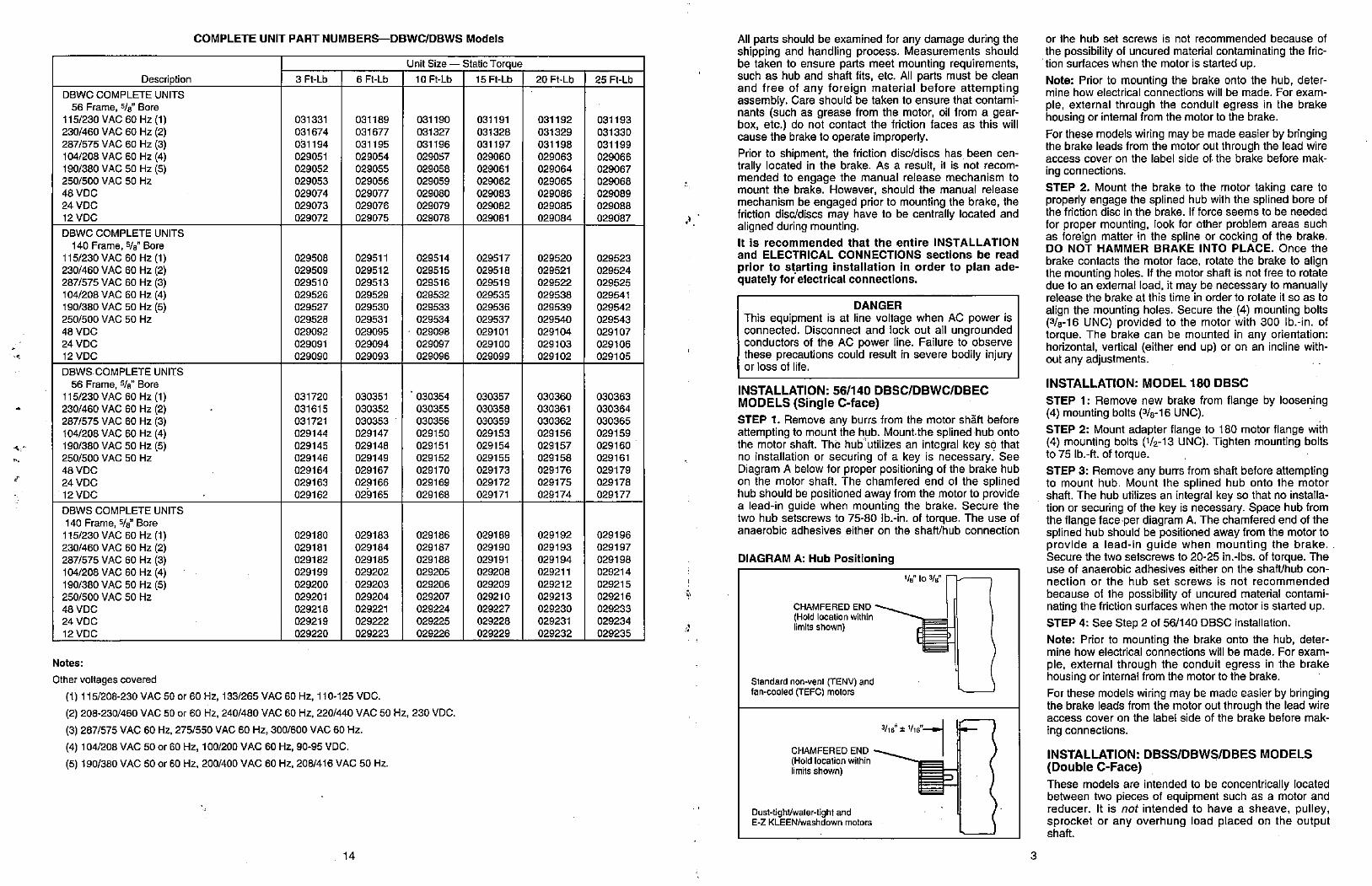
F.I
Description
DBWC COMPLETE UNITS
56 Frame, 5/8 Bore
115/230 VAC 60 Hz (1)230/460 VAC 60 Hz (2)
287/575 VAC 60 Hz (3)
104/208 VAC 60 Hz (4)
190/380 VAC 50 Hz (5)250/500 VAC 50 Hz
48 VDC
24 VDC12 VDC
DBWC COMPLETE UNITS
140 Frame, 5/8" Bore
115/230 VAC 60 Hz (1)230/460 VAC 60 Hz (2)287/575 VAC 60 Hz (3)
104/208 VAC 60 Hz (4)190/380 VAC 50 Hz (5)250/500 VAC 50 Hz
48 VDC
24 VDC
12 VDC
DBWS COMPLETE UNITS
56 Frame, %" Bore
115/230 VAC 60 Hz (1)230/460 VAC 60 Hz (2)
287/575 VAC 60 Hz (3)104/208 VAC 60 Hz (4)
190/380 VAC 50 Hz (5)250/500 VAC 50 Hz
48 VDC
24 VDC12 VDC
DBWS COMPLETE UNITS
140 Frame, 5/8" Bore
115/230 VAC 60 Hz (1)
230/460 VAC 60 Hz (2)287/575 VAC 60 Hz (3)
104/208 VAC 60 Hz (4)
190/380 VAC 50 Hz (5)250/500 VAC 50 Hz
48 VDC
24 VDC
12 VDC
COMPLETE UNIT PART NUMBERS-DBWC/DBWS Models
3 Ft-Lb
031331
031674
031194
029051
029052
029053
029074
029073
029072
029508
029509
029510
029526
029527
029528
029092
029091
029090
031720
031615
031721
029144
029145
029146
029164
029163
029162
029180
029181
029182
029199
029200
029201
029218
029219
029220
6 Ft-Lb
031189
031677
031195
029054
029055
029056
029077
029076
029075
029511
029512
029513
029529
029530
029531
029095
029094
029093
030351
030352
030353
029147
029148
029149
029167
029166
029165
029183
029184
029185
029202
029203
029204
029221
029222
029223
Unit Size
10 Ft-Lb
031190
031327
031196
029057
029058
029059
029080
029079
029078
029514
029515
029516
029532
029533
029534
029098
029097
029096
030354
030355
030356
029150
029151
029152
029170
029169
029168
029186
029187
029188
029205
029206
029207
029224
029225
029226
Notes:
Other voltages covered
(1) 115/208-230 VAC 50 or 60 Hz, 133/265 VAC 60 Hz, 110-125 VDC.
(2) 208-230/460 VAC 50 or 60 Hz, 240/480 VAC 60 Hz, 220/440 VAC 50 Hz, 230 VDC.
(3) 287/575 VAC 60 Hz, 275/550 VAC 60 Hz, 300/600 VAC 60 Hz.
(4) 104/208 VAC 50 or 60 Hz, 100/200 VAC 60 Hz, 90-95 VDC.
(5) 190/380 VAC 50 or 60 Hz, 200/400 VAC 60 Hz, 208/416 VAC 50 Hz.
14
Static Torque
15 Ft-Lb
031191
031328
031197
029060
029061
029062
029083
029082
029081
029517
029518
029519
029535
029536
029537
029101
029100
029099
030357
030358
030359
029153
029154
029155
029173
029172
029171
029189
029190
029191
029208
029209
029210
029227
029228
029229
20 Ft-Lb
031192
031329
031198
029063
029064
029065
029086
029085
029084
029520
029521
029522
029538
029539
029540
029104
029103
029102
030360
030361
030362
029156
029157
029158
029176
029175
029174
029192
029193
029194
029211
029212
029213
029230
029231
029232
25 Ft-Lb
031193
031330
031199
029066
029067
029068
029089
029088
029687
029523
029524
029525
029541
029542
029543
029107
029106
029105
030363
030364
030365
029159
029160
029161
029179
029178
029177
029196
029197
029198
029214
029215
029216
029233
029234
029235
All parts should be examined for any damage during theshipping and handling process. Measurements shouldbe taken to ensure parts meet mounting requirements,
' such as hub and shaft fits, etc. All parts must be cleanand free of any foreign material before attemptingassembly. Care should be taken to ensure that contami-nants (such as grease from the motor, oil from a gear-box, etc.) do not contact the friction faces as this willcause the brake to operate improperly.
Prior to shipment, the friction disc/discs has been cen-trally located in the brake. As a result, it is not recom-mended to engage the manual release mechanism tomount the brake. However, should the manual release
mechanism be engaged prior to mounting the brake, the
j * friction disc/discs may have to be centrally located andaligned during mounting.
It is recommended that the entire INSTALLATION
and ELECTRICAL CONNECTIONS sections be read
prior to starting installation in order to plan ade-quately for electrical connections.
DANGER
This equipment is at line voltage when AC power isconnected. Disconnect and lock out all ungroundedconductors of the AC power line. Failure to observethese precautions could result in severe bodily injuryor loss of life.
INSTALLATION: 56/140 DBSC/DBWC/DBEC
MODELS (Single C-face)
STEP 1. Remove any burrs from the motor shaft beforeattempting to mount the hub. Mount.the splined hub ontothe motor shaft. The hub'utilizes an integral key s<? thatno installation or securing of a key is necessary. SeeDiagram A below for proper positioning of the brake hubon the motor shaft. The chamfered end of the splinedhub should be positioned away from the motor to providea lead-in guide when mounting the brake. Secure thetwo hub setscrews to 75-80 lb.-in. of torque. The use ofanaerobic adhesives either on the shaft/hub connection
DIAGRAM A: Hub Positioning
CHAMFERED END
(Hold location withinlimits shown)
Standard non-vent (TENV) andfan-cooled (TEFC) motors
CHAMFERED END
(Hold location withinlimits shown)
Dust-tighVwater-tight andE-Z KLEEN/washdown motors
1/s" to 34"
3/is" * 1/16"--• 1-
3
or the hub set screws is not recommended because of
the possibility of uncured material contaminating the fric-tion surfaces when the motor is started up.
Note: Prior to mounting the brake onto the hub, deter-mine how electrical connections will be made. For exam-
pie, external through the conduit egress in the brakehousing or internal from the motor to the brake.
For these models wiring may be made easier by bringingthe brake leads from the motor out through the lead wireaccess cover on the label side of the brake before mak-
ng connections.
STEP 2. Mount the brake to the motor taking care toproperly engage the splined hub with the splined bore ofthe friction disc in the brake. If force seems to be needed
for proper mounting, look for other problem areas suchas foreign matter in the spline or cocking of the brake.DO NOT HAMMER BRAKE INTO PLACE. Once the
brake contacts the motor face, rotate the brake to alignthe mounting holes. If the motor shaft is not free to rotatedue to an external load, it may be necessary to manuallyrelease the brake at this time in order to rotate it so as to
align the mounting holes. Secure the (4) mounting bolts(3/8-16 UNC) provided to the motor with 300 lb.-in. oftorque. The brake can be mounted in any orientation:horizontal, vertical (either end up) or on an incline with-out any adjustments.
INSTALLATION: MODEL 180 DBSC
STEP 1: Remove new brake from flange by loosening(4) mounting bolts (3/8-16 UNC).
STEP 2: Mount adapter flange to 180 motor flange with(4) mounting bolts (1/2-13 UNC). Tighten mounting boltsto 75 lb.-ft. of torque.
STEP 3: Remove any burrs from shaft before attemptingto mount hub. Mount the splined hub onto the motorshaft. The hub utilizes an integral key so that no installa-tion or securing of the key is necessary. Space hub fromthe flange face·per diagram A. The chamfered end of thesplined hub should be positioned away from the motor toprovide a lead-in guide when mounting the brake.Secure the two setscrews to 20-25 in.-lbs. of torque. Theuse of anaerobic adhesives either on the shafUhub con-
nection or the hub set screws is not recommended
because of the possibility of uncured material contami-nating the friction surfaces when the motor is started up.
STEP 4: See Step 2 of 56/140 DBSC installation.
Note: Prior to mounting the brake onto the hub, deter-mine how electrical connections will be made. For exam-
pie, external through the conduit egress in the brakehousing or internal from the motor to the brake.
For these models wiring may be made easier by bringingthe brake leads from the motor out through the lead wireaccess cover on the label side of the brake before mak-
ing connections.
INSTALLATION: DBSS/DBWS/DBES MODELS
(Double C-Face)
These models are intended to be concentrically locatedbetween two pieces of equipment such as a motor andreducer. It is not intended to have a sheave, pulley,sprocket or any overhung load placed on the outputshaft.
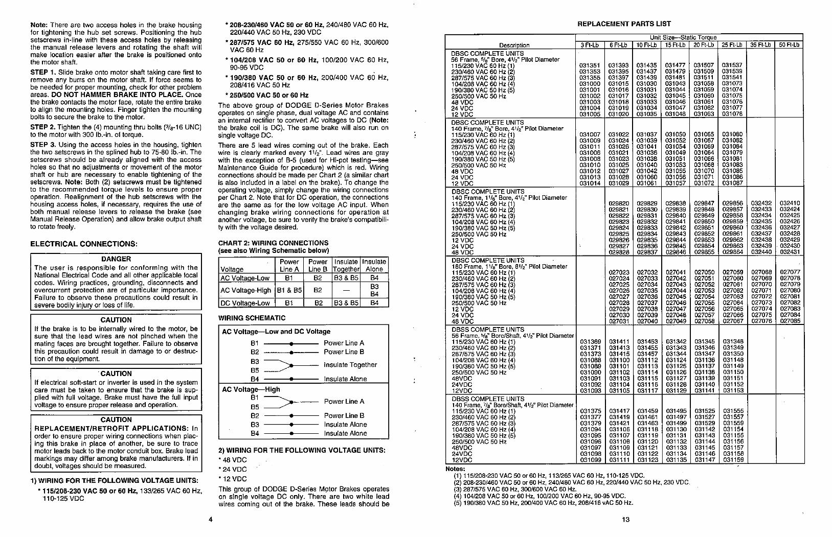
Note: There are two access holes in the brake housingfor tightening the hub set screws. Positioning the hubsetscrews in-line with these access holes by releasingthe manual release levers and rotating the shaft willmake location easier after the brake is positioned ontothe motor shaft.
STEP 1. Slide brake onto motor shaft taking care first toremove any burrs on the motor shaft. If force seems tobe needed for proper mounting, check for other problemareas. DO NOT HAMMER BRAKE INTO PLACE. Once
the brake contacts the motor face, rotate the entire brake
to align the mounting holes. Finger tighten the mountingbolts to secure the brake to the motor.
STEP 2. Tighten the (4) mounting thru bolts (3/8-16 UNC)to the motor with 300 lb.-in. of torque.
STEP 3. Using the access holes in the housing, tightenthe two setscrews in the splined hub to 75-80 lb.-in. Thesetscrews should be already aligned with the accessholes so that no adjustments or movement of the motorshaft or hub are necessary to enable tightening of thesetscrews. Note: Both (2) setscrews must be tightenedto the recommended torque levels to ensure properoperation. Realignment of the hub setscrews with thehousing access holes, if necessary, requires the use ofboth manual release levers to release the brake (seeManual Release Operation) and allow brake output shaftto rotate freely.
ELECTRICAL CONNECTIONS:
DANGER
The user is responsible for conforming with theNational Electrical Code and all other applicable localcodes. Wiring practices, grounding, disconnects andovercurrent protection are of particular importance.Failure to observe these precautions could result insevere bodily injury or loss of life.
CAUTION
If the brake is to be internally wired to the motor, besure that the lead wires are not pinched when themating faces are brought together. Failure to observethis precaution could result in damage to or destruc-tion of the equipment.
CAUTION
If electrical soft-start or inverter is used in the systemcare must be taken to ensure that the brake is sup-plied with full voltage. Brake must have the full inputvoltage to ensure proper release and operation.
CAUTION
REPLACEMENT/RETROFIT APPLICATIONS: In
order to ensure proper wiring connections when plac-ing this brake in place of another, be sure to tracemotor leads back to the motor conduit box. Brake lead
markings may differ among brake manufacturers. If indoubt, voltages should be measured.
1) WIRING FOR T.HE FOLLOWING VOLTAGE UNITS:
* 115/208-230 VAC 50 or 60 Hz, 133/265 VAC 60 Hz,110-125 VDC
4
* 208-230/460 VAC 50 or 60 Hz, 240/480 VAC 60 Hz,220/440 VAC 50 Hz, 230 VDC
* 287/575 VAC 60 Hz, 275/550 VAC 60 Hz, 300/600VAC 60 Hz
* 104/208 VAC 50 or 60 Hz, 100/200 VAC 60 Hz,
90-95 VDC
* 190/380 VAC 50 or 60 Hz, 200/400 VAC 60 Hz,208/416 VAC 50 Hz
* 250/500 VAC 50 or 60 Hz
The above group of DODGE D-Series Motor Brakesoperates on single phase, dual voltage AC and containsan internal rectifier to convert AC voltages to DC (Note:the brake coil is DC). The same brake will also run onsingle voltage DC.
There are 5 lead wires coming out of the brake. Eachwire is clearly marked every 11/2: Lead wires are graywith the exception of B-5 (used for Hi-pot testing-seeMaintenance Guide for procedure) which is red. Wiringconnections should be made per Chart 2 (a similar chartis also included in a label on the brake). To change theoperating voltage, simply change the wiring connectionsper Chart 2. Note that for DC operation, the connectionsare the same as for the low voltage AC input. Whenchanging brake wiring connections for operation atanother voltage, be sure to verify the brake's compatibili-ty with the voltage desired.
CHART 2: WIRING CONNECTIONS
(see also Wiring Schematic below)
Voltage
AC Voltage-Low
AC Voltage-High
DC Voltage-Low
WIRING SCHEMATIC
Power
Line A
B1
Bl & 85
B1
Power
Line B
B2
B2
B2
Insulate
Together83 & 85
83 & 85
AC Voltage-Low and DC Voltage
81 0 Power Line A
82 0 Power Line B
B3
85 Insulate Together
84 • Insulate Alone
AC Voltage-HighB1
85 82 •
83 •
84 •
Power Line A
Power Line B
Insulate Alone
Insulate Alone
Insulate
Alone
B4
B3
B4
B4
2) WIRING FOR THE FOLLOWING VOLTAGE UNITS:
* 48 VDC
*24 VDC
* 12 VDC
This group of DODGE D-Series Motor Brakes operateson single voltage DC only. There are two white leadwires coming out of the brake. These leads should be
Description
DBSC COMPLETE UNITS56 Frame, 5/8" Bore, 41/2" Pilot Diameter115/230 VAC 60 Hz (1)230/460 VAC 60 Hz (2)287/575 VAC 60 Hz (3)104/208 VAC 60 Hz (4)190/380 VAC 50 Hz (5)250/500 VAC 50 Hz48 VDC
24 VDC
12 VDC
DBSC COMPLETE UNITS
140 Frame, 7/8" Bore, 41/2" Pilot Diameter115/230 VAC 60 Hz (1)230/460 VAC 60 Hz (2)287/575 VAC 60 Hz (3)104/208 VAC 60 Hz (4)190/380 VAC 50 Hz (5)250/500 VAC 50 Hz
48 VDC24 VDC
12 VDC
DBSC COMPLETE UNITS
140 Frame, 11/8" Bore, 41/2" Pilot Diameter115/230 VAC 60 Hz (1)230/460 VAC 60 Hz (2)287/575 VAC 60 Hz (3)104/208 VAC 60 Hz (4)190/380 VAC 50 Hz (5)250/500 VAC 50 Hz12 VDC
24 VDC
48 VDC
DBSC COMPLETE UNITS
180 Frame, 11/8" Bore, 81/2" Pilot Diameter115/230 VAC 60 Hz (1)230/460 VAC 60 Hz (2)287/575 VAC 60 Hz (3)104/208 VAC 60 Hz (4)190/380 VAC 50 Hz (5)250/500 VAC 50 Hz
12 VDC
24 VDC48 VDC
DBSS COMPLETE UNITS56 Frame, 5/8" Bore/Shaft, 41/2" Pilot Diameter115/230 VAC 60 Hz (1)230/460 VAC 60 Hz (2)287/575 VAC 60 Hz (3)104/208 VAC 60 Hz (4)190/380 VAC 50 Hz (5)250/500 VAC 50 Hz
48VDC
24VDC
12VDC
DBSS COMPLETE UNITS
140 Frame, 7/8" Bore/Shaft, 41/2" Pilot Diameter115/230 VAC 60 Hz (1)230/460 VAC 60 Hz (2)287/575 VAC 60 Hz (3)104/208 VAC 60 Hz (4)190/380 VAC 50 Hz (5)250/500 VAC 50 Hz
48VDC
24VDC12VDC
REPLACEMENT PARTS LIST
3 Ft-Lb
031351
031353
031355
031000
031001
031002031003
031004
031005
031007
031009
031011031006
031008
031010
031012
031013
031014
031369
031371
031373031088
031089
031090
031091
031092
031093
031375
031377
031379
031094
031095031096
031097
031098
031099
6 Ft-Lb
031393
031395
031397
031015
031016031017
031018
031019
031020
031022031024031026
031021031023
031025031027
031028031029
029820
029821
029822
029823
029824
029825
029826
029827
029828
027023
027024
027025
027026
027027
027028
027029
027030
027031
031411
031413
031415
031100
031101
031102
031103
031104
031105
031417
031419
031421031106
031107
031108
031109
031110
031111
Unit Size-Static Torque10 Ft-Lb 15 Ft-Lb 20 Ft-Lb
031435
031437
031439
031030
031031
031032
031033
031034
031035
031037031039
031041031036
031038
031040
031042031060
031061
029829
029830
029831
029832
029833
029834
029835
029836
029837
027032
027033
027034
027035
027036
027037
027038
027039
027040
031453
031455
031457
031112
031113
031114
031115
031116
031117
031459
031461
031463
031118
031119
031120
031121
031122
031123
031477
031479
031481
031043
031044
031045
031046031047
031048
031050
031052
031054
031049
031051
031053
031055
031056
031057
029838
029839
029840
029841
029842
029843
029844
029845
029846
027041
027042
027043
027044
027045
027046
027047
027048
027049
031342031343
031344031124
031125
031126
031127
031128
031129
031495
031497
031499
031130
031131
031132
031133
031134
031135
Notes:
(1) 115/208-230 VAC 50 or 60 Hz, 113/265 VAC 60 Hz, 110-125 VDC.(2) 208-230/460 VAC 50 or 60 Hz, 240/480 VAC 60 Hz, 220/440 VAC 50 Hz, 230 VDC.(3) 287/575 VAC 60 Hz, 300/600 VAC 60 Hz.(4) 104/208 VAC 50 or 60 Hz, 100/200 VAC 60 Hz, 90-95 VDC.(5) 190/380 VAC 50 Hz, 200/400 VAC 60 Hz, 208/416 vAC 50 Hz.
13
031507
031509
031511
031058
031059
031060
031061
031062
031063
031065031067
031069
031064031066
031068031070
031071
031072
029847
029848
029849
029850
029851
029852
029853
029854029855
027050
027051
027052
027053
027054
027055
027056
027057
027058
031345
031346031347
031136
031137
031138
031139031140
031141
031525031527
031529
031142
031143031144
031145
031146
031147
25 Ft-Lb
031537
031539031541
031073
031074
031075
031076
031077031078
031080
031082
031084
031079
031081
031083
031085
031086
031087
029856
029857
029858
029859
029860
029861
029862
029863
029864
027059
027060
027061
027062
027063
027064
027065
027066
027067
031348
031349
031350
031148031149
031150
031151
031152
031153
031555
031557
031559
031154
031155
031156
031157
031158
031159
35 Ft-Lb
032432
032433
032434032435
032436
032437
032438
032439
032440
027068
027069
027070
027071
027072
027073
027074
027075
027076
50 Ft-Lb
032410
032424
032425
032426
032427
032428
032429032430
032431
027077
027078
027079
027080027081
027082
027083
027084
027085
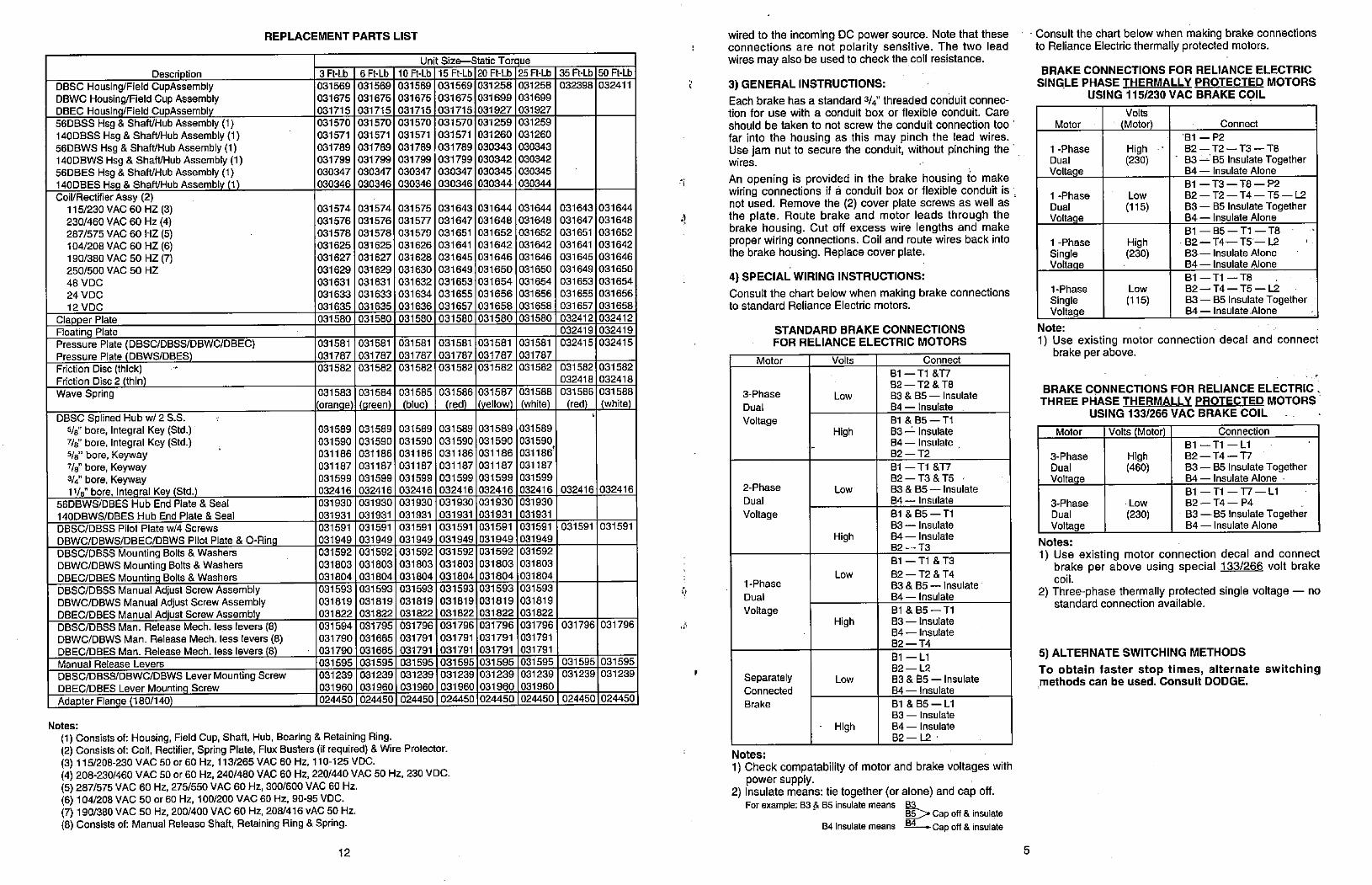
Description
DBSC Housing/Field CupAssemblyDBWC Housing/Field Cup AssemblyDBEC Housing/Field CupAssembly56DBSS Hsg & ShaWHub Assembly (1)
140DBSS Hsg & ShaNHub Assembly (1)56DBWS Hsg & Shaft/Hub Assembly (1)140DBWS Hsg & Shaft/Hub Assembly (1)56DBES Hsg & ShaWHub Assembly (1)140DBES Hsg & Shaft/Hub Assembly (1)Coil/Rectifier Assy (2)
115/230 VAC 60 HZ (3)230/460 VAC 60 Hz (4)287/575 VAC 60 HZ (5)
104/208 VAC 60 HZ (6)190/380 VAC 50 HZ (7)250/500 VAC 50 HZ
48 VDC
24 VDC12 VDC
Clapper Plate
Floating Plate
Pressure Plate (DBSC/DBSS/DBWC/DBEC)Pressure Plate (DBWS/DBES)
Friction Disc (thick)Friction Disc 2 (thin)Wave Spring
DBSC Splined Hub w/ 2 S.S.5/8' bore, Integral Key (Std.)7/8 bore, Integral Key (Std.)5/8- bore, Keyway7/8" bore, Keyway
3/4" bore, Keyway11/8" bore, Integral Key (Std.)
56DBWS/DBES Hub End Plate & Seal
140DBWS/DBES Hub End Plate & Seal
REPLACEMENT PARTS LIST
DBSC/DBSS Pilot Plate w/4 Screws
DBWC/DBWS/DBEC/DBWS Pilot Plate & 0-RingDBSC/DBSS Mounting Bolts & WashersDBWC/DBWS Mounting Bolts & WashersDBEC/DBES Mounting Bolts & WashersDBSC/DBSS Manual Adjust Screw AssemblyDBWC/DBWS Manual Adjust Screw AssemblyDBEC/DBES Manual Adjust Screw AssemblyDBSC/DBSS Man. Release Mech. less levers (8)DBWC/DBWS Man. Release Mech. less levers (8)DBEC/DBES Man. Release Mech. less levers (8)Manual Release Levers
DBSC/DBSS/DBWC/DBWS Lever Mounting ScrewDBEC/DBES Lever Mounting ScrewAdapter Flange (180/140)
3 Ft-Lb
031569
031675
031715
031570
031571
031789
031799
030347
030346
031574
031576
031578
031625
031627
031629
031631
031633
031635
031580
031581
031787
031582
031583
(orange)
031589
031590
031186
031187
031599
032416
031930
031931
031591
031949
031592
031803
031804
031593
031819
031822
031594
031790
031790
031595
031239
031960
024450
6 Ft-Lb
031569
031675
031715
031570
031571
031789
031799
030347
030346
031574
031576
031578
031625
031627
031629
031631
031633
031635
031580
031581
031787
031582
031584
(green)
031589
031590
031186
031187
031599
032416
031930
031931
031591
031949
031592
031803
031804
031593
031819
031822
031795
031665
031665
031595
031239
031960
024450
Unit Size-Static Torque10 Ft-Lb 15 Ft-Lb 20 Ft-Lb 25 Ft-Lb
031569
031675
031715
031570
031571
031789
031799
030347
030346
031575
031577
031579
031626
031628
031630
031632
031634
031636
031580
031581
031787
031582
031585
(blue)
031589
031590
031186
031187
031599
032416
031930
031931
031591
031949
031592
031803
031804
031593
031819
031822
031796
031791
031791
031595
031239
031960
024450
Notes:
(1) Consists of: Housing, Field Cup, Shaft, Hub, Bearing & Retaining Ring.(2) Consists of: Coil, Rectifier, Spring Plate, Flux Busters (if required) & Wire Protector.(3) 115/208-230 VAC 50 or 60 Hz, 113/265 VAC 60 Hz, 110-125 VDC.(4) 208-230/460 VAC 50 or 60 Hz, 240/480 VAC 60 Hz, 220/440 VAC 50 Hz, 230 VDC.(5) 287/575 VAC 60 Hz, 275/556 VAC 60 Hz, 300/600 VAC 60 Hz.(6) 104/208 VAC 50 or 60 Hz, 100/200 VAC 60 Hz, 90-95 VDC.(7) 190/380 VAC 50 Hz, 200/400 VAC 60 Hz, 208/416 vAC 50 Hz.(8) Consists of: Manual Release Shaft, Retaining Ring & Spring.
12
031569
031675
031715
031570
031571
031789
031799
030347
030346
031643
031647
031651
031641
031645
031649
031653
031655
031657
031580
031581
031787
031582
031586
(red)
031589
031590
031186
031187
031599
032416
031930
031931
031591
031949
031592
031803
031804
031593
031819
031822
031796
031791
031791
031595
031239
031960
024450
031258
031699
031927
031259
031260
030343
030342
030345
030344
031644
031648
031652
031642
031646
031650
031654
031656
031658
031580
031581
031787
031582
031587
(yellow)
031589
031590
031186
031187
031599
032416
031930
031931
031591
031949
031592
031803
031804
031593
031819
031822
031796
031791
031791
031595
031239
031960
024450
031258
031699
031927
031259
031260
030343
030342
030345
030344
031644
031648
031652
031642
031646
031650
031654
031656
031658
031580
031581
031787
031582
031588
(white)
031589
031590
031186'
031187
031599
032416
031930
031931
031591
031949
031592
031803
031804
031593
031819
031822
031796
031791
031791
031595
031239
031960
024450
35 R-Lb
032398
031643
031647
031651
031641
031645
031649
031653
031655
031657
032412
032419
032415
031582
032418
031586
(red)
032416
031591
031796
031595
031239
024450
50 Ft-Lb
032411
031644
031648
031652
031642
031646
031650
031654
031656
031658
032412
032419
032415
031582
032418
031588
(white)
032416
031591
031796
031595
031239
024450
i.
j
wired to the incoming DC power source. Note that theseconnections are not polarity sensitive. The two leadwires may also be used to check the coil resistance.
3) GENERAL INSTRUCTIONS:
Each brake has a standard 3/4" threaded conduit connec-tion for use with a conduit box or flexible conduit. Care
should be taken to not screw the conduit connection too 'far into the housing as this may pinch the lead wires.Use jam nut to secure the conduit, without pinching the 'wires.
An opening is provided in the brake housing to makewiring connections if a conduit box or flexible conduit is not used. Remove the (2) cover plate screws as well asthe plate. Route brake and motor leads through thebrake housing. Cut off excess wire lengths and makeproper wiring connections. Coil and route wires back intothe brake housing. Replace cover plate.
4) SPECIAL WIRING INSTRUCTIONS:
Consult the chart below when making brake connectionsto standard Reliance Electric motors.
Motor
3-Phase
Dual
Voltage
2-Phase
Dual
Voltage
1-Phase
Dual
Voltage
SeparatelyConnected
Brake
STANDARD BRAKE CONNECTIONS
FOR RELIANCE ELECTRIC MOTORS
Volts
Low
High
Low
High
Low
High
Low
High
Connect
81 - Tl &T7
82-T2&TB
83 & 85 - Insulate
84 - Insulate
Bl & 85 - Tl
83 -1- Insulate
84 - Insulate ,82-T2
81 - Tl &T7
82-T3&TS
83 & 85 - Insulate
84 - Insulate
81 & 85 - Tl
83 - Insulate
84 - Insulate
82 - T3
81 - Tl & T3
82-T2&*4
83 & 85 - insulale
84 - Insulate
Bl & 85 - Tl
83 - Insulate
84 - Insulate
82-T4
Bl - Ll
82-1-2
83 & 85 - Insulate
84 - Insulate
Bl & 85 - Ll83 - Insulate
84 - Insulate
82 - L.2 '
Notes:
1) Check compatability of motor and brake voltages withpower supply.
2) Insulate means: tie together (or alone) and cap off.For example: 83 & 85 insulate means 83
EE> Cap off & insulate84 insulate means M-Capoff & insulate
5
Consult the chart below when making brake connectionsto Reliance Electric thermally protected motors.
BRAKE CONNECTIONS FOR RELIANCE ELECTRICSINGLE PHASE THERMALLY PROTECTED MOTORS
USING 115/230 VAC BRAKE COIL
Volts
(Motor)Motor Connect
'81 -P2
1 -Phase High 82-T2-T)-TBDual (230) 83 -1 85 Insulate TogetherVoltage 84 - Insulate Alone
81 - T3 - T8 - P2
1 -Phase Low 82-T2-T4-TS-1-2
Dual (115) 83 - 85 Insulate TogetherVoltage 84 - Insulate Alone
81-85 -Tl-TB
1 -Phase High 82 -T4 -TS- l-2
Single (230) 83 - Insulate Alone
Voltage 84 - Insulate Alone
81 - Tl - T8
1-Phase Low 82-T4-TS-L2
Single (115) 83 - 85 Insulate Together
Voltage 84 - Insulate.Alone
Note:
1) Use existing motor connection decal and connectbrake per above.
.
BRAKE CONNECTIONS FOR RELIANCE ELECTRIC .THREE PHASE THERMALLY PROTECTED MOTORS
USING 133/266 VAC BRAKE COIL .
Motor Volts (Motor) Connection
81 - Tl - Ll
3-Phase High 82-T4-T7
Dual (460) 83 - 85 Insulate TogetherVoltage 84 - Insulate Alone
Bl-Tl-T7-Ll
3-Phase Low 82-T4-P4
Dual (230) 83 - 85 Insulate TogetherVoltage 84 - Insulate Alone
Notes:
1) Use existing motor connection decal and connectbrake per above using special 133/266 volt brakecoil.
2) Three-phase thermally protected single voltage - nostandard connection available.
5) ALTERNATE SWITCHING METHODS
To obtain faster stop times, alternate switchingmethods can be used. Consult DODGE.
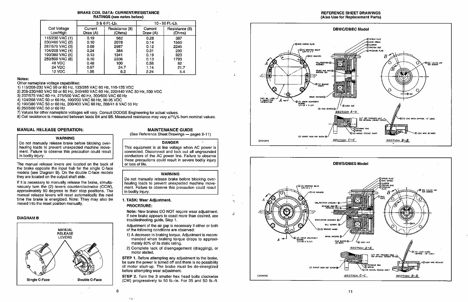
Coil VoltageLow/High
115/230 VAC (1)230/460 VAC (2)287/575 VAC (3)104/208 VAC (4)190/380 VAC (5)250/500 VAC (6)
48 VDC24 VDC12 VDC
BRAKE COIL DATA: CURRENT/RESISTANCE
RATINGS (see notes below)
Current
Draw (A)
0.19
0.10
0.09
0.24
0.13
0.10
0.48
0.97
1.95
3 & 6 Ft.-Lb.
Resistance (8)(Ohms)
562
2078
2987
384
1341
2336
100
24.7
6.2
Current
Draw (A)
0.28
0.14
0.12
0.31
0.19
0.13
0.58
1.14
2.24
10 - 50 Ft.-Lb.
Resistance (8)(Ohms)
387
1550
2245
290
923
1793
82
21.7
5.4
Notes:
Other nameplate voltage capabilities:1) 115/208-230 VAC 50 or 60 Hz, 133/265 VAC 60 Hz, 110-125 VDC2) 208-230/460 VAC 50 or 60 Hz, 240/480 VAC 60 Hz, 220/440 VAC 50 Hz, 230 VDC3) 237/575 VAC 60 Hz, 275/550 VAC 60 Hz, 300/600 VAC 60 Hz4) 104/208 VAC 50 or 60 Hz, 100/200 VAC 60 Hz, 90-95 VDC5) 190/380 VAC 50 or 60 Hz, 200/400 VAC 60 Hz, 208/41 6 VAC 50 Hz6) 250/500 VAC 50 or 60 Hz7) Values for other nameplate voltages will vary. Consult DODGE Engineering for actual values.8) Coil resistance is measured between leads 84 and 85. Measured resistance may vary *7112% from nominal values.
MANUAL RELEASE OPERATION:
WARNING
Do not manually release brake before blocking over-hauling loads to prevent unexpected machine move-ment. Failure to observe this precaution could resultin bodily injury.
The manual release levers are located on the back of
the brake opposite the input hub for the single C-facemodels (see Diagram B). On the double C-face modelsthey are located on the output shaft side.
If it is necessary to manually release the brake, simulta-neously turn the (2) levers counterclockwise (CCW),approximately 90 degrees to their stop positions. Themanual release levers will reset automatically the nexttime the brake is energized. Note: They may also bemoved into the reset position manually.
DIAGRAM B
Single C-Face
MANUAL
RELEASE
LEVERS
Double C-Face
6
MAINTENANCE GUIDE
(See Reference Sheet Drawings - pages 9-11)
DANGER -
This equipment is at line voltage when AC power isconnected. Disconnect and lock out all ungroundedconductors of the AC power line. Failure to observethese precautions could result in severe bodily injuryor loss of life.
WARNING
Do not manually release brake before blocking over-hauling loads to prevent unexpected machine move-ment. Failure to observe this precaution could resultin bodily injury.
1. TASK: Wear Adjustment.
PROCEDURE:
Note: New brakes DO NOT require wear adjustment.If new brake appears to coast more than desired, seetroubleshooting guide, Step 1.
Adjustment of the air gap is necessary if either or bothof the following conditions are observed:
1) A decrease in braking torque. Adjustment is recom-mended when braking torque drops to approxi-mately 80% of its static rating.
2) Complete lack of disengagement (dragging), ormotor stalled.
STEP 1. Before attempting any adjustment to the brake,be sure the power is turned off and there is no possibilityof motor start-up. The brake must be de-energizedbefore attempting wear adjustment.
STEP 2. Turn the 3 smaller hex head bolts clockwise
(CW) progressively to 50 lb.-in. For 35 and 50 lb.-ft.
5-
A
•cZET# A 1*[,FORMUTIC»4
CAD4894
A
0
*]RE EGRESS PLATE
55rr': BOLTS
(43 WASHERS
Sjo£,sr
BRAKE HOUSWG®/ -
REFERENCE SHEET DRAWINGS
(Also Use for Replacement Parts)
Wro-
SPLINE HUB WITHUGECRAL KEY
DBWC/DBEC Model
SPR:NG PLATE
WAVE SPRING
,-*CUFFERFmCTION DISC
PRESSURE PLATE
B
0
0
--* KEY
0
li 102 UNC
LOCK NUT
Am (6) LEK WIRCS (#PPROX. WV LOING)
- LEAD WIRE RETAINER
21#/a//sn/o"1/4-28 x 2-3/4
(3) FLUX BUSTER
SECTION A-A
El , Lo=° -© 12) M,NUAL ROIASE SH•n
(2) SOCKEr HGO NP SCREW ®JSECTION C-C
DBWS/DBES Model
US-16 X 4
(4) *ASHERS
Coll/RECTIFIER ASSEMBLY
RETNING raINGRETAINING RING
62 i-*:,O \2 - -4
CAD4895
0
1/4-28 X 2-3/4
SHuff/SPUNC ASSEMBLY {IH
MU BUJUNG ®- (2) RELEASE KNOBS
BRAKE HOUSING
(2) SOCKET HEAD CAP SCREW
C SPRING PLATE
#VE SPRING
CUPPER
FRICT)ON DISC
B
SECTION B-B
- 0 Wic
RAU'rER LOCK NUT
SECTION A-A
0' ---© (:;,45:D nREONG,--
LED IRC RET/NER
/ 1 1 \ \>© RETAINING RIC\ L© SPR;NG
SECTION C-C
11
SECTION B-B
1
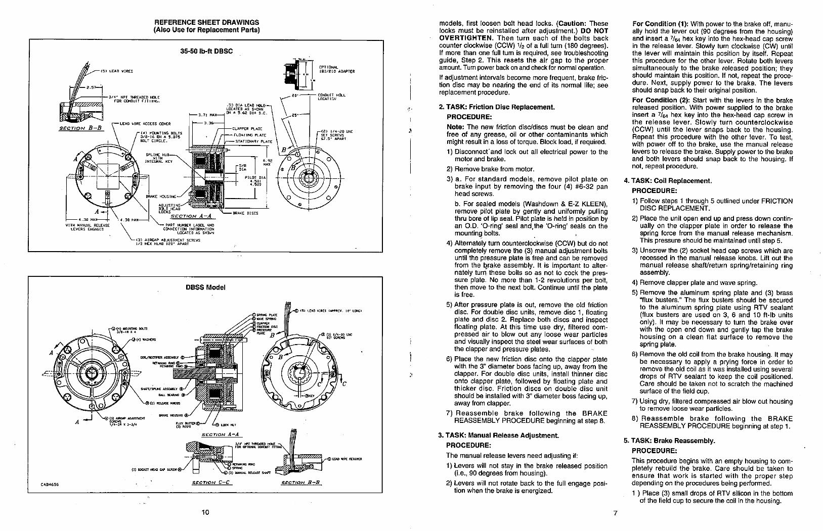
F -2.57--
SEC-nON B-B
A
- 4.30 MAX |
WITH MANUAL RELEASELEVERS ENGAGED
0
(5) LEAD WIRES
REFERENCE SHEET DRAWINGS
(Also Use for Replacement Parts)
35-50 lb-ft DBSC
3/4· NPT THREADED HOLEFOR CONDUIT FITTING.
.50 DIA LEAD HOLDLOCATED AS SHOWN
ON A 5.62 DIA 3.C- 3.71 HA-
LEAD VIRE ACCESS COVER -3.36-
- CLAPPER PLATE
' /- FLOATING PLATEBOLT CIRCLE. ' - STATIONARY PLATE
SPL I NE HUB- 1*6%ME
INTEGIRAL KEY 6.92rs/8 MAX
DIA
--- --1 -2 - ; PILOT DIA4.5014.509
BRAKE HOUS ING --/ YBil"BTIZIM ADJUSTING-0'BOLT HEADLOCKS -X-mAKE DISCS
\ SECTION A-A4.30 MA- \
L- PART NUMBER LABEL AND]CONNECTION INFORMATION
LOCATED AS SHOWN
L <3) AIRGAP ADJUSTMENT SCREWS1/2 HEX HEAD 120· APART
848 BOUS
DBSS Model
0, (41 ·,445}ERS
ACOIL/RECTFIER ASEISLY
RETANING RING
RETAB#40 RING
SE X - rrIFrV-' :..
SA#Fr/SPUNE ASSEMBLY d>' BALL BEARING ®J |
(2) RELEASE KNODS0
BRAKE HOUSING
x 2-3/4
CAD4656
SPRING PLATE
AVE SPEM#G
Ct/PPERFRICION DISC
0B
0
0
OPT[ONAL
180/210 ADAPTER
20·- CONDUIT HOLELOCATION
<2) 1/4-20 UNCSET SCREWS
67.5- APART
0
0
N LEAD WIRES (APPROX, 10' LING)
KEY
C
0
m 7<142 UNC
8YUF LOCK NUT
SECT ON A-A
3/r WT n·REACED HOLE -1 7
04 OpnON*L CONDUF FrTT,He
\>-(p RETANIB RI,G
(2) SOCKET HOO CAP - \ HS) SPRNG\-© (z) IwiuAL RaBSE SMFT CIZESSECTION C-C SECTION B-B
10
C
models, first loosen bolt head locks. (Caution: Theselocks must be reinstalled after adjustment.) DO NOTOVERTIGHTEN. Then turn each of the bolts back
counter clockwise (CCW) 1/2 of a full turn (180 degrees).If more than one full tum is required, see troubleshootingguide, Step 2. This resets the air gap to the properamount. Tum power back on and check for normal operation.
If adjustment intervals become more frequent, brake fric-tion disc may be nearing the end of its normal life; seereplacement procedure.
2. TASK: Friction Disc Replacement.PROCEDURE:
Note: The new friction disc/discs must be clean and
free of any grease, oil or other contaminants whichmight result in a loss of torque. Block load, if required.
1) Disconnectand lock out all electrical power to themotor and brake.
2) Remove brake from motor.
3) a. For standard models, remove pilot plate onbrake input by removing the four (4) #6-32 panhead screws.
b. For sealed models (Washdown & E-Z KLEEN),remove pilot plate by gently and uniformly pullingthru bore of lip seal. Pilot plate is held in position byan O.D. '0-ring' seal and,the '0-ring' seals on themounting bolts.
4) Alternately turn counterclockwise (CCW) but do notcompletely remove the (3) manual adjustment boltsuntil the pressure plate is free and can be removedfrom the brake assembly. It is important to alter-nately tum these bolts so as not to cock the pres-sure plate. No more than 1-2 revolutions per bolt,then move to the next bolt. Continue until the plateis free.
5) After pressure plate is out, remove the old frictiondisc. For double disc units, remove disc 1, floatingplate and disc 2. Replace both discs and inspectfloating plate. At this time use dry, filtered com-pressed air to blow out any loose wear particles
i and visually inspect the steel wear surfaces of boththe clapper and pressure plates.
6) Place the new friction disc onto the clapper platewith the 3" diameter boss facing up, away from theclapper. For double disc units, install thinner disconto clapper plate, followed by floating plate andthicker disc. Friction discs on double disc unit
should be installed with 3" diameter boss facing up,away from clapper.
7) Reassemble brake following the BRAKEREASSEMBLY PROCEDURE beginning at step 8.
3. TASK: Manual Release Adjustment.
PROCEDURE:
The manual release levers need adjusting if:
1) Levers will not stay in the brake released position(i.e., 90 degrees from housing).
2) Levers will not rotate back to the full engage posi-tion when the brake is energized.
7
For Condition (1): With power to the brake off, manu-ally hold the lever out (90 degrees from the housing)and insert a 7/64 hex key into the hex-head cap screwin the release lever. Slowly turn clockwise (CW) untilthe lever will maintain this position by itself. Repeatthis procedure for the other lever. Rotate both leverssimultaneously to the brake released position; theyshould maintain this position. If not, repeat the proce-dure. Next, supply power to the brake. The leversshould snap back to their original position.
For Condition (2): Start with the levers in the brakereleased position. With power supplied to the brakeinsert a 7/64 hex key into the hex-head cap screw inthe release lever. Slowly turn counterclockwise(CCW) until the lever snaps back to the housing.Repeat this procedure with the other lever. To test,with power off to the brake, use the manual releaselevers to release the brake. Supply power to the brakeand both levers should snap back to the housing. Ifnot, repeat procedure.
4. TASK: Coil Replacement.
PROCEDURE:
1) Follow steps 1 through 5 outlined under FRICTIONDISC REPLACEMENT.
2) Place tile unit open end up and press down contin-ually on the clapper plate in order to release thespring force from the manual release mechanism.This pressure should be maintained until step 5.
3) Unscrew the (2) socket head cap screws which arerecessed in the manual release knobs. Lift out the
manual release shaft/return spring/retaining ringassembly.
4) Remove clapper plate and wave spring.
5) Remove the aluminum spring plate and (3) brass"flux busters." The flux busters should be secured
to the aluminum spring plate using RTV sealant(flux busters are used on 3, 6 and 10 ft-lb unitsonly). It may be necessary to turn the brake overwith the open end down and gently tap the brakehousing on a clean flat surface to remove thespring plate. -
6) Remove the old coil from the brake housing. It maybe necessary to apply a prying force in order toremove the old coil as it was installed using severaldrops of RTV sealant to keep the coil positioned.Care should be taken not to scratch the machined
surface of the field cup.
7) Using dry, filtered compressed air blow out housingto remove loose wear particles.
8) Reassemble brake following the BRAKEREASSEMBLY PROCEDURE beginning at step 1.
5. TASK: Brake Reassembly.PROCEDURE:
This procedure begins with an empty housing to com-pletely rebuild the brake. Care should be taken toensure that work is started with the proper stepdepending on the procedures being performed.
1 ) Place (3) small drops of RTV silicon in the bottomof the field cup to secure the coil in the housing.
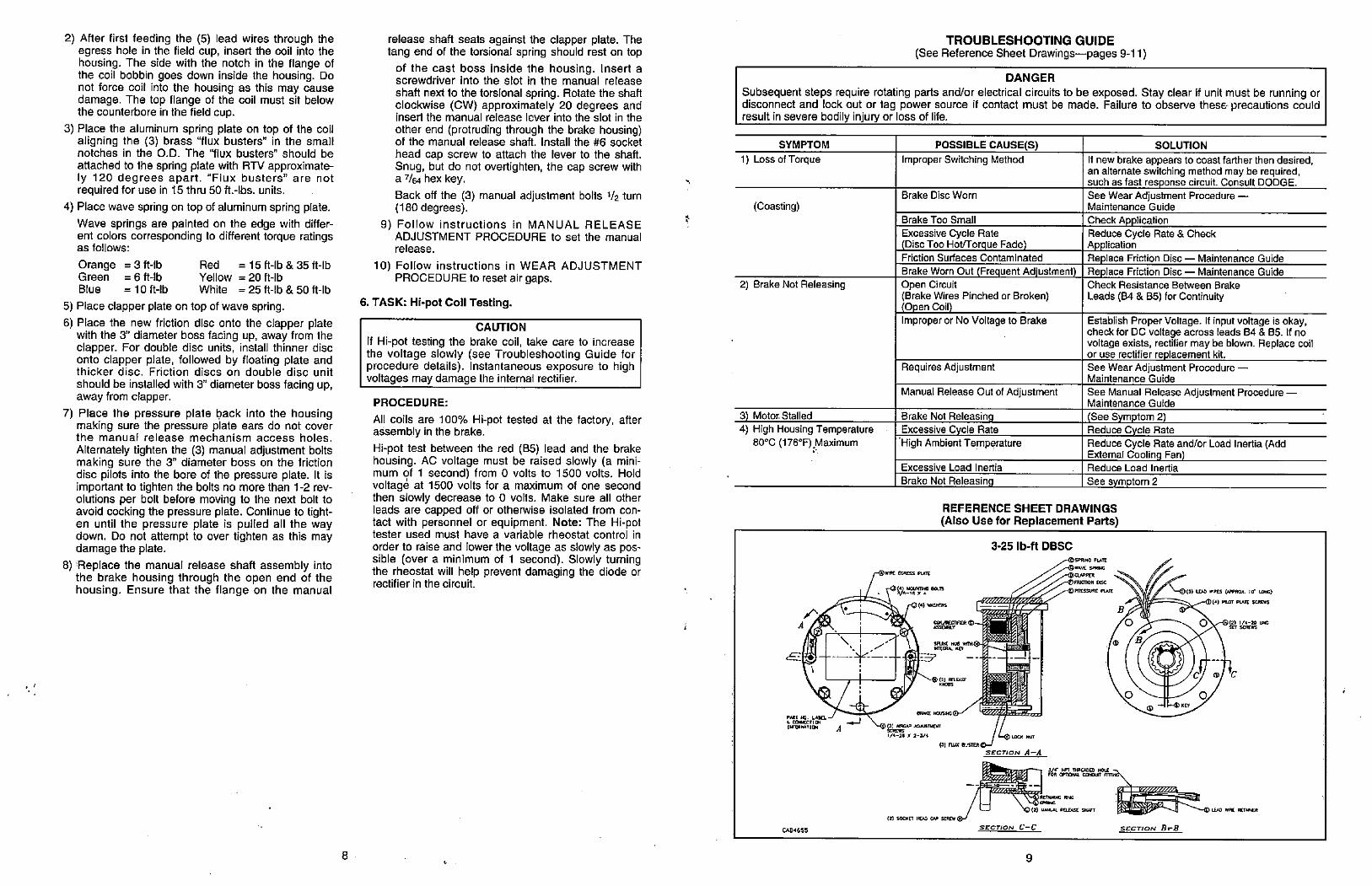
./
2) After first feeding the (5) lead wires through theegress hole in the field cup, insert the coil into thehousing. The side with the notch in the flange ofthe coil bobbin goes down inside the housing. Donot force coil into the housing as this may causedamage. The top flange of the coil must sit belowthe counterbore in the field cup.
3) Place the aluminum spring plate on top of the coilaligning the (3) brass "flux busters" in the smallnotches in the O.D. The "flux busters" should be
attached to the spring plate with RTV approximate-ly 120 degrees apart. "Flux busters" are notrequired for use in 15 thru 50 ft.-lbs. units.
4) Place wave spring on top of aluminum spring plate.Wave springs are painted on the edge with differ-ent colors corresponding to different torque ratingsas follows:
Orange = 3 ft-lb Red = 15 ft-lb & 35 ft-lb
Green = 6 ft-lb Yellow = 20 ft-lb
Blue = 10 ft-lb White = 25 ft-lb & 50 ft-lb
5) Place clapper plate on top of wave spring.
6) Place the new friction disc onto the clapper platewith the 3" diameter boss facing up, away from theclapper. For double disc units, install thinner disconto clapper plate, followed by floating plate andthicker disc. Friction discs on double disc unit
should be installed with 3" diameter boss facing up,away from clapper.
7) Place the pressure plate back into the housingmaking sure the pressure plate ears do not coverthe manual release mechanism access holes.
Alternately tighten the (3) manual adjustment boltsmaking sure the 3" diameter boss on the frictiondisc pilots into the bore of the pressure plate. It isimportant to tighten the bolts no more than 1-2 rev-olutions per bolt before moving to the next bolt toavoid cocking the pressure plate. Continue to tight-en until the pressure plate is pulled all the waydown. Do not attempt to over tighten as this maydamage the plate.
8) Replace the manual release shaft assembly intothe brake housing through the open end of thehousing. Ensure that the flange on the manual
8
release shaft seats against the clapper plate. Thetang end of the torsional spring should rest on top
of the cast boss inside the housing. Insert ascrewdriver into the slot in the manual release
shaft next to the torsional spring. Rotate the shaftclockwise (CW) approximately 20 degrees andinsert the manual release lever into the slot in the
other end (protruding through the brake housing)of the manual release shaft. Install the #6 socket
head cap screw to attach the lever to the shaft.Snug, but do not overtighten, the cap screw witha 7/64 hex key.
Back off the (3) manual adjustment bolts 1/2 turn(180 degrees).
9) Follow instructions in MANUAL RELEASEADJUSTMENT PROCEDURE to set the manual
release.
10) Follow instructions in WEAR ADJUSTMENTPROCEDURE to reset air gaps.
6. TASK: Hi-pot Coil Testing.
CAUTION
If Hi-pot testing the brake coil, take care to increasethe voltage slowly (see Troubleshooting Guide forprocedure details). Instantaneous exposure to highvoltages may damage the internal rectifier.
PROCEDURE:
All coils are 100% Hi-pot tested at the factory, afteradsembly in the brake.
Hi-pot test between the red (85) lead and the brakehousing. AC voltage must be raised slowly (a mini-mum of 1 second) from 0 volts to 1500 volts. Holdvoltage at 1500 volts for a maximum of one secondthen slowly decrease to 0 volts. Make sure all otherleads are capped off or otherwise isolated from con-tact with personnel or equipment. Note: The Hi-pottester used must have a variable rheostat control in
order to raise and lower the voltage as slowly as pos-sible (over a minimum of 1 second). Slowly turningthe rheostat will help prevent damaging the diode orrectifier in the circuit.
TROUBLESHOOTING GUIDE
(See Reference Sheet Drawings-pages 9-11)
DANGER
Subsequent steps require rotating parts and/or electrical circuits to be exposed. Stay clear if unit must be running ordisconnect and lock out or tag power source if contact must be made. Failure to observe these precautions couldresult in severe bodily injury or loss of life.
SYMPTOM
1) Loss of Torque
(Coasting)
2) Brake Not Releasing
3) Motor. Stalled
4) High Housing Temperature
80°C (176'F) Maximum
.Er
A
e
Mal# -1
CAD4655
POSSIBLE CAUSE(S)
Improper Switching Method
Brake Disc Worn
Brake Too Small
Excessive Cycle Rate(Disc Too Hot/Torque Fade)Friction Surfaces Contaminated
Brake Worn Out (Frequent Adjustment)
Open Circuit(Brake Wires Pinched or Broken)(Open Coil)
Improper or No Voltage to Brake
Requires Adjustment
Manual Release Out of Adjustment
Brake Not Releasing
Excessive Cycle Rate
'High Ambient Temperature
Excessive Load Inertia
Brake Not Releasing
ERE EGRESS PUTE
ses
(4) ¥SHERS
SOLUTION
If new brake appears to coast farther then desired,an alternate switching method may be required,such as fast response circuit. Consult DODGE.
See Wear Adjustment Procedure -Maintenance Guide
Check Application
Reduce Cycle Rate & CheckApplication
Replace Friction Disc - Maintenance Guide
Replace Friction Disc - Maintenance GuideCheck Resistance Between Brake
Leads (84 & E35) for Continuity
Establish Proper Voltage. If input voltage is okay,check for DC voltage across leads 84 & 85. H novoltage exists, rectifier may be blown. Replace coilor use rectifier replacement kit.
See Wear Adjustment Procedure -Maintenance Guide
See Manual Release Adjustment ProcedureMaintenance Guide
(See Symptom 2)
Reduce Cycle Rate
Reduce Cycle Rate and/or Load Inertia (AddExternal Cooling Fan)Reduce Load Inertia
See symptom 2
REFERENCE SHEET DRAWINGS
(Also Use for Replacement Parts)
#SS[kaly
-rz,wm,
MAKE HOJS,B
A -1/4-28 X 2-3/4
3-25 lb-ft DBSC
1
4
LOCK PUT
9
SPRING PLATZ
WA'•t SP*540
CPPER 2FRICTION DiSC
MASSURC PLATE
0
95
(5) LEAD W'RES BPPROX 1(r LONG)
(4) PILOT PLATE SCRCIS
0 0 5 '41*C
B
(I)-®KEY
CNC
0
(3) FLUX BUSIER
SECTION A-A
- "/0 #6fc;:;:T'-94
\-© LEAOW, RETA,NER
(21 SOCKET le[ CV SCREW 04SECTION C-C SECTION BrB
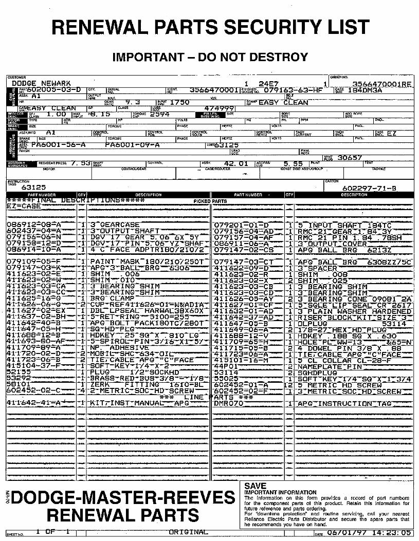
U
HP.
5MttAbY CLEANil Sfi
CLASS 1.00 It&*,T• 4· TYPE IMTR
IFR
086912-08-A-602437=04=A-0791-5-6-0-6-ZN-
0791-58=12=D---08691-4--1-0-A-
r-1--r--4-
1
RENEWAL PARTS SECURITY LIST
CUSTOMER
DODGE NEWARK
[691602UU-03-ASSY. Al
SIZE
ASSY.MTO Al
8888 SIZERS· PAe,vul -06-AFINISH
RED'GEAH PRESS /. 33MOTOR
ASRUCTION63125
PARTNUMBER
*****r 11\[AL
EZ=CASE- ·'-DES
0791-09*05-F-0791-47=03=K-4-1-1-623-02-E-421-623=02=W -4-1-1-623-03-CA-41-1-623=03=CC-4-1-1-625-16-G-41-1-626-06-G -41-1-627=02-EX-41-1-637-02-BH-4-1-1-6-42-40--B-41-1'647-05-H -41-1-688-*12-8-4-1-1-693-80-AF-4-1-1-709-89-A-41-1-720-02-D -4-1-1723-06-8 -41-51-04-37-F -521-55 -53292-58101
602452--02-C--
4-1-1-642*4-1-A»r
-MI-!m./..P,0
-r-r-1-
-r-1-
-2
-r-r
-1-
-2-2
-1-
-1--1--4
-1
88
.-i
-
IMPORTANT - DO NOT DESTROY
1
,ENT. GOODSNO33664700011 FINISHEDorr, ,RIALpur MX.
REAS 9.3 1 1Y; 1750 S/F CLASS Iwit. 15 QUE 2594
IHPTORQUE
1 ?80'ROL |TROLTORQUE PHASEPA001-OV-A
CONTROLIGEAR
MtN,
4749991Fiall SIZE
VOLTS
PHASE HERTZ
HERTZLUBE63125
1 MY
CONTROL ASSYCASDAEOUCER
DESCRIPTION
ir I lu[\is*****I
PICKED PARTS
-3-GEARCASE
-3-OUTPUT-SHAFT- 62- _- · 2-DGV-1-7-GEAR-570-66-X-SY-DGVT-1-7-P-IN-5:06-YZ-SHAFZ4 C FACE -ADPTR-1-80721-072
-PAINT-MASK-1807210725OT--APG-3-BALL-BRG -6306--r-SHIM.006-
-3-BEAR-ING-SHIM
-3-BEAR INGZSHIM -BRG-CLAMP
-CUP-REF41-1-626=01==WEADrA--DBC-CPSEAL-HARWAE38XGOX-
-5-RET-RING--5100=255---Z-APG-BOLT-PACK-1-BOTC728OT-SQ-HD-PEG-
-HDKEY:25-SQ-X:81-0-EG--5-SPIROL-PIN-311-6-IXT--51---NP. ADHESIVE-MOB-IC-SHC-634-OIC ..-TIETCABCE-APG-"C-"FACE--SOFT-KEY-1-/4-X-2
-PLUG - 172"SOCKHD--BRASS-RED-BUS-3/8-=-178--ZERK-FITTING-1-6-1-0-BE-
-2TMETRICISOC-HD-SCREW-*-*-*-L-INE-P
-KITT-INST-MANUAL-AP G----
24E7079163-63-
1=TEASY CLEAN
ImHZ PH. IMPMVOLTS
I mr |MENT VOLTS
42. 01 1 gEss,
HF
1 =1:
5.55 1 PALNT
CONST DISC ASSY./GAOUP
1
ORDER NO.
Igesr
EL
3566470001 RE184DM3A
**, BORE
ENCL
IENCL
lag 30657
CARTON
TEST
2NCL
1 EAZE EZ
TACH*IT
602297-71-BPART NUMBER · DESCRIPTION
./Ill./...Il,Ir
-079201-01-D--0791-56=04-ADZZ-0791-57=-0-4-A-F
-08691-1-065*--079-1-47-62-CS
-0791-47t03-CT--41-1-622-09-D-.-4-1-1-623-02=R-41-1-623-02-X--74-1-1-623-03-CB
-41-1-623-03-CD--4-1-1-626-05-AY-41-1-627--01-n-CFZZ-41-1-632-0-1--AD-41-1-642-37-AD--4-1-1-647=-05=B-411-649-06-A---41-1-688-12-V
-4-1-1-709-6-5=H.-411715-05-B-41-172306-A--4-15-1-0-1-=1-6-M-4-4P01.- L_ --' 1-531-1-4
-55025-Z-Z-Z-=-602452-01-A-602452=02=F-ARTS-***DMR070-
IDODGE-MASTER-REEVES
RENEWAL PARTS|$HEETNO, 1 OF 11 1 UMiGiNAL
-1-=1*
1
If
-5-INPOT-SAAFT 184-TC-IRMCI21=GEARIC-864.3.F-RMC 21 PIN 1.84 .78SH
33-0-OTPUTICONER---APG BALL BRG 6213Z
-AP-G-BACLB-R-G-6-368ZZ-/5-C-3-SPACERT -SHIR .OOB
ISBIMI002* 1 --12.__L__L_-_3 BEARING SHIM
-3IBEARING-SAIM-3 BEAR-ING CORE 09081-2-A5ZSGLE-LIP-SEAL-CR-2617-
-3 PC-A-IN-WA-SFIER-FIARDENED-RISER-BLOCK--KIT-SIZE-32OCPLUG 53114
178=27-HEX=HDZPCOG--ADKEY .1-88 SQ *-7630
ROCE-PL-WWEI;31 ---665=N--4-DOWEL P-IN 3/8 X . 882TIET-CABLE-APG C-"FACEZZ-5-CL-COLLAR-C[328-FNAMEPCATET-P-IN-_SQHDPEUG
LSOFT-KE_Y-174-SQ-X-717-374-5-METRIC HD-SCREW3IMETR-I-CISOCIRD-I-SCREWZZ
-1-
Lf--
-r-1-2-r-1-
1-r2-r-r2
-r
--
2
-r12r
r
r
-APG-ZINSTRUCTIONITAG--..
SAVEIMPORTANT INFORMATION
The information on this form provides a record of part numbersfor the component parts of this product. Retain this information forfuture reference and parts ordering.For 'downtime protection' and routine servicing, call your nearestReliance Electric Parts Distributor and secure the spare parts thathe recommends you have on hand.
1 1 |DATE 06/01/97 14:23: 05
=n
/6
RENEWAL PARTS
CONTACT YOUR NEAREST RELIANCE PARTS DISTRIBUTOR IN THE YELLOW PAGES UNDER THE
HEADINGS SPEED REDUCERS, POWER TRANSMISSION EQUIPMENT, OR VARIABLE SPEED DRIVES.
r„ OR
CONTACT DODGE-MASTER-REEVES RENEWAL PARTS QUOTATIONS, FOR ASSISTANCEAT PHONE NUMBER 1-803-297-4160. IDENTIFICATION NUMBER FROM UNIT i·NAMEPLATE WILL BE REQUIRED FOR PARTS ASSISTANCE.r' ,
SERVICE ENGINEERS5 0 -L
FOR RATES AND AVAILABILITY OF SERVICES CALL 1-812-378-2416.
AFTER HOURS EMERGENCY SERVICE
- Parts in stock are available.for shipment 24 hours a day, 365 days a year for your' BREAKDOWN requiremsnts(A specim handling charge is Made to assure sameday shipment on EgEOSENCY BREAKDOWN : orders for*arts in stock not
c jequiring assembly. ·-,_:f;1 Gr
-3.7 1 -T U 3.3 r , J , : ,
CONTACT<-YppyNEAREST PARTS DIS¥RIBUTOR FIRST
c 0-6"-E - -.
*, . :,, , Dodge/MasteiP*Is (If Part No. Is Known) ..... 502-839-7233
- (Workdays:,only uAtil 12:00'P.M. - - Weekends-and Halidays,'f. call 606-281 -5996.. E ·; 1 '
Dgdge/Master) Parts (H ,PArt Ng. UnknoWn) 7.-..9?803-297-4800r , Y.-A. : 4
Reeves Parts...·..6.'.:f):*.r, ':0,...., fl :f,: ..8036297-4800 '''-4 6:'i '13
DODGE = MASTER . REEVESRENEWAL PARTS' "1
J ., t.,
A
[RE) [Ed][E@Ell)8(REIFTE[lig
@1-El0= A 0
L
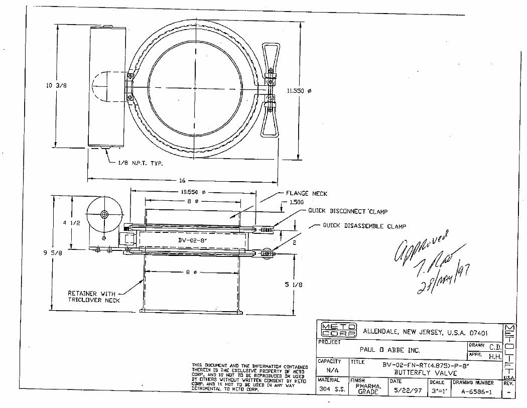
10 3/8\
-
4 1/2 1
0
9 5/8 -- 4 4
1/8 N.PA. TYP.
Krl_
ds==5
RETAINER WITH 1TRICLOVER NECK
16
10.550 0
80
BV-02-8
8 0
Ih
11,550 0
4
5 1/8
i
LANGE NECK
1.500
t - QUICK DISCONNECT TLAMP
- QUICK DISASSEMBLE CLAMP
1 2
THIS DOCUMENT AND THE INFORMATION CONTAINEDTHEREIN IS THE EXCLUSIVE PROPERTY OF METOCORP. AND IS NOT TO BE REPRODUCED OR USEDBY OTHERS WITHOUT WRITTEN CONSENT BY METOCORP. AND IS NOT TO BE USED IN ANY WAYDETRIMENTAL TO METO CORP.
MEE--I
.CORP.
PROJECT
CAPACITY
N/A
MATERIAL
304 S.S.
Q 9 Q% . /1-«\5/1)iPM
ALLENDALE, NEW JERSEY, U,S.A. 07401
DRAWN r nPAUL 0 ABBE INC.
Appi, H.H,T[TLE
BV-02-FN-RT(4875)-P-8'BUTTERFLY VALVE
ANISH DATE SCALE DRAWING NUMBERPHARMA.GRADE 5/22/97 3'=1' A-6586-1
MET
L_
F
TU.S.A.
REV.
.
.
.
TECHNICAL
REFERENCE
MANUAL
Reference No. - 424306
PRODUCED FOR
PAUL O. ABBE INC.JOB NO.: A46665
August 15, 1997

2 00
4
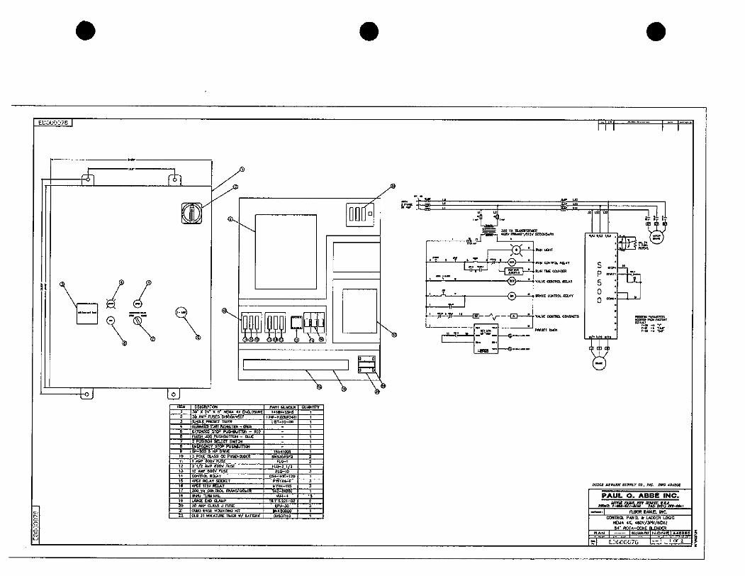
::r'
8CO
0U
EC000370
11k
.
I..
EY' i
l21 lilITEM
2
3
4
5
6
7
8
,0
12
13
14
15
;;M
t9
20
21
22
r
/IT@
DES*PDON
30' X 24 X 8- N£MA 41 0405URE
30 WP FUSED DISCONNECT
ENGI PRESEr RUER
ALLUUU SUR; RS<TRN-GWI
EX}40EO STOP FOSHeurro, - RED
Tpm =-*- *EMERGENCY STOP PUSHBUTIONSP-500 5 HP DRIE
' SFArl. FUSOfem%'trn:17'£011Rl IM
S;; SRZr3¢0 yA CONTROL mANS*miER
il{RU TERWINAL
&611*'icCUBJ BASE 110UNMNG *07
Cue M INIATURE TUER 1/ BATERY
PART NUIBIR
141459<8
19 IR- N,mOPJ,IRI
LIET-10-N
JSUIC]05
*530*520
FLO-l
FLO-2 1/2FL>10
CS*-40£-120
P m fl-E
MY#N- 115
T.2-81200
%'LU-4
19.11&221-02
LP--30
BNKS<00'0
OUgT110
60*Tlryl
1
1
1
2
2
1
3
3
15
2
\6
r- TE .
7,-
EE
ZOO YA mANSFID/[R40/ V0RIB.. 5[Z....
-t-'.74%0,1.7 '1..:RUN mECOUNTER
RMI CONTROL ZAY
@
L_5.14%-"-91- -Ar - --fl'-,BLE (XM= OW„TETS.
2,1£/T me
.
i.i.-i----.i- ,
m,IL, IA2 W,
urn 'fm *m
S..2P 'rt,5 H0 -
0 -:
: 93 DE
-UT
EE#
]
NXI ILIAN,r Sl/,Lr CO. rK Gle 4,4306
PAUL O. ABBE INC.
.r.."'..*-554:"."St'n.,4,-,1 nUOR CANIC INC
EESSRAN | --- |03/.ul/07|NONe| AICIoa
rl E- CK:.076 1 4 „,#-- 1 1 OF 2
1
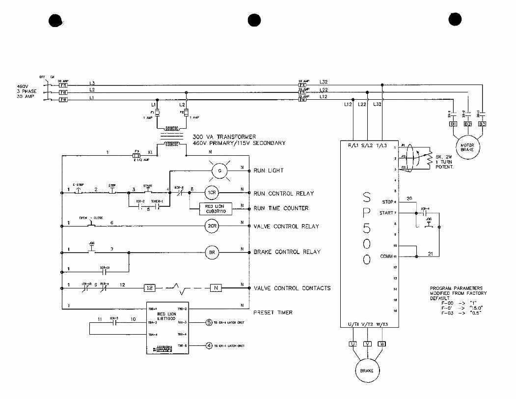
OFF ON
30 A,F
460V «-[EE LJ3 PHASE .-4-17611 L2
30 AMP .1.-<20 LlLl L2
Fl R
1 WF 1 AMP
300 VA TRANSFORM
r-'immL-1 460V PRIMARY/115V_3!_1 N21/2 AMP
<Gl N
£-STOP STOP SIART
12IT 03 A tecilf ® N
1CR-2 TIMER-1
1-11-5-1 A L RED UON -N
CUBJT110
C 1 opNr-L.[sc 6 N
<2CR 0
1 .7 N(BR 1 0
1 ICR-lA C 11
1 1(R-,8 9 2(R-1 12 Nf J.f Fifk- \Ir- - -
1
11 *CR-3 10
788-1
TBA-3
104-4
RED UON
LIBT1000
6-1
180-2
TBB-3
ma-4
Taa--5
TO CA-, LA,CH CRCT
---=eD To CRl-, LATOf (RCT
N
ER
SECONDARY
RUN UGHT
RUN CONTROL RELAY
RUN 1-IME COUNTER
VALVE CONTROL RELAY
BRAKE CONTROL RELAY
10 NAP
Erp
L32
L22
Ll 2
2 VALVE CONTROL CONTACTS
PRESET TIMER
n
L12 L22
n
O /
L32
R/Ll S/L2 T/L3
S
P
5
0
0
STOPe
START 7
COMM ii
U/Tl V/T2 W/T3
UVW
BRAKE
18
8
1C
8
4
3
2
12
13
14
9
10
LiET liT IT
f MOTOR \< BRAKE 1
1 TURN
P3\ 1 POTENT.
20
1CR-4
O IHIJnG
21
PROGRAM PARAMETERS
MODIFIED FROM FACTORY
DEFAULT
F-00 -> "1"F-01 -> "15.0"
F-03 -> "0.5"
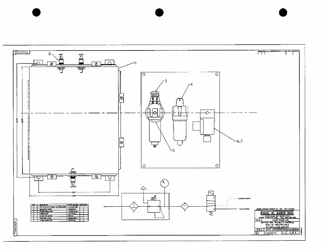
RE
U
EDCCO375
5 a
TD
2
4
5
.
\1 u 1 11-WN£
Il W.
- 100'
C€5¢MMPnCN
tr K 10, / 8. 1/'MA 4* D/"Fl
BUU¢MEAD UMKIN
rt-/RORATCR
UJOQUAR
0-160 P....
SCLENCO ¥,4
3 Pli COP#!ECTOR
1,1*PHa,K
3180,6&06
1.&BIlli
1$30¢>do
C31HS¢561*P5293Zss
t¥
OIJAMmt.
/
FH-1
E
0
0
V
.
1*
9 Ll J11
L__3
3
5
4
3
1-
0
0
6,7
EXMAUST 0.11PUT
WLE NlPUT
.
1-1.-i --- 1 -. 1
noxi NETARK =p,tr 00, n=. Z= 44*OU
PAUL O. ABBE INC.
PNCWZ: 1-100-61'41;* n.t ?MO *0-N[f
.--,1 FLOOR DANEl INC
.AINCEN BOX, PNEUIJATIC CONTROLS
INEMA 4 480//3PH/66HZ54' ROTI-CONE BLENDER
RAN | --- |03/WN|NONC|I4686I
*-1-"' E-00-0676 ' 1.-T I.fo- -

.
.
CO
En
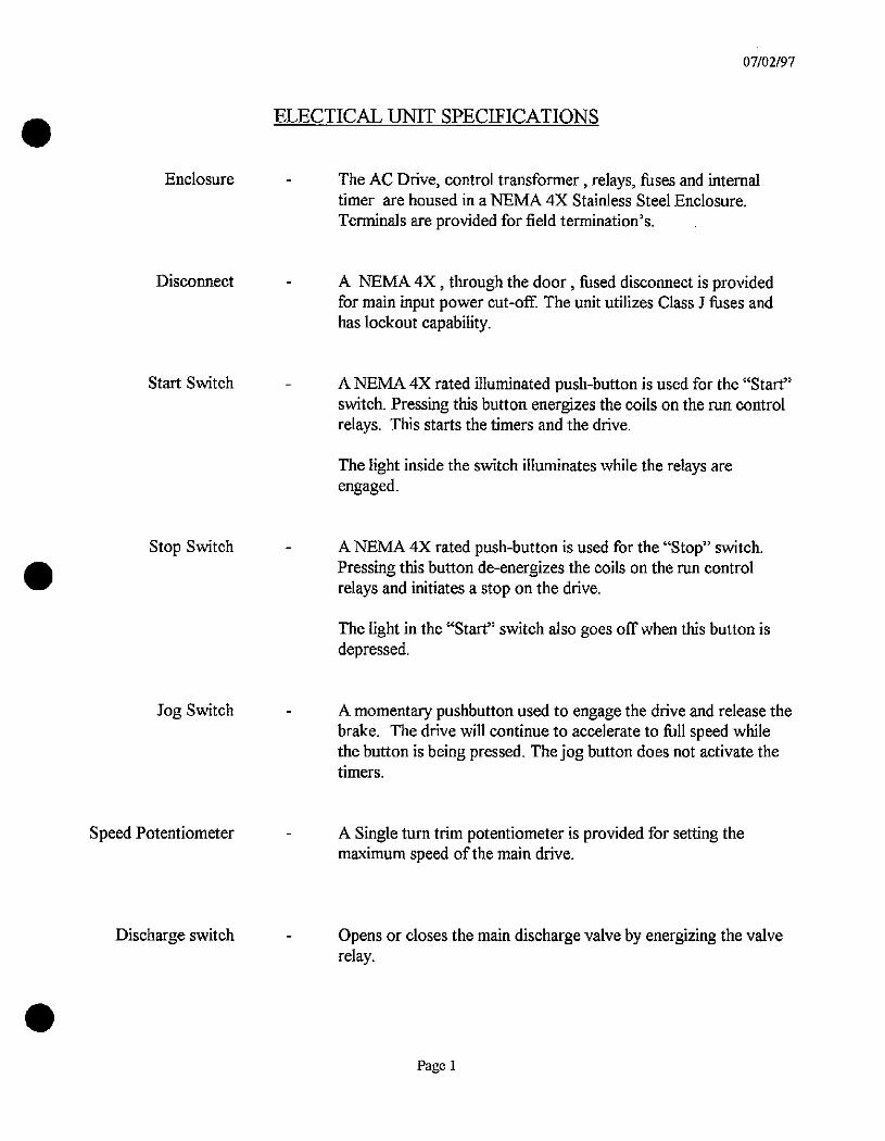
Enclosure
Disconnect
Start Switch
Stop Switch
Jog Switch
Speed Potentiometer
Discharge switch
ELECTICAL UNIT SPECIFICATIONS
The AC Drive, control transformer, relays, fuses and internaltimer are housed in a NEMA 4X Stainless Steel Enclosure.
Terminals are provided for field termination's.
07/02/97
A NEMA 4X, through the door, fused disconnect is providedfor main input power cut-ofF. The unit utilizes Class J fuses andhas lockout capability.
A NEMA 4X rated illuminated push-button is used for the "Start"switch. Pressing this button energizes the coils on the run controlrelays. This starts the timers and the drive.
The light inside the switch illuminates while the relays areengaged.
A NEMA 4X rated push-button is used for the «Stop" switch.Pressing this button de-energizes the coils on the run control
relays and initiates a stop on the drive.
The light in the 'Start" switch also goes offwhen this button isdepressed.
A momentary pushbutton used to engage the drive and release thebrake. The drive will continue to accelerate to full speed whilethe button is being pressed. The jog button does not activate thetimers.
A Single turn trim potentiometer is provided for setting themaximum speed ofthe main drive.
Opens or closes the main discharge valve by energizing the valverelay.
Page 1
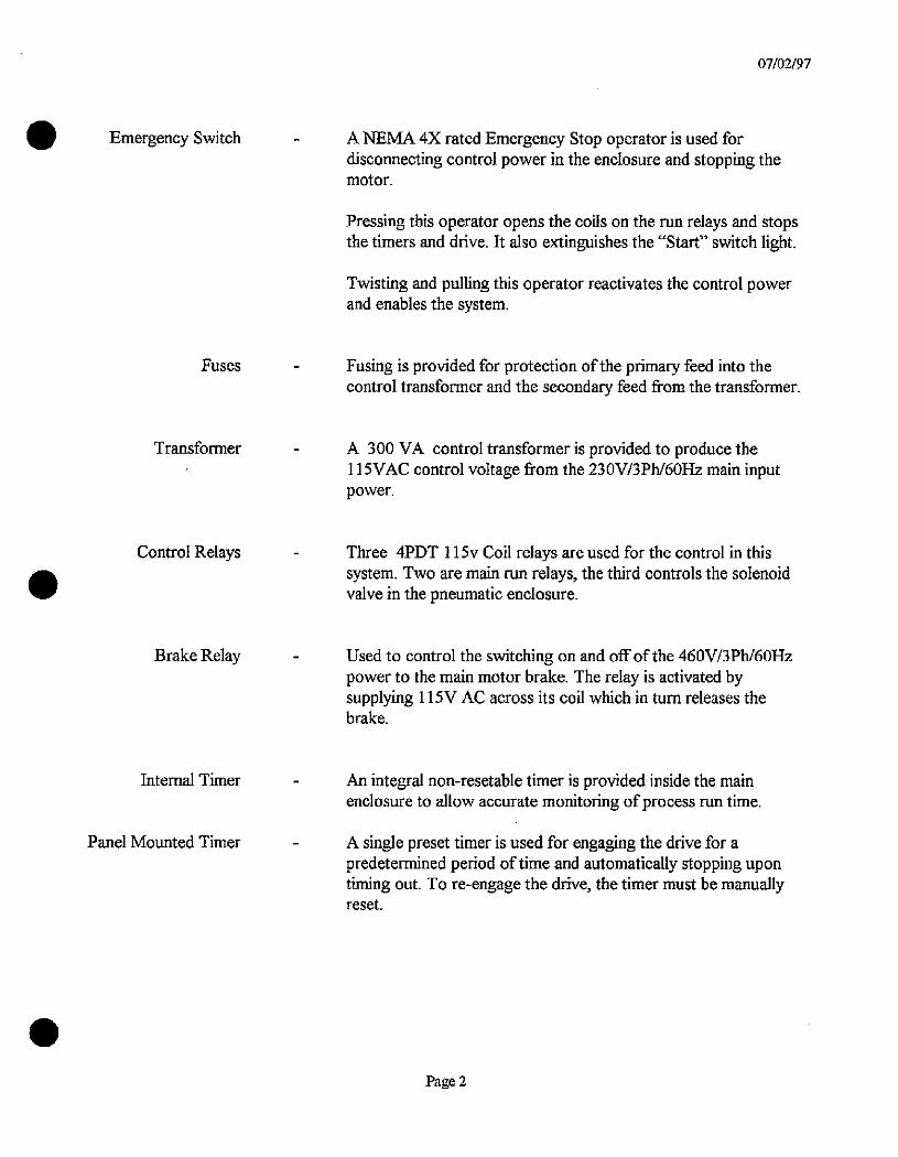
Emergency Switch
.
Fuses
Transformer
Control Relays
Brake Relay
Internal Timer
Panel Mounted Timer
A NEMA 4X rated Emergency Stop operator is used fordisconnecting control power in the enclosure and stopping thennotor.
07/02/97
Pressing this operator opens the coils on the run relays and stopsthe timers and drive. It also extinguishes the *Start" switch light.
Twisting and pulling this operator reactivates the control powerand enables the system.
Fusing is provided for protection ofthe primary feed into thecontrol transformer and the secondary feed from the transformer.
A 300 VA control transformer is provided to produce the115VAC control voltage from the 230V/3Ph/60Hz main input
power.
Three 4PDT 115v Coil relays are used for the control in thissystem. Two are main run relays, the third controls the solenoidvalve in the pneumatic enclosure.
Used to control the switching on and off of the 460V/3Ph/60Hzpower to the main motor brake. The relay is activated bysupplying 115V AC across its coil which in turn releases thebrake.
An integral non-resetable timer is provided inside the mainenclosure to allow accurate monitoring ofprocess run time.
A single preset timer is used for engaging the drive for apredetermined period oftime and automatically stopping upontiming out. To re-engage the drive, the timer must be manuallyreset.
Page 2
Enclosure
Regulator
Pressure Gauge
Lubricator
Solenoid
PNEUMATIC UNIT SPECIFICATIONS
The regulator, pressure gauge, lubricator, and air solenoid arehoused in a NEMA 4X Stainless Steel Enclosure.
07/02/97
Controls the maximum output pressure to the discharge valve.
Displays the current set output pressure to the discharge valve.
Dispenses the required amount of lubricant to the air as it flows tothe discharge valve.
Controls the flow of air to the discharge valve. When energized bythe valve control relay, the solenoid allows the air to pass throughand opens the discharge valve.
Page 3

EC/D
.
Fuses
3 pcs
3 pcs
2 pc
1 pc
LPJ-30SP
FLQ-10
FLQ-1
FLQ-2.5
Miscellaneous
1 pc D5-N130
1 pc MY4N-115
RECOMMENDED SPARE PARTS
30 AMP Class J fuse
10 AMP, 600V
1 AMP, 600V
2.5 AMP, 600V
120V Incandescent Bulb for Push-button
115V 4PDT Relay
Page 4
07/02/97

EErl
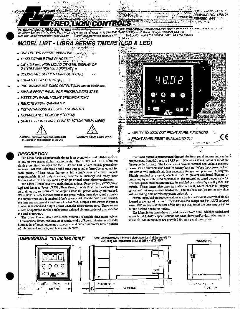
.
.
.4. 2- < 1
'·1 ,- - ·': '.1 -..BULLET/NNO.-.LBT-F
7 497:-»;r:4_·--er---,-:=Llt»SREV/SED696 - 'f-%*4*iw.; 1-'.. ..:7': I:.':1*4.---.SI..DRAWING NO. LP0104
REDYIZION*6*!TRdES{Ff b ,/ . •i
INTERNATIONAL HEADQUARTERS--:IT---p·: -- -**EUROPEAN HEADQUARTERS"- 0-r '-1·-' --:--
.20 Willow Springs Cirde, York, Pa. 17402, (717)-767-651·f FAX: (717) 764-0839*892 Plymauth Road, Slough, Berkshire. SL1 4LPWebsite- htlp://www.redlion-controls.com E-mail- [email protected] r ENGLAND +44 1753 696888 FAX: +44 1753 696339
1 15: .
MODEL LIST - LIBRA SERIES TIMERS.(LCD_& LED)
.ONE OR TWO PRESET VERSIONS .e ..4 t- ...-. 11 SELECTABLE TIME RANGES - - -
. 0.5* (12.7 mm) HIGH LIQUID CRYSTAL DISPLAY OR0.4" (102 mm) HIGH LED DISPLAYI
. SOLID-STATE C6RRENT SINK OUTPUT(S). FORM C RELAY OUTPUT(S).
s PROGRAMMABLE TIMED OUTPUT (0.01 sec to 99.99 sec.)
. SIMPLE FRONT PANEL FOR PROGRAMMING EASE
. MEETS DIN PANEL MOUNT SPECIFICATIONS
. REMOTE RESET CAPABILITY
. INSTANTANEOUS & DELAYED CONTACTS u
. NON-VOLATILE MEMORY (ISPROM)
. SEALED FRONT PANEL CONSTRUCTION (NEMA 4/IP65)
LJ La tr
CAUnON: Read complete instructions prior CAUTION: Risk d electric shock. to insttlaton and operation of the unit.**4
DESCRIPTIONThe Libra Series of presettable timers is an economical and reliable sohftion
to onc or two preset timing requirements. The LIETl and LIBTIEre thesinglepreset timerversions andthe LIBT2 and LIBTZE are the dual presettimerversions. All four units have a solid-state output and a form C relay output for ,each preset. These units feature a full complement of control inpUtB.programmable timed output values, non-volatile memory and many otherfearures which will satisfy most any single or dual preset timer requirement.
The Libra Timers have two main timing actions, Reset to Zero (7?7Z) £7imeupl and Reset to Preset 0?77) mme Downl. With RTZ, the timer resets to zero, times up, and activates the outputs when the preset value(*) are reached.When RTP is used,Ihe unit starts at the preset value. times down, and activatesthe output when zero is reached (singleprzset unit). For the dual preset version,the time starts at preset 2 and times toward zero. Output 1 fires when the preset1 value is reached and outpvt 2 fires when the time reaches zero. There are tenmodes of operation for the s.ngle presetunit and sixteenmodes ofoperation forthe dual preset unit.
The Libra Timers also have eleven different selectable time range values.These include: hours, minutes, orseconds; tenths of hours, minutes, or seconds;hundredths of hours, minutes, or seconds; and two chronometer time functionsof minutes and *conds; and hours and minutes.
DIMENSIONS "In inches (mrn)
OJOCU _L_1 LJ
0000Pt K
EOAOR
r· MIT .· 89.- -ry
2.83'(721-
2.83
(72)
TL
$
L 0-1 0 n -1
0, 0@@Pl P 2
g8 R
T
L
4jst
. ABILITY TO LOCK OUT FRONT PANEL FUNCTIONS
. FRONT PANEL RESET ENABLBDISABLE/
C€
The timed output is programmed through the front panel buttons and can be kprogrammed from 0.01 sec. to 99.99 sec. Bbe unitk timed output is ser at thefactory to be 0.1 sec) The Libra timers have an internal non-volatile memorydevice which eliminates the need for battery back-up. When input power is lost.this device will maintain all data necessary for system operation. A ProgramDisable terminal is present which is used to prevent accidental Ehanges ortampering by unauthorized personnel to the preset<) or timed output valuets):The front panel reset button can also be enabled or disabled by a rear panel DIPswitch. These timers also have an on-line self-test, which checks all displaydriver and micro-processor hardware. The self-test can be nm at any timewithout losing time or missing preset value(s).
Power, input, and output connections are made via removable terminal blockslocated at the rear ofthe unit. These blocks can accept one #14 AWG strippedwire. DIP switches at the rear ofthe unit are used to set the time ranges and toset the desired operating modes.
The Libra Series timershave a metal die-cast front bezel, which is seated, andmeets NEMA 4/IP65 specifications for wash-down and/or dust when properlyinstalldit Mounting clips are provided for easy panel installation
Note: Recommended minimum clearance (behind the panel) formounting dip installation is 2.7-(69)H x 4.9(114)W.
1 -- I- 1
.11.131 V6.60(142.21
2.60|661
2.GB.(681
PANEL CUT-OUT
2.687681 .
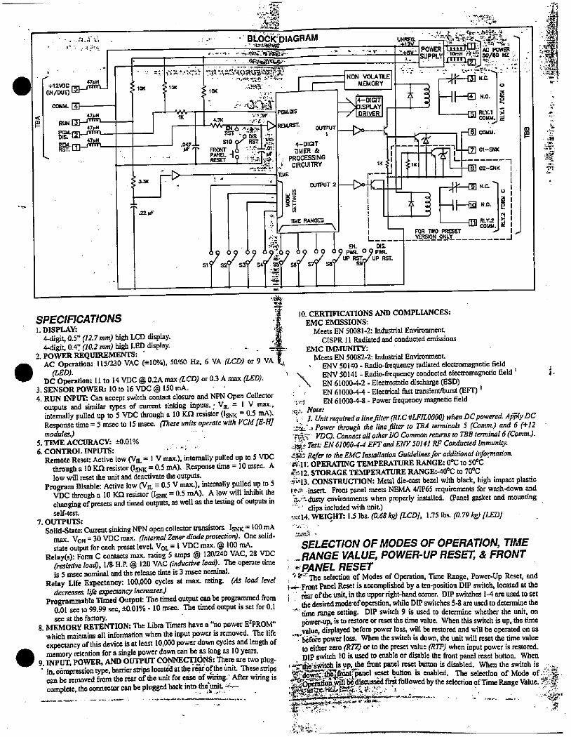
.
.
+12*Crm_rL
COMM. Il47UH
DIS. 1-47uH98#:mirmn
4©.0
- BLOCK:DIAGRAMI I .2,328*1, -1 I.- ...... ,<-„.':%
-511//rbkilt-AASHORea,-xe/.1 -
1Qi 11K .8'23
10K
1- A.ass- POLOIS
110
m 6 H*p vRST ».
WASE laRESET 9 .'-BM * : PROCESSING
' -72:12 CIRCUITRY
U 11--R ! .-- 11ME
- - 0U1PUT 2
/ 0nlpt
TIME RANGES
+12V - 0 ' -h "n -v 1. .44.1 POWER . +--J-1.A k POWER
4- 19·}PPLYI -48*.Attt:150/60 HZ ·«
+ m
11(
NON VOLATILE
MEMORY
*ISPLAYI
--Kr
1*:2r--4
1
oy .91 1 1 1.0-Iffftff.f P RST.
SPECIFICATIONS1. DISPLAY:
4-digit, 0.5" (12.7 mm) high LCD display.4-digit, 0.4 (10.2 mm) high LED display.
2. POWER REQUIREMENTS: - .-AC Operation: 1 15/230 VAC (tl0%), 50/60 Hz, 6 VA (LCD) or 9 VA
(LED).DC Operation: 11 to 14 VDC @ 0.2A max (LCD) or 0.3 A max (LED).
3. SENSOR POWER: 10 to 16 VDC @ 150 mA.4. RUN INPUTS Can accept switch contact closure and NPN Open Collector
outputs and similar types of current sinking inputs. · VIL = 1 V max..internally pulled up to 5 VDC through a 10 KA resistor (ISNK = 0.5 mA).Response time = 5 msec to 15 msec. micze units operate with FCM fE„mmodulm.)
5. TIME ACCURACY: *081%6. CONTROL INPUTS:
Remote Reset: Active low (VIL =lV max.), internally pulled up to 5 VDCthrough a 10 Kn resistor (ISNK = 0.5 mA). Response time = 10 nisec. Alow will reset the unit and deactivate the outputs.
Program Disable: Active low (VIL = 0.5 V max·), internally pulled up to 5V[)C through a 10 Kn resistor (ISNK = 0.5 mA). A low will inhibit thechanging of presets and timed outputs, as well as the testing of outputs inself-test
7. OUTPUTS:
Solid-State: Current sinking NPN open collector transistors. ISNK = 100 mAmax. VOH = 30 VDC max. (Internal Zener diodeprotection). Onesolid-state output for each preset level. Vol = 1 VDC max. @ 100 niA.
Relay(s): Form C contacts max. rating 5 amps @ 120/240 VAC, 28 VDC(resistiveload), 1/8 H.P. @ 120 VAC (inductive laad). The operate timeis 5 msec nominal and the release time is 3 msec nominal.
Relay Life Expectancy: 100,000 cycles at max. rating. Ms load leveldecreases, life expectancy increases.)
Programmable Timed Output: The timed output canbc programmed from0.01 sec to 99.99 sec, *0.01% - 10 nisec. The timed output is set for 0.1sec at the factory.
8. MEMORY RETENTION: The Libra Timers have a "no power IFPROM"which maintains all information when the input power is removed. The lifeexpectancyof this device is at least 10,000 power down cycles and length ofmemory retention for a single power down can be as long as 10 years.
9. INPUT, POWER, AND OUTPUT CONNECTIONS: There are two plug- in, compressiontype, banierstrips located attherGof thc 6nit. Thesestrips
can be removed from the rear of the unit for ease of 4iling.' After wring iscomplete, the connector can be plugged back into the-,nit. ·:--
- 41' d ILC
«1--[El N.0.
al &M.
i -[] COL{M.r=mil-[Z] 01-SNK
02-SNK
A V IBN.c, -
1 -HHfN.o031&YJ
FOR TWO PRESET --VERSION ONLY
0
2
0
10. CERTIFICATIONS AND COMPLIANCES:EMC EMISSIONS:
Meets EN 500814: Industrial EnvironmentCISPR 11 Radiated and conducted emissions
EMC IMMUNITY:Meets EN 50082-2: Industrial Environment.
, ENV 50140 -Radio-frequency radiated electromagnetic fieldENV 50141 - Radio-frequency conducted electromagnetic field 1
. \ EN 61000-4-2 - Electrostatic discharge (ESD)EN 61000-4-4 - Electrical fast transient/burst (EFT) 1EN 61000-4-8 - Power frequency magnetic field
I.;, Noter 1. Unit required a tine Jilter (RLC #LFIL0000) when DC powered. Aly DC·,pi .. Power through the line jilter to TBA terminals 5 (Comm) and 6 (+12
3*S VDC). Connect all other VO Common returns to TBB terminal 6 (Comm.).a*y Tesc EN 61 000-4-4 EFT and ENV 50141 RF Conducted Immunity.62£3 Refer to the EMC Installation Guidelines for additional information.rbll. OPERATING TEMPERATURE RANGE: 0°C to 50°C2·:12. STORAGE TEMPERATURE RANGE:-40°C to 70°C·@'13. CONSTRUCTION: Metal die·cast bezel with black. high impact plastic112! insert. Front panel meets NEMA 4/IP65 requirements for wash-down and8..tdusty environments when properly installed. (Panel gasket and mounting
clipsincluded with unit)96.14. WEIGHT. 13 lbs. (0.68 kg) /LCD;, 1.75 lbs. (0.79 kg) /LEDJ
--n
=El
:Tyf
'5
SELECTION OF MODES OF OPERATION, TIME_RANGE VALUE, POWER-UP RESET, & FRONT© PANEL RESET
12'·The selection of Modes of Operation. Time Range, Power-Up Reset, and2- Front Panel Reset is accomplished by a ten-position DIP switch, located at the
rar of the unit, in the upper right-hand corner. DIP switches 14 are used to set the desired modcof operation,while DIP switches 5-8 are used to determine the' time range setting. DIP switch 9 is used to determine whether the unit, on
p6wer.up, is to restore or reset the time value. When this switch is up, the timevalue, displayed before power loss. will be restored and will be operated on asbefore power loss. When the switch is down, the unit will reset the time valueto either zero (R74 or to the preset value FIP) when input power is restored.DIP switch 10 is used to enable or disable the front panel reset button. When
' S-&'autch is up the front panel reset button is Babled When the switch is - ..4¢1EG;ir¢*sot,ffi reset button is enabled. The selection of Mode of.61*be-discuss#d f followedby the selection pfTime Range Value. 14*:jEEZEE{Ze- ·- ·:*ir.TTE%. r.:i.-/ /.../. . Y
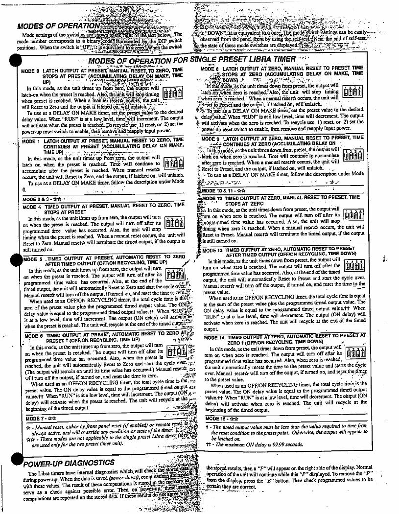
. :,-"'-4¢,;"9,...'..bg>:91 :4:.,
MODES OF OPERATIONZ23>**hUbi@SP'Mode settings of the switches'2S*i*Lk_-9£1kENbelow:,-The
mode number correspcUs to I BIP,switchpositions. When the switch is 3Jrl,'it-6-equivalnt to a &2mhA iheswitch
.*,» *'·54*As.Famj=-m*;zm:2&. :4
1 -
.
*50*0 ,9:42:9*ASk'--'*Aifi,21*..d-< LLE?.'*-1* ·;··-34 -, *is"DOK:', itis equivaic-ntto.a one©nodjswitch·settings can,be easily--,the stateJof these mode*,itches are displayUi*1SE.1*YYOF.ZI bbserved frpm the-;ai21, fr6it by kising-thd Self-tcEifNA:rihe end of self-test;'1 '
-
MODES OF OPERATION FOR SINGLE PRESET LIBRATIMER '-11.7 * t
MODE 0 LATCH OUTPUT AT PRESET,MANUAL RESEr,TO ZERO, TIME MODE 8 LATCH OUTPUT AT ZERO, MANUAL RESET TO PRESET TIMESTOPS AT PRESET (ACCUMULATING DELAY ON MAKE, TIME ' .GS·STOPS AT ZERO (ACCUMULATING DELAY ON MAKES, TIME
" S-{*DOWN) 4 5*.5 4,112*3:3·, er .- · ··up) *. «.4,·-2.*f...2+64**bi: ..In this mode, as the unit times up from zero, thd-butput will Inthis le, s'thounit dm42&wn frompreset.the output.will
when preset is reached. When amanual reset*,ocgurs, the,uniC.will Reset to Zero and the outpiit if latallad 6ey*6tatc£36' - 28*-Assa'and the'ou*it iflatched 64 will untatch. · . .,
To use as a DELAY ON MAKE timer, sEfihB¥mid-WuE to the desired :-* Touse as a DELAY ON MAKE timer, set the preset value to the desireddelay value. When "RUN" is ht a low le,;el, t6*€#nlincreient. The output t. delaikalud.,When "RUN" is ath low level, time will decrcment The outputwill activate when the preset is QachJ> m¢*Ift;se, 11 reset or 2) set the 4 willa*Nate when the zero is reached. To recycle use 1) reset, or 2) set the-power-up resct switch to enable. then rem6ve and reapply input power.power-up reset switch to enable, th€rcniovedApply input power.
-
,.. MODE 1 LATCH OUTPUT AT PRESET, MANUAL RESET TO ZERO, TIME MODE 9 LATCH OUTPUT AT ZERO, MANUAL RESET TO PRESET, TIME
CONTINUES AT PRESET (ACCUMULATING DELAY ON MAKE - - Cit¢ CONTINUES AT ZERO (ACCUMULATING DELAY ON _2.-Iri'thts:nddd,astheunittimesdown frompreset.th66utatwill'-i.1-AA ,; 1./ E'KI .' I. .
In this mode, as the unit times up from ·zsro. the output will ..latchonivhenzero is reached. Timd,kill contini@'tpaccumu!,te 111!illilmilatch on when the preset is reached. Time'will continue to .* after 570 is mached. When a manual reset* occurs. the unit willaccumulate after the preset is reached. When Inanual reset* . 5 ResZi to Preset,'and the output, if latched on, will unlatch. , ,occurs, the unit will Reset to Zero, and the output, if latched on, will unlatch. 5-· Touse asa DELAY ON MAKE timer, follow the description under Mode
To use as a DELAY ON MAKE timer, follow the description under Mode .*8 I.... 3--' ..-. . I
MODE 10 & 11 -**MODE 2& 3 - ** ., - . _ *MODE 12 TIMED OUfPUT ATZERO, MANUAL RESETTO PRESET, TIME
MODE 4 11MED OUTPUT AT PRESET, MANUAL RESET TO ZERO, TIME Zf:'' ' STOPS AT ZEROSTOPS AT PRESET Zi. In this mode, as the unit times down from preset, the output willIn this mode, as the unit times up fromzero, the output will tum t, 2 3 4, urn on when zero isreached. The output will rum off after its dl[;]dldllon when the preset is reached. The output will turn off after its @| 0-programmed time value has occurred. Also, the unit will stop
programmed time value has occurred. Also, the unit will stop Btiming when zero is reached. When a manual reset* occurs, the unit willtiming whenthe preset is reached. When a manual reset occurs, the unit will ]Reset to Preset Manual reset* will terminate the timed output, if the outputReset to Zero. Manual reset* will terminate the timed output, if the output is -MODE 13 TIMED OUTPUT ATZERO, AUTOMATIC RESETTO PRESET
5.is still turned on.
still turned on.
MODE 5. TIMED OUTPUT AT PRESET, AUTOMATIC RESET TO ZERO F AFTER TIMED OUTPUT (OFF/ON RECYCUNG, T[ME DOWN)
AFTER TIMED OUTPUT (OFF/ON RECYCLING, TIME UP) / Inthis mode, as the unittimes down from preset, the output will ,In this mode, as tile unit times up fromzero, the output will turn turn on when zero is reached. The output will turn off after the Illl|
on when the preset is·reached. The output will turn off after iB 'IhilifiJ - programmed tinie value has occwred. Also. attheend of thetimed 1programmed time value has occurred. Also, at the end of the *. output, the unit will automatically Reset to Preset and start the cyclc over.
S. ,
timed output, the unit will automatically Reset to Zero and start the cycle ofer.r: Manual reset* will turn offthe output, if turned on, and reset the time to theManual reset* will turn off the output, if turned on, and reset the time to z6;S.,lff · preset value. ' · --
When used as an OFF/ON RECYCLING timer, the total cycle time is th#' When usedasan OFF/ON RECYCLING timer, thetotal cycle time is equalsum of the preset value plus the programmed timed output value. The ON?K to the sum of the preset value plus the programmed timed output value. Thedelay value is equal to the programmed timed output value.tt When "R. ON delay value is equal to the programmed timedoutput value.tt Whenis at a low level, time will increment. The output (ON delay) will activate@ "RUN" is at a low level, time will decrement The output (ON delay) will
when the preset is reached. The unit will recycle at the end ofthe timed oytp *rwhen zero is reached. The unit will recycle at tile end 6f the timedMODE 6 TIMED OUTPUT AT PRESEr, AUTOMATIC RESET TO ZERO AT*
PRESET t (OFF/ON RECYCLING, TIME UP) ; ,!Aif MODE 14 TIMED OUTPUT AT ZERO, AUTOMATIC RESET TO PRESET ATZERO t (OFF/ON RECYCUNG, TIME DOWN) .In this mode, as the unit times up from zero, the output will turn
on when the preset is reached. '.he output will turn off after A 1*51% In this mode, as the unittimes down frompreset, the output will''I ,programmed time value has occurred. Also, when the preset is L----4;f. turn on when zero is reached. The output will tim off after its []reached, the unit will automatically Reset to Zero and start the cycle over. c.' programmed time value has occurred. Also, when zero is reached,(The output will remain on until its time value has occurred.) Manual reset* 94 the unit automatically resets the time to the preset vilue and startS the 6yplewill tum off the output, if turned on, and reset the time to zero. . «*3, over. Manual reset* will aim off the output, if turned on, and reset. thetif°$
When used as an OFF/ON RECYCLING timer, the total cycle time is the:re to the preset value.
preset value. The ON delay value is equal to the programmed timed output,$4*When used as an OFF/ON RECYCLING timer, the total cycle time,is the
value.tt When"RUN" is at a low level, time will increment. The output (ON ir r: Preset value. The ON delay value is equal to the programmed timed 6utputdelay) will activate when the presct is reached. The unit will recycle at the - value.tt When "RUN" is atalow level, time will decrement The output (ONbeginning o f the timed output. :.,.pr.f7- delay) will activate when zero is reached. Tile unit will recycle at the_L--./ beginning ofthetimedoutput. -
c - £:S.ViMODE 7-** -PA% 00E15-ita* -Manual reset. either by.front panet reset (fenabled) or remotereseL is ::-. -always active andwilloverride any conditionorstateof the timU5*99 1 -netimed output vaitte must be less thanthevalue required totimefrom** - nese modes are not applicable to ihe single preset Ilibra time,1[u0 t: =ron to the preset point. Otherwise. the output willappear to
are used only for the two presd timer unit). . -,,"131212:» _-2=5*A tt - The maximum ON delay is 99.99 seconds.
POWER-UP DIAGNOSTICSThe Libra timers have internal diagnostics which.will che«th18ii:12. thesff!3¢Fesults.then a "P" will appearon theright side ofthe display. Normalduring power.up. When the data is saved 0,ower.down),computatio*SE; 1 OPention.oftheunitwill continue while this "P"displayed. To remove the "P"with these values, The result of these computations is stored in * I¥mE!*5jd#51.- fkom the display, press the "E" button. Then check programmed values to beserve as a check against possible error. Then on '86weSkib1¢F«K*IlE'*n *ZE·(9rrect.computations are repeated on the stofed da If tliase reilikdhot agreti*¤f·· --
4 .f·42*·.-**ES.7*,
a.
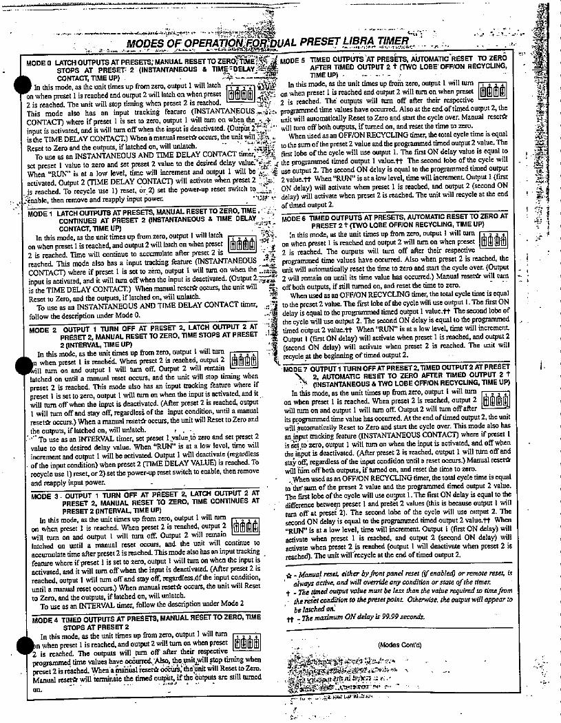
-
'1 .. ..e.*
MODES OFOPERA¥ION*bUAL PRESET LIBRA TIMER '.L..# -- *FE &*HIC64*33*S»*• ,
•46 '0) ./!.B .1*" 'Al'*Ae.* ''- 73 -' '' - .':-
MODE 0 LATCH OUTPUTS ATPRESETS;MANUAL RESETTO ZER611AEj* MODE 5 TIMED OUTPUTSAT PRESErS, AUTOMATICRESET TO ZEROSTOPS AT PRESET- 2 (INSTANTANEOUS & TIME H)ELAY.11:BE AFTER TIMED OUTPUT 2 t (TWO LOSE' OFF/ON RECYCLING,9. ..
CONTACT, TIME UP) TIME UP) In this mode, as the unit times up from zero, output 1 will latch 1 - i *92 In this mode, as the unit times up fronp zero, output 1 will turnon when preset 1 is reached and output 2 willtatchon when preset [ f-, on when preset lis reached and output 2 wili turn on when preset |IblhAIDI2 is reached. The unit will stop timing when preset 2 is reached. 11+ 2 is reached. The' outputs will turn off after their respectiveThis mode also has an input tracking feature (INSTANTANEOUS-g-;:. programmed time values have occurred. Also at the end oftimed output 2, theCONTACT) where if preset 1 is set to zero, output 1 will turn on when the -, + unit will automatically Reset to Zero and start the cycle over. Manual reset*input is activated, and it will turn off when the input is deactivated. (Ou®t 23>E -" will turn offboth outputs, if' turned on, and reset tile time to zero.is the TIME DELAY CONTACT.) Whena manual reset* occurs, the unitwill'*i . When used as an OFF/ON RECYCLING timer, the total cycle time is equalReset to Zero and the outputs, if latched on, will unlatch. -- 214%f to the sum of the preset 2 value andthe progammed timed output 2 value. The
To use as an INSTANTANEOUS AND TIME DELAY CONTACT tinicri'-Sys, first lobe of the cycle will use output 1. The first ON delay value is equal toset preset 1 value to zero and set preset 2 value to the desired delay value::' /1 4 the programmed timed output 1 value.tt The second lobe of the cycle willWhen "RUN" is at a low level, time will increment and output 1 will be If £ use output 2. The second ON delay is equal to the programmed timed outputactivated. Output 2 (TIME DELAY CONTACI) will activate vien preset 2 84.4.. 2 value.tt When"RUN" is at a low level, time will increment. Output 1 (first
-js reached. To recycle use 1) reset. or 2) set the power-up reset switch to.j: ON delay) will activate when preset 1 is reached, and output 2 (second ON. . 2.inable, then remove and reapply input power. ·U, 1. delay) will activate when preset 2 is reached The unit will recycle at the end
oftimed output 2." · MODE 1 LATCH OUTPUTS AT PRESETS, MANUAL RESET TO ZERO, TIME,·'.:CONnNUES AT PRESET 2 (INSTANTANEOUS & TIME DELAY, < - MODE 6 TIMED OUTPUTS AT PRESETS, AUTOMATIC RESET TO ZERO ATCONTACT, TIME UP) PRESET 2 t (T'WO LOBE OFF/ON RECYCLING, TIME UP)
fe
In this mode, as the unit times up from zero, output 1 will tatch In this mode, as the unit times up from zero, output 1 will turnon when preset 1 is reached, and output 2 will latch on when preset *1 81 on when preset lis reached and output 2 will turn on when preset 1[hd#*ib2 is reached. Time will continue to accumulate after preset 2 is ' ' · -7 2 is reached. The outputs will turn off after their respectivereached. This mode also has a input tracking feature (INSTANTANEOUS ,li€ programmed time values have occurred. Also when preset 2 is reached, theCONTACT) where if preset 1 is set to zero, output 1 will mm on when the -.mt- unit witl automatically reset the time to zero and start the cycle over. (Outputinput is activated, and it will turn off when the input is deactivated. (Outpuil*Z- 2 will remain on until its time value has occurred.) Manual reset* will turnis the TIME DELAY CONTACT.) When manual reset* occurs, the unit will *: off both outputs, if still turned on, and reset the time to zero.Reset to Zero, and the outputs, if latched on, will unlatch. 5 When used as an OFF/ON RECYCLING timer, the total cycle time is equal
To use as an INSTANTANEOUS AND TIME DELAY CONTACT timer. - 11 to the preset 2 value. The first lobe of the cycle will use output 1. The first ONfollow the description under Mode 0. ..'.·< delay is equal to the programmed timed output 1 value.tt The second lobe ofMODE 2 OUTPUT 1 TURN OFF AT PRESET 2. LATCH OUTPUT 2 AT ''1 the cycle will use output 2. The second ON delay is equal to the programmedPRESET 2, MANUAL RESET TO ZERO, TIME STOPS AT PRESET .1· timed output 2 value.tt When "RUN" is at a low level, time vvill increment
2 (INTERVAL, TIME UP)Z Output 1 (first ON delay) will activate when preset l is reached, and output 2.it (second ON delay) will activate when preset 2 is reached. The unit will
In this mode, as the unit times up from zero, output 1 will turnwhen preset 1 is reached. When preset 2 is reached, output 2 Idithli#1 - recycle at the beginning oftimed output 2.11 turn on and output 1 will turn off. Output 2 will remain MODE 7 OUTPUTl TURN OFF AT PRESET 2, TIMED OUTPUT2 AT PRESET
latched on until a manual reset occurs, and the unit will stop timing when \. 2, AUTOMATIC RESET TO ZERO AFTER TIMED OUTPUT 2 tpreset 2 is reached. This mode also has an input tracking feature where if '4 (INSTANTANEOUS & TWO LOBE OFF/ON RECYCLING, TIME UP)preset 1 is set to zero, output 1 will turn on when the input is activated, and it In this mode, as the unit times up from zero, output 1 will min Iwill turn off when the input is deactivated. (After preset 2 is reached, output on when preset 1 is reached. When preset 2 is reached, output 2 1%/thaild1 will tum offend stay off, regardlesi of the input condition, until a manual will turn on and output 1 will turn off. Output 2 will nirn off afterreset* occurs.) When amanual reset* occurs, the unit will Reset to Zero and its programmed time value has occurred. At the end of timed output 2, the unitthe outputs, if latched on, will unlatch. will automatically Reset to Zero and start the cycle over. This mode also has·'" To use as an INTERVAL timer, set preset lyalue.td zero and set preset 2 an«jpput tmcking feature (INSTANTANEOUS CONTACT) where if preset 1value to the desired delay value. When "RUN" is at a low level, time will is Sel to zero, output 1 will turn on when the input is activated, and off whenincrement and output 1 will be activated. Output 1 will deactivate (regardless the input is deactivated. (After preset 2 is reached, output 1 will turn off and
- of the input condition) when preset 2 (TIME DELAY VALUE) is reached. To stai' off, regardless ofthe input condition until a reset occurs.) Manual resetlkrecycle use 1) reset, or 2) set the power-up reset switch to enable, then remove will Rim off both outputs, if turned on, and reset the time to zero.
and reapply input power. · .Whenused as an OFF/ON RECYCLING timer, the total cycletime is equalto'thersum oftic preset 2 value and the programmed timed output 2 value.
MODE 3 - OUTPUT 1 TURN OFF AT PRESET 2, LATCH OUTPUT 2 AT Thetst lobe of the cycle will use ouJut 1. The first ON delay is equal to thePRESET 2, MANUAL RESET TO ZERO, TIME CONTINUES AT difference between preset l and preset 2 values (this is because output 1 willPRESEr 2 (INTERVAL TIME UP) turn off' at preset 2). The second lobe of the cycle will use output 2. The
In this mode, as the unit times up from zero, output 1 will mm Ion when preset 1 is reached. When preset 2 is reached. output.2 i AltlI second ON delay is equal to the programmed timed output 2 value.tt When
"RUN" is at a low level, time will increment. Output 1 (first ON delay) willwill turn on and output 1 will nim off. Output 2 Will remain activate when preset 1 is reached, and output 2 (second ON delay) willlatched on until a manual reset occurs, and the unit will continue toaccumulate time after preset 2 is reached. Thismode also has an input tracking
activate when preset 2 is reached (output 1 will deactivate when preset 2 isreached). The unit will-recycle at the end of timed output 2.
feature where if preset 1 is set to zero, output 1 will turn on when the mput isactivated, and it will turn off when the input is deactivated. (After prext 2 isreached, output 1 will tum off and stay off, regardless.6fthe input condition, *. Manual resel. either by front panel reset (ifenabled) or remote reset, is
until a manual reset occurs.) When manual reset* occurs, the unit will Reset ' always active,andwilt overrideany conditionorstateof the timer.
to Zero, and the outputs, if latched on, will unlatch.t .netimed output value must be less thanthevalue requind totime from
To use as an INTERVAL timer, follow the description under Mode 2 . thereptcondition to thepresetpoint Otherwise.the outputwillappear toDe latched ok
MODE 4 TIMED OUTPUTS AT PRESETS, MANUAL RESETTO ZERO, TIME tt -The maximum ON delay is 99.99 seconds.STOPS AT PRESET 2
.-I
- In this mode, as the unit times up from zero, output 1 will turnn when preset 1 is reached, and output 2 will tum on when preset IhIAL*1*1
L.,(Modes Conrd)
2 is reached. The outputs will turn off after their respectiveprogrammed time values have 0*urred. Also, the unityill stop timing when
. preset 2 is reached. When a manual reset* odaurs, theunit will Reset to Zero.fil»*P:*-4:9 f#:**A'1.=:# . ,en,65.*t.<f,44:0·,s: u.'9..6:Y-5.·=.i 1
Manual reset* will terminate the timed outpilt, if the 6ittpUtS are still turned.
on. *ful:*Y:1158:'•Ctz.'trocr· MI, r.· - -
.
11
3/ELF
=
=Z
a '.*i
4 4
Si
i.
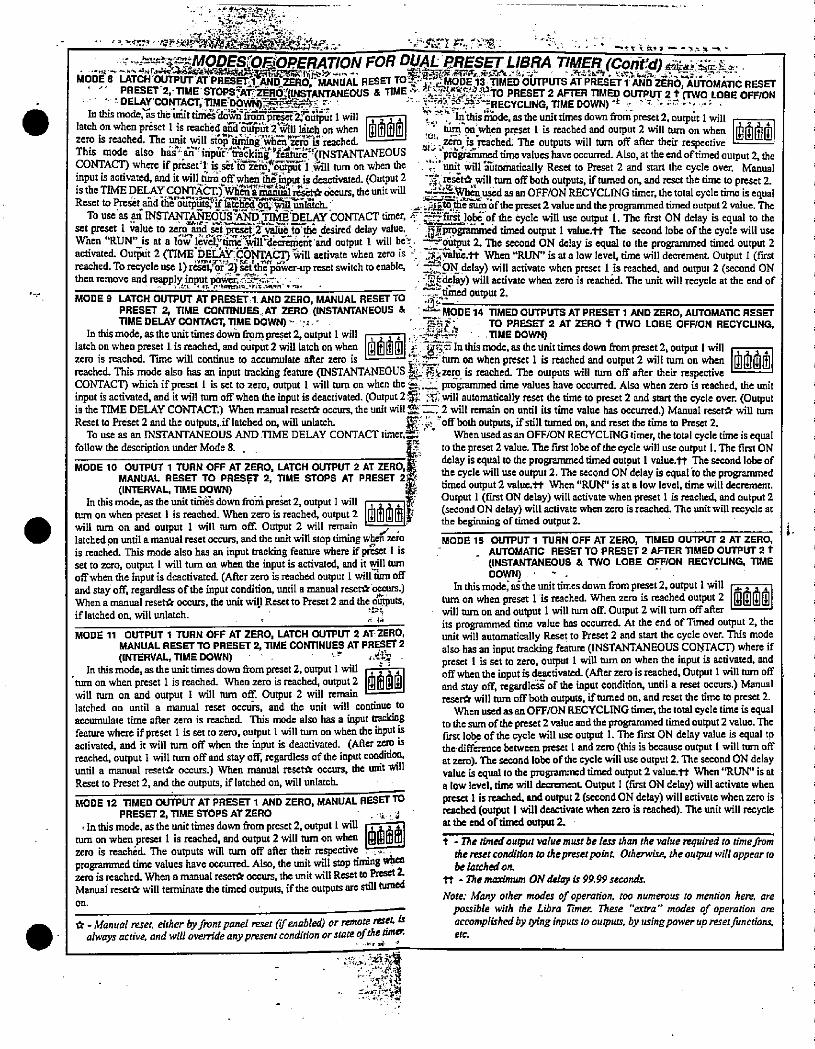
·fY?CriSS.iE..
1. '3'-trN··*Kl4J<<TEUP _.---__Y'*El F.".3·31 · - --f Ir #. 1 --teor-k
g ->«49*MODES<Or*)PERATION FOR DUAL RRESET LIBRA TIMER (Corit'd) *au: ie„ L.108#Er,,#755.*Grtwk.,7,- · - 1-4:6. rir.&62&: -'..n#r.·F--
MODES LATCH'OUTPUTAT'PRESErr»AND ZERO,'MANUAL RESET TOT--NMODE 13 TIMED OUTPUTS AT PRESET 1 AND ZERO, AUTOMATIC RESETPRESET 2, TIME STOPS*iZER*(INSTANTANEOUS & TIME 2 fig'659.rro PRESET 2 AFTER TIMED OUTPUT 2 + (TWO LOBE OFF/ONIntllis11,et,1ttwill - - -- thisnxide astheumttlmesdownfromprese£2, outputlwillr-'75.4-RECYCUNG,TIME DOWN) -t - ': U..1.--
latchon when prdset lis reache€28>i$§),2j*,h-on when 11 , non»en prfser 1 is reached and output 2 will tum on when |LD®|zero is reached. The unit witt stop timing wheq,zTds reached. 1---I · zero is reached. The outputs will turn ofF after their respectiveThis mode also harlm"inpdf'i82kii*'feabe'-(INSTANTANEOUS programmed time values have occurred. Also, at the end oftimed output 2, theCONTACT) where if preset-lis«inRiN*R"1*ill tum on when the . ';:" unit willlRitomatically Reset to Preset 2 and start the cycle over. Manualinput is activated, and it will@ri;9ff'*,*iput is deactivated. (Output 2 -.-4-. res* will him off both outputs, if turned on, and reset the time to preset 2.is the TIME DELAY 9355·) Ebsill&»Ad.lms.d* ckcurs, the unit will ZES&*das an OFF/ON RECYCLING timer. the total cycle time is equalReset to Preset aiid iite outplfstijf18kh-4.993©Alick, - .Aito.¢le sum oftlic preset 2 value and the propmmed timed output 2 value. The
To useas an INSTANTANEOUSAND TIMEDELAY CONTACT timer, 1- 5*firk lobd-of the cycle will use output 1. The first ON delay is equal to theset preset 1 *alue to zeni*-**ji2>R11 to the desired delay value.. -,fprogrammed timed output 1 value.tt The second iobe ofthe cycle will useWhen "RUN'Us at a low level;Vmeyill decNinciit'd output 1 will bel. ZE@4yut 2. The second ON delay is equal to the programmed timed output 2activated. Output 2 mME-DELAYfCONTACI) ill activate when zero is < .vallie.tt When "RUN" is ata low level, time will decrement. Output 1 (first
·V=•.le -' FL r r.,1 .0
reached To recycle use 1)resetior 2) setthe power-up reset switch to enable. · 3ZPN-delay) will activate when preset 1 is reached, and output 2 (second ONthenmmove and m?ppl,¥j,P,tE*illS--„-., , . -
-2 timed output 2.-Efidelay) will activate when zero is reached. The unit will recycle at the end of
MODE 9 LATCH OUTPUT AT PRESET.1 AND ZERO, MANUAL RESET TO .7:PRESET 2, TIME CONTINUES AT ZERO (INSTANTANEOUS & ' -f- MODE 14 TIMED OUTPUTS AT PRESET 1 AND ZERO, AUTOMATIC RESETTIME DELAY CONTACT, TIME DOWN) -·: - ' -- TO PRESET 2 AT ZERO t (TWO LOSE OFF/ON RECYCLING,In this mode, as tile unit times dod frpm preset 2, outputlwill , 2 3 4 i ., --SAG . TIME DOWN)
latch on when preset 1 is reached, and output 2 will latch on when 1[illfill[Ill,j 3Inthismode, asthe Unittimes down from preset 2, output i will Izero is reached. Time will continue to accumulate after zero is L----1 --2=, turn on when preset 1 is reached and output 2 will turn on when F]reached. This mode also has an input tracking feature (INSTANTANEOUS * Et<ze:p is reached. The outputs will turn off after their respectiveCONTACT) which if preset 1 is set to zero, output 1 will turn on when the * .2- programmed time values have occurred. Also when zero is reached, the unitinput is activated. and it will tum off when the input is deactivated. (Output 2* 7.f will automatically reset the time to preset 2 and start the cycle over. (Outputis the TIME DELAY CONTACT.) When manual reset* occurs, the unit will Z Z- 2 will remain on until its time value has occurred.) Manual reset* will tumReset to Preset 2 and the outputs, if latched on, will unlatch. lir j.:-off both outputs, if still turned on, and reset the time to Preset 2.
To use as an INSTANTANEOUS AND TIME DELAY CONTACT timer,_. When used as an OFF/ON RECYCLING timer, the total cycle time is equalfollow the description under Mode 8. . to the preset 2 value. The first lobe ofthe cycle will use output 1. The first ON
delay is equal to the programmed timed output 1 value.tt The second lobc ofMODE 10 OUTPUT 1 TURN OFF AT ZERO, LATCH OUTPUT 2 AT ZERO,
MANUAL RESET TO PRESET 2, TIME STOPS AT PRESET 2the cycle will use output 2. The second ON delay is equal to the programmed
(INTERVAL, TIME DOWN) timed output 2 value. tt When "RUN" is at a low level, time will decrement.
In this mode, as the unit tis down from preset 2, output l will i, . Output 1 (first ON delay) will activate when preset 1 is reached. and output 2turn on when preset 1 is reached. When zero is reached, output,2 @[ the beginning of timed outpu 2.(second ON delay) will activate when zero is reached. The unit will recycle at
will tum on and output 1 will tum off. Output 2 will remamlatched on until amanual reset occurs, and the unit will stop timing when zero MODE 15 OUTPUT 1 TURN OFF AT ZERO, TIMED OUTPUT 2 AT ZERO,is reached. This mode also has an input tracking feature where ifpriset 1 is - _ AUTOMATIC RESET TO PRESET 2 AFTER TIMED OUTPUT 2 t
set to zero, output 1 will turn on when the input is activated, and it will turn (INSTANTANEOUS & TWO LOSE OFF/ON RECYCLING, TIME
offwhen the input is deactivated (After zero is reached ourput 1 will'Etrn off DOWN)
and stay off, regardless of the input condition, until a manual reset* 6ccurs.) In this mode; aithe unit times down frompreset 2, output 1 will i1,1
When a manual reset* occurs, the unit will Reset to Preset 2 and the outputs, turn on when preset 1 is reached. When zero is reached output 2 |maiiin|if latched on, will unlatch. ' - witt turn on and output 1 will turn off. Output 2 will tum offafter
r 1,» its programmed time value has occurred. At the end of Timed output 2, theMODE 11 OUTPUT 1 TURN OFF AT ZERO, LATCH OUTPUT 2 AT ZERO, unit will automatically Reset to Preset 2 and start the cycle over. This mode
MANUAL RESET TO PRESET 2, TIME CONTINUES AT PRESET 2(INTERVAL, TIME DOWN) .'. 4*
also has an input tracking feature (INSTANTANEOUS CONTACT) where if. preset 1 is set to zero, output 1 will turn on when the input is activated, and
In this mode, as the unit times down from preset 2, output 1 will- offwhenthe input is dcactivated (After zero is reached, Output 1 will turn off'turn on when preset 1 is reached. When zero is reached, output 2 and stay off, regardleS of the input condition, until a reset occurs.) Manualwill turn on and output 1 will tum ofK Output 2 will remain reset* will turn off both outputs, if turned on, and reset the time to preset 2.latched on until a manual reset occurs, and the unit will continue to When used as an OFF/ON RECYCLING timer. the total cycle time is equalaccumulate time after zero is reached. This mode also has a input tmcking to the sum of thepreset 2 value andtheprogrammed timed output 2 value. Thefeature where if preset 1 is set to zero, output 1 will turn on when the input is first lobe ofthe cycle will use output 1. The first ON delay value is equal toactivated. and it will tim off when the input is deactivated. (After zero is the difference between preset 1 and zero (this is because output 1 will turn offreached, output 1 will turn offand stay off, regardless of the input condition at zero). The second lobc of the cycle will use output 2. The second ON delayuntil a manual reset* occurs.) When manual resetfr occurs, the unit Will value is equal to the progranm:d timed output 2 value.tt When "RUN" is atReset to Preset 2, and the outputs, if latched on, will unlatch. a low level, time will decrcment. Output I (first ON delay) will activate when
MODE 12 TIMED OUTPUT AT PRESET 1 AND ZERO, MANUAL RESET TO preset 1 is reached. and output 2 (second ON delay) will activate when zero is
PRESET 2, TIME STOPS AT ZERO reached (output 1 will deactivate when zero is reached). The unit will recycle. In this mode, as the unit times down from preset 2, output 1 Will at the end oftimed output 1turn on when preset 1 is reached, and output 2 will tum on wherl 1 - Ilie timed oupur vulue must be len than the vatue nquired zo time»m
zero is reachdd. The outputs will tum off after theirrespective - *. thereset condition to thepreset point Otherwise, the outputwill appear toproglmnmed time values have occurred. Also, the unit will stop timing when be /ctched on.zero is reached. When a manual reset* occurs, the unit will Reset to Preset 1 tt - The maximum ON delay is 99.99 seconds.Manuai reset* will terminate the timed outputs, if the outputs are still turned
Note: Many other modes of operation, roo numerous to mention here, areOn. ' 1 -- possible with the Libra Timer. These "extra" modes of operation are
*-Manual reset. either by front pane! reset (ifenabled) or remote reset. ix accomplished by tying inputs to outputs, by using powerup resetfunctions,
always active, and will override any piesent condirionor xmas ofiketimu: erc.
- . :..'.4 ..:di 411
i
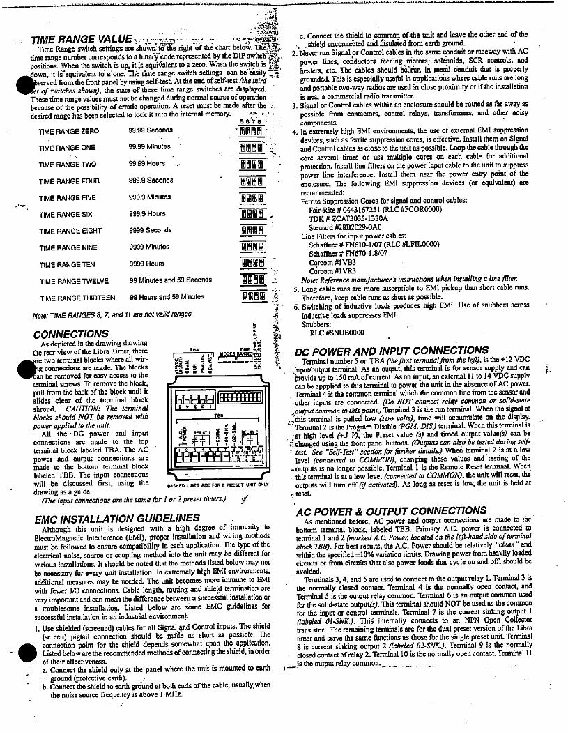
.
'.CMY
TIME RANGE VALUE-»„ -·.- . -***ntt·
Time Range switch settings are sh@Sn'tY&2 rightof the chart belot:.-The/f*time range number corresponds to a binaifcode represented by the DIP switch _334positions. When the switch is up, itis equi*atent to a zero. When the switch is *
--down, it is-equivalent to a one. Th»e time range switch settings can be«eksilyS*served from the front panel by using self-test. At the end of self-test (the thinter of switches shown), the state of these time range switches are displayed.
These time range values must not be changed during normal course of operationbecause of the possibility of erratic operation. A reset must be made after the:.desired range has been selected to lock it into the internal memory.
5678 '
TIME RANGE ZERO 99.99 Seconds .MIlam -/. 'TIME RANGE ONE 99.99 Minutes MliER..
TIME RANGE TWO 99.99 Hours EM'm- I
TIME RANGE FOUR 999.9 Seconds .1891/r
TIME RANGE FIVE 999.9 Minutes IlgliBil
TIME RANGE SIX 999.9 Hours 'MWIWII' .
TIME RANGE EIGHT 9999 Seconds wim m le
TIME RANGE NINE 9999 Minutes :18"12
TIME RANGE TEN 9999 Hours limwm .I
TIME RANGE TWELVE 99 Minutes and 59 Seconds @Rmin 4
TIME RANGE THIRTEEN 99 Hours and 59 Minutes Wgimm *
Note: TIME RANGES 3.7, and ll are not valid ranges.
CONNECTIONS 5 *:
As depicted in the drawing showing *# 2
tile rear view of the Libra Timer, there TBA
..Iare two terminal blocks where all wir- L1 connections are made. The blocks gliti _-_AL_lee f
56 1
,=ican be removed for easy access to theterminal screws. To remove the block, /pull from the back of the block until itslides clear of the terminal block QEIRIAE] ..EHEHHshroud. CAUTION: The tenninal 5,£21
blocks should NOT be removed with · ·· Tee
power applied to the unit. 1 r *:All the DC power and input HY RELAY I | Z 91 RELAY 2
connections are made to the top 1 ff-1 9 49 ff-1terminal block labeled TBA. The AC ECIZ;ISjZEZ;Il,Tn,2--30power and output connections are rvrr'rrint'.:'fr_11made to the bottom tenninal block
labeled TBB. The input connections 7- rwill be discussed first, using the DASHED LINES ARE FOR 2 PRESET UNIT ONLY
drawing as a guide.(The input connections am the samefor l or 2 preset timers.) f
EMC INSTALLATION GUIDELINESAlthough this unit is designed with a high degree of -immunity to
ElectroMagnetic Interference (EMD, proper installation and widng methodsmust be followed to ensure compatibility in each application. The type of theelectrical noise, source or coupling method into the unit may be different forvarious installations. It should be noted that the methods listed below may notbe necessary for every unit installation. In extremely high EMI environments,additional measures may be needed. The unit becomes more immune to EM 1with fewer 1/0 connections. Cable length, routing and shield termination arevery important and can mean the difference between a succeisful installation ora troublesome installation. Listed below are sbme EMC guidelines forsuccessful installation in an industrial environment.
1. Use shielded (screened) cables for all Signal and Control inputs. The shield(screen) pigtail connection should be mide as short as possible. Theconnection point for the shield depends somewhat upon the application.- Listed below are the recommended methods of connecting the shield, in orderof their effectiveness.
a. Connect the shield only at the panel where the unit is mounted to earth . ground (protective earth).
b. Connect the shield to earth ground at both ends of the cable, usually. whenthe noise source frequency is above 1 MHz.
2*
c. Connect the shield to common of the unit and leave the other end of the, shield unconnoted and flsulaied tomearth ground.
2. Never run Signal pr Control cables in the same conduit or raceway with ACpower lines, conductors feedin motors, solenoids, SCR controls, andheaters, etc. The cables should beirun in metal conduit that is properlygrounded. This is especially useful in applications where cable runs are longand portable two-way radios are used in close proximity or if the installationis near a commercial radio transmitter.
3. Signal or Control cables within an enclosure should be routed as far away aspossible from contactors, control relays, transformers, and other noisycomponents.
4. In extremely high EMI environments, the use of external EMI suppressiondevices, such as ferrite suppression cores, is effective. Install them on Signaland Control cables as close to theunitas possible. Loop the cable through thecore several times or use multiple cores on each cable for additionalprotection. Install line filters on the power input cable to the unit to suppresspower line interference. Install them near the power entry point of theenclosure. The following EMI suppression devices (or equivalent) arerecommended:
Ferrite Suppression Cores for signal and control cables:Fair-Rite # 0443167251 (RLC #FCOR0000)TDK # ZCAT3035-1330ASteward #2882029-OAO
Line Filters for input power cables:Schaffner # FN610-1/07 (RLC #LFILO{)00)Schaffner # FN670-1.8/07Corcom #1VB3
Corcom #1VR3
Note: Reference manufacturer's instructions when installing a line filter.5. Long cable runs are more susceptible to EMI pickup than short cable runs.
Therefore, keep cable runs as short as possible.6. Switching of inductive loads produces high EMI. Use of snubbers across
inductive loads suppresses EMI.Snubbers:
RLC #SNUB0000
DC POWER AND INPUT CONNECTIONSTenninal number 5 on TBA (thefirst renninatpum the k/V, is the +12 VDC
,*ut/output terminal. As an output, this terminal is for sensor supply and canprovide up to 150 mA of' current As an input, an external 11 to 14 VDC supplycan be appplied to this terminal to power the unit in the absence of AC power.Terminal 4 is the common terminal which the common line from the sensor and
-other inputs are coonected. (Do NOT connect relay common or solid-state,:output common to this point) Terminal 3 is the run terminal. When the signal at-this terminal is pulled low (ze,0 vole), time will accumulate on the display.
Terminal 2 is the Program Disable (PGM. DAS.) terminal. When this terminal is. at high level (+5 F), the Preset value (s) and timed output value(s) can be
C changed using the front panel buttons. (Outputs can alio be tested during se(A' test. See "Sef-Tat" secrionforfu,·ther detai'Le When terminal 2 is at a low
level (connected to COMMOM, changing these values and' testing of the- outputs is no longer possible. Terminal 1 is the Remote Reset terminal. When
this terminal is at a low level (connected to COMMOAO, the unit will reset, theoutputs will tum off (f activated). As long as reset is low, the unit is held at
., reset.
AC POWER & OUTPUT CONNECTIONSAs mentioned before, AC power and output connections are made to the
bottom tenninal block, labeled TBB. Primary A.C. power is connected toternina 1 andl (marked A.C. Power, located on the left-hand side of terminalblock TRB). For best results, the A.C. Power should be relatively "clean"andwithinthe specified *10% variation limits. Drawing power from heavily loadedcircuits or from circuits that also power loads that cycle on and off, should beavoided.
Terminals 3,4, and 5 are used to connect to tile output relay 1. Terminal 3 isthe normally closed contact. Terminal 4 is the normally open contact. andTerminal 5 is the output relay common. Terminal 6 is an output common usedfor the solid-state outpugs). This terminal should NOT be used as the commonfor the input or control terminals. Terminal 7 is the current sinking output 1Babeled OMNK.). Thid internally connects to an NPN Open Collectoruansistor. The remaining terminals are for the dual preset version of tile Libratimer and serve the same functions as those for the single preset unit. Terminal8 is current sinking output 2 (labeled 02-SNK.). Terminal 9 is the normallyclosed contact of relay 2. Terminal 10 is the normally open contact. Tenninal 11is thc output relay common.
4
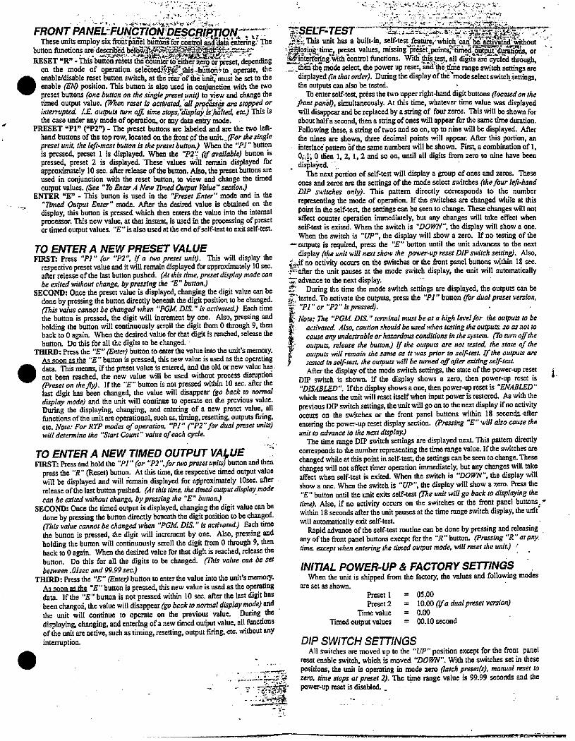
FRONT PANEL-FUNCTION'DESCRIPTIONiThese units employ six frontpaAl bilit for 6onti61 andkaiA enteringS'Ihe
button Amotions amdescribdbdi63!SS',EIE5,E,24,4W.4.RESET "R" -This buttonresets thecounter to>ither zero or preset, depending
on the mode of Qperation selebted»foi'this.b6£on:to operate, the
enable/disable reset button switch, at the raarAfahnirmusi be set to tileenable BM position. This button is also used in conjunction with the twopreset buttons (one button on the sing/epreset unit) to view and change thetimed output value. (lphen reset if activated, a// pivcsa an stopped orinfenipted. LE. outputs mni €g tbne stops,Y«plaq 29 *364 etc.) Iltis isthe case under any mode of operation,.or any data entry mode.
PRESET Upl" ("P27 - The preset buttons are labeled and are the two left-hand buttons of the top row, located on the front of the unit. for the singlepreset unit. theteft-mostbuttonisthepreset button.) Wligathe "Pl"buttonis pressed, preset 1 is displayed. When the "22" Ofavailable) button ispressed, preset 2 is displayed. These- values will remain displayed forapproximately 10 sec. after release ofthe button. Also, the preset buttons areused in conjunction with the reset button, to view and change the timedoutput values. (See "To Enter.4 New 7Tmed Output Value"section.)
ENTER UE" - This button is used in the "Preset Enter" mode and in the
"7Dned Output Enter" mode. After the desired value is obtained on thedisplay, this burton is pressed which then enters the value into the internalprocessor. This new value, at that instant, is used in the processing of presetor timed output values. "E"isalsousedatthe end ofsclf-test to exit self-test.
TO ENTER A NEW PRESET VALUEFIRST: Press "Pl" (or "P2", ff a two praget unit). This will displaythe
respectivepreset value and it will remain displayed for approximately 10 sec.after release of the last button pushed. (At this n'me, preser displaymodecanbe exited without change. by pressing the "E" button.)
SECOND: Once the preset value is displayed, changing the digit value can bedone by pressing the button directly beneath the digit position to be changed.(This value cannotbechanged when "PGM. DIS."is activated.) Each timethe button is pressed, the digit will increment by one. Also, pressing andholding the button will continuously scroll the digit from 0 through 9, thenback to 0 again. When the desired value for that digit is reached, release thebutton. Do this for all the digits to be changed.
THIRD: Press the "E" IEnred button to enter the value into the unit's memory.As soon asthe "E " button is pressed, this new value is used as the operating
data. This means, if the preset value is entered, and the old or new valuc hall.not been reached, the new value will be used without process disruptiod(Preset on thely). If the "E" button is not pressed within 10 sec. after thelast digit has been changed, the value will disappear (go back to normaldispiq mode) and the unit will continue to operate on the previous value.During the displaying, changing, and entering of a new preset value, allfunctions of the unit are operational, such as, timing, resetting, outputs firing,etc. Note: For RIP modes of operation, "Pl " ("P2" for dual preset units)witt determine the "Start Count" value of each cycle.
TO ENTER A NEW TIMED OUTPUT VAI,UEFIRST: Press andhold the "Pl" (or '72':fortwopresetuMits) button and then
press the "R" (Reset) button. At this time, the respective timed output valuewill be displayed and will kmain displayed for a#proximately 10sec. afterrelease of the last buttonpushed. (Arthistime, the,imedoutput displaymodecan be exited without change, by pressing the "E" button.)
SECOND: Once the timed output is displayed, changing the digit value can bedone by pressing the button directly beneath the digit position to be changed.frhis value cannot be changedwhen "PGM. DIS." is activated.) Each timsthe button is pressed, the digit will increment by one. Also, pressing andholding the button will continuously scroll the digit from 0 through 9, thenback to 0 again. When the desired value for that digit is reached, release thebutton. Do this far all the digits to be changed. (mis value can be setberween .Olsec and 99.99 sec.)
THIRD: Press the "E" (Enter) button to enter the value into the unit's memory.As soon as the "E" button is pressed, this new value is used as the operatingdata. If the "E" button is not pressed within 10 sec. after the last digit hasbeen changed, the value will disappear (goback tononnal dirplay mode) and the unit will continue to operate on the previous value. During thedisplaying, changing, and entering ofa new timed output value, atl functionsofthe unit are active, such as timing, resetting, output firing, etc. without anyinterruption.
-I.- . --*4,+rd.
a..:"12819- L23:551
*SEEF,1 tul£6>,This unit has a built-in, self-:st,8**'whi*h-,42=*%*hout .,
1 ':tfjesi#tinic, preset values, missing preset.points;-timEd,StEYBiwatigns, or:'interf4%;ith Zontrol Ainctions. Witi;1NN8, all diits are cycled thr6ugh,ZiNSAh;mode select, the power up reset, and'tlle.time range switch settings arc
displayed Un thar orded, During the displayofthCinode selectswitcllsettings,the outputs can also be tested.
To enter self-test, press the two upperright-hand digitbuttons (located on thefont pond), simultaneously. At this time, whatever time value was displayedwill disappear and be replaced by a string of four zeros. This will be shown forabout halfa second, then a string of ones will appear for the same time'duration.Following these, a string oftwos and so on, up to nine will be displayed. Afterthe nines are shown, three decimal points will appear. After this portion, anihterlace pattern 6f the same numbers will be shown. First a combination of 1,0,·.1,0 tien 1,2,1,2 and so on, until all digits from zero to nine have been
, di*lai,eci. ,The next portion of self-test will display a group of ones and zeros. These
ones and zeros are the settings of the mode select switches (thefour le#-handDIP switches only). This pattern directly corresponds to the numberrepresenting the mode of operation. If the switches are changed while at thispoint in the self-test, the settings can be seen to change. These changes will notaffect counter operation immediately, but any changes will take effect whenself-test is exited. When the switch is "DOWN", the display will show a one.When the switch is "UP", tile display will show a zero. If no testing of the
- outputs is required, press the "E" button until the unit advances to the nextdisplay Ohe unitwill nextshow the power-up reset DIP switch setting). Also.
:if no activity occurs on the switches or the front panel buttons within 18 sec.* after the unit pauses at the mode switch display, the unit will automaticallyT advance to the next display.3* During the time the mode switch settings are displayed, the outputs can bef 'tested. To activate the outputs, press the "Pl" button gor dual preset version,*4 "Pl" or "PZ"is pressed).
, Note: The "PGM. DIS." terminal must beata highlevelfor the outputs tobe
acrivated Atio, caution should be used when testing the outputs. so as not tocauseany undesirable orhazardousconditionsinthesystem. go turn ofthe: outputs, release the button.) If the outputs are not tested. the state of the
outputs wUZ nmain the same as it was p,Yor to sel/:test If the ouiputs aretested in self-test the outputs will be turned oll-after witingself-tenAfter the display of the mode switch settings. the state of the power-up reset i
DIP switch is shown. If the display shows a zero, then power-up reset is"DISABLED". Ifthe display shows aone, then power-up reset is "ENABLED"which means the unit will reset itself when input power is restored. As with theprevious DIP switch settings, the unit will go on to the next display if no activityoccurs on the switches or the front panel buttons within 18 seconds afterentering the power-up reset display section. (Pressing "E" will also cause rheunit to advance to the next display)
The time range DIP switch settings are displayed next This pattern directlycorresponds to the number representing the time range value. If the switches arechanged while at this point in self-test, the settings can be seen to change. Thesechanges will not affect timer operation immediately, but any changes will takeaffect when self-test is exited. When the switch is "DOFFN", the display will
show a one. When the switch is "UP", the display will show a zero. Press the"E" button until the unit exits self-test (71ie unit wiN go back ro displaying thetime). Also, if no activity occurs on the switches or the front panel buttons;,within 18 seconds after the unit pauses at the time range switch display, the uidtwill automatically exit self-test.
Rapid advance of the self-test routine can be done by pressing and releasingany of the front panel buttons except f6r the "R" button. (Pressing '72" aranytime. except when entering the timed output mode, will reset the unit.) ,
INITIAL POWER-UP & FACTORY SETTINGSWhen the unit is shipped from the factory, the values and following modes
are set as shown.
Preset 1
Preset 2
Time value
Timed output values
05.00
10.00 (if a dual preset version)0.00
00.10 second
DIP SWITCH SETTINGSAll switches are moved up to the "UP" position except for the front panel
reset enable switch, which is moved "DOWN". With the switches set in thesepositions, tile unit is operating in mode zero (larch prese:(s), manual reset rozero. ame stops at preset 2). The th range value is 99.99 seconds and thepower-up reset is disabled.
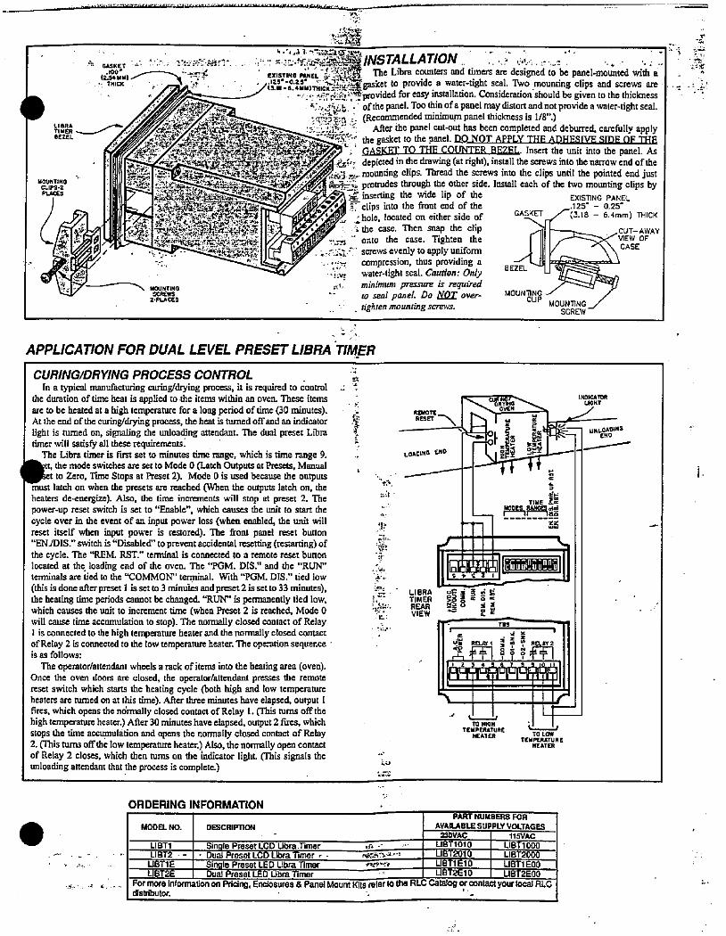
- Ill.-
d GASKET -. '· · -5:E-Msy£*:-. . .·-te :c.'y:f< 22i@INSTALLAT/ONlijoi.1 /- ExisT,Na pL;4 -i.-52ER The Libra counters and timers are designed to be panel-mounted with a·- THICK ,. 1 (3.10 - 6.4MMOTHICK .22-:*r.125*-0.25' . *' W?'2*gasket to provide a water-tight seal. Two mounting clips and screws are
· -«: ·· 9- :01'.,.5provided foreasy installation. Consideration shouldbe given to the thicknessr:,,4. i. . ofthe panel. Toothinofa panel may distort and notprovide a water-tight seal...r,Bi,: .· (Recommended minimum panel thickness is 1/8".)
LMJFL -- After the panel cut-out has been completed and deburred, carefully apply
-2 c **11.·'.: *p**#4645-94/jji,- depicted in the drawing (at right), install the screws into the narrow end ofthe:%* 25: .18@i. "'4TA*3*617-/" *,10-3 2.-mounting clips. Thread the screws into the clips until the pointed end justMCS;% = 4 protrudes through the other side. Install each of the two mounting clips byPLACES -,»' f33'*'-='- 4 F
EXISmNG PANEL®,1' inserting the wide lip of the
2 f ts,I 442· tiS·555£6'zie,Hih*=47 1 ., .0' Cclips into the front end of the .125' - 0.25-
r - :* Y«;.**KS?Zt . ,• .« ihole, located on either side of GASKET3.18 - 6.4mm) THICK. .6 the case. Then snap the clip 3:?4 - -CUT-AWAY-,m -' onto the case. Tighten the /'-ZZ-><' WEW OF
' ..Inu screws evenly to apply uni:forrn / \CASE_. ··-* compression, thus providing a- 28 E11
., water-tight seal. Caunon: Only -
419- MinGCUP MOUNTING /
e. minimum pressure is required
2·PLACES - to seal panel. Do NOT over- MOUNTING - /- . tighten mounting scravs.
SCREW
APPLICATION FOR DUAL LEVEL PRESET LIBRA TIMER
CURING/DRYING PROCESS CONTROL rIn a typical manufacturing curing/drying process, it is required to control +
the duration of time heat is applied to the items within an oven. These items ,are to be heated at a high temperamre for a long period of time (30 minutes).At the end of the curing/drying process, the heat is turned ofrand an indicator *light is turned on, signaling rhe unloading attendant. The dual preset Libra t.timer will satisfy all these requirements.
The Libra timer is first set to minutes time range, which is time range 9./4 the mode switches are set to Mode 0 (Latch Outputs at Presets, Manual ,ct to Zero, Time Stops at Preset 2). Mode 0 is used because the outputs
must latch on when the presets are reached (When the outputs latch on, theheaters de<nergize). Also, the time increments will stop at preset 2. Thepower-up reset switch is set to "Enable", which causes the unit to start thecycle over in the event of an input power loss (when enabled, the unit will
reset itself when input power is restored). The front panel reset button"EN./DIS." switch is "Disabled" to prevent accidental resetting (restarting) ofthe cycle. The "REM. RST." terminal is connected to a remote reset buttonlocated at the. loading end of the oven. The "PGM. IMS." and the *'RUN"terminals are tied to the *'COMMON' terminal. With "PGM. DIS." tied low
(this is done after preset 1 is set to 3 minuies and preset 2 is set to 33 minutes),the heating time periods cannot be changed. "RUN" is permanently tied low,which causes the unit to increment time (when Preset 2 is reached, Mode 0will cause time accumulation to stop). The nonnally closed contact of Relay1 is connected to the high temperature heater and the normally closed contactof Rclay 2 is connected to the low temperature heater. The operation sequence -is as follows:
The operator/attendant wheels a rack of items into the heating area (oven).Once the oven doors are closed, the operator/attendant presses the remotereset switch which starts the heating cycle (both high and low temperatureheaters are aimed on at this time). After three minutes have elapsed, output 1
fires, which opens the ndrmally closed contact of Relay 1. (This turns off thehigh temperature heater.) After 30 minutes have elapsed, output 2 fires, whichstops tile time accumulation and opens the nomnally closed contact of Relay2. (This turns offthe low temperature heater.) Also, the normally open contactof Relay 2 closes, which then turns on the Indicator light. Chis signals theunloading attendant that the process is complete.)
.ef
·»:
'P
Gu:.54
ART#7 i b
LOAOING END
[NOICATOR
LIGHT
4-ir- ENDUNLOADING
ime :wy
5
TIIdE - tai-5-255#
S6
*1*ly .MUU,il'vit'!!i;LIBRA 95 i 5 Ei tiTIMER *B 5 x o xREAR *20 VIEW
---"= 4:*
3K Mi H i *49A444#444477
,
TO HIGH
TEMPERATUREHEATER
r
TEMPERREHEATER
ORDERING INFORMATION
PART NUMBERS FOR
. MODELN DESCRIPTION AVAILABLE SUPPLY VOLTAGES23DVAC 115VAC
LIBT1 Single Preset LCD Ubra.Timer -5-E- '· LIST1O1O LIST 1000UBT2010 LIBT2000LIBT2 - - , Dual Preset LCD Ubra Timer , .
LIBTl E Single Preset LED Ubra Timer UBTl E10 LIBTl EOO- r¥631'1.2LIST2E Dual Preset LED Ubra Timer UBT2610 LIBT2EOO
For more information on Pricing, Enclosures & Panel Mount 15rio the RLC Catalog or contact your local RLCdistributor.
i.
NS
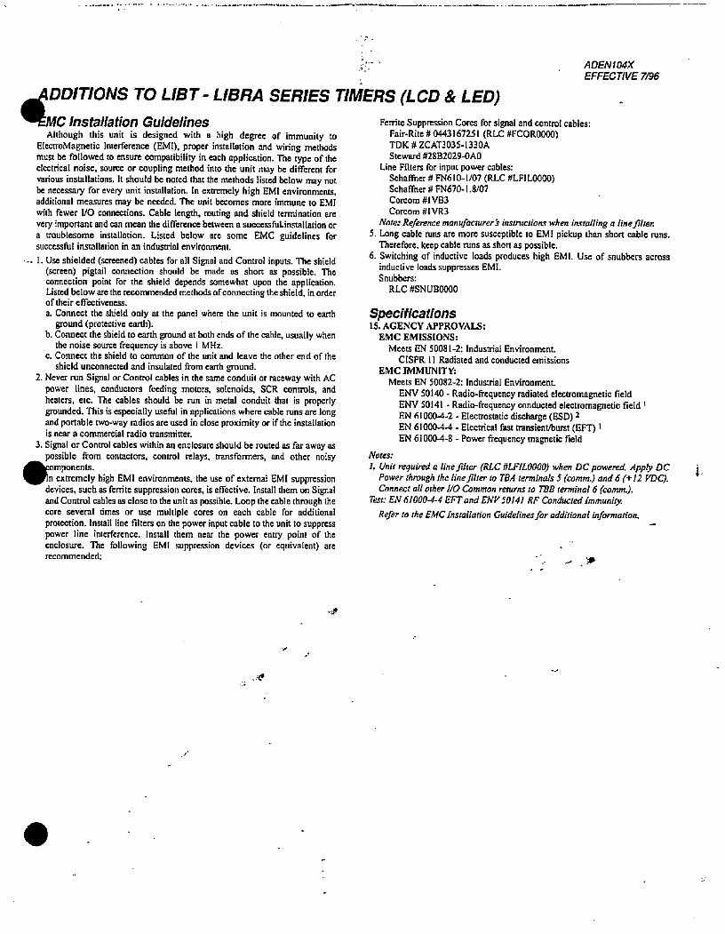
DDITIONS TO LIST - LIBRA SERIES T'EMC Installation Guidelines
Although this unit is designed with a high degree of immunity toElectroMagnetic Interference (EMI), proper installation and wiring methodsmust be followed to ensure compatibility in each application, The type of theelectrical noise, source or coupling method into the unit may be different forvarious installations. It should be noted that the methods listed below may notbe necessary for every unit installation. In extremely high EMI environments,additional measures may be needed. The unit becomes more immune to EMIwith fewer 1/0 connections. Cable length, routing and shield termination arevery important and can mean the difference between a successfuLinstallation ora troublesome installation. Listed below are some EMC guidelines forsuccessful installation in an industrial environment.
.- 1. Use shielded (screened) cables for all Signal and Control inputs. The shield(screen) pigtail connection should bc made as short as possible. Theconnection point for the shield depends somewhat UpOn the application.Listed below are the recommended methods of connecting the shield, in ordero f their c ffectiveness.
a. Connect the shield only at the panel where the unit is mounted to earthground (protective earth).
b. Connect the shield to earth ground at both ends of the cable, usually whenthe noise source frequency is above I MHz.
c. Connect the shield to common of the unit and leave the other end of the
shield unconnected and insulated from earth ground.2. Never run Signal or Control cables in the same conduit or raceway with AC
power lines, conductors feeding motors, solenoids, SCR controls, andheaters. etc. The cables should be run in metal conduit that is properlygrounded. This is especially useful in applications where cable runs are longand portable two-way radios are used in close proximity or if the installationis near a commercial radio transmitter.
3. Signal or Control cables within an enclosure should be routed as far away aspossible from contactors, control relays, tensformers. and other noisy
omponents.n extremely high EMI environments. the use of external EMI suppression
devices, such as ferrite suppression cores, is effective. Install them on Signaland Control cables as close to the unit as possible. Loop the cable through thecore several times or use multiple cores on each cable for additionalprotection. Install line filters on the power input cable to the unit to suppresspower line interference. Install them near the power entry point of theenclosure. The following EMI suppression devices (or equivalent) arerecommended:
ADEN104X
EFFECTIVE 7/96
IMERS (LCD & LED)
Ferritc Suppression Cores for signal and control cables:Fair-Rite # 0443167251 (RLC #FCOR0000)TDK # ZCAT3035-1330A
Steward #28B2029-OAO
Line Filters for input power cables:
Schaffner # FN610-1/07 (RLC #LFIL0000)Schaffner # FN670-1.8/07
Corcom #IVB3
Corcom #IVR3
Note: Reference manufacturer s instructions when installing a line.Biter.5. Long cable runs are more susceptible to EM! pickup than short cable runs.
Therefore. keep cable runs as short as possible.6. Switching of inductive loads produces high EMI. Use of snubbers across
inductive loads suppresses EMI.Snubbers:
RLC #SNUB0000
Specifications15. AGENCY APPROVALS:
EMC EMISSIONS:
Meets EN 50081-2: Industrial Environment.
CISPR 11 Radiated and conducted emissionsEMC IMMUNITY:
Meets EN 50082-2: Industrial Environment.
ENV 50140 - Radio-frequency radiated electromagnetic fieldENV 50141 - Radio-frequency conducted electromagnetic field 1EN 61000-44 - Electrostatic discharge (ESD) 2EN 610004-4 - Electrical fast transient/burst (EFT) 1EN 610004-8 - Power frequency magnetic field
Notes:
1. Unit required a line-filter (RLC #LFILOOO[)) when DC powered. Apply DC .Power through the line Jilter to TBA terminals 5 (comm.) and 6 (+ 12 YDC).Connect alt other UO Common returns to TBB terminal 6 (comm.).
Test: EN 61000-4-4 EFTand ENV 50141 RFConducted immunity.
Refer to the EMC Installation Guidelines for additional information.
.
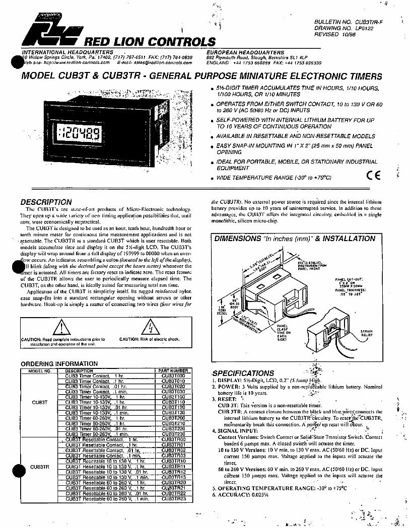
r,-
RED LION CONTROLS
. fBULLETIN NO. CU83T/R-FDRAWING NO. LP0122
REVISED 10/96
INTERNATIONAL HEADQUARTERS . EUROPEAN HEADQUARTERS
Willow Springs Circle. York. Pa. 17402, (717) 767·6511 FAX: (717) 764·0839 892 Plymouth Road. Slough, Berkshire SL1 4LPIieb site- http:i/www.redlion-controls.com E.mail· [email protected] ENGLAND *44 1753 696888 FAX: +44 1753 696339
MODEL CU83T & CU83TR - GENERAL PURPOSE MINIATURE ELECTRONIC TIMERS
. 5!/2-DIGIT TIMER ACCUMULATES TIME IN HOURS. 1/10 HOURS.1/100 HOURS, OR 1/10 MINUTES
. OPERATES FROM EITHER SWITCH CONTACT. 10 to 130 V OR 60
to 260 V (AC 50/60 Hz or DC) INPUTS
.
1.1-
DESCRIPTION
The CUBJT's :,re si:,te-of-m·l products of Micro-Electronie tedinologyThey open up a #,·ide wiriety of new timing applica,lion possibilities that, untilnow, were economically impractical
The CUB3T is designed lo be used as an hour. tenth hour. hundredih hour ortenth minute meier for continuous time measurement applications and is not·.resenable. The CUB3TR is a standard CU83T which is user resettable. Both
models accumulate time and display it on the 57-digit LCD. The CUB3T'sdisplay will wrap :tround from a filll display of 199999 to 00000 when an over-
-,Dow occurs. An indicator. resenibling u colon (located to the leR ofthe display),
11 blink (along with fhe decimal point except the hours meted whenever the•-nmer is actuated. All timers are factory reser to indicate zero. The reset feature
of the CUB3-1'R allows the user to periodically measure elapsed time. TheCUB]T, on the olher hand. is ideally suited for measuring total run time.
Application of the CUBJT is simplicity itself. Its rugged rcinfurced nyloncase snap·fits into a standard rectangular opening without screws or ocherhardware. Hook-up is simply :1 matter ofeo,Inecting two wires (four wires for
CAUTION: Read complete instructions prior toinstallation and operation of me Ii,ill.
ORDERING INFORMATION
MODEL NO.
CUB3T
CU83TR
CAUTION: Risk of electric shock.
DESCRIPTION
CUB3 Timer Conlact. 1 hr.CUB3 Timer Conlact, .1 hr.
CUB33 Timer Contact. 01 hr.
CUB3 Timer Contact, .1 min.
CUB3 Timer 10-130V, 1 hr.CUB3 Timer 10-130V, .1 hr.CUB33 Timer 10-130V, .01 hr.
CUB3 Timer 10·130V, .1 min.
CU83 Timer 60-260V. 1 hr.
CUB3 Timer 60-26OV, .1 hr.
CUB3 Timer 60·260V, .01 hr.
CUBS Timer 60-260V, .1 min.
. CU83T Resetlable Contact, 1 hr.
CU83T Resettable Contact, .1 hr.GU83T Resettable Contact, .01 hr.
CU83T Resettable Contact. .1 min.
CUBST Resettable 10 to 130 V. 1 hr.CUB3T Resettable 10 10130 V, .1 hr.
CU83T Resettable 10 10130 V. .01 hr.
CU83T Resettable 10 10130 V, .1 min.CU83T Reseltable 60 to 260 V, 1 hr.CU83T Resettable 60 to 260 V. .1 hr.
CU83T Resettable 60 to 260 V. .01 hr.
CU83T Resellable 60 to 260 V, .1 min.
PART NUMBER
CU83TOOO
CUBGT010
CUBGT020
CUMT030
CU83T1 OO
CU83T110
CU83T120
CUB3T130CU83T200
CU83T210
CU83T220
CU83T230
CU83TROO
CU83TRO1
CU83TR02
CU83TR03
CU83TR 10
CUETR11
CU83TR 12
CU83TR13
CU83TR20
CUBBTR21CU83TR22
CU83TR23
. SELF-POWERED WITH INTERNAL UTHIUM BATTERY FOR UPTO 10 YEARS OF CONTINUOUS OPERATION
. AVAILABLE IN RESETTABLE AND NON-RESETTABLE MODELS
. EASY SNAP-IN MOUNTING IN 1" X 2" (25 mm x 50 mm) PANELOPENING
. IDEAL FOR PORTABLE, MOBILE, OR STATIONARY INDUSTRIAL EQUIPMENT
0 WIDE TEMPERATURE RANGE (-30 to +75°C) C€ 6
lite CUB3TR). No external power source is required since the internal lithium
battery provides up 10 10 years of uninterrupted service. in addition [0 these
advantages, the CUInT oiltrs Ihe integrtiled circuiliy, embedded in a singlemonolithic, silicon micro-chip.
DIMENSIONS "In inches (mm)" & INSTALLATION
:/5:i...3..9;0-13 SIBEZEL
4-t. PROTRUSION FROU
I. f tp/&/- PANEL FRONT
«/5(24.21
110- 8009
PANEL
BEZEL 1 /
CLASP
PA=RE:PANEL TH,CKNE35:
05'TO.,25
STRAIH
RELIEF
SPECIFICATIONS1. DISPLAY: 514-Digit, LCD, 0.2" (5. imm) Hih.2. POWER: 3 Volts supplied by a non-replabable lithium battery. Nominal
battery life is 10 years.3. RESET: h · , f
CUB JT: This version is a non-resettable timer.
CUB 3TR: A contact closure between the bl4ck and blue wires,cgnnects the 9 ·internal limium battery to the CUB3TRWircuitry. To resel<Ille'CUBJTR,
motnentarily break this connection. K,pfef up reset willcur. * :,4. S[GNAL INPUT:
Contact Versions: Switch Contact or SolidrS[ate Transisior Switch.«Contact
bur(led 6 pamps max. A closed switch will actuate the timer.
10 to 130 V Versions: 10 V min. to 130 V max. AC (50/60 Hz) or DC. Inpul
current 150 ;tamps max. Voltage applied to the inputs will actuate thetimer.
60 to 260 V Versions: 60 V min. to 260 V max. AC (50/60 liz) or DC. Inputcmrent 150 pamps max. Voltage applied to the inputs will actuale thetimer.
5. OPERATING TEMPERATURE RANGE: -30° to +75°C
6. ACCURACY: 0.025%
..,
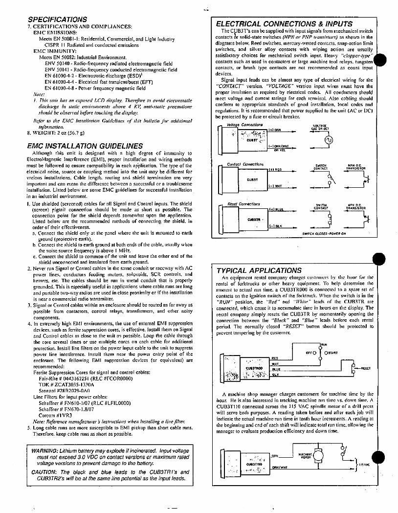
SPECIFICATIONS
7. CERTIFICATIONS AND COMPLIANCES:
EMC EMISSIONS
Meets EN 50081-1: Residential, Commercial, and Light IndustryCISPR 11 Radiated and conducted emissions
ERIC IMMUNITY:
Meets EN 50082: industrial Environment.
ENV 50140 - Radio-frequency radialed electromagnetic fieldENV 50141 - Radio-frequency conducted electromagnetic fieldEN 61000-4-2 - Electrostatic discharge (ESD)'EN 61000-4-4 - Electrical fast transient/burst (EFT)
EN 61000-4-8 - Power frequency magnetic fieldNofe:
j. This unit hcix cin exposed LCD display. Therefore m avoid eleclms:aticdischalze in smtie environments ubove 4 KK zinti-static precautionsshould be obsen·ed befoi·e touching the display.
Relt· to [he EMC Installalion Guidelines qf thir bulletin ®r additionalinformation.
8. WEIGHT: 2 oz (56.7 g)
EMC INSTALLATION GUIDELINES
Although this unit is designed with a high degree of immunity toElectroMagnetic Interference (EMI). proper installation and wiring methodsmust be followed to ensure compatibility in each aliplication. The type of theeleclrical noise, source or coupling method into the unit may be different forvarious installations. Cable length. routing and shield termination are vcry
important and can mean the difference between a successful or a troublesomeinstallation. Listed below are sonie EMC guidelines for successful installationin an industrial environment.
1. Use shielded (screened) cables for all Signal and Control inputs. The shield(screen) pigtail connection should be made as short as possible. Theconnection point for the shield depends somewhat upon the application.Listed below are the recommended methods of connecting the shield, inorder of their e frectiveness.
a. Connect the shield only at the panel where the unit is mounted to earthground (prolective earlh).
b. Connect the shield to earth ground at both ends of ihe cable, usually whenthe noise source frequency is above I MHz.
c. Connect the shield to common of the unit and leave the other end of the
shield unconnected and insulated from earth ground.2. Never run Signal or Control cables in tlic fame condilit or raceway with AC
power lines, conducturx fucding motors. solenoids. SCR controls. andheaters. etc. The cables should be run in metal conduit that[ is properlygrounded. Tlils is especially useful in applications where cable runs are longand portable two-way radios are used in close proximity or if the installationis tiear a commercial radio transmitter.
3. Signal or Control cables within an enclosure should be routed as far away aspossible from contactors, control relays, transformers, and other noisy
components.
4. In extremely high EMI enviromnents, the use of extemal EMI suppressiondevices. such as fcrrite suppression cores, is effective. Install them on Signaland Control cables as close to the unit as possible. Loop the cahle throughthe core several times or use multiple cores on each cable for additionalprotection. Install line filters on the power input cable to the unit to suppresspower line interference. Install them near tlic power cn(ry point of theenclosure. Tile following EM 1 suppression devices (or equivalent) arerecommended:
Ferrite Suppression Cores for signal and control cables:Fair-Rite # 0443 167251 (RLC #FCOR0000)TDK # ZCAT3035-1330A
Steward #2882029-OAO
Line Filters for input power cables:Schaffncr # FN610-1/07(RLC #LFIL0000)Schaffner # FN670- 1.8/07
Corcom # 1 VR3
Nofe.: Reference mant,factwer's insinictions when insmiling a line jllter.
5. Long cable runs are more susceptible to EMI pickup than short cable runs.Therefore. keep cable runs as short as possible.
WARNING: Lithium battery may explode ifincinerated. Input voltagemust not exceed 3.0 VDC on contact versions or maximum rated
voltage versions to prevent damage to the battery.
CAUTION: The black and blue leads to the CUB3TR1's and
CU83TR2's will be at Ihe same line potential as the input leads.
-
-
ELECTRICAL CONNECTIONS & INPUTS
The CUB3T's can be supplied with input signals from mechanical switchcontacts L solid-state switches (NPN or PNP fransiwors) as shown in the
diagrams below. Reed switches. mercury-wetted contacts. snap-action limitswitches, and silver alloy contacts with wiping action are usuallysatisfactory choices for mechanical switch input. Heavy "clapper-O,pecontacts such as used in contactors or large machine tool relays. tungsten contacts, or brush typc contacts are not recommended as count inputdevices.
Signal input leads can be almost any type of electrical wiring for thc"CONTACT" version. "VOLTAGE' version input wires must have the
proper insulation as required by electrical codes. All conductors shouldmeet voltage and current ratings for erich terminal Also cabling shouldconform to appropriate standards of good installation. local codes mid
regulations. It is recommended that power supplied to the unit (AC or DC)be protected by a fuse or circuit breaker.
- Volfage Connections VOLTAGE
· „ WORN r irc OR DC; 1cue,r:· 9(-l ORN/WHT
I .OR YEL
Confac# Conneclions
CUBBT
Reset Connections
CUeSTR
WIRED
(-I WHT
(t) BLUE
2-1 BLK
C*1[W, r*sMOR
c8Wf& ,=NiON4 ,
SWITCH CLOSED-POWER ON
TYPICAL APPLICATIONS
An equipment rental company chnrges customers by the hour tiir Ilicrental of forktrucks or other heavy equipment. To help determine theamount to actual run time. a CUB3TR000 is connected to a spare set ofcontacts on the ignition switch of Ihe forkinick. When the switch is in the"RUN" position. the "Red" and "ff'hife" leads of the CU83TR areconnected, which cause it to accumulate tiine iii hours on the display. Therental company simply resets the CUB)TR by momentarily opening theconnection between the "Black " and "Bhle " leads before each rental
period. The normally closed "RESET" button should be protected toprevent Inml,ering by tlic clistoilier.
'+
CUBSTMOO
2 .ty'
r
1 OFFO +OSTART
RED
WHT
1--RESETBLUE KOLK
A machine shop manager charges customers for machine lime by tlichour. He is also interested in tracking ninchitic rim time vs. down time. ACUB3TI 10 connected across the 115 VAC spindle motor of a drill presswill serve both purposes. A reading taken before and after each job willindicate the actual machine run time in tenth hour increments. A reading atthe beginning and end of each shift will indicate total run time. allowing themanager to evaluate production efficiency and down time.
CU83 T·110
ORN MOTOA *» MACHINEORN/WHT
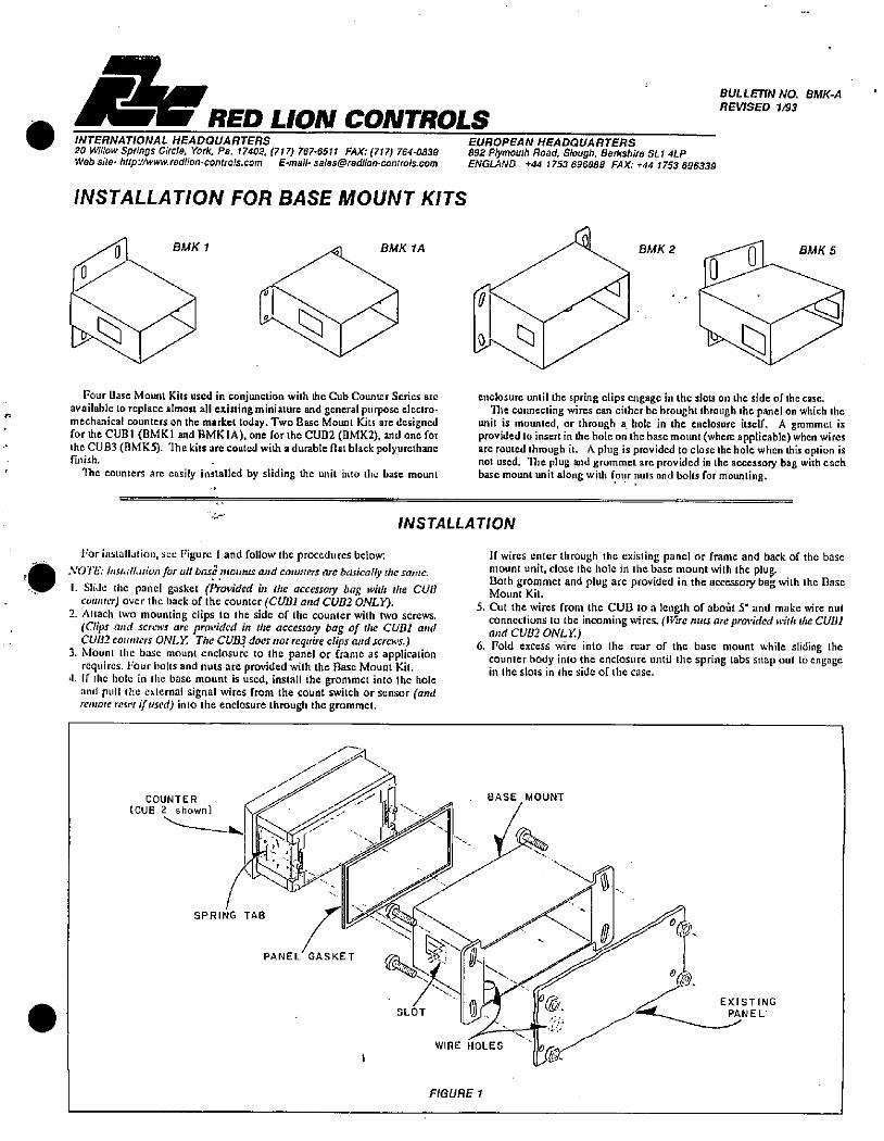
RED LION CONTROLSINTERNATIONAL HEADQUARTERS20 Willow Springs Circle, York. Pa. 17402. (717) 767-6511 FAX: (717) 764-0839Web site- htip://www.redlion-controls.com E-mail- [email protected]
INSTALLATION FOR BASE MOUNT KITS
BMK 1 BMK IA
11 \ /<11
Four Base Mount Kits used in conjunclion with Lic Cub Counter Scrics arcavailable Lo replace almost a existing miniature and general purpose electro·mechanical counters on the market today. Two Base Mount Kits are designedfor the CUBI (BMKt and BMKIA), one for the CUB2 (BMK2), and one forthc CUB3(BMKS). Thekits arecoated with adurable flat black polyurethancfinish.
'llic counters are easily installed by sliding the unit into the base mount
0
EUROPEAN HEADQUARTERS892 Plymouth Road, Slough. Berkshire SL1 4LPENGLAND +44 1753 696888 FAX: +44 1753 696339
BULLETIN NO. BMK-A
REVISED 183
BMK 2 BMK 5
l«///7enclosure until the spring clips engage in the slots on the side of Ihc case.
The connecting wires can either be brought through [he panel on which Ihcunit is mounted, or through a hole in the enclosure itself. A grommct isprovided to insertin the hole on thebase mount (where applicable) when wiresarc routed through it. A plug is provided to close the hole when this option isnot used. The plug and grommci arc provided in the accessory bag with eachbase mount unit along with four nuts and bolts for mounting.
INSTALLATION
For installation, acc Figurc 1 and follow the procedures below.a NOTE. InsmU.nion for all basl mounts and coumers are basically die same.
..
7 1. Slide the panel gasket (Provided in me accessog bag wit/: the CURcolmier) over the back of the counter (CUBl mid CUB2 ONLYO.
2. Attach two mounting clips to the side of Ihc counter with two scrcws.(Clips and screws are provided in {he accessoly bag of the CUBI andCUBZ counlers ONLY. The CUB3 does not requirectips and screws.)
3. Mount thc base mount enclosure to the panel or frame as applicationrequires. l'our bolts and nuts are provided with the Base Mount Kil.
4. If the hole in the base mount is uscd, install the grommct into the holeand pull the external signal wires from the count switch or sensor (andremofe resi·/ (fused) into the enclosure through the grommct.
If wires enter through the existing panel or frame and back of the basemount unit, close the hole in the base mount with the plug.Both grommet and plug arc provided in the accessory bag with ihc BaseMount Kit.
5. Cut the wires from the CUB to a length of aboOt 5" and make wirc nulconnections to the incoming wires. (Wire nuu are provided with the CUBI
and CUBC ONLY.)
6. Fold excess wire into the rear of thc base mount while sliding thecounter body into the enclosure until the spring tabs snap out to engagein the slots in ihe side of the case.
COUNTER /i(CUB 2 shown) \
BASE MOUNT
fl liSPRING TAB , 1 ..659(021 -.
/0
{53\<4441PANEL GASKET 4 + 4.EXISTING
SLOT m. ff.: PAN E L'
/
WIRE HOLES --FIGURE 1
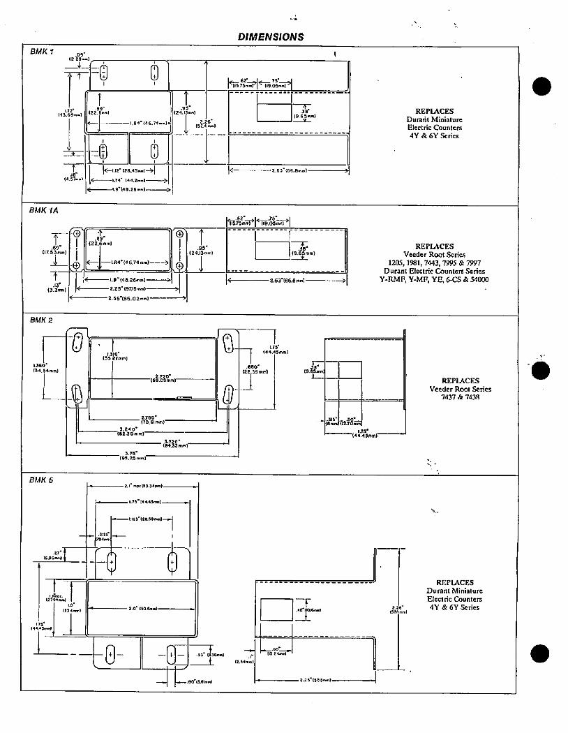
BMK 1
BMKlA
-F1 .69' (1753'm)
L
t.13"
1 (3.31rm)
BMK 2
1.360'
(34.54.m)
BMK 6
rne
C
.27"
{606-)
09'
/2 2-9-m]
-rr -y l)148:.1 (245)
1=1-Ijjj 11'84'(461Ii %1
14.-1 -1.74- 144.2--1-|4-1.12(28.45..1-4|
*S--1,9"(48.25.-I-
1.0"
(254.nm)
1 1(44.45 -4
/11.BIO"
(33.27mm)
8-
.
.89-
(22.6mm]
*---I. 84"{46.74mm)---2-1.9"(48.26-m)-
2.25'(51:15mn)
2.56"(65.0211
182-30mi
(9s:Rl,m)
/01://mi
2700"[70.(Irnm)
2.I mi 01.34#m)
1.75"[4445,m)
-/125.120.58..1-4
.3:29 -CnIM
--1+1
2.0. (50 amm)
(2413.4
1 /#
1 I c:.'.Mli
CUM*
-8-
S-
.
6.
33- (830mnd
150 (3.61mmt
+
\Q
+
C
DIMENSIONS
. 115,75.4/-- 7£.41
119.05mr)
19 65mm).38
2.63*(66. Bmml
*6(671*-42;1*1
7.880/
[22.35 mm)
-
(2.5•mm)
19.65mm).38'
2.61(66.Bmm)
175
(44.-Smrn)
-m=-1
-r.,0-(els-
19.r-C
-,s21:m#Fit.75'
[44.45mmi
2.2£ (SZmml
3
REPLACES
Duralit Miniature
Electric Counters
4Y & 6Y Series
REPLACES
Veeder Root Series
1205,1981,7443,7995 & 7997Durant Electric Counters Series
Y-RMF, Y-MF, YB, 6-CS & 54000
MS
REPLACES
Veeder Root Series
7437 & 7438
REPLACESDurant Miniature
Electric Counters
4Y & 6Y Series
1..
.
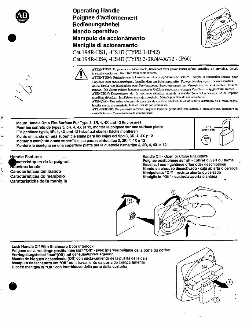
.
1
Operating HandlePoignee d'actionnementBedienungshebel
Mando operativoManipulo de accionfimento
Maniglia di azionamentoCat 194R-HS1, -HSlE (TYPE 1-IP42)Cat 194R-H54, -HS4E (TYPE 3-3R/4/4X/12 - IP66)
5
ATI'ENTION: To prevent electrical shock, disconnect from power source before installing or servicing. Installin suitable enclosure. Keep freefrom conuminants.ATTENTION: Prdalablement a l'installation et aux opdrations de service. couper l'alimentation secteur pourempecher louts chocs dlectriques. Installerdans uneboire appropride. Protegerle relaiscontreles conmminants.ACHTUNG: Vor Installations oder Servicearbeiten Stromversorgung zur Vermcidung von elektrischen Unflillentrennen. Die Gerate mussen in einem passenden Gebause eingebaut und gegen Verschmulming geschutzt wer{len.ATENCION: Descondctese de la corriente el,Ectrica. antes de la instalacion o del servicio. a fin de impedirsacudidas eldcuicas. Instatelo en una caja apropinds Mantdngato libre de con[aminantes.ATENCAO: Para evitar choques, desconectar da corrente elktrica antes de fazer a insual*o ou a manutengao.Instalarem cain apropriada. Manter livre de contaminantes.ATIENZIONE: Per prevenire informni, togliere tensione prima dell'installazione o manutenzione. Installare incustodia idonea. Tenere lontano da contaminand.
Mount Handle On a Flat Surface For Type 3, 3R, 4, 4X and 12 EnclosuresPour les coffrets de types 3,3R, 4,4X et 12, monter la polgnee sur une surface platteFur gehause typ 3, SR, 4,4X und 12 hebel auf ebener flache montierenMonte el mando en una superficie plana para las cajas del tlpo 3, 3R, 4, 4X y 12Montar o marnipulo numa superficie lisa para recintos tipo 3, 3R, 4, 4X e 12Montare la maniglia su una superficie piatta per le custodie nema tipo 3, 3R, 4, 4X, e 12
11@ndle Features
1 acteristiques de la poigneeMebelmerkmale
N Caracteristicas del mando
Caracterfsticas do manipuloCaratteristiche della maniglia
mm
in.
5.9
(3/16 - 5/16)
Handle Off - Open or Close EnclosurePoignee positionnee sur off - cotfret ouvert ou fermeHebel auf aus - gehause offen oder geschlossenMando de bloqueo desactivado - caja abierta o cerradaManipulo en "Off" . recinto aberto ou cerradoManlglia in "Off" - custodia aperta o chiusa
Pf-
Lock Handle Off With Enclosure Door Interlock
Poignee de verrouillage positionnee surr "Off" - avec interverrouillage de la porte du coffretVerriegelungshebel "aus"(Off) mit'gehauseturverriegelungMando de bloqueo desactivado (Off) con enclavamiento de la puerta de la cajaManipulo da fechadura em "Off" com travamento da porta do compartimentoBlocco maniglia in "Off" con interblocco della porto della custodia
0
U
1
,-r-i
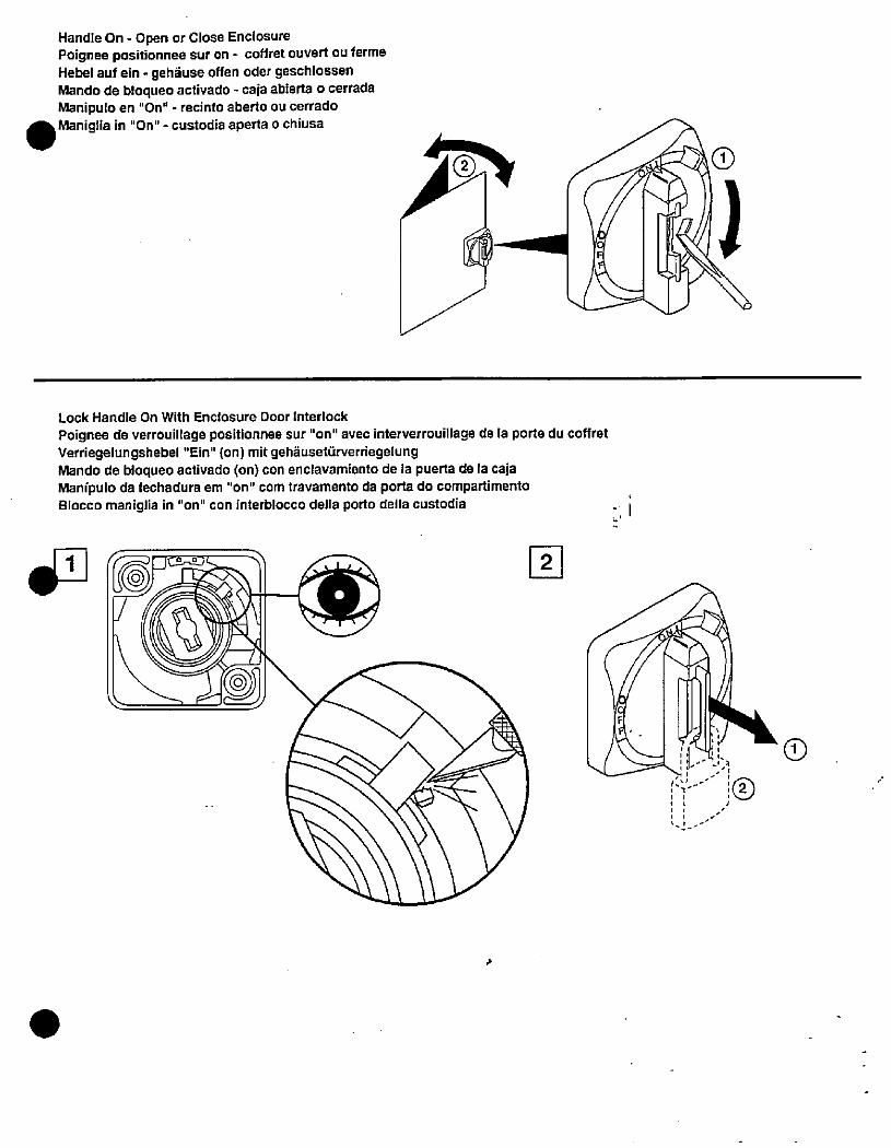
Handle On - Open or Close EnclosurePoignee positionnee sur on - coffret ouvert ou fermeHebel auf ein - gehause offen oder geschlossenMando de bloqueo activado - caja abierta o cerradaManipulo en "On" - recinto aberto ou cerradoManiglia in "On" - custodia aperta o chiusa
P
Lock Handle On With Enclosure Door Interlock
Poignee de verrouillage positionnee sur "on" avec interverrouillage de la porte du coffretVerriegelungshebel "Ein" (on) mit gehauseturverriegelungMando de bloqueo activado (on) con enclavamiento de la puerta de la cajaManipulo da fechadura em "on" com travamento da porta do compartimentoBlocco maniglia in "on" con interblocco della porlo della custodia
r -% 1 0 0
1 .
F
F
1/ ;
/ I
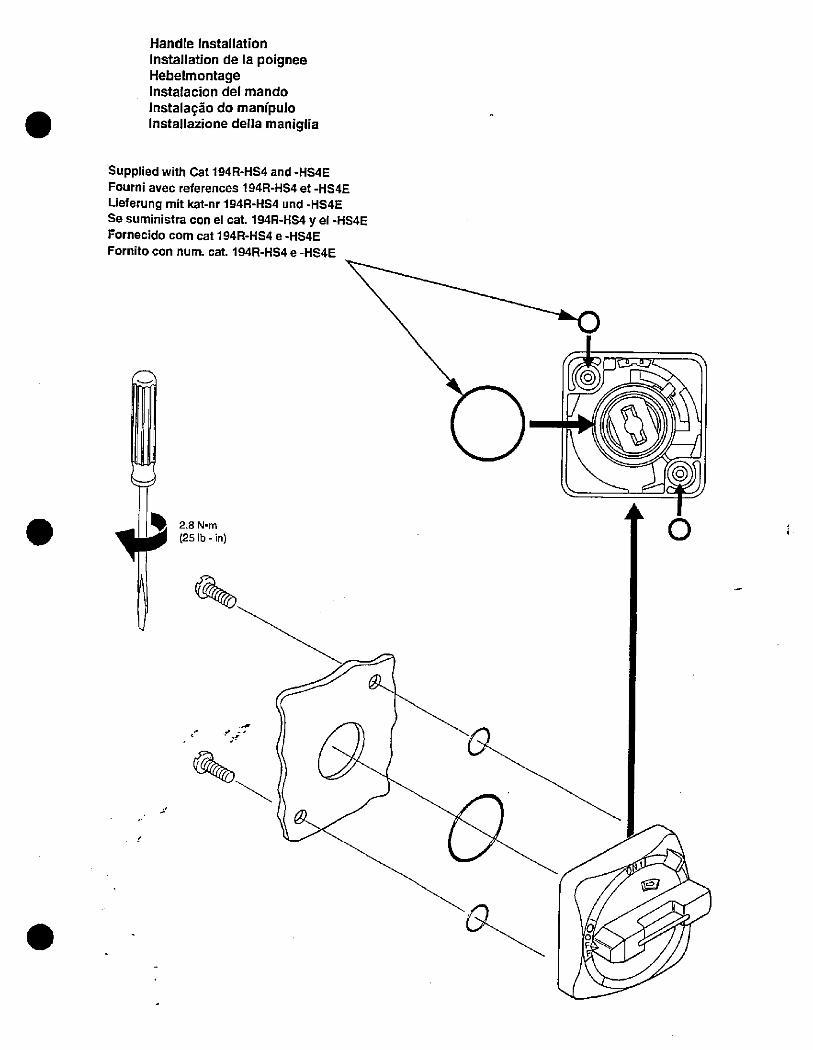
Handle Installation
Installation de la poigneeHebelmontageInstalacion del mando
Instalaao do manfpuloInstallazione della maniglia
Supplied with Cat 194R-HS4 and -HS#E
Fourni avec references 194R-HS4 et -HS*E
Lieferung mit kat-nr 194R-HS4 und -HS#ESe suministra con el cat. 194R-HS4 y el -HS4EFornecido com cat 194R-HS# e -HS#E
Fornito con num. cat. 194R-HS#e-HS#E
2.8 N.m(25 Ib - in)
0
n
0
F
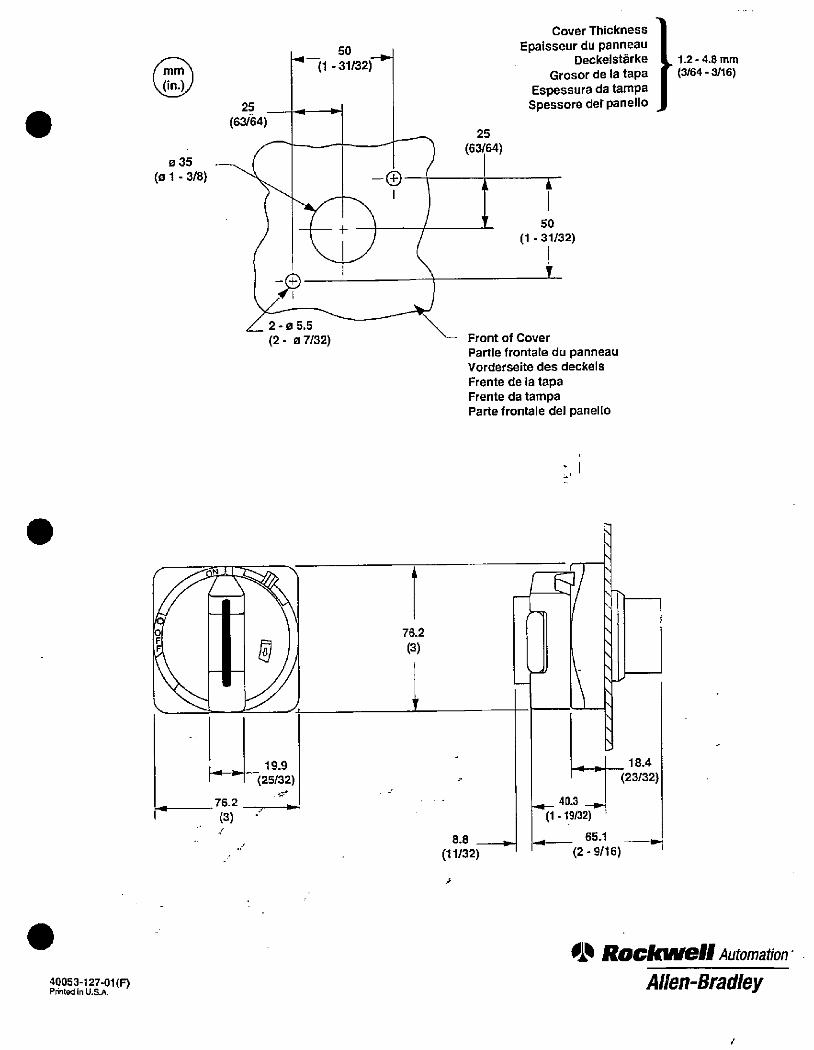
.
40053-127-01(IDPrinted in U.S.A.
9
mm
(in.)
035
(01 - 3/8)
25
(63/64)
(1 - 31/32)
2-05.5
(2 - 0 7/32)
19.9 ,(25/32)
76.21 .wh
(3)
76.2
(3)
A
8.8
(11/32)
25
(63/64)
Cover Thickness
Epaisseur du panneauDeckelstarke
Grosor de la tapaEspessura da tampa
Spessore def panello
50
(1 - 31/32)
Front of Cover
Partle frontale du panneauVorderseite des deckels
Frente de la tapaFrente da tampaParte frontale del panello
4»E\
\
\
\
\
\
18.4
(23/32)
1,- 40.3 -1,-(1 - 19/32)
- _ 65.1 -(2 - 9/16)
1.2 - 4.8 mm(3/64 - 3/16)
01. ROCIONell Automation-
Allen-Bradley
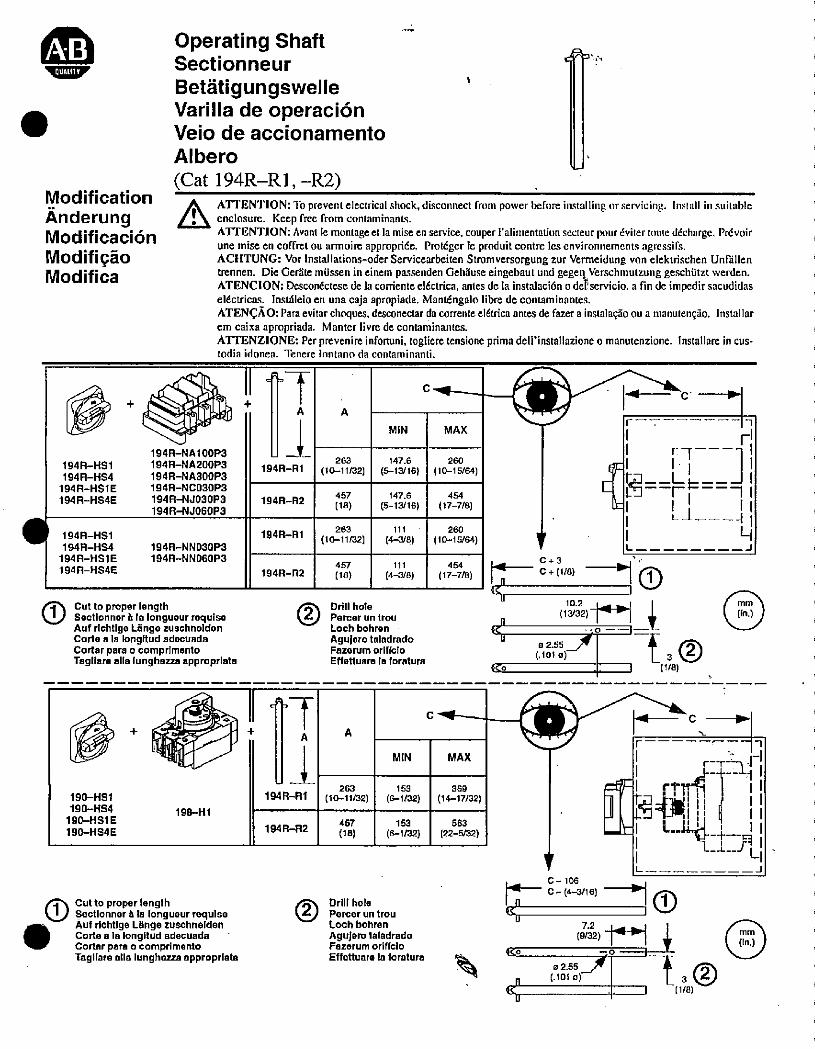
.
Modification
AnderungModificaci6n
ModifiaoModifica
Operating ShaftSectionneur
BetatigungswelleVarilla de operaci6nVeio de accionamento
Albero
(Cat 194R-Rl, -R2)
ATTENTION: To prevent electrical shock, disconnect from power before installing or servicing. Install in .suitableenclosure. Keep free from contaminants.
ATTENTION: Avant le montage et la misc en service, couper i alimentation secteur pour dviter mute ddcharge. Pr6voirune misc en coffret ou armoire appropride. Proldger le produit contre les environnements agressifs.ACHTUNG: Vor Installations-oder Servicearbeiten Stromversorgung zur Vermeidung von elektrischen Unfillentrennen. Die Geriite mussen in einem passenden Gehiluse eingebaut und gegen Verschmutzung geschutzt werden.ATENCION: Desconictese de la cordente e!6ctrica, antes de la instalacidn o defservicio. a fin de impedir sacudidaseldctricas. Insthlelo en una caja apropiada. Mant6ngalo libre de containinantes.ATENCAO: Para evitar choques, desconectar da corrente e16trica antes de fazer a instalaqao ou a manutengao. Installarem caixa apropriada. Manter livm de contaminantes.ATI'ENZIONE: Per prevenire infortuni, togliere tensione prima dell'installazione o manutenzione. Installare in cus-todia idonea. Tenere lontano da contaminanti.
194R-HS1
194A-HS#
194R-HSlE
194R-HS#E
194R-HS1
194R-HS4
194R-HSl E
194R-HS4E
194R-NAl OOP3
194R-NA200P3
194R-NA300P3
194R-NC030PS
194R-NJ030P3
194R-NJOGOP3
194R-NN030P3
194R-NN060P3
A
194R-Rl
194R-R2
194R-Rl
194R-R2
* Cut to proper lengthSectionner h la longueur requiseAuf richtlge Lange zuschnelden
Corte a la longitud adocuadaCortar para o comprimentoTagliare alla lunghezza approprlata
0 + Ei3*FORI190-HS1
190-HS4
190-HSl E
190-HS#E
198-Hl
+A
194R-Rl
194R-R2
Cutto proper lengthSectionner A la tonguourrequise Auf richtlge Lange zuschneldenCorte a In longllud adecuadaCortar para o comprimentoTagliare alla lunghezza approprlata
263
(10-11/32)
263
(10-11/32)
457
(18)
457
(18)
A
MIN
147.6
(5-13/16}
147.6
(5-13/16)
111
(4-3/8)
111
(4--3/8)
Drill hole
Percer un trou
Loch bohren
Aguiero taladradoFazerum oriffcioEffettuare la foratura
A
263
(10-11/32)
457
(18)
MIN
153
(6-1/32)
153
(6-1/32)
Drill hole
Porcer un trou
Loch bohren
Agujero taladradoFazerum oriffclo
Effettuare la foratura
C
C
MAX
260
(10-15/64)
454
(17-7/8)
260
(10-15/64)
454
(17-7/8)
MAX
369
(14-17/32)
563
(22-5/32)
[i
-4---- C
r-711
kr
r
C+3
4CU
0255- ta®(.101 0)
Ko 1 { 1/8)
C -It
E rtlf1r·rif
El* /1 i11-_I L
C-106
|--- C-(4-3/16) --1 (f)IC I \·4
U7.2
(9/32)_1 4 @5go
02.55 - t.3®(.101 0)
(1/8)
n
L
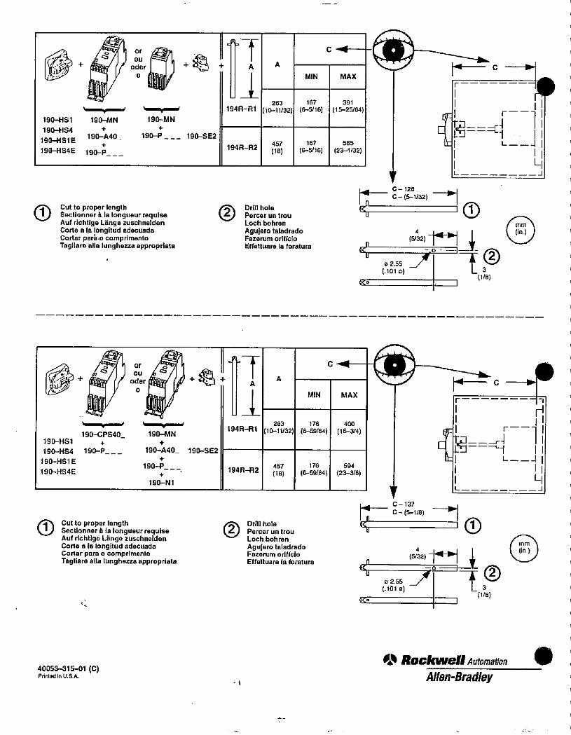
/ a 1 7 or
92:9 + ode, OU + *1 +
19041S1
190-HS4
190-HSl E
190-HS#E
190-MN
+
190-A40_+
190-P___
190-MN
+
190-P 190-SE2
= A
A
194R-Rl
194R-A2
263
(10-11/32)
Cut to proper length Drill holeSectionner a la longueur requise Percer un trouAuf richtige Lange zuschnelden Loch bohren
Corte a la longitud adecuada Aguiero taladradoCortar pari o comprimento Fazerum oriflclo
Tagllam alla lunghozza appropriata Effettuare la foratura
1904151
190-HS4
190-HSl E
190-HS4E
4 0% 4 1.+ oder +43+
0
,
190-CPS40_+
190-P___
I ,
190-MN
+
190-A40_+
190-P__-+
190-Nl
190-SE2
4-F
A
194R-Rl
194R-A2
A
263
(10-11/32)
457
(18)
* Cut to proper length Drill hole
Sectionner a la longueur requise Percer un trouAuf richtige Lange zuschnelden Loch bohren
Corle a la longitud adecuada Aguiero taladradoCortar para o comprimonlo Fazorum oriffcio
Tagliare alia lunghena appropriata Effettuare la foratura
40053-315-01 (C)Printed in U.S.A.
457
(18)
A
MIN
167
(6-5/16)
167
(6-5/16)
MIN
176
(6-59/64)
176
(6-59/64)
C 1--
MAX
391
(15-25/64)
585
(23-1/32)
C Mt--
MAX
400
(15-3/4)
594
(23-3/8)
[t[
1=--C-128
C - (5-1/32) -'146 1 U
02.55 J * ®(.101 0) LJ
(1/8)to ,
V
1=---C- 137
C - (5-1/8) -+1< 1 /U
4
(5/32)_r-1 4*CU 32.55 34 ' t 3
(.1010)(1/8)
4C. 1
010 RockWell Automa#on
Allen-Bradley
T1
r
-4-=i
L
r
--LiL
mm
(in )
-1
-1
.
1
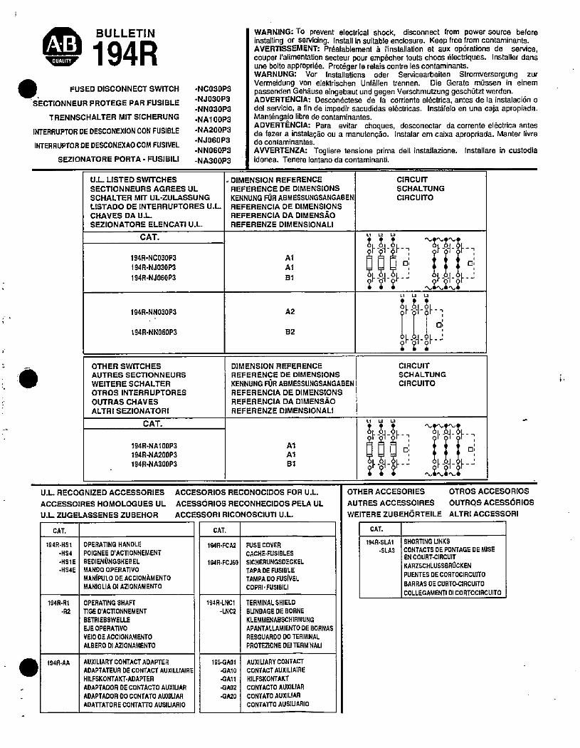
//4 BULLETIN
9 194RFUSED DISCONNECT SWITCH
SECTIONNEUR PROTEGE PAR FUSIBLE
TRENNSCHALTER MIT SICHERUNG
INTERRUPTOR DE DESCONEXION CON FUSIBLE
INTERRUPTOR DE DESCONEXAO COM FUSIVEL
SEZIONATORE PORTA - FUSIBILI
-NCOSOPS
-NJOSOP3
-NN030P3
-NAl OOP3
-NA200P3
-NJ060P3
-NNOGOP)
-NA300P3
U.L LISTED SWITCHES
SECTIONNEURS AGREES ULSCHALTER MIT UL-ZULASSUNG
LISTADO DE INTERRUPTORES U.L
CHAVES DA U.L
SEZIONATORE ELENCATI U.L.
CAT.
194R-NC030P3
194R-NJ030P3
194R-NJOGOP3
194R-NN030P3
194R-NNOBOP3
OTHER SWITCHES
AUTRES SECTIONNEURS
WEITERE SCHALTER
OTROSINTERRUPTORES
OUTRAS CHAVES
ALTRI SEZIONATORI
CAT.
194R·NA1OOP3
194R-NA200P3
194R-NA300P3
U.L. RECOGNIZED ACCESSORIES
ACCESSOIRES HOMOLOGUES UL
U.L. ZUGELASSENES ZUBEHOR
CAT.
194R-H51
-HS4
-HSl E
4154E
194A-Rl
·R2
194R·AA
OPERATING HANDLE
POIGNEE D'ACTIONNEMENT
BEDIENONGSHEBEL
MANDO OPERATIVO
MAN[PULO DEACCIONAMENTOMANIGUA 01 ABONAMENTO
OPERATING SHAFT
TIGE D'ACTIONNEMENT
BETRIEBSWELLE
EJE OPERATIVO
VEIO DE ACCIONAMENTO
ALBERO DI AZIONAMENTO
AUXILIARY CONTACT ADAPTER
ADAPTATEUR DE CONTACT AUXILLIAIRE
HILFSKONTAKT·ADAPTER
ADAPTADOR DE CONTACTO AUXIUAR
ADAPTADOR 00 CONTATO AUXILIAA
AOATTATORE CONTATTO AUSIUARIO
A1
A1
B1
WARNING: To prevent electrical shock, disconnect from power source beforeinstalling or Servicing. Install in suitable enclosure. Keep free from contaminants.AVERTISSEMENT: Praalablement a rinstallation et aux oparations de service,couper ralimentation secteur pour empacher touts chocs dlectriques. Installer dansune boite appropride. Protdger le relais contre les contaminants.WARNUNG: Vor Installations oder Servicearbeiten Stromversorgling zurVermeidung von elektrischen Unfallen trennen. Die Gerate mussen in einempassenden Gehause eingebaut und gegen Verschmutzung geschOtzt werden.ADVERTENCIA: Descondctese de la corriente e16ctrica, antes de la instalaci6n odel servicio, a fin de impedir sacudidas eldctricas. insthlelo en una caja apropiada.Mantangalo libre de contaminantes.ADVERTENCIA: Para evitar choques, desconectar da corrente elactrica antesde fazer a instalagao ou a manutenao. Instalar em caixa apropriada. Manter livrede contaminantes.
AVVERTENZA: Togliere tensione prima dell installazione. Installare in custodiaidonea. Tenere lontano da contaminanti.
. DIMENSION REFERENCE
REFERENCE DE DIMENSIONSKENNUNG FOR ABMESSUNGSANGABEN
REFERENCIA DE DIMENSIONSREFERENCIA DA DIMENSAOREFERENZE DIMENSIONALI
A2
82
DIMENSION REFERENCEREFERENCE DE DIMENSIONS
KENNUNG FOR ABMESSUNGSANGABENREFERENCIA DE DIMENSIONS
REFERENCIA DA DIMENSAOREFERENZE DIMENSIONAL!
A1
A1
81
ACCESORDS RECONOCIDOS FOR U.L.
ACESSORIOS RECONHECIDOS PELA UL
ACCESSORI RICONOSCIUTI U.L.
CAT.
194R·FCA2
194R-FCJ60
194R-LNCl
-UNC2
195·GA01
-GA10
-GAll
-GAO 2
-GA20
FUSE COVERCACHE-FUSIBLES
SICHERUNGSDECKELTAPA DE FUSIBLE
TAMPA DO FUSIVELCOPRI·FUSIBILI
TERMINAL SHIELD
BUNDAGE DE BORNE
KLEMMENABSCHIRMUNG
APANTALLAMIENTO OE BORNAS
RESGUARDO DO TERMINAL
PROTEBONE DE! TERMINALI
AUXILIARY CONTACT
CONTACT AUXILIAIREHILFSKONTAKT
CONTACTO AUXILIAR
CONTATO AUXILIAA
CONTATTO AUSIUARIO
CIRCUIT
SCHALTUNG
CIRCUITO
Li CZ L.0
SP-Zirs,- ,00©-I] 1 1 i al5&-4--6-- 01·-01-- F -21,67*/TS
LtuU
St-%-1-=f..
2==
CIRCUIT
SCHALTUNG
CIRCUITO
U 12 U
$.A-;i-_
Ef-4 in _0]OTHER ACCESORIES OTROS ACCESORIOS
AUTRES ACCESSOIRES OUTRQS ACESSORIOSWEITERE ZUBEHORTEILE ALTRI ACCESSORI
CAT.
194R-SLA1
·SLA3
SHORTING LINKS
CONTACTS OE PONTAGE DE MISE
EN COURT-CIRCUIT
KARZSCHLUSSBROCKEN
PUENTES DE CORTOCIRCUITO
BARRAS OE CURTO-CIRCUITO
COLLEGAMENTI 01 CORTOCIRCUITO
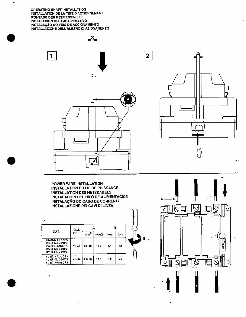
.
.
OPERATING SHAFT INSTALLATION
INSTALLATION DE LA TIGE D'ACTIONNEMENTMONTAGE DER BETRIESSWELLE
INSTALACION DEL EJE OPERATIVOINSTALAGAo DO VEIO DE ACCIONAMENTOINSTALLAZIONE DELL'ALBERO DI AZIONAMENTO
u
04
UE
SI
U lu1
1
POWER WIRE INSTALLATION
INSTALLATION DU FIL DE PUISSANCE
INSTALLATION DES NETZKABELS
INSTALACION DEL HILO DE AUMENTACION
INSTALAGAo DO CABO DE CORRENTEINSTALLAZIONE DEI CAVI DI UNEA
CAT.
194R-NAl OOP3194 R-NA 200P3
194 R-NJ030P3
194 R-NC 030 P3
1944-NN 030 P3
194R-NA300P3194R-NJOSOPS194R-NN 0605'3
E
DIM.
REF.
Al, A2
81.82
mm
2.5-10
2.5-25
2
A
#AWG
14-8
144
N•m
1.4
4.0
B
lb-in
12
35
2,3.
B
u
ol [51311-83-1 id*111[t
-=*-11.-ZF:-C3Bluu ..-11
4[--1*1-af-]Is
3
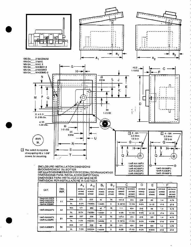
.
195-GA
195-GA
195GA
195-GA
195-GA
195-GA
L.1 W -U
IfioF=%, 2 MAXIMUM
, 2 MAX, MAX 2. MAXIMO 2
, 2 MAXIMO
, MASSIMO 2
1 1
MIQY2-05.5
2-219 dia.
0351.38 dia.
mm
in.
The switch is capableof accepting #8 x 1-3/8'screws for mounting
11 1
4IL -
1-»111 1
tt1; 1
rLJ 1
A
G =
H-I'-
.t.
9 0
70
91»%3-93-
50
14102
25
63/64
IR
s
4T ,
A 2MINIMUM
MINK
MINMD
-·4- U
1
1 ,
1tl/1 '11 1It 1
1
40.3 -lb
11' 1.19,3225
63/64 L J
SO J, 11-31/32
EVCLOSURE INSTALLATION DIMENSIONSEMCOMBREMENT DU BOITIER
INSTALLATIONSABMESSUNGEN FOR DIESCHALTSCHRANKMONTAGEDIMENSIONS PARA INSTALACION EMPOTRADADIMENSOES PARA INSTALAGAO DO GABINETEDIMENSIONI PER INSTALLAZIONE IN CUSTODIA
CAT.
194R-NAloOP3
194R-NA200P3194R-NC030P3194R-NJOLB
194:A-NN030P3
194R-NA300P3
194R-NJOGOPJ
194R-NN060P3
A 1
A2
81
82
DIM.
REF.
mm
in.
mm
in.
mm
in.
mm
in.
A1MNULIM
M N MD
AANMO
171
6-3/4
171
6-34
197
7-34
197
7-3/4
203
7-63/64
203
7-63/64
228
8-63/64
228
8-63/64
*L
45
45
149/64
45
149/64
149/64
45 *
149/64
81MNMUM
MINMO
MINMO
3
3
76
3
B2MINMU,1
MINMO
MINMO
76
76
76
3
2-M42.0 N·m
18 lb-in
G -7-+1
Ir-- -11----------&-1-,41--7-1,1
-/
'' i,---------- -1 L-1 lili1 11 1/ 1
$-r' 1, 1 11 1/1 11 1 1
1 111 /1 , 1
:1 1 1
: Ill1,
11 1 1
1 1, 1 1
+ 821+A2
MINMLM
MirJUO
MINIMO
147.6
5-13/16
111
44/8
147.6
111
4-3/8
MAX]MUM
MAXMO
MAXI.'40
MASSIMO
1 t H-7 A.fl
Q,
1 94R -NC 03OP 3
194R-NJ030P3
194R-NN030P 3
5- 13/16
C
454
177/8
454
17-7/8
454
17-7/8
454
17- 7/8
248
9-3/4
248
94/4
248
D
MNMUM
MINMO
MINA)
248
9-3/4
9-3/4
E
-f]
105
E
-FC-4-
-----------
T
1 1
,
4-# 4
1-T1 1
1 1
L
U
1 1It
1 17 1
1 1
1 1
1 1
1 1
4-M#2.ON•m -718 lb-in
- G-0:44H-+114-1 L
6 + S)01 e
194R-NA300P3
194R-NJOGOP3194R-NN060P3
MIMMU.4
MINMO '
MIMMO
89
3-112
89
3-1/2
4-9/64
105
4-9/64
MINMLM
MINMO
MiNMO
1.4
1/16
1.4
1/16
1.4
1/16
1.4
1/16
MAXMUM
MAXMO
1.,Axi.,0
MASSIMO
4.78
3/16
4.78
3/16
4.78
3/16
4.78
3/16
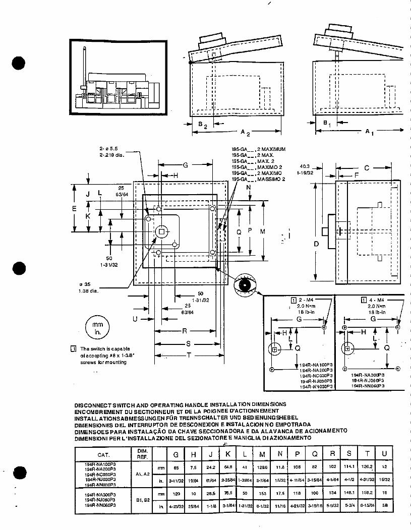
.
.
2- 05.5
2-219 dia.
62564b
50
1-31/32
0 35
1.38 dia.
mm
in.
The switch is capableof accepting #8 x 1-3/8"
screws for mounting
1
*----Z--------7
1 1, E,
1
1 1
1 1! 1
1 /1 -1-1
/,Iii
1 11 , 1
1 7----
1 111 -1
lili ,it I
lia1-13 ' £47
f - A -', 811 2 1
195-GA
195-GA
195-GAG---p 19FGA
195GA
195·GA
1/ N
V/ /i kOf :102 T
IftS ' 4L-JI1 1
1,
0' '
U-*
50
1-31 r32
25
63/64
R
S
T
.5
, 2 MAXIMUM
, 2 MAX., MAX 2, MAXIMO 2
, 2 MAXIMO
, MASSIMO 2
M
A
40.3 _I-1-19/32
2-M4i 2.ON•m
18 lb-in
G D-1
i »H* 11 L@-1 Q
01 94R-NAl OOP 3
1 94R- NA 200P 3
194R-NC030P 3194R-NJ030P31 94R-NN 030P 3
E
Al
-4AFCA
--------------
---
4/-
0-1
1 ,
1 1
1 1 ;4Z*==4=i===/1 1
/, 1/1 1/1 ;
4-M4
2.0 N•m 718 tb-in
11 G --,Pr•--H 4*1
L. 1
0 6 -t -4194R-NA300P3
194R-NJOGOP3
194R-NN 060!'3
DISCONNECT SWITCH AND OPERATING HANDLE INSTALLATION DIMEN SIONSENCOMBREMENT DU SECTIONNEUR ET DE LA POIGNEE D'ACTIONNEMENTINSTALLATIONSABMESSUNGEN FOR TRENNSCHALTER UND BEDIENUNGSHEBELDIMENSIONES DEL INTERRUPTOR DE DESCONEXION E INSTALACION NO EMPOTRADADIMENSOESPARA INSTALAGAO DA CHAVE SECCIONADORA E DA ALAVANCA DE ACIONAMENTODIMENSIONI PER L'INSTALLA ZIONE DEL SEZIONATORE E MANIGLIA DI AZIONAMENTO
D M. KLMNPQRSCAT. REF. GHJ
194R-NA:OOP3
194R-NA200P3
194R-NC030P3194R-NJOGOP3
194R+INOSOPS
194R-NASOOP3
194R-NJOBOP3
1944-NNOGOP3
A A2
81 82
nm
n.
mn
85
3 1/32
120
4-23/32
19/64
0
25/64
24.2
61/64
28.5
1- /8
64.8
53
76.5
3-1/64
139'6
50
4 1296
5- /64
153
-31/32 6 1/32
11.8
5/32
1.5
11/16
06
4- 1/64
118
4-21/32
82
3-15/64
100
3- 5/16
D
102
4-1/64
134
5 9/32
1 .1
4- 12
146.1
5/4
126.2
4-31/32
158.2
T
615/61
12
U
1 5/32
16
58
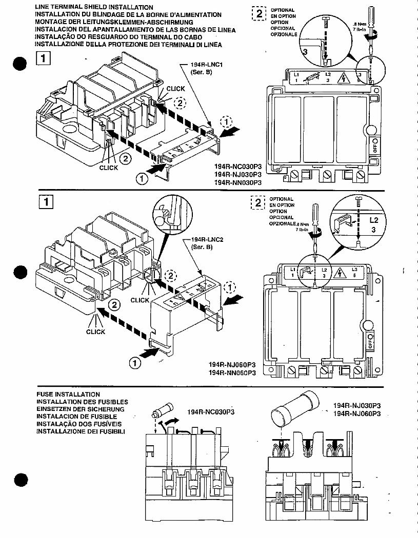
LINE TERMINAL SHIELD INSTALLATIONINSTALLATION DU BUNDAGE DE LA BORNE D'ALIMENTATION
MONTAGE DER LEITUNGSKLEMMEN-ABSCHIRMUNGINSTALACION DEL APANTALLAMIENTO DE LAS BORNAS DE UNEA
INSTALACAO DO RESGUARDO DO TERMINAL DO CABOINSTALLAZIONE DELLA PROTEZIONE DEI TERMINAU DI LINEA
0
0
CLICK
CLICK
194R-LNCl
(Ser. B)
lillf'r-
,
194R-NC030P3
194R-NJ030P3
194R-NN030P3
r-194R-LNC2
(Ser. B)
, .i> -A
C\.AC K-.
%-
194R-NJOGOP3
194R-NNOGOP3
/1,0.CLICK v4
FUSE INSTALLATION
INSTALLATION DES FUSIBLES
EINSETZEN DER SICHERUNGINSTALACION DE FUSIBLE
INSTALACAo DOS FUsfvEISINSTALLAZIONE DEI FUSIBILI
-1[
6,1 194R-NC030p3
+ Y-1 ,-J-1.-51-
a F
-If
1-R
0
, A- ; OPTIONAL; / ' Eli OPTION--- OPTION
.8 Bm HOPCIONAL 7 lb·In 110OPZIONALE 1
L.1 L / L--U
(Q=0
i OPTIONAL
' EN OPTION
OprIONOPCIONAL Al
OPZIONALE.8 N,11 I r 4 1
TLl 1 44.112 A L'
8 : u f
((20
- b
.Uf?-_r --1__i -1_5=-1111 la=11®11' totallis
194R-NJ030P3
194R-NJ060P3
LJ 1__1 1-j
Frd fo]-FEIt
-1
0
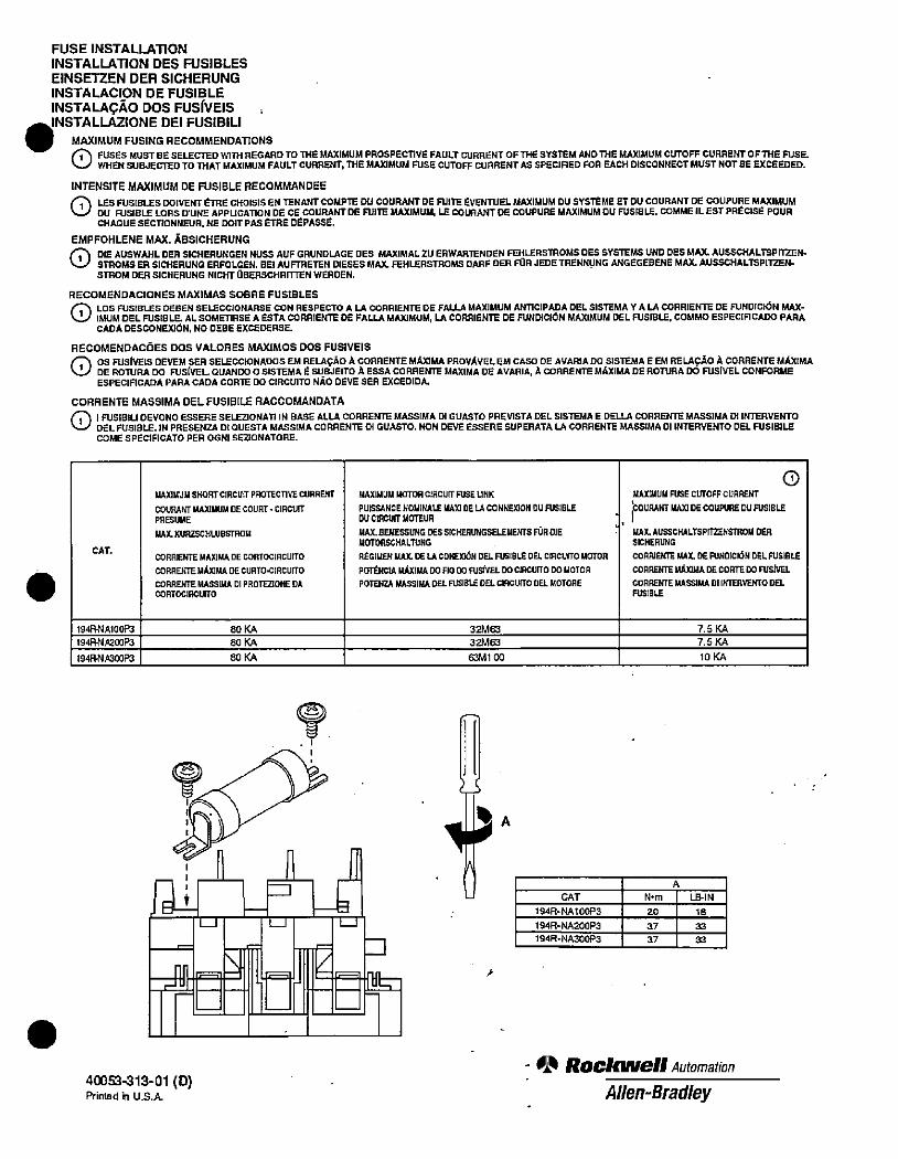
.
FUSE INSTALLATION
INSTALLATION DES FUSIBLES
EINSETZEN DER SICHERUNG
INSTALACION DE FUSIBLE
INSTALAGAO DOS FUSIVEIS .-INSTALLAZIONE DEI FUSIBILI
MAXIMUM FUSING RECOMMENDATIONS0 FUSES MUST BE SELECTED WITH REGARD TO THE MAXIMUM PROSPECTIVE FAULT CURRENT OFTHE SYSTEM AND THE MAXIMUM CUTOFF CURRENT OFTHE FUSE.WHEN SUBJECTED TO THAT MAXIMUM FAULT CURRENT, THE MAXIMUM FUSE CUTOFF cURRENT AS SPECIFIED FOR EACH DISCONNECT MUST NOTRE EXCEEDED.
INTENSITE MAXIMUM DE FUSIBLE RECOMMANDEE
rih LES FUSIBLES DOIVENT £TRE CHOISIS EN TENANTCOMPTE DU COURANT DE FUITE EvENTUEL MAXIMUM DU SYS*ME ET DU COURANT DEE COUPURE MAXIMUM\-/ DU FUSIBLE LORS D'UNE APPUCATION DE CE COURANT DE FUITE MAXIMUM, LE COURANT DE COUPURE MAXIMUM DU FUSIBLE, COMME IL EST PRECISE POUR
CHAQUE SECTIONNEUR, NE DOIT PAS 6TRE DPASSE.
EMPFOHLENE MAX. ABSICHERUNG
0 DIE AUSWAHL DER SICHERUNGEN NUSS AUF GRUNDLAGE DES MAXIMALZU EAWARTENDEN FEHLERSmOMS DES SYSTEMS UND DES MAX AUSSCHALTSPinEN-STROMS ER SICHERUNG ERFOLGEN. BEI AUFTRETEN DIESES MAX. FEHLERSTROMS DARF DER FOR JEDE TRENNUNG ANGEGEBENE MAX. AUSSCHALTSPITZEN-STROM DER SICHERUNG NICHT OBERSCHRITTEN WEADEN.
RECOMENDACIONES MAXIMAS SOBAE FUSIBLES
LOS FUSIBLES DEBEN SELECCIONARSE CON RESPECTO A LA COARIENTE DE FALLA MAXIMUM ANTICIPADA DEL SISTEMA Y A LA CORRIENTE DE FUNDICION MAX-1 IMUM DEL FUSIBLE At SOMETIRSE A ESTA CORRIENTE DE FALLA MAXIMUM, LA CORRIENTE DE FUNDICION MAXIMUM DEL FUSIBLE. COMMO ESPECIFICADO PARA
CADA DESCONEXION, NO OEBE EXCEDERSE.
RECOMENDAC6ES DOS VALORES MAXIMOS DOS FUSIVEISOS FUSIVElS OEVEM SER SELECCIONADOS EM RELAQAO A CORRENTE MAXIMA PROVAVELEM CASO DE AVARIA 00 SISTEMA E EM RELAfAO A CORRENTE MAXIMA
1 DE ROTURA DO FUSfVEL QUAN[JO O SISTEMA E SUBJEITO A ESSA CORRENTE MAXIMA DE AVARIA, A COARENTE MAXIMA DE AOTURA DO FUSIVEL CONFORMEESPECIFICAOA PARA CADA CORTE DO CIRCUITO NAo DEVE SER EXCED[DA.
CORRENTE MASSIMA DEL FUSIBILE RACCOMANDATA
1 1 FUSIBIU DEVONO ESSERE SELEZIONAll IN BASE ALLA CORRENTE MASSIMA DI GUASTO PREVISTA DEL SISTEMA E DELLA CORRENTE MASSIMA 01 INTERVENTODELFUSIBLE. IN PRESENZA DI QUESTA MASSIMA CORRENTE 01 GUASTO. NON DEVE ESSERE SUPERATA LA COARENTE MASSIMA 01 INTERVENTO DEL FUSIBILECOME SPECIRCATO PER OGNI SeONATORE.
CAT.
194*AlOOK
19481\IA200P3
1948·NA30083
1UUIMUM SHORT CIRCUIT PROTECTIVE CURRENT
COURANT MAXIMUM DE COURT - CIRCUITPRESUME
UAX. KURZSCHLUBSTROM
CORRENTE MAXIMA DE CORTOCIRCUITO
CORRENTE MAIGMA DE CURTOIRCUITO
CORRENTE MASSIMA DI PROTEZIONE DACORTOCIRCUITO
80 KA
80 KA
80 KA
MAXIMUM MOTOR CIRCUFT FUSE LINK
PUISSANCE NOMINALE mil DE LA CONNEXON OU FUSIBLE
Dll CIRCUIT MC]TEUR
MAX. BEMESSUNG DES SICHERUNGSELEMENTS FORDIEMOTORSCHALTUNG
REGIMEN MA)L DE LA CONE]06N DELFUSIBLE DEL CRCU[TO MOTOR
POTENCIA MAXIMA DO Flo 00 FUSIVEL DOCIACUITO 00 MOTORPOTENZA MASSIMA DEL FUSIBLE DEL CIACUrrO DEL MOTORE
my
- Tr 1-0 3
=111[,Er LE.-1 -EE'fir40053-313-01 (D)Printed h U.S.A
32M63
32M63
63MloO
..
U
4A
CAT
194R-NAl OOP3
194R-NA200P3
194R-NA300F)3
A
N•m
20
37
17
LB-IN
18
33
33
MAXIMUU FUSE CUTOFF CURRENT
COURANT MA)0 DE COUPURE DU FUSIBLE
MAX. AUSSCHALTSPITZENSTROM DEB
SICHERUNG
COARIENTE MAX. DE FUNDICBN DEL FUSIBLE
CORRENTEMAJOMADECORTEDOFUSiVEL
CORRENTE MASSIMA DI INTERVENTO DELFUSIBLE
7.5 KA
7.5 KA
10 KA
- 00 Rockwell Automation
Allen-Bradley
0
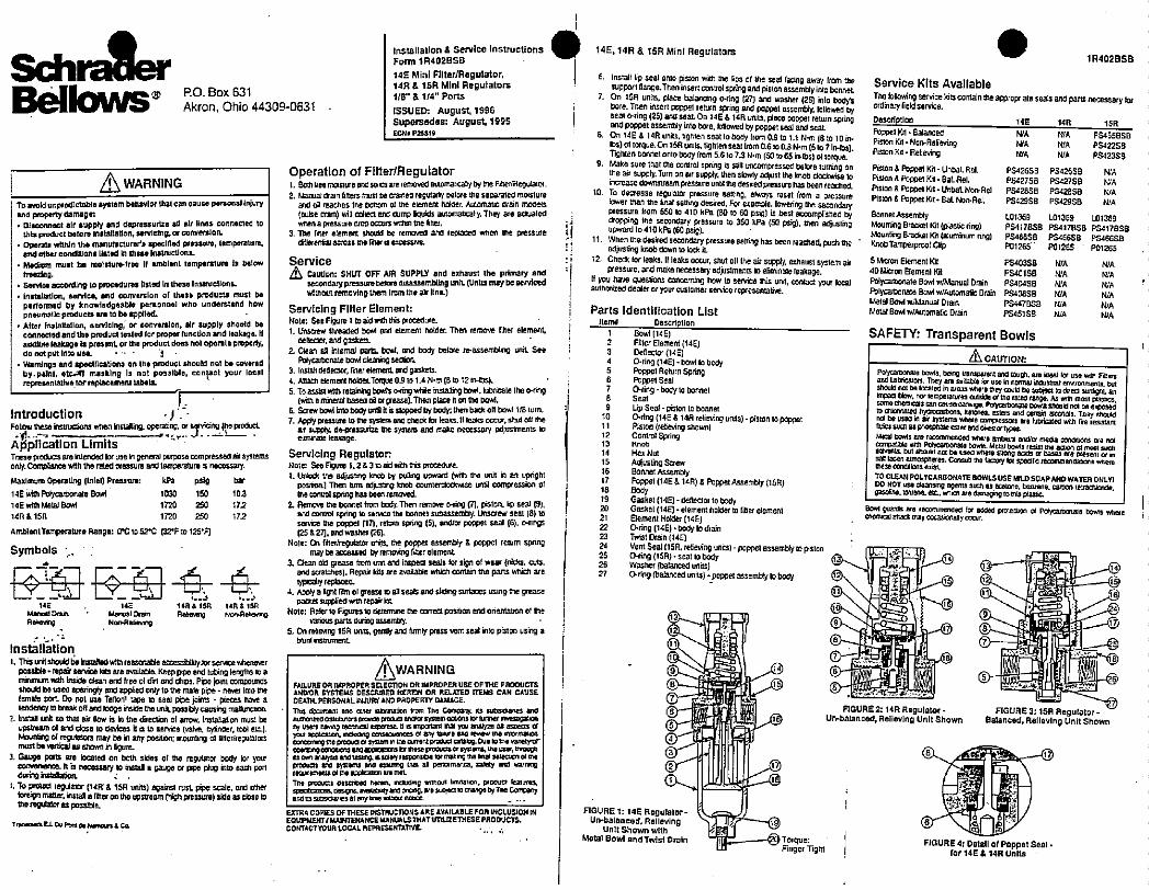
Sdk mlerBellows® RO. Box 631
Akron, Ohio 44309-0631
WARNINGTo avoid unprodletable system behavlorthal can cmuse personallnjuryand property damegr• Disconnact alt supply and depressurize 811 alr lines connected to
this priduct beforo Installation, sorvicing, or conversion.• Operiti wi:hin mi marturacturoh specified pressure, temperature
and other condmons listed In trisse instructions· Medium must bo molsluio-froe [l Imblent temperature is below
Mezing.
• Service according [o proceaures listed In thesalnstructions.• Inst,!lation, service. and con¥enlon of these products must be
performed by knowledgeable personnel who uncentand howpneumallc products ire to bo applied.
• After installation, servicing, or conversion, alr supply should boconnected and thi product tesled for proper function and Isakage. Ifal,dible leakage 1% presant or thi product docs not oper,lo pmperly,do not put Intouse. 1
• Warnings and speclncations on the product should not bi covered
by.paint. etcia masking li not possible. conpet your localrepresantallys.for replacement isbell
Introduction
Fouow these hslructions when *slaning. operaung. m spking fe f,owELApplication Limits "These pIcts are intended tor usein general purpose comfessed ax systemsonly. Compaance with the rated pressure and temperature is necessary.
Maximum Operallng (Inlel) Presim: kh psig bar
14E with Potycarbonate 80.4 1030 150 10.3
14E with kletal Bowl 1720 250 172
14R&15R 1720 250 172
AmblentTemperature Range: Ot to 522 132'F:0 125'7
Symbols ·
-FE -BJE -4- 414E 14E 14R & 15ft 148&15R
ManuaiD,ain · Manual Drain Rele,Ing N/,Aeic. ngRobevrg Non-Re"M
Installation
1. Thislnishouldbeiristalled¥Athreasonabla accesslyjorserv¥:ewheneverpossble - lepair Ben,ice kim ale Evailat8. Keep pipe and liking lengths to amanizim with Inside clean ard Iree of dirt and ch©s. Pipe jotm compoundsshould ba used sparingly and applied only to the male pipe - ne,er imo thelemae port Do not uss Tenont tape 10 88% pipe joints - pieces have atendency S break oM and looge inside the unil. p)33*lycausng mal[Incoon.
2. Instal unit 10 43! air flew is in the Erection of mrow. Installation must beupstream 01 and close lo devices It is to service (valve, cylinder, tool et).MMIg & regulatofs may ba m any position; mounling 01 lillemegulalmmust be„16cal as shown n igure.
3. Gal,90 ports are located on both sides 01 the regulator body lor yowconvarianca. It is n,r#,-7 to install a gauge or Fpe plug tntc each portduring bstanabon.
L To Prolod iegulamr (14R· & 191 units) against lust pA, scale. ancl otherIoreign mailer, Istaa filter on the,stream (high pressure) side as close to01* regdator 03 possible
Trac-"'i E L 4 7," 1 N.mcln 8 Ca
Installation & Service InstructionsForm 1R402858
145 Mini Filter/Regulator, 145,14R & 15RMini Regulators14R & 15R Mini Regulators1/8" & 1/4" Ports
ISSUED: August, 1996 1Supersecles: August.1995ECN, P25 519
Operation of Filter/Regulator1. Botn tree mots,ure anosoles are removed autornatcallybytne Finermeguator.2. Idanial arn finers must De cra:ned regularly Delore the seoarated moisture
and oil reaches the bottom of me element holaer. Automatg [Iran mooels
(ouse drsn) ¥,i collect enci ammp liquids aulomaicaly. They are actuatedwnen a pressure crop occufs witkn tne filter.
3. The IMer elemernt sholld be removed ar* replaced when the pressurediterential across me fine, 8 excessive.
Service
Caution: SHUT OFF AIR SUPPLY and exhaust the primary andseconcary pressure beloodisassembling unIL (Units may be servicedwithout remo¥Ingthern Irom the air lina)
Servicing Filter Element:Note: See Foure 1 to aidwitht* Focedure.1. Unscrew threaded bd and element holder. Then remove Imer element,
deneclor, and gaskets.
1 Clean al htemal parts. bo*i. md body before re-assembling uniL SeePolycarbonate bowl dearking section.
3. install delleclor, rtterelement and gaskets.4. Attach element hok er.Torque 0.9 to 1.4 N·m B to 12 in-lbs).
5. To assist wim retab*ig beak o·ring v/hile instaning bowl. hbricate the 0-ring(wilk a mberal baseo oa orgaase).Then plaze n on the bod.
6. Scrm, bowlinto body unB il is slipped by body: then back 011 bowl 1/8 turn-7. Apply pressure to Ule sys,em and chedc lor leaks. N leaks occur, Shut Off tile
air supply CO-pressurize me systern and make necessary adjustments :oelmunm leakage.
Servicing Regulator:Note: See Figwg 1,2&3 toad with this procedure.
1, Unkxit tne adjustng knob by puOing upward (with the unit in an uprightPositionj Then turn 06FWID *ob counte,cloawlse imm compression ofthe comrot spring has been removed.
2. Remove the bonnet from body. Then remove 047 0. pistor, lip seal (91,and control sping to serve une bonnel subassembly. Unswew seal (8) toservice the poppel (17], iehm sing (5). aneor poppet seal (61 onngs(25 & 27). and wwher (261
Note: On merkegdatoi ur:4 tie poppet assembly & poppet return spfingmay be accessed by removng liner element
1 Clean 09 grease tiom unn and inspect seals lor sign of wear (nicks, arts.4 scraches). Repair los ate available rdlich conlan me pans which arety», replaced
4. Apply a Bght rtlrn ©1 Feag lo all sea and sld•,g surlaces using me greasepacket supplied with repal k
Note: Reler to Figures lo determne the correa posit,on and orientabon of thevanous parts g assembly.
5, On relimng 15R uni, gently and frmly press vent seal into piston using ablunlmsuument
WARNING |FAILURE OA IMPROPER SELECHON OR IMPROPER USE OF THE PRODUCTSANDOR SYSTEMS DESCRIBED HEREIN OR RELATED ITEMS CAN CAUSE
DEATH, PERSONAL iNJURY AND PAOPERTY DAMAGE.
111,3 6xurnent Bno otner #*<mation trom The Ccnpaily. as wtzioanes andauthonreo ostrattors gronce :Nockc: anc*©r system collors lor turlner rr.estgaknry users na·.Ing tecnnal c.pertse. R 15 ,Mc.tant #al yc analy- an Ispec:$ Ofyoct Acci ation, r.1,.ng c¢nicouences of any ta..e ano ree* the Iumm,ortCC**39,g 010 FOCJC: u :752/m i the 0Jnlent procia cilalog. Duo 10 :na vanet,Gr©pe,mr,9 cont®ons Sno Gf/x:crn t r Hlesel,oducs CY sy=ems. 128 use5, treJgnEs 0*n aufria and :251:ng 6 5010'yi sconttle lor mak ng me Inal 361#coon 01 meprocum and sys:ems and *33:rng thai 0 perlormance, sality and warningrecurimints el mi applicxicn ar, miL
Tne Or©Oucts oescr/Fo hormt Eau*ng muou! 6"81/n, Fooua ks,tures.xed=j„4 0594.,ILD#y *Corcrlg, sre $.60(10 anarge 0, Tra Conx=tyanc :3 51.©searles al my trns w,$re,1 not,ce.
EXTRA COMES OF THESE :NSTRUCT)ONS ARE AVAILABLE FOM INCLUSIONINEOUIPMENT/MAINTEHANCE,LANUALS THATUTTUZE THESE PRODUCTS.DONTACT YOUR LOCAL REPRESENTATIVE
6. Install lip seal onto piston with me fps ol the seal faang away from thesupport Ilange. Then insert control spring and piston assembly into bonneL
7. On 15R units. place balancing 0·ring (27 and washer (26] into bodnbore. Then insert poppet return spring and poppel assembly, lollowed byseat o·ring (25) and seal On 14E & 14R units. place poppet return springand poppet assembly into Dore. lonowed by poppet Beal and seaL
8. On 14E & 14R units. tignten seal to body trom 0.9 to 1.1 N·m (8 to 10 18lbs) of torque.On 15R units, tightenseat from 0.6 10 0.8 *m (5 to 7 ints).Tighlen bonnet onto body from 5.6 to 7.3 N·m (50 to 65 in·lbs) ol torque.
9. Make sure tnat me cor,lro! spring is s#11 uncompressed betore turning onthe aw supply. Turn on air supply. then slowly aoiust the knob clockwise toincrease downstream pressure unlit the desired pressure has been reached.
10. To decrease regula:or pressure setting. always reset from a pressurelower than the final serting des,red. For example. lowering me secondarypressure irom 550 10 410 kPa (8010 60 psig) is best accomplished by
1 dropping tile secondary pressure to 350 kPa (50 psig). then acliuslhguped 10 410 k Pa (60 osig).
, 11. When the desired secondary pressure Setting has been reached, push meh adjusung knobdown tolodiL: ; 12. Check tor leaks. 11 leaks occur, Shut oft the air supply, exhaust system air
V pressure, and maks necessary adjuslments to enminale leakage.11 you have questions concerning how to service this unit, contact jur localauthorized dealer or your customer service representative.
Parts identification ListItem# Description
1 Boattl#El; 2 Filter Bement (14E); 3 Denector (14 E)
4 Bring (14E1 - bo·,110 body5 Poppet Return Spring6 Puppet Seal
7 0,ing-body to bonnel
9 Up Seal - piston to bonnet10 0-ring (14E & 14Rrelieving units) - piston to poppet11 Piston (reteving shovm)
2rl SPFing14 Hex Nut
m *4-17 Poppel (14E & 1411) & Poppet Assembly (15FI)18 80*19 Gasket (140 - denector to body20 Gaskel (14E} -element holderto finer element21 Element Holder (14E)22 0·ring (14E)·body to drain23 Tmst Drain (148
24 Vent Seat (15R. reaeving units) - poppet assemblyto piston25 0ring (15R) - seat to body26 Washer (balanced units)27 0-ring (balanced units) - popPet assembly to body
FIGURE 1: 14ERegulator-Un-balanced, Relleving
Unit Shown withMotal Bowl and Twist Drain
13
1
11
1
9
8
7
6 7,
5
5-
1
Torque:
Finger Tght
1 R402BSB
Service Kits Available
The lollowing service kitscontain theapproptiate seals and parts necessary tofordmary field service.
Description 14E 14R 15R
Foppet Kit - Balanced WA NIA PS455BSBPiston Kil - Non-Relieving N/A N/A PS42258Piston KA - Relie,ing WA N/A PS423SB
Piston & Poppel Kit - Unbal. Rel. PS426SB PS42658 N/A
Pislon & poppet Kit - Bal. Rel. PS#2758 PS427SB NIA
Piston & Poppet Kit . Unbal. Non·Rel PS42858 PS·:28SB WA
Piston & Poppet Et - BaL NomAel. PS429SB PS,12968 NIA
Bonnet Asembly [01369 L01369 L01369Mounting Brackel Kit (plastic ring) PS417858 PS417[3SS PS#178SBMounting Bracke: 151 (aluminum ring) PSBESSB PS4166SB PS466SBKnobTamperfooClip P01265 P01265 - P01265
5 Micron Element Kit PS40358 NIA N'A40 M·cron Element Kit PS40158 WA N/A
Polycalbonale BOM w/Manual Dmin PS40458 WA NIA '
Folycarbonate Bowl w/Automatic Drain PS408SB WA N/AMetal Bowl w/Manual Drain P5447858 mA WAMetal Bowl w/Automatic Drain PS451 SB N,/A MA
SAFETY: Transparent Bowls
6 CAlmON:
Zit:Z52;C2UTZ:Sfij':1Zt5:-2:: 'shculd not be kocated in areai where they couk, be subject lo djrect sunlight. animpact blo,/. nor lemperatums outside of the rated fang. As wim mos, piastics.sorna chemas can cause damaga Por).Zr>onate tents Bhoukj not be exposeto cni/:nated hyerucarbons, ketores. esters and cermin alconols. They shouldnot be usal in air symems ¥,te,8 /Inliessors afe lubricated with fire resistantnuics sual as phosphate cs:er and *€ster typesMetal Hits are recommended v,here ambient and/or meda concitions afe nol#249*.:te#T:7Ut#&#Ort,#AW<*&505: isan laden atmospheres. Consult the factory lor specific recommenalaboris ¥dnen,
TO CLEAN POLYCARBONATE BOWLS USE MILD SOAPAND WATER ONLYIDO NOT usi diansing agents such aa acitone, benzene. Cart)on tettachionce,gasogne. toluene. es. whwal AM dan*,glothls planc.
BcM guark are imnmmended for adood protection or Polycarbonate thils wherecherncal anack may O¢:casionaNy occur.
0 !11#1 irl
Q.14 -*aM/l
(7)-=9*51 |gL-@
1@Ye@fa(5>-11#m[3311£111 /,UL-@
11=21-=®FIGURE 2: 14R Regulator FIGURE 3: 15R Regulator-
Un-balanced, Relleving Unit Shown Balanced, Relleving Unit Shown
8 - 1
6
f
FIGURE 4: Dotall of Poppet Seal .for 14E & 14R Units
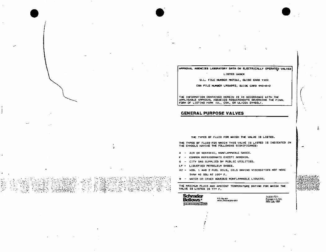
'I
,#,:i. ' ,-0-»·?2,1 :..,->.:..6,1.. 'i.,..
rf
APPROVAL ABENCIES LABORATORY DATA ON ELECTRICALLY OPERATED VALVES
LISTED UNDER
U. L. FILE NUMBER MH7261, GUIDE CARD YIOZ
CCESA FILE NUIBER LR50392, GUIDE CARD 440-A-0
THE INFORMATION CONTAINED HEREIN IS IN ACCORDANCE WITH THE
APPLICABLE APPROVAL AGENCIES REQUIREMENTS GOVERNING THE FINAL
FORM OF LISTING MARK (UL, CSA, OR UL/CSA SYMBOL).
GENERAL PURPOSE VALVES
THE TYPES OF FLUID FOR WHICH THEE VALVE IS LISTED.
THE TYPES OF FLUID FOR WHICH THIS VALVE IS LISTED IS INDICATED IN
THE SYMBOLS HAVING THE FOLLOWING SIGNIFICANCE:
A - AIR OR NONTOXIC, NONFLAMMABLE GASES-
F - COMMON REFRIGERANTS EXCEPT AMMONIA.
G - CITY GAS SUPPLIED BY PUBLIC UTILITIES.
LP - LIQUEFIED PETROLEUM GASES.
02 - NOS. 1 AND 2 FUEL OILS, OILS HAVING VISCOSITIES NOT MORE
THAN 40 SSU AT 100- F.
W - WATER OR OTHER AQUEOUS NONFLAMMABLE LIQUIDS.
THE MAX I MUM FLU I D AND AMB Ie,IT TEMPERATURE RATING FOR DIHICH THE
VALVE IS LISTED 18 77- F.
SchraderBellows®[Ilt)mIESE
Plo 6=631Aron. Oho 443]9-0631
74000-7011
Printed in USAREV July 1991
(
e.,-vcr.·>-S*7-51&10'fa.te>:A-,3-26©:.71*·:···,·; 357'.-9
./, ••4 r, -4?117,WARN I NG--iituse 81'tht<)rbdWL,noibduse e.xp/mon andpersonal'uvury.£ Do not use wi'4outfirse reading and'r understanding these instructions and the apparatus initallation and 6pdfai:Ag uisiructions4 drir'1,1,2..9, 011'Imu,::B --3'el• 8 Bis},IM,1 0% ly,lr•tith :1,1,!N A 9)8,. -c·,}rhiA 1 rLE f 7
' Ad! co'!,4 1/.1 ''% mm&=1 Mi; 11·'fl "r,3 3 , MMIETEK 2 06*ObE,biVibidi. LIA#45 r r,• .' HUNTER SPRING PRODUCTS
F L '"11 ' 117,51 a·ligra:44,Ubli· i r i#," , .,1£ A -wrar} Bus*,ri,i#A f.11 n SELLERSVILLEnPENNSYLVANIA, 18960 . „, ,., .. i.,, .m 2,; :,·,- -,*,¥ , 0 9&4)#fittin4-' , ' 4/444 8•r „*Dr, i=19*be "
" USE'AND INSTALEATIONOF PRESSURE GAUGES ' 1.,
The following formation oninstallation anduse hasbeeixce,pted fr* ASME B40 1-1991 The complek ASME B40 1-1991 standard which confaim 'additional informalioii may be,obmincdfrom the Amencan Society of Mdchanwat Eng,neers, 22 11,w Dni:e, BJ'2300, Fatdield, NJ 07007-2300 ,1,Y14 ]i4re2&0 ctnnectioo•1 3 1:a, ···-u che:ncal (dkraY;4'idir resemble 6*losive'flttlird' 11'; " 116,•4 3'chAnge n
"'14,'*11196(w. •- 1 k rili.dampers or snubbers, syp A restrictorplacedinthegaugepres-. 1 3,14.1{Location of Connection |f 'i•· 2NE other sundar items; am avallab|e for sure mletwil[ reduce.pressure 4.17.6 Vibration-Induced Fatigue(a) stem mounted -bottom orback usem these potentially hazardous sys. and restrtck fluid [low.9,11<cp,' e1,3 Failure. Inaddihon loits effect on tile(b) surface mounted - bottom or teens. Ibellazardpotent,almcicasesal open Bourdon tuberc" back ·r,q.r' '- *50 8,1,11 ., 71' ' , 'i, g:!FRemovemeitand linkage (seepara.(c) flush mounted - back ; I ' ·,1. „·«· .- ht,#.r.J'm#?f pl;TU;r; '* „ 1 4.2 7.2 4 overpreshurel,'Failure: "" UZi reti;mhjlikaor:it:1•.u. 1 ,•' 4.2.4 Ihe,foljowing systems are con --Overp[es:Prd fallurg m cjuse4by the,»ops parts of thetirssure element as',3342 Type or Connection Taper mderedpotentiallynazardousandiousl ' appl,callon ormtcmal firtssuregreater sembly 'nlis admg could'causef?:pe connections for pressures up be carefully evaluated than tberated imits of the elast,c cle-,- cracksintheelementieself, ormjomis20 0)00 VW,000 kpa),95 d Ca)compressed gas systems ment and can occur when a low pms- Case pressure bulldup may be slow8. or !/2-14Nri,..1 (bloxygen systemsAmencan Standard extemal or mter- (c)systeniscootatnulghydrogenorfrec s pZJ*t liC etiZf , , Mde*Zieoft¥,ULgh ratcofholemay
nallfperpipethreadsperANSUASME hydrogen atoms 4/1 It.81 1 required. Abow thispres overpressurefallure. usuallymorecrita-' · case pressure ns£ which could resultsum,/4 Mgh ressure tubmft connec- i i' Mw:;,nu,d sy:=,(,6,;:mid A]yfidj,84-,b ' " EAYW7 'imkr 0 an explosivelions, or eaua maybe 11563 Other (e}pressuresystemscontaining any ex- and may cause parts to be propelled m l
appropriately sized connections, cm-, plosive or flammable mixture,or me- any dinction, Cases with pressure , 4.18 Premure Connection See rtcploying scating means other than,la- dium , .rf, 1, 1 .·, 4 1,-« , ,3pered Utreads, are acceptable. (0 steam systems
re[ief ovenings will not always retainexpelleapatts ' ' '"' .,1 ommendations m para. 3.34 F
In applwauons of stem mounted Woonsteady pressumbystcms .Placing a restnctor m-GpressuA ' ' 43 Safety Recommendationsi4
gauge*•especially with litwd filled (6)systems where high ove:pressure - gauge mid will notreduceticimmed,cases andiwherxvibrationts sbvere,,A .,- could be accidentally applied. 4.3 1 Operating Pressu re. The prest ate cffect or failure. but willhelpcon" - suregaugeselecled shouldhave a full
possibitconsideration should be
IN.of fulure of Illgiven to the (
e stempori·.,r,i o tZ:%:fl:NZIMI:5 4 · scale pressure such that the ODeratinpassoc:atedpipmg¢aused bythc vibrat- & 1, mternal contaminabon or where lower ary effects. . pressure occurs m themiddial:alf (25mgmassol Lhegauge Alargeconnec pressure gauges could be installed in to 75%) of Ihe scale. 1he full scalehon(eg, 1/2NPT Instead of 1/4NFT) higher pressure systems It ts gene,ally accepted tbat solid pressure of the gauge,;elected should
front cases with pressure rellcf back be approxrmately two tunes the inorastroogerstent matenal (e g .stain- - 0) systems contaming radjoacllve or - wd! reduce thepossibility of parts be- (ended operating pressure.less steer mstcad.of brass),or both, . , toxic fluids (hquids or.gases) 1 -should be considered. (k) systems mstalled m a hai#dous Log projected forward mthp event of „ , Should it be necessaiy for Ihe oper-failurel .
environment ating pressure to exceed 75% of fullThe windowalonewill notprovide scale contact thesuppller forrecom-3.4 110 Moununpapressuregaugem adequate protection against mlernal mendationsa position other 15an that 'at whtch lt, 16:Ni.4.15,When gaues are Lo bc used m case ressure bulldup, and can be the Inus doesnotapply totest, retarded, or- -- was calibrated can affect lid·accuracl 7 Si'(4*.contactwith merna havmg known or mostmrdous component
Noribd calibratmgposition,supright uncertamcorrosiveeffcctsorknown to , flippressed scald gauges- - Short duration pressure impulses inandvertical Forapplications requir- bc radloactive, mndomor unique de (pressurespikes)mayoccurmhydrau * 432 UseorGaugesNearZeroPres-Ing mounting Li other than this post- SU'uctive phenomena can occur In llc or pneumauc systems, gecially sure1104 notify the supplier suchcases theusershoutdalways fur when valves oren orclose Jile mag- Thcuscofgaugesnearzero pressure Lsnish thesupplier or manuructurerwith mtudcofthespikesmaybemanytimes not recommended because the accu-3.4.1112 Caytion to Users. 1 3 r , mfonoation relative to the applicatton thenormaloperattI; pressure,andmay racy tolerance may bea large percent-Pressure gaukes can be rendered inac- andsolicithis advicepnortomstalla not De tndicated b the gauge. The '"' age of the appited Dr(Wate, dunng sh,pment despite care tion of tlic gauge. · 31.'' , essure If forresuitcould be immediate failure. ora i example, aO/100 :Orade B gauge staken 10 packagmg ' To ensure con- 4.2.6Fireand explosionswilimapres- larpeupscaleerror A restnctor (mub- used fo measure Sm. the accuracy offormancelothestandardgradetowhich ', sure system calo cause pressum ele. ber)mayreducelliemag,litudeofthe 2, measurement wiliL+/-3psl, or-/the pressure Rauze was manufactured, ment failure,with very violent effects, pressure transmitted to the elaslic ele- ' 50% of the appited pressure, It] addl11 shoulclpe EheEked before use .,j, : r„ evento thepdmtofcoinpletelydismic- ment
r-, -_ i w 1 _ - 1 ' .nt gratmg ormelti[10 thepressitr:,uge . . 1,2 - 't u tion, thescareof a gaugels oftoi kid4 SAFETY-,' - " :1:. 4+11 4*101,441197 :41 "out with takeup; whwn can result m4.1 Scope ,
f, , Violenteffccisitrealsoprodulc4 fallum occursdleto whcn --4 17·3Currosion Falliir*torrosidS ruslher maccuracies when mcasunng-failumoccurs when the elashcclcmentYhtS SectiOn of the Standard pre-,' (!)hydrogenembnulement; pressures (hatareasmall percentageothas bcco weakened through attack by ' ihe Raule spansents vertam mformationto guide us. 4:(b)contammationofacompressed gas, corrosive chemicals present meliherera. SUFpliers, and manufactumrs to- (c)formattonofacetylides, Rirthesamereasons, gaugesshouldthe media ms, de or Uic environment not be used for the purpose of indicat-wardmmimmingthehazardsthatcould , ·(d)weakenmgofsonsolder joints by outside it. Failuremayoccuraspin-: I mg that chcpressure m a tank, auto-result from misuse or mtsapplication stam or other heal sources, holeleakagethroghtheelementwals , z clave. or olher similar untt has beenof pressure gauR.es with elit:c etc (e)weakeningofsoftsolderedorsilvcr or early fatigue tallure due to stress completely exhausted to atmosphericments. Theuserniould becomefamil- brazed Jomls caused by heat sources cracking brought about by chemical pressure.Depending on & accuracytarwithallsectionsofthis Standard,as t.i.,suchasfires,'
at] aspects ofsafety cannotbecovered..i,•,
Fcorrosion, deterloration or embnulcment of the and the span of the gauge and thematerial
in this Section. Consult the manufac- possibility that Ukeup is mcorporatedturer or supplier for advice whenever tncalstiock,' 1 ' '4: Actiemicai(diaphragm)sealshould , , atthebeginningofthescale,hazardous_tlimps uncertamty about 00 safe ap 1) excessive vibration. , be considered for use with pressure 1 1, pressure may remain m the tank even
media liatmay have acorrosiveeffect , ihough the gauge m indicating zeroicayof a pressure gaugetr •1':,Off*1001'57Faiturcm acompressedgassystem on theelastic element.imzr rjuoRnur.*Ii*pressureA venting device must belt. 4,..m¥-20*.... itr" ' *in lean be expected to produce violent4 2 G46721 DiscusAIon effects. ' QU., i le 1 · 1(19! .TE,¥i-tr-,Ds. lf , ,rk ,r" , ·usedtocomoletelyreducelliepressurete safetv results from in-, 4 2.7.4 Explosiye Failure. Explosive 4 - beforeunlockingcovers, removu}gfit-fatlureiscausedbytherelease of ex- tings, orperforming other similar ac-; igt ,ingandcareful selection " A 4 2.7Modesof Pressure,Ga6ze Fall- Plosive enugy genented by a chemi ' tivittesand mstdktion of gauges into a ores- cal reaction such as can result whensure system The user should dorm 17 1 Fatu;ue Fallure. Fatisue fail. admbatic compresslon of oxygen oc- 11 4-13 Compatibility With the Pressurethesupplierofall conditionsperllnent , um caused by pressure induced struss curs inthe presence of hydrocarbons, ' Mediumtotheapplication andenvtronmentso generally o©curs from the =Ide tolhe Itas geneelly accepted thatthercis no , Ille elast:celement ls generaity a thlnthat 11:e mmpller can recommend the 9 outside along a highly stressed edge knownmeansoforedicting themagnt- . „walled member, which of necessity
,, most suitabre gauge rpr the apphcag•,, radius,appearing asasmall crackthat tlideor effects of thistype of fatium., *operates undcrhigh stress condiuonstion.·
-I pagatesatongtheedgeradius. Such Forthismodeoffatiure, asoltdwallor and must, therefore be carefully se4 12Thehistory orsafety with respect ilures am usually moreentlcal w,lh partillon between the elast}celement lected for compatibility with thepres-i . #.6 ¢,(0 the use orpressure gdoges has 6®ell. #,p,i. liquid_
excettent. Injuiytope:sonnelanddam- I.Q.-in *1 Fabgua cracks 1&&hill, release the =#As'*r: nlne-ss,anli 4 suremedlumbeingmeasured. Noneofg projected forward. ' the common elcment materials is iin-4 .. , pervlous to every tyoe of chemicalagotopropertyhavebecommimal 'In 4, gnedia nuld slowly so casa pressure 4 1715 Vibration Faildre Themost-*, attack The Lotenttaffor CONOSIVe at-mostinstances,thecauseoffallurchas 48 bulldupcan beaverted by Droviding common mode of v:bration fallum ts T,i r lack Ls esta6lished bv many factors,been masuse ormisapplication. pressure relief openings m tic that where the movement parts wear mcludin& tbe concenfallon, tempera-|- becauscof high cyclm loadmgcaused. ·ture. andcontammationofthemedium|4 23?Ihe presmrAZing elemmt in - ;1%Z'te Rishngh ap- by vibration, resulung m gradualloss Theusershould inEonnthegaugesupimostgauges ts subjected tohigh tnter- + proaches the ultimale strength of the: 2 r oT accuracy. and. ultimatcly fallure of ,. plier of the installation conditions so'nal stresses. and applicabons exist element matenal, fatigue fallure may,' r thr; pomler to Indicate any pressure 8.lat the appropnate element matertals'where the possibility of catastrophicfailumispresent Prdsureregulators,
IMPORT ANT · Red other s,de Jor odditional inunce:ons and *arfungs Q..7. b.m ASMB B4(11 1991 conbmi on b:ck)
.
canbe selecki _ Laboratories, Inc-Someof thescspecificscrvicegaugesarellstedbelow.jIbelist
/ 0.3.4 116 addition to the factors discussed above, the capabltity of a pressure , 4,„g tsnot mlendedtoincludealltypes. and thouserhould always advf thoupplier, of all'ap hcatioh details., *:enced by lie dcsign. materials, an,*cabo,9 ,(,f, ti'F »P„N :,01,13, 31·,8%,Pimi,11 4,r' 3,\* r,,·, '1' I J, 4 1L .Commoo methods of Joining aresoftsoldenng, silverbrazing, and weldmg 4 3.8.2 Acet,lene Gau» A gaugedcsigned to mdicate acetylene pressure„ It|Joints can be affected by temperature, stras and corrosive media Where ----· shall be consttucted ustng matertals that are compatible with commercially
application questions anse, these factors should be considered and discussed by66 user and manufacturer i :'1,,1 1 mila fetylene.i,The gauge may bear the mscnpoon ACETYLIENE on the4 3 5 Somespecial appkcations reclutrethatth6 presureblementassembly have 1 ' F 4.3 83 Ammonin Gauga Agauge des,gned tomdicalc ammonta pressure andahighdegreeofleakage mtcar:ty omanuracturer and user to assure Ula t*5¤&h·'6·t, ·;!15%12T11n»::: .
. + scalemarkmgsonthediali lai .R„4,
4.3.6 .1- 4,4 nniZ,fBit,9-4.4 6 0; :j#, ii*1?3„1*i Jo,-1 ' yfil f At , 438.4Chemical(316iDA*ge*dto mdicatethepressureorclrA,si;436 Solid FronL k isgenerally acceptedthotasolia trontcaseperpara3 3 1 will red,ke the possibility of parts bemg Projected for,vard m the event of 3 4 M,1, or hjgh miscosity fluKS. or both. €rhe prunan, matenal(sj in contact with theelastic elementassembly fallure. An exception ts explosive failure O£0pplafticm pressuremediummaybeldentlfiedonthedial Rmaxbecquippedwithachemical
,. element assembly r, [diapbragm) seal LIsation dam or pressure rettef dev,ce, ora combination1 :nesedencestleiJ'toin,nimlietialdamagetopersonnel and propertx Inthe
4!3 dil'r*2<'1)fqlild'FiliSci 'It ha been general practice td use glvcenne or'.. 1, event of gauge failure.*Dey may, however. also reduceaccuracy or Sensitivtty.sillcone- fillmg-liquids However these [hulda may not be suitaole for ar 'orboth. 1. .Ji to-/4 1 "' u i /5 1,„. i 1
applications. They shouldbeavoided where strong oxidizmg agents mcludmg,IO ' ;,h"n'n-,1.,901LudiV' •l, ·11 : t.,
43 8.5 Oxygen Gauge.AgauR) desinned toind,cate oxy-en Dressure Cleanbul not imtted to, oxygen, chlorine, nitric acti. and hydroaen peroxide Bre A 1,nessshalrcomplywithievelIV(seeSactionS) Thed,alsffaLISeclearlymarkedinvolvedAIn the presence of oxidaing agents, potcolial hazaa can result from
0.,v'*,1. ,*Cmue,e,7}14&.,;9,9,1 M,,,1,4,v, 16*,5=%=;for.U,SPNO=11*5515;*1 11?". '3,7,Da user shall fumish deta!led mforniation relative',to the'ypplicatiuniof,j 4.4 Reuse of Pressure eluges · 4 74 .Raugeshavingliquld filledcasesandsollcittlieadyce,of*,8 gaugesuppperp«, . Itis not recommended that pressure gauges be moved from one appllcallon JTo installation another Shouldit be necessary,'however. the followmg must be considered. r„.Comideralion shoitld also bd gn,en to thJ insta1;0461J h];drkulic kffilhli, 4
may becreatedby oneofthemodesoffallureoullinddmpara417 Thehydraultc 4 4 1 Chem ical Compalibilit.hne consequence* of incompatibility canrangeeffEct due to pressure element failure could cause the,window,Ip t projected, b tom contammutzon to explosrve failure For example. mo¥Ing an 0,1 servaceforwardeven when a case having a solid froBt.ls employed.& ,.,6 ,, JL. re, 1,, gapge to oxygen service can result m explosrve failure
4.11011;14or.' Placing a reAItA bctwed Ilw ir&urcionJectiqQ and thr' 44 2 Partial Fatigua The fin:installation may involve pressurepulsabon thatelasticelementwilinotrcducetheimmediateeffecto fallure,butwillbelpcontrot, has expended most of the gaugelde. resulting m early faugue ul the secondflow of escapmg fluid following rupture and reduce*,potent:al olksecondaty mstallation
,1 1 #,2: 4,/.,Hi< 9<CTEk'Le,1,» 9;1: ,&,4.,t __ .Ltic,4,164,1;illrwau_ f. 4413'I 'lluM'I,
Corrosion Corrosion'of the pressure clement assembly m the first4 3 8 Specific Service Conditions ' mstallation may be sufficientto cause early folure m the second mstallatton.4 18.1 Specific applications forpressure gauges exist whe hazardsareknown 1In many,nstances. requirements for design, construction, and use of gauges for, 4.4 4OtherConsiderations. WhenrcustnR.auve,aliguidelmescoveredmtillsthese applications are specified by state or federal agencies or Underwnters Standard relative to application or gauges shofild Se rollowed m (bc same manner
1: as whena new gauge is selected. ,f -1 941 "4.B.p.on, 1 ., L, ,
j .<, 'In add,tion:o [heASME 840 1-1991 standord, the following addmonul instrud,onsandfvorm,ng:should be readand undentood befom using th:$ produr¢2A*e,9 import t ofs'blcctuig and installmgpregure diuges isthe considerationof the hazards resultln the event the gauge faik The primary causes oriallure 5 5 Freauency or Accuracy Evalgationuc misapplicationand(brabuse of the gauge "Illose people wr,o are reponmble forthe , i Where tte pressuremeasureinent 13 cntical and gauze rallureor gross Inaccuracy willselection and unstallabon or pressure gauges must recoingc conditiou wh.ch will 1 resull m flazard to personnel orproperly, the gauge Aliould be chedked for accuracy and
--- -adversetraffect theabilityoftforaur,elorcitorm:116 funclionor wincliwilliead loearly 9, properoperation on a perlodic bans ,falluro. These conditions mayllienbe discussed with tlie manufacturer to obtain Ihcir i
'11 "
recommendations ../ /4# ai#u 8 't.' 92 1 , 4 R 41 ,• 6 Use &18 Oxygen _ A
talijai@'coAM,6,9 i i Gauges used for measurement ofoxygen pressurb must bc [rce of contannration wlitun
1· Loss ofaccuncy 1 1 Ir„"141 itthe Dressure contalmn on. Various levels of clcanliness are 5Decifted in ANSI
840 1 The zauxe iMFd the equipment to which the gauge m akached (pressurej<rl' Clog&4 or,ho pressuro o,a, or damage to the mterml mpchsmsm so that ' • 11 regulaim, glindus, ac.) must bekepiclean zo aa not to contammate the £auze. Fillcrs1 I 4 there la either '· f ; on thoequipment must boaamlned periodically and clcancdor mplacodI lic sudden'1*izaa:noindicatiditwienprdsuroisapplicdor ' '11 m-rush 01 a hlgh presmire gas will momentari ly create a very high t©inperat uto which in10, :b' theroisanind:cation orpicssurccven thoughnono 15 applied. 1 1 ·4/n' e the presence of oxygen may iEntte the contaminant caustng a violent explosion f 3 A leak m tile pressure conia,ning parts or Joints.. i . 4 i i e ,, Thercrore, when the valvemn the oxygen supply tank Is opened, to admit oxygen lo1114 'Acrackorfatiguefatlureorthebourdon. . , f: r,Il 4 I 1, , ,r r,1 ., the regulator, the valve shoold be opened verialowly so alto alIow the pressure to
1,105. Bumtmg of the bourdon duo to severe overpressure. bulld up slowly in order lo accompltsh thisitis recommended that the tank valve be, 14, An explosion wiann thesysterndue toadierincal rraction orthepressure opened momentarily and then closed mugly but not excessively before attachtngale
,* r[edjum with contarmnafs (55ng the 4Durdon,tglode. . - regulator Tins wilrnot only blow,outaccunaliated dirt inthe valve, butwill alsogiare4* ? 1 ' dic Falve m a cond,tton thai will Qumt It to be opened alowly rather than mdaenly
Whert:pecithng:us:*fliMillmgaprasuregiuge,the follUinli t'mustbegive¢; brcakinzloosens arrsull orbngrlod Inn nolly Whenblecdmzthcoxygentankpnorattention. ' . 1' .1 1, i alwu,111 the regulator be certain the Valve opening ts directea away trom any open Ji Iil,420.b.,* :),Q!41 .Joy lim 1,1 01'1 :Irl' u'IbOK '44) 1 . nameandultopentor *henopeninglheoxygen lankvalve,theoperatormus[ not1 OpeFatin:Pressured h 10, -11 1,4 . 8.5 T'lili itandinfronl ororbehindthegaugeand mustive,reyeand raceproteclion. int.jusDonot coonnuously operate thegaugeatmorethan75% of thespan. Bourdan [ubesare , 3 9, ei tti in 11 there le an exolomon due 10 containinated equipment any particles projectednecessartly highly stressed, especially in ranges ovcr 1000 Im md contimous operation ' Irom the gallge will notbe propelled directly K the operatorat full scale wtll remill m pty fattgue failureand sub=lucn[ rupture „a,11 1 1 49. F 1 -, *HVH
2."Madri111.:94 & ,1 4 n' '*i It '11 11'J , 1,; .16 9 J -1 9 'i ' ,7 Uill,Ith Hydrogen ,9'f. Steel bourdonsmcluding400sen65 stainless steclat'csublectto ll,drogen embnttlementBe ce,tain Lhe mate;,aifor d@ pUu:o con,mmng'pditloils 6rtho gauge aro comoattble, whenstressed- Measummemtof.gamor liquidscontainingliydrogen(such asnat,tral gas,
with tho Ixessurlzed mtinm ·Gauges are cormnonly made o[ coo alloys'lbrass, sour oil) require the use of gccial materials for the bourdon-bronze;e[G) and may be subject lomes corromonorchernical attaLE',Bouraons have '1relallvely tfun'walls, and UN'accuric¥ or the mdicationgis directly affeced by any 8 Venting or Case i in 4rm' ln/OB-f, 7 '" 1.
-f«- reductionin:ha wdl lildneu,I Uw ul Ule salne rnatqial for tho bourdon aa l,sc4 fbriliqu _ _ -yentsprovidedln Ihopressum biaugecase (cleafancoaroundpremroconnectlon,rubbertank or associalcd plpin 19 nr,1 necezii,nly good piactice A matcrial having a conosion EZomnicts, presum rellefbact dc) must not be closed or restncted acm opualmi.rate of 001'16'ear may ve alibble for thc piping. but mli be entlrely unsuitable for a , ·Inere ls always l!10_pogibility tltal the pressuze medium will be adnutted to the casebourdon having a wait tjuckness of for example, 008 inclics la ts unpcrative that the 1 intenor as aresult ora lenknip, JoLic or bourdon tube faitura Ifihis occurs, the pressureproper bourdon inatenal boselestedfor lim service on which the gaugets used,.Gauges, mediummust bevented from ule caso 50 8 nolto build up trficicnt pressuretoruvturespectallyconstructed [orcolrosionier v,wc arcivallable ,i ,-J:·7, 1; nrn< or: 1 , Ilic casc or mndow, However, venting mil not prevent case rupture m the even[ of a
m Ii '1 JE:i,,A i 1 , «, j *D; 15 ' violent explogon·I or3 Cyclk Pressureand Vibration r'
Conianuous.raptdpomtcrmotion will result inexcessive wear6rthemronal mochansm 9 Liquid Filled Gugesand cause gross crrom m thopress:remdicated andpossibly carly fatigue failure or tile' Performance or Dressure gauges used in severe vibration or pu Isanng pressirescrvlce,bourdon. Ifthepotnte:rmotiontaductomechanicalv,bration,Ute gaugenuslberemotely , canbeunprovedby mlingthe gauge case wltha viscous fluid. Gauzes constnictcdm thlsmountcdonanon vibratlng suiraccandconncted tothcapparatus by flcolible mbing If ' mnner noccsson y requlm scoled cascs to prevet the escape of Ilic I:quid..[loweverthopointermotionmduc topressum pulsattons, a mittableaampermust beuscd between switei,imns ur v,mtin£ Ilie ca·:emuslbe provtded. In some insiances this vent ts scaled
· the pressuresourcaand the gauge. 1, fir" 11 1,",151|41.-_ I ./4 i' >4i in prevenl loei or nuiddunrm shipment, and must be released after thegaugcts mstalled.rl lIt ilir 5 4 72Lb hil UDIJ t. '1'4 , Be certain to follow the Mislallallon instructions for properly ventmi tic gauge aner
lit*P@IE litk 1*urdon millail aner eSM&!'612 #r&656 th i45511;zr * installut:on, 7bs liquid filling moslcommonly us,s a mixture or glycen and.Zatermed:urn. inc larger the number of applied pressure cycles and the greater tne extent or Glycerin can combine withstrong oxidtzing agents hicluding (but not limited to)the pressurecycle, lite earher ranummiloccur Ilw faugue fa,lurc may be explosive., , chiorine, nitric acid and hydrogen peroilde. and mult In an explosion which canSmce such a failurewill be hazafdouslo personnel or property, precautions must Be takal· ' ' causeproperlydamapeand personallnjury Irgaugesare (obeusedlrigchier¥ke,
0 ©ontan or direct 11,rcle ze or * ptessurized mediw in sat manneL p,do nof,V glycerindYges, consulliheractory rorpropr niling medium,
|i--WARNING:--Misuse orthts'product m;@Tifie'«plosionand Fli, ,
injury Donotuse withoutflrstreading and understanding " these instructidnsandtheapparatus installationandoperating instructions " ' H'h•.
„ Important- Read other side fur additional instructions and warnings. , „ ·· rein#1421
.
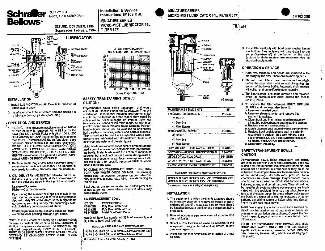
mumTUBE EfELEET
RESTRJCTORHOLDER
RESTRECTOR
GASKET
LOCATWG .
EYELET --0ATOMIZER
-1
6
6
6
6
Sch der RO. Box 631
Akron, Ohio 44309-0631
Bellows®ISSUED: OCTOBER, 1995Supersedes: February, 1994
DEFLECTOR
80"/
P.4 -
f -. 1
OUTERSIGHT DO'/5
OUTER
SIGHT COME
LUBRICATOR
METERING SCREW
- SEAL
METER#JGSCREW
-,r * f SEALDER.ECTOR
SEAL
BODY'BOWL
CHECKBALL
--N PJCKUP TURE
INSTALLATION
1. Install WBRICATOR so Air Flow is in direction ofarrow cast in body.
2. Installation should be upstream from the deviceitisto lubricate (valve, cylinders, tool, etc.).
f OPERATION AND SERVICE- 1. FILLING--Inlet pressure must be eliminated before
fill plug or bowl is removed. Fill to fill line on thebowl (DO NOT OVER FILL) with oil of 100 to 200SSU viscosity at 100°F and an aniline point greaterthan 200°F-same as SAE No. 10 (petroleum basehydraulic oils or spindle oils are good examples).DO NOT USE OILS WITH ADHESIVES OR TACKYADDITIVES COMPOUNDED OILS CONTAININGSOLVENTS, GRAPHITE, SOAPS OR DETER-GENTS (automotive oils generally contain deter-genls) ARE NOT RECOMMENDED.
2. Replace the fill plug and/or bowl assembly firmly-excessive torque is not necessary.The lubricator isnow ready for setting. Repressurize the lubricator.
3. OIL DELIVERY ADJUSTMENT-To adjust oildelivery, use a small blade slotted screwdriver toturn the adjusting screw in the top of the lubricator.Leaner-Clockwise
Richer-Counterclockwise
By counting the number 01 drops per minute in thesight dome, you can adjust to your requirements.Approximately 3% of the drops seen in sight domego downstream. Adjust drip rate accordingly. Con-suit oil delivery conversion chart above.
25 drops per minute equal is one ounce per hour- -volume of oil passing through sight dome.
NOTE: This is a constant density type lubricator whichdelivers a constant ratio of oil to air flow. Therefore, ilair flow increases or decreases, oil delivery will beadjusted propoMionately. ONLY IF A DIFFERENTRATIO IS DESIRED SHOULDYOUR NEEDLE VALMESETTING BE CHANGED AFTER YOUR INITIALSETTING.
installation & ServiceInstructions 1 M103 DSB MINIATURE SERIESMICROMIST LUBRICATOR 14LFILIER 14F
Oil Delivery Conversion3% of Drip Rate To Downstream
6* 7
¤6
:5 - -
4 +
S 3Ez
-
67 100 133 67 200 233
Dome Drip Rate DPM
SAFETY: TRANSPARENT BOWLSCAUTION:
Polycarbonate bowls, being transparent and tough,are ideal for use with Filters and Lubricators. They aresuitable for use in normal industrial environments, butshould not be located in areas where they could besubjected to direct sunlight, an impact blow, nortemperatures outside of the rated range. As with mostplastics, some chemicals can cause damage. Polycar-bonate bowls should not be exposed to chlorinatedhydro carbons, ketones, esters and certain alcohols.They should not be used in air systems where com-pressors are lubricated with fire-resistant fluids suchas phosphate ester and di-ester types.Metal bowls are recommended where ambient and/ormedia conditions are not compatible with polycarbon-ate bowls. Metal bowls resist the action of most suchsolvents, but should not be used when strong acids orbases are present or in salt laden atmospheres. Con-suit the factory for specific recommendations wherethese conditions exist.
TO CLEAN POLYCARBONATE BOWLS USE MILDSOAP AND WATER ONLY! DO NOT use cleaningagents such as acetone, benzene, carbon tetrachlo=ride, gasoline, toluene, etc., which are damaging tothis plastic.
Bowl guards are recommended for added protectionof polycarbonate bowls where chemical altack mayoccasionally occur.
14L REPLACEMENT BOWL
KFT NO. DESCRIPTIONPS420SB Poly Bowl With DrainPS421SB Poly Bowl Without DrainPS447BSB Metal Bowl With Drain
NOTE: All bowl kits consist of (1) bowl assembly and(1) body to bowl seal (o-ring).
MAXIMUM PRESSUAE AND TEMPERATURE
150 PSIG @ 125°F (10 bar 0 52'C) with Polycarbonate Bowl250 PSIG @ 175°F (17 bar 0 80'C) with Metal Bowl ,
*. Conversion: 1 bar = 14.5 PSI; °C 4/9 (°F - 32)
1
MINIATURE SERIES iMICRO-MIST LUBRICATOR 144 FILTER 14F'.1
1FILTER
4
BODY
GRING
GASKET
8001
MYST
DRAN
DEFLECTOR
EUMENT
HOLDER
(ELEMENT)
GASKET
(ELE. END
MAINTENANCE SERVICE KITS
5 MICROMETER ELEMENT KrT
(2) Gasket
(1) Bowl Seal
(1) Filler Bement
40 MICROMETER ELEMENT
(2) Gasket
(1) Bowl Seal
(1) Filter Elemem
POLYCARBONATE BOWLMANUALDRAIN
POLYCARBONATE BOWLAUTOMATIC DRAIN
METAL BOWL MANUAL DRAIN
METALBOWLWITHAUTOMATIC DRAIN
5 MICROMETER ELEMENTCARTRIDGE KfT
.1M103 DSB
5. Install filter vertically with bowl drain mechanism atthe bottom. Free moisture will thus drain into the
sump (*quiet-zone') at the bottom of the bowl(automatic drain models are recommended asstandard equipment).
/., OPERATION & SERVICE
'
PS408SB
14F
PS403SB
PS401SB
MAXIMUM PRESSURE AND TEMPERATURE
PS404SB
PS4OBSB
P5447BSB
PS451SB
PS407SB
150 PSIG O 125°F (10 bar 0 52'C) with Polycarbonate Bowl
250 PSIG O 1757 (17 bar O 80°C) with Metal Bowl
Conversion: 1 bar- 14.5 PSI; °C =5/9 (*F - 32)
INSTALLATION
1. The equipment to which the filter is attached shouldbe internally cleaned to remove all traces of accu-mulated oil and dirt. Also, new pipe or hose shouldbe Installed between the filter and equipment beingprotected.
2. Blow all upstream pipe work dear of accumulateddirt and liquids.
3. Select a filler location as close as possible to theequipment being protected and upstream 01 anypressure regulator.
4. Install filter so that air flows in the direction of arrowon body.
1. Both free moisture and solids are removed auto-
matically by the mter. There are no moving parts.
2. Manual drain filters must be dralned regularlybefore the separated moisture and oil reaches thebottom of the lower baffle. Automatic drain models
will collect and dump liquids automatically.
3. The filter element should be removed and replacedwhen the pressure fferentjal across the filter Is 1ten (10) PSIG.
4. To service the filter element: SHUT OFF AIR
SUPPLY and de-pressurize the unita. Unscrew threaded bowl.
b. Unscrew element holder and remove filterelement & gaskets.
c. Clean bowl and internal parts before reassembling. See polycarbonate bowl deaning section.
d. Replace element and gaskets (2)e.Attach element post assembly and tighten firmly. i -f. Replace bowl seal; lubricate seal to assist In
retaining it in position. Use only mineral baseoils or grease. DO NOT use synthetic oils such .as esters, and DO NOT use silicones.
g.Screw bowl into body.
SAFETY: TRANSPARENT BOWLS
CAUTION
Polycarbonate bowls, being transparent and tough,are ideal for use with Filters and Lubricators. They aresuitable for use in normal industrial environments, butshould not be located in areas where they could besubjected to an impact blow, nortemperatures outsideof the rated range. As with most plastics, somechemicals can cause damage. Polycarbonate bowlsshould not be exposed to chlorinated hydro-carbons,ketones, esters, and certain alcohols.They should notbe used in air systems where compressors are lubri-cated with fire resistant nuids such as phosphate es-ters and di-esters types. In areas where polycarbon-
--ate bowls are exposed to high temperatures or atmo-spheres containing vapors or fluids, which are damag-ing to plastic, use metal bowls.
Metal bowls resist the action of most such solvents but
should not be used where strong acids or bases arepresent or in salt laden atmospheres. Consult the tac-tory for specific recommendations where these con-ditions exist.
TO CLEAN POLYCARBONATE BOWLS USE MILD
SOAP AND WATER ONLYI DO NOT use cleaningagents such as acatone, benzene, carbon letrachlo-ride, gasoline, toluene, etc.. which are damaging tothis plastic.
.¥
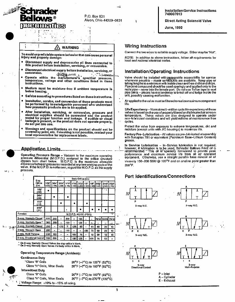
9
*44%1 01/Bc/MBellows®BEDHm]IEI][IE
.
P.O. Box 631
Akron, Ohio 44309-0631
i
1
i i A WARNING ,|To avoid unpredictable system behavior that can'cause personalinjury and property damage:
• Disconnect supply and depressurize all lines connected tothis product before Installation, servicing, or conversion.
• Disconnect electrical supply before installation, servicing, orconversion. . 'r.
' *·+ ;4•3,4<00364• Operate within the manufacturehs specified pressure,
temperature, voltage and other conditions listed in theseinstructions.
• Medium must be moisture-tree 11 ambient temperature isbelow freezing.
• Setwice according to procedures listed on these instructions.• Installation, service, and conversion of these products must
be performed by knowledgeable personnel who understandhow pneumatic products are to be applied.
• Arter installation, servicing, or conversion, pressure andelectrical supplies should be connected and the producttested for proper function and leakage. If audible or visual
' leakage Is present, ortheproductdoes nol operate properly,do not put into use.
• Warnings and specifications on the product should not becovered by paint, etc. If masking is not possible, contact yourlocal representative for replacement labels.
Function
Application I imitqOperating Pressure Range - Vacuum to the maximum operatingpressure differential (M.O.P.D.) assigned to the orifice structurechosen from chart below. M.O.P.D. is the maximum allowabledifference between pressures recorded at any two working ports of thevalve. If the M.O.P.D. is notknown, regard the M.O. P.D. as tho supplypressure.
1 Body Otifte (Cv)
|1/32-| 3/64| 3'64| 1/16*|1/16-| 302·| 1/8'| 1/8" 932 34167/37(.02) (.06) (.06) (.10) (.10) (.20) (.32) 1.32) (.42) (.52) (.73)
.
Stop0,01ce
[Cv)
1/32·
(.02)
3/64.
006)
1/16·
(.12)
·arxt
(.21}
. 2-way. Normally Closed ·
2-way. Normally Open " 3-way, Normally Closed3-way, Nornath' Open
3-way. Mulli Purpose
3-way. Directional Control
500250300 1 200250 -200 -250 150
300 200
M.O.P.O.
200 -
150 -
2 125
150 -
A
100 75
150 125
* On 2-way Normally Closed Valves the stop orilice is blank." On 2-way Normally Open Valves the body olifice 13 blank.
'175
eDC
125
125
90
(PSI 3)
--
- 65
100 75
50
!100
75/50
40
50
30
75
20
25
10
50
.
50/25
Operating Temperature Range (Ambient):Continuous Duty
'Class '8" Coils 20F (-7*C) to 125'F (52°C)Class 'H" Coils, Viton Seals 20F (-700) to 1800F (8200)
intermillent DutyClass 'B Coils 20F (-7°C) to 1800F (82°C)f*e. Class "H" Coils, Viton Seals 20F (-70C) to 270'F (1320C)
2 Voltage Range: +10% to -15% of rating.
25/1C
10
10
10
1
Wiring InstructionsConned the two wires to suitable supply voltage. Either may be"Hot-.
NOTE: In addition to above instructions, follow all requirements forlocal and national electrical codes.
installation/Operating instructions
Valve should be insialled wilheap*lable accessibility for servicewhenever possible - repair sen/16*kits are available. Keep pipe ortubing lengthstoaminimum with insideclean and free oldirtandchips.Pipe joint compound should be Used sparinglyand applied only to themale pipe- never into the female port. Do not use Teflon tape to sealpipe joints - pieces have a tendency to break oll and lodge inside theunit, possibly causing malfunction. .
Airappliedtothevalvemustbelilteredtorealizemaximum component
U fe Expeclancy - Normal multi-million cycle lite expeclancy of these: valves is based on theuse of properly filteredand lubricatedairatroom
temperature. These valves are also designed to operate undernon-lubricated conditions and will yield millions of maintenance treecycles.
Protect the valve from exposure to extreme temperatures, dirt andmoisture (except units with JIC housings) to maximize life.
Factory Pre-Lubrication -All valves are pre-lubricated atassemblywith Sunaplex 781 or equivalent (Petroleum Base-Lithium Content)grease.
, in Service Lubrication - In-Service lubrication is not required:! however, il lubrication is to,be.used, Schrader Bellows F442 oil is
15=miended. -This oil Ii"specially formulated to provide peakperformance and maximum service life from all air operatedequipment. Otherwise, use a straight paraffin base mineral oil ofviscosity 100-200 SSU @ 100©F and an anatine point greater than200F.
Port Identifications/Connections
A
NT
P
2-way N.C.
M
--, N.]\\ 1 - M3-way N.C.
2
- -263 13-way
Directional Control
3 M
P - Inlet
A - CylinderE - Exhaust
P
A
Installation/Service Instructions
740007013
Direct Acting Solenold Valve
June, 1992
2-way N.O.
E P
3-way N.0.
-T T1 3
3-wayMultl-Purpose
T
1
Service Procedures
mNOTE: All cleaning of parts to be done with mineal spiritsr equivalent cleaning solution. Grease should be aineral based lubricant (Sunaplex 781).General Service - Remove exhaust adapter (A> - whereapplicable and hex nut (B) on top of valve or operator.Separate the housing and coil assembly from the plungerguide(D). Remove the fluxwasher(C)-whereapplicable.Remove the plunger guide (D), spnng (E), 0-ring (F) andplunger (G). Use spanner wrench no. 740007100. Cleanall paris taking special care to remove all foreign malterfrom seal areas.
Coil Replacement (Conduit or Grommet) - Remove coil(H) through bottom of housing and replace with new coil: ·· n ·' 1Coil Replacement (Hazardous Duty) - Remove cap (J)and spacer (K). Remove coil (H) through top of housingand replace with new mil. Assemble in reverse order otdisassembly. .
r.
Coil Replacement (J.I.C.) - Loosen cover sorews (L) and Bremovecoverassembly. Remove flux washer (C),coil (H)andwave washers (M) Replace with new one. Assemble in reverse order 01 disassembly.Replace plunger and guide (See Kit Selection), or entireoperator. Assemble parts in reverse order of disassembly.Tighten hex nut to 20-25 in-lbs. Assemble exhaustadaptor and tighten ta 20-25 in-lbs. for Hazardous DutyEnclosures (hand tight is sufficientwith other endosures). CIndiqator Light ReglacementIndicator Lights120V 60Hz / 110V 50Hz . . H1910924V DC ............... H19110
1. Remove dome nut (8), loosen cover screws (L) and E'
remove cover assembly (N).. .,/1.4,;1 ....:''*Ilnjig will, Avir,Al eads -Snap open splicecorinect68*"" 'd pry clip out ol splice. Slide wires out of splice.-mnits with 3-Pin or 5-Pin Connectors - Twist off two Awire nuts (P) connected to lamp leads.
3. Crush lens of indicator light (0), pull out of cover andretain 0-ring (R).
4. Strip insulation of 1 01 indicator light lead wires 1/2-.Slide 0-ringontonew lampand slide thru hole in cover.
---
Repair KitsFUNCTION
3 WAY N.C.
3 WAY N.O.
3 WAY MULTI-PURPOSE2 WAY N.O. AND
3 WAY DIRECTIONAL CONTROL2 WAY N.C.
H
M
H
*-
STOP ORIF CE1132 3/64' 1/le 3132"
744008031 744008046 744008062 744008093742008031742008046 742008062 742008093745008031745008046 745008062 745008093
746008031746008046 746008062 746008093
NOTE: For viion seals Change the 7th digit in part nurrber Imm f to •6·.EXAMPLE: 744008031 would ba 744008631 for viton seals.
EXHAUST ADAPTER(INCLUQEFV?'ING)**e
\CONDUIT G
F
1/8· PPE 1/4· PIPE
744008000 744108000BUNA) BUNA)
744008600 744108600(VITON) (VITON)
M
J.I.C.
4
.., 44*dqu#
COILS ....4,
B VOLTAGE/ CLASS 'B· CLASS ·H· GLASS 'BKJ · 6\/60HZ 740007141 740007291 760007141
HERTZSPADE
12V/60HZ 740007142 740007292 780007142 '1H.\ 24V/60HZ 740007143 740007293 7800071435. Units With Flvina Leads,- Slide one indicator light wire BVDCinto each splice. Connect red cdt lead with red lamp »/leadand white coilleadwith white lamplead. Placectip '
120V/60HZ 740007145 740007295 7800071454BV/60HZ 740007152 740007202 780007152into spliceand pressuntil flush with topof splice (viceor
liIESESSGU 12VDC 740007152 740007202 780007152
shut.
4801//60HZ 740007147 740007297 780007147assembly.
24OV/eOHZ 740007148 740007296 780007146
24VDC 740007153 740007203 780007153120VDC 740007155 740007205 7800071556. Reassemble junction box cover and tighten screws to E F 120V/502
740007165
230VDC 740007156 740007206 78000715620-25 in-lbs. Screw on dome nut.
240W50HZ 740007166G 4401//50HZ 740007167
- HAZARDOUS.DUTY,*r 4 : 4, ". - -1·'n't*21 , , t.,e
'EXTRA COPIES OF THESE INSTRUCTIONSARE AVAILABLE FOR INBLUSION IN EQUIPMENT/MAITEd-ANCSfMANUALS THAT UTILIZE THESE PRODUCTS. CONTACT YOUR LOCAL REPRESENTATIVE .I.- I
A WARNINGFAILURE OR IMPROPER SELECTION OR IMPROPER USE OF THE PRODUCTS AND/OR SYSTEMS DESCRIBED HEREIN OR RELATED ITEMS CAN CAUSE "DEATH, PERSONAL INJURY AND PROPERTY DAMAGES. . ··i
0 users having technical expertise. Il la Important that you analyze att aspects 01 your application, Induding consequences ol any lailure and ieview :he Information 1This document and other Intormailon fromThe Corr©any, Its subsWIalles and aulhollzed distilbutors provideproduciand'ors¥stemoptions for fulther Inveslgation by 1concerning the product or system In the cunent product catalog. Due to the variety 01 operating conditions and applications lor these products or systems. the user.through ils own analysis and testing. 18 solely responsble for maKIng the ,inal arlmion ol the products and systems and assuring thai all performance. salely andwarning mquirements of the application ara met.
Theproducts describedhemin. including without timitation.product features, spedtications,6,19ns, availatmy and pticing, ara subjecttochange by TheCorr¥,any and ..1*4. I !its subsidlifles atany lima without notice.
0
B
CP
74009:9AL
741008000
.rhinH:*Nat 9 1 ·--
5
NQL
R
NONE

.
,

f
SP500 AC Drive
Installation and Operation ManualVersion 3.1
Instruction Manual D2-3356-2
00 ROCIONell Automation
Reliance Electric
The information in this manual is subject to change without notice.
ATTENTION: Only qualified electrical personnel familiar with the construction and operation ofthis equipment and the hazards involved should install, adjust, operate, and/or service thisequipment. Read and understand this manual in its entirety before proceeding.
Throughout this manual, the following advisories are used to point out safety considerations:
.
ATTENTION: Identifies information about practices or circumstances that can lead to personalinjury or death, property damage, or economic loss.
Important: Identifies information that is critical for successful application and understanding of the product.
Note: Identifies additional information that is helpful for successful application and understanding of theproduct.
Reliance, ReSource, and AutoMax are trademarks of Rockwell Automation.
© 1997 Rockwell International Corporation
f
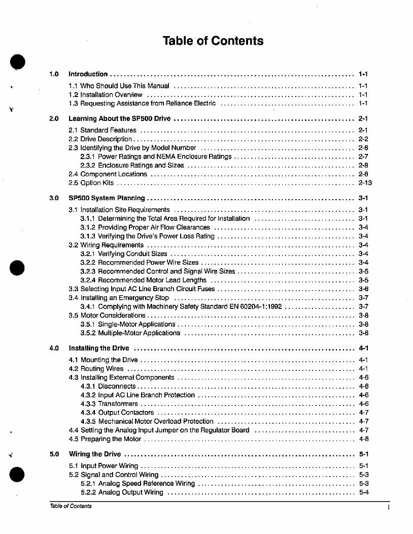
Y
.
1.0 Introduction...
Table of Contents
1.1 Who Should Use This Manual ...............
1.2 Installation Overview ......................
1.3 Requesting Assistance from Reliance Electric
2.0 Learning About the SP500 Drive
2.1 Standard Features ................................
2.2 Drive Description..................................
2.3 Identifying the Drive by Model Number ..............
2.3.1 Power Ratings and NEMA Enclosure Ratings . .
2.3.2 Enclosure Ratings and Sizes ................
2.4 Component Locations ..........................2.5 Option Kits .........................................
3.0 SP500 System Planning 3-1
3.1 Installation Site Requirements .................................... 3-1
3.1.1 Determining the Total Area Required for Installation . . . . . . . . . . . 3-1
3.1.2 Providing Proper Air Flow Clearances ........................ 3-4
3.1.3 Verifyingthe Drive's Power Loss Rating ................................ 3-4
3.2 Wiring Requirements ..................................... 3-4
3.2.1 Verifying Conduit Sizes ................................................. 3-4
3.2.2 Recommended Power Wire Sizes .......................... 3-4
3.2.3 Recommended Control and Signal Wire Sizes................. 3-5
3.2.4 Recommended Motor Lead Lengths ......................... 3-5
3.3 Selecting Input AC Line Branch Circuit Fuses....................... 3-6
3.4 Installing an Emergency Stop .................................... 3-7
3.4.1 Complying with Machinery Safety Standard EN 60204-1 :1992 .. . 3-7
3.5 Motor Considerations ............................................ 3-8
3.5.1 Single-Motor Applications ................................... 3-8
3.5.2 Multiple-Motor Applications ................................ 3-8
4.0 installing the Drive 4-1
4.1 Mounting the Drive................................... 4-1
4.2 Routing Wires ....................................... 4-1
4.3 Installing External Components ........................ 4-6
4.3.1 Disconnects .................................... 4-6
4.3.2 Input AC Une Branch Protection ................... 4-6
4.3.3 Transformers ................................. 4-6
4.3.4 Output Contactors ............................ 4-7
4.3.5 Mechanical Motor Overload Protection .............. 4-7
4.4 Setting the Analog Input Jumper on the Regulator Board 4-7
4.5 Preparing the Motor .......... ........................ 4-8
5.0 Wiring the Drive
5.1 Input Power Wiring ..................
5.2 Signal and Control Wiring ............
5.2.1 Analog Speed Reference Wiring
5.2.2 Analog Output Wiring ..........
Table of Contents
1-1
1-1
1-1
1-1
2-1
5-1
5-1
5-3
5-3
5-4
2-1
2-2
2-6
2-7
2-8
2-8
2-13
5.2.3 Digital Input Wiring .........
5.2.4 Snubber Resistor Wiring ...5.2.5 Output Status Relay Wiring
5.3 Output Power Wiring ...........5.4 Grounding ...... ..............
6.0 Completing the Installation .................
6.1 Checking the Installation With the Power Off .....
6.2 Checking Drive Operation............
7.0 Keypad and Display Operation ...............
7.1 Display Description .....................................7.2 Key Descriptions ..........................................
7.3 LED Descriptions .................................
7.4 Program Mode ........................................... 7.5 Monitor Mode
7.5.1 Displaying the Percent Selected Speed Reference ......
7.5.2 Scaling the RPM Display and Reference Using F-08 .....7.6 Drive Control .................................,..........
7.6.1 Changing the Reference Using the Keypad ..............
8.0 Programming Reference ............
8.1 Displaying or Changing Parameter Values....
8.2 Ensuring Program Security..............8.3 Parameter Descriptions ..................
9.0 Troubleshooting Reference .................
9.1 Verifying DC Bus Voltage ...................................
9.2 Troubleshooting the Drive Using Fault Codes..................
9.3 Accessing and Clearing the Error Log ........................9.4 Checking the Drive's Power Module Circuitry with the Power Off
6-1
6-1
6-2
7-1
8-1
8-1
8-2
8-4
9-1
9-1
9-3
9-6
9-8
SPSOO AC Drive Installation and Operation Manual, Version 3.1
7-1
7-1
7-2
7-4
7-5
7-6
7-6
7-7
7-7
54
5-8
5-9
5-10
5-10
f
4.
Appendix ATechnical Specifications .
Appendix B
Record of User Settings .
Appendix C
Alphabetical Listing of Parameters
Appendices
Appendix DCompliance with Machinery Safety Standard EN-60204-1:1992
Appendix E
Compliance with Electromagnetic Compatibility Standards
Appendix F
Replacement Parts
Glossary...
Index.
Table of Contents
A-1
B-1
C-1
D-1
E-1
F-1
. Glossary-1
. Index-1
m
IV
List of Figures
Figure 2.1 - SP500 System Diagram .............
Figure 2.2 - SP500 System Diagram (Continued) ....
Figure 2.3 - Regulator Board Component Locations
Figure 2.4 - Identifying the Drive Model Number.....
Figure 2.5 - Enclosure A Component Locations ...
Figure 2.6 - Enclosure B Component Locations ....
Figure 2.7 - Enclosure C Component Locations
Figure 2.8 - Enclosure D Component Locations ....
Figure 3.1 - Enclosure A Dimensions ....
Figure 3.2 - Enclosure B Dimensions .............
Figure 3.3 - Enclosure C Dimensions .............
Figure 3.4 - Enclosure D Dimensions .............
Figure 3.5 - How to Measure Motor Lead Lengths
Figure 4.1 - Enclosure A Wire Routing Locations ......................
Figure 4.2 - Enclosure B Wire Routing Locations ......................
Figure 4.3 - Enclosure C Wire Routing Locations .....................
Figure 4.4 - Enclosure D Wire Routing Locations .....................
Figure 4.5 - Jumper J6 Settings for the Analog Input Speed Reference
. 2-3
.. 2-4
.. 2-5
... 2-6
... 2-9
...2-10
... 2-11
.. 2-12
. 3-2
.. 3-2
.. 3-3
3-3
.. 3-6
4-2
.. 4-3
.. 4-4
. 4-5
..4-7
Figure 5.1 - Typical Electrical Connections ............................... 5-2
Figure 5.2 - Typical Control Terminal Strip Connections ................................ ... 5-3
Figure 5.3 - Analog Speed Reference Wiring Connections ..:......................... . 5-4
Figure 5.4 - Analog Output Wiring Connections .......................................... .. 5-4
Figure 5.5 - Two-Wire StarVStop Sample Control Wiring .......................................... 5-5
Figure 5.6 - Three-Wire StarUStop Sample Control Wiring ................................ .. 5-5
Figure 5.7 - Multi-Speed Preset Sample Control Wiring ................................... ... 5-6
Figure 5.8 - Terminal Usage During Multi-Speed Preset Operation ............................ ... 5-7
Figure 5.9 - Snubber Resistor Wiring Connections for M/N 1 SU2>000< Drives ... . 5-8
Figure 5.10 - Snubber Resistor Wiring Connections for M/N 1 SU4)0(xx and 1 SU5>00<x Drives . 5-9
Figure 5.11 - Output Status Relay Wiring Connections . . . . . . . . . . . . . . . . . . . . . . 5-9
Figure 7.1 - SP500 Keypad and Display .....
Figure 7.2 - SP500 Menu Structure .......
Figure 7.3 - Example of a Program Mode Display.
Figure 7.4 - Example of a Monitor Mode Display
Figure 8.1 - Manual Torque Boost Adjustment Range
. 7-1
. 7-4
. 7-5
.. 7-6
. 8-6
SP500 AC Drive installation and Operation Manual, Version 3.1
Figure 8.2 - Volts/Hertz Curve. . 8-7
Figure 9.1 - DC Bus Terminals on Model 1 SU1xxxx and 1 SU2xxxx Drives ........................... 9-2
Figure 9.2 - DC Bus Terminals on Model 1 SU4)000( and 1 SU5¤xx Drives (except 1 SU4x015, 1 SU4)(020) . . 9-2'.
Figure 9.3 -DC Bus Terminals on Model 1 SU4x015 and 1 SU4x020 Drives .......................... 9-3
Figure E.1 - AC Mains Filter Dimensions ............
Figure E.2 - Typical SP500 Single-Phase Connections
Figure E.3 - Typical SP500 Three-Phase Connections .
Figure E.4- 1/0 Signal Cable.............................
Table of Contents
. E-3
.. E-5
.. E-5
.. E-7
V
V1
Table 2.1
Table 2.2
Table 2.2
Table 2.3
Table 3.1
Table 3.2
Table 3.3
Table 3.4
Table 3.5
Table 3.6
Table 3.7
Table 3.8
Table 7.1
Table 7.2
Table 7.3
Table 8.1
Table 8.2
Table 9.1
Table 9.2
Table 9.3
List of Tables
- SP500 Model Number Notation .................
- Power and NEMA Enclosure Ratings.................
- Power and NEMA Enclosure Ratings (Continued)
-SP500 Option Kits .............................
- Air Flow Clearances .................................................
- Recommended Power Wire Sizes for M/N 1 SU1 xx= and 1 SU2)000( Drives ....
- Recommended Power Wire Sizes for M/N 1 SU4xxxx and 1 SU5xxxx Drives .....
- Recommended Power Wire Sizes for M/N 1 SU4x015 and 1 SU4x020 Drives............
- Recommended Power Terminal Tightening Torque ...................
- Recommended Control and Signal Wire Sizes and Tightening Torque
- Motor Lead Length Guidelines .....................................
- AC Input Line Fuse Selection Values . . ...................
- Key Descriptions ..............
- Drive Status LED Descriptions
- Monitor Mode LED Descriptions .
- Multi-Speed Presets Digital Inputs ...
- Auto-Restartable Faults ............
- Drive Faults and Corrective Actions
- Resistance Checks for Input Diodes
- Resistance Checks for IGBTs ......
Table A.1 - Service Conditions .......
Table A.2 - Dimensions ...............
Table A.3 - Environmental Conditions
Table A.4 - Drive Inputs .............
Table A.5-Drive Outputs ....................
Table E.1
Table E.2
Table F.1
Table F.2
Table F.3
- AC Mains Filters ......................................
-AC Mains Filter Mounting Dimensions and Weights ....
- Replacement Parts List for Model 1 SU2xxx)( Drives
- Replacement Parts Ust for Model 1 SU4)000( Drives
- Replacement Parts Ust for Model 1 SU5)000< Drives
. 2-6
..2-7
. 2-8
.. 2-13
. 3-4
3-4
... 3-5
... 3-5
... 3-5
. 3-5
. 3-6
. 3-7
. 9-3
..9-8
.. 9-9
. A-1
.. A-1
... A-1
...A-2
... A-2
. E-2
... E-4
. F-1
.. F-1
.. F-2
7-2
. 7-3
7-3
8-16
. 8-17
SP500 AC Drive Installation and Operation Manual, Version 3.1
W
1.0 Introduction
The products described in this manual are manufactured by Reliance Electric Industrial Company.
1.1 Who Should Use This Manual
This manual is intended for qualified electrical personnel responsible for installing, programming,starting up, and maintaining the SP500 drive.
1.2 Installation Overview
This manual describes how to install and troubleshoot the SP500 drive. Drive installation consists of
the following basic tasks:
• Plan your installation using the guidelines presented in chapter 3. If your installation must be incompliance with Electromagnetic Compatibility Standards, read Appendix E also.
• Mount the drive and install external components according to the guidelines presented inchapter 4.
• Wire the drive's input power, output power, and control signal terminal strip using the instructionsin chapter 5.
• Adjust parameter values, if required. The parameters are described in chapter 8. For quickreference, the factory-set values are listed in Appendix B.
• Perform the power-off and power-on checks described in chapter 6 to complete the installation.
If problems occur during drive operation, refer to chapter 9. Appendix F lists the parts of the drive thatcan be replaced.
Before you begin the installation procedure, become familiar with the drive by reading chapter 2,which provides an overview of the drive and its features, chapter 7, which describes the operation ofthe keypad and the display, and Appendix A, which lists the drive's technical specifications.
1.3 Requesting Assistance from Reliance Electric
Introduction
If you have any questions or problems with the products described in this instruction manual, contactyour local Reliance Electric sales office. For technical assistance, calll-800-726-8112, Mondaythrough Friday, 8:00 AM to 5:00 PM (EST).
1-1

1-2 SP500 AC Drive Installation and Operation Manual, Version 3.1

1
2.0 Learning About the SP500 DriveThis chapter describes the SP500 drive and how to identify it based on its model number. Thischapter also provides power and enclosure rating information. ,
2.1 Standard Features
The SP500 drive has the following features:
• On-board keypad and display providing:
Start/Stop/Reset control
FonNard/Reverse (reverse-disable selectable)
Setpoint adjustment
Motor RPM, %load, or output voltage display
Drive diagnostics
• 500 millisecond power dip ride4hrough
• 150% overload for one minute
• 0.5 to 240 Hz three-phase voltage output
• NEMA 1 and NEMA 4/12 enclosures
• A snubber resistor braking signal and a scaled voltage analog output (0 to 10 VDCD which isproportional to:
Output frequency
Output amps
Output voltage
Selected reference
• Quiet motor operation with high carrier frequency selection
• Drive protection
C)vercurrent
Short circuit
Ground fault
Overvoltage
Undervoltage
Overtemperature
• UL/CSA electronic overload that meets NEC/CEC requirements
• User-selectable relay contact for indications of drive running, drive faulted, or drive at selectedspeed
• User-selectable power-up start, auto-restart, and coast-to-rest or ramp-to-rest stop functions
• User-selectable local or remote operation
• 29 user-adjustable software parameters
2.2 Drive Description
The SP500 drive is an AC PWM (pulse-width-modulated) inverter that operates on single- orthree-phase power. See figures 2.1 and 2.2. AC input power is applied to the drive's input terminals.
Learning About the SP500 Drive 2-1
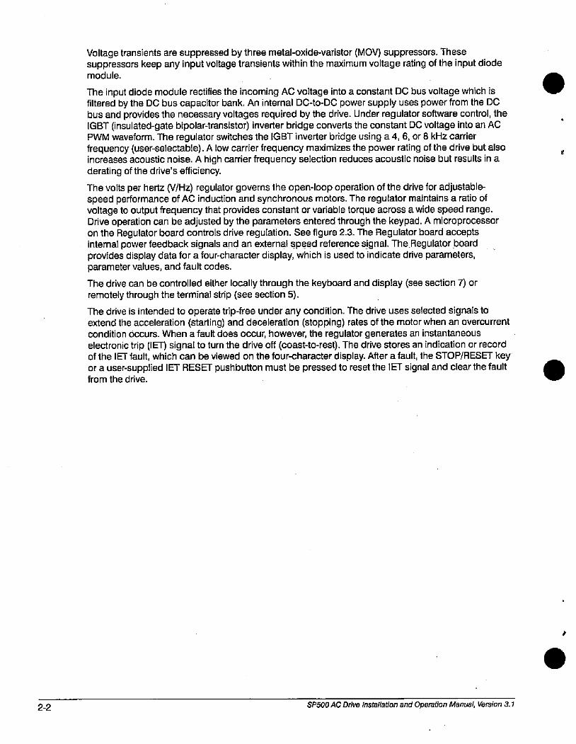
2-2
Voltage transients are suppressed by three metal-oxide-varistor (MOV) suppressors. Thesesuppressors keep any input voltage transients within the maximum voltage rating of the input diodemodule.
The input diode module rectifies the incoming AC voltage into a constant DC bus voltage which isfiltered by the DC bus capacitor bank. An internal DC-to-DC power supply uses power from the DCbus and provides the necessary voltages required by the drive. Under regulator software control, the
*
IGBT (insulated-gate bipolaMransistor) inverter bridge converts the constant DC voltage into an ACPWM waveform. The regulator switches the IGBT inverter bridge using a 4,6, or 8 kHz carrierfrequency (user-selectable). A low carrier frequency maximizes the power rating of the drive but alsoincreases acoustic noise. A high carrier frequency selection reduces acoustic noise but results in aderating of the drive's efficiency.
The volts per hertz (V/Hz) regulator governs the open-loop operation of the drive for adjustable-speed performance of AC induction and synchronous motors. The regulator maintains a ratio ofvoltage to output frequency that provides constant or variable torque across a wide speed range.Drive operation can be adjusted by the parameters entered through the keypad. A microprocessoron the Regulator board controls drive regulation. See figure 2.3. The Regulator board acceptsinternal power feedback signals and an external speed reference signal. The Regulator boardprovides display data for a four-character display, which is used to indicate drive parameters,parameter values, and fault codes.
The drive can be controlled either locally through the keyboard and display (see section 7) orremotely through the terminal strip (see section 5).
The drive is intended to operate trip-free under any condition. The drive uses selected signals toextend the acceleration (starting) and deceleration (stopping) rates of the motor when an overcurrentcondition occurs. When a fault does occur, however, the regulator generates an instantaneouselectronic trip (IET) signal to turn the drive off (coast40-rest). The drive stores an indication or recordof the IET fault, which can be viewed on the four-character display. After a fault, the STOP/RESET key
or a user-supplied IET RESET pushbutton must be pressed to reset the IET signal and clear the fault from the drive.
SP500 AC Drive installation and Operation Manual, Version 3.1
.
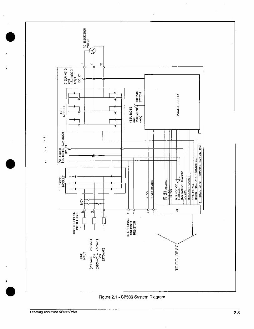
W
88
U
g8=E
E
-%.2 000.-0
X90D
S5
LO
*--0-0
4
D > 9
.K
Learning About the SP500 Drive
BiB
2b
S
W55&
,-0
M
S *o
Z=>Ii
CK Ul +
III
999
N
1 050
Z0
5D
n n:
Z2
0
0
50<C
1 05*Or-
62558O0Ir
0
80
5
0-«>
+ 1
Figure 2.1 - SP500 System Diagram
589
n
&7
8 821 >m
1 m-
C\1
0,1
eE
0
a-
3U)
6g0-
E
SuUS
S:
0
:
5 485351c
0* U
We W
L
Wr
5g
0
4
2-3
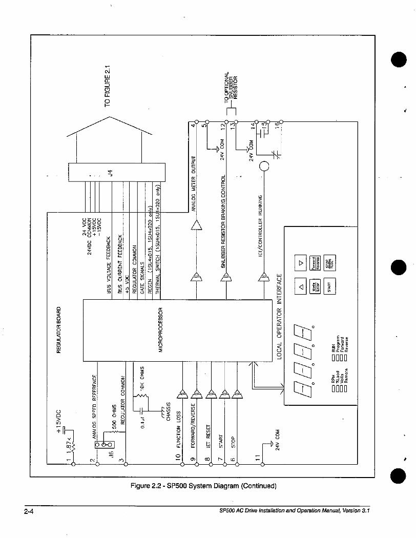
2-4
SCO
Cn
0
-599
U
N
g
g+
LAI
LUCKLuLlLL;
EL.Cl.
M
9--
N
D
LL
01-
X
W
E9
E
-J
Z
8
5
0BOW0
"1
ro
8
LO
+
00
f(Z
U)
0
5
0
SZ
5
u)
lo
3Ul
I
0
9E('0
B
8
0
d
5C
0
:
S
5
[1
5
m
5
m
-1
* Ir OnQU,2
5@m
# 10 M
22
el
Z
8
E
Cz
00
* tO (0'---
4
_5
0
CD
Z
CE
CKLLI
0
f f
0660
Ld
5
L- {'1')
0- c> co A W
[1
m
a
=f-0 Figure 2.2 - SP500 System Diagram (Continued)
LU
CL
0
B
LJ
EOfLLl
Bil
Eng00
00911]0
SP500 AC Drive installation and Operation Manual, Version 3.1
&2KB
0000
EP:
i&2&
0000
.
2
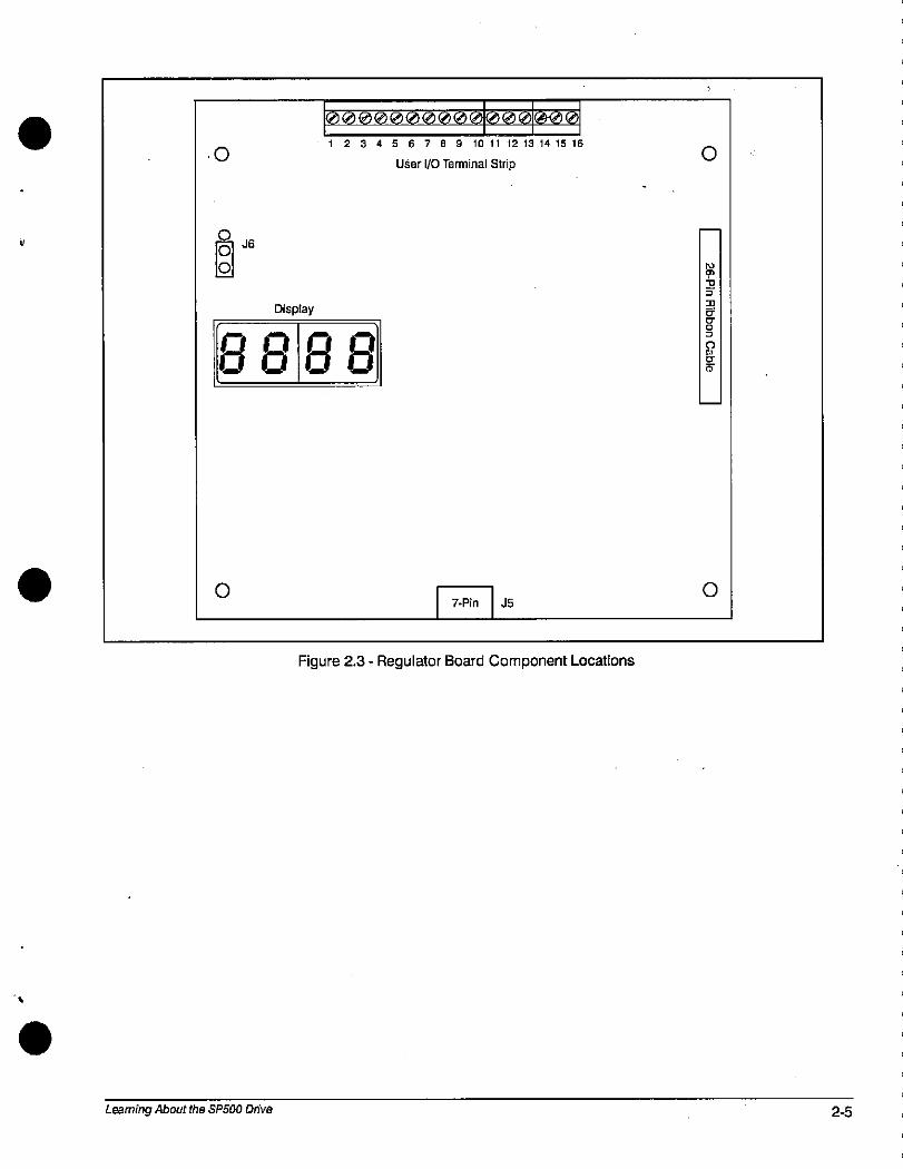
0
000000002_0000@00
1 2 3 4 5 6 7 8 910111213141516
.0U5er 1/0 Terminal Strip
1Q1
88
Learning About the SPSOO Drive
Display
88
7-Pin J5
Figure 2.3 - Regulator Board Component Locations
0
8210
Sg0
0
2-5
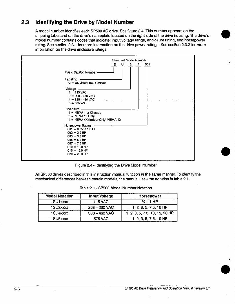
2-6
2.3 Identifying the Drive by Model Number
A model number identifies each SP500 AC drive. See figure 2.4. This number appears on theshipping label and on the drive's nameplate located on the right side of the drive housing. The drive's model number contains codes that indicate: input voltage range, enclosure rating, and horsepowerrating. See section 2.3.1 for more information on the drive power ratings. See section 2.3.2 for moreinformation on the drive enclosure ratings.
Basic Catalog Number
Horse
001
002
003
005
007
010
015
020
LabelingU = UL Listed, IEC Certified
Voltage1 = 115 VAC2 = 200 - 230 VAC4 = 380 - 460 VAC5 = 575 VAC
Standard Model Number
1SU21001
Endosure
1 = NEMA 1 or Chassis
2 = NEMA 12 Only4 = NEMA 4X (Indoor Only)/NEMA 12
power Rating= 0.25 to 1.0 HP
= 2.0 HP
= 3.0 HP
= 5.0 HP
= 7.5 HP
= 10.0 HP
= 15.0 HP
= 20.0 HP
Figure 2.4 - Identifying the Drive Model Number
All SP500 drives described in this instruction manual function in the same manner. To identify themechanical differences between certain models, the manual uses the notation in table 2.1.
Model Notation
1 SU 1 >000<
1 SU2xxxx
1 SU4xxxx
1 SU5)000<
Table 2.1 - SP500 Model Number Notation
Input Voltage
115 VAC
208 - 230 VAC
380 - 460 VAC
575 VAC
Horsepower
1/4 -1 HP
1,2,3,5,7.5,10 HP
1,2,3,5,7.5,10,15,20 HP
1,2,3,5,7.5,10 HP
SP500 AC Drive Installation and Operation Manual, Version 3.1
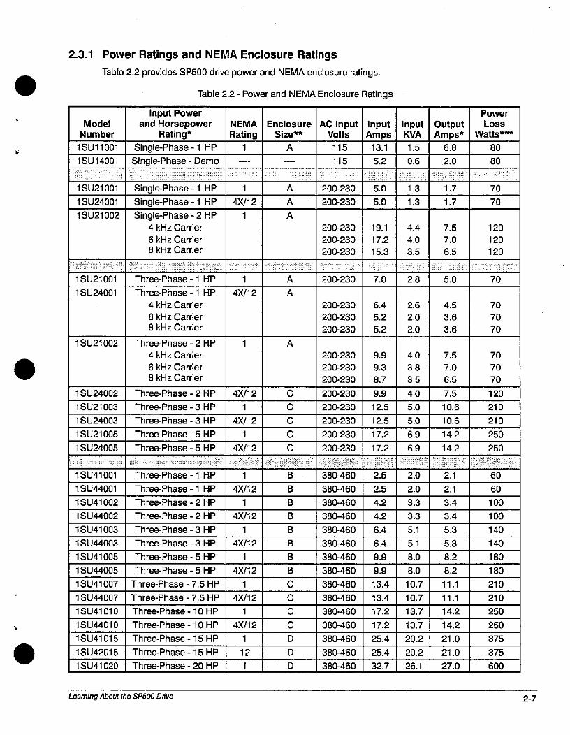
2.3.1
Model
Number
Power Ratings and NEMA Enclosure Ratings
Table 2.2 provides SP500 drive power and NEMA enclosure ratings.
1 SU11001
1 SU14001
1 SU21001
1 SU24001
1 SU21002
1 SU21001
1 SU24001
1 SU21002
1 SU24002
1 SU21003
1 SU24003
1 SU21005
1 SU24005
1 SU41001
1 SU44001
1 SU41002
1 SU44002
1 SU41003
1 SU44003
1 SU41005
1 SU44005
1 SU41007
1 SU44007
1 SU41010
1 SU44010
1 SU41015
1 SU42015
1 SU41020
Input Powerand Horsepower
Rating*
Single-Phase - 1 HP
Single-Phase - Demo
Single-Phase -1 HP
Single-Phase - 1 HP
Single-Phase - 2 HP4 kHz Carrier
6 kHz Carrier
8 kHz Carrier
Three-Phase - 1 HP
Three-Phase - 1 HP
4 kHz Carrier
6 kHz Carrier
8 kHz Carrier
Three-Phase - 2 HP
4 kHz Carrier
6 kHz Carrier
8 kHz Carrier
Three-Phase - 2 HP
Three-Phase - 3 HP
Three-Phase - 3 HP
Three-Phase - 5 HP
Three-Phase - 5 HP
Three-Phase - 1 HP
Three-Phase - 1 HP
Three-Phase - 2 HP
Three-Phase - 2 HP
Three-Phase - 3 HP
Three-Phase - 3 HP
Three-Phase - 5 HP
Three-Phase - 5 HP
Three-Phase - 7.5 HP
Three-Phase - 7.5 HP
Three-Phase - 10 HP
Three-Phase - 10 HP
Three-Phase - 15 HP
Three-Phase - 15 HP
Three-Phase - 20 HP
Learning About the SPSOO Drive
NEMA
Rating
1
1
1
4X/12
1
1
4X/12
4X/12
1
4X/12
1
4X/12
1
4X/12
1
4X/12
1
4X/12
1
4X/12
1
4X/12
1
4X/12
1
12
1
Enclosure
Size **
A
A
A
A
A
A
A
C
C
C
C
C
B
B
B
B
B
B
B
B
C
C
C
C
D
D
D
Table 2.2 - Power and NEMA Enclosure Ratings
AC InputVolts
200-230
200-230
200-230
200-230
200-230
200-230
200-230
200-230
200-230
200-230
200-230
200-230
200-230
200-230
200-230
200-230
200-230
380-460
380-460
380-460
380460
380-460
380-460
380-460
380-460
380-460
380-460
380-460
380460
380-460
380-460
380-460
115
115
InputAmps
13.1
7.0
6.4
5.2
5.2
5.2
9.9
5.0
5.0
9.9
9.3
8.7
19.1
17.2
15.3
12.5
12.5
17.2
17.2
2.5
2.5
4.2
4.2
6.4
6.4
9.9
9.9
13.4
13.4
17.2
17.2
25.4
25.4
32.7
InputKVA
1.5
0.6
1.3
1.3
4.4
4.0
3.5
2.8
2.6
2.0
2.0
4.0
3.8
3.5
4.0
5.0
5.0
6.9
6.9
8.0
8.0
10.7
10.7
13.7
13.7
20.2
20.2
26.1
2.0
2.0
3.3
3.3
5.1
5.1
OutputAmps*
6.8
2.0
5.0
4.5
3.6
3.6
7.5
7.0
6.5
1.7
1.7
7.5
7.0
6.5
7.5
10.6
10.6
14.2
14.2
11.1
11.1
14.2
14.2
21.0
21.0
27.0
2.1
2.1
3.4
3.4
5.3
5.3
8.2
8.2
Power
Loss
Watts ***
80
80
70
70
120
210
210
250
250
70
70
70
70
70
70
120
120
120
70
60
60
100
100
140
140
180
180
210
210
250
250
375
375
600
2-7
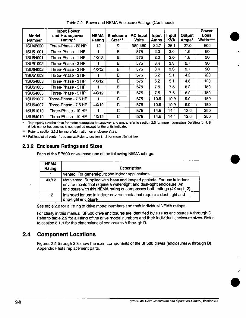
2-8
Model
Number
1 SU42020
1 SU51001
1 SU54001
1 SU51002
1 SU54002
1 SU51003
1 SU54003
1 SU51005
1 SU54005
1 SU51007
1 SU54007
1 SU51010
1 SU54010
Table 2.2 - Power and NEMA Enclosure Ratings (Continued)
Input Powerand Horsepower
Rating*
Three-Phase - 20 HP
Three-Phase - 1 HP
Three-Phase - 1 HP
Three-Phase - 2 HP
Three-Phase - 2 HP
Three-Phase - 3 HP
Three-Phase - 3 HP
Three-Phase - 5 HP
Three-Phase - 5 HP
Three-Phase - 7.5 HP
Three-Phase - 7.5 HP
Three-Phase - 10 HP
Three-Phase - 10 HP
NEMA
Rating
12
1
4X/12
1
4X/12
1
4X/12
1
4X/12
1
4)</12
1
4X/12
Enclosure
Size **
D
B
B
B
B
B
B
B
B
C
C
C
C
AC InputVolts
380-460
575
575
575
575
575
575
575
575
575
575
575
575
InputAmps
32.7
2.0
2.0
3.4
3.4
5.2
5.2
7.5
7.5
10.9
10.9
14.5
14.5
InputKVA
26.1
5.1
5.1
2.0
2.0
3.3
3.3
7.5
7.5
10.9
10.9
14.4
14.4
OutputAmps*
27.0
1.6
1.6
2.7
27
4.3
4.3
6.2
6.2
9.0
9.0
12.0
12.0
600
50
50
90
90
120
120
150
150
Power
Loss
Watts ***
* To properly size the drive for motor nameplate horsepower and amps, refer to section 3.5 for more information. Derating for 4,6,8 kHz carrier frequencies is not required except for the units indicated.
** Refer to section 2.3.2 for more information on enclosure sizes.
*** Full-load at all carrier frequencies. Refer to section 3.1.3 for more information.
2.3.2
2.4
Enclosure Ratings and Sizes
Each of the SP500 drives have one of the following NEMA ratings:
NEMA
Rating
1
4X/12
Description
Vented. For general-purpose indoor applications.Not vented. Supplied with base and keypad gaskets. For use in indoorenvironments that require a water-tight and dust4ight enclosure. Anenclosure with this NEMA rating encompasses both ratings (4X and 12).
12 Intended for use in indoor environments that require a dust-tight anddrip4ight enclosure.
See table 2.2 for a listing of drive model numbers and their individual NEMA ratings.
For clarity in this manual, SP500 drive enclosures are identified by size as enclosures A through D.Refer to table 2.2 for a listing of the drive model numbers and their individual enclosure sizes. Referto section 3.1.1 for the dimensions of enclosures A through D.
Component Locations
Figures 2.5 through 2.8 show the main components of the SP500 drives (enclosures A through D).Appendix F lists replacement parts.
SP500 AC Drive installation and Operation Manual, Version 3.1
180
180
250
250
/
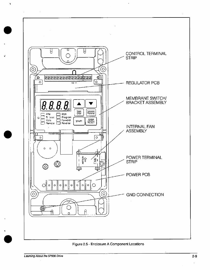
V 7 U le olf w
39El
0
0000000000000000
1011
8.8.8.8. 4]1']Mode 1 FO'A,Cm RJU m RUN .211 dfEE. .'
O [Z] % LOGo [I] Program C[III Voks 0 Forward | S. I-EQE. 1gl Remote Reverse l RESET
r
e ©
L. 0110 0
nfl
0
11 - 1
Learning About the SP500 Drive
0
CO-#
0Io J
0
/
0
0
-
[rf)
1 3
1 29 '*1 -
0 0
/
CONTROL TERMINALSTRIP
REGULATOR PCB
MEMBRANE SWITCH/BRACKET ASSEMBLY
INTERNAL FAN
ASSEMBLY
POWER TERMINAL
STRIP
POWER PCB
GND CONNECTION
Figure 2.5 - Enclosure A Component Locations
2-9
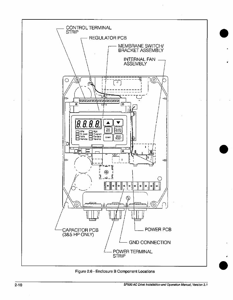
2-10
CONTROL TERMINALE-- STRIP
REGULATOR PCB
F BRACKET ASSEMBLYMEMBRANE SWITCH/
INTERNAL FAN
ASSEMBLY --7
------urIf
40
\ 1('11
RAR v
Es«d RUN
ProgramForward
Remote Reverse
e /--,4Ir =
11 */ 111
(
\ 0.
1 u..1. 1 lili.lili
LE_11 1START 1 -STOP
1 RESEr Yi j
1 - -1-1- - 11 1-%s 24 4L
11
1
/1, 1 @ :=52==5 (h" 1«,S k
CAPACITOR PCB TI L(3&5 HP ONLY)
L-- POWER TERMINALSTRIP
+
0
+1*1+ 1 //-11
111 f@7 FL
POWER PCB
GND CONNECTION
Figure 2.6 - Enclosure B Component Locations
SP500 AC Drive Installation and Operation Manual, Version 3.1
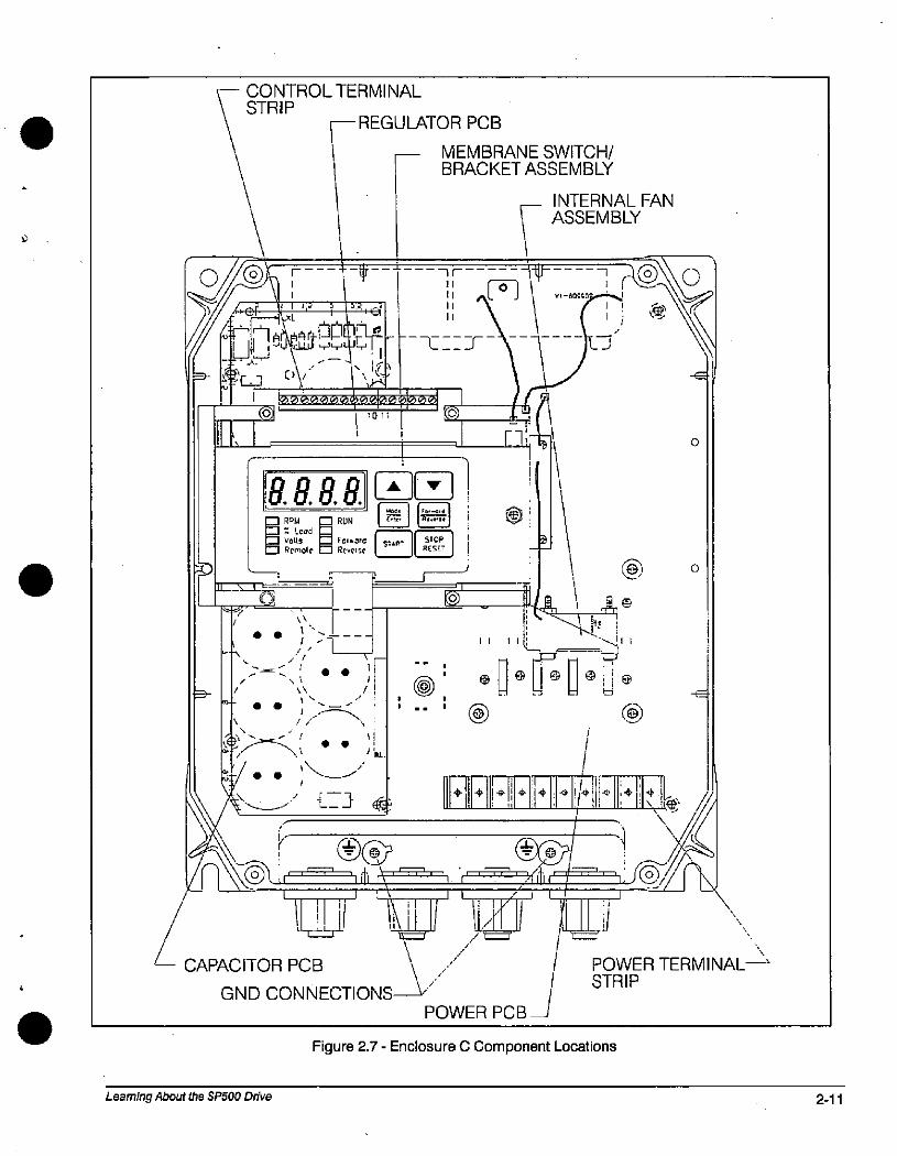
f
O/
CONTROLTERMINALSTRIP
--- REGULATOR PCB-- MEMBRANE SWITCH/
1 BRACKET ASSEMBLY_ INTERNAL FAN
ASSEMBLY@ 1 1* " --1-{11-' I f--6-7 11 ]-2011 4, J *-4 "1 i \,R i id 1111
7. tfa 1-€- fi
lU
1 1 d .i @ 1!.1 /f, 1 [-111 01 1
8.8.8.8. ZI I '1 jE RDM RUN ®Volts /2/ Fo,•aid 5'AR-
SIOP
Remole Cl Reverse RESET
--
0,----
\\
1 \\ 1
\
-1 /
\\ \44 1
¢
t
r
/ 11..
1 1 61.
//.
@
11
B
@ 0
1 1 1 ..dll
O - Lit O- fe e@
il ,
-LIJ 42 + + 1+1*14 *' 4 1+It & /\
It/1 Ll It \
CAPACITOR PCB POLR PCB_ 1 STRIPGND CONNECTIONS
POWER TERMINAL->
Learning About the SP500 Drive
Figure 2.7 - Enclosure C Component Locations
2-11
1
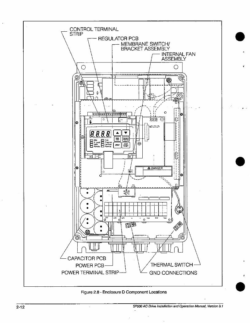
2-12
S
CONTROLTERMINAL7 STRIP
f\0 15 k \ 3
1 »0010.000 1
RARR-Z--33
MEMBs *1* 14ZZ}si---1-- 1
157-3
k:
6
(3«46'
CAPACITOR PCB
POWER PCB -
POWER TERMINAL STRIP
REGULATOR PCB
- MEMBRANE SWITCH/BRACKET ASSEMBLY
INTERNAL FAN
ASSEMBLY
E -
000.01 1 /
1__-2__-r-'
.% 4.
n-
' ,i///
\ 1/'11 0
i :fig.k ed--{71*::ss
@
A DANGER
t
/.
.-h
4." 11
0
lilli IN i-Ll i
0
r.--
e
1-.k.
%\
0*k
0
./ W A \
04/\\ 1-'r/1»JS
'-4 I lin_1j / THERMAL SWITCH
GND CONNECTIONS
Figure 2.8 - Enclosure D Component Locations
03
SP500 AC Drive Installation and Operation Manual, Version 3.1
.
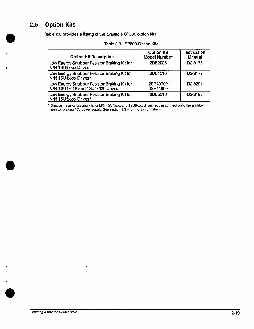
2.5 Option Kits
Table 2.3 provides a listing of the available SP500 option kits.
Table 2.3 - SP500 Option Kits
Option Kit Description
Low Energy Snubber Resistor Braking Kit forM/N 1 SU2xxxx Drives
Low Energy Snubber Resistor Braking Kit forM/N 1 SU4xxxx Drives*
Low Energy Snubber Resistor Braking Kit forM/N 1 SU4x015 and 1 SU4x020 Drives
Low Energy Snubber Resistor Braking Kit forM/N 1 SU5)000( Drives*
Option KitModel Number
2082005
2084010
2SR40700
2SR41800
2D85010
Instruction
Manual
D2-3178
D2-3179
D2-3291
D2-3180
* Snubber resistor braking kits for M/N 1 SU4)000 and 1 SU51000 drives require connection to the snubberresistor braking l OV power supply. See section 5.2.4 for more information.
Learning About the SP500 Drive 2-13

2-14 SP500 AC Drive installation and Operation Manual, Version 3.1
4
.
3.0 SP500 System Planning
. This chapter provides information that you must consider when planning an SP500 drive installation.Installation site, wiring, and motor application requirements are included.
A ATTENTION: Only qualified electrical personnel familiar with the construction andoperation of this equipment and the hazards involved should install, adjust, operate, orservice this equipment. Read and understand this manual and other applicablemanuals in their entirety before proceeding.
ATTENTION: Use of power correction capacitors on the output of the drive can result inerratic operation of the motor, nuisance tripping, and/or permanent damage to thedrive. Remove power correction capacitors before proceeding.
ATTENTION: The user is responsible for conforming with all applicable local, national,and international codes.
3.1 Installation Site Requirements
3.1.1
It is important to properly plan before installing an SP500 drive to ensure that the drive's environmentand operating conditions are satisfactory. Note that no devices are to be mounted behind the drive.This area must be kept clear of all control and power wiring. Read the following recommendationsbefore continuing with the drive installation.
Before deciding on an installation site, consider the following guidelines:
• The area chosen should allow the space required for proper airflow as specified in sections 3.1.1and 3.1.2.
• Do not install the drive above 1000 meters (3300 feet) without derating output power. For every91.4 meters (300 feet) above 1000 meters (3300 feet), derate the output current by 1 %.
• Verify that the drive location will meet the following environmental conditions:
Operating temperature (ambient): 0 to +40'C (32 to 104'F)
Storage temperature (ambient): - 40 to +65'C (-40 to +149'ID
Humidity: 5 to 95% (non-condensing)
• Verify that NEMA 1 drives can be kept clean, cool, and dry.
• Be sure NEMA 1 drives are located away from oil, coolants, or other airborne contaminants.
• Verify that the AC power distribution system meets the service conditions specified in table A.1.
Determining the Total Area Required for Installation
Figures 3.1 to 3.4 provide drive dimensions for enclosures A through D as an aid in calculating thetotal area required by the SP500 drives. Appendix A lists drive weights.
SP500 System Planning 3-1
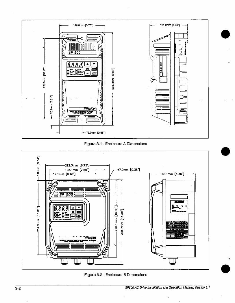
3-2
r
6
E
ii
%'ELEE
CO
CO
EEElo
0'1
:0
EE
146.Omm [5.751
'pe.90-251 1%='1 SP 5003/c 1*
,- I.ill
V/ SP 500 -
8.8.8.88 76 8,4-EZLEZ=
AV [
Rgil
1 f'df .,2-26:e.at"lijC j
222.3mm [8.751-198.1 mm [7.801
12.1 mm [0.481
73.Omm [2.88"]
P
EE
8N
Figure 3.1 - Enclosure A Dimensions
/
Il
088,8, GIE]
UU' Ull 11111
F07.Omm [0.281
Figure 3.2 - Enclosure B Dimensions
r
0
EE
C4
r
E
EE
A
0-'1
f \
121.9mm [4.80"1
,
,
,
11
1 "1'.1:Bili i i
d
U
160.1 mm [6.307
"31"lia
52-.
l'Ir
SP500 AC Drive Installation and Operation Manual, Version 3.1
-J
Am,=fil:i
i
.
.
a
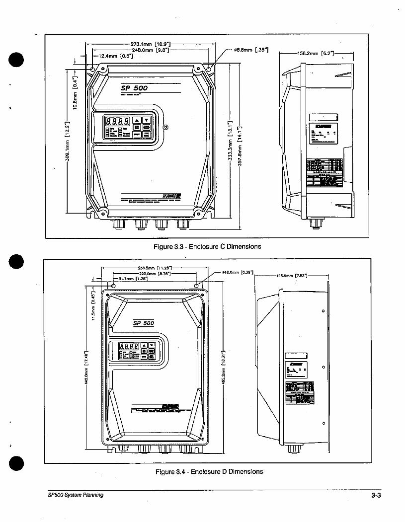
CN
EE-
1
EE00
0
K
278.1 mm [10.97248.Omm [9.81
- -12.4mm [0.5-1-7lzY'
SP 500
.
1 89.98 [El[El
J Mt@li = rf
=j roy'-W W 11111-11JU
E
F08.Bmm [.351
Figure 3.3 - Enclosure C Dimensions
286.5mm [11.287
223.Ornm [8.78731.7mm [1.251
61-r " .
1 1
SP500 System Planning
SP 500
Mit@,8.
// Ji
1 /41Lrl u' 11181 1111. , 1.11 n_1
F- 010.Omm [0.391
r.
CMi
EE/9
S
r
S
EE
/9
Figure 3.4 - Enclosure D Dimensions
158.2mm [6.27---11
a/54
-%/r
198.9mm [7.837 1
0
0
0
\uul -
i
-
3-3
1
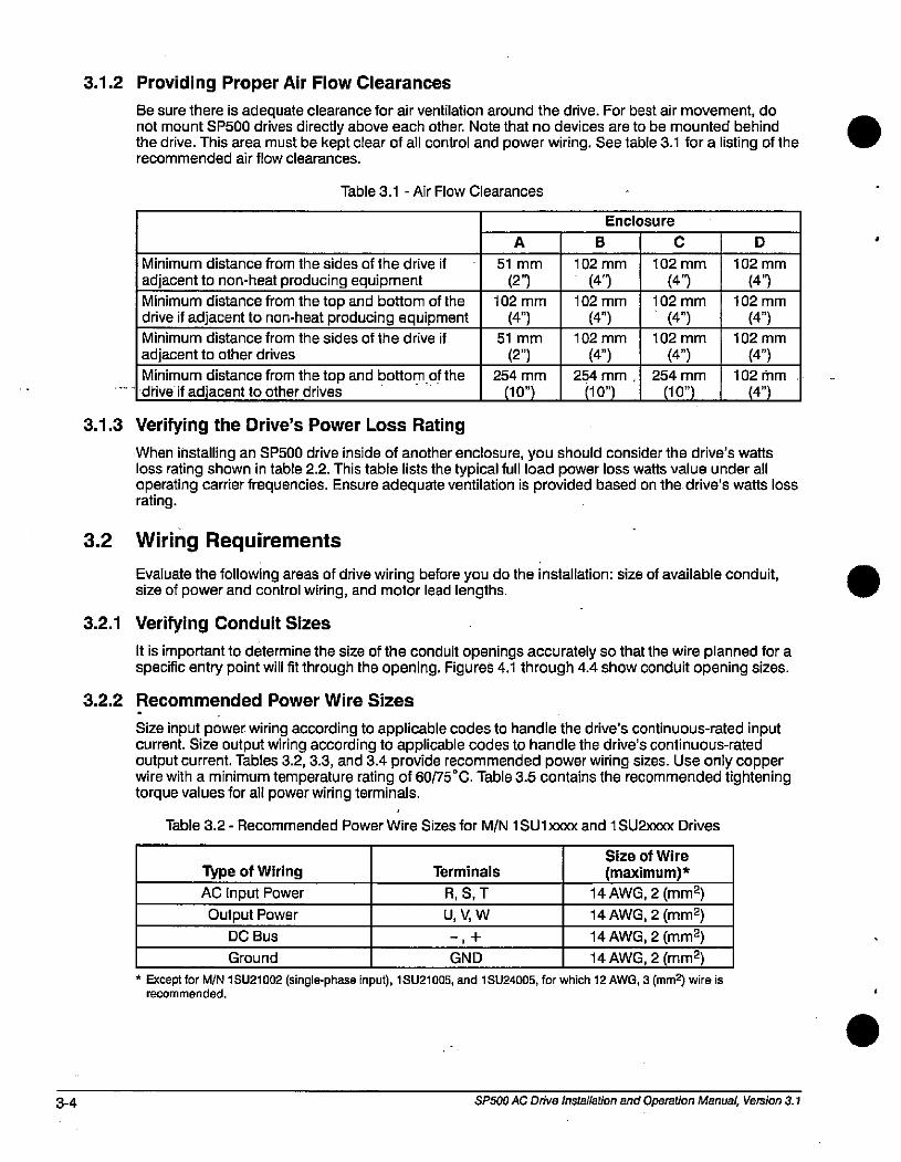
3-4
3.1.2 Providing Proper Air Flow Clearances
Be sure there is adequate clearance for air ventilation around the drive. For best air movement, donot mount SP500 drives directly above each other. Note that no devices are to be mounted behindthe drive. This area must be kept clear of all control and power wiring. See table 3.1 for a listing of therecommended air flow clearances.
Table 3.1 - Air Flow Clearances
Minimum distance from the sides of the drive if
adjacent to non-heat producing equipment
Minimum distance from the top and bottom of thedrive if adjacent to non-heat producing equipmentMinimum distance from the sides of the drive if
adjacent to other drives
Minimum distance from the top and bottom of thedrive if adjacent to other drives
3.1.3 Verifying the Drive's Power Loss Rating
A
51 mm
(27102 mm
51 mm
(2")254 mm
(10")
B
Enclosure
102 mm
(4'3
102 mm
(4")
102 mm
(4")
254 mm,
C
102 mm
(4')
102 mm
(4")102 mm
(4")254 mm
(10")
D
102 mm
(4")
102 mm
(4")
102 mm
(4")
102 mm
(47
When installing an SP500 drive inside of another enclosure, you should consider the drive's wattsloss rating shown in table 2.2. This table lists the typical full load power loss watts value under alloperating carrier frequencies. Ensure adequate ventilation is provided based on the drive's watts lossrating.
3.2 Wiring Requirements
3.2.1
Evaluate the following areas of drive wiring before you do the installation: size of available conduit, size of power and control wiring, and motor lead lengths.
Verifying Conduit Sizes
It is important to determine the size of the conduit openings accurately so that the wire planned for aspecific entry point will fit through the opening. Figures 4.1 through 4.4 show conduit opening sizes.
3.2.2 Recommended Power Wire Sizes
Size input power wiring according to applicable codes to handle the drive's continuous-rated inputcurrent. Size output wiring according to applicable codes to handle the drive's continuous-ratedoutput current. Tables 3.2,3.3, and 3.4 provide recommended power wiring sizes. Use only copperwire with a minimum temperature rating of 60/75'C. Table 3.5 contains the recommended tighteningtorque values for all power wiring terminals.
Table 3.2 - Recommended Power Wire Sizes for M/N 1 SUl )000 and 1 SU2xxxx Drives
Type of Wiring
AC Input Power
Output Power
DC Bus
Terminals
R, S, T
U, V, W
GND
Size of Wire
(maximum)*
14 AWG, 2 (mm2)
14 AWG, 2 (mm2)14 AWG, 2 (mm2)
Ground 14 AWG, 2 (mm2)
* Except for M/N 1 SU21002 (single-phase input), 1 SU21005, and 1 SU24005, for which 12 AWG, 3 (mm2) wire isrecommended.
SP500 AC Drive Installation and Operation Manual, Version 3.1
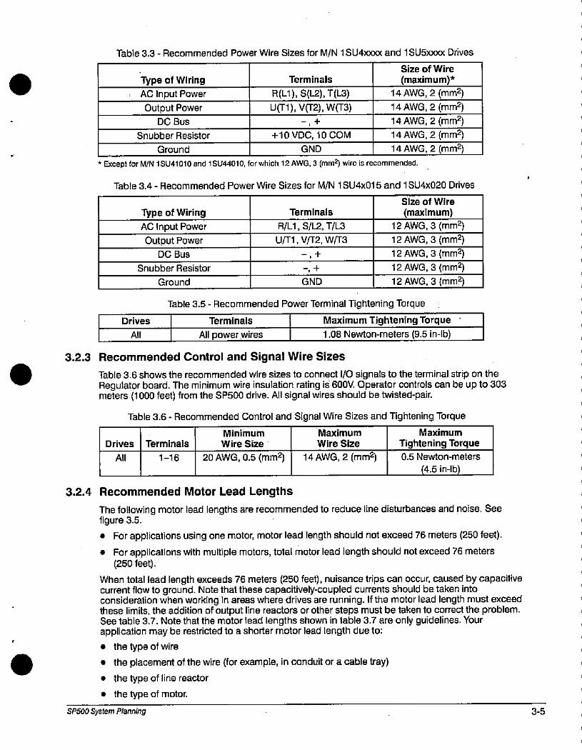
Table 3.3 - Recommended Power Wire Sizes for M/N 1 SU4)000( and 1 SU5xxxx Drives
Type of Wiring
AC Input Power
Output Power
DC Bus
Snubber Resistor
Ground
Terminals
R(Ll),S(1-2),T(L3)
l.151),V(12),Wrr3)
+10 VDC, 10 COM
GND
Size of Wire
(maximum)*
14 AWG, 2 (mm2)
14 AWG, 2 (mm2)14 AWG, 2 (mm2)14 AWG, 2 (mm2)
14 AWG, 2 (mm2)
* Except for M/N 1 SU41010 and 1 SU44010, for which 12 AWG, 3 (mm5 wire is recommended.
Table 3.4 - Recommended Power Wire Sizes for M/N 1 SU4x015 and 1 SU4x020 Drives
Drives
All
Type of Wiring
AC Input Power
Output PowerDC Bus
Snubber Resistor
Ground
Terminals
R/Ll, S/L.2, T/L3
U/Tl, V/T2, WF3
GND
Size of Wire
(maximum)
12 AWG, 3 (mm2)
12 AWG, 3 (min2)
12 AWG, 3 (mr,12)12 AWG, 3 (mm2)
12 AWG, 3 (mm2)
Table 3.5 - Recommended Power Terminal Tightening Torque
Terminals
All power wires
Maximum Tightening Torque
1.08 Newton-meters (9.5 in-lb)
3.2.3 Recommended Control and Signal Wire Sizes
Table 3.6 shows the recommended wire sizes to connect 1/0 signals to the terminal strip on theRegulator board. The minimum wire insulation rating is 600V. Operator controls can be up to 303meters (1000 feet) from the SP500 drive. All signal wires should be twisted-pair.
Table 3.6 - Recommended Control and Signal Wire Sizes and Tightening Torque
Drives
All
Terminals
1-16
Minimum
Wire Size
20 AWG, 0.5 (mm2)
3.2.4 Recommended Motor Lead Lengths
Maximum
Wire Size
14 AWG, 2 (mm2)
Maximum
Tightening Torque
0.5 Newton-meters
(4.5 in-lb)
The following motor lead lengths are recommended to reduce line disturbances and noise. Seefigure 3.5.
• For applications using one motor, motor lead length should not exceed 76 meters (250 feet).
• For applications with multiple motors, total motor lead length should not exceed 76 meters(250 feet).
When total lead length exceeds 76 meters (250 feet), nuisance trips can occur, caused by capacitivecurrent flow to ground. Note that these capacitively-coupled currents should be taken intoconsideration when working in areas where drives are running. If the motor lead length must exceedthese limits, the addition of output line reactors or other steps must be taken to correct the problem.See table 3.7. Note that the motor lead lengths shown in table 3.7 are only guidelines. Yourapplication may be restricted to a shorter motor lead length due to:
• the type of wire
• the placement of the wire (for example, in conduit or a cable tray)
• the type of line reactor
• the type of motor.
SP500 System Planning 3-5
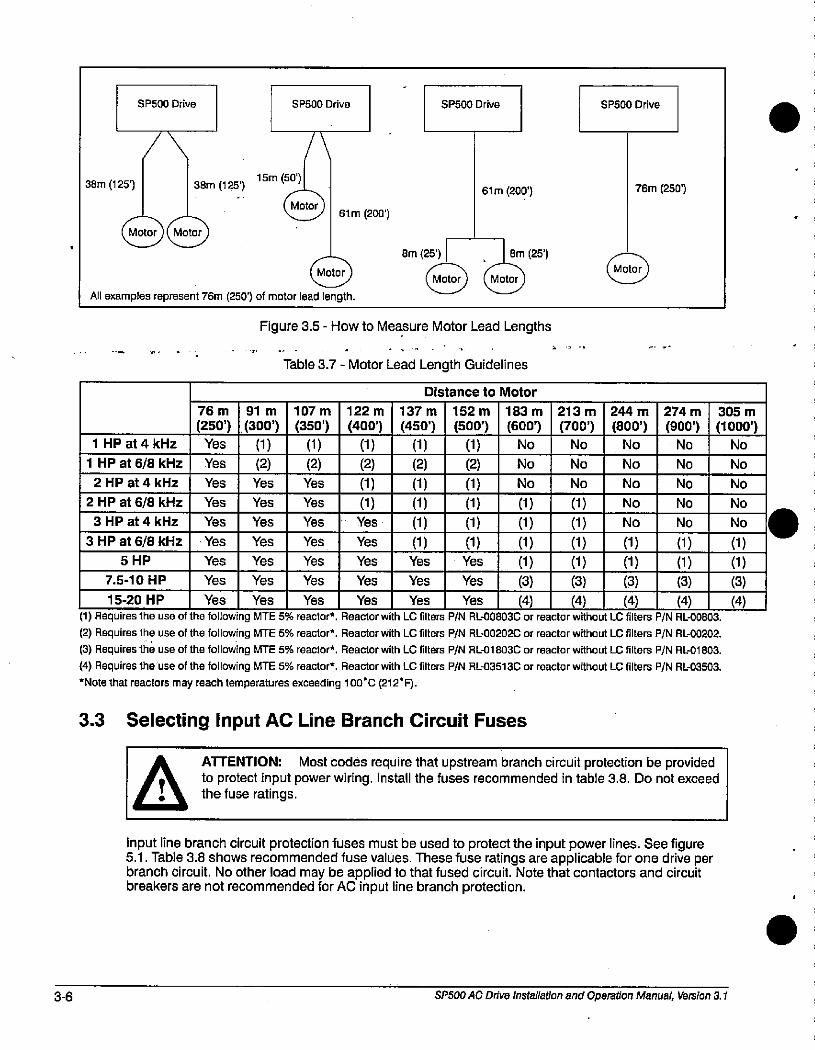
3-6
38m (125')
SP500 Drive
Motor Motor
38m (125115m (50')
SP500 Drive
Motor
SP500 Drive
61 m (200')
107m
(350')
(1)
(2)
\
Motor
61 m (200')
All examples represent 76m (250') of motor lead length.
1 HP at 4 kHz
76 m
(250')Yes
91 m
(300')
(1)
(2)
Bm (25') Bm (251( Motor ) ( Motor )
Figure 3.5 - How to Measure Motor Lead Lengths
Table 3.7 - Motor Lead Length Guidelines
122 m
(400')(1)
137 m
(450')
(1)
Distance to Motor
152 m
(500')
(1)
183 m
(600')
NO
213 m
(700')No
SP500 Drive
Motor
244 m
(800')
No
76m (250')
274 m
(900')
NO
1 HP at 6/8 kHz Yes (2) (2) (2) No No No No
2 HP at 4 kHz Yes Yes Yes (1) (1) (1) No No No No
2 HP at 6/8 kHz Yes Yes Yes (1) (1) (1) ' (1) (1) No No
3 HP at 4 kHz Yes Yes Yes Yes (1) (1) (1) (1) No No
3 HP at 6/8 kHz Yes Yes Yes Yes (1) (1) (1) (1) (1) (1)5 HP Yes Yes Yes Yes Yes Yes (1) (1) (1) (1)
7.5-10 HP Yes Yes Yes Yes Yes Yes (3) (3) (3) (3)15-20 H P Yes Yes Yes Yes Yes Yes (4) (4) (4) (4)
(1) Requires the use of the following MTE 5% reactor*. Reactor with LC filters P/N RL-00803(3 or reactor without LC filters P/N RL-00803.
(2) Requires the use of the following MTE 5% reactor*. Reactor with LC filters P/N R!:00202C or reactor without LC filters P/N RL-00202.
(3) Requires the use of the following MTE 5% reactor*. Reactor with LC filters P/N R601803C or reactor without LC filters P/N AL-01803.
(4) Requires the use of the following MTE 5% reactor*. Reactor with EC filters P/N Rl-03513C or reactor without LC filters P/N RL-03503.*Note that reactors may reach temperatures exceeding 100'C (212'F).
3.3 Selecting Input AC Line Branch Circuit Fuses
ATTENTION: Most codes require that upstream branch circuit protection be provided
0 the fuse ratings.to protect input power wiring. Install the fuses recommended in table 3.8. Do not exceed
Input line branch circuit protection fuses must be used to protect the input power lines. See figure5.1. Table 3.8 shows recommended fuse values. These fuse ratings are applicable for one drive perbranch circuit. No other load may be applied to that fused circuit. Note that contactors and circuitbreakers are not recommended for AC input line branch protection.
SP500 AC Drive Installation and Operation Manual, Version 3.1
305 m
(1000')No
(1)
(1)
(3)
(4)
No
No
No
No
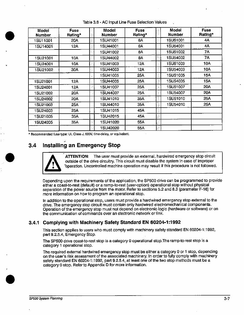
Model
Number
1 SU11001
1 SU14001
1 SU21001
1 SU24001
1 SU21002
1 SU21001
1 SU24001
1 SU21002
1 SU24002
1 SU21003
1 SU24003
1 SU21005
1 SU24005
Fuse
Rating*
20A
12A
1 SU41001
1 SU41007
3.4 Installing an Emergency Stop
10A
10A
30A
12A
12A
20A
20A
25A
25A
35A
35A
Table 3.8 - AC Input Line Fuse Selection Values
Model
Number
1 SU44001
1 SU41002
1 SU44002
1 SU41003
1 SU44003
1 SU41005
1 SU44005
1 SU44007
1 SU41010
1 SU44010
1 SU41015
1 SU42015
1 SU41020
1 SU42020
* Recommended fuse type: UL Class J, 600V, time-delay, or equivalent.
3.4.1
Fuse
Rating*
6A
6A
8A
8A
1 SU54001
1 SU54010
ATTENTION: The user must provide an external, hardwired emergency stop circuitoutside of the drive circuitry. This circuit must disable the system in case of improper
-operation. Uncontrolled machine operation may result if this procedure is not followed..
12A
12A
25A
25A
25A
25A
35A
35A
45A
45A
55A
55A
Model
Number
1 SU51001
1 SU51002
1 SU54002
1 SU51003
1 SU54003
1 SU51005
1 SU54005
1 SU51007
1 SU54007
1 SU51010
Fuse
Rating*
4A
4A
7A
7A
10A
10A
15A
15A
20A
20A
25A
25A
Depending upon the requirements of the application, the SP500 drive can be programmed to provideeither a coast-to-rest (default) or a ramp-to-rest (user-option) operational stop without physicalseparation of the power source from the motor. Refer to sections 5.2 and 8.3 (parameter F-16) formore information on how to program an operational stop.
In addition to the operational stop, users must provide a hardwired emergency stop external to thedrive. The emergency stop circuit must contain only hardwired electromechanical componants.Operation of the emergency stop must not depend on electronic logic (hardware or software) or onthe communication of commands over an electronic network or link.
Complying with Machinery Safety Standard EN 60204-1:1992
This section applies to users who must comply with machinery safety standard EN 60204-1:1992,part 9.2.5.4, Emergency Stop.
The SP500 drive coast-to-rest stop is a category 0 operational stop.The ramp-to-rest stop is acategory 1 operational stop.
The required external hardwired emergency stop must be either a category 0 or 1 stop, dependingon the user's risk assessment of the associated machinery. In order to fully comply with machinerysafety standard EN 60204-1:1992, part 9.2.5.4, at least one of the two stop methods must be acategory 0 stop. Refer to Appendix D for more information.
SP500 System Planning 3-7
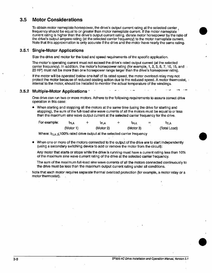
3-8
3.5 Motor Considerations
To obtain motor nameplate horsepower, the drive's output current rating at the selected carrier ,frequency should be equal to or greater than motor nameplate current. If the motor nameplate 'current rating is higher than the drive's output current rating, derate motor horsepower by the ratio ofthe drive's output ampere rating (at the selected carrier frequency) to the motor nameplate current.Note that this approximation is only accurate if the drive and the motor have nearly the same rating.
3.5.1 Single-Motor Applications
Size the drive and motor for the load and speed requirements of the specific application.
The motor's operating current must not exceed the drive's rated output current (at the selectedcarrier frequency). In addition, the motor's horsepower rating (for example, 1,2,3,5,7,10,15, and20 HP) must not be more than one horsepower range larger than the drive's horsepower rating.
If the motor will be operated below one-half of its rated speed, the motor overload relay may notprotect the motor because of reduced cooling action due to the reduced speed. A motor thermostat,internal to the motor, should be installed to monitor the actual temperature of the windings.
3.5.2 Multiple-Motor Applications -
One drive can run two or more motors. Adhere to the following requirements to assure correct driveoperation in this case:
• When starting and stopping all the motors at the same time (using the drive for starting andstopping), the sum of the full-load sine wave currents of all the motors must be equal to or lessthan the maximum sine wave output current at the selected carrier frequency for the drive.
For example: |FLA + |FLA + |FLA
(Motor 1) (Motor 2) (Motor 3)
Where: ITLA 5100% rated drive output at the selected carrier frequency
|TLA
(Total Load)
• When one or more of the motors connected to the output of the drive are to start independently(using a secondary switching device to add or remove the motor from the circuit):
Any motor that starts or stops while the drive is running must have a current rating less than 10%of the maximum sine wave current rating of the drive at the selected carrier frequency.
The sum of the maximum full-load sine wave currents of all the motors connected continuously tothe drive must be less than the maximum output current rating under all conditions.
Note that each motor requires separate thermal overload protection (for example, a motor relay or amotor thermostat).
4
SP500 AC Drive installation and Operation Manual, Version 3.1
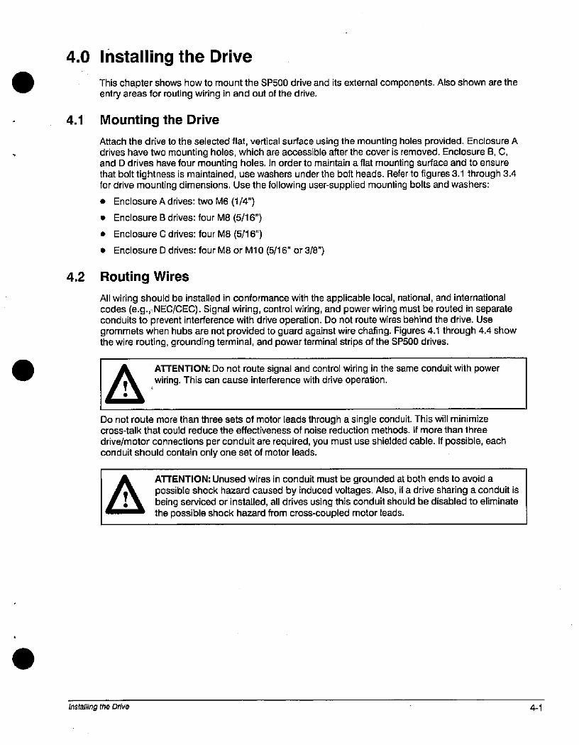
4.0 installing the Drive
. This chapter shows how to mount the SP500 drive and its external components. Also shown are theentry areas for routing wiring in and out of the drive.
4.1 Mounting the Drive
Attach the drive to the selected flat, vertical surface using the mounting holes provided. Enclosure Adrives have two mounting holes, which are accessible after the cover is removed. Enclosure B, C,and D drives have four mounting holes. In order to maintain a flat mounting surface and to ensurethat bolt tightness is maintained, use washers under the bolt heads. Refer to figures 3.1 through 3.4for drive mounting dimensions. Use the following user-supplied mounting bolts and washers:
• Enclosure A drives: two M6 (1/4")
• Enclosure B drives: four MB (5/16")
• Enclosure C drives: four M8 (5/16")
• Enclosure D drives: four M8 or M10 (5/16" or 3/8")
4.2 Routing Wires
All wiring should be installed in conformance with the applicable local, national, and internationalcodes (e.g., NEC/CEEC). Signal wiring, control wiring, and power wiring must be routed in separateconduits to prevent interference with drive operation. Do not route wires behind the drive. Usegrommets when hubs are not provided to guard against wire chafing. Figures 4.1 through 4.4 showthe wire routing, grounding terminal, and power terminal strips of the SP500 drives.
ATTENTION: Do not route signal and control wiring in the same conduit with powerwiring. This can cause interference with drive operation.
Do not route more than three sets of motor leads through a single conduit. This will minimizecross-talk that could reduce the effectiveness of noise reduction methods. If more than three
drive/motor connections per conduit are required, you must use shielded cable. If possible, eachconduit should contain only one set of motor leads.
ATTENTION: Unused wires in conduit must be grounded at both ends to avoid apossible shock hazard caused by induced voltages. Also, if a drive sharing a conduit is
, 0 being serviced or installed, all drives using this conduit should be disabled to eliminate= the possible shock hazard from cross-coupled motor leads.
installing the Drive 4-1
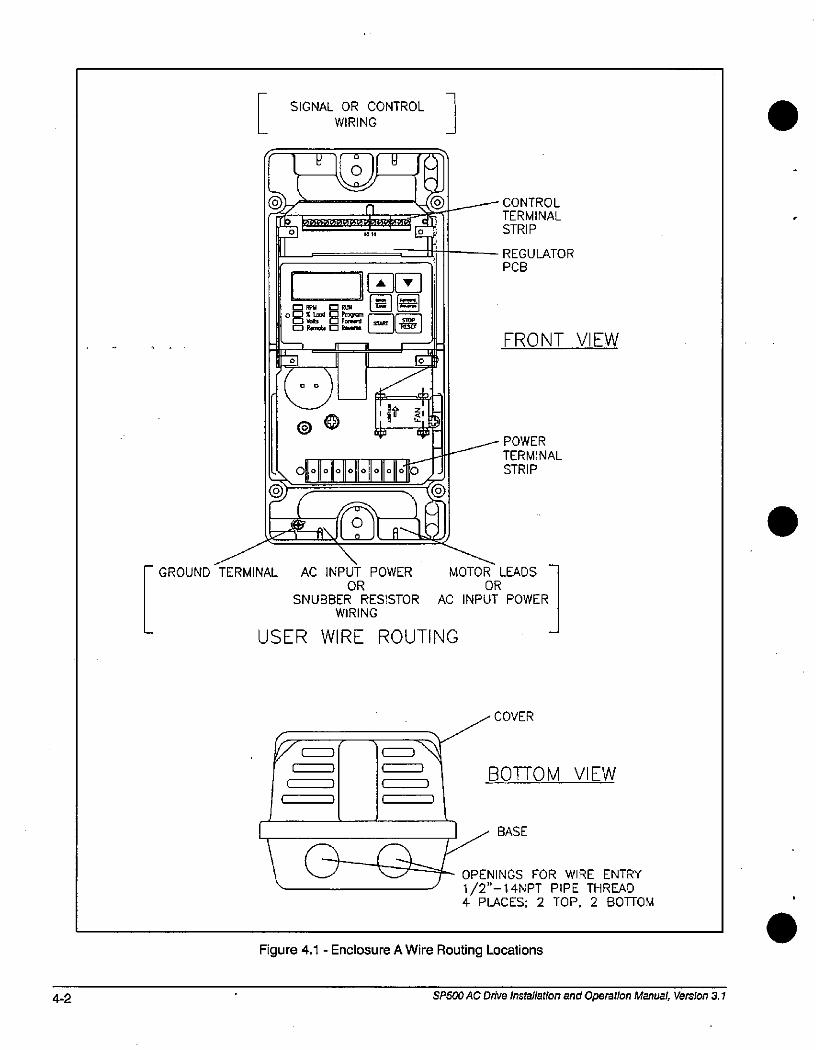
4-2
GROUND TERMINAL
SIGNAL OR CONTROL WIRING
- I Wel W ieL0 15%1 0 Ful
°BUr EB.0 Remote 0 Rm,ne
tE ' 1
Coo)
@e
A V
IE =1
4 00 0000
*-f---5D f RN 9 1 A-4
AC INPUT POWEROR
SNUBBER RESISTOR
WIRING
USER WIRE ROUTING
C )
)
( 1
,
* 3
n
100=1=00*0*04- -fir
1 Ef?
*=t4 4
0000
0
Figure 4.1 - Enclosure A Wire Routing Locations
0
CONTROL
TERMINAL
STRIP
REGULATOR
PCB
FRONT VIEW
POWER
TERMINAL
STRIP
MOTOR LEADS
OR
AC INPUT POWER
COVER
BOTTOM VIEW
BASE
OPENINGS FOR WIRE ENTRY
1 /2 - 14NPT PIPE THREAD4 PLACES; 2 TOP, 2 BOTTOM
SP500 AC Drive installation and Operation Manual, Version 3.1
.
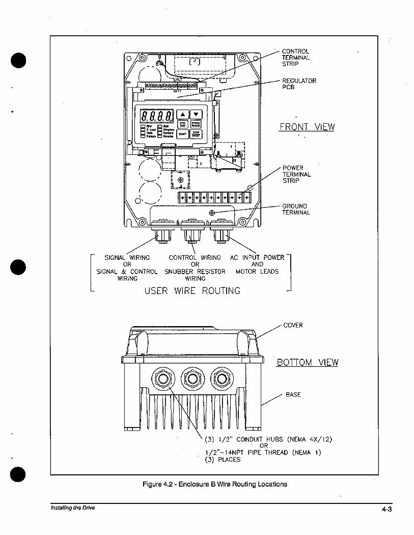
Installing the Drive
0@ 4
6 (-3 #
+ +1 ,
CONTROL
TERMINALSTRIP
REGULATOR
PCB
411 @LJ
tnAr
1119'r
V
1- O- 1 5 1121
PF==a===[3=41 '1,1-23]LE) r7 - '=7, 50 1 1)1-=» / -hzz _[32__LC9]
n@
# @ 11
++ + +
0 - 'Imi
+ +
r--'
++
.e
@El
SIGNAL WIRING CONTROL WIRING AC INPUT POWER
OR OR AND
SIGNAL & CONTROL SNUBBER RESISTOR MOTOR LEADS
WIRING WIRING
USER WIRE ROUTING
1 lilli 1rj Q U u M,4& 1 D V.fu
FRONT VIEW
POWER
TERMINAL
STRIP
GROUND
TERMINAL
COVER
BOTTOM VIEW
BASE
(3) 1/2 CONDUIT HUBS (NEMA 4X/12)OR
1/2"-14NPT PIPE THREAD (NEMA 1)(3) PLACES
Figure 4.2 - Enclosure B Wire Routing Locations
4-3
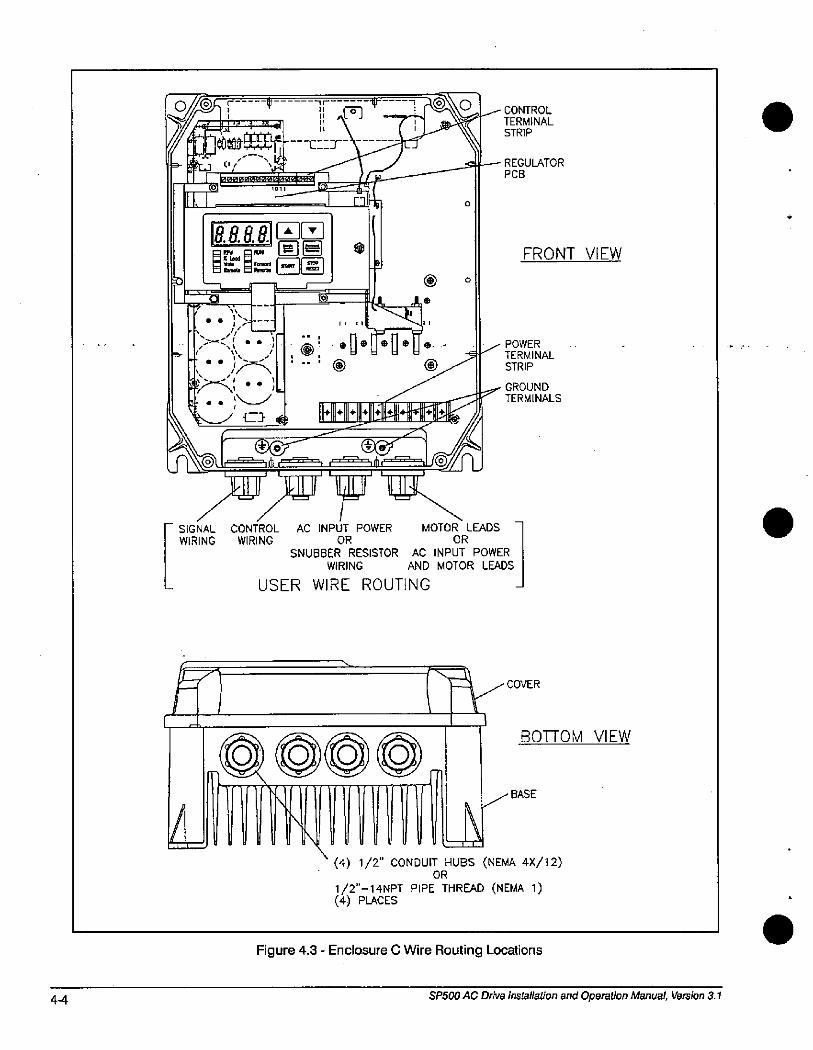
4-4
L.
E-
, -9- *63 c, ''*-*&3:T IM/6.2£im*'*EM
1011
E-1 _01
8.8.88 A],1
=El= - 11 =
-1 0-7¥UZZZ--.
- 7 ; .1-
e
-Ir *----3 -1(fE011 *->tr
L__J J
B
® 0
„ „ IEZEzl,,
% 7
--- - ---f®®s/ @®r '@1 --=h'11 1-==4- , 1-lili /.-r=:;1'«
»f/»'p *\SIGNAL
WIRING
0
CONTROL
TERMINAL
STRIP
REGULATORPCB
FRONT VIEW
-,, POWERTERMINAL
STRIP
GROUNDTERMINALS
CONTROL AC INPUT POWER MOTOR LEADS
WIRING OR OR
SNUBBER RESISTOR AC INPUT POWER
WIRING AND MOTOR LEADS
USER WIRE ROUTING -
.-COVER
1 1
000*BOTTOM VIEW
BASE
(4) 1/2" CONDUIT HUBS (NEMA 4X/12)OR
1/2"-14NPT PIPE THREAD (NEMA 1)(4) PLACES
Figure 4.3 - Enclosure C Wire Routing Locations
SP500 AC Drive installation and Operation Manual, Version 3.1
.
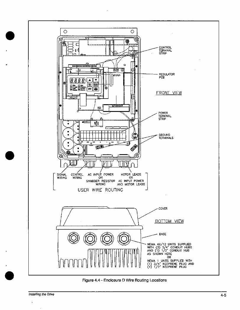
Installing the Drive
f
0
SL
.E{El cIR:':-{
-
mr
L -11-----
YE>*
- *%:0 *111.1 ..0».-9.noo#*01 1 /
0, , -lo '- oIF I n
IllI 8.88.8 'A li! 1 --= r i--ti
MIME{Z][*] 1 b 1-oR_1-I- 1 111-1 j E- 1 0
1
81 I-7
.r
6 .C===E * 3 1 1/--- O- ISi*k_-:L_ 200F*-Trlb f-=--7 -7
1»»' »lj' 1*1-1SIGNAL CONTROL AC INPUT POWER MOTOR LEADS
WIRING WIRING OR OR
SNUBBER RESISTOR AC INPUT POWER
WIRING AND MOTORLEADS
USER WIRE ROUTING
UUuUUULJL L
Figure 4.4 - Enclosure D Wire Routing Locations
0
0
il
CONTROL
TERMINALSTRIP
- REGULATOR
PCB
FRONT VIEW
POWER
TERMINALSTRIP
GROUND
TERMINALS
COVER
OTTOM VIEW
- BASE
- NEMA 4)(/12 UNITS SUPPUEDWITH <3) 3/4" CONDUIT HUBSAND (1) 1/2" CONDUIT HUBAS SHOWN HERE
ORNEMA 1 UNITS SUPPLIED WITH
(1) 3/4" NEOPRENE PLUG AND(1) 1/2" NEOPRENE PLUG
4-5
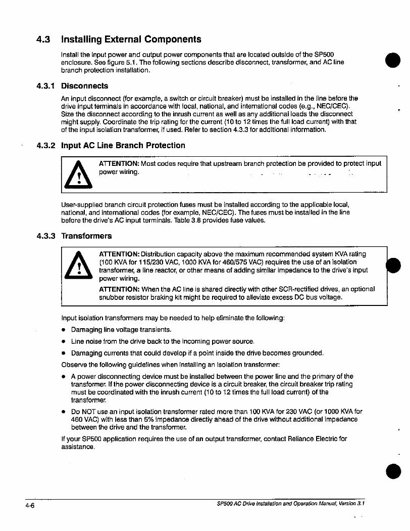
4-6
4.3
4.3.1
Installing External Components
Install the input power and output power components that are located outside of the SP500enclosure. See figure 5.1. The following sections describe disconnect, transformer, and AC line branch protection installation.
Disconnects
An input disconnect (for example, a switch or circuit breaker) must be installed in the line before thedrive input terminals in accordance with local, national, and international codes (e.g., NEC/CEC).Size the disconnect according to the inrush current as well as any additional loads the disconnectmight supply. Coordinate the trip rating for the current (10 to 12 times the full load current) with thatof the input isolation transformer, if used. Refer to section 4.3.3 for additional information.
4.3.2 Input AC Line Branch Protection
A ATTENTION: Most codes require that upstream branch protection be provided to protect input
power wiring.
User-supplied branch circuit protection fuses must be installed according to the applicable local,national, and international codes (for example, NEC/CEEC). The fuses must be installed in the linebefore the drive's AC input terminals. Table 3.8 provides fuse values.
4.3.3 Transformers
aATTENTION: Distribution capacity above the maximum recommended system KVA rating(100 KVA for 115/230 VAC, 1000 KVA for 460/575 VAC) requires the use of an isolationtransformer, a line reactor, or other means of adding similar impedance to the drive's inputpower wiring.
ATTENTION: When the AC line is shared directly with other SCR-rectified drives, an optionalsnubber resistor braking kit might be required to alleviate excess DC bus voltage.
Input isolation transformers may be needed to help eliminate the following:
• Damaging line voltage transients.
• Line noise from the drive back to the incoming power source.
• Damaging currents that could develop if a point inside the drive becomes grounded.
Observe the following guidelines when installing an isolation transformer:
• A power disconnecting device must be installed between the power line and the primary of thetransformer. If the power disconnecting device is a circuit breaker, the circuit breaker trip ratingmust be coordinated with the inrush current (10 to 12 times the full load current) of thetransformer.
Do NOT use an input isolation transformer rated more than 100 KVA for 230 VAC (or 1000 KVA for460 VAC) with less than 5% impedance directly ahead of the drive without additional impedancebetween the drive and the transformer.
If your SP500 application requires the use of an output transformer, contact Reliance Electric forassistance.
SP500 AC Drive Installation and Operation Manual, Version 3.1
r
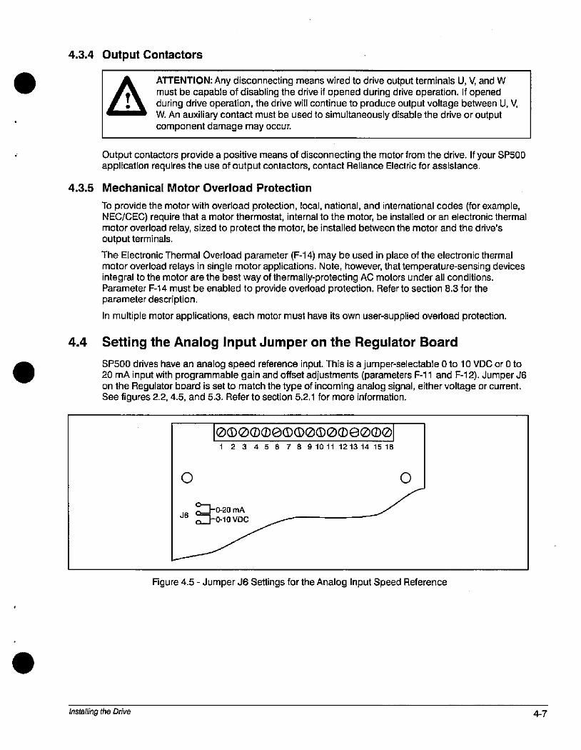
4.3.4 Output Contactors
ATTENTION: Any disconnecting means wired to drive output terminals U, V, and WA, must be capable of disabling the drive if opened during drive operation. If openedduring drive operation, the drive will continue to produce output voltage between U, V,
I W. An auxiliary contact must be used to simultaneously disable the drive or outputcomponent damage may occur.
Output contactors provide a positive means of disconnecting the motor from the drive. If your SP500application requires the use of output contactors, contact Reliance Electric for assistance.
4.3.5 Mechanical Motor Overload Protection
To provide the motor with overload protection, local, national, and international codes (for example,NEC/CEC) require that a motor thermostat, internal to the motor, be installed or an electronic thermalmotor overload relay, sized to protect the motor, be installed between the motor and the drive'soutput terminals.
The Electronic Thermal Overload parameter (F-14) may be used in place of the electronic thermalmotor overload relays in single motor applications. Note, however, that temperature-sensing devicesintegral to the motor are the best way of thermally-protecting AC motors under all conditions.Parameter F-14 must be enabled to provide overload protection. Refer to section 8.3 for theparameter description.
In multiple motor applications, each motor must have its own user-supplied overload protection.
4.4 Setting the Analog Input Jumper on the Regulator Board
SP500 drives have an analog speed reference input. This is a jumper-selectable 0 to 10 VDC or 0 to20 mA input with programmable gain and offset adjustments (parameters F-11 and F-12). Jumper J6on the Regulator board is set to match the type of incoming analog signal, either voltage or current.See figures 2.2,4.5, and 5.3. Refer to section 5.2.1 for more information.
installing the Drive
0
0000000*000*e000
1 2 3 4 5 6 7 8 91011 121314 1516
0-0.20 mAn tO-10 VDC
Figure 4.5 - Jumper J6 Settings for the Analog input Speed Reference
0
4-7
4-8
4.5
Use the following procedure to set jumper J6:
A ATTENTION: DC bus capacitors retain hazardous voltages after input power has been disconnected. After disconnecting input power, wait five (5) minutes for the DC bus
/ 0 capacitors to discharge and then check the voltage with a voltmeter to ensure the DCI--Il bus capacitors are discharged before touching any internal components.
Step 1. Turn off and lock out input power. Wait five minutes.
Step 2. Remove the cover from the drive by unscrewing the four cover screws.
Step 3. Verify that the DC bus voltage is zero by following the procedure in section 9.1.
Step 4. Locate jumper J6 on the Regulator board. Refer to figure 2.3.
Step 5. Move the jumper to the desired setting as shown in figure 4.5.
Step 6. Reattach the cover.
Step 7. Reapply input power.
Step 8. Verify that parameters F-11 and F-12 are correctly set.
Note that if the setting of jumper J6 is changed, the regulator software will not automatically detect it.Verify that parameters F-11 (gain) and F-12 (offset) are set correctly before starting the drive.
Preparing the Motor
Follow these guidelines when preparing to install the motor:
• Verify that the motor is the appropriate size to use with the drive.
• Verify that the total motor lead length does not exceed the values given in section 3.2.4.
• Follow the instructions in the motor instruction manual when installing the motor.
• Verify that the motor is properly aligned with the application's machine to minimize unnecessarymotor loading due to shaft misalignment.
• If the motor is accessible when it is running, install a protective guard around all exposed rotatingparts.
SP500 AC Drive installation and Operation Manual, Version 3.1
5.0 Wiring the Drive
. This chapter describes how to wire the SP500 drive including: input wiring, control and signal wiring,output wiring, and grounding.
5.1 Input Power Wiring
Use the following steps to connect AC input power to the drive:
Step 1. Verify that the AC input power to the drive corresponds to the drive's nameplate voltage andfrequency
Step 2. Wire the AC input power leads by routing them according to the type of enclosure. Seefigures 4.1 through 4.4. See tables 3.2 through 3.4 for recommended wire sizes.
A ATTENTION: Do not route signal and control wiring with power wiring in the same
conduit.This can cause interference with drive operation.
Step 3.
Step 4.
Wiring the Drive
Connect the AC input power leads to terminals R,S,T on the power terminal strip. Seefigure 5.1.
Tighten terminals R and S (single-phase input) or terminals R,S,T (three-phase input) to theproper torque as shown in table 3.5.
5-1

5-2
User-
Supplied
User-
Supplied
AC InputVoltage
GND
TITyManual
Disconnect SffFuse
Motor Overload
Relay (Optional ifElectronic
Overload is Used)
R/Ll S/l-2 T/1-3
4
Ugl V/2 W/3
M
SP500Drive
GND
n
GND
U-L
Figure 5.1 - Typical Electrical Connections
SP500 AC Drive installation and Operation Manual, Version 3.1
.
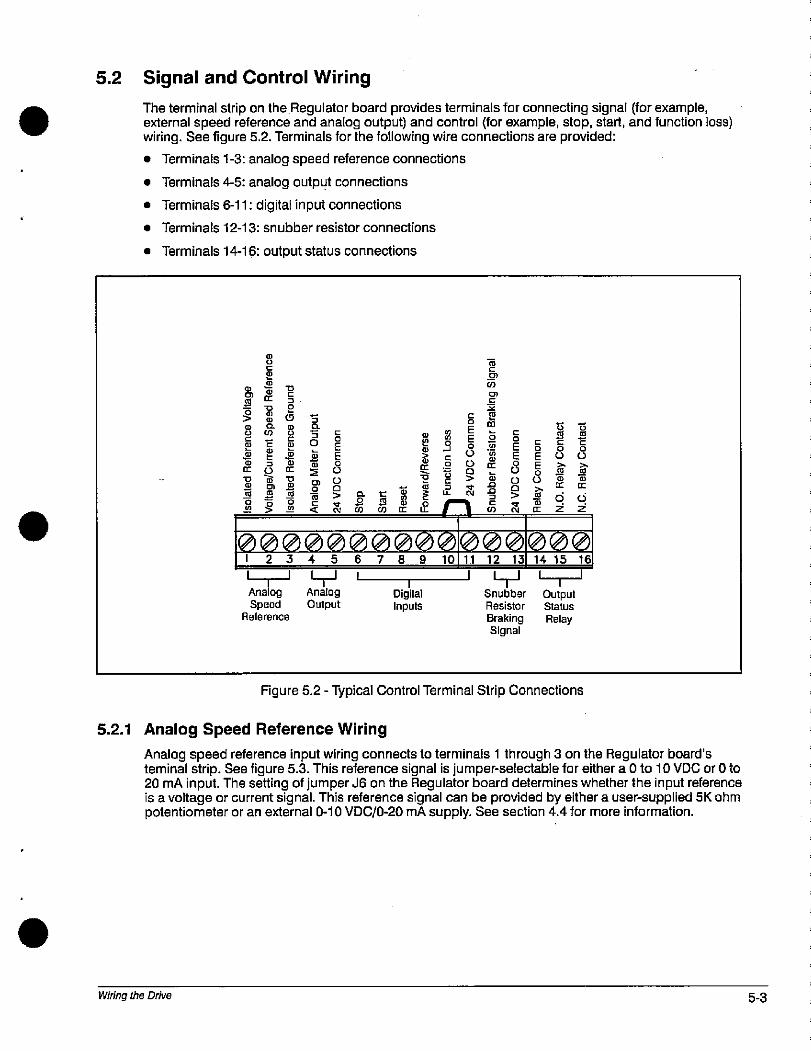
5.2 Signal and Control Wiring
&
2
8
The terminal strip on the Regulator board provides terminals for connecting signal (for example,external speed reference and analog output) and control (for example, stop, start, and function loss)wiring. See figure 5.2. Terminals for the following wire connections are provided:
• Terminals 1-3: analog speed reference connections
• Terminals 4-5: analog output connections
• Terminals 6-11: digital input connections
• Terminals 12-13: snubber resistor connections
• Terminals 14-16: output status connections
8
2 e
- C
5 25 10 m
5 2R O
5 E
SCL
3E E
80
9 n v E0
&522
CD
2
gw E
5 01 9
H
i15
E)
1/
0000000000000000678910 14 15 16123
1 1
Analog
SpeedReference
4 5
LJ I
AnalogOutput
Digital
Inputs
11 12 13
Snubber
Resistor
BrakingSignal
T E
S E5 82 0n
gEE0
0
S5
g0
0
i
OutputStatus
Relay
Figure 5.2 - Typical Control Terminal Strip Connections
5.2.1 Analog Speed Reference Wiring
g0
CE
0
Z
Analog speed reference input wiring connects to terminals 1 through 3 on the Regulator board'steminal strip. See figure 5.3. This reference signal is jumper-selectable for either a 0 to 10 VDC or 0 to20 mA input. The setting of jumper J6 on the Regulator board determines whether the input referenceis a voltage or current signal. This reference signal can be provided by either a user-supplied SK ohmpotentiometer or an external 0-10 VDC/0-20 mA supply. See section 4.4 for more information.
Wiring the Drive 5-3
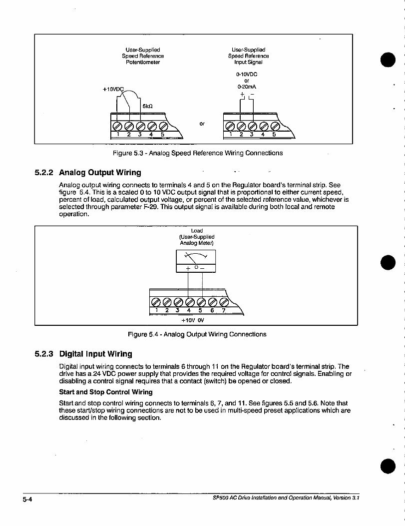
5-4
+10VD
User-SuppliedSpeed Reference
Potentiometer
51<Q
0000012345
or
User-SuppliedSpeed Reference
Input Signal
0-10VDC
or
0-20mA
L
0000012345
Figure 5.3 - Analog Speed Reference Wiring Connections
5.2.2 Analog Output Wiring
\
Analog output wiring connects to terminals 4 and 5 on the Regulator board's terminal strip. Seefigure 5.4. This is a scaled 0 to 10 VDC output signal that is proportional to either current speed,percent of load, calculated output voltage, or percent of the selected reference value, whichever isselected through parameter F-29. This output signal is available during both local and remoteoperation.
5.2.3 Digital Input Wiring
Load
(User-SuppliedAnalog Meter)
+ 0-
000000@\1234 567
+lov OV
Figure 5.4 - Analog Output Wiring Connections
Digital input wiring connects to terminals 6 through 11 on the Regulator board's terminal strip. Thedrive has a 24 VDC power supply that provides the required voltage for control signals. Enabling ordisabling a control signal requires that a contact (switch) be opened or closed.
Start and Stop Control Wiring
Start and stop control wiring connects to terminals 6,7, and 11. See figures 5.5 and 5.6. Note thatthese starUstop wiring connections are not to be used in multi-speed preset applications which arediscussed in the following section.
SP500 AC Drive Installation and Operation Manual, Version 3.1
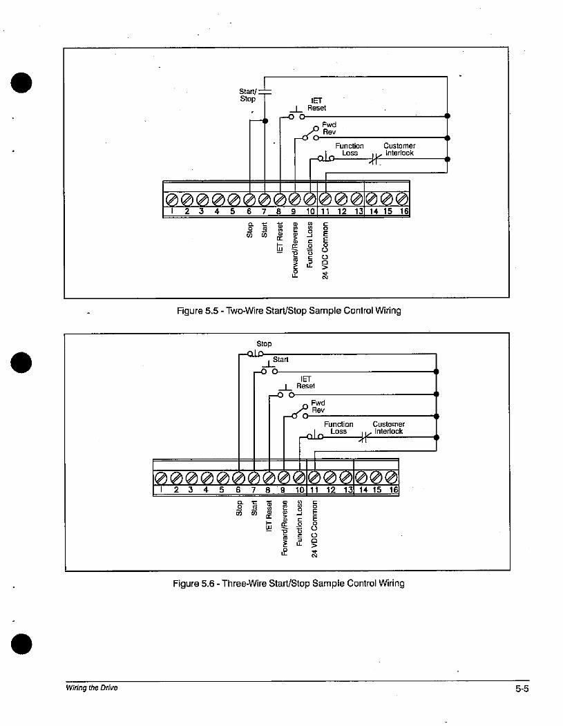
Wiring the Drive
Start/Stop IET
_L Reset-00
Fwd3 Rev
-0 0
Function Customer
-alo Loss ir Interlock
000000000000000012345 6789 10 11 12 13 14 15 16
0 t
2 1CO CO
[r
m
U>
E
LL
C
.9S
5LL
Figure 5.5 - Two-Wire Start/Stop Sample Control Wiring
Stop--aLD
Start1
,-0 0
iE0
0
8Z
IET
_L Reset-00
- Fwd/'-' Rev
-60
Function Customer
-ato LOSS Jr Interlock
60000011 12 13 14 15 16
000000000012345678910
/ 19 0
I 0 2
mE
(0
E2
Figure 5.6 - Three-Wire Start/Stop Sample Control Wiring
C
LL
E0
0
0
9
@
5
5-5
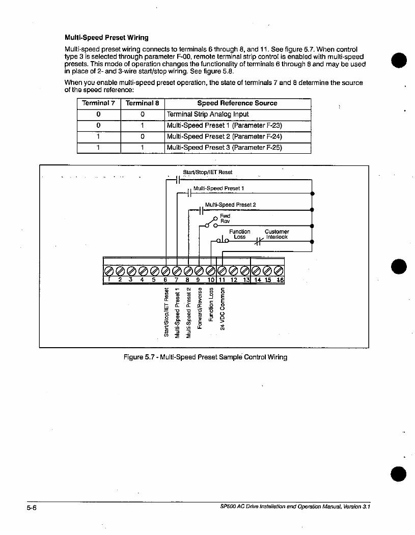
5-6
Multi-Speed Preset Wiring
Multi-speed preset wiring connects to terminals 6 through 8, and 11. See figure 5.7. When controltype 3 is selected through parameter F-00, remote terminal strip control is enabled with multi-speedpresets. This mode of operation changes the functionality of terminals 6 through 8 and may be usedin place of 2- and 3-wire start/stop wiring. See figure 5.8.
When you enable multi-speed preset operation, the state of terminals 7 and 8 determine the sourceof the speed reference:
Terminal 7
1
1
0
0
Terminal 8
0
1
0
1
Speed Reference Source
Terminal Strip Analog Input
Multi-Speed Preset 1 (Parameter F-23)
Multi-Speed Preset 2 (Parameter F-24)
Multi-Speed Preset 3 (Parameter F-25)
Start/Stop/IET Reset
LHI
-11Multi-Speed Preset 1
Multi-Speed Preset 211
„ FwdA' Rev
-ioFunction Customer
-ato Loss Ar Interlock
60000011 12 13 14 15 46
0000000000r2345678910
S .I N
B 65 @
65%0
S 2.(5
a S i
5 3>
0
E Ir0
Figure 5.7 - Multi-Speed Preset Sample Control Wiring
gEE
80
52RI
S
0
SP500 AC Drive installation and Operation Manual, Version 3.1
.
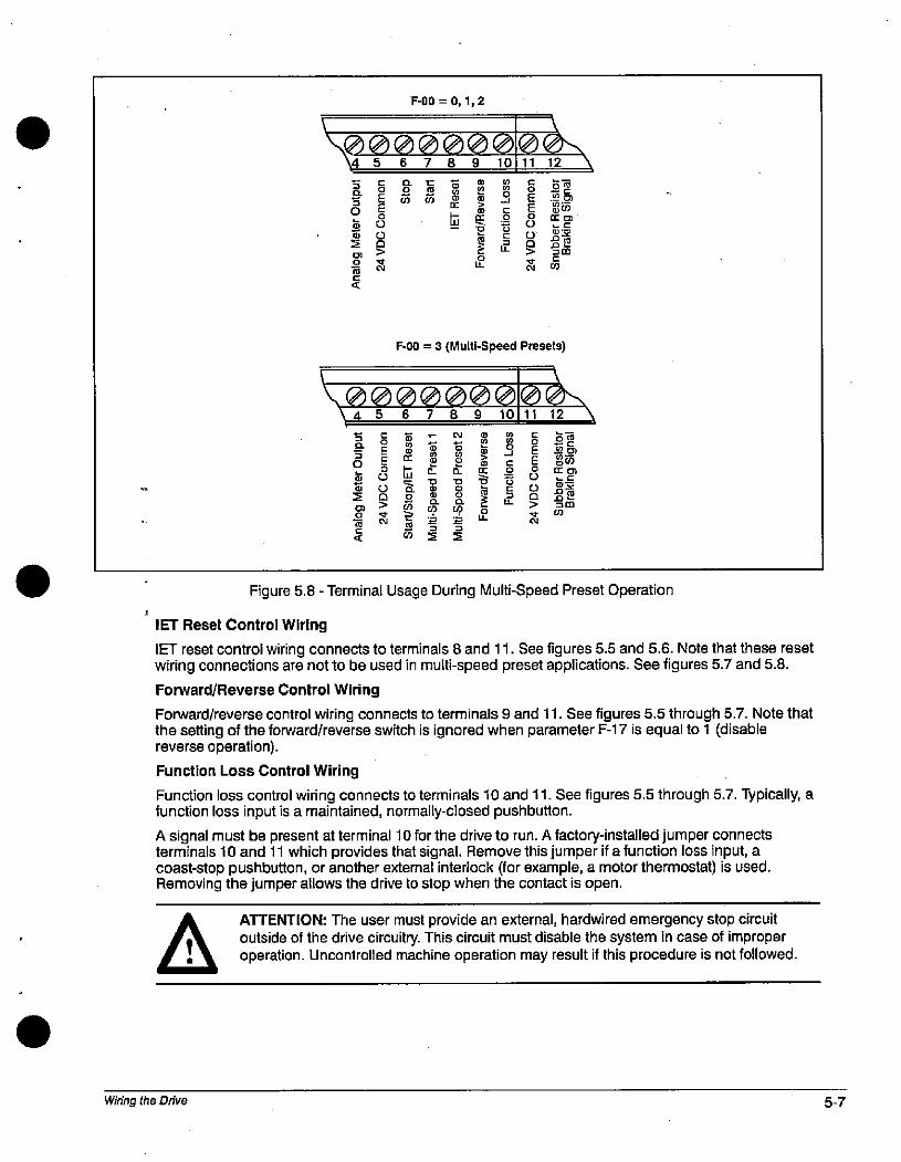
n
S0
g)La
30
9
m
S
F-00 = 0,1,2
30000000\456789101112
3&%BEE M 0 50-9$ 1 E 50
5 0 ES *85/5 0 8 immr 5 g Lir r .SM16 N Z U CO
F-00 = 3 (Multi-Speed Presets)
000000045 678910
r N
2 20- 0-
0 9+
--
2
-1
C
5IL
E
80
9
0611 12
Figure 5.8 - Terminal Usage During Multi-Speed Preset Operation
IET Reset Control Wiring
IET reset control wiring connects to terminals 8 and 11. See figures 5.5 and 5.6. Note that these resetwiring connections are not to be used in multi-speed preset applications. See figures 5.7 and 5.8.
Forward/Reverse Control Wiring
Forward/reverse control wiring connects to terminals 9 and 11. See figures 5.5 through 5.7. Note thatthe setting of the forward/reverse switch is ignored when parameter F-17 is equal to 1 (disablereverse operation).
Function Loss Control Wiring
Function loss control wiring connects to terminals 10 and 11. See figures 5.5 through 5.7. Typically, afunction loss input is a maintained, normally-closed pushbutton.
A signal must be present at terminal 10 for the drive to run. A factory-installed jumper connectsterminals 10 and 11 which provides that signal. Remove this jumper if a function loss input, acoast-stop pushbutton, or another external interlock (for example, a motor thermostat) is used.Removing the jumper allows the drive to stop when the contact is open.
Wiring the Drive
ATTENTION: The user must provide an external, hardwired emergency stop circuitoutside of the drive circuitry. This circuit must disable the system in case of improperoperation. Uncontrolled machine operation may result if this procedure is not followed.
gaCO
5-7
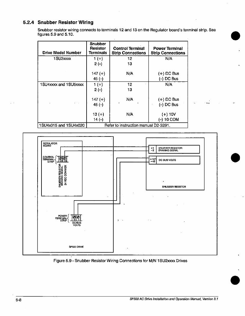
5-8
5.2.4 Snubber Resistor Wiring
Snubber resistor wiring connects to terminals 12 and 13 on the Regulator board's terminal strip. Seefigures 5.9 and 5.10.
Drive Model Number
1 SU2>000<
1 SU4)000< and 1 SU5xxxx
1 SU4x015 and 1 SU4x020
REGULATORBOARD
CONTROL fTERMINALZ |||
STRIP 1*121-11
50 6
0
POWER fTERMINAL=< 10101
STRIP i '+'-'- DC BUS
VOLIS
SP500 DRIVE
Snubber
Resistor
Terminals
1 (+)2 (-)
147 (+)
45 (-)
1 (+)
2 (-)
147 (+)
45 (-)
13 (+)
14 (-)
Control Terminal
Strip Connections12
13
N/A
N/A
12
13
Power Terminal
Strip Connections
N/A
(+) DC Bus
(-) DC Bus
N/A
(+) DC Bus
(-) DC Bus
N/A (+) 10V
(-) 10 COMRefer to instruction manual D2-3291.
+1 SNUBBER RESISTOR-2 BRAKiNG SIGNAL
+147DC BUS VOLTS
-45
SNUBBER RESISTOR
Figure 5.9 - Snubber Resistor Wiring Connections for M/N 1 SU21000 Drives
SPSOO AC Drive Installation and Operation Manual, Version 3.1
.
.
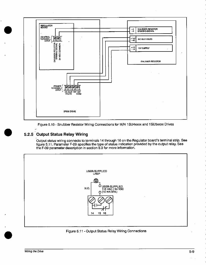
REGULATOR
BOARD
sTRIP
2 5
50 AZE R
)m &
111STRIP 1 + - + -
4 DC BUS 1 OV lOV
VOLIS COM
SP500 DRIVE
+1 SNUBBER RESISTOR-2 BRAKING SIGNAL
+147 DC BUS VOLTS-45
+13
-1410VSUPPLY
SNUBBER RESISTOR
Figure 5.10 - Snubber Resistor Wiring Connections for M/N 1 SU4xxxx and 1 SU5>000< Drives
5.2.5 Output Status Relay Wiring
Output status wiring connects to terminals 14 through 16 on the Regulator board's terminal strip. Seefigure 5.11. Parameter F-09 specifies the type of status indication provided by the output relay. Seethe F-09 parameter description in section 8.3 for more information.
Wiring the Drive
USER-SUPPLIEDLAMP
U USER-SUPPLIEDN.O. 115 VAC/24 VDC
(10 mA Min.)
5014 15 16
Figure 5.11 - Output Status Relay Wiring Connections
5-9
Flo
5.3 Output Power Wiring
Use the following steps to connect AC output power wiring from the drive to the motor:
Step 1. Wire the AC output power leads by routing them according to the type of enclosure. Seefigures 4.1 through 4.4. See tables 3.2 through 3.4 for recommended wire sizes.
.
ATTENTION: Do not route signal and control wiring with power wiring in the sameconduit.This can cause interference with drive operation.
Do not route more than three sets of motor leads through a single conduit. This willminimize cross4alk which could reduce the effectiveness of noise reduction methods. If
more than three drive/motor connections per conduit are required, you must use shieldedcable. If possible, each conduit should contain only one set of motor leads.
ATTENTION: Unused wires in conduit must be grounded at both ends to avoid apossible shock hazard caused by induced voltages. Also, if a drive sharing aconduit is being serviced or installed, all drives using this conduit should bedisabled to eliminate the possible shock hazard from cross-coupled motor leads.
Step 2. Connect the AC output power motor leads to terminals U, V, and W on the power terminalstrip. See figure 5.1.
Step 3. Tighten terminals U, V, and W to the proper torque as shown in table 3.5.
5.4 Grounding
A ATTENTION: The user is responsible for conforming with all applicable local,
national, and international codes.
Use the following steps to ground the drive:
Step 1. Remove the drive's cover.
Step 2.
Step 3.
Step 4.
Run a suitable equipment grounding conductor unbroken from the drive's ground terminalto the motor's ground terminal and then to earth ground. See figures 4.1 through 4.4 and5.1.
Connect a suitable grounding connector to the motor frame and transformer (if used). Runeach conductor unbroken to earth ground.
When adding more than one grounding conductor wire to a single chassis ground, twist theconductors together.
Re-attach the drive's cover.
SP500 AC Drive Installation and Operation Manual, Version 3.1
6.0 Completing the Installation
6.1
This chapter provides procedures to check the installation.
A ATTENTION: only qualified electrical personnel familiar with the construction and
operation of this equipment and the hazards involved should install, adjust, operate,/ 0 and/or service this equipment. Read and understand this manual in its entirety beforeI proceeding.
Checking the Installation With the Power Off
ATTENTION: DC bus capacitors retain hazardous voltages after input power has beendisconnected. After disconnecting input power, wait five (5) minutes for the DC buscapacitors to discharge and then the check the voltage with a voltmeter to ensure the
I DC bus capacitors are discharged before touching any internal components.
Perform the following checks of the drive installation with the power off:
Step 1. Turn off, lock out, and tag the input power to the drive. Wait five minutes.
Step 2. Check the DC bus potential with a voltmeter as described in section 9.1 to ensure that theDC bus capacitors are discharged.
Step 3. If an input disconnect is installed, make sure it is in the off position.
Step 4. Make sure the drive interlocks installed around the driven machine are operational.
ATTENTION: The user must provide an external, hardwired emergency stop circuitoutside of the drive circuitry. This circuit must disable the system in case of improper
, . operation. Uncontrolled machine operation may result if this procedure is not followed.
Step 5. Verify that the user-installed stop pushbutton is wired correctly. Be sure the factory-installedjumper at terminals 10 and 11 has been removed so that the coast-stop pushbutton willwork. (Refer to section 5.2.3.)
,.
Step 6.
Step 7.
Step 8.
Step 9.
ATTENTION: Make sure electrical commons are not intermixed in the drive.
Remove any debris from around the drive.
Check that there is adequate clearance around the drive.
Verify that the wiring to the control terminal strip and power terminals is correct. Refer tochapter 5.
Check that the wire sizes are within terminal specifications and that the terminals aretightened to the appropriate torque specifications. Refer to tables 3.2 through 3.6.
Step 10. Check that the user-supplied branch circuit protection is installed and correctly rated.
Step 11. Check that the incoming AC power is rated correctly.
Step 12. Check the motor installation and length of motor leads.
Step 13. Disconnect any power correction capacitors connected between the drive and the motor.
Completing the Installation 6-1
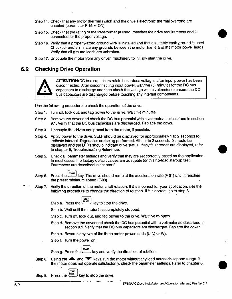
6-2
6.2
Step 14. Check that any motor thermal switch and the drive's electronic thermal overload areenabled (parameter F-15 = ON).
Step 15. Check that the rating of the transformer (if used) matches the drive requirements and isconnected for the proper voltage.
Step 16. Verify that a properly-sized ground wire is installed and that a suitable earth ground is used.Check for and eliminate any grounds between the motor frame and the motor power leads.Verify that all ground leads are unbroken.
Step 17. Uncouple the motor from any driven machinery to initially start the drive.
Checking Drive Operation
ATTENTION: DC bus capacitors retain hazardous voltages after input power has beendisconnected. After disconnecting input power, wait five (5) minutes for the DC bus
, 0 capacitors to discharge and then check the voltage with a voltmeter to ensure the DCI bus capacitorsare dis®arged before touching any internal components.
Use the following procedure to check the operation of the drive:
Step 1. Turn off, lock out, and tag power to the drive. Wait five minutes.
Step 2. Remove the cover and check the DC bus potential with a voltmeter as described in section9.1. Verify that the DC bus capacitors are discharged. Replace the cover.
Step 3. Uncouple the driven equipment from the motor, if possible.
Step 4. Apply power to the drive. SELF should be displayed for approximately 1 to 2 seconds toindicate internal diagnostics are being performed. After 1 to 2 seconds, 0 should bedisplayed and the LEDs should indicate drive status. If any fault codes are displayed, referto chapter 9, Troubleshooting Reference.
Step 5. Check all parameter settings and verify that they are set correctly based on the application.In most cases, the factory default values are adequate for this no-load start-up test.Parameters are described in chapter 8.
Step 6.
Step 7.
Step 8.
Press the L__J key. The drive should ramp at the acceleration rate (F-01) until it reachesthe preset minimum speed (F-03).
Verify the direction of the motor shaft rotation. If it is incorrect for your application, use thefollowing procedure to change the direction of rotation. If it is correct, go to step 8.
SIRE
RESET
Step a. Press the key to stop the drive.
Step b. Wait until the motor has completely stopped.
Step c. Turn off, lock out, and tag power to the drive. Wait five minutes.
Step d. Remove the cover and check the DC bus potential with a voltmeter as described insection 9.1. Verify that the DC bus capacitors are discharged. Replace the cover.
Step e. Reverse any two of the three motor power leads (U, V, or W).
Step f. Turn the power on.
1 STARTStep g. Press the L_J key and verify the direction of rotation.Using the A and V' keys, run the motor without any load across the speed range. Ifthe motor does not operate satisfactorily, check the parameter settings. Refer to chapter 8.
1 RESET 1
Step 9. Press the L__J key to stop the drive.
SP500 AC Drive Installation and Operation Manual, Version 3.1
Step 10. Turn off, lock out, and tag power to the drive. Wait five minutes. Remove the cover andcheck the DC bus potential with a voltmeter as described in section 9.1. Verify that the DCbus capacitors are discharged. Replace the cover.
Step 11. Couple the driven equipment to the motor.
Step 12. Turn power on.
START Step 13. Press the l key.
Step 14. Run the drive across the required speed range under load. If the motor does not rotate atminimum speed, increase the manual torque boost (F-06).
Step 15. If the drive operates the motor properly, go to step 16.
If the drive does not operate the motor properly, follow the steps below:
Step a. Refer to chapter 9, Troubleshooting Reference, if any fault codes were displayedduring start up.
Step b. Verify the parameter settings again.
Step 16. If the drive operates the motor properly:
1=1Step a. Press the CD key to stop the drive.
Step b. Record the parameter settings in Appendix B.
Completing the Installation 6-3

G4 SP500 AC Drive Installation and Operation Manual, Version 3.1
.
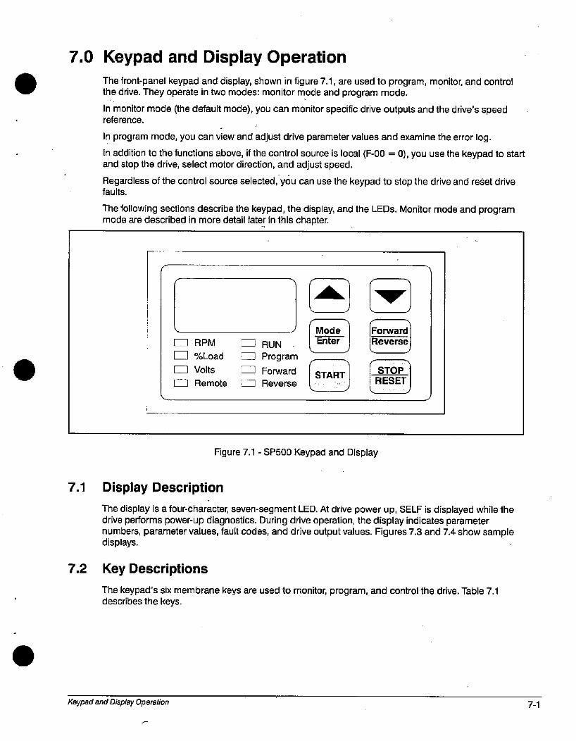
7.0 Keypad and Display Operation
The front-panel keypad and display, shown in figure 7.1, are used to program, monitor, and controlthe drive. They operate in two modes: monitor mode and program mode.
In monitor mode (the default mode), you can monitor specific drive outputs and the drive's speedreference.
In program mode, you can view and adjust drive parameter values and examine the error log.
In addition to the functions above, if the control source is local (F-00 = 0), you use the keypad to startand stop the drive, select motor direction, and adjust speed.
Regardless of the control source selected, you can use the keypad to stop the drive and reset drivefaults.
The following sections describe the keypad, the display, and the LEDs. Monitor mode and programmode are described in more detail later in this chapter.
1 RPM
E-1 %Load
0 Volts
0 Remote
7.1 Display Description
0 RUN .
F-1 Program
E Forward
0 Reverse
Mode
Enter
START«
Figure 7.1 - SP500 Keypad and Display
Forward
Reverse
STOP
RESET
The display is a four-character, seven-segment LED. At drive power up, SELF is displayed while thedrive performs power-up diagnostics. During drive operation, the display indicates parameternumbers, parameter values, fault codes, and drive output values. Figures 7.3 and 7.4 show sampledisplays.
7.2 Key Descriptions
The keypad's six membrane keys are used to monitor, program, and control the drive. Table 7.1describes the keys.
Keypad and Display Operation 7-1
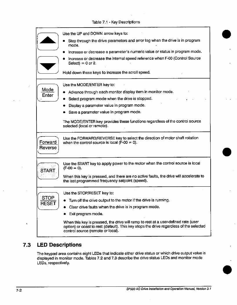
7-2
Mode
Enter
Forward
Reverse
START
STOP
RESET
Table 7.1 - Key Descriptions
Use the UP and DOWN arrow keys to:
• Step through the drive parameters and error log when the drive is in programmode. ,
• Increase or decrease a parameter's numeric value or status in program mode.
• Increase or decrease the internal speed reference when F-00 (Control SourceSelect) = 0 or 2.
Hold down these keys to increase the scroll speed.
Use the MODE/ENTER key to:
• Advance through each monitor display item in monitor mode.
• Select program mode when the drive is stopped.
• Display a parameter value in program mode.
• Save a parameter value in program mode.
The MODE/ENTER key provides these functions regardless of the control sourceselected (local or remote).
Use the FORWARD/REVERSE key to select the direction of motor shaft rotationwhen the control source is local (F-00 = 0).
Use the START key to apply power to the motor when the control source is local(F-00 = 0).
When this key is pressed, and there are no active faults, the drive will accelerate tothe last programmed frequency setpoint (speed).
Use the STOP/RESET key to:
• Turn off the drive output to the motor if the drive is running.
• Clear drive faults when the drive is in program mode.
• Exit program mode.
When this key is pressed, the drive will ramp to rest at a user-defined rate (useroption) or coast to rest (default). This key stops the drive regardless of the selectedcontrol source (remote or local).
7.3 LED Descriptions
The keypad area contains eight LEDs that indicate either drive status or which drive output value isdisplayed in monitor mode. Tables 7.2 and 7.3 describe the drive status LEDs and monitor modeLEDs, respectively.
SPSOO AC Drive installation and Operation Manual, Version 3.1
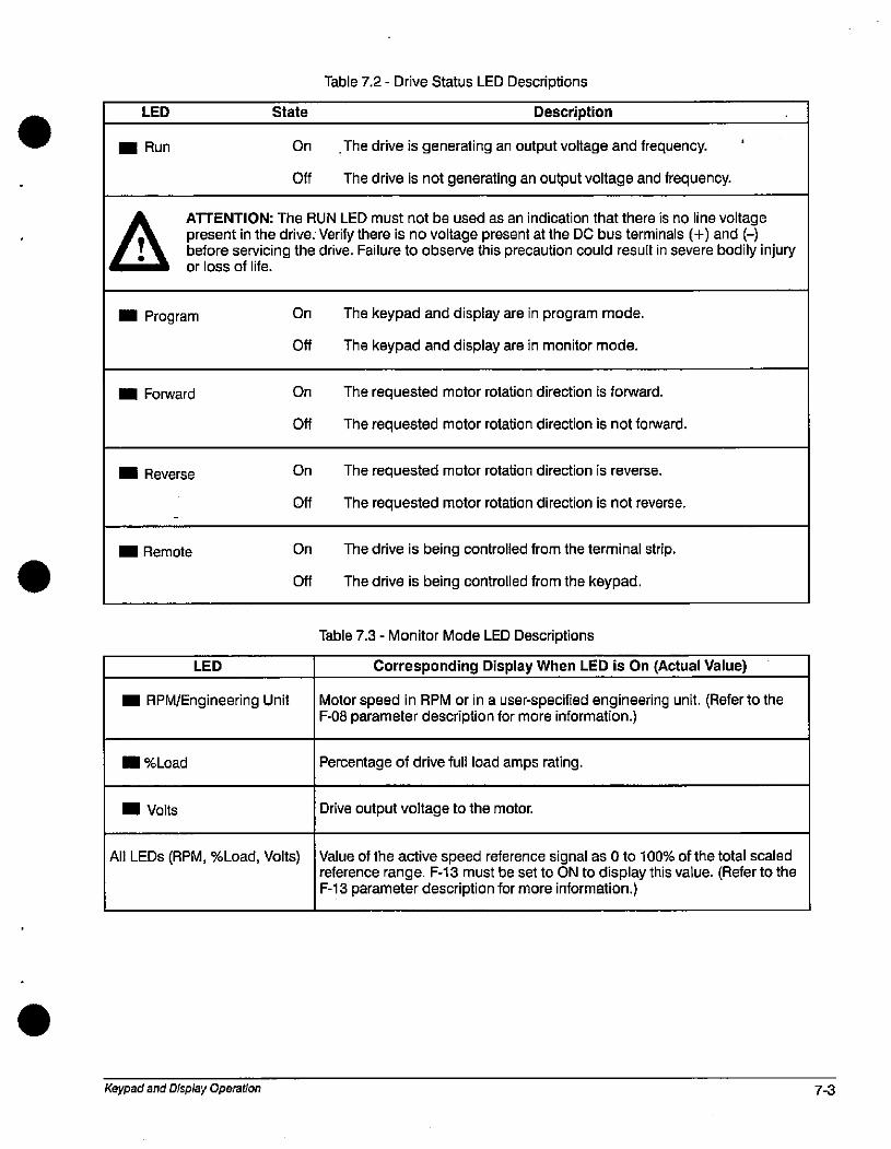
LED
I Run
State
On
Off
Table 7.2 - Drive Status LED Descriptions
Description
.The drive is generating an output voltage and frequency.
The drive is not generating an output voltage and frequency.
aATTENTION: The RUN LED must not be used as an indication that there is no line voltagepresent in the drive. Verify there is no voltage present at the DC bus terminals (+) and (-)before servicing the drive. Failure to observe this precaution could result in severe bodily injuryor loss of life.
.. Program
I Forward
Il Reverse
i Remote
LED
I RPM/Engineering Unit
I %Load
i Volts
All LEDs (RPM, %Load, Volts)
Keypad and Display Operation
On
Off
On
Off
On
Off
On
Off
The keypad and display are in program mode.
The keypad and display are in monitor mode.
The requested motor rotation direction is forward.
The requested motor rotation direction is not forward.
The requested motor rotation direction is reverse.
The requested motor rotation direction is not reverse.
The drive is being controlled from the terminal strip.
The drive is being controlled from the keypad.
Table 7.3 - Monitor Mode LED Descriptions
Corresponding Display When LED is On (Actual Value)
Motor speed in RPM or in a user-specified engineering unit. (Refer to theF-08 parameter description for more information.)
Percentage of drive full load amps rating.
Drive output voltage to the motor.
Value of the active speed reference signal as 0 to 100% of the total scaledreference range. F-13 must be set to ON to display this value. (Refer to theF-13 parameter description for more information.)
7-3
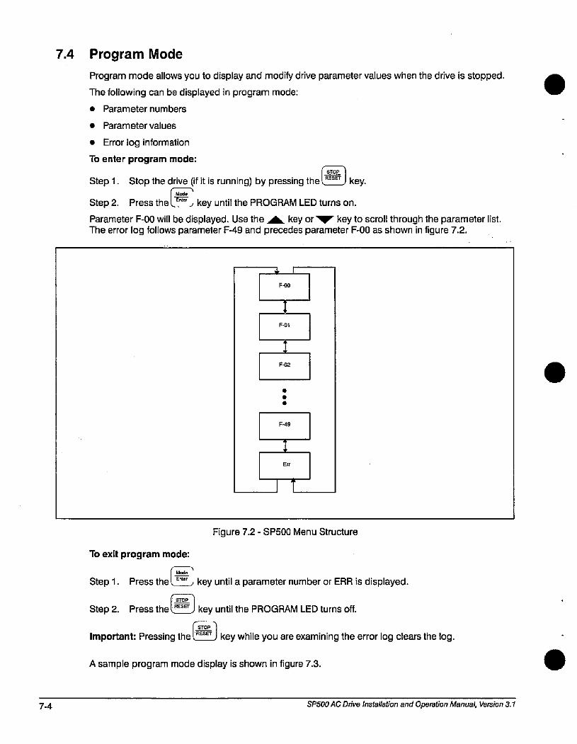
7-4
F.02
7.4 Program Mode
Program mode allows you to display and modify drive parameter values when the drive is stopped. The following can be displayed in program mode:
• Parameter numbers
• Parameter values
• Error log information
To enter program mode:
I srop
Step 1. Stop the drive (if it is running) by pressing the lm key1 Mode
Step 2. Press the lYL key until the PROGRAM LED turns on.
Parameter F-00 will be displayed. Use the A key or '7 key to scroll through the parameter list.The error log follows parameter F-49 and precedes parameter F-00 as shown in figure 7.2.
.L I
F-(to
I
F-01
:
F-49
Err
It
Figure 7.2 - SP500 Menu Structure
To exit program mode:
IMEL
Step 1. Press the l Emor , key until a parameter number or ERR is displayed.
STOP 1
Step 2. Press the l RESET J key until the PROGRAM LED turns off.
filImportant: Pressing the LRESET J key while you are examining the error log clears the log.
A sample program mode display is shown in figure 7.3.
SP500 AC Drive Installation and Operation Manual, Version 3.1
.
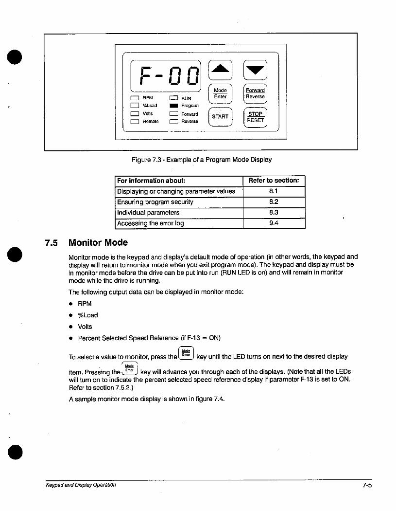
7.5
r _ ri nUU
6 RPM
%Load
0 Volts
EZ] Remote
Q RUN
I Program
E Forward
0 Reverse
U( Mode ] Forward Enter I IReverseJ
ru*21 1621 l»ESE
Figure 7.3 - Example of a Program Mode Display
For information about:
Displaying or changing parameter values
Ensuring program security
Individual parameters
Accessing the error log
Monitor Mode
Refer to section:
8.1
8.2
8.3
9.4
Monitor mode is the keypad and display's default mode of operation (in other words, the keypad anddisplay will return to monitor mode when you exit program mode). The keypad and display must bein monitor mode before the drive can be put into run (RUN LED is on) and will remain in monitormode while the drive is running.
The following output data can be displayed in monitor mode:
• RPM
• %Load
• Volts
• Percent Selected Speed Reference (if F-13 = ON)
Mode
To select a value to monitor, press the key until the LED turns on next to the desired display' Midiitem. Pressing the £ E'to' key will advance you through each of the displays. (Note that all the LEDs
will turn on to indicate the percent selected speed reference display if parameter F-13 is set to ON.Refer to section 7.5.2.)
A sample monitor mode display is shown in figure 7.4.
Keypad and Display Operation 7-5
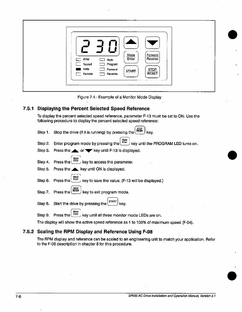
7-6
7.5.1
C JU6 RPM
Z %Load
- Volts
I Remote
El RUN
1 Program
U Forward
0 Reverse
U*
| -Mosle 1 Enter Reverse
Figure 7.4 - Example of a Monitor Mode Display
Displaying the Percent Selected Speed Reference
To display the percent selected speed reference, parameter F-13 must be set to ON. Use thefollowing procedure to display the percent selected speed reference:
L srop 1Step 1. Stop the drive (if it is running) by pressing the fRESET J key.
1 E!9!5 1Step 2. Enter program mode by pressing the l E- j key until the PROGRAM LED turns on.
Step 3. Press the AA or vlv key until F-13 is displayed.
Mode
Step 4. Press the key to access the parameter.
Step 5. Press the AA key until ON is displayed.
Step 6.
Step 7.
Step 8.
Press the
Press the
Mode
ERierkey to save the value. (F-13 will be displayed.)
6% ' key to exit program mode.START
Start the drive by pressing the key.
I ModeStep 9. Press the. E= , key until all three monitor mode LEDs are on.
The display will show the active speed reference as 1 to 100% of maximum speed (F-04).
7.5.2 Scaling the RPM Display and Reference Using F-08
The RPM display and reference can be scaled to an engineering unit to match your application. Referto the F-08 description in chapter 8 for this procedure.
SP500 AC Drive Installation and Operation Manual, Version 3.1
7.6 Drive Control
When the control source is the local keypad (F-00 = 0), the keypad is used to control the drive. Thismeans that the drive will respond to START, STOP/RESET, and FORWARD/REVERSE commandsonly from the keypad.
The functions of the keypad keys are described in section 7.2. Refer to the F-00 Control SourceSelect parameter description in chapter 8 for more information on selecting a drive control source.
7.6.1 Changing the Reference Using the Keypad
The speed reference can be increased or decreased using the A or 77 key when F-00 = 0 or 2.The display will show the internal speed reference in hertz (Hz) while the keys are pressed. There willbe a slight delay before the display returns to the active monitor mode.
Note that changing the drive's internal speed reference using the A or 77 key when the drive isunder remote control will have no operational effect on the drive (unless F-00 = 2).
Keypad and Display Operation 7-7

7-8 SP500 AC Drive Installation and Operation Manual, Version 3.1
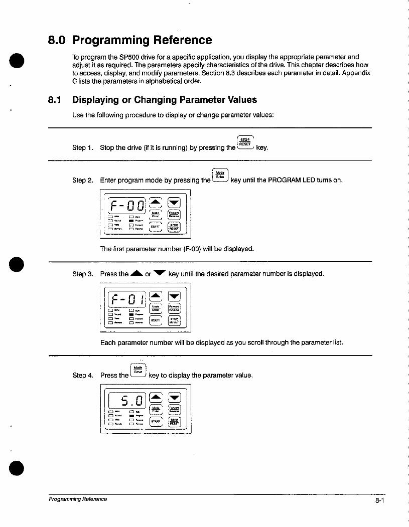
8.0 Programming Reference
To program the SP500 drive for a specific application, you display the appropriate parameter andadjust it as required. The parameters specify characteristics of the drive. This chapter describes howto access, display, and modify parameters. Section 8.3 describes each parameter in detail. AppendixC lists the parameters in alphabetical order.
8.1 Displaying or Changing Parameter Values
Use the following procedure to display or change parameter values:
r-*1IRESET
Step 1. Stop the drive (if it is running) by pressing the L----, key.
[ MOE 1
Step 2. Enter program mode by pressing the LZL; key until the PROGRAM LED turns on.
F - O d F. {*16.w J nir 21
lEZZI0- - -- -
1 El =.= 22 IlThe first parameter number (F-00) will be displayed.
Step 3. Press the A or vlv key until the desired parameter number is displayed.
F-0 1Cl- C]=
0 tl- --
m- C.-•.
*E *
Each parameter number will be displayed as you scroll through the parameter list.
Model1 Enter 1
Step 4. Press the - key to display the parameter value.
Programming Reference
c n3.U
= RM' (-
Cl- --
m- [22 4-,
0- (-ir i
8-1
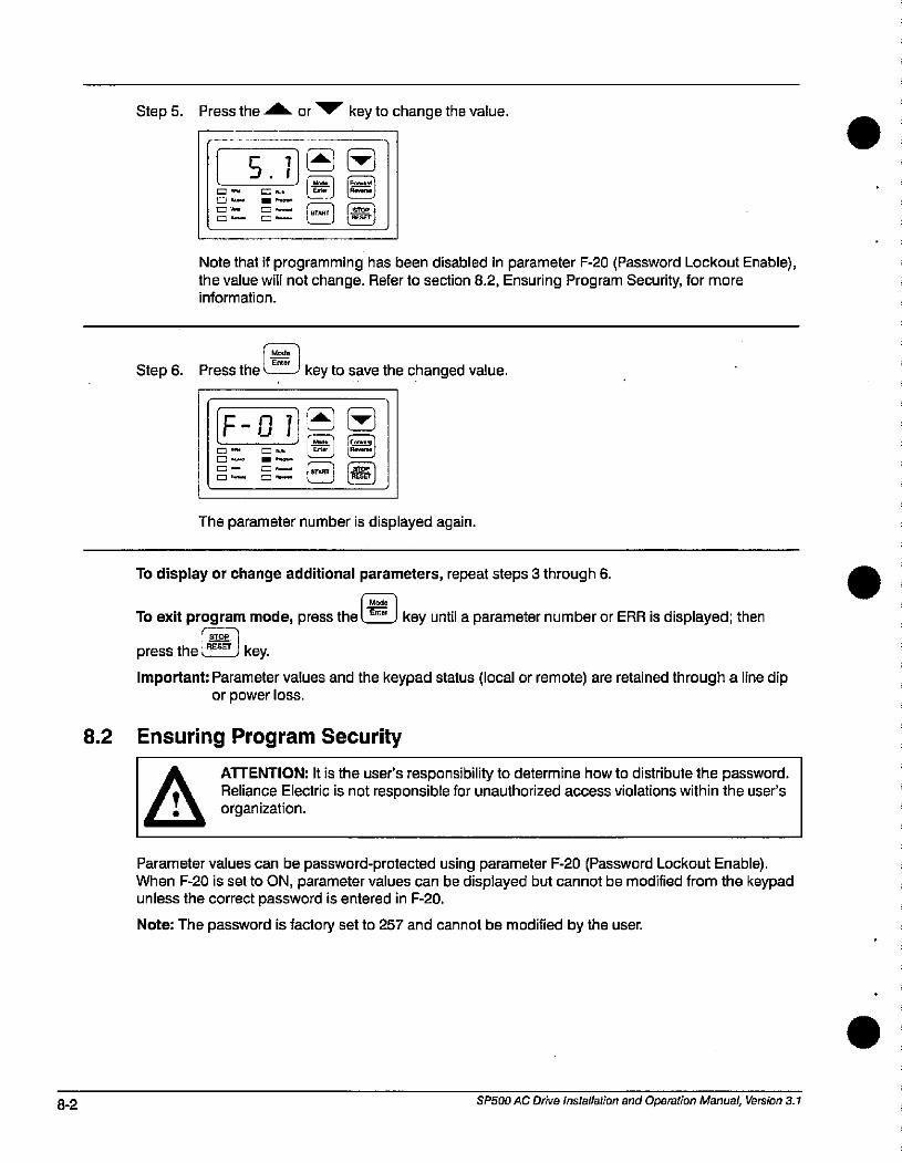
8-2
Step 5. Press the A or V key to change the value.
5.10 - m„
CJ UW - PI+,-=-
m- C- El *
Note that if programming has been disabled in parameter F-20 (Password Lockout Enable),the value will not change. Refer to section 8.2, Ensuring Program Security, for moreinformation.
Step 6. Press the L___ key to save the changed value.
F-0121*C - m MUN L.EL' eZZI0.... --
=- B *
The parameter number is displayed again.
To display or change additional parameters, repeat steps 3 through 6.
| Mode 1
To exit program mode, press thel-5; J key until a parameter number or ERR is displayed; thenr=-1
press the LZJ key.
Important: Parameter values and the keypad status (local or remote) are retained through a line dipor power loss.
8.2 Ensuring Program Security
ATTENTION: It is the user's responsibility to determine how to distribute the password.Reliance Electric is not responsible for unauthorized access violations within the user's
organization.
Parameter values can be password-protected using parameter F-20 (Password Lockout Enable).When F-20 is set to ON, parameter values can be displayed but cannot be modified from the keypadunless the correct password is entered in F-20.
Note: The password is factory set to 257 and cannot be modified by the user.
SP500 AC Drive Installation and Operation Manual, Version 3.1
.
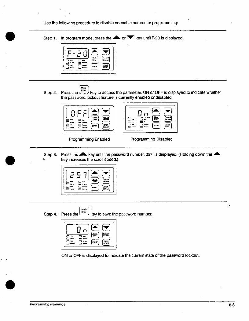
Use the following procedure to disable or enable parameter programming:
Step 1. In program mode, press the A or 'V key until F-20 is displayed.
Step 2.
F -2 01 6 (*=- m- J {*El//m-
0 - s= {E]
IMs* 11 Enter I
Press the L__j key to access the parameter. ON or OFF is displayed to indicate whetherthe password lockout feature is currently enabled or disabled.
OFFC- 0 FN
En-
m- m-
[-3 - C) -
lue- 1 9---
Programming Enabled
nun
= PM,
m lili - .-I-[=1 - C] r--
0-
Programming Disabled
Step 3. Press the A key until the password number, 257, is displayed. (Holding down the Akey increases the scroll speed.)
251C Rn, = -C- --
0- 0-
0- ¤ P"m.,
Step 4. Press the
nun0-
0-
0- m -
Ell
key to save the password number.
l-ELI tmI
ON or OFF is displayed to indicate the current state of the password lockout.
Programming Reference 8-3
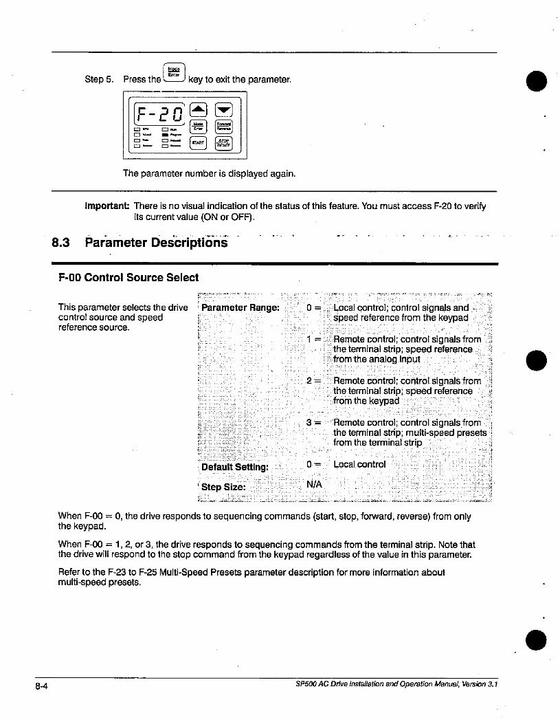
8-4
ModelEnter IStep 5. Press the ,-__J key to exit the parameter.
F-201* *m I... -./.-
=-
m- B E-D
The parameter number is displayed again.
Important: There is no visual indication of the status of this feature. You must access F-20 to verifyits current value (ON or OFF).
8.3 Parameter Descriptions
F-00 Control Source Select
This parameter selects the drive [ Parameter Range:control source and speed :reference source. 1
j
Default Setting:
' Step Size:
0 = Local control; control signals andspeed reference from the keypad
I »
1 = Remote control; control signals from 1the terminal strip; speed reference :-from the analog input
2 = Remote control; control signals from 1the terminal strip; speed reference 4from the keypad
:
3 == Remote control; control signals from jthe terminal strip; multi-speed presets,from the terminal strip
0 = Local control
N/A
When F-00 = 0, the drive responds to sequencing commands (start, stop, forward, reverse) from onlythe keypad.
When F-00 = 1, 2, or 3, the drive responds to sequencing commands from the terminal strip. Note thatthe drive will respond to the stop command from the keypad regardless of the value in this parameter.
Refer to the F-23 to F-25 Multi-Speed Presets parameter description for more information aboutmulti-speed presets.
SPSOO AC Drive Installation and Operation Manual, Version 3.1
F-01 Acceleration Time
This parameter specifies the Parameter Range:amount of time it takes the motor, Default Setting:to ramp from stop to the ' Step Size:maximum speed setting in F-04. '
0.5 to 90 seconds
5.0 seconds
0.10 seconds
If the setpoint frequency requested from the keypad (using theA and vlvkeys) is less than themaximum speed setting, the time to ramp to that frequency will be proportionally less than the actualrate setting. For example, if F-04 = 60 Hz and F-01 = 4 seconds, it will take 2 seconds to ramp to afrequency reference of 30 Hz.
Note that if the acceleration rate is set too fast, an overcurrent fault may occur (OC will be displayed).
F-02 Deceleration Time
This parameter specifies the Parameter Range:amount of time it takes the motor s Default Setting:to ramp from the maximum Step Size:speed setting in F-04 to a stop.
0.5 to 90 seconds
5.0 seconds
0.10 seconds
If the frequency requested from the keypad (using the A and Vv keys) is less than the maximumspeed setting, the time to ramp to that frequency will be proportionally less than the actual rate setting.For example, if F-04 = 60 Hz and F-02 = 4 seconds, it will take 2 seconds to ramp to a frequencyreference of 0 Hz from 30 Hz.
Note that if the deceleration rate is set too fast, a high bus fault may occur (HU will be displayed).
F-03 Minimum Speed
This parameter limits the speedreference to the drive.
Regardless of what speedreference is supplied, theregulator will not command aspeed less than the value inF-03.
Parameter Range:Default Setting:Step Size:
0.5 to 30 Hz
5.0 Hz
0.10 Hz if F-04 < 100 Hz
0.25 Hz if F-04 2 100 Hz
ATTENTION: The SP500 drive is intended to operate the motor at a predeterminedminimum speed unless disconnected from the power source. The user is responsible forassuring safe conditions for operating personnel by providing suitable guards, audible or
I visual alarms, or otherdevices to indicate that the drive is operating at minimum speed,(possibly zero speed), or the user must verify that the motor output shaft will rotate at allcombinations of load and output speed required by the application.
Programming Reference 8-5
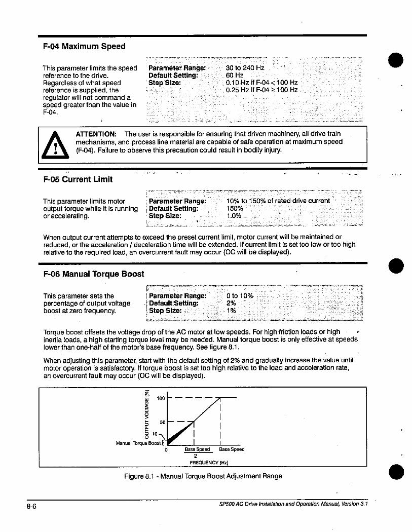
8-6
F-04 Maximum Speed
This parameter limits the speedreference to the drive.
Regardless of what speedreference is supplied, theregulator will not command aspeed greater than the value inF-04.
Parameter Range:Default Setting:Step Size:
30 to 240 Hz
60 Hz
0.10 Hz if F-04 < 100 Hz
0.25 Hz if F-04 2 100 Hz
ATTENTION: The user is responsible for ensuring that driven machinery, all drive-trainmechanisms, and process line material are capable of safe operation at maximum speed
, 0 (F-04). Failure to observe this precaution could result in bodily injury.
F-05 Current Limit
This parameter limits motor Parameter Range:output torque while it is running i Default Setting:or accelerating. Step Size:
vue»
10% to 150% of rated drive current
150%
1.0%
When output current attempts to exceed the preset current limit, motor current will be maintained orreduced, or the acceleration / deceleration time will be extended. If current limit is set too low or too highrelative to the required load, an overcurrent fault may occur (OC will be displayed).
F-06 Manual Torque Boost
This parameter sets thepercentage of output voltageboost at zero frequency.
1 Parameter Range:,1 Default Setting:5 Step Size:
0 to 10%
2%
1%
Torque boost offsets the Voltage drop of the AC motor at low speeds. For high friction loads or highinertia loads, a high starting torque level may be needed. Manual torque boost is only effective at speedslower than one-half of the motor's base frequency. See figure 8.1.
When adjusting this parameter, start with the default setting of 2% and gradually increase the value untilmotor operation is satisfactory. If torque boost is set too high relative to the load and acceleration rate,an overcurrent fault may occur (OC will be displayed).
ELU 100
5 50
5 10Manual Torque Boost E
--
1 11
Base Speed Base Speed2
FREQUENCY (Hz)
Figure 8.1 - Manual Torque Boost Adjustment Range
SP500 AC Drive Installation and Operation Manual, Version 3.1
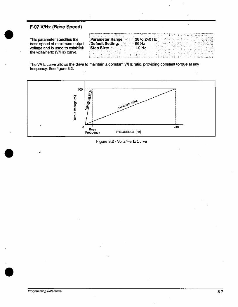
F-07 V/Hz (Base Speed)
This parameter specifies thebase speed at maximum outputvoltage and is used to establishthe volts/hertz (V/Hz) curve.
&
5
30
Parameter Range:Default Setting:Step Size:
30 to 240 Hz60 Hz
1.0 Hz
The WHz curve allows the drive to maintain a constant V/Hz ratio, providing constant torque at anyfrequency. See figure 8.2.
Programming Reference
100
0
El
Base
Frequency
Minimum
FREQUENCY (Hz)
Figure 8.2 - Volts/Hertz Curve
240
8-7
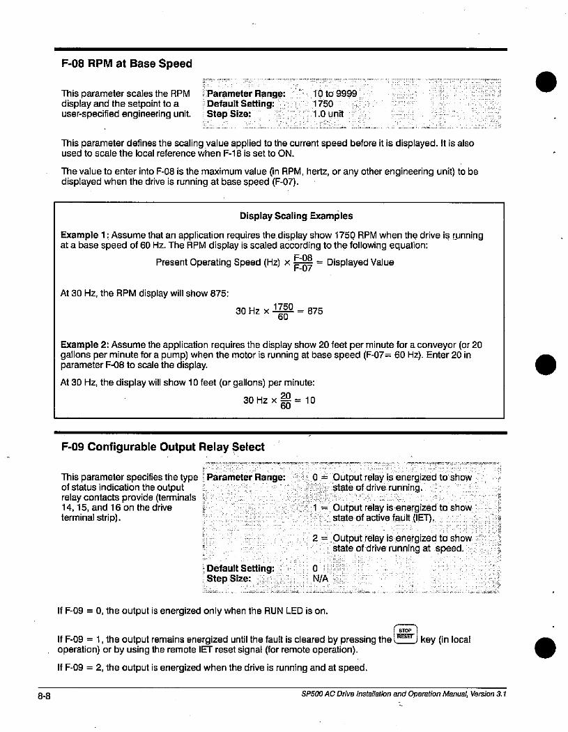
8-8
F-08 RPM at Base Speed
This parameter scales the RPM Parameter Range: - 10 to 9999display and the setpoint to a Default Setting: 1750
user-specified engineering unit. Step Size: 1.0 unit
This parameter defines the scaling value applied to the current speed before it is displayed. It is alsoused to scale the local reference when F-18 is set to ON.
The value to enter into F-08 is the maximum value (in RPM, hertz, or any other engineering unit) to bedisplayed when the drive is running at base speed (F-07).
Display Scaling Examples
Example 1: Assume that an application requires the display show 1750 RPM when the drive is runningat a base speed of 60 Hz. The RPM display is scaled according to the following equation:
Present Operating Speed (Hz) x 2 = Displayed Value
At 30 Hz, the RPM display will show 875:
30 Hz x 1750 = 87560
Example 2: Assume the application requires the display show 20 feet per minute for a conveyor (or 20gallons per minute for a pump) when the motor is running at base speed (F-07= 60 Hz). Enter 20 inparameter F-08 to scale the display.
At 30 Hz, the display will show 10 feet (or gallons) per minute:
30 Hz x 20 = 1060
F-09 Configurable Output Relay Select
This parameter specifies the type Parameter Range: 0 = Output relay is energized to showof status indication the output state of drive running.relay contacts provide (terminals 14,15, and 16 on the drive ; 1 = Output relay is energized to showterminal strip). state of active fault (IET).
· Default Setting:Step Size:
--
If F-09 = 0, the output is energized only when the RUN LED is on.
0
N/A
2 = Output relay is energized to showstate of drive running at speed.
STOP
If F-09 = 1, the output remains energized until the fault is cleared by pressing the key (in local operation) or by using the remote IET reset signal (for remote operation).
If F-09 = 2, the output is energized when the drive is running and at speed.
SP500 AC Drive Installation and Operation Manual, Version 3.1
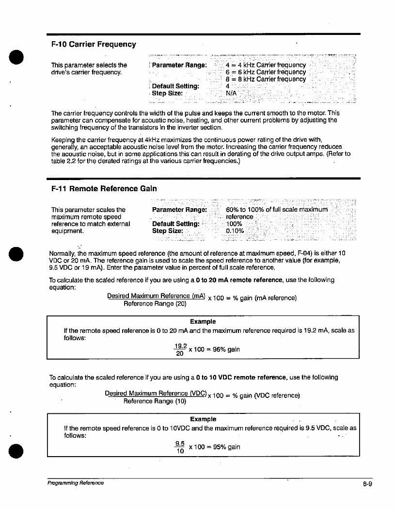
F-10 Carrier Frequency
This parameter selects thedrive's carrier frequency.
:»Parameter Range:
Default Setting:Step Size:
4 = 4 kHz Carrier frequency6 = 6 kHz Carrier frequency8 = 8 kHz Carrier frequency4
N/A
.
The carrier frequency controls the width of the pulse and keeps the current smooth to the motor. Thisparameter can compensate for acoustic noise, heating, and other current problems by adjusting theswitching frequency of the transistors in the inverter section.
Keeping the carrier frequency at 4kHz maximizes the continuous power rating of the drive with,generally, an acceptable acoustic noise level from the motor. Increasing the carrier frequency reducesthe acoustic noise, but in some applications this can result in derating of the drive output amps. (Refer totable 2.2 for the derated ratings at the various carrier frequencies.)
F-11 Remote Reference Gain
This parameter scales themaximum remote speedreference to match external
equipment.
Parameter Range:
Default Setting:Step Size:
60% to 100% offull scale maximum
reference
100%
0.10%
Normally, the maximum speed reference (the amount of reference at maximum speed, F-04) is either 10VDC or 20 mA. The reference gain is used to scale the speed reference to another value (for example,9.5 VDC or 19 mA). Enter the parameter value in percent of full scale reference.
To calculate the scaled reference if you are using a 0 to 20 mA remote reference, use the followingequation:
Desired Maximum Reference (mA) x 100 = 56 gain (mA reference)Reference Range (20)
Example
If the remote speed reference is 0 to 20 mA and the maximum reference required is 19.2 mA, scale asfollows:
19.2- x 100 = 96% gain20
To calculate the scaled reference if you are using a 0 to 10 VDC remote reference, use the followingequation:
Desired Maximum Reference (VDC) x 100 = % gain (VDC reference)Reference Range (10)
Example
If the remote speed reference is 0 to 10VDC and the maximum reference required is 9.5 VDC, scale asfollows:
Programming Reference
9.5
-1-6 x 100 = 95% gain
8-9
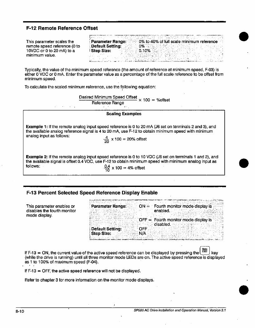
8-10
F-12 Remote Reference Offset
This parameter scales theremote speed reference (0 to10VDC or 0 to 20 mA) to aminimum value.
r
Parameter Range:Default Setting:
1 Step Size:
0% to 40% of full scale minimum reference
0%
0.10%
Typically, the value of the minimum speed reference (the amount of reference at minimum speed, F-03) iseither 0 VDC or 0 mA. Enter the parameter value as a percentage of the full scale reference to be offset fromminimum speed.
To calculate the scaled minimum reference, use the following equation:
Desired Minimum Speed Offsetx 100
Reference Range
Scaling Examples
%offset
Example 1: If the remote analog input speed reference is 0 to 20 mA (J6 set on terminals 2 and 3), andthe available analog reference signal is 4 to 20 mA, use F-12 to obtain minimum speed with minimumanalog input as follows: -4 x 100 = 20% offset
20
Example 2: If the remote analog input speed reference is 0 to 10 VDC (J6 set on terminals 1 and 2), andthe available signal is offset 0.4 VDC, use F-12 to obtain minimum speed with minimum analog input asfollows: 114 X 100 = 4% offset
10
F-13 Percent Selected Speed Reference Display Enable
This parameter enables ordisables the fourth monitor
mode display.
Parameter Range: ON = Fourth monitor mode display isenabled.
Default Setting:
Step Size:
OFF = Fourth monitor mode display isdisabled.
OFF
N/A
If F-13 = ON, the current value of the active speed reference can be displayed by pressing the key(while the drive is running) until all three monitor mode LEDs are on. The active speed reference is displayedas 1 to 100% of maximum speed (F-04).I.
If F-13 = OFF, the active speed reference will not be displayed.
Refer to chapter 3 for more information on the monitor mode displays.
SP500 AC Drive installation and Operation Manual, Version 3.1
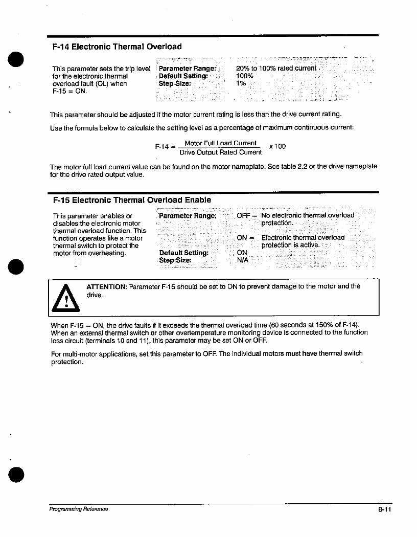
F-14 Electronic Thermal Overload
This parameter sets the trip level ' Parameter Range:for the electronic thermal Default Setting:overload fault (01_) when ' Step Size:F-15 = ON.
20% to 100% rated current
100%
1%
This parameter should be adjusted if the motor current rating is less than the drive current rating.
Use the formula below to calculate the setting level as a percentage of maximum continuous current:
F-14 = -Motor Full Load Current
x 100Drive Output Rated Current
The motor full load current value can be found on the motor nameplate. See table 2.2 or the drive nameplatefor the drive rated output value.
F-15 Electronic Thermal Overload Enable
This parameter enables or Parameter Range:disables the electronic motorthermal overload function. This
function operates like a motorthermal switch to protect themotor from overheating. Default Setting:
Step Size:
OFF = No electronic thermal overload
protection.
ON = Electronic thermal overload
protection is active.ON
N/A
A ATTENTION: Parameter F-15 should be set to ON to prevent damage to the motor and the
When F-15 = ON, the drive faults if it exceeds the thermal overload time (60 seconds at 150% of F-14).When an external thermal switch or other overtemperature monitoring device is connected to the functionloss circuit (terminals 10 and 11), this parameter may be set ON or OFF.
For multi-motor applications, set this parameter to OFF. The individual motors must have thermal switchprotection.
Programming Reference 8-11
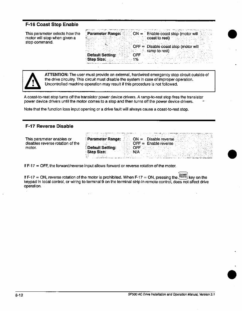
8-12
F-16 Coast Stop Enable·
This parameter selects how the Parameter Range: ON = Enable coast stop (motor will motor will stop when given a coast to rest)stop command.
Default Setting:Step Size:
OFF = Disable coast stop (motor willramp to rest)
OFF
1%
A ATTENTION: The user must provide an external, hardwired emergency stop circuit outside of
the drive circuitry. This circuit must disable the system in case of improper operation., 0 Uncontrolled machine operation may result if this procedure is not followed.
A coast-to-rest stop turns off the transistor power device drivers. A ramplo-rest stop fires the transistorpower device drivers until the motor comes to a stop and then turns off the power device drivers. -
Note that the function loss input opening or a drive fault will always cause a coast-to-rest stop.
F-17 Reverse Disable
This parameter enables ordisables reverse rotation of the
motor.
i Parameter Range:
Default Setting:Step Size:
ON = Disable reverse
OFF = Enable reverse
OFF
N/A '
If F-17 = OFF, the forward/reverse input allows forward or reverse rotation of the motor.
i Forward i
If F-17 = ON, reverse rotation of the motor is prohibited. When F-17 = ON, pressing the »- j key on thekeypad in local control, or wiring to terminal 9 on the terminal strip in remote control, does not affect driveoperation.
SP500 AC Drive Installation and Operation Manual, Version 3.1
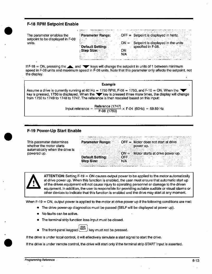
F-18 RPM Setpoint Enable
-
The parameter enables the , Parameter Range:setpoint to be displayed in F-08 iunits.
! Default Setting:i »Step Size:
OFF = Setpoint is displayed in hertz.
ON =
ONN/A
Setpoint is displayed in the unitsspecified in F-08.
If F-18 = ON, pressing the A and YV keys will change the setpoint in units of 1 between minimumspeed in F-08 units and maximum speed in F-08 units. Note that this parameter only affects the setpoint, notthe display.
Example
Assume a drive is currently running at 60 Hz = 1750 RPM, F-08 = 1750, and F-10 = ON. When the VYkey is pressed, 1750 is displayed. When the V key is pressed three more times, the display will changefrom 1750 to 1749 to 1748 to 1747. The reference is then rescaled based on this input:
Reference (1747)Input reference =
F-08 (1750)x F-04 (60Hz) = 59.89 Hz
F-19 Power-Up Start Enable
This parameter determineswhether the motor starts
automatically when the drive ispowered up.
Parameter Range: OFF = Motor does not start at drive
powerup.
Default Setting:Step Size:
ON = Motor starts at drive power up.OFF ·
N/A
A ATTENTION: Setting F-19 = ON causes output power to be applied to the motor automaticallyat drive power up. When this function is enabled, the user must ensure that automatic start upof the driven equipment will not cause injury to operating personnel or damage to the driven
I equipment.In addition, the user is responsible for providing suitable audible or visual alarms orother devices to indicate that this function is enabled and the drive may start at any moment.
When F-19 = ON, output power is applied to the motor at drive power up if the following conditions are met:
• The drive power-up diagnostics must be passed (SELF will be displayed at power up).
• No faults can be active.
• The terminal strip function loss input must be closed.
• The front-panel keypad l J key must not be pressed.
If the drive is under local control, it will effectively simulate a start signal to start the drive.
If the drive is under remote control, the drive will start only if the terminal strip START input is asserted.
Programming Reference 8-13
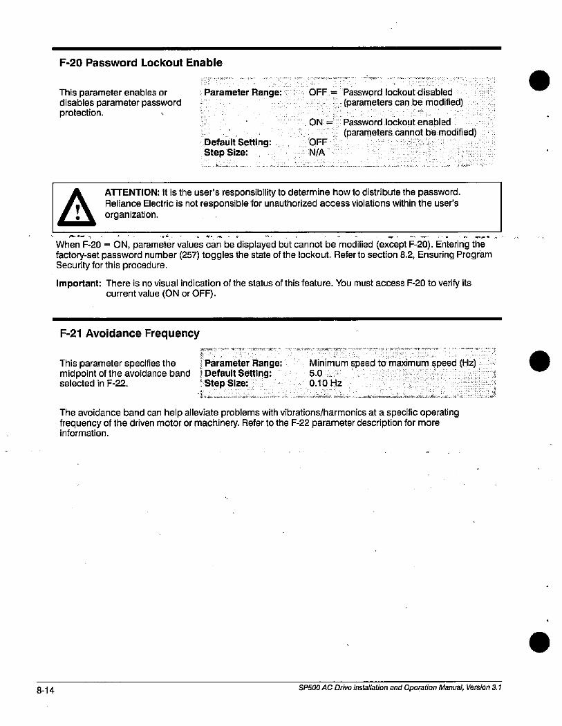
8-14
F-20 Password Lockout Enable
This parameter enables ordisables parameter passwordprotection.
j Parameter Range: OFF = Password lockout disabled
(parameters can be modified)
Default Setting:Step Size:
ON = Password lockout enabled
(parameters cannot be modified)OFF
N/A
L.JATTENTION: It is the user's responsibility to determine how to distribute the password.
Reliance Electric is not responsible for unauthorized access violations within the user'sorganization.
.
When F-20 = ON, parameter values can be displayed but cannot be modified (except F-20). Entering thefactory-set password number (257) toggles the state of the lockout. Refer to section 8.2, Ensuring ProgramSecurity for this procedure.
Important: There is no visual indication of the status of this feature. You must access F-20 to verify itscurrent value (ON or OFF).
F-21 Avoidance Frequency
This parameter specifies the Parameter Range:midpoint of the avoidance band ; Default Setting:selected in F-22. ' Step Size:
Minimum speed to maximum speed (Hz)5.0
0.10 Hz
The avoidance band can help alleviate problems with vibrations/harmonics at a specific operatingfrequency of the driven motor or machinery. Refer to the F-22 parameter description for moreinformation.
SP500 AC Drive Installation and Operation Manual, Version 3.1
.
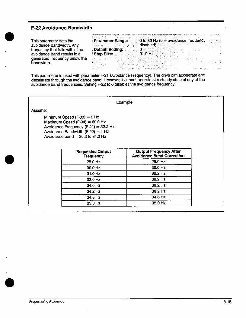
F-22 Avoidance Bandwidth
This parameter sets the - Parameter Range:avoidance bandwidth. Anyfrequency that falls within the , Default Setting:avoidance band results in a ' Step Size:generated frequency below thebandwidth.
0 to 30 Hz (0disabled)0
0.10 Hz
avoidance frequency
This parameter is used with parameter F-21 (Avoidance Frequency). The drive can accelerate anddecelerate through the avoidance band. However, it cannot operate at a steady state at any of theavoidance band frequencies. Setting F-22 to 0 disables the avoidance frequency.
Assume:
Minimum Speed (F-03) = 3 HzMaximum Speed (F-04) = 60.0 HzAvoidance Frequency (F-21) = 32.2 HzAvoidance Bandwidth (F-22) = 4 HzAvoidance band = 30.2 to 34.2 Hz
Programming Reference
Requested OutputFrequency
25.0 Hz
30.0 Hz
31.0 Hz
32.0 Hz
34.0 Hz
34.2 Hz
34.3 Hz
35.0 Hz
Example
Output Frequency AfterAvoidance Band Correction
25.0 Hz
30.0 Hz
30.2 Hz
30.2 Hz
30.2 Hz
30.2 Hz
34.3 Hz
35.0 Hz
8-15
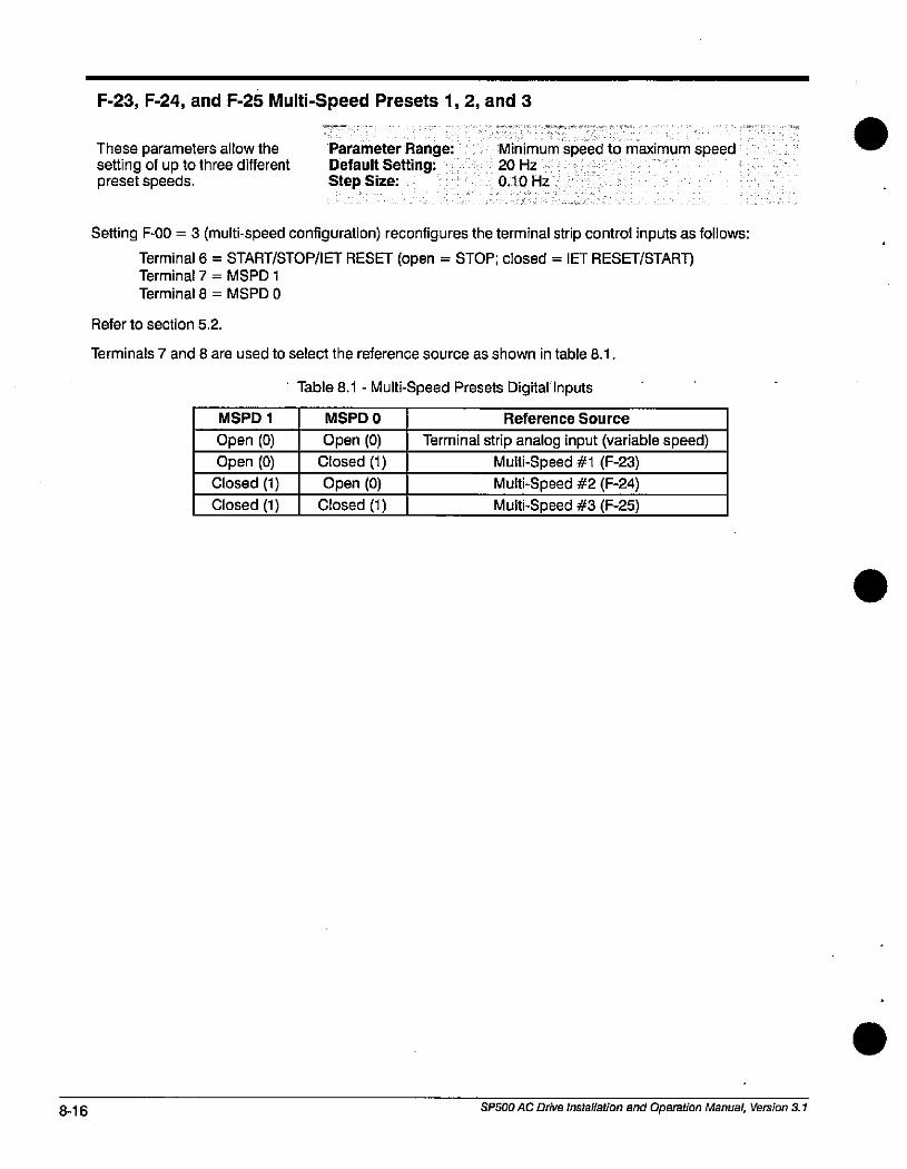
8-16
F-23, F-24, and F-25 Multi-Speed Presets 1,2, and 3
These parameters allow thesetting of up to three differentpresetspeeds.
Parameter Range:Default Setting:Step Size:
Minimum speed to maximum speed20 Hz
0.10 Hz
Setting F-00 = 3 (multi-speed configuration) reconfigures the terminal strip control inputs as follows:
Terminal 6 = START/STOP/IET RESET (open = STOP; closed = IET RESET/START)Terminal 7 = MSPD 1
Terminal 8 = MSPD 0
Refer to section 5.2.
Terminals 7 and 8 are used to select the reference source as shown in table 8.1.
' Table 8.1 - Multi-Speed Presets Digital Inputs
MSPD 1
Open (0)
Open (0)Closed (1)
Closed (1)
MSPD 0
Open (0)
Closed (1)
Open (0)
Closed (1)
Reference Source
Terminal strip analog input (variable speed)
Multi-Speed #1 (F-23)
Multi-Speed #2 (F-24)Multi-Speed #3 (F-25)
SP500 AC Drive installation and Operation Manual, Version 3.1
.
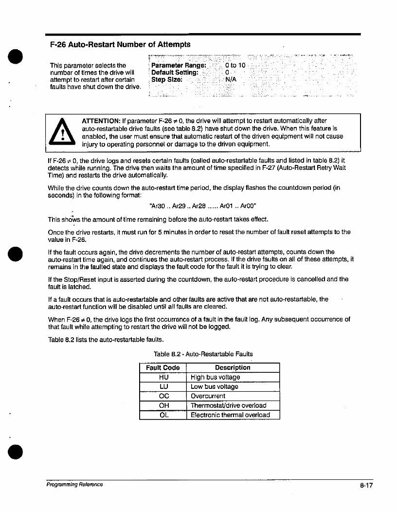
F-26 Auto-Restart Number of Attempts
This parameter selects thenumber of times the drive will
attempt to restart after certainfaults have shut down the drive.
Parameter Range:Default 'Setting:Step Size:
Oto 10
0
N/A
ATTENTION: if parameter F-26 4 0, the drive will attempt to restart automatically afterauto-restartable drive faults (see table 8.2) have shut down the drive. When this feature is
, 0 enabled, the user must ensure that automatic restart of the driven equipment will not causeI injury to operating personnel or damage to the driven equipment.
If F-26 + 0, the drive logs and resets certain faults (called auto-restartable faults and listed in table 8.2) itdetects while running. The drive then waits the amount of time specified in F-27 (Auto-Restart Retry WaitTime) and restarts the drive automatically.
While the drive counts down the auto-restart time period, the display flashes the countdown period (inseconds) in the following format:
"Ar30.. Ar29.. Ar28 ...... Ar01 .- ArOO"
This shows the amount of time remaining before the auto-restart takes effect.
Once the drive restarts, it must run for 5 minutes in order to reset the number of fault reset attempts to thevalue in F-26.
If the fault occurs again, the drive decrements the number of auto-restart attempts, counts down theauto-restart time again, and continues the auto-restart process. If the drive faults on all of these attempts, itremains in the faulted state and displays the fault code for the fault it is trying to clear.
If the Stop/Reset input is asserted during the countdown, the auto-restart procedure is cancelled and thefault is latched.
If a fault occurs that is auto-restartable and other faults are active that are not auto-restartable, theauto-restart function will be disabled until all faults are cleared.
When F-26 # 0, the drive logs the first occurrence of a fault in the fault log. Any subsequent occurrence ofthat fault while attempting to restart the drive will not be logged.
Table 8.2 lists the auto-restartable faults.
Programming Reference
Table 8.2 - Auto-Restartable Faults
Fault Code
HU
LU
0C
0H
0L
Description
High bus voltage
Low bus voltage
Overcurrent
Thermostat/drive overload
Electronic thermal overload
8-17
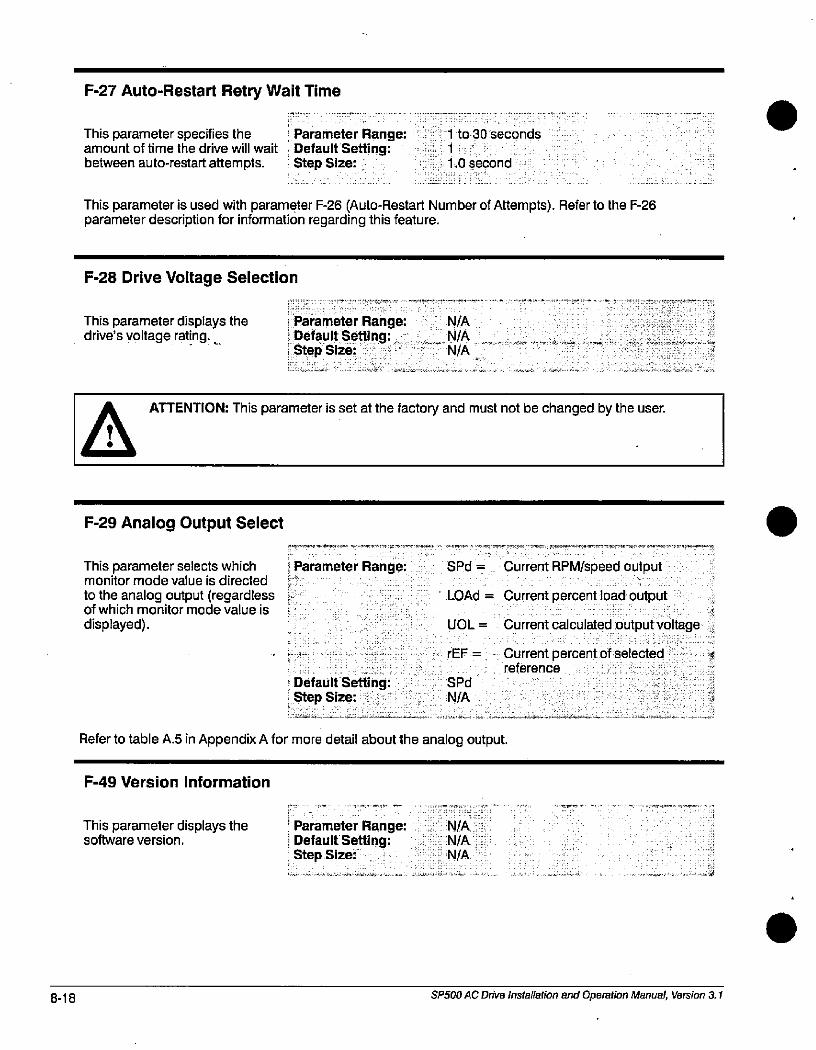
8-18
F-27 Auto-Restart Retry Wait Time
This parameter specifies theamount of time the drive will wait
between auto-restart attempts.
Parameter Range:Default'Setting:Step Size:
1 to 30 seconds
1
1.0 second
This parameter is used with parameter F-26 (Auto-Restart Number of Attempts). Refer to the F-26parameter description for information regarding this feature.
F-28 Drive Voltage Selection
This parameter displays thedrive's voltage rating.
.
Parameter Range:Default Setting:Step Size:
ATTENTION: This parameter is set at the factory and must not be changed by the user.
F-29 Analog Output Select
This parameter selects whichmonitor mode value is directed
to the analog output (regardlessof which monitor mode value is
displayed).
Parameter Range:
Default Setting:Step Size:
SPd
N/A
N/A
N/AN/A
SPd =
LOAd
UOL=
rEF =
Refer to table A.5 in Appendix A for more detail about the analog output.
F-49 Version Information
This parameter displays thesoftware version.
' Parameter Range:; Default Setting:' Step Size:
N/AN/AN/A
Current RPM/speed output
Current percent load output
Current calculated output voltage
Current percent of selected kreference
SP500 AC Drive Installation and Operation Manual, Version 3.1
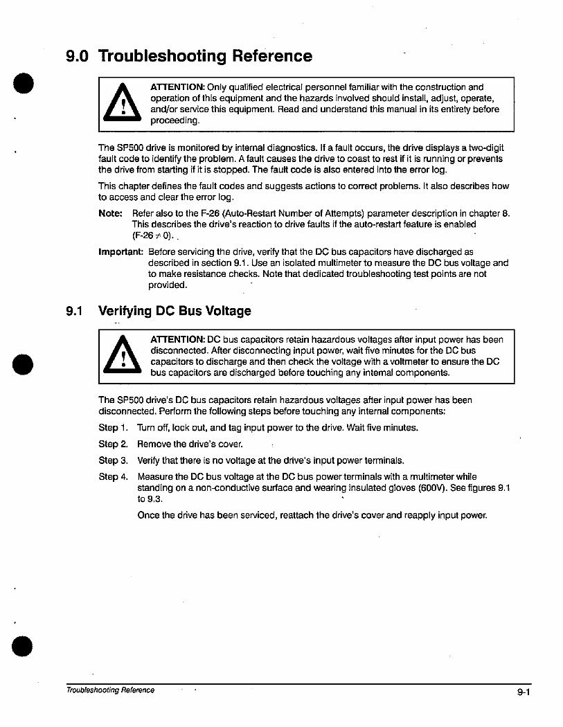
9.0 Troubleshooting Reference
aATTENTION: Only qualified electrical personnel familiar with the construction andoperation of this equipment and the hazards involved should install, adjust, operate,and/or service this equipment. Read and understand this manual in its entirety beforeproceeding.
The SP500 drive is monitored by internal diagnostics. If a fault occurs, the drive displays a two-digitfault code to identify the problem. A fault causes the drive to coast to rest if it is running or preventsthe drive from starting if it is stopped. The fault code is also entered into the error log.
This chapter defines the fault codes and suggests actions to correct problems. It also describes how
to access and clear the error log.
Note: Refer also to the F-26 (Auto-Restart Number of Attempts) parameter description in chapter 8.This describes the drive's reaction to drive faults if the auto-restart feature is enabled
(F-26 + 0)..
Important: Before servicing the drive, verify that the DC bus capacitors have discharged asdescribed in section 9.1. Use an isolated multimeter to measure the DC bus voltage andto make resistance checks. Note that dedicated troubleshooting test points are notprovided.
9.1 Verifying DC Bus Voltage
ATTENTION: DC bus capacitors retain hazardous voltages after input power has beendisconnected. After disconnecting input power, wait five minutes for the DC buscapacitors to discharge and then check the voltage with a voltmeter to ensure the DC
I bus capacitors are discharged before touching any internal components.
The SP500 drive's DC bus capacitors retain hazardous voltages after input power has been
disconnected. Perform the following steps before touching any internal components:
Step 1. Turn off, lock out, and tag input power to the drive. Wait five minutes.
Step 2. Remove the drive's cover. .
Step 3. Verify that there is no voltage at the drive's input power terminals.
Step 4. Measure the DC bus voltage at the DC bus power terminals with a multimeter whilestanding on a non-conductive surface and wearing insulated gloves (600\9. See figures 9.1to 9.3.
Once the drive has been serviced, reattach the drive's cover and reapply input power.
Troubleshooting Reference 9-1
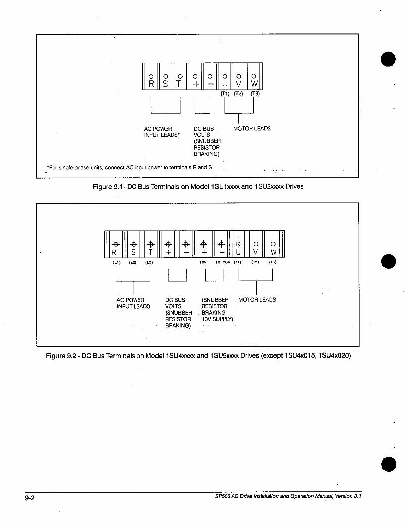
9-2
0
R0 0
ST
AC POWER
INPUT LEADS*
0000
+ 11 V
51) 52)
11-1-11DC BUS
VOLTS
(SNUBBERRESISTOR
BRAKING)
. *For single-phase units, connect AC input power to terminals R and S.
MOTOR LEADS
0
W
53)
Figure 9.1- DC Bus Terminals on Model 1 SU1;000< and 1 SU2)000< Drives
+R S
(Ll) (12) (U)
AC POWER
INPUT LEADS
+T
++
DC BUS
VOLIS
(SNUBBERRESISTOR
BRAKING)
+ U
+V
+W
10V 10 COM (Tl) (T2) (T3)
(SNUBBERRESISTOR
BRAKING
1 OV SUPPLO
MOTOR LEADS
Figure 9.2 - DC Bus Terminals on Model 1 SU4woo and 1 SU5xxxx Drives (except 1 SU4x015, 1 SU4x020)
SP500 AC Drive Installation and Operation Manual, Version 3.1
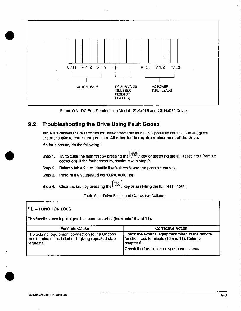
U/Tl V/T2 W/T3 + - R/Ll S/L2 T/L3
MOTOR LEADS DC BUS VOLIS
(SNUBBERRESISTOR
BRAKING)
AC POWER
INPUT LEADS
Figure 9.3 - DC Bus Terminals on Model 1 SU4x015 and 1 SU4x020 Drives
9.2 Troubleshooting the Drive Using Fault Codes
Table 9.1 defines the fault codes for user-correctable faults, lists possible causes, and suggestsactions to take to correct the problem. All other faults require replacement of the drive.
If a fault occurs, do the following:
Step 1. Try to clear the fault first by pressing the l,EE- key or asserting the IET reset input (remoteoperation). If the fault reoccurs, continue with step 2.
Step 2. Refer to table 9.1 to identify the fault code and the possible causes.
Step 3. Perform the suggested corrective action(s).
F.moplStep 4. Clear the fault by pressing the l RESEr J key or asserting the IET reset input.
FL = FUNCTION LOSS
Table 9.1 - Drive Faults and Corrective Actions
The function loss input signal has been asserted (terminals 10 and 11).
Possible Cause
The external equipment connection to the functionloss terminals has failed or is giving repeated stoprequests.
Troubleshooting Reference
Corrective Action
Check the external equipment wired to the remotefunction loss terminals (10 and 11). Refer tochapter 5.
Check the function loss input connections.
9-3
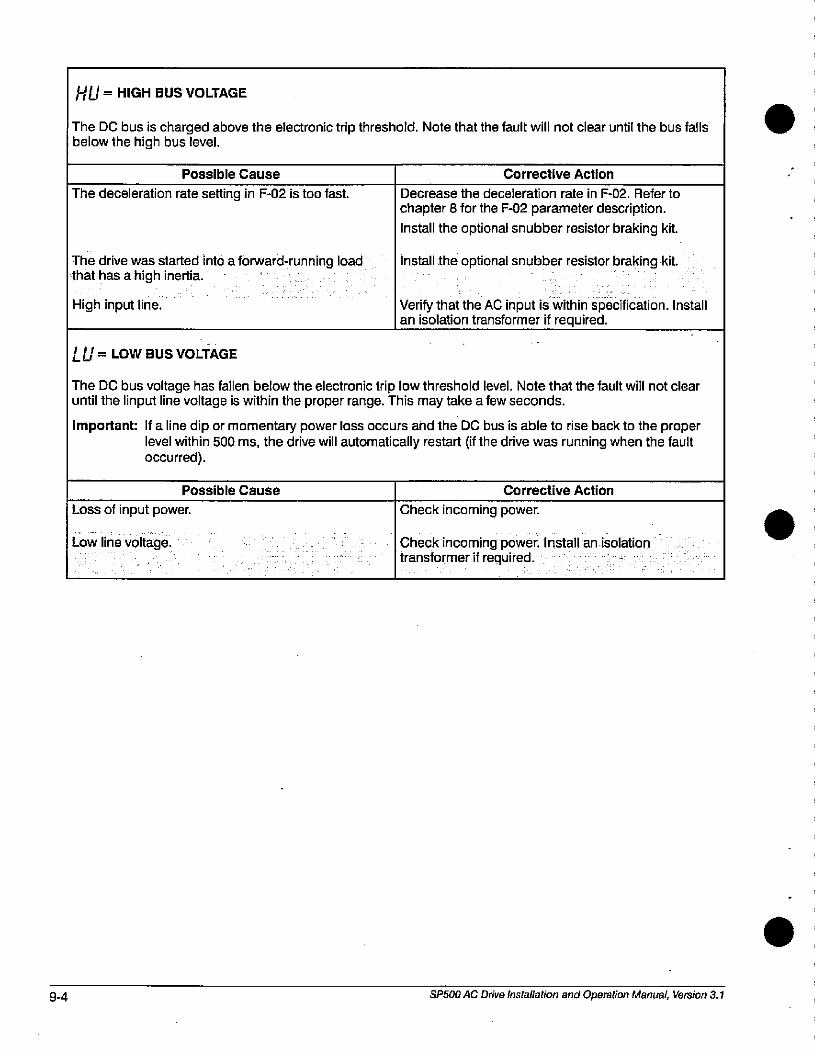
9-4
HU = HIGH BUS VOLTAGE
The DC bus is charged above the electronic trip threshold. Note that the fault will not clear until the bus fallsbelow the high bus level.
Possible Cause
The deceleration rate setting in F-02 is too fast.
The drive was started into a forward-running loadthat has a high inertia.
High input line.
LU = LOW BUS VOLTAGE
Corrective Action
Decrease the deceleration rate in F-02. Refer to
chapter 8 for the F-02 parameter description.
Install the optional snubber resistor braking kit.
Install the optional snubber resistor braking kit.
Verify that the AC input is within specification. Installan isolation transformer if required.
The DC bus voltage has fallen below the electronic trip low threshold level. Note that the fault will not clearuntil the linput line voltage is within the proper range. This may take a few seconds.
Important: If a line dip or momentary power loss occurs and the DC bus is able to rise back to the properlevel within 500 ms, the drive will automatically restart (if the drive was running when the faultoccurred).
Loss of input power.
Low line voltage.
Possible Cause Corrective Action
Check incoming power.
Check incoming power. Install an isolationtransformer if required.
SP500 AC Drive Installation and Operation Manual, Version 3.1
.
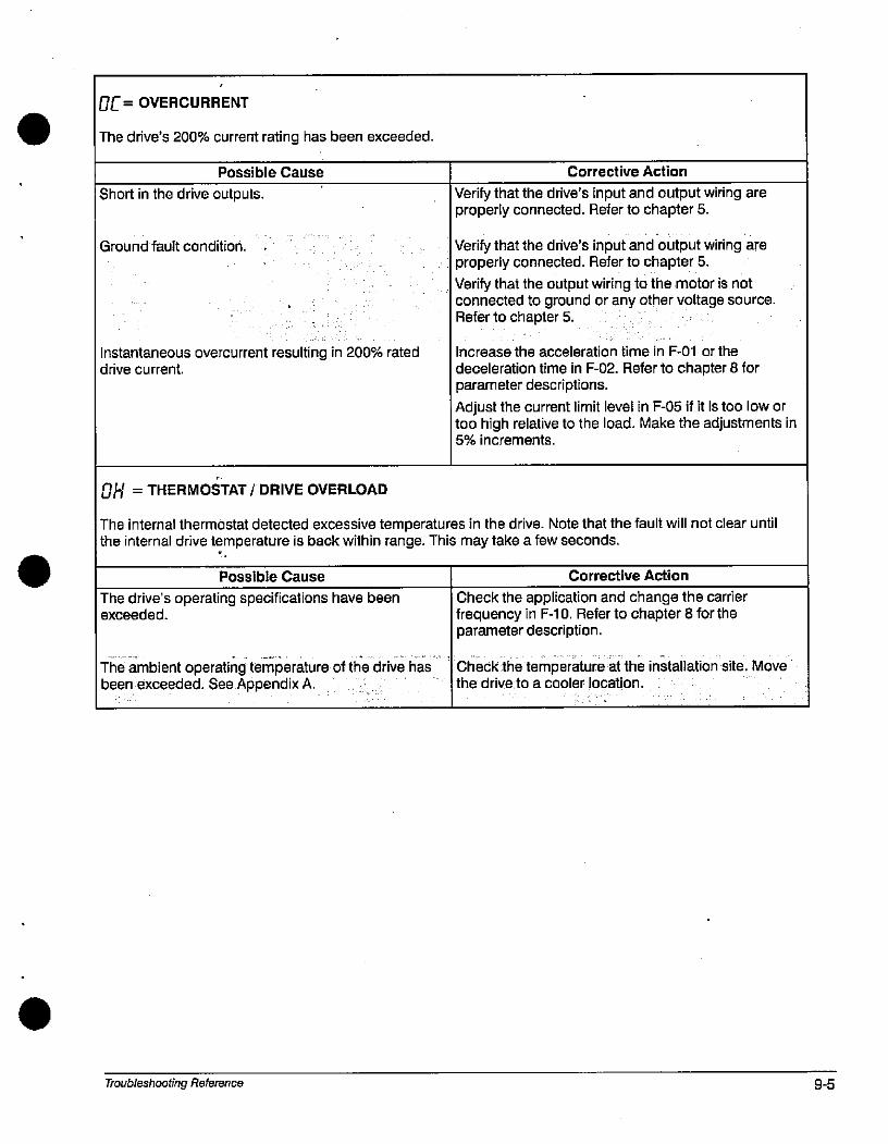
.
.
06= OVERCURRENT
The drive's 200% current rating has been exceeded.
Possible Cause
Short in the drive outputs.
Ground fault condition.
Instantaneous overcurrent resulting in 200% rateddrive current.
OH = THERMOSTAT / DRIVE OVERLOAD
Corrective Action
Verify that the drive's input and output wiring areproperly connected. Refer to chapter 5.
Verify that the drive's input and output wiring areproperly connected. Refer to chapter 5.
Verify that the output wiring to the motor is notconnected to ground or any other voltage source.Refer to chapter 5.
increase the acceleration time in F-01 or the
deceleration time in F-02. Refer to chapter 8 forparameter descriptions.
Adjust the current limit level in F-05 if it is too low ortoo high relative to the load. Make the adjustments in5% increments.
The internal thermostat detected excessive temperatures in the drive. Note that the fault will not clear untilthe internal drive temperature is back within range. This may take a few seconds.
Possible Cause
The drive's operating specifications have beenexceeded.
The ambient operating temperature of the drive hasbeen exceeded. See Appendix A.
Troubleshooting Reference
Corrective Action
Check the application and change the carrierfrequency in F-10. Refer to chapter 8 for theparameter description.
Check the temperature at the installation site. Movethe driveto a cooler location.
9-5
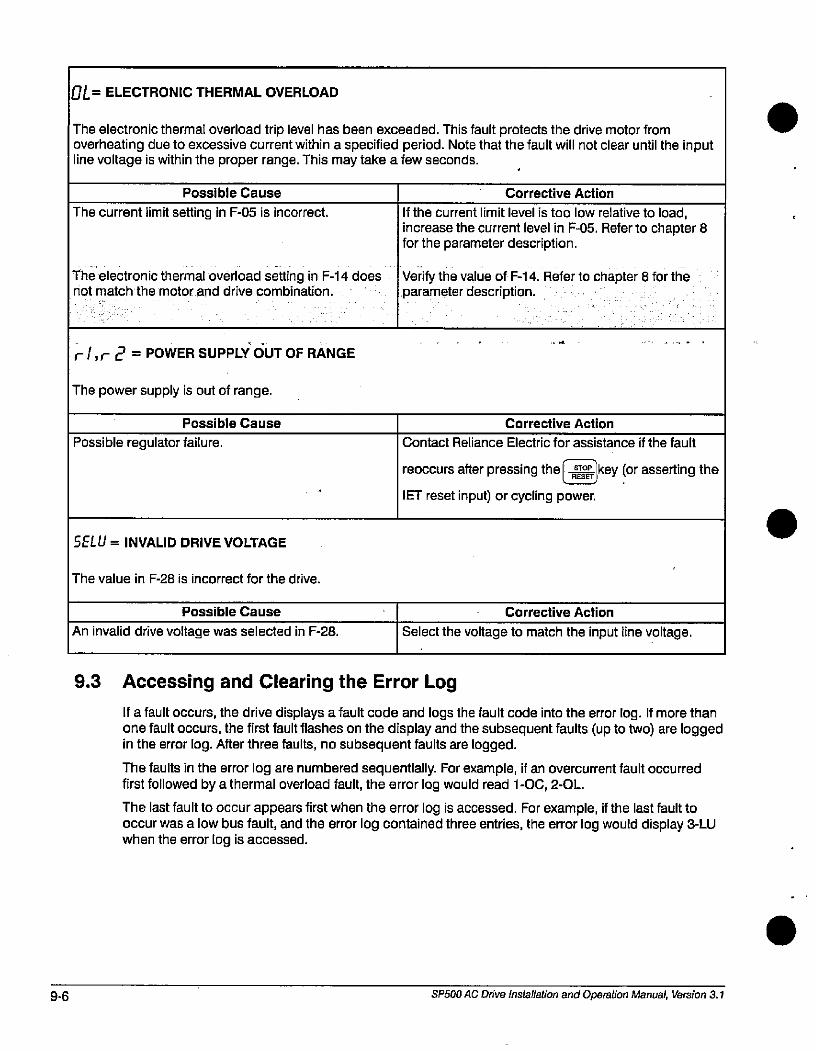
9-6
OL= ELECTRONIC THERMAL OVERLOAD
The electronic thermal overload trip level has been exceeded. This fault protects the drive motor fromoverheating due to excessive current within a specified period. Note that the fault will not clear until the inputline voltage is within the proper range. This may take a few seconds.
Possible Cause
The current limit setting in F-05 is incorrect.
The electronic thermal overload setting in F-14 doesnot match the motor and drive combination.
r/,r 2 = POWER SUPPLY OUT OF RANGE
The power supply is out of range.
Possible Cause
Possible regulator failure.
SELU = INVALID DRIVE VOLTAGE
The value in F-28 is incorrect for the drive.
Possible Cause
An invalid drive voltage was selected in F-28.
9.3
Corrective Action
If the current limit level is too low relative to load,
increase the current level in F-05. Refer to chapter 8for the parameter description.
Verify the value of F-14. Refer to chapter 8 for theparameter description.
Corrective Action
Contact Reliance Electric for assistance if the fault
reoccurs after pressing the*key for asserting theNET reset input) or cycling power.
Corrective Action
Select the voltage to match the input line voltage.
Accessing and Clearing the Error Log
If a fault occurs, the drive displays a fault code and logs the fault code into the error log. If more thanone fault occurs, the first fault flashes on the display and the subsequent faults (up to two) are loggedin the error log. After three faults, no subsequent faults are logged.
The faults in the error log are numbered sequentially. For example, if an overcurrent fault occurredfirst followed by a thermal overload fault, the error log would read 1 -OC, 2-OL.
The last fault to occur appears first when the error log is accessed. For example, if the last fault tooccur was a low bus fault, and the error log contained three entries, the error log would display 3-LUwhen the error log is accessed.
SP500 AC Drive Installation and Operation Manual, Version 3.1
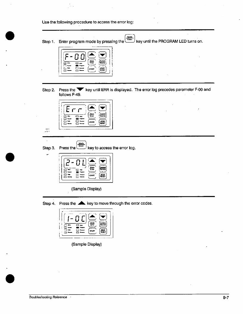
Use the following procedure to access the error log:
Step 1. Enter program mode by pressing the J key until the PROGRAM LED turns on.
F-00E Z. = -0- CZ] P-•f,
C- m-
(-2 ;*.14L__1 L__j
IE®
Step 2. Press the V' key until ERR is displayed. The error log precedes parameter F-00 andfollows F-49.
Erre - m-
0./.----
C --
1_ModilStep 3. Press the l-EZY key to access the error log.
Step 4.
2-OL**rz;7 m1
m- m- 1 Elli + A.... 1
0 - 0-
0 - e - Ell
(Sample Display)
Press the AA key to move through the error codes.
1 B- o i11%5 ==-
Troubleshooting Reference
CL l*J
(Sample Display)
9-7
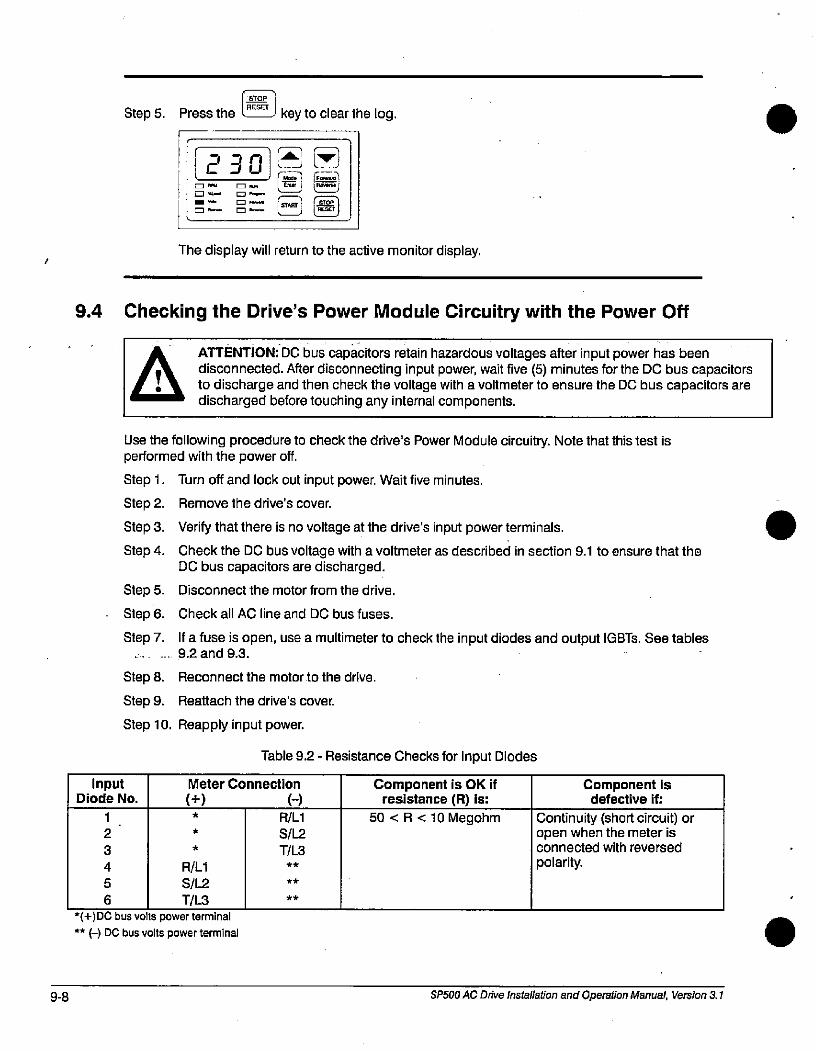
9-8
1 STOP 1
Step 5. Press the lZZLI key to clear the log.
7 1 MClu
C] "61 e-
EZ=m- m-
The display will return to the active monitor display.
9.4 Checking the Drive's Power Module Circuitry with the Power Off
InputDiode No.
1
2
3
4
5
6
aATTENTION: DC bus capacitors retain hazardous voltages after input power has beendisconnected. After disconnecting input power, wait five (5) minutes for the DC bus capacitorsto discharge and then check the voltage with a voltmeter to ensure the DC bus capacitors aredischarged before touching any internal components.
Use the following procedure to check the drive's Power Module circuitry. Note that this test isperformed with the power off.
Step 1. Turn off and lock out input power. Wait five minutes.
Step 2. Remove the drive's cover.
Step 3. Verify that there is no voltage at the drive's input power terminals.
Step 4. Check the DC bus voltage with a voltmeter as described in section 9.1 to ensure that theDC bus capacitors are discharged.
Step 5. Disconnect the motor from the drive.
Step 6. Check all AC line and DC bus fuses.
Step 7. If a fuse is open, use a multimeter to check the input diodes and output IGBTs. See tables9.2 and 9.3.
Step 8. Reconnect the motor to the drive.
Step 9. Reattach the drive's cover.
Step 10. Reapply input power.
*
*
R/Ll
S/L2
T7L3
Table 9.2 - Resistance Checks for Input Diodes
Meter Connection
H*
*(+)DC bus volts power terminal
** (-) DC bus volts power terminal
R/Ll
S/L2
17L3**
**
**
Component is OK ifresistance (R) is:
50 <R<10 Megohm
Component isdefective if:
Continuity (short circuit) oropen when the meter isconnected with reversed
polarity.
SP500 AC Drive Installation and Operation Manual, Version 3.1
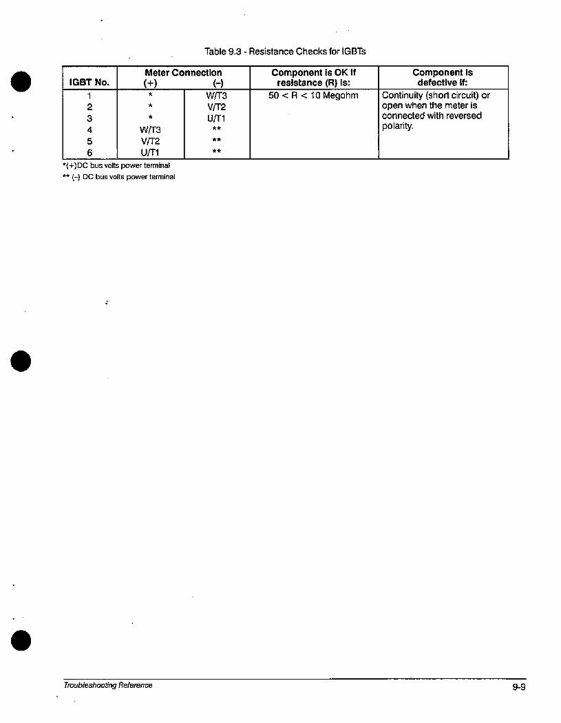
IGBT No.
1
2
3
4
5
6
*
W/T3
VF2
U/Tl
Table 9.3 - Resistance Checks for IGBTs
Meter Connection
* W/T3
V/T2U/Tl**
**
*(+)DC bus volts power terminal
** (-) DC bus volts power terminal
4
Troubleshooting Reference
**
Component is OK ifresistance (R) ls:
50 <R<10 Megohm
Component isdefective if:
Continuity (short circuit) oropen when the meter isconnected with reversed
polarity.
9-9

9-10 SP500 AC Drive Installation and Operation Manual, Version 3.1
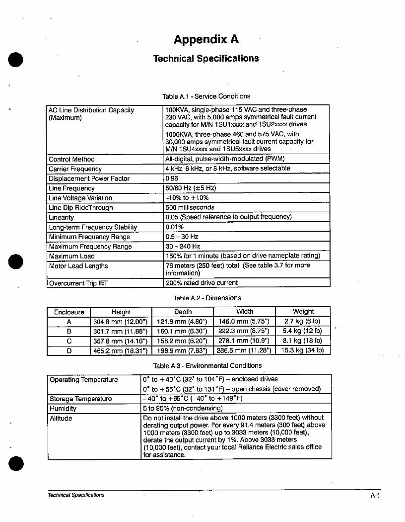
AC Une Distribution Capacity(Maximum)
Control Method
Carrier Frequency
Displacement Power Factor
Line Frequency
Line Voltage Variation
Line Dip RideThrough
Linearity
Long4erm Frequency Stability
Minimum Frequency Range
Maximum Frequency Range
Maximum Load
Motor Lead Lengths
Overcurrent Trip IET
Enclosure
A
B
C
D
Height
304.8 mm (12.00")
301.7 mm (11.88")
357.8 mm (14.10")
465.2 mm (18.31")
Operating Temperature
Storage Temperature
Humidity
Altitude
Technical Specifications
Appendix A
Technical Specifications
Table A.1 - Service Conditions
100KVA, single-phase 115 VAC and three-phase230 VAC, with 5,000 amps symmetrical fault currentcapacity for M/N 1 SU l=xx and 1 SU21000< drives
1000KVA, three-phase 460 and 575 VAC, with30,000 amps symmetrical fault current capacity forM/N 1 SUzboox and 1 SU5xox drives
All-digital, pulse-width-modulated (PWM)4 kHz, 6 kHz, or 8 kHz, software selectable
0.96
50/60 Hz (+5 Hz)
-10% to +10%
500 milliseconds
0.05 (Speed reference to output frequency)0.01%
0.5 - 30 Hz
30 - 240 Hz
150% for 1 minute (based on drive nameplate rating)76 meters (250 feet) total (See table 3.7 for moreinformation)
200% rated drive current
Table A.2 - Dimensions
Depth
121.9 mm (4.80")
160.1 mm (6.30")
158.2 mm (6.20")
198.9 mm (7.83")
Width
146.0 mm (5.75")
222.3 mm (8.75")278.1 mm (10.9")
286.5 mm (11.28")
Table A.3 - Environmental Conditions
Weight
2.7 kg (6 lb)
5.4 kg (12 lb)
8.1 kg (18 lb)
15.3 kg (34 lb)
00 to +40®C (32' to 104®F) -enclosed drives
0® to +55 C (32' to 131 'F) -open chassis (cover removed)-40' to +65'C (-40' to +149'F)
5 to 95% (non-condensing)
Do not install the drive above 1000 meters (3300 feet) withoutderating output power. For every 91.4 meters (300 feet) above1000 meters (3300 feet) up to 3033 meters (10,000 feet),derate the output current by 1%. Above 3033 meters(10,000 feet), contact your local Reliance Electric sales officefor assistance.
A-1
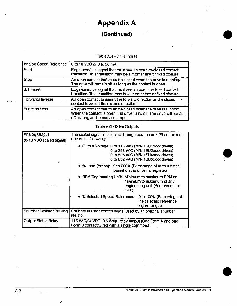
A-2
Analog Speed Reference
Start
Stop
IET Reset
Forward/Reverse
Function Loss
Analog Output
(0-10 VDC scaled signal)
Snubber Resistor Braking
Output Status Relay
Appendix A
(Continued)
Table A.4 - Drive Inputs
0 to 10 VDC or 0 to 20 mA
Edge-sensitive signal that must see an open-to-closed contacttransition. This transition may be a momentary or fixed closure.
An open contact that must be closed when the drive is running.The drive will remain off as long as the contact is open.
Edge-sensitive signal that must see an open-to-closed contacttransition. This transition may be a momentary or fixed closure.
An open contact to assert the forward direction and a closedcontact to assert the reverse direction.
An open contact that must be closed when the drive is running.When the contact is open, the drive turns off. The drive will remainoff as long as the contact is open.
Table A.5 - Drive Outputs
The scaled signal is selected through parameter F-29 and can beone of the following:
• Output Voltage: 0 to 115 VAC (M/N. 1 SU1 )000 drives)0 to 253 VAC (M/N 1 SU2)000< drives)0 to 506 VAC (M/N 1 SU4)000< drives)0 to 632 VAC (M/N 1 SU5)000 drives)
• % Load (Amps): 0 to 200% (Percentage of output ampsbased on the drive nameplate.)
• RPM/Engineering Unit: Minimum to maximum RPM orminimum to maximum of anyengineering unit (See parameterF-08)
• % Selected Speed Reference: 0 to 100% (Percentage ofthe selected reference
signal range.)
Snubber resistor control signal used by an optional snubberresistor. -
115 VAC/24 VDC, 0.5 Amp, relay output (One Form A and oneForm B contact wired with a single common.)
SP500 AC Drive Installation and Operation Manual, Version 3.1
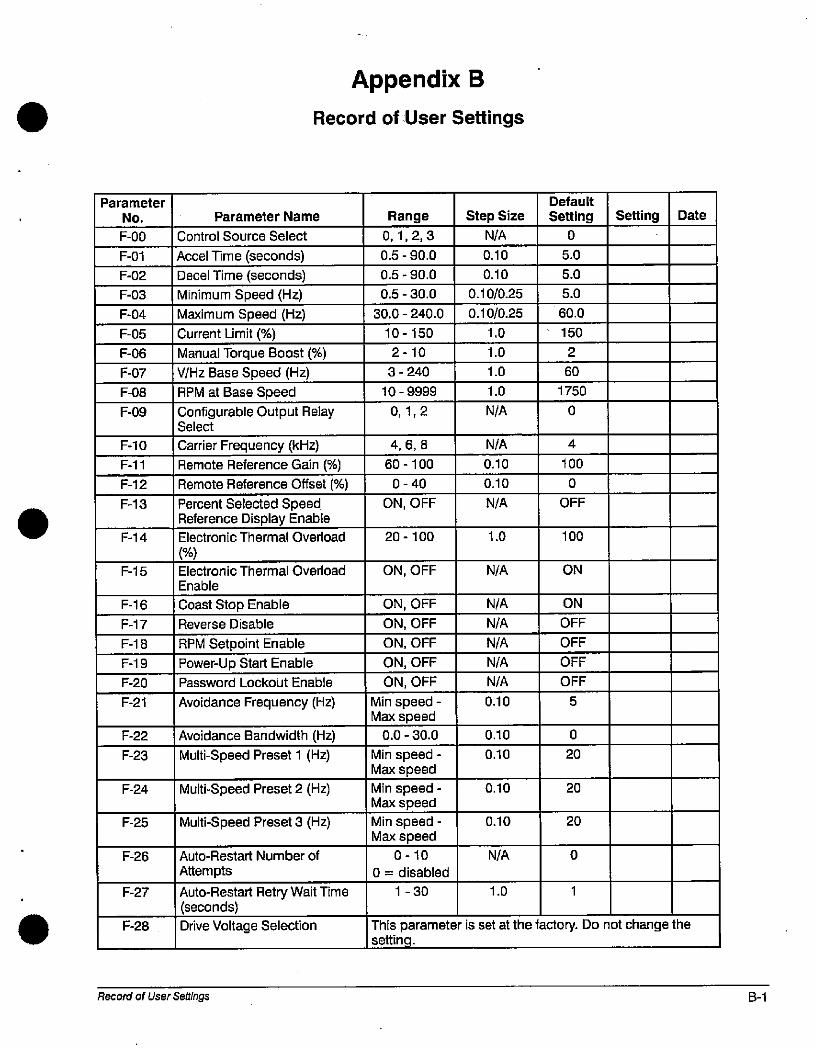
Parameter
No.
F-00
F-01
F-02
F-03
F-04
F-05
F-06
F-07
F-08
F-09
F-10
F-11
F-12
F-13
F-14
F-15
F-16
F-17
F-18
F-19
F-20
F-21
F-22
F-23
F-24
F-25
F-26
F-27
F-28
Parameter Name
Control Source Select
Accel Time (seconds)
Decel Time (seconds)
Minimum Speed (Hz)
Maximum Speed (Hz)
Current Limit (96)
Manual Torque Boost (%)
V/Hz Base Speed (Hz)
RPM at Base Speed
Configurable Output RelaySelect
Carrier Frequency (kHz)
Remote Reference Gain (%)
Appendix B
Record of User Settings
Remote Reference Offset (%)
Percent Selected SpeedReference Display EnableElectronic Thermal Overload
(%)
Electronic Thermal Overload
Enable
Coast Stop Enable
Reverse Disable
RPM Setpoint Enable
Power-Up Start EnablePassword Lookout Enable
Avoidance Frequency (Hz)
Avoidance Bandwidth (Hz)
Multi-Speed Preset 1 (Hz)
Multi-Speed Preset 2 (Hz)
Multi-Speed Preset 3 (Hz)
Auto-Restart Number of
Attempts
Auto-Restart Retry Wait Time(seconds)
Drive Voltage Selection
Record of User Settings
Range
0,1,2,3
0.5 - 90.0
0.5 - 90.0
0.5 - 30.0
30.0 - 240.0
10-150
2-10
3 - 240
10 -9999
0,1,2
4,6,8
60-100
0-40
ON, OFF
20-100
ON, OFF
ON, OFF
ON, OFF
ON, OFF
ON, OFF
ON, OFF
Min speed -Max speed
0.0 - 30.0
Min speed -Max speed
Min speed -Max speed
Min speed -Max speed
0-10
0 = disabled
1 - 30
Step Size
N/A
0.10
0.10
0.10/0.25
0.10/0.25
1.0
1.0
1.0
1.0
N/A
N/A
0.10
0.10
N/A
1.0
0.10
0.10
0.10
N/A
N/A
N/A
N/A
N/A
N/A
0.10
0.10
N/A
1.0
Default
Setting
0
5.0
5.0
5.0
60.0
150
2
60
1750
0
100
0
OFF
4
100
ON
0
20
20
20
1
0
Setting
This parameter is set at the factory. Do not change thesetting.
ON
OFF
OFF
OFF
OFF
5
Date
B-1
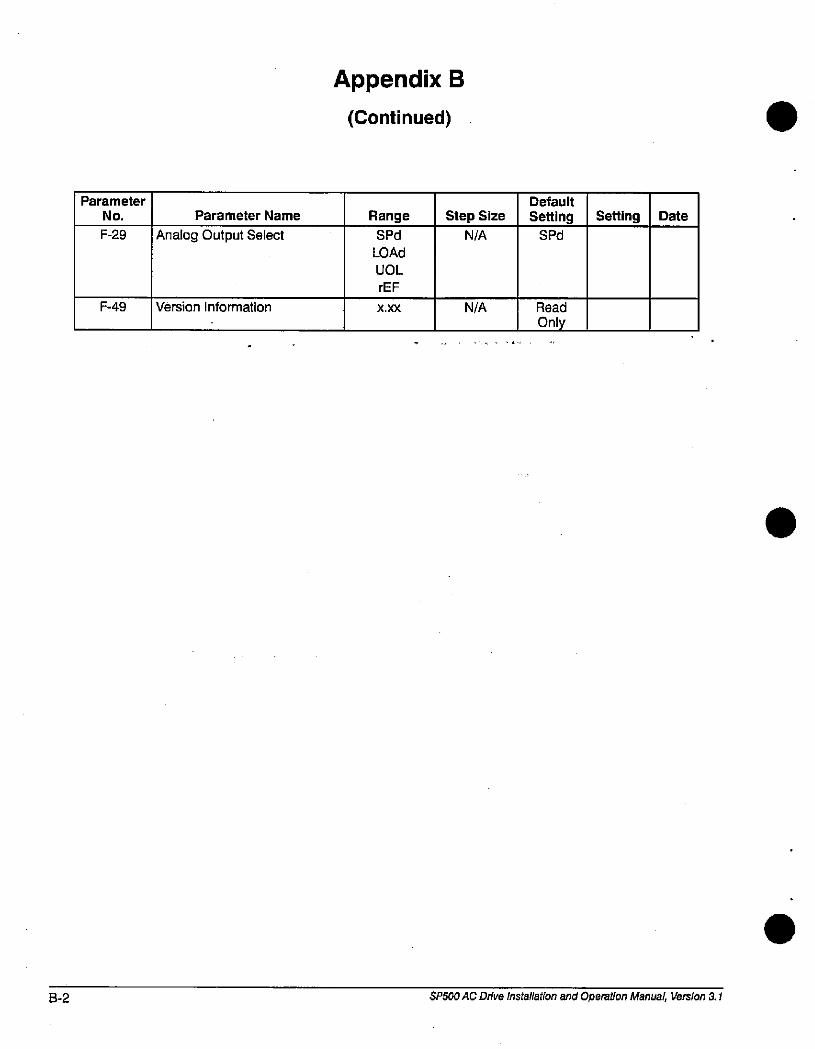
8-2
Parameter
No.
F-29
F-49
Parameter Name
Analog Output Select
Version Information
Appendix B
(Continued)
Range
SPd
LOAd
UOL
rEF
X.XX
Step Size
N/A
N/A
Default
SettingSPd
Read
Only
Setting Date
SP500 AC Drive installation and Operation Manual, Version 3.1
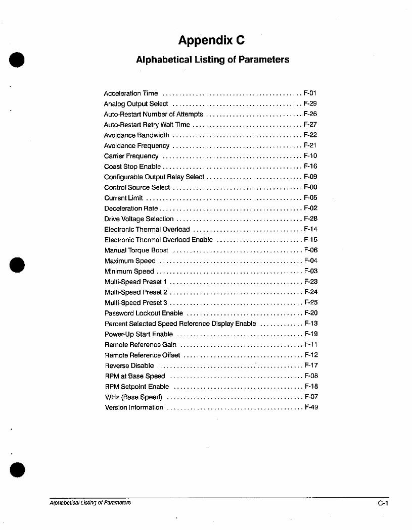
Appendix C
Alphabetical Listing of Parameters
Acceleration Time .............................. . F-01
Analog Output Select ............................. . F-29
Auto-Restart Number of Attempts .................... . F-26
Auto-Restart Retry Wait Time . . . . . . . . . . . . . . . . . . . . . , , .F-27
Avoidance Bandwidth ............................... . F-22
Avoidance Frequency ........................ .. F-21
Carrier Frequency ............................. F-10
Coast Stop Enable ................................ ... F-16
Configurable Output Relay Select.... ............. . F-09
Control Source Select............ ............... F-00
Current Limit ..................................... .... F-05
Deceleration Rate .........................,.'..... .. F-02
Drive Voltage Selection ............................... .. F-28
Electronic Thermal Overload ..................... .. F-14
Electronic Thermal Overload Enable ......... .. F-15
Manual Torque Boost ................ .............. ... F-06
Maximum Speed ................. ............. .. F-04
Minimum Speed .................................. .. F-03
Multi-Speed Preset 1 ................................ .. F-23
Multi-Speed Preset 2 ................................ ... F-24
Multi-Speed Preset 3 ................................. .. F-25
Password Lockout Enable ...................... .. F-20
Percent Selected Speed Reference Display Enable ... F-13
Power-Up Start Enable ............................. . F-19
Remote Reference Gain ......................... F-11
Remote Reference Offset ................ .......... ... F-12
Reverse Disable ................................... F-17
RPM at Base Speed ................................. . F-08
RPM Setpoint Enable ............... .............. ...F-18
V/Hz (Base Speed) ......................................... F-07
Version Information ............................ .. F-49
Alphabetical Listing of Parameters C-1

C-2 SP500 AC Drive installation and Operation Manual, Version 3.1
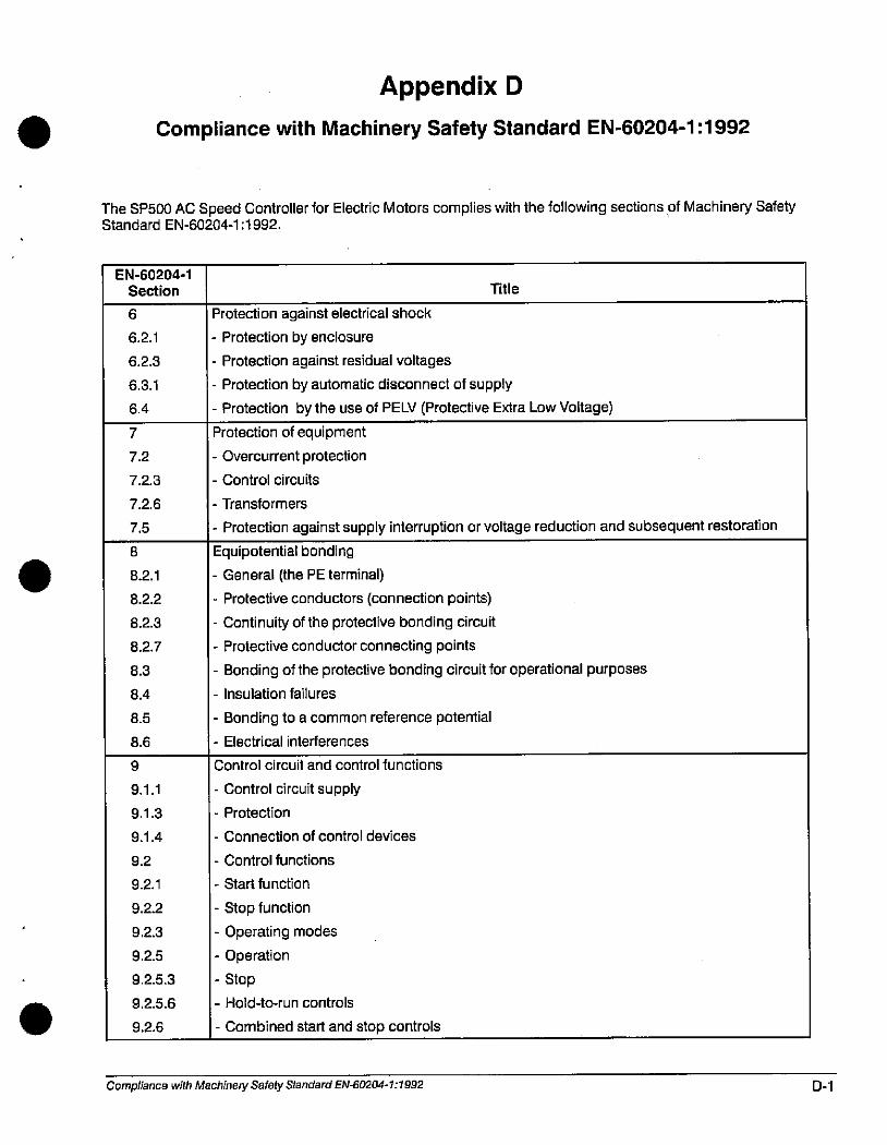
Appendix D
Compliance with Machinery Safety Standard EN-60204-1:1992
The SP500 AC Speed Controller for Electric Motors complies with the following sections of Machinery SafetyStandard EN-60204-1:1992.
EN-60204-1
Section
6
6.2.1
6.2.3
6.3.1
6.4
7
7.2
7.2.3
7.2.6
7.5
8
8.2.1
8.2.2
8.2.3
8.2.7
8.3
8.4
8.5
8.6
9
9.1.1
9.1.3
9.1.4
9.2
9.2.1
9.2.2
9.2.3
9.2.5
9.2.5.3
9.2.5.6
9.2.6
Title
Protection against electrical shock
- Protection by enclosure
- Protection against residual voltages
- Protection by automatic disconnect of supply
- Protection by the use of PELY (Protective Extra Low Voltage)
Protection of equipment
- Overcurrent protection
- Control circuits
- Transformers
- Protection against supply interruption or voltage reduction and subsequent restoration
Equipotential bonding
- General (the PE terminal)
- Protective conductors (connection points)
- Continuity of the protective bonding circuit
- Protective conductor connecting points
- Bonding of the protective bonding circuit for operational purposes
- Insulation failures
- Bonding to a common reference potential
- Electrical interferences
Control circuit and control functions
- Control circuit supply
- Protection
- Connection of control devices
- Control functions
- Start function
- Stop function
- Operating modes
- Operation
- Stop
- Hold-to-run controls
- Combined start and stop controls
Compliance with Machinery Safety Standard EN-60204-1:1992 D-1
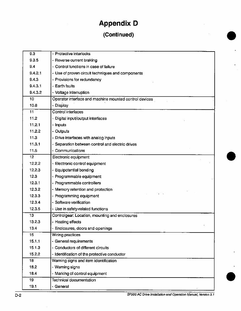
D-2
19.1
18
18.2
18.4
19
10
10.8
9.3
9.3.5
9.4
9.4.2.1
9.4.3
9.4.3.1
9.4.3.2
11
11.2
11.2.1
11.2.2
11.3
11.3.1
11.5
12
12.2.2
12.2.3
12.3
12.3.1
12.3.2
12.3.3
12.3.4
12.3.5
13
13.2.3
13.4
15
15.1.1
15.1.3
15.2.2
Appendix D
(Continued)
- Protective interlocks
- Reverse current braking
- Control functions in case of failure
- Use of proven circuit techniques and components
- Provisions for redundancy
- Earth faults
- Voltage interruption
Operator interface and machine mounted control devices
- Display
Control interfaces
- Digital input/output interfaces
- Inputs
- Outputs
- Drive interfaces with analog inputs
- Separation between control and electric drives
- Communications
Electronic equipment
- Electronic control equipment
- Equipotential bonding
- Programmable equipment
- Programmable controllers
- Memory retention and protection
- Programming equipment
- Software verification
- Use in safety-related functions
Controlgear: Location, mounting and enclosures
- Heating effects
- Enclosures, doors and openings
Wiring practices
- General requirements
- Conductors of different circuits
- Identification of the protective conductor
Warning signs and item identification
- Warning signs
- Marking of control equipment
Technical documentation
- General
SP500 AC Drive Installation and Operation Manual, Version 3.1
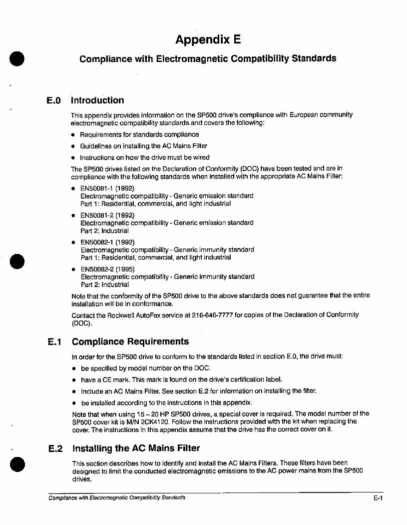
Appendix E
Compliance with Electromagnetic Compatibility Standards
E.0 Introduction
This appendix provides information on the SP500 drive's compliance with European communityelectromagnetic compatibility standards and covers the following:
• Requirements for standards compliance
• Guidelines on installing the AC Mains Filter
• Instructions on how the drive must be wired
The SP500 drives listed on the Declaration of Conformity (DOC) have been tested and are incompliance with the following standards when installed with the appropriate AC Mains Filter:
• EN50081-1 (1992)Electromagnetic compatibility - Generic emission standardPart 1: Residential, commercial, and light industrial
• EN50081-2 (1992)Electromagnetic compatibility - Generic emission standardPart 2: Industrial
• EN50082-1 (1992)Electromagnetic compatibility - Generic immunity standardPart 1: Residential, commercial, and light industrial
• EN50082-2 (1995)Electromagnetic compatibility - Generic immunity standardPart 2: Industrial
Note that the conformity of the SP500 drive to the above standards does not guarantee that the entireinstallation will be in conformance.
Contact the Rockwell AutoFax service at 216-646-7777 for copies of the Declaration of Conformity(DOC).
E.1 Compliance Requirements
In order for the SP500 drive to conform to the standards listed in section E.0, the drive must:
• be specified by model number on the DOC.
• have a CE mark. This mark is found on the drive's certification label.
• include an AC Mains Filter. See section E.2 for information on installing the filter.
• be installed according to the instructions in this appendix.
Note that when using 15-20 HP SP500 drives, a special cover is required. The model number of theSP500 cover kit is M/N 2CK4120. Follow the instructions provided with the kit when replacing thecover. The instructions in this appendix assume that the drive has the correct cover on it.
E.2 Installing the AC Mains Filter
. This section describes how to identify and install the AC Mains Filters. These filters have beendesigned to limit the conducted electromagnetic emissions to the AC power mains from the SP500drives.
Compliance with Electromagnetic Compatibility Standards E-1
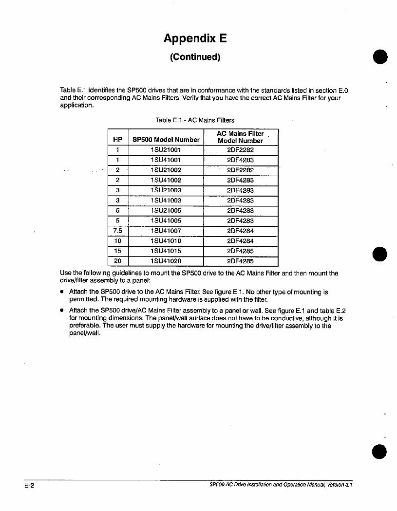
E-2
2
2
3
3
5
5
7.5
Appendix E
(Continued)
Table E.1 identifies the SP500 drives that are in conformance with the standards listed in section E.0
and their corresponding AC Mains Filters. Verify that you have the correct AC Mains Filter for yourapplication.
10
15
20
HP
1
1
Table E.1 - AC Mains Filters
SP500 Model Number
1 SU21001
1 SU41001
1 SU21002
1 SU41002
1 SU21003
1 SU41003
1 SU21005
1 SU41005
1 SU41007
1 SU41010
1 SU41015
1 SU41020
AC Mains Filter .Model Number
2DF2282
2DF4283
2DF2282
2DF4283
2DF4283
2DF4283
2DF4283
2DF4283
2DF4284
2DF4284
2DF4285
2DF4285
Use the following guidelines to mount the SP500 drive to the AC Mains Filter and then mount thedrive/filter assembly to a panel:
Attach the SP500 drive to the AC Mains Filter. See figure E.1. No other type of mounting ispermitted. The required mounting hardware is supplied with the filter.
Attach the SP500 drive/AC Mains Filter assembly to a panel or wall. See figure E.1 and table E.2for mounting dimensions. The panel/wall surface does not have to be conductive, although it ispreferable. The user must supply the hardware for mounting the drive/filter assembly to thepanel/wall.
SP500 AC Drive Installation and Operation Manual, Version 3.1
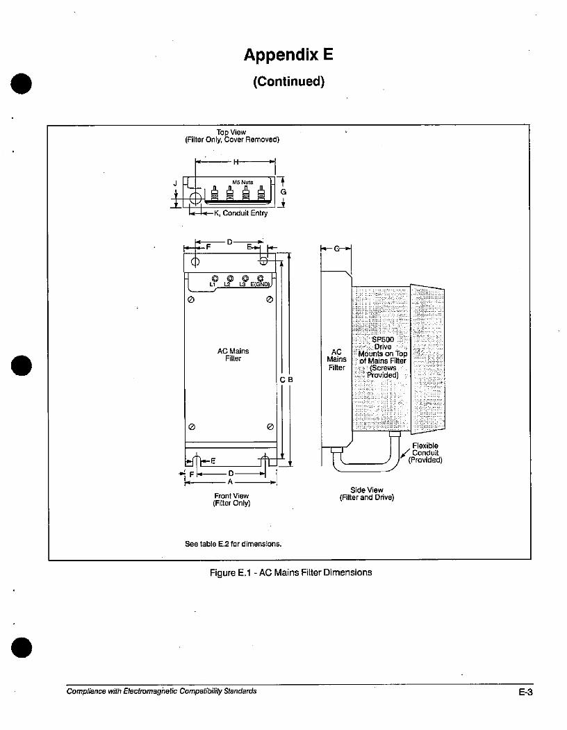
0
IlL
0
0
Appendix E
(Continued)
Top View(Filter Only, Cover Removed)
Il
t-- MS Nuts
101.A A A 1&414-K, Conduit Entry
0
E
D E-»111.-0000-Ll l-2 L.3 E(GND)-
AC MainsFilter
1.F & 2Front View
(Filter Only)
See table E.2 for dimensions.
7G
CB
A
ACMains
Filter
SP500
DriveMounts on Topof Mains Filter
(ScrewsProvided)
Side View
(Filter and Drive)
Figure E.1 - AC Mains Filter Dimensions
Compliance with Electromagnetic Compatibility Standards
Flexible
,/ Conduit(Provided)
E-3
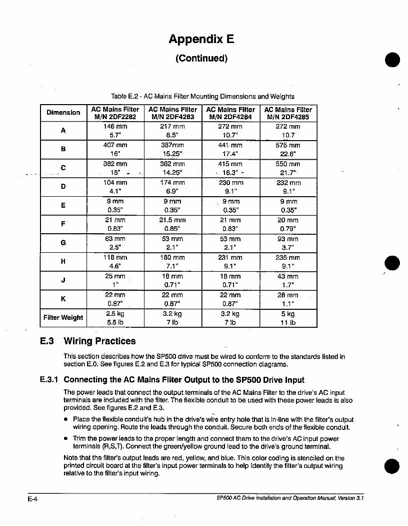
E-4
Dimension
C
J
A
D
H
G
K
E
F
B
Filter Weight
Appendix E
(Continued)
Table E.2 - AC Mains Filter Mounting Dimensions and Weights
AC Mains Filter
M/N 2DF2282
146 mm
5.7"
407 mm
16"
382 mm
15'
104 mm
4.1"
9 mm
0.35"
21 mm
0.83"
63 mm
2.5"
118 mm
4.6"
25 mm
1"
22 mm
0.87"
2.5 kg
5.5 Ib
E.3 Wiring Practices
AC Mains Filter
M/N 2DF4283
217 mm
8.5"
387mm
15.25.
362 mm
14.25"
174 mm
6.9"
9 mm
0.35"
21.5 mm
0.85"
53 mm
2.1"
180 mm
7.1 "
18 mm
0.71 "
22 mm
0.87"
3.2 kg7 Ib
AC Mains Filter
M/N 2DF4284
272 mm
10.7"
441 mm
17.4"
415 mm
16.3" -
230 mm
9.1 "
9 mm
0.35"
21 mm
0.83"
53 mm
2.1.
231 mm
9.1 '
18 mm
0.71"
22 mm
0.87"
3.2 kg7 Ib
AC Mains Filter
M/N 2DF4285
272 mm
10.7
575 mm
22.6"
550 mm
21.7"
232 mm
9.1"
9 mm
0.35"
20 mm
0.79"
93 mm
3.7"
235 mm
9.1 "
43 mm
1.7"
28 mm
1.1"
5 kg11 Ib
This section describes how the SP500 drive must be wired to conform to the standards listed in
section E.0. See figures E.2 and E.3 for typical SP500 connection diagrams.
E.3.1 Connecting the AC Malns Filter Output to the SP500 Drive Input
The power leads that connect the output terminals of the AC Mains Filter to the drive's AC inputterminals are included with the filter. The flexible conduit to be used with these power leads is alsoprovided. See figures E.2 and E.3.
• Place the flexible conduit's hub in the drive's wire entry hole that is in-line with the filter's outputwiring opening. Route the leads through the conduit. Secure both ends of the flexible conduit.
Trim the power leads to the proper length and connect them to the drive's AC input powerterminals (R,S,T). Connect the green/yellow ground lead to the drive's ground terminal.
Note that the filter's output leads are red, yellow, and blue. This color coding is stenciled on theprinted circuit board at the filter's input power terminals to help identify the filter's output wiringrelative to the filter's input wiring.
SP500 AC Drive installation and Operation Manual, Version 3.1
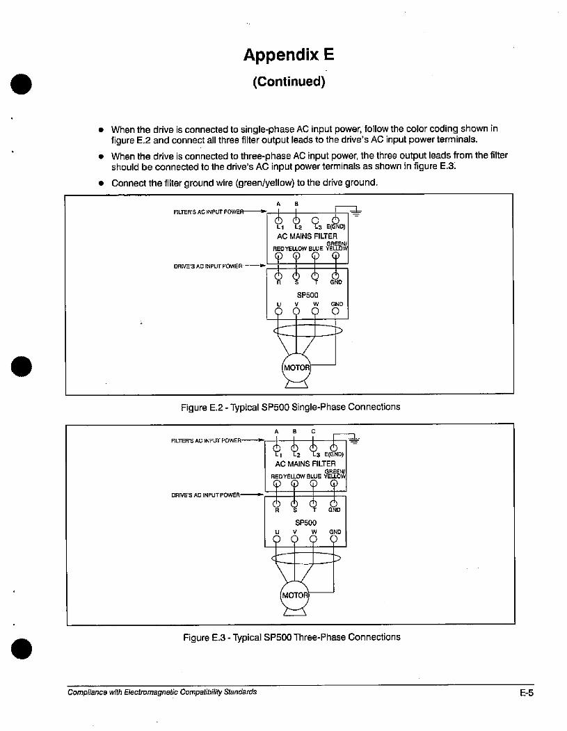
Appendix E
(Continued)
• When the drive is connected to single-phase AC input power, follow the color coding shown infigure E.2 and connect all three filter output leads to the drive's AC input power terminals.
• When the drive is connected to three-phase AC input power, the three output leads from the filtershould be connected to the drive's AC input power terminals as shown in figure E.3.
• Connect the filter ground wire (green/yellow) to the drive ground.
FILTER'S AC INPUT POWER---+-
DRIVE'S AC INPUT POWER-
A 8
&606=Ll L2 L3 E(GND)AC MAINS FILIER
GREEN/
REDYEUOW BLUE YELLOW
SP500
u 6#
MOTOR
GND
0
Figure E.2 - Typical SP500 Single-Phase Connections
FILTERS AG INPUT POWER-
DRIVE'SAC INPUT POWER-
C
--1 5 6 r-*Ll L2 L3 E(GND)
AC MAINS FILTERGREEN/
REDYELLOW BLUE YEUOW
fs,1SP500
Udd
MOTOR
Figure E.3 - Typical SP500 Three-Phase Connections
Compliance with Electromagnetic Compatibility Standards
GND
0
E-5
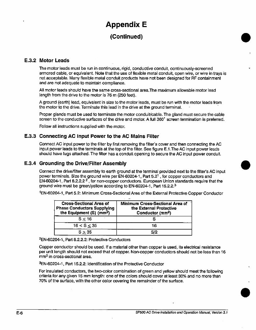
E-6
E.3.2 Motor Leads
Appendix E
(Continued)
The motor leads must be run in continuous, rigid, conductive conduit, continuously-screenedarmored cable, or equivalent. Note that the use of flexible metal conduit, open wire, or wire in trays isnot acceptable. Many flexible metal conduit products have not been designed for RF containmentand are not adequate to maintain compliance.
All motor leads should have the same cross-sectional area.The maximum allowable motor lead
length from the drive to the motor is 76 m (250 feet).
A ground (earth) lead, equivalent in size to the motor leads, must be run with the motor leads fromthe motor to the drive. Terminate this lead in the drive at the ground terminal.
Proper glands must be used to terminate the motor conduit/cable. The gland must secure the cablescreen to the conductive surfaces of the drive and motor. A full 360' screen termination is preferred.
Follow all instructions supplied with the motor.
E.3.3 Connecting AC Input Power to the AC Mains Filter
Connect AC input power to the filter by first removing the filter's cover and then connecting the ACinput power leads to the terminals at the top of the filter. See figure E.1.The AC input power leadsshould have lugs attached. The filter has a conduit opening to secure the AC input power conduit.
E.3.4 Grounding the Drive/Filter Assembly
Connect the drive/filter assembly to earth ground at the terminal provided next to the filter's AC inputpower terminals. Size the ground wire per EN-60204-1, Part 5.21 , for copper conductors andEN-60204-1, Part 8.2.2.2 2, for non-copper conductors. European Union standards require that theground wire must be green/yellow according to EN-60204-1, Part 15.2.2.3
1EN-60204-1, Part 5.2: Minimum Cross-Sectional Area of the External Protective Copper Conductor
Cross-Sectional Area of
Phase Conductors Supplyingthe Equipment (S) (mm2)
S<16
16<S<35
S > 35
Minimum Cross-Sectional Area of
the External Protective
Conductor (mm2)
S
2EN-60204-1, Part 8.2.2.2: Protective Conductors
16
S12
Copper conductor should be used. If a material other than copper is used, its electrical resistanceper unit length should not exceed that of copper. Non-copper conductors should not be less than 16mm2 in cross-sectional area.
3EN-60204-1, Part 15.2.2: Identification of the Protective Conductor
For insulated conductors, the two-color combination of green and yellow should meet the followingcriteria for any given 15 mm length: one of the colors should cover at least 30% and no more than70% of the surface, with the other color covering the remainder of the surface.
SP500 AC Drive Installation and Operation Manual, Version 3.1
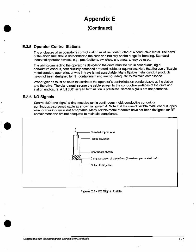
E.3.5 Operator Control Stations
Appendix E
(Continued)
The enclosure of an operator's control station must be constructed of a conductive metal. The coverof the enclosure should be bonded to the case and not rely on the hinge for bonding. Standardindustrial operator devices, e.g., pushbuttons, switches, and meters, may be used.
The wiring connecting the operator's devices to the drive must be run in continuous, rigid,conductive conduit, continuously-screened armored cable, or equivalent. Note that the use of flexiblemetal conduit, open wire, or wire in trays is not acceptable. Many flexible metal conduit productshave not been designed for RF containment and are not adequate to maintain compliance.
Proper glands must be used to terminate the operator's control station conduit/cable at the stationand the drive. The gland must secure the cable screen to the conductive surfaces of the drive andstation enclosure. A full 360. screen termination is preferred. Screen pigtails are not permitted.
E.3.6 1/0 Signals
Il_
t
Control (1/0) and signal Wiring must be run in continuous, rigid, conductive conduit orcontinuously-screened cable as shown in figure E.4. Note that the use of flexible metal conduit, openwire, or wire in trays is not acceptable. Many flexible metal products have not been designed for RFcontainment and are not adequate to maintain compliance.
Stranded copper wire
Plastic insulation
Inner plastic sheath
Compact screen of galvanized (tinned) copper or steel braid
Outer plastic jacket
Figure E.4 - 1/0 Signal Cable
Compliance with Electromagnetic Compatibility Standards E-7

E-8 SP500 AC Drive Installation and Operation Manual, Version 3.1
.
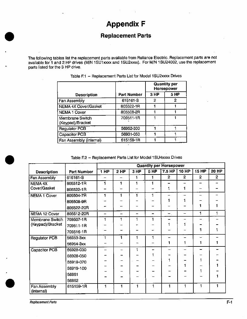
Appendix F
Replacement Parts
The following tables list the replacement parts available from Reliance Electric. Replacement parts are notavailable for 1 and 2 HP drives (M/N 1 SU1 000( and 1 SU2xx00. For M/N 1 SU24002, use the replacementparts listed for the 3 HP drive.
Description
Fan Assembly
NEMA 4X
Cover/Gasket
NEMA 1 Cover
NEMA 12 Cover
Membrane Switch
(Keypad)/Bracket
Regulator PCB
Capacitor PCB
Fan Assembly(Internal)
Replacement Parts
Table F.1 Replacement Parts List for Model 1 SU2xxxx Drives
Description
Fan Assembly
NEMA 4X Cover/Gasket
NEMA 1 Cover
Membrane Switch
(Keypad)/Bracket
Regulator PCB
Capacitor PCB
Fan Assembly (Internal)
Part Number
615161-S
805522-1 R
805508-2R
709511-1 R
56952-300
56931-050
615159-1 R
2
Quantity perHorsepower
3 HP 5 HP
1
1
1
2
Table F.2 - Replacement Parts List for Model 1 SU4xxxx Drives
Part Number
615161-S
805512-1 R
805522-1 R
805504-7R
805508-9R
805522-2OR
805512-2OR
709507-1 R
709511 -1 R
709516-1 R
56953-3xx
56954-3xx
56928-030
56928-050
56919-070
56919-100
56961
56962
615159-1 R
1
1
1 HP
1
1
1
1
2 HP
1
1
1
1
1
1
1
1
1
1
1
1
1
1
1
1
1
1
1
1
1
1
1
1
Quantity per Horsepower
3 HP 5 HP 7.5 HP 10 HP
2
1
1
1
1
1
1
1
1
1
1
1
2
1
1
1
1
15 HP
1
1
2
1
1
1
1
1
20 HP
1
1
2
1
1
1
1
1
F-1
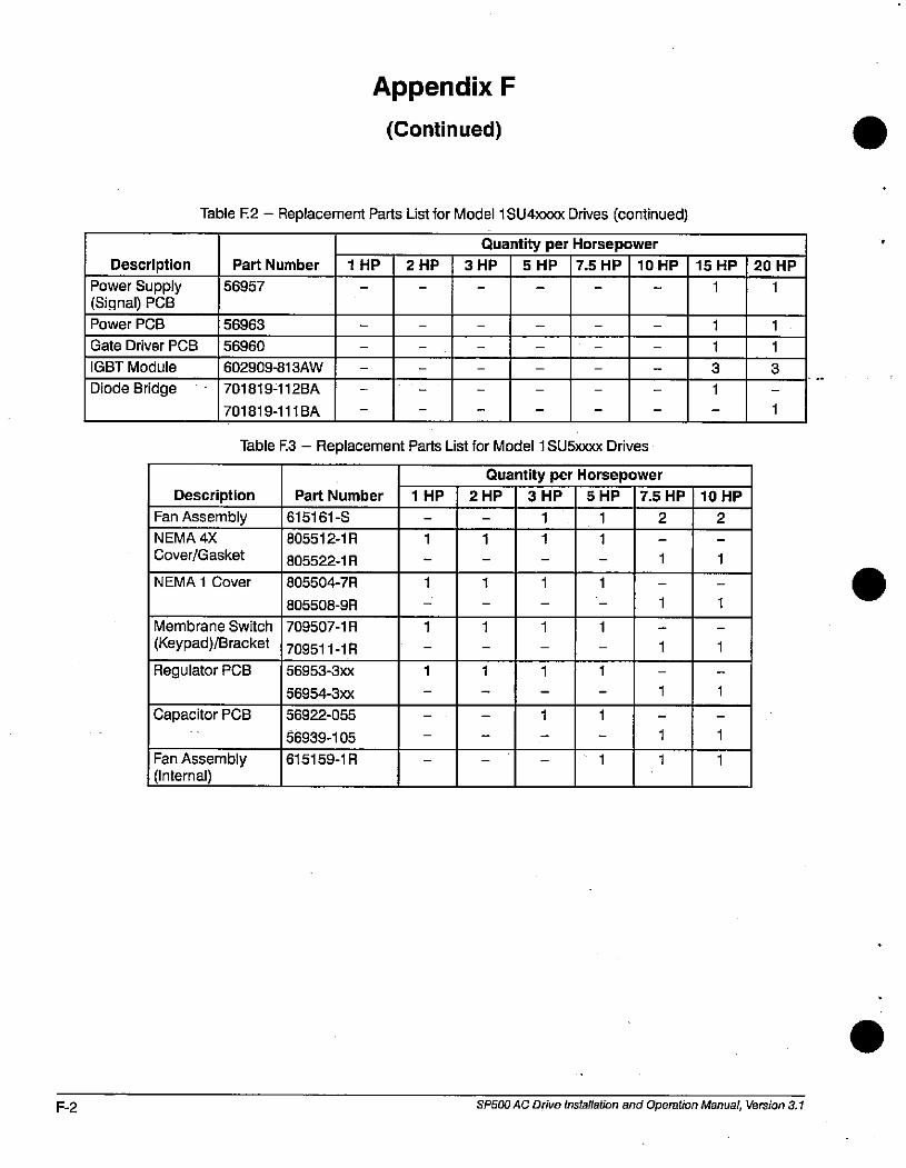
F-2
Description
Power Supply(Signal) PCB
Power PCB
Gate Driver PCB
IGBT Module
Diode Bridge
Appendix F
(Continued)
Part Number
56957
56963
56960
602909-813AW
Description
Fan AssemblyNEMA 4X
Cover/Gasket
701819-112BA
701819-111 BA
NEMA 1 Cover
1 HP 2 HP
Membrane Switch
(Keypad)/Bracket
Regulator PCB
Capacitor PCB
Fan Assembly(Internal)
Part Number
615161-S
805512-1 R
805522-1 R
805504-7R
805508-9R
709507-1 R
709511 -1 R
56953-3xx
56954-3xx
56922-055
56939-105
615159-1 R
1
1
1
1
Table F.2 - Replacement Parts List for Model 1 SU4xxxx Drives (continued)
1
1
Quantity per Horsepower
3 HP 5 HP 7.5 HP 10 HP
Table F.3 - Replacement Parts List for Model 1 SU5xxxx Drives
1 HP
1
1
Quantity per Horsepower2 HP 3 HP 5 HP 7.5 HP
1
1
1
1
1
1 1
1
1
1
1
1
1
1
1
1
1
1
1
2
15 HP
1
1
1
3
1
1
1
1
1
1
1
10 HP
2
1
1
20 HP
SP500 AC Drive Installation and Operation Manual, Version 3.1
1
1
3
.
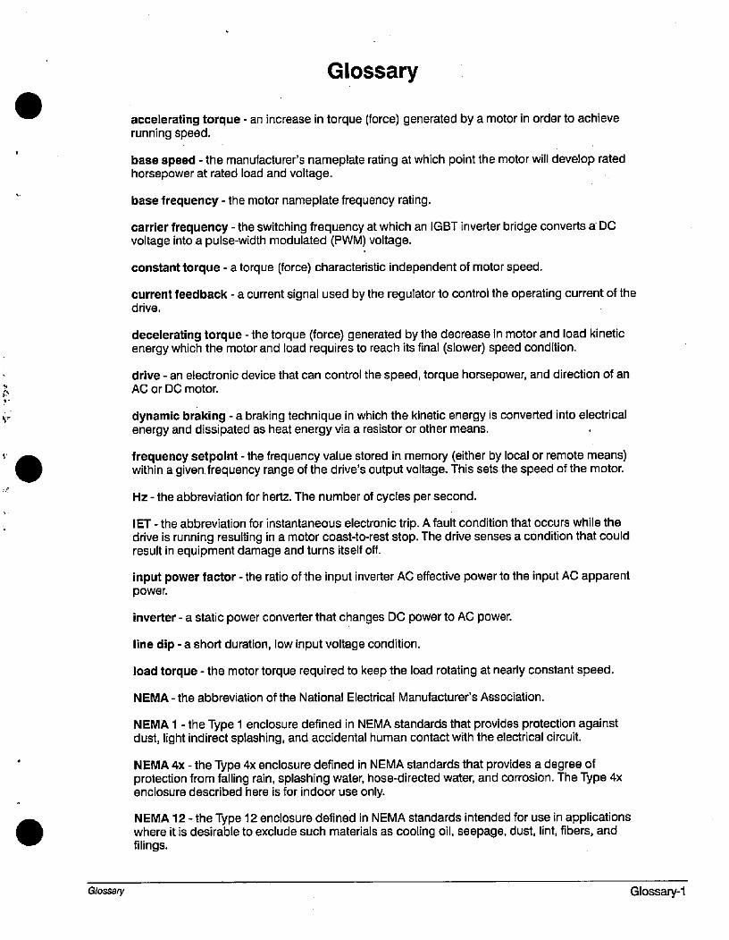
£:
Glossary
accelerating torque - an increase in torque (force) generated by a motor in order to achieverunning speed.
base speed - the manufacturer's nameplate rating at which point the motor will develop ratedhorsepower at rated load and voltage.
base frequency - the motor nameplate frequency rating.
carrier frequency - the switching frequency at which an IGBT inverter bridge converts a DCvoltage into a pulse-width modulated (PWM) voltage.
constant torque - a torque (force) characteristic independent of motor speed.
current feedback - a current signal used by the regulator to control the operating current of thedrive.
decelerating torque - the torque (force) generated by the decrease in motor and load kineticenergy which the motor and load requires to reach its final (slower) speed condition.
drive - an electronic device that can control the speed, torque horsepower, and direction of anAC or DC motor.
dynamic braking - a braking technique in which the kinetic energy is converted into electricalenergy and dissipated as heat energy via a resistor or other means.
r frequency setpoint - the frequency value stored in memory (either by local or remote means)within a given frequency range of the drive's output voltage. This sets the speed of the motor.
Hz - the abbreviation for hertz. The number of cycles per second.
IET - the abbreviation for instantaneous electronic trip. A fault condition that occurs while thedrive is running resulting in a motor coast-to-rest stop. The drive senses a condition that couldresult in equipment damage and turns itself off.
input power factor - the ratio of the input inverter AC effective power to the input AC apparentpower.
inverter - a static power converter that changes DC power to AC power.
line dip - a short duration, low input voltage condition.
load torque - the motor torque required to keep the load rotating at nearly constant speed.
NEMA - the abbreviation of the National Electrical Manufacturer's Association.
NEMA 1 - the Type 1 enclosure defined in NEMA standards that provides protection againstdust, light indirect splashing, and accidental human contact with the electrical circuit.
NEMA 4x - the Type 4x enclosure defined in NEMA standards that provides a degree ofprotection from falling rain, splashing water, hose-directed water, and corrosion. The Type 4xenclosure described here is for indoor use only.
NEMA 12 - the Type 12 enclosure defined in NEMA standards intended for use in applicationswhere it is desirable to exclude such materials as cooling oil, seepage, dust, lim, fibers, andfilings.
G/ossary Glossary-1
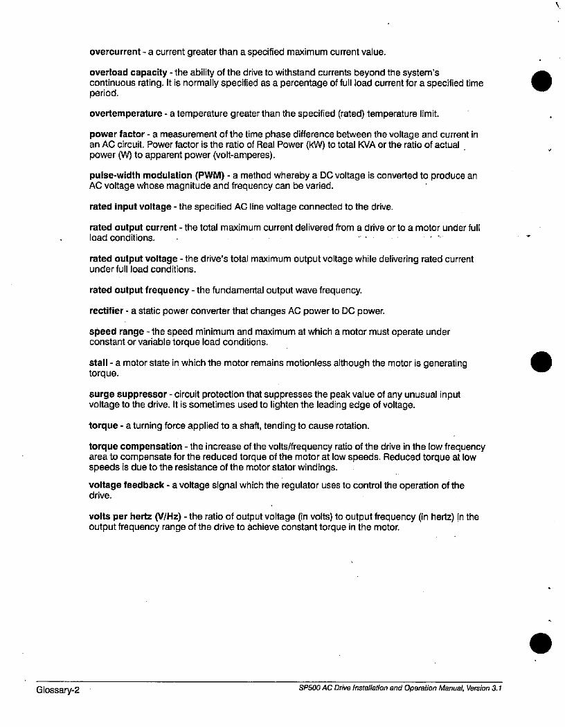
Glossary-2
overcurrent - a current greater than a specified maximum current value.
overload capacity - the ability of the drive to withstand currents beyond the system'scontinuous rating. It is normally specified as a percentage of full load current for a specified time period.
overtemperature - a temperature greater than the specified (rated) temperature limit.
power factor - a measurement of the time phase difference between the voltage and current inan AC circuit. Power factor is the ratio of Real Power (kW) to total KVA or the ratio of actualpower (W) to apparent power (volt-amperes).
pulse-width modulation (PWM) - a method whereby a DC voltage is converted to produce anAC voltage whose magnitude and frequency can be varied.
rated input voltage - the specified AC line voltage connected to the drive.
rated output current - the total maximum current delivered from a drive or to a motor under fullload conditions. .
rated output voltage - the drive's total maximum output voltage while delivering rated currentunder full load conditions.
rated output frequency - the fundamental output wave frequency.
rectifier - a static power converter that changes AC power to DC power.
speed range - the speed minimum and maximum at which a motor must operate underconstant or variable torque load conditions.
stall - a motor state in which the motor remains motionless although the motor is generatingtorque.
surge suppressor - circuit protection that suppresses the peak value of any unusual inputvoltage to the drive. It is sometimes used to lighten the leading edge of voltage.
torque - a turning force applied to a shaft, tending to cause rotation.
torque compensation - the increase of the volts/frequency ratio of the drive in the low frequencyarea to compensate for the reduced torque of the motor at low speeds. Reduced torque at lowspeeds is due to the resistance of the motor stator windings.
voltage feedback - a voltage signal which the regulator uses to control the operation of thedrive.
volts per hertz (V/Hz) - the ratio of output voltage (in volts) to output frequency (in hertz) in theoutput frequency range of the drive to achieve constant torque in the motor.
SP500 AC Drive Installation and Operation Manual, Version 3.1
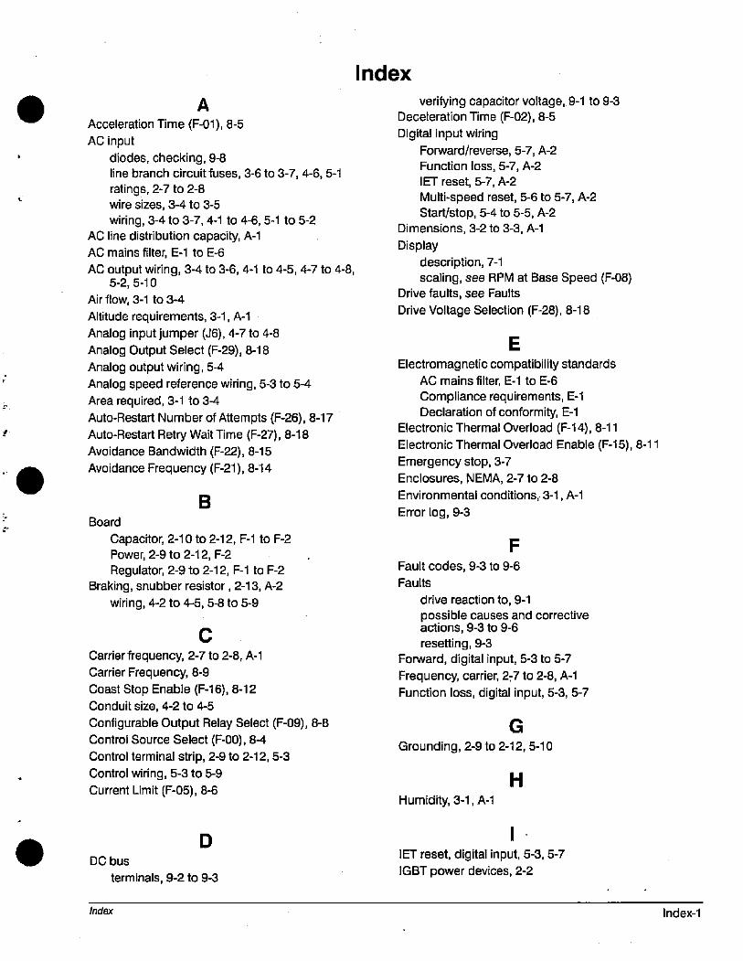
. AAcceleration Time (F-01), 8-5
AC input
· diodes, checking, 9-8
line branch circuit fuses, 3-6 to 3-7,4-6,5-1
ratings, 2-7 to 2-8wire sizes, 3-4 to 3-5
wiring, 3-4 to 3-7,4-1 to 4-6,5-1 to 5-2
AC line distribution capacity, A-1AC mains filter, E-1 to E-6
AC output wiring, 3-4 to 3-6,4-1 to 4-5,4-7 to 4-8,5-2,5-10
Air flow, 3-1 to 3-4
Altitude requirements, 3-1, A-1
Analog input jumper (J6), 4-7 to 4-8Analog Output Select (F-29), 8-18
Analog output wiring, 5-4
» Analog speed reference wiring, 5-3 to 5-4
Area required, 3-1 to 3-4
Auto-Restart Number of Attempts (F-26), 8-17
z Auto-Restart Retry Wait Time (F-27), 8-18
Avoidance Bandwidth (F-22), 8-15
Avoidance Frequency (F-21), 8-14
B
Board
Capacitor, 2-10 to 2-12, F-1 to F-2Power, 2-9 to 2-12, F-2
Regulator, 2-9 to 2-12, F-1 to F-2
Braking, snubber resistor, 2-13, A-2
wiring, 4-2 to 4-5,5-8 to 5-9
C
Carrier frequency, 2-7 to 2-8, A-1
Carrier Frequency, 8-9
Coast Stop Enable (F-16), 8-12
Conduit size, 4-2 to 4-5
Configurable Output Relay Select (F-09), 8-8
Control Source Select (F-00), 8-4
Control terminal strip, 2-9 to 2-12,5-3
Control wiring, 5-3 to 5-9
Current Limit (F-05), 8-6
D DC bus
terminals, 9-2 to 9-3
Index
Index
verifying capacitor voltage, 9-1 to 9-3Deceleration Time (F-02), 8-5
Digital input wiring
Forward/reverse, 5-7, A-2
Function loss, 5-7, A-2
IET reset, 5-7, A-2
Multi-speed reset, 5-6 to 5-7, A-2
StarUstop, 5-4 to 5-5, A-2
Dimensions, 3-2 to 3-3, A-1
Display
description, 7-1
scaling, see RPM at Base Speed (F-08)Drive faults, see Faults
Drive Voltage Selection (F-28), 8-18
E
Electromagnetic compatibility standards
AC mains filter, E-1 to E-6
Compliance requirements, E-1
Declaration of conformity, E-1
Electronic Thermal Overload (F-14), 8-11
Electronic Thermal Overload Enable (F-15), 8-11
Emergency stop, 3-7
Enclosures, NEMA, 2-7 to 2-8
Environmental conditions, 3-1, A-1
Error log, 9-3
F
Fault codes, 9-3 to 9-6
Faults
drive reaction to, 9-1
possible causes and correctiveactions, 9-3 to 9-6
resetting, 9-3
Forward, digital input, 5-3 to 5-7
Frequency, carrier, 2r7 to 2-8, A-1
Function loss, digital input, 5-3,5-7
G
Grounding, 2-9 to 2-12,5-10
H
Humidity, 3-1, A-1
1
IET reset, digital input, 5-3,5-7
IGBT power devices, 2-2
Index-1
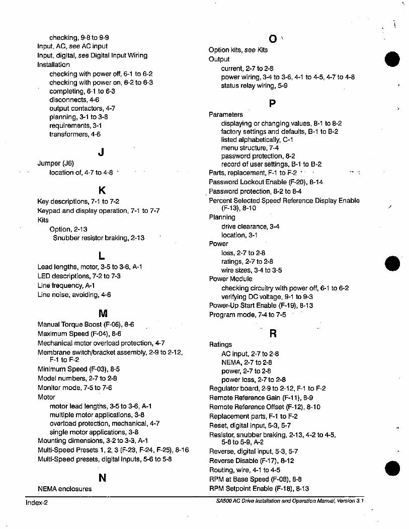
checking, 9-8 to 9-9
Input, AC, see AC input
Input, digital, see Digital Input WiringInstallation
checking with power off, 6-1 to 6-2checking with power on, 6-2 to 6-3
completing, 6-1 to 6-3disconnects, +6
output contactors, 4-7
planning, 3-1 to 3-8
requirements, 3-1transformers, 4-6
J
Jumper (J6)
location of, 4-7 to 4-8
K
Key descriptions, 7-1 to 7-2
Keypad and display operation, 7-1 to 7-7Kits
Option, 2-13
Snubber resistor braking, 2-13
L
Lead lengths, motor, 3-5 to 3-6, A-1
LED descriptions, 7-2 to 7-3
Une frequency, A-1
Une noise, avoiding, 4-6
N
M
Manual Torque Boost (F-06), 8-6
Maximum Speed (F-04), 8-6
Mechanical motor overload protection, 4-7
Membrane switch/bracket assembly, 2-9 to 2-12,F-1 to F-2
Minimum Speed (F-03), 8-5
Model numbers, 2-7 to 2-8
Monitor mode, 7-5 to 7-6
Motor
motor lead lengths, 3-5 to 3-6, A-1
multiple motor applications, 3-8
overload protection, mechanical, 4-7single motor applications, 3-8
Mounting dimensions, 3-2 to 3-3, A-1
Multi-Speed Presets 1, 2, 3 (F-23, F-24, F-25), 8-16
Multi-Speed presets, digital inputs, 5-6 to 5-8
NEMA enclosures
Index-2
0
Option kits, see Kits
Output
current, 2-7 to 2-8
power wiring, 34 to 3-6, 4-1 to 4-5, 4-7 to 4-8
status relay wiring, 5-9
PParameters
displaying or changing values, 8-1 to 8-2
factory settings and defaults, 8-1 to 8-2listed alphabetically, C-1menu structure, 7-4
password protection, 8-2
record of user settings, 8-1 to 8-2Parts, replacement, F-1 to F-2 '
Password Lockout Enable (F-20), 8-14
. Password protection, 8-2 to 8-4
Percent Selected Speed Reference Display Enable(F-13), 8-10
Planning
drive clearance, 3-4
location, 3-1
Power
loss, 2-7 to 2-8
ratings, 2-7 to 2-8
wire sizes, 3-4 to 3-5
Power Module
checking circuitry with power off, 6-1 to 6-2
verifying DC voltage, 9-1 to 9-3
Power-Up Start Enable (F-19), 8-13
Program mode, 7-4 to 7-5
R
Ratings
AC input, 2-7 to 2-8NEMA, 2-7 to 2-8
power, 2-7 to 2-8power loss, 2-7 to 2-8
Regulator board, 2-9 to 2-12, F-1 to F-2
Remote Reference Gain (F-11), 8-9
Remote Reference Offset (F-12), 8-10
Replacement parts, F-1 to F-2
Reset, digital input, 5-3,5-7
Resistor, snubber braking, 2-13,4-2 to 4-5,5-8 to 5-9, A-2
Reverse, digital input, 5-3,5-7
Reverse Disable (F-17), 8-12
Routing, wire, 4-1 to 4-5
RPM at Base Speed (F-08), 8-8
RPM Setpoint Enable (F-18), 8-13
SASOO AC Drive installation and Operation Manual, Version 3.1
0
S
Scaling the RPM display and reference, 7-6
Signal wiring, 5-3 to 5-9
Site requirements, 3-1
Snubber resistor braking, 2-13, 4-2 to 4-5, 5-8 to5-9, A-2
Specifications
conduit opening sizes, 4-2 to 4-5
environmental, 3-1, A-1
dimensions, 3-2 to 3-3, A-1
drive inputs, A-2
drive outputs, A-2
service conditions, A-1
terminal torque ratings, 3-5
wire sizes, 3-4 to 3-5
Start, digital input, 5-3 to 5-5
Stop, digital input, 5-3 to 5-5
Stopping the drive, 3-7
Index
T
Terminal strip
torque specifications, 3-5wire sizes, 3-4 to 3-5
wiring, 5-3 to 5-9
Testing, IGBI 9-8 to 9-9
Torque specifications, 3-5
Transformer, isolation, 4-6
V
Ventilation, see Air Flow
Version Information (F-49), 8-18
WHz (Base Speed) (F-07), 8-7
W
Watts loss rating, 2-7 to 2-8Weights, A-1
Wire routing, 4-1 to 4-5
Index-3

Index-4 SA500 AC Drive Installation and Operation Manual, Version 3.1
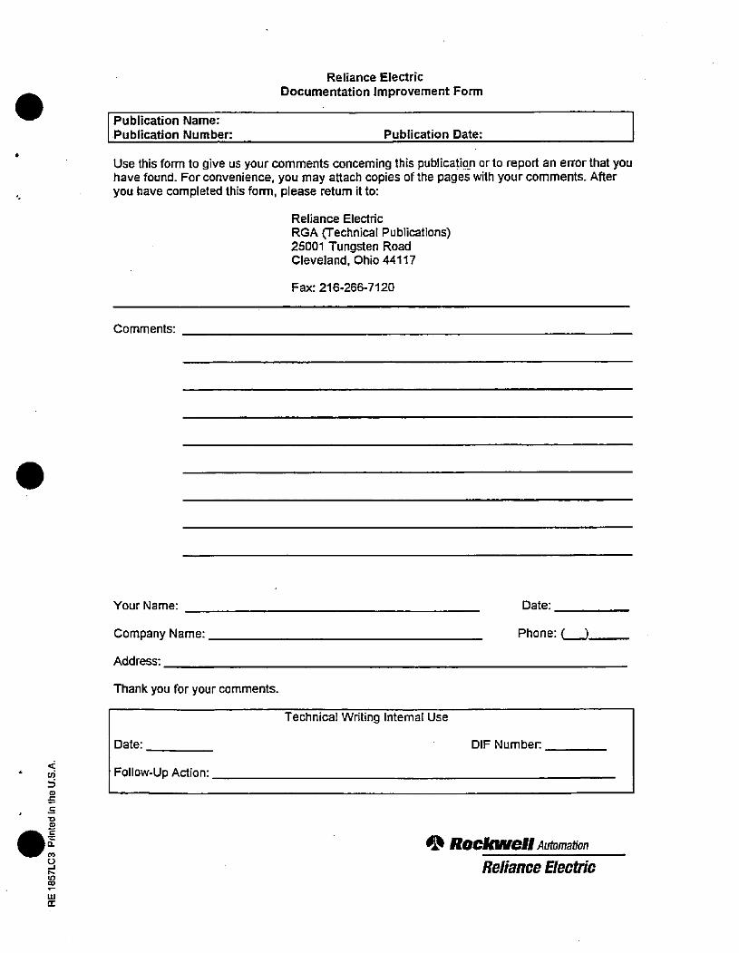
6 6
2C-
LLI
CE
Publication Name:
Publication Number:
Reliance Electric
Documentation improvement Form
Publication Date:
Use this form to give us your comments concerning this publication or to report an error that youhave found. For convenience, you may attach copies of the pages with your comments. Afteryou have completed this form, please return it to:
Comments:
Your Name:
Company Name:
Address:
Thank you for your comments.
Date:
Follow-Up Action:
Reliance Electric
RGA (Technical Publications)25001 Tungsten RoadCleveland, Ohio 44117
Fax: 216-266-7120
Technical Writing Internal Use
Date:
Phone: ( )
DIF Number.
03 ROCIONell Aummation
Reliance Electric

Reliance Electric / 24703 Euclid Avenue / Cleveland, Ohio 44117 / (216) 266-7000
Printed in U.S.A. 02-3356-2
* ROCIon,ell Automation
Reliance Electric
July 1997
J
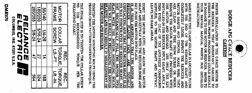
0
3 gC
00
0
Z0
C
0
mmmr
o m
N00
$N
fi
0'
Eg
E
eN
00
.,6
=
TI K
K 0m :u
000050 r
m5
-1r OWPO4108-1 C ·
·m
-1
r 0
1. ObZC·'m
33 Eg
MEgme 59E= a@
SS @@Sm 58
m 8E
=10&,ezmEgo5EimES:SO
<-1MtgE05
Z0
Zam»i
E :3 zimas88g0 0 -1
Z0
iEr,
M 22
MSQ 0
il s, Ef 5 El
Eimal9-4Okr-
INFBBE'i
muggE=*EgmEMEZE8 F#1. STOe.&451AMSm@EE5m
- E Eqi@: sEEF= sial= EE EM mr·:0Om
1255151 3-1, 5 8 2 m M 8 8 5 S E
859@S
EHilMgo-:cm
=*5%12=
0 717
m
7 8:
E.r8 *9ipsr ROMed
3BiME
mm:Emtlte-it00400
0
M
)!rj
MM
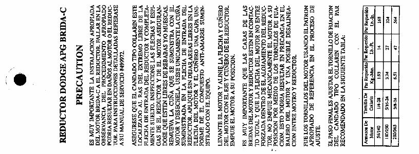
U
AQ
e
. 09
0
U
E
2152um %5 , 0 , r,; J H J < 4 4
EZ< BE m=*4535552,25 ,5m==Em =====83=ms= 8899 104 w 82 Amumfgazedl >i:i <>r;, si 3$
Cons»ly.=i MOM MN
5 3#Mild REBERMIOEME' 29= 61#MmE =Em-Mmg:Z ='55 2,E 8zOE6 JUREBE Mas:=85=:sENE= em=
F NIN"95 +EBE: 24/amigi Wel152<SE: 5<529euM <El,Acg 6
4"WPKFDUEmE=m= FAMEW#ldsm=EE@mm EMB
3*ME<dE# ME%5S@gE:El ZE<%2920%9%„SAJ#MR ZAOFOE=med < L=J
EE=Esm* SZO Quin
119 0-'020 *za@MagEm,# 4%e> 9
*2@Z@=ReE Ew2§5582*5* EDAlSiREB 2§tifaim@292 SEQi
&0-30 91WlmE22220;Jo %222
MJ
085
Z Z E-005%
25FU] O Dffugt,05
mom
Zoa
2-,8dE#
f (4a
1d
Ea
ms
0
Z
5
8
M
A
mi
0
A
B
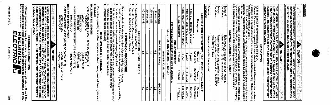
a
C
.
h, 1!!i E4332r
B d! O a: 60 1111
25& 22
iB5S St
15·8
Beammx
%159*9. 0 -n
m,3000mgs-¤/
iMESS0=90-1/Cloa
:*EjaEES5EME%
§8»»Elowgm
.SEE=2,dag
mES¥5
m
00 = ZZi S·sK5 22
zee zimIN<*a -8 ae=mils 555*BE9*01Nz o isigfW fif 8.8BM63586zBM@ 1 Teeles 129 592•
Lz<028<F zza 5 11:§811 589Z03 =oz-O OU n *{03®5- <71 R
92,6/PS"p PMS s =sa/566 3/gr0.0 m 2. 1/ 102/iiaE 245/*= m I 10===..BRESISE
2 3 iE piftilis jigE
A * 385S4 ra.W6%10.BrEne §*Mimiq H Hifi: i N i*0„ *4% Bi' 12. fiSBN m 30
v 4 ,« Bia Irn On
8 6 P [m =-"K Ta il2 ES* i
5 1/. 5 m
2 45
*W5522
E5
m6
gg
=m
. -L
E5SS
im
g0
5n
{D
R
5
i5
i:
0
E
g
i
e
F
15i6am
l@8m
g
Z
6) *
3 3
iZ
ii0
-·S3 3mgI 5
0
S
8
i
ro I
8 a
N -
2 1
§§
ZK
> 20
ii
.
g=0
a
B
I
i
E
Fm
E
E
ECD
E
@
Q
9
8
3
2S
g0
- -1
*RmUB f
SS 2%3%5SF/n
9Z
0285
0 sl6
H0@
52
82
3 8
S5
SS0
5·580 525
ES:=o as Rm -9 9
02.:
OP.2
1 512. c
5 a isaii
0 g
3SF7
3802#EKEQQ8:162503'E
§34'3§3Efi§52 §85;52
=z ifi:fi-- 51 1 11 i
.a *5.
. i; AggE-. SS = S.
55 trE E55 SS]* *
- 25 63
iNc.
E a5m
&a
8*./
0
Z502
0.
>Irr-1
5&23mEamz55/ZSWizdooOZO.m
MOK,=a
mEOzo42#ES=E/=m·25zo
Z-loc
62=5miEZEgs5
690Esm=z4/ZO
E29
0&>0
713 m z
5
m
mBE
5=00==
mwZ
o3emp
032
5eS
Q:
9 ¤
Sm
0
0Z
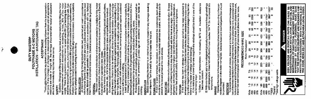
I LuI0
0Z
m Ok
. mui 41) 0.1
A<z
Eig
0_1a <C
Z
iiiE :263&ME'o
==M
i 14REY
111 E u 2O EeZ :Se
ElftiYint
5231
2 &·* 2
Mi:iZIEY
0000.= 8-4-2. B.8 Ef 6.62 :B ala 6 * SSoowAE-6 &%. 50 8 BB€ 5 5 852 Za
fifii! 880& SE 525.EB= %81 14m:55 9 XEDXDES66£,R 31,1 21 Giflii.Ef Iii*li5:fs: f 2%11 ti 11:511*i *11":1.30-el
2:=:27 M[DE€ 0. oES ne e o,r-ailifff im 1: i gil: 0.3 RE#/.81.SIES 186 t.i538 li83 2 185:lfi f!.iff 5 /3 :EY :1 11 /{ ap fyiti lilli:;559*&2 :2 .2:Bil*235"(4 905-0 N:g:52%=5 [email protected] :w 1915-#58z skr:-80 59-=25% 2=8 S°20450 20 Er€--E
f] 1 41 ij i; 1: Pul i·i liialfill ij i121*fll 52€* 1511,#Zi**11{19,2,2.=.A®. e.ol 169:d:MEfE:RiE22fENs11 E2ia i#€a=8365=:52:®1811/fili Vilit ilillilliffiltilit .
-z - F 1% 5·ijil *if :83,1 "affe f <Bul m FA B :ul 0 @0 E I E£28 w 5 2·D
&8
5 14
5 11RE 11
'Re EE
em §1
!{. iiiiz ly:0= -2
29 822
ZEE 62Eg
iii lill i
iii.
Zlia=
SIES
W=ZOi / 11/25E€*2:8:'SE=c --ac
.2 EE o
1 iii
Oj#:SEEEI5S2%52951#*EBE
2 E2
528 8 9 8291* § i }1
15 3 * EEDie .0 3 EO025 1 E EME=all 1 1 :5lili w /{Hi i iii1**5 0 LE
3262/ 1 }1&1&22 5 omS:ESQ -. SBBRF kE i if:5250 E -ag
liESSS §1 -306-2&2:1* 0" fERS§121112 21 851
it lit; f 11 Fi f#f56=8 - CV
BEE:
2.5 6 0
952,
EE:9 5
8 5
fY
9:
05 5
BmE2
23 52;%li/1 4 1 1 i1 E -B *3 i5* E*38
00: 6
il /{31EE E- Cv
M56 <e35MONS W#ES,5
¤2
Zt
R*0- Eli*8
88- 812800 . . orn0
REN* s I kk-0 10 I.
98*- 2 ' 28-/ .
g... 9 1§§)LOCY(OCO El ggo'141 -
8188*M . 0
89©02
.©00P --
2m8Z
2233 81 §§1 =o 1
'°833 R '88' 380 0
9333 8880 1 '&- -<0 052
12%11 figg R*,;5> C.'1 Mu S N * 10: 7:
Ng:M@600<og<SE
' #E/§3MS
M*gE@5805£:<555SEEd*Sa0-:Zz=Ul-1
a·51555/. 244=5-2
=Sid==SME=me=mgaliEWOAZBjafas=