part 27-1: electrical simulation models - wind turbines - sai
TRANSCRIPT
Irish StandardI.S. EN 61400-27-1:2015
Wind turbines - Part 27-1: Electricalsimulation models - Wind turbines
© CENELEC 2015 No copying without NSAI permission except as permitted by copyright law.
Thi
s is
a fr
ee 2
2 pa
ge s
ampl
e. A
cces
s th
e fu
ll ve
rsio
n on
line.
I.S. EN 61400-27-1:2015I.S. EN 61400-27-1:2015
Incorporating amendments/corrigenda/National Annexes issued since publication:
The National Standards Authority of Ireland (NSAI) produces the following categories of formal documents:
I.S. xxx: Irish Standard — national specification based on the consensus of an expert panel and subject to public consultation.
S.R. xxx: Standard Recommendation — recommendation based on the consensus of an expert panel and subject to public consultation.
SWiFT xxx: A rapidly developed recommendatory document based on the consensus of the participants of an NSAI workshop.
This document replaces/revises/consolidates the NSAI adoption of the document(s) indicated on theCEN/CENELEC cover/Foreword and the following National document(s):
NOTE: The date of any NSAI previous adoption may not match the date of its original CEN/CENELECdocument.
This document is based on:
EN 61400-27-1:2015
Published:
2015-10-16
This document was publishedunder the authority of the NSAIand comes into effect on:
2015-11-03
ICS number:
27.180
NOTE: If blank see CEN/CENELEC cover page
NSAI1 Swift Square, Northwood, Santry Dublin 9
T +353 1 807 3800 F +353 1 807 3838 E [email protected] W NSAI.ie
Sales:T +353 1 857 6730 F +353 1 857 6729 W standards.ie
Údarás um Chaighdeáin Náisiúnta na hÉireann
Thi
s is
a fr
ee 2
2 pa
ge s
ampl
e. A
cces
s th
e fu
ll ve
rsio
n on
line.
National ForewordNational Foreword
I.S. EN 61400-27-1:2015 is the adopted Irish version of the European Document EN 61400-27-1:2015, Windturbines - Part 27-1: Electrical simulation models - Wind turbines
This document does not purport to include all the necessary provisions of a contract. Users are responsiblefor its correct application.
Compliance with this document does not of itse lf confer immunity from legal obligations .Compliance with this document does not of itse lf confer immunity from legal obligations .
In line with international standards practice the decimal point is shown as a comma (,) throughout thisdocument.
Thi
s is
a fr
ee 2
2 pa
ge s
ampl
e. A
cces
s th
e fu
ll ve
rsio
n on
line.

This page is intentionally left blank
Thi
s is
a fr
ee 2
2 pa
ge s
ampl
e. A
cces
s th
e fu
ll ve
rsio
n on
line.
EUROPEAN STANDARD
NORME EUROPÉENNE
EUROPÄISCHE NORM
EN 61400-27-1
October 2015
ICS 27.180
English Version
Wind turbines - Part 27-1: Electrical simulation models - Wind turbines
(IEC 61400-27-1:2015)
Eoliennes - Partie 27-1: Modèles de simulation électrique - Eoliennes
(IEC 61400-27-1:2015)
Windenergieanlagen - Teil 27-1: Elektrische Simulationsmodelle - Windenergieanlagen
(IEC 61400-27-1:2015)
This European Standard was approved by CENELEC on 2015-03-20. CENELEC members are bound to comply with the CEN/CENELEC Internal Regulations which stipulate the conditions for giving this European Standard the status of a national standard without any alteration.
Up-to-date lists and bibliographical references concerning such national standards may be obtained on application to the CEN-CENELEC Management Centre or to any CENELEC member.
This European Standard exists in three official versions (English, French, German). A version in any other language made by translation under the responsibility of a CENELEC member into its own language and notified to the CEN-CENELEC Management Centre has the same status as the official versions.
CENELEC members are the national electrotechnical committees of Austria, Belgium, Bulgaria, Croatia, Cyprus, the Czech Republic, Denmark, Estonia, Finland, Former Yugoslav Republic of Macedonia, France, Germany, Greece, Hungary, Iceland, Ireland, Italy, Latvia, Lithuania, Luxembourg, Malta, the Netherlands, Norway, Poland, Portugal, Romania, Slovakia, Slovenia, Spain, Sweden, Switzerland, Turkey and the United Kingdom.
European Committee for Electrotechnical Standardization Comité Européen de Normalisation Electrotechnique
Europäisches Komitee für Elektrotechnische Normung
CEN-CENELEC Management Centre: Avenue Marnix 17, B-1000 Brussels
© 2015 CENELEC All rights of exploitation in any form and by any means reserved worldwide for CENELEC Members.
Ref. No. EN 61400-27-1:2015 E
I.S. EN 61400-27-1:2015T
his
is a
free
22
page
sam
ple.
Acc
ess
the
full
vers
ion
onlin
e.
EN 61400-27-1:2015
2
European foreword
The text of document 88/510/FDIS, future edition 1 of IEC 61400-27-1, prepared by IEC TC 88 "Wind turbines" was submitted to the IEC-CENELEC parallel vote and approved by CENELEC as EN 61400-27-1:2015.
The following dates are fixed: • latest date by which the document has
to be implemented at national level by publication of an identical national standard or by endorsement
(dop) 2016-04-16
• latest date by which the national standards conflicting with the document have to be withdrawn
(dow) 2018-03-20
Attention is drawn to the possibility that some of the elements of this document may be the subject of patent rights. CENELEC [and/or CEN] shall not be held responsible for identifying any or all such patent rights.
Endorsement notice
The text of the International Standard IEC 61400-27-1:2015 was approved by CENELEC as a European Standard without any modification. In the official version, for Bibliography, the following note has to be added for the standard indicated:
IEC 61400-25 (Series) NOTE Harmonised as EN 61400-25 (Series).
I.S. EN 61400-27-1:2015T
his
is a
free
22
page
sam
ple.
Acc
ess
the
full
vers
ion
onlin
e.
EN 61400-27-1:2015
3
Annex ZA (normative)
Normative references to international publications with their corresponding European publications
The following documents, in whole or in part, are normatively referenced in this document and are indispensable for its application. For dated references, only the edition cited applies. For undated references, the latest edition of the referenced document (including any amendments) applies.
NOTE 1 When an International Publication has been modified by common modifications, indicated by (mod), the relevant EN/HD applies.
NOTE 2 Up-to-date information on the latest versions of the European Standards listed in this annex is available here: www.cenelec.eu.
Publication Year Title EN/HD Year IEC 60050 series International Electrotechnical Vocabulary - series IEC 61400-21 - Wind turbines -- Part 21: Measurement and
assessment of power quality characteristics of grid connected wind turbines
EN 61400-21 -
I.S. EN 61400-27-1:2015T
his
is a
free
22
page
sam
ple.
Acc
ess
the
full
vers
ion
onlin
e.

This page is intentionally left blank
Thi
s is
a fr
ee 2
2 pa
ge s
ampl
e. A
cces
s th
e fu
ll ve
rsio
n on
line.
IEC 61400-27-1 Edition 1.0 2015-02
INTERNATIONAL STANDARD NORME INTERNATIONALE
Wind turbines – Part 27-1: Electrical simulation models – Wind turbines Eoliennes – Partie 27-1: Modèles de simulation électrique – Eoliennes
IEC
614
00-2
7-1:
2015
-02(
en-fr
)
®
colourinside
I.S. EN 61400-27-1:2015T
his
is a
free
22
page
sam
ple.
Acc
ess
the
full
vers
ion
onlin
e.
THIS PUBLICATION IS COPYRIGHT PROTECTED Copyright © 2015 IEC, Geneva, Switzerland All rights reserved. Unless otherwise specified, no part of this publication may be reproduced or utilized in any form or by any means, electronic or mechanical, including photocopying and microfilm, without permission in writing from either IEC or IEC's member National Committee in the country of the requester. If you have any questions about IEC copyright or have an enquiry about obtaining additional rights to this publication, please contact the address below or your local IEC member National Committee for further information. Droits de reproduction réservés. Sauf indication contraire, aucune partie de cette publication ne peut être reproduite ni utilisée sous quelque forme que ce soit et par aucun procédé, électronique ou mécanique, y compris la photocopie et les microfilms, sans l'accord écrit de l'IEC ou du Comité national de l'IEC du pays du demandeur. Si vous avez des questions sur le copyright de l'IEC ou si vous désirez obtenir des droits supplémentaires sur cette publication, utilisez les coordonnées ci-après ou contactez le Comité national de l'IEC de votre pays de résidence.
IEC Central Office Tel.: +41 22 919 02 11 3, rue de Varembé Fax: +41 22 919 03 00 CH-1211 Geneva 20 [email protected] Switzerland www.iec.ch
About the IEC The International Electrotechnical Commission (IEC) is the leading global organization that prepares and publishes International Standards for all electrical, electronic and related technologies. About IEC publications The technical content of IEC publications is kept under constant review by the IEC. Please make sure that you have the latest edition, a corrigenda or an amendment might have been published. IEC Catalogue - webstore.iec.ch/catalogue The stand-alone application for consulting the entire bibliographical information on IEC International Standards, Technical Specifications, Technical Reports and other documents. Available for PC, Mac OS, Android Tablets and iPad. IEC publications search - www.iec.ch/searchpub The advanced search enables to find IEC publications by a variety of criteria (reference number, text, technical committee,…). It also gives information on projects, replaced and withdrawn publications. IEC Just Published - webstore.iec.ch/justpublished Stay up to date on all new IEC publications. Just Published details all new publications released. Available online and also once a month by email.
Electropedia - www.electropedia.org The world's leading online dictionary of electronic and electrical terms containing more than 30 000 terms and definitions in English and French, with equivalent terms in 15 additional languages. Also known as the International Electrotechnical Vocabulary (IEV) online. IEC Glossary - std.iec.ch/glossary More than 60 000 electrotechnical terminology entries in English and French extracted from the Terms and Definitions clause of IEC publications issued since 2002. Some entries have been collected from earlier publications of IEC TC 37, 77, 86 and CISPR. IEC Customer Service Centre - webstore.iec.ch/csc If you wish to give us your feedback on this publication or need further assistance, please contact the Customer Service Centre: [email protected].
A propos de l'IEC La Commission Electrotechnique Internationale (IEC) est la première organisation mondiale qui élabore et publie des Normes internationales pour tout ce qui a trait à l'électricité, à l'électronique et aux technologies apparentées. A propos des publications IEC Le contenu technique des publications IEC est constamment revu. Veuillez vous assurer que vous possédez l’édition la plus récente, un corrigendum ou amendement peut avoir été publié. Catalogue IEC - webstore.iec.ch/catalogue Application autonome pour consulter tous les renseignements bibliographiques sur les Normes internationales, Spécifications techniques, Rapports techniques et autres documents de l'IEC. Disponible pour PC, Mac OS, tablettes Android et iPad. Recherche de publications IEC - www.iec.ch/searchpub La recherche avancée permet de trouver des publications IEC en utilisant différents critères (numéro de référence, texte, comité d’études,…). Elle donne aussi des informations sur les projets et les publications remplacées ou retirées. IEC Just Published - webstore.iec.ch/justpublished Restez informé sur les nouvelles publications IEC. Just Published détaille les nouvelles publications parues. Disponible en ligne et aussi une fois par mois par email.
Electropedia - www.electropedia.org Le premier dictionnaire en ligne de termes électroniques et électriques. Il contient plus de 30 000 termes et définitions en anglais et en français, ainsi que les termes équivalents dans 15 langues additionnelles. Egalement appelé Vocabulaire Electrotechnique International (IEV) en ligne. Glossaire IEC - std.iec.ch/glossary Plus de 60 000 entrées terminologiques électrotechniques, en anglais et en français, extraites des articles Termes et Définitions des publications IEC parues depuis 2002. Plus certaines entrées antérieures extraites des publications des CE 37, 77, 86 et CISPR de l'IEC. Service Clients - webstore.iec.ch/csc Si vous désirez nous donner des commentaires sur cette publication ou si vous avez des questions contactez-nous: [email protected].
I.S. EN 61400-27-1:2015T
his
is a
free
22
page
sam
ple.
Acc
ess
the
full
vers
ion
onlin
e.
IEC 61400-27-1 Edition 1.0 2015-02
INTERNATIONAL STANDARD NORME INTERNATIONALE
Wind turbines – Part 27-1: Electrical simulation models – Wind turbines Eoliennes – Partie 27-1: Modèles de simulation électrique – Eoliennes
INTERNATIONAL ELECTROTECHNICAL COMMISSION
COMMISSION ELECTROTECHNIQUE INTERNATIONALE ICS 27.180
ISBN 978-2-8322-2226-3
® Registered trademark of the International Electrotechnical Commission Marque déposée de la Commission Electrotechnique Internationale
®
Warning! Make sure that you obtained this publication from an authorized distributor. Attention! Veuillez vous assurer que vous avez obtenu cette publication via un distributeur agréé.
colourinside
I.S. EN 61400-27-1:2015T
his
is a
free
22
page
sam
ple.
Acc
ess
the
full
vers
ion
onlin
e.
– 2 – IEC 61400-27-1:2015 IEC 2015
CONTENTS
FOREWORD ........................................................................................................................... 7 INTRODUCTION ..................................................................................................................... 9 1 Scope ............................................................................................................................ 12 2 Normative references .................................................................................................... 12 3 Terms, definitions, abbreviations and subscripts ............................................................ 12
3.1 Terms and definitions ............................................................................................ 12 3.2 Abbreviations and subscripts ................................................................................ 17
3.2.1 Abbreviations ................................................................................................. 17 3.2.2 Subscripts ..................................................................................................... 18
4 Symbols and units ......................................................................................................... 19 4.1 General ................................................................................................................. 19 4.2 Symbols (units) ..................................................................................................... 19
5 Specification of models .................................................................................................. 21 5.1 Overview............................................................................................................... 21 5.2 General specifications ........................................................................................... 21 5.3 Model interface ..................................................................................................... 23 5.4 Parameters and initialisation ................................................................................. 24
5.4.1 General ......................................................................................................... 24 5.4.2 Parameter categories .................................................................................... 24 5.4.3 Global parameters ......................................................................................... 24 5.4.4 Initialisation ................................................................................................... 24
5.5 Modular structure of models .................................................................................. 25 5.5.1 Generic modular structure ............................................................................. 25 5.5.2 Type 1 ........................................................................................................... 26 5.5.3 Type 2 ........................................................................................................... 28 5.5.4 Type 3 ........................................................................................................... 30 5.5.5 Type 4 ........................................................................................................... 33
5.6 Module library ....................................................................................................... 37 5.6.1 Aerodynamic models ..................................................................................... 37 5.6.2 Mechanical models ........................................................................................ 38 5.6.3 Generator set models .................................................................................... 39 5.6.4 Electrical equipment ...................................................................................... 44 5.6.5 Control models .............................................................................................. 44 5.6.6 Grid protection model .................................................................................... 55
6 Specification of validation procedure ............................................................................. 57 6.1 Overview............................................................................................................... 57 6.2 General specifications ........................................................................................... 58 6.3 Validation procedure ............................................................................................. 59
6.3.1 Voltage dips .................................................................................................. 59 6.3.2 Reference point changes ............................................................................... 64 6.3.3 Grid protection ............................................................................................... 64
Annex A (informative) Validation test documentation............................................................ 66 A.1 General ................................................................................................................. 66 A.2 Simulation model and validation setup information ................................................ 66 A.3 Template for validation test results ....................................................................... 66
I.S. EN 61400-27-1:2015T
his
is a
free
22
page
sam
ple.
Acc
ess
the
full
vers
ion
onlin
e.
IEC 61400-27-1:2015 IEC 2015 – 3 –
A.3.1 General ......................................................................................................... 66 A.3.2 Voltage dips .................................................................................................. 67 A.3.3 Reference point changes ............................................................................... 67 A.3.4 Grid protection ............................................................................................... 68
Annex B (normative) Limits to possible model accuracy ....................................................... 69 B.1 General ................................................................................................................. 69 B.2 Inevitable simulation errors ................................................................................... 69 B.3 Measurement errors .............................................................................................. 69
Annex C (normative) Digital 2nd order critically damped low pass filter ................................. 71 Annex D (informative) Simplified plant level model ............................................................... 72
D.1 General ................................................................................................................. 72 D.2 Area of application ................................................................................................ 72 D.3 Voltage and reactive power controller model description ....................................... 72 D.4 Frequency and active power controller model description...................................... 74
Annex E (informative) Two-dimensional aerodynamic model ................................................ 76 E.1 Objective .............................................................................................................. 76 E.2 Model approach .................................................................................................... 76 E.3 Model parameter fits ............................................................................................. 77 E.4 Use cases ............................................................................................................. 80
E.4.1 General ......................................................................................................... 80 E.4.2 Stability study use cases ............................................................................... 80 E.4.3 Validation use cases ...................................................................................... 80
E.5 Model initialisation at derated conditions ............................................................... 80 Annex F (informative) Generic Software Interface for use of models in different software environments .......................................................................................................... 81
F.1 Description of the approach .................................................................................. 81 F.2 Description of the Software interface .................................................................... 82
F.2.1 Description of data structures ........................................................................ 82 F.2.2 Functions for communication through the ESE-interface ................................ 83 F.2.3 Inputs, Outputs, Parameters .......................................................................... 85
Annex G (normative) Block symbol library ............................................................................ 86 G.1 General ................................................................................................................. 86 G.2 Time step delay .................................................................................................... 86 G.3 Stand-alone ramp rate limiter ................................................................................ 86 G.4 First order filter with absolute limits, rate limits and freeze flag ............................. 87 G.5 Lookup table ......................................................................................................... 88 G.6 Comparator ........................................................................................................... 88 G.7 Timer .................................................................................................................... 88 G.8 Anti windup integrator ........................................................................................... 89 G.9 Integrator with reset .............................................................................................. 90 G.10 First order filter with limitation detection ................................................................ 90 G.11 Delay flag ............................................................................................................. 91 G.12 Raising edge detection ......................................................................................... 91
Bibliography .......................................................................................................................... 93 Figure 1 – Classification of power system stability according to IEEE/CIGRE Joint Task Force on Stability Terms and Definitions ................................................................................. 9 Figure 2 – Example of step response. ................................................................................... 15
I.S. EN 61400-27-1:2015T
his
is a
free
22
page
sam
ple.
Acc
ess
the
full
vers
ion
onlin
e.
– 4 – IEC 61400-27-1:2015 IEC 2015
Figure 3 – General interface between WT model, grid model and WP model ......................... 23 Figure 4 – General interface for initialisation of WT model, WP model and grid model. ......... 25 Figure 5 – Generic modular structure of WT models.............................................................. 26 Figure 6 – Main electrical and mechanical components of type 1 WTs .................................. 26 Figure 7 – Modular structure for the type 1A WT model......................................................... 27 Figure 8 – Modular structure for the type 1B WT model......................................................... 28 Figure 9 – Main electrical and mechanical components of type 2 WTs .................................. 29 Figure 10 – Modular structure for the type 2 WT model ......................................................... 29 Figure 11 – Modular structure for the type 2 control model .................................................... 30 Figure 12 – Main electrical and mechanical components of type 3 WTs ................................ 31 Figure 13 – Modular structure for the type 3 WT model ......................................................... 31 Figure 14 – Modular structure for the type 3 control models .................................................. 32 Figure 15 – Main electrical and mechanical components of type 4 WTs ................................ 33 Figure 16 – Modular structure for the type 4A WT model ....................................................... 34 Figure 17 – Modular structure for the type 4A control model ................................................. 34 Figure 18 – Modular structure for the type 4B WT model ....................................................... 35 Figure 19 – Modular structure for the type 4B control model ................................................. 36 Figure 20 – Block diagram for constant aerodynamic torque model ....................................... 37 Figure 21 – Block diagram for one-dimensional aerodynamic model ..................................... 37 Figure 22 – Block diagram for two-dimensional aerodynamic model ...................................... 38 Figure 23 – Block diagram for two mass model ..................................................................... 39 Figure 24 – Block diagram for type 3A generator set model .................................................. 40 Figure 25 – Block diagram for type 3B generator set model .................................................. 42 Figure 26 – Block diagram for type 4 generator set model ..................................................... 43 Figure 27 – Block diagram for the reference frame rotation model......................................... 44 Figure 28 – Block diagram for pitch control power model ...................................................... 45 Figure 29 – Block diagram for pitch angle control model ....................................................... 46 Figure 30 – Block diagram for rotor resistance control model ................................................ 47 Figure 31 – Block diagram for type 3 P control model ........................................................... 48 Figure 32 – Block diagram for type 3 torque PI ..................................................................... 49 Figure 33 – Block diagram for type 4A P control model ......................................................... 49 Figure 34 – Block diagram for type 4B P control model ......................................................... 50 Figure 35 – Block diagram for Q control model...................................................................... 52 Figure 36 – Block diagram for current limiter ......................................................................... 54 Figure 37 – Block diagram for constant Q limitation model .................................................... 54 Figure 38 – Block diagram for QP and QU limitation model ................................................... 55 Figure 39 – Block diagram for grid protection system ............................................................ 56 Figure 40 – Block diagram for u-f measurement .................................................................... 57 Figure 41 – Signal processing structure with "play-back" method applied. ............................. 60 Figure 42 – Signal processing structure with "full grid simulation" method applied. ............... 61 Figure 43 – Voltage dip windows........................................................................................... 63 Figure D.1 – Block diagram for WP reactive power controllers .............................................. 74 Figure D.2 – Block diagram for WP active power controller ................................................... 75
I.S. EN 61400-27-1:2015T
his
is a
free
22
page
sam
ple.
Acc
ess
the
full
vers
ion
onlin
e.
IEC 61400-27-1:2015 IEC 2015 – 5 –
Figure E.1 – Aerodynamic power as function of blade angle Θ and wind speed v ................. 77 Figure E.2 – Partial derivative of power with respect to rotor speed change ∂paero/∂ωWTR as function of blade angle Θ and wind speed v .............................................. 77 Figure E.3 – Partial derivative of power with respect to blade angle dpθ as function of blade angle Θ ....................................................................................................................... 78 Figure E.4 – Partial derivative of power with respect to rotor speed change dpω as function of wind speed v for 1 p.u. (solid line) and 0,5 p.u. (dashed line) active power .......... 78 Figure E.5 – Approximation of aerodynamic power as function of wind speed ....................... 79 Figure E.6 – Approximation of the blade angle as function of wind speed ............................. 79 Figure F.1 – Sequence of Simulation on use of ESE-interface .............................................. 85 Figure G.1 – Block symbol for single integration time step delay ........................................... 86 Figure G.2 – Block symbol for stand-alone ramp rate limiter ................................................. 86 Figure G.3 – Block diagram for implementation of the stand-alone ramp rate limiter ............. 87 Figure G.4 – Block symbol for first order filter with absolute limits, rate limits and freeze flag ............................................................................................................................ 87 Figure G.5 – Block diagram for implementation of the first order filter with absolute limits, rate limits and freeze state.......................................................................................... 87 Figure G.6 – Block diagram for implementation of the freeze state without filter (T = 0) ......... 88 Figure G.7 – Block symbol for lookup table ........................................................................... 88 Figure G.8 – Block symbols for comparators ......................................................................... 88 Figure G.9 – Block symbol for timer ...................................................................................... 89 Figure G.10 – Function of timer ............................................................................................ 89 Figure G.11 – Block symbol for anti windup integrator .......................................................... 89 Figure G.12 – Block diagram for implementation of anti windup integrator ............................ 90 Figure G.13 – Block symbol for integrator with reset ............................................................. 90 Figure G.14 – Block symbol for first order filter with limitation detection ................................ 90 Figure G.15 – Block diagram for implementation of first order filter with limitation detection ............................................................................................................................... 91 Figure G.16 – Block symbol for delay flag ............................................................................. 91 Figure G.17 – Block diagram for implementation of delay flag ............................................... 91 Figure G.18 – Block symbol raising edge detection ............................................................... 92 Figure G.19 – Block diagram for raising edge detection ........................................................ 92 Table 1 – Global WT model parameters ................................................................................ 24 Table 2 – Initialisation variable used explicitly in model block diagrams ................................ 25 Table 3 – Modules used in type 1A model ............................................................................. 27 Table 4 – Modules used in type 1B model ............................................................................. 28 Table 5 – Modules used in type 2 model ............................................................................... 30 Table 6 – Modules used in type 3 model ............................................................................... 32 Table 7 – Modules used in type 4A model ............................................................................. 35 Table 8 – Modules used in type 4B model ............................................................................. 36 Table 9 – Parameter list for one-dimensional aerodynamic model ......................................... 37 Table 10 – Parameter list for two-dimensional aerodynamic model ....................................... 37 Table 11 – Parameter list for two-mass model....................................................................... 39 Table 12 – Parameter list for type 3A generator set model .................................................... 40
I.S. EN 61400-27-1:2015T
his
is a
free
22
page
sam
ple.
Acc
ess
the
full
vers
ion
onlin
e.
– 6 – IEC 61400-27-1:2015 IEC 2015
Table 13 – Parameter list for type 3B generator set model .................................................... 41 Table 14 – Parameter list for type 4 generator set model ...................................................... 43 Table 15 – Parameter list for reference frame rotation model ................................................ 43 Table 16 – Parameter list for pitch control power model ........................................................ 44 Table 17 – Parameter list for pitch angle control model ......................................................... 45 Table 18 – Parameter list for rotor resistance control model .................................................. 46 Table 19 – Parameter list for p control model type 3 ............................................................. 47 Table 20 – Parameter list for p control model type 4A ........................................................... 49 Table 21 – Parameter list for p control model type 4B ........................................................... 50 Table 22 – General WT Q control modes MqG ...................................................................... 50 Table 23 – UVRT Q control modes MqUVRT ......................................................................... 51 Table 24 – Parameter list for q control model ........................................................................ 51 Table 25 – Description of FUVRT flag values ........................................................................ 53 Table 26 – Parameter list for current limiter model ................................................................ 53 Table 27 – Parameter list for constant Q limitation model...................................................... 54 Table 28 – Parameter list for QP and QU limitation model ..................................................... 55 Table 29 – Parameter list for grid protection model ............................................................... 56 Table 30 – Windows applied for error calculations ................................................................ 63 Table A.1 – Required information about simulation model and validation setup ..................... 66 Table A.2 – Additional information required if full grid method is applied ............................... 66 Table A.3 – Validation summary for voltage dips ................................................................... 67 Table A.4 – Validation summary for reference point changes ................................................ 68 Table A.5 – Validation summary for grid protection ............................................................... 68 Table D.1 – Parameters used in the voltage and reactive power control model ..................... 73 Table D.2 – Parameters used in the frequency and active power control model .................... 74 Table E.1 – Points characterising the relation between the wind speed v and the partial derivative dpω ....................................................................................................................... 78 Table E.2 – Parameter list for the aerodynamics of a specific WT type ................................. 79
I.S. EN 61400-27-1:2015T
his
is a
free
22
page
sam
ple.
Acc
ess
the
full
vers
ion
onlin
e.
IEC 61400-27-1:2015 IEC 2015 – 7 –
INTERNATIONAL ELECTROTECHNICAL COMMISSION
_____________
WIND TURBINES –
Part 27-1: Electrical simulation models –
Wind turbines
FOREWORD 1) The International Electrotechnical Commission (IEC) is a worldwide organization for standardization comprising
all national electrotechnical committees (IEC National Committees). The object of IEC is to promote international co-operation on all questions concerning standardization in the electrical and electronic fields. To this end and in addition to other activities, IEC publishes International Standards, Technical Specifications, Technical Reports, Publicly Available Specifications (PAS) and Guides (hereafter referred to as “IEC Publication(s)”). Their preparation is entrusted to technical committees; any IEC National Committee interested in the subject dealt with may participate in this preparatory work. International, governmental and non-governmental organizations liaising with the IEC also participate in this preparation. IEC collaborates closely with the International Organization for Standardization (ISO) in accordance with conditions determined by agreement between the two organizations.
2) The formal decisions or agreements of IEC on technical matters express, as nearly as possible, an international consensus of opinion on the relevant subjects since each technical committee has representation from all interested IEC National Committees.
3) IEC Publications have the form of recommendations for international use and are accepted by IEC National Committees in that sense. While all reasonable efforts are made to ensure that the technical content of IEC Publications is accurate, IEC cannot be held responsible for the way in which they are used or for any misinterpretation by any end user.
4) In order to promote international uniformity, IEC National Committees undertake to apply IEC Publications transparently to the maximum extent possible in their national and regional publications. Any divergence between any IEC Publication and the corresponding national or regional publication shall be clearly indicated in the latter.
5) IEC itself does not provide any attestation of conformity. Independent certification bodies provide conformity assessment services and, in some areas, access to IEC marks of conformity. IEC is not responsible for any services carried out by independent certification bodies.
6) All users should ensure that they have the latest edition of this publication.
7) No liability shall attach to IEC or its directors, employees, servants or agents including individual experts and members of its technical committees and IEC National Committees for any personal injury, property damage or other damage of any nature whatsoever, whether direct or indirect, or for costs (including legal fees) and expenses arising out of the publication, use of, or reliance upon, this IEC Publication or any other IEC Publications.
8) Attention is drawn to the Normative references cited in this publication. Use of the referenced publications is indispensable for the correct application of this publication.
9) Attention is drawn to the possibility that some of the elements of this IEC Publication may be the subject of patent rights. IEC shall not be held responsible for identifying any or all such patent rights.
International Standard IEC 61400-27-1 has been prepared IEC Technical Committee 88: Wind turbines.
The text of this draft is based on the following documents:
Enquiry draft Report on voting
88/510/FDIS 88/529/RVD
Full information on the voting for the approval of this technical specification can be found in the report on voting indicated in the above table.
This publication has been drafted in accordance with the ISO/IEC Directives, Part 2.
I.S. EN 61400-27-1:2015T
his
is a
free
22
page
sam
ple.
Acc
ess
the
full
vers
ion
onlin
e.
– 8 – IEC 61400-27-1:2015 IEC 2015
A list of all parts in the IEC 61400 series, published under the general title Wind turbines, can be found on the IEC website.
The committee has decided that the contents of this publication will remain unchanged until the stability date indicated on the IEC web site under "http://webstore.iec.ch" in the data related to the specific publication. At this date, the publication will be
• reconfirmed,
• withdrawn,
• replaced by a revised edition, or
• amended.
IMPORTANT – The 'colour inside' logo on the cover page of this publication indicates that it contains colours which are considered to be useful for the correct understanding of its contents. Users should therefore print this document using a colour printer.
I.S. EN 61400-27-1:2015T
his
is a
free
22
page
sam
ple.
Acc
ess
the
full
vers
ion
onlin
e.
IEC 61400-27-1:2015 IEC 2015 – 9 –
INTRODUCTION
The IEC 61400-27 series specifies standard dynamic electrical simulation models for wind power generation. IEC 61400-27-1 specifies wind turbine models and model validation procedure. IEC 61400-27-2 will specify wind power plant models and model validation procedure.
The increasing penetration of wind energy in power systems implies that Transmission System Operators (TSOs) and Distribution System Operators (DSOs) need to use dynamic models of wind power generation for power system stability studies. The models developed by the wind turbine manufacturers reproduce the behaviour of their machines with a high level of detail. Such level of detail is not suitable for stability studies of large power systems with a huge number of wind power plants, firstly because the high level of detail increases the complexity and thus computer time dramatically, and secondly because the use of detailed manufacturer specific models requires a substantial amount of input data to represent the individual wind turbine types.
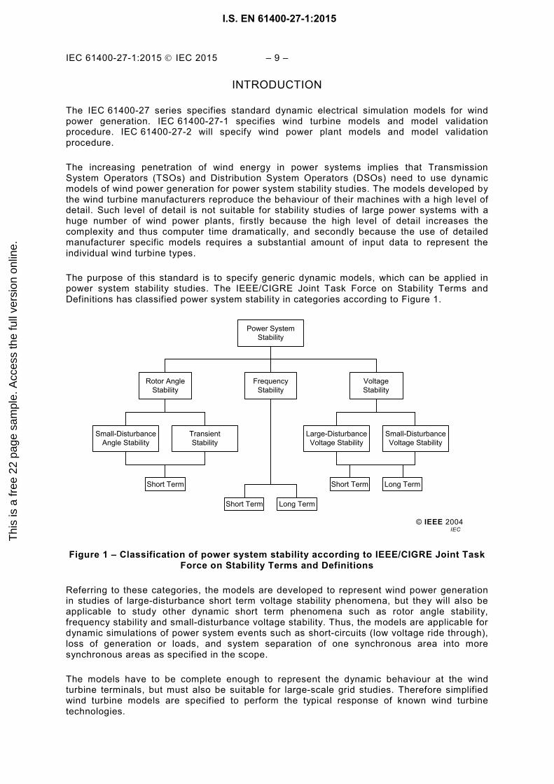
The purpose of this standard is to specify generic dynamic models, which can be applied in power system stability studies. The IEEE/CIGRE Joint Task Force on Stability Terms and Definitions has classified power system stability in categories according to Figure 1.
Figure 1 – Classification of power system stability according to IEEE/CIGRE Joint Task Force on Stability Terms and Definitions
Referring to these categories, the models are developed to represent wind power generation in studies of large-disturbance short term voltage stability phenomena, but they will also be applicable to study other dynamic short term phenomena such as rotor angle stability, frequency stability and small-disturbance voltage stability. Thus, the models are applicable for dynamic simulations of power system events such as short-circuits (low voltage ride through), loss of generation or loads, and system separation of one synchronous area into more synchronous areas as specified in the scope.
The models have to be complete enough to represent the dynamic behaviour at the wind turbine terminals, but must also be suitable for large-scale grid studies. Therefore simplified wind turbine models are specified to perform the typical response of known wind turbine technologies.
© IEEE 2004
Power SystemStability
FrequencyStability
Rotor AngleStability
VoltageStability
Small-DisturbanceVoltage Stability
Large-DisturbanceVoltage Stability
TransientStability
Small-DisturbanceAngle Stability
Short Term Long Term
Short Term Long Term
Short Term
IEC
I.S. EN 61400-27-1:2015T
his
is a
free
22
page
sam
ple.
Acc
ess
the
full
vers
ion
onlin
e.
– 10 – IEC 61400-27-1:2015 IEC 2015
The wind turbine models specified in this standard are for fundamental frequency positive sequence response1. The models have the following limitations:
– The models are not intended for long term stability analysis. – The models are not intended for investigation of sub-synchronous interaction phenomena. – The models are not intended for investigation of the fluctuations originating from wind
speed variability in time and space. This implies that the models do not include phenomena such as turbulence, tower shadow, wind shear and wakes.
– The models do not cover phenomena such as harmonics, flicker or any other EMC emissions included in the IEC 61000 series.
– The models have not been developed explicitly with eigenvalue calculation (for small signal stability) in mind2.
– The models specified here apply only to wind turbines, and therefore do not include wind power plant level controls and additional equipment such as SVCs, STATCOMs and other devices which will be covered by IEC 61400-27-2. The wind turbine models interface to the wind power plant controller models in IEC 61400-27-2.
– This standard does not address the specifics of short-circuit calculations. – The models are not applicable to studies of extremely weak systems including situations
where wind turbines are islanded without other synchronous generation. – The models are limited by the technical specifications in 5.2.
The validation procedure specified in this standard is intended to be applied to standard models and other fundamental frequency wind turbine models. The validation procedure has the following limitations:
– The validation procedure does not specify any requirements to model accuracy. It only specifies measures to quantify the accuracy of the model3.
– The validation procedure does not specify test and measurement procedures, as it is based on tests specified in IEC 61400-21.
– The simulation model validation is not intended to justify compliance to any grid code requirement, power quality requirements or national legislation.
– The test and measurement procedures introduce errors which limit the possible accuracy as specified in the validation procedure.
– The validation procedure does not include steady state validation, but focuses on validation of the dynamic performance of the model.
The following stakeholders are potential users of the models specified in this standard:
– TSOs and DSOs are end users of the models, performing power system stability studies as part of the planning as well as the operation of the power systems.
– Wind plant owners are typically responsible to provide the wind power plant models to TSO and/or DSO prior to plant commissioning.
– wind turbine manufacturers will typically provide the wind turbine models to the owner.
_______________
1 This standard is dealing with balanced as well as unbalanced faults, but for unbalanced faults, only the positive sequence components are specified.
2 These wind generation systems are highly non-linear and simplifications have been made in the development of the proposed models. Thus, linearisation for eigenvalue analysis is not trivial nor necessarily appropriate based on these simplified models.
3 Clause 6 specifies a large number of measures for model accuracy. The importance of the individual measure depends on the type of grid and type of stability study. Annex B describes limits to the possible accuracy of the models.
I.S. EN 61400-27-1:2015T
his
is a
free
22
page
sam
ple.
Acc
ess
the
full
vers
ion
onlin
e.

IEC 61400-27-1:2015 IEC 2015 – 11 –
– Developers of modern software for power system simulation tools will use the standard to implement standard wind power models as part of the software library.
– Certification bodies in case of independent wind turbine model validation. – Education and research communities, who can also benefit from the generic models, as
the manufacturer specific models are typically confidential.
I.S. EN 61400-27-1:2015T
his
is a
free
22
page
sam
ple.
Acc
ess
the
full
vers
ion
onlin
e.
– 12 – IEC 61400-27-1:2015 IEC 2015
WIND TURBINES –
Part 27-1: Electrical simulation models – Wind turbines
1 Scope
IEC 61400-27 defines standard electrical simulation models for wind turbines and wind power plants. The specified models are time domain positive sequence simulation models, intended to be used in power system and grid stability analyses. The models are applicable for dynamic simulations of short term stability in power systems. IEC 61400-27 includes procedures for validation of the specified electrical simulation models. The validation procedure for IEC 61400-27 is based on tests specified in IEC 61400-21.
IEC 61400-27 consists of two parts with the following scope:
– IEC 61400-27-1 specifies dynamic simulation models for generic wind turbine topologies/ concepts / configurations on the market. IEC 61400-27-1 defines the generic terms and parameters with the purpose of specifying the electrical characteristics of a wind turbine at the connection terminals. The models are described in a modular way which can be applied for future wind turbine concepts. The dynamic simulation models refer to the wind turbine terminals. The validation procedure specified in IEC 61400-27-1 focuses on the IEC 61400-21 tests for response to voltage dips, reference point changes and grid protection.
– IEC 61400-27-2 specifies dynamic simulation models for the generic wind power plant topologies / configurations on the market including wind power plant control and auxiliary equipment. In addition IEC 61400-27-2 specifies a method to create models for future wind power plant configurations. The wind power plant models are based on the wind turbine models specified in IEC 61400-27-1.
The electrical simulation models specified in IEC 61400-27 are independent of any software simulation tool.
2 Normative references
The following documents, in whole or in part, are normatively referenced in this document and are indispensable for its application. For dated references, only the edition cited applies. For undated references, the latest edition of the referenced document (including any amendments) applies.
IEC 60050, International electrotechnical vocabulary
IEC 61400-21, Wind turbines – Part 21: Measurement and assessment of power quality characteristics of grid connected wind turbines
3 Terms, definitions, abbreviations and subscripts
3.1 Terms and definitions
For the purposes of this document, the terms and definitions given in IEC 60050-415, as well as the following apply:
I.S. EN 61400-27-1:2015T
his
is a
free
22
page
sam
ple.
Acc
ess
the
full
vers
ion
onlin
e.

This is a free preview. Purchase the entire publication at the link below:
Looking for additional Standards? Visit SAI Global Infostore
Learn about LexConnect, All Jurisdictions, Standards referenced in Australian legislation
Need to speak with a Customer Service Representative - Contact Us
Thi
s is
a fr
ee 2
2 pa
ge s
ampl
e. A
cces
s th
e fu
ll ve
rsio
n on
line.
I.S. EN 61400-27-1:2015 - PDF