paper 110, hunt et al, microtunneling in gravel, cobbles and boulders, f
TRANSCRIPT
Microtunneling in Gravel, Cobbles and Boulders
Steven W Hunt
CH2M HILL, Henderson, Nevada, USA
Don E. Del Nero
CH2M HILL, Atlanta, Georgia, USA
Andrew J. Finney
CH2M HILL, Sacramento, California, USA
ABSTRACT: Perhaps the most challenging ground condition for microtunneling is a full face of wet, cohesionless, high permeability gravel with cobbles and boulders (GCB). This ground condition increases
the risk of potential impacts such as: a jammed excavation chamber; high torque and microtunnel boring machine (MTBM) stalling; excessive overmining resulting in lost ground settlement damage or sinkholes; significant MTBM advance rate reductions; excessive abrasion damage to cutters, cutterhead, rock crusher, intake ports, slurry mucking system; and impact vibration damage to MTBM gears and bearings. The risk of these potential impacts may make microtunneling inadvisable, but at least necessitates use of special measures to help make microtunneling more manageable. This paper elaborates on the challenges of microtunneling in GCB and provides potential solutions to mitigate the most significant risks.
INTRODUCTION
Microtunneling in gravel with cobbles and boulders is significantly more challenging than common microtunneling. Previous papers by the authors and others have addressed the particular demands associated with microtunneling through boulders - see Hunt and Del Nero 2010 and Hunt and Del Nero 2012. The focus of this paper is specifically on microtunneling in a gravel matrix with or without cobbles and boulders.
Some tunnel engineers believe that microtunneling in gravel with cobbles and boulders is too risky and should be avoided. The authors believe that with special measures it is feasible, and that it may be the only practical solution in some situations. The special measures are needed to:
• Control the rate of flow of cut ground past the cutterhead into the crushing chamber relative to the advance rate to reduce risk of chamber choking, high torque and MTBM stalling.
• Maximize available MTBM torque for rotating the cutterhead and rock crushing. • Provide a durable cutterhead, cutters and rock crusher that can adequately excavate, fracture and
commutate cobbles and boulders into gravel size (< 75 mm or 3 inches) for pumping. • Provide a bentonite or a bentonite-polymer-additive slurry with properties to help provide face
stability, prevent excessive slurry losses, control of muck flow into the crushing chamber; lubricate muck to minimize mixing and crushing friction and wear of rock crusher, intake ports, slurry lines and slurry pumps; and to stabilize the slurry to help maintain suspension of clasts in pumped slurry to prevent clogging and jammed slurry lines.
Control of flow of excavated material (muck) into the crushing chamber is essential for successful microtunneling in GCB. If the rate of MTBM advance is too high relative to the flow rate of GCB into the chamber, the rock crusher will not able to commutate clasts fast enough for pumping and the chamber will become jammed. As the chamber jams, MTBM torque will become excessive and eventually the MTBM will stall. If the rate of advance is too slow relative to the rate of flow of GCB into the chamber, overmining will likely occur resulting in excess ground loss, settlements or sinkholes.
HIGHLIGHTED RISK AND POTENTIAL MITIGATIONS
Ground and Groundwater Conditions
Wet, cohesionless, high permeability gravel or GCB tends to cause several important geotechnical challenges. This ground condition has one of the lowest standup times possible. As the groundwater head increases, the standup time decreases and challenges of providing face stability increases. Unbalanced
groundwater heads as small as 1 m (0.1 bar) can cause flowing ground with overmining and excessive settlements. Contractors often attempt to compensate for flowing ground by increasing MTBM thrust and advance rate. However, ingesting more ground with cobble size clasts than can be crushed and pumped for the advance rate may create a high commutation energy demand (see Hunt and Del Nero 2012) and excessive torque resulting in a stalled MTBM. Flowing ground and overmining must be prevented by reductions in the cutterhead opening ratio (COR) and by applying effective face pressure using an engineered slurry that forms a filter cake and application of slurry pressurize equal to groundwater pressure and active earth pressure.
To properly characterize GCB for determining MTBM components and operation, the subsurface investigation program should be designed to indicate:
• Percentages of ground types anticipated for the tunnel zone and stratigraphy including three dimensional extent of gravel and high permeability zones.
• Groundwater heads and ranges in porosity and permeability of all aquifers and gravel zones. • Cobble and boulder conditions including: sizes, shapes, distributions, cobble volume ratio (CVR)
and boulder volume ratio (BVR), rock unconfined compressive strengths, and abrasivity of rock clasts (e.g. Cerchar abrasivity index - CAI).
• Grain size distributions, abrasivity range, percentage of fines, cohesiveness or unconfined strength (extent of cementation, if any) and Atterberg Limits of tunnel zone matrix soil.
In order to successfully microtunnel in GCB, the subsurface investigation program must focus on obtaining reliable data for the properties listed above. A significant subsurface investigation challenge in GCB is sufficient recovery of gravel, cobbles and boulders to allow reasonable baselining. Special subsurface investigation methods are needed to supplement normal rotary wash, hollow stem auger and STP sampling methods. Those that have been found to be effective in ground with GCB include rotosonic borings, bucket augers, test pits, and caissons with windows (Hunt and Del Nero 2010, Hunt and Del Nero 2012).
Face Pressure and MTBM Muck Conveyance Slurry
Presuming that permeability and groundwater head are adequately known, the next challenge is to apply an effective face pressure that minimizes flowing ground and overmining. To be effective, the face pressure must be at least equal to the groundwater pressure at invert plus a component for active earth pressure. This is a very difficult task in very high permeability ground, which can generally be assumed to have a permeability of 10-2 cm/sec or more. Counterbalancing the water pressure can be readily achieved by pressurizing the excavation chamber to the required level regardless of the slurry mixture being used. Resisting flowing ground and overmining is more difficult.
To provide face stability, the muck conveyance slurry must have sufficient viscosity and other properties to form a “filter cake” at the heading. A thorough discussion of slurries for microtunneling and recommendations for slurry properties for various soil types are given in Boyce et al. 2011 and Camp et al. 2011. Kim and Tonon 2010 provide a detailed discussion of filter cake formation by slurries and face stability for various soil types including high permeability cohesionless soils. Fritz 2003 provides a thorough discussion of mix designs and additives needed for slurry shield tunneling in ground with high permeability.
Contractors like to use a water-soil slurry to reduce slurry costs and improve separation plant efficiency. Water-soil slurry may be suitable for microtunneling in clayey or silty ground, but it is not suitable in high permeability, cohesionless soils with less than 10 percent fines (< 10 percent passing the no. 200 sieve). The muck conveyance slurry for microtunneling in a gravel matrix with less than 10 to 15 percent fines, should not be water-soil only slurry. If the slurry is too thin and a filter cake is not formed, the slurry will excessively flow into the ground and only provide resistance to flowing ground from seepage pressure. Adequate face pressure to resist ground flow will not develop and large volumes of slurry will be lost. A properly designed bentonite slurry or bentonite-polymer-additive slurry should be used when microtunneling in high permeability gravel or GCB to resist uncontrolled flowing ground and mitigate risk of overmining, a jammed excavation chamber and a stalled MTBM.
In addition to face control, use of bentonite or bentonite-polymer-additive slurry is also important for lubrication to reduce muck shearing and pumping friction and to reduce abrasion of the cutters, cutterhead, rock crusher, intake ports, slurry lines, pumps and separation plant. These factors are discussed below. Despite all these potential benefits, often too little attention is given to the muck conveyance slurry design to achieve successful microtunneling in a gravel matrix. While the slurry design is very important, another critical element is the MTBM cutterhead opening configuration and extent.
Cutterhead Opening Ratio
The cutterhead opening ratio (COR), which is the percentage of open area on the cutterhead, and size and distribution of openings from the center are critically important considerations for microtunneling in GCB. MTBMs typically have CORs ranging from 20 to over 50 percent and may be as high as 80 percent. Larger CORs are generally desired in cohesive soils (firm or slow raveling ground) to improve muck flow and help prevent clay clogging at the cutterhead opening. Smaller CORs are generally desired in cohesionless soils (flowing or fast raveling ground) to help restrict muck flow.
Where the ground has sufficiently low permeability, no active groundwater head and sufficient strength to be stable in an open face condition, a larger COR is also generally desired in GCB with a total clast volume ratio less than 2-3 percent (clast volume ratio is the total volume of cobbles and boulders as a percentage of excavated volume). Larger cutterhead openings increase the size of clasts that can be passed and minimize the amount of cobble and boulder fracturing required by cutters to be passable into the excavation chamber, which may or may not be desirable. While a larger COR helps reduce cutter and cutterhead wear and damage, it increases risk of a jammed MTBM and may increase rock crusher wear since more commutation energy must be expended to reduce rock clasts to gravel size for flow through intake ports and the slurry piping system. To determine the best COR for a project with variable ground with GCB, the contractor and MTBM manufacturer should determine:
• What COR is needed in combination with properly pressurized engineered muck conveyance slurry to provide adequate face stability (avoid flowing ground);
• Whether more cobble and boulder fracturing should be completed by the cutters or more by the rock crusher depending on cutter types, cutterhead opening sizes and available torque; and
• Impacts of the COR on advance rates and lost ground settlement risk for the entire tunnel drive (s). In high-permeability GCB, a meter or more of groundwater head may result in potentially flowing or fast
raveling ground. A smaller COR may be needed to help reduce the flow of ground into the MTBM chamber and thereby reduce the risk of torque overload, choking and stalling. The use of locally thicker bentonite slurry or bentonite slurry with polymer or fiber additives may be suitable for controlling the face in small pockets (mixed face or full face) of gravel or GCB, but it may not be sufficient to prevent the excavation chamber from getting jammed with excessive cobbles and boulders that must be crushed. Furthermore, use of a smaller COR helps reduce dependence on the slurry mix design and ability to rapidly adjust it in changing ground conditions.
Considerable energy is required to crush cobbles and boulders to gravel size for passage through intake ports, slurry lines, elbows, valves and pumps to a separation plant. MTBMs have limited power and torque for use in turning the cutterhead and in crushing rocks within the excavation chamber. In GCB, the volume of cobbles and boulders that enter the chamber should be limited to reduce the commutation energy demand and prevent excessive torque and stalling. To minimize the energy required for commutation, the bentonite slurry should be designed to have a lubrication benefit. In addition, the intake ports and slurry lines should be designed as large as possible to allow passage of larger clasts than normal to reduce commutation energy.
Based on experience from several projects, Hunt and Del Nero 2012 suggested that cutterhead opening ratio limits should be specified when clast volume ratios over 10 percent are expected. Where the anticipated clast volume ratio exceeds 10 percent, the COR should be reduced to 25 percent or less and may need to be in the range of 10 to 20 percent. Where the ground permeability is over 10-2 cm/sec, the COR should be lower and closer to 10 percent to help minimize the risk that bentonite slurry will be thick enough for face stability. Where the ground permeability is lower, the risk that the bentonite slurry viscosity will be inadequate is lower and the COR may be higher and closer to 20 percent.
Cutterhead opening size and configuration should be optimized for the size, distribution, and geometry of the clasts anticipated and the range of soil matrix conditions expected. For instance, if the clasts tend to be planar, then several smaller openings may not be the best geometry even though the cutterhead opening ratio is suitable. Several long openings at the face may still meet the requirement for a reduced COR, but may permit the passage of too many large clasts that may ultimately clog the crushing chamber and stall the drive.
While reduced CORs for microtunneling GCB have been found effective at reducing risk of overmining and a jammed excavation chamber and stalled MTBM, COR reductions will likely reduce MTBM advance rates. Reduced advance rates are the price that must be paid to successfully microtunnel in GCB. However, reduced advance rates may improve MTBM cutter ability to fracture boulders at the heading while reducing cutter impact damage and wear (Hunt and Del Nero 2012). Reduced impact vibrations and torque spikes also help reduce risk of MTBM cutterhead bearing and gear damage.
MTBM Torque
The thrust and torque required for an MTBM to effectively advance through GCB is dependent on many factors including: soil density; gravel content, clast volume ratios; clast sizes and strengths; energy required to fracture, pluck and crush clasts; muck flow friction in the MTBM chamber, intakes and slurry mucking system; and friction between the ground and MTBM and jacked pipe. GCB with higher density or that is weakly cemented tends to increase the torque required to cut, pluck and pass cobbles and boulders. As the clast volume ratio increases, the commutation energy and MTBM torque demand increase. In addition to clast volume ratios, the size and unconfined compressive strength of the clasts also influences torque demand (Hunt and Del Nero 2010). A boulder will generally require more torque to cut and pluck than scattered cobbles for the same clast volume ratio. Torque spikes above that required for general excavation will result when the cutters impact boulders at the face. The sustained energy and torque required to cut and fracture or pluck clasts at the heading increases as the unconfined compressive strength of the rock increases (Hunt and Del Nero 2012).
After cobbles and boulders are partially cut, plucked and passed into the MTBM excavation chamber, the energy required to crush the clasts to a gravel size for slurry mucking is very high and increases with both increasing clast volume ratio and increasing unconfined compressive strength of the clasts. Torque spikes are also likely to occur when one or more, large, high strength clasts are engaged by the rock crusher.
When microtunneling in GCB with a clast volume ratio greater than 10 percent, the selected MTBM should be provided with the highest torque available from manufacturers for the excavated diameter and operating cutterhead speed. Specifying or at least strongly suggesting use of the maximum available torque for the planned excavated diameter is strongly recommended to help reduce the risk of stalling in this ground condition. MTBM shield skin-up in GCB should be avoided or only done with caution and after careful assessment of commutation energy need and available torque. Depending on the percent increase in diameter and the MTBM drive system, excessive skin-up most likely means more ground will be mined than the machine was designed for from a torque standpoint. Specifying a limit on how much skin-up, if any, of a MTBM will be allowed may be prudent for tunneling in GCB. The issue of skin-up is addressed in the Alameda Siphon No. 4 case history later in the paper.
Friction and Lubrication
The friction of the slurry and muck rotating through the MTBM crusher and flowing to intake ports is much higher than normal when boring in GCB with few fines. Friction increases as the gravel content and clast volume ratio increase. Friction also increases as the abrasiveness of the clasts and matrix increase. Higher friction and resistance to muck flow results in higher torque demand. Use of an appropriately designed bentonite or bentonite-polymer-additive slurry helps lubricate the muck and to reduce the muck resistance to flow and thereby torque demand. In addition to reducing friction, the bentonite also helps to reduce abrasive wear of the rock crusher, intakes and slurry mucking system (Milligan 2000). If ground conditions are such that GCB can be broken down outside of the cutterhead, that may also allow a reduction in torque as the clasts actually ingested would likely be smaller in size and therefore require lower commutation energy.
Abrasion and Wear
Another potential consequence of using water-soil only conveyance slurry in ground with a gravel matrix and cobbles and boulders is excessive abrasion, cutter impact damage and wear. GCB muck within water-soil slurry without bentonite is much more abrasive than in bentonite slurry. A more abrasive slurry results in higher MTBM torque and higher rates of wear of the rock crusher bars and arms, the chamber slurry intake ports, the slurry pump and slurry return lines, particularly at pipe bends (Milligan 2000). Severe intake port wear from crushed GCB may cause MTBM slurry lines to become jammed and advance stopped (Camp 2007b and Staheli et al 1999).
When clast volume ratios are in the range of approximately 3 to 10 percent within a gravel matrix, measures such as use of engineered bentonite-polymer-additive slurry and cutterhead opening ratio reduction are likely needed. When clast volume ratios exceed 10 percent and very abrasive gravel and clasts are expected (Cerchar Abrasivity Index, CAI > 2 or 3), microtunneling should be avoided unless special measures are provided to manage the abrasion and stalling risks. These measures might include: a combination head with disk cutters, reduced COR, cutterhead and crusher armoring, use of bentonite-polymer-additive slurry; use of larger intake ports and slurry lines; use of intake port surface hardening and specified minimum TBM cutterhead torque requirements.
SELECTED CASE HISTORIES
Woods Trunk Sewer Replacement Project; Portland, Oregon
The Woods Trunk Sewer Replacement Project in Portland, Oregon is an example of repeated MTBM stalling followed by successful microtunneling after MTBM and conveyance slurry modifications. The case involves a 249 m (817 ft) long drive using a 741 mm (54-inch) diameter Soltau RVS 600 MTBM to jack 914 mm (36-inch) ID reinforced concrete pipe (Hickey and Staheli 2007). The initial ~58 m (~190 ft) of drive from launch was described as “very dense poorly graded gravel [GP] in a silty sand matrix with [cobbles] and boulders up to 24-inch [600 mm]”. The groundwater head was not reported, but is estimated at ~ 6 m (20 ft) based on the geologic profile (Staheli 2008).
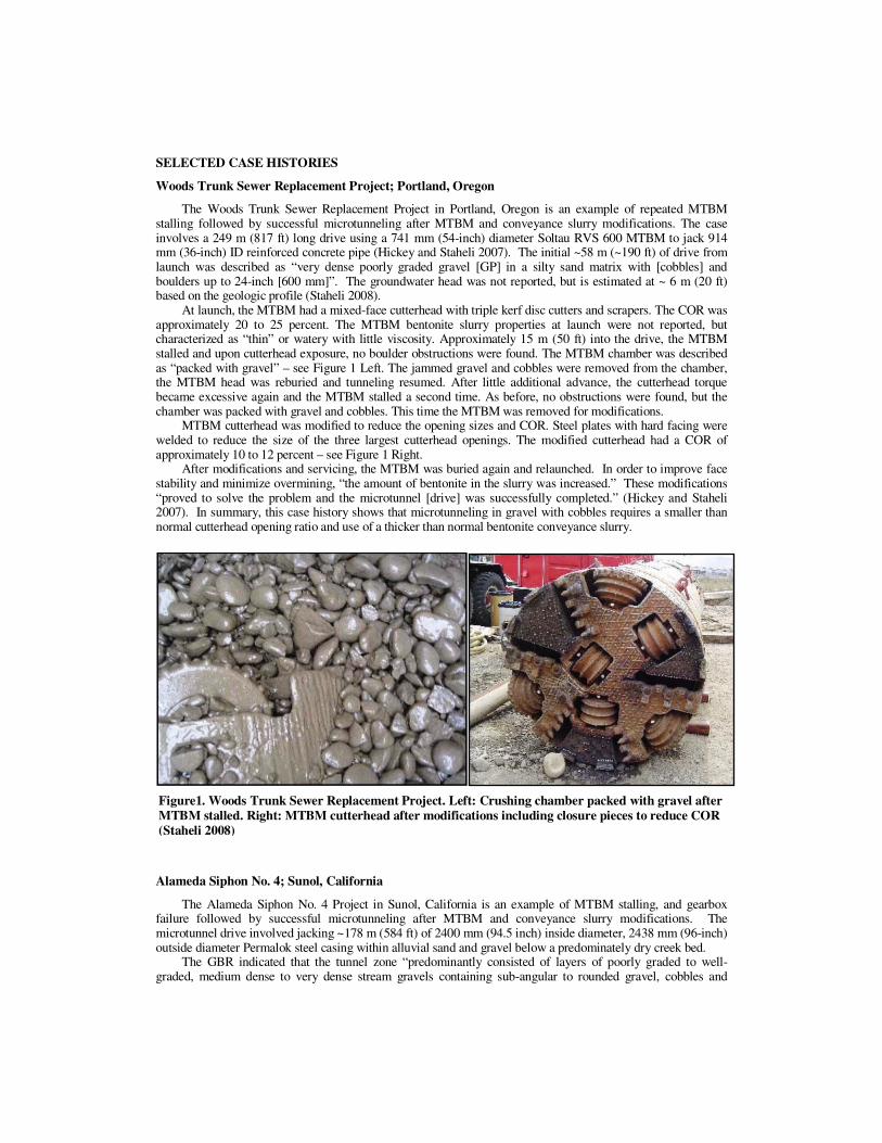
At launch, the MTBM had a mixed-face cutterhead with triple kerf disc cutters and scrapers. The COR was approximately 20 to 25 percent. The MTBM bentonite slurry properties at launch were not reported, but characterized as “thin” or watery with little viscosity. Approximately 15 m (50 ft) into the drive, the MTBM stalled and upon cutterhead exposure, no boulder obstructions were found. The MTBM chamber was described as “packed with gravel” – see Figure 1 Left. The jammed gravel and cobbles were removed from the chamber, the MTBM head was reburied and tunneling resumed. After little additional advance, the cutterhead torque became excessive again and the MTBM stalled a second time. As before, no obstructions were found, but the chamber was packed with gravel and cobbles. This time the MTBM was removed for modifications.
MTBM cutterhead was modified to reduce the opening sizes and COR. Steel plates with hard facing were welded to reduce the size of the three largest cutterhead openings. The modified cutterhead had a COR of approximately 10 to 12 percent – see Figure 1 Right.
After modifications and servicing, the MTBM was buried again and relaunched. In order to improve face stability and minimize overmining, “the amount of bentonite in the slurry was increased.” These modifications “proved to solve the problem and the microtunnel [drive] was successfully completed.” (Hickey and Staheli 2007). In summary, this case history shows that microtunneling in gravel with cobbles requires a smaller than normal cutterhead opening ratio and use of a thicker than normal bentonite conveyance slurry.
Alameda Siphon No. 4; Sunol, California
The Alameda Siphon No. 4 Project in Sunol, California is an example of MTBM stalling, and gearbox failure followed by successful microtunneling after MTBM and conveyance slurry modifications. The microtunnel drive involved jacking ~178 m (584 ft) of 2400 mm (94.5 inch) inside diameter, 2438 mm (96-inch) outside diameter Permalok steel casing within alluvial sand and gravel below a predominately dry creek bed.
The GBR indicated that the tunnel zone “predominantly consisted of layers of poorly graded to well-graded, medium dense to very dense stream gravels containing sub-angular to rounded gravel, cobbles and
Figure1. Woods Trunk Sewer Replacement Project. Left: Crushing chamber packed with gravel after
MTBM stalled. Right: MTBM cutterhead after modifications including closure pieces to reduce COR
(Staheli 2008)
boulders, with varying amounts of sand, silt and clay.” The geological profile in GBR indicated that the tunnel zone soil was predominately within soils with a USCS symbol of “GP-GC”. The GBR did not specifically baseline cobble and boulder quantities, but it indicated that “A substantial number of cobbles and boulders were encountered” and “Therefore, during the microtunnel construction, dense to very dense gravelly, clayey materials containing cobbles and boulders, with boulders up to 3 feet [~1 m] in size, should be expected”.
In preparation for a Disputes Review Board (DRB) hearing, a study was made of Geotechnical Data Report Standard Penetration Test N-value data and sample descriptions along the tunnel alignment (Hunt 2011). In addition the alignment data was compared to N-values and reported cobble and boulder volume ratios within an adjacent, long, deep test trench in the same alluvial unit. The test trench data showed that alluvial gravel deposits contained cobbles and small boulders (up to ~ 500 mm or 18-inches in size) with total cobble + boulder volume ratios ranging from 5 to 40 percent. Based on all the available data at the time of bidding, a reasonable interpretation of the data indicated that bidders should have expected a total average cobble and boulder ratio of ~20 percent with a CVR of ~16 percent and BVR of ~4 percent. In addition, local zones had an expectable total cobble and boulder volume ratio of ~40 percent with a CVR of ~32 percent and BVR of ~8 percent (Hunt 2011). These expectable cobble and boulder quantities were very high for both the average and locally concentrated zones and indicated high risk of MTBM problems with chocking and cutter wear and damage.
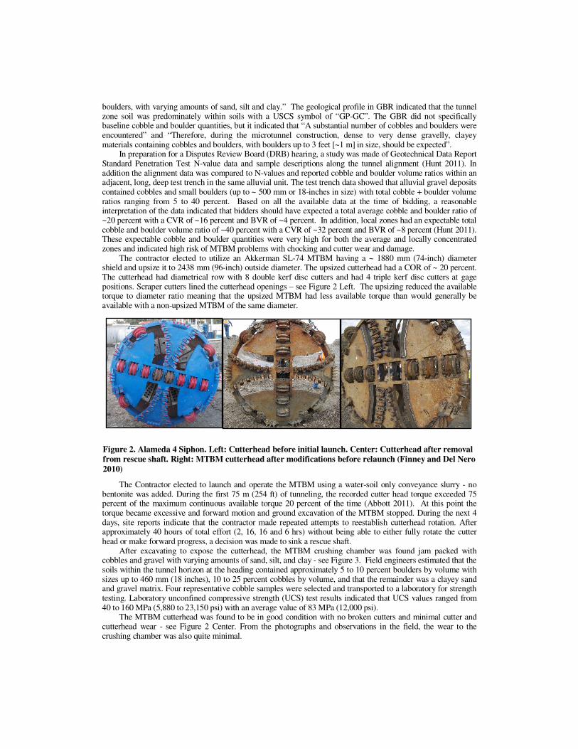
The contractor elected to utilize an Akkerman SL-74 MTBM having a ~ 1880 mm (74-inch) diameter shield and upsize it to 2438 mm (96-inch) outside diameter. The upsized cutterhead had a COR of ~ 20 percent. The cutterhead had diametrical row with 8 double kerf disc cutters and had 4 triple kerf disc cutters at gage positions. Scraper cutters lined the cutterhead openings – see Figure 2 Left. The upsizing reduced the available torque to diameter ratio meaning that the upsized MTBM had less available torque than would generally be available with a non-upsized MTBM of the same diameter.
The Contractor elected to launch and operate the MTBM using a water-soil only conveyance slurry - no bentonite was added. During the first 75 m (254 ft) of tunneling, the recorded cutter head torque exceeded 75 percent of the maximum continuous available torque 20 percent of the time (Abbott 2011). At this point the torque became excessive and forward motion and ground excavation of the MTBM stopped. During the next 4 days, site reports indicate that the contractor made repeated attempts to reestablish cutterhead rotation. After approximately 40 hours of total effort (2, 16, 16 and 6 hrs) without being able to either fully rotate the cutter head or make forward progress, a decision was made to sink a rescue shaft.
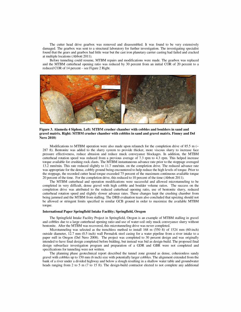
After excavating to expose the cutterhead, the MTBM crushing chamber was found jam packed with cobbles and gravel with varying amounts of sand, silt, and clay - see Figure 3. Field engineers estimated that the soils within the tunnel horizon at the heading contained approximately 5 to 10 percent boulders by volume with sizes up to 460 mm (18 inches), 10 to 25 percent cobbles by volume, and that the remainder was a clayey sand and gravel matrix. Four representative cobble samples were selected and transported to a laboratory for strength testing. Laboratory unconfined compressive strength (UCS) test results indicated that UCS values ranged from 40 to 160 MPa (5,880 to 23,150 psi) with an average value of 83 MPa (12,000 psi).
The MTBM cutterhead was found to be in good condition with no broken cutters and minimal cutter and cutterhead wear - see Figure 2 Center. From the photographs and observations in the field, the wear to the crushing chamber was also quite minimal.
Figure 2. Alameda 4 Siphon. Left: Cutterhead before initial launch. Center: Cutterhead after removal
from rescue shaft. Right: MTBM cutterhead after modifications before relaunch (Finney and Del Nero
2010)
The cutter head drive gearbox was removed and disassembled. It was found to be very extensively damaged. The gearbox was sent to a structural laboratory for further investigation. The investigating specialist found that the gears and gearbox had little wear but the cast iron planetary carrier casting had failed and cracked at multiple locations (Abbott 2011).
Before tunneling could resume, MTBM repairs and modifications were made. The gearbox was replaced and the MTBM cutterhead opening ratio was reduced by 30 percent from an initial COR of 20 percent to a reduced COR of 14 percent – see Figure 2 Right.
Modifications to MTBM operation were also made upon relaunch for the completion drive of 85.5 m (~ 287 ft). Bentonite was added to the slurry system to provide thicker, more viscous slurry to increase face pressure effectiveness, reduce abrasion and reduce muck conveyance blockages. In addition, the MTBM cutterhead rotation speed was reduced from a previous average of 7.3 rpm to 4.3 rpm. This helped increase torque available for crushing rock clasts. The MTBM instantaneous advance rate prior to the stoppage averaged 13.2 mm/min. This rate reduced slightly to 11.7 mm/min. on the completion drive. The reduced advance rate was appropriate for the dense, cobbly ground being encountered to help reduce the high levels of torque. Prior to the stoppage, the recorded cutter head torque exceeded 75 percent of the maximum continuous available torque 20 percent of the time. For the completion drive, this reduced to 10 percent of the time (Abbott 2011).
The MTBM cutterhead and operation modifications were successful and allowed microtunneling to be completed in very difficult, dense gravel with high cobble and boulder volume ratios. The success on the completion drive was attributed to the reduced cutterhead opening ratio, use of bentonite slurry, reduced cutterhead rotation speed and slightly slower advance rates. These changes kept the crushing chamber from being jammed and the MTBM from stalling. The DRB evaluation team also concluded that upsizing should not be allowed or stringent limits specified in similar GCB ground in order to maximize the available MTBM torque.
International Paper Springfield Intake Facility; Springfield, Oregon
The Springfield Intake Facility Project in Springfield, Oregon is an example of MTBM stalling in gravel and cobbles due to a large cutterhead opening ratio and use of water-soil only muck conveyance slurry without bentonite. After the MTBM was recovered, this microtunneling drive was never completed.
Microtunneling was selected as the trenchless method to install 168 m (550 ft) of 1524 mm (60-inch) outside diameter, 12.7 mm (0.5 inch) wall Permalok steel casing for a water pipeline from a river intake to a paper mill in Oregon (Del Nero 2008). The project was completed to 30 percent design and was originally intended to have final design completed before bidding, but instead was bid as design-build. The proposed final design subsurface investigation program and preparation of a GDR and GBR were not completed and specifications for tunneling were not written.
The planning phase geotechnical report described the tunnel zone ground as dense, cohesionless sandy gravel with cobbles up to 150 mm (6 inch) size with potentially larger cobbles. The alignment extended from the bank of a river under a divided highway and below a slough resulting in a shallow water table and groundwater heads ranging from 2 to 5 m (7 to 15 ft). The design-build contractor elected to not complete any additional
Figure 3. Alameda 4 Siphon. Left: MTBM crusher chamber with cobbles and boulders in sand and
gravel matrix. Right: MTBM crusher chamber with cobbles in sand and gravel matrix. Finney and Del
Nero 2010)
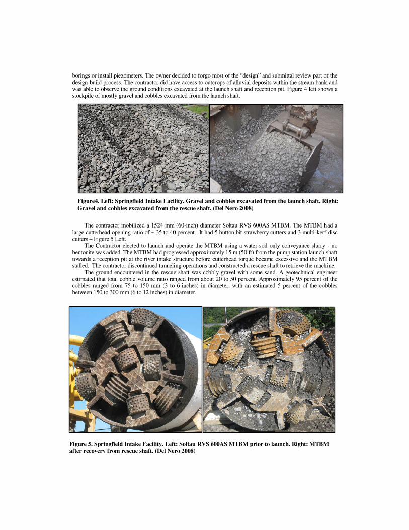
borings or install piezometers. The owner decided to forgo most of the “design” and submittal review part of the design-build process. The contractor did have access to outcrops of alluvial deposits within the stream bank and was able to observe the ground conditions excavated at the launch shaft and reception pit. Figure 4 left shows a stockpile of mostly gravel and cobbles excavated from the launch shaft.
The contractor mobilized a 1524 mm (60-inch) diameter Soltau RVS 600AS MTBM. The MTBM had a large cutterhead opening ratio of ~ 35 to 40 percent. It had 5 button bit strawberry cutters and 3 multi-kerf disc cutters – Figure 5 Left.
The Contractor elected to launch and operate the MTBM using a water-soil only conveyance slurry - no bentonite was added. The MTBM had progressed approximately 15 m (50 ft) from the pump station launch shaft towards a reception pit at the river intake structure before cutterhead torque became excessive and the MTBM stalled. The contractor discontinued tunneling operations and constructed a rescue shaft to retrieve the machine.
The ground encountered in the rescue shaft was cobbly gravel with some sand. A geotechnical engineer estimated that total cobble volume ratio ranged from about 20 to 50 percent. Approximately 95 percent of the cobbles ranged from 75 to 150 mm (3 to 6-inches) in diameter, with an estimated 5 percent of the cobbles between 150 to 300 mm (6 to 12 inches) in diameter.
Figure4. Left: Springfield Intake Facility. Gravel and cobbles excavated from the launch shaft. Right:
Gravel and cobbles excavated from the rescue shaft. (Del Nero 2008)
Figure 5. Springfield Intake Facility. Left: Soltau RVS 600AS MTBM prior to launch. Right: MTBM
after recovery from rescue shaft. (Del Nero 2008)
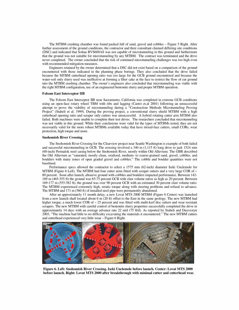
The MTBM crushing chamber was found packed full of sand, gravel and cobbles – Figure 5 Right. After further assessment of the ground conditions, the contractor and their consultant claimed differing site conditions (DSC) and indicated that Soltau RVS600AS was not capable of microtunneling in this ground and furthermore that the ground was not suitable for microtunneling by any MTBM. The contract was terminated and the drive never completed. The owner concluded that the risk of continued microtunneling challenges was too high even with recommended mitigation measures.
Engineers retained by the owner determined that a DSC did not exist based on a comparison of the ground encountered with those indicated in the planning phase borings. They also concluded that the drive failed because the MTBM cutterhead opening ratio was too large for the GCB ground encountered and because the water-soil only slurry used was ineffective at forming a filter cake at the face to restrict the flow of cut ground into the MTBM crushing chamber. The owner’s engineers also concluded that microtunneling was viable with the right MTBM configuration, use of an engineered bentonite slurry and proper MTBM operation.
Folsom East Interceptor IIB
The Folsom East Interceptor IIB near Sacramento, California was completed in extreme GCB conditions using an open-face rotary wheel TBM with ribs and lagging (Castro et.al 2001) following an unsuccessful attempt to prove the viability of microtunneling during a “Construction Methods Microtunneling Proving Project” (Staheli et al. 1999). During the proving project, a conventional slurry shield MTBM with a high cutterhead opening ratio and scraper only cutters was unsuccessful. A hybrid rotating cutter arm MTBM also failed. Both machines were unable to complete their test drives. The researchers concluded that microtunneling was not viable in this ground. While their conclusions were valid for the types of MTBMs tested, they are not necessarily valid for the more robust MTBMs available today that have mixed-face cutters, small CORs, wear protection, high torque and more.
Snohomish River Crossing
The Snohomish River Crossing for the Clearview project near Seattle Washington is example of both failed and successful microtunneling in GCB. The crossing involved a 340 m (1,115 ft) long drive to jack 1524 mm (60-inch) Permalok steel casing below the Snohomish River, mostly within Old Alluvium. The GBR described the Old Alluvium as “saturated, mostly clean, oxidized, medium- to coarse-grained sand, gravel, cobbles, and boulders with many zones of open graded gravel and cobbles.” The cobble and boulder quantities were not baselined.
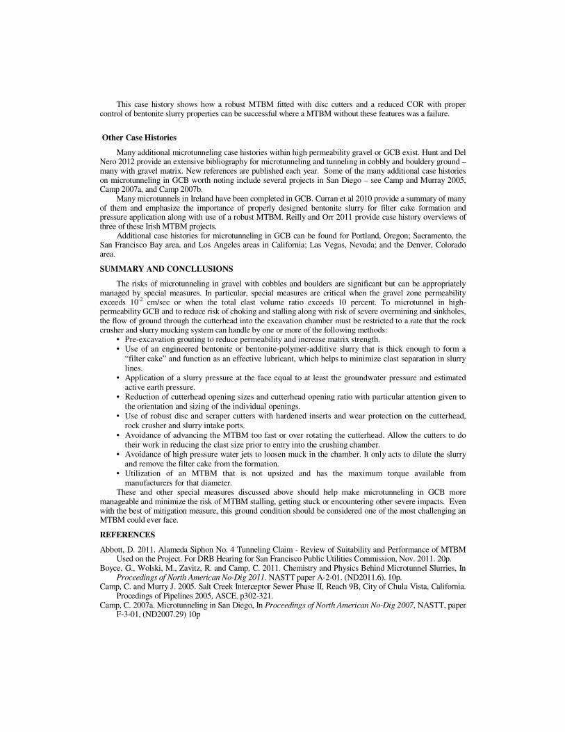
Performance specs allowed the contractor to select a 1575 mm (62-inch) diameter Iseki Unclemole for MTBM (Figure 6 Left). The MTBM had four cutter arms fitted with scraper cutters and a very large COR of ~ 80 percent. Soon after launch, abrasive ground with cobbles and boulders impacted performance. Between 142-169 m (465-555 ft) the ground was 65-75 percent GCB with clast volume ratios as high as 20 percent. Between 169-177 m (555-582 ft), the ground was over 90 percent GCB with an estimated 30 percent clast volume ratio. The MTBM experienced extremely high, erratic torque along with steering problems and refusal to advance. The MTBM and 171 m (560 ft) of installed steel pipe were permanently abandoned.
After an approximately 11 month delay, a new Lovat MTS 2000 MTBM (Figure 6 Center) was launched from a new launch shaft located about 6 m (20 ft) offset to the East in the same geology. The new MTBM had higher torque, a much lower COR of ~ 25 percent and was fitted with multi-kerf disc cutters and wear resistant scrapers. The new MTBM with careful control of bentonite slurry properties successfully completed the drive in approximately 14 days with an average advance rate 22 m/d (75 ft/d). As reported by Staheli and Duyvestyn 2003, “The machine had little to no difficulty excavating the materials it encountered.” The new MTBM cutters and cutterhead experienced very little wear – Figure 6 Right.
Figure 6. Left: Snohomish River Crossing. Iseki Unclemole before launch. Center: Lovat MTS 2000 before launch. Right: Lovat MTS 2000 after breakthrough with minimal cutter and cutterhead wear.
This case history shows how a robust MTBM fitted with disc cutters and a reduced COR with proper control of bentonite slurry properties can be successful where a MTBM without these features was a failure.
Other Case Histories
Many additional microtunneling case histories within high permeability gravel or GCB exist. Hunt and Del Nero 2012 provide an extensive bibliography for microtunneling and tunneling in cobbly and bouldery ground – many with gravel matrix. New references are published each year. Some of the many additional case histories on microtunneling in GCB worth noting include several projects in San Diego – see Camp and Murray 2005, Camp 2007a, and Camp 2007b.
Many microtunnels in Ireland have been completed in GCB. Curran et al 2010 provide a summary of many of them and emphasize the importance of properly designed bentonite slurry for filter cake formation and pressure application along with use of a robust MTBM. Reilly and Orr 2011 provide case history overviews of three of these Irish MTBM projects.
Additional case histories for microtunneling in GCB can be found for Portland, Oregon; Sacramento, the San Francisco Bay area, and Los Angeles areas in California; Las Vegas, Nevada; and the Denver, Colorado area.
SUMMARY AND CONCLLUSIONS
The risks of microtunneling in gravel with cobbles and boulders are significant but can be appropriately managed by special measures. In particular, special measures are critical when the gravel zone permeability exceeds 10-2 cm/sec or when the total clast volume ratio exceeds 10 percent. To microtunnel in high-permeability GCB and to reduce risk of choking and stalling along with risk of severe overmining and sinkholes, the flow of ground through the cutterhead into the excavation chamber must be restricted to a rate that the rock crusher and slurry mucking system can handle by one or more of the following methods:
• Pre-excavation grouting to reduce permeability and increase matrix strength. • Use of an engineered bentonite or bentonite-polymer-additive slurry that is thick enough to form a
“filter cake” and function as an effective lubricant, which helps to minimize clast separation in slurry lines.
• Application of a slurry pressure at the face equal to at least the groundwater pressure and estimated active earth pressure.
• Reduction of cutterhead opening sizes and cutterhead opening ratio with particular attention given to the orientation and sizing of the individual openings.
• Use of robust disc and scraper cutters with hardened inserts and wear protection on the cutterhead, rock crusher and slurry intake ports.
• Avoidance of advancing the MTBM too fast or over rotating the cutterhead. Allow the cutters to do their work in reducing the clast size prior to entry into the crushing chamber.
• Avoidance of high pressure water jets to loosen muck in the chamber. It only acts to dilute the slurry and remove the filter cake from the formation.
• Utilization of an MTBM that is not upsized and has the maximum torque available from manufacturers for that diameter.
These and other special measures discussed above should help make microtunneling in GCB more manageable and minimize the risk of MTBM stalling, getting stuck or encountering other severe impacts. Even with the best of mitigation measure, this ground condition should be considered one of the most challenging an MTBM could ever face.
REFERENCES
Abbott, D. 2011. Alameda Siphon No. 4 Tunneling Claim - Review of Suitability and Performance of MTBM Used on the Project. For DRB Hearing for San Francisco Public Utilities Commission, Nov. 2011. 20p.
Boyce, G., Wolski, M., Zavitz, R. and Camp, C. 2011. Chemistry and Physics Behind Microtunnel Slurries, In Proceedings of North American No-Dig 2011. NASTT paper A-2-01. (ND2011.6). 10p.
Camp, C. and Murry J. 2005. Salt Creek Interceptor Sewer Phase II, Reach 9B, City of Chula Vista, California. Procedings of Pipelines 2005, ASCE. p302-321.
Camp, C. 2007a. Microtunneling in San Diego, In Proceedings of North American No-Dig 2007, NASTT, paper F-3-01, (ND2007.29) 10p
Camp, C. 2007b. Microtunneling and HDD through Alluvium in Chula Vista, CA, In Proceedings of North American No-Dig 2007, NASTT, paper F-3-01, (ND2007.103) 10p.
Camp, C., Zavitz, R., Sorteberg, B. and Boyce, G. 2011. Slurry Management for Microtunneling Projects, In Proceedings of North American No-Dig 2011. NASTT Paper A-2-05. (ND2011.10). 9p.
Castro, R., Webb, R. and Nonnweiler J. 2001. Tunneling Through Cobbles in Sacramento, California. In: Proceedings 2001 Rapid Excavation and Tunneling Conference, W.H. Hansmire & I.M. Gowring, (Eds). SME, Littleton, Colorado, (R2001.74) 907-918.
Curran, B.G., McCabe, B.A. and Ward, M.J. 2010. Microtunneling – the future for pipeline construction? The Engineers Journal. Jan/Feb 2010 64(1):16-20.
Del Nero, D. 2008. International Paper, Springfield Intake Facility, Evaluation of Vadnais Microtunnel Construction Efforts. Technical Memorandum by CH2M Hill, For International Paper Co. 26p.
Finney, A.F. and Del Nero. D.E. 2010. Preliminary Findings Related to a Notice of a Potential Claim of Differing Conditions (SPR Letter 270). Technical Memorandum for San Francisco Public Utilities Commission. 17p.
Fritz, P. 2003. Slurry Shield Tunneling in Highly Permeable Ground. In Proceedings of 12th Panamerican Conference on Soil Mechanics and Geotechnical Engineering and 39th U.S. Rock Mechanics Symposium, Cambridge MA. June 22-25, 2003. 8p.
Hickey, M. and Staheli, K. 2007. Woods Trunk Sewer Replacement Project – A Challenge, In Proceedings of North American No-Dig 2007, NASTT Paper C-1-03. (ND2007.39). 10p.
Hunt, S.W. 2011. Assessment of Microtunneling Aspects in Gravel-Cobble-Boulder Ground, Alameda Siphon No. 4, For DRB Hearing for San Francisco Public Utilities Commission, Nov. 2011. 20p
Hunt, S.W. and Del Nero, D.E. 2010.Two Decades of Advances Investigating, Baselining and Tunneling in Bouldery Ground. Proceedings of 2010 World Tunnelling Congress, Vancouver, ITA-TAC. 8p.
Hunt, S.W. and Del Nero, D.E. 2012. Microtunneling in Cobbles and Boulders. In handouts of Microtunneling Short Course. Colorado School of Mines. Golden, CO. 36p.
Kim, S.H. and Tonon, F. 2010. Face stability and required support pressure for TBM driven tunnels with ideal face membrane – Drained case. Tunnelling and Underground Space Technology, 2010-9. 25(5):526-542.
Milligan, G., 2000. Lubrication and Soil Conditioning In Tunnelling, Pipe Jacking And Microtunnelling, A State of the Art Review. Geotechnical Consulting Group. 46p.
Reilly, C. and Orr, T. 2001. Microtunneling – Recent Experience in Ireland. In proceedings of International No-Dig 2011, Berlin. International Society for Trenchless Technology (ISTT). Paper 2-A-04. 10p.
Staheli, K. 2008. Woods Trunk Sewer Replacement Project, Portland, Oregon. In Construction Method: Microtunneling. Staheli Trenchless Consultants. 1p. www.stahelitrenchless.com. Last accessed Jan 2013.
Staheli, K., Bennett, D., Maggi, M.A., Watson, M.B. and Corwin B.J. 1999. Folsom East 2 Construction Proving Project: Field Evaluation of Alternative Methods in Cobbles and Boulders. In: Geo-Engineering for Underground Facilities, G. Fernandez, & R. Bauer (Eds), ASCE, Reston, Virginia, (1999) 720-730.
Staheli, K. and Duyvestyn, G. 2003. Snohomish River Crossing: Bring on the Boulders, Success on the Second Attempt. Proceedings of North American No-Dig 2003, NASTT, Las Vegas, April, Paper B-4-03 (ND2003.33), 12p.