pa - emarketplace
TRANSCRIPT
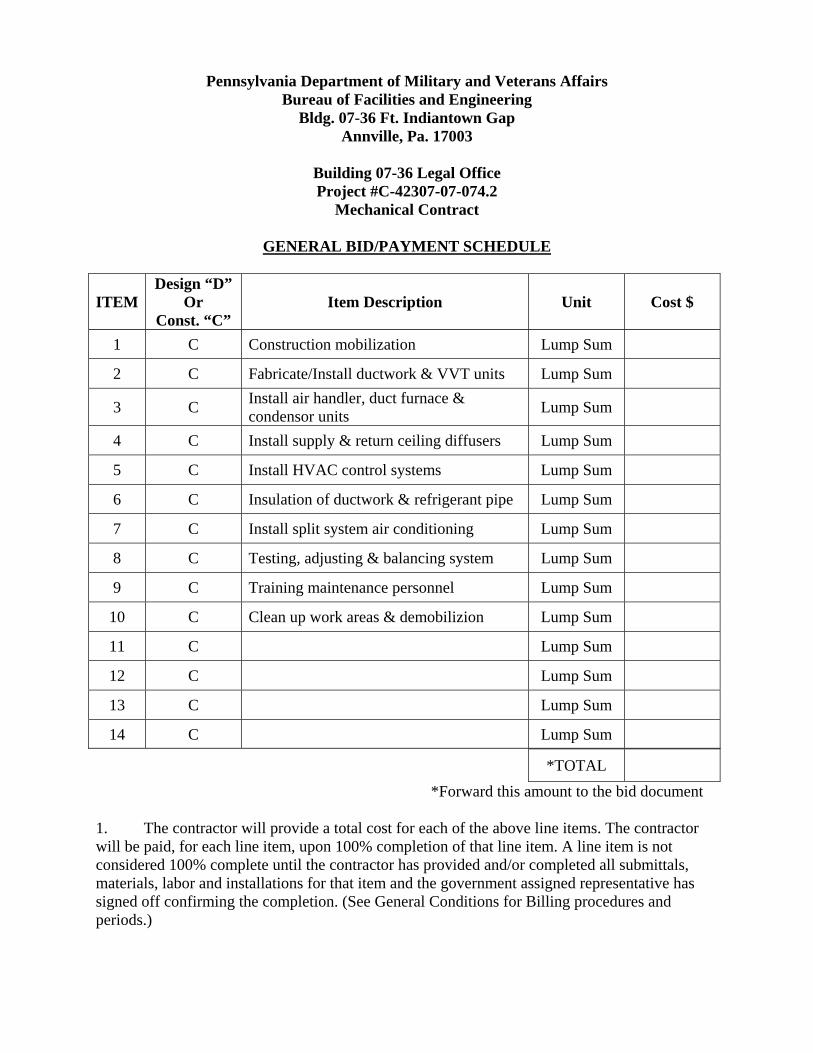
Pennsylvania Department of Military and Veterans Affairs Bureau of Facilities and Engineering
Bldg. 07-36 Ft. Indiantown Gap Annville, Pa. 17003
Building 07-36 Legal Office Project #C-42307-07-074.2
Mechanical Contract
GENERAL BID/PAYMENT SCHEDULE
ITEM Design “D”
Or Const. “C”
Item Description Unit Cost $
1 C Construction mobilization Lump Sum
2 C Fabricate/Install ductwork & VVT units Lump Sum
3 C Install air handler, duct furnace & condensor units Lump Sum
4 C Install supply & return ceiling diffusers Lump Sum
5 C Install HVAC control systems Lump Sum
6 C Insulation of ductwork & refrigerant pipe Lump Sum
7 C Install split system air conditioning Lump Sum
8 C Testing, adjusting & balancing system Lump Sum
9 C Training maintenance personnel Lump Sum
10 C Clean up work areas & demobilizion Lump Sum
11 C Lump Sum
12 C Lump Sum
13 C Lump Sum
14 C Lump Sum
*TOTAL
*Forward this amount to the bid document 1. The contractor will provide a total cost for each of the above line items. The contractor will be paid, for each line item, upon 100% completion of that line item. A line item is not considered 100% complete until the contractor has provided and/or completed all submittals, materials, labor and installations for that item and the government assigned representative has signed off confirming the completion. (See General Conditions for Billing procedures and periods.)
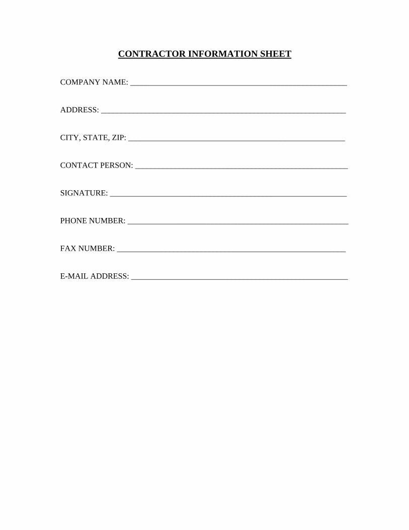
CONTRACTOR INFORMATION SHEET COMPANY NAME: ______________________________________________________ ADDRESS: _____________________________________________________________ CITY, STATE, ZIP: ______________________________________________________ CONTACT PERSON: _____________________________________________________ SIGNATURE: ___________________________________________________________ PHONE NUMBER: _______________________________________________________ FAX NUMBER: _________________________________________________________ E-MAIL ADDRESS: ______________________________________________________
Department of General Services GSPUR-89 Rev. 2/15/02
RECIPROCAL LIMITATIONS ACT REQUIREMENTS
Please Complete Applicable Portion of Pages 3 & 4 and Return with Bid.
NOTE: These Requirements Do Not Apply To Bids Under $10,000.00 I. REQUIREMENTS
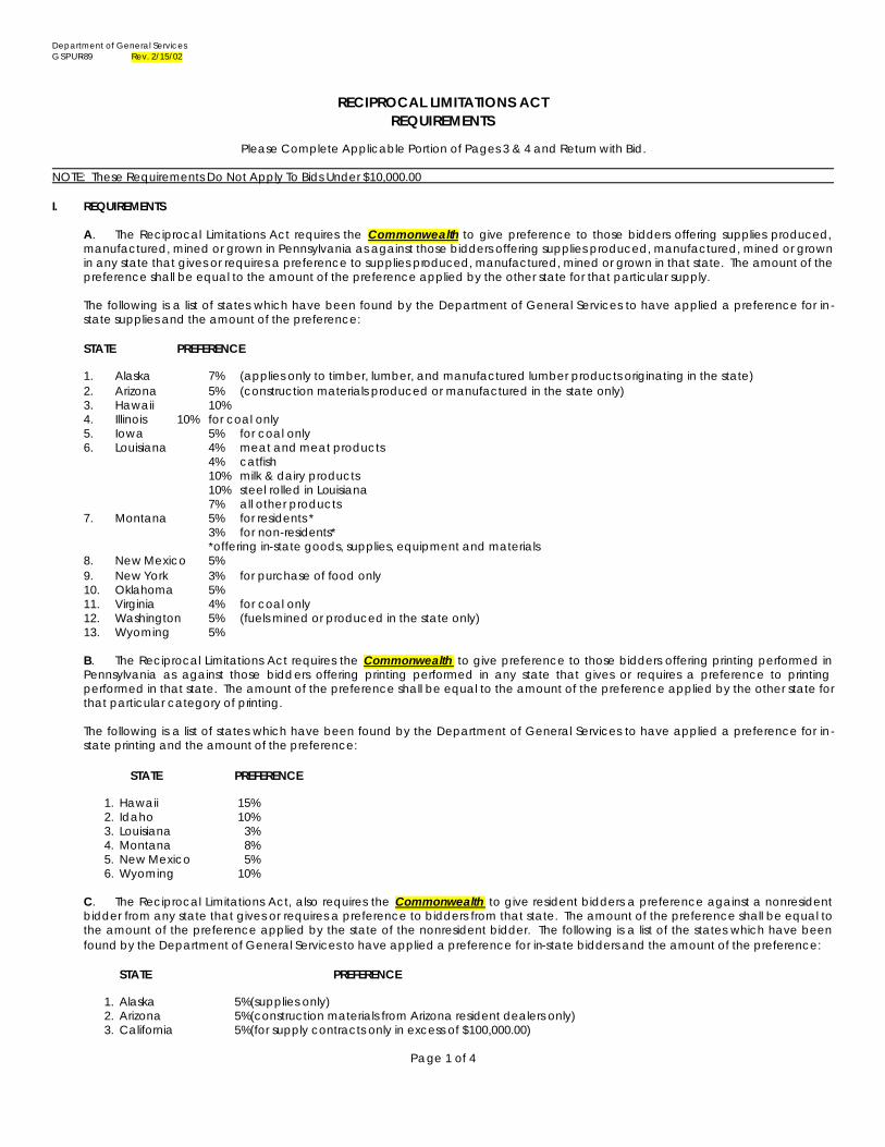
A. The Reciprocal Limitations Act requires the Commonwealth to give preference to those bidders offering supplies produced, manufactured, mined or grown in Pennsylvania as against those bidders offering supplies produced, manufactured, mined or grown in any state that gives or requires a preference to supplies produced, manufactured, mined or grown in that state. The amount of the preference shall be equal to the amount of the preference applied by the other state for that particular supply.
The following is a list of states which have been found by the Department of General Services to have applied a preference for in-state supplies and the amount of the preference:
STATE PREFERENCE 1. Alaska 7% (applies only to timber, lumber, and manufactured lumber products originating in the state) 2. Arizona 5% (construction materials produced or manufactured in the state only) 3. Hawaii 10% 4. Illinois 10% for coal only 5. Iowa 5% for coal only 6. Louisiana 4% meat and meat products 4% catfish 10% milk & dairy products 10% steel rolled in Louisiana 7% all other products 7. Montana 5% for residents * 3% for non-residents* *offering in-state goods, supplies, equipment and materials 8. New Mexico 5% 9. New York 3% for purchase of food only 10. Oklahoma 5% 11. Virginia 4% for coal only 12. Washington 5% (fuels mined or produced in the state only) 13. Wyoming 5%
B. The Reciprocal Limitations Act requires the Commonwealth to give preference to those bidders offering printing performed in Pennsylvania as against those bidders offering printing performed in any state that gives or requires a preference to printing performed in that state. The amount of the preference shall be equal to the amount of the preference applied by the other state for that particular category of printing.
The following is a list of states which have been found by the Department of General Services to have applied a preference for in-state printing and the amount of the preference:
STATE PREFERENCE 1. Hawaii 15% 2. Idaho 10% 3. Louisiana 3% 4. Montana 8% 5. New Mexico 5% 6. Wyoming 10%
C. The Reciprocal Limitations Act, also requires the Commonwealth to give resident bidders a preference against a nonresident bidder from any state that gives or requires a preference to bidders from that state. The amount of the preference shall be equal to the amount of the preference applied by the state of the nonresident bidder. The following is a list of the states which have been found by the Department of General Services to have applied a preference for in-state bidders and the amount of the preference:
STATE PREFERENCE 1. Alaska 5%(supplies only) 2. Arizona 5%(construction materials from Arizona resident dealers only) 3. California 5%(for supply contracts only in excess of $100,000.00)
Page 1 of 4
Department of General Services GSPUR-89 Rev. 2/15/02
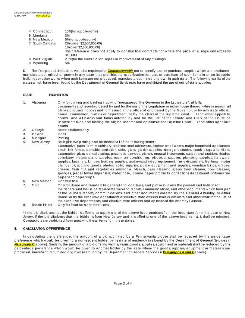
4. Connecticut 10%(for supplies only) 5. Montana 3% 6. New Mexico 5%(for supplies only) 7. South Carolina 2%(under $2,500,000.00) 1%(over $2,500,000.00)
This preference does not apply to construction contracts nor where the price of a single unit exceeds $10,000.
8. West Virginia 2.5%(for the construction, repair or improvement of any buildings 9. Wyoming 5%
D. The Reciprocal Limitations Act also requires the Commonwealth not to specify, use or purchase supplies which are produced, manufactured, mined or grown in any state that prohibits the specification for, use, or purchase of such items in or on its public buildings or other works, when such items are not produced, manufactured, mined or grown in such state. The following is a list of the states which have been found by the Department of General Services to have prohibited the use of out-of-state supplies:
STATE PROHIBITION
1. Alabama Only for printing and binding involving ”messages of the Governor to the Legislature“, all bills, documents and reports ordered by and for the use of the Legislature or either house thereof while in session; all blanks, circulars, notices and forms used in the office of or ordered by the Governor, or by any state official, board, commission, bureau or department, or by the clerks of the supreme court . . ./and other appellate courts/; and all blanks and forms ordered by and for the use of the Senate and Clerk or the House of Representatives, and binding the original records and opinions of the Supreme Court . . . /and other appellate courts/
2. Georgia Forest products only 3. Indiana Coal 4. Michigan Printing
5. New Jersey For legislative printing and bidders for all of the following items:* automotive parts, farm machinery, stainless steel tableware, kitchen small wares, major household appliances, chain link fence, portable sanitation units, glass, glazier supplies, storage batteries, spark plugs and filters, automotive glass, dental casting, prosthetic devices, pianos, musical instruments, carpet and cushion, shades, upholstery materials and supplies, room air conditioning, electrical supplies, plumbing supplies, hardware supplies, fasteners, lumber, building supplies, audiovisual/video equipment, fire extinguishers, fire hose, motor oils, fuel oil, sporting goods, photographic supplies, police equipment and supplies, venetian blinds, drapes, cheese, fresh fruit and vegetables, ammonia, bleach, pails, cleaning soaps, toilet cleaner, bowl cleaner, sponges, paper towel dispensers, water hose, course paper products, corrections department uniforms fine paper and paper cups.
6. New Mexico Construction 7. Ohio Only for House and Senate bills, general and local laws, and joint resolutions; the journals and bulletins of
the Senate and house of Representatives and reports, communications, and other documents which form part of the journals; reports, communications, and other documents ordered by the General Assembly, or either House, or by the executive department or elective state officers; blanks, circulars, and other work for the use of the executive departments, and elective state officers; and opinions of the Attorney General.
8. Rhode Island Only for food for state institutions.
*If the bid discloses that the bidder is offering to supply one of the above-listed products from the listed state (or in the case of New Jersey, if the bid discloses that the bidder is from New Jersey and it is offering one of the above-listed items), it shall be rejected. Contractors are prohibited from supplying these items from these states.
II. CALCULATION OF PREFERENCE In calculating the preference, the amount of a bid submitted by a Pennsylvania bidder shall be reduced by the percentage preference which would be given to a nonresident bidder by its state of residency (as found by the Department of General Services in Paragraph C above). Similarly, the amount of a bid offering Pennsylvania goods, supplies, equipment or materials shall be reduced by the percentage preference which would be given to another bidder by the state where the goods, supplies, equipment or materials are produced, manufactured, mined or grown (as found by the Department of General Services in Paragraphs A and B above).
Page 2 of 4
Department of General Services GSPUR-89 Rev. 2/15/02
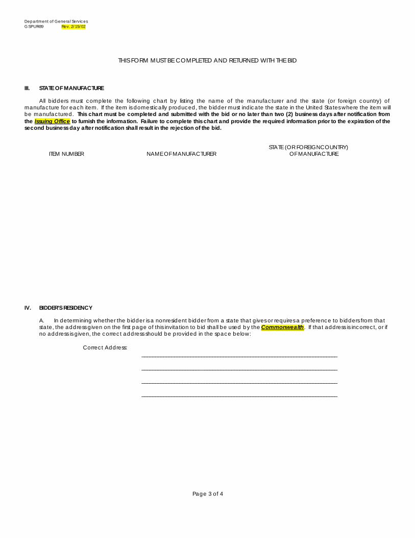
THIS FORM MUST BE COMPLETED AND RETURNED WITH THE BID
III. STATE OF MANUFACTURE All bidders must complete the following chart by listing the name of the manufacturer and the state (or foreign country) of manufacture for each item. If the item is domestically produced, the bidder must indicate the state in the United States where the item will be manufactured. This chart must be completed and submitted with the bid or no later than two (2) business days after notification from the Issuing Office to furnish the information. Failure to complete this chart and provide the required information prior to the expiration of the second business day after notification shall result in the rejection of the bid. STATE (OR FOREIGNCOUNTRY) ITEM NUMBER NAME OF MANUFACTURER OF MANUFACTURE IV. BIDDER’S RESIDENCY
A. In determining whether the bidder is a nonresident bidder from a state that gives or requires a preference to bidders from that state, the address given on the first page of this invitation to bid shall be used by the Commonwealth. If that address is incorrect, or if no address is given, the correct address should be provided in the space below:
Correct Address:
________________________________________________________________________
________________________________________________________________________
________________________________________________________________________
________________________________________________________________________
Page 3 of 4
Department of General Services GSPUR-89 Rev. 2/15/02
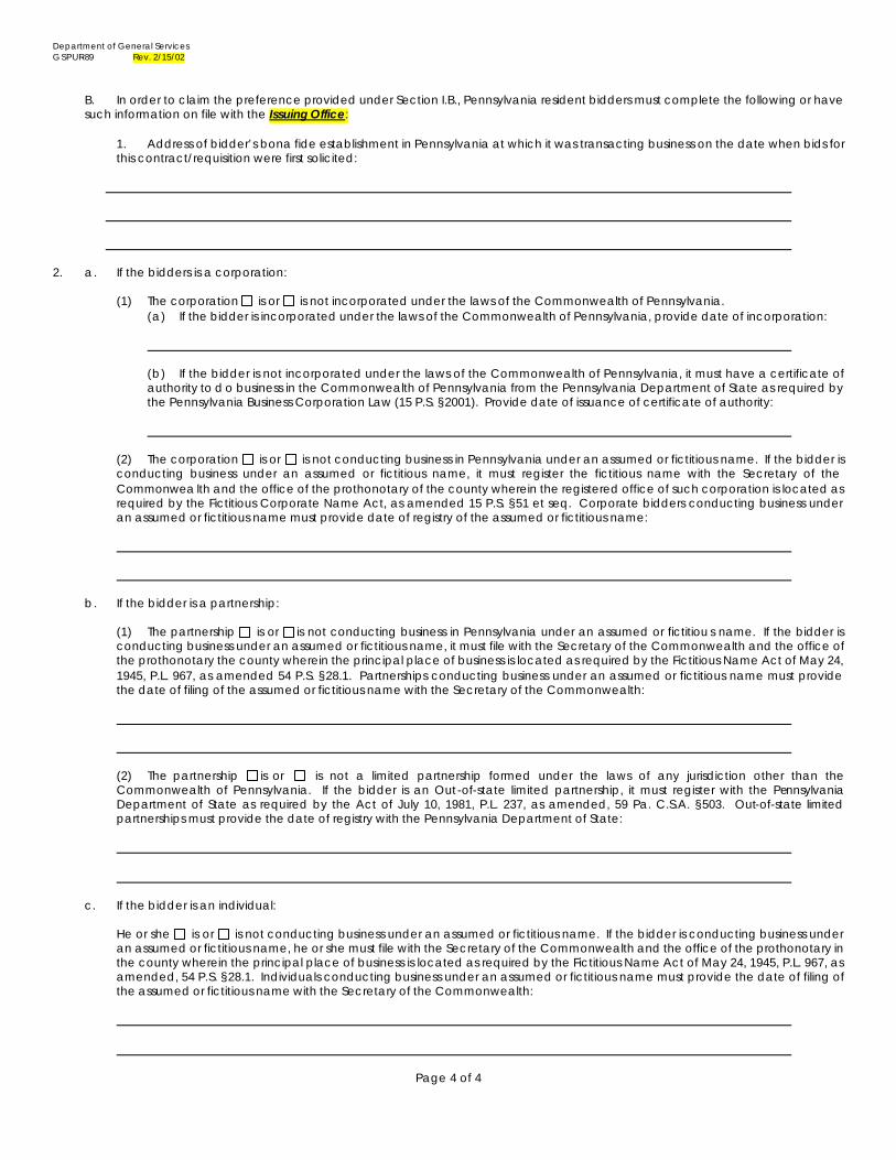
B. In order to claim the preference provided under Section I.B., Pennsylvania resident bidders must complete the following or have such information on file with the Issuing Office:
1. Address of bidder’s bona fide establishment in Pennsylvania at which it was transacting business on the date when bids for this contract/requisition were first solicited:
2. a. If the bidders is a corporation:
(1) The corporation is or is not incorporated under the laws of the Commonwealth of Pennsylvania. (a) If the bidder is incorporated under the laws of the Commonwealth of Pennsylvania, provide date of incorporation:
(b) If the bidder is not incorporated under the laws of the Commonwealth of Pennsylvania, it must have a certificate of authority to d o business in the Commonwealth of Pennsylvania from the Pennsylvania Department of State as required by the Pennsylvania Business Corporation Law (15 P.S. §2001). Provide date of issuance of certificate of authority:
(2) The corporation is or is not conducting business in Pennsylvania under an assumed or fictitious name. If the bidder is conducting business under an assumed or fictitious name, it must register the fictitious name with the Secretary of the Commonwea lth and the office of the prothonotary of the county wherein the registered office of such corporation is located as required by the Fictitious Corporate Name Act, as amended 15 P.S. §51 et seq. Corporate bidders conducting business under an assumed or fictitious name must provide date of registry of the assumed or fictitious name:
b. If the bidder is a partnership:
(1) The partnership is or is not conducting business in Pennsylvania under an assumed or fictitiou s name. If the bidder is conducting business under an assumed or fictitious name, it must file with the Secretary of the Commonwealth and the office of the prothonotary the county wherein the principal place of business is located as required by the Fictitious Name Act of May 24, 1945, P.L. 967, as amended 54 P.S. §28.1. Partnerships conducting business under an assumed or fictitious name must provide the date of filing of the assumed or fictitious name with the Secretary of the Commonwealth:
(2) The partnership is or is not a limited partnership formed under the laws of any jurisdiction other than the Commonwealth of Pennsylvania. If the bidder is an Out-of-state limited partnership, it must register with the Pennsylvania Department of State as required by the Act of July 10, 1981, P.L. 237, as amended, 59 Pa. C.S.A. §503. Out-of-state limited partnerships must provide the date of registry with the Pennsylvania Department of State:
c. If the bidder is an individual:
He or she is or is not conducting business under an assumed or fictitious name. If the bidder is conducting business under an assumed or fictitious name, he or she must file with the Secretary of the Commonwealth and the office of the prothonotary in the county wherein the principal place of business is located as required by the Fictitious Name Act of May 24, 1945, P.L. 967, as amended, 54 P.S. §28.1. Individuals conducting business under an assumed or fictitious name must provide the date of filing of the assumed or fictitious name with the Secretary of the Commonwealth:
Page 4 of 4
GSPUR 95 Revised 08/06/01
BIDDING PREFERENCE FOR PRODUCTS WITH RECYCLED POSTCONSUMER MATERIAL
PLEASE NOTE: Bidders ARE NOT required to complete this form or obtain the following Manufacturer's Recycled Postconsumer Material Certification if they ARE NOT seeking a bidding preference for products or printing with recycled postconsumer material. A. PREFERENCE Except as otherwise provided in Paragraph G, every bidder who certifies that the goods, supplies, equipment, materials or printing, which the bidder is offering, contains at least 10% of recycled postconsumer material shall be given a five percent (5%) preference against any bidder that has not so certified (or such higher percentage specified in the invitation for bids for the bidding preference for products with recycled postconsumer material) "Postconsumer material" is defined as "Any product generated by a business or consumer which has served its intended end use, and which has been separated or diverted from solid waste for the purpose of collection, recycling, and disposition. The term includes industrial by-products that would otherwise go to disposal or processing facilities. The term does not include internally generated scraps that is commonly returned to industrial or manufacturing processes." This preference for products and printing with recycled postconsumer material shall be in addition to any reciprocal preference for Pennsylvania bidders and manufacturers. B. BIDDER CERTIFICATION If the bidder is submitting a bid price on more than one item, and the percentage of recycled postconsumer material differs for each item, the bidder must state the percentage for each item. Bidder certifies that the goods, supplies, equipment, materials or printing which the bidder is offering: (to be completed by the bidder)
Item No.________Contains___ __% of recycled postconsumer material.
Item No.________Contains_______% of recycled postconsumer material.
Item No.________Contains_______% of recycled postconsumer material. (use additional sheets if necessary to complete required information)
If a bidder does not comply with this Subsection (B), he shall not be eligible for the 5% preference. C. MANUFACTURER'S RECYCLED POSTCONSUMER MATERIAL CERTIFICATION In addition to the Bidder Certification in Subsection (B), in order to be eligible for the 5% preference a manufacturer's certification must be completed, signed and submitted by each of the manufacturers listed by the bidder in Section III of the Reciprocal Limitations Act Requirements of this Invitation for Bid. Bidders must use the enclosed Manufacturer's Recycled Postconsumer Material Certification form. If this form is not completed, signed and submitted with the bid, no bidding preference shall be given to the bidder. D. FEDERAL FUNDS No preference shall be given if the Commonwealth's receipt of federal funds would be jeopardized by granting the preference. E. TIE BIDS When there is a tie for lowest responsible bidder, the Department of General Services may consider, as one factor in determining to whom the contract should be awarded, which of the bids provides for the greatest percentage of recycled postconsumer material in the product or printing.
GSPUR 95 Revised 08/06/01
F. ENFORCEMENT Awarded bidders may be required, after delivery of the goods, supplies, equipment, materials or printing, to provide the Commonwealth with documentary evidence that the goods, supplies, equipment, materials or printing was in fact produced with the certified percentage of recycled postconsumer material. If a bidder is awarded a contract or a purchase order on the basis of the 5% preference and fails to supply the item(s) with the required content of recycled postconsumer material or refuses or fails to provide sufficient documentary evidence that the item(s) was in fact produced with the certified percentage of recycled postconsumer material, the Department reserves the right, at its sole discretion, to: 1) Reduce the purchase price paid to the contractor by 5%. 2) Require the contractor to remove and replace the materials at the contractor`s sole expense. 3) Cancel the contract or the purchase order. 4) Obtain the item(s) from another source. 5) Pursue its other remedies under the contract for damages and costs for breach of contract. G. STEEL AND ALUMINUM PRODUCTS EXCEPTION The Commonwealth of Pennsylvania recognizes that both steel and aluminum products are universally made of recycled material, including postconsumer steel and postconsumer aluminum. Therefore, if steel or aluminum is used in the manufacture of the product offered by a bidder in response to this invitation to bid, the bidder is not required to provide certification that the product contains recycled postconsumer material. If a bidder is offering a product with steel or aluminum and the steel or aluminum contains no postconsumer material, the bidder is required to provide written notification in its bid. Bidders offering products containing steel and/or aluminum shall be given a five percent bidding preference over bidders offering: (1) steel or aluminum products that are reported to be made without recycled (postconsumer) content and (2) non-steel or non-aluminum products (such as plastic) which are not certified as containing recycled (postconsumer) content.
GSPUR 95 Revised 08/06/01
MANUFACTURER RECYCLED POSTCONSUMER MATERIAL CERTIFICATION
TO BE COMPLETED BY MANUFACTURER: NAME OF MANUFACTURING FIRM: ADDRESS OF MANUFACTURING FIRM: FEDERAL EMPLOYER I.D. NO: CONTRACT OR REQUISITION NO: NAME OF BIDDER: ADDRESS OF BIDDER:
Goods, supplies, equipment, materials or printing which the manufacturer will furnish to the bidder if the bidder is awarded the above-referenced contract or purchase requisition:
Short description of the nature of the postconsumer material which will be contained in the goods, supplies,
equipment, materials or printing:
CERTIFICATION: I, the undersigned officer of the above-named firm, do hereby certify that I am authorized to provide this certification on behalf of the above-named firm and that the goods, supplies, equipment, materials or printing listed above which my company will furnish to the bidder named above, if the bidder is awarded the above-referenced contract or purchase requisition, shall contain not less than _____% postconsumer material as that term is defined in the invitation for bid. The nature of the postconsumer material is also identified above. I understand that this document is subject to the provisions of the Unsworn Falsification of Authorities Act (18 P.S. Section 4904). PLEASE NOTE: Bidders ARE NOT required to complete this form if they ARE NOT seeking a bidding preference for products with recycled post-consumer material. Signature Name of Signatory Title Date
CONTRACT
FOR
MECHANICAL CONSTRUCTION
DEPARTMENT OF MILITARY AND VETERANS AFFAIRS
CHIEF COUNSEL (CC)
JUDGE ADVOCATE GENERAL (JAG)
OFFICE OF POLICY AND LEGISLATIVE LIAISON (LLO)
AREA 7, BUILDING NUMBER 7-36
FT. INDIANTOWN GAP - LEBANON COUNTY - PENNSYLVANIA
DMVA PROJECT # C-42307-07-012.2
SPECIFICATION TABLE OF CONTENTS DIVISION 1 – GENERAL REQUIREMENTS SECTION 010000 – General Requirements Pg. 010000-1 to 010000-3 SECTION 011200 – Coordination Pg. 011200-1 to 011200-2 DIVISION 08 – OPENINGS SECTION 089000 – Louvers and Vents Pg. 089000-1 to 089000-7 DIVISION 23 – HVAC SECTION 230500 – Common Work Results for HVAC Pg. 230500-1 to230500-5 SECTION 230529 – Hangers and Supports Pg. 230529-1 to 230529-4 SECTION 230593 – Testing, Adjusting and Balancing Pg. 230593-1 to 230593-9 SECTION 230700 – HVAC Insulation Pg. 230700-1 to 230700-9 SECTION 230900 – Instrumentation and Control for HVAC Pg. 230900-1 to 230900-11 SECTION 231126 – Facility Liquefied-Petroleum Gas Piping Pg. 231126-1 to 231126-11 SECTION 233113 – Metal Ducts Pg. 233113-1 to 233113-6 SECTION 233300 – Air Duct Accessories Pg. 233300-1 to 233300-9 SECTION 233423 – HVAC Power Ventilators Pg. 233423-1 to 233423-6 SECTION 233713 – Diffusers, Registers and Grilles Pg. 233713-1 to 233713-3 SECTION 235100 – Breeching, Chimneys and Stacks Pg. 235100-1 to 235100-3 SECTION 235513 – Fuel Fired Duct Heaters Pg. 235513-1 to 235513-4 SECTION 236313 – Air Cooled Refrigerant Condensers Pg. 236313-1 to 236313-5 SECTION 237313 – Modular Indoor Central Station Air Handler Pg. 237313-1 to 237313-12 SECTION 238126 – Split System Air Conditioner Pg. 238126-1 to 238126-4 SECTION 238239 – Unit Heaters Pg. 238239-1 to 238239-3
Pg.1 of 2
SCHEDULE OF MATERIAL SUBMITTALS Pg. 1 to Pg. 2 DRAWING INDEX DWG. NO DRAWING DATED M-1 of 3 HVAC Floor Plan July 08 M-2 of 3 HVAC Schedules July 08 M-3 of 3 HVAC Elevations and Details July 08
Pg.2 of 2
DMVA PROJECT # C-42307-07-012.2 LEGAL OFFICE, BLDG. 07-36
010000 - 1 of 2SPECIAL REQUIREMENTS & INFORMATION
DIVISION 1 – GENERAL REQUIREMENTS
SECTION 010000 - SPECIAL REQUIREMENTS & INFORMATION PART 1 – GENERAL 1.1 STIPULATIONS a. The General Conditions, drawings and all other attached documents form a part of this Section and all
other Sections by reference thereto and have the same force and effect as if printed herewith in full. The Contractor shall be strictly accountable for the cognizance of carrying out the provisions thereof.
1.2 SCOPE OF WORK, GENERAL a. The work under this Contract shall generally consist of, but not necessarily be limited to, providing all
labor, material, devices, tools and equipment required for the construction of a new legal office at Fort Indiantown Gap located in Annville, Lebanon County, Pennsylvania. The subject work shall include constructing the lighting, power, and fire alarm systems, equipment connections, and related appurtenances in accordance with the specifications and drawings and subject to the terms and conditions of all other Contract Documents.
1.3 POINTS OF CONTACT a. Questions during the bidding process or in reference to the General (.1) Design Drawings and
Specifications: Architectural Supervisor Telephone No. (717) 861-8575 FAX No. (717) 861-8583 b. Questions during the bidding process or in reference to the HVAC (.2) Design Drawings and
Specifications: Mechanical Engineer I Telephone No. (717) 861-2614 FAX No. (717) 861-8583 c. Questions during the bidding process or in reference to the Plumbing (.3) Design Drawings and
Specifications: Mechanical Engineer I Telephone No. (717) 861-2614 FAX No. (717) 861-8583 d. Questions during the bidding process or in reference to the Electrical (.4) Design Drawings and
Specifications: Electrical Engineer Supervisor Telephone No. (717) 861-9494 FAX No. (717) 861-8583
DMVA PROJECT # C-42307-07-012.2 LEGAL OFFICE, BLDG. 07-36
010000 - 2 of 2SPECIAL REQUIREMENTS & INFORMATION
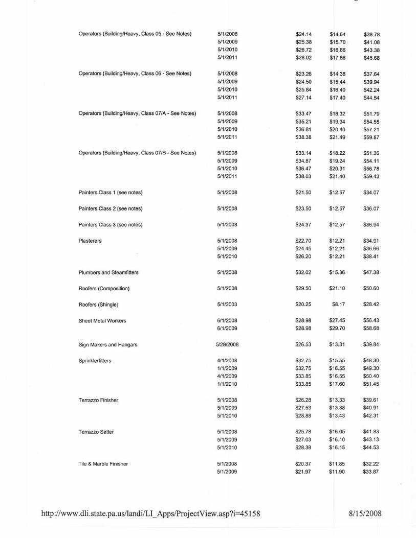
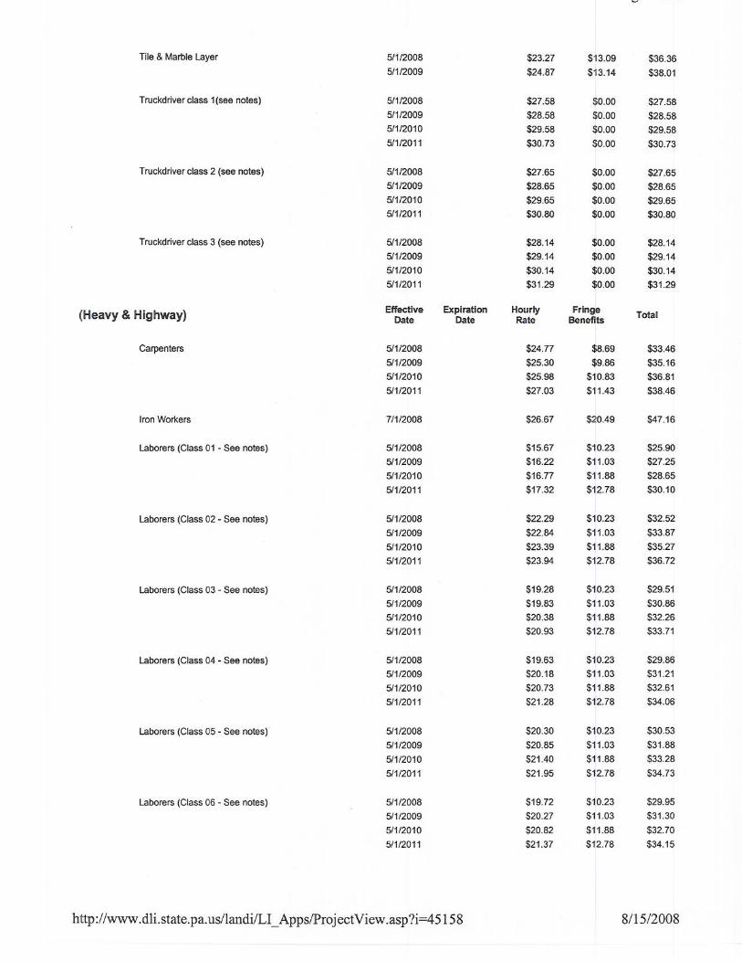
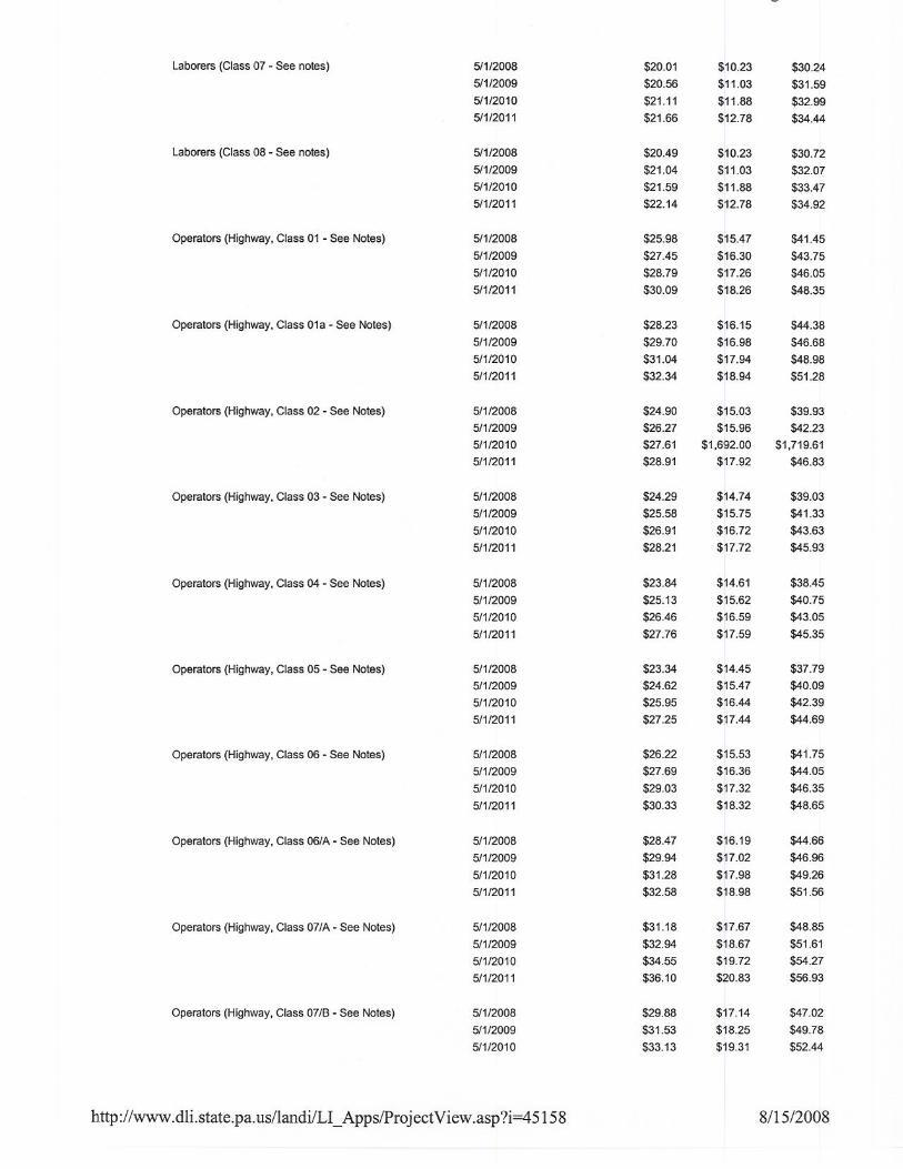
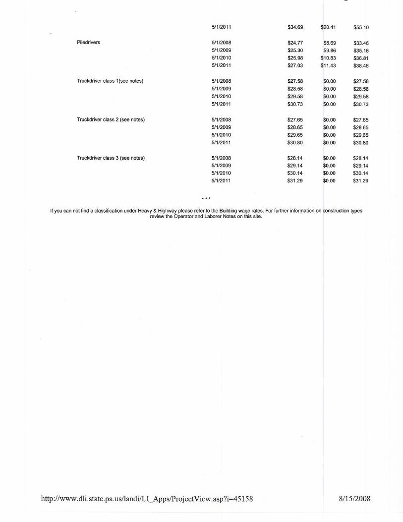
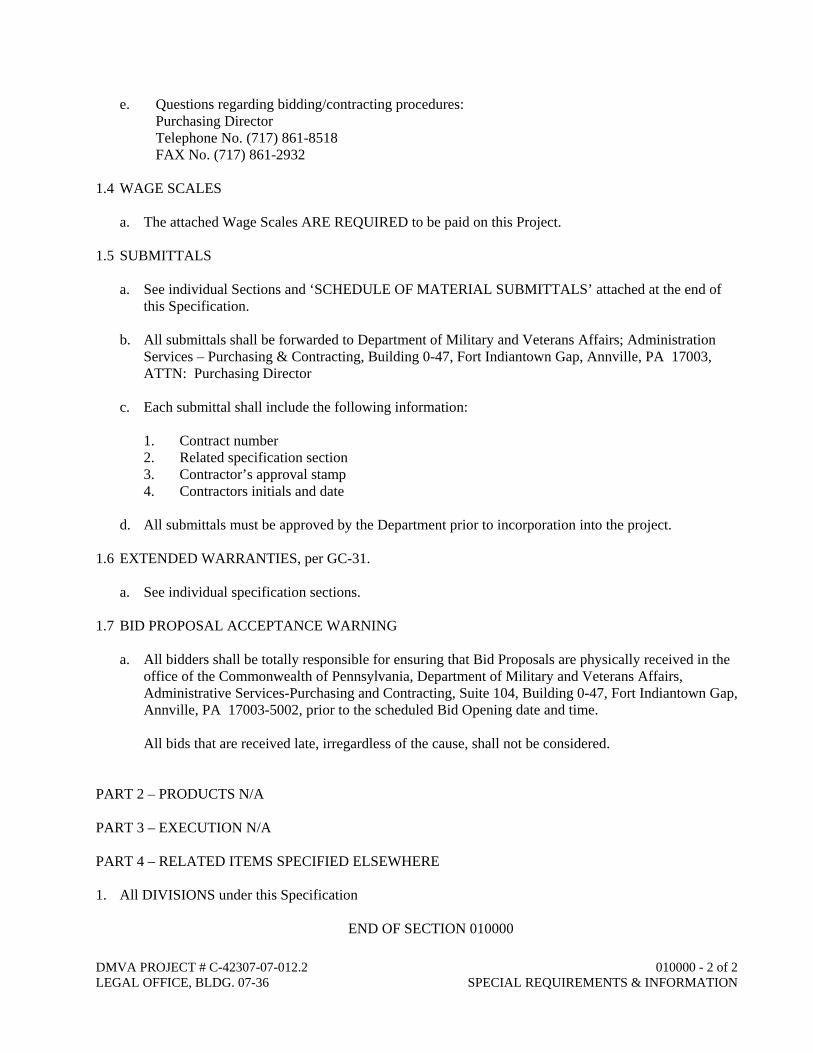
e. Questions regarding bidding/contracting procedures: Purchasing Director Telephone No. (717) 861-8518 FAX No. (717) 861-2932 1.4 WAGE SCALES a. The attached Wage Scales ARE REQUIRED to be paid on this Project. 1.5 SUBMITTALS a. See individual Sections and ‘SCHEDULE OF MATERIAL SUBMITTALS’ attached at the end of
this Specification. b. All submittals shall be forwarded to Department of Military and Veterans Affairs; Administration
Services – Purchasing & Contracting, Building 0-47, Fort Indiantown Gap, Annville, PA 17003, ATTN: Purchasing Director
c. Each submittal shall include the following information: 1. Contract number 2. Related specification section 3. Contractor’s approval stamp 4. Contractors initials and date d. All submittals must be approved by the Department prior to incorporation into the project. 1.6 EXTENDED WARRANTIES, per GC-31. a. See individual specification sections. 1.7 BID PROPOSAL ACCEPTANCE WARNING a. All bidders shall be totally responsible for ensuring that Bid Proposals are physically received in the
office of the Commonwealth of Pennsylvania, Department of Military and Veterans Affairs, Administrative Services-Purchasing and Contracting, Suite 104, Building 0-47, Fort Indiantown Gap, Annville, PA 17003-5002, prior to the scheduled Bid Opening date and time.
All bids that are received late, irregardless of the cause, shall not be considered. PART 2 – PRODUCTS N/A PART 3 – EXECUTION N/A PART 4 – RELATED ITEMS SPECIFIED ELSEWHERE 1. All DIVISIONS under this Specification
END OF SECTION 010000
DIVISION 1 – GENERAL REQUIREMENTS
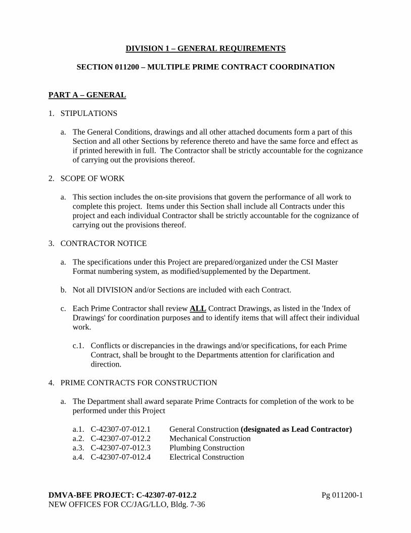
SECTION 011200 – MULTIPLE PRIME CONTRACT COORDINATION PART A – GENERAL 1. STIPULATIONS a. The General Conditions, drawings and all other attached documents form a part of this
Section and all other Sections by reference thereto and have the same force and effect as if printed herewith in full. The Contractor shall be strictly accountable for the cognizance of carrying out the provisions thereof.
2. SCOPE OF WORK a. This section includes the on-site provisions that govern the performance of all work to
complete this project. Items under this Section shall include all Contracts under this project and each individual Contractor shall be strictly accountable for the cognizance of carrying out the provisions thereof.
3. CONTRACTOR NOTICE a. The specifications under this Project are prepared/organized under the CSI Master
Format numbering system, as modified/supplemented by the Department. b. Not all DIVISION and/or Sections are included with each Contract. c. Each Prime Contractor shall review ALL Contract Drawings, as listed in the 'Index of
Drawings' for coordination purposes and to identify items that will affect their individual work.
c.1. Conflicts or discrepancies in the drawings and/or specifications, for each Prime
Contract, shall be brought to the Departments attention for clarification and direction.
4. PRIME CONTRACTS FOR CONSTRUCTION a. The Department shall award separate Prime Contracts for completion of the work to be
performed under this Project a.1. C-42307-07-012.1 General Construction (designated as Lead Contractor) a.2. C-42307-07-012.2 Mechanical Construction a.3. C-42307-07-012.3 Plumbing Construction a.4. C-42307-07-012.4 Electrical Construction
DMVA-BFE PROJECT: C-42307-07-012.2 Pg 011200-1 NEW OFFICES FOR CC/JAG/LLO, Bldg. 7-36
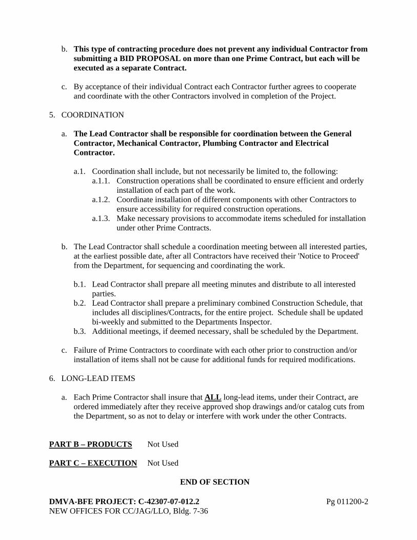
b. This type of contracting procedure does not prevent any individual Contractor from submitting a BID PROPOSAL on more than one Prime Contract, but each will be executed as a separate Contract.
c. By acceptance of their individual Contract each Contractor further agrees to cooperate
and coordinate with the other Contractors involved in completion of the Project. 5. COORDINATION a. The Lead Contractor shall be responsible for coordination between the General
Contractor, Mechanical Contractor, Plumbing Contractor and Electrical Contractor.
a.1. Coordination shall include, but not necessarily be limited to, the following: a.1.1. Construction operations shall be coordinated to ensure efficient and orderly
installation of each part of the work. a.1.2. Coordinate installation of different components with other Contractors to
ensure accessibility for required construction operations. a.1.3. Make necessary provisions to accommodate items scheduled for installation
under other Prime Contracts. b. The Lead Contractor shall schedule a coordination meeting between all interested parties,
at the earliest possible date, after all Contractors have received their 'Notice to Proceed' from the Department, for sequencing and coordinating the work.
b.1. Lead Contractor shall prepare all meeting minutes and distribute to all interested
parties. b.2. Lead Contractor shall prepare a preliminary combined Construction Schedule, that
includes all disciplines/Contracts, for the entire project. Schedule shall be updated bi-weekly and submitted to the Departments Inspector.
b.3. Additional meetings, if deemed necessary, shall be scheduled by the Department. c. Failure of Prime Contractors to coordinate with each other prior to construction and/or
installation of items shall not be cause for additional funds for required modifications. 6. LONG-LEAD ITEMS a. Each Prime Contractor shall insure that ALL long-lead items, under their Contract, are
ordered immediately after they receive approved shop drawings and/or catalog cuts from the Department, so as not to delay or interfere with work under the other Contracts.
PART B – PRODUCTS Not Used PART C – EXECUTION Not Used
END OF SECTION
DMVA-BFE PROJECT: C-42307-07-012.2 Pg 011200-2 NEW OFFICES FOR CC/JAG/LLO, Bldg. 7-36
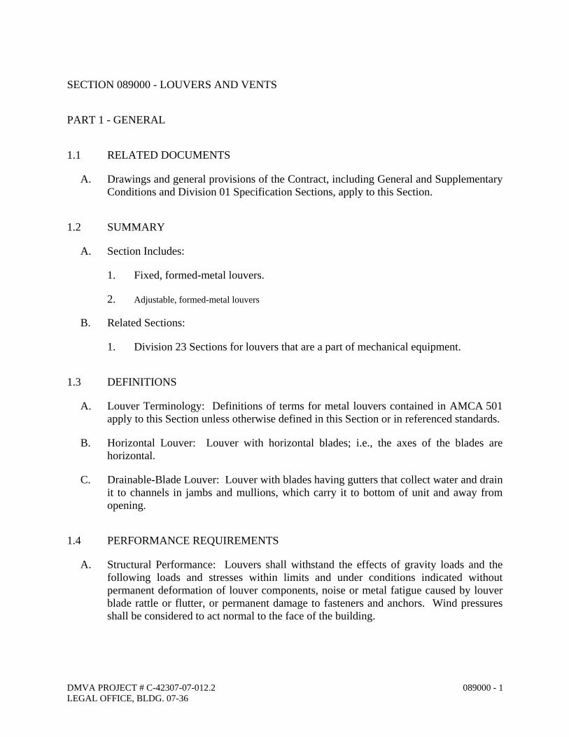
SECTION 089000 - LOUVERS AND VENTS
PART 1 - GENERAL
1.1 RELATED DOCUMENTS
A. Drawings and general provisions of the Contract, including General and Supplementary Conditions and Division 01 Specification Sections, apply to this Section.
1.2 SUMMARY
A. Section Includes:
1. Fixed, formed-metal louvers.
2. Adjustable, formed-metal louvers
B. Related Sections:
1. Division 23 Sections for louvers that are a part of mechanical equipment.
1.3 DEFINITIONS
A. Louver Terminology: Definitions of terms for metal louvers contained in AMCA 501 apply to this Section unless otherwise defined in this Section or in referenced standards.
B. Horizontal Louver: Louver with horizontal blades; i.e., the axes of the blades are horizontal.
C. Drainable-Blade Louver: Louver with blades having gutters that collect water and drain it to channels in jambs and mullions, which carry it to bottom of unit and away from opening.
1.4 PERFORMANCE REQUIREMENTS
A. Structural Performance: Louvers shall withstand the effects of gravity loads and the following loads and stresses within limits and under conditions indicated without permanent deformation of louver components, noise or metal fatigue caused by louver blade rattle or flutter, or permanent damage to fasteners and anchors. Wind pressures shall be considered to act normal to the face of the building.
DMVA PROJECT # C-42307-07-012.2 LEGAL OFFICE, BLDG. 07-36
089000 - 1
B. Louver Performance Ratings: Provide louvers complying with requirements specified, as demonstrated by testing manufacturer's stock units identical to those provided, except for length and width according to AMCA 500-L.
1.5 SUBMITTALS
A. Product Data: For each type of product indicated.
1. For louvers specified to bear AMCA seal, include printed catalog pages showing specified models with appropriate AMCA Certified Ratings Seals.
B. Shop Drawings: For louvers and accessories. Include plans, elevations, sections, details, and attachments to other work. Show frame profiles and blade profiles, angles, and spacing.
1. Show weep paths, gaskets, flashing, sealant, and other means of preventing water intrusion.
2. Show mullion profiles and locations.
1.6 QUALITY ASSURANCE
A. Source Limitations: Obtain louvers and vents from single source from a single manufacturer where indicated to be of same type, design, or factory-applied color finish.
B. Welding: Qualify procedures and personnel according to the following:
1. AWS D1.2/D1.2M, "Structural Welding Code - Aluminum." 2. AWS D1.3, "Structural Welding Code - Sheet Steel." 3. AWS D1.6, "Structural Welding Code - Stainless Steel."
C. SMACNA Standard: Comply with recommendations in SMACNA's "Architectural Sheet Metal Manual" for fabrication, construction details, and installation procedures.
1.7 PROJECT CONDITIONS
A. Field Measurements: Verify actual dimensions of openings by field measurements before fabrication.
PART 2 - PRODUCTS
2.1 MATERIALS
A. Galvanized-Steel Sheet: ASTM A 653/A 653M, G60 zinc coating, mill phosphatized.
DMVA PROJECT # C-42307-07-012.2 LEGAL OFFICE, BLDG. 07-36
089000 - 2
B. Aluminum Extrusions: ASTM B 221, Alloy 6063-T5, T-52, or T6.
C. Aluminum Sheet: ASTM B 209, Alloy 3003 or 5005 with temper as required for forming, or as otherwise recommended by metal producer for required finish.
D. Fasteners: Use types and sizes to suit unit installation conditions.
1. Use hex-head or Phillips pan-head screws for exposed fasteners unless otherwise indicated.
2. For fastening galvanized steel, use hot-dip-galvanized steel or 300 series stainless-steel fasteners.
3. For color-finished louvers, use fasteners with heads that match color of louvers.
2.2 FABRICATION, GENERAL
A. Assemble louvers in factory to minimize field splicing and assembly. Disassemble units as necessary for shipping and handling limitations. Clearly mark units for reassembly and coordinated installation.
B. Vertical Assemblies: Where height of louver units exceeds fabrication and handling limitations, fabricate units to permit field-bolted assembly with close-fitting joints in jambs and mullions, reinforced with splice plates.
C. Maintain equal louver blade spacing, including separation between blades and frames at head and sill, to produce uniform appearance.
D. Fabricate frames, including integral sills, to fit in openings of sizes indicated, with allowances made for fabrication and installation tolerances, adjoining material tolerances, and perimeter sealant joints.
E. Include supports, anchorages, and accessories required for complete assembly.
F. Provide vertical mullions of type and at spacings indicated, but not more than recommended by manufacturer, or 72 inches o.c., whichever is less.
1. Fully Recessed Mullions: Where indicated, provide mullions fully recessed behind louver blades. Where length of louver exceeds fabrication and handling limitations, fabricate with close-fitting blade splices designed to permit expansion and contraction.
2. Semirecessed Mullions: Where indicated, provide mullions partly recessed behind louver blades so louver blades appear continuous. Where length of louver exceeds fabrication and handling limitations, fabricate with interlocking split mullions and close-fitting blade splices designed to permit expansion and contraction.
3. Exposed Mullions: Where indicated, provide units with exposed mullions of same width and depth as louver frame. Where length of louver exceeds fabrication and handling limitations, provide interlocking split mullions designed to permit expansion and contraction.
DMVA PROJECT # C-42307-07-012.2 LEGAL OFFICE, BLDG. 07-36
089000 - 3
4. Exterior Corners: Prefabricated corner units with mitered blades with concealed close-fitting splices and with semirecessed mullions at corners.
G. Provide subsills made of same material as louvers for recessed louvers.
H. Join frame members to each other and to fixed louver blades with fillet welds, threaded fasteners, or both, as standard with louver manufacturer unless otherwise indicated or size of louver assembly makes bolted connections between frame members necessary.
2.3 FIXED, FORMED-METAL LOUVERS
A. Horizontal, Drainable-Blade Louver drawing designation, e.g., LV-1 thru LV-5: See Drawing Schedule for size.
1. Basis-of-Design Product: Subject to compliance with requirements, provide product indicated on Drawings or comparable product by one of the following:
a. Greenheck Fan Corporation. (Basis of Design) b. Air Balance Inc.; a Mestek company. c. Airolite Company, LLC (The). d. Ruskin Company; Tomkins PLC.
2. Louver Depth: 4 inches. 3. Frame and Blade Material and Nominal Thickness: 6063T5 Aluminum extrusion,
not less than 0.081 inch for frames and 0.081 inch for blades. 4. Mullion Type: Semi - Recessed. 5. Louver Performance Ratings:
a. Free Area: See Schedule for each louver.
6. AMCA Seal: Mark units with AMCA Certified Ratings Seal.
2.4 ADJUSTABLE, FORMED-METAL LOUVERS
A. Louver Operation: Provide adjustable louvers with operating mechanisms to suit louver sizes.
1. Motor operation with 2-position, spring-return application with power on, motor opens louver; with power off, spring closes louver; 110-V, 60-Hz motor and limit switch; equipped with frame-mounted switch terminals for controlling devices.
B. Single-Blade, Adjustable Louver LV-3:
1. Louver Depth: 4 inches. 2. Blade Type: Plain. 3. Frame and Blade Material and Nominal Thickness: Galvanized-steel sheet, not less than 0.052
inch for frames and 0.040 inch for blades. 4. Accessories: Equip louvers as follows:
a. Vinyl blade-edge gaskets for each louver blade.
DMVA PROJECT # C-42307-07-012.2 LEGAL OFFICE, BLDG. 07-36
089000 - 4
b. Stainless-steel jamb seal] or vinyl blade-end gaskets.
5. Louver Performance Ratings: a. Air Performance: Not more than 0.10-inch wg static pressure drop at 800-fpm free-area
intake velocity. b. Air Leakage: Not more than 3.5 cfm/sq. ft. of louver gross area at a differential static
pressure of 0.15-inch wg with adjustable louver blades closed.
6. AMCA Seal: Mark units with AMCA Certified Ratings Seal.
2.5 LOUVER SCREENS
A. General: Provide screen at each exterior louver.
1. Screen Location for Fixed Louvers: Interior face. 2. Screening Type: Bird screening screen where indicated. 3. Frabricated Insect Screen channel, removable for cleaning.
B. Louver Screen Frames: Fabricate with mitered corners to louver sizes indicated.
1. Metal: Same kind and form of metal as indicated for louver to which screens are attached. Reinforce extruded-aluminum screen frames at corners with clips.
2. Finish: Same finish as louver frames to which louver screens are attached.
2.6 FINISHES, GENERAL
A. Comply with NAAMM's "Metal Finishes Manual for Architectural and Metal Products" for recommendations for applying and designating finishes.
2.7 ALUMINUM SHEET FINISHES
A. Finish louvers after assembly.
B. Kynar/Hylar premium paint finish: Immediately after cleaning and pretreating, apply manufacturer's standard 2-coat, baked-on finish consisting of prime coat and thermosetting topcoat, with a minimum dry film thickness of 1 mil for topcoat. Comply with coating manufacturer's written instructions for applying and baking to achieve a minimum dry film thickness of 2 mils.
1. Color and Gloss: Match Architect's sample.
PART 3 - EXECUTION
3.1 EXAMINATION
DMVA PROJECT # C-42307-07-012.2 LEGAL OFFICE, BLDG. 07-36
089000 - 5
A. Examine substrates and openings, with Installer present, for compliance with requirements for installation tolerances and other conditions affecting performance.
B. Proceed with installation only after unsatisfactory conditions have been corrected.
3.2 PREPARATION
A. Coordinate setting drawings, diagrams, templates, instructions, and directions for installation of anchorages that are to be embedded in concrete or masonry construction. Coordinate delivery of such items to Project site.
3.3 INSTALLATION
A. Locate and place louvers and vents level, plumb, and at indicated alignment with adjacent work.
B. Use concealed anchorages where possible. Provide brass or lead washers fitted to screws where required to protect metal surfaces and to make a weathertight connection.
C. Form closely fitted joints with exposed connections accurately located and secured.
D. Provide perimeter reveals and openings of uniform width for sealants and joint fillers, as indicated.
E. Repair finishes damaged by cutting, welding, soldering, and grinding. Restore finishes so no evidence remains of corrective work. Return items that cannot be refinished in the field to the factory, make required alterations, and refinish entire unit or provide new units.
F. Protect unpainted galvanized and nonferrous-metal surfaces that will be in contact with concrete, masonry, or dissimilar metals from corrosion and galvanic action by applying a heavy coating of bituminous paint or by separating surfaces with waterproof gaskets or nonmetallic flashing.
G. Install concealed gaskets, flashings, joint fillers, and insulation as louver installation progresses, where weathertight louver joints are required. Comply with Division 07 Section "Joint Sealants" for sealants applied during louver installation.
3.4 ADJUSTING AND CLEANING
A. Test operation of adjustable louvers and adjust as needed to produce fully functioning units that comply with requirements.
B. Clean exposed surfaces of louvers and vents that are not protected by temporary covering, to remove fingerprints and soil during construction period. Do not let soil accumulate during construction period.
DMVA PROJECT # C-42307-07-012.2 LEGAL OFFICE, BLDG. 07-36
089000 - 6
C. Before final inspection, clean exposed surfaces with water and a mild soap or detergent not harmful to finishes. Thoroughly rinse surfaces and dry.
D. Restore louvers and vents damaged during installation and construction so no evidence remains of corrective work. If results of restoration are unsuccessful, as determined by Architect, remove damaged units and replace with new units.
1. Touch up minor abrasions in finishes with air-dried coating that matches color and gloss of, and is compatible with, factory-applied finish coating.
END OF SECTION 089000
DMVA PROJECT # C-42307-07-012.2 LEGAL OFFICE, BLDG. 07-36
089000 - 7
SECTION 230500 - COMMON WORK RESULTS FOR HVAC
PART 1 - GENERAL
1.1 RELATED DOCUMENTS
A. Drawings and general provisions of the Contract, including General and Supplementary Conditions and Division 01 Specification Sections, apply to this Section.
1.2 SUMMARY
A. This Section includes the following:
1. Equipment installation requirements common to equipment sections. 2. Concrete bases. 3. Supports and anchorages.
1.3 DEFINITIONS
A. Finished Spaces: Spaces other than mechanical and electrical equipment rooms, furred spaces, pipe and duct chases, unheated spaces immediately below roof, spaces above ceilings, unexcavated spaces, crawlspaces, and tunnels.
B. Exposed, Interior Installations: Exposed to view indoors. Examples include finished occupied spaces and mechanical equipment rooms.
C. Exposed, Exterior Installations: Exposed to view outdoors or subject to outdoor ambient temperatures and weather conditions. Examples include rooftop locations.
D. Concealed, Interior Installations: Concealed from view and protected from physical contact by building occupants. Examples include above ceilings and chases.
1.4 QUALITY ASSURANCE
A. Steel Pipe Welding: Qualify processes and operators according to ASME Boiler and Pressure Vessel Code: Section IX, "Welding and Brazing Qualifications."
1. Comply with provisions in ASME B31 Series, "Code for Pressure Piping." 2. Certify that each welder has passed AWS qualification tests for welding processes
involved and that certification is current.
B. Electrical Characteristics for HVAC Equipment: Equipment of higher electrical characteristics may be furnished provided such proposed equipment is approved in
DMVA-BFE PROJECT #C-42307-07-012.2 LEGAL OFFICE, BLDG. 07-36
230500 - 1
writing and connecting electrical services, circuit breakers, and conduit sizes are appropriately modified. If minimum energy ratings or efficiencies are specified, equipment shall comply with requirements.
1.5 DELIVERY, STORAGE, AND HANDLING
A. Deliver pipes and tubes with factory-applied end caps. Maintain end caps through shipping, storage, and handling to prevent pipe end damage and to prevent entrance of dirt, debris, and moisture.
1.6 COORDINATION
A. Arrange for pipe spaces, chases, slots, and openings in building structure during progress of construction, to allow for HVAC installations.
B. Coordinate installation of required supporting devices and set sleeves in poured-in-place concrete and other structural components as they are constructed.
C. Coordinate requirements for access panels and doors for HVAC items requiring access that are concealed behind finished surfaces.
PART 2 - PRODUCTS
2.1 MANUFACTURERS
A. In other Part 2 articles where subparagraph titles below introduce lists, the following requirements apply for product selection:
1. Available Manufacturers: Subject to compliance with requirements, manufacturers offering products that may be incorporated into the Work include, but are not limited to, the manufacturers specified.
2.2 PIPE, TUBE, AND FITTINGS
A. Refer to individual Division 23 piping Sections for pipe, tube, and fitting materials and joining methods.
B. Pipe Threads: ASME B1.20.1 for factory-threaded pipe and pipe fittings.
2.3 JOINING MATERIALS
A. Refer to individual Division 23 piping Sections for special joining materials not listed below.
DMVA-BFE PROJECT #C-42307-07-012.2 LEGAL OFFICE, BLDG. 07-36
230500 - 2
B. Solder Filler Metals: ASTM B 32, lead-free alloys. Include water-flushable flux according to ASTM B 813.
C. Brazing Filler Metals: AWS A5.8, BCuP Series, copper-phosphorus alloys for general-duty brazing, unless otherwise indicated; and AWS A5.8, BAg1, silver alloy for refrigerant piping, unless otherwise indicated.
D. Welding Filler Metals: Comply with AWS D10.12 for welding materials appropriate for wall thickness and chemical analysis of steel pipe being welded.
PART 3 - EXECUTION
3.1 PIPING SYSTEMS - COMMON REQUIREMENTS
A. Install piping according to the following requirements and Division 23 Sections specifying piping systems.
B. Drawing plans, schematics, and diagrams indicate general location and arrangement of piping systems. Indicated locations and arrangements were used to size pipe. Install piping as indicated unless deviations to layout are approved on Coordination Drawings.
C. Install piping in concealed locations, unless otherwise indicated and except in equipment rooms and service areas.
D. Install piping indicated to be exposed and piping in equipment rooms and service areas at right angles or parallel to building walls. Diagonal runs are prohibited unless specifically indicated otherwise.
E. Install piping to permit valve servicing.
F. Install piping free of sags and bends.
G. Install fittings for changes in direction and branch connections.
H. Install piping to allow application of insulation.
3.2 PIPING JOINT CONSTRUCTION
A. Join pipe and fittings according to the following requirements and Division 23 Sections specifying piping systems.
B. Remove scale, slag, dirt, and debris from inside and outside of pipe and fittings before assembly.
DMVA-BFE PROJECT #C-42307-07-012.2 LEGAL OFFICE, BLDG. 07-36
230500 - 3
C. Soldered Joints: Apply ASTM B 813, water-flushable flux, unless otherwise indicated, to tube end. Construct joints according to ASTM B 828 or CDA's "Copper Tube Handbook," using lead-free solder alloy complying with ASTM B 32.
D. Brazed Joints: Construct joints according to AWS's "Brazing Handbook," "Pipe and Tube" Chapter, using copper-phosphorus brazing filler metal complying with AWS A5.8.
E. Threaded Joints: Thread pipe with tapered pipe threads according to ASME B1.20.1. Cut threads full and clean using sharp dies. Ream threaded pipe ends to remove burrs and restore full ID. Join pipe fittings and valves as follows:
1. Apply appropriate tape or thread compound to external pipe threads unless dry seal threading is specified.
2. Damaged Threads: Do not use pipe or pipe fittings with threads that are corroded or damaged. Do not use pipe sections that have cracked or open welds.
3.3 PIPING CONNECTIONS
A. Install unions, in piping NPS 2 and smaller, adjacent to each valve and at final connection to each piece of equipment.
3.4 EQUIPMENT INSTALLATION - COMMON REQUIREMENTS
A. Install equipment to allow maximum possible headroom unless specific mounting heights are not indicated.
B. Install equipment level and plumb, parallel and perpendicular to other building systems and components in exposed interior spaces, unless otherwise indicated.
C. Install HVAC equipment to facilitate service, maintenance, and repair or replacement of components. Connect equipment for ease of disconnecting, with minimum interference to other installations.
D. Install equipment to allow right of way for piping installed at required slope.
3.5 CONCRETE BASES
A. Concrete Bases: Anchor equipment to concrete base according to equipment manufacturer's written instructions.
1. Construct concrete bases of dimensions indicated, but not less than 4 inches larger in both directions than supported unit.
2. Install dowel rods to connect concrete base to concrete floor. Unless otherwise indicated, install dowel rods on 18-inch centers around the full perimeter of the base.
DMVA-BFE PROJECT #C-42307-07-012.2 LEGAL OFFICE, BLDG. 07-36
230500 - 4
3. Install epoxy-coated anchor bolts for supported equipment that extend through concrete base, and anchor into structural concrete floor.
4. Place and secure anchorage devices. Use supported equipment manufacturer's setting drawings, templates, diagrams, instructions, and directions furnished with items to be embedded.
5. Install anchor bolts to elevations required for proper attachment to supported equipment.
6. Install anchor bolts according to anchor-bolt manufacturer's written instructions. 7. Use 3000-psi 28-day compressive-strength concrete and reinforcement.
3.6 ERECTION OF METAL SUPPORTS AND ANCHORAGES
A. Cut, fit, and place miscellaneous metal supports accurately in location, alignment, and elevation to support and anchor HVAC materials and equipment.
B. Field Welding: Comply with AWS D1.1.
END OF SECTION 230500
DMVA-BFE PROJECT #C-42307-07-012.2 LEGAL OFFICE, BLDG. 07-36
230500 - 5
SECTION 230529 - HANGERS AND SUPPORTS FOR HVAC PIPING AND EQUIPMENT
PART 1 - GENERAL
1.1 RELATED DOCUMENTS
A. Drawings and general provisions of the Contract, including General and Supplementary Conditions and Division 01 Specification Sections, apply to this Section.
1.2 SUMMARY
A. Section Includes:
1. Metal pipe hangers and supports. 2. Equipment supports.
B. Related Sections: 1. Division 23 Section "Metal Ducts" for duct hangers and supports.
1.3 DEFINITIONS
A. MSS: Manufacturers Standardization Society of The Valve and Fittings Industry Inc.
1.4 PERFORMANCE REQUIREMENTS
A. Structural Performance: Hangers and supports for HVAC piping and equipment shall withstand the effects of gravity loads and stresses within limits and under conditions indicated according to ASCE/SEI 7. 1. Design equipment supports capable of supporting combined operating weight of
supported equipment and connected systems and components. 2. Design seismic-restraint hangers and supports for piping and equipment and
obtain approval from authorities having jurisdiction.
1.5 SUBMITTALS
A. Product Data: For each type of product indicated.
B. Shop Drawings: Show fabrication and installation details and include calculations for the following; include Product Data for components:
1. Equipment supports.
DMVA-BFE PROJECT #C-42307-07-012.2 LEGAL OFFICE, BLDG. 07-36
230529 - 1
1.6 QUALITY ASSURANCE
A. Structural Steel Welding Qualifications: Qualify procedures and personnel according to AWS D1.1/D1.1M, "Structural Welding Code - Steel."
PART 2 - PRODUCTS
2.1 METAL PIPE HANGERS AND SUPPORTS
A. Carbon-Steel Pipe Hangers and Supports:
1. Description: MSS SP-58, Types 1 through 58, factory-fabricated components. 2. Galvanized Metallic Coatings: Pregalvanized or hot dipped. 3. Nonmetallic Coatings: Plastic coating, jacket, or liner. 4. Padded Hangers: Hanger with fiberglass or other pipe insulation pad or cushion
to support bearing surface of piping. 5. Hanger Rods: Continuous-thread rod, nuts, and washer made of carbon steel.
B. Copper Pipe Hangers:
1. Description: MSS SP-58, Types 1 through 58, copper-coated-steel, factory-fabricated components.
2. Hanger Rods: Continuous-thread rod, nuts, and washer made of copper-coated steel.
2.2 EQUIPMENT SUPPORTS
A. Description: Welded, shop- or field-fabricated equipment support made from structural carbon-steel shapes.
2.3 MISCELLANEOUS MATERIALS
A. Structural Steel: ASTM A 36/A 36M, carbon-steel plates, shapes, and bars; black and galvanized.
PART 3 - EXECUTION
3.1 HANGER AND SUPPORT INSTALLATION
A. Install hangers and supports complete with necessary attachments, inserts, bolts, rods, nuts, washers, and other accessories.
B. Equipment Support Installation: Fabricate from welded-structural-steel shapes.
DMVA-BFE PROJECT #C-42307-07-012.2 LEGAL OFFICE, BLDG. 07-36
230529 - 2
C. Load Distribution: Install hangers and supports so that piping live and dead loads and stresses from movement will not be transmitted to connected equipment.
D. Insulated Piping:
1. Attach clamps and spacers to piping.
a. Piping Operating above Ambient Air Temperature: Clamp may project through insulation.
b. Piping Operating below Ambient Air Temperature: Use thermal-hanger shield insert with clamp sized to match OD of insert.
2. Install MSS SP-58, Type 39, protection saddles if insulation without vapor barrier is indicated. Fill interior voids with insulation that matches adjoining insulation.
3. Shield Dimensions for Pipe: Not less than the following:
a. NPS 1/4 to NPS 3-1/2: 12 inches long and 0.048 inch thick.
3.2 EQUIPMENT SUPPORTS
A. Fabricate structural-steel stands to suspend equipment from structure overhead or to support equipment above floor.
B. Provide lateral bracing, to prevent swaying, for equipment supports.
3.3 METAL FABRICATIONS
A. Cut, drill, and fit miscellaneous metal fabrications for equipment supports.
B. Fit exposed connections together to form hairline joints. Field weld connections that cannot be shop welded because of shipping size limitations.
C. Field Welding: Comply with AWS D1.1/D1.1M procedures for shielded, metal arc welding; appearance and quality of welds; and methods used in correcting welding work; and with the following:
1. Use materials and methods that minimize distortion and develop strength and corrosion resistance of base metals.
2. Obtain fusion without undercut or overlap. 3. Remove welding flux immediately. 4. Finish welds at exposed connections so no roughness shows after finishing and so
contours of welded surfaces match adjacent contours.
DMVA-BFE PROJECT #C-42307-07-012.2 LEGAL OFFICE, BLDG. 07-36
230529 - 3
3.4 ADJUSTING
A. Hanger Adjustments: Adjust hangers to distribute loads equally on attachments and to achieve indicated slope of pipe.
B. Trim excess length of continuous-thread hanger and support rods to 1-1/2 inches.
3.5 HANGER AND SUPPORT SCHEDULE
A. Comply with MSS SP-69 for pipe-hanger selections and applications that are not specified in piping system Sections.
1. Carbon- or Alloy-Steel Riser Clamps (MSS Type 42): For support of pipe risers NPS 3/4 to NPS 24 if longer ends are required for riser clamps.
B. Building Attachments: Unless otherwise indicated and except as specified in piping system Sections, install the following types:
1. Side-Beam or Channel Clamps (MSS Type 20): For attaching to bottom flange of beams, channels, or angles.
2. Top-Beam Clamps (MSS Type 25): For top of beams if hanger rod is required tangent to flange edge.
END OF SECTION 230529
DMVA-BFE PROJECT #C-42307-07-012.2 LEGAL OFFICE, BLDG. 07-36
230529 - 4
SECTION 230593 - TESTING, ADJUSTING, AND BALANCING FOR HVAC
PART 1 - GENERAL
1.1 RELATED DOCUMENTS
A. Drawings and general provisions of the Contract, including General and Supplementary Conditions and Division 01 Specification Sections, apply to this Section.
1.2 SUMMARY
A. Section Includes:
1. Balancing Air Systems:
a. Constant-volume air systems. b. Multizone systems.
1.3 DEFINITIONS
A. AABC: Associated Air Balance Council.
B. NEBB: National Environmental Balancing Bureau.
C. TAB: Testing, adjusting, and balancing.
D. TABB: Testing, Adjusting, and Balancing Bureau.
E. TAB Specialist: An entity engaged to perform TAB Work.
1.4 SUBMITTALS
A. Qualification Data: Within 30 days of Contractor's Notice to Proceed, submit documentation that the TAB contractor and this Project's TAB team members meet the qualifications specified in "Quality Assurance" Article.
B. Strategies and Procedures Plan: Within 30 days of Contractor's Notice to Proceed, submit TAB strategies and step-by-step procedures as specified in "Preparation" Article.
C. Certified TAB reports.
1.5 QUALITY ASSURANCE
DMVA-BFE Project: #C-42307-07-012.2 LEGAL OFFICE, BLDG. 07-36
230593 - 1
A. TAB Contractor Qualifications: Engage a TAB entity certified by AABC, NEBB or TABB.
1. TAB Field Supervisor: Employee of the TAB contractor and certified by AABC, NEBB or TABB.
2. TAB Technician: Employee of the TAB contractor and who is certified by AABC NEBB or TABB as a TAB technician.
B. Certify TAB field data reports and perform the following:
1. Review field data reports to validate accuracy of data and to prepare certified TAB reports.
2. Certify that the TAB team complied with the approved TAB plan and the procedures specified and referenced in this Specification.
C. TAB Report Forms: Use standard TAB contractor's forms approved by Architect.
D. Instrumentation Type, Quantity, Accuracy, and Calibration: As described in ASHRAE 111, Section 5, "Instrumentation."
PART 2 - PRODUCTS (Not Applicable)
PART 3 - EXECUTION
3.1 EXAMINATION
A. Examine the Contract Documents to become familiar with Project requirements and to discover conditions in systems' designs that may preclude proper TAB of systems and equipment.
B. Examine systems for installed balancing devices, such as test ports, flow-control devices, and manual volume dampers. Verify that locations of these balancing devices are accessible.
C. Examine the approved submittals for HVAC systems and equipment.
D. Examine design data including HVAC system descriptions, statements of design assumptions for environmental conditions and systems' output, and statements of philosophies and assumptions about HVAC system and equipment controls.
E. Examine supply, return, or relief air to verify that they meet the leakage class of connected ducts as specified in Division 23 Section "Metal Ducts" and are properly separated from adjacent areas. Verify that penetrations in plenum walls are sealed and fire-stopped if required.
F. Examine equipment performance data including fan curves.
DMVA-BFE Project: #C-42307-07-012.2 LEGAL OFFICE, BLDG. 07-36
230593 - 2
1. Relate performance data to Project conditions and requirements, including system effects that can create undesired or unpredicted conditions that cause reduced capacities in all or part of a system.
2. Calculate system-effect factors to reduce performance ratings of HVAC equipment when installed under conditions different from the conditions used to rate equipment performance. To calculate system effects for air systems, use tables and charts found in AMCA 201, "Fans and Systems," or in SMACNA's "HVAC Systems - Duct Design." Compare results with the design data and installed conditions.
G. Examine system and equipment installations and verify that field quality-control testing, cleaning, and adjusting specified in individual Sections have been performed.
H. Examine test reports specified in individual system and equipment Sections.
I. Examine HVAC equipment and filters and verify that bearings are greased, belts are aligned and tight, and equipment with functioning controls is ready for operation.
J. Examine terminal units, such as variable-air-volume boxes, and verify that they are accessible and their controls are connected and functioning.
K. Examine operating safety interlocks and controls on HVAC equipment.
L. Report deficiencies discovered before and during performance of TAB procedures. Observe and record system reactions to changes in conditions. Record default set points if different from indicated values.
3.2 PREPARATION
A. Prepare a TAB plan that includes strategies and step-by-step procedures.
B. Complete system-readiness checks and prepare reports. Verify the following:
1. Permanent electrical-power wiring is complete. 2. Automatic temperature-control systems are operational. 3. Equipment and duct access doors are securely closed. 4. Balance, smoke, and fire dampers are open. 5. Ceilings are installed in critical areas where air-pattern adjustments are required
and access to balancing devices is provided. 6. Windows and doors can be closed so indicated conditions for system operations
can be met.
3.3 GENERAL PROCEDURES FOR TESTING AND BALANCING
DMVA-BFE Project: #C-42307-07-012.2 LEGAL OFFICE, BLDG. 07-36
230593 - 3
A. Perform testing and balancing procedures on each system according to the procedures contained in SMACNA's "HVAC Systems - Testing, Adjusting, and Balancing" and in this Section.
1. Comply with requirements in ASHRAE 62.1-2004, Section 7.2.2, "Air Balancing."
B. Cut insulation, ducts, and equipment cabinets for installation of test probes to the minimum extent necessary for TAB procedures.
1. After testing and balancing, patch probe holes in ducts with same material and thickness as used to construct ducts.
2. After testing and balancing, install test ports and duct access doors that comply with requirements in Division 23 Section "Air Duct Accessories."
3. Install and join new insulation that matches removed materials. Restore insulation, coverings, vapor barrier, and finish according to Division 23 Section "HVAC Insulation."
C. Mark equipment and balancing devices, including damper-control positions, valve position indicators, fan-speed-control levers, and similar controls and devices, with paint or other suitable, permanent identification material to show final settings.
D. Take and report testing and balancing measurements in inch-pound (IP)] and metric (SI) units.
3.4 GENERAL PROCEDURES FOR BALANCING AIR SYSTEMS
A. Prepare test reports for both fans and outlets. Obtain manufacturer's outlet factors and recommended testing procedures. Crosscheck the summation of required outlet volumes with required fan volumes.
B. Prepare schematic diagrams of systems' "as-built" duct layouts.
C. For variable-air-volume systems, develop a plan to simulate diversity.
D. Determine the best locations in main and branch ducts for accurate duct-airflow measurements.
E. Check airflow patterns from the outdoor-air louvers and dampers and the return- and exhaust-air dampers through the supply-fan discharge and mixing dampers.
F. Locate start-stop and disconnect switches, electrical interlocks, and motor starters.
G. Verify that motor starters are equipped with properly sized thermal protection.
H. Check dampers for proper position to achieve desired airflow path.
I. Check for airflow blockages.
DMVA-BFE Project: #C-42307-07-012.2 LEGAL OFFICE, BLDG. 07-36
230593 - 4
J. Check condensate drains for proper connections and functioning.
K. Check for proper sealing of air-handling-unit components.
L. Verify that air duct system is sealed as specified in Division 23 Section "Metal Ducts."
3.5 PROCEDURES FOR CONSTANT-VOLUME AIR SYSTEMS
A. Adjust fans to deliver total indicated airflows within the maximum allowable fan speed listed by fan manufacturer.
1. Measure total airflow.
a. Where sufficient space in ducts is unavailable for Pitot-tube traverse measurements, measure airflow at terminal outlets and inlets and calculate the total airflow.
2. Measure fan static pressures as follows to determine actual static pressure:
a. Measure outlet static pressure as far downstream from the fan as practical and upstream from restrictions in ducts such as elbows and transitions.
b. Measure static pressure directly at the fan outlet or through the flexible connection.
c. Measure inlet static pressure of single-inlet fans in the inlet duct as near the fan as possible, upstream from the flexible connection, and downstream from duct restrictions.
d. Measure inlet static pressure of double-inlet fans through the wall of the plenum that houses the fan.
3. Measure static pressure across each component that makes up an air-handling unit, rooftop unit, and other air-handling and -treating equipment including gas fired duct furnace.
a. Report the cleanliness status of filters and the time static pressures are measured.
4. Measure static pressures entering and leaving other devices, such as sound traps, heat-recovery equipment, and air washers, under final balanced conditions.
5. Review Record Documents to determine variations in design static pressures versus actual static pressures. Calculate actual system-effect factors. Recommend adjustments to accommodate actual conditions.
6. Obtain approval from Architect for adjustment of fan speed higher or lower than indicated speed. Comply with requirements in Division 23 Sections for air-handling units for adjustment of fans, belts, and pulley sizes to achieve indicated air-handling-unit performance.
7. Do not make fan-speed adjustments that result in motor overload. Consult equipment manufacturers about fan-speed safety factors. Modulate dampers and
DMVA-BFE Project: #C-42307-07-012.2 LEGAL OFFICE, BLDG. 07-36
230593 - 5
measure fan-motor amperage to ensure that no overload will occur. Measure amperage in full-cooling, full-heating, economizer, and any other operating mode to determine the maximum required brake horsepower.
B. Adjust volume dampers for main duct, submain ducts, and major branch ducts to indicated airflows within specified tolerances.
1. Measure airflow of submain and branch ducts.
a. Where sufficient space in submain and branch ducts is unavailable for Pitot-tube traverse measurements, measure airflow at terminal outlets and inlets and calculate the total airflow for that zone.
2. Measure static pressure at a point downstream from the balancing damper, and adjust volume dampers until the proper static pressure is achieved.
3. Remeasure each submain and branch duct after all have been adjusted. Continue to adjust submain and branch ducts to indicated airflows within specified tolerances.
C. Measure air outlets and inlets without making adjustments.
1. Measure terminal outlets using a direct-reading hood or outlet manufacturer's written instructions and calculating factors.
D. Adjust air outlets and inlets for each space to indicated airflows within specified tolerances of indicated values. Make adjustments using branch volume dampers rather than extractors and the dampers at air terminals.
1. Adjust each outlet in same room or space to within specified tolerances of indicated quantities without generating noise levels above the limitations prescribed by the Contract Documents.
2. Adjust patterns of adjustable outlets for proper distribution without drafts.
3.6 PROCEDURES FOR MULTIZONE SYSTEMS
A. Set unit at maximum airflow through the cooling coil.
B. Adjust each zone's balancing damper to achieve indicated airflow within the zone.
3.7 PROCEDURES FOR MOTORS
A. Motors, 1/2 HP and Larger: Test at final balanced conditions and record the following data:
1. Manufacturer's name, model number, and serial number. 2. Motor horsepower rating. 3. Motor rpm.
DMVA-BFE Project: #C-42307-07-012.2 LEGAL OFFICE, BLDG. 07-36
230593 - 6
4. Efficiency rating. 5. Nameplate and measured voltage, each phase. 6. Nameplate and measured amperage, each phase. 7. Starter thermal-protection-element rating.
B. Motors Driven by Variable-Frequency Controllers: Test for proper operation at speeds varying from minimum to maximum. Test the manual bypass of the controller to prove proper operation. Record observations including name of controller manufacturer, model number, serial number, and nameplate data.
3.8 PROCEDURES FOR CONDENSING UNITS
A. Verify proper rotation of fans.
B. Measure entering- and leaving-air temperatures.
C. Record compressor data.
3.9 TOLERANCES
A. Set HVAC system's air flow rates and water flow rates within the following tolerances:
1. Supply, Return, and Exhaust Fans and Equipment with Fans: Plus or minus 10 percent.
2. Air Outlets and Inlets: Plus or minus 10 percent.
3.10 REPORTING
A. Initial Construction-Phase Report: Based on examination of the Contract Documents as specified in "Examination" Article, prepare a report on the adequacy of design for systems' balancing devices. Recommend changes and additions to systems' balancing devices to facilitate proper performance measuring and balancing. Recommend changes and additions to HVAC systems and general construction to allow access for performance measuring and balancing devices.
3.11 FINAL REPORT
A. General: Prepare a certified written report; tabulate and divide the report into separate sections for tested systems and balanced systems.
1. Include a certification sheet at the front of the report's binder, signed and sealed by the certified testing and balancing engineer.
2. Include a list of instruments used for procedures, along with proof of calibration.
B. Final Report Contents: In addition to certified field-report data, include the following:
DMVA-BFE Project: #C-42307-07-012.2 LEGAL OFFICE, BLDG. 07-36
230593 - 7
1. Fan curves. 2. Manufacturers' test data. 3. Field test reports prepared by system and equipment installers. 4. Other information relative to equipment performance; do not include Shop
Drawings and product data.
C. General Report Data: In addition to form titles and entries, include the following data:
1. Title page. 2. Name and address of the TAB contractor. 3. Project name. 4. Project location. 5. Architect's name and address. 6. Engineer's name and address. 7. Contractor's name and address. 8. Report date. 9. Signature of TAB supervisor who certifies the report. 10. Table of Contents with the total number of pages defined for each section of the
report. Number each page in the report. 11. Summary of contents including the following:
a. Indicated versus final performance. b. Notable characteristics of systems. c. Description of system operation sequence if it varies from the Contract
Documents.
12. Nomenclature sheets for each item of equipment. 13. Data for terminal units, including manufacturer's name, type, size, and fittings. 14. Notes to explain why certain final data in the body of reports vary from indicated
values. 15. Test conditions for fans and pump performance forms including the following:
a. Settings for outdoor-, return-, and exhaust-air dampers. b. Conditions of filters. c. Cooling coil, wet- and dry-bulb conditions. d. Fan drive settings including settings and percentage of maximum pitch
diameter. e. Inlet vane settings for variable-air-volume systems. f. Settings for supply-air, static-pressure controller. g. Other system operating conditions that affect performance.
D. System Diagrams: Include schematic layouts of air distribution systems. Present each system with single-line diagram and include the following:
1. Quantities of outdoor, supply, return, and exhaust airflows. 2. Duct, outlet, and inlet sizes. 3. Pipe and valve sizes and locations.
DMVA-BFE Project: #C-42307-07-012.2 LEGAL OFFICE, BLDG. 07-36
230593 - 8
4. Terminal units. 5. Balancing stations. 6. Position of balancing devices.
3.12 ADDITIONAL TESTS
A. Within 90 days of completing TAB, perform additional TAB to verify that balanced conditions are being maintained throughout and to correct unusual conditions.
B. Seasonal Periods: If initial TAB procedures were not performed during near-peak summer and winter conditions, perform additional TAB during near-peak summer and winter conditions.
END OF SECTION 230593
DMVA-BFE Project: #C-42307-07-012.2 LEGAL OFFICE, BLDG. 07-36
230593 - 9
SECTION 230700 - HVAC INSULATION
PART 1 - GENERAL
1.1 RELATED DOCUMENTS
A. Drawings and general provisions of the Contract, including General and Supplementary Conditions and Division 01 Specification Sections, apply to this Section.
1.2 SUMMARY
A. Section Includes:
1. Insulation Materials:
a. Flexible elastomeric. b. Mineral fiber.
2. Adhesives. 3. Sealants. 4. Factory-applied jackets. 5. Tapes.
1.3 SUBMITTALS
A. Product Data: For each type of product indicated. Include thermal conductivity, thickness, and jackets.
1.4 QUALITY ASSURANCE
A. Installer Qualifications: Skilled mechanics who have successfully completed an apprenticeship program or another craft training program certified by the Department of Labor, Bureau of Apprenticeship and Training.
B. Fire-Test-Response Characteristics: Insulation and related materials shall have fire-test-response characteristics indicated, as determined by testing identical products per ASTM E 84, by a testing and inspecting agency acceptable to authorities having jurisdiction. Factory label insulation and jacket materials and adhesive, and tapes, with appropriate markings of applicable testing and inspecting agency.
1. Insulation Installed Indoors: Flame-spread index of 25 or less, and smoke-developed index of 50 or less.
DMVA-BFE PROJECT #C-42307-07-012.2 LEGAL OFFICE, BLDG. 07-36
230700 - 1
1.5 DELIVERY, STORAGE, AND HANDLING
A. Packaging: Insulation material containers shall be marked by manufacturer with appropriate ASTM standard designation, type and grade, and maximum use temperature.
1.6 COORDINATION
A. Coordinate clearance requirements with piping Installer for piping insulation application, duct Installer for duct insulation application, and equipment Installer for equipment insulation application. Before preparing piping and ductwork Shop Drawings, establish and maintain clearance requirements for installation of insulation and field-applied jackets and finishes and for space required for maintenance.
PART 2 - PRODUCTS
2.1 INSULATION MATERIALS
A. Comply with requirements in Part 3 schedule articles for where insulating materials shall be applied.
B. Products shall not contain asbestos, lead, mercury, or mercury compounds.
C. Flexible Elastomeric: Closed-cell, sponge- or expanded-rubber materials. Comply with ASTM C 534, Type I for tubular materials and Type II for sheet materials.
1. Products: Subject to compliance with requirements, available products that may be incorporated into the Work include, but are not limited to, the following:
a. Aeroflex USA Inc.; Aerocel. b. Armacell LLC; AP Armaflex. c. RBX Corporation; Insul-Sheet 1800 and Insul-Tube 180.
D. Mineral-Fiber Blanket Insulation: Mineral or glass fibers bonded with a thermosetting resin. Comply with ASTM C 553, Type II and ASTM C 1290, Type III with factory-applied FSK jacket. Factory-applied jacket requirements are specified in "Factory-Applied Jackets" Article.
1. Products: Subject to compliance with requirements, available products that may be incorporated into the Work include, but are not limited to, the following:
a. CertainTeed Corp.; Duct Wrap. b. Johns Manville; Microlite. c. Knauf Insulation; Duct Wrap. d. Manson Insulation Inc.; Alley Wrap. e. Owens Corning; All-Service Duct Wrap.
DMVA-BFE PROJECT #C-42307-07-012.2 LEGAL OFFICE, BLDG. 07-36
230700 - 2
2.2 ADHESIVES
A. Materials shall be compatible with insulation materials, jackets, and substrates and for bonding insulation to itself and to surfaces to be insulated, unless otherwise indicated.
B. Flexible Elastomeric and Polyolefin Adhesive: Comply with MIL-A-24179A, Type II, Class I.
1. Products: Subject to compliance with requirements, available products that may be incorporated into the Work include, but are not limited to, the following:
a. Aeroflex USA Inc.; Aeroseal. b. Armacell LCC; 520 Adhesive. c. Foster Products Corporation, H. B. Fuller Company; 85-75. d. RBX Corporation; Rubatex Contact Adhesive.
C. Mineral-Fiber Adhesive: Comply with MIL-A-3316C, Class 2, Grade A.
1. Products: Subject to compliance with requirements, available products that may be incorporated into the Work include, but are not limited to, the following:
a. Childers Products, Division of ITW; CP-82. b. Foster Products Corporation, H. B. Fuller Company; 85-20. c. ITW TACC, Division of Illinois Tool Works; S-90/80. d. Marathon Industries, Inc.; 225. e. Mon-Eco Industries, Inc.; 22-25.
D. FSK Jacket Adhesive: Comply with MIL-A-3316C, Class 2, Grade A for bonding insulation jacket lap seams and joints.
1. Products: Subject to compliance with requirements, available products that may be incorporated into the Work include, but are not limited to, the following:
a. Childers Products, Division of ITW; CP-82. b. Foster Products Corporation, H. B. Fuller Company; 85-20. c. ITW TACC, Division of Illinois Tool Works; S-90/80. d. Marathon Industries, Inc.; 225. e. Mon-Eco Industries, Inc.; 22-25.
2.3 SEALANTS
A. Joint Sealants:
1. Materials shall be compatible with insulation materials, jackets, and substrates. 2. Permanently flexible, elastomeric sealant. 3. Service Temperature Range: Minus 100 to plus 300 deg F. 4. Color: White or gray.
DMVA-BFE PROJECT #C-42307-07-012.2 LEGAL OFFICE, BLDG. 07-36
230700 - 3
B. FSK and Metal Jacket Flashing Sealants:
1. Products: Subject to compliance with requirements, available products that may be incorporated into the Work include, but are not limited to, the following:
a. Childers Products, Division of ITW; CP-76-8. b. Foster Products Corporation, H. B. Fuller Company; 95-44. c. Marathon Industries, Inc.; 405. d. Mon-Eco Industries, Inc.; 44-05. e. Vimasco Corporation; 750.
2. Materials shall be compatible with insulation materials, jackets, and substrates. 3. Fire- and water-resistant, flexible, elastomeric sealant. 4. Service Temperature Range: Minus 40 to plus 250 deg F. 5. Color: Aluminum.
2.4 FACTORY-APPLIED JACKETS
A. Insulation system schedules indicate factory-applied jackets on various applications. When factory-applied jackets are indicated, comply with the following:
1. FSK Jacket: Aluminum-foil, fiberglass-reinforced scrim with kraft-paper backing; complying with ASTM C 1136, Type II.
2.5 TAPES
A. FSK Tape: Foil-face, vapor-retarder tape matching factory-applied jacket with acrylic adhesive; complying with ASTM C 1136.
1. Products: Subject to compliance with requirements, available products that may be incorporated into the Work include, but are not limited to, the following:
a. Avery Dennison Corporation, Specialty Tapes Division; Fasson 0827. b. Compac Corp.; 110 and 111. c. Ideal Tape Co., Inc., an American Biltrite Company; 491 AWF FSK. d. Venture Tape; 1525 CW, 1528 CW, and 1528 CW/SQ.
2. Width: 3 inches. 3. Thickness: 6.5 mils. 4. Adhesion: 90 ounces force/inch in width. 5. Elongation: 2 percent. 6. Tensile Strength: 40 lbf/inch in width. 7. FSK Tape Disks and Squares: Precut disks or squares of FSK tape.
PART 3 - EXECUTION
DMVA-BFE PROJECT #C-42307-07-012.2 LEGAL OFFICE, BLDG. 07-36
230700 - 4
3.1 EXAMINATION
A. Examine substrates and conditions for compliance with requirements for installation and other conditions affecting performance of insulation application.
1. Verify that systems and equipment to be insulated have been tested and are free of defects.
2. Verify that surfaces to be insulated are clean and dry. 3. Proceed with installation only after unsatisfactory conditions have been corrected.
3.2 PREPARATION
A. Surface Preparation: Clean and dry surfaces to receive insulation. Remove materials that will adversely affect insulation application.
3.3 GENERAL INSTALLATION REQUIREMENTS
A. Install insulation materials, accessories, and finishes with smooth, straight, and even surfaces; free of voids throughout the length of equipment, ducts and fittings, and piping including fittings, valves, and specialties.
B. Install insulation materials, forms, vapor barriers or retarders, jackets, and thicknesses required for each item of equipment, duct system, and pipe system as specified in insulation system schedules.
C. Install accessories compatible with insulation materials and suitable for the service. Install accessories that do not corrode, soften, or otherwise attack insulation or jacket in either wet or dry state.
D. Install insulation with longitudinal seams at top and bottom of horizontal runs.
E. Do not weld brackets, clips, or other attachment devices to piping, fittings, and specialties.
F. Keep insulation materials dry during application and finishing.
G. Install insulation with tight longitudinal seams and end joints. Bond seams and joints with adhesive recommended by insulation material manufacturer.
H. Install insulation with least number of joints practical.
I. Where vapor barrier is indicated, seal joints, seams, and penetrations in insulation at hangers, supports, anchors, and other projections with vapor-barrier mastic.
1. Install insulation continuously through hangers and around anchor attachments. 2. For insulation application where vapor barriers are indicated, extend insulation on
anchor legs from point of attachment to supported item to point of attachment to
DMVA-BFE PROJECT #C-42307-07-012.2 LEGAL OFFICE, BLDG. 07-36
230700 - 5
structure. Taper and seal ends at attachment to structure with vapor-barrier mastic.
3. Install insert materials and install insulation to tightly join the insert. Seal insulation to insulation inserts with adhesive or sealing compound recommended by insulation material manufacturer.
4. Cover inserts with jacket material matching adjacent pipe insulation. Install shields over jacket, arranged to protect jacket from tear or puncture by hanger, support, and shield.
J. Apply adhesives and sealants at manufacturer's recommended coverage rate and wet and dry film thicknesses.
K. Install insulation with factory-applied jackets as follows:
1. Draw jacket tight and smooth. 2. Cover circumferential joints with 3-inch- wide strips, of same material as
insulation jacket. Secure strips with adhesive and outward clinching staples along both edges of strip, spaced 4 inches o.c.
3. Overlap jacket longitudinal seams at least 1-1/2 inches. Install insulation with longitudinal seams at bottom of pipe. Clean and dry surface to receive self-sealing lap. Staple laps with outward clinching staples along edge at 4 inches o.c.
4. Cover joints and seams with tape as recommended by insulation material manufacturer to maintain vapor seal.
5. Where vapor barriers are indicated, apply vapor-barrier mastic on seams and joints and at ends adjacent to duct and pipe flanges and fittings.
L. Cut insulation in a manner to avoid compressing insulation more than 75 percent of its nominal thickness.
M. Finish installation with systems at operating conditions. Repair joint separations and cracking due to thermal movement.
N. Repair damaged insulation facings by applying same facing material over damaged areas. Extend patches at least 4 inches beyond damaged areas. Adhere, staple, and seal patches similar to butt joints.
O. For above ambient services, do not install insulation to the following:
1. Vibration-control devices. 2. Testing agency labels and stamps. 3. Nameplates and data plates. 4. Manholes. 5. Handholes. 6. Cleanouts.
DMVA-BFE PROJECT #C-42307-07-012.2 LEGAL OFFICE, BLDG. 07-36
230700 - 6
3.4 PENETRATIONS
A. Insulation Installation at Aboveground Exterior Wall Penetrations: Install insulation continuously through wall penetrations.
1. Seal penetrations with flashing sealant. 2. For applications requiring only indoor insulation, terminate insulation inside wall
surface and seal with joint sealant. For applications requiring indoor and outdoor insulation, install insulation for outdoor applications tightly joined to indoor insulation ends. Seal joint with joint sealant.
3. Extend jacket of outdoor insulation outside wall flashing and overlap wall flashing at least 2 inches.
4. Seal jacket to wall flashing with flashing sealant.
3.5 FLEXIBLE ELASTOMERIC INSULATION INSTALLATION
A. Seal longitudinal seams and end joints with manufacturer's recommended adhesive to eliminate openings in insulation that allow passage of air to surface being insulated.
B. Insulation Installation on Pipe Fittings and Elbows:
1. Install mitered sections of pipe insulation. 2. Secure insulation materials and seal seams with manufacturer's recommended
adhesive to eliminate openings in insulation that allow passage of air to surface being insulated.
C. Insulation Installation on Valves and Pipe Specialties:
1. Install preformed valve covers manufactured of same material as pipe insulation when available.
2. When preformed valve covers are not available, install cut sections of pipe and sheet insulation to valve body. Arrange insulation to permit access to packing and to allow valve operation without disturbing insulation.
3. Install insulation to flanges as specified for flange insulation application. 4. Secure insulation to valves and specialties and seal seams with manufacturer's
recommended adhesive to eliminate openings in insulation that allow passage of air to surface being insulated.
3.6 MINERAL-FIBER INSULATION INSTALLATION
A. Blanket Insulation Installation on Ducts and Plenums: Secure with adhesive and insulation pins.
1. Apply adhesives according to manufacturer's recommended coverage rates per unit area, for percent coverage of duct and plenum surfaces.
DMVA-BFE PROJECT #C-42307-07-012.2 LEGAL OFFICE, BLDG. 07-36
230700 - 7
2. Apply adhesive to entire circumference of ducts and to all surfaces of fittings and transitions.
3. Install either capacitor-discharge-weld pins and speed washers or cupped-head, capacitor-discharge-weld pins on sides and bottom of horizontal ducts and sides of vertical ducts as follows:
a. On duct sides with dimensions 18 inches and smaller, place pins along longitudinal centerline of duct. Space 3 inches maximum from insulation end joints, and 16 inches o.c.
b. On duct sides with dimensions larger than 18 inches, place pins 16 inches o.c. each way, and 3 inches maximum from insulation joints. Install additional pins to hold insulation tightly against surface at cross bracing.
c. Pins may be omitted from top surface of horizontal, rectangular ducts and plenums.
d. Do not overcompress insulation during installation. e. Impale insulation over pins and attach speed washers. f. Cut excess portion of pins extending beyond speed washers or bend parallel
with insulation surface. Cover exposed pins and washers with tape matching insulation facing.
4. For ducts and plenums with surface temperatures below ambient, install a continuous unbroken vapor barrier. Create a facing lap for longitudinal seams and end joints with insulation by removing 2 inches from 1 edge and 1 end of insulation segment. Secure laps to adjacent insulation section with 1/2-inch outward-clinching staples, 1 inch o.c. Install vapor barrier consisting of factory- or field-applied jacket, adhesive, vapor-barrier mastic, and sealant at joints, seams, and protrusions.
a. Repair punctures, tears, and penetrations with tape or mastic to maintain vapor-barrier seal.
5. Overlap unfaced blankets a minimum of 2 inches on longitudinal seams and end joints. At end joints, secure with steel bands spaced a maximum of 18 inches o.c.
6. Install insulation on rectangular duct elbows and transitions with a full insulation section for each surface. Install insulation on round and flat-oval duct elbows with individually mitered gores cut to fit the elbow.
7. Insulate duct stiffeners, hangers, and flanges that protrude beyond insulation surface with 6-inch- wide strips of same material used to insulate duct. Secure on alternating sides of stiffener, hanger, and flange with pins spaced 6 inches o.c.
3.7 DUCT INSULATION SCHEDULE, GENERAL
A. Ducts Requiring Insulation:
1. Indoor, concealed supply air. 2. Indoor, exposed supply and outdoor air. 3. Indoor, concealed return located in nonconditioned space.
DMVA-BFE PROJECT #C-42307-07-012.2 LEGAL OFFICE, BLDG. 07-36
230700 - 8
4. Indoor, concealed exhaust between isolation damper and penetration of building exterior.
5. Indoor, exposed exhaust between isolation damper and penetration of building exterior.
B. Items Not Insulated: 1. Factory-insulated flexible ducts. 2. Flexible connectors. 3. Vibration-control devices. 4. Factory-insulated access panels and doors.
3.8 INDOOR DUCT AND PLENUM INSULATION SCHEDULE
A. Return-Air, Supply-Air, Outdoor-Air and Exhaust-Air duct insulation shall be Mineral-Fiber Blanket: 1-1/2 inches thick and 1.5-lb/cu. ft. nominal density.
3.9 PIPING INSULATION SCHEDULE, GENERAL
A. Acceptable preformed pipe and tubular insulation materials and thicknesses are identified for each piping system and pipe size range.
3.10 INDOOR PIPING INSULATION SCHEDULE
A. Refrigerant Suction and Hot-Gas Piping and Flexible tubing:
1. All Pipe Sizes: Insulation shall be Flexible Elastomeric: 1 inch thick.
3.11 OUTDOOR, ABOVEGROUND PIPING INSULATION SCHEDULE
A. Refrigerant Suction and Hot-Gas Piping and Flexible tubing:
1. All Pipe Sizes: Insulation shall be Flexible Elastomeric: 2 inches thick.
END OF SECTION 230700
DMVA-BFE PROJECT #C-42307-07-012.2 LEGAL OFFICE, BLDG. 07-36
230700 - 9
SECTION 230900 - INSTRUMENTATION AND CONTROL FOR HVAC
PART 1 - GENERAL
1.1 RELATED DOCUMENTS
A. Drawings and general provisions of the Contract, including General and Supplementary Conditions and Division 01 Specification Sections, apply to this Section.
1.2 SUMMARY
A. This Section includes control equipment for HVAC systems and components, including control components for terminal heating and cooling units not supplied with factory-wired controls.
B. Related Sections include the following:
1. Division 23 Section "Sequence of Operations for HVAC Controls" for requirements that relate to this Section.
1.3 SUBMITTALS
A. Product Data: For each control device indicated.
B. Shop Drawings:
1. Schematic flow diagrams. 2. Power, signal, and control wiring diagrams. 3. Details of control panel faces. 4. Damper schedule. 5. Valve schedule. 6. DDC System Hardware: Wiring diagrams, schematic floor plans, and schematic
control diagrams. 7. Control System Software: Schematic diagrams, written descriptions, and points
list.
C. Software and firmware operational documentation.
D. Field quality-control test reports.
E. Operation and maintenance data.
DMVA-BFE Project: #C-42307-07-012.2 LEGAL OFFICE, BLDG. 07-36
230900 - 1
1.4 QUALITY ASSURANCE
A. Installer Qualifications: Automatic control system manufacturer's authorized representative who is trained and approved for installation of system components required for this Project.
B. Electrical Components, Devices, and Accessories: Listed and labeled as defined in NFPA 70, Article 100, by a testing agency acceptable to authorities having jurisdiction, and marked for intended use.
C. Comply with ASHRAE 135 for DDC system components.
PART 2 - PRODUCTS
2.1 MANUFACTURERS
A. In other Part 2 articles where titles below introduce lists, the following requirements apply to product selection:
1. Available Manufacturers: Subject to compliance with requirements, manufacturers offering products that may be incorporated into the Work include, but are not limited to, manufacturers specified.
2. Manufacturers: Subject to compliance with requirements, provide products by one of the manufacturers specified.
2.2 CONTROL SYSTEM
A. Manufacturers:
1. Johnson Controls, Inc.; Controls Group.
B. Control system shall consist of sensors, indicators, actuators, final control elements, interface equipment, other apparatus, accessories, and software connected to distributed controllers operating in multiuser, multitasking environment on token-passing network and programmed to control mechanical systems. A web based interface with the network via dynamic color graphics with each mechanical system, building floor plan, and control device depicted by point-and-click graphics.
2.3 DDC EQUIPMENT
A. Control Units: Modular, comprising processor board with programmable, nonvolatile, random-access memory; local operator access and display panel; integral interface equipment; and backup power source.
DMVA-BFE Project: #C-42307-07-012.2 LEGAL OFFICE, BLDG. 07-36
230900 - 2
1. Units monitor or control each I/O point; process information; execute commands from other control units, devices, and operator stations; and download from or upload to operator workstation or diagnostic terminal unit.
2. Stand-alone mode control functions operate regardless of network status. Functions include the following:
a. Global communications. b. Discrete/digital, analog, and pulse I/O. c. Monitoring, controlling, or addressing data points. d. Software applications, scheduling, and alarm processing. e. Testing and developing control algorithms without disrupting field
hardware and controlled environment.
B. Local Control Units: Modular, comprising processor board with electronically programmable, nonvolatile, read-only memory; and backup power source.
1. Units monitor or control each I/O point, process information, and download from or upload to operator workstation or diagnostic terminal unit.
2. Stand-alone mode control functions operate regardless of network status. Functions include the following:
a. Global communications. b. Discrete/digital, analog, and pulse I/O. c. Monitoring, controlling, or addressing data points.
3. Local operator interface provides for download from or upload to operator workstation or diagnostic terminal unit.
C. I/O Interface: Hardwired inputs and outputs may tie into system through controllers. Protect points so that shorting will cause no damage to controllers.
1. Binary Inputs: Allow monitoring of on-off signals without external power. 2. Pulse Accumulation Inputs: Accept up to 10 pulses per second. 3. Analog Inputs: Allow monitoring of low-voltage (0- to 10-V dc), current (4 to 20
mA), or resistance signals. 4. Binary Outputs: Provide on-off or pulsed low-voltage signal, selectable for
normally open or normally closed operation with three-position (on-off-auto) override switches and status lights.
5. Analog Outputs: Provide modulating signal, either low voltage (0- to 10-V dc) or current (4 to 20 mA) with status lights, two-position (auto-manual) switch, and manually adjustable potentiometer.
6. Tri-State Outputs: Provide two coordinated binary outputs for control of three-point, floating-type electronic actuators.
7. Universal I/Os: Provide software selectable binary or analog outputs.
D. Power Supplies: Transformers with Class 2 current-limiting type or overcurrent protection; limit connected loads to 80 percent of rated capacity. DC power supply
DMVA-BFE Project: #C-42307-07-012.2 LEGAL OFFICE, BLDG. 07-36
230900 - 3
shall match output current and voltage requirements and be full-wave rectifier type with the following:
1. Output ripple of 5.0 mV maximum peak to peak. 2. Combined 1 percent line and load regulation with 100-mic.sec. response time for
50 percent load changes. 3. Built-in overvoltage and overcurrent protection and be able to withstand 150
percent overload for at least 3 seconds without failure.
E. Power Line Filtering: Internal or external transient voltage and surge suppression for workstations or controllers with the following:
1. Minimum dielectric strength of 1000 V. 2. Maximum response time of 10 nanoseconds. 3. Minimum transverse-mode noise attenuation of 65 dB. 4. Minimum common-mode noise attenuation of 150 dB at 40 to 100 Hz.
2.4 UNITARY CONTROLLERS
A. Unitized, capable of stand-alone operation with sufficient memory to support its operating system, database, and programming requirements, and with sufficient I/O capacity for the application.
1. Configuration: Local keypad and display; diagnostic LEDs for power, communication, and processor; wiring termination to terminal strip or card connected with ribbon cable; memory with bios; and 72-hour battery backup.
2. Operating System: Manage I/O communication to allow distributed controllers to share real and virtual object information and allow central monitoring and alarms. Perform automatic system diagnostics; monitor system and report failures.
3. Enclosure: Dustproof rated for operation at 32 to 120 deg F.
2.5 ALARM PANELS
A. Unitized cabinet with suitable brackets for wall or floor mounting. Fabricate of 0.06-inch-thick, furniture-quality steel or extruded-aluminum alloy, totally enclosed, with hinged doors and keyed lock and with manufacturer’s standard shop-painted finish.
B. Indicating light for each alarm point, single horn, acknowledge switch, and test switch, mounted on hinged cover. 1. Alarm Condition: Indicating light flashes and horn sounds. 2. Acknowledge Switch: Horn is silent and indicating light is steady. 3. Second Alarm: Horn sounds and indicating light is steady. 4. Alarm Condition Cleared: System is reset and indicating light is extinguished. 5. Contacts in alarm panel allow remote monitoring by independent alarm company.
DMVA-BFE Project: #C-42307-07-012.2 LEGAL OFFICE, BLDG. 07-36
230900 - 4
2.6 ANALOG CONTROLLERS
A. Step Controllers: 6- or 10-stage type, with heavy-duty switching rated to handle loads and operated by electric motor.
B. Electric, Outdoor-Reset Controllers: Remote-bulb or bimetal rod-and-tube type, proportioning action with adjustable throttling range, adjustable set point, scale range minus 10 to plus 70 deg F, and single- or double-pole contacts.
C. Electronic Controllers: Wheatstone-bridge-amplifier type, in steel enclosure with provision for remote-resistance readjustment. Identify adjustments on controllers, including proportional band and authority.
1. Single controllers can be integral with control motor if provided with accessible control readjustment potentiometer.
D. Fan-Speed Controllers: Solid-state model providing field-adjustable proportional control of motor speed from maximum to minimum of 55 percent and on-off action below minimum fan speed. Controller shall briefly apply full voltage, when motor is started, to rapidly bring motor up to minimum speed. Equip with filtered circuit to eliminate radio interference.
2.7 ELECTRONIC SENSORS
A. Description: Vibration and corrosion resistant; for wall, immersion, or duct mounting as required.
B. RTDs and Transmitters:
1. Manufacturers:
a. MAMAC Systems, Inc.
2. Accuracy: Plus or minus 0.2 percent at calibration point. 3. Wire: Twisted, shielded-pair cable. 4. Insertion Elements in Ducts: Single point, 8 inches or 18 inches long; use where
not affected by temperature stratification or where ducts are smaller than 9 sq. ft. 5. Averaging Elements in Ducts: 18 inches long, rigid or 24 inches long, rigid 48
inches long, rigid 24 feet long, flexible; use where prone to temperature stratification or where ducts are larger than 9 sq. ft.; length as required.
6. Insertion Elements for Liquids: Brass socket with minimum insertion length of 2-1/2 inches.
7. Room Sensor Cover Construction: Manufacturer's standard locking covers.
a. Set-Point Adjustment: Concealed or Exposed. b. Set-Point Indication: Concealed or Keyed or Exposed. c. Thermometer: Concealed Exposed Red-reading glass Spiral bimetal.
DMVA-BFE Project: #C-42307-07-012.2 LEGAL OFFICE, BLDG. 07-36
230900 - 5
8. Outside-Air Sensors: Watertight inlet fitting, shielded from direct sunlight. 9. Room Security Sensors: Stainless-steel cover plate with insulated back and
security screws.
C. Room Sensor Cover Construction: Manufacturer's standard locking covers.
1. Set-Point Adjustment: Exposed. 2. Set-Point Indication: Exposed.
D. Room sensor accessories include the following:
1. Insulating Bases: For sensors located on exterior walls. 2. Guards: Locking; heavy-duty, transparent plastic; mounted on separate base. 3. Adjusting Key: As required for calibration and cover screws.
2.8 STATUS SENSORS
A. Status Inputs for Fans: Differential-pressure switch with pilot-duty rating and with adjustable range of 0- to 5-inch wg.
B. Status Inputs for Electric Motors: Comply with ISA 50.00.01, current-sensing fixed- or split-core transformers with self-powered transmitter, adjustable and suitable for 175 percent of rated motor current.
C. Voltage Transmitter (100- to 600-V ac): Comply with ISA 50.00.01, single-loop, self-powered transmitter, adjustable, with suitable range and 1 percent full-scale accuracy.
D. Power Monitor: 3-phase type with disconnect/shorting switch assembly, listed voltage and current transformers, with pulse kilowatt hour output and 4- to 20-mA kW output, with maximum 2 percent error at 1.0 power factor and 2.5 percent error at 0.5 power factor.
E. Current Switches: Self-powered, solid-state with adjustable trip current, selected to match current and system output requirements.
F. Electronic Damper Position Indicator: Visual scale indicating percent of travel and 2- to 10-V dc, feedback signal.
1. Available Manufacturers:
a. BEC Controls Corporation. b. I.T.M. Instruments Inc.
2.9 THERMOSTATS
A. Available Manufacturers: 1. Johnson Controls Inc.; Controls Group.
DMVA-BFE Project: #C-42307-07-012.2 LEGAL OFFICE, BLDG. 07-36
230900 - 6
2. Carrier; Division of United Technologies Group. 3. Danfoss Inc.; Air-Conditioning and Refrigeration Div. 4. Honywell International Inc.; Home & Building Controls. 5. tekmar Control Systems, Inc.
B. Electric, solid-state, microcomputer-based room thermostat with remote sensor.
1. Automatic switching from heating to cooling. 2. Preferential rate control to minimize overshoot and deviation from set point. 3. Set up for four separate temperatures per day. 4. Instant override of set point for continuous or timed period from 1 hour to 31
days. 5. Short-cycle protection. 6. Programming based on every day of week. 7. Selection features include degree F or degree C display, 12- or 24-hour clock,
keyboard disable, remote sensor, and fan on-auto. 8. Battery replacement without program loss. 9. Thermostat display features include the following:
a. Time of day. b. Actual room temperature. c. Programmed temperature. d. Programmed time. e. Day of week. f. System mode indications include "heating," "off," "fan auto," and "fan on."
C. Low-Voltage, On-Off Thermostats: NEMA DC 3, 24-V, bimetal-operated, mercury-switch type, with adjustable or fixed anticipation heater, concealed set-point adjustment, 55 to 85 deg F set-point range, and 2 deg F maximum differential.
2.10 ACTUATORS
A. Electric Motors: Size to operate with sufficient reserve power to provide smooth modulating action or two-position action.
1. Comply with requirements in Division 23 Section "Common Motor Requirements for HVAC Equipment."
2. Permanent Split-Capacitor or Shaded-Pole Type: Gear trains completely oil immersed and sealed. Equip spring-return motors with integral spiral-spring mechanism in housings designed for easy removal for service or adjustment of limit switches, auxiliary switches, or feedback potentiometer.
3. Nonspring-Return Motors for Dampers Larger Than 25 Sq. Ft: Size for running torque of 150 in. x lbf and breakaway torque of 300 in. x lbf.
4. Spring-Return Motors for Dampers Larger Than 25 Sq. Ft.: Size for running and breakaway torque of 150 in. x lbf.
DMVA-BFE Project: #C-42307-07-012.2 LEGAL OFFICE, BLDG. 07-36
230900 - 7
B. Electronic Actuators: Direct-coupled type designed for minimum 60,000 full-stroke cycles at rated torque.
1. Manufacturers:
a. Belimo Aircontrols (USA), Inc.
2. Valves: Size for torque required for valve close off at maximum pump differential pressure.
3. Dampers: Size for running torque calculated as follows:
a. Parallel-Blade Damper with Edge Seals: 7 inch-lb/sq. ft. of damper. b. Opposed-Blade Damper with Edge Seals: 5 inch-lb/sq. ft. of damper. c. Dampers with 2- to 3-Inch wg of Pressure Drop or Face Velocities of 1000
to 2500 fpm: Increase running torque by 1.5. d. Dampers with 3- to 4-Inch wg of Pressure Drop or Face Velocities of 2500
to 3000 fpm: Increase running torque by 2.0.
4. Coupling: V-bolt and V-shaped, toothed cradle. 5. Overload Protection: Electronic overload or digital rotation-sensing circuitry. 6. Fail-Safe Operation: Mechanical, spring-return mechanism. Provide external,
manual gear release on nonspring-return actuators. 7. Power Requirements (Two-Position Spring Return): 24-V ac. 8. Power Requirements (Modulating): Maximum 10 VA at 24-V ac or 8 W at 24-V
dc. 9. Proportional Signal: 2- to 10-V dc or 4 to 20 mA, and 2- to 10-V dc position
feedback signal. 10. Temperature Rating: 40 to 104 deg F. 11. Temperature Rating (Smoke Dampers): Minus 22 to plus 250 deg F. 12. Run Time: 12 seconds open, 5 seconds closed.
2.11 DAMPERS
A. Manufacturers:
1. Air Balance Inc. 2. Greenheck
B. Dampers: AMCA-rated, parallel-blade design; 0.108-inch- minimum thick, galvanized-steel or 0.125-inch-minimum thick, extruded-aluminum frames with holes for duct mounting; damper blades shall not be less than 0.064-inch-thick galvanized steel with maximum blade width of 8 inches and length of 48 inches.
1. Secure blades to 1/2-inch-diameter, zinc-plated axles using zinc-plated hardware, with oil-impregnated sintered bronze blade bearings, blade-linkage hardware of zinc-plated steel and brass, ends sealed against spring-stainless-steel blade bearings, and thrust bearings at each end of every blade.
DMVA-BFE Project: #C-42307-07-012.2 LEGAL OFFICE, BLDG. 07-36
230900 - 8
2. Operating Temperature Range: From minus 40 to plus 200 deg F. 3. Edge Seals, Standard Pressure Applications: Closed-cell neoprene. 4. Edge Seals, Low-Leakage Applications: Use inflatable blade edging or
replaceable rubber blade seals and spring-loaded stainless-steel side seals, rated for leakage at less than 10 cfm per sq. ft. of damper area, at differential pressure of 4-inch wg when damper is held by torque of 50 in. x lbf; when tested according to AMCA 500D.
2.12 SEQUENCE OF OPERATION
A. System Control: The system shall be controlled as follows:
1. Actuate Relief Air Damper when static pressure exceeds recommended levels. 2. See drawings for additional control requirements. These requirements are not all inclusive. The contractor shall provide all controls and appurtenances as required for proper operation as described in the specifications and on the drawings.
PART 3 - EXECUTION
3.1 INSTALLATION
A. Verify location of thermostats, and other exposed control sensors with Drawings and room details before installation. Install devices 60 inches above the floor.
1. Install averaging elements in ducts and plenums in crossing or zigzag pattern.
B. Install automatic dampers according to Division 23 Section "Air Duct Accessories."
C. Install damper motors on outside of duct in warm areas, not in locations exposed to outdoor temperatures.
D. Install refrigerant instrument wells, valves, and other accessories according to Division 23 Section "Refrigerant Piping."
E. Install duct volume-control dampers according to Division 23 Sections specifying air ducts.
3.2 ELECTRICAL WIRING AND CONNECTION INSTALLATION
A. Install raceways, boxes, and cabinets according to Division 26 Section "Raceway and Boxes for Electrical Systems."
DMVA-BFE Project: #C-42307-07-012.2 LEGAL OFFICE, BLDG. 07-36
230900 - 9
B. Install building wire and cable according to Division 26 Section "Low-Voltage Electrical Power Conductors and Cables."
C. Install signal and communication cable according to Division 27 Section "Communications Horizontal Cabling."
D. Connect manual-reset limit controls independent of manual-control switch positions. Automatic duct heater resets may be connected in interlock circuit of power controllers.
E. Connect hand-off-auto selector switches to override automatic interlock controls when switch is in hand position.
3.3 FIELD QUALITY CONTROL
A. Manufacturer's Field Service: Engage a factory-authorized service representative to inspect, test, and adjust field-assembled components and equipment installation, including connections, and to assist in field testing. Report results in writing.
B. Perform the following field tests and inspections and prepare test reports:
1. Operational Test: After electrical circuitry has been energized, start units to confirm proper unit operation. Remove and replace malfunctioning units and retest.
2. Test and adjust controls and safeties. 3. Test calibration of electronic controllers by disconnecting input sensors and
stimulating operation with compatible signal generator. 4. Test each point through its full operating range to verify that safety and operating
control set points are as required. 5. Test each control loop to verify stable mode of operation and compliance with
sequence of operation. Adjust PID actions. 6. Test each system for compliance with sequence of operation. 7. Test software and hardware interlocks.
C. DDC Verification:
1. Verify that instruments are installed before calibration, testing, and loop or leak checks.
2. Check instruments for proper location and accessibility. 3. Check instrument installation for direction of flow, elevation, orientation,
insertion depth, and other applicable considerations. 4. Check instrument tubing for proper fittings, slope, material, and support. 5. Check installation of air supply for each instrument. 6. Check flow instruments. Inspect tag number and line and bore size, and verify
that inlet side is identified and that meters are installed correctly. 7. Check pressure instruments, piping slope, installation of valve manifold, and self-
contained pressure regulators. 8. Check temperature instruments and material and length of sensing elements.
DMVA-BFE Project: #C-42307-07-012.2 LEGAL OFFICE, BLDG. 07-36
230900 - 10
9. Check control valves. Verify that they are in correct direction. 10. Check DDC system as follows:
a. Verify that DDC controller power supply is from emergency power supply, if applicable.
b. Verify that wires at control panels are tagged with their service designation and approved tagging system.
c. Verify that spare I/O capacity has been provided. d. Verify that DDC controllers are protected from power supply surges.
D. Replace damaged or malfunctioning controls and equipment and repeat testing procedures.
3.4 DEMONSTRATION
A. Engage a factory-authorized service representative to train Owner's maintenance personnel to adjust, operate, and maintain HVAC instrumentation and controls. Refer to Division 01 Section "Demonstration and Training."
END OF SECTION 230900
DMVA-BFE Project: #C-42307-07-012.2 LEGAL OFFICE, BLDG. 07-36
230900 - 11
SECTION 231126 - FACILITY LIQUEFIED-PETROLEUM GAS PIPING
PART 1 - GENERAL
1.1 RELATED DOCUMENTS
A. Drawings and general provisions of the Contract, including General and Supplementary Conditions and Division 01 Specification Sections, apply to this Section.
1.2 SUMMARY
A. Section Includes:
1. Pipes, tubes, and fittings. 2. Piping specialties. 3. Piping and tubing joining materials. 4. Valves. 5. Pressure regulators. 6. Storage containers. 7. Mechanical sleeve seals.
1.3 DEFINITIONS
A. Exposed, Interior Installations: Exposed to view indoors. Examples include finished occupied spaces and mechanical equipment rooms.
B. Exposed, Exterior Installations: Exposed to view outdoors or subject to outdoor ambient temperatures and weather conditions. Examples include rooftop locations.
C. LPG: Liquefied-petroleum gas.
1.4 PERFORMANCE REQUIREMENTS
A. Minimum Operating-Pressure Ratings:
1. For Piping Containing Only Vapor:
a. Piping and Valves: 125 psig unless otherwise indicated.
B. LPG System Pressure within Buildings: One pressure range. 0.5 psig or less.
1.5 SUBMITTALS
A. Product Data: For each type of the following:
1. Piping specialties.
DMVA-BFE PROJECT #C-42307-07-012.2 LEGAL OFFICE, BLDG. 07-36
231126 - 1
2. Valves. Include pressure rating, capacity, settings, and electrical connection data of selected models.
3. Pressure regulators. Indicate pressure ratings and capacities. 4. Dielectric fittings. 5. Storage containers. 6. Mechanical sleeve seals. 7. Escutcheons.
1.6 QUALITY ASSURANCE
A. Steel Support Welding Qualifications: Qualify procedures and personnel according to AWS D1.1/D1.1M, "Structural Welding Code - Steel."
B. Pipe Welding Qualifications: Qualify procedures and operators according to ASME Boiler and Pressure Vessel Code.
C. Electrical Components, Devices, and Accessories: Listed and labeled as defined in NFPA 70, by a qualified testing agency, and marked for intended location and application.
1.7 DELIVERY, STORAGE, AND HANDLING
A. Deliver pipes and tubes with factory-applied end caps. Maintain end caps through shipping, storage, and handling to prevent pipe end damage and to prevent entrance of dirt, debris, and moisture.
PART 2 - PRODUCTS
2.1 PIPES, TUBES, AND FITTINGS
A. Steel Pipe: ASTM A 53/A 53M, black steel, Schedules 40 and 80, Type E or S, Grade B.
1. Malleable-Iron Threaded Fittings: ASME B16.3, Class 150, standard pattern. 2. Wrought-Steel Welding Fittings: ASTM A 234/A 234M for butt welding and
socket welding. 3. Unions: ASME B16.39, Class 150, malleable iron with brass-to-iron seat, ground
joint, and threaded ends.
4. Protective Coating for Underground Piping: Factory-applied, three-layer coating of epoxy, adhesive, and PE.
a. Joint Cover Kits: Epoxy paint, adhesive, and heat-shrink PE sleeves.
DMVA-BFE PROJECT #C-42307-07-012.2 LEGAL OFFICE, BLDG. 07-36
231126 - 2
2.2 PIPING SPECIALTIES
A. Y-Pattern Strainers:
1. Body: ASTM A 126, Class B, cast iron with bolted cover and bottom drain connection.
2. End Connections: Threaded ends for NPS 2 and smaller. 3. Strainer Screen: 60-mesh startup strainer and perforated stainless-steel basket
with 50 percent free area. 4. CWP Rating: 125 psig.
2.3 JOINING MATERIALS
A. Joint Compound and Tape: Suitable for LPG.
B. Welding Filler Metals: Comply with AWS D10.12/D10.12M for welding materials appropriate for wall thickness and chemical analysis of steel pipe being welded.
2.4 MANUAL GAS SHUTOFF VALVES
A. See "Aboveground Manual Gas Shutoff Valve Schedule" Articles for where each valve type is applied in various services.
B. General Requirements for Metallic Valves, NPS 2 and Smaller for Vapor Service: Comply with ASME B16.33.
1. CWP Rating: 125 psig. 2. Threaded Ends: Comply with ASME B1.20.1. 3. Dryseal Threads on Flare Ends: Comply with ASME B1.20.3. 4. Listing: Listed and labeled by an NRTL acceptable to authorities having
jurisdiction for valves 1 inch and smaller.
C. Two-Piece, Full-Port, Bronze Ball Valves with Bronze Trim: MSS SP-110.
1. Body: Bronze, complying with ASTM B 584. 2. Ball: Chrome-plated bronze. 3. Stem: Bronze; blowout proof. 4. Seats: Reinforced TFE; blowout proof. 5. Packing: Threaded-body packnut design with adjustable-stem packing. 6. Ends: Threaded, flared, or socket as indicated in "Aboveground Manual Gas
Shutoff Valve Schedule" Articles. 7. CWP Rating: 600 psig. 8. Listing: Valves NPS 1 and smaller shall be listed and labeled by an NRTL
acceptable to authorities having jurisdiction. 9. Service: Suitable for LPG service with "WOG" indicated on valve body.
DMVA-BFE PROJECT #C-42307-07-012.2 LEGAL OFFICE, BLDG. 07-36
231126 - 3
2.5 PRESSURE REGULATORS
A. General Requirements:
1. Single stage and suitable for LPG. 2. Steel jacket and corrosion-resistant components. 3. Elevation compensator. 4. End Connections: Threaded for regulators NPS 2 and smaller.
B. Pressure Regulators: Comply with ANSI Z21.80.
1. Body and Diaphragm Case: Cast iron or die-cast aluminum. 2. Springs: Zinc-plated steel; interchangeable. 3. Diaphragm Plate: Zinc-plated steel. 4. Seat Disc: Nitrile rubber resistant to gas impurities, abrasion, and deformation at
the valve port. 5. Orifice: Aluminum; interchangeable. 6. Seal Plug: Ultraviolet-stabilized, mineral-filled nylon. 7. Single-port, self-contained regulator with orifice no larger than required at
maximum pressure inlet and no pressure sensing piping external to the regulator. 8. Pressure regulator shall maintain discharge pressure setting downstream and not
exceed 150 percent of design discharge pressure at shutoff. 9. Overpressure Protection Device: Factory mounted on pressure regulator. 10. Atmospheric Vent: Factory- or field-installed, stainless-steel screen in opening if
not connected to vent piping. 11. Maximum Inlet Pressure: 100 psig.
2.6 DIELECTRIC FITTINGS
A. Dielectric Unions:
1. Minimum Operating-Pressure Rating: 150 psig. 2. Combination fitting of copper alloy and ferrous materials. 3. Insulating materials suitable for LPG. 4. Combination fitting of copper alloy and ferrous materials with threaded, brazed-
joint, plain, or welded end connections that match piping system materials.
2.7 STORAGE CONTAINERS
A. Description: Factory fabricated, complying with requirements in NFPA 58 and ASME Boiler and Pressure Vessel Code and bearing the ASME label. Tanks shall be rated for 250-psig minimum working pressure.
1. Liquid outlet and vapor inlet and outlet connections shall have shutoff valves with excess-flow safety shutoff valves and bypass and back-pressure check valves with
DMVA-BFE PROJECT #C-42307-07-012.2 LEGAL OFFICE, BLDG. 07-36
231126 - 4
smaller than 0.039-inch drill-size hole to equalize pressure. Liquid-fill connection shall have backflow check valve.
a. Connections: Color-code and tag valves to indicate type.
1) Liquid fill and outlet, red. 2) Vapor inlet and outlet, yellow.
2. Level gage shall indicate current level of liquid in the container. 3. Pressure relief valves, type and number as required by NFPA 58, connected to
vapor space and having discharge piping same size as relief-valve outlet and long enough to extend at least 84 inches directly overhead. Identify relief valves as follows:
a. Discharge pressure in psig. b. Rate of discharge for standard air in cfm. c. Manufacturer's name. d. Catalog or model number.
4. Container pressure gage. 5. For outdoor installation, exposed metal surfaces mechanically cleaned, primed,
and painted for resistance to corrosion. 6. Stainless-Steel Nameplate: Attach to aboveground storage container or to
adjacent structure for underground storage container.
a. Name and address of supplier or trade name of container. b. Water capacity in gallons and liters. c. Design pressure in psig. d. Outside surface area in sq. ft.. e. Year of manufacture. f. Shell thickness in inches. g. Overall length in feet. h. OD in feet. i. Manufacturer's serial number. j. ASME Code label.
7. Felt support pads and two concrete or painted-steel saddles per storage container. Corrosion protection required at container-to-felt contact.
2.8 SLEEVES
A. Steel Pipe Sleeves: ASTM A 53/A 53M, Type E, Grade B, Schedule 40, galvanized steel, plain ends.
DMVA-BFE PROJECT #C-42307-07-012.2 LEGAL OFFICE, BLDG. 07-36
231126 - 5
2.9 MECHANICAL SLEEVE SEALS
A. Description: Modular sealing element unit, designed for field assembly, to fill annular space between pipe and sleeve.
1. Sealing Elements: EPDM interlocking links shaped to fit surface of pipe. Include type and number required for pipe material and size of pipe and sleeve.
2. Pressure Plates: Carbon steel. 3. Connecting Bolts and Nuts: Carbon steel with corrosion-resistant coating of
length required to secure pressure plates to sealing elements. Include one nut and bolt for each sealing element.
2.10 LABELING AND IDENTIFYING
A. Detectable Warning Tape: Acid- and alkali-resistant PE film warning tape manufactured for marking and identifying underground utilities, a minimum of 6 inches wide and 4 mils thick, continuously inscribed with a description of utility, with metallic core encased in a protective jacket for corrosion protection, detectable by metal detector when tape is buried up to 30 inches deep; colored yellow.
PART 3 - EXECUTION
3.1 EXAMINATION
A. Examine roughing-in for LPG piping system to verify actual locations of piping connections before equipment installation.
B. Proceed with installation only after unsatisfactory conditions have been corrected.
3.2 EARTHWORK
A. Comply with requirements in Division 31 Section "Earth Moving" for excavating, trenching, and backfilling.
3.3 OUTDOOR PIPING INSTALLATION
A. Comply with NFPA 58 and NFPA 54 requirements for installation and purging of LPG piping.
B. Install underground, LPG piping buried at least 36 inches below finished grade. Comply with requirements in Division 31 Section "Earth Moving" for excavating, trenching, and backfilling.
C. Steel Piping with Protective Coating:
DMVA-BFE PROJECT #C-42307-07-012.2 LEGAL OFFICE, BLDG. 07-36
231126 - 6
1. Apply joint cover kits to pipe after joining to cover, seal, and protect joints. 2. Replace pipe having damaged PE coating with new pipe.
D. Install fittings for changes in direction and branch connections.
E. Joints for connection to inlets and outlets on regulators and valves may be flanged or threaded to match the equipment.
F. Aboveground, Exterior-Wall Pipe Penetrations: Seal penetrations using sleeves and mechanical sleeve seals. Select sleeve size to allow for 1-inch annular clear space between pipe and sleeve for installing mechanical sleeve seals.
1. Install steel pipe for sleeves smaller than 6 inches in diameter.
G. Underground, Exterior-Wall Pipe Penetrations: Install cast-iron "wall pipes" for sleeves. Seal pipe penetrations using mechanical sleeve seals. Select sleeve size to allow for 1-inch (25-mm) annular clear space between pipe and sleeve for installing mechanical sleeve seals.
H. Mechanical Sleeve Seal Installation: Select type and number of sealing elements required for pipe material and size. Position pipe in center of sleeve. Assemble mechanical sleeve seals and install in annular space between pipe and sleeve. Tighten bolts against pressure plates that cause sealing elements to expand and make watertight seal.
I. Install pressure gage upstream and downstream from each regulator.
3.4 INDOOR PIPING INSTALLATION
A. Comply with NFPA 54 for installation and purging of LPG piping.
B. Drawing plans, schematics, and diagrams indicate general location and arrangement of piping systems. Indicated locations and arrangements were used to size pipe and calculate friction loss, expansion, and other design considerations. Install piping as indicated unless deviations to layout are approved on Coordination Drawings.
C. Arrange for pipe spaces, chases, slots, sleeves, and openings in building structure during progress of construction, to allow for mechanical installations.
D. Install piping indicated to be exposed and piping in equipment rooms and service areas at right angles or parallel to building walls. Diagonal runs are prohibited unless specifically indicated otherwise.
E. Locate valves for easy access.
F. Install LPG piping at uniform grade of 2 percent down toward drip and sediment traps.
G. Install piping free of sags and bends.
DMVA-BFE PROJECT #C-42307-07-012.2 LEGAL OFFICE, BLDG. 07-36
231126 - 7
H. Install fittings for changes in direction and branch connections.
I. Install escutcheons for penetrations of exterior walls.
J. Verify final equipment locations for roughing-in.
K. Comply with requirements in Sections specifying gas-fired appliances and equipment for roughing-in requirements.
L. Drips and Sediment Traps: Install drips at points where condensate may collect, including service-meter outlets. Locate where readily accessible to permit cleaning and emptying. Do not install where condensate is subject to freezing.
1. Construct drips and sediment traps using tee fitting with bottom outlet plugged or capped. Use nipple a minimum length of 3 pipe diameters, but not less than 3 inches long and same size as connected pipe. Install with space below bottom of drip to remove plug or cap.
M. Extend relief vent connections for service regulators, line regulators, and overpressure protection devices to outdoors and terminate with weatherproof vent cap.
N. Use eccentric reducer fittings to make reductions in pipe sizes. Install fittings with level side down.
O. Connect branch piping from top or side of horizontal piping.
P. Do not use LPG piping as grounding electrode.
3.5 VALVE INSTALLATION
A. Install regulators and overpressure protection devices with maintenance access space adequate for servicing and testing.
3.6 PIPING JOINT CONSTRUCTION
A. Ream ends of pipes and tubes and remove burrs.
B. Remove scale, slag, dirt, and debris from inside and outside of pipe and fittings before assembly.
C. Threaded Joints:
1. Thread pipe with tapered pipe threads complying with ASME B1.20.1. 2. Cut threads full and clean using sharp dies. 3. Ream threaded pipe ends to remove burrs and restore full ID of pipe. 4. Apply appropriate tape or thread compound to external pipe threads unless
dryseal threading is specified.
DMVA-BFE PROJECT #C-42307-07-012.2 LEGAL OFFICE, BLDG. 07-36
231126 - 8
5. Damaged Threads: Do not use pipe or pipe fittings with threads that are corroded or damaged. Do not use pipe sections that have cracked or open welds.
3.7 HANGER AND SUPPORT INSTALLATION
A. Install hangers for horizontal steel piping with the following maximum spacing and minimum rod sizes:
1. NPS 1 and Smaller: Maximum span, 96 inches; minimum rod size, 3/8 inch.
3.8 CONNECTIONS
A. Install LPG piping electrically continuous, and bonded to gas appliance equipment grounding conductor of the circuit powering the appliance according to NFPA 70.
B. Install piping adjacent to appliances to allow service and maintenance of appliances.
C. Connect piping to appliances using manual gas shutoff valves and unions. Install valve within 72 inches of each gas-fired appliances and equipment. Install union between valve and appliances or equipment.
D. Sediment Traps: Install tee fitting with capped nipple in bottom to form drip, as close as practical to inlet of each appliance.
3.9 STORAGE CONTAINER INSTALLATION
A. Fill storage container to at least 80 percent capacity with propane.
B. Install piping connections with swing joints or flexible connectors to allow for storage container settlement and for thermal expansion and contraction.
C. Ground containers according to NFPA 780.
D. Set storage containers in felt pads on concrete or steel saddles. Install corrosion protection at container-to-felt contact.
E. Set storage container on concrete ballast base large enough to offset buoyancy of empty storage container immersed in water.
F. Install tie-down straps over container anchored in ballast base and repair damaged coating.
G. Install cathodic protection for storage container.
DMVA-BFE PROJECT #C-42307-07-012.2 LEGAL OFFICE, BLDG. 07-36
231126 - 9
3.10 LABELING AND IDENTIFYING
A. Install detectable warning tape directly above gas piping, 12 inches below finished grade, except 6 inches below subgrade under pavements and slabs.
3.11 PAINTING
A. Paint exposed, exterior metal piping, valves, service regulators, service meters and meter bars, earthquake valves, and piping specialties, except components with factory-applied paint or protective coating.
1. Alkyd System: MPI EXT 5.1D.
a. Prime Coat: Alkyd anticorrosive metal primer. b. Intermediate Coat: Exterior alkyd enamel matching topcoat. c. Topcoat: Exterior alkyd enamel flat. d. Color: Yellow.
B. Paint exposed, interior metal piping, valves, service regulators, service meters and meter bars, earthquake valves, and piping specialties, except components with factory-applied paint or protective coating.
1. Latex Over Alkyd Primer System: MPI INT 5.1Q.
a. Prime Coat: Alkyd anticorrosive metal primer. b. Intermediate Coat: Interior latex matching topcoat. c. Topcoat: Interior latex flat. d. Color: Yellow.
C. Damage and Touchup: Repair marred and damaged factory-applied finishes with materials and by procedures to match original factory finish.
3.12 DEMONSTRATION
A. Engage a factory-authorized service representative to train Owner's maintenance personnel to adjust, operate, and maintain LPG equipment.
3.13 OUTDOOR PIPING SCHEDULE
A. Underground LPG vapor pipingshall be Schedule 40, steel pipe with wrought-steel fittings and welded joints, or mechanical couplings. Coat pipe and fittings with protective coating for steel piping.
B. Aboveground LPG vapor pipingshall be Schedule 40, steel pipe with wrought-steel fittings and welded joints, or mechanical couplings.
DMVA-BFE PROJECT #C-42307-07-012.2 LEGAL OFFICE, BLDG. 07-36
231126 - 10
3.14 INDOOR PIPING SCHEDULE FOR SYSTEM PRESSURES LESS THAN 0.5 PSIG
A. Aboveground, branch and distribution piping NPS 1 and smaller shall be Schedule 40, steel pipe with malleable-iron fittings and threaded joints.
3.15 ABOVEGROUND MANUAL GAS SHUTOFF VALVE SCHEDULE
A. Distribution piping valves and valves in branch piping for single appliance shall be Two-piece, full-port, bronze ball valves with bronze trim.
END OF SECTION 231126
DMVA-BFE PROJECT #C-42307-07-012.2 LEGAL OFFICE, BLDG. 07-36
231126 - 11
)
SECTION 233113 - METAL DUCTS
PART 1 - GENERAL
1.1 RELATED DOCUMENTS
A. Drawings and general provisions of the Contract, including General and Supplementary Conditions and Division 01 Specification Sections, apply to this Section.
1.2 SUMMARY
A. Section Includes:
1. Single-wall rectangular ducts and fittings. 2. Single-wall round ducts and fittings. 3. Sealants and gaskets. 4. Hangers and supports.
B. Related Sections:
1. Division 23 Section "Testing, Adjusting, and Balancing for HVAC" for testing, adjusting, and balancing requirements for metal ducts.
2. Division 23 Section "Air Duct Accessories" for dampers, sound-control devices, duct-mounting access doors and panels, turning vanes, and flexible ducts.
1.3 QUALITY ASSURANCE
A. ASHRAE Compliance: Applicable requirements in ASHRAE 62.1-2004, Section 5 - "Systems and Equipment" and Section 7 - "Construction and System Start-Up."
B. ASHRAE/IESNA Compliance: Applicable requirements in ASHRAE/IESNA 90.1-2004, Section 6.4.4 - "HVAC System Construction and Insulation."
PART 2 - PRODUCTS
2.1 SINGLE-WALL RECTANGULAR DUCTS AND FITTINGS
A. General Fabrication Requirements: Comply with SMACNA's "HVAC Duct Construction Standards - Metal and Flexible" based on indicated static-pressure class unless otherwise indicated.
DMVA-BFE PROJECT #C-42307-07-012.2 LEGAL OFFICE, BLDG. 07-36
233113 - 1
)
B. Transverse Joints: Select joint types and fabricate according to SMACNA's "HVAC Duct Construction Standards - Metal and Flexible," Figure 1-4, "Transverse (Girth) Joints," for static-pressure class, applicable sealing requirements, materials involved, duct-support intervals, and other provisions in SMACNA's "HVAC Duct Construction Standards - Metal and Flexible."
C. Longitudinal Seams: Select seam types and fabricate according to SMACNA's "HVAC Duct Construction Standards - Metal and Flexible," Figure 1-5, "Longitudinal Seams - Rectangular Ducts," for static-pressure class, applicable sealing requirements, materials involved, duct-support intervals, and other provisions in SMACNA's "HVAC Duct Construction Standards - Metal and Flexible."
D. Elbows, Transitions, Offsets, Branch Connections, and Other Duct Construction: Select types and fabricate according to SMACNA's "HVAC Duct Construction Standards - Metal and Flexible," Chapter 2, "Fittings and Other Construction," for static-pressure class, applicable sealing requirements, materials involved, duct-support intervals, and other provisions in SMACNA's "HVAC Duct Construction Standards - Metal and Flexible."
2.2 SEALANT AND GASKETS
A. General Sealant and Gasket Requirements: Surface-burning characteristics for sealants and gaskets shall be a maximum flame-spread index of 25 and a maximum smoke-developed index of 50 when tested according to UL 723; certified by an NRTL.
B. Two-Part Tape Sealing System:
1. Tape: Woven cotton fiber impregnated with mineral gypsum and modified acrylic/silicone activator to react exothermically with tape to form hard, durable, airtight seal.
2. Tape Width: 3 inches. 3. Sealant: Modified styrene acrylic. 4. Water resistant. 5. Mold and mildew resistant. 6. Maximum Static-Pressure Class: 10-inch wg, positive and negative. 7. Service: Indoor and outdoor. 8. Service Temperature: Minus 40 to plus 200 deg F. 9. Substrate: Compatible with galvanized sheet steel (both PVC coated and bare),
stainless steel, or aluminum.
C. Water-Based Joint and Seam Sealant:
1. Application Method: Brush on. 2. Solids Content: Minimum 65 percent. 3. Shore A Hardness: Minimum 20. 4. Water resistant. 5. Mold and mildew resistant.
DMVA-BFE PROJECT #C-42307-07-012.2 LEGAL OFFICE, BLDG. 07-36
233113 - 2
)
6. VOC: Maximum 75 g/L (less water). 7. Maximum Static-Pressure Class: 10-inch wg, positive and negative. 8. Service: Indoor or outdoor. 9. Substrate: Compatible with galvanized sheet steel (both PVC coated and bare),
stainless steel, or aluminum sheets.
2.3 HANGERS AND SUPPORTS
A. Hanger Rods for Noncorrosive Environments: Cadmium-plated steel rods and nuts.
B. Hanger Rods for Corrosive Environments: Electrogalvanized, all-thread rods or galvanized rods with threads painted with zinc-chromate primer after installation.
C. Strap and Rod Sizes: Comply with SMACNA's "HVAC Duct Construction Standards - Metal and Flexible," Table 4-1, "Rectangular Duct Hangers Minimum Size," and Table 4-2, "Minimum Hanger Sizes for Round Duct."
D. Duct Attachments: Sheet metal screws, blind rivets, or self-tapping metal screws; compatible with duct materials.
E. Trapeze and Riser Supports:
1. Supports for Galvanized-Steel Ducts: Galvanized-steel shapes and plates. 2. Supports for Stainless-Steel Ducts: Stainless-steel shapes and plates. 3. Supports for Aluminum Ducts: Aluminum or galvanized steel coated with zinc
chromate.
PART 3 - EXECUTION
3.1 DUCT APPLICATIONS
A. Static-Pressure Classes: Unless otherwise indicated, construct ducts according to the following:
1. Supply Ducts: 1-inch wg . 2. Return Ducts (Negative Pressure): 1/2-inch wg. 3. Exhaust Ducts (Negative Pressure): 1-inch wg.
3.2 DUCT INSTALLATION
A. Drawing plans, schematics, and diagrams indicate general location and arrangement of duct system. Indicated duct locations, configurations, and arrangements were used to size ducts and calculate friction loss for air-handling equipment sizing and for other design considerations. Install duct systems as indicated unless deviations to layout are approved on Shop Drawings and Coordination Drawings.
DMVA-BFE PROJECT #C-42307-07-012.2 LEGAL OFFICE, BLDG. 07-36
233113 - 3
)
B. Install ducts according to SMACNA's "HVAC Duct Construction Standards - Metal and Flexible" unless otherwise indicated.
C. Install ducts with fewest possible joints.
D. Install factory- or shop-fabricated fittings for changes in direction, size, and shape and for branch connections.
E. Unless otherwise indicated, install ducts vertically and horizontally, and parallel and perpendicular to building lines.
F. Install ducts close to walls, overhead construction, columns, and other structural and permanent enclosure elements of building.
G. Install ducts with a clearance of 1 inch, plus allowance for insulation thickness.
H. Route ducts to avoid passing through transformer vaults and electrical equipment rooms and enclosures.
I. Where ducts pass through non-fire-rated interior partitions and exterior walls and are exposed to view, cover the opening between the partition and duct or duct insulation with sheet metal flanges of same metal thickness as the duct. Overlap openings on four sides by at least 1-1/2 inches.
J. Where ducts pass through fire-rated interior partitions and exterior walls, install fire dampers. Comply with requirements in Division 23 Section "Air Duct Accessories" for fire and smoke dampers.
K. Protect duct interiors from moisture, construction debris and dust, and other foreign materials. Comply with SMACNA's "Duct Cleanliness for New Construction Guidelines."
L. Non-Fire-Rated Partition Penetrations: Where ducts pass through interior partitions and exterior walls and are exposed to view, conceal spaces between construction openings and ducts or duct insulation with sheet metal flanges of same metal thickness as ducts. Overlap openings on 4 sides by at least 1-1/2 inches.
M. Fire-Rated Partition Penetrations: Where ducts pass through interior partitions and exterior walls, install appropriately rated fire dampers, sleeves, and firestopping sealant. Fire and smoke dampers are specified in Division 15 Section "Duct Accessories." Firestopping materials and installation methods are specified in Division 7 Section "Through-Penetration Firestop Systems."
N. Protect duct interiors from the elements and foreign materials until building is enclosed. Follow SMACNA's "Duct Cleanliness for New Construction."
DMVA-BFE PROJECT #C-42307-07-012.2 LEGAL OFFICE, BLDG. 07-36
233113 - 4
)
3.3 SEAM AND JOINT SEALING
A. Seal duct seams and joints according to SMACNA's "HVAC Duct Construction Standards-Metal and Flexible" for duct pressure class indicated.
1. For pressure classes lower than 2-inch wg, seal transverse joints.
B. Seal ducts before external insulation is applied.
3.4 HANGER AND SUPPORT INSTALLATION
A. Comply with SMACNA's "HVAC Duct Construction Standards - Metal and Flexible," Chapter 4, "Hangers and Supports."
B. Building Attachments: Concrete inserts, powder-actuated fasteners, or structural-steel fasteners appropriate for construction materials to which hangers are being attached.
1. Where practical, install concrete inserts before placing concrete. 2. Install powder-actuated concrete fasteners after concrete is placed and completely
cured. 3. Use powder-actuated concrete fasteners for standard-weight aggregate concretes
or for slabs more than 4 inches thick. 4. Do not use powder-actuated concrete fasteners for lightweight-aggregate
concretes or for slabs less than 4 inches thick. 5. Do not use powder-actuated concrete fasteners for seismic restraints.
C. Hanger Spacing: Comply with SMACNA's "HVAC Duct Construction Standards - Metal and Flexible," Table 4-1, "Rectangular Duct Hangers Minimum Size," and Table 4-2, "Minimum Hanger Sizes for Round Duct," for maximum hanger spacing; install hangers and supports within 24 inches of each elbow and within 48 inches of each branch intersection.
D. Support vertical ducts with steel angles or channel secured to the sides of the duct with welds, bolts, sheet metal screws, or blind rivets; support at each floor and at a maximum intervals of 16 feet.
E. Install upper attachments to structures. Select and size upper attachments with pull-out, tension, and shear capacities appropriate for supported loads and building materials where used.
3.5 CONNECTIONS
A. Make connections to equipment with flexible connectors complying with Division 23 Section "Air Duct Accessories."
B. Comply with SMACNA's "HVAC Duct Construction Standards - Metal and Flexible" for branch, outlet and inlet, and terminal unit connections.
DMVA-BFE PROJECT #C-42307-07-012.2 LEGAL OFFICE, BLDG. 07-36
233113 - 5
)
3.6 START UP
A. Air Balance: Comply with requirements in Division 23 Section "Testing, Adjusting, and Balancing for HVAC."
END OF SECTION 233113
DMVA-BFE PROJECT #C-42307-07-012.2 LEGAL OFFICE, BLDG. 07-36
233113 - 6
SECTION 233300 - AIR DUCT ACCESSORIES
PART 1 - GENERAL
1.1 RELATED DOCUMENTS
A. Drawings and general provisions of the Contract, including General and Supplementary Conditions and Division 01 Specification Sections, apply to this Section.
1.2 SUMMARY
A. Section Includes:
1. Backdraft and pressure relief dampers. 2. Manual volume dampers. 3. Turning vanes. 4. VVT Dampers, Bypass and Control System. 5. Fire Dampers 6. Flexible connectors. 7. Flexible ducts. 8. Removable Insect screen.
1.3 SUBMITTALS
A. Product Data: For each type of product indicated.
B. Shop Drawings: For duct accessories. Include plans, elevations, sections, details and attachments to other work.
1. Detail duct accessories fabrication and installation in ducts and other construction. Include dimensions, and required clearances; and method of field assembly into duct systems and other construction. Include the following:
a. Special fittings. b. Manual volume damper installations. c. Fire-damper, smoke-damper, combination fire- and smoke-damper,
including sleeves; and duct-mounted access doors. d. Wiring Diagrams: For power, signal, and control wiring. e. Insect screen frame and channels and hardware.
C. Operation and Maintenance Data: For air duct accessories to include in operation and maintenance manuals.
DMVA-BFE PROJECT #C-42307-07-012.2 LEGAL OFFICE, BLDG. 07-36
233300 - 1
1.4 QUALITY ASSURANCE
A. Comply with NFPA 90A, "Installation of Air Conditioning and Ventilating Systems," and with NFPA 90B, "Installation of Warm Air Heating and Air Conditioning Systems."
B. Comply with AMCA 500-D testing for damper rating.
1.5 EXTRA MATERIALS
A. Furnish extra materials that match products installed and that are packaged with protective covering for storage and identified with labels describing contents.
PART 2 - PRODUCTS
2.1 MATERIALS
A. Comply with SMACNA's "HVAC Duct Construction Standards - Metal and Flexible" for acceptable materials, material thicknesses, and duct construction methods unless otherwise indicated. Sheet metal materials shall be free of pitting, seam marks, roller marks, stains, discolorations, and other imperfections.
B. Galvanized Sheet Steel: Comply with ASTM A 653/A 653M.
1. Galvanized Coating Designation: G60. 2. Exposed-Surface Finish: Mill phosphatized.
C. Extruded Aluminum: Comply with ASTM B 221, Alloy 6063, Temper T6.
D. Reinforcement Shapes and Plates: Galvanized-steel reinforcement where installed on galvanized sheet metal ducts; compatible materials for aluminum and stainless-steel ducts.
E. Tie Rods: Galvanized steel, 1/4-inch minimum diameter for lengths 36 inches or less; 3/8-inch minimum diameter for lengths longer than 36 inches.
2.2 MANUAL VOLUME DAMPERS
A. Standard, Steel, Manual Volume Dampers:
1. Manufacturers: Subject to compliance with requirements, provide products by one of the following:
a. Air Balance Inc.; a division of Mestek, Inc. b. American Warming and Ventilating; a division of Mestek, Inc.
DMVA-BFE PROJECT #C-42307-07-012.2 LEGAL OFFICE, BLDG. 07-36
233300 - 2
c. McGill AirFlow LLC. d. METALAIRE, Inc. e. Ruskin Company. f. Vent Products Company, Inc.
2. Standard leakage rating[, with linkage outside airstream. 3. Suitable for horizontal or vertical applications. 4. Frames:
a. Hat-shaped, galvanized-steel channels, 0.064-inch minimum thickness. b. Mitered and welded corners. c. Flanges for attaching to walls and flangeless frames for installing in ducts.
5. Blades:
a. Multiple or single blade. b. Parallel- or opposed-blade design. c. Stiffen damper blades for stability. d. Galvanized-steel, 0.064 inch thick.
6. Blade Axles: Galvanized steel. 7. Bearings:
a. Molded synthetic. b. Dampers in ducts with pressure classes of 3-inch wg or less shall have axles
full length of damper blades and bearings at both ends of operating shaft.
8. Tie Bars and Brackets: Galvanized steel.
B. Low-Leakage, Steel, Manual Volume Dampers:
1. Manufacturers: Subject to compliance with requirements, provide products by one of the following:
a. Air Balance Inc.; a division of Mestek, Inc. b. American Warming and Ventilating; a division of Mestek, Inc. c. McGill AirFlow LLC. d. METALAIRE, Inc. e. Ruskin Company. f. Vent Products Company, Inc.
2. Low-leakage rating[, with linkage outside airstream, and bearing AMCA's Certified Ratings Seal for both air performance and air leakage.
3. Suitable for horizontal or vertical applications. 4. Frames:
a. U shaped. b. Galvanized-steel channels, 0.064 inch thick.
DMVA-BFE PROJECT #C-42307-07-012.2 LEGAL OFFICE, BLDG. 07-36
233300 - 3
c. Mitered and welded corners. d. Flanges for attaching to walls and flangeless frames for installing in ducts.
5. Blades:
a. Multiple or single blade. b. Parallel- or opposed-blade design. c. Stiffen damper blades for stability. d. Galvanized, roll-formed steel, 0.064 inch thick.
6. Blade Axles: Galvanized steel. 7. Bearings:
a. Molded synthetic. b. Dampers in ducts with pressure classes of 3-inch wg or less shall have axles
full length of damper blades and bearings at both ends of operating shaft.
8. Blade Seals: Neoprene. 9. Jamb Seals: Cambered aluminum. 10. Tie Bars and Brackets: Galvanized steel. 11. Accessories:
a. Include locking device to hold single-blade dampers in a fixed position without vibration.
C. Jackshaft:
1. Size: 1-inch diameter. 2. Material: Galvanized-steel pipe rotating within pipe-bearing assembly mounted
on supports at each mullion and at each end of multiple-damper assemblies. 3. Length and Number of Mountings: As required to connect linkage of each
damper in multiple-damper assembly.
D. Damper Hardware:
1. Zinc-plated, die-cast core with dial and handle made of 3/32-inch- thick zinc-plated steel, and a 3/4-inch hexagon locking nut.
2. Include center hole to suit damper operating-rod size. 3. Include elevated platform for insulated duct mounting.
2.3 TURNING VANES
A. Manufacturers: Subject to compliance with requirements, provide products by one of the following:
1. Ductmate Industries, Inc. 2. Duro Dyne Inc.
DMVA-BFE PROJECT #C-42307-07-012.2 LEGAL OFFICE, BLDG. 07-36
233300 - 4
3. METALAIRE, Inc. 4. Ward Industries, Inc.; a division of Hart & Cooley, Inc.
B. Manufactured Turning Vanes for Metal Ducts: Curved blades of galvanized sheet steel; support with bars perpendicular to blades set; set into vane runners suitable for duct mounting.
1. Acoustic Turning Vanes: Fabricate airfoil-shaped aluminum extrusions with perforated faces and fibrous-glass fill.
C. General Requirements: Comply with SMACNA's "HVAC Duct Construction Standards - Metal and Flexible"; Figures 2-3, "Vanes and Vane Runners," and 2-4, "Vane Support in Elbows."
D. Vane Construction: Single wall.
2.4 VVT DAMPERS, BYPASS AND CONTROL SYSTEM
A. Basis-of-Design Product: Subject to compliance with requirements, provide product indicated on Drawings and Schedules VVT-1 Thru VVT-6, Bypass Damper and Controls, Johnson Control Metasys or comparable product by one of the following:
1. Trane VariTrac System 2. YORK International Corporation. 3. Approved Equal.
B. Equipment and items listed as follows shall be of one manufacturer and installed according to manufacturers instructions and as shown on the Drawings:
C. Zone Dampers: Rectangular Zone dampers with DDC Controls and dedicated 24volt Size and locate as shown on drawings. VVT-1 thru VVT-6. Each zone damper shall be controlled by an individual zone sensor.
D. By-Pass Damper and Controller: Communicating by-pass controller on supply air duct and Rectangular By-Pass Damper on supply to return ductwork. Controller measures supply air temperature and pressure to VVT Control panel and modulates by-pass damper.
E. Mechanical Contractor shall provide and install all necessary control wiring and dedicated 24V transformers necessary to operate the HVAC system.
2.5 FIRE DAMPERS
A. Manufacturers: Subject to compliance with requirements, provide products by one of the following:
1. Greenheck Fan Corporation.
DMVA-BFE PROJECT #C-42307-07-012.2 LEGAL OFFICE, BLDG. 07-36
233300 - 5
2. McGill AirFlow LLC. 3. METALAIRE, Inc. 4. Ruskin Company.
B. Type: Dynamic; rated and labeled according to UL 555 by an NRTL.
C. Closing rating in ducts up to 4-inch wg static pressure class and minimum 4000-fpm velocity.
D. Fire Rating: 1-1/2 hours.
E. Frame: Curtain type with blades outside airstream; fabricated with roll-formed, 0.034-inch-thick galvanized steel; with mitered and interlocking corners.
F. Mounting Sleeve: Factory- or field-installed, Type ‘B’ Sleeve galvanized sheet steel.
1. Minimum Thickness: 0.052 or 0.138 inch thick, as indicated, and of length to suit application.
G. Mounting Orientation: Vertical as indicated.
H. Blades: Roll-formed, interlocking, 0.034-inch-thick, galvanized sheet steel. In place of interlocking blades, use full-length, 0.034-inch- thick, galvanized-steel blade connectors.
I. Heat-Responsive Device: Replaceable, 165 deg F rated, fusible links.
2.6 FLEXIBLE CONNECTORS
A. Manufacturers: Subject to compliance with requirements, provide products by one of the following:
1. Ductmate Industries, Inc. 2. Duro Dyne Inc. 3. Ventfabrics, Inc. 4. Ward Industries, Inc.; a division of Hart & Cooley, Inc.
B. Materials: Flame-retardant or noncombustible fabrics.
C. Coatings and Adhesives: Comply with UL 181, Class 1.
D. Metal-Edged Connectors: Factory fabricated with a fabric strip 3-1/2 inches wide attached to 2 strips of 2-3/4-inch- wide, 0.028-inch-thick, galvanized sheet steel or 0.032-inch- thick aluminum sheets. Provide metal compatible with connected ducts.
E. Indoor System, Flexible Connector Fabric: Glass fabric double coated with neoprene.
1. Minimum Weight: 26 oz./sq. yd.
DMVA-BFE PROJECT #C-42307-07-012.2 LEGAL OFFICE, BLDG. 07-36
233300 - 6
2. Tensile Strength: 480 lbf/inch in the warp and 360 lbf/inch in the filling. 3. Service Temperature: Minus 40 to plus 200 deg F.
F. Thrust Limits: Combination coil spring and elastomeric insert with spring and insert in compression, and with a load stop. Include rod and angle-iron brackets for attaching to fan discharge and duct.
1. Frame: Steel, fabricated for connection to threaded rods and to allow for a maximum of 30 degrees of angular rod misalignment without binding or reducing isolation efficiency.
2. Outdoor Spring Diameter: Not less than 80 percent of the compressed height of the spring at rated load.
3. Minimum Additional Travel: 50 percent of the required deflection at rated load. 4. Lateral Stiffness: More than 80 percent of rated vertical stiffness. 5. Overload Capacity: Support 200 percent of rated load, fully compressed, without
deformation or failure. 6. Elastomeric Element: Molded, oil-resistant rubber or neoprene. 7. Coil Spring: Factory set and field adjustable for a maximum of 1/4-inch
movement at start and stop.
2.7 FLEXIBLE DUCTS
A. Manufacturers: Subject to compliance with requirements, provide products by one of the following:
1. Flexmaster U.S.A., Inc. 2. McGill AirFlow LLC. 3. Ward Industries, Inc.; a division of Hart & Cooley, Inc.
B. Insulated, Flexible Duct: UL 181, Class 1, 2-ply vinyl film supported by helically wound, spring-steel wire; fibrous-glass insulation; polyethylene vapor-barrier film.
1. Pressure Rating: 10-inch wg positive and 1.0-inch wg negative. 2. Maximum Air Velocity: 4000 fpm. 3. Temperature Range: Minus 10 to plus 160 deg F. 4. Insulation R-value: Comply with ASHRAE/IESNA 90.1-2004.
C. Insulated, Flexible Duct: UL 181, Class 1, black polymer film supported by helically wound, spring-steel wire; fibrous-glass insulation; polyethylene vapor-barrier film.
1. Pressure Rating: 4-inch wg positive and 0.5-inch wg negative. 2. Maximum Air Velocity: 4000 fpm. 3. Temperature Range: Minus 20 to plus 175 deg F. 4. Insulation R-Value: Comply with ASHRAE/IESNA 90.1-2004.
D. Flexible Duct Connectors:
DMVA-BFE PROJECT #C-42307-07-012.2 LEGAL OFFICE, BLDG. 07-36
233300 - 7
1. Clamps: Stainless-steel band with cadmium-plated hex screw to tighten band with a worm-gear action in sizes 3 through 18 inches, to suit duct size.
2.8 REMOVABLE INSECT SCREEN AND FRAME
A. Shop Fabricate a removable insect screen for the air intake opening in mechanical room Labeled LV-1: Provide the items necessary to complete the screen as follows:
1. 2” deep duct flange for channel installation. 2. ‘C’-Channels for top and 2 sides of inside flange. 3. Aluminum screen frame and screen with spline gasket. 4. Cam locks or cam handles. 5. See Detail on Drawing.
B. Subject to compliance with requirements, provide products by one of the following:
1. Blaine Window Hardware Inc.
2. Approved Equal.
PART 3 - EXECUTION
3.1 INSTALLATION
A. Install duct accessories according to applicable details in SMACNA's "HVAC Duct Construction Standards - Metal and Flexible" for metal ducts and in NAIMA AH116, "Fibrous Glass Duct Construction Standards," for fibrous-glass ducts.
B. Install backdraft dampers at inlet of exhaust fans or exhaust ducts as close as possible to exhaust fan unless otherwise indicated.
C. Install volume dampers at points on supply, return, and exhaust systems where branches extend from larger ducts. Where dampers are installed in ducts having duct liner, install dampers with hat channels of same depth as liner, and terminate liner with nosing at hat channel.
1. Install steel volume dampers in steel ducts.
D. Set dampers to fully open position before testing, adjusting, and balancing.
E. Install test holes at fan inlets and outlets and elsewhere as indicated.
F. Install flexible connectors to connect ducts to equipment.
G. Install firedampers according to UL listing.
DMVA-BFE PROJECT #C-42307-07-012.2 LEGAL OFFICE, BLDG. 07-36
233300 - 8
H. For fans developing static pressures of 5-inch wg and more, cover flexible connectors with loaded vinyl sheet held in place with metal straps.
I. Install VVT system and related controls as per manufacturers recommendation and as shown on drawings.
J. Connect terminal units to supply ducts directly or with maximum 12-inch lengths of flexible duct. Do not use flexible ducts to change directions.
K. Connect diffusers to ducts directly or with maximum 72-inch lengths of flexible duct clamped or strapped in place.
L. Connect flexible ducts to metal ducts with draw bands.
M. Install thrust limits at centerline of thrust, symmetrical on both sides of equipment. Attach thrust limits at centerline of thrust and adjust to a maximum of 1/4-inch movement during start and stop of fans.
N. Install Insect screen as shown on drawing details. Spot weld or fasten ‘C’-channels in mounting flange between duct connection and louver opening on interior side of mechanical room. Fabricate screen frame with aluminum lineals of not less then 3/8” x ¾” high mill finish frame and aluminum screen. Install Cam locks or Cam handles to underside of duct to allow lowering screen for clearing.
3.2 FIELD QUALITY CONTROL
A. Tests and Inspections:
1. Operate dampers to verify full range of movement. 2. Inspect turning vanes for proper and secure installation. 3. Operate remote damper operators to verify full range of movement of operator
and damper. 4. Operate fire, smoke, and combination fire and smoke dampers to verify full range
of movement and verify that proper heat-response device is installed.
END OF SECTION 233300
DMVA-BFE PROJECT #C-42307-07-012.2 LEGAL OFFICE, BLDG. 07-36
233300 - 9
SECTION 233423 - HVAC POWER VENTILATORS
PART 1 - GENERAL
1.1 RELATED DOCUMENTS
A. Drawings and general provisions of the Contract, including General and Supplementary Conditions and Division 01 Specification Sections, apply to this Section.
1.2 SUMMARY
A. This Section includes the following:
1. Ceiling-mounting ventilators. 2. Propeller fans.
1.3 PERFORMANCE REQUIREMENTS
A. Project Altitude: Base fan-performance ratings on sea level.
B. Operating Limits: Classify according to AMCA 99.
1.4 SUBMITTALS
A. Product Data: Include rated capacities, furnished specialties, and accessories for each type of product indicated and include the following:
1. Certified fan performance curves with system operating conditions indicated. 2. Certified fan sound-power ratings. 3. Motor ratings and electrical characteristics, plus motor and electrical accessories. 4. Material thickness and finishes, including color charts. 5. Fan speed controllers.
B. Shop Drawings: Detail equipment assemblies and indicate dimensions, weights, loads, required clearances, method of field assembly, components, and location and size of each field connection.
1. Wiring Diagrams: Power, signal, and control wiring. 2. Vibration Isolation Base Details: Detail fabrication, including anchorages and
attachments to structure and to supported equipment. Include auxiliary motor slides and rails, and base weights.
DMVA-BFE PROJECT #C-42307-07-012.2 LEGAL OFFICE, BLDG. 07-36
233423 - 1
C. Operation and Maintenance Data: For power ventilators to include in emergency, operation, and maintenance manuals.
1.5 QUALITY ASSURANCE
A. Electrical Components, Devices, and Accessories: Listed and labeled as defined in NFPA 70, Article 100, by a testing agency acceptable to authorities having jurisdiction, and marked for intended use.
B. AMCA Compliance: Products shall comply with performance requirements and shall be licensed to use the AMCA-Certified Ratings Seal.
C. NEMA Compliance: Motors and electrical accessories shall comply with NEMA standards.
D. UL Standard: Power ventilators shall comply with UL 705.
1.6 DELIVERY, STORAGE, AND HANDLING
A. Deliver fans as factory-assembled unit, to the extent allowable by shipping limitations, with protective crating and covering.
B. Disassemble and reassemble units, as required for moving to final location, according to manufacturer's written instructions.
C. Lift and support units with manufacturer's designated lifting or supporting points.
1.7 COORDINATION
A. Coordinate size and location of structural-steel support members.
PART 2 - PRODUCTS
2.1 CEILING-MOUNTING VENTILATORS
A. Available Manufacturers: Subject to compliance with requirements, manufacturers offering products that may be incorporated into the Work include, but are not limited to, the following:
B. Manufacturers: Subject to compliance with requirements, provide products by one of the following:
DMVA-BFE PROJECT #C-42307-07-012.2 LEGAL OFFICE, BLDG. 07-36
233423 - 2
C. Basis-of-Design Product: Subject to compliance with requirements, provide [the product indicated on Drawings and Schedules Greenheck or a comparable product by one of the following:
1. American Coolair Corp. 2. JencoFan; Div. of Breidert Air Products. 3. Loren Cook Company. 4. NuTone Inc. 5. Penn Ventilation.
D. Description: Centrifugal fans designed for installing in ceiling or wall or for concealed in-line applications.
E. Housing: Steel, lined with acoustical insulation.
F. Fan Wheel: Centrifugal wheels directly mounted on motor shaft. Fan shrouds, motor, and fan wheel shall be removable for service.
G. Grille: Painted aluminum, louvered grille with flange on intake and thumbscrew attachment to fan housing.
H. Electrical Requirements: Junction box for electrical connection on housing and receptacle for motor plug-in.
I. Accessories:
1. Time-Delay Switch: Assembly with single-pole rocker switch, timer, and cover plate.
2. Motion Sensor: Motion detector with adjustable shutoff timer. 3. Isolation: Rubber-in-shear vibration isolators.
J. Capacities and Characteristics: (See Exhaust Fan Schedule on Drawings)
2.2 PROPELLER FANS
A. Available Manufacturers: Subject to compliance with requirements, manufacturers offering products that may be incorporated into the Work include, but are not limited to, the following:
B. Manufacturers: Subject to compliance with requirements, provide products by one of the following:
C. Basis-of-Design Product: Subject to compliance with requirements, provide the product indicated on Drawings and schedule Greenheck or a comparable product by one of the following:
1. Acme Engineering & Mfg. Corp.
DMVA-BFE PROJECT #C-42307-07-012.2 LEGAL OFFICE, BLDG. 07-36
233423 - 3
2. Aerovent; a Twin City Fan Company. 3. American Coolair Corp. 4. Loren Cook Company. 5. NuTone Inc. 6. Penn Ventilation.
D. Description: Direct-driven propeller fans consisting of fan blades, hub, housing, orifice ring, motor, drive assembly, and Humidistat accessories.
E. Housing: Galvanized-steel sheet with flanged edges and integral orifice ring with baked-enamel finish coat applied after assembly.
F. Fan Wheel: Replaceable, aluminum, airfoil blades fastened to cast-aluminum hub; factory set pitch angle of blades.
G. Direct Drive Assembly: Resiliently mounted to housing, statically and dynamically balanced and selected for continuous operation at maximum rated fan speed and motor horsepower, with final alignment and adjustment made after installation.
1. Fan Shaft: Turned, ground, and polished steel; keyed to wheel hub. 2. Shaft Bearings: Permanently lubricated, permanently sealed, self-aligning ball
bearings.
H. Accessories:
1. Gravity Shutters: Aluminum blades in aluminum frame; interlocked blades with nylon bearings.
2. Wall Sleeve: Galvanized steel to match fan and accessory size. 3. Disconnect Switch: Nonfusible type, with thermal-overload protection mounted
inside fan housing, factory wired through an internal aluminum conduit. 4. Humidistat fan activation control set to energize at 60% (RH) Relative Humidity.
I. Capacities and Characteristics: (See Fan Schedule on Drawings)
2.3 SOURCE QUALITY CONTROL
A. Sound-Power Level Ratings: Comply with AMCA 301, "Methods for Calculating Fan Sound Ratings from Laboratory Test Data." Factory test fans according to AMCA 300, "Reverberant Room Method for Sound Testing of Fans." Label fans with the AMCA-Certified Ratings Seal.
B. Fan Performance Ratings: Establish flow rate, pressure, power, air density, speed of rotation, and efficiency by factory tests and ratings according to AMCA 210, "Laboratory Methods of Testing Fans for Rating."
DMVA-BFE PROJECT #C-42307-07-012.2 LEGAL OFFICE, BLDG. 07-36
233423 - 4
PART 3 - EXECUTION
3.1 INSTALLATION
A. Install power ventilators level and plumb.
B. Support suspended units from structure.
C. Install units with clearances for service and maintenance.
3.2 CONNECTIONS
A. Duct installation and connection requirements are specified in other Division 23 Sections. Drawings indicate general arrangement of ducts and duct accessories. Make final duct connections with flexible connectors. Flexible connectors are specified in Division 23 Section "Air Duct Accessories."
B. Install ducts adjacent to power ventilators to allow service and maintenance.
C. Ground equipment according to Division 26 Section "Grounding and Bonding for Electrical Systems."
D. Connect wiring according to Division 26 Section "Low-Voltage Electrical Power Conductors and Cables."
3.3 FIELD QUALITY CONTROL
A. Perform the following field tests and inspections and prepare test reports:
1. Verify that shipping, blocking, and bracing are removed. 2. Verify that unit is secure on mountings and supporting devices and that
connections to ducts and electrical components are complete. Verify that proper thermal-overload protection is installed in motors, starters, and disconnect switches.
3. Verify that cleaning and adjusting are complete. 4. Disconnect fan drive from motor, verify proper motor rotation direction, and
verify fan wheel free rotation and smooth bearing operation. Reconnect fan drive system, align.
5. Verify lubrication for bearings and other moving parts. 6. Disable automatic temperature-control operators, energize motor and adjust fan to
indicated rpm, and measure and record motor voltage and amperage. 7. Shut unit down and reconnect automatic RH temperature-control operators. 8. Remove and replace malfunctioning units and retest as specified above.
B. Test and adjust controls and safeties. Replace damaged and malfunctioning controls and equipment.
DMVA-BFE PROJECT #C-42307-07-012.2 LEGAL OFFICE, BLDG. 07-36
233423 - 5
3.4 ADJUSTING
A. Refer to Division 23 Section "Testing, Adjusting, and Balancing for HVAC" for testing, adjusting, and balancing procedures.
B. Replace fan and motor as required to achieve design airflow.
C. Lubricate bearings.
END OF SECTION 233423
DMVA-BFE PROJECT #C-42307-07-012.2 LEGAL OFFICE, BLDG. 07-36
233423 - 6
SECTION 233713 - DIFFUSERS, REGISTERS, AND GRILLES
PART 1 - GENERAL
1.1 RELATED DOCUMENTS
A. Drawings and general provisions of the Contract, including General and Supplementary Conditions and Division 01 Specification Sections, apply to this Section.
1.2 SUMMARY
A. Section Includes:
1. Square ceiling diffusers. 2. Louver face diffusers. 3. Fixed face registers and grilles.
B. Related Sections:
1. Division 08 Section "Louvers and Vents" for fixed and adjustable louvers and wall vents, whether or not they are connected to ducts.
2. Division 23 Section "Air Duct Accessories" for fire and smoke dampers and volume-control dampers not integral to diffusers, registers, and grilles.
1.3 SUBMITTALS
A. Product Data: For each type of product indicated, include the following:
1. Data Sheet: Indicate materials of construction, finish, and mounting details; and performance data including throw and drop, static-pressure drop, and noise ratings.
2. Diffuser, Register, and Grille Schedule: Indicate drawing designation, room location, quantity, model number, size, and accessories furnished.
PART 2 - PRODUCTS
2.1 CEILING DIFFUSERS
A. Square Ceiling Diffusers:
1. Basis-of-Design Product: Subject to compliance with requirements, provide the product by one of the following: a. Price Industries b. Krueger. c. Titus.
2. Devices shall be specifically designed for variable-air-volume flows. 3. Material: Aluminum.
DMVA-BFE PROJECT #C-42307-07-012.2 LEGAL OFFICE, BLDG. 07-36
233713 - 1
4. Finish: Baked enamel, white. 5. Face Size: 24 by 24 inches, and 12 by 12 inches. 6. Face Style: Three cone. 7. Mounting: Surface & T-bar. 8. Pattern: Fixed, Three & Two position.
B. Louver Face Diffuser:
1. Basis-of-Design Product: Subject to compliance with requirements, provide the product by one of the following:
a. Price Industries. b. METALAIRE, Inc. c. Titus.
2. Material: Aluminum. 3. Finish: Baked enamel, white. 4. Mounting: Surface with beveled frame. 5. Pattern: One-way core style. 6. Accessories:
a. Square to round neck adaptor. b. Adjustable pattern vanes.
2.2 REGISTERS AND GRILLES
A. Fixed Face Register:
1. Basis-of-Design Product: Subject to compliance with requirements, provide the product by one of the following:
a. Price Industries. b. Hart & Cooley Inc. c. Titus.
2. Material: Aluminum. 3. Finish: Baked enamel, white. 4. Face Arrangement: 1/2-by-1/2-by-1/2-inch grid core. 5. Core Construction: Integral. 6. Frame: 1 inch wide. 7. Mounting: Lay in.
B. Fixed Face Grille:
1. Basis-of-Design Product: Subject to compliance with requirements, provide the product by one of the following:
a. Price Industries.
DMVA-BFE PROJECT #C-42307-07-012.2 LEGAL OFFICE, BLDG. 07-36
233713 - 2
b. Hart & Cooley Inc. c. Titus.
2. Material: Aluminum. 3. Finish: Baked enamel, white. 4. Face Arrangement: 1/2-by-1/2-by-1/2-inch grid core. 5. Core Construction: Integral. 6. Frame: 1 inch wide. 7. Mounting: Lay in.
2.3 SOURCE QUALITY CONTROL
A. Verification of Performance: Rate diffusers, registers, and grilles according to ASHRAE 70, "Method of Testing for Rating the Performance of Air Outlets and Inlets."
PART 3 - EXECUTION
3.1 EXAMINATION
A. Examine areas where diffusers, registers, and grilles are to be installed for compliance with requirements for installation tolerances and other conditions affecting performance of equipment.
B. Proceed with installation only after unsatisfactory conditions have been corrected.
3.2 INSTALLATION
A. Install diffusers, registers, and grilles level and plumb.
B. Ceiling-Mounted Outlets and Inlets: Drawings indicate general arrangement of ducts, fittings, and accessories. Air outlet and inlet locations have been indicated to achieve design requirements for air volume, noise criteria, airflow pattern, throw, and pressure drop. Make final locations where indicated, as much as practical. For units installed in lay-in ceiling panels, locate units in the center of panel. Where architectural features or other items conflict with installation, notify Architect for a determination of final location.
C. Install diffusers, registers, and grilles with airtight connections to ducts and to allow service and maintenance of dampers, air extractors, and fire dampers.
3.3 ADJUSTING
A. After installation, adjust diffusers, registers, and grilles to air patterns indicated, or as directed, before starting air balancing.
END OF SECTION 233713
DMVA-BFE PROJECT #C-42307-07-012.2 LEGAL OFFICE, BLDG. 07-36
233713 - 3
)
SECTION 235100 - BREECHINGS, CHIMNEYS, AND STACKS
PART 1 - GENERAL
1.1 RELATED DOCUMENTS
A. Drawings and general provisions of the Contract, including General and Supplementary Conditions and Division 01 Specification Sections, apply to this Section.
1.2 SUMMARY
A. This Section includes the following:
1. Listed double-wall vents.
1.3 QUALITY ASSURANCE
A. Source Limitations: Obtain listed system components through one source from a single manufacturer.
PART 2 - PRODUCTS
2.1 LISTED TYPE B VENTS
A. Manufacturers: Subject to compliance with requirements, provide products by one of the following:
1. American Metal Products; MASCO Corporation. 2. FAMCO. 3. Hart & Cooley, Inc. 4. Heat-Fab, Inc. 5. Metal-Fab, Inc. 6. Selkirk Inc.; Selkirk Metalbestos and Air Mate.
B. Description: Double-wall metal vents tested according to UL 441 and rated for 480 deg F continuously for Type B. with neutral or negative flue pressure complying with NFPA 211.
C. Construction: Inner shell and outer jacket separated by at least a 1/4-inch airspace.
D. Inner Shell: ASTM A 666, Type 430 stainless steel.
DMVA-BFE PROJECT #C-42307-07-012.2 LEGAL OFFICE, BLDG. 07-36
235100 - 1
)
E. Outer Jacket: Galvanized or Aluminized steel.
F. Accessories: Tees, elbows, increasers, draft-hood connectors, terminations, adjustable roof flashings, storm collars, support assemblies, thimbles, firestop spacers, and fasteners; fabricated from similar materials and designs as vent-pipe straight sections; all listed for same assembly.
1. Termination: Round chimney top designed to exclude minimum 98 percent of rainfall.
PART 3 - EXECUTION
3.1 EXAMINATION
A. Examine areas and conditions for compliance with requirements for installation tolerances and other conditions affecting performance of work.
1. Proceed with installation only after unsatisfactory conditions have been corrected.
3.2 APPLICATION
A. Listed Type B Vents: Vents for certified gas appliances.
3.3 INSTALLATION OF LISTED VENTS AND CHIMNEYS
A. Locate to comply with minimum clearances from combustibles and minimum termination heights according to product listing or NFPA 211, whichever is most stringent.
B. Support vents at intervals recommended by manufacturer to support weight of vents and all accessories, without exceeding appliance loading.
C. Slope breechings down in direction of appliance, with condensate drain connection at lowest point piped to nearest drain.
D. Lap joints in direction of flow.
E. Join sections with acid-resistant joint cement to provide continuous joint and smooth interior finish.
F. Erect stacks plumb to finished tolerance of no more than 1 inch out of plumb from top to bottom.
DMVA-BFE PROJECT #C-42307-07-012.2 LEGAL OFFICE, BLDG. 07-36
235100 - 2
)
3.4 CLEANING
A. After completing system installation, including outlet fittings and devices, inspect exposed finish. Remove burrs, dirt, and construction debris and repair damaged finishes.
B. Clean breechings internally, during and after installation, to remove dust and debris. Clean external surfaces to remove welding slag and mill film. Grind welds smooth and apply touchup finish to match factory or shop finish.
C. Provide temporary closures at ends of breechings, chimneys, and stacks that are not completed or connected to equipment.
END OF SECTION 15550
DMVA-BFE PROJECT #C-42307-07-012.2 LEGAL OFFICE, BLDG. 07-36
235100 - 3
SECTION 235513 - FUEL-FIRED DUCT HEATERS
PART 1 - GENERAL
1.1 RELATED DOCUMENTS
A. Drawings and general provisions of the Contract, including General and Supplementary Conditions and Division 01 Specification Sections, apply to this Section.
1.2 SUMMARY
A. This Section includes gas-fired duct heaters.
1.3 SUBMITTALS
A. Product Data: For each type of gas-fired duct heater indicated. Include rated capacities, operating characteristics, and accessories.
B. Operation and Maintenance Data: For gas-fired duct heaters to include in emergency, operation, and maintenance manuals.
C. Warranty: Special warranty specified in this Section.
1.4 QUALITY ASSURANCE
A. Electrical Components, Devices, and Accessories: Listed and labeled as defined in NFPA 70, Article 100, by a testing agency acceptable to authorities having jurisdiction, and marked for intended use.
B. ASHRAE/IESNA 90.1-2004 Compliance: Applicable requirements in ASHRAE/IESNA 90.1-2004, Section 6 - "Heating, Ventilating, and Air-Conditioning."
1.5 WARRANTY
A. Special Warranty: Manufacturer's standard form in which manufacturer agrees to repair or replace heat exchanger of gas-fired duct heater that fails in materials or workmanship within specified warranty period.
1. Warranty Period: Ten years from date of Substantial Completion.
DMVA-BFE PROJECT #C-42307-07-012.2 LEGAL OFFICE, BLDG. 07-36
235513 - 1
PART 2 - PRODUCTS
2.1 MANUFACTURED UNITS
A. Basis-of-Design Product: Subject to compliance with requirements, provide the product indicated on Drawing & schedule DF-1 Trane Company, Unitary Products Group or a comparable product by one of the following:
1. Modine Manufacturing Company. 2. Reznor/Thomas & Betts Corporation. 3. Approved equal.
B. Description: Factory assembled, piped, and wired; and complying with ANSI Z83.8/CSA 2.6.
C. Fuel Type: Design burner for propane gas having characteristics same as those of gas available at Project site.
D. Type of Venting: Power vented.
1. Concentric, Terminal Vent Assembly: Power-vent outlet with roof caps. Include adapter assembly for connection to outlet pipes, and flashing for roof penetration.
E. Indoor External Housing: Steel cabinet with integral support inserts and removable bottom arranged to serve as drain pan.
1. External Casings and Cabinets: Baked enamel over corrosion-resistant-treated surface.
2. Suspension Attachments: Reinforce suspension attachments at connection to gas-fired duct heaters.
a. Seismic Fabrication Requirements: Fabricate suspension attachments of gas-fired duct heaters, accessories mountings, and components with reinforcement strong enough to withstand seismic forces defined in
F. Internal Casing: Aluminized steel, arranged to contain airflow, with duct flanges at inlet and outlet.
G. Heat Exchanger: Stainless steel.
H. Burner Material: Stainless steel.
I. Power Venter: Integral, motorized centrifugal fan interlocked with gas valve.
J. Controls: Regulated redundant gas valve containing pilot solenoid valve, electric gas valve, pilot filter, pressure regulator, pilot shutoff, and manual shutoff all in one body.
1. Gas Control Valve: Two stage.
DMVA-BFE PROJECT #C-42307-07-012.2 LEGAL OFFICE, BLDG. 07-36
235513 - 2
2. Ignition: Electronically controlled electric spark with flame sensor. 3. Fan Thermal Switch: Operates fan on heat-exchanger temperature. 4. Vent Flow Verification: Differential pressure switch to verify open vent. 5. Control transformer. 6. High Limit: Thermal switch or fuse to stop burner. 7. Thermostat: Devices and wiring are specified in Division 23 Section
"Instrumentation and Control for HVAC."
K. Capacities and Characteristics:
1. Flue Outlet: 5” inches diameter. 2. Gas Input: 250 MBH. 3. Gas Output: 200 MBH. 4. Minimum Combustion Efficiency: 80 percent. 5. External Static Pressure: 0.52 inches wg.
PART 3 - EXECUTION
3.1 INSTALLATION
A. Install and connect gas-fired duct heaters and associated fuel and vent features and systems according to NFPA 54, applicable local codes and regulations, and manufacturer's written installation instructions.
B. Suspended Units: Suspend from substrate using threaded rods, spring hangers, and building attachments. Secure rods to unit hanger attachments. Adjust hangers so unit is level and plumb.
1. Spring hangers are specified in Division 23 Section "Hangers and Supports for HVAC Piping and Equipment.
2. Restrain the unit to resist code-required horizontal acceleration.
3.2 CONNECTIONS
A. Piping installation requirements are specified in other Division 23 Sections. Drawings indicate general arrangement of piping, fittings, and specialties.
B. Install piping adjacent to gas-fired duct heaters to allow service and maintenance.
C. Gas Piping: Comply with Division 22 Section Facility Liquefied-Petroleum Gas Piping. Connect gas piping to gas train inlet; provide union with enough clearance for burner removal and service.
D. Vent Connections: Comply with Division 22 Section "Breechings, Chimneys, and Stacks."
DMVA-BFE PROJECT #C-42307-07-012.2 LEGAL OFFICE, BLDG. 07-36
235513 - 3
E. Duct Connections: Comply with Division 22 Section Metal Ducts.
F. Electrical Connections: Comply with applicable requirements in Division 26 Sections.
1. Install electrical devices furnished with heaters but not specified to be factory mounted.
3.3 FIELD QUALITY CONTROL
A. Perform tests and inspections and prepare test reports.
1. Manufacturer's Field Service: Engage a factory-authorized service representative to inspect components, assemblies, and equipment installations, including connections, and to assist in testing.
B. Tests and Inspections:
1. Test and adjust controls and safeties. Replace damaged and malfunctioning controls and equipment.
2. Verify bearing lubrication. 3. Verify proper motor rotation. 4. Test Reports: Prepare a written report to record the following:
a. Test procedures used. b. Test results that comply with requirements. c. Test results that do not comply with requirements and corrective action
taken to achieve compliance with requirements.
C. Remove and replace malfunctioning units and retest as specified above.
3.4 ADJUSTING
A. Adjust initial temperature set points.
B. Adjust burner and other unit components for optimum heating performance and efficiency.
3.5 DEMONSTRATION
A. Engage a factory-authorized service representative to train Owner's maintenance personnel to adjust, operate, and maintain gas-fired duct heaters. Refer to Division 01 Section "Demonstration and Training."
END OF SECTION 235513
DMVA-BFE PROJECT #C-42307-07-012.2 LEGAL OFFICE, BLDG. 07-36
235513 - 4
SECTION 236313 - AIR-COOLED REFRIGERANT CONDENSERS
PART 1 - GENERAL
1.1 RELATED DOCUMENTS
A. Drawings and general provisions of the Contract, including General and Supplementary Conditions and Division 01 Specification Sections, apply to this Section.
1.2 SUMMARY
A. This Section includes packaged, air-cooled condensers for outdoor installation.
1.3 SUBMITTALS
A. Product Data: For each air-cooled condenser, include rated capacities, operating characteristics, furnished specialties, and accessories. Include equipment dimensions, weights and structural loads, required clearances, method of field assembly, components, and location and size of each field connection.
B. Shop Drawings: Signed and sealed by a qualified professional engineer.
1. Vibration Isolation Base Details: Detail fabrication including anchorages and attachments to structure and to supported equipment. Include auxiliary motor slides and rails and equipment mounting frames.
2. Wiring Diagrams: Power, signal, and control wiring.
C. Field quality-control test reports.
D. Operation and Maintenance Data: For air-cooled condensers to include in emergency, operation, and maintenance manuals.
1.4 QUALITY ASSURANCE
A. Product Options: Drawings indicate size, profiles, and dimensional requirements of air-cooled condensers and are based on the specific system indicated. Refer to Division 01 Section "Product Requirements."
B. Electrical Components, Devices, and Accessories: Listed and labeled as defined in NFPA 70, Article 100, by a testing agency acceptable to authorities having jurisdiction, and marked for intended use.
DMVA-BFE PROJECT #C-42307-07-012.2 LEGAL OFFICE, BLDG. 07-36
236313 - 1
C. Fabricate and label refrigeration system according to ASHRAE 15, "Safety Code for Mechanical Refrigeration."
D. ASHRAE/IESNA 90.1-2004 Compliance: Applicable requirements in ASHRAE/IESNA 90.1-2004, Section 6 - "Heating, Ventilating, and Air-Conditioning."
1.5 COORDINATION
A. Coordinate size and location of concrete bases. Cast anchor-bolt inserts into bases. Concrete, reinforcement, and formwork requirements are specified in Division 03.
B. Coordinate location of refrigerant piping and electrical roughins.
PART 2 - PRODUCTS
2.1 MANUFACTURERS
A. Basis-of-Design Product: Subject to compliance with requirements, provide product indicated on Drawings and Schedules CU-1, Trane 10 Ton Dual Circuit Air Conditioning Unit or comparable product by one of the following:
1. Carrier Corporation; Carrier Air Conditioning Div. 2. York International Corp. 3. Approved Equal.
2.2 MANUFACTURED UNITS
A. Description: Factory assembled and tested; consisting of casing, condenser coils, condenser fans and motors, and unit controls.
B. Condenser Coil: Seamless copper-tube, finned coil; factory tested at 425 psig.
1. Coil Fin: Aluminum. 2. Circuit: To match compressors with liquid subcooling coil. 3. Refrigerant Accessories: Provide receiver, pressure control, and solenoid valve
for each circuit.
C. Condenser Fans and Drives: Propeller fans with aluminum fan blades, for vertical air discharge; directly driven with permanently lubricated ballbearing motors with integral current- and thermal-overload protection.
D. Operating and Safety Controls: Include condenser fan motor thermal and overload cutouts; 115-V control transformer, if required; magnetic contactors for condenser fan motors and a nonfused factory-mounted and -wired disconnect switch for single external electrical power connection.
DMVA-BFE PROJECT #C-42307-07-012.2 LEGAL OFFICE, BLDG. 07-36
236313 - 2
E. Unit Casings: Galvanized zinc-coated steel treated and finished with manufacturer's standard paint coating, designed for outdoor installation with weather protection for components and controls, and with the following:
1. Removable panels for access to controls, condenser fans, motors, and drives. 2. Plated-steel fan guards.
2.3 MOTORS
A. General requirements for motors.
1. Motor Sizes: Minimum size as indicated. If not indicated, large enough so driven load will not require motor to operate in service factor range above 1.0.
2. Controllers, Electrical Devices, and Wiring: Electrical devices and connections are specified in Division 26 Sections.
2.4 SOURCE QUALITY CONTROL
A. Verification of Performance: Rate air-cooled condensers according to ARI 460.
B. Testing Requirements: Factory test sound-power-level ratings according to ARI 270.
PART 3 - EXECUTION
3.1 EXAMINATION
A. Examine substrates, areas, and conditions, with Installer present, for compliance with requirements for installation tolerances and other conditions affecting performance of air-cooled condensers.
B. Examine roughing-in for refrigerant piping systems to verify actual locations of piping connections before equipment installation.
C. Examine walls, floors, and roofs for suitable conditions where air-cooled condensers will be installed.
D. Proceed with installation only after unsatisfactory conditions have been corrected.
3.2 INSTALLATION
A. Install units level and plumb, firmly anchored in locations indicated; maintain manufacturer's recommended clearances.
DMVA-BFE PROJECT #C-42307-07-012.2 LEGAL OFFICE, BLDG. 07-36
236313 - 3
B. Install air-cooled condensers on concrete base. Concrete base is specified in Division 23 Section "Common Work Results for HVAC," and concrete materials and installation requirements are specified in Division 03.
C. Concrete Bases:
1. Install dowel rods to connect concrete base to concrete slab. Unless otherwise indicated, install dowel rods on 18-inch centers around full perimeter of the base.
2. For equipment supported on structural slab, install epoxy-coated anchor bolts that extend through concrete base and anchor into structural concrete floor.
3. Place and secure anchorage devices. Use setting drawings, templates, diagrams, instructions, and directions furnished with items to be embedded.
4. Install anchor bolts to elevations required for proper attachment to supported equipment.
5. Install anchor bolts according to anchor-bolt manufacturer's written instructions.
D. Vibration Isolation: Mount air-cooled condensers on rubber pads with a minimum deflection of 1/4 inch. Vibration isolation devices and installation requirements.
E. Maintain manufacturer's recommended clearances for service and maintenance.
F. Loose Components: Install electrical components, devices, and accessories that are not factory mounted.
3.3 CONNECTIONS
A. Piping installation requirements are specified in other Division 23 Sections. Drawings indicate general arrangement of piping, fittings, and specialties.
B. Install piping adjacent to machine to allow service and maintenance.
C. Refrigerant Piping: Connect piping to unit with pressure relief, service valve, filter-dryer, and moisture indicator on each refrigerant-circuit liquid line. Refrigerant piping and specialties are specified in Division 23 Section "Refrigerant Piping."
3.4 FIELD QUALITY CONTROL
A. Perform the following field tests and inspections and prepare test reports:
1. Perform electrical test and visual and mechanical inspection. 2. Leak Test: After installation, charge system and test for leaks. Repair leaks and
retest until no leaks exist. 3. Operational Test: After electrical circuitry has been energized, start units to
confirm proper motor rotation and unit operation. Complete manufacturer's starting checklist.
DMVA-BFE PROJECT #C-42307-07-012.2 LEGAL OFFICE, BLDG. 07-36
236313 - 4
4. Test and adjust controls and safeties. Replace damaged and malfunctioning controls and equipment.
5. Verify proper airflow over coils.
B. Verify that vibration isolation and flexible connections properly dampen vibration transmission to structure.
C. Remove and replace malfunctioning air-cooled condensers and retest as specified above.
3.5 STARTUP SERVICE
A. Complete installation and startup checks according to manufacturer's written instructions and perform the following:
1. Inspect for physical damage to unit casing. 2. Verify that access doors move freely and are weathertight. 3. Clean units and inspect for construction debris. 4. Verify that all bolts and screws are tight. 5. Adjust vibration isolation and flexible connections. 6. Verify that controls are connected and operational.
B. Lubricate bearings on fans.
C. Verify that fan wheel is rotating in the correct direction and is not vibrating or binding.
D. Start unit according to manufacturer's written instructions and complete manufacturer's startup checklist.
E. Measure and record airflow over coils.
F. Verify proper operation of capacity control device.
G. Verify that vibration isolation and flexible connections properly dampen vibration transmission to structure.
H. After startup and performance test, lubricate bearings.
3.6 DEMONSTRATION
A. Engage a factory-authorized service representative to train Owner's maintenance personnel to adjust, operate, and maintain air-cooled condensers.
END OF SECTION 236313
DMVA-BFE PROJECT #C-42307-07-012.2 LEGAL OFFICE, BLDG. 07-36
236313 - 5
SECTION 237313 - MODULAR INDOOR CENTRAL-STATION AIR-HANDLING UNITS
PART 1 - GENERAL
1.1 RELATED DOCUMENTS
A. Drawings and general provisions of the Contract, including General and Supplementary Conditions and Division 01 Specification Sections, apply to this Section.
1.2 SUMMARY
A. Section Includes:
1. Constant-air-volume, dual-duct air-handling units.
1.3 PERFORMANCE REQUIREMENTS
A. Delegated Design: Design vibration isolation and seismic-restraint details, including comprehensive engineering analysis by a qualified professional engineer, using performance requirements and design criteria indicated.
B. Structural Performance: Casing panels shall be self-supporting and capable of withstanding 133 percent of internal static pressures indicated, without panel joints exceeding a deflection within completed casings.
1.4 SUBMITTALS
A. Product Data: For each air-handling unit indicated.
1. Unit dimensions and weight. 2. Cabinet material, metal thickness, finishes, insulation, and accessories. 3. Fans:
a. Certified fan-performance curves with system operating conditions indicated.
b. Certified fan-sound power ratings. c. Fan construction and accessories. d. Motor ratings, electrical characteristics, and motor accessories.
4. Certified coil-performance ratings with system operating conditions indicated. 5. Dampers, including housings, linkages, and operators. 6. Filters with performance characteristics.
DMVA-BFE PROJECT #C-42307-07-012.2 LEGAL OFFICE, BLDG. 07-36
237313 - 1

B. Warranty: Special warranty specified in this Section.
C. Field quality-control reports.
D. Operation and Maintenance Data: For air-handling units to include in emergency, operation, and maintenance manuals.
1.5 QUALITY ASSURANCE
A. Electrical Components, Devices, and Accessories: Listed and labeled as defined in NFPA 70, by a qualified testing agency, and marked for intended location and application.
B. NFPA Compliance: Comply with NFPA 90A for design, fabrication, and installation of air-handling units and components.
C. ARI Certification: Air-handling units and their components shall be factory tested according to ARI 430, "Central-Station Air-Handling Units," and shall be listed and labeled by ARI.
D. ASHRAE Compliance: Applicable requirements in ASHRAE 62.1-2004, Section 5 - "Systems and Equipment" and Section 7 - "Construction and Startup."
E. ASHRAE/IESNA 90.1-2004 Compliance: Applicable requirements in ASHRAE/IESNA 90.1-2004, Section 6 - "Heating, Ventilating, and Air-Conditioning."
F. Comply with NFPA 70.
1.6 COORDINATION
A. Coordinate size and location of concrete bases for units. Cast anchor-bolt inserts into bases. Concrete, reinforcement, and formwork are specified in Division 03 Section "Cast-in-Place Concrete."
1.7 WARRANTY
A. Special Warranty: Manufacturer's standard form in which manufacturer agrees to repair or replace components of split-system air-conditioning units that fail in materials or workmanship within specified warranty period.
1. Warranty Period: Five years from date of Substantial Completion.
DMVA-BFE PROJECT #C-42307-07-012.2 LEGAL OFFICE, BLDG. 07-36
237313 - 2
PART 2 - PRODUCTS
2.1 MANUFACTURERS
A. Basis-of-Design Product: Subject to compliance with requirements, provide product indicated on Drawings and Schedules AHU-1, Trane Split System Air Conditioning Unit or comparable product by one of the following:
1. Carrier Corporation; a member of the United Technologies Corporation Family. 2. YORK International Corporation. 3. Approved Equal.
2.2 UNIT CASINGS
A. General Fabrication Requirements for Casings:
1. Forming: Form walls, roofs, and floors with at least two breaks at each joint. 2. Casing Joints: Sheet metal screws or pop rivets. 3. Sealing: Seal all joints with water-resistant sealant. 4. Factory Finish for Galvanized-Steel Casings: Apply manufacturer's standard
primer immediately after cleaning and pretreating. 5. Factory Finish for Galvanized-Steel Casings: Immediately after cleaning and
pretreating, apply manufacturer's standard two-coat, baked-on enamel finish, consisting of prime coat and thermosetting topcoat.
6. Airstream Surfaces: Surfaces in contact with the airstream shall comply with requirements in ASHRAE 62.1-2004.
B. Casing Insulation and Adhesive:
1. Materials: ASTM C 1071. 2. Location and Application: Factory applied with adhesive and mechanical
fasteners to the internal surface of section panels downstream from, and including, the cooling-coil section.
a. Liner Adhesive: Comply with ASTM C 916, Type I. b. Mechanical Fasteners: Galvanized steel, suitable for adhesive attachment,
mechanical attachment, or welding attachment to duct without damaging liner when applied as recommended by manufacturer and without causing leakage in cabinet.
c. Liner materials applied in this location shall have air-stream surface coated with a temperature-resistant coating or faced with a plain or coated fibrous mat or fabric depending on service-air velocity.
3. Location and Application: Encased between outside and inside casing.
C. Inspection and Access Panels and Access Doors:
DMVA-BFE PROJECT #C-42307-07-012.2 LEGAL OFFICE, BLDG. 07-36
237313 - 3
1. Panel and Door Fabrication: Formed and reinforced, single- or double-wall and insulated panels of same materials and thicknesses as casing.
2. Inspection and Access Panels:
a. Fasteners: Two or more camlock type for panel lift-out operation. Arrangement shall allow panels to be opened against air-pressure differential.
b. Gasket: Neoprene, applied around entire perimeters of panel frames. c. Size: Large enough to allow inspection and maintenance of air-handling
unit's internal components.
3. Access Doors:
a. Hinges: A minimum of two ball-bearing hinges or stainless-steel piano hinge and two wedge-lever-type latches, operable from inside and outside. Arrange doors to be opened against air-pressure differential.
b. Gasket: Neoprene, applied around entire perimeters of panel frames. c. Fabricate windows in fan section doors of double-glazed, wire-reinforced
safety glass with an air space between panes and sealed with interior and exterior rubber seals.
4. Locations and Applications:
a. Fan Section: Inspection and access panels. b. Access Section: Doors. c. Coil Section: Inspection and access panel. d. Damper Section: Inspection and access panels. e. Filter Section: Inspection and access panels large enough to allow periodic
removal and installation of filters. f. Mixing Section: Doors. g. Humidifier Section: Doors.
D. Condensate Drain Pans:
1. Fabricated with two percent slope in at least two planes to collect condensate from cooling coils (including coil piping connections, coil headers, and return bends) and from humidifiers and to direct water toward drain connection.
a. Length: Extend drain pan downstream from leaving face to comply with ASHRAE 62.1-2004.
b. Depth: A minimum of 2 inches deep.
2. Formed sections. 3. Single-wall, galvanized-steel sheet. 4. Drain Connection: Located at lowest point of pan and sized to prevent overflow.
Terminate with threaded nipple on both ends of pan.
a. Minimum Connection Size: NPS 1.
DMVA-BFE PROJECT #C-42307-07-012.2 LEGAL OFFICE, BLDG. 07-36
237313 - 4
5. Pan-Top Surface Coating: Asphaltic waterproofing compound. 6. Units with stacked coils shall have an intermediate drain pan to collect condensate
from top coil.
2.3 FAN, DRIVE, AND MOTOR SECTION
A. Fan and Drive Assemblies: Statically and dynamically balanced and designed for continuous operation at maximum-rated fan speed and motor horsepower.
1. Shafts: Designed for continuous operation at maximum-rated fan speed and motor horsepower, and with field-adjustable alignment.
a. Turned, ground, and polished hot-rolled steel with keyway. Ship with a protective coating of lubricating oil.
b. Designed to operate at no more than 70 percent of first critical speed at top of fan's speed range.
B. Centrifugal Fan Housings: Formed- and reinforced-steel panels to form curved scroll housings with shaped cutoff and spun-metal inlet bell.
1. Bracing: Steel angle or channel supports for mounting and supporting fan scroll, wheel, motor, and accessories.
2. Horizontal-Flanged, Split Housing: Bolted construction. 3. Housing for Supply Fan: Attach housing to fan-section casing with metal-edged
flexible duct connector. 4. Flexible Connector: Factory fabricated with a fabric strip 3-1/2 inches wide
attached to 2 strips of 2-3/4-inch- wide, 0.028-inch thick, galvanized-steel sheet or 0.032-inch- thick aluminum sheets; select metal compatible with casing.
a. Flexible Connector Fabric: Glass fabric, double coated with neoprene. Fabrics, coatings, and adhesives shall comply with UL 181, Class 1.
1) Fabric Minimum Weight: 26 oz./sq. yd. 2) Fabric Tensile Strength: 480 lbf/inch in the warp and 360 lbf/inch in
the filling. 3) Fabric Service Temperature: Minus 40 to plus 200 deg F.
C. Airfoil, Centrifugal Fan Wheels: Smooth-curved inlet flange, backplate, and hollow die-formed airfoil-shaped blades continuously welded at tip flange and backplate; cast-iron or cast-steel hub riveted to backplate and fastened to shaft with set screws.
D. Fan Shaft Bearings:
1. Prelubricated and Sealed, Ball Bearings: Self-aligning, pillow-block type with a rated life of 120,000 hours according to ABMA 9.
DMVA-BFE PROJECT #C-42307-07-012.2 LEGAL OFFICE, BLDG. 07-36
237313 - 5
E. Belt Drives: Factory mounted, with adjustable alignment and belt tensioning, service factor based on fan motor.
1. Pulleys: Cast iron or cast steel with split, tapered bushing; dynamically balanced at factory.
2. Motor Pulleys: Adjustable pitch for use with 3-hp motors and smaller; fixed pitch for use with motors larger than 3 hp. Select pulley size so pitch adjustment is at the middle of adjustment range at fan design conditions.
3. Belts: Oil resistant, nonsparking, and nonstatic; in matched sets for multiple-belt drives.
4. Belt Guards: Comply with requirements specified by OSHA and fabricate according to SMACNA's "HVAC Duct Construction Standards".
F. Variable-Inlet Vanes: Steel, with blades supported at both ends with permanently lubricated bearings. Variable mechanism terminating in single lever for connection to control actuator with connecting shaft for second set of variable inlet vanes on double-width fans.
G. Motor: Comply with NEMA designation, temperature rating, service factor, enclosure type, and efficiency requirements for motors.
2.4 COIL SECTION
A. General Requirements for Coil Section:
1. Comply with ARI 410. 2. Fabricate coil section to allow removal and replacement of coil for maintenance
and to allow in-place access for service and maintenance of coil(s). 3. For multizone units, provide air deflectors and air baffles to balance airflow
across coils. 4. Coils shall not act as structural component of unit.
2.5 AIR FILTRATION SECTION
A. General Requirements for Air Filtration Section:
1. Comply with NFPA 90A. 2. Provide minimum arrestance according to ASHRAE 52.1, and a minimum
efficiency reporting value (MERV) according to ASHRAE 52.2. 3. Provide filter holding frames arranged for flat or angular orientation, with access
doors on both sides of unit. Filters shall be removable from one side or lifted out from access plenum.
B. Disposable Panel Filters:
1. Factory-fabricated, viscous-coated, flat-panel type.
DMVA-BFE PROJECT #C-42307-07-012.2 LEGAL OFFICE, BLDG. 07-36
237313 - 6
2. Thickness: 1 inch. 3. Frame: Galvanized steel, with metal grid on outlet side, steel rod grid on inlet
side, hinged, and with pull and retaining handles.
2.6 DAMPERS
A. General Requirements for Dampers: Leakage rate, according to AMCA 500, "Laboratory Methods for Testing Dampers for Rating," air quantity at 2000-fpm face velocity through damper and 4-inch wg pressure differential.
B. Electronic Damper Operators:
1. Direct-coupled type designed for minimum 60,000 full-stroke cycles at rated torque.
2. Electronic damper position indicator shall have visual scale indicating percent of travel and 2- to 10-V dc, feedback signal.
3. Operator Motors:
a. Comply with NEMA designation, temperature rating, service factor, enclosure type, and efficiency requirements for motors.
b. Size to operate with sufficient reserve power to provide smooth modulating action or two-position action.
c. Permanent Split-Capacitor or Shaded-Pole Type: Gear trains completely oil immersed and sealed. Equip spring-return motors with integral spiral-spring mechanism in housings designed for easy removal for service or adjustment of limit switches, auxiliary switches, or feedback potentiometer.
4. Nonspring-Return Motors for Dampers Larger Than 25 Sq. Ft. Size for running torque of 150 in. x lbf and breakaway torque of 300 in. x lbf
5. Spring-Return Motors for Dampers Larger Than 25 Sq. Ft. Size for running and breakaway torque of 150 in. x lbf .
6. Coupling: V-bolt and V-shaped, toothed cradle. 7. Overload Protection: Electronic overload or digital rotation-sensing circuitry. 8. Fail-Safe Operation: Mechanical, spring-return mechanism with external, manual
gear release on nonspring-return actuators. 9. Actuator Housing: Molded or die-cast zinc or aluminum. Operators in
subparagraph below have superior torque but require at least 25 psig (172 kPa) of air.
10. Inlet-Vane Operators: High pressure, with pilot positioners.
C. Outdoor- and Return-Air Mixing Dampers: Parallel-blade, galvanized-steel dampers mechanically fastened to cadmium-plated steel operating rod in reinforced cabinet. Connect operating rods with common linkage and interconnect linkages so dampers operate simultaneously.
D. Mixing Section: Multiple-blade, air-mixer assembly located immediately downstream of mixing section.
DMVA-BFE PROJECT #C-42307-07-012.2 LEGAL OFFICE, BLDG. 07-36
237313 - 7
E. Combination Filter and Mixing Section:
1. Cabinet support members shall hold 1-inch thick, pleated, flat, permanent or throwaway filters.
2. Multiple-blade, air-mixer assembly shall mix air to prevent stratification, located immediately downstream of mixing box.
F. Cooling Coil:
1. Sensible Heat-Transfer Rate: 91.85 Btu/h. 2. Total Heat-Transfer Rate: 127.16 Btu/h. 3. Entering-Air, Dry-Bulb Temperature: 80 deg F. 4. Entering-Air, Wet-Bulb Temperature: 67 deg F. 5. Leaving-Air, Dry-Bulb Temperature: 62.79 deg F. 6. Leaving-Air, Wet-Bulb Temperature: 58.54 deg F. 7. Face Area: 11.2 sq. ft. 8. Maximum Face Velocity: 394 fpm. 9. Tube Material: Copper. 10. Tube Thickness: .375 inches. 11. Fin Type: Plate. 12. Fin Material: Aluminum. 13. Fin and Tube Joint: Mechanical bond. 14. Refrigerant Type: R22.
2.7 SOURCE QUALITY CONTROL
A. Fan Sound-Power Level Ratings: Comply with AMCA 301, "Methods for Calculating Fan Sound Ratings from Laboratory Test Data." Test fans according to AMCA 300, "Reverberant Room Method for Sound Testing of Fans." Fans shall bear AMCA-certified sound ratings seal.
B. Fan Performance Rating: Factory test fan performance for airflow, pressure, power, air density, rotation speed, and efficiency. Rate performance according to AMCA 210, "Laboratory Methods of Testing Fans for Aerodynamic Performance Rating."
C. Refrigerant Coils: Factory tested to 450 psig according to ARI 410 and ASHRAE 33.
2.8 AIR-COOLED, COMPRESSOR-CONDENSER COMPONENTS
A. Casing: Steel, finished with baked enamel in color selected by Architect, with removable panels for access to controls, weep holes for water drainage, and mounting holes in base. Provide brass service valves, fittings, and gage ports on exterior of casing.
DMVA-BFE PROJECT #C-42307-07-012.2 LEGAL OFFICE, BLDG. 07-36
237313 - 8
B. Compressor: Hermetically sealed with crankcase heater and mounted on vibration isolation. Compressor motor shall have thermal- and current-sensitive overload devices, start capacitor, relay, and contactor.
1. Compressor Type: Scroll. 2. Two-speed compressor motor with manual-reset high-pressure switch and
automatic-reset low-pressure switch. 3. Refrigerant: R-22.
C. Refrigerant Coil: Copper tube, with mechanically bonded aluminum fins, complying with ARI 210/240, and with liquid subcooler.
D. Fan: Aluminum-propeller type, directly connected to motor.
E. Motor: Permanently lubricated, with integral thermal-overload protection.
F. Low Ambient Kit: Permits operation down to 45 deg F.
G. Mounting Base: Polyethylene.
H. Minimum Energy Efficiency: Comply with ASHRAE/IESNA 90.1-2004, "Energy Standard for Buildings except Low-Rise Residential Buildings."
2.9 ACCESSORIES
A. Thermostat: Low voltage with subbase to control compressor and evaporator fan.
B. Automatic-reset timer to prevent rapid cycling of compressor.
C. Refrigerant Line Kits: Soft-annealed copper suction and liquid lines factory cleaned, dried, pressurized, and sealed; factory-insulated suction line with flared fittings at both ends.
PART 3 - EXECUTION
3.1 EXAMINATION
A. Examine areas and conditions, with Installer present, for compliance with requirements for installation tolerances and other conditions affecting performance of the Work.
B. Examine casing insulation materials and filter media before air-handling unit installation. Reject insulation materials and filter media that are wet, moisture damaged, or mold damaged.
C. Examine roughing-in for condensate drainage piping systems and electrical services to verify actual locations of connections before installation.
D. Proceed with installation only after unsatisfactory conditions have been corrected.
DMVA-BFE PROJECT #C-42307-07-012.2 LEGAL OFFICE, BLDG. 07-36
237313 - 9
3.2 INSTALLATION
A. Equipment Mounting: Install air-handling units on concrete bases using elastomeric pads or as supplied by Manuf. Secure units to anchor bolts installed in concrete bases. Comply with requirements for concrete bases specified in Division 03 Section "Cast-in-Place Concrete." Comply with requirements for vibration isolation devices specified in
1. Install dowel rods to connect concrete base to concrete floor. Unless otherwise indicated, install dowel rods on 18-inch centers around the full perimeter of concrete base.
2. Install epoxy-coated anchor bolts that extend through concrete base and anchor into structural concrete floor.
3. Place and secure anchorage devices. Use setting drawings, templates, diagrams, instructions, and directions furnished with items to be embedded.
4. Install anchor bolts to elevations required for proper attachment to supported equipment.
B. Arrange installation of units to provide access space around air-handling units for service and maintenance.
C. Do not operate fan system until filters (temporary or permanent) are in place. Replace temporary filters used during construction and testing, with new, clean filters.
3.3 CONNECTIONS
A. Comply with requirements for piping specified in other Division 23 Sections. Drawings indicate general arrangement of piping, fittings, and specialties.
B. Install piping adjacent to air-handling unit to allow service and maintenance.
C. Connect piping to air-handling units mounted on vibration isolators with flexible connectors.
D. Connect condensate drain pans using NPS 1-1/4, ASTM B 88, Type M copper tubing. Extend to nearest equipment or floor drain. Construct deep trap at connection to drain pan and install cleanouts at changes in direction.
E. Refrigerant Piping: Comply with applicable requirements in Division 23 Section "Refrigerant Piping." Install shutoff valve and union or flange at each supply and return connection.
F. Connect duct to air-handling units with flexible connections. Comply with requirements in Division 23 Section "Air Duct Accessories."
3.4 FIELD QUALITY CONTROL
DMVA-BFE PROJECT #C-42307-07-012.2 LEGAL OFFICE, BLDG. 07-36
237313 - 10
A. Perform tests and inspections.
1. Manufacturer's Field Service: Engage a factory-authorized service representative to inspect components, assemblies, and equipment installations, including connections, and to assist in testing.
B. Tests and Inspections: 1. Charge refrigerant coils with refrigerant and test for leaks. 2. Fan Operational Test: After electrical circuitry has been energized, start units to
confirm proper motor rotation and unit operation. 3. Test and adjust controls and safeties. Replace damaged and malfunctioning
controls and equipment.
C. Air-handling unit or components will be considered defective if unit or components do not pass tests and inspections.
D. Prepare test and inspection reports.
3.5 STARTUP SERVICE
A. Engage a factory-authorized service representative to perform startup service.
1. Complete installation and startup checks according to manufacturer's written instructions.
2. Verify that shipping, blocking, and bracing are removed. 3. Verify that unit is secure on mountings and supporting devices and that
connections to piping, ducts, and electrical systems are complete. Verify that proper thermal-overload protection is installed in motors, controllers, and switches.
4. Verify proper motor rotation direction, free fan wheel rotation, and smooth bearing operations. Reconnect fan drive system, align belts, and install belt guards.
5. Verify that bearings, pulleys, belts, and other moving parts are lubricated with factory-recommended lubricants.
6. Verify that outdoor- and return-air mixing dampers open and close, and maintain minimum outdoor-air setting.
7. Comb coil fins for parallel orientation. 8. Install new, clean filters. 9. Verify that manual and automatic volume control and fire and smoke dampers in
connected duct systems are in fully open position.
B. Starting procedures for air-handling units include the following:
1. Energize motor; verify proper operation of motor, drive system, and fan wheel. Adjust fan to indicated rpm. Replace fan and motor pulleys as required to achieve design conditions.
2. Measure and record motor electrical values for voltage and amperage.
DMVA-BFE PROJECT #C-42307-07-012.2 LEGAL OFFICE, BLDG. 07-36
237313 - 11
3. Manually operate dampers from fully closed to fully open position and record fan performance.
3.6 ADJUSTING
A. Adjust damper linkages for proper damper operation.
B. Comply with requirements in Division 23 Section "Testing, Adjusting, and Balancing for HVAC" for air-handling system testing, adjusting, and balancing.
3.7 CLEANING
A. After completing system installation and testing, adjusting, and balancing air-handling unit and air-distribution systems and after completing startup service, clean air-handling units internally to remove foreign material and construction dirt and dust. Clean fan wheels, cabinets, dampers, coils, and filter housings; and install new, clean filters.
3.8 DEMONSTRATION
A. Engage a factory-authorized service representative to train Owner's maintenance personnel to adjust, operate, and maintain air-handling units.
END OF SECTION 237313
DMVA-BFE PROJECT #C-42307-07-012.2 LEGAL OFFICE, BLDG. 07-36
237313 - 12
SECTION 238126 - SPLIT-SYSTEM AIR-CONDITIONERS
PART 1 - GENERAL
1.1 RELATED DOCUMENTS
A. Drawings and general provisions of the Contract, including General and Supplementary Conditions and Division 01 Specification Sections, apply to this Section.
1.2 SUMMARY
A. This Section includes split-system air-conditioning unit consisting of separate evaporator-fan and compressor-condenser components. Units are designed for exposed or concealed mounting. Install in locations as shown on Drawing M-1 and in Room 113.
1.3 SUBMITTALS
A. Product Data: Include rated capacities, furnished specialties, and accessories for each type of product indicated. Include performance data in terms of capacities, outlet velocities, static pressures, sound power characteristics, motor requirements, and electrical characteristics.
B. Shop Drawings: Diagram power, signal, and control wiring.
C. Operation and Maintenance Data: For split-system air-conditioning units to include in emergency, operation, and maintenance manuals.
D. Warranty: Special warranty specified in this Section.
1.4 QUALITY ASSURANCE
A. Product Options: Drawings indicate size, profiles, and dimensional requirements of split-system units and are based on the specific system indicated. Refer to Division 01 Section "Product Requirements."
B. Electrical Components, Devices, and Accessories: Listed and labeled as defined in NFPA 70, Article 100, by a testing agency acceptable to authorities having jurisdiction, and marked for intended use.
C. ASHRAE Compliance: Applicable requirements in ASHRAE 62.1-2004, Section 5 - "Systems and Equipment" and Section 7 - "Construction and Startup."
DMVA-BFE PROJECT #C-42307-07-012.2 LEGAL OFFICE, BLDG. 07-36
238126 - 1
D. ASHRAE/IESNA 90.1-2004 Compliance: Applicable requirements in ASHRAE/IESNA 90.1-2004, Section 6 - "Heating, Ventilating, and Air-Conditioning."
1.5 COORDINATION
A. Coordinate size and location of concrete bases for units. Cast anchor-bolt inserts into bases. Concrete, reinforcement, and formwork are specified in Division 03 Section "Cast-in-Place Concrete."
1.6 WARRANTY
A. Special Warranty: Manufacturer's standard form in which manufacturer agrees to repair or replace components of split-system air-conditioning units that fail in materials or workmanship within specified warranty period.
1. Warranty Period: Five years from date of Substantial Completion.
PART 2 - PRODUCTS
2.1 MANUFACTURERS
A. Basis-of-Design Product: Subject to compliance with requirements, provide product indicated on Drawings and Schedules AHU-2 & CU-2, Mitsubishi Split System Air Conditioning Unit or comparable product by one of the following:
1. Carrier Air Conditioning; Div. of Carrier Corporation. 2. Mitsubishi Electronics America, Inc.; HVAC Division. 3. Sanyo Fisher (U.S.A.) Corp..
2.2 CEILING-MOUNTING, EVAPORATOR-FAN COMPONENTS
A. Cabinet: Enameled steel with removable panels on front and ends and discharge drain pans with drain connection.
1. Airstream Surfaces: Surfaces in contact with the airstream shall comply with requirements in ASHRAE 62.1-2004.
2. Drain Pan and Drain Connection: Comply with ASHRAE 62.1-2004.
B. Refrigerant Coil: Copper tube, with mechanically bonded aluminum fins, complying with ARI 210/240, and with thermal-expansion valve.
C. Fan: Direct drive, centrifugal fan and integral condensate pump.
D. Filters: Disposable, with ASHRAE 52.2 MERV rating of 6 or higher.
DMVA-BFE PROJECT #C-42307-07-012.2 LEGAL OFFICE, BLDG. 07-36
238126 - 2
2.3 AIR-COOLED, COMPRESSOR-CONDENSER COMPONENTS
A. Casing: Steel, finished with baked enamel with removable panels for access to controls, weep holes for water drainage, and mounting holes in base. Provide brass service valves, fittings, and gage ports on exterior of casing.
B. Compressor: Hermetically sealed with crankcase heater and mounted on vibration isolation. Compressor motor shall have thermal- and current-sensitive overload devices, start capacitor, relay, and contactor.
1. Compressor Type: Reciprocating or Scroll. 2. Two-speed compressor motor with manual-reset high-pressure switch and
automatic-reset low-pressure switch. 3. Refrigerant: R-22.
C. Refrigerant Coil: Copper tube, with mechanically bonded aluminum fins, complying with ARI 210/240, and with liquid subcooler.
D. Fan: Aluminum-propeller type, directly connected to motor.
E. Motor: Permanently lubricated, with integral thermal-overload protection.
F. Low Ambient Kit: Permits operation down to 45 deg F.
G. Mounting Base: Polyethylene.
H. Minimum Energy Efficiency: Comply with ASHRAE/IESNA 90.1-2004, "Energy Standard for Buildings except Low-Rise Residential Buildings."
2.4 ACCESSORIES
A. Thermostat: Low voltage with subbase to control compressor and evaporator fan.
B. Automatic-reset timer to prevent rapid cycling of compressor.
C. Refrigerant Line Kits: Soft-annealed copper suction and liquid lines factory cleaned, dried, pressurized, and sealed; factory-insulated suction line with flared fittings at both ends.
PART 3 - EXECUTION
3.1 INSTALLATION
A. Install units level and plumb.
B. Install evaporator-fan components using manufacturer's standard mounting devices securely fastened to building structure.
DMVA-BFE PROJECT #C-42307-07-012.2 LEGAL OFFICE, BLDG. 07-36
238126 - 3
C. Install ground-mounting, compressor-condenser components on 4-inch thick, reinforced concrete base; 4 inches larger on each side than unit. Concrete, reinforcement, and formwork are specified in Division 03 Section "Cast-in-Place Concrete." Coordinate anchor installation with concrete base.
D. Install seismic restraints.
E. Install compressor-condenser components on restrained, spring isolators with a minimum static deflection of 1 inch.
F. Install and connect precharged refrigerant tubing to component's quick-connect fittings. Install tubing to allow access to unit.
3.2 CONNECTIONS
A. Piping installation requirements are specified in other Division 23 Sections. Drawings indicate general arrangement of piping, fittings, and specialties.
B. Install piping adjacent to unit to allow service and maintenance.
C. Ground equipment according to Division 26 Section "Grounding and Bonding for Electrical Systems."
D. Electrical Connections: Comply with requirements in Division 26 Sections for power wiring, switches, and motor controls.
3.3 STARTUP SERVICE
A. Engage a factory-authorized service representative to perform startup service.
1. Complete installation and startup checks according to manufacturer's written instructions.
3.4 DEMONSTRATION
A. Engage a factory-authorized service representative to train Owner's maintenance personnel to adjust, operate, and maintain units. Refer to Division 01 Section "Demonstration and Training."
END OF SECTION 238126
DMVA-BFE PROJECT #C-42307-07-012.2 LEGAL OFFICE, BLDG. 07-36
238126 - 4
SECTION 238239 - UNIT HEATERS
PART 1 - GENERAL
1.1 RELATED DOCUMENTS
A. Drawings and general provisions of the Contract, including General and Supplementary Conditions and Division 01 Specification Sections, apply to this Section.
1.2 SUMMARY
A. Section Includes:
1. Wall heaters with propeller fans and electric-resistance heating coils.
1.3 SUBMITTALS
A. Product Data: Include rated capacities, operating characteristics, furnished specialties, and accessories for each product indicated.
B. Operation and Maintenance Data: For cabinet unit heaters to include in emergency, operation, and maintenance manuals.
1.4 QUALITY ASSURANCE
A. Electrical Components, Devices, and Accessories: Listed and labeled as defined in NFPA 70, Article 100, by a testing agency acceptable to authorities having jurisdiction, and marked for intended use.
B. ASHRAE Compliance: Applicable requirements in ASHRAE 62.1-2004, Section 5 - "Systems and Equipment" and Section 7 - "Construction and Startup."
C. ASHRAE/IESNA 90.1-2004 Compliance: Applicable requirements in ASHRAE/IESNA 90.1-2004, Section 6 - "Heating, Ventilating, and Air-Conditioning."
PART 2 - PRODUCTS
2.1 WALL HEATERS
A. Available Manufacturers: Subject to compliance with requirements, manufacturers offering products that may be incorporated into the Work include, but are not limited to, the following:
DMVA-BFE PROJECT #C-42307-07-012.2 LEGAL OFFICE, BLDG. 07-36
238239 - 1
1. QMark Electric Heating; a division of Marley Engineered Products. 2. Berko Electric Heating; a division of Marley Engineered Products. 3. Marley Electric Heating; a division of Marley Engineered Products. 4. Trane Company (The); Unitary Products Group.
B. Description: An assembly including chassis, electric heating coil, fan, motor, and controls. Comply with UL 2021.
C. Cabinet:
1. Front Panel: Stamped-steel louver Extruded-aluminum bar grille, with removable panels fastened with tamperproof fasteners.
2. Finish: Baked enamel over baked-on primer with manufacturer's standard color, applied to factory-assembled and -tested wall heaters before shipping.
3. Airstream Surfaces: Surfaces in contact with the airstream shall comply with requirements in ASHRAE 62.1-2004.
D. Surface-Mounting Cabinet Enclosure: Steel with finish to match cabinet.
E. Electric-Resistance Heating Coil: Nickel-chromium heating wire, free from expansion noise and hum, embedded in magnesium oxide refractory and sealed in corrosion-resistant metallic sheath. Terminate elements in stainless-steel, machine-staked terminals secured with stainless-steel hardware, and limit controls for high temperature protection. Provide integral circuit breaker for overcurrent protection.
F. Fan: Aluminum propeller directly connected to motor.
G. Motor: Permanently lubricated
H. Controls: Unit-mounted, self-contained thermostat.
I. Electrical Connection: Factory wire motors and controls for a single field connection.
J. Capacities and Characteristics:
1. Airflow: 100 cfm 2. Heating Coil: 1500 W 3. Electrical Characteristics for Single-Point Connection:
a. Volts: 208 b. Phase: 1 c. Hertz: 60 d. Full-Load Amperes: 12.5
PART 3 - EXECUTION
3.1 EXAMINATION
DMVA-BFE PROJECT #C-42307-07-012.2 LEGAL OFFICE, BLDG. 07-36
238239 - 2
A. Examine areas to receive unit heaters for compliance with requirements for installation tolerances and other conditions affecting performance.
B. Examine roughing-in for electrical connections to verify actual locations before unit heater installation.
C. Proceed with installation only after unsatisfactory conditions have been corrected.
3.2 DEMONSTRATION
A. Train Owner's maintenance personnel to adjust, operate, and maintain cabinet unit heaters.
END OF SECTION 238239
DMVA-BFE PROJECT #C-42307-07-012.2 LEGAL OFFICE, BLDG. 07-36
238239 - 3
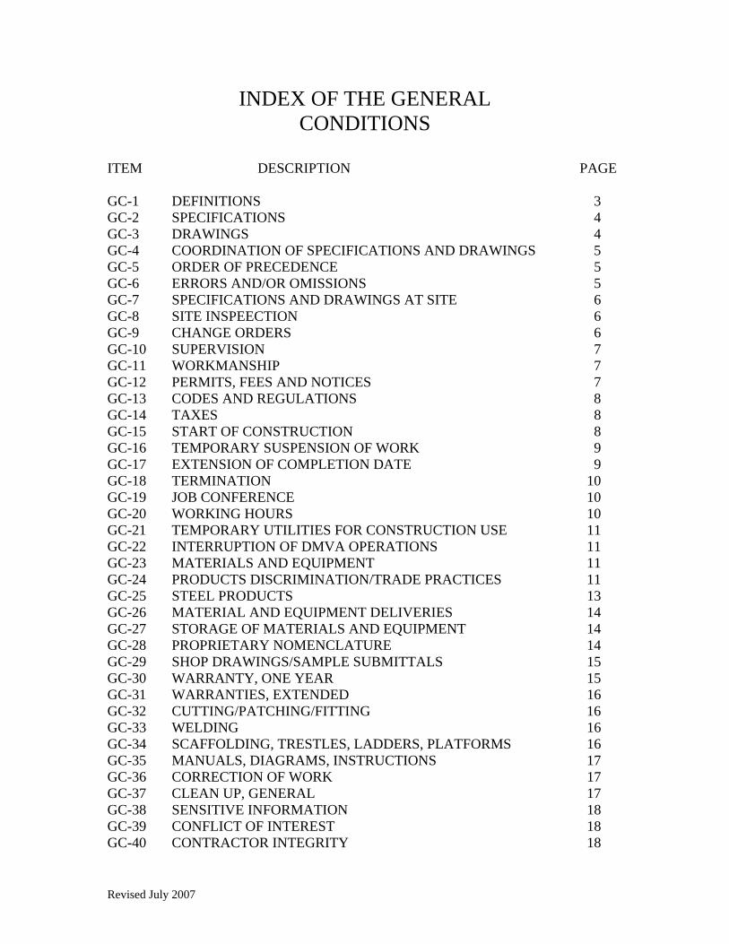
Revised July 2007
INDEX OF THE GENERAL CONDITIONS
ITEM DESCRIPTION PAGE GC-1 DEFINITIONS 3 GC-2 SPECIFICATIONS 4 GC-3 DRAWINGS 4 GC-4 COORDINATION OF SPECIFICATIONS AND DRAWINGS 5 GC-5 ORDER OF PRECEDENCE 5 GC-6 ERRORS AND/OR OMISSIONS 5 GC-7 SPECIFICATIONS AND DRAWINGS AT SITE 6 GC-8 SITE INSPEECTION 6 GC-9 CHANGE ORDERS 6 GC-10 SUPERVISION 7 GC-11 WORKMANSHIP 7 GC-12 PERMITS, FEES AND NOTICES 7 GC-13 CODES AND REGULATIONS 8 GC-14 TAXES 8 GC-15 START OF CONSTRUCTION 8 GC-16 TEMPORARY SUSPENSION OF WORK 9 GC-17 EXTENSION OF COMPLETION DATE 9 GC-18 TERMINATION 10 GC-19 JOB CONFERENCE 10 GC-20 WORKING HOURS 10 GC-21 TEMPORARY UTILITIES FOR CONSTRUCTION USE 11 GC-22 INTERRUPTION OF DMVA OPERATIONS 11 GC-23 MATERIALS AND EQUIPMENT 11 GC-24 PRODUCTS DISCRIMINATION/TRADE PRACTICES 11 GC-25 STEEL PRODUCTS 13 GC-26 MATERIAL AND EQUIPMENT DELIVERIES 14 GC-27 STORAGE OF MATERIALS AND EQUIPMENT 14 GC-28 PROPRIETARY NOMENCLATURE 14 GC-29 SHOP DRAWINGS/SAMPLE SUBMITTALS 15 GC-30 WARRANTY, ONE YEAR 15 GC-31 WARRANTIES, EXTENDED 16 GC-32 CUTTING/PATCHING/FITTING 16 GC-33 WELDING 16 GC-34 SCAFFOLDING, TRESTLES, LADDERS, PLATFORMS 16 GC-35 MANUALS, DIAGRAMS, INSTRUCTIONS 17 GC-36 CORRECTION OF WORK 17 GC-37 CLEAN UP, GENERAL 17 GC-38 SENSITIVE INFORMATION 18 GC-39 CONFLICT OF INTEREST 18 GC-40 CONTRACTOR INTEGRITY 18
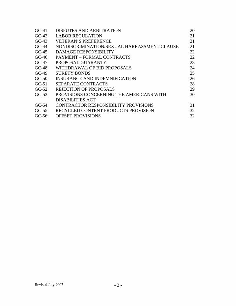
Revised July 2007
- 2 -
GC-41 DISPUTES AND ARBITRATION 20 GC-42 LABOR REGULATION 21 GC-43 VETERAN’S PREFERENCE 21 GC-44 NONDISCRIMINATION/SEXUAL HARRASSMENT CLAUSE 21 GC-45 DAMAGE RESPONSIBILITY 22 GC-46 PAYMENT – FORMAL CONTRACTS 22 GC-47 PROPOSAL GUARANTY 23 GC-48 WITHDRAWAL OF BID PROPOSALS 24 GC-49 SURETY BONDS 25 GC-50 INSURANCE AND INDEMNIFICATION 26 GC-51 SEPARATE CONTRACTS 28 GC-52 REJECTION OF PROPOSALS 29 GC-53 PROVISIONS CONCERNING THE AMERICANS WITH 30 DISABILITIES ACT GC-54 CONTRACTOR RESPONSIBILITY PROVISIONS 31 GC-55 RECYCLED CONTENT PRODUCTS PROVISION 32 GC-56 OFFSET PROVISIONS 32
Revised July 2007
- 3 -
GENERAL CONDITIONS
GC-1 DEFINITIONS: The terms below are used throughout this specification and shall be interpreted per the following: (1). The terms Department and DMVA, shall both mean or refer to the Commonwealth of Pennsylvania, Department of Military and Veterans Affairs, Fort Indiantown Gap, Annville, PA 17003, as if written in full. (2). Field Construction Maintenance Manager (FCMM) shall mean the person employed by and/or authorized to represent the Department and shall act in its behalf and best interest. (3). The terms Armory, Organizational Maintenance Shop (OMS), Training Site, Fort Indiantown Gap, or Veterans Home, shall all mean or refer to the actual location at which the work shall be accomplished, as if written in full. (4). The term Contractor shall mean that person/s, partnership, corporation, or entity responsible for the specified work, to include his/her employees, representatives, agents and any Subcontractor retained to assist in the execution of the work. (5). The term Contractor shall mean that person/s, partnerships, corporations or entity, to include employees, agents and representatives, retained by the Contractor to assist in the execution of the specified work. The Contractor shall have complete and ultimate responsibility for all work performed by Subcontractors. (6). A Flyer is a written order to bidders, issued by the Department prior to the due date for submittal of Invitation for Bids and Contract Proposal, clarifying points of issue and/or authorizing additions, deletions or modification to the specification and/or drawings. All flyers shall become and be enforced as a part of the Contract Documents. Receipt of all flyers shall be acknowledged on the Bidding Documents at time of submittal. (7). A Change Order is a written order to the Contractor, issued after the execution of all Contract Documents, authorizing a change in the work irregardless of any adjustment in the Contract sum. All Change Orders will be issued by the Department’s Purchasing Office and will be valid only after fully executed by all parties. The Contract shall not be authorized to incorporate any work required by Change Order until after receipt of the fully completed Change Order is received from the Department. The Change Order will be the original purchase order number with the revisions included.
Revised July 2007
- 4 -
(8). The date of Commencement of work is the date upon which the Department Notice to Proceed, is issued to the Contractor in completed form. (9). The date of Substantial Completion of work, or designated portion thereof, is the date on which the FCMM inspects and approves that construction is sufficiently complete, in accordance with the Contract Documents, so that DMVA may occupy the project or designated portion thereof. (10). Final Acceptance shall mean total completion of all specified work in accordance with all Contract Documents and subject to final job site inspection by FCMM. This final acceptance, and date thereof, shall be documented by signing of a Receiving Report by the FCMM, and shall further serve as the beginning date of all implied and written warranties in accordance with GC-30 and GC-31. GS-2. SPECIFICATIONS:
a. The specifications are drawn to indicate the general character and extent of the work to be accomplished. If before or during the completion of the work, the Contractor deems it necessary to modify the specifications, such modifications will first be reviewed and approved by the Department. Should any incidental work or material be required which is not denoted in the specifications, either directly or indirectly, but which is necessary for the proper carrying out of the intent thereof, the Contractor is to understand the same to be implied and required, and shall perform all such work as fully as if it were particularly described and delineated.
b. The organization of the specifications into divisions, sections, articles and
paragraphs shall not limit the Contractor in dividing the work among Subcontractors and tradesmen, or in establishing the extent of work to be performed by any trade or limit the responsibility for a complete project.
GS-3. DRAWINGS:
a. The drawings, if provided, are prepared to indicate the general character and extent of the work to be accomplished. If before or during the prosecution of the work, the Contractor deems it necessary to modify the drawings, such modifications will first be reviewed and approved by the Department. Should any incidental work or material be required which is not shown on the drawings, either directly or indirectly, but which is necessary for the proper carrying out of the intent thereof, the Contractor is to understand the same to be implied and required, and shall perform all such work as fully as if it were particularly delineated.
b. Drawings shall be distributed and used in full sets only, as the work required by
different trades may appear on more than one drawing.
Revised July 2007
- 5 -
c. Drawings shall not be scaled to obtain dimensions. If a dimension is not given, cannot be computed or a question should arise, contact the Department for clarification.
d. All dimensions and existing conditions shall be checked and verified at the site by
the Contractor. Materials, parts, equipment, etc. shall be furnished to field measurements. Dimensions given relative to existing equipment and construction are for Contractors general information and shall be verified in the field.
GC-4. COORDINATION OF SPECIFICATIONS AND DRAWINGS: Specifications and drawings are complimentary. What is written, shown and/or required by any one part shall be as binding as if written, shown and/or required by all. GC-5. ORDER OF PRECEDENCE: Whenever possible, Contract Documents and the drawings should be read together to give effect to all provisions. In the even of a conflict among provisions that is not reasonably reconcilable, the following order of precedence shall apply: (1). The Specifications (2). The General Conditions (3). The Drawings, if included (4). The Contract Bonds (5). The Invitation for Bid and Contract Proposal (6). Any other documents incorporated in the Contract GC-6. ERRORS AND/OR OMISSIONS:
a. The Contractor shall perform the work in accordance with the intent of the drawings and specifications, and shall not take advantage of any error, omission, and/or discrepancy between the drawings and specifications. In the event the Contractor discovers such an error or omission, he shall immediately notify the Department. The Contractor shall not proceed with work in any area where an error or discrepancy is claimed until the error or discrepancy is resolved by the Department. When required, the Department will make such corrections and interpretations deemed necessary for fulfillment of the drawings and specifications.
b. Any modification of, or change in, the drawings or specifications required to
update, adjust, accept or fully complete the work contemplated by the Contract, shall be determined and ordered, in writing, by the Department.
Revised July 2007
- 6 -
GC-7. SPECIFICATIONS AND DRAWINGS AT SITE: Contractor shall maintain on site one complete set of drawings and specifications, to include any and all flyers and change orders. These documents shall be for use of visiting personnel only. GC-8. SITE INSPECTION:
a. Prior to submission of bid, and at no cost to the Department, the Contractor is encouraged to physically visit/inspect the project site to determine exact sizes, quantities, locations, and local conditions that may effect work, etc.
b. Should any discrepancies, points of issue or conflicts arise between the local
conditions and these specifications and/or drawings, the facts shall be reported to the Department at least ten (10) working days prior to bid opening, for clarification. If warranted, a flyer citing such clarification, addition and/or deletion, shall be issued to all bidders.
c. Submission of a bid and/or the execution of the Contract shall demonstrate
compliance with this requirement and negate any future right of the Contractor, in producing a complete and satisfactory project, to claim extra compensation.
GC-9. CHANGE ORDERS:
a. See Definitions, paragraph a. (7), GC-1.
b. The Department, without invalidating the Contract, and within the general scope of the other Contract Documents, may order changes in the work consisting of additions, deletions, modifications or other revisions as required, the Contract sum and the Contract time being adjusted accordingly. All such changes in the work shall be only authorized by written Change Order issued by the Department, and shall be executed under the applicable conditions of the Contract Documents.
c. The cost or credit to the Department resulting from a Change in the Work shall be
determined in one or more of the following ways at the option of the Department: (1). By mutual acceptance of a lump sum properly itemized. (2). By unit prices stated in the Contract Documents or subsequently agreed
upon. (3). By arbitration if all parties fail to agree upon adjustments to be made in
accordance with GC-41.
d. The Department shall have authority to order minor changes in the work not involving an adjustment in the Contract sum or an extension of the Contract time, and not inconsistent with the intent of the Contract Documents.
Revised July 2007
- 7 -
e. Under NO circumstances shall the Contractor comply with any verbal or written
instructions from DMVA, for addition, deletions or alterations to the Contract drawing and specifications. All such requests shall be directed to the Department or the FCMM for approval. Failure to obtain written change order or amendment prior to compliance with requests shall be at the Contractors risk and he shall remain liable for any expenses and/or corrections required by the Department.
f. Nothing provided in the Condition: however, shall excuse the Contractor from
proceeding with the prosecution of the work. GC-10. SUPERVISION: The Contractor shall employ a competent supervisor, who shall be in constant attendance at the project site during the progress of the work. The supervisor shall represent the Contractor and have the authority to act on the Contractors behalf, in his/her absence. All communications given to the supervisor shall be as binding as if given to the Contractor. GC-11. WORKMANSHIP:
a. All workmanship shall be first class and in conformance with the best professional trade practices, procedures and standards.
b. The Contractor shall be responsible to the Department for the acts and/or
omissions, of all his employees and all Subcontractors, their agents and employees, and all other persons performing any of the work under this contract.
c. Only workman skilled in their respective trades will be employed on this work.
d. All work shall be performed in such manner as to prevent damage or injury to the
DMVA Property, contents or personnel, adjacent properties and the general public. (See GC-45 for temporary protective measures.)
GC-12. PERMITS, FEES AND NOTICES:
a. The Contractor shall secure and pay for all permits, fees, licenses, certificates, inspections, etc. required by any Federal, State or local authorities necessary for the proper execution and completion of his work.
b. The Contractor shall pay any and all hookup costs levied by any public or private
utility company.
c. The Contractor shall give all notices require by any public or private entity.
d. The Contractor shall be responsible for notifying all utility companies of construction start, in full compliance with the requirement of P.L § 852, Act 287
Revised July 2007
- 8 -
approved 10 December 1974 and shall further check and verify the location of existing utilities required to remain in place, including that overhead or underground, and take all necessary precaution to prevent injury or damage during the performance of the Contract and shall be responsible for any and all damages thereto.
GC-13. CODES AND REGULATIONS:
a. All work required under this Contract shall be in strict compliance with all Federal, State, and local statutes/codes/regulations, whichever being the more stringent. Additional requirements, if applicable, shall be so listed under specific items elsewhere.
b. The Contractor, in his own best interest, shall review and be familiar with all
applicable laws, codes, ordinances, regulations, rules and orders which bear on the performance of the work under this Contract and shall further comply with such items. If the Contractor observes that any of the Contract Documents are at variance therewith, in any respect, he shall properly notify the Department in writing. If the Contractor performs any work that is contrary to such applicable laws, ordinances, regulations, rules or orders, and without such written notice to the Department, he shall assume full responsibility therefore and shall bear all costs attributable thereto.
c. Where mentioned herein and/or elsewhere in the specifications all Federal, State
and local codes, rules, regulations, laws, etc. shall refer to editions in effect at the date of proposal, including current addenda and errata if any.
GC-14. TAXES: The Contractor shall pay all sales, consumer, use and other similar taxes required by law. GC-15. START OF CONSTRUCTION:
a. Upon receipt of the fully executed Department Agreement, the Contractor shall start construction within tem (10) working days and/or notify the Department or its’ Inspector of intentions to start and the justification for start date extension.
b. Absolutely no construction will be started until an Initial Job Conference is
conducted in accordance with GC-19, a Department Agreement is fully executed by all parties, all bonds in accordance with GC-49 and insurance requirements in accordance with GC-50 are complied with.
c. Failure to start construction with paragraph a., this GC, may be cause to terminate
this contract.
Revised July 2007
- 9 -
GC-16. TEMPORARY SUSPENSION OF WORK:
a. If, in the judgment of the Department, the Contractor is taking undue risk of damage to any part of a structure or installation by proceeding with the work during unfavorable weather or other unsuitable conditions, then the Department at its option, may suspend the work temporarily, either wholly or in part for such periods as may be necessary for safe and proper prosecution of the work. In case of such suspension, an extension of time may be allowed provided the conditions of GC-17 are complied with, but no allowance will be made to the Contractor for any additional expense of damages resulting therefrom. It shall be clearly understood that the failure of the Department to suspense the work shall not relieve the Contractor of his responsibility as specified.
b. During Annual Training, Mobilization and/or when the facility is unoccupied, for
any reason, work may be temporarily suspended for such time periods as required, unless prior arrangements have been made with and approved by the Department.
c. When the Department directs resumption of the work, the Contractor shall resume
full operations within a period of ten (10) days after date of notice to do so.
d. Suspensions of work as outlined above shall not in itself automatically extend the Contract completion time. If additional time is required or anticipated, the Contractor shall submit a request for extension of time in accordance with GC-17.
GC-17. EXTENSION OF COMPLETION DATE:
a. If the Contractor is delayed at any time in the progress of the work by any act or neglect of the Department or its’ employees, by any separate Contractor employed by the Department, by changes ordered in the work, by labor disputes, fire, unusual delay in transportation, causes beyond the Contractor’s control, delay authorized by the Department pending arbitration, temporary suspension of work or by any other cause which the Department determines may justify the delay, then the Contract time may be extended for such reasonable time as the Department may determine and approve, upon Contractor’s request.
b. All requests for extension of time shall be submitted, not more than fifteen (15)
days from date of occurrence, to the Department in writing, on the Contractor’s letterhead. Justification for the extension and period of time requested shall be so stated. Additional documentation may be required by the Department as necessary.
c. Upon receipt of the request, the Department shall review, grant or deny the
request and/or require additional documentation be submitted within ten (10) days. The Department shall notify the Contractor within ten (10) working days from receipt of request of approval/disapproval and additional time to be granted.
Revised July 2007
- 10 -
GC-18. TERMINATION:
a. The Department may terminate this Contract for default if the Contractor fails to perform satisfactorily. If the Contract is terminated for default, the Contractor shall remain liable to the Department for completion of the project in accordance with the Contract Documents. Such termination shall be cause for forfeiture of Performance Bond, provided under GC-49 and/or other monetary restitution for any direct or consequential damages arising out of the default.
b. The Department may terminate this Contract at any time without penalty upon
written notice to the Contractor if State and/or Federal funds are not available to fund this Contract.
c. The Department may terminate this Contract if the Contractor fails to start
construction in accordance with GC-15.
d. The Department may immediately terminate this Contract, without written notice or penalty, should the Contractor’s Insurance policies, required under GC-50, be cancelled during the terms of this Contract and any approved extension thereof.
e. The Department may terminate this Contract at any time, in accordance with GC-
44, for discrimination against any persons.
f. The Department may terminate this Contract at any time for it’s convenience upon thirty (30) days written notice to the Contractor of such termination.
GC-19. JOB CONFERENCE:
a. An Initial Job Conference shall be conducted, prior to start of any construction between the Department and the Contractor.
b. Contractor shall notify the FCMM a minimum of five (5) working days prior to
start of work for scheduling of conference.
c. In addition to the Initial Job Conference, such interim work progress conferences, as required, shall be conducted at the site and attend by a representative of the Department, Contractor and/or a representative authorized to act on his/her behalf.
GC-20. WORKING HOURS:
a. All work shall be done during the normal working hours of DMVA Monday through Friday, excluding State and Federal Holidays, unless prior arrangements have been made and approved by the Department.
b. Under certain unusual conditions, the Department may require that the Contractor
work other than the normal working hours of DMVA. Such work shall be
Revised July 2007
- 11 -
authorized only by the Department, shall further be defined in paragraph j., Section 1 – Special Requirements/Information, this specification, and shall be complied with at no additional expense to the Contract.
GC-21. TEMPORARY UTILITIES FOR CONSTRUCTION USE:
a. DMVA shall provide temporary water, sanitary facilities, electricity (except for welding), heat and phone (local calls only), unless otherwise specified.
b. These utilities shall only be provided to such extent and capacities as that
currently existing on site. Additional capacities and/or facilities, in excess of existing, required to comply with the Contract shall be provided by the Contractor at his expense.
GC-22. INTERRUPTION OF DMVA OPERATIONS:
a. Whenever it becomes necessary to interrupt existing utility services of DMVA, such as sewer, water, phone, gas, heat, electric service or other utilities the Department may require the work to continue on a twenty-four (24) hour basis until the service is restored, or at such alternate time required, see paragraph b., GC-20.
b. All work or interruption of utilities shall be completely coordinated with DMVA
so as to minimize any interference with normal operations. GC-23. MATERIAL AND EQUIPMENT:
a. All materials and equipment required by this Contract shall be warranted by the Contractor to be new and in perfect condition, unless otherwise specified and approved by the Department.
b. The Department has the right to reject any materials or equipment not in strict
accordance with the specifications.
c. Rejected material shall be immediately removed from the site at the Contractor’s expense.
GC-24. PRODUCTS DISCRIMINATION/TRADE PRODUCTS:
a. The Contractor shall not use, or permit to be used in the work, any supplies, equipment or materials manufactured in any state or territory of the United States which does not permit the purchase or use of supplies, equipment or materials manufactured in the Commonwealth of Pennsylvania, in or on it’s public building or other works of such state or territory.
Revised July 2007
- 12 -
States/Territories included: Alaska, Arkansas, Hawaii, Montana, New Mexico, Wyoming, Puerto Rico, West Virginia. The Department reserves the right to amend this listing at any time.
b. In accordance with the Trade Practices Act of July 23, 1968, P.L. § 686 (71 P.S. Section 773.101 et seq.), the Contractor cannot and shall not use, or permit to be used in the work, any aluminum or steel products made in a foreign country which is listed below as a foreign country which discriminates against aluminum or steel products manufactured in Pennsylvania. The countries of Brazil, South Korea, Spain, Mexico, and Argentina have been found to discriminate against certain product manufactured in Pennsylvania. Therefore, the purchase or use of those countries’ products, as listed below, is not permitted:
(1). Brazil: Welded carbon steel pipes and tubes; carbon steel wire rod; tool steel; certain stainless steel products including hot-rolled stainless steel bar; concrete steel wire strand’ hot-rolled carbon steel plates in coil; hot-rolled carbon steel sheet, and cold-rolled carbon steel sheet. (2). Spain: Certain stainless steel products including steel wire rod; hot-rolled stainless steel bars; and cold-formed stainless steel bars; pre-stressed concrete steel wire strand; and certain steel products including hot-rolled steel plate, cold-rolled carbon steel plate, carbon steel structural shapes, galvanized carbon steel sheet, hot-rolled carbon steel bars, and cold-formed carbon steel bars. (3). South Korea: Welded carbon steel pipes and tubes; hot-rolled carbon steel plate; hot-rolled carbon steel sheet; and galvanized steel sheet. (4). Mexico: Certain iron-metal construction castings including manhole covers, rings and frames, catch basin frames and grates, cleanout covers, grates, meter boxes, and valve boxes; galvanized carbon steel sheet; cold-rolled carbon steel sheet; carbon steel sheet; carbon steel plate in coil; carbon steel plate cut to length; and small diameter carbon steel plate welded pipe. (5). Argentina: Carbon steel wire rod and cold-rolled carbon steel sheet. c. Any products incorporated into the work in contradiction to this requirement,
either before or after the fact, shall be removed and replaced with acceptable products. Any subsequent work required to restore adjacent areas due to such work shall be at the Contractor’s expense.
d. In addition to the requirement of paragraph c., this GC, additional penalties for
violation of this General Condition may and/or can be imposed as found in the Trade Practices Act, which include becoming ineligible for Public Works Contracts for a period of three (3) years.
Revised July 2007
- 13 -
e. Note that this GC in no way relieves the Contractor of responsibility to comply with the additional requirements of GC-25, which prohibits the use of foreign made steel and cast iron products.
GC-25. STEEL PRODUCTS:
a. In the performance of any Contract awarded pursuant to this invitation to bid, the Contractor, Subcontractors, materialmen, or suppliers shall use only steel products, rolled, formed, shaped, drawn, extruded, forged, cast, fabricated, or otherwise similarly processed, or processed by a combination of two or more of such operations, from steel made in the United States by the open hearth, basic oxygen, electric furnace, Bessemer, or other steel-making process. Steel products included not only cast iron products, but also machinery and equipment listed in United States Department of Commerce Standard Industrial Classifications 25 (furniture and fixtures), 35 (machinery, except electrical), and 37 (transportation equipment), and of, fabricated from, or containing steel components. If a product contains both foreign and United States steel, it shall be determined to be a United State steel product only if at least 75% of the cost of the articles, materials, and supplies have been mined, produced, or manufactured, as the case may be, in the United States. Transportation equipment shall be determined to be a United States steel product only if it complies with Section 165 of Public Law 97-424 (96 Stat. 2136).
b. When unidentified steel products are supplied under a Contract, before any
payment will be made, the Contractor must provide documentation including, but not limited to invoices, bill of lading, and mill certification that the steel was melted and manufactured in the United States. If a steel product is identifiable from it’s face, the Contractor must submit certification which satisfies the Department that the Contractor has fully complied with this provision. The Department shall not provide for, or may any payments to, any person who has not complied with the Act. Any such payments made to any person by the Department which should not have been made as a result of the Act shall be recoverable directly from the Contractor, Subcontractor, manufacturer, or supplier who did not comply with the Act.
c. In addition to the withholding of payments, any person who willfully violates any
of the provisions of the Act shall be prohibited from submitting any bids to any public agency for a period of five (5) years from the date of the determination that a violation has occurred. In the even the person who violates the provision of the Act is a Subcontractor, manufacturer, or supplier, such person shall be prohibited from performing any work or supplying any materials to a public agency for a period of five (5) years from the date of the determination that a violation has occurred.
Revised July 2007
- 14 -
d. The Contractor shall include the provisions of this General Condition in every subcontract and supply contract so that the provisions of the Act shall be binding upon each Subcontractor and supplier.
GC-26. MATERIAL AND EQUIPMENT DELIVERIES:
a. If requested, DMVA, with prior notice/coordination/approval, will accept delivery of construction materials and equipment in the Contractor’s absence.
b. In accepting such deliveries, the Department shall in no way be held responsible
for unloading, proper storage, security, verifying the completeness of the shipment or liable for claims of damaged or missing materials/equipment.
GC-27. STORAGE OF MATERIALS AND EQUIPMENT:
a. Storage areas for construction materials, equipment and tools shall be provided by DMVA only to such extent as the existing facilities allow and all storage shall be strictly confined to these approved areas.
b. In no way shall such stored materials and equipment interfere with the normal
operations of DMVA and the Contractor may be required to relocate stored items should current circumstance change due to unforeseen conditions or monthly Guard Inactive Duty Training.
c. On site storage trailers shall not be permitted without prior approval of DMVA.
d. DMVA shall in no way be held responsible for the security of and/or damage to
any stored items. GC-28. PROPRIETARY NOMENCLATURE: Brand names, where specified, are given only for the purposed of establishing a standard type and quality for estimating purpose. Similar materials will be acceptable if submitted to the Department for approval, with sufficient documentation on which to base a decision. Subsequent to Contractor’s declaration in writing of the type, size, model and make of a major item of equipment to be furnished, no substitution shall be made without approval in writing by the Department.
Revised July 2007
- 15 -
GC-29. SHOP DRAWING SAMPLE SUBMITTAL:
a. The Contractor shall submit to the Department, for approval, such shop drawings, samples, catalog cuts, descriptive data, certifications, etc. as required, for those construction items to be incorporated into the project and in the quantities as listed elsewhere.
b. Each item submitted shall indicate the project number, Contractor’s name and
Contractor’s approval by initialing, and be dated.
c. All submittals shall be at the Contractor’s expense.
d. Contractor shall coordinate the submittals so that delays in the construction shall be avoided due to a certain phase of work being dependent on the other phases.
e. Absolutely no items required for submittal, shall be ordered or installed prior to
approval by the Department.
f. NO SUBSTITUTIONS shall be made after approval has been granted.
g. See paragraph g., Section 1 – Special Requirements/Information, this specification, for itemized listing of submittal items.
GC-30. WARRANTY, ONE YEAR:
a. The Contractor shall warrant that all materials, equipment and workmanship, under this Contract, shall be free of any defects for a period of ONE (1) year after date of final acceptance, see paragraph a. (10), GC-1.
b. Upon notice, the Contractor, at his expense, shall promptly make all required
repairs and/or replacements of such defects to the satisfaction and approval of the Department.
c. Any adjacent construction disturbed in fulfillment of this warranty, as well as any
subsequent damage to other parts of contents of the facility due to such defects, shall also be repaired and/or replaced to original condition and the satisfaction/approval of the Department, at no additional expense.
d. The Department shall make any and all corrections required under this warranty
due to the Contractor’s failure to fulfill this obligation, by either commencement of repair work and/or notification to the FCMM of intentions. The Contractor shall remain liable, to the Department, for such work required to make corrections of items incorporated into the project under all Contract Documents. Such failure to honor this requirement shall be cause for forfeit of Warranty Bond, provided under GC-49 and/or other monetary restitution for any direct or consequential damages arising out of this failure to comply.
Revised July 2007
- 16 -
e. The Department retains the right to make, without voiding this warranty, any and
all necessary emergency repairs/replacements, as necessary, should the Contractor not respond within a reasonable time period to prevent damage or endanger the facility, personnel and/or its’ contents. Costs for such work shall be charged to the Contractor.
GC-31. WARRANTIES, EXTENDED:
a. The Department, in addition to the one year warranty, may require an extended warranty period, of either the Contractor and/or material and equipment manufactures and suppliers, for certain items as elsewhere specified.
b. Any such required warranties shall be in written form and submitted to the
FCMM prior to final acceptance.
c. Paragraph b., c., d. and e. of GC-30 shall be a part of this requirement as if written in full.
d. See paragraph h., Section 1 – Special Requirement/Information, this specification,
for itemized listing and warranty period required. GC-32. CUTTING/PATCHING/FITTING: Contractor shall be responsible for all cutting, fitting and patching, of the existing structure of individual components thereof, as required for implementation of the specified work. All cutting shall be accomplished in such manner as the final finish shall match the adjacent areas and be to the satisfaction of the Department. All such work shall be at no additional cost to the Contract. GC-33. WELDING: All welding, if required, shall be performed only by certified welders who have passed qualification test using procedures covered in the American Welding Society Standard B3.0, Part II, or the Military Standard MIL-STD-248, such certification shall be provided to the Department prior to start of work and dated within the preceding 12 months. Contractor shall have readily available on #10 ABC portable fire extinguisher during welding operations. Contractor shall provide temporary protection of adjacent materials or equipment as required. All electric power for welding on the site of the project shall be supplied by the Contractor, who shall use self-contained engine generating units for producing such power. GC-34. SCAFFOLDING, TRESTLES, LADDERS, PLATFORMS: The Contractor shall furnish at his own cost and expense, all scaffolding, trestles, ladders and platforms and other equipment that is required for the execution of the work. All
Revised July 2007
- 17 -
such items shall be in full compliance with the safety regulations of the Occupational Safety and Health Administration, latest edition. GC-35. MANUALS, DIAGRAMS, INSTRUCTIONS:
a. Prior to final acceptance of work the Contractor shall submit all operation manuals, maintenance manuals, wiring diagrams and other manuals or literature, for all equipment incorporated into the project, to the FCMM.
b. The Contractor shall further provide qualified person/s, as required to explain and
demonstrate proper equipment operation, care and maintenance to DMVA representatives.
GC-36. CORRECTION OF WORK:
a. The Contractor shall promptly correct all work rejected by the Department as defective or nonconforming, or as failing to conform to the Contract Documents whether observed or after fabrication, installation or completion. The Contractor shall bear all costs of correction such rejected work.
b. If the Contractor does not remove or correct such defective or nonconforming
work within a period of ten (10) days from notice or notify the FCMM of intentions, the Department shall retain the right to proceed with such steps as necessary to correct defects. Costs of such work shall be charged to the Contractor.
GC-37. CLEAN UP, GENERAL
a. The Contractor, at all times, shall keep the premises free from accumulation of waste materials, debris and rubbish caused by his operation.
b. At the completion of the work or when directed by the Department, and such
other times as required to provide a clean/safe working environment, the Contractor shall remove all such refuse from the site and properly dispose of that refuse in accordance with all Federal, State and local codes and regulations.
c. The Contractor shall also promptly remove all construction tools, equipment,
machinery, trailers and surplus materials from the site when no longer required.
d. All areas of the Department shall be restored to the same state of cleanliness that existed prior to start of work.
e. At completion of the project all areas of work shall be left “broom clean” except,
and in addition to, specific cleaning as elsewhere specified.
Revised July 2007
- 18 -
f. See paragraph i., Section 1 – Special Requirements/Information, this specification, for listing of specific/additional items to be cleaned.
GC-38. SENSITIVE INFORMATION: The Contractor shall not publish or otherwise disclose, except to the Department, any information or data obtained under, or as a result of this Contract (except for public information as defined in the Right-to-Know Law, Act of June 27, 1957 P.L. 390, as amended, 65 P.S. 66.1), without the express consent of the Department. GC-39. CONFLICT OF INTEREST:
a. Interests of Members of the Commonwealth – No officer, member, employee of the Commonwealth or member of its’ governing body who exercises any function or responsibilities under this Contract shall participate in any decision relating to this Contract which affects their personal interest or interest of any corporation, partnership or association in which he/she is, directly or indirectly interested; nor shall any such officer, member, employee of the Commonwealth or member of its’ governing body have any interest, direct or indirect, in this Contract or the proceeds thereof.
b. Interests of Contractor – The Contractor covenants that he/she presently has no
interest and shall not acquire any interest, directly or indirectly, which would conflict in any manner or degree with the performance of its’ services hereunder. The Contractor further covenants that in the performance of this Contract, he/she shall not knowingly employ any person having such interest and certified that no member of the board of the Contractor or any of its’ officers or directors has such adverse interest.
GC-40. CONTRACTOR INTEGRITY:
a. Definitions. (1). Confidential information means information that is not public knowledge, or available to the public on request, disclosure of which would give an unfair, unethical, or illegal advantage to another desiring to contract with the Commonwealth. (2). Consent means written permission signed by a duly authorized officer or employee of the Commonwealth, provided that where the material facts have been disclosed, in writing, by pre-qualification, bid, proposal, or contractual terms, the Commonwealth shall be deemed to have consented by virtue of execution of this agreement.
Revised July 2007
- 19 -
(3). Contractor means the individual or entity that has entered into this agreement with the Commonwealth, including directors, officers, partners, managers, key employees, and owners of more than a 5% interest. (4). Financial Interest Means:
a. ownership of more than 5% interest in any business, or b. holding a position as an officer, director, trustee, partner, employee, or
the like, or holding any position of management. (5). Gratuity means any payment of more than nominal monetary value in the
form of cash, travel, entertainment, gifts, meals, lodging, loans, subscriptions, advances, deposits of money, services, employment, or contracts of any kind.
b. The Contractor shall maintain the highest standards of integrity in the
performance of this agreement and shall take no action in violation of state or federal laws, regulations, or other requirements that govern contracting with the Commonwealth.
c. The Contractor shall not disclose to others any confidential information gained by
virtue of this agreement.
d. The Contractor shall not, in connection with this or any other agreement with the Commonwealth, directly or indirectly, offer, confer, or agree to confer any pecuniary benefit on anyone as consideration for the decision, opinion, recommendation, vote, other exercise of discretion, or violation of a known legal duty by any officer or employee of the Commonwealth.
e. The Contractor shall not, in connection with this or any other agreement with the
Commonwealth, directly or indirectly, offer, give, or agree or promise to give to anyone any gratuity for the benefit of or at the direction or request of any officer or employee of the Commonwealth.
f. Except with the consent of the Commonwealth, neither the contractor nor anyone
in privity with him or her shall accept or agree to accept from, or give or agree to give to, any person, any gratuity from any person in connection with the performance of work under this agreement except as provided herein.
g. Except with the consent of the Commonwealth, the Contractor shall not have a
financial interest in any other Contractor, Subcontractor, or supplier providing services, labor, or material on this project.
h. The Contractor, upon being informed that any violation of these provisions has
occurred or may occur, shall immediately notify the Commonwealth in writing.
Revised July 2007
- 20 -
i. The Contractor, by execution of this agreement and by the submission of any bills or invoices for payment pursuant thereto, certifies and represents that he or she has not violated any of these provisions.
j. The Contractor, upon the inquiry or request of the Inspector General of the
Commonwealth or any of that official’s agents or representatives, shall provide, or if appropriate, make promptly available for inspection or copying, any information of any type or form deemed relevant by the Inspector General to the Contractor’s integrity or responsibility, as those terms are defined by the Commonwealth’s statutes, regulations, or management directives. Such information may include, but shall not be limited to, the Contractor’s business or financial records, documents or files of any type or form which refer to or concern this agreement. Such information shall be retained by the Contractor for a period of three (3) years beyond the termination of the contract unless otherwise provided by law.
k. For violation of any of the above provisions, the Commonwealth may terminate
this and any other agreement with the Contractor, claim liquidated damages in an amount equal to the value of anything received in breach of these provisions, claim damages for all expenses incurred in obtaining another contract to complete performance hereunder, and debar and suspend the Contractor from doing business with the Commonwealth. These rights and remedies are cumulative, and the use and nonuse of any one shall not preclude the use of all or any other. These rights and remedies are in addition to those the Commonwealth may have under law, statute, regulations, or otherwise.
GC-41. DISPUTES AND ARBITRATION:
a. The parties agree that they will endeavor to settle all claims, disputes, and questions arising under this Contract by mutual agreement. Any claim, dispute, question or other matter arising under this Contract, or any claimed breach hereof, will be discussed by the parties at a conference to be held with ten (10) days after either party files a written dispute, claim, question or other matter with the other party. If the dispute, claim, questions or other matter is no informally resolved at the conference, the Secretary, State Armory Board, upon request of either party, will issue a written decision on the dispute, claim or questions. This decision will be issued not more than fifteen (15) days after the dispute’s conference and shall be considered the final agency decision on this matter subject to review by the Board of Claims set forth in paragraph b., this General Condition.
b. All questions or disputes arising between the parties hereto respecting any matter
pertaining to this Contract or any part thereof, or any breach of said Contract arising thereunder which are not resolved informally, in accordance with paragraph a., this GC or by the disputes conference shall be referred to the Board of Claims, (as set for in Act of May 20, 1937, P.L. § 72B as amended by Act No. 1978-260, 72 P.S. 4651-1 et seq) whose decision and aware shall be final, binding
Revised July 2007
- 21 -
and conclusive upon all parties hereto, and all rights or any action of law or in equity and by virtue of this Contract, and all matters connected with and relative thereto are hereby expressly waived. Reference to questions under this arbitration provision must be prior to the final payment to the Contractor.
GC-42. LABOR REGULATION:
a. All laws of the Commonwealth pertaining to regulations and conditions of employment shall be observed, including Labor Discrimination Act 382, approved July 18, 1935.
b. All laborers and mechanics employed by the Contractor for the work to be
performed under this contract shall have been residents of the Commonwealth for at least ninety days prior to their employment in compliance with Act No. 414, approved July 19, 1935.
c. Failure to keep and comply with this provision shall be sufficient legal reason to
refuse payment of the contract price to the Contractor. GC-43. VETERAN’S PREFERENCE: The Department recommends that, all things being equal, Contractors give preference in employment on Department projects to veterans of the Armed Services of the United States of America. GC-44. NON DISCRIMINATION/SEXUAL HARASSMENT CLAUSE: During the terms of this Contract, Contractor agrees as follows: (1). In the hiring of any employee(s) for the manufacture of supplies, performance of work, or any other activity required under the Contract or any subcontract, the Contractor, Subcontractor, or any person acting on behalf of the Contractor or Subcontractor shall not, by reason of gender, race, creed, or color, discriminate against any citizen of this Commonwealth who is qualified and available to perform the work to which the employment relates. (2). Neither the Contractor nor any Subcontractor nor any person on their behalf shall in any manner discriminate against or intimidate any employee involved in the manufacture of supplies, the performance of work, or any other activity required under the Contract on account of gender, race, creed or color. (3). Contractors and Subcontractors shall establish and maintain a written sexual harassment policy and shall inform their employees of the policy. The policy must contain a notice that sexual harassment will not be tolerated and employees who practice it will be disciplined.
Revised July 2007
- 22 -
(4). Contractors shall not discriminate by reason of gender, race, creed, or color against any Subcontractor of supplier who is qualified to perform the work to which the contract relates. (5). The Contractor and each Subcontractor shall furnish all necessary employment documents and records to and permit access to their books, records, and accounts by the contracting agency and Bureau of Contract Administration and Business Development, for purposes of investigation, to ascertain compliance with provisions of this Non Discrimination/Sexual Harassment Clause. If the Contractor or any Subcontractor does not possess documents of records reflecting the necessary information requested, the Contractor or Subcontractor shall furnish such information on reporting forms supplied by the contracting agency or the Bureau of Contract Administration and Business Development. (6.) The Contractor shall include the provisions of this Non Discrimination/Sexual Harassment Clause in every subcontract so that such provisions will be binding upon each Subcontractor. (7). The Commonwealth may cancel or terminate the contract, and all money due or to become due under the Contract may be forfeited for a violation of the terms and conditions of this Non Discrimination/Sexual Harassment Clause. In addition, the agency may proceed with debarment or suspension and may place the Contractor in the Contractor Responsibility File. GC-45. DAMAGE RESPONSIBILITY: The Contractor shall provide, at no additional expense to the Department, such temporary protective measures required and/or if directed so by the Department to protect the existing DMVA property and contents, adjacent properties and contents and the general public. (1). Any damage to any part of the structure, its’ contents, adjacent properties or contents caused during the execution of this Contract shall remain the Contractor’s responsibility to repair or replace, at the option of and to the satisfaction of the Department at no additional expense to the Contract. (2). All temporary protective items shall be promptly removed, by the Contractor, when no longer required or when so directed by the FCMM. GC-46. PAYMENT – FORMAL CONTRACTS:
a. Upon completion and final inspection/acceptance of all specified work, to include any changes, the Contractor will be paid the total amount of the contract sum, subject to any authorized additions to or deductions from said amount by valid Change Order in accordance with GC-9.
Revised July 2007
- 23 -
b. Requests for partial payment will be coordinated with the FCMM and forwarded to Contracting Officer for approval. Partial payment will not exceed payment for work completed less ten percent (10%). Partial payment will not be accepted more than once every thirty (30) days.
c. Payment for stored materials will be approved only for materials for DMVA
projects and actually stored on the job site. GC-47. PROPOSAL GUARANTY:
a. For Informal Contracts, see paragraph a. (11), GC-1. None required for this type of contract. b. For Formal Contracts, see paragraph a. (12), GC-1. (1). A bid bond, certified check, bank cashier’s check, trust company treasurer’s check or an irrevocable money order, drawn to the order of the Commonwealth of Pennsylvania, in an amount not less than five percent (5%) of the bid amount submitted, must accompany bidding documents. Should a bid bond be selected as the bidders choice of proposal guaranty it WILL ONLY BE ACCEPTED on MA-SAB Form 7, provided with Contract proposal documents. (2). Company check, personal checks or regular/standard money orders WILL NOT be considered as security. (3). Failure to comply with this General Condition shall be cause to reject a Contractor’s bid submittal. (4). Forfeiture of proposal guaranty:
(a). If the Bid Proposal is withdrawn under any other Conditions or circumstances than stated under GC-48. (b). If the lowest responsible bidder to whom the Contract is awarded fails to obtain and/or submit the surety bonds required by GC-49 within thirty (30) days after receipt of the Department Agreement, the amount of the proposal guaranty shall be forfeited to the Commonwealth, not as a penalty, but as liquidated damages. (c). If the lowest responsible bidder to whom the Contract is awarded fails to obtain and/or submit the insurance required by GC-50 within thirty (30) days after receipt of the Department Agreement, the amount of the proposal
Revised July 2007
- 24 -
guaranty shall be forfeited to the Commonwealth, not as a penalty, but as liquidated damages. (d). If the lowest responsible bidder to whom the Contract is awarded fails to start construction as required by GC-15, the amount of the proposal guaranty shall be forfeited to the Commonwealth, not as a penalty, but as liquidated damages.
GC-48. WITHDRAWAL OF BID PROPOSALS:
a. Prior to bid opening: Bidders may withdraw any bid proposal after it has been received by the Department without forfeiture of proposal guaranty, see GC-47, provided the bidder makes a formal request in writing and the request is received by the Department prior to the time of bid opening. Where the request for withdrawal is made by telegram, said withdrawal will not be effective until a confirmation letter is received by the Department. The letter confirming the withdrawal must be postmarked prior to the time of the bid opening, must be registered or certified and must be executed by the parties authorized to execute the Contract Bid Proposal. Request for withdrawal will not be accepted over the telephone.
b. After the bid opening:
(1). Bidders may withdraw a bid proposal from consideration after the bid opening without forfeiture of proposal guaranty, see GC-47, provided the bid price was submitted in good faith, and the bidder submits credible evidence that the reason for the price bid being substantially lower was a clerical mistake as opposed to a judgment mistake, or was actually due to an unintentional and substantial arithmetical error or an unintentional omission of a substantial quantity or work, labor, material or services made directly in the compilation of the bid, provided the following conditions are complied with:
(a). The Department is notified, in writing, with two (2) business days after the bid opening.
(b). The withdrawal of the bid would not result in the awarding of the contract or another bid of the same bidder, partners, a corporation or business venture owned by or in which any interest is held by the bidder.
(2). No bidder who is permitted to withdraw a bid shall supply any material or labor to, or perform any Subcontract or other work agreement for any person to whom the contract is awarded without the written approval of the Department.
Revised July 2007
- 25 -
(3). Should all bids be rejected, due to such withdrawal, and the Department decided to re-bid the project, the bidder permitted to withdraw their bid proposal shall be liable for the costs of printing new bidding/contract documents and mailing such documents to bidders which desire to resubmit a new bid and were on the original bidders list. (4). Under no circumstances shall the withdrawing bidder be permitted to resubmit a bid on the same project. (5). Should either the Department or the bidder intend to contest any items under this General Condition, such shall be done so in accordance with the provisions of Title 73, Act 1974, Jan 23, P.L. 9, N. 4, 1 to 8. GC-49. SURETY BONDS: a. For Informal Contracts, see paragraph a. (11), GC-1. (1). None required for this type of Contract. b. For Formal Contracts, see paragraph a. (12), GC-1. Prior to the award of any
contract, the successful Contractor must furnish to the Department the following Contract Surety Bonds, in the amounts specified:
(1). Performance Bond in the amount of one hundred percent (100%) of the Contract amount. Such bond shall be for the faithful performance of the contract in accordance with the plans, specifications, conditions and all other Contract Documents. Such bond shall be solely for the protection of the DMVA. (2). Payment Bond (labor and material) in the amount of one hundred percent (100%) of the contract amount. Such bond shall be solely for the protection of claimants supplying labor or materials to the Prime Contractor to whom the contract was awarded, or to any provided for in such contract and shall be conditioned for the prompt payment of all such material furnished or labor supplied or performed in the prosecution of the work. “Labor or materials” shall include public utility services and reasonable rentals of equipment, but only for periods when the equipment rented is actually used at the project site. (3). Warranty Bond in the amount of ten percent (10%) of the contract amount. Such bond shall be for the correction of defects in materials, equipment, fixtures, workmanship or other items incorporated into the project, through the execution of compliance with all Contract Documents, which occur within a one (1) year period after completion of the project, if such defects are not corrected, to the satisfaction of the Department, by the Contractor in accordance with the requirements of GC-30.
Revised July 2007
- 26 -
(4). Surety Bonds shall be submitted within fifteen (15) days after the receipt of the Department Agreement, for Contractor’s signature. Surety bonds shall be properly executed and certified by the Contractor’s surety company. (5). Failure to secure and submit such surety bonds shall be cause to forfeit Contractor’s proposal guaranty per requirements of GC-47, and could further be cause for not awarding contract. GC-50. INSURANCE AND INDEMNIFICATION:
a. For formal and informal contracts, see paragraph a. (11) and (12), GC-1. (1). The Contractor shall take out and maintain during the life of this Contract, and any approved extension thereof, public liability insurance against bodily injury, death and/or property damage that may arise out of, or be related to, the activities of the Contractor under this contract, in the minimum amounts as follows:
(a). $250,000 per person and $1,000,000 per occurrence for person/bodily injury and/or death
(b). $1,000,000 for property damage
(c). The Department reserves the right to require additional insurance or adjust the amount of coverage required, if further specified under paragraph j. Section 1 – Special Requirements/Information, this specification.
(2). The Contractor shall also take out and maintain during the life of this contract, and any approved extension thereof, appropriate Workmen’s Compensation coverage, in accordance with the laws of the Commonwealth of Pennsylvania. (3). Insurance coverage shall apply to the operations of the Contractor, Contractors employees/offices, agents, general public, Department personnel, Subcontractors, Subcontractor’s employees and any other assignees and/or persons either directly or indirectly employed by the Contractor. (4). The Contractor, by execution of this Contract, certifies that he/she has taken out insurance policies in the amounts specified under paragraph (1) and paragraph (2), this General Condition.
(a). Certificate of Insurance shall be submitted within thirty (30) days after the receipt of the Department Agreement for Contractor signature. Certificate of Insurance WILL ONLY BE ACCEPTED on Commonwealth Form STD-24, which will be provided to the Contractor, and shall be properly executed and certified by the Contractor’s insurance company.
(b). The Commonwealth of Pennsylvania, and the Department of Military and Veterans Affairs, must be named as additional insured on all policies of
Revised July 2007
- 27 -
liability insurance taken out under this section and the Certificate of Insurance shall expressly indicated that the above named parties are named as additional insured.
(c.) Failure to secure and submit such Certificate of Insurance shall be cause to forfeit Contractor’s proposal guaranty per requirements of GC-47, and could further be cause for not awarding Contract.
(5). All policies shall be issued only by Insurance Companies authorized to conduct such business under the laws of the Commonwealth of Pennsylvania. (6). The Department shall not be responsible for any loss of life, personal injury or property damage of any kind arising out of, or related to, the performance and completion of the contract. The Contractor expressly agrees to indemnify, hold harmless, and defend the Commonwealth of Pennsylvania, The Department of Military and Veterans Affairs, and their employees, agents and assigns, from and against any and all claims, loss, damage, injury, and liability, however caused, resulting from, arising out of, or in connection with the work to be performed under this agreement caused or contributed to in any way by the negligence or alleged negligence, at other tortuous conduct (intentional or unintentional) on the part of the Contractor and/or any of the Subcontractors, agents, employees or assigns. (7). Required policies under this General Condition shall be in effect from the date of Contractor’s acceptance of the Department Agreement, so noted by signature thereto, and shall remain through the entire period of the contract. Cancellation of any required insurance during the term of the Contract shall be cause for immediate stoppage of all work by the Contractor and any of his/her assignees, until such time tat proof of policy reinstatement is provided to the Department. Failure to immediately reinstate cancelled insurance could further cause termination of this Contract in accordance with GC-18, paragraph d., and forfeiture of surety bonds. Any damage caused to the structure or its’ contents because of such stoppage shall be the Contractor’s responsibility to repair or replace, to the Department’s satisfaction, at no additional cost to the Contract amount. (8). Failure of the Contractor’s insurance company to notify the Department of any policy cancellation, shall in no way limit the Contractor’s responsibility and/or liability for bodily injuries and/or property damage, for which the Contractor, the Contractor’s heirs, or assignees shall be held personally accountable for the financial restitution of claimants. (9). Insurance and Indemnification: Automobile Liability Insurance in the amount of $1,000,000 for injury to or death of one person in a single occurrence and $3,000,000 for injury to or death of more than one single occurrence and $500,000 for a single occurrence of property damage.
Revised July 2007
- 28 -
(10). The insurance shall not contain any endorsements of any other form designed to limit and restrict any action by the Commonwealth as an additional insured, against the insurance coverage in regard to the work performed for the Commonwealth. GC-51. SEPARATE CONTRACTS:
a. The Department reserves the right to aware separate Prime Contracts in connection with certain portions of work required for this project.
b. When separate Prime Contractors are awarded for different portions of the
project, the Contractor in the Contract Documents shall be the Contractor who signs each separate Prime Contract.
c. Mutual responsibility of Contractors:
(1). The Contractor shall afford other Prime Contractors reasonable opportunity for execution of their work, the introduction and storage of their materials and equipment, and shall properly connect and coordinate his work with the work awarded by the Department to other Contractors. (2). Work shall be conducted and coordinated so as not to interfere with the work of other Contractors. If any part of the Contractor’s work depends on proper execution of, or results of, the work of any other Prime Contractor, not under contract to him, the Contractor shall inspect such work and promptly report in writing to the Department any apparent interference, discrepancies, defects or delays in such work that renders it unsuitable for proper execution and results of his work. Failure of the Contract to so inspect and report shall constitute an acceptance of the other Prime Contractor’s work as fit and proper to receive his work, except as to defects which may develop in the other Prime Contractor’s work after the execution of the Contractor’s work. In the event that any of the prime Contractors shall not complete the various portions of their work in general harmony, and another Prime Contractor shall be cause damage or injury shall have the right to settle by agreement or arbitration such claim or dispute in accordance with the provision of paragraph d., this General Condition. The Department, however, shall not be liable to any Prime Contractor for any increased costs or damages resulting from the defective work, interference, or delays of other Prime Contractors. d. Disputes, claims or actions between Contractors (1). Should the Contractor, either himself or by his Subcontractors, agents, or employees, cause damage or injury to the property or work of any other Prime Contractor, or fail to perform his work with due diligence or delay any other Prime Contractors who shall suffer additional expense or damage thereby, and a dispute or claim shall arise from such action, it shall be settled per paragraph (2), this General Condition. It is agreed by all parties that disputes or actions between Contractors concerning the additional expense or damage hereinbefore mentioned shall not delay
Revised July 2007
- 29 -
completion of the work which shall be continued by the parties, subject to the rights afforded by paragraph d. this General Condition. It is agreed by the parties to this Contract that the intent of this clause is to benefit each Prime Contractor on the project and further that they specifically exclude claims against the Department for delay or other damages. (2). The Contractor agrees that all claims, disputes and other matters in question between Prime Contractors, which arise out of, or are related to this Contract or the breach thereof, shall be settled by agreement or resolved by arbitration in accordance with the Construction Industry Arbitration Rules of the American Arbitration Association then in effect, unless the parties mutually agree otherwise. This agreement to arbitrate shall be in consideration of the fact that all other Prime Contractors agree to this same arbitration provision as provided in each separate Prime Contract required for the construction of this project, and shall be specifically enforceable under the prevailing Arbitration Law. The award rendered by the arbitrators shall be final, and judgment may be entered upon in accordance with applicable law in any court having jurisdiction thereof. (3). Notice of the demand for arbitration shall be filed in writing with the other Prime Contractors, the American Arbitration Association and an Informational copy shall be filed with the Department. The demand for arbitration shall be made within a reasonable time after the claim, dispute, or other matter in question has arisen. The Department shall not be a party to the claim, dispute or other matter in question, but shall be a witness in any arbitration at the request of any party to the arbitration, nor shall such claim or dispute be subject to the Board of Claims proceedings provided in GC-41 which is only for settlement for disputes between the Department and a Prime Contractor. e. The following order of precedence shall be observed for the responsibility of
overall coordination and supervision when more than one prime contract is awarded for a project:
(1). General Contractor (2). HVAC Contractor (3). Electrical Contractor (4). Plumbing Contractor (5). Other
GC-52. REJECTION OF PROPOSAL:
a. The Department reserves the right to reject any and/or all bids, in its’ discretion, for any of the following conditions:
Revised July 2007
- 30 -
(1). If proposals show any omission or irregularities of any kind. (2). If proposals show any addition, deletion or qualification not solicited. (3). If proposals are altered in any fashion. (4). If proposals are not submitted on and/or with all Department provided and
approved forms, fully executed by proper authority. (5). If proposal is not accompanied with a proposal guaranty, in accordance with
GC-47. (6). If bulletins issued prior to proposal due date are not acknowledged and
submitted with other bidding documents, in accordance with paragraph (6), GC-1.
(7). If proposal amount exceeds allocated funding or contracting limit. (8). If in the Department’s opinion, it is in the best interest of the
Commonwealth of Pennsylvania.
b. All proposals are subject to legal review by the Department Chief Counsel, for determination of the above conditions. Technical defects or irregularities on proposals may be waived upon the recommendation of the Department Chief Counsel.
GC-53. PROVISIONS CONCERNING THE AMERICANS WITH DISABILITIES ACT: During the term of this contract, the Contractor agrees as follows: (1). Pursuant to federal regulations promulgated under the authority of The Americans with Disabilities Act, 28 C.F.R. § 35.101 et seq., The Contractor understands and agrees that no individual with a disability shall, on the basis of the disability, be excluded from participation in this contract or from activities provided for under this Contract. As a condition of accepting and executing this Contract, the Contractor agrees to comply with the “General Prohibitions Against Discrimination,” 28 C.F.R. § 35.130, and all other regulations promulgated under Title II of the Americans with Disabilities Act which are applicable to the benefits, services, programs, and activities provided by the Commonwealth of Pennsylvania through contract with outside contractors. (2). The Contractor shall be responsible for and agrees to indemnify and hold harmless the Commonwealth of Pennsylvania from all losses, damages, expenses, claims, demands, suits, and actions brought by any party against the Commonwealth of Pennsylvania as a result of the Contractor’s failure to comply with the provisions of paragraph (1).
Revised July 2007
- 31 -
GC-54. CONTRACTOR RESPONSIBILITY PROVISIONS: For the purpose of these provisions, the term contractor is defined as any person, including, but not limited to, a bidder, offeror, loan recipient, grantee or subgrantee, who has furnished or seeks to furnish goods, supplies, services or leased space, or who has performed or seeks to perform construction activity under contract, subcontract, grant or subgrant with the Commonwealth , or with a person under contract, subcontract, grant or subgrant with the Commonwealth or its’ state-affiliated entities, and state-related institutions. The term Contractor may include a permittee, licensee, or any agency, political subdivision, instrumentality, public authority, or other entity of the Commonwealth. (1). The Contractor must certify, in writing, for itself and all its’ subcontractors, that as of the date of its’ execution of any Commonwealth contract, that neither the Contractor, nor any Subcontractors, nor any suppliers are under suspension or debarment by the Commonwealth or any government entity, instrumentality, or authority and, if the contractor cannot so certify, then it agrees to submit, along with the bid/proposal, a written explanation of why such certification cannot be made. (2). The Contractor must also certify, in writing, that as of the date of its execution, of any Commonwealth contract, it has not tax liabilities or other Commonwealth obligations. (3). The Contractor’s obligations pursuant to these provisions are ongoing from and after the effective date of the Contract through the termination date thereof. Accordingly, the Contractor shall have an obligation to inform the contracting agency if, at any time during the term of the Contract, it becomes delinquent in the payment of taxes or other Commonwealth obligations, or if it, or any of its’ Subcontractors, are suspended or debarred by the Commonwealth, the federal government, or any other state or government entity. Such notification shall be made within fifteen (15) days of the date of suspension or debarment. (4). The failure of the Contractor to notify the contracting agency of its’ suspension or debarment by the Commonwealth, any other state, or the federal government, shall constitute an event of default of the Contract with the Commonwealth. (5). The Contractor agrees to reimburse the Commonwealth for the reasonable cost of investigation incurred by the Office of State Inspector General for investigations of the Contractor’s compliance with the terms of this or any other agreement between the Contractor and the Commonwealth which results in the suspension or debarment of the Contractor. Such cost shall included, but shall not be limited to, salaries of investigators, including overtime; travel and lodging expenses; and expert witness and documentary fees. The Contractor shall not be responsible for investigations that do not result in the Contractor’s suspension or debarment.
Revised July 2007
- 32 -
(6). The Contractor may obtain a current list of suspended and debarred Commonwealth contractors by either searching the internet at http://www.dgsweb.state.pa.us/DebarmentList_portlet or contacting the: Department of General Services Office of the Chief Counsel 603 North Office Building Harrisburg, PA 17125 Telephone No. 717-783-6472 Fax No. 717-787-9138 GC-55. RECYCLED CONTENT PRODUCTS PROVISION: The recycled content products provision referenced in Management Directive 215.14, does not apply to this Contract. GC-56. OFFSET PROVISION: The Contractor agrees that the Commonwealth may set off the amount of any state tax liability or other debit of the Contractor or its’ subsidiaries that is owed to the Commonwealth and not being contested on appeal against any payments due the Contractor under this or any other contract with the Commonwealth.