oxygen electrochemistry as a cornerstone for sustainable energy conversion
TRANSCRIPT

Nanostructured ElectrocatalystsDOI: 10.1002/anie.201306588
Oxygen Electrochemistry as a Cornerstone forSustainable Energy ConversionIoannis Katsounaros,* Serhiy Cherevko, Aleksandar R. Zeradjanin, andKarl J. J. Mayrhofer*
AngewandteChemie
Keywords:electrolysis · fuel cells · nanostructures ·oxygen evolution ·oxygen reduction
.AngewandteReviews I. Katsounaros, K. J. J. Mayrhofer et al.
102 www.angewandte.org � 2014 Wiley-VCH Verlag GmbH & Co. KGaA, Weinheim Angew. Chem. Int. Ed. 2014, 53, 102 – 121

1. Introduction
Finding sustainable solutions to the looming energy crisison both the small and large scale has become one of the mosturgent challenges on the way to reduce our dependence onconventional energy sources based on fossil fuels.[1,2] Over thelast few years, several technologies that provide electricalenergy from renewable sources (e.g. solar photovoltaics, windpower generators etc) have been increasingly implemented.[3]
However, the supply of energy from such sources is inter-mittent, and since the usage of electricity fluctuates inde-pendently this leads to a continuous mismatch betweensupply and demand. Therefore, to provide integrated solu-tions, such technologies must be coupled with advancedenergy conversion and storage processes.[2–4] In this frame-work, electrochemistry plays an essential role, as it allowstransformations between electrical and chemical energy andvice versa, thereby enabling the storage of energy in the formof chemical bonds. This is broadly termed electrochemicalenergy conversion and storage.[5] In particular, when thesupply from renewable sources exceeds the demand, theelectrical energy surplus can be used to carry out nonsponta-neous electrochemical reactions (in electrolysis cells) andstored in the more convenient form of chemical energy. Attimes when the supply does not meet the demand, the energydeficit can be covered by converting the previously storedchemical energy into electrical energy through spontaneouselectrochemical reactions occurring in galvanic cells.
Although rechargeable batteries are already commonlyused for energy conversion for small-scale portable applica-tions (e.g. in mobile phones, laptops, or even cars) incommercially available devices,[6] other approaches based oncontinuous electrolysis and galvanic reactors for large-scaleapplications still require major research efforts to reach thisstate. For example, the reduction of carbon dioxide as aninitial reactant to produce either fuels directly (e.g. methanol)or precursors for the formation of fuels (e.g. synthetic gas)seems promising for large-scale applications (“methanoleconomy”).[7] Even though this carbon cycle includes the
advantage of the easy storage and transportation of a liquidfuel using the existing infrastructure, there is still a highdemand for fundamental research on the selective reductiveconversion of carbon dioxide with high activity as well as thereverse oxidation process.[8, 9] Much more interest has so farbeen devoted to energy conversion based on the hydrogencycle (“hydrogen economy”).[10] In this case, water splitting isused as the initial reaction, which leads to the evolution ofhydrogen at the cathode [Eq. (1)] and of oxygen at the anode[Eq. (2)] of the electrolyzer (the reactions are shown foracidic media).
4 Hþ þ 4 e� Ð 2 H2 ð1Þ
2 H2OÐ O2 þ 4 Hþ þ 4 e� ð2Þ
The hydrogen fuel produced can thereafter be oxidized atthe anode [reverse reaction to Eq. (1)] during times of highdemand, while the counter reaction is the reduction of oxygenthat takes place at the cathode [reverse reaction to Eq. (2)] ofa H2/air fuel cell. It is nowadays well established that thehydrogen evolution and oxidation reactions proceed at a highrate, for example, on platinum-based catalysts.[11] The bottle-neck, particularly in acidic media at low temperature isactually the development of materials for the catalysis of theelectrochemical oxygen reactions, namely the oxygen evolu-tion reaction—OER (in electrolyzers) and the oxygenreduction reaction—ORR (in fuel cells).
Highly dispersed, nanostructured electrocatalysts aretypically used to increase the surface-to-volume ratio and
Electrochemistry will play a vital role in creating sustainable energysolutions in the future, particularly for the conversion and storage ofelectrical into chemical energy in electrolysis cells, and the reverseconversion and utilization of the stored energy in galvanic cells. Thecommon challenge in both processes is the development of—pref-erably abundant—nanostructured materials that can catalyze theelectrochemical reactions of interest with a high rate over a sufficientlylong period of time. An overall understanding of the related processesand mechanisms occurring under the operation conditions is a neces-sity for the rational design of materials that meet these requirements. Apromising strategy to develop such an understanding is the inves-tigation of the impact of material properties on reaction activity/selectivity and on catalyst stability under the conditions of operation,as well as the application of complementary in situ techniques for theinvestigation of catalyst structure and composition.
From the Contents
1. Introduction 103
2. Fundamental Aspects of theReactions of Interest 104
3. Catalysis of the ElectrochemicalOxygen Reduction Reaction(ORR) 105
4. Catalysis of the ElectrochemicalOxygen Evolution Reaction(OER) 110
5. Outlook and Future Challenges 115
[*] Dr. I. Katsounaros, Dr. S. Cherevko, Dr. A. R. Zeradjanin,Dr. K. J. J. MayrhoferDepartment of Interface Chemistry and Surface EngineeringMax-Planck-Institut f�r Eisenforschung GmbHMax-Planck-Strasse 1, 40237 D�sseldorf (Germany)E-mail: [email protected]
[email protected]: www.mpie.de/ecat
Nanostructured ElectrocatalystsAngewandte
Chemie
103Angew. Chem. Int. Ed. 2014, 53, 102 – 121 � 2014 Wiley-VCH Verlag GmbH & Co. KGaA, Weinheim

thus the electrochemical reaction rates.[12] However, theapplication of such catalysts under the conditions of theOER and the ORR faces severe challenges related to theactivity, the stability, and the abundance of the materials used.In this Review, we focus on the recent developmentsregarding the understanding of the catalysis of the two crucialreactions, namely the OER and the ORR, in aqueous mediafrom a surface electrochemistry point of view, and we describethe current and future challenges for designing materials thatcan be used for large-scale applications and extended opera-tional times. For the important progress made in the field ofmolecular and enzymatic catalysis with regard to the watersplitting and formation reactions, the interested reader isreferred to other extended reviews.[13–15]
2. Fundamental Aspects of the Reactions of Interest
2.1. Thermodynamics
The equilibrium potential for the O2/H2O redox couple isgiven by the Nernst equation [Eq. (3)], where ai is the activityof species i in water. The standard potential for theequilibrium shown in Equation (2) is Eo
O2=H2 O¼ þ1:229V
versus the standard hydrogen electrode (SHE), using thefree energy for the formation of liquid water from oxygenunder standard conditions.[16] Therefore, at 25 8C, the equi-librium potential becomes more negative by 59.2 mV versusthe SHE for a one-unit increase in the pH value, and by14.8 mV for a tenfold decrease of aO2
, which equals the partialpressure of oxygen. In addition, the ORR and the OER mayinvolve the formation of hydrogen peroxide as an intermedi-ate [Eqs. (4) and (5)]. The corresponding equilibrium poten-tials are given by Equations (6) and (7), and the standard
potentials for Equations (4) and (5) are EoO2=H2 O2
¼ þ0:695 Vand Eo
H2 O2=H2 O¼ þ1:763 V versus the SHE, respectively.[17]
EO2=H2 O ¼ EoO2=H2 O
� RT4 F
lna2
H2O
aO2a4
Hþð3Þ
O2 þ 2 Hþ þ 2 e� Ð H2O2 ð4Þ
H2O2 þ 2 Hþ þ 2 e� Ð 2 H2O ð5Þ
EO2=H2 O2¼ Eo
O2=H2 O2
� RT2 F
lnaH2O2
aO2a2
Hþð6Þ
EH2 O2=H2O ¼ EoH2 O2=H2 O
� RT2 F
lna2
H2O
aH2O2a2
Hþð7Þ
2.2. Reaction Mechanism
The equilibrium in Equation (2) given above is an overallexpression for the complete OER and ORR. However, bothreactions involve several elementary steps, and in particularfour electron-transfer steps, four proton-transfer steps (cou-pled or decoupled with the electron transfer), and one bond-breaking (ORR) or bond-forming (OER) step.[18] In thisscenario, one additionally needs to consider that otherprocesses, such as desorption/adsorption processes as well aschemical (e.g. disproportionation) reactions may occur andplay an essential role in the product formation.[18] The above-mentioned steps always take place in series and lead to certainintermediates, and their sequence constitutes the reactionmechanism on a given surface. The elucidation of themechanism of both reactions is important for the determi-nation of rate-limiting steps; however, understanding theOER and ORR mechanisms is not easy due to the challengesof unambiguously interpretating kinetic data, identifying
Ioannis Katsounaros received his PhD onelectrocatalysis from the Aristotle Universityof Thessaloniki with Dr. G. Kyriacou in2009. Afterwards, he worked on the activityand stability of ORR catalysts at the Max-Planck-Institut f�r Eisenforschung. SinceSeptember 2013 he has been a Marie-CurieInternational Outgoing Fellow, workingjointly at the Argonne National Laboratoryand at the University of Illinois at Urbana-Champaign on energy conversion and stor-age.
Serhiy Cherevko studied physics at the V.N.Karazin Kharkiv National University(Ukraine) and received his MSc in 2004. Hecompleted his PhD with Prof. C.-H. Chungin 2009 at the Sungkyunkwan University(SKKU; Republic of Korea), where heremained until 2011. Since then, he hasbeen carrying out postdoctoral research atthe Max-Planck-Institut f�r Eisenforschung.His research interests focus on processes atthe metal(oxide)–electrolyte interface, partic-ularly noble metal oxidation and dissolution.
Aleksandar R. Zeradjanin received his PhDin 2012 from the Ruhr-Universit�t Bochum,under the supervision of Prof. W. Schuh-mann. Currently he is a research associate inthe electrocatalysis group at the Max-Planck-Institut f�r Eisenforschung. His mainresearch interests are in energy conversion atthe electrochemical interface, including fun-damental and applied aspects of electro-catalysis and electroanalytical chemistry.
Karl J. J. Mayrhofer received his PhD fromthe TU Vienna in 2006 after a research stayat the Lawrence Berkeley National Lab withDr. N. M. Markovic. He then spent threeyears with Prof. M. Arenz at the TU M�n-chen before becoming a group leader at theMax-Planck-Institut f�r Eisenforschung inthe Department of Interface Chemistry andSurface Engineering. His research focuses onunderstanding the solid–liquid interfaceduring electrochemical reactions and on thedevelopment of materials for energy conver-sion.
.AngewandteReviews
I. Katsounaros, K. J. J. Mayrhofer et al.
104 www.angewandte.org � 2014 Wiley-VCH Verlag GmbH & Co. KGaA, Weinheim Angew. Chem. Int. Ed. 2014, 53, 102 – 121

intermediates in situ (e.g. by spectroscopy), and explicitlysupporting a preferable mechanism by means of electronicstructure calculations when considering solvated systems.[19,20]
The proposed ORR and OER mechanisms can be unifiedin a single scheme (Scheme 1):1) The ORR proceeds through a dissociation mechanism
when the O�O bond of oxygen breaks directly uponadsorption and the formed Oads is reduced successively toOHads and to H2O
ads; reversing this mechanism yields therecombination mechanism of the OER.
2) The association mechanism for the ORR and the OERinvolves the formation of OOHads, which breaks into Oads
and OHads (for the ORR) or forms from the recombina-tion of these species (for the OER).
3) Moreover, the ORR can proceed through the peroxomechanism when two electron-transfer steps lead succes-sively to OOHads and to HOOHads, and the latter thenbreaks into OHads; reversing this mechanism yields theperoxo mechanism for the OER.
2.3. Adsorption of Oxygenated Species on Transition-MetalSurfaces
The formation of adsorbed oxygenated species (e.g. Oads,OHads, OOHads), originating from the aqueous electrolyte and/or the reaction itself, is considered as the decisive process fordetermining the catalyst performance. Oxidation of thesurface can inhibit the ORR or enhance the OER, and maybe involved in degradation processes, such as dissolution.[21,22]
The adsorption energies of the oxygenated species involved inthe ORR and OER mechanism on transition-metal surfacesand their oxides are proportional to each other.[23, 24] Thisparticular scaling relationship stems from a more universalcorrelation between the adsorption energies of any adsor-bates bound similarly to a surface.[25, 26] The existence of sucha proportionality allows the adsorption energy of only one ofthe involved species (e.g. DEO, DEOH, or DEOOH) to beconsidered when trying to determine catalytic trends. More-over, the adsorption energy of a species on a transition-metalsurface has been correlated to the position of the d-bandcenter (ed) with respect to the Fermi level (eF) (known as thed-band center model).[27–29] According to this model, themetal–adsorbate (e.g. M�Oads) bond is weaker when thedistance between the Fermi level and the d-band center
(eF�ed) is larger. Thus, the d-band center can be used (insteadof the adsorption energy of a species on the surface) as anactivity descriptor. Even though there are some reports thatquestion if the d-band center alone is enough to describe theenergy of adsorption,[30–32] this model still enables a simplifiedcorrelation, with good accuracy, between the catalytic activityand the surface electronic properties.
3. Catalysis of the Electrochemical OxygenReduction Reaction (ORR)
3.1. Activity for the ORR3.1.1. Activity Trends for the ORR
The ORR is limited by either the formation of OOHads orthe removal of OHads.[33] The existing scaling relationsdescribed in Section 2.3 impose a compromise betweena neither too strong nor too weak binding of OOHads andOHads for the optimum ORR activity. This can be visualizedby a volcano-type relationship (Figure 1) with respect to the
adsorption energy of any oxygenated species, for example, theOads.
[33, 34] Catalysts located on the left side of the volcano inFigure 1 bind oxygen too strongly, and thus the reaction isretarded by desorption of the OHads. In contrast, for catalystslocated on the right side of the volcano in Figure 1, the rate-determining step is the weak adsorption of oxygen asa reactant. The activity is maximized at the top of thevolcano, and corresponds to a catalyst with a moderatebinding energy of the oxygenated species.[33, 34] However, thetop of the volcano still does not correspond to a catalyst witha zero overpotential, because of the limitations that originatefrom the scaling relations.[35]
Of all the pure metals, platinum is the most active as it islocated closest to the top of the volcano.[34] In the furtherdiscussion on noble metals for the ORR we will focus on Pt-based materials in acidic solutions, as they represent the mostactive and most studied systems.
Scheme 1. Proposed ORR and OER mechanisms.
Figure 1. Volcano-type relationship for the ORR activity versus theoxygen binding energy. Reprinted from Ref. [34] with permission fromthe American Chemical Society.
Nanostructured ElectrocatalystsAngewandte
Chemie
105Angew. Chem. Int. Ed. 2014, 53, 102 – 121 � 2014 Wiley-VCH Verlag GmbH & Co. KGaA, Weinheim www.angewandte.org
3.1.2. Structural Sensitivity of the ORR—Size/Shape Effects
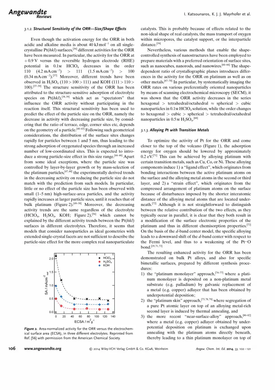
Even though the activation energy for the ORR in bothacidic and alkaline media is about 40 kJmol�1 on all single-crystalline Pt(hkl) surfaces,[36] different activities for the ORRhave been measured. In particular, the activity for the ORR at+ 0.9 V versus the reversible hydrogen electrode (RHE)potential in 0.1m HClO4 decreases in the order110 (4.2 mAcm�2) > 111 (1.5 mAcm�2) > 100(0.34 mA cm�2).[37] Moreover, different trends have beenobserved in H2SO4 (110> 100> 111) and KOH (111> 110>100).[37–39] The structure sensitivity of the ORR has beenattributed to the structure-sensitive adsorption of electrolytespecies on Pt(hkl),[38, 39] which act as “spectators” thatinfluence the ORR activity without participating in thereaction itself. This structural sensitivity has been used topredict the effect of the particle size on the ORR, namely thedecrease in activity with decreasing particle size, by consid-ering that the ratio of terrace, edge, corner sites etc, dependson the geometry of a particle.[40–43] Following such geometricalconsiderations, the distribution of the surface sites changesrapidly for particles between 1 and 5 nm, thus leading to thestrong adsorption of oxygenated species through an increasednumber of low-coordinated sites. This is expected to intro-duce a strong particle-size effect in this size range.[44–46] Apartfrom some ideal exceptions, where the particle size wascontrolled by layer-by-layer growth or by mass-selection ofthe platinum particles,[47, 48] the experimentally derived trendsin the decreasing activity on reducing the particle size do notmatch with the prediction from such models. In particular,little or no effect of the particle size has been observed withsmall (1–5 nm) high-surface-area particles, and the activityrapidly increases at larger particle sizes, until it reaches that ofbulk platinum (Figure 2).[49–58] Moreover, the decreasingactivity trends are the same regardless of the electrolyte(HClO4, H2SO4, KOH; Figure 2),[56] which cannot beexplained by the different activity trends between the Pt(hkl)surfaces in different electrolytes. Therefore, it seems thatmodels that consider nanoparticles as ideal geometries withextended single-crystal facets are not sufficient to describe theparticle-size effect for the more complex real nanoparticulate
catalysts. This is probably because of effects related to thenon-ideal shape of real catalysts, the mass transport of oxygenwithin micropores, the catalyst support, or the interparticledistance.[59]
Nevertheless, various methods that enable the shape-controlled synthesis of nanostructures have been employed toprepare materials with a preferred orientation of surface sites,such as nanocubes, nanorods, and nanowires.[60–66] The shape-dependent ratio of crystallographic planes introduces differ-ences in the activity for the ORR on platinum as well as onother metals.[67–70] In particular, by systematically imaging theORR rates on various preferentially oriented nanoparticlesby means of scanning electrochemical microscopy (SECM), itwas shown that the ORR activity decreases in the serieshexagonal > tetrahedral/octahedral � spherical > cubicnanoparticles in 0.1m HClO4 solution, while the order changesto hexagonal > cubic > spherical > tetrahedral/octahedralnanoparticles in 0.5m H2SO4.
[68]
3.1.3. Alloying Pt with Transition Metals
To optimize the activity of Pt for the ORR and comecloser to the top of the volcano (Figure 1), the adsorptionenergy for oxygen should be lowered by approximately0.2 eV.[71] This can be achieved by alloying platinum withcertain transition metals, such as Cu, Co, or Ni. These alloyingcomponents induce 1) a “ligand effect”, which originates frombonding interactions between the active platinum atoms onthe surface and the alloying metal atoms in the second or thirdlayer, and 2) a “strain effect”, which originates from thecompressed arrangement of platinum atoms on the surfacebecause of disturbances imposed by the shorter interatomicdistance of the alloying metal atoms that are located under-neath.[72] Although it is not straightforward to distinguishbetween the relative contribution of the two effects, as theytypically occur in parallel, it is clear that they both result ina modification of the surface electronic properties of theplatinum and thus in different chemisorption properties.[72]
On the basis of the d-band center model, the specific alloyingleads to a downward shift of the d-band center with respect tothe Fermi level, and thus to a weakening of the Pt�Obond.[29,71, 73]
The resulting enhanced activity for the ORR has beendemonstrated on bulk Pt alloys, and also for specificbimetallic surfaces, prepared by different synthesis proce-dures:1) the “platinum monolayer” approach,[74–77] where a plati-
num monolayer is deposited on a non-platinum metalsubstrate (e.g. palladium) by galvanic replacement ofa metal (e.g. copper) adlayer that has been obtained byunderpotential deposition;
2) the “platinum skin” approach,[73, 78,79] where segregation ofa pure Pt atomic layer on top of an alloying metal-richsecond layer is induced by thermal annealing, and
3) the more recent “near-surface-alloy” approach,[80–82]
where a metal (e.g. copper) adlayer obtained by under-potential deposition on platinum is exchanged uponannealing with the platinum atoms directly beneath,thereby leading to a thin platinum monolayer on top of
Figure 2. Area-normalized activity for the ORR versus the electrochem-ical surface area (ECSA), in three different electrolytes. Reprinted fromRef. [56] with permission from the American Chemical Society.
.AngewandteReviews
I. Katsounaros, K. J. J. Mayrhofer et al.
106 www.angewandte.org � 2014 Wiley-VCH Verlag GmbH & Co. KGaA, Weinheim Angew. Chem. Int. Ed. 2014, 53, 102 – 121
the second layer that consists mainly of foreign metalatoms.
Regardless of the preparation method, volcano-typerelationships between the oxygen adsorption energy (or thed-band center) and the ORR activity for various alloys havebeen derived experimentally.[73, 75,80]
Extensive efforts have been directed over the last fewyears towards the preparation of applied bimetallic nano-structured electrocatalysts with an enhanced activity for theORR.[83–89] Nanoparticles based on alloying platinum withtransition metals, approximately in a stoichiometry of Pt3M(M: Cu, Co, Ni, ….) are generally more active than pureplatinum particles, and the activity follows the same trends asthose established for model surfaces.[50, 89–95] However, theactivity enhancement on alloy nanoparticles is typicallyslightly lower than that on extended surfaces, so it is ofmajor importance to control the size, shape, and initial alloycomposition of nanoparticles upon synthesis, as they all havean important impact on the catalyst performance.[96–100]
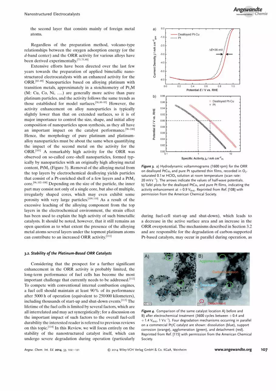
Hence, the morphology of pure platinum and platinum-alloy nanoparticles must be about the same when quantifyingthe impact of the second metal on the activity for theORR.[101] A remarkably high activity for the ORR wasobserved on so-called core–shell nanoparticles, formed typ-ically by nanoparticles with an originally high alloying metalcontent, PtM3 (Figure 3). Removal of the alloying metal fromthe top layers by electrochemical dealloying yields particlesthat consist of a Pt-enriched shell of a few layers and a PtM3
core.[96, 102–108] Depending on the size of the particle, the innerpart may consist not only of a single core, but also of multiple,irregularly shaped cores, which may even exhibit someporosity with very large particles.[109, 110] As a result of theexcessive leaching of the alloying component from the toplayers in the electrochemical environment, the strain effecthas been used to explain the high activity of such bimetalliccatalysts. It should be noted, however, that it still remains anopen question as to what extent the presence of the alloyingmetal atoms several layers under the topmost platinum atomscan contribute to an increased ORR activity.[111]
3.2. Stability of the Platinum-Based ORR Catalysts
Considering that the prospect for a further significantenhancement in the ORR activity is probably limited, thelong-term performance of fuel cells has become the mostimportant challenge that currently needs to be addressed.[112]
To compete with conventional internal combustion engines,a fuel cell should maintain at least 90 % of its performanceafter 5000 h of operation (equivalent to 250000 kilometers),including thousands of start-up and shut-down events.[113] Thelifetime of the fuel cells is limited by several factors, which areall interrelated and may act synergistically; for a discussion onthe important impact of such factors to the overall fuel-celldurability the interested reader is referred to previous reviewson this topic.[114] In this Review, we will focus entirely on thestability of the nanostructured catalyst itself, which canundergo severe degradation during operation (particularly
during fuel-cell start-up and shut-down), which leads toa decrease in the active surface area and an increase in theORR overpotential. The mechanisms described in Section 3.2and are responsible for the degradation of carbon-supportedPt-based catalysts, may occur in parallel during operation, as
Figure 3. a) Hydrodynamic voltammograms (1600 rpm) for the ORRon dealloyed PtCu3 and pure Pt sputtered thin films, recorded in O2-saturated 0.1m HClO4 solution at room temperature (scan rate:20 mVs�1). The arrows indicate the values of half-wave potentials.b) Tafel plots for the dealloyed PtCu3 and pure Pt films, indicating theactivity enhancement at + 0.9 VRHE. Reprinted from Ref. [108] withpermission from the American Chemical Society.
Figure 4. Comparison of the same catalyst location A) before andB) after electrochemical treatment (3600 cycles between + 0.4 and+ 1.4 VRHE, 1 Vs�1). Four degradation mechanisms occurring in parallelon a commercial Pt/C catalyst are shown: dissolution (blue), supportcorrosion (orange), agglomeration (green), and detachment (red).Reprinted from Ref. [115] with permission from the American ChemicalSociety.
Nanostructured ElectrocatalystsAngewandte
Chemie
107Angew. Chem. Int. Ed. 2014, 53, 102 – 121 � 2014 Wiley-VCH Verlag GmbH & Co. KGaA, Weinheim www.angewandte.org

can be visualized (Figure 4) using identical location trans-mission electron microscopy (IL-TEM).[115] This overlap ofmechanisms highlights the inherent difficulty in understand-ing and preventing the loss of active surface area that isobserved macroscopically.[116]
3.2.1. Platinum Dissolution
The dissolution of platinum is a fundamental process thatcan occur on any (nanoparticulate or extended) platinumsurface. Smaller particles are more susceptible to dissolutiondue to their higher surface energy (Gibbs–Thomsoneffect).[117,118] Individual platinum particles that dissolvebecome reduced in size, which has been visualized directly(Figure 4).[115, 119] Within a fuel cell, platinum dissolution fromnanoparticle catalysts may result in: 1) removal of platinumwith the water outlet stream,[120] 2) redeposition of platinumon larger particles, that is, Ostwald ripening,[121,122] and3) reduction of dissolved platinum with permeated hydrogenand redeposition within the membrane.[123, 124] It is well-established that Pt dissolution is more pronounced duringpotential cycling than under steady-state conditions,[21,125–127]
although there has been no consensus on whether platinumdissolves during the positive- or the negative-goingsweep.[125,127–132] Recently, it was possible to unambiguouslydistinguish between an anodic and a cathodic dissolutionprocess, with the latter being more prominent by far,particularly through the increase in the upper potentiallimit.[21] This confirms previous assumptions that platinumdissolution is associated with changes in the Pt state (e.g. fromthe oxidized to the reduced Pt state or the opposite).[132–134]
Even though the exact mechanism of the dissolution ofplatinum still remains unclear, a certain interrelation betweenPt dissolution and Pt-O site exchange at high potentials andleading to weakly bound platinum species is likely the cause,as such species are more susceptible to dissolution.[132,135–137]
Further investigations need to be directed to an overallunderstanding of the dissolution of other noble metals[22,138]
and their alloys,[139] as well as of applied catalysts, which willinspire extensions of theoretical models and enable theprediction and prevention of the dissolution of nanoparticlecatalysts in applied systems under various operating con-ditions.[133, 134,140–142]
3.2.2. Ostwald Ripening
Following the dissolution of platinum from small particles,the redeposition of dissolved platinum species on largerparticles may occur as a consequence of the reduction of thesurface energy. During Ostwald ripening, small particlesshrink, while large particles become even larger; therefore, anoverall increase in the average particle size is expected. Onecan distinguish between two types of Ostwald ripening: 1) a3D process, when dissolved species are transported throughthe electrolyte prior to reduction and deposition,[122] and 2) a2D process when dissolved platinum is transported on to thecarbon support prior to deposition.[121] Direct visualization ofOstwald ripening occurring in thick catalytic films underharsh potential cycling conditions was recently achieved.[143]
3.2.3. Corrosion of the Support
The oxidation of carbon to CO2, which is thermodynami-cally possible above + 0.207 VRHE,[144] is kinetically limitedbelow + 1.2 VRHE depending on the temperature.[145] On thebasis of early gas phase oxidation studies,[146] it has beenproposed that the corrosion of high-surface-area carbon isinitiated by the corrosion of disordered carbon sites in thecore of the carbon particles.[147, 148] Such degradation, whichoccurs at elevated temperatures and leads to a hollow-like ora shrinked structure, was recently visualized in electrochem-ical studies.[149] At room temperature, severe carbon corrosionleading to a shrinkage of the support structure and even toa complete removal of a whole fraction of the aggregate hasbeen observed under harsh potential conditions (see alsoFigure 4).[115, 150]
Carbon corrosion has important consequences, as it canaccelerate secondary degradation mechanisms such asagglomeration and particle detachment,[115] while the associ-ated loss of porosity can severely limit the mass transport ofreactants and thus deteriorate the performance in theelectrochemical reactor.[151]
A variety of other carbon supports has been developed toovercome these issues,[152] such as multiwalled carbon nano-tubes,[153, 154] graphene,[155] ordered mesoporous or nanoporouscarbons,[156, 157] hollow graphitic spheres,[158] activated carbonnanofibers,[159] and carbon aerogels.[160] In some cases, thedurability of the catalyst was superior to conventional nano-structures; however, a deep understanding of the impact ofthe support morphology on retarding individual degradationmechanisms is still lacking. An alternative strategy to addressthe stability issues of carbon-based materials is to usetransition-metal oxides as supports. Typically, so-called Mag-n�li phases (TinO2n-1, on average Ti4O7), but also WO3, NbO2,TaO2, and TiO2 have been employed because of theirremarkable stability under fuel-cell conditions, low cost,commercial availability, ease of control of the size andstructure, and good dispersion of the catalyst.[161–163] However,such oxides typically have low electronic conductivity, whichhas to be increased by producing oxygen vacancies orintroducing an appropriate dopant. In addition, the use ofunsupported platinum nanostructures has also been inves-tigated as a way to avoid the contribution of support corrosionin the overall degradation.[62–64,70] A different, prominentapproach was pioneered by 3M, with the so-called nano-structured thin-film (NSTF) catalysts, which consist ofplatinum sputtered onto oriented arrays of crystallineorganic-pigment whiskers.[164, 165] These catalysts are not onlymore active than carbon-supported catalysts, almost matchingthe specific activity of extended surfaces, but they are alsosignificantly more resistant to primary degradation mecha-nisms.
3.2.4. Agglomeration
The agglomeration of platinum particles leads to particlegrowth and thus to decreased utilization of platinum withrespect to its mass. Agglomeration occurs when smallerparticles come in contact and form a larger particle (Figure 4),
.AngewandteReviews
I. Katsounaros, K. J. J. Mayrhofer et al.
108 www.angewandte.org � 2014 Wiley-VCH Verlag GmbH & Co. KGaA, Weinheim Angew. Chem. Int. Ed. 2014, 53, 102 – 121

in a reshaping process that is driven by the reduction of thesurface energy.[149] Particles may originally be in contact aftersynthesis; in that case they may immediately coalesce,depending on the potential. Otherwise, contact has to beestablished in the following ways prior to coales-cence:[115, 116,166] 1) adjacent particles may approach eachother as a result of the shrinkage of the support followingcarbon corrosion (see Section 3.2.3) 2) particles may migrateover the support and come into contact with other adjacentparticles, which may also show some mobility. The probabilityof agglomeration is inversely dependent on the interparticledistance;[167] thus, the probability increases at areas with highparticle density,[115, 168] or in cases of higher platinum con-tent.[169]
3.2.5. Particle Detachment
The complete loss of platinum particles that detach fromthe support, thereby leading to a decrease in the total numberof particles without introducing a change in the particle size, isan additional mechanism that has been visualized by electronmicroscopy (Figure 4).[115,149, 170–172] Particle detachment orig-inates from a weakening of the particle–support interac-tion,[173] and can thus be initiated by corrosion of thesupport.[149] For this reason, detachment and agglomerationare usually observed in parallel, as both can occur aftercarbon corrosion.[115, 149, 168, 172]
3.2.6. Leaching of Alloying Metal Atoms
The less-noble metal atoms typically suffer from selectivedissolution during operation of the fuel cell, even in alreadypreleached alloys, which leads to a gradual loss of theenhancing effect of the alloying metal on the ORR activity(Figure 5).[166, 174,175] Depending on the initial composition andsize, the remaining particles can form porous structures or
thicker Pt-enriched shells. Moreover, the dissolved less-noblemetal can cause additional issues for the overall performanceof the fuel cell. The exchange of protonic sites in the ionomerwith metal cations can lead to[50,120, 176] 1) higher resistance ofthe membrane and the catalyst-layer ionomer, 2) loweroxygen diffusion in the ionomer, and 3) degradation of themembrane through the formation of peroxo radicals. Inaddition, the dissolved metal ions may migrate across themembrane and deposit on the anode of the fuel cell.[110]
In an acidic environment, the dissolution of the non-noblemetal surface atoms (such as Cu, Co, etc) is thermodynami-cally favorable at potentials to which the ORR catalysts areexposed, but alloy material in the core underneath a Pt shell isalso susceptible to dissolution. Three mechanisms, which mayoccur in parallel, can be considered as possible explanationsof these observations:1) the diffusion of platinum surface atoms may not allow the
formation of a uniform protective layer of Pt, thus leavingsome alloying metal atoms exposed to the electrolyte,[177]
2) the alloying metal atoms can segregate to the sur-face,[178, 179] and
3) dissolution of the alloying metal atoms can follow thedissolution of platinum atoms in the protective shell.[21]
In any case, the dissolution of the less-noble metal maycontinue, possibly until only platinum atoms remain in thenanostructure. Of the various platinum alloys that have beeninvestigated, extended Pt3Y and Pt5Gd surfaces seem to bethe most stable.[180–182] However, the preparation of thecorresponding nanoparticles is not straightforward becausethe standard potentials for the Y3+/Y and the Gd3+/Gd redoxcouples are very negative.
3.3. Abundance of the Materials Used in ORR Catalysts
If all the platinum produced annually (ca. 200 t yr�1)[184]
was used for hydrogen/air fuel cells at state-of-the-artloadings, it would only suffice for approximately 4–5 millioncars per year. As a consequence of the limited availability ofplatinum and the related high cost, massive efforts have beendirected toward the synthesis of ORR catalysts based on moreabundant (and cheaper) non-noble materials.[185] The mainchallenge in this case is to design catalysts that will at leastapproach the activity of platinum, but at the same time will bestable for long-term operation under acidic conditions. Inalkaline media, non-noble materials typically exhibit a loweroverpotential for the ORR and better stability compared toacidic electrolytes.[186] A highly inspiring letter to Nature[187] in1964 motivated extensive research toward the synthesis ofpyrolyzed transition-metal-containing macrocyclic com-pounds, such as metal phthalocyanines and metal porphyr-ins.[188–191] More than two decades later it was shown that thecomplex macrocycles can be replaced by other nitrogen-containing polymers capable of binding transition metals,[192]
thereby highlighting the essential role of the transition-metalion coordinated by nitrogen atoms (MeNxCy) in the observedcatalytic activity. Some authors have proposed that the metalion does not remain in the active site after the heat treatment,
Figure 5. Specific and mass activities of the Pt3Cu/C core–shell, Pt3Cu/C skeleton, andPt/C catalyst at the beginning (BoL) and end of life (EoL), namelybefore and after 10 000 degradation cycles in 0.5m H2SO4 in thepotential window indicated in the legend. The activities were measuredat 0.9 VRHE in the same electrolyte. The Figure was constructed fromthe data published in Table 1 of Ref. [183].
Nanostructured ElectrocatalystsAngewandte
Chemie
109Angew. Chem. Int. Ed. 2014, 53, 102 – 121 � 2014 Wiley-VCH Verlag GmbH & Co. KGaA, Weinheim www.angewandte.org

but only catalyzes the formation of the active sites consistingof only nitrogen and carbon during the heat treatment, thusleading to the so-called “metal-free catalysts” after chemicalleaching.[193–196] However, there is as yet no undisputedevidence that the chemical leaching can entirely remove themetal from the heat-treated catalyst. Instead, it has beenshown that the ORR on Fe/N/C is inhibited by the presence ofiron-complexing cyanide, thus indicating the existence ofa metal-based active site for the ORR.[197]
Following the notion that a high density of active MeN4
sites per unit volume is required to create active non-noblemetal catalysts, intensive efforts have been made over the lastfew years to develop novel synthesis routes.[198–207] In addition,a lot of work has been carried out to resolve the mechanism ofthe ORR on non-noble metal catalysts, as well as the nature ofthe active sites.[197, 208–212] These studies have led to significantimprovements and breakthroughs in the activity of non-noblecatalysts for the ORR, which can almost approach theactivities obtained on platinum;[200, 201] excellent reviewshave recently been published.[213,214] In one of the prominentexamples, remarkably high activities (Figure 6) were obtained
by synthesizing catalysts consisting of nitrogen-coordinatediron incorporated into microporous carbon.[200] The authorsattributed the observed high catalytic activity to the forma-tion of a high density of Fe-N4 sites within the micropores ofthe carbon support. To approach the performance of com-mercial Pt/C catalysts (0.4 mgPt cm�2) in the fuel cell, loadingsin the order of a few mg cm�2 were required, which results ina high catalyst layer thickness. This has the consequence thatsevere mass-transport limitations on the cathode can occur ina H2/O2 and—even more so—in a H2/air fuel cell, therebyleading to drops in performance at high current densities(Figure 6). Despite the major advances in regard to activity,the largest challenge, namely the stability of non-noble
materials at operating temperatures, will have to be addressedmore intensively in the future to render such a material classviable for applications. The stability issues that the non-noblematerials experience are related to the oxidation of tran-sition-metal-based active sites by the intermediate H2O2,oxidation of the carbon support, and exposure of the cathodeto high potentials. An excellent description of these issues fornon-noble materials is provided in a recent review.[213]
4. Catalysis of the Electrochemical OxygenEvolution Reaction (OER)
4.1. Activity for the OER4.1.1. Activity Trends for the OER
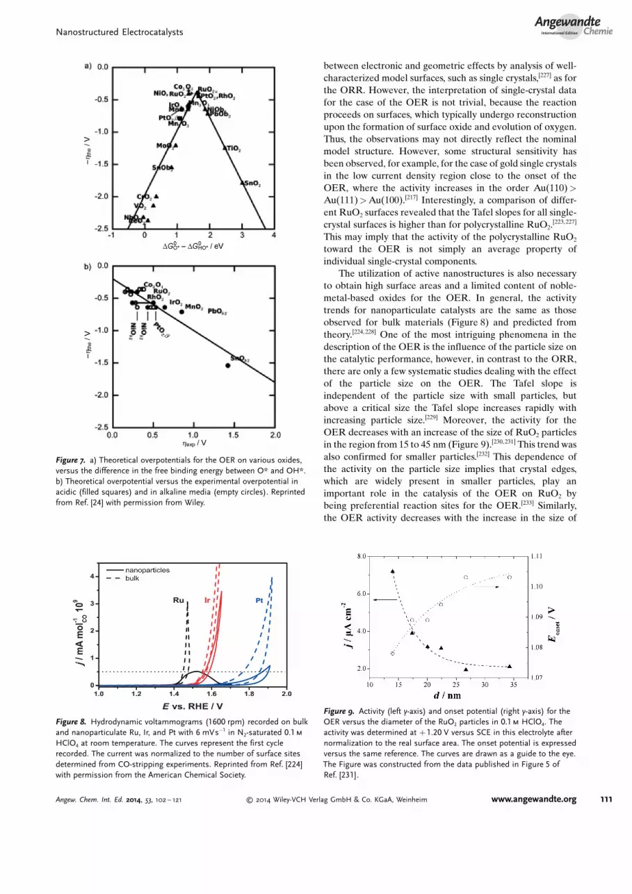
In contrast to the ORR, the oxygen evolution reactionalways proceeds on oxidized surfaces,[215–217] and is limitedeither by the strong adsorption of OOHads or the weakadsorption of Oads.[218] Based on the existing scaling relationsthat were described in Section 2.3, the difference in the freebinding energy between O* and OH* was introduced asa universal catalytic descriptor for the OER to constructvolcano-type plots (Figure 7a).[24] According to the Sabatierprinciple, an optimal, moderate binding energy of the OERintermediates assures the highest catalytic activity.[219] Theobtained theoretical activity trends are, in general, consistentwith old experimental investigations, which showed that theactivity toward the OER on rutile-, spinel-, or perovskite-typeoxides follows a volcano-type dependence on the enthalpychange of the transition from a lower to higher oxide or othersimilar activity descriptors.[24, 220–222] Thus, a good correlationbetween the theoretical and the experimental overpotentialtoward the OER was observed (Figure 7b).[24] Experimen-tally, rutile-type RuO2 was found to exhibit the highestactivity for the OER (Figure 8).[220, 223, 224] Compared toa theoretical optimum catalyst, the oxygen adsorption onRuO2 is slightly too weak.[218]
Despite the general aggreement between theory andexperiment, some discrepancies still exist; for example,according to DFT calculations Co3O4 should exhibit a slightlylower overpotential than even RuO2 (Figure 7a).[24] Suchdiscrepancies between theory and experiment may derivefrom the simplification made when using a single activitydescriptor, and/or from the fact that the model surfaces thatare used for computational predictions do not completelycapture all the characteristics of polycrystalline surfaces, suchas of surface defects and of changes in the surface stateoccurring during the reaction.
Since alkaline electrolyzers operate at current densitiesthat are about 2–3 times lower than that of acidic electro-lyzers,[225,226] we will focus in the next subsections, as for theORR, mainly on nanostructured electrocatalysts for the OERin an acidic environment.
4.1.2. Structural Sensitivity of the OER
To understand the relationship between structure andactivity toward the OER, it would be desirable to distinguish
Figure 6. Voltage–current curves in a H2/O2 fuel cell using membraneelectrode assemblies (MEAs) with a cathode made of two loadings ofthe best nonprecious-metal Fe/N/C catalyst (NPMC) synthesized byLef�vre et al. Also shown is the comparison with a commercial GorePRIMEA 5510 MEA (W. L. Gore & Associates) with 0.4 mgPt cm�2
loading at the cathode. Reprinted from Ref. [200] with permission fromAAAS.
.AngewandteReviews
I. Katsounaros, K. J. J. Mayrhofer et al.
110 www.angewandte.org � 2014 Wiley-VCH Verlag GmbH & Co. KGaA, Weinheim Angew. Chem. Int. Ed. 2014, 53, 102 – 121
between electronic and geometric effects by analysis of well-characterized model surfaces, such as single crystals,[227] as forthe ORR. However, the interpretation of single-crystal datafor the case of the OER is not trivial, because the reactionproceeds on surfaces, which typically undergo reconstructionupon the formation of surface oxide and evolution of oxygen.Thus, the observations may not directly reflect the nominalmodel structure. However, some structural sensitivity hasbeen observed, for example, for the case of gold single crystalsin the low current density region close to the onset of theOER, where the activity increases in the order Au(110)>Au(111)>Au(100).[217] Interestingly, a comparison of differ-ent RuO2 surfaces revealed that the Tafel slopes for all single-crystal surfaces is higher than for polycrystalline RuO2.
[223,227]
This may imply that the activity of the polycrystalline RuO2
toward the OER is not simply an average property ofindividual single-crystal components.
The utilization of active nanostructures is also necessaryto obtain high surface areas and a limited content of noble-metal-based oxides for the OER. In general, the activitytrends for nanoparticulate catalysts are the same as thoseobserved for bulk materials (Figure 8) and predicted fromtheory.[224, 228] One of the most intriguing phenomena in thedescription of the OER is the influence of the particle size onthe catalytic performance, however, in contrast to the ORR,there are only a few systematic studies dealing with the effectof the particle size on the OER. The Tafel slope isindependent of the particle size with small particles, butabove a critical size the Tafel slope increases rapidly withincreasing particle size.[229] Moreover, the activity for theOER decreases with an increase of the size of RuO2 particlesin the region from 15 to 45 nm (Figure 9).[230, 231] This trend wasalso confirmed for smaller particles.[232] This dependence ofthe activity on the particle size implies that crystal edges,which are widely present in smaller particles, play animportant role in the catalysis of the OER on RuO2 bybeing preferential reaction sites for the OER.[233] Similarly,the OER activity decreases with the increase in the size of
Figure 8. Hydrodynamic voltammograms (1600 rpm) recorded on bulkand nanoparticulate Ru, Ir, and Pt with 6 mVs�1 in N2-saturated 0.1m
HClO4 at room temperature. The curves represent the first cyclerecorded. The current was normalized to the number of surface sitesdetermined from CO-stripping experiments. Reprinted from Ref. [224]with permission from the American Chemical Society.
Figure 9. Activity (left y-axis) and onset potential (right y-axis) for theOER versus the diameter of the RuO2 particles in 0.1m HClO4. Theactivity was determined at + 1.20 V versus SCE in this electrolyte afternormalization to the real surface area. The onset potential is expressedversus the same reference. The curves are drawn as a guide to the eye.The Figure was constructed from the data published in Figure 5 ofRef. [231].
Figure 7. a) Theoretical overpotentials for the OER on various oxides,versus the difference in the free binding energy between O* and OH*.b) Theoretical overpotential versus the experimental overpotential inacidic (filled squares) and in alkaline media (empty circles). Reprintedfrom Ref. [24] with permission from Wiley.
Nanostructured ElectrocatalystsAngewandte
Chemie
111Angew. Chem. Int. Ed. 2014, 53, 102 – 121 � 2014 Wiley-VCH Verlag GmbH & Co. KGaA, Weinheim www.angewandte.org

IrO2 particles.[234] In contrast, Co-doped RuO2 exhibits anopposite behavior,[230] which indicates that the crystal edgesdo not play an important role on the kinetics of the OER inthis case. This may be attributed to a different rate-determin-ing process for the two materials; in particular, it wassuggested that the OER is controlled by charge transfer onRuO2, while on Co-doped RuO2 the rate-determining step isthe recombination of the oxygen at the electrode surface.[230]
The support has an effect on the catalytic activity of nanosizedparticles, which can be attributed to a better utilization of theactive sites and/or to interactions between the catalyst and thesupport.[163,235, 236] In addition, the spatial distribution of theactive sites and prevention of surface segregation is of highimportance for the performance of gas-evolving electro-des.[237–239] Thus, direct monitoring of the local activity for theOER at the solid–liquid interface becomes necessary to studycertain nanostructural effects clearly.[240,241]
4.1.3. Importance of the Void Fraction in NanostructuredCatalysts for the OER
One distinct feature which separates the gas-consumingORR and the gas-evolving OER on high-surface-area cata-lytic layers is that the OER proceeds with an increase inoverpressure across the electrode–electrolyte interface.[242]
This means that reaction sites in the “inner” surface alsobecome active with an increasing overpotential and means thereaction “spreads” into the inner catalytic layers.[243] This isopposite to the ORR, where only the outer surface atoms areactive when the reduction becomes diffusion-limited uponincreasing the overpotential. In this sense, it is of majorimportance for the OER to also consider the void fraction orporosity of the catalytic layers during synthesis. A verypromising approach for catalyst design in heterogeneouscatalysis is the preparation of a system with trimodal poreporosity.[244] Particularly the macro- (pore size > 50 nm) andthe mesoporosity play an essential role, as the microporousfraction (pore size < 2 nm) of the total surface is relativelyinaccessible by reactants during electrochemical reactions.The mass transport of species inside the micropores may beorders of magnitude lower than in the bulk solution.[245, 246]
Another essential part of the hierarchical architecturingof catalytic layers for the OER is structuring for the efficientdetachment of gas bubbles. Namely, the availability of activesites and thus the efficiency of gas evolution strongly dependon the surface morphology. When the rate of the OERbecomes sufficiently high, the concentration of oxygen at thesolid–liquid interface may overcome the saturation concen-tration expected from Henry�s law, so that not all the O2
molecules produced can be completely solvated.[247, 248] Gasbubbles start to form and behave like a “sink” for furtherdissolved gas.[249] The gas phase at the solid–liquid interface,however, can block parts of the electroactive surface area,which causes an inhibition of the macrokinetics of theelectrode (increase in overpotential).[250] A minimization ofthe gas-bubble detachment radius can significantly increasethe frequency of gas-bubble detachment. A key strategy inperformance optimization is, thus, the introduction of pores,cracks, and/or channels into the electrode structure, where
nucleated gas bubbles are limited in growth.[251] Efficientcatalyst morphologies can promote the detachment of smallbubbles with a high frequency, which was confirmed exper-imentally using SECM.[252] The acceleration of gas evolutionwas already also shown to be a very promising strategy fordecreasing the overpotential for similar reactions, such aschlorine evolution.[251, 253, 254]
4.1.4. Mixed Transition-Metal Oxides
Analogous to alloying Pt with transition metals in the caseof the ORR, various mixed metal oxides are commonlyemployed instead of pure RuO2 or IrO2 as catalysts for theOER.[255] The aim is to 1) tune the intrinsic OER activity,[241]
2) stabilize the catalytic component,[256] and 3) reduce thenoble-metal content.[257] Increased activities compared toRuO2 can, for example, be achieved with a TiO2/RuO2 mixedoxide.[241] This enhancement was attributed to the promotedcharge transfer from RuOx towards TiO2, which fits into thegeneral expectation that charge transfer on surfaces thatcontain mixtures of two transition metals will occur to theelement with the larger fraction of empty states in its valenceband.[258] Another very promising coating with remarkableactivity and stability is Ta2O5/IrO2,
[259] where the catalyticallyactive component IrO2 in a tetragonal rutile-type structure isincorporated into a Ta2O5 matrix. In such structures, theamount of active and expensive Ir can be reduced by theaddition of Pd, Nb, etc, while still maintaining the originalactivity.[260–262] Moreover, an increase in the activity can beachieved by mixing Ir with Ru.[256,263] The properties of allthese oxide layers depend strongly on the preparationmethod.[264] An usual approach to obtain mixed metal oxidecatalysts for the OER is based on the thermal decompositionof mixtures of solutions of precursor salts.[265] Anothercommon synthesis route is the sol–gel procedure.[266] Regard-less of which preparation method is followed in the synthesis,the precursor employed has a pronounced influence on thephysicochemical properties and the performance of thecatalytic layer.[267] During the synthesis of mixed-metaloxides, the effective conversion of the precursor salt, thecrystallization, and the formation of the active rutile phasedepend strongly on the thermal treatment. The proper choiceof synthesis temperature is additionally important to avoiddecomposition of the metastable solid solution into individualoxides on the surface, and to prevent the formation of aninsulating layer between the support and the catalyticlayer.[253] Certainly, to form mixed oxides in the form ofa solid solution, it is important that the parameters of thecrystal lattice match according to Hume–Rothery rules.[268]
Furthermore, if the loading of the noble component needs tobe reduced, limitations arising from percolation phenomenamay be introduced. The possibility of obtaining randomlydistributed isolated clusters increases particularly for very lowloading. In that case, the clusters, even though they arecatalytically active, can be electrically disconnected from thesupport and, thus, not contribute to the reaction.[269]
.AngewandteReviews
I. Katsounaros, K. J. J. Mayrhofer et al.
112 www.angewandte.org � 2014 Wiley-VCH Verlag GmbH & Co. KGaA, Weinheim Angew. Chem. Int. Ed. 2014, 53, 102 – 121
4.2. Stability of the OER Catalysts
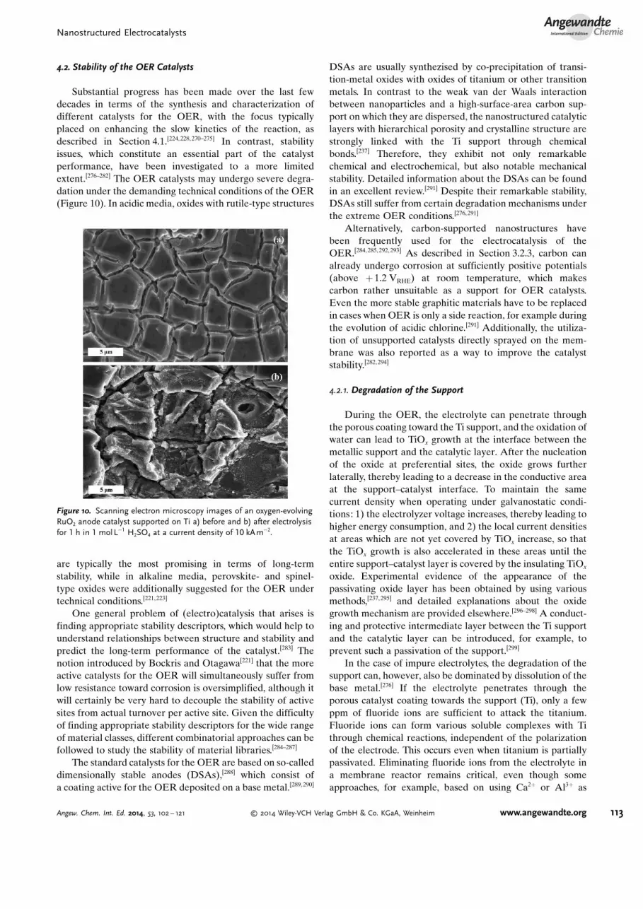
Substantial progress has been made over the last fewdecades in terms of the synthesis and characterization ofdifferent catalysts for the OER, with the focus typicallyplaced on enhancing the slow kinetics of the reaction, asdescribed in Section 4.1.[224,228, 270–275] In contrast, stabilityissues, which constitute an essential part of the catalystperformance, have been investigated to a more limitedextent.[276–282] The OER catalysts may undergo severe degra-dation under the demanding technical conditions of the OER(Figure 10). In acidic media, oxides with rutile-type structures
are typically the most promising in terms of long-termstability, while in alkaline media, perovskite- and spinel-type oxides were additionally suggested for the OER undertechnical conditions.[221,223]
One general problem of (electro)catalysis that arises isfinding appropriate stability descriptors, which would help tounderstand relationships between structure and stability andpredict the long-term performance of the catalyst.[283] Thenotion introduced by Bockris and Otagawa[221] that the moreactive catalysts for the OER will simultaneously suffer fromlow resistance toward corrosion is oversimplified, although itwill certainly be very hard to decouple the stability of activesites from actual turnover per active site. Given the difficultyof finding appropriate stability descriptors for the wide rangeof material classes, different combinatorial approaches can befollowed to study the stability of material libraries.[284–287]
The standard catalysts for the OER are based on so-calleddimensionally stable anodes (DSAs),[288] which consist ofa coating active for the OER deposited on a base metal.[289, 290]
DSAs are usually synthezised by co-precipitation of transi-tion-metal oxides with oxides of titanium or other transitionmetals. In contrast to the weak van der Waals interactionbetween nanoparticles and a high-surface-area carbon sup-port on which they are dispersed, the nanostructured catalyticlayers with hierarchical porosity and crystalline structure arestrongly linked with the Ti support through chemicalbonds.[237] Therefore, they exhibit not only remarkablechemical and electrochemical, but also notable mechanicalstability. Detailed information about the DSAs can be foundin an excellent review.[291] Despite their remarkable stability,DSAs still suffer from certain degradation mechanisms underthe extreme OER conditions.[276, 291]
Alternatively, carbon-supported nanostructures havebeen frequently used for the electrocatalysis of theOER.[284, 285, 292, 293] As described in Section 3.2.3, carbon canalready undergo corrosion at sufficiently positive potentials(above + 1.2 VRHE) at room temperature, which makescarbon rather unsuitable as a support for OER catalysts.Even the more stable graphitic materials have to be replacedin cases when OER is only a side reaction, for example duringthe evolution of acidic chlorine.[291] Additionally, the utiliza-tion of unsupported catalysts directly sprayed on the mem-brane was also reported as a way to improve the catalyststability.[282, 294]
4.2.1. Degradation of the Support
During the OER, the electrolyte can penetrate throughthe porous coating toward the Ti support, and the oxidation ofwater can lead to TiOx growth at the interface between themetallic support and the catalytic layer. After the nucleationof the oxide at preferential sites, the oxide grows furtherlaterally, thereby leading to a decrease in the conductive areaat the support–catalyst interface. To maintain the samecurrent density when operating under galvanostatic condi-tions: 1) the electrolyzer voltage increases, thereby leading tohigher energy consumption, and 2) the local current densitiesat areas which are not yet covered by TiOx increase, so thatthe TiOx growth is also accelerated in these areas until theentire support–catalyst layer is covered by the insulating TiOx
oxide. Experimental evidence of the appearance of thepassivating oxide layer has been obtained by using variousmethods,[237, 295] and detailed explanations about the oxidegrowth mechanism are provided elsewhere.[296–298] A conduct-ing and protective intermediate layer between the Ti supportand the catalytic layer can be introduced, for example, toprevent such a passivation of the support.[299]
In the case of impure electrolytes, the degradation of thesupport can, however, also be dominated by dissolution of thebase metal.[276] If the electrolyte penetrates through theporous catalyst coating towards the support (Ti), only a fewppm of fluoride ions are sufficient to attack the titanium.Fluoride ions can form various soluble complexes with Tithrough chemical reactions, independent of the polarizationof the electrode. This occurs even when titanium is partiallypassivated. Eliminating fluoride ions from the electrolyte ina membrane reactor remains critical, even though someapproaches, for example, based on using Ca2+ or Al3+ as
Figure 10. Scanning electron microscopy images of an oxygen-evolvingRuO2 anode catalyst supported on Ti a) before and b) after electrolysisfor 1 h in 1 molL�1 H2SO4 at a current density of 10 kA m�2.
Nanostructured ElectrocatalystsAngewandte
Chemie
113Angew. Chem. Int. Ed. 2014, 53, 102 – 121 � 2014 Wiley-VCH Verlag GmbH & Co. KGaA, Weinheim www.angewandte.org
complexing agents, have been proposed.[276] Besides Ti, thedegradation of other base metals, such as Ta and Sn, is also ofinterest; Ta is much more stable towards corrosion, althoughit is very sensitive to oxidation at elevated temperatures.[300]
4.2.2. Dissolution of the Catalyst Layer
Efficient electron transfer during the OER on variousoxides is related to redox transitions with standard potentialsin the range of those of the reaction.[301, 302] For example, theonset for the OER on RuO2 coincides with the transition ofthe oxide from a lower (e.g. RuO2) to a higher (RuO4)oxidation state (Eo =+ 1.387 VNHE for Ru2+/Ru4+). Followingthis transition, the oxide in the higher oxidation state, which isan actual intermediate of the OER, will be reduced again tothe initial state by accepting electrons from the oxygen-containing species of deprotonated water (O*, OH*, …).Although the activity of RuO2 depends on the potential of theRuO4 formation, the stability depends on the solubility ofRuO4.
[276, 303,304] Similarly, dissolution has been observedduring the OER on IrO2, where soluble IrO4+ species areformed at potentials above + 2.0 VSHE.[270] This potential is,however, significantly higher than that reached at practicalcurrent densities, so that the dissolved amounts are rather low.The dissolution of Ir was suggested to occur at potentials aslow as + 1.6 VRHE, although significant dissolution typicallyrequires higher potentials.[305, 306] The difference in the dis-solution rates between IrO2 and RuO2 is also reflected inFigure 8, where Ru in the nanoparticulate form loses itsactivity and probably implies a complete dissolution of the Runanoparticles even after a single sweep.[224] Despite simplyconsidering thermodynamics, the approach described aboveindicates that particular redox transitions can indeed providehints for the interplay between activity and stability. Never-theless, as the kinetics and the mechanism of noble metaloxide dissolution are in general not well understood, moreexperimental efforts will be necessary in the future.
4.2.3. Gas Phase—Induced Degradation
The formation of gas bubbles during the OER introducesdifferent sources for performance loss:1) The partial blockage of the electrode through bubble
formation leads to a local increase in the actual currentdensities in areas which are still accessible, and these localcurrent densities may be significantly higher than nominalones.[250] These inhomogeneous conditions can have enor-mous effects on the stability of the electrode which wouldnot occur under uniform operation.[307] Therefore, the typeof porosity is important for the overall performance in thelong run, as it influences the accessibility of regions of thenanostructured surface, as described in section 4.1.3.
2) In extreme cases, mechanical rupture of the catalystcoating may occur as a result of the high pressure of gasgenerated inside the pores of the catalytic material.[276]
4.3. Abundance of the Materials Used in OER Catalysts
Despite the low OER overpotential and decent stability ofRuO2 or IrO2 under operation conditions, their use aselectrocatalyst materials on a large scale is barely feasibledue to their limited abundance in the Earth’s crust and theirrelated high cost.[184] The limited availability of these materi-als is a driver for the development of OER catalysts based onmore-abundant, nonprecious elements. However, the stabilityof non-noble materials under the OER conditions is partic-ularly critical in acidic media,[221] while their performance inneutral or alkaline solutions seems to be more promising.Moreover, materials based on less scarce (PbO2) or abundant(Fe3O4) elements show large overpotentials for the OER.[220]
The same is true for TiO2, ZrO2, SnO2, Ta2O5, and CeO2,which can nevertheless be used as the matrix for thecatalytically active component. In contrast, MnO2 and theless-abundant Co3O4 seem to have a significant potential toapproach the activity of RuO2 or IrO2.
[308]
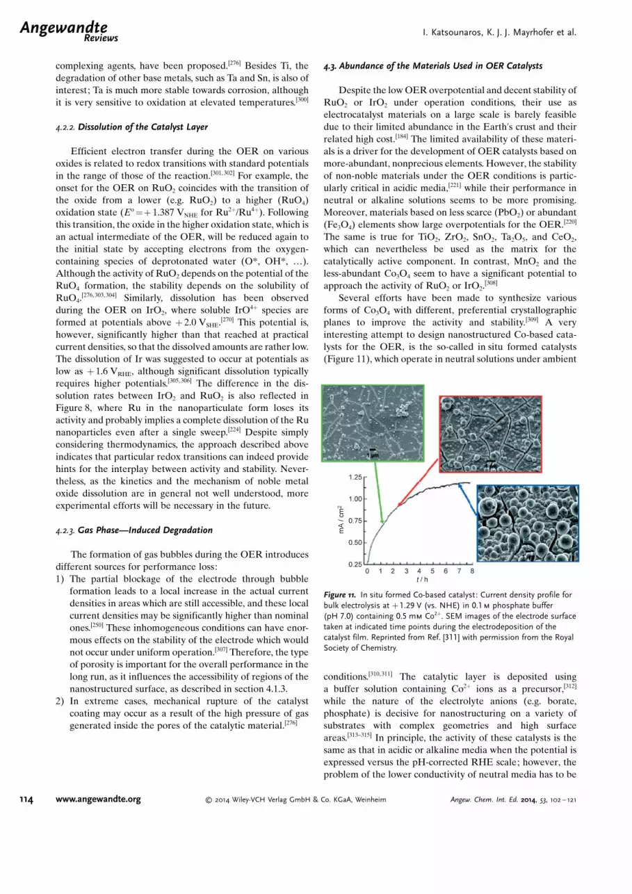
Several efforts have been made to synthesize variousforms of Co3O4 with different, preferential crystallographicplanes to improve the activity and stability.[309] A veryinteresting attempt to design nanostructured Co-based cata-lysts for the OER, is the so-called in situ formed catalysts(Figure 11), which operate in neutral solutions under ambient
conditions.[310, 311] The catalytic layer is deposited usinga buffer solution containing Co2+ ions as a precursor,[312]
while the nature of the electrolyte anions (e.g. borate,phosphate) is decisive for nanostructuring on a variety ofsubstrates with complex geometries and high surfaceareas.[313–315] In principle, the activity of these catalysts is thesame as that in acidic or alkaline media when the potential isexpressed versus the pH-corrected RHE scale; however, theproblem of the lower conductivity of neutral media has to be
Figure 11. In situ formed Co-based catalyst: Current density profile forbulk electrolysis at + 1.29 V (vs. NHE) in 0.1m phosphate buffer(pH 7.0) containing 0.5 mm Co2+. SEM images of the electrode surfacetaken at indicated time points during the electrodeposition of thecatalyst film. Reprinted from Ref. [311] with permission from the RoyalSociety of Chemistry.
.AngewandteReviews
I. Katsounaros, K. J. J. Mayrhofer et al.
114 www.angewandte.org � 2014 Wiley-VCH Verlag GmbH & Co. KGaA, Weinheim Angew. Chem. Int. Ed. 2014, 53, 102 – 121
addressed by using solutions of sufficiently high ionicstrength. Nevertheless, the appealing “self-healing” phenom-ena of the in situ formed catalysts, where the electrolyteanions (e.g. phosphate) play a crucial role in recovering theCo-based (also extended to Ni-based) catalyst,[316, 317] couldmitigate the rupture of the catalyst surface, which is unavoid-able when the oxide itself participates in the OER, thusassuring long-term operation.
On the other hand, MnOx (formally MnO2) is alsopromising considering the rich redox chemistry of Mn andits much better abundance in the Earth’s crust compared toCo.[318] From experimental studies assisted by DFT calcula-tions,[318] it has been suggested that nanostructured a-Mn2O3 isan excellent catalyst for the OER. The catalyst undergoesphase changes at the surface as a function of the appliedpotential. This suggests that a key aspect in understanding thebehavior of Mn oxide catalysts is to understand the surfacereconstruction at the electrochemical interface during theOER. Even though there is increasing interest in developingnon-noble MnOx-based electrodes,[319,320] much systematicwork is still needed.
Last but not least, a tenfold increase in the OER activitycompared to IrO2 was achieved in alkaline media witha perovskite of the type Ba0.5Sr0.5Co0.8Fe0.2O3�d.
[222] The highactivity of this catalyst was predicted by a design approachthat combined a systematic investigation of the OER activityof various transition-metal oxides with molecular orbitalmodeling, and was confirmed by rotating ring-disc electrodeand galvanostatic measurements. Structural changes fromcorner- to edge-sharing octahedra, which occurs during wateroxidation for Ba0.5Sr0.5Co0.8Fe0.2O3�d and some other perov-skites, have been associated with their impressive activitytoward the OER.[321] The performance of such materials in thelong term is expected to be of particular importance.[322,323]
5. Outlook and Future Challenges
The large-scale deployment of electrochemical energyconversion and storage technologies is currently limited bythe severe challenges in the design of efficient catalysts for theOER and ORR, which directly affect the cost of the devices.The main deficiencies are related to:1) the activity of the electrodes, as both oxygen reactions
exhibit significant overpotential even on the most activecatalysts known, thereby resulting in higher energy con-sumption for water splitting and in lower energy recoveryfor the recombination of H2 and O2;
2) the stability of the electrodes, as the OER and ORRcatalysts are exposed to harsh conditions that are detri-mental for the overall long-term performance of theelectrochemical cell;
3) the abundance of the materials used, as the most activecatalysts for the OER and the ORR are based on noblemetals that are, in general, scarce and expensive.
Although specifically designed materials nowadays satisfysome of these requirements, developing nanostructuredmaterials for the ORR and OER that address all three
criteria under real conditions still remains an enormouschallenge.
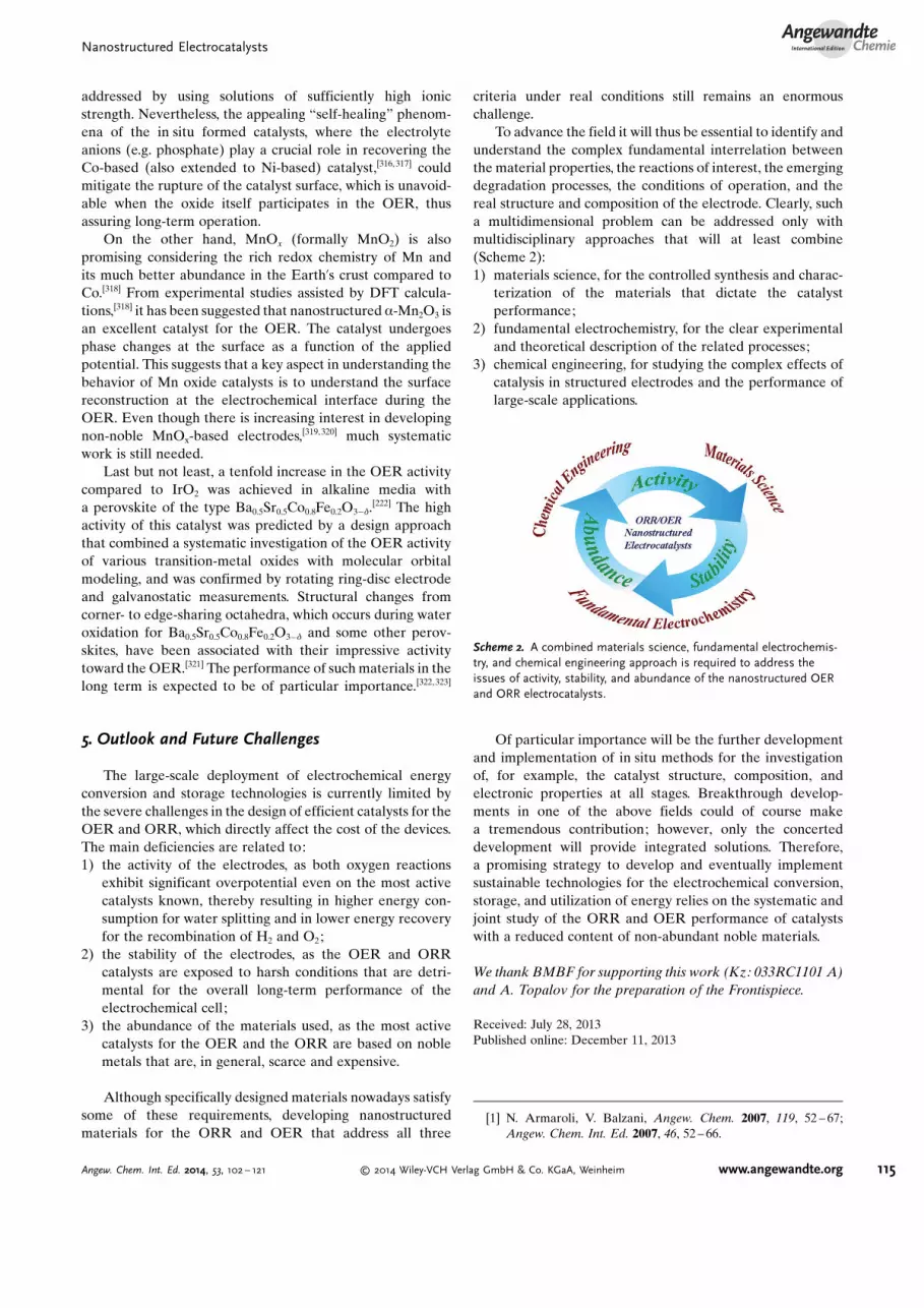
To advance the field it will thus be essential to identify andunderstand the complex fundamental interrelation betweenthe material properties, the reactions of interest, the emergingdegradation processes, the conditions of operation, and thereal structure and composition of the electrode. Clearly, sucha multidimensional problem can be addressed only withmultidisciplinary approaches that will at least combine(Scheme 2):1) materials science, for the controlled synthesis and charac-
terization of the materials that dictate the catalystperformance;
2) fundamental electrochemistry, for the clear experimentaland theoretical description of the related processes;
3) chemical engineering, for studying the complex effects ofcatalysis in structured electrodes and the performance oflarge-scale applications.
Of particular importance will be the further developmentand implementation of in situ methods for the investigationof, for example, the catalyst structure, composition, andelectronic properties at all stages. Breakthrough develop-ments in one of the above fields could of course makea tremendous contribution; however, only the concerteddevelopment will provide integrated solutions. Therefore,a promising strategy to develop and eventually implementsustainable technologies for the electrochemical conversion,storage, and utilization of energy relies on the systematic andjoint study of the ORR and OER performance of catalystswith a reduced content of non-abundant noble materials.
We thank BMBF for supporting this work (Kz: 033RC1101 A)and A. Topalov for the preparation of the Frontispiece.
Received: July 28, 2013Published online: December 11, 2013
[1] N. Armaroli, V. Balzani, Angew. Chem. 2007, 119, 52 – 67;Angew. Chem. Int. Ed. 2007, 46, 52 – 66.
Scheme 2. A combined materials science, fundamental electrochemis-try, and chemical engineering approach is required to address theissues of activity, stability, and abundance of the nanostructured OERand ORR electrocatalysts.
Nanostructured ElectrocatalystsAngewandte
Chemie
115Angew. Chem. Int. Ed. 2014, 53, 102 – 121 � 2014 Wiley-VCH Verlag GmbH & Co. KGaA, Weinheim www.angewandte.org

[2] N. S. Lewis, D. G. Nocera, Proc. Natl. Acad. Sci. USA 2006, 103,15729 – 15735.
[3] M. Z. Jacobson, Energy Environ. Sci. 2009, 2, 148 – 173.[4] D. Gust, T. A. Moore, A. L. Moore, Acc. Chem. Res. 2009, 42,
1890 – 1898.[5] Z. Yang, J. Zhang, M. C. W. Kintner-Meyer, X. Lu, D. Choi, J. P.
Lemmon, J. Liu, Chem. Rev. 2011, 111, 3577 – 3613.[6] P. G. Bruce, B. Scrosati, J.-M. Tarascon, Angew. Chem. 2008,
120, 2972 – 2989; Angew. Chem. Int. Ed. 2008, 47, 2930 – 2946.[7] G. A. Olah, Angew. Chem. 2005, 117, 2692 – 2696; Angew.
Chem. Int. Ed. 2005, 44, 2636 – 2639.[8] Y. Hori in Modern Aspects of Electrochemistry (Ed.: C.
Vayenas), Springer, New York, 2008, pp. 89 – 189.[9] S. Wasmus, A. K�ver, J. Electroanal. Chem. 1999, 461, 14 – 31.
[10] J. O�M. Bockris, Science 1972, 176, 1323 – 1323.[11] N. M. Markovic, P. N. Ross, Surf. Sci. Rep. 2002, 45, 117 – 229.[12] F. Raimondi, G. G. Scherer, R. Kçtz, A. Wokaun, Angew.
Chem. 2005, 117, 2228 – 2248; Angew. Chem. Int. Ed. 2005, 44,2190 – 2209.
[13] J. A. Cracknell, K. A. Vincent, F. A. Armstrong, Chem. Rev.2008, 108, 2439 – 2461.
[14] S. C. Barton, J. Gallaway, P. Atanassov, Chem. Rev. 2004, 104,4867 – 4886.
[15] V. Artero, M. Chavarot-Kerlidou, M. Fontecave, Angew. Chem.2011, 123, 7376 – 7405; Angew. Chem. Int. Ed. 2011, 50, 7238 –7266.
[16] G. N. Lewis, M. Randall, J. Am. Chem. Soc. 1914, 36, 1969 –1993.
[17] I. Katsounaros, W. B. Schneider, J. C. Meier, U. Benedikt, P. U.Biedermann, A. A. Auer, K. J. J. Mayrhofer, Phys. Chem.Chem. Phys. 2012, 14, 7384 – 7391.
[18] I. Katsounaros, W. B. Schneider, J. C. Meier, U. Benedikt, P. U.Biedermann, A. Cuesta, A. A. Auer, K. J. J. Mayrhofer, Phys.Chem. Chem. Phys. 2013, 15, 8058 – 8068.
[19] M. Shao, P. Liu, R. R. Adzic, J. Am. Chem. Soc. 2006, 128,7408 – 7409.
[20] T. Jacob, W. A. Goddard, ChemPhysChem 2006, 7, 992 – 1005.[21] A. A. Topalov, I. Katsounaros, M. Auinger, S. Cherevko, J. C.
Meier, S. O. Klemm, K. J. J. Mayrhofer, Angew. Chem. 2012,124, 12782 – 12785; Angew. Chem. Int. Ed. 2012, 51, 12613 –12615.
[22] S. Cherevko, A. A. Topalov, I. Katsounaros, K. J. J. Mayrhofer,Electrochem. Commun. 2013, 28, 44 – 46.
[23] J. Rossmeisl, A. Logadottir, J. K. Nørskov, Chem. Phys. 2005,319, 178 – 184.
[24] I. C. Man, H.-Y. Su, F. Calle-Vallejo, H. A. Hansen, J. I.Mart�nez, N. G. Inoglu, J. Kitchin, T. F. Jaramillo, J. K. Nørskov,J. Rossmeisl, ChemCatChem 2011, 3, 1159 – 1165.
[25] F. Calle-Vallejo, J. I. Mart�nez, J. M. Garc�a-Lastra, J. Ross-meisl, M. T. M. Koper, Phys. Rev. Lett. 2012, 108, 116103.
[26] E. M. Fern�ndez, P. G. Moses, A. Toftelund, H. A. Hansen, J. I.Mart�nez, F. Abild-Pedersen, J. Kleis, B. Hinnemann, J.Rossmeisl, T. Bligaard, J. K. Nørskov, Angew. Chem. 2008,120, 4761 – 4764; Angew. Chem. Int. Ed. 2008, 47, 4683 – 4686.
[27] B. Hammer, J. K. Nørskov, Nature 1995, 376, 238 – 240.[28] A. Nilsson, L. G. M. Pettersson, J. K. Nørskov, Chemical
Bonding at Surfaces and Interfaces, Elsevier, Amsterdam, 2011.[29] B. Hammer, J. K. Nørskov, Adv. Catal. 2000, 45, 71 – 129.[30] C. Lu, I. C. Lee, R. I. Masel, A. Wieckowski, C. Rice, J. Phys.
Chem. A 2002, 106, 3084 – 3091.[31] B. Huang, L. Zhuang, L. Xiao, J. Lu, Chem. Sci. 2013, 4, 606 –
611.[32] E. Santos, P. Hindelang, P. Quaino, E. N. Schulz, G. Soldano, W.
Schmickler, ChemPhysChem 2011, 12, 2274 – 2279.[33] J. Rossmeisl, G. S. Karlberg, T. Jaramillo, J. K. Nørskov, Fara-
day Discuss. 2009, 140, 337 – 346.
[34] J. K. Nørskov, J. Rossmeisl, A. Logadottir, L. Lindqvist, J. R.Kitchin, T. Bligaard, H. Jonsson, J. Phys. Chem. B 2004, 108,17886 – 17892.
[35] M. T. M. Koper, J. Electroanal. Chem. 2011, 660, 254 – 260.[36] B. N. Grgur, N. M. Markovic, P. N. Ross, Can. J. Chem. 1997, 75,
1465 – 1471.[37] D. Strmcnik, Active Sites for PEM Fuel Cell Reactions in
Model and Real Systems, PhD Dissertation, Univerza v Ljubl-jani, 2007.
[38] N. M. Markovic, H. A. Gasteiger, P. N. Ross, J. Phys. Chem.1995, 99, 3411 – 3415.
[39] N. M. Markovic, H. A. Gasteiger, P. N. Ross, J. Phys. Chem.1996, 100, 6715 – 6721.
[40] R. Van Hardeveld, F. Hartog, Surf. Sci. 1969, 15, 189 – 230.[41] W. Romanowski, Surf. Sci. 1969, 18, 373 – 388.[42] J. M. Montejano-Carrizales, F. Aguilera-Granja, J. L. Mor�n-
L�pez, Nanostruct. Mater. 1997, 8, 269 – 287.[43] M. T. M. Koper, Nanoscale 2011, 3, 2054 – 2073.[44] K. Kinoshita, J. Electrochem. Soc. 1990, 137, 845 – 848.[45] S. Mukerjee, J. McBreen, J. Electroanal. Chem. 1998, 448, 163 –
171.[46] G. A. Tritsaris, J. Greeley, J. Rossmeisl, J. K. Nørskov, Catal.
Lett. 2011, 141, 909 – 913.[47] M. Shao, A. Peles, K. Shoemaker, Nano Lett. 2011, 11, 3714 –
3719.[48] F. J. Perez-Alonso, D. N. McCarthy, A. Nierhoff, P. Hernandez-
Fernandez, C. Strebel, I. E. L. Stephens, J. H. Nielsen, I.Chorkendorff, Angew. Chem. 2012, 124, 4719 – 4721; Angew.Chem. Int. Ed. 2012, 51, 4641 – 4643.
[49] Y. Takasu, N. Ohashi, X.-G. Zhang, Y. Murakami, H. Mina-gawa, S. Sato, K. Yahikozawa, Electrochim. Acta 1996, 41,2595 – 2600.
[50] H. A. Gasteiger, S. S. Kocha, B. Sompalli, F. T. Wagner, Appl.Catal. B 2005, 56, 9 – 35.
[51] K. J. J. Mayrhofer, B. B. Blizanac, M. Arenz, V. R. Stamen-kovic, P. N. Ross, N. M. Markovic, J. Phys. Chem. B 2005, 109,14433 – 14440.
[52] H. Yano, J. Inukai, H. Uchida, M. Watanabe, P. K. Babu, T.Kobayashi, J. H. Chung, E. Oldfield, A. Wieckowski, Phys.Chem. Chem. Phys. 2006, 8, 4932 – 4939.
[53] A. Sarapuu, A. Kasikov, T. Laaksonen, K. Kontturi, K.Tammeveski, Electrochim. Acta 2008, 53, 5873 – 5880.
[54] H. Ye, J. A. Crooks, R. M. Crooks, Langmuir 2007, 23, 11901 –11906.
[55] K. J. J. Mayrhofer, D. Strmcnik, B. B. Blizanac, V. Stamenkovic,M. Arenz, N. M. Markovic, Electrochim. Acta 2008, 53, 3181 –3188.
[56] M. Nesselberger, S. Ashton, J. C. Meier, I. Katsounaros, K. J. J.Mayrhofer, M. Arenz, J. Am. Chem. Soc. 2011, 133, 17428 –17433.
[57] W. Sheng, S. Chen, E. Vescovo, Y. Shao-Horn, J. Electrochem.Soc. 2012, 159, B96 – B103.
[58] K. Ke, K. Hiroshima, Y. Kamitaka, T. Hatanaka, Y. Morimoto,Electrochim. Acta 2012, 72, 120 – 128.
[59] M. Nesselberger, M. Roefzaad, R. F. Hamou, P. U. Bieder-mann, F. F. Schweinberger, S. Kunz, K. Schloegl, G. K. H.Wiberg, S. Ashton, U. Heiz, K. J. J. Mayrhofer, M. Arenz, Nat.Mater. 2013, 12, 919 – 924.
[60] T. S. Ahmadi, Z. L. Wang, T. C. Green, A. Henglein, M. A. El-Sayed, Science 1996, 272, 1924 – 1925.
[61] A. Chen, P. Holt-Hindle, Chem. Rev. 2010, 110, 3767 – 3804.[62] Z. Chen, M. Waje, W. Li, Y. Yan, Angew. Chem. 2007, 119,
4138 – 4141; Angew. Chem. Int. Ed. 2007, 46, 4060 – 4063.[63] H. Zhou, W. Zhou, R. R. Adzic, S. S. Wong, J. Phys. Chem. C
2009, 113, 5460 – 5466.[64] W. J. Khudhayer, A. U. Shaikh, T. Karabacak, Adv. Sci. Lett.
2011, 4, 3551 – 3559.
.AngewandteReviews
I. Katsounaros, K. J. J. Mayrhofer et al.
116 www.angewandte.org � 2014 Wiley-VCH Verlag GmbH & Co. KGaA, Weinheim Angew. Chem. Int. Ed. 2014, 53, 102 – 121

[65] J. Chen, B. Lim, E. P. Lee, Y. Xia, Nano Today 2009, 4, 81 – 95.[66] M. Subhramannia, V. K. Pillai, J. Mater. Chem. 2008, 18, 5858 –
5870.[67] V. Komanicky, H. Iddir, K.-C. Chang, A. Menzel, G. Karape-
trov, D. Hennessy, P. Zapol, H. You, J. Am. Chem. Soc. 2009,131, 5732 – 5733.
[68] C. M. S�nchez-S�nchez, J. Solla-Gull�n, F. J. Vidal-Iglesias, A.Aldaz, V. Montiel, E. Herrero, J. Am. Chem. Soc. 2010, 132,5622 – 5624.
[69] C. M. S�nchez-S�nchez, F. J. Vidal-Iglesias, J. Solla-Gull�n, V.Montiel, A. Aldaz, J. M. Feliu, E. Herrero, Electrochim. Acta2010, 55, 8252 – 8257.
[70] E. Antolini, J. Perez, J. Mater. Sci. 2011, 46, 4435 – 4457.[71] V. Stamenkovic, B. S. Mun, K. J. J. Mayrhofer, P. N. Ross, N. M.
Markovic, J. Rossmeisl, J. Greeley, J. K. Nørskov, Angew.Chem. 2006, 118, 2963 – 2967; Angew. Chem. Int. Ed. 2006, 45,2897 – 2901.
[72] J. R. Kitchin, J. K. Nørskov, M. A. Barteau, J. G. Chen, Phys.Rev. Lett. 2004, 93, 156801.
[73] V. R. Stamenkovic, B. S. Mun, M. Arenz, K. J. J. Mayrhofer,C. A. Lucas, G. F. Wang, P. N. Ross, N. M. Markovic, Nat. Mater.2007, 6, 241 – 247.
[74] S. R. Brankovic, J. X. Wang, R. R. Adzic, Surf. Sci. 2001, 474,L173 – L179.
[75] J. L. Zhang, M. B. Vukmirovic, Y. Xu, M. Mavrikakis, R. R.Adzic, Angew. Chem. 2005, 117, 2170 – 2173; Angew. Chem. Int.Ed. 2005, 44, 2132 – 2135.
[76] R. R. Adzic, J. Zhang, K. Sasaki, M. B. Vukmirovic, M. Shao,J. X. Wang, A. U. Nilekar, M. Mavrikakis, J. A. Valerio, F.Uribe, Top. Catal. 2007, 46, 249 – 262.
[77] M. B. Vukmirovic, J. Zhang, K. Sasaki, A. U. Nilekar, F. Uribe,M. Mavrikakis, R. R. Adzic, Electrochim. Acta 2007, 52, 2257 –2263.
[78] V. R. Stamenkovic, B. S. Mun, K. J. J. Mayrhofer, P. N. Ross,N. M. Markovic, J. Am. Chem. Soc. 2006, 128, 8813 – 8819.
[79] V. R. Stamenkovic, B. Fowler, B. S. Mun, G. F. Wang, P. N. Ross,C. A. Lucas, N. M. Markovic, Science 2007, 315, 493 – 497.
[80] I. E. L. Stephens, A. S. Bondarenko, F. J. Perez-Alonso, F.Calle-Vallejo, L. Bech, T. P. Johansson, A. K. Jepsen, R.Frydendal, B. P. Knudsen, J. Rossmeisl, I. Chorkendorff, J.Am. Chem. Soc. 2011, 133, 5485 – 5491.
[81] A. S. Bondarenko, I. E. L. Stephens, L. Bech, I. Chorkendorff,Electrochim. Acta 2012, 82, 517 – 523.
[82] A. S. Bandarenka, A. S. Varela, M. Karamad, F. Calle-Vallejo,L. Bech, F. J. Perez-Alonso, J. Rossmeisl, I. E. L. Stephens, I.Chorkendorff, Angew. Chem. 2012, 124, 12015 – 12018; Angew.Chem. Int. Ed. 2012, 51, 11845 – 11848.
[83] R. Ferrando, J. Jellinek, R. L. Johnston, Chem. Rev. 2008, 108,845 – 910.
[84] S. Guo, E. Wang, Nano Today 2011, 6, 240 – 264.[85] M. Chen, J. P. Liu, S. Sun, J. Am. Chem. Soc. 2004, 126, 8394 –
8395.[86] M. Min, J. Cho, K. Cho, H. Kim, Electrochim. Acta 2000, 45,
4211 – 4217.[87] Y. Qian, W. Wen, P. A. Adcock, Z. Jiang, N. Hakim, M. S. Saha,
S. Mukerjee, J. Phys. Chem. C 2008, 112, 1146 – 1157.[88] M. K. Carpenter, T. E. Moylan, R. S. Kukreja, M. H. Atwan,
M. M. Tessema, J. Am. Chem. Soc. 2012, 134, 8535 – 8542.[89] S. Mukerjee, S. Srinivasan, M. P. Soriaga, J. McBreen, J. Phys.
Chem. 1995, 99, 4577 – 4589.[90] S. Mukerjee, S. Srinivasan, J. Electroanal. Chem. 1993, 357,
201 – 224.[91] S. Mukerjee, S. Srinivasan, M. P. Soriaga, J. McBreen, J.
Electrochem. Soc. 1995, 142, 1409 – 1422.[92] U. A. Paulus, A. Wokaun, G. G. Scherer, T. J. Schmidt, V.
Stamenkovic, N. M. Markovic, P. N. Ross, Electrochim. Acta2002, 47, 3787 – 3798.
[93] U. A. Paulus, A. Wokaun, G. G. Scherer, T. J. Schmidt, V.Stamenkovic, V. Radmilovic, N. M. Markovic, P. N. Ross, J.Phys. Chem. B 2002, 106, 4181 – 4191.
[94] D. Wang, H. L. Xin, R. Hovden, H. Wang, Y. Yu, D. A. Muller,F. J. DiSalvo, H. D. AbruÇa, Nat. Mater. 2012, 12, 81 – 87.
[95] J. Wu, J. Zhang, Z. Peng, S. Yang, F. T. Wagner, H. Yang, J. Am.Chem. Soc. 2010, 132, 4984 – 4985.
[96] P. Mani, R. Srivastava, P. Strasser, J. Phys. Chem. C 2008, 112,2770 – 2778.
[97] C. Wang, D. van der Vliet, K.-C. Chang, H. You, D. Strmcnik,J. A. Schlueter, N. M. Markovic, V. R. Stamenkovic, J. Phys.Chem. C 2009, 113, 19365 – 19368.
[98] C. Wang, M. Chi, G. Wang, D. van der Vliet, D. Li, K. More, H.-H. Wang, J. A. Schlueter, N. M. Markovic, V. R. Stamenkovic,Adv. Funct. Mater. 2011, 21, 147 – 152.
[99] C. Wang, N. M. Markovic, V. R. Stamenkovic, ACS Catal. 2012,2, 891 – 898.
[100] S. Guo, S. Zhang, S. Sun, Angew. Chem. 2013, 125, 8686 – 8705;Angew. Chem. Int. Ed. 2013, 52, 8526 – 8544.
[101] B. C. Beard, P. N. Ross, J. Electrochem. Soc. 1990, 137, 3368 –3374.
[102] P. Strasser, S. Koh, T. Anniyev, J. Greeley, K. More, C. Yu, Z.Liu, S. Kaya, D. Nordlund, H. Ogasawara, M. F. Toney, A.Nilsson, Nat. Chem. 2010, 2, 454 – 460.
[103] P. Strasser, Rev. Chem. Eng. 2009, 25, 255 – 295.[104] R. Srivastava, P. Mani, N. Hahn, P. Strasser, Angew. Chem.
2007, 119, 9146 – 9149; Angew. Chem. Int. Ed. 2007, 46, 8988 –8991.
[105] S. Koh, P. Strasser, J. Am. Chem. Soc. 2007, 129, 12624 – 12625.[106] K. C. Neyerlin, R. Srivastava, C. Yu, P. Strasser, J. Power
Sources 2009, 186, 261 – 267.[107] D. Wang, Y. Yu, H. L. Xin, R. Hovden, P. Ercius, J. A. Mundy,
H. Chen, J. H. Richard, D. A. Muller, F. J. DiSalvo, H. D.AbruÇa, Nano Lett. 2012, 12, 5230 – 5238.
[108] R. Yang, J. Leisch, P. Strasser, M. F. Toney, Chem. Mater. 2010,22, 4712 – 4720.
[109] M. Oezaslan, M. Heggen, P. Strasser, J. Am. Chem. Soc. 2012,134, 514 – 524.
[110] Z. Yu, J. Zhang, Z. Liu, J. M. Ziegelbauer, H. Xin, I. Dutta,D. A. Muller, F. T. Wagner, J. Phys. Chem. C 2012, 116, 19877 –19885.
[111] F. T. Wagner, B. Lakshmanan, M. F. Mathias, J. Phys. Chem.Lett. 2010, 1, 2204 – 2219.
[112] F. A. de Bruijn, V. A. T. Dam, G. J. M. Janssen, Fuel Cells 2008,8, 3 – 22.
[113] The U. S. Department of Energy, “Fuel cell technologies officemulti-year research, development and demonstration plan—Technical Plan: Fuel Cells,” can be found under http://www1.eere.energy.gov/hydrogenandfuelcells/mypp/pdfs/fuel_cells.pdf, 2011.
[114] R. Borup, J. Meyers, B. Pivovar, Y. S. Kim, R. Mukundan, N.Garland, D. Myers, M. Wilson, F. Garzon, D. Wood, P. Zelenay,K. More, K. Stroh, T. Zawodzinski, J. Boncella, J. E. McGrath,M. Inaba, K. Miyatake, M. Hori, K. Ota, Z. Ogumi, S. Miyata,A. Nishikata, Z. Siroma, Y. Uchimoto, K. Yasuda, K. Kimijima,N. Iwashita, Chem. Rev. 2007, 107, 3904 – 3951.
[115] J. C. Meier, C. Galeano, I. Katsounaros, A. A. Topalov, A.Kostka, F. Sch�th, K. J. J. Mayrhofer, ACS Catal. 2012, 2, 832 –843.
[116] J. C. Meier, I. Katsounaros, C. Galeano, H. J. Bongard, A. A.Topalov, A. Kostka, A. Karschin, F. Sch�th, K. J. J. Mayrhofer,Energy Environ. Sci. 2012, 5, 9319 – 9330.
[117] Y. Shao-Horn, W. C. Sheng, S. Chen, P. J. Ferreira, E. F. Holby,D. Morgan, Top. Catal. 2007, 46, 285 – 305.
[118] L. Tang, B. Han, K. Persson, C. Friesen, T. He, K. Sieradzki, G.Ceder, J. Am. Chem. Soc. 2010, 132, 596 – 600.
Nanostructured ElectrocatalystsAngewandte
Chemie
117Angew. Chem. Int. Ed. 2014, 53, 102 – 121 � 2014 Wiley-VCH Verlag GmbH & Co. KGaA, Weinheim www.angewandte.org

[119] F. J. Perez-Alonso, C. F. Elkjaer, S. S. Shim, B. L. Abrams,I. E. L. Stephens, I. Chorkendorff, J. Power Sources 2011, 196,6085 – 6091.
[120] S. Mukerjee, S. Srinivasan, Handbook of Fuel Cells : Funda-mentals, Technology, Applications (Eds.: W. Vielstich, A.Lamm, H. A. Gasteiger), Wiley, Chichchester, 2003, p. 503.
[121] J. A. S. Bett, K. Kinoshita, P. Stonehart, J. Catal. 1976, 41, 124 –133.
[122] P. N. Ross in Catalyst Deactivation (Eds.: E. E. Petersen, A. T.Bell), Marcel Dekker, New York, 1987, p. 165.
[123] J. Aragane, H. Urushibata, T. Murahashi, J. Appl. Electrochem.1996, 26, 147 – 152.
[124] P. J. Ferreira, G. J. la O�, Y. Shao-Horn, D. Morgan, R.Makharia, S. Kocha, H. A. Gasteiger, J. Electrochem. Soc.2005, 152, A2256 – A2271.
[125] K. Kinoshita, J. T. Lundquist, P. Stonehart, J. Electroanal.Chem. 1973, 48, 157 – 166.
[126] K.-I. Ota, S. Nishigori, N. Kamiya, J. Electroanal. Chem. 1988,257, 205 – 215.
[127] X. Wang, R. Kumar, D. J. Myers, Electrochem. Solid-State Lett.2006, 9, A225 – A227.
[128] D. C. Johnson, D. T. Napp, S. Bruckenstein, Electrochim. Acta1970, 15, 1493 – 1509.
[129] A. P. Yadav, A. Nishikata, T. Tsuru, J. Electrochem. Soc. 2009,156, C253 – C258.
[130] M. Umeda, Y. Kuwahara, A. Nakazawa, M. Inoue, J. Phys.Chem. C 2009, 113, 15707 – 15713.
[131] D. A. J. Rand, R. Woods, J. Electroanal. Chem. 1972, 35, 209 –218.
[132] G. Inzelt, B. Berkes, �. Kriston, Electrochim. Acta 2010, 55,4742 – 4749.
[133] R. M. Darling, J. P. Meyers, J. Electrochem. Soc. 2003, 150,A1523 – A1527.
[134] R. M. Darling, J. P. Meyers, J. Electrochem. Soc. 2005, 152,A242 – A247.
[135] G. Jerkiewicz, G. Vatankhah, J. Lessard, M. P. Soriaga, Y.-S.Park, Electrochim. Acta 2004, 49, 1451 – 1459.
[136] Z. Nagy, H. You, Electrochim. Acta 2002, 47, 3037 – 3055.[137] M. Wakisaka, S. Asizawa, H. Uchida, M. Watanabe, Phys.
Chem. Chem. Phys. 2010, 12, 4184 – 4190.[138] S. O. Klemm, A. Karschin, A. K. Schuppert, A. A. Topalov,
A. M. Mingers, I. Katsounaros, K. J. J. Mayrhofer, J. Electroa-nal. Chem. 2012, 677, 50 – 55.
[139] J. Zhang, K. Sasaki, E. Sutter, R. R. Adzic, Science 2007, 315,220 – 222.
[140] S. G. Rinaldo, J. Stumper, M. Eikerling, J. Phys. Chem. C 2010,114, 5773 – 5785.
[141] E. F. Holby, D. Morgan, J. Electrochem. Soc. 2012, 159, B578 –B591.
[142] E. F. Holby, W. Sheng, Y. Shao-Horn, D. Morgan, EnergyEnviron. Sci. 2009, 2, 865 – 871.
[143] N. Hodnik, M. Zorko, B. Jozinovic, M. Bele, G. Drazic, S.Hocevar, M. Gaberscek, Electrochem. Commun. 2013, 30, 75 –78.
[144] M. Pourbaix, Atlas of Electrochemical Equilibria in AqueousSolutions, Pergamon, Brussels, 1966.
[145] K. Kinoshita, Carbon—Electrochemical and PhysicochemicalProperties, Wiley, New York, 1988.
[146] F. A. Heckman, D. F. Harling, Rubber Chem. Technol. 1966, 39,1 – 13.
[147] K. Kinoshita, J. Bett, Carbon 1973, 11, 237 – 247.[148] G. A. Gruver, J. Electrochem. Soc. 1978, 125, 1719 – 1720.[149] K. Schlçgl, K. J. J. Mayrhofer, M. Hanzlik, M. Arenz, J.
Electroanal. Chem. 2011, 662, 355 – 360.[150] Z. Y. Liu, J. L. Zhang, P. T. Yu, J. X. Zhang, R. Makharia, K. L.
More, E. A. Stach, J. Electrochem. Soc. 2010, 157, B906 – B913.
[151] H. Schulenburg, B. Schwanitz, N. Linse, G. G. Scherer, A.Wokaun, J. Krbanjevic, R. Grothausmann, I. Manke, J. Phys.Chem. C 2011, 115, 14236 – 14243.
[152] S. Shrestha, Y. Liu, W. E. Mustain, Catal. Rev. Sci. Eng. 2011,53, 256 – 336.
[153] J. Kim, S. W. Lee, C. Carlton, Y. Shao-Horn, J. Phys. Chem.Lett. 2011, 2, 1332 – 1336.
[154] F. Hasch�, M. Oezaslan, P. Strasser, Phys. Chem. Chem. Phys.2010, 12, 15251 – 15258.
[155] B. Seger, P. V. Kamat, J. Phys. Chem. C 2009, 113, 7990 – 7995.[156] D. Banham, F. Feng, K. Pei, S. Ye, V. Birss, J. Mater. Chem. A
2013, 1, 2812 – 2820.[157] S. H. Joo, S. J. Choi, I. Oh, J. Kwak, Z. Liu, O. Terasaki, R.
Ryoo, Nature 2001, 412, 169 – 172.[158] C. Galeano, J. C. Meier, V. Peinecke, H. Bongard, I. Katsou-
naros, A. A. Topalov, A. Lu, K. J. J. Mayrhofer, F. Sch�th, J.Am. Chem. Soc. 2012, 134, 20457 – 20465.
[159] F. Alcaide, G. �lvarez, O. Miguel, M. J. L�zaro, R. Moliner, A.L�pez-Cudero, J. Solla-Gull�n, E. Herrero, A. Aldaz, Electro-chem. Commun. 2009, 11, 1081 – 1084.
[160] J. Marie, S. Berthon-Fabry, P. Achard, M. Chatenet, A.Pradourat, E. Chainet, J. Non-Cryst. Solids 2004, 350, 88 – 96.
[161] S. Andersson, B. Coll�n, U. Kuylenstierna, A. Magn�li, ActaChem. Scand. 1957, 11, 1641 – 1652.
[162] J. M. Jaksic, D. Labou, G. D. Papakonstantinou, A. Siokou,M. M. Jaksic, J. Phys. Chem. C 2010, 114, 18298 – 18312.
[163] S. G. Neophytides, K. Murase, S. Zafeiratos, G. Papakonstanti-nou, F. E. Paloukis, N. V. Krstajic, M. M. Jaksic, J. Phys. Chem.B 2006, 110, 3030 – 3042.
[164] M. K. Debe, A. K. Schmoeckel, G. D. Vernstrom, R. Atana-soski, J. Power Sources 2006, 161, 1002 – 1011.
[165] M. K. Debe, R. T. Atanasoski, A. J. Steinbach, ECS Trans.2011, 937 – 954.
[166] Y. Yu, H. L. Xin, R. Hovden, D. Wang, E. D. Rus, J. A. Mundy,D. A. Muller, H. D. AbruÇa, Nano Lett. 2012, 12, 4417 – 4423.
[167] J. C. Meier, C. Galeano, I. Katsounaros, J. Witte, H. J. Bongard,A. A. Topalov, C. Baldizzone, S. Mezzavilla, F. Sch�th, K. J. J.Mayrhofer, Beilstein J. Nanotechnol. 2013, submitted.
[168] K. Hartl, M. Hanzlik, M. Arenz, Energy Environ. Sci. 2011, 4,234 – 238.
[169] E. Ruckenstein, B. Pulvermacher, J. Catal. 1973, 29, 224 – 245.[170] K. J. J. Mayrhofer, J. C. Meier, S. J. Ashton, G. K. H. Wiberg, F.
Kraus, M. Hanzlik, M. Arenz, Electrochem. Commun. 2008, 10,1144 – 1147.
[171] K. J. J. Mayrhofer, S. J. Ashton, J. C. Meier, G. K. H. Wiberg,M. Hanzlik, M. Arenz, J. Power Sources 2008, 185, 734 – 739.
[172] K. Schlçgl, M. Hanzlik, M. Arenz, J. Electrochem. Soc. 2012,159, B677 – B682.
[173] W. B. Schneider, U. Benedikt, A. A. Auer, ChemPhysChem2013, 14, 2984 – 2989.
[174] K. Jayasayee, J. A. R. V. Veen, T. G. Manivasagam, S. Celebi,E. J. M. Hensen, F. A. de Bruijn, Appl. Catal. B 2012, 111, 515 –526.
[175] C. E. Carlton, S. Chen, P. J. Ferreira, L. F. Allard, Y. Shao-Horn, J. Phys. Chem. Lett. 2012, 3, 161 – 166.
[176] T. Okada, Y. Ayato, M. Yuasa, I. Sekine, J. Phys. Chem. B 1999,103, 3315 – 3322.
[177] J. Erlebacher, M. J. Aziz, A. Karma, N. Dimitrov, K. Sieradzki,Nature 2001, 410, 450 – 453.
[178] P. B. Balbuena, R. Callejas-Tovar, P. Hirunsit, J. M. Mart�nezde La Hoz, Y. Ma, G. E. Ram�rez-Caballero, Top. Catal. 2012,55, 322 – 335.
[179] K. J. J. Mayrhofer, K. Hartl, V. Juhart, M. Arenz, J. Am. Chem.Soc. 2009, 131, 16348 – 16349.
[180] J. Greeley, I. E. L. Stephens, A. S. Bondarenko, T. P. Johansson,H. A. Hansen, T. F. Jaramillo, J. Rossmeisl, I. Chorkendorff,J. K. Nørskov, Nat. Chem. 2009, 1, 552 – 556.
.AngewandteReviews
I. Katsounaros, K. J. J. Mayrhofer et al.
118 www.angewandte.org � 2014 Wiley-VCH Verlag GmbH & Co. KGaA, Weinheim Angew. Chem. Int. Ed. 2014, 53, 102 – 121

[181] I. E. L. Stephens, A. S. Bondarenko, L. Bech, I. Chorkendorff,ChemCatChem 2012, 4, 341 – 349.
[182] M. Escudero-Escribano, A. Verdaguer-Casadevall, P. Mala-crida, U. Grønbjerg, B. P. Knudsen, A. K. Jepsen, J. Rossmeisl,I. E. L. Stephens, I. Chorkendorff, J. Am. Chem. Soc. 2012, 134,16476 – 16479.
[183] A. Marcu, G. Toth, R. Srivastava, P. Strasser, J. Power Sources2012, 208, 288 – 295.
[184] P. C. K. Vesborg, T. F. Jaramillo, RSC Adv. 2012, 2, 7933 – 7947.[185] A. Morozan, B. Jousselme, S. Palacin, Energy Environ. Sci.
2011, 4, 1238 – 1254.[186] N. Ramaswamy, S. Mukerjee, J. Phys. Chem. C 2011, 115,
18015 – 18026.[187] R. Jasinski, Nature 1964, 201, 1212 – 1213.[188] R. Jasinski, J. Electrochem. Soc. 1965, 112, 526 – 528.[189] H. Alt, H. Binder, G. Sandstede, J. Catal. 1973, 28, 8 – 19.[190] A. Bettelheim, R. J. H. Chan, T. Kuwana, J. Electroanal. Chem.
1979, 99, 391 – 397.[191] J. Zagal, M. P�ez, A. A. Tanaka, J. R. dos Santos, Jr., C. A.
Linkous, J. Electroanal. Chem. 1992, 339, 13 – 30.[192] S. Gupta, D. Tryk, I. Bae, W. Aldred, E. Yeager, J. Appl.
Electrochem. 1989, 19, 19 – 27.[193] K. Wiesener, Electrochim. Acta 1986, 31, 1073 – 1078.[194] K. Gong, F. Du, Z. Xia, M. Durstock, L. Dai, Science 2009, 323,
760 – 764.[195] V. Nallathambi, J.-W. Lee, S. P. Kumaraguru, G. Wu, B. N.
Popov, J. Power Sources 2008, 183, 34 – 42.[196] P. H. Matter, U. S. Ozkan, Catal. Lett. 2006, 109, 115 – 123.[197] M. S. Thorum, J. M. Hankett, A. A. Gewirth, J. Phys. Chem.
Lett. 2011, 2, 295 – 298.[198] H. Wang, R. Ct�, G. Faubert, D. Guay, J. P. Dodelet, J. Phys.
Chem. B 1999, 103, 2042 – 2049.[199] R. Bashyam, P. Zelenay, Nature 2006, 443, 63 – 66.[200] M. Lefvre, E. Proietti, F. Jaouen, J.-P. Dodelet, Science 2009,
324, 71 – 74.[201] G. Wu, K. L. More, C. M. Johnston, P. Zelenay, Science 2011,
332, 443 – 447.[202] Y. Tang, B. L. Allen, D. R. Kauffman, A. Star, J. Am. Chem.
Soc. 2009, 131, 13200 – 13201.[203] R. Liu, D. Wu, X. Feng, K. M�llen, Angew. Chem. 2010, 122,
2619 – 2623; Angew. Chem. Int. Ed. 2010, 49, 2565 – 2569.[204] E. Proietti, F. Jaouen, M. Lefvre, N. Larouche, J. Tian, J.
Herranz, J.-P. Dodelet, Nat. Commun. 2011, 2, 416.[205] H. R. Byon, J. Suntivich, Y. Shao-Horn, Chem. Mater. 2011, 23,
3421 – 3428.[206] A. Serov, M. H. Robson, B. Halevi, K. Artyushkova, P.
Atanassov, Electrochem. Commun. 2012, 22, 53 – 56.[207] S. Ma, G. A. Goenaga, A. V. Call, D.-J. Liu, Chem. Eur. J. 2011,
17, 2063 – 2067.[208] T. S. Olson, S. Pylypenko, P. Atanassov, K. Asazawa, K.
Yamada, H. Tanaka, J. Phys. Chem. C 2010, 114, 5049 – 5059.[209] T. S. Olson, S. Pylypenko, J. E. Fulghum, P. Atanassov, J.
Electrochem. Soc. 2010, 157, B54 – B63.[210] J. Herranz, F. Jaouen, M. Lefvre, U. I. Kramm, E. Proietti, J.-P.
Dodelet, P. Bogdanoff, S. Fiechter, I. Abs-Wurmbach, P.Bertrand, T. M. Arruda, S. Mukerjee, J. Phys. Chem. C 2011,115, 16087 – 16097.
[211] Z. Shi, H. Liu, K. Lee, E. Dy, J. Chlistunoff, M. Blair, P. Zelenay,J. Zhang, Z.-S. Liu, J. Phys. Chem. C 2011, 115, 16672 – 16680.
[212] U. I. Kramm, J. Herranz, N. Larouche, T. M. Arruda, M.Lefvre, F. Jaouen, P. Bogdanoff, S. Fiechter, I. Abs-Wurmbach,S. Mukerjee, J.-P. Dodelet, Phys. Chem. Chem. Phys. 2012, 14,11673 – 11688.
[213] F. Jaouen, E. Proietti, M. Lefvre, R. Chenitz, J.-P. Dodelet, G.Wu, H. T. Chung, C. M. Johnston, P. Zelenay, Energy Environ.Sci. 2011, 4, 114 – 130.
[214] Z. Chen, D. Higgins, A. Yu, L. Zhang, J. Zhang, EnergyEnviron. Sci. 2011, 4, 3167 – 3192.
[215] M. Wohlfahrt-Mehrens, J. Heitbaum, J. Electroanal. Chem.1987, 237, 251 – 260.
[216] S. Fierro, T. Nagel, H. Baltruschat, C. Comninellis, Electro-chem. Commun. 2007, 9, 1969 – 1974.
[217] O. Diaz-Morales, F. Calle-Vallejo, C. de Munck, M. T. M.Koper, Chem. Sci. 2013, 4, 2334 – 2343.
[218] J. Rossmeisl, Z.-W. Qu, H. Zhu, G.-J. Kroes, J. K. Nørskov, J.Electroanal. Chem. 2007, 607, 83 – 89.
[219] H. Dau, C. Limberg, T. Reier, M. Risch, S. Roggan, P. Strasser,ChemCatChem 2010, 2, 724 – 761.
[220] S. Trasatti, Electrochim. Acta 1984, 29, 1503 – 1512.[221] J. O�M. Bockris, T. Otagawa, J. Electrochem. Soc. 1984, 131,
290 – 302.[222] J. Suntivich, K. J. May, H. A. Gasteiger, J. B. Goodenough, Y.
Shao-Horn, Science 2011, 334, 1383 – 1385.[223] Y. Matsumoto, E. Sato, Mater. Chem. Phys. 1986, 14, 397 – 426.[224] T. Reier, M. Oezaslan, P. Strasser, ACS Catal. 2012, 2, 1765 –
1772.[225] K. Zeng, D. Zhang, Prog. Energy Combust. Sci. 2010, 36, 307 –
326.[226] A. Ursua, L. M. Gandia, P. Sanchis, Proc. IEEE 2012, 100, 410 –
426.[227] P. Castelli, S. Trasatti, F. H. Pollak, W. E. O�Grady, J. Electroa-
nal. Chem. 1986, 210, 189 – 194.[228] Y. Lee, J. Suntivich, K. J. May, E. E. Perry, Y. Shao-Horn, J.
Phys. Chem. Lett. 2012, 3, 399 – 404.[229] E. Guerrini, S. Trasatti, Russ. J. Electrochem. 2006, 42, 1017 –
1025.[230] J. Jirkovsky, M. Makarova, P. Krtil, Electrochem. Commun.
2006, 8, 1417 – 1422.[231] K. Macounov�, J. Jirkovsky, M. V. Makarova, J. Franc, P. Krtil,
J. Solid State Electrochem. 2009, 13, 959 – 965.[232] J. C. Cruz, V. Baglio, S. Siracusano, V. Antonucci, A. S. Aric�,
R. Ornelas, L. Ortiz-Frade, G. Osorio-Monreal, S. M. Dur�n-Torres, L. G. Arriaga, Int. J. Electrochem. Sci. 2011, 6, 6607 –6619.
[233] J. Jirkovsky, H. Hoffmannov�, M. Klementov�, P. Krtil, J.Electrochem. Soc. 2006, 153, E111 – E118.
[234] E. Rasten, G. Hagen, R. Tunold, Electrochim. Acta 2003, 48,3945 – 3952.
[235] R. E. Fuentes, S. Rau, T. Smolinka, J. W. Weidner, ECS Trans.2010, 28, 23 – 35.
[236] R. E. Fuentes, J. Farell, J. W. Weidner, Electrochem. Solid-StateLett. 2011, 14, E5 – E7.
[237] R. Chen, V. Trieu, A. R. Zeradjanin, H. Natter, D. Teschner, J.Kintrup, A. Bulan, W. Schuhmann, R. Hempelmann, Phys.Chem. Chem. Phys. 2012, 14, 7392 – 7399.
[238] A. R. Zeradjanin, T. Schilling, S. Seisel, M. Bron, W. Schuh-mann, Anal. Chem. 2011, 83, 7645 – 7650.
[239] H. Over, Electrochim. Acta 2013, 93, 314 – 333.[240] A. Minguzzi, M. A. Alpuche-Aviles, J. R. L�pez, S. Rondinini,
A. J. Bard, Anal. Chem. 2008, 80, 4055 – 4064.[241] L.-�. N slund, C. M. S�nchez-S�nchez, �. S. Ingason, J. B ck-
strçm, E. Herrero, J. Rosen, S. Holmin, J. Phys. Chem. C 2013,117, 6126 – 6135.
[242] H. Wendt, Electrochim. Acta 1994, 39, 1749 – 1756.[243] S. Ardizzone, G. Fregonara, S. Trasatti, Electrochim. Acta 1990,
35, 263 – 267.[244] K. P. de Jong, J. Zecevic, H. Friedrich, P. E. de Jongh, M. Bulut,
S. van Donk, R. Kenmogne, A. Finiels, V. Hulea, F. Fajula,Angew. Chem. 2010, 122, 10272 – 10276; Angew. Chem. Int. Ed.2010, 49, 10074 – 10078.
[245] D. R. Rolison, Science 2003, 299, 1698 – 1701.[246] J. Koresh, A. Soffer, J. Electrochem. Soc. 1977, 124, 1379 – 1385.[247] H. Vogt, Electrochim. Acta 1984, 29, 167 – 173.
Nanostructured ElectrocatalystsAngewandte
Chemie
119Angew. Chem. Int. Ed. 2014, 53, 102 – 121 � 2014 Wiley-VCH Verlag GmbH & Co. KGaA, Weinheim www.angewandte.org
[248] H. Vogt, J. Appl. Electrochem. 1993, 23, 1323 – 1325.[249] N. P. Brandon, G. H. Kelsall, J. Appl. Electrochem. 1985, 15,
475 – 484.[250] H. Vogt, Electrochim. Acta 2012, 78, 183 – 187.[251] A. R. Zeradjanin, F. La Mantia, J. Masa, W. Schuhmann,
Electrochim. Acta 2012, 82, 408 – 414.[252] A. R. Zeradjanin, E. Ventosa, A. S. Bondarenko, W. Schuh-
mann, ChemSusChem 2012, 5, 1905 – 1911.[253] R. Chen, V. Trieu, B. Schley, H. Natter, J. Kintrup, A. Bulan, R.
Weber, R. Hempelmann, Z. Phys. Chem. 2013, 227, 651 – 666.[254] V. Trieu, B. Schley, H. Natter, J. Kintrup, A. Bulan, R.
Hempelmann, Electrochim. Acta 2012, 78, 188 – 194.[255] R. S. Yeo, J. Orehotsky, W. Visscher, S. Srinivasan, J. Electro-
chem. Soc. 1981, 128, 1900 – 1904.[256] R. Kçtz, S. Stucki, Electrochim. Acta 1986, 31, 1311 – 1316.[257] J. P�rez-Ram�rez, C. Mondelli, T. Schmidt, O. F.-K. Schl�ter, A.
Wolf, L. Mleczko, T. Dreier, Energy Environ. Sci. 2011, 4,4786 – 4799.
[258] J. A. Rodriguez, D. W. Goodman, Science 1992, 257, 897 – 903.[259] Y. E. Roginskaya, O. V. Morozova, E. N. Loubnin, A. V. Popov,
Y. I. Ulitina, V. V. Zhurov, S. A. Ivanov, S. Trasatti, J. Chem.Soc. Faraday Trans. 1993, 89, 1707 – 1715.
[260] E. N. Balko, P. H. Nguyen, J. Appl. Electrochem. 1991, 21, 678 –682.
[261] K. Kadakia, M. K. Datta, O. I. Velikokhatnyi, P. Jampani, S. K.Park, P. Saha, J. A. Poston, A. Manivannan, P. N. Kumta, Int. J.Hydrogen Energy 2012, 37, 3001 – 3013.
[262] M. K. Datta, K. Kadakia, O. I. Velikokhatnyi, P. H. Jampani,S. J. Chung, J. A. Poston, A. Manivannan, P. N. Kumta, J. Mater.Chem. A 2013, 1, 4026 – 4037.
[263] N. Mamaca, E. Mayousse, S. Arrii-Clacens, T. W. Napporn, K.Servat, N. Guillet, K. B. Kokoh, Appl. Catal. B 2012, 111 – 112,376 – 380.
[264] C. Angelinetta, S. Trasatti, L. D. Atanasoska, Z. S. Minevski,R. T. Atanasoski, Mater. Chem. Phys. 1989, 22, 231 – 247.
[265] M. Rubel, R. Haasch, P. Mrozek, A. Wieckowski, C. De Pauli,S. Trasatti, Vacuum 1994, 45, 423 – 427.
[266] F. I. Mattos-Costa, P. de Lima-Neto, S. A. S. Machado, L. A.Avaca, Electrochim. Acta 1998, 44, 1515 – 1523.
[267] S. Ardizzone, M. Falciola, S. Trasatti, J. Electrochem. Soc. 1989,136, 1545 – 1550.
[268] R. D. Shannon, Solid State Commun. 1968, 6, 139 – 143.[269] Y. E. Roginskaya, I. D. Belova, B. S. Galyamov, F. K. Chibir-
ova, R. R. Shiprina, Mater. Chem. Phys. 1989, 22, 203 – 229.[270] S. Gottesfeld, S. Srinivasan, J. Electroanal. Chem. 1978, 86, 89 –
104.[271] J.-M. Hu, J.-Q. Zhang, C.-N. Cao, Int. J. Hydrogen Energy 2004,
29, 791 – 797.[272] D. K. Bediako, Y. Surendranath, D. G. Nocera, J. Am. Chem.
Soc. 2013, 135, 3662 – 3674.[273] Q. Liu, J. Jin, J. Zhang, ACS Appl. Mater. Interfaces 2013, 5,
5002 – 5008.[274] R. Subbaraman, D. Tripkovic, K.-C. Chang, D. Strmcnik, A. P.
Paulikas, P. Hirunsit, M. Chan, J. Greeley, V. Stamenkovic,N. M. Markovic, Nat. Mater. 2012, 11, 550 – 557.
[275] R. L. Doyle, M. E. G. Lyons, Phys. Chem. Chem. Phys. 2013, 15,5224 – 5237.
[276] G. N. Martelli, R. Ornelas, G. Faita, Electrochim. Acta 1994, 39,1551 – 1558.
[277] S. Fierro, A. Kapałka, C. Comninellis, Electrochem. Commun.2010, 12, 172 – 174.
[278] L. Ouattara, S. Fierro, O. Frey, M. Koudelka, C. Comninellis, J.Appl. Electrochem. 2009, 39, 1361 – 1367.
[279] R. T. Atanasoski, L. L. Atanasoska, D. A. Cullen, G. M.Haugen, K. L. More, G. D. Vernstrom, Electrocatalysis 2012,3, 284 – 297.
[280] R. T. Atanasoski, L. L. Atanasoska, D. A. Cullen, Electro-catalysis in Fuel Cells (Ed.: M. Shao), Springer, London, 2013,pp. 637 – 663.
[281] J. C. Cruz, V. Baglio, S. Siracusano, R. Ornelas, L. Ortiz-Frade,L. G. Arriaga, V. Antonucci, A. S. Aric�, J. Nanopart. Res. 2011,13, 1639 – 1646.
[282] S. Song, H. Zhang, X. Ma, Z. Shao, R. T. Baker, B. Yi, Int. J.Hydrogen Energy 2008, 33, 4955 – 4961.
[283] J. K. Nørskov, T. Bligaard, J. Rossmeisl, C. H. Christensen, Nat.Chem. 2009, 1, 37 – 46.
[284] K. C. Neyerlin, G. Bugosh, R. Forgie, Z. Liu, P. Strasser, J.Electrochem. Soc. 2009, 156, B363 – B369.
[285] R. Forgie, G. Bugosh, K. C. Neyerlin, Z. Liu, P. Strasser,Electrochem. Solid-State Lett. 2010, 13, B36 – B39.
[286] G. Chen, D. A. Delafuente, S. Sarangapani, T. E. Mallouk,Catal. Today 2001, 67, 341 – 355.
[287] D. Seley, K. Ayers, B. A. Parkinson, ACS Comb. Sci. 2013, 15,82 – 89.
[288] H. B. Beer, J. Electrochem. Soc. 1980, 127, 303C – 307C.[289] C. Comninellis, G. P. Vercesi, J. Appl. Electrochem. 1991, 21,
335 – 345.[290] C. Comninellis, G. P. Vercesi, J. Appl. Electrochem. 1991, 21,
136 – 142.[291] S. Trasatti, Electrochim. Acta 2000, 45, 2377 – 2385.[292] J. Wu, Y. Xue, X. Yan, W. Yan, Q. Cheng, Y. Xie, Nano Res.
2012, 5, 521 – 530.[293] Y. Gorlin, T. F. Jaramillo, J. Am. Chem. Soc. 2010, 132, 13612 –
13614.[294] G. Li, H. Yu, X. Wang, S. Sun, Y. Li, Z. Shao, B. Yi, Phys. Chem.
Chem. Phys. 2013, 15, 2858 – 2866.[295] S. M. Hoseinieh, F. Ashrafizadeh, M. H. Maddahi, J. Electro-
chem. Soc. 2010, 157, E50 – E56.[296] N. Cabrera, N. F. Mott, Rep. Prog. Phys. 1949, 12, 163 – 184.[297] K. J. Vetter, F. Gorn, Electrochim. Acta 1973, 18, 321 – 326.[298] R. Kirchheim, Electrochim. Acta 1987, 32, 1619 – 1629.[299] M. Morita, C. Iwakura, H. Tamura, Electrochim. Acta 1978, 23,
331 – 335.[300] F. Cardarelli, P. Taxil, A. Savall, C. Comninellis, G. Manoli, O.
Leclerc, J. Appl. Electrochem. 1998, 28, 245 – 250.[301] A. C. C. Tseung, S. Jasem, Electrochim. Acta 1977, 22, 31 – 34.[302] P. Rasiyah, J. Electrochem. Soc. 1984, 131, 803 – 808.[303] R. Kçtz, S. Stucki, D. Scherson, D. M. Kolb, J. Electroanal.
Chem. 1984, 172, 211 – 219.[304] A. R. Zeradjanin, N. Menzel, P. Strasser, W. Schuhmann,
ChemSusChem 2012, 5, 1897 – 1904.[305] D. N. Buckley, L. D. Burke, J. Chem. Soc. Faraday Trans. 1 1975,
71, 1447 – 1459.[306] D. N. Buckley, L. D. Burke, J. Chem. Soc. Faraday Trans. 1 1976,
72, 2431 – 2440.[307] B. V. Tilak, V. I. Birss, J. Wang, C.-P. Chen, S. K. Rangarajan, J.
Electrochem. Soc. 2001, 148, D112 – D120.[308] S. Ardizzone, S. Trasatti, Adv. Colloid Interface Sci. 1996, 64,
173 – 251.[309] J. A. Koza, Z. He, A. S. Miller, J. A. Switzer, Chem. Mater. 2012,
24, 3567 – 3573.[310] M. W. Kanan, D. G. Nocera, Science 2008, 321, 1072 – 1075.[311] M. W. Kanan, Y. Surendranath, D. G. Nocera, Chem. Soc. Rev.
2009, 38, 109 – 114.[312] M. W. Kanan, J. Yano, Y. Surendranath, M. Dinca, V. K.
Yachandra, D. G. Nocera, J. Am. Chem. Soc. 2010, 132, 13692 –13701.
[313] C. L. Farrow, D. K. Bediako, Y. Surendranath, D. G. Nocera,S. J. L. Billinge, J. Am. Chem. Soc. 2013, 135, 6403 – 6406.
[314] E. R. Young, R. Costi, S. Paydavosi, D. G. Nocera, V. Bulovic,Energy Environ. Sci. 2011, 4, 2058 – 2061.
[315] Y. Surendranath, M. Dinca, D. G. Nocera, J. Am. Chem. Soc.2009, 131, 2615 – 2620.
.AngewandteReviews
I. Katsounaros, K. J. J. Mayrhofer et al.
120 www.angewandte.org � 2014 Wiley-VCH Verlag GmbH & Co. KGaA, Weinheim Angew. Chem. Int. Ed. 2014, 53, 102 – 121

[316] D. A. Lutterman, Y. Surendranath, D. G. Nocera, J. Am. Chem.Soc. 2009, 131, 3838 – 3839.
[317] M. Dinca, Y. Surendranath, D. G. Nocera, Proc. Natl. Acad. Sci.USA 2010, 107, 10337 – 10341.
[318] H.-Y. Su, Y. Gorlin, I. C. Man, F. Calle-Vallejo, J. K. Nørskov,T. F. Jaramillo, J. Rossmeisl, Phys. Chem. Chem. Phys. 2012, 14,14010 – 14022.
[319] F. Jiao, H. Frei, Energy Environ. Sci. 2010, 3, 1018 – 1027.[320] K. L. Pickrahn, S. W. Park, Y. Gorlin, H.-B.-R. Lee, T. F.
Jaramillo, S. F. Bent, Adv. Energy Mater. 2012, 2, 1269 – 1277.
[321] M. Risch, A. Grimaud, K. J. May, K. A. Stoerzinger, T. J. Chen,A. N. Mansour, Y. Shao-Horn, J. Phys. Chem. C 2013, 117,8628 – 8635.
[322] K. J. May, C. E. Carlton, K. A. Stoerzinger, M. Risch, J.Suntivich, Y.-L. Lee, A. Grimaud, Y. Shao-Horn, J. Phys.Chem. Lett. 2012, 3, 3264 – 3270.
[323] A. Grimaud, K. J. May, C. E. Carlton, Y.-L. Lee, M. Risch,W. T. Hong, J. Zhou, Y. Shao-Horn, Nat. Commun. 2013, 4,2439.
Nanostructured ElectrocatalystsAngewandte
Chemie
121Angew. Chem. Int. Ed. 2014, 53, 102 – 121 � 2014 Wiley-VCH Verlag GmbH & Co. KGaA, Weinheim www.angewandte.org