owner's manual - amazon s3
TRANSCRIPT
REGAL# 783072 12-2017
OWNER’S MANUAL
2000 ES/ESX
21 OBX
CALIFORNIA EVAPORATIVE EMISSION CONTROLWARRANTY STATEMENT
YOUR WARRANTY RIGHTS AND OBLIGATIONS
Th e California Air Resources Board and Regal Marine Industries Inc. are pleased to explain the evaporative emission control system warranty on your Model Year 2018 spark-ignition marine watercraft . In California, new spark ignition marine watercraft must be designed, built, and equipped to meet the states stringent anti-smog standards. Regal Marine Industries must war-rant the evaporative emission control system on your spark-ignition marine watercraft for the person listed below provided there has been no abuse, neglect or improper maintenance of your spark-ignition marine watercraft .Your evaporative emission control system may include parts such as carbu-retors, fuel tanks, fuel lines, fuel caps. valves, canisters, fi lters, vapor hoses, clamps, connectors and other associated components.
MANUFACTURER’S WARRANTY COVERAGE
Th is evaporative emission control system is warranted for two years. If any evaporative emission-related part on your spark-ignition marine watercraft is defective, the part will be repaired by Regal Marine Industries, Inc.
OWNER’S MANUAL RESPONSIBILITIES
As the spark ignition marine watercraft owner, you are responsible for the performance of the required maintenance listed in your owner’s manual. Regal Maine Industries, Inc. recommends that you retain all receipts covering maintenance on your spark-ignition marine water-craft , but Regal Marine Industries, Inc. cannot deny warranty solely on the lack of receipts.
As the owner, you should be aware that Regal Marine Industries, Inc. may deny you warranty coverage of your spark-ignition marine wa-tercraft or a part has failed due to abuse, neglect, or improper mainte-nance or unapproved modifi cations.
You are responsible for presenting your spark-ignition marine water-craft to a Regal Marine Industries, Inc. distribution center or a service center as soon as the problem exists. Th e warranty repairs should be completed in a reasonable amount of time, not to exceed 30 days. If you have any questions regarding your warranty coverage, you should contact Regal Marine Industries, Inc. at 407-851-4360.
CALIFORNIA EVAPORATIVE EMISSION CONTROLWARRANTY STATEMENT (CONTINUED)
13 CCR 2861 PARTS LIST:
Evaporative System Parts List includes:
Canisters-US EPA Evaporative family names HDPHMDRNT10 &
HDPHMDRNN10
Fuel Hose- CARB Component Executive Order #’s RM-17-003 & RM 17-008
Fuel Tanks- (Aluminum)
Deck Fills- EPA Compliant
Fuel Vent- P-TRAP ISO 10088 Compliant
Primer Bulb- Low Perm EPA & CARB Certifi ed- EPA # GAT-WPLINE121-008
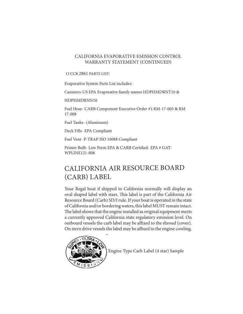
CALIFORNIA AIR RESOURCE BOARD (CARB) LABELYour Regal boat if shipped to California normally will display an oval shaped label with stars. Th is label is part of the California Air Resource Board (Carb) SD/I rule. If your boat is operated in the state of California and/or bordering waters, this label MUST remain intact. Th e label shows that the engine installed as original equipment meets a currently approved California state regulatory emission level. On outboard vessels the carb label may be affi xed to the shroud (cover).On stern drive vessels the label may be affi xed to the engine cowling.
Engine Type Carb Label (4 star) Sample

INTRODUCTION
Your Regal Owner’s Manual 11General Information 12Regal Warranty 22
1 SAFETY ON BOARD
Safety Labels 27General Boating Safety 29Required Safety Equipment 33Fire Extinguishers 36Visual Distress Signals 38Sound Protecting Devices 41 Navigation Lights 41Pollution Regulations 43Exhaust & Carbon Monoxide 47 Boating Under Th e Infl uence 51 Boating Accidents 53Water Sports 55 Weather & Water Conditions 62Federal Regulations-Security 65
2 RULES OF THE ROAD
Navigation Rules Defi ned 67Navigation Rules 68Night Running 75Bridge Clearance 76
3 ENGINES & CONTROLS
Engine Basics 79Stern Drive Basics 96 Propellers 100Instrumentation 101Helm Controls 10821 OBX Outboard Engine/Controls 117
4 SYSTEMS
Fire Port/Auto Fire Ext. 157 Bilge/Drainage 158 Electrical 160 Canvas 168 Entertainment 175 5 VESSEL OPERATION
Getting Underway 176Fueling 178Starting & Stopping 181Steering 184Fenders 186Dock Line Basics 187Steps To Stern Drive Docking 190Stern Drive Maneuvering 192Trim Angle 195Anchoring 200Emergencies 204First Aid 205Hypothermia 206Environmental Awareness 207
Table Of Contents

Table Of Contents
7 CARE & MAINTENANCE Cosmetic Care 246Maintenance 256
8 TROUBLESHOOTING
Diagnostic Charts 293
9 STORAGE/WINTERIZATION
Decommissioning Checklist 304 Recommissioning Checklist 307
10 TRAILERING Before Towing 309Driving 314Launching 315Loading Boat 317
11 GLOSSARY & INDEX
Glossary 319Index 323
12 TECHNICAL
Information 327Drawings 345
6 EQUIPMENT OPERATION
Automatic Fire Extinguisher 209Battery Switch 210Bilge Pump 211Blower 212Canvas 213Bow Filler Cushion 218Bow Walk Th rough Doors 219Cockpit Carpet 220Cockpit Seagrass Mat 221Cockpit Table 222Docking Lights 224Dual Battery Switch 225Drain Plug 227PowerTower 228Pressure Water System 231SeaDek-Swim Platform 234Seat Operation-Helm 235Seat Operation-Sundeck 237Ski Tow 238Storage-Seat 239Sport Tower 240Stereo Performance Package 242Transom Door 244Transom Trim Switch 245

1-7
Dear Regal Owner,
I know I speak for everyone at Regal when I welcome you to the ever-growing family of Regal boat owners. You’ve chosen a craft that is recognized worldwide for its standard of excellence. Each step in construction has been carefully scrutinized to assure comfort, per-formance, reliability and safety for both your passengers and yourself.
Your boat is certifi ed by the National Marine Manufacturers Associa-tion. It also complies with the applicable standards set by the United States Coast Guard and the American Boat and Yacht Council. Your Regal boat was built with the same attention to detail and quality of construction that we would expect in a boat we would purchase ourselves. Whether you’re a veteran boater or a newcomer, we strongly urge you to read this boat owner’s manual thoroughly. Familiarize your-self with the various components of your boat, and heed the safety precautions noted herein.
If you have questions that are not covered in this manual, please con-sult your authorized Regal dealer for assistance or phone the Regal factory at 407-851-4360. Th ank you, and welcome to the “World of Regal !”
Duane KuckPresident & CEO
Welcome To Regal

1-8
With God’s help
and a steadfast commitment to integrity,
we will develop a team
of exceptional people and relationships
to provide
exceptional customer satisfaction.

INT-9
Introduction
THIS PAGE IS LEFT INTENTIONALLY BLANK
INT-10
Boating is becoming more popular every year. Th ere are numerous types of recreational vessels on our waterways today involved in an every growing number of activities. Th erefore, as a new boat owner it is of the highest priority to learn about general boating practices before operating your craft . Your Regal dealer will answer many questions and provide valuable “hands on” information during the completion of the new boat delivery process. In addition, your dealer has received special factory training on the product line and his services should be employed to solve technical problems and periodic maintenance beyond the scope of this manual. Also, your Regal dealer carries a line of factory approved parts and accessories. Your Regal dealer can provide information regarding national training organizations such as the U.S. Power Squadron and United States Coast Guard Auxiliary. Along with other organizations and literature, they can help build your “boating savvy” by developing the necessary skills and awareness to be a safe and component skipper. Your local library can also help in providing recommended boating literature such as Chapman Piloting (Seamanship & Boat Handling by Elbert S. Maloney).Remember, the waterways can change from normal to abnormal conditions in a heartbeat. Knowing how to react quickly comes from experience and knowledge which can be gained through boating education.
Welcome aboard!
Introduction
INT-11
Introduction
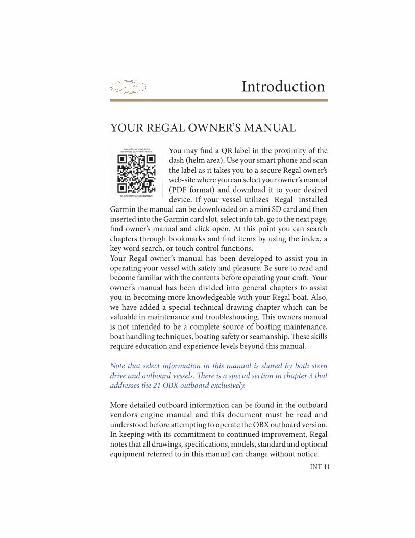
You may fi nd a QR label in the proximity of the dash (helm area). Use your smart phone and scan the label as it takes you to a secure Regal owner’s web-site where you can select your owner’s manual (PDF format) and download it to your desired device. If your vessel utilizes Regal installed
Garmin the manual can be downloaded on a mini SD card and then inserted into the Garmin card slot, select info tab, go to the next page, fi nd owner’s manual and click open. At this point you can search chapters through bookmarks and fi nd items by using the index, a key word search, or touch control functions.Your Regal owner’s manual has been developed to assist you in operating your vessel with safety and pleasure. Be sure to read and become familiar with the contents before operating your craft . Your owner’s manual has been divided into general chapters to assist you in becoming more knowledgeable with your Regal boat. Also, we have added a special technical drawing chapter which can be valuable in maintenance and troubleshooting. Th is owners manual is not intended to be a complete source of boating maintenance, boat handling techniques, boating safety or seamanship. Th ese skills require education and experience levels beyond this manual.
Note that select information in this manual is shared by both stern drive and outboard vessels. Th ere is a special section in chapter 3 that addresses the 21 OBX outboard exclusively.
More detailed outboard information can be found in the outboard vendors engine manual and this document must be read and understood before attempting to operate the OBX outboard version.In keeping with its commitment to continued improvement, Regal notes that all drawings, specifi cations, models, standard and optional equipment referred to in this manual can change without notice.
YOUR REGAL OWNER’S MANUAL
INT-12
OWNER’S INFORMATION PACKETRegal has provided an information pouch for on board reference. Read and become familiar with the materials. This packet contains valuable literature on your propulsion package,
standard and optional equipment, systems, along with various care and cleaning instructions. Be sure to store the information pouch in a clean dry location.
GENERAL INFORMATION
Hull Identifi cation Number (HIN)
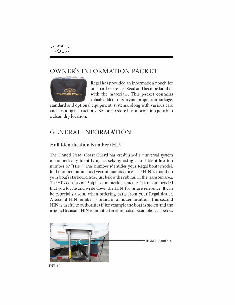
Th e United States Coast Guard has established a universal system of numerically identifying vessels by using a hull identifi cation number or “HIN.” Th is number identifi es your Regal boats model, hull number, month and year of manufacture. Th e HIN is found on your boat’s starboard side, just below the rub rail in the transom area.Th e HIN consists of 12 alpha or numeric characters. It is recommended that you locate and write down the HIN for future reference. It can be especially useful when ordering parts from your Regal dealer. A second HIN number is found in a hidden location. Th is second HIN is useful to authorities if for example the boat is stolen and the original transom HIN is modifi ed or eliminated. Example seen below.
RGMFQ000J718
INT-13
Introduction
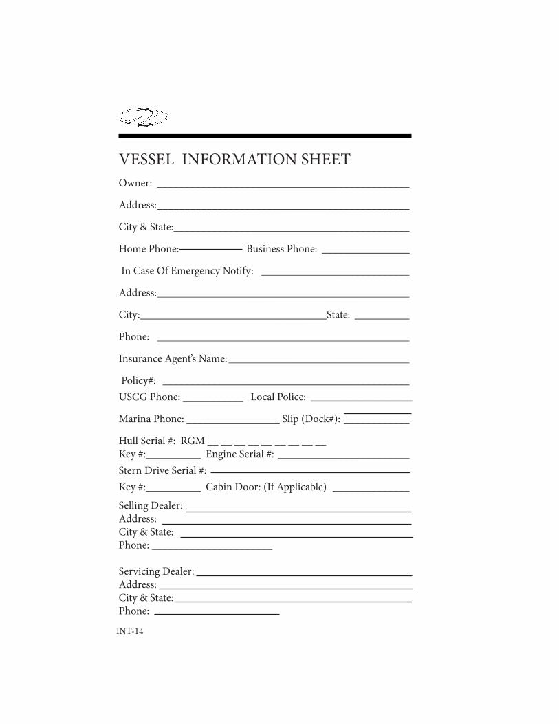
Vessel Information Sheet
It is recommended that you fi ll out the information on the following page. It will supply vital statistics on your vessel. Make a copy of the data for safe keeping at home.
Vessel Float Plan
Fill out the fl oat plan on the following page before departing. Leave it with a responsible person who will notify the United States Coast Guard or local law enforcement authorities if you do not return as planned. If you change your plans be sure to notify this person. Make copies of the fl oat plan and use one each time you go boating. Th is will help people know where to fi nd you should you not return on schedule. Do not fi le the fl oat plan with the United States Coast Guard.
INT-14
VESSEL INFORMATION SHEETOwner: ______________________________________________
Address: ______________________________________________
City & State: ___________________________________________
Home Phone: Business Phone: ________________
In Case Of Emergency Notify: ___________________________
Address: ______________________________________________
City:__________________________________State: __________
Phone: ______________________________________________
Insurance Agent’s Name: _________________________________
Policy#: _____________________________________________USCG Phone: ___________ Local Police: _____________________________________
Marina Phone: _________________ Slip (Dock#): ____________
Hull Serial #: RGM __ __ __ __ __ __ __ __ __Key #:__________ Engine Serial #: ________________________Stern Drive Serial #:Key #:__________ Cabin Door: (If Applicable) ______________
Selling Dealer: Address: City & State:Phone: ______________________
Servicing Dealer:Address:City & State:Phone:

INT-15
Introduction
Owner: Safety Equipment Aboard:Address: Life Jackets City & State: First Aid Kit Telephone#: Flares Cell Phone#: Flashlight VHF Radio Person Filing Report: AnchorName: Compass Home Telephone#: Food Cell Phone #: Water Make Of Boat: Destination: Registration#: Leave From:Length: Time Left :Boat Name: Going To:Gel Color: Fuel Level: 1/4, 1/2, 3/4, F Trim Color: Est. Time Of Arrival:I/O-Outboard: Hull I.D.#: Return: Fuel Capacity: Est. Time of Arrival: If not back by o’clock call Coast GuardOther Information:
Name Of Person Aboard Age Address Phone#
FLOAT PLAN
INT-16
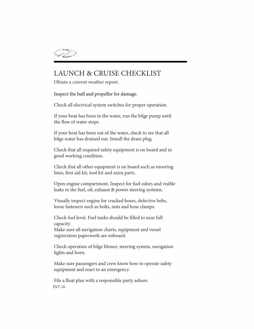
Obtain a current weather report.
Inspect the hull and propeller for damage.
Check all electrical system switches for proper operation.
If your boat has been in the water, run the bilge pump until the fl ow of water stops. If your boat has been out of the water, check to see that all bilge water has drained out. Install the drain plug.
Check that all required safety equipment is on board and in good working condition.
Check that all other equipment is on board such as mooring lines, fi rst aid kit, tool kit and extra parts.
Open engine compartment. Inspect for fuel odors and visible leaks in the fuel, oil, exhaust & power steering systems.
Visually inspect engine for cracked hoses, defective belts, loose fasteners such as bolts, nuts and hose clamps.
Check fuel level. Fuel tanks should be fi lled to near full capacity. Make sure all navigation charts, equipment and vessel registration paperwork are onboard.
Check operation of bilge blower, steering system, navigation lights and horn.
Make sure passengers and crew know how to operate safety equipment and react to an emergency.
File a fl oat plan with a responsible party ashore.
LAUNCH & CRUISE CHECKLIST

INT-17
Introduction
SUGGESTED TOOLS, PARTS & GEAR
SUGGESTED TOOLS SPARE PARTS
Allen Wrenches Fuel FilterJack Knife Spark PlugsPhillips Screwdriver Set Water Pump BeltSlotted Screwdriver Set PropellersRegular Pliers Alternator BeltCombination Wrench Set Anti-Siphon SetRatchet & Socket Set Propeller Nut & HardwareHammer Engine OilWire Crimpers Extra Light BulbsVise Grip Pliers Extra BatteriesFloating Flashlight Duct TapeNut Driver Set Electrical TapeOil Filter Wrench Power Steering, Trim FluidsFuel Filter Wrench Water Pump Impeller Spare Keys On Floater BASIC GEAR
Tie Lines Mooring Lines Dock Fenders First Aid Kit Boat Hook Foul Weather Gear VHF Radio, EPIRB, GPS, Cell Phone Charts & Plotting Instruments Emergency Water & Food Bailer Or Hand Pump Fire Extinguisher Personal Flotation Devices Anchor & Line Life Raft
INT-18
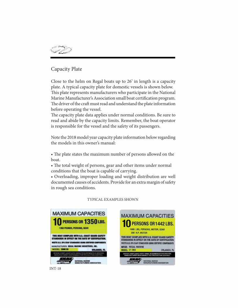
Capacity Plate
TYPICAL EXAMPLES SHOWN
Close to the helm on Regal boats up to 26’ in length is a capacity plate. A typical capacity plate for domestic vessels is shown below.Th is plate represents manufacturers who participate in the National Marine Manufacturer’s Association small boat certifi cation program. Th e driver of the craft must read and understand the plate information before operating the vessel.Th e capacity plate data applies under normal conditions. Be sure to read and abide by the capacity limits. Remember, the boat operator is responsible for the vessel and the safety of its passengers.
Note the 2018 model year capacity plate information below regarding the models in this owner’s manual:
• Th e plate states the maximum number of persons allowed on the boat.• Th e total weight of persons, gear and other items under normalconditions that the boat is capable of carrying.• Overloading, improper loading and weight distribution are well documented causes of accidents. Provide for an extra margin of safety in rough sea conditions.
INT-19
Introduction
Owner Registration & Systems Checklist
Please note that your Regal boat requires the proper registration by your authorized Regal dealer. To initiate your warranty the dealer must complete the owner’s registration form and systems checklist at the time of delivery. Th e owner must sign the paperwork to acknowledge that the dealer has reviewed the boat systems and warranty provisions with the owner. Th e owner should keep the original paperwork that features a temporary warranty registration. A Regal express limited warranty certifi cate containing all relevant boat and engine serial numbers will be sent aft er the factory receives the paperwork.
Dealer Responsibility
Your boat has undergone rigid quality assurance inspections before leaving the factory. However, your dealer has been trained to perform fi nal pre-delivery checks and to service your Regal boat prior to your pick-up. Your dealer’s responsibilities include:
A complete orientation in the operation of your Regal boat, including matters relating to the safe operation of your craft .
Completion and mailing of your boat registration warranty form to Regal.
Warranties, registration materials, owner’s manual, operation, installation and maintenance instructions for all auxiliary equipment supplied with or installed on your Regal boat.

INT-20
Owner Responsibility
You are entitled to all the benefi ts and services outlined in your Regal boat warranty. However, you have certain responsibilities to ensure warranty satisfaction. Th ese are:
To read the warranty materials and understand them fully.
To examine the boat in detail at the time of delivery.
To apply the following; boating rules and regulations, safety equipment, environmental regulations, accident reports and warranty regulation terms and conditions.
To read thoroughly all literature supplied with your boat, including this owner’s manual and to follow the recommendations in the literature.
To return the boat aft er the recommended hours of engine operation for the proper dealer service inspections.
To provide proper maintenance and periodic servicing of your boat and equipment as set forth in the various manuals supplied.
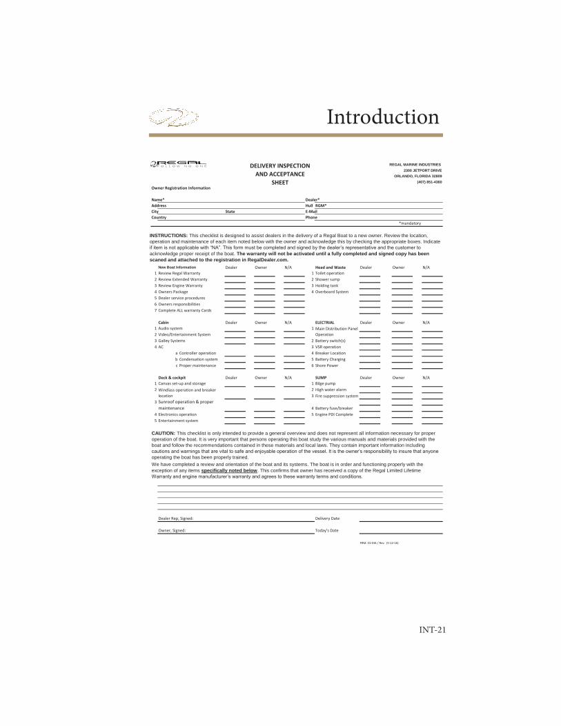
INT-21
Introduction
REGAL MARINE INDUSTRIES 2300 JETPORT DRIVE
ORLANDO, FLORIDA 32809(407) 851-4360
Owner Registration Information
Name* Dealer*Address Hull #RGM*City State E-MailCountry Phone
*mandatory
New Boat Information Dealer Owner N/A Head and Waste Dealer Owner N/A1 Review Regal Warranty 1 Toilet operation2 Review Extended Warranty 2 Shower sump3 Review Engine Warranty 3 Holding tank4 Owners Package 4 Overboard System5 Dealer service procedures6 Owners responsibilities 7 Complete ALL warranty Cards
Cabin Dealer Owner N/A ELECTRIAL Dealer Owner N/A1 Audio system 12 Video/Entertainment System3 Galley Systems 2 Battery switch(s)4 AC 3 VSR operation
a Controller operation 4 Breaker Locationb Condensation system 5 Battery Chargingc Proper maintenance 6 Shore Power
Deck & cockpit Dealer Owner N/A SUMP Dealer Owner N/A1 Canvas set-up and storage 1 Bilge pump2 2 High water alarm
33
4 Battery fuse/breaker4 Electronics operation 5 Engine PDI Complete5 Entertainment system
Dealer Rep, Signed: Delivery Date
Owner, Signed: Today's Date
FRM: CS-DIA / Rev. (5-12-16)
CAUTION: This checklist is only intended to provide a general overview and does not represent all information necessary for proper operation of the boat. It is very important that persons operating this boat study the various manuals and materials provided with the boat and follow the recommendations contained in these materials and local laws. They contain important information including cautions and warnings that are vital to safe and enjoyable operation of the vessel. It is the owner’s responsibility to insure that anyone operating the boat has been properly trained.We have completed a review and orientation of the boat and its systems. The boat is in order and functioning properly with the exception of any items specifically noted below. This confirms that owner has received a copy of the Regal Limited Lifetime Warranty and engine manufacturer’s warranty and agrees to these warranty terms and conditions.
INSTRUCTIONS: This checklist is designed to assist dealers in the delivery of a Regal Boat to a new owner. Review the location, operation and maintenance of each item noted below with the owner and acknowledge this by checking the appropriate boxes. Indicate if item is not applicable with “NA”. This form must be completed and signed by the dealer’s representative and the customer to acknowledge proper receipt of the boat. The warranty will not be activated until a fully completed and signed copy has been scaned and attached to the registration in RegalDealer.com.
Fire suppression system
DELIVERY INSPECTION AND ACCEPTANCE
SHEET
Main Distribution Panel Operation
Windlass operation and breaker locationSunroof operation & proper maintenance

INT-22
REGAL MARINE INDUSTRIES, INC.LIMITED WARRANTYWelcome to the Worldwide Family of Regal Owners! We are very pleased that you have chosen a Regal Powerboat!
Th is document is your Limited Warranty Registration Certifi cate and Statement of Limited Warranty. Please check the registration information section for accuracy. If this information is not correct or if you change your address at some future date, please notify us at the following address: Regal Marine Industries, Inc. Attention: Warranty Registrations, 2300 Jetport Drive, Orlando, Florida 32809; or e-mail [email protected].
Please read the warranty carefully. It contains important information on Regal’s claims procedures and your rights and obligations under this warranty.
WHAT IS COVERED: Th is Limited Warranty applies only to Regal boats beginning with model year 2017.
LIFETIME LIMITED STRUCTURAL DECK & HULL WARRANTY: Regal Marine Industries, Inc. warrants to the original retail purchaser of this boat if purchased from an authorized Regal dealer that the selling dealer or Regal will repair or replace the factory installed fi berglass if it is found to be structurally defective in material or workmanship for as long as the original retail purchaser owns the boat. For purposes of this Limited Warranty, the hull is defi ned as the single fi berglass casting which rests on the water. Th is Limited Warranty is subject to all limitations and conditions explained below.
FIVE-YEAR TRANSFERABLE LIMITED STRUCTURAL HULL WARRANTY: In addition to the Lifetime Limited Structural Hull Warranty, Regal off ers a Transferable Five-Year Limited Structural Hull Warranty. Under the Five-Year Transferable Limited Structural Hull Warranty, Regal will repair or replace the fi berglass hull or deck if it is found to be structurally defective in material or workmanship within the fi rst (5) years aft er the date of delivery to the original retail purchaser. Any remaining term of this Five-Year Limited Hull Warranty may be transferred to a second owner if within 60 days of purchase, the new owner registers the transfer with Regal and pays the established Limited Warranty transfer fee. Contact Regal Customer Service at the above address for details.
FIVE-YEAR LIMITED HULL BLISTER WARRANTY: Regal warrants that the Regal selling dealer or Regal will repair any underwater gelcoated surfaces of the hull against laminate blisters which occur as a result of defects in material or workmanship within (5) years of the date of delivery, provided that the original factory gelcoat surface has not been altered. Alternation would include but is not limited to damage repair; excessive sanding, scraping, sandblasting; or from improper surface preparation for application of a marine barrier coating or bottom paint, any of which shall void this Five-Year Limited Hull Blister Warranty. Proper preparation must be applied to the hull bottom if the boat is to be moored for periods in excess of (60) days. Regal Marine shall repair or cause to be repaired any covered laminate blisters based on the following prorated schedule. Less than three (3) years from delivery date - 100%, Th ree (3) to (4) years from delivery date - 50%, Four (4) to (5) years from delivery date - 25%.
INT-23
Introduction
Reimbursement shall be limited to one repair, not to exceed ($100.00) dollars per foot of boat length prior to prorating. Regal’s prior authorization for the method and cost of repair, must be obtained before repairs are commenced. All costs to transport the boat for repairs are the responsibility of the owner.
LIMITED GENERAL WARRANTY: In addition to above hull warranties, Regal warrants to the original purchaser of this boat if purchased from an authorized Regal dealer, that the authorized Regal dealer or Regal will repair or replace any parts found to be defective in materials or workman-ship for a period of one (1) year from the date of delivery, subject to all exceptions, limitations and conditions contained herein.
LIMITED EXTERIOR FINISH WARRANTY: Regal warrants that the authorized Regal selling dealer or Regal will repair cosmetic defects in the exterior gelcoated fi nish including cracks, air voids or crazing for one year from the date of delivery, subject to all limitations and conditions contained herein. All warranty work is to be performed at a Regal dealership or other location authorized by a Regal Customer Service Manager aft er it is established to Regal’s satisfaction that there is a defect in material or workmanship.
CUSTOMER OBLIGATIONS: Th e following are conditions precedent to the availability of any benefi ts under these limited warranties:
(a) Th e purchaser, who is not Regal’s sales agent and is otherwise not in any general or sales agency relationship with Regal, must sign and the authorized Regal selling dealer, must submit to Regal the “NEW BOAT DELIVERY and ACCEPTANCE CHECKLIST” within fi ft een (15) days of the date of delivery and such information must be on fi le at Regal.(b) Th e purchaser must fi rst notify the authorized Regal selling dealer from whom the boat was purchased of any claim under this Limited Warranty within the applicable Limited Warranty period and within a reasonable period of time (not to exceed thirty (30) days) aft er the defect is or should have been discovered.(c) Regal will not be responsible to repair any condition or replace any part, (1) if the use of the boat is continued aft er the defect is or should have been discovered; and (2) if such continued use causes other or additional damage to the boat or component parts of the boat.(d) Based on the authorized Regal selling dealer’s knowledge of Regal’s Limited Warranty policy and/or consultations with Regal, the dealer will accept the claim and arrange for appropriate repairs to be performed, or deny the claim if it is not within the Limited Warranty policy.(e) Th e authorized Regal selling dealer will contact the Regal boat owner regarding instructions for delivery of boat or part for covered warranty repair if it is covered by the Limited Warranty. ALL COSTS TO OR FROM THE BOAT AND/OR TRANSPORT OF THE BOAT FOR REPAIRS ARE THE RESPONSIBILITY OF THE OWNER.(f) If the Regal boat owner believes a claim has been denied in error or the authorized Regal selling dealer has performed the warranty work in an unsatisfactory manner, the owner must notify Regal’s Customer Service Department in writing at the address listed for further consideration. Regal will then review the claim and take appropriate follow-up action.(g) Before bringing any action, claim, lawsuit, or otherwise seeking relief against Regal based on any alleged breach of any of the Limited Warranties, terms or conditions herein, the Regal Boat owner must contact Regal’s Customer Service Department Directly allow Regal, beyond those eff orts made by its authorized Regal dealer, notice an opportunity to cure any alleged breach of any of the terms of any of the Limited Warranties.
INT-24
WARRANTY EXCEPTIONS: THIS LIMITED WARRANTY does not cover, the following are not warranted are excluded from the terms of the Regal Limited Warranty and the following terms apply to any Regal Limited Warranty.(a) Engines, drives, controls. propellers, batteries, metal plating or fi nishes, windshield breakage, leak-age, fading and deterioration of paints, canvas, vinyl, upholstery and fabrics;(b) Gelcoat surfaces including, but not limited to discoloration or blistering except as noted above;(c) Accessories and items which were not part of the boat when shipped from the Regal factory, or which carry their own individual warranty and/or any damage caused by such accessories or items;(d) Damage caused by one or more of the following: misuse, accident,corrosion, galvanic corrosion, negligence, lack of proper maintenance, or improper trailering;(e) Any boat used for racing, or used for rental or commercial purposes;(f) Any boat operated contrary to any instructions furnished by Regal, including instructions and guidance provided in the Regal Owner’s Manual, or operated in violation of any federal, state, Coast Guard or other governmental agency laws, rules, or regulations;(g) Th e limited warranty is void if alterations have been made to the boat;(h) Transportation of boat or parts to and/or from the REGAL factory or service location;(i) Travel time or haul outs, loss of time or inconvenience;(j) Any published or announced catalog performance characteristics of speed, fuel and oil consumption, and static or dynamic transportation in the water;(k) Any boat that has been re-powered beyond Regal’s power recommendations;(1) Boats damaged by accident and boats damaged while being loaded onto, transported upon or unloaded from trailers, cradles, or other devices used to place boats in water, remove boats from water or store or transport boats on or over land;(m) Any item repaired, replaced or modifi ed under the terms of this warranty does not in any way prolong, extend or change any terms set forth in this limited warranty;(n) Water damage to, dry rot to, condensation to, or absorption by interior surfaces, wood structures or polyurethane foam; interior wood including, but not limited to mold, bleeding and/or discoloration as a result of condensation or moisture or water continually contacting the plywood causing staining to upholstery, carpet or other interior surfaces;(o) Costs or charges derived from inconvenience or loss of use, commercial or monetary loss due to time loss, and any other special, incidental or consequential damage of any kind or nature whatsoever; (p) Regal reserves the right to improve the design or manufacture process of Regal boats without obligation to modify previously produced product;
NO WAVIER OF THESE TERMS: Th e terms, conditions, limitations and disclaimers contained herein cannot be wavered except by the Customer Service Manager of Regal. Any such wavier must be in writing. Neither the dealer, nor the customer, nor any service, sales and/or warranty representative of Regal is authorized to waive and/or modify theseconditions, limitations and/or disclaimers.
EXCEPT AS SET FORTH HEREIN OR ON ANY OTHER WRITTEN EXPRESS LIMITED WARRANTIES BY REGAL, THERE ARE NO OTHER WARRANTIES EITHER EXPRESSED OR IMPLIED PROVIDED BY REGAL ON THIS BOAT. ALL OTHER WARRAN-TIES, EXPRESS OR IMPLIED, INCLUDING IMPLIED WARRANTIES OF FITNESS AND MERCHANTABILITY, ARE EXPRESSLY EXCLUDED. REGAL FURTHER DISCLAIMS ANY LIABILITY FOR ECONOMIC LOSS ARISING FROM CLAIMS OF PRODUCT FAILURE, NEGLIGENCE, DEFECTIVE DESIGN, MANUFACTURING DEFECT, FAILURE TO WARN AND/OR INSTRUCT, LACK OF SEAWORTHINESS, AND ANY OTHER THEORY OF LIABILITY NOT EXPRESSLY COVERED UNDER THE TERMS OF THIS LIMITED WARRANTY.
AS SET FORTH ABOVE, REGAL MAKES NO IMPLIED WARRANTY OF MERCHANTABILITY AND EXPRESSLY EXCLUDES ANY SUCH WARRANTY. TO THE EXTENT SUCH EXCLUSION IS NOT ALLOWED BY LAW OR AN IMPLIED WARRANTY OF MERCHANTABILITY IS ALLOWED BY LAW: (1) ANY IMPLIED WARRANTY OF MERCHANTABILITY THAT IS, AS A MATTER OF LAW, NOT PERMITTED TO BE EXCLUDED AS SET FORTH ABOVE, IS LIMITED TO ONE

INT-25
Introduction
YEAR FROM THE DATE OF DELIVERY TO THE FIRST RETAIL OWNER; (2) NEITHER REGAL NOR ANY SELLING DEALER SHALL HAVE ANY RESPONSIBILITY FOR LOSS OR USE OF THE BOAT, LOSS OF TIME, INCONVENIENCE, COMMERCIAL LOSS, INCIDENTAL OR CONSEQUENTIAL DAMAGES. SOME STATES MAY NOT ALLOW EXCLUSIONS OF IMPLIED WAR-RANTIES OR LIMITATIONS ON HOW LONG ANY IMPLIED WARRANTY LASTS, SO THE ABOVE LIMITATION MAY NOT BE APPLICABLE. SOME STATES MAY NOT ALLOW THE EXCLUSION OR LIMITATION OF INCIDENTAL OR CONSEQUENTIAL DAMAGES, SO THE ABOVE LIMITATIONS OR EXCLUSIONS MAY NOT BE APPLICABLE IN THOSE STATES. THIS WARRANTY GIVES THE OWNER SPECIFIC LEGAL RIGHTS, AND THE OWNER MAY ALSO HAVE OTHER RIGHTS WHICH VARY FROM STATE TO STATE.
THE TERMS AND CONDITIONS CONTAINED HEREIN, AS WELL AS THOSE OF ANY DOCUMENTS PREPARED IN CON-JUNCTION WITH THE SALE OF THIS VESSEL MAY NOT BE MODIFIED, ALTERED OR WAIVED BY ANY ACTION, INACTION OR REPRESENTATIONS, WHETHER ORAL OR IN WRITING, EXCEPT UPON THE EXPRESSED, WRITTEN AUTHORITY OF A MANAGEMENT LEVEL EMPLOYEE OF REGAL. Some states do not allow limitations on how long an implied warranty lasts, so the above limitation may not apply to you. Regal’s obligation with respect to this warranty is limited to making repairs to or replacing the defective parts and no claim for breach of warranty shall be cause for cancellation or rescission of the contract or sale for any boat manufacturer by REGAL MARINE INDUSTRIES, INC.
Regal will discharge its obligations under this warranty as rapidly as possible, but cannot guarantee any specifi c completion date due to the diff erent nature of claims which may be made and services which may be required. Regal reserves the right to change or improve the design of its boats without obligation to modify any boat previously manufactured. Th is limited warranty gives you specifi c legal rights, and you may also have other rights which may vary from state to state. Regal shall in no way be responsible for any repairs not PRE-AUTHORIZED by a Regal Customer Service Manager or repairs performed by a repair shop not PRE-AUTHORIZED by a Regal Customer Service Manager.
ARBITRATION OF DISPUTES AND WAVIER OF JURY TRIALEXCEPT AS SPECIFICALLY EXCLUDED IN THIS LIMITED WARRANTY, PURCHASER, REGAL AND AUTHORIZED REGAL DEALER AGREE TO SUBMIT ANY AND ALL CONTROVERSIES, CLAIMS OR DISPUTED ARISING OUT OF OR RELATING TO THE BOAT AND THIS LIMITED WARRANTY AND ALL OTHER AGREEMENTS EXECUTED BY PURCHASER RELATED TO THE BOAT TO BINDING ARBITRATION. IT IS THE EXPRESS INTENT OF PURCHASER, REGAL AND DEALER THAT THIS ARBITRATION PROVISION APPLIES TO ALL DISPUTES, INCLUDING CONTRACT DISPUTES, TORT CLAIMS, FRAUD CLAIMS AND FRAUD-IN-THE INDUCEMENT CLAIMS, STATUTORY CLAIMS AND REGULATORY CLAIMS RELATING IN AY MANNER TO THE BOAT AND THIS LIMITED WARRANTY.
IF ANY CONTROVERSY OR CLAIM DESCRIBED IN THIS ARBITRATION PROVISION IS DETERMINED FOR ANY REASON TO BE INELIGIBLE FOR ARBITRATION, AND FOR ANY CONTROVERSIES, CLAIMS, OR DISPUTES SPECIFICALLY EX-EMPTED FROM ARBITRATION, THEN THOSE CONTROVERSIES, CLAIMS, OR DISPUTES SHALL INSTEAD BE DECIDED BY A JUDGE OF A COURT OF COMPETENT JURISDICTION, IN ORANGE COUNTY,FLORIDA, WITHOUT A JURY. PURCHASER, REGAL AND DEALER KNOWINGLY AND VOLUNTARILY WAIVE THE RIGHT TO A TRIAL BY JURY FOR ALL SUCH CON-TROVERSIES, CLAIMS AND DISPUTES. PURCHASER, REGAL, AND DEALER UNDERSTAND THAT THERE SHALL BE NO JURY TRIAL, WHETHER THE CONTROVERSY OR CLAIM IS DECIDED BY ARBITRATION OR BY TRIAL BEFORE A JUDGE. NOTWITHSTANDING THE PROVISIONS OF THIS ARBITRATION AGREEMENT, WITH REGARD TO CONTROVERSIES AND/OR ENTITLEMENT TO POSSESSION OF EITHER THE BOAT OR ANY TRADE-IN, ANY PARTY HERETO MAY RESORT TO A JUDICIAL DETERMINATION (BY A JUDGE AND NOT A JURY). OF SUCH CONTROVERSIES, DISPUTES OR CLAIMS WITH-OUT WAIVING ANY RIGHT TO DEMAND ARBITRATION WITH RESPECT TO ALL OTHER CONTROVERSIES, DISPUTES OR CLAIMS BETWEEN THE PARTIES A MORE SPECIFICALLY SET FORTH IN THIS ARBITRATION PROVISION.
ALL ARBITRATIONS SHALL PROCEED THROUGH THE AMERICAN ARBITRATION ASSOCIATION AND BE SUBJECT TO ITS COMMERCIAL ARBITRATION RULES, EXCEPT AS SET FORTH HEREIN. THE ARBITRATORS SHALL HAVE THE AUTHORITY TO AWARD ANY FORM OF RELIEF THAT COULD BE PROPERLY AWARDED IN A CIVIL ACTION IN THE STATE OF FLORIDA FOR THE TYPE OF CLAIMS PRESENTED, SUBJECT HOWEVER , TO ALL LIMITATIONS, PREDICATES, AND CONDITIONS COVERING SUCH REMEDIES OR RELIEF UNDER FLORIDA LAW.
THE PURCHASER, REGAL OR DEALER MAY DEMAND ARBITRATION OF A CLAIM BY FILING A WRITTEN DEMAND FOR ARBITRATION, ALONG WITH A STATEMENT OF THE MATTER IN CONTROVERSY WITH THE AMERICAN ARBITRATION ASSOCIATION, AND SIMULTANEOUSLY SERVING A COPY UPON THE OTHER PARTY. PURCHASER, REGAL AND DEALER AGREE THAT THE ARBITRATION PROCEEDING SHALL BE CONDUCTED IN ORANGE COUNTY, FLORIDA UNLESS OTHER-WISE AGREED BY THE PARTIES. EACH PARTY AGREES TO BEAR THEIR OWN ATTORNEY FEES AND COSTS. THE FILING FEES AND ALL OTHER THIRD-PARTY COSTS FOR THE ARBITRATION, INCLUDING THE ARBITRATOR’S FEE SHALL BE PAID BY THE FILING PARTY INITIATING THE ARBITRATION. THE PREVAILING PARTY SHALL BE ENTITLED TO REIMBURSE-MENT OF THEIR REASONABLE ATTORNEY FEES AND REASONABLE EXPENSES FROM THE NON-PREVAILING PARTY.
REGISTRATION INFORMATION:

1-26
Notes
Safety On Board
1-1
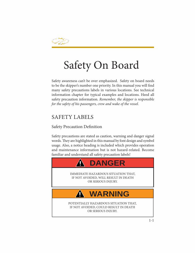
Safety awareness can’t be over emphasized. Safety on board needs to be the skipper’s number one priority. In this manual you will fi nd many safety precautions labels in various locations. See technical information chapter for typical examples and locations. Heed all safety precaution information. Remember, the skipper is responsible for the safety of his passengers, crew and wake of the vessel.
SAFETY LABELSSafety Precaution Defi nition
Safety precautions are stated as caution, warning and danger signal words. Th ey are highlighted in this manual by font design and symbol usage. Also, a notice heading is included which provides operation and maintenance information but is not hazard-related. Become familiar and understand all safety precaution labels!
DANGERIMMEDIATE HAZARDOUS SITUATION THAT,
IF NOT AVOIDED, WILL RESULT IN DEATHOR SERIOUS INJURY.
WARNINGPOTENTIALLY HAZARDOUS SITUATION THAT,
IF NOT AVOIDED, COULD RESULT IN DEATHOR SERIOUS INJURY.
1-2
Chapter 1
Precautionary Labels
Read and understand all safety labels affi xed to your Regal boat. Most of the safety labels are found close to the helm, aft cockpit and or swim platform. Th e location of the labels may vary by model and the label list does not cover everything! Use common sense to analyze the result of an action on board your vessel. Always think safety fi rst!
GENERAL OR SPECIFICATION WHICH IS IMPORTANT TOCORRECT OPERATION OR MAINTENANCE, BUT IS NOT
HAZARD RELATED.
NOTICE
INDICATES A POTENTIALLY HAZARDOUS SITUATIONOR UNSAFE PRACTICE THAT, IF NOT AVOIDED,
MAY RESULT IN INJURY OR PROPERTY OR PRODUCT DAMAGE.
CAUTION
DO NOT REMOVE OR COVER ANY PRECAUTIONARY LABELS.KEEP HARSH CHEMICALS AWAY FROM LABELS.
IF A LABEL BECOMES ILLEGIBLE, CONTACT THE CLOSESTREGAL DEALER FOR ORDERING REPLACEMENTS.
NOTICE
1-3
Safety On Board
GENERAL BOATING SAFETY
We understand that you are eager to get your Regal boat on the water. However, we strongly suggest that you thoroughly familiarizeyourself and friends or members of your family with safe boating practices before setting out.Remember, that along with the freedom and exhilaration of boating comes the responsibility that you have for the safety of your passengers and other boaters who share the water with you.Boating regulations vary from state to state. Check with your local state and local authorities for the regulations pertaining to your area.
Check with local weather stations, the U. S. Coast Guard, or weather station broadcasts for the latest conditions. Remember getting caught in severe weather is hazardous, Check weather conditions periodically while you are boating and before your outing. If you are forced to operate your boat in a storm condition, take common sense precautions; wear PFD’s, store gear, reduce speed and head for safe refuge.
It is best to avoid operating your boat in foggy weather. When fog sets in, take bearings, log courses and speeds. You are required to emit a fi ve second blast from your horn or whistle once a minute. Also, have your passengers wear PFD’s and observe for oncoming vessels.
Operating in shallow water presents a number of hazards including sand bars and water levels infl uenced by tides. If the vessel ever strikes an underwater hazard, check for boat and engine damage. If the engine vibrates excessively after striking an underwater obstruction,it may indicate a damaged propeller. If you run aground, seek help by radio or fl ares.
Make sure your boat and equipment are in top condition. Do this by frequently inspecting the hull, engine and gear.
1-4
Chapter 1You must provide a Coast Guard approved personal fl otation device (PFD) for every person on board. Th ese PFD’s should be in good condition and easily accessible.
Insist that non-swimmers and children on board wear a PFD at all times. Any time you encounter rough weather conditions, make sure everyone on board is wearing a PFD, including yourself. Instruct your passengers in how to put on their PFDs and be sure they know their storage location on the boat. Remember, in an emergency, a PFD that cannot be quickly located and worn is useless.
Never allow anyone to sit anywhere on the boat not specifi cally designed as a seat. While underway, ALWAYS insist passengers remain seated.
Use maximum caution when fueling. Never allow any smoke or fl ame nearby while you are fueling. ALWAYS check for fuel leaks and fumes when fueling is completed.
GASOLINE VAPORS CAN EXPLODE!BEFORE STARTING ENGINES, OPERATE BLOWER
4 MINUTES. VISUALLY CHECK AND SNIFF ENGINECOMPARTMENT FOR GASOLINE FUMES OR LEAKS.RUN BLOWER MOTOR BELOW CRUISING SPEEDS.
WARNING
USE OF ALCOHOL ENHANCED FUEL, OR A FUELOTHER THAN GASOLINE CAN LEAD TO DETERIORATION
OF THE FUEL SYSTEM COMPONENTS,CAN RESULT IN FIRE AND POSSIBLE EXPLOSION!
WARNING
1-5
Safety On Board
Never overload your boat! An overloaded boat, or one with uneven weight distribution, can be diffi cult to steer.
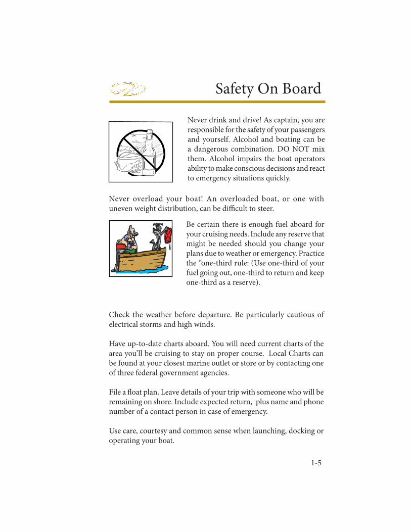
Be certain there is enough fuel aboard for your cruising needs. Include any reserve that might be needed should you change your plans due to weather or emergency. Practice the “one-third rule: (Use one-third of your fuel going out, one-third to return and keep one-third as a reserve).
Check the weather before departure. Be particularly cautious of electrical storms and high winds.
Have up-to-date charts aboard. You will need current charts of the area you’ll be cruising to stay on proper course. Local Charts can be found at your closest marine outlet or store or by contacting one of three federal government agencies.
File a fl oat plan. Leave details of your trip with someone who will be remaining on shore. Include expected return, plus name and phone number of a contact person in case of emergency.
Use care, courtesy and common sense when launching, docking or operating your boat.
Never drink and drive! As captain, you are responsible for the safety of your passengers and yourself. Alcohol and boating can be a dangerous combination. DO NOT mix them. Alcohol impairs the boat operators ability to make conscious decisions and react to emergency situations quickly.
1-6
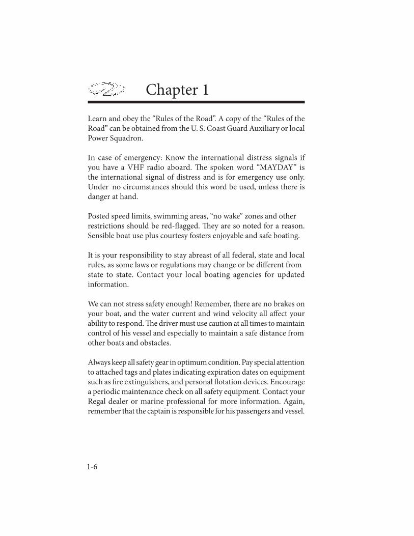
Chapter 1Learn and obey the “Rules of the Road”. A copy of the “Rules of the Road” can be obtained from the U. S. Coast Guard Auxiliary or local Power Squadron.
Ιn case of emergency: Know the international distress signals if you have a VHF radio aboard. Th e spoken word “MAYDAY” is the international signal of distress and is for emergency use only. Under no circumstances should this word be used, unless there is danger at hand.
Posted speed limits, swimming areas, “no wake” zones and other restrictions should be red-fl agged. Th ey are so noted for a reason. Sensible boat use plus courtesy fosters enjoyable and safe boating.
It is your responsibility to stay abreast of all federal, state and local rules, as some laws or regulations may change or be diff erent from state to state. Contact your local boating agencies for updated information.
We can not stress safety enough! Remember, there are no brakes on your boat, and the water current and wind velocity all aff ect your ability to respond. Th e driver must use caution at all times to maintain control of his vessel and especially to maintain a safe distance from other boats and obstacles.
Always keep all safety gear in optimum condition. Pay special attention to attached tags and plates indicating expiration dates on equipment such as fi re extinguishers, and personal fl otation devices. Encourage a periodic maintenance check on all safety equipment. Contact your Regal dealer or marine professional for more information. Again, remember that the captain is responsible for his passengers and vessel.

1-7
Safety On Board
REQUIRED SAFETY EQUIPMENT
Personal Flotation Devices
All personal fl otation devices (PFD’s) must be Coast Guard approved, in good working condition, and must be the correct size for the wearer. All PFD’s must be readily access ible . This means being able to wear them in a reasonable amount of time
in case of an emergency (fi re, boat sinking, etc.). Th ey should not be stored or locked in closed areas. Also, make sure that all coverings are removed, such as plastic from any PFD’s. Th rowable devices such as a ring buoys need to be available for immediate deployment. A PFD should be worn at all times when your boat is operating on the water. A PFD may save your life, but it must be worn to do so.As minimum U. S. Coast Guard requirements all recreational boats must carry one type I, II, III, or V PFD (wearable) for each person aboard. See the explanation following for each type. For type V to be counted they must be used according to the label instructions. In addition, all boats over 16’ must carry one Type IV (throwable) PFD. Some states require that PFD’s be worn by children of specifi c ages at all times. Check with state boating agencies for particular requirements in your state before taking children on the water.Remember PFD’s will not necessarily keep you from drowning, even though they are designed to keep a person from sinking. When purchasing PFD’s make sure it safely fi ts the person wearing it. It is a good idea to test PFD’s in a shallow pool before trying on the water.Refer to the USCG minimum equipment requirements at the end of this chapter. It is meant to be a guide only. Contact state and local agencies for additional equipment requirements. Remember as the captain of your vessel you are responsible for its safe operation.
1-8
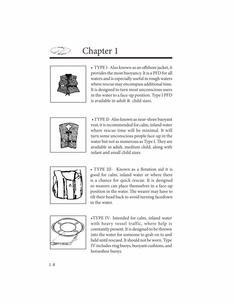
Chapter 1• TYPE I- Also known as an off shore jacket, it provides the most buoyancy. It is a PFD for all waters and is especially useful in rough waters where rescue may encompass additional time. It is designed to turn most unconscious users in the water to a face-up position. Type I PFD is available in adult & child sizes.
• TYPE II- Also known as near-shore buoyant vest, it is recommended for calm, inland water where rescue time will be minimal. It will turn some unconscious people face-up in the water but not as numerous as Type I. Th ey are available in adult, medium child, along with infant and small child sizes.
• TYPE III- Known as a fl otation aid it is good for calm, inland water or where there is a chance for quick rescue. It is designed so wearers can place themselves in a face-up position in the water. Th e wearer may have to tilt their head back to avoid turning facedown in the water.
•TYPE IV- Intended for calm, inland water with heavy vessel traffic, where help is constantly present. It is designed to be thrown into the water for someone to grab on to and held until rescued. It should not be worn. Type IV includes ring buoys, buoyant cushions, and horseshoe buoys.

1-9
Safety On Board
• TYPE V- This is the least bulky of all PFD’s. It contains a small amount of inherent buoyancy, and an infl atable chamber. It is rated even to a Type I, II, or III PFD (as noted on the jacket label) when infl ated. Hybrid PFD’s must be worn to be acceptable.equipment.
√ Do a periodic operation check of all PFD’s in shallow water.
√ Be sure to air dry all PFD’s aft er each use. Store in a dry, easily accessible location.
√ Check periodically for broken zippers, frayed webbing, water soaked kapok bags, missing straps, and sewing that is undone.
√ Clean each PFD with mild soap and water only. Again, let dry suffi ciently before storing.
√ Keep PFD’s out of grease and oil since they can deteriorate the jacket inner and outer materials.
√ Check any kapok-bagged jackets by squeezing. If jacket loses air the bag is defective and the PFD should be thrown away.
√ Grab the cover with the fi ngers. If the cover material rips, the PFD is rotted and should be thrown away.
√ If the kapok bag is hard the PFD should be discarded.
Maintaining your PFD’s
A PFD is only useful if it’s well maintained. Always be aware of PFD age since it has a life expectancy like any other piece of equipment.

1-10
Chapter 1
FIRE EXTINGUISHERSGeneral Information
Fire extinguishers are classifi ed by a letter and numeric symbol. Th e letter references the type of fi re the unit is designed to extinguish. For example, type B extinguishers commonly used on boats are designed to put out fl ammable liquids such as grease, oil and gasoline.The number indicates the general size of the extinguisher and minimum extinguishing agent weight.
FIRE EXTINGUISHER CONTENTS
CLASS FOAM C02 DRY CHEM. HALON IN GALS. IN LBS. IN LBS. IN LBS.
B-I 1.25 4 2 2.5
B-II 2.5 15 10 10
MINIMUM PORTABLE FIRE EXTINGUISHERS REQUIRED
VESSEL NO FIXED WITH FIXED LENGTH SYSTEM SYSTEM
LESS THAN 26’ 1 B-1 0 26’ TO LESS THAN 40’ 2 B-1 OR 1 B-II 1 B-1 40’ TO 65’ 3 B-1 OR 1 B-II 2 B-1 AND 1 B-1 OR 1 B-II

1-11
Safety On Board
U. S. Coast Guard approved fi re extinguishers are required on all Regal boats. Besides the minimum Coast Guard requirements always check state and local agencies for additional requirements. Coast Guard approved extinguishers are hand-portable, either B-I or B-II classifi cation. U. S. Coast Guard approved hand-portable and semi-portable extinguishers contain a metal plate that shows the manufacturer’s name and extinguisher type, capacity and operating instructions. Th ey have a special marine type mounting bracket which keeps the extinguisher solidly mounted until needed. Th e extinguisher needs to be mounted in a readily accessible location. All approved extinguishers need to have an indication gauge.
USCG- Approved Fire Extinguisher Types & FeaturesTh e dry chemical agent is widely used because of its convenience and low cost. Th e extinguisher canister is filled with a white dry chemical power along with a pressurized gas. Shake this type periodically because they tend to “pack” on the canister bottom.
The foam type uses a chemical foaming agent plus water and is best when used for fires involving flammable liquids- solvents, gasoline,oil, grease and various paints. It will work on fi res involving rubber, plastics, cloth, wood, and paper. It leaves a messy residue. Not for electric fi res. Th e carbon dioxide unit uses CO2 gas under high pressure, with a funnel discharge hose usually swivel mounted. This extinguisher leaves no residue and no interior engine harm. To ensure workability, weigh the unit annually. A 10% max. weight variance is allowed.
1-12
Chapter 1Another type of liquefied gas used today is Halon. This gas is colorless and odorless, heavier than air and sinks to the lower bilge to extinguish fi res. Since the year 2000 ingredients for Halon have changed to a more environmental friendly formula. Halon is used in portable-hand units along with making up the majority of boat automatic fire extinguishing systems. The canister needs to be weighed once a year. Halon units must feature a dash mount indicator. Refer to the information regarding fi re prevention in this manual.
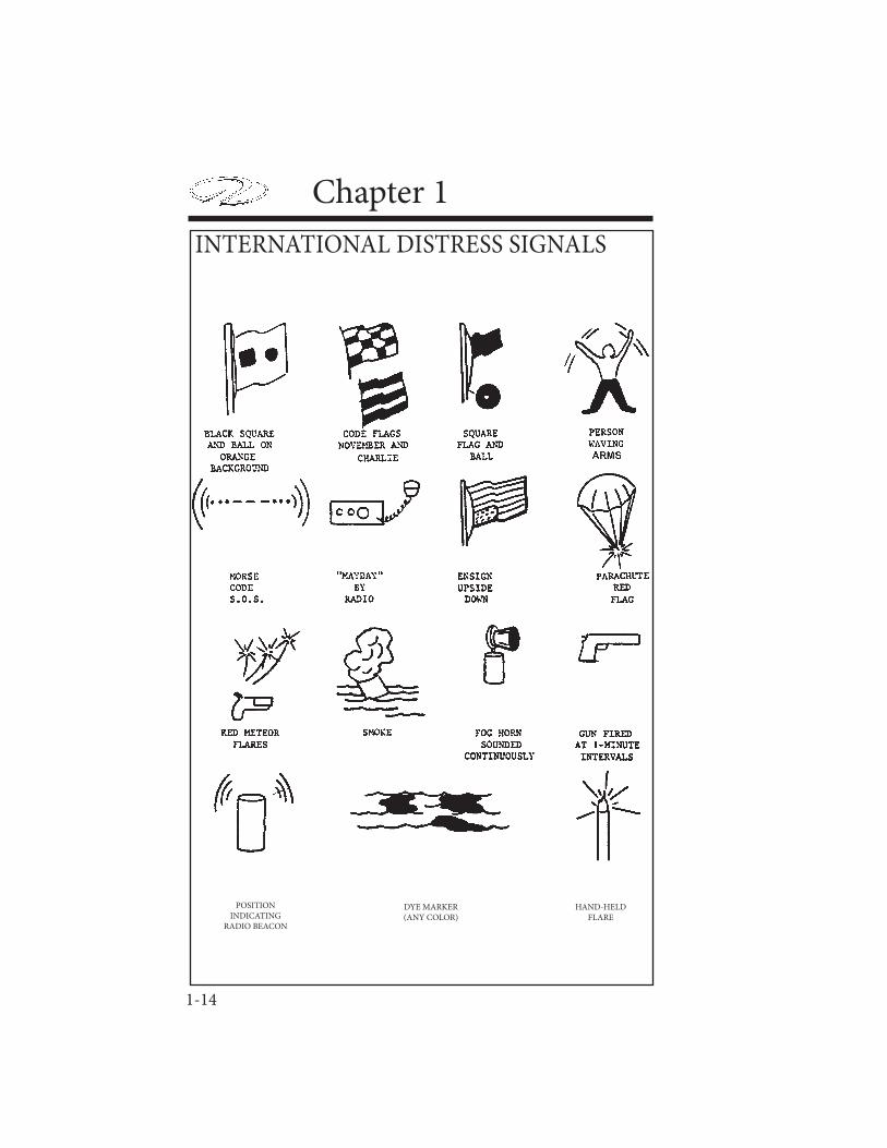
VISUAL DISTRESS SIGNALS
All vessels used on coastal waters, any of the Great Lakes, territorial seas, and those waters connected directly to them , up to point where a body of water is less than two miles wide, must have Coast Guard approved visual distress signals.
Pyrotechnic Devices
Pyrotechnic visual distress signals must be Coast Guard approved, be ready for service and must be readily accessible. Th ey all display a marking which is the service life, which must not have expired. A minimum of 3 devices are required for day and 3 devices for night.Some devices meet both day and night requirements. Pyrotechnic devices should be stored in a cool, dry location. Most of these devices can be purchased in an highly visible (orange) watertight container. Types of Coast Guard approved pyrotechnic distress signals and associated devices are:
Pyrotechnic red fl ares, hand- held or aerial type.
Pyrotechnic orange smoke, hand-held or fl oating type.
Launchers for parachute fl ares or aerial red meteors.
1-13
Safety On Board
All in all, each distress signal has certain pros and cons. Th ere is no distress signal that is best under all situations. Pyrotechnics are recognized worldwide as superior distress signals. A downfall is they emit a very hot fl ame that can cause burns and or ignite fl ammable materials. Pistol launched and hand-held parachute fl ares operate consistent with fi rearms and therefore must be carefully handled. Check with local and state regulations since some of these device are considered fi rearms and are prohibited.
Non-Pyrotechnic Devices
Non-pyrotechnic devices must all be in serviceable condition, readily accessible, and must be certifi ed by the manufacturer to comply with Coast Guard standards. Th ey include:
Orange distress fl ag.
Electric distress fl ag.
Th e distress fl ag is for day use only. It must be 3 x 3 or larger with a black square and ball on an orange background. It can be spotted when attached to a boat hook, long fi shing rod, or paddle with the person waving the fl ag back and forth overhead.Th e electric distress fl ag is for night use only fl ashing the international SOS distress signal (..._ _ _ ...).Under Inland Navigation Rules, a high intensity white light that fl ashes at regular intervals from 50-70 times per minute is considered a distress signal.Remember that regulations prohibit the display of visual distress signals on the water under any circumstances except when assistance is required to prevent immediate or potential danger to passengers on a vessel.
1-14
Chapter 1
POSITIONINDICATING
RADIO BEACON
DYE MARKER(ANY COLOR)
HAND-HELDFLARE
INTERNATIONAL DISTRESS SIGNALS
1-15
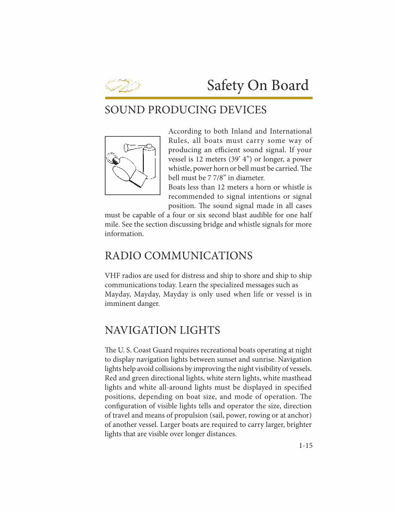
Safety On BoardSOUND PRODUCING DEVICES
According to both Inland and International Rules, all boats must carry some way of producing an effi cient sound signal. If your vessel is 12 meters (39’ 4”) or longer, a power whistle, power horn or bell must be carried. Th e bell must be 7 7/8” in diameter. Boats less than 12 meters a horn or whistle is recommended to signal intentions or signal position. Th e sound signal made in all cases
must be capable of a four or six second blast audible for one half mile. See the section discussing bridge and whistle signals for more information.
RADIO COMMUNICATIONSVHF radios are used for distress and ship to shore and ship to ship communications today. Learn the specialized messages such as Mayday, Mayday, Mayday is only used when life or vessel is in imminent danger.
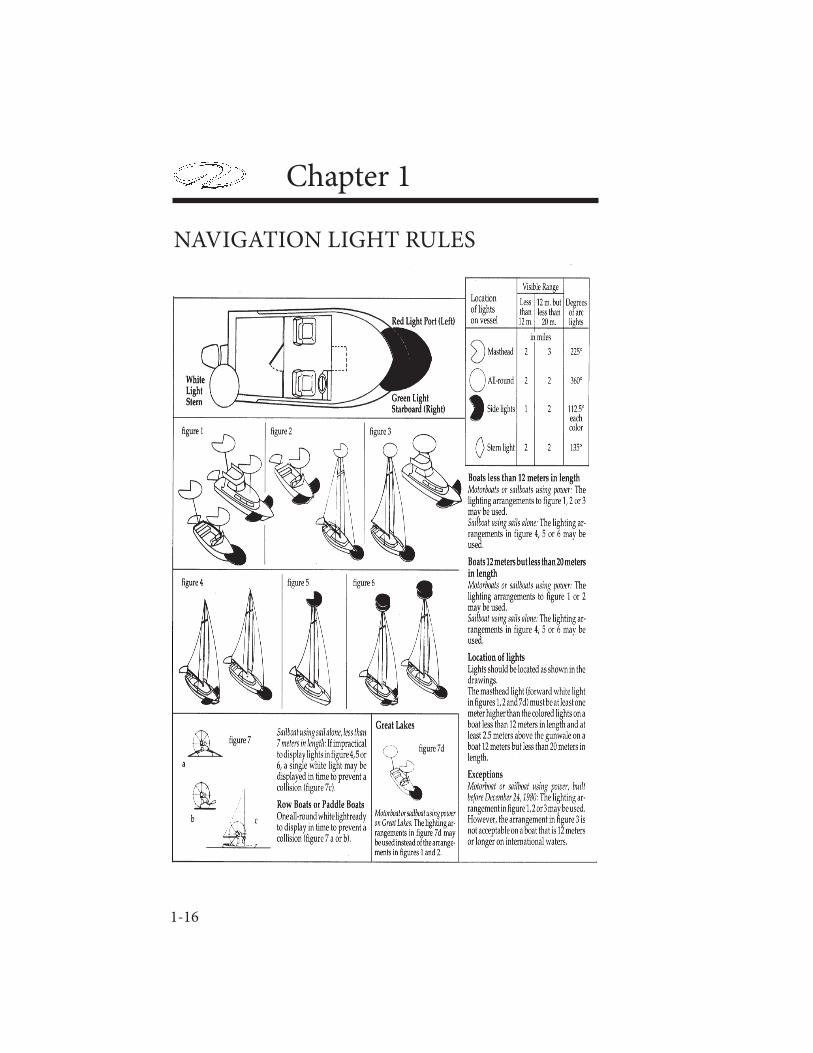
NAVIGATION LIGHTSTh e U. S. Coast Guard requires recreational boats operating at night to display navigation lights between sunset and sunrise. Navigation lights help avoid collisions by improving the night visibility of vessels. Red and green directional lights, white stern lights, white masthead lights and white all-around lights must be displayed in specifi ed positions, depending on boat size, and mode of operation. Th e confi guration of visible lights tells and operator the size, direction of travel and means of propulsion (sail, power, rowing or at anchor) of another vessel. Larger boats are required to carry larger, brighter lights that are visible over longer distances.
1-16
Chapter 1
NAVIGATION LIGHT RULES

1-17
Safety On Board
POLLUTION REGULATIONS
Th e Federal Water Pollution Control Act prohibits the discharge of oil or hazardous substances which may be harmful into U. S. navigable waters. Vessels 26’and larger must display a placard at least 5” x 8”, made of durable material, fi xed in a conspicuous machinery space location, stating the following:
All vessels regardless of size must immediately notify the U. S. Coast Guard if your vessel discharges oil or hazardous substances in the water. Call toll free 800-424-8802. Report the following information: location, source, size, color, substances and time observed. If installed, this placard may be located in the engine compartment.
1-18
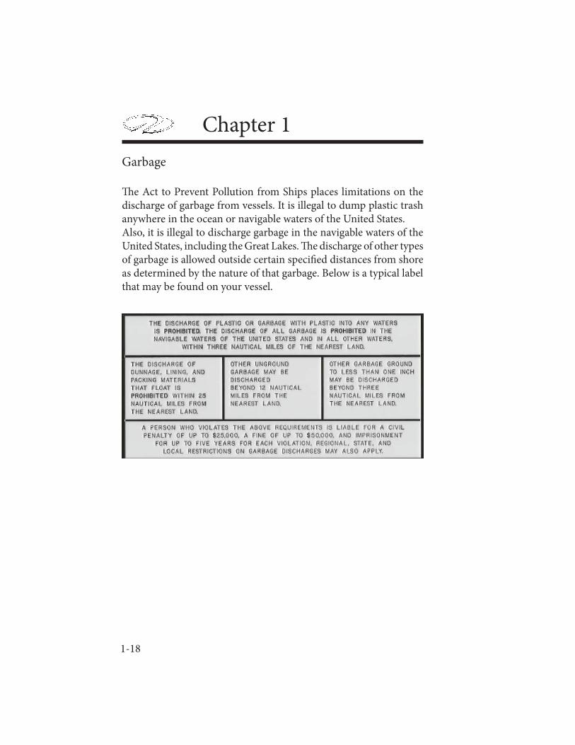
Chapter 1Garbage
Th e Act to Prevent Pollution from Ships places limitations on the discharge of garbage from vessels. It is illegal to dump plastic trash anywhere in the ocean or navigable waters of the United States. Also, it is illegal to discharge garbage in the navigable waters of the United States, including the Great Lakes. Th e discharge of other types of garbage is allowed outside certain specifi ed distances from shore as determined by the nature of that garbage. Below is a typical label that may be found on your vessel.

1-19
Safety On Board
1-20
Chapter 1
Remember the U. S. Coast Guard requirements are minimal standards. Th ey are an excellent starting point. Check with local and state boating agencies for further required safety equipment. You are best prepared for emergencies by a well equipped vessel. Don’t skimp when purchasing equipment for your boat!
COMMUNICATIONS
It is a good idea to carry communication gear such as a VHF-FM and/or HF transceivers set up for your operating area. Also, cell phones are useful in many coastal areas. Be sure to carry extra batteries. Also, mainly for off shore vessels, EPIRB’s are designed to quickly and accurately alert rescue forces, indicate an
accurate distress position, and guide units to the distress scene. Th ese devices operate from satellite signals sent to a ground station where the signal is downloaded. Th e downside is that they are relatively expensive and are used less today by the recreational boater but they are reliable even when other communications have been exhausted.
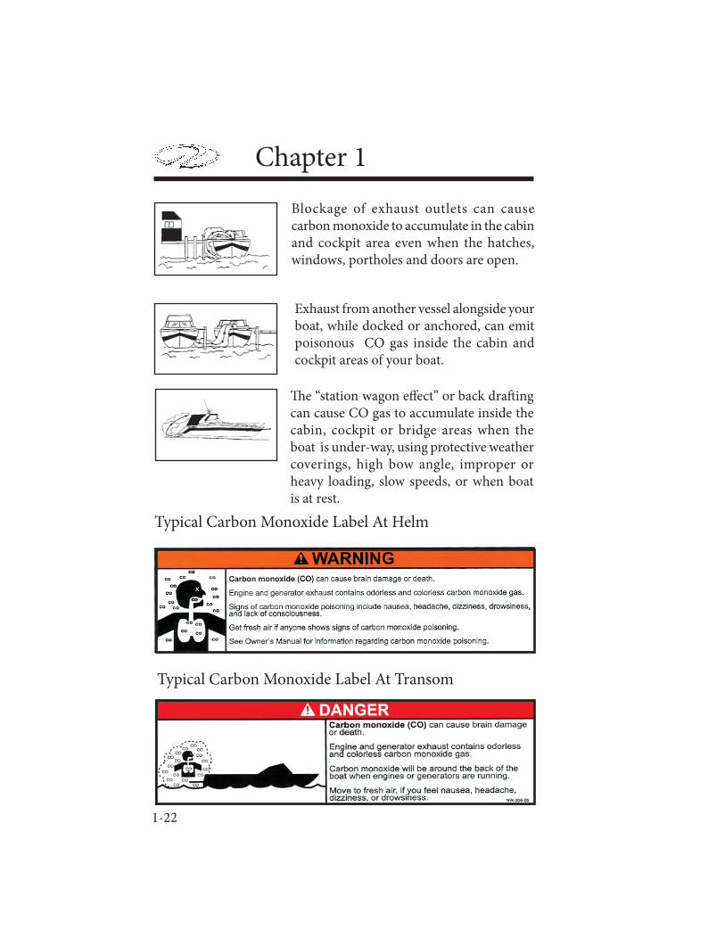
LIFE RAFTS
I n f l a t a b l e l i f e r a f t s a r e recommended for oceangoing and operating a vessel in a large body of water like the Great Lakes. They provide a shelter for extended periods. If used,
make sure it is large enough for all aboard and contains the proper emergency equipment pack. Periodically fi nd a professional to service the life raft . Store it on board in an area safe from sharp objects. Make sure the life raft is Coast Guard approved.
EPIRB

1-21
Safety On Board
EXHAUST & CARBON MONOXIDECarbon monoxide (CO) in exhaust can be hazardous. It is important for you and your passengers to be aware of the potential safety hazard created by exhaust gases. Familiarize yourself with the symptoms of carbon monoxide poisoning.
For safety sake avoid the following:
1. Do not allow the boat to remain stationary with the engine idling for an extended period of time.2. Do not disable the carbon monoxide alarms that come with your Regal boat. Test the unit in accordance with the alarm manufacturers instructions.
3. Do not operate the engine for extended periods of time while in a confi ned area or where exhaust outlets face a wall or bulkhead.
4. Do not operate the engine for an extended period of time with the canvas in the upright and installed position.
5. Have the engine exhaust system inspected when the boat is in for service.
6. Persons sleeping can easily be overcome by carbon monoxide without realizing it. Do not sleep on board while the engine is running or a neighboring boats engine is running.
AVOID SERIOUS INJURY OR DEATH FROM CO POISONING!DO NOT OPERATE THE VESSEL WITH PEOPLE
HOLDING ON TO THE SWIM PLATFORMWHILE IN THE WATER.
WARNING
1-22
Chapter 1
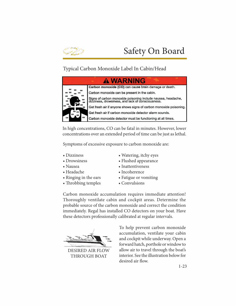
Th e “station wagon eff ect” or back draft ing can cause CO gas to accumulate inside the cabin, cockpit or bridge areas when the boat is under-way, using protective weather coverings, high bow angle, improper or heavy loading, slow speeds, or when boat is at rest.
Blockage of exhaust outlets can cause carbon monoxide to accumulate in the cabin and cockpit area even when the hatches, windows, portholes and doors are open.
Exhaust from another vessel alongside your boat, while docked or anchored, can emit poisonous CO gas inside the cabin and cockpit areas of your boat.
Typical Carbon Monoxide Label At Helm
Typical Carbon Monoxide Label At Transom
1-23
Safety On Board
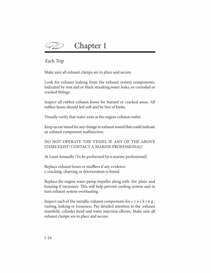
In high concentrations, CO can be fatal in minutes. However, lower concentrations over an extended period of time can be just as lethal.
Symptoms of excessive exposure to carbon monoxide are:
• Dizziness • Watering, itchy eyes • Drowsiness • Flushed appearance • Nausea • Inattentiveness• Headache • Incoherence• Ringing in the ears • Fatigue or vomiting• Th robbing temples • Convulsions Carbon monoxide accumulation requires immediate attention! Thoroughly ventilate cabin and cockpit areas. Determine the probable source of the carbon monoxide and correct the condition immediately. Regal has installed CO detectors on your boat. Have these detectors professionally calibrated at regular intervals.
To help prevent carbon monoxide accumulation, ventilate your cabin and cockpit while underway. Open a forward hatch, porthole or window to allow air to travel through the boat’s interior. See the illustration below for desired air fl ow.
DESIRED AIR FLOWTHROUGH BOAT
Typical Carbon Monoxide Label In Cabin/Head
1-24
Chapter 1
Make sure all exhaust clamps are in place and secure.
Look for exhaust leaking from the exhaust system components, indicated by rust and or black streaking,water leaks, or corroded or cracked fi ttings.
Inspect all rubber exhaust hoses for burned or cracked areas. All rubber hoses should feel soft and be free of kinks.
Visually verify that water exits at the engine exhaust outlet.
Keep an ear tuned for any change in exhaust sound that could indicate an exhaust component malfunction.
DO NOT OPERATE THE VESSEL IF ANY OF THE ABOVE ITEMS EXIST! CONTACT A MARINE PROFESSIONAL!
At Least Annually (To be performed by a marine professional)
Replace exhaust hoses or muffl ers if any evidence o cracking, charring or deterioration is found.
Replace the engine water pump impeller along with the plate and housing if necessary. Th is will help prevent cooling system and in turn exhaust system overheating.
Inspect each of the metallic exhaust components for c r a c k i n g , rusting, leaking or looseness. Pay detailed attention to the exhaust manifold, cylinder head and water injection elbows. Make sure all exhaust clamps are in place and secure.
Each Trip
1-25
Safety On Board
BOATING UNDER THE INFLUENCE
Operating a vessel while intoxicated became a specifi c federal off ense eff ective in 1988. Th e ruling set federal standards for determining when an individual is intoxicated. If the blood alcohol content (BAC) is .10% (.08 in some states) or higher for operators of recreational vessels being used only for pleasure are subject to a civil penalty up to $1,000 or criminal penalty up to $5,000, one year imprisonment or both. In some states the fi nes and imprisonment may increase signifi cantly.Th e eff ects of alcohol and drugs account for the highest single cause of marine accidents and deaths. Most deaths in boating accidents occur when someone falls into the water. Balance is one of the fi rst things you lose when drinking alcohol or under the infl uence of drugs. Th e problem arises out of not knowing your balance is restricted.Overall vision is reduced by alcohol especially at night, along with double or blurred vision. Peripheral vision is lessened which restricts seeing vessels or objects on the side. Also, color awareness decreases especially with red and green which happen to be the colors of boat navigation lights, buoys, and channel markers. Alcohol will greatly increase your heat loss so it increases the eff ects of hypothermia. Finally, your ability to make correct judgements in emergency situations is greatly reduced. Alcohol takes away the brains ability to process information quickly and delays a persons reaction time. Don’t drink and drive!
FEDERAL LAWS PROHIBIT OPERATING A VESSELUNDER THE INFLUENCE OF ALCOHOL OR DRUGS.
THESE LAWS ARE VIGOROUSLY ENFORCEDBY ALL LAW ENFORCEMENT AGENCIES.
WARNING
1-26
Chapter 1
Alcohol Myths And Facts
Myth: Beer is less intoxicating than other alcoholic beverages.Fact: One 12 oz. can of beer has about the same amount of alcohol as a 5oz. glass of wine or a shot of liquor. Myth: Black coff ee, fresh air, and a shower will sober the eff ects of alcohol.Fact: Aft er consuming alcohol time is the only thing that will sober you up. Our bodies average burning 1 oz. of alcohol every hour. If a person is drunk, it will take about seven or more hours to sober up.Myth: Telling if a person is too drunk to operate a vessel is easy.Fact: Many experienced drinkers have learned to compensate for the visual eff ects of alcohol and can disguise their drunk condition.Myth: You’re the best person to judge if you are fi t to operate a boat.Fact: Judgement is one of the fi rst elements you lose when drinking.
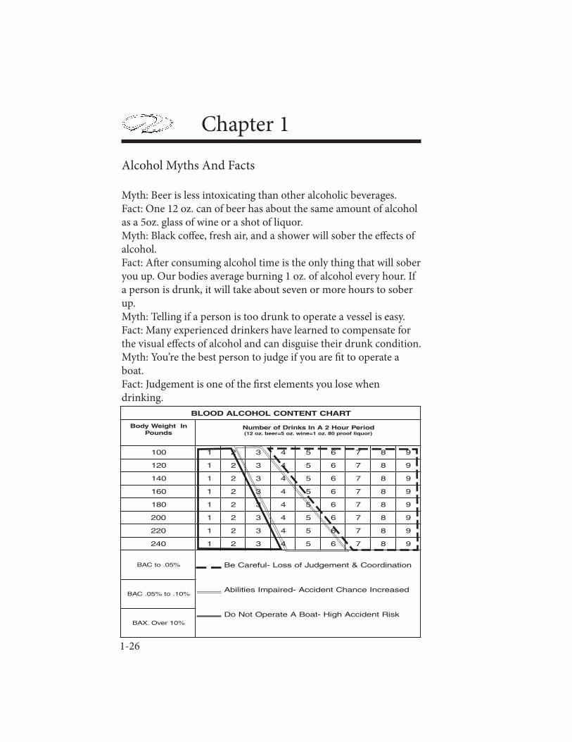
TRAHCTNETNOCLOHOCLADOOLB
nIthgieWydoBsdnuoP
doirePruoH2AnIsknirDforebmuN)rouqilfoorp08.zo1=eniw.zo5=reeb.zo21(
001 1 2 3 4 5 6 7 8 9
021 1 2 3 4 5 6 7 8 9
041 1 2 3 4 5 6 7 8 9
061 1 2 3 4 5 6 7 8 9
081 1 2 3 4 5 6 7 8 9
002 1 2 3 4 5 6 7 8 9
022 1 2 3 4 5 6 7 8 9
042 1 2 3 4 5 6 7 8 9
%50.otCAB noitanidrooC&tnemegduJfossoL-luferaCeB
desaercnIecnahCtnediccA-deriapmIseitilibA
ksiRtnediccAhgiH-taoBAetarepOtoNoD
%01.ot%50.CAB
%01revO.XAB
1-27
Safety On Board
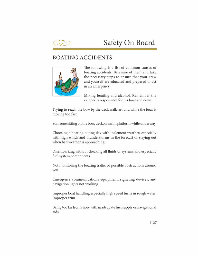
BOATING ACCIDENTSTh e following is a list of common causes of boating accidents. Be aware of them and take the necessary steps to ensure that your crew and yourself are educated and prepared to act in an emergency.
Mixing boating and alcohol. Remember the skipper is responsible for his boat and crew.
Trying to reach the bow by the deck walk-around while the boat is moving too fast.
Someone sitting on the bow, deck, or swim platform while underway.
Choosing a boating outing day with inclement weather, especially with high winds and thunderstorms in the forecast or staying out when bad weather is approaching..
Disembarking without checking all fl uids or systems and especially fuel system components.
Not monitoring the boating traffi c or possible obstructions around you.
Emergency communications equipment, signaling devices, and navigation lights not working.
Improper boat handling especially high speed turns in rough water. Improper trim.
Being too far from shore with inadequate fuel supply or navigational aids.
1-28
Chapter 1Passengers, especially children that are not wearing the proper life saving devices.
Skipper or passengers not seated in the boat.
Running a craft that is mechanically marginal.
Reporting Boating Accidents
According to the Federal Boat Safety Act of 1971 involving collision, accident or other casualty, the operator must make a formal report within 48 hours to the nearest state boating authority when the incident involves:
1. Death2. Injury requiring treatment other than fi rst aid3. Th e disappearance of someone from a boat under death or injury circumstances.
A formal report must be made within 10 days for accidents involving more than $500 damage or complete loss of vessel.For information regarding accident reporting, please call:
Boating Safety Hotline at 800-368-5647.
Rendering Assistance
Th e operator of a vessel is obligated by law to provide assistance that can be provided safely to any individuals in dangerous situation on the waterways. Th e operator is subject to fi ne and or imprisonment for failure to do so. Move cautiously and think before acting.
1-29
Safety On Board
WATER SPORTS
Besides learning the safety precautions for safe boating, as well as understanding and knowing required rules and regulations, you are obligated to be particularly careful around other water sportsman, such as scuba divers, water skiers, wakeboarders, and fi sherman.
Skin & Scuba Divers
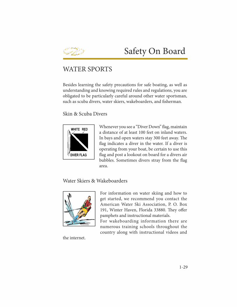
Whenever you see a “Diver Down” fl ag, maintain a distance of at least 100 feet on inland waters. In bays and open waters stay 300 feet away. Th e fl ag indicates a diver in the water. If a diver is operating from your boat, be certain to use this fl ag and post a lookout on board for a divers air bubbles. Sometimes divers stray from the fl ag area.
Water Skiers & Wakeboarders
For information on water skiing and how to get started, we recommend you contact the American Water Ski Association, P. O. Box 191, Winter Haven, Florida 33880. Th ey off er pamphets and instructional materials.For wakeboarding information there are numerous training schools throughout the country along with instructional videos and
the internet.

1-30
Chapter 1General safety procedures for towing skiers and wakeboarders include the following:
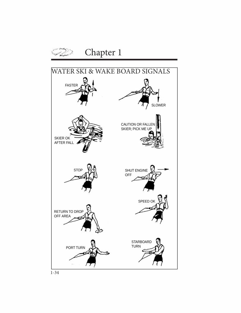
Know your hand signals and make sure all your passengers know them. See the illustration.
Do not allow non-swimmers to ski or wakeboard. You’re asking for trouble!
Always have an observer on board whose sole job is to watch the skier/wakeboarder and communicate with the driver.
If you plan to do alot of skiing/wakeboarding, it is advisable to have a ski pylon and driver’s rear view mirror installed.
Acquaint yourself with the ski site before skiing/wakeboarding.
Follow the speed limits and all posted signs- i.e. no wake, etc.
Keep the boat away from swimmers or other people in the water.
Avoid running near the shoreline or in heavily congested areas with skier/wakeboarder in tow.
Do not allow skier/wakeboarder to spray fi sherman or other parties.
Keep the engine speed steady while towing a skier/wakeboarder.
Make wide turns with skier/wakeboarder in tow.
Instruct skier/wakeboarder in case of a fall to raise his ski in the air to ensure his visibility.
Always turn your engine off when the skier/wakeboarder is near the platform or transom.
1-31
Safety On BoardIf the skier falls, return promptly to retrieve him, circling wide from the starboard side, to bring his rope within easy grasp. See illustration.
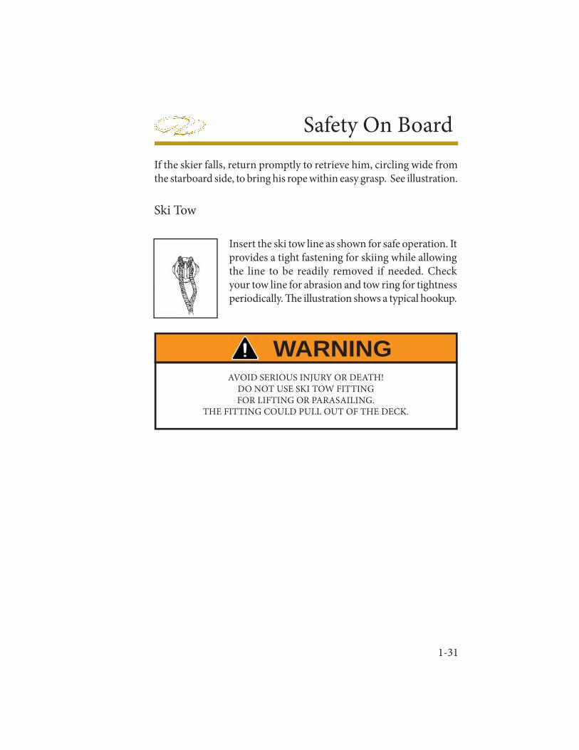
Insert the ski tow line as shown for safe operation. It provides a tight fastening for skiing while allowing the line to be readily removed if needed. Check your tow line for abrasion and tow ring for tightness periodically. Th e illustration shows a typical hookup.
Ski Tow
AVOID SERIOUS INJURY OR DEATH! DO NOT USE SKI TOW FITTINGFOR LIFTING OR PARASAILING.
THE FITTING COULD PULL OUT OF THE DECK.
WARNING
1-32
Chapter 1
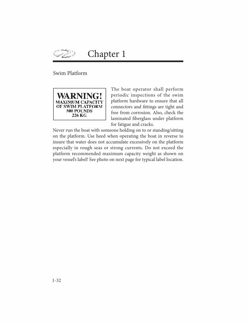
The boat operator shall perform periodic inspections of the swim platform hardware to ensure that all connectors and fi ttings are tight and free from corrosion. Also, check the laminated fi berglass under platform for fatigue and cracks.
Never run the boat with someone holding on to or standing/sitting on the platform. Use heed when operating the boat in reverse to insure that water does not accumulate excessively on the platform especially in rough seas or strong currents. Do not exceed the platform recommended maximum capacity weight as shown on your vessel’s label! See photo on next page for typical label location.
Swim Platform
1-33
Safety On Board
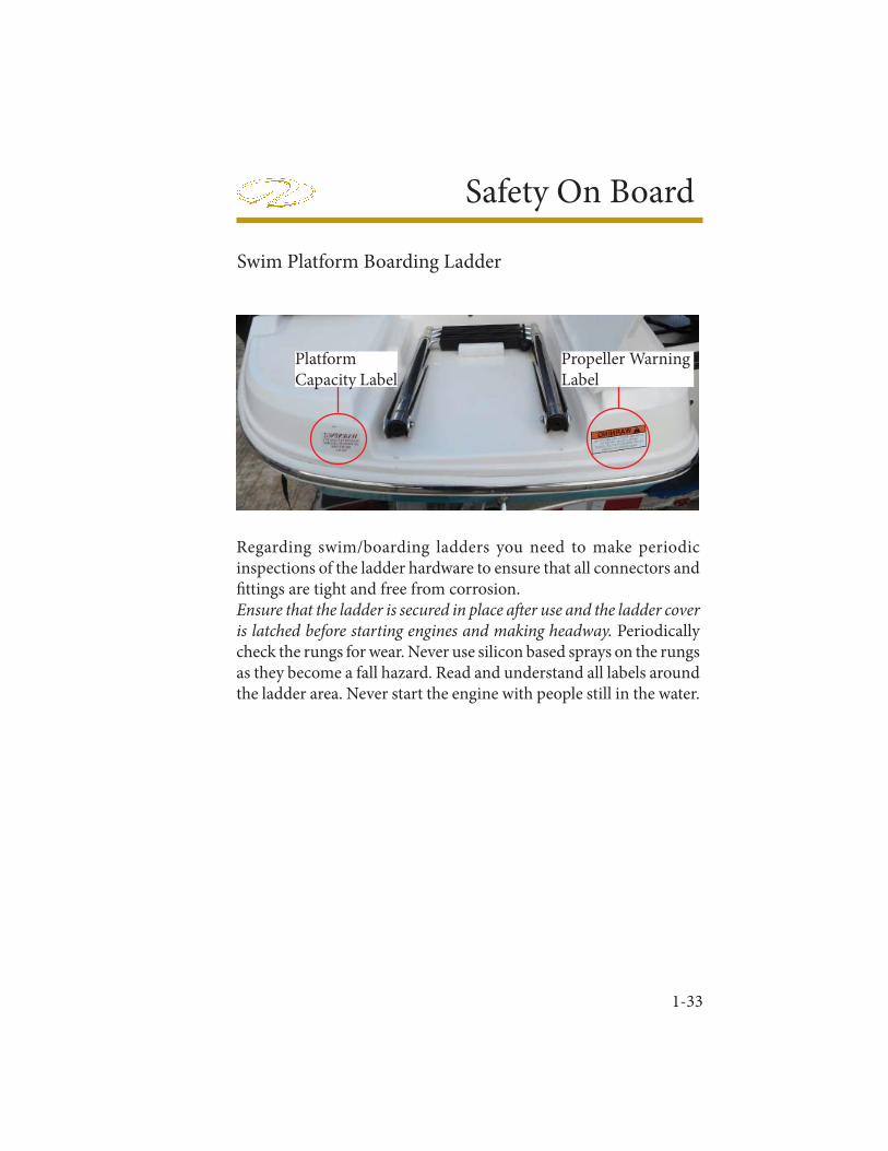
Swim Platform Boarding Ladder
Regarding swim/boarding ladders you need to make periodic inspections of the ladder hardware to ensure that all connectors and fi ttings are tight and free from corrosion. Ensure that the ladder is secured in place aft er use and the ladder cover is latched before starting engines and making headway. Periodically check the rungs for wear. Never use silicon based sprays on the rungs as they become a fall hazard. Read and understand all labels around the ladder area. Never start the engine with people still in the water.
PlatformCapacity Label
Propeller WarningLabel
1-34
Chapter 1
WATER SKI & WAKE BOARD SIGNALS
FASTER
SLOWER
SKIER OKAFTER FALL
CAUTION OR FALLENSKIER; PICK ME UP
STOP SHUT ENGINEOFF
RETURN TO DROPOFF AREA
SPEED OK
PORT TURN
STARBOARDTURN
1-35
Safety On Board
Fishing
Most boaters fi sh from time to time. With the propulsion systems of today it is possible to fi sh in out-of-the-way places. When cruising, stay clear of fi sherman. Th ey may have lines or nets out which might be cut or get caught in your propeller if you come too close. Slow down when approaching fi shing boats. Do not return to cruising speed until the boats have been passed. If a fi shing boat should be
anchored, a large wake could fl ip or swamp the boat, upset fi shing gear, pull the anchor loose from the bottom or worse yet cause someone to fall overboard.When fi shing from your boat, never anchor in shipping channel or tie up to any navigational aids. Th ese must be kept clear of at all times.Be sure to carry a chart of the area and be on the lookout for shallow water and hidden obstructions. Pick up a local tidal chart if appropriate so you do not end up grounded. Remember, the skipper is responsible for any damage caused by his wake. Use common sense and be a responsible captain!
AVOID SERIOUS INJURY OR DEATH! DO NOT OPERATE THE VESSEL
WITH PEOPLE IN THE WATER ORHOLDING ON TO THE SWIM PLATFORM STRUCTURE
OR HARDWARE.
WARNING
1-36
Chapter 1
WEATHER & WATER CONDITIONS
Before a boating outing check the weather conditions. As we all know the weather can change rapidly in many parts of the country. It does so sometimes without being predicted. NOAA weather radio reports are continuously available on designated frequencies installed on VHF radios and various handheld devices. Also, many local radio stations carry weather reports.
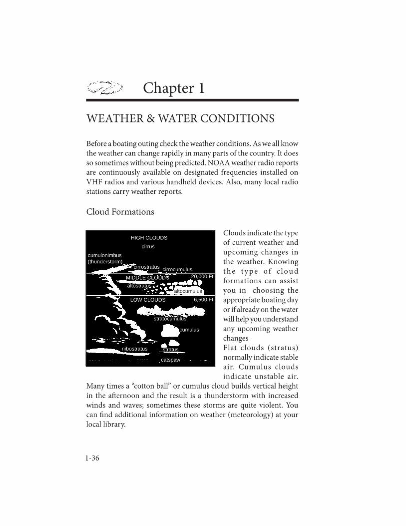
Cloud Formations
Clouds indicate the type of current weather and upcoming changes in the weather. Knowing t h e t y p e o f c l ou d formations can assist you in choosing the appropriate boating day or if already on the water will help you understand any upcoming weather changesFlat clouds (stratus) normally indicate stable air. Cumulus clouds indicate unstable air.
Many times a “cotton ball” or cumulus cloud builds vertical height in the aft ernoon and the result is a thunderstorm with increased winds and waves; sometimes these storms are quite violent. You can fi nd additional information on weather (meteorology) at your local library.
20,000 Ft.
6,500 Ft.
HIGH CLOUDS
MIDDLE CLOUDS
LOW CLOUDS
catspaw
nibostratus stratus
cumulus
stratocumulus
cumulonimbus(thunderstorm)
cirrus
cirrostratus cirrocumulus
altostratusaltocumulus
1-37
Safety On Board
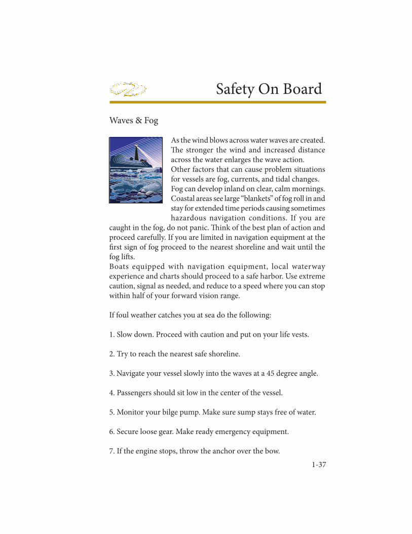
Waves & Fog
As the wind blows across water waves are created. Th e stronger the wind and increased distance across the water enlarges the wave action.Other factors that can cause problem situations for vessels are fog, currents, and tidal changes.Fog can develop inland on clear, calm mornings. Coastal areas see large “blankets” of fog roll in and stay for extended time periods causing sometimes hazardous navigation conditions. If you are
caught in the fog, do not panic. Th ink of the best plan of action and proceed carefully. If you are limited in navigation equipment at the fi rst sign of fog proceed to the nearest shoreline and wait until the fog lift s.Boats equipped with navigation equipment, local waterway experience and charts should proceed to a safe harbor. Use extreme caution, signal as needed, and reduce to a speed where you can stop within half of your forward vision range.
If foul weather catches you at sea do the following:
1. Slow down. Proceed with caution and put on your life vests.
2. Try to reach the nearest safe shoreline.
3. Navigate your vessel slowly into the waves at a 45 degree angle.
4. Passengers should sit low in the center of the vessel.
5. Monitor your bilge pump. Make sure sump stays free of water.
6. Secure loose gear. Make ready emergency equipment.
7. If the engine stops, throw the anchor over the bow.
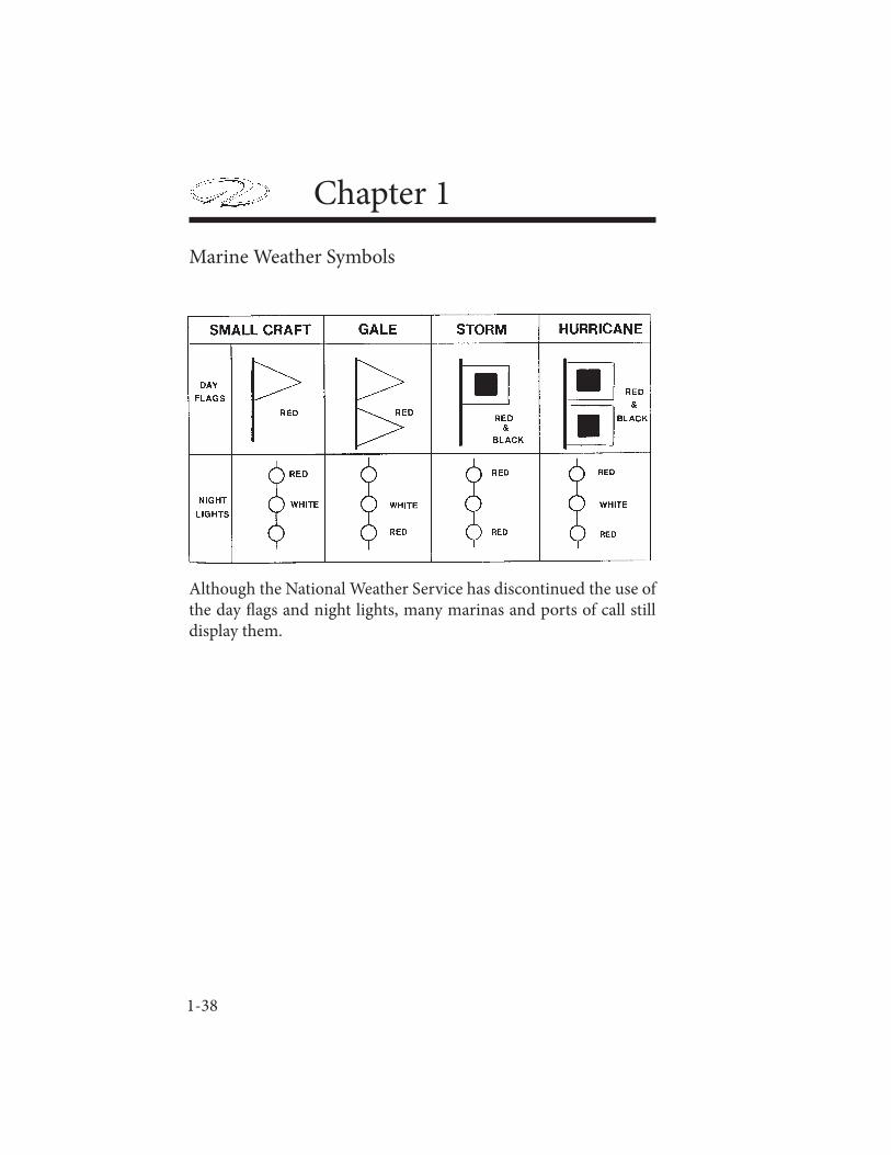
1-38
Chapter 1
Marine Weather Symbols
Although the National Weather Service has discontinued the use of the day fl ags and night lights, many marinas and ports of call still display them.
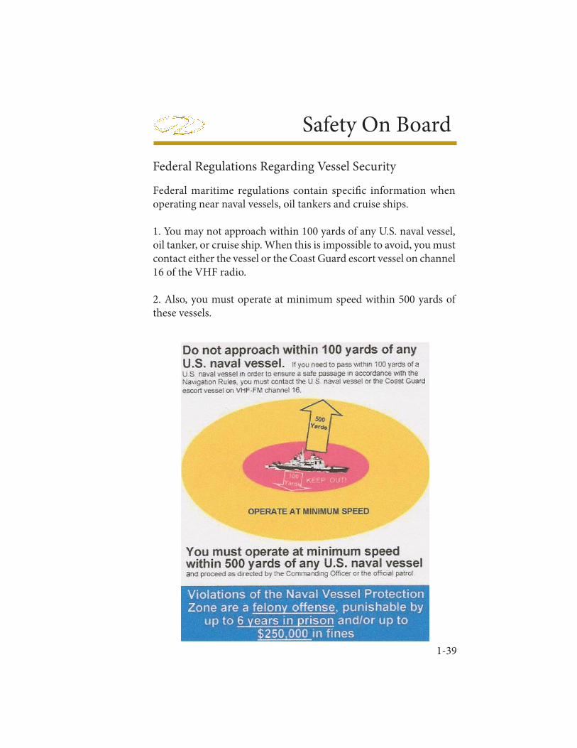
1-39
Safety On Board
Federal Regulations Regarding Vessel Security
Federal maritime regulations contain specifi c information when operating near naval vessels, oil tankers and cruise ships.
1. You may not approach within 100 yards of any U.S. naval vessel, oil tanker, or cruise ship. When this is impossible to avoid, you must contact either the vessel or the Coast Guard escort vessel on channel 16 of the VHF radio.
2. Also, you must operate at minimum speed within 500 yards of these vessels.

1-40
Chapter 1
Notes
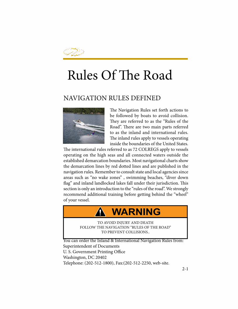
Rules Of � e Road
2-1
NAVIGATION RULES DEFINED
� e Navigation Rules set forth actions to be followed by boats to avoid collision. � ey are referred to as the “Rules of the Road”. � ere are two main parts referred to as the inland and international rules. � e inland rules apply to vessels operating inside the boundaries of the United States.
� e international rules referred to as 72 COLREGS apply to vessels operating on the high seas and all connected waters outside the established demarcation boundaries. Most navigational charts show the demarcation lines by red dotted lines and are published in the navigation rules. Remember to consult state and local agencies since areas such as “no wake zones” , swimming beaches, “diver down ! ag” and inland landlocked lakes fall under their jurisdiction. � is section is only an introduction to the “rules of the road”. We strongly recommend additional training before getting behind the “wheel” of your vessel.
You can order the Inland & International Navigation Rules from:Superintendent of DocumentsU. S. Government Printing O" ceWashington, DC 20402Telephone: (202-512-1800), Fax:(202-512-2250, web-site.
TO AVOID INJURY AND DEATH FOLLOW THE NAVIGATION “RULES OF THE ROAD”
TO PREVENT COLLISIONS..
Chapter 2
2-2
NAVIGATION RULES
Right Of Way
1. Cross waves at right angles.
2. When caught in heavy water or squalls, head either directly into the waves or at a slight angle. Reduce speed, but maintain enough power to maneuver your boat safely.
3. Keep your speed under control. Respect the rights of other boaters engaged in all water sports. Give them a “wide berth”.
4. Whenever meeting a boat head on, keep to the right where possible.
5. When two boats cross, the boat to the right (starboard) has the right of way.
6. When overtaking or passing, the boat being passed has the right of way.
In general, boats with less maneuverability have right-of-way over more agile cra! . " e skipper must keep his cra! clear of the following vessels:• A vessel not under command or aground; due to their circumstances, these vessels have no maneuverability.
• A vessel restricted in its maneuverability; these vessels usually are performing work which limits their maneuverability such as surveying, dredging, laying pipe or cable, or servicing navigational markers among others.
• A vessel engaged in # shing; these include boats # shing with lines, trawls or nets, but not trolling lines.
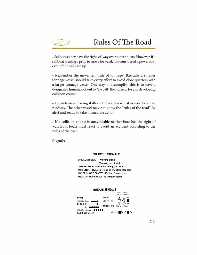
Rules Of � e Road
2-3
• Sailboats; they have the right-of-way over power boats. However, if a sailboat is using a prop to move forward, it is considered a powerboat even if the sails are up.
• Remember the unwritten “rule of tonnage”. Basically a smaller tonnage vessel should take every e! ort to avoid close quarters with a larger tonnage vessel. One way to accomplish this is to have a designated human lookout to “eyeball” the horizon for any developing collision course.
• Use defensive driving skills on the waterway just as you do on the roadway. � e other vessel may not know the “rules of the road” Be alert and ready to take immediate action.
• If a collision course is unavoidable neither boat has the right of way. Both boats must react to avoid an accident according to the rules of the road.
Signals
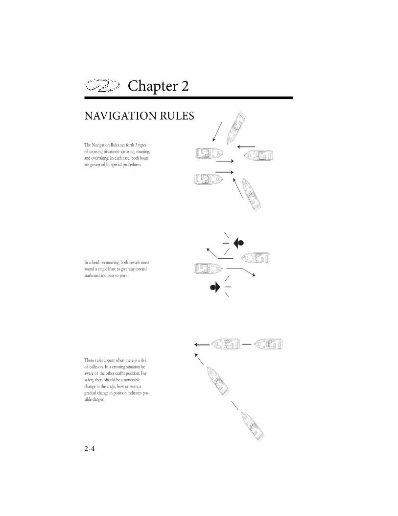
Chapter 2
2-4
The Navigation Rules set forth 3 types
of crossing situations- crossing, meeting,
and overtaking. In each case, both boats
are governed by special procedures.
In a head-on meeting, both vessels must
sound a single blast to give way toward
starboard and pass to port.
These rules appear when there is a risk
of collision. In a crossing situation be
aware of the other craft's position. For
safety, there should be a noticeable
change in the angle, bow or stern; a
gradual change in position indicates pos-
sible danger.
NAVIGATION RULES
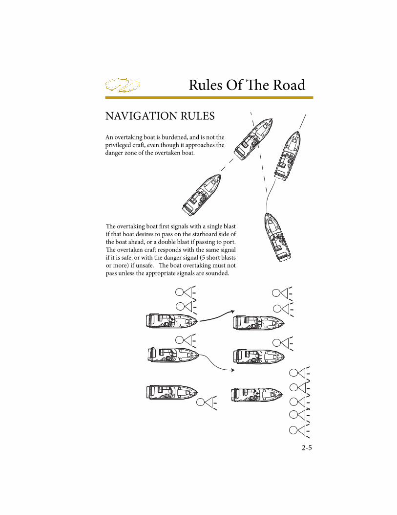
Rules Of � e Road
2-5
An overtaking boat is burdened, and is not the privileged cra! , even though it approaches the danger zone of the overtaken boat.
� e overtaking boat " rst signals with a single blast if that boat desires to pass on the starboard side of the boat ahead, or a double blast if passing to port. � e overtaken cra! responds with the same signal if it is safe, or with the danger signal (5 short blasts or more) if unsafe. � e boat overtaking must not pass unless the appropriate signals are sounded.
NAVIGATION RULES
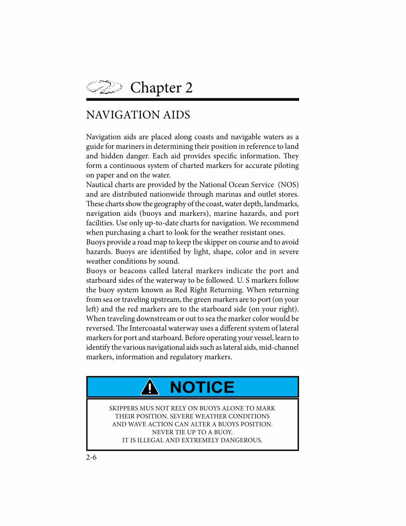
Chapter 2
2-6
NAVIGATION AIDS
Navigation aids are placed along coasts and navigable waters as a guide for mariners in determining their position in reference to land and hidden danger. Each aid provides speci! c information. " ey form a continuous system of charted markers for accurate piloting on paper and on the water.Nautical charts are provided by the National Ocean Service (NOS) and are distributed nationwide through marinas and outlet stores. " ese charts show the geography of the coast, water depth, landmarks, navigation aids (buoys and markers), marine hazards, and port facilities. Use only up-to-date charts for navigation. We recommend when purchasing a chart to look for the weather resistant ones.Buoys provide a road map to keep the skipper on course and to avoid hazards. Buoys are identi! ed by light, shape, color and in severe weather conditions by sound.Buoys or beacons called lateral markers indicate the port and starboard sides of the waterway to be followed. U. S markers follow the buoy system known as Red Right Returning. When returning from sea or traveling upstream, the green markers are to port (on your le# ) and the red markers are to the starboard side (on your right). When traveling downstream or out to sea the marker color would be reversed. " e Intercoastal waterway uses a di$ erent system of lateral markers for port and starboard. Before operating your vessel, learn to identify the various navigational aids such as lateral aids, mid-channel markers, information and regulatory markers.
SKIPPERS MUS NOT RELY ON BUOYS ALONE TO MARK THEIR POSITION. SEVERE WEATHER CONDITIONS
AND WAVE ACTION CAN ALTER A BUOYS POSITION.NEVER TIE UP TO A BUOY.
IT IS ILLEGAL AND EXTREMELY DANGEROUS.
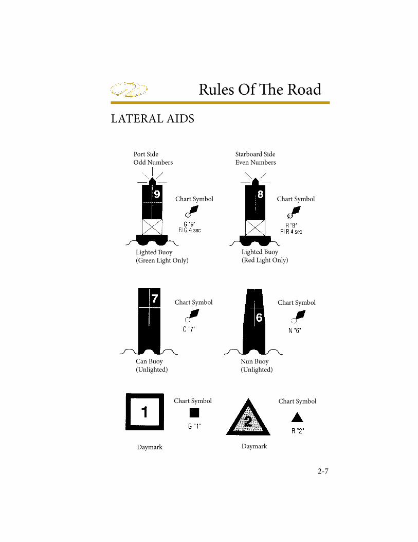
Rules Of � e Road
2-7
LATERAL AIDS
Starboard SideEven Numbers
Port SideOdd Numbers
Chart Symbol Chart Symbol
Chart Symbol Chart Symbol
Chart Symbol Chart Symbol
Lighted Buoy(Green Light Only)
Lighted Buoy(Red Light Only)
Can Buoy(Unlighted)
Nun Buoy(Unlighted)
Daymark Daymark
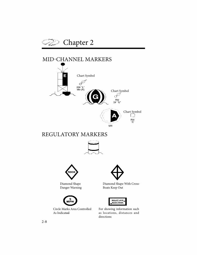
Chapter 2
2-8
Chart Symbol
Chart Symbol
Chart Symbol
Diamond ShapeDanger Warning
Diamond Shape With Cross-Boats Keep Out
Circle Marks Area Controlled As Indicated
For showing information such as locations, distances and directions
MID-CHANNEL MARKERS
REGULATORY MARKERS
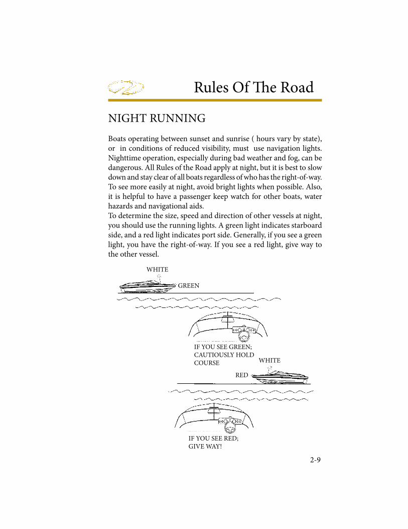
Rules Of � e Road
2-9
Boats operating between sunset and sunrise ( hours vary by state), or in conditions of reduced visibility, must use navigation lights. Nighttime operation, especially during bad weather and fog, can be dangerous. All Rules of the Road apply at night, but it is best to slow down and stay clear of all boats regardless of who has the right-of-way. To see more easily at night, avoid bright lights when possible. Also, it is helpful to have a passenger keep watch for other boats, water hazards and navigational aids.To determine the size, speed and direction of other vessels at night, you should use the running lights. A green light indicates starboard side, and a red light indicates port side. Generally, if you see a green light, you have the right-of-way. If you see a red light, give way to the other vessel.
NIGHT RUNNING
WHITE
WHITE
GREEN
RED
IF YOU SEE RED;GIVE WAY!
IF YOU SEE GREEN;CAUTIOUSLY HOLDCOURSE

BRIDGE CLEARANCE
Be aware that your vessel requires a speci� ed bridge clearance height. � is height is a measured estimate from the waterline to the top of the highest object usually the sport arch, radar or the masthead light depending on what arch equipment is installed. All canvas should be in the stored position. � e estimated height can change because of variances in the loaded condition of the vessel. Consult the bridge clearance speci� cations located in Chapter 12 (technical information section). An easy way to measure bridge clearance is to have someone place a long straightedge such as a piece of wood at a 90 degree angle across the highest point of the boat with the boat in the water. � en with a tape rule measure the distance straight down (90 degrees) to the waterline. Take this measurement with the fuel and water tanks 1/2 full and only 1 person besides yourself on board. � is will give you a safe measurement. As your boat is loaded down with people the bridge clearance will be slightly lower. Some bridges are tendered. Know and use the proper bridge signals when approaching these bridges (see bridge signals on page 2-3). You can also monitor and communicate on channel 13 of a VHF radio for bridge information in most domestic locals. Other bridges are marked with a clearance measurement and you are on your own. A� er determining your vessel will clear the bridge proceed with caution at a safe idle speed. Keep your eye on vessel tra� c at all times in order to react quickly. Resume a safe speed once clear of the bridge structure and acknowledgment of clear visibility.Use common sense regarding bridge clearance because bodily injury and property damage could result if a mishap occurs with a bridge.
2-10
Chapter 2
BRIDGE LIGHTING
Bridge lighting is maintained by the Department of Homeland Security. On the following pages are 2 typical examples of night-time bridge lighting. As the skipper approaches bascule and � xed bridges light position (arc of visibility) and color will indicate the safe channel
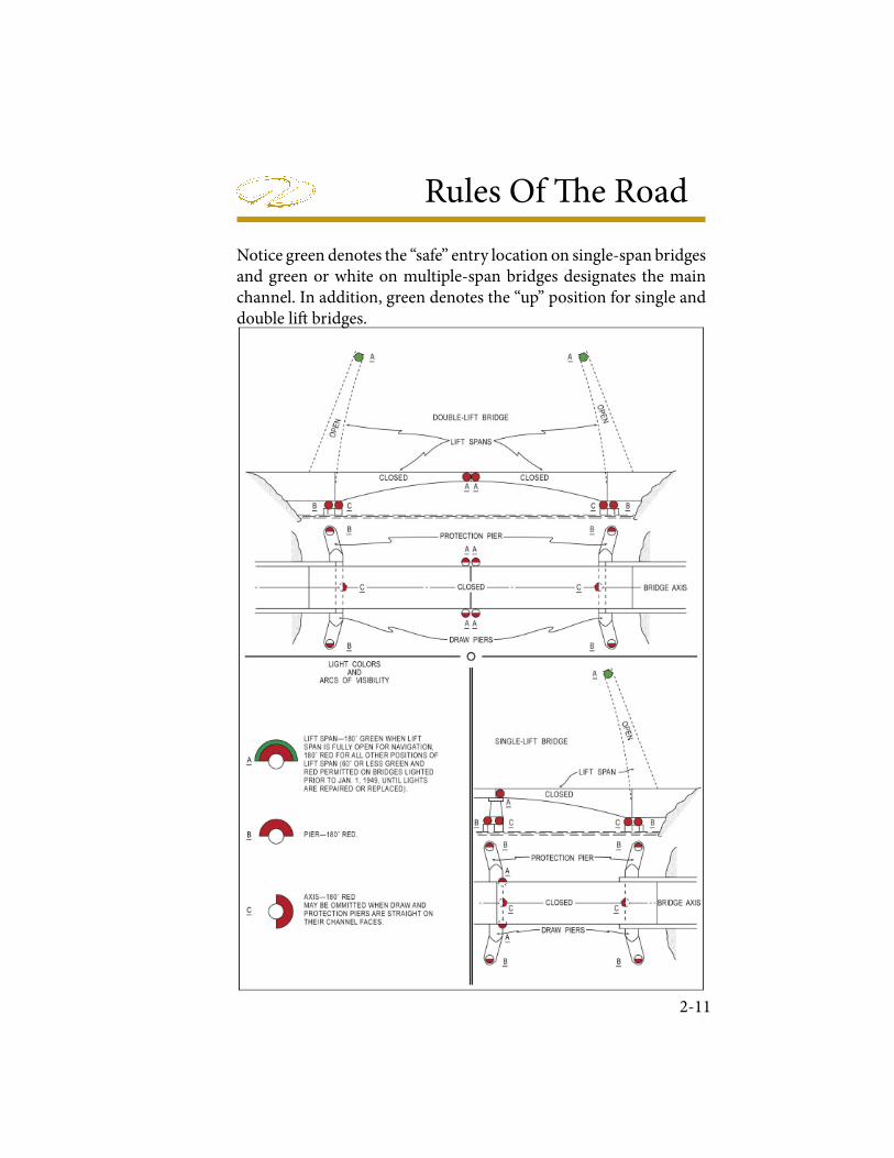
Rules Of � e Road
2-11
Notice green denotes the “safe” entry location on single-span bridges and green or white on multiple-span bridges designates the main channel. In addition, green denotes the “up” position for single and double li! bridges.
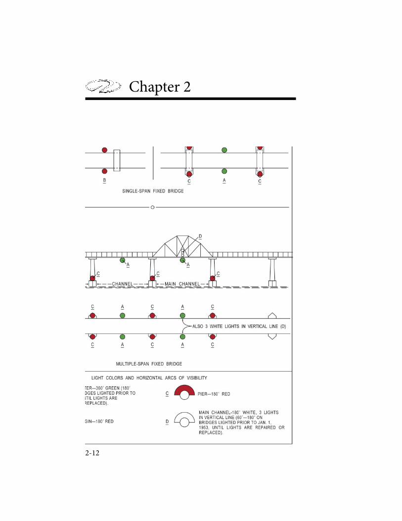
Chapter 2
2-12
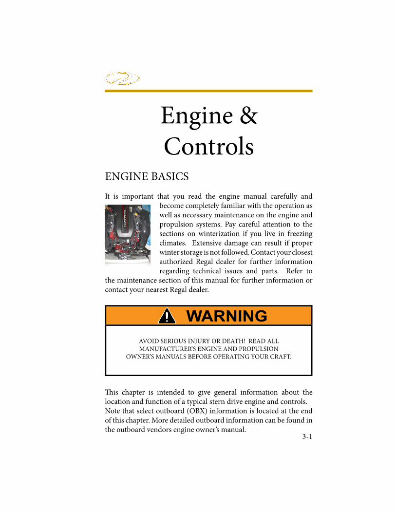
Engine & Controls
3-1
ENGINE BASICS
It is important that you read the engine manual carefully and become completely familiar with the operation as well as necessary maintenance on the engine and propulsion systems. Pay careful attention to the sections on winterization if you live in freezing climates. Extensive damage can result if proper winter storage is not followed. Contact your closest authorized Regal dealer for further information regarding technical issues and parts. Refer to
the maintenance section of this manual for further information or contact your nearest Regal dealer.
! is chapter is intended to give general information about the location and function of a typical stern drive engine and controls. Note that select outboard (OBX) information is located at the end of this chapter. More detailed outboard information can be found in the outboard vendors engine owner’s manual.
AVOID SERIOUS INJURY OR DEATH! READ ALL MANUFACTURER’S ENGINE AND PROPULSION
OWNER’S MANUALS BEFORE OPERATING YOUR CRAFT.
Chapter 3
Engine function is based o� four principles; fuel, compression, ignition, and exhaust. � e proper ratio of fuel and air must be drawn into the engine’s cylinders in order to be compressed by the pistons and ignited by a spark. � e force of which pushes the piston back down, providing the energy used to turn your propeller, before the engine kicks into the exhaust stage where it expels the by-products. If any of these four functions fail, so does the engine itself.
Beyond these basic concepts of engine functionality include engine cooling, lubrication, electrical, and ventilation systems. � e speci� c details of these systems can be found in your owner’s manual for the speci� c engine option you chose on your Regal boat. � ese options are limited to speci� c single drive Mercury and Volvo engines.
Engine Mounts
� e engine is placed in the boat on a set of metal or wooden platforms called mounts. In addition, engines use rubber insulated mounts to keep the engine from moving laterally and athwart ship (right angles to the center line), as well as reduce vibration from the engine and drive. Periodically, the mount hardware should be checked for tightness.
3-2
AVOID SERIOUS INJURY OR DEATH! USE ONLY APPROVEDMARINE REPLACEMENT PARTS THAT ARE IGNITION PROTECTED
IN AND AROUND THE ENGINE COMPARTMENT
Engine & Controls
Engine Alignment
! e engine uses a rubber spline hub to which the out drive sha" is attached. ! is alignment speci# cation between the engine and out drive needs to be checked periodically. It should be checked a" er every 50 hours of operation, or if the vessel has run aground or hit a submerged object. Alignment should be checked by a Regal dealer or marine professional, since special tools and procedures are required.
Engine Removal
In the event the engine or out drive (sometimes referred to as stern drive) require major service where it needs to be removed, consult your Regal dealer as they have special training on these procedures.
Engine Checklist Before Each Outing
Every engine option may require di$ erent checks before each use, but a general engine checklist is included here as a guide.
Engine/ Stern Drive:
Check the cooling system. Ensure there are no leaks, and that coolant level is su% cient.
Check the fuel pump for operation, and check fuel lines for leaks.
Check engine oil level.
Check power steering ' uid level.
Check power trim ' uid.
3-3
Chapter 3
At Helm/ Deck
Check power trim for operation.
Check control lever for operational defects. Check the clip and safety lanyard for functionality.
Check gauges for accuracy.
Check fuel level and ensure it is su! cient for the outboard and inbound trip with a reserve.
ENGINE COOLING SYSTEM
Your typical engine normally utilizes a raw water cooling system for cooling the engine. It is important that this system continues to run properly at all times to avoid hazardous situations and ensure a safe voyage.
Raw water is drawn up through the stern drive through pick-up feeds by the water pump. Water passes through a thermostat which controls how much cool water circulates through the engine before passing through a circulatory pump and impeller that distributes the coolant throughout the engine block. " e cool water absorbs heat produced by the engine, before being emitted via a coolant exhaust system.
Impeller/ Water Pump
Periodically, the coolant system’s impeller and pump should be inspected for debris or damage. Damaged parts will a# ect the system’s ability to function, and may cause engine damage.
3-4
Engine & Controls
Coolant Hoses
Before each trip, the coolant system should be checked for leaks. A! er locating the pump housing, check the hose feeds for leaks, particularly around the hose clamps. Inspect the hoses for signs of melting or cracks, and replace as necessary.
" ermostat
If the temperature gauge starts yielding abnormal readings, it may become necessary to look at or replace the engine thermostat a! er determining whether it is functioning properly. " e thermostat reads the temperature of coolant and determines whether to open or close a valve to allow warm sea water to pass into the exhaust manifold. " e thermostat may recirculate hot coolant for the purposes of reaching standard operating temperatures. If standard operating temperatures have been reached, the thermostat will open a valve and allow hot raw water to exit through the exhaust manifold. To inspect the thermostat, locate the thermostat housing, remove the housing, thermostat, o-ring, and gasket. Inspect these components for damage, and replace as necessary. Clean the intake manifold and thermostat housing at the location of the gasket to ensure a tight # t before replacing components.
3-5
AVOID OPENING THE FILLER CAP FOR THE COOLANT SYSTEM OR DISCONNECTING THE COOLANT SYSTEM HOSES WHILE THE
ENGINE IS STILL ON / HOT. UPON LOSS OF SYSTEM PRESSURE, STEAM OR HOT COOLANT CAN SPRAY OUT OF THE SYSTEM
CAUSING BURNS.

Chapter 3
Typical Open ! ermostat DiagramTypical Closed ! ermostat Diagram
Freshwater Flushing Port
Some engines o" er a fresh water # ushing system. A$ er linking up to a fresh water hose at the # ush port, water can be pumped through the engine’s raw water cooling system to # ush out all salt and debris that may be le$ behind. It is supposed to be utilized a$ er each trip to ensure a maximum lifespan of your cooling system components. Check your engine owner’s manual regarding this system’s availability and use. Some manufacturers incorporate a # ushing port directly into the engine’s coolant hose system while others require an adapter to be inserted onto the pick up feeds on the stern drive.
ENGINE ELECTRICAL SYSTEM
Your engine utilizes a great deal of electronic equipment. Some equipment sends signals between the engine and dash mounted instruments, while other systems set o" alarms, and still others are used by the engine to generate a spark and ignite the fuel. ! e battery switch controls electrical power distribution to the boat systems.To regularly maintain your DC electrical system, inspect the battery charge before each trip. Test all gauges and control equipment prior to departure, and replace as necessary. Spark plugs should
3-6
Engine & Controls
be replaced according to your engine owner’s manual maintenance schedule. When a fuse blows, investigate the problem, ! x it, and then replace the fuse.
Gauge Electrical Signals
Most engines transmit signals through electrical harnesses to di" erent components. # e thermostat for instance transmits an electrical signal to the dash temperature gauge which mechanically rotates the needle in the display to represent the approximate engine temperature. Faults in these electrical components should be fully inspected by your Regal dealer.
Alarms
When a malfunction with your engine or drive occurs, select engines will sound an alarm to alert the skipper of a problem. Common engine and stern drive problems include overheating, low oil pressure, or a miscommunication with equipment. Learn the alarm systems that apply to your engine by consulting your engine owner’s manual.
3-7
AVOID OPERATION OF THE ENGINE AFTER AN ALARM HAS SOUNDED. USE OF THE ENGINE WITHOUT ADDRESSING THE
PROBLEM MAY RESULT IN ENGINE DAMAGE OR FAILURE.
Chapter 3
Distributor
Your gasoline engine ignites the fuel by use of a spark generated at the precise moment when the fuel mixture has been fully compressed. However, your engine doesn’t spark each cylinder at the same time; each cylinder requires a spark according to which stage of the engine cycle the cylinder is located. A distributor takes the electrical current generated by the starter battery and distributes the electrical potential to each cylinder in turn as needed to generate the spark.
Spark Plugs
� e spark plugs are the parts that make the spark occur. As electrical potential builds on one side of the gap based upon the energy distributed by the distributor, the potential eventually grows large enough to cause the electric current to jump the gap on the spark plug. � is spark is what ignites the compressed fuel generating a controlled explosion that will power the piston down and deliver power to the drive sha� .
Alternator
Under normal circumstances, the starter battery would wear down a� er being used so o� en to generate a spark for the engine. � is isn’t an ideal setup because a strong battery is needed for continual operation. A weak battery does no good out on the water. � e alternator connected to a serpentine belt takes care of recharging the battery(ies). As the serpentine belt rotates the pulley, a magnet inside a coil of electric wire rotates with the pulley. � e rotation of this magnet inside the coil of wire (alternator) generates a current which is the used to recharge the battery.
3-8
Engine & Controls
However, in an e! ort to conserve battery life, the starter battery should still be turned o! a" er every trip. # is limits the drain on the battery while the boat is not in use. # e alternator will only recharge the battery while the engine is running. So if the battery is drained before it can provide the initial spark to the engine to start the serpentine belt turning, the alternator cannot charge the battery system.
Fuses
In addition, the engine comes equipped with fuses that could “blow” when engine components attempt to draw more power than the piece of equipment or wiring can handle. When the fuse blows, it breaks the circuit, and electricity stops $ owing. Before replacing the fuse, investigate the cause of the problem, and why the equipment was overworked. Some engines feature a fuse box, while others feature in-line fuses, while still others feature a mixture of both. Refer to your engine owner’s manual for complete details on your electrical system.
ENGINE EXHAUST SYSTEM
Your engine expels the by-products of the engine operation through an exhaust system, just like cars do. In boats however, this exhaust system mixes the debris le" over a" er the power stroke of the engine with the hot water that is expelled a" er cooling the engine. Basically the exhaust system contains the exhaust manifolds, exhaust vent and most likely a catalytic converter. Basically the exhaust $ ows through the catalytic converter to purify the exhaust before expelling the exhaust through the stern drive either just above the propeller, or through the prop sha" .
3-9
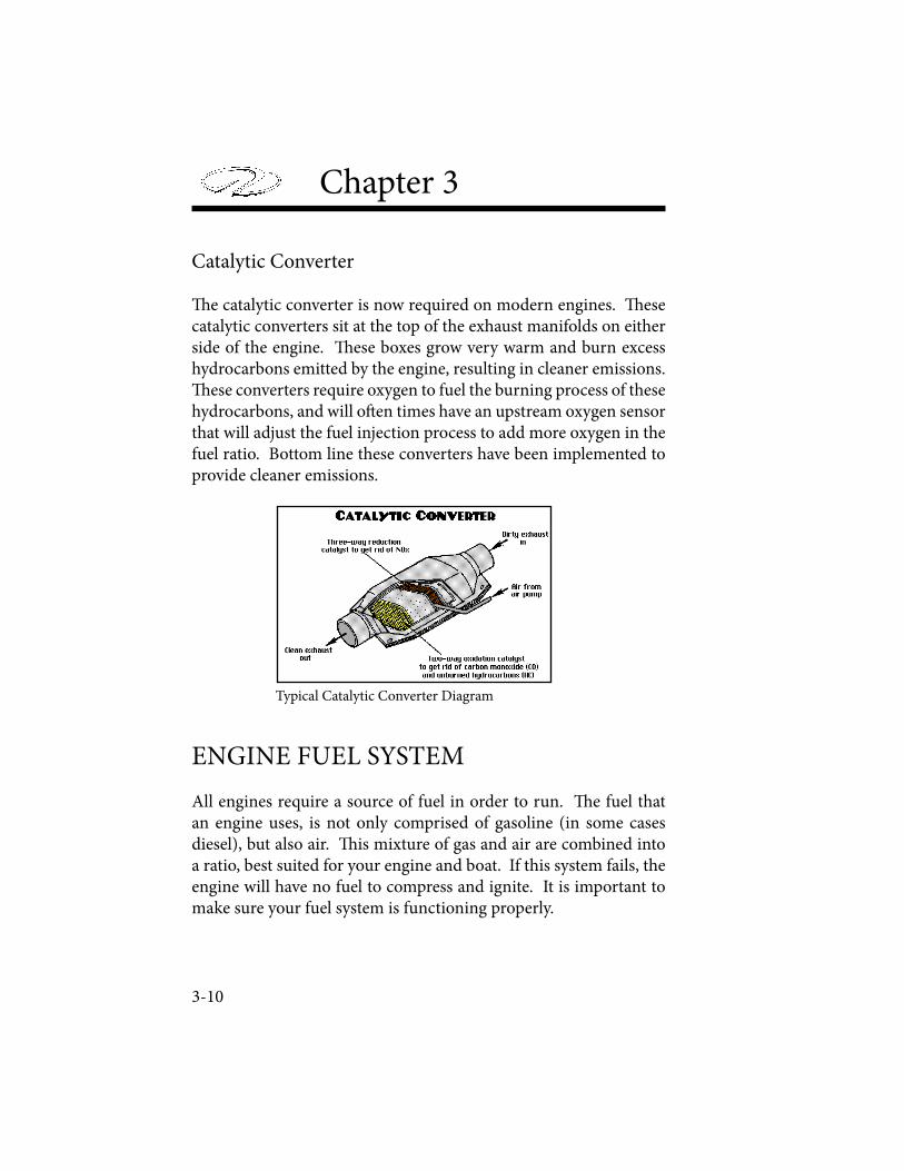
Chapter 3
Catalytic Converter
� e catalytic converter is now required on modern engines. � ese catalytic converters sit at the top of the exhaust manifolds on either side of the engine. � ese boxes grow very warm and burn excess hydrocarbons emitted by the engine, resulting in cleaner emissions. � ese converters require oxygen to fuel the burning process of these hydrocarbons, and will o� en times have an upstream oxygen sensor that will adjust the fuel injection process to add more oxygen in the fuel ratio. Bottom line these converters have been implemented to provide cleaner emissions.
Typical Catalytic Converter Diagram
ENGINE FUEL SYSTEM
All engines require a source of fuel in order to run. � e fuel that an engine uses, is not only comprised of gasoline (in some cases diesel), but also air. � is mixture of gas and air are combined into a ratio, best suited for your engine and boat. If this system fails, the engine will have no fuel to compress and ignite. It is important to make sure your fuel system is functioning properly.
3-10
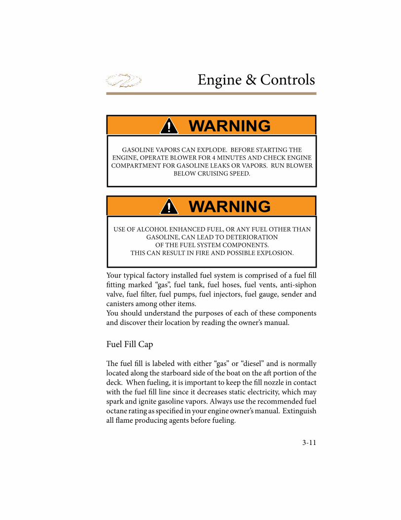
Engine & Controls
Your typical factory installed fuel system is comprised of a fuel ! ll ! tting marked “gas”, fuel tank, fuel hoses, fuel vents, anti-siphon valve, fuel ! lter, fuel pumps, fuel injectors, fuel gauge, sender and canisters among other items.You should understand the purposes of each of these components and discover their location by reading the owner’s manual.
Fuel Fill Cap
" e fuel ! ll is labeled with either “gas” or “diesel” and is normally located along the starboard side of the boat on the a# portion of the deck. When fueling, it is important to keep the ! ll nozzle in contact with the fuel ! ll line since it decreases static electricity, which may spark and ignite gasoline vapors. Always use the recommended fuel octane rating as speci! ed in your engine owner’s manual. Extinguish all $ ame producing agents before fueling.
3-11
GASOLINE VAPORS CAN EXPLODE. BEFORE STARTING THE ENGINE, OPERATE BLOWER FOR 4 MINUTES AND CHECK ENGINE COMPARTMENT FOR GASOLINE LEAKS OR VAPORS. RUN BLOWER
BELOW CRUISING SPEED.
USE OF ALCOHOL ENHANCED FUEL, OR ANY FUEL OTHER THAN GASOLINE, CAN LEAD TO DETERIORATION
OF THE FUEL SYSTEM COMPONENTS. THIS CAN RESULT IN FIRE AND POSSIBLE EXPLOSION.
Chapter 3
Anti Siphon Valve
� e anti-siphon valve at the base of the fuel feed line is pulled o� its seat by fuel pump pressure as the engine is cranking or running. It forms a one-way fuel roadway by sealing o� the fuel feed line from the fuel � tting. It prevents fuel from siphoning out of the tank in the event of a fuel line rupture, or disconnected fuel feed hose. It is an important safety item, so DO NOT remove the anti-siphon valve.
Fuel Vent
Fuel vents are o� en combined into the fuel � tting on the deck. Fuel tanks are vented overboard for the fumes to escape. While the tank is � lled with fuel, air is displaced by the incoming fuel, and relieved through the fuel vent hose. When the fuel tank is near full, slow down or stop the nozzle � ow to keep the fuel from splashing out the vent.
Fuel Hoses
Fuel hoses transport gasoline from one component to another. � ese hoses are required to be of certain diameters in order to comply with engineering and environmental standards. Hose clamps are o� en used to seal the hose to a � tting, and these connections should be checked regularly along with the entire system at least yearly.
Fuel Pumps/ Filter
From the fuel tank, gasoline is moved from the tank to the engine by the pressure produced by fuel pumps. One fuel pump is used to move fuel from the fuel tank to the fuel � lter, while a second pump will pump � ltered fuel to each cylinder in the engine block. � e � lter normally located right next to the fuel pumps is meant to
3-12

Engine & Controls
take out some small debris as well as small amounts of water. Fuel ! lters are not able to remove large amounts of water. If the fuel becomes contaminated with water, the fuel must be run through a fuel polisher available at select marinas to remove large amounts of water.
Fuel Injectors
A" er the fuel has passed through the fuel pumps and ! lter, it is ready to be injected into the engine. Because boat engines run o# four strokes (intake, compression, spark, exhaust), fuel must be delivered to the appropriate cylinders at the appropriate time for optimal engine performance. $ is action is performed by fuel injectors that inject an air and fuel mixture into the engine cylinders.
Fuel Sender & Gauge
A fuel sender on the fuel gauge uses a dipstick/% oat system to measure the amount of fuel le" in the tank. $ is measurement generates a speci! c resistance value in an electronic circuit connected to the fuel gauge at the helm. As di# erent fuel levels are reached, the resistance value in the circuit with the fuel gauge changes which is read by the fuel gauge and is converted to an approximate fuel level.
Fuel Tank
$ e fuel tank should be inspected before each cruise. $ is should be done when you check the fuel lines for tightness and leaks. Your Regal boat uses an aluminum or polyester fuel tank that has been tested several times along with other fuel system components for safety requirements and dependability in house, and they are inspected independently by National Marine Manufactures Association personnel.
3-13
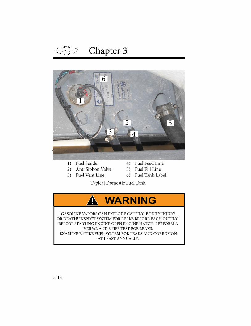
Chapter 3
3-14
Typical Fuel Tank
1) Fuel Sender 4) Fuel Feed Line 2) Anti Siphon Valve 5) Fuel Fill Line 3) Fuel Vent Line 6) Fuel Tank Label
Typical Domestic Fuel Tank
GASOLINE VAPORS CAN EXPLODE CAUSING BODILY INJURYOR DEATH! INSPECT SYSTEM FOR LEAKS BEFORE EACH OUTING.BEFORE STARTING ENGINE OPEN ENGINE HATCH. PERFORM A
VISUAL AND SNIFF TEST FOR LEAKS.EXAMINE ENTIRE FUEL SYSTEM FOR LEAKS AND CORROSION
AT LEAST ANNUALLY.
1
2
3 4
5
6

Engine & Controls
ENGINE LUBRICATION SYSTEM
Whenever two components rub together, friction causes wear on both components. To minimize the wear on your engine, a lubrication system has been put in place to help components slide next to each other easier. ! is is particularly important within the inner workings of an engine. It is important to ensure your lubrication system is working properly at all times.
Your Regal utilizes lubrication and " uids that need regular check ups. ! ese engine " uids are engine oil and power steering " uid. Refer to your engine owner’s manual for speci# c details regarding the proper maintenance procedure of your lubrication system. ! e pictures displayed in this section may represent a di$ erent engine model than the one equipped on your Regal boat. All pictures and procedures in this section are meant to be used as a guide, and should not take priority over the proper engine owner’s manual.
Engine Oil
! e purpose of engine oil is to lubricate the cylinders of the engine and ensure that parts that regularly move against each other have reduced friction to reduce wear and noise between components. An oil # lter keeps metal particles and water out of the engine’s interior.
Engines performing on regular oil should have the oil drained and replaced every 100 hours while synthetic oil typically should be drained and replaced every 200 hours. In either case, if your Regal boat has endured one year since its last oil change, the oil should be changed again. ! e oil # lter should be replaced every time the oil is changed, or upon damage. It is normal for the # rst 50 hours of operation to require frequent changes until the engine is seasoned.
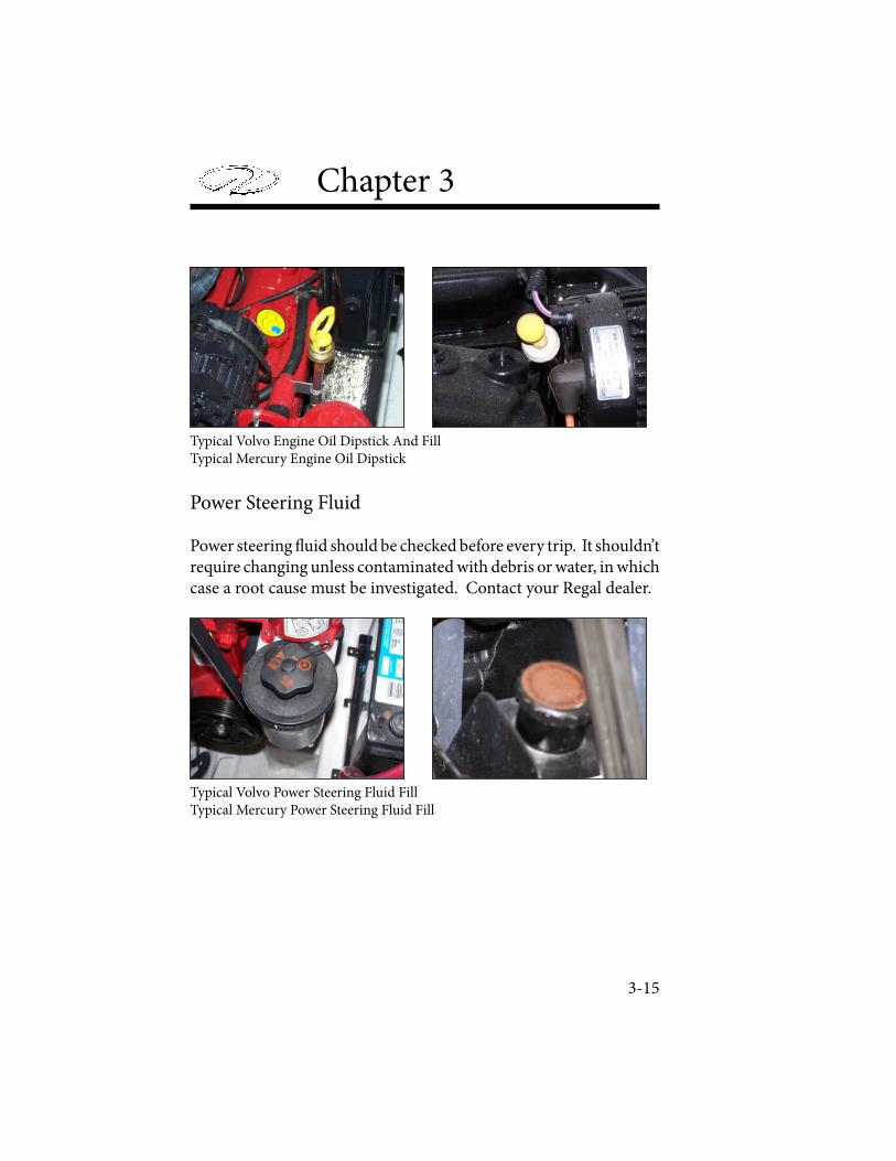
Chapter 3
Typical Volvo Engine Oil Dipstick And FillTypical Mercury Engine Oil Dipstick
Power Steering Fluid
Power steering ! uid should be checked before every trip. It shouldn’t require changing unless contaminated with debris or water, in which case a root cause must be investigated. Contact your Regal dealer.
Typical Volvo Power Steering Fluid FillTypical Mercury Power Steering Fluid Fill
3-15
Engine & Controls
Other Component Lubrication
System components may also require their own lubrication schedule. Steering systems, throttle cable, shi! cable, stern drive u-joint splines and o-rings, and the engine coupler may require grease, oil, or other lubrication. Refer to your engine owner’s manual for speci" c details.
ENGINE VENTILATION
Ventilation systems are required for all engine compartments. Your vessel features a set of deck vents located in proximity to the sun pad seat which constantly supply fresh air to the engine compartment. A powered blower motor attached to duct work in the lower one third of the bilge (4” black hoses) evacuates air to the atmosphere. # e other vents are used to take air into the engine/ engine compartment. Read and understand the following warning!
All owners are responsible for keeping their boat’s ventilation system operating properly. # is means making sure the vent openings are obstruction free, ducts are not blocked, blower operates properly, and all worn parts are replaced with approved marine ignition protected components.
3-16
GASOLINE VAPORS CAN EXPLODE. BEFORE STARTING THE ENGINE, OPERATE THE BLOWER FOR 4 MINUTES AND CHECK THE ENGINE COMPARTMENT FOR GASOLINE LEAKS OR VAPORS. ALWAYS RUN
BLOWER BELOW CRUISING SPEEDS.
Chapter 3
STERN DRIVE BASICS
Inboard/outboard drives, or stern drives, make it easier to control your boat. Your Regal comes standard with either a Mercury or Volvo stern drive. � is drive is what converts the power produced by the engine into the force required to spin a propeller. It is important that you read the stern drive manual carefully and become familiar with the operation as well as necessary maintenance on the drive unit components. Pay careful attention to the section on winterization if you live in freezing climates. Extensive damage can result if proper winter storage is not followed.
Stern Drive Mounts
� e stern drive attaches to your vessel via the transom assembly. It is through this assembly that the engine passes its energy to the stern drive to spin the propeller. � ese mounts should be inspected by a marine professional periodically.
Stern Drive Alignment
Your stern drive unit connects to the engine coupler by use of the drive sha� . � e splines on the drive sha� are inserted into the engine coupler, allowing energy to be transferred to the drive. � is alignment should be inspected periodically or a� er running aground.
Stern Drive Removal
� e stern drive should only be removed by a professional. � e stern drive should be removed or inspected a� er failure, in particular, a� er water enters the power trim � uid or bellows. It is best to leave stern drive removal to a marine professional or your Regal dealer.
3-17

Engine & Controls
STERN DRIVE MECHANICS
! e engine transmits rotational energy to the drive sha" at the engine coupler. Once engine output energy is transferred to the drive sha" , it undergoes a ratio change determined by the gear case. ! is converts the revolutions of your engine to applicable rotations of the propeller. From here, the propeller sha" turns in accordance with the energy ratio determined by the gear case, and rotates the propeller sha" . Your drive hub and other prop hardware keeps the propeller in contact with the prop sha" allowing the propeller to spin without coming o# the sha" .! e stern drive uses water pickup feeds normally found on the port and starboard face of the stern drive. ! ese holes allow raw water to be drawn up into the stern drive and pass through the transom to the engine where it can be used as coolant. Used water as regulated by the thermostat is transferred back to the stern drive and emitted at a vent above the propeller, or through the prop sha" , depending on the engine and drive manufacturer. Refer to your stern drive owner’s manual for details on the location and operation of the components.
3-18

Chapter 3
STERN DRIVE LUBRICATION
� e stern drive uses power trim � uid, drive oil, and propsha� lubricants to reduce wear on moving components. � ese � uids should be checked according to the recommended maintenance procedures determined by the stern drive manufacturer.
Drive Oil
Drive oil keeps all the mechanical components in the stern drive functioning optimally. It reduces friction in the stern drive. Sometimes drive oil is called gear lubricant, as the oil essentially lubricates the gears inside the gear box. Drive oil should be inspected with each trip. � e location of the drive oil may change based on your manufacturer, as some chose to mount the � ll on the stern drive, while others chose to mount it separately in the engine compartment or on the engine.
Typical Volvo Drive Oil DipstickTypical Mercury Gear Lube Fill
3-20
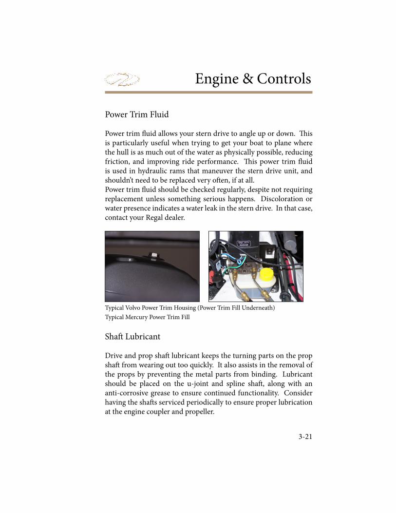
Engine & Controls
Power Trim Fluid
Power trim ! uid allows your stern drive to angle up or down. " is is particularly useful when trying to get your boat to plane where the hull is as much out of the water as physically possible, reducing friction, and improving ride performance. " is power trim ! uid is used in hydraulic rams that maneuver the stern drive unit, and shouldn’t need to be replaced very o# en, if at all.Power trim ! uid should be checked regularly, despite not requiring replacement unless something serious happens. Discoloration or water presence indicates a water leak in the stern drive. In that case, contact your Regal dealer.
Typical Volvo Power Trim Housing (Power Trim Fill Underneath)
Typical Mercury Power Trim Fill
Sha# Lubricant
Drive and prop sha# lubricant keeps the turning parts on the prop sha# from wearing out too quickly. It also assists in the removal of the props by preventing the metal parts from binding. Lubricant should be placed on the u-joint and spline sha# , along with an anti-corrosive grease to ensure continued functionality. Consider having the sha# s serviced periodically to ensure proper lubrication at the engine coupler and propeller.
3-21

Chapter 3
PROPELLERS
Regal has carefully tested and chosen the propellers to give your stern drive boat the best possible performance based on the engine and propulsion package you choose. We have allowed for the additional weight in equipment that might be added to the boat. It is a good idea to carry a spare set of propellers and hand tools onboard, in order to handle emergency propeller changes. Refer to the sterndrive manual for procedures, as the application is unique to the manufacturer. Call a marine professional or your Regal dealer for further information.
Propulsion ChecklistAt least twice a year, check the propeller for:
Loose, missing, or corroded hardware.
Nicks, dings, or missing propeller material
Bent propeller blades.
Objects wrapped around the prop such as � sh line.
Decomposing propeller blades (electrolysis symptom).
Aluminum prop with paint coming o� near blade tip (ventilation symptom).
Check the propeller rubber hub for slippage
Contact a propeller shop or your closest Regal dealer if any of the above symptoms exist. � ey have purchased special equipment to refurbish both stainless steel and aluminum propellers.
3-22
•
•
•
•
•
•
•

Engine & Controls
INSTRUMENTATION
! e helm station is equipped with a complete set of instruments that allows you to monitor the condition of the engine. Close observation of the gauges may save the engine from damage. Gauges do however have some inaccuracy, so do not rely upon them fully.
! e dash ignition panel is protected by a amain 20 amp ignition breaker located next to the key switch on the panel. It is connected through the ignition switch. Your dash instrumentation (gauges, displays, etc.) are protected by a 10 amp fuse underneath the dash. Should this fuse “blow”, investigate the cause before replacing it. Also located on your ignition panel is a 12 volt accessory plug that " ts many portable electronic chargers meant for a cigarette plug.
Note that with the battery switch in the “o# ” position, there is no power to the dashboard, and the ignition switch will not function properly.
All electrical features are protected by a 50 amp main breaker mounted close to the battery switch. A fuse for the stereo memory and the automatic bilge pump system are also located next to the battery switch in the engine compartment. Fuses for the engine may be located either in-line, between components, or in a fuse box. A separate 40 amp breaker protects the optional stereo performance package and is located next to the battery switch. All the switches on the dashboard also have a fuse, located in the forward starboard storage area directly in front of the helm. Should a fuse “blow” it is " rst necessary to " gure out the reason and address the cause.
3-23
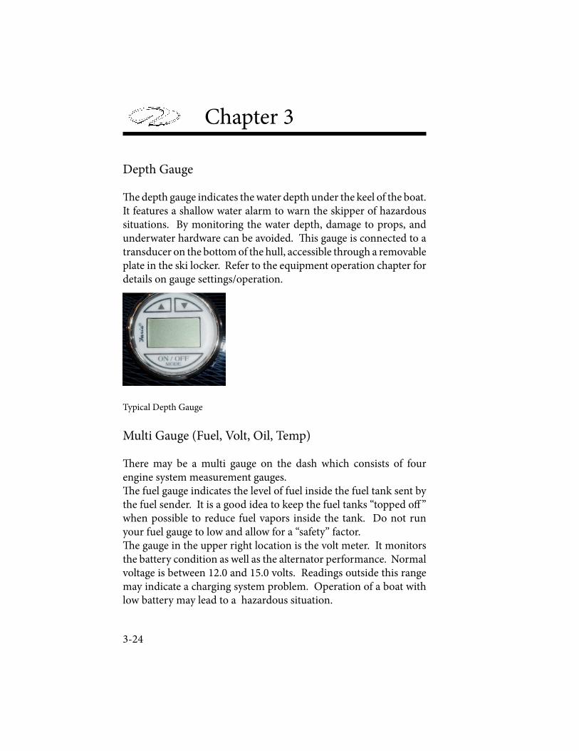
Chapter 3
Depth Gauge
! e depth gauge indicates the water depth under the keel of the boat. It features a shallow water alarm to warn the skipper of hazardous situations. By monitoring the water depth, damage to props, and underwater hardware can be avoided. ! is gauge is connected to a transducer on the bottom of the hull, accessible through a removable plate in the ski locker. Refer to the equipment operation chapter for details on gauge settings/operation.
Typical Depth Gauge
Multi Gauge (Fuel, Volt, Oil, Temp)
! ere may be a multi gauge on the dash which consists of four engine system measurement gauges.! e fuel gauge indicates the level of fuel inside the fuel tank sent by the fuel sender. It is a good idea to keep the fuel tanks “topped o" ” when possible to reduce fuel vapors inside the tank. Do not run your fuel gauge to low and allow for a “safety” factor.! e gauge in the upper right location is the volt meter. It monitors the battery condition as well as the alternator performance. Normal voltage is between 12.0 and 15.0 volts. Readings outside this range may indicate a charging system problem. Operation of a boat with low battery may lead to a hazardous situation.
3-24

Engine & Controls
! e gauge in the lower le" location is the oil pressure gauge. It indicates the pressure of the oil inside the engine lubrication system. A drop in oil pressure may indicate a low oil situation or leak. Operation of the engines with low oil pressure could lead to engine damage.
! e gauge in the lower right location is the temperature gauge. It monitors the cooling system’s e# ect on the engine as registered by the thermostat. A sudden increase in the temperature could be a sign of a malfunctioning cooling system. Continued operation of the engines without a proper cooling system could lead to engine damage.
Typical Multi Gauge
Speedometer
! e speedometer indicates the approximate speed of travel of your boat in miles per hour and kilometers per hour by measuring water pressure against a small hole in a device mounted on the transom or stern drive. Obey all posted speed limit signs and slow down near other boaters and swimmers to a safe speed. Remember, you are responsible for the wake produced by your boat.
3-25
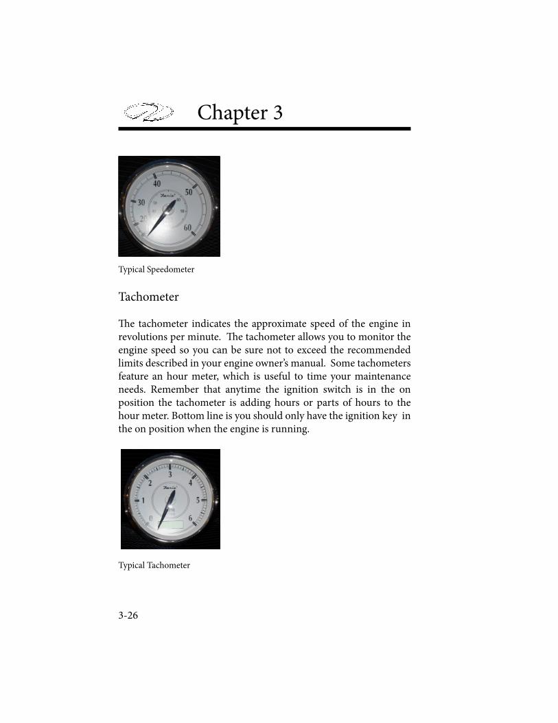
Chapter 3
Typical Speedometer
Tachometer
� e tachometer indicates the approximate speed of the engine in revolutions per minute. � e tachometer allows you to monitor the engine speed so you can be sure not to exceed the recommended limits described in your engine owner’s manual. Some tachometers feature an hour meter, which is useful to time your maintenance needs. Remember that anytime the ignition switch is in the on position the tachometer is adding hours or parts of hours to the hour meter. Bottom line is you should only have the ignition key in the on position when the engine is running.
Typical Tachometer
3-26
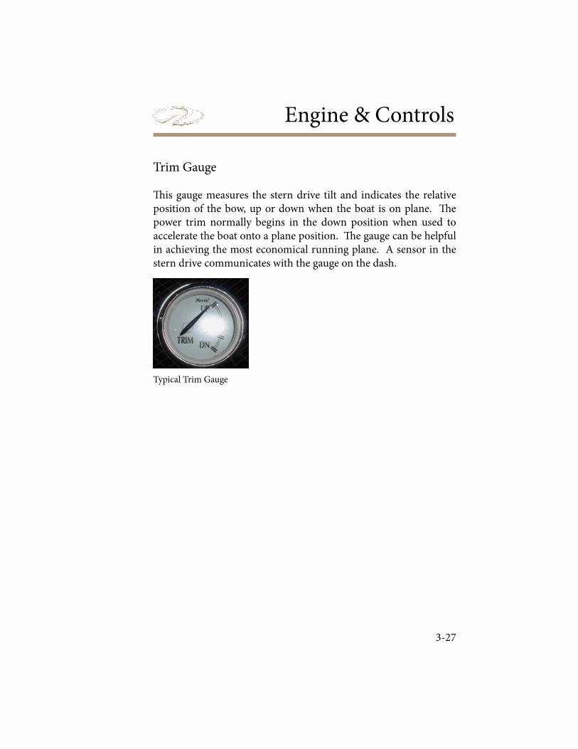
Engine & Controls
3-27
Trim Gauge
! is gauge measures the stern drive tilt and indicates the relative position of the bow, up or down when the boat is on plane. ! e power trim normally begins in the down position when used to accelerate the boat onto a plane position. ! e gauge can be helpful in achieving the most economical running plane. A sensor in the stern drive communicates with the gauge on the dash.
Typical Trim Gauge
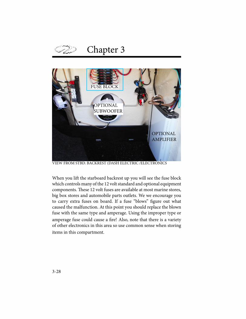
Chapter 3
3-28
OPTIONALAMPLIFIER
OPTIONALSUBWOOFER
FUSE BLOCK
VIEW FROM STBD. BACKREST (DASH ELECTRIC /ELECTRONICS
When you li! the starboard backrest up you will see the fuse block which controls many of the 12 volt standard and optional equipment components. " ese 12 volt fuses are available at most marine stores, big box stores and automobile parts outlets. We we encourage you to carry extra fuses on board. If a fuse “blows” # gure out what caused the malfunction. At this point you should replace the blown fuse with the same type and amperage. Using the improper type or
amperage fuse could cause a # re! Also, note that there is a variety of other electronics in this area so use common sense when storing
items in this compartment.
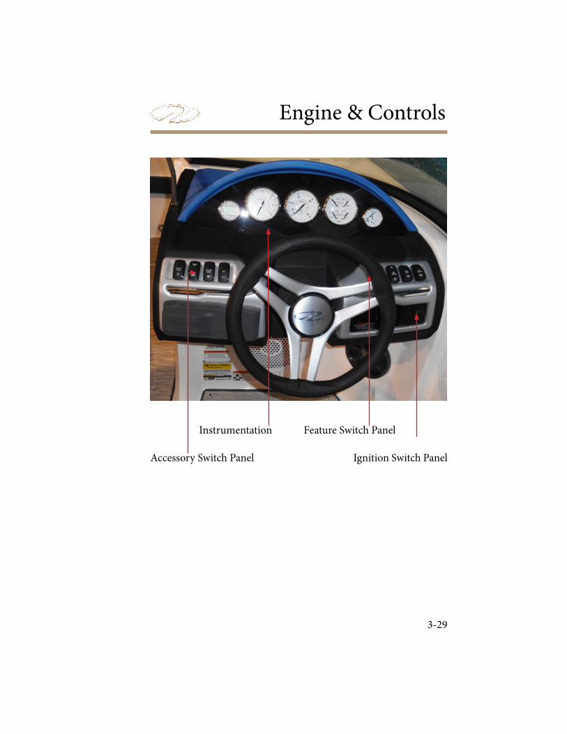
Engine & Controls
3-29
Accessory Switch Panel
Feature Switch Panel
Ignition Switch Panel
Instrumentation
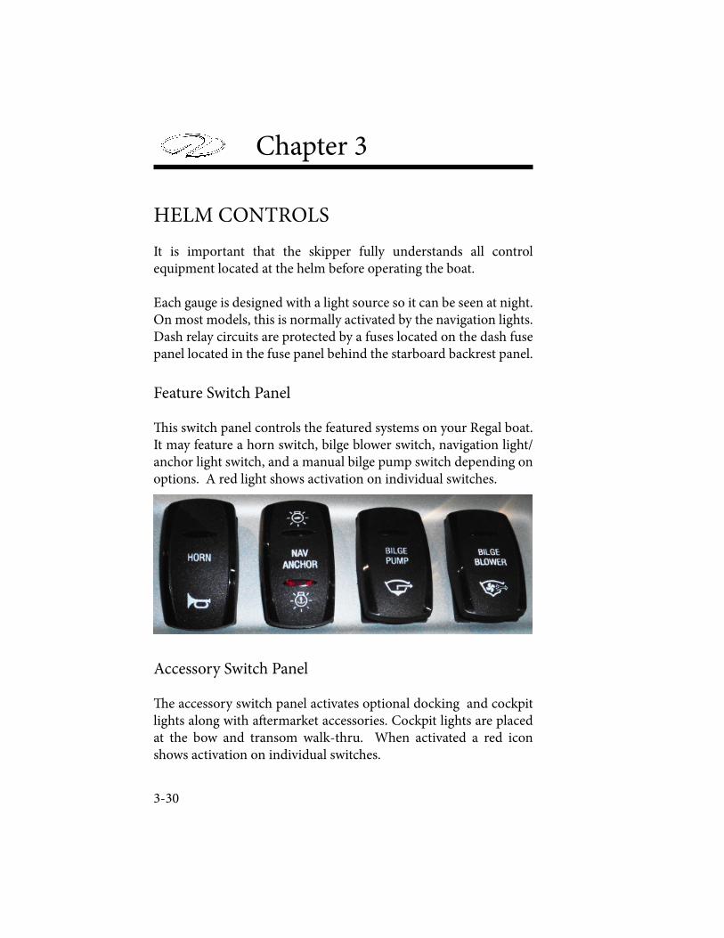
Chapter 3
HELM CONTROLS
It is important that the skipper fully understands all control equipment located at the helm before operating the boat.
Each gauge is designed with a light source so it can be seen at night. On most models, this is normally activated by the navigation lights. Dash relay circuits are protected by a fuses located on the dash fuse panel located in the fuse panel behind the starboard backrest panel.
Feature Switch Panel
! is switch panel controls the featured systems on your Regal boat. It may feature a horn switch, bilge blower switch, navigation light/anchor light switch, and a manual bilge pump switch depending on options. A red light shows activation on individual switches.
Accessory Switch Panel
! e accessory switch panel activates optional docking and cockpit lights along with a" ermarket accessories. Cockpit lights are placed at the bow and transom walk-thru. When activated a red icon shows activation on individual switches.
3-30
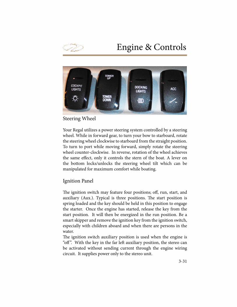
Engine & Controls
Steering Wheel
Your Regal utilizes a power steering system controlled by a steering wheel. While in forward gear, to turn your bow to starboard, rotate the steering wheel clockwise to starboard from the straight position. To turn to port while moving forward, simply rotate the steering wheel counter-clockwise. In reverse, rotation of the wheel achieves the same e! ect, only it controls the stern of the boat. A lever on the bottom locks/unlocks the steering wheel tilt which can be manipulated for maximum comfort while boating.
Ignition Panel
" e ignition switch may feature four positions; o! , run, start, and auxiliary (Aux.). Typical is three positions. " e start position is spring loaded and the key should be held in this position to engage the starter. Once the engine has started, release the key from the start position. It will then be energized in the run position. Be a smart skipper and remove the ignition key from the ignition switch, especially with children aboard and when there are persons in the water. " e ignition switch auxiliary position is used when the engine is “o! ”. With the key in the far le# auxiliary position, the stereo can be activated without sending current through the engine wiring circuit. It supplies power only to the stereo unit.
3-31
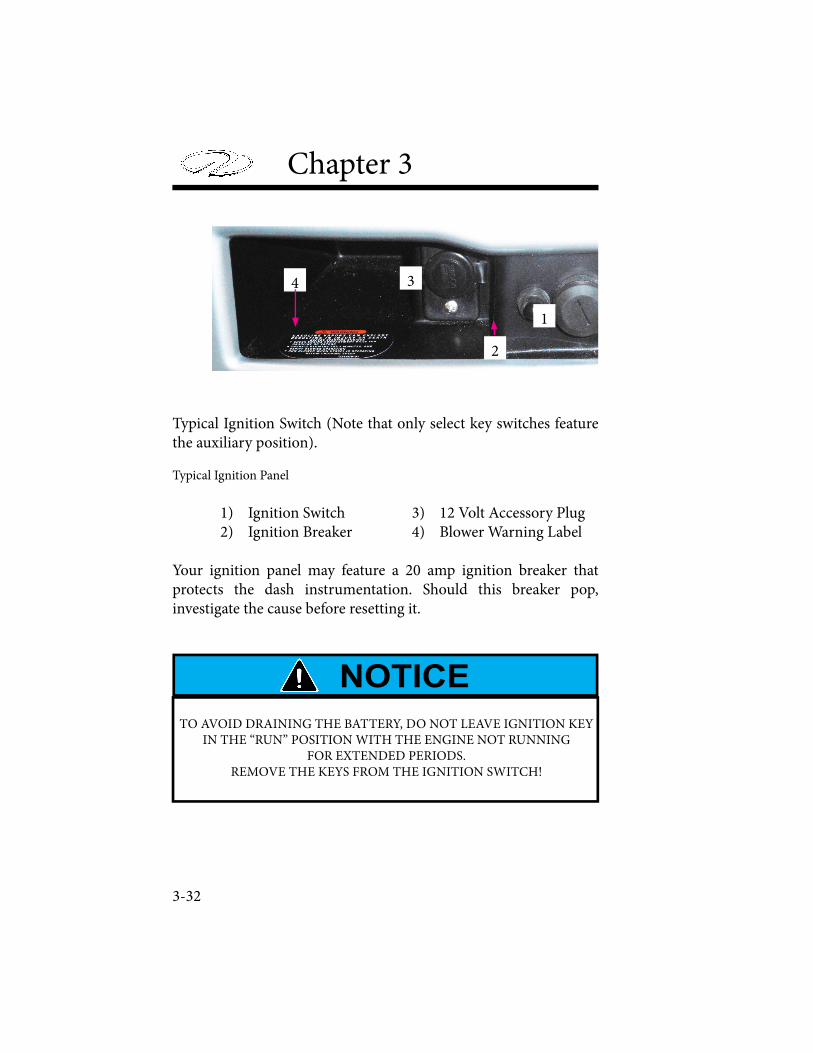
Chapter 3
Typical Ignition Switch (Note that only select key switches feature the auxiliary position).
Typical Ignition Panel
1) Ignition Switch 3) 12 Volt Accessory Plug 2) Ignition Breaker 4) Blower Warning Label
Your ignition panel may feature a 20 amp ignition breaker that protects the dash instrumentation. Should this breaker pop, investigate the cause before resetting it.
3-32
2
3
1
4
TO AVOID DRAINING THE BATTERY, DO NOT LEAVE IGNITION KEY IN THE “RUN” POSITION WITH THE ENGINE NOT RUNNING
FOR EXTENDED PERIODS. REMOVE THE KEYS FROM THE IGNITION SWITCH!
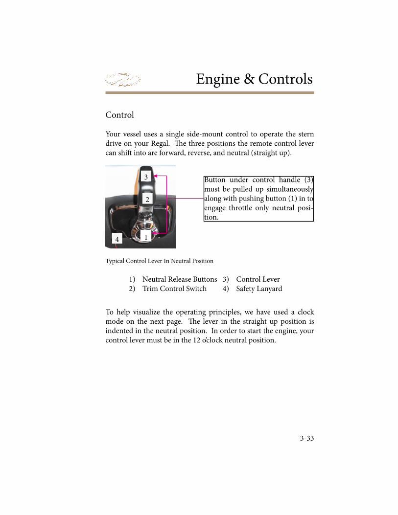
Engine & Controls
Control
Your vessel uses a single side-mount control to operate the stern drive on your Regal. ! e three positions the remote control lever can shi" into are forward, reverse, and neutral (straight up).
To help visualize the operating principles, we have used a clock mode on the next page. ! e lever in the straight up position is indented in the neutral position. In order to start the engine, your control lever must be in the 12 o’clock neutral position.
3-33
4
3
2
1
Button under control handle (3) must be pulled up simultaneously along with pushing button (1) in to engage throttle only neutral posi-tion.
Typical Control Lever In Neutral Position
1) Neutral Release Buttons 3) Control Lever 2) Trim Control Switch 4) Safety Lanyard
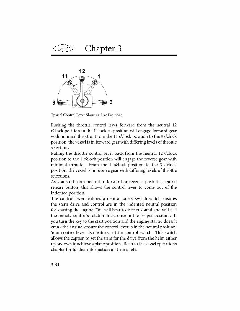
Chapter 3
Pushing the throttle control lever forward from the neutral 12 o’clock position to the 11 o’clock position will engage forward gear with minimal throttle. From the 11 o’clock position to the 9 o’clock position, the vessel is in forward gear with di� ering levels of throttle selections.Pulling the throttle control lever back from the neutral 12 o’clock position to the 1 o’clock position will engage the reverse gear with minimal throttle. From the 1 o’clock position to the 3 o’clock position, the vessel is in reverse gear with di� ering levels of throttle selections.As you shi� from neutral to forward or reverse, push the neutral release button, this allows the control lever to come out of the indented position.� e control lever features a neutral safety switch which ensures the stern drive and control are in the indented neutral position for starting the engine. You will hear a distinct sound and will feel the remote control’s rotation lock, once in the proper position. If you turn the key to the start position and the engine starter doesn’t crank the engine, ensure the control lever is in the neutral position.Your control lever also features a trim control switch. � is switch allows the captain to set the trim for the drive from the helm either up or down to achieve a plane position. Refer to the vessel operations chapter for further information on trim angle.
3-34
Typical Control Lever Showing Five Positions
Engine & Controls
Follow these points when shi! ing:
DO NOT shi! quickly from forward to reverse gear positions as drive system damage may occur.
DO NOT “pump” the throttle in neutral or " ooding will result just as will happen if you pump the automobile accelerator pedal. Today’s engines use an enrichment valve system that requires very little starting throttle.
DO NOT try to shi! into forward or reverse gear at high rpm’s. Personal injury, drive system, or property damage may result.
Only use idle throttle positions when docking or maneuvering in tight quarters.
Wear your safety lanyard at all times.
Never shi! the controls with the engine not running. Control, linkage, and/or stern drive damage may occur.
For more information, read and understand your engine manufacturer’s manual before operating remote control.
3-35
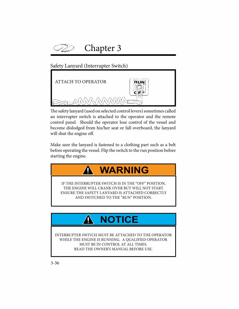
Chapter 3
Safety Lanyard (Interrupter Switch)
� e safety lanyard (used on selected control levers) sometimes called an interrupter switch is attached to the operator and the remote control panel. Should the operator lose control of the vessel and become dislodged from his/her seat or fall overboard, the lanyard will shut the engine o� .
Make sure the lanyard is fastened to a clothing part such as a belt before operating the vessel. Flip the switch to the run position before starting the engine.
3-36
ATTACH TO OPERATOR
IF THE INTERRUPTER SWITCH IS IN THE “OFF” POSITION, THE ENGINE WILL CRANK OVER BUT WILL NOT START.
ENSURE THE SAFETY LANYARD IS ATTACHED CORRECTLY AND SWITCHED TO THE “RUN” POSITION.
INTERRUPTER SWITCH MUST BE ATTACHED TO THE OPERATOR WHILE THE ENGINE IS RUNNING. A QUALIFIED OPERATOR
MUST BE IN CONTROL AT ALL TIMES. READ THE OWNER’S MANUAL BEFORE USE.
Engine & Controls
3-37
STEERING
Your Regal stern drive uses a rack style steering system. ! ese systems transfer helm mechanical motion to the engine. ! ere is a hydraulic steering cylinder which with the assistance of a steering pump sends " uid force to the stern drive steering arm, changing the course of the boat, depending on the direction the steering wheel is turned. Since the steering system is the primary link for engine control, it must be periodically inspected and maintained. ! e hardware at both the helm and engine must be checked regularly for tightness and lubrication. Check the steering system for full steering to port and starboard before disembarking. Refer to the steering manufacturer’s owner’s manual for more information.
AVOID PERSONAL INJURY AND PROPERTY DAMAGE! LOOSENING OR LOSS OF ONE OR MORE FASTENERS MAY CAUSE FAILURE OF THE STEERING SYSTEM, OR DAMAGE TO THE STEERING CABLE,
RESULTING IN LOSS OF STEERING CONTROL. PERIODICALLY INSPECT THE STEERING SYSTEM.
AVOID PERSONAL INJURY AND PROPERTY DAMAGE! ABRUPT TURNS ABOVE 30 MPH MAY RESULT IN LOSS OF CONTROL.
STEERING RESPONSE AT HIGH SPEEDS CAN BE VERY SUDDEN. ABRUPT TURNS MAY CAUSE YOU TO CROSS OVER YOUR OWN
WAKE. JUMPING A WAKE, SUDDEN TURNS, AND INCREASES OR DECREASES IN SPEED MAY PROVE DANGEROUS. THE OPERATOR MUST MAKE SURE THAT ALL PASSENGERS ARE SEATED SECURELY
BEFORE MAKING SPEED OR DIRECTIONAL CHANGES.
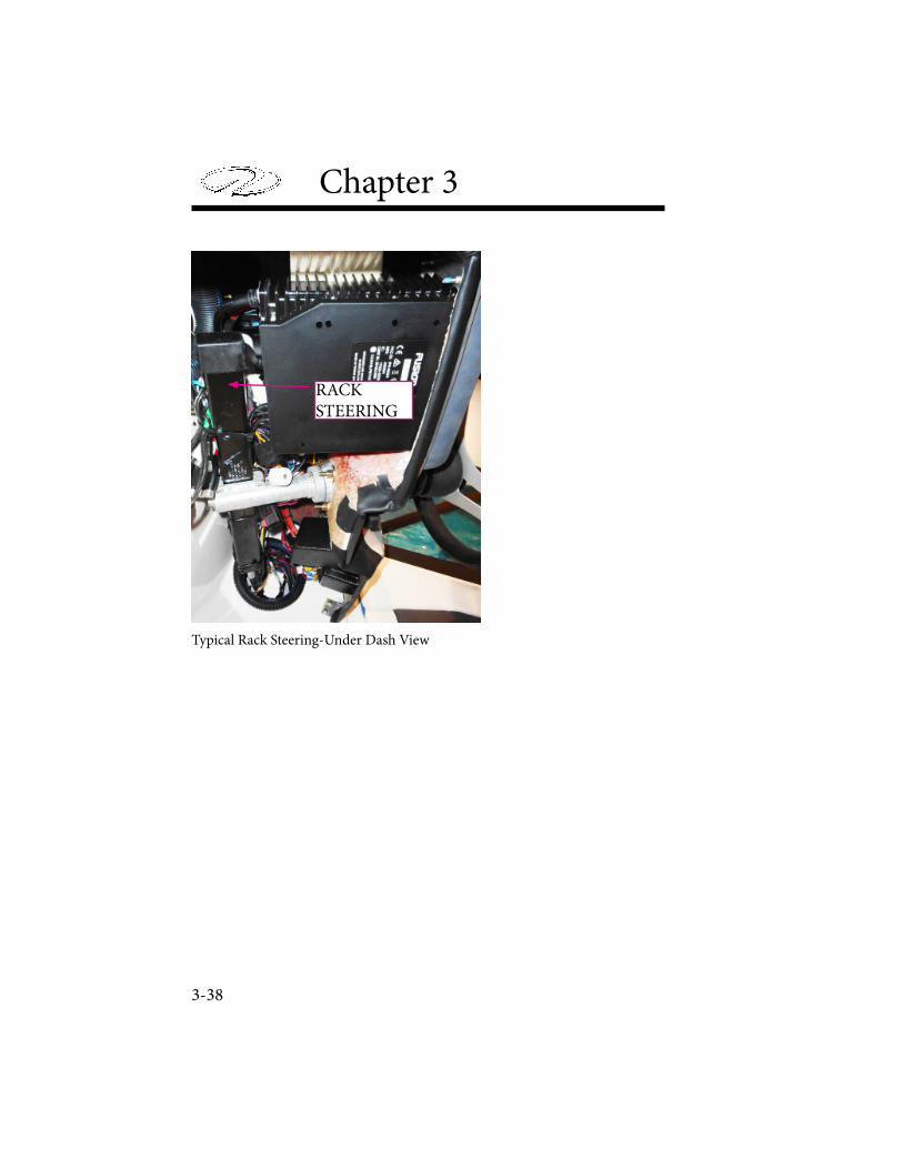
Chapter 3
Typical Rack Steering-Under Dash View
RACKSTEERING
3-38
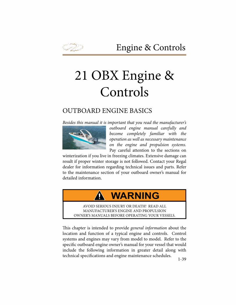
Engine & Controls
1-39
OUTBOARD ENGINE BASICS
Besides this manual it is important that you read the manufacturer’s outboard engine manual carefully and become completely familiar with the operation as well as necessary maintenance on the engine and propulsion systems. Pay careful attention to the sections on
winterization if you live in freezing climates. Extensive damage can result if proper winter storage is not followed. Contact your Regal dealer for information regarding technical issues and parts. Refer to the maintenance section of your outboard owner’s manual for detailed information.
! is chapter is intended to provide general information about the location and function of a typical engine and controls. Control systems and engines may vary from model to model. Refer to the speci" c outboard engine owner’s manual for your vessel that would include the following information in greater detail along with technical speci" cations and engine maintenance schedules.
21 OBX Engine & Controls
AVOID SERIOUS INJURY OR DEATH! READ ALL MANUFACTURER’S ENGINE AND PROPULSION
OWNER’S MANUALS BEFORE OPERATING YOUR VESSELS.
Chapter 3
1-40
Engines function is based from four principles; fuel, compression, ignition, and exhaust. ! e proper ratio of fuel and air must be drawn into the engine’s cylinders in order to be compressed by the pistons and ignited by a spark the force of which pushes the piston back down, providing the energy used to turn your propeller, before the engine kicks into the exhaust stage where it expels the by-products. If any of these four functions fail, so does the engine itself.Beyond these basic concepts of engine functionality include engine cooling, lubrication, and electrical systems. ! e speci" c details of these systems can be found in your owner’s manual for the speci" c engine option you chose on your Regal boat.
Engine Removal
In the event the outboard engine needs to be removed from the vessel consult your Regal dealer. He has the factory trained knowledge and equipment to remove the engine safely and e# ciently.
Engine Checklist Before Each Outing
Every engine option may require di$ erent checks before each use, but a general engine checklist is included here as a guide.
• Check crankcase engine and gear case oil levels.
• If installed, check power steering % uid level at the pump.
• Check power trim % uid.
At Helm/ Deck
• Check power trim for operation.
• Check control lever for operational defects.

Engine & Controls
1-41
• Check the clip and safety lanyard for functionality.
• Check gauges for accuracy.
• Check fuel level and ensure it is su! cient for the outboard and inbound trip with a reserve.
ENGINE COOLING SYSTEM
Your typical engine normally utilizes a raw water system for cooling the engine with intakes at the gear case. It is important that this system continues to run unobstructed at all times to avoid hazardous situations and to ensure a safe voyage.
Raw water is drawn up through the outboard vertical drivesha" housing through pick-up feeds in the gear case vicinity. Water passes through a power head thermostat which controls how much water circulates through the engine. # e cool water absorbs heat produced by the engine, before being emitted via the coolant exhaust system.# ere is a access hole on the port side of the power head which shows a visual stream of water at all times. If no water is visible with the engine running shut down the engine and investigate the
problem. At times this relief hole can be plugged by debris.
Impeller/ Water Pump
Periodically, the water pump and impeller should be inspected for debris, damage or excessive wear due to water chemistry such as mineral or silt conditions. Damaged parts will a$ ect the system’s ability to function, and may cause engine overheating or damage. Contact your closest Regal dealer for more information and maintenance schedules of key outboard engine cooling systems.
Chapter 3
1-42
! ermostat
If the temperature gauge starts yielding abnormal readings, it may become necessary to look at or replace the powerhead thermostat a" er determining whether it is functioning properly. ! e thermostat reads the temperature of coolant and determines whether to open or close a valve to allow warm sea water to pass into the exhaust manifold. ! e thermostat may recirculate hot coolant for the purposes of reaching standard operating temperatures. If standard operating temperatures have been reached, the thermostat will open a valve and allow hot raw water to exit through the exhaust manifold. For more information read your outboard engine manual or contact the closest Regal dealer .Dealers have the necessary knowledge and tools to troubleshoot any engine related problems.
Freshwater Flushing Attachment
Your outboard features a fresh water # ushing system. A" er linking up to a fresh water hose at the # ush port, water can be pumped through the engine’s raw water cooling system to # ush out all salt and debris that may be le" behind. Normally there is a hose thread $ tting on the side of the engine. A" er the connection is opened a garden hose is connected to the $ tting and the engine can be # ushed. It is best to connect the # ushing system up when the engine is warm since the thermostat is open at this time to allow water to circulate through the entire head rather than bypassing the cylinder head areas.
AVOID TOUCHING THE THERMOSTAT OR ITS COMPONENTS WHILE THE ENGINE IS ON / HOT. AVOID RUNNING THE ENGINE WITHOUT
A FUNCTIONING THERMOSTAT, AS IT MAY OVERHEAT.

Engine & Controls
1-43
ENGINE ELECTRICAL SYSTEM
Your engine utilizes a great deal of electronic equipment. Select equipment sends signals between the engine and the Garmin, while other systems set o� alarms, and still others are used by the engine to generate a spark and ignite the fuel. � e battery switch controls electrical power distribution to the boat systems.
To regularly maintain your DC electrical system, inspect the battery charge before each trip. Test all gauges and control equipment prior to departure, and replace as necessary. Spark plugs should be replaced according to your engine owner’s manual maintenance schedule. When a fuse blows, investigate the problem before replacing fuse.
Gauge Electrical Signals
Your outboard transmits signals through electrical harnesses to di� erent components through the use of NMEA 2000 connections and a “backbone system”. A standard Garmin plotter displays the engine functions. � e fuel gauge and power trim gauges use stand alone technology to display readings. Also, idiot lights are display tolerances that are classi� ed as being abnormal. Faults in these electrical components should be fully inspected by your Regal dealer.
Alarms
When a malfunction with your outboard engine occurs, the Garmin plotter alerts the skipper of a problem. Common engine problems include overheating, low oil pressure, or a miscommunication with equipment. Learn the alarm systems that apply to your engine by consulting your engine owner’s manual.
Chapter 3
1-44
Spark Plugs
! e spark plugs are the piece of equipment that make the spark occur. As electrical potential builds on one side of the gap based upon the energy distributed by the distributor, the potential eventually grows large enough to cause the electric current to jump the gap on the spark plug. ! is spark is what ignites the compressed fuel generating a controlled explosion that will power the piston down and deliver power to the drive sha" .
Stator
Under normal circumstances, the starter battery would wear down a" er being used so o" en to generate a spark for the engine. ! is isn’t an ideal setup because a strong battery is needed for continual operation. A weak battery does no good out on the water. ! e stator takes care of recharging the battery(ies). However, in an e# ort to conserve battery life, the starter battery switch should still be turned o# a" er every trip and turned on at the start of every trip. ! is limits the drain on the battery while the boat is not in use. ! e stator will only recharge the battery while the engine is running.
AVOID OPERATION OF THE ENGINE AFTER AN ALARM HAS SOUNDED. USE OF THE ENGINE WITHOUT ADDRESSING THE
PROBLEM MAY RESULT IN ENGINE DAMAGE OR FAILURE. REFER TO YOUR OUTBOARD ENGINE MANUAL FOR MORE INFORMATION.
Engine & Controls
1-45
Fuses
Your engine also comes equipped with fuses that will “blow” when engine components attempt to draw more power than the piece of equipment or wiring can handle. When the fuse blows, it breaks the circuit, and electricity stops � owing. Before replacing the fuse, investigate the cause of the problem, and why the equipment was overworked. Your outboard engine uses a helm mounted fuse box which is accessible by li� ing the starboard bow backrest while others feature in-line fuses, while still others feature a mixture of both. Refer to your outboard engine owner’s manual for complete details on your electrical system and the location of any engine mounted over current protection.
ENGINE EXHAUST SYSTEM
Your engine expels the by-products of the engine operation through an exhaust system, just like cars do. In boats however, this exhaust system mixes the debris le� over a� er the power stroke of the engine with the hot water that is expelled a� er cooling the engine. Basically the exhaust � ows through the powerhead before expelling the exhaust through the vertical drive housing either just above the propeller, or through the prop sha� .
ENGINE FUEL SYSTEM
All engines require a source of fuel in order to run. � e fuel that an engine uses, is not only comprised of gasoline but also air. � is mixture of gas and air are combined into a ratio, best suited for your engine and boat. If this system fails, the engine will have no fuel to compress and ignite. It is important to make sure your fuel system is functioning properly.
Chapter 3
1-46
Your typical factory installed fuel system is comprised of a fuel ! ll ! tting marked “gas”, fuel tank, fuel hoses, fuel vents, anti-siphon valve, water separator ! lter, fuel gauge, and sender among other items.You should understand the purposes of each of these components and discover their location by reading this manual along with the outboard owner’s manual so that you can ! x a fuel system problem when the need arises out on the water. " e pictures displayed in this section may not re# ect your speci! c engine model.
USE OF ALCOHOL ENHANCED FUEL, OR ANY FUEL OTHER THAN GASOLINE, CAN LEAD TO DETERIORATION OF THE FUEL
SYSTEM COMPONENTS. THIS CAN RESULT IN FIRE AND POSSIBLE EXPLOSION.
GASOLINE VAPORS CAN EXPLODE. BEFORE STARTING THE ENGINE, CHECK ENGINE COMPARTMENT FOR GASOLINE LEAKS OR VAPORS.
INSPECT ENTIRE FUEL SYSTEM AT LEAST ON AN ANNUAL BASIS.
AVOID BODILY INJURY OR DEATH DUE TO FIRE OR EXPLOSION FROM GASOLINE VAPORS!
NEVER STORE PORTABLE FUEL TANKS OR OTHER FLAMMABLE LIQUIDS ON BOARD THE VESSEL

Engine & Controls
1-47
Fuel Fill Cap
! e fuel " ll is labeled “gas” and is located along the starboard a# deck. When fueling it is important to keep the " ll nozzle in contact with the fuel " ll line since it decreases static electricity, which may spark and ignite gasoline vapors. Always use the recommended fuel octane rating as speci" ed
in your outboard engine owner’s manual. Extinguish all $ ame producing agents before fueling. ! e " ll cap leads to the anti-siphon valve and fuel tank. Ensure that the gas cap ratchets shut which ensures that vapors are contained within the system.
Anti Siphon Valve
! e anti-siphon valve at the base of the fuel feed line is pulled o% its seat by fuel pump pressure as the engine is cranking or running. It forms a one-way fuel roadway by sealing o% the fuel feed line from the fuel " tting. It prevents fuel from siphoning out of the tank in the event of a fuel line rupture, or disconnected fuel feed hose. It is an important safety item, so DO NOT remove the anti-siphon valve.
Fuel Vent
Fuel vents are o# en combined into the fuel " tting on the deck. Fuel tanks are vented overboard for the fumes to escape. While the tank is " lled with fuel, air is displaced by the incoming fuel, and relieved through the fuel vent hose. When the fuel tank is near full, slow or
stop the nozzle $ ow to keep the fuel from splashing out the vent.
Chapter 3
1-48
Fuel Hoses
Fuel hoses transport gasoline from one component to another. ! ese hoses are required to be of certain diameters in order to comply with engineering standards. Hose clamps are o" en used to seal the hose to a # tting, and should be checked regularly.
Fuel Pumps/Filter
From the fuel tank, gasoline is moved from the tank to the engine by the pressure produced in fuel pumps. Fuel # lters are used to catch debris and water. Typically, a fuel # lter is located before the engine fuel pump and a water separator # lter is found between the fuel tank
and the outboard engine.
Fuel Sender & Gauge
A fuel sender on the fuel gauge uses a dipstick/$ oat system to measure the amount of fuel le" in the tank. ! is measurement generates a speci# c resistance value in an electronic circuit connected to the fuel gauge at the helm. As di% erent fuel levels are reached, the resistance value in the circuit with the fuel gauge changes which is read by the fuel gauge and is converted to an approximate fuel level.
Fuel Tank
! e fuel tank should be inspected for damage before each voyage. ! is should be done when you check the fuel lines for tightness and leaks. Your Regal boat uses an aluminum or polyester fuel tank that has been tested several times along with other fuel system components for safety requirements and dependability in house, and they are inspected independently by National Marine Manufactures Association personnel. Typical fuel tank and hoses shown below.

Engine & Controls
1-49
12 3
54
Typical Fuel Tank- Note that fuel tanks feature aluminum or polyester material
1) Fuel Sender 4) Fuel Feed Line 2) Anti Siphon Valve 5) Fuel Fill Line 3) Fuel Vent Line
ENGINE LUBRICATION SYSTEM
Whenever two components rub together, friction causes wear on both components. To minimize the wear on your engine, a lubrication system has been put in place to help components slide next to each other easier. ! is is particularly important within the inner workings of an engine. It is important to ensure your lubrication system is working properly at all times.Your Regal utilizes lubrication and " uids that need regular check ups. ! ese engine " uids include engine and gearcase oil along with steering " uids. Refer to your outboard engine owner’s manual for speci# c details regarding the proper maintenance procedure of your lubrication system. ! e pictures displayed in this section may
represent a di$ erent engine model than your vessel.
Chapter 3
1-50
Engine Oil
! e purpose of engine oil is to lubricate the cylinders of the engine and ensure that parts that regularly move against each other have reduced friction to reduce wear and noise between components. An oil " lter keeps metal particles and water out of the engine’s interior.
Engines performing on regular oil should have the oil drained and replaced every 100 hours while synthetic oil typically should be drained and replaced every 200 hours. In either case, if your Regal boat has endured one year since its last oil change, the oil should be changed again. ! e oil " lter should be replaced every time the oil is changed, or upon damage. It is normal for the " rst 50 hours of operation to require frequent changes until the engine is seasoned.
Other Component Lubrication
System components may also require their own lubrication schedule. Steering systems, throttle cable, shi# cable, stern drive u-joint splines and o-rings, and the engine coupler may require grease, oil, or other lubrication. Refer to your engine owner’s manual for speci" c details.
LOWER UNIT LUBRICATION
Your outboard uses power trim $ uid, drive oil, and propsha# lubricants to reduce wear on moving components. ! ese $ uids should be checked according to the recommended maintenance procedures determined by the outboard manufacturer.
Engine & Controls
1-51
Gearcase Oil
Gearcase oil keeps all the mechanical components of the propsha! gear assembly functioning optimally. It reduces friction in the gearcase as the gears revolve. Sometimes gearcase oil is called gear lubricant, as the oil essentially lubricates the gears inside the gear box. Gearcase oil should be inspected periodically according to factory maintenance schedules.
Power Trim Fluid
Power trim " uid allows your outboard to angle up or down. # is is particularly useful when trying to get your boat to plane where the hull is as much out of the water as physically possible, reducing friction, and improving ride performance. # is power trim " uid is used in hydraulic rams that maneuver the outboard unit, and shouldn’t need to be replaced very o! en, if at all.Power trim " uid should be checked regularly, despite not requiring replacement unless something serious happens. Discoloration or water presence indicates a water leak in the stern drive. In that case, contact your Regal dealer.
PROPELLERS
Regal has carefully tested and chosen the propellers to give your outboard boat the best possible performance based on the engine and propulsion package you choose. We have allowed for the additional weight in equipment that might be added to the boat. It is a good idea to carry a spare set of propellers and hand tools onboard, in order to handle emergency propeller changes. Refer to the outboard manual for procedures, as the application is unique to the manufacturer. Call a marine professional or your Regal dealer for further information.
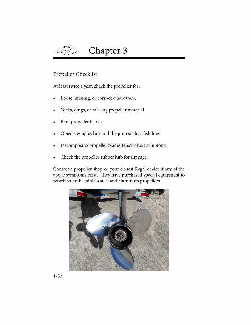
Chapter 3
1-52
Propeller Checklist
At least twice a year, check the propeller for:
• Loose, missing, or corroded hardware.
• Nicks, dings, or missing propeller material
• Bent propeller blades.
• Objects wrapped around the prop such as ! sh line.
• Decomposing propeller blades (electrolysis symptom).
• Check the propeller rubber hub for slippage
Contact a propeller shop or your closest Regal dealer if any of the above symptoms exist. " ey have purchased special equipment to refurbish both stainless steel and aluminum propellers.

Engine & Controls
1-53
INSTRUMENTATION
� e helm station is equipped with a fuel gauge and depth gauge along with the ability to monitor engine functions through the Garmin unit. Close observation of the gauges may save the engine from damage. Gauges do however have some inaccuracy, so do not rely upon them fully.
Note that with the battery switch in the “o� ” position, there is no power to the dashboard, and the ignition switch will not function properly.
All electrical features are protected by a main fuse mounted close to the battery switch. A fuse for the stereo memory and the automatic bilge pump system are also located next to the battery switch in the engine compartment. Fuses for the engine are located either in-line, between components, or in a fuse box. All the switches on the dashboard also have a fuse, located in the forward starboard storage area directly in front of the helm. Should a fuse “blow” it is � rst necessary to � gure out the reason and address the cause before resetting it.
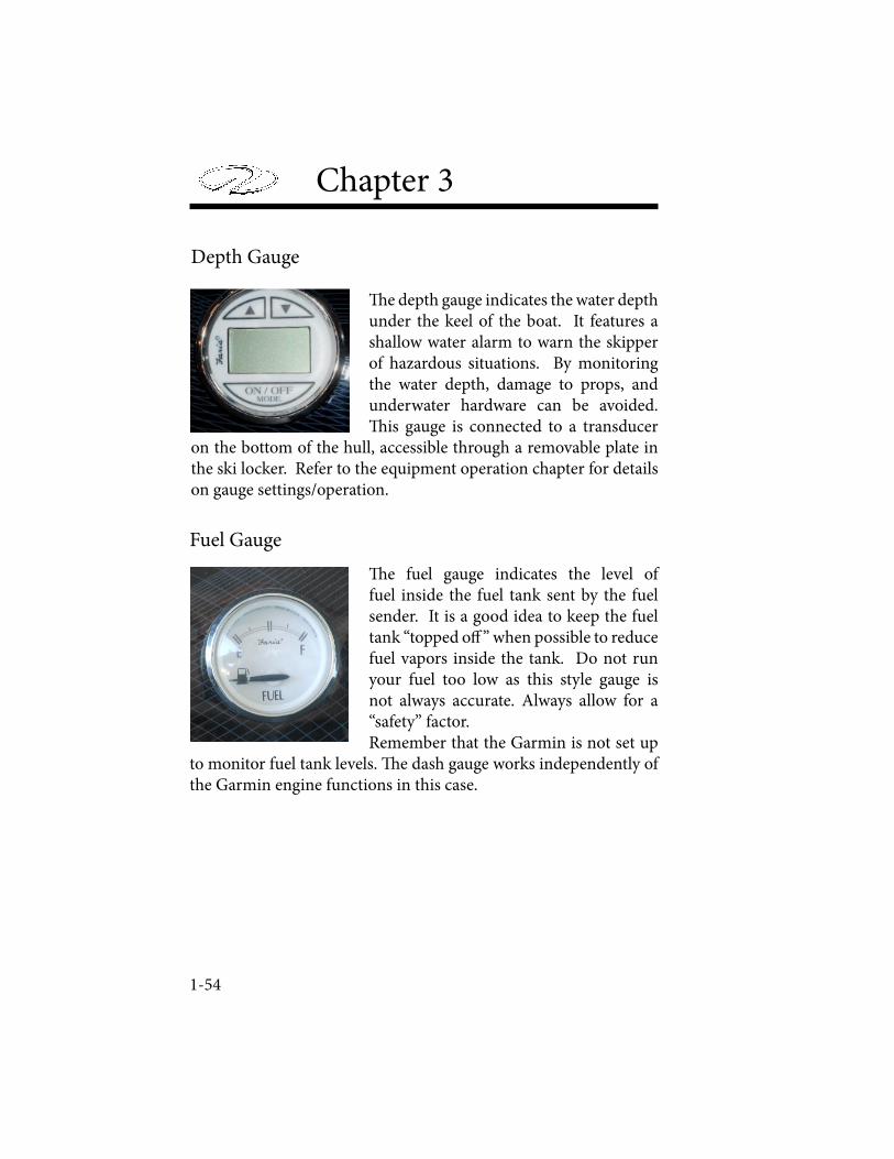
Chapter 3
1-54
Depth Gauge
! e depth gauge indicates the water depth under the keel of the boat. It features a shallow water alarm to warn the skipper of hazardous situations. By monitoring the water depth, damage to props, and underwater hardware can be avoided. ! is gauge is connected to a transducer
on the bottom of the hull, accessible through a removable plate in the ski locker. Refer to the equipment operation chapter for details on gauge settings/operation.
Fuel Gauge
! e fuel gauge indicates the level of fuel inside the fuel tank sent by the fuel sender. It is a good idea to keep the fuel tank “topped o" ” when possible to reduce fuel vapors inside the tank. Do not run your fuel too low as this style gauge is not always accurate. Always allow for a “safety” factor.Remember that the Garmin is not set up
to monitor fuel tank levels. ! e dash gauge works independently of the Garmin engine functions in this case.
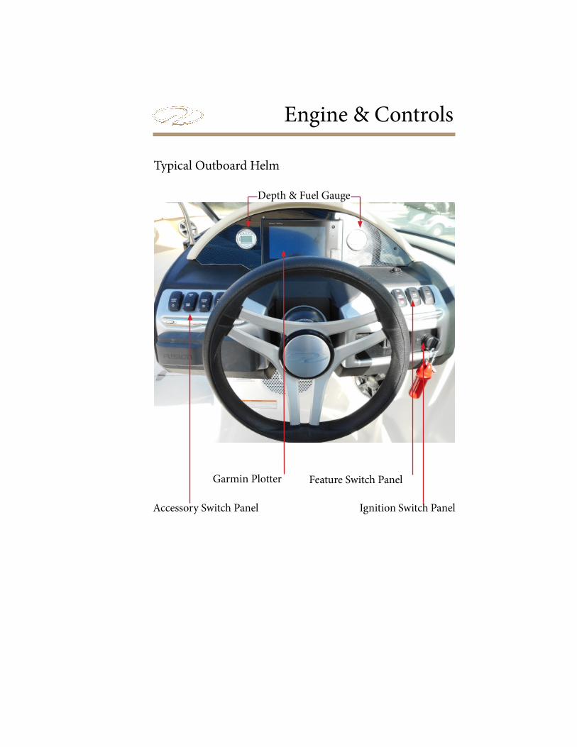
Engine & Controls
Typical Outboard Helm
Accessory Switch Panel
Feature Switch Panel
Ignition Switch Panel
Garmin Plotter
Depth & Fuel Gauge

Chapter 3
1-56
Garmin Engine Monitoring Display
A Garmin chartplotter is currently standard equipment on your outboard. It features many GPS features along with the ability to monitor engine system functions including revolutions per minute (rpm’s), GPS speed, voltage, fuel ! ow rate, trim, and temperature along with tracking engine hours.
Note that the Garmin and Fusion circuitry use individual sources to power up the system. " e key switch does not power up these 2 systems. Also, the depth and fuel gauge displays are independent of the Garmin engine displays.
1. To power up the Garmin GPS press the on button located on the upper display.
2. " e function AV/Gauges,Controls will appear as one of the choice boxes. Press the box. Another screen with engine will appear.
3. Press the engine box and the engine gauge displays will appear (oil pressure is engine code driven only); fuel level uses dash gauge to display fuel levels).

Engine & Controls
1-57
Garmin screen showing sample GPS functions. For detailed plotter instructions refer to the Garmin operator’s manual in the owner’s information packet as it guides you through the simple to the more complex operations. Also, more technical information can be found on the Garmin web-site under the key word MARINE.
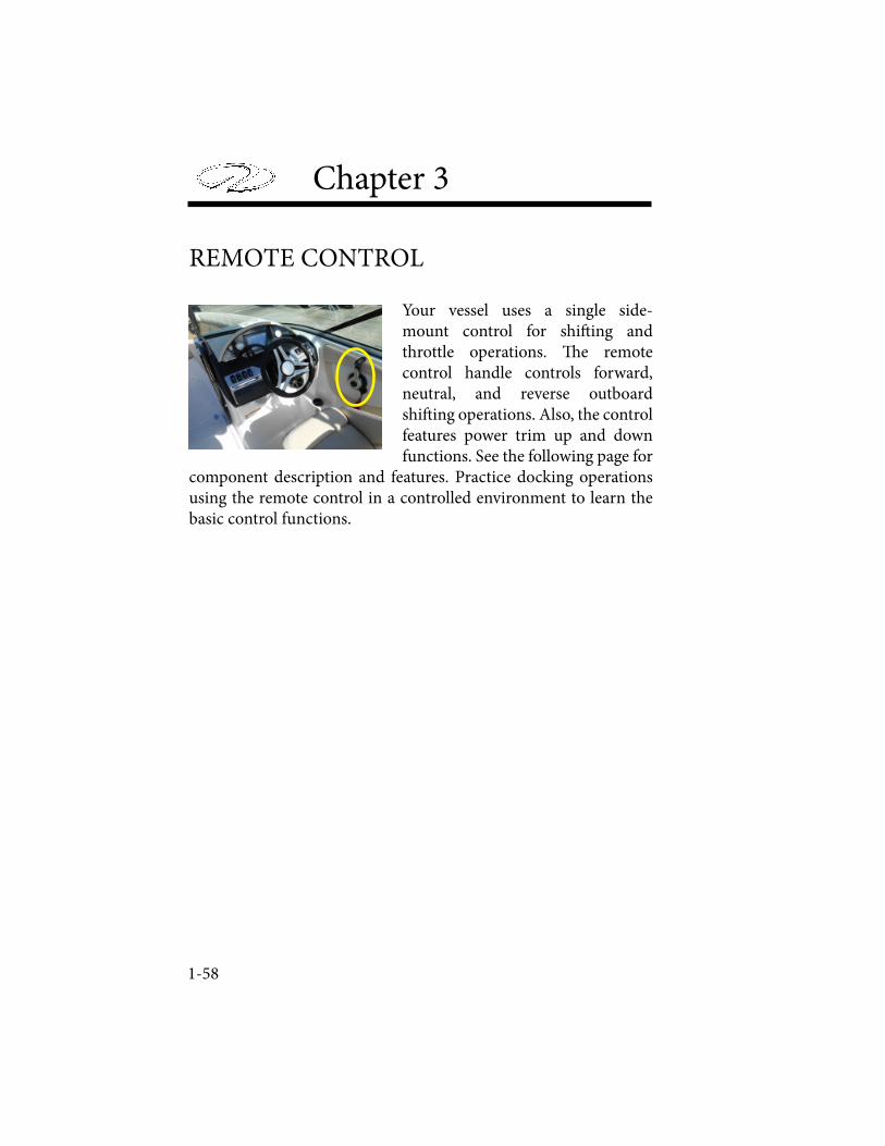
Chapter 3
1-58
REMOTE CONTROL
Your vessel uses a single side-mount control for shi! ing and throttle operations. " e remote control handle controls forward, neutral, and reverse outboard shi! ing operations. Also, the control features power trim up and down functions. See the following page for
component description and features. Practice docking operations using the remote control in a controlled environment to learn the basic control functions.
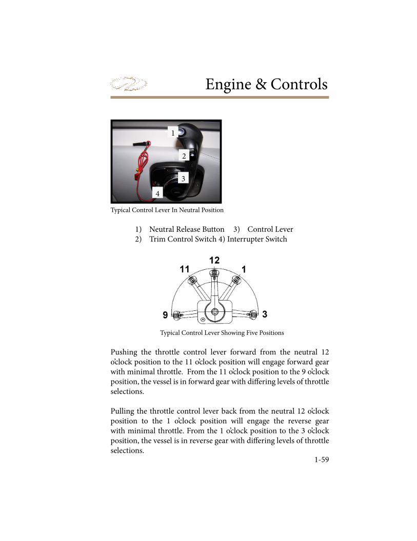
Engine & Controls
1-59
Typical Control Lever In Neutral Position
1) Neutral Release Button 3) Control Lever 2) Trim Control Switch 4) Interrupter Switch
Typical Control Lever Showing Five Positions
Pushing the throttle control lever forward from the neutral 12 o’clock position to the 11 o’clock position will engage forward gear with minimal throttle. From the 11 o’clock position to the 9 o’clock position, the vessel is in forward gear with di! ering levels of throttle selections.
Pulling the throttle control lever back from the neutral 12 o’clock position to the 1 o’clock position will engage the reverse gear with minimal throttle. From the 1 o’clock position to the 3 o’clock position, the vessel is in reverse gear with di! ering levels of throttle selections.
1
2
3
4
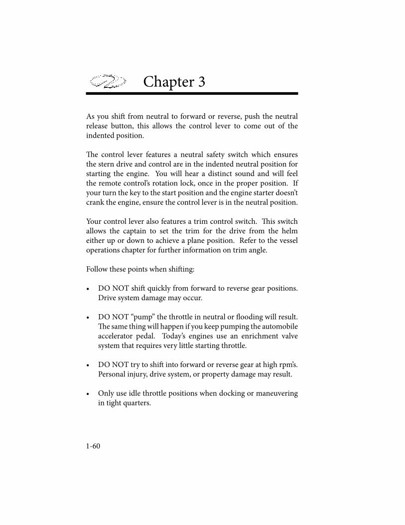
Chapter 3
1-60
As you shi! from neutral to forward or reverse, push the neutral release button, this allows the control lever to come out of the indented position.
" e control lever features a neutral safety switch which ensures the stern drive and control are in the indented neutral position for starting the engine. You will hear a distinct sound and will feel the remote control’s rotation lock, once in the proper position. If your turn the key to the start position and the engine starter doesn’t crank the engine, ensure the control lever is in the neutral position.
Your control lever also features a trim control switch. " is switch allows the captain to set the trim for the drive from the helm either up or down to achieve a plane position. Refer to the vessel operations chapter for further information on trim angle.
Follow these points when shi! ing:
• DO NOT shi! quickly from forward to reverse gear positions. Drive system damage may occur.
• DO NOT “pump” the throttle in neutral or # ooding will result. " e same thing will happen if you keep pumping the automobile accelerator pedal. Today’s engines use an enrichment valve system that requires very little starting throttle.
• DO NOT try to shi! into forward or reverse gear at high rpm’s. Personal injury, drive system, or property damage may result.
• Only use idle throttle positions when docking or maneuvering in tight quarters.
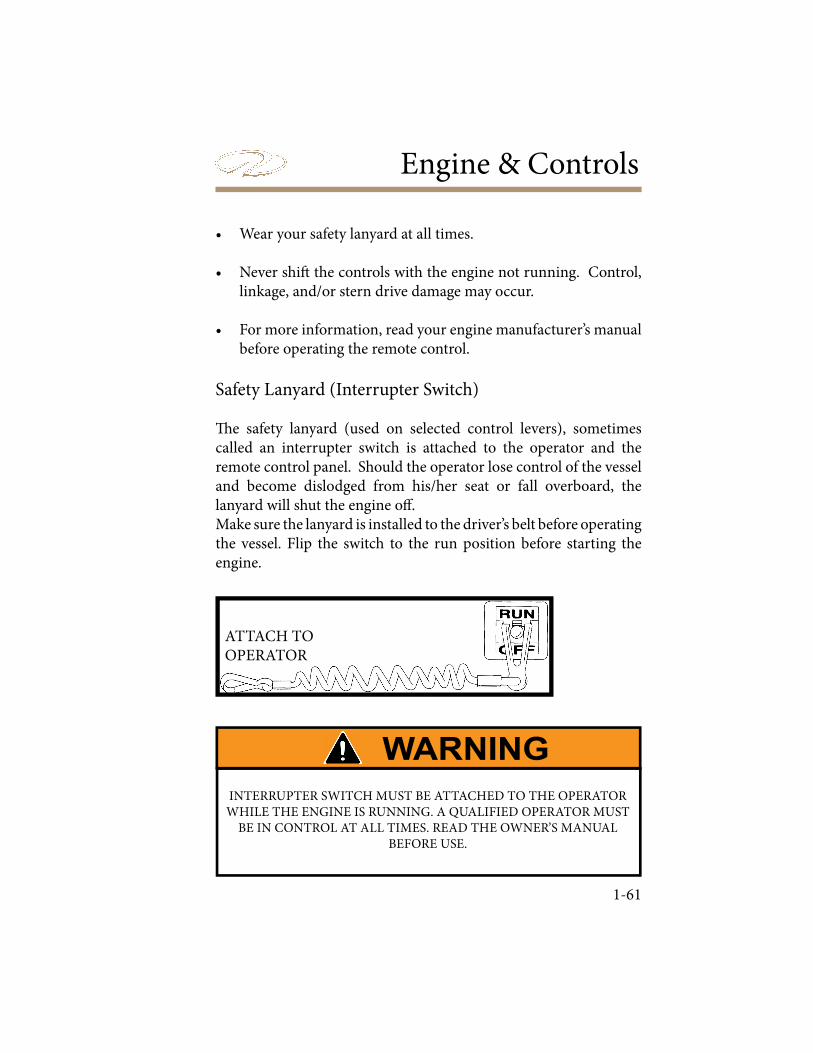
Engine & Controls
1-61
• Wear your safety lanyard at all times.
• Never shi� the controls with the engine not running. Control, linkage, and/or stern drive damage may occur.
• For more information, read your engine manufacturer’s manual before operating the remote control.
Safety Lanyard (Interrupter Switch)
� e safety lanyard (used on selected control levers), sometimes called an interrupter switch is attached to the operator and the remote control panel. Should the operator lose control of the vessel and become dislodged from his/her seat or fall overboard, the lanyard will shut the engine o� .Make sure the lanyard is installed to the driver’s belt before operating the vessel. Flip the switch to the run position before starting the engine.
INTERRUPTER SWITCH MUST BE ATTACHED TO THE OPERATOR WHILE THE ENGINE IS RUNNING. A QUALIFIED OPERATOR MUST
BE IN CONTROL AT ALL TIMES. READ THE OWNER’S MANUAL BEFORE USE.
ATTACH TO OPERATOR
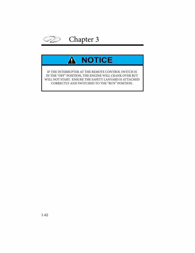
Chapter 3
1-62
IF THE INTERRUPTER AT THE REMOTE CONTROL SWITCH IS IN THE “OFF” POSITION, THE ENGINE WILL CRANK OVER BUT
WILL NOT START. ENSURE THE SAFETY LANYARD IS ATTACHED CORRECTLY AND SWITCHED TO THE “RUN” POSITION.

Engine & Controls
1-63
STEERING-HYDRAULIC
Typical outboards feature a hydraulic style steering system. � e unit utilizes check valves which permit hydraulic � uid to pass through the system allowing the steering arm at the outboard to turn the vessel to port or starboard as the steering wheel is rotated in either direction. � is check valve cluster is located in a pump assembly behind the steering wheel. � e hardware at both the helm and engine must be checked regularly for tightness, lubrication, and leaks. See the steering system overview on the following page. Check the steering system before each outing by turning steering wheel fully to port and starboard. Check for � uid leaks at the helm and outboard ends and air in the system. � ere is a hydraulic steering plug integrated into the dash that must be removed before � lling the system with � uid. Refer to the steering manufacturer’s information in the owner’s information packet for � lling instructions or contact a Regal dealer to schedule maintenance. Filling hardware (plastic bottle, hose and hardware) is needed for � lling and bleeding the system. Note that only SeaStar Steering Fluid is to be used.
AVOID BODILY INJURY, DEATH AND/OR PROPERTY DAMAGEDUE TO LOSS OF STEERING CONTROL!
THE FLUID LEVEL MUST BE CHECKED AND MAINTAINED BEFORE EACH USE TO ENSURE SAFE STEERING OPERATION.
INSPECT ENTIRE STEERING SYSTEM AT LEAST TWO (2)TIMES PER YEAR.
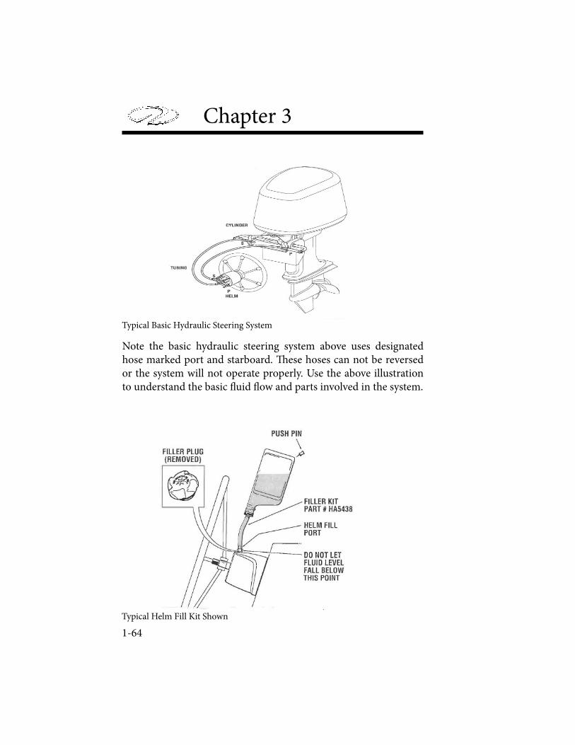
Chapter 3
1-64
Typical Basic Hydraulic Steering System
Typical Helm Fill Kit Shown
Note the basic hydraulic steering system above uses designated hose marked port and starboard. ! ese hoses can not be reversed or the system will not operate properly. Use the above illustration to understand the basic " uid " ow and parts involved in the system.
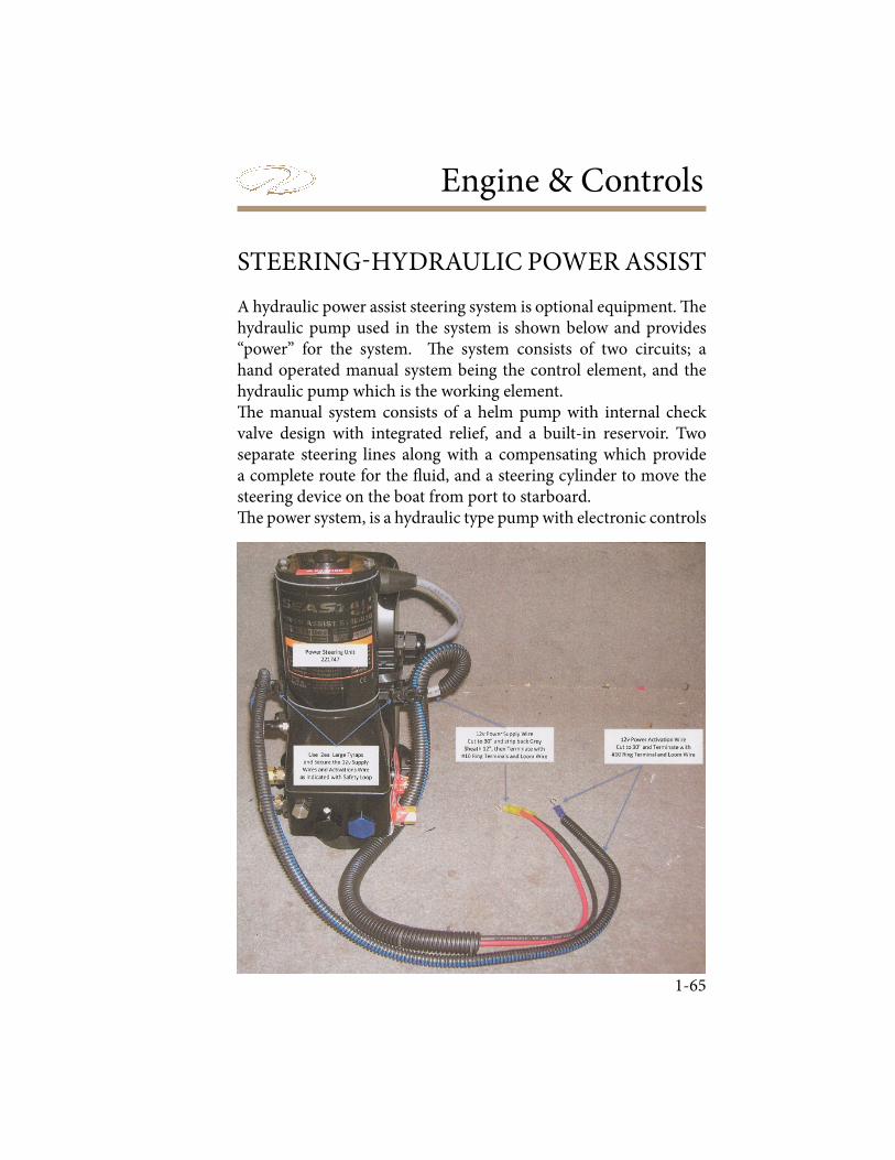
Engine & Controls
1-65
A hydraulic power assist steering system is optional equipment. ! e hydraulic pump used in the system is shown below and provides “power” for the system. ! e system consists of two circuits; a hand operated manual system being the control element, and the hydraulic pump which is the working element.! e manual system consists of a helm pump with internal check valve design with integrated relief, and a built-in reservoir. Two separate steering lines along with a compensating which provide a complete route for the " uid, and a steering cylinder to move the steering device on the boat from port to starboard.! e power system, is a hydraulic type pump with electronic controls
STEERING-HYDRAULIC POWER ASSIST
Chapter 3
1-66
that increases the ! uid being sent from the helm pump to the steer-ing cylinder which results in much easier steering at the wheel for the operator even with larger loads. A compensating line connects the power assist unit to the helm pump, allowing the power assist unit to share ! uid with the helm reservoir.Should the power assist unit fail or lose power, the hydraulic system will automatically revert to a manual hydraulic system." ere is a hydraulic steering plug integrated into the dash that must be removed before # lling the system with ! uid. Refer to the steering manufacturer’s information in the owner’s information packet for # lling instructions or contact a Regal dealer to schedule maintenance. Filling hardware (plastic bottle, hose and hardware) is needed for # lling and bleeding the system. Use only hydraulic ! uid type as recommended by SeaStar.
AVOID BODILY INJURY, DEATH AND/OR PROPERTY DAMAGEDUE TO LOSS OF STEERING CONTROL!
THE FLUID LEVEL MUST BE CHECKED AND MAINTAINED BEFORE EACH USE TO ENSURE SAFE STEERING OPERATION.
INSPECT ENTIRE STEERING SYSTEM AT LEAST TWO (2) TIMESPER YEAR.
STEERING-HYDRAULIC POWER ASSIST
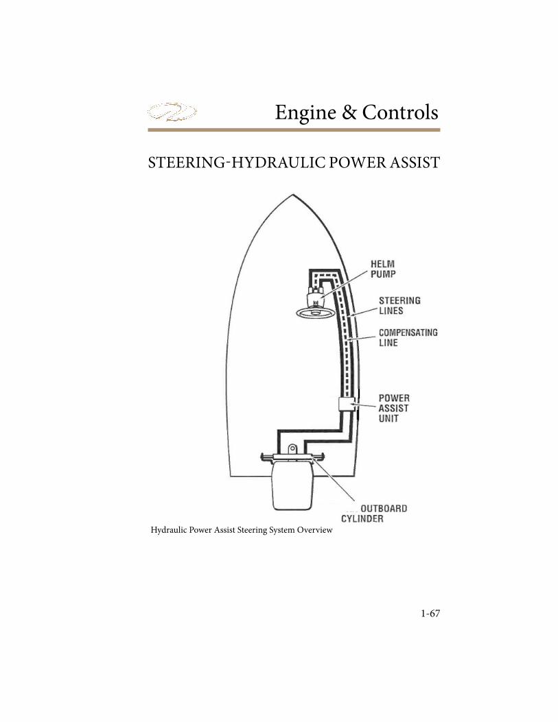
Engine & Controls
1-67
STEERING-HYDRAULIC POWER ASSIST
Hydraulic Power Assist Steering System Overview
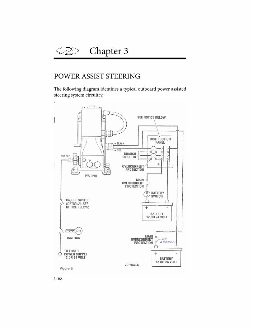
Chapter 3
1-68
POWER ASSIST STEERING
! e following diagram identi" es a typical outboard power assisted steering system circuitry.
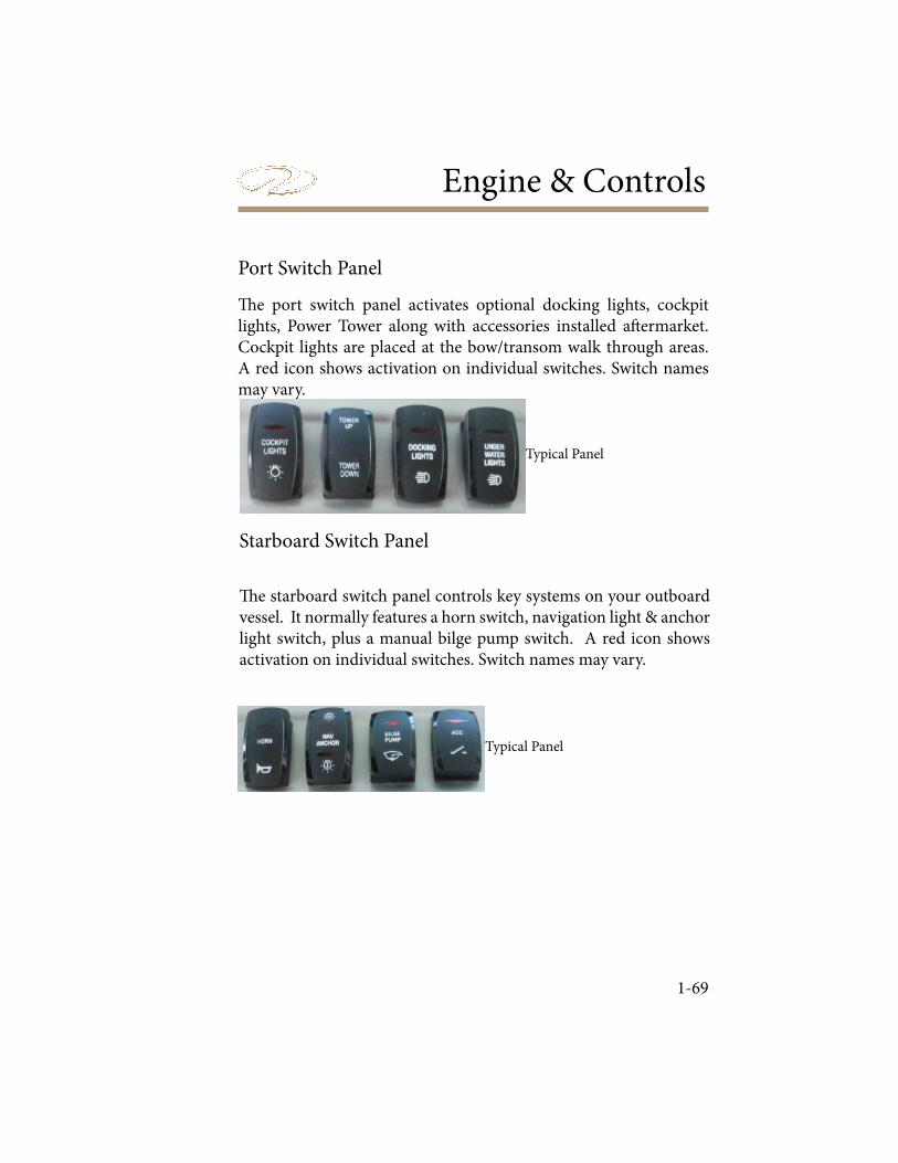
Engine & Controls
1-69
! e starboard switch panel controls key systems on your outboard vessel. It normally features a horn switch, navigation light & anchor light switch, plus a manual bilge pump switch. A red icon shows activation on individual switches. Switch names may vary.
! e port switch panel activates optional docking lights, cockpit lights, Power Tower along with accessories installed a" ermarket. Cockpit lights are placed at the bow/transom walk through areas. A red icon shows activation on individual switches. Switch names may vary.
Port Switch Panel
Starboard Switch Panel
Typical Panel
Typical Panel
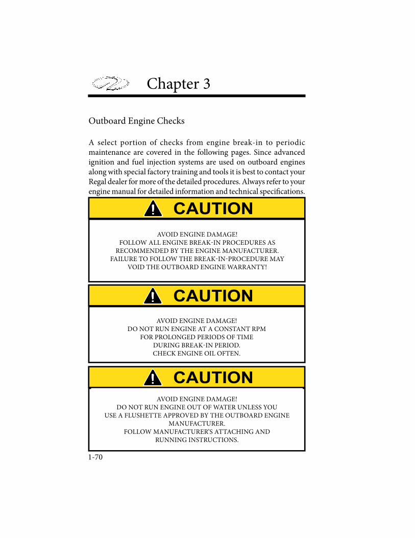
Chapter 3
1-70
Outboard Engine Checks
A select portion of checks from engine break-in to periodic maintenance are covered in the following pages. Since advanced ignition and fuel injection systems are used on outboard engines along with special factory training and tools it is best to contact your Regal dealer for more of the detailed procedures. Always refer to your engine manual for detailed information and technical speci! cations.
AVOID ENGINE DAMAGE!FOLLOW ALL ENGINE BREAK-IN PROCEDURES AS
RECOMMENDED BY THE ENGINE MANUFACTURER.FAILURE TO FOLLOW THE BREAK-IN-PROCEDURE MAY
VOID THE OUTBOARD ENGINE WARRANTY!
AVOID ENGINE DAMAGE!DO NOT RUN ENGINE AT A CONSTANT RPM
FOR PROLONGED PERIODS OF TIMEDURING BREAK-IN PERIOD.CHECK ENGINE OIL OFTEN.
AVOID ENGINE DAMAGE!DO NOT RUN ENGINE OUT OF WATER UNLESS YOU
USE A FLUSHETTE APPROVED BY THE OUTBOARD ENGINEMANUFACTURER.
FOLLOW MANUFACTURER’S ATTACHING ANDRUNNING INSTRUCTIONS.
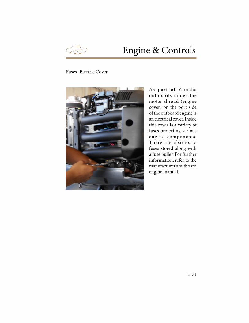
Engine & Controls
1-71
Fuses- Electric Cover
As par t of Yamaha outboards under the motor shroud (engine cover) on the port side of the outboard engine is an electrical cover. Inside this cover is a variety of fuses protecting various engine components. There are also extra fuses stored along with a fuse puller. For further information, refer to the manufacturer’s outboard engine manual.
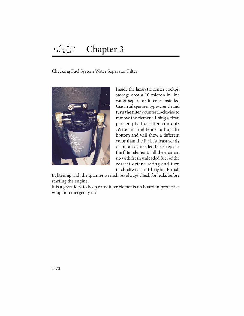
Chapter 3
1-72
Checking Fuel System Water Separator Filter
Inside the lazarette center cockpit storage area a 10 micron in-line water separator ! lter is installed Use an oil spanner type wrench and turn the ! lter counterclockwise to remove the element. Using a clean pan empty the filter contents .Water in fuel tends to hug the bottom and will show a di" erent color than the fuel. At least yearly or on an as needed basis replace the ! lter element. Fill the element up with fresh unleaded fuel of the correct octane rating and turn it clockwise until tight. Finish
tightening with the spanner wrench. As always check for leaks before starting the engine.It is a great idea to keep extra ! lter elements on board in protective wrap for emergency use.
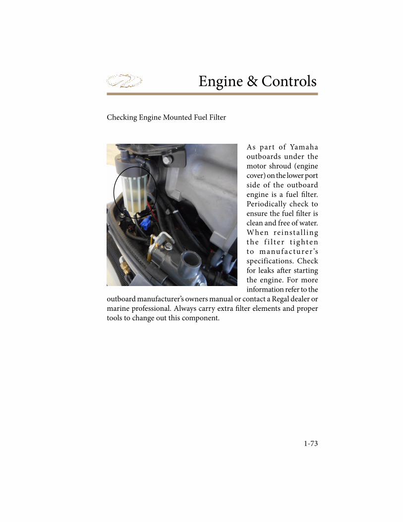
Engine & Controls
1-73
Checking Engine Mounted Fuel Filter
As part of Yamaha outboards under the motor shroud (engine cover) on the lower port side of the outboard engine is a fuel � lter. Periodically check to ensure the fuel � lter is clean and free of water. When re insta l l ing t h e f i l t e r t i g ht e n to manu f a c tu re r ’s specifications. Check for leaks a� er starting the engine. For more information refer to the
outboard manufacturer’s owners manual or contact a Regal dealer or marine professional. Always carry extra � lter elements and proper tools to change out this component.
Chapter 3
1-74
Engine Crankcase Oil
Note that Yamaha outboard engines are shipped from the factory without engine oil. Before starting the engine for the ! rst time the correct type and amount of oil must be added (See your outboard owner’s manual for details before attempting to start the engine). " ere is a tag shipped with the engine saying that the engine oil is to be ! lled. " is tag should be removed a# er the engine oil has been ! lled for the ! rst time. Also, refer to the following pages and the outboard engine owner’s manual for the correct procedures for checking and/or adding engine oil to the crankcase.
Engine Break-In Procedure
Note that your 4 cycle outboard engine requires a period of break-in for the internal engine parts to wear in properly. Following the break-in procedure will assist in producing longer engine life and increased performance. See your outboard owner’s manual for speci! c break-in procedures for your speci! c model.
CHECK THAT THE ENGINE IS FILLED WITH TYPE AND VISCOSITY OF OIL BEFORE
FIRST TIME OPERATION TO AVOID ENGINE DAMAGE.
FAILURE TO FOLLOW THE ENGINE MANUFACTURER’S PROPER BREAK-IN PROCEDURE COULD RESULT
IN SEVERE ENGINE DAMAGE, REDUCED ENGINE LIFE CYCLEAND MAY VOID THE ENGINE MANUFACTURER’S WARRANTY.
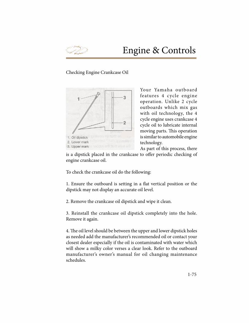
Engine & Controls
1-75
Your Yamaha outb oard features 4 cycle engine operation. Unlike 2 cycle outboards which mix gas with oil technology, the 4 cycle engine uses crankcase 4 cycle oil to lubricate internal moving parts. � is operation is similar to automobile engine technology. As part of this process, there
is a dipstick placed in the crankcase to o� er periodic checking of engine crankcase oil.
To check the crankcase oil do the following:
1. Ensure the outboard is setting in a � at vertical position or the dipstick may not display an accurate oil level.
2. Remove the crankcase oil dipstick and wipe it clean.
3. Reinstall the crankcase oil dipstick completely into the hole. Remove it again.
4. � e oil level should be between the upper and lower dipstick holes as needed add the manufacturer’s recommended oil or contact your closest dealer especially if the oil is contaminated with water which will show a milky color verses a clear look. Refer to the outboard manufacturer’s owner’s manual for oil changing maintenance schedules.
Checking Engine Crankcase Oil

Chapter 3
1-76
W h e n a d d i n g crankcase oi l be sure to utilize the m a n u f a c t u r e r ’s recommended type and viscosity. For changing crankcase oi l contac t your closest Regal dealer f o r a d d i t i o n a l information since they have the special
tools and knowledge for these maintenance procedures.
Checking/Filling Crankcase Oil- (Continued)
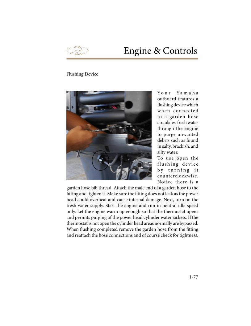
Engine & Controls
1-77
Flushing Device
Y o u r Y a m a h a outboard features a ! ushing device which w he n c on ne c te d to a garden hose circulates fresh water through the engine to purge unwanted debris such as found in salty, brackish, and silty water.To use open the f l u s h i n g d e v i c e b y t u r n i n g i t counterclockwise. Notice there is a
garden hose bib thread. Attach the male end of a garden hose to the " tting and tighten it. Make sure the " tting does not leak as the power head could overheat and cause internal damage. Next, turn on the fresh water supply. Start the engine and run in neutral idle speed only. Let the engine warm up enough so that the thermostat opens and permits purging of the power head cylinder water jackets. If the thermostat is not open the cylinder head areas normally are bypassed.When ! ushing completed remove the garden hose from the " tting and reattach the hose connections and of course check for tightness.
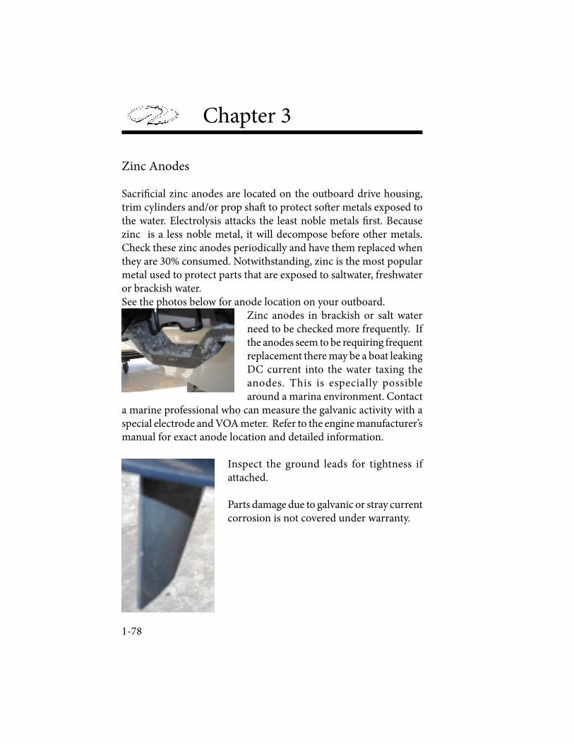
Chapter 3
1-78
Zinc Anodes
Sacri! cial zinc anodes are located on the outboard drive housing, trim cylinders and/or prop sha" to protect so" er metals exposed to the water. Electrolysis attacks the least noble metals ! rst. Because zinc is a less noble metal, it will decompose before other metals. Check these zinc anodes periodically and have them replaced when they are 30% consumed. Notwithstanding, zinc is the most popular metal used to protect parts that are exposed to saltwater, freshwater or brackish water.See the photos below for anode location on your outboard.
Zinc anodes in brackish or salt water need to be checked more frequently. If the anodes seem to be requiring frequent replacement there may be a boat leaking DC current into the water taxing the anodes. This is especially possible around a marina environment. Contact
a marine professional who can measure the galvanic activity with a special electrode and VOA meter. Refer to the engine manufacturer’s manual for exact anode location and detailed information.
Inspect the ground leads for tightness if attached.
Parts damage due to galvanic or stray current corrosion is not covered under warranty.

Systems
4-1
SystemsStandard Fire Port
! is optional system features a " xed " re extinguisher mounted along the engine compartment wall. ! e extinguishing system uses an environmentally friendly agent HFC227 ea. ! is colorless, odorless gas is lique" ed in the canister until deployment. ! e agent has acceptable toxicity ratings in enclosed spaces of your engine compartment’s size and is approved by the EPA. ! e " re extinguisher should be checked according to manufacturer speci" cations by a marine professional. DO NOT attempt to disassemble the " re extinguishing contraption. ! is " xed system is not intended to be explosion suppressive. Boat owner’s need to take normal precautions for checking gasoline fumes and using blowers.Your automatic " re extinguisher uses an actuator to discharge. ! is is usually enclosed by a metal cage. DO NOT handle the " re extinguisher at this location. Sensors are mounted to the extinguisher to detect a " re. A pressure gauge is also mounted for easier checkups.A manual discharge cable runs from the " re extinguisher to the helm or a# cockpit where a “T” handle and pin can manually discharge the extinguisher. If a " re starts, DO NOT wait for the automatic system to take e$ ect - manually discharge the system by removing the pin and pulling the “T” handle.
Note that as standard equipment (stern drive)there is a " re port and plug installed in the rear bench seat area. ! e plug includes a decal. In a " re emergency place a hand held " re extinguisher in the port and pull the pin to evacuate the agent.
Automatic Fire Extinguisher
Chapter 4
4-2
BILGE/DRAINAGE
Regal boats are designed with a drainage system so water can be moved to the bilge from the deck where the bilge pump can pump it out to the through hull drain normally on the a# starboard side. It is important to keep all drains clear of debris so when a wave % oods the deck of the boat, all water will leave in an e$ ective manner.
Your boat is equipped with main drains installed near the transom walk-thru on the a# starboard side of your boat, underneath the a# cockpit seats where the cooler normally is set, and a third drain installed in the ski locker. All three of these drains then route back to the bilge pump in the engine compartment. All cup holders and the bow storage compartment drain to the ski locker whereupon it is transferred to the engine compartment bilge pump.
Once the water has been drained to the bilge pump in the engine compartment, the bilge pump can pump it out through a hole located along the a# starboard side of your boat. ! e bilge pump is connected to a fuse located near the battery switch in the engine compartment and also to an automatic % oat switch placed directly forward of the bilge pump. ! e bilge pump receives power from your battery, and the automatic % oat switch is installed so that the bilge pump will automatically turn on as required. ! e circuit to the bilge pump receives battery power regardless of the state of your battery switch, so turning o$ the battery switch at the end of each voyage will not a$ ect your boat’s ability to pump water out of the bilge. A manual switch, operated from the dashboard however, requires the battery switch to be turned on.
Monitor your bilge pump’s condition to keep your vessel from sinking due to taking on large amounts of water. Debris should be cleared from the impeller regularly. Inspect the condition of the impeller and replace the impeller as necessary.
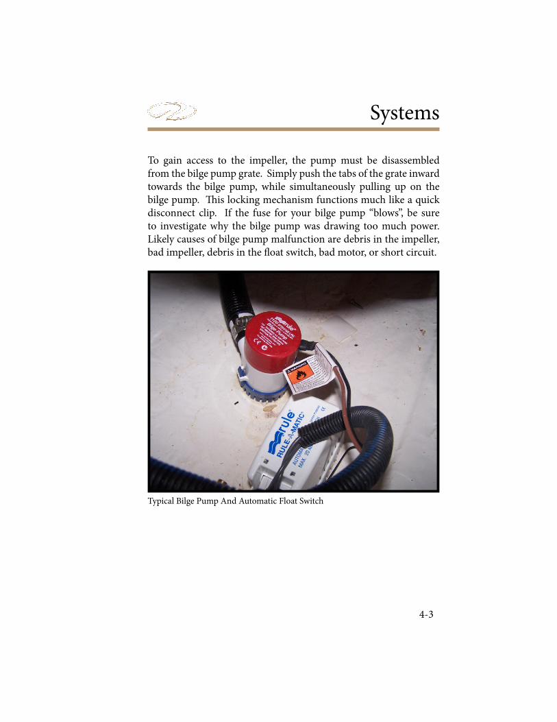
Systems
4-3
To gain access to the impeller, the pump must be disassembled from the bilge pump grate. Simply push the tabs of the grate inward towards the bilge pump, while simultaneously pulling up on the bilge pump. ! is locking mechanism functions much like a quick disconnect clip. If the fuse for your bilge pump “blows”, be sure to investigate why the bilge pump was drawing too much power. Likely causes of bilge pump malfunction are debris in the impeller, bad impeller, debris in the % oat switch, bad motor, or short circuit.
Typical Bilge Pump And Automatic Float Switch

Chapter 4
4-4
ELECTRICAL
Your boat runs o$ direct current (DC), supplied by your battery. Regal boats primarily use 12 volt DC batteries located in your engine compartment. It is called direct current because the current % ows one way in the circuit. Your automobile is a typical example of 12 volt DC current
Direct Current (12 Volt DC)
Storage batteries (sometimes called wet-lead cell batteries) furnish 12 volt electricity to boat components. Storage batteries use two dissimilar metals immersed in a liquid (acid) to carry current. ! e engines require large amounts of battery power for starting purposes. Check the maintenance chapter for battery information.
An automobile battery is charged up by the engine alternator. ! e same holds true for the marine battery. ! e dash volt meter displays the battery voltage. If the volt meter shows below 12 volts, there could be a charging system malfunction. ! is condition needs to be addressed before the voyage and before the batteries become completely drained.
Your battery should be removed for proper winter storage. A battery not properly stored for winter or extended periods of latency may exhibit charging problems. See the storage and winterization chapter for battery storage information.
Wire Color Codes
Utilize the following table when looking at your electrical harnesses. Your boat may not feature all of these functions, as some are optional features, while others are not available on your model.

Systems
4-5
COLOR GAUGE FUNCTIONBlack 16 to 4 All Grounds
Black / White 16 Halon Automatic Fire Extinguishing System
Blue 14 Interior Lights
Blue 10 Cabin Light Main Feed
Blue / White 16 Transom Courtesy Lights
Blue / White 14 Cockpit Lights
Brown 12 Water Pressure Pump
Brown 16 A# Bilge Pump / Manual
Brown 16 Fwd. Bilge Pump / Manual
Brown / Black 10 Overboard Discharge
Brown / Pink 16 Carbon Monoxide Detector
Brown / Red 16 Fwd. Auto Bilge Pump
Brown / White 16 A# Auto Bilge Pump
Grey 16 Bow Navigation Lights
Grey / Black 16 Mast Light (Anchor Light)
Grey / White 16 Mast Light (Fwd. Running)
Green 16 Tank Level Monitor
Green 8 Bonding
Orange 16 Windshield Wiper / Run
Orange 12 Refrigerator, Hatch Run
Orange 10 Spotlight
Orange / Black 16 Horn
Orange / White
16 Windshield Wiper Park
Purple 16 Hour Meter
Red 16 Gas Vapor Detector, Stereo Remote, Breaker To Dash Feed Lines
Red 14 Positive Feed, Electronics
Red 8 Positive Feed, Alternator Charge
Red 8 Positive Feed, Alternator Charge
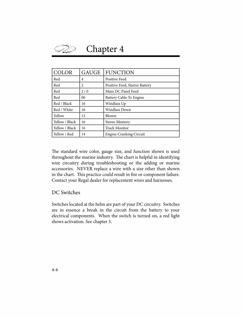
Chapter 4
4-6
COLOR GAUGE FUNCTIONRed 4 Positive Feed
Red 2 Positive Feed, Starter Battery
Red 2 / 0 Main DC Panel Feed
Red 00 Battery Cable To Engine
Red / Black 16 Windlass Up
Red / White 16 Windlass Down
Yellow 12 Blower
Yellow / Black 16 Stereo Memory
Yellow / Black 16 Track Monitor
Yellow / Red 14 Engine Cranking Circuit
! e standard wire color, gauge size, and function shown is used throughout the marine industry. ! e chart is helpful in identifying wire circuitry during troubleshooting or the adding or marine accessories. NEVER replace a wire with a size other than shown in the chart. ! is practice could result in " re or component failure. Contact your Regal dealer for replacement wires and harnesses.
DC Switches
Switches located at the helm are part of your DC circuitry. Switches are in essence a break in the circuit from the battery to your electrical components. When the switch is turned on, a red light shows activation. See chapter 3.
Systems
4-7
DC CIRCUIT PROTECTION
As part of the direct current circuitry, depending on the make and model engine you chose, will have either in line fuses or a fuse box for its electrical components. ! ese fuses protect the engine wiring from overloads. Refer to the engine manufacturer’s manual for the fuse locations, sizes, and operations.
A dash fuse box protects the individual switch controlled components and is located in the starboard bow storage locker.! e ignition panel is protected by a 20 amp breaker usually mounted to the panel itself. All gauges and helm electrical systems like the head radio unit are protected by a dashboard protection fuse located underneath the dash connected to the ignition switch. Your fusion stereo is also protected by a fusion installed stereo memory fuse normally located underneath the dash along the radio wiring, in addition to the Regal provided stereo memory fuse in the engine compartment near the battery switch. Additionally, there is an automatic bilge pump fuse located next to the battery switch in the engine compartment. See chapter 3.
If the fuses “blow” or breakers “pop” due to an overload, the cause should be investigated before replacing the fuse or resetting the breaker. Only replace fuses with the same amperage and type. In emergency situations, fuses installed in the fuse block for features that are not used on your model can be used as replacements when appropriately sized for the fuse your are replacing.

Chapter 4
4-8
FUSE FUNCTION AMPS TYPE PLACEAccessory 1 (If Included) 15 Fuse Dash Fuse
Box
Accessory 2 (Not Available) 15 Fuse Dash Fuse Box
Bilge Pump Manual 7.5 Fuse Dash Fuse Box
Bilge Pump Automatic 10 Fuse Engine
Blower 10 Fuse Dash Fuse Box
Cockpit Lights 10 Fuse Dash Fuse Box
Actuator- Protects Dash Switching 10 Breaker Actuator Box
Actuator- Port or Starboard Gear 25 Fuse Actuator Box
Main Breaker- Battery Switch to Helm 50 Breaker Battery Switch Area
Docking Lights (Not Available) 15 Fuse Dash Fuse Box
Fresh Water 7.5 Fuse Dash Fuse Box
Garmin (Not Available) 10 Fuse Dash Fuse Box
Horn 10 Fuse Dash Fuse Box
Ignition Breaker 20 Breaker Ignition Panel
Navigation / Anchor Lights 10 Fuse Dash Fuse Box
Stereo Memory Fusion Feed 15 Fuse Underneath Dash
Stereo Memory Main Feed 15 Fuse Engine
Stereo Performance (Optional) 40 Breaker BatterySwitch Area
12 Volt Accessory 15 Fuse Dash Fuse Box
**Typical Fuses
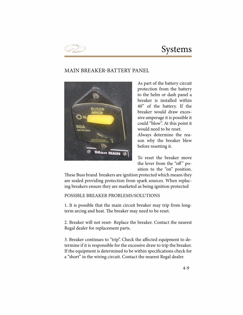
Systems
4-9
MAIN BREAKER-BATTERY PANEL
As part of the battery circuit protection from the battery to the helm or dash panel a breaker is installed within 40” of the battery. If the breaker would draw exces-sive amperage it is possible it could “blow”. At this point it would need to be reset. Always determine the rea-son why the breaker blew before resetting it.
To reset the breaker move the lever from the “o$ ” po-sition to the “on” position.
! ese Buss brand breakers are ignition protected which means they are sealed providing protection from spark sources. When replac-ing breakers ensure they are marketed as being ignition protected
POSSIBLE BREAKER PROBLEMS/SOLUTIONS
1. It is possible that the main circuit breaker may trip from long-term arcing and heat. ! e breaker may need to be reset.
2. Breaker will not reset- Replace the breaker. Contact the nearest Regal dealer for replacement parts.
3. Breaker continues to “trip”. Check the a$ ected equipment to de-termine if it is responsible for the excessive draw to trip the breaker. If the equipment is determined to be within speci" cations check for a “short” in the wiring circuit. Contact the nearest Regal dealer.
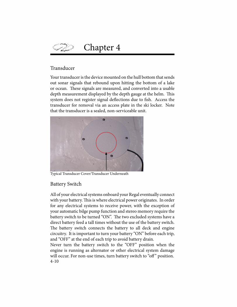
Chapter 4
4-10
Your transducer is the device mounted on the hull bottom that sends out sonar signals that rebound upon hitting the bottom of a lake or ocean. ! ese signals are measured, and converted into a usable depth measurement displayed by the depth gauge at the helm. ! is system does not register signal de% ections due to " sh. Access the transducer for removal via an access plate in the ski locker. Note that the transducer is a sealed, non-serviceable unit.
All of your electrical systems onboard your Regal eventually connect with your battery. ! is is where electrical power originates. In order for any electrical systems to receive power, with the exception of your automatic bilge pump function and stereo memory require the battery switch to be turned “ON”. ! e two excluded systems have a direct battery feed a tall times without the use of the battery switch. ! e battery switch connects the battery to all deck and engine circuitry. It is important to turn your battery “ON” before each trip, and “OFF” at the end of each trip to avoid battery drain. Never turn the battery switch to the “OFF” position when the engine is running as alternator or other electrical system damage will occur. For non-use times, turn battery switch to “o$ ” position.
Battery Switch
Transducer
Typical Transducer Cover/Transducer Underneath
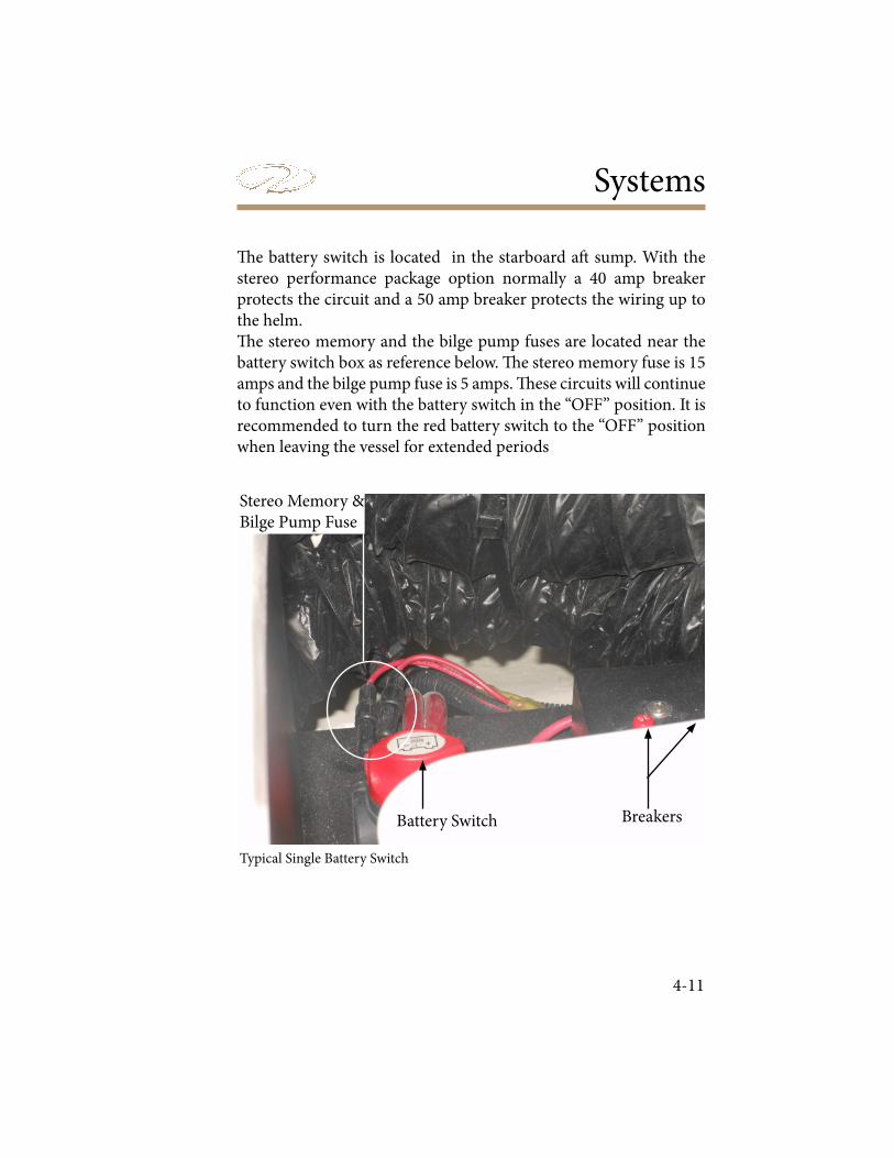
Systems
4-11
! e battery switch is located in the starboard a# sump. With the stereo performance package option normally a 40 amp breaker protects the circuit and a 50 amp breaker protects the wiring up to the helm. ! e stereo memory and the bilge pump fuses are located near the battery switch box as reference below. ! e stereo memory fuse is 15 amps and the bilge pump fuse is 5 amps. ! ese circuits will continue to function even with the battery switch in the “OFF” position. It is recommended to turn the red battery switch to the “OFF” position when leaving the vessel for extended periods
Typical Single Battery Switch
Breakers
Stereo Memory &Bilge Pump Fuse
Battery Switch
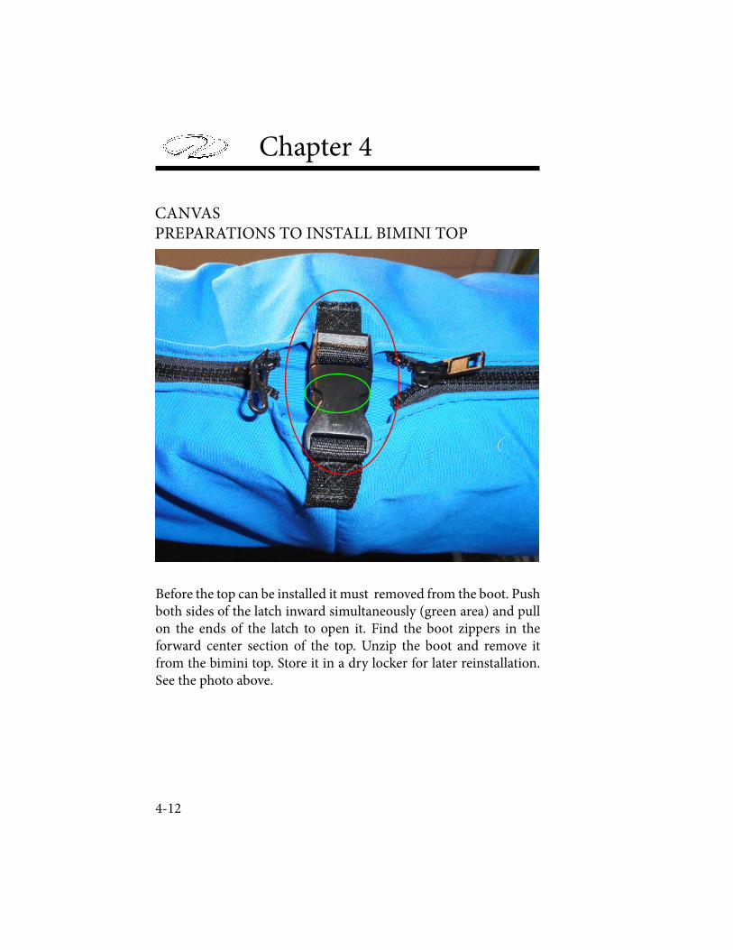
Chapter 4
4-12
Before the top can be installed it must removed from the boot. Push both sides of the latch inward simultaneously (green area) and pull on the ends of the latch to open it. Find the boot zippers in the forward center section of the top. Unzip the boot and remove it from the bimini top. Store it in a dry locker for later reinstallation. See the photo above.
CANVAS PREPARATIONS TO INSTALL BIMINI TOP
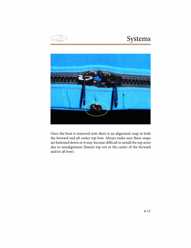
Systems
4-13
Once the boot is removed note there is an alignment snap in both the forward and a# center top bow. Always make sure these snaps are buttoned down or it may become di: cult to install the top arms due to misalignment (bimini top not in the center of the forward and/or a# bow).
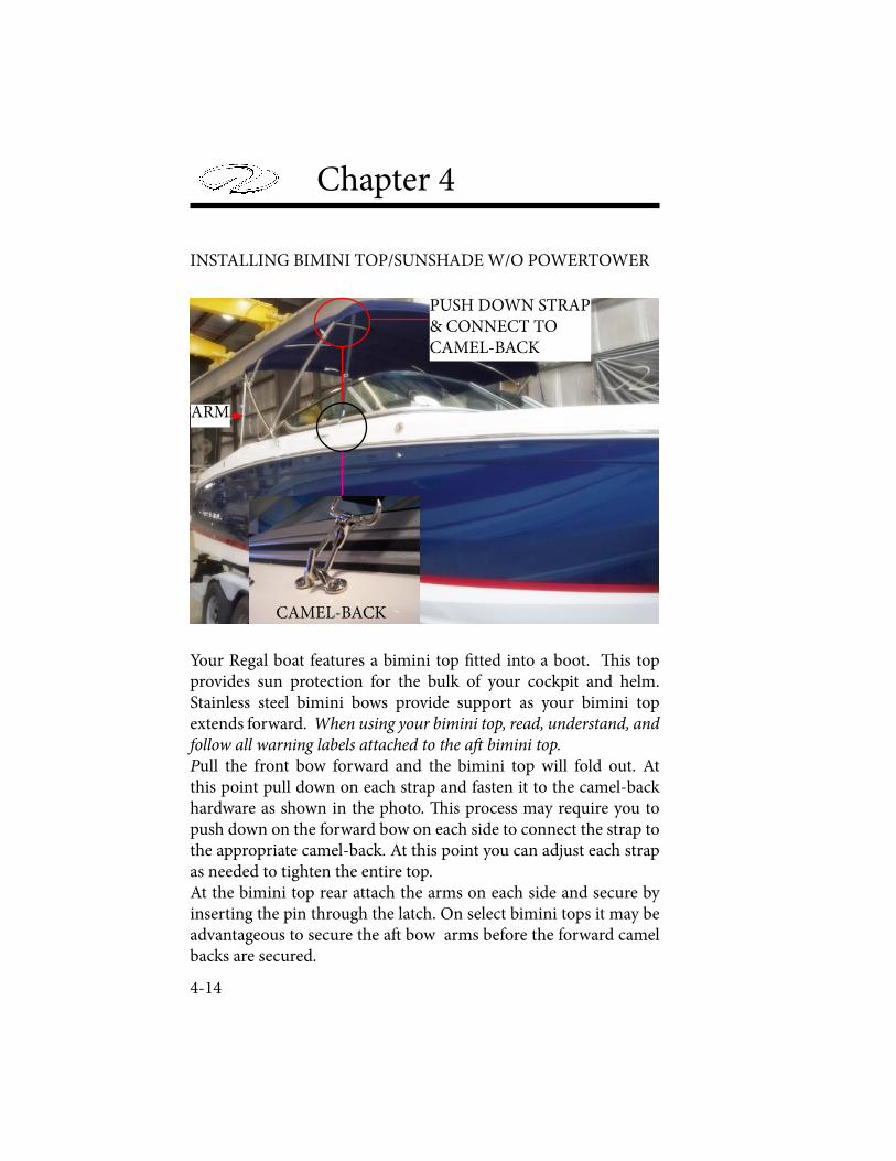
Chapter 4
4-14
CAMEL-BACK
PUSH DOWN STRAP& CONNECT TOCAMEL-BACK
ARM
INSTALLING BIMINI TOP/SUNSHADE W/O POWERTOWER
Your Regal boat features a bimini top " tted into a boot. ! is top provides sun protection for the bulk of your cockpit and helm. Stainless steel bimini bows provide support as your bimini top extends forward. When using your bimini top, read, understand, and follow all warning labels attached to the a! bimini top. Pull the front bow forward and the bimini top will fold out. At this point pull down on each strap and fasten it to the camel-back hardware as shown in the photo. ! is process may require you to push down on the forward bow on each side to connect the strap to the appropriate camel-back. At this point you can adjust each strap as needed to tighten the entire top.At the bimini top rear attach the arms on each side and secure by inserting the pin through the latch. On select bimini tops it may be advantageous to secure the a# bow arms before the forward camel backs are secured.

Systems
4-15
DIAGRAM AND INSTALLATION INSTRUCTIONS FOR BIMINI TOP/SUNSHADE-VESSELS WITH OPTIONAL POWERTOWER.
1. Find jaw between pins on bottom of port forward bow. Move sliding jaw over the top pin to release the forward bow and pull up to upper set of pins allowing the jaws to slide over the bottom pin and locking in between the pins (yellow arrow). See " gure B. Do the same with the starboard forward bow.
2. Find one of the straight eyed arms as shown in Figure B on the following pages. Turn the white cha" ng block in a direction so its % at surface is between the straight arm and the PowerTower to protect it. While pushing down on the starboard forward bow align the straight arm with the forward end of the jaw and install the ball end of the straight arm into the front of the jaw. Install a lanyard pin which will lock it in place. Do the same with the other straight arm.
3. Locate the 90 degree a# arms. ! ere are 2 each for the a# bows. See Figure B. Start with either side. Pull down on the a# top and insert the top arm into the top jaw. Lock the arm in place by inserting a lanyard pin. Repeat the same process with the lower 90 degree arm. Follow the same procedure with the 90 degree arms on the other side.
4. Note that the forward bow utilizes a strap and latch similar to the latch on the boot. ! is strap assists in holding the bimini top down as the vessel is making forward headway. Attach the upper and lower strap together and attach at the camel-back. Remember not to exceed 35 mph with the bimini top up on the
waterways Also, the bimini top must be disassembled and zipped
into the boot before towing on the highway.

Chapter 4
4-16
5. Perform the steps in reverse order to disassemble the bimini top. ! e sliding jaw on the forward bow will need to be pushed down to the lower set of pins on the forward bow on both sides for the top to set in the proper place. Use the arm retainer blocks to latch the arms in place.Reinstall bimini top in boot and zip up the boot.
6. Be sure to read the canvas manufacturer’s information regarding caring for your canvas and more detailed installation information which can be found in the owner’s information packet.
PREVENT POSSIBLE BODILY INJURY AND PROPERTY DAMAGEDUE TO THE CANVAS/CANVAS HARDWARE DISLODGING!
DO NOT USE BIMINI CANVAS CRUISING ABOVE A SPEED OF 30 MILES PER HOUR. IF TOWING BOAT BEFORE TRAILERING
MAKE SURE BIMINI TOP/SUNSCREEN IS ATTACHED TOHARDWARE SECURELY, ZIPPERED AND LATCHED
INSIDE CANVAS BOOT!
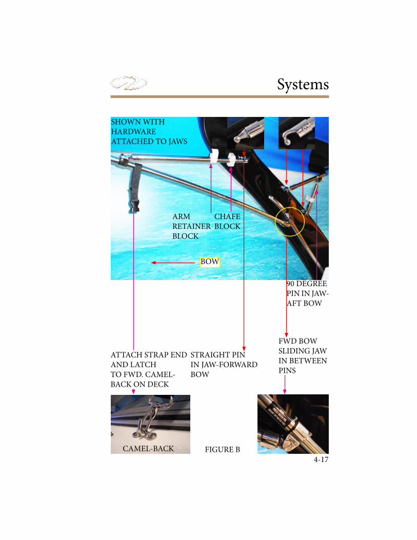
Systems
4-17
FWD BOW SLIDING JAWIN BETWEENPINS
STRAIGHT PININ JAW-FORWARDBOW
90 DEGREEPIN IN JAW-AFT BOW
CAMEL-BACK
SHOWN WITH HARDWAREATTACHED TO JAWS
FIGURE B
BOW
CHAFEBLOCK
ARMRETAINERBLOCK
ATTACH STRAP END AND LATCHTO FWD. CAMEL-BACK ON DECK
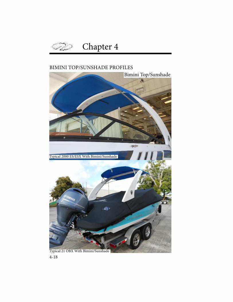
Chapter 4
4-18
Bimini Top/Sunshade
Typical 2000 ES/ESX With Bimini/Sunshade
Typical 21 OBX With Bimini/Sunshade
BIMINI TOP/SUNSHADE PROFILES
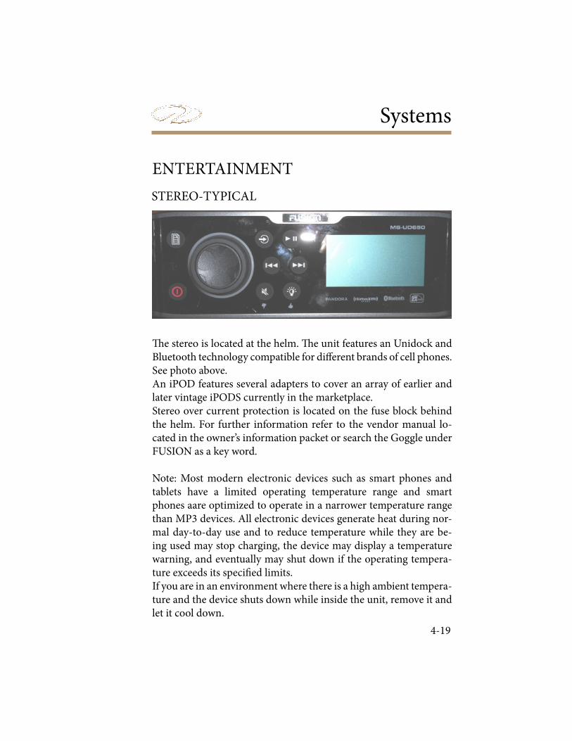
Systems
4-19
ENTERTAINMENT
STEREO-TYPICAL
! e stereo is located at the helm. ! e unit features an Unidock and Bluetooth technology compatible for di$ erent brands of cell phones. See photo above. An iPOD features several adapters to cover an array of earlier and later vintage iPODS currently in the marketplace.Stereo over current protection is located on the fuse block behind the helm. For further information refer to the vendor manual lo-cated in the owner’s information packet or search the Goggle under FUSION as a key word.
Note: Most modern electronic devices such as smart phones and tablets have a limited operating temperature range and smart phones aare optimized to operate in a narrower temperature range than MP3 devices. All electronic devices generate heat during nor-mal day-to-day use and to reduce temperature while they are be-ing used may stop charging, the device may display a temperature warning, and eventually may shut down if the operating tempera-ture exceeds its speci" ed limits.If you are in an environment where there is a high ambient tempera-ture and the device shuts down while inside the unit, remove it and let it cool down.
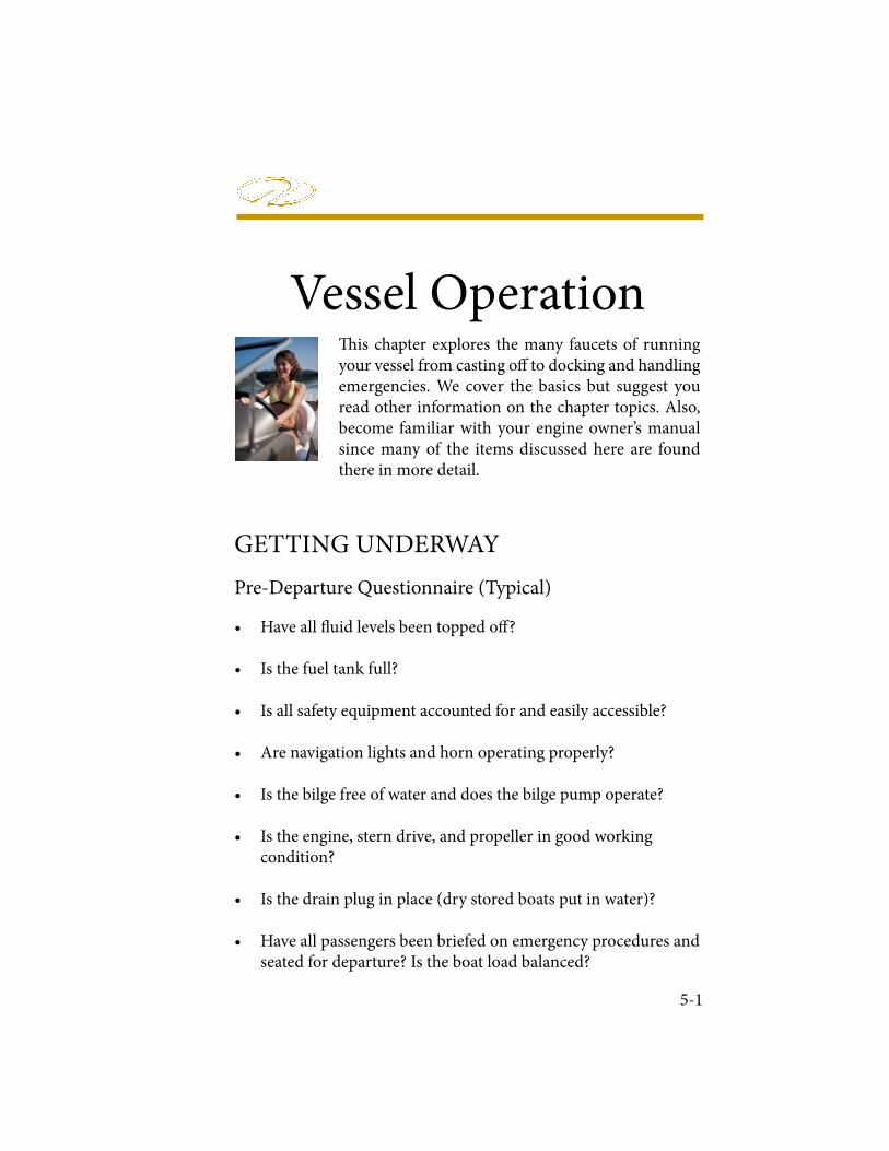
Vessel Operation
5-1
! is chapter explores the many faucets of running your vessel from casting o" to docking and handling emergencies. We cover the basics but suggest you read other information on the chapter topics. Also, become familiar with your engine owner’s manual since many of the items discussed here are found there in more detail.
Pre-Departure Questionnaire (Typical)
• Have all # uid levels been topped o" ?
• Is the fuel tank full?
• Is all safety equipment accounted for and easily accessible?
• Are navigation lights and horn operating properly?
• Is the bilge free of water and does the bilge pump operate?
• Is the engine, stern drive, and propeller in good working condition?
• Is the drain plug in place (dry stored boats put in water)?
• Have all passengers been briefed on emergency procedures and seated for departure? Is the boat load balanced?
GETTING UNDERWAY

Chapter 5
5-2
• Is the operator sober, alert and ready to skipper the vessel?
• Have all passengers been ! tted for life jackets?
• Has a " oat plan been ! led and le# with a component person?
• Has the bilge been sni$ ed and the fuel system leak checked?
• Are all seacocks open (if applicable)?
• Is all communication equipment in good operating condition?
• Has a second person been briefed on operational procedures should the skipper become disabled?
• Are all gauges and electrical switches functioning properly?
• Has weather information been gathered and analyzed?
Underway Questionnaire
• A# er casting o$ have all dock lines and fenders been stowed?
• Are all passengers seated and all transom doors closed?
• As skipper are you monitoring the dash gauges for changes?
• As skipper are you on the lookout for changing weather?
• As skipper are you checking for abnormal vibration?
• Is the remote control safety lanyard (if equipped) tightly secured to your belt or clothing?
Vessel Operation
5-3
• Have you removed the keys from the ignition and secured them?
• Have all systems been checked for leaks?
• Has the battery switch been turned to the “o! ” position?
• Are all seacocks closed?
• Has the fuel tank been " lled enough to prevent condensation?
• Is the vessel properly tied and covered with equipment stored?
Disembarking Questionnaire
FUELING
AVOID SERIOUS INJURY OR DEATH FROM LEAKING FUEL!
INSPECT ENTIRE FUEL SYSTEMAT LEAST ONCE A YEAR.
AVOID PERSONAL INJURY OR DEATH!GASOLINE IS A HIGHLY FLAMMABLE
AND EXPLOSIVE MATERIAL. PRACTICE “NO SMOKING” AND EXTINGUISH ALL
FLAMMABLE MATERIALS WITHIN 75 FEET OF THE FUEL DOCK.
Chapter 5
5-4
Before Fueling
• Make sure a working ! re extinguisher is available.
• Stop engines and any device that can cause a spark.
• Disembark all passengers and crew not needed for fueling.
• Fuel if possible during the daylight hours.
• Check to ensure nobody is smoking in the boat or near the fueling dock.
• Close all portholes, hatches and doors to keep vapors from blowing aboard and settling in the bilge.
• Tie up your boat securely at the fuel dock.
• Identify the fuel ! ll. Unfortunately, people have mistakenly ! lled the water or waste with fuel.
• Visually inspect all fuel system components before each ! lling.
• Avoid using fuels with alcohol additives. " ey can attack fuel system hoses and cause deterioration.
SINCE GASOLINE IS AVAILABLE IN SEVERAL GRADES INCLUDINGETHANOL & VARIOUS OCTANE LEVELS, REFER TO THE ENGINE
MANUFACTURER’S OWNER’S MANUAL FOR THE CORRECTONE FOR YOUR ENGINE USING IMPROPER OCTANE FUEL
CAN CAUSE ENGINE DAMAGE AND VOID THE WARRANTY.
Vessel Operation
5-5
During Fueling
• Keep the fuel nozzle in contact with the fuel ! ll to guard against static sparks. " e fuel ! ll pipe is grounded through the fuel system wiring to protect against static electricity.
• Avoid over! lling the fuel tank. Leave room for expansion. Also, if fuel exits the fuel vent indicating the tank is full, this situation is dangerous and unfriendly to the environment.
• Avoid spilling any fuel. Clean up any fuel accidently spilled with a clean rag and dispose of it on shore.
A# er Fueling
• Close all fuel ! ll openings tightly. Use a fuel key if needed.
• Open all portholes, hatches and doors.
• Energize the blower for a minimum of 4 minutes.
• Sni$ in the lower bilge and engine compartment for gas fumes. If fumes are detected continue to ventilate until the odor is gone. Look for any traces of fuel droplets or spillage. Do not start the engines, smoke or run any electrical components except the blower until the fumes can no longer be detected.
Chapter 5
5-6
! e following general information covers starting and stopping your engine. Read and understand all previous information on remote controls, fueling and operational procedures. Pay particular attention to all labels. Refer to the engine owner’s manual for in- -depth propulsion system information.
Review all pre-departure information. Before starting your engine make sure all canvas is removed and stored. Start engine only in a well ventilated location to avoid CO buildup. Turn the battery switch to the number 1 or 2 position. Set the remote control handle in the neutral position. Advance the neutral throttle position as instructed in the engine owner’s manual. Connect the safety lanyard to a belt or secure to clothing such as a pants belt loop. Keep passengers seated and away from controls.Turn the ignition key to the momentarily start position. You will hear the starter cranking over the engine. When the engine starts release the key switch. It will automatically align itself in the run position.If the engine does not start, refrain from cranking the engine over 10-12 seconds. Allow the starter and battery a chance to recover. Advance the remote control in the neutral throttle position as recommended in engine manual. Do not race the remote control in neutral position.
STARTING & STOPPING
Starting Guidelines
AVOID SERIOUS INJURY OR DEATHFROM GASOLINE VAPORS! BEFORE STARTING ENGINE,
OPERATE BLOWER 4 MINUTES AND VISUALLY CHECK ENGINE COMPARTMENT AND PERFORM SNIFF TEST
FOR GASOLINE LEAKS OR VAPORS. RUN BLOWERBELOW CRUISING SPEEDS.
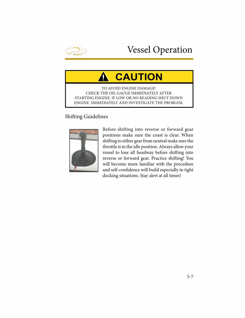
Vessel Operation
5-7
Shi! ing Guidelines
Before shifting into reverse or forward gear positions make sure the coast is clear. When shi! ing to either gear from neutral make sure the throttle is in the idle position. Always allow your vessel to lose all headway before shi! ing into reverse or forward gear. Practice shi! ing! You will become more familiar with the procedure and self-con# dence will build especially in tight docking situations. Stay alert at all times!
TO AVOID ENGINE DAMAGE!CHECK THE OIL GAUGE IMMEDIATELY AFTER
STARTING ENGINE. IF LOW OR NO READING SHUT DOWNENGINE IMMEDIATELY AND INVESTIGATE THE PROBLEM.

Chapter 5
5-8
Stopping
Before stopping the engine make sure the remote control is in neutral low idle speed. A! er an outing let the engine cool down at idle speeds for a few minutes before turning the ignition o" . Glance at the gauges one last time to monitor their readings. Do not pull on the safety lanyard verses the ignition switch to stop the engine. Never turn o" the engine o" while in gear since water could enter the engine through the exhaust system and cause extensive damage. Above all, use common sense!
Vessel Operation
5-9
Most vessels use a rotary or rack style steering system. ! ese systems transfer helm mechanical motion to the engine. ! ere is a hydraulic steering cylinder which with the assistance of a steering pump sends " uid force to the stern drive steering arm changing the course of the boat, depending on the direction the steering wheel is turned.Since the steering system is the primary link for engine control, it must be periodically inspected and maintained. ! e hardware at both the helm and engine must be checked regularly for tightness.Check the steering system for full steering port and starboard before disembarking. Refer to the steering manufacturer’s literature in the owner’s packet and the maintenance chapter for more information.
STEERING
AVOID SERIOUS INJURY OR DEATH! THE OPERATOR OF THE VESSEL MUST HAVE COMPLETE
CONTROL OF THE HELM STEERING STATION WHILE THEVESSEL IS MOVING. NEVER LEAVE THE HELM STATION
UNATTENDED WHILE THE VESSEL IS MAKING HEADWAY.
AVOID SERIOUS INJURY OR DEATH! LOOSENING OR LOSS OF ONE OR MORE FASTENERS MAYCAUSE FAILURE OF THE STEERING SYSTEM OR DAMAGE
TO THE STEERING CABLE, RESULTING IN LOSS OF STEERINGCONTROL INSPECT THE SYSTEM AT LEAST ANNUALLY.
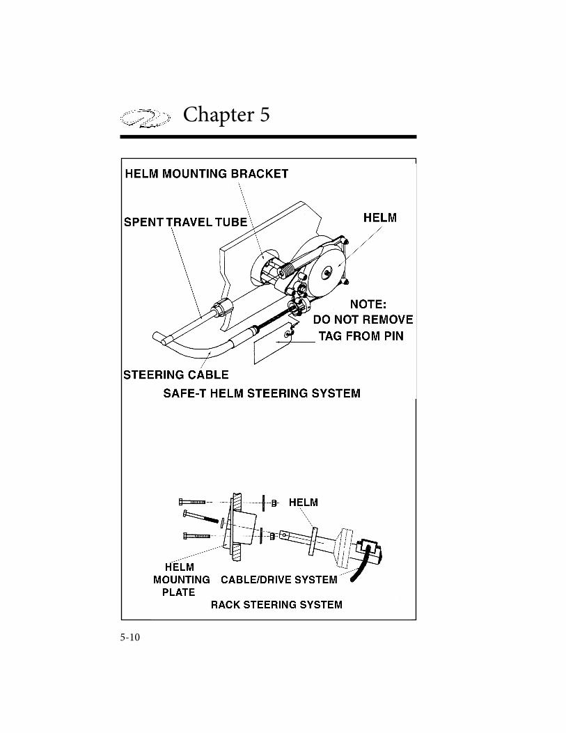
Chapter 5
5-10
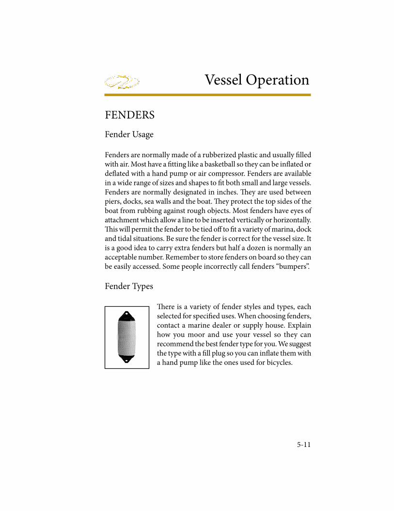
Vessel Operation
5-11
FENDERS
Fender Usage
Fenders are normally made of a rubberized plastic and usually ! lled with air. Most have a ! tting like a basketball so they can be in" ated or de" ated with a hand pump or air compressor. Fenders are available in a wide range of sizes and shapes to ! t both small and large vessels. Fenders are normally designated in inches. # ey are used between piers, docks, sea walls and the boat. # ey protect the top sides of the boat from rubbing against rough objects. Most fenders have eyes of attachment which allow a line to be inserted vertically or horizontally. # is will permit the fender to be tied o$ to ! t a variety of marina, dock and tidal situations. Be sure the fender is correct for the vessel size. It is a good idea to carry extra fenders but half a dozen is normally an acceptable number. Remember to store fenders on board so they can be easily accessed. Some people incorrectly call fenders “bumpers”.
Fender Types
# ere is a variety of fender styles and types, each selected for speci! ed uses. When choosing fenders, contact a marine dealer or supply house. Explain how you moor and use your vessel so they can recommend the best fender type for you. We suggest the type with a ! ll plug so you can in" ate them with a hand pump like the ones used for bicycles.
Chapter 5
5-12
DOCK LINE BASICS
Most skippers use dock line terminology fairly loose but there is more to the basics than just bow or stern lines. There are several lines that can be secured to the bow and stern and depending on their direction and use, can be called other names. Remember that “forward” and “a! ” refer to the direction that a spring line runs from the vessel, and not where it is secured on board.
" ere is only one true bow line. It is secured to the forward cleat and run forward along the dock to prevent the vessel from moving to the stern. " e stern line leads from a rear cleat to a piling or cleat on the dock astern of the vessel. " is line keeps the boat from moving ahead. For small vessels these are the only lines needed for normal wind and current conditions. If located in a tidal environment, keep slack in the lines.
Breast Lines
" ese lines are attached to the bow and stern that lead to nearly right angles from the center of the vessel to the dock. " ey help keep larger vessels from moving away from the dock, or are pulled in to help people board the vessel. Larger vessels may use bow or quarter breast lines.
Spring Lines
Most small boats use two spring lines although it is possible to have four. " ey are called the a! er bow spring and forward quarter spring.
Bow & Stern Lines
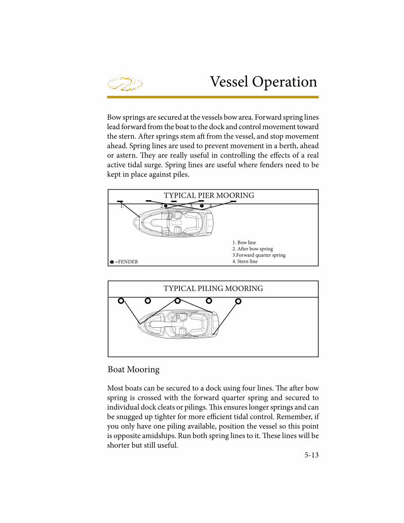
Vessel Operation
5-13
Bow springs are secured at the vessels bow area. Forward spring lines lead forward from the boat to the dock and control movement toward the stern. A! er springs stem a! from the vessel, and stop movement ahead. Spring lines are used to prevent movement in a berth, ahead or astern. " ey are really useful in controlling the e# ects of a real active tidal surge. Spring lines are useful where fenders need to be kept in place against piles.
1. Bow line2. A! er bow spring3.Forward quarter spring4. Stern line
1. 2. 3. 4.
TYPICAL PIER MOORING
=FENDER
TYPICAL PILING MOORING
Boat Mooring
Most boats can be secured to a dock using four lines. " e a! er bow spring is crossed with the forward quarter spring and secured to individual dock cleats or pilings. " is ensures longer springs and can be snugged up tighter for more e$ cient tidal control. Remember, if you only have one piling available, position the vessel so this point is opposite amidships. Run both spring lines to it. " ese lines will be shorter but still useful.
Chapter 5
5-14
! e bow and stern lines should be relatively at a 45 degree angle with the dock. ! e stern line can be attached to the near-shore quarter cleat, but will work more e" ciently to the o# shore quarter cleat. ! e longer line will allow the boat $ ow with the tide with less time checking the vessel.
Dock Line Sizing
Most dock lines today are made of nylon, either of twisted rope or braided core and cover. ! e most o% en used material is nylon because of its stretching abilities absorbing shock loads. It is chafe resistant for extended life and is easier on bare hands. ! e line’s size varies with the vessel. Normally, a vessel in the 20’ to 40’ boats will use 1/2” diameter nylon lines. Larger yachts use 5/8” and 3/4” diameter nylon lines. Smaller boats can use 3/8” nylon lines.Dock lines need to have the strength to hold the vessel and have enough density to resist cha& ng. ! ey shouldn’t be too heavy that they lose their shock-absorbing capabilities. Use the right size line for the vessel since a line to large for the boat will pull hard against the vessel since it won’t be forced to stretch. If the line is too small for the vessel, there is no margin for wear and chafe when under strain.
Securing Lines
When mooring your boat, make sure the dock lines are secured at both ends. Depending on your situation you may need to loop the eye splice of the dock line around a piling. Sometimes the mooring line will lead down sharply from the piling to the deck cleat. Loop the eye splice around the piling twice to keep it from being pulled up o# the pile. Pull the line through the looped eye if the mooring line is too small to go around the piling twice or too small to & t over once.If you must drop a line over a piling that already holds another boat’s line, run the eye of the line up through the & rst eye from below, then loop it over the pile. ! is will allow either line to be removed without
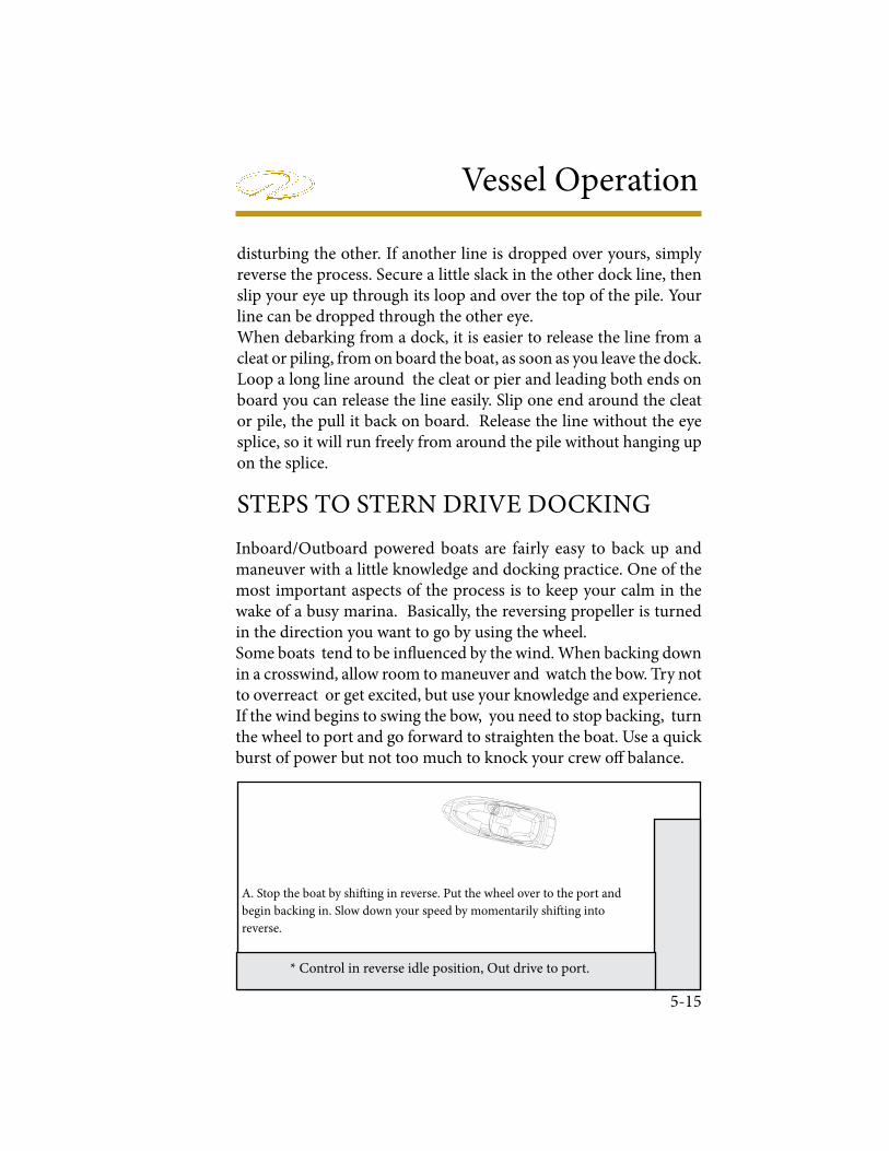
Vessel Operation
5-15
disturbing the other. If another line is dropped over yours, simply reverse the process. Secure a little slack in the other dock line, then slip your eye up through its loop and over the top of the pile. Your line can be dropped through the other eye. When debarking from a dock, it is easier to release the line from a cleat or piling, from on board the boat, as soon as you leave the dock. Loop a long line around the cleat or pier and leading both ends on board you can release the line easily. Slip one end around the cleat or pile, the pull it back on board. Release the line without the eye splice, so it will run freely from around the pile without hanging up on the splice.
STEPS TO STERN DRIVE DOCKING
Inboard/Outboard powered boats are fairly easy to back up and maneuver with a little knowledge and docking practice. One of the most important aspects of the process is to keep your calm in the wake of a busy marina. Basically, the reversing propeller is turned in the direction you want to go by using the wheel. Some boats tend to be in! uenced by the wind. When backing down in a crosswind, allow room to maneuver and watch the bow. Try not to overreact or get excited, but use your knowledge and experience. If the wind begins to swing the bow, you need to stop backing, turn the wheel to port and go forward to straighten the boat. Use a quick burst of power but not too much to knock your crew o" balance.
* Control in reverse idle position, Out drive to port.
A. Stop the boat by shi# ing in reverse. Put the wheel over to the port and
begin backing in. Slow down your speed by momentarily shi# ing into
reverse.
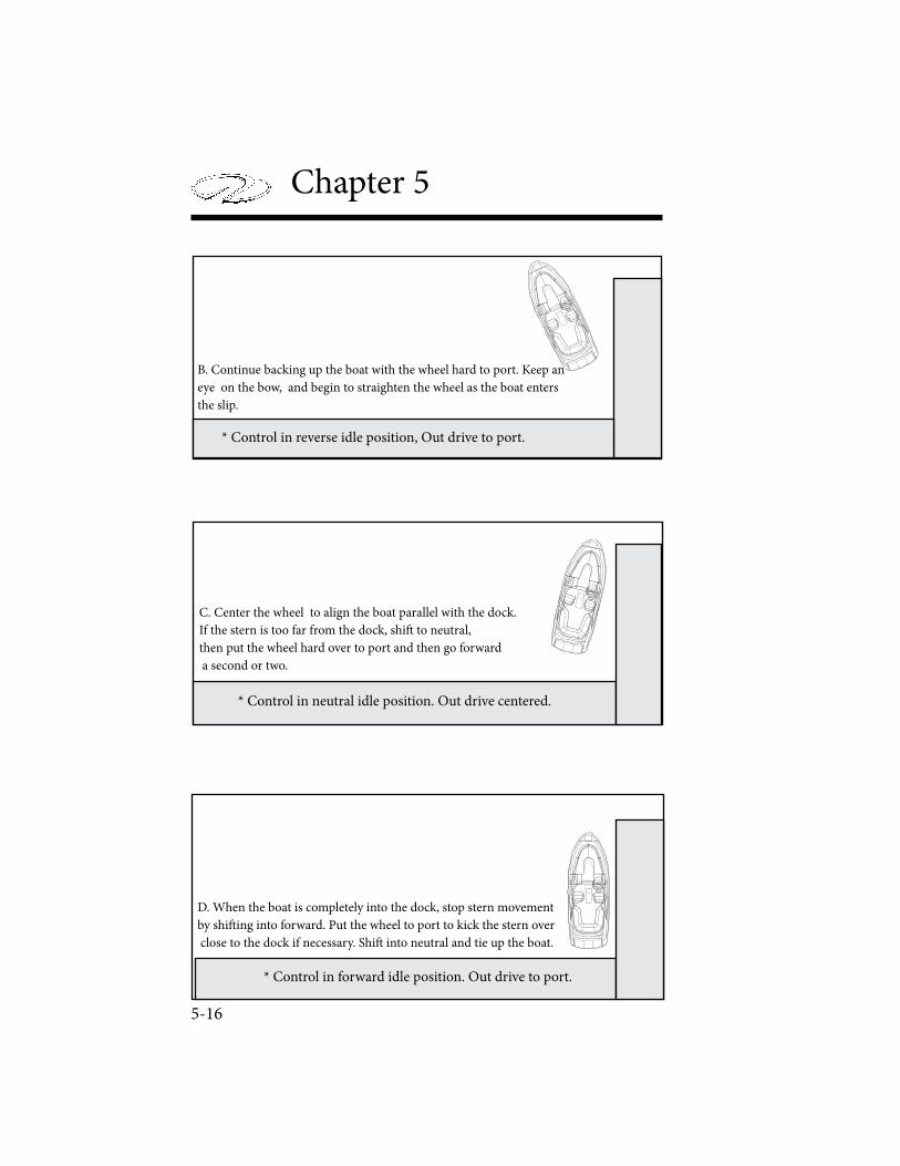
Chapter 5
5-16
* Control in reverse idle position, Out drive to port.
B. Continue backing up the boat with the wheel hard to port. Keep an
eye on the bow, and begin to straighten the wheel as the boat enters
the slip.
* Control in neutral idle position. Out drive centered.
C. Center the wheel to align the boat parallel with the dock.
If the stern is too far from the dock, shi! to neutral,
then put the wheel hard over to port and then go forward
a second or two.
* Control in forward idle position. Out drive to port.
D. When the boat is completely into the dock, stop stern movement
by shi! ing into forward. Put the wheel to port to kick the stern over
close to the dock if necessary. Shi! into neutral and tie up the boat.
Vessel Operation
5-17
STERN DRIVE MANEUVERING
Inboard/outboard, I/O or sometimes called stern drive boats do not have rudders. ! e boat uses a steering system that directs the propeller thrust, by turning the stern drive unit where the propeller is mounted. Normally maneuvering the I/O boat is easier than a similar single screw vessel.Directing propeller energy (thrust) makes slower speed maneuvering easier. ! e propeller discharge current is turned from one side to the other which results in turning forces. Rudder boats need water to " ow by the rudder to be e# cient. Stern drive units are designed to have reduced sha$ angle, so the propeller does not produce as much unequal blade thrust and resistance as does a propeller on a single screw boat. Large horsepower stern drive boats do produce more thrust and steering torque but your vessel has the advantage of power steering. Below is some basic information on how single stern drive boats handle in normal conditions.
Gathering Headway
When a stern drive is not moving forward or reverse in the water and the propeller is not turning, (shi$ in neutral) the boat will not react to the helm steering wheel. As soon as the vessel is shi$ ed into forward gear the propellers action creates a discharge motion and generates energy in the form of thrust. If the stern drive is centered, the discharge motion is directed straight back causing the vessel to advance forward.You may notice that if you advance the throttle quickly in initial take-o% (make sure you have a & rm grip on the wheel), the boat has a tendency to pull the stern of the vessel to starboard. ! ere is a trim tab (also serves as a sacri& cial anode) located on the vertical drive housing just to the top of the propeller blade. ! is trim tab helps compensate for the low speed steering torque. Once the boat increases headway and the propeller is operating in a faster water " ow this torque e% ect decreases.
Chapter 5
5-18
Sometimes the trim tab may need adjustment on stern drive models. Contact your Regal dealer for further information or consult your engine manufacturer’s manual.
Turning
Once the boat has gathered headway, with the boat planing at the correct bow angle and the stern drive unit and helm straight the boat tends to stay on a uniform course heading. To assure the boat trim angle is correct use the trim gauge as a guide while activating the trim button on the remote control panel.When the helm wheel is turned to the right or starboard, the stern drive unit is turned in the same direction. ! e propeller’s discharge force is directed to starboard forcing the boats stern to port. Water " owing past the hull strikes the stern drive gear housing in its starboard side, creating additional turning torque. ! e stern starts a move to port, forcing the bow to starboard.If the helm is turned to the le# or port the stern drive turns to port, the stern of the boat goes starboard as the bow turns to port.As the vessel operator gains experience, he will better gauge each maneuver and speed situation. In this way he will understand the handling characteristics of his boat. He needs to keep the safety of his passengers in the highest priority.
Backing Down
Inboard/Outboard (I/O) boats do not have rudders. ! e boat uses a steering system that directs the propeller thrust, by turning the stern drive unit where the propeller is mounted. Normally maneuvering the I/O boat is easier than a similar single screw vessel.If your boat has the steering wheel and stern drive straight with the control in reverse, the stern will be pushed a bit to port by the reversing propeller thrust. ! is tendency to back to port can be eliminated by turning the stern drive to starboard.
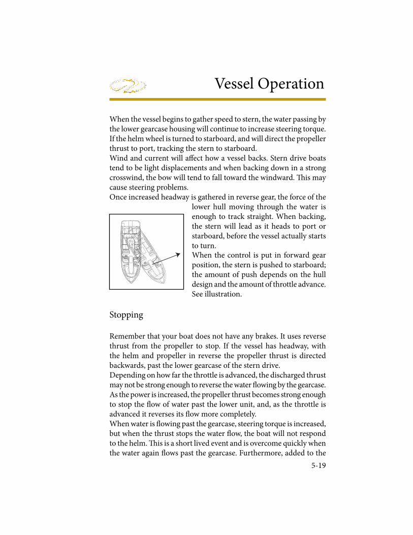
Vessel Operation
5-19
When the vessel begins to gather speed to stern, the water passing by the lower gearcase housing will continue to increase steering torque. If the helm wheel is turned to starboard, and will direct the propeller thrust to port, tracking the stern to starboard.Wind and current will a! ect how a vessel backs. Stern drive boats tend to be light displacements and when backing down in a strong crosswind, the bow will tend to fall toward the windward. " is may cause steering problems. Once increased headway is gathered in reverse gear, the force of the
lower hull moving through the water is enough to track straight. When backing, the stern will lead as it heads to port or starboard, before the vessel actually starts to turn.When the control is put in forward gear position, the stern is pushed to starboard; the amount of push depends on the hull design and the amount of throttle advance. See illustration.
Stopping
Remember that your boat does not have any brakes. It uses reverse thrust from the propeller to stop. If the vessel has headway, with the helm and propeller in reverse the propeller thrust is directed backwards, past the lower gearcase of the stern drive.Depending on how far the throttle is advanced, the discharged thrust may not be strong enough to reverse the water # owing by the gearcase. As the power is increased, the propeller thrust becomes strong enough to stop the # ow of water past the lower unit, and, as the throttle is advanced it reverses its # ow more completely.When water is # owing past the gearcase, steering torque is increased, but when the thrust stops the water # ow, the boat will not respond to the helm. " is is a short lived event and is overcome quickly when the water again # ows past the gearcase. Furthermore, added to the
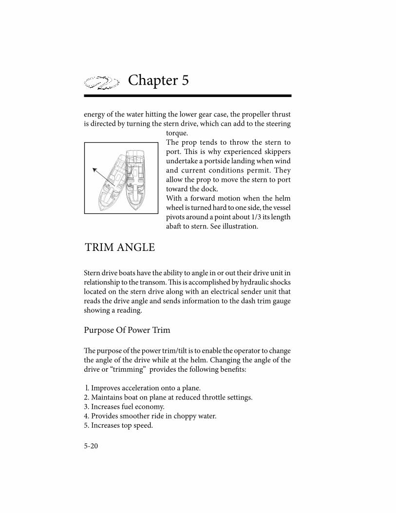
Chapter 5
5-20
energy of the water hitting the lower gear case, the propeller thrust is directed by turning the stern drive, which can add to the steering
torque. The prop tends to throw the stern to port. ! is is why experienced skippers undertake a portside landing when wind and current conditions permit. They allow the prop to move the stern to port toward the dock.With a forward motion when the helm wheel is turned hard to one side, the vessel pivots around a point about 1/3 its length aba" to stern. See illustration.
Stern drive boats have the ability to angle in or out their drive unit in relationship to the transom. ! is is accomplished by hydraulic shocks located on the stern drive along with an electrical sender unit that reads the drive angle and sends information to the dash trim gauge showing a reading.
Purpose Of Power Trim
! e purpose of the power trim/tilt is to enable the operator to change the angle of the drive while at the helm. Changing the angle of the drive or “trimming” provides the following bene# ts:
l. Improves acceleration onto a plane.2. Maintains boat on plane at reduced throttle settings.3. Increases fuel economy.4. Provides smoother ride in choppy water.5. Increases top speed.
TRIM ANGLE
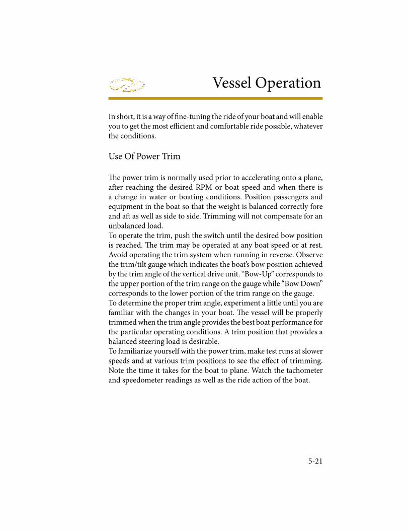
Vessel Operation
5-21
In short, it is a way of ! ne-tuning the ride of your boat and will enable you to get the most e" cient and comfortable ride possible, whatever the conditions.
Use Of Power Trim
# e power trim is normally used prior to accelerating onto a plane, a$ er reaching the desired RPM or boat speed and when there is a change in water or boating conditions. Position passengers and equipment in the boat so that the weight is balanced correctly fore and a$ as well as side to side. Trimming will not compensate for an unbalanced load. To operate the trim, push the switch until the desired bow position is reached. # e trim may be operated at any boat speed or at rest. Avoid operating the trim system when running in reverse. Observe the trim/tilt gauge which indicates the boat’s bow position achieved by the trim angle of the vertical drive unit. “Bow-Up” corresponds to the upper portion of the trim range on the gauge while “Bow Down” corresponds to the lower portion of the trim range on the gauge.To determine the proper trim angle, experiment a little until you are familiar with the changes in your boat. # e vessel will be properly trimmed when the trim angle provides the best boat performance for the particular operating conditions. A trim position that provides a balanced steering load is desirable. To familiarize yourself with the power trim, make test runs at slower speeds and at various trim positions to see the e% ect of trimming. Note the time it takes for the boat to plane. Watch the tachometer and speedometer readings as well as the ride action of the boat.
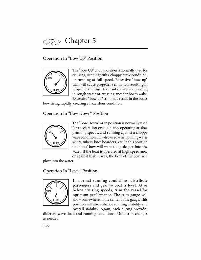
Chapter 5
5-22
! e “Bow Up” or out position is normally used for cruising, running with a choppy wave condition, or running at full speed. Excessive “bow up” trim will cause propeller ventilation resulting in propeller slippage. Use caution when operating in rough water or crossing another boat’s wake. Excessive “bow up” trim may result in the boat’s
bow rising rapidly, creating a hazardous condition.
Operation In “Bow Down” Position
! e “Bow Down” or in position is normally used for acceleration onto a plane, operating at slow planning speeds, and running against a choppy wave condition. It is also used when pulling water skiers, tubers, knee boarders, etc. In this position the boats’ bow will want to go deeper into the water. If the boat is operated at high speed and/or against high waves, the bow of the boat will
plow into the water.
Operation In “Level” Position
In normal running conditions, distribute passengers and gear so boat is level. At or below cruising speeds, trim the vessel for optimum performance. The trim gauge will show somewhere in the center of the gauge. ! is position will also enhance running visibility and overall stability. Again, each outing provides
di" erent wave, load and running conditions. Make trim changes as needed.
DN UP
TRIM
DN UP
TRIM
DN UP
TRIM
Operation In “Bow Up” Position
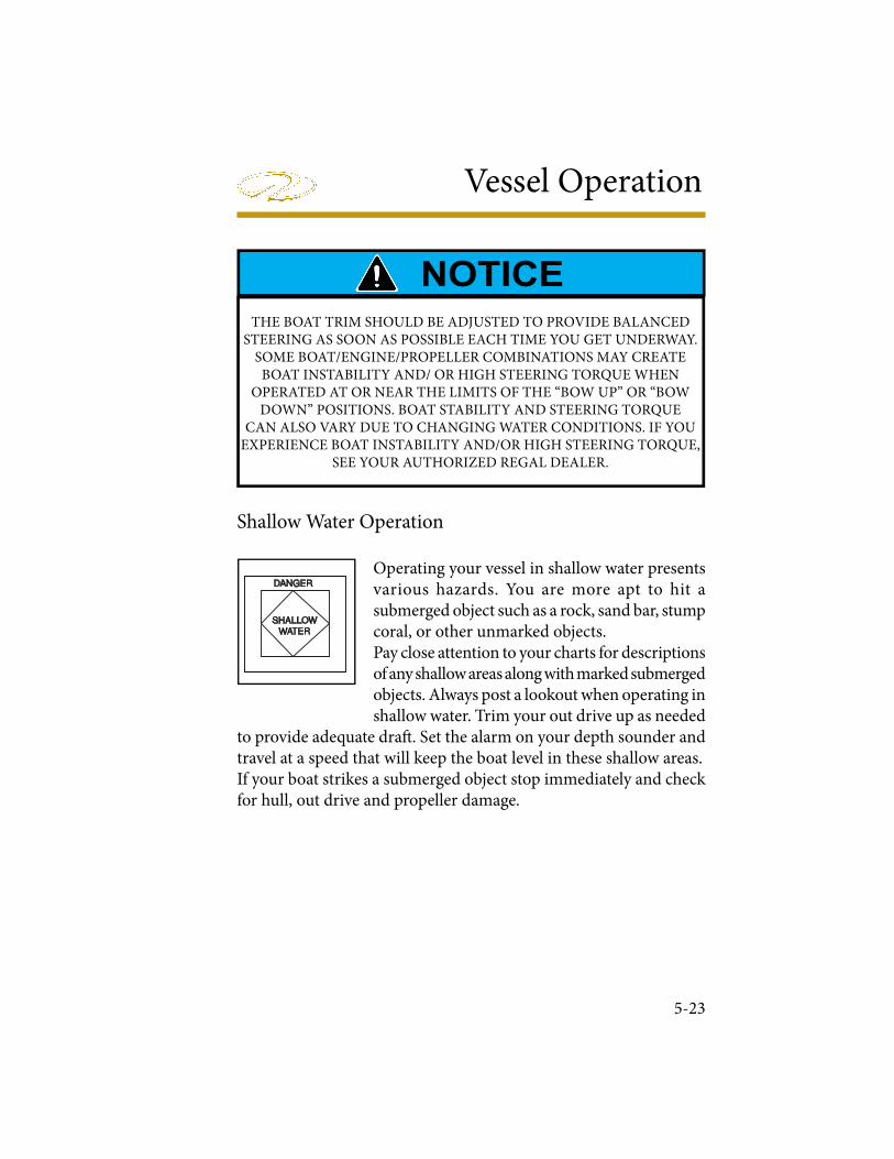
Vessel Operation
5-23
Shallow Water Operation
Operating your vessel in shallow water presents various hazards. You are more apt to hit a submerged object such as a rock, sand bar, stump coral, or other unmarked objects. Pay close attention to your charts for descriptions of any shallow areas along with marked submerged objects. Always post a lookout when operating in shallow water. Trim your out drive up as needed
to provide adequate dra! . Set the alarm on your depth sounder and travel at a speed that will keep the boat level in these shallow areas. If your boat strikes a submerged object stop immediately and check for hull, out drive and propeller damage.
SHALLOW
WATER
DANGER
THE BOAT TRIM SHOULD BE ADJUSTED TO PROVIDE BALANCED STEERING AS SOON AS POSSIBLE EACH TIME YOU GET UNDERWAY.
SOME BOAT/ENGINE/PROPELLER COMBINATIONS MAY CREATE BOAT INSTABILITY AND/ OR HIGH STEERING TORQUE WHEN
OPERATED AT OR NEAR THE LIMITS OF THE “BOW UP” OR “BOW DOWN” POSITIONS. BOAT STABILITY AND STEERING TORQUE
CAN ALSO VARY DUE TO CHANGING WATER CONDITIONS. IF YOU EXPERIENCE BOAT INSTABILITY AND/OR HIGH STEERING TORQUE,
SEE YOUR AUTHORIZED REGAL DEALER.
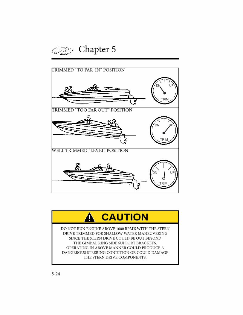
Chapter 5
5-24
DN UP
TRIM
TRIMMED “TO FAR IN” POSITION
DN UP
TRIM
TRIMMED “TOO FAR OUT” POSITION
DN UP
TRIM
WELL TRIMMED “LEVEL” POSITION
DO NOT RUN ENGINE ABOVE 1000 RPM’S WITH THE STERNDRIVE TRIMMED FOR SHALLOW WATER MANEUVERING
SINCE THE STERN DRIVE COULD BE OUT BEYOND THE GIMBAL RING SIDE SUPPORT BRACKETS.
OPERATING IN ABOVE MANNER COULD PRODUCE ADANGEROUS STEERING CONDITION OR COULD DAMAGE
THE STERN DRIVE COMPONENTS.
Vessel Operation
5-25
ANCHORING
Selecting the correct anchor is an important decision. ! e anchor style in part depends on the usage and boat type. Regal boats designate an anchor type and or model. Some models incorporate chain, line with an optional windlass. Contact an authorized Regal dealer for more information.Anchoring is easier with another person on board.
First be certain that the line for the anchor is properly attached, to avoid losing the anchor and anchor line overboard.For most anchors to perform more e" ciently, you should attach 3 to 6 feet of chain. ! e chain will stand up to the abrasion of sand, rock, or mud on the bottom much better than a nylon line. It should be galvanized to reduce corrosion. Next, attach a length of nylon line to the other end of the chain. ! e nylon will stretch under a heavy strain cushioning the impact of waves or wind on both the boat and the anchor.To anchor, select a well protected area, preferably with a # at bottom. Contrary to modern belief, you do not throw the anchor over while the boat is making headway, or moving forward. In fact, the bow of the boat should be bought slowly backward, while easing the anchor slowly over the side of the boat until it hits the bottom. To “snub the line” means to stop its outward “pay” or movement. Usually the length of anchor line used should be 5 to 10 times the depth of the water.A$ er you have anchored, check your position with landmarks if possible. You need to continue to monitor these landmarks to make sure you are not dri$ ing. Since anchoring can also be an emergency procedure, the anchor and line should be readily accessible. For increased holding power in windy conditions, two anchors are sometimes set. If your primary anchor drags, you can run out your secondary anchor without picking up the primary one. ! e important thing is to lay them out at an angle. When setting two anchors, make sure they are fastened to separate rodes or cleats. ! is is done in case you need to adjust one later so the line is accessible.
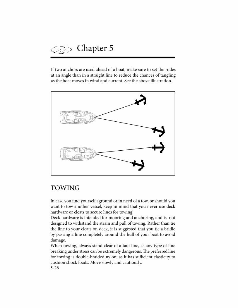
Chapter 5
5-26
If two anchors are used ahead of a boat, make sure to set the rodes at an angle than in a straight line to reduce the chances of tangling as the boat moves in wind and current. See the above illustration.
TOWING
In case you ! nd yourself aground or in need of a tow, or should you want to tow another vessel, keep in mind that you never use deck hardware or cleats to secure lines for towing!Deck hardware is intended for mooring and anchoring, and is not designed to withstand the strain and pull of towing. Rather than tie the line to your cleats on deck, it is suggested that you tie a bridle by passing a line completely around the hull of your boat to avoid damage.When towing, always stand clear of a taut line, as any type of line breaking under stress can be extremely dangerous. # e preferred line for towing is double-braided nylon; as it has su$ cient elasticity to cushion shock loads. Move slowly and cautiously.
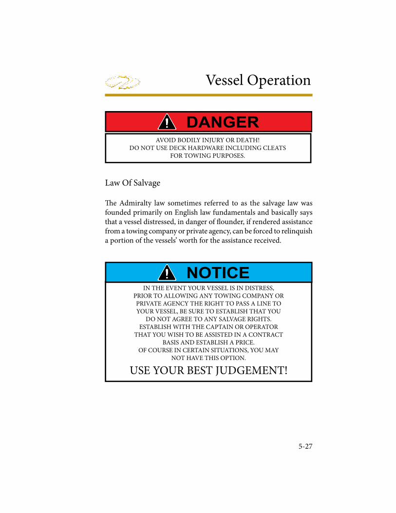
Vessel Operation
5-27
! e Admiralty law sometimes referred to as the salvage law was founded primarily on English law fundamentals and basically says that a vessel distressed, in danger of " ounder, if rendered assistance from a towing company or private agency, can be forced to relinquish a portion of the vessels’ worth for the assistance received.
Law Of Salvage
IN THE EVENT YOUR VESSEL IS IN DISTRESS,PRIOR TO ALLOWING ANY TOWING COMPANY OR PRIVATE AGENCY THE RIGHT TO PASS A LINE TOYOUR VESSEL, BE SURE TO ESTABLISH THAT YOU
DO NOT AGREE TO ANY SALVAGE RIGHTS. ESTABLISH WITH THE CAPTAIN OR OPERATOR
THAT YOU WISH TO BE ASSISTED IN A CONTRACTBASIS AND ESTABLISH A PRICE.
OF COURSE IN CERTAIN SITUATIONS, YOU MAYNOT HAVE THIS OPTION.
USE YOUR BEST JUDGEMENT!
AVOID BODILY INJURY OR DEATH!DO NOT USE DECK HARDWARE INCLUDING CLEATS
FOR TOWING PURPOSES.
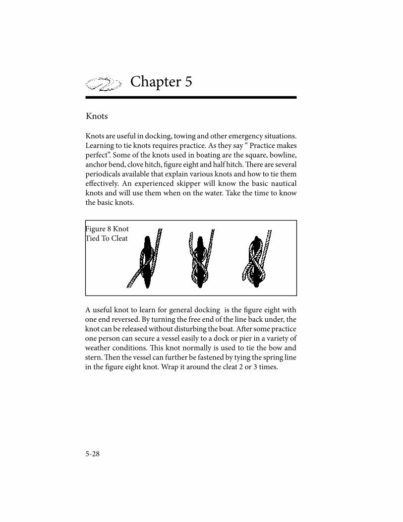
Chapter 5
5-28
Knots
Knots are useful in docking, towing and other emergency situations. Learning to tie knots requires practice. As they say “ Practice makes perfect”. Some of the knots used in boating are the square, bowline, anchor bend, clove hitch, ! gure eight and half hitch. " ere are several periodicals available that explain various knots and how to tie them e# ectively. An experienced skipper will know the basic nautical knots and will use them when on the water. Take the time to know the basic knots.
A useful knot to learn for general docking is the ! gure eight with one end reversed. By turning the free end of the line back under, the knot can be released without disturbing the boat. A$ er some practice one person can secure a vessel easily to a dock or pier in a variety of weather conditions. " is knot normally is used to tie the bow and stern. " en the vessel can further be fastened by tying the spring line in the ! gure eight knot. Wrap it around the cleat 2 or 3 times.
Figure 8 KnotTied To Cleat
Vessel Operation
5-29
EMERGENCIES
Always be ready to help others on the water if possible, but do not take any unnecessary risks. Use equipment to save a life, but do not risk a life to save equipment. Consult earlier information in this manual concerning accidents, etc. Also, read other literature concerning on the water emergencies. Be alert and prepared!
Fire
Fire aboard a vessel can spread quickly and can cause tremendous alarm among everyone. Most " res can be prevented by keeping the bilge free from oil and debris. Keep all equipment stowed and maintained in working order. Carry a backup " re extinguisher on board. If something becomes a possible " re hazard, remove that possibility at once. Never use water on gasoline, oil or electrical " res. When you dump water on an electrical " re a you can be shocked since water conducts electricity.Follow these instructions if a " re breaks out:
A. Fit everyone aboard with a life jacket. Turn o# the ignition.
B. Try to keep the " re downwind. If the " re is to the stern, head the bow toward the wind. If forward, put the stern to the wind.
C. If the engine should catch " re, shut o# the fuel supply Usually there is a fuel tank access that you can crimp the fuel feed line.
D. Use a hand " re extinguisher. Make sure to point it at the base of the $ ames. Use short bursts and sweep the extinguisher side to side. Remember : (4 lb. extinguisher discharges in 20 seconds)% ese actions help prevent the " re from spreading to other parts of the boat. You can extinguish " res quickly if you act swi& ly. Have a plan of action in motion in case a " re breaks out.
Chapter 5
5-30
FIRST AID
Knowing ! rst aid can save lives. A ! rst aid kit and the ability to use it are important ingredients for the safety of a skippers’ passengers, crew and vessel. Having con! dence and competence in handling medical emergencies on board is a must for the skipper. Invest your time in a ! rst aid course available at the American Red Cross.
CPR (Basic Life Support)
If someone is seriously injured have another person call for help while the injured individual is being attended.
Check for possible danger signs; loss of breathing, unconsciousness,severe bleeding and heartbeat. If you determine the individual is not breathing or unconscious place the victim on their back on a hard surface and do the following:
1. If unconscious, open the airway. Neck li" , head li" or chin head li" .
2. If not breathing, begin arti! cial breathing. Pinch the nose. Give 4 quick breaths. If airway is blocked, try back blows, abdominal or chest thrusts and ! nger probe until airway is open.
3. Check for pulse. Begin arti! cial circulation. Depress sternum 2”. 15 compressions rate 80 per minute. 2 quick breaths. Continue uninterrupted until advanced medical support is available.
Follow up immediately with medical authorities!

Vessel Operation
5-31
HYPOTHERMIA
Hypothermia is a condition where the body temperature decreases because the body can’t generate enough heat to maintain its normal temperature. It can be serious and usually occurs where victims have been immersed in water (under 68 degrees) for extended periods of time. If you encounter a possible hypothermia victim call for help on the radio and get the person out of the water.Symptoms are:
1. Shivering that if condition is advanced may stop.
2. Confusion, clumsiness or slurred speech.
3. Rigid muscles.
4. Semiconscious to unconscious.
Treat hypothermia by the following:
� Remove wet clothing.
� Monitor the victim’s pulse and breathing.
� Rapidly apply heat to the body core by using blankets, naked bodies or warm water.
� Do not give the person any food or drink.
� Do not warm the arms and legs. Warming of these extremities can be fatal.
Follow up immediately with medical authorities!

Chapter 5
5-32
ENVIRONMENTAL AWARENESS
! ere are numerous vessels operating on our waterways on a daily basis. Each boat has as impact on our environment. Boat operation habits, marine sanitation, and maintenance all play a role in a delicate battle to keep the ecosystem clean. Each of us has a role in doing our part as a environmentally conscious skipper to conserve our waterways.! e National Marine Manufacturer’s Association lists their top ten of Eco-Boating Practices as follows:
1. Observe all regulatory agency policies regarding marine toilets.
2. If equipped with a holding tank, use marina pump-out facilities.
3. If used, make sure bottom paints are legal and ecosystem friendly.
4. Use only biodegradable cleaning agents.
5. Dispose of all garbage and liter on shore properly, not on the water. 6. Don’t top o" fuel tanks. Leave expansion room. Clean up spills.
7. Watch your wake and propeller wash.
8. Make sure your engines are well tuned and maintained.
9. Control your bilge water.
10. When # shing, practice the “catch and release” principle.
Follow these basic practices when on the waterways. Treat the environment in a way that you would like to be treated.

Equipment Operation
� is chapter will supply basic information to the boat operator to assist in understanding selected standard and optional equipment components on the vessel. Select equipment described here may not be installed on your boat or the pictorials may not exactly resemble components on your cra� . Remember that equipment changes somewhat by boat model. Regal is constantly improving its product line and therefore may make changes in vendor parts and speci� cations without notice. For detailed information on equipment, please refer to the owner’s information packet.
AFTERMARKET ACCESSORIES
A� ermarket equipment can be controlled via accessory switches at the dash. Due to the selection of options like a PowerTower, docking lights, and pressure water your accessory switches may control a variety of systems. You may elect to have non-factory based accessories installed on your vessel. Ensure that your equipment is installed by a licensed marine professional and that it will not jeopardize the safety of your vessel. Don’t forget to install the appropriate gauge wire and fuse for your a� ermarket products. REGAL IS NOT RESPONSIBLE FOR PROBLEMS CAUSED BY AFTERMARKET INSTALLATIONS.
6-1

Chapter 6
6-2
AUTOMATIC FIRE EXTINGUISHER
Optional Automatic Fire Extinguisher
If installed the automatic ! re extinguisher is mounted in the engine compartment. It uses sensors to automatically discharge when a ! re occurs, although it can be manually discharged. Upon actuation, you may hear a sound similar to that of a small ! rearm, followed by a rushing air sound. A charged system shows a light at the dash indicator, while a discharged system shows no light at the indicator - re! ll accordingly.
Automatic activation will occur at di" erent times depending on the severity of the ! re picked up by sensors. WHEN THE FIRE EXTINGUISHER IS ACTIVATED, IMMEDIATELY SHUT DOWN ALL ENGINES, POWERED VENTILATION (BLOWER), ELECTRICAL SYSTEMS, AND EXTINGUISH ALL SMOKING MATERIALS. DO NOT OPEN THE ENGINE COMPARTMENT UNTIL A SUITABLE AMOUNT OF TIME HAS PASSED SINCE THE EXTINGUISHER STOPPED DISCHARGING. Opening the engine compartment prematurely may cause a re% ash as air is allowed to ! ll the engine compartment. When opening the engine compartment door, have a hand-held extinguisher ready in case of re% ash. Be cautious of hot metal when investigating the cause of the ! re.
If a ! re has started in the engine compartment, DO NOT wait for the automatic ! re extinguisher system to kick in. Locate the ! re extinguisher manual discharge lever a& er closing the engine compartment, and turning o" the blower and electronic equipment. Remove the safety pin from the “T” handle, and pull ! rmly to release.

Equipment Operation
6-3
For safety information, refer to your ! re extinguisher label. General safety requirements are described in the safety on board chapter of this manual. For system information, refer to the systems chapter of this manual. Maintenance requirements are described in the maintenance chapter of this manual.
Typical Dashboard Automatic Extinguishing System LightTypical Mounted Automatic Fire ExtinguisherTypical Manual Discharge Pin For Automatic Fire Extinguisher
BATTERY SWITCH
Standard Battery Switch
Your Regal uses an “ON” and “OFF” position battery switch located in the cockpit that not only provides power for the engine, but runs all the features on your boat. With this style switch, the operator simply turns the knob to the “on” position before starting the engine and to the “o" ” position when exiting the boat. Make sure the knob is fully detented when selecting the “on” or “o" ” functions. Again, remember to deactivate the battery switch upon leaving the vessel.
AVOID SERIOUS INJURY OR DEATH! DO NOT BREATH FUMES OR VAPORS
CAUSED BY AN EXTINGUISHING AGENT. VAPORS ARE HAZARDOUS AND TOXIC.
Chapter 6
6-4
BILGE PUMP
Before each outing, check the operation of the bilge pump, automatic switch, and manual switch. � e bilge pump should automatically activate when water reaches a pre-determined height in the engine compartment. Test the bilge pup manually at the dashboard with the switch. Periodically check for bilge debris around the grates of both the bilge pump and automatic switch, and also bilge pump impeller.
� e automatic mode for your bilge pump works similarly to the manual method. Both methods control the bilge pump by a switch, but the automatic mode utilizes a � oat switch. Float switches have a � oat that sits at water level, and when the � oat reaches a certain height, it trips the switch and activates the bilge pump.
You may need to disassemble the bilge pump from the grate in order to clean or access the inner mechanisms. To remove the bilge pump, utilize the quick disconnect tabs on either side of the bilge pump, squeezing them like a backpack clip while pulling up on the pump.
For switch control location, refer to the engine and controls chapter. For bilge and drainage system information and electrical system information, refer to the systems chapter. Refer to the vessel operations chapter for pre departure use. Maintenance requirements are described in the maintenance chapter.
AVOID DAMAGE TO THE ALTERNATORAND/OR CHARGING SYSTEM COMPONENTS.
NEVER TURN THE BATTERY SWITCH TO THE “OFF” POSITION WHILE THE ENGINE IS RUNNING.
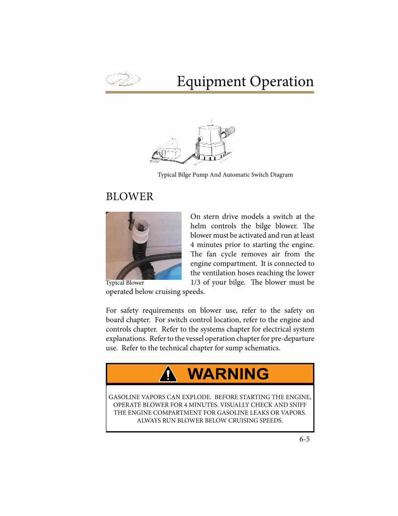
Equipment Operation
6-5
Typical Bilge Pump And Automatic Switch Diagram
BLOWER
On stern drive models a switch at the helm controls the bilge blower. ! e blower must be activated and run at least 4 minutes prior to starting the engine. ! e fan cycle removes air from the engine compartment. It is connected to the ventilation hoses reaching the lower 1/3 of your bilge. ! e blower must be
operated below cruising speeds.
For safety requirements on blower use, refer to the safety on board chapter. For switch control location, refer to the engine and controls chapter. Refer to the systems chapter for electrical system explanations. Refer to the vessel operation chapter for pre-departure use. Refer to the technical chapter for sump schematics.
GASOLINE VAPORS CAN EXPLODE. BEFORE STARTING THE ENGINE, OPERATE BLOWER FOR 4 MINUTES. VISUALLY CHECK AND SNIFF THE ENGINE COMPARTMENT FOR GASOLINE LEAKS OR VAPORS.
ALWAYS RUN BLOWER BELOW CRUISING SPEEDS.
Typical Blower

Chapter 6
6-6
CANVAS & COVERS
Bimini Top
Your Regal boat is equipped with a bimini top. Refer to the systems chapter where the installation process is explained in detail. Pay special attention to the diagrams for parts identi� cation used in the
application.
Bow & Cockpit Cover
� e optional cockpit cover installs over the windshield and snaps to the deck. � e cockpit cover is meant to protect the cockpit of the boat from weather elements, and is not used for towing purposes. � e same is true for the bow cover. � e bow cover, sometimes called a tonneau cover, protects the front of the boat from weather and snaps to the deck. Likewise, the bow cover should not be used for towing. � e bow and cockpit cover usually snap and velcro together at the center windshield location.
To install the bow/cockpit cover:
First note that on the bow end of the cockpit cover, there is a velcro strip used to attach to an optional bow cover. � is strip can be used to align the covers with your boat. Simply align the velcroed edge with the windshield.
Ensure the center windshield is in the closed position. Start snapping the cover to the deck by use of the eyelet snaps, starting at the bow and working a� .
Notice in the middle underside of your cover, you may � nd an area of reinforced canvas with an eyelet snap. � is snap connects to a
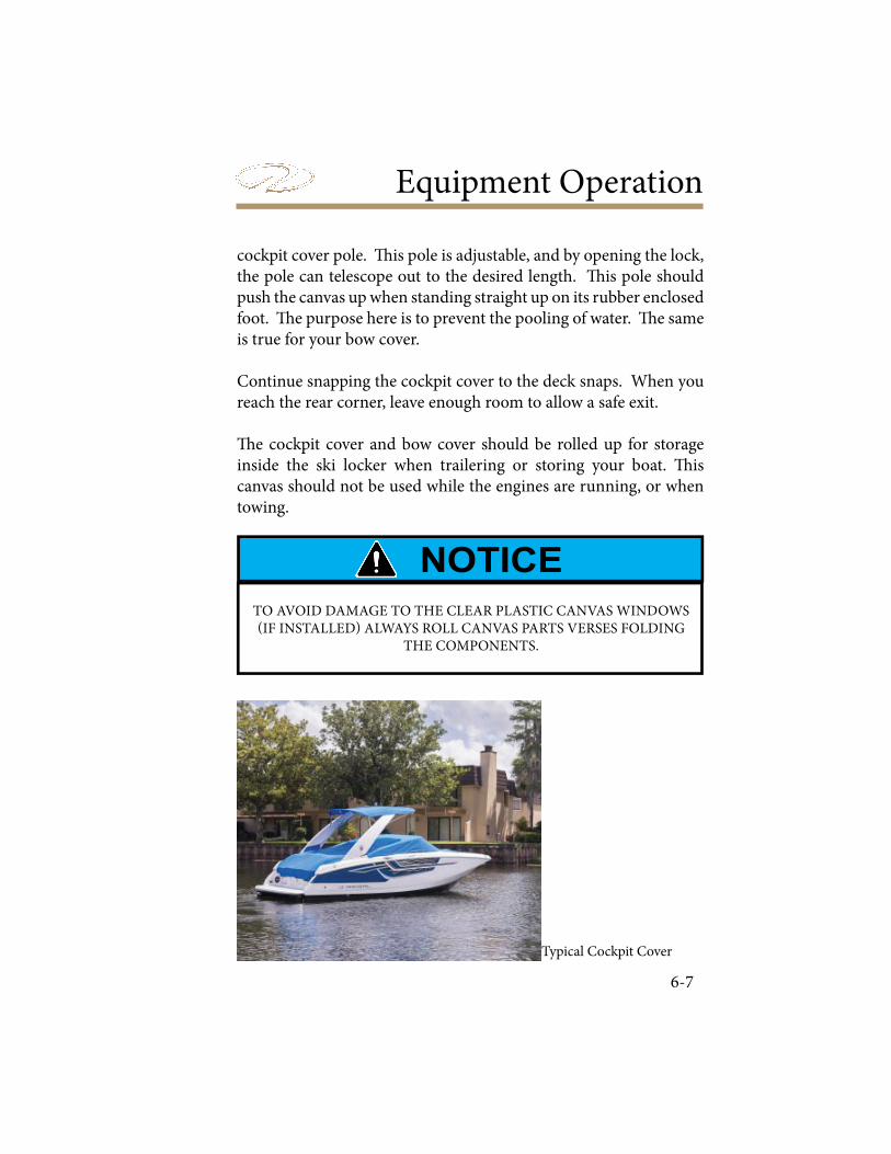
Equipment Operation
6-7
cockpit cover pole. ! is pole is adjustable, and by opening the lock, the pole can telescope out to the desired length. ! is pole should push the canvas up when standing straight up on its rubber enclosed foot. ! e purpose here is to prevent the pooling of water. ! e same is true for your bow cover.
Continue snapping the cockpit cover to the deck snaps. When you reach the rear corner, leave enough room to allow a safe exit.
! e cockpit cover and bow cover should be rolled up for storage inside the ski locker when trailering or storing your boat. ! is canvas should not be used while the engines are running, or when towing.
Typical Bow Cover
TO AVOID DAMAGE TO THE CLEAR PLASTIC CANVAS WINDOWS (IF INSTALLED) ALWAYS ROLL CANVAS PARTS VERSES FOLDING
THE COMPONENTS.
Typical Cockpit Cover
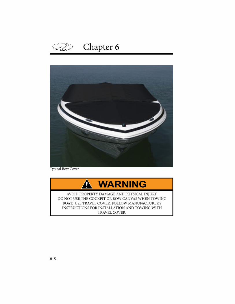
Chapter 6
6-8
AVOID PROPERTY DAMAGE AND PHYSICAL INJURY. DO NOT USE THE COCKPIT OR BOW CANVAS WHEN TOWING
BOAT. USE TRAVEL COVER. FOLLOW MANUFACTURER’SINSTRUCTIONS FOR INSTALLATION AND TOWING WITH
TRAVEL COVER.
Typical Bow Cover
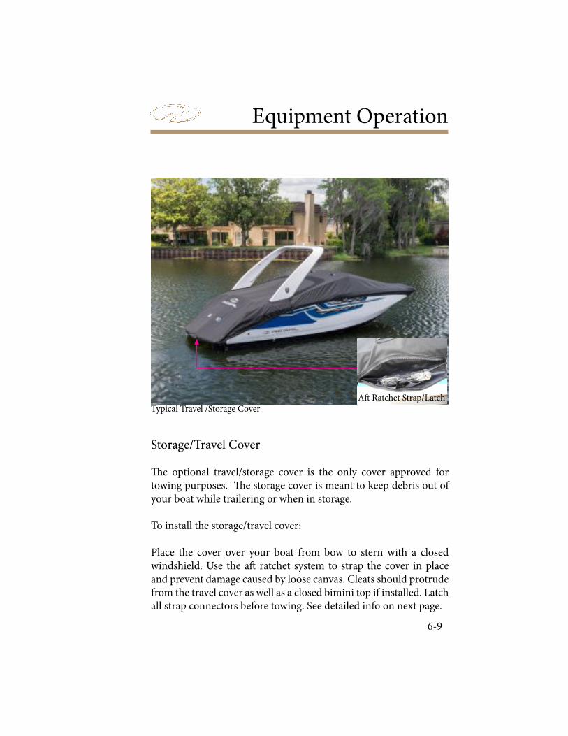
Equipment Operation
6-9
Storage/Travel Cover
! e optional travel/storage cover is the only cover approved for towing purposes. ! e storage cover is meant to keep debris out of your boat while trailering or when in storage.
To install the storage/travel cover:
Place the cover over your boat from bow to stern with a closed windshield. Use the a" ratchet system to strap the cover in place and prevent damage caused by loose canvas. Cleats should protrude from the travel cover as well as a closed bimini top if installed. Latch all strap connectors before towing. See detailed info on next page.
Typical Travel /Storage CoverA" Ratchet Strap/Latch
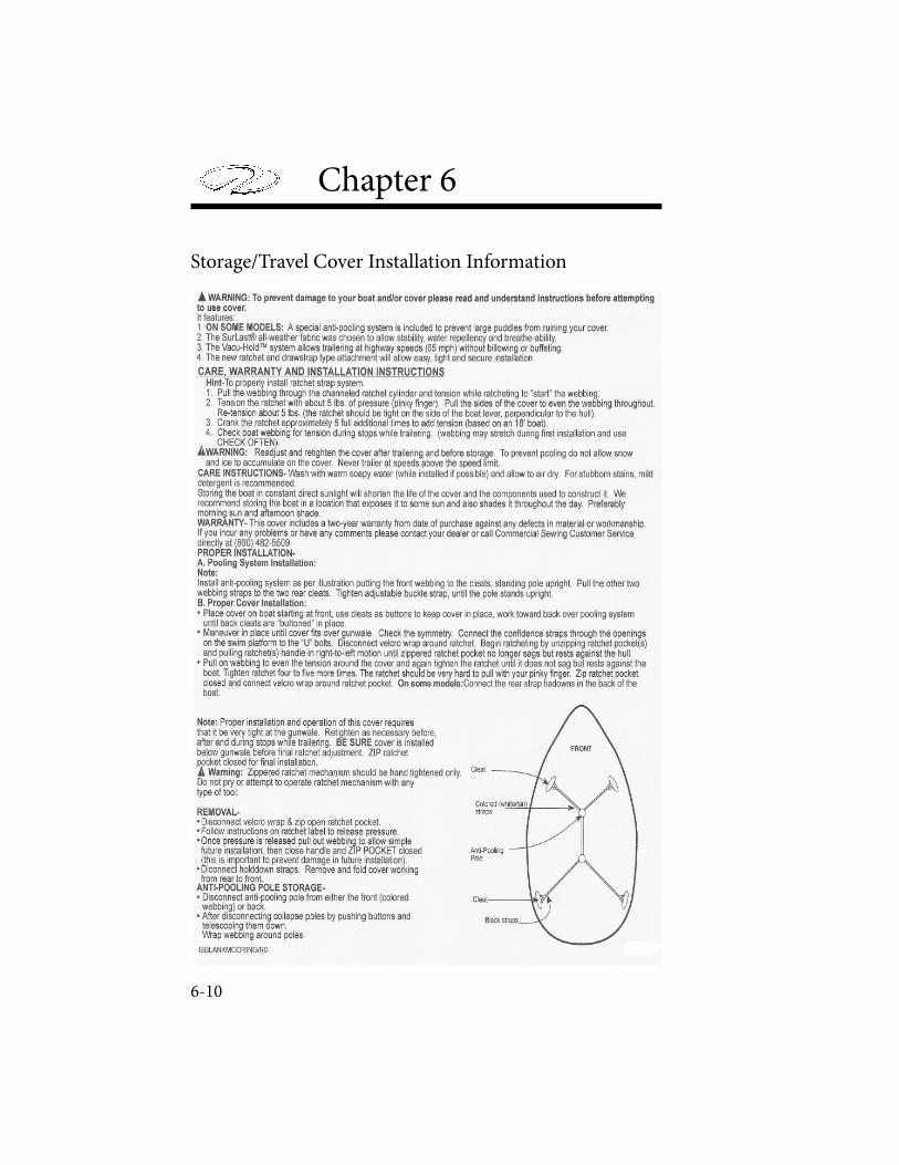
Chapter 6
6-10
Storage/Travel Cover Installation Information
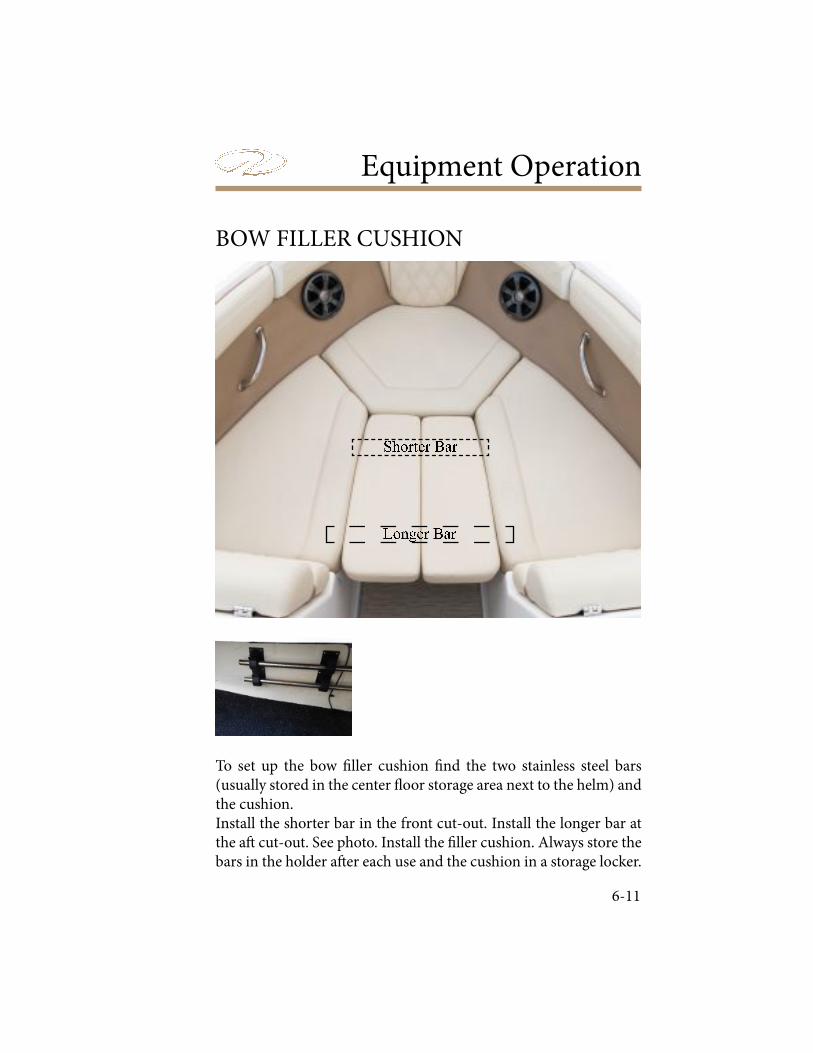
Equipment Operation
6-11
BOW FILLER CUSHION
� � � � � � � � � �� � � � � � �
To set up the bow ! ller cushion ! nd the two stainless steel bars (usually stored in the center " oor storage area next to the helm) and the cushion.Install the shorter bar in the front cut-out. Install the longer bar at the a# cut-out. See photo. Install the ! ller cushion. Always store the bars in the holder a# er each use and the cushion in a storage locker.

Chapter 6
6-12
BOW WALK THROUGH DOORS
To set up the bow walk through doors simply pull each door to the center of the walkway and li! the stainless steel latch enough to clear the top of the doors and lower the latch to hold the door set in place. " e doors provide a barrier to the elements such as wind, rain or wave action at the bow. Ensure that the center windshield latch set is locked a! er setting up the doors.

Equipment Operation
6-13
COCKPIT CARPET
Cockpit carpet features a forty ounce weight with a heavy duty non-skid marine backing. As required, snaps are installed. When removing carpet use care when pulling on the snaps. Use silicone spray on snaps.Note: Before towing on the highway roll-up the cockpit carpet and store it in a locker to prevent it from blowing out of the vessel. Do not yank on the carpet to remove it as you may pull out a snap.When storing cockpit carpet always roll it verses folding it. Also, before rolling it for periods of extended storage make sure the carpet is dry to help eliminate odors and possible mildew.
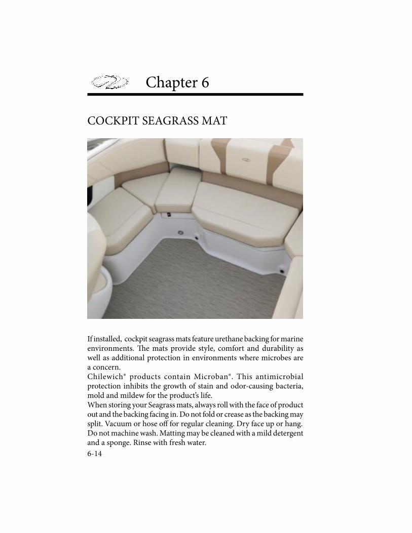
Chapter 6
6-14
COCKPIT SEAGRASS MAT
If installed, cockpit seagrass mats feature urethane backing for marine environments. ! e mats provide style, comfort and durability as well as additional protection in environments where microbes are a concern.Chilewich® products contain Microban®. This antimicrobial protection inhibits the growth of stain and odor-causing bacteria, mold and mildew for the product’s life.When storing your Seagrass mats, always roll with the face of product out and the backing facing in. Do not fold or crease as the backing may split. Vacuum or hose o# for regular cleaning. Dry face up or hang.Do not machine wash. Matting may be cleaned with a mild detergent and a sponge. Rinse with fresh water.
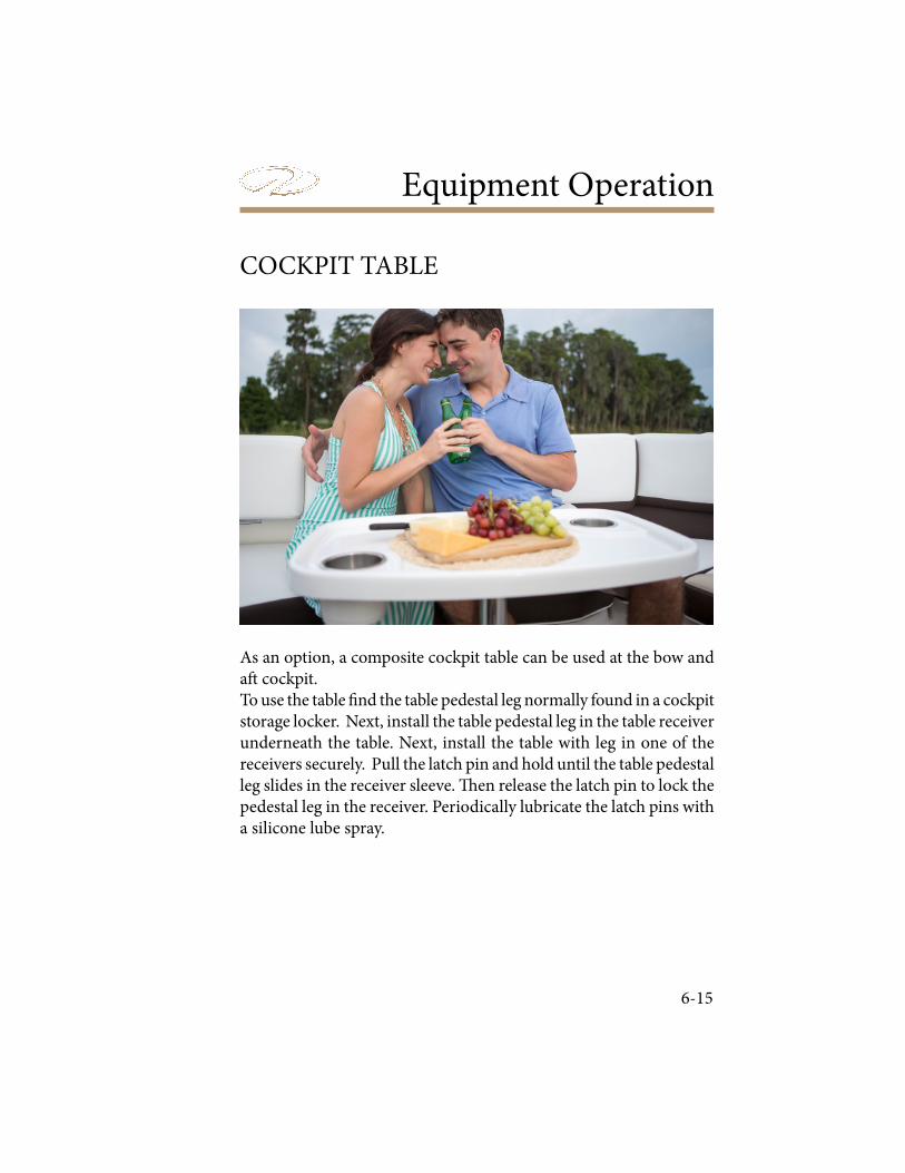
Equipment Operation
6-15
COCKPIT TABLE
As an option, a composite cockpit table can be used at the bow and a! cockpit. To use the table " nd the table pedestal leg normally found in a cockpit storage locker. Next, install the table pedestal leg in the table receiver underneath the table. Next, install the table with leg in one of the receivers securely. Pull the latch pin and hold until the table pedestal leg slides in the receiver sleeve. # en release the latch pin to lock the pedestal leg in the receiver. Periodically lubricate the latch pins with a silicone lube spray.

Chapter 6
6-16
Showing Table In Bow Receiver
Showing Table In Cockpit Receiver
Showing Table Receiver
Showing Pedestal Leg In Table Receiver
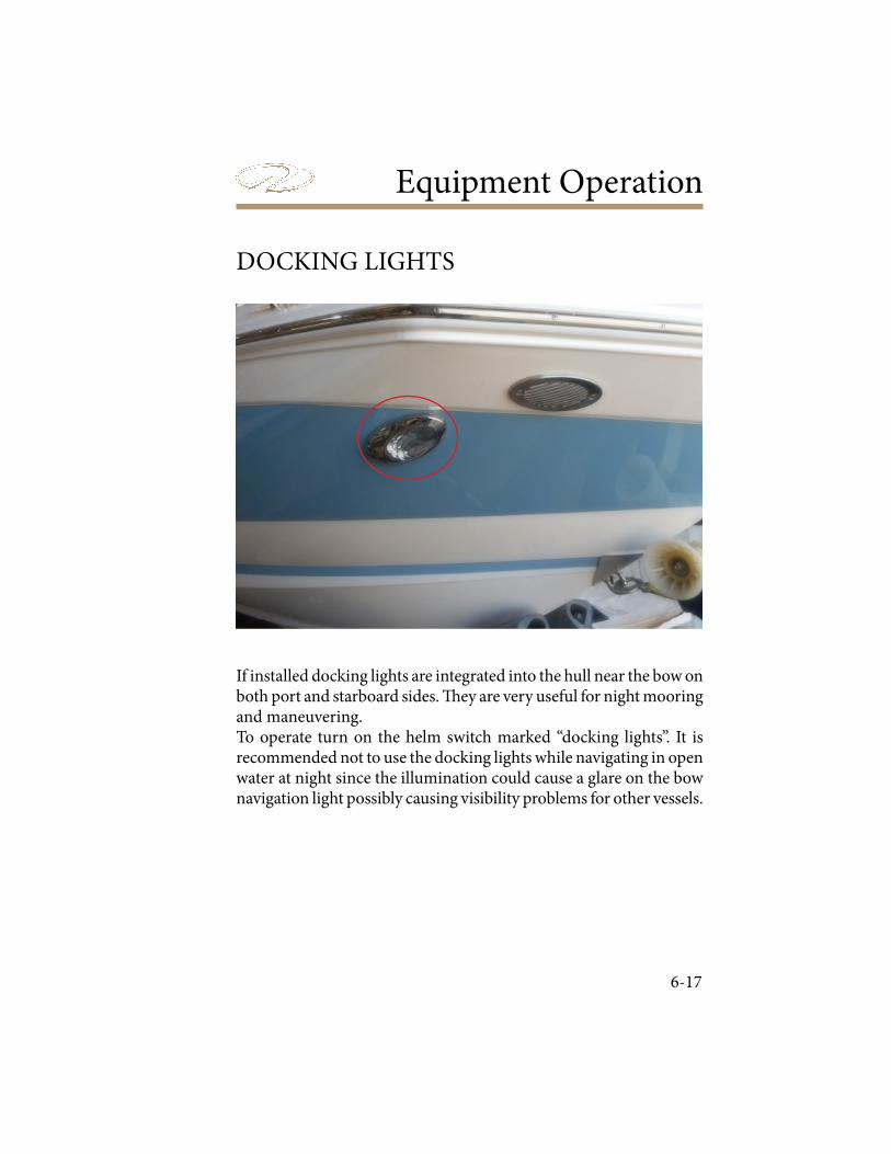
Equipment Operation
6-17
DOCKING LIGHTS
If installed docking lights are integrated into the hull near the bow on both port and starboard sides. ! ey are very useful for night mooring and maneuvering. To operate turn on the helm switch marked “docking lights”. It is recommended not to use the docking lights while navigating in open water at night since the illumination could cause a glare on the bow navigation light possibly causing visibility problems for other vessels.
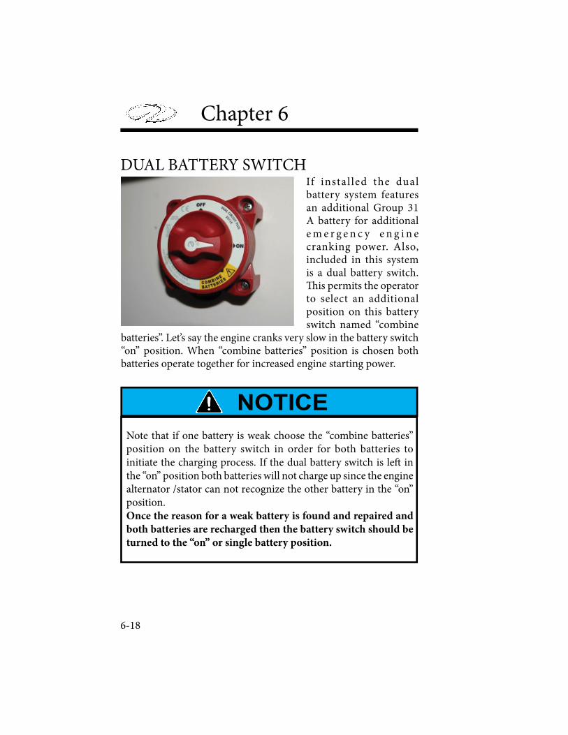
Chapter 6
6-18
DUAL BATTERY SWITCHIf instal led the dual battery system features an additional Group 31 A battery for additional e m e r g e n c y e n g i n e cranking power. Also, included in this system is a dual battery switch. � is permits the operator to select an additional position on this battery switch named “combine
batteries”. Let’s say the engine cranks very slow in the battery switch “on” position. When “combine batteries” position is chosen both batteries operate together for increased engine starting power.
Note that if one battery is weak choose the “combine batteries” position on the battery switch in order for both batteries to initiate the charging process. If the dual battery switch is le! in the “on” position both batteries will not charge up since the engine alternator /stator can not recognize the other battery in the “on” position.Once the reason for a weak battery is found and repaired and
both batteries are recharged then the battery switch should be
turned to the “on” or single battery position.
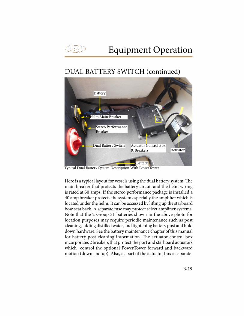
Equipment Operation
6-19
DUAL BATTERY SWITCH (continued)
COCKPIT LIGHTS
A switch at the helm controls the courtesy lights in the cockpit area. Using these lights is especially useful when boarding or exiting the vessel at night. A light is normally located at the bow and transom walk-thru areas.
Refer to the engine and controls chapter for switch location and function. Refer to the systems chapter for electrical system wiring. Refer to the technical chapter for component locations and hookup.
Typical Dual Battery System Description With PowerTower
Dual Battery Switch
Helm Main Breaker
Stereo Performance Breaker
Battery
Battery
Actuator Control Box& Breakers Actuator
Here is a typical layout for vessels using the dual battery system. ! e main breaker that protects the battery circuit and the helm wiring is rated at 50 amps. If the stereo performance package is installed a 40 amp breaker protects the system especially the ampli$ er which is located under the helm. It can be accessed by li" ing up the starboard bow seat back. A separate fuse may protect select ampli$ er systems.Note that the 2 Group 31 batteries shown in the above photo for location purposes may require periodic maintenance such as post cleaning, adding distilled water, and tightening battery post and hold down hardware. See the battery maintenance chapter of this manual for battery post cleaning information. ! e actuator control box incorporates 2 breakers that protect the port and starboard actuators which control the optional PowerTower forward and backward motion (down and up). Also, as part of the actuator box a separate
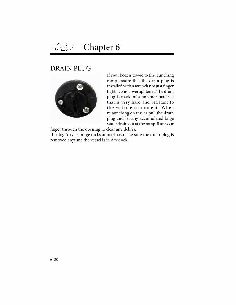
Chapter 6
6-20
DRAIN PLUGIf your boat is towed to the launching ramp ensure that the drain plug is installed with a wrench not just ! nger tight. Do not overtighten it. " e drain plug is made of a polymer material that is very hard and resistant to the water environment. When relaunching on trailer pull the drain plug and let any accumulated bilge water drain out at the ramp. Run your
! nger through the opening to clear any debris.If using “dry” storage racks at marinas make sure the drain plug is removed anytime the vessel is in dry dock.
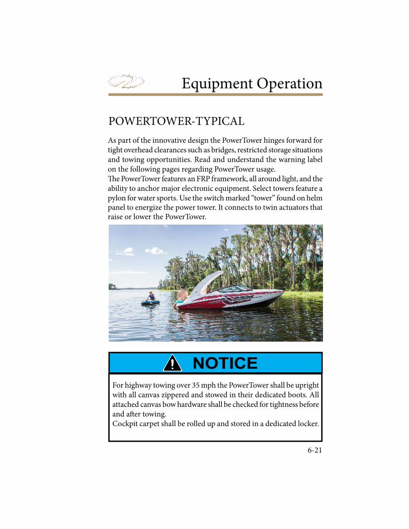
Equipment Operation
6-21
POWERTOWER-TYPICAL
As part of the innovative design the PowerTower hinges forward for tight overhead clearances such as bridges, restricted storage situations and towing opportunities. Read and understand the warning label on the following pages regarding PowerTower usage.! e PowerTower features an FRP framework, all around light, and the ability to anchor major electronic equipment. Select towers feature a pylon for water sports. Use the switch marked “tower” found on helm panel to energize the power tower. It connects to twin actuators that raise or lower the PowerTower.
For highway towing over 35 mph the PowerTower shall be upright with all canvas zippered and stowed in their dedicated boots. All attached canvas bow hardware shall be checked for tightness before and a" er towing. Cockpit carpet shall be rolled up and stored in a dedicated locker.
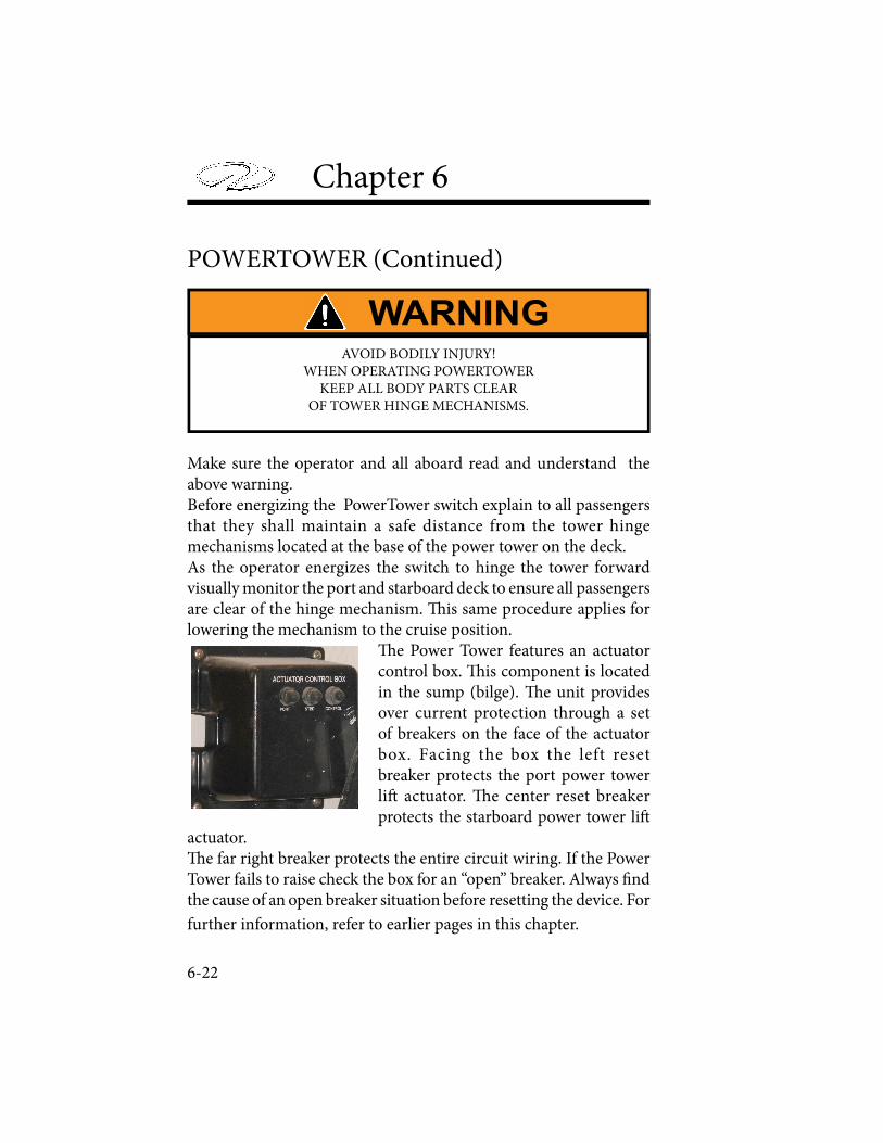
Chapter 6
6-22
POWERTOWER (Continued)
AVOID BODILY INJURY! WHEN OPERATING POWERTOWER
KEEP ALL BODY PARTS CLEAROF TOWER HINGE MECHANISMS.
Make sure the operator and all aboard read and understand the above warning.Before energizing the PowerTower switch explain to all passengers that they shall maintain a safe distance from the tower hinge mechanisms located at the base of the power tower on the deck. As the operator energizes the switch to hinge the tower forward visually monitor the port and starboard deck to ensure all passengers are clear of the hinge mechanism. " is same procedure applies for lowering the mechanism to the cruise position.
" e Power Tower features an actuator control box. " is component is located in the sump (bilge). " e unit provides over current protection through a set of breakers on the face of the actuator box. Facing the box the left reset breaker protects the port power tower li# actuator. " e center reset breaker protects the starboard power tower li#
actuator." e far right breaker protects the entire circuit wiring. If the Power Tower fails to raise check the box for an “open” breaker. Always $ nd the cause of an open breaker situation before resetting the device. For
further information, refer to earlier pages in this chapter.
Equipment Operation
6-23
AVOID BODILY INJURY OR DEATH DUE TO MISUSE OF THE SPORTS TOWER! DO NOT PULL MORE THAN TWO (2) PEOPLE AT A TIME FROM THE SPORTS TOWER. USE SPORTS TOWER ONLY
FOR KNEEBOARDS, WATER SKIS, WAKEBOARDS, OR SINGLE PERSON WATERSPORTS PRODUCTS. THIS SPORTS TOWER WAS
NOT DESIGNED AND SHALL NOT BE USED FOR TOWING OF BOATS, PERSONAL WATERCRAFTS, FLOATING DOCKS OR ANY
OTHER TYPE OF FLOATING VESSEL OR CRAFT. THIS SPORTS TOWER SHALL NOT BE USED FOR PULLING PARASAILING OR
ANY OTHER EQUIPMENT NOT APPROVED. THIS SPORTS TOWER SHALL NOT BE USED TO PULL INFLATABLE WATERSPORTS
TOYS OF ANY KIND. NEVER LET PASSENGERS SIT DIRECTLY BEHIND THE SPORTS TOWER ROPE ATTACHMENT POINT
WHILE PULLING APPROVED WATERSPORTS ACTIVITIES, DO NOT LET LOOSE WATERSPORTS ROPE HANG FROM THE SPORTS TOWER. ALWAYS INSPECT THE SPORTS TOWER PRIOR TO USE
TO ENSURE IT IS NOT DEFORMED, DEFLECTED, AND THAT ALL BOLTS ARE IN PLACE AND TIGHT. WATER LEVELS CAN VARY
DAILY AND IN SOME CASES HOURLY. BE AWARE OF MINIMUM CLEARANCE OF BRIDGES, TREE LIMBS, AND OTHER OBSTACLES, BEFORE ATTEMPTING TO PASS OR GO UNDER ANY OVERHEAD
STRUCTURE.

Chapter 6
6-24
PRESSURE WATER SYSTEM
A transom cold water shower/wash down using a pressurized water system is available on select models. It consists of a 11 gallon water tank, deck ! ll/vent, water pump/strainer, piping and of course the transom mounted sprayer with hose. " e option is very useful for rinsing o# when exiting from the water and helps keep the swim platform clean. In salt areas it can be used to spray o# the a$ ladder, hardware and assists in reducing corrosion." ere is a helm switch labeled FRESH WATER PUMP that controls the water pressure to the pump/strainer which in turn delivers the water to the transom shower sprayer. Remember in freezing climates, drain the system and add Winterban or similar protective additive to the water system. Turn the sprayer wand to activate/deactivate water % ow.
Turn Sprayer Wand To Activate Flow
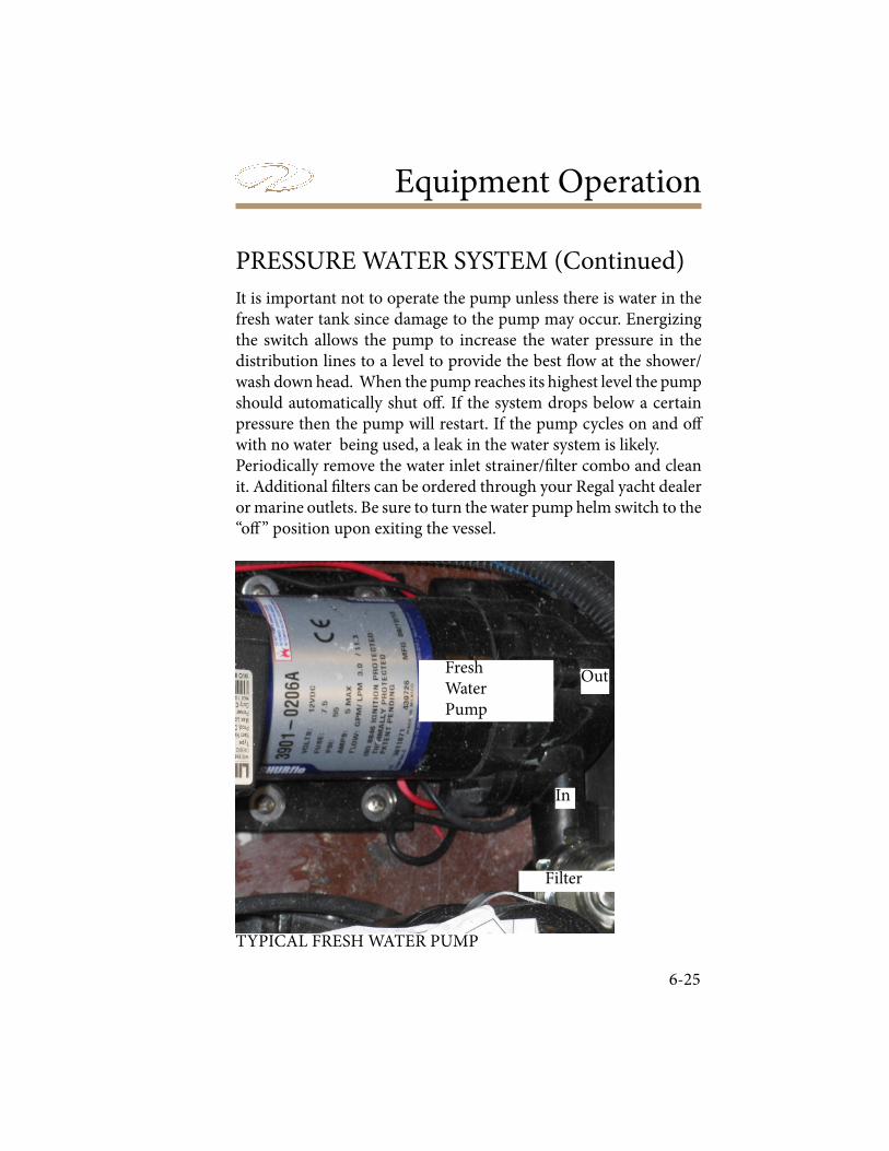
Equipment Operation
6-25
Filter
Fresh WaterPump
In
Out
PRESSURE WATER SYSTEM (Continued)
It is important not to operate the pump unless there is water in the fresh water tank since damage to the pump may occur. Energizing the switch allows the pump to increase the water pressure in the distribution lines to a level to provide the best ! ow at the shower/wash down head. When the pump reaches its highest level the pump should automatically shut o" . If the system drops below a certain pressure then the pump will restart. If the pump cycles on and o" with no water being used, a leak in the water system is likely.Periodically remove the water inlet strainer/# lter combo and clean it. Additional # lters can be ordered through your Regal yacht dealer or marine outlets. Be sure to turn the water pump helm switch to the “o" ” position upon exiting the vessel.
TYPICAL FRESH WATER PUMP
Chapter 6
6-26
THE FRESH WATER SYSTEM IS NOT POTABLE (DRINKABLE). USE IT FOR RINSING AND WASH DOWN PURPOSES ONLY.
# is label identi$ es the fresh water system used on this vessel as non-potable (not drinkable) and is found on the $ berglass near the component or directly attached to the transom spray wand.
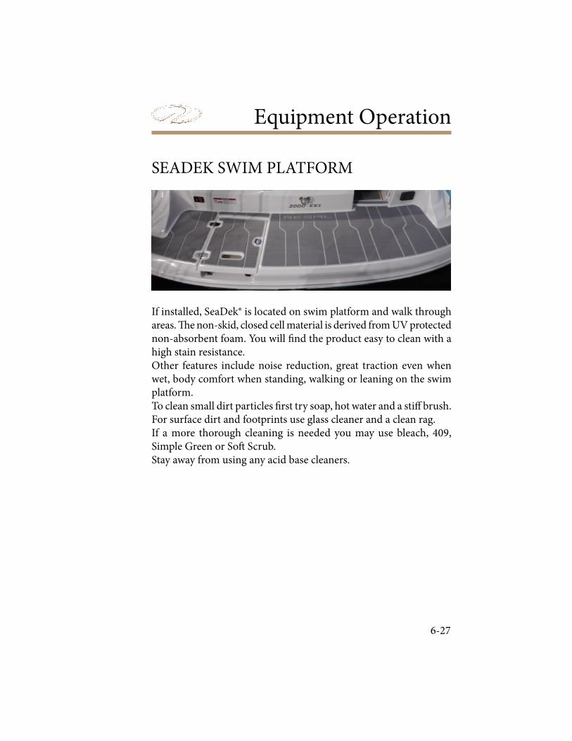
Equipment Operation
6-27
SEADEK SWIM PLATFORM
If installed, SeaDek® is located on swim platform and walk through areas. " e non-skid, closed cell material is derived from UV protected non-absorbent foam. You will # nd the product easy to clean with a high stain resistance. Other features include noise reduction, great traction even when wet, body comfort when standing, walking or leaning on the swim platform.To clean small dirt particles # rst try soap, hot water and a sti$ brush.For surface dirt and footprints use glass cleaner and a clean rag.If a more thorough cleaning is needed you may use bleach, 409, Simple Green or So% Scrub.Stay away from using any acid base cleaners.
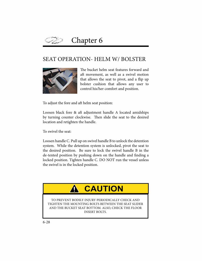
Chapter 6
6-28
SEAT OPERATION- HELM W/ BOLSTER
! e bucket helm seat features forward and a" movement, as well as a swivel motion that allows the seat to pivot, and a # ip up bolster cushion that allows any user to control his/her comfort and position.
To adjust the fore and a" helm seat position:
Loosen black fore & a" adjustment handle A located amidships by turning counter clockwise. ! en slide the seat to the desired location and retighten the handle.
To swivel the seat:
Loosen handle C. Pull up on swivel handle B to unlock the detention system. While the detention system is unlocked, pivot the seat to the desired position. Be sure to lock the swivel handle B in the de-tented position by pushing down on the handle and $ nding a locked position. Tighten handle C. DO NOT run the vessel unless the swivel is in the locked position.
TO PREVENT BODILY INJURY PERIODICALLY CHECK AND TIGHTEN THE MOUNTING BOLTS BETWEEN THE SEAT SLIDER AND THE BUCKET SEAT BOTTOM. ALSO, CHECK THE FLOOR
INSERT BOLTS.
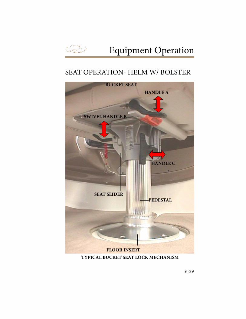
Equipment Operation
6-29
HANDLE A
SWIVEL HANDLE B
HANDLE C
SEAT SLIDER
PEDESTAL
FLOOR INSERT
BUCKET SEAT
SEAT OPERATION- HELM W/ BOLSTER
TYPICAL BUCKET SEAT LOCK MECHANISM
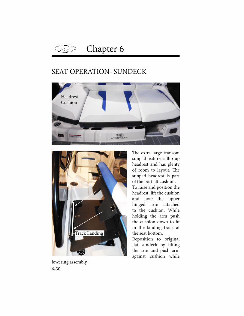
Chapter 6
6-30
SEAT OPERATION- SUNDECK
! e extra large transom sunpad features a " ip-up headrest and has plenty of room to layout. ! e sunpad headrest is part of the port a# cushion.To raise and position the headrest, li# the cushion and note the upper hinged arm attached to the cushion. While holding the arm push the cushion down to $ t in the landing track at the seat bottom.Reposition to original " at sundeck by li# ing the arm and push arm against cushion while
lowering assembly.
Track Landing
HeadrestCushion
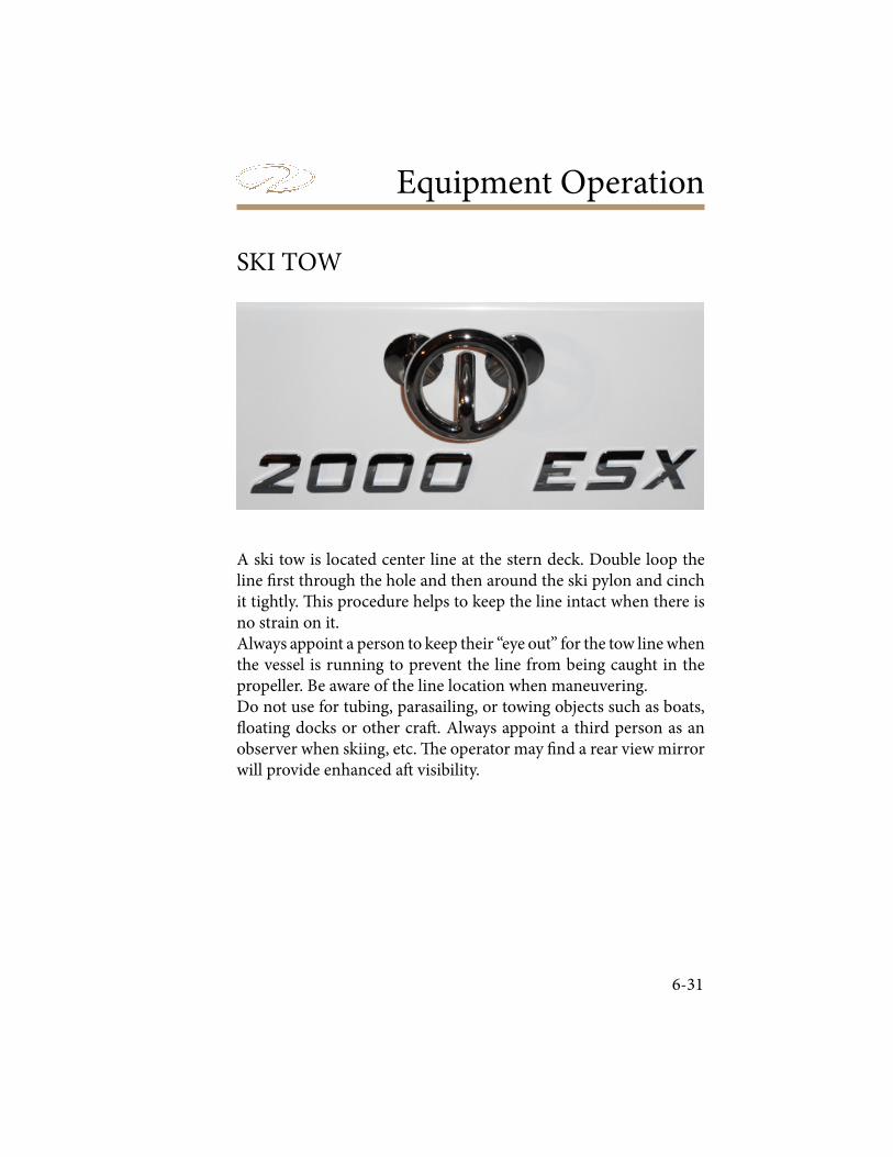
Equipment Operation
6-31
SKI TOW
A ski tow is located center line at the stern deck. Double loop the line ! rst through the hole and then around the ski pylon and cinch it tightly. " is procedure helps to keep the line intact when there is no strain on it.Always appoint a person to keep their “eye out” for the tow line when the vessel is running to prevent the line from being caught in the propeller. Be aware of the line location when maneuvering.Do not use for tubing, parasailing, or towing objects such as boats, # oating docks or other cra$ . Always appoint a third person as an observer when skiing, etc. " e operator may ! nd a rear view mirror will provide enhanced a$ visibility.
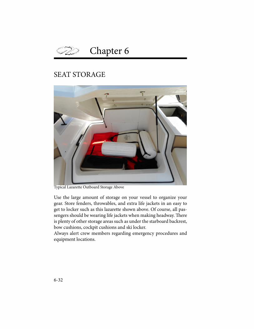
Chapter 6
6-32
SEAT STORAGE
Typical Lazarette Outboard Storage Above
Use the large amount of storage on your vessel to organize your gear. Store fenders, throwables, and extra life jackets in an easy to get to locker such as this lazarette shown above. Of course, all pas-sengers should be wearing life jackets when making headway. ! ere is plenty of other storage areas such as under the starboard backrest, bow cushions, cockpit cushions and ski locker. Always alert crew members regarding emergency procedures and equipment locations.
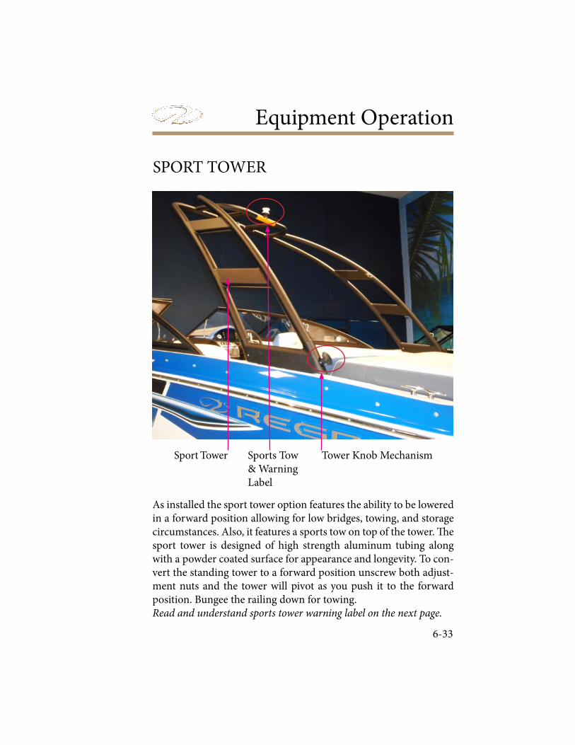
Equipment Operation
6-33
SPORT TOWER
Tower Knob MechanismSports Tow& WarningLabel
Sport Tower
As installed the sport tower option features the ability to be lowered in a forward position allowing for low bridges, towing, and storage circumstances. Also, it features a sports tow on top of the tower. ! e sport tower is designed of high strength aluminum tubing along with a powder coated surface for appearance and longevity. To con-vert the standing tower to a forward position unscrew both adjust-ment nuts and the tower will pivot as you push it to the forward position. Bungee the railing down for towing. Read and understand sports tower warning label on the next page.
Chapter 6
6-34
AVOID BODILY INJURY OR DEATH DUE TO MISUSE OF THE SPORTS TOWER! DO NOT PULL MORE THAN TWO (2) PEOPLE AT A TIME FROM THE SPORTS TOWER. USE SPORTS TOWER ONLY
FOR KNEEBOARDS, WATER SKIS, WAKEBOARDS, OR SINGLE PERSON WATERSPORTS PRODUCTS. THIS SPORTS TOWER WAS
NOT DESIGNED AND SHALL NOT BE USED FOR TOWING OF BOATS, PERSONAL WATERCRAFTS, FLOATING DOCKS OR ANY
OTHER TYPE OF FLOATING VESSEL OR CRAFT. THIS SPORTS TOWER SHALL NOT BE USED FOR PULLING PARASAILING OR
ANY OTHER EQUIPMENT NOT APPROVED. THIS SPORTS TOWER SHALL NOT BE USED TO PULL INFLATABLE WATERSPORTS
TOYS OF ANY KIND. NEVER LET PASSENGERS SIT DIRECTLY BEHIND THE SPORTS TOWER ROPE ATTACHMENT POINT
WHILE PULLING APPROVED WATERSPORTS ACTIVITIES, DO NOT LET LOOSE WATERSPORTS ROPE HANG FROM THE SPORTS TOWER. ALWAYS INSPECT THE SPORTS TOWER PRIOR TO USE
TO ENSURE IT IS NOT DEFORMED, DEFLECTED, AND THAT ALL BOLTS ARE IN PLACE AND TIGHT. WATER LEVELS CAN VARY
DAILY AND IN SOME CASES HOURLY. BE AWARE OF MINIMUM CLEARANCE OF BRIDGES, TREE LIMBS, AND OTHER OBSTACLES, BEFORE ATTEMPTING TO PASS OR GO UNDER ANY OVERHEAD
STRUCTURE.

Equipment Operation
6-35
STEREO PERFORMANCE PACKAGE
! e optional stereo performance package features Fusion signature speakers including a sub-woofer, 4 channel ampli" er and transom remote to provide leading edge performance in sound, power and usability. ! e simplicity of design contributes to low distortion and high e# ciency. Normally the amp is located under the starboard helm. ! e circuit is protected by a 40 amp breaker located in the a$ port sump. ! e ampli" er does not require any type of maintenance other than periodic checking of the wiring connectors for tightness. Since the ampli" er can generate heat when used keep objects away from it under the helm area. Contact your Fusion owner’s manual or closest Regal dealer for additional information.
AMPLIFIER
UNDERHELM
FUSEPANEL
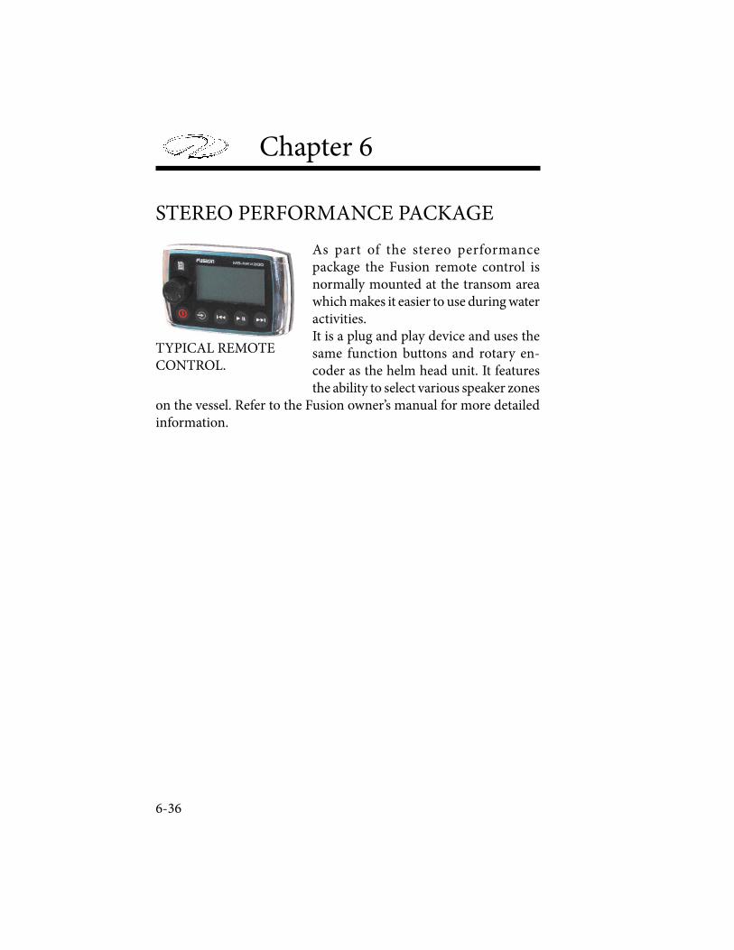
Chapter 6
6-36
TYPICAL REMOTE CONTROL.
As part of the stereo performance package the Fusion remote control is normally mounted at the transom area which makes it easier to use during water activities. It is a plug and play device and uses the same function buttons and rotary en-coder as the helm head unit. It features the ability to select various speaker zones
on the vessel. Refer to the Fusion owner’s manual for more detailed information.
STEREO PERFORMANCE PACKAGE

Equipment Operation
6-37
TRANSOM DOOR (GATE)
Typical Transom Door (Gate) Showing Latch
! e transom door features a latch to secure it. With the starboard a" cushion positioned it provides down # ooding relief from rough seas especially when traveling in reverse or catching the trough of a wave. Boat operator to ensure the transom door is closed and latched when making headway!
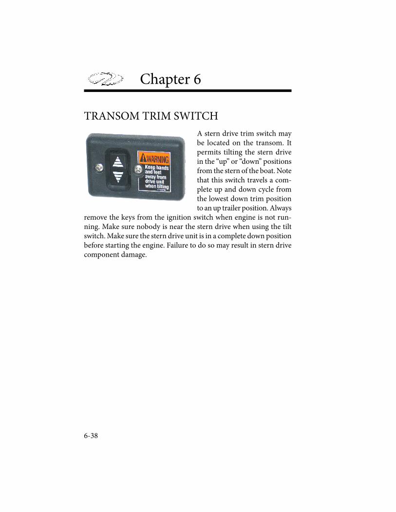
Chapter 6
6-38
TRANSOM TRIM SWITCH
A stern drive trim switch may be located on the transom. It permits tilting the stern drive in the “up” or “down” positions from the stern of the boat. Note that this switch travels a com-plete up and down cycle from the lowest down trim position to an up trailer position. Always
remove the keys from the ignition switch when engine is not run-ning. Make sure nobody is near the stern drive when using the tilt switch. Make sure the stern drive unit is in a complete down position before starting the engine. Failure to do so may result in stern drive component damage.

Cosmetic Care &Maintenance
7-1
COSMETIC CARE
� is section covers the care and maintenance of your Regal boat. Many cosmetic care topics including exterior hardware, upholstery, � berglass and canvas are covered along with major equipment and systems. Refer to the owner’s information packet and the appropriate engine manufacturer’s manuals for further detailed instructions.
Cockpit and vinyl require periodic cleaning to maintain a neat appearance and to prevent the build up of dirt, mildew and con-taminants that may stain and reduce the vinyl life if they are not removed. � e frequency of cleaning depends on the amount of use and conditions to which the vinyl is subjected. Most common stains can be cleaned using warm, soapy water and clear rinses. Scrubbing with a so� bristle brush will help loosen soiled material from embossed surfaces and under welting. If the stains are not removed with the above method use a mild cleaner such as Fantastic. � is cleaner should be used only as needed and not the normal means. With more stubborn stains, rubbing alcohol or mineral spirits may be tried cautiously. Widespread solvent use can severely damage or discolor vinyl. Try to remove stains immediately before they have a chance to penetrate the surface of the vinyl.
Upholstery
7-2
Chapter 7
Powdered abrasives, steel wool, or industrial strength cleaners are not recommended for cleaning our vinyl. Lacquer solvents will cause immediate damage. Dilute chlorine bleach before using. Do not wax the vinyl as it may cause cracking. Always wear protective gloves and make sure there is su! cient ventilation when cleaning vinyl. Wear eye protection.Remember that suntan oil will damage vinyl. Use suntan lotion in-stead of suntan oil. Exposure to the sun is a natural enemy of vinyl upholstery. Keep the vessel covered with a cockpit cover when not in use.
Use approved cleaners on carpet. Always try on a test area " rst. Many spots and spills can be removed using a cleaner combined with a clean, white terry towel. Try not to soak an area excessively and do not use solvents because most interior carpet is rubber backed and glued in place. Solvents and abrasives will break down the backing and " bers. Note: Always roll up cockpit carpet before towing your
boat. Store carpet in a locker.
Use plastic cleaners and polishes recommended for marine use only. Use proper applicators. Read all instructions carefully. Test the product in a small area " rst. Use a so# rag and always rinse the surface with water. Ammonia based cleaners and abrasives will damage plastic parts.
Plastics
Cockpit Carpet
TO AVOID PROPERTY DAMAGE NEVER CLEAN PLASTIC SURFACES WITH A DRY CLOTH OR GLASS CLEANING SOLUTIONS
CONTAINING AMMONIA. NEVER USE SOLVENTS OR WIPE WITH ABRASIVES.
Cosmetic Care & Maintenance
7-3
Spaghetti Mat
Spaghetti mat is used in most of our storage lockers. It is a thick black material that looks like pasta. It provides cushioned support for stored items along with the ability to weep water and condensation through its porus design. To clean spaghetti mat remove from the storage area and use a hose and nozzle to remove debris. Air dry and reinstall in compartment. Material features ability to dry quickly. For heavier cleaning spray with a mild liquid soap and rinse with fresh water. Air dry.
Fiberglass & Gelcoat
Routine maintenance is the only practical way to keep the surface of your boat looking shiny and new. Most objects le! outdoors will gradually deteriorate from exposure to the sun, water, dust and pol-lution. Such outdoor exposure can cause your boat’s gelcoated surface to change or fade. Darker colors tend to fade more rapidly than lighter colors because they absorb more of the sun’s rays (ultraviolet and infrared).Basic maintenance includes monthly washing of the boat’s surface to remove normal accumulation of soil and stain.
AVOID BODILY INJURY FROM FALLING!WAXED SURFACES CAN BE VERY SLIPPERY. DO NOT WAX
NORMALLY USED AREAS OF THE DECK, LINER, OR GUNWALES.DO NOT WAX ANY TEXTURED OR NONSKID SURFACES
SUCH AS FLOORS, WALKWAYS, STEPS, LADDERS OR SWIMPLATFORMS. WEAR NON-SLIP FOOTWEAR WHEN WALKING
ON VESSEL SURFACES.
7-4
Chapter 7
Use a mild detergent such as dishwasher powder or liquid. Do not use automatic dishwasher detergent. Avoid any kind of alkaline cleaners such as trisodium phosphate (TSP), abrasives, bleaches and ammonia. For best results use cleaners that are recommended for ! berglass.
It is recommended that you wax the gelcoat surface twice yearly to prevent loss of gloss and to protect the ! nish. Use only waxes for ! berglass and follow the label instructions. Apply a 3’ x 3’ section at a time using clean applicator cloths or a bu" ng bonnet. When a haze develops, use a power bu# er at low speeds (1200-2000 rpm) to remove the haze. Keep the bu# er moving to avoid heat buildup. $ e power bu# er is very e" cient at removing contaminants from gelcoat. Never wax gelcoat in the direct sun.When the washing and waxing as recommended does not restore the shine it may be necessary to use a ! ne rubbing compound. Do not apply rubbing compound in direct sunlight. A power bu# er at low speed does an excellent job to remove impurities from the gel coat that cause dulling. Use light pressure and keep the bu# er moving. Re-wax a% er compounding to bu# the surface. “Hairline cracks” or “spider webbing” could develop in the gelcoat surface of a hull or deck. $ is can be caused by impact or other factors. Small air pockets or gouges may also occur through normal wear. $ ese do not a# ect the strength of the hull or deck and can be repaired by yourself, a marine professional or a Regal dealer.$ e a# ected area should be chipped or sanded away and a thin layer of color matched gelcoat applied. $ is layer is then sanded smooth and bu# ed to its original luster.
TO AVOID DAMAGE TO THE DECK OR HULL BOTTOMDUE TO SCRATCH MARKS. NEVER USE WIRE BRUSHES,
SCOURING PADS, OR OTHER ABRASIVE TYPE MATERIALS AND SOLUTIONS. THEY WILL COLLECT MARINE GROWTH
ALONG WITH OTHER FOREIGN MATERIALS.
Cosmetic Care & Maintenance
7-5
Most minor scratches, nicks, and dents can be removed by com-pounding the surface. Marine type compounds can be found at most auto body supply stores. Specify a number 25 which is a coarser compound up to a number 55 being less coarse. Various glazes and polishes are available as needed. Ask your marine professional or Regal dealer for more information. Fiberglass hulls are strong but they can be damaged. A ! berglass hull has virtually no internal stresses. " us when a part is broken or punctured, the rest of the hull retains its original shape. A severe blow will either be absorbed or result in a de! nite localized break. A break of this nature should be checked and repaired by a marine professional or a Regal dealer.
Minor Repairs
You will need the following materials for minor repairs:
• Gelcoat• Clear Liquid Catalyst• Putty Knife• Razor Blade• Fine Sandpaper (400,600,1000)• Wax Paper (to cover repair area)
AVOID BODILY INJURY DUE TO FLAMMABLES! GELCOAT & FIBERGLASS RESIN ARE FLAMMABLE.
WORK IN A WELL VENTILATED AREA FREE FROM OPEN FLAMES.DO NOT SMOKE.
7-6
Chapter 7
For minor repairs refer to the following procedure: 1. Clean the area to be repaired and get rid of any wax or grease residues.
2. Clean out scratches, chips, and nicks.
3. Sand area to be repaired so gelcoat will bond.
4. In a separate container, measure only the amount of gelcoat you will need. Mix a ratio of 2% ratio of catalyst to the amount of gelcoat being used (a spoonful of gelcoat will require only a drop or two of catalyst). Do not pour any unused portions of the gelcoat/catalyst mixture back into either original container.
5. Apply gelcoat to area leaving a slight li! above the surface.
6. Cover the area with wax paper. It will help the mixture to set up faster.
7. Remove wax paper and shave o" any extra gel coat with a razor blade.
8. A! er the area is shaved smooth, start with the 400, 600, and # nally 1000 grit sand papers.
9. Bu" the area with compound, polish and a # nish wax. You may notice a di" erence between the repaired area and the original # nish due to the natural weathering process.
Canvas
Boat canvas is in most cases subjected to more severe punishment than practically any other type of material. Moisture, dirt and chemi-cals from industrial fallout, heat, ultraviolet rays and salt water are all factors which accelerate the deterioration of your boat canvas.
Cosmetic Care & Maintenance
7-7
! ese elements can cause serious damage if le" unchecked.! e boat top and other canvas supplied on your Regal boat are manufactured from top quality materials to provide you with years of trouble free service. ! e following information on the care, cleaning and proper storage of the fabrics and fasteners that make up your marine canvas is being provided to help you maintain the appearance and ease of operation.Sunbrella is used on most Regal tops, a" curtains, camper enclo-sures, bow tonneaus and cockpit covers. Sunbrella is a woven fabric made from 100% solution dyed acrylic # ber. It is color fast and will withstand long term exposure to the sun (ultraviolet rays) without excessive fading.Sunbrella is a woven fabric. Even though it is treated with water repellency some “misting” through the fabric is typical. With new canvas, the greatest potential for leakage is through the sewn seams. Because Sunbrella and the long term thread used is synthetic, the holes created by sewing will not swell up and seal when exposed to water as cotton does. Usually the movement of the fabric in use will move the # bers enough to seal the holes. You may apply Apseal or Uniseal to the seams to speed up this process.When the canvas is new, the # t will normally be tight. It is designed this way because Sunbrella stretches as it ages, ! e initial tight # t al-lows for a suitable # t for the life of the canvas. ! e Sunbrella # t will vary slightly in the heat, cold, and rain.
Sunbrella Cleaning Instructions
Sunbrella should be cleaned regularly before substances such as dirt, roof particles, etc., are allowed to accumulate on and become embedded in the fabric. ! e fabric can be cleaned without being removed from the boat. Simply brush o$ any loose dirt, hose down, and clean with a mild solution of natural soap in lukewarm water. Rinse thoroughly to remove soap. DO NOT USE DETERGENTS! Allow to air dry.For heavily soiled fabric, remove the top from the frame.
7-8
Chapter 7
Soak the fabric in a solution that has been mixed to the following proportions.: 1/2 cup of bleach and 1/4 cup of Ivory or Lux soap (liquid or soap) per each gallon of lukewarm water. Allow the fabric to soak until the bleach has killed the mildew and the stains can be brushed out with a common kitchen scrub brush. Rinse the fabric thoroughly in cold water to remove all the soap. ! is may require several rinsings. Incomplete rinsing can cause deterioration of sewing threads and prohibit the fabric from being properly retreated. Allow the fabric to dry completely. DO NOT STEAM PRESS OR DRY IN AN ELECTRIC OR GAS DRYER! Excessive heat can damage and shrink the fabric since it is heat sensitive.! is method of cleaning may remove part of the water and stain repellent that was applied to the fabric during its manufacture. It is recommended to retreat with such water repellency products as Apseal and Uniseal. We do not recommend any wax based treatments such as ! ompson’s Water Seal or any of the silicone products such as SC-15 or Aqua-Tite. Wax based products prevent the fabric from breathing, and encourage mildew growth while the silicone products interact with the original # uorocarbon $ nish and seem to cause a rapid loss of water repellency.
Clear Vinyl, Zipper & Snap Care
Never store canvas wet or in an unventilated, moist area. Always roll the canvas instead of folding. ! is is of particular importance on side curtains or any other part with the clear vinyl “glass”. Roll the top carefully around the bows and cover with the storage boot provided. ! e clear vinyl “glass” used in side curtains, a% curtains, visors, and camper enclosures is very susceptible to heat and cold. Keep vinyl curtains from touching metal tubing to minimize burning the vinyl.If the boat is stored with top, side curtains and a% curtain in place, heat build up inside the boat may discolor the vinyl.To clean the clear “vinyl” glass, use a solution of Ivory or Lux soap, liquid or # akes, and lukewarm water. Allow to air dry. Never use any type of abrasive cleaner as it will scratch the “vinyl” glass. ! ere
Cosmetic Care & Maintenance
7-9
are many cleaners and scratch removers on the market speci! cally for clear vinyl. Handle the clear curtains carefully. " ey are so# and prone to scratching.Canvas parts are designed with zippers. When zippers are new they can be a little di$ cult to use. Zip carefully without forcing the zipper or the material. " ey will loosen with use. A zipper lubricant may be used to help new zippers as well as maintaining used ones. " e most vulnerable part of the zipper is the starts. Use care when beginning to close the zipper.Canvas snap fasteners should be unsnapped as close to the button as possible. Never remove canvas by pulling roughly on the edge of the material. " is can damage the canvas as well as the fasteners. Use petroleum jelly on snaps to keep them from developing corrosion especially in harsh environments.
Hull Bottom
Never use wire brushes or highly abrasive scouring pads on your hull bottom. It could damage the gel coat surface or the bottom paint. " e bottom of your boat needs to be clean since the build up of natural coatings from water or marine life can potentially create drag and a% ect your boat’s performance. Contact a marine professional or Regal dealer for more information.
Metal
Keep all stainless steel and other metal parts rinsed and wiped dry. To maintain their ! nish annually polish the stainless steel and other bright works at least annually. Use commercially available metal products and read the labels carefully before use. Refer to the ( yer in the owners information pouch. Most marinas and boating retail outlets carry metal care products.

7-10
Chapter 7
FREQUENT STAINS/CLEAN-UP STEPS 1 2 3
Co! ee, Tea, Chocolate................................... B Permanent Marker*........................................ E B CHousehold Dirt............................................... A BGrease............................................................... D BKetchup, Tomato Products............................ A BLatex Paint....................................................... A BOil Base Paint.................................................. D B Mustard............................................................. A B CSuntan Oil........................................................ A BAsphalt/Road Tar........................................... D BCrayon.............................................................. D BEngine Oil........................................................ BSpray Paint....................................................... BChewing Gum................................................. D AShoe Polish*..................................................... D BBallpoint Pen*.................................................. E B ALipstick............................................................. A BEyeshadow........................................................ E BMildew*............................................................ C B AWet Leaves *.................................................... C B A
A= So" brush; warm soapy water/rinse/ dry
B= Fantastik cleaner
C= One tablespoon ammonia, 1/4 cup of hydrogen peroxide, 3/4 cup of warm water/rinse/dry
D= Scrape o! residue ( use ice to li" gum)
E= Denatured alcohol/rinse/dry
* # ese products contain dyes which leave permanent stains.
Cosmetic Care & Maintenance
7-11
MAINTENANCE
Engine
Each stern drive engine package is unique and quite complex. A select portion of the maintenance items are covered in this chapter. Many times because of the advanced ignition and fuel injection systems used on marine engines it is best to use trained marine professionals. For more detailed information, refer to the manufacturer’s engine owner’s manual or call your closest authorized Regal dealer.
Stern Drive
! e stern drive unit should be checked before each outing. Tilt up the drive and check for any debris around the intake and any " sh line tangled in the propeller. Check your engine manual for stern drive maintenance schedules or call your nearest authorized Regal dealer.
Propellers
Out-of-balance or nicked props may e# ect performance or cause vibration. Damaged props should be replaced, but those that are chipped or bent can usually be reconditioned by a marine dealer or a propeller repair facility. When cruising, carry an spare set of props on board because many marinas do not carry a full inventory of replacement propellers. Also, carry an extra set of prop hardware. Refer to the manufacturer’s engine manual for appropriate stern drive and inboard propeller replacement.Be sure to make a note of the propeller diameter and pitch while the vessel is in dry dock. ! ey are pressed into the prop for easy reading. In an emergency select propeller blades can be straightened by laying the propeller blade on a 2 x 4 and hammering the bent portion of the blade until straight. ! is procedure will assist the operator in reaching port so he can have the propeller re-pitched in a jig.
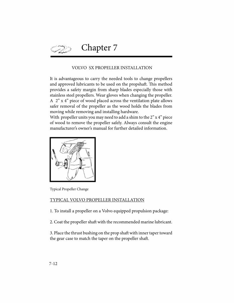
7-12
Chapter 7
VOLVO SX PROPELLER INSTALLATION
It is advantageous to carry the needed tools to change propellers and approved lubricants to be used on the propsha! . " is method provides a safety margin from sharp blades especially those with stainless steel propellers. Wear gloves when changing the propeller.A 2” x 4” piece of wood placed across the ventilation plate allows safer removal of the propeller as the wood holds the blades from moving while removing and installing hardware.With propeller units you may need to add a shim to the 2” x 4” piece of wood to remove the propeller safely. Always consult the engine manufacturer’s owner’s manual for further detailed information.
Typical Propeller Change
TYPICAL VOLVO PROPELLER INSTALLATION
1. To install a propeller on a Volvo equipped propulsion package:
2. Coat the propeller sha! with the recommended marine lubricant.
3. Place the thrust bushing on the prop sha! with inner taper toward the gear case to match the taper on the propeller sha! .
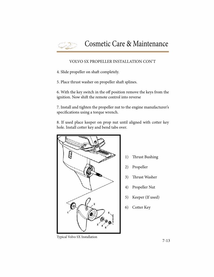
Cosmetic Care & Maintenance
7-13
VOLVO SX PROPELLER INSTALLATION CON’T
4. Slide propeller on sha! completely.
5. Place thrust washer on propeller sha! splines.
6. With the key switch in the o" position remove the keys from the ignition. Now shi! the remote control into reverse
7. Install and tighten the propeller nut to the engine manufacturer’s speci# cations using a torque wrench.
8. If used place keeper on prop nut until aligned with cotter key hole. Install cotter key and bend tabs over.
1) $ rust Bushing
2) Propeller
3) $ rust Washer
4) Propeller Nut
5) Keeper (If used)
6) Cotter Key
Typical Volvo SX Installation
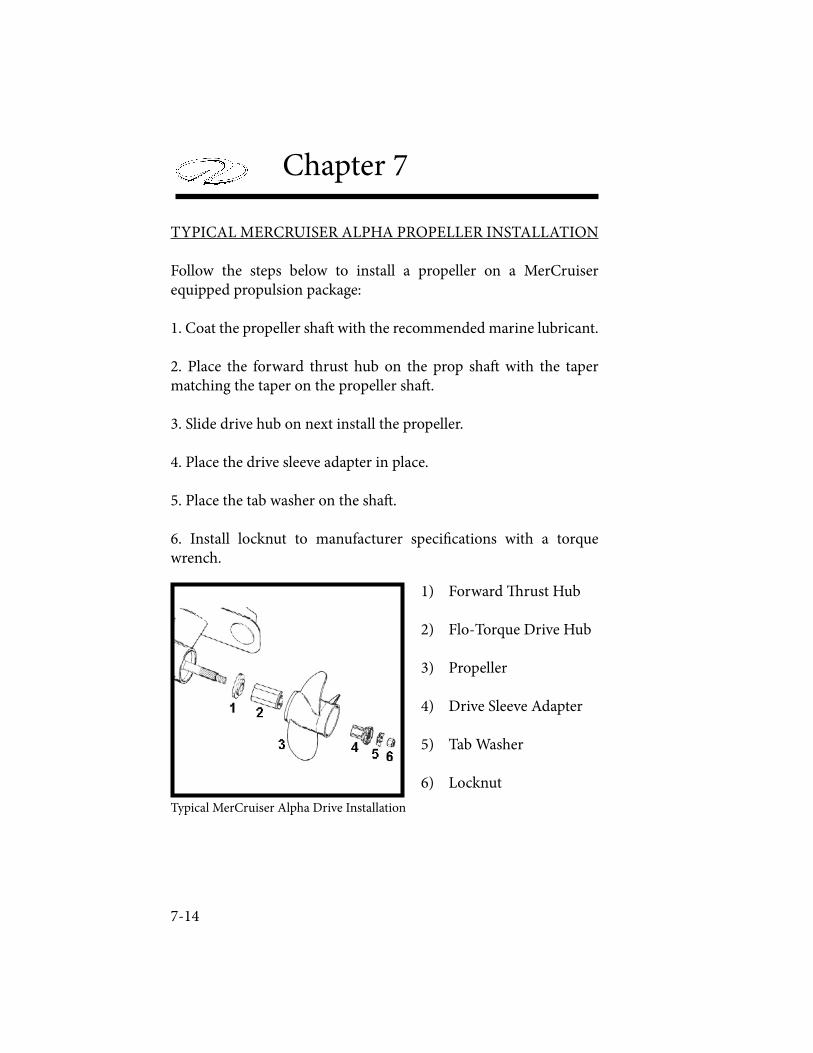
7-14
Chapter 7
TYPICAL MERCRUISER ALPHA PROPELLER INSTALLATION
Follow the steps below to install a propeller on a MerCruiser equipped propulsion package:
1. Coat the propeller sha! with the recommended marine lubricant.
2. Place the forward thrust hub on the prop sha! with the taper matching the taper on the propeller sha! .
3. Slide drive hub on next install the propeller.
4. Place the drive sleeve adapter in place.
5. Place the tab washer on the sha! .
6. Install locknut to manufacturer speci" cations with a torque wrench.
1) Forward # rust Hub
2) Flo-Torque Drive Hub
3) Propeller
4) Drive Sleeve Adapter
5) Tab Washer
6) Locknut
Typical MerCruiser Alpha Drive Installation
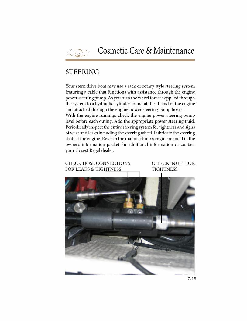
Cosmetic Care & Maintenance
7-15
Your stern drive boat may use a rack or rotary style steering system featuring a cable that functions with assistance through the engine power steering pump. As you turn the wheel force is applied through the system to a hydraulic cylinder found at the a! end of the engine and attached through the engine power steering pump hoses. With the engine running, check the engine power steering pump level before each outing. Add the appropriate power steering " uid. Periodically inspect the entire steering system for tightness and signs of wear and leaks including the steering wheel. Lubricate the steering sha! at the engine. Refer to the manufacturer’s engine manual in the owner’s information packet for additional information or contact your closest Regal dealer.
CHECK HOSE CONNECTIONSFOR LEAKS & TIGHTNESS .
CHECK NUT FOR TIGHTNESS.
STEERING
7-16
Chapter 7
Frequently check your battery terminals for corrosion build-up. If you ! nd a greenish, powdery substance, remove the cable connec-tions and clean both the both the terminals and the connectors with a wire brush. When the cleaning is ! nished reconnect the battery cables and coat the terminal with an approved grease or petroleum jelly to help prevent further corrosion. Check the electrolyte level at least every 30 days, more o" en in hot weather. # e level should be maintained between the top of the battery plates and the bottom of the ! ll cap opening. Add distilled water as needed a" er charging the batteries or periodically as needed. Do not over! ll because sulfuric acid could run over and cause burns or an explosion. Batteries should be charged outside the boat. Do not smoke or bring $ ames near a battery that is being or has recently been charged. # e hydrogen gas generated by battery charging is highly explosive. Set batteries on a block of wood rather than concrete since this pro-cedure will help the batteries from losing their charge.Do not allow a metal object or loose wires to spark across battery posts while working close to the battery. Contact across terminals will cause a short circuit and personal injury may result.Tighten all battery connectors securely. Check their tightness by pulling on the connectors. # ey should not move from their tight-ened position. Be sure to reinstall the positive boot over the battery terminal a" er tightening the battery post connection. While using the boat, use the volt meter to monitor the charge level of the bat-tery. Monitor the charge with the engines turned o% (static condi-tion). # e engine alternators recharge the batteries. A fully charged bat-tery will indicate between 12.3 and 12.6 volts on the voltmeter. Readings below this could indicate a dead battery cell or a charging system malfunction which should be checked by a marine profes-sional.
BATTERY
Cosmetic Care & Maintenance
7-17
TO PREVENT BODILY INJURY!BATTERIES CONTAIN SULFURIC ACID (POISON)
WHICH ALSO CAN CAUSE BURNS.AVOID CONTACT WITH THE SKIN, EYES & CLOTHING.
IF CONTACTED, FLUSH WITH WATER AT LEAST 15 MINUTES. IF SWALLOWED, DRINK LARGE AMOUNTS OF WATER OR MILK. FOLLOW UP WITH MILK OF MAGNESIA, BEATEN EGG OR VEGETABLE OIL. GET
MEDICAL ATTENTION IMMEDIATELY!
TO PREVENT BODILY INJURY!WEAR GOGGLES, RUBBER GLOVES
AND A PROTECTIVE APRON WHEN WORKING WITH A BATTERY.
BATTERY ELECTROLYTE CAUSES SEVERE EYE DAMAGE AND SKIN BURNS.
IN CASE OF SPILLAGE, WASH AREA WITH A SOLUTION OF BAKING SODA AND WATER.
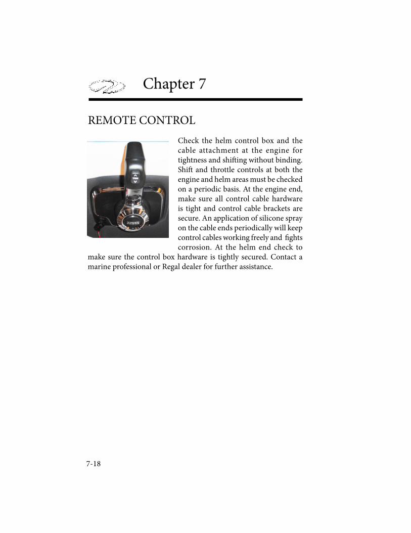
7-18
Chapter 7
Check the helm control box and the cable attachment at the engine for tightness and shi! ing without binding. Shi! and throttle controls at both the engine and helm areas must be checked on a periodic basis. At the engine end, make sure all control cable hardware is tight and control cable brackets are secure. An application of silicone spray on the cable ends periodically will keep control cables working freely and " ghts corrosion. At the helm end check to
make sure the control box hardware is tightly secured. Contact a marine professional or Regal dealer for further assistance.
REMOTE CONTROL
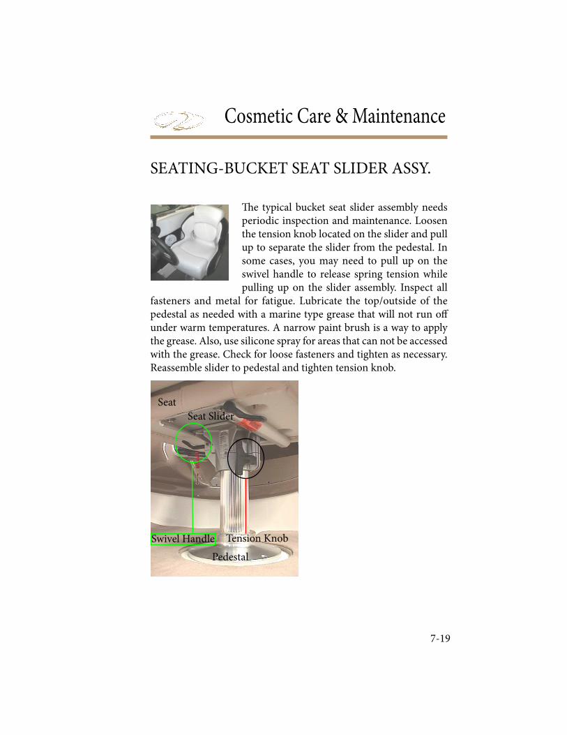
Cosmetic Care & Maintenance
7-19
! e typical bucket seat slider assembly needs periodic inspection and maintenance. Loosen the tension knob located on the slider and pull up to separate the slider from the pedestal. In some cases, you may need to pull up on the swivel handle to release spring tension while pulling up on the slider assembly. Inspect all
fasteners and metal for fatigue. Lubricate the top/outside of the pedestal as needed with a marine type grease that will not run o" under warm temperatures. A narrow paint brush is a way to apply the grease. Also, use silicone spray for areas that can not be accessed with the grease. Check for loose fasteners and tighten as necessary. Reassemble slider to pedestal and tighten tension knob.
SEATING-BUCKET SEAT SLIDER ASSY.
Swivel Handle Tension Knob
Seat
Seat Slider
Pedestal
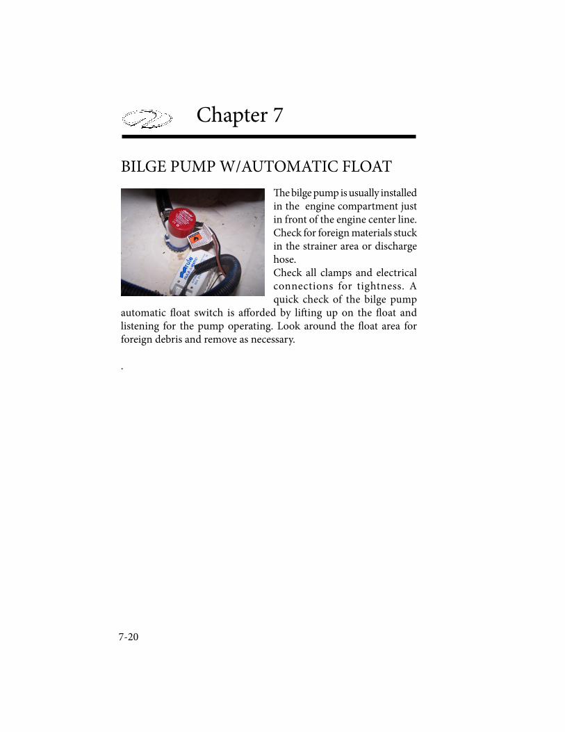
7-20
Chapter 7
! e bilge pump is usually installed in the engine compartment just in front of the engine center line. Check for foreign materials stuck in the strainer area or discharge hose. Check all clamps and electrical connections for tightness. A quick check of the bilge pump
automatic " oat switch is a# orded by li$ ing up on the " oat and listening for the pump operating. Look around the " oat area for foreign debris and remove as necessary.
.
BILGE PUMP W/AUTOMATIC FLOAT
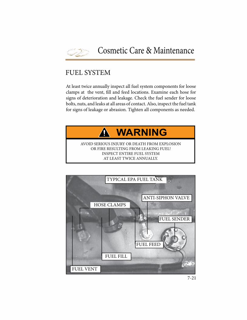
Cosmetic Care & Maintenance
7-21
At least twice annually inspect all fuel system components for loose clamps at the vent, ! ll and feed locations. Examine each hose for signs of deterioration and leakage. Check the fuel sender for loose bolts, nuts, and leaks at all areas of contact. Also, inspect the fuel tank for signs of leakage or abrasion. Tighten all components as needed.
HOSE CLAMPS
FUEL FEED
FUEL SENDER
ANTI-SIPHON VALVE
TYPICAL EPA FUEL TANK
FUEL VENT
FUEL FILL
FUEL SYSTEM
AVOID SERIOUS INJURY OR DEATH FROM EXPLOSION OR FIRE RESULTING FROM LEAKING FUEL!
INSPECT ENTIRE FUEL SYSTEM AT LEAST TWICE ANNUALLY.

7-22
Chapter 7
! e fuse panel is located near the helm area. On select models the panel can be accessed by li" ing the starboard bow seat backrest.Fuses are of the automotive type and can be obtained at most auto a" ermarket stores or your closest authorized Regal dealer who can order it as a designated fuse pack. It is recommended that you carry all the di# erent amperages . When a fuse “blows” determine the cause before replacing the fuse. Never replace with a higher amperage fuse since the equipment or wiring could overheat and may cause a $ re.
Typical Fuse Panel
PANEL-FUSES

Cosmetic Care & Maintenance
7-23
The Fusion® stereo head unit requires little maintenance. When washing the cockpit, do not discharge water directly at the stereo unit. Possible damage
may result. As with any CD unit clean your CD’s to keep them from skipping. " is process also aids in keeping dust out of the unit. Never allow water to enter the iPOD mechanism behind the head cover.For further information, refer to your stereo owner’s manual located in the owner’s information packet.
STEREO
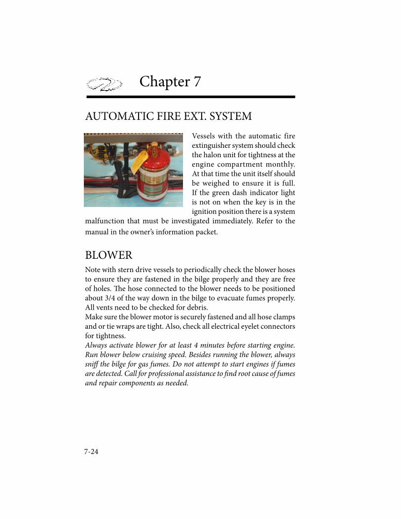
7-24
Chapter 7
Vessels with the automatic fire extinguisher system should check the halon unit for tightness at the engine compartment monthly. At that time the unit itself should be weighed to ensure it is full. If the green dash indicator light is not on when the key is in the ignition position there is a system
malfunction that must be investigated immediately. Refer to the
manual in the owner’s information packet.
Note with stern drive vessels to periodically check the blower hoses to ensure they are fastened in the bilge properly and they are free of holes. ! e hose connected to the blower needs to be positioned about 3/4 of the way down in the bilge to evacuate fumes properly. All vents need to be checked for debris.Make sure the blower motor is securely fastened and all hose clamps and or tie wraps are tight. Also, check all electrical eyelet connectors for tightness. Always activate blower for at least 4 minutes before starting engine. Run blower below cruising speed. Besides running the blower, always sni� the bilge for gas fumes. Do not attempt to start engines if fumes are detected. Call for professional assistance to � nd root cause of fumes and repair components as needed.
AUTOMATIC FIRE EXT. SYSTEM
BLOWER
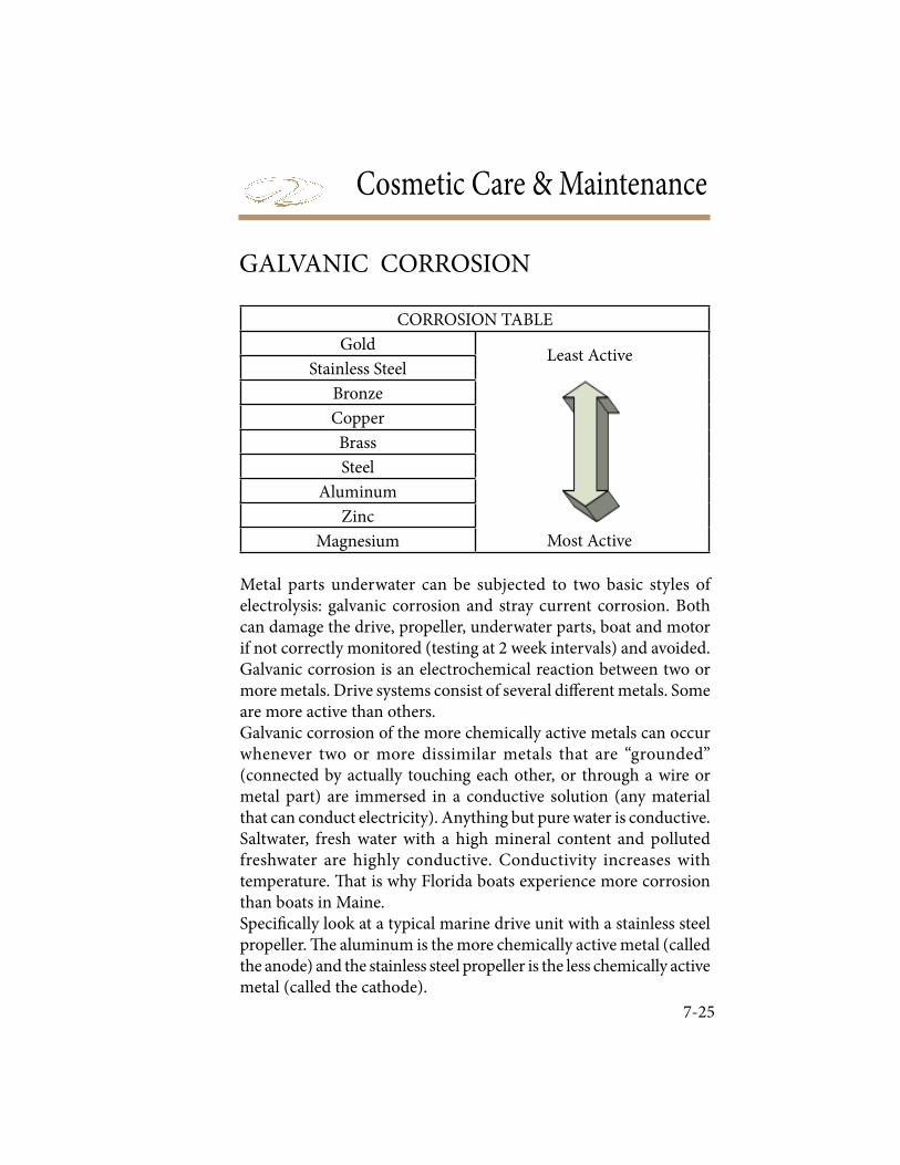
Cosmetic Care & Maintenance
7-25
Metal parts underwater can be subjected to two basic styles of electrolysis: galvanic corrosion and stray current corrosion. Both can damage the drive, propeller, underwater parts, boat and motor if not correctly monitored (testing at 2 week intervals) and avoided.Galvanic corrosion is an electrochemical reaction between two or more metals. Drive systems consist of several di! erent metals. Some are more active than others.Galvanic corrosion of the more chemically active metals can occur whenever two or more dissimilar metals that are “grounded” (connected by actually touching each other, or through a wire or metal part) are immersed in a conductive solution (any material that can conduct electricity). Anything but pure water is conductive. Saltwater, fresh water with a high mineral content and polluted freshwater are highly conductive. Conductivity increases with temperature. " at is why Florida boats experience more corrosion than boats in Maine.Speci# cally look at a typical marine drive unit with a stainless steel propeller. " e aluminum is the more chemically active metal (called the anode) and the stainless steel propeller is the less chemically active metal (called the cathode).
CORROSION TABLE
Gold
Stainless Steel
Bronze
Copper
Brass
Steel
Aluminum
Zinc
Magnesium
Least Active
Most Active
GALVANIC CORROSION
7-26
Chapter 7
Typically electrons ! ow from the anode (the aluminum drive unit),via the external conducting path to the cathode (stainless steel propeller). If there is a very large anode connected to a small cath-ode, the anode will corrode very slowly. If a very large cathode is connected to a small anode, the anode will corrode very quickly. Obviously, if you do not control galvanic corrosion, over time the aluminum will corrode away." e # rst sign of galvanic corrosion is paint blistering (starting on sharp edges) below the water line- a white powdery substance forms on the exposed metal areas. As the corrosion advances, the exposed metal will become deeply pitted as the metal is actually eaten away.Another condition which will increase galvanic corrosion is the re-moval or reduction in surface area of the sacri# cial anodes. Never add a$ ermarket products that are connected to the engine ground such as stainless steel steering aids and trim planes.Zinc connected to aluminum will form a corrosion cell but the alu-minum (drive) becomes the cathode and the zinc (anode) corrodes.
Even though your boat may not have shore power aboard current from nearby vessels with shore power can produce stray current galvanic corrosion. Stray current corrosion occurs when metal with an electrical current ! owing into it is immersed in water that is grounded (lake, ocean, pond). " e current can leave the metal and ! ow through the water to ground. " is will cause rapid corrosion of the metal at the point where the current leaves. When a vessel nearby is plugged into shore power, they can po-tentially tie your aluminum drive unit to their boat via the green grounding shore power lead. Your aluminum drive unit could be the receiving end of a large galvanic cell (a battery) interconnected with nearby vessels or even through the marina’s metal structures via their electrical system.

Cosmetic Care & Maintenance
7-27
! e vessel should be tested every couple of weeks to determine the integrity of the anode protection system. If not installed, Volvo and Mercury o" er an optional corrosion protection system that utilizes the anode/cathode theory to assist in o" setting galvanic corrosion.Another way to test the system is to measure the hull potential. ! is is accomplished by immersing a reference electrode, usually a sil-ver/silver chloride into the water about six inches behind the drive. With leads attached to a digital multi-meter the hull potential is read on the DC scale and compared to recommended speci# cations for the water body type. See the owner’s information vendor packet for more information or contact your nearest authorized Regal dealer.
Tips To Aid In Maintaining Galvanic Integrity
1. Test the galvanic integrity of your vessel every 2 weeks. Trim the stern drive/outboard and inspect anodes/parts for signs of galvanic corrosion, stray current corrosion or loose fasteners. Contact your closest Regal dealer/marine professional for further information.2. Never paint over anodes as they will become inoperative. Always leave at least one inch between bottom paint and any underwater # tting such as seacocks, swim platform stanchions and all drive and propulsion related underwater parts.
3. Periodically remove vessel from water and clean/pressure wash all outdrive, anode and hull bottom areas to remove growth.
4. Ensure vessel is using the correct anode metal for the body of water that it is moored. See the engine/drive manufacturer informa-tion packets for more information or contact an authorized dealer.
5. Ensure that the drive is completely “in” down to provide more complete anode protection when vessel is moored.
6. Do not attempt to use magnesium anodes in saltwater. ! ey will provide overprotection.
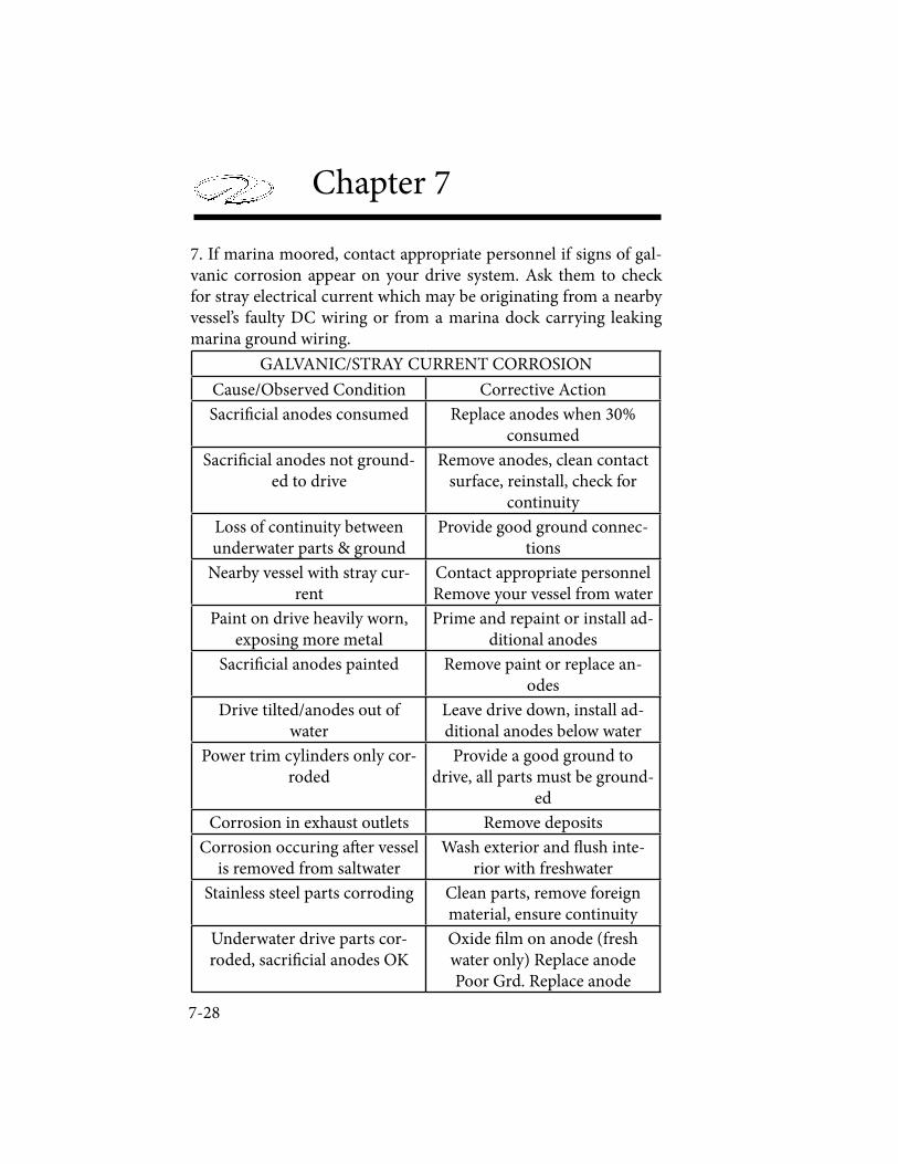
7-28
Chapter 7
7. If marina moored, contact appropriate personnel if signs of gal-vanic corrosion appear on your drive system. Ask them to check for stray electrical current which may be originating from a nearby vessel’s faulty DC wiring or from a marina dock carrying leaking marina ground wiring.
GALVANIC/STRAY CURRENT CORROSION
Cause/Observed Condition Corrective Action
Sacri! cial anodes consumed Replace anodes when 30% consumed
Sacri! cial anodes not ground-ed to drive
Remove anodes, clean contact surface, reinstall, check for
continuity
Loss of continuity between underwater parts & ground
Provide good ground connec-tions
Nearby vessel with stray cur-rent
Contact appropriate personnelRemove your vessel from water
Paint on drive heavily worn, exposing more metal
Prime and repaint or install ad-ditional anodes
Sacri! cial anodes painted Remove paint or replace an-odes
Drive tilted/anodes out of water
Leave drive down, install ad-ditional anodes below water
Power trim cylinders only cor-roded
Provide a good ground to drive, all parts must be ground-
ed
Corrosion in exhaust outlets Remove deposits
Corrosion occuring a" er vessel is removed from saltwater
Wash exterior and # ush inte-rior with freshwater
Stainless steel parts corroding Clean parts, remove foreign material, ensure continuity
Underwater drive parts cor-roded, sacri! cial anodes OK
Oxide ! lm on anode (fresh water only) Replace anodePoor Grd. Replace anode
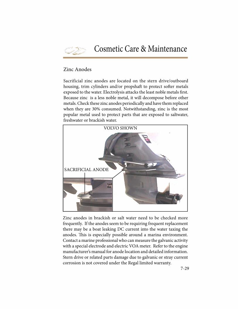
Cosmetic Care & Maintenance
7-29
Zinc anodes in brackish or salt water need to be checked more frequently. If the anodes seem to be requiring frequent replacement there may be a boat leaking DC current into the water taxing the anodes. ! is is especially possible around a marina environment. Contact a marine professional who can measure the galvanic activity with a special electrode and electric VOA meter. Refer to the engine manufacturer’s manual for anode location and detailed information. Stern drive or related parts damage due to galvanic or stray current corrosion is not covered under the Regal limited warranty.
SACRIFICIAL ANODE
VOLVO SHOWN
Zinc Anodes
Sacrificial zinc anodes are located on the stern drive/outboard housing, trim cylinders and/or propsha" to protect so" er metals exposed to the water. Electrolysis attacks the least noble metals # rst. Because zinc is a less noble metal, it will decompose before other metals. Check these zinc anodes periodically and have them replaced when they are 30% consumed. Notwithstanding, zinc is the most popular metal used to protect parts that are exposed to saltwater, freshwater or brackish water.
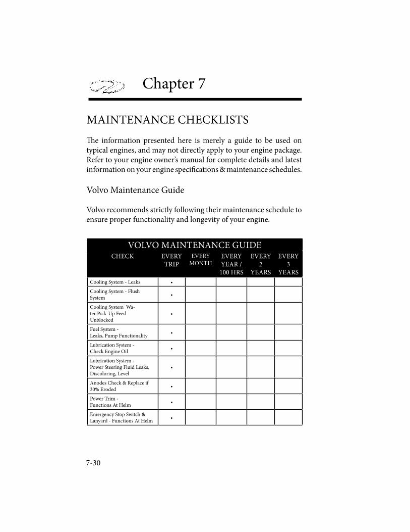
7-30
Chapter 7
MAINTENANCE CHECKLISTS
! e information presented here is merely a guide to be used on typical engines, and may not directly apply to your engine package. Refer to your engine owner’s manual for complete details and latest information on your engine speci" cations & maintenance schedules.
Volvo Maintenance Guide
Volvo recommends strictly following their maintenance schedule to ensure proper functionality and longevity of your engine.
VOLVO MAINTENANCE GUIDECHECK EVERY
TRIP
EVERYMONTH
EVERY YEAR /
100 HRS
EVERY 2
YEARS
EVERY 3
YEARS
Cooling System - Leaks •
Cooling System - Flush System
•
Cooling System Wa-ter Pick-Up Feed Unblocked
•
Fuel System - Leaks, Pump Functionality
•
Lubrication System - Check Engine Oil
•
Lubrication System - Power Steering Fluid Leaks, Discoloring, Level
•
Anodes Check & Replace if 30% Eroded
•
Power Trim - Functions At Helm
•
Emergency Stop Switch & Lanyard - Functions At Helm
•
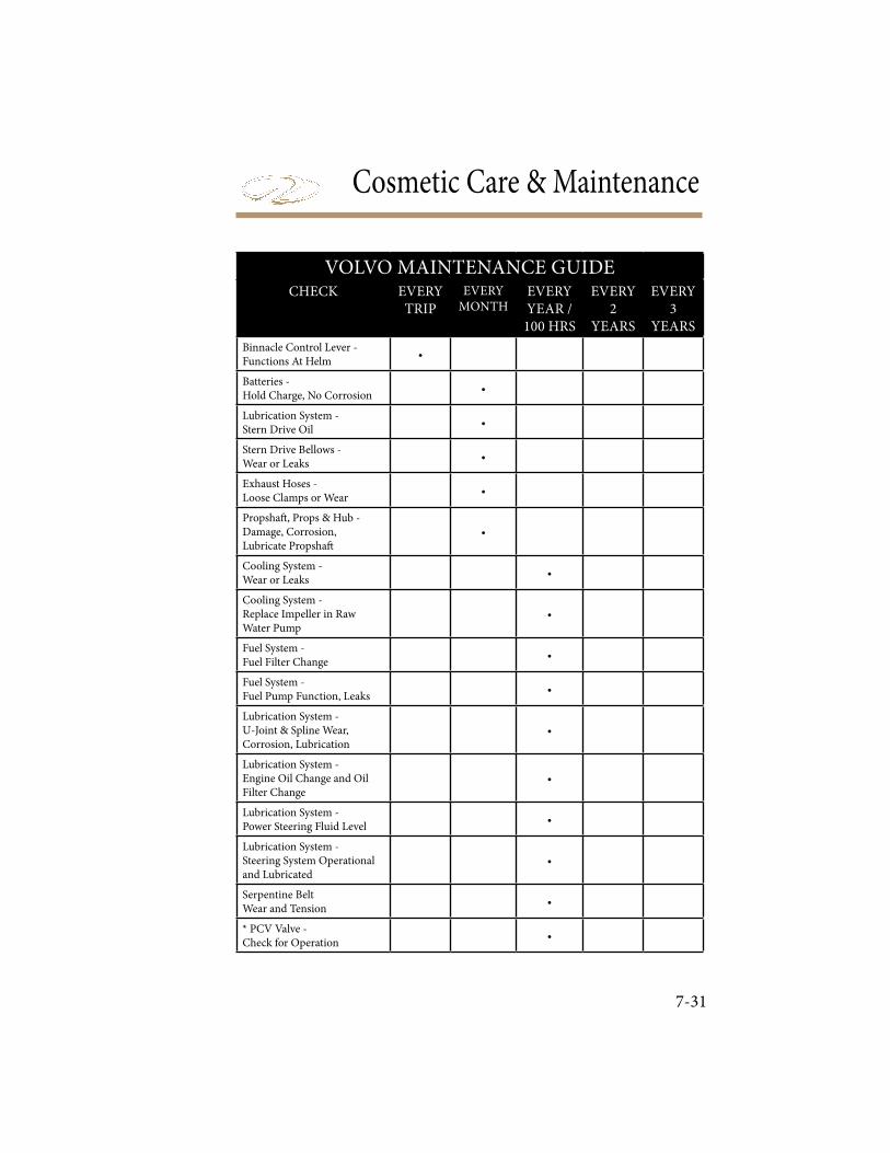
Cosmetic Care & Maintenance
7-31
VOLVO MAINTENANCE GUIDECHECK EVERY
TRIP
EVERYMONTH
EVERY YEAR /
100 HRS
EVERY 2
YEARS
EVERY 3
YEARS
Binnacle Control Lever - Functions At Helm
•
Batteries - Hold Charge, No Corrosion
•
Lubrication System - Stern Drive Oil
•
Stern Drive Bellows - Wear or Leaks
•
Exhaust Hoses - Loose Clamps or Wear
•
Propsha! , Props & Hub - Damage, Corrosion, Lubricate Propsha!
•
Cooling System - Wear or Leaks
•
Cooling System - Replace Impeller in Raw Water Pump
•
Fuel System - Fuel Filter Change
•
Fuel System - Fuel Pump Function, Leaks
•
Lubrication System - U-Joint & Spline Wear, Corrosion, Lubrication
•
Lubrication System - Engine Oil Change and Oil Filter Change
•
Lubrication System - Power Steering Fluid Level
•
Lubrication System - Steering System Operational and Lubricated
•
Serpentine Belt Wear and Tension
•
* PCV Valve - Check for Operation
•
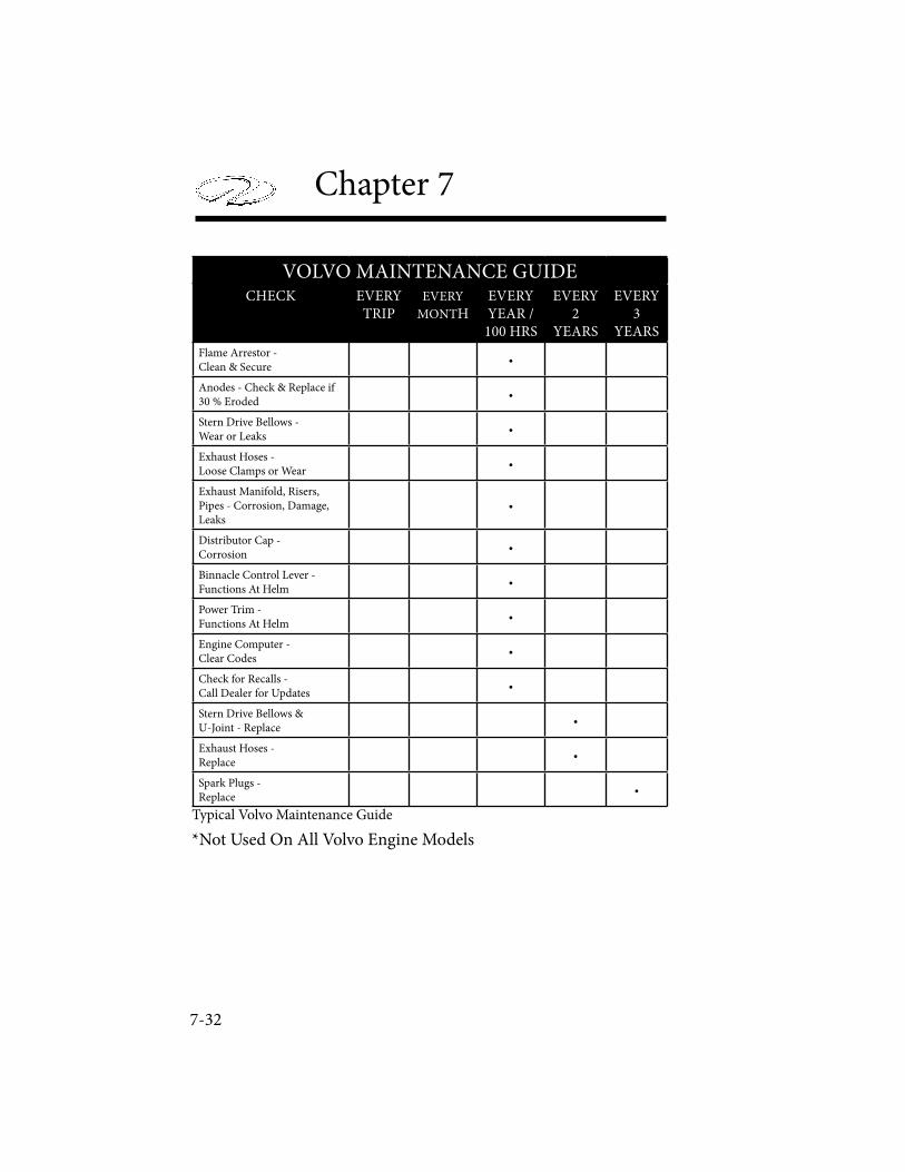
7-32
Chapter 7
VOLVO MAINTENANCE GUIDECHECK EVERY
TRIPEVERY
MONTHEVERY YEAR /
100 HRS
EVERY 2
YEARS
EVERY 3
YEARS
Flame Arrestor - Clean & Secure
•
Anodes - Check & Replace if 30 % Eroded
•
Stern Drive Bellows - Wear or Leaks
•
Exhaust Hoses - Loose Clamps or Wear
•
Exhaust Manifold, Risers, Pipes - Corrosion, Damage, Leaks
•
Distributor Cap - Corrosion
•
Binnacle Control Lever - Functions At Helm
•
Power Trim - Functions At Helm
•
Engine Computer - Clear Codes
•
Check for Recalls - Call Dealer for Updates
•
Stern Drive Bellows & U-Joint - Replace
•
Exhaust Hoses - Replace
•
Spark Plugs - Replace
•
Typical Volvo Maintenance Guide
*Not Used On All Volvo Engine Models
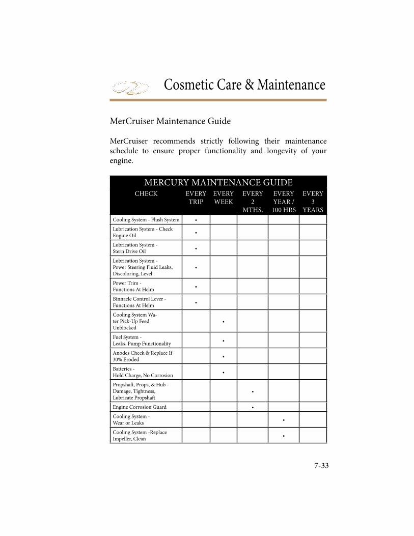
Cosmetic Care & Maintenance
7-33
MerCruiser Maintenance Guide
MerCruiser recommends strictly following their maintenance schedule to ensure proper functionality and longevity of your engine.
MERCURY MAINTENANCE GUIDECHECK EVERY
TRIPEVERY WEEK
EVERY 2
MTHS.
EVERY YEAR /
100 HRS
EVERY 3
YEARS
Cooling System - Flush System •
Lubrication System - Check Engine Oil
•
Lubrication System - Stern Drive Oil
•
Lubrication System - Power Steering Fluid Leaks, Discoloring, Level
•
Power Trim - Functions At Helm
•
Binnacle Control Lever - Functions At Helm
•
Cooling System Wa-ter Pick-Up Feed Unblocked
•
Fuel System - Leaks, Pump Functionality
•
Anodes Check & Replace If 30% Eroded
•
Batteries - Hold Charge, No Corrosion
•
Propsha! , Props, & Hub - Damage, Tightness, Lubricate Propsha!
•
Engine Corrosion Guard •
Cooling System - Wear or Leaks
•
Cooling System -Replace Impeller, Clean
•
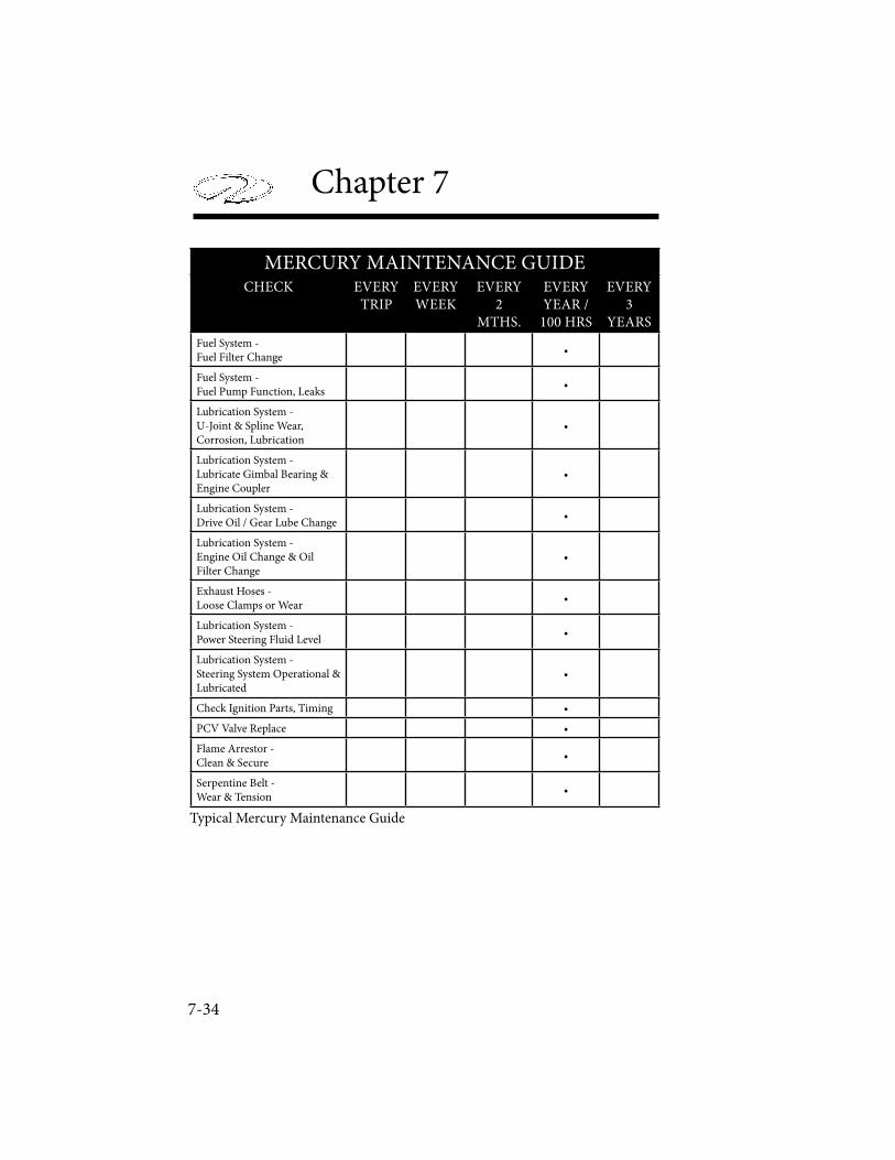
7-34
Chapter 7
MERCURY MAINTENANCE GUIDECHECK EVERY
TRIPEVERY WEEK
EVERY 2
MTHS.
EVERY YEAR /
100 HRS
EVERY 3
YEARS
Fuel System - Fuel Filter Change
•
Fuel System - Fuel Pump Function, Leaks
•
Lubrication System - U-Joint & Spline Wear, Corrosion, Lubrication
•
Lubrication System - Lubricate Gimbal Bearing & Engine Coupler
•
Lubrication System - Drive Oil / Gear Lube Change
•
Lubrication System - Engine Oil Change & Oil Filter Change
•
Exhaust Hoses - Loose Clamps or Wear
•
Lubrication System - Power Steering Fluid Level
•
Lubrication System - Steering System Operational & Lubricated
•
Check Ignition Parts, Timing •
PCV Valve Replace •
Flame Arrestor - Clean & Secure
•
Serpentine Belt - Wear & Tension
•
Typical Mercury Maintenance Guide
Cosmetic Care & Maintenance
7-35
Engine
Each engine and stern drive package is unique and quite complex. A select portion of the maintenance items are covered in this chapter including general lubrication speci! cations and periodic maintenance. Because of the advanced ignition and fuel injection systems used on marine engines it is best to contact your Regal dealer for more of the detailed service procedures.
AVOID ENGINE DAMAGE!FOLLOW ALL ENGINE BREAK-IN PROCEDURES AS
RECOMMENDED BY THE ENGINE MANUFACTURER. FAILURE TO FOLLOW THE BREAK-IN PROCEDURE MAY VOID
THE ENGINE AND STERN DRIVE WARRANTY.
AVOID ENGINE DAMAGE!DO NOT RUN ENGINE AT A CONSTANT RPM
FOR PROLONGED PERIODS OF TIME DURING BREAK-IN PERIOD. CHECK ENGINE OIL OFTEN.
AVOID ENGINE DAMAGE!DO NOT RUN ENGINE OUT OF WATER
UNLESS YOU HAVE AN OPTIONAL FLUSHETTE. FOLLOW MANUFACTURER’S ATTACHING &
RUNNING INSTRUCTIONS.

7-36
Chapter 7
Recommended Lubricant Speci! cations
Volvo Engine Oil Requirements
Due to recent EPA mandates on internal combustion engines new units are built with catalytic convertors installed in the exhaust manifolds, along with a system of sensors and computer controls. " ese newer engines require special oil requirements to extend the life of the catalysts.Refer to the Volvo engine operator’s manual for the correct oil requirements for catalyst type engines, or contact your nearest Regal or Volvo dealer for further information.For other engines not manufactured as catalyst engines refer to your engine operator’s manual for correct oil recommendations.
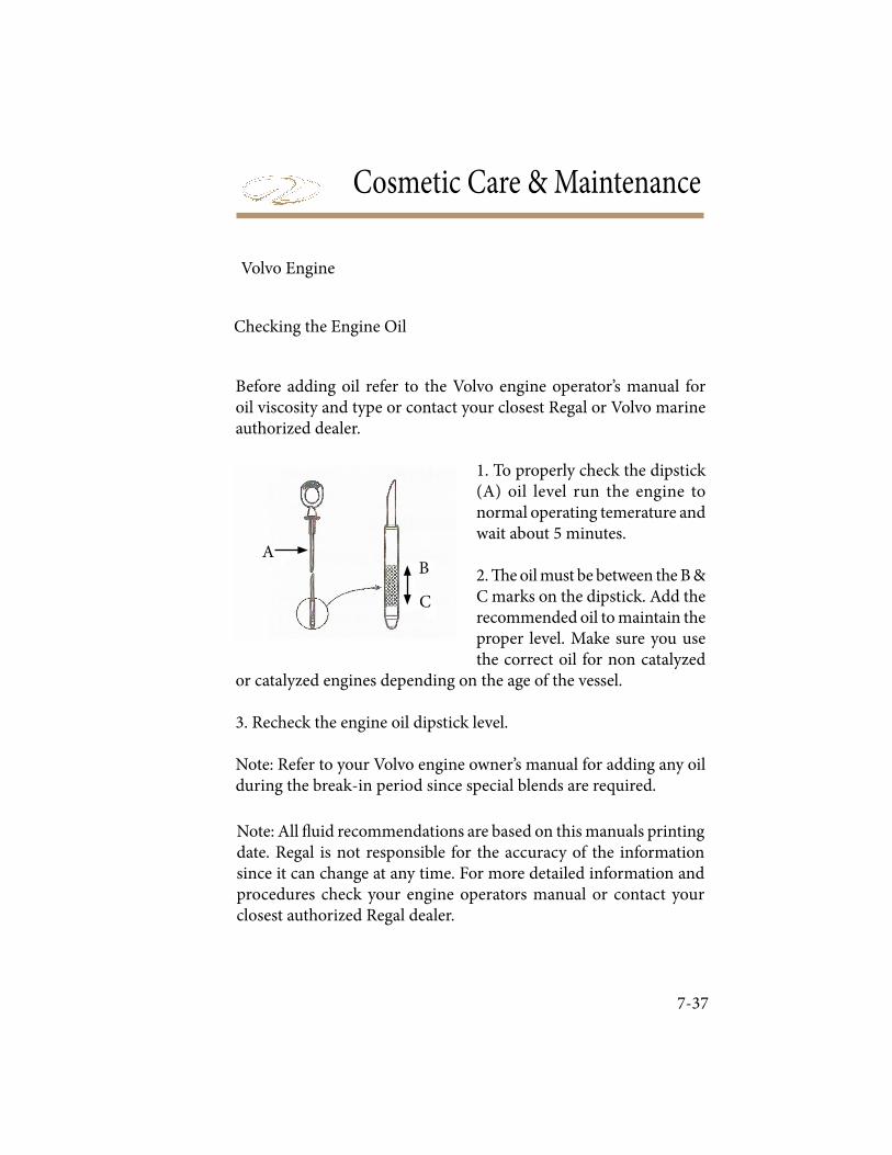
Cosmetic Care & Maintenance
7-37
Before adding oil refer to the Volvo engine operator’s manual for oil viscosity and type or contact your closest Regal or Volvo marine authorized dealer.
1. To properly check the dipstick (A) oil level run the engine to normal operating temerature and wait about 5 minutes. 2. ! e oil must be between the B & C marks on the dipstick. Add the recommended oil to maintain the proper level. Make sure you use the correct oil for non catalyzed
or catalyzed engines depending on the age of the vessel.
3. Recheck the engine oil dipstick level.
Note: Refer to your Volvo engine owner’s manual for adding any oil during the break-in period since special blends are required.
Note: All " uid recommendations are based on this manuals printing date. Regal is not responsible for the accuracy of the information since it can change at any time. For more detailed information and procedures check your engine operators manual or contact your closest authorized Regal dealer.
Volvo Engine
Checking the Engine Oil
A
C
B
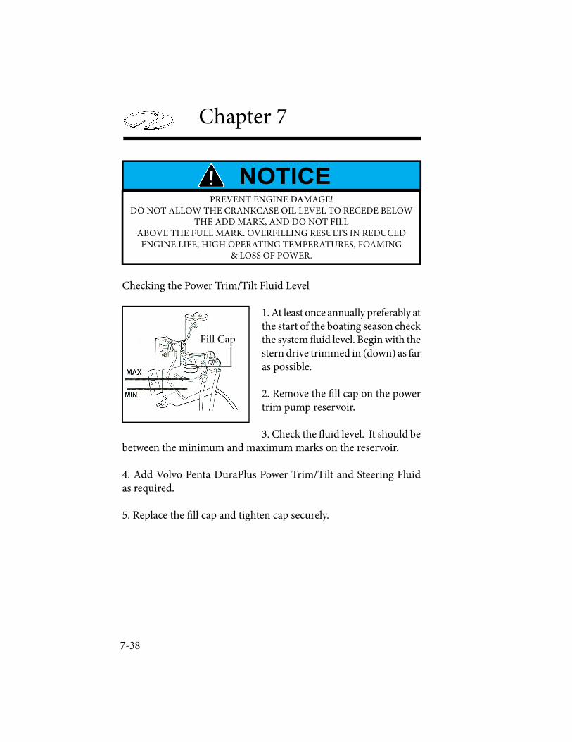
7-38
Chapter 7
Checking the Power Trim/Tilt Fluid Level
1. At least once annually preferably at the start of the boating season check the system ! uid level. Begin with the stern drive trimmed in (down) as far as possible.
2. Remove the " ll cap on the power trim pump reservoir.
3. Check the ! uid level. It should be between the minimum and maximum marks on the reservoir.
4. Add Volvo Penta DuraPlus Power Trim/Tilt and Steering Fluid as required.
5. Replace the " ll cap and tighten cap securely.
Fill Cap
PREVENT ENGINE DAMAGE!DO NOT ALLOW THE CRANKCASE OIL LEVEL TO RECEDE BELOW
THE ADD MARK, AND DO NOT FILLABOVE THE FULL MARK. OVERFILLING RESULTS IN REDUCED ENGINE LIFE, HIGH OPERATING TEMPERATURES, FOAMING
& LOSS OF POWER.
Cosmetic Care & Maintenance
7-39
Checking Power Steering Fluid
1. Check the power steering ! uid before each boating outing. Remove the steering reservoir and check the ! uid level. If the engine has not been running use the “COLD” mark. Use the “HOT” mark for engines that have been running at normal operating temperature as indicated by the temperature gauge.
2. " e ! uid should be between the minimum and maximum marks on the dipstick. If needed, # ll to the proper level with Volvo Penta Dura Plus Power Trim/Tilt & Steering Fluid. DO NOT OVERFILL THE STEERING PUMP RESERVOIR.
3. Replace the # ll cap and tighten securely.
PREVENT STEERING OPERATION IMPAIRMENT OR COMPONENT DAMAGE!
NEVER FILL THE POWER STEERING SYSTEM WITH AN UNKNOWN OIL.
TO FILL TRIM, CRANKCASE & POWER STEERING LEVELS WITHOUT SPILLING FLUID
PURCHASE A FUNNEL AT AN AUTOMOTIVE STORE WITH A LONGER NECK
THAT WILL FIT THE RESERVOIR OPENINGS.
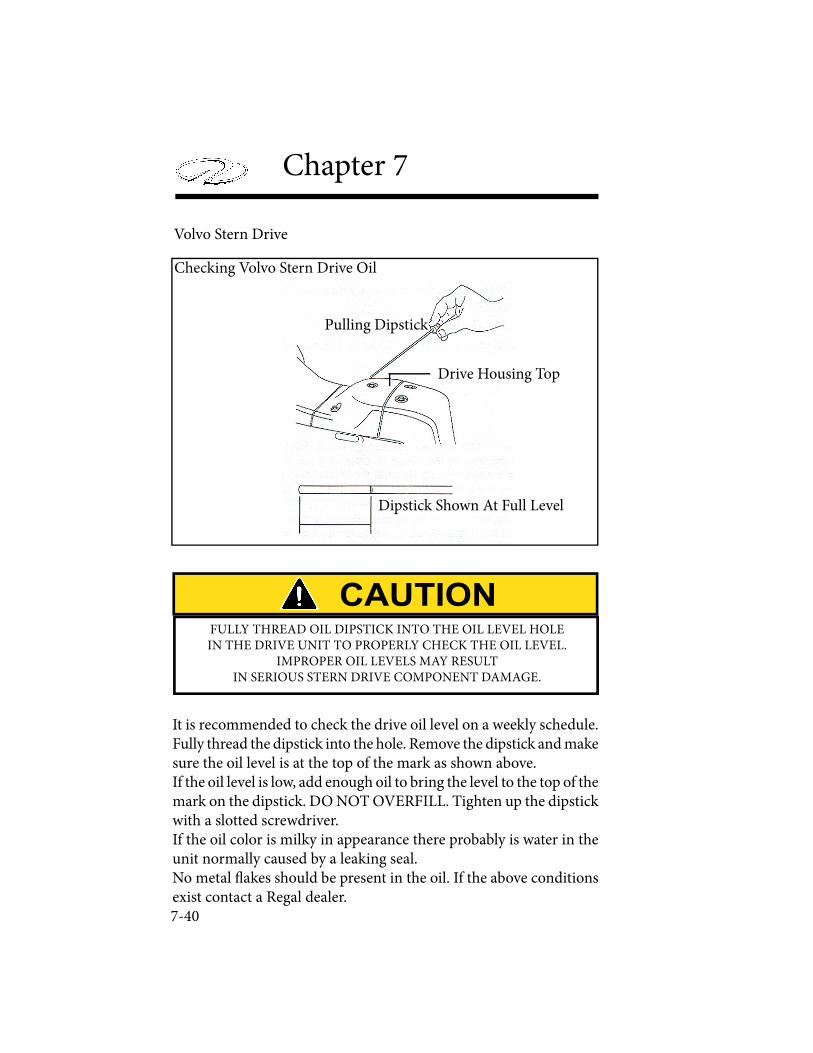
7-40
Chapter 7
Volvo Stern Drive
Checking Volvo Stern Drive Oil
Dipstick Shown At Full Level
Pulling Dipstick
Drive Housing Top
It is recommended to check the drive oil level on a weekly schedule. Fully thread the dipstick into the hole. Remove the dipstick and make sure the oil level is at the top of the mark as shown above.If the oil level is low, add enough oil to bring the level to the top of the mark on the dipstick. DO NOT OVERFILL. Tighten up the dipstick with a slotted screwdriver. If the oil color is milky in appearance there probably is water in the unit normally caused by a leaking seal. No metal ! akes should be present in the oil. If the above conditions exist contact a Regal dealer.
FULLY THREAD OIL DIPSTICK INTO THE OIL LEVEL HOLE IN THE DRIVE UNIT TO PROPERLY CHECK THE OIL LEVEL.
IMPROPER OIL LEVELS MAY RESULT IN SERIOUS STERN DRIVE COMPONENT DAMAGE.
Cosmetic Care & Maintenance
7-41
MerCruiser Engine
4. When checking or ! lling the engine crankcase oil ensure that the vessel is level in the water or on a trailer.
For changing the engine oil & ! lter see the MerCruiser maintenance schedule and operation manual or contact your Regal dealer.
Note: Above are basic recommendations. Regal is not responsible for the accuracy of the information since it can change at any time. For more detailed information and procedures check your engine operators manual or call your closest Regal dealer.
Checking Engine Crankcase Oil
1. Before adding oil make sure it is the type recommended for the type of engine installed. Consult your MerCruiser engine operator’s manual.Check the engine oil by ! rst allowing the engine to warm up. Stop the engine and allow about 5 minutes for the oil to drain to the oil pan to obtain an accurate reading.
2. Remove the dipstick. Wipe it clean and reinstall it into the dipstick tube. Wait 1 minute to allow any trapped air to vent. ( Install dipstick with oil indication marks facing the " ywheel end of the engine. Add engine oil type and viscosity as recommended in the engine operator’s manual. to the full or OK points on the oil dipstick. DO NOT OVERFILL!
3. Remove the dipstick and look at the oil level. Level must be between full or OK range and add. Reinstall dipstick into the tube.
7-42
Chapter 7
Changing Engine Crankcase Oil
Due to recent EPA mandates on internal combustion engines new units are built with catalytic convertors installed in the exhaust manifolds, along with a system of sensors and computer controls. ! ese newer engines require special oil requirements to extend the life of the catalysts.Refer to the MerCruiser engine operator’s manual for the correct oil requirements for catalyst type engines, or contact your nearest Regal or MerCruiser dealer for further information.For other engines not manufactured as catalyst engines refer to your engine operator’s manual for correct oil recommendations.
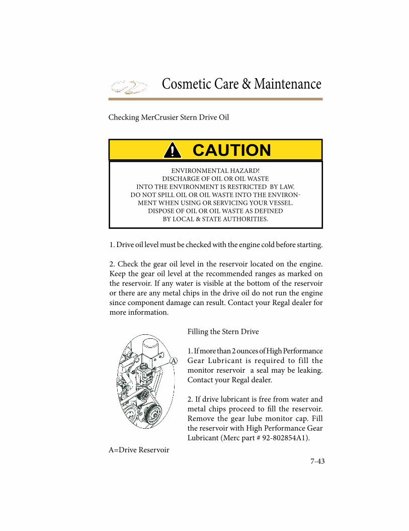
Cosmetic Care & Maintenance
7-43
Checking MerCrusier Stern Drive Oil
1. Drive oil level must be checked with the engine cold before starting.
2. Check the gear oil level in the reservoir located on the engine. Keep the gear oil level at the recommended ranges as marked on the reservoir. If any water is visible at the bottom of the reservoir or there are any metal chips in the drive oil do not run the engine since component damage can result. Contact your Regal dealer for more information.
Filling the Stern Drive
1. If more than 2 ounces of High Performance Gear Lubricant is required to fill the monitor reservoir a seal may be leaking. Contact your Regal dealer.
2. If drive lubricant is free from water and metal chips proceed to ! ll the reservoir. Remove the gear lube monitor cap. Fill the reservoir with High Performance Gear Lubricant (Merc part # 92-802854A1).
A=Drive Reservoir
A
ENVIRONMENTAL HAZARD!
DISCHARGE OF OIL OR OIL WASTE
INTO THE ENVIRONMENT IS RESTRICTED BY LAW.
DO NOT SPILL OIL OR OIL WASTE INTO THE ENVIRON-
MENT WHEN USING OR SERVICING YOUR VESSEL.
DISPOSE OF OIL OR OIL WASTE AS DEFINED
BY LOCAL & STATE AUTHORITIES.
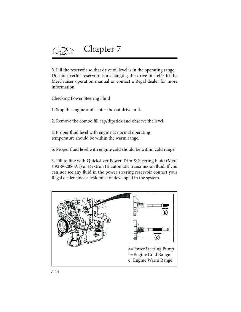
7-44
Chapter 7
3. Fill the reservoir so that drive oil level is in the operating range.Do not over! ll reservoir. For changing the drive oil refer to the MerCruiser operation manual or contact a Regal dealer for more information.
Checking Power Steering Fluid
1. Stop the engine and center the out drive unit.
2. Remove the combo ! ll cap/dipstick and observe the level. a. Proper " uid level with engine at normal operating temperature should be within the warm range.
b. Proper " uid level with engine cold should be within cold range.
3. Fill to line with Quicksilver Power Trim & Steering Fluid (Merc # 92-802880A1) or Dextron III automatic transmission " uid. If you can not see any " uid in the power steering reservoir contact your Regal dealer since a leak must of developed in the system.
a=Power Steering Pumpb=Engine Cold Rangec=Engine Warm Range
Cosmetic Care & Maintenance
7-45
Checking Power Trim Fluid
1. Place the stern drive unit in the full down position.
2. Observe the oil level. Level must be between the “MIN” or “MAX” lines on the reservoir.
3. Fill as necessary with Power Trim & Steering Fluid (Merc part # 92-802880Al).
Re! lling " e Reservoir
1. Remove the ! ll cap from the reservoir. Fill cap is vented.
2. Add lubricant to bring level to the within the “MIN” and “MAX” lines on the reservoir. Use Power Trim & Steering Fluid (92- 802880A1).
3. Install the cap.
Changing Power Trim Fluid
1. Power steering $ uid does not require changing unless it becomes contaminated with water or debris. Contact a Regal dealer to change the $ uid.
ALWAYS CHECK THE OIL LEVEL WITH THE STERN DRIVE
IN THE “FULL” DOWN OR “IN” POSITION.
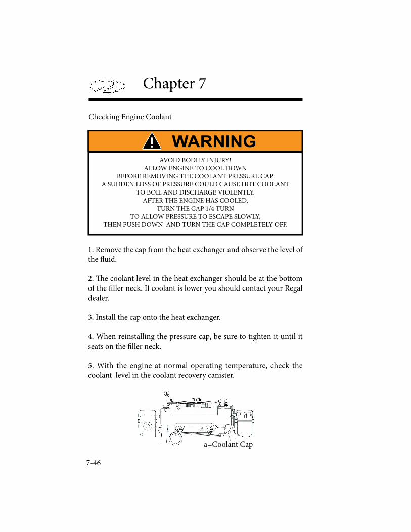
7-46
Chapter 7
Checking Engine Coolant
1. Remove the cap from the heat exchanger and observe the level of the ! uid.
2. " e coolant level in the heat exchanger should be at the bottom of the # ller neck. If coolant is lower you should contact your Regal dealer.
3. Install the cap onto the heat exchanger.
4. When reinstalling the pressure cap, be sure to tighten it until it seats on the # ller neck.
5. With the engine at normal operating temperature, check the coolant level in the coolant recovery canister.
a=Coolant Cap
AVOID BODILY INJURY!ALLOW ENGINE TO COOL DOWN
BEFORE REMOVING THE COOLANT PRESSURE CAP. A SUDDEN LOSS OF PRESSURE COULD CAUSE HOT COOLANT
TO BOIL AND DISCHARGE VIOLENTLY. AFTER THE ENGINE HAS COOLED,
TURN THE CAP 1/4 TURN TO ALLOW PRESSURE TO ESCAPE SLOWLY,
THEN PUSH DOWN AND TURN THE CAP COMPLETELY OFF.
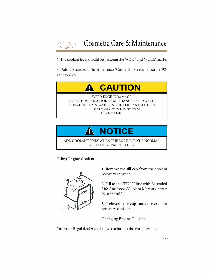
Cosmetic Care & Maintenance
7-47
6. ! e coolant level should be between the “ADD” and “FULL” marks.
7. Add Extended Life Antifreeze/Coolant (Mercury part # 92-877770K1).
Filling Engine Coolant
1. Remove the " ll cap from the coolant recovery canister.
2. Fill to the “FULL” line with Extended Life Antifreeze/Coolant Mercury part # 92-877770K1.
3. Reinstall the cap onto the coolant recovery canister.
Changing Engine Coolant
Call your Regal dealer to change coolant in the entire system.
AVOID ENGINE DAMAGE!DO NOT USE ALCOHOL OR METHANOL BASED ANTI-FREEZE OR PLAIN WATER IN THE COOLANT SECTION
OF THE CLOSED COOLING SYSTEM AT ANY TIME.
ADD COOLANT ONLY WHEN THE ENGINE IS AT A NORMAL OPERATING TEMPERATURE.
Troubleshooting
� e following diagnostic information will assist you in identifying minor electrical, fuel, and mechanical problems. Some of the items listed require technical training and tools.
� � � � � � � � � � � � � � � � � � � �� � � � � � � � � � � � � � � � � � � � � � � � � � � � � � � � � � � � � � � � � � � � � � � � � � � � � � � � � � � � � � � � � � � � � � � � � � � � � � � � � � � � � � � � � � � � � � � �� � � � � � � � � � � � � � � � � � � � � � � � � � � � � � �Also, you can contact your closest Regal dealer or marine professional for more information. Most defects can be found by doing a logical sequence of elimination.
PREVENT INJURY OR DEATH! USE ONLY APPROVED MARINE REPLACEMENT PARTS
THAT ARE IGNITION PROTECTED.
PREVENT INJURY OR DEATH! BEFORE PERFORMING ANY MAINTENANCE WORK,
TURN OFF THE BATTERY SWITCH AND REMOVE THE IGNITION KEY FROM THE SWITCH.
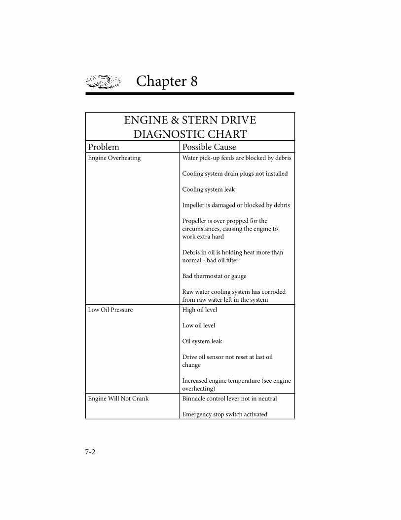
7-2
Chapter 8
ENGINE & STERN DRIVEDIAGNOSTIC CHART
Problem Possible CauseEngine Overheating Water pick-up feeds are blocked by debris
Cooling system drain plugs not installed
Cooling system leak
Impeller is damaged or blocked by debris
Propeller is over propped for the circumstances, causing the engine to work extra hard
Debris in oil is holding heat more than normal - bad oil ! lter
Bad thermostat or gauge
Raw water cooling system has corroded from raw water le" in the system
Low Oil Pressure High oil level
Low oil level
Oil system leak
Drive oil sensor not reset at last oil change
Increased engine temperature (see engine overheating)
Engine Will Not Crank Binnacle control lever not in neutral
Emergency stop switch activated
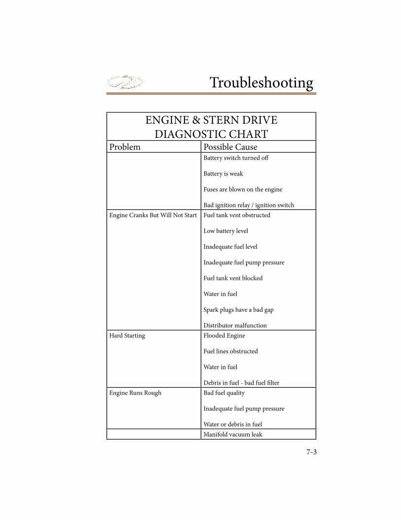
Troubleshooting
7-3
ENGINE & STERN DRIVEDIAGNOSTIC CHART
Problem Possible CauseBattery switch turned o!
Battery is weak
Fuses are blown on the engine
Bad ignition relay / ignition switch
Engine Cranks But Will Not Start Fuel tank vent obstructed
Low battery level
Inadequate fuel level
Inadequate fuel pump pressure
Fuel tank vent blocked
Water in fuel
Spark plugs have a bad gap
Distributor malfunction
Hard Starting Flooded Engine
Fuel lines obstructed
Water in fuel
Debris in fuel - bad fuel " lter
Engine Runs Rough Bad fuel quality
Inadequate fuel pump pressure
Water or debris in fuel
Manifold vacuum leak
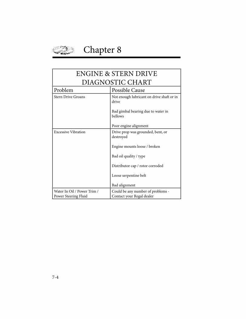
7-4
Chapter 8
ENGINE & STERN DRIVEDIAGNOSTIC CHART
Problem Possible CauseStern Drive Groans Not enough lubricant on drive sha! or in
drive
Bad gimbal bearing due to water in bellows
Poor engine alignment
Excessive Vibration Drive prop was grounded, bent, or destroyed
Engine mounts loose / broken
Bad oil quality / type
Distributor cap / rotor corroded
Loose serpentine belt
Bad alignment
Water In Oil / Power Trim / Power Steering Fluid
Could be any number of problems - Contact your Regal dealer

Troubleshooting
7-5
CONTROL SYSTEMDIAGNOSTIC CHART
Problem Possible CauseNo Reading On Gauge or Gauge Is Inaccurate
Faulty gauge
Faulty wiring to gauge
Faulty sender
Gauge Reads Erratic Loose ground or hot wire connection
Binnacle Control Lever Sti! / Inoperative / Stalls When Shi" ing
Shi" system bushings and seals broken
Kinked, broken, damaged cable
Friction brake is too tight and must be loosened
Control box jammed
Depth Gauge Inaccurate Blocked transducer sight hole
Bad gauge
Bad transducer
Stern Drive Trim Not Functioning
Bad motor in trim control unit
Faulty wiring
Water in bellows / power trim # uid
Steering System Not Functioning Uneven load
Poorly lubricated steering system
Lack of power steering # uid
Kinked, broken, damaged cable

7-6
Chapter 8
ELECTRICAL SYSTEMDIAGNOSTIC CHART
Problem Possible CauseNo 12 Volt Power At Battery Battery switch turned o!
Weak or dead battery
Battery cables disconnected from storage
Bad voltmeter or voltmeter connection
Battery Not Charging While Engine Is Running
Loose / damaged serpentine belt
Faulty alternator - check with volt meter
Faulty volt meter
Battery Will Not Hold Charge Faulty / old battery
12 Volt Equipment Not Working Fuse blown - investigate why the equipment was drawing too much current or why it had a circuit short. Check fuses in dash fuse box, underneath the dash, and in the engine compartment
Weak or dead battery if all 12v equipment fails to function
Corroded / loose wire connection
Internal equipment short / failure

Troubleshooting
7-7
BILGE & DRAINAGE SYSTEMDIAGNOSTIC CHART
Problem Possible CauseBilge Pump Not Functioning Automatically
Float switch jammed - check for debris
Automatic bilge pump fuse blown - investigate why the equipment was drawing too much current or why it had a circuit short
Battery connection corroded
Impeller is damaged or blocked by debris
Bad bilge pump motor
Bilge pump discharge hose blocked
Bilge Pump Not Functioning Manually
Battery switch turned o!
Bilge pump dashboard fuse blown - investigate why the equipment was drawing too much current or why it had a circuit short
Battery connection corroded
Bad bilge pump switch
Impeller is damaged or blocked by debris
Bad bilge pump motor
Bilge pump discharge hose blocked
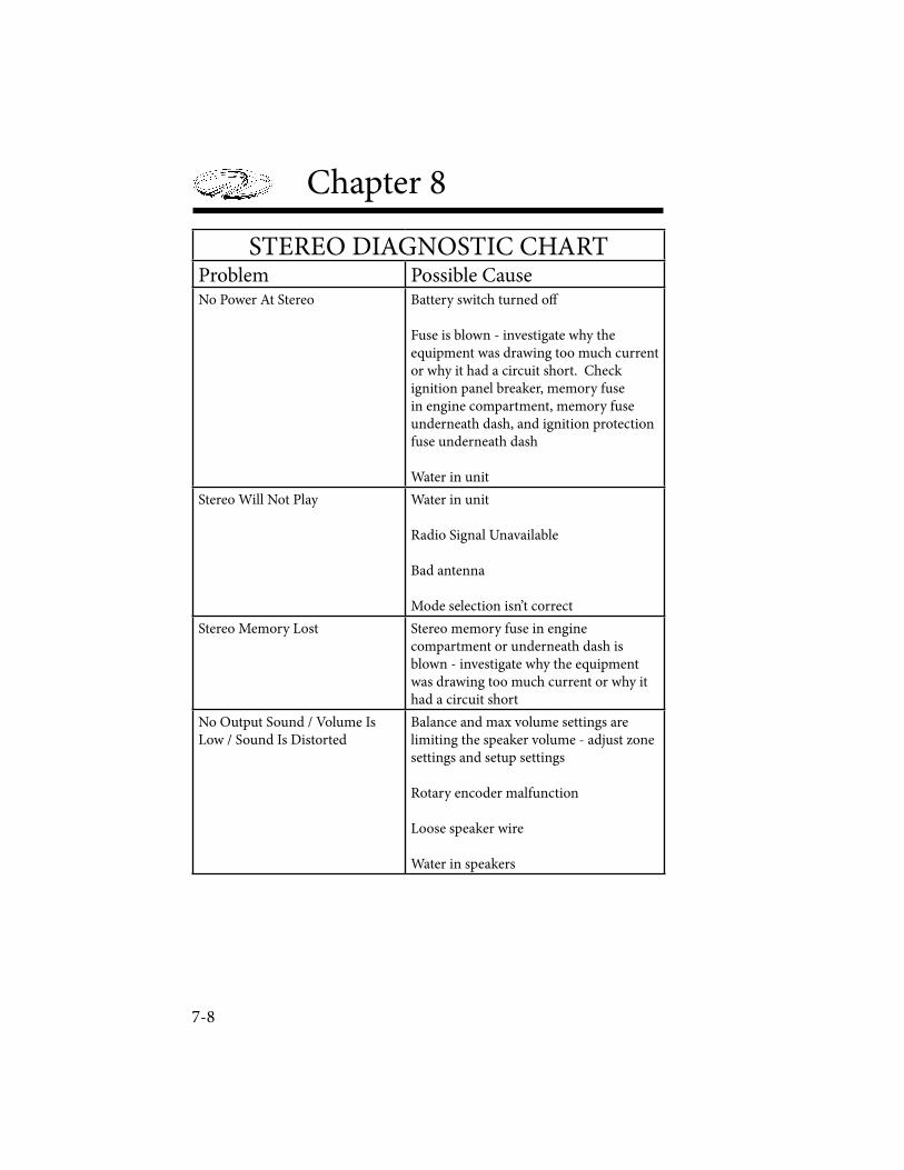
7-8
Chapter 8
STEREO DIAGNOSTIC CHARTProblem Possible CauseNo Power At Stereo Battery switch turned o!
Fuse is blown - investigate why the equipment was drawing too much current or why it had a circuit short. Check ignition panel breaker, memory fuse in engine compartment, memory fuse underneath dash, and ignition protection fuse underneath dash
Water in unit
Stereo Will Not Play Water in unit
Radio Signal Unavailable
Bad antenna
Mode selection isn’t correct
Stereo Memory Lost Stereo memory fuse in engine compartment or underneath dash is blown - investigate why the equipment was drawing too much current or why it had a circuit short
No Output Sound / Volume Is Low / Sound Is Distorted
Balance and max volume settings are limiting the speaker volume - adjust zone settings and setup settings
Rotary encoder malfunction
Loose speaker wire
Water in speakers

Troubleshooting
7-9
STEREO DIAGNOSTIC CHARTProblem Possible CauseAdded Performance Package Speakers Working Only
Ampli! er fuse blown - investigate why the equipment was drawing too much current or why it had a circuit short
Standard zone max volume settings are low
Loose speaker wire connections
Water in cockpit speakers
Standard Speakers Working Only Added speaker zone max volume settings are low
Loose speaker wire connection
Water in bow speakers
iPod Not Working iPod not plugged in properly using appropriate sleeves
iPod mode not selected
Internal iPod problem
LCD Screen Not Displaying Water in unit

7-10
Chapter 8
AUDIBLE ALARMS
It is important to read the engine owner’s manual to diagnose engine alarms and faults. Depending on the propulsion package installed, alarm sounds can vary.
On your Regal boat, your engine sounds an alarm in the case of one of the following causes:
• Low Oil Pressure
• Engine Overheating
To quickly diagnose these problems, look at the multi-gauge equipped on your vessel. Monitor the oil pressure gauge and temperature gauge, and troubleshoot accordingly. Be weary of faulty gauges however, and investigate the problem at the engine as necessary.

Storage & Winterization
9-1
Storage procedures are outlined in this chapter. ! ese are general guidelines to follow before longer periods of storage such as over the winter in colder climates. Be sure to familiarize yourself with all relevant information in the owner’s information packet. Special winterization procedures are necessary for the boat equipment and systems. Use the enclosed checklists to help you identify areas of concern and maintenance. ! ese lists cover land stored boats either inside or outside. Call a Regal dealer or marine professional for further information.
EXPLOSION, FIRE AND POLLUTION HAZARD!DO NOT FILL FUEL TANK TO RATED CAPACITY.
LEAVE ROOM FOR EXPANSION.USE A FUEL STABILIZER IN THE FUEL TANK.
REMOVE BATTERY(IES) WHEN VESSEL IS IN LONG PERIODS OF STORAGE.
TO PREVENT ENGINE DAMAGE!USE ONLY ETHYLENE GLYCOL BASE ANTIFREEZE.
DO NOT USE ALCOHOL BASE PRODUCTS.
Chapter 9
9-2
DECOMISSIONING CHECKLIST
ENGINE
1. Run engine. Pour a fuel stabilizer/conditioner in the fuel tank. Allow time for it to circulate through the fuel system.
2. Change all engine ! uids as referenced in the engine manufacturer’s owners manual. Contact a Regal dealer.
3. Drain cooling and exhaust system by a marine professional Pickle the engine. Contact a Regal dealer for more information.
4. Spray all exterior parts with Remove propeller. Refurbish as needed.
5. A" er cleaning touch up paint on stern drive/outboard as needed.
6. Apply coat of wax to stern drive/outboard drive hsg and shroud.
BOAT
1. Check hull bottom for any # berglass damage.
2. A" er cleaning apply a coat of wax to hull and deck surfaces.
3. Pour a pint of 50/50 antifreeze into bilge pump.
4. Never block up boat bottom. May cause structural damage.
5. Remove battery. Use a trickle charger as needed.
6. Remove all loose gear and electronics from boat. Inspect all equipment for wear and damage. Store in a clean, dry environment.

Storage & Winterization
9-3
7. Remove drain plug. Clean drain plug hole of debris as needed. Enclose drain plug in plastic bag and tie to steering wheel.
8. Regarding outside storage, make sure bow is higher than stern to permit proper drainage.
9. Clean all upholstery and store so it breathes.
10. Conduct a visual inspection to ensure boat is balanced properly on the trailer, cradle or blocks.
11. Wrap boat with appropriate cover. Tie down for protection from rain, snow and/or wind. Prop up cover to provide proper ventilation. Do not cover up the fuel vents.Drain the fresh water system per instructions in this chapter.
TRAILER
1. Repack all wheel bearings per manufacturer’s speci! cations.
2. Check all trailer parts for excessive wear. Replace/refurbish as needed.
3. Use touch up paint on trailer as needed.
4. Lubricate all moving parts as needed.
5. Check all lighting and brakes (if applicable).
Chapter 9
9-4
FRESH WATER SYSTEM (Models w/Transom Shower Wand)
1. Activate the fresh water pump switch.
2. Activate transom shower wand and allow tank to empty.
3. When tank is empty shut o! fresh water pump switch.
4. Mix nontoxic antifreeze with water in accordance with the manufacturer’s recommendations. (Available at marina & RV stores)
5. Pour solution into the fresh water tank.
6. Turn on fresh water pump switch.
7. Open transom shower wand (if equipped) and purge until a steady stream of nontoxic antifreeze " ows from the faucet. Turn the fresh water switch to the “o! ” position.
WASTE SYSTEM (If Equipped)
1. With chemical heads, make sure to dump both upper and lower tanks. 2. Rinse well with fresh water.
AVOID VESSEL AND ENGINE DAMAGE!CONTACT MARINE PROFESSIONAL FOR WINTERIZATION
INSTRUCTIONS AS DAMAGE ISNOT COVERED BY REGAL WARRANTY.
Storage & Winterization
9-5
RECOMISSIONING CHECKLIST
ENGINE/STERN DRIVE
Check all components per engine manufacturer’s owners manual especially ! uid levels. Check for fuel, exhaust, oil, and water leaks.Run engine at idle on “ear mu" s” (! ushette) before launching. Note that select outboards use a garden hose adapter system.
BOAT
Install drain plug.
Install battery and tighten all terminals.
Check all equipment, switches, alarms, gauges and breakers for proper operation.
Add necessary chemicals and water to chemical head (If Equipped).
Add water to fresh water tank. Turn on faucet to purge tank.
Re# ll water tank.
Make sure all safety gear is on board and in excellent working condition.
A$ er launching, check controls and gauges for proper operation.
TRAILER
Make sure all equipment is in excellent working condition.

CHAPTER 9
Notes

Trailering
10-1
is chapter covers trailering/towing basics including equipment, maintenance, and techniques of using a trailer. Check with state and local agencies for detailed information on required equipment, safety issues, and licensing before attempting to tow your vessel.
Before towing your boat, be sure to check the air pressure of your tires for the recommended in" ation speci# cation. Also, be certain that your tow vehicle is in good working order.Install any bimini top and sunshade in their respective boots before towing. Store cockpit carpet along with cockpit/bow covers. is can make it especially di$ cult to drive safely, as the hitch may be in danger of striking the road. Also, this situation can be caused by worn vehicle rear shock absorbers. One option is to install a set of air shocks which will assist in supporting the load. As a rule of thumb 5 to 7 percent of the total trailer load should be on the trailer tongue.Check all lights to ensure they all work properly. You may # nd it helpful at ask someone to check your turn signals, brake lights, and towing lights while you remain in the vehicle. Be certain that the trailer winch cable is securely attached to the boat’s bow eye and the cable lock is engaged. Make sure the bow of the boat is snug against the bow stop at the winch stand. It is a good idea to tie another line or secure an extra cable to the winch stand and boat bow eye as a backup system.Be certain that your trailer is of rated capacity for the size and weight of your boat, including the weight for all fuel, water and gear. Your authorized Regal dealer can advise you on the proper trailer capacity and tongue weight (weight exerted on the rear of your vehicle).Never use a bumper mounted trailer hitch. Always use a bolted or welded frame-mounted hitch, class 2 or 3.
Trailering
BEFORE TOWING
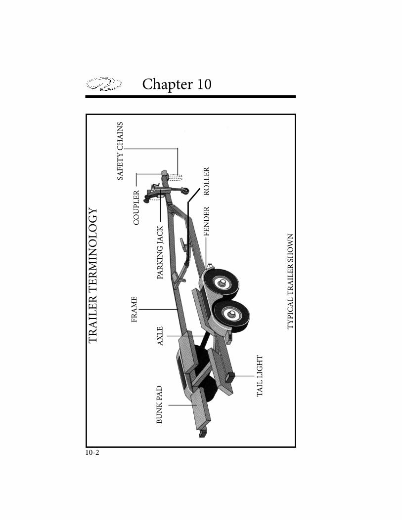
10-2
Chapter 10 T
RA
ILE
R T
ER
MIN
OL
OG
Y
TA
IL L
IGH
T
FE
ND
ER
SAF
ET
Y C
HA
INS
CO
UP
LE
R
PAR
KIN
G J
AC
KA
XL
EB
UN
K P
AD
FR
AM
E
RO
LL
ER
TY
PIC
AL
TR
AIL
ER
SH
OW
N
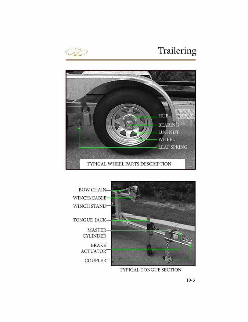
Trailering
10-3
TYPICAL TONGUE SECTION
TYPICAL WHEEL PARTS DESCRIPTION
LEAF SPRING
HUB
BEARING
LUG NUT
WHEEL
BOW CHAIN
WINCH/CABLE
WINCH STAND
TONGUE JACK
MASTERCYLINDER
BRAKE ACTUATOR
COUPLER
10-4
Chapter 10
Consult your Regal dealer for more information.Should your trailer be equipped with surge brakes, that is brakes on the trailer that cut in with a very slight delay when your brakes are applied, be sure to follow recommended service and maintenance instructions. Be sure that the trailer master cylinder is ! lled with the recommended " uid before towing your boat. Inspect the trailer brake lines for any leakage. Also, if you notice brake " uid on the inside of the tires, you may have a wheel cylinder leaking. Consult a professional.Never place your hands between the trailer hitch coupling and the hitch ball on your towing vehicle while hooking up. Be sure the tongue jack is in the full up position before departure. Be certain safety chains are crisscrossed and secured; do not allow them to drag on the road.Be sure to buy a suitable set of tie downs which can be attached to the boats’ stern eyes and the eyelets provided on most trailers. Tighten them securely and neatly fold up the extra strap material and secure it with tape so it doesn’t loosen and dangle on the road.Check the trailer lug nuts for the proper torque. Use a foot pound wrench and torque in a star sequence to the correct poundage as recommended by the trailer manufacturer. Torque the lug nuts at half the poundage on all nuts. # en set the torque wrench to the full poundage and fasten to the last foot poundage ! gure. Check the trailer tires o$ en for voids, excessive wear or out of round tire conditions. If the trailer seems to vibrate you may have a bad tire or one that is unbalanced. # ese wheels can be rebalanced at most automotive or tire shops. Never pull a boat on a patched tire. Buy a spare tire and wheel including a hub and wheel bearing assembly. Mount it on the trailer for speedy installation should a blow out occur. Check the trailer harness often for signs of fraying. Check the harness connector for corrosion. Make sure the trailer harness when connected to the trailer has enough slack for turning Check the wheel bearings for wear periodically by a professional. On most trailers, there is a zerk ! tting on the wheel hub to add the proper lubricant to the wheel bearing with a grease gun. # ese wheel bearing waterproof covers for the bearings can be purchased at retail outlets.

Trailering
10-5
SPARE PARTS CHECKLIST
Longer towing trips increase the need for special preparations. Sometimes these extended trips cover areas where it is di! cult in locating repair parts due to a breakdown. Following is a checklist of recommended items to add a safety net to your trip.
Trailer-
1. Trailer tire jack2. Spare hub assembly including wheel bearings3. Spare tire4. Lug wrench5. Jack stand6. 12 volt air compressor- found at automotive box stores7. Spare bearing protector 8. Extra tie-down straps9. Trailer light bulbs10. Brake pads and brake " uid11. Grease gun
Tow Vehicle-
1. Tool kit including necessary ratchet and sockets2. Jumper cables3. Extra fuses4. Engine oil5. Transmission " uid6. Wheel chocks7. Highway " ares8. 12 volt spotlight- type that plugs into 12 volt accessory outlet9. Flashlight & spare batteries10. Waterless hand cleaner and rags11. Electrical connectors and crimpers12. Low voltage electrical tester
10-6
Chapter 10
Be sure everything is secured in the boat and canvas is down in the towing position with the bimini stored in the boot. Tilt the stern drive up to clear the road and any bumps that might occur while in transit.
DRIVING
Practice maneuvering the vehicle and trailer in a large, empty parking lot or open space. If you practice slowly and cautiously, you will soon develop a feel for maneuvering the trailer . Test your vehicle and trailer brakes before departure along with the lights. Pack a tool kit with extra bulbs, fuses and ! uids.Drive as smoothly as possible, anticipating your stops and giving yourself plenty of room for turning and stopping. Avoid any quick turns or sudden jerks of the steering wheel.Remember to maintain safe speed limits. It takes longer to stop your loaded boat. Allow enough room to the front in bad weather. Keep an eye on your rig through the rear view and side mirrors. If your rear view mirror is obstructed, purchase a set of side mirrors that extend out over the side of the vehicle for increased visibility. In addition, it is a good idea to install a set of round mirrors to the side mirrors as they help identify blind spots.Plan to stop periodically on your way to check the trailer hitch for tightness, harness connector, tires and wheel bearings. Also, check to make sure the load is balanced.
Trailering
10-7
LAUNCHING
Serious accidents can occur at the launching ramp. ! erefore, it is imperative you be alert and attentive during launching and docking activities. Study the ramp area and surrounding water for any potential hazards, such as a short ramp or one with a drop o" at the end. If you are uncertain of the conditions, ask someone else who has just used the ramp if there are any peculiarities to the area. Install the drain plug. Attach 2 lines, one each at the bow and stern, to control your boat once it is o" the trailer. If you need additional fenders to keep the sides of the boat from banging against the ramp walls, use those as well.Unhook the stern tie-downs and the winch line to the bow. Unplug the trailer harness connector so the hot trailer light bulbs won’t blow out when they come in contact with water. When backing in, have someone assist, giving the palms up stop signal when the boat is in deep enough water to # oat o" , or when the rear wheels of your vehicle approach the water’s edge.A$ er your boat is # oating freely, position it clear of the trailer before pulling out of the water. If there is no one to help you, secure one of the lines you’ve attached from the boat to the dock and use the other line to pull the boat o" trailer. ! e process is easier with 2 people.
AVOID LOSING VEHICLE TRACTION!DO NOT ALLOW REAR WHEELS TO ENCOUNTER
SAND OR SLIPPERY CONCRETE CONDITIONS.
AVOID BODILY INJURY!RAMPS ARE VERY SLIPPERY.
DO NOT ATTEMPT TO WALK OR STAND ON AN ANGLED BOAT RAMP.
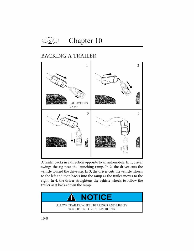
10-8
Chapter 10
BACKING A TRAILER
A trailer backs in a direction opposite to an automobile. In 1, driver swings the rig near the launching ramp. In 2, the driver cuts the vehicle toward the driveway. In 3, the driver cuts the vehicle wheels to the le! and then backs into the ramp as the trailer moves to the right. In 4, the driver straightens the vehicle wheels to follow the trailer as it backs down the ramp.
1 2
3 4
LAUNCHINGRAMP
ALLOW TRAILER WHEEL BEARINGS AND LIGHTS TO COOL BEFORE SUBMERGING
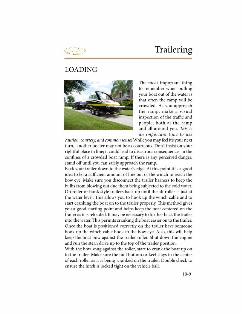
Trailering
10-9
LOADING
The most important thing to remember when pulling your boat out of the water is that o! en the ramp will be crowded. As you approach the ramp, make a visual inspection of the tra" c and people, both at the ramp and all around you. � is is an important time to use
caution, courtesy, and common sense! While you may feel it’s your next turn, another boater may not be as courteous. Don’t insist on your rightful place in line; it could lead to disastrous consequences in the con# nes of a crowded boat ramp. If there is any perceived danger, stand o$ until you can safely approach the ramp.Back your trailer down to the water’s edge. At this point it is a good idea to let a su" cient amount of line out of the winch to reach the bow eye. Make sure you disconnect the trailer harness to keep the bulbs from blowing out due them being subjected to the cold water. On roller or bunk style trailers back up until the a! roller is just at the water level. % is allows you to hook up the winch cable and to start cranking the boat on to the trailer properly. % is method gives you a good starting point and helps keep the boat centered on the trailer as it is reloaded. It may be necessary to further back the trailer into the water. % is permits cranking the boat easier on to the trailer.Once the boat is positioned correctly on the trailer have someone hook up the winch cable hook to the bow eye. Also, this will help keep the boat bow against the trailer roller. Shut down the engine and run the stern drive up to the top of the trailer position.With the bow snug against the roller, start to crank the boat up on to the trailer. Make sure the hull bottom or keel stays in the center of each roller as it is being cranked on the trailer. Double check to ensure the hitch is locked tight on the vehicle ball.
10-10
Chapter 10
Make sure the boat is covered properly and all loose gear is stowed.On bunk style trailers, watch the bunks to make sure the boat is centered as they usually do not touch any rollers other than the a! one because the boat weight is being supported more by the bunks as it is cranked onto the trailer. Stop cranking the winch when the boat bow contacts the bow roller. Be sure the winch is in the locked position. Stand back and visually check to see that the boat is centered on the trailer.A! er pulling your boat away from the ramp, be sure to go through all the checks involved before departure. Reinstall the harness connector and check the lights, brakes, safety chain, winch, hitch, and tie downs. Remove the drain plug to exit any excess water in the bilge. Reinstall the hull drain plug and tighten it. For longer storage periods remove the drain plug and keep in a plastic bag tied to the steering wheel.
AVOID PERSONAL INJURY!DO NOT LET ANYONE STAND NEAR THE WINCH OR CABLE AS THE
CABLE UNDER LOAD COULD BREAK.
HULL BOTTOM DAMAGE COULD RESULT FROM THE BOAT NOT BEING POSITIONED
ON THE ROLLERS BUT RESTING ON THE TRAILER FRAME. AVOID BACKING TRAILER
TOO FAR INTO THE WATER!

Glossary & Index
11-1
Below is a brief list of nautical terminology. For more detailed glossaries we recommend you check your local library, book retailer, marine store or internet.
GLOSSARY
Abeam: at right angles to the fore and a! line and o" the boat
Aboard: on or in the boat
Above: the part of the boat on a vessel which is above the interior of the boat
A! , A! er:: a! is the boat section toward the stern or back of the boat Amidships: toward the center of the boat from either side to side or rear to front Beam: the width of a boat at its widest part Bilge: the lower interior of the hull of the boat Bitter end: the end of a line also the end of an anchor line
Bow: the front, or forward part of the boat
Bulkhead: the vertical partition or wall of a boat
Chapter 11
11-2
Cast o! : to let go or release
Chine: the line fore and a" formed by the intersection of the side and bottom of the boat
Chock: deck # tting used to secure or guide anchor or tie lines
Cleat: deck # tting with protruding arms around which lines are secured
Cockpit: the seating space used to accommodate passengers
Cuddy: a small cabin in the fore part of the boat
Deck: the open $ ooring surface on which crew and passengers walk
Dra" : the depth from the waterline of the boat to the lowest part of the boat, which indicates how much water is required to $ oat the boat
FasTrac- a proven hull bottom design which incorporates a full, mid-beam step that reduces drag by forcing air under the hull to decrease drag and friction.
Fathom: a measurement of depth; one fathom equals six feet
Fender: a cushion hung from the side of a boat to prevent it from rubbing against a dock or against other boats
Fend o! : to push o! to avoid sharp contact with dock or other vessel
Fore: the part of the boat toward the bow or front
Freeboard: the height of the top side from the waterline to the deck at its shortest point (% e distance from sheer or gunwale to the water).

Glossary & Index
11-3
Gunwale: rail or upper edge of the side of the boat
Head: toilet
Hull: the part of the hull from the deck down
Keel: the lowest point of a boat; the backbone of the vessel
Knots: a measurement of speed indicating nautical miles per hour
Lee: the side opposite that from which the wind is blowing: the side sheltered from the wind
Leeward: the direction toward which the wind is blowing
PFD: personal ! otation device; required for each person aboard
Port: the le" side of the boat when facing forward (an easy way to remember the di# erence between “port” and “starboard” is that both “port” and “le" ” have four letters)
Shank: the main body of an anchor
Sheer: the curve of the boat’s deck from fore to a" when seen from the side
Starboard: the right side of the boat when facing forward
Stern: the a" end of the boat
Stern drive: an inboard/outboard (I/O) unit
Stringer: strengthening integral unit fastened from fore to a" inside the hull and $ berglass encapsulated for added strength: much like the skeleton system of our body

Chapter 11
11-4
Top o! : to " ll up a tank
Transom: the vertical part of the stern
Trim: the boat’s balance when properly loaded
Wake: the path of a boat le# astern in the water
Windward: the direction from which the wind blows; opposite of leeward

Glossary & Index
11-5
AAccessories 208Accidents 53 Accident Reporting 54Aids To Navigation 72Anchor Light 42Anchoring 200Audible Alarms 302Automatic Fire Extinguisher 38
BBattery 261 294Battery Switch 166 210 225 295 Bilge/Drainage 158 299Bilge Pump 159 211 265 299Bimini Top 168 213 309Blower 30 95 212 Boating Under ! e In" uence 51Bottom Blocking 304Bow Cover 213Bow Filler Cushion 218Bow Walk ! rough Doors 219Bridge Clearance 76Bucket Seat 235Buoys & Markers 74
INDEXCCanvas 213 257Capacity Plate 18 Carbon Monoxide 47 Cardiopulmonary Resuscitation 205Cockpit Carpet 220Cockpit Cover 213Circuit Breakers 267Controls 111
136
DDealer Responsibilities 19Decommissioning 304Depth Sounder 102 225 295Diagnostic Charts 293Direct Current (DC) 160Distress Signals 41Diver’s Flag 55Docking 190Dock Lines 187Drain Plug 227
EEPIRB 146Electrical 160Emergencies 204Engine-Basics 117 179 Environmental Awareness 207 Exhaust 47

Chapter 11
11-6
IIgnition Panel 109Ignition Switch 110 Index 323Interrupt Switch 112
KKnots 203
LLadder 33Lighting 164 224 Life Ra! 46Load Capacity 18 Law of Salvage 202Launch & Cruise Checklist 16Lubrication-Engine 93 127 281 286Lubrication-Drive 98 128 285
MManeuvering 192Maintenance Guides 275Maintaining PFD’S 35Masthead Light 42 45Matts 221Metal (Cleaning) 254Minimum Required Equipment 45
FFenders 186Fiberglass 248Filters 232Fire Extinguishers 36Fire Port 157First Aid 207Fishing 61Float Plan 15Fueling 178Fuel System- Engine 88 123Fuel System Warning 2 266Fuses 164
GGalvanic Corrosion 270Garbage Placard 44Gauges (Instrumentation) 101 131Gelcoat Maintenance 248 General Boating Safety 29 Getting Underway 176 Glossary 320
HHelm Controls 108 147 HIN 12Horn 108 164Hour Meter 104Hull Bottom 254Hypothermia 206

Glossary & Index
11-7
NNavigational Aids 72Navigation Lights 41 161Navigation Rules 60Neutral Safety Switch 111New Boat Delivery Sheet 21Night Running 75
OOil Spills 43Overloading 18Owner’s Information Packet 12Owner’s Registration 19 Owner Responsibilities 20
PPersonal Flotation Devices 33 Plastics 247Pollution Regulations 43PowerTower 228Power Trim 195Precautionary Safety Labels 27Pre-departure Questionnaire 176Pressure Water System 231Propellers 100 130Pyrotechnic Devices 28
RRadio Communication 41 Recommissioning 307Registration Information 19Right-Of-Way 68Rules Of ! e Road 67
SSafety Labels 27Safety Inspection 29Seating 235 264Shallow Water Operation 198 Shi" ing-Remote Control 112 137 182Signals-Navigation 69 Signals-Skiing 60Skiing Precautions 56Ski Tow 57 238Speci# cations TechSound Producing Devices 41Speedometer 103Sport Tower 240Spring Line 187Starting & Stopping 181Stern Line 187Steering 115 184 284Stereo 175 242 268 301Stereo Performance Package 242 Stereo Remote 243Stern Drive Basics 96Storage/Travel Cover 216Swim Platform 58 234

Chapter 11
11-8
VVentilation 49 95Visual Distress Signals 38Volvo Engine Alarm 85
WWake 61Wake Sports 55 Warning Labels 27Warranty 22Weather 12Windshield-Center Latch 219Winterizing 303 Wiring Color Codes 161
ZZinc Anodes 274
TTachometer 104Table 222 Technical 327 Temperature Gauge 103 Towing 201 Trailering 309Trailer Switch 245Transducer 166Transom Door 244Transom Remote 245Travel Cover 216Trim Angle 195Trim Gauge 105Troubleshooting 293
UUpholstery 246

Technical Information
12-1
! e following technical information and drawings can be an aid in troubleshooting electrical and mechanical problems along with the charts located in the troubleshooting chapter.
Note that all product specifications, models, standard and optional equipment, systems, along
with the technical information is subject to change without notice.
For more information contact your nearest authorized Regal dealer. For the location of your nearest authorized dealer call 407-851-4360. or visit the web-site at www.RegalBoats.com.
Your Regal dealer has received special factory training on the entire product line and his services should be employed to solve technical problems.
NOTICE

12-2
FUEL FILL HOSE
ANTI-SIPHONVALVE
FUEL FEEDHOSE
FUEL VENTHOSE
FUEL/ VENT DECK FILL
BLOWER
TYPICAL DOMESTICCOMPLIANT FUEL SYSTEM
(2000 ES/ESX SHOWN)
FUEL TANK
ENGINE
CARBON CANISTER
FUEL SENDER
NOTE: 21 OBX USES SIMILAR FUEL SYSTEM MINUS BILGEBLOWER.

Technical Information
12-3
2000 ES/ESX SPECIFICATIONSLENGTH OVERALL USA
20’’2”CE
6.15 M
CENTERLINE LENGTH
20’2” 6.15 M
BEAM 8’ 6” 2.5 M
DEADRISE 20 DEGREES
APPROXIMATE DRY WEIGHT W/ BASE ENGINE 3400 LBS. 1542.0 KG
APPROXIMATE OVER-ALL HEIGHT TO TOP OF WINDSHIELD ON TRAILER
6’ 5” 1.96 M
APPROXIMATE BRIDGE CLEARANCE-TOWER UP 6’ 3”
1.9 M
APPROXIMATE BRIDGE CLEARANCE-TOWER DOWN
4’ 4” 1.3 M
COCKPIT DEPTH-HELM
30” 0.79 M
APPROXIMATE DRAFT- TRIM DRIVE UP/DOWN
20”-31” .50-.79 M
FUEL CAPACITY 40 GALS EST. 151 L
PERSONS CAPACITY 10 8
MAXIMUM CAPACITY; PERSONS & GEAR 1350 LBS. N/A
MAXIMUM LOAD RECOMMENDED; PER-SONS & GEAR
N/A 762.0 KG* RCD II
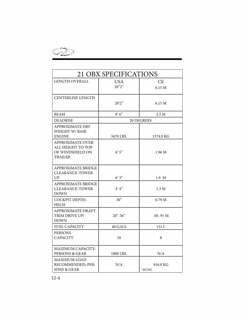
12-4
21 OBX SPECIFICATIONSLENGTH OVERALL USA
20’’2”CE
6.15 M
CENTERLINE LENGTH
20’2” 6.15 M
BEAM 8’ 6” 2.5 M
DEADRISE 20 DEGREES
APPROXIMATE DRY WEIGHT W/ BASE ENGINE 3470 LBS. 1574.0 KG
APPROXIMATE OVER-ALL HEIGHT TO TOP OF WINDSHIELD ON TRAILER
6’ 5” 1.96 M
APPROXIMATE BRIDGE CLEARANCE-TOWER UP 6’ 3”
1.9 M
APPROXIMATE BRIDGE CLEARANCE-TOWER DOWN
4’ 4” 1.3 M
COCKPIT DEPTH-HELM
30” 0.79 M
APPROXIMATE DRAFT- TRIM DRIVE UP/DOWN
20”-36” .50-.91 M
FUEL CAPACITY 40 GALS 151 L
PERSONS CAPACITY 10 8
MAXIMUM CAPACITY; PERSONS & GEAR 1800 LBS. N/A
MAXIMUM LOAD RECOMMENDED; PER-SONS & GEAR
N/A 916.0 KG* RCDII
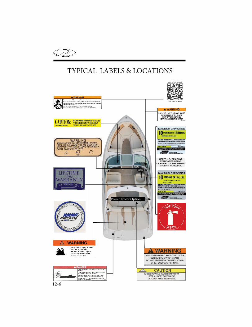
12-6
TYPICAL LABELS & LOCATIONS
Power Tower Option
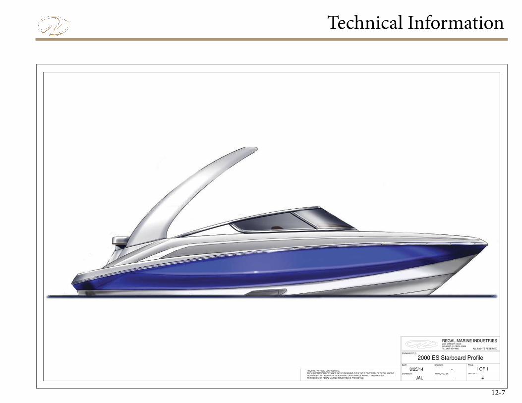
Technical Information
12-7
2000 ES Starboard Profile
8/25/14
JAL
-PROPRIETARY AND CONFIDENTIAL:THE INFORMATION CONTAINED IN THIS DRAWING IS THE SOLE PROPERTY OF REGAL MARINE INDUSTRIES. ANY REPRODUCTION IN PART OR AS WHOLE WITHOUT THE WRITTENPERMISSION OF REGAL MARINE INDUSTRIES IS PROHIBITED. -
1 OF 1REVISION:
2300 JETPORT DRIVEORLANDO, FLORIDA 32809TEL (407) 851-4360
DRAWN BY:
REGAL MARINE INDUSTRIES
PAGE:
ALL RIGHTS RESERVED
DRAWING TITLE:
APPROVED BY: DWG. NO.:
DATE:
4
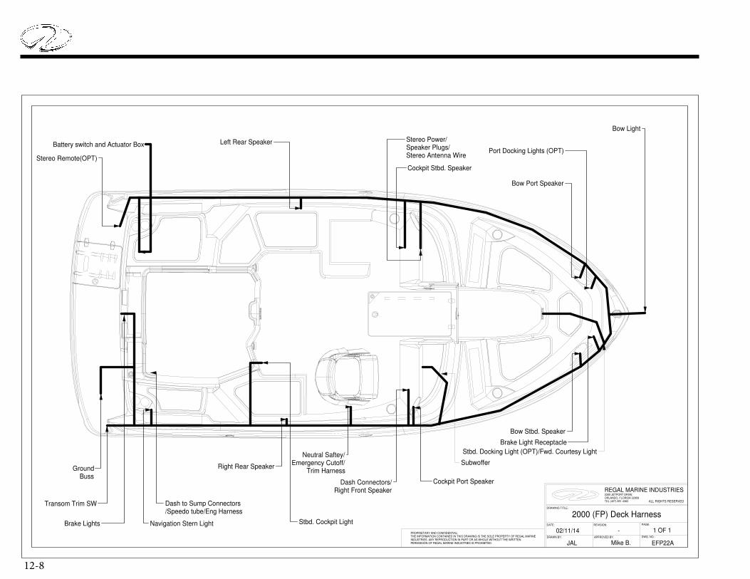
12-8
Battery switch and Actuator Box
2000 (FP) Deck Harness
DWG. NO.:
ALL RIGHTS RESERVED
DRAWING TITLE:
2300 JETPORT DRIVEORLANDO, FLORIDA 32809TEL (407) 851-4360
DRAWN BY:
Mike B.
PAGE:
02/11/14DATE:
1 OF 1REVISION:
-
JAL EFP22A
PROPRIETARY AND CONFIDENTIAL:THE INFORMATION CONTAINED IN THIS DRAWING IS THE SOLE PROPERTY OF REGAL MARINE INDUSTRIES. ANY REPRODUCTION IN PART OR AS WHOLE WITHOUT THE WRITTENPERMISSION OF REGAL MARINE INDUSTRIES IS PROHIBITED.
REGAL MARINE INDUSTRIES
APPROVED BY:
Dash to Sump Connectors/Speedo tube/Eng Harness
Navigation Stern LightBrake Lights
Ground Buss
Stereo Power/Speaker Plugs/Stereo Antenna Wire
Left Rear Speaker
Transom Trim SW
Right Rear Speaker
Stbd. Cockpit Light
Port Docking Lights (OPT)
Neutral Saftey/Emergency Cutoff/
Trim Harness
Stbd. Docking Light (OPT)/Fwd. Courtesy Light
Bow Port Speaker
Bow Stbd. Speaker
Subwoffer
Cockpit Stbd. Speaker
Stereo Remote(OPT)
Cockpit Port Speaker
Brake Light Receptacle
Bow Light
Dash Connectors/ Right Front Speaker

Technical Information
12-9
TRAILER CONNECTOR PLUG INSERTS
INTO BOAT BOW RECEPTACLE
1
2 3
4
16 GAUGE GREEN
16 GAUGE YELLOW
16 GAUGE BROWN
16 GAUGE WHITE
TRAILER HARNESS
16 GAUGE BLACK
16 GAUGE GREEN
16 GAUGE YELLOW/BLACK
TRAILER
CONNECTOR
PLUG
BOAT BOW
RECEPTACLETYPICAL TRAILER PLUG
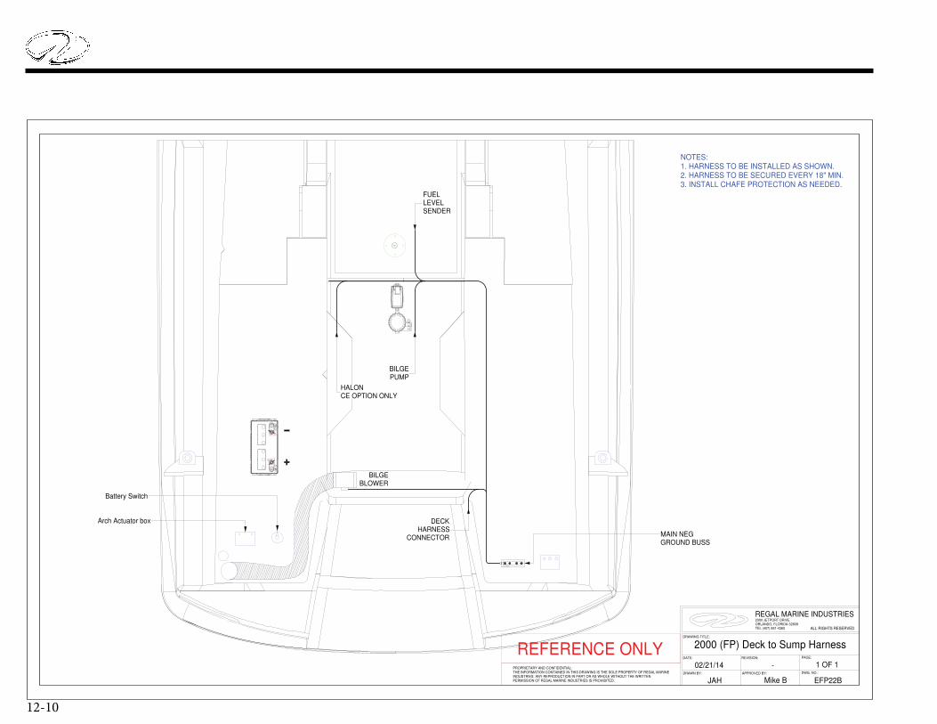
12-10
REFERENCE ONLY
NOTES:1. HARNESS TO BE INSTALLED AS SHOWN.2. HARNESS TO BE SECURED EVERY 18" MIN.3. INSTALL CHAFE PROTECTION AS NEEDED.
REVISION:DATE:
DRAWN BY: DWG. NO.:
02/21/14
Mike B
-
ALL RIGHTS RESERVED
2300 JETPORT DRIVEORLANDO, FLORIDA 32809TEL (407) 851-4360
REGAL MARINE INDUSTRIES
1 OF 1PROPRIETARY AND CONFIDENTIAL:THE INFORMATION CONTAINED IN THIS DRAWING IS THE SOLE PROPERTY OF REGAL MARINE INDUSTRIES. ANY REPRODUCTION IN PART OR AS WHOLE WITHOUT THE WRITTENPERMISSION OF REGAL MARINE INDUSTRIES IS PROHIBITED.
PAGE:
APPROVED BY:
DRAWING TITLE:
EFP22B
2000 (FP) Deck to Sump Harness
JAH
BILGEPUMP
FUELLEVELSENDER
HALONCE OPTION ONLY
DECKHARNESS
CONNECTOR
BILGEBLOWER
Battery Switch
Arch Actuator box
MAIN NEGGROUND BUSS
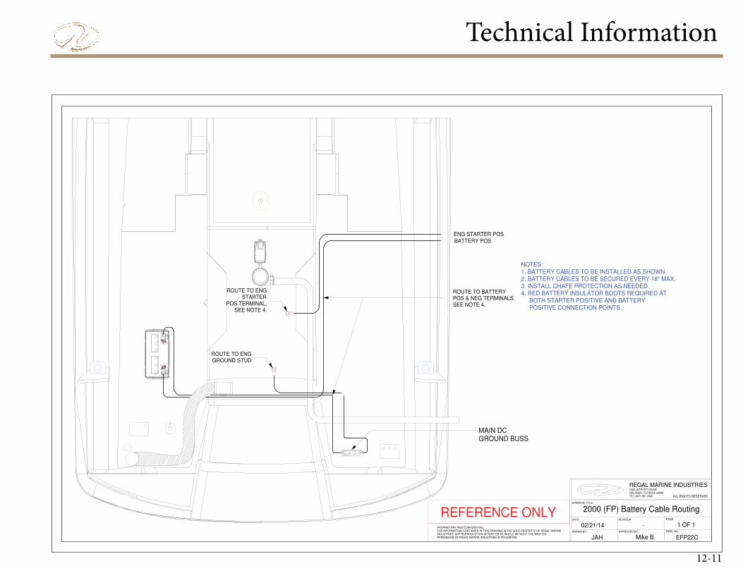
Technical Information
12-11
REFERENCE ONLY
NOTES:1. BATTERY CABLES TO BE INSTALLED AS SHOWN.2. BATTERY CABLES TO BE SECURED EVERY 18" MAX.3. INSTALL CHAFE PROTECTION AS NEEDED.4. RED BATTERY INSULATOR BOOTS REQUIRED AT BOTH STARTER POSITIVE AND BATTERY POSITIVE CONNECTION POINTS.
REVISION:
ALL RIGHTS RESERVED
DWG. NO.:
PROPRIETARY AND CONFIDENTIAL:THE INFORMATION CONTAINED IN THIS DRAWING IS THE SOLE PROPERTY OF REGAL MARINE INDUSTRIES. ANY REPRODUCTION IN PART OR AS WHOLE WITHOUT THE WRITTENPERMISSION OF REGAL MARINE INDUSTRIES IS PROHIBITED.
2300 JETPORT DRIVEORLANDO, FLORIDA 32809TEL (407) 851-4360
REGAL MARINE INDUSTRIES
Mike B.JAH EFP22CAPPROVED BY:
-PAGE:
2000 (FP) Battery Cable RoutingDATE:
02/21/14
DRAWING TITLE:
1 OF 1DRAWN BY:
ROUTE TO ENGGROUND STUD
ROUTE TO ENGSTARTER
POS TERMINAL.SEE NOTE 4.
ENG STARTER POS
BATTERY POS
ROUTE TO BATTERYPOS & NEG TERMINALS.SEE NOTE 4.
MAIN DCGROUND BUSS
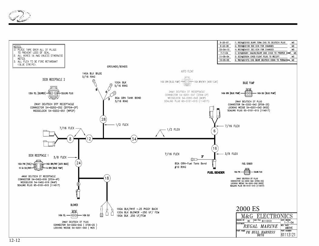
12-12
2000 ES

Technical Information
12-13
2000 ES Persons Capacity
8/25/14
JAH
-PROPRIETARY AND CONFIDENTIAL:THE INFORMATION CONTAINED IN THIS DRAWING IS THE SOLE PROPERTY OF REGAL MARINE INDUSTRIES. ANY REPRODUCTION IN PART OR AS WHOLE WITHOUT THE WRITTENPERMISSION OF REGAL MARINE INDUSTRIES IS PROHIBITED. -
1 OF 1REVISION:
2300 JETPORT DRIVEORLANDO, FLORIDA 32809TEL (407) 851-4360
DRAWN BY:
REGAL MARINE INDUSTRIES
PAGE:
ALL RIGHTS RESERVED
DRAWING TITLE:
APPROVED BY: DWG. NO.:
DATE:
2
15.5"W X 29.5"L Allowance Per Person
CE Persons Capacity: 8 Persons

12-14
REFERENCE ONLY
NOTES:1) Dimensions given are for reference, use splashes/fixtures to locate hardware.
STERN EYE
BRONZE DRAIN PLUG
7
1
2
5
FUEL VENT
BOW SCUFF PLATE SS
1
3
DRAIN
ELECTRIC HORN
1
6
QTY.
1
1
DESCRIPTION
DOCKING LIGHTS (Optional)
1
BILL OF MATERIALS
8
ITEM
14
1
CHROME PLATE NYLON THRU HULL
2
DRAWN BY:
PROPRIETARY AND CONFIDENTIAL:THE INFORMATION CONTAINED IN THIS DRAWING IS THE SOLE PROPERTY OF REGAL MARINE INDUSTRIES. ANY REPRODUCTION IN PART OR AS WHOLE WITHOUT THE WRITTENPERMISSION OF REGAL MARINE INDUSTRIES IS PROHIBITED.
REVISION:
ALL RIGHTS RESERVED
DWG. NO.:
REGAL MARINE INDUSTRIES
PAGE:DATE:
2300 JETPORT DRIVEORLANDO, FLORIDA 32809TEL (407) 851-4360
-
2000 (FP) Hull Hardware
1 OF 102/25/14APPROVED BY:
MFP24BJAH Mike B.
DRAWING TITLE:
TRANSOM VIEW
STARBOARD VIEW
(27")
(52")
(15 1/4")
(15 1/4")
Ø7/8"
Ø1 3/8"
(12 1/4")
(2")Ø1 1/8" (Centered)
(12")
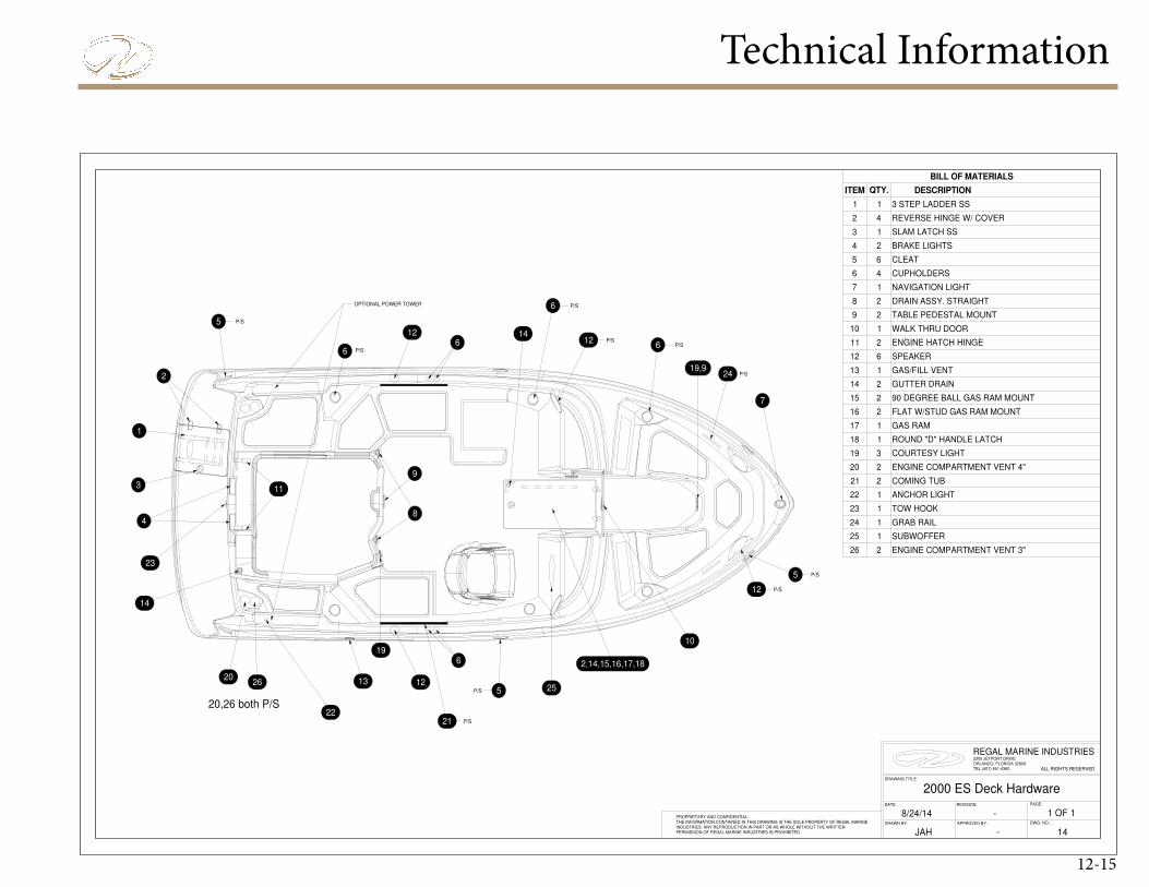
Technical Information
12-15
2000 ES Deck Hardware
-
GRAB RAIL
TOW HOOK
ANCHOR LIGHT
1
1
2 COMING TUB
1
1 SUBWOFFER
21
COURTESY LIGHT
P/S
23
OPTIONAL POWER TOWER
P/S
P/S
P/S
P/S
P/S
P/S
20
19
4
1
ROUND "D" HANDLE LATCH118
GAS RAM
FLAT W/STUD GAS RAM MOUNT
90 DEGREE BALL GAS RAM MOUNT
17
16
15
2
2
GUTTER DRAIN214
GAS/FILL VENT113
SPEAKER12
ENGINE HATCH HINGE2
WALK THRU DOOR
TABLE PEDESTAL MOUNT
2 DRAIN ASSY. STRAIGHT
NAVIGATION LIGHT
CUPHOLDERS
6 CLEAT
2 BRAKE LIGHTS
11
10
9
8
7
6
5
4
3 SLAM LATCH SS
42 REVERSE HINGE W/ COVER
1
1
1
3 STEP LADDER SS
JAH
-PROPRIETARY AND CONFIDENTIAL:THE INFORMATION CONTAINED IN THIS DRAWING IS THE SOLE PROPERTY OF REGAL MARINE INDUSTRIES. ANY REPRODUCTION IN PART OR AS WHOLE WITHOUT THE WRITTENPERMISSION OF REGAL MARINE INDUSTRIES IS PROHIBITED.
1 OF 1REVISION:
2300 JETPORT DRIVEORLANDO, FLORIDA 32809TEL (407) 851-4360
DRAWN BY:
REGAL MARINE INDUSTRIES
PAGE:
ALL RIGHTS RESERVED
DRAWING TITLE:
APPROVED BY: DWG. NO.:
DATE:
DESCRIPTIONITEM QTY.
11
BILL OF MATERIALS
22
P/S
24
25
P/S
26 2
ENGINE COMPARTMENT VENT 4"
ENGINE COMPARTMENT VENT 3"
20,26 both P/S
2
3
2
14
8/24/14
6
P/S
9
23
24
25
2122
5
7
5
11
8
1320
14
3
1
4
2
5
14
6
126
12
6
10
12
6
612
2,14,15,16,17,18
26
19
19,9
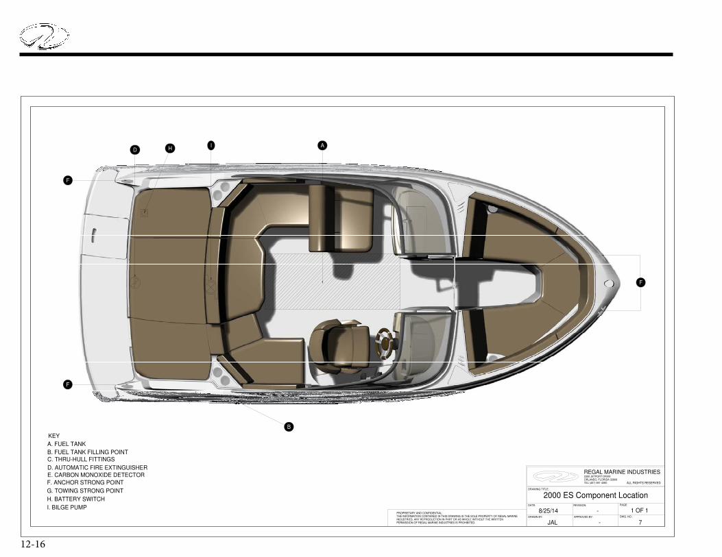
12-16
2000 ES Component Location
8/25/14
JAL
-PROPRIETARY AND CONFIDENTIAL:THE INFORMATION CONTAINED IN THIS DRAWING IS THE SOLE PROPERTY OF REGAL MARINE INDUSTRIES. ANY REPRODUCTION IN PART OR AS WHOLE WITHOUT THE WRITTENPERMISSION OF REGAL MARINE INDUSTRIES IS PROHIBITED. -
1 OF 1REVISION:
2300 JETPORT DRIVEORLANDO, FLORIDA 32809TEL (407) 851-4360
DRAWN BY:
REGAL MARINE INDUSTRIES
PAGE:
ALL RIGHTS RESERVED
DRAWING TITLE:
APPROVED BY: DWG. NO.:
DATE:
7
F
F
F
HDA
B
I
KEY
A. FUEL TANK
B. FUEL TANK FILLING POINTC. THRU-HULL FITTINGS
F. ANCHOR STRONG POINT
H. BATTERY SWITCH
I. BILGE PUMP
E. CARBON MONOXIDE DETECTOR
D. AUTOMATIC FIRE EXTINGUISHER
G. TOWING STRONG POINT
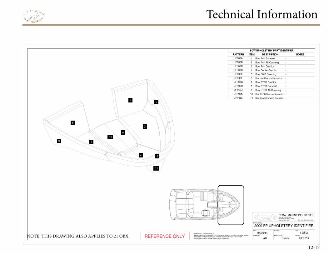
Technical Information
12-17
REFERENCE ONLY
UFP06L
UFP06J
Bow STBD filler cushion option
BOW UPHOLSTERY PART IDENTIFIER
UFP06G
-11
-
Bow STBD Aft Coaming
Bow STBD Backrest
UFP06K
Bow FWD CoamingUFP06E
Bow Center CushionUFP06D
Bow Port CushionUFP06C
Bow Port Aft CoamingUFP06B
Bow Port BackrestUFP06A 1 -
Bow Lower Forward Coaming
10
NOTESDESCRIPTIONPATTERN ITEM
Bow port filler cushion option
-
-
-
-
-
-
-
-
2
3
4
5
6
7
8
9
UFP06H
Bow STBD Cushion
UFP06F
JAH
1 OF 2-01/30/14
UFP25X
2000 FP UPHOLSTERY IDENTIFIER
PROPRIETARY AND CONFIDENTIAL:THE INFORMATION CONTAINED IN THIS DRAWING IS THE SOLE PROPERTY OF REGAL MARINE INDUSTRIES. ANY REPRODUCTION IN PART OR AS WHOLE WITHOUT THE WRITTENPERMISSION OF REGAL MARINE INDUSTRIES IS PROHIBITED.
REVISION:
2300 JETPORT DRIVEORLANDO, FLORIDA 32809TEL (407) 851-4360
DRAWN BY:
REGAL MARINE INDUSTRIES
PAGE:
ALL RIGHTS RESERVED
DRAWING TITLE:
APPROVED BY: DWG. NO.:
DATE:
Rick N.NOTE: THIS DRAWING ALSO APPLIES TO 21 OBX
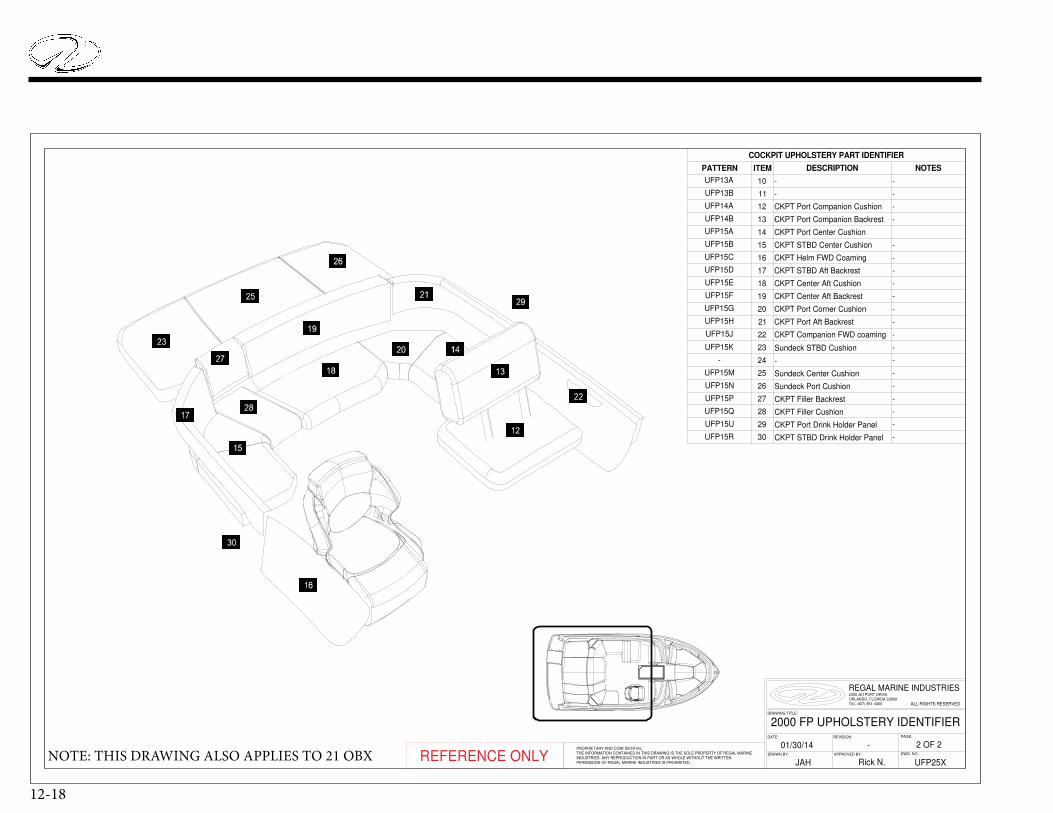
12-18
REFERENCE ONLY
22
-
27
23
-
-
-
-
28
24
UFP15K
CKPT Port Drink Holder Panel
-
-
NOTES
-
-
-
-
COCKPIT UPHOLSTERY PART IDENTIFIER
Sundeck STBD Cushion
UFP15Q
UFP15P
25
CKPT Companion FWD coamingUFP15J
CKPT Port Aft BackrestUFP15H
UFP15G
29
DESCRIPTION
-
-
UFP13A
CKPT Port Corner Cushion
-
CKPT Port Companion Cushion
-
-
CKPT Port Center Cushion
-
Sundeck Center Cushion
CKPT STBD Aft BackrestUFP15D
CKPT Helm FWD CoamingUFP15C
CKPT STBD Center CushionUFP15B
26
UFP15R
UFP15U
CKPT Center Aft Backrest
-
UFP15F
CKPT Center Aft Cushion
CKPT STBD Drink Holder Panel
UFP15E
UFP15A
-
UFP13B
14
13
-
UFP14A
CKPT Filler Cushion
30
-
UFP14B
CKPT Filler Backrest
CKPT Port Companion Backrest
-
PATTERN ITEM
Sundeck Port CushionUFP15N
-
-
UFP15M
-
10
11
12
15
16
17
18
19
20
21
2000 FP UPHOLSTERY IDENTIFIER
UFP25X
DATE:
DWG. NO.:APPROVED BY:
DRAWING TITLE:
ALL RIGHTS RESERVED
PAGE:
REGAL MARINE INDUSTRIES
DRAWN BY:
2300 JETPORT DRIVEORLANDO, FLORIDA 32809TEL (407) 851-4360
REVISION:
PROPRIETARY AND CONFIDENTIAL:THE INFORMATION CONTAINED IN THIS DRAWING IS THE SOLE PROPERTY OF REGAL MARINE INDUSTRIES. ANY REPRODUCTION IN PART OR AS WHOLE WITHOUT THE WRITTENPERMISSION OF REGAL MARINE INDUSTRIES IS PROHIBITED. JAH
2 OF 2-01/30/14
Rick N.NOTE: THIS DRAWING ALSO APPLIES TO 21 OBX
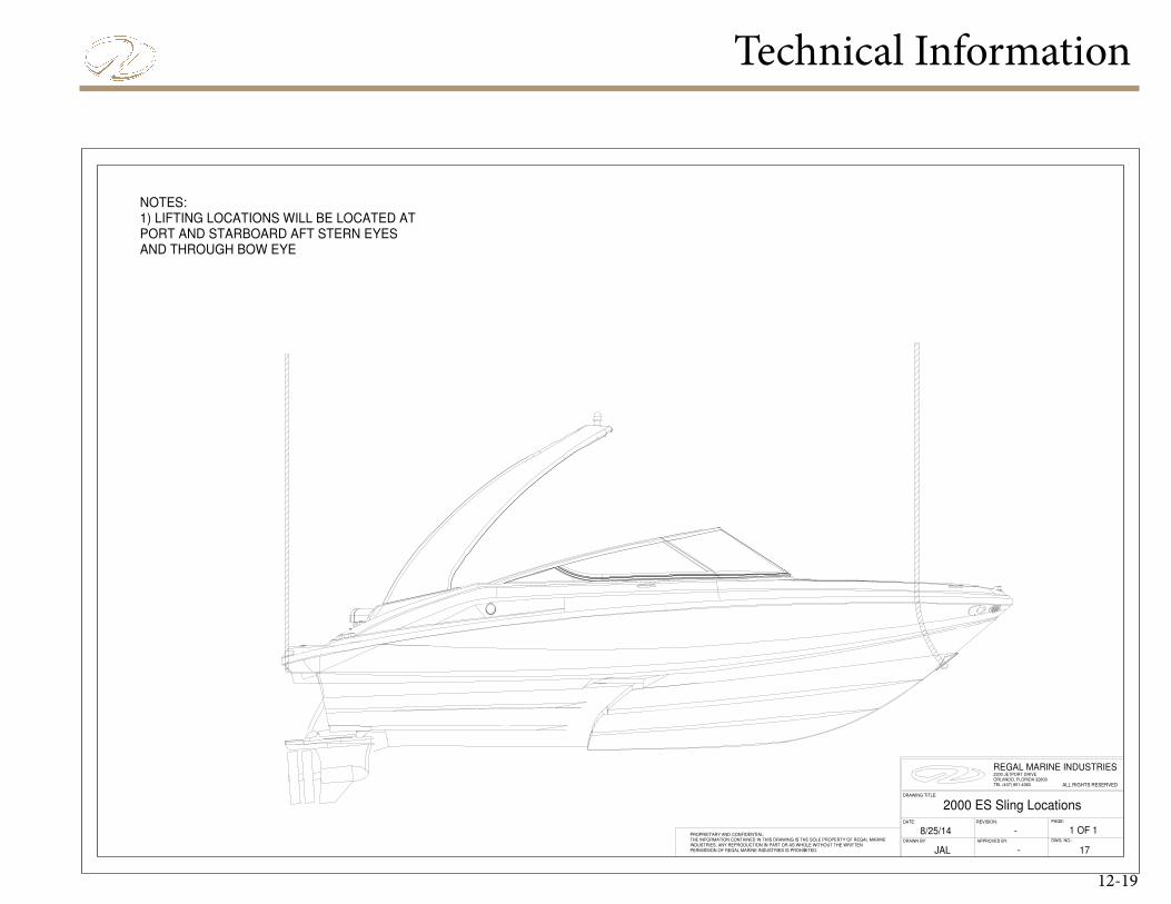
Technical Information
12-19
2000 ES Sling Locations
8/25/14DATE:
DWG. NO.:APPROVED BY:
DRAWING TITLE:
ALL RIGHTS RESERVED
PAGE:
REGAL MARINE INDUSTRIES
DRAWN BY:
2300 JETPORT DRIVEORLANDO, FLORIDA 32809TEL (407) 851-4360
REVISION:
1 OF 1
-
PROPRIETARY AND CONFIDENTIAL:THE INFORMATION CONTAINED IN THIS DRAWING IS THE SOLE PROPERTY OF REGAL MARINE INDUSTRIES. ANY REPRODUCTION IN PART OR AS WHOLE WITHOUT THE WRITTENPERMISSION OF REGAL MARINE INDUSTRIES IS PROHIBITED.
-
JAL 17
NOTES:1) LIFTING LOCATIONS WILL BE LOCATED ATPORT AND STARBOARD AFT STERN EYESAND THROUGH BOW EYE
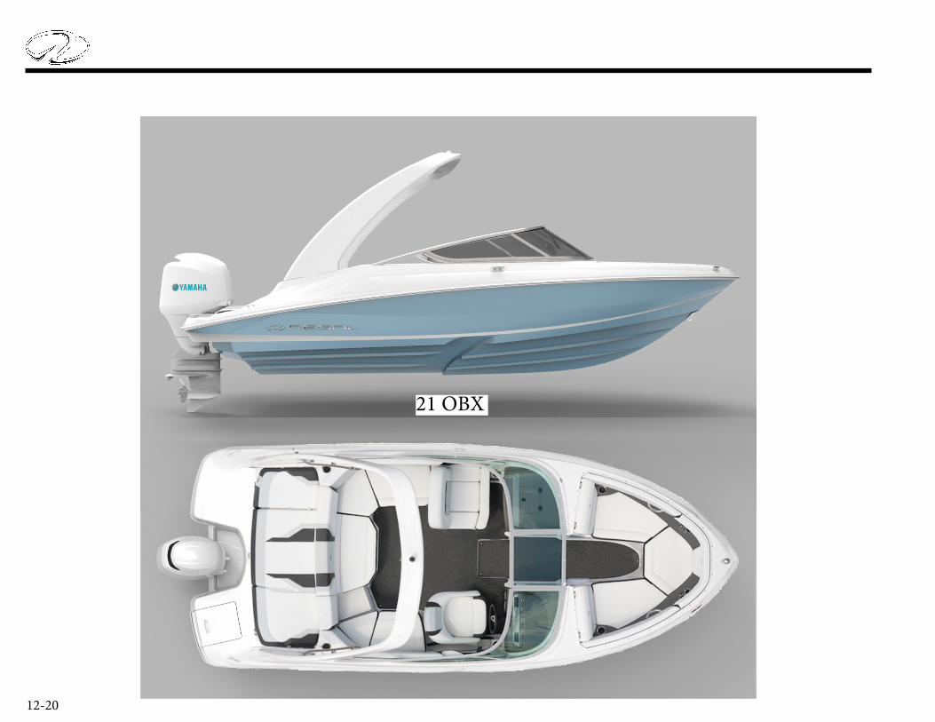
12-20
21 OBX
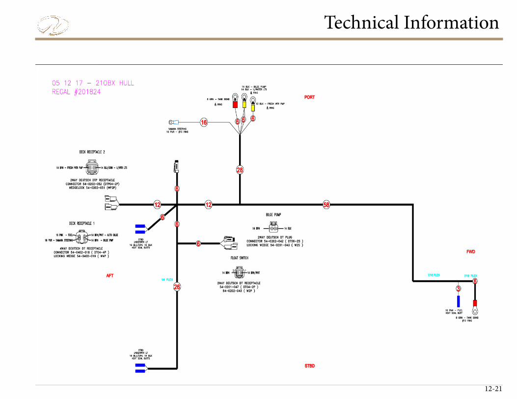
Technical Information
12-21
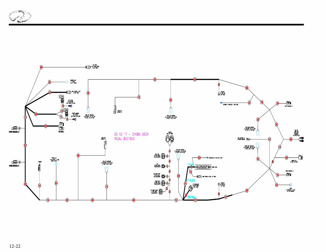
12-22

Technical Information
12-23
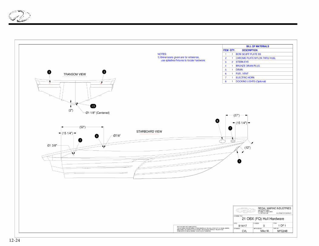
12-24
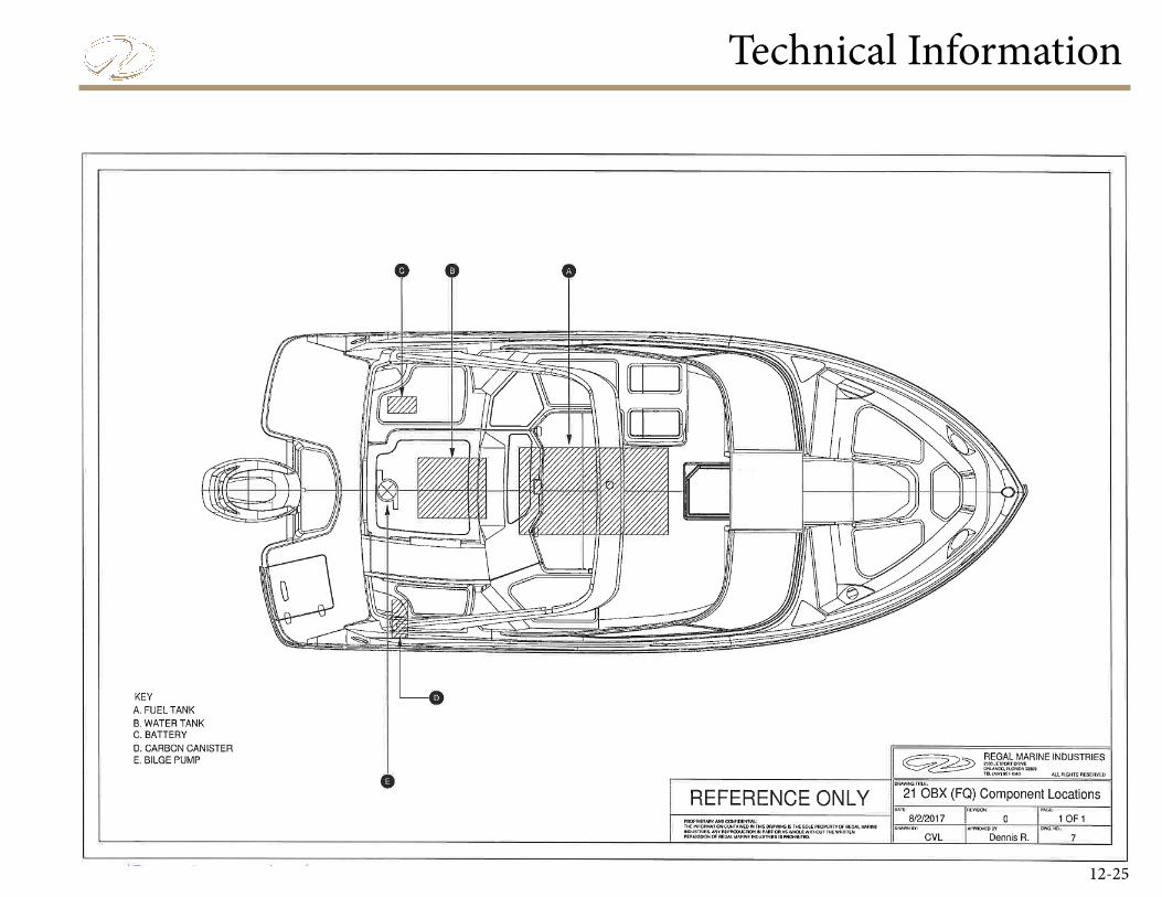
Technical Information
12-25
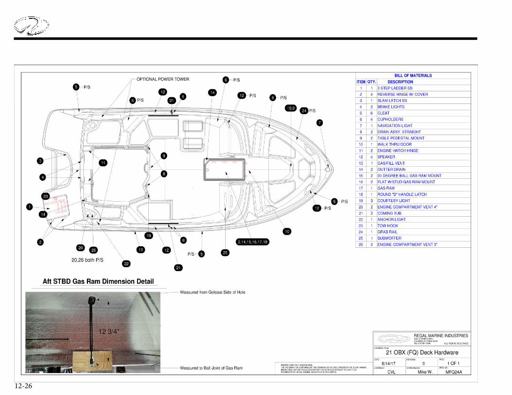
12-26
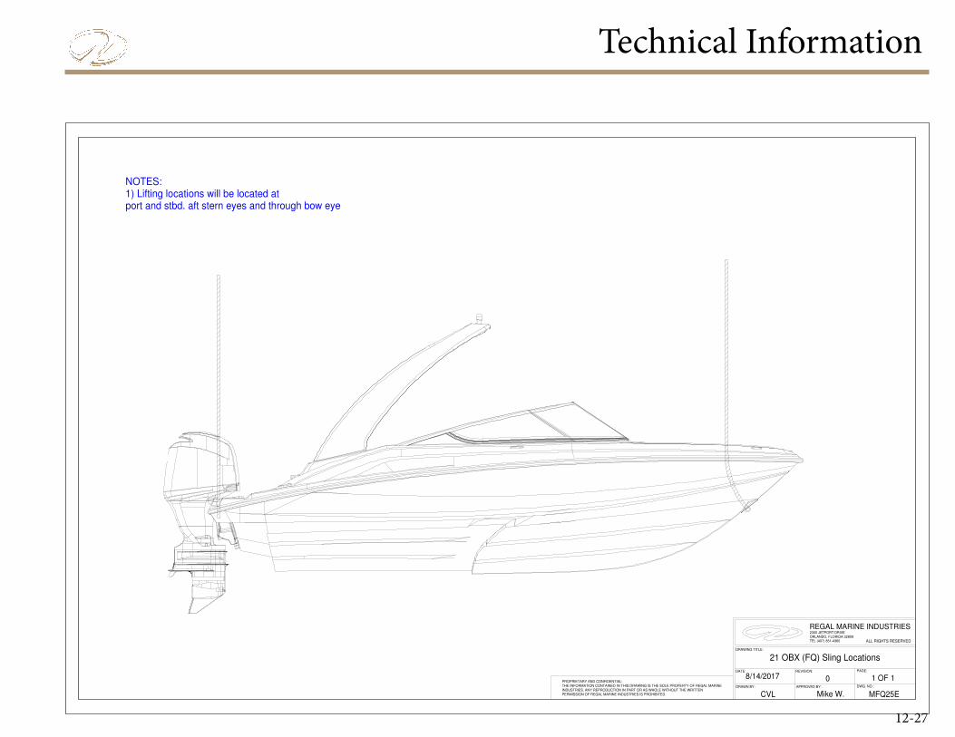
Technical Information
12-27
NOTES:1) Lifting locations will be located at port and stbd. aft stern eyes and through bow eye
APPROVED BY: DWG. NO.:
ALL RIGHTS RESERVED
DRAWING TITLE:
PROPRIETARY AND CONFIDENTIAL:THE INFORMATION CONTAINED IN THIS DRAWING IS THE SOLE PROPERTY OF REGAL MARINE INDUSTRIES. ANY REPRODUCTION IN PART OR AS WHOLE WITHOUT THE WRITTENPERMISSION OF REGAL MARINE INDUSTRIES IS PROHIBITED.
DRAWN BY:
PAGE:
8/14/2017
MFQ25E
REGAL MARINE INDUSTRIES
CVL
21 OBX (FQ) Sling Locations
2300 JETPORT DRIVEORLANDO, FLORIDA 32809TEL (407) 851-4360
REVISION:DATE:
Mike W.
0 1 OF 1