origin of undesirable cracks during layer transfer
TRANSCRIPT
Origin of undesirable cracks during layer
transfer
L. Ponsona) , K. Diest, H.A. Atwater,G. Ravichandran and K. Bhattacharya
Division of Engineering and Applied Science, California Institute of Technology,
Pasadena, CA 91125, USA
a) Electronic mail: [email protected]
28th October 2008
Abstract
We investigate the origin of undesirable transverse cracks oftenobserved in thin films obtained by the layer transfer technique. Dur-ing this process, two crystals bonded to each other containing a weakplan produced by ion implantation are heated to let a thin layer ofone of the material on the other. The level of stress imposed on thefilm during the heating phase due to the mismatch of thermal ex-pansion coefficients of the substrate and the film is shown to be therelevant parameter of the problem. In particular, it is shown thatif the film is submitted to a tensile stress, the microcracks producedby ion implantation are not stable and deviate from their straighttrajectory making the layer transfer process impossible. However, ifthe compressive stress exceeds a threshold value, after layer transfer,the film can buckle and delaminate, leading to transverse cracks in-duced by bending. As a result, we show that the imposed stress σm
– or equivalently the heating temperature – must be within the range−σc < σm < 0 to produce an intact thin film where σc depends onthe interfacial fracture energy and the size of defects at the interfacebetween film and substrate.
1
hal-0
0334
784,
ver
sion
1 -
28 O
ct 2
008
1 Introduction
Various applications in electronics and optics require the synthesis of highquality, defect-free single crystals on a substrate of a different material. Di-verse heteroepitaxial growth processes have been proposed (e.g. [1]), butthese methods impose severe restrictions on the film/substrate combinations.Recently, the layer transfer process has been proposed and shows promise asan alternative when the film/substrate pair is very different [2, 3]. The layertransfer is accomplished by implanting hydrogen or helium ions into a bulkcrystal of the film to be synthesized and then bonding it to a substrate. Act-ing as damage precursors, these ions induce nucleation and growth of cavitieswhen the specimen is heated at a sufficiently high temperature, transferringonto the substrate a single crystal thin film whose thickness correspondsto the depth of ion implantation. However, for some systems and somegiven heating conditions, undesirable transverse cracks are also produced inthe thin film during the splitting process. This phenomenon renders thetransferred thin film useless for applications in microelectronics and others.Therefore, understanding the origin of such cracks is crucial to avoid theirformation. Identifying quantitatively the conditions and the systems thatare advantageous to nucleate these undesirable cracks will help to definethe limitations of the layer transfer process, and to design possible solutionsto overcome these limitations. This motivates the present analysis and themechanism of formation of these undesirable cracks is the central point ofthis study.
In Section 2, the geometry used during the layer transfer process as wellas the state of stress in the film are described. Then, a first possible origin ofthin film failure is investigated in Section 3: the stability of cracks nucleatingfrom defects introduced by ion implantation in the material to be cut is ana-lyzed and we show that these cracks propagate parallel to the film/substrateinterface only for a compressive state of stress in the film. In Section 4,we show that a compressive stress in thin film can also lead to cracking bybuckling, delamination and then failure of the film. This analysis providesa range for the compressive stress and therefore limitations of the heatingtemperature for a given system with fixed film thickness that will lead to acontinuous thin film. In the following section, these theoretical predictionsare combined with experimental observations made on a lithium niobate filmbonded to a silicon substrate. The two failure mechanisms proposed previ-ously to explain the presence of transverse cracks are clearly identified by
2
hal-0
0334
784,
ver
sion
1 -
28 O
ct 2
008
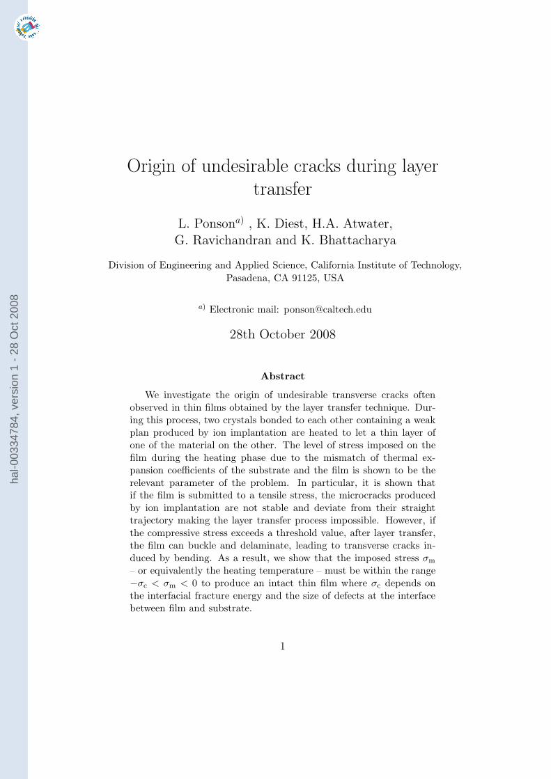
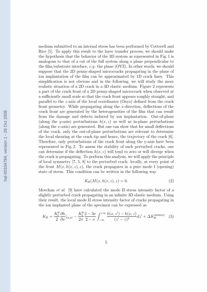
Figure 1: Geometry and stress field of the layered system. The dashed planecoincides with the plane of ion implantation.
a post-bonding analysis of the specimen after layer transfer. The theoreti-cal criterion for good layer transfer (−σc < σm < 0) is found to agree withexperimental observations.
2 Geometry of the system and stress state of
the film
To perform layer transfer, the material to be cut is bonded on a substrateas shown in Fig. 1. A bonding layer, observed to improve adhesion and avoidundesirable cracking for some systems, is also shown. Its influence on thewhole system is limited to the interface properties between film and substrate(fracture energy and defect size) so that this interlayer can be neglected in thefollowing analysis without loss of generality. Such a layered system is thensubmitted to an elevated temperature ∆T and microcracks can nucleate inthe plane of the film where hydrogen or helium has been previously implanted(dashed plane in Fig. 1). When these microcracks coalesce, the bulk singlecrystal is separated from the transferred thin film with thickness h.
3
hal-0
0334
784,
ver
sion
1 -
28 O
ct 2
008
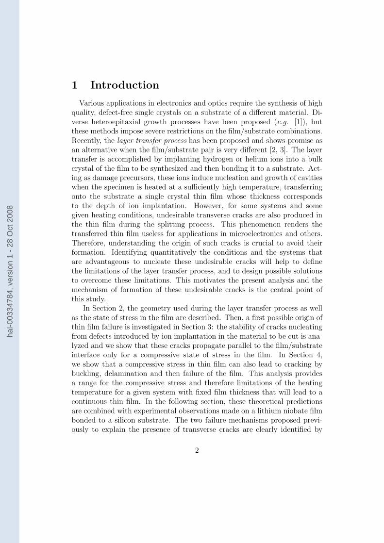
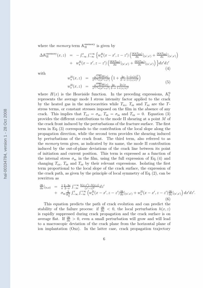
Figure 2: Geometry of a slightly perturbed crack propagating in the filmobserved at sufficiently small scale so that the crack front appears on averageto be straight.
During the heating phase of the process, the film is submitted to anhomogeneous bi-axial stress σm caused by the mismatch in thermal expansionbetween the film and the substrate. Noting ∆α = αs − αf, the differencebetween the linear thermal expansion coefficients of the substrate and thefilm, one can show that irrespective of the thickness and thermal propertiesof the bonding layer, the stress in the film is given by [4]
σm =E
1 − ν∆T∆α (1)
where E and ν are the Young’s modulus and the Poisson’s ratio of the film,respectively. In the following sections, we will see that to ensure transferof a thin film without undesirable transverse cracks, the stress imposed onthe film must be within a certain range of values to be determined in thefollowing sections.
3 Stability of microcracks in the film
Let’s focus first on the trajectory of microcracks that initiate from thedefects induced by the presence of hydrogen and helium in the specimen.To result in layer transfer, these microcracks are expected to propagate in arelatively straight manner, i.e. parallel to the interface between the film andthe substrate. The stability analysis of a 1D crack propagating in a 2D elastic
4
hal-0
0334
784,
ver
sion
1 -
28 O
ct 2
008
medium submitted to an internal stress has been performed by Cotterell andRice [5]. To apply this result to the layer transfer process, we should makethe hypothesis that the behavior of the 3D system as represented in Fig. 1 isanalogous to that of a cut of the full system along a plane perpendicular tothe film/substrate interface, e.g. the plane (OYZ). In other words, we shouldsuppose that the 2D penny-shaped microcracks propagating in the plane ofion implantation of the film can be approximated by 1D crack lines. Thissimplification is not obvious and in the following, we will study the morerealistic situation of a 2D crack in a 3D elastic medium. Figure 2 representsa part of the crack front of a 2D penny-shaped microcrack when observed ata sufficiently small scale so that the crack front appears roughly straight, andparallel to the z-axis of the local coordinates (Oxyz) defined from the crackfront geometry. While propagating along the x-direction, deflections of thecrack front are generated by the heterogeneities of the film that can resultfrom the damage and defects induced by ion implantation. Out-of-plane(along the y-axis) perturbations h(x, z) as well as in-plane perturbations(along the x-axis) are generated. But one can show that for small deflectionsof the crack, only the out-of-plane perturbations are relevant to determinethe local shearing at the crack tip and hence, the trajectory of the crack [6].Therefore, only perturbations of the crack front along the y-axis have beenrepresented in Fig. 2. To assess the stability of such perturbed cracks, onecan determine if the deflection h(x, z) will tend to zero or will diverge whenthe crack is propagating. To perform this analysis, we will apply the principleof local symmetry [7, 5, 8] to the perturbed crack: locally, at every point ofthe front M(x, h(x, z), z), the crack propagates in a pure mode I (opening)state of stress. This condition can be written in the following way
KII(M(x, h(x, z), z) = 0. (2)
Movchan et al. [9] have calculated the mode II stress intensity factor of aslightly perturbed crack propagating in an infinite 3D elastic medium. Usingtheir result, the local mode II stress intensity factor of cracks propagating inthe ion implanted plane of the specimen can be expressed as
KII =K0
I
2
∂h
∂x|(x,z) −
K0I
2π
2 − 3ν
2 − ν
∫ +∞
−∞
h(x, z′) − h(x, z)
(z′ − z)2dz′ + ∆K
memoryII (3)
5
hal-0
0334
784,
ver
sion
1 -
28 O
ct 2
008
where the memory term KmemoryII is given by
∆KmemoryII (x, z) = − ∫ x
−∞
∫+∞−∞
{
wIIx (x − x′, z − z′)
(
∂(hTxx)∂x
|(x’,z’) + ∂(hTxz)∂z
|(x’,z’)
)
+ wIIz (x − x′, z − z′)
(
∂(hTxz)∂x
|(x’,z’) + ∂(hTzz)∂z
|(x’,z’)
) }
dx′dz′
(4)with
wIIx (x, z) =
√−2xH(x)
π3/2∗(x2+z2)
(
1 + 2ν2−ν
1−(z/x)2
1+(z/x)2
)
wIIz (x, z) =
√−2xH(x)
π3/2∗(x2+z2)2ν
2−ν2z/x
1+(z/x)2
(5)
where H(x) is the Heaviside function. In the preceding expressions, K0I
represents the average mode I stress intensity factor applied to the crackby the heated gas in the microcavities while Txx, Tzz and Txz are the T -stress terms, or constant stresses imposed on the film in the absence of anycrack. This implies that Txx = σm, Tzz = σm and Txz = 0. Equation (3)provides the different contributions to the mode II shearing at a point M ofthe crack front induced by the perturbations of the fracture surface. The firstterm in Eq. (3) corresponds to the contribution of the local slope along thepropagation direction, while the second term provides the shearing inducedby perturbations of the crack front. The third term, also referred to asthe memory term gives, as indicated by its name, the mode II contributioninduced by the out-of-plane deviations of the crack line between its pointof initiation and current position. This term is expressed as a function ofthe internal stress σm in the film, using the full expression of Eq. (4) andchanging Txx, Tzz and Txz by their relevant expressions. Isolating the firstterm proportional to the local slope of the crack surface, the expression ofthe crack path, as given by the principle of local symmetry of Eq. (2), can berewritten as
∂h∂x|(x,z) = 1
π2−3ν2−ν
∫+∞−∞
h(x,z′)−h(x,z)(z′−z)2
dz′
+ σm2
K0
I
∫ x−∞
∫+∞−∞
(
wIIx (x − x′, z − z′)∂h
∂x|(x’,z’) + wII
z (x − x′, z − z′)∂h∂z|(x’,z’)
)
dx′dz′.
(6)This equation predicts the path of crack evolution and can predict the
stability of the failure process: if ∂h∂x
< 0, the local perturbation h(x, z)is rapidly suppressed during crack propagation and the crack surface is onaverage flat. If ∂h
∂x> 0, even a small perturbation will grow and will lead
to a macroscopic deviation of the crack plane from the horizontal plane ofion implantation (Oxz). In the latter case, crack propagation trajectory
6
hal-0
0334
784,
ver
sion
1 -
28 O
ct 2
008
is referred to as unstable. This situation will clearly lead to catastrophictransverse cracks in the thin film during the layer transfer process.
Next, we assess the relevance of each term of the right-hand side of Eq. (6)that determines the stability of microcracks in the film during the heatingprocess. The first term acts as a non-local restoring force along the crackfront that tries to maintain it perfectly planar. However, it does not preventthe crack from deviating away from the mean crack plane [10], and therefore,does not contribute directly to the stability of the crack. The second termis composed of a part proportional to ∂h
∂xand another proportional to ∂h
∂z.To
assess the relative importance of each term, one can compare their two pref-actors, wII
x and wIIz , respectively. According to Eq. (5), wII
z is smaller than
wIIx [11], and for most values of (z, x), one gets wII
xwII
z≪ 1. In other words,
the stability of the crack is mainly dictated by the term proportional to ∂h∂x
,leading to the approximation
∂h
∂x|(x,z) ≃ σm
2
K0I
∫ x
−∞
∫ +∞
−∞wII
x (x − x′, z − z′)∂h
∂x|(x’,z’)dx′dz′. (7)
From this equation, one can assess the evolution of the local slope of thecrack surface. From Eq. (5), one notes that wII
x > 0. Therefore, the sign ofσm will determine the evolution of the solution of Eq. (7). If σm > 0, then|∂h∂x| is expected to increase when the crack propagates, while with σm < 0,
∂h∂x
will tend to zero after a characteristic distance [12].From the analysis of the stability of a crack propagating during the heat-
ing phase of the layer transfer process, one gets finally:
(i) If the thin film is in a state of tensile stress (σm > 0), then the micro-cracks nucleated from the damage induced by ion implantation duringthe heating phase will deviate from their straight trajectory. One cantherefore expect some difficulties obtaining good splitting of the upperpart of the sample and some transverse cracks within the transferredthin film from systematic deviations of these microcracks.
(ii) If the film is in a state of compressive stress (σm < 0), then the micro-cracks are expected to propagate along a straight trajectory in a planeparallel to that of the ion implantation and will result in the transfer ofan crack-free, single crystal thin film. This compressive stress state isobtained if the thermal expansion coefficient of the film if larger thanthat of the substrate (see Eq. (1)).
7
hal-0
0334
784,
ver
sion
1 -
28 O
ct 2
008
As a result, the condition σm < 0 is necessary to obtain straight crackpropagation and therefore an intact thin film. Let us note that this resultis not limited to multilayer systems and can be extended to other systemswhere the crack trajectory needs to be analyzed: a 2D crack will remainconfined to a plane perpendicular to the external tensile loading if the stressis in tension along all the directions of this plane while it will deviate fromthe straight trajectory if the stress is compressive along the mean plane ofthe crack. This result extends the analysis of Cotterell and Rice [5] limitedto 2D systems to the more realistic situation of 3D systems. In the followingsection, we will investigate another possible origin of film cracking and showthat there is a limit to the amount of compressive stress the film can support,and an excessively high compressive stress in the film can also lead to poorquality transferred thin films.
4 Buckling, delamination and failure of the
film
Here, another possible mechanism for film cracking during layer transferprocess is investigated. Previously, we have shown that a state of tensilestress in the crystal containing the implanted plane must be avoided to ensureproper layer transfer. Therefore, systems with negative mismatch ∆α =αs − αf between thermal expansion coefficients of the substrate and the filmwill be advantageously chosen. As an indirect consequence, the thin filmfreshly obtained after crystal layer transfer process might be submitted to ahigh compressive stress σm < 0, as given by Eq. (1).
It is well known that thin films under compression can buckle and de-laminate [13, 4]. We will see that these processes can have catastrophicconsequences because it can lead to film failure by bending. In the followingsection, the conditions leading to buckling, delamination and failure of thefilm produced by layer transfer and subjected to a compressive stress σm areinvestigated in detail. The film is supposed to be perfectly brittle so thatthe equations of elasticity for thin plates can be used. In addition, in firstapproximation, the fracture energy Gc of the film/substrate interface is as-sumed to be constant and independent of the phase angle φ = arctan(KII
KI
) ofthe stress acting on the interface [4].
8
hal-0
0334
784,
ver
sion
1 -
28 O
ct 2
008
4.1 Delamination of a film with a semi-infinite defect
Under compressive stress, a film bonded to a substrate can delaminate inorder to release its internal stress. For an infinite film bonded to an infinitesubstrate with a straight delamination front separating the film into twosemi-infinite bonded and debonded parts, the elastic energy released duringthe propagation over a unit area is given by [4]
Gdel = |σ2m|
h
2
1 − ν2
E(8)
where h, E and ν are the thickness, the Young’s modulus and the Poisson’sratio of the film, respectively. Noting Gc the interfacial fracture energy be-tween the film and the substrate – or between the film and the bonding layerif an additional layer has been added to the system [Fig. 2], one can use theGriffith criteria Gdel = Gc providing the onset of crack propagation to get anexpression of the critical stress σdel for delamination
σdel =
√
2EGc
h(1 − ν2). (9)
It must be emphasized that the initial condition taken here with a semi infi-nite debonded zone favoured interfacial crack propagation. In more realisticsystems with defects or debonded zones of finite size at the interface betweenfilm and substrate (or bonding layer), such a level of compressive stress mightnot induce delamination. In addition, another mechanism must be taken intoaccount to describe the delamination of films: buckling frequently observedin thin film under compression leads to modifications of the expression ofthe energy release rate G as given in Eq. (8). In the following section, wefocus on this process and the conditions for film buckling. The out of planedisplacements of the film are then taken into consideration in order to pre-dict propagation of the delamination crack. In all the following, we limitour analysis to a 2D geometry of the specimen (e.g. plane (Oyz) in Fig. 1).We consider defects of length 2a at the interface between film and substrate,and determine if these debonded zones can grow and lead to catastrophicconsequences for layer transfer, such as film failure.
4.2 Buckling of the film
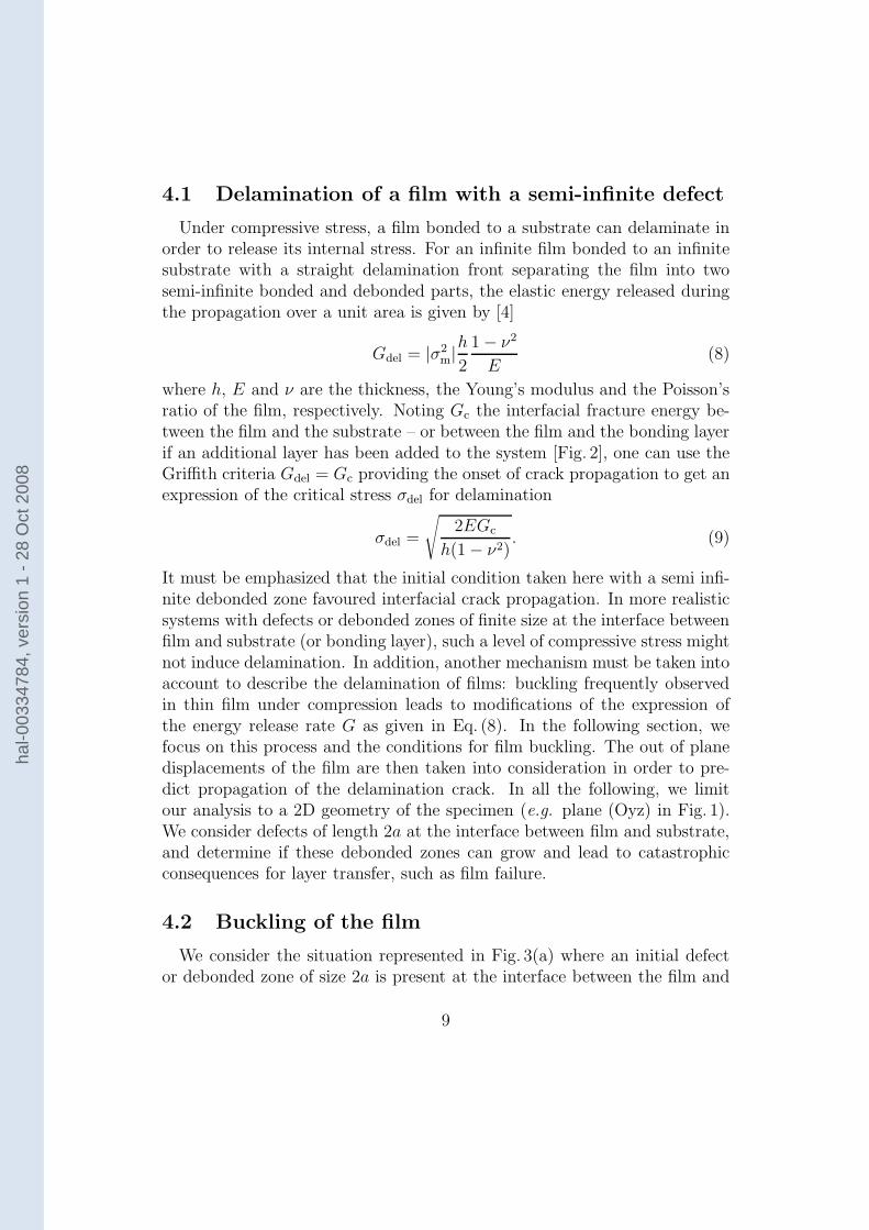
We consider the situation represented in Fig. 3(a) where an initial defector debonded zone of size 2a is present at the interface between the film and
9
hal-0
0334
784,
ver
sion
1 -
28 O
ct 2
008
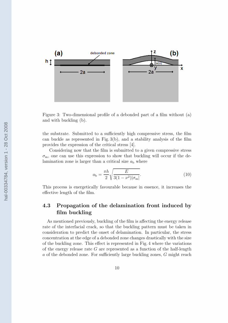
Figure 3: Two-dimensional profile of a debonded part of a film without (a)and with buckling (b).
the substrate. Submitted to a sufficiently high compressive stress, the filmcan buckle as represented in Fig. 3(b), and a stability analysis of the filmprovides the expression of the critical stress [4].
Considering now that the film is submitted to a given compressive stressσm, one can use this expression to show that buckling will occur if the de-lamination zone is larger than a critical size ab where
ab =πh
2
√
E
3(1 − ν2)|σm|. (10)
This process is energetically favourable because in essence, it increases theeffective length of the film.
4.3 Propagation of the delamination front induced by
film buckling
As mentioned previously, buckling of the film is affecting the energy releaserate of the interfacial crack, so that the buckling pattern must be taken inconsideration to predict the onset of delamination. In particular, the stressconcentration at the edge of a debonded zone changes drastically with the sizeof the buckling zone. This effect is represented in Fig. 4 where the variationsof the energy release rate G are represented as a function of the half-lengtha of the debonded zone. For sufficiently large buckling zones, G might reach
10
hal-0
0334
784,
ver
sion
1 -
28 O
ct 2
008
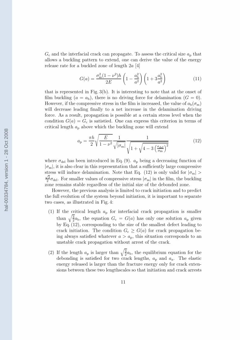
Gc and the interfacial crack can propagate. To assess the critical size ap thatallows a buckling pattern to extend, one can derive the value of the energyrelease rate for a buckled zone of length 2a [4]
G(a) =σ2
m(1 − ν2)h
2E
(
1 − a2b
a2
)(
1 + 3a2
b
a2
)
(11)
that is represented in Fig. 3(b). It is interesting to note that at the onset offilm buckling (a = ab), there is no driving force for delamination (G = 0).However, if the compressive stress in the film is increased, the value of ab(σm)will decrease leading finally to a net increase in the delamination drivingforce. As a result, propagation is possible at a certain stress level when thecondition G(a) = Gc is satistied. One can express this criterion in terms ofcritical length ap above which the buckling zone will extend
ap =πh
2
√
E
1 − ν2
1√
|σm|1
√
1 +
√
4 − 3(
σdelσm
)2
(12)
where σdel has been introduced in Eq. (9). ap being a decreasing function of|σm|, it is also clear in this representation that a sufficiently large compressivestress will induce delamination. Note that Eq. (12) is only valid for |σm| >√
32
σdel. For smaller values of compressive stress |σm| in the film, the bucklingzone remains stable regardless of the initial size of the debonded zone.
However, the previous analysis is limited to crack initiation and to predictthe full evolution of the system beyond initiation, it is important to separatetwo cases, as illustrated in Fig. 4:
(1) If the critical length ap for interfacial crack propagation is smaller
than√
32ab, the equation Gc = G(a) has only one solution ap given
by Eq. (12), corresponding to the size of the smallest defect leading tocrack initiation. The condition Gc ≥ G(a) for crack propagation be-ing always satisfied whatever a > ap, this situation corresponds to anunstable crack propagation without arrest of the crack.
(2) If the length ap is larger than√
32ab, the equilibrium equation for the
debonding is satisfied for two crack lengths, ap and aa. The elasticenergy released is larger than the fracture energy only for crack exten-sions between these two lengthscales so that initiation and crack arrests
11
hal-0
0334
784,
ver
sion
1 -
28 O
ct 2
008
occur successively for a = ap (Eq. (12)) and a = aa with
aa =πh
2
√
E
1 − ν2
1√
|σm|1
√
1 −√
4 − 3(
σdelσm
)2
(13)
The conditions for both situations can be rewritten in terms of stress,and unstable crack propagation corresponds to |σm| ≥ σdel while crack arrest
will be observed if σdel > |σm| ≥√
32
σdel. The value of the defect lengthcorresponding to ap = aa is noted adel where
adel =πh
24
√
2hE
3Gc(1 − ν2). (14)
In both cases, the propagation of these interfacial cracks may adverselyaffect the quality of the transferred thin film. In particular, for sufficientlylarge buckled patterns, i.e. large enough interfacial crack extension, a trans-verse crack induced by the bending generated in the film can fracture thecrystal layer. It is worth to note that this process may not occur for an inter-facial failure with a small extension. The conditions to obtain such transversecracks are now discussed in detail.
4.4 Failure of the thin film induced by bending
When buckling occurs, the delaminated zone undergoes bending. If theoriginal debonded zone is sufficiently small, bending increases while the sizeof the buckling zone increases. For a sufficiently large buckling zone, the filmis not strong enough to support the tensile stress induced by bending in thefilm and a crack initiating from the upper surface of the film in x = 0 willpropagate parallel to the y-axis towards lower surface [Fig. 3(b)]. In this ge-ometry, crack propagation is expected to be highly unstable, and propagationwill occur all through the crystal layer.
To predict the onset of crack initiation, we use a criterion based on thevalue of the curvature of the film (akin to critical strain), as e.g. [14]: failureoccurs when the curvature d2w
dx2 at some point of the film exceeds the criticalvalue 1
Rcwhere Rc is a constant depending on the intrinsic strength of the
material, but also on the state of surface of the freshly cut crystal. As clearfrom Fig. 3(b), a possible transverse crack will initiate around x = 0 where
12
hal-0
0334
784,
ver
sion
1 -
28 O
ct 2
008
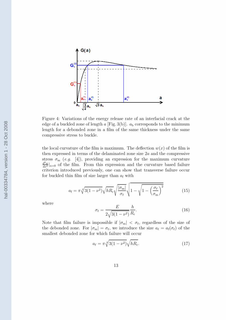
Figure 4: Variations of the energy release rate of an interfacial crack at theedge of a buckled zone of length a [Fig. 3(b)]. ab corresponds to the minimumlength for a debonded zone in a film of the same thickness under the samecompressive stress to buckle.
the local curvature of the film is maximum. The deflection w(x) of the film isthen expressed in terms of the delaminated zone size 2a and the compressivestress σm (e.g. [4]), providing an expression for the maximum curvatured2wdx2 |x=0 of the film. From this expression and the curvature based failurecriterion introduced previously, one can show that transverse failure occurfor buckled thin film of size larger than af with
af = π 4
√
3(1 − ν2)√
hRc
√
|σm|σℓ
√
√
√
√1 −√
1 −(
σℓ
σm
)2
(15)
where
σℓ =E
2√
3(1 − ν2)
h
Rc
. (16)
Note that film failure is impossible if |σm| < σℓ, regardless of the size ofthe debonded zone. For |σm| = σℓ, we introduce the size aℓ = af(σℓ) of thesmallest debonded zone for which failure will occur
aℓ = π 4
√
3(1 − ν2)√
hRc. (17)
13
hal-0
0334
784,
ver
sion
1 -
28 O
ct 2
008
4.5 Comparisons of the various length scales of theproblem and criterion for film failure
In the preceding paragraphs, the criteria for film buckling, extension of thedebonded zone and transverse failure of the film were expressed in terms ofdebonded zone size. In these three cases, it was possible to define a criticalsize above which the process is expected to occur. For the specific case ofpropagation of the delamination front, our analysis showed also that abovea critical length, the process will stop. These critical debonded sizes wereshown to depend on the applied stress in the film, and their dependence withσm were explicitly given in Eq. (10), (12) and (15).
To be able to predict in a simple way film failure during layer transfer,these three criteria are represented on a same graph in Fig. 5 where thecompressive stress |σm| in the film is given along the abscissa and the half-length a of the debonded zone along the ordinate. In this representation,the state of the system at a given time corresponds to a point of coordinates(|σm|, a). For each process studied, i.e. buckling, delamination and filmfailure, the space (|σm|, a) can be divided into two distinct regions, separatedby the curves ab(|σm|), {ap(|σm|), aa(|σm|)} and af(|σm|). If the system,characterized by its coordinates (|σm|, a), is in the region defined for a givenprocess, then this process will occur, while if the system corresponds to apoint lower than the critical curve defined for the phenomenon, one does notexpect this process to occur. Therefore, this relatively simple representationcan be used to follow the temporal evolution of the layered specimen.
Such diagrams are represented in Fig. 5 where the critical defect lengthab(|σm|) for buckling, ap(|σm|), aa(|σm|) for propagation and arrest of thedelamination front and af(|σm|) for film failure are plotted. The relativeposition of the curve defining the domain for buckling and delaminationis robust and independent to a greater extent of the specific value of theparameter of the problem. In particular, ab is always smaller than ap, and inthe limit of large compressive stress, ab ≃ ap. However, the position of thedomain corresponding to film failure with respect to these curves may changewith the value of the parameters. For illustrative purposes, two cases havebeen considered: on Fig. 5(a), af is larger than ab and ap. This corresponds tolarge film thickness and/or highly resistant film. The other kind of systemscorresponding to the diagram of Fig. 5(b) is associated with a small strengthof the film – large critical film curvature Rc at failure – and/or small filmthickness.
14
hal-0
0334
784,
ver
sion
1 -
28 O
ct 2
008
Figure 5: Diagrams representing the state of the system and its evolutionduring the layer transfer process in two different cases: (a) film with highresistance to failure/small thickness; (b) film with low resistance/large thick-ness. In this representation, the state of the system is a point of coordinates(|σm|, a) corresponding to the level of the compressive stress in the film andthe half-length of the debonded zones at the interface film/substrate, respec-tively. Depending on the position on this graph, one can determine if thethin film will buckle (above the red line ab(|σm|)), the delamination frontwill propagate (domain with vertical green arrows), or the film will break(hatched blue domain). To avoid film cracking during layer transfer, thesystem must remain in a state below the solid line in this representation.
15
hal-0
0334
784,
ver
sion
1 -
28 O
ct 2
008
In both diagrams, the hatched part corresponds to states of the systemwhere the film is broken. Propagation of the interfacial crack, and thus extentof the debonded zone, is indicated by vertical arrows.
Let’s consider at first the case of a highly resistant to failure film witha small thickness [Fig. 5(a)]. Whatever the initial size aini of the largestdefects at the interface film/substrate, one can follow the evolution of thesystem during the layer transfer process. For example, let’s take an initialdefect size of the order of adel. During layer transfer, the temperature isincreased and as a result, |σm| also increases according to Eq. (1). At the verybeginning, the system evolution is represented by a horizontal line becausethe debonded zone remains unchanged. When the system reached the lineab(|σm|) demarcating the flat film and the film buckling, this zone starts tobuckle, but a still remains constant, so the specimen evolution can still berepresented by an horizontal line. When the system reaches the line ap(|σm|)demarcating the stable buckled film and the propagation of the interfacialcrack, there is delamination of the film and a increases. Therefore, a verticalline now describes the evolution of the film geometry. Two cases are thenpossible: either the initial defect was sufficiently small (a < a1), and theextension of the buckled domain lead to film failure, the trajectory of thesystem in this representation reaching the border of the hatched zone. Inthat case, the critical debonded zone size before appearance of transversecracks is provided by ap(|σm| ≥ σ1) (represented as a solid line). Or thecrack stop before film failure, leading to a debonded zone of size aa smallerthan af. The system will break only if the temperature is increased again,resulting to a quasi-static propagation of the delamination crack of half-length aa. Transverse cracks will eventually initiate if the compressive stressis sufficiently high so that aa(|σm|) reaches the critical size for failure af.In this case, the critical compressive stress σ1 for film cracking is given byaa(σ1) = af(σ1) = a2. Defining also a1 = ap(σ1), one gets finally the followingvariations of the maximum admissible compressive stress σc with the initialdefect size:
- for aini < a1, σc = a−1p (aini) where ap(σ) is provided by Eq. (12),
- for a1 < aini < a2, σc = σ1,
- for a2 < aini < aℓ, σc = a−1f (aini) where af(σ) is provided by Eq. (15),
- for aℓ < aini, σc = σℓ given in Eq. (17).
16
hal-0
0334
784,
ver
sion
1 -
28 O
ct 2
008
Let’s now focus on the case of films with large thickness and/or low re-sistance to failure. From the analysis of the corresponding diagram pre-sented in Fig. 5(b), two cases can be isolated: for initial defects smaller thana3 = ab(σℓ), the film remains intact as far as the critical stress for bucklingis not reached. At this threshold, the debonded zone starts to buckle and atransverse crack appears at the same time. This means that the critical stressσc for film failure is provided by the expression of the buckling stress for adebonded zone of size aini that can be derived from Eq. (10). For larger initialdefects aini > a3, the film first buckles and then breaks when the compressivestress reaches the critical stress for failure σℓ. This leads us to conclude that
- for aini < a3, σc = π2
12E
1−ν2
(
haini
)2,
- for a3 < aini, σc = σℓ given in Eq. (17).
It is interesting to note that in the limit of very small defects a ≪ adel,both kinds of systems represented by two rather different diagrams lead tothe same expression of the critical compressive stress for film cracking. Usingthe approximation ab ≃ ap valid for large compressive stress, one gets in both
cases σc ≃ π2
12E
1−ν2
(
haini
)2. The same remark is also valid in the limit of large
defects for which σc = σℓ = E
2√
3(1−ν2)
hRc
on a general manner.
This analysis provides an upper limit σc to the compressive stress thatcan be imposed on the film. Conversely using Eq. (1), the maximum layertransfer temperature to which the system can be exposed to avoid failure canbe also predicted. With the result obtained in Section 3 from the stabilityanalysis of microcracks leading to film splitting, one gets a range of admis-sible stress −σc < σm < 0 for the system during the whole process, eachlimit corresponding to distinct failure modes. The theoretical predictionsare compared with experimental observations in the following section.
5 Discussion and comparison with experimen-
tal results
To determine to what extent the previous analysis applies to experimen-tal situations, two kinds of experiments for which transverse cracks in thefilm were observed have been analysed. Each one corresponds to one fail-ure mechanism analysed in the previous sections. The first experiment is
17
hal-0
0334
784,
ver
sion
1 -
28 O
ct 2
008
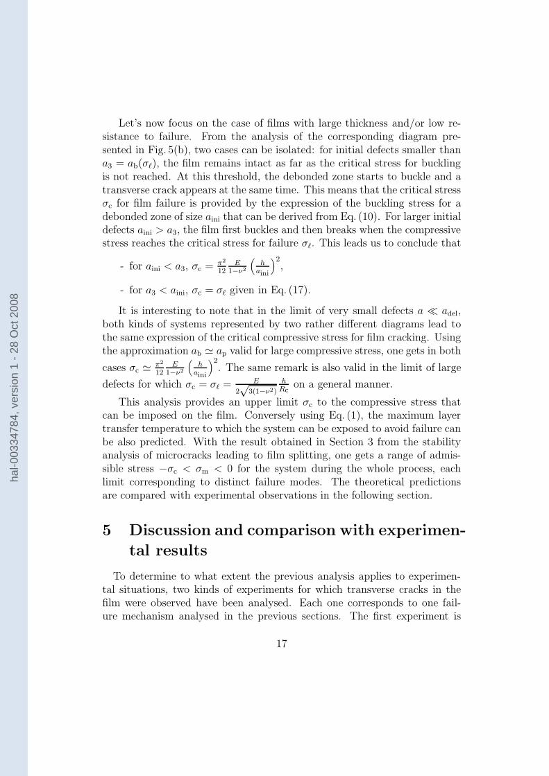
Figure 6: SEM image of the top surface of an ion implanted LiNbO3 sampleafter heating. Transverse cracks can be seen coming from the implantedregion in the LiNbO3, through the thin film, and emerging on the top surfaceof the sample.
devoted to the study of the stability of microcraks in the film, and analyzethe effect of the tensile/compressive state of stress on their trajectory. Thesecond experiment has been designed to study the effect of large compressivestresses on the film.
5.1 Effect of the compressive/tensile state of the stress
on the stability of cracks
For the first experiment, a sample of lithium niobate (LiNbO3), was im-planted with hydrogen and helium to a depth of h = 400 nm below the topsurface. The specimen was simply heated and no bonding was involved. Inthis case, a coherent thin film of LiNbO3 is not separated from the rest ofthe material; rather, the cracks that initiated at the plane of implantationimmediately deviate from a horizontal trajectory and finally emerge at thetop surface of the sample [Fig. 6].
To explain these results, we assess the effect of the absence of substrateon the stress state in the LiNbO3 specimen: the stress σm remains equal tozero, even during the heating phase. Therefore, the cracks initiating from theimplanted plane are unstable and as discussed in Section 3, they are expectedto deviate from a horizontal trajectory. This observation is in agreement withthe condition σm < 0 that was proposed in Section 3 to ensure successful layer
18
hal-0
0334
784,
ver
sion
1 -
28 O
ct 2
008
transfer.
5.2 Effect of a high compressive stress on the film
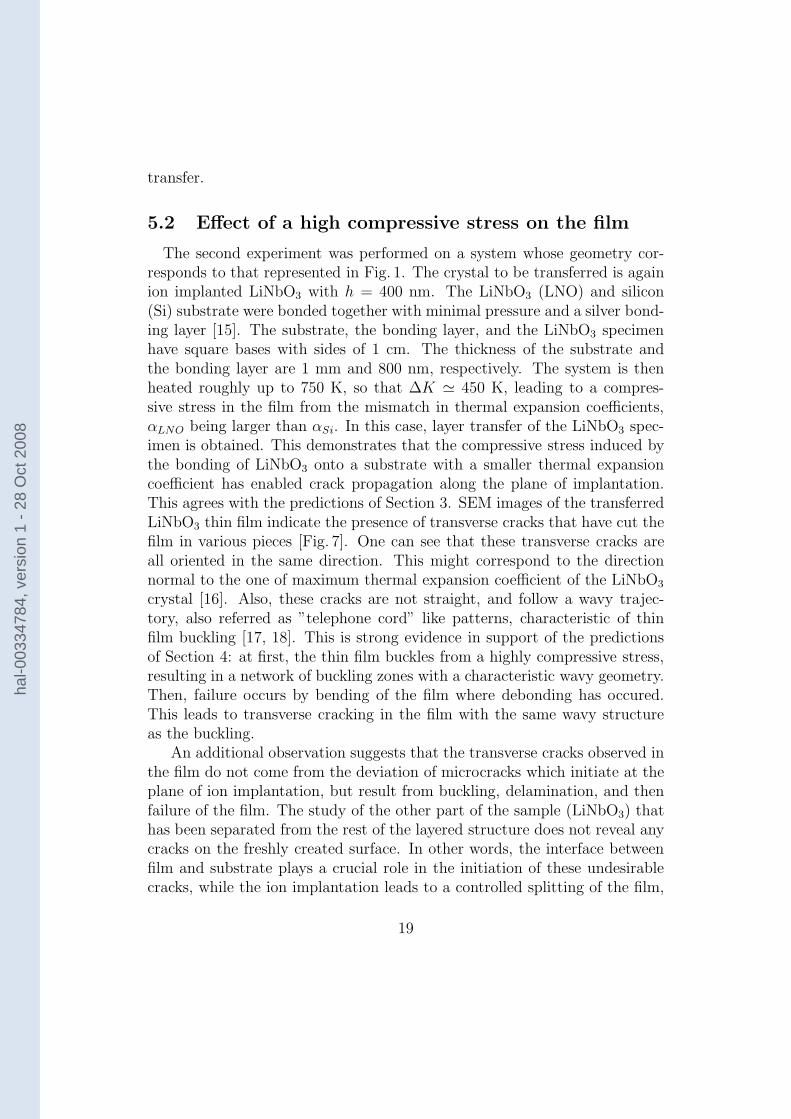
The second experiment was performed on a system whose geometry cor-responds to that represented in Fig. 1. The crystal to be transferred is againion implanted LiNbO3 with h = 400 nm. The LiNbO3 (LNO) and silicon(Si) substrate were bonded together with minimal pressure and a silver bond-ing layer [15]. The substrate, the bonding layer, and the LiNbO3 specimenhave square bases with sides of 1 cm. The thickness of the substrate andthe bonding layer are 1 mm and 800 nm, respectively. The system is thenheated roughly up to 750 K, so that ∆K ≃ 450 K, leading to a compres-sive stress in the film from the mismatch in thermal expansion coefficients,αLNO being larger than αSi. In this case, layer transfer of the LiNbO3 spec-imen is obtained. This demonstrates that the compressive stress induced bythe bonding of LiNbO3 onto a substrate with a smaller thermal expansioncoefficient has enabled crack propagation along the plane of implantation.This agrees with the predictions of Section 3. SEM images of the transferredLiNbO3 thin film indicate the presence of transverse cracks that have cut thefilm in various pieces [Fig. 7]. One can see that these transverse cracks areall oriented in the same direction. This might correspond to the directionnormal to the one of maximum thermal expansion coefficient of the LiNbO3
crystal [16]. Also, these cracks are not straight, and follow a wavy trajec-tory, also referred as ”telephone cord” like patterns, characteristic of thinfilm buckling [17, 18]. This is strong evidence in support of the predictionsof Section 4: at first, the thin film buckles from a highly compressive stress,resulting in a network of buckling zones with a characteristic wavy geometry.Then, failure occurs by bending of the film where debonding has occured.This leads to transverse cracking in the film with the same wavy structureas the buckling.
An additional observation suggests that the transverse cracks observed inthe film do not come from the deviation of microcracks which initiate at theplane of ion implantation, but result from buckling, delamination, and thenfailure of the film. The study of the other part of the sample (LiNbO3) thathas been separated from the rest of the layered structure does not reveal anycracks on the freshly created surface. In other words, the interface betweenfilm and substrate plays a crucial role in the initiation of these undesirablecracks, while the ion implantation leads to a controlled splitting of the film,
19
hal-0
0334
784,
ver
sion
1 -
28 O
ct 2
008
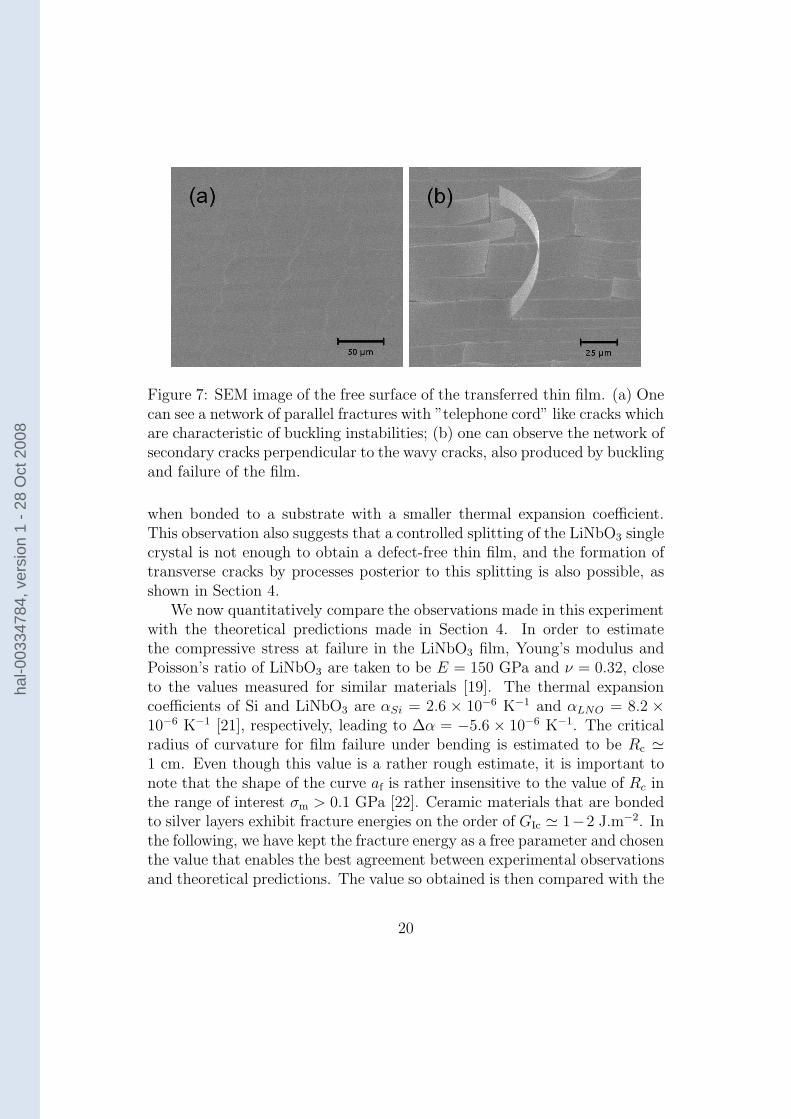
Figure 7: SEM image of the free surface of the transferred thin film. (a) Onecan see a network of parallel fractures with ”telephone cord” like cracks whichare characteristic of buckling instabilities; (b) one can observe the network ofsecondary cracks perpendicular to the wavy cracks, also produced by bucklingand failure of the film.
when bonded to a substrate with a smaller thermal expansion coefficient.This observation also suggests that a controlled splitting of the LiNbO3 singlecrystal is not enough to obtain a defect-free thin film, and the formation oftransverse cracks by processes posterior to this splitting is also possible, asshown in Section 4.
We now quantitatively compare the observations made in this experimentwith the theoretical predictions made in Section 4. In order to estimatethe compressive stress at failure in the LiNbO3 film, Young’s modulus andPoisson’s ratio of LiNbO3 are taken to be E = 150 GPa and ν = 0.32, closeto the values measured for similar materials [19]. The thermal expansioncoefficients of Si and LiNbO3 are αSi = 2.6 × 10⁻⁶ K−1 and αLNO = 8.2 ×10⁻⁶ K−1 [21], respectively, leading to ∆α = −5.6 × 10⁻⁶ K−1. The criticalradius of curvature for film failure under bending is estimated to be Rc ≃1 cm. Even though this value is a rather rough estimate, it is important tonote that the shape of the curve af is rather insensitive to the value of Rc inthe range of interest σm > 0.1 GPa [22]. Ceramic materials that are bondedto silver layers exhibit fracture energies on the order of GIc ≃ 1−2 J.m−2. Inthe following, we have kept the fracture energy as a free parameter and chosenthe value that enables the best agreement between experimental observationsand theoretical predictions. The value so obtained is then compared with the
20
hal-0
0334
784,
ver
sion
1 -
28 O
ct 2
008
0 0.2 0.4 0.6 0.8 10
5
10
15
20
25
30
|σm
| (GPa)
a (µ
m) a
f
ab
aa
ap
σfailure
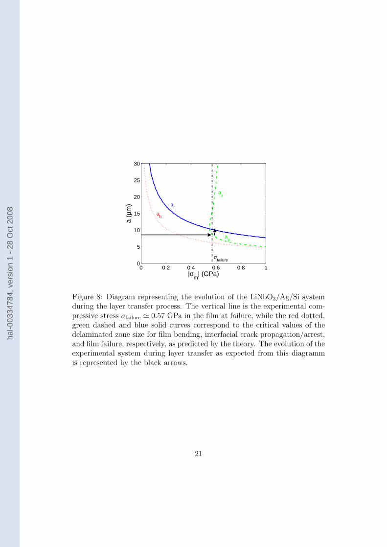
Figure 8: Diagram representing the evolution of the LiNbO3/Ag/Si systemduring the layer transfer process. The vertical line is the experimental com-pressive stress σfailure ≃ 0.57 GPa in the film at failure, while the red dotted,green dashed and blue solid curves correspond to the critical values of thedelaminated zone size for film bending, interfacial crack propagation/arrest,and film failure, respectively, as predicted by the theory. The evolution of theexperimental system during layer transfer as expected from this diagrammis represented by the black arrows.
21
hal-0
0334
784,
ver
sion
1 -
28 O
ct 2
008
expected values for ceramic-silver fracture energy.Using the previous numerical values and Eq. (1), it is possible to estimate
the compressive stress σfailure ≃ 0.57 GPa in the film at T ≃ 750 K for whichundesired cracks appear. For the LiNbO3/Ag/Si system studied here, onecan also calculate the failure diagram to determine the state of the systemwith respect to |σm| and a [Fig. 8]. To reproduce corretly the experimentalobservations, one chooses GIc ≃ 0.5 J.m−2 that is smaller but comparableto the expected values GIc ≃ 1 − 2 J.m−2. The diagram so obtained isanalogous to Fig. 5(a) plotted in a general case. The value of the compressivestress at T ≃ 750 K is also represented on this diagram as a vertical dashedline. It is now possible to identify the different processes that have led tothe failure of the film. Using the representation of the system state shownin Fig. 8, the initiation of the transverse cracks in the film is given by theintersection of the vertical dashed line giving the level of stress at film failurewith the curve af(|σm|) demarcating intact films from broken films. Thisprovides a raisonable estimate a ≃ 8 µm of the size of the defects at theinterface between the silver bonding layer and the LiNbO3 film that will leadultimately to undesirable cracks in the film.
From this diagram, one can also follow the history of the film failureduring the heating phase. The evolution of the system during the initial phaseis described by the horizontal arrow represented in Fig. 8. One observes atfirst that the defects at the interface between Ag and LiNbO3 of size a ≃ 8 µmwill start to buckle for σm ≃ 0.3 GPa (corresponding to a temperature of≃ 450 K). This value is given by the intersection of the horyzontal arrowwith the curve ab. When the compressive stress in the film is sufficientlyhigh, close to σfailure, the interfacial cracks start to propagate. A networkof debonded zones with a telephone cord like geometry then develops. Thisprocess will lead ultimately to the telephone cord like cracks observed post-mortem on the thin film surface [Fig. 7(a)] when the debonded zones willstart to extend in the transverse direction [23]. The evolution of the systemin this last regime is described by the vertical arrow represented in Fig.. 8.Finally, the failure of the film corresponding to the intersection of the verticalarrow with the curve af is obtained for a lateral size of the debonded zonesof the order of a ≃ 10 µm. This is fully compatible with the post-mortemobservations made on the film surface after layer transfer.
22
hal-0
0334
784,
ver
sion
1 -
28 O
ct 2
008
6 Conclusion
The origin of the undesirable cracking often observed during layer transferhas been investigated. From our theoretical analysis based on Fracture Me-chanics, it appears that the state of stress in the film, direct consequenceof the mismatch between the thermal expansion coefficients of the film andthe substrate, is driving the failure processes. More precisely, two phenom-ena identified in experimental examples are studied in detail and shown toinduce catastrophic failure of thin films obtained by layer transfer: (i) themicrocracks that are made to propagate in the implanted plane parallel tothe film/substrate interface to split the specimen can deviate from their hor-izontal trajectory and cut the film. The analysis of their stability in the full3D geometry of the considered system shows that these microcracks will notfollow a straight path if the film is submitted to a compressive stress σm < 0;(ii) an important tensile stress in the film can also have catastrophic conse-quences. When the specimen is already cut but still heated, defects at thefilm-substrate interface can buckle and induce film delamination, resultingultimately in a failure of the film by bending. This process has been an-alyzed in detail and the critical stress (critical temperature) at which eachstage occurs has been expressed in term of defect size, film thickness and frac-ture properties of the film. Therefore, it is possible to predict the maximumcompressive stress σc that can be sustained by the system. Taking into con-sideration both these failure processes, one can define a range of admissiblestresses −σc < σm < 0 in the film.
From these results, it is now possible to identify the systems amenable tothe layer transfer technique. In particular, the conditions on the admissiblestress in the film can be expressed in terms of system properties: the substratemust be chosen so that its thermal expansion coefficient is smaller than thatof the film. But this condition is not sufficient and above a critical heatingtemperature corresponding to a compressive stress σc, cracked film will beproduced. This temperature must be smaller than the one necessary to makethe microcracks propagate in the implanted plane of the film. To overcomethis difficulty and increase the admissible stress in the film, the quality of theinterface between film and substrate must be improved, decreasing both thedefect size and increasing the interfacial fracture energy. A plastic interlayer(e.g. Ag, Pt) used to accommodate the contact between the both surfacesmight be relevant. Increasing the film thickness might be also an alternativeto avoid failure of the system.
23
hal-0
0334
784,
ver
sion
1 -
28 O
ct 2
008
Finally, let us note that another effect may result in intrinsic limitationsof the layer transfer process. The material to be cut is usually a single crys-tal with preferential cleavage planes. As a result, the implanted plane maynot correspond to the easy direction of the film. To what extent a crackcan propagate in the direction of maximal tensile stress – parallel to thesubstrate/film interface – rather than deviate for a plane of lower fractureenergy is still a matter of debate [24, 25]. A theoretical framework provid-ing accurate predictions on the propagation direction of cracks in anisotropicmedia would lead to a clear determination of the systems as well as the crys-tallographic film orientations that can be obtained using the layer transfertechnique. Works are currently in progress in this direction.
acknowledgmentThis work has been supported by the Center for the Science and Engi-
neering of Materials (CSEM).
References
[1] J. Ayers, Heteroepitaxy of semiconductors : theory, growth, and charac-
terization (CRC Press, Boca Raton, 2007).
[2] M. Bruel, Electron. Lett. 31, 1201 (1995).
[3] Y. B. Park, K. Diest, and H. A. Atwater, J. Appl. Phys. 102, 1 (2007).
[4] L. B. Freund and S. Suresh, Thin film materials (Cambridge UniversityPress, Cambridge and New York, 2003).
[5] B. Cotterell and J. R. Rice, Int. J. Frac., 16, 155 (1980).
[6] H. Larralde and R. C. Ball, Europhys. Lett. 30, 87 (1995).
[7] R. V. Gol’dstein and R. L. Salganik, Int. J. Frac. 10, 507 (1974).
[8] J. Hogdon and J. P. Sethna., Phys. Rev. B 47, 4831 (1993).
[9] A. B. Movchan, H. Gao, and J. R. Willis, Int. J. Solids Struct. 35, 3419(1998).
24
hal-0
0334
784,
ver
sion
1 -
28 O
ct 2
008
[10] For example, one can consider a crack with a perfectly straight fronth(x, z) = h(x). In that case, this term equals to zero, but h can bearbitrary large, leading to an unstable crack propagation.
[11] One can show that wIIz (x,z)
wIIx (x,z)
≤ 2ν2−ν
.
[12] For example, one can derivate the Eq. (7) with respect to the variable
x. Considering an initial perturbation ∂h∂x
> 0, the sign of∂( ∂h
∂x)∂x
, andtherefore the stability of the crack – positive (resp. negative) for anunstable (resp. stable) crack – is then provided by the sign of σm.
[13] J. W. Hutchinson and Z. Suo, Adv. App. Mech. 29, 63 (1992).
[14] B. Audoly and S. Neukirch, Phys. Rev. Lett., 95, 095505 (2005).
[15] K. Diest, M. J. Archer, J. A. Dionne, Y. B. Park, M. J. Czubakowski,and H. A. Atwater (submitted).
[16] The thermal expansion coefficients of LNO crystal are different alongthe various crystalline directions.
[17] G. Parry, A. Cimetiere, C. Coupeau, J. Jolin, and J. Grilhe, Phys Rev.E, 74, 066601 (2006).
[18] K. Crosby and R. Bradley, Phys. Rev. E 59, R2542 (1999).
[19] H. B. Huntington, The elastic constants of crystals, (Academic Press,New York and London, 1958).
[20] C. Y. Lee, M. Dupeux, and W. H. Tuan, Mat. Sci. Eng. A 467, 125(2007).
[21] B. H. Kim, J. H. An, and K. S. Hwang, J. Matter. Sci., 41, 2165 (2006).
[22] From the expression of af given in Eq. (15), one can notice that thislength becomes independent of σm for large value of the stress in thefilm.
[23] This expansion of the debonded zone in two stages might be explainedby a slight anisotropy of the thermal expansion coefficient of the LiNbO3
single crystal. In the first stage, the compressive stress, larger along one
25
hal-0
0334
784,
ver
sion
1 -
28 O
ct 2
008
of the crystallographic orientation of LiNbO3, produces an extensionof the initial defects – assimilated to circular debonded zones – intotelephone cord like patterns that is not accompanied by an increase ofthe maximum curvature of the buckled zones. This is the case in thesecond stage characterized by a lateral expansion of these zones thatproduces film failure.
[24] M.B. Buczek and C.T. Herakovich, J. Composite Mater. 19, 544 (1985).
[25] A. Azdhari, S. Nemat-Nasser, and J. Rome, Int. J. Frac. 94, 251 (1998).
26
hal-0
0334
784,
ver
sion
1 -
28 O
ct 2
008