organic chemistry, 2nd edition - tajassus
TRANSCRIPT

DAVID KLEIN
SECOND EDITION
Organic Chemistry


DaviD KleinJohns Hopkins University
Second edition
Organic Chemistry
VICE PRESIDENT, PUBLISHER Petra RecterSPONSORING EDITOR Joan KalkutSENIOR MARKETING MANAGER Kristine RuffSENIOR PROJECT EDITOR Jennifer YeeSENIOR PRODUCT DESIGNER Geraldine OsnatoSENIOR ASSOCIATE EDITOR Veronica ArmourDESIGN DIRECTOR Harold NolanSENIOR DESIGNER Maureen Eide/DeMarinis Design LLCCOVER DESIGN Thomas NerySENIOR PHOTO EDITOR Lisa GeeEDITORIAL ASSISTANTS Mallory Fryc, Susan TsuiSENIOR CONTENT MANAGER Kevin HolmSENIOR MEDIA SPECIALIST Daniela DiMaggioSENIOR PRODUCTION EDITOR Elizabeth Swain
Cover/preface photo credits: flask 1-(yellow and red pill capsule) rya sick/iStockphoto, (tiny pills) coulee/iStock-photo; flask 2-(syringe) Stockcam/Getty Images, (liquid) mkurthas/iStockphoto; flask 3-(key) Gary S. Chapman/Photographer's Choice/Getty Images, (key pile) Olexiy Bayev/Shutterstock; flask 4-(poppy) Margaret Rowe/Garden Picture Library/Getty Images, (poppies) Kuttelvaserova Stuchelova/ Shutterstock; flask 5-(tomato evolu-tion)Alena Brozova/Shutterstock, (cherry tomatoes) Natalie Erhova (summerky)/Shutterstock, (cherry tomatoes pile) © Jessica Peterson/Tetra Images/Corbis; flask 6-(ribbon) macia/Getty Images (ribbon symbol) JamesBrey/iStockphoto; flask 7-(scoop) Fuse/Getty Images (coffee beans) Vasin Lee/Shutterstock, (espresso) Rob Stark/Shutterstock; flask 8-(smoke) stavklem/ Shutterstock, (chili peppers) Ursula Alter/Getty Images.
This book was set in 10/12 Garamond by Prepare and printed and bound by Courier-Kendallville. The cover was printed by Courier-Kendallville.
Founded in 1807, John Wiley & Sons, Inc. has been a valued source of knowledge and understanding for more than 200 years, helping people around the world meet their needs and fulfill their aspirations. Our company is built on a foundation of principles that include responsibility to the communities we serve and where we live and work. In 2008, we launched a Corporate Citizenship Initiative, a global effort to address the environmental, social, economic, and ethical challenges we face in our business. Among the issues we are addressing are carbon impact, paper specifications and procurement, ethical conduct within our business and among our vendors, and community and charitable support. For more information , please visit our website: www.wiley.com/go/citizenship.
The paper in this book was manufactured by a mill whose forest management programs include sustained yield-harvesting of its timberlands. Sustained yield harvesting principles ensure that the number of trees cut each year does not exceed the amount of new growth.
Copyright © 2015, 2012 John Wiley and Sons, Inc. All rights reserved.
No part of this publication may be reproduced, stored in a retrieval system or transmitted in any form or bar any means, electronic, mechanical, photocopying recording, scanning or otherwise, except as permitted under Sections 107 or 108 of the 1976 United States Copyright Act, without either the prior written permission of the Publisher or authorization through payment of the appropriate per-copy fee to the Copyright Clearance Center, 222 Rosewood Drive, Danvers, MA 01923, (978) 750-8400, fax (978) 646-8600, Requests to the Publisher for permission should be addressed to the Permissions Department, John Wiley Sons, Inc, 111 River Street, Hoboken, NJ 07030-5774, (201) 748-6011, fax (201) 748-6008.
Evaluation copies are provided to qualified academics and professionals for review purposes only, for use in their courses during the next academic year. These copies are licensed and may not be sold or transferred to a third party. Upon completion of the review period, please return the evaluation copy to Wiley. Return instructions and a free of charge return shipping label are available at www.wiley.com/go/returnlabel. Outside of the United States, please contact your local representative.
ISBNMain edition: 978-1-118-45228-8Binder version: 978-1-118-45431-2
Printed in the United States of America 10 9 8 7 6 5 4 3 2 1

DedicationTo Larry,
By inspiring me to pursue a career in organic chemistry instruction, you served as the spark for the creation of this book. You showed me that any subject can be fascinating (even organic chemistry!) when presented by a masterful teacher. Your mentorship and friendship have profoundly shaped the course of my life, and I hope that this book will always serve as a source of pride and as a reminder of the impact you’ve had on your students.
To my wife, Vered,This book would not have been possible without your partnership. As I worked for years
in my office, you shouldered all of our life responsibilities, including taking care of all of the needs of our five amazing children. This book is our collective accomplishment and will forever serve as a testament of your constant support that I have come to depend on for everything in life. You are my rock, my partner, and my best friend. I love you.

Brief Contents 1 A Review of General Chemistry: Electrons, Bonds, and Molecular Properties 1
2 Molecular Representations 51
3 Acids and Bases 96
4 Alkanes and Cycloalkanes 139
5 Stereoisomerism 192
6 Chemical Reactivity and Mechanisms 236
7 Substitution Reactions 287
8 Alkenes: Structure and Preparation via Elimination Reactions 341
9 Addition Reactions of Alkenes 404
10 Alkynes 464
11 Radical Reactions 500
12 Synthesis 547
13 Alcohols and Phenols 576
14 Ethers and Epoxides; Thiols and Sulfides 633
15 Infrared Spectroscopy and Mass Spectrometry 683
16 Nuclear Magnetic Resonance Spectroscopy 731
17 Conjugated Pi Systems and Pericyclic Reactions 782
18 Aromatic Compounds 832
19 Aromatic Substitution Reactions 874
20 Aldehydes and Ketones 931
21 Carboxylic Acids and Their Derivatives 984
22 Alpha Carbon Chemistry: Enols and Enolates 1044
23 Amines 1102
24 Carbohydrates 1151
25 Amino Acids, Peptides, and Proteins 1193
26 Lipids 1239
27 Synthetic Polymers 1279

1A Review of General Chemistry: Electrons, Bonds, and Molecular Properties 1
1.1 Introduction to Organic Chemistry 2
1.2 The Structural Theory of Matter 3
1.3 Electrons, Bonds, and Lewis Structures 4
1.4 Identifying Formal Charges 8
1.5 Induction and Polar Covalent Bonds 9
PRACTICALLY SPEAKING Electrostatic Potential Maps 12
1.6 Atomic Orbitals 12
1.7 Valence Bond Theory 16
1.8 Molecular Orbital Theory 17
1.9 Hybridized Atomic Orbitals 18
1.10 VSEPR Theory: Predicting Geometry 25
1.11 Dipole Moments and Molecular Polarity 30
1.12 Intermolecular Forces and Physical Properties 34
PRACTICALLY SPEAKING Biomimicry and Gecko Feet 36
MEDICALLY SPEAKING Drug-Receptor Interactions 40
1.13 Solubility 41
MEDICALLY SPEAKING Propofol: The Importance of Drug Solubility 42
Review of Concepts & Vocabulary • SkillBuilder Review • Practice Problems • Integrated Problems • Challenge Problems
2Molecular Representations 51
2.1 Molecular Representations 52
2.2 Bond-Line Structures 54
2.3 Identifying Functional Groups 59
MEDICALLY SPEAKING Marine Natural Products 61
2.4 Carbon Atoms with Formal Charges 62
2.5 Identifying Lone Pairs 62
2.6 Three-Dimensional Bond-Line Structures 66
MEDICALLY SPEAKING Identifying the Pharmacophore 67
2.7 Introduction to Resonance 68
2.8 Curved Arrows 70
2.9 Formal Charges in Resonance Structures 73
2.10 Drawing Resonance Structures via Pattern Recognition 75
2.11 Assessing Relative Importance of Resonance Structures 81
2.12 Delocalized and Localized Lone Pairs 85
Review of Concepts & Vocabulary • SkillBuilder Review • Practice Problems • Integrated Problems • Challenge Problems
3Acids and Bases 96
3.1 Introduction to Brønsted-Lowry Acids and Bases 97
3.2 Flow of Electron Density: Curved Arrow Notation 97
MEDICALLY SPEAKING Antacids and Heartburn 100
3.3 Brønsted-Lowry Acidity: A Quantitative Perspective 101
MEDICALLY SPEAKING Drug Distribution and pKa 108
3.4 Brønsted-Lowry Acidity: Qualitative Perspective 109
3.5 Position of Equilibrium and Choice of Reagents 122
3.6 Leveling Effect 125
3.7 Solvating Effects 126
3.8 Counterions 127
PRACTICALLY SPEAKING Baking Soda versus Baking Powder 128
3.9 Lewis Acids and Bases 129
Review of Concepts & Vocabulary • SkillBuilder Review • Practice Problems • Integrated Problems • Challenge Problems
4Alkanes and Cycloalkanes 139
4.1 Introduction to Alkanes 140
4.2 Nomenclature of Alkanes 140
PRACTICALLY SPEAKING Pheromones: Chemical Messengers 145
MEDICALLY SPEAKING Naming Drugs 153
4.3 Constitutional Isomers of Alkanes 154
4.4 Relative Stability of Isomeric Alkanes 155
4.5 Sources and Uses of Alkanes 156
v
Contents

vi CONTENTS
PRACTICALLY SPEAKING An Introduction to Polymers 158
4.6 Drawing Newman Projections 158
4.7 Conformational Analysis of Ethane and Propane 160
4.8 Conformational Analysis of Butane 162
MEDICALLY SPEAKING Drugs and Their Conformations 166
4.9 Cycloalkanes 167
MEDICALLY SPEAKING Cyclopropane as an Inhalation Anesthetic 168
4.10 Conformations of Cyclohexane 169
4.11 Drawing Chair Conformations 170
4.12 Monosubstituted Cyclohexane 172
4.13 Disubstituted Cyclohexane 175
4.14 cis-trans Stereoisomerism 180
4.15 Polycyclic Systems 181
Review of Concepts & Vocabulary • SkillBuilder Review • Practice Problems • Integrated Problems • Challenge Problems
5Stereoisomerism 192
5.1 Overview of Isomerism 193
5.2 Introduction to Stereoisomerism 196
PRACTICALLY SPEAKING The Sense of Smell 202
5.3 Designating Configuration Using the Cahn-Ingold-Prelog System 203
MEDICALLY SPEAKING Chiral Drugs 208
5.4 Optical Activity 209
5.5 Stereoisomeric Relationships: Enantiomers and Diastereomers 214
5.6 Symmetry and Chirality 218
5.7 Fischer Projections 223
5.8 Conformationally Mobile Systems 225
5.9 Resolution of Enantiomers 226
Review of Concepts & Vocabulary • SkillBuilder Review • Practice Problems • Integrated Problems • Challenge Problems
6Chemical Reactivity and Mechanisms 236
6.1 Enthalpy 237
6.2 Entropy 240
6.3 Gibbs Free Energy 243
PRACTICALLY SPEAKING Explosives 244 PRACTICALLY SPEAKING Do Living Organisms Violate
the Second Law of Thermodynamics? 245
6.4 Equilibria 246
6.5 Kinetics 248
MEDICALLY SPEAKING Nitroglycerin: An Explosive with Medicinal Properties 251
PRACTICALLY SPEAKING Beer-Making 252
6.6 Reading Energy Diagrams 253
6.7 Nucleophiles and Electrophiles 256
6.8 Mechanisms and Arrow Pushing 260
6.9 Combining the Patterns of Arrow Pushing 266
6.10 Drawing Curved Arrows 268
6.11 Carbocation Rearrangements 271
6.12 Reversible and Irreversible Reaction Arrows 273
Review of Concepts & Vocabulary • SkillBuilder Review • Practice Problems • Integrated Problems • Challenge Problems
7Substitution Reactions 287
7.1 Introduction to Substitution Reactions 288
7.2 Alkyl Halides 289
7.3 Possible Mechanisms for Substitution Reactions 292
7.4 The SN2 Mechanism 296
PRACTICALLY SPEAKING SN2 Reactions in Biological Systems—Methylation 302
7.5 The SN1 Mechanism 303
7.6 Drawing the Complete Mechanism of an SN1 Reaction 309
7.7 Drawing the Complete Mechanism of an SN2 Reaction 316
MEDICALLY SPEAKING Radiolabelled Compounds in Diagnostic Medicine 319
7.8 Determining Which Mechanism Predominates 320
7.9 Selecting Reagents to Accomplish Functional Group Transformation 327
MEDICALLY SPEAKING Pharmacology and Drug Design 330
Review of Reactions • Review of Concepts & Vocabulary SkillBuilder Review • Practice Problems Integrated Problems • Challenge Problems
CONTENTS vii
8Alkenes: Structure and Preparation via Elimination Reactions 341
8.1 Introduction to Elimination Reactions 342
8.2 Alkenes in Nature and in Industry 342
PRACTICALLY SPEAKING Pheromones to Control Insect Populations 343
8.3 Nomenclature of Alkenes 345
8.4 Stereoisomerism in Alkenes 348
MEDICALLY SPEAKING Phototherapy Treatment for Neonatal Jaundice 352
8.5 Alkene Stability 353
8.6 Possible Mechanisms for Elimination 356
8.7 The E2 Mechanism 358
8.8 Drawing the Products of an E2 Reaction 371
8.9 The E1 Mechanism 372
8.10 Drawing the Complete Mechanism of an E1 Process 377
8.11 Drawing the Complete Mechanism of an E2 Process 382
8.12 Substitution vs. Elimination: Identifying the Reagent 383
8.13 Substitution vs. Elimination: Identifying the Mechanism(s) 387
8.14 Substitution vs. Elimination: Predicting the Products 391
Review of Synthetically Useful Elimination Reactions Review of Concepts & Vocabulary • SkillBuilder Review • Practice Problems • Integrated Problems • Challenge Problems
9Addition Reactions of Alkenes 404
9.1 Introduction to Addition Reactions 405
9.2 Addition vs. Elimination: A Thermodynamic Perspective 406
9.3 Hydrohalogenation 407
PRACTICALLY SPEAKING Cationic Polymerization and Polystyrene 415
9.4 Acid-Catalyzed Hydration 416
PRACTICALLY SPEAKING Industrial Production of Ethanol 420
9.5 Oxymercuration-Demercuration 420
9.6 Hydroboration-Oxidation 422
9.7 Catalytic Hydrogenation 428
PRACTICALLY SPEAKING Partially Hydrogenated Fats and Oils 434
9.8 Halogenation and Halohydrin Formation 435
9.9 Anti Dihydroxylation 440
9.10 Syn Dihydroxylation 443
9.11 Oxidative Cleavage 444
9.12 Predicting Products of an Addition Reaction 446
9.13 Synthesis Strategies 448
Review of Reactions • Review of Concepts & Vocabulary • SkillBuilder Review • Practice Problems Integrated Problems • Challenge Problems
10Alkynes 464
10.1 Introduction to Alkynes 465
MEDICALLY SPEAKING The Role of Molecular Rigidity 466
PRACTICALLY SPEAKING Conducting Organic Polymers 467
10.2 Nomenclature of Alkynes 467
10.3 Acidity of Acetylene and Terminal Alkynes 470
10.4 Preparing Alkynes 473
10.5 Reduction of Alkynes 474
10.6 Hydrohalogenation of Alkynes 478
10.7 Hydration of Alkynes 481
10.8 Halogenation of Alkynes 487
10.9 Ozonolysis of Alkynes 487
10.10 Alkylation of Terminal Alkynes 488
10.11 Synthesis Strategies 489
Review of Reactions • Review of Concepts & Vocabulary SkillBuilder Review • Practice Problems Integrated Problems • Challenge Problems
11Radical Reactions 500
11.1 Radicals 501
11.2 Common Patterns in Radical Mechanisms 506
11.3 Chlorination of Methane 510
11.4 Thermodynamic Considerations for Halogenation Reactions 513
11.5 Selectivity of Halogenation 516
11.6 Stereochemistry of Halogenation 519

11.7 Allylic Bromination 522
11.8 Atmospheric Chemistry and the Ozone Layer 524
PRACTICALLY SPEAKING Fighting Fires with Chemicals 526
11.9 Autooxidation and Antioxidants 527
MEDICALLY SPEAKING Why is an Overdose of Acetaminophen Fatal? 530
11.10 Radical Addition of HBr: Anti-Markovnikov Addition 531
11.11 Radical Polymerization 535
11.12 Radical Processes in the Petrochemical Industry 538
11.13 Halogenation as a Synthetic Technique 538
Review of Synthetically Useful Radical Reactions Review of Concepts & Vocabulary • SkillBuilder Review • Practice Problems • Integrated Problems • Challenge Problems
12Synthesis 547
12.1 One-Step Syntheses 548
12.2 Functional Group Transformations 549
12.3 Reactions that Change the Carbon Skeleton 554
MEDICALLY SPEAKING Vitamins 556
12.4 How to Approach a Synthesis Problem 557
MEDICALLY SPEAKING The Total Synthesis of Vitamin B12 559
12.5 Retrosynthetic Analysis 560 PRACTICALLY SPEAKING Retrosynthetic Analysis 568
12.6 Practical Tips for Increasing Proficiency 568
MEDICALLY SPEAKING Total Synthesis of Taxol 570
Review of Concepts & Vocabulary • SkillBuilder Review • Practice Problems • Integrated Problems • Challenge Problems
13Alcohols and Phenols 576
13.1 Structure and Properties of Alcohols 577
MEDICALLY SPEAKING Chain Length as a Factor in Drug Design 582
13.2 Acidity of Alcohols and Phenols 583
13.3 Preparation of Alcohols via Substitution or Addition 586
13.4 Preparation of Alcohols via Reduction 587
13.5 Preparation of Diols 595
PRACTICALLY SPEAKING Antifreeze 596
13.6 Preparation of Alcohols via Grignard Reagents 596
13.7 Protection of Alcohols 600
13.8 Preparation of Phenols 602
MEDICALLY SPEAKING Phenols as Antifungal Agents 603
13.9 Reactions of Alcohols: Substitution and Elimination 603
PRACTICALLY SPEAKING Drug Metabolism 607
13.10 Reactions of Alcohols: Oxidation 609
PRACTICALLY SPEAKING Breath Tests to Measure Blood Alcohol Level 610
13.11 Biological Redox Reactions 613
PRACTICALLY SPEAKING Biological Oxidation of Methanol and Ethanol 614
13.12 Oxidation of Phenol 615
13.13 Synthesis Strategies 616
Review of Reactions • Review of Concepts & Vocabulary SkillBuilder Review • Practice Problems Integrated Problems • Challenge Problems
14Ethers and Epoxides; Thiols and Sulfides 633
14.1 Introduction to Ethers 634
14.2 Nomenclature of Ethers 634
14.3 Structure and Properties of Ethers 637
MEDICALLY SPEAKING Ethers as Inhalation Anesthetics 638
14.4 Crown Ethers 639
MEDICALLY SPEAKING Polyether Antibiotics 641
14.5 Preparation of Ethers 641
14.6 Reactions of Ethers 644
14.7 Nomenclature of Epoxides 647
MEDICALLY SPEAKING Epothilones as Novel Anticancer Agents 648
14.8 Preparation of Epoxides 648
MEDICALLY SPEAKING Active Metabolites and Drug Interactions 651
14.9 Enantioselective Epoxidation 652
14.10 Ring-Opening Reactions of Epoxides 654
PRACTICALLY SPEAKING Ethylene Oxide as a Sterilizing Agent for Sensitive Medical Equipment 657
viii CONTENTS

CONTENTS ix
MEDICALLY SPEAKING Cigarette Smoke and Carcinogenic Epoxides 662
14.11 Thiols and Sulfides 663
14.12 Synthesis Strategies Involving Epoxides 667
Review of Reactions • Review of Concepts & Vocabulary • SkillBuilder Review • Practice Problems Integrated Problems • Challenge Problems
15Infrared Spectroscopy and Mass Spectrometry 683
15.1 Introduction to Spectroscopy 684
PRACTICALLY SPEAKING Microwave Ovens 686
15.2 IR Spectroscopy 686
MEDICALLY SPEAKING IR Thermal Imaging for Cancer Detection 687
15.3 Signal Characteristics: Wavenumber 689
15.4 Signal Characteristics: Intensity 693
PRACTICALLY SPEAKING IR Spectroscopy for Testing Blood Alcohol Levels 696
15.5 Signal Characteristics: Shape 696
15.6 Analyzing an IR Spectrum 700
15.7 Using IR Spectroscopy to Distinguish between Two Compounds 705
15.8 Introduction to Mass Spectrometry 707
PRACTICALLY SPEAKING Mass Spectrometry for Detecting Explosives 708
15.9 Analyzing the (M)+• Peak 709
15.10 Analyzing the (M+1)+• Peak 710
15.11 Analyzing the (M+2)+• Peak 712
15.12 Analyzing the Fragments 714
15.13 High Resolution Mass Spectrometry 717
15.14 Gas Chromatography—Mass Spectrometry 719
15.15 Mass Spectrometry of Large Biomolecules 720
MEDICALLY SPEAKING Medical Applications of Mass Spectrometry 720
15.16 Hydrogen Deficiency Index: Degrees of Unsaturation 721
Review of Concepts & Vocabulary • SkillBuilder Review • Practice Problems • Integrated Problems • Challenge Problems
16Nuclear Magnetic Resonance Spectroscopy 731
16.1 Introduction to NMR Spectroscopy 732
16.2 Acquiring a 1H NMR Spectrum 734
16.3 Characteristics of a 1H NMR Spectrum 736
16.4 Number of Signals 736
16.5 Chemical Shift 743
16.6 Integration 749
16.7 Multiplicity 752
16.8 Drawing the Expected 1H NMR Spectrum of a Compound 760
16.9 Using 1H NMR Spectroscopy to Distinguish between Compounds 762
MEDICALLY SPEAKING Detection of Impurities in Heparin Sodium Using 1H NMR Spectroscopy 764
16.10 Analyzing a 1H NMR Spectrum 764
16.11 Acquiring a 13C NMR Spectrum 767
16.12 Chemical Shifts in 13C NMR Spectroscopy 768
16.13 DEPT 13C NMR Spectroscopy 770
MEDICALLY SPEAKING Magnetic Resonance Imaging (MRI) 772
Review of Concepts & Vocabulary • SkillBuilder Review • Practice Problems • Integrated Problems • Challenge Problems
17Conjugated Pi Systems and Pericyclic Reactions 782
17.1 Classes of Dienes 783
17.2 Conjugated Dienes 784
17.3 Molecular Orbital Theory 786
17.4 Electrophilic Addition 790
17.5 Thermodynamic Control vs. Kinetic Control 793
PRACTICALLY SPEAKING Natural and Synthetic Rubbers 796
17.6 An Introduction to Pericyclic Reactions 797
17.7 Diels–Alder Reactions 798
17.8 MO Description of Cycloadditions 804
17.9 Electrocyclic Reactions 806
17.10 Sigmatropic Rearrangements 812
MEDICALLY SPEAKING The Photoinduced Biosynthesis of Vitamin D 814
17.11 UV-VIS Spectroscopy 814
PRACTICALLY SPEAKING Sunscreens 819
17.12 Color 820
PRACTICALLY SPEAKING Bleach 820
17.13 The Chemistry of Vision 821
Review of Reactions • Review of Concepts & Vocabulary SkillBuilder Review • Practice Problems Integrated Problems • Challenge Problems
18Aromatic Compounds 832
18.1 Introduction to Aromatic Compounds 833 PRACTICALLY SPEAKING What Is Coal? 834
18.2 Nomenclature of Benzene Derivatives 834
18.3 Structure of Benzene 838
18.4 Stability of Benzene 838
PRACTICALLY SPEAKING Molecular Cages 843
18.5 Aromatic Compounds Other than Benzene 845
MEDICALLY SPEAKING The Development of Nonsedating Antihistamines 852
18.6 Reactions at the Benzylic Position 854
18.7 Reduction of the Aromatic Moiety 858
18.8 Spectroscopy of Aromatic Compounds 861
PRACTICALLY SPEAKING Buckyballs and Nanotubes 864
Review of Reactions • Review of Concepts & Vocabulary SkillBuilder Review • Practice Problems Integrated Problems • Challenge Problems
19Aromatic Substitution Reactions 874
19.1 Introduction to Electrophilic Aromatic Substitution 875
19.2 Halogenation 876
MEDICALLY SPEAKING Halogenation in Drug Design 879
19.3 Sulfonation 879
PRACTICALLY SPEAKING What Are Those Colors in Fruity Pebbles? 881
19.4 Nitration 882
19.5 Friedel–Crafts Alkylation 883
MEDICALLY SPEAKING The Discovery of Prodrugs 884
19.6 Friedel–Crafts Acylation 887
19.7 Activating Groups 889
19.8 Deactivating Groups 893
19.9 Halogens: The Exception 895
19.10 Determining the Directing Effects of a Substituent 897
19.11 Multiple Substituents 900
19.12 Synthesis Strategies 907
19.13 Nucleophilic Aromatic Substitution 914
19.14 Elimination-Addition 916
19.15 Identifying the Mechanism of an Aromatic Substitution Reaction 918
Review of Reactions • Review of Concepts & Vocabulary SkillBuilder Review • Practice Problems Integrated Problems • Challenge Problems
20Aldehydes and Ketones 931
20.1 Introduction to Aldehydes and Ketones 932
20.2 Nomenclature 933
20.3 Preparing Aldehydes and Ketones: A Review 936
20.4 Introduction to Nucleophilic Addition Reactions 937
20.5 Oxygen Nucleophiles 939
MEDICALLY SPEAKING Acetals as Prodrugs 946
20.6 Nitrogen Nucleophiles 947
PRACTICALLY SPEAKING Beta-Carotene and Vision 951
20.7 Hydrolysis of Acetals, Imines, and Enamines 956
MEDICALLY SPEAKING Prodrugs 958
20.8 Sulfur Nucleophiles 959
20.9 Hydrogen Nucleophiles 960
20.10 Carbon Nucleophiles 962
PRACTICALLY SPEAKING Cyanohydrin Derivatives in Nature 964
20.11 Baeyer-Villiger Oxidation of Aldehydes and Ketones 967
20.12 Synthesis Strategies 969
20.13 Spectroscopic Analysis of Aldehydes and Ketones 972
Review of Reactions • Review of Concepts & Vocabulary • SkillBuilder Review • Practice Problems Integrated Problems • Challenge Problems
x CONTENTS

CONTENTS xi
21Carboxylic Acids and Their Derivatives 984
21.1 Introduction to Carboxylic Acids 985
21.2 Nomenclature of Carboxylic Acids 986
21.3 Structure and Properties of Carboxylic Acids 987
21.4 Preparation of Carboxylic Acids 991
21.5 Reactions of Carboxylic Acids 992
21.6 Introduction to Carboxylic Acid Derivatives 993
MEDICALLY SPEAKING Sedatives 995
21.7 Reactivity of Carboxylic Acid Derivatives 997
21.8 Preparation and Reactions of Acid Chlorides 1005
21.9 Preparation and Reactions of Acid Anhydrides 1011
MEDICALLY SPEAKING How does Aspirin Work? 1013
21.10 Preparation of Esters 1013
21.11 Reactions of Esters 1015
PRACTICALLY SPEAKING How Soap Is Made 1016 MEDICALLY SPEAKING Esters as Prodrugs 1018
21.12 Preparation and Reactions of Amides 1020
PRACTICALLY SPEAKING Polyamides and Polyesters 1021 MEDICALLY SPEAKING Beta-Lactam Antibiotics 1024
21.13 Preparation and Reactions of Nitriles 1025
21.14 Synthesis Strategies 1027
21.15 Spectroscopy of Carboxylic Acids and Their Derivatives 1033
Review of Reactions • Review of Concepts & Vocabulary SkillBuilder Review • Practice Problems Integrated Problems • Challenge Problems
22Alpha Carbon Chemistry: Enols and Enolates 1044
22.1 Introduction to Alpha Carbon Chemistry: Enols and Enolates 1045
22.2 Alpha Halogenation of Enols and Enolates 1052
22.3 Aldol Reactions 1057
PRACTICALLY SPEAKING Muscle Power 1060 PRACTICALLY SPEAKING Why Meat from Younger
Animals is Softer 1064
22.4 Claisen Condensations 1068
22.5 Alkylation of the Alpha Position 1071
22.6 Conjugate Addition Reactions 1079
MEDICALLY SPEAKING Glutathione Conjugation and Biological Michael Reactions 1082
22.7 Synthesis Strategies 1086
Review of Reactions • Review of Concepts & Vocabulary SkillBuilder Review • Practice Problems Integrated Problems • Challenge Problems
23Amines 1102
23.1 Introduction to Amines 1103
MEDICALLY SPEAKING Drug Metabolism Studies 1104
23.2 Nomenclature of Amines 1105
23.3 Properties of Amines 1107
MEDICALLY SPEAKING Fortunate Side Effects 1109 MEDICALLY SPEAKING Amine Ionization and Drug
Distribution 1114
23.4 Preparation of Amines: A Review 1114
23.5 Preparation of Amines via Substitution Reactions 1115
23.6 Preparation of Amines via Reductive Amination 1119
23.7 Synthesis Strategies 1121
23.8 Acylation of Amines 1124
23.9 The Hofmann Elimination 1125
23.10 Reactions of Amines with Nitrous Acid 1128
23.11 Reactions of Aryldiazonium Ions 1131
23.12 Nitrogen Heterocycles 1135
MEDICALLY SPEAKING H2-Receptor Antagonists and the Development of Cimetidine 1136
23.13 Spectroscopy of Amines 1138Review of Reactions • Review of Concepts & Vocabulary SkillBuilder Review • Practice Problems Integrated Problems • Challenge Problems
24Carbohydrates 1151
24.1 Introduction to Carbohydrates 1152
24.2 Classifying Monosaccharides 1152
24.3 Configuration of Aldoses 1155
24.4 Configuration of Ketoses 1157

24.5 Cyclic Structures of Monosaccharides 1158
24.6 Reactions of Monosaccharides 1166
24.7 Disaccharides 1173
MEDICALLY SPEAKING Lactose Intolerance 1176 PRACTICALLY SPEAKING Artificial Sweeteners 1177
24.8 Polysaccharides 1178
24.9 Amino Sugars 1179
24.10 N-Glycosides 1180
MEDICALLY SPEAKING Aminoglycoside Antibiotics 1181 MEDICALLY SPEAKING Erythromycin Biosynthesis 1185
Review of Reactions • Review of Concepts & Vocabulary SkillBuilder Review • Practice Problems Integrated Problems • Challenge Problems
25Amino Acids, Peptides, and Proteins 1193
25.1 Introduction to Amino Acids, Peptides, and Proteins 1194
25.2 Structure and Properties of Amino Acids 1195
PRACTICALLY SPEAKING Nutrition and Sources of Amino Acids 1197
PRACTICALLY SPEAKING Forensic Chemistry and Fingerprint Detection 1202
25.3 Amino Acid Synthesis 1202
25.4 Structure of Peptides 1207
MEDICALLY SPEAKING Polypeptide Antibiotics 1213
25.5 Sequencing a Peptide 1214
25.6 Peptide Synthesis 1216
25.7 Protein Structure 1225
MEDICALLY SPEAKING Diseases Caused by Misfolded Proteins 1228
25.8 Protein Function 1229
Review of Reactions • Review of Concepts & Vocabulary SkillBuilder Review • Practice Problems Integrated Problems • Challenge Problems
26Lipids 1239
26.1 Introduction to Lipids 1240
26.2 Waxes 1241
26.3 Triglycerides 1242
26.4 Reactions of Triglycerides 1245
PRACTICALLY SPEAKING Soaps vs. Synthetic Detergents 1250
26.5 Phospholipids 1254
MEDICALLY SPEAKING Selectivity of Antifungal Agents 1257
26.6 Steroids 1258
MEDICALLY SPEAKING Cholesterol and Heart Disease 1261
MEDICALLY SPEAKING Anabolic Steroids and Competitive Sports 1264
26.7 Prostaglandins 1265
MEDICALLY SPEAKING NSAIDs and COX-2 Inhibitors 1267
26.8 Terpenes 1268
Review of Synthetically Useful Reactions • Review of Concepts & Vocabulary • SkillBuilder Review • Practice Problems • Integrated Problems • Challenge Problems
27Synthetic Polymers 1279
27.1 Introduction to Synthetic Polymers 1280
27.2 Nomenclature of Synthetic Polymers 1280
27.3 Copolymers 1282
27.4 Polymer Classification by Reaction Type 1284
27.5 Polymer Classification by Mode of Assembly 1292
27.6 Polymer Classification by Structure 1294
27.7 Polymer Classification by Properties 1297
PRACTICALLY SPEAKING Safety Glass and Car Windshields 1299
27.8 Polymer Recycling 1299
Review of Reactions • Review of Concepts & Vocabulary SkillBuilder Review • Practice Problems Integrated Problems • Challenge Problems
Appendix A: Nomenclature of Polyfunctional Compounds A-1
Glossary G–1
Credits Cr–1
Index I–1
xii CONTENTS
WHY I WROTE THIS BOOK
Students who perform poorly on organic chemistry exams often report having invested count-less hours studying. Why do many students have difficulty preparing themselves for organic chemistry exams? Certainly, there are several contributing factors, including inefficient study habits, but perhaps the most dominant factor is a fundamental disconnect between what students learn in the lecture hall and the tasks expected of them during an exam. To illustrate the discon-nect, consider the following analogy.
Imagine that a prestigious university offers a course entitled “Bike-Riding 101.” Throughout the course, physics and engineering professors explain many concepts and principles (for exam-ple, how bicycles have been engineered to minimize air resistance). Students invest significant time studying the information that was presented, and on the last day of the course, the final exam consists of riding a bike for a distance of 100 feet. A few students may have innate talents and can accomplish the task without falling. But most students will fall several times, slowly making it to the finish line, bruised and hurt; and many students will not be able to ride for even one second without falling. Why? Because there is a disconnect between what the students learned and what they were expected to do for their exam.
Many years ago, I noticed that a similar disconnect exists in traditional organic chemistry instruction. That is, learning organic chemistry is much like bicycle riding; just as the students in the bike-riding analogy were expected to ride a bike after attending lectures, it is often expected that organic chemistry students will independently develop the necessary skills for solving prob-lems. While a few students have innate talents and are able to develop the necessary skills inde-pendently, most students require guidance. This guidance was not consistently integrated within existing textbooks, prompting me to write the first edition of my textbook, Organic Chemistry, 1e. The main goal of my text was to employ a skills-based approach to bridge the gap between theory (concepts) and practice (problem-solving skills). The phenomenal success of the first edition has been extremely gratifying because it provides strong evidence that my skills-based approach is indeed effective at bridging the gap described above.
I firmly believe that the scientific discipline of organic chemistry is NOT merely a compila-tion of principles, but rather, it is a disciplined method of thought and analysis. Students must certainly understand the concepts and principles, but more importantly, students must learn to think like organic chemists . . . that is, they must learn to become proficient at approaching new situations methodically, based on a repertoire of skills. That is the true essence of organic chemistry.
A SKILLS-BASED APPROACH
To address the disconnect in organic chemistry instruction, I have developed a skills-based approach to instruction. The textbook includes all of the concepts typically covered in an organic chemistry textbook, complete with conceptual checkpoints that promote mastery of the concepts, but special emphasis is placed on skills development through SkillBuilders to support these concepts. Each SkillBuilder contains 3 parts:
Learn the Skill: contains a solved problems that demonstrates a particular skill.
Practice the Skill: includes numerous problems (similar to the solved problem in Learn the Skill) that give students valuable opportunities to practice and master the skill.
Apply the Skill: contains one or two more challenging problems in which the student must apply the skill in a slightly different environment. These problems include conceptual, cumu-lative, and applied problems that encourage students to think outside of the box. Sometimes problems that foreshadow concepts introduced in later chapters are also included.
xiii
Preface
xiii

xiv PREFACE
At the end of each SkillBuilder, a Need More Practice? reference suggests end-of-chapter problems that students can work to practice the skill.
This emphasis upon skills development will provide students with a greater opportunity to develop proficiency in the key skills necessary to succeed in organic chemistry. Certainly, not all necessary skills can be covered in a textbook. However, there are certain skills that are fundamental to all other skills.
As an example, resonance structures are used repeatedly throughout the course, and stu-dents must become masters of resonance structures early in the course. Therefore a significant portion of Chapter 2 is devoted to pattern-recognition for drawing resonance structures. Rather than just providing a list of rules and then a few follow-up problems, the skills-based approach provides students with a series of skills, each of which must be mastered in sequence. Each skill is reinforced with numerous practice problems. The sequence of skills is designed to foster and develop proficiency in drawing resonance structures.
As another example of the skills-based approach, Chapter 7, Substitution Reactions, places special emphasis on the skills necessary for drawing all of the mechanistic steps for SN2 and SN1 processes. Students are often confused when they see an SN1 process whose mechanism is com-prised of four or five mechanistic steps (proton transfers, carbocation rearrangements, etc.). This chapter contains a novel approach that trains students to identify the number of mechanistic steps required in a substitution process. Students are provided with numerous examples and are given ample opportunity to practice drawing mechanisms.
The skills-based approach to organic chemistry instruction is a unique approach. Certainly, other textbooks contain tips for problem solving, but no other textbook consistently presents skills development as the primary vehicle for instruction.
WHAT’S NEW IN THIS EDITION
Peer review played a very strong role in the development of the first edition of Organic Chemistry. Specifically, the first edition manuscript was reviewed by nearly 500 professors and over 5,000 students. In preparing the second edition, peer review has played an equally prominent role. We have received a tremendous amount of input from the market, including surveys, class tests, diary reviews, and phone interviews. All of this input has been carefully culled and has been instrumental in identifying the focus of the second edition.
Literature-based Challenge Problems The first edition of my textbook, Organic Chemistry 1e, was written to address a gap between theory (concepts) and practice (problem-solving skills). In Organic Chemistry 2e, I have endeav-ored to bridge yet another gap between theory and practice. Specifically, students who have studied organic chemistry for an entire year are often left profoundly disconnected from the dynamic and exciting world of research in the field of organic chemistry. That is, students are not exposed to actual research performed by practicing organic chemists around the world. To bridge this gap and to address market feedback suggesting that the text would benefit from a larger number of challenge problems, I’ve created literature-based Challenge Problems for this edition. These problems will expose students to the fact that organic chemistry is an evolving, active branch of science, central to addressing global challenges.
The literature-based Challenge Problems are more challenging than the problems presented in the text’s SkillBuilders because they require the students to think “outside the box” and to pre-dict or explain an unexpected observation. Over 225 new literature-based Challenge Problems have been added in Organic Chemistry, 2e. All of these problems are based on the chemical litera-ture and include references. The problems are all designed to be thought-provoking puzzles that are challenging, but possible to solve with the principles and skills developed in the textbook. The inclusion of literature-based problems will expose students to exciting real-world examples of chemical research being conducted in real laboratories. Students will see that organic chem-istry is a vibrant field of study, with endless possibilities for exploration and research that can benefit the world in very concrete ways. Most chapters of Organic Chemistry, 2e will have 8-10 literature-based Challenge Problems. These problems are all coded for assigning and grading in

WileyPLUS. In addition, within the WileyPLUS course for Organic Chemistry, 2e, I’ve created problem solving videos that provide key strategies for solving a subset of these problems.
Rewriting for ClarityIn response to market feedback a few sections in the textbook have been rewritten for clarity: Chapter 7: Substitution Reactions/Section 7.5: The SN1 Mechanism
• The discussion of the rate-determining step has been revised to focus on the highest energy transition state. A more detailed discussion of the thermodynamic principles involved is now included.
Chapter 20: Aldehydes and Ketones/Section 20.7: Mechanism Strategies
• The section on hydrolysis, as well as the corresponding SkillBuilder, have been rewritten for clarity.
Chapter 20: Aldehydes and Ketones/Section 20.10: Carbon Nucleophiles
• The discussion of the Wittig reaction mechanism has been revised to better reflect the observations and insights discussed in the literature.
Applications and Chapter OpenersMuch like the literature-based Challenge Problems underscore the relevance of organic chemis-try to current research in the field, the Medically Speaking and Practically Speaking applications demonstrate how the first principles of organic chemistry are relevant to practicing physicians and have everyday commercial applications. We have received very positive feedback from the market regarding these applications. In recognition of the fact that some applications generate more interest than others, we’ve replaced approximately 10% of the applications, to make them even more relevant and exciting. Since these applications are often foreshadowed in the Chapter Openers, many Chapter Openers have been revised as well.
Reference MaterialsAn appendix containing rules for naming polyfunctional compounds as well as a reference table of pKa values are now included.
In addition, all known errors, inaccuracies, or ambiguities have been corrected in the sec-ond edition.
TEXT ORGANIZATION
The sequence of chapters and topics in Organic Chemistry, 2e do not differ markedly from that of other organic chemistry textbooks. Indeed, the topics are presented in the traditional order, based on functional groups (alkenes, alkynes, alcohols, ethers, aldehydes and ketones, carboxylic acid derivatives, etc.). Despite this traditional order, a strong emphasis is placed on mechanisms, with a focus on pattern recognition to illustrate the similarities between reactions that would otherwise appear unrelated (for example, acetal formation and enamine formation, which are mechanistically quite similar). No shortcuts were taken in any of the mechanisms, and all steps are clearly illustrated, including all proton transfer steps.
Two chapters (6 and 12) are devoted almost entirely to skill development and are generally not found in other textbooks. Chapter 6, Chemical Reactivity and Mechanisms, emphasizes skills that are necessary for drawing mechanisms, while Chapter 12, Synthesis, prepares the students for proposing syntheses. These two chapters are strategically positioned within the traditional order described above and can be assigned to the students for independent study. That is, these two chapters do not need to be covered during precious lecture hours, but can be, if so desired.
The traditional order allows instructors to adopt the skills-based approach without having to change their lecture notes or methods. For this reason, the spectroscopy chapters (Chapters 15 and 16) were written to be stand-alone and portable, so that instructors can cover these chap-ters in any order desired. In fact, five of the chapters (Chapters 2, 3, 7, 13, and 14) that precede the spectroscopy chapters include end-of-chapter spectroscopy problems, for those students who
PREFACE xv

xvi PREFACE
covered spectroscopy earlier. Spectroscopy coverage also appears in subsequent functional group chapters, specifically Chapter 18 (Aromatic Compounds), Chapter 20 (Aldehydes and Ketones), Chapter 21 (Carboxylic Acids and Their Derivatives), Chapter 23 (Amines), Chapter 24 (Carbohydrates), and Chapter 25 (Amino Acids, Peptides, and Proteins).
THE WileyPLUS ADVANTAGE
WileyPLUS is a research-based online environment for effective teaching and learning. WileyPLUS is packed with interactive study tools and resources, including the complete online textbook.
New to WileyPLUS for Organic Chemistry, 2eWileyPLUS for Organic Chemistry, 2e highlights David Klein’s innovative pedagogy and teach-ing style:
• NEW Solved Problem Videos by David Klein, extends the SkillBuilding pedagogy by walking students through problem solving strategies for the new end of chapter literature-based Challenge Problems.
• NEW Guided Online (GO) Tutorials walk students step-by-step through solving the problem using David Klein’s problem-solving pedagogy.
• NEW Do you Remember? Practice Quizzes help students prepare for chapter course materials by evaluating students’ foundational knowledge.
WileyPLUS for Organic Chemistry, 2e is now supported by an adaptive learning module called ORION. Based on cognitive science, ORION provides students with a personal, adaptive learn-ing experience so they can build proficiency in concepts and use their study time effectively. WileyPLUS with ORION helps students learn by learning about them.
WileyPLUS with ORION is great as:• An adaptive pre-lecture tool that assesses your students’ conceptual knowledge so they
come to class better prepared.• A personalized study guide that helps students understand both strengths and areas
where they need to invest more time, especially in preparation for quizzes and exams.
Unique to ORION, students begin by taking a quick diagnostic for any chapter. This will determine each student’s baseline proficiency on each topic in the chapter. Students see their individual diagnostic report to help them decide what to do next with the help of ORION’s recommendations.
For each topic, students can either Study, or Practice. Study directs the students to the specific topic they choose in WileyPLUS, where they can read from the e-textbook, or use the variety of relevant resources available there. Students can also practice, using questions and feedback powered by ORION’s adaptive learn-ing engine. Based on the results of their diagnostic and ongoing practice, ORION will present students with questions appropriate for their current level of under-standing, and will continuously adapt to each student, helping them build their proficiency.
ORION includes a number of reports and ongoing recommendations for students to help them maintain their proficiency over time for each topic. Students can easily access ORION from multiple places within WileyPLUS. It does not require any additional registration, and there will not be any additional charge for students using this adaptive learning system.MAINTAIN
PRACTICE
BEGIN

Hallmark Features of WileyPLUS for Organic Chemistry, 2e Breadth and Depth of Assessment: Four unique silos of assessment are available to Instructors for creating online homework and quizzes.
Reaction exploReR
in chapteR/eoc assessment
concept masteRy
test Bank
Meaningful practice of MechanisMs and synthesis probleMs (a database of over 100,000 questions)
100% of review probleMs and end of chapter questions are coded for on line assessMent
pre-build concept Mastery assignMents ( froM database of over 12,500 questions)
rich testbank consisting of over 3,000 questions
w i l e y P l u s a s s e s s m e n t for organic cheMistry
ADDITIONAL INSTRUCTOR RESOURCES
Testbank Authored by Kevin Minbiole, Villanova University and Vidyullata Waghulde, St. Louis Community College, Meramec.PowerPoint Lecture Slides with Answer Slides Authored by James Beil, Lorain County Community College.PowerPoint Art Slides Images selected by Christine Hermann, Radford University.Personal Response System (“Clicker”) Questions Authored by Cynthia Lamberty, Cloud County Community College, Geary County Campus, Neal Tonks, College of Charleston, Christine Whitlock, Georgia Southern University.
STUDENT RESOURCES
Student Study Guide and Solutions Manual (ISBN 9781118700815) Authored by David Klein. The second edition of the Student Study Guide and Solutions Manual to accompany Organic Chemistry, 2e contains:
• More detailed explanations within the solutions for every problem.• Concept Review Exercises• SkillBuilder Review Exercises• Reaction Review Exercises• A list of new reagents for each chapter, with a description of their function.• A list of “Common Mistakes to Avoid” in every chapter.
Molecular Visions™ Model Kit To support the learning of organic chemistry concepts and allow students the tactile experience of manipulating physical models, we offer a molecular modeling kit from the Darling Company. The model kit can be bundled with the textbook or purchased stand alone.
CUSTOMIZATION AND FLEXBILE OPTIONS TO MEET YOUR NEEDS
All Access PacksThe All Access Pack for Organic Chemistry, 2e by David Klein gives today’s students everything they need for their course anytime, anywhere, and on any device. The All Access Pack includes:
• WileyPLUS• Wiley eText powered by VitalSource• Student Solutions Manual in a binder-ready looseleaf format
PREFACE xvii
Scan this code to view a sample Chapter of the Student Study/ Solutions Manual for Organic Chemistry, 2e
xviii PREFACE
A l A b A m AMarco Bonizzoni, The University of AlabamaRichard Rogers, University of South
AlabamaKevin Shaughnessy, The University of
AlabamaTimothy Snowden, The University of
Alabama
A r i zo n A Satinder Bains, Paradise Valley Community
CollegeCindy Browder, Northern Arizona
UniversityJohn Pollard, University of Arizona
C A l i f o r n i A Dianne A. Bennett, Sacramento City
College
Megan Bolitho, University of San FranciscoElaine Carter, Los Angeles City CollegeCarl Hoeger, University of California,
San DiegoLing Huang, Sacramento City CollegeMarlon Jones, Long Beach City CollegeJens Kuhn, Santa Barbara City CollegeBarbara Mayer, California State University,
FresnoHasan Palandoken, California Polytechnic
State UniversityTeresa Speakman, Golden West CollegeLinda Waldman, Cerritos College
C o l o r A d oKenneth Miller, Fort Lewis College
f l o r i d AEric Ballard, University of Tampa
Mapi Cuevas, Santa Fe CollegeDonovan Dixon, University of Central
FloridaAndrew Frazer, University of Central
FloridaRandy Goff, University of West FloridaHarpreet Malhotra, Florida State College,
Kent CampusGlenroy Martin, University of TampaTchao Podona, Miami Dade CollegeBobby Roberson, Pensacola State College
G e o r G i A Vivian Mativo, Georgia Perimeter CollegeMichele Smith, Georgia Southwestern State
University
i n d i A n A Hal Pinnick, Purdue University Calumet
second edition
Reviewers
Wiley custom select Wiley Custom Select allows you to create a textbook with precisely the content you want, in a simple, three-step online process that brings your students a cost-efficient alternative to a tradi-tional textbook. Select from an extensive collection of content at http://customselect.wiley.com, upload your own materials as well, and select from multiple delivery formats—full color or black and white print with a variety of binding options, or eBook. Preview the full text online, get an instant price quote, and submit your order; we’ll take it from there.
WileyFlexWileyFlex offers content in flexible and cost-saving options to students. Our goal is to deliver our learning materials to our customers in the formats that work best for them, whether it’s tra-ditional text, eTextbook, WileyPLUS, loose-leaf binder editions, or customized content through Wiley Custom Select.
contRibutoRs to Organic chemistry, 2eI owe special thanks to my contributors for their collaboration, hard work and creativity. Many of the new, literature-based, challenge problems were written by Kevin Caran, James Madison University; Danielle Jacobs, Rider University; William Maio, New Mexico State University, Las Cruces; Kensaku Nakayama, California State University, Long Beach; and Justin Wyatt, College of Charleston. Many of the new Medically Speaking and Practically Speaking applications throughout the text were written by Susan Lever, University of Missouri, Columbia; Glenroy Martin, University of Tampa; John Sorensen, University of Manitoba; and Ron Swisher, Oregon Institute of Technology.
AcKnoWLedGeMentsThe feedback received from both faculty and students supported the creation, development, and execution of both the first and second editions of Organic Chemistry. I wish to extend sincere thanks to my colleagues (and their students) who have graciously devoted their time to offer valuable comments that helped shape this textbook.

K a n s a s Cynthia Lamberty, Cloud County
Community College
K e n t u c K y Lili Ma, Northern Kentucky UniversityTanea Reed, Eastern Kentucky UniversityChad Snyder, Western Kentucky University
L o u i s i a n a Kathleen Morgan, Xavier University of
LouisianaSarah Weaver, Xavier University of
Louisiana
M a i n e Amy Keirstead, University of New England
M a r y L a n d Jesse More, Loyola University MarylandBenjamin Norris, Frostburg State University
M a s s a c h u s e t t s Rich Gurney, Simmons College
M i c h i g a n Dalia Kovacs, Grand Valley State University
M i s s o u r i Eike Bauer, University of Missouri, St. LouisAlexei Demchenko, University of Missouri,
St. LouisDonna Friedman, St. Louis Community
College at Florissant ValleyJack Lee Hayes, State Fair Community
CollegeVidyullata Waghulde, St. Louis Community
College, Meramec
n e b r a s K a James Fletcher, Creighton University
n e va d a Pradip Bhowmik, University of Nevada,
Las Vegas
n e w J e r s e y Thomas Berke, Brookdale Community
CollegeDanielle Jacobs, Rider University
n e w yo r K Michael Aldersley, Rensselaer Polytechnic
InstituteBrahmadeo Dewprashad, Borough of
Manhattan Community CollegeEric Helms, SUNY GeneseoRuben Savizky, Cooper Union
n o r t h c a r o L i n a Deborah Pritchard, Forsyth Technical
Community College
o h i o James Beil, Lorain County Community
CollegeAdam Keller, Columbus State Community
CollegeMike Rennekamp, Columbus State
Community College
o K L a h o M a Steven Meier, University of Central
Oklahoma
o r e g o n Gary Spessard, University of Oregon
P e n n s y Lva n i a Rodrigo Andrade, Temple UniversityGeneive Henry, Susquehanna UniversityMichael Leonard, Washington & Jefferson
College
William Loffredo, East Stroudsburg University
Gloria Silva, Carnegie Mellon UniversityMarcus Thomsen, Franklin & Marshall
CollegeEric Tillman, Bucknell UniversityWilliam Wuest, Temple University
s o u t h c a r o L i n a Rick Heldrich, College of Charleston
s o u t h d a Ko ta Grigoriy Sereda, University of South Dakota
t e n n e s s e e Phillip Cook, East Tennessee State University
t e x a s Frank Foss, University of Texas at ArlingtonScott Handy, Middle Tennessee State
UniversityCarl Lovely, University of Texas at ArlingtonJavier Macossay, The University of Texas-Pan
AmericanPatricio Santander, Texas A&M UniversityClaudia Taenzler, University of Texas, Dallas
v i r g i n i a Joyce Easter, Virginia Wesleyan CollegeChristine Hermann, Radford University
c a n a d aAshley Causton, University of Calgary Michael Chong, University of WaterlooIsabelle Dionne, Dawson CollegePaul Harrison, McMaster UniversityEdward Lee-Ruff, York UniversityR. Scott Murphy, University of ReginaJohn Sorensen, University of ManitobaJackie Stewart, The University of British
Columbia
Focus Group ParticipantsBeverly Clement, Blinn CollegeGreg Crouch, Washington State
UniversityIshan Erden, San Francisco State
UniversityHenry Forman, University of California,
MercedChammi Gamage-Miller, Blinn College
Randy Goff, University of West Florida
Jonathan Gough, Long Island University
Thomas Hughes, Siena CollegeWillian Jenks, Iowa State UniversityPaul Jones, Wake Forest UniversityPhillip Lukeman, St. John’s University
Andrew Morehead, East Carolina University
Joan Muyanyatta-Comar, Georgia State University
Christine Pruis, Arizona State UniversityLaurie Starkey, California Polytechnic
University at PomonaDon Warner, Boise State University
PREFACE xix
Class TestersSteve Gentemann, Southwestern Illinois
CollegeLaurel Habgood, Rollins CollegeShane Lamos, St. Michael’s College
Brian Love, East Carolina UniversityJames Mackay, Elizabethtown CollegeTom Russo, Florida State College, Kent
Campus
Ethan Tsui, Metropolitan State Univeristy of Denver

xx PREFACE
Philip Albiniak, Ball State UniversityThomas Albright, University of HoustonMichael Aldersley, Rensselaer Polytechnic
InstituteDavid Anderson, University of Colorado,
Colorado SpringsMerritt Andrus, Brigham Young UniversityLaura Anna, Millersville UniversityIvan Aprahamian, Dartmouth CollegeYiyan Bai, Houston Community College Satinder Bains, Paradise Valley Community
CollegeC. Eric Ballard, University of TampaEdie Banner, Richmond UniversityJames Beil, Lorain County Community
CollegePeter Bell, Tarleton State UniversityDianne Bennet, Sacramento City CollegeThomas Berke, Brookdale Community
CollegeDaniel Bernier, Riverside Community
CollegeNarayan Bhat, University of Texas Pan
AmericanGautam Bhattacharyya, Clemson UniversitySilas Blackstock, University of AlabamaLea Blau, Yeshiva UniversityMegan Bolitho, University of San FranciscoMatthias Brewer, The University of VermontDavid Brook, San Jose State UniversityCindy Browder, Northern Arizona
UniversityPradip Browmik, University of Nevada, Las
VegasBanita Brown, University of North Carolina
CharlotteKathleen Brunke, Christopher Newport
UniversityTimothy Brunker, Towson UniversityJared Butcher, Ohio UniversityArthur Cammers, University of Kentucky,
LexingtonKevin Cannon, Penn State University,
AbingtonKevin Caran, James Madison UniversityJeffrey Carney, Christopher Newport
UniversityDavid Cartrette, South Dakota State
UniversitySteven Castle, Brigham Young University
Brad Chamberlain, Luther CollegePaul Chamberlain, George Fox UniversitySeveda Chamras, Glendale Community
CollegeTom Chang, Utah State UniversityDana Chatellier, University of DelawareSarah Chavez, Washington UniversityEmma Chow, Palm Beach Community
CollegeJason Chruma, University of VirginiaPhillip Chung, Montefiore Medical CenterSteven Chung, Bowling Green State
UniversityNagash Clarke, Washtenaw Community
CollegeAdiel Coca, Southern Connecticut State
UniversityJeremy Cody, Rochester Institute of
TechnologyPhillip Cook, East Tennessee State
UniversityJeff Corkill, Eastern Washington UniversitySergio Cortes, University of Texas at DallasPhilip J. Costanzo, California Polytechnic
State University, San Luis ObispoWyatt Cotton, Cincinnati State CollegeMarilyn Cox, Louisiana Tech University David Crich, University of Illinois at
ChicagoMapi Cuevas, Sante Fe Community CollegeScott Davis, Mercer University, MaconFrank Day, North Shore Community
CollegePeter de Lijser, California State University,
FullertonRoman Dembinski, Oakland University Brahmadeo Dewprashad, Borough of
Manhattan Community CollegePreeti Dhar, SUNY New PaltzBonnie Dixon, University of Maryland,
College ParkTheodore Dolter, Southwestern Illinois
CollegeNorma Dunlap, Middle Tennessee State
UniversityJoyce Easter, Virginia Wesleyan CollegeJeffrey Elbert, University of Northern IowaJ. Derek Elgin, Coastal Carolina UniversityDerek Elgin, Coastal Carolina UniversityCory Emal, Eastern Michigan University
Susan Ensel, Hood CollegeDavid Flanigan, Hillsborough Community
CollegeJames T. Fletcher, Creighton UniversityFrancis Flores, California Polytechnic State
University, PomonaJohn Flygare, Stanford UniversityFrantz Folmer-Andersen, SUNY New PaltzRaymond Fong, City College of San
FranciscoMark Forman, Saint Joseph’s UniversityFrank Foss, University of Texas at ArlingtonAnnaliese Franz, University of California,
DavisAndrew Frazer, University of Central FloridaLee Friedman, University of Maryland,
College ParkSteve Gentemann, Southwestern Illinois
CollegeTiffany Gierasch, University of Maryland,
Baltimore CountyScott Grayson, Tulane UniversityThomas Green, University of Alaska,
FairbanksKimberly Greve, Kalamazoo Valley
Community CollegeGordon Gribble, Dartmouth CollegeRay A. Gross, Jr., Prince George’s
Community CollegeNathaniel Grove, University of North
Carolina, WilmingtonYi Guo, Montefiore Medical CenterSapna Gupta, Palm Beach State CollegeKevin Gwaltney, Kennesaw State UniversityAsif Habib, University of Wisconsin,
WaukeshaDonovan Haines, Sam Houston State
UniversityRobert Hammer, Louisiana State UniversityScott Handy, Middle Tennessee State
UniversityChristopher Hansen, Midwestern State
UniversityKenn Harding, Texas A&M UniversityMatthew Hart, Grand Valley State
UniversityJack Hayes, State Fair Community CollegeEric Helms, SUNY GeneseoMaged Henary, Georgia State University,
Langate
FIRST EDITION REVIEWERS: CLASS TEST PARTICIPANTS, FOCUS GROUP PARTICIPANTS, AND ACCURACY CHECKERS
Accuracy CheckersEric Ballard, University of TampaKevin Caran, James Madison UniversityJames Fletcher, Creighton University
Michael Leonard, Washington and Jefferson College
Kevin Minbiole, Villanova University
John Sorenson, University of Manitoba

Amanda Henry, Fresno City CollegeChristine Hermann, Radford UniversityPatricia Hill, Millersville UniversityLing Huang, Sacramento City CollegeJohn Hubbard, Marshall UniversityRoxanne Hulet, Skagit Valley CollegeChristopher Hyland, California State
University, FullertonDanielle Jacobs, Rider UniversityChristopher S. Jeffrey, University of Nevada,
RenoDell Jensen, Augustana CollegeYu Lin Jiang, East Tennessee State UniversityRichard Johnson, University of New
HampshireMarlon Jones, Long Beach City CollegeReni Joseph, St. Louis Community College,
Meramec CampusCynthia Judd, Palm Beach State CollegeEric Kantorowski, California Polytechnic
State University, San Luis ObispoAndrew Karatjas, Southern Connecticut
State UniversityAdam Keller, Columbus State Community
CollegeMushtaq Khan, Union County CollegeJames Kiddle, Western Michigan UniversityKevin Kittredge, Siena CollegeSilvia Kolchens, Pima Community CollegeDalila Kovacs, Grand Valley State UniversityJennifer Koviach-Côté, Bates CollegePaul J. Kropp, University of North Carolina,
Chapel HillJens-Uwe Kuhn, Santa Barbara City CollegeSilvia Kölchens, Pima County Community
CollegeMassimiliano Lamberto, Monmouth
UniversityCindy Lamberty, Cloud County Community
College, Geary County CampusKathleen Laurenzo, Florida State CollegeWilliam Lavell, Camden County CollegeIyun Lazik, San Jose City CollegeMichael Leonard, Washington & Jefferson
CollegeSam Leung, Washburn UniversityMichael Lewis, Saint Louis UniversityScott Lewis, James Madison UniversityDeborah Lieberman, University of
CincinnatiHarriet Lindsay, Eastern Michigan
UniversityJason Locklin, University of GeorgiaWilliam Loffredo, East Stroudsburg
University Robert Long, Eastern New Mexico
University Rena Lou, Cerritos CollegeBrian Love, East Carolina UniversityDouglas Loy, University of ArizonaFrederick A. Luzzio, University of Louisville
Lili Ma, Northern Kentucky UniversityJavier Macossay-Torres, University of Texas
Pan AmericanKirk Manfredi, University of Northern IowaNed Martin, University of North Carolina,
WilmingtonVivian Mativo, Georgia Perimeter College,
ClarkstonBarbara Mayer, California State University,
FresnoDominic McGrath, University of ArizonaSteven Meier, University of Central
OklahomaDina Merrer, Barnard CollegeStephen Milczanowski, Florida State CollegeNancy Mills, Trinity UniversityKevin Minbiole, James Madison UniversityThomas Minehan, California State
University, NorthridgeJames Miranda, California State University,
SacramentoShizue Mito, University of Texas at El PasoDavid Modarelli, University of AkronJesse More, Loyola CollegeAndrew Morehead, East Carolina UniversitySarah Mounter, Columbia College of
MissouriBarbara Murray, University of RedlandsKensaku Nakayama, California State
University, Long BeachThomas Nalli, Winona State UniversityRichard Narske, Augustana CollegeDonna Nelson, University of Oklahoma Nasri Nesnas, Florida Institute of TechnologyWilliam Nguyen, Santa Ana CollegeJames Nowick, University of California,
IrvineEdmond J. O’Connell, Fairfield UniversityAsmik Oganesyan, Glendale Community
CollegeKyungsoo Oh, Indiana University, Purdue
University IndianapolisGreg O’Neil, Western Washington
UniversityEdith Onyeozili, Florida Agricultural &
Mechanical UniversityCatherine Owens Welder, Dartmouth
CollegeAnne B. Padias, University of ArizonaHasan Palandoken, California Polytechnic
State University, San Luis ObispoChandrakant Panse, Massachusetts Bay
Community CollegeSapan Parikh, Manhattanville CollegeJames Parise Jr., Duke UniversityEdward Parish, Auburn UniversityKeith O. Pascoe, Georgia State UniversityMichael Pelter, Purdue University, CalumetLibbie Pelter, Purdue University, CalumetH. Mark Perks, University of Maryland,
Baltimore County
John Picione, Daytona State CollegeChris Pigge, University of IowaHarold Pinnick, Purdue University, CalumetTchao Podona, Miami Dade CollegeJohn Pollard, University of ArizonaOwen Priest, Northwestern University,
EvanstonPaul Primrose, Baylor UniversityChristine Pruis, Arizona State UniversityMartin Pulver, Bronx Community CollegeShanthi Rajaraman, Richard Stockton
College of New JerseySivappa Rasapalli, University of
Massachusetts, DartmouthCathrine Reck, Indiana University,
BloomingtonRon Reese, Victoria CollegeMike Rennekamp, Columbus State
Community CollegeOlga Rinco, Luther CollegeMelinda Ripper, Butler County Community
CollegeHarold Rogers, California State University,
FullertonMary Roslonowski, Brevard Community
CollegeRobert D. Rossi, Gloucester County CollegeEriks Rozners, Northeastern UniversityGillian Rudd, Northwestern State UniversityThomas Russo, Florida State College—Kent
CampusLev Ryzhkov, Towson UniversityPreet-Pal S. Saluja, Triton CollegeSteve Samuel, SUNY Old WestburyPatricio Santander, Texas A&M UniversityGita Sathianathan, California State
University, FullertonSergey Savinov, Purdue University, West
LafayetteAmber Schaefer, Texas A&M UniversityKirk Schanze, University of FloridaPaul Schueler, Raritan Valley Community
CollegeAlan Schwabacher, University of Wisconsin,
MilwaukeePamela Seaton, University of North
Carolina, WilmingtonJason Serin, Glendale Community CollegeGary Shankweiler, California State
University, Long BeachKevin Shaughnessy, The University of
AlabamaEmery Shier, Amarillo CollegeRichard Shreve, Palm Beach State CollegeJohn Shugart, Coastal Carolina UniversityEdward Skibo, Arizona State UniversityDouglas Smith, California State University,
San BernadinoMichelle Smith, Georgia Southwestern State
UniversityRhett Smith, Clemson University
PREFACE xxi

This book could not have been created without the incredible efforts of the following peo-ple at John Wiley & Sons, Inc.
Photo Editor Lisa Gee helped identify exciting photos. Maureen Eide and freelance designer Anne DeMarinis conceived of a visually refreshing and compelling interior design and cover. Senior Production Editor Elizabeth Swain kept this book on schedule and was vital to ensuring such a high-quality product. Joan Kalkut, Sponsoring Editor was invaluable in the creation of both editions of this book. Her tireless efforts, together with her day-to-day guidance and insight, made this project possible. Senior Product Designer Geraldine Osnato and Senior Associate Editor Veronica Armour conceived of and built a compelling WileyPLUS course. Senior Marketing Manager Kristine Ruff enthusiastically created an exciting message for this book. Editorial assistants Mallory Fryc and Susan Tsui helped to manage many facets of the review and supplements process. Senior Project Editor Jennifer Yee managed the creation of the second edition of the solutions manual. Publisher Petra Recter provided strong vision and guidance in bringing this book to market.
Despite my best efforts, as well as the best efforts of the reviewers, accuracy checkers, and class testers, errors may still exist. I take full responsibility for any such errors and would encour-age those using my textbook to contact me with any errors that you may find.
David R. Klein, Ph.D.Johns Hopkins University
xxii PREFACE
Irina Smoliakova, University of North Dakota
Timothy Snowden, University of AlabamaChad Snyder, Western Kentucky UniversityScott Snyder, Columbia UniversityVadim Soloshonok, University of OklahomaJohn Sowa, Seton Hall UniversityLaurie Starkey, California Polytechnic State
University, PomonaMackay Steffensen, Southern Utah
UniversityMackay Steffensen, Southern Utah
UniversityRichard Steiner, University of UtahCorey Stephenson, Boston UniversityNhu Y Stessman, California State University,
StanislausErland Stevens, Davidson CollegeJames Stickler, Allegany College of MarylandRobert Stockland, Bucknell UniversityJennifer Swift, Georgetown UniversityRon Swisher, Oregon Institute of TechnologyCarole Szpunar, Loyola University ChicagoClaudia Taenzler, University of Texas at
DallasJohn Taylor, Rutgers University, New
BrunswickRichard Taylor, Miami UniversityCynthia Tidwell, University of Montevallo
Eric Tillman, Bucknell UniversityBruce Toder, University of RochesterAna Tontcheva, El Camino CollegeJennifer Tripp, San Francisco State
UniversityAdam Urbach, Trinity UniversityMelissa Van Alstine, Adelphi UniversityChristopher Vanderwal, University of
California, IrvineAleskey Vasiliev, East Tennessee State
UniversityHeidi Vollmer-Snarr, Brigham Young
UniversityEdmir Wade, University of Southern
Indiana Vidyullata Waghulde, St. Louis Community
CollegeLinda Waldman, Cerritos CollegeKenneth Walsh, University of Southern
Indiana Reuben Walter, Tarleton State UniversityMatthew Weinschenk, Emory UniversityAndrew Wells, Chabot CollegePeter Wepplo, Monmouth University`Lisa Whalen, University of New MexicoRonald Wikholm, University of
Connecticut, StorrsAnne Wilson, Butler UniversityMichael Wilson, Temple University
Leyte Winfield, Spelman CollegeAngela Winstead, Morgan State
UniversityPenny Workman, University of Wisconsin,
Marathon CountyStephen Woski, University of AlabamaStephen Wuerz, Highland Community
CollegeLinfeng Xie, University of Wisconsin,
OshkoshHanying Xu, Kingsborough Community
College of CUNYJinsong Zhang, California State University,
ChicoRegina Zibuck, Wayne State University
C A n A D AAshley Causton, University of CalgaryMichael Chong, University of WaterlooAndrew Dicks, University of TorontoTorsten Hegmann, University of ManitobaIan Hunt, University of CalgaryNorman Hunter, University of ManitobaMichael Pollard, York UniversityStanislaw Skonieczny, University of
TorontoJackie Stewart, University of British
ColumbiaShirley Wacowich-Sgarbi, Langara College
Scan this code to learn more about David Klein and Organic Chemistry, 2e

1.1 Introduction to Organic Chemistry
1.2 The Structural Theory of Matter
1.3 Electrons, Bonds, and Lewis Structures
1.4 Identifying Formal Charges
1.5 Induction and Polar Covalent Bonds
1.6 Atomic Orbitals
1.7 Valence Bond Theory
1.8 Molecular Orbital Theory
1.9 Hybridized Atomic Orbitals
1.10 VSEPR Theory: Predicting Geometry
1.11 Dipole Moments and Molecular Polarity
1.12 Intermolecular Forces and Physical Properties
1.13 Solubility
A Review of General ChemistryELECTRONS, BONDS, AND MOLECULAR PROPERTIES
DiD you ever wonDer . . .what causes lightning?
Believe it or not, the answer to this question is still the sub-ject of debate (that’s right … scientists have not yet figured out
everything, contrary to popular belief ). There are various theories that attempt to explain what causes the buildup of electric charge in clouds. One thing is clear, though—lightning involves a flow of elec-trons. By studying the nature of electrons and how electrons flow, it is possible to control where lightning will strike. A tall building can be protected by installing a lightning rod (a tall metal column at the top of the building) that attracts any nearby lightning bolt, thereby preventing a direct strike on the building itself. The lightning rod on the top of the Empire State Building is struck over a hundred times each year.
Just as scientists have discovered how to direct electrons in a bolt of lightning, chemists have also discovered how to direct electrons in chemical reactions. We will soon see that although organic chemistry is literally defined as the study of compounds containing carbon atoms, its true essence is actually the study of electrons, not atoms. Rather than thinking of reactions in terms of the motion of atoms, we
1
continued >

2 CHAPTER 1 A Review of General Chemistry
must recognize that reactions occur as a result of the motion of electrons. For example, in the following reaction the curved arrows represent the motion, or flow, of electrons. This flow of electrons causes the chemical change shown:
ClH
HH
C Br ClH
HH
+C Br@ @
Throughout this course, we will learn how, when, and why electrons flow during reactions. We will learn about the barriers that prevent electrons from flowing, and we will learn how to overcome those barriers. In short, we will study the behavioral pat-terns of electrons, enabling us to predict, and even control, the outcomes of chemical reactions.
This chapter reviews some relevant concepts from your general chemistry course that should be familiar to you. Specifically, we will focus on the central role of electrons in form-ing bonds and influencing molecular properties.
1.1 Introduction to Organic Chemistry
In the early nineteenth century, scientists classified all known compounds into two categories: Organic compounds were derived from living organisms (plants and animals), while inorganic compounds were derived from nonliving sources (minerals and gases). This distinction was fueled by the observation that organic compounds seemed to possess different properties than inorganic compounds. Organic compounds were often difficult to isolate and purify, and upon heating, they decomposed more read-ily than inorganic compounds. To explain these curious observations, many scientists subscribed to a belief that compounds obtained from living sources possessed a special “vital force” that inorganic compounds lacked. This notion, called vitalism, stipulated that it should be impossible to convert inorganic compounds into organic compounds without the introduction of an outside vital force. Vitalism was dealt a serious blow in 1828 when German chemist Friedrich Wöhler demonstrated the conversion of ammonium cyanate (a known inorganic salt) into urea, a known organic compound found in urine:
Heat
Ammonium cyanate(Inorganic)
NH4OCN C
O
Urea(Organic)
H2N NH2
Over the decades that followed, other examples were found, and the concept of vitalism was gradually rejected. The downfall of vitalism shattered the original distinction between organic and inorganic compounds, and a new definition emerged. Specifically, organic compounds became defined as those compounds containing carbon atoms, while inorganic compounds generally were defined as those compounds lacking carbon atoms.
Organic chemistry occupies a central role in the world around us, as we are surrounded by organic compounds. The food that we eat and the clothes that we wear are comprised of organic compounds. Our ability to smell odors or see colors results from the behavior of organic compounds. Pharmaceuticals, pesticides, paints, adhesives, and plastics are all made from organic compounds. In fact, our bodies are constructed mostly from organic compounds (DNA, RNA, proteins, etc.) whose behavior and function are determined by the guiding principles of organic chemistry. The responses of our bodies to pharmaceuticals are the results of reactions guided by the principles of organic chemistry. A deep understanding of those principles enables the design of new drugs that fight disease and improve the overall quality of life and longevity. Accordingly, it is not surprising that organic chemistry is required knowledge for anyone entering the health professions.
By THe wAyThere are some carbon‑containing compounds that are traditionally excluded from organic classification. For example, ammonium cyanate (seen on this page) is still classified as inorganic, despite the presence of a carbon atom. Other exceptions include sodium carbonate (Na2CO3) and potassium cyanide (KCN), both of which are also considered to be inorganic compounds. We will not encounter many more exceptions.

1.2 The Structural Theory of Matter 3
1.2 The Structural Theory of Matter
In the mid-nineteenth century three individuals, working independently, laid the conceptual foun-dations for the structural theory of matter. August Kekulé, Archibald Scott Couper, and Alexander M. Butlerov each suggested that substances are defined by a specific arrangement of atoms. As an example, consider the following two compounds:
H C
H
H
O C
H
H
H
Dimethyl etherBoiling point = –23°C
H C
H
H
C O
H
H
H
EthanolBoiling point = 78.4°C
These compounds have the same molecular formula (C2H6O), yet they differ from each other in the way the atoms are connected—that is, they differ in their constitution. As a result, they are called constitutional isomers. Constitutional isomers have different physical properties and differ-ent names. The first compound is a colorless gas used as an aerosol spray propellant, while the second compound is a clear liquid, commonly referred to as “alcohol,” found in alcoholic beverages.
According to the structural theory of matter, each element will generally form a predictable number of bonds. For example, carbon generally forms four bonds and is therefore said to be tetravalent. Nitrogen generally forms three bonds and is therefore trivalent. Oxygen forms two bonds and is divalent, while hydrogen and the halogens form one bond and are monovalent (Figure 1.1).
Tetravalent Trivalent Divalent Monovalent
C N
Carbon generallyforms four bonds.
Nitrogen generallyforms three bonds.
O
Oxygen generallyforms two bonds.
H X
Hydrogen and halogensgenerally form one bond.
(where X = F, Cl, Br, or I)FiguRE 1.1Valencies of some common elements encountered in organic chemistry.
SKILLBUILDER
LEARN the skill
1.1 determining the constitution of small molecules
There is only one compound that has molecular formula C2H5Cl. Determine the constitution of this compound.
SoLuTioN The molecular formula indicates which atoms are present in the compound. In this example, the compound contains two carbon atoms, five hydrogen atoms, and one chlorine atom. Begin by determining the valency of each atom that is present in the compound. Each carbon atom is expected to be tetravalent, while the chlorine and hydrogen atoms are all expected to be monovalent:
C CH
C2 H5 Cl
H H H H Cl
STEP 1Determine the valency
of each atom in the compound.

4 CHAPTER 1 A Review of General Chemistry
1.3 Electrons, Bonds, and Lewis Structures
What Are Bonds?As mentioned, atoms are connected to each other by bonds. That is, bonds are the “glue” that hold atoms together. But what is this mysterious glue and how does it work? In order to answer this ques-tion, we must focus our attention on electrons.
The existence of the electron was first proposed in 1874 by George Johnstone Stoney (National University of Ireland), who attempted to explain electrochemistry by suggesting the existence of a particle bearing a unit of charge. Stoney coined the term electron to describe this particle. In 1897, J. J. Thomson (Cambridge University) demonstrated evidence supporting the existence of Stoney’s mysterious electron and is credited with discovering the electron. In 1916, Gilbert Lewis (University of California, Berkeley) defined a covalent bond as the result of two atoms sharing a pair of electrons. As a simple example, consider the formation of a bond between two hydrogen atoms:
DH = –436 kJ/molH+H H H
Each hydrogen atom has one electron. When these electrons are shared to form a bond, there is a decrease in energy, indicated by the negative value of DH. The energy diagram in Figure 1.2 plots the energy of the two hydrogen atoms as a function of the distance between them. Focus on the right side of the diagram, which represents the hydrogen atoms separated by a large distance. Moving toward the left on the diagram, the hydrogen atoms approach each other, and there are several forces that must be taken into account: (1) the force of repulsion between the two nega-tively charged electrons, (2) the force of repulsion between the two positively charged nuclei, and (3) the forces of attraction between the positively charged nuclei and the negatively charged elec-trons. As the hydrogen atoms get closer to each other, all of these forces get stronger. Under these
STEP 2Determine how the
atoms are connected—atoms with the highest
valency should be placed at the center
and monovalent atoms should be placed at the
periphery.
Now we must determine how these atoms are connected. The atoms with the most bonds (the carbon atoms) are likely to be in the center of the compound. In contrast, the chlorine atom and hydrogen atoms can each form only one bond, so those atoms must be placed at the periphery. In this example, it does not matter where the chlorine atom is placed. All six possible positions are equivalent.
H C
H
H
C Cl
H
H
1.1 Determine the constitution of the compounds with the following molecular formulas:
(a) CH4O (b) CH3Cl (c) C2H6 (d) CH5N
(e) C2F6 (f ) C2H5Br (g) C3H8
1.2 There are two constitutional isomers with molecular formula C3H7Cl, because there are two possibilities for the location of the chlorine atom. It can be connected either to the central carbon atom or to one of the other two (equivalent) carbon atoms. Draw both isomers.
1.3 Draw three constitutional isomers that have molecular formula C3H8O.
1.4 Draw all constitutional isomers that have molecular formula C4H10O.
Try Problems 1.34, 1.46, 1.47, 1.54
PRACTiCE the skill
APPLy the skill
need more PRACTiCE?
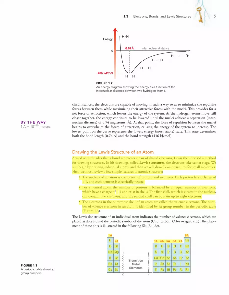
1.3 Electrons, Bonds, and Lewis Structures 5
circumstances, the electrons are capable of moving in such a way so as to minimize the repulsive forces between them while maximizing their attractive forces with the nuclei. This provides for a net force of attraction, which lowers the energy of the system. As the hydrogen atoms move still closer together, the energy continues to be lowered until the nuclei achieve a separation (inter-nuclear distance) of 0.74 angstroms (Å). At that point, the force of repulsion between the nuclei begins to overwhelm the forces of attraction, causing the energy of the system to increase. The lowest point on the curve represents the lowest energy (most stable) state. This state determines both the bond length (0.74 Å) and the bond strength (436 kJ/mol).
By THe wAy1 Å = 10-10 meters.
Internuclear distance0.74 Å
–436 kJ/mol
0
Energy
H H
H H
H H
H HH H+
Drawing the Lewis Structure of an AtomArmed with the idea that a bond represents a pair of shared electrons, Lewis then devised a method for drawing structures. In his drawings, called Lewis structures, the electrons take center stage. We will begin by drawing individual atoms, and then we will draw Lewis structures for small molecules. First, we must review a few simple features of atomic structure:
• The nucleus of an atom is comprised of protons and neutrons. Each proton has a charge of +1, and each neutron is electrically neutral.
• For a neutral atom, the number of protons is balanced by an equal number of electrons, which have a charge of -1 and exist in shells. The first shell, which is closest to the nucleus, can contain two electrons, and the second shell can contain up to eight electrons.
• The electrons in the outermost shell of an atom are called the valence electrons. The num-ber of valence electrons in an atom is identified by its group number in the periodic table (Figure 1.3).
The Lewis dot structure of an individual atom indicates the number of valence electrons, which are placed as dots around the periodic symbol of the atom (C for carbon, O for oxygen, etc.). The place-ment of these dots is illustrated in the following SkillBuilder.
FiguRE 1.3A periodic table showing group numbers.
TransitionMetal
Elements
1A 8A
2A 3A 4A 5A 6A 7AH
Li Be
Na Mg
K Ca
Rb Sr
Cs Ba
B C
Al Si
Ga Ge
In Sn
Tl Pb
N O
P S
As Se
Sb Te
Bi Po
F Ne
He
Cl Ar
Br Kr
I Xe
At Rn
FiguRE 1.2An energy diagram showing the energy as a function of the internuclear distance between two hydrogen atoms.

6 CHAPTER 1 A Review of General Chemistry
Drawing the Lewis Structure of a Small MoleculeThe Lewis dot structures of individual atoms are combined to produce Lewis dot structures of small molecules. These draw-ings are constructed based on the observation that atoms tend to bond in such a way so as to achieve the electron configuration of a noble gas. For example, hydrogen will form one bond to achieve the electron configuration of helium (two valence electrons), while second-row elements (C, N, O, and F) will form the necessary number of bonds so as to achieve the electron configura-tion of neon (eight valence electrons).
C H
H
H
H
CH HH
H
STEP 1Determine the number
of valence electrons.
STEP 2Place one valence
electron by itself on each side of the atom.
STEP 3If the atom has more
than four valence electrons, the remaining electrons are paired with
the electrons already drawn.
1.5 Draw a Lewis dot structure for each of the following atoms:
(a) Carbon (b) Oxygen (c) Fluorine (d) Hydrogen
(e) Bromine (f ) Sulfur (g) Chlorine (h) Iodine
1.6 Compare the Lewis dot structure of nitrogen and phosphorus and explain why you might expect these two atoms to exhibit similar bonding properties.
1.7 Name one element that you would expect to exhibit bonding properties similar to boron. Explain.
1.8 Draw a Lewis structure of a carbon atom that is missing one valence electron (and therefore bears a positive charge). Which second‑row element does this carbon atom resemble in terms of the number of valence electrons?
1.9 Draw a Lewis structure of a carbon atom that has one extra valence electron (and therefore bears a negative charge). Which second‑row element does this carbon atom resemble in terms of the number of valence electrons?
PRACTiCE the skill
APPLy the skill
SKILLBUILDER
LEARN the skill
1.2 drawing the lewis dot structure of an atom
Draw the Lewis dot structure of (a) a boron atom and (b) a nitrogen atom.
SoLuTioN(a) In a Lewis dot structure, only valence electrons are drawn, so we must first determine
the number of valence electrons. Boron belongs to group 3A on the periodic table, and it therefore has three valence electrons. The periodic symbol for boron (B) is drawn, and each electron is placed by itself (unpaired) around the B, like this:
B
(b) Nitrogen belongs to group 5A on the periodic table, and it therefore has five valence electrons. The periodic symbol for nitrogen (N) is drawn, and each electron is placed by itself (unpaired) on a side of the N until all four sides are occupied:
N
Any remaining electrons must be paired up with the electrons already drawn. In the case of nitrogen, there is only one more electron to place, so we pair it up with one of the four unpaired electrons (it doesn’t matter which one we choose):
N

1.3 Electrons, Bonds, and Lewis Structures 7
Draw the Lewis structure of CH2O.
SoLuTioNThere are four discrete steps when drawing a Lewis structure: First determine the number of valence electrons for each atom:
H HC O
Then, connect any atoms that form more than one bond. Hydrogen atoms only form one bond each, so we will save those for last. In this case, we connect the C and the O:
OC
Next, connect all hydrogen atoms. We place the hydrogen atoms next to carbon, because carbon has more unpaired electrons than oxygen:
HOH C
Finally, check to see if each atom (except hydrogen) has an octet. In fact, neither the carbon nor the oxygen has an octet, so in a situation like this, the unpaired electrons are shared as a double bond between carbon and oxygen:
HOH C
HOH C
Now all atoms have achieved an octet. When drawing Lewis structures, remember that you cannot simply add more electrons to the drawing. For each atom to achieve an octet the existing electrons must be shared. The total number of valence electrons should be correct when you are finished. In this example, there was one carbon atom, two hydrogen atoms, and one oxygen atom, giving a total of 12 valence electrons (4 + 2 + 6). The drawing above MUST have 12 valence electrons, no more and no less.
1.10 Draw a Lewis structure for each of the following compounds:
(a) C2H6 (b) C2H4 (c) C2H2
(d) C3H8 (e) C3H6 (f ) CH3OH
1.11 Borane (BH3) is very unstable and quite reactive. Draw a Lewis structure of borane and explain the source of the instability.
1.12 There are four constitutional isomers with molecular formula C3H9N. Draw a Lewis structure for each isomer and determine the number of lone pairs on the nitrogen atom in each case.
Try Problems 1.35, 1.38, 1.42
STEP 1Draw all individual
atoms.
STEP 2Connect atoms that form more than one
bond.
STEP 3Connect the
hydrogen atoms.
STEP 4Pair any unpaired
electrons so that each atom achieves an
octet.
This observation, called the octet rule, explains why carbon is tetravalent. As just shown, it can achieve an octet of electrons by using each of its four valence electrons to form a bond. The octet rule also explains why nitrogen is trivalent. Specifically, it has five valence electrons and requires three bonds in order to achieve an octet of electrons. Notice that the nitrogen atom con-tains one pair of unshared, or nonbonding, electrons, called a lone pair.
In the next chapter, we will discuss the octet rule in more detail; in particular, we will explore when it can be violated and when it cannot be violated. For now, let’s practice drawing Lewis structures.
N HH
H
NH HH
PRACTiCE the skill
APPLy the skill
need more PRACTiCE?
SKILLBUILDER
LEARN the skill
1.3 drawing the lewis structure of a small molecule

8 CHAPTER 1 A Review of General Chemistry
SKILLBUILDER
LEARN the skill
1.4 calculating formal charge
Consider the nitrogen atom in the structure below and determine if it has a formal charge:
N
H
H
H H
SoLuTioNWe begin by determining the appropriate number of valence electrons for a nitrogen atom. Nitrogen is in group 5A of the periodic table, and it should therefore have five valence electrons.
Next, we count how many valence electrons are exhibited by the nitrogen atom in this particular example:
1.4 Identifying Formal Charges
A formal charge is associated with any atom that does not exhibit the appropriate number of valence electrons. When such an atom is present in a Lewis structure, the formal charge must be drawn. Identifying a formal charge requires two discrete tasks:
1. Determine the appropriate number of valence electrons for an atom. 2. Determine whether the atom exhibits the appropriate number of electrons.
The first task can be accomplished by inspecting the periodic table. As mentioned earlier, the group number indicates the appropriate number of valence electrons for each atom. For example, carbon is in group 4A and therefore has four valence electrons. Oxygen is in group 6A and has six valence electrons.
After identifying the appropriate number of electrons for each atom in a Lewis structure, the next task is to determine if any of the atoms exhibit an unexpected num-ber of electrons. For example, consider the following structure:
STEP 1Determine the
appropriate number of valence electrons.
STEP 3Assign a formal
charge.
O
H HC
H
Each hydrogen atom has one valence electron, as expected. The carbon atom also has the appropriate number of valence electrons (four), but the oxygen atom does not. The oxygen atom in this structure exhibits seven valence electrons, but it should only have six. In this case, the oxygen atom has one extra electron, and it must therefore bear a negative formal charge, which is indicated like this: C
H
O
H H
@
Each line represents two shared electrons (a bond). For our purposes, we must split each bond apart equally, and then count the number of electrons on each atom:
C HH
H
O
N H
H
H
H
In this case, the nitrogen atom exhibits only four valence electrons. It is missing one electron, so it must bear a positive charge, which is shown like this:
NH H
H
H!
STEP 2Determine the actual
number of valence electrons in this case.

1.5 Induction and Polar Covalent Bonds 9
H HC
H(f )
H C C
H
H
O
(g)
AlCl Cl
Cl
Cl
Cl
(h)
C C
H
H
H N
H
H O
O
(i)
AlH H
H
H
(a)O
H H
H
(b)
H NC
H
H
HC
H
H
(c) H H
H
C
O
(d)
H HC
H(e)
1.14 Draw a structure for each of the following ions; in each case, indicate which atom possesses the formal charge:
(a) BH4- (b) NH2
- (c) C2H5+
Try Problem 1.41
1.5 Induction and Polar Covalent Bonds
Chemists classify bonds into three categories: (1) covalent, (2) polar covalent, and (3) ionic. These categories emerge from the electronegativity values of the atoms sharing a bond. Electronegativity is a measure of the ability of an atom to attract electrons. Table 1.1 gives the electronegativity values for elements commonly encountered in organic chemistry.
1.13 Identify any formal charges in the structures below:
table 1.1 electronegativity values of some common elements
H2.1
Li1.0
Be1.5
B2.0
C2.5
N3.0
O3.5
F4.0
K0.8
Br2.8
Na0.9
Mg1.2
Al1.5
Si1.8
P2.1
S2.5
Cl3.0
Increasing electronegativity
Increasingelectronegativity
When two atoms form a bond, one critical consideration allows us to classify the bond: What is the difference in the electronegativity values of the two atoms? Below are some rough guidelines:
If the difference in electronegativity is less than 0.5, the electrons are considered to be equally shared between the two atoms, resulting in a covalent bond. Examples include C!C and C!H:
CC HC
The C!C bond is clearly covalent, because there is no difference in electronegativity between the two atoms forming the bond. Even a C!H bond is considered to be covalent, because the difference in electronegativity between C and H is less than 0.5.
If the difference in electronegativity is between 0.5 and 1.7, the electrons are not shared equally between the atoms, resulting in a polar covalent bond. For example, consider a bond between carbon and oxygen (C!O). Oxygen is significantly more electronegative (3.5) than carbon (2.5), and therefore oxygen will more strongly attract the electrons of the bond.
PRACTiCE the skill
APPLy the skill
need more PRACTiCE?
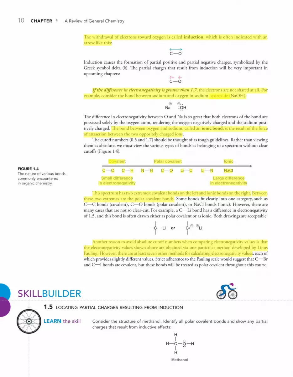
10 CHAPTER 1 A Review of General Chemistry
SKILLBUILDER
LEARN the skill
1.5 locating partial charges resulting from induction
Consider the structure of methanol. Identify all polar covalent bonds and show any partial charges that result from inductive effects:
OH
H
HC
H
Methanol
The withdrawal of electrons toward oxygen is called induction, which is often indicated with an arrow like this:
C O
Induction causes the formation of partial positive and partial negative charges, symbolized by the Greek symbol delta (d). The partial charges that result from induction will be very important in upcoming chapters:
C Od–d+
If the difference in electronegativity is greater than 1.7, the electrons are not shared at all. For example, consider the bond between sodium and oxygen in sodium hydroxide (NaOH):
ONa H@!
The difference in electronegativity between O and Na is so great that both electrons of the bond are possessed solely by the oxygen atom, rendering the oxygen negatively charged and the sodium posi-tively charged. The bond between oxygen and sodium, called an ionic bond, is the result of the force of attraction between the two oppositely charged ions.
The cutoff numbers (0.5 and 1.7) should be thought of as rough guidelines. Rather than viewing them as absolute, we must view the various types of bonds as belonging to a spectrum without clear cutoffs (Figure 1.4).
This spectrum has two extremes: covalent bonds on the left and ionic bonds on the right. Between these two extremes are the polar covalent bonds. Some bonds fit clearly into one category, such as C!C bonds (covalent), C!O bonds (polar covalent), or NaCl bonds (ionic). However, there are many cases that are not so clear-cut. For example, a C!Li bond has a difference in electronegativity of 1.5, and this bond is often drawn either as polar covalent or as ionic. Both drawings are acceptable:
Li LiC or C@ !
Another reason to avoid absolute cutoff numbers when comparing electronegativity values is that the electronegativity values shown above are obtained via one particular method developed by Linus Pauling. However, there are at least seven other methods for calculating electronegativity values, each of which provides slightly different values. Strict adherence to the Pauling scale would suggest that C!Br and C!I bonds are covalent, but these bonds will be treated as polar covalent throughout this course.
C C Li CC H N H C O
Covalent Polar covalent Ionic
Li N
Small differencein electronegativity
Large differencein electronegativity
NaClFiguRE 1.4The nature of various bonds commonly encountered in organic chemistry.

1.5 Induction and Polar Covalent Bonds 11
STEP 1Identify all polar covalent bonds.
STEP 2Determine the
direction of each dipole.
STEP 3Indicate the location
of partial charges.
SoLuTioNFirst identify all polar covalent bonds. The C!H bonds are considered to be covalent because the electronegativity values for C and H are fairly close. It is true that carbon is more electronegative than hydrogen, and therefore, there is a small inductive effect for each C!H bond. However, we will generally consider this effect to be negligible for C!H bonds.
The C!O bond and the O!H bond are both polar covalent bonds:
OH
H
HC
HPolar covalent
Now determine the direction of the inductive effects. Oxygen is more electronegative than C or H, so the inductive effects are shown like this:
OH
H
HC
H
These inductive effects dictate the locations of the partial charges:
OH
H
HC
H
d–d+ d+
1.15 For each of the following compounds, identify any polar covalent bonds by drawing d+ and d- symbols in the appropriate locations:
(a)
CH
H
O
H
C
H
H
C
H
H
O C
H
H
H
(b)
CH
H
F
Cl
(c)
CH
H
Mg
H
Br
(d)
H O C
H
H
C
H
H
O HC
H
H O
(e)
H C C
H
H
HC
H
H O
(f )
CCl
Cl
Cl
Cl
1.16 The regions of d+ in a compound are the regions most likely to be attacked by an anion, such as hydroxide (HO-). In the compound below, identify the two carbon atoms that are most likely to be attacked by a hydroxide ion:
CH
H
H
C
H
H
C
H
H
C
O
C
H
H
Cl
Try Problems 1.36, 1.37, 1.48, 1.57
PRACTiCE the skill
APPLy the skill
need more PRACTiCE?

12 CHAPTER 1 A Review of General Chemistry
1.6 Atomic Orbitals
Quantum MechanicsBy the 1920s, vitalism had been discarded. Chemists were aware of constitutional isomerism and had developed the structural theory of matter. The electron had been discovered and identified as the source of bonding, and Lewis structures were used to keep track of shared and unshared electrons. But the understanding of electrons was about to change dramatically.
In 1924, French physicist Louis de Broglie suggested that electrons, heretofore considered as particles, also exhibited wavelike properties. Based on this assertion, a new theory of matter was born. In 1926, Erwin Schrödinger, Werner Heisenberg, and Paul Dirac independently proposed a math-ematical description of the electron that incorporated its wavelike properties. This new theory, called wave mechanics, or quantum mechanics, radically changed the way we viewed the nature of matter and laid the foundation for our current understanding of electrons and bonds.
Quantum mechanics is deeply rooted in mathematics and represents an entire subject by itself. The mathematics involved is beyond the scope of our course, and we will not discuss it here. However, in order to understand the nature of electrons, it is critical to understand a few simple highlights from quantum mechanics:
• An equation is constructed to describe the total energy of a hydrogen atom (i.e., one proton plus one electron). This equation, called the wave equation, takes into account the wavelike behavior of an electron that is in the electric field of a proton.
• The wave equation is then solved to give a series of solutions called wavefunctions. The Greek symbol psi (y) is used to denote each wavefunction (y1, y2, y3, etc.). Each of these wavefunc-tions corresponds to an allowed energy level for the electron. This result is incredibly impor-tant because it suggests that an electron, when contained in an atom, can only exist at discrete energy levels (y1, y2, y3, etc.). In other words, the energy of the electron is quantized.
• Each wavefunction is a function of spatial location. It provides information that allows us to assign a numerical value for each location in three-dimensional space relative to the nucleus.
electrostatic Potential Mapspractically speaking
Partial charges can be visualized with three‑dimensional, rainbow‑like images called electrostatic potential maps. As an example, consider the electrostatic potential map of chloromethane:
Most negative(δ−)
Most positive(δ+)
Color scaleElectrostaticpotential map
of chloromethane
Chloromethane
C
Cl
HHH
d−
d+
δ−
δ+
In the image, a color scale is used to represent areas of d- and d+. As indicated, red represents a region that is d-,
while blue represents a region that is d+. In reality, electro‑static potential maps are rarely used by practicing organic chemists when they communicate with each other; how‑ever, these illustrations can often be helpful to students who are learning organic chemistry. Electrostatic potential maps are generated by performing a series of calcula‑tions. Specifically, an imaginary point positive charge is positioned at various locations, and for each location, we calculate the potential energy associated with the attrac‑tion between the point positive charge and the surround‑ing electrons. A large attraction indicates a position of d-, while a small attraction indicates a position of d+. The results are then illustrated using colors, as shown.
A comparison of any two electrostatic potential maps is only valid if both maps were prepared using the same color scale. Throughout this book, care has been taken to use the same color scale whenever two maps are directly compared to each other. However, it will not be useful to compare two maps from different pages of this book (or any other book), as the exact color scales are likely to be different.

1.6 Atomic Orbitals 13
x
y
z
x
y
z
x
y
z
x
y
z
FiguRE 1.5Illustrations of an s orbital and three p orbitals.
Electron Density and Atomic OrbitalsAn orbital is a region of space that can be occupied by an electron. But care must be taken when trying to visualize this. There is a statement from the previous section that must be clarified because it is potentially misleading: “y2 represents the probability of finding an electron in a particular loca-tion.” This statement seems to treat an electron as if it were a particle flying around within a specific region of space. But remember that an electron is not purely a particle—it has wavelike properties as well. Therefore, we must construct a mental image that captures both of these properties. That is not easy to do, but the following analogy might help. We will treat an occupied orbital as if it is a cloud—similar to a cloud in the sky. No analogy is perfect, and there are certainly features of clouds that are very different from orbitals. However, focusing on some of these differences between electron clouds (occupied orbitals) and real clouds makes it possible to construct a better mental model of an electron in an orbital:
• Clouds in the sky can come in any shape or size. However, electron clouds only come in a small number of shapes and sizes (as defined by the orbitals).
• A cloud in the sky is comprised of billions of individual water molecules. An electron cloud is not comprised of billions of particles. We must think of an electron cloud as a single entity, even though it can be thicker in some places and thinner in other places. This concept is criti-cal and will be used extensively throughout the course in explaining reactions.
• A cloud in the sky has edges, and it is possible to define a region of space that contains 100% of the cloud. In contrast, an electron cloud does not have defined edges. We frequently use the term electron density, which is associated with the probability of finding an electron in a particular region of space. The “shape” of an orbital refers to a region of space that contains 90–95% of the electron density. Beyond this region, the remaining 5–10% of the electron density tapers off but never ends. In fact, if we want to consider the region of space that con-tains 100% of the electron density, we must consider the entire universe.
In summary, we must think of an orbital as a region of space that can be occupied by electron density. An occupied orbital must be treated as a cloud of electron density. This region of space is called an atomic orbital (AO), because it is a region of space defined with respect to the nucleus of a single atom. Examples of atomic orbitals are the s, p, d, and f orbitals that were discussed in your general chemistry textbook.
Phases of Atomic OrbitalsOur discussion of electrons and orbitals has been based on the premise that electrons have wavelike properties. As a result, it will be necessary to explore some of the characteristics of simple waves in order to understand some of the characteristics of orbitals.
The square of that value (y2 for any particular location) has a special meaning. It indicates the probability of finding the electron in that location. Therefore, a three-dimensional plot of y2 will generate an image of an atomic orbital (Figure 1.5).

14 CHAPTER 1 A Review of General Chemistry
Consider a wave that moves across the surface of a lake (Figure 1.6). The wavefunction (y) math-ematically describes the wave, and the value of the wavefunction is dependent on location. Locations above the average level of the lake have a positive value for y (indicated in red), and locations below the average level of the lake have a negative value for y (indicated in blue). Locations where the value of y is zero are called nodes.
Similarly, orbitals can have regions where the value of y is positive, negative, or zero. For exam-ple, consider a p orbital (Figure 1.7). Notice that the p orbital has two lobes: The top lobe is a region of space where the values of y are positive, while the bottom lobe is a region where the values of y are negative. Between the two lobes is a location where y = 0. This location represents a node.
Be careful not to confuse the sign of y (+ or -) with electrical charge. A positive value for y does not imply a positive charge. The value of y (+ or -) is a mathematical convention that refers to the phase of the wave (just like in the lake). Although y can have positive or negative values, nev-ertheless y2 (which describes the electron density as a function of location) will always be a positive number. At a node, where y = 0, the electron density (y2) will also be zero. This means that there is no electron density located at a node.
From this point forward, we will draw the lobes of an orbital with colors (red and blue) to indi-cate the phase of y for each region of space.
Filling Atomic Orbitals with ElectronsThe energy of an electron depends on the type of orbital that it occupies. Most of the organic com-pounds that we will encounter will be composed of first- and second-row elements (H, C, N, and O). These elements utilize the 1s orbital, the 2s orbital, and the three 2p orbitals. Our discussions will therefore focus primarily on these orbitals (Figure 1.8). Electrons are lowest in energy when they occupy a 1s orbital, because the 1s orbital is closest to the nucleus and it has no nodes (the more nodes that an orbital has, the greater its energy). The 2s orbital has one node and is farther away form the nucleus; it is therefore higher in energy than the 1s orbital. After the 2s orbital, there are three 2p orbitals that are all equivalent in energy to one another. Orbitals with the same energy level are called degenerate orbitals.
As we move across the periodic table, starting with hydrogen, each element has one more elec-tron than the element before it (Figure 1.9). The order in which the orbitals are filled by electrons is determined by just three simple principles:
1. The Aufbau principle. The lowest energy orbital is filled first. 2. The Pauli exclusion principle. Each orbital can accommodate a maximum of two electrons
that have opposite spin. To understand what “spin” means, we can imagine an electron spinning
FiguRE 1.6Phases of a wave moving across the surface of a lake.
c is (–) c is (–)c is (+) c is (+)
Nodec = 0
Average levelof lake
FiguRE 1.7The phases of a p orbital.
c is (+)
c is (–)
Node
FiguRE 1.8Illustrations of s orbitals and three p orbitals.
x
y
z
x
y
z
x
y
z
x
y
z
x
y
z
1s 2s 2py 2px 2pz

1.6 Atomic Orbitals 15
in space (although this is an oversimplified explanation of the term “spin”). For reasons that are beyond the scope of this course, electrons only have two possible spin states (designated by hor v). In order for the orbital to accommodate two electrons, the electrons must have opposite spin states.
3. Hund’s rule. When dealing with degenerate orbitals, such as p orbitals, one electron is placed in each degenerate orbital first, before electrons are paired up.
The application of the first two principles can be seen in the electron configurations shown in Figure 1.9 (H, He, Li, and Be). The application of the third principle can be seen in the electron configura-tions for the remaining second-row elements (Figure 1.10).
FiguRE 1.9Energy diagrams showing the electron configurations for H, He, Li, and Be.
Energy
Hydrogen1s
Helium1s
Lithium1s
2s
2p
Beryllium1s
2s
2p
FiguRE 1.10Energy diagrams showing the electron configurations for B, C, N, O, F, and Ne.
Ene
rgy
Boron1s
2s
2p
Carbon1s
2s
2p
Nitrogen1s
2s
2p
Oxygen1s
2s
2p
Fluorine1s
2s
2p
Neon1s
2s
2p
STEP 1Place the valence
electrons in atomic orbitals using the Aufbau principle,
the Pauli exclusion principle, and
Hund’s rule.
STEP 2Identify the number
of valence electrons in each atomic orbital.
SKILLBUILDER
LEARN the skill
1.6 identifying electron configurations
Identify the electron configuration of a nitrogen atom.
SoLuTioNThe electron configuration indicates which atomic orbitals are occupied by electrons. Nitrogen has a total of seven electrons. These electrons occupy atomic orbitals of increasing energy, with a maximum of two electrons in each orbital:
Nitrogen1s
2s
2p
Two electrons occupy the 1s orbital, two electrons occupy the 2s orbital, and three electrons occupy the 2p orbitals. This is summarized using the following notation:
1s22s22p3
1.17 Determine the electron configuration for each of the following atoms:
(a) Carbon (b) Oxygen (c) Boron (d) Fluorine (e) Sodium (f ) Aluminum
PRACTiCE the skill

16 CHAPTER 1 A Review of General Chemistry
1.7 Valence Bond Theory
With the understanding that electrons occupy regions of space called orbitals, we can now turn our attention to a deeper understanding of covalent bonds. Specifically, a covalent bond is formed from the overlap of atomic orbitals. There are two commonly used theories for describing the nature of atomic orbital overlap: valence bond theory and molecular orbital (MO) theory. The valence bond approach is more simplistic in its treatment of bonds, and therefore we will begin our discussion with valence bond theory.
If we are going to treat electrons as waves, then we must quickly review what happens when two waves interact with each other. Two waves that approach each other can interfere in one of two possible ways—constructively or destructively. Similarly, when atomic orbitals overlap, they can interfere either constructively (Figure 1.11) or destructively (Figure 1.12).
FiguRE 1.11Constructive interference resulting from the interaction of two electrons.
An electronis like a wave
An electronis like a wave
Internuclear distance Internucleardistance
Constructiveinterference
Bring thesewaves closertogether...
...and thewaves reinforceeach other
FiguRE 1.12Destructive interference resulting from the interaction of two electrons.
Destructiveinterference
Bring thesewaves closertogether...
...and thewaves canceleach other
A node
FiguRE 1.13The overlap of the 1s atomic orbitals of two hydrogen atoms, forming molecular hydrogen (H2).
1.18 Determine the electron configuration for each of the following ions:
(a) A carbon atom with a negative charge (c) A nitrogen atom with a positive charge
(b) A carbon atom with a positive charge (d) An oxygen atom with a negative charge
Try Problem 1.44
Constructive interference produces a wave with larger amplitude. In contrast, destructive interfer-ence results in waves canceling each other, which produces a node (Figure 1.12).
According to valence bond theory, a bond is simply the sharing of electron density between two atoms as a result of the constructive interference of their atomic orbitals. Consider, for example, the bond that is formed between the two hydrogen atoms in molecular hydrogen (H2). This bond is formed from the overlap of the 1s orbitals of each hydrogen atom (Figure 1.13).
The electron density of this bond is primarily located on the bond axis (the line that can be drawn between the two hydrogen atoms). This type of bond is called a sigma (s) bond and is char-acterized by circular symmetry with respect to the bond axis. To visualize what this means, imagine a plane that is drawn perpendicular to the bond axis. This plane will carve out a circle (Figure 1.14). This is the defining feature of s bonds and will be true of all purely single bonds. Therefore, all single bonds are s bonds.
FiguRE 1.14An illustration of a sigma bond, showing the circular symmetry with respect to the bond axis.
Circularcross section
+
APPLy the skill
need more PRACTiCE?

1.8 Molecular Orbital Theory 17
1.8 Molecular Orbital Theory
In most situations, valence bond theory will be sufficient for our purposes. However, there will be cases in the upcoming chapters where valence bond theory will be inadequate to describe the observa-tions. In such cases, we will utilize molecular orbital theory, a more sophisticated approach to viewing the nature of bonds.
Much like valence bond theory, molecular orbital (MO) theory also describes a bond in terms of the constructive interference between two overlapping atomic orbitals. However, MO theory goes one step further and uses mathematics as a tool to explore the consequences of atomic orbital overlap. The mathematical method is called the linear combination of atomic orbitals (LCAO). According to this theory, atomic orbitals are mathematically combined to produce new orbitals, called molecular orbitals.
It is important to understand the distinction between atomic orbitals and molecular orbitals. Both types of orbitals are used to accommodate electrons, but an atomic orbital is a region of space associated with an individual atom, while a molecular orbital is associated with an entire molecule. That is, the molecule is considered to be a single entity held together by many electron clouds, some of which can actually span the entire length of the molecule. These molecular orbitals are filled with electrons in a particular order in much the same way that atomic orbitals are filled. Specifically, electrons first occupy the lowest energy orbitals, with a maximum of two electrons per orbital. In order to visualize what it means for an orbital to be associated with an entire molecule, we will explore two molecules: molecular hydrogen (H2) and bromomethane (CH3Br).
Consider the bond formed between the two hydrogen atoms in molecular hydrogen. This bond is the result of the overlap of two atomic orbitals (s orbitals), each of which is occupied by one elec-tron. According to MO theory, when two atomic orbitals overlap, they cease to exist. Instead, they are replaced by two molecular orbitals, each of which is associated with the entire molecule (Figure 1.15).
Node
Antibonding MO
Bonding MO
Energy 1s 1s
FiguRE 1.15An energy diagram showing the relative energy levels of bonding and antibonding molecular orbitals.
FiguRE 1.16A low‑energy molecular orbital of CH3Br. Red and blue regions indicate the different phases, as described in Section 1.6. Notice that this molecular orbital is associated with the entire molecule, rather than being associated with two specific atoms.
In the energy diagram shown in Figure 1.15, the individual atomic orbitals are represented on the right and left, with each atomic orbital having one electron. These atomic orbitals are combined mathematically (using the LCAO method) to produce two molecular orbitals. The lower energy molecular orbital, or bonding MO, is the result of constructive interference of the original two atomic orbitals. The higher energy molecular orbital, or antibonding MO, is the result of destruc-tive interference. Notice that the antibonding MO has one node, which explains why it is higher in energy. Both electrons occupy the bonding MO in order to achieve a lower energy state. This lower-ing in energy is the essence of the bond. For an H!H bond, the lowering in energy is equivalent to 436 kJ/mol. This energy corresponds with the bond strength of an H!H bond (as shown in Figure 1.2).
Now let’s consider a molecule such as CH3Br, which contains more than just one bond. Valence bond theory continues to view each bond separately, with each bond being formed from two overlap-ping atomic orbitals. In contrast, MO theory treats the bonding electrons as being associated with the entire molecule. The molecule has many molecular orbitals, each of which can be occupied by two electrons. Figure 1.16 illustrates one of the many molecular orbitals of CH3Br. This molecular orbital is capable of accommodating up to two electrons. Red and blue regions indicate the different phases, as described in Section 1.6. As we saw with molecular hydrogen, not all molecular orbitals

18 CHAPTER 1 A Review of General Chemistry
FiguRE 1.17The LUMO of CH3Br.
will be occupied. The bonding electrons will occupy the lower energy molecular orbitals (such as the one shown in Figure 1.16), while the higher energy molecular orbitals remain unoccupied. For
every molecule, two of its molecular orbitals will be of particular interest: (1) the highest energy orbital from among the occupied orbitals is called the highest occupied molecular orbital,
or HOMO, and (2) the lowest energy orbital from among the unoccupied orbitals is called the lowest unoccupied molecular orbital, or LUMO. For example, in Chapter 7, we will explore a reaction in which CH3Br is attacked by a hydroxide ion (HO-). In order for this process to occur, the hydroxide ion must transfer its electron density into the lowest energy, empty molecular orbital, or LUMO, of CH3Br (Figure 1.17). The nature
of the LUMO (i.e., number of nodes, location of nodes, etc.) will be useful in explaining the preferred direction from which the hydroxide ion will attack.We will use MO theory several times in the chapters that follow. Most notably, in Chapter 17,
we will investigate the structure of compounds containing several double bonds. For those com-pounds, valence bond theory will be inadequate, and MO theory will provide a more meaningful understanding of the bonding structure. Throughout this textbook, we will continue to develop both valence bond theory and MO theory.
1.9 Hybridized Atomic Orbitals
Methane and sp3 HybridizationLet us now apply valence bond theory to the bonds in methane:
H H
H
H
C
Methane
Recall the electron configuration of carbon (Figure 1.18). This electron configuration cannot satisfac-torily describe the bonding structure of methane (CH4), in which the carbon atom has four separate C!H bonds, because the electron configuration shows only two atomic orbitals capable of forming bonds (each of these orbitals has one unpaired electron). This would imply that the carbon atom will form only two bonds, but we know that it forms four bonds. We can solve this problem by imagin-ing an excited state of carbon (Figure 1.19): a state in which a 2s electron has been promoted to a higher energy 2p orbital. Now the carbon atom has four atomic orbitals capable of forming bonds, but there is yet another problem here. The geometry of the 2s and three 2p orbitals does not satisfac-torily explain the observed three-dimensional geometry of methane (Figure 1.20). All bond angles are 109.5°, and the four bonds point away from each other in a perfect tetrahedron. This geometry cannot be explained by an excited state of carbon because the s orbital and the three p orbitals do not occupy a tetrahedral geometry. The p orbitals are separated from each other by only 90° (as seen in Figure 1.5) rather than 109.5°.
This problem was solved in 1931 by Linus Pauling, who suggested that the electronic configu-ration of the carbon atom in methane does not necessarily have to be the same as the electronic configuration of a free carbon atom. Specifically, Pauling mathematically averaged, or hybridized, the 2s orbital and the three 2p orbitals, giving four degenerate hybridized atomic orbitals (Figure 1.21). The hybridization process in Figure 1.21 does not represent a real physical process that the orbitals undergo. Rather, it is a mathematical procedure that is used to arrive at a satisfactory description of
FiguRE 1.18An energy diagram showing the electron configuration of carbon.
Energy
1s
2s
2p
FiguRE 1.19An energy diagram showing the electronic excitation of an electron in a carbon atom.
1s
2s
2p
1s
2s
2p
Energy Excitation
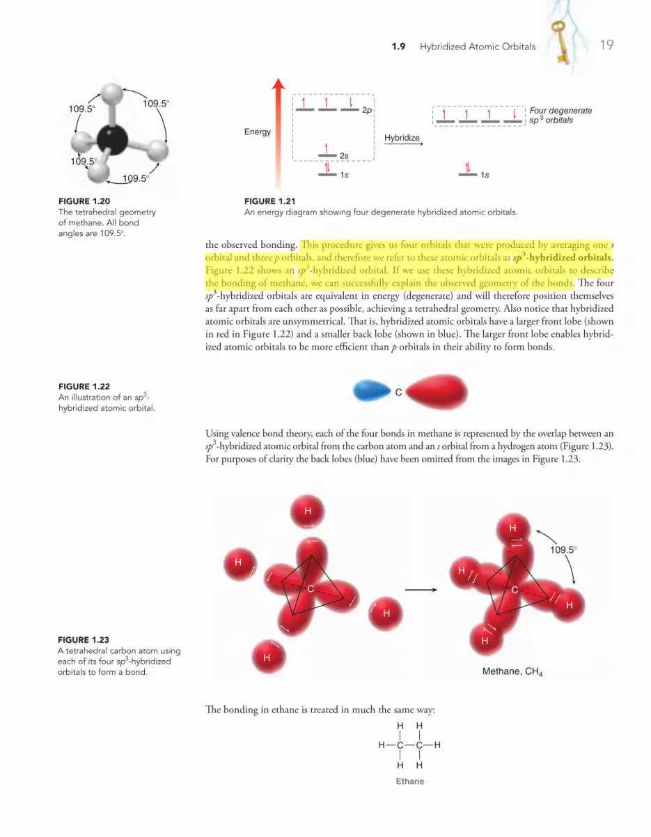
1.9 Hybridized Atomic Orbitals 19
the observed bonding. This procedure gives us four orbitals that were produced by averaging one s orbital and three p orbitals, and therefore we refer to these atomic orbitals as sp3-hybridized orbitals. Figure 1.22 shows an sp3-hybridized orbital. If we use these hybridized atomic orbitals to describe the bonding of methane, we can successfully explain the observed geometry of the bonds. The four sp3-hybridized orbitals are equivalent in energy (degenerate) and will therefore position themselves as far apart from each other as possible, achieving a tetrahedral geometry. Also notice that hybridized atomic orbitals are unsymmetrical. That is, hybridized atomic orbitals have a larger front lobe (shown in red in Figure 1.22) and a smaller back lobe (shown in blue). The larger front lobe enables hybrid-ized atomic orbitals to be more efficient than p orbitals in their ability to form bonds.
FiguRE 1.20The tetrahedral geometry of methane. All bond angles are 109.5°.
109.5°
109.5°
109.5°
109.5°
FiguRE 1.21An energy diagram showing four degenerate hybridized atomic orbitals.
1s
2s
2p
1s
EnergyHybridize
Four degeneratesp3 orbitals
FiguRE 1.22An illustration of an sp3‑hybridized atomic orbital.
C
FiguRE 1.23A tetrahedral carbon atom using each of its four sp3‑hybridized orbitals to form a bond.
H
H
H
H
H
H
H
H
C
109.5°
Methane, CH4
C
The bonding in ethane is treated in much the same way:
H H
H
H
C
H
H
C
Ethane
Using valence bond theory, each of the four bonds in methane is represented by the overlap between an sp3-hybridized atomic orbital from the carbon atom and an s orbital from a hydrogen atom (Figure 1.23). For purposes of clarity the back lobes (blue) have been omitted from the images in Figure 1.23.
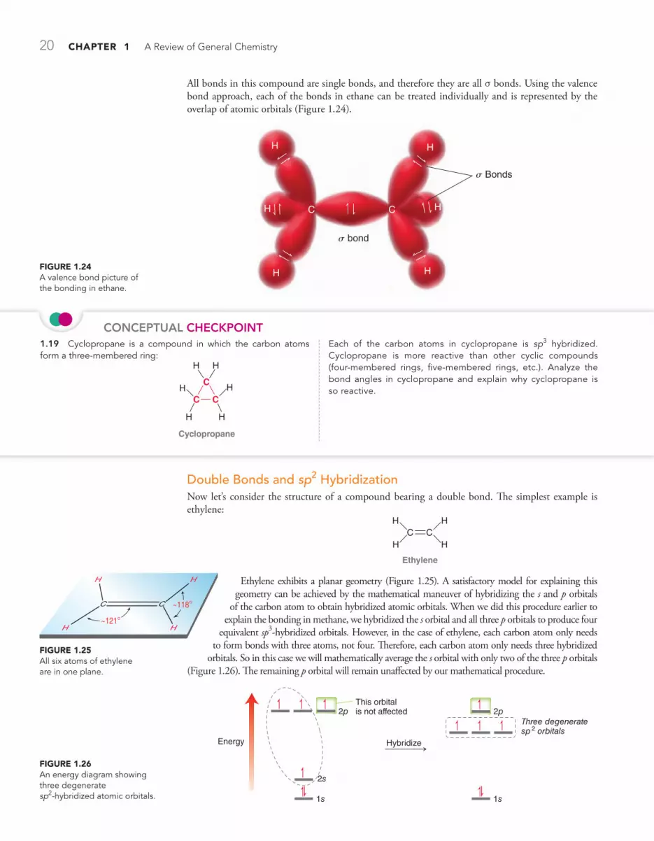
20 CHAPTER 1 A Review of General Chemistry
Double Bonds and sp2 HybridizationNow let’s consider the structure of a compound bearing a double bond. The simplest example is ethylene:
CHH
HHC
Ethylene
Ethylene exhibits a planar geometry (Figure 1.25). A satisfactory model for explaining this geometry can be achieved by the mathematical maneuver of hybridizing the s and p orbitals
of the carbon atom to obtain hybridized atomic orbitals. When we did this procedure earlier to explain the bonding in methane, we hybridized the s orbital and all three p orbitals to produce four
equivalent sp3-hybridized orbitals. However, in the case of ethylene, each carbon atom only needs to form bonds with three atoms, not four. Therefore, each carbon atom only needs three hybridized
orbitals. So in this case we will mathematically average the s orbital with only two of the three p orbitals (Figure 1.26). The remaining p orbital will remain unaffected by our mathematical procedure.
FiguRE 1.25All six atoms of ethylene are in one plane.
~118°
~121°
C
H
H H
H
C
FiguRE 1.26An energy diagram showing three degenerate sp2‑hybridized atomic orbitals. 1s
2s
2p 2p
1s
Energy Hybridize
Three degeneratesp2 orbitals
This orbitalis not affected
All bonds in this compound are single bonds, and therefore they are all s bonds. Using the valence bond approach, each of the bonds in ethane can be treated individually and is represented by the overlap of atomic orbitals (Figure 1.24).
HH
C C HH
HH
s Bonds
s bond
FiguRE 1.24A valence bond picture of the bonding in ethane.
ConCePTuAl CHeCkPoinT1.19 Cyclopropane is a compound in which the carbon atoms form a three‑membered ring:
C
H H
CCH H
H H
Cyclopropane
Each of the carbon atoms in cyclopropane is sp3 hybridized. Cyclopropane is more reactive than other cyclic compounds (four‑membered rings, five‑membered rings, etc.). Analyze the bond angles in cyclopropane and explain why cyclopropane is so reactive.
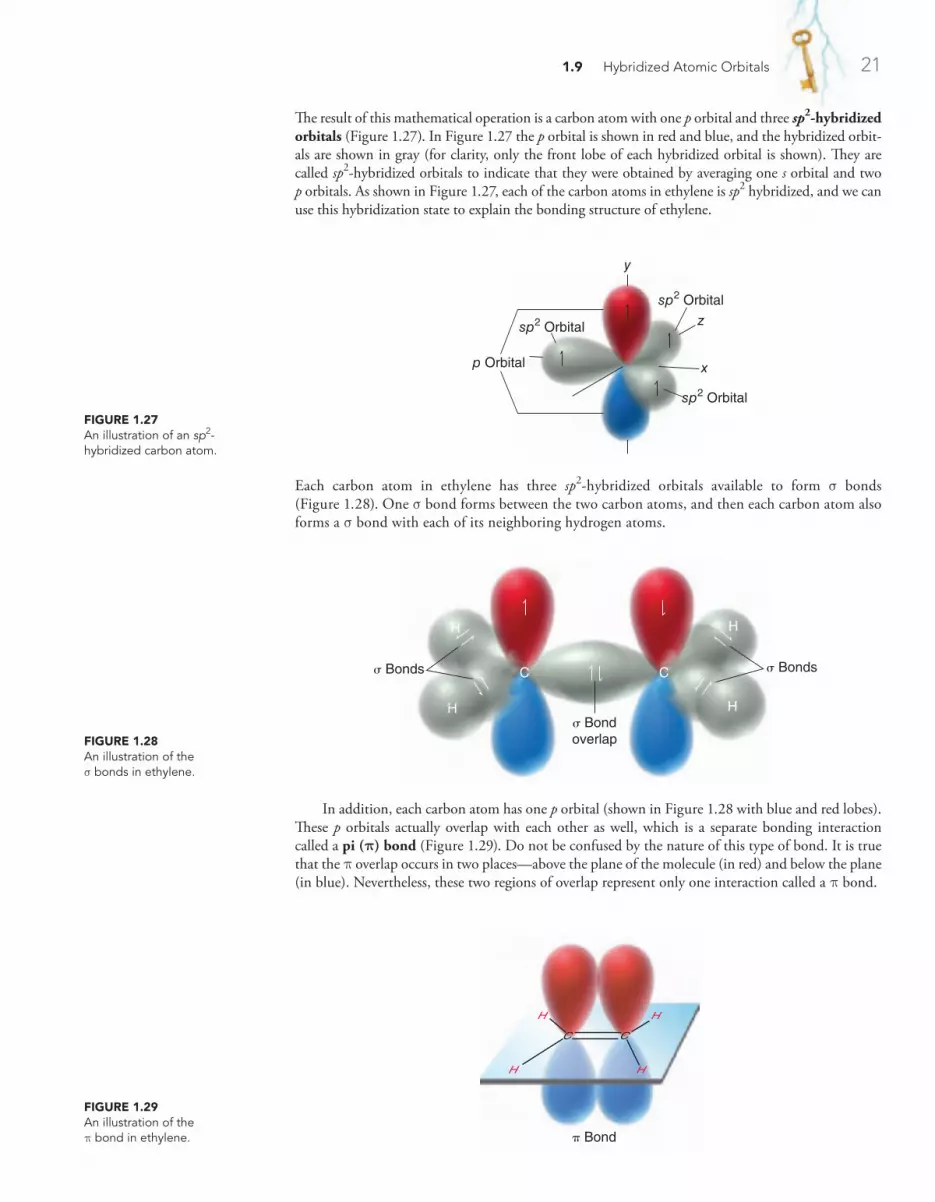
1.9 Hybridized Atomic Orbitals 21
Each carbon atom in ethylene has three sp2-hybridized orbitals available to form s bonds (Figure 1.28). One s bond forms between the two carbon atoms, and then each carbon atom also forms a s bond with each of its neighboring hydrogen atoms.
FiguRE 1.28An illustration of the s bonds in ethylene.
C C
H
HH
Hσ Bondoverlap
σ Bonds σ Bonds
FiguRE 1.29An illustration of the p bond in ethylene.
H
H
H
C
H
C
π Bond
FiguRE 1.27An illustration of an sp2‑hybridized carbon atom.
sp2 Orbital
p Orbital x
y
zsp2 Orbital
sp2 Orbital
The result of this mathematical operation is a carbon atom with one p orbital and three sp2-hybridized orbitals (Figure 1.27). In Figure 1.27 the p orbital is shown in red and blue, and the hybridized orbit-als are shown in gray (for clarity, only the front lobe of each hybridized orbital is shown). They are called sp2-hybridized orbitals to indicate that they were obtained by averaging one s orbital and two p orbitals. As shown in Figure 1.27, each of the carbon atoms in ethylene is sp2 hybridized, and we can use this hybridization state to explain the bonding structure of ethylene.
In addition, each carbon atom has one p orbital (shown in Figure 1.28 with blue and red lobes). These p orbitals actually overlap with each other as well, which is a separate bonding interaction called a pi (p) bond (Figure 1.29). Do not be confused by the nature of this type of bond. It is true that the p overlap occurs in two places—above the plane of the molecule (in red) and below the plane (in blue). Nevertheless, these two regions of overlap represent only one interaction called a p bond.

22 CHAPTER 1 A Review of General Chemistry
The picture of the p bond in Figure 1.29 is based on the valence bond approach (the p orbitals are simply drawn overlapping each other). Molecular orbital theory provides a fairly similar image of a p bond. Compare Figure 1.29 with the bonding MO in Figure 1.30.
ConCePTuAl CHeCkPoinT
Triple Bonds and sp HybridizationNow let’s consider the bonding structure of a compound bearing a triple bond, such as acetylene:
CC HH
Acetylene
A triple bond is formed by sp-hybridized carbon atoms. To achieve sp hybridization, one s orbital is mathematically averaged with only one p orbital (Figure 1.31). This leaves two p orbitals
FiguRE 1.30An energy diagram showing images of bonding and antibonding MOs in ethylene.
π Antibonding MO
π Bonding MO
Node
Energy 2p 2p
To summarize, we have seen that the carbon atoms of ethylene are connected via a s bond and a p bond. The s bond results from the overlap of sp2-hybridized atomic orbitals, while the p bond results from the overlap of p orbitals. These two separate bonding interactions (s and p) comprise the double bond of ethylene.
FiguRE 1.31An energy diagram showing two degenerate sp‑hybridized atomic orbitals.
1s
2s
2p 2p
1s
EnergyHybridize
Two degeneratesp orbitals
These orbitalsare not affected
1.20 Consider the structure of formaldehyde:
O
Formaldehyde
CH H
(a) Identify the type of bonds that form the CPO double bond.
(b) Identify the atomic orbitals that form each COH bond.
(c) What type of atomic orbitals do the lone pairs occupy?
1.21 Sigma bonds experience free rotation at room temperature:
C
HH
H
HH
H
C
In contrast, p bonds do not experience free rotation. Explain. (Hint: Compare Figures 1.24 and 1.29, focusing on the orbitals used in forming a s bond and the orbitals used in forming a p bond. In each case, what happens to the orbital overlap during bond rotation?)
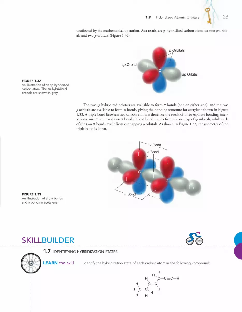
1.9 Hybridized Atomic Orbitals 23
The two sp-hybridized orbitals are available to form s bonds (one on either side), and the two p orbitals are available to form p bonds, giving the bonding structure for acetylene shown in Figure 1.33. A triple bond between two carbon atoms is therefore the result of three separate bonding inter-actions: one s bond and two p bonds. The s bond results from the overlap of sp orbitals, while each of the two p bonds result from overlapping p orbitals. As shown in Figure 1.33, the geometry of the triple bond is linear.
FiguRE 1.33An illustration of the s bonds and p bonds in acetylene.
π Bond
σ Bond
π Bond
C
H
H
C
FiguRE 1.32An illustration of an sp‑hybridized carbon atom. The sp‑hybridized orbitals are shown in gray.
p Orbitals
sp Orbital
sp Orbital
C
unaffected by the mathematical operation. As a result, an sp-hybridized carbon atom has two sp orbit-als and two p orbitals (Figure 1.32).
SKILLBUILDER
LEARN the skill
1.7 identifying hybridization states
Identify the hybridization state of each carbon atom in the following compound:
C C
C
H C
H
C C HH
H
C
H
H
H
HH

24 CHAPTER 1 A Review of General Chemistry
SoLuTioNTo determine the hybridization state of an uncharged carbon atom, simply count the number of s bonds and p bonds:
sp3
C
sp2
C
sp
C
A carbon atom with four single bonds (four s bonds) will be sp3 hybridized. A carbon atom with three s bonds and one p bond will be sp2 hybridized. A carbon atom with two s bonds and two p bonds will be sp hybridized. Carbon atoms bearing a positive or negative charge will be discussed in more detail in the upcoming chapter.
Using the simple scheme above, the hybridization state of most carbon atoms can be determined instantly:
sp3
sp3 sp
sp2
C C
C
H C
H
C C HH
H
C
H
H
H
HH
1.22 Below are the structures of two common over‑the‑counter pain relievers. Determine the hybridization state of each carbon atom in these compounds:
(a)
C
CC
C
CC
HO
CO
C
H
H
H
OOH
Acetylsalicyclic acid(aspirin)
CH
H H
(b)
O
OC
CC
C
CC C
C
H
H
C
H
H
CC
C
H H
H
HH H
H
HH
C HHH
H
H
Ibuprofen(Advil or Motrin)
1.23 Determine the hybridization state of each carbon atom in the following compounds:
(a)
CC
H
H
H
H
C C
(b)
O
H HC
C
Try Problems 1.55, 1.56, 1.58
Bond Strength and Bond LengthThe information we have seen in this section allows us to compare single bonds, double bonds, and triple bonds. A single bond has only one bonding interaction (a s bond), a double bond has two bonding interactions (one s bond and one p bond), and a triple bond has three bonding interactions (one s bond and two p bonds). Therefore, it is not surprising that a triple bond is stronger than a double bond, which in turn is stronger than a single bond. Compare the strengths and lengths of the C!C bonds in ethane, ethylene, and acetylene (Table 1.2).
PRACTiCE the skill
APPLy the skill
need more PRACTiCE?

1.10 VSEPR Theory: Predicting Geometry 25
ConCePTuAl CHeCkPoinT
1.24 Rank the indicated bonds in terms of increasing bond length:
C C
C
H C
H
C C HH
H
C
H
H
H
HH
table 1.2 comparison of bond lengths and bond energies for ethane, ethylene, and acetylene
ethane ethylene acetylene
Structure
H H H H
H
HH H
H
H HC
CC
C
C
C
H
1.54 Å 1.34 Å
1.20 Å
C!C bond length 1.54 Å 1.34 Å 1.20 Å
Bond energy 368 kJ/mol 632 kJ/mol 820 kJ/mol
1.10 VSEPR Theory: Predicting Geometry
In order to predict the geometry of a small compound, we focus on the central atom and count the number of s bonds and lone pairs. The total (s bonds plus lone pairs) is called the steric number. Figure 1.34 gives several examples in which the steric number is 4 in each case.
FiguRE 1.34Calculation of the steric number for methane, ammonia, and water.
C
H
H
HH
# of s bonds = 4# of lone pairs = 0
Steric number = 4
# of s bonds = 3# of lone pairs = 1
Steric number = 4
H N H
H
# of s bonds = 2# of lone pairs = 2
Steric number = 4
H HO
The steric number indicates the number of electron pairs (bonding and nonbonding) that are repelling each other. The repulsion causes the electron pairs to arrange themselves in three-dimensional space so as to achieve maximal distance from each other. As a result, the geometry of the central atom will be determined by the steric number. This principle is called the valence shell electron pair repulsion (VSEPR) theory. Let’s take a closer look at the geometry of each of the compounds above.
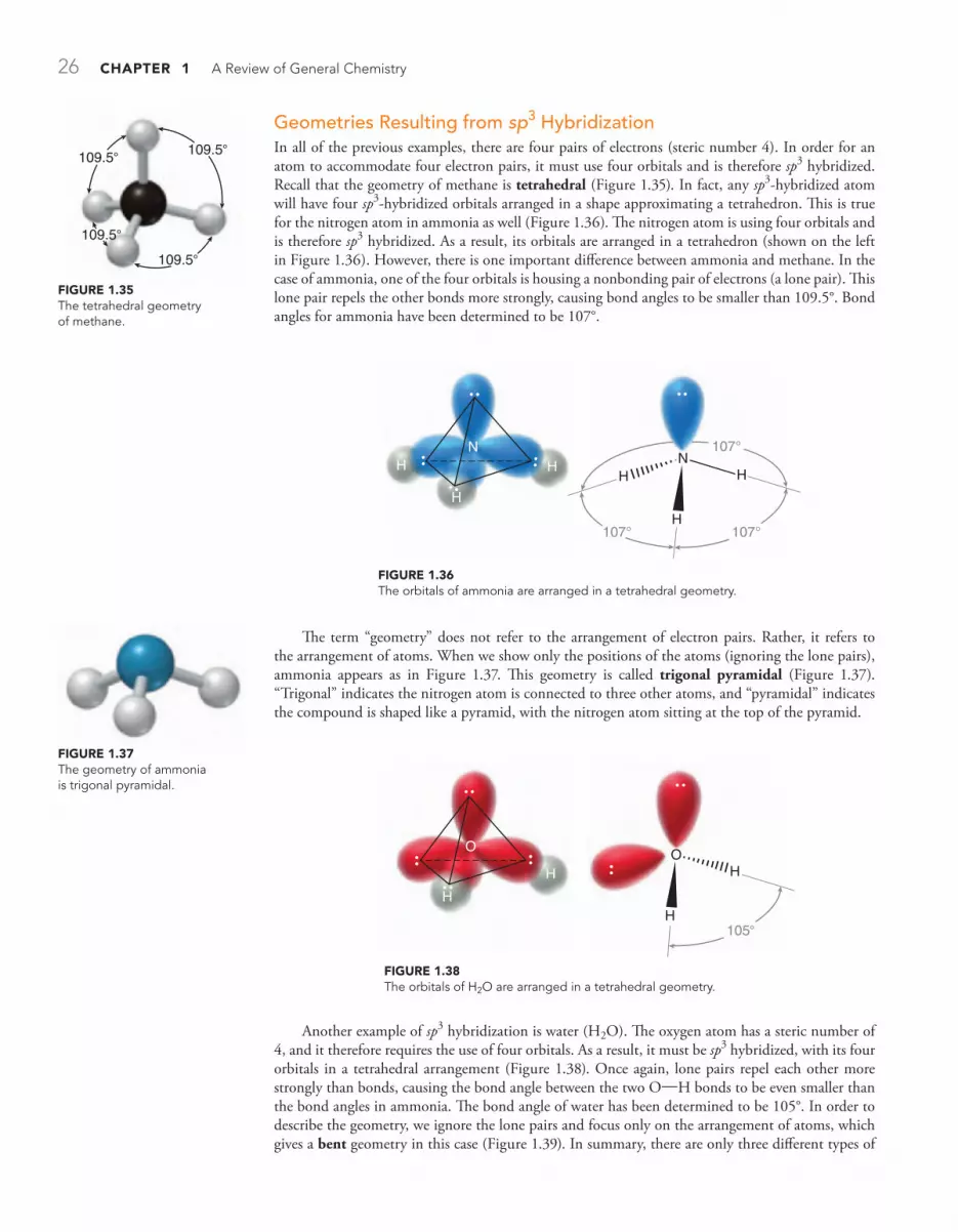
26 CHAPTER 1 A Review of General Chemistry
Geometries Resulting from sp3 HybridizationIn all of the previous examples, there are four pairs of electrons (steric number 4). In order for an atom to accommodate four electron pairs, it must use four orbitals and is therefore sp3 hybridized. Recall that the geometry of methane is tetrahedral (Figure 1.35). In fact, any sp3-hybridized atom will have four sp3-hybridized orbitals arranged in a shape approximating a tetrahedron. This is true for the nitrogen atom in ammonia as well (Figure 1.36). The nitrogen atom is using four orbitals and is therefore sp3 hybridized. As a result, its orbitals are arranged in a tetrahedron (shown on the left in Figure 1.36). However, there is one important difference between ammonia and methane. In the case of ammonia, one of the four orbitals is housing a nonbonding pair of electrons (a lone pair). This lone pair repels the other bonds more strongly, causing bond angles to be smaller than 109.5°. Bond angles for ammonia have been determined to be 107°.
Another example of sp3 hybridization is water (H2O). The oxygen atom has a steric number of 4, and it therefore requires the use of four orbitals. As a result, it must be sp3 hybridized, with its four orbitals in a tetrahedral arrangement (Figure 1.38). Once again, lone pairs repel each other more strongly than bonds, causing the bond angle between the two O!H bonds to be even smaller than the bond angles in ammonia. The bond angle of water has been determined to be 105°. In order to describe the geometry, we ignore the lone pairs and focus only on the arrangement of atoms, which gives a bent geometry in this case (Figure 1.39). In summary, there are only three different types of
FiguRE 1.37The geometry of ammonia is trigonal pyramidal.
109.5°
109.5°
109.5°
109.5°
FiguRE 1.35The tetrahedral geometry of methane.
FiguRE 1.36The orbitals of ammonia are arranged in a tetrahedral geometry.
NN
107° 107°
107°
H H
H
H
H H
0 _ 3 eps
The term “geometry” does not refer to the arrangement of electron pairs. Rather, it refers to the arrangement of atoms. When we show only the positions of the atoms (ignoring the lone pairs), ammonia appears as in Figure 1.37. This geometry is called trigonal pyramidal (Figure 1.37). “Trigonal” indicates the nitrogen atom is connected to three other atoms, and “pyramidal” indicates the compound is shaped like a pyramid, with the nitrogen atom sitting at the top of the pyramid.
FiguRE 1.38The orbitals of H2O are arranged in a tetrahedral geometry.
O
H
H
O H
H 105°

1.10 VSEPR Theory: Predicting Geometry 27
table 1.3 geometries resulting from sp3 hybridization
example steric number
hybridization arrangement of electron pairs
arrangement of atoms (geometry)
CH4 4 sp3 Tetrahedral Tetrahedral
NH3 4 sp3 Tetrahedral Trigonal pyramidal
H2O 4 sp3 Tetrahedral Bent
FiguRE 1.39The geometry of water is bent.
Geometries Resulting from sp2 HybridizationWhen the central atom of a small compound has a steric number of 3, it will be sp2 hybridized. As an example, consider the structure of BF3. Boron has three valence electrons, each of which is used to form a bond. The result is three bonds and no lone pairs, giving a steric number of 3. The central boron atom therefore requires three orbitals, rather than four, and must be sp2 hybridized. Recall that sp2-hybridized orbitals achieve maximal separation in a trigonal planar arrangement (Figure 1.40): “trigonal” because the boron is connected to three other atoms and “planar” because all atoms are found in the same plane (as opposed to trigonal pyramidal).
FiguRE 1.40The geometry of BF3 is trigonal planar.
B
F
F F
F
F F
B120° 120°
120°
As another example, consider the nitrogen atom of an imine:
N
An imine
To determine the geometry of the nitrogen atom, we first consider the steric number, which is not affected by the presence of the p bond. Why not? Recall that a p bond results from the overlap of p orbitals. The steric number of an atom is meant to indicate how many hybridized orbitals are neces-sary (p orbitals are not included in this count). The steric number in this case is 3 (Figure 1.41). As a result, the nitrogen atom must be sp2 hybridized. The sp2 hybridization state is always characterized by a trigonal planar arrangement of electron pairs, but when describing geometry, we focus only on the atoms (ignoring any lone pairs). The geometry of this nitrogen atom is therefore bent:
looking AHeADWe will explore imines in more detail in Chapter 20.
FiguRE 1.41The steric number of the nitrogen atom of an imine.
N# of s bonds = 2
# of lone pairs = 1
Steric number = 3
geometry arising from sp3 hybridization: tetrahedral, trigonal pyramidal, and bent. In all cases, the electrons were arranged in a tetrahedron, but the lone pairs were ignored when describing geometry. Table 1.3 summarizes this information.

28 CHAPTER 1 A Review of General Chemistry
As another example of sp hybridization, consider the structure of CO2:
CO O
Once again, the p bonds do not impact the calculation of the steric number, so the steric number is 2. The carbon atom must be sp hybridized and is therefore linear.
As summarized in Figure 1.43, the three hybridization states give rise to five common geometries.
Geometry Resulting from sp HybridizationWhen the central atom of a small compound has a steric number of 2, the central atom will be sp hybrid-ized. As an example, consider the structure of BeH2. Beryllium has two valence electrons, each of which is used to form a bond. The result is two bonds and no lone pairs, giving a steric number of 2. The central beryllium atom therefore requires only two orbitals and must be sp hybridized. Recall that sp-hybridized orbitals achieve maximal separation when they are linear (Figure 1.42).
H HBe
180°
Linear geometryof BeH2
FiguRE 1.42The geometry of BeH2 is linear.
FiguRE 1.43A decision tree for determining geometry.
sp3 sp2 sp
Tetrahedralarrangement ofelectron pairs
Tetrahedral Bent Linear
Trigonal planararrangement ofelectron pairs
Lineararrangement ofelectron pairs
If steric number = 4
No lonepairs
Two lonepairsOne
lonepair
One lonepair No lone
pairs
If steric number = 3 If steric number = 2
Trigonalpyramidal
Trigonalplanar
Predict the geometry for all atoms (except hydrogen) in the compound below:
N
C C
CC
H H
HH
HH
H
O
SKILLBUILDER
LEARN the skill
1.8 predicting geometry
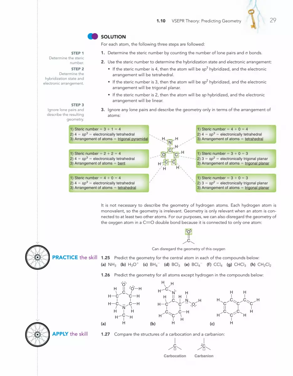
1.10 VSEPR Theory: Predicting Geometry 29
SoLuTioNFor each atom, the following three steps are followed:
1. Determine the steric number by counting the number of lone pairs and s bonds.
2. Use the steric number to determine the hybridization state and electronic arrangement:
• If the steric number is 4, then the atom will be sp3 hybridized, and the electronic arrangement will be tetrahedral.
• If the steric number is 3, then the atom will be sp2 hybridized, and the electronic arrangement will be trigonal planar.
• If the steric number is 2, then the atom will be sp hybridized, and the electronic arrangement will be linear.
3. Ignore any lone pairs and describe the geometry only in terms of the arrangement of atoms:
1) Steric number = 4 + 0 = 42) 4 = sp3 = electronically tetrahedral3) Arrangement of atoms = tetrahedral
1) Steric number = 3 + 1 = 42) 4 = sp3 = electronically tetrahedral3) Arrangement of atoms = trigonal pyramidal
1) Steric number = 2 + 2 = 42) 4 = sp3 = electronically tetrahedral3) Arrangement of atoms = bent
1) Steric number = 3 + 0 = 32) 3 = sp2 = electronically trigonal planar3) Arrangement of atoms = trigonal planar
1) Steric number = 4 + 0 = 42) 4 = sp3 = electronically tetrahedral3) Arrangement of atoms = tetrahedral
1) Steric number = 3 + 0 = 32) 3 = sp2 = electronically trigonal planar3) Arrangement of atoms = trigonal planar
N
C C
CC
H H
HH
HH
H
O
It is not necessary to describe the geometry of hydrogen atoms. Each hydrogen atom is monovalent, so the geometry is irrelevant. Geometry is only relevant when an atom is con‑nected to at least two other atoms. For our purposes, we can also disregard the geometry of the oxygen atom in a CRO double bond because it is connected to only one atom:
O
C
Can disregard the geometry of this oxygen
1.25 Predict the geometry for the central atom in each of the compounds below:
(a) NH3 (b) H3O+ (c) BH4- (d) BCl3 (e) BCl4
- (f ) CCl4 (g) CHCl3 (h) CH2Cl2
1.26 Predict the geometry for all atoms except hydrogen in the compounds below:
(a)
N
O
C
C C
CC
C
H
H
H
H
H
H
H
H
HH
H
O
(b)
ON
N
C
CC
C
CC
CH
HH
H
H
H
H H
H
H
HH (c)
C
CC
C
CC C
CH
H
H
H
H
H
H
H
1.27 Compare the structures of a carbocation and a carbanion:
C
Carbocation Carbanion
C@!
STEP 3Ignore lone pairs and describe the resulting
geometry.
STEP 1Determine the steric
number.
STEP 2Determine the
hybridization state and electronic arrangement.
PRACTiCE the skill
APPLy the skill
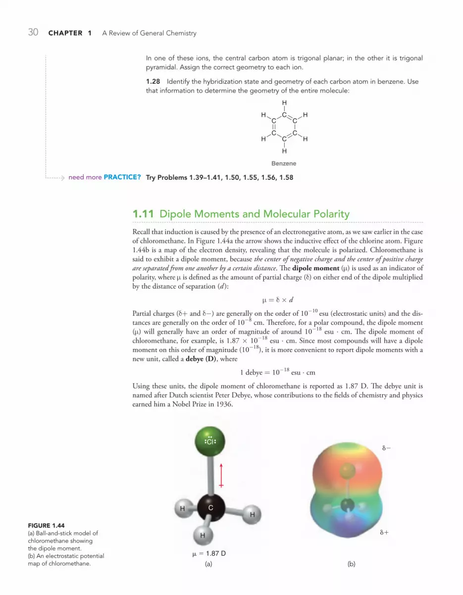
30 CHAPTER 1 A Review of General Chemistry
In one of these ions, the central carbon atom is trigonal planar; in the other it is trigonal pyramidal. Assign the correct geometry to each ion.
1.28 Identify the hybridization state and geometry of each carbon atom in benzene. Use that information to determine the geometry of the entire molecule:
Benzene
C
CC
C
CC HH
H
H
H
H
Try Problems 1.39–1.41, 1.50, 1.55, 1.56, 1.58
1.11 Dipole Moments and Molecular Polarity
Recall that induction is caused by the presence of an electronegative atom, as we saw earlier in the case of chloromethane. In Figure 1.44a the arrow shows the inductive effect of the chlorine atom. Figure 1.44b is a map of the electron density, revealing that the molecule is polarized. Chloromethane is said to exhibit a dipole moment, because the center of negative charge and the center of positive charge are separated from one another by a certain distance. The dipole moment (m) is used as an indicator of polarity, where m is defined as the amount of partial charge (d) on either end of the dipole multiplied by the distance of separation (d ):
m = d Ž d
Partial charges (d+ and d-) are generally on the order of 10-10 esu (electrostatic units) and the dis-tances are generally on the order of 10-8 cm. Therefore, for a polar compound, the dipole moment (m) will generally have an order of magnitude of around 10-18 esu × cm. The dipole moment of chloromethane, for example, is 1.87 Ž 10-18 esu × cm. Since most compounds will have a dipole moment on this order of magnitude (10-18), it is more convenient to report dipole moments with a new unit, called a debye (D), where
1 debye = 10-18 esu × cm
Using these units, the dipole moment of chloromethane is reported as 1.87 D. The debye unit is named after Dutch scientist Peter Debye, whose contributions to the fields of chemistry and physics earned him a Nobel Prize in 1936.
FiguRE 1.44(a) Ball‑and‑stick model of chloromethane showing the dipole moment.(b) An electrostatic potential map of chloromethane.
HH
H
Cl
C
μ = 1.87 D
δ−
δ+
(b)(a)
need more PRACTiCE?

1.11 Dipole Moments and Molecular Polarity 31
Measuring the dipole moment of a particular bond allows us to calculate the percent ionic character of that bond. As an example, let’s analyze a C!Cl bond. This bond has a bond length of 1.772 Ž 10-8 cm, and an electron has a charge of 4.80 Ž 10-10 esu. If the bond were 100% ionic, then the dipole moment would be
m = e Ž d = (4.80 Ž 10-10 esu) Ž (1.772 Ž 10-8 cm) = 8.51 Ž 10-18 esu × cm
or 8.51 D. In reality, the bond is not 100% ionic. The experimentally observed dipole moment is measured at 1.87 D, and we can use this value to calculate the percent ionic character of a C!Cl bond:
1 878 51
100% 22%..
DD
× =
Table 1.4 shows the percent ionic character for a few of the bonds that we will frequently encoun-ter in this text. Take special notice of the CRO bond. It has considerable ionic character, render-ing it extremely reactive. Chapters 20–22 are devoted exclusively to the reactivity of compounds containing CRO bonds.
table 1.4 percent ionic character for several bonds
bond bond length (Ž 10-8 cm)
observed m (d) percent ionic character
C!O 1.41 0.7 D (0.7 10 esu cm)(4.80 10 esu) (1.41 10
18
10 8Ž
Ž-
-
-×
Ž Ž cm)100% 10%=
O!H 0.96 1.5 D (1.5 10 esu cm)(4.80 10 esu) (0.96 10
18
10 8Ž
Ž-
-
-×
Ž Ž cm)100% 33%=
CRO 1.227 2.4 D (2.4 10 esu cm)(4.80 10 esu) (1.23 10
18
10 8Ž
Ž-
-
-×
Ž Ž cm)100% 41%=
Chloromethane was a simple example, because it has only one polar bond. When dealing with a compound that has more than one polar bond, it is necessary to take the vector sum of the individual dipole moments. The vector sum is called the molecular dipole moment, and it takes into account both the magnitude and the direction of each individual dipole moment. For example, consider the structure of dichloromethane (Figure 1.45). The individual dipole moments partially cancel, but not completely. The vector sum produces a dipole moment of 1.14 D, which is significantly smaller than the dipole moment of chloromethane because the two dipole moments here partially cancel each other.
FiguRE 1.45The molecular dipole moment of dichloromethane is the net sum of all dipole moments in the compound. Molecular dipole moment
C
HH Cl
ClThe vector sumof the individualdipole moments
produces amolecular dipole moment
C
Cl
HH Cl
The presence of a lone pair has a significant effect on the molecular dipole moment. The two electrons of a lone pair are balanced by two positive charges in the nucleus, but the lone pair is separated from the nucleus by some distance. There is, therefore, a dipole moment associated with every lone pair. Common examples are ammonia and water (Figure 1.46).
FiguRE 1.46The net dipole moments of ammonia and water.
Netdipole moment
Netdipole moment
NH H
H
OH H

32 CHAPTER 1 A Review of General Chemistry
FiguRE 1.47A ball‑and‑stick model of carbon tetrachloride. The individual dipole moments cancel to give a zero net dipole moment.
Cl
Cl
Cl
Cl
Identify whether each of the following compounds exhibits a molecular dipole moment. If so, indicate the direction of the net molecular dipole moment:
(a) CH3CH2OCH2CH3 (b) CO2
SoLuTioN(a) In order to determine whether the individual dipole moments cancel each other com‑pletely, we must first predict the molecular geometry. Specifically, we need to know if the geometry around the oxygen atom is linear or bent:
H3C CH3H H
H H
CH3C CH3
H
H
H
H
CO
Linear Bent
C CO
In this way, the lone pairs contribute significantly to the magnitude of the molecular dipole moment, although they do not alter its direction. That is, the direction of the molecular dipole moment would be the same with or without the contribution of the lone pairs.
Table 1.5 shows experimentally observed molecular dipole moments (at 20°C) for several common solvents. Notice that carbon tetrachloride (CCl4) has no molecular dipole moment. In this case, the individual dipole moments cancel each other completely to give the molecule a zero net dipole moment (m = 0). This example (Figure 1.47) demonstrates that we must take geometry
into account when assessing molecular dipole moments.
table 1.5 dipole moments for some common solvents (at 20°c)compound structure dipole
moment
compound structure dipole moment
Acetone
CH3H3CC
O 2.69 D Ammonia :NH3 1.47 D
Chloromethane CH3Cl 1.87 D Diethyl ether
H C
H
H
C C H
H
H
H
H
C
H
H
O
1.15 D
Water H2O 1.85 D Methylene chloride
CH2Cl2 1.14 D
Methanol CH3OH 1.69 D Pentane
H C
H
H
C C H
H
H
C
H
H
H
H
C
H
H 0 D
Ethanol
H C
H
H
C H
H
H
O
1.66 D Carbon tetrachloride
CCl4 0 D
STEP 1Predict the molecular geometry.
SKILLBUILDER
LEARN the skill
1.9 identifying the presence of molecular dipole moments

1.11 Dipole Moments and Molecular Polarity 33
To make this determination, we use the three‑step method from the previous section:
1. The steric number of the oxygen atom is 4.
2. Therefore, the hybridization state must be sp3, and the arrangement of electron pairs must be tetrahedral.
3. Ignore the lone pairs, and the oxygen atom has a bent geometry.
After determining the molecular geometry, now draw all dipole moments and determine whether they cancel each other. In this case, they do not fully cancel each other:
These individual dipole moments
produce a net dipole momentH3C CH3H H
H H
C CO
H3C CH3H H
H H
C CO
This compound does in fact have a net molecular dipole moment, and the direction of the moment is shown above.
(b) Carbon dioxide (CO2) has two CRO bonds, each of which exhibits a dipole moment. In order to determine whether the individual dipole moments cancel each other completely, we must first predict the molecular geometry. We apply our three‑step method: The steric number is 2, the hybridization state is sp, and the compound has a linear geometry. As a result, we expect the dipole moments to fully cancel each other:
OCO
In a similar way, the dipole moments associated with the lone pairs also cancel each other, and therefore CO2 does not have a net molecular dipole moment.
1.29 Identify whether each of the following compounds exhibits a molecular dipole moment. For compounds that do, indicate the direction of the net molecular dipole moment:
(a) CHCl3 (b) CH3OCH3 (c) NH3 (d) CCl2Br2
(e)
O
C C
CCH
H H
H
H
HH
H
(f )
OC
CO
C
C H
H
H
H
H
H
H
H (g)
O
O
C
CC
C
CC
HHH
H
H
HH H (h)
CC C
C CC
H
H
H
H
H H
O
O
H H
(i)
Cl
C C
HH
Cl
(j) Cl
Cl
C C
H
H (k) Cl
Cl
C C
H
H (l)
Cl
Cl Cl
Cl
C C
1.30 Which of the following compounds has the larger dipole moment? Explain your choice:
CHCl3 or CBrCl3
1.31 Bonds between carbon and oxygen (C!O) are more polar than bonds between sulfur and oxygen (S!O). Nevertheless, sulfur dioxide (SO2) exhibits a dipole moment while carbon dioxide (CO2) does not. Explain this apparent anomaly.
Try Problems 1.37, 1.40, 1.43, 1.61, 1.62
STEP 3Draw the net
dipole moment.
STEP 2Identify the
direction of all dipole moments.
PRACTiCE the skill
APPLy the skill
need more PRACTiCE?

34 CHAPTER 1 A Review of General Chemistry
1.12 Intermolecular Forces and Physical Properties
The physical properties of a compound are determined by the attractive forces between the individual molecules, called intermolecular forces. It is often difficult to use the molecular structure alone to predict a precise melting point or boiling point for a compound. However, a few simple trends will allow us to compare compounds to each other in a relative way, for example, to predict which com-pound will boil at a higher temperature.
All intermolecular forces are electrostatic—that is, these forces occur as a result of the attrac-tion between opposite charges. The electrostatic interactions for neutral molecules (with no formal charges) are often classified as (1) dipole-dipole interactions, (2) hydrogen bonding, and (3) fleet-ing dipole-dipole interactions.
Dipole-Dipole InteractionsCompounds with net dipole moments can either attract each other or repel each other, depending on how they approach each other in space. In the solid phase, the molecules align so as to attract each other (Figure 1.48).
In the liquid phase, the molecules are free to tumble in space, but they do tend to move in such a way so as to attract each other more often than they repel each other. The resulting net attraction between the molecules results in an elevated melting point and boiling point. To illustrate this, com-pare the physical properties of isobutylene and acetone:
IsobutyleneMelting point = –140.3°C
Boiling point = –6.9°C
CH2
AcetoneMelting point = –94.9°CBoiling point = 56.3°C
O
CH3C CH3
CH3C CH3
Isobutylene lacks a significant dipole moment, but acetone does have a net dipole moment. Therefore, acetone molecules will experience greater attractive interactions than isobutylene molecules. As a result, acetone has a higher melting point and higher boiling point than isobutylene.
Hydrogen BondingThe term hydrogen bonding is misleading. A hydrogen bond is not actually a “bond” but is just a specific type of dipole-dipole interaction. When a hydrogen atom is connected to an electronega-tive atom, the hydrogen atom will bear a partial positive charge (d+) as a result of induction. This d+ can then interact with a lone pair from an electronegative atom of another molecule. This can be illustrated with water or ammonia (Figure 1.49). This attractive interaction can occur with any
FiguRE 1.48In solids, molecules align themselves so that their dipole moments experience attractive forces.
δ+δ+δ+ δ− δ−δ−
Hydrogen bond interactionbetween molecules of water
Hydrogen bond interactionbetween molecules of ammonia
H
N H
H
N HH H
H
H
H
OH
O
(a) (b)
d–d+d–d+
FiguRE 1.49(a) Hydrogen bonding between molecules of water. (b) Hydrogen bonding between molecules of ammonia.
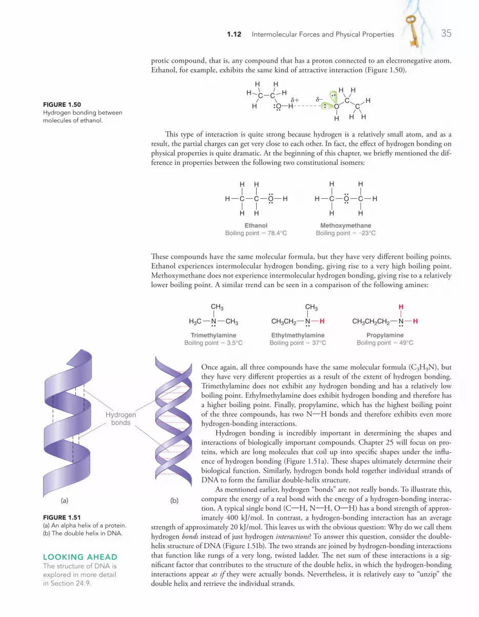
1.12 Intermolecular Forces and Physical Properties 35
protic compound, that is, any compound that has a proton connected to an electronegative atom. Ethanol, for example, exhibits the same kind of attractive interaction (Figure 1.50).
This type of interaction is quite strong because hydrogen is a relatively small atom, and as a result, the partial charges can get very close to each other. In fact, the effect of hydrogen bonding on physical properties is quite dramatic. At the beginning of this chapter, we briefly mentioned the dif-ference in properties between the following two constitutional isomers:
EthanolBoiling point = 78.4°C
C O HH
H H
H H
C
MethoxymethaneBoiling point = –23°C
HH
H
H
C C
H
H
O
These compounds have the same molecular formula, but they have very different boiling points. Ethanol experiences intermolecular hydrogen bonding, giving rise to a very high boiling point. Methoxymethane does not experience intermolecular hydrogen bonding, giving rise to a relatively lower boiling point. A similar trend can be seen in a comparison of the following amines:
TrimethylamineBoiling point = 3.5°C
CH3H3C
CH3
N
EthylmethylamineBoiling point = 37°C
HCH3CH2
CH3
N
PropylamineBoiling point = 49°C
HCH3CH2CH2
H
N
Once again, all three compounds have the same molecular formula (C3H9N), but they have very different properties as a result of the extent of hydrogen bonding. Trimethylamine does not exhibit any hydrogen bonding and has a relatively low boiling point. Ethylmethylamine does exhibit hydrogen bonding and therefore has a higher boiling point. Finally, propylamine, which has the highest boiling point of the three compounds, has two N!H bonds and therefore exhibits even more hydrogen-bonding interactions.
Hydrogen bonding is incredibly important in determining the shapes and interactions of biologically important compounds. Chapter 25 will focus on pro-teins, which are long molecules that coil up into specific shapes under the influ-ence of hydrogen bonding (Figure 1.51a). These shapes ultimately determine their biological function. Similarly, hydrogen bonds hold together individual strands of DNA to form the familiar double-helix structure.
As mentioned earlier, hydrogen “bonds” are not really bonds. To illustrate this, compare the energy of a real bond with the energy of a hydrogen-bonding interac-tion. A typical single bond (C!H, N!H, O!H) has a bond strength of approx-imately 400 kJ/mol. In contrast, a hydrogen-bonding interaction has an average
strength of approximately 20 kJ/mol. This leaves us with the obvious question: Why do we call them hydrogen bonds instead of just hydrogen interactions? To answer this question, consider the double-helix structure of DNA (Figure 1.51b). The two strands are joined by hydrogen-bonding interactions that function like rungs of a very long, twisted ladder. The net sum of these interactions is a sig-nificant factor that contributes to the structure of the double helix, in which the hydrogen-bonding interactions appear as if they were actually bonds. Nevertheless, it is relatively easy to “unzip” the double helix and retrieve the individual strands.
OC
H
O H
C
C
H H
H
H H
C
HH
H
HH
d–d+FiguRE 1.50Hydrogen bonding between molecules of ethanol.
looking AHeADThe structure of DNA is explored in more detail in Section 24.9.
FiguRE 1.51(a) An alpha helix of a protein. (b) The double helix in DNA.
Hydrogenbonds
(a) (b)

36 CHAPTER 1 A Review of General Chemistry
Fleeting Dipole-Dipole InteractionsSome compounds have no permanent dipole moments, and yet analysis of boiling points indicates that they must have fairly strong intermolecular attractions. To illustrate this point, consider the following compounds:
Butane(C4H10)
Boiling point = 0°C
C C C
H H H H
H
H H
H H H
C
Pentane(C5H12)
Boiling point = 36°C
H
H
H
CC C C
H H H H
H
H
H H H
C
Hexane(C6H14)
Boiling point = 69°C
H
H
H
C
H
H
CC C C
H H H H
H
H
H H H
C
These three compounds are hydrocarbons, compounds that contain only carbon and hydrogen atoms. If we compare the properties of the hydrocarbons above, an important trend becomes appar-ent. Specifically, the boiling point appears to increase with increasing molecular weight. This trend can be justified by considering the fleeting, or transient, dipole moments that are more prevalent in larger hydrocarbons. To understand the source of these temporary dipole moments, we consider the electrons to be in constant motion, and therefore, the center of negative charge is also constantly moving around within the molecule. On average, the center of negative charge coincides with the center of positive charge, resulting in a zero dipole moment. However, at any given instant, the center of negative charge and the center of positive charge might not coincide. The resulting transient dipole moment can then induce a separate transient dipole moment in a neighboring molecule, initiating a fleeting attraction between the two molecules (Figure 1.52). These attractive forces are called London dispersion forces, named after German-American physicist Fritz London. Large hydrocarbons have
looking AHeADHydrocarbons will be discussed in more detail in Chapters 4, 17, and 18.
Biomimicry and gecko Feetpractically
speaking
The term biomimicry describes the notion that scientists often draw creative inspiration from studying nature. By investigating some of nature’s processes, it is possible to mimic those pro‑cesses and to develop new technology. One such example is based on the way that geckos can scurry up walls and along ceil‑ings. Until recently, scientists were baffled by the curious ability of geckos to walk upside down, even on very smooth surfaces such as polished glass.
As it turns out, geckos do not use any chemical adhesives, nor do they use suction. Instead, their abilities arise from the intermolecular forces of attraction between the molecules in their feet and the molecules in the surface on which they are walking. When you place your hand on a surface, there are cer‑tainly intermolecular forces of attraction between the molecules of your hand and the surface, but the microscopic topography of your hand is quite bumpy. As a result, your hand only makes contact with the surface at perhaps a few thousand points. In contrast, the foot of a gecko has approximately half a million microscopic flexible hairs, called setae, each of which has even smaller hairs.
When a gecko places its foot on a surface, the flexible hairs allow the gecko to make extraordinary contact with the surface, and the resulting London dispersion forces are collectively strong enough to support the gecko.
In the last decade, many research teams have drawn inspi‑ration from geckos and have created materials with densely
packed microscopic hairs. For example, some scientists are developing adhesive bandages that could be used in the heal‑ing of surgical wounds, while other scientists are developing special gloves and boots that would enable people to climb up walls (and perhaps walk upside down on ceilings). Imagine the possibility of one day being able to walk on walls and ceilings like Spiderman.
There are still many challenges that we must overcome before these materials will show their true potential. It is a tech‑nical challenge to design microscopic hairs that are strong enough to prevent the hairs from becom‑ing tangled but flexible enough to allow the hairs to stick to any sur‑face. Many researchers believe that these challenges can be over‑come, and if they are right, we might have the oppor‑tunity to see the world turned literally upside down within the next decade.
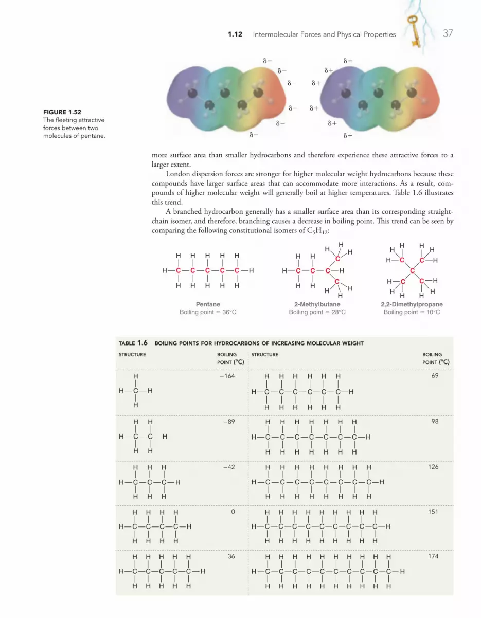
1.12 Intermolecular Forces and Physical Properties 37
FiguRE 1.52The fleeting attractive forces between two molecules of pentane.
δ−δ−
δ−
δ−
δ−
δ−
δ+δ+
δ+
δ+
δ+
δ+
table 1.6 boiling points for hydrocarbons of increasing molecular weight
structure boiling point (°c)
structure boiling point (°c)
C H
H
H
H
-164
H
H
H
C
H
H
CC C C
H H H H
H
H
H H H
C
69
C C H
H H
H
H
H -89
H
H
H
C
H
H
CC C C
H H H H
H
C
H
H
H
H H H
C
98
C C H
H H
H
C
H
H
H
H -42
H
H
H
C
H
H
CC C C
H H H H
H
C
H
H
C
H
H
H
H H H
C
126
C C H
H H
H
C
H
H
C
H
H
H
H 0
H
H
H
C
H
H
CC C C
H H H H
H
C
H
H
C
H
H
C
H
H
H
H H H
C
151
C C H
H H
H
C
H
H
C
H
H
C
H
H
H
H 36
H
H
H
C
H
H
CC C C
H H H H
H
C
H
H
C
H
H
C
H
H
C
H
H
H
H H H
C
174
more surface area than smaller hydrocarbons and therefore experience these attractive forces to a larger extent.
London dispersion forces are stronger for higher molecular weight hydrocarbons because these compounds have larger surface areas that can accommodate more interactions. As a result, com-pounds of higher molecular weight will generally boil at higher temperatures. Table 1.6 illustrates this trend.
A branched hydrocarbon generally has a smaller surface area than its corresponding straight-chain isomer, and therefore, branching causes a decrease in boiling point. This trend can be seen by comparing the following constitutional isomers of C5H12:
C C H
H H
H
C
H
H
C
H
H
C
H
H
H
H
PentaneBoiling point = 36°C
C
C
H
H
H
H
H
C
H
H
C
H
H
C
H
H
H
2-MethylbutaneBoiling point = 28°C
C
H H
HH
H
H H HH
H
H H
CC
C
C
2,2-DimethylpropaneBoiling point = 10°C
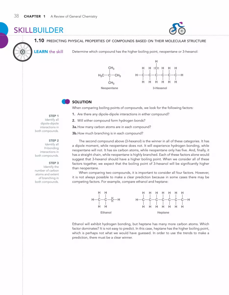
38 CHAPTER 1 A Review of General Chemistry
Determine which compound has the higher boiling point, neopentane or 3‑hexanol:
Neopentane
H3C C
CH3
CH3
CH3
3-Hexanol
H
H
H
C
H
H
CC C C
H H H H
H
H
H
H
O H
C
SoLuTioNWhen comparing boiling points of compounds, we look for the following factors:
1. Are there any dipole‑dipole interactions in either compound?
2. Will either compound form hydrogen bonds?
3a. How many carbon atoms are in each compound?
3b. How much branching is in each compound?
The second compound above (3‑hexanol) is the winner in all of these categories. It has a dipole moment, while neopentane does not. It will experience hydrogen bonding, while neopentane will not. It has six carbon atoms, while neopentane only has five. And, finally, it has a straight chain, while neopentane is highly branched. Each of these factors alone would suggest that 3‑hexanol should have a higher boiling point. When we consider all of these factors together, we expect that the boiling point of 3‑hexanol will be significantly higher than neopentane.
When comparing two compounds, it is important to consider all four factors. However, it is not always possible to make a clear prediction because in some cases there may be competing factors. For example, compare ethanol and heptane:
Heptane
H
H
C
H
H
H
C
H
H
CC C C
H H H H
H
H
H H H
C
Ethanol
C
H
H
H C H
H
H
O
Ethanol will exhibit hydrogen bonding, but heptane has many more carbon atoms. Which factor dominates? It is not easy to predict. In this case, heptane has the higher boiling point, which is perhaps not what we would have guessed. In order to use the trends to make a prediction, there must be a clear winner.
STEP 1 Identify all
dipole‑dipole interactions in
both compounds.
STEP 3Identify the
number of carbon atoms and extent
of branching in both compounds.
STEP 2Identify all H‑bonding
interactions in both compounds.
SKILLBUILDER
LEARN the skill
1.10 predicting physical properties of compounds based on their molecular structure

1.12 Intermolecular Forces and Physical Properties 39
1.32 For each of the following pairs of compounds, identify the higher boiling compound and justify your choice:
(b)
C
CC
C
C
C
CC
C
CC H
H
HH
H H
HH
HH
H H
H
H
HH H
H
H
H
H H
(c)
C C C
H H H H
H
H
H H H
C O HH
H
H
CC C
H H H
H
H H H
CO
C C C
H H H H
H
H
H H H
C O H C
C
CC
H
H
HH
HH
H
H
H H
O
(d)
C C
C
C
H
C
C
H
H
H
H
H
H
H
H
H
H
H
H
H
H C
H
H
C
H
H
C C
H
H
C
H
H
H
C
H
H
H
HO O
(a)
1.33 Arrange the following compounds in order of increasing boiling point:
C C H
H H
H
C
H
H
C
H
H
C
H
H
H
H
C C C
H H H H
H
H
H H H
C O H
C C
H H
H
C
H
H
C
H
H
C
H
H
H
H
H
H
C O H
C
C
CC H
HH
HH
H
H
H H
C H
HH
H
H
H
H
H
HC CC
C
C
HH
H
H
H H
Try Problems 1.52, 1.53, 1.60
PRACTiCE the skill
APPLy the skill
need more PRACTiCE?
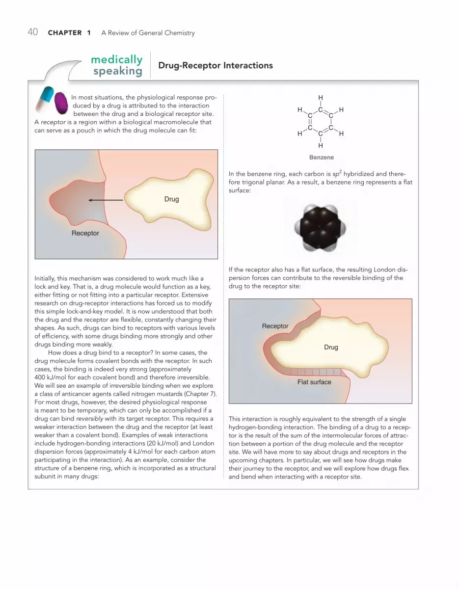
40 CHAPTER 1 A Review of General Chemistry
Drug-receptor interactionsmedically speaking
In most situations, the physiological response pro‑duced by a drug is attributed to the interaction between the drug and a biological receptor site.
A receptor is a region within a biological macromolecule that can serve as a pouch in which the drug molecule can fit:
Receptor
Drug
Initially, this mechanism was considered to work much like a lock and key. That is, a drug molecule would function as a key, either fitting or not fitting into a particular receptor. Extensive research on drug‑receptor interactions has forced us to modify this simple lock‑and‑key model. It is now understood that both the drug and the receptor are flexible, constantly changing their shapes. As such, drugs can bind to receptors with various levels of efficiency, with some drugs binding more strongly and other drugs binding more weakly.
How does a drug bind to a receptor? In some cases, the drug molecule forms covalent bonds with the receptor. In such cases, the binding is indeed very strong (approximately 400 kJ/mol for each covalent bond) and therefore irreversible. We will see an example of irreversible binding when we explore a class of anticancer agents called nitrogen mustards (Chapter 7). For most drugs, however, the desired physiological response is meant to be temporary, which can only be accomplished if a drug can bind reversibly with its target receptor. This requires a weaker interaction between the drug and the receptor (at least weaker than a covalent bond). Examples of weak interactions include hydrogen‑bonding inter actions (20 kJ/mol) and London dispersion forces (approximately 4 kJ/mol for each carbon atom participating in the interaction). As an example, consider the structure of a benzene ring, which is incorporated as a structural subunit in many drugs:
Benzene
C
CC
C
CC HH
H
H
H
H
In the benzene ring, each carbon is sp2 hybridized and there‑fore trigonal planar. As a result, a benzene ring represents a flat surface:
If the receptor also has a flat surface, the resulting London dis‑persion forces can contribute to the reversible binding of the drug to the receptor site:
Receptor
Flat surface
Drug
This interaction is roughly equivalent to the strength of a single hydrogen‑bonding interaction. The binding of a drug to a recep‑tor is the result of the sum of the intermolecular forces of attrac‑tion between a portion of the drug molecule and the receptor site. We will have more to say about drugs and receptors in the upcoming chapters. In particular, we will see how drugs make their journey to the receptor, and we will explore how drugs flex and bend when interacting with a receptor site.

1.13 Solubility 41
1.13 Solubility
Solubility is based on the principle that “like dissolves like.” In other words, polar compounds are soluble in polar solvents, while nonpolar compounds are soluble in nonpolar solvents. Why is this so? A polar compound experiences dipole-dipole interactions with the molecules of a polar sol-vent, allowing the compound to dissolve in the solvent. Similarly, a nonpolar compound experiences London dispersion forces with the molecules of a nonpolar solvent. Therefore, if an article of clothing is stained with a polar compound, the stain can generally be washed away with water (like dissolves like). However, water will be insufficient for cleaning clothing stained with nonpolar compounds, such as oil or grease. In a situation like this, the clothes can be cleaned with soap or by dry cleaning.
SoapSoaps are compounds that have a polar group on one end of the molecule and a nonpolar group on the other end (Figure 1.53).
FiguRE 1.53The hydrophilic and hydrophobic ends of a soap molecule.
Nonpolar group(hydrophobic)
Polar group(hydrophilic)
C
H
H
C
H
H
C C
H
H
C
H
H
C
H
H
H
C
H
H
H
C
H
H
C
H
H
C C
H
H
C
H
H
C
H
H
H
C
H
H
H
HC–
O
O
The surface of the micelle is comprised of all of the polar groups, rendering the micelle water soluble. This is a clever way to dissolve the oil in water, but this technique only works for clothing that can be subjected to water and soap. Some clothes will be damaged in soapy water, and in those situations, dry cleaning is the preferred method.
Dry CleaningRather than surrounding the nonpolar compound with a micelle so that it will be water soluble, it is actually conceptually simpler to use a nonpolar solvent. This is just another application of the principle of “like dissolves like.” Dry cleaning utilizes a nonpolar solvent, such as tetrachloroethylene, to dissolve the nonpolar compounds. This compound is nonflammable, making it an ideal choice as a solvent. Dry cleaning allows clothes to be cleaned without coming into contact with water or soap.
FiguRE 1.54A micelle is formed when the hydrophobic tails of soap molecules surround the nonpolar oil molecules.
Oilmolecules
Polar group
Nonpolar group
C C
Cl
Cl
Cl
Cl
Tetrachloroethylene
The polar group represents the hydrophilic region of the molecule (literally, “loves water”), while the nonpolar group represents the hydrophobic region of the molecule (literally, “afraid of water”). Oil mol-ecules are surrounded by the hydrophobic tails of the soap molecules, forming a micelle (Figure 1.54).
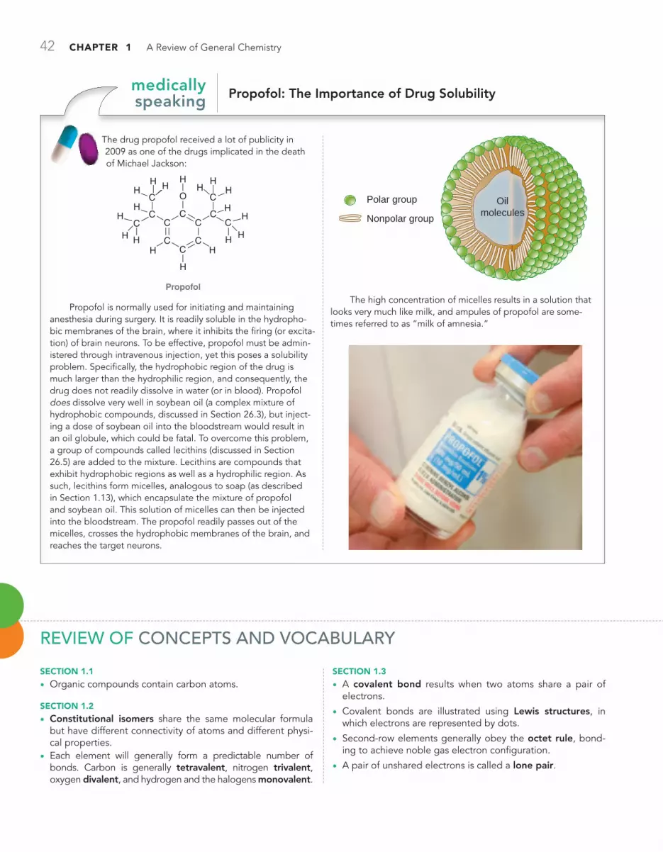
42 CHAPTER 1 A Review of General Chemistry
Propofol: The Importance of Drug Solubilitymedically speaking
The drug propofol received a lot of publicity in 2009 as one of the drugs implicated in the death of Michael Jackson:
CC
O
CCC
CC
C
CC
HH HH H
H H
H
H
H
C CH H H
HH
H
H
H
Propofol
Propofol is normally used for initiating and maintaining anesthesia during surgery. It is readily soluble in the hydropho-bic membranes of the brain, where it inhibits the firing (or excita-tion) of brain neurons. To be effective, propofol must be admin-istered through intravenous injection, yet this poses a solubility problem. Specifically, the hydrophobic region of the drug is much larger than the hydrophilic region, and consequently, the drug does not readily dissolve in water (or in blood). Propofol does dissolve very well in soybean oil (a complex mixture of hydrophobic compounds, discussed in Section 26.3), but inject-ing a dose of soybean oil into the bloodstream would result in an oil globule, which could be fatal. To overcome this problem, a group of compounds called lecithins (discussed in Section 26.5) are added to the mixture. Lecithins are compounds that exhibit hydrophobic regions as well as a hydrophilic region. As such, lecithins form micelles, analogous to soap (as described in Section 1.13), which encapsulate the mixture of propofol and soybean oil. This solution of micelles can then be injected into the bloodstream. The propofol readily passes out of the micelles, crosses the hydrophobic membranes of the brain, and reaches the target neurons.
Oilmolecules
Polar group
Nonpolar group
The high concentration of micelles results in a solution that looks very much like milk, and ampules of propofol are some-times referred to as “milk of amnesia.”
Review of ConCepts and voCabulaRy
SECTion 1.1
• Organic compounds contain carbon atoms.
SECTion 1.2
• Constitutional isomers share the same molecular formula but have different connectivity of atoms and different physi-cal properties.
• Each element will generally form a predictable number of bonds. Carbon is generally tetravalent, nitrogen trivalent, oxygen divalent, and hydrogen and the halogens monovalent.
SECTion 1.3
• A covalent bond results when two atoms share a pair of electrons.
• Covalent bonds are illustrated using Lewis structures, in which electrons are represented by dots.
• Second-row elements generally obey the octet rule, bond-ing to achieve noble gas electron configuration.
• A pair of unshared electrons is called a lone pair.

Review of Concepts and Vocabulary 43
SECTioN 1.4
• A formal charge occurs when atoms do not exhibit the appropriate number of valence electrons; formal charges must be drawn in Lewis structures.
SECTioN 1.5
• Bonds are classified as (1) covalent, (2) polar covalent, or (3) ionic.
• Polar covalent bonds exhibit induction, causing the forma‑tion of partial positive charges (d+) and partial negative charges (d-). electrostatic potential maps present a visual illustration of partial charges.
SECTioN 1.6
• Quantum mechanics describes electrons in terms of their wavelike properties.
• A wave equation describes the total energy of an electron when in the vicinity of a proton. Solutions to wave equations are called wavefunctions (y), where y2 represents the prob‑ability of finding an electron in a particular location.
• Atomic orbitals are represented visually by generating three‑dimensional plots of y2; nodes indicate that the value of y is zero.
• An occupied orbital can be thought of as a cloud of electron density.
• Electrons fill orbitals following three principles: (1) the Aufbau principle, (2) the Pauli exclusion principle, and (3) Hund’s rule. Orbitals with the same energy level are called degenerate orbitals.
SECTioN 1.7
• valence bond theory treats every bond as the sharing of electron density between two atoms as a result of the con‑structive interference of their atomic orbitals. Sigma (s) bonds are formed when the electron density is located primarily on the bond axis.
SECTioN 1.8
• Molecular orbital theory uses a mathematical method called the linear combination of atomic orbitals (LCAO) to form molecular orbitals. Each molecular orbital is associated with the entire molecule, rather than just two atoms.
• The bonding MO of molecular hydrogen results from con‑structive interference between its two atomic orbitals. The antibonding MO results from destructive interference.
• An atomic orbital is a region of space associated with an individual atom, while a molecular orbital is associated with an entire molecule.
• Two molecular orbitals are the most important to consider: (1) the highest occupied molecular orbital, or HOMO, and (2) the lowest unoccupied molecular orbital, or LUMO.
SECTioN 1.9
• Methane’s tetrahedral geometry can be explained using four degenerate sp3-hybridized orbitals to achieve its four single bonds.
• Ethylene’s planar geometry can be explained using three degenerate sp2-hybridized orbitals. The remaining p orbitals
overlap to form a separate bonding interaction, called a pi (p) bond. The carbon atoms of ethylene are connected via a s bond, resulting from the overlap of sp2‑hybridized atomic orbit‑als, and via a p bond, resulting from the overlap of p orbitals, both of which comprise the double bond of ethylene.
• Acetylene’s linear geometry is achieved via sp-hybridized car‑bon atoms in which a triple bond is created from the bonding interactions of one s bond, resulting from overlapping sp orbit‑als, and two p bonds, resulting from overlapping p orbitals.
• Triple bonds are stronger and shorter than double bonds, which are stronger and shorter than single bonds.
SECTioN 1.10
• The geometry of small compounds can be predicted using valence shell electron pair repulsion (vSePr) theory, which focuses on the number of s bonds and lone pairs exhibited by each atom. The total, called the steric number, indicates the number of electron pairs that repel each other.
• A tetrahedral arrangement of orbitals indicates sp3 hybrid-ization (steric number 4). A compound’s geometry depends on the number of lone pairs and can be tetrahedral, trigonal pyramidal, or bent.
• A trigonal planar arrangement of orbitals indicates sp2 hybridization (steric number 3); however, the geometry may be bent, depending on the number of lone pairs.
• Linear geometry indicates sp hybridization (steric number 2).
SECTioN 1.11
• Dipole moments (m) occur when the center of negative charge and the center of positive charge are separated from one another by a certain distance; the dipole moment is used as an indicator of polarity (measured in debyes).
• The percent ionic character of a bond is determined by measuring its dipole moment. The vector sum of individual dipole moments in a compound determines the molecular dipole moment.
SECTioN 1.12
• The physical properties of compounds are determined by intermolecular forces, the attractive forces between molecules.
• Dipole-dipole interactions occur between two molecules that possess permanent dipole moments. Hydrogen bond‑ing, a special type of dipole‑dipole interaction, occurs when the lone pairs of an electronegative atom interact with an electron‑poor hydrogen atom. Compounds that exhibit hydrogen bonding have higher boiling points than similar compounds that lack hydrogen bonding.
• london dispersion forces result from the interaction between transient dipole moments and are stronger for larger alkanes due to their larger surface area and ability to accommodate more interactions.
SECTioN 1.13
• Polar compounds are soluble in polar solvents; nonpolar compounds are soluble in nonpolar solvents.
• Soaps are compounds that contain both hydrophilic and hydrophobic regions. The hydrophobic tails surround non‑polar compounds, forming a water‑soluble micelle.

44 CHAPTER 1 A Review of General Chemistry
1.2 Drawing the Lewis Dot structure of an atom
STEP 1 Determine the numberof valence electrons.
N NNGroup 5A
(five electrons)
STEP 3 If the atom has more than four valence electrons, the remaining electrons are paired with the electrons already drawn.
STEP 2 Place one electron by itself on each side of the atom.
Try Problems 1.5–1.9
1.3 Drawing the Lewis structure of a smaLL moLecuLe
STEP 1 Draw allindividual atoms.
STEP 2 Connect atomsthat form more thanone bond.
STEP 3 Connecthydrogen atoms.
STEP 4 Pair any unpairedelectrons, so that eachatom achieves an octet.
CH2O
C H H O
C OOC
HH C
H
H O
Try Problems 1.10–1.12, 1.35, 1.38, 1.42
1.4 caLcuLating formaL charge
STEP 1 Determine appropriate number of valence electrons.
STEP 2 Determine the number of valence electrons in this case.
STEP 3 Assign a formal charge.
N H
H
H
HN H
H
H
HH
H
H
H NGroup 5A
(five electrons)Four
electrons ... missing an electron.
!
Try Problems 1.13, 1.14, 1.41
1.5 Locating PartiaL charges
STEP 1 Identify all polar covalent bonds.
STEP 2 Determine thedirection of each dipole.
STEP 3 Indicate locationof partial charges.
C
H
H
HH O
Polar covalent
C
H
H
HH O C
H
H
HH Od–d+ d+
Try Problems 1.15, 1.16, 1.36, 1.37, 1.48, 1.57
sKiLLBuiLDer reView1.1 Determining the constitution of smaLL moLecuLes
STEP 1 Determine the valency of each atom in the compound.
STEP 2 Determine how the atoms are connected. Atoms with highest valency should be placed at the center, and monovalent atoms should be placed at the periphery.
H C
H
H
C Cl
H
H
C C H
C2 H5 Cl
H H H H Cl
Try Problems 1.1–1.4, 1.34, 1.46, 1.47, 1.54
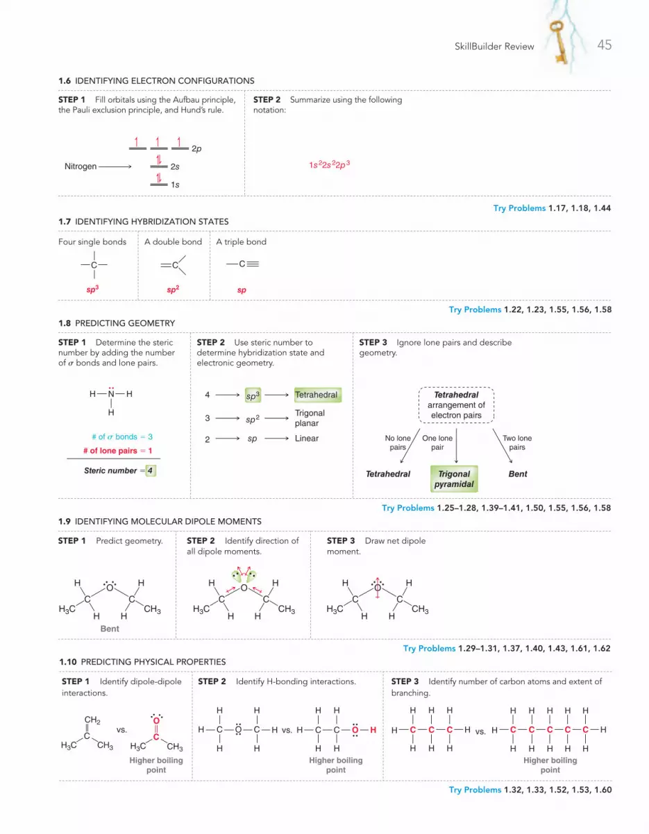
SkillBuilder Review 45
1.6 IDEnTIFyInG ELECTROn COnFIGURATIOnS
STEP 1 Fill orbitals using the Aufbau principle,the Pauli exclusion principle, and Hund’s rule.
STEP 2 Summarize using the followingnotation:
Nitrogen
1s
2s
2p
1s22s22p3
Try Problems 1.17, 1.18, 1.44
1.7 IDEnTIFyInG HyBRIDIzATIOn STATES
Four single bonds A double bond A triple bond
sp3
C
sp
C
sp2
C
Try Problems 1.22, 1.23, 1.55, 1.56, 1.58
1.8 PREDICTInG GEOMETRy
STEP 1 Determine the steric number by adding the number of s bonds and lone pairs.
STEP 2 Use steric number to determine hybridization state and electronic geometry.
STEP 3 Ignore lone pairs and describe geometry.
H N H
H
# of s bonds = 3
# of lone pairs = 1
Steric number = 4
4 Tetrahedralsp3
Trigonalplanar
3 sp2
Linear2 sp
Trigonalpyramidal
Tetrahedral Bent
No lonepairs
One lonepair
Two lonepairs
Tetrahedralarrangement ofelectron pairs
Try Problems 1.25–1.28, 1.39–1.41, 1.50, 1.55, 1.56, 1.58
1.9 IDEnTIFyInG MOLECULAR DIPOLE MOMEnTS
Bent
H3C CH3H H
H H
C CO
STEP 1 Predict geometry.
H3C CH3H H
H H
C CO
STEP 2 Identify direction of all dipole moments.
H3C CH3H H
H H
C CO
STEP 3 Draw net dipole moment.
Try Problems 1.29–1.31, 1.37, 1.40, 1.43, 1.61, 1.62
1.10 PREDICTInG PHySICAL PROPERTIES
STEP 3 Identify number of carbon atoms and extent of branching.
H
H
H
CC C C
H H H H
H
H
H H H
CC C C
H H H
H
H
H H
H vs.
Higher boilingpoint
STEP 2 Identify H-bonding interactions.
C C
H H
H
H
H
HO vs. C C O
H H
H
H
H
H
Higher boilingpoint
STEP 1 Identify dipole-dipole interactions.
vs.
H3C CH3
C
CH2
H3C CH3
C
O
Higher boilingpoint
Try Problems 1.32, 1.33, 1.52, 1.53, 1.60

46 CHAPTER 1 A Review of General Chemistry
Note: Most of the Problems are available within , an online teaching and learning solution.
1.34 Draw structures for all constitutional isomers with the following molecular formulas:
(a) C4H10 (b) C5H12 (c) C6H14
(d) C2H5Cl (e) C2H4Cl2 (f ) C2H3Cl3
1.35 Draw structures for all constitutional isomers with the molecular formula C4H8 that have:
(a) Only single bonds (b) One double bond
1.36 For each compound below, identify any polar covalent bonds and indicate the direction of the dipole moment using the symbols d+ and d-:
(a) HBr (b) HCl (c) H2O (d) CH4O
1.37 For each pair of compounds below, identify the one that would be expected to have more ionic character. Explain your choice.
(a) NaBr or HBr (b) BrCl or FCl
1.38 Draw a Lewis dot structure for each of the following compounds:
(a) CH3CH2OH (b) CH3CN
1.39 Predict the geometry of each atom except hydrogen in the com-pounds below:
(a)
CCH C C H
HH H H
H H H@
(b)
C C H
H H
CH
H
O
H
H!
(c)
N C C O H
H H H
H
H
H H!
(d)
C C C
H H H
H
H
H H
O@
1.40 Draw a Lewis structure for a compound with molecular formula C4H11N in which three of the carbon atoms are bonded to the nitrogen atom. What is the geometry of the nitrogen atom in this compound? Does this compound exhibit a molecular dipole moment? If so, indicate the direction of the dipole moment.
1.41 Draw a Lewis structure of the anion AlBr4- and determine its
geometry.
1.42 Draw the structure for the only constitutional isomer of cyclopropane:
Cyclopropane
C
H H
CCH H
H H
1.43 Determine whether each compound below exhibits a molecular dipole moment:
(a) CH4 (b) NH3 (c) H2O
(d) CO2 (e) CCl4 (f ) CH2Br2
1.44 Identify the neutral element that corresponds with each of the following electron configurations:
(a) 1s22s22p4 (b) 1s22s22p5 (c) 1s22s22p2
(d) 1s22s22p3 (e) 1s22s22p63s23p5
1.45 In the compounds below, classify each bond as covalent, polar covalent, or ionic:
(a) NaBr (b) NaOH (c) NaOCH3
(d) CH3OH (e) CH2O
1.46 Draw structures for all constitutional isomers with the following molecular formulas:
(a) C2H6O (b) C2H6O2 (c) C2H4Br2
1.47 Draw structures for any five constitutional isomers with molecular formula C2H6O3.
1.48 For each type of bond below, determine the direction of the expected dipole moment:
(a) C!O (b) C!Mg (c) C!N (d) C!Li
(e) C!Cl (f ) C!H (g) O!H (h) N!H
1.49 Predict the bond angles for all bonds in the following compounds:
(a) CH3CH2OH (b) CH2O (c) C2H4 (d) C2H2
(e) CH3OCH3 (f ) CH3NH2 (g) C3H8 (h) CH3CN
1.50 Identify the expected hybridization state and geometry for the central atom in each of the following compounds:
(a) N
H H
H
(b) B
H H
H
(c) C
H H
H
!
(d) C
H H
H@
(e) O
H H
H!
1.51 Count the total number of s bonds and p bonds in the com-pound below:
H
H
H
H
CC C C
H H
C NCH
H
H
O
1.52 For each pair of compounds below, predict which compound will have the higher boiling point and explain your choice:
(a) CH3CH2CH2OCH3 or CH3CH2CH2CH2OH
(b) CH3CH2CH2CH3 or CH3CH2CH2CH2CH3
(c)
HC C C
H H
H
H
HO
or
H
H
C
H
H
C
H
H
CH H
1.53 Which of the following pure compounds will exhibit hydrogen bonding?
(a) CH3CH2OH (b) CH2O (c) C2H4 (d) C2H2
(e) CH3OCH3 (f ) CH3NH2 (g) C3H8 (h) NH3
Practice Problems
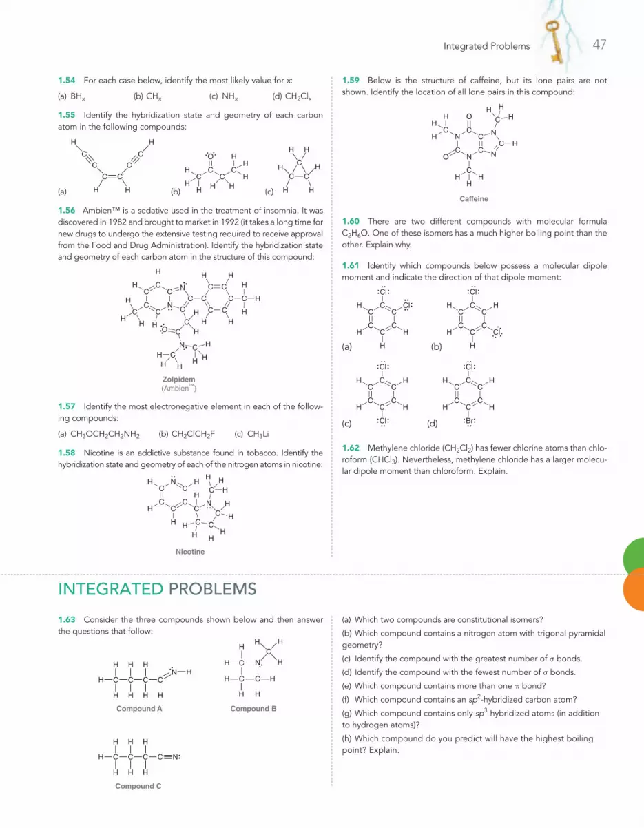
Integrated Problems 47
1.54 For each case below, identify the most likely value for x:
(a) BHx (b) CHx (c) NHx (d) CH2Clx
1.55 Identify the hybridization state and geometry of each carbon atom in the following compounds:
(a)
C
H
H
C
C
H
H
C
C
C
(b)
CC C
O
CH
H HHH
HH
H
(c)
C
H H
CCH H
H H
1.56 Ambien™ is a sedative used in the treatment of insomnia. It was discovered in 1982 and brought to market in 1992 (it takes a long time for new drugs to undergo the extensive testing required to receive approval from the Food and Drug Administration). Identify the hybridization state and geometry of each carbon atom in the structure of this compound:
N
O
Zolpidem(Ambien™)
N
NCC
CC
C
C
C
C
CC
C
C C C
C
CC
C
H
H
HH
H
H
H
H
HHH
HHH
H
H
HHH
HH
C
1.57 Identify the most electronegative element in each of the follow-ing compounds:
(a) CH3OCH2CH2NH2 (b) CH2ClCH2F (c) CH3Li
1.58 Nicotine is an addictive substance found in tobacco. Identify the hybridization state and geometry of each of the nitrogen atoms in nicotine:
N
Nicotine
C
CC
C
C
C
C C
C
CH
HH H
H
H
H
HHH
HH
H
H
N
1.59 Below is the structure of caffeine, but its lone pairs are not shown. Identify the location of all lone pairs in this compound:
Caffeine
N
NC
C
N
C
NC
O
O
C
C
H
HH
H
H
HH
HHH
C
C
1.60 There are two different compounds with molecular formula C2H6O. One of these isomers has a much higher boiling point than the other. Explain why.
1.61 Identify which compounds below possess a molecular dipole moment and indicate the direction of that dipole moment:
(a)
Cl
Cl
C
CC
C
CCH
H
H
H
(b)
Cl
Cl
C
CC
C
CC HH
H
H
(c)
Cl
Cl
C
CC
C
CC HH
H H
(d)
Cl
Br
C
CC
C
CC HH
H H
1.62 Methylene chloride (CH2Cl2) has fewer chlorine atoms than chlo-roform (CHCl3). Nevertheless, methylene chloride has a larger molecu-lar dipole moment than chloroform. Explain.
1.63 Consider the three compounds shown below and then answer the questions that follow:
Compound A
C
H
C
H
HH
C
H
H
C
H
H
HN
Compound B
Compound C
CC
H
H
C
H
H
C
H
H
H N
CH
H
H
N
H CC
C
HH
H
H
H
(a) Which two compounds are constitutional isomers?
(b) Which compound contains a nitrogen atom with trigonal pyramidal geometry?
(c) Identify the compound with the greatest number of s bonds.
(d) Identify the compound with the fewest number of s bonds.
(e) Which compound contains more than one p bond?
(f) Which compound contains an sp2-hybridized carbon atom?
(g) Which compound contains only sp3-hybridized atoms (in addition to hydrogen atoms)?
(h) Which compound do you predict will have the highest boiling point? Explain.
Integrated Problems
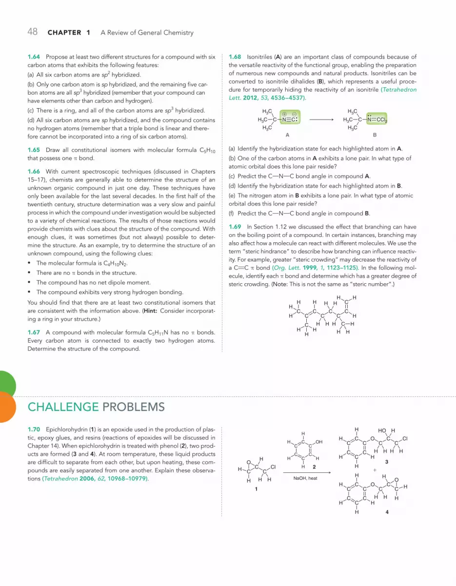
48 CHAPTER 1 A Review of General Chemistry
1.64 Propose at least two different structures for a compound with six carbon atoms that exhibits the following features:
(a) All six carbon atoms are sp2 hybridized.
(b) Only one carbon atom is sp hybridized, and the remaining five car-bon atoms are all sp3 hybridized (remember that your compound can have elements other than carbon and hydrogen).
(c) There is a ring, and all of the carbon atoms are sp3 hybridized.
(d) All six carbon atoms are sp hybridized, and the compound contains no hydrogen atoms (remember that a triple bond is linear and there-fore cannot be incorporated into a ring of six carbon atoms).
1.65 Draw all constitutional isomers with molecular formula C5H10 that possess one p bond.
1.66 With current spectroscopic techniques (discussed in Chapters 15–17), chemists are generally able to determine the structure of an unknown organic compound in just one day. These techniques have only been available for the last several decades. In the first half of the twentieth century, structure determination was a very slow and painful process in which the compound under investigation would be subjected to a variety of chemical reactions. The results of those reactions would provide chemists with clues about the structure of the compound. With enough clues, it was sometimes (but not always) possible to deter-mine the structure. As an example, try to determine the structure of an unknown compound, using the following clues:
• The molecular formula is C4H10N2.
• There are no p bonds in the structure.
• The compound has no net dipole moment.
• The compound exhibits very strong hydrogen bonding.
You should find that there are at least two constitutional isomers that are consistent with the information above. (Hint: Consider incorporat-ing a ring in your structure.)
1.67 A compound with molecular formula C5H11N has no p bonds. Every carbon atom is connected to exactly two hydrogen atoms. Determine the structure of the compound.
1.68 Isonitriles (A) are an important class of compounds because of the versatile reactivity of the functional group, enabling the preparation of numerous new compounds and natural products. Isonitriles can be converted to isonitrile dihalides (B), which represents a useful proce-dure for temporarily hiding the reactivity of an isonitrile (Tetrahedron Lett. 2012, 53, 4536–4537).
@!
N CC N CCl2C
B
H3C
H3C
H3C
H3C
H3C
H3C
A
(a) Identify the hybridization state for each highlighted atom in A.
(b) One of the carbon atoms in A exhibits a lone pair. In what type of atomic orbital does this lone pair reside?
(c) Predict the C!N!C bond angle in compound A.
(d) Identify the hybridization state for each highlighted atom in B.
(e) The nitrogen atom in B exhibits a lone pair. In what type of atomic orbital does this lone pair reside?
(f) Predict the C!N!C bond angle in compound B.
1.69 In Section 1.12 we discussed the effect that branching can have on the boiling point of a compound. In certain instances, branching may also affect how a molecule can react with different molecules. We use the term “steric hindrance” to describe how branching can influence reactiv-ity. For example, greater “steric crowding” may decrease the reactivity of a CRC p bond (Org. Lett. 1999, 1, 1123–1125). In the following mol-ecule, identify each p bond and determine which has a greater degree of steric crowding. (Note: This is not the same as “steric number”.)
CC
CC
C
CC
C
C
H
HHH
H
HH
H
H H
H H
H
H
H
H
CH H
Challenge Problems
1.70 Epichlorohydrin (1) is an epoxide used in the production of plas-tic, epoxy glues, and resins (reactions of epoxides will be discussed in Chapter 14). When epichlorohydrin is treated with phenol (2), two prod-ucts are formed (3 and 4). At room temperature, these liquid products are difficult to separate from each other, but upon heating, these com-pounds are easily separated from one another. Explain these observa-tions (Tetrahedron 2006, 62, 10968–10979).
CC
O
CCl
H
H H
H
H
CC
HO
CCl
H
H HC
CC
C
CC
H
H
H
H
H
OH
NaOH, heat
OC
CC
CC
C H H
H
H
H
H
H
+
CC
O
CO
H
HH
H
H
C
CC
C
CC
H
H
H
H
H1
23
4

Challenge Problems 49
1.71 Consider the following table that provides bond lengths for a variety of C!X bonds (measured in Å).
X = F X = Cl X = Br X = I
C X 1.40 1.79 1.97 2.16
XC 1.34 1.88 2.10
C X 1.27 1.63 1.79
(a) Compare the data for bonds of the type Csp3!X. Describe the trend that you observe and offer an explanation for this trend.
(b) Compare the data for bonds of the following types: Csp3!F, and Csp2!F, and Csp!F. Describe the trend that you observe and offer an explanation.
(c) When comparing the bond lengths for Csp2!Cl and Csp!I, the trends established in the first two parts of this problem appear to be in conflict with each other. Describe how the two trends oppose each other, and then use the data in the table to determine which bond you predict to be longer. Explain your choice.
1.72 Positron emission tomography (PET) is a medical imaging tech‑nique that produces a three‑dimensional picture of functional processes in the body, such as the brain uptake of glucose. PET imaging requires the introduction of [18F]‑fluorine (a radioactive isotope of fluorine) into molecules and can be achieved by several routes, such as the following (Tetrahedron Lett. 2003, 44, 9165–9167):
+
!
@
18F
18F
C C
H
H
H
H
Br N C C
H
H
H
H
O
C
C
H
H
H
H
H
H
N C C
H
H
H
H
O
C
C
C
H
H
C
H
H
H HH
HHH Br
H
H
(a) Identify the hybridization for every heteroatom (atom other than C or H) in the three compounds. Note: Throughout this chapter, all lone pairs were drawn. We will soon see (Chapter 2) that lone pairs are often omitted from structural drawings, because they can be inferred by the presence or absence of formal charges. In this problem, none of the lone pairs have been drawn.
(b) Predict the bond angle of each C!N!C bond in the product.
(c) Identify the type of atomic orbital(s) that contain the lone pairs on the oxygen atom in the product.
1.73 Phenalamide A2 belongs to a class of natural products that are of interest because of their antibiotic, antifungal, and antiviral activity. In the first total synthesis of this compound, the following boronate ester was utilized (Org. Lett. 1999, 1, 1713–1715):
O
CO
C
CC
CBC
C OC
CO
H3C CH3
CH3
CH3
H
H
HH
HH
HH
H
(a) Determine the hybridization state of the boron atom.
(b) Predict the O!B!O bond angle and then suggest a reason why the actual bond angle might deviate from the predicted value in this case.
(c) The lone pairs have not been drawn. Draw all of them. (Hint: Note that the structure has no formal charges.)
1.74 The formation of a variety of compounds called oxazolidinones is important for the synthesis of many different natural products and other compounds that have potential use as future medicines. One method for preparing oxazolidinones involves the conversion of a hydroximoyl chloride, such as compound 1, into a nitrile oxide, such as compound 2 (J. Org. Chem. 2009, 74, 1099–1113):
O
C
C
C C
C
C
C N
HH
H
H H
C
N
Cl
C
CC
C
C C
OH
HH
H
H H
1 2
(a) Identify any formal charges that are missing from the structures of 1 and 2.
(b) Determine which compound is expected to be more soluble in a polar solvent, and justify your choice.
(c) Determine the amount by which the C!C!N bond angle increases as a result of the conversion from 1 to 2.
1.75 The following compound belongs to a class of compounds, called estradiol derivatives, which show promise in the treatment of breast cancer (Tetrahedron Lett. 2001, 42, 8579–8582):
C
CC
C
CC
CC
CC C
CC
C
C
C
C
HO
C OC
CC C
Cc
Cb
CaH
H
H H
H
H
H
HHH
H
H H
H
H
H H H HH
HH H
H
H
H
H
(a) Determine the hybridization state of Ca, Cb, and Cc.
(b) Determine the H!Ca!Cb bond angle.
(c) Determine the Ca!Cb!Cc bond angle.
(d) Cb exhibits two p bonds: one to Ca, and the other to Cc. Draw a picture of Ca, Cb and Cc that shows the relative orientation of the two different p orbitals that Cb is utilizing to form its two p bonds. Also show the p orbitals on Ca and Cc that are being used by each of those atoms. Describe the relative orientation of the p orbitals on Ca and Cc.

50 CHAPTER 1 A Review of General Chemistry
1.76 The study of analogues of small peptide chains (Chapter 25), called peptidomimetics, provides models to understand the observed stabilizing effects in larger peptides, including enzymes (nature’s cata‑lysts). The following structure shows promise for studying how enzymes coil up into very discrete shapes that endow them with catalytic func‑tion (Org. Lett. 2001, 3, 3843–3846):
O C
O
NC
H3C
H3C
H3C C
H
H
CH2
N
CH3C CH3
H
C
H
O
N
H
C
CH3
CH3
H
(a) This compound has two N!C!N units, with differing bond angles. Predict the difference in bond angles between these two units and explain the source of the difference.
(b) When this compound was prepared and investigated, it demon‑strated a preference for adopting a three‑dimensional shape in which the two highlighted regions were in close proximity. Describe the inter‑action that occurs and create a drawing that illustrates this interaction.
1.77 Organic polymers (molecules with very high molecular weight) can be designed with pores (cavities) that are specifically tailored to fit a particular guest molecule due to complementary size, shape, and functional group interactions (intermolecular forces). Such systems are often inspired by binding sites in natural enzymes, which display a high degree of specificity for a particular guest. Several porous polymers were designed to bind bisphenol A (compound 1), a compound that is of environmental concern due to its ability to mimic natural hor‑
mones such as estrogen (J. Am. Chem. Soc. 2009, 131, 8833–8838). Schematics of the binding sites of two of these polymers are shown below. Polymer A was found to have only limited selectivity in that it binds 1 or 2 (a control guest molecule) to a similar degree. Polymer B is more selective in that it binds strongly to 1 and weakly to 2. Draw pictures showing how each guest (1, 2) may bind in the pores of each polymer (A, B), and propose an explanation for the differences in bind‑ing specificity described above.
C C C
CH3
CH3C C
C
CCCC
C
C C
C
CC
N
C C
C
C C
N
CC
C
CC
C
C C
CC
C C
C
CC
C
C C C
C C
C
CCCC
C
C C
OHHO H2N NH2
1 2
Binding sitein polymer A
Binding sitein polymer B
H H
HH
H H
HH
H H
H H
H H
HH
H
H
H H
HH
H H
HH
H H
H H
H H
H H
O
O O
O
H H

2.1 Molecular Representations
2.2 Bond-Line Structures
2.3 Identifying Functional Groups
2.4 Carbon Atoms with Formal Charges
2.5 Identifying Lone Pairs
2.6 Three-Dimensional Bond-Line Structures
2.7 Introduction to Resonance
2.8 Curved Arrows
2.9 Formal Charges in Resonance Structures
2.10 Drawing Resonance Structures via Pattern Recognition
2.11 Assessing Relative Importance of Resonance Structures
2.12 Delocalized and Localized Lone Pairs
Molecular RepresentationsDiD you ever wonDer . . .how new drugs are designed?
Scientists employ many techniques in the design of new drugs. One such technique, called lead modification, enables scientists
to identify the portion of a compound responsible for its medicinal properties and then to design similar compounds with better proper-ties. We will see an example of this technique, specifically, where the discovery of morphine led to the development of a whole family of potent analgesics (codeine, heroin, methadone, and many others).
In order to compare the structures of the compounds being discussed, we will need a more efficient way to draw the structures of organic compounds. Lewis structures are only efficient for small molecules, such as those we considered in the previous chapter. The goal of this chapter is to master the skills necessary to use and inter-pret the drawing method most often utilized by organic chemists and biochemists. These drawings, called bond-line structures, are fast to draw and easy to read, and they focus our attention on the reactive centers in a compound. In the second half of this chapter, we will see that bond-line structures are inadequate in some circumstances, and we will explore the technique that chemists employ to deal with the inadequacy of bond-line structures.
2
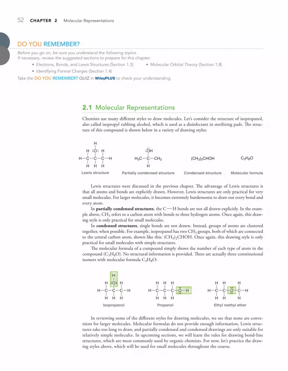
52 CHAPTER 2 Molecular Representations
2.1 Molecular Representations
Chemists use many different styles to draw molecules. Let’s consider the structure of isopropanol, also called isopropyl rubbing alcohol, which is used as a disinfectant in sterilizing pads. The struc-ture of this compound is shown below in a variety of drawing styles:
Condensed structure Molecular formulaLewis structure
O
Partially condensed structure
OH
C HC
H
H
CH
H
H H
H
CH3CH3C
H
(CH3)2CHOH C3H8O
Lewis structures were discussed in the previous chapter. The advantage of Lewis structures is that all atoms and bonds are explicitly drawn. However, Lewis structures are only practical for very small molecules. For larger molecules, it becomes extremely burdensome to draw out every bond and every atom.
In partially condensed structures, the COH bonds are not all drawn explicitly. In the exam-ple above, CH3 refers to a carbon atom with bonds to three hydrogen atoms. Once again, this draw-ing style is only practical for small molecules.
In condensed structures, single bonds are not drawn. Instead, groups of atoms are clustered together, when possible. For example, isopropanol has two CH3 groups, both of which are connected to the central carbon atom, shown like this: (CH3)2CHOH. Once again, this drawing style is only practical for small molecules with simple structures.
The molecular formula of a compound simply shows the number of each type of atom in the compound (C3H8O). No structural information is provided. There are actually three constitutional isomers with molecular formula C3H8O:
Isopropanol
C HC
H
H
CH
H
H H
H
O
Propanol
CC
H
H
CH
HH
H H
HO
Ethyl methyl ether
CCCH
HH
H H
H
H
H
O
In reviewing some of the different styles for drawing molecules, we see that none are conve-nient for larger molecules. Molecular formulas do not provide enough information, Lewis struc-tures take too long to draw, and partially condensed and condensed drawings are only suitable for relatively simple molecules. In upcoming sections, we will learn the rules for drawing bond-line structures, which are most commonly used by organic chemists. For now, let’s practice the draw-ing styles above, which will be used for small molecules throughout the course.
Do You RemembeR?Before you go on, be sure you understand the following topics. If necessary, review the suggested sections to prepare for this chapter:
• Electrons, Bonds, and Lewis Structures (Section 1.3) • Molecular Orbital Theory (Section 1.8)
• Identifying Formal Charges (Section 1.4)
Take the DO YOU REMEMBER? QUIZ in to check your understanding.

2.1 Molecular Representations 53
STEP 1 Draw each group
separately.
STEP 2 Draw all COH bonds.
PRACTiCE the skill
APPly the skill
need more PRACTiCE?
SKILLBUILDER
lEARN the skill
2.1 converting between different drawing styles
Draw a Lewis structure for the following compound:
(CH3)2CHOCH2CH3
SoluTioN This compound is shown in condensed format. In order to draw a Lewis structure, begin by drawing out each group separately, showing a partially condensed structure:
(CH3)2CHOCH2CH3
Condensed structure Partially condensed structure
HC CH2CH3H3C
CH3
O
Then draw all C H bonds:
O O
Partially condensed structure Lewis structure
HCH3C
CH3
CH2CH3 CC
C
H
CC
H
H
H
HH H
H
H H
H
H
2.1 Draw a Lewis structure for each of the compounds below:
(a) CH2RCHOCH2CH(CH3)2 (b) (CH3CH2)2CHCH2CH2OH
(c) (CH3CH2)3COH (d) (CH3)2CRCHCH2CH3
(e) CH2RCHCH2OCH2CH(CH3)2 (f ) (CH3CH2)2CRCH2
(g) (CH3)3CCH2CH2OH (h) CH3CH2CH2CH2CH2CH3
(i) CH3CH2CH2OCH3 (j) (CH3CH2CH2)2CHOH
(k) (CH3CH2)2CHCH2OCH3 (l) (CH3)2CHCH2OH
2.2 Identify which two compounds below are constitutional isomers:
(CH3)3COCH3 (CH3)2CHOCH3 (CH3)2CHOCH2CH3
2.3 Identify the number of sp3-hybridized carbon atoms in the following compound:
(CH3)2CRCHC(CH3)3
2.4 Cyclopropane (shown below) has only one constitutional isomer. Draw a condensed structure of that isomer.
H2C
H2CCH2
Try Problems 2.49, 2.50

54 CHAPTER 2 Molecular Representations
2.2 Bond-Line Structures
It is not practical to draw Lewis structures for all compounds, especially large ones. As an example, consider the structure of amoxicillin, one of the most commonly used antibiotics in the penicillin family:
N
N
N
OO
C
CC
C
CC C
C C
C
CH
C
CC
C
C
H
H
H
H
H HH
H H
H
HH
H
HH
H
H
Amoxicillin
S
OO
HO
Previously fatal infections have been rendered harmless by antibiotics such as the one above. Amoxicillin is not a large compound, yet drawing this compound is time consuming. To deal with this problem, organic chemists have developed an efficient drawing style that can be used to draw molecules very quickly. Bond-line structures not only simplify the drawing process but also are easier to read. The following is a bond-line structure of amoxicillin.
HO
NH2
N
O N
S
HOO
O
H
Most of the atoms are not drawn, but with practice, these drawings will become very user-friendly. Throughout the rest of this textbook, most compounds will be drawn in bond-line format, and there-fore, it is absolutely critical to master this drawing technique. The following sections are designed to develop this mastery.
How to Read Bond-Line StructuresBond-line structures are drawn in a zigzag format ( ), where each corner or endpoint rep-resents a carbon atom. For example, each of the following compounds has six carbon atoms (count them!):
Double bonds are shown with two lines, and triple bonds are shown with three lines:
Notice that triple bonds are drawn in a linear fashion rather than in a zigzag format, because triple bonds involve sp-hybridized carbon atoms, which have linear geometry (Section 1.9). The two car-bon atoms of a triple bond and the two carbon atoms connected to them are drawn in a straight line. All other bonds are drawn in a zigzag format; for example, the following compound has eight carbon atoms:
By The wayYou may find it worthwhile to purchase or borrow a molecular model set. There are several different kinds of molecular model sets on the market, and most of them are comprised of plastic pieces that can be connected to generate models of small molecules. Any one of these model sets will help you to visualize the relationship between molecular structures and the drawings used to represent them.

SKILLBUILDER
lEARN the skill
2.2 reading bond-line structures
Consider the structure of diazepam, first marketed by the Hoffmann-La Roche Company under the trade name Valium:
Diazepam(Valium)
N
N
Cl
O
Valium is a sedative and muscle relaxant used in the treatment of anxiety, insomnia, and sei-zures. Identify the number of carbon atoms in diazepam, then fill in all the missing hydrogen atoms that are inferred by the drawing.
SoluTioN Remember that each corner and each endpoint represents a carbon atom. This compound therefore has 16 carbon atoms, highlighted below:
N
N
Cl
O
2.2 Bond-Line Structures 55
Hydrogen atoms bonded to carbon are also not shown in bond-line structures, because it is assumed that each carbon atom will possess enough hydrogen atoms so as to achieve a total of four bonds. For example, the highlighted carbon atom below appears to have only two bonds:
OThe drawing indicates only two bonds
connected to this carbon atom
Therefore, we can infer that there must be two more bonds to hydrogen atoms that have not been drawn (to give a total of four bonds). In this way, all hydrogen atoms are inferred by the drawing:
O
H H
H H
H
H
H
H
HH
With a bit of practice, it will no longer be necessary to count bonds. Familiarity with bond-line structures will allow you to “see” all of the hydrogen atoms even though they are not drawn. This level of familiarity is absolutely essential, so let’s get some practice.
STEP 1 Count the carbon
atoms, which are represented
by corners or endpoints.

56 CHAPTER 2 Molecular Representations
Each carbon atom should have four bonds. We therefore draw enough hydrogen atoms in order to give each carbon atom a total of four bonds. Any carbon atoms that already have four bonds will not have any hydrogen atoms:
N
N
Cl
O
H
HH
H
H
HHH
H
H HH H
2.5 For each of the following molecules, determine the number of carbon atoms present and then determine the number of hydrogen atoms connected to each carbon atom:
(a) (b) O
N
H
(c) (d)
(e) OH
O
(f )
O
(g)
O
(h)
OH
(i) ( j) (k)
O
(l)
O
2.6 Each transformation below shows a starting material being converted into a product (the reagents necessary to achieve the transformation have not been shown). For each transformation, determine whether the product has more carbon atoms, fewer carbon atoms, or the same number of carbon atoms as the starting material. In other words, deter-mine whether each transformation involves an increase, decrease, or no change in the number of carbon atoms.
(a)
O
(b)
O
O
(c)
OH
(d)
O
O
HO
OH
2.7 Identify whether each transformation below involves an increase, a decrease, or no change in the number of hydrogen atoms:
(a) (b)
Try Problems 2.39, 2.49, 2.52
PRACTiCE the skill
APPly the skill
need more PRACTiCE?
STEP 2Count the hydrogen atoms. Each carbon
atom will have enough hydrogen
atoms to have exactly four bonds.
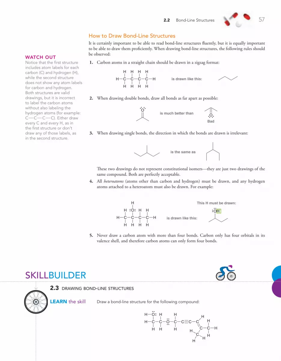
2.2 Bond-Line Structures 57
How to Draw Bond-Line StructuresIt is certainly important to be able to read bond-line structures fluently, but it is equally important to be able to draw them proficiently. When drawing bond-line structures, the following rules should be observed:
1. Carbon atoms in a straight chain should be drawn in a zigzag format:
is drawn like this:C CC C
H
H
H
H
H
H
H
H
H
H
2. When drawing double bonds, draw all bonds as far apart as possible:
Ois much better than
Bad
O
3. When drawing single bonds, the direction in which the bonds are drawn is irrelevant:
is the same as
These two drawings do not represent constitutional isomers—they are just two drawings of the same compound. Both are perfectly acceptable.
4. All heteroatoms (atoms other than carbon and hydrogen) must be drawn, and any hydrogen atoms attached to a heteroatom must also be drawn. For example:
O
is drawn like this:
OH
This H must be drawn:
C CC C
H
H
H
H
H
HH
H
H
H
5. Never draw a carbon atom with more than four bonds. Carbon only has four orbitals in its valence shell, and therefore carbon atoms can only form four bonds.
waTCh ouTNotice that the first structure includes atom labels for each carbon (C) and hydrogen (H), while the second structure does not show any atom labels for carbon and hydrogen. Both structures are valid drawings, but it is incorrect to label the carbon atoms without also labeling the hydrogen atoms (for example: COCOCOC). Either draw every C and every H, as in the first structure or don’t draw any of those labels, as in the second structure.
SKILLBUILDER
lEARN the skill
2.3 drawing bond-line structures
Draw a bond-line structure for the following compound:
O
O
H C C
H
HH
C
H
H
C C C
C
H
C
C
H
H
HH
HH
H
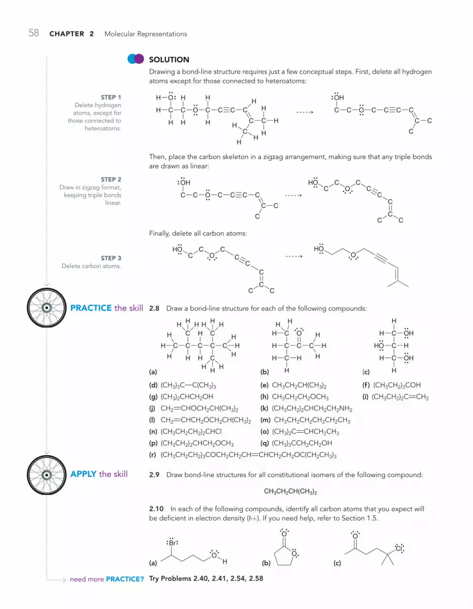
58 CHAPTER 2 Molecular Representations
SoluTioNDrawing a bond-line structure requires just a few conceptual steps. First, delete all hydrogen atoms except for those connected to heteroatoms:
O
OHO
H C C
H
HH
C
H
H
C C C
C C
H
C
C
H
H
HH
HH
H
C C C CC C
C
C
O
Then, place the carbon skeleton in a zigzag arrangement, making sure that any triple bonds are drawn as linear:
HOO
O
OH
C C C C C C
C
C
C
CC C
CC
C
CCC
Finally, delete all carbon atoms:
HOO
HOOC
C CC
CC
CCC
2.8 Draw a bond-line structure for each of the following compounds:
(a)
C C
C
H
H
H
H
H H H
C
H
H
C
CH H H
CH H H
CHH
H
(b)
O
H C
CHH H
CH
H
H
C C
H
H
H
(c)
OH
HO
OHC
C
C
H
H
H
H
H
(d) (CH3)3C!C(CH3)3 (e) CH3CH2CH(CH3)2 (f ) (CH3CH2)3COH
(g) (CH3)2CHCH2OH (h) CH3CH2CH2OCH3 (i) (CH3CH2)2CRCH2
(j) CH2RCHOCH2CH(CH3)2 (k) (CH3CH2)2CHCH2CH2NH2
(l) CH2RCHCH2OCH2CH(CH3)2 (m) CH3CH2CH2CH2CH2CH3
(n) (CH3CH2CH2)2CHCl (o) (CH3)2CRCHCH2CH3
(p) (CH3CH2)2CHCH2OCH3 (q) (CH3)3CCH2CH2OH
(r) (CH3CH2CH2)3COCH2CH2CHRCHCH2CH2OC(CH2CH3)3
2.9 Draw bond-line structures for all constitutional isomers of the following compound:
CH3CH2CH(CH3)2
2.10 In each of the following compounds, identify all carbon atoms that you expect will be deficient in electron density (d+). If you need help, refer to Section 1.5.
(a) O
Br
H (b)
O
O (c)
Cl
O
Try Problems 2.40, 2.41, 2.54, 2.58
STEP 1 Delete hydrogen atoms, except for
those connected to heteroatoms.
STEP 2 Draw in zigzag format,
keeping triple bonds linear.
STEP 3 Delete carbon atoms.
PRACTiCE the skill
APPly the skill
need more PRACTiCE?

2.3 Identifying Functional Groups 59
2.3 Identifying Functional Groups
Bond-line drawings are the preferred drawing style used by practicing organic chemists. In addition to being more efficient, bond-line drawings are also easier to read. As an example, consider the fol-lowing reaction:
(CH3)2CHCHRC(CH3)2 (CH3)2CHCH2CH(CH3)2H2
Pt
When the reaction is presented in this way, it is somewhat difficult to see what is happening. It takes time to digest the information being presented. However, when we redraw the same reaction using bond-line structures, it becomes very easy to identify the transformation taking place:
H2
Pt
It is immediately apparent that a double bond is being converted into a single bond. With bond-line drawings, it is easier to identify the functional group and its location. A functional group is a characteristic group of atoms/bonds that possess a predictable chemical behavior. In each of the reactions below, the starting material has a carbon-carbon double bond, which is a functional group. Compounds with carbon-carbon double bonds typically react with molecular hydrogen (H2) in the presence of a catalyst (such as Pt). Both of the starting materials below have a carbon-carbon double bond, and consequently, they exhibit similar chemical behavior.
H2
Pt
H2
Pt
The chemistry of every organic compound is determined by the functional groups present in the compound. Therefore, the classification of organic compounds is based on their functional groups. For example, compounds with carbon-carbon double bonds are classified as alkenes, while com-pounds possessing an OH group are classified as alcohols. Many of the chapters in this book are organized by functional group. Table 2.1 provides a list of common functional groups and the cor-responding chapters in which they appear.
ConCePTual CheCkPoinT
2.11 Atenolol and enalapril are drugs used in the treatment of heart disease. Both of these drugs lower blood pressure (albeit in different ways) and reduce the risk of heart attack. Using Table 2.1, identify and label all functional groups in these two compounds:
Atenolol Enalapril
O
OH
N
O O
H
N
OHOO
N
H
NH2
O

60 CHAPTER 2 Molecular Representations
table 2.1 examples of common functional groups
functional group* classification example chapter
X
(X=Cl, Br, or I)
R Alkyl halide Cl
n-Propyl chloride
7
C C
R
RR
R Alkene
1-Butene
8, 9
C C RR Alkyne
1-Butyne
10
OHR AlcoholOH
1-Butanol
13
OR R EtherO
Diethyl ether
14
SHR Thiol
1-Butanethiol
SH14
SR R SulfideS
Diethyl sulfide
14
Aromatic (or arene)
Methylbenzene
18, 19
functional group* classification example chapter
O
R R
Ketone
2-Butanone
O 20
O
HR
Aldehyde
H
Butanal
O 20
O
O
HR
Carboxylic acid
Pentanoic acid
O
O
H
21
X
O
R
Acyl halide
Acetyl chloride
Cl
O 21
O
O
O
R R
Anhydride
Acetic anhydride
O
O
O 21
O
O
RR
Ester
O
O
Ethyl acetate
21
NR
R
R
O Amide
NH2
Butanamide
O 21
NR R
R Amine
N
Diethylamine
H 23
* The “R” refers to the remainder of the compound, usually carbon and hydrogen atoms.
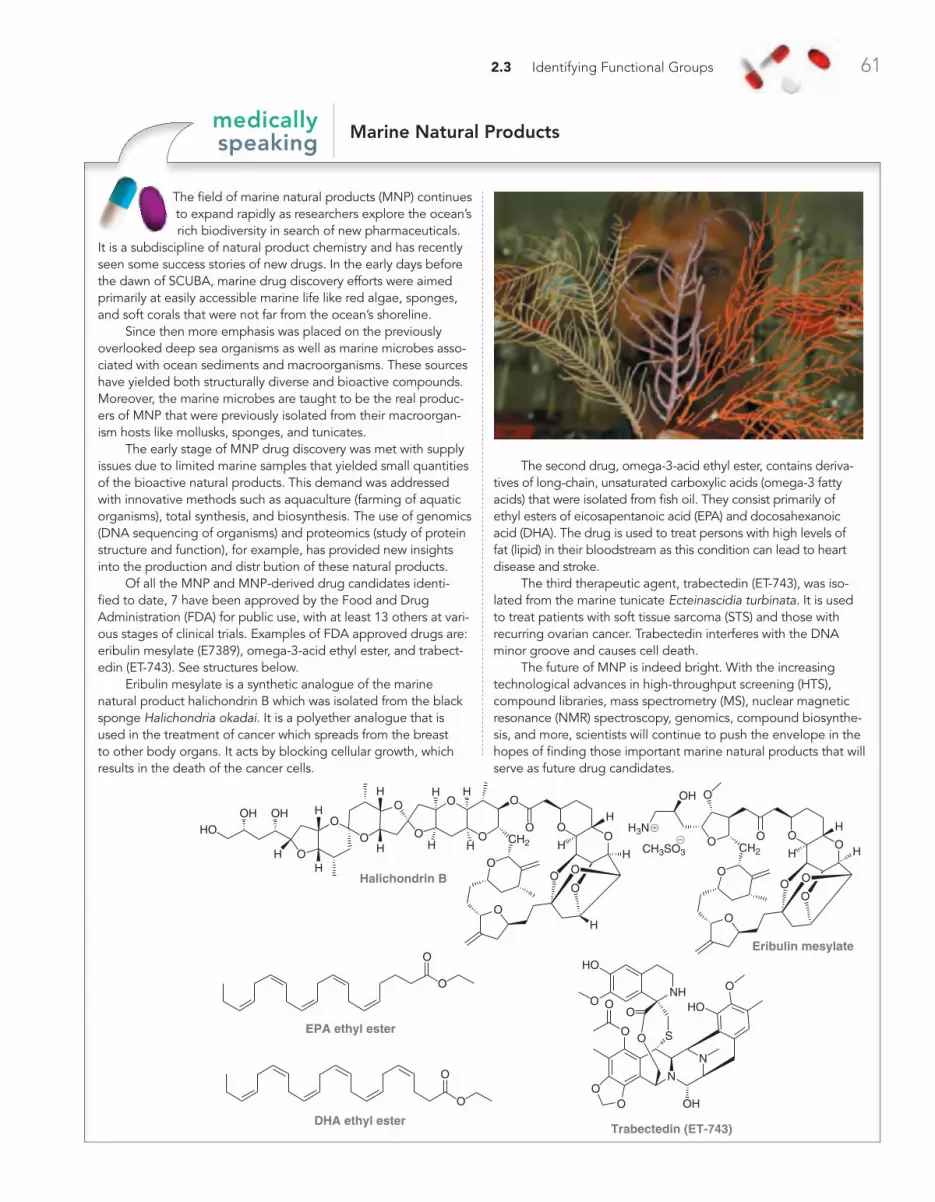
2.3 Identifying Functional Groups 61
Marine natural Productsmedically speaking
The field of marine natural products (MNP) continues to expand rapidly as researchers explore the ocean’s rich biodiversity in search of new pharmaceuticals.
It is a subdiscipline of natural product chemistry and has recently seen some success stories of new drugs. In the early days before the dawn of SCUBA, marine drug discovery efforts were aimed primarily at easily accessible marine life like red algae, sponges, and soft corals that were not far from the ocean’s shoreline.
Since then more emphasis was placed on the previously overlooked deep sea organisms as well as marine microbes asso-ciated with ocean sediments and macroorganisms. These sources have yielded both structurally diverse and bioactive compounds. Moreover, the marine microbes are taught to be the real produc-ers of MNP that were previously isolated from their macroorgan-ism hosts like mollusks, sponges, and tunicates.
The early stage of MNP drug discovery was met with supply issues due to limited marine samples that yielded small quantities of the bioactive natural products. This demand was addressed with innovative methods such as aquaculture (farming of aquatic organisms), total synthesis, and biosynthesis. The use of genomics (DNA sequencing of organisms) and proteomics (study of protein structure and function), for example, has provided new insights into the production and distr bution of these natural products.
Of all the MNP and MNP-derived drug candidates identi-fied to date, 7 have been approved by the Food and Drug Administration (FDA) for public use, with at least 13 others at vari-ous stages of clinical trials. Examples of FDA approved drugs are: eribulin mesylate (E7389), omega-3-acid ethyl ester, and trabect-edin (ET-743). See structures below.
Eribulin mesylate is a synthetic analogue of the marine natural product halichondrin B which was isolated from the black sponge Halichondria okadai. It is a polyether analogue that is used in the treatment of cancer which spreads from the breast to other body organs. It acts by blocking cellular growth, which results in the death of the cancer cells.
The second drug, omega-3-acid ethyl ester, contains deriva-tives of long-chain, unsaturated carboxylic acids (omega-3 fatty acids) that were isolated from fish oil. They consist primarily of ethyl esters of eicosapentanoic acid (EPA) and docosahexanoic acid (DHA). The drug is used to treat persons with high levels of fat (lipid) in their bloodstream as this condition can lead to heart disease and stroke.
The third therapeutic agent, trabectedin (ET-743), was iso-lated from the marine tunicate Ecteinascidia turbinata. It is used to treat patients with soft tissue sarcoma (STS) and those with recurring ovarian cancer. Trabectedin interferes with the DNA minor groove and causes cell death.
The future of MNP is indeed bright. With the increasing technological advances in high-throughput screening (HTS), compound libraries, mass spectrometry (MS), nuclear magnetic resonance (NMR) spectroscopy, genomics, compound biosynthe-sis, and more, scientists will continue to push the envelope in the hopes of finding those important marine natural products that will serve as future drug candidates.
O O
O
OO
O
CH2 CH2
O
HH
HH
O
OO
O
O
O
O
OO
H
H H
H
H
O
HH
H
H
OHOH
Halichondrin B
O OO
O
O
OH
H3N
O
H
H H
O
OO
Eribulin mesylate
CH3SO3
O
O
O
O
EPA ethyl ester
DHA ethyl ester
N
N
OO
O
O HONH
O
HO
O S
O
OH
O
HO
Trabectedin (ET-743)
@
!
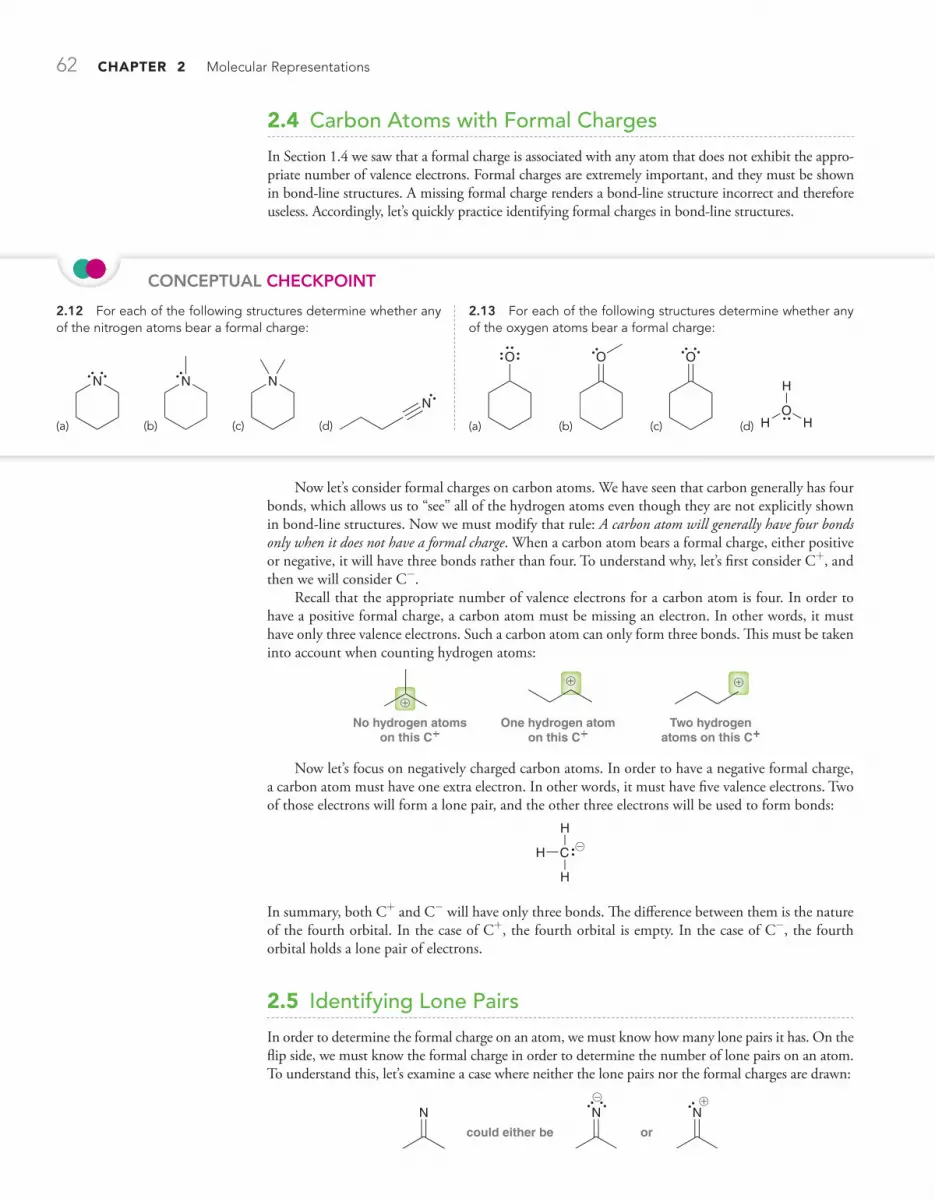
62 CHAPTER 2 Molecular Representations
Now let’s consider formal charges on carbon atoms. We have seen that carbon generally has four bonds, which allows us to “see” all of the hydrogen atoms even though they are not explicitly shown in bond-line structures. Now we must modify that rule: A carbon atom will generally have four bonds only when it does not have a formal charge. When a carbon atom bears a formal charge, either positive or negative, it will have three bonds rather than four. To understand why, let’s first consider C+, and then we will consider C-.
Recall that the appropriate number of valence electrons for a carbon atom is four. In order to have a positive formal charge, a carbon atom must be missing an electron. In other words, it must have only three valence electrons. Such a carbon atom can only form three bonds. This must be taken into account when counting hydrogen atoms:
No hydrogen atoms on this C+
One hydrogen atom on this C+
Two hydrogen atoms on this C+
!
! !
Now let’s focus on negatively charged carbon atoms. In order to have a negative formal charge, a carbon atom must have one extra electron. In other words, it must have five valence electrons. Two of those electrons will form a lone pair, and the other three electrons will be used to form bonds:
CH
H
H
@
In summary, both C+ and C- will have only three bonds. The difference between them is the nature of the fourth orbital. In the case of C+, the fourth orbital is empty. In the case of C-, the fourth orbital holds a lone pair of electrons.
2.5 Identifying Lone Pairs
In order to determine the formal charge on an atom, we must know how many lone pairs it has. On the flip side, we must know the formal charge in order to determine the number of lone pairs on an atom. To understand this, let’s examine a case where neither the lone pairs nor the formal charges are drawn:
could either be or
N N N@ !
ConCePTual CheCkPoinT
2.12 For each of the following structures determine whether any of the nitrogen atoms bear a formal charge:
(a)
N
(b)
N
(c)
N
(d)
N
2.13 For each of the following structures determine whether any of the oxygen atoms bear a formal charge:
(a)
O
(b)
O
(c)
O
(d) O
H H
H
2.4 Carbon Atoms with Formal Charges
In Section 1.4 we saw that a formal charge is associated with any atom that does not exhibit the appro-priate number of valence electrons. Formal charges are extremely important, and they must be shown in bond-line structures. A missing formal charge renders a bond-line structure incorrect and therefore useless. Accordingly, let’s quickly practice identifying formal charges in bond-line structures.

2.5 Identifying Lone Pairs 63
If the lone pairs were shown, then we could determine the charge (two lone pairs would mean a negative charge, and one lone pair would mean a positive charge). Alternatively, if the formal charge were shown, then we could determine the number of lone pairs (a negative charge would mean two lone pairs, and a positive charge would mean one lone pair).
Therefore, a bond-line structure will only be clear if it contains either all of the lone pairs or all of the formal charges. Since there are typically many more lone pairs than formal charges in any one particular structure, chemists have adopted the convention of always drawing formal charges, which allows us to leave out the lone pairs.
Now let’s get some practice identifying lone pairs when they are not drawn. The following example will demonstrate the thought process:
O@
In order to determine the number of lone pairs on the oxygen atom, we simply use the same two-step process described in Section 1.4 for calculating formal charges:
1. Determine the appropriate number of valence electrons for the atom. Oxygen is in group 6A of the periodic table, and therefore, it should have six valence electrons.
2. Determine if the atom actually exhibits the appropriate number of electrons. This oxygen atom has a negative formal charge, which means it must have one extra electron. Therefore, this oxygen atom must have 6 + 1 = 7 valence electrons. One of those electrons is being used to form the COO bond, which leaves six electrons to be housed as lone pairs. This oxygen atom must therefore have three lone pairs:
is the same asOO
@@
The process above represents an important skill; however, it is even more important to become famil-iar enough with atoms that the process becomes unnecessary. There are just a handful of patterns to recognize. Let’s go through them methodically, starting with oxygen. Table 2.2 summarizes the important patterns that you will encounter for oxygen atoms.
• A negative charge corresponds with one bond and three lone pairs.• The absence of charge corresponds with two bonds and two lone pairs.• A positive charge corresponds with three bonds and one lone pair.
waTCh ouTFormal charges must always be drawn and can never be omitted, unlike lone pairs, which may be omitted from a bond-line structure.
table 2.2 formal charge on an oxygen atom associated with a particular number of bonds and lone pairs
Examples:Examples:Examples:
3 bonds + 1 lone pair1 bond + 3 lone pairs 2 bonds + 2 lone pairs
O
O
H
O
O
OO
OO
O
OHH
O
HO
O
OH2 OH
H
O
H
H
NoCharge
@ !
@
@ @
@
!
! !
!!
!
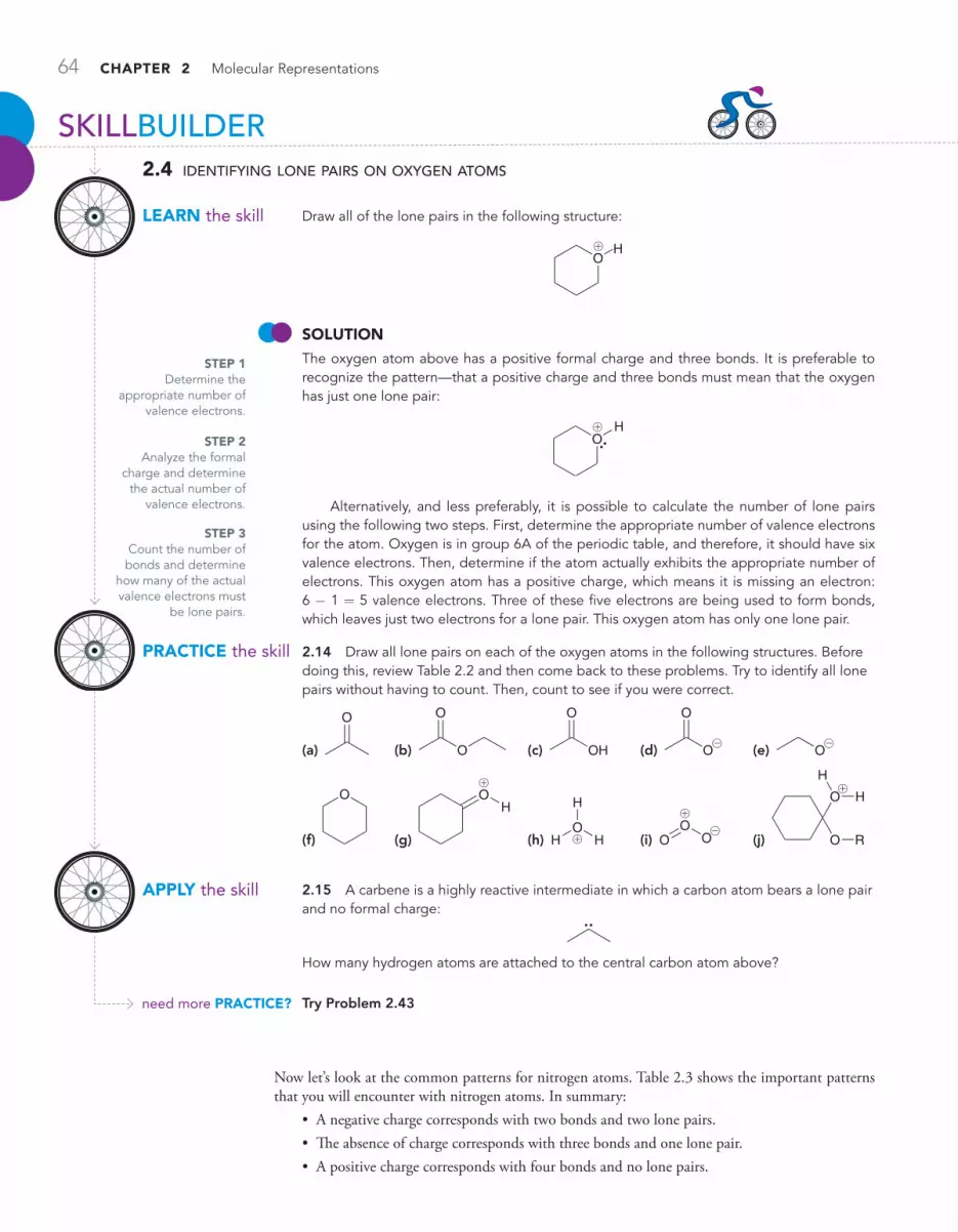
64 CHAPTER 2 Molecular Representations
STEP 1 Determine the
appropriate number of valence electrons.
STEP 2 Analyze the formal
charge and determine the actual number of
valence electrons.
STEP 3 Count the number of bonds and determine
how many of the actual valence electrons must
be lone pairs.
PRACTiCE the skill
APPly the skill
need more PRACTiCE?
SKILLBUILDER
lEARN the skill
2.4 identifying lone pairs on oxygen atoms
Draw all of the lone pairs in the following structure:
OH!
SoluTioN The oxygen atom above has a positive formal charge and three bonds. It is preferable to recognize the pattern—that a positive charge and three bonds must mean that the oxygen has just one lone pair:
OH!
Alternatively, and less preferably, it is possible to calculate the number of lone pairs using the following two steps. First, determine the appropriate number of valence electrons for the atom. Oxygen is in group 6A of the periodic table, and therefore, it should have six valence electrons. Then, determine if the atom actually exhibits the appropriate number of electrons. This oxygen atom has a positive charge, which means it is missing an electron: 6 - 1 = 5 valence electrons. Three of these five electrons are being used to form bonds, which leaves just two electrons for a lone pair. This oxygen atom has only one lone pair.
2.14 Draw all lone pairs on each of the oxygen atoms in the following structures. Before doing this, review Table 2.2 and then come back to these problems. Try to identify all lone pairs without having to count. Then, count to see if you were correct.
(a)
O
(b) O
O
(c) OH
O
(d) O
O
@ (e) O
@
(f)
O
(g)
OH
!
(h) O
H H
H
! (i) O
OO
!
@ (j)
O
O
H
H
R
!
2.15 A carbene is a highly reactive intermediate in which a carbon atom bears a lone pair and no formal charge:
How many hydrogen atoms are attached to the central carbon atom above?
Try Problem 2.43
Now let’s look at the common patterns for nitrogen atoms. Table 2.3 shows the important patterns that you will encounter with nitrogen atoms. In summary:
• A negative charge corresponds with two bonds and two lone pairs.• The absence of charge corresponds with three bonds and one lone pair.• A positive charge corresponds with four bonds and no lone pairs.
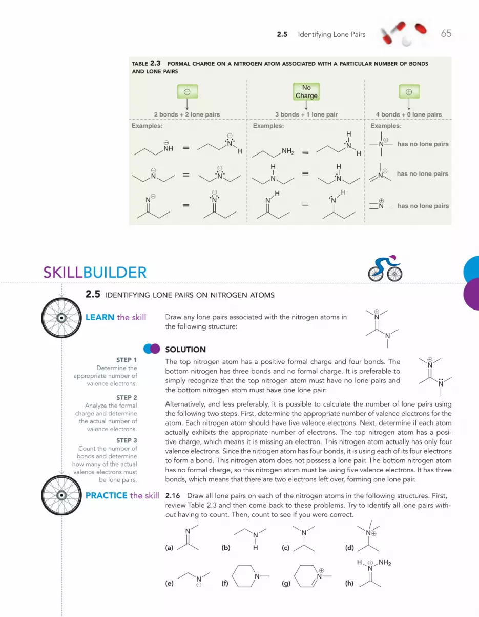
2.5 Identifying Lone Pairs 65
Draw any lone pairs associated with the nitrogen atoms in the following structure:
SoluTioN The top nitrogen atom has a positive formal charge and four bonds. The bottom nitrogen has three bonds and no formal charge. It is preferable to simply recognize that the top nitrogen atom must have no lone pairs and the bottom nitrogen atom must have one lone pair:
Alternatively, and less preferably, it is possible to calculate the number of lone pairs using the following two steps. First, determine the appropriate number of valence electrons for the atom. Each nitrogen atom should have five valence electrons. Next, determine if each atom actually exhibits the appropriate number of electrons. The top nitrogen atom has a posi-tive charge, which means it is missing an electron. This nitrogen atom actually has only four valence electrons. Since the nitrogen atom has four bonds, it is using each of its four electrons to form a bond. This nitrogen atom does not possess a lone pair. The bottom nitrogen atom has no formal charge, so this nitrogen atom must be using five valence electrons. It has three bonds, which means that there are two electrons left over, forming one lone pair.
2.16 Draw all lone pairs on each of the nitrogen atoms in the following structures. First, review Table 2.3 and then come back to these problems. Try to identify all lone pairs with-out having to count. Then, count to see if you were correct.
(a)
N
(b)
N
H (c)
N
(d)
N!
(e) N@ (f)
N (g)
N!
(h)
NNH2H !
STEP 1Determine the
appropriate number of valence electrons.
table 2.3 formal charge on a nitrogen atom associated with a particular number of bonds and lone pairs
2 bonds + 2 lone pairs 3 bonds + 1 lone pair 4 bonds + 0 lone pairs
Examples: Examples: Examples:
has no lone pairsN
has no lone pairsN
has no lone pairsN
NHN
H
N N
N N
NH2N
H
H
H
N
H
N
NH
NH
NoCharge
@
@
@
@@
@
@!
!
!
!
STEP 3Count the number of bonds and determine
how many of the actual valence electrons must
be lone pairs.
STEP 2Analyze the formal
charge and determine the actual number of
valence electrons.
N
N
!
N
N
!
SKILLBUILDER
lEARN the skill
2.5 identifying lone pairs on nitrogen atoms
PRACTiCE the skill
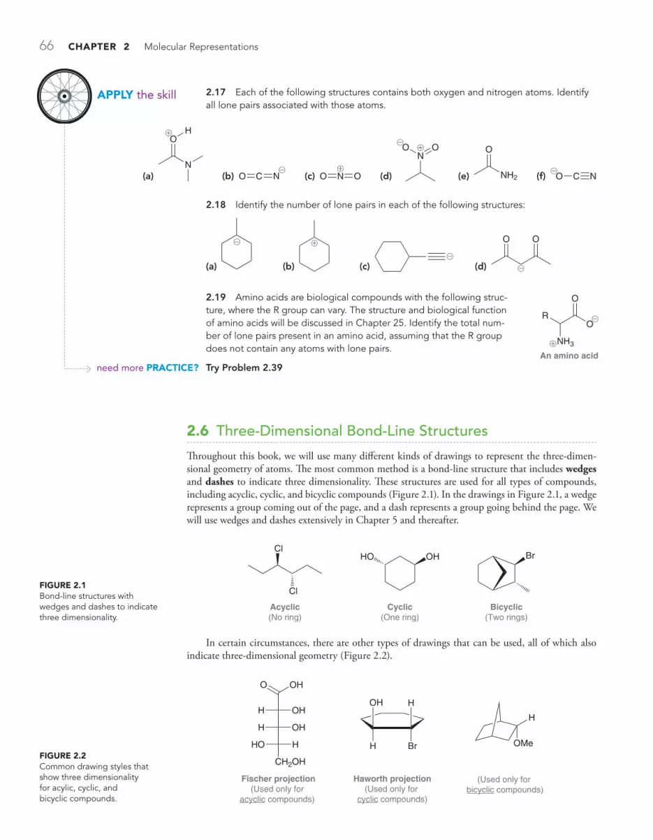
66 CHAPTER 2 Molecular Representations
2.17 Each of the following structures contains both oxygen and nitrogen atoms. Identify all lone pairs associated with those atoms.
2.6 Three-Dimensional Bond-Line Structures
Throughout this book, we will use many different kinds of drawings to represent the three-dimen-sional geometry of atoms. The most common method is a bond-line structure that includes wedges and dashes to indicate three dimensionality. These structures are used for all types of compounds, including acyclic, cyclic, and bicyclic compounds (Figure 2.1). In the drawings in Figure 2.1, a wedge represents a group coming out of the page, and a dash represents a group going behind the page. We will use wedges and dashes extensively in Chapter 5 and thereafter.
2.18 Identify the number of lone pairs in each of the following structures:
(a)
@
(b)
!
(c) @
(d)
OO
@
2.19 Amino acids are biological compounds with the following struc-ture, where the R group can vary. The structure and biological function of amino acids will be discussed in Chapter 25. Identify the total num-ber of lone pairs present in an amino acid, assuming that the R group does not contain any atoms with lone pairs.
Try Problem 2.39
(a)
O
N
H!
(b) NO C@
(c) NO O!
(d)
NO O!
@
(e) NH2
O
(f) O C N@
O
NH3
O
R
An amino acid
!
@
FiguRE 2.1Bond-line structures with wedges and dashes to indicate three dimensionality.
Cl
Cl
Acyclic(No ring)
OHHO
Cyclic(One ring)
Br
Bicyclic(Two rings)
APPly the skill
need more PRACTiCE?
In certain circumstances, there are other types of drawings that can be used, all of which also indicate three-dimensional geometry (Figure 2.2).
FiguRE 2.2Common drawing styles that show three dimensionality for acylic, cyclic, and bicyclic compounds.
H OH
H OH
CH2OH
HO H
O OH
Fischer projection(Used only for
acyclic compounds)
OH
H
H
Br
Haworth projection(Used only for
cyclic compounds)
OMe
H
(Used only for bicyclic compounds)
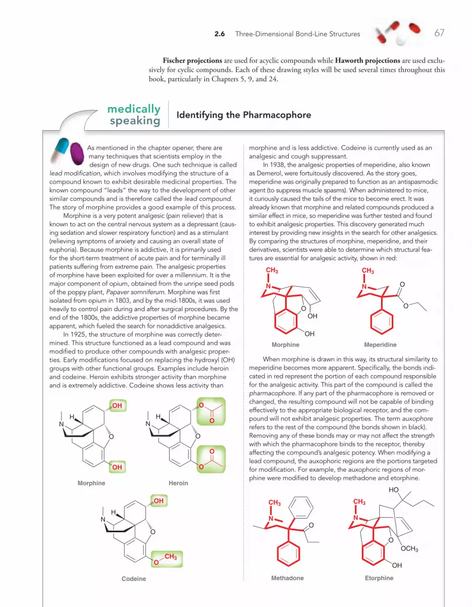
2.6 Three-Dimensional Bond-Line Structures 67
Fischer projections are used for acyclic compounds while Haworth projections are used exclu-sively for cyclic compounds. Each of these drawing styles will be used several times throughout this book, particularly in Chapters 5, 9, and 24.
As mentioned in the chapter opener, there are many techniques that scientists employ in the design of new drugs. One such technique is called
lead modification, which involves modifying the structure of a compound known to exhibit desirable medicinal properties. The known compound “leads” the way to the development of other similar compounds and is therefore called the lead compound. The story of morphine provides a good example of this process.
Morphine is a very potent analgesic (pain reliever) that is known to act on the central nervous system as a depressant (caus-ing sedation and slower respiratory function) and as a stimulant (relieving symptoms of anxiety and causing an overall state of euphoria). Because morphine is addictive, it is primarily used for the short-term treatment of acute pain and for terminally ill patients suffering from extreme pain. The analgesic properties of morphine have been exploited for over a millennium. It is the major component of opium, obtained from the unripe seed pods of the poppy plant, Papaver somniferum. Morphine was first isolated from opium in 1803, and by the mid-1800s, it was used heavily to control pain during and after surgical procedures. By the end of the 1800s, the addictive properties of morphine became apparent, which fueled the search for nonaddictive analgesics.
In 1925, the structure of morphine was correctly deter-mined. This structure functioned as a lead compound and was modified to produce other compounds with analgesic proper-ties. Early modifications focused on replacing the hydroxyl (OH) groups with other functional groups. Examples include heroin and codeine. Heroin exhibits stronger activity than morphine and is extremely addictive. Codeine shows less activity than
morphine and is less addictive. Codeine is currently used as an analgesic and cough suppressant.
In 1938, the analgesic properties of meperidine, also known as Demerol, were fortuitously discovered. As the story goes, meperidine was originally prepared to function as an antispasmodic agent (to suppress muscle spasms). When administered to mice, it curiously caused the tails of the mice to become erect. It was already known that morphine and related compounds produced a similar effect in mice, so meperidine was further tested and found to exhibit analgesic properties. This discovery generated much interest by providing new insights in the search for other analgesics. By comparing the structures of morphine, meperidine, and their derivatives, scientists were able to determine which structural fea-tures are essential for analgesic activity, shown in red:
Morphine Meperidine
N
OOH
OH
CH3
N
O
CH3
O
When morphine is drawn in this way, its structural similarity to meperidine becomes more apparent. Specifically, the bonds indi-cated in red represent the portion of each compound responsible for the analgesic activity. This part of the compound is called the pharmacophore. If any part of the pharmacophore is removed or changed, the resulting compound will not be capable of binding effectively to the appropriate biological receptor, and the com-pound will not exhibit analgesic properties. The term auxophore refers to the rest of the compound (the bonds shown in black). Removing any of these bonds may or may not affect the strength with which the pharmacophore binds to the receptor, thereby affecting the compound’s analgesic potency. When modifying a lead compound, the auxophoric regions are the portions targeted for modification. For example, the auxophoric regions of mor-phine were modified to develop methadone and etorphine.
Methadone Etorphine
N
CH3
ON
OOCH3
OH
CH3
HO
identifying the Pharmacophoremedically speaking
Morphine
O
OH
OH
NH
Codeine
O
O
OH
N
CH3
Heroin
O
O
O
N O
O
H
H

68 CHAPTER 2 Molecular Representations
Methadone, developed in Germany during World War II, is used to treat heroin addicts suffering from withdrawal symptoms. Methadone binds to the same receptor as heroin, but it has a longer retention time in the body, thereby enabling the body to cope with the decreasing levels of drug that normally cause withdrawal symptoms. Etorphine is over 3000 times more potent than morphine and is used exclusively in veterinary medicine to immobilize elephants and other large mammals.
Scientists are constantly searching for new lead com-pounds. In 1992, researchers at NIH (National Institutes of Health) in Bethesda, Maryland, isolated epibatidine from the skin of the Ecuadorian frog, Epipedobates tricolor. Epibatidine was found to be an analgesic that is 200 times more potent than morphine. Further studies indi-cated that epibatidine and mor-phine bind to different receptors. This discovery is very exciting, because it means that epibatidine can serve as a new lead compound. Although this compound is too toxic for clinical use, a significant number of researchers are currently working to identify the pharmacophore of epibati-dine and to develop nontoxic derivatives. This area of research indeed looks promising.
ConCePTual CheCkPoinT2.20 Troglitazone, rosiglitazone, and pioglitazone, all anti-diabetic drugs introduced to the market in the late 1990s, are believed to act on the same receptor:
Troglitazone
SN
O
O
H
O
O
HO
Rosiglitazone
SN
O
O
H
O
N
N
Pioglitazone
SN
O
O
H
O
N
(a) Based on these structures, try to identify the likely pharmacophore that is responsible for the anti-diabetic activity of these drugs.
(b) Consider the structure of rivoglitazone (below). This compound is currently being studied for potential anti-diabetic activity. Based on your analysis of the likely pharma-cophore, do you believe that rivoglitazone will exhibit antidia-betic properties?
Rivoglitazone
O N
NO
SN
O
H
O
Epibatidine
HNNCl
2.7 Introduction to Resonance
The Inadequacy of Bond-Line StructuresWe have seen that bond-line structures are generally the most efficient and preferred way to draw the structure of an organic compound. Nevertheless, bond-line structures suffer from one major defect. Specifically, a pair of bonding electrons is always represented as a line that is drawn between two atoms, which implies that the bonding electrons are confined to a region of space directly in between two atoms. In some cases, this assertion is acceptable, as in the following structure:

2.7 Introduction to Resonance 69
In this case, the p electrons are in fact located where they are drawn, in between the two central car-bon atoms. But in other cases, the electron density is spread out over a larger region of the molecule. For example, consider the following ion, called an allyl carbocation:
!
It might seem from the drawing above that there are two p electrons on the left side and a positive charge on the right side. But this is not the entire picture, and the drawing above is inadequate. Let’s take a closer look and first analyze the hybridization states. Each of the three carbon atoms above is sp2 hybridized. Why? The two carbon atoms on the left side are each sp2 hybridized because each of those carbon atoms is utilizing a p orbital to form the p bond (Section 1.9). The third carbon atom, bearing the positive charge, is also sp2 hybridized because it has an empty p orbital. Figure 2.3 shows the three p orbitals associated with an allyl carbocation. This image focuses our attention on the continuous system of p orbitals, which functions as a “conduit,” allowing the two p electrons to be associated with all three carbon atoms. Valence bond theory is inadequate for analysis of this system because it treats the electrons as if they were con-fined between only two atoms. A more appropriate analysis of the allyl cation requires the use of molecular orbital (MO) theory (Section 1.8), in which electrons are associated with the molecule as a whole, rather than individual atoms. Specifically, in MO theory, the entire molecule is treated as one entity, and all of the electrons in the entire molecule occupy regions of space called molecu-lar orbitals. Two electrons are placed in each orbital, starting with the lowest energy orbital, until all electrons occupy orbitals.
According to MO theory, the three p orbitals shown in Figure 2.3 no longer exist. Instead, they have been replaced by three MOs, illustrated in Figure 2.4 in order of increasing energy. Notice that the lowest energy MO, called the bonding molecular orbital, has no vertical nodes. The next higher energy MO, called the nonbonding molecular orbital, has one vertical node. The highest energy MO, called the antibonding molecular orbital, has two vertical nodes. The p electrons of the allyl system will fill these MOs, starting with the lowest energy MO. How many p electrons will occupy these MOs? The allyl carbocation has only two p electrons, rather than three, because one of the carbon atoms bears a positive formal charge indicating that one electron is missing. The two p electrons of the allyl system will occupy the lowest energy MO (the bonding MO). If the missing electron were to return, it would occupy the next higher energy MO, which is the nonbonding MO. Focus your attention on the nonbonding MO.
H H
HH
CC C
H
FiguRE 2.3The overlapping p orbitals of an allyl carbocation.
Antibonding MO
Nonbonding MO
Bonding MO
FiguRE 2.4The molecular orbitals associated with the p electrons of an allylic system.
The nonbonding molecular orbital (from Figure 2.4) associated with the p electrons of an allylic system.
There should be an electron occupying this nonbonding MO, but the electron is missing. Therefore, the colored lobes are empty and represent regions of space that are electron deficient. In conclusion, MO theory suggests that the positive charge of the allyl carbocation is associated with the two ends of the system, rather than just one end.
In a situation like this, any single bond-line structure that we draw will be inadequate. How can we draw a positive charge that is spread out over two locations, and how can we draw two p electrons that are associated with three carbon atoms?
ResonanceThe approach that chemists use to deal with the inadequacy of bond-line structures is called resonance. According to this approach, we draw more than one bond-line structure and then mentally meld them together: ! !
70 CHAPTER 2 Molecular Representations
These drawings are called resonance structures, and they show that the positive charge is spread over two locations. Notice that we separate resonance structures with a straight, two-headed arrow, and we place brackets around the structures. The arrow and brackets indicate that the drawings are resonance structures of one entity. This one entity, called a resonance hybrid, is not flipping back and forth between the different resonance structures. To better understand this, consider the following analogy: A person who has never before seen a nectarine asks a farmer to describe a nectarine. The farmer answers:
Picture a peach in your mind, and now picture a plum in your mind. Well, a nectarine has features of both fruits: the inside tastes like a peach, the outside is smooth like a plum, and the color is somewhere in between the color of a peach and the color of a plum. So take your image of a peach together with your image of a plum and meld them together in your mind into one image. That’s a nectarine.
Here is the important feature of the analogy: The nectarine does not vibrate back and forth every second between being a peach and being a plum. A nectarine is a nectarine all of the time. The image of a peach by itself is not adequate to describe a nectarine. Neither is the image of a plum. But by combining certain characteristics of a peach with certain characteristics of a plum, it is possible to imagine the features of a nectarine. Similarly, with resonance structures, no single drawing adequately describes the nature of the electron density spread out over the molecule. To deal with this problem, we draw several drawings and then meld them together in our minds to obtain one image, or hybrid, just as we did to obtain an image for a nectarine.
Don’t be confused by this important point: The term “resonance” does not describe something that is happening. Rather, it is a term that describes the way we deal with the inadequacy of our bond-line drawings.
Resonance StabilizationWe developed the concept of resonance using the allyl cation as an example, and we saw that the positive charge of an allyl cation is spread out over two locations. This spreading of charge, called delocalization, is a stabilizing factor. That is, the delocalization of either a positive charge or a negative charge stabilizes a molecule. This stabilization is often referred to as resonance stabilization, and the allyl cation is said to be resonance stabilized. Resonance stabilization plays a major role in the outcome of many reactions, and we will invoke the concept of resonance in almost every chapter of this text-book. The study of organic chemistry therefore requires a thorough mastery of drawing resonance structures, and the following sections are designed to foster the necessary skills.
2.8 Curved Arrows
In this section, we will focus on curved arrows, which are the tools necessary to draw resonance structures properly. Every curved arrow has a tail and head:
Tail Head
Curved arrows used for drawing resonance structures do not represent the motion of electrons—they are simply tools that allow us to draw resonance structures with ease. These tools treat the electrons as if they were moving, even though the electrons are actually not moving at all. In Chapter 3, we will encounter curved arrows that actually do represent the flow of electrons. For now, keep in mind that all curved arrows in this chapter are just tools and do not represent a flow of electrons.
It is essential that the tail and head of every arrow be drawn in precisely the proper location. The tail shows where the electrons are coming from, and the head shows where the electrons are going (remember, the electrons aren’t really going anywhere, but we treat them as if they were for the purpose of drawing the resonance structures). We will soon learn patterns for drawing proper curved arrows. But, first, we must learn where not to draw curved arrows. There are two rules that must be followed when drawing curved arrows for resonance structures:
1. Avoid breaking a single bond. 2. Never exceed an octet for second-row elements.
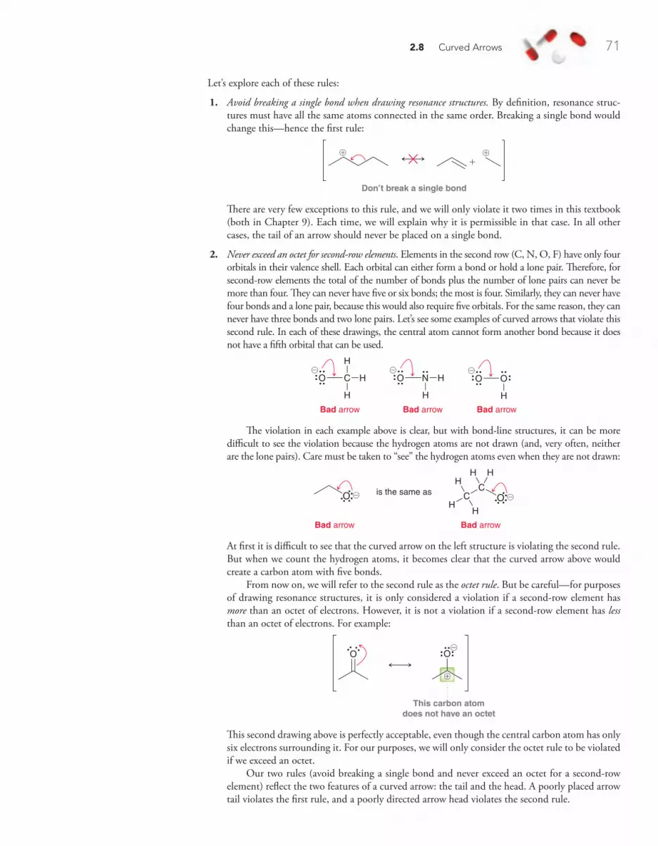
2.8 Curved Arrows 71
Let’s explore each of these rules:
1. Avoid breaking a single bond when drawing resonance structures. By definition, resonance struc-tures must have all the same atoms connected in the same order. Breaking a single bond would change this—hence the first rule:
+
Don’t break a single bond
! !
There are very few exceptions to this rule, and we will only violate it two times in this textbook (both in Chapter 9). Each time, we will explain why it is permissible in that case. In all other cases, the tail of an arrow should never be placed on a single bond.
2. Never exceed an octet for second-row elements. Elements in the second row (C, N, O, F) have only four orbitals in their valence shell. Each orbital can either form a bond or hold a lone pair. Therefore, for second-row elements the total of the number of bonds plus the number of lone pairs can never be more than four. They can never have five or six bonds; the most is four. Similarly, they can never have four bonds and a lone pair, because this would also require five orbitals. For the same reason, they can never have three bonds and two lone pairs. Let’s see some examples of curved arrows that violate this second rule. In each of these drawings, the central atom cannot form another bond because it does not have a fifth orbital that can be used.
Bad arrow
O C H
H
H
Bad arrow
NO H
H
Bad arrow
O O
H
@ @ @
The violation in each example above is clear, but with bond-line structures, it can be more difficult to see the violation because the hydrogen atoms are not drawn (and, very often, neither are the lone pairs). Care must be taken to “see” the hydrogen atoms even when they are not drawn:
is the same asO OCC
H HH
HH
Bad arrowBad arrow
@ @
At first it is difficult to see that the curved arrow on the left structure is violating the second rule. But when we count the hydrogen atoms, it becomes clear that the curved arrow above would create a carbon atom with five bonds.
From now on, we will refer to the second rule as the octet rule. But be careful—for purposes of drawing resonance structures, it is only considered a violation if a second-row element has more than an octet of electrons. However, it is not a violation if a second-row element has less than an octet of electrons. For example:
O O
This carbon atomdoes not have an octet
!
@
This second drawing above is perfectly acceptable, even though the central carbon atom has only six electrons surrounding it. For our purposes, we will only consider the octet rule to be violated if we exceed an octet.
Our two rules (avoid breaking a single bond and never exceed an octet for a second-row element) reflect the two features of a curved arrow: the tail and the head. A poorly placed arrow tail violates the first rule, and a poorly directed arrow head violates the second rule.
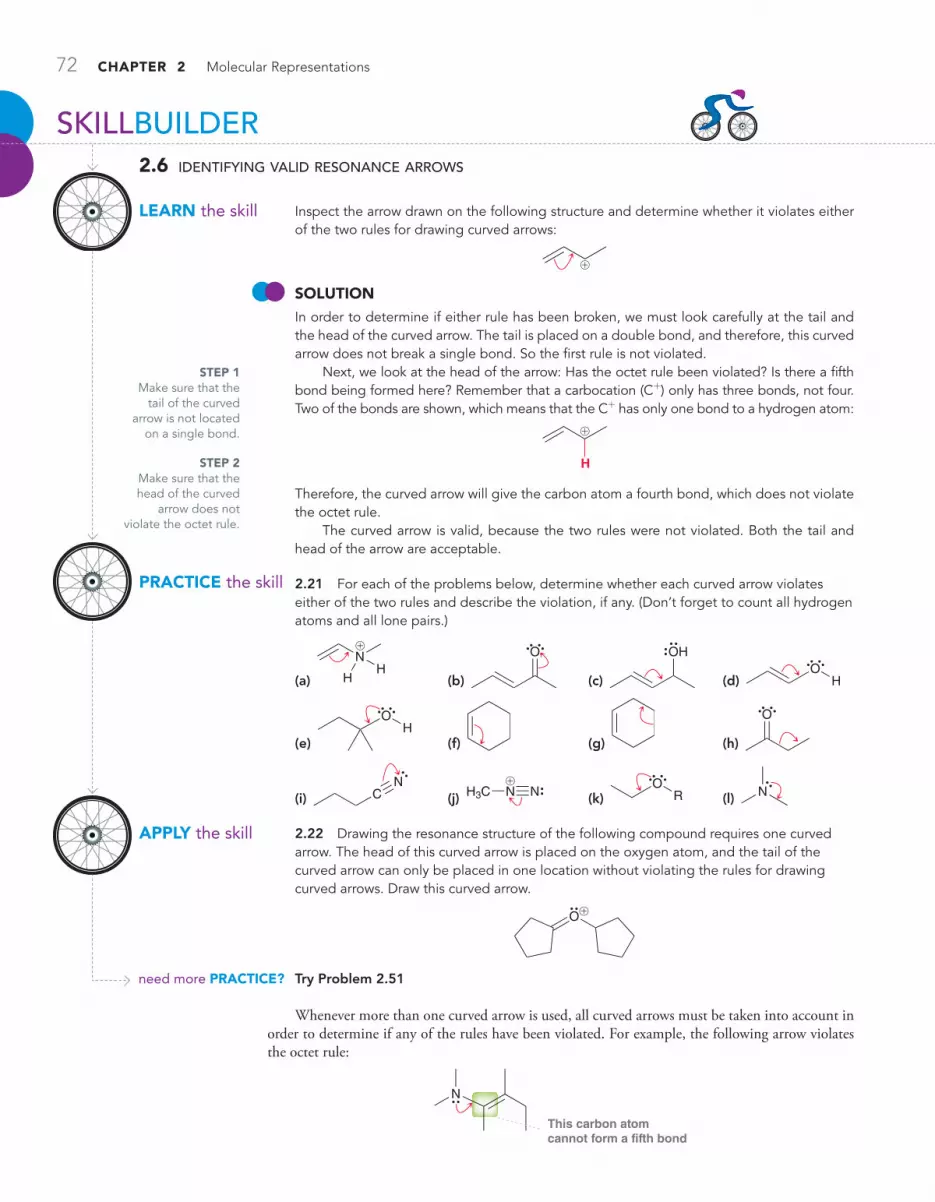
72 CHAPTER 2 Molecular Representations
PRACTiCE the skill
APPly the skill
need more PRACTiCE?
SKILLBUILDER
lEARN the skill
2.6 identifying valid resonance arrows
Inspect the arrow drawn on the following structure and determine whether it violates either of the two rules for drawing curved arrows:
!
SoluTioN In order to determine if either rule has been broken, we must look carefully at the tail and the head of the curved arrow. The tail is placed on a double bond, and therefore, this curved arrow does not break a single bond. So the first rule is not violated.
Next, we look at the head of the arrow: Has the octet rule been violated? Is there a fifth bond being formed here? Remember that a carbocation (C+) only has three bonds, not four. Two of the bonds are shown, which means that the C+ has only one bond to a hydrogen atom:
H
!
Therefore, the curved arrow will give the carbon atom a fourth bond, which does not violate the octet rule.
The curved arrow is valid, because the two rules were not violated. Both the tail and head of the arrow are acceptable.
2.21 For each of the problems below, determine whether each curved arrow violates either of the two rules and describe the violation, if any. (Don’t forget to count all hydrogen atoms and all lone pairs.)
(a)
N
HH
!
(b)
O
(c)
OH
(d) O
H
(e)
OH
(f) (g) (h)
O
(i) N
C (j) NH3C N!
(k) O
R (l) N
2.22 Drawing the resonance structure of the following compound requires one curved arrow. The head of this curved arrow is placed on the oxygen atom, and the tail of the curved arrow can only be placed in one location without violating the rules for drawing curved arrows. Draw this curved arrow.
O!
Try Problem 2.51
STEP 2Make sure that the head of the curved
arrow does not violate the octet rule.
STEP 1Make sure that the
tail of the curved arrow is not located
on a single bond.
Whenever more than one curved arrow is used, all curved arrows must be taken into account in order to determine if any of the rules have been violated. For example, the following arrow violates the octet rule:
N
This carbon atomcannot form a fifth bond

2.9 Formal Charges in Resonance Structures 73
However, by adding another curved arrow, we remove the violation:
N N!
@
The second curved arrow removes the violation of the first curved arrow. In this example, both arrows are acceptable, because taken together, they do not violate our rules.
Arrow pushing is much like bike riding. The skill of bike riding cannot be learned by watching someone else ride. Learning to ride a bike requires practice. Falling occasionally is a necessary part of the learning process. The same is true with arrow pushing. The only way to learn is with practice. This chapter is designed to provide ample opportunity for practicing and mastering resonance structures.
2.9 Formal Charges in Resonance Structures
In Section 1.4, we learned how to calculate formal charges. Resonance structures very often contain formal charges, and it is absolutely critical to draw them properly. Consider the following example:
O ?
In this example, there are two curved arrows. The first arrow pushes one of the lone pairs to form a bond, and the second arrow pushes the p bond to form a lone pair on a carbon atom. When both arrows are pushed at the same time, neither of the rules is violated. So, let’s focus on how to draw the resonance structure by following the instructions provided by the curved arrows. We delete one lone pair from oxygen and place a p bond between carbon and oxygen. Then we must delete the COC p bond and place a lone pair on carbon:
O O
The arrows are really a language, and they tell us what to do. However, the structure is not complete without drawing formal charges. If we apply the rules of assigning formal charges, oxygen acquires a positive charge and carbon acquires a negative charge:
O O!
@
Another way to assign formal charges is to think about what the arrows are indicating. In this case, the curved arrows indicate that the oxygen atom is losing a lone pair and gaining a bond. In other words, it is losing two electrons and only gaining one back. The net result is the loss of one electron, indicating that oxygen must incur a positive charge in the resonance structure. A similar analysis for the carbon atom on the bottom right shows that it must incur a negative charge. Notice that the overall net charge is the same in each resonance structure. Let’s practice assigning formal charges in resonance structures.
waTCh ouTThe electrons are not really moving. We are just treating them as if they were.
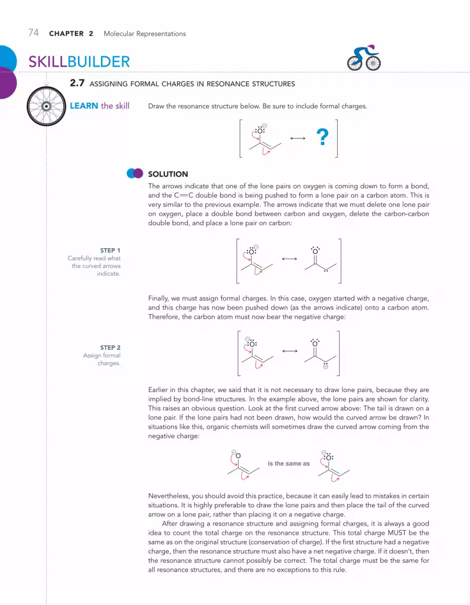
74 CHAPTER 2 Molecular Representations
STEP 1 Carefully read what
the curved arrows indicate.
STEP 2 Assign formal
charges.
SKILLBUILDER
lEARN the skill
2.7 assigning formal charges in resonance structures
Draw the resonance structure below. Be sure to include formal charges.
O ?@
SoluTioN The arrows indicate that one of the lone pairs on oxygen is coming down to form a bond, and the CPC double bond is being pushed to form a lone pair on a carbon atom. This is very similar to the previous example. The arrows indicate that we must delete one lone pair on oxygen, place a double bond between carbon and oxygen, delete the carbon-carbon double bond, and place a lone pair on carbon:
O O@
Finally, we must assign formal charges. In this case, oxygen started with a negative charge, and this charge has now been pushed down (as the arrows indicate) onto a carbon atom. Therefore, the carbon atom must now bear the negative charge:
O O
@
@
Earlier in this chapter, we said that it is not necessary to draw lone pairs, because they are implied by bond-line structures. In the example above, the lone pairs are shown for clarity. This raises an obvious question. Look at the first curved arrow above: The tail is drawn on a lone pair. If the lone pairs had not been drawn, how would the curved arrow be drawn? In situations like this, organic chemists will sometimes draw the curved arrow coming from the negative charge:
is the same asO O
@@
Nevertheless, you should avoid this practice, because it can easily lead to mistakes in certain situations. It is highly preferable to draw the lone pairs and then place the tail of the curved arrow on a lone pair, rather than placing it on a negative charge.
After drawing a resonance structure and assigning formal charges, it is always a good idea to count the total charge on the resonance structure. This total charge MUST be the same as on the original structure (conservation of charge). If the first structure had a negative charge, then the resonance structure must also have a net negative charge. If it doesn’t, then the resonance structure cannot possibly be correct. The total charge must be the same for all resonance structures, and there are no exceptions to this rule.
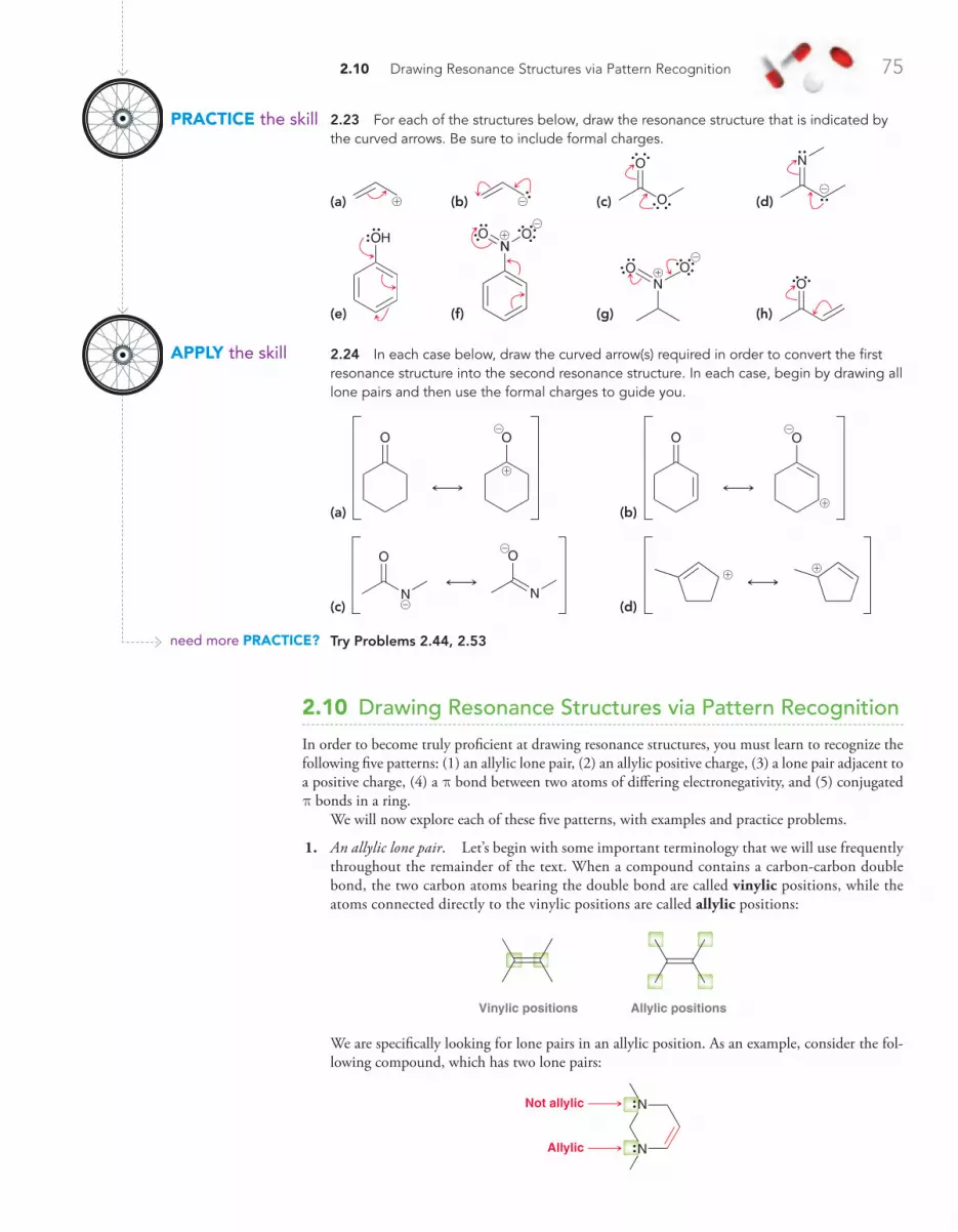
2.10 Drawing Resonance Structures via Pattern Recognition 75
2.23 For each of the structures below, draw the resonance structure that is indicated by the curved arrows. Be sure to include formal charges.
(a) ! (b) @ (c) O
O
(d)
N
@
(e)
OH
(f)
O ONN!
@
(g)
O ON!
@
(h)
O
2.24 In each case below, draw the curved arrow(s) required in order to convert the first resonance structure into the second resonance structure. In each case, begin by drawing all lone pairs and then use the formal charges to guide you.
(a)
OO
!
@
(b)
OO
!
@
(c) N
OO
N
@
@ (d)
!!
Try Problems 2.44, 2.53
2.10 Drawing Resonance Structures via Pattern Recognition
In order to become truly proficient at drawing resonance structures, you must learn to recognize the following five patterns: (1) an allylic lone pair, (2) an allylic positive charge, (3) a lone pair adjacent to a positive charge, (4) a p bond between two atoms of differing electronegativity, and (5) conjugated p bonds in a ring.
We will now explore each of these five patterns, with examples and practice problems.
1. An allylic lone pair. Let’s begin with some important terminology that we will use frequently throughout the remainder of the text. When a compound contains a carbon-carbon double bond, the two carbon atoms bearing the double bond are called vinylic positions, while the atoms connected directly to the vinylic positions are called allylic positions:
Vinylic positions Allylic positions
We are specifically looking for lone pairs in an allylic position. As an example, consider the fol-lowing compound, which has two lone pairs:
N
NNot allylic
Allylic
PRACTiCE the skill
APPly the skill
need more PRACTiCE?

76 CHAPTER 2 Molecular Representations
We must learn to identify lone pairs in allylic positions. Here are several examples:
O
O N
N
OO
@@
In the last three cases above, the lone pairs are not next to a carbon-carbon double bond and are technically not allylic lone pairs (an allylic position is the position next to a carbon-carbon double bond and not any other type of double bond). Nevertheless, for purposes of drawing resonance structures, we will treat these lone pairs in the same way that we treat allylic lone pairs. Specifically, all of the examples above exhibit at least one lone pair next to a p bond.
For each of the examples above, there will be a resonance structure that can be obtained by drawing exactly two curved arrows. The first curved arrow goes from the lone pair to form a p bond, while the second curved arrow goes from the p bond to form a lone pair:
O
O N
N
OO
@@
Let’s carefully consider the formal charges produced in each of the cases above. When the atom with the lone pair has a negative charge, then it transfers its negative charge to the atom that ultimately receives a lone pair:
NN
@
@
@@
When the atom with the lone pair does not have a negative charge, then it will incur a positive charge, while the atom receiving the lone pair will incur a negative charge:
O
OO
O
O
N
O O
N
O
@
!
@
!
@
!

2.10 Drawing Resonance Structures via Pattern Recognition 77
2. An allylic positive charge. Again we are focusing on allylic positions, but this time, we are look-ing for a positive charge located in an allylic position:
Allylic positive charge
!
When there is an allylic positive charge, only one curved arrow will be required; this arrow goes from the p bond to form a new p bond:
! !
Notice what happens to the formal charge in the process. The positive charge is moved to the other end of the system.
In the previous example, the positive charge was next to one p bond. The following example contains two p bonds, which are said to be conjugated, because they are separated from each other by exactly one s bond (we will explore conjugated p systems in more detail in Chapter 17).
!
In this situation, we push each of the double bonds over, one at a time:
! ! !
It is not necessary to waste time recalculating formal charges for each resonance structure, because the arrows indicate what is happening. Think of a positive charge as a hole of electron density—a place that is missing an electron. When we push p electrons to plug up the hole, a new hole is created nearby. In this way, the hole is simply moved from one location to another. Notice that in the above structures the tails of the curved arrows are placed on the p bonds, not on the positive charge. Never place the tail of a curved arrow on a positive charge (that is a common mistake).
ConCePTual CheCkPoinT
2.25 For each of the compounds below, locate the pattern we just learned (lone pair next to a p bond) and draw the appropriate reso-nance structure:
(a)
O
O
(b)
@
(c)
O
(d)
NH2
(e)
ON
O@
!
(f)
O@
(g) N
Acetylcholine(a neurotransmitter)
O
O
!
(h)
5-Amino-4-oxopentanoic acid(used in therapy and diagnosis
of hepatic tumors)
H2N
O
OH
O
Recognizing this pattern (a lone pair next to a p bond) will save time in calculating formal charges and determining if the octet rule is being violated.

78 CHAPTER 2 Molecular Representations
3. A lone pair adjacent to a positive charge. Consider the following example:
O@
!
The oxygen atom exhibits three lone pairs, all of which are adjacent to the positive charge. This pattern requires only one curved arrow. The tail of the curved arrow is placed on a lone pair, and the head of the arrow is placed to form a p bond between the lone pair and the posi-tive charge:
O O@
!
Notice what happens with the formal charges above. The atom with the lone pair has a negative charge in this case, and therefore the charges end up canceling each other. Let’s consider what happens with formal charges when the atom with the lone pair does not bear a negative charge. For example, consider the following:
O O
!
!
Once again, there is a lone pair adjacent to a positive charge. Therefore, we draw only one curved arrow: The tail goes on the lone pair, and the head is placed to form a p bond. In this case, the oxygen atom did not start out with a negative charge. Therefore, it will incur a positive charge in the resonance structure (remember conservation of charge).
ConCePTual CheCkPoinT
2.26 Draw the resonance structure(s) for each of the compounds below:
(a) !
(b)
!
(c)
!
(d)
!
ConCePTual CheCkPoinT
2.27 For each of the compounds below, locate the lone pair adjacent to a positive charge and draw the resonance structure:
(a)
N! (b)
N@
! (c)
O !

2.10 Drawing Resonance Structures via Pattern Recognition 79
In one of the previous problems, a negative charge and a positive charge are seen canceling each other to become a double bond. However, there is one situation where it is not possible to combine charges to form a double bond—this occurs with the nitro group. The structure of the nitro group looks like this:
O ON
@!
In this case, there is a lone pair adjacent to a positive charge, yet we cannot draw a single curved arrow to cancel out the charges:
Not avalid
resonancestructure
O ON
@!
Why not? The curved arrow shown above violates the octet rule, because it would give the nitrogen atom five bonds. Remember that second-row elements can never have more than four bonds. There is only one way to draw the curved arrow above without violating the octet rule—we must draw a second curved arrow, like this:
O ON
OON
@@!!
Look carefully. These two curved arrows are simply our first pattern (a lone pair next to a p bond). Notice that the charges have not been canceled. Rather, the location of the negative charge has moved from one oxygen atom to the other. The two resonance structures above are the only two valid resonance structures for a nitro group. In other words, the nitro group must be drawn with charge separation, even though the nitro group is overall neutral. The structure of the nitro group cannot be drawn without the charges.
4. A p bond between two atoms of differing electronegativity. Recall that electronegativity measures the ability of an atom to attract electrons. A chart of electronegativity values can be found in Section 1.11. For purposes of recognizing this pattern, we will focus on CRO and CRN double bonds.
O N
In these situations, we move the p bond up onto the electronegative atom to become a lone pair:
OO@
!
Notice what happens with the formal charges. A double bond is being separated into a positive and negative charge (this is the opposite of our third pattern, where the charges came together to form a double bond).

80 CHAPTER 2 Molecular Representations
looking aheaDIn this molecule, called benzene, the electrons are delocalized. As a result, benzene exhibits significant resonance stabilization. We will explore the pronounced stability of benzene in Chapter 18.
5. Conjugated p bonds enclosed in a ring. In one of the previous patterns, we referred to p bonds as being conjugated when they are separated from each other by one s bond (i.e., CRC!CRC).
When conjugated p bonds are enclosed in a ring of alternating double and single bonds, we push all of the p bonds over by one position:
When drawing the resonance structure above, all of the p bonds can be pushed clockwise or they can all be pushed counterclockwise. Either way achieves the same result.
ConCePTual CheCkPoinT
2.28 Draw a resonance structure for each of the compounds below.
(a)
N
(b)
O
(c)
O
2.29 Draw a resonance structure of the compound below, which was isolated from the fruits of Ocotea corymbosa, a native plant of the Brazilian Cerrado.
OH
O
2.30 Draw a resonance structure of the compound shown below, called 2-heptanone, which is found in some kinds of cheese.
O
ConCePTual CheCkPoinT
2.31 Fingolimod is a novel drug that has recently been developed for the treatment of multiple sclerosis. In April of 2008, research-ers reported the results of phase III clinical trials of fingolimod, in which 70% of patients who took the drug daily for three years were relapse free. This is a tremendous improvement over previ-ous drugs that only prevented relapse in 30% of patients. Draw a resonance structure of fingolimod:
Fingolimod
H2N
HO OH
Figure 2.5 summarizes the five patterns for drawing resonance structures. Take special notice of the number of curved arrows used for each pattern. When drawing resonance structures, always begin by looking for the patterns that utilize only one curved arrow. Otherwise, it is possible to miss a resonance structure. For example, consider the resonance structures of the following compound:
O
O
O
O
O
O@@
!!

2.11 Assessing Relative Importance of Resonance Structures 81
Notice that each pattern used in this example involves only one curved arrow. If we had started by recognizing a lone pair next to a p bond (which utilizes two curved arrows), then we might have missed the middle resonance structure above:
O
O
O
O
!
@
Allyliclone pair
Allylicpositive charge
Lone pair adjacentto positive charge
p bond between twoatoms of differingelectronegativity
Conjugated p bondsenclosed in a ring
One curved arrow One curved arrow One curved arrow Three curved arrows Two curved arrows
O
OO
!
!
@
FiguRE 2.5A summary of the five patterns for drawing resonance structures.
ConCePTual CheCkPoinT
2.32 Draw resonance structures for each of the following compounds:
(a)
O
(b) ! (c) @ (d) O
O
(e)
O
!
(f )
O
(g)
N
! (h) N
(i)
N
O ( j) Cl
O
2.11 Assessing Relative Importance of Resonance Structures
Not all resonance structures are equally significant. A compound might have many valid resonance structures (structures that do not violate the two rules), but it is possible that one or more of the structures is insignificant. To understand what we mean by “insignificant,” let’s revisit the analogy that we used earlier in the chapter to explain the concept of resonance.
Recall the analogy in which we merged the image of a peach with the image of a plum to obtain an image of a nectarine (Section 2.7). Now let’s modify that analogy slightly. Imagine that we create a new type of fruit that is a hybrid between three fruits: a peach, a plum, and a kiwi. Suppose that the hypothetical hybrid fruit has the following character: 65% peach character, 34% plum character, and 1% kiwi character. This hybrid fruit is expected to look almost exactly like a nectarine, because the amount of kiwi character is too small to affect the nature of the resulting hybrid. Even though the new fruit is actually a hybrid of all three fruits, it will look like a hybrid of only two fruits—because the kiwi character is insignificant.
A similar concept exists when comparing resonance structures. For example, a compound could have three resonance structures, but the three structures might not contribute equally to the overall resonance hybrid. One resonance structure might be the major contributor (like the peach), while another might be insignificant (like the kiwi). In order to understand the true nature of the compound, we must be able to compare resonance structures and determine which struc-tures are major contributors and which structures are not significant.

82 CHAPTER 2 Molecular Representations
Three rules will guide us in determining the significance of resonance structures:
1. Minimize charges. The best kind of structure is one without any charges. It is acceptable to have one or two charges, but structures with more than two charges should be avoided, if pos-sible. Compare the following two cases:
O
O
OH
O
@
Both compounds have a lone pair next to a CRO double bond. So we might expect these com-pounds to have the same number of significant resonance structures. But they do not. Let’s see why. Consider the resonance structures of the first compound:
O
O
Best
HO
O
OK
HO
O
OK
H
@@
!
!
The first resonance structure is the major contributor to the overall resonance hybrid, because it has no charge separation. The other two drawings have charge separation, but there are only two charges in each drawing, so they are both significant resonance structures. They might not contribute as much character as the first resonance structure does, but they are still significant. Therefore, this compound has three significant resonance structures.
Now, let’s try the same approach for the other compound:
OK
O
O
Not significant
O
O
OK
O
O@
@
@
@
!
The first and last structures are acceptable (each has only one charge), but the middle resonance structure has too many charges. This resonance structure is not significant, and therefore, it will not contribute much character to the overall resonance hybrid. It is like the kiwi in our analogy above. This compound has only two significant resonance structures.
One notable exception to this rule involves compounds containing the nitro group (!NO2), which have resonance structures with more than two charges. Why? We saw earlier that the structure of the nitro group must be drawn with charge separation in order to avoid violating the octet rule:
O O OONN
@@! !
Therefore, the two charges of a nitro group don’t really count when we are counting charges. Consider the following case as an example:
O ON
OON
@@@
! !
!
If we apply the rule about limiting charge separation to no more than two charges, then we might say that the second resonance structure above appears to have too many charges to be significant. But it actually is significant, because the two charges associated with the nitro group are not included in the count. We would consider the resonance structure above as if it only had two charges, and therefore it is significant.

SKILLBUILDER
lEARN the skill
2.8 drawing significant resonance structures
Draw all significant resonance structures of the following compound:
SoluTioN We begin by looking for any of the five pat-terns. This compound contains a CRO bond (a p bond between two atoms of differing electro-negativity), and we can therefore draw the fol-lowing resonance structure:
This resonance structure is valid, because it was generated using one of the five patterns. However, it has too many charges, and it is therefore not significant. In general, try to avoid drawing resonance structures with three or more charges.
2.11 Assessing Relative Importance of Resonance Structures 83
2. Electronegative atoms, such as N, O, and Cl, can bear a positive charge, but only if they possess an octet of electrons. Consider the following as an example:
The second resonance structure is significant, even though it has a positive charge on oxygen. Why? Because the positively charged oxygen has an octet of electrons (three bonds plus one lone pair = 6 + 2 = 8 electrons). In fact, the second resonance structure is even more significant than the first resonance structure. We might have thought otherwise, because the first resonance structure has a positive charge on carbon, which is generally much better than having a positive charge on an electronegative atom. Nevertheless, the second resonance structure is more significant because all of its atoms achieve an octet. In the first structure, oxygen has its octet, but carbon only has six electrons. In the second resonance structure, both oxygen and carbon have an octet, which makes that structure more significant, even though the positive charge is on oxygen.
Here is another example, this time with the positive charge on nitrogen:
NN!
!
Once again, the second structure is significant, in fact, even more significant than the first. In summary, the most significant resonance structures are generally those in which all atoms have an octet.
3. Avoid drawing a resonance structure in which two carbon atoms bear opposite charges. Such reso-nance structures are generally insignificant, for example:
H2C
H
H
H
C N C N
H2C
H
H
H
H2C
H
H
H
Not significant
NC
C@ @
!!
In this case, the third resonance structure is insignificant because it has both a C+ and a C-. The presence of carbon atoms with opposite charges, whether close to each other (as in the example above) or far apart, renders the structure insignificant. Throughout this text, we will see only one exception to this rule (in Problem 18.54).
STEP 1 Using the five
patterns, identify a resonance structure.
OOH H
!
!
O O H!
OOO O H H@
! !
!
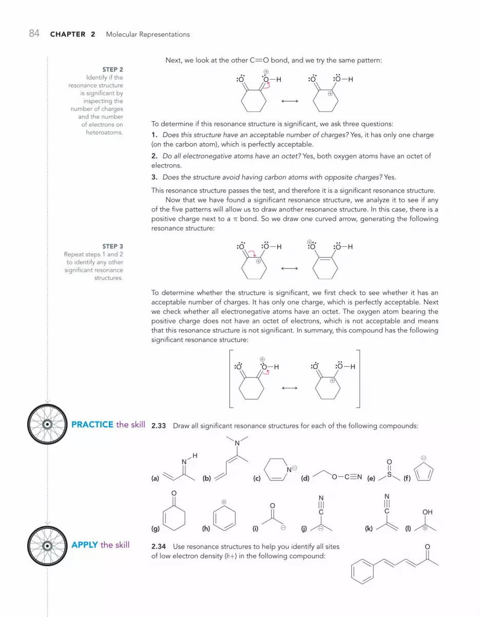
84 CHAPTER 2 Molecular Representations
Next, we look at the other CRO bond, and we try the same pattern:
O OO O H H!
!
To determine if this resonance structure is significant, we ask three questions:
1. Does this structure have an acceptable number of charges? Yes, it has only one charge (on the carbon atom), which is perfectly acceptable.
2. Do all electronegative atoms have an octet? Yes, both oxygen atoms have an octet of electrons.
3. Does the structure avoid having carbon atoms with opposite charges? Yes.
This resonance structure passes the test, and therefore it is a significant resonance structure.Now that we have found a significant resonance structure, we analyze it to see if any
of the five patterns will allow us to draw another resonance structure. In this case, there is a positive charge next to a p bond. So we draw one curved arrow, generating the following resonance structure:
O O O OH H!
!
To determine whether the structure is significant, we first check to see whether it has an acceptable number of charges. It has only one charge, which is perfectly acceptable. Next we check whether all electronegative atoms have an octet. The oxygen atom bearing the positive charge does not have an octet of electrons, which is not acceptable and means that this resonance structure is not significant. In summary, this compound has the following significant resonance structure:
O O O OH H
!
!
2.33 Draw all significant resonance structures for each of the following compounds:
(a)
NH
(b)
N
(c) N@
(d) O C N (e) S
O
(f )
@
(g)
O
(h)
!
(i)
O
@ (j)
C
N
@ (k)
C
N
(l)
OH
!
2.34 Use resonance structures to help you identify all sites of low electron density (d+) in the following compound:
STEP 2 Identify if the
resonance structure is significant by inspecting the
number of charges and the number of electrons on
heteroatoms.
STEP 3 Repeat steps 1 and 2 to identify any other
significant resonance structures.
O
PRACTiCE the skill
APPly the skill
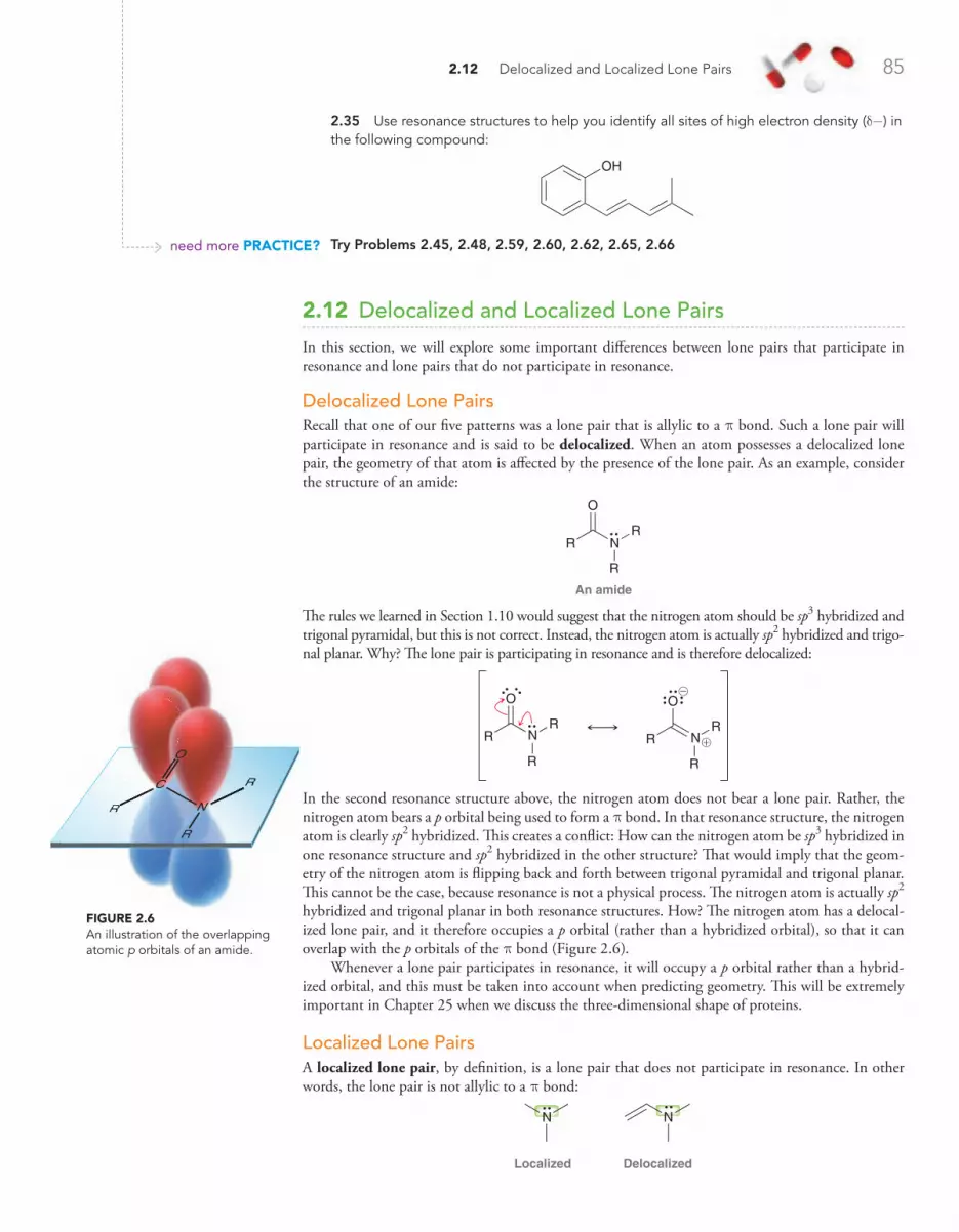
2.12 Delocalized and Localized Lone Pairs 85
2.12 Delocalized and Localized Lone Pairs
In this section, we will explore some important differences between lone pairs that participate in resonance and lone pairs that do not participate in resonance.
Delocalized Lone PairsRecall that one of our five patterns was a lone pair that is allylic to a p bond. Such a lone pair will participate in resonance and is said to be delocalized. When an atom possesses a delocalized lone pair, the geometry of that atom is affected by the presence of the lone pair. As an example, consider the structure of an amide:
N
An amide
R
O
R
R
The rules we learned in Section 1.10 would suggest that the nitrogen atom should be sp3 hybridized and trigonal pyramidal, but this is not correct. Instead, the nitrogen atom is actually sp2 hybridized and trigo-nal planar. Why? The lone pair is participating in resonance and is therefore delocalized:
O
N
O
NRR
R
RR
R
@
!
In the second resonance structure above, the nitrogen atom does not bear a lone pair. Rather, the nitrogen atom bears a p orbital being used to form a p bond. In that resonance structure, the nitrogen atom is clearly sp2 hybridized. This creates a conflict: How can the nitrogen atom be sp3 hybridized in one resonance structure and sp2 hybridized in the other structure? That would imply that the geom-etry of the nitrogen atom is flipping back and forth between trigonal pyramidal and trigonal planar. This cannot be the case, because resonance is not a physical process. The nitrogen atom is actually sp2
hybridized and trigonal planar in both resonance structures. How? The nitrogen atom has a delocal-ized lone pair, and it therefore occupies a p orbital (rather than a hybridized orbital), so that it can overlap with the p orbitals of the p bond (Figure 2.6).
Whenever a lone pair participates in resonance, it will occupy a p orbital rather than a hybrid-ized orbital, and this must be taken into account when predicting geometry. This will be extremely important in Chapter 25 when we discuss the three-dimensional shape of proteins.
Localized Lone PairsA localized lone pair, by definition, is a lone pair that does not participate in resonance. In other words, the lone pair is not allylic to a p bond:
N
Localized Delocalized
N
R
R
RR
RR
R
C
N
O
FiguRE 2.6 An illustration of the overlapping atomic p orbitals of an amide.
2.35 Use resonance structures to help you identify all sites of high electron density (d-) in the following compound:
OH
Try Problems 2.45, 2.48, 2.59, 2.60, 2.62, 2.65, 2.66need more PRACTiCE?

86 CHAPTER 2 Molecular Representations
H H
HH
C
C C
H
FiguRE 2.7Resonance applies to systems that involve overlapping p orbitals that form a “conduit.”
In some cases, a lone pair might appear to be delocalized even though it is actually localized. For example, consider the structure of pyridine:
NLone pair
p bond
Pyridine
The lone pair in pyridine appears to be allylic to a p bond, and it is tempting to use our pattern to draw the following resonance structure:
Not a valid resonance structure
N N
@
!
However, this resonance structure is not valid. Why not? In this case, the lone pair on the nitrogen atom is actually not participating in resonance, even though it is next to a p bond. Recall that in order for a lone pair to participate in resonance, it must occupy a p orbital that can overlap with the neighboring p orbitals, forming a “conduit” (Figure 2.7).
FiguRE 2.8The overlapping p orbitals of pyridine.
H
H H
HH
C
C C
CC
N
Lone pair
In the case of pyridine, the nitrogen atom is already using a p orbital for the p bond (Figure 2.8). The nitrogen atom can only use one p orbital to join in the conduit shown in Figure 2.8, and that p orbital is already being utilized by the p bond. As a result, the lone pair cannot join in the conduit, and therefore it cannot participate in resonance. In this case, the lone pair occupies an sp2-hybridized orbital, which is in the plane of the ring.
Here is the bottom line: Whenever an atom possesses both a p bond and a lone pair, they will not both participate in resonance. In general, only the p bond will participate in resonance, and the lone pair will not.
Let’s get some practice identifying localized and delocalized lone pairs and using that information to determine geometry.

2.12 Delocalized and Localized Lone Pairs 87
SKILLBUILDER
lEARN the skill
2.9 identifying localized and delocalized lone pairs
Histamine is a compound that plays a key role in many biological functions. Most notably, it is involved in immune responses, where it triggers the symptoms of allergic reactions:
Histamine
NN
NH2
H
Each nitrogen atom exhibits a lone pair. In each case, identify whether the lone pair is local-ized or delocalized and then use that information to determine the hybridization state and geometry for each nitrogen atom in histamine.
SoluTioN Let’s begin with the nitrogen on the right side of the compound. This lone pair is localized, and therefore we can use the method outlined in Section 1.10 to determine the hybridization state and geometry:
N
There are 3 bonds and 1 lone pair, and therefore:
1) Steric number=3+1=42) 4=sp3=electronically tetrahedral 3) Arrangement of atoms=trigonal pyramidal
NNH
H
H
This lone pair is not participating in resonance, so our method accurately predicts the geom-etry to be trigonal pyramidal.
Now, let’s consider the nitrogen atom on the left side of the compound. The lone pair on that nitrogen atom is delocalized by resonance:
NH2
NN
NH2
NN
H H@
!
Therefore, this lone pair is actually occupying a p orbital, rendering the nitrogen atom sp2 hybridized, rather than sp3 hybridized. As a result, the geometry is trigonal planar.
Now let’s consider the remaining nitrogen atom:
NN
N
HH
H
This nitrogen atom already has a p bond par-ticipating in resonance. Therefore, the lone pair cannot also participate in resonance. In this case, the lone pair must be localized. The nitrogen atom is in fact sp2 hybridized and exhibits bent geometry.
To summarize, each of the nitrogen atoms in histamine has a different geometry:
Trigonal planar
Bent
Trigonal pyramidal
NN
N
HH
H
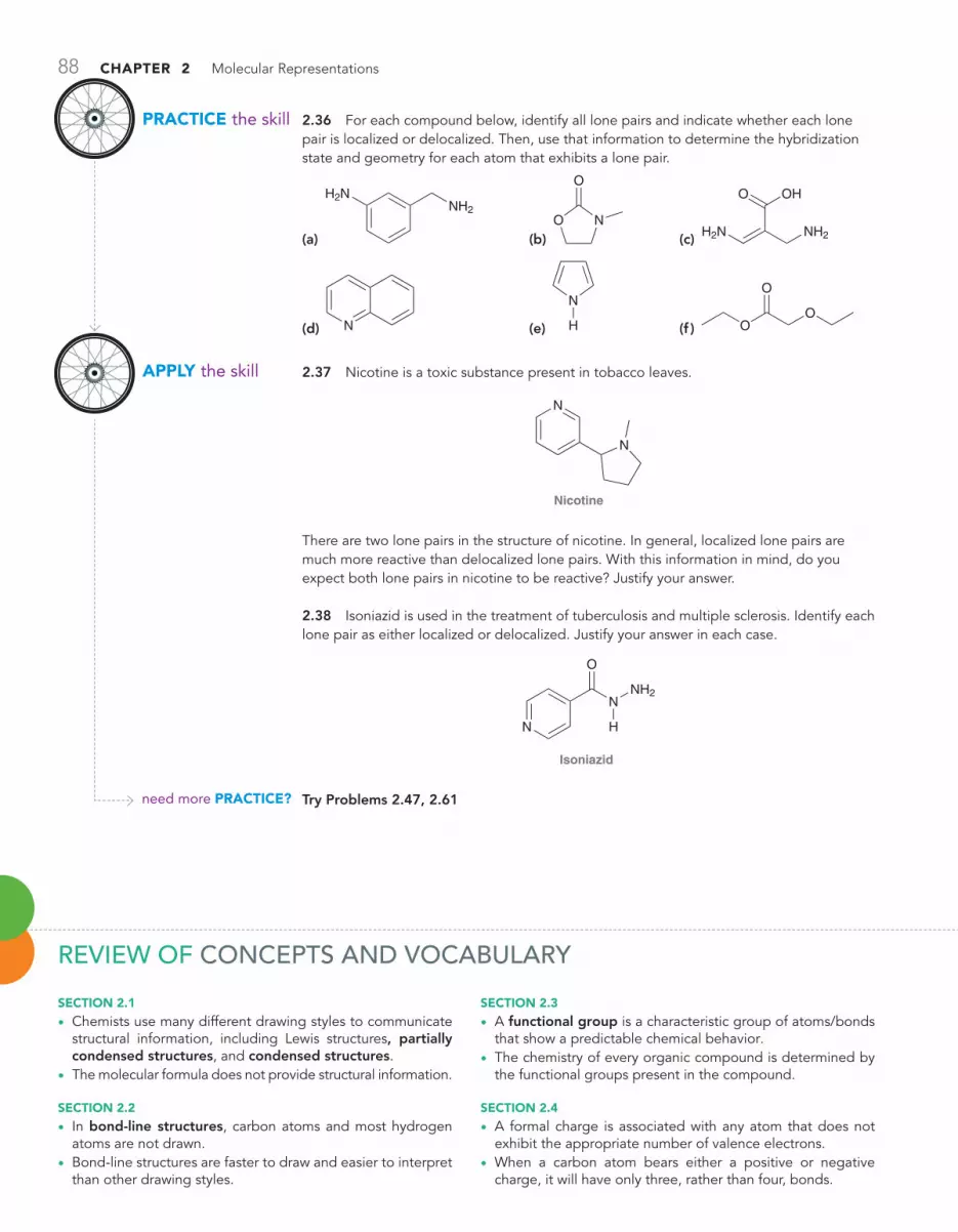
88 CHAPTER 2 Molecular Representations
2.36 For each compound below, identify all lone pairs and indicate whether each lone pair is localized or delocalized. Then, use that information to determine the hybridization state and geometry for each atom that exhibits a lone pair.
(a)
H2NNH2
(b) NO
O
(c)
O OH
NH2H2N
(d) N (e)
N
H (f ) OO
O
2.37 Nicotine is a toxic substance present in tobacco leaves.
Nicotine
N
N
There are two lone pairs in the structure of nicotine. In general, localized lone pairs are much more reactive than delocalized lone pairs. With this information in mind, do you expect both lone pairs in nicotine to be reactive? Justify your answer.
2.38 Isoniazid is used in the treatment of tuberculosis and multiple sclerosis. Identify each lone pair as either localized or delocalized. Justify your answer in each case.
Isoniazid
N
N
O
NH2
H
Try Problems 2.47, 2.61
PRACTiCE the skill
APPly the skill
need more PRACTiCE?
REvIEw OF COnCEPTS AnD vOCABULARY
SECTioN 2.1
• Chemists use many different drawing styles to communicate structural information, including Lewis structures, partially condensed structures, and condensed structures.
• The molecular formula does not provide structural information.
SECTioN 2.2
• In bond-line structures, carbon atoms and most hydrogen atoms are not drawn.
• Bond-line structures are faster to draw and easier to interpret than other drawing styles.
SECTioN 2.3
• A functional group is a characteristic group of atoms/bonds that show a predictable chemical behavior.
• The chemistry of every organic compound is determined by the functional groups present in the compound.
SECTioN 2.4
• A formal charge is associated with any atom that does not exhibit the appropriate number of valence electrons.
• When a carbon atom bears either a positive or negative charge, it will have only three, rather than four, bonds.

SkillBuilder Review 89
SECTioN 2.5
• Lone pairs are often not drawn in bond-line structures. It is important to recognize that these lone pairs are present.
SECTioN 2.6
• In bond-line structures, a wedge represents a group coming out of the page, and a dash represents a group behind the page.
• Other drawings used to show three dimensionality include Fischer projections and haworth projections.
SECTioN 2.7
• Bond-line structures are inadequate in some situations, and an approach called resonance is required.
• resonance structures are separated by double-headed arrows and surrounded by brackets:
! !
• resonance stabilization refers to the delocalization of either a positive charge or a negative charge via resonance.
SECTioN 2.8
• Curved arrows are tools for drawing resonance structures.• When drawing curved arrows for resonance structures, avoid
breaking a single bond and never exceed an octet for sec-ond-row elements.
SECTioN 2.9
• All formal charges must be shown when drawing resonance structures.
SECTioN 2.10
• Resonance structures are most easily drawn by looking for the following five patterns:
1. An allylic lone pair2. An allylic positive charge3. A lone pair adjacent to a positive charge4. A p bond between two atoms of differing electronegativity5. Conjugated p bonds enclosed in a ring
• When drawing resonance structures, always begin by looking for the patterns that utilize only one curved arrow.
SECTioN 2.11
• There are three rules for identifying significant resonance structures:
1. minimize charge.2. electronegative atoms (N, o, Cl, etc.) can bear a positive
charge, but only if they possess an octet of electrons.
3. Avoid drawing a resonance structure in which two carbon atoms bear opposite charges.
SECTioN 2.12
• A delocalized lone pair participates in resonance and occu-pies a p orbital.
• A localized lone pair does not participate in resonance. • Whenever an atom possesses both a p bond and a lone pair,
they will not both participate in resonance.
SKILLBUILDER REvIEw2.1 COnvERTInG BETwEEn DIFFEREnT DRAwInG STYLES
Draw the Lewis structure of this compound.
(CH3)3COCH3 O CH3C
CH3
CH3
H3C
STEP 1 Draw each group separately.
C C H
H
H
O
C
H
H H
H
H
HC
C
H
H
H
STEP 2 Draw all C H bonds.
Try Problems 2.1–2.4, 2.49, 2.50
2.2 READInG BOnD-LInE STRUCTURES
STEP 1 The end of every line represents a carbon atom.
STEP 2 Each carbon atom will possess enough hydrogen atoms in order to achieve four bonds.
N
N
O
Cl
N
N
O
Cl
Identify all carbon atoms and hydrogen atoms.
N
N
Cl
O
H
HH
H
H
HHH
H
H HH H
Try Problems 2.5–2.7, 2.39, 2.49, 2.52

90 CHAPTER 2 Molecular Representations
2.4 IDEnTIFYInG LOnE PAIRS On OxYGEn ATOMS
A neutral oxygen atom...Oxygen with a negative charge... Oxygen with a positive charge...
...has one lone pair....has two lone pairs....has three lone pairs.
OO O
@!
Try Problems 2.14, 2.15, 2.43
2.5 IDEnTIFYInG LOnE PAIRS On nITROGEn ATOMS
...has two lone pairs. ...has one lone pair. ...has no lone pairs.
A neutral nitrogen atom...Nitrogen with a negative charge... Nitrogen with a positive charge...
N N N@ !
Try Problems 2.16–2.19, 2.39
2.6 IDEnTIFYInG vALID RESOnAnCE ARROwS
HeadTail
RULE 1: The tail of a curved arrow should not be placed on a single bond.
RULE 2: The head of a curved arrow cannot result in a bond causing a second-row element to exceed an octet.
Try Problems 2.21, 2.22, 2.51
2.7 ASSIGnInG FORMAL CHARGES In RESOnAnCE STRUCTURES
O
...has been pushed to here.
This negative charge...
Read the curved arrows.
O@
@
Try Problems 2.23, 2.24, 2.44, 2.53
2.3 DRAwInG BOnD-LInE STRUCTURES
Draw a bond line drawing of this compound.
STEP 1 Delete all hydrogen atoms except for those connected to heteroatoms.
STEP 2 Draw in zig zag format, keeping triple bonds linear.
O HOO
STEP 3 Delete all carbon atoms.
H C C O
HH
H
O
H
C
H
H
C C C
C
H
C
C
H
H
HH
HH
O
OH
C C C C C C
C
C
C
CCHO C
CC
C
CCC
Try Problems 2.8–2.10, 2.40, 2.41, 2.54, 2.58

Practice Problems 91
2.8 DRAwInG SIGnIFICAnT RESOnAnCE STRUCTURES
Significant Not significant
Oxygen does not have an octet.Too many charges
Significant Not significant
OOO OH O H H O HOO @
! !
!!
!
Try Problems 2.33–2.35, 2.45, 2.48, 2.59, 2.60, 2.62, 2.65, 2.662.9 IDEnTIFYInG LOCALIZED AnD DELOCALIZED LOnE PAIRS
The lone pair on this nitrogen atom is delocalized by resonance, and it therefore occupies a p orbital.
As a result, the nitrogen atom is sp2 hybridized and is therefore trigonal planar.
O
NH2
O
NH2
@
!
Try Problems 2.36–2.38, 2.47, 2.61
note: Most of the Problems are available within , an online teaching and learning solution.
2.39 Draw all carbon atoms, hydrogen atoms, and lone pairs for the following compounds:
O OH
O
OHO
N
O
H
Caffeine
N
N N
N
O
O
Acetaminophen(Tylenol)
Acetylsalicylic acid(aspirin)
2.40 Draw bond-line structures for all constitutional isomers of C4H10.
2.41 Draw bond-line structures for all constitutional isomers of C5H12.
2.42 Draw bond-line structures for vitamin A and vitamin C:
Vitamin A
C
CC
C
CC
C C
C
C
CC
C
C
CC
C
C
CO
H
HH H
H
H
H
H
C
H
H HH
H H
H
HH
HHHH
H
HH
HH H H H
H
Vitamin C
C C
CO
C
OHHO
OCC
HO
HO H
H H
H
2.43 How many lone pairs are found in the structure of vitamin C?
2.44 Identify the formal charge in each case below:
O
N
N
O
O N
2.45 Draw significant resonance structures for the following compound:
O
2.46 Learning to extract structural information from molecular formulas:
(a) Write out the molecular formula for each of the following compounds:
Compare the molecular formulas for the above compounds and fill in the blanks in the following sentence: The number of hydrogen atoms is equal to __________ times the number of carbon atoms plus __________.
(b) Now write out the molecular formula for each of these compounds:
PRACTICE PROBLEMS

92 CHAPTER 2 Molecular Representations
Each of the compounds above has either a double bond or a ring. Compare the molecular formulas for each of these compounds. In each case, the number of hydrogen atoms is __________ times the number of carbon atoms. Fill in the blank.
(c) Now write out the molecular formula for each of these compounds:
Each of the compounds above has either a triple bond or two double bonds or two rings or a ring and a double bond. Compare the molec-ular formulas for each of these compounds. In each case, the number of hydrogen atoms is __________ times the number of carbon atoms minus __________. Fill in the blanks.
(d) Based on the trends above, answer the following questions about the structure of a compound with molecular formula C24H48. Is it pos-sible for this compound to have a triple bond? Is it possible for this compound to have a double bond?
(e) Draw all constitutional isomers that have the molecular formula C4H8.
2.47 Each compound below exhibits one lone pair. In each case, iden-tify the type of atomic orbital in which the lone pair is contained.
(a)
N!
(b)
@
(c)
N!
2.48 Draw all significant resonance structures for each of the follow-ing compounds:
(a)
N
OH
H!
(b) O! (c)
!
2.49 Write a condensed structural formula for each of the following compounds:
(a) (b) OH (c)
2.50 What is the molecular formula for each compound in the previous problem?
2.51 Which of the following drawings is not a resonance structure for 1-nitrocyclohexene? Explain why it cannot be a valid resonance structure.
(a)
ON
O!@
(b)
NOO !
@
(c)
NOO
!
!@@
(d)
NOO
2.52 Identify the number of carbon atoms and hydrogen atoms in the compound below:
2.53 Identify any formal charges in the following structures:
(a) O
(b) N N (c) O
(d) N
2.54 Draw bond-line structures for all constitutional isomers with molecular formula C4H9Cl.
2.55 Draw resonance structures for each of the following:
(a)
O
(b)
O!
(c) ! (d) N
(e)
NH2
(f )
@
(g)
O
(h) O
O
(i) OH! ( j)
O
!
2.56 Determine the relationship between the two structures below. Are they resonance structures or are they constitutional isomers?
O O
@
@
2.57 Consider each pair of compounds below and determine whether the pair represent the same compound, constitutional isomers, or dif-ferent compounds that are not isomeric at all:
(a) (b)
(c) (d)
2.58 Draw a bond-line structure for each of the following compounds:
(a) CH2RCHCH2C(CH3)3 (b) (CH3CH2)2CHCH2CH2OH
(c) CH#COCH2CH(CH3)2 (d) CH3CH2OCH2CH2OCH2CH3
(e) (CH3CH2)3CBr (f ) (CH3)2CRCHCH3
2.59 A mixture of sulfuric acid and nitric acid will produce small quan-tities of the nitronium ion (NO2
+):
ONO!
Does the nitronium ion have any significant resonance structures? Why or why not?
2.60 Consider the structure of ozone:
OO
O@
!
Ozone is formed in the upper atmosphere, where it absorbs short-wavelength UV radiation emitted by the sun, thereby protecting us from harmful radiation. Draw all significant resonance structures for ozone. (hint: Begin by drawing all lone pairs.)

Integrated Problems 93
2.61 Melatonin is an animal hormone believed to have a role in regu-lating the sleep cycle:The structure of melatonin incorporates two nitrogen atoms. What are the hybridization state and geometry of each nitrogen atom? Explain your answer.
2.62 Draw all significant resonance structures for each of the follow-ing compounds:
Estradiol(Female sex hormone)
Testosterone(Male sex hormone)
HO
OH
H
HH
O
OH
H
HH
Melatonin
N N
O
OCH3
HH
InTEGRATED PROBLEMS
2.63 Cycloserine is an antibiotic isolated from the microbe Streptomyces orchidaceous. It is used in conjunction with other drugs for the treatment of tuberculosis.
Cycloserine
O
N
O
H NH2
(a) What is the molecular formula of this compound?
(b) How many sp3-hybridized carbon atoms are present in this structure?
(c) How many sp2-hybridized carbon atoms are present in this structure?
(d) How many sp-hybridized carbon atoms are present in this structure?
(e) How many lone pairs are present in this structure?
(f) Identify each lone pair as localized or delocalized.
(g) Identify the geometry of each atom (except for hydrogen atoms).
(h) Draw all significant resonance structures of cycloserine.
2.64 Ramelteon is a hypnotic agent used in the treatment of insomnia:
Ramelteon
O
N
H
O
(a) What is the molecular formula of this compound?
(b) How many sp3-hybridized carbon atoms are present in this structure?
(c) How many sp2-hybridized carbon atoms are present in this structure?
(d) How many sp-hybridized carbon atoms are present in this structure?
(e) How many lone pairs are present in this structure?
(f) Identify each lone pair as localized or delocalized.
(g) Identify the geometry of each atom (except for hydrogen atoms).
2.65 In the compound below, identify all carbon atoms that are elec-tron deficient (d+) and all carbon atoms that are electron rich (d-). Justify your answer with resonance structures.
H
OH
H
O
2.66 Consider the following two compounds:
Compound A Compound B
O
O
O
O
(a) Identify which of these two compounds has greater resonance stabilization.
(b) Would you expect compound C (below) to have a resonance stabi-lization that is more similar to compound A or to compound B?
Compound C
O O
2.67 Single bonds generally experience free rotation at room tem-perature (as will be discussed in more detail in Chapter 4):
Free rotation of single bond
Nevertheless, the “single bond” shown below exhibits a large barrier to rotation. In other words, the energy of the system is greatly increased if that bond is rotated. Explain the source of this energy barrier. (hint: Think about the atomic orbitals being used to form the “conduit.”)
!
!
Problems 2.68–2.69 are intended for students who have already covered ir spectroscopy (Chapter 15).
2.68 Polymers are very large compounds, assembled from smaller units, called monomers. For example, polymer 2, called poly(vinyl ace-tate), is made from vinyl acetate (1). Polymer 2 can be converted to poly-mer 4, called poly(vinyl alcohol), or PVA, via a process called hydrolysis (explored further in Chapter 21). Complete hydrolysis of 2 leads to 4, while incomplete hydrolysis of 2 leads to 3 in which the polymer chain still con-tains some residual acetate groups. Polymer 2 is one of the main ingre-dients in white glue, while polymer 3 is present in aqueous PVA glues.

94 CHAPTER 2 Molecular Representations
Describe how IR spectroscopy can be used to monitor the conversion of 3 to 4. Specifically, describe what you would look for to confirm complete hydrolysis of the acetate groups (J. Chem. Ed. 2006, 83, 1534–1536).
O
O
O
O
O
O
O
O
2
OH
O
OH
OH
O
3
OH
OH
OH
OH
4
NaOH
H2O
O
O
1
2.69 Coumarin and its derivatives exhibit a broad array of industrial applications, including, but not limited to, cosmetics, food preservatives, and fluorescent laser dyes. Some derivatives of coumarin, such as war-farin, exhibit antithrombic activity and are currently used as blood thin-ners (to prevent the formation of potentially fatal blood clots). Identify how you might use IR spectroscopy to monitor the following reaction, in which compound 1 is converted into a coumarin derivative (compound 2). Describe at least three different signals that you could analyze to con-firm the transformation of 1 to 2 (J. Chem. Ed. 2006, 83, 287–289).
2
1
N OH
H
O O
O
O
O
O
ON
Piperidine
CHALLEnGE PROBLEMS
2.70 CL-20 and HMX are both powerful explosives. CL-20 produces a more powerful blast but is generally considered too shock-sensitive for practical use. HMX is significantly less sensitive and is used as a stan-dard military explosive. When a 2:1 mixture of the two compounds is cocrystallized, the resulting explosive is expected to be more powerful than HMX alone, but with a sensitivity similar to HMX (Cryst. Growth Des. 2012, 12, 4311–4314).
N N
NN
N N
NNNO2
NO2O2N
O2N
NN
NO2
NO2
NO2
O2N
O2N
O2NCL-20 HMX
(a) What are the molecular formulas for CL-20 and HMX?
(b) Consider the lone pair of electrons on one of the nitrogen atoms within the ring(s) for either molecule. Is the lone pair localized or delocalized?
2.71 Progesterone is a female hormone that plays a critical role in the menstrual cycle by preparing the lining of the uterus for implanta-tion of an egg. During W. S. Johnson’s biomimetic synthesis of pro-gesterone (a synthesis that draws inspiration from and mimics natu-rally occurring, biosynthetic pathways), one of the final reactions in the synthesis was believed to have proceeded via the following inter-mediate (J. Am. Chem. Soc. 1971, 93, 4332–4334). Use resonance structures to explain why this intermediate is particularly stable.
!O
H H
H O
O
2.72 Many compounds with desirable medicinal properties are iso-lated from natural sources and are thus referred to as natural products.
However, a compound’s medicinal properties are often known before the structure of the compound has been determined. Below are exam-ples of compounds where the first proposed structure was incorrect (Angew. Chem. Int. Ed. 2005, 44, 1012–1044). In each case, the cor-responding correct structure is also shown. Identify all functional groups in each pair of compounds and then compare the similarities and differ-ences between their molecular structures.
(a)
HO
H
H
H
Correct structureof cholesterol
OH
Proposed structureof cholesterol
(b)
O
NH
N
OH
O
OCH3
O
O
O
OCH3
Proposed structure of porritoxin Correct structure of porritoxin
2.73 The following compound is an intermediate in the synthesis of a gelator, which is a compound capable of self-assembling to form a gel in an organic liquid (Soft Matter 2012, 8, 5486–5492).
N
O
H
OO(CH2)11CH3
CH3(CH2)11O
CH3(CH2)11O
H

Challenge Problems 95
(a) Identify each functional group in the molecule.
(b) In Chapter 4, we will learn that molecules generally rotate freely around single bonds, while rotation around double bonds is signifi-cantly restricted. Consider the four single bonds connecting the two rings in this structure. Two of them can rotate freely, while the other two cannot. Identify the two with restricted rotation and justify your answer by drawing resonance structures.
2.74 The reaction between an aldehyde and an amine results in the formation of a functional group called an imine, as shown in the follow-ing general reaction:
+O
R R′NH2
NR′
R
An imine
Consider the reactants a–D, which have been used in the synthesis of novel self-assembling molecules with unique and dynamic architectures (Langmuir 2012, 28, 14567–14572).
!
!
!
!
A
D
O
O
O
H
N (CH2)10
(CH2)10
(CH2)10
(CH2)10
N
O
O
N
N
H
O
H2N
NH2
C
B
H2N NH2
(a) Draw the product of the reaction between:
i. a and C (2:1 molar ratio)
ii. C and D (1:2 molar ratio)
iii. a and B (2:1 molar ratio)
iv. B and D (1:2 molar ratio)
(b) What is the relationship between the products of reactions iii and iv?
2.75 The following compound is an amino acid derivative (Chapter 25). In solution, molecules of this compound show a tendency to “stick” together, or self-assemble, via a series of intermolecular hydrogen bonds. During self-assembly, the growing aggregate can entrap mol-ecules of liquid, thereby forming a gel (J. Am. Chem. Soc. 2009, 131, 11478–11484).
NN
O
N
O
NN
O
O
N
H
HH
H
H
H
(a) Each of the six hydrogen atoms bound directly to nitrogen can form a hydrogen bond, but H’s that are on the amides can form stron-ger hydrogen bonds than H’s on the amines. Explain why this is so using resonance.
(b) Draw the intermolecular hydrogen bonds that form during self-assembly. Do this by drawing three molecules stacked directly on top of each other, each in the orientation shown. Then, draw hydrogen bonds from the central molecule to each of the other two molecules, showing eight intermolecular H bonds between amide H’s on one molecule to amide O’s on adjacent molecules.
2.76 In Chapter 3, we will explore the factors that render compounds acidic or basic. Tropolone (1) is a compound that is both fairly acidic and fairly basic (J. Org. Chem. 1997, 62, 3200–3207). It is acidic because it is capable of losing a proton (H+) to form a relatively stable anion (2), while it is basic because of its ability to receive a proton to form cation 3:
–H+H+
@
!
O
O
1
O
O
2
O
O
3
H
H
H
(a) Draw all significant resonance structures of anion 2 and of cation 3 and explain why each of these ions is stabilized.
(b) In compound 1, the bond lengths for the C!C bonds vary greatly and alternate in length (long, short, long, etc.). But in ions 2 and 3, the lengths of the bonds are similar. Explain.
(c) The intramolecular hydrogen bonding interaction in 3 is signifi-cantly diminished in comparison to 1. Explain.
2.77 Triphenylmethane dyes are among the first synthetic dyes devel-oped for commercial use. A comparison of the structures of these com-pounds reveals that even small differences in structure can lead to large differences in color (Chem. Rev. 1993, 93, 381–433). The structures of three such dyes are shown below.
@!N
R
R
N
X
Basic violet 4
Basic green 4
Basic red 9
Cl
N(C2H5)2 C2H5
X RH CH3
NH2 H
R
R
(a) Draw resonance structures for basic green 4 that illustrate the delocalization of the positive charge.
(b) Determine whether basic green 4 or basic violet 4 is expected to have greater resonance stabilization. Justify your choice.
2.78 Basic red 1 is a tetracyclic compound (it has four rings) that shares many structural similarities with the dyes in the previous problem (Chem. Rev. 1993, 93, 381–433). This compound has many significant resonance structures, and the positive charge is highly delocalized. While resonance structures can be drawn in which the positive charge is spread throughout all four rings, nonetheless, one of the rings likely bears very little of the charge relative to the other rings. Identify the ring that is not participating as effectively in resonance and suggest an explanation.
@
! ClO N
HN
H
O
OBasic red 1
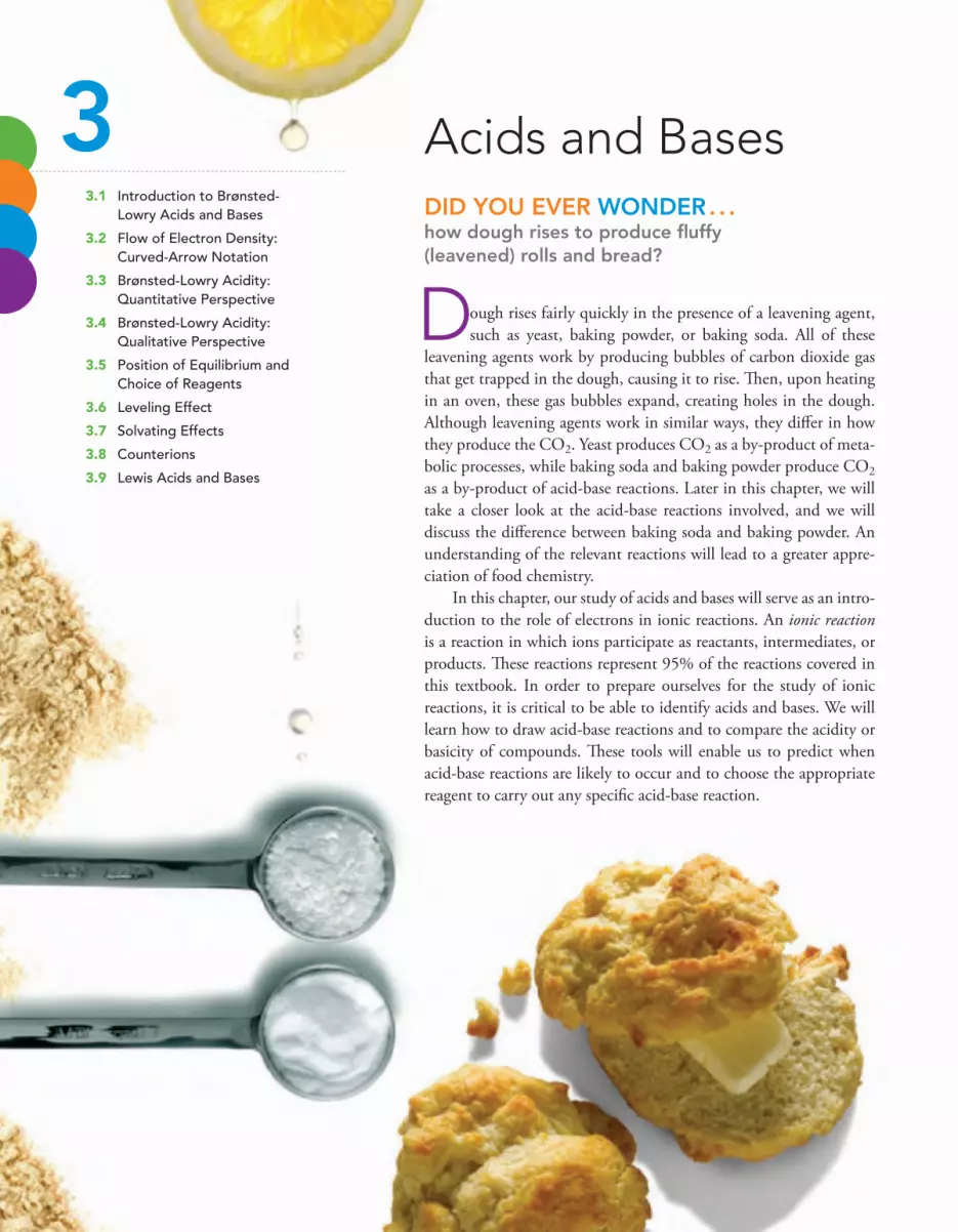
3.1 Introduction to Brønsted-Lowry Acids and Bases
3.2 Flow of Electron Density: Curved-Arrow Notation
3.3 Brønsted-Lowry Acidity: Quantitative Perspective
3.4 Brønsted-Lowry Acidity: Qualitative Perspective
3.5 Position of Equilibrium and Choice of Reagents
3.6 Leveling Effect
3.7 Solvating Effects
3.8 Counterions
3.9 Lewis Acids and Bases
Acids and BasesDID YOU EVER wOnDER . . .how dough rises to produce fluffy (leavened) rolls and bread?
Dough rises fairly quickly in the presence of a leavening agent, such as yeast, baking powder, or baking soda. All of these
leavening agents work by producing bubbles of carbon dioxide gas that get trapped in the dough, causing it to rise. Then, upon heating in an oven, these gas bubbles expand, creating holes in the dough. Although leavening agents work in similar ways, they differ in how they produce the CO2. Yeast produces CO2 as a by-product of meta-bolic processes, while baking soda and baking powder produce CO2 as a by-product of acid-base reactions. Later in this chapter, we will take a closer look at the acid-base reactions involved, and we will discuss the difference between baking soda and baking powder. An understanding of the relevant reactions will lead to a greater appre-ciation of food chemistry.
In this chapter, our study of acids and bases will serve as an intro-duction to the role of electrons in ionic reactions. An ionic reaction is a reaction in which ions participate as reactants, intermediates, or products. These reactions represent 95% of the reactions covered in this textbook. In order to prepare ourselves for the study of ionic reactions, it is critical to be able to identify acids and bases. We will learn how to draw acid-base reactions and to compare the acidity or basicity of compounds. These tools will enable us to predict when acid-base reactions are likely to occur and to choose the appropriate reagent to carry out any specific acid-base reaction.
3

3.2 Flow of Electron Density: Curved-Arrow Notation 97
Do You RemembeR?Before you go on, be sure you understand the following topics.If necessary, review the suggested sections to prepare for this chapter.
3.1 Introduction to Brønsted-Lowry Acids and Bases
This chapter will focus primarily on Brønsted-Lowry acids and bases. There is also a brief section dealing with Lewis acids and bases, a topic that is revisited in Chapter 6 and subsequent chapters.
The definition of Brønsted-Lowry acids and bases is based on the transfer of a proton (H+). An acid is defined as a proton donor, while a base is defined as a proton acceptor. As an example, consider the following acid-base reaction:
OClCl
Acid(proton donor)
O
Base(proton acceptor)
HH H H H
H
+ +@
!
In the reaction above, HCl functions as an acid because it donates a proton to H2O, while H2O func-tions as a base because it accepts the proton from HCl. The products of a proton transfer reaction are called the conjugate base and the conjugate acid:
+HCl
Acid
Cl–
Conjugatebase
Base
H2O
Conjugateacid
H3O+++
In this reaction, Cl- is the conjugate base of HCl. In other words, the conjugate base is what remains of the acid after it has been deprotonated. Similarly, in the reaction above, H3O+ is the conjugate acid of H2O. We will use this terminology throughout the rest of this chapter, so it is important to know these terms well.
In the example above, H2O served as a base by accepting a proton, but in other situations, it can serve as an acid by donating a proton. For example:
OH
Conjugatebase
Acid
OH H
Base
O
Conjugateacid
OH
@
@++
In this case, water functions as an acid rather than a base. Throughout this course, we will see count-less examples of water functioning either as a base or as an acid, so it is important to understand that both are possible and very common. When water functions as an acid, as in the reaction above, the conjugate base is HO-.
3.2 Flow of Electron Density: Curved-Arrow Notation
All reactions are accomplished via a flow of electron density (the motion of electrons). Acid-base reac-tions are no exception. The flow of electron density is illustrated with curved arrows:
AHB B H A@@
+ +
Although these curved arrows look exactly like the curved arrows used for drawing resonance struc-tures, there is an important difference. When drawing resonance structures, curved arrows are used
• Drawing and Interpreting Bond-Line Structures (Section 2.2)
• Identifying Formal Charges (Sections 1.4 and 2.4)• Identifying Lone Pairs (Section 2.5)
• Drawing Resonance Structures (Section 2.10)
Take the DO YOU REMEMBER? QUIZ in to check your understanding.

98 CHAPTER 3 Acids and Bases
simply as tools and do not represent any real physical process. But in the reaction above, the curved arrows do represent an actual physical process. There is a flow of electron density that causes a pro-ton to be transferred from one reagent to another; the curved arrows illustrate this flow. The arrows show the reaction mechanism, that is, they show how the reaction occurs in terms of the motion of electrons.
Notice that the mechanism of a proton transfer reaction involves electrons from a base deprot-onating an acid. This is an important point, because acids do not lose protons without the help of a base. It is necessary for a base to abstract the proton. Here is a specific example:
OH
Base Acid Conjugateacid
H2O
Conjugatebase
O
O
H
O
O
@
@+ +
In this example, hydroxide (HO-) functions as a base to abstract a proton from the acid. Notice that there are exactly two curved arrows. The mechanism of a proton transfer always involves at least two curved arrows.
In Chapter 6, reaction mechanisms will be introduced and explored in more detail. Mechanisms represent the core of organic chemistry, and by proposing and comparing mechanisms, we will dis-cover trends and patterns that define the behavior of electrons. These trends and patterns will enable us to predict how electron density flows and to explain new reactions. For almost every reaction throughout this book, we will propose a mechanism and then analyze it in detail.
Most mechanisms involve one or more proton transfer steps. For example, one of the first reac-tions to be covered (Chapter 8) is called an elimination reaction, and it is believed to occur via the following mechanism:
O H HO
H
H
O H
H
HO
H
H
Proton transfer Proton transfer
!
!
!
–H2O
This mechanism has many steps, each of which is shown with curved arrows. Notice that the first and last steps are simply protons transfers. In the first step, H3O+ functions as an acid, and in the last step, water is acting as a base.
Clearly, proton transfers play an integral role in reaction mechanisms. Therefore, in order to become proficient in drawing mechanisms, it is essential to master proton transfers. Important skills to be mastered include drawing curved arrows properly, being able to predict when a proton transfer is likely or unlikely, and being able to determine which acid or base is appropriate for a specific situ-ation. Let’s get some practice drawing the mechanism of a proton transfer.
SKILLBUILDER
LEARN the skill
3.1 drawing the mechanism of a proton transfer
Draw a mechanism for the following acid-base reaction. Label the acid, base, conjugate acid, and conjugate base:
Water Methoxide
CH3O
Methanol
CH3OH
Hydroxide
HOOH H
@ @
++

3.2 Flow of Electron Density: Curved-Arrow Notation 99
SoLuTioNWe begin by identifying the acid and the base. Water is losing a proton to form hydroxide. Therefore, water is functioning as a proton donor, rendering it an acid. Methoxide (CH3O-) is accepting the proton to form methanol (CH3OH). Therefore, methoxide is the base.
To draw the mechanism properly, remember that there must be two curved arrows. The tail of the first curved arrow is placed on a lone pair of the base and the head is placed on the proton of the acid. This first curved arrow shows the base abstracting the proton. The next curved arrow always comes from the X!H bond being broken and goes to the atom connected to the proton:
CH3OHHO
Base
CH3O
Acid
HO
H
@ @
++
Make sure that the head and tail of each arrow are positioned in exactly the right place or the mechanism will be incorrect.
When water loses a proton, hydroxide is generated. Therefore, hydroxide is the conju-gate base of water. When methoxide receives the proton, methanol is generated. Methanol is therefore the conjugate acid of methoxide:
HO CH3OHCH3OH
OH
@ @
+ +
Base Conjugatebase
Conjugateacid
Acid
3.1 All of the following acid-base reactions are reactions that we will study in greater detail in the chapters to follow. For each one, draw a mechanism and then clearly label the acid, base, conjugate acid, and conjugate base:
(a)
OH
OH
O
HO
H
@
@
++
(b)
O
HO
H
H OH
HO
H
!
!+ +
(c)
O
N
O
N
H
@
@
+ +
(d) OH
O
OH
HO
H
O
O@
@
++
3.2 Each of the following mechanisms contains one or more errors—that is, the curved arrows may or may not be correct. In each case, identify the errors and then describe what modification would be necessary in order to make the curved arrows correct. Explain your suggested modification in each case (the following examples represent common student errors, so it is in your best interests to identify these errors, recognize them, and then avoid these mistakes):
(a)
Cl
N ClH N H
@
!+
STEP 1 Identify the acid
and the base.
STEP 2 Draw the first curved arrow.
STEP 3 Draw the second
curved arrow.
PRACTiCE the skill
APPLy the skill
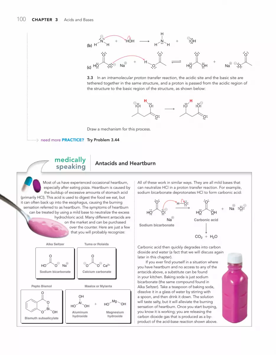
100 CHAPTER 3 Acids and Bases
need more PRACTiCE?
(b) HOH OHN
H H HN
H
H@
@
++
(c) HO O
O
Na HO
O
OH
O
OH
Na
O
O@ @! !+ +
3.3 In an intramolecular proton transfer reaction, the acidic site and the basic site are tethered together in the same structure, and a proton is passed from the acidic region of the structure to the basic region of the structure, as shown below:
O
O
OH
O
O
OH
@@
Draw a mechanism for this process.
Try Problem 3.44
Antacids and Heartburnmedically speaking
Most of us have experienced occasional heartburn, especially after eating pizza. Heartburn is caused by the buildup of excessive amounts of stomach acid
(primarily HCl). This acid is used to digest the food we eat, but it can often back up into the esophagus, causing the burning
sensation referred to as heartburn. The symptoms of heartburn can be treated by using a mild base to neutralize the excess
hydrochloric acid. Many different antacids are on the market and can be purchased
over the counter. Here are just a few that you will probably recognize:
Maalox or Mylanta
Aluminumhydroxide
Magnesiumhydroxide
HOAl
OH
OH
HOMg
OH
Pepto Bismol
Bismuth subsalicylate
OBi
O
O
OH
Tums or Rolaids
Calcium carbonate
O O
O
Ca2+
Alka Seltzer
Sodium bicarbonate
NaHO O
O
@ @@ !
+
All of these work in similar ways. They are all mild bases that can neutralize HCl in a proton transfer reaction. For example, sodium bicarbonate deprotonates HCl to form carbonic acid:
Sodium bicarbonateCarbonic acid
HO O
O
Na
H Cl
Na
CO2 + H2O
HO OH
O
Cl@
@
!
!
+
Carbonic acid then quickly degrades into carbon dioxide and water (a fact that we will discuss again later in this chapter).
If you ever find yourself in a situation where you have heartburn and no access to any of the antacids above, a substitute can be found in your kitchen. Baking soda is just sodium bicarbonate (the same compound found in Alka Seltzer). Take a teaspoon of baking soda, dissolve it in a glass of water by stirring with a spoon, and then drink it down. The solution will taste salty, but it will alleviate the burning sensation of heartburn. Once you start burping, you know it is working; you are releasing the carbon dioxide gas that is produced as a by-product of the acid-base reaction shown above.

3.3 Brønsted-Lowry Acidity: Quantitative Perspective 101
3.3 Brønsted-Lowry Acidity: Quantitative Perspective
There are two ways to predict when a proton transfer reaction will occur: (1) via a quantitative approach (comparing pKa values) or (2) via a qualitative approach (analyzing the structures of the acids). It is essential to master both methods. In this section, we focus on the first method, and in the upcoming sections we will focus on the second method.
Using pKa Values to Compare AcidityThe terms Ka and pKa were defined in your general chemistry textbook, but it is worthwhile to quickly review their definitions. Consider the following general acid-base reaction between HA (an acid) and H2O (functioning as a base in this case):
HA A−H2O H3O+++
The reaction is said to have reached equilibrium when there is no longer an observable change in the concentrations of reactants and products. At equilibrium, the rate of the forward reaction is exactly equivalent to the rate of the reverse reaction, which is indicated with two arrows pointing in oppo-site directions, as shown above. The position of equilibrium is described by the term Keq, which is defined in the following way:
Keq =[HA] [H2O]
[A−][H3O+]
It is the product of the equilibrium concentrations of the products divided by the product of the equilibrium concentrations of the reactants. When an acid-base reaction is carried out in dilute aque-ous solution, the concentration of water is fairly constant (55.5M) and can therefore be removed from the expression. This gives us a new term, Ka:
Ka = Keq [H2O] =[HA]
[A−][H3O+]
The value of Ka measures the strength of the acid. Very strong acids can have a Ka on the order of 1010 (or 10,000,000,000), while very weak acids can have a Ka on the order of 10-50 (or 0.00000000000000000000000000000000000000000000000001). The values of Ka are often very small or very large numbers. To deal with this, chemists often express pKa values, rather than Ka values, where pKa is defined as
pKa = – log Ka
When pKa is used as the measure of acidity, the values will generally range from -10 to 50. We will deal with pKa values extensively throughout this chapter, and there are two things to keep in mind: (1) A strong acid will have a low pKa value, while a weak acid will have a high pKa value. For example, an acid with a pKa of 10 is more acidic than an acid with a pKa of 16. (2) Each unit represents an order of magnitude. An acid with a pKa of 10 is six orders of magnitude (one million times) more acidic than an acid with a pKa of 16. Table 3.1 provides pKa values for many of the compounds com-monly encountered in this course. A pKa table with more data can be found on the inside cover of this book.

102 CHAPTER 3 Acids and Bases
table 3.1 pKa values of common compounds and their conjugate bases
acid pKa conjugate base
Strongest acid
HO S O
O
O
H -9 O S O
O
O
H@
Weakest base
HO
!
-7.3
O
HCl -7 Cl@
H
HO
H!
-1.74H
OH
HO
O
4.75O
O
@
H
O O
H
9.0
O O
H
@
HO
9.9O
@
HHO
15.7H
O@
HO 16 O
@
HO
18O
@
H
O
H H
19.2
O
H H
@
HH C C 25 H C C@
H
HN
H 38 H
NH
@
H
C C
H
H
H
44 C C
H
H
H
@
Weakest acid
H
C C
H
H
H
H
H 50 C C
H
H
H
H
H@
Strongest base
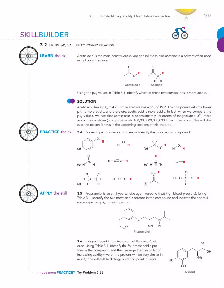
3.3 Brønsted-Lowry Acidity: Quantitative Perspective 103
PRACTiCE the skill
APPLy the skill
need more PRACTiCE?
SKILLBUILDER
LEARN the skill
3.2 using pKa values to compare acids
Acetic acid is the main constituent in vinegar solutions and acetone is a solvent often used in nail polish remover:
Acetic acid
HO
O
Acetone
H
O
H H
Using the pKa values in Table 3.1, identify which of these two compounds is more acidic.
SoLuTioN Acetic acid has a pKa of 4.75, while acetone has a pKa of 19.2. The compound with the lower pKa is more acidic, and therefore, acetic acid is more acidic. In fact, when we compare the pKa values, we see that acetic acid is approximately 14 orders of magnitude (1014) more acidic than acetone (or approximately 100,000,000,000,000 times more acidic). We will dis-cuss the reason for this in the upcoming sections of this chapter.
3.4 For each pair of compounds below, identify the more acidic compound:
(a)
HO
HHO
(b) H
O H HO
(c) HH C C
H
HN
H (d) HCl
H
HO
H!
(e) H
C C
H
H
H
H
H HH C C
(f )
HO S O
O
O
H
HO
!
3.5 Propranolol is an antihypertensive agent (used to treat high blood pressure). Using Table 3.1, identify the two most acidic protons in the compound and indicate the approxi-mate expected pKa for each proton:
Propranolol
O
OH
N
H
3.6 L-dopa is used in the treatment of Parkinson’s dis-ease. Using Table 3.1, identify the four most acidic pro-tons in the compound and then arrange them in order of increasing acidity (two of the protons will be very similar in acidity and difficult to distinguish at this point in time):
Try Problem 3.38 L-dopa
HO
OH
OH
O
NH2

104 CHAPTER 3 Acids and Bases
Using pKa Values to Compare BasicityWe have seen how to use pKa values to compare acids, but it is also possible to use pKa values to compare bases to one another. It is not necessary to use a separate chart of pKb values. The following example will demonstrate how to use pKa values to compare basicity.
PRACTiCE the skill
SKILLBUILDER
LEARN the skill
3.3 using pka values to compare basicity
Using the pKa values in Table 3.1, identify which of the following anions is a stronger base:
O O O
@ @
SoLuTioN Each of these bases can be thought of as the conjugate base of some acid. We just need to compare the pKa values of those acids. To do this, we imagine protonating each of the bases above, producing the following conjugate acids:
O O O
We then look up the pKa values of these acids and compare them:
pKa = 9.0
O O
pKa = 19.2
O
The first compound has a lower pKa value and is therefore a stronger acid than the second compound. Remember that the stronger acid always generates the weaker base. As a result, the conjugate base of the first compound will be a weaker base than the conjugate base of the second compound:
O
Weaker acid
generates
Stronger base
OO O
Stronger acid
generates
O O
Weaker base
@ @
3.7 Identify the stronger base in each of the following cases:
(a) H C C HN
H@
@
(b) O O@ @
(c)
O
HO
H (d) OOH@ @
(e)
H C CC C
H
H
H
H
H@
@
(f ) Cl OH@@
STEP 1 Draw the
conjugate acid of each base.
STEP 2Compare pKa
values.
STEP 3Identify the
stronger base.

3.3 Brønsted-Lowry Acidity: Quantitative Perspective 105
Using pKa Values to Predict the Position of EquilibriumUsing the chart of pKa values, we can also predict the position of equilibrium for any acid-base reac-tion. The equilibrium will always favor formation of the weaker acid (higher pKa value). For example, consider the following acid-base reaction:
O
HO
OH
pKa = 15.7 pKa = 18
Base Acid Conjugate acid Conjugate base
@
+
@
+ HO
H
The equilibrium for this reaction will lean to the right side, favoring formation of the weaker acid.For some reactions, the pKa values are so vastly different that for practical purposes the reac-
tion is treated not as an equilibrium process but rather as one that goes to completion. For example, consider the following reaction:
APPLy the skill
need more PRACTiCE?
3.8 The following compound has three nitrogen atoms:
N
N
N
H
H
H
H
Each of the nitrogen atoms exhibits a lone pair that can function as a base (to abstract a proton from an acid). Rank these three nitrogen atoms in terms of increasing base strength using the following information:
pKa = 3.4
N H
pKa = 3.8
N
H
H
H
pKa = 10.5
H3C N
H
H
H! !!
3.9 Consider the following pKa values and then answer the following questions:
pKa = 10.5
H3C N
H
H
H
pKa = –2.2
H3C O
H
H!
!
(a) For the following compound, will the lone pair on the nitrogen atom be more or less basic than the lone pair on the oxygen atom?
ONH
H
H
(b) Fill in the blanks: The lone pair on the ____________ atom is ____________ orders of magnitude more basic than the lone pair on the ____________ atom.
Try Problem 3.50

106 CHAPTER 3 Acids and Bases
Conjugate base
OH
Base
pKa = 15.7
Acid
HO
H
pKa = 50
Conjugate acid
H
@
@++
The reverse process is negligible, and for such reactions, organic chemists often draw an irreversible arrow, rather than the traditional equilibrium arrows. Technically, it is true that all proton transfers are equilibrium processes, but in the case above, the pKa values are so vastly different (34 orders of magnitude) that we can essentially ignore the reverse reaction.
SKILLBUILDER
LEARN the skill
3.4 using pka values to predict the position of equilibrium
Using pKa values from Table 3.1, determine the position of equilibrium for each of the fol-lowing two proton transfer reactions:
(a)
O
HO
H
H OH
HO
H!
!
+ +
(b) H
OH
O O
OH–
O O
@
@
++
SoLuTioN (a) We begin by identifying the acid on either side of the reaction, and then we compare their pKa values:
O
H+O
H
pKa = –1.74
HO
H
H
pKa = –7.3
OH
!
!
+
In this reaction, the CRO bond receives a proton (protonation of CRO bonds will be dis-cussed in more detail in Chapter 20). The equilibrium always favors the weaker acid (the acid with the higher pKa value). The pKa values shown above are both negative numbers, so it can be confusing as to which is the higher pKa value: -1.74 is a larger number than -7.3. Therefore, the equilibrium will favor the left side of the reaction, which is drawn like this:
O
HO
H
H OH
HO
H!
!
++
The difference in pKa values represents a difference in acidity of nearly six orders of magni-tude. This means that at any given moment in time, approximately one out of every million CRO bonds will bear a proton. When we study this reaction later on, we will see that pro-tonation of a CRO bond can serve as a way to catalyze a number of reactions. For catalytic purposes, it is sufficient to have only a small percentage of the CRO bonds protonated.
STEP 1Identify the
acid on each side of the
equilibrium.
STEP 2 Compare pKa
values.

3.3 Brønsted-Lowry Acidity: Quantitative Perspective 107
STEP 1 Identify the
acid on each side of the
equilibrium.
STEP 2 Compare pKa
values.
PRACTiCE the skill
APPLy the skill
need more PRACTiCE?
(b) We must first identify the acid on either side of the reaction and then compare their pKa values:
pKa = 15.7
HO
H
pKa = 9.0
O OOH
O O
@
@++
This reaction shows the deprotonation of a b-diketone (a compound with two CRO bonds separated from each other by one carbon atom). Once again, this is a proton transfer that we will study in more depth later in the course. The equilibrium will favor the side of the weaker acid (the side with the higher pKa value). Therefore, the equilibrium will favor the right side of the reaction:
HO
H
O O
OH
O O
@
+@
+
The difference in pKa values represents a difference in acidity of six orders of magnitude. In other words, when hydroxide is used to deprotonate a b-diketone, the vast majority of the dik-etone molecules are deprotonated (only one out of every million is not deprotonated). We can conclude from this analysis that hydroxide is a suitable base to accomplish this deprotonation.
3.10 Determine the position of equilibrium for each acid-base reaction below:
(a) OH
HO
HOH O@
@ ++
(b)
O
H
OH
O
H2O
@
+@
+
(c) H
HO
HClCl
HO
H
H@
!++
(d) C C HH NH2 NH3C CH@ @
++
3.11 Hydroxide is not a suitable base for deprotonating acetylene:
C CH
Acetylene
C C HH
Hydroxide
OH H O H@ @
++
Explain why not. Can you propose a base that would be suitable?
Try Problem 3.48

108 CHAPTER 3 Acids and Bases
Drug Distribution and pKamedically speaking
Most drugs will endure a very long journey before reaching their site of action. This journey involves several transitions between polar environments
and nonpolar environments. In order for a drug to reach its intended target, it must be capable of being distributed in both types of environments along the journey. A drug’s ability to tran-sition between environments is, in most cases, a direct result of the drug’s acid-base properties. In fact, most drugs today are acids or bases and, as such, are in equilibrium between charged and uncharged forms. As an example, consider the structure of aspirin and its conjugate base:
Uncharged form
Aspirin
OCCH3
O
O
OCCH3
O
OH
Charged form
Conjugate base
O
OH+
@
+
In the equilibrium above, the left side represents the uncharged form of aspirin, while the right side represents the charged form (the conjugate base). The position of this equilibrium, or percent ionization, will depend on the pH of the solution. The pKa of aspirin is approximately 3.0. At a pH of 3.0 (when pH = pKa), aspirin and its conjugate base will be present in equal amounts. That is, 50% ionization occurs. At a pH below 3, the uncharged form will predominate. At a pH above 3, the charged form will predominate.
With this in mind, consider the journey that aspirin takes after you ingest it. This journey begins in your stomach, where the pH can be as low as 2. Under these very acidic conditions, aspirin is mostly in its uncharged form. That is, there is very little of the conjugate base present. The uncharged form of aspirin is absorbed by the nonpolar environment of the gastric mucosa in your stomach and the intestinal mucosa in the intestinal tract. After passing through these nonpolar environments, the molecules of aspirin enter the blood, which is a polar (aqueous) environment with a pH of approximately 7.4. At that pH, aspirin exists mainly in the charged form (the conjugate base), and it is distributed throughout the circulatory system in this form. Then, in order to pass the blood-brain barrier, or a cell membrane, the molecules must be converted once again into the uncharged form so that they can pass through the necessary nonpolar envi-ronments. The drug is capable of successfully reaching the tar-get because of its ability to exist in two different forms (charged and uncharged). This ability allows it to pass through polar envi-ronments as well as nonpolar environments.
The case above (aspirin) was an example of an acid that achieves biodistribution as a result of its ability to lose a proton. In contrast, some drugs are bases, and they achieve
biodistribution as a result of their ability to gain a proton. For example, codeine (discussed in the previous chapter) can func-tion as a base and accept a proton:
CodeineUncharged form
O
O
HO
NH
H
CodeineCharged form
O
O
HO
N H
H Cl
Cl@
!
Once again, the drug exists in two forms: charged and uncharged. But in this case a low pH favors the charged form rather than the uncharged form. Consider the journey that codeine takes after you ingest it. The drug first encounters the acidic environment of the stomach, where it is protonated and exists mostly in its charged form:
pKa = 8.2
Cl
O
O
HO
N HH
@
!
With a pKa of 8.2, the charged form predominates at low pH. It cannot pass through nonpolar environments and is therefore not absorbed by the gastric mucosa in the stomach. When the drug reaches the basic conditions of the intestines, it is deprotonated, and the uncharged form predominates. Only then can it transi-tion at an appreciable rate into a nonpolar environment.
Accordingly, the efficacy of any drug is highly dependent on its acid-base properties. This must be taken into account in the design of new drugs. It is certainly important that a drug can bind with its designated receptor, but it is equally important that its acid-base properties allow it to reach the receptor efficiently.

3.4 Brønsted-Lowry Acidity: Qualitative Perspective 109
3.4 Brønsted-Lowry Acidity: Qualitative Perspective
In the previous section, we learned how to compare acids or bases by comparing pKa values. In this section, we will now learn how to make such comparisons by analyzing and comparing their struc-tures and without the use of pKa values.
Conjugate Base StabilityIn order to compare acids without the use of pKa values, we must look at the conjugate base of each acid:
–H+
HA
Conjugate base of HA
A@
If A- is very stable (weak base), then HA must be a strong acid. If, on the other hand, A- is very unstable (strong base), then HA must be a weak acid. As an illustration of this point let’s consider the deprotonation of HCl:
HCl
Conjugate base
Cl–H+ @
Chlorine is an electronegative atom, and it can therefore stabilize a negative charge. The chloride ion (Cl-) is in fact very stable, and therefore, HCl is a strong acid. HCl can serve as a proton donor because the conjugate base left behind is stabilized.
Let’s look at one more example. Consider the structure of butane:
H
Conjugate base
–H+@
When butane is deprotonated, a negative charge is generated on a carbon atom. Carbon is not a very electronegative element and is generally not capable of stabilizing a negative charge. Since this C- is very unstable, we can conclude that butane is not very acidic.
LOOkIng AHEADIn Section 22.2, we will see an exceptional case of a stabilized negative charge on a carbon atom. Until then, most instances of C- are considered to be very unstable.
COnCEPTUAL CHECkPOInT
3.12 Amino acids, such as glycine, are the key building blocks of proteins and will be discussed in greater detail in Chapter 25. At the pH of the stomach, gly-cine exists predominantly in a protonated form in which there are two acidic pro-tons of interest. The pKa values for these protons are shown. Using this informa-tion, draw the form of glycine that will predominate at physiological pH of 7.4.
pKa = 2.35pKa = 9.87
Glycine
O
O
HN
H
H H
!
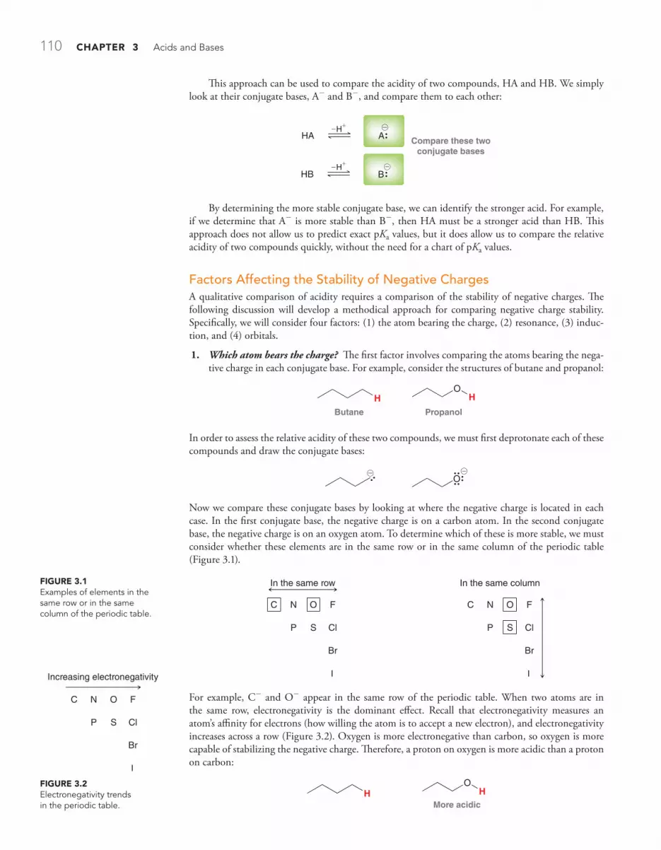
110 CHAPTER 3 Acids and Bases
This approach can be used to compare the acidity of two compounds, HA and HB. We simply look at their conjugate bases, A- and B-, and compare them to each other:
Compare these twoconjugate bases
HA A
HB B–
–H+
–H+
@
By determining the more stable conjugate base, we can identify the stronger acid. For example, if we determine that A- is more stable than B-, then HA must be a stronger acid than HB. This approach does not allow us to predict exact pKa values, but it does allow us to compare the relative acidity of two compounds quickly, without the need for a chart of pKa values.
Factors Affecting the Stability of Negative ChargesA qualitative comparison of acidity requires a comparison of the stability of negative charges. The following discussion will develop a methodical approach for comparing negative charge stability. Specifically, we will consider four factors: (1) the atom bearing the charge, (2) resonance, (3) induc-tion, and (4) orbitals.
1. Which atom bears the charge? The first factor involves comparing the atoms bearing the nega-tive charge in each conjugate base. For example, consider the structures of butane and propanol:
Butane
HPropanol
OH
In order to assess the relative acidity of these two compounds, we must first deprotonate each of these compounds and draw the conjugate bases:
O@ @
Now we compare these conjugate bases by looking at where the negative charge is located in each case. In the first conjugate base, the negative charge is on a carbon atom. In the second conjugate base, the negative charge is on an oxygen atom. To determine which of these is more stable, we must consider whether these elements are in the same row or in the same column of the periodic table (Figure 3.1).
FiguRE 3.1Examples of elements in the same row or in the same column of the periodic table.
FiguRE 3.2Electronegativity trends in the periodic table.
C
Increasing electronegativity
N O F
ClSP
Br
I
In the same row
C N O F
ClSP
Br
I
C N O F
ClSP
Br
I
In the same column
For example, C- and O- appear in the same row of the periodic table. When two atoms are in the same row, electronegativity is the dominant effect. Recall that electronegativity measures an atom’s affinity for electrons (how willing the atom is to accept a new electron), and electronegativity increases across a row (Figure 3.2). Oxygen is more electronegative than carbon, so oxygen is more capable of stabilizing the negative charge. Therefore, a proton on oxygen is more acidic than a proton on carbon:
HMore acidic
OH

3.4 Brønsted-Lowry Acidity: Qualitative Perspective 111
The story is different when comparing two atoms in the same column of the periodic table. For example, let’s compare the acidity of water and hydrogen sulfide:
HO
H HS
H
In order to assess the relative acidity of these two compounds, we deprotonate each of them and compare their conjugate bases:
OH SH@@
In this example, we are comparing O- and S-, which appear in the same column of the periodic table. In such a case, electronegativity is not the dominant effect. Instead, the dominant effect is size (Figure 3.3). Sulfur is larger than oxygen and can therefore better stabilize a negative charge by spreading the charge over a larger volume of space. As such, HS- is more stable than HO-, and therefore, H2S is a stronger acid than H2O. We can verify this prediction by looking at pKa values (the pKa of H2S is 7.0, while the pKa of H2O is 15.7).
Increasingelectronegativity
C N O F
ClSP
Br
I
Increasingsize
C N O F
ClSP
Br
I
FiguRE 3.3Competing trends in the periodic table: size vs. electronegativity.
To summarize, there are two important trends: electronegativity (for comparing atoms in the same row) and size (for comparing atoms in the same column).
SKILLBUILDER
LEARN the skill
3.5 assessing relative stability: factor 1—atom
Compare the two protons that are shown in the following compound. Which one is more acidic?
O
NH
H
SoLuTioNThe first step is to deprotonate each location and draw the two possible conjugate bases:
OH
N
O
NH@
@
We now compare these two conjugate bases and determine which one is more stable. The first conjugate base has a negative charge on nitrogen, while the second conjugate base has a negative charge on oxygen. Nitrogen and oxygen are in the same row of the periodic table, so electronegativity is the determining factor. Oxygen is more electronegative than
STEP 1 Draw the
conjugate bases.
STEP 2Compare the
location of the charge in each case.

112 CHAPTER 3 Acids and Bases
2. Resonance. The second factor for comparing conjugate base stability is resonance. To illustrate the role of resonance in charge stability, let’s consider the structures of ethanol and acetic acid:
Ethanol Acetic acid
OH
O
O
H
In order to compare the acidity of these two compounds, we must deprotonate each of them and draw the conjugate bases:
O O
O
@@
In both cases, the negative charge is on oxygen. Therefore, factor 1 does not indicate which proton is more acidic. But there is a critical difference between these two negative charges. The first conjugate base has no resonance structures, while the second conjugate base does:
O
O
O
O@
@
In this case, the charge is delocalized over both oxygen atoms. Such a negative charge will be more stable than a negative charge localized on one oxygen atom:
Charge is localized(less stable)
O
O
Charge is delocalized(more stable)
O@
@
PRACTiCE the skill
APPLy the skill
need more PRACTiCE?
nitrogen and can better stabilize the negative charge. Therefore, the proton on the oxygen can be removed with greater ease than the proton on the nitrogen:
OH More
acidic
NH
3.13 In each compound below, two protons are clearly identified. Determine which of the two protons is more acidic:
(a)
O
H
H
(b)
H C N
H
H
H
H (c)
HSOH (d)
N HO
H
3.14 Nitrogen and sulfur are neither in the same row nor in the same column of the peri-odic table. Nevertheless, you should be able to identify which proton below is more acidic. Explain your choice:
N
H
SH
Try Problems 3.45b, 3.47h, 3.51b,h, 3.53
STEP 3 The more stable conjugate base
corresponds with the more acidic
proton.

3.4 Brønsted-Lowry Acidity: Qualitative Perspective 113
For this reason, compounds containing a CRO bond directly next to an OH are generally mildly acidic, because their conjugate bases are resonance stabilized:
OOO
Resonance-stabilizedconjugate base
–H+
A carboxylic acid
R OH
R O R O
@
@
These compounds are called carboxylic acids. The R group above simply refers to the rest of the molecule that has not been drawn. Carboxylic acids are actually not very acidic at all compared with inorganic acids such as H2SO4 or HCl. Carboxylic acids are only considered to be acidic when compared with other organic compounds. The “acidity” of carboxylic acids highlights the fact that acidity is relative.
SKILLBUILDER
LEARN the skill
3.6 assessing relative stability: factor 2—resonance
Compare the two protons shown in the following compound. Which one is more acidic?
N
H H
O
N
SoLuTioNBegin by drawing the respective conjugate bases:
H
N
O
N N
H
O
N@@
In the first conjugate base, the charge is localized on nitrogen:
N
O
Charge is localizedNOT resonance stabilized
N
H@
In the second conjugate base, the charge is delocalized by resonance:
Charge is resonance stabilized
N
O
N
H
N
O
N
H@
@
STEP 1 Draw the
conjugate bases.
STEP 2 Look for
resonance stabilization.
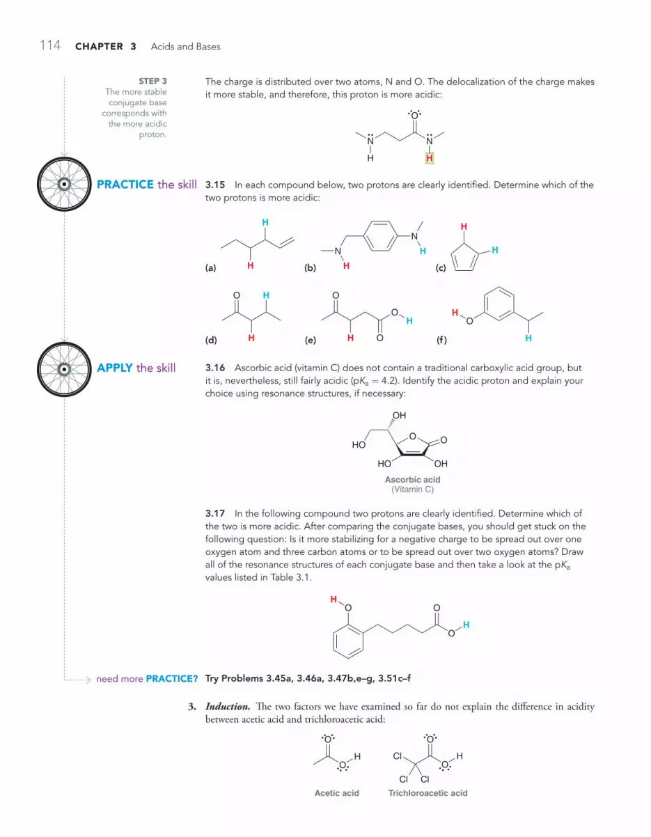
114 CHAPTER 3 Acids and Bases
3. Induction. The two factors we have examined so far do not explain the difference in acidity between acetic acid and trichloroacetic acid:
Acetic acid
O
O
H
Trichloroacetic acid
O
OHCl
Cl Cl
PRACTiCE the skill
APPLy the skill
need more PRACTiCE?
The charge is distributed over two atoms, N and O. The delocalization of the charge makes it more stable, and therefore, this proton is more acidic:
N
O
N
H H
3.15 In each compound below, two protons are clearly identified. Determine which of the two protons is more acidic:
(a)
H
H (b)
H
N
N
H (c)
H
H
(d)
O H
H (e)
O
H
O
O
H
(f ) H
OH
3.16 Ascorbic acid (vitamin C) does not contain a traditional carboxylic acid group, but it is, nevertheless, still fairly acidic (pKa = 4.2). Identify the acidic proton and explain your choice using resonance structures, if necessary:
Ascorbic acid(Vitamin C)
O
OH
O
OHHO
HO
3.17 In the following compound two protons are clearly identified. Determine which of the two is more acidic. After comparing the conjugate bases, you should get stuck on the following question: Is it more stabilizing for a negative charge to be spread out over one oxygen atom and three carbon atoms or to be spread out over two oxygen atoms? Draw all of the resonance structures of each conjugate base and then take a look at the pKa values listed in Table 3.1.
OH
O
O
H
Try Problems 3.45a, 3.46a, 3.47b,e–g, 3.51c–f
STEP 3 The more stable conjugate base
corresponds with the more acidic
proton.
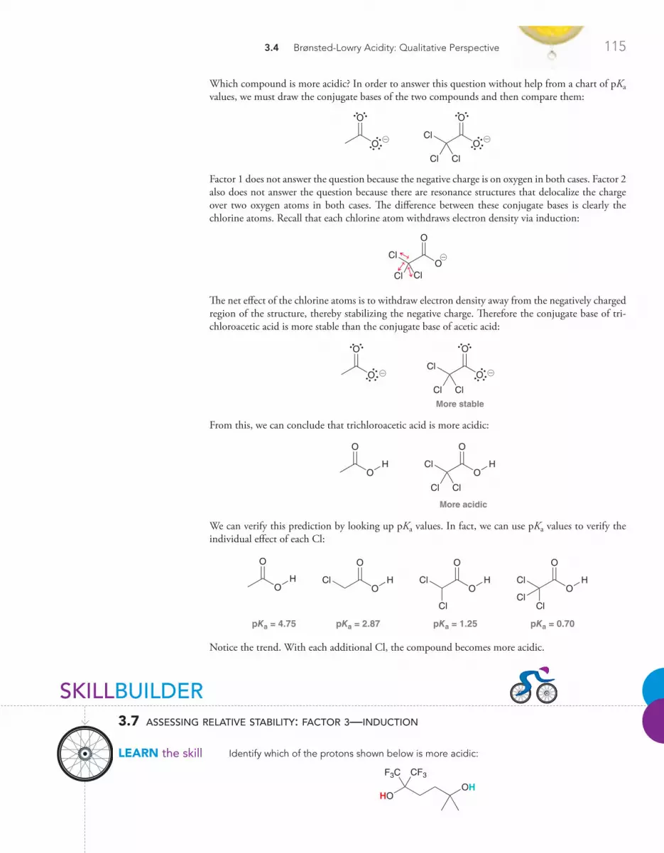
3.4 Brønsted-Lowry Acidity: Qualitative Perspective 115
Which compound is more acidic? In order to answer this question without help from a chart of pKa values, we must draw the conjugate bases of the two compounds and then compare them:
O
O
O
O
Cl
Cl Cl
@@
Factor 1 does not answer the question because the negative charge is on oxygen in both cases. Factor 2 also does not answer the question because there are resonance structures that delocalize the charge over two oxygen atoms in both cases. The difference between these conjugate bases is clearly the chlorine atoms. Recall that each chlorine atom withdraws electron density via induction:
O
Cl
Cl ClO
@
The net effect of the chlorine atoms is to withdraw electron density away from the negatively charged region of the structure, thereby stabilizing the negative charge. Therefore the conjugate base of tri-chloroacetic acid is more stable than the conjugate base of acetic acid:
O
O
More stable
O
O
Cl
Cl Cl
@ @
From this, we can conclude that trichloroacetic acid is more acidic:
O
O
H
More acidic
O
O
HCl
Cl Cl
We can verify this prediction by looking up pKa values. In fact, we can use pKa values to verify the individual effect of each Cl:
O
O
HO
O
HCl
ClCl
pKa = 4.75 pKa = 2.87 pKa = 1.25 pKa = 0.70
O
O
HClO
O
HCl
Cl
Notice the trend. With each additional Cl, the compound becomes more acidic.
SKILLBUILDER
LEARN the skill
3.7 assessing relative stability: factor 3—induction
Identify which of the protons shown below is more acidic:
HOOH
F3C CF3

116 CHAPTER 3 Acids and Bases
STEP 2 Look for inductive
effects.
STEP 3 The more stable conjugate base
corresponds with the more acidic
proton.
PRACTiCE the skill
APPLy the skill
need more PRACTiCE?
SoLuTioNBegin by drawing the respective conjugate bases:
OOH
F3C CF3
HOO
F3C CF3
@
@
In the conjugate base on the left, the charge is stabilized by the inductive effects of the nearby fluorine atoms. In contrast, the conjugate base on the right lacks this stabilization. Therefore, we predict that the conjugate base on the left is more stable. And as a result, we conclude that the proton near the fluorine atoms will be more acidic:
HOOH
F3C CF3
3.18 Identify the most acidic proton in each of the following compounds and explain your choice:
(a) O
OH
HF3C (b)
HOOH
O
O
Cl Cl
3.19 For each pair of compounds below, identify which compound is more acidic and explain your choice:
(a) OH
Cl
O
Cl
OH
O
Cl (b)
OH
O
Br
OH
OBr
3.20 Consider the structure of 2,3-dichloropropanoic acid:
OH
O
Cl
Cl
This compound has many constitutional isomers.(a) Draw a constitutional isomer that is slightly more acidic and explain your choice.
(b) Draw a constitutional isomer that is slightly less acidic and explain your choice.
(c) Draw a constitutional isomer that is significantly (at least 10 orders of magnitude) less acidic and explain your choice.
3.21 Consider the two protons highlighted in the following compound:
OO
Cl F
HH
Do you expect these protons to be equivalent or is one proton more acidic than the other? Explain your choice. (Hint: Think carefully about the geometry at the central carbon atom.)
Try Problems 3.46b, 3.47c, 3.51g
STEP 1 Draw the conjugate
bases.

3.4 Brønsted-Lowry Acidity: Qualitative Perspective 117
4. Orbitals. The three factors we have examined so far will not explain the difference in acidity between the two identified protons in the following compound:
H
H
Draw the conjugate bases to compare them:
H
H@
@
In both cases, the negative charge is on a carbon atom, so factor 1 does not help. In both cases, the charge is not stabilized by resonance, so factor 2 does not help. In both cases, there are no inductive effects to consider, so factor 3 does not help. The answer here comes from looking at the hybridiza-tion states of the orbitals that accommodate the charges. Recall from Chapter 1 that a carbon with a triple bond is sp hybridized, a carbon with a double bond is sp2 hybridized, and a carbon with all single bonds is sp3 hybridized. The first conjugate base (above left) has a negative charge on an sp2-hybridized carbon atom, while the second conjugate base (above right) has a negative charge on an sp-hybridized carbon atom. What difference does this make? Let’s quickly review the shapes of hybridized orbitals (Figure 3.4).
A pair of electrons in an sp-hybridized orbital is held closer to the nucleus than a pair of electrons in an sp2- or sp3-hybridized orbital. As a result, electrons residing in an sp orbital are stabilized by being close to the nucleus. Therefore, a negative charge on an sp-hybridized carbon is more stable than a negative charge on an sp2-hybridized carbon:
More stable
@
@
We conclude that a proton on a triple bond will be more acidic than a proton on a double bond, which in turn will be more acidic than a proton on a carbon with all single bonds. We can verify this trend by looking at the pKa values in Figure 3.5. These pKa values suggest that this effect is very significant; acetylene is 19 orders of magnitude more acidic than ethylene.
FiguRE 3.5pKa values for ethane, ethylene, and acetylene.
H
HH
HHH
EthanepKa 50
H
H H
H
EthylenepKa 44
HH
AcetylenepKa 25
sp3 sp2 sp
FiguRE 3.4Relative shapes of hybridized orbitals.
SKILLBUILDER
LEARN the skill
3.8 assessing relative stability: factor 4—orbitals
Determine which of the protons identified below is more acidic:
1-Pentene
C CC
H
CCH
H
H
H
H
H
H
H
H

118 CHAPTER 3 Acids and Bases
STEP 1 Draw the conjugate
bases.
STEP 3 The more stable conjugate base
corresponds with the more acidic proton.
STEP 2 Analyze the orbital
that accommodates the charge in each
case.
PRACTiCE the skill
APPLy the skill
need more PRACTiCE?
SoLuTioNBegin by drawing the respective conjugate bases:
C C
H
CC
CH
H
H
H
H
H
H
HC CC
H
CC
H
H
H
H
H
H
H
H
@
@
In both cases, the negative charge is on a carbon atom, so factor 1 does not help. In both cases, the charge is not stabilized by resonance, so factor 2 does not help. In both cases, there are no inductive effects to consider, so factor 3 does not help. The answer here comes from looking at the hybridization states of the orbitals that accommodate the charges. The first conjugate base has the negative charge in an sp3-hybridized orbital, while the second conjugate base has the negative charge in an sp2-hybridized orbital. An sp2-hybridized orbital is closer to the nucleus than an sp3-hybridized orbital and therefore better stabilizes a negative charge. So we conclude that the vinylic proton is more acidic:
C CC
H
CCH
H
H
H
H
H
H
H
H
3.22 Identify which of the following compounds is more acidic. Explain your choice:
H
C C
H
H
H
C CH H
3.23 Identify the most acidic proton in each of the following compounds:
3.24 Amines contain C!N single bonds, while imines contain C!N double bonds:
Amine
R N
H
HImine
N
R
R H
Most simple amines have a pKa somewhere in the range between 35 and 45. Based on this information, predict which statement is most likely to be true and explain the reasoning behind your selection:
(a) Most imines will have a pKa below 35.
(b) Most imines will have a pKa above 45.
(c) Most imines will have a pKa in the range between 35 and 45.
Try Problem 3.45c

3.4 Brønsted-Lowry Acidity: Qualitative Perspective 119
Ranking the Factors That Affect the Stability of Negative ChargesWe have thus far examined four factors that affect the stability of negative charges. We must now consider their order of priority—in other words, which factor takes precedence when two or more factors are present?
Generally speaking, the order of priority is the order in which the factors were presented:
1. Atom. Which atom bears the charge? (How do the atoms compare in terms of electronegativity and size? Remember the difference between comparing atoms in the same row vs. atoms in the same column.)
2. Resonance. Are there any resonance effects that make one conjugate base more stable than the other?
3. Induction. Are there any inductive effects that stabilize one of the conjugate bases? 4. Orbital. In what orbital do we find the negative charge for each conjugate base?
A helpful way to remember the order of these four factors is to take the first letter of each factor, giv-ing the following mnemonic device: ARIO.
As an example, let’s compare the protons shown in the following two compounds:
PropyleneEthanol
HO
H
We compare these compounds by drawing their conjugate bases:
O @ @
Factor 1 suggests that the first conjugate base is more stable (O- better than C-). However, factor 2 suggests that the second conjugate base is more stable (resonance that delocalizes the charge). This leaves us with an important question: Is a negative charge more stable when it is localized on one oxygen atom or is a negative charge more stable when it is delocalized over two carbon atoms? The answer is: In general, factor 1 beats factor 2. A negative charge is more stable on one oxygen than on two carbon atoms. We can verify this assertion by comparing pKa values (Figure 3.6).
In fact, the pKa values indicate that a negative charge on one oxygen atom is 27 orders of magni-tude (a billion billion billion times) more stable than a negative charge on two carbon atoms.
This prioritization scheme (ARIO) will often be helpful, but strict adherence to it can sometimes produce the wrong prediction. In other words, there are many exceptions. As an example, compare the structures of acetylene and ammonia:
NH3
AmmoniaAcetylene
C CH H
To determine which compound is more acidic, we draw the conjugate bases:
NH2C CH @ @
When comparing these two negative charges, there are two competing factors. Factor 1 suggests that the second conjugate base is more stable (N- is more stable than C-), but factor 4 suggests that the first conjugate base is more stable (an sp-hybridized orbital can stabilize a negative charge better than an sp3-hybridized orbital). In general, factor 1 wins over the others. But this case is an exception, and factor 4 (orbitals) actually predominates here. In this case, the negative charge is more stable on the carbon atom, even though nitrogen is more electronegative than carbon:
NH2
More stable
C CH @ @
FiguRE 3.6pKa values for ethanol and ethylene.
pKa=16
OH
pKa=43

120 CHAPTER 3 Acids and Bases
In fact, for this reason, H2N- is often used as a base to deprotonate a triple bond:
NH2 NH3
pKa = 38pKa = 25
C C HH C CH@
@+ +
We see from the pKa values that acetylene is 13 orders of magnitude more acidic than ammonia. This explains why H2N- is a suitable base for deprotonating acetylene.
There are, of course, other exceptions to the ARIO prioritization scheme, but the exception shown above is the most common. In the vast majority of cases, it would be a safe bet to apply the four factors in the order ARIO to provide a qualitative assessment of acidity. However, to be certain, it is always best to look up pKa values and verify your prediction.
STEP 1 Draw the
conjugate bases.
STEP 3 The more stable conjugate base
corresponds with the more acidic
proton.
STEP 2 Analyze all four
factors.
SKILLBUILDER
LEARN the skill
3.9 assessing relative stability: all four factors
Determine which of the two protons identified below is more acidic and explain why:
O
O
O
OHH
CCl3
SoLuTioNWe always begin by drawing the respective conjugate bases:
O
O
O
OH
CCl3
O
O
O
OH
CCl3
@ @
Now we consider all four factors (ARIO) in comparing the stability of these negative charges:
1. Atom. In both cases, the charge is on an oxygen atom, so this factor doesn’t help.
2. Resonance. The conjugate base on the left is resonance stabilized while the conjugate base on the right is not. Based on this factor alone, we would say the conjugate base on the left is more stable.
3. Induction. The conjugate base on the right has an inductive effect that stabilizes the charge while the conjugate base on the left does not. Based on this factor alone, we would say the conjugate base on the right is more stable.
4. Orbital. This factor does not help.
Our analysis reveals a competition between two factors. In general, resonance will beat induction. Based on this, we predict that the conjugate base on the left is more stable. Therefore, we conclude that the following proton is more acidic:
O
O
O
OHH
CCl3

3.4 Brønsted-Lowry Acidity: Qualitative Perspective 121
PRACTiCE the skill
APPLy the skill
need more PRACTiCE?
3.25 In each compound below, two protons are clearly identified. Determine which of the two protons is more acidic:
(a)
OH
H
(b)
OO
H H (c)
NH2HO
O
N
(d)
N
H
H (e)
N NH
H (f )
HOSH
O
S
(g)
N
HH (h)
O
OHHO
(i)
N
S
O
O
OH
O
H
3.26 For each pair of compounds below, predict which will be more acidic:
(a) HCI HBr (b) H2O H2S (c) NH3 CH4
(d) HH H2C CH2 (e)
OH
Cl3C CCl3
OH
3.27 The following compound is one of the strongest known acids:
F3C
F3CCF3 CF3
CF3SN N N
O
SN
O
S
O
O SO
S
O
O
H
(a) Explain why it is such a strong acid.
(b) Suggest a modification to the structure that would render the compound even more acidic.
3.28 Amphotericin B is a powerful antifungal agent used for intravenous treatment of severe fungal infections. Identify the most acidic proton in this compound:
Amphotericin B
O
O O
O
OH
O
OH
OH
HO
NH2
OH
OHOH
OH
OH OHHO
O
Try Problems 3.47d, 3.51a, 3.57–3.61

122 CHAPTER 3 Acids and Bases
3.5 Position of Equilibrium and Choice of Reagents
Earlier in this chapter, we learned how to use pKa values to determine the position of equilibrium. In this section, we will learn to predict the position of equilibrium just by comparing conjugate bases without using pKa values. To see how this works, let’s examine a generic acid-base reaction:
H HBBA + +A@ @
This equilibrium represents the competition between two bases (A- and B-) for H+. The question is whether A- or B- is more capable of stabilizing the negative charge. The equilibrium will always favor the more stabilized negative charge. If A- is more stable, then the equilibrium will favor for-mation of A-. If B- is more stable, then the equilibrium will favor formation of B-. Therefore, the position of equilibrium can be predicted by comparing the stability of A- and B-. Let’s see an example of this.
STEP 1Identify the
base on either side of the
equilibrium.
STEP 2 Compare the
stability of these two bases using all four
factors.
SKILLBUILDER
LEARN the skill
3.10 predicting the position of equilibrium without using pka values
Predict the position of equilibrium for the following reaction:
+ +N
O
H
S
NHN
S
N
O
@ @
SoLuTioNWe look at both sides of the equilibrium and compare the stability of the base on each side:
S
+ +N
O
HN
HN
S
N
O
@ @
To determine which of these bases is more stable, we use the four factors (ARIO):
1. Atom. In both cases, the negative charge appears to be on a nitrogen atom, so this factor is not relevant.
2. Resonance. Both of these bases are resonance stabilized, but we do expect one of them to be more stable:
N
O
N
O
N
S
N
S
@
@
@
@
The first base has the negative charge delocalized over N and S. The second base has the negative charge delocalized over N and O. Because of its size, sulfur is more efficient than oxygen at stabilizing a negative charge, so we expect the first base to be more stable.

3.5 Position of Equilibrium and Choice of Reagents 123
STEP 3 The
equilibrium will favor the more stable
base.
PRACTiCE the skill
APPLy the skill
need more PRACTiCE?
3. Induction. Neither of these bases is stabilized by inductive effects.
4. Orbital. Not a relevant factor in this case.
Based on factor 2, we conclude that the base on the left side is more stable, and there-fore the equilibrium favors the left side of the reaction. Our prediction can be verified if we look up pKa values for the acid on either side of the reaction:
O
N
O
+ +
pKa = 15 (Weaker acid)
pKa = 13 (Stronger acid)
NH
N
S
HN
S
@ @
The equilibrium favors production of the weaker acid (higher pKa), so the left side is favored, just as we predicted.
3.29 Predict the position of equilibrium for each of the following reactions:
(a)
+ +
OH O@
@
(b) + +
NH2
O
O NH
OH
O
@
@
(c)
+ OH H2O+
OH
O
@
@
3.30 As we will learn in Chapter 21, treating a lactone (a cyclic ester) with sodium hydrox-ide will initially produce an anion:
NaOH
Initially formed
O
OO
O
H
O
@
This anion rapidly undergoes an intramolecular proton transfer (see Problem 3.3), in which the negatively charged oxygen atom abstracts the nearby acidic proton. Draw the product of this intramolecular acid-base process and then identify which side of the equilibrium is favored. Explain your answer.
Try Problems 3.49, 3.52

124 CHAPTER 3 Acids and Bases
The process described in the previous SkillBuilder can also be used to determine whether a specific reagent is suitable for accomplishing a particular proton transfer, as shown in SkillBuilder 3.11.
STEP 1 Draw the
equilibrium.
STEP 2 Compare the
stability of the bases on either side of the equilibrium using all
four factors.
STEP 3The reagent is only suitable if
the equilibrium favors the desired
products.
PRACTiCE the skill
SKILLBUILDER
LEARN the skill
3.11 choosing the appropriate reagent for a proton transfer reaction
Determine whether H2O would be a suitable reagent for protonating the acetate ion:
O
O
@
SoLuTioNWe begin by drawing the acid-base reaction that occurs when the base is protonated by water:
O+ + OH
O
O
H
O
HO
H@
@
Now compare the bases on either side of the reaction and ask which is more stable:
OHO
O
@
@
Applying the four factors (ARIO), we see that the base on the left side is more stable because of resonance. Therefore, the equilibrium will favor the left side of the reaction. This means that H2O is not a suitable proton source in this situation. In order to protonate this base, an acid stronger than water is required. A suitable acid would be H3O+.
3.31 In each of the following cases, identify whether the reagent shown is suitable to accomplish the task described. Explain why or why not:
(a) To protonate using H2O
N@
(b)
To protonate using N
H
@
(c)
To deprotonate NH2using
H
C C
H
H H
@
(d)
To protonate H2Ousing
OO
@

3.6 Leveling Effect 125
APPLy the skill
need more PRACTiCE?
(e) To protonate H2Ousing @
(f ) To deprotonate using NH2H C C H@
3.32 We will learn the following reactions in upcoming chapters. For each of these reac-tions, notice that the product is an anion (ignore the positively charged ion in each case). In order to obtain a neutral product, this anion must be treated with a proton source in a pro-cess called “working up the reaction.“ For each of the following reactions, identify whether water will be a suitable proton source for working up the reaction:
(a) NaOH
O
O
O
O
Na@
!
Chapter 21
(b)
NaOHHeat
Cl ONa
@
!
Chapter 19
Try Problems 3.40, 3.42
3.6 Leveling Effect
Bases stronger than hydroxide cannot be used when the solvent is water. To illustrate why, consider what happens if we mix the amide ion (H2N-) and water:
+ + OHN OH
NHH H H H
H@
@
The amide ion is a strong enough base to deprotonate water, forming a hydroxide ion (HO-). A hydroxide ion is more stable than an amide ion, so the equilibrium will favor formation of hydroxide. In other words, the amide ion is destroyed by the solvent and replaced with a hydroxide ion. In fact, this is true of any base stronger than HO-. If a base stronger than HO- is dissolved in water, the base reacts with water to produce hydroxide. This is called the leveling effect.
In order to work with bases that are stronger than hydroxide, a solvent other than water must be employed. For example, in order to work with an amide ion as a base, we use liquid ammonia (NH3) as a solvent. If a specific situation requires a base even stronger than an amide ion, then liquid ammonia cannot be used as the solvent. Just as before, if a base stronger than H2N- is dis-solved in liquid ammonia, the base will be destroyed and converted into H2N-. Once again, the leveling effect prevents us from having a base stronger than an amide ion in liquid ammonia. In order to use a base that is even stronger than H2N-, we must use a solvent that cannot be readily deprotonated. There are a number of solvents with high pKa values, such as hexane and THF, that can be used to dissolve very strong bases:
Hexane Tetrahydrofuran(THF)
O

126 CHAPTER 3 Acids and Bases
Throughout the course, we will see other examples of solvents suitable for working with very strong bases.
The leveling effect is also observed in acidic solutions. For example, consider the following equi-librium that is established in an aqueous solution of H2SO4:
H O S O H
O
O
pKa = –9 pKa = –1.7
H O S O
O
O
O
HO
HH H
H
+ +@
!
Although this is indeed an equilibrium process, consider the difference in pKa values (approximately seven pKa units). This indicates that H2SO4 is 107 (or 10 million) times more acidic than a hydro-nium ion (H3O+). As such, there is very little H2SO4 that is actually present in an aqueous solu-tion of H2SO4. Specifically, there will be one molecule of H2SO4 for every 10 million hydronium ions. That is, 99.99999% of all sulfuric acid molecules will have transferred their protons to water molecules. A similar situation occurs with aqueous HCl or any other strong acid that is dissolved in water. In other words, an aqueous solution of either H2SO4 or HCl can simply be viewed as an aqueous solution of H3O+. The main difference between concentrated H2SO4 and dilute H2SO4 is the concentration of H3O+.
3.7 Solvating Effects
In some cases, solvent effects are invoked to explain small differences in pKa values. For example, compare the acidity of tert-butanol and ethanol:
tert-ButanolpKa = 18
OH
EthanolpKa = 16
OH
The pKa values indicate that tert-butanol is less acidic than ethanol by two orders of magnitude. In other words, the conjugate base of tert-butanol is less stable than the conjugate base of ethanol. This difference in stability is best explained by considering the interactions between each conjugate base and the surrounding solvent molecules (Figure 3.7). Compare the way in which each conjugate base interacts with solvent molecules. The tert-butoxide ion is very bulky, or sterically hindered, and is less capable of interacting with the solvent. The ethoxide ion is not as sterically hindered so it can accommodate more solvent interactions. As a result, ethoxide is better solvated and is therefore more stable than tert-butoxide (Figure 3.7). This type of solvent effect is generally weaker than the other effects we have encountered in this chapter (ARIO).
COnCEPTUAL CHECkPOInT
3.33 Predict which of the following compounds is more acidic:
After making your prediction, use the pKa values from Table 3.1 to determine whether your prediction was correct.
OHEthanol
HO
HWater

3.8 Counterions 127
3.8 Counterions
Negatively charged bases are always accompanied by positively charged species, called cations (pro-nounced CAT-EYE-ONZ). For example, HO- must be accompanied by a counterion, such as Li+, Na+, or K+. We will often see the following reagents: LiOH, or NaOH, or KOH. Don’t be alarmed. All of these reagents are simply HO- with the counterion indicated. Sometimes it is shown; some-times not. Even when the counterion is not shown, it is still there. It is just not indicated because it is largely irrelevant. Up to this point in this chapter, counterions have not been shown, but from here on they will be. For example, consider the following reaction:
+ +H H H H
OHH H
H
NON@
@
This reaction might be shown like this:
NaNH2 + +H2O NH3 NaOH
It is important to become accustomed to ignoring the cations when they are indicated and to focus on the real players—the bases. Although counterions generally do not play a significant role in reactions, they can, under some circumstances, influence the course of a reaction. We will only see one or two such examples throughout this course. The overwhelming majority of reactions that we encounter are not significantly affected by the choice of counterion.
tert-Butoxide
O Solvent
Solvent
Solvent
Ethoxide
OSolvent
So
lvent
Solvent
Solvent
@ @
FiguRE 3.7Electrostatic potential maps of tert-butoxide and ethoxide.
LOOkIng BACkYour general chemistry textbook likely used the term spectator ion to refer to a counterion.
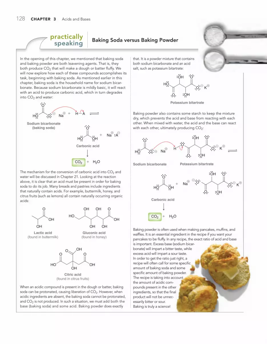
128 CHAPTER 3 Acids and Bases
Baking Soda versus Baking Powderpractically speaking
In the opening of this chapter, we mentioned that baking soda and baking powder are both leavening agents. That is, they both produce CO2 that will make a dough or batter fluffy. We will now explore how each of these compounds accomplishes its task, beginning with baking soda. As mentioned earlier in this chapter, baking soda is the household name for sodium bicar-bonate. Because sodium bicarbonate is mildly basic, it will react with an acid to produce carbonic acid, which in turn degrades into CO2 and water:
+CO2 H2O
Sodium bicarbonate(baking soda)
H A
+
+
O
OHO Na
Carbonic acid
O
OHHOA Na
@
@
!
!
The mechanism for the conversion of carbonic acid into CO2 and water will be discussed in Chapter 21. Looking at the reaction above, it is clear that an acid must be present in order for baking soda to do its job. Many breads and pastries include ingredients that naturally contain acids. For example, buttermilk, honey, and citrus fruits (such as lemons) all contain naturally occurring organic acids:
Lactic acid(found in buttermilk)
OH
O
OH
Gluconic acid(found in honey)
OH
O
OH
OH
OH
OH
HO
Citric acid(found in citrus fruits)
OH
OO
OHHO
OOH
When an acidic compound is present in the dough or batter, baking soda can be protonated, causing liberation of CO2. However, when acidic ingredients are absent, the baking soda cannot be protonated, and CO2 is not produced. In such a situation, we must add both the base (baking soda) and some acid. Baking powder does exactly
that. It is a powder mixture that contains both sodium bicarbonate and an acid salt, such as potassium bitartrate:
Potassium bitartrate
OH O
OHO
HOO K
@ !
Baking powder also contains some starch to keep the mixture dry, which prevents the acid and base from reacting with each other. When mixed with water, the acid and the base can react with each other, ultimately producing CO2:
H
+CO2 H2O
Sodium bicarbonate
Carbonic acid
Potassium bitartrate
O
HO O Na
O
O
OH
OH
O
O K
HO
O
OH+ O Na
OH
OHO
O
O K
@!
@
@@
!
!!
Baking powder is often used when making pancakes, muffins, and waffles. It is an essential ingredient in the recipe if you want your pancakes to be fluffy. In any recipe, the exact ratio of acid and base is important. Excess base (sodium bicar-bonate) will impart a bitter taste, while excess acid will impart a sour taste. In order to get the ratio just right, a recipe will often call for some specific amount of baking soda and some specific amount of baking powder. The recipe is taking into account the amount of acidic com-pounds present in the other ingredients, so that the final product will not be unnec-essarily bitter or sour. Baking is truly a science!

3.9 Lewis Acids and Bases 129
3.9 Lewis Acids and Bases
The Lewis definition of acids and bases is broader than the Brønsted-Lowry definition. According to the Lewis definition, acidity and basicity are described in terms of electrons, rather than protons. A Lewis acid is defined as an electron acceptor, while a Lewis base is defined as an electron donor. As an illustration, consider the following Brønsted-Lowry acid-base reaction:
++ ClH H
H
OH
Acid(electronacceptor)
ClH H
Base(electrondonor)
O@
!
HCl is an acid according to either definition. It is a Lewis acid because it serves as an electron acceptor, and it is a Brønsted-Lowry acid because it serves as a proton donor. But the Lewis defini-tion is an expanded definition of acids and bases, because it includes reagents that would otherwise not be classified as acids or bases. For example, consider the following reaction:
H H
H
H
BFB
F
F F
F
F
+
Base(electron donor)
Acid(electron acceptor)
O O@
!
According to the Brønsted-Lowry definition, BF3 is not considered an acid because it is has no protons and cannot serve as a proton donor. However, according to the Lewis definition, BF3 can serve as an electron acceptor, and it is therefore a Lewis acid. In the reaction above, H2O is a Lewis base because it serves as an electron donor.
Take special notice of the curved-arrow notation. There is only one curved arrow in the reaction above, not two.
Chapter 6 will introduce the skills necessary to analyze reactions, and in Section 6.7 we will revisit the topic of Lewis acids and bases. In fact, we will see that most of the reactions in this text-book occur as the result of the reaction between a Lewis acid and a Lewis base. For now, let’s get some practice identifying Lewis acids and Lewis bases.
SKILLBUILDER
LEARN the skill
3.12 identifying lewis acids and lewis bases
Identify the Lewis acid and the Lewis base in the reaction between BH3 and THF:
SoLuTioNWe must first decide the direction of electron flow. Which reagent is serving as the electron donor and which reagent is serving as the electron acceptor? To answer this question, we analyze each reagent and look for a lone pair of electrons. Boron is in the third column of the periodic table and only has three valence electrons. It is using all three valence elec-trons to form bonds, which means that it does not have a lone pair of electrons. Rather, it has an empty p orbital (for a review of the structure of BH3, see Section 1.10). Oxygen does have a lone pair. So, we con-clude that oxygen attacks boron:
BH3 is the electron acceptor (Lewis acid), and THF is the electron donor (Lewis base).
STEP 1Identify the
direction of the flow of electrons.
STEP 2Identify the electron
acceptor as the Lewis acid and the electron donor as
the Lewis base.
HB
H
H
O
BH H
H
+
THF
O @
!
HB
H
HO
BH H
H
+O
@
!
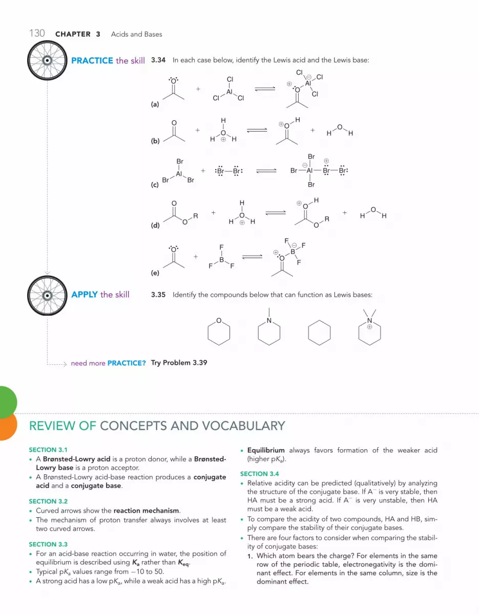
130 CHAPTER 3 Acids and Bases
PRACTiCE the skill
APPLy the skill
need more PRACTiCE?
3.34 In each case below, identify the Lewis acid and the Lewis base:
(a) Cl
AlCl
Cl+
O Al
Cl
Cl
Cl
O
@
!
(b)
O
HO
H+ +OH
HO
H
H
!
!
(c) Br
AlBr
Br+ Br Br AlBr
Br
Br
BrBr@
!
(d) H
OH
O
O
R + +H
OH
H
O
OH
R!
!
(e) F
BF
F+
O B
F
F
F
O
@
!
3.35 Identify the compounds below that can function as Lewis bases:
O N N!
Try Problem 3.39
REVIEw OF CONCEPTS AND VOCABULARY
SECTioN 3.1
• A Brønsted-Lowry acid is a proton donor, while a Brønsted-Lowry base is a proton acceptor.
• A Brønsted-Lowry acid-base reaction produces a conjugate acid and a conjugate base.
SECTioN 3.2
• Curved arrows show the reaction mechanism.• The mechanism of proton transfer always involves at least
two curved arrows.
SECTioN 3.3
• For an acid-base reaction occurring in water, the position of equilibrium is described using Ka rather than Keq.
• Typical pKa values range from -10 to 50.• A strong acid has a low pKa, while a weak acid has a high pKa.
• Equilibrium always favors formation of the weaker acid (higher pKa).
SECTioN 3.4
• Relative acidity can be predicted (qualitatively) by analyzing the structure of the conjugate base. If A- is very stable, then HA must be a strong acid. If A- is very unstable, then HA must be a weak acid.
• To compare the acidity of two compounds, HA and HB, sim-ply compare the stability of their conjugate bases.
• There are four factors to consider when comparing the stabil-ity of conjugate bases:1. Which atom bears the charge? For elements in the same
row of the periodic table, electronegativity is the domi-nant effect. For elements in the same column, size is the dominant effect.

SkillBuilder Review 131
2. Resonance—a negative charge is stabilized by resonance.3. Induction—electron-withdrawing groups, such as halo-
gens, stabilize a nearby negative charge via induction.4. orbital—a negative charge in an sp-hybridized orbital will
be closer to the nucleus and more stable than a negative charge in an sp3-hybridized orbital.
• When multiple factors compete, ARIO (atom, resonance, induction, orbital) is generally the order of priority, but there are exceptions.
SECTioN 3.5
• The equilibrium of an acid-base reaction always favors the more stabilized negative charge.
SECTioN 3.6
• A base stronger than hydroxide cannot be used when the sol-vent is water because of the leveling effect. If a stronger base is desired, a solvent other than water must be employed.
SECTioN 3.7
• In some cases, solvent effects explain small differences in pKa’s. For example, bases that are bulky, or sterically hin-dered, are generally less efficient at forming stabilizing sol-vent interactions.
SECTioN 3.8
• Negatively charged bases are always accompanied by posi-tively charged species called cations.
• The choice of the counterion does not affect most reactions encountered in this book.
SECTioN 3.9
• A Lewis acid is an electron acceptor, while a Lewis base is an electron donor.
SKILLBUILDER REVIEw3.1 DRAwINg ThE MEChANISM OF A PROTON TRANSFER
OCH3O
Base Acid
STEP 1 Identify the acid and the base.
OCH3O
Base Acid
STEP 2 Draw the first curved arrow....(a) Place tail on lone pair (of base).(b) Place head on proton (from acid).
CH3O
Base Acid
STEP 3 Draw the second curved arrow....(a) Place tail on O—H bond.(b) Place head on O.
H H H H HO
H@ @ @
Try Problems 3.1–3.3, 3.44
3.2 USINg pKa VALUES TO COMPARE ACIDS
pKa = 19.2
O
H
H H
O
O
H
More acidic
pKa = 4.75
The compound with the lower pKa is more acidic.
Try Problems 3.4–3.6, 3.38
3.3 USINg pKa VALUES TO COMPARE BASICITY
O O
O
EXAMPLE Compare the basicity of these two anions.
O O
OH
H
STEP 1 Draw the conjugateacid of each.
O O
O
pKa = 9
pKa = 19
STEP 2 Compare pKa values.
O Ogenerates
Weaker acid Stronger base
STEP 3 Identify the stronger base.
@
@
@
Try Problems 3.7–3.9, 3.50

132 CHAPTER 3 Acids and Bases
3.4 USINg pKa VALUES TO PREDICT ThE POSITION OF EQUILIBRIUM
HO
H
O O O O
OH
Base BaseAcid Acid
+ +
STEP 1 Identify the acid on each side of the equilibrium.
O O
pKa = 9.0
HO
H
pKa = 15.7
STEP 2 Compare pKa values.
The equilibrium will favor the weaker acid.
@
@
Try Problems 3.10–3.11, 3.48
3.5 ASSESSINg RELATIVE STABILITY: FACTOR 1—ATOM
STEP 3 The more stable conjugate base...
OH
N
HN O
H...corresponds with
the more acidic proton.
STEP 2 Compare location of charge taking into account two trends.
C N O F
P S Cl
Br
I
Electronegativity
Size
STEP 1 Draw the conjugate bases...
O
N
H
N OH
OH
H
N
...in order to comparetheir stability.
@
@
@
Try Problems 3.13, 3.14, 3.45b, 3.47h, 3.51b, h, 3.533.6 ASSESSINg RELATIVE STABILITY: FACTOR 2—RESONANCE
STEP 1 Draw the conjugate bases...
O
O
OO
H
O
H
OH
O
O
O
H
...in order to comparetheir stability.
STEP 3 The more stable conjugate base...
OO
H
O
OO
H
O
H
...corresponds withthe more acidic proton.
STEP 2 Look for resonance stabilization.
O
OH
O
O
H
Not resonance stabilized
Resonance stabilized
O
O
@
@
@
@
@
Try Problems 3.15–3.17, 3.45a, 3.46a, 3.47b,e–g, 3.51c–f
3.7 ASSESSINg RELATIVE STABILITY: FACTOR 3—INDUCTION
STEP 1 Draw the conjugate bases...
O
O
OH
O
CCl3
H
OH
CCl3
CCl3
H
...in order to comparetheir stability.
O
STEP 3 The more stable conjugate base...
OOH
CCl3
OH
O
CCl3
H
...corresponds withthe more acidic proton.
STEP 2 Look for inductive effects.
OOH
CCl3
Morestable
@
@
@
@
Try Problems 3.18–3.21, 3.46b, 3.47c, 3.51g
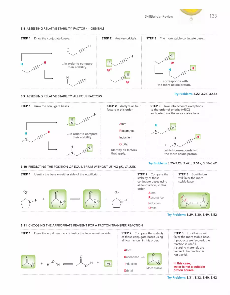
SkillBuilder Review 133
3.8 ASSESSINg RELATIVE STABILITY: FACTOR 4—ORBITALS
H
sp3
sp
STEP 2 Analyze orbitals.
H
...corresponds withthe more acidic proton.
H
sp
STEP 3 The more stable conjugate base...STEP 1 Draw the conjugate bases...
HH
H
H
...in order to comparetheir stability.
@
@
@
@
@
Try Problems 3.22–3.24, 3.45c3.9 ASSESSINg RELATIVE STABILITY: ALL FOUR FACTORS
N
H
N
H H
...which corresponds withthe more acidic proton.
STEP 3 Take into account exceptionsto the order of priority (ARIO)and determine the more stable base...
N
N
H H
N
H
H
...in order to comparetheir stability.
STEP 1 Draw the conjugate bases...
Identify all factorsthat apply.
Resonance
Induction
Orbital
Atom
STEP 2 Analyze all four factors in this order:
@
@
@
Try Problems 3.25–3.28, 3.47d, 3.51a, 3.58–3.62
3.11 ChOOSINg ThE APPROPRIATE REAgENT FOR A PROTON TRANSFER REACTION
STEP 1 Draw the equilibrium and identify the base on either side.
OHO
O
HH
OHO
O
+ +
STEP 2 Compare the stability of these conjugate bases usingall four factors, in this order:
O
OResonance
Induction
Orbital
Atom
More stable
STEP 3 Equilibrium will favor the more stable base.If products are favored, thereaction is useful.If starting materials are favored, the reaction is not useful.
In this case,water is not a suitableproton source.
@@ @
Try Problems 3.31, 3.32, 3.40, 3.42
3.10 PREDICTINg ThE POSITION OF EQUILIBRIUM wIThOUT USINg pKa VALUES
STEP 3 Equilibrium will favor the more stable base.
S
N
S
N
Resonance
Induction
Orbital
Atom
STEP 2 Compare the stability of these conjugate bases using all four factors, in this order:
STEP 1 Identify the base on either side of the equilibrium.
+ +H
O
N
S
N
O
NH
S
N@ @@
@
Try Problems 3.29, 3.30, 3.49, 3.52

134 CHAPTER 3 Acids and Bases
3.12 IDENTIFYINg LEwIS ACIDS AND LEwIS BASES
STEP 1 Identify the directionof the flow of electrons.
HB
H
H+
To here From here
O
STEP 2 Identify the electron acceptor as the Lewis acidand the electron donor as the Lewis base.
HB
H
H
+
Acceptor Donor
Lewis acid Lewis base
O
Try Problems 3.34, 3.35, 3.39
note: Most of the Problems are available within , an online teaching and learning solution.
3.36 Draw the conjugate base for each of the following acids:
(a) OH (b)
O
(c) NH3 (d) H3O+
(e) OH
O
(f )
N
H
(g) NH4+
3.37 Draw the conjugate acid for each of the following bases:
(a) @
(b)
O
@ (c) NaNH2 (d) H2O
(e) OH (f ) NH2 (g)
O
(h) NaOH
3.38 Compound A has a pKa of 7 and compound B has a pKa of 10. Compound A is how many times more acidic than compound B?
(a) 3 (b) 3000 (c) 1000
3.39 In each reaction, identify the Lewis acid and the Lewis base:
(a)
OH + O
H
!
!
(b)
OHF
BF
F+
FB
F
FO
H
@
!
(c) ClAl
Cl
Cl+Cl
Cl
Al Cl
Cl
Cl@!
3.40 What reaction will take place if H2O is added to a mixture of NaNH2/NH3?
3.41 Would ethanol (CH3CH2OH) be a suitable solvent in which to perform the following proton transfer? Explain your answer:
+ + NH3
H
NH2
@
@
3.42 Would water be a suitable proton source to protonate the fol-lowing compound?
ONa
O
3.43 Write an equation for the proton transfer reaction that occurs when each of the following acids reacts with water. In each case, draw curved arrows that show the mechanism of the proton transfer:
(a) HBr (b)
H O S O
O
O
H
(c)
OH!
3.44 Write an equation for the proton transfer reaction that occurs when each of the following bases reacts with water. In each case, draw curved arrows that show the mechanism of the proton transfer:
(a) @ (b) O
@
(c)
@
(d)
N@
3.45 In each case, identify the more stable anion. Explain why it is more stable:
(a) vs.@ @
(b) vs.N@
@
(c) vs.@@
3.46 In each group of compounds below, select the most acidic compound:
(a)
N
H
N
H
(b)
O O O O
Cl
Cl Cl
PRACTICE PROBLEMS

Integrated Problems 135
3.47 For each pair of compounds below, identify the more acidic compound:
(a)
OH SH
(b)
OH OH
(c)
OH
Cl
Cl
Cl
Cl
Cl
OH
(d)
NH2
(e) O
O
OHO
O
H (f )
O O
(g)
O
(h) NH2
O
OH
O
3.48 HA has a pKa of 15, while HB has a pKa of 5. Draw the equilib-rium that would result upon mixing HB with NaA. Does the equilibrium favor formation of HA or of HB?
3.49 For each reaction below, draw the mechanism (curved arrows) and then predict which side of the reaction is favored under equilibrium conditions:
(a) HO
H
OH
+ +O
HO
@
@
(b)
SH
OH
+
+
O
S
@
@
(c)
H2S
SH
S+ +HS
S
S@
@
(d)
O NH
O NH
@ @
3.50 Rank the following anions in terms of increasing basicity:
HO O
O
O O@ @ @ @
3.51 For each compound below, identify the most acidic proton in the compound:
(a)
NH2H
(b)
H2N OH
SH
(c) (d) O
(e)
HO
O
OH
NH2 (f ) H
O
(g)
HO
OCl
Cl
OH
O
OHO (h) HS OH
INTEgRATED PROBLEMS
3.52 In each case below, identify the acid and the base. Then draw the curved arrows showing a proton transfer reaction. Draw the prod-ucts of that proton transfer and then predict the position of equilibrium:
(a) O
O
H LiOH+
(b) HO
HLi +@ !
(c)
O O
NaOH+
3.53 Draw all constitutional isomers with molecular formula C2H6S and rank them in terms of increasing acidity.
3.54 Draw all constitutional isomers with molecular formula C3H8O and rank them in terms of increasing acidity.
3.55 Consider the structure of cyclopentadiene and then answer the following questions:
Cyclopentadiene
(a) How many sp3-hybridized carbon atoms are present in the structure of cyclopentadiene?
(b) Identify the most acidic proton in cyclopentadiene. Justify your choice.
(c) Draw all resonance structures of the conjugate base of cyclopentadiene.
(d) How many sp3-hybridized carbon atoms are present in the conju-gate base?
(e) What is the geometry of the conjugate base?
(f ) How many hydrogen atoms are present in the conjugate base?
(g) How many lone pairs are present in the conjugate base?

136 CHAPTER 3 Acids and Bases
3.56 In Section 3.4, we learned four factors (ARIO) for comparing the relative acidity of compounds. When two of these factors are in compe-tition, the order of priority is the order in which these factors were cov-ered (“atom” being the most important factor and “orbital” being the least important). However, we also mentioned that there are exceptions to this order of priority. One such exception was covered at the end of Section 3.4. Compare the two compounds below and determine if they constitute another exception. Justify your choice:
pKa = 4.75 pKa = 10.6
OH SH
O
3.57 Consider the pKa values of the following constitutional isomers:
OH
O
OH
pKa = 3.0
Salicylic acid
O
OH
HO
pKa = 4.6
para-Hydroxybenzoic acid
Using the rules that we developed in this chapter (ARIO), we might have expected these two compounds to have the same pKa. Nevertheless, they are different. Salicylic acid is apparently more acidic than its constitutional isomer. Can you offer an explanation for this observation?
3.58 Consider the following compound with molecular formula C4H8O2:
O
OH
C4H8O2
(a) Draw a constitutional isomer that you expect will be approximately one trillion (1012) times more acidic than the compound above.
(b) Draw a constitutional isomer that you expect will be less acidic than the compound above.
(c) Draw a constitutional isomer that you expect will have approxi-mately the same pKa as the compound above.
3.59 There are only four constitutional isomers with molecular formula C4H9NO2 that contain a nitro group (!NO2). Three of these isomers have similar pKa values, while the fourth isomer has a much higher pKa value. Draw all four isomers and identify which one has the higher pKa. Explain your choice.
3.60 Predict which of the following compounds is more acidic and explain your choice:
N
NH2
N
NH2
3.61 Below is the structure of rilpivirine, a promising new anti-HIV drug that combats resistant strains of HIV. Its ability to side-step resis-tance will be discussed in the upcoming chapter.
N
N
N
H
NN
N
H
Rilpivirine
(a) Identify the two most acidic protons in rilpivirine.
(b) Identify which of these two protons is more acidic. Explain your choice.
3.62 Most common amines (RNH2) exhibit pKa values between 35 and 45. R represents the rest of the compound (generally carbon and hydrogen atoms). However, when R is a cyano group, the pKa is found to be drastically lower:
R N
H
H H
pKa = 35–45
N C N
H
pKa = 17
(a) Explain why the presence of the cyano group so drastically impacts the pKa.
(b) Can you suggest a different replacement for R that would lead to an even stronger acid (pKa lower than 17)?
3.63 In one step of a recent total synthesis of (-)-seimatopolide A, a potential antidiabetic drug, the following two structures reacted with each other in an acid-base reaction (Tetrahedron Lett. 2012, 53, 5749–5752):
O
OO
7
OSi
OH
N
!
(a) Identify the acid and the base, draw the products of the reaction, and show a mechanism for their formation.
(b) Using the pKa values provided in Problem 3.9 as a rough guideline, predict the position of equilibrium for this acid-base reaction.
Problems 3.64–3.65 are intended for students who have already covered IR spectroscopy (Chapter 15).
3.64 Deuterium (D) is an isotope of hydrogen, in which the nucleus has one proton and one neutron. This nucleus, called a deuteron, behaves very much like a proton, although there are observed differ-ences in the rates of reactions involving either protons or deuterons (an effect called the kinetic isotope effect). Deuterium can be introduced into a compound via the process below:
(a) The C!Mg bond in compound 3 can be drawn as ionic. Redraw 3 as an ionic species, with BrMg+ as a counterion, and then draw the mechanism for the conversion of 3 to 4.
(b) The IR spectrum of compound 4 exhibits a group of signals between 1250 and 1500 cm-1, a signal at 2180 cm-1, and another group of signals between 2800 and 3000 cm-1. Identify the loca-tion of the C-D signal in the spectrum and explain your reasoning (J. Chem. Ed. 1981, 58, 79–80).

Challenge Problems 137
MgD2O
1
2
4
1) Br2, hνH D
BrBr2hν MgBr
3Et2OChapter
11 Chapter13
2) Mg, Et2O3) D2O
3.65 The bengamides are a series of natural products that have shown inhibitory effects on the enzyme methionine aminopeptidase, which plays a key role in the growth of new blood vessels, a necessary process for the progression of diseases such as solid tumor cancers and rheumatoid arthritis. During the synthesis of bengamides, it is often required to convert OH groups into other, less reactive groups, called protecting groups, which can be converted back into OH groups when desired. For example, compound 1 is protected upon treatment with compound 2 in the presence of compound 4 (Tetrahedron Lett. 2007, 48, 8787–8789). First, 1 reacts with 2 to give intermediate 3, which is then deprotonated by 4 to give 5:
(a) Draw the structure of 5 and show a mechanism for its formation from 3.
(b) Use a quantitative argument (pKa values) to verify that 4 is an appropriate base for this transformation.
(c) Explain how you would use IR spectroscopy to verify the conver-sion of 1 to 5.
OMe
OMe
OSiMe3
OSiMe3
O
O
O
O
O
Me3Si H
NMe Me
=
OH
O
OPh
Ph
Ph
Ph
PhPh
Ph
O
O1
35
Si Cl2
4
!
ChALLENgE PROBLEMS
3.66 Asteltoxin, isolated from the cultures of Aspergillus stellatus, exhibits a potent inhibitory effect on the activity of E. coli BF1-ATPase. During S. L. Schreiber’s synthesis of asteltoxin, compound 1 was treated with a strong base to form anion 2 (J. Am. Chem. Soc. 1984, 106, 4186–4188):
O
O
O
O
O
O
O
O
HO
HO
H
Strong base2
1
Asteltoxin (3)
(a) Identify the most acidic proton in 1 and justify your choice using any necessary drawings.
(b) Determine whether each of the following bases would be suitable for deprotonating compound 1 and explain your decision in each case: (i) NaOH, (ii) NaNH2, or (iii) CH3CO2Na.
3.67 In a key step during a recent synthesis of 7-desmethoxyfusar-entin, a compound that is known to display cytotoxicity against breast cancer cells (MCF-7), an acid-base reaction was employed, in which the following two structures reacted with each other (Tetrahedron Lett. 2012, 53, 4051–4053). Predict the products of this reaction, and pro-pose a mechanism for their formation:
OOR
OSiH
NNH
!
3.68 During a synthesis of (+)-coronafacic acid, a key component in the plant toxin coronatine, the following reaction was performed, in which a ketone was converted into an acetal (the acetal functional group will be covered in Chapter 20). In this case, p-toluenesulfonic acid (p-TsOH) func-tions as an acid catalyst (J. Org. Chem. 2009, 74, 2433–2437):
O
O
O
OH OH
p-TsOH
O
O
O
O
(– H2O)
p-TsOH = S
O
O
OH
89%
(a) The mechanism for this process begins with a proton transfer step in which the ketone is protonated. Draw this mechanistic step using curved arrows.
(b) For this protonation step, predict whether the equilibrium favors the protonated ketone. Justify your prediction with estimated pKa values.
3.69 Phakellin (3), a natural product isolated from marine organisms, has been studied for its potential use as an antibiotic agent. During studies aimed at developing a strategy for the synthesis of phakellin and its derivatives, compound 1 was investigated as a potential precur-sor (Org. Lett. 2002, 4, 2645–2648):
N
N
O
O
HH
1
N
Li
(LDA)2 N
N
O
N
N
H
H2N
3
@!

138 CHAPTER 3 Acids and Bases
(a) Identify the most acidic proton in compound 1, draw the corresponding conjugate base, 2, and justify your choice.
(b) Using a quantitative argument based on pKa values as well as a qualitative argument based on structural comparisons, justify why lithium diisopropyl amide (LDA) is a suitable base to deprotonate 1.
(c) Draw a mechanism for the conversion of 1 to 2.
3.70 The Nazarov cyclization is a versatile method for making five-membered rings, a common feature in many natural products. This pro-cess has been used successfully in the preparation of many complex structures with a wide variety of biological activities, including antibiotic and anticancer properties (Org. Lett. 2003, 5, 4931–4934). The key step of the Nazarov cyclization involves a Lewis acid, such as AlCl3. In the first step of the mechanism, compound 1 interacts with AlCl3 to form a Lewis acid-Lewis base complex. Determine the site within com-pound 1 that interacts most strongly with the Lewis acid and justify your choice by exploring the resonance structures of the resulting complex:
O
O
AlCl3O
O
1 2
3.71 Crude extracts from the ginkgo tree, Ginkgo biloba, have been used for centuries to alleviate symptoms associated with asthma. There are four principal components of Ginkgo extracts, called ginkgolide A, B, D, and M. During E. J. Corey’s classic synthesis of ginkgolide B, com-pound 1 was converted into compound 5 (J. Am. Chem. Soc. 1988, 110, 649–651):
O
O 3a
OH3CO
H3CO
TfO
TfTf NTf
N
= S
O
O
CF3
NTf
Li
Li
1
2
4
56
3b
+
@!
@
!
(a) Draw the resonance-stabilized anion (3) that is expected when compound 1 is treated with LDA (compound 2), which was intro-duced in Problem 3.69.
(b) Draw a mechanism for the conversion of 1 to 3 and explain why this step is irreversible.
(c) Upon treatment with 4, anion 3 is converted into compound 5, and byproduct 6 is formed. Describe the factors that render 6 a particu-larly stable anion.
3.72 The pKa of the most acidic CH2 group in each of the following compounds was measured in DMSO as solvent (J. Org. Chem. 1981, 46, 4327–4331).
Acid
CH3COCH2CO2CH2CH3, 1 14.1PhCH2CN, 2 21.9PhCH2CO2CH2CH3, 3 22.7PhCH2CON(CH3)2, 4 26.6
pKa
Ph =
Given the data above, determine which of the following two com-pounds (5 or 6) is more acidic by comparing the stability of the corre-sponding conjugate bases. Include all necessary resonance contribu-tors in your discussion. Consider the given pKa values in determining which resonance contributors are more effective in stabilizing the con-jugate bases.
O
5 6
3.73 The following compound has been designed to allow for label-ing of a specific site of a protein (J. Am. Chem. Soc. 2009, 131, 8720–8721):
H2N
CO2H
NH
O
O
Consider each of the possible positions on this molecule that can be deprotonated. Predict the likely product of an acid/base reaction of one mole of this molecule with each of the following:
(a) One mole of EtNa
(b) Two moles of EtNa
(c) Three moles of EtNa
(d) Four moles of EtNa
(e) One mole of EtONa
(f) Two moles of EtONa
(g) Three moles of EtONa
(h) Four moles of EtONa