optis™ software instructions for use - product manuals
TRANSCRIPT
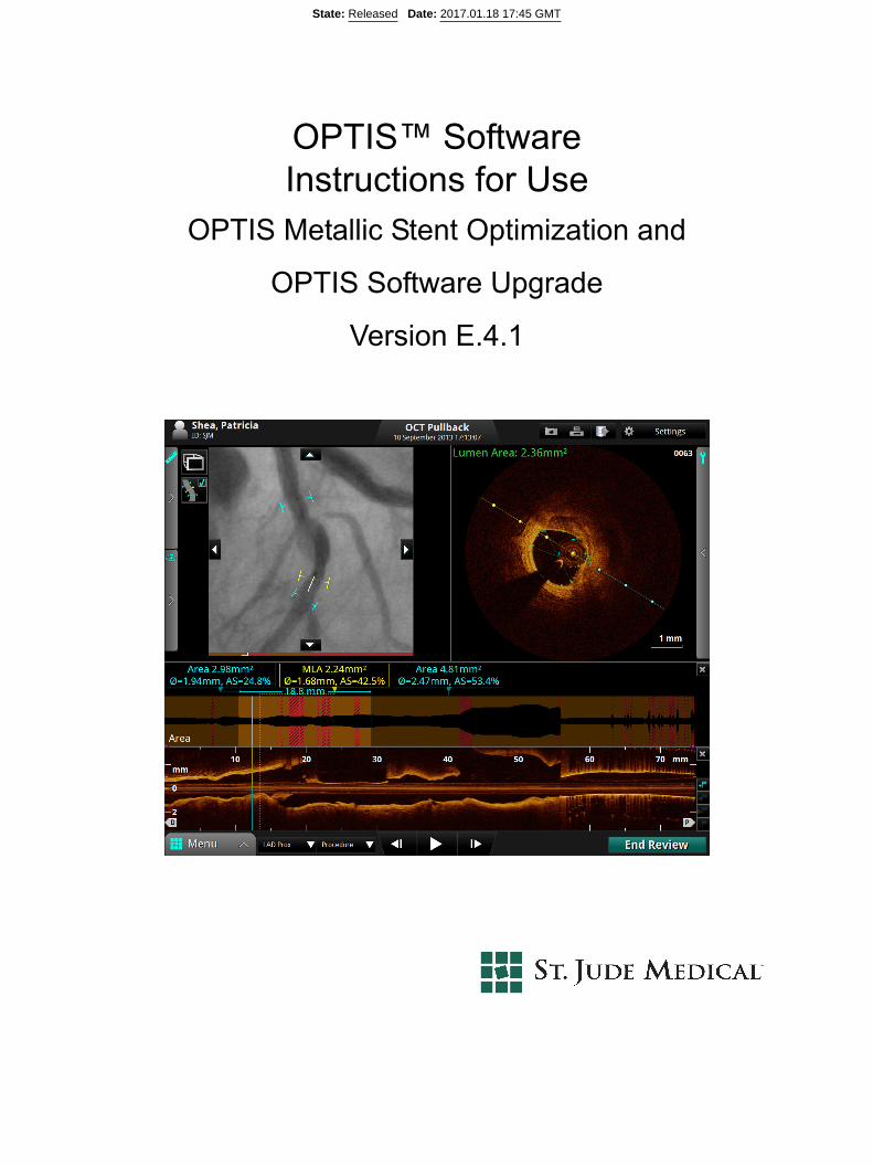
OPTIS™ Software Instructions for Use
OPTIS Metallic Stent Optimization and
OPTIS Software Upgrade
Version E.4.1
State: Released Date: 2017.01.18 17:45 GMT

Information provided within this Document is subject to change without notice and although believed tobe accurate, St. Jude Medical, Inc. and its affiliated companies including without limitation, St. JudeMedical System AB (Sweden), assume no responsibility for any errors, omissions or inaccuracies.
©2017 St. Jude Medical, Inc. and its related companies. All rights reserved. Reproduction, adaptation, or translation without prior permission is prohibited, except as allowed under copyright laws.
Pat. http://patents.sjm.com. Unless otherwise noted, ™ indicates that the name is a trademark of, orlicensed to, St. Jude Medical or one of its subsidiaries. ST. JUDE MEDICAL, the color gold and thenine-squares symbol are trademarks and services marks of St. Jude Medical, Inc. and its relatedcompanies.
The OPTIS™ Software incorporates third party licensed software as described at the following URL:www.sjmprofessional.com/ilumien-legal-notices
Bluetooth® is a registered trademark of Bluetooth SIG, Inc.
St. Jude Medical Coordination Center BVBA Australian Sponsor:
The Corporate Village St. Jude Medical Australia Pty Limited
Da Vincilaan 11 Box F1 17 Orion Rd.,
1935 Zaventem Belgium Lane Cove NSW 2066 Australia
+32 2 774 68 11 +61 2 9936 1200
LightLab Imaging, Inc. Phone: +1 855 478 5833 US Toll-free4 Robbins Road +1 651 756 5833 InternationalWestford, MA 01886USA
www.sjm.com
Service E-mail: [email protected]
Part Number ARTUS600005835 A
ENGLISH
Printed in the U.S.A. 2017-01
CAUTION: Federal law restricts this device to sale by or on the order of a Physician licensed bylaw of the state in which he practices to use or order the use of the device.
State: Released Date: 2017.01.18 17:45 GMT

OPTIS™ Software ARTUS600005835 AInstructions for Use Front-iii
SAFETY INFORMATION
Please review this manual carefully before using your OPTIS™ Software, especially the safety informa-tion in Chapter 11 “Safety Information”. Also, especially note Warnings and Cautions shown throughoutthe manual.
Using These Instructions for Use
This manual describes the St. Jude Medical™ OPTIS™ Software. In it you will find:
• Descriptions of the OPTIS™ Software and the user interface.
• Procedures for using the OPTIS™ Software and the user interface.
• System safety.
State: Released Date: 2017.01.18 17:45 GMT
Front-iv
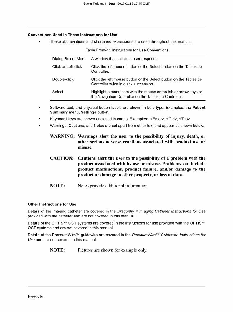
Conventions Used in These Instructions for Use
• These abbreviations and shortened expressions are used throughout this manual.
• Software text, and physical button labels are shown in bold type. Examples: the PatientSummary menu, Settings button.
• Keyboard keys are shown enclosed in carets. Examples: <Enter>, <Ctrl>, <Tab>.
• Warnings, Cautions, and Notes are set apart from other text and appear as shown below.
WARNING: Warnings alert the user to the possibility of injury, death, orother serious adverse reactions associated with product use ormisuse.
CAUTION: Cautions alert the user to the possibility of a problem with theproduct associated with its use or misuse. Problems can includeproduct malfunctions, product failure, and/or damage to theproduct or damage to other property, or loss of data.
NOTE: Notes provide additional information.
Other Instructions for Use
Details of the imaging catheter are covered in the Dragonfly™ Imaging Catheter Instructions for Useprovided with the catheter and are not covered in this manual.
Details of the OPTIS™ OCT systems are covered in the instructions for use provided with the OPTIS™OCT systems and are not covered in this manual.
Details of the PressureWire™ guidewire are covered in the PressureWire™ Guidewire Instructions forUse and are not covered in this manual.
NOTE: Pictures are shown for example only.
Table Front-1: Instructions for Use Conventions
Dialog Box or Menu A window that solicits a user response.
Click or Left-click Click the left mouse button or the Select button on the Tableside Controller.
Double-click Click the left mouse button or the Select button on the Tableside Controller twice in quick succession.
Select Highlight a menu item with the mouse or the tab or arrow keys or the Navigation Controller on the Tableside Controller.
State: Released Date: 2017.01.18 17:45 GMT

OPTIS™ Software ARTUS600005835 AInstructions for Use Front-i
Contents
Figures
Tables
System Overview
OPTIS™ Software Features . . . . . . . . . . . . . . . . . . . . . . . . . . . . . . . . . . . . . . . . . .1-1
OPTIS™ Software Symbols . . . . . . . . . . . . . . . . . . . . . . . . . . . . . . . . . . . . .1-2
Indications for Use and Intended Use . . . . . . . . . . . . . . . . . . . . . . . . . . . . . . . . . . .1-4
Contraindications . . . . . . . . . . . . . . . . . . . . . . . . . . . . . . . . . . . . . . . . . . . . . . . . . . .1-5
Warnings (OCT) . . . . . . . . . . . . . . . . . . . . . . . . . . . . . . . . . . . . . . . . . . . . . . . . . . .1-6
Precautions (OCT) . . . . . . . . . . . . . . . . . . . . . . . . . . . . . . . . . . . . . . . . . . . . . . . . . .1-7
Complications (OCT) . . . . . . . . . . . . . . . . . . . . . . . . . . . . . . . . . . . . . . . . . . . . . . .1-8Recording . . . . . . . . . . . . . . . . . . . . . . . . . . . . . . . . . . . . . . . . . . . . . . . . . . . .1-8
System Setup
Power On . . . . . . . . . . . . . . . . . . . . . . . . . . . . . . . . . . . . . . . . . . . . . . . . . . . . . . . . .2-2Shut Down . . . . . . . . . . . . . . . . . . . . . . . . . . . . . . . . . . . . . . . . . . . . . . . . . . .2-3
FFR Settings . . . . . . . . . . . . . . . . . . . . . . . . . . . . . . . . . . . . . . . . . . . . . . . . . . . . . .2-4
Room Selection (applicable for OPTIS™ mobile systems only) . . . . . . . . . . . . . .2-5
State: Released Date: 2017.01.18 17:45 GMT

Contents
Front-ii
Opening a Patient Record
Home Screen . . . . . . . . . . . . . . . . . . . . . . . . . . . . . . . . . . . . . . . . . . . . . . . . . . . . . .3-2
Entering New Patient Information. . . . . . . . . . . . . . . . . . . . . . . . . . . . . . . . . . . . . . 3-3
Select Patient Menu . . . . . . . . . . . . . . . . . . . . . . . . . . . . . . . . . . . . . . . . . . . . . . . . .3-5
Patient Summary Menu . . . . . . . . . . . . . . . . . . . . . . . . . . . . . . . . . . . . . . . . . . . . . .3-7
Editing Patient Information . . . . . . . . . . . . . . . . . . . . . . . . . . . . . . . . . . . . . . . . . . .3-9
Editing Case Information. . . . . . . . . . . . . . . . . . . . . . . . . . . . . . . . . . . . . . . . . . . . .3-10
Importing a Patient Database. . . . . . . . . . . . . . . . . . . . . . . . . . . . . . . . . . . . . . . . . .3-11
Opening a Saved Recording or Still Image . . . . . . . . . . . . . . . . . . . . . . . . . . . . . . .3-12
Performing an FFR Procedure
Setting up the OPTIS™ Software . . . . . . . . . . . . . . . . . . . . . . . . . . . . . . . . . . . . . . 4-1
Performing an FFR . . . . . . . . . . . . . . . . . . . . . . . . . . . . . . . . . . . . . . . . . . . . . . . . .4-2
Recording FFR. . . . . . . . . . . . . . . . . . . . . . . . . . . . . . . . . . . . . . . . . . . . . . . . . . . . .4-7
Reviewing an FFR Recording . . . . . . . . . . . . . . . . . . . . . . . . . . . . . . . . . . . . . . . . .4-9
PressureWire™ Guidewire Troubleshooting. . . . . . . . . . . . . . . . . . . . . . . . . . . . . .4-12
Performing an OCT Procedure
Overview . . . . . . . . . . . . . . . . . . . . . . . . . . . . . . . . . . . . . . . . . . . . . . . . . . . . . . . . . 5-1Required Material and Equipment . . . . . . . . . . . . . . . . . . . . . . . . . . . . . . . . .5-1OCT Imaging Overview. . . . . . . . . . . . . . . . . . . . . . . . . . . . . . . . . . . . . . . . .5-2
OCT Operating Modes. . . . . . . . . . . . . . . . . . . . . . . . . . . . . . . . . . . . . . . . . . . . . . .5-3
OCT Recording Types . . . . . . . . . . . . . . . . . . . . . . . . . . . . . . . . . . . . . . . . . . . . . . .5-3
OCT Trigger Types . . . . . . . . . . . . . . . . . . . . . . . . . . . . . . . . . . . . . . . . . . . . . . . . .5-4
Angio Co-Registration. . . . . . . . . . . . . . . . . . . . . . . . . . . . . . . . . . . . . . . . . . . . . . .5-5
Setting up the OPTIS™ Software . . . . . . . . . . . . . . . . . . . . . . . . . . . . . . . . . . . . . . 5-5
Preparing to Acquire OCT Recordings . . . . . . . . . . . . . . . . . . . . . . . . . . . . . . . . . .5-6
Confirm Recording Settings . . . . . . . . . . . . . . . . . . . . . . . . . . . . . . . . . . . . . . . . . .5-10
Dragonfly™ Imaging Catheter Insertion and Positioning . . . . . . . . . . . . . . . . . . . .5-11Sterile Operator . . . . . . . . . . . . . . . . . . . . . . . . . . . . . . . . . . . . . . . . . . . . . . .5-12
State: Released Date: 2017.01.18 17:45 GMT
Contents
OPTIS™ Software ARTUS600005835 AInstructions for Use Front-iii
Acquiring Patient Images. . . . . . . . . . . . . . . . . . . . . . . . . . . . . . . . . . . . . . . . . . . . .5-15Catheter Failure . . . . . . . . . . . . . . . . . . . . . . . . . . . . . . . . . . . . . . . . . . . . . . .5-18
Reviewing OCT Recordings
Image Window. . . . . . . . . . . . . . . . . . . . . . . . . . . . . . . . . . . . . . . . . . . . . . . . . . . . .6-3
Measurements Menu . . . . . . . . . . . . . . . . . . . . . . . . . . . . . . . . . . . . . . . . . . . . . . . .6-6
View Menu . . . . . . . . . . . . . . . . . . . . . . . . . . . . . . . . . . . . . . . . . . . . . . . . . . . . . . .6-7
Tools Menu . . . . . . . . . . . . . . . . . . . . . . . . . . . . . . . . . . . . . . . . . . . . . . . . . . . . . . .6-10
Reviewing with Angio Co-Registration . . . . . . . . . . . . . . . . . . . . . . . . . . . . . . . . .6-11Angio Co-Registration Guidance . . . . . . . . . . . . . . . . . . . . . . . . . . . . . . . . . .6-13Angio Co-Registration View . . . . . . . . . . . . . . . . . . . . . . . . . . . . . . . . . . . . .6-20Angio Co-Registration Troubleshooting . . . . . . . . . . . . . . . . . . . . . . . . . . . .6-25
3D Bifurcation and 3D Navigation Views. . . . . . . . . . . . . . . . . . . . . . . . . . . . . . . .6-31
3D Bifurcation Display . . . . . . . . . . . . . . . . . . . . . . . . . . . . . . . . . . . . . . . . . . . . . .6-32
3D Navigation Advanced Display . . . . . . . . . . . . . . . . . . . . . . . . . . . . . . . . . . . . . . 6-35
3D Options Menus . . . . . . . . . . . . . . . . . . . . . . . . . . . . . . . . . . . . . . . . . . . . . . . . . .6-35Display Mode Tissue, Lumen, and Tissue + Lumen . . . . . . . . . . . . . . . . . . . 6-373D Options Stent Only . . . . . . . . . . . . . . . . . . . . . . . . . . . . . . . . . . . . . . . . . .6-393D Options Guidewire Display . . . . . . . . . . . . . . . . . . . . . . . . . . . . . . . . . . .6-403D Options Side Branch(es). . . . . . . . . . . . . . . . . . . . . . . . . . . . . . . . . . . . . . 6-423D Options Flythrough. . . . . . . . . . . . . . . . . . . . . . . . . . . . . . . . . . . . . . . . . .6-43Limitations of 3D Display . . . . . . . . . . . . . . . . . . . . . . . . . . . . . . . . . . . . . . .6-44
L-Mode Bookmark Controls . . . . . . . . . . . . . . . . . . . . . . . . . . . . . . . . . . . . . . . . . .6-45
Setting Playback Range in L-Mode . . . . . . . . . . . . . . . . . . . . . . . . . . . . . . . . . . . . .6-46Limitations of L-Mode Data. . . . . . . . . . . . . . . . . . . . . . . . . . . . . . . . . . . . . . 6-47Lumen Profile Display With MLA Controls Overview. . . . . . . . . . . . . . . . .6-48
Stent Apposition Indicator . . . . . . . . . . . . . . . . . . . . . . . . . . . . . . . . . . . . . . . . . . . .6-51
Rendered Stent Display . . . . . . . . . . . . . . . . . . . . . . . . . . . . . . . . . . . . . . . . . . . . . .6-53
Playback Controls . . . . . . . . . . . . . . . . . . . . . . . . . . . . . . . . . . . . . . . . . . . . . . . . . .6-55
Calibration Adjustment (Tableside Controller Not Connected) . . . . . . . . . . . . . . .6-56
Calibration Adjustment (Tableside Controller Connected) . . . . . . . . . . . . . . . . . . . 6-58
Adjust Playback Settings . . . . . . . . . . . . . . . . . . . . . . . . . . . . . . . . . . . . . . . . . . . . .6-60
Exporting a Recording or Still Frame . . . . . . . . . . . . . . . . . . . . . . . . . . . . . . . . . . .6-61
Capturing Still Images . . . . . . . . . . . . . . . . . . . . . . . . . . . . . . . . . . . . . . . . . . . . . . .6-61
State: Released Date: 2017.01.18 17:45 GMT
Contents
Front-iv
Saving a Still Image . . . . . . . . . . . . . . . . . . . . . . . . . . . . . . . . . . . . . . . . . . . .6-61
Printing Still Images . . . . . . . . . . . . . . . . . . . . . . . . . . . . . . . . . . . . . . . . . . . . . . . .6-62Printing a Still Image . . . . . . . . . . . . . . . . . . . . . . . . . . . . . . . . . . . . . . . . . . .6-62
Measurements and Annotations
Measurements and Text Callouts in the Image Files. . . . . . . . . . . . . . . . . . . . . . . .7-1
Verifying Calibration. . . . . . . . . . . . . . . . . . . . . . . . . . . . . . . . . . . . . . . . . . . . . . . .7-1
Techniques to Improve Measurement Accuracy . . . . . . . . . . . . . . . . . . . . . . . . . . .7-2Measurements and Annotations in the L-Mode View . . . . . . . . . . . . . . . . . . 7-2
Length Measurements . . . . . . . . . . . . . . . . . . . . . . . . . . . . . . . . . . . . . . . . . . . . . . .7-3Making a Length (Distance) Measurement . . . . . . . . . . . . . . . . . . . . . . . . . .7-4
Area Measurements . . . . . . . . . . . . . . . . . . . . . . . . . . . . . . . . . . . . . . . . . . . . . . . . .7-5Making a Manual Area Measurement . . . . . . . . . . . . . . . . . . . . . . . . . . . . . .7-5
Adding Text Callouts. . . . . . . . . . . . . . . . . . . . . . . . . . . . . . . . . . . . . . . . . . . . . . . .7-7Adding Text Callouts . . . . . . . . . . . . . . . . . . . . . . . . . . . . . . . . . . . . . . . . . . .7-8
The %AS Calculation . . . . . . . . . . . . . . . . . . . . . . . . . . . . . . . . . . . . . . . . . . . . . . .7-9Formula for %AS Calculation . . . . . . . . . . . . . . . . . . . . . . . . . . . . . . . . . . . .7-9Make a %AS Calculation . . . . . . . . . . . . . . . . . . . . . . . . . . . . . . . . . . . . . . . .7-9
The %DS Calculation . . . . . . . . . . . . . . . . . . . . . . . . . . . . . . . . . . . . . . . . . . . . . . .7-11Formula for %DS Calculation . . . . . . . . . . . . . . . . . . . . . . . . . . . . . . . . . . . .7-11Make a %DS Calculation . . . . . . . . . . . . . . . . . . . . . . . . . . . . . . . . . . . . . . . .7-11
Field of View . . . . . . . . . . . . . . . . . . . . . . . . . . . . . . . . . . . . . . . . . . . . . . . . . . . . . .7-13Increase/Decrease Field of View . . . . . . . . . . . . . . . . . . . . . . . . . . . . . . . . . .7-13Zooming In Manually. . . . . . . . . . . . . . . . . . . . . . . . . . . . . . . . . . . . . . . . . . .7-14Quick Zoom . . . . . . . . . . . . . . . . . . . . . . . . . . . . . . . . . . . . . . . . . . . . . . . . . .7-15
Editing Measurements and Annotations . . . . . . . . . . . . . . . . . . . . . . . . . . . . . . . . .7-16Moving Individual Points. . . . . . . . . . . . . . . . . . . . . . . . . . . . . . . . . . . . . . . .7-17Adding Points to a Multiple Point Area . . . . . . . . . . . . . . . . . . . . . . . . . . . . .7-17Deleting Points from a Multiple Point Area. . . . . . . . . . . . . . . . . . . . . . . . . .7-17Deleting Individual Measurements or Text Callouts . . . . . . . . . . . . . . . . . . . 7-18Deleting All Measurements and Text Callouts . . . . . . . . . . . . . . . . . . . . . . .7-18
Exporting, Importing, and Managing Files
Compatible Transfer Media and USB Devices . . . . . . . . . . . . . . . . . . . . . . . . . . . .8-2Optical Media . . . . . . . . . . . . . . . . . . . . . . . . . . . . . . . . . . . . . . . . . . . . . . . . .8-2USB Connected Media. . . . . . . . . . . . . . . . . . . . . . . . . . . . . . . . . . . . . . . . . .8-2
State: Released Date: 2017.01.18 17:45 GMT
Contents
OPTIS™ Software ARTUS600005835 AInstructions for Use Front-v
File Formats . . . . . . . . . . . . . . . . . . . . . . . . . . . . . . . . . . . . . . . . . . . . . . . . . . . . . . .8-4About Native (Raw OCT) Format . . . . . . . . . . . . . . . . . . . . . . . . . . . . . . . . .8-4About DICOM Format . . . . . . . . . . . . . . . . . . . . . . . . . . . . . . . . . . . . . . . . . .8-4About Standard Format . . . . . . . . . . . . . . . . . . . . . . . . . . . . . . . . . . . . . . . . .8-5
Image Format and Size in Standard Formats. . . . . . . . . . . . . . . . . . . . . . . . . . . . . .8-6File Size . . . . . . . . . . . . . . . . . . . . . . . . . . . . . . . . . . . . . . . . . . . . . . . . . . . . .8-6Standard File Format . . . . . . . . . . . . . . . . . . . . . . . . . . . . . . . . . . . . . . . . . . .8-6
Exporting Files During a Review . . . . . . . . . . . . . . . . . . . . . . . . . . . . . . . . . . . . . . 8-7Exporting Files in Native (Raw) Format . . . . . . . . . . . . . . . . . . . . . . . . . . . .8-8Exporting Files in DICOM Format . . . . . . . . . . . . . . . . . . . . . . . . . . . . . . . .8-10Exporting Files in Standard Formats . . . . . . . . . . . . . . . . . . . . . . . . . . . . . . .8-12
Exporting Files from the Patient Summary Menu . . . . . . . . . . . . . . . . . . . . . . . . . .8-14
Using Exported Standard Format Recordings . . . . . . . . . . . . . . . . . . . . . . . . . . . . .8-16St. Jude Medical™ DICOM Viewer . . . . . . . . . . . . . . . . . . . . . . . . . . . . . . .8-16
Deleting Files. . . . . . . . . . . . . . . . . . . . . . . . . . . . . . . . . . . . . . . . . . . . . . . . . . . . . .8-20Deleting Files from the Patient Summary Menu . . . . . . . . . . . . . . . . . . . . . .8-20Deleting Files from the Database Menu. . . . . . . . . . . . . . . . . . . . . . . . . . . . .8-21
Transfer and Import Messages. . . . . . . . . . . . . . . . . . . . . . . . . . . . . . . . . . . . . . . . .8-22
Duplicate File Name Messages . . . . . . . . . . . . . . . . . . . . . . . . . . . . . . . . . . . . . . . .8-24
Database Statistics . . . . . . . . . . . . . . . . . . . . . . . . . . . . . . . . . . . . . . . . . . . . . . . . . .8-24
Importing Patient Information From a DICOM Worklist or Storage Server . . . . .8-25
Maintenance
Contacting St. Jude Medical Service . . . . . . . . . . . . . . . . . . . . . . . . . . . . . . . . . . . .9-2
Maintenance. . . . . . . . . . . . . . . . . . . . . . . . . . . . . . . . . . . . . . . . . . . . . . . . . . . . . . .9-3Transferring Log Files . . . . . . . . . . . . . . . . . . . . . . . . . . . . . . . . . . . . . . . . . .9-4Identifying the Software Version . . . . . . . . . . . . . . . . . . . . . . . . . . . . . . . . . .9-6
User Interface Reference
Setup Dialog Box and Submenus . . . . . . . . . . . . . . . . . . . . . . . . . . . . . . . . . . . . . 10-1
Setup - Acquisition Menu . . . . . . . . . . . . . . . . . . . . . . . . . . . . . . . . . . . . . . . . . . .10-2
Setup - Acquisition/Other Menu . . . . . . . . . . . . . . . . . . . . . . . . . . . . . . . . . . . . . .10-4
Setup - Administration Menu . . . . . . . . . . . . . . . . . . . . . . . . . . . . . . . . . . . . . . . .10-5
Setup - Database Menu . . . . . . . . . . . . . . . . . . . . . . . . . . . . . . . . . . . . . . . . . . . . .10-7
State: Released Date: 2017.01.18 17:45 GMT

Contents
Front-vi
Setup - Database/Maintenance Menu . . . . . . . . . . . . . . . . . . . . . . . . . . . . . . . . . .10-9
Setup - Database/Physician Menu . . . . . . . . . . . . . . . . . . . . . . . . . . . . . . . . . . . . . 10-11
Setup - DICOM Menu . . . . . . . . . . . . . . . . . . . . . . . . . . . . . . . . . . . . . . . . . . . . . .10-12
Setup - DICOM/Local Host Menu. . . . . . . . . . . . . . . . . . . . . . . . . . . . . . . . . . . . . 10-17
Setup - Display Menu . . . . . . . . . . . . . . . . . . . . . . . . . . . . . . . . . . . . . . . . . . . . . .10-19
Setup - Display - 3D Menu . . . . . . . . . . . . . . . . . . . . . . . . . . . . . . . . . . . . . . . . . .10-21
Setup - Display - Angio Menu. . . . . . . . . . . . . . . . . . . . . . . . . . . . . . . . . . . . . . . .10-22
Setup - Display - Stent Menu. . . . . . . . . . . . . . . . . . . . . . . . . . . . . . . . . . . . . . . . .10-23
Setup - Lumen Profile . . . . . . . . . . . . . . . . . . . . . . . . . . . . . . . . . . . . . . . . . . . . . .10-25
Setup - Measurements Menu . . . . . . . . . . . . . . . . . . . . . . . . . . . . . . . . . . . . . . . . .10-27
Setup - Measurements/Labels Menu . . . . . . . . . . . . . . . . . . . . . . . . . . . . . . . . . . .10-28
Setup - Print Menu. . . . . . . . . . . . . . . . . . . . . . . . . . . . . . . . . . . . . . . . . . . . . . . . .10-29
Setup - Room Manager (OPTIS™ integrated systems). . . . . . . . . . . . . . . . . . . . .10-30
Setup - Room Manager (applicable OPTIS™ mobile systems) . . . . . . . . . . . . . .10-31
Setup - Service Menu. . . . . . . . . . . . . . . . . . . . . . . . . . . . . . . . . . . . . . . . . . . . . . .10-36
Setup - Service/System Diagnostics Menu . . . . . . . . . . . . . . . . . . . . . . . . . . . . . .10-39
Setup - Localization Menu. . . . . . . . . . . . . . . . . . . . . . . . . . . . . . . . . . . . . . . . . . .10-41
Safety Information
Patient Safety . . . . . . . . . . . . . . . . . . . . . . . . . . . . . . . . . . . . . . . . . . . . . . . . . . . . .11-2General . . . . . . . . . . . . . . . . . . . . . . . . . . . . . . . . . . . . . . . . . . . . . . . . . . . . .11-2
. . . . . . . . . . . . . . . . . . . . . . . . . . . . . . . . . . . . . . . . . . . . . . . . . . . . . . . . . . . . . . . .11-3
System Imaging Limitations . . . . . . . . . . . . . . . . . . . . . . . . . . . . . . . . . . . . . . . . .11-3Considerations for Optimal Vessel Imaging . . . . . . . . . . . . . . . . . . . . . . . .11-3Considerations for Optimal Tissue Imaging . . . . . . . . . . . . . . . . . . . . . . . .11-3
System Specifications
System - Safety & Regulatory . . . . . . . . . . . . . . . . . . . . . . . . . . . . . . . . . . . . . . . .12-1
. . . . . . . . . . . . . . . . . . . . . . . . . . . . . . . . . . . . . . . . . . . . . . . . . . . . . . . . . . . . . . . .12-2
State: Released Date: 2017.01.18 17:45 GMT

Contents
OPTIS™ Software ARTUS600005835 AInstructions for Use Front-vii
Index
State: Released Date: 2017.01.18 17:45 GMT

Contents
Front-viii
State: Released Date: 2017.01.18 17:45 GMT
OPTIS™ Software ARTUS600005835 AInstructions for Use Front-i
Figures2-1 Startup Screen. . . . . . . . . . . . . . . . . . . . . . . . . . . . . . . . . . . . . . . . . . . . . . . . .2-22-2 Shutdown Menu . . . . . . . . . . . . . . . . . . . . . . . . . . . . . . . . . . . . . . . . . . . . . . .2-32-3 Room Selection Screen . . . . . . . . . . . . . . . . . . . . . . . . . . . . . . . . . . . . . . . . .2-52-4 Startup Room Selection Screen . . . . . . . . . . . . . . . . . . . . . . . . . . . . . . . . . . .2-62-5 Room Selection Screen With No Rooms Configured . . . . . . . . . . . . . . . . . . 2-62-6 Bluetooth® wireless technology Tooltip . . . . . . . . . . . . . . . . . . . . . . . . . . . .2-8
3-1 Home Screen . . . . . . . . . . . . . . . . . . . . . . . . . . . . . . . . . . . . . . . . . . . . . . . . .3-23-2 Add New Patient Menu . . . . . . . . . . . . . . . . . . . . . . . . . . . . . . . . . . . . . . . . .3-33-3 Select Patient Menu . . . . . . . . . . . . . . . . . . . . . . . . . . . . . . . . . . . . . . . . . . . .3-53-4 Default Patient Alert. . . . . . . . . . . . . . . . . . . . . . . . . . . . . . . . . . . . . . . . . . . .3-63-5 Patient Summary Menu . . . . . . . . . . . . . . . . . . . . . . . . . . . . . . . . . . . . . . . . .3-73-6 Edit Patient Menu. . . . . . . . . . . . . . . . . . . . . . . . . . . . . . . . . . . . . . . . . . . . . .3-93-7 Case Information Menu . . . . . . . . . . . . . . . . . . . . . . . . . . . . . . . . . . . . . . . . .3-103-8 Recording as shown in the Patient Summary Menu. . . . . . . . . . . . . . . . . . . .3-123-9 OCT Review Screen. . . . . . . . . . . . . . . . . . . . . . . . . . . . . . . . . . . . . . . . . . . .3-134-1 Set AO transducer height and open AO transducer guidance message . . . . .4-24-2 Flush PressureWire™ guidewire guidance message . . . . . . . . . . . . . . . . . . . 4-34-3 Turn on PressureWire™ guidewire guidance message . . . . . . . . . . . . . . . . .4-44-4 Advance PressureWire™ guidewire and Equalize guidance message. . . . . .4-54-5 Pd/Pa waveforms equalizing . . . . . . . . . . . . . . . . . . . . . . . . . . . . . . . . . . . . .4-74-6 Recording . . . . . . . . . . . . . . . . . . . . . . . . . . . . . . . . . . . . . . . . . . . . . . . . . . . .4-84-7 FFR Review Screen (FFR Recording Selected). . . . . . . . . . . . . . . . . . . . . . .4-114-8 FFR Review Screen (Pd/Pa Recording Selected). . . . . . . . . . . . . . . . . . . . . .4-115-1 Purge Catheter guidance message . . . . . . . . . . . . . . . . . . . . . . . . . . . . . . . . .5-75-2 Connect Catheter to DOC Guidance Message . . . . . . . . . . . . . . . . . . . . . . . .5-85-3 Catheter Connected, Initial Calibration done . . . . . . . . . . . . . . . . . . . . . . . . .5-95-4 OCT Settings Menu (during Recording) . . . . . . . . . . . . . . . . . . . . . . . . . . . .5-105-5 Incorrect and Correct Calibration (Dragonfly™ Duo Imaging Catheter shown
in fingertips)5-135-6 Incorrect and Correct Calibration (Dragonfly™ OPTIS™ Imaging Catheter shown
in fingertips)5-135-7 System Display - Acquisition. . . . . . . . . . . . . . . . . . . . . . . . . . . . . . . . . . . . .5-155-8 Catheter Failure message . . . . . . . . . . . . . . . . . . . . . . . . . . . . . . . . . . . . . . . .5-185-9 Catheter Failure Guidance . . . . . . . . . . . . . . . . . . . . . . . . . . . . . . . . . . . . . . .5-18
5-10 Safe Unload Guidance, Screen 1 . . . . . . . . . . . . . . . . . . . . . . . . . . . . . . . . . .5-19
State: Released Date: 2017.01.18 17:45 GMT
Figures
Front-ii
5-11 Safe Unload Guidance, Screen 2 . . . . . . . . . . . . . . . . . . . . . . . . . . . . . . . . . .5-205-12 Safe Unload Guidance, Screen 3 . . . . . . . . . . . . . . . . . . . . . . . . . . . . . . . . . .5-21
6-1 Measurements. . . . . . . . . . . . . . . . . . . . . . . . . . . . . . . . . . . . . . . . . . . . . . . . .6-6
6-1 . . . . . . . . . . . . . . . . . . . . . . . . . . . . . . . . . . . . . . . . . . . . . . . . . . . . . . . . . . . .6-66-2 View . . . . . . . . . . . . . . . . . . . . . . . . . . . . . . . . . . . . . . . . . . . . . . . . . . . . . . . .6-76-3 Tools. . . . . . . . . . . . . . . . . . . . . . . . . . . . . . . . . . . . . . . . . . . . . . . . . . . . . . . .6-106-4 Angio-Coregistration Thumbnail Image . . . . . . . . . . . . . . . . . . . . . . . . . . . .6-116-5 Angio Co-Registration: Co-Register . . . . . . . . . . . . . . . . . . . . . . . . . . . . . . .6-126-6 Angio Co-Registration Guided Workflow, Step 1 . . . . . . . . . . . . . . . . . . . . .6-136-7 Angio Co-Registration Guided Workflow, Step 2 . . . . . . . . . . . . . . . . . . . . .6-146-8 Angio Co-Registration Guided Workflow, Step 2 with Trace. . . . . . . . . . . .6-156-9 Initial incorrect vessel trace with two control points. . . . . . . . . . . . . . . . . . . 6-16
6-10 Corrected vessel trace using one additional point. . . . . . . . . . . . . . . . . . . . . .6-176-11 Angio Co-Registration Guided Workflow, Step 3 . . . . . . . . . . . . . . . . . . . . .6-186-12 Angio Co-registration completed successfully screen . . . . . . . . . . . . . . . . . .6-196-13 Tissue Display . . . . . . . . . . . . . . . . . . . . . . . . . . . . . . . . . . . . . . . . . . . . . . . .6-376-14 Lumen Display . . . . . . . . . . . . . . . . . . . . . . . . . . . . . . . . . . . . . . . . . . . . . . . .6-386-15 Tissue + Lumen Display . . . . . . . . . . . . . . . . . . . . . . . . . . . . . . . . . . . . . . . .6-386-16 Stent Display: Half Stent . . . . . . . . . . . . . . . . . . . . . . . . . . . . . . . . . . . . . . . .6-396-17 Stent Display: Full Stent. . . . . . . . . . . . . . . . . . . . . . . . . . . . . . . . . . . . . . . . .6-396-18 Guidewire Partially Rendered / Solid Display . . . . . . . . . . . . . . . . . . . . . . . .6-406-19 Guidewire Solid Display . . . . . . . . . . . . . . . . . . . . . . . . . . . . . . . . . . . . . . . .6-416-20 Adjusted Playback Range. . . . . . . . . . . . . . . . . . . . . . . . . . . . . . . . . . . . . . . .6-466-21 Low Confidence MLA . . . . . . . . . . . . . . . . . . . . . . . . . . . . . . . . . . . . . . . . . .6-496-22 Automatically Computed MLA Frame . . . . . . . . . . . . . . . . . . . . . . . . . . . . .6-496-23 Overridden MLA Frame. . . . . . . . . . . . . . . . . . . . . . . . . . . . . . . . . . . . . . . . .6-496-24 Restore MLA Frame. . . . . . . . . . . . . . . . . . . . . . . . . . . . . . . . . . . . . . . . . . . .6-506-25 Cross-Sectional View: Rendered Stent Display. . . . . . . . . . . . . . . . . . . . . . .6-546-26 Playback Calibration (TSC not connected and Dragonfly Duo shown, in progress)
6-566-27 Playback Calibration (TSC connected and Dragonfly Duo shown, click-move-click
in progress)6-586-28 Playback Calibration Circle complete
(TSC connected)6-596-29 Field of View Settings . . . . . . . . . . . . . . . . . . . . . . . . . . . . . . . . . . . . . . . . . .6-607-1 Length Measurement . . . . . . . . . . . . . . . . . . . . . . . . . . . . . . . . . . . . . . . . . . .7-37-2 Manual Area Measurement (in progress). . . . . . . . . . . . . . . . . . . . . . . . . . . .7-57-3 Text Callouts . . . . . . . . . . . . . . . . . . . . . . . . . . . . . . . . . . . . . . . . . . . . . . . . .7-77-4 Enter Note Dialog Box . . . . . . . . . . . . . . . . . . . . . . . . . . . . . . . . . . . . . . . . . .7-87-5 Select Area Measurement Dialog Box . . . . . . . . . . . . . . . . . . . . . . . . . . . . . .7-97-6 %AS Calculation . . . . . . . . . . . . . . . . . . . . . . . . . . . . . . . . . . . . . . . . . . . . . .7-107-7 %AS Error Message . . . . . . . . . . . . . . . . . . . . . . . . . . . . . . . . . . . . . . . . . . . .7-107-8 Select Length Measurement Dialog Box . . . . . . . . . . . . . . . . . . . . . . . . . . . .7-11
State: Released Date: 2017.01.18 17:45 GMT

Figures
OPTIS™ Software ARTUS600005835 AInstructions for Use Front-iii
7-9 %DS Calculation . . . . . . . . . . . . . . . . . . . . . . . . . . . . . . . . . . . . . . . . . . . . . .7-127-10 Zooming an Image . . . . . . . . . . . . . . . . . . . . . . . . . . . . . . . . . . . . . . . . . . . . .7-147-11 Setup Menu, Display Option . . . . . . . . . . . . . . . . . . . . . . . . . . . . . . . . . . . . .7-158-1 Export Button (OCT) . . . . . . . . . . . . . . . . . . . . . . . . . . . . . . . . . . . . . . . . . . .8-78-2 The Export Wizard - Step 1 . . . . . . . . . . . . . . . . . . . . . . . . . . . . . . . . . . . . . . 8-88-3 Define Alternate Patient ID Menu . . . . . . . . . . . . . . . . . . . . . . . . . . . . . . . . .8-88-4 Highlighted Records. . . . . . . . . . . . . . . . . . . . . . . . . . . . . . . . . . . . . . . . . . . .8-148-5 St. Jude Medical™ DICOM Viewer - Image View . . . . . . . . . . . . . . . . . . . .8-168-6 St. Jude Medical™ DICOM Viewer - Attributes View . . . . . . . . . . . . . . . . .8-178-7 Import Database Menu . . . . . . . . . . . . . . . . . . . . . . . . . . . . . . . . . . . . . . . . . .8-188-8 Deletion Warning Alert . . . . . . . . . . . . . . . . . . . . . . . . . . . . . . . . . . . . . . . . .8-218-9 Add Patient - Step 1 (Worklist) . . . . . . . . . . . . . . . . . . . . . . . . . . . . . . . . . . .8-25
8-10 Add Patient - Step 2 . . . . . . . . . . . . . . . . . . . . . . . . . . . . . . . . . . . . . . . . . . . .8-268-11 Add Patient - Step 1 (Storage Server) . . . . . . . . . . . . . . . . . . . . . . . . . . . . . .8-289-1 Transfer Event Log Files Menu . . . . . . . . . . . . . . . . . . . . . . . . . . . . . . . . . . .9-49-2 System Startup Window. . . . . . . . . . . . . . . . . . . . . . . . . . . . . . . . . . . . . . . . .9-6
10-1 Setup - Acquisition Menu. . . . . . . . . . . . . . . . . . . . . . . . . . . . . . . . . . . . . . .10-210-2 Setup - Acquisition/Other Menu . . . . . . . . . . . . . . . . . . . . . . . . . . . . . . . . .10-410-3 Setup - Administration Menu. . . . . . . . . . . . . . . . . . . . . . . . . . . . . . . . . . . .10-510-4 Setup - Database Menu. . . . . . . . . . . . . . . . . . . . . . . . . . . . . . . . . . . . . . . . .10-710-5 Setup - Database/Maintenance Menu. . . . . . . . . . . . . . . . . . . . . . . . . . . . . .10-910-6 Setup - Database/Physician Menu . . . . . . . . . . . . . . . . . . . . . . . . . . . . . . . .10-1110-7 Setup - DICOM Menu . . . . . . . . . . . . . . . . . . . . . . . . . . . . . . . . . . . . . . . . .10-1310-8 Configure DICOM Menu . . . . . . . . . . . . . . . . . . . . . . . . . . . . . . . . . . . . . . .10-1410-9 Setup - DICOM/Local Host Menu . . . . . . . . . . . . . . . . . . . . . . . . . . . . . . . .10-17
10-10 Setup - Display Menu. . . . . . . . . . . . . . . . . . . . . . . . . . . . . . . . . . . . . . . . . .10-1910-11 Setup - 3D Menu . . . . . . . . . . . . . . . . . . . . . . . . . . . . . . . . . . . . . . . . . . . . .10-2110-12 Setup - Angio Menu . . . . . . . . . . . . . . . . . . . . . . . . . . . . . . . . . . . . . . . . . . .10-2210-13 Setup - Stent Menu . . . . . . . . . . . . . . . . . . . . . . . . . . . . . . . . . . . . . . . . . . . .10-2310-14 Single Apposition Threshold Setting . . . . . . . . . . . . . . . . . . . . . . . . . . . . . .10-2410-15 Setup - Lumen Profile . . . . . . . . . . . . . . . . . . . . . . . . . . . . . . . . . . . . . . . . .10-2510-16 Setup - Measurements Menu . . . . . . . . . . . . . . . . . . . . . . . . . . . . . . . . . . . .10-2710-17 Setup - Measurements/Labels Menu . . . . . . . . . . . . . . . . . . . . . . . . . . . . . .10-2810-18 Setup - Print Menu . . . . . . . . . . . . . . . . . . . . . . . . . . . . . . . . . . . . . . . . . . . .10-2910-19 Setup - Room Manager (OPTIS™ integrated systems) . . . . . . . . . . . . . . . .10-3010-20 Setup - Room Manager (applicable OPTIS™ mobile systems). . . . . . . . . .10-3110-21 Room Manager: Enter Room Information . . . . . . . . . . . . . . . . . . . . . . . . . .10-3210-22 Add Room dialog box . . . . . . . . . . . . . . . . . . . . . . . . . . . . . . . . . . . . . . . . .10-3310-23 Add Device dialog box. . . . . . . . . . . . . . . . . . . . . . . . . . . . . . . . . . . . . . . . .10-3410-24 Room Manager: New Room Added. . . . . . . . . . . . . . . . . . . . . . . . . . . . . . .10-3510-25 Setup - Service Menu . . . . . . . . . . . . . . . . . . . . . . . . . . . . . . . . . . . . . . . . . .10-3610-26 Setup - Service/System Diagnostics Menu . . . . . . . . . . . . . . . . . . . . . . . . .10-3910-27 Setup - Localization Menu . . . . . . . . . . . . . . . . . . . . . . . . . . . . . . . . . . . . . . 10-41
State: Released Date: 2017.01.18 17:45 GMT

Figures
Front-iv
State: Released Date: 2017.01.18 17:45 GMT

OPTIS™ Software ARTUS600005835 AInstructions for Use Front-i
Tables
Front-1 Instructions for Use Conventions . . . . . . . . . . . . . . . . . . . . . . . . . . . . . . Front-iv
1-1 Symbols Description . . . . . . . . . . . . . . . . . . . . . . . . . . . . . . . . . . . . . . . . . . .1-2
2-1 Room Selection Icons. . . . . . . . . . . . . . . . . . . . . . . . . . . . . . . . . . . . . . . . . . .2-7
3-1 Home Screen . . . . . . . . . . . . . . . . . . . . . . . . . . . . . . . . . . . . . . . . . . . . . . . . .3-23-2 Select Patient Menu functions . . . . . . . . . . . . . . . . . . . . . . . . . . . . . . . . . . . .3-53-3 Patient Summary Menu functions . . . . . . . . . . . . . . . . . . . . . . . . . . . . . . . . .3-7
4-1 FFR Review Screen (FFR and Pd/Pa Selected) . . . . . . . . . . . . . . . . . . . . . . .4-95-1 System Display Description - Acquisition . . . . . . . . . . . . . . . . . . . . . . . . . . .5-15
6-1 OPTIS™ Software Features . . . . . . . . . . . . . . . . . . . . . . . . . . . . . . . . . . . . . . 6-16-2 OCT Display Overview (upper section). . . . . . . . . . . . . . . . . . . . . . . . . . . . .6-36-3 OCT Display Overview (lower section). . . . . . . . . . . . . . . . . . . . . . . . . . . . .6-56-4 View Menu Functions . . . . . . . . . . . . . . . . . . . . . . . . . . . . . . . . . . . . . . . . . .6-86-5 Measurement and Annotation Tool Functions . . . . . . . . . . . . . . . . . . . . . . . .6-106-6 Basic OCT / Angio Co-registration View . . . . . . . . . . . . . . . . . . . . . . . . . . .6-206-7 Stent Roadmap / Angio Co-Registration View . . . . . . . . . . . . . . . . . . . . . . .6-226-8 Angio Co-registration View with L-Mode Bookmark Integration . . . . . . . .6-236-9 Angio Co-registration / Stent Apposition Integration . . . . . . . . . . . . . . . . . . 6-24
6-10 3D Bifurcation Overview (Ostium View) . . . . . . . . . . . . . . . . . . . . . . . . . . .6-336-11 3D Bifurcation Overview (Carina View) . . . . . . . . . . . . . . . . . . . . . . . . . . . .6-346-12 3D Navigation . . . . . . . . . . . . . . . . . . . . . . . . . . . . . . . . . . . . . . . . . . . . . . . .6-356-13 3D Options Menus . . . . . . . . . . . . . . . . . . . . . . . . . . . . . . . . . . . . . . . . . . . . .6-366-14 3D Flythrough Overview . . . . . . . . . . . . . . . . . . . . . . . . . . . . . . . . . . . . . . . .6-436-15 Bookmark Controls . . . . . . . . . . . . . . . . . . . . . . . . . . . . . . . . . . . . . . . . . . . .6-456-16 MLA Controls . . . . . . . . . . . . . . . . . . . . . . . . . . . . . . . . . . . . . . . . . . . . . . . .6-486-17 Stent Apposition Indicator Bar. . . . . . . . . . . . . . . . . . . . . . . . . . . . . . . . . . . .6-516-18 L-Mode Rendered Stent Display . . . . . . . . . . . . . . . . . . . . . . . . . . . . . . . . . .6-536-19 Playback Controls. . . . . . . . . . . . . . . . . . . . . . . . . . . . . . . . . . . . . . . . . . . . . .6-55
8-1 Optical Media Characteristics . . . . . . . . . . . . . . . . . . . . . . . . . . . . . . . . . . . .8-28-2 Import Database Menu Options . . . . . . . . . . . . . . . . . . . . . . . . . . . . . . . . . . .8-19
State: Released Date: 2017.01.18 17:45 GMT
Tables
Front-ii
8-3 Transfer Messages . . . . . . . . . . . . . . . . . . . . . . . . . . . . . . . . . . . . . . . . . . . . .8-228-4 Duplicate File Name Messages . . . . . . . . . . . . . . . . . . . . . . . . . . . . . . . . . . .8-24
10-1 Setup Dialog Box Common Options . . . . . . . . . . . . . . . . . . . . . . . . . . . . . .10-110-2 Setup - Acquisition Menu Settings. . . . . . . . . . . . . . . . . . . . . . . . . . . . . . . .10-210-3 Setup - Acquisition/Other Menu Settings . . . . . . . . . . . . . . . . . . . . . . . . . .10-410-4 Setup - Administration Menu Settings . . . . . . . . . . . . . . . . . . . . . . . . . . . . .10-510-5 Setup - Database Menu Settings. . . . . . . . . . . . . . . . . . . . . . . . . . . . . . . . . .10-710-6 Setup - Database/Maintenance Menu Settings. . . . . . . . . . . . . . . . . . . . . . .10-910-7 Setup - Database/Physician Settings . . . . . . . . . . . . . . . . . . . . . . . . . . . . . .10-1110-8 Setup - DICOM Menu Settings . . . . . . . . . . . . . . . . . . . . . . . . . . . . . . . . . .10-1310-9 Setup - Configure DICOM Menu Settings. . . . . . . . . . . . . . . . . . . . . . . . . .10-15
10-10 Setup - DICOM/Local Host Menu Settings . . . . . . . . . . . . . . . . . . . . . . . . .10-1710-11 Setup - Display Menu Settings. . . . . . . . . . . . . . . . . . . . . . . . . . . . . . . . . . .10-1910-12 Setup - Lumen Profile Settings . . . . . . . . . . . . . . . . . . . . . . . . . . . . . . . . . .10-2610-13 Setup - Measurements Menu Settings . . . . . . . . . . . . . . . . . . . . . . . . . . . . .10-2710-14 Setup - Measurements/Labels Menu Settings . . . . . . . . . . . . . . . . . . . . . . .10-2810-15 Setup - Print Menu Settings . . . . . . . . . . . . . . . . . . . . . . . . . . . . . . . . . . . . . 10-2910-16 Setup - Room Manager (OPTIS™ integrated systems) Settings . . . . . . . . .10-3010-17 Setup - Room Manager Settings. . . . . . . . . . . . . . . . . . . . . . . . . . . . . . . . . .10-3110-18 Setup - Service Menu Settings . . . . . . . . . . . . . . . . . . . . . . . . . . . . . . . . . . .10-3710-19 Setup - Service/System Diagnostics Menu Settings. . . . . . . . . . . . . . . . . . .10-3910-20 Localization Menu Settings . . . . . . . . . . . . . . . . . . . . . . . . . . . . . . . . . . . . . 10-41
12-1 System Safety & Regulatory Specifications . . . . . . . . . . . . . . . . . . . . . . . .12-1
State: Released Date: 2017.01.18 17:45 GMT

OPTIS™ Software ARTUS600005835 AInstructions for Use 1-1
System Overview 1
OPTIS™ Software Features
Optical Coherence Tomography (OCT) is an imaging modality that uses fiber-optic tech-nology. The OPTIS™ Software uses optical imaging catheters that emit near-infraredlight to produce high-resolution real-time images. The frequency and bandwidth charac-teristics of the near-infrared light used in these systems result in image resolution that issuperior to typical medical ultrasound images.
Fractional Flow Reserve (FFR) is the ratio of distal coronary arterial pressure to aorticpressure, measured during hyperemia. It provides the maximal blood flow in the presenceof a stenosis as a fraction of the achievable blood flow that would exist in the hypotheticalsituation that the stenosis was not present. The physician may use the FFR parameter,along with knowledge of patient history, medical expertise and clinical judgment to deter-mine if therapeutic intervention is indicated. This functionality is achieved when theOPTIS™ Software is used in conjunction with the manufacturer's wireless distal intracor-onary pressure transducer and a proximal aortic pressure transducer.
Pd/Pa is the ratio of distal coronary arterial pressure to aortic pressure measured at restingconditions. The physician may use Pd/Pa at rest, along with knowledge of patient history,medical expertise and clinical judgment to determine if additional measurement of FFRduring hyperemia or therapeutic intervention is indicated. In addition, the system incor-porates Angio Co-registration, which allows the user to visualize the position of OCTimage data on angiography images, tightening the linkage between anatomical assess-ment with OCT and subsequent therapeutic actions.
CAUTION: Medical personnel who use the OPTIS™ Software must be aware ofthe system’s limitations. Only trained operators can determine if useof the OPTIS™ Software is appropriate. Be sure to read Chapter 11“Safety Information”, before operating the OPTIS™ Software for thefirst time.
State: Released Date: 2017.01.18 17:45 GMT

System OverviewOPTIS™ Software Features
1-2
OPTIS™ Software Symbols
Before using the system, read these Instructions for Use carefully, including the identifi-cation of symbols used on the equipment.
Table 1-1: Symbols Description
Follow Instructions for Use
Conformité Européenne (European Conformity). Affixed in accordance with European Council Directive 93/42/EEC (NB 0086) and R&TTE Directive 1999/5/EC (NB 0086) and 2011/65/EU. Hereby, St. Jude Medical declares that this device is in compliance with the essential requirements and other relevant provisions of this directive.
ATTENTION!: consult accompanying documents.
Caution
Date of Manufacture
Manufacturer
Consult instructions for use
Disposal of the equipment must be in accordance with local laws.
Temperature Range (Shipping label)
Atmospheric Range (Shipping label)
Humidity Range (Shipping label)
Product Weight
500hPa
1060hPa
State: Released Date: 2017.01.18 17:45 GMT

System OverviewOPTIS™ Software Features
OPTIS™ Software ARTUS600005835 AInstructions for Use 1-3
Keep Dry
Do not use if package is damaged.
Affixed to this device in accordance with European Council Directives 2002/96/EC.
These directives call for separate collection and disposal of electrical and electronic equipment. Sorting such waste and removing it from other forms of waste lessens the contribution of potentially toxic substances into munici-pal disposal systems and into the larger ecosystem.
Return the device to St. Jude Medical at the end of its operating life.
Software Upgrade Kit
Includes:
Software Upgrade
Quantity
Catalog Number
E.U. Contact Rep
Lot Number
Caution: Federal Law restricts this device to sale by or on the order of a phy-sician.
Table 1-1: Symbols Description (continued)
LOT
State: Released Date: 2017.01.18 17:45 GMT
System OverviewIndications for Use and Intended Use
1-4
Indications for Use and Intended Use
The OPTIS™ Software with Dragonfly™ DUO or Dragonfly™ OPTIS™ Imaging Cath-eter is intended for the imaging of coronary arteries and is indicated in patients who arecandidates for transluminal interventional procedures. The Dragonfly™ DUO or Dragon-fly™ OPTIS™ Imaging Catheter is intended for use in vessels 2.0 to 3.5 mm in diameter.The Dragonfly™ DUO or Dragonfly™ OPTIS™ Imaging Catheter is not intended foruse in the left main coronary artery or in a target vessel which has undergone a previousbypass procedure.
The OPTIS™ Software will further acquire radio frequency signal outputs from both adistal intracoronary pressure transducer and a proximal aortic pressure transducer todetermine the physiological parameter, Fractional Flow Reserve (FFR). The physicianmay use the FFR parameter, along with knowledge of patient history, medical expertiseand clinical judgment to determine if therapeutic intervention is indicated.
CAUTION: The OPTIS™ Software is intended for use by appropriate medicalpersonnel who have received OPTIS™ Software and system training.St. Jude Medical and its employees cannot give instructions in theinterpretation or diagnosis of recordings and makes no attempt to doso.
WARNING: Prior to use, please review the Instructions for Use supplied with theOPTIS™ OCT system, Dragonfly™ Imaging Catheter and with thePressureWire™ guidewire for more information.
State: Released Date: 2017.01.18 17:45 GMT
System OverviewContraindications
OPTIS™ Software ARTUS600005835 AInstructions for Use 1-5
Contraindications
Use of the St. Jude Medical™ OPTIS™ Software is contraindicated where introductionof any catheter would constitute a threat to patient safety.
Contraindications (listed alphabetically) include:
• Bacteremia or sepsis
• Major coagulation system abnormalities
• Patients diagnosed with coronary artery spasm
• Patients disqualified for CABG surgery
• Patients disqualified for PTCA
• Severe hemodynamic instability or shock
• Total occlusion
• Large thrombus
• Acute renal failure
NOTE: The system has no patient alarm functions. Do not use for cardiac monitor-ing.
State: Released Date: 2017.01.18 17:45 GMT

System OverviewWarnings (OCT)
1-6
Warnings (OCT)
• Appropriate anticoagulant and vasodilator therapy must be used during the proce-dure as needed.
• Refer to the contrast media’s instructions-for-use for general warnings and precau-tions relating to use of the contrast media.
CAUTION: Before creating an OCT recording, review Chapter 5 “Performing anOCT Procedure” for additional warnings and cautions.
State: Released Date: 2017.01.18 17:45 GMT
System OverviewPrecautions (OCT)
OPTIS™ Software ARTUS600005835 AInstructions for Use 1-7
Precautions (OCT)
• Safety and effectiveness have been established for the following patient population:adult patients undergoing non-emergent percutaneous coronary interventions inlesions with reference vessel diameters between 2.0 to 3.5 mm, which were notlocated in the left main coronary artery or in a target vessel which has undergoneprevious bypass procedures.
• All operators must be trained prior to using the OPTIS™ Software, OPTIS™ sys-tems, and the Dragonfly™ Imaging Catheter.
• Only 100% contrast media is approved for human use.
State: Released Date: 2017.01.18 17:45 GMT
System OverviewComplications (OCT)
1-8
Complications (OCT)
The risks involved in vascular imaging include those associated with all catheterizationprocedures. The following complications (listed alphabetically) may occur as a conse-quence of intravascular imaging and may necessitate additional medical treatment includ-ing surgical intervention.
• Acute myocardial infarction or unstable angina
• Allergic reaction to the contrast media
• Arterial dissection, injury, or perforation
• Cardiac arrhythmias
• Coronary artery spasm
• Death
• Embolism
• Thrombus formation
Recording
CAUTION: The system may place the point of FFR at the wrong location due toabnormal heart beat or artifact in Pa from flushing the guiding cath-eter. The responsible physician should confirm that the point selectedby the system is a valid point of FFR.
CAUTION: If the cursor position has been saved, the FFR value is changedaccordingly.
CAUTION: Before creating an FFR recording, review Chapter 4 “Performing anFFR Procedure” for additional warnings and cautions.
State: Released Date: 2017.01.18 17:45 GMT
OPTIS™ Software ARTUS600005835 AInstructions for Use 2-1
System Setup 2
State: Released Date: 2017.01.18 17:45 GMT
System SetupPower On
2-2
Power On
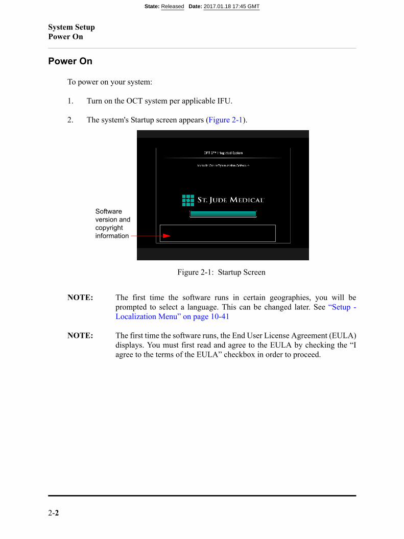
To power on your system:
1. Turn on the OCT system per applicable IFU.
2. The system's Startup screen appears (Figure 2-1).
NOTE: The first time the software runs in certain geographies, you will beprompted to select a language. This can be changed later. See “Setup -Localization Menu” on page 10-41
NOTE: The first time the software runs, the End User License Agreement (EULA)displays. You must first read and agree to the EULA by checking the “Iagree to the terms of the EULA” checkbox in order to proceed.
Figure 2-1: Startup Screen
Software version and copyright information
State: Released Date: 2017.01.18 17:45 GMT
System SetupPower On
OPTIS™ Software ARTUS600005835 AInstructions for Use 2-3
Shut Down
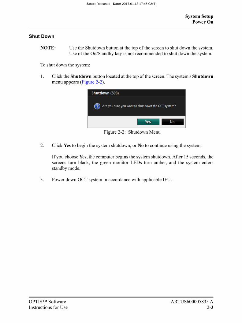
NOTE: Use the Shutdown button at the top of the screen to shut down the system.Use of the On/Standby key is not recommended to shut down the system.
To shut down the system:
1. Click the Shutdown button located at the top of the screen. The system's Shutdownmenu appears (Figure 2-2).
2. Click Yes to begin the system shutdown, or No to continue using the system.
If you choose Yes, the computer begins the system shutdown. After 15 seconds, thescreens turn black, the green monitor LEDs turn amber, and the system entersstandby mode.
3. Power down OCT system in accordance with applicable IFU.
Figure 2-2: Shutdown Menu
State: Released Date: 2017.01.18 17:45 GMT
System SetupFFR Settings
2-4
FFR Settings
NOTE: To access the full FFR Settings menu, you must be in the process of mak-ing an FFR recording, and have selected a room (see “Room Selection(applicable for OPTIS™ mobile systems only)” on page 2-5) for the FFRprocedure.
1. Click the Settings button at the top of the screen.
The FFR Settings menu opens.
2. Confirm that the FFR settings are correct for this patient.
• Pressure Scale: Changes the vertical scale of the pressure waveform display.The default setting is 0-200 mmHg.
• Sweep Speed: Changes how fast the screen is updated and the level of detailvisible to the user. A high number is suitable when a detailed picture of thetracings is required. A low number is suitable when displaying slow changes,for instance during intravenous infusing and pullback. The default setting isNormal.
• Mean Filter Length (Beats): Changes the time over which the mean pres-sure value is calculated. The adjustments are made by selecting the mean cal-culation filter length, measured in number of heartbeats. The default setting is3 heartbeats.
CAUTION: Choosing a high number of heartbeats makes the pressureaveraging slower and less sensitive to artifacts, but mayalso result in overly insensitive averaging which is notice-able when there is a short hyperemic plateau. Choosing alow number of heartbeats makes the pressure averagingfaster and more sensitive to pressure changes, desirableusing a short hyperemic plateau, but it may also result inan averaging overly sensitive to arrhythmia and pressuredisturbances.
NOTE: An insensitive or overly sensitive averaging of pressure mayresult in an incorrect FFR value.Changes in the Mean Filter Length setting are not applied toprevious FFR recordings. When a new patient is selected, the Mean Filter Length set-ting is reset to 3 heartbeats.
State: Released Date: 2017.01.18 17:45 GMT
System SetupRoom Selection (applicable for OPTIS™ mobile systems only)
OPTIS™ Software ARTUS600005835 AInstructions for Use 2-5
Room Selection (applicable for OPTIS™ mobile systems only)
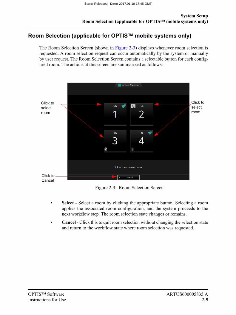
The Room Selection Screen (shown in Figure 2-3) displays whenever room selection isrequested. A room selection request can occur automatically by the system or manuallyby user request. The Room Selection Screen contains a selectable button for each config-ured room. The actions at this screen are summarized as follows:
• Select - Select a room by clicking the appropriate button. Selecting a roomapplies the associated room configuration, and the system proceeds to thenext workflow step. The room selection state changes or remains.
• Cancel - Click this to quit room selection without changing the selection stateand return to the workflow state where room selection was requested.
Figure 2-3: Room Selection Screen
Click to select room
Click to select room
Click to Cancel
State: Released Date: 2017.01.18 17:45 GMT
System SetupRoom Selection (applicable for OPTIS™ mobile systems only)
2-6
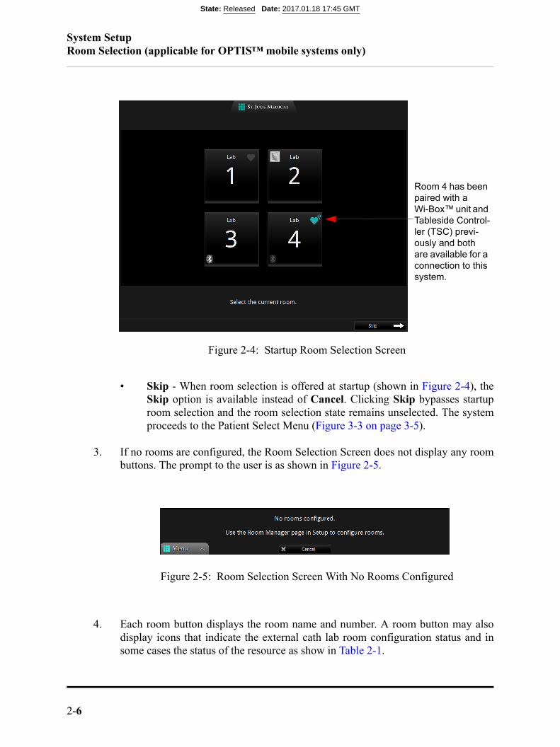
• Skip - When room selection is offered at startup (shown in Figure 2-4), theSkip option is available instead of Cancel. Clicking Skip bypasses startuproom selection and the room selection state remains unselected. The systemproceeds to the Patient Select Menu (Figure 3-3 on page 3-5).
3. If no rooms are configured, the Room Selection Screen does not display any roombuttons. The prompt to the user is as shown in Figure 2-5.
4. Each room button displays the room name and number. A room button may alsodisplay icons that indicate the external cath lab room configuration status and insome cases the status of the resource as show in Table 2-1.
Figure 2-4: Startup Room Selection Screen
Figure 2-5: Room Selection Screen With No Rooms Configured
Room 4 has been paired with a Wi-Box™ unit and Tableside Control-ler (TSC) previ-ously and both are available for a connection to this system.
State: Released Date: 2017.01.18 17:45 GMT

System SetupRoom Selection (applicable for OPTIS™ mobile systems only)
OPTIS™ Software ARTUS600005835 AInstructions for Use 2-7
Table 2-1: Room Selection Icons
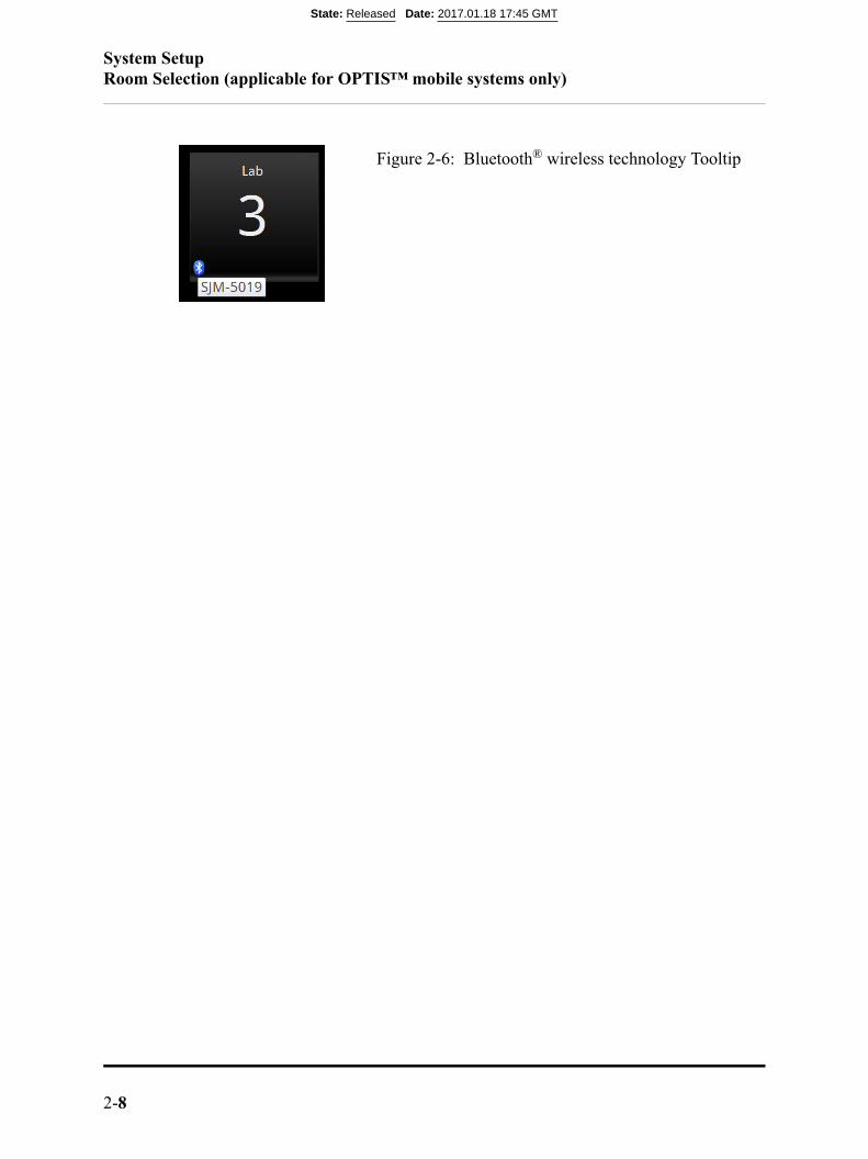
5. The absence of an icon shown in Table 2-1 indicates that the room is not configuredto use the associated resource. When a room is configured for TSC/BT, the name ofthe configured TSC is displayed in a tooltip. To display the tooltip, mouse over theBluetooth® wireless technology icon as shown in Figure 2-6.
Icon Resource Location Description
FFR Wi-Box™ unit Upper rightRoom is configured for FFR. Wi-Box ™ unit is visible for con-nection via wireless connection
FFR Wi-Box™ unit Upper right
Room is configured for FFR. Wi-Box™ unit is not visible for connection via wireless connec-tion.
Angio Coregistration Upper leftRoom is configured for angio coregistration video acquisition.
TSC via Bluetooth® wireless technology
Lower left
Room is configured for Blue-
tooth® wireless technology (BT) connection to TSC. The system is currently connected to this TSC via BT.
TSC via Bluetooth® wireless technology
Lower left
Room is configured for BT con-nection to TSC. The configured TSC is detected and is available to accept a connection.
NOTE: It can take up to 10 sec-onds for a change inTSC/BT availability tobe detected.
TSC via Bluetooth® wireless technology
Lower left
Room is configured for BT con-nection to TSC. The configured TSC is not detected or is not available to accept a connection.
NOTE: It can take up to 10 sec-onds for a change inTSC/BT availability tobe detected.
State: Released Date: 2017.01.18 17:45 GMT
System SetupRoom Selection (applicable for OPTIS™ mobile systems only)
2-8
Figure 2-6: Bluetooth® wireless technology Tooltip
State: Released Date: 2017.01.18 17:45 GMT
OPTIS™ Software ARTUS600005835 AInstructions for Use 3-1
Opening a Patient Record 3
CAUTION: Please note St. Jude Medical makes no representation or warrantythat use of the OPTIS™ Software complies with applicable privacy,security and confidentiality laws, but encourages you to assess yourown risk as you use, disclose, control, process or transfer patienthealth information with the OPTIS™ Software.
State: Released Date: 2017.01.18 17:45 GMT
Opening a Patient RecordHome Screen
3-2
Home Screen
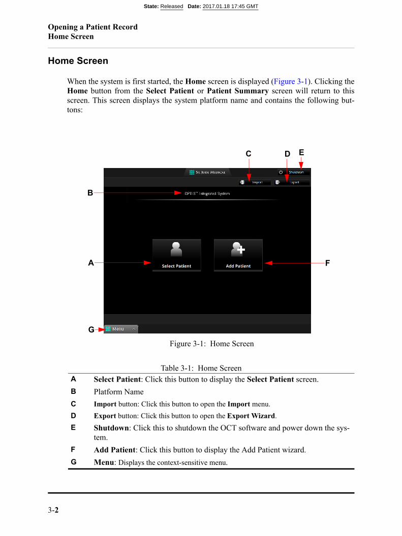
When the system is first started, the Home screen is displayed (Figure 3-1). Clicking theHome button from the Select Patient or Patient Summary screen will return to thisscreen. This screen displays the system platform name and contains the following but-tons:
Table 3-1: Home ScreenA Select Patient: Click this button to display the Select Patient screen.
B Platform Name
C Import button: Click this button to open the Import menu.
D Export button: Click this button to open the Export Wizard.
E Shutdown: Click this to shutdown the OCT software and power down the sys-tem.
F Add Patient: Click this button to display the Add Patient wizard.
G Menu: Displays the context-sensitive menu.
Figure 3-1: Home Screen
A
D
F
C
G
E
B
State: Released Date: 2017.01.18 17:45 GMT
Opening a Patient RecordEntering New Patient Information
OPTIS™ Software ARTUS600005835 AInstructions for Use 3-3
Entering New Patient Information
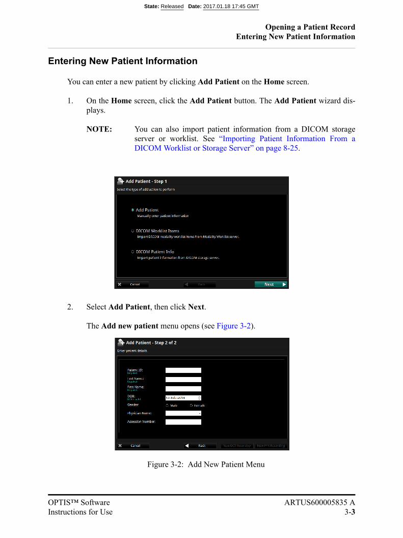
You can enter a new patient by clicking Add Patient on the Home screen.
1. On the Home screen, click the Add Patient button. The Add Patient wizard dis-plays.
NOTE: You can also import patient information from a DICOM storageserver or worklist. See “Importing Patient Information From aDICOM Worklist or Storage Server” on page 8-25.
2. Select Add Patient, then click Next.
The Add new patient menu opens (see Figure 3-2).
Figure 3-2: Add New Patient Menu
State: Released Date: 2017.01.18 17:45 GMT
Opening a Patient RecordEntering New Patient Information
3-4
3. Enter the patient information as needed.
NOTE: You must enter Patient ID, First name, and Last name before youcan save the patient information.
4. Click New OCT Recording to save and begin a new OCT recording for thispatient, click New FFR Recording to save and begin a new FFR recording for thispatient, or Cancel to close the menu without saving and return to the Home Screen.Click Back to return to the Add Patient wizard.
State: Released Date: 2017.01.18 17:45 GMT
Opening a Patient RecordSelect Patient Menu
OPTIS™ Software ARTUS600005835 AInstructions for Use 3-5
Select Patient Menu
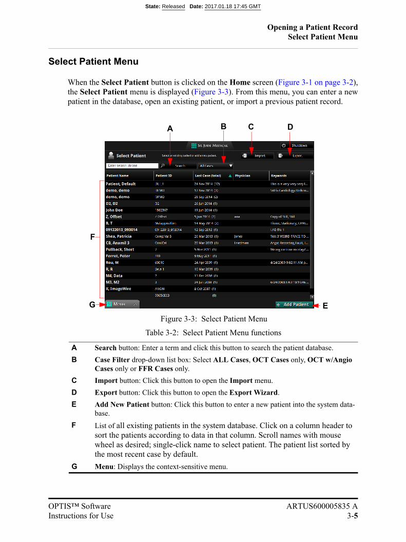
When the Select Patient button is clicked on the Home screen (Figure 3-1 on page 3-2),the Select Patient menu is displayed (Figure 3-3). From this menu, you can enter a newpatient in the database, open an existing patient, or import a previous patient record.
Table 3-2: Select Patient Menu functions
A Search button: Enter a term and click this button to search the patient database.
B Case Filter drop-down list box: Select ALL Cases, OCT Cases only, OCT w/Angio Cases only or FFR Cases only.
C Import button: Click this button to open the Import menu.
D Export button: Click this button to open the Export Wizard.
E Add New Patient button: Click this button to enter a new patient into the system data-base.
F List of all existing patients in the system database. Click on a column header to sort the patients according to data in that column. Scroll names with mouse wheel as desired; single-click name to select patient. The patient list sorted by the most recent case by default.
G Menu: Displays the context-sensitive menu.
Figure 3-3: Select Patient Menu
A DB
F
C
EG
State: Released Date: 2017.01.18 17:45 GMT
Opening a Patient RecordSelect Patient Menu
3-6
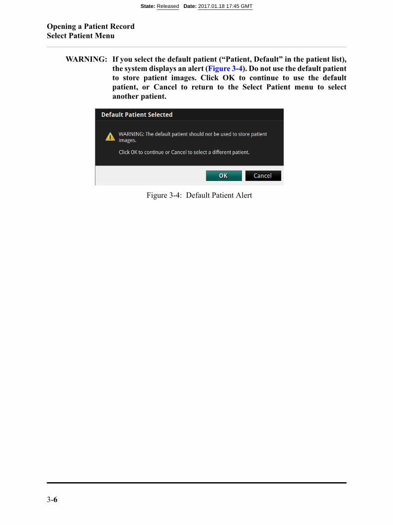
WARNING: If you select the default patient (“Patient, Default” in the patient list),the system displays an alert (Figure 3-4). Do not use the default patientto store patient images. Click OK to continue to use the defaultpatient, or Cancel to return to the Select Patient menu to selectanother patient.
Figure 3-4: Default Patient Alert
State: Released Date: 2017.01.18 17:45 GMT
Opening a Patient RecordPatient Summary Menu
OPTIS™ Software ARTUS600005835 AInstructions for Use 3-7
Patient Summary Menu
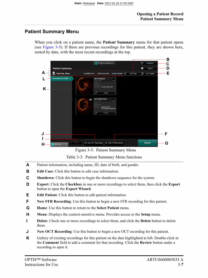
When you click on a patient name, the Patient Summary menu for that patient opens(see Figure 3-5). If there are previous recordings for this patient, they are shown here,sorted by date, with the most recent recordings at the top.
Table 3-3: Patient Summary Menu functions
A Patient information, including name, ID, date of birth, and gender.
B Edit Case: Click this button to edit case information.
C Shutdown: Click this button to begin the shutdown sequence for the system.
D Export: Click the Checkbox in one or more recordings to select them, then click the Export button to open the Export Wizard.
E Edit Patient: Click this button to edit patient information.
F New FFR Recording: Use this button to begin a new FFR recording for this patient.
G Home: Use this button to return to the Select Patient menu.
H Menu: Displays the context-sensitive menu. Provides access to the Setup menu.
I Delete: Check one or more recordings to select them, and click the Delete button to delete them.
J New OCT Recording: Use this button to begin a new OCT recording for this patient.
K Gallery of existing recordings for this patient on the date highlighted at left. Double-click in the Comment field to add a comment for that recording. Click the Review button under a recording to open it.
Figure 3-5: Patient Summary Menu
A
CD
IH
E
F
G
J
L
K
B
State: Released Date: 2017.01.18 17:45 GMT

Opening a Patient RecordPatient Summary Menu
3-8
L Case List (dates of recordings) for this patient. The list is sorted by date, with the most recent recordings at the top.
Table 3-3: Patient Summary Menu functions
State: Released Date: 2017.01.18 17:45 GMT
Opening a Patient RecordEditing Patient Information
OPTIS™ Software ARTUS600005835 AInstructions for Use 3-9
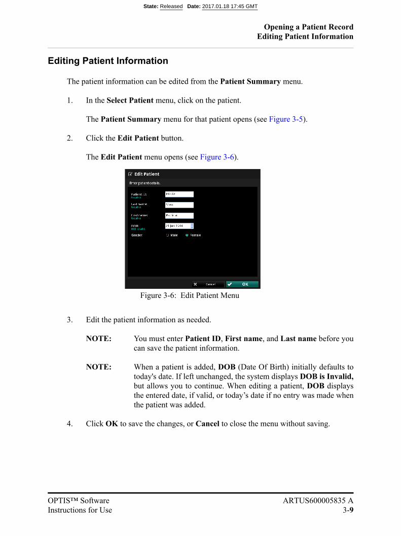
Editing Patient Information
The patient information can be edited from the Patient Summary menu.
1. In the Select Patient menu, click on the patient.
The Patient Summary menu for that patient opens (see Figure 3-5).
2. Click the Edit Patient button.
The Edit Patient menu opens (see Figure 3-6).
3. Edit the patient information as needed.
NOTE: You must enter Patient ID, First name, and Last name before youcan save the patient information.
NOTE: When a patient is added, DOB (Date Of Birth) initially defaults totoday's date. If left unchanged, the system displays DOB is Invalid,but allows you to continue. When editing a patient, DOB displaysthe entered date, if valid, or today’s date if no entry was made whenthe patient was added.
4. Click OK to save the changes, or Cancel to close the menu without saving.
Figure 3-6: Edit Patient Menu
State: Released Date: 2017.01.18 17:45 GMT
Opening a Patient RecordEditing Case Information
3-10
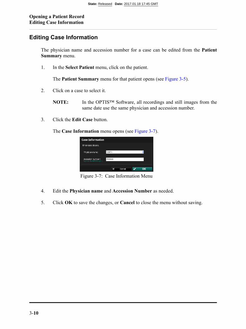
Editing Case Information
The physician name and accession number for a case can be edited from the PatientSummary menu.
1. In the Select Patient menu, click on the patient.
The Patient Summary menu for that patient opens (see Figure 3-5).
2. Click on a case to select it.
NOTE: In the OPTIS™ Software, all recordings and still images from thesame date use the same physician and accession number.
3. Click the Edit Case button.
The Case Information menu opens (see Figure 3-7).
4. Edit the Physician name and Accession Number as needed.
5. Click OK to save the changes, or Cancel to close the menu without saving.
Figure 3-7: Case Information Menu
State: Released Date: 2017.01.18 17:45 GMT
Opening a Patient RecordImporting a Patient Database
OPTIS™ Software ARTUS600005835 AInstructions for Use 3-11
Importing a Patient Database
Current and legacy OCT and FFR recordings taken on a St. Jude MedicalTM OCT systemcan be imported into the system using the Import button on the Select Patient menu. Formore information on importing patient files or information, see “Exporting, Importing,and Managing Files” on page 8-1.
State: Released Date: 2017.01.18 17:45 GMT
Opening a Patient RecordOpening a Saved Recording or Still Image
3-12
Opening a Saved Recording or Still Image
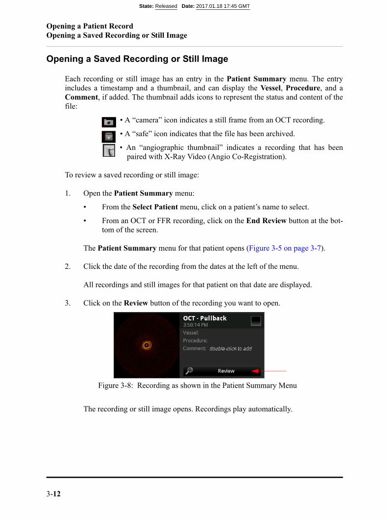
Each recording or still image has an entry in the Patient Summary menu. The entryincludes a timestamp and a thumbnail, and can display the Vessel, Procedure, and aComment, if added. The thumbnail adds icons to represent the status and content of thefile:
• A “camera” icon indicates a still frame from an OCT recording.
• A “safe” icon indicates that the file has been archived.
• An “angiographic thumbnail” indicates a recording that has beenpaired with X-Ray Video (Angio Co-Registration).
To review a saved recording or still image:
1. Open the Patient Summary menu:
• From the Select Patient menu, click on a patient’s name to select.
• From an OCT or FFR recording, click on the End Review button at the bot-tom of the screen.
The Patient Summary menu for that patient opens (Figure 3-5 on page 3-7).
2. Click the date of the recording from the dates at the left of the menu.
All recordings and still images for that patient on that date are displayed.
3. Click on the Review button of the recording you want to open.
The recording or still image opens. Recordings play automatically.
Figure 3-8: Recording as shown in the Patient Summary Menu
State: Released Date: 2017.01.18 17:45 GMT
Opening a Patient RecordOpening a Saved Recording or Still Image
OPTIS™ Software ARTUS600005835 AInstructions for Use 3-13
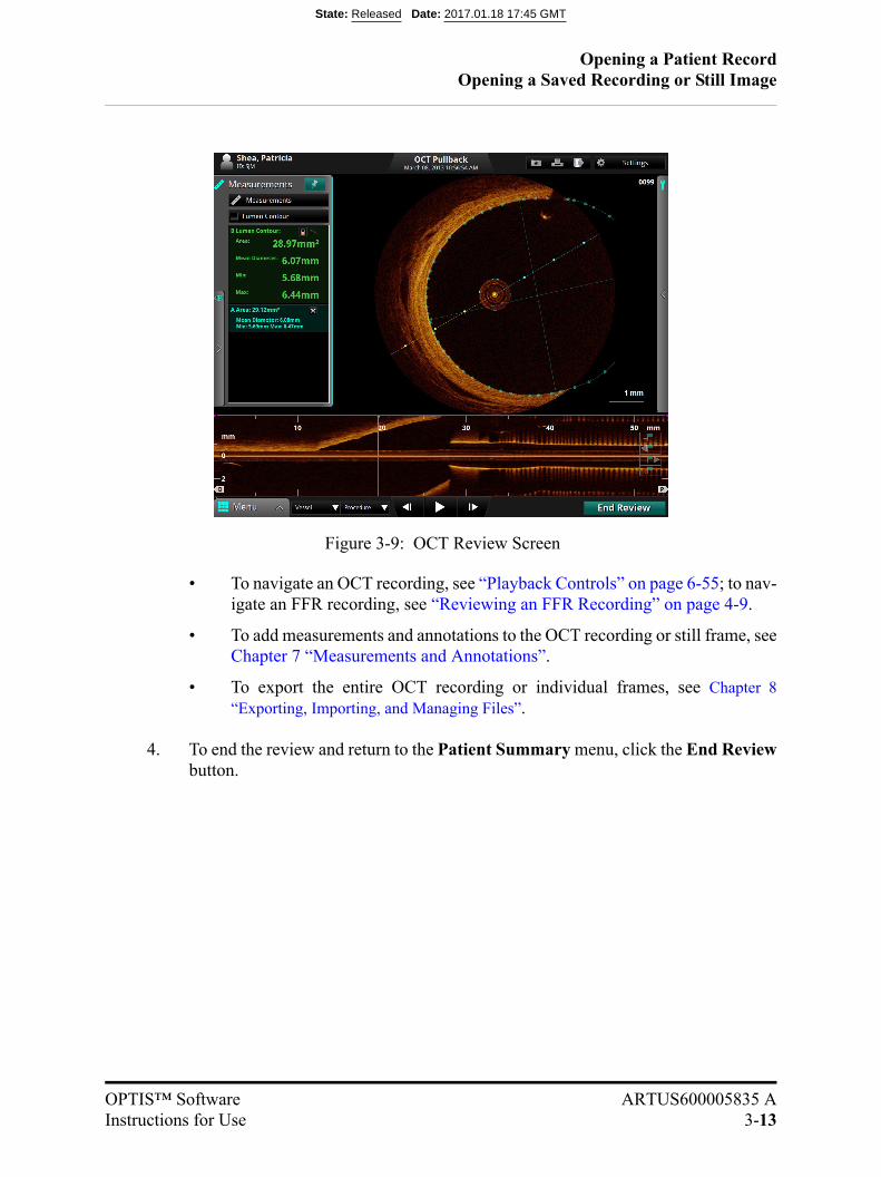
• To navigate an OCT recording, see “Playback Controls” on page 6-55; to nav-igate an FFR recording, see “Reviewing an FFR Recording” on page 4-9.
• To add measurements and annotations to the OCT recording or still frame, seeChapter 7 “Measurements and Annotations”.
• To export the entire OCT recording or individual frames, see Chapter 8“Exporting, Importing, and Managing Files”.
4. To end the review and return to the Patient Summary menu, click the End Reviewbutton.
Figure 3-9: OCT Review Screen
State: Released Date: 2017.01.18 17:45 GMT

Opening a Patient RecordOpening a Saved Recording or Still Image
3-14
State: Released Date: 2017.01.18 17:45 GMT
OPTIS™ Software ARTUS600005835 AInstructions for Use 4-1
Performing an FFR Procedure 4
Setting up the OPTIS™ Software
1. Turn on the system. See “Power On” on page 2-2.
State: Released Date: 2017.01.18 17:45 GMT

Performing an FFR ProcedurePerforming an FFR
4-2
Performing an FFR
The Wi-Box™ unit should be connected to your facility’s Hemodynamic Recording Sys-tem at installation.
1. The screen displays the main screen with the guidance message “Set AO transducerheight to heart level, then open AO transducer to air. Click Zero Pa.” or press theProximal Marker Button on the Tableside Controller.
2. Position the AO transducer so that it is level with the patient’s heart.
NOTE: The AO transducer should remain level with the patient’s heart throughoutthe procedure.
3. Open the AO transducer to air.
Figure 4-1: Set AO transducer height and open AO transducer guidance message
State: Released Date: 2017.01.18 17:45 GMT
Performing an FFR ProcedurePerforming an FFR
OPTIS™ Software ARTUS600005835 AInstructions for Use 4-3
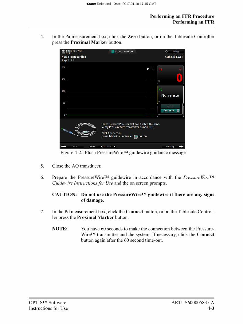
4. In the Pa measurement box, click the Zero button, or on the Tableside Controllerpress the Proximal Marker button.
5. Close the AO transducer.
6. Prepare the PressureWire™ guidewire in accordance with the PressureWire™Guidewire Instructions for Use and the on screen prompts.
CAUTION: Do not use the PressureWire™ guidewire if there are any signsof damage.
7. In the Pd measurement box, click the Connect button, or on the Tableside Control-ler press the Proximal Marker button.
NOTE: You have 60 seconds to make the connection between the Pressure-Wire™ transmitter and the system. If necessary, click the Connectbutton again after the 60 second time-out.
Figure 4-2: Flush PressureWire™ guidewire guidance message
State: Released Date: 2017.01.18 17:45 GMT
Performing an FFR ProcedurePerforming an FFR
4-4
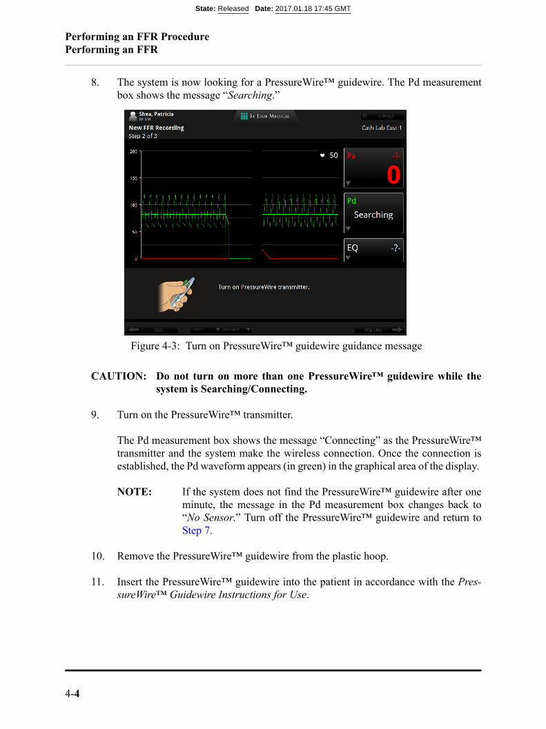
8. The system is now looking for a PressureWire™ guidewire. The Pd measurementbox shows the message “Searching.”
CAUTION: Do not turn on more than one PressureWire™ guidewire while thesystem is Searching/Connecting.
9. Turn on the PressureWire™ transmitter.
The Pd measurement box shows the message “Connecting” as the PressureWire™transmitter and the system make the wireless connection. Once the connection isestablished, the Pd waveform appears (in green) in the graphical area of the display.
NOTE: If the system does not find the PressureWire™ guidewire after oneminute, the message in the Pd measurement box changes back to“No Sensor.” Turn off the PressureWire™ guidewire and return toStep 7.
10. Remove the PressureWire™ guidewire from the plastic hoop.
11. Insert the PressureWire™ guidewire into the patient in accordance with the Pres-sureWire™ Guidewire Instructions for Use.
Figure 4-3: Turn on PressureWire™ guidewire guidance message
State: Released Date: 2017.01.18 17:45 GMT
Performing an FFR ProcedurePerforming an FFR
OPTIS™ Software ARTUS600005835 AInstructions for Use 4-5
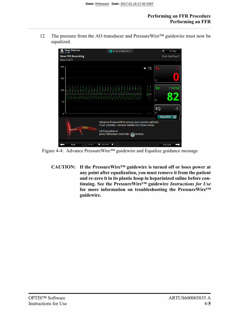
12. The pressure from the AO transducer and PressureWire™ guidewire must now beequalized.
CAUTION: If the PressureWire™ guidewire is turned off or loses power atany point after equalization, you must remove it from the patientand re-zero it in its plastic hoop in heparinized saline before con-tinuing. See the PressureWire™ guidewire Instructions for Usefor more information on troubleshooting the PressureWire™guidewire.
Figure 4-4: Advance PressureWire™ guidewire and Equalize guidance message
State: Released Date: 2017.01.18 17:45 GMT
Performing an FFR ProcedurePerforming an FFR
4-6
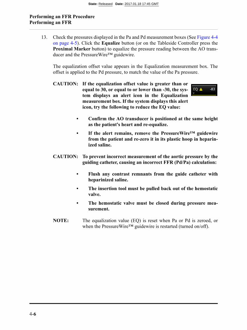
13. Check the pressures displayed in the Pa and Pd measurement boxes (See Figure 4-4on page 4-5). Click the Equalize button (or on the Tableside Controller press theProximal Marker button) to equalize the pressure reading between the AO trans-ducer and the PressureWire™ guidewire.
The equalization offset value appears in the Equalization measurement box. Theoffset is applied to the Pd pressure, to match the value of the Pa pressure.
CAUTION: If the equalization offset value is greater than orequal to 30, or equal to or lower than -30, the sys-tem displays an alert icon in the Equalizationmeasurement box. If the system displays this alerticon, try the following to reduce the EQ value:
• Confirm the AO transducer is positioned at the same heightas the patient's heart and re-equalize.
• If the alert remains, remove the PressureWire™ guidewirefrom the patient and re-zero it in its plastic hoop in heparin-ized saline.
CAUTION: To prevent incorrect measurement of the aortic pressure by theguiding catheter, causing an incorrect FFR (Pd/Pa) calculation:
• Flush any contrast remnants from the guide catheter withheparinized saline.
• The insertion tool must be pulled back out of the hemostaticvalve.
• The hemostatic valve must be closed during pressure mea-surement.
NOTE: The equalization value (EQ) is reset when Pa or Pd is zeroed, orwhen the PressureWire™ guidewire is restarted (turned on/off).
State: Released Date: 2017.01.18 17:45 GMT
Performing an FFR ProcedureRecording FFR
OPTIS™ Software ARTUS600005835 AInstructions for Use 4-7
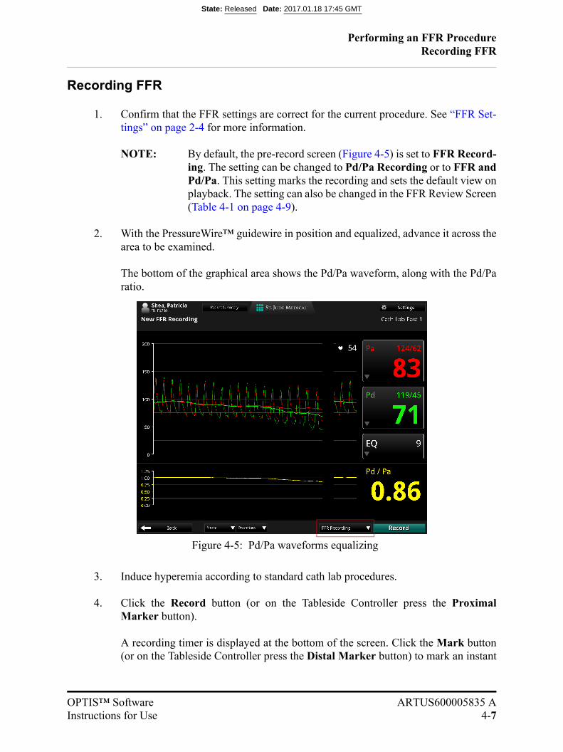
Recording FFR
1. Confirm that the FFR settings are correct for the current procedure. See “FFR Set-tings” on page 2-4 for more information.
NOTE: By default, the pre-record screen (Figure 4-5) is set to FFR Record-ing. The setting can be changed to Pd/Pa Recording or to FFR andPd/Pa. This setting marks the recording and sets the default view onplayback. The setting can also be changed in the FFR Review Screen(Table 4-1 on page 4-9).
2. With the PressureWire™ guidewire in position and equalized, advance it across thearea to be examined.
The bottom of the graphical area shows the Pd/Pa waveform, along with the Pd/Paratio.
3. Induce hyperemia according to standard cath lab procedures.
4. Click the Record button (or on the Tableside Controller press the ProximalMarker button).
A recording timer is displayed at the bottom of the screen. Click the Mark button(or on the Tableside Controller press the Distal Marker button) to mark an instant
Figure 4-5: Pd/Pa waveforms equalizing
State: Released Date: 2017.01.18 17:45 GMT
Performing an FFR ProcedureRecording FFR
4-8
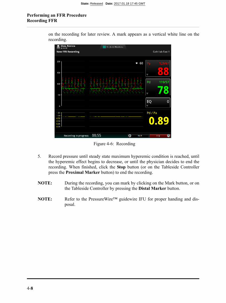
on the recording for later review. A mark appears as a vertical white line on therecording.
5. Record pressure until steady state maximum hyperemic condition is reached, untilthe hyperemic effect begins to decrease, or until the physician decides to end therecording. When finished, click the Stop button (or on the Tableside Controllerpress the Proximal Marker button) to end the recording.
NOTE: During the recording, you can mark by clicking on the Mark button, or onthe Tableside Controller by pressing the Distal Marker button.
NOTE: Refer to the PressureWire™ guidewire IFU for proper handing and dis-posal.
Figure 4-6: Recording
State: Released Date: 2017.01.18 17:45 GMT
Performing an FFR ProcedureReviewing an FFR Recording
OPTIS™ Software ARTUS600005835 AInstructions for Use 4-9
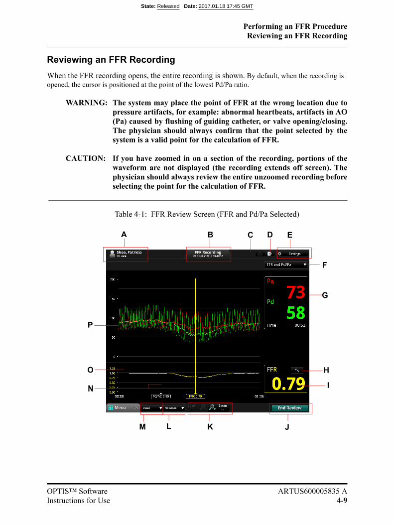
Reviewing an FFR Recording
When the FFR recording opens, the entire recording is shown. By default, when the recording is opened, the cursor is positioned at the point of the lowest Pd/Pa ratio.
WARNING: The system may place the point of FFR at the wrong location due topressure artifacts, for example: abnormal heartbeats, artifacts in AO(Pa) caused by flushing of guiding catheter, or valve opening/closing.The physician should always confirm that the point selected by thesystem is a valid point for the calculation of FFR.
CAUTION: If you have zoomed in on a section of the recording, portions of thewaveform are not displayed (the recording extends off screen). Thephysician should always review the entire unzoomed recording beforeselecting the point for the calculation of FFR.
P
G
HO
K J
N
A C EB
LM
D
Table 4-1: FFR Review Screen (FFR and Pd/Pa Selected)
I
F
State: Released Date: 2017.01.18 17:45 GMT
Performing an FFR ProcedureReviewing an FFR Recording
4-10
A Patient name and ID.
See “Editing Patient Information” on page 3-9 for more information.
B Recording date and time.
C Print file to USB button: Available when a USB drive is connected. Click to print the FFR recording file to a USB drive.
D Export button: Click to open the Export Wizard.
See Chapter 8 “Exporting, Importing, and Managing Files” for more information.
E Settings button: Click to open the FFR Settings menu.
See “FFR Settings” on page 2-4 for more information.
F Select FFR and Pd/Pa, FFR Recording, or Pd/Pa Recording. See Figure 4-7 and Figure 4-8 on page 4-11.
G Pa/Pd measurement box. Mean Pa value at the cursor is displayed. Mean Pd value at the cur-sor is displayed.
H Restore FFR button: After you have moved the FFR cursor during review; click on Restore FFR to reset it to the location it was at when you opened the recording.
NOTE: Upon ending the FFR review, the marker will stay saved to the last point it was on.If it is opened again, the reset button will be grayed out, until the FFR marker isthen again moved.
I The FFR or Pd/Pa value at the cursor (the selected cursor value displays here).
J End Review / New Recording : Click the End Review button to close this window and return to the Patient Summary menu.
NOTE: While the system is connected to a PressureWire™ guidewire, the button Recordappears here. Click the New Recording button to close this review and begin a newFFR recording.
CAUTION: When closing the recording, the current cursor position and correspond-ing FFR value is saved. When the recording is re-opened, the cursorappears at the saved position. The cursor may then be moved, and the dis-played Pa and Pd pressures and FFR value change to reflect the new cur-sor position.
K Zoom in/Zoom out of the recording, centered on the cursor.
L Procedure list: Click to open a drop-down list of procedures to describe this recording.
M Vessel list: Click to open a drop-down list of vessels to describe this recording.
N Move the cursor(s) to read the current value at any point in the recording. The selected cur-sor turns to yellow.
O FFR waveform.
P Pa and Pd pressure waveforms.
State: Released Date: 2017.01.18 17:45 GMT

Performing an FFR ProcedureReviewing an FFR Recording
OPTIS™ Software ARTUS600005835 AInstructions for Use 4-11
If you select FFR Recording, you will see FFR only as in Figure 4-7.
If you select Pd/Pa Recording, you will see Pd/Pa only as in Figure 4-8.
Figure 4-7: FFR Review Screen (FFR Recording Selected)
Figure 4-8: FFR Review Screen (Pd/Pa Recording Selected)
State: Released Date: 2017.01.18 17:45 GMT

Performing an FFR ProcedurePressureWire™ Guidewire Troubleshooting
4-12
PressureWire™ Guidewire Troubleshooting
In case of low power in the PressureWire™ guidewire, the light on thePressureWire™ guidewire unit flashes yellow, and a low battery indica-tor appears in the Pd measurement box.
If there is a problem with your PressureWire™ guidewire, refer to thePressureWire™ Guidewire Instructions for Use for details.
State: Released Date: 2017.01.18 17:45 GMT
OPTIS™ Software ARTUS600005835 AInstructions for Use 5-1
Performing an OCT Procedure 5
Overview
The OCT procedure requires two operators; a sterile operator and a non-sterile operator.All steps requiring contact with the Dragonfly™ Imaging Catheter, the outside of the ster-ile DOC cover, or the draped tableside controller must be performed by the sterile opera-tor. All steps performed within the sterile DOC cover or in direct contact with theOPTIS™ OCT system must be performed by the non-sterile operator. The informationderived from the features of the OPTIS Software are directly dependent on the OCTimage data. Therefore, it is important to have good image quality of the OCT images toensure accurate results. Always review the OCT images for adequate image quality priorto using the software features.
Required Material and Equipment
• OPTIS™ Software
• Dragonfly™ Duo Imaging Catheter or Dragonfly™ OPTIS™ Imaging Catheter
• Sterile DOC Cover
• 3 mL purge syringe
• Contrast media indicated for coronary use, for purging and flush (allow 15 mL foreach run planned)
• 0.014 inch guidewire (with torque device if desired)
• Guide catheter (6 French, 0.068 inch ID or larger, with no side holes)
• Sheath introducer (to match guide catheter)
• Hemostatic Y-Adapter/Connector
• Heparinized, physiologic saline solution, for hydrophilic catheter preparation
• Power injector pump for coronary angiography or manual syringe (capable ofinjecting 4.0 mL /sec for a total of 14 mL in 3.5 seconds)
State: Released Date: 2017.01.18 17:45 GMT

Performing an OCT ProcedureOverview
5-2
OCT Imaging Overview
1. Position - Locate the Dragonfly™ Imaging Catheter relative to the targetlesion/stent.
2. Purge - Clear blood from the catheter lumen, if present, using the attached 3 mLsyringe.
3. Puff - Inject a small amount (~ 4 mL) of contrast through the guide catheter to eval-uate clearance.
If clarity is marginal, check the orientation of the guide catheter and target vessel.
4. Pullback - From Live View, select Enable to start the imaging process.
NOTE: In the left coronary system, guide catheter placement and orientation iskey to achieving good contrast flow. This is particularly true in the LCX.
State: Released Date: 2017.01.18 17:45 GMT
Performing an OCT ProcedureOCT Operating Modes
OPTIS™ Software ARTUS600005835 AInstructions for Use 5-3
OCT Operating Modes
During acquisition, the system is divided into Standby View and Live View.
• Standby View - The DOC is not rotating the imaging catheter. The last imageviewed through the catheter lens is shown on the display.
• Live View - The DOC is rotating the imaging catheter at low-speed, and is trans-mitting images from the catheter lens to the display.
After the image has been recorded, see Chapter 6 “Reviewing OCT Recordings” for moreinformation on reviewing OCT recordings.
OCT Recording Types
The system can make two types of recordings: Pullback (Hi-Res or Survey) and Station-ary. See “Setup - Acquisition Menu” on page 10-2 for more information.
NOTE: Hi-Res is a 54 mm pullback recording with double the frame density ascompared with Survey. Survey is a 75 mm pullback recording with stan-dard frame density.
NOTE: The instructions in this manual are for Pullback recordings. Differencesfor Stationary recordings are noted where applicable.
State: Released Date: 2017.01.18 17:45 GMT
Performing an OCT ProcedureOCT Trigger Types
5-4
OCT Trigger Types
Automatic - The default setting in which the system triggers a pullback automaticallywhen a brief sequence of clear image frames are detected as a result of contrast injection.If the flush injection is not detected within 15 seconds after being enabled, the systemreturns to Live View.
Manual - The system does not perform a pullback until the operator clicks the Start Pull-back button on the screen, or presses the Enable button on the DOC. If the flush injectionis not detected within 15 seconds after being enabled, the system returns to Live View.
State: Released Date: 2017.01.18 17:45 GMT
Performing an OCT ProcedureAngio Co-Registration
OPTIS™ Software ARTUS600005835 AInstructions for Use 5-5
Angio Co-Registration
For systems so enabled, Angio Co-Registration allows the user to align the angiographyand OCT recording so that OCT frames correlate with the corresponding angiographyposition. This functionality allows the user to more easily determine their position in theOCT relative to the lesion and may assist with interventional planning and assessment.See “Reviewing with Angio Co-Registration” on page 6-11 for more information.
Setting up the OPTIS™ Software
1. Turn on the system. See “Power On” on page 2-2.
State: Released Date: 2017.01.18 17:45 GMT

Performing an OCT ProcedurePreparing to Acquire OCT Recordings
5-6
Preparing to Acquire OCT Recordings
New OCT recordings are started from the Patient Summary menu.
1. If necessary, enter the patient’s information. See “Editing Patient Information” onpage 3-9.
NOTE: Patient information should be entered into the system and selectedfor use before beginning a recording.If you are entering a patient through the Add New Patient menu,click the New OCT Recording button (located at the bottom of Step2 of the Add New Patient wizard), and continue with Step 4 below.
2. In the Select Patient menu, click on the patient.
The Patient Summary menu for that patient opens (Figure 3-5 on page 3-7).
3. In the Patient Summary menu, click the New OCT Recording button.
NOTE: If necessary, enter Physician name and Accession number for thiscase, and click OK.
4. If Flush Medium was set to anything other than Contrast for the previous patient,the setting is changed back to Contrast and an alert appears.
The system will ask you to confirm or choose another flush medium, then click OKto close the alert. If you need to change the Flush Medium setting, see “ConfirmRecording Settings” on page 5-10.
State: Released Date: 2017.01.18 17:45 GMT

Performing an OCT ProcedurePreparing to Acquire OCT Recordings
OPTIS™ Software ARTUS600005835 AInstructions for Use 5-7
5. The screen displays the guidance message “Purge catheter with contrast” (Figure5-1).
NOTE: To prevent this guidance message from appearing, check the box next tothe message “Do not show this screen again.”
6. Purge the Dragonfly™ Imaging Catheter per the appropriate Dragonfly™ ImagingCatheter IFU.
Figure 5-1: Purge Catheter guidance message
State: Released Date: 2017.01.18 17:45 GMT
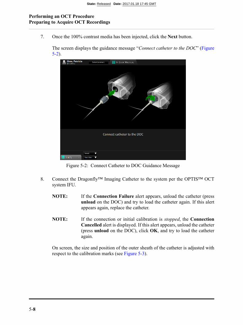
Performing an OCT ProcedurePreparing to Acquire OCT Recordings
5-8
7. Once the 100% contrast media has been injected, click the Next button.
The screen displays the guidance message “Connect catheter to the DOC” (Figure5-2).
8. Connect the Dragonfly™ Imaging Catheter to the system per the OPTIS™ OCTsystem IFU.
NOTE: If the Connection Failure alert appears, unload the catheter (pressunload on the DOC) and try to load the catheter again. If this alertappears again, replace the catheter.
NOTE: If the connection or initial calibration is stopped, the ConnectionCancelled alert is displayed. If this alert appears, unload the catheter(press unload on the DOC), click OK, and try to load the catheteragain.
On screen, the size and position of the outer sheath of the catheter is adjusted withrespect to the calibration marks (see Figure 5-3).
Figure 5-2: Connect Catheter to DOC Guidance Message
State: Released Date: 2017.01.18 17:45 GMT
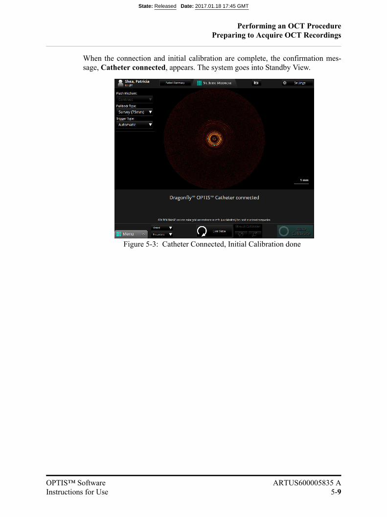
Performing an OCT ProcedurePreparing to Acquire OCT Recordings
OPTIS™ Software ARTUS600005835 AInstructions for Use 5-9
When the connection and initial calibration are complete, the confirmation mes-sage, Catheter connected, appears. The system goes into Standby View.
Figure 5-3: Catheter Connected, Initial Calibration done
State: Released Date: 2017.01.18 17:45 GMT

Performing an OCT ProcedureConfirm Recording Settings
5-10
Confirm Recording Settings
Non-sterile Operator
1. Click the Settings button at the top of the screen.
A context-sensitive Settings menu opens on the right.
Additional pullback settings are displayed in the menu on the left. For AngioCo-Registration, click on the Acquire Angio button. Angiography video inputmust be present for the Acquire Angio button to become live.
2. Confirm all settings are correct for this recording.
NOTE: If Flush Medium has been restricted to Contrast Only, you cannotchange the Flush Medium setting. See “Setup - Acquisition/OtherMenu” on page 10-4 for more information. If Recording Type has been set to Stationary, you cannot change thePullback Length setting. See “Setup - Acquisition Menu” on page10-2 for more information.
CAUTION: To obtain accurate measurements, be sure the selection for theFlush Medium is the same as the medium in which you are imag-ing.
NOTE: Only 100% contrast media is approved for human OCT Imaging.
NOTE: Click the Menu button at the bottom of the screen to open theOPTIS™ Software Setup dialog box. See Chapter 10 “User Inter-face Reference” for more information.
Figure 5-4: OCT Settings Menu (during Recording)
State: Released Date: 2017.01.18 17:45 GMT

Performing an OCT ProcedureDragonfly™ Imaging Catheter Insertion and Positioning
OPTIS™ Software ARTUS600005835 AInstructions for Use 5-11
Dragonfly™ Imaging Catheter Insertion and Positioning
State: Released Date: 2017.01.18 17:45 GMT
Performing an OCT ProcedureDragonfly™ Imaging Catheter Insertion and Positioning
5-12
Sterile Operator
1. POSITION the catheter according to your catheter’s Instructions for Use.
Non-sterile Operator (or Sterile Operator)
2. Press the Live View button (or click on Live View) to start live-scan imaging(low-speed rotation of the imaging core).
CAUTION: Monitor the OCT image for indications of catheter optical fail-ure. If optical failure is suspected, return to Standby View (clickthe Standby View button), remove the catheter, and replace itwith a new one.
3. Calibrate either by clicking on the Auto Calibrate button or by using the ManualCalibration buttons. You can also Auto Calibrate by pressing the Enable buttonon the DOC.
4. Verify calibration as follows:
State: Released Date: 2017.01.18 17:45 GMT
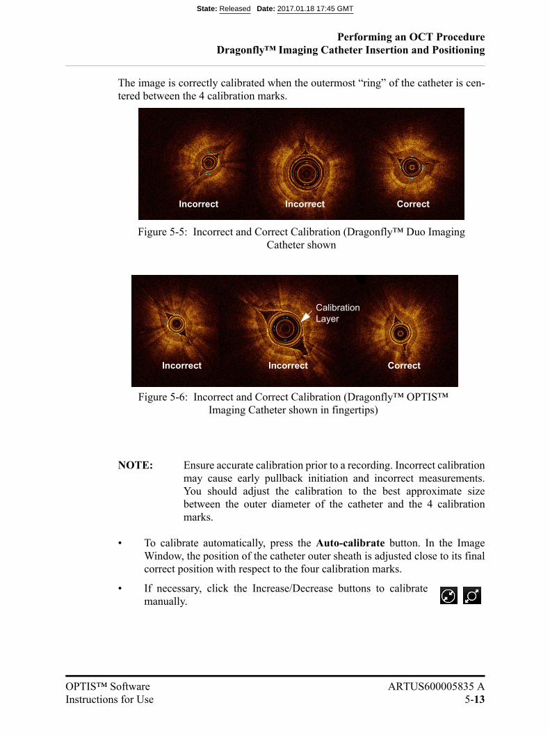
Performing an OCT ProcedureDragonfly™ Imaging Catheter Insertion and Positioning
OPTIS™ Software ARTUS600005835 AInstructions for Use 5-13
The image is correctly calibrated when the outermost “ring” of the catheter is cen-tered between the 4 calibration marks.
NOTE: Ensure accurate calibration prior to a recording. Incorrect calibrationmay cause early pullback initiation and incorrect measurements.You should adjust the calibration to the best approximate sizebetween the outer diameter of the catheter and the 4 calibrationmarks.
• To calibrate automatically, press the Auto-calibrate button. In the ImageWindow, the position of the catheter outer sheath is adjusted close to its finalcorrect position with respect to the four calibration marks.
• If necessary, click the Increase/Decrease buttons to calibratemanually.
Figure 5-5: Incorrect and Correct Calibration (Dragonfly™ Duo Imaging Catheter shown
Incorrect Incorrect Correct
Incorrect Incorrect Correct
Figure 5-6: Incorrect and Correct Calibration (Dragonfly™ OPTIS™ Imaging Catheter shown in fingertips)
Calibration Layer
State: Released Date: 2017.01.18 17:45 GMT
Performing an OCT ProcedureDragonfly™ Imaging Catheter Insertion and Positioning
5-14
Sterile Operator
5. PURGE the catheter according to your catheter’s Instructions for Use.Applicationof negative pressure to draw blood into the catheter is not recommended. Blood inthe catheter lumen will obscure the image and can be difficult to completely purge.
6. Ensure the guide catheter is oriented to preferentially direct contrast flow to the tar-get artery, and verify angiographically that adequate flow of contrast is delivered tothe artery.
NOTE: PUFF-- Injecting a small “puff” of contrast while reviewing theimage on screen to verify that adequate flow of contrast is deliveredto the artery.
7. The operator can inject the media either by manual flush or automated injector. Ifusing an automated injector, verify the following for flush delivery:
• 4 ml/sec or less flush rate.
• 14 ml total flush volume.
• If using an automated injector, pressure limit 300 psi, or the nearest availablesetting.
8. Verify the stopcock position on the manifold is set to allow flow from the injectionpump into the guide catheter.
State: Released Date: 2017.01.18 17:45 GMT
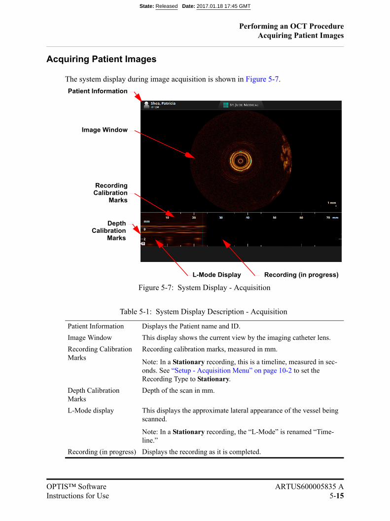
Performing an OCT ProcedureAcquiring Patient Images
OPTIS™ Software ARTUS600005835 AInstructions for Use 5-15
Acquiring Patient Images
The system display during image acquisition is shown in Figure 5-7.
Table 5-1: System Display Description - Acquisition
Patient Information Displays the Patient name and ID.
Image Window This display shows the current view by the imaging catheter lens.
Recording Calibration Marks
Recording calibration marks, measured in mm.
Note: In a Stationary recording, this is a timeline, measured in sec-onds. See “Setup - Acquisition Menu” on page 10-2 to set the Recording Type to Stationary.
Depth Calibration Marks
Depth of the scan in mm.
L-Mode display This displays the approximate lateral appearance of the vessel being scanned.
Note: In a Stationary recording, the “L-Mode” is renamed “Time-line.”
Recording (in progress) Displays the recording as it is completed.
Recording (in progress)
RecordingCalibration
Marks
L-Mode Display
Figure 5-7: System Display - Acquisition
Image Window
Depth
Patient Information
CalibrationMarks
State: Released Date: 2017.01.18 17:45 GMT

Performing an OCT ProcedureAcquiring Patient Images
5-16
Non-sterile Operator
NOTE: If you are performing a Stationary recording, the Enable Pullback andStart Pullback buttons are replaced with a Start Recording button. Donot press the Start Recording button until you have notified the sterileoperator that the system is ready, and that the contrast media has beeninjected. Clicking the Start Recording button (or Sterile Operator press-ing the Enable button on the DOC) begins the recording immediately; thesystem does not wait for a clearing from the contrast injection.
1. With the system in Live View, calibrate either by clicking on the Auto Calibratebutton or by using the Manual Calibration buttons (or Sterile Operator press theEnable button on the DOC). Click the Enable Pullback button (or Sterile Operatorpress the Enable button on the DOC) to allow the system to detect initiation of theimaging flush.
You have 15 seconds to initiate the flush for the pullback.
NOTE: When acquiring the angiographic images for Angio Co-Registration,with a corresponding OCT recording, the X-ray imaging equipmentmust be stationary throughout the X-Ray Video. For best results,choose the view that minimizes occurrences of vessel foreshorteningand branch overlapping. This should minimize co-registration inac-curacies.
• LAO Caudal view or “spider view” may produce inaccurateresults due to severe foreshortening. Spider view may be used toobtain side-by-side, time-synchronized display of angiographicand OCT images even in the presence of severe foreshortening,but automated co-registration results may be limited.
• Note that the presence of radio-opaque objects or devices thatoverlap the target vessel may impair the performance of theAngio Co-registration feature.
• Ensure the X-Ray Video captures the entire OCT pullback and theradiopaque tip of the guidewire, within one stationary field ofview.
• Do not use a frame rate of less than 15 frames per second (fps) ormore than 30 fps during acquisition of X-Ray Video.
2. Notify the Sterile Operator that the system is enabled.
State: Released Date: 2017.01.18 17:45 GMT
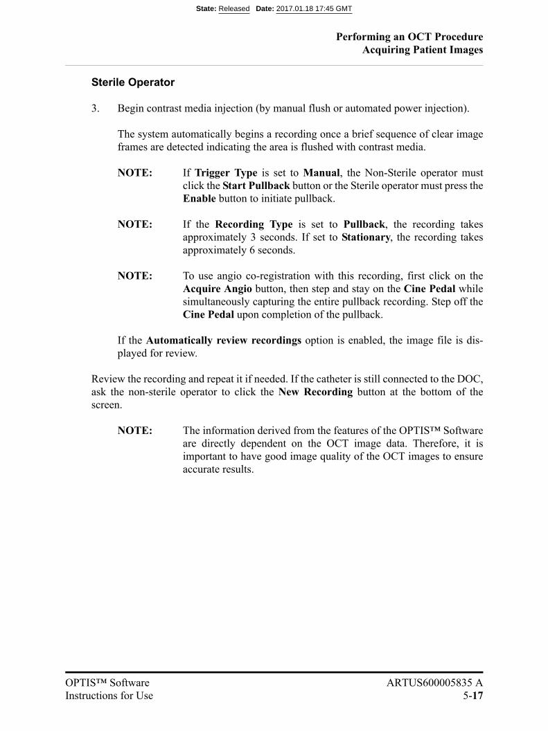
Performing an OCT ProcedureAcquiring Patient Images
OPTIS™ Software ARTUS600005835 AInstructions for Use 5-17
Sterile Operator
3. Begin contrast media injection (by manual flush or automated power injection).
The system automatically begins a recording once a brief sequence of clear imageframes are detected indicating the area is flushed with contrast media.
NOTE: If Trigger Type is set to Manual, the Non-Sterile operator mustclick the Start Pullback button or the Sterile operator must press theEnable button to initiate pullback.
NOTE: If the Recording Type is set to Pullback, the recording takesapproximately 3 seconds. If set to Stationary, the recording takesapproximately 6 seconds.
NOTE: To use angio co-registration with this recording, first click on theAcquire Angio button, then step and stay on the Cine Pedal whilesimultaneously capturing the entire pullback recording. Step off theCine Pedal upon completion of the pullback.
If the Automatically review recordings option is enabled, the image file is dis-played for review.
Review the recording and repeat it if needed. If the catheter is still connected to the DOC,ask the non-sterile operator to click the New Recording button at the bottom of thescreen.
NOTE: The information derived from the features of the OPTIS™ Softwareare directly dependent on the OCT image data. Therefore, it isimportant to have good image quality of the OCT images to ensureaccurate results.
State: Released Date: 2017.01.18 17:45 GMT
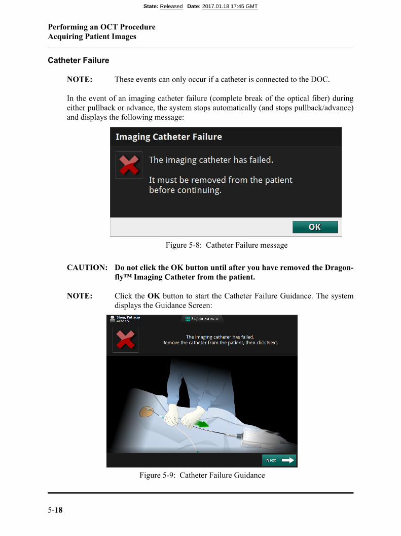
Performing an OCT ProcedureAcquiring Patient Images
5-18
Catheter Failure
NOTE: These events can only occur if a catheter is connected to the DOC.
In the event of an imaging catheter failure (complete break of the optical fiber) duringeither pullback or advance, the system stops automatically (and stops pullback/advance)and displays the following message:
CAUTION: Do not click the OK button until after you have removed the Dragon-fly™ Imaging Catheter from the patient.
NOTE: Click the OK button to start the Catheter Failure Guidance. The systemdisplays the Guidance Screen:
Figure 5-8: Catheter Failure message
Figure 5-9: Catheter Failure Guidance
State: Released Date: 2017.01.18 17:45 GMT
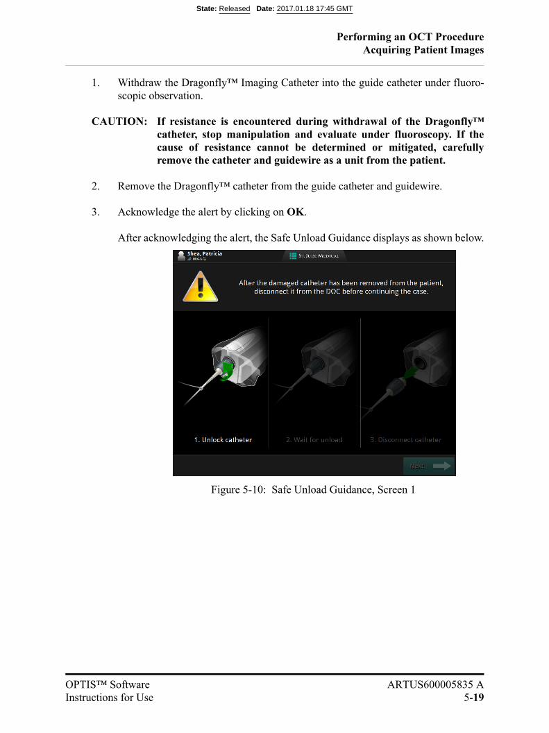
Performing an OCT ProcedureAcquiring Patient Images
OPTIS™ Software ARTUS600005835 AInstructions for Use 5-19
1. Withdraw the Dragonfly™ Imaging Catheter into the guide catheter under fluoro-scopic observation.
CAUTION: If resistance is encountered during withdrawal of the Dragonfly™catheter, stop manipulation and evaluate under fluoroscopy. If thecause of resistance cannot be determined or mitigated, carefullyremove the catheter and guidewire as a unit from the patient.
2. Remove the Dragonfly™ catheter from the guide catheter and guidewire.
3. Acknowledge the alert by clicking on OK.
After acknowledging the alert, the Safe Unload Guidance displays as shown below.
Figure 5-10: Safe Unload Guidance, Screen 1
State: Released Date: 2017.01.18 17:45 GMT
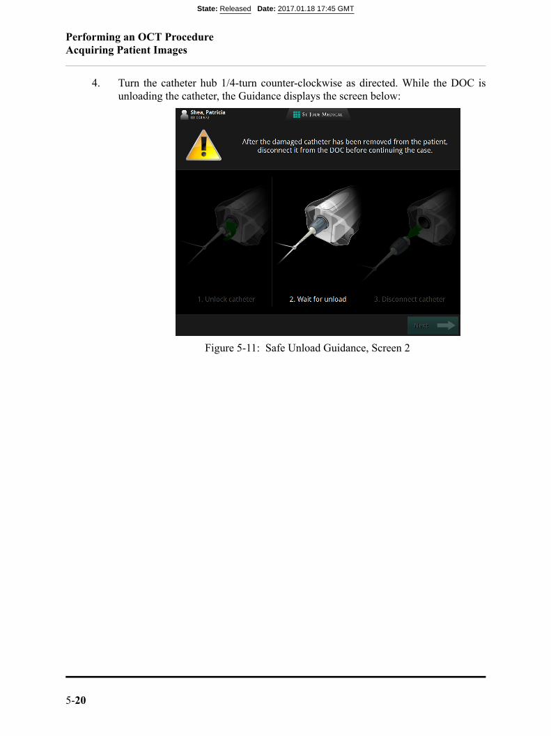
Performing an OCT ProcedureAcquiring Patient Images
5-20
4. Turn the catheter hub 1/4-turn counter-clockwise as directed. While the DOC isunloading the catheter, the Guidance displays the screen below:
Figure 5-11: Safe Unload Guidance, Screen 2
State: Released Date: 2017.01.18 17:45 GMT
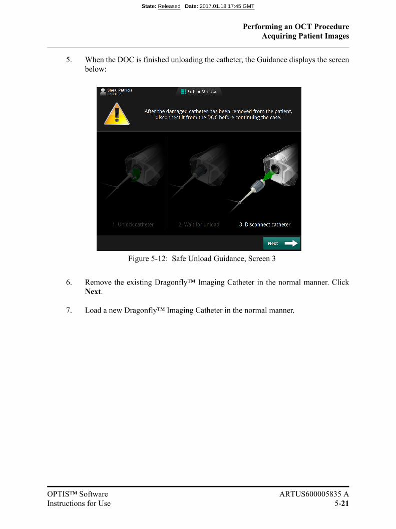
Performing an OCT ProcedureAcquiring Patient Images
OPTIS™ Software ARTUS600005835 AInstructions for Use 5-21
5. When the DOC is finished unloading the catheter, the Guidance displays the screenbelow:
6. Remove the existing Dragonfly™ Imaging Catheter in the normal manner. ClickNext.
7. Load a new Dragonfly™ Imaging Catheter in the normal manner.
Figure 5-12: Safe Unload Guidance, Screen 3
State: Released Date: 2017.01.18 17:45 GMT

Performing an OCT ProcedureAcquiring Patient Images
5-22
State: Released Date: 2017.01.18 17:45 GMT

OPTIS™ Software ARTUS600005835 AInstructions for Use 6-1
Reviewing OCT Recordings 6
NOTE: The availability of the OPTIS™ Software feature set is determined by theOPTIS™ OCT system and OPTIS™ Software configuration: Not all soft-ware features described below are available in all system and softwareconfigurations.
The OPTIS™ Software features as related to configurations are summarized in the tablebelow:
NOTE: The OPTIS™ Software features are derived from the OCT images andhighlight information already present in the OCT image data for improved
Table 6-1: OPTIS™ Software Features
FeatureOPTIS™
Metallic Stent Optimization
OPTIS™ Software Upgrade
Angio Co-Registration
Stent Roadmap (Reference frame markers and Bookmarks)
X
Apposition Indicator X
Advanced Display
3D Bifurcation X
3D Navigation X X
3D Options Menu for 3D Advanced Displays
Guidewires X
Side Branch(es) X
Display Modes (Tissue+Lumen, Lumen, Stent Only)
X
Flythrough X
Stent Display Apposition Indicator X
Rendered Stent X
State: Released Date: 2017.01.18 17:45 GMT

Reviewing OCT Recordings
6-2
ease of use. The results of these features must be used in conjunction witha thorough review of the cross-sectional OCT image and L-Mode forproper interpretation and assessment. They are not intended to replace thereviewing of the OCT images.
NOTE: Making measurements, calculations, and text annotations is covered inChapter 7 “Measurements and Annotations”. Exporting images is coveredin Chapter 8 “Exporting, Importing, and Managing Files”.
State: Released Date: 2017.01.18 17:45 GMT

Reviewing OCT RecordingsImage Window
OPTIS™ Software ARTUS600005835 AInstructions for Use 6-3
Image Window
When reviewing recordings, the Image Window shows a cross-section of the pullback orstill frame (Table 6-2 and Table 6-3).
Table 6-2: OCT Display Overview (upper section)
A Patient name and ID.
See “Editing Patient Information” on page 3-9 for more information.
B Recording date and time.
C Lumen Contour Measurements: Displays either Mean Diameter or Area of the cross sec-tion. The display setting can be changed at “Setup - Lumen Profile” on page 10-25
D Capture button: Available on a still frame or paused recording. Click to save the current frame.
E Print button: Available when a USB drive is connected and the system is displaying a still frame or paused recording. Click to print the current frame to file.
See “Printing Still Images” on page 6-62 for more information.
F Export button: Click to open the Export Wizard.
See Chapter 8 “Exporting, Importing, and Managing Files” for more information.
AE G
H
I
P
B D
K
F
M
O
N
Q
L
I
J
C
State: Released Date: 2017.01.18 17:45 GMT
Reviewing OCT RecordingsImage Window
6-4
G Settings button: Click to open the (Playback) Settings menu.
See “Calibration Adjustment (Tableside Controller Connected)” on page 6-58 for more information.
H Frame number: Only visible on a paused recording when Tool Panel is closed.
I Tool Panel containing Measurement and Annotation tools: Use these to add measurements, calculations, and add text to recordings and still images.
See Chapter 7 “Measurements and Annotations” for more information.
J Cut-Plane Indicator: The cut-plane is shown as a solid line in the cross-sectional view. Click and drag this to change the lateral view shown in the L-Mode display.
K Image Window: A cross-sectional view of the current location of the pullback.
L OCT Frame Indicator (Angio Co-Registration view): Representation in the Angiography Window of the L-Mode Current Frame Indicator.
M View Menu: Includes the Advanced Display, Lumen Profile and Rendered Stent sub-menus.
N Stent Roadmap: This group of markers comprises the Proximal Marker, Distal Marker, MLA Marker, and Bookmarks,
O Markers On/Off Button: Click to turn on and off all indicators in Ango Co-Registration view with the exception of the OCT Frame Indicator.
P Measurements Menu: This section lists measurements from the current image; click on a measurement to highlight it in the Image Window.
Q View Mode (all advanced display views): Click to toggle between Window mode (shown above) and Full Screen Mode. Also available as a button on the Tableside Controller.
State: Released Date: 2017.01.18 17:45 GMT
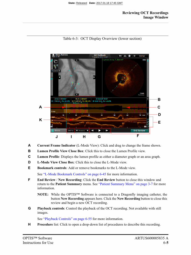
Reviewing OCT RecordingsImage Window
OPTIS™ Software ARTUS600005835 AInstructions for Use 6-5
Table 6-3: OCT Display Overview (lower section)
A Current Frame Indicator (L-Mode View): Click and drag to change the frame shown.
B Lumen Profile View Close Box: Click this to close the Lumen Profile view.
C Lumen Profile: Displays the lumen profile as either a diameter graph or an area graph.
D L-Mode View Close Box: Click this to close the L-Mode view.
E Bookmark controls: Add or remove bookmarks to the L-Mode view.
See “L-Mode Bookmark Controls” on page 6-45 for more information.
F End Review / New Recording: Click the End Review button to close this window and return to the Patient Summary menu. See “Patient Summary Menu” on page 3-7 for more information.
NOTE: While the OPTIS™ Software is connected to a Dragonfly imaging catheter, thebutton New Recording appears here. Click the New Recording button to close thisreview and begin a new OCT recording.
G Playback controls: Control the playback of the OCT recording. Not available with still images.
See “Playback Controls” on page 6-55 for more information.
H Procedure list: Click to open a drop-down list of procedures to describe this recording.
E
G
K
HIJ F
B
D
A C
State: Released Date: 2017.01.18 17:45 GMT
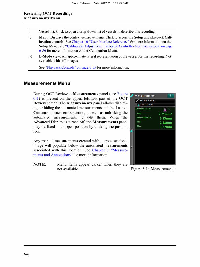
Reviewing OCT RecordingsMeasurements Menu
6-6
Measurements Menu
During OCT Review, a Measurements panel (see Figure6-1) is present on the upper, leftmost part of the OCTReview screen. The Measurements panel allows display-ing or hiding the automated measurements and the LumenContour of each cross-section, as well as unlocking theautomated measurements to edit them. When theAdvanced Display is turned off, the Measurements panelmay be fixed in an open position by clicking the pushpinicon.
Any manual measurements created with a cross-sectionalimage will populate below the automated measurementsassociated with this location. See Chapter 7 “Measure-ments and Annotations” for more information.
NOTE: Menu items appear darker when they arenot available.
I Vessel list: Click to open a drop-down list of vessels to describe this recording.
J Menu: Displays the context-sensitive menu. Click to access the Setup and playback Cali-bration controls. See Chapter 10 “User Interface Reference” for more information on the Setup Menu; see “Calibration Adjustment (Tableside Controller Not Connected)” on page 6-56 for more information on the Calibration Menu.
K L-Mode view: An approximate lateral representation of the vessel for this recording. Not available with still images.
See “Playback Controls” on page 6-55 for more information.
Figure 6-1: Measurements
XX
State: Released Date: 2017.01.18 17:45 GMT
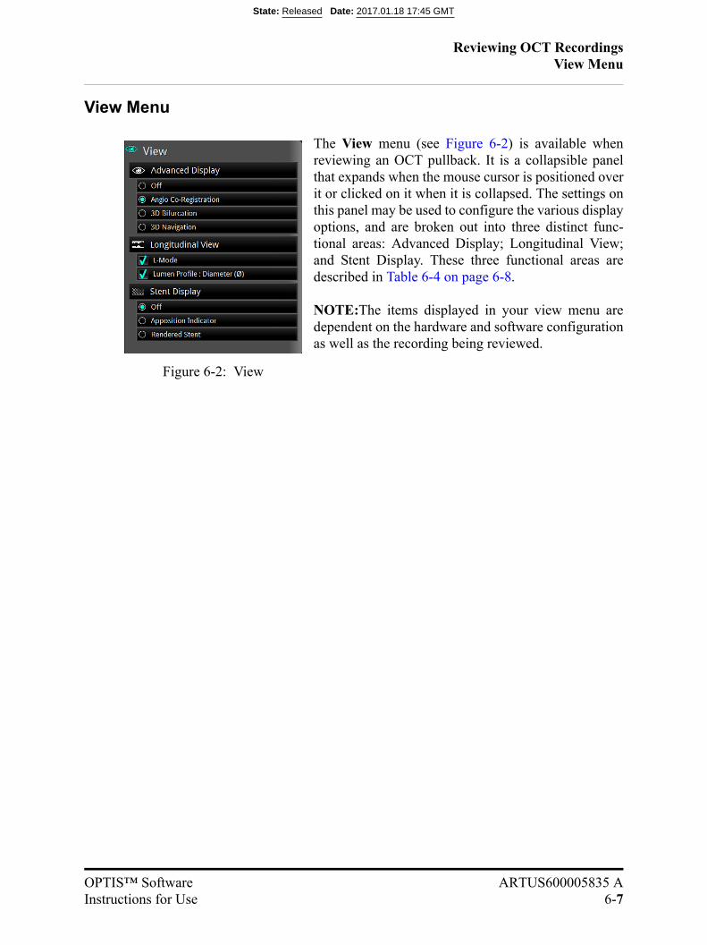
Reviewing OCT RecordingsView Menu
OPTIS™ Software ARTUS600005835 AInstructions for Use 6-7
View Menu
The View menu (see Figure 6-2) is available whenreviewing an OCT pullback. It is a collapsible panelthat expands when the mouse cursor is positioned overit or clicked on it when it is collapsed. The settings onthis panel may be used to configure the various displayoptions, and are broken out into three distinct func-tional areas: Advanced Display; Longitudinal View;and Stent Display. These three functional areas aredescribed in Table 6-4 on page 6-8.
NOTE:The items displayed in your view menu aredependent on the hardware and software configurationas well as the recording being reviewed.
Figure 6-2: View
State: Released Date: 2017.01.18 17:45 GMT
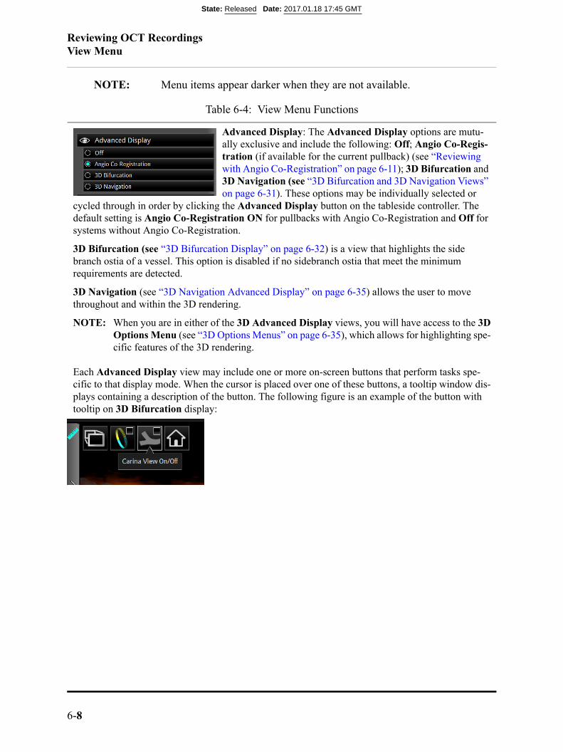
Reviewing OCT RecordingsView Menu
6-8
NOTE: Menu items appear darker when they are not available.
Table 6-4: View Menu Functions
Advanced Display: The Advanced Display options are mutu-ally exclusive and include the following: Off; Angio Co-Regis-tration (if available for the current pullback) (see “Reviewing with Angio Co-Registration” on page 6-11); 3D Bifurcation and 3D Navigation (see “3D Bifurcation and 3D Navigation Views” on page 6-31). These options may be individually selected or
cycled through in order by clicking the Advanced Display button on the tableside controller. The default setting is Angio Co-Registration ON for pullbacks with Angio Co-Registration and Off for systems without Angio Co-Registration.
3D Bifurcation (see “3D Bifurcation Display” on page 6-32) is a view that highlights the side branch ostia of a vessel. This option is disabled if no sidebranch ostia that meet the minimum requirements are detected.
3D Navigation (see “3D Navigation Advanced Display” on page 6-35) allows the user to move throughout and within the 3D rendering.
NOTE: When you are in either of the 3D Advanced Display views, you will have access to the 3DOptions Menu (see “3D Options Menus” on page 6-35), which allows for highlighting spe-cific features of the 3D rendering.
Each Advanced Display view may include one or more on-screen buttons that perform tasks spe-cific to that display mode. When the cursor is placed over one of these buttons, a tooltip window dis-plays containing a description of the button. The following figure is an example of the button with tooltip on 3D Bifurcation display:
State: Released Date: 2017.01.18 17:45 GMT

Reviewing OCT RecordingsView Menu
OPTIS™ Software ARTUS600005835 AInstructions for Use 6-9
Longitudinal View: This sub menu displays the 2D, lateral renderings of the OCT and OCT-derived measurements throughout the pullback.
• L-Mode: During the OCT pullback recording, the system captures evenlyspaced cross-sectional images and uses them to construct a lateral view ofthe vessel anatomy. The lateral view is shown in the L-Mode display in thelowest portion of the screen; the distal portion of the recording is to the left.
NOTE: If reviewing a Stationary recording, the L-Mode display is renamedTimeline. The Timeline represents the stationary view of the catheterduring the six seconds of recording.
• Lumen Profile; Displays the lumen profile as either a diameter graph or anarea graph (Lumen Profile units are selectable in Setup > Lumen Profile“Setup - Lumen Profile” on page 10-25). For pullbacks, Lumen Profile alsodisplays the minimum lumen area controls and values for the recording.
• For information on customizing MLA info, see “Setup - Lumen Profile” onpage 10-25.
NOTE: MLA computations are not available with still images or stationaryrecordings.
Stent Display: The Stent Display options are dependent on the platform configuration. When available, Stent Display options are disabled if no stent is detected during pullback. The Stent Display options are mutually exclusive and include the follow-ing: Off, Apposition Indicator (see “Stent Apposition Indica-tor” on page 6-51), and Rendered Stent (see “Rendered Stent
Display” on page 6-53). The default setting is Off, and is reset each time a new recording is loaded. The Apposition Indicator options are described in “Tools Menu” on page 6-10. The Rendered Stent options are described in “Rendered Stent Display” on page 6-53.
Table 6-4: View Menu Functions
State: Released Date: 2017.01.18 17:45 GMT
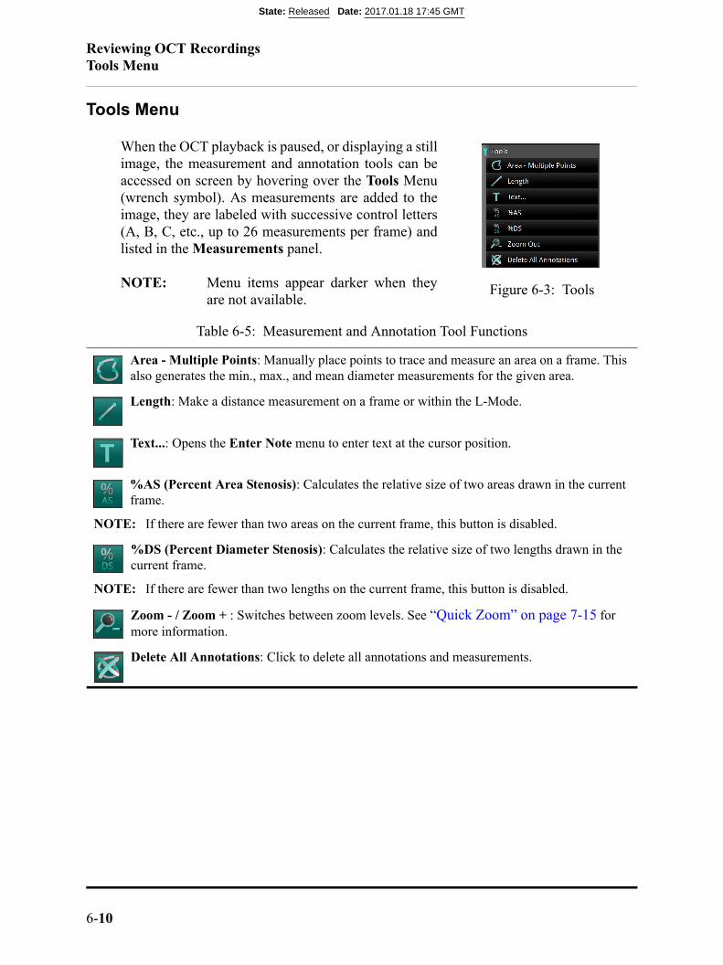
Reviewing OCT RecordingsTools Menu
6-10
Tools Menu
When the OCT playback is paused, or displaying a stillimage, the measurement and annotation tools can beaccessed on screen by hovering over the Tools Menu(wrench symbol). As measurements are added to theimage, they are labeled with successive control letters(A, B, C, etc., up to 26 measurements per frame) andlisted in the Measurements panel.
NOTE: Menu items appear darker when theyare not available.
Table 6-5: Measurement and Annotation Tool Functions
Area - Multiple Points: Manually place points to trace and measure an area on a frame. This also generates the min., max., and mean diameter measurements for the given area.
Length: Make a distance measurement on a frame or within the L-Mode.
Text...: Opens the Enter Note menu to enter text at the cursor position.
%AS (Percent Area Stenosis): Calculates the relative size of two areas drawn in the current frame.
NOTE: If there are fewer than two areas on the current frame, this button is disabled.
%DS (Percent Diameter Stenosis): Calculates the relative size of two lengths drawn in the current frame.
NOTE: If there are fewer than two lengths on the current frame, this button is disabled.
Zoom - / Zoom + : Switches between zoom levels. See “Quick Zoom” on page 7-15 for more information.
Delete All Annotations: Click to delete all annotations and measurements.
Figure 6-3: Tools
State: Released Date: 2017.01.18 17:45 GMT

Reviewing OCT RecordingsReviewing with Angio Co-Registration
OPTIS™ Software ARTUS600005835 AInstructions for Use 6-11
Reviewing with Angio Co-Registration
Only pullback images that contain Angio Co-Registration data can be used for thistype of review. Identify the presence of Angio Co-Registration data by locating ablack and white angiographic thumbnail image in the upper-left corner of the pull-back on the Patient Summary screen.
1. From the Patient Summary screen, identify a pullback that contains a black andwhite angiographic thumbnail image in the upper-left corner.
2. Click the review button. The OCT review begins to playback.
NOTE: Please contact your St. Jude Medical Service Representative (see“Contacting St. Jude Medical Service” on page 9-2) to calibrateAngio Co-Registration if any of the following has occurred:
• Angiography system is upgraded or a new system installed
• Any repairs or changes relating to the angiography video processor
• Any repairs or changes to the cables between the system cabinet and theangiography system
• Any upgrades to the angiography system software
Figure 6-4: Angio-Coregistration Thumbnail Image
State: Released Date: 2017.01.18 17:45 GMT
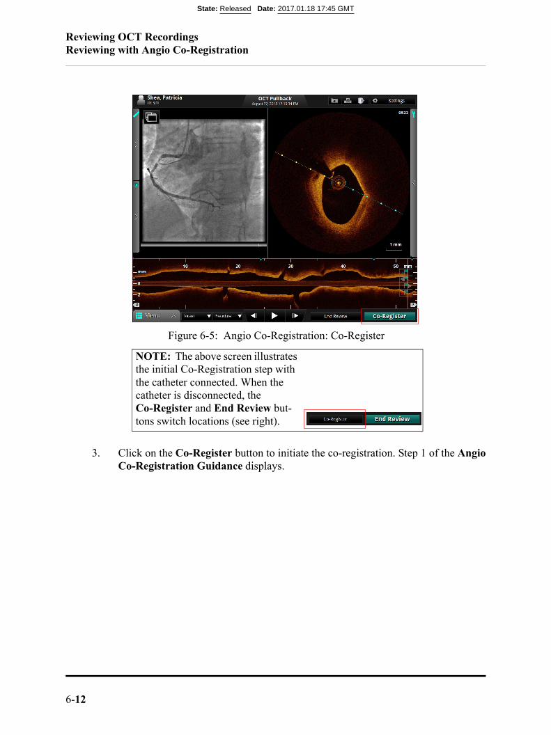
Reviewing OCT RecordingsReviewing with Angio Co-Registration
6-12
3. Click on the Co-Register button to initiate the co-registration. Step 1 of the AngioCo-Registration Guidance displays.
NOTE: The above screen illustrates the initial Co-Registration step with the catheter connected. When the catheter is disconnected, the Co-Register and End Review but-tons switch locations (see right).
Figure 6-5: Angio Co-Registration: Co-Register
State: Released Date: 2017.01.18 17:45 GMT
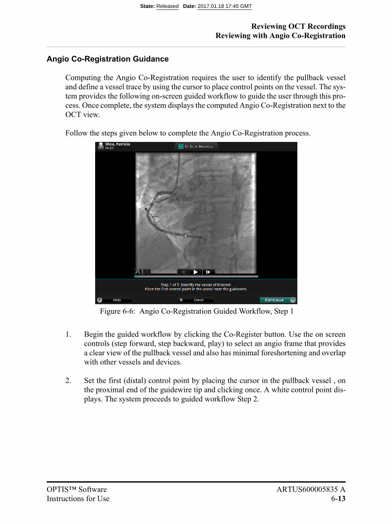
Reviewing OCT RecordingsReviewing with Angio Co-Registration
OPTIS™ Software ARTUS600005835 AInstructions for Use 6-13
Angio Co-Registration Guidance
Computing the Angio Co-Registration requires the user to identify the pullback vesseland define a vessel trace by using the cursor to place control points on the vessel. The sys-tem provides the following on-screen guided workflow to guide the user through this pro-cess. Once complete, the system displays the computed Angio Co-Registration next to theOCT view.
Follow the steps given below to complete the Angio Co-Registration process.
1. Begin the guided workflow by clicking the Co-Register button. Use the on screencontrols (step forward, step backward, play) to select an angio frame that providesa clear view of the pullback vessel and also has minimal foreshortening and overlapwith other vessels and devices.
2. Set the first (distal) control point by placing the cursor in the pullback vessel , onthe proximal end of the guidewire tip and clicking once. A white control point dis-plays. The system proceeds to guided workflow Step 2.
Figure 6-6: Angio Co-Registration Guided Workflow, Step 1
State: Released Date: 2017.01.18 17:45 GMT
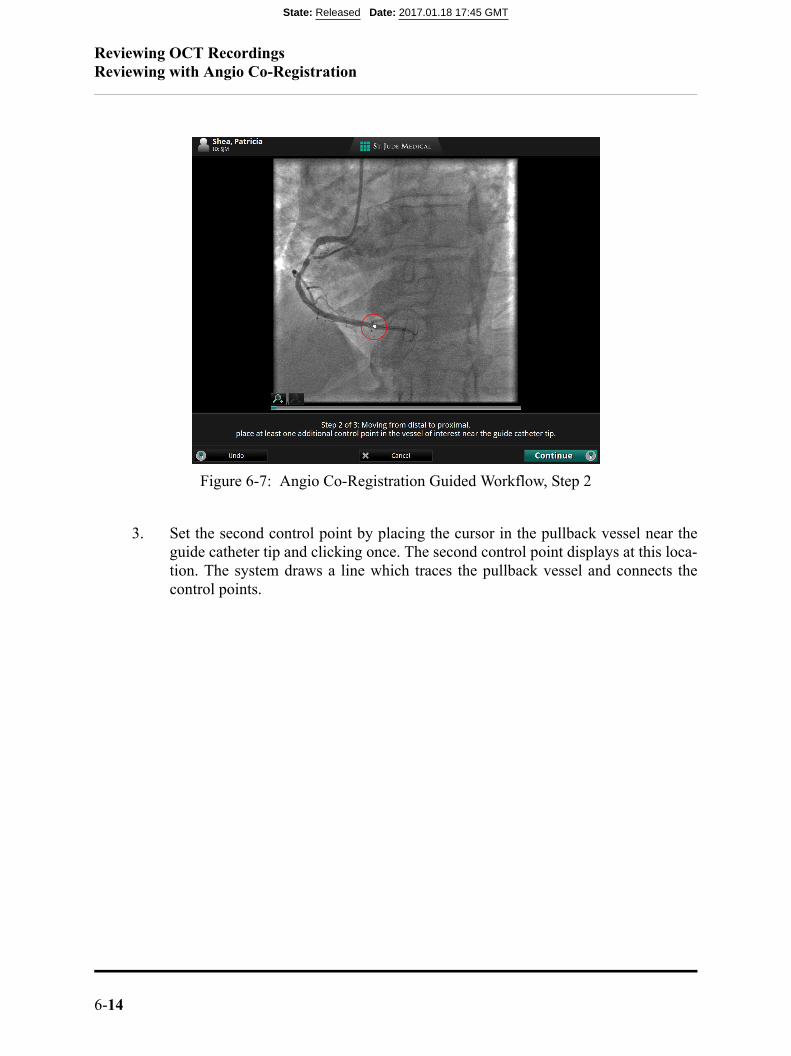
Reviewing OCT RecordingsReviewing with Angio Co-Registration
6-14
3. Set the second control point by placing the cursor in the pullback vessel near theguide catheter tip and clicking once. The second control point displays at this loca-tion. The system draws a line which traces the pullback vessel and connects thecontrol points.
Figure 6-7: Angio Co-Registration Guided Workflow, Step 2
State: Released Date: 2017.01.18 17:45 GMT
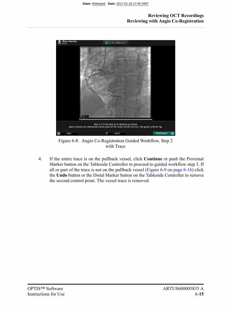
Reviewing OCT RecordingsReviewing with Angio Co-Registration
OPTIS™ Software ARTUS600005835 AInstructions for Use 6-15
4. If the entire trace is on the pullback vessel, click Continue or push the ProximalMarker button on the Tableside Controller to proceed to guided workflow step 3. Ifall or part of the trace is not on the pullback vessel (Figure 6-9 on page 6-16) clickthe Undo button or the Distal Marker button on the Tableside Controller to removethe second control point. The vessel trace is removed.
Figure 6-8: Angio Co-Registration Guided Workflow, Step 2 with Trace
State: Released Date: 2017.01.18 17:45 GMT
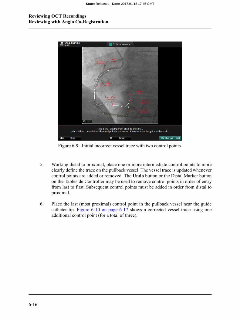
Reviewing OCT RecordingsReviewing with Angio Co-Registration
6-16
5. Working distal to proximal, place one or more intermediate control points to moreclearly define the trace on the pullback vessel. The vessel trace is updated whenevercontrol points are added or removed. The Undo button or the Distal Marker buttonon the Tableside Controller may be used to remove control points in order of entryfrom last to first. Subsequent control points must be added in order from distal toproximal.
6. Place the last (most proximal) control point in the pullback vessel near the guidecatheter tip. Figure 6-10 on page 6-17 shows a corrected vessel trace using oneadditional control point (for a total of three).
Figure 6-9: Initial incorrect vessel trace with two control points.
State: Released Date: 2017.01.18 17:45 GMT
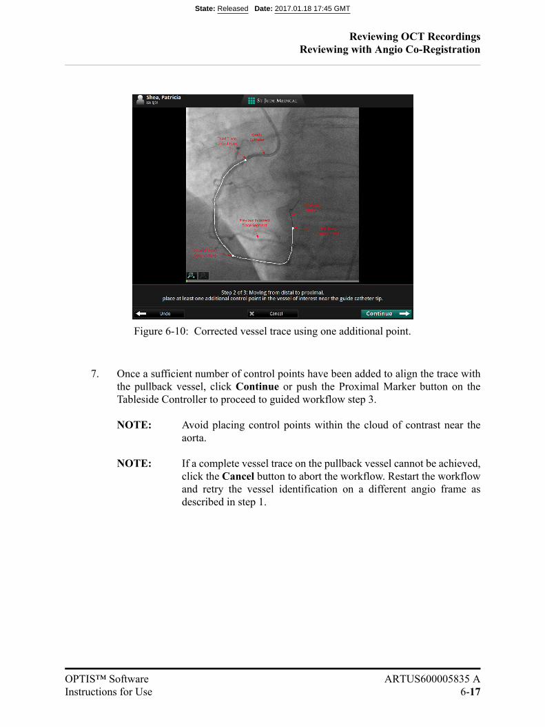
Reviewing OCT RecordingsReviewing with Angio Co-Registration
OPTIS™ Software ARTUS600005835 AInstructions for Use 6-17
7. Once a sufficient number of control points have been added to align the trace withthe pullback vessel, click Continue or push the Proximal Marker button on theTableside Controller to proceed to guided workflow step 3.
NOTE: Avoid placing control points within the cloud of contrast near theaorta.
NOTE: If a complete vessel trace on the pullback vessel cannot be achieved,click the Cancel button to abort the workflow. Restart the workflowand retry the vessel identification on a different angio frame asdescribed in step 1.
Figure 6-10: Corrected vessel trace using one additional point.
State: Released Date: 2017.01.18 17:45 GMT
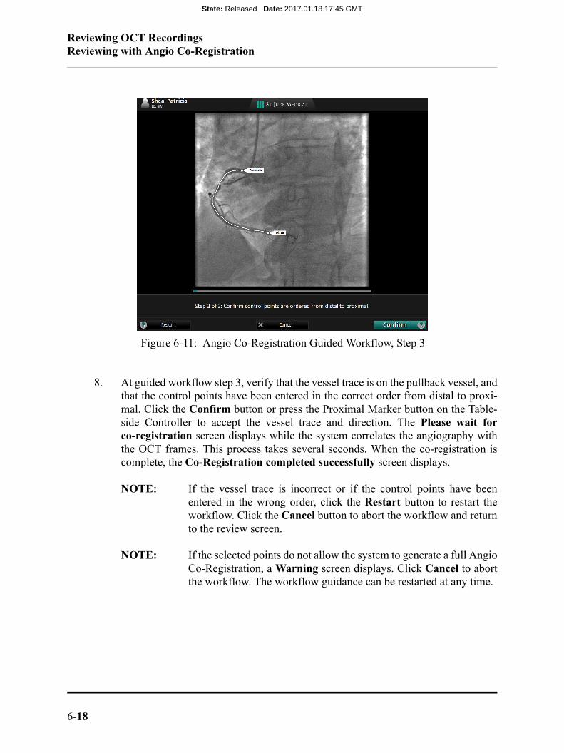
Reviewing OCT RecordingsReviewing with Angio Co-Registration
6-18
8. At guided workflow step 3, verify that the vessel trace is on the pullback vessel, andthat the control points have been entered in the correct order from distal to proxi-mal. Click the Confirm button or press the Proximal Marker button on the Table-side Controller to accept the vessel trace and direction. The Please wait forco-registration screen displays while the system correlates the angiography withthe OCT frames. This process takes several seconds. When the co-registration iscomplete, the Co-Registration completed successfully screen displays.
NOTE: If the vessel trace is incorrect or if the control points have beenentered in the wrong order, click the Restart button to restart theworkflow. Click the Cancel button to abort the workflow and returnto the review screen.
NOTE: If the selected points do not allow the system to generate a full AngioCo-Registration, a Warning screen displays. Click Cancel to abortthe workflow. The workflow guidance can be restarted at any time.
Figure 6-11: Angio Co-Registration Guided Workflow, Step 3
State: Released Date: 2017.01.18 17:45 GMT

Reviewing OCT RecordingsReviewing with Angio Co-Registration
OPTIS™ Software ARTUS600005835 AInstructions for Use 6-19
9. Ensure that the enlarged image to the left has a circle tracking the lens markerthroughout the pullback. Ensure the tracing of the pathway is within the vessel.Then, click the Accept button or push the Proximal Marker button on the TablesideController to use the successful Angio Co-Registration. The main screen displaysthe co-registered images. Click the Cancel button to exit the workflow withoutaccepting the new co-registration result.
NOTE: To verify the Co-Registration result, navigate the Current FrameIndicator to an anatomical landmark in the L-Mode that can becross-referenced with the OCT Frame Indicator on the AngioCo-Registration view.
NOTE: After Angio Co-Registration is completed, the Co-Registerbutton is relocated to the context-sensitive Menu if needed. Ifyou need to Co-Register again, then click on the Co-Registerbutton, which will bring you back to Step 1 of the AngioCo-Registration Guidance.
Figure 6-12: Angio Co-registration completed successfully screen
State: Released Date: 2017.01.18 17:45 GMT
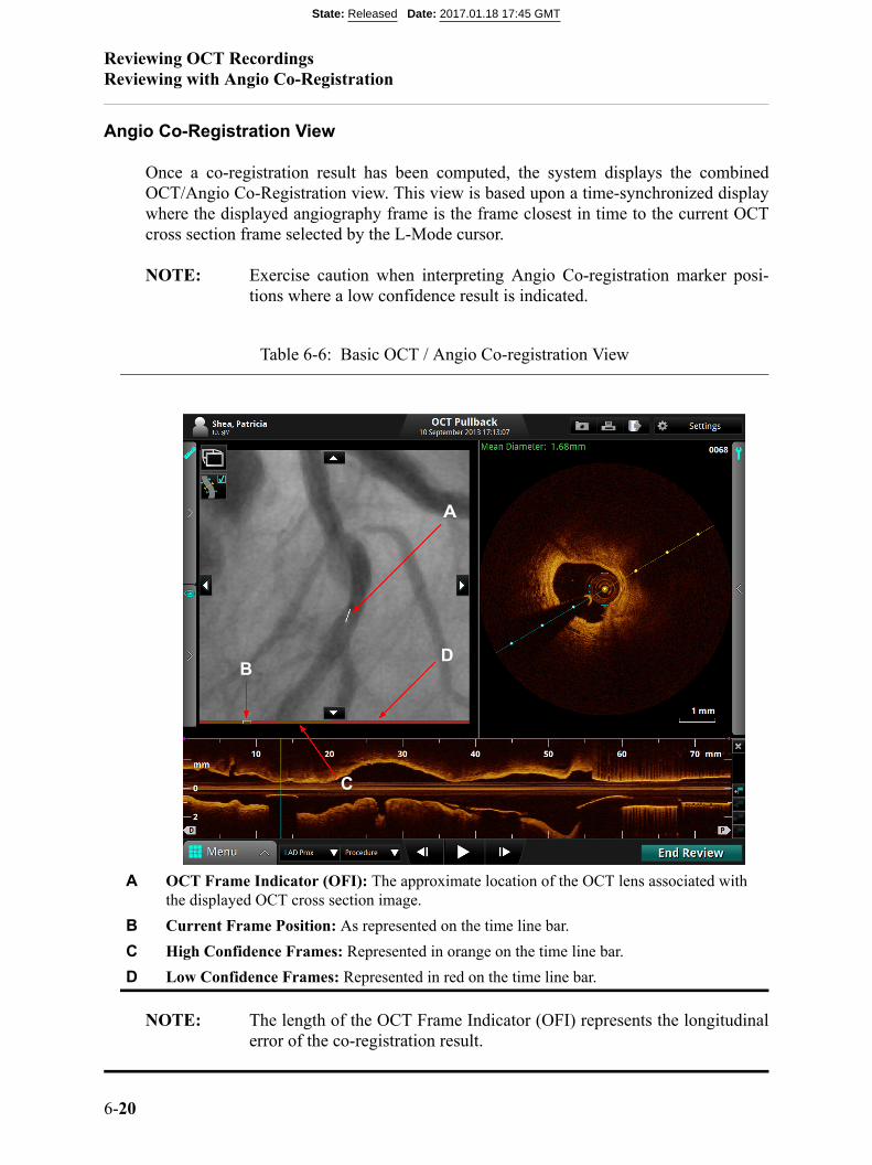
Reviewing OCT RecordingsReviewing with Angio Co-Registration
6-20
Angio Co-Registration View
Once a co-registration result has been computed, the system displays the combinedOCT/Angio Co-Registration view. This view is based upon a time-synchronized displaywhere the displayed angiography frame is the frame closest in time to the current OCTcross section frame selected by the L-Mode cursor.
NOTE: Exercise caution when interpreting Angio Co-registration marker posi-tions where a low confidence result is indicated.
NOTE: The length of the OCT Frame Indicator (OFI) represents the longitudinalerror of the co-registration result.
Table 6-6: Basic OCT / Angio Co-registration View
A OCT Frame Indicator (OFI): The approximate location of the OCT lens associated with the displayed OCT cross section image.
B Current Frame Position: As represented on the time line bar.
C High Confidence Frames: Represented in orange on the time line bar.
D Low Confidence Frames: Represented in red on the time line bar.
BD
C
A
State: Released Date: 2017.01.18 17:45 GMT
Reviewing OCT RecordingsReviewing with Angio Co-Registration
OPTIS™ Software ARTUS600005835 AInstructions for Use 6-21
NOTE: The color of the OFI indicates the confidence of the co-registration resultat that location. White indicates high confidence, and red indicates lowconfidence. The indicator coloring also corresponds with the position onthe time line bar below the angiogram image. The color red indicateswhere the Angio Co-registration accuracy may be lower due to poor visi-bility of the lens marker. Exercise caution when interpreting AngioCo-registration results in these areas.
NOTE: It is possible that the co-registration result does not include an OFI posi-tion on a particular angio co-registration frame. This is most likely at theextreme proximal end the pullback. In this case, the no OFI warning ban-ner is displayed (see “Angio Co-Registration Troubleshooting”, No OCTFrame Indicator).
NOTE: To use the Quick Zoom feature (see “Quick Zoom” on page 7-15) on theAngiography window click on the angiography image.
When the Lumen Profile display is on, the approximate locations of the distal referenceframe, proximal reference frame, and MLA/Area Frame are represented as the StentRoadmap on the angiography image.
State: Released Date: 2017.01.18 17:45 GMT
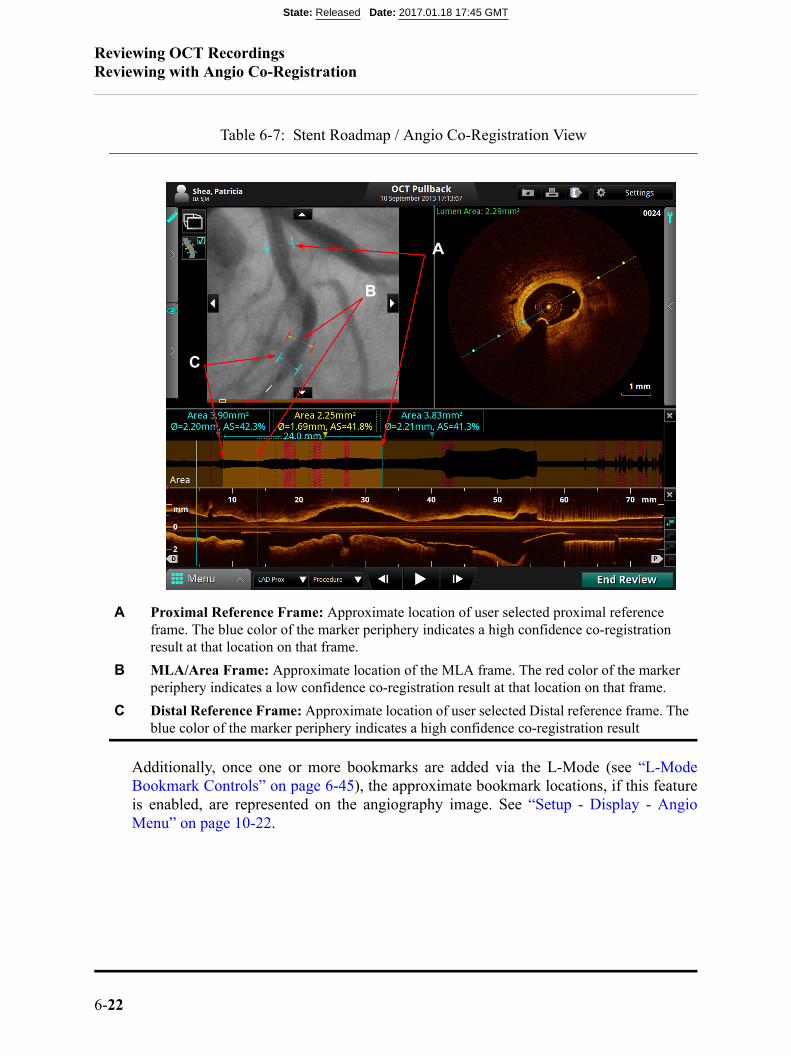
Reviewing OCT RecordingsReviewing with Angio Co-Registration
6-22
Additionally, once one or more bookmarks are added via the L-Mode (see “L-ModeBookmark Controls” on page 6-45), the approximate bookmark locations, if this featureis enabled, are represented on the angiography image. See “Setup - Display - AngioMenu” on page 10-22.
Table 6-7: Stent Roadmap / Angio Co-Registration View
A Proximal Reference Frame: Approximate location of user selected proximal reference frame. The blue color of the marker periphery indicates a high confidence co-registration result at that location on that frame.
B MLA/Area Frame: Approximate location of the MLA frame. The red color of the marker periphery indicates a low confidence co-registration result at that location on that frame.
C Distal Reference Frame: Approximate location of user selected Distal reference frame. The blue color of the marker periphery indicates a high confidence co-registration result
B
C
A
State: Released Date: 2017.01.18 17:45 GMT
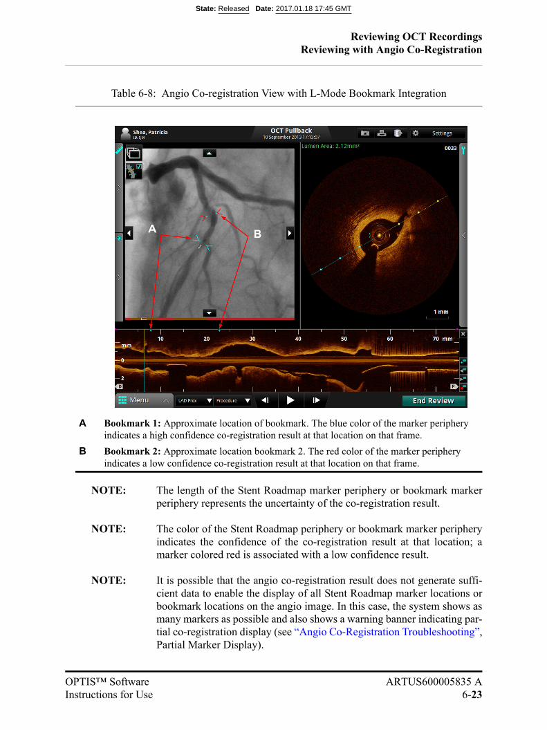
Reviewing OCT RecordingsReviewing with Angio Co-Registration
OPTIS™ Software ARTUS600005835 AInstructions for Use 6-23
NOTE: The length of the Stent Roadmap marker periphery or bookmark markerperiphery represents the uncertainty of the co-registration result.
NOTE: The color of the Stent Roadmap periphery or bookmark marker peripheryindicates the confidence of the co-registration result at that location; amarker colored red is associated with a low confidence result.
NOTE: It is possible that the angio co-registration result does not generate suffi-cient data to enable the display of all Stent Roadmap marker locations orbookmark locations on the angio image. In this case, the system shows asmany markers as possible and also shows a warning banner indicating par-tial co-registration display (see “Angio Co-Registration Troubleshooting”,Partial Marker Display).
Table 6-8: Angio Co-registration View with L-Mode Bookmark Integration
A Bookmark 1: Approximate location of bookmark. The blue color of the marker periphery indicates a high confidence co-registration result at that location on that frame.
B Bookmark 2: Approximate location bookmark 2. The red color of the marker periphery indicates a low confidence co-registration result at that location on that frame.
BA
State: Released Date: 2017.01.18 17:45 GMT
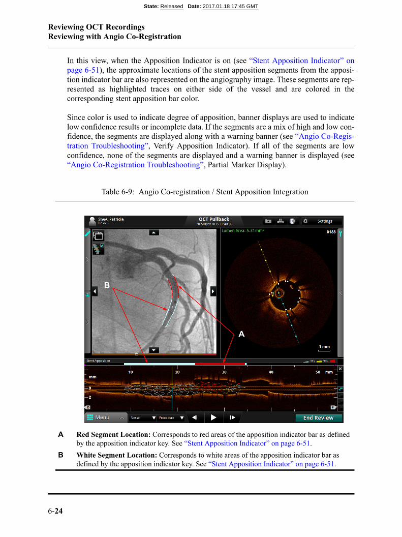
Reviewing OCT RecordingsReviewing with Angio Co-Registration
6-24
In this view, when the Apposition Indicator is on (see “Stent Apposition Indicator” onpage 6-51), the approximate locations of the stent apposition segments from the apposi-tion indicator bar are also represented on the angiography image. These segments are rep-resented as highlighted traces on either side of the vessel and are colored in thecorresponding stent apposition bar color.
Since color is used to indicate degree of apposition, banner displays are used to indicatelow confidence results or incomplete data. If the segments are a mix of high and low con-fidence, the segments are displayed along with a warning banner (see “Angio Co-Regis-tration Troubleshooting”, Verify Apposition Indicator). If all of the segments are lowconfidence, none of the segments are displayed and a warning banner is displayed (see“Angio Co-Registration Troubleshooting”, Partial Marker Display).
Table 6-9: Angio Co-registration / Stent Apposition Integration
A Red Segment Location: Corresponds to red areas of the apposition indicator bar as defined by the apposition indicator key. See “Stent Apposition Indicator” on page 6-51.
B White Segment Location: Corresponds to white areas of the apposition indicator bar as defined by the apposition indicator key. See “Stent Apposition Indicator” on page 6-51.
B
A
State: Released Date: 2017.01.18 17:45 GMT
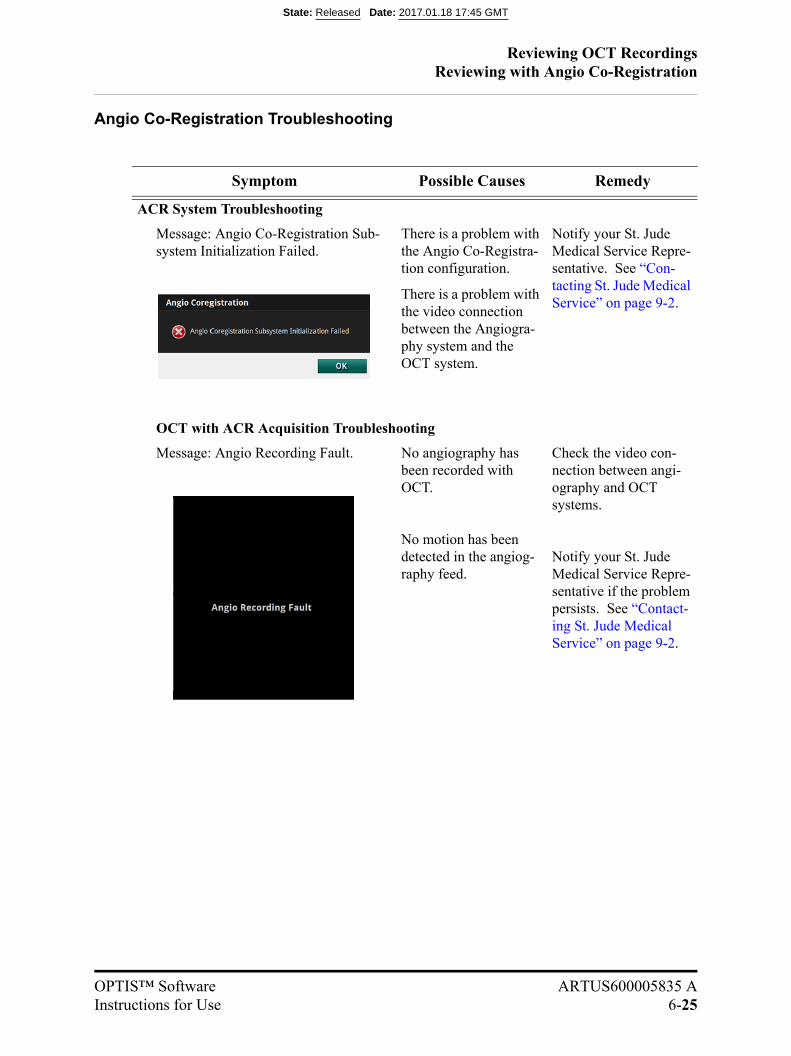
Reviewing OCT RecordingsReviewing with Angio Co-Registration
OPTIS™ Software ARTUS600005835 AInstructions for Use 6-25
Angio Co-Registration Troubleshooting
Symptom Possible Causes Remedy
ACR System Troubleshooting
Message: Angio Co-Registration Sub-system Initialization Failed.
There is a problem with the Angio Co-Registra-tion configuration.
There is a problem with the video connection between the Angiogra-phy system and the OCT system.
Notify your St. Jude Medical Service Repre-sentative. See “Con-tacting St. Jude Medical Service” on page 9-2.
OCT with ACR Acquisition Troubleshooting
Message: Angio Recording Fault. No angiography has been recorded with OCT.
No motion has been detected in the angiog-raphy feed.
Check the video con-nection between angi-ography and OCT systems.
Notify your St. Jude Medical Service Repre-sentative if the problem persists. See “Contact-ing St. Jude Medical Service” on page 9-2.
State: Released Date: 2017.01.18 17:45 GMT
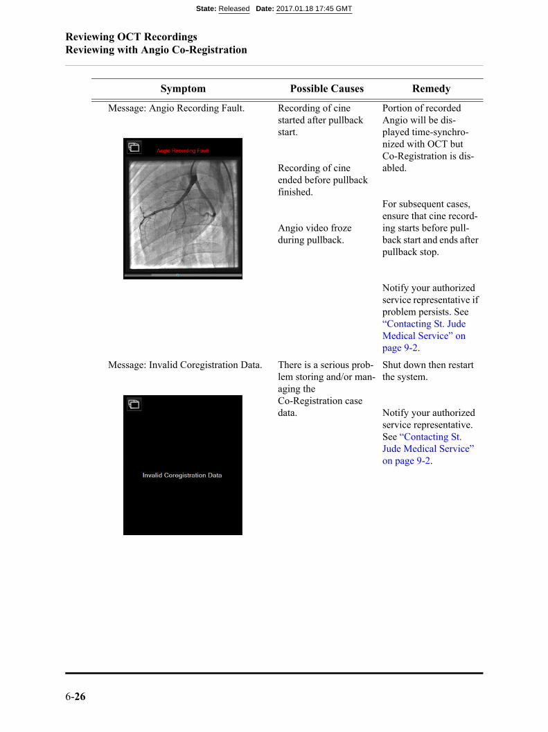
Reviewing OCT RecordingsReviewing with Angio Co-Registration
6-26
Message: Angio Recording Fault. Recording of cine started after pullback start.
Recording of cine ended before pullback finished.
Angio video froze during pullback.
Portion of recorded Angio will be dis-played time-synchro-nized with OCT but Co-Registration is dis-abled.
For subsequent cases, ensure that cine record-ing starts before pull-back start and ends after pullback stop.
Notify your authorized service representative if problem persists. See “Contacting St. Jude Medical Service” on page 9-2.
Message: Invalid Coregistration Data. There is a serious prob-lem storing and/or man-aging the Co-Registration case data.
Shut down then restart the system.
Notify your authorized service representative. See “Contacting St. Jude Medical Service” on page 9-2.
Symptom Possible Causes Remedy
State: Released Date: 2017.01.18 17:45 GMT

Reviewing OCT RecordingsReviewing with Angio Co-Registration
OPTIS™ Software ARTUS600005835 AInstructions for Use 6-27
Coreg Workflow Troubleshooting
Message: The vessel trace is not valid. Click Retry to enter a new trace or Can-cel to exit.
The user-entered trace is not on a valid vessel.
The cine recording may have stopped before the end of pullback.
Click Retry to start the vessel trace entry work-flow from the begin-ning.
Message: Co-Registration failed; the lens marker could not be detected. Click Enter Marker to register with a manual lens marker position or Exit.
The computation of the coregistration cannot be completed.
The system may be hav-ing difficulty identify-ing the lens marker on the Angio frames.
Click Enter Marker to re-register by manually identifying the lens marker on an Angio frame where it is visi-ble.
Click Exit if this result is seen again on the sec-ond attempt. This is an indication that the Co-Registration cannot be computed.
Message: The entered lens marker posi-tion is not valid. Click Retry to enter another or Cancel to exit.
The system cannot find the lens marker at the manually identified position.
Click Retry to enter a new position or Cancel to exit the workflow.
Symptom Possible Causes Remedy
State: Released Date: 2017.01.18 17:45 GMT
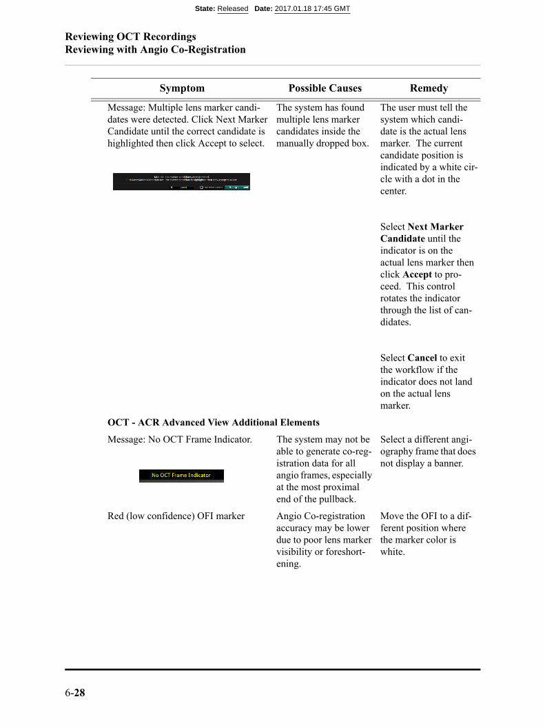
Reviewing OCT RecordingsReviewing with Angio Co-Registration
6-28
Message: Multiple lens marker candi-dates were detected. Click Next Marker Candidate until the correct candidate is highlighted then click Accept to select.
The system has found multiple lens marker candidates inside the manually dropped box.
The user must tell the system which candi-date is the actual lens marker. The current candidate position is indicated by a white cir-cle with a dot in the center.
Select Next Marker Candidate until the indicator is on the actual lens marker then click Accept to pro-ceed. This control rotates the indicator through the list of can-didates.
Select Cancel to exit the workflow if the indicator does not land on the actual lens marker.
OCT - ACR Advanced View Additional Elements
Message: No OCT Frame Indicator. The system may not be able to generate co-reg-istration data for all angio frames, especially at the most proximal end of the pullback.
Select a different angi-ography frame that does not display a banner.
Red (low confidence) OFI marker Angio Co-registration accuracy may be lower due to poor lens marker visibility or foreshort-ening.
Move the OFI to a dif-ferent position where the marker color is white.
Symptom Possible Causes Remedy
State: Released Date: 2017.01.18 17:45 GMT
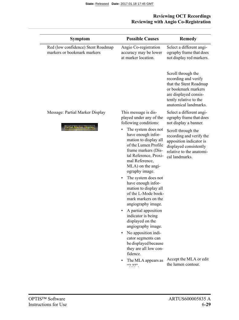
Reviewing OCT RecordingsReviewing with Angio Co-Registration
OPTIS™ Software ARTUS600005835 AInstructions for Use 6-29
Red (low confidence) Stent Roadmap markers or bookmark markers
Angio Co-registration accuracy may be lower at marker location.
Select a different angi-ography frame that does not display red markers.
Scroll through the recording and verify that the Stent Roadmap or bookmark markers are displayed consis-tently relative to the anatomical landmarks.
Message: Partial Marker Display This message is dis-played under any of the following conditions:
• The system does not have enough infor-mation to display all of the Lumen Profile frame markers (Dis-tal Reference, Proxi-mal Reference, MLA) on the angi-ography image.
• The system does not have enough infor-mation to display all of the L-Mode book-mark markers on the angiography image.
• A partial apposition indicator is being displayed on the angiography image.
• No apposition indi-cator segments can be displayed because they are all low con-fidence.
• The MLA appears as “?.??”.
Select a different angi-ography frame that does not display a banner.
Scroll through the recording and verify the apposition indicator is displayed consistently relative to the anatomi-cal landmarks.
Accept the MLA or edit the lumen contour.
Symptom Possible Causes Remedy
State: Released Date: 2017.01.18 17:45 GMT
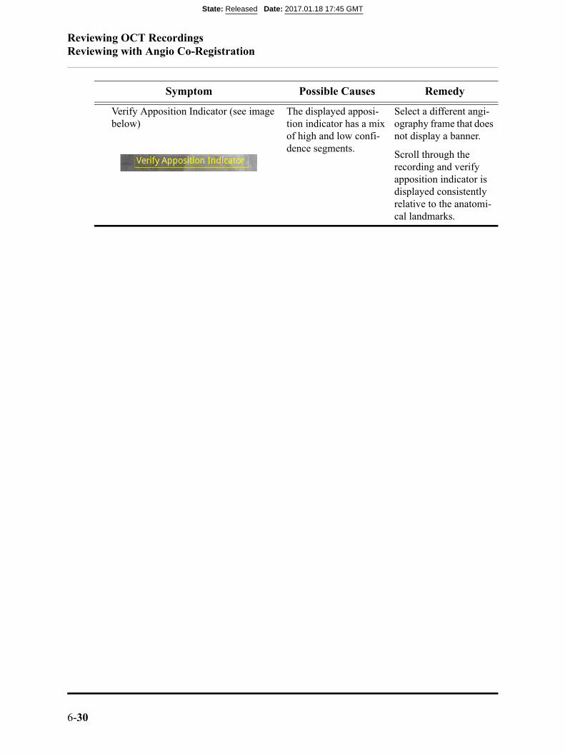
Reviewing OCT RecordingsReviewing with Angio Co-Registration
6-30
Verify Apposition Indicator (see image below)
The displayed apposi-tion indicator has a mix of high and low confi-dence segments.
Select a different angi-ography frame that does not display a banner.
Scroll through the recording and verify apposition indicator is displayed consistently relative to the anatomi-cal landmarks.
Symptom Possible Causes Remedy
State: Released Date: 2017.01.18 17:45 GMT

Reviewing OCT Recordings3D Bifurcation and 3D Navigation Views
OPTIS™ Software ARTUS600005835 AInstructions for Use 6-31
3D Bifurcation and 3D Navigation Views
3D Bifurcation (see “3D Bifurcation Display” on page6-32) or 3D Navigation (see “3D Navigation AdvancedDisplay” on page 6-35) views are accessed from the Viewmenu. A 3D region displays to the left of the Cross Sec-tion. 3D Bifurcation or 3D Navigation views are notavailable in stationary recordings and captured frames. The
Cross Section and 3D view can be resized by dragging the vertical line that separatesthem. While 3D Bifurcation or 3D Navigation is ON, new measurements cannot beadded on the Cross Section, and existing measurements cannot be edited on the CrossSection. The 3D Navigation is always available, while 3D Bifurcation is only availablewhen supported by the platform configuration.
The 3D region can be zoomed in or out by clicking and dragging inside the 3D regionwith the right mouse button. Single-clicking on the 3D volume updates the current frame(3D Navigation view only) and the 3D display is zoomed in by fixed factors, configu-rable under Setup > Display (see “Setup - Display Menu” on page 10-19).
State: Released Date: 2017.01.18 17:45 GMT
Reviewing OCT Recordings3D Bifurcation Display
6-32
3D Bifurcation Display
The 3D Bifurcation advanced display, shown in Table 6-10, provides views of detectedside branch ostia. When 3D Bifurcation view is first displayed, the closest side branchostium to the current frame is selected and the 3D cut-plane will be offset by 90º to pro-vide a straight-on view of the side branch (ostium view default shown in Table 6-10)while the L-mode cut-plane is adjusted to cut through the side branch (carina view shownin Table 6-11 on page 6-34). This orthogonal 3D cut-plane is displayed on the cross-sec-tional image as a pink cut-plane in Table 6-10.
Detected side branch ostia are indicated on the Lumen Profile (or L-mode) view as smalldots with vertical dashed lines. Clicking on the Lumen Profile or L-mode image alongthese vertical dashed lines or dots will navigate the current frame indicator to that sidebranch ostium and adjust the cut-planes as necessary to view that side branch ostium. If aside branch ositium is located on the same frame as the MLA, distal, or proximal refer-ence frame, the circular side branch ostium marker is enabled for side branch ostium nav-igation.
Clicking and dragging on the 3D cross section allows the camera to be rotated left andright relative to the vertical axis. The angle is constrained to approximately plus or minus75 degrees. A Reset View button resets the default camera angle, zoom factor, and resetsthe current frame to the center of the side branch ostium.
NOTE: The frame indicators are not drawn over side branch ostia in any 3Dadvanced display,
NOTE: The rendering of the sidebranch ostia must be verified with the cross-sec-tional and L-Mode OCT images.
NOTE: A sidebranch ostium may not be rendered completely if there is presenceof another OCT artifact near it e.g. guidewire or metallic stent strut"shadow".
State: Released Date: 2017.01.18 17:45 GMT
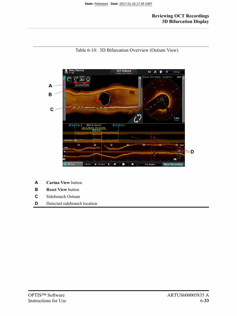
Reviewing OCT Recordings3D Bifurcation Display
OPTIS™ Software ARTUS600005835 AInstructions for Use 6-33
Table 6-10: 3D Bifurcation Overview (Ostium View)
A Carina View button
B Reset View button
C Sidebranch Ostium
D Detected sidebranch location
A
B
C
D
State: Released Date: 2017.01.18 17:45 GMT

Reviewing OCT Recordings3D Bifurcation Display
6-34
The 3D cut-plane can be synchronized with the L-mode cut-plane by clicking the CarinaView button in the 3D image region. In this view, both the L-mode and 3D images showa lateral view of the side branch ostia (see Table 6-11). This view shows a single cut-planeindicator on the cross-sectional image.
Table 6-11: 3D Bifurcation Overview (Carina View)
A Carina View button
B Carina (displayed in 3D image region)
C Carina (displayed in L-Mode)
A
B
C
State: Released Date: 2017.01.18 17:45 GMT
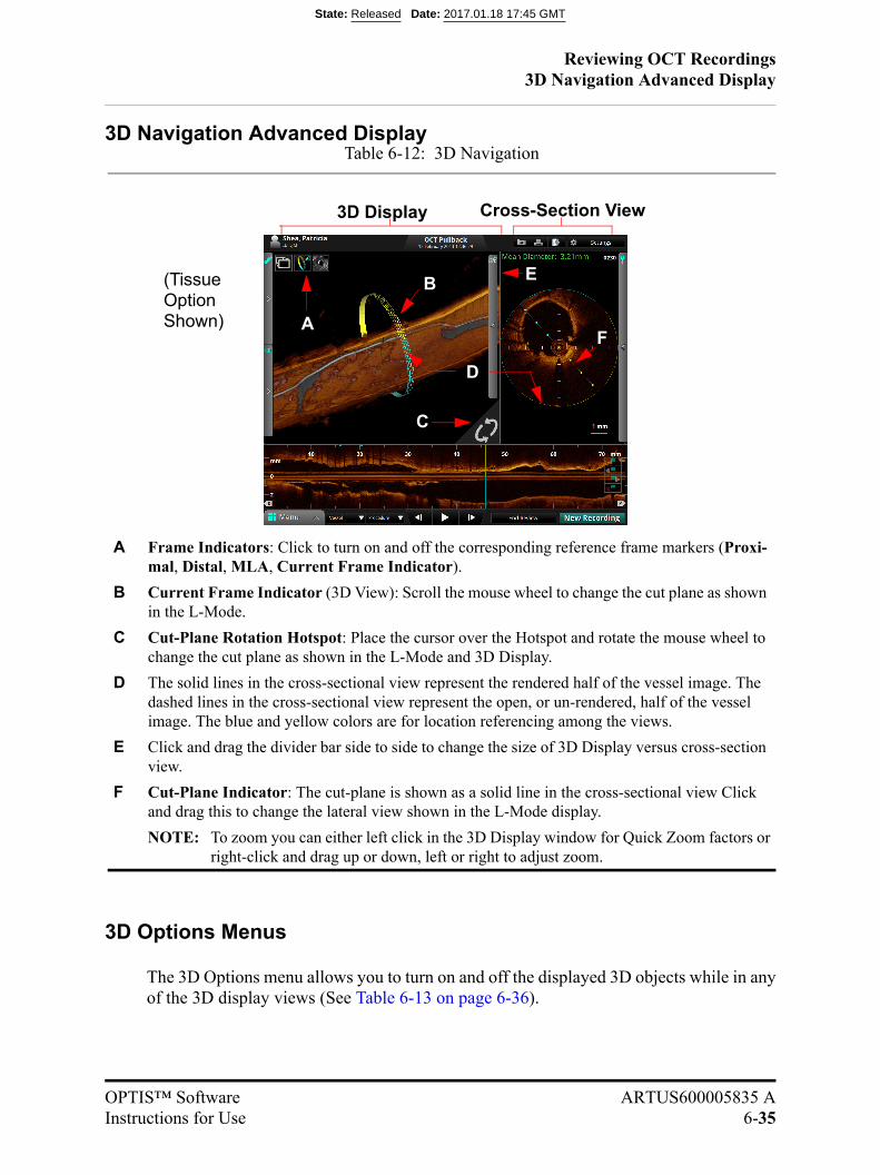
Reviewing OCT Recordings3D Navigation Advanced Display
OPTIS™ Software ARTUS600005835 AInstructions for Use 6-35
3D Navigation Advanced Display
3D Options Menus
The 3D Options menu allows you to turn on and off the displayed 3D objects while in anyof the 3D display views (See Table 6-13 on page 6-36).
Table 6-12: 3D Navigation
A Frame Indicators: Click to turn on and off the corresponding reference frame markers (Proxi-mal, Distal, MLA, Current Frame Indicator).
B Current Frame Indicator (3D View): Scroll the mouse wheel to change the cut plane as shown in the L-Mode.
C Cut-Plane Rotation Hotspot: Place the cursor over the Hotspot and rotate the mouse wheel to change the cut plane as shown in the L-Mode and 3D Display.
D The solid lines in the cross-sectional view represent the rendered half of the vessel image. The dashed lines in the cross-sectional view represent the open, or un-rendered, half of the vessel image. The blue and yellow colors are for location referencing among the views.
E Click and drag the divider bar side to side to change the size of 3D Display versus cross-section view.
F Cut-Plane Indicator: The cut-plane is shown as a solid line in the cross-sectional view Click and drag this to change the lateral view shown in the L-Mode display.
NOTE: To zoom you can either left click in the 3D Display window for Quick Zoom factors orright-click and drag up or down, left or right to adjust zoom.
A
C
B
3D Display Cross-Section View
(TissueOptionShown)
E
D
F
State: Released Date: 2017.01.18 17:45 GMT

Reviewing OCT Recordings3D Options Menus
6-36
Table 6-13: 3D Options Menus
A 3D Bifurcation
B 3D Navigation with Rendered Stent on
C 3D Navigation with Rendered Stent and Flythrough on
A CB
State: Released Date: 2017.01.18 17:45 GMT
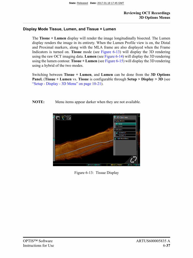
Reviewing OCT Recordings3D Options Menus
OPTIS™ Software ARTUS600005835 AInstructions for Use 6-37
Display Mode Tissue, Lumen, and Tissue + Lumen
The Tissue + Lumen display will render the image longitudinally bisected. The Lumendisplay renders the image in its entirety. When the Lumen Profile view is on, the Distaland Proximal markers, along with the MLA frame are also displayed when the FrameIndicators is turned on. Tissue mode (see Figure 6-13) will display the 3D renderingusing the raw OCT imaging data. Lumen (see Figure 6-14) will display the 3D renderingusing the lumen contour. Tissue + Lumen (see Figure 6-15) will display the 3D renderingusing a hybrid of the two modes.
Switching between Tissue + Lumen, and Lumen can be done from the 3D OptionsPanel. (Tissue + Lumen vs. Tissue is configurable through Setup > Display > 3D (see“Setup - Display - 3D Menu” on page 10-21).
NOTE: Menu items appear darker when they are not available.
Figure 6-13: Tissue Display
State: Released Date: 2017.01.18 17:45 GMT
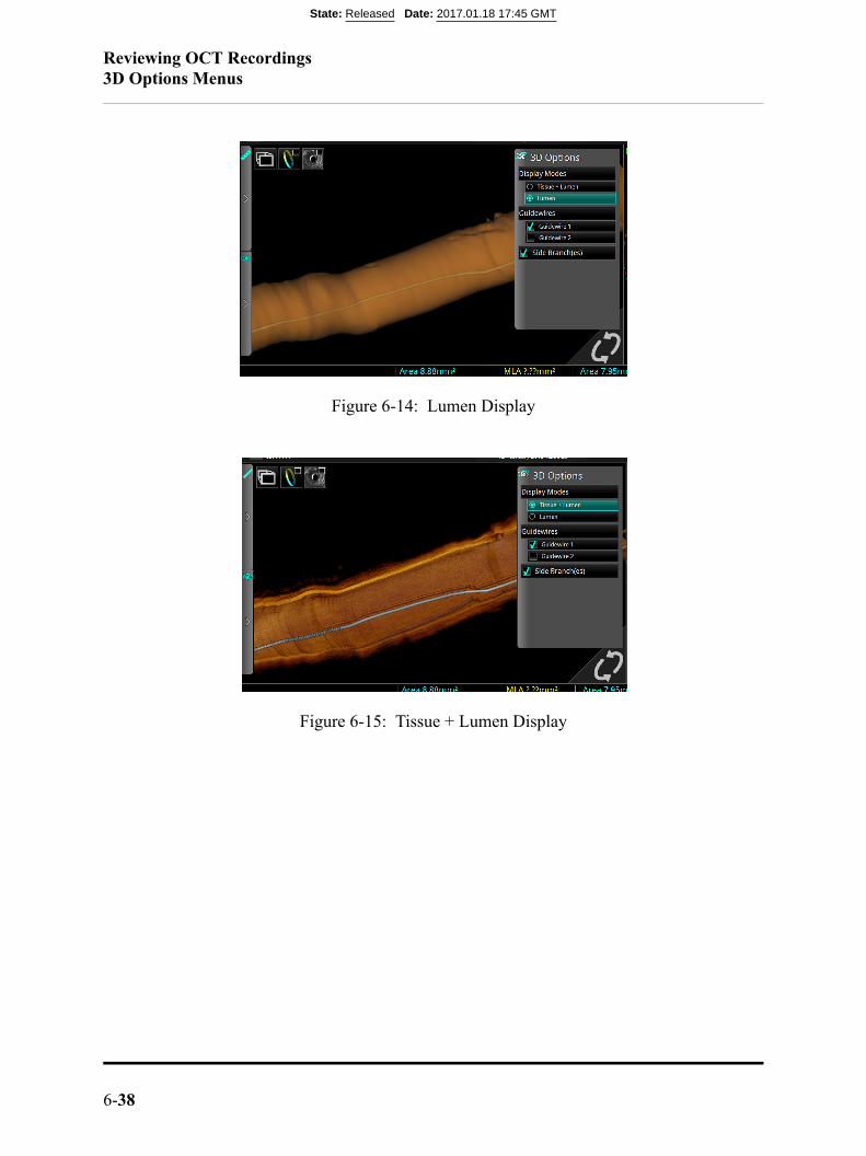
Reviewing OCT Recordings3D Options Menus
6-38
Figure 6-14: Lumen Display
Figure 6-15: Tissue + Lumen Display
State: Released Date: 2017.01.18 17:45 GMT
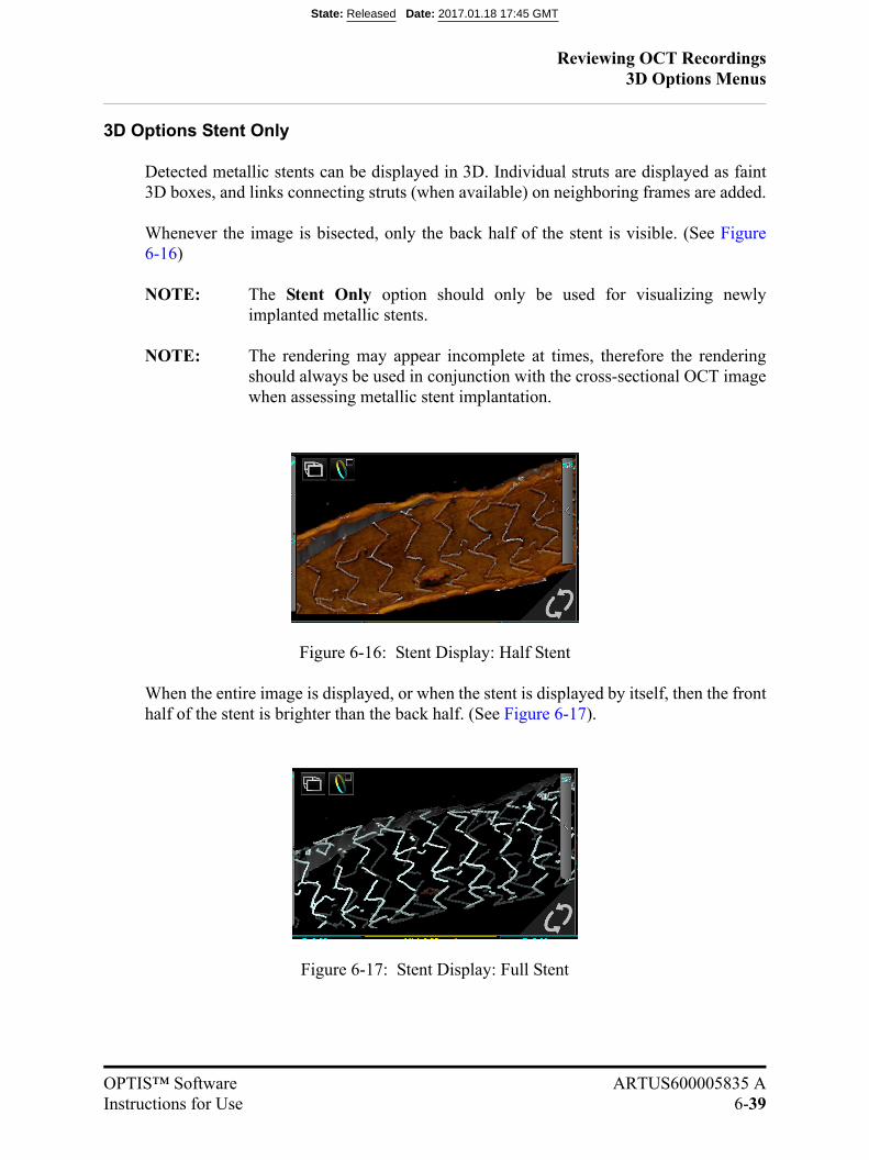
Reviewing OCT Recordings3D Options Menus
OPTIS™ Software ARTUS600005835 AInstructions for Use 6-39
3D Options Stent Only
Detected metallic stents can be displayed in 3D. Individual struts are displayed as faint3D boxes, and links connecting struts (when available) on neighboring frames are added.
Whenever the image is bisected, only the back half of the stent is visible. (See Figure6-16)
NOTE: The Stent Only option should only be used for visualizing newlyimplanted metallic stents.
NOTE: The rendering may appear incomplete at times, therefore the renderingshould always be used in conjunction with the cross-sectional OCT imagewhen assessing metallic stent implantation.
Figure 6-16: Stent Display: Half Stent
When the entire image is displayed, or when the stent is displayed by itself, then the fronthalf of the stent is brighter than the back half. (See Figure 6-17).
Figure 6-17: Stent Display: Full Stent
State: Released Date: 2017.01.18 17:45 GMT
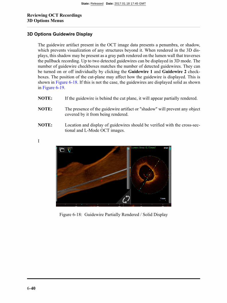
Reviewing OCT Recordings3D Options Menus
6-40
3D Options Guidewire Display
The guidewire artifact present in the OCT image data presents a penumbra, or shadow,which prevents visualization of any structures beyond it. When rendered in the 3D dis-plays, this shadow may be present as a gray path rendered on the lumen wall that traversesthe pullback recording. Up to two detected guidewires can be displayed in 3D mode. Thenumber of guidewire checkboxes matches the number of detected guidewires. They canbe turned on or off individually by clicking the Guidewire 1 and Guidewire 2 check-boxes. The position of the cut-plane may affect how the guidewire is displayed. This isshown in Figure 6-18. If this is not the case, the guidewires are displayed solid as shownin Figure 6-19.
NOTE: If the guidewire is behind the cut plane, it will appear partially rendered.
NOTE: The presence of the guidewire artifact or "shadow" will prevent any objectcovered by it from being rendered.
NOTE: Location and display of guidewires should be verified with the cross-sec-tional and L-Mode OCT images.
I
Figure 6-18: Guidewire Partially Rendered / Solid Display
State: Released Date: 2017.01.18 17:45 GMT

Reviewing OCT Recordings3D Options Menus
OPTIS™ Software ARTUS600005835 AInstructions for Use 6-41
Figure 6-19: Guidewire Solid Display
State: Released Date: 2017.01.18 17:45 GMT
Reviewing OCT Recordings3D Options Menus
6-42
3D Options Side Branch(es)
The Side Branch(es) option will turn on or off side branch ostia display. Side branch ostiacan be highlighted in 3D mode by a thick, pink outline and holes in the lumen surface.(See Table 6-10 on page 6-33). Only side branch ostia that have diameter greater than1.5mm are displayed on the L-Mode and in 3D mode.
NOTE: The rendering of the sidebranch ostia must be verified with the cross-sec-tional and L-Mode OCT images.
NOTE: A sidebranch ostium may not be rendered completely if there is presenceof another OCT artifact near it e.g. guidewire or metallic stent “shadow”.
State: Released Date: 2017.01.18 17:45 GMT

Reviewing OCT Recordings3D Options Menus
OPTIS™ Software ARTUS600005835 AInstructions for Use 6-43
3D Options Flythrough
3D Flythrough is accessed via 3D Navigation view. Click the 3D Flythrough button onthe upper-left corner of the 3D display to enter 3D Flythrough mode. The 3D Flyth-rough mode allows you to view the vessel from the inside. Clicking and dragging on the3D display allows you to change the camera direction in the following orientations: up,down, left, and right. The Reset View button allows you to reset the viewing direction ofthe camera. See Table 6-14. The 3D Flythrough view does not rotate when the cut-planeis rotated.
The Default Flythrough direction is Proximal to Distal. In this mode, the playback direc-tion is reversed (See Table 6-14). It is possible to change the Flythrough direction fromDistal to Proximal from the 3D options panel.
Table 6-14: 3D Flythrough Overview
A 3D Flythrough button
B Reset View button
C Distal/Proximal 3D Flythrough direction indicator
C
A
B
State: Released Date: 2017.01.18 17:45 GMT
Reviewing OCT Recordings3D Options Menus
6-44
Limitations of 3D Display
Please be aware of the following limitations of the 3D Display Option:
• The 3D displays are directly dependent on the OCT image data. Therefore, it isimportant to have good image quality of the OCT images to ensure accurate render-ing.
• The 3D displays are approximations that may appear straight and rotationallyaligned and have other imaging artifacts due to the method of tomographic recon-struction.
• The presence of red thrombus may degrade the quality of the 3D renderings.
• 3D Display reconstructions that appear “saw-toothed” or appear to have segmentsthat are misaligned can lead to misinterpretation by an inexperienced user.
• Shortening or lengthening artifacts or other degradations in the 3D Display recon-struction may occur due to the relative motion of the imaging catheter with respectto the coronary artery caused by the patient’s heart motion.
• Due to the catheter’s arbitrary position within the vessel, 3D Display may not berepresentative of the actual vessel lumen.
• The vessel diameter shown in the 3D Display may appear significantly smaller thanthe actual diameter when the catheter position is off center and close to the vesselwall. To avoid misinterpreting the image when this occurs, rotate the cut-plane toexamine all views of the 3D Display.
State: Released Date: 2017.01.18 17:45 GMT
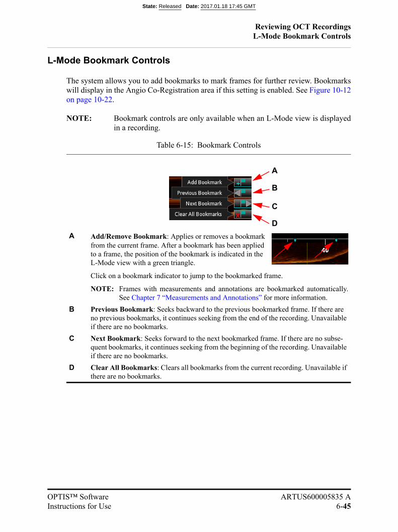
Reviewing OCT RecordingsL-Mode Bookmark Controls
OPTIS™ Software ARTUS600005835 AInstructions for Use 6-45
L-Mode Bookmark Controls
The system allows you to add bookmarks to mark frames for further review. Bookmarkswill display in the Angio Co-Registration area if this setting is enabled. See Figure 10-12on page 10-22.
NOTE: Bookmark controls are only available when an L-Mode view is displayedin a recording.
Table 6-15: Bookmark Controls
A Add/Remove Bookmark: Applies or removes a bookmark from the current frame. After a bookmark has been applied to a frame, the position of the bookmark is indicated in the L-Mode view with a green triangle.
Click on a bookmark indicator to jump to the bookmarked frame.
NOTE: Frames with measurements and annotations are bookmarked automatically.See Chapter 7 “Measurements and Annotations” for more information.
B Previous Bookmark: Seeks backward to the previous bookmarked frame. If there are no previous bookmarks, it continues seeking from the end of the recording. Unavailable if there are no bookmarks.
C Next Bookmark: Seeks forward to the next bookmarked frame. If there are no subse-quent bookmarks, it continues seeking from the beginning of the recording. Unavailable if there are no bookmarks.
D Clear All Bookmarks: Clears all bookmarks from the current recording. Unavailable if there are no bookmarks.
A
B
C
D
State: Released Date: 2017.01.18 17:45 GMT

Reviewing OCT RecordingsSetting Playback Range in L-Mode
6-46
Setting Playback Range in L-Mode
By default, the system plays the entire length of a pullback during the review. You canshorten the length of the playback by moving the ends of the playback range.
NOTE: Playback range markers are only available on recordings in the L-Modeview. By default, they are at the distal and proximal ends of the recording.
To change the playback range:
1. Use the Playback Controls at the bottom of the screen to pause the playback.
2. Click on the range markers (purple triangles) and position them before and after thearea to be played during review.
NOTE: If the recording is exported as an AVI file, this range determines the lengthof the exported recording.
NOTE: If the L-Mode view is changed (for example, turned Off), the playbackrange is restored to the full length of the recording.
Playback Range markers
Current Frame Indicator
Figure 6-20: Adjusted Playback Range
State: Released Date: 2017.01.18 17:45 GMT
Reviewing OCT RecordingsSetting Playback Range in L-Mode
OPTIS™ Software ARTUS600005835 AInstructions for Use 6-47
Limitations of L-Mode Data
Please be aware of the following limitations of L-Mode data:
• Due to the catheter’s arbitrary position within the vessel, L-Mode data may not berepresentative of the actual vessel lumen.
• The presence of red thrombus may degrade the quality of the information derivedfrom OCT imaging.
• The vessel diameter shown in the L-Mode reconstruction may appear significantlysmaller than the actual diameter when the catheter position is off center and close tothe vessel wall. To avoid misinterpreting the image when this occurs, rotate the cut-plane to examine all views of the L-Mode.
• The L-Mode display may appear straight and rotationally aligned and have otherimaging artifacts due to the method of tomographic reconstruction.
• L-Mode reconstructions that appear “saw-toothed” or appear to have segments thatare misaligned can lead to misinterpretation by an inexperienced user.
• Shortening or lengthening artifacts in the L-Mode reconstruction may occur due tothe relative motion of the Dragonfly catheter with respect to the coronary arterycaused by the patient’s heart motion.
State: Released Date: 2017.01.18 17:45 GMT
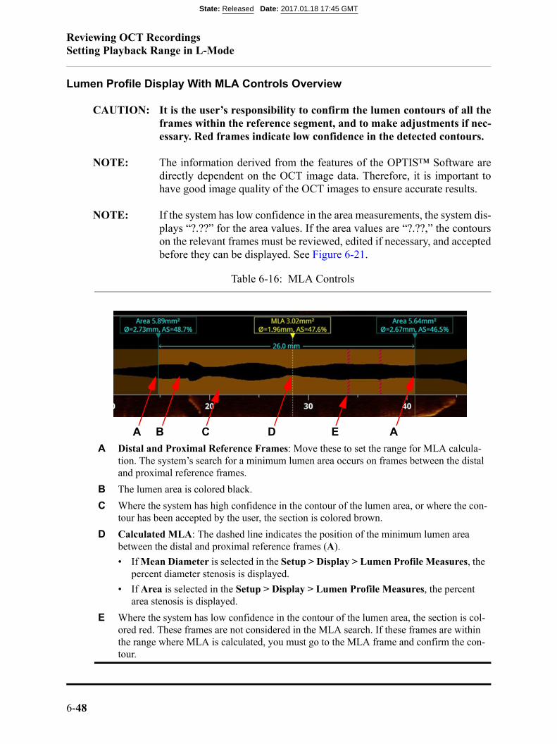
Reviewing OCT RecordingsSetting Playback Range in L-Mode
6-48
Lumen Profile Display With MLA Controls Overview
CAUTION: It is the user’s responsibility to confirm the lumen contours of all theframes within the reference segment, and to make adjustments if nec-essary. Red frames indicate low confidence in the detected contours.
NOTE: The information derived from the features of the OPTIS™ Software aredirectly dependent on the OCT image data. Therefore, it is important tohave good image quality of the OCT images to ensure accurate results.
NOTE: If the system has low confidence in the area measurements, the system dis-plays “?.??” for the area values. If the area values are “?.??,” the contourson the relevant frames must be reviewed, edited if necessary, and acceptedbefore they can be displayed. See Figure 6-21.
Table 6-16: MLA Controls
A Distal and Proximal Reference Frames: Move these to set the range for MLA calcula-tion. The system’s search for a minimum lumen area occurs on frames between the distal and proximal reference frames.
B The lumen area is colored black.
C Where the system has high confidence in the contour of the lumen area, or where the con-tour has been accepted by the user, the section is colored brown.
D Calculated MLA: The dashed line indicates the position of the minimum lumen area between the distal and proximal reference frames (A).
• If Mean Diameter is selected in the Setup > Display > Lumen Profile Measures, the percent diameter stenosis is displayed.
• If Area is selected in the Setup > Display > Lumen Profile Measures, the percent area stenosis is displayed.
E Where the system has low confidence in the contour of the lumen area, the section is col-ored red. These frames are not considered in the MLA search. If these frames are within the range where MLA is calculated, you must go to the MLA frame and confirm the con-tour.
B C EA D A
State: Released Date: 2017.01.18 17:45 GMT
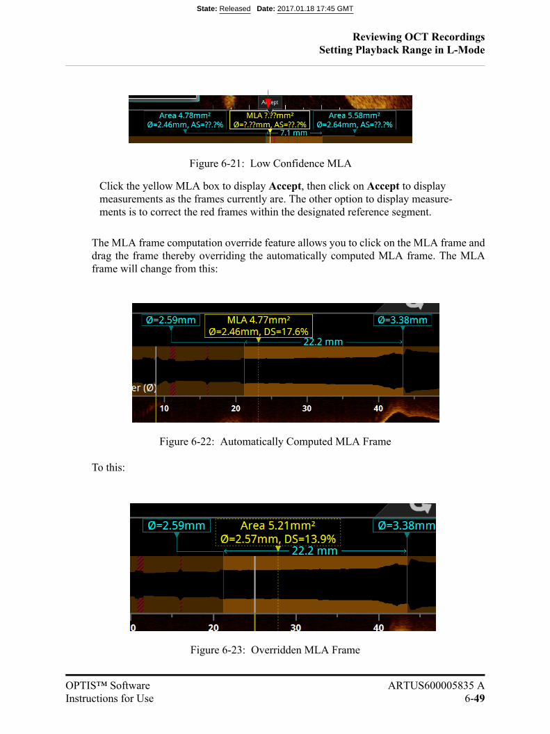
Reviewing OCT RecordingsSetting Playback Range in L-Mode
OPTIS™ Software ARTUS600005835 AInstructions for Use 6-49
The MLA frame computation override feature allows you to click on the MLA frame anddrag the frame thereby overriding the automatically computed MLA frame. The MLAframe will change from this:
Figure 6-22: Automatically Computed MLA Frame
To this:
Figure 6-23: Overridden MLA Frame
Figure 6-21: Low Confidence MLA
Click the yellow MLA box to display Accept, then click on Accept to display measurements as the frames currently are. The other option to display measure-ments is to correct the red frames within the designated reference segment.
State: Released Date: 2017.01.18 17:45 GMT
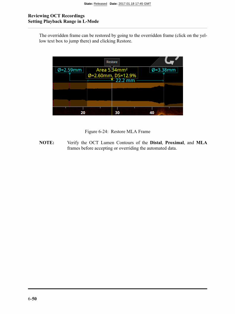
Reviewing OCT RecordingsSetting Playback Range in L-Mode
6-50
The overridden frame can be restored by going to the overridden frame (click on the yel-low text box to jump there) and clicking Restore.
Figure 6-24: Restore MLA Frame
NOTE: Verify the OCT Lumen Contours of the Distal, Proximal, and MLAframes before accepting or overriding the automated data.
State: Released Date: 2017.01.18 17:45 GMT
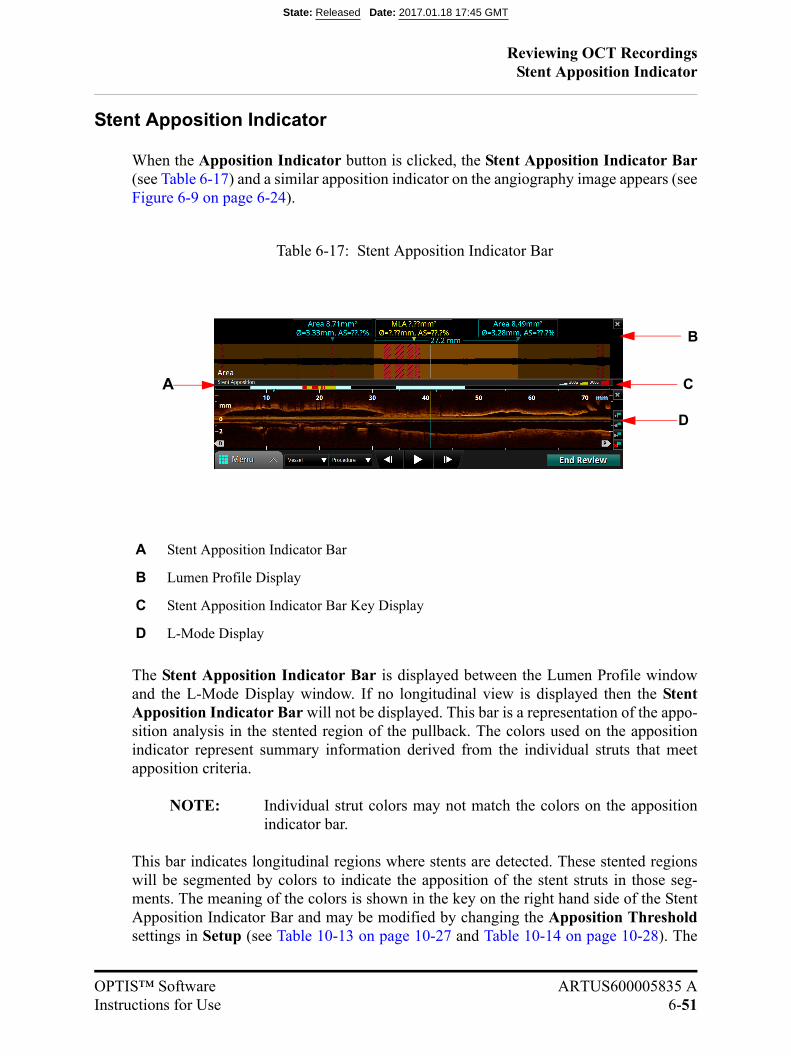
Reviewing OCT RecordingsStent Apposition Indicator
OPTIS™ Software ARTUS600005835 AInstructions for Use 6-51
Stent Apposition Indicator
When the Apposition Indicator button is clicked, the Stent Apposition Indicator Bar(see Table 6-17) and a similar apposition indicator on the angiography image appears (seeFigure 6-9 on page 6-24).
The Stent Apposition Indicator Bar is displayed between the Lumen Profile windowand the L-Mode Display window. If no longitudinal view is displayed then the StentApposition Indicator Bar will not be displayed. This bar is a representation of the appo-sition analysis in the stented region of the pullback. The colors used on the appositionindicator represent summary information derived from the individual struts that meetapposition criteria.
NOTE: Individual strut colors may not match the colors on the appositionindicator bar.
This bar indicates longitudinal regions where stents are detected. These stented regionswill be segmented by colors to indicate the apposition of the stent struts in those seg-ments. The meaning of the colors is shown in the key on the right hand side of the StentApposition Indicator Bar and may be modified by changing the Apposition Thresholdsettings in Setup (see Table 10-13 on page 10-27 and Table 10-14 on page 10-28). The
Table 6-17: Stent Apposition Indicator Bar
A Stent Apposition Indicator Bar
B Lumen Profile Display
C Stent Apposition Indicator Bar Key Display
D L-Mode Display
B
B
D
CA
State: Released Date: 2017.01.18 17:45 GMT

Reviewing OCT RecordingsStent Apposition Indicator
6-52
Apposition Indicators displayed along the outside of the vessel on the Angio Co-Regis-tration image are identical in meaning to the Stent Apposition Indicator Bar.
State: Released Date: 2017.01.18 17:45 GMT
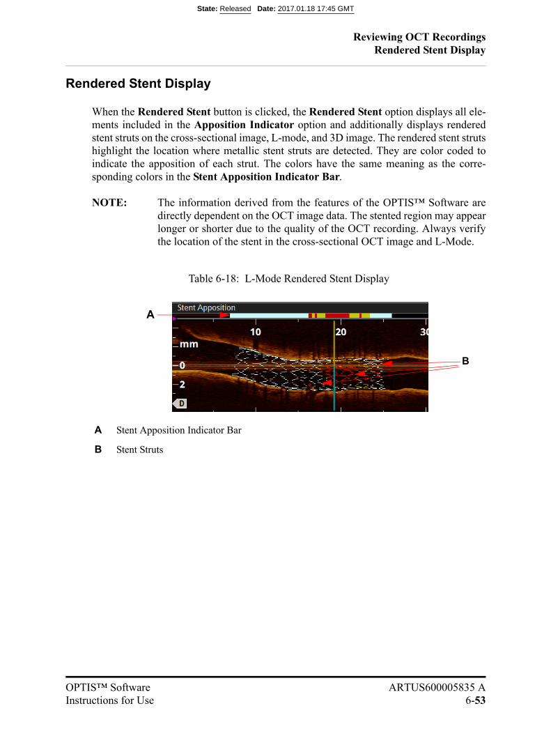
Reviewing OCT RecordingsRendered Stent Display
OPTIS™ Software ARTUS600005835 AInstructions for Use 6-53
Rendered Stent Display
When the Rendered Stent button is clicked, the Rendered Stent option displays all ele-ments included in the Apposition Indicator option and additionally displays renderedstent struts on the cross-sectional image, L-mode, and 3D image. The rendered stent strutshighlight the location where metallic stent struts are detected. They are color coded toindicate the apposition of each strut. The colors have the same meaning as the corre-sponding colors in the Stent Apposition Indicator Bar.
NOTE: The information derived from the features of the OPTIS™ Software aredirectly dependent on the OCT image data. The stented region may appearlonger or shorter due to the quality of the OCT recording. Always verifythe location of the stent in the cross-sectional OCT image and L-Mode.
Table 6-18: L-Mode Rendered Stent Display
A Stent Apposition Indicator Bar
B Stent Struts
B
A
State: Released Date: 2017.01.18 17:45 GMT
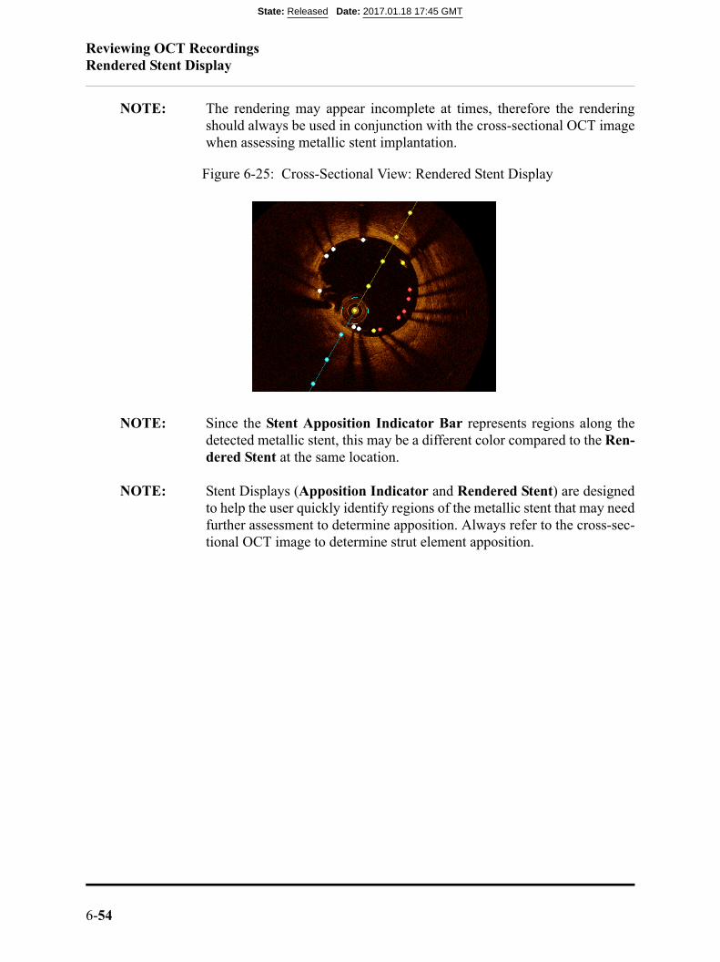
Reviewing OCT RecordingsRendered Stent Display
6-54
NOTE: The rendering may appear incomplete at times, therefore the renderingshould always be used in conjunction with the cross-sectional OCT imagewhen assessing metallic stent implantation.
NOTE: Since the Stent Apposition Indicator Bar represents regions along thedetected metallic stent, this may be a different color compared to the Ren-dered Stent at the same location.
NOTE: Stent Displays (Apposition Indicator and Rendered Stent) are designedto help the user quickly identify regions of the metallic stent that may needfurther assessment to determine apposition. Always refer to the cross-sec-tional OCT image to determine strut element apposition.
Figure 6-25: Cross-Sectional View: Rendered Stent Display
State: Released Date: 2017.01.18 17:45 GMT
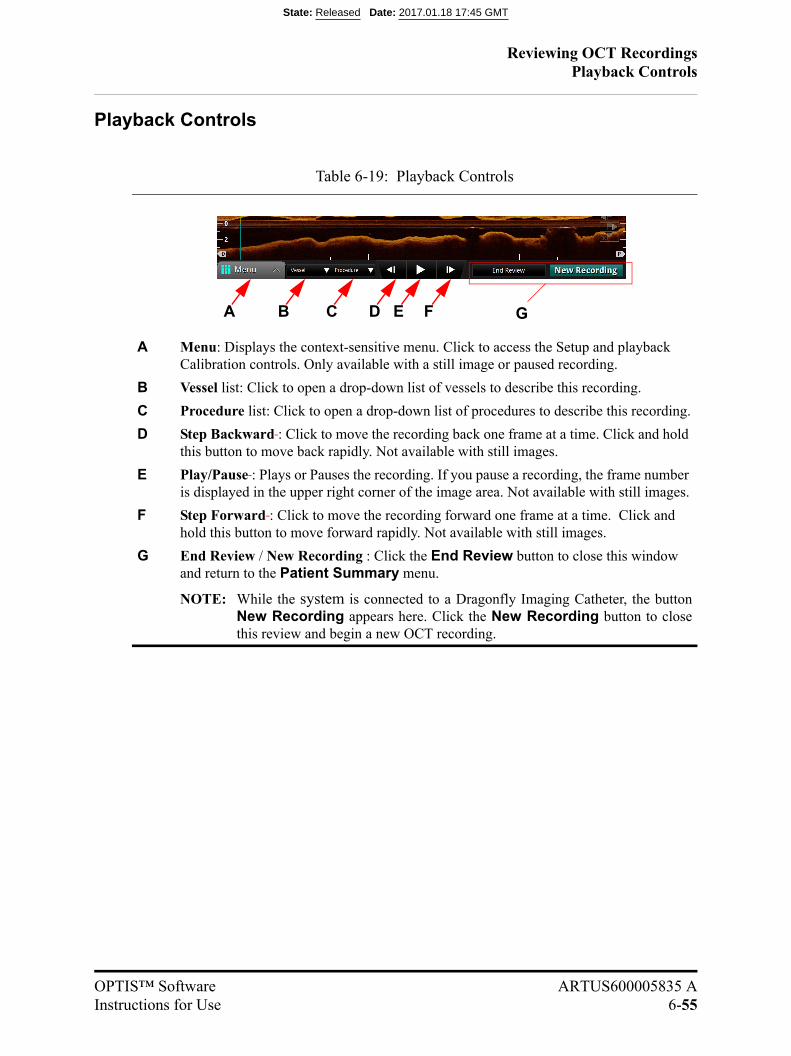
Reviewing OCT RecordingsPlayback Controls
OPTIS™ Software ARTUS600005835 AInstructions for Use 6-55
Playback Controls
Table 6-19: Playback Controls
A Menu: Displays the context-sensitive menu. Click to access the Setup and playback Calibration controls. Only available with a still image or paused recording.
B Vessel list: Click to open a drop-down list of vessels to describe this recording.
C Procedure list: Click to open a drop-down list of procedures to describe this recording.
D Step Backward : Click to move the recording back one frame at a time. Click and hold this button to move back rapidly. Not available with still images.
E Play/Pause : Plays or Pauses the recording. If you pause a recording, the frame number is displayed in the upper right corner of the image area. Not available with still images.
F Step Forward : Click to move the recording forward one frame at a time. Click and hold this button to move forward rapidly. Not available with still images.
G End Review / New Recording : Click the End Review button to close this window and return to the Patient Summary menu.
NOTE: While the system is connected to a Dragonfly Imaging Catheter, the buttonNew Recording appears here. Click the New Recording button to closethis review and begin a new OCT recording.
A E F GB C D
State: Released Date: 2017.01.18 17:45 GMT
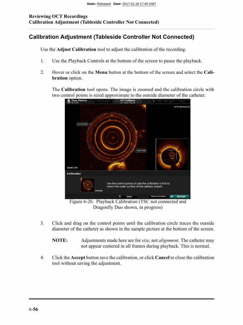
Reviewing OCT RecordingsCalibration Adjustment (Tableside Controller Not Connected)
6-56
Calibration Adjustment (Tableside Controller Not Connected)
Use the Adjust Calibration tool to adjust the calibration of the recording.
1. Use the Playback Controls at the bottom of the screen to pause the playback.
2. Hover or click on the Menu button at the bottom of the screen and select the Cali-bration option.
The Calibration tool opens. The image is zoomed and the calibration circle withtwo control points is sized approximate to the outside diameter of the catheter.
3. Click and drag on the control points until the calibration circle traces the outsidediameter of the catheter as shown in the sample picture at the bottom of the screen.
NOTE: Adjustments made here are for size, not alignment. The catheter maynot appear centered in all frames during playback. This is normal.
4. Click the Accept button save the calibration, or click Cancel to close the calibrationtool without saving the adjustment.
Figure 6-26: Playback Calibration (TSC not connected and Dragonfly Duo shown, in progress)
State: Released Date: 2017.01.18 17:45 GMT
Reviewing OCT RecordingsCalibration Adjustment (Tableside Controller Not Connected)
OPTIS™ Software ARTUS600005835 AInstructions for Use 6-57
NOTE: If necessary, you can return the recording to its default calibration byclicking the Remove Adjustment button. If you remove or changethe calibration, any changes that you have made to the automati-cally-generated Lumen Profile contours will alter the subsequentmeasurements.
NOTE: If you enter the Calibration workflow after the system has success-fully calibrated the recording (Dragonfly OPTIS™ Catheter only),an Override message will be displayed alerting you that the record-ing has already been calibrated by the system. If you override a suc-cessful continuous calibration, the results may be less accurateacross the recording. Generally this should be done only if the cal-ibration performed by the system is clearly in error.
State: Released Date: 2017.01.18 17:45 GMT

Reviewing OCT RecordingsCalibration Adjustment (Tableside Controller Connected)
6-58
Calibration Adjustment (Tableside Controller Connected)
Use the Adjust Calibration tool to adjust the calibration of the recording.
1. Use the Playback Controls at the bottom of the screen to pause the playback.
2. Hover or click on the Menu button at the bottom of the screen and select the Cali-bration option.
The Calibration tool opens. The image is zoomed. Click-move-click a calibrationcircle sized approximate to the outside diameter of the catheter.
3. Continue to click-move-click until the calibration circle traces the outside diameterof the catheter as shown in the sample picture at the bottom of the screen.
Figure 6-27: Playback Calibration (TSC connected and Dragonfly Duo shown, click-move-click in progress)
State: Released Date: 2017.01.18 17:45 GMT

Reviewing OCT RecordingsCalibration Adjustment (Tableside Controller Connected)
OPTIS™ Software ARTUS600005835 AInstructions for Use 6-59
NOTE: Adjustments made here are for size, not alignment. The catheter maynot appear centered in all frames during playback. This is normal.
4. Click the Accept button save the calibration, or click Cancel to close the calibrationtool without saving the adjustment.
NOTE: If necessary, you can return the recording to its default calibration byclicking the Remove Adjustment button. If you remove or changethe calibration, any changes that you have made to the automati-cally-generated Lumen Profile contours will alter the subsequentmeasurements.
Figure 6-28: Playback Calibration Circle complete (TSC connected)
State: Released Date: 2017.01.18 17:45 GMT
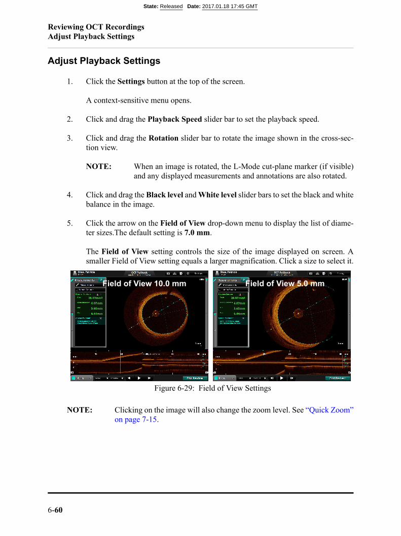
Reviewing OCT RecordingsAdjust Playback Settings
6-60
Adjust Playback Settings
1. Click the Settings button at the top of the screen.
A context-sensitive menu opens.
2. Click and drag the Playback Speed slider bar to set the playback speed.
3. Click and drag the Rotation slider bar to rotate the image shown in the cross-sec-tion view.
NOTE: When an image is rotated, the L-Mode cut-plane marker (if visible)and any displayed measurements and annotations are also rotated.
4. Click and drag the Black level and White level slider bars to set the black and whitebalance in the image.
5. Click the arrow on the Field of View drop-down menu to display the list of diame-ter sizes.The default setting is 7.0 mm.
The Field of View setting controls the size of the image displayed on screen. Asmaller Field of View setting equals a larger magnification. Click a size to select it.
NOTE: Clicking on the image will also change the zoom level. See “Quick Zoom”on page 7-15.
Figure 6-29: Field of View Settings
Field of View 10.0 mm Field of View 5.0 mm
State: Released Date: 2017.01.18 17:45 GMT

Reviewing OCT RecordingsExporting a Recording or Still Frame
OPTIS™ Software ARTUS600005835 AInstructions for Use 6-61
Exporting a Recording or Still Frame
Refer to Chapter 8 “Exporting, Importing, and Managing Files” for more informa-tion on exporting a recording or still frame.
Capturing Still Images
You can use the Capture button to save a still image from a recording, or to savea copy of an existing still frame. All measurements and annotations on that screenare saved with the captured image.
NOTE: The Capture button is unavailable while a recording is playing. Pause theplayback at the frame that you want to capture.
Saving a Still Image
1. Display the frame that you want to capture.
2. Click the Capture button.
A confirmation message appears, and the captured image appears in the PatientSummary menu.
NOTE: The still image is saved with the same date as the source file. It isgrouped in the Patient Summary menu with other recordings andimages of the same date.
In the Patient Summary menu, the system adds the frame number to the title of thecaptured image (for example, “OCT Frame 145”).
State: Released Date: 2017.01.18 17:45 GMT
Reviewing OCT RecordingsPrinting Still Images
6-62
Printing Still Images
You can use the Print button to print the current screen (including still frame,L-Mode, and any visible annotations) to an attached USB drive. All measurementsand annotations on that screen are saved with the captured image.
NOTE: The Print button is unavailable while a recording is playing. Pause theplayback at the frame that you want to print.
NOTE: If you are printing the file to a USB drive, you can set the file format. See“Setup - Print Menu” on page 10-29 for more information.
Printing a Still Image
1. Display the frame that you want to print.
2. Click the Print button.
A confirmation message appears, and the file is saved on the attached USB drive.
State: Released Date: 2017.01.18 17:45 GMT
OPTIS™ Software ARTUS600005835 AInstructions for Use 7-1
Measurements and Annotations 7
Measurements and Text Callouts in the Image Files
Measurements and text callouts that are added to images do not change the underlyingimage data. The unannotated image is always preserved and can be reviewed without themeasurements and callouts. All measurements and annotations added during the proce-dure are preserved in the file.
Measurements and text callouts can be modified or deleted, and pen color, line width andpoint size can be set. In addition, pen color can be set to automatically cycle so that sub-sequent measurements are displayed in different colors. For information on setting pencolor, line width, and point size, see “Setup - Measurements/Labels Menu” on page10-28.
CAUTION: If you want to make measurements on files which will be exported tostandard formats, you must make the measurements BEFOREexporting the images. Using non-OCT software to measure standardformat images will not produce accurate measurements.
CAUTION: Do not use images that have been exported to JPEG or CompressedAVI formats for clinical decision making. These formats use compres-sion methods that may degrade the image quality.
NOTE: All measurements and calculations can be made in the cross-section viewof the OCT image, but only horizontal length measurements and text anno-tations can be made in the L-Mode view.
Verifying Calibration
Before making measurements, you must verify the calibration. If the calibration for thisrecording or still image has not been adjusted, or if it has been reset, the calibration toolappears when you begin to take a measurement. See “Calibration Adjustment (TablesideController Not Connected)” on page 6-56 for more information.
State: Released Date: 2017.01.18 17:45 GMT
Measurements and AnnotationsTechniques to Improve Measurement Accuracy
7-2
Once the calibration is accepted, you can begin taking measurements.
NOTE: Calibration before making measurements should not be necessary whenusing the Dragonfly OPTIS™ catheter. The OPTIS™ Software softwarein conjunction with the Dragonfly OPTIS™ catheter uses Continuous Cal-ibration technology to eliminate the need for this step in the workflow.
Techniques to Improve Measurement Accuracy
Follow these guidelines to improve measurement accuracy:
• Before making measurements, use the Zoom function to zoom into the region ofinterest until you can clearly see borders and other features you want to measure(see “Field of View” on page 7-13).
• Place the measurement cursor correctly on the image, using the same measurementtechnique each time you perform the same type of measurement.
• Avoid making measurements in areas that have artifacts that disguise tissue.
Measurements and Annotations in the L-Mode View
All annotations and measurements are typically made in the cross-section view area of theImage Window. Only horizontal measurements, useful for determining pullback distance,are permitted in the L-Mode view.
CAUTION: Artifacts may result in misrepresentation of L-Mode data, so L-Modeis not recommended for quantization of clinical information.
State: Released Date: 2017.01.18 17:45 GMT
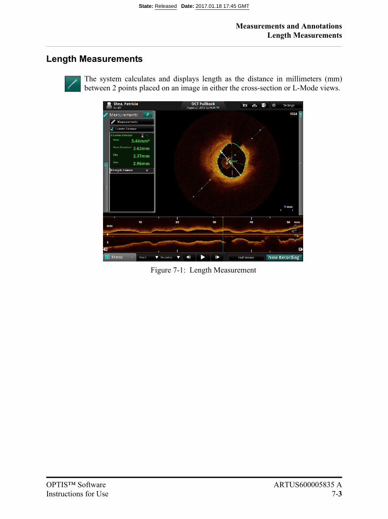
Measurements and AnnotationsLength Measurements
OPTIS™ Software ARTUS600005835 AInstructions for Use 7-3
Length Measurements
The system calculates and displays length as the distance in millimeters (mm)between 2 points placed on an image in either the cross-section or L-Mode views.
Figure 7-1: Length Measurement
State: Released Date: 2017.01.18 17:45 GMT
Measurements and AnnotationsLength Measurements
7-4
Making a Length (Distance) Measurement
1. Select the still image or paused recording that you want to measure.
2. Click on the Length button (Table 6-5 on page 6-10). The cursor changes to a pen.
3. Click anywhere in the Image Window (cross-section view or L-Mode view) toplace the starting point for the length measurement.
NOTE: Both start and end points must be in the same view. Forexample, if the starting point is placed in the cross-sectionview, the end point must also be in the cross-section view.To cancel the measurement, press the <Esc> key or clickthe Cancel button.
4. Use the mouse to position the pen cursor at the end point and click to set the point.
The completed, labeled distance measurement result appears in the AnnotationsPanel. If you position the cursor over the line, the length is shown over the center ofthe line.
State: Released Date: 2017.01.18 17:45 GMT
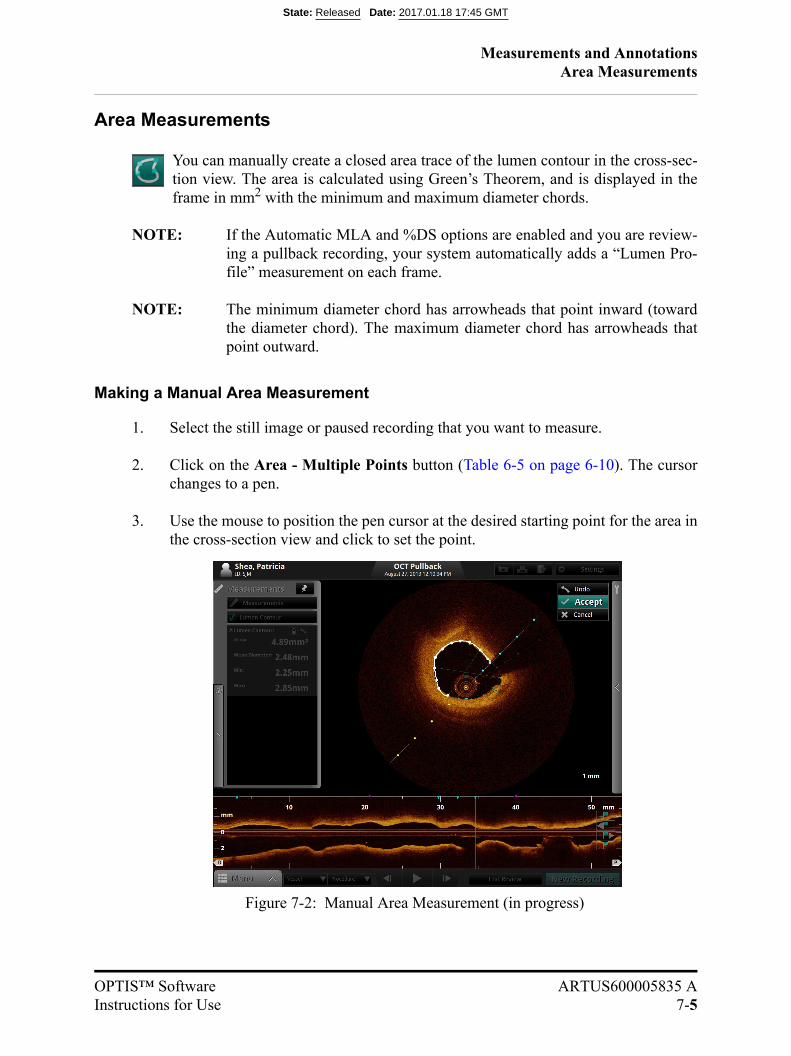
Measurements and AnnotationsArea Measurements
OPTIS™ Software ARTUS600005835 AInstructions for Use 7-5
Area Measurements
You can manually create a closed area trace of the lumen contour in the cross-sec-tion view. The area is calculated using Green’s Theorem, and is displayed in theframe in mm2 with the minimum and maximum diameter chords.
NOTE: If the Automatic MLA and %DS options are enabled and you are review-ing a pullback recording, your system automatically adds a “Lumen Pro-file” measurement on each frame.
NOTE: The minimum diameter chord has arrowheads that point inward (towardthe diameter chord). The maximum diameter chord has arrowheads thatpoint outward.
Making a Manual Area Measurement
1. Select the still image or paused recording that you want to measure.
2. Click on the Area - Multiple Points button (Table 6-5 on page 6-10). The cursorchanges to a pen.
3. Use the mouse to position the pen cursor at the desired starting point for the area inthe cross-section view and click to set the point.
Figure 7-2: Manual Area Measurement (in progress)
State: Released Date: 2017.01.18 17:45 GMT
Measurements and AnnotationsArea Measurements
7-6
NOTE: Click the Undo button to the left of the toolbar to delete themost recent point added to the image.
4. Continue to add points with the pen cursor until you have accurately traced the areato be measured. You can place as many points as you like around the border of thedesired area. At least three points are required.
NOTE: The first two points are connected by a straight line. When you placesubsequent points, the straight line becomes a smooth curve con-necting all points but not closing the area until you click the Acceptbutton, or the last point is sufficiently close to the initial point for thesystem to automatically complete the area. Placing more pointsincreases measurement accuracy.
NOTE: You must click either Accept or Cancel to complete themeasurement. Click Cancel to completely erase the mea-surement.
5. Click the Accept button to the left of the toolbar to save the measurement, or clickthe Cancel button to cancel it.
State: Released Date: 2017.01.18 17:45 GMT
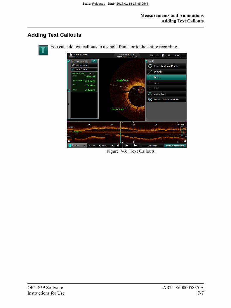
Measurements and AnnotationsAdding Text Callouts
OPTIS™ Software ARTUS600005835 AInstructions for Use 7-7
Adding Text Callouts
You can add text callouts to a single frame or to the entire recording.
Figure 7-3: Text Callouts
State: Released Date: 2017.01.18 17:45 GMT
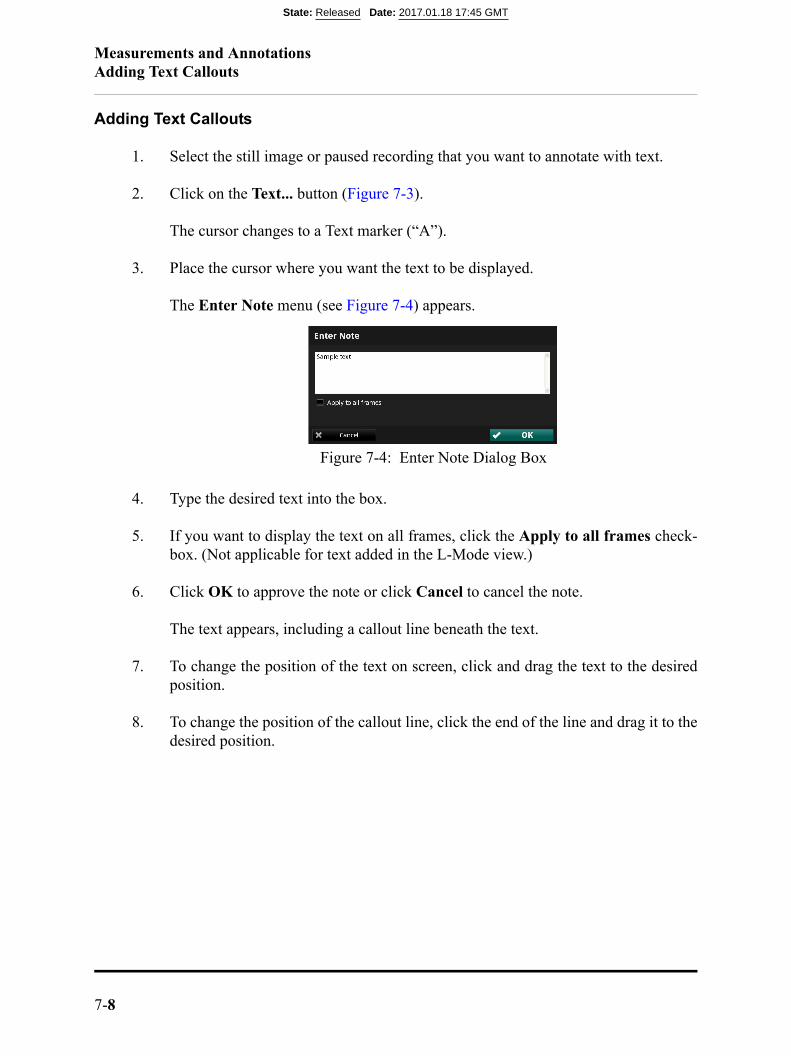
Measurements and AnnotationsAdding Text Callouts
7-8
Adding Text Callouts
1. Select the still image or paused recording that you want to annotate with text.
2. Click on the Text... button (Figure 7-3).
The cursor changes to a Text marker (“A”).
3. Place the cursor where you want the text to be displayed.
The Enter Note menu (see Figure 7-4) appears.
4. Type the desired text into the box.
5. If you want to display the text on all frames, click the Apply to all frames check-box. (Not applicable for text added in the L-Mode view.)
6. Click OK to approve the note or click Cancel to cancel the note.
The text appears, including a callout line beneath the text.
7. To change the position of the text on screen, click and drag the text to the desiredposition.
8. To change the position of the callout line, click the end of the line and drag it to thedesired position.
Figure 7-4: Enter Note Dialog Box
State: Released Date: 2017.01.18 17:45 GMT
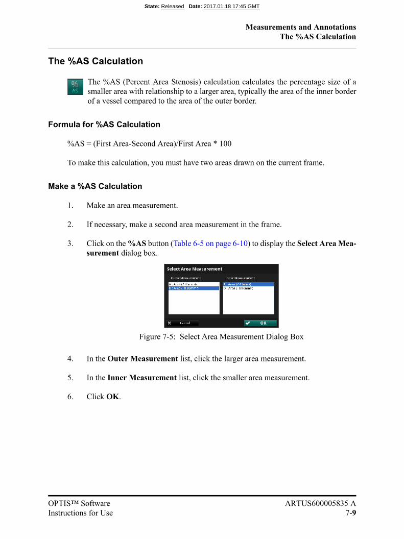
Measurements and AnnotationsThe %AS Calculation
OPTIS™ Software ARTUS600005835 AInstructions for Use 7-9
The %AS Calculation
The %AS (Percent Area Stenosis) calculation calculates the percentage size of asmaller area with relationship to a larger area, typically the area of the inner borderof a vessel compared to the area of the outer border.
Formula for %AS Calculation
%AS = (First Area-Second Area)/First Area * 100
To make this calculation, you must have two areas drawn on the current frame.
Make a %AS Calculation
1. Make an area measurement.
2. If necessary, make a second area measurement in the frame.
3. Click on the %AS button (Table 6-5 on page 6-10) to display the Select Area Mea-surement dialog box.
4. In the Outer Measurement list, click the larger area measurement.
5. In the Inner Measurement list, click the smaller area measurement.
6. Click OK.
Figure 7-5: Select Area Measurement Dialog Box
State: Released Date: 2017.01.18 17:45 GMT
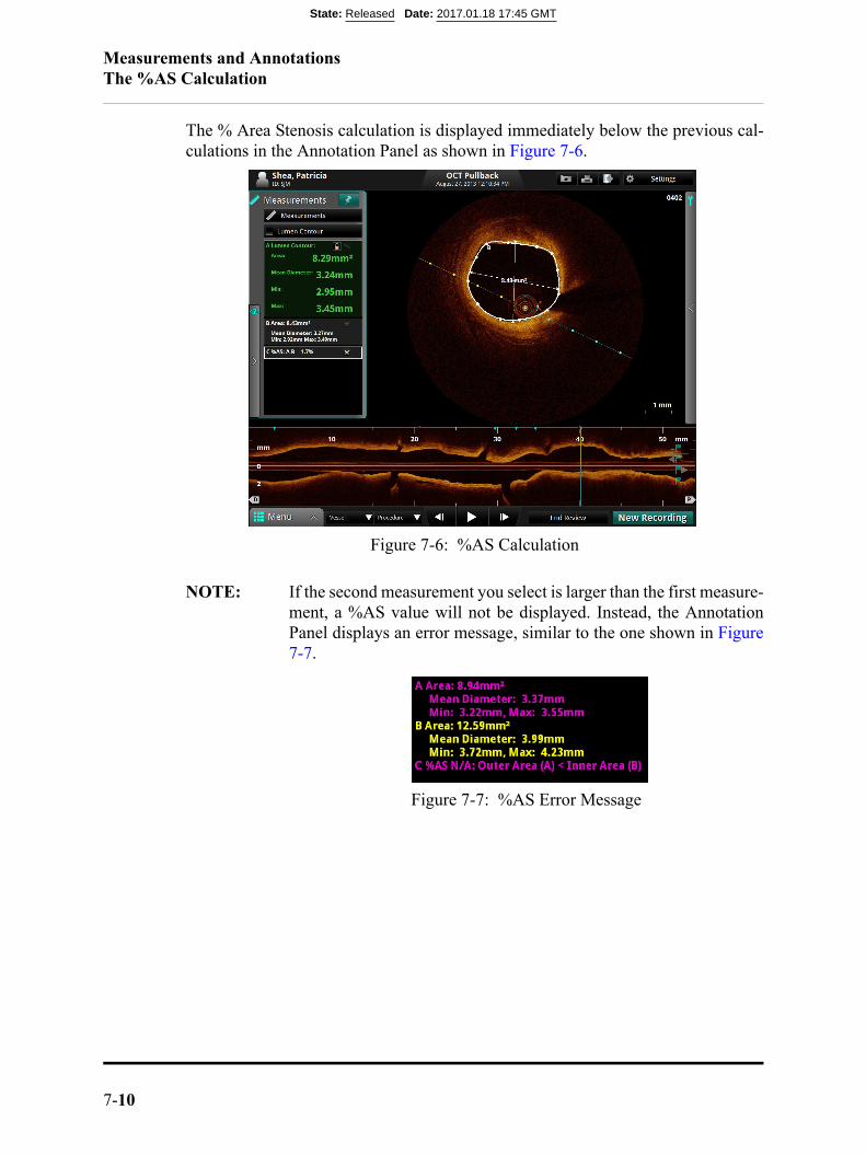
Measurements and AnnotationsThe %AS Calculation
7-10
The % Area Stenosis calculation is displayed immediately below the previous cal-culations in the Annotation Panel as shown in Figure 7-6.
NOTE: If the second measurement you select is larger than the first measure-ment, a %AS value will not be displayed. Instead, the AnnotationPanel displays an error message, similar to the one shown in Figure7-7.
Figure 7-6: %AS Calculation
Figure 7-7: %AS Error Message
State: Released Date: 2017.01.18 17:45 GMT
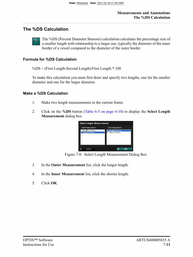
Measurements and AnnotationsThe %DS Calculation
OPTIS™ Software ARTUS600005835 AInstructions for Use 7-11
The %DS Calculation
The %DS (Percent Diameter Stenosis) calculation calculates the percentage size ofa smaller length with relationship to a larger one, typically the diameter of the innerborder of a vessel compared to the diameter of the outer border.
Formula for %DS Calculation
%DS = (First Length-Second Length)/First Length * 100
To make this calculation you must first draw and specify two lengths, one for the smallerdiameter and one for the larger diameter.
Make a %DS Calculation
1. Make two length measurements in the current frame.
2. Click on the %DS button (Table 6-5 on page 6-10) to display the Select LengthMeasurement dialog box.
3. In the Outer Measurement list, click the longer length.
4. In the Inner Measurement list, click the shorter length.
5. Click OK.
Figure 7-8: Select Length Measurement Dialog Box
State: Released Date: 2017.01.18 17:45 GMT
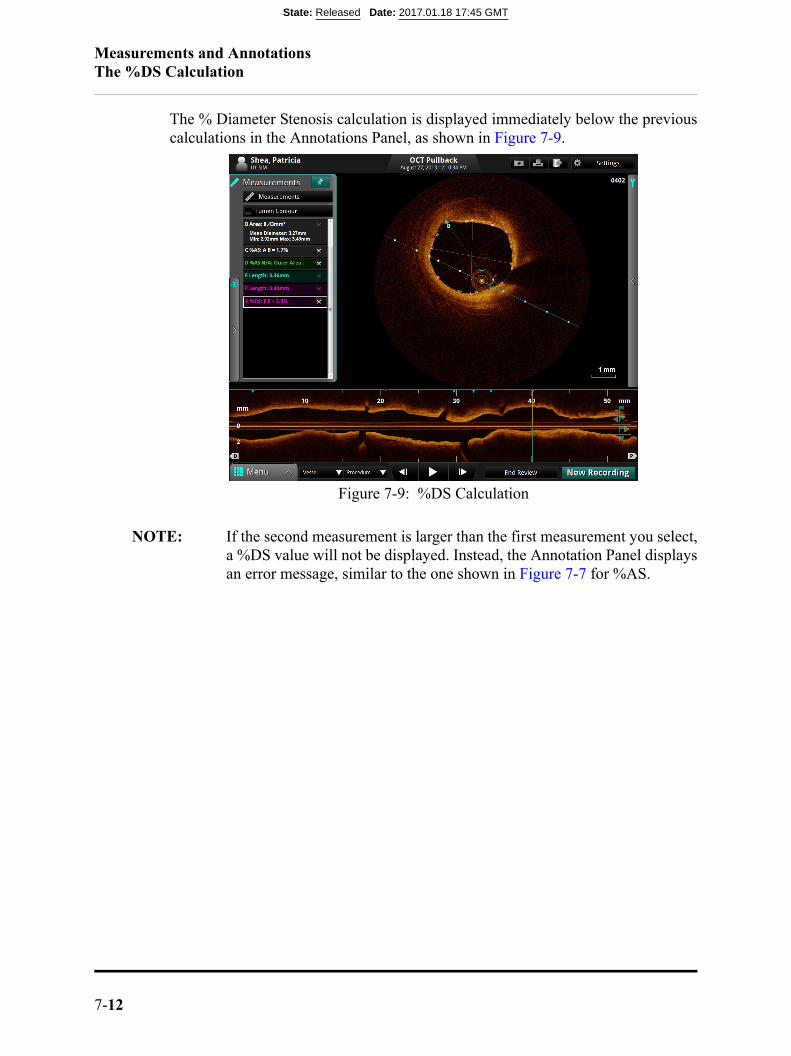
Measurements and AnnotationsThe %DS Calculation
7-12
The % Diameter Stenosis calculation is displayed immediately below the previouscalculations in the Annotations Panel, as shown in Figure 7-9.
NOTE: If the second measurement is larger than the first measurement you select,a %DS value will not be displayed. Instead, the Annotation Panel displaysan error message, similar to the one shown in Figure 7-7 for %AS.
Figure 7-9: %DS Calculation
State: Released Date: 2017.01.18 17:45 GMT
Measurements and AnnotationsField of View
OPTIS™ Software ARTUS600005835 AInstructions for Use 7-13
Field of View
You can zoom out on a recording or still image in order to see the full lumen on a largevessel, centered on the catheter.
NOTE: Using either Zoom function does not change the image data that is saved;it merely changes the portion of the data that is displayed.
Increase/Decrease Field of View
Click to increase the field of view on the recording or still image. Click again toreturn to normal image size.
NOTE: Depending on the current Flush Medium, the image may not occupy theentire 10.5 mm diameter.
You can change the magnification of the zoomed field. See “Calibration Adjustment(Tableside Controller Connected)” on page 6-58 for more information.
State: Released Date: 2017.01.18 17:45 GMT
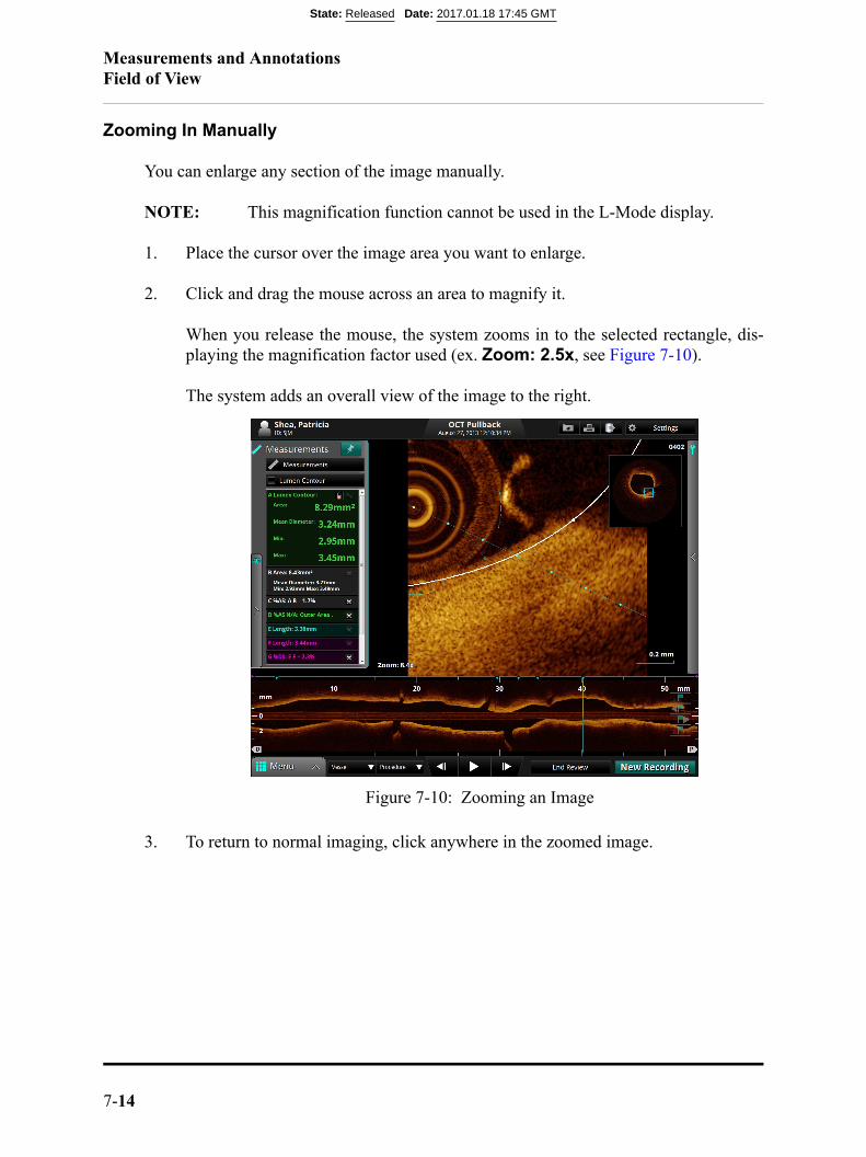
Measurements and AnnotationsField of View
7-14
Zooming In Manually
You can enlarge any section of the image manually.
NOTE: This magnification function cannot be used in the L-Mode display.
1. Place the cursor over the image area you want to enlarge.
2. Click and drag the mouse across an area to magnify it.
When you release the mouse, the system zooms in to the selected rectangle, dis-playing the magnification factor used (ex. Zoom: 2.5x, see Figure 7-10).
The system adds an overall view of the image to the right.
3. To return to normal imaging, click anywhere in the zoomed image.
Figure 7-10: Zooming an Image
State: Released Date: 2017.01.18 17:45 GMT
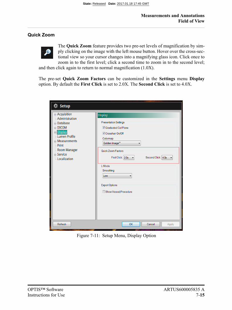
Measurements and AnnotationsField of View
OPTIS™ Software ARTUS600005835 AInstructions for Use 7-15
Quick Zoom
The Quick Zoom feature provides two pre-set levels of magnification by sim-ply clicking on the image with the left mouse button. Hover over the cross-sec-tional view so your cursor changes into a magnifying glass icon. Click once tozoom in to the first level; click a second time to zoom in to the second level;
and then click again to return to normal magnification (1.0X).
The pre-set Quick Zoom Factors can be customized in the Settings menu Displayoption. By default the First Click is set to 2.0X. The Second Click is set to 4.0X.
Figure 7-11: Setup Menu, Display Option
State: Released Date: 2017.01.18 17:45 GMT

Measurements and AnnotationsEditing Measurements and Annotations
7-16
Editing Measurements and Annotations
All measurements and annotations can be moved, deleted, or edited.
• Area and length measurements can be adjusted by moving or deleting controlpoints.
• Text annotations can be moved or deleted.
• The Lumen Contour is locked by default. Click the Lock Icon to lock orunlock the automatically-generated Lumen Contour. You must unlock theLumen Contour in order to make modifications to the area.
NOTE: When a measurement is changed, calculations that depend on that mea-surement are updated automatically.
State: Released Date: 2017.01.18 17:45 GMT

Measurements and AnnotationsEditing Measurements and Annotations
OPTIS™ Software ARTUS600005835 AInstructions for Use 7-17
Moving Individual Points
To move an individual point, click on the point and drag it to a new location.
NOTE: When you select a point, the point changes from a circle to a square, indi-cating that it may now be moved.
NOTE: When you edit an automatically-generated Lumen Profile contour,an Accept/Cancel toolbar displays. Click Cancel to cancel editing, orclick Accept to accept the changes. Next, an arrow icon appears inthe corner of the measurement listed in the Annotations Panel. Click thearrow to reset the contour on that frame back to the automatically-gener-ated Lumen Profile contour.
Adding Points to a Multiple Point Area
To add additional points to a multiple point area, click on the curve between two points.A new point will be added where you click.
NOTE: When you position the mouse over a location where a point can be added,the cursor changes from an arrow to a hand.
Deleting Points from a Multiple Point Area
To delete selected points in a multiple point area, click on the desired point and press the<Del> key on the keyboard.
NOTE: When you select a point, it changes from a circle to a square, indicatingthat it may now be deleted.
State: Released Date: 2017.01.18 17:45 GMT
Measurements and AnnotationsEditing Measurements and Annotations
7-18
Deleting Individual Measurements or Text Callouts
NOTE: If a measurement is in use with a calculation (for example, an areaused by %AS), the individual measurement cannot be deleted untilthe calculation is deleted.
To delete a measurement:
• Click on the “x” next to it in the Annotations Panel. The measurement is deleted.
To delete a distance measurement in the L-Mode:
1. Click on a distance measurement in the L-Mode to select it. A white box appearsaround the label.
2. Press the <Del> key on the keyboard.
The distance measurement is deleted.
To delete a text callout:
1. Click on a text callout to select it. A white box appears around the text callout.
2. Press the <Del> key on the keyboard.
The text callout is deleted.
Deleting All Measurements and Text Callouts
Click to delete all measurements, calculations, and text callouts from this recordingor still image.
State: Released Date: 2017.01.18 17:45 GMT
OPTIS™ Software ARTUS600005835 AInstructions for Use 8-1
Exporting, Importing, and Managing Files 8
CAUTION: Please note St. Jude Medical makes no representation or warrantythat use of the OPTIS™ Software complies with applicable privacy,security and confidentiality laws, but encourages you to assess yourown risk as you use, disclose, control, process or transfer patienthealth information with the OPTIS™ Software.
NOTE: Do not remove media (CD/DVD/USB) during an import or export func-tion. Verify that the data transfer is complete before removing media.
State: Released Date: 2017.01.18 17:45 GMT
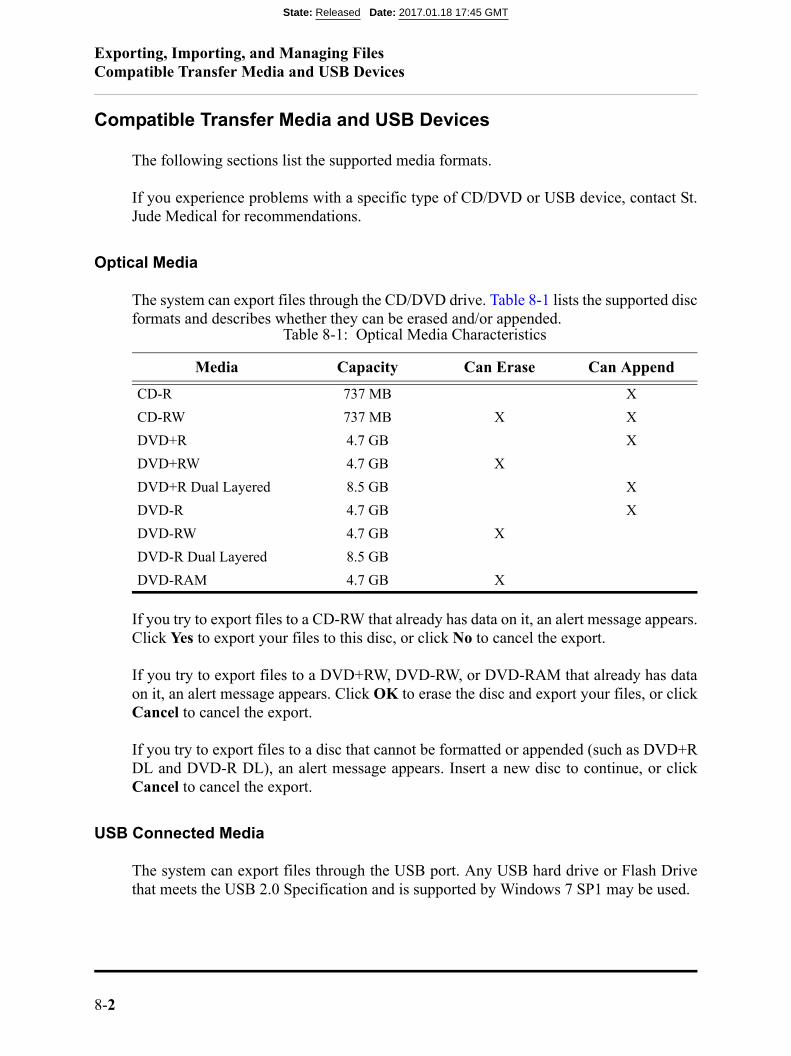
Exporting, Importing, and Managing FilesCompatible Transfer Media and USB Devices
8-2
Compatible Transfer Media and USB Devices
The following sections list the supported media formats.
If you experience problems with a specific type of CD/DVD or USB device, contact St.Jude Medical for recommendations.
Optical Media
The system can export files through the CD/DVD drive. Table 8-1 lists the supported discformats and describes whether they can be erased and/or appended.
If you try to export files to a CD-RW that already has data on it, an alert message appears.Click Yes to export your files to this disc, or click No to cancel the export.
If you try to export files to a DVD+RW, DVD-RW, or DVD-RAM that already has dataon it, an alert message appears. Click OK to erase the disc and export your files, or clickCancel to cancel the export.
If you try to export files to a disc that cannot be formatted or appended (such as DVD+RDL and DVD-R DL), an alert message appears. Insert a new disc to continue, or clickCancel to cancel the export.
USB Connected Media
The system can export files through the USB port. Any USB hard drive or Flash Drivethat meets the USB 2.0 Specification and is supported by Windows 7 SP1 may be used.
Table 8-1: Optical Media Characteristics
Media Capacity Can Erase Can Append
CD-R 737 MB X
CD-RW 737 MB X X
DVD+R 4.7 GB X
DVD+RW 4.7 GB X
DVD+R Dual Layered 8.5 GB X
DVD-R 4.7 GB X
DVD-RW 4.7 GB X
DVD-R Dual Layered 8.5 GB
DVD-RAM 4.7 GB X
State: Released Date: 2017.01.18 17:45 GMT

Exporting, Importing, and Managing FilesCompatible Transfer Media and USB Devices
OPTIS™ Software ARTUS600005835 AInstructions for Use 8-3
WARNING: Inside the catheterization lab only port-powered USB drives may beconnected to the USB port. Connecting externally powered devices tothe USB port in the patient vicinity may compromise electrical isola-tion and cause patient injury.
NOTE: Outside the catheterization lab, IEC 60950-compliant, externally poweredUSB hard drives may be connected to the USB port.
State: Released Date: 2017.01.18 17:45 GMT

Exporting, Importing, and Managing FilesFile Formats
8-4
File Formats
Files can be exported in native file format (raw OCT format), a standard graphic file for-mat (standard format), or DICOM format. Exported files can be saved on a CD/ DVD orexternal USB device, or exported to a DICOM storage server. You can choose whether todelete files after transfer or keep them on the system.
About Native (Raw OCT) Format
If you export in native (raw OCT) file format, every feature of the OCT file will beexported, and the files can be imported into another current or legacy St. Jude Medical™OCT system, or an Offline Review Workstation (ORW) and reviewed and manipulatedthere. An exported OCT file contains exactly the same data as the original file, includingany measurements and annotation additions, all patient information associated with eachfile, and system diagnostic information to help diagnose possible image quality problems.
Note the following:
• Native (raw OCT) files can be reviewed and manipulated only with a current or leg-acy St. Jude Medical™ OCT system, or an Offline Review Workstation (ORW).They cannot be accessed with any other systems or software.
• Native (raw OCT) files are large; exporting to CD/DVD may require many discs.
About DICOM Format
For a multiple-frame recording using DICOM format stored on a network server, themaximum resolution is 800 x 800.
NOTE: To export files complete with Angio Co-registration data, use native (rawOCT) format. DICOM format does not support Angio Co-registrationdata.
State: Released Date: 2017.01.18 17:45 GMT

Exporting, Importing, and Managing FilesFile Formats
OPTIS™ Software ARTUS600005835 AInstructions for Use 8-5
About Standard Format
If you export in standard file formats (AVI, compressed AVI, or Multi-page TIFF forrecordings; JPEG, TIFF, or BMP for images), the images can be used in computer appli-cations outside the system, but cannot be imported into a current or legacy St. Jude Med-ical™ OCT system, or an Offline Review Workstation (ORW).
NOTE: For standard format multiple-file exports, the same limitations apply asdescribed in “Image Format and Size in Standard Formats”. Just as whenexporting a single file, you can choose the size and format.
State: Released Date: 2017.01.18 17:45 GMT
Exporting, Importing, and Managing FilesImage Format and Size in Standard Formats
8-6
Image Format and Size in Standard Formats
When exporting files in standard formats, the system gives you several choices of formatand file resolution (size). When making these choices, keep in mind the following:
File Size
• File size is dependent on resolution; the lower the resolution, the smaller the file.
• Decreasing resolution makes the resulting image grainier, but no quantitativedata, annotations or measurements are lost.
• Increasing resolution results in higher image quality in the exported file. Fora file that is a single frame (from a captured image, a paused image, or froma recording that has been edited down to only one frame), the maximum res-olution for export is 2048 x 2048.
• For a multiple-frame recording, the maximum resolution is 1024 x 1024.
• It is best to select the resolution that will actually be used in the intended applica-tion. When images are enlarged or reduced by the system, the maximum usefulinformation is preserved. External applications may not apply the same diligencewhen enlarging or reducing an image.
Standard File Format
• The system can export recordings as either AVI, compressed AVI, or Multi-pageTIFF format.
• Most computers include standard players that will play AVI format files.
• The Compressed AVI and Multi-page TIFF formats require that special play-ers for these formats be installed on the computer you will use to review thefiles.
• The system can export still images as either JPEG, TIFF, or BMP.
• TIFF and BMP files are high resolution bit-map files with large file size.
• JPEG files are compressed image files designed especially for viewing in acomputer application. They are significantly smaller than TIFF or BMP files,and are typically the best choice for slide shows or other applications wherethe files will be viewed on a computer monitor.
State: Released Date: 2017.01.18 17:45 GMT
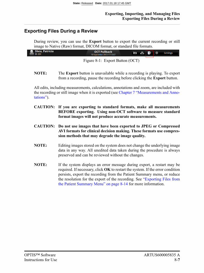
Exporting, Importing, and Managing FilesExporting Files During a Review
OPTIS™ Software ARTUS600005835 AInstructions for Use 8-7
Exporting Files During a Review
During review, you can use the Export button to export the current recording or stillimage to Native (Raw) format, DICOM format, or standard file formats.
NOTE: The Export button is unavailable while a recording is playing. To exportfrom a recording, pause the recording before clicking the Export button.
All edits, including measurements, calculations, annotations and zoom, are included withthe recording or still image when it is exported (see Chapter 7 “Measurements and Anno-tations”).
CAUTION: If you are exporting to standard formats, make all measurementsBEFORE exporting. Using non-OCT software to measure standardformat images will not produce accurate measurements.
CAUTION: Do not use images that have been exported to JPEG or CompressedAVI formats for clinical decision making. These formats use compres-sion methods that may degrade the image quality.
NOTE: Editing images stored on the system does not change the underlying imagedata in any way. All unedited data taken during the procedure is alwayspreserved and can be reviewed without the changes.
NOTE: If the system displays an error message during export, a restart may berequired. If necessary, click OK to restart the system. If the error conditionpersists, export the recording from the Patient Summary menu, or reducethe resolution for the export of the recording. See “Exporting Files fromthe Patient Summary Menu” on page 8-14 for more information.
Figure 8-1: Export Button (OCT)
State: Released Date: 2017.01.18 17:45 GMT
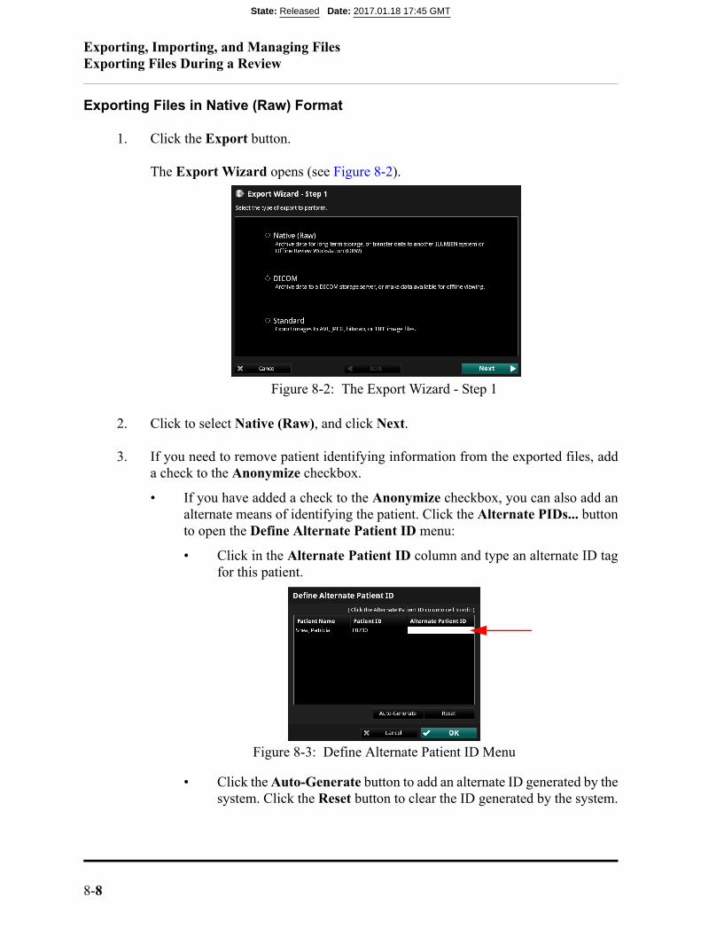
Exporting, Importing, and Managing FilesExporting Files During a Review
8-8
Exporting Files in Native (Raw) Format
1. Click the Export button.
The Export Wizard opens (see Figure 8-2).
2. Click to select Native (Raw), and click Next.
3. If you need to remove patient identifying information from the exported files, adda check to the Anonymize checkbox.
• If you have added a check to the Anonymize checkbox, you can also add analternate means of identifying the patient. Click the Alternate PIDs... buttonto open the Define Alternate Patient ID menu:
• Click in the Alternate Patient ID column and type an alternate ID tagfor this patient.
• Click the Auto-Generate button to add an alternate ID generated by thesystem. Click the Reset button to clear the ID generated by the system.
Figure 8-2: The Export Wizard - Step 1
Figure 8-3: Define Alternate Patient ID Menu
State: Released Date: 2017.01.18 17:45 GMT
Exporting, Importing, and Managing FilesExporting Files During a Review
OPTIS™ Software ARTUS600005835 AInstructions for Use 8-9
• Click OK to approve the change and close the menu, or Cancel toreturn to previous settings and close the Define Alternate Patient IDmenu.
4. Click to set the System File Options for the file(s) that you are exporting:
• Leave Unchanged - the files are exported, but the original files in the systemare not changed.
• Mark as Archived - the files are exported, and marked as archived.
• Remove when Complete - the files are deleted from the system once theexport is complete.
5. Click Next to approve the settings and open the next page of the Export Wizard.
NOTE: Click Back to return to the previous page, or click Cancel to exit theExport Wizard without exporting files.
6. Click to select an Export Destination:
NOTE: If an output device is not available, that option cannot be selected.
NOTE: Check that the Free space in the Drive Capacity section is largeenough to save the files that are being exported.
• Click CD/DVD to export to a CD/DVD.
If the inserted CD/DVD is blank, you can edit the name in the Volume Labelfield.
• Click External Drive to export to an external USB device.
If necessary, click the External Drive selection box to select the correct drivelocation from the drop-down menu.
Click the Ellipsis (...) button to the right of the Path selection box to browsefor a specific folder on the device.
7. Click Next to approve the settings and open the next page of the Export Wizard.
The next page of the Export Wizard opens. The menu shows a summary of ExportInformation.
8. Click Export to export the selected files.
The export begins. If necessary, click Cancel to stop the export in progress.
State: Released Date: 2017.01.18 17:45 GMT
Exporting, Importing, and Managing FilesExporting Files During a Review
8-10
9. When complete, click Done to close the Export Wizard.
Exporting Files in DICOM Format
1. Click the Export button.
The Export Wizard opens (see Figure 8-2).
2. Click to select DICOM, and click Next.
NOTE: If you are reviewing a single frame instead of a recording, skip to Step 5
3. Click to select the material to be exported:
• Pullback
• Current Frame
• Bookmarked Frames - This choice is unavailable if there are no book-marked frames in the recording.
4. Click Next to approve the settings and open the next page of the Export Wizard.
NOTE: Click Back to return to the previous page, or click Cancel to exit theExport Wizard without exporting files.
5. If you need to remove patient identifying information from the exported files, adda check to the Anonymize checkbox.
6. Click to set the System File Options for the file(s) that you are exporting:
• Leave Unchanged - the files are exported, but the original files in the systemare not changed.
• Mark as Archived - the files are exported, and marked as archived.
7. Click Next to approve the settings and open the next page of the Export Wizard.
8. Click to select an Export Destination:
NOTE: If an output device is not available, that option cannot be selected.
NOTE: Check that the Free space in the Drive Capacity section is largeenough to save the files that are being exported.
• Click CD/DVD to export to a CD/DVD.
State: Released Date: 2017.01.18 17:45 GMT
Exporting, Importing, and Managing FilesExporting Files During a Review
OPTIS™ Software ARTUS600005835 AInstructions for Use 8-11
If the inserted CD/DVD is blank, you can edit the name in the Volume Labelfield.
• Click External Drive to export to an external USB device.
If necessary, click the External Drive selection box to select the correct drivelocation from the drop-down menu.
Click the Ellipsis (...) button to the right of the Path selection box to browsefor a specific folder on the device.
• Click Remote Store to export to a network DICOM Server.
NOTE: The Remote Store option is enabled only if the DICOM net-work connection has been configured on the DICOM tab ofthe Setup dialog box (see Chapter 10 “User Interface Refer-ence”for more information on DICOM settings).
9. Click Next to approve the settings and open the next page of the Export Wizard.
The next page of the Export Wizard opens, showing the Select DICOM Optionspage.
• In the Image Type section, select the desired DICOM image type as well asany additional options.
NOTE: When exporting to a DICOM Server, only the options sup-ported by that server will be enabled.
10. Click Next to approve the settings and open the next page of the Export Wizard.
The next page of the Export Wizard opens, showing a summary of Export Infor-mation.
11. Click Export to export the selected files.
The export begins. If necessary, click Cancel to stop the export in progress.
12. When complete, click Done to close the Export Wizard.
State: Released Date: 2017.01.18 17:45 GMT
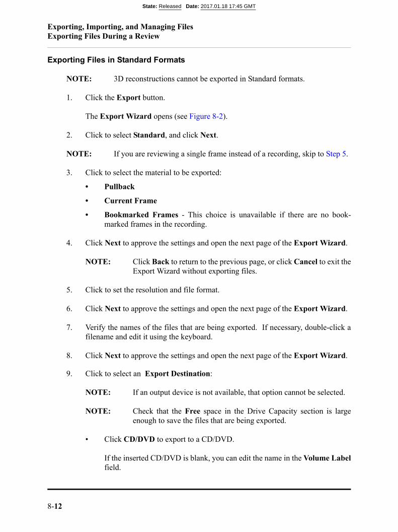
Exporting, Importing, and Managing FilesExporting Files During a Review
8-12
Exporting Files in Standard Formats
NOTE: 3D reconstructions cannot be exported in Standard formats.
1. Click the Export button.
The Export Wizard opens (see Figure 8-2).
2. Click to select Standard, and click Next.
NOTE: If you are reviewing a single frame instead of a recording, skip to Step 5.
3. Click to select the material to be exported:
• Pullback
• Current Frame
• Bookmarked Frames - This choice is unavailable if there are no book-marked frames in the recording.
4. Click Next to approve the settings and open the next page of the Export Wizard.
NOTE: Click Back to return to the previous page, or click Cancel to exit theExport Wizard without exporting files.
5. Click to set the resolution and file format.
6. Click Next to approve the settings and open the next page of the Export Wizard.
7. Verify the names of the files that are being exported. If necessary, double-click afilename and edit it using the keyboard.
8. Click Next to approve the settings and open the next page of the Export Wizard.
9. Click to select an Export Destination:
NOTE: If an output device is not available, that option cannot be selected.
NOTE: Check that the Free space in the Drive Capacity section is largeenough to save the files that are being exported.
• Click CD/DVD to export to a CD/DVD.
If the inserted CD/DVD is blank, you can edit the name in the Volume Labelfield.
State: Released Date: 2017.01.18 17:45 GMT
Exporting, Importing, and Managing FilesExporting Files During a Review
OPTIS™ Software ARTUS600005835 AInstructions for Use 8-13
• Click External Drive to export to an external USB device.
If necessary, click the External Drive selection box to select the correct drivelocation from the drop-down menu.
Click the Ellipsis (...) button to the right of the Path selection box to browsefor a specific folder on the device.
10. Click Next to approve the settings and open the next page of the Export Wizard.
The next page of the Export Wizard opens. The menu shows a summary of ExportInformation.
11. Click Export to export the selected files.
The export begins. If necessary, click Cancel to stop the export in progress.
12. When complete, click Done to close the Export Wizard.
State: Released Date: 2017.01.18 17:45 GMT

Exporting, Importing, and Managing FilesExporting Files from the Patient Summary Menu
8-14
Exporting Files from the Patient Summary Menu
You can export files from the Patient Summary menu.
1. In the Patient Summary menu, add a check to the checkbox of each file that youwant to export.
A white border appears around each record that is selected.
NOTE: In the Patient Summary menu, you can select multiple files fromthe same date, but not from different dates. Within the Export Wiz-ard, you can select additional files from different dates and differentpatients.
NOTE: To deselect a file, clear the check from the checkbox. The check andwhite border disappear to indicate that the file is no longer selected.
2. Click the Export button at the top of the screen.
The Export Wizard opens (see Figure 8-2).
3. Click to select an export format, and click Next.
The next page of the Export Wizard opens.
Figure 8-4: Highlighted Records
State: Released Date: 2017.01.18 17:45 GMT

Exporting, Importing, and Managing FilesExporting Files from the Patient Summary Menu
OPTIS™ Software ARTUS600005835 AInstructions for Use 8-15
4. To filter the list, click the All, Unarchived, or New since last archive button.
5. If necessary, add a check to the checkbox of any other recording to be exported.
• Add a check to the checkbox of patient to select all recordings for thatpatient.
• Add a check to the checkbox of the first entry in the list to select allrecordings.
6. Click Next to approve the list of files for export and open the next page of theExport Wizard.
• If you are exporting in Native (Raw) format, refer to Step 3 in “ExportingFiles in Native (Raw) Format” on page 8-8 to continue the export.
• If you are exporting in DICOM format, refer to Step 5 in “Exporting Files inDICOM Format” on page 8-10 to continue the export.
• If you are exporting in standard formats, refer to Step 5 in “Exporting Files inStandard Formats” on page 8-12 to continue the export.
State: Released Date: 2017.01.18 17:45 GMT
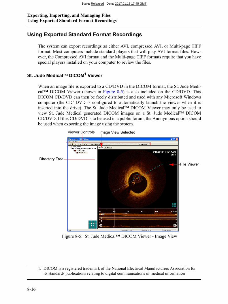
Exporting, Importing, and Managing FilesUsing Exported Standard Format Recordings
8-16
Using Exported Standard Format Recordings
The system can export recordings as either AVI, compressed AVI, or Multi-page TIFFformat. Most computers include standard players that will play AVI format files. How-ever, the Compressed AVI format and the Multi-page TIFF formats require that you havespecial players installed on your computer to review the files.
St. Jude Medical™ DICOM1 Viewer
When an image file is exported to a CD/DVD in the DICOM format, the St. Jude Medi-cal™ DICOM Viewer (shown in Figure 8-5) is also included on the CD/DVD. ThisDICOM CD/DVD can then be freely distributed and used with any Microsoft Windowscomputer (the CD/ DVD is configured to automatically launch the viewer when it isinserted into the drive). The St. Jude Medical™ DICOM Viewer may only be used toview St. Jude Medical generated DICOM images on a St. Jude Medical™ DICOMCD/DVD. If this CD/DVD is to be used in a public forum, the Anonymous option shouldbe used when exporting the image using the system.
1. DICOM is a registered trademark of the National Electrical Manufacturers Association forits standards publications relating to digital communications of medical information
Figure 8-5: St. Jude Medical™ DICOM Viewer - Image View
Viewer Controls
File Viewer
Directory Tree
Image View Selected
State: Released Date: 2017.01.18 17:45 GMT
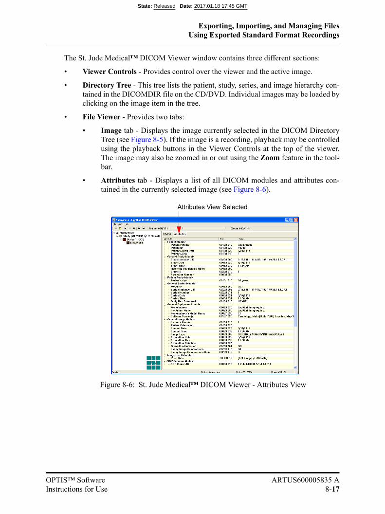
Exporting, Importing, and Managing FilesUsing Exported Standard Format Recordings
OPTIS™ Software ARTUS600005835 AInstructions for Use 8-17
The St. Jude Medical™ DICOM Viewer window contains three different sections:
• Viewer Controls - Provides control over the viewer and the active image.
• Directory Tree - This tree lists the patient, study, series, and image hierarchy con-tained in the DICOMDIR file on the CD/DVD. Individual images may be loaded byclicking on the image item in the tree.
• File Viewer - Provides two tabs:
• Image tab - Displays the image currently selected in the DICOM DirectoryTree (see Figure 8-5). If the image is a recording, playback may be controlledusing the playback buttons in the Viewer Controls at the top of the viewer.The image may also be zoomed in or out using the Zoom feature in the tool-bar.
• Attributes tab - Displays a list of all DICOM modules and attributes con-tained in the currently selected image (see Figure 8-6).
Figure 8-6: St. Jude Medical™ DICOM Viewer - Attributes View
Attributes View Selected
State: Released Date: 2017.01.18 17:45 GMT
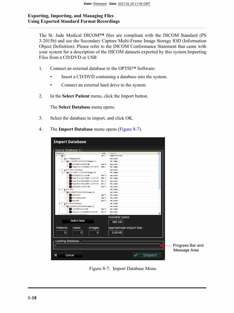
Exporting, Importing, and Managing FilesUsing Exported Standard Format Recordings
8-18
The St. Jude Medical DICOM™ files are compliant with the DICOM Standard (PS3-2015b) and use the Secondary Capture Multi-Frame Image Storage IOD (InformationObject Definition). Please refer to the DICOM Conformance Statement that came withyour system for a description of the DICOM datasets exported by this system.ImportingFiles from a CD/DVD or USB
1. Connect an external database to the OPTIS™ Software:
• Insert a CD/DVD containing a database into the system.
• Connect an external hard drive to the system.
2. In the Select Patient menu, click the Import button.
The Select Database menu opens.
3. Select the database to import, and click OK.
4. The Import Database menu opens (Figure 8-7).
Figure 8-7: Import Database Menu
Progress Bar and Message Area
State: Released Date: 2017.01.18 17:45 GMT
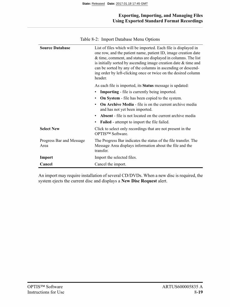
Exporting, Importing, and Managing FilesUsing Exported Standard Format Recordings
OPTIS™ Software ARTUS600005835 AInstructions for Use 8-19
An import may require installation of several CD/DVDs. When a new disc is required, thesystem ejects the current disc and displays a New Disc Request alert.
Table 8-2: Import Database Menu Options
Source Database List of files which will be imported. Each file is displayed in one row, and the patient name, patient ID, image creation date & time, comment, and status are displayed in columns. The list is initially sorted by ascending image creation date & time and can be sorted by any of the columns in ascending or descend-ing order by left-clicking once or twice on the desired column header.
As each file is imported, its Status message is updated:
• Importing - file is currently being imported.
• On System - file has been copied to the system.
• On Archive Media - file is on the current archive media and has not yet been imported.
• Absent - file is not located on the current archive media
• Failed - attempt to import the file failed.
Select New Click to select only recordings that are not present in the OPTIS™ Software.
Progress Bar and Message Area
The Progress Bar indicates the status of the file transfer. The Message Area displays information about the file and the transfer.
Import Import the selected files.
Cancel Cancel the import.
State: Released Date: 2017.01.18 17:45 GMT
Exporting, Importing, and Managing FilesDeleting Files
8-20
Deleting Files
You can delete files by any of the following methods:
• Exporting images with the Remove When Complete function turned on (see“Exporting Files in Native (Raw) Format” on page 8-8).
• Select and delete files from the Patient Summary menu.
• Select and delete files from the Database menu.
CAUTION: Once files are deleted, they cannot be restored. After files have beendeleted, they can only be imported back to your system from yourarchived copies.
Deleting Files from the Patient Summary Menu
1. In the Patient Summary menu, add a check to the checkbox of each file that youwant to delete (see Figure 8-4 on page 8-14).
A white border appears around each record that is selected.
NOTE: In the Patient Summary menu, you can select multiple files fromthe same date, but not from different dates.
NOTE: To deselect a file, clear the check from the checkbox. The check andwhite border disappear to indicate that the file is no longer selected.
2. Click the Delete button at the bottom of the screen.
A prompt asks you to confirm that you want to delete the selected files.
3. Click Yes to delete the files, or click No to cancel the deletion and return to thePatient Summary menu.
State: Released Date: 2017.01.18 17:45 GMT

Exporting, Importing, and Managing FilesDeleting Files
OPTIS™ Software ARTUS600005835 AInstructions for Use 8-21
Deleting Files from the Database Menu
1. Click the Menu button and select Setup. The Setup dialog box opens.
2. Click the Database button to open the Database menu (see Figure 10-4 on page10-7).
3. Add a check to the checkbox of any recording to be deleted.
• Add a check to the checkbox of patient to select all recordings for that patient.
• Add a check to the checkbox of the first entry in the list to select all record-ings.
4. Click the Delete button.
A prompt asks you to confirm that you want to delete the selected files.
5. Click Yes to delete the files, or click No to cancel the deletion and return to theDatabase menu.
Figure 8-8: Deletion Warning Alert
State: Released Date: 2017.01.18 17:45 GMT
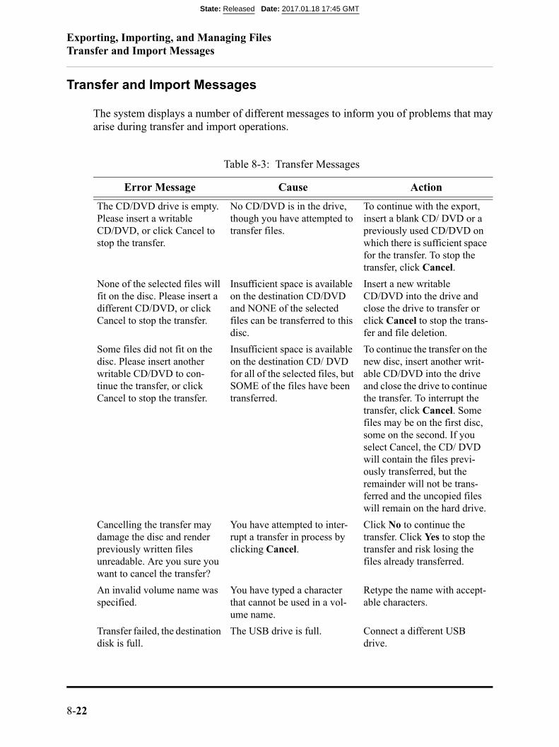
Exporting, Importing, and Managing FilesTransfer and Import Messages
8-22
Transfer and Import Messages
The system displays a number of different messages to inform you of problems that mayarise during transfer and import operations.
Table 8-3: Transfer Messages
Error Message Cause Action
The CD/DVD drive is empty. Please insert a writable CD/DVD, or click Cancel to stop the transfer.
No CD/DVD is in the drive, though you have attempted to transfer files.
To continue with the export, insert a blank CD/ DVD or a previously used CD/DVD on which there is sufficient space for the transfer. To stop the transfer, click Cancel.
None of the selected files will fit on the disc. Please insert a different CD/DVD, or click Cancel to stop the transfer.
Insufficient space is available on the destination CD/DVD and NONE of the selected files can be transferred to this disc.
Insert a new writable CD/DVD into the drive and close the drive to transfer or click Cancel to stop the trans-fer and file deletion.
Some files did not fit on the disc. Please insert another writable CD/DVD to con-tinue the transfer, or click Cancel to stop the transfer.
Insufficient space is available on the destination CD/ DVD for all of the selected files, but SOME of the files have been transferred.
To continue the transfer on the new disc, insert another writ-able CD/DVD into the drive and close the drive to continue the transfer. To interrupt the transfer, click Cancel. Some files may be on the first disc, some on the second. If you select Cancel, the CD/ DVD will contain the files previ-ously transferred, but the remainder will not be trans-ferred and the uncopied files will remain on the hard drive.
Cancelling the transfer may damage the disc and render previously written files unreadable. Are you sure you want to cancel the transfer?
You have attempted to inter-rupt a transfer in process by clicking Cancel.
Click No to continue the transfer. Click Yes to stop the transfer and risk losing the files already transferred.
An invalid volume name was specified.
You have typed a character that cannot be used in a vol-ume name.
Retype the name with accept-able characters.
Transfer failed, the destination disk is full.
The USB drive is full. Connect a different USB drive.
State: Released Date: 2017.01.18 17:45 GMT
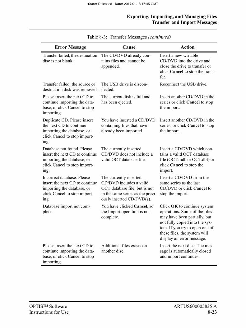
Exporting, Importing, and Managing FilesTransfer and Import Messages
OPTIS™ Software ARTUS600005835 AInstructions for Use 8-23
Transfer failed, the destination disc is not blank.
The CD/DVD already con-tains files and cannot be appended.
Insert a new writable CD/DVD into the drive and close the drive to transfer or click Cancel to stop the trans-fer.
Transfer failed, the source or destination disk was removed.
The USB drive is discon-nected.
Reconnect the USB drive.
Please insert the next CD to continue importing the data-base, or click Cancel to stop importing.
The current disk is full and has been ejected.
Insert another CD/DVD in the series or click Cancel to stop the import.
Duplicate CD. Please insert the next CD to continue importing the database, or click Cancel to stop import-ing.
You have inserted a CD/DVD containing files that have already been imported.
Insert another CD/DVD in the series. or click Cancel to stop the import.
Database not found. Please insert the next CD to continue importing the database, or click Cancel to stop import-ing.
The currently inserted CD/DVD does not include a valid OCT database file.
Insert a CD/DVD which con-tains a valid OCT database file (OCT.mdb or OCT.dbf) or click Cancel to stop the import.
Incorrect database. Please insert the next CD to continue importing the database, or click Cancel to stop import-ing.
The currently inserted CD/DVD includes a valid OCT database file, but is not in the same series as the previ-ously inserted CD/DVD(s).
Insert a CD/DVD from the same series as the last CD/DVD or click Cancel to stop the import.
Database import not com-plete.
You have clicked Cancel, so the Import operation is not complete.
Click OK to continue system operations. Some of the files may have been partially, but not fully copied into the sys-tem. If you try to open one of these files, the system will display an error message.
Please insert the next CD to continue importing the data-base, or click Cancel to stop importing.
Additional files exists on another disc.
Insert the next disc. The mes-sage is automatically closed and import continues.
Table 8-3: Transfer Messages (continued)
Error Message Cause Action
State: Released Date: 2017.01.18 17:45 GMT

Exporting, Importing, and Managing FilesDuplicate File Name Messages
8-24
Duplicate File Name Messages
Duplicate file name messages warn you when a file has been selected for export with thesame name as one already saved. The system does not allow any files to be overwritten.
NOTE: Do not save an image using the same name used for a previous file. St.Jude Medical recommends that you label media containing exported fileswith descriptive information, including the procedure or export date. Toresolve these errors when copying to CD/DVDs, insert another CD/DVDinto the drive and close the drive. File transfer resumes automatically. Ifthe transfer is cancelled, the uncopied files will remain on the hard drive.
Database Statistics
You can check the size and statistics of your system’s database using the Database Main-tenance button in the Setup dialog box. See “Setup - Database/Maintenance Menu” onpage 10-9 for more information. As a best practice, archive your data regularly.
Table 8-4: Duplicate File Name Messages
Message Cause Action
Duplicate files could not be written. Please insert a differ-ent CD/DVD to continue the transfer, or click Cancel to stop the transfer
SOME of the file names in an export set are already found on the installed CD/DVD.
Files with non-identical names will be written to the current CD/DVD; files with identical names will not be written. To save the files with the duplicate file names, insert a new CD/DVD and continue with the transfer. To stop the transfer, click Cancel.
The disc already contains files with the same names. Please insert a different CD/DVD to continue the transfer, or click Cancel to stop the transfer.
ALL the file names in an export set are already found on the installed CD/DVD.
To save these files with these file names, insert a new CD/DVD and continue with the transfer. To stop the trans-fer, click Cancel. This mes-sage may be displayed when the Delete after transfer checkbox in the Manage Exported Files menu is unchecked, leading to re-exporting the same files.
State: Released Date: 2017.01.18 17:45 GMT

Exporting, Importing, and Managing FilesImporting Patient Information From a DICOM Worklist or Storage Server
OPTIS™ Software ARTUS600005835 AInstructions for Use 8-25
Importing Patient Information From a DICOM Worklist or Storage Server
From DICOM Worklist
To import patient information From a DICOM Modality Worklist (DICOM Worklist),complete the following steps:
1. From the Select Patient menu, click the Add Patient button. The Add Patient -Step 1 guidance displays.
NOTE: If there is more than one DICOM Modality Worklist Server detected,select the desired server when prompted.
2. Select DICOM Worklist Items. Click the Next button. The Add Patient - Step 2guidance displays.
Figure 8-9: Add Patient - Step 1 (Worklist)
State: Released Date: 2017.01.18 17:45 GMT
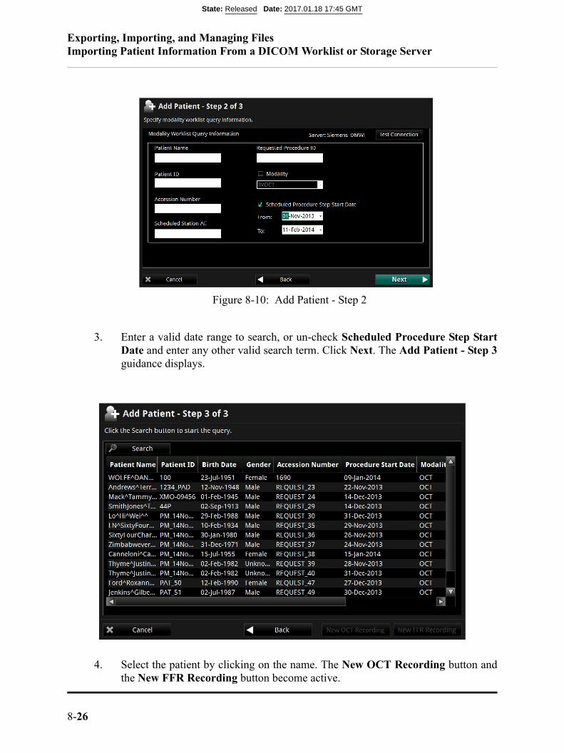
Exporting, Importing, and Managing FilesImporting Patient Information From a DICOM Worklist or Storage Server
8-26
3. Enter a valid date range to search, or un-check Scheduled Procedure Step StartDate and enter any other valid search term. Click Next. The Add Patient - Step 3guidance displays.
4. Select the patient by clicking on the name. The New OCT Recording button andthe New FFR Recording button become active.
Figure 8-10: Add Patient - Step 2
State: Released Date: 2017.01.18 17:45 GMT

Exporting, Importing, and Managing FilesImporting Patient Information From a DICOM Worklist or Storage Server
OPTIS™ Software ARTUS600005835 AInstructions for Use 8-27
5. Click either the New OCT Recording button or the New FFR Recording buttonto continue.
From a DICOM Storage Server
To import patient information From a DICOM Storage Server, complete the followingsteps:
1. From the Select Patient menu, click the Add Patient button. The Add Patient -Step 1 guidance displays.
State: Released Date: 2017.01.18 17:45 GMT
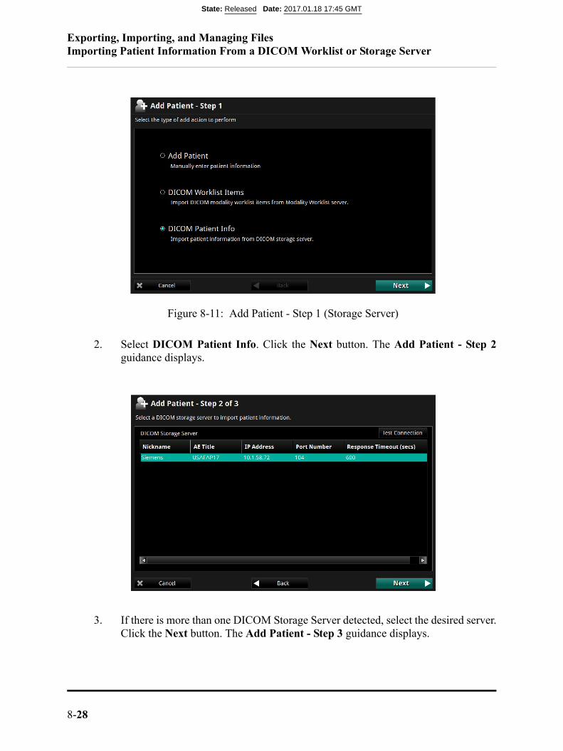
Exporting, Importing, and Managing FilesImporting Patient Information From a DICOM Worklist or Storage Server
8-28
2. Select DICOM Patient Info. Click the Next button. The Add Patient - Step 2guidance displays.
3. If there is more than one DICOM Storage Server detected, select the desired server.Click the Next button. The Add Patient - Step 3 guidance displays.
Figure 8-11: Add Patient - Step 1 (Storage Server)
State: Released Date: 2017.01.18 17:45 GMT
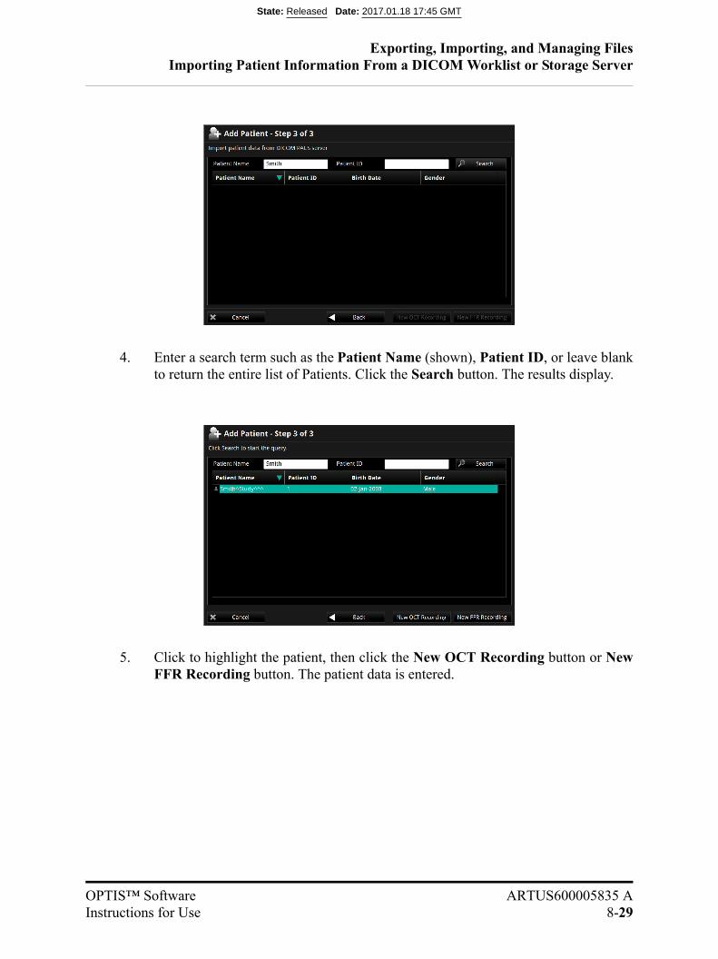
Exporting, Importing, and Managing FilesImporting Patient Information From a DICOM Worklist or Storage Server
OPTIS™ Software ARTUS600005835 AInstructions for Use 8-29
4. Enter a search term such as the Patient Name (shown), Patient ID, or leave blankto return the entire list of Patients. Click the Search button. The results display.
5. Click to highlight the patient, then click the New OCT Recording button or NewFFR Recording button. The patient data is entered.
State: Released Date: 2017.01.18 17:45 GMT

Exporting, Importing, and Managing FilesImporting Patient Information From a DICOM Worklist or Storage Server
8-30
State: Released Date: 2017.01.18 17:45 GMT

OPTIS™ Software ARTUS600005835 AInstructions for Use 9-1
Maintenance 9
State: Released Date: 2017.01.18 17:45 GMT

MaintenanceContacting St. Jude Medical Service
9-2
Contacting St. Jude Medical Service
Service can be contacted at:
E-mail: [email protected]: +1 855 478 5833 US Toll-free +1 651 756 5833 International
State: Released Date: 2017.01.18 17:45 GMT

MaintenanceMaintenance
OPTIS™ Software ARTUS600005835 AInstructions for Use 9-3
Maintenance
Maintenance of the system consists of:
• Transferring log files.
• Identifying the installed software version.
State: Released Date: 2017.01.18 17:45 GMT
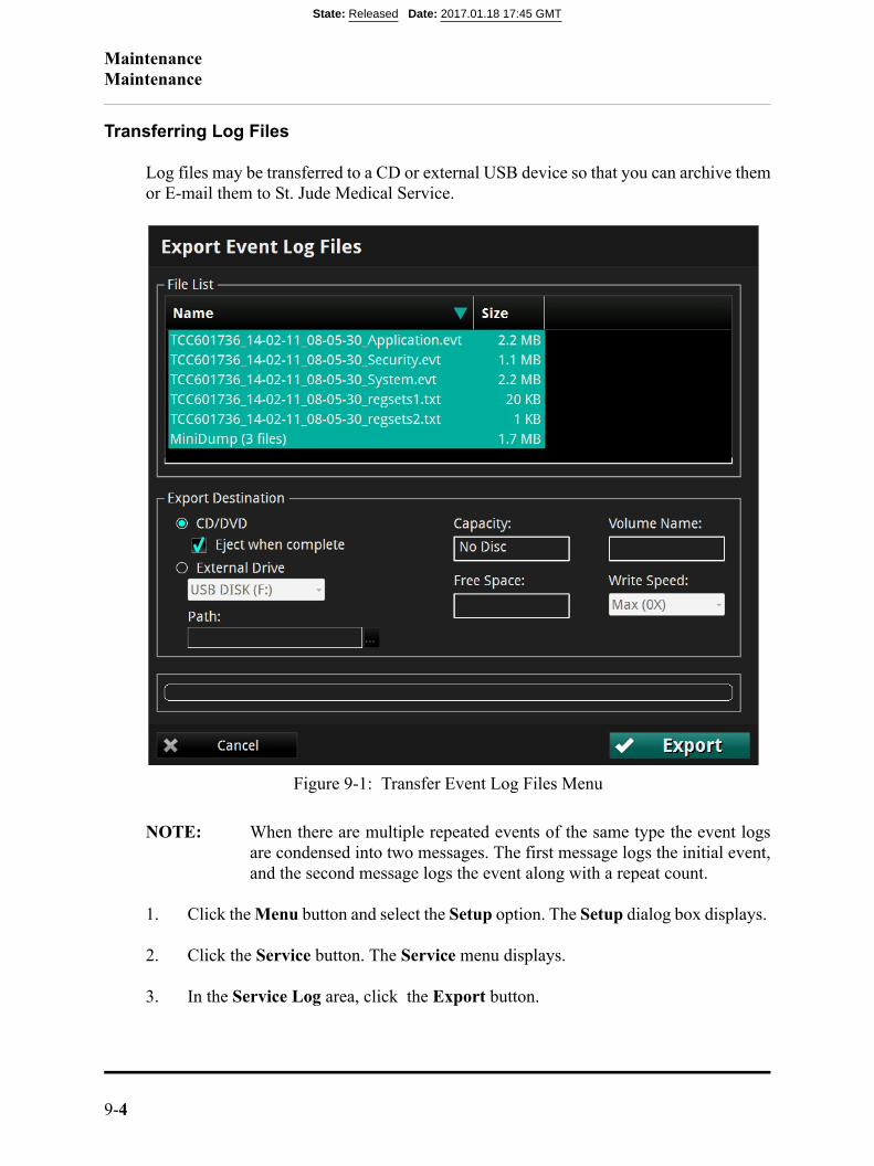
MaintenanceMaintenance
9-4
Transferring Log Files
Log files may be transferred to a CD or external USB device so that you can archive themor E-mail them to St. Jude Medical Service.
NOTE: When there are multiple repeated events of the same type the event logsare condensed into two messages. The first message logs the initial event,and the second message logs the event along with a repeat count.
1. Click the Menu button and select the Setup option. The Setup dialog box displays.
2. Click the Service button. The Service menu displays.
3. In the Service Log area, click the Export button.
Figure 9-1: Transfer Event Log Files Menu
State: Released Date: 2017.01.18 17:45 GMT
MaintenanceMaintenance
OPTIS™ Software ARTUS600005835 AInstructions for Use 9-5
The Transfer Event Log Files menu opens (Figure 9-1), which lists all the files tobe exported.
4. Click to select a Transfer Destination:
NOTE: If an output device is not available, that option cannot be selected.
NOTE: Check that the Free space in the Drive Capacity section is largeenough to save the files that are being exported.
• Click CD/DVD to export to a CD/DVD.
If the inserted CD/DVD is blank, you can edit the name in the Volume Labelfield.
• Click External Drive to export to an external USB device.
If necessary, click the External Drive selection box to select the correct drivelocation from the drop-down menu.
Click the Ellipsis (...) button to the right of the Path selection box to browsefor a specific folder on the device.
5. Click the Transfer button to transfer the files or Cancel to cancel the operation.
State: Released Date: 2017.01.18 17:45 GMT
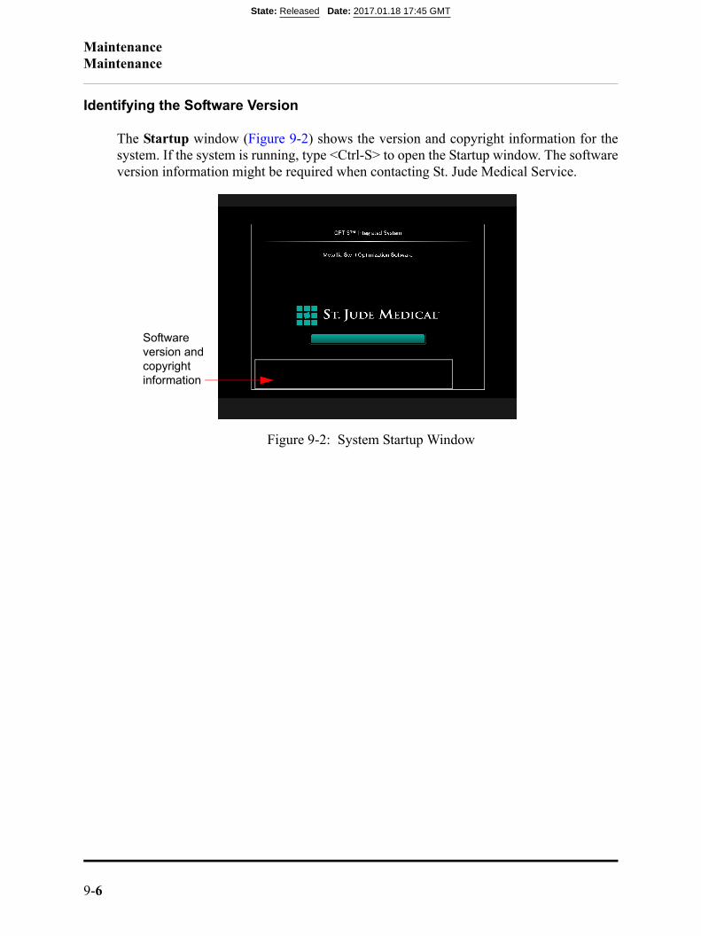
MaintenanceMaintenance
9-6
Identifying the Software Version
The Startup window (Figure 9-2) shows the version and copyright information for thesystem. If the system is running, type <Ctrl-S> to open the Startup window. The softwareversion information might be required when contacting St. Jude Medical Service.
Figure 9-2: System Startup Window
Software version and copyright information
State: Released Date: 2017.01.18 17:45 GMT
OPTIS™ Software ARTUS600005835 AInstructions for Use 10-1
User Interface Reference 10
Setup Dialog Box and Submenus
The Setup dialog box provides access to all of the configuration and service functions forthe system. The Setup dialog box is accessed by selecting the Setup option from theMenu button options on the Select Patient or Patient Summary screen.
NOTE: When creating or reviewing an OCT recording, the Settings button opensa context-sensitive OCT Settings menu. When creating an FFR recording,the Settings button opens the FFR Settings menu.
All menus within the Setup dialog box share the following common buttons located at thebottom of the dialog box.
Table 10-1: Setup Dialog Box Common Options
Refresh Click to update the values displayed in the current tab.
OK Click to approve any changes and close the Setup dialog box.
Cancel Click to cancel any changes and close the Setup dialog box.
Apply Click to approve any changes and keep the Setup dialog box open.
State: Released Date: 2017.01.18 17:45 GMT
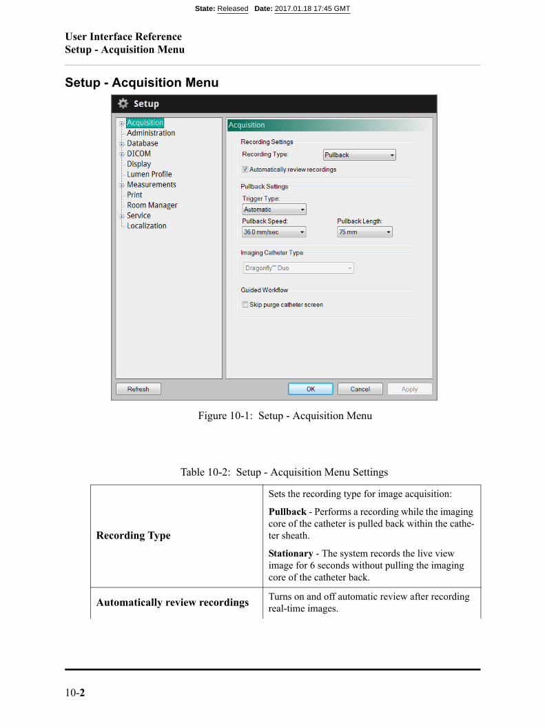
User Interface ReferenceSetup - Acquisition Menu
10-2
Setup - Acquisition Menu
Table 10-2: Setup - Acquisition Menu Settings
Recording Type
Sets the recording type for image acquisition:
Pullback - Performs a recording while the imaging core of the catheter is pulled back within the cathe-ter sheath.
Stationary - The system records the live view image for 6 seconds without pulling the imaging core of the catheter back.
Automatically review recordingsTurns on and off automatic review after recording real-time images.
Figure 10-1: Setup - Acquisition Menu
State: Released Date: 2017.01.18 17:45 GMT

User Interface ReferenceSetup - Acquisition Menu
OPTIS™ Software ARTUS600005835 AInstructions for Use 10-3
Trigger Type
Sets the Pullback trigger type to use for image acquisition:
Automatic - The system automatically begins a recording when it detects that the vessel has been cleared by the flush injection.
Manual - The system does not perform a pullback until you click the Start Pullback button on the screen, or press the Enable button on the DOC.
Pullback Speed
Sets the pullback speed.
NOTE: For Dragonfly™ Duo or Dragon-fly™OPTIS™ catheters, available speedsare 18 and 36 mm/sec.
Pullback Length
Sets the length of the pullback.
NOTE: For Dragonfly™ Duo or Dragonfly™OPTIS™ catheters Pullback Length is54 mm when speed is 18 mm/sec and 75mm when speed is 36 mm/sec.
Imaging Catheter Type
NOTE: This displays the type of catheter when acatheter has been connected.
NOTE: Only Dragonfly™ imaging catheters areapproved for use with the OPTIS™ Soft-ware for cardiovascular imaging.
Guided WorkflowTurns on and off the appearance of the purge cathe-ter guidance message.
Table 10-2: Setup - Acquisition Menu Settings (continued)
State: Released Date: 2017.01.18 17:45 GMT
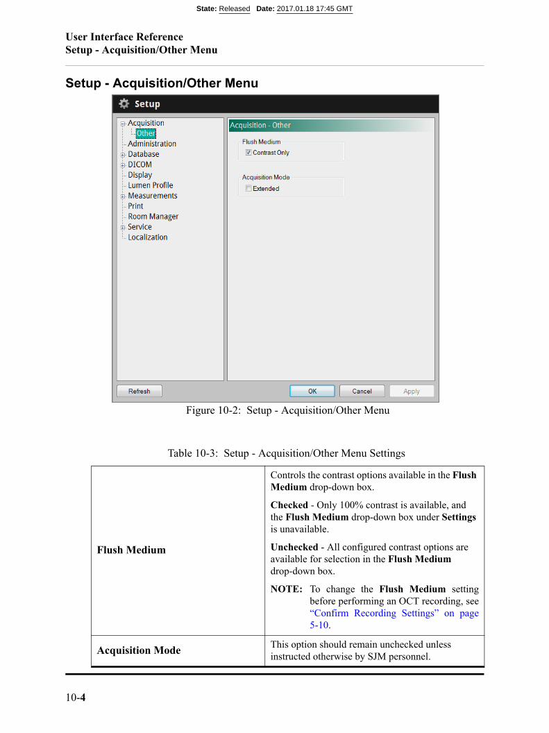
User Interface ReferenceSetup - Acquisition/Other Menu
10-4
Setup - Acquisition/Other Menu
Table 10-3: Setup - Acquisition/Other Menu Settings
Flush Medium
Controls the contrast options available in the Flush Medium drop-down box.
Checked - Only 100% contrast is available, and the Flush Medium drop-down box under Settings is unavailable.
Unchecked - All configured contrast options are available for selection in the Flush Medium drop-down box.
NOTE: To change the Flush Medium settingbefore performing an OCT recording, see“Confirm Recording Settings” on page5-10.
Acquisition ModeThis option should remain unchecked unless instructed otherwise by SJM personnel.
Figure 10-2: Setup - Acquisition/Other Menu
State: Released Date: 2017.01.18 17:45 GMT
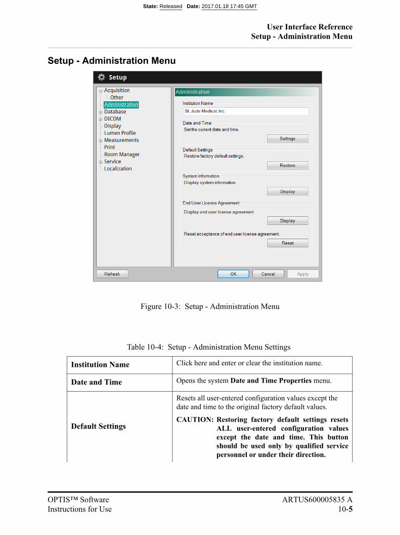
User Interface ReferenceSetup - Administration Menu
OPTIS™ Software ARTUS600005835 AInstructions for Use 10-5
Setup - Administration Menu
Table 10-4: Setup - Administration Menu Settings
Institution Name Click here and enter or clear the institution name.
Date and Time Opens the system Date and Time Properties menu.
Default Settings
Resets all user-entered configuration values except the date and time to the original factory default values.
CAUTION: Restoring factory default settings resetsALL user-entered configuration valuesexcept the date and time. This buttonshould be used only by qualified servicepersonnel or under their direction.
Figure 10-3: Setup - Administration Menu
State: Released Date: 2017.01.18 17:45 GMT

User Interface ReferenceSetup - Administration Menu
10-6
System InformationDisplays current date, system name, institution name, and software version
End User License Agreement
Displays EULA.
Resets EULA. The EULA must be accepted upon first operation after reset in order to access the system.
Table 10-4: Setup - Administration Menu Settings (continued)
State: Released Date: 2017.01.18 17:45 GMT
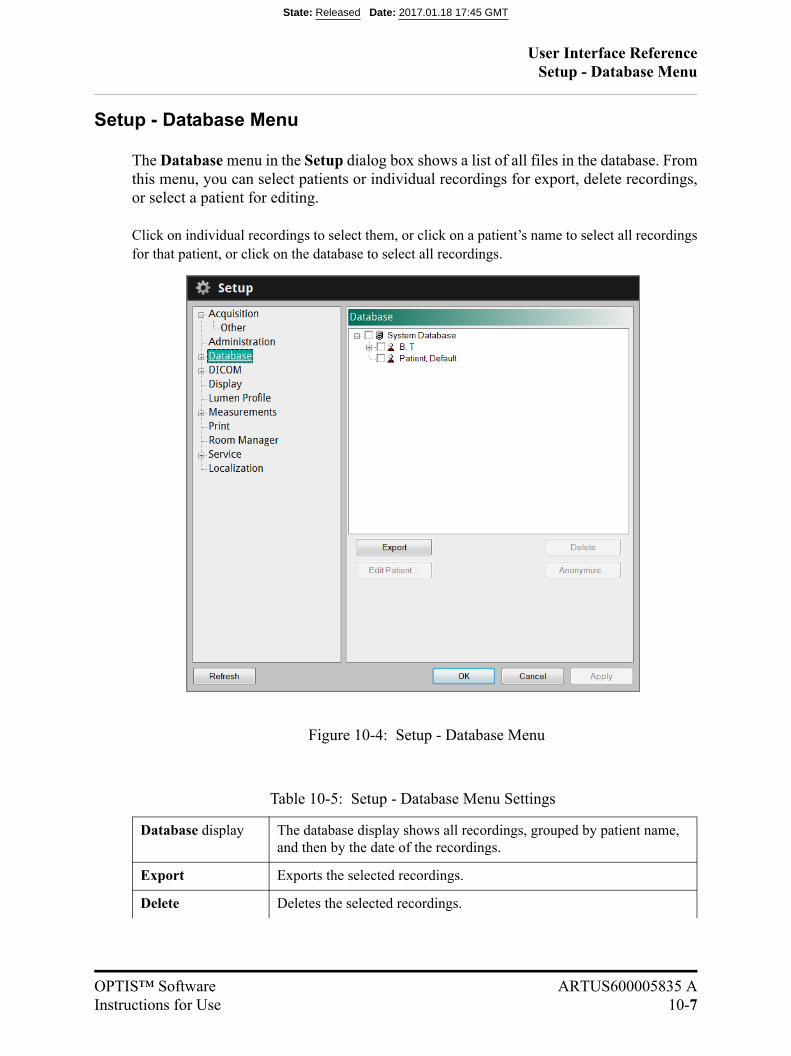
User Interface ReferenceSetup - Database Menu
OPTIS™ Software ARTUS600005835 AInstructions for Use 10-7
Setup - Database Menu
The Database menu in the Setup dialog box shows a list of all files in the database. Fromthis menu, you can select patients or individual recordings for export, delete recordings,or select a patient for editing.
Click on individual recordings to select them, or click on a patient’s name to select all recordingsfor that patient, or click on the database to select all recordings.
Table 10-5: Setup - Database Menu Settings
Database display The database display shows all recordings, grouped by patient name, and then by the date of the recordings.
Export Exports the selected recordings.
Delete Deletes the selected recordings.
Figure 10-4: Setup - Database Menu
State: Released Date: 2017.01.18 17:45 GMT

User Interface ReferenceSetup - Database Menu
10-8
Edit Patient... Click on a patient’s name to edit the patient’s information. See “Edit-ing Patient Information” on page 3-9 for more information.
Anonymize... Click on a patient’s name to remove the patient’s identifying informa-tion from the record. See “Exporting Files in Native (Raw) Format”, Step 3, on page 8-8, for an explanation of the anonymization function.
Table 10-5: Setup - Database Menu Settings (continued)
State: Released Date: 2017.01.18 17:45 GMT

User Interface ReferenceSetup - Database/Maintenance Menu
OPTIS™ Software ARTUS600005835 AInstructions for Use 10-9
Setup - Database/Maintenance Menu
You can check the status of the system’s OCT database using the Database Maintenancemenu in the Setup dialog box. From this menu, you can check the size of the databasefile, as well as the number of files referenced by the database and the combined size ofthese files. This menu also warns you of possible issues found with files in the system’sdatabase.
Table 10-6: Setup - Database/Maintenance Menu Settings
Disk UsageProvides both a graphic and text showing the amount of free and used space on the system’s hard disk.
Figure 10-5: Setup - Database/Maintenance Menu
State: Released Date: 2017.01.18 17:45 GMT
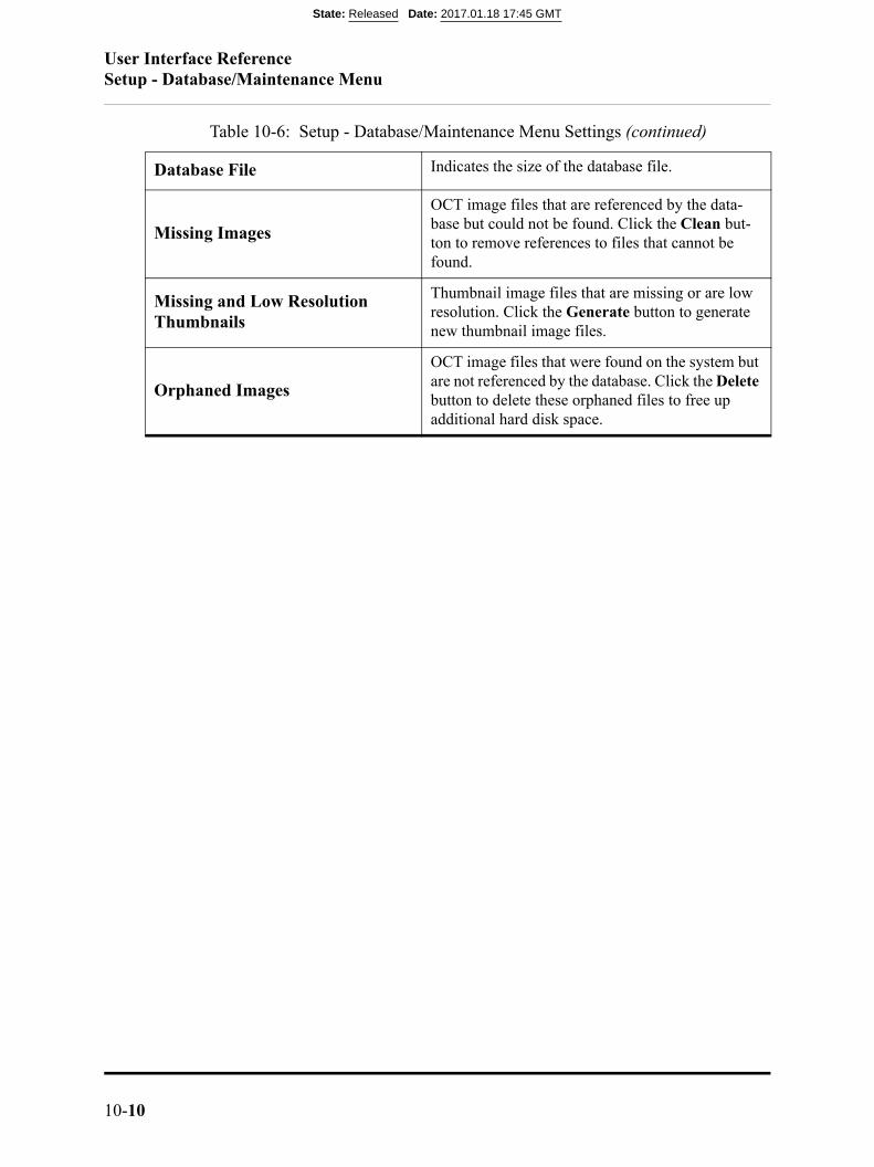
User Interface ReferenceSetup - Database/Maintenance Menu
10-10
Database File Indicates the size of the database file.
Missing Images
OCT image files that are referenced by the data-base but could not be found. Click the Clean but-ton to remove references to files that cannot be found.
Missing and Low Resolution Thumbnails
Thumbnail image files that are missing or are low resolution. Click the Generate button to generate new thumbnail image files.
Orphaned Images
OCT image files that were found on the system but are not referenced by the database. Click the Delete button to delete these orphaned files to free up additional hard disk space.
Table 10-6: Setup - Database/Maintenance Menu Settings (continued)
State: Released Date: 2017.01.18 17:45 GMT
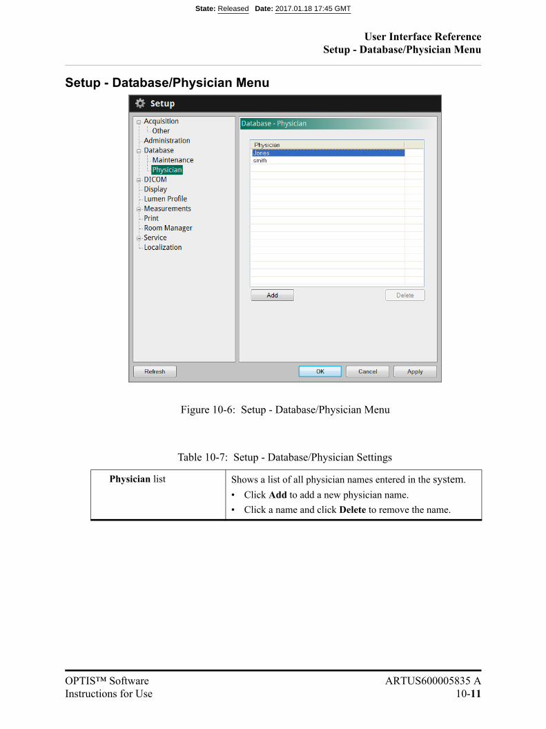
User Interface ReferenceSetup - Database/Physician Menu
OPTIS™ Software ARTUS600005835 AInstructions for Use 10-11
Setup - Database/Physician Menu
Table 10-7: Setup - Database/Physician Settings
Physician list Shows a list of all physician names entered in the system.
• Click Add to add a new physician name.
• Click a name and click Delete to remove the name.
Figure 10-6: Setup - Database/Physician Menu
State: Released Date: 2017.01.18 17:45 GMT
User Interface ReferenceSetup - DICOM Menu
10-12
Setup - DICOM Menu
The DICOM menus in the Setup dialog box are used to configure the network settings ofthe system and the Remote DICOM Server so that the system can initiate a network con-nection between the two systems. If multiple network adapters exist on the system (not aSt. Jude Medical standard configuration) only the primary network adapter can be used.
CAUTION: The OPTIS™ Software should only be connected to a secure intranet.Direct connection to the Internet may interfere with correct operationand/or result in inappropriate access to patient information, and voidssystem warranties. Please note St. Jude Medical makes no representation or warrantythat use of the OPTIS™ Software complies with applicable privacy,security and confidentiality laws, but encourages you to assess yourown risk as you use, disclose, control, process or transfer patienthealth information with the system.
State: Released Date: 2017.01.18 17:45 GMT
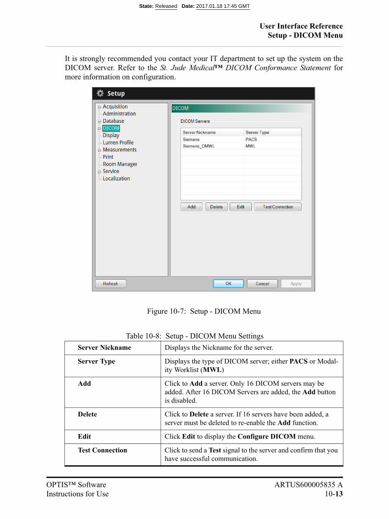
User Interface ReferenceSetup - DICOM Menu
OPTIS™ Software ARTUS600005835 AInstructions for Use 10-13
It is strongly recommended you contact your IT department to set up the system on theDICOM server. Refer to the St. Jude Medical™ DICOM Conformance Statement formore information on configuration.
Table 10-8: Setup - DICOM Menu Settings
Server Nickname Displays the Nickname for the server.
Server Type Displays the type of DICOM server; either PACS or Modal-ity Worklist (MWL)
Add Click to Add a server. Only 16 DICOM servers may be added. After 16 DICOM Servers are added, the Add button is disabled.
Delete Click to Delete a server. If 16 servers have been added, a server must be deleted to re-enable the Add function.
Edit Click Edit to display the Configure DICOM menu.
Test Connection Click to send a Test signal to the server and confirm that you have successful communication.
Figure 10-7: Setup - DICOM Menu
State: Released Date: 2017.01.18 17:45 GMT
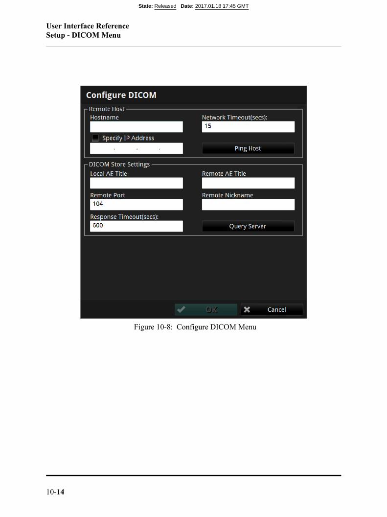
User Interface ReferenceSetup - DICOM Menu
10-14
Figure 10-8: Configure DICOM Menu
State: Released Date: 2017.01.18 17:45 GMT
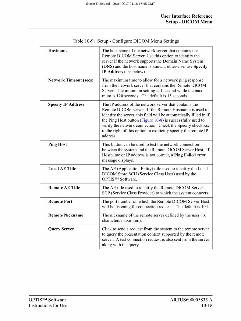
User Interface ReferenceSetup - DICOM Menu
OPTIS™ Software ARTUS600005835 AInstructions for Use 10-15
Table 10-9: Setup - Configure DICOM Menu Settings
Hostname The host name of the network server that contains the Remote DICOM Server. Use this option to identify the server if the network supports the Domain Name System (DNS) and the host name is known; otherwise, use Specify IP Address (see below).
Network Timeout (secs) The maximum time to allow for a network ping response from the network server that contains the Remote DICOM Server. The minimum setting is 1 second while the maxi-mum is 120 seconds. The default is 15 seconds.
Specify IP Address The IP address of the network server that contains the Remote DICOM server. If the Remote Hostname is used to identify the server, this field will be automatically filled in if the Ping Host button (Figure 10-8) is successfully used to verify the network connection. Check the Specify checkbox to the right of this option to explicitly specify the remote IP address.
Ping Host This button can be used to test the network connection between the system and the Remote DICOM Server Host. If Hostname or IP address is not correct, a Ping Failed error message displays.
Local AE Title The AE (Application Entity) title used to identify the Local DICOM Store SCU (Service Class User) used by the OPTIS™ Software.
Remote AE Title The AE title used to identify the Remote DICOM Server SCP (Service Class Provider) to which the system connects.
Remote Port The port number on which the Remote DICOM Server Host will be listening for connection requests. The default is 104.
Remote Nickname The nickname of the remote server defined by the user (16 characters maximum).
Query Server Click to send a request from the system to the remote server to query the presentation context supported by the remote server. A test connection request is also sent from the server along with the query.
State: Released Date: 2017.01.18 17:45 GMT
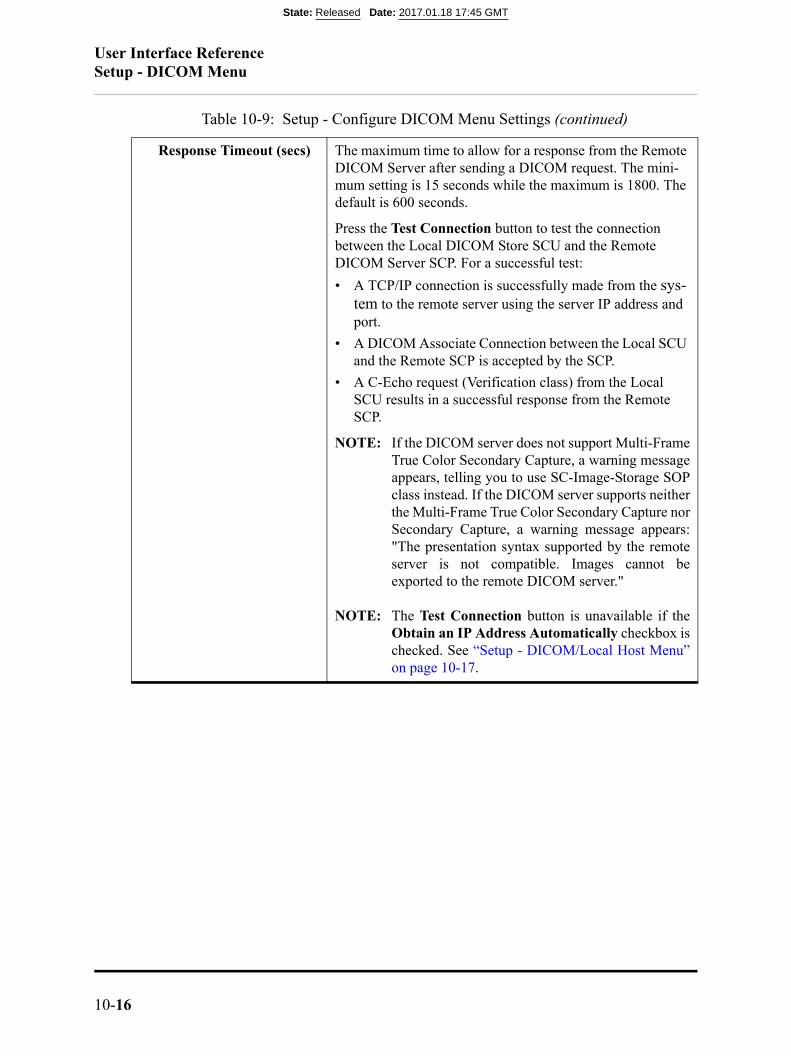
User Interface ReferenceSetup - DICOM Menu
10-16
Response Timeout (secs) The maximum time to allow for a response from the Remote DICOM Server after sending a DICOM request. The mini-mum setting is 15 seconds while the maximum is 1800. The default is 600 seconds.
Press the Test Connection button to test the connection between the Local DICOM Store SCU and the Remote DICOM Server SCP. For a successful test:
• A TCP/IP connection is successfully made from the sys-tem to the remote server using the server IP address and port.
• A DICOM Associate Connection between the Local SCU and the Remote SCP is accepted by the SCP.
• A C-Echo request (Verification class) from the Local SCU results in a successful response from the Remote SCP.
NOTE: If the DICOM server does not support Multi-FrameTrue Color Secondary Capture, a warning messageappears, telling you to use SC-Image-Storage SOPclass instead. If the DICOM server supports neitherthe Multi-Frame True Color Secondary Capture norSecondary Capture, a warning message appears:"The presentation syntax supported by the remoteserver is not compatible. Images cannot beexported to the remote DICOM server."
NOTE: The Test Connection button is unavailable if theObtain an IP Address Automatically checkbox ischecked. See “Setup - DICOM/Local Host Menu”on page 10-17.
Table 10-9: Setup - Configure DICOM Menu Settings (continued)
State: Released Date: 2017.01.18 17:45 GMT
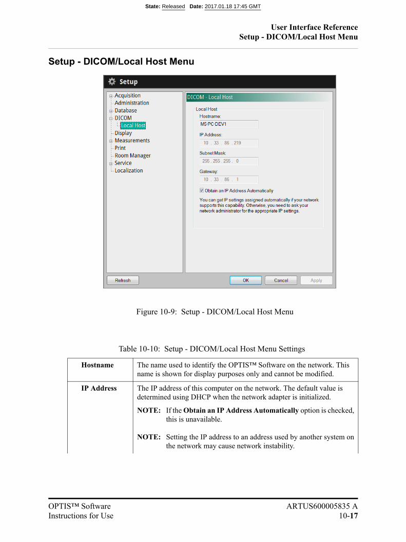
User Interface ReferenceSetup - DICOM/Local Host Menu
OPTIS™ Software ARTUS600005835 AInstructions for Use 10-17
Setup - DICOM/Local Host Menu
Table 10-10: Setup - DICOM/Local Host Menu Settings
Hostname The name used to identify the OPTIS™ Software on the network. This name is shown for display purposes only and cannot be modified.
IP Address The IP address of this computer on the network. The default value is determined using DHCP when the network adapter is initialized.
NOTE: If the Obtain an IP Address Automatically option is checked,this is unavailable.
NOTE: Setting the IP address to an address used by another system onthe network may cause network instability.
Figure 10-9: Setup - DICOM/Local Host Menu
State: Released Date: 2017.01.18 17:45 GMT
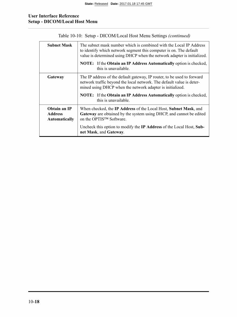
User Interface ReferenceSetup - DICOM/Local Host Menu
10-18
Subnet Mask The subnet mask number which is combined with the Local IP Address to identify which network segment this computer is on. The default value is determined using DHCP when the network adapter is initialized.
NOTE: If the Obtain an IP Address Automatically option is checked,this is unavailable.
Gateway The IP address of the default gateway, IP router, to be used to forward network traffic beyond the local network. The default value is deter-mined using DHCP when the network adapter is initialized.
NOTE: If the Obtain an IP Address Automatically option is checked,this is unavailable.
Obtain an IP Address Automatically
When checked, the IP Address of the Local Host, Subnet Mask, and Gateway are obtained by the system using DHCP, and cannot be edited on the OPTIS™ Software.
Uncheck this option to modify the IP Address of the Local Host, Sub-net Mask, and Gateway.
Table 10-10: Setup - DICOM/Local Host Menu Settings (continued)
State: Released Date: 2017.01.18 17:45 GMT

User Interface ReferenceSetup - Display Menu
OPTIS™ Software ARTUS600005835 AInstructions for Use 10-19
Setup - Display Menu
Table 10-11: Setup - Display Menu Settings
Graduated Cut Plane
Check this checkbox to add graduated marks to the cut plane indi-cator to use as scale marks.
Figure 10-10: Setup - Display Menu
State: Released Date: 2017.01.18 17:45 GMT
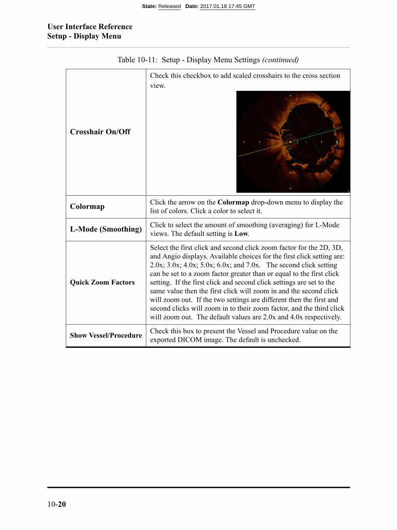
User Interface ReferenceSetup - Display Menu
10-20
Crosshair On/Off
Check this checkbox to add scaled crosshairs to the cross section view.
ColormapClick the arrow on the Colormap drop-down menu to display the list of colors. Click a color to select it.
L-Mode (Smoothing)Click to select the amount of smoothing (averaging) for L-Mode views. The default setting is Low.
Quick Zoom Factors
Select the first click and second click zoom factor for the 2D, 3D, and Angio displays. Available choices for the first click setting are: 2.0x; 3.0x; 4.0x; 5.0x; 6.0x; and 7.0x. The second click setting can be set to a zoom factor greater than or equal to the first click setting. If the first click and second click settings are set to the same value then the first click will zoom in and the second click will zoom out. If the two settings are different then the first and second clicks will zoom in to their zoom factor, and the third click will zoom out. The default values are 2.0x and 4.0x respectively.
Show Vessel/ProcedureCheck this box to present the Vessel and Procedure value on the exported DICOM image. The default is unchecked.
Table 10-11: Setup - Display Menu Settings (continued)
State: Released Date: 2017.01.18 17:45 GMT
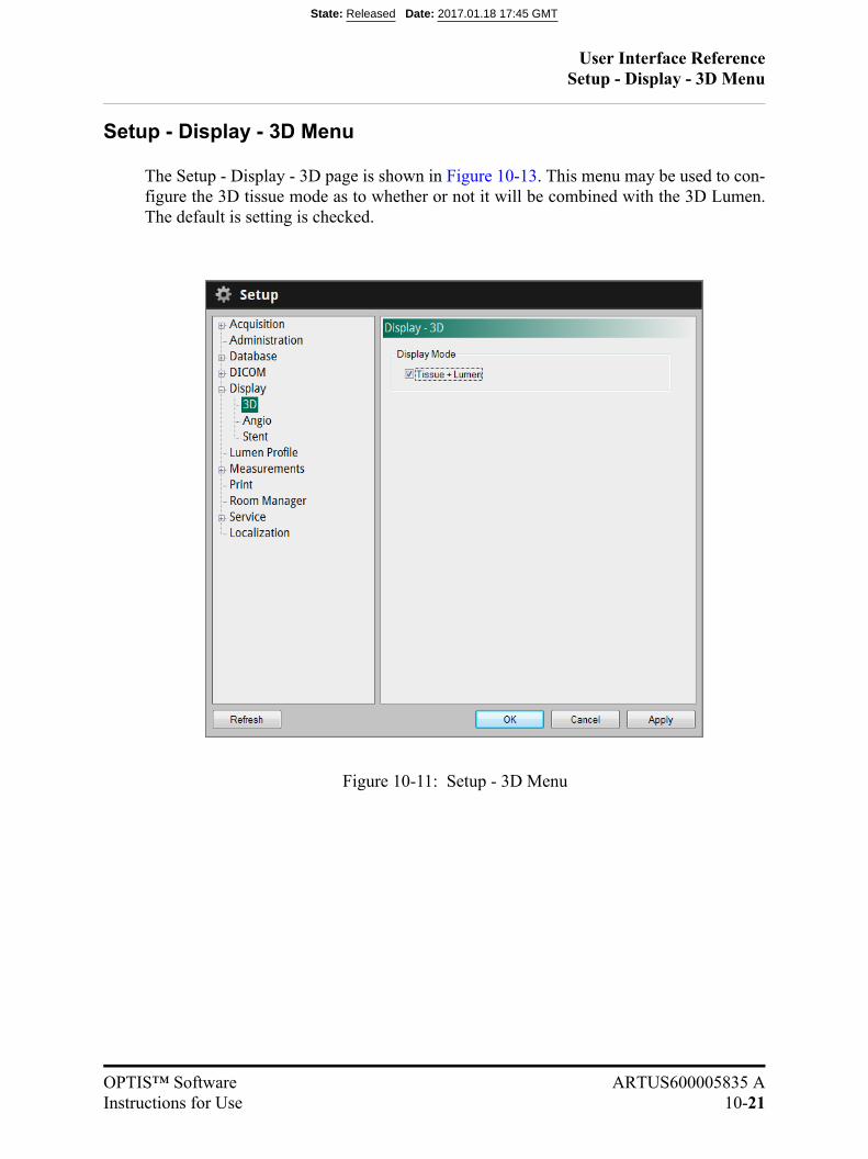
User Interface ReferenceSetup - Display - 3D Menu
OPTIS™ Software ARTUS600005835 AInstructions for Use 10-21
Setup - Display - 3D Menu
The Setup - Display - 3D page is shown in Figure 10-13. This menu may be used to con-figure the 3D tissue mode as to whether or not it will be combined with the 3D Lumen.The default is setting is checked.
Figure 10-11: Setup - 3D Menu
State: Released Date: 2017.01.18 17:45 GMT

User Interface ReferenceSetup - Display - Angio Menu
10-22
Setup - Display - Angio Menu
The Setup - Display - Angio page is shown in Figure 10-12. This menu may be used todisplay the L-Mode bookmarks on the Angio Co-Registration view. The default setting isunchecked.
Figure 10-12: Setup - Angio Menu
State: Released Date: 2017.01.18 17:45 GMT

User Interface ReferenceSetup - Display - Stent Menu
OPTIS™ Software ARTUS600005835 AInstructions for Use 10-23
Setup - Display - Stent Menu
The Setup - Display - Stent page is shown in Figure 10-13. This menu may be used tochange the Apposition Thresholds (microns) settings that are used to color the renderedstent struts and indicate the strut apposition. There are two apposition threshold settings,a low apposition threshold (default: 200 microns) and a high apposition threshold(default: 300 microns). Strut apposition will fall into one of three ranges and be coloredas follows:
• Silver: Struts with an apposition value less than the low threshold.
• Yellow: Struts with an apposition value greater than or equal to the low thresholdAND less than the high threshold.
• Red: Struts with an apposition value greater than or equal to the high threshold.
The Apposition Thresholds (microns) values may be changed using the range slidercontrol. Drag the left slider to change the low threshold. Drag the right slider to change
Figure 10-13: Setup - Stent Menu
State: Released Date: 2017.01.18 17:45 GMT

User Interface ReferenceSetup - Display - Stent Menu
10-24
the high threshold. The two thresholds may be changed together, maintaining the samerange, by dragging the yellow section between the sliders. To set a single threshold value,drag the two sliders together where the threshold is desired. See Figure 10-14 for anexample of a single threshold setting.
Figure 10-14: Single Apposition Threshold Setting
State: Released Date: 2017.01.18 17:45 GMT
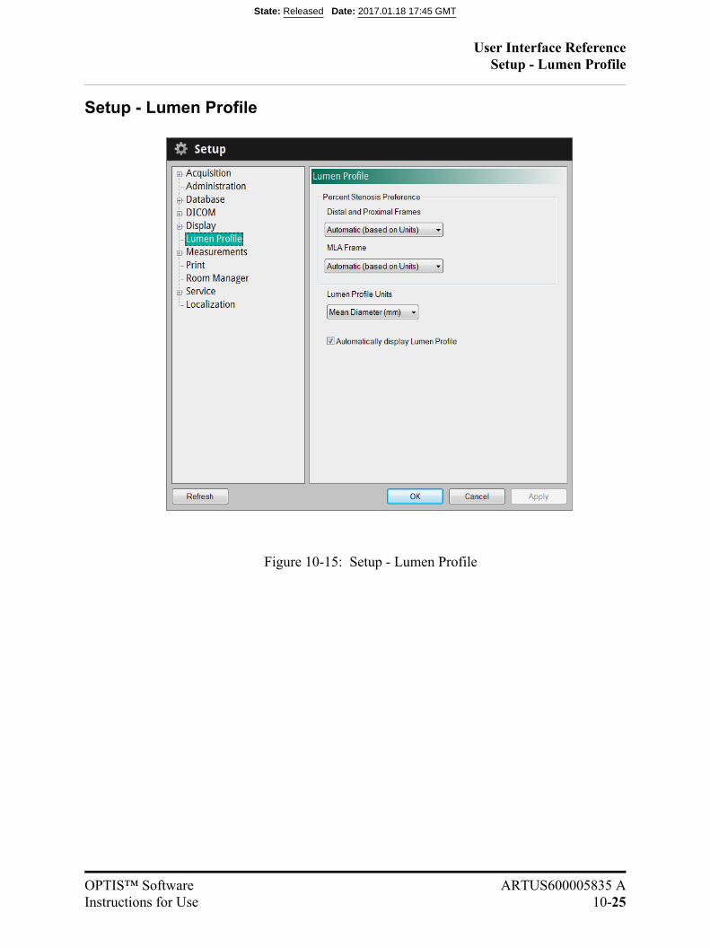
User Interface ReferenceSetup - Lumen Profile
OPTIS™ Software ARTUS600005835 AInstructions for Use 10-25
Setup - Lumen Profile
Figure 10-15: Setup - Lumen Profile
State: Released Date: 2017.01.18 17:45 GMT
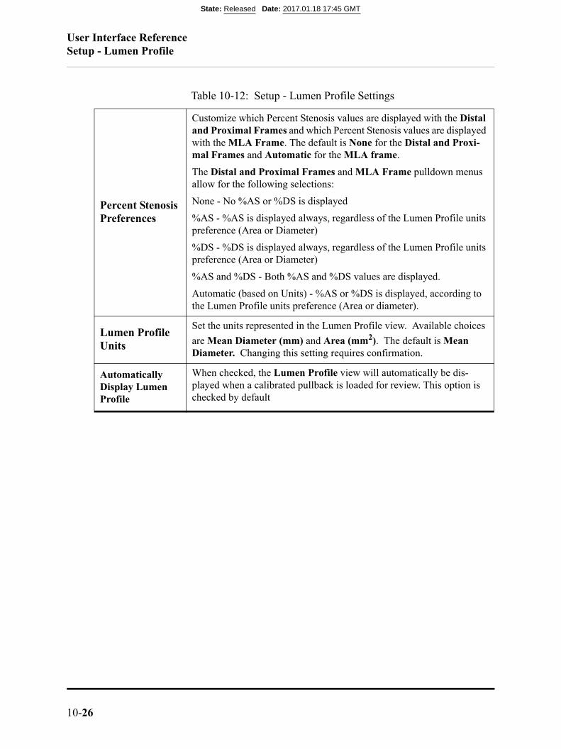
User Interface ReferenceSetup - Lumen Profile
10-26
Table 10-12: Setup - Lumen Profile Settings
Percent Stenosis Preferences
Customize which Percent Stenosis values are displayed with the Distal and Proximal Frames and which Percent Stenosis values are displayed with the MLA Frame. The default is None for the Distal and Proxi-mal Frames and Automatic for the MLA frame.
The Distal and Proximal Frames and MLA Frame pulldown menus allow for the following selections:
None - No %AS or %DS is displayed
%AS - %AS is displayed always, regardless of the Lumen Profile units preference (Area or Diameter)
%DS - %DS is displayed always, regardless of the Lumen Profile units preference (Area or Diameter)
%AS and %DS - Both %AS and %DS values are displayed.
Automatic (based on Units) - %AS or %DS is displayed, according to the Lumen Profile units preference (Area or diameter).
Lumen Profile Units
Set the units represented in the Lumen Profile view. Available choices
are Mean Diameter (mm) and Area (mm2). The default is Mean Diameter. Changing this setting requires confirmation.
Automatically Display Lumen Profile
When checked, the Lumen Profile view will automatically be dis-played when a calibrated pullback is loaded for review. This option is checked by default
State: Released Date: 2017.01.18 17:45 GMT
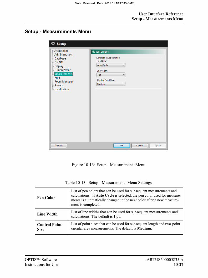
User Interface ReferenceSetup - Measurements Menu
OPTIS™ Software ARTUS600005835 AInstructions for Use 10-27
Setup - Measurements Menu
Table 10-13: Setup - Measurements Menu Settings
Pen Color
List of pen colors that can be used for subsequent measurements and calculations. If Auto Cycle is selected, the pen color used for measure-ments is automatically changed to the next color after a new measure-ment is completed.
Line WidthList of line widths that can be used for subsequent measurements and calculations. The default is 1 pt.
Control Point Size
List of point sizes that can be used for subsequent length and two-point circular area measurements. The default is Medium.
Figure 10-16: Setup - Measurements Menu
State: Released Date: 2017.01.18 17:45 GMT

User Interface ReferenceSetup - Measurements/Labels Menu
10-28
Setup - Measurements/Labels Menu
Table 10-14: Setup - Measurements/Labels Menu Settings
Default LabelsLabel text that will be used when making the indi-cated type of measurement.
Click and type in any field to change that label.
Figure 10-17: Setup - Measurements/Labels Menu
State: Released Date: 2017.01.18 17:45 GMT
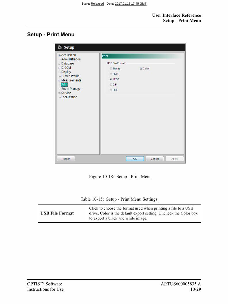
User Interface ReferenceSetup - Print Menu
OPTIS™ Software ARTUS600005835 AInstructions for Use 10-29
Setup - Print Menu
Table 10-15: Setup - Print Menu Settings
USB File FormatClick to choose the format used when printing a file to a USB drive. Color is the default export setting. Uncheck the Color box to export a black and white image.
Figure 10-18: Setup - Print Menu
State: Released Date: 2017.01.18 17:45 GMT
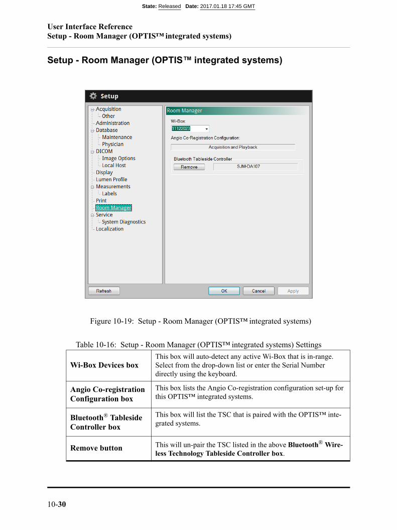
User Interface ReferenceSetup - Room Manager (OPTIS™ integrated systems)
10-30
Setup - Room Manager (OPTIS™ integrated systems)
Table 10-16: Setup - Room Manager (OPTIS™ integrated systems) Settings
Wi-Box Devices boxThis box will auto-detect any active Wi-Box that is in-range. Select from the drop-down list or enter the Serial Number directly using the keyboard.
Angio Co-registration Configuration box
This box lists the Angio Co-registration configuration set-up for this OPTIS™ integrated systems.
Bluetooth® Tableside Controller box
This box will list the TSC that is paired with the OPTIS™ inte-grated systems.
Remove button This will un-pair the TSC listed in the above Bluetooth® Wire-less Technology Tableside Controller box.
Figure 10-19: Setup - Room Manager (OPTIS™ integrated systems)
State: Released Date: 2017.01.18 17:45 GMT

User Interface ReferenceSetup - Room Manager (applicable OPTIS™ mobile systems)
OPTIS™ Software ARTUS600005835 AInstructions for Use 10-31
Setup - Room Manager (applicable OPTIS™ mobile systems)
Table 10-17: Setup - Room Manager Settings
Room Manager box Displays any active Wi-Box™ unit within range.
ACRConfiguration box
This box lists the Angio Co-registration configuration set-up for this applicable OPTIS™ mobile system.
Add buttonClick to display the Add Room dialog box. Use the Add Room dialog box to add a Wi-Box™ unit to the Room Manager.
TablesideController box
This box will list the TSC that is paired with the applicable OPTIS™ mobile systems.
Room boxThis box will list the Room configured for the applicable OPTIS™ mobile systems
Wi-Box™ unit boxThis box will list the Wi-Box™ unit that is paired with the appli-cable OPTIS™ mobile system.
Figure 10-20: Setup - Room Manager (applicable OPTIS™ mobile systems)
State: Released Date: 2017.01.18 17:45 GMT
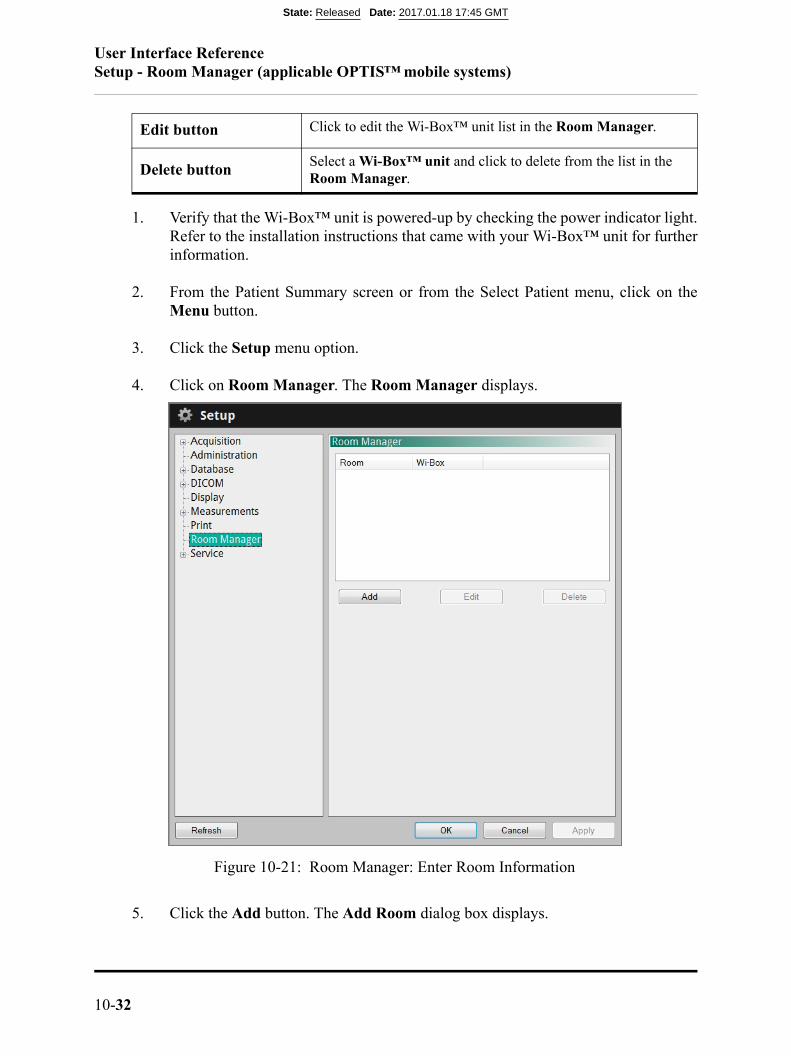
User Interface ReferenceSetup - Room Manager (applicable OPTIS™ mobile systems)
10-32
1. Verify that the Wi-Box™ unit is powered-up by checking the power indicator light.Refer to the installation instructions that came with your Wi-Box™ unit for furtherinformation.
2. From the Patient Summary screen or from the Select Patient menu, click on theMenu button.
3. Click the Setup menu option.
4. Click on Room Manager. The Room Manager displays.
5. Click the Add button. The Add Room dialog box displays.
Edit button Click to edit the Wi-Box™ unit list in the Room Manager.
Delete buttonSelect a Wi-Box™ unit and click to delete from the list in the Room Manager.
Figure 10-21: Room Manager: Enter Room Information
State: Released Date: 2017.01.18 17:45 GMT

User Interface ReferenceSetup - Room Manager (applicable OPTIS™ mobile systems)
OPTIS™ Software ARTUS600005835 AInstructions for Use 10-33
6. Enter the Room Name and Room Number, then select the desired Wi-Box™ unit(by its serial number) from the Devices box. (The serial number is visible on thefront panel of the Wi-Box™ unit.)
NOTE: Be sure to check the Wi-Box™ unit serial number. The Devices boxwill auto-detect any active Wi-Box™ unit that is in-range. Ensurethat the Wi-Box™ unit serial number selected matches theWi-Box™ unit device present in the current room.
NOTE: The Wi-Box™ unit serial numbers can also be entered directly intothe Devices box.
Figure 10-22: Add Room dialog box
State: Released Date: 2017.01.18 17:45 GMT

User Interface ReferenceSetup - Room Manager (applicable OPTIS™ mobile systems)
10-34
7. To add a Tableside Controller, click the Add button in the Tableside Controllersection of the Add Room dialog box. The Device dialog box displays.
8. Select the desired tableside controller from Detected Controllers list and clickAdd. The selected tableside controller is added and the Add Room dialog displays.
9. Click OK. The room added is now displayed on the Room Manager (See Figure10-24 on page 10-35).
Figure 10-23: Add Device dialog box
State: Released Date: 2017.01.18 17:45 GMT
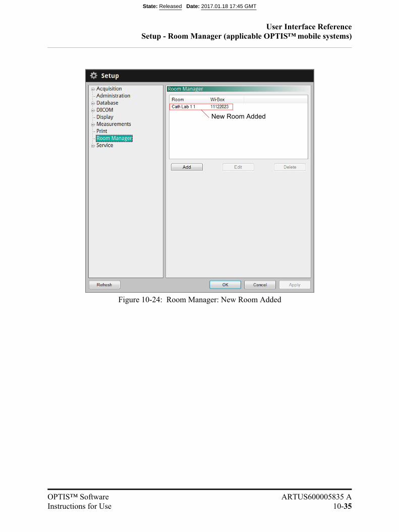
User Interface ReferenceSetup - Room Manager (applicable OPTIS™ mobile systems)
OPTIS™ Software ARTUS600005835 AInstructions for Use 10-35
New Room Added
Figure 10-24: Room Manager: New Room Added
State: Released Date: 2017.01.18 17:45 GMT
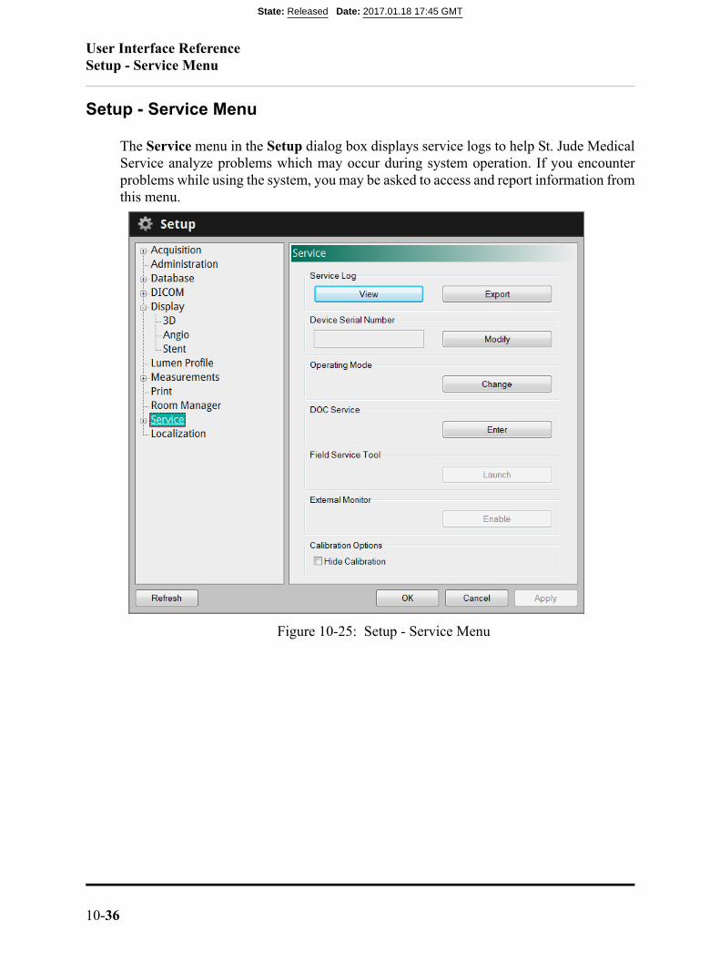
User Interface ReferenceSetup - Service Menu
10-36
Setup - Service Menu
The Service menu in the Setup dialog box displays service logs to help St. Jude MedicalService analyze problems which may occur during system operation. If you encounterproblems while using the system, you may be asked to access and report information fromthis menu.
Figure 10-25: Setup - Service Menu
State: Released Date: 2017.01.18 17:45 GMT
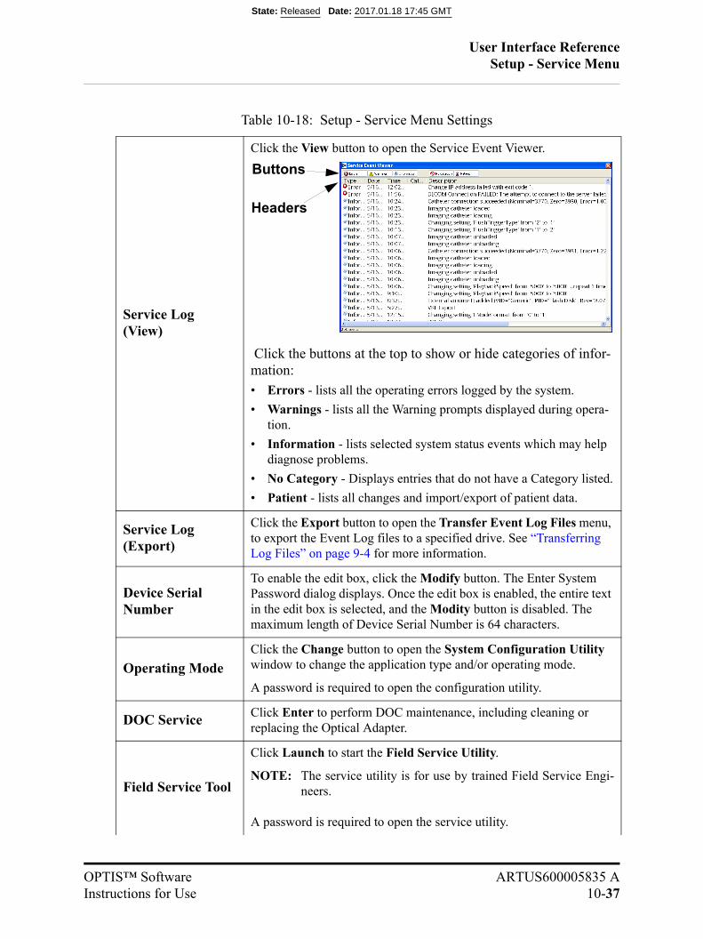
User Interface ReferenceSetup - Service Menu
OPTIS™ Software ARTUS600005835 AInstructions for Use 10-37
Table 10-18: Setup - Service Menu Settings
Service Log (View)
Click the View button to open the Service Event Viewer.
Click the buttons at the top to show or hide categories of infor-mation:• Errors - lists all the operating errors logged by the system.
• Warnings - lists all the Warning prompts displayed during opera-tion.
• Information - lists selected system status events which may help diagnose problems.
• No Category - Displays entries that do not have a Category listed.
• Patient - lists all changes and import/export of patient data.
Service Log (Export)
Click the Export button to open the Transfer Event Log Files menu, to export the Event Log files to a specified drive. See “Transferring Log Files” on page 9-4 for more information.
Device Serial Number
To enable the edit box, click the Modify button. The Enter System Password dialog displays. Once the edit box is enabled, the entire text in the edit box is selected, and the Modity button is disabled. The maximum length of Device Serial Number is 64 characters.
Operating ModeClick the Change button to open the System Configuration Utility window to change the application type and/or operating mode.
A password is required to open the configuration utility.
DOC ServiceClick Enter to perform DOC maintenance, including cleaning or replacing the Optical Adapter.
Field Service Tool
Click Launch to start the Field Service Utility.
NOTE: The service utility is for use by trained Field Service Engi-neers.
A password is required to open the service utility.
Buttons
Headers
State: Released Date: 2017.01.18 17:45 GMT
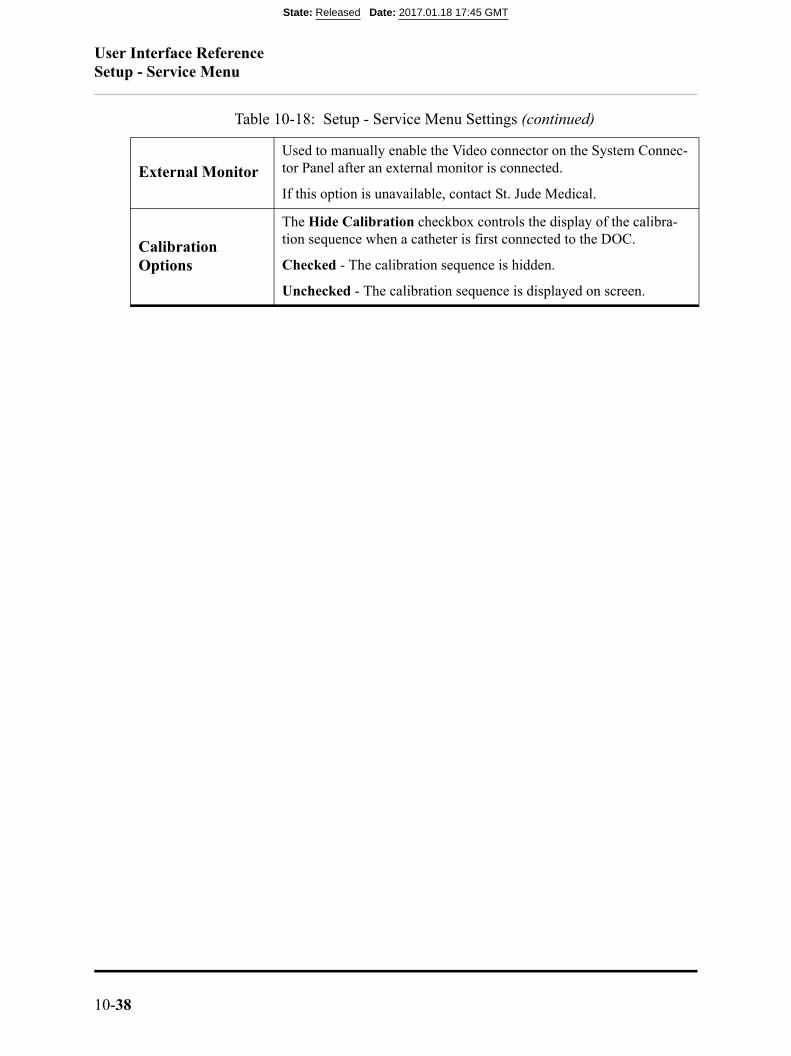
User Interface ReferenceSetup - Service Menu
10-38
External MonitorUsed to manually enable the Video connector on the System Connec-tor Panel after an external monitor is connected.
If this option is unavailable, contact St. Jude Medical.
Calibration Options
The Hide Calibration checkbox controls the display of the calibra-tion sequence when a catheter is first connected to the DOC.
Checked - The calibration sequence is hidden.
Unchecked - The calibration sequence is displayed on screen.
Table 10-18: Setup - Service Menu Settings (continued)
State: Released Date: 2017.01.18 17:45 GMT

User Interface ReferenceSetup - Service/System Diagnostics Menu
OPTIS™ Software ARTUS600005835 AInstructions for Use 10-39
Setup - Service/System Diagnostics Menu
The System Diagnostics menu in the Setup dialog box is provided to help St. Jude Med-ical Service monitor and analyze signal levels in the imaging engine either in real time orat the time a recording was made. When the tab is selected the system immediately dis-plays the detected signal levels while in Acquisition mode or the signal values when thecurrent image was captured when in Playback mode. If you encounter problems whileusing the system, you may be asked to access and report information from this tab
Table 10-19: Setup - Service/System Diagnostics Menu Settings
Power Supplies +5VA Supply - The +5 volt AC power supply voltage.
+5VD Supply - The +5 volt DC power supply voltage.
+24VD Supply - The +24 volt DC power supply voltage.
DOC Current - The current being drawn by the DOC in mA.
Figure 10-26: Setup - Service/System Diagnostics Menu
State: Released Date: 2017.01.18 17:45 GMT
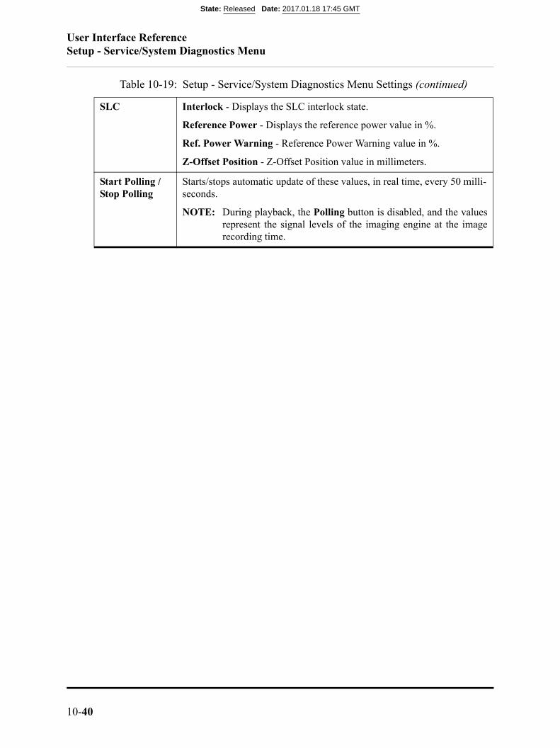
User Interface ReferenceSetup - Service/System Diagnostics Menu
10-40
SLC Interlock - Displays the SLC interlock state.
Reference Power - Displays the reference power value in %.
Ref. Power Warning - Reference Power Warning value in %.
Z-Offset Position - Z-Offset Position value in millimeters.
Start Polling / Stop Polling
Starts/stops automatic update of these values, in real time, every 50 milli-seconds.
NOTE: During playback, the Polling button is disabled, and the valuesrepresent the signal levels of the imaging engine at the imagerecording time.
Table 10-19: Setup - Service/System Diagnostics Menu Settings (continued)
State: Released Date: 2017.01.18 17:45 GMT
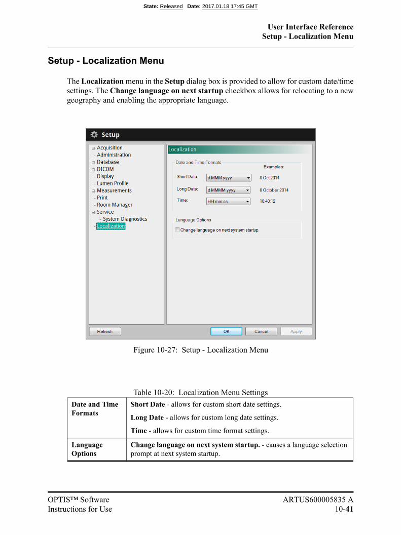
User Interface ReferenceSetup - Localization Menu
OPTIS™ Software ARTUS600005835 AInstructions for Use 10-41
Setup - Localization Menu
The Localization menu in the Setup dialog box is provided to allow for custom date/timesettings. The Change language on next startup checkbox allows for relocating to a newgeography and enabling the appropriate language.
Table 10-20: Localization Menu Settings
Date and Time Formats
Short Date - allows for custom short date settings.
Long Date - allows for custom long date settings.
Time - allows for custom time format settings.
Language Options
Change language on next system startup. - causes a language selection prompt at next system startup.
Figure 10-27: Setup - Localization Menu
State: Released Date: 2017.01.18 17:45 GMT

User Interface ReferenceSetup - Localization Menu
10-42
State: Released Date: 2017.01.18 17:45 GMT

OPTIS™ Software ARTUS600005835 AInstructions for Use 11-1
Safety Information 11
State: Released Date: 2017.01.18 17:45 GMT

Safety InformationPatient Safety
11-2
Patient Safety
The OPTIS™ Software is intended for use only by medical personnel trained in its oper-ation and skilled in the clinical procedures to be used.
To avoid any potential hazard to patients, follow the precautions outlined in this section.
General
WARNING: Failure to follow the guidelines described in these Instructions for Useand in the Instructions for Use provided with the accessories mayresult in injury to patients and damage to equipment.
• Always read and follow the Instructions for Use supplied with the OCT system,Dragonfly Imaging Catheter and with the PressureWire™ guidewire.
• Always use controls, make adjustments and perform procedures as specified inthese Instructions for Use.
State: Released Date: 2017.01.18 17:45 GMT
Safety Information
OPTIS™ Software ARTUS600005835 AInstructions for Use 11-3
System Imaging Limitations
The OPTIS™ Software is intended for use by medical personnel who have received train-ing in the use of the system. To determine if system use is appropriate, the trained usermust be aware of system imaging limitations.
This section includes information about system capabilities and limitations for both ves-sel and tissue imaging.
Considerations for Optimal Vessel Imaging
The OPTIS™ Software can be used to image through vessels or to image the inner sur-face of certain vessels. Since the Dragonfly catheter is smaller than the diameter of thevessel being imaged, the position of the catheter in the vessel has an effect on the portionof the vessel that can be imaged.
• Imaging range is greatest when the imaging catheter is centered in the lumen.
• Imaging range is least when the imaging catheter is placed eccentrically (off-center)in the lumen, against the wall of the vessel.
Considerations for Optimal Tissue Imaging
The maximum imaging depth within a vessel wall ranges from approximately 0.9 mm to1.3 mm and is limited by optical attenuation caused by scattering of the optical beam bymicrostructures in the vessel. For example, penetration of the OCT beam is deepest in cal-cified tissue and shallowest in dense fibrotic tissue.
State: Released Date: 2017.01.18 17:45 GMT

Safety InformationSystem Imaging Limitations
11-4
State: Released Date: 2017.01.18 17:45 GMT
OPTIS™ Software ARTUS600005835 AInstructions for Use 12-1
System Specifications 12
System - Safety & RegulatoryTable 12-1: System Safety & Regulatory Specifications
Category Specifications
Regulatory Approvals US 510(k) clearance.
State: Released Date: 2017.01.18 17:45 GMT

System Specifications
12-2
State: Released Date: 2017.01.18 17:45 GMT

OPTIS™ Software ARTUS600005835 AInstructions for Use 1-1
Index
Symbols
%AS, 6-10, 7-9%DS, 6-10, 7-11
Numerics
3D Display, 6-31
A
Acquisition mode, 10-39Adding Points, 7-17Annotation
adding text, 7-7text, 7-8
Area Measurementsautomatic, 7-5
Auto Cycle Drawing Color, 10-26, 10-27
B
Bookmarkclear all bookmarks, 6-45creating, 6-45next bookmark, 6-45previous bookmark, 6-45
C
Calculation%AS, 7-9%DS, 7-11
Calloutadding, 7-8position, 7-8
Calloutsadding, 7-7
Catheterconnection to DOC, 5-6insertion, 5-11positioning, 5-11purge, 5-7
Caution, meaning and format, Front-ivComplications, 1-8Complications from Use, 1-8Contact Information
company, Front-iiservice, 9-2
Contraindications for Use, 1-5Control Point Size, 10-27Conventions Used in Manual, Front-ivCreating a New Patient, 3-3Cross-section View
zoom, 7-14
D
Databasecreate a new patient, 3-3import, 8-18Setup dialog box, 10-7statistics, 8-24, 10-9
Database Tab, 10-7Delete
files, 8-21measurements, 7-18points, 7-17
State: Released Date: 2017.01.18 17:45 GMT
IndexE
St. Jude Medical1-2 Part Number ARTUS600005835 A
Depth Calibration Marks, 5-15Diagnostics Tab, 10-39DICOM
viewer, 8-16DICOM Tab, 10-12DOC
catheter connection, 5-6
E
External Drive, 8-9, 8-10, 8-12
F
File Size, 8-6Files
deleting, 8-21Flush Medium
warning, 1-6
G
Green’s Theorem, 7-5
H
Home menu, 3-5
I
Image Compressioncaution, 7-1, 8-7
Image Formatraw, 8-4standard, 8-5
Imaginglimitations, 11-3tissue, 11-3vessel, 11-3
Import OCT Files, 8-18Indications for Use, 1-4Instructions for Use
other manuals, Front-ivIntended Use, 1-4
L
Length Measurement, 7-4Line Width, 10-26, 10-27Live Mode, 10-39Live View, 5-3L-Mode
caution, 7-2cut-plane, 5-15limitations, 6-47measurements and annotations, 7-2
Log Files, 9-4, 10-36
M
Maintenance, 9-3Manual
conventions, Front-ivMeasurement Accuracy, 7-2Measurement and Annotation tools, 6-35Measurements
adding points, 7-17caution, 7-1, 8-7deleting all measurements, 7-18deleting individual measurements, 7-18deleting measurements, 7-18deleting points, 7-17editing, 7-16length, 7-4moving individual points, 7-17
Minimum Lumen Area, 6-48MLA, 6-48Moving Points, 7-17
N
Near-infrared Light, 1-1Note, meaning and format, Front-iv
O
OCT Database, see Database
State: Released Date: 2017.01.18 17:45 GMT
IndexP
OPTIS™ Software ARTUS600005835 AInstructions for Use 1-3
OCT Procedurecatheter connection, 5-6catheter insertion, 5-11catheter positioning, 5-11materials and equipment, 5-1recording, 5-15
Optical Coherence Tomography, 1-1Optimal Tissue Imaging, 11-3Optimal Vessel Imaging, 11-3
P
Patientacquiring image, 5-15creating a record, 3-3safety, 11-2
Patient Entrycreating, 3-3
Patient RecordOpen, Create, 3-1
Pen Color, 10-26, 10-27Percent Area Stenosis, 6-10, 7-9Percent Diameter Stenosis, 6-10, 7-11Playback Calibration
setting, 6-56Playback Mode, 10-39playback range, 6-46Power
off, 2-3on, 2-2
Precautions for Use, 1-7Pullback
trigger, 10-3Purge Catheter, 5-7
R
Rangeplayback, 6-46
Raw Formatdescription, 8-4
Recordingstatus, 5-15
Recording calibration marks, 5-15Remote DICOM Store, 8-11
Reviewingsaved images, 6-1
S
Safetypatient, 11-2
Select Measurementpercent area stenosis, 7-9percent diameter stenosis, 7-11
Select Patient menu, 3-5Service Tab, 10-36Setup Dialog Box
Database tab, 10-7Diagnostics tab, 10-39DICOM tab, 10-12Service tab, 10-36
Shutdownprocedure, 2-3
Specificationssafety and regulatory, 12-1
Standard File Format, 8-6Standard Format
description, 8-5Standby View, 5-3System
features, 1-1imaging limitations, 11-3power on, 2-2setup, 2-1shut down, 2-3
System Displayduring image acquisition, 5-15
T
Textadding, 7-7display options, 7-8entry, 7-8position, 7-8
Tissue Imaging, 11-3Transfer Messages, 8-22, 8-24Trigger Type, 10-3
State: Released Date: 2017.01.18 17:45 GMT
IndexU
St. Jude Medical1-4 Part Number ARTUS600005835 A
TroubleshootingPressureWire
power failure, 4-12
U
USBmedia, 8-2
V
Vessel Imaging, 11-3
W
Warning, 1-6Warning, meaning and format, Front-iv
Z
ZoomDICOM Viewer, 8-17measurements, 7-2region, 7-14
State: Released Date: 2017.01.18 17:45 GMT

IndexZ
OPTIS™ Software ARTUS600005835 AInstructions for Use 1-5
State: Released Date: 2017.01.18 17:45 GMT

*ARTUS600005835*
State: Released Date: 2017.01.18 17:45 GMT