optimization of foam-filled double circular tubes under axial and oblique impact loading conditions
TRANSCRIPT

Optimization of foam-filled double circular tubes under axialand oblique impact loading conditions
F. Djamaluddin, S. Abdullah n, A.K. Ariffin, Z.M. NopiahDepartment of Mechanical and Materials Engineering, Faculty of Engineering and Built Environment, Universiti Kebangsaan Malaysia, 43600 UKM Bangi,Selangor, Malaysia
a r t i c l e i n f o
Article history:Received 17 April 2014Received in revised form9 October 2014Accepted 30 October 2014
Keywords:Aluminium foamCrashworthinessCylindrical tubeOptimizationOblique impact
a b s t r a c t
This paper presents the multi objective optimization of foam-filled tubular tubes under pure axialand oblique impact loadings. In this work, the double circular tubes, whose bottom is the boundarycondition, while at the top, is the impacted rigid wall; with respect to the axis of the tubes. The optimalcrash parameter solutions, namely the minimum peak crushing force and the maximum specific energyabsorption, are constructed by the Non-dominated Sorting Genetic Algorithm-II and the Radial BasisFunction. Different configurations of structures, such as empty empty double tube (EET), foam filledempty double tube (FET), and foam filled foam filled double tube (FFT), are identified for theircrashworthiness performance indicators. The results show that the optimal foam filled foam filled tube(FFT) had better crashworthiness than the others under pure axial loading. However, the foam filledempty tube (FET) was the best choice for structures under an oblique loading.
& 2014 Elsevier Ltd. All rights reserved.
1. Introduction
One aim of the automotive industry is to increase the crash-worthiness capability of structures and decrease weight for savefuel. Finding new materials and designs plays a major role inachieving this target. Simulated testing was chosen over physicaltesting due to cost. To improve the energy absorption of a material,thin-walled behaviour, which considered the parameters of geo-metry, size, cross-section, and loading conditions of the tubes, wasstudied [1,2]. The energy absorption behaviour of thin-walledcircular tubes under axial impact has been studied by severalscholars [1–5]. The dynamic instability of different cross-sections,such as circular and square tubes, subjected to axial impactloading, was reported in a book authored by Jones [2]. However,the progressive buckling, inversion, and splitting of circular tubeswere previously discussed by [3]. Furthermore, Alghamdi et al. [4]studied the different structure’s collapsibility as energy absorbers,namely circular and square tubes. Without increasing volume andweight too much, to improve the crashworthiness capability ofthin-walled tubes, some researchers [6–11] used cellular materials,namely foams and honeycombs. The energy absorption capability
of empty filled foam circular tubes, using a double-cell profile, wasstudied by Seitzberger et al. [12,13] and Nurick et al. [14].
In a real-world vehicle collapse event, thin-walled tubes work,not only with pure axial or pure bending loads, but also with acombination of axial and oblique loadings; particularly in abumper system. The energy absorption capabilities of thin-walled tubes reduce more under a combination of axial andoblique impacts, compared to pure axial loads. The crush beha-viour of mild steel square columns was analysed by Han and Park[15], indicating that from the axial to the bending collapse mode,there was a critical load angle at the transition place. Reyes et al.[16–19] studied square aluminium extrusion response, squaretubes with and without foam, and circular tubes subjected tooblique loading, and obtained both experiment and simulationresults. In addition, Li et al. [20] carried out deformation andenergy absorption testing, using the experiment results for alu-minium foam circular tubes, subjected to an oblique quasi-staticloading. For tapered thin-walled rectangular tubes, Nagel andThambiratnam [21–23] showed that this structure had moreadvantages than straight tubes under an oblique impact. In othertypes of structure, Ahmad et al. [24] also investigated the benefitsof using foam-filled conical tubes under an oblique impact. Mean-while, double circular tubes under axial and bending conditionsusing experimental and numerical testing were investigated byGuo et al. [25–28]. All gave good promising findings towards thedevelopment of crashworthiness properties.
Contents lists available at ScienceDirect
journal homepage: www.elsevier.com/locate/tws
Thin-Walled Structures
http://dx.doi.org/10.1016/j.tws.2014.10.0150263-8231/& 2014 Elsevier Ltd. All rights reserved.
n Corresponding author. Tel.: þ60 3 89118411; fax: þ60 3 89259659.E-mail addresses: [email protected] (F. Djamaluddin),
[email protected] (S. Abdullah), [email protected] (A.K. Ariffin),[email protected] (Z.M. Nopiah).
Thin-Walled Structures 87 (2015) 1–11
In recent years, concerns have increased on the optimizationtechniques applied to structural designs; especially to optimizethe configurations of foam or cellular material filled thin-walledcolumns and tubes. For instance, maximizing energy absorptionand minimizing the weight of foam filled [29,30] and honeycomb[31] under axial loads was investigated by Zarei and Kröger. Inaddition, multi objective optimization was used [32] to maximizespecific energy absorption (SEA) and minimize the Peak CrushingForce (PCF) of honeycomb filled single and bitubular polygonaltubes. Aluminium foam filled-filled monotubal and bitubal thinwalled square columns were optimized [33,34] using multi objec-tive optimization. The results showed the foam-filled bitubalconfiguration to have more energy absorption efficiently thanempty and its aluminium foam filler. Acar et al. [35] identifiedthe maximum Crush Force Efficiency (CFE) and maximum SEA oftapered circular thin-walled tubes using multi objective crash-worthiness optimization. The crashworthiness designs of emptyand foam filled thin-walled square columns under an obliqueimpact loading were performed and indicated better outcomes[36]. Different mathematical programming was used to seekoptimal solutions, such as genetic algorithms (GA) [37,33]. Sun etal. [38,39] used Particle Swarm Optimization (PSO) to optimize,with a two stage multi fidelity method for honeycomb, andoptimized the crashworthiness design of Functionally Grade Foam(FGF) structures using Multi Objective Particle Swarm Optimiza-tion (MOPSO).
For all of the above mentioned studies, there was a limitedconcern about the foam-filled configuration of the double circulartube; particularly under different loading conditions. Furthermore,because of their good capability in energy absorption, thesestructures should be explored more, in order to gain an optimaldesign [20,28]. The aim of this current study paper is to optimizethe crashing behaviour of double circular tubes under pure axialand oblique impact loadings using three different tubes, namelyempty-empty double tube (EET), Foam-filled Empty Tube (FET),and Foam-Filled double Tube (FFT). In the design’s problems,crashworthiness criteria i.e., SEA and PCF, were considered asdesign variables, such as diameter of cross-section, thickness,material, yield stress of wall, and the foam density. This workused s Non-dominated Sorting Genetic Algorithm (NSGA-II), dueto the effectiveness of the crashworthiness design [40,41], tocompare the optimal crashworthiness of the structures.
2. Materials and methods
2.1. Crashworthiness indicator of double tubes under axial andoblique impact loadings
To evaluate the energy-absorbance of structures, it is necessaryto define the crashworthiness indicators. The parameters forinstance Energy Absorption (EA), SEA, and PCF can efficientlyevaluate the crashworthiness of structures. Energy absorptioncan be calculated as:
EA¼Z δ
0F δ� �
dδ ð1Þ
where F(δ) is the instantaneous crashing force with a function ofthe displacement δ.
SEA indicates the absorbed energy (EAtotal) per unit mass(Mtotal) of a structure as:
SEA¼ EAtotal
Mtotalð2Þ
where Mtotal is the structure’s total mass. In this case, a highervalue indicates the higher energy absorption efficiency of a material.
The average crush force (Favg) is the response parameter for theenergy absorption capability:
Favg ¼EAtotal
δð3Þ
where energy is absorbed (EAtotal) during collapse and displace-ment (δ).
Crush force efficiency is defined as the ratio of the averagecrush force (Fagv) to the peak crush force (Fmax),
CFE¼ FavgFmax
ð4Þ
Peak Crushing Force (PCF) is another important indicator inthe design of energy absorption structures to absorb the impactenergy in collision. When impact occurs i.e., automotive, PCF isable to determine the occupant’s survival rate; therefore, severaloccupants injuries or even death [40] are caused by a large PCF.
2.2. Finite element models of the structures
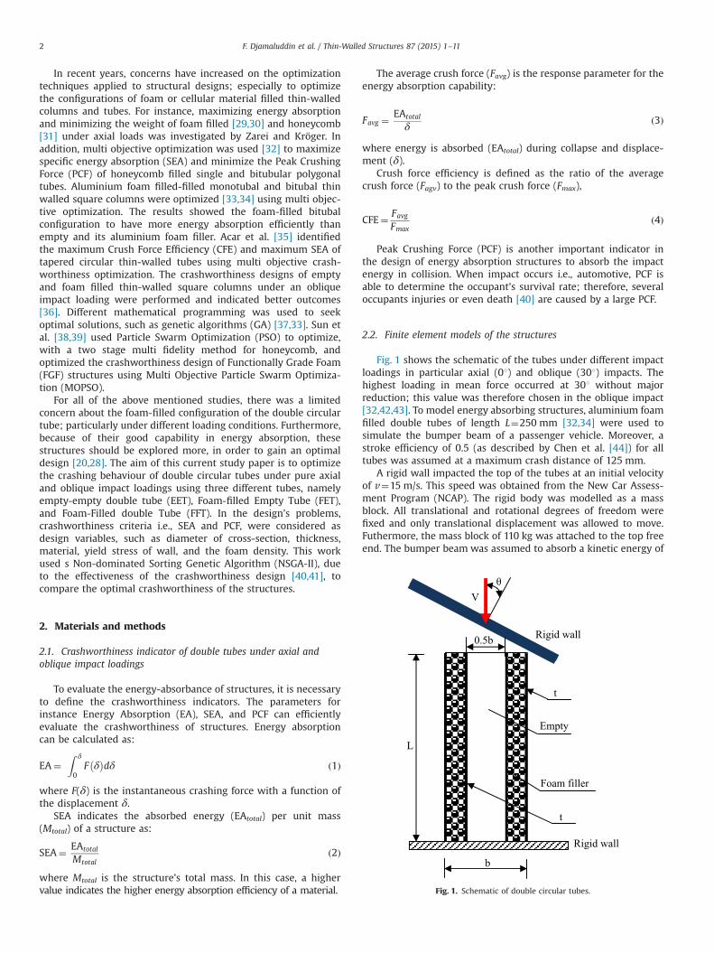
Fig. 1 shows the schematic of the tubes under different impactloadings in particular axial (01) and oblique (301) impacts. Thehighest loading in mean force occurred at 301 without majorreduction; this value was therefore chosen in the oblique impact[32,42,43]. To model energy absorbing structures, aluminium foamfilled double tubes of length L¼250 mm [32,34] were used tosimulate the bumper beam of a passenger vehicle. Moreover, astroke efficiency of 0.5 (as described by Chen et al. [44]) for alltubes was assumed at a maximum crash distance of 125 mm.
A rigid wall impacted the top of the tubes at an initial velocityof v¼15 m/s. This speed was obtained from the New Car Assess-ment Program (NCAP). The rigid body was modelled as a massblock. All translational and rotational degrees of freedom werefixed and only translational displacement was allowed to move.Futhermore, the mass block of 110 kg was attached to the top freeend. The bumper beam was assumed to absorb a kinetic energy of
Fig. 1. Schematic of double circular tubes.
F. Djamaluddin et al. / Thin-Walled Structures 87 (2015) 1–112

about 10% of the compact car’s mass (about 1.100 kg) according toreference [45].
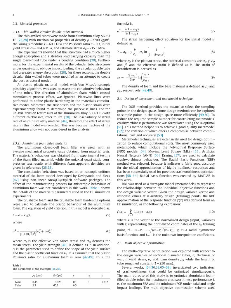
This material structure had a yield stress of aluminium thin-walled tubes σy and the density of foam filler ρf.. The cross-sectionof the bitubal circular tubes is shown in Fig. 2. The outer diameter,b and the inner diameter, 0.5b of each tube measured 90 mm and45 mm, respectively. The outer and inner thicknesses (t) of thedouble tube walls were the same at 1.8 mm.
Fig. 3 shows the three FE models of Empty-Empty Tube (EET),empty-foam filled tube (FET), and foam filled-foam filled tube(FFT). Comparing the three double circular tubes with differentconfigurations is important to design new bumper beamstructures.
To develop the aluminium foam filled tubular tube models andto predict the response of thin walled structures impacted by afree falling impinging mass, the Finite Element (FE) code ABAQUS—Explicit was used.
The walls of the tubular tubes were modelled using four nodeshell continuum elements with five integration points along theelement’s thickness direction. Moreover, the foam filled tube wasmodelled using eight node continuum elements with a reducedintegration technique combined with the hourglass control. Toavoid both artificial zero energy deformation modes and volu-metric locking, enhancement-based hourglass control and reducedintegration were applied. Based on a mesh convergence study ofshells and foam elements, a 2 mm element size was chosen.A mesh convergence was addressed to ensure a sufficient meshdensity and to accurately capture the deformation process. Thecontact interaction between all components was the generalcontact algorithm used to avoid interpenetration of tube walls,which is less intense in terms of computational time. Meanwhile,the contacts between the foam and the tube walls were modelledas a finite sliding penalty based contact algorithm, with contactpairs and a hard contact. The friction coefficient value for allcontact surfaces was set at 0.3 (as used in previous works [25,28]).
Fig. 2. Cross section of double circular tubes (a) empty-empty double tube (EET),(b) foam filled empty double tube (FET), and (c) foam filled-foam filled doubleTube (FFT).
Fig. 3. The finite element model of cylindrical tubes. (a) EET, (b) FET and (c) FFT.
F. Djamaluddin et al. / Thin-Walled Structures 87 (2015) 1–11 3
2.3. Material properties
2.3.1. Thin-walled circular double tubes materialThe thin-walled tubes were made from aluminium alloy A6063
T6 [25,28] with mechanical properties of density ρ¼2700 kg/m3,the Young’s modulus E¼60.2 GPa, the Poisson’s ratio ν¼0.3, initialyield stress σy¼184.4 MPa, and ultimate stress σu¼215.5 MPa.
The experiments showed that this structure had a much higherenergy absorption and a steadier load carrying capacity than thesingle foam-filled tube under a bending condition [28]. Further-more, for the experimental results of the cylinder tube structuresunder quasi-static oblique impact loading, the circular double tubehad a greater energy absorption [20]. For these reasons, the doublecircular thin walled tubes were modified in an attempt to createthe best structural model.
An elastic–plastic material model, with Von Mises’s isotropicplasticity algorithm, was used to assess the constitutive behaviourof the tubes. The direction of aluminium foam, which causedmanufacture process effect, was ignored. Piecewise lines wereperformed to define plastic hardening in the material’s constitu-tive model. Moreover, the true stress and the plastic strain wereexperimentally found to determine the piecewise lines. For theuniaxial tension test results of the aluminium alloy A6063 T6 withdifferent thicknesses, refer to Ref. [28]. The insensitivity of strainrate of aluminium alloy material [46], therefore the effect of strainrate in this model was omitted. This was because fracture of thealuminium alloy was not considered in the analysis.
2.3.2. Aluminium foam filled materialThe aluminium closed-cell foam filler was used, with an
average mechanical property value obtained from material tests.The material’s behaviour was obtained from experimental testingof the foam filled material, while the uniaxial quasi-static com-pression test results with different foam apparent densities aregiven in references [25,28].
The constitutive behaviour was based on an isotropic uniformmaterial of the foam model developed by Deshpande and Fleck[47] using non-linear ABAQUS/Explicit software packages. Theeffect of the manufacturing process for anisotropic behaviour ofaluminium foam was not considered in this work. Table 1 showsthe details of the material’s parameters used in the FE simulationexperiments.
The crushable foam and the crushable foam hardening optionswere used to calculate the plastic behaviour of the aluminiumfoam. The equation of yield criterion in this model is described as,
F ¼ σ̂�Yr0 ð5Þ
where
σ̂2 ¼ 1½1þðα=3Þ2�
σ2e þ αs2
m
� � ð6Þ
where σe is the effective Von Mises stress and σm denotes themean stress. The yield strength [48] is defined as Y. In addition,α is the parameter used to define the shape of the yield surfaceand the plastic coefficient function νp. It is assumed that the plasticPoisson’s ratio for aluminium foam is zero [42,49]; thus, the
formula is,
α2 ¼ 2ð1�2νpÞ9ð1þνpÞ
ð7Þ
The strain hardening effect equation for the initial model isdefined as,
Y ¼ σpþ γε̂εD
þα2 ln1
1�ðε̂=εDÞβ
" #ð8Þ
where σp is the plateau stress, the material constants are α2, γ, εDand β, and the effective strain is defined as ε̂. The strain ofdensification is derived as,
εD ¼ �9þσ2
3α2 lnρf
ρf o
!ð9Þ
The density of foam and the base material is defined as ρf andρfo, respectively [42,48].
2.4. Design of experiment and metamodel technique
The DOE method provides the means to select the samplingpoints in the design space. Some design methods can be exploredto sample points in the design space more efficiently [49,50]. Toreduce the required sample number for constructing metamodels,crashworthiness performance was formulated using the D-optimal[51]. This method helped us to achieve a good quality metamodel[52]; the criterion of which offers a compromise between compu-tational cost and accuracy [53].
Metamodel techniques are extensively used for design optimi-zation to reduce computational costs. The most commonly usedmetamodels, which include the Polynomial Response Surface(PRS) models [54], Moving Least Square (MLS) [55], ArtificialNeural Network (ANN) [56], Kriging [57], are used to calculatecrashworthiness behaviour. The Radial Basis Functions (RBF)method was selected, because it indicates a fairly good accuracyfor the global approximation of highly nonlinear responses andhas been successfully used for previous crashworthiness optimiza-tions [58–64]. Radial basis function was created by MATLAB inthis work.
RBF was used as a surrogate model (metamodels) to representthe relationships between the individual objective functions andthe design variable vector. Given the design variable vector andresponse values at n arbitrary design (training) points, the RBFapproximation of the response function f0(x) was derived from anFE simulation, as the following expression:
f 0 xð Þ ¼ ∑n
i ¼ 1λi∅ jjx�xijjð Þ ð10Þ
where x is the vector of the normalized design (input) variableswith xi representing the normalized coordinates of the ith training
point, ri¼ x�xij jj j ¼ffiffiffiffiffiffiffiffiffiffiffiffiffiffiffiffiffiffiffiffiffiffiffiffiffiffiffiffiffiffiffiffiffiffið x�xið ÞT x�xið ÞÞ
q, ∅ is a radial symmetric
basis function, and i¼1 is the unknown interpolation coefficients.
2.5. Multi objective optimization
The multi-objective optimization was explored with respect tothe design variables of sectional diameter tubes, b; thickness ofwall, t; yield stress, σy and foam density ρf, while the length oftube remained constant (L¼250 mm).
Several works, [34,36,38,65–69], investigated two indicatorsof crashworthiness that could be optimized simultaneously.The main purpose of this study is to optimize aluminium foam-filled double tubes for maximum crashworthiness performance i.e., the maximum SEA and the minimum PCF, under axial and angleimpact loadings. The multi-objective optimization scheme used
Table 1The parameters of the materials [25,28].
ρg (cm³) E (Gpa) ν νp k
Foam 0.45 0.625 0.1 0 1.732Tube 2.7 60.2 0.3
F. Djamaluddin et al. / Thin-Walled Structures 87 (2015) 1–114

can be expressed mathematically as:
Min F xð Þ ¼ ½f 1 yð Þ; f 2 yð Þ;…; f n yð Þ�Tgu yð ÞZ0;u¼ 1;…;n
hv yð Þ ¼ 0; v¼ 1;…;m
8><>: ð11Þ
where y is the design variable vector, n is the objective functionnumber, fn(y) is the objective function of the objective, yV ¼yV1 ; y
V2 ;…yV1
� �denotes the lower bound, and yU ¼ yU1 ; y
U2 ;…yU1
� �the upper bound of the m design variables, and n and m are thenumbers of unequal and equal constraints, respectively.
Genetic Algorithm (GA) is a popular optimization tool, becauseit avoids the trapping capability for searching for an optimum inlocal optima [70]. The Non-dominated Sorting GA (NSGA) algo-rithm, such as NSGA version I and II, are a more effective andefficient algorithm for ranking the solution, assigning rankingfitness, and benchmarking number problems [71].
The flowchart details for the crashworthiness optimization ofdouble tubes under two impact loadings are shown in Fig. 4. First,the DoE method was used to define the design space and generatesampling points for different angle loadings (phase I). Second, FEAwas used to acquire the design responses for the initial D-Optimalmodels of the design objectives (phase II). Finally, Pareto solutions
of structures under different loading conditions used the NSGA IImethod (phase III).
3. Results and discussion
3.1. Model validation
Finite element models were compared to the experimentaldata based on the work by Li et al. [20] to ensure that they weresufficiently accurate for design optimization. The double circularaluminium foam tube model, subjected to oblique loading, wasvalidated. The circular tube material was aluminium alloy AA6063T6. In the experimental test [20], the double circular tube speci-men was under a quasi-static oblique loading with a constantloading speed of 0.09 mm/s. The geometrics of the tube werelength 90 mm, and outer and inner diameters of 38 mm and24 mm, respectively. The thicknesses of the tube wall tube i.e.,the inner and the outer, were 2.0 mm and 1.2 mm, respectively.Table 2 compares the FE experiment [20] under different angles ofimpact (01 and 151) for double foam filled tube, found a goodagreement for both results.
A radial basis functions metamodel was constructed to accu-rately sample points. To validate these models at a reasonable cost,five extra random points [34,36] were generated within the designdomains of the six types of tubes subjected to the two specific loadangles considered herein; which were 01 and 301.
Both FE and RBF models were used to predict the responses(SEA and PCF) at these validation points. To measure the degree ofapproximation of the radial basis functions metamodel to the FEAresults, the Relative Error (RE) [68] can be evaluated as:
RE¼ y xð Þ� ~y xð ÞyðxÞ
�������� ð12Þ
where ~yðxÞ is the radial basis functions models and y(x) is the finiteelement result.
Initialization of design variable (b, t, ρf, σy)
D – Optimal experiment design variable
Construct Radial Basis Function metamodel of SEA and PCF
Optimization using NSGA II
Converge?
Add DOE sampling point Pareto front of the MOD problems
Phase I
Phase II
Finite element analysis
Phase III
Fig. 4. Flowchart of crashworthiness multiobjective optimization for tubes.
Table 2Difference between FE and experimental tests.
Impact angle(1)
FE Li ZB et al[20]
Error(%)
Energy Absorption (J) 0 3427.34 3524 2.74Specific energy absorption(J/g)
25.93 26.7 2.88
Energy Absorption (J) 15 3197.28 3286 2.69Specific energy absorption(J/g)
24.25 24.8 2.19
F. Djamaluddin et al. / Thin-Walled Structures 87 (2015) 1–11 5

Fig. 5 (EET), Fig. 6 (FET), and Fig. 7 (FFT), show the percentageof relative errors (% RE) of the initial sample points for the FEAand the RBF in five random sample points. The results show thatthe RE for these RBF metamodel approximations was less than 4%.Thus, it can be assumed that the RBF model for the objectivefunctions (SEA and PCF) provided sufficient accuracy for designoptimization.
3.2. Crashworthiness optimization design
The multi-objective optimization of aluminium foam doubletube equations were derived by considering several parameters.Multi-objectives were applied when more than one objectiveexisted and it needed to be used in the presence of trade-offsbetween two or more conflicting objectives. New objectives and
SEA(kJ/kg)
0
0.5
1
1.5
2
2.5
3
3.5
4
RE
(%)
0
0.5
1
1.5
2
2.5
3
3.5
4
RE
(%)
0
0.5
1
1.5
2
2.5
3
3.5
4
RE
(%)
0
0.5
1
1.5
2
2.5
3
3.5
4
RE
(%)
PCF(kN)
SEA(kJ/kg)
PCF(kN)
Fig. 5. Relative errors of design objectives of EET under (a) axial impact and (b) oblique impact.
SEA(kJ/kg)0
0.5
1
1.5
2
2.5
3
3.5
4
RE
(%)
0
0.5
1
1.5
2
2.5
3
3.5
4
RE
(%)
0
0.5
1
1.5
2
2.5
3
3.5
4
RE
(%)
0
0.5
1
1.5
2
2.5
3
3.5
4
RE
(%)
PCF(kN)
SEA(kJ/kg)
PCF(kN)
Fig. 6. Relative errors of design objectives of FET under (a) axial impact and (b) oblique impact.
F. Djamaluddin et al. / Thin-Walled Structures 87 (2015) 1–116

constraint functions, with respect to design variables, such as t, b,σy, ρf and objective functions, namely SEA and PCF for doublecircular tubes, were constructed (see Eqs. (13)–(15)).
Case one, the empty-empty double tube (EET). This tube condi-tion was empty (ρf¼0), with wall thickness (t), diameter (b),and wall material (σy) of bitubal tube. The design problem ofoptimization was defined as:
Minf�SEAðb; t; σyÞ;PCFðb; t;σyÞg1:6 mm rtr3:0 mms:t: 80 mm rb r100 mm150 MPa rσyr230 MPa
8>>>><>>>>:
ð13Þ
Case two, the foam filled empty double tube (FET). The doubletubes, with empty and foam filled, with ρf as the foam density,were formulated as follows:
Minf�SEAðb; t;ρf ;σyÞ;PCFðb; t;ρf ;σyÞg1:6 mm rtr3:0 mms:t: 80 mmrb r100 mm150 MPa rσyr230 MPa110 kg=m3rρf r270 kg=m3
8>>>>>><>>>>>>:
ð14Þ
Case three, the foam filled–foam filled double tube (FFT). Theformula is mathematically shown as:
Minf�SEAðb; t;ρf ;σyÞ;PCFðb; t;ρf ;σyÞg1:6 mm rtr3:0 mms:t: 80 mm rb r100 mm150 MPa rσyr230 MPa110 kg=m3rρf r270 kg=m3
8>>>>>><>>>>>>:
ð15Þ
The design variables, namely upper and lower bounds, werecalculated by referring to the typical dimensions of a passengercar bumper beam in the literature [20,33,34].
MOD problems can be calculated to obtain the Pareto fronts(as shown in Eqs. (13)–(15)). Based on radial basis functionsmetamodels, the NSGA-II algorithm was adopted to investigatethe design space. To create an initial 200 design point popula-tion for all cases of MOD, we used the DoE method. Byconsidering the convergence of optimizations iterating for 20generations, PCF vs.—SEA Pareto fronts graphs were generatedusing NSGA-II for EET, FET, and FFT tube structures. It wasclear that they conflicted with each other in all SEA and PCFcriteria design cases. Each double tube showed an increasingSEA, which led to undesirable PCF increases (as illustrated inFigs. 14 and 15).
3.3. Comparison of the structures under axial and oblique impactloadings
To compare the crashworthiness of the structures, a multi-objective optimization (as shown in Eqs. (13)–(15)), was used. Allof the structures had similar dimensions, boundary, and loadingconditions, as those considering the design variable (as shown inFig. 1). The comparison of deformation patterns from the differentstructures can be seen. There were some progressive crease in theEET and FET (see Fig. 8a and b), while the FFT (Fig. 8c) indicatedvery limited expansion in the lateral direction.
The structures under oblique impact (Fig. 9) revealed that theFET (Fig. 9b) can withstand more than EET and FFT (Fig. 9a and c).Due to the comparison of different concept designs, the energyabsorption was plotted to the deformation of the length of tubes.Moreover, as a function of deformation, the energy absorption wasplotted to simplify the comparison of structure configurationdesign concepts.
SEA(kJ/kg) SEA(kJ/kg)
0
0.5
1
1.5
2
2.5
3
3.5
4
PCF(kN) PCF(kN)
RE
(%)
0
0.5
1
1.5
2
2.5
3
3.5
4
RE
(%)
0
0.5
1
1.5
2
2.5
3
3.5
4
RE
(%)
0
0.5
1
1.5
2
2.5
3
3.5
4
RE
(%)
Fig. 7. Relative errors of design objectives of FFT under (a) axial impact and (b) oblique impact.
F. Djamaluddin et al. / Thin-Walled Structures 87 (2015) 1–11 7

Fig. 8. Deformation modes of (a) FFT, (b) FET and (c) EET under pure axial impact loading.
Fig. 9. Deformation modes of (a) FFT, (b) FET and (c) EET under oblique impact loading.
0
10
20
30
40
50
60
70
80
90
0 30 60 90 120 150
Ener
gy (k
J)
Displacement (mm)
EET
FET
FFT
Fig. 10. Energy absorbtion capability for various structures of the foam filler doubletube under pure axial loading.
0
10
20
30
40
50
60
70
0 30 60 90 120 150
Ener
gy (k
J)
Displacement (mm)
EET
FET
FFT
Fig. 11. Energy absorption capability for various structures of the foam filler doubletube under oblique loading.
F. Djamaluddin et al. / Thin-Walled Structures 87 (2015) 1–118

Figs. 10 and 11 show that FET and FFT were better energyabsorbers in both loading conditions. It can be seen that the EETgeometry had lower energy absorption than other configurationstructures under axial and oblique loadings. However, the combi-nation structures i.e., FET and FFT had more energy absorptioncapacity and lower peak crushing force, due to the frictionalinteraction between the foam-filler and the inner/outer tubes[34,72]. These structures will therefore be able to improve thecrashworthiness performance of thin-walled tubes; especially invehicle design.
Table 3 lists the optimal configurations of EET (columns 4–6),FET (columns 4–7), and FFT (columns 4–7) under both loadingconditions, and the ideal optimal values for two single objectivefunctions, SEA (column 8) and PCF (column 9). For each of thestructure designs in this table, first the maximum SEA is 19.98 kJ/kg when FFT was under pure axial impact. It is preferable that thewall has a thickness value of 2.230 mm and material yield stress of203.89 MPa, while for the minimization of PCF at EET under 301with wall thickness lower bounds of 2.451 mm and yield stress of208.81 MPa. This is evidence that there is a confliction betweenthe two objective functions of the crashworthiness and theverification applied multi objective optimization in such problems.Second, the optimal diameter of each circular double tube formaximum SEA is generally different under both impact conditions.For instance, the diameter of the optimal section of FFT under pureaxial impact for maximum SEA was 85.61 mm, while in the sameobjective under 301, it was 90.23 mm. In these two cases, thecorresponding optimal values for FET were 87.54 mm and88.92 mm, respectively. Apparently, the large diameter tube gavethe effect of energy absorption with a constant tube length. Thus,yield wall of tube material more susceptible to deform structuresand more energy efficient progressive collapse mode underoblique impact. However, increasing mass with a large tubediameter effects reducing SEA. Finally, foam-filler tubes of theminimum PCF were close to lower bond of 146.32 kg/m3 for bothimpact angles. The optimum value to maximize SEA was found tobe the highest foam density of 219.65 kg/m3 when the circulardouble tube was impacted at a 301 angle. However, the optimalfoam density of the SEA maximization lowers under pure axialimpact more than oblique impact, as seen in reference [33,36], alsoare shown in Figs. 12 and 13).
Table 3Optimal designs for three structures.
Impactangle
Doubletubes
Objectivefunction
b(mm)
t(mm)
σy(MPa)
ρf(kg/m3)
SEA(kJ/kg)
PCF(kN)
0 EET SEA 87.43 2.451 197.54 – 16.64 158.87PCF 85.61 2.345 210.63 – 4.78 63.54
FET SEA 87.59 2.643 200.73 206.74 18.57 163.23PCF 86.78 2.943 199.32 154.75 5.48 75.12
FFT SEA 90.21 2.230 198.97 203.89 19.98 172.49PCF 87.02 2.753 209.45 146.32 6.43 83.43
30 EET SEA 87.43 2.102 203.76 – 8.83 66.23PCF 86.31 2.451 208.81 – 2.86 30.85
FET SEA 89.92 2.991 208.34 205.38 10.16 81.09PCF 87.44 2.459 205.62 169.21 3.98 47.54
FFT SEA 90.23 2.145 201.54 219.65 9.82 73.94PCF 89.45 2.751 206.69 178.42 4.64 39.3
13.54
15.89
17.45
0 4 8 12 16 20
EET
FET
FFT
SEA (kJ/kg)
Fig. 12. Specific energy absorption for various structures of the foam filler doublecircular tubes under pure axial impact.
6.94
9.12
8.92
0 2 4 6 8 10
EET
FET
FFT
SEA (kJ/kg)
Fig. 13. Specific energy absorption for various structures of the foam filler doublecircular tubes under oblique impact.
-20 -18 -16 -14 -12 -10 -8 -6 -4
20
40
60
80
100
120
140
160
180
-SEA
PC
F
EETFFTFET
Fig. 14. Pareto fronts for various structures of foam filler double tubes under pureaxial loading.
Fig. 15. Pareto fronts for various structures of foam filler double tubes underoblique loading.
F. Djamaluddin et al. / Thin-Walled Structures 87 (2015) 1–11 9

Multi-objective optimization was explored with respect to thedesign variables of sectional diameter tubes, b; thickness, t; yieldstress, σy and foam density ρf. In addition, five random samplepoints [36] were considered to define the errors between the FEAand the radial basis functions models. The circular double tubesPareto fronts can be plotted (see Figs. 14 and 15) using the radialbasis functions and NSGA-II optimization method. In this section,EET, FET, and FFT were optimized under 01 and 301 as pure axialand oblique loading conditions. For the entry of foam-filler in thecrashworthiness simulation, the corresponding MOD problemsand RBF models were implied.
4. Conclusions
The crashworthiness design for thin-walled structures made ofaluminium foam filled circular tubes was explored in this paper.Crashworthiness criteria, such as specific energy absorption (SEA)and Peak Crushing Force (PCF) were calculated under axial andoblique impact loadings. Multi objective problems based on RadialBasis Functions (RBF) were constructed using Finite ElementAnalysis (FEA). As a result, the maximum SEA and the minimumPCF under pure axial loading conditions were 19.98 kJ/kg and63.54 kN, respectively. Similarly, the value under an impact angleof 301 obtained the maximum value of SEA at 10.16 kJ/kg and theminimum PCF of 30.85 kJ/kg. Normally, it was found that increas-ing the angle of loading on the double circular tubes led to adecrease in the values of SEA and PCF.
The main result can be described as follows: first, Non-dominated Sorting Genetic Algorithm-II (NSGA-II) was used forthe multi-objective optimization of SEA and PCF for circulardouble tubes. Second, to optimize the different double tubestructures, namely empty-empty double tube (EET), foam filled-empty double tube (FET), and foam filled-foam filled double tube(FFT). Third, results comparison showed that FFT crashworthinessperformed about 12% better than the others structures (i.e., EETand FET) for pure axial impact. To compare structures under anoblique impact of 301, the results demonstrated that FET of wasthe best choice, about 7% for the SEA better than FFT. The FET andFFT were good potential candidates for energy absorbing crash-worthiness structure applications, to protect vehicle occupantsduring accidents or collisions.
References
[1] Lu G, Yu T. Energy absorption of structures and materials. Woodhead Publish-ing Limited; 2003.
[2] Jones N. Structural impact. Cambridge University Press; 1989.[3] Reid SR. Plastic deformation mechanisms in axial compressed metal tubes
used as impact energy absorbers. Int J Mech Sci 1993;35(12):1035–52.[4] Alghamdi AAA. Collapsible impact energy absorbers: an overview. Thin Walled
Struct 2001;39(2):189–213.[5] Alexander JM. An approximate analysis of the collapse of thin cylindrical shells
under axial loading. Q J Mech Appl Math 1960;13:10–5.[6] Hanssen AG, Langseth M, Hopperstad OS. Static crushing of square alumi-
nium extrusions with aluminium foam filler. Int J Mech Sci 1999;41(8):967–93.
[7] Hanssen AG, Langseth M, Hopperstad OS. Axial crushing of aluminiumcolumns with aluminium foam filler. In: Proceedings of the seventh interna-tional symposium on structural failure and plasticity (IMPLAST2000); 2000. p.401–7.
[8] Hopperstad OS, Langseth M, Hanssen AG. Static and dynamic crushing ofcircular aluminium extrusions with aluminium foam filler. Int J Impact Eng2000;24(5):475–507.
[9] Hopperstad OS, Langseth M, Hanssen AG. Optimum design for energyabsorption of square aluminium columns with aluminium foam filler. Int JMech Sci 2001;43(1):153–76.
[10] Santosa SP, Wierzbicki T, Hanssen AG, Langseth M. Experimental andnumerical studies of foam-filled sections. Int J Impact Eng 2000;24(5):509–34.
[11] Thornton PH. Energy absorption by foam filled structures. SAE paper 800081;2005.
[12] Seitzberger M, Rammerstorfer RF, Degischer HP, Gradinger R. Crushing ofaxially compressed steel tubes filled with aluminium foam. Acta Mech1997;125:93–105.
[13] Seitzberger M, Rammerstorfer FG, Gradinger R, Degischer HP, BlaimscheinM, Walch C. Experimental studies on the quasi-static axial crushing ofsteel columns filled with aluminium foam. Int J Solids Struct 2000;37(30):4125–47.
[14] Yuen S, Kim Chung, Nurick GN, Starke RA. The energy absorption character-istics of double-cell tubular profiles. Lat Am J Solids Struct 2008;5(4):289–317.
[15] Han DC, Park SH. Collapse behavior of square thin-walled columns subjectedto oblique loads. Thin-walled Struct 1999;35:167–84.
[16] Reyes A, Langseth M, Hopperstad OS. Crashworthiness of aluminum extru-sions subjected to oblique loading: experiments and numerical analyses. Int JMech Sci 2002;44(9):1965–84.
[17] Reyes A, Langseth M, Hopperstad OS. Square aluminum tubes subjected tooblique loading. Int J Impact Eng 2003;28(10):1077–106.
[18] Børvik T, Hopperstad OS, Reyes A, Langseth M, Solomos G, Dyngeland T. Emptyand foam-filled circular aluminium tubes subjected to axial and oblique quasi-static loading. Int J Crashworthiness 2003;8(5):481–94.
[19] Reyes A, Hopperstad OS, Langseth M. Aluminum foam-filled extrusionssubjected to oblique loading: experimental and numerical study. Int J SolidsStruct 2004;41(5–6):1645–75.
[20] Li ZB, Yu JL, Guo LW. Deformation and energy absorption of aluminum foam-filled tubes subjected to oblique loading. Int J Mech Sci 2012:48–56.
[21] Nagel G, Thambiratnam D. A numerical study on the impact response andenergy absorption of tapered thin-walled tubes. Int J Mech Sci 2004;46:201–16.
[22] Nagel G, Thambiratnam D. Computer simulation and energy absorption oftapered thin-walled rectangular tubes. Thin-Wall Struct 2005;43:1225–42.
[23] Nagel G, Thambiratnam D. Dynamic simulation and energy absorption oftapered thin-walled tubes under oblique impact loading. Int J Impact Eng2006;32:1595–620.
[24] Ahmad Z, Thambiratnam DP, Tan ACC. Dynamic energy absorption character-istics of foam-filled conical tubes under oblique impact loading. Int J ImpactEng 2010;37:475–88.
[25] Guo LW, Yu JL. Bending behavior of aluminum foam-filled double cylindricaltubes. Acta Mech 2011;222:233–44.
[26] Guo LW, Yu JL. Bending response of sandwiched double tube structures withaluminum foam core. In: Lu JWZ, Leung AYT, Iu VP, Mok KM, editors..Proceedings of the ISCM II & EPMESC XII, Hong Kong-Macau, 2009. AIPCP1233, Part One. Melville, New York: American Institute of Physics; 2010. p.602–607.
[27] Guo LW, Yu JL. Experimental studies on the quasi-static axial crushingbehavior of double square columns filled with aluminum foams. J Exp Mech2010;25(3):271–8 ([in Chinese]).
[28] Guo LW, Yu JL. Dynamic bending response of double cylindrical tubes filledwith aluminum foam. Int J Impact Eng 2011;38(2–3):85–94.
[29] Zarei HR, Kröger M. Optimization of the foam-filled aluminum tubes for crushbox application. Thin-Wall Struct 2008;46:214–21.
[30] Zarei HR, Kröger M. Bending behavior of empty and foam-filled beams:structural optimization. Int J Impact Eng 2008;35:521–9.
[31] Zarei H, Kröger M. Optimum honeycomb filled crash absorber design. MaterDes 2008;29:193–204.
[32] Yin H, Wen G, Hou S, Chen K. Crushing analysis and multiobjective crash-worthiness optimization of honeycomb-filled single and bitubular polygonaltubes. Mater Des 2011;32:4449–60.
[33] Hou S, Li Q, Long S, Yang X, Li W. Crashworthiness design for foam filled thin-wall structures. Mater Des 2009;30:2024–32.
[34] Zhang Y, Sun G, Li G, Luo Z, Li Q. Optimization of foam-filled bitubal structuresfor crashworthiness criteria. Mater Des 2012;38:99–109.
[35] Acar E, Guler MA, Gerçeker B, Cerit ME, Bayram B. Multi-objective crash-worthiness optimization of tapered thin-walled tubes with axisymmetricindentations. Thin-Wall Struct 2011;49:94–105.
[36] Yang S, Qi C. Multiobjective optimization for empty and foam-filled squarecolumns under oblique impact loading. Int J Impact Eng 2013:177–91.
[37] Nariman-Zadeh N, Darvizeh A, Jamali A. Pareto optimization of energyabsorption of square aluminium columns using multi-objective genetic algo-rithms. Proc Inst Mech Eng Part B J Eng Manuf 2006;220:213–24.
[38] Sun GY, Li GY, Stone M, Li Q. Application two-stage multi-fidelity optimizationprocedure for honeycomb-type. Comput Mater Sci 2010;49:500–11.
[39] Sun GY, Li GY, Hou SJ, Zhou SW, Li W, Li Q. Crashworthiness design forfunctionally graded foam filled thin-walled structures. Mater Sci Eng, A2010;527:1911–9.
[40] Liao XT, Li Q, Yang XJ, Li W, Zhang WG. A two-stage multiobjective optimiza-tion of vehicle crashworthiness under frontal impact. Int J Crashworthiness2008;13:279–88.
[41] Liao XT, Li Q, Zhang WG, Yang XJ. Multiobjective optimization for crash safetydesign of vehicle using stepwise regression model. Struct MultidisciplinaryOptim 2008;35:561–9.
[42] Ahmad Z, Thambiratnam DP. Dynamic computer simulation and energyabsorption of foam-filled conical tubes under axial impact loading. ComputStruct 2009;87(3–4):186–97.
[43] Tarlochan F, Samerb F, Hamoudac AMS, Rameshd S, Karam K. Design of thinwall structures for energy absorption applications: enhancement of crash-worthiness due to axial and oblique impact forces. Thin Walled Struct2013;71:7–17.
F. Djamaluddin et al. / Thin-Walled Structures 87 (2015) 1–1110

[44] Chen WG, Wierzbicki T. Relative merits of single-cell, multi-cell and foamfilled thin-walled structures in energy absorption. Thin Walled Struct2001;39:287–306.
[45] Witteman WJ. Improved vehicle crashworthiness design by control of theenergy absorption for different collisions situation. Netherlands: EindhovenUniversity of Technology; 1999 (PhD thesis).
[46] Langseth M, Hopperstad OS. Static and dynamic axial crushing of square thin-walled aluminium extrusions. Int J Impact Eng 1996;18:949–68.
[47] Deshpande VS, Fleck NA. Isotropic constitutive models for metallic foams. JMech Phys Solids 2000;48:1253–83.
[48] Shahbeyk S, Spetrinic N, Vafai A. Numerical modelling of dynamically loadedmetal foam-filled square columns. Int J Impact Eng 2007;34:573–86.
[49] Reyes A, Hopperstad OS, Berstad T, Hanssen AG, Langseth M. Constitutivemodeling of aluminum foam including fracture and statistical variation ofdensity. Eur J Mech A: Solids 2003;22(6):815–35.
[50] Kleijnen JPC. An overview of the design and analysis of simulation experi-ments for sensitivity analysis. Eur J Oper Res 2005;164(2):287–300.
[51] Song XG, Sun GY, Li GY, Gao WZ, Li Q. Crashworthiness optimization design offoam-filled tapered thin-walled structures using multiple surrogate models.Struct Multidisciplinary Optim 2013;47(2):221–31.
[52] Myers RH, Montgomery DC. Response surface methodology: process andproduct optimization using designed experiments. New York: Wiley; 1995.
[53] Redhe M, Forsberge J, Janssone T, Marklund PO, Nilsson L. Using the responsesurface methodology and the D-optimality criterion in crashworthinessrelated problems an analysis of the surface approximation error versus thenumber of function evaluations. Struct Multidisciplinary Optim2002;24:185–94.
[54] Roux W. Structural optimization using response surface approximations. PhDthesis, University of Pretoria, 1997.
[55] Myers RH, Montgomery DC. Response surface methodology: process andproduct optimization using designed experiments. New York: Wiley; 1995.
[56] Lancaster P, Salkauskas K. Surfaces generated by moving least squaremethods. Math Comput 1981;37:141–58.
[57] Ding S, Li H, Su C, Yu J, Jin F. Evolutionary artificial neural networks: a review.Artif Intell Rev 2011:1–10.
[58] Acar E, Rais-Rohani M. Ensemble of metamodels with optimized weightfactors. Struct Multidisciplinary Optim 2008;37:279–94.
[59] Rais-Rohani M, Singh MN. Comparison of global and local response surfacetechniques in reliability-based optimization of composite structures. StructMultidisciplinary Optim 2003;26:333–45.
[60] Fang H, Rais-Rohani M, Liu Z, Horstemeyer MF. A comparative study ofmetamodeling methods for multiobjective crashworthiness optimization.Comput Struct 2005;85:2121–36.
[61] Chang Q, Shu Y, Fangliang D. Crushing analysis and multiobjective crash-worthiness optimization of tapered square tubes under oblique impactloading. Thin-Walled Struct 2012;59:103–19.
[62] Fang H, Wang Q. On the effectiveness of assessing model accuracy at designpoints for radial basis functions. Commun Numer Methods Eng2008;24:219–35.
[63] Salehghaffari S, Rais-Rohani M, Anajafi. Analysis and optimization of exter-nally stiffened crush tubes. Thin-Walled Struct 2011;49:397–408.
[64] Hou S, Li Q, Long S, Yang X, Li W. Crashworthiness design for foam filled thin-wall structures. Mater Des 2009;30:2024–32.
[65] Yin H, Wen G, Liu Z, Qing Q. Crashworthiness optimization design for foam-filled multi-cell thin-walled structures. Thin-Walled Struct 2014;75:8–17.
[66] Franulovic M, Basan R, Prebil I. Genetic algorithm in material model para-meters identification for low-cycle fatique. Comput Mater Sci2009;75:505–10.
[67] Zhang Y, Sun G, Xu X, Li G, Li Q. Multiobjective crashworthiness optimizationof hollow and conical tubes for multiple load cases. Thin-Walled Struct2014;82:331–42.
[68] Fang J, Gao Y, Sun G, Zhang Y, Li Q. Crashworthiness design of foam-filledbitubal structures with uncertainty. Int J Linear Mech 2014.
[69] Yin H, Wen G, Fang H, Qing Q, Kong X, Xiao J, et al. Multiobjectivecrashworthiness optimization design of functionally graded foam-filledtapered tube based on dynamic ensemble metamodel. Mater Des2014;55:747–57.
[70] Murugan P, Kannan S, Baskar S. NGSA-II algorithm in for multiobjectivevgeneration expansion planning problem. Eletric Power Syst Res2009;79:622–8.
[71] Deb K. Multiobjective optimization using evolutionary algorithms. John Wiley& Sons; 2001.
[72] Othman A, Abdullah A, Ariffin AK, Mohamed NAN. Investigating the quasi-static axial crushing behavior of polymeric foam-filled composite pultrusionsquare tubes. Mater Des 2014;632:446–59.
F. Djamaluddin et al. / Thin-Walled Structures 87 (2015) 1–11 11