optimal synthesis of planar mechanisms via an extensible-link approach
TRANSCRIPT
Optimal synthesis of planar mechanismsvia an extensible-link approach
J.-F. Collard1, P. Duysinx2, P. Fisette1
1Universite Catholique de Louvain (UCL), Center for Research in MechatronicsPlace du Levant 2, 1348 Louvain-la-Neuve2Universite de Liege (ULg), Department of Mechanics, Ground Vehicles Research GroupChemin des Chevreuils 1, 4000 Liegee-mail: [email protected]
AbstractThis paper presents a novel approach to optimize the design of planar mechanisms with revolute jointsfor function-generation or path synthesis. The proposed method is based on the use of an extensible-linkmechanism model whose strain energy is minimized to find the optimal rigid design. This enables us toget rid of assembling constraints and the use of natural coordinates makesthe objective function simpler.The optimization strategy is divided into two stages: the first one relies on multiplepartial optimizationsand provides hot starting point for the second stage which involves all thevariables and all the energycontributions. The question of finding the global optimum is reviewed. Instead, a simple algorithm isproposed to explore the design space and to find several local optima among which the designer may choosethe best one taking other criteria into account (e.g. stiffness, collision, size,. . . ). Two applications arepresented to illustrate the whole process.
1 Introduction
Optimization of complex multibody systems represents a real present interest along with the increasingdevelopment of computer resources. This is particularly true consideringclosed-loop mechanisms whoseassembling constraints represents a particular issue when evolving the optimization process strategy. A fewsolutions have been proposed to deal with them [13]. For example, the authors have suggested to penalizeproperly the objective function using the conditioning of the assembling constraints Jacobian matrix [4].Another well-known approach in path synthesis is to deform the mechanism subject to a perfect following ofthe desired path [8, 1, 2]. From this point of view, the path-following objective becomes a trivial optimizationconstraint while the deformation energy is the actual objective to minimize. Therefore, the mechanismassembles at best each time the optimization process computes the objective function.
In optimal design synthesis, a second issue consists in the choice of the formalism to describe the geometry ofthe mechanism. Among the different possibilities, one can mention the common use of relative coordinatesin real form [3, 6, 10] or in complex form [16]. This formalism has the advantage to limit the number ofassembling constraints but introduces trigonometric functions involving angular variables: it enhances thenon-linearity of the problem and makes the optimization more complex. The use ofnatural – or point –coordinates is also wide-spread [8, 1, 2, 11, 7]. In comparison with relative coordinates, natural coordinatesinvolve additional algebraic constraints. However, these equations only consist in linear and/or distancefunctions. This coordinate system is thus well suited to the use of gradient-based optimization techniquessuch as least squares methods.
The proposed method tries to combine these two features: extensible-link mechanisms and natural coordi-nates. The first one enables to solve the problem of non-assembly while thesecond one greatly simplifiesthe type of objective function. The associated optimization strategy is dividedinto two parts. The first one
is based on the minimization of the deformation energy over the followed path [6]. The result of these firstmultiplepartial optimizations is then used as starting point for the second part. Then, thetotal strain energy,i.e. the sum of all thepartial energy functions, is optimized not only with respect to some point coordinatesbut also to the design parameters themselves [1].
Afterwards, this improvement has enabled to outline an important issue in mechanism optimization: differentlocal optima starting from different initial parameters. The choice of the optimal mechanism among theselocal optima relies on other design constraints which may be more difficult to compute and not taken intoaccount in the original problem. Since it is interesting for the designer to keep and compare some of the bestmechanisms (i.e. local optima), an exploration strategy of the design space is proposed to ’unearth’ most ofthe possible optima.
Different kinds of requirements may be encountered in dimensional mechanisms synthesis: path or functiongeneration, body guidance, or mixed problems. Most applications concern path synthesis problems [13, 3, 6,10, 16, 12, 18] and the four-bar mechanism will constitute a basic example inthe following. More realisticapplications of function-generation synthesis will also be given based onthe Ackerman steering linkageproblem: a four-bar and then a six-bar synthesis [20, 15, 19].
The paper is organized as follows. In Section 2, the general optimization problem is modeled and formu-lated using the four-bar mechanism as example: the objective function is buildand the sensitivity analysisis performed. In Section 3, the optimization strategy is developed. Section 4 presents a more realistic appli-cation of function generation synthesis for the four-bar Ackerman steering linkage. Section 5 deals with thequestion of finding the global optimum following by a new method to explore the design space. Before someconclusions and prospects in Section 7, a more complete application to optimize a six-bar steering linkage ispresented to illustrate the concepts in Section 6.
2 Problem formulation
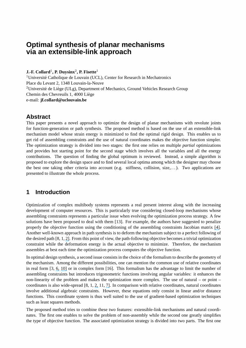
Let us consider the well-known planar example of a four-bar mechanism which has to follow a desired path(see dotted line in Fig. 1.a). In order to make the mechanism exactly follow the given path, the four-bar ismodeled with extensible links which replace the rigid bars and triangle by five springs with stiffnesskj andnatural lengthslj , j = 1 . . . 5 (see Fig. 1.b).
→
a. Rigid mechanism. . . b. . . . modeled by a extensible-link mechanism
Figure 1: Model adaptation of four-bar mechanism for path synthesis
The desired path is discretized intoN points, leading toN different configurations of the mechanism. Whenit moves, the different pointsP0 . . . P4 composing the mechanism have different behaviors:P0 andP4 stayfixed to the ground,P3 follows exactly theN points composing the path andP1 andP2 are free to reach theequilibrium. All these points can thus be arranged into three groups:
• thestaticpointsP0, P4;
• thetrackingpointP3;
• thefloatingpointsP1, P2.
Their absolute coordinates are saved respectively in the following vectors: s, t andf . As the tracking pointand the floating points may have different coordinates for each configuration,t andf are referenced by theindexi: ti andfi, i = 1 . . . N .Grouping the natural lengthslj in the column vectorl and the stiffness parameterskj on the diagonal of thestiffness matrixK, we define the total strain energy as a scalar cost function:
E (s, t1, . . . , tN , f1, . . . , fN , l,K) =1
2
N∑
i=1
(di − l)TK (di − l) , (1)
where indexi stands for theith configuration of the mechanism anddi is a column vector containing thefive distancedi
j computed between each pair of linked points. For the moment, the only known parametersare the2N ∗ 2 coordinates of the floating points. The stiffness parameterskj may be chosen by the user.They play the role of weights in the sum of all the contributions to the total energy. Making a bar stifferincreases its relative importance in the cost function but this possibility is not used in the following. Afterthese considerations, the optimization problem is stated as follows:
mins,f1,...,fN ,l
1
2
N∑
i=1
[d (s, ti, fi) − l]T K [d (s, ti, fi) − l] , (2)
where the actual design parameters ares and l. This constitutes an obvious non-linear least squares opti-mization problem. Defined that way, the problem remains difficult to solve. Therefore, two propositions aregiven below to improve the homogeneity of the problem and to avoid multiple triangleconfigurations.
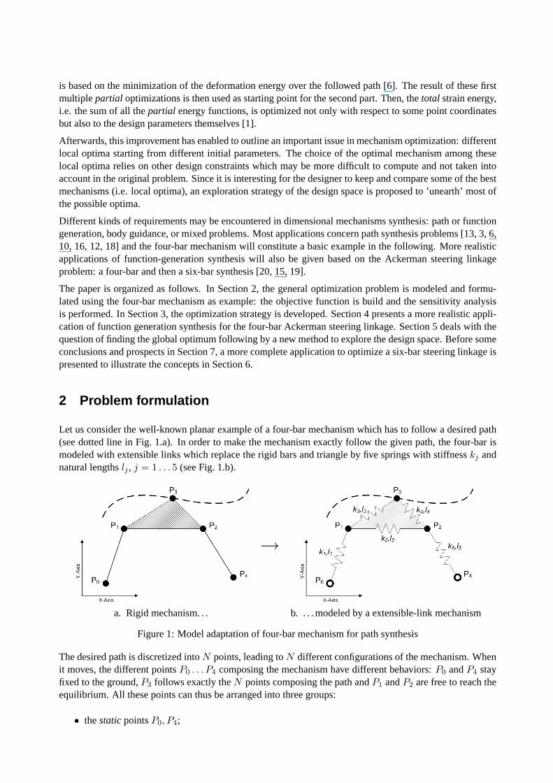
Firstly, let us remark that the actual design parameters, thestaticpoints coordinatess and the natural lengthl, appear in different terms of the cost function. This makes the cost function differently sensitive to bothof them. We propose to transform each static point coordinates into the natural lengths of two springs (seeFig. 2). In this way, a new floating point is inserted inf , the vectors is appended to the vectorl and twonew stiffness parameters are added to the diagonal of matrixK. Note that the corresponding functionsd(s, ti, fi) become actually the two coordinate values which are not always positive: this introduces so-calledorientedsprings according to the sign of their natural lengths. But this has no consequence on theenergy formulation (1). For example, replacingstatic point (x0, y0) of Fig. 2 would create two additionalcontributions to the total energy:1
2kx(x − x0)
2 and 12ky(y − y0)
2. Thanks to this transformation, all thedesign parameters may be grouped into the same vectorl.
→
Figure 2: New model of static points
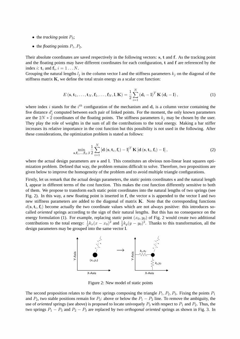
The second proposition relates to the three springs composing the triangleP1, P2, P3. Fixing the pointsP1
andP2, two stable positions remain forP3: above or below theP1 − P2 line. To remove the ambiguity, theuse oforientedsprings (see above) is proposed to locate univoquelyP3 with respect toP1 andP2. Thus, thetwo springsP1 − P3 andP2 − P3 are replaced by twoorthogonal orientedsprings as shown in Fig. 3. In
this example, both contributions of springs3 and4 are replaced by:12ka(a − a0)
2 and 12kb(b − b0)
2, with
a =−−−→P1P2·
−−−→P1P3
∥
∥
∥
−−−→P1P2
∥
∥
∥
andb =−−−→P1P2×
−−−→P1P3
∥
∥
∥
−−−→P1P2
∥
∥
∥
· z.
→
Figure 3: New model of triangle element
Finally, taking both propositions into account, the total cost function (1) becomes:
E(
t1, . . . , tN , f1, . . . , fN , l, K)
=1
2
N∑
i=1
(
di − l
)TK
(
di − l
)
, (3)
leading to the following rearranged optimization problem:
minf1,...,fN ,l
1
2
N∑
i=1
[
d (ti, fi) − l
]TK
[
d (ti, fi) − l
]
, (4)
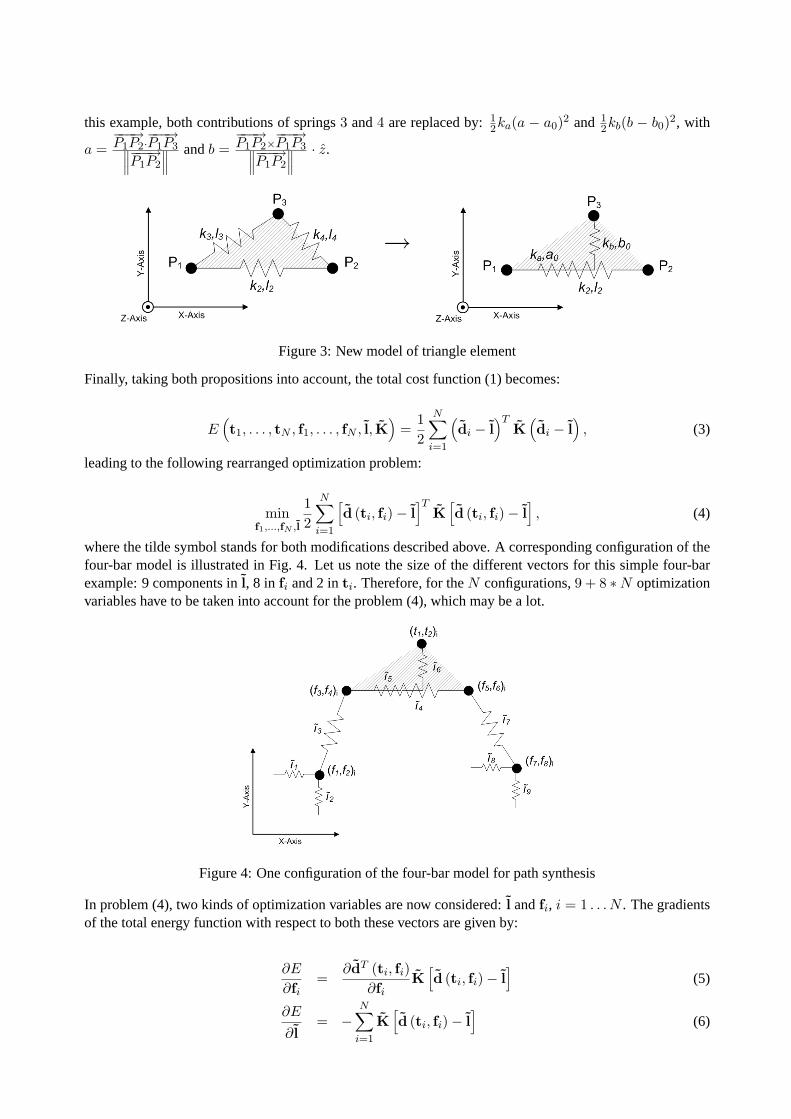
where the tilde symbol stands for both modifications described above. A corresponding configuration of thefour-bar model is illustrated in Fig. 4. Let us note the size of the different vectors for this simple four-barexample: 9 components inl, 8 in fi and 2 inti. Therefore, for theN configurations,9 + 8 ∗ N optimizationvariables have to be taken into account for the problem (4), which may be alot.
Figure 4: One configuration of the four-bar model for path synthesis
In problem (4), two kinds of optimization variables are now considered:l andfi, i = 1 . . . N . The gradientsof the total energy function with respect to both these vectors are given by:
∂E
∂fi=
∂dT (ti, fi)
∂fiK
[
d (ti, fi) − l
]
(5)
∂E
∂ l= −
N∑
i=1
K
[
d (ti, fi) − l
]
(6)
Let us point out that (5) only depends on theith configuration if the design parametersl are fixed. This maygreatly simplify the optimization problem and is the basis of the first part of optimization strategy describedin the next Section.
3 Optimization strategy
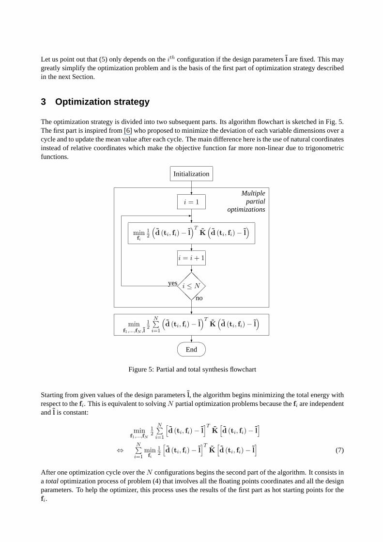
The optimization strategy is divided into two subsequent parts. Its algorithm flowchart is sketched in Fig. 5.The first part is inspired from [6] who proposed to minimize the deviation of each variable dimensions over acycle and to update the mean value after each cycle. The main difference here is the use of natural coordinatesinstead of relative coordinates which make the objective function far more non-linear due to trigonometricfunctions.
Initialization
?i = 1
?
minfi
12
(
d (ti, fi) − l
)TK
(
d (ti, fi) − l
)
?i = i + 1
?
���
@@@
���
@@@
i ≤ Nyes
no
?
minf1,...,fN ,l
12
N∑
i=1
(
d (ti, fi) − l
)TK
(
d (ti, fi) − l
)
?��
��End
-
Multiplepartial
optimizations
Figure 5: Partial and total synthesis flowchart
Starting from given values of the design parametersl, the algorithm begins minimizing the total energy withrespect to thefi. This is equivalent to solvingN partial optimization problems because thefi are independentandl is constant:
minf1,...,fN
12
N∑
i=1
[
d (ti, fi) − l
]TK
[
d (ti, fi) − l
]
⇔N∑
i=1
minfi
12
[
d (ti, fi) − l
]TK
[
d (ti, fi) − l
]
(7)
After one optimization cycle over theN configurations begins the second part of the algorithm. It consists ina total optimization process of problem (4) that involves all the floating points coordinates and all the designparameters. To help the optimizer, this process uses the results of the first part as hot starting points for thefi.
As explained in Section 2, the number of optimization parameters may increase rapidly (e.g.9 + 8N = 169variables for the four-bar mechanism withN = 20 synthesis points) if the mechanism and/or the pathget more complex. As the parameter space is larger, a more robust optimization algorithm is needed. Forinstance, the so-called dog-leg algorithm [14]: this trust-region method is also well-known and useful tosolve systems of nonlinear equations.
4 Application to four-bar steering linkage synthesis
This Section presents an interesting application of function generation synthesis. The goal is to optimizesteering linkage of vehicles. In the first subsection, the function to generate is established from the Ack-ermann condition. Secondly, the proposed optimization strategy is applied to thesynthesis of a four-barsteering linkage.
4.1 The Ackermann condition
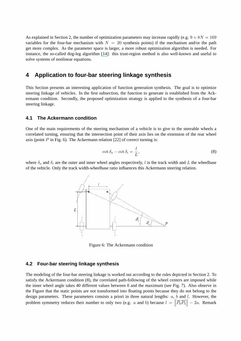
One of the main requirements of the steering mechanism of a vehicle is to give to the steerable wheels acorrelated turning, ensuring that the intersection point of their axis lies on the extension of the rear wheelaxis (pointP in Fig. 6). The Ackermann relation [22] of correct turning is:
cot δo − cot δi =l
L, (8)
whereδo andδi are the outer and inner wheel angles respectively,l is the track width andL the wheelbaseof the vehicle. Only the track width-wheelbase ratio influences this Ackermann steering relation.
Figure 6: The Ackermann condition
4.2 Four-bar steering linkage synthesis
The modeling of the four-bar steering linkage is worked out according to the rules depicted in Section 2. Tosatisfy the Ackermann condition (8), the correlated path-following of the wheel centers are imposed whilethe inner wheel angle takes 40 different values between 0 and the maximum (see Fig. 7). Also observe inthe Figure that the static points are not transformed into floating points because they do not belong to thedesign parameters. These parameters consists a priori in three natural lengths: a, b and l. However, theproblem symmetry reduces their number to only two (e.g.a andb) becausel =
∥
∥
∥
−−−→P0P5
∥
∥
∥ − 2a. Remark
that the function is penalized around the origin of the design space to avoid singular configurations of themechanism. The objective function (3) is extended here as follows:
Eext =
E if∥
∥
∥
−−−→P0P2
∥
∥
∥ ≥ dmin
12
(∥
∥
∥
−−−→P0P2
∥
∥
∥ − dmin
)2if
∥
∥
∥
−−−→P0P2
∥
∥
∥ < dmin
, (9)
where the threshold valuedmin is a chosen realistic minimum distance (e.g.dmin = 10 cm).
→
Figure 7: Model adaptation of four-bar linkage for function-generation synthesis
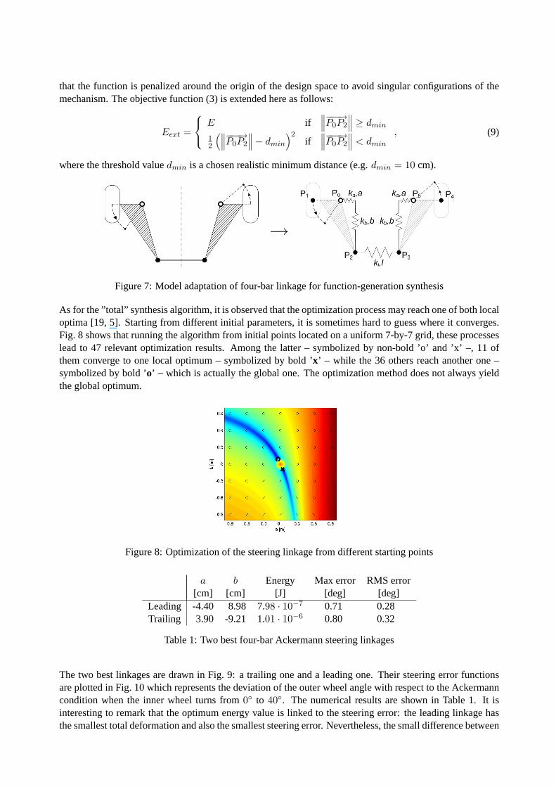
As for the ”total” synthesis algorithm, it is observed that the optimization process may reach one of both localoptima [19, 5]. Starting from different initial parameters, it is sometimes hard toguess where it converges.Fig. 8 shows that running the algorithm from initial points located on a uniform7-by-7 grid, these processeslead to 47 relevant optimization results. Among the latter – symbolized by non-bold’o’ and ’x’ –, 11 ofthem converge to one local optimum – symbolized by bold ’x’ – while the 36 others reach another one –symbolized by bold ’o’ – which is actually the global one. The optimization method does not always yieldthe global optimum.
Figure 8: Optimization of the steering linkage from different starting points
a b Energy Max error RMS error[cm] [cm] [J] [deg] [deg]
Leading -4.40 8.98 7.98 · 10−7 0.71 0.28Trailing 3.90 -9.21 1.01 · 10−6 0.80 0.32
Table 1: Two best four-bar Ackermann steering linkages
The two best linkages are drawn in Fig. 9: a trailing one and a leading one. Their steering error functionsare plotted in Fig. 10 which represents the deviation of the outer wheel anglewith respect to the Ackermanncondition when the inner wheel turns from0◦ to 40◦. The numerical results are shown in Table 1. It isinteresting to remark that the optimum energy value is linked to the steering error: the leading linkage hasthe smallest total deformation and also the smallest steering error. Nevertheless, the small difference between
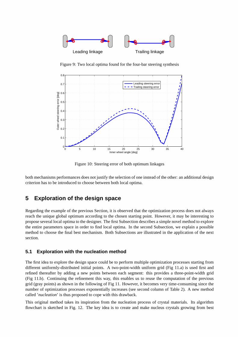
Leading linkage Trailing linkage
Figure 9: Two local optima found for the four-bar steering synthesis
0 5 10 15 20 25 30 35 400
0.1
0.2
0.3
0.4
0.5
0.6
0.7
0.8
Inner wheel angle [deg]
Out
er w
heel
ste
erin
g er
ror
[deg
]
Leading steering errorTrailing steering error
Figure 10: Steering error of both optimum linkages
both mechanisms performances does not justify the selection of one instead of the other: an additional designcriterion has to be introduced to choose between both local optima.
5 Exploration of the design space
Regarding the example of the previous Section, it is observed that the optimization process does not alwaysreach the unique global optimum according to the chosen starting point. However, it may be interesting topropose several local optima to the designer. The first Subsection describes a simple novel method to explorethe entire parameters space in order to find local optima. In the second Subsection, we explain a possiblemethod to choose the final best mechanism. Both Subsections are illustrated in the application of the nextsection.
5.1 Exploration with the nucleation method
The first idea to explore the design space could be to perform multiple optimization processes starting fromdifferent uniformly-distributed initial points. A two-point-width uniform grid (Fig 11.a) is used first andrefined thereafter by adding a new points between each segment: this provides a three-point-width grid(Fig 11.b). Continuing the refinement this way, this enables us to reuse the computation of the previousgrid (gray points) as shown in the following of Fig 11. However, it becomesvery time-consuming since thenumber of optimization processes exponentially increases (see second column of Table 2). A new methodcalled ’nucleation’ is thus proposed to cope with this drawback.
This original method takes its inspiration from the nucleation process of crystal materials. Its algorithmflowchart is sketched in Fig. 12. The key idea is to create and make nucleuscrystals growing from best
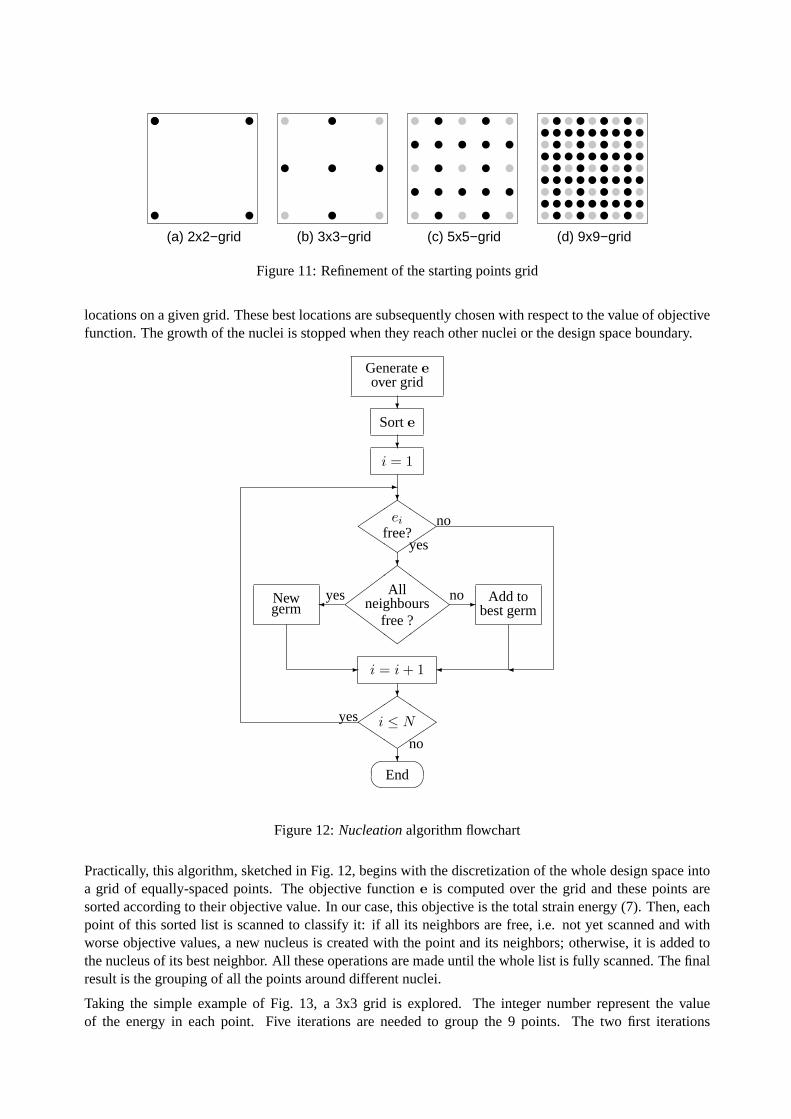
(a) 2x2−grid (b) 3x3−grid (c) 5x5−grid (d) 9x9−grid
Figure 11: Refinement of the starting points grid
locations on a given grid. These best locations are subsequently chosen with respect to the value of objectivefunction. The growth of the nuclei is stopped when they reach other nuclei or the design space boundary.
Generateeover grid
?Sorte
?i = 1
?
��
�
Q�
��
Qei
free?no
yes?
��
��
ZZ
ZZ
��
��
ZZ
ZZ
Allneighbours
free ?
yes no
i = i + 1
?
��
�
Q�
��
Q
i ≤ Nyes
no?�
�� End
-
- Add tobest germ
�
�Newgerm
- �
Figure 12:Nucleationalgorithm flowchart
Practically, this algorithm, sketched in Fig. 12, begins with the discretization of the whole design space intoa grid of equally-spaced points. The objective functione is computed over the grid and these points aresorted according to their objective value. In our case, this objective is thetotal strain energy (7). Then, eachpoint of this sorted list is scanned to classify it: if all its neighbors are free,i.e. not yet scanned and withworse objective values, a new nucleus is created with the point and its neighbors; otherwise, it is added tothe nucleus of its best neighbor. All these operations are made until the whole list is fully scanned. The finalresult is the grouping of all the points around different nuclei.
Taking the simple example of Fig. 13, a 3x3 grid is explored. The integer number represent the valueof the energy in each point. Five iterations are needed to group the 9 points. The two first iterations
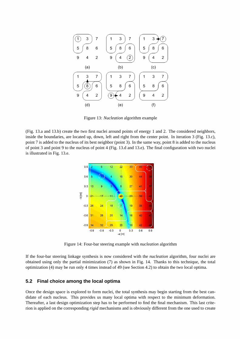
Figure 13:Nucleationalgorithm example
(Fig. 13.a and 13.b) create the two first nuclei around points of energy 1and 2. The considered neighbors,inside the boundaries, are located up, down, left and right from the center point. In iteration 3 (Fig. 13.c),point 7 is added to the nucleus of its best neighbor (point 3). In the same way, point 8 is added to the nucleusof point 3 and point 9 to the nucleus of point 4 (Fig. 13.d and 13.e). The final configuration with two nucleiis illustrated in Fig. 13.e.
Figure 14: Four-bar steering example withnucleationalgorithm
If the four-bar steering linkage synthesis is now considered with thenucleationalgorithm, four nuclei areobtained using only the partial minimization (7) as shown in Fig. 14. Thanks to thistechnique, the totaloptimization (4) may be run only 4 times instead of 49 (see Section 4.2) to obtain the two local optima.
5.2 Final choice among the local optima
Once the design space is explored to form nuclei, the total synthesis may begin starting from the best can-didate of each nucleus. This provides us many local optima with respect to theminimum deformation.Thereafter, a last design optimization step has to be performed to find the final mechanism. This last crite-rion is applied on the correspondingrigid mechanisms and is obviously different from the one used to create
the nuclei. Concerning the steering linkage synthesis, thenucleationprocess is based on the minimum de-formation energy (7). However, the last objective will be the actual steering error of the rigid mechanism (asshown in Fig. 10 for the four-bar linkage) or even a more practical objective to choose the best candidate (seethe end of Section 6). It is therefore computed by simulation of the rigid mechanism instead of the extensibleone. This is illustrated in the next Section.
6 Application to six-bar steering linkage synthesis
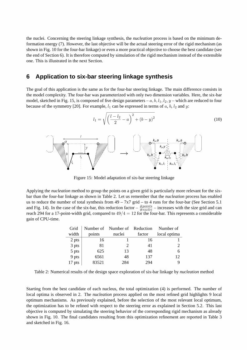
The goal of this application is the same as for the four-bar steering linkage.The main difference consists inthe model complexity. The four-bar was parameterized with only two dimension variables. Here, the six-barmodel, sketched in Fig. 15, is composed of five design parameters –a, b, l1, l2, y – which are reduced to fourbecause of the symmetry [20]. For example,l1 can be expressed in terms ofa, b, l2 andy:
l1 =
√
(
l − l22
− a
)2
+ (b − y)2 (10)
→
Figure 15: Model adaptation of six-bar steering linkage
Applying thenucleationmethod to group the points on a given grid is particularly more relevant for thesix-bar than the four-bar linkage as shown in Table 2. Let us remember that thenucleationprocess has enabledus to reduce the number of total synthesis from 49 – 7x7 grid – to 4 runs forthe four-bar (See Section 5.1and Fig. 14). In the case of the six-bar, this reduction factor –#points
#nuclei– increases with the size grid and can
reach 294 for a 17-point-width grid, compared to49/4 = 12 for the four-bar. This represents a considerablegain of CPU-time.
Grid Number of Number of Reduction Number ofwidth points nuclei factor local optima2 pts 16 1 16 13 pts 81 2 41 25 pts 625 13 48 69 pts 6561 48 137 12
17 pts 83521 284 294 9
Table 2: Numerical results of the design space exploration of six-bar linkage bynucleationmethod
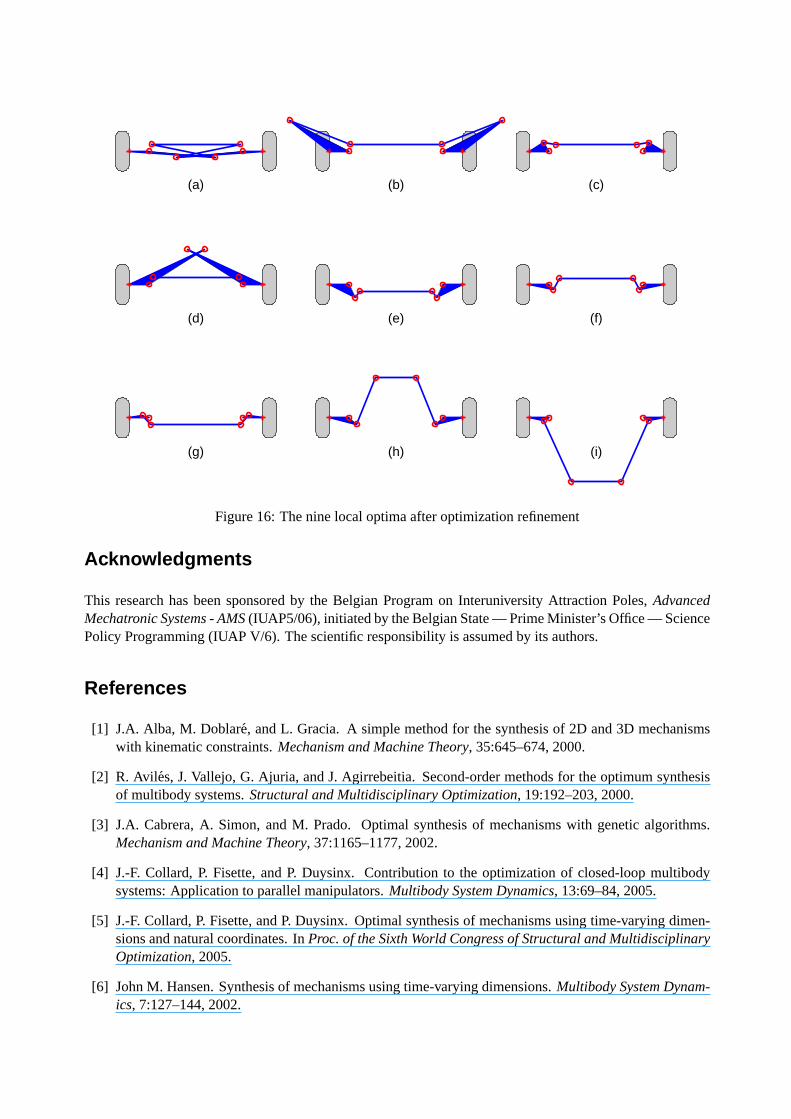
Starting from the best candidate of each nucleus, the total optimization (4) is performed. The number oflocal optima is observed in 2. Thenucleationprocess applied on the most refined grid highlights 9 localoptimum mechanisms. As previously explained, before the selection of the mostrelevant local optimum,the optimization has to be refined with respect to the steering error as explainedin Section 5.2. This lastobjective is computed by simulating the steering behavior of the corresponding rigid mechanism as alreadyshown in Fig. 10. The final candidates resulting from this optimization refinement are reported in Table 3and sketched in Fig. 16.

a b l2 y Energy Max error RMS error Mean dev.[m] [m] [m] [m] [J] [deg] [deg] [% of center]
(a) -0.99 0.09 1.33 0.100 6.78 · 10−12 0.0015 0.0003 >100 %(b) 0.89 -0.46 1.37 0.101 1.72 · 10−11 0.0024 0.0005 >100 %(c) 0.09 -0.12 1.21 0.095 2.01 · 10−08 0.0220 0.0031 >100 %(d) -0.83 -0.53 1.28 0.108 2.10 · 10−09 0.0685 0.0151 >100 %(e) -0.09 0.20 1.08 -0.104 4.48 · 10−08 0.1026 0.0335 >100 %(f) -0.06 0.08 1.11 0.093 1.56 · 10−05 0.3215 0.1232 45 %(g) 0.09 -0.04 1.34 -0.099 9.20 · 10−06 0.3659 0.1245 >100 %(h) -0.11 0.09 0.61 0.601 1.11 · 10−06 0.5977 0.1923 2 %(i) 0.09 0.04 0.75 -0.953 2.34 · 10−04 0.5647 0.1718 37 %
Table 3: The nine local optima after optimization refinement
Compared with the results of the four-bar steering linkage in Fig. 10, all the nine local optima improve boththe maximum and the RMS steering errors. Moreover, these values are so small that it could be interestingto add a more practical criterion. A robustness criterion is proposed: the sensitivity analysis of the steeringerror with respect to the optimum design parameters. A perturbation of 0.5 mm –which could correspondto absolute precision machining – is chosen for each of the four dimensions and also for all combination ofthem. The steering error cost function is thus computed 16 times around eachof the nine optima. In the lastcolumn of Table 3, the mean deviation of the objective over the 16 neighbors of each optimum is represented.This may give a basis for the last decision of the designer. Undeniably, mechanism (h) is the most robust inthe sensitivity sense. However, the designer could choose mechanism (f) because it is more compact than(h) or (i). All these considerations obviously depend on the way each criterion is taken into account by thedesigner.
7 Conclusion and prospects
Based on a strain energy approach of extensible-link mechanisms coupledwith the use of natural coordinates,an original optimization method has been developed to solve path synthesis andfunction generation problemsof planar mechanisms. Divided into two stages, the method tries first to find good starting points withmultiple partial optimizations and then uses them in afull synthesis of the mechanism. It seems efficientbut does not guarantee to obtain the global optimum as it was illustrated via the four-bar steering linkageapplication.
Following that observation, the question of finding the global optimum has been reviewed and extended withthe exploration of the design space to find the most of local optima. To avoid ’astronomical’ CPU time, asimple method inspired from crystals nucleation has been proposed to dividethe design space into nucleicentered on local optima. Starting from the latter, the optimization has been refined and a last criterionapplied to choose the final mechanism.
In terms of prospects, our effort will concentrate on developing other exploration strategies of the designspace. The comparison of these different strategies and their results willbe useful to validate them. Itcould be also interesting to classify the different local optima based on different types of criteria. We alsointend to extend the method further to topologies with prismatic joints or to three-dimensional mechanisms.Extending the application field is also an interesting prospect: other kinematic objectives instead of path orfunction-generator synthesis or even dynamical ones could be investigated. The more challenging issue oftopology optimization of mechanisms could be tackled on the basis of this work, involving for example anadditional higher-level optimization process as proposed by [17], or optimizing simultaneously the topologyand the dimensions of mechanisms as developped by [21], or [9] for path-generation problems using trussrepresentation.
(a) (b) (c)
(d) (e) (f)
(g) (h) (i)
Figure 16: The nine local optima after optimization refinement
Acknowledgments
This research has been sponsored by the Belgian Program on Interuniversity Attraction Poles,AdvancedMechatronic Systems - AMS(IUAP5/06), initiated by the Belgian State — Prime Minister’s Office — SciencePolicy Programming (IUAP V/6). The scientific responsibility is assumed by its authors.
References
[1] J.A. Alba, M. Doblare, and L. Gracia. A simple method for the synthesis of 2D and 3D mechanismswith kinematic constraints.Mechanism and Machine Theory, 35:645–674, 2000.
[2] R. Avil es, J. Vallejo, G. Ajuria, and J. Agirrebeitia. Second-order methods for the optimum synthesisof multibody systems.Structural and Multidisciplinary Optimization, 19:192–203, 2000.
[3] J.A. Cabrera, A. Simon, and M. Prado. Optimal synthesis of mechanismswith genetic algorithms.Mechanism and Machine Theory, 37:1165–1177, 2002.
[4] J.-F. Collard, P. Fisette, and P. Duysinx. Contribution to the optimization ofclosed-loop multibodysystems: Application to parallel manipulators.Multibody System Dynamics, 13:69–84, 2005.
[5] J.-F. Collard, P. Fisette, and P. Duysinx. Optimal synthesis of mechanisms using time-varying dimen-sions and natural coordinates. InProc. of the Sixth World Congress of Structural and MultidisciplinaryOptimization, 2005.
[6] John M. Hansen. Synthesis of mechanisms using time-varying dimensions. Multibody System Dynam-ics, 7:127–144, 2002.
[7] Ole Fjendbo Jensen and John M. Hansen. Treating the problem of non-assembly for dimensionalsynthesis of spatial mechanisms. In Schonfeld & Ziegler, editor,The Fifth World Congress of Structuraland Multidisciplinary Optimization, pages 431–432. ISSMO, Italian Polytechnic Press, may 2003.
[8] J. M. Jimenez, G. Alvarez, J. Cardenal, and J. Cuadrado. A simple and general method for kinematicsynthesis of spatial mechanisms.Mechanism and Machine Theory, 32(3):323–341, 1997.
[9] A. Kawamoto. Path-generation of articulated mechanisms by shape and topology variations in non-linear truss representation.International Journal for Numerical Methods in Engineering, 64:1557–1574, 2005.
[10] M.A. Laribi, A. Mlika, L. Romdhane, and S. Zeghloul. A combined genetic algorithm-fuzzy logicmethod GA-FL in mechanisms synthesis.Mechanism and Machine Theory, 39:717–735, 2004.
[11] Mauro Da Lio, Vittore Cossalter, and Roberto Lot. On the use of natural coordinates in optimal syn-thesis of mechanisms.Mechanism and Machine Theory, 35:1367–1389, 2000.
[12] Francisco T. Sanchez Marın and Antonio Perez Gonzalez. Global optimization in path synthesis basedon design space reduction.Mechanism and Machine Theory, 38:579–594, 2003.
[13] R.J. Minnaar, D.A. Tortorelli, and J.A. Snyman. On nonassembly in the optimal dimensional synthesisof planar mechanisms.Structural and Multidisciplinary Optimization, 21:345–354, 2001.
[14] M.J.D. Powell. Nonlinear Programming, chapter A new algorithm for unconstrained optimization.Academic Press, 1970.
[15] S. Pramanik. Kinematic synthesis of a six-member mechanism for automotivesteering.ASME Journalof Mechanical Design, 124:642–645, dec 2002.
[16] R. Sancibrian, F. Viadero, P. Garcıa, and A. Fernandez. Gradient-based optimization of path synthesisproblems in planar mechanisms.Mechanism and Machine Theory, 39:839–856, 2004.
[17] Kai Sedlaczek, Timo Gaugele, and Peter Eberhard. Topology optimized synthesis of planar kinematicrigid body mechanisms. InProc. of the Multibody Dynamics 2005, Eccomas Thematic Conference,2005.
[18] P.S. Shiakolas, D. Koladiya, and J. Kebrle. On the optimum synthesis of six-bar linkages using differ-ential evolution and the geometric centroid of precision positions technique.Mechanism and MachineTheory, 40:319–335, 2005.
[19] P.A. Simionescu and D. Beale. Optimum synthesis of the four-bar function generator in its symmetricembodiment: the ackermann steering linkage.Mechanism and Machine Theory, 37:1487–1504, 2002.
[20] P.A. Simionescu, M.R. Smith, and I. Tempea. Synthesis and analysis of the two loop translational inputsteering mechanism.Mechanism and Machine Theory, 35:927–943, 2000.
[21] M. Stolpe and A. Kawamoto. Design of planar articulated mechanisms using branch and bound.Math-ematical Programming, 103:357–397, 2005.
[22] J.Y. Wong. Theory of Ground Vehicles, chapter Handling characteristics of Road Vechicles, pages335–387. John Wiley & Sons, 3rd edition, 2001.