operation & maintenance manual
TRANSCRIPT

��������������� ������
����������
��������������������������� ����
������� ������ ��������
����������������� ������� ������������������������ ������ �������� ���� ���������� �������� ��� ����� ���� ������ ������ �������� � �������������� ������������ ������ ������ ��� ���� ������� ��� ���� ������������������������������������������������������������� ����������������� �������
��������

FOREWORD
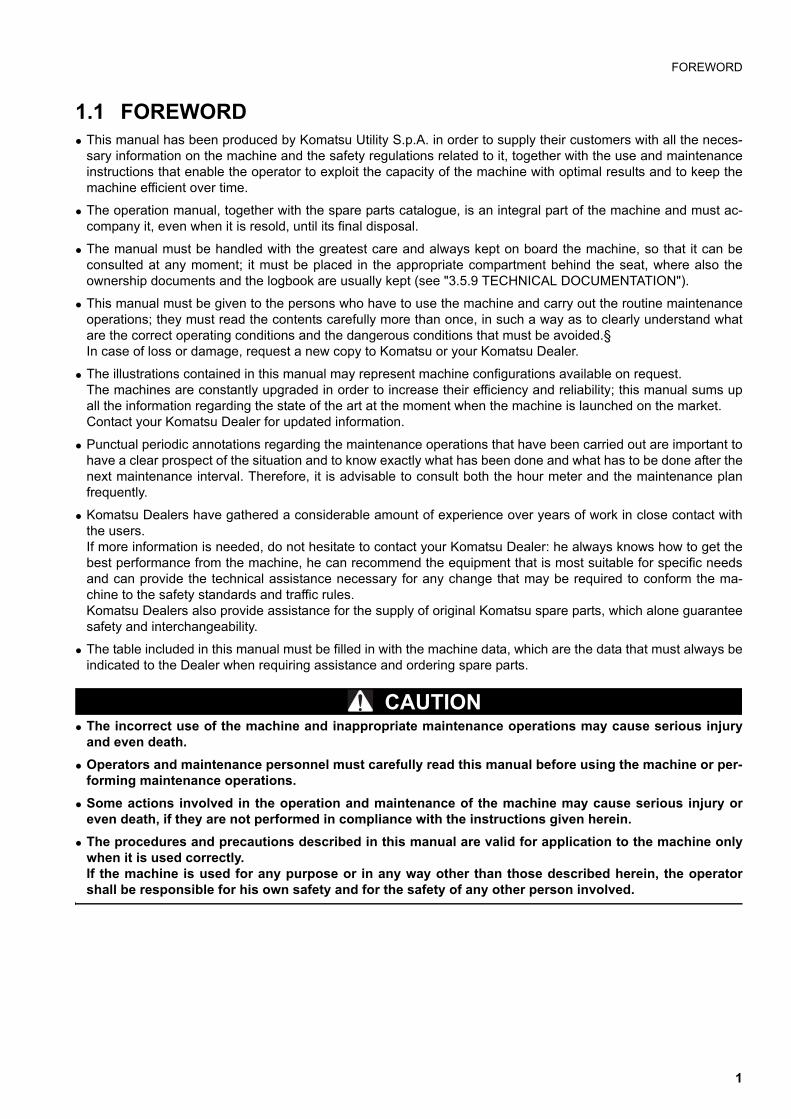
1.1 FOREWORDq This manual has been produced by Komatsu Utility S.p.A. in order to supply their customers with all the neces-
sary information on the machine and the safety regulations related to it, together with the use and maintenanceinstructions that enable the operator to exploit the capacity of the machine with optimal results and to keep themachine efficient over time.
q The operation manual, together with the spare parts catalogue, is an integral part of the machine and must ac-company it, even when it is resold, until its final disposal.
q The manual must be handled with the greatest care and always kept on board the machine, so that it can beconsulted at any moment; it must be placed in the appropriate compartment behind the seat, where also theownership documents and the logbook are usually kept (see "3.5.9 TECHNICAL DOCUMENTATION").
q This manual must be given to the persons who have to use the machine and carry out the routine maintenanceoperations; they must read the contents carefully more than once, in such a way as to clearly understand whatare the correct operating conditions and the dangerous conditions that must be avoided.§In case of loss or damage, request a new copy to Komatsu or your Komatsu Dealer.
q The illustrations contained in this manual may represent machine configurations available on request.The machines are constantly upgraded in order to increase their efficiency and reliability; this manual sums upall the information regarding the state of the art at the moment when the machine is launched on the market.Contact your Komatsu Dealer for updated information.
q Punctual periodic annotations regarding the maintenance operations that have been carried out are important tohave a clear prospect of the situation and to know exactly what has been done and what has to be done after thenext maintenance interval. Therefore, it is advisable to consult both the hour meter and the maintenance planfrequently.
q Komatsu Dealers have gathered a considerable amount of experience over years of work in close contact withthe users.If more information is needed, do not hesitate to contact your Komatsu Dealer: he always knows how to get thebest performance from the machine, he can recommend the equipment that is most suitable for specific needsand can provide the technical assistance necessary for any change that may be required to conform the ma-chine to the safety standards and traffic rules.Komatsu Dealers also provide assistance for the supply of original Komatsu spare parts, which alone guaranteesafety and interchangeability.
q The table included in this manual must be filled in with the machine data, which are the data that must always beindicated to the Dealer when requiring assistance and ordering spare parts.
CAUTIONq The incorrect use of the machine and inappropriate maintenance operations may cause serious injury
and even death.
q Operators and maintenance personnel must carefully read this manual before using the machine or per-forming maintenance operations.
q Some actions involved in the operation and maintenance of the machine may cause serious injury oreven death, if they are not performed in compliance with the instructions given herein.
q The procedures and precautions described in this manual are valid for application to the machine onlywhen it is used correctly.If the machine is used for any purpose or in any way other than those described herein, the operatorshall be responsible for his own safety and for the safety of any other person involved.
1

INFORMATION ON SAFETY
1.2 INFORMATION ON SAFETYMany accidents are caused by insufficient knowledge of and failure to comply with the safety regulations pre-scribed for the maintenance operations that must be performed on the machine.In order to avoid accidents, before starting work and before carrying out any maintenance operation, carefully readand be sure to understand all the information and warnings contained in this manual and given on the plates ap-plied onto the machine. To allow the operator to use the machine in total safety, precautions and safety plates are described in this manualand applied to the machine in order to supply information regarding situations that involve potential risks and themeasures that may be adopted to avoid such situations.
Terminology used in the signs
The following terms are used in the signs to inform the user that there is a situation of potential danger that maycause injury or damage. In this manual and in the plates applied to the machine the following terms are used to indicate potential dangers.
DANGERq Indicates a situation of imminent danger that, if not avoided, may cause serious injury and even death.
The use of this term must be limited to situations of extreme danger.
WARNINGq Indicates a situation of potential danger that, if not avoided, may cause serious injury and even death.
CAUTIONq Indicates a situation of potential danger that, if not avoided, may cause moderate injury. This term can
also be used as a warning in case of dangerous procedures.
Other terms used in the signs
In addition to those indicated above, the following warning terms are used to recommend the precautions to betaken to protect the machine or to supply useful information.
IMPORTANTq This term is used to indicate precautions that must be taken in order to avoid actions that may reduce
the life of the machine.
NOTEq This word is used to indicate a useful piece of information.
Komatsu cannot reasonably predict every circumstance that might involve a potential hazard during the operationor maintenance of the machine; for this reason, the safety messages included in this manual and applied onto themachine may not include all possible safety precautions.If all the procedures and operations prescribed for this machine are kept to, you can be sure that the operator andthe persons in the vicinity will work in total safety, with no risk of damaging the machine. In case of doubt regardingthe safety measures necessary for some procedures, contact Komatsu or your local Dealer.
2

INFORMATION ON SAFETY
DANGERq Before starting any maintenance operation, position the machine on firm and level ground, engage the
safety locks of the equipment and of the controls, stop the engine and apply the parking brake.
DANGERq To make the information clearer, some illustrations in this manual represent the machine without safety
guards. Do not use the machine without guards and do not start the engine when the hood is open, un-less this is expressly prescribed for certain maintenance operations.
WARNINGq It is strictly forbidden to modify the setting of the hydraulic system safety valves; Komatsu cannot be
held liable for any personal injury, or damage to property or the machine, if this has been tampered withby modifying the standard setting of the hydraulic system.
WARNINGq Before carrying out any electric welding operation, disconnect the battery and the alternator. (See
"2.8.13 PRECAUTIONS CONCERNING THE BATTERY AND THE ALTERNATOR").
WARNINGq Install only authorized additional equipment (See "6.1 AUTHORIZED OPTIONAL EQUIPMENT").
WARNINGq The machine can travel on roads only if equipped with suitable lighting, signalling and safety devices
and if this type of use is authorized by the logbook. Before travelling on roads, make sure that the equipment with which the machine is provided is homolo-gated and that the safety locks are correctly engaged.
DANGERq It is absolutely forbidden to manoeuvre the machine while standing on the ground.
Each operation must be carried out by the operator correctly seated in the driving position.
3
INTRODUCTION
1.3 INTRODUCTION
1.3.1 INTENDED USESThe Komatsu BACKHOE LOADERS described in this manual have been designed and constructed to be usedmainly with the following functions:
q LOADER
q EXCAVATOR
Through the installation of optional equipment, the machine can also be used for the following applications:
q HANDLING OF MATERIALS (4IN1 BUCKET - PALLET FORKS)
q SNOWPLOUGH (ANGLEDOZER BLADE - SNOWPLOUGH)
q DEMOLITION (HAND HAMMER - HAMMER ON THE BACKHOE)
q DITCH CLEANING AND DIGGING (SPECIAL BUCKETS)
1.3.2 IMPROPER OR UNAUTHORIZED USE
CAUTIONq This paragraph describes some improper or unauthorized uses of the machine; since it is impossible to
predict all possible improper uses, if the machine is going to be used for particular applications, contactyour Komatsu Dealer before carrying out the work.
IMPORTANTq The instructions regarding the authorized optional equipment are given in the relevant operation and
maintenance manuals; if the equipment is supplied by Komatsu, these publications are enclosed to thismanual.
q The instructions regarding the assembly of the authorized equipment, the controls requiring special ar-rangements on the machine and the hydraulic couplings necessary for the operation of the equipmentare grouped in the final section of this manual.
Komatsu BACKHOE LOADERS are constructed exclusively for the handling, excavation and treatment of inertmaterials; therefore, the following uses are absolutely forbidden:
q USE OF THE MACHINE BY MINORS OR INEXPERIENCED PERSONS.
q USE OF THE MACHINE FOR LIFTING PERSONS OR OBJECTS.
q TRANSPORTATION OF PERSONS even if they are in the operator’s cab.
q TRANSPORTATION OF CONTAINERS with fluids, flammable fluids, loose material, without the appropriateslinging equipment.
q TRANSPORTATION AND LIFTING (EVEN IF IN EXCEPTIONAL CASES) OF EQUIPMENT OR MATERIALSTHAT PROTRUDE FROM THE BUCKET OR ARE NOT SECURED TO THE BUCKET BY MEANS OF ROPESOR CHAINS.
q USE OF THE BUCKET FOR DRIVING OR EXTRACTING PILES.
q USE OF THE MACHINE FOR TOWING DAMAGED VEHICLES ON ROADS.
q USE OF THE MACHINE FOR LIFTING DAMAGED VEHICLES.
4
INTRODUCTION
1.3.3 MAIN CHARACTERISTICSq Simple and easy operation.
q Servo-assisted steering with priority hydraulic system.
q 4-gear mechanical gearshift and transmission with hydraulic converter; reversal controlled by a lever positionedunder the steering wheel.
q Loader control through a single servo lever ensuring also combined movements that can be modulated propor-tionally and continually.
q Backhoe controls through mechanical levers ensuring also combined movements that can be modulated propor-tionally and continually. On request, the backhoe can be controlled by means of two servo levers.
q Complete series of instruments visible from the two operating positions (loader or backhoe).
q Separate accelerator controls for the two operating positions.
q Foot brake control.
q Easy maintenance with simplified intervals.
1.3.4 RUNNING-INEvery machine is scrupulously adjusted and tested before delivery.A new machine, however, must be used carefully for the first 100 hours, in order to ensure proper running-in of thevarious components.If the machine is subjected to an excessive work load at the beginning of its service life, its productivity and func-tionality will be untimely reduced.Every new machine must be used carefully, paying special attention to the following indications:
q After the start, let the engine idle for 5 minutes, in such a way as to warm it up gradually before actual operation.
q Avoid operating the machine with the limit loads allowed or at high speed.
q Avoid abrupt starts or accelerations, useless sudden decelerations and abrupt reversals.
q After the first 250 hours of use, carry out the following operations, in addition to those to be performed every 250hours:
1 - Change the hydraulic transmission oil and filter.
2 - Change the differential unit oil (front and rear axle).
3 - Change the final reduction gear oil (front and rear axle).
4 - Change the hydraulic circuit oil filter.
SYNTHETIC BIODEGRADABLE OIL TYPE HEES
On machines in which the synthetic biodegradable oil type HEES is used, the following operations are to be per-formed together with the standard maintenance operations.
q After the first 50 hours of operation, change the hydraulic circuit drain filter.
q After the first 500 hours of operation, change the hydraulic circuit oil.
IMPORTANTq When changing the oil filters (cartridges), check their innner part to make sure that there are no depos-
its. If abundant deposits are observed, find out what may have caused their accumulation before startingthe machine.
q The number of operation hours is indicated by the hour meter.
5
PRODUCT IDENTIFICATION
1.4 PRODUCT IDENTIFICATIONThe Komatsu backhoe loader and its main components are identified by serial numbers stamped on the identifica-tion plates. The serial number and the identification numbers of the components are the only numbers that mustbe indicated to the Dealer when requiring assistance and ordering spare parts.
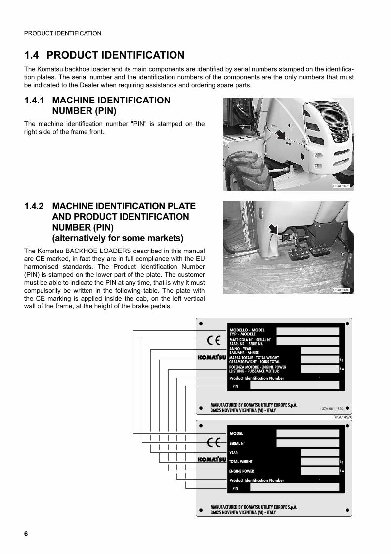
1.4.1 MACHINE IDENTIFICATION NUMBER (PIN)
The machine identification number "PIN" is stamped on theright side of the frame front.
1.4.2 MACHINE IDENTIFICATION PLATE AND PRODUCT IDENTIFICATION NUMBER (PIN)(alternatively for some markets)
The Komatsu BACKHOE LOADERS described in this manualare CE marked, in fact they are in full compliance with the EUharmonised standards. The Product Identification Number(PIN) is stamped on the lower part of the plate. The customermust be able to indicate the PIN at any time, that is why it mustcompulsorily be written in the following table. The plate withthe CE marking is applied inside the cab, on the left verticalwall of the frame, at the height of the brake pedals.
��������
�������
37A-98-11820
MODELLO - MODELTYP - MODELE
kg
kw
MANUFACTURED BY KOMATSU UTILITY EUROPE S.p.A.36025 NOVENTA VICENTINA (VI) - ITALY
MATRICOLA N˚ - SERIAL N˚FABR. NR. - SERIE NR.ANNO - YEARBAUJAHR - ANNEEMASSA TOTALE - TOTAL WEIGHTGESAMTGEWICHT - POIDS TOTALPOTENZA MOTORE - ENGINE POWERLEISTUNG - PUISSANCE MOTEUR
Product Identification Number
PIN
RKA14970
MODEL
kg
kw
MANUFACTURED BY KOMATSU UTILITY EUROPE S.p.A.36025 NOVENTA VICENTINA (VI) - ITALY
SERIAL N˚
YEAR
TOTAL WEIGHT
ENGINE POWER
Product Identification Number
PIN
37A-98-11820
6
PRODUCT IDENTIFICATION
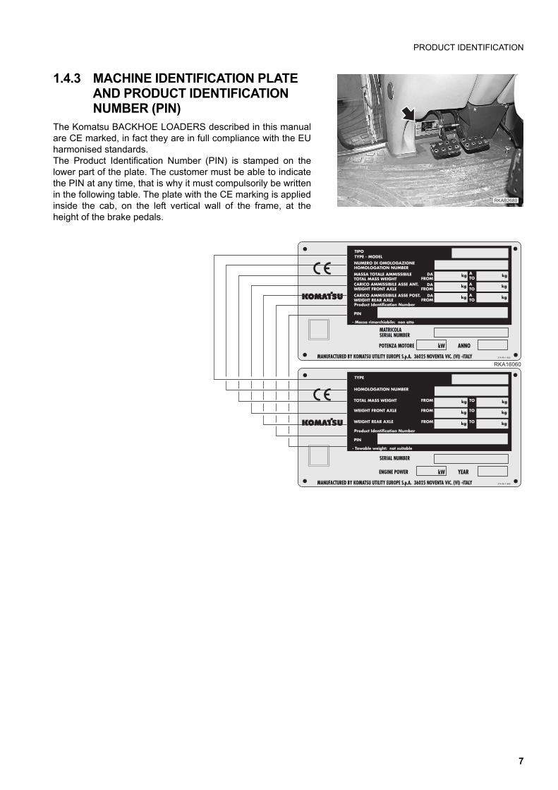
1.4.3 MACHINE IDENTIFICATION PLATE AND PRODUCT IDENTIFICATION NUMBER (PIN)
The Komatsu BACKHOE LOADERS described in this manualare CE marked, in fact they are in full compliance with the EUharmonised standards.The Product Identification Number (PIN) is stamped on thelower part of the plate. The customer must be able to indicatethe PIN at any time, that is why it must compulsorily be writtenin the following table. The plate with the CE marking is appliedinside the cab, on the left vertical wall of the frame, at theheight of the brake pedals.
�������
��������������� ��������������������
��������������
������������������������������������������������������������������������
����������������������������������������������� !�"#"�$�"�!���%& �
��
������
������
������
���
���
���
���$''$��"%���("$&") *��!�!�$���
������������
����� ����� �����
����
������������������������ ���������������������������������������������� �
!
+,
+,
+,
+,
+,
+,
�����������
�����������������
����
���������������
���������������
��������������
��������� !�"#"�$�"�!���%& �
��
��
��
��
����-$&) �- ",(�*��!���'�"�$&)
��"������!�
���� �����
���
������������������������ ���������������������������������������������� �
!
+,
+,
+,
+,
+,
+,
�����������
����
����
����
�������
7
PRODUCT IDENTIFICATION
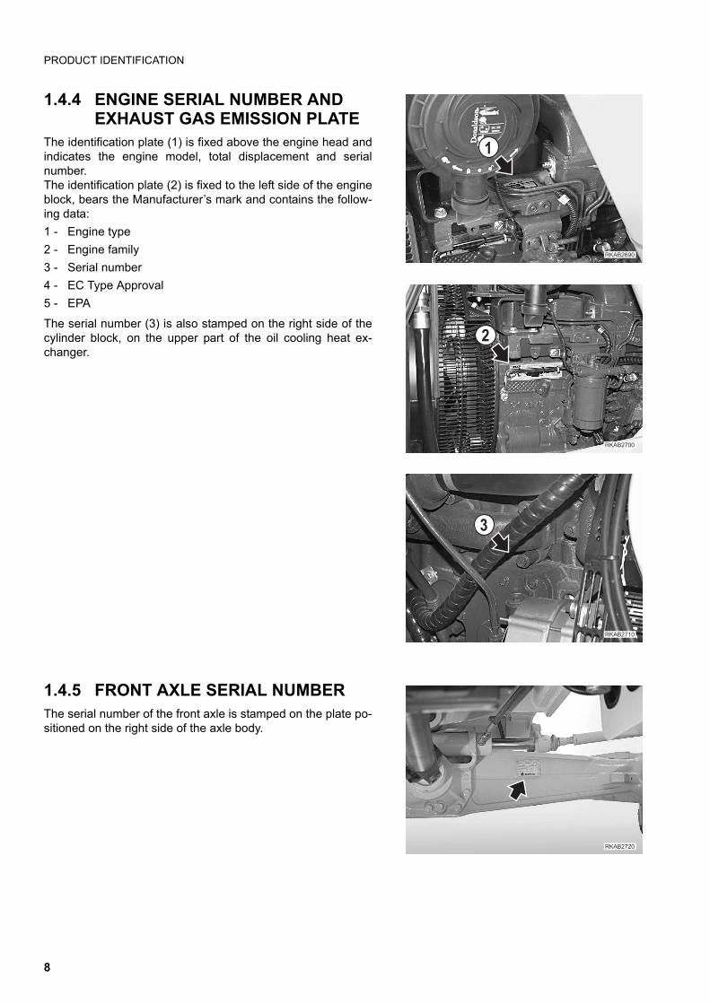
1.4.4 ENGINE SERIAL NUMBER AND EXHAUST GAS EMISSION PLATE
The identification plate (1) is fixed above the engine head andindicates the engine model, total displacement and serialnumber.The identification plate (2) is fixed to the left side of the engineblock, bears the Manufacturer’s mark and contains the follow-ing data:
1 - Engine type
2 - Engine family
3 - Serial number
4 - EC Type Approval
5 - EPA
The serial number (3) is also stamped on the right side of thecylinder block, on the upper part of the oil cooling heat ex-changer.
1.4.5 FRONT AXLE SERIAL NUMBERThe serial number of the front axle is stamped on the plate po-sitioned on the right side of the axle body.
��������
�
��������
�
�������
�
��������
8
PRODUCT IDENTIFICATION
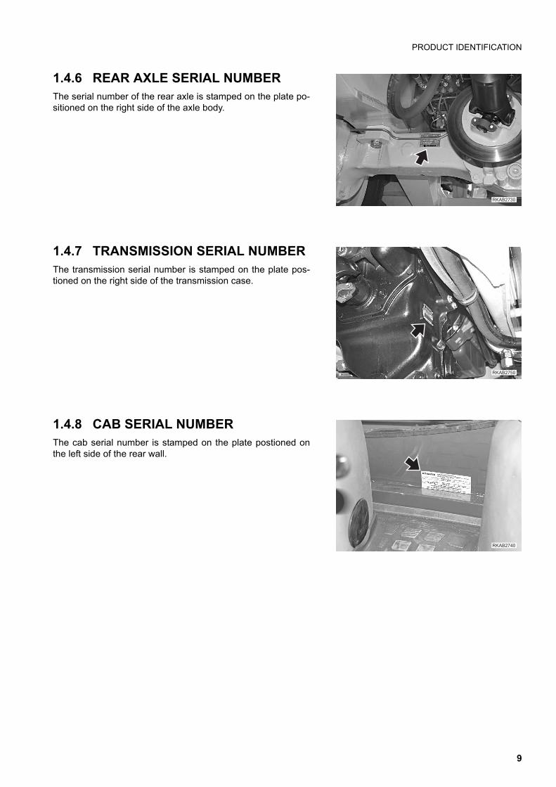
1.4.6 REAR AXLE SERIAL NUMBERThe serial number of the rear axle is stamped on the plate po-sitioned on the right side of the axle body.
1.4.7 TRANSMISSION SERIAL NUMBERThe transmission serial number is stamped on the plate pos-tioned on the right side of the transmission case.
1.4.8 CAB SERIAL NUMBERThe cab serial number is stamped on the plate postioned onthe left side of the rear wall.
��������
������ �
��������
9

PRODUCT IDENTIFICATION
1.4.9 SERIAL NUMBERS AND DEALER’S ADDRESS
Machine no. Mod.
Front axle no.
Rear axle no.
Transmission no.
Dealer:
Address:
Tel.
Contact person:
NOTES:
Cab no.
Product identification number (PIN)
Engine no.
10
TABLE OF CONTENTS
TABLE OF CONTENTS
FOREWORD
1.1 FOREWORD.......................................................................................................................................... 1
1.2 INFORMATION ON SAFETY................................................................................................................ 2
1.3 INTRODUCTION ................................................................................................................................... 41.3.1 INTENDED USES .................................................................................................................... 41.3.2 IMPROPER OR UNAUTHORIZED USE .................................................................................. 41.3.3 MAIN CHARACTERISTICS...................................................................................................... 51.3.4 RUNNING-IN ............................................................................................................................ 5
1.4 PRODUCT IDENTIFICATION ............................................................................................................... 61.4.1 MACHINE IDENTIFICATION NUMBER (PIN) ......................................................................... 61.4.2 MACHINE IDENTIFICATION PLATE AND PRODUCT IDENTIFICATION NUMBER
(PIN) (alternatively for some markets) ..................................................................................... 61.4.3 MACHINE IDENTIFICATION PLATE AND PRODUCT IDENTIFICATION NUMBER (PIN) .... 71.4.4 ENGINE SERIAL NUMBER AND EXHAUST GAS EMISSION PLATE ................................... 81.4.5 FRONT AXLE SERIAL NUMBER............................................................................................. 81.4.6 REAR AXLE SERIAL NUMBER ............................................................................................... 91.4.7 TRANSMISSION SERIAL NUMBER........................................................................................ 91.4.8 CAB SERIAL NUMBER............................................................................................................ 91.4.9 SERIAL NUMBERS AND DEALER’S ADDRESS .................................................................... 10
TABLE OF CONTENTS ........................................................................................................................ 11
SAFETY AND ACCIDENT PREVENTION
2.1 SAFETY, NOISE AND VIBRATION PLATES....................................................................................... 202.1.1 POSITION OF THE SAFETY PLATES .................................................................................... 202.1.2 PICTOGRAMS AND RELEVANT MEANINGS......................................................................... 222.1.3 POSITION OF THE NOISE PLATES ON MACHINES WITH CAB .......................................... 282.1.4 VIBRATIONS TO WHICH THE OPERATOR IS SUBJECTED ................................................ 29
2.2 GENERAL PRECAUTIONS .................................................................................................................. 302.2.1 GENERAL SAFETY RULES .................................................................................................... 302.2.2 SAFETY DEVICES AND GUARDS.......................................................................................... 302.2.3 CLOTHING AND PERSONAL PROTECTION ITEMS ............................................................. 302.2.4 UNAUTHORIZED MODIFICATIONS ....................................................................................... 302.2.5 LEAVING THE OPERATOR’S SEAT ....................................................................................... 312.2.6 GETTING ON AND OFF THE MACHINE................................................................................. 322.2.7 CHECKING THE REAR-VIEW MIRRORS .............................................................................. 322.2.8 PREVENTING FIRES DUE TO FUEL AND OIL ..................................................................... 332.2.9 PREVENTING BURNS ............................................................................................................ 332.2.10 PREVENTING DAMAGE DUE TO ASBESTOS POWDER .................................................... 342.2.11 PREVENTING DAMAGE CAUSED BY THE WORK EQUIPMENT ........................................ 342.2.12 FIRE EXTINGUISHERS AND FIRST AID KIT ........................................................................ 352.2.13 PRECAUTIONS CONCERNING THE CAB STRUCTURE ...................................................... 352.2.14 PRECAUTIONS CONCERNING THE EQUIPMENT ............................................................... 35
2.3 PRECAUTIONS TO BE TAKEN BEFORE STARTING THE ENGINE................................................. 362.3.1 SAFETY ON THE WORK SITE ............................................................................................... 362.3.2 FIRE PREVENTION ................................................................................................................ 362.3.3 PRECAUTIONS TO BE TAKEN FOR THE OPERATOR'S CAB ............................................. 362.3.4 ROOM VENTILATION ............................................................................................................. 372.3.5 CLEANING WINDOWS, MIRRORS AND LIGHTS - CHECKING THE WINDSHIELD
WIPER BLADES AND THE BULBS ......................................................................................... 37
11
TABLE OF CONTENTS
2.4 PRECAUTIONS TO BE TAKEN DURING WORK................................................................................ 382.4.1 WHEN STARTING THE ENGINE............................................................................................. 382.4.2 RULES FOR TRAVELLING ON ROADS.................................................................................. 382.4.3 HAND SIGNALS....................................................................................................................... 392.4.4 CHECKS FOR TRAVELLING IN REVERSE ............................................................................ 442.4.5 MOVING THE MACHINE ......................................................................................................... 442.4.6 WORKING ON SLOPES ......................................................................................................... 452.4.7 PREVENTING ELECTROCUTION .......................................................................................... 462.4.8 VISIBILITY ................................................................................................................................ 472.4.9 WORKING ON ICY OR SNOW-COVERED SURFACES......................................................... 472.4.10 PREVENTING DAMAGE CAUSED BY THE WORK EQUIPMENT ......................................... 472.4.11 WORKING ON LOOSE GROUND ........................................................................................... 472.4.12 PARKING THE MACHINE........................................................................................................ 48
2.5 TRANSPORTING THE MACHINE ON OTHER VEHICLES ................................................................. 492.5.1 LOADING AND UNLOADING THE MACHINE ........................................................................ 492.5.2 TRANSPORT............................................................................................................................ 49
2.6 BATTERY .............................................................................................................................................. 502.6.1 PREVENTING RISKS THAT MAY BE DUE TO THE BATTERY ............................................. 502.6.2 STARTING WITH BOOSTER CABLES ................................................................................... 50
2.7 PRECAUTIONS FOR EMERGENCY RECOVERY............................................................................... 51
2.8 PRECAUTIONS TO BE TAKEN DURING MAINTENANCE................................................................. 522.8.1 WARNING PLATES.................................................................................................................. 522.8.2 TOOLS ..................................................................................................................................... 522.8.3 PERSONNEL............................................................................................................................ 532.8.4 EQUIPMENT ........................................................................................................................... 532.8.5 WORKING UNDER THE MACHINE ........................................................................................ 532.8.6 KEEPING THE MACHINE CLEAN .......................................................................................... 542.8.7 USE OF THE ENGINE DURING MAINTENANCE ................................................................... 542.8.8 PERIODICAL CHANGE OF THE SAFETY RELATED PARTS................................................ 542.8.9 STOP THE ENGINE BEFORE CARRYING OUT ANY MAINTENANCE OPERATION
OR INSPECTION .................................................................................................................... 552.8.10 RULES TO BE FOLLOWED DURING FUEL OR OIL TOPPING UP ...................................... 562.8.11 CHECKING THE COOLANT LEVEL IN THE RADIATOR........................................................ 562.8.12 USING LAMPS ......................................................................................................................... 562.8.13 PRECAUTIONS CONCERNING THE BATTERY AND THE ALTERNATOR .......................... 572.8.14 PRECAUTIONS CONCERNING THE STARTER .................................................................... 572.8.15 HANDLING HIGH-PRESSURE PIPES..................................................................................... 582.8.16 PRECAUTIONS TO BE TAKEN WHEN WORKING ON HIGH- PRESSURE SYSTEMS ....... 582.8.17 PRECAUTIONS FOR MAINTENANCE WORK INVOLVING HIGH TEMPERATURES
AND PRESSURES ................................................................................................................... 582.8.18 HYDRAULIC ACCUMULATOR ................................................................................................ 592.8.19 COOLING FAN AND FAN BELT .............................................................................................. 592.8.20 WASTE MATERIALS................................................................................................................ 592.8.21 PRECAUTIONS CONCERNING TECHNOPOLYMERS AND ELASTOMERS........................ 602.8.22 PRECAUTIONS TO BE TAKEN WHEN INFLATING THE TYRES ......................................... 602.8.23 PRECAUTIONS FOR THE INSTALLATION OF THE EXHAUST SYSTEM TAILPIPE............ 612.8.24 PRECAUTIONS TO BE TAKEN WHEN USING SYNTHETIC BIODEGRADABLE
OIL TYPE «HEES»................................................................................................................... 61
12
TABLE OF CONTENTS
DESCRIPTION AND USE OF THE MACHINE
3.1 SAFETY LOCKS ................................................................................................................................... 643.1.1 FRONT LOADER LOCKS ........................................................................................................ 643.1.2 BACKHOE LOCKS................................................................................................................... 66
3.2 GENERAL VIEWS................................................................................................................................. 683.2.1 FRONT GENERAL VIEW......................................................................................................... 683.2.2 BACKHOE GENERAL VIEW.................................................................................................... 693.2.3 CAB INSIDE GENERAL VIEW................................................................................................. 70
3.2.3.1 CAB INSIDE GENERAL VIEW (mechanical backhoe controls).............................. 703.2.3.2 CAB INSIDE GENERAL VIEW (backhoe servo controls) ....................................... 71
3.3 INSTRUMENTS AND CONTROLS....................................................................................................... 723.3.1 FRONT INSTRUMENTS .......................................................................................................... 723.3.2 SIDE INSTRUMENTS .............................................................................................................. 763.3.3 PUSH BUTTONS ON THE FRONT LOADER CONTROL LEVER .......................................... 843.3.4 PUSH BUTTON ON THE GEARSHIFT LEVER....................................................................... 853.3.5 CAB SWITCHES AND ELECTRIC ACCESSORIES................................................................ 863.3.6 MACHINE CONTROLS ............................................................................................................ 89
3.3.6.1 MACHINE CONTROLS (version with mechanically-controlled backhoe) .............. 893.3.6.2 MACHINE CONTROLS (version with servo-assisted backhoe) ............................. 913.3.6.3 ADJUSTING THE CONTROLS .............................................................................. 111
3.4 FUSES AND RELAYS........................................................................................................................... 1143.4.1 CENTRAL UNIT FUSES – RELAYS AND ENGINE LINE........................................................ 114
3.4.1.1 FUSES ................................................................................................................... 1143.4.1.2 RELAYS .................................................................................................................. 116
3.4.2 VENTILATION, HEATING AND AIR CONDITIONING FUSES AND RELAYS ........................ 1173.4.2.1 FUSES ................................................................................................................... 1173.4.2.2 RELAYS ................................................................................................................. 117
3.5 GUARDS, CAB AND DRIVER’S SEAT ................................................................................................ 1183.5.1 ENGINE HOOD ........................................................................................................................ 1183.5.2 CAB .......................................................................................................................................... 1193.5.3 VENTILATION AND HEATING ................................................................................................ 1223.5.4 AIR CONDITIONER (if installed) .............................................................................................. 1233.5.5 SEAT ........................................................................................................................................ 125
3.5.5.1 SEAT (STANDARD) ............................................................................................... 1253.5.5.2 SEAT (OPTIONAL) ................................................................................................ 126
3.5.6 SAFETY BELT.......................................................................................................................... 1273.5.7 FIRE EXTINGUISHER ............................................................................................................ 1273.5.8 FIRST AID KIT ......................................................................................................................... 1273.5.9 TECHNICAL DOCUMENTATION ........................................................................................... 1273.5.10 STORAGE COMPARTMENT .................................................................................................. 128
3.6 USE OF THE MACHINE........................................................................................................................ 1293.6.1 CHECKS TO BE CARRIED OUT BEFORE STARTING THE ENGINE ................................... 129
3.6.1.1 VISUAL CHECKS.................................................................................................... 1293.6.1.2 OPERATIONAL CHECKS ...................................................................................... 130
3.6.2 STARTING THE ENGINE ........................................................................................................ 1313.6.2.1 STARTING WITH WARM ENGINE OR IN TEMPERATE CLIMATES ................... 1313.6.2.2 STARTING WITH COLD ENGINE OR IN COLD CLIMATES ................................ 132
3.6.3 WARMING THE ENGINE......................................................................................................... 1333.6.4 HEATING THE HYDRAULIC OIL............................................................................................. 1333.6.5 HOW TO MOVE THE MACHINE ............................................................................................. 134
3.6.5.1 DIFFERENTIAL LOCKING...................................................................................... 1353.6.5.2 ENGAGING THE FOUR-WHEEL DRIVE ............................................................... 135
13
TABLE OF CONTENTS
3.6.5.3 WORKING ON SLOPES ........................................................................................ 1363.6.5.4 MAXIMUM IMMERSION DEPTH ............................................................................ 137
3.7 PARKING THE MACHINE .................................................................................................................... 1383.7.1 PARKING ON LEVEL GROUND .............................................................................................. 1383.7.2 PARKING ON SLOPES............................................................................................................ 139
3.8 STOPPING THE ENGINE ..................................................................................................................... 140
3.9 TRANSPORTING THE MACHINE ON OTHER VEHICLES ................................................................. 1413.9.1 LOADING AND UNLOADING THE MACHINE......................................................................... 1413.9.2 TRANSPORT............................................................................................................................ 142
3.10 PRECAUTIONS TO BE TAKEN IN THE COLD SEASON ................................................................... 1433.10.1 FUEL AND LUBRICANTS ........................................................................................................ 1433.10.2 COOLANT ................................................................................................................................ 1433.10.3 BATTERY ................................................................................................................................. 1443.10.4 OTHER PRECAUTIONS .......................................................................................................... 1443.10.5 PRECAUTIONS TO BE TAKEN AT THE END OF WORK ...................................................... 144
3.11 PRECAUTIONS TO BE TAKEN AT THE END OF THE WINTER........................................................ 145
3.12 USING THE MACHINE AS A LOADER................................................................................................ 1463.12.1 BUCKET POSITION INDICATOR ............................................................................................ 1463.12.2 ORGANIZING THE WORK AREA............................................................................................ 146
3.12.2.1 LOADING HEAPED AND LEVEL MATERIAL ........................................................ 1473.12.2.2 LOADING OPERATIONS ON SLOPES.................................................................. 148
3.12.3 CHANGING THE STANDARD FRONT BUCKET ................................................................... 148
3.13 USING THE MACHINE AS AN EXCAVATOR...................................................................................... 1493.13.1 POSITIONING THE BUCKET ACCORDING TO THE WORK THAT MUST
BE CARRIED OUT .................................................................................................................. 1493.13.2 POSITIONING THE MACHINE FOR DIGGING OPERATIONS............................................... 1503.13.3 SLIDING THE BACKHOE UNIT SIDEWARDS ........................................................................ 1513.13.4 DIGGING METHOD.................................................................................................................. 152
3.13.4.1 CHANGING THE BACKHOE BUCKET................................................................... 153
3.14 LONG PERIODS OF INACTIVITY ........................................................................................................ 1543.14.1 PREPARING THE MACHINE FOR A LONG PERIOD OF INACTIVITY .................................. 1543.14.2 PREPARING THE ENGINE FOR A LONG PERIOD OF INACTIVITY..................................... 1563.14.3 MAINTENANCE DURING A PERIOD OF INACTIVITY ........................................................... 1563.14.4 RESTARTING THE ENGINE.................................................................................................... 1573.14.5 AFTER THE PERIOD OF INACTIVITY .................................................................................... 157
3.15 TROUBLESHOOTING .......................................................................................................................... 1583.15.1 HOW TO REMOVE THE MACHINE......................................................................................... 1583.15.2 AFTER THE FUEL HAS RUN OUT.......................................................................................... 1583.15.3 IF THE BATTERY HAS RUN DOWN ....................................................................................... 159
3.15.3.1 STARTING WITH BOOSTER CABLES .................................................................. 1603.15.4 OTHER TROUBLES................................................................................................................. 161
3.15.4.1 ELECTRICAL CIRCUIT........................................................................................... 1613.15.4.2 HYDRAULIC SYSTEM............................................................................................ 1613.15.4.3 BRAKING SYSTEM ................................................................................................ 1623.15.4.4 CONVERTER.......................................................................................................... 1623.15.4.5 ENGINE................................................................................................................... 162
14
TABLE OF CONTENTS
MAINTENANCE
4.1 GUIDE TO MAINTENANCE.................................................................................................................. 166
4.2 MAINTENANCE NOTES....................................................................................................................... 1684.2.1 NOTES REGARDING THE ENGINE ....................................................................................... 168
4.2.1.1 ENGINE OIL............................................................................................................ 1684.2.1.2 COOLANT............................................................................................................... 1684.2.1.3 FUEL ....................................................................................................................... 169
4.2.2 NOTES REGARDING THE HYDRAULIC SYSTEM................................................................. 1694.2.3 NOTES REGARDING THE ELECTRIC SYSTEM.................................................................... 1704.2.4 NOTES REGARDING LUBRICATION ..................................................................................... 1704.2.5 PARTS SUBJECT TO WEAR THAT PERIODICALLY NEED CHANGING.............................. 171
4.3 FUEL, COOLANT AND LUBRICANTS ................................................................................................ 1724.3.1 LUBRICATION WITH GREASE ............................................................................................... 1734.3.2 HOMOLOGATED SYNTHETIC BIODEGRADABLE LUBRICANTS “HEES” ........................... 174
4.4 DRIVING TORQUES ............................................................................................................................. 1754.4.1 STANDARD DRIVING TORQUES FOR SCREWS AND NUTS .............................................. 1754.4.2 SPECIFIC DRIVING TORQUES FOR SCREWS AND NUTS ................................................. 1764.4.3 STANDARD DRIVING TORQUES FOR HOSES WITH ORFS................................................ 176
4.5 LUBRICATION ...................................................................................................................................... 1774.5.1 LUBRICATION DIAGRAM........................................................................................................ 1774.5.2 LUBRICATION DIAGRAM (4in1 bucket and pallet forks) ........................................................ 1784.5.3 LUBRICATION DIAGRAM (front bucket quick couplings) ........................................................ 1794.5.4 LUBRICATION DIAGRAM (offset device) ................................................................................ 180
4.6 PERIODICAL CHANGE OF THE SAFETY RELATED COMPONENTS.............................................. 1814.6.1 SAFETY RELATED PARTS ..................................................................................................... 182
4.6.1.1 FUEL SYSTEM ...................................................................................................... 1824.6.1.2 DELIVERY HYDRAULIC SYSTEM ........................................................................ 1834.6.1.3 FRONT LOADER HYDRAULIC SYSTEM............................................................... 1844.6.1.4 BACKHOE HYDRALIC SYSTEM............................................................................ 1854.6.1.5 OPERATOR’S SAFETY ......................................................................................... 186
4.7 MAINTENANCE PLAN.......................................................................................................................... 187
4.8 MAINTENANCE PROCEDURES.......................................................................................................... 1894.8.1 WHEN REQUIRED................................................................................................................... 189
4.8.1.a CHECKING, CLEANING OR CHANGING THE ENGINE AIR FILTERS ................ 1894.8.1.b CHECKING AND CLEANING THE CAB AIR FILTER ............................................ 1904.8.1.c CHECKING AND CLEANING THE AIR RECIRCULATION FILTER
(only for machines with air conditioner)................................................................... 1914.8.1.d CHECKING THE DETERGENT LEVEL IN THE WINDSHIELD WASHER
RESERVOIR ........................................................................................................... 1914.8.1.e CHECKING THE WINDSHIELD WIPER BLADES.................................................. 1924.8.1.f LUBRICATING THE CAB DOOR HINGES............................................................. 1924.8.1.g FUSES AND RELAYS – CHECK AND CHANGE................................................... 1924.8.1.h BLEEDING THE BRAKING CIRCUIT ..................................................................... 1934.8.1.i CHECKING AND ADJUSTING THE FRONT WHEEL TOE-IN .............................. 1944.8.1.j CHECKING THE BRAKING EFFICIENCY.............................................................. 1944.8.1.k CHECKING AND ADJUSTING THE PARKING BRAKE......................................... 1954.8.1.l CHECKING AND ADJUSTING THE BRAKE PEDAL STROKE ............................. 1964.8.1.m ADJUSTING THE AUTOMATIC RETURN-TO-DIG DEVICE OF THE
FRONT BUCKET (if installed) ................................................................................. 1964.8.1.n CHECKING AND ADJUSTING THE STABILIZER SLACK .................................... 197
4.8.2 MAINTENANCE INTERVALS IN CASE OF USE OF THE DEMOLITION HAMMER .............. 1984.8.2.a CHANGING THE HYDRAULIC OIL FILTER........................................................... 198
15

TABLE OF CONTENTS
4.8.2.b CHANGING THE HYDRAULIC OIL ........................................................................ 1984.8.3 CHECKS TO BE CARRIED OUT BEFORE STARTING THE ENGINE ................................... 199
4.8.3.a VARIOUS CHECKS ................................................................................................ 1994.8.3.b CHECKING THE COOLANT LEVEL....................................................................... 1994.8.3.c CHECKING THE FUEL LEVEL............................................................................... 2004.8.3.d CHECKING THE ENGINE OIL LEVEL ................................................................... 200
4.8.4 MAINTENANCE EVERY 10 HOURS OF OPERATION ........................................................... 2014.8.4.a LUBRICATING THE JOINTS .................................................................................. 201
4.8.5 MAINTENANCE AFTER THE FIRST 50 HOURS OF OPERATION (Only for machines in which synthetic biodegradable oil type HEES is used).......................... 203
4.8.6 MAINTENANCE EVERY 50 HOURS OF OPERATION ........................................................... 2034.8.6.a CHECKING THE HYDRAULIC OIL LEVEL ............................................................ 2034.8.6.b CHECKING THE FLUID LEVEL IN THE RADIATOR ............................................. 2044.8.6.c CHECKING THE BRAKING SYSTEM OIL LEVEL ................................................. 2044.8.6.d LUBRICATING THE PROPELLER SHAFTS .......................................................... 2054.8.6.e LUBRICATING THE FRONT AXLE JOINTS AND CENTRAL COUPLING ............ 2064.8.6.f CHECKING THE TYRE PRESSURE ..................................................................... 2064.8.6.g DRAINING THE WATER SEPARATOR ................................................................. 207
4.8.7 MAINTENANCE AFTER THE FIRST 250 HOURS OF OPERATION ...................................... 2084.8.8 MAINTENANCE EVERY 250 HOURS OF OPERATION ......................................................... 208
4.8.8.a CHECKING THE ALTERNATOR-FAN BELT.......................................................... 2084.8.8.b CHECKING AND ADJUSTING THE A/C COMPRESSOR BELT TENSION
(only for machines with air conditioner) ................................................................... 2094.8.8.c CHECKING THE BATTERY ELECTROLYTE LEVEL ............................................ 2104.8.8.d CHECKING THE FRONT AXLE OIL LEVELS ........................................................ 2114.8.8.e CHECKING THE REAR AXLE OIL LEVEL ............................................................. 2114.8.8.f CHECKING THE HYDRAULIC TRANSMISSION OIL LEVEL ............................... 2124.8.8.g CHECKING THE WHEEL NUT DRIVING TORQUE............................................... 212
4.8.9 MAINTENANCE AFTER THE FIRST 500 HOURS OF OPERATION(Only for machines in which synthetic biodegradable oil type HEES is used).......................... 213
4.8.10 MAINTENANCE EVERY 500 HOURS OF OPERATION ......................................................... 2134.8.10.a CHANGING THE ENGINE OIL ............................................................................... 2134.8.10.b CHANGING THE ENGINE OIL FILTER.................................................................. 2144.8.10.c CHANGING THE HYDRAULIC SYSTEM OIL FILTER ........................................... 2144.8.10.d CHANGING THE FUEL FILTER ............................................................................. 2174.8.10.e DRAINING THE FUEL TANK.................................................................................. 2184.8.10.f DRAINING THE HYDRAULIC OIL TANK
(only for machines in which synthetic biodegradable oil type HEES is used) ......... 2194.8.10.g CLEANING THE OUTSIDE OF THE RADIATOR .................................................. 2204.8.10.h CLEANING THE OUTSIDE OF THE A/C CONDENSER
(only for machines with air conditioner) .................................................................. 2214.8.11 MAINTENANCE EVERY 1000 HOURS OF OPERATION ....................................................... 222
4.8.11.a CHANGING THE FRONT AXLE OIL ...................................................................... 2224.8.11.b CHANGING THE REAR AXLE OIL......................................................................... 2234.8.11.c CHANGING THE HYDRAULIC TRANSMISSION OIL............................................ 2244.8.11.d CHANGING THE HYDRAULIC TRANSMISSION OIL FILTER .............................. 225
4.8.12 MAINTENANCE EVERY 2000 HOURS OF OPERATION ....................................................... 2264.8.12.a CHANGING THE HYDRAULIC OIL AND CLEANING THE INTAKE FILTER......... 2264.8.12.b CHANGING THE COOLANT ................................................................................. 2284.8.12.c CHANGING THE BRAKING SYSTEM OIL ............................................................. 2294.8.12.d CHECKING THE ALTERNATOR AND THE STARTER ......................................... 2304.8.12.e CHANGING THE ALTERNATOR BELT.................................................................. 2304.8.12.f CHECKING THE A/C COOLING GAS QUANTITY
(only for machines with air conditioner) ................................................................... 2304.8.13 MAINTENANCE EVERY 3000 HOURS OF OPERATION ....................................................... 231
16
TABLE OF CONTENTS
4.8.13.a CHECKING THE ENGINE RETAINING SCREWS AND DAMPING ELEMENTS .. 2314.8.13.b CHECKING AND ADJUSTING THE ENGINE VALVE CLEARANCE AND
THE INJECTION TIMING ADVANCE ..................................................................... 2314.8.14 MAINTENANCE EVERY 4000 HOURS OF OPERATION ....................................................... 232
4.8.14.a CHANGING THE A/C DEWATERING FILTER(Only for machines with air conditioner) ................................................................. 232
4.8.14.b CHECKING THE OPERATING CONDITIONS OF THE A/C COMPRESSOR(Only for machines with air conditioner) ................................................................. 232
4.8.14.c CHANGING THE ENGINE THERMOSTATIC VALVE............................................ 232
TECHNICAL SPECIFICATIONS
5.1 TECHNICAL DATA ............................................................................................................................... 2345.1.1 STANDARD OVERALL DIMENSIONS .................................................................................... 234
5.1.1.1 OVERALL DIMENSIONS WITH STANDARD ARM................................................ 2345.1.1.2 OVERALL DIMENSIONS WITH TELESCOPIC ARM............................................. 234
5.1.2 TECHNICAL CHARACTERISTICS .......................................................................................... 2355.1.3 LIFTING CAPACITIES ............................................................................................................. 237
5.1.3.1 SYMBOL TABLE..................................................................................................... 2375.1.3.2 LIFTING CAPACITIES (STANDARD ARM) ............................................................ 2385.1.3.3 LIFTING CAPACITIES (TELESCOPIC ARM) ......................................................... 239
AUTHORIZED OPTIONAL EQUIPMENT
6.1 AUTHORIZED OPTIONAL EQUIPMENT ............................................................................................. 2426.1.1 PRECAUTIONS REGARDING SAFETY.................................................................................. 2426.1.2 PRECAUTIONS REGARDING THE INSTALLATION OF EQUIPMENT.................................. 2436.1.3 CHARACTERISTICS OF THE OPTIONAL EQUIPMENT........................................................ 244
6.2 FRONT EQUIPMENT QUICK COUPLING DEVICES .......................................................................... 2456.2.1 MANUAL QUICK COUPLING .................................................................................................. 2456.2.2 HYDRAULIC QUICK COUPLING FOR STANDARD BUCKET ............................................... 2466.2.3 HYDRAULIC QUICK COUPLING FOR 4in1 BUCKET AND OPTIONAL EQUIPMENT
WITH UNIDIRECTIONAL OIL FLOW ...................................................................................... 246
6.3 4in1 BUCKET........................................................................................................................................ 2476.3.1 DESCRIPTION AND CONTROLS .......................................................................................... 2476.3.2 SAFETY DEVICES .................................................................................................................. 2476.3.3 INSTALLING THE 4in1 BUCKET ............................................................................................ 2486.3.4 USING THE 4in1 BUCKET ...................................................................................................... 2496.3.5 MAINTENANCE ....................................................................................................................... 249
6.4 PALLET FORKS ................................................................................................................................... 2506.4.1 DESCRIPTION ......................................................................................................................... 2506.4.2 SAFETY DEVICES .................................................................................................................. 2516.4.3 USING THE FORKS ................................................................................................................ 251
6.4.3.1 PREPARING THE PALLET FORKS FOR USE ..................................................... 2526.4.3.2 OVERTURNING THE FORKS FOR TRAVEL ON ROADS ................................... 252
6.4.4 REMOVING THE FORKS ........................................................................................................ 2536.4.5 INSTALLING THE FORKS ....................................................................................................... 2536.4.6 MAINTENANCE ....................................................................................................................... 253
6.5 BACKHOE TELESCOPIC ARM............................................................................................................ 2546.5.1 DESCRIPTION AND CONTROL.............................................................................................. 254
6.5.1.1 CONTROL (version with mechanically-controlled backhoe) .................................. 2546.5.1.2 CONTROL (version with servo-assisted backhoe).................................................. 254
6.5.2 SAFETY DEVICES................................................................................................................... 2556.5.3 USING THE TELESCOPIC ARM ............................................................................................. 2556.5.4 MAINTENANCE ....................................................................................................................... 256
6.5.4.1 ADJUSTING THE GUIDE SLACK........................................................................... 256
17
TABLE OF CONTENTS
6.6 CONFIGURATION FOR THE INSTALLATION OF THE DEMOLITION HAMMER ............................. 2586.6.1 DESCRIPTION AND CONTROL .............................................................................................. 258
6.6.1.1 CONTROL (version with mechanically-controlled backhoe) ................................... 2586.6.1.2 CONTROL (version with servo-assisted backhoe).................................................. 258
6.6.2 USE OF THE DEMOLITION HAMMER AND RULES TO BE OBSERVED ............................. 2596.6.3 INSTALLING AND REMOVING THE DEMOLITION HAMMER ............................................... 263
6.6.3.1 INSTALLING THE HAMMER .................................................................................. 2636.6.3.2 REMOVING THE HAMMER.................................................................................... 265
6.6.4 USING THE HAMMER ............................................................................................................. 2656.6.5 MAINTENANCE........................................................................................................................ 265
6.7 APPLICATION OF THE OFFSET DEVICE........................................................................................... 2666.7.1 DESCRIPTION AND CONTROL ............................................................................................. 266
6.7.1.1 CONTROL (version with mechanically-controlled backhoe) ................................... 2666.7.1.2 CONTROL (version with servo-assisted backhoe).................................................. 267
6.7.2 MAINTENANCE........................................................................................................................ 267
6.8 CONFIGURATION FOR THE USE OF OPTIONAL EQUIPMENT WITHUNIDIRECTIONAL OIL FLOW.............................................................................................................. 2686.8.1 DESCRIPTION AND CONTROL ............................................................................................. 268
6.8.1.1 CONTROL (version with mechanically-controlled backhoe) ................................... 2686.8.1.2 CONTROL (version with servo-assisted backhoe).................................................. 268
6.8.2 INSTALLING AND CONNECTING THE EQUIPMENT ........................................................... 2696.8.3 MAINTENANCE........................................................................................................................ 269
6.9 CONFIGURATION FOR THE USE OF THE CLAMSHELL BUCKET .................................................. 2706.9.1 DESCRIPTION AND CONTROL .............................................................................................. 270
6.9.1.1 CONTROL (version with mechanically-controlled backhoe) ................................... 2706.9.1.2 CONTROL (version with servo-assisted backhoe).................................................. 271
6.9.2 INSTALLING THE CLAMSHELL BUCKET............................................................................... 2726.9.3 USING THE CLAMSHELL BUCKET ........................................................................................ 2736.9.4 MAINTENANCE........................................................................................................................ 273
6.10 CONFIGURATION FOR THE USE OF THE HAND HYDRAULIC HAMMER....................................... 2746.10.1 DESCRIPTION AND CONTROL .............................................................................................. 2746.10.2 INSTALLING AND REMOVING THE HAND HAMMER .......................................................... 275
6.10.2.1 CONNECTING THE HAND HAMMER.................................................................... 2756.10.2.2 REMOVING THE CONNECTIONS ........................................................................ 276
6.10.3 USING THE HAMMER ............................................................................................................. 2766.10.4 MAINTENANCE........................................................................................................................ 276
6.11 LOAD STABILIZER SYSTEM (LSS) (Optional) .................................................................................. 2776.11.1 LOAD STABILIZER SYSTEM (LSS) ACCUMULATOR ........................................................... 277
6.12 REAR EQUIPMENT MECHANICAL QUICK COUPLING DEVICE ...................................................... 2786.12.1 EQUIPMENT COUPLING AND RELEASE PROCEDURE ...................................................... 2796.12.2 MAINTENANCE........................................................................................................................ 280
18

��������� ���������������
19
SAFETY, NOISE AND VIBRATION PLATES
2.1 SAFETY, NOISE AND VIBRATION PLATES
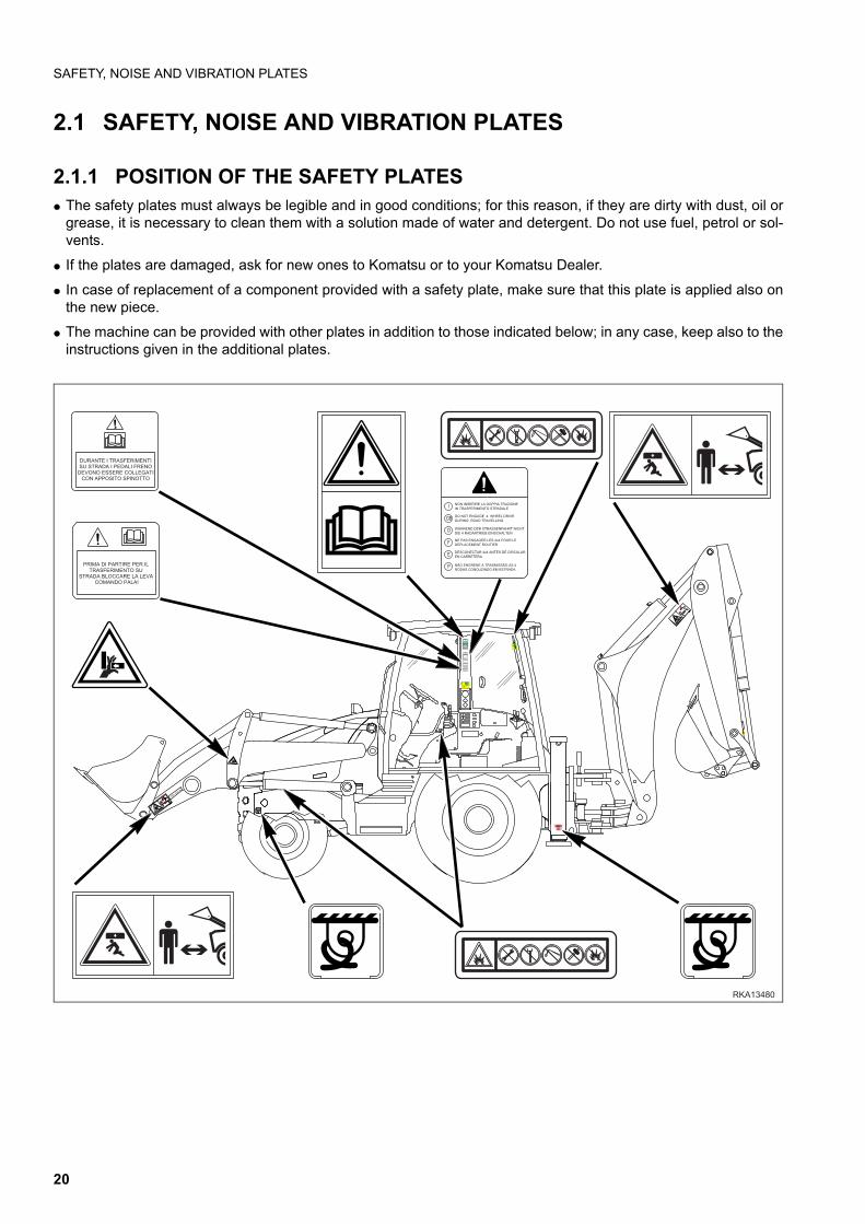
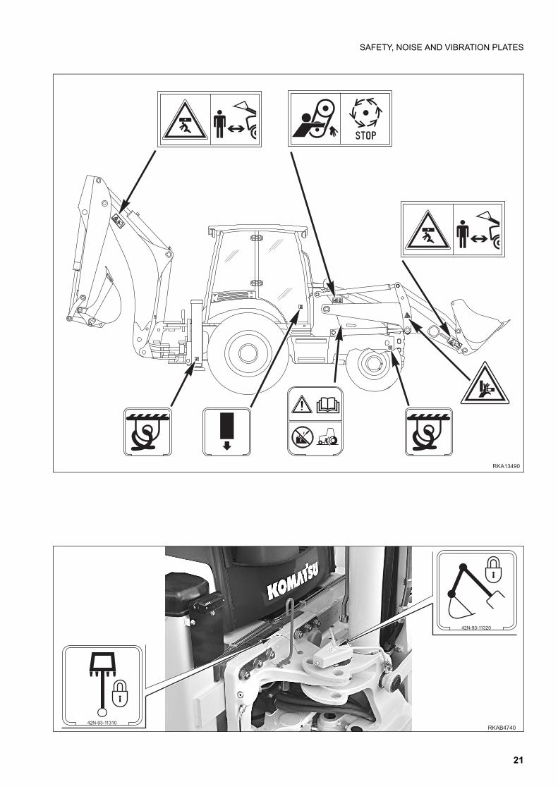
2.1.1 POSITION OF THE SAFETY PLATESq The safety plates must always be legible and in good conditions; for this reason, if they are dirty with dust, oil or
grease, it is necessary to clean them with a solution made of water and detergent. Do not use fuel, petrol or sol-vents.
q If the plates are damaged, ask for new ones to Komatsu or to your Komatsu Dealer.
q In case of replacement of a component provided with a safety plate, make sure that this plate is applied also onthe new piece.
q The machine can be provided with other plates in addition to those indicated below; in any case, keep also to theinstructions given in the additional plates.
42N-9
3-1
42N-9
3-11
380
1380
42N-93-11130
DURANTE I TRASFERIMENTISU STRADA I PEDALI FRENO
DEVONO ESSERE COLLEGATICON APPOSITO SPINOTTO
42N-93-11110
INON INSERIRE LA DOPPIA TRAZIONEIN TRASFERIMENTO STRADALE
GB
D
F
E
P
DO NOT ENGAGE 4 WHEEL DRIVEDURING ROAD TRAVELLING
W˜HREND DER STRASSENFAHRT NICHTDIE 4 RADANTRIEB EINSCHALTEN
NE PAS ENGAGER LES 4x4 POUR LEDEPLACEMENT ROUTIER
DESCONECTAR 4x4 ANTES DE CIRCULAREN CARRETERA
NˆO ENGRENE A TRASMISSˆO AS 4RODAS CONDUZINDO EM ESTRADA
42N-93-11120
42N-93-142N-93-112201220
42N-93-142N-93-113601360
SWL 1000 kg
42N-93-1
42N-93-11380
1380
395-93-1395-93-11330
1330
SPEED CONTROL+
BUCKET OPEN
DIFFERENTIALLOCK DECLUTCH
BUCKET CLOSE
KICK-DOWNL
L
+
PRIMA DI PARTIRE PER IL TRASFERIMENTO SU
STRADA BLOCCARE LA LEVA COMANDO PALA!
RKA13480
DURANTE I TRASFERIMENTISU STRADA I PEDALI FRENO
DEVONO ESSERE COLLEGATICON APPOSITO SPINOTTO
PRIMA DI PARTIRE PER IL TRASFERIMENTO SU
STRADA BLOCCARE LA LEVA COMANDO PALA!
I
GB
D
F
E
P
20
SAFETY, NOISE AND VIBRATION PLATES
SWL 1000 kg
RKA13490
����������
�����������������
21
SAFETY, NOISE AND VIBRATION PLATES
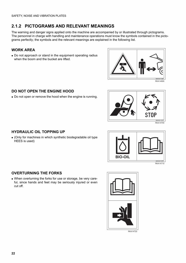
2.1.2 PICTOGRAMS AND RELEVANT MEANINGSThe warning and danger signs applied onto the machine are accompanied by or illustrated through pictograms.The personnel in charge with handling and maintenance operations must know the symbols contained in the picto-grams perfectly; the symbols and the relevant meanings are explained in the following list.
WORK AREA q Do not approach or stand in the equipment operating radius
when the boom and the bucket are lifted.
DO NOT OPEN THE ENGINE HOOD q Do not open or remove the hood when the engine is running.
HYDRAULIC OIL TOPPING UP q (Only for machines in which synthetic biodegradable oil type
HEES is used)
OVERTURNING THE FORKS q When overturning the forks for use or storage, be very care-
ful, since hands and feet may be seriously injured or evencut off.
���������
�������
����������
�������
����������
������
�������
�������
22
SAFETY, NOISE AND VIBRATION PLATES
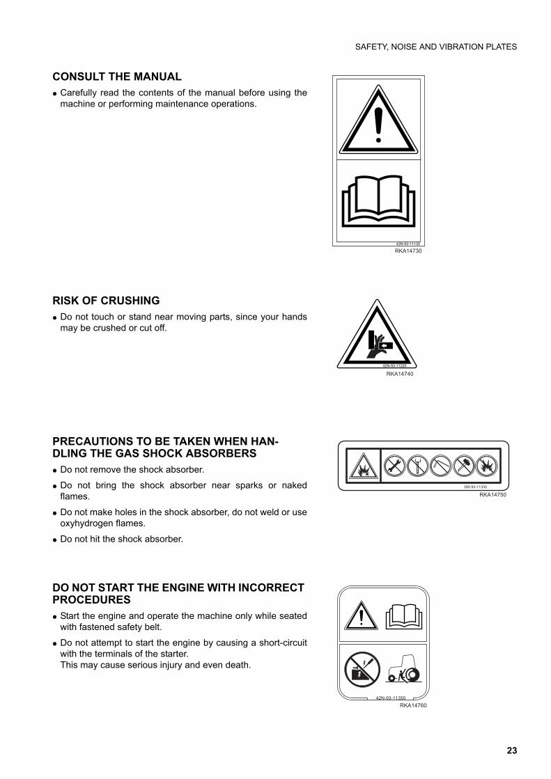
CONSULT THE MANUAL q Carefully read the contents of the manual before using the
machine or performing maintenance operations.
RISK OF CRUSHING q Do not touch or stand near moving parts, since your hands
may be crushed or cut off.
PRECAUTIONS TO BE TAKEN WHEN HAN-DLING THE GAS SHOCK ABSORBERS q Do not remove the shock absorber.
q Do not bring the shock absorber near sparks or nakedflames.
q Do not make holes in the shock absorber, do not weld or useoxyhydrogen flames.
q Do not hit the shock absorber.
DO NOT START THE ENGINE WITH INCORRECT PROCEDURES q Start the engine and operate the machine only while seated
with fastened safety belt.
q Do not attempt to start the engine by causing a short-circuitwith the terminals of the starter. This may cause serious injury and even death.
42N-93-11130
RKA14730
RKA14740
42N-93-11220
395-93-11330
RKA14750
42N-93-11350
RKA14760
23
SAFETY, NOISE AND VIBRATION PLATES
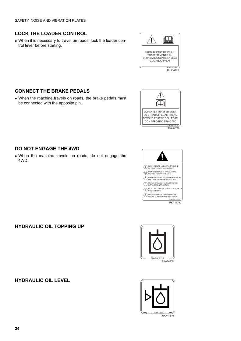
LOCK THE LOADER CONTROL q When it is necessary to travel on roads, lock the loader con-
trol lever before starting.
CONNECT THE BRAKE PEDALS q When the machine travels on roads, the brake pedals must
be connected with the apposite pin.
DO NOT ENGAGE THE 4WD q When the machine travels on roads, do not engage the
4WD.
HYDRAULIC OIL TOPPING UP
HYDRAULIC OIL LEVEL
���������������������������������������
������������������������������������
�����������
�������
������������������������������������������������������������������ ������������������������
��������
������
I
GB
D
F
E
P
42N-93-11120
RKA14790
�����������
�����
37A-98-12290
RKA14810
24

SAFETY, NOISE AND VIBRATION PLATES
HYDRAULIC OIL FILTER
REFUELLING
FUEL FILTER
ENGINE LUBRICATING OIL FILTER
ENGINE AIR SUCTION FILTER
ENGINE COOLANT
37A-98-12310
RKA14820
37A-98-12240
RKA14830
D
37A-98-12250
RKA14840
D
37A-98-12230
RKA14850
37A-98-12260
RKA14860
37A-98-12340
RKA14870
25

SAFETY, NOISE AND VIBRATION PLATES
COOLANT PRESSURE
TRANSMISSION OIL LEVEL
TRANSMISSION OIL FILTER
POWER OUTLET
BOOM LOCK
SWING LOCK
37A-98-12270
RKA14880
�� ��������
���� �
�� ��������
���� �
42N-93-11270
RKA14890
12 V
42N-93-11320
RKA14900
42N-93-11310
RKA14910
26
SAFETY, NOISE AND VIBRATION PLATES
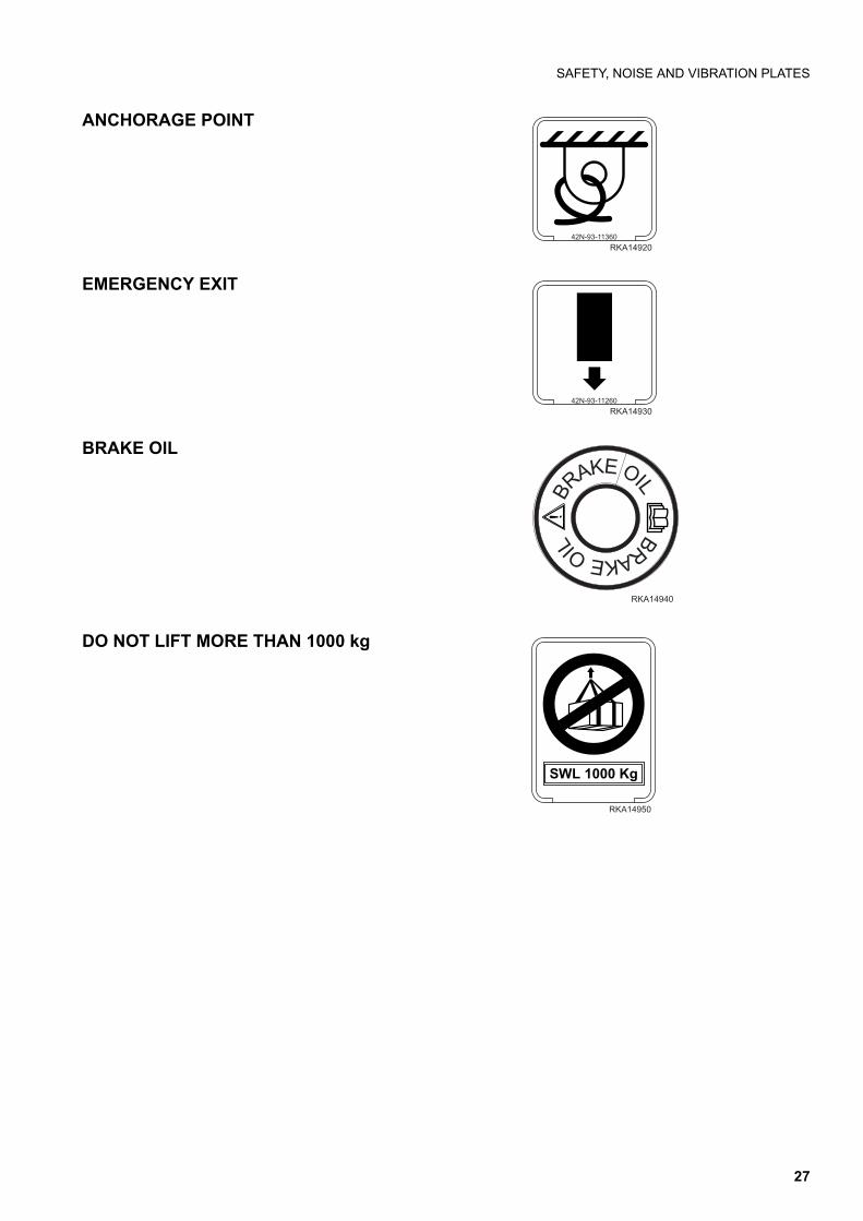
ANCHORAGE POINT
EMERGENCY EXIT
BRAKE OIL
DO NOT LIFT MORE THAN 1000 kg
42N-93-11360
RKA14920
42N-93-11260
RKA14930
BRAKE OIL
BRAKEOIL
RKA14940
RKA14950
SWL 1000 Kg
27
SAFETY, NOISE AND VIBRATION PLATES
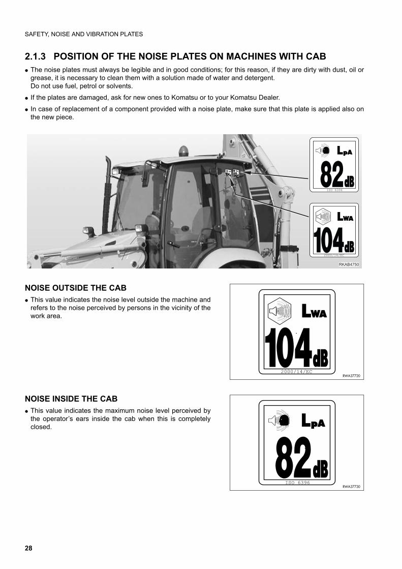
2.1.3 POSITION OF THE NOISE PLATES ON MACHINES WITH CABq The noise plates must always be legible and in good conditions; for this reason, if they are dirty with dust, oil or
grease, it is necessary to clean them with a solution made of water and detergent.Do not use fuel, petrol or solvents.
q If the plates are damaged, ask for new ones to Komatsu or to your Komatsu Dealer.
q In case of replacement of a component provided with a noise plate, make sure that this plate is applied also onthe new piece.
NOISE OUTSIDE THE CABq This value indicates the noise level outside the machine and
refers to the noise perceived by persons in the vicinity of thework area.
NOISE INSIDE THE CABq This value indicates the maximum noise level perceived by
the operator’s ears inside the cab when this is completelyclosed.
��������
��� �
������ �
����������RWA37720
RWA37730��� ����
28

SAFETY, NOISE AND VIBRATION PLATES
2.1.4 VIBRATIONS TO WHICH THE OPERATOR IS SUBJECTEDq According to the results of the tests carried out to determine the vibrations transmitted to the operator by the ma-
chine, the upper limbs are subjected to vibrations lower than 2.5 m/sq.sec., while the seated part of the body issubjected to vibrations lower than 0.5 m/sq.sec.
29
GENERAL PRECAUTIONS
2.2 GENERAL PRECAUTIONS
2.2.1 GENERAL SAFETY RULESq Only trained and authorized personnel can use the machine and perform maintenance operations.
q Follow all the safety rules, precautions and instructions when using the machine or performing maintenance op-erations.
q When working with other operators or when the work site is often occupied by other operators, make sure thateveryone knows and understands all the signs described above and, in any case, that everyone works in such away as to be able to see the machine and to be visible to the operator.
2.2.2 SAFETY DEVICES AND GUARDSq Make sure that all the guards and covers are in the correct position. Have guards and covers changed or re-
paired if damaged. Do not use the machine without guards, nor remove the guards when the engine is running.
q Always use the proper safety devices to lock the machine when parking and remember to fasten the safety belt.
q For the safety devices, see "3.1 SAFETY LOCKS".
q For the safety belt, see "3.5.6 SAFETY BELT".
q Do not remove the safety devices and always keep them in good operating conditions.
q Any improper use of the safety devices may result in serious injury or even death.
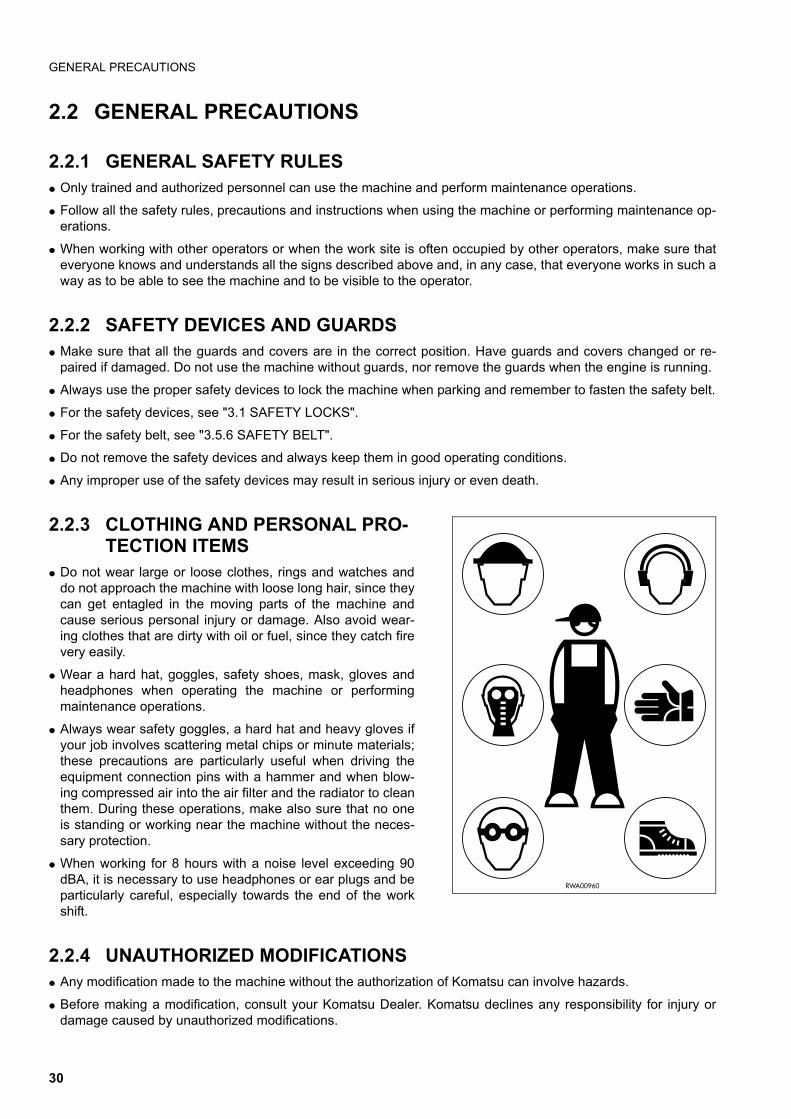
2.2.3 CLOTHING AND PERSONAL PRO-TECTION ITEMS
q Do not wear large or loose clothes, rings and watches anddo not approach the machine with loose long hair, since theycan get entagled in the moving parts of the machine andcause serious personal injury or damage. Also avoid wear-ing clothes that are dirty with oil or fuel, since they catch firevery easily.
q Wear a hard hat, goggles, safety shoes, mask, gloves andheadphones when operating the machine or performingmaintenance operations.
q Always wear safety goggles, a hard hat and heavy gloves ifyour job involves scattering metal chips or minute materials;these precautions are particularly useful when driving theequipment connection pins with a hammer and when blow-ing compressed air into the air filter and the radiator to cleanthem. During these operations, make also sure that no oneis standing or working near the machine without the neces-sary protection.
q When working for 8 hours with a noise level exceeding 90dBA, it is necessary to use headphones or ear plugs and beparticularly careful, especially towards the end of the workshift.
2.2.4 UNAUTHORIZED MODIFICATIONSq Any modification made to the machine without the authorization of Komatsu can involve hazards.
q Before making a modification, consult your Komatsu Dealer. Komatsu declines any responsibility for injury ordamage caused by unauthorized modifications.
RWA00960
30
GENERAL PRECAUTIONS
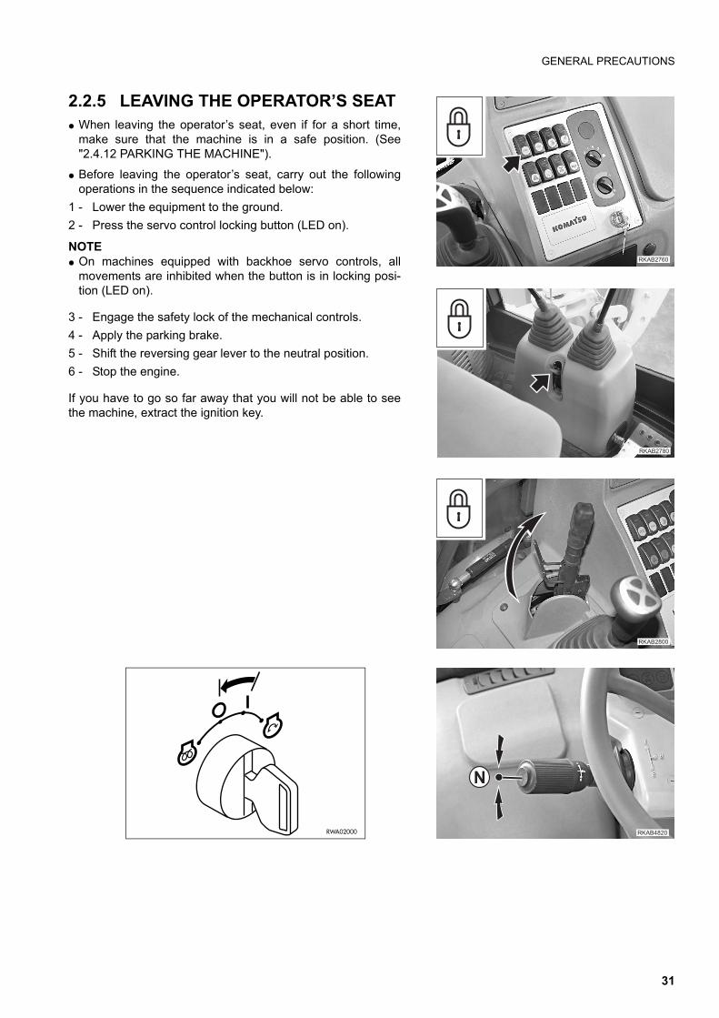
2.2.5 LEAVING THE OPERATOR’S SEATq When leaving the operator’s seat, even if for a short time,
make sure that the machine is in a safe position. (See"2.4.12 PARKING THE MACHINE").
q Before leaving the operator’s seat, carry out the followingoperations in the sequence indicated below:
1 - Lower the equipment to the ground.
2 - Press the servo control locking button (LED on).
NOTEq On machines equipped with backhoe servo controls, all
movements are inhibited when the button is in locking posi-tion (LED on).
3 - Engage the safety lock of the mechanical controls.
4 - Apply the parking brake.
5 - Shift the reversing gear lever to the neutral position.
6 - Stop the engine.
If you have to go so far away that you will not be able to seethe machine, extract the ignition key.
��������
�������
�������
�
�������RWA02000
31
GENERAL PRECAUTIONS
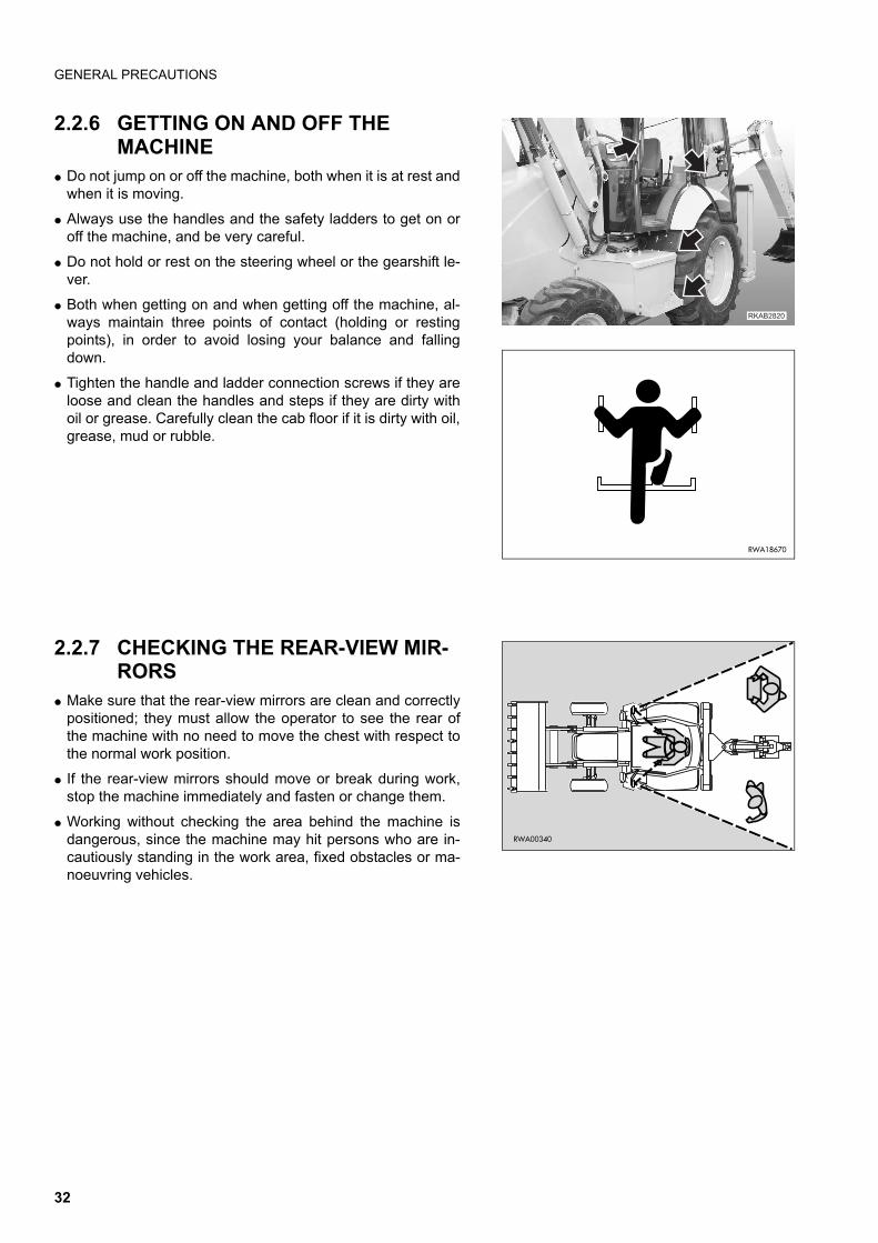
2.2.6 GETTING ON AND OFF THE MACHINE
q Do not jump on or off the machine, both when it is at rest andwhen it is moving.
q Always use the handles and the safety ladders to get on oroff the machine, and be very careful.
q Do not hold or rest on the steering wheel or the gearshift le-ver.
q Both when getting on and when getting off the machine, al-ways maintain three points of contact (holding or restingpoints), in order to avoid losing your balance and fallingdown.
q Tighten the handle and ladder connection screws if they areloose and clean the handles and steps if they are dirty withoil or grease. Carefully clean the cab floor if it is dirty with oil,grease, mud or rubble.
2.2.7 CHECKING THE REAR-VIEW MIR-RORS
q Make sure that the rear-view mirrors are clean and correctlypositioned; they must allow the operator to see the rear ofthe machine with no need to move the chest with respect tothe normal work position.
q If the rear-view mirrors should move or break during work,stop the machine immediately and fasten or change them.
q Working without checking the area behind the machine isdangerous, since the machine may hit persons who are in-cautiously standing in the work area, fixed obstacles or ma-noeuvring vehicles.
�������
RWA18670
RWA00340
32
GENERAL PRECAUTIONS
2.2.8 PREVENTING FIRES DUE TO FUEL AND OIL
Fuel, oil and some types of antifreeze can be easily ignited ifthey get in contact with a flame. Fuel is flammable and there-fore very dangerous.
q Keep any naked flame away from flammable fluids.
q Stop the engine and do not smoke when refuelling.
q Top up with fuel and oil only after stopping the engine and inwell ventilated areas.
q Top up with fuel and oil in a well delimited area and do not al-low unauthorized persons to approach.
q When refuelling, hold the fuel gun firmly and keep it con-stantly in contact with the filler until you have finished, in or-der to avoid sparks due to static electricity.
q After topping up, tighten the fuel and oil safety caps securely.
q Do not fill the tank completely, in order to leave room for thefuel to expand.
q If some fuel is inadvertently spilled, wipe it up immediately.
2.2.9 PREVENTING BURNS q If the engine coolant, the engine oil and the hydraulic oil are
hot, use heavy cloths and wear gloves, heavy clothing andsafety goggles before carrying out any check or touching thehot parts.
q Before checking the coolant level, stop the engine and letthe fluid cool down. If a check is necessary due to the overheating of the engine,loosen the radiator cap slowly, to release any residual pres-sure before removing it. The hot fluid that spurts out maycause serious burns.
q Before checking the engine oil and hydraulic circuit oil level,stop the engine and let the oil cool down. The hot oil thatmay be sprayed out of the tank may cause serious burns.
RWA00970
RWA00980
RWA00990
33
GENERAL PRECAUTIONS
2.2.10 PREVENTING DAMAGE DUE TO ASBESTOS POWDER
q Asbestos powder can be hazardous to your health if it is in-haled.
q If you handle materials containing asbestos fibers, keep tothe instructions given below:
1 - Do not use compressed air, but only exhaust fans toclean the machine, and make sure that the room in whichyou are working is properly ventilated.
2 - Use low-pressure water to abate dust when cleaning.
3 - If there is danger that there may be asbestos powder inthe air, operate the machine with the wind to your backwhenever possible.
4 - Even if the cab provides suitable protection, use an ap-proved and homologated respirator.
5 - The powder gathered during the cleaning operations mustbe wet and put in a sealed and marked container, so thatit can be safely disposed of according to the regulations inforce.
2.2.11 PREVENTING DAMAGE CAUSED BY THE WORK EQUIPMENT
q Do not stand within the operating radius of the work equip-ment, even when the operator is on board the machine andthe engine is running.
q Do not stand or work under the arms or the articulationswhen the arms are lifted, if you are not sure that the safetylocks have been duly engaged.
q Do not carry out any operation requiring the arms to be lifted,if you are not sure that the locks are correctly positioned andconnected to the arms.
RWA01000
RWA01010
RWA01020
34

GENERAL PRECAUTIONS
2.2.12 FIRE EXTINGUISHERS AND FIRST AID KIT
q Make sure that fire extinguishers have been provided andcheck their position.
q Periodically make sure that the fire extinguishers are loadedand that you know how to use them.
q Find out where the first aid kit has been located.
q Periodically make sure that the first aid kit contains the nec-essary disinfectants, bandages, medicines, etc.
q It is necessary to know what to do in case of fire.
q Make sure that you have the phone numbers of the personsor structures you may need to contact in case of an emer-gency at hand (both at the worksite and where maintenanceoperations are performed).
2.2.13 PRECAUTIONS CONCERNING THE CAB STRUCTUREq If the cab is inadvertently hit or the machine overturns during work, the cab may be damaged with consequent
reduction of its stiffness and of the safety that must be guaranteed to the operator (ROPS/FOPS).Contact Komatsu or your Komatsu Dealer to have the cab structure and resistance checked in case of impact ordamage.
2.2.14 PRECAUTIONS CONCERNING THE EQUIPMENTq When installing and using optional equipment, carefully read the relevant instruction manual and keep to the in-
dications given therein.
q Do not use optional or special equipment without the authorization of Komatsu or a Komatsu Dealer.Installing and using any equipment not authorized by Komatsu may create safety problems and may have nega-tive consequences on both the efficiency and life of the machine.
q Komatsu cannot be held liable for any injury, accident, product failure resulting from the installation and use ofunauthorized equipment.
RWA01030
35
PRECAUTIONS TO BE TAKEN BEFORE STARTING THE ENGINE
2.3 PRECAUTIONS TO BE TAKEN BEFORE STARTING THE ENGINE
2.3.1 SAFETY ON THE WORK SITE q Before starting the engine, thoroughly check the area for any
unusual condition of the ground due to which work may bedangerous.
q Check the conditions of the ground at the work site and be-fore starting the engine define the work plan and the bestand safest operating procedure.
q Level the ground surface as much as possible before carry-ing out any operation.
q In case of work on the road, protect pedestrians and cars bydesignating a person for work site traffic duty and installfences around the work site.
q If water lines, gas lines, and telephone or high-voltage elec-trical lines are located under the work site, contact the rele-vant utility company in order to find out their exact position orto disconnect them until the end of the operations. Be carefulnot to sever or damage any of these lines.
q Check the water depth and the force and flow direction of thecurrent before operating in water or on river banks.
2.3.2 FIRE PREVENTION q Completely remove all wood chips, rubbish, paper and other
flammable materials that may have accumulated inside theengine compartment, since they can cause fires.
q Check the fuel and hydraulic system pipes for leaks and ifnecessary repair them. Wipe up any excess oil, fuel or otherflammable fluids.
q Make sure that fire extinguishers are available in the workarea.
2.3.3 PRECAUTIONS TO BE TAKEN FOR THE OPERATOR'S CABq Do not leave objects or tools lying around in the operator's cab. They may prevent the use of the brakes and
cause serious accidents.
q Keep the cab floor and the controls (steering wheel and levers) clean, by removing any trace of oil and greaseand, as far as the floor is concerned, remove any excess dirt (earth, stones, etc.).
q Check the safety belt and change it if it is broken or damaged. Replace any component only with homologatedparts available at Komatsu or its Dealers.
q Make always sure that the lock of the right door, which is considered the emergency door, is open.
RWA00220
RWA01040
36
PRECAUTIONS TO BE TAKEN BEFORE STARTING THE ENGINE
2.3.4 ROOM VENTILATION q Before starting the machine in confined or poorly ventilated
places, provide for proper ventilation or connect the engineexhaust pipe to a suction duct. The engine exhaust gasescan be deadly.
2.3.5 CLEANING WINDOWS, MIRRORS AND LIGHTS - CHECKING THE WINDSHIELD WIPER BLADES AND THE BULBS
q Remove any trace of dirt from the cab windows and the lights and clean the rear-view mirrors; this will ensuregood visibility on the work area.
q Adjust the rear-view mirrors if they have moved, so that the operator seated in the driving position can clearlysee the area behind the machine.If any window, light or mirror is damaged, change it.
q Make sure that the road lights, stop lights, direction indicators and work lights are properly working. If necessary,change the faulty bulbs with new ones, making sure that their power is correct.
q Check the conditions of the windshield wiper blades; the scraping wire must be smooth, with no indentations andattached to the rubber back of the blade.In case of doubt on the efficiency of the scraping wire, change the blades.
RWA01050
37
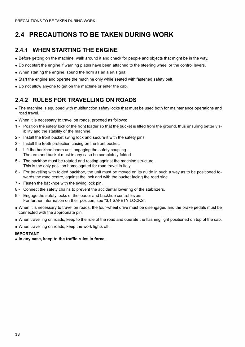
PRECAUTIONS TO BE TAKEN DURING WORK
2.4 PRECAUTIONS TO BE TAKEN DURING WORK
2.4.1 WHEN STARTING THE ENGINEq Before getting on the machine, walk around it and check for people and objects that might be in the way.
q Do not start the engine if warning plates have been attached to the steering wheel or the control levers.
q When starting the engine, sound the horn as an alert signal.
q Start the engine and operate the machine only while seated with fastened safety belt.
q Do not allow anyone to get on the machine or enter the cab.
2.4.2 RULES FOR TRAVELLING ON ROADSq The machine is equipped with multifunction safety locks that must be used both for maintenance operations and
road travel.
q When it is necessary to travel on roads, proceed as follows:
1 - Position the safety lock of the front loader so that the bucket is lifted from the ground, thus ensuring better vis-ibility and the stability of the machine.
2 - Install the front bucket swing lock and secure it with the safety pins.
3 - Install the teeth protection casing on the front bucket.
4 - Lift the backhoe boom until engaging the safety coupling. The arm and bucket must in any case be completely folded.
5 - The backhoe must be rotated and resting against the machine structure. This is the only position homologated for road travel in Italy.
6 - For travelling with folded backhoe, the unit must be moved on its guide in such a way as to be positioned to-wards the road centre, against the lock and with the bucket facing the road side.
7 - Fasten the backhoe with the swing lock pin.
8 - Connect the safety chains to prevent the accidental lowering of the stabilizers.
9 - Engage the safety locks of the loader and backhoe control levers. For further information on their position, see "3.1 SAFETY LOCKS".
q When it is necessary to travel on roads, the four-wheel drive must be disengaged and the brake pedals must beconnected with the appropriate pin.
q When travelling on roads, keep to the rule of the road and operate the flashing light positioned on top of the cab.
q When travelling on roads, keep the work lights off.
IMPORTANTq In any case, keep to the traffic rules in force.
38
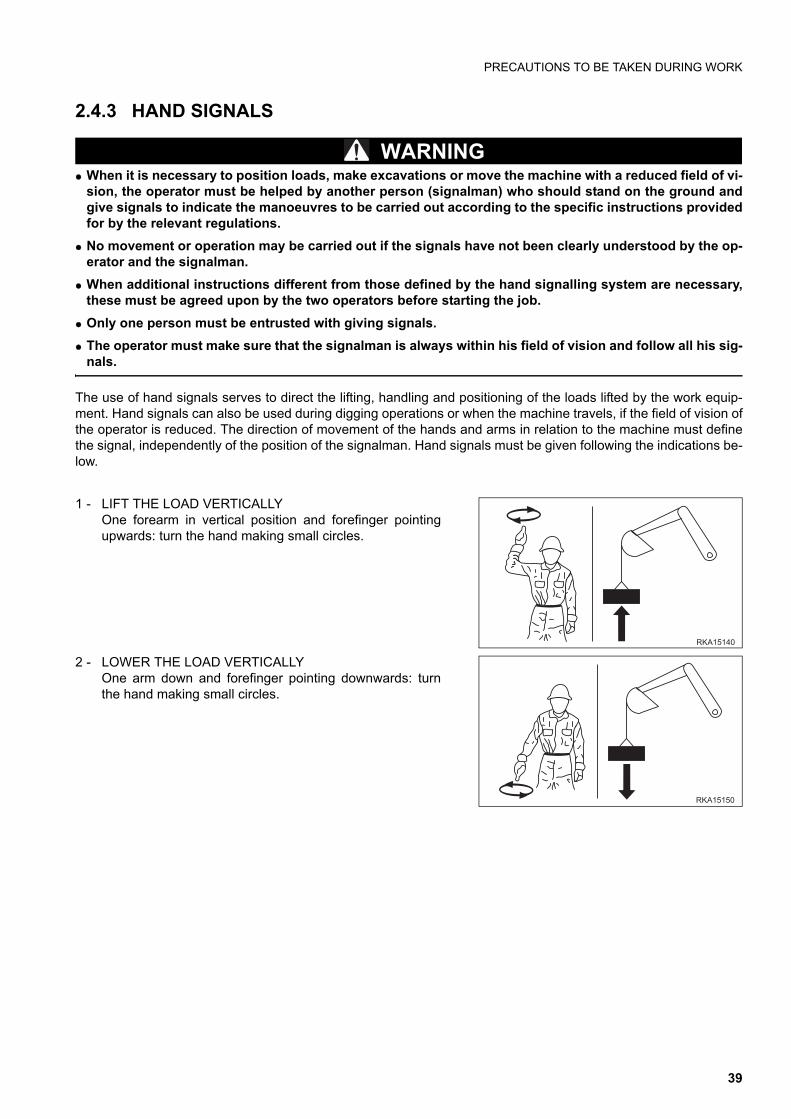
PRECAUTIONS TO BE TAKEN DURING WORK
2.4.3 HAND SIGNALS
WARNINGq When it is necessary to position loads, make excavations or move the machine with a reduced field of vi-
sion, the operator must be helped by another person (signalman) who should stand on the ground andgive signals to indicate the manoeuvres to be carried out according to the specific instructions providedfor by the relevant regulations.
q No movement or operation may be carried out if the signals have not been clearly understood by the op-erator and the signalman.
q When additional instructions different from those defined by the hand signalling system are necessary,these must be agreed upon by the two operators before starting the job.
q Only one person must be entrusted with giving signals.
q The operator must make sure that the signalman is always within his field of vision and follow all his sig-nals.
The use of hand signals serves to direct the lifting, handling and positioning of the loads lifted by the work equip-ment. Hand signals can also be used during digging operations or when the machine travels, if the field of vision ofthe operator is reduced. The direction of movement of the hands and arms in relation to the machine must definethe signal, independently of the position of the signalman. Hand signals must be given following the indications be-low.
1 - LIFT THE LOAD VERTICALLYOne forearm in vertical position and forefinger pointingupwards: turn the hand making small circles.
2 - LOWER THE LOAD VERTICALLYOne arm down and forefinger pointing downwards: turnthe hand making small circles.
��� ��
��� �
39
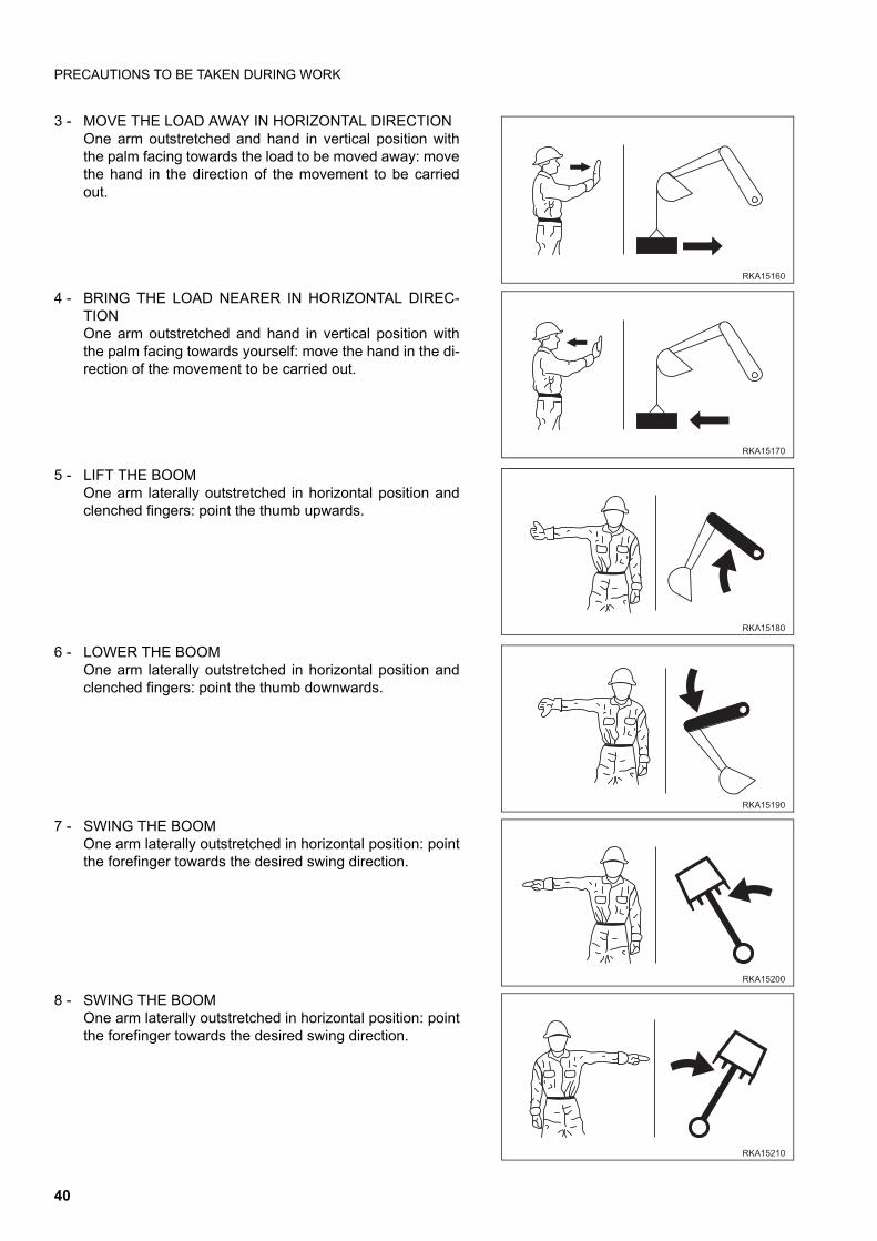
PRECAUTIONS TO BE TAKEN DURING WORK
3 - MOVE THE LOAD AWAY IN HORIZONTAL DIRECTIONOne arm outstretched and hand in vertical position withthe palm facing towards the load to be moved away: movethe hand in the direction of the movement to be carriedout.
4 - BRING THE LOAD NEARER IN HORIZONTAL DIREC-TIONOne arm outstretched and hand in vertical position withthe palm facing towards yourself: move the hand in the di-rection of the movement to be carried out.
5 - LIFT THE BOOMOne arm laterally outstretched in horizontal position andclenched fingers: point the thumb upwards.
6 - LOWER THE BOOMOne arm laterally outstretched in horizontal position andclenched fingers: point the thumb downwards.
7 - SWING THE BOOMOne arm laterally outstretched in horizontal position: pointthe forefinger towards the desired swing direction.
8 - SWING THE BOOMOne arm laterally outstretched in horizontal position: pointthe forefinger towards the desired swing direction.
��� ��
��� ��
��� �
��� ��
��� ���
��� ��
40
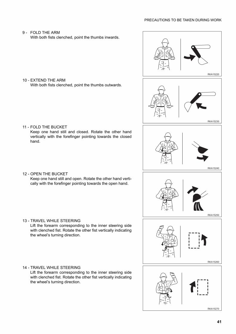
PRECAUTIONS TO BE TAKEN DURING WORK
9 - FOLD THE ARMWith both fists clenched, point the thumbs inwards.
10 - EXTEND THE ARMWith both fists clenched, point the thumbs outwards.
11 - FOLD THE BUCKETKeep one hand still and closed. Rotate the other handvertically with the forefinger pointing towards the closedhand.
12 - OPEN THE BUCKETKeep one hand still and open. Rotate the other hand verti-cally with the forefinger pointing towards the open hand.
13 - TRAVEL WHILE STEERING Lift the forearm corresponding to the inner steering sidewith clenched fist. Rotate the other fist vertically indicatingthe wheel’s turning direction.
14 - TRAVEL WHILE STEERING Lift the forearm corresponding to the inner steering sidewith clenched fist. Rotate the other fist vertically indicatingthe wheel’s turning direction.
��� ���
��� ���
��� ���
��� � �
��� ���
��� ���
41
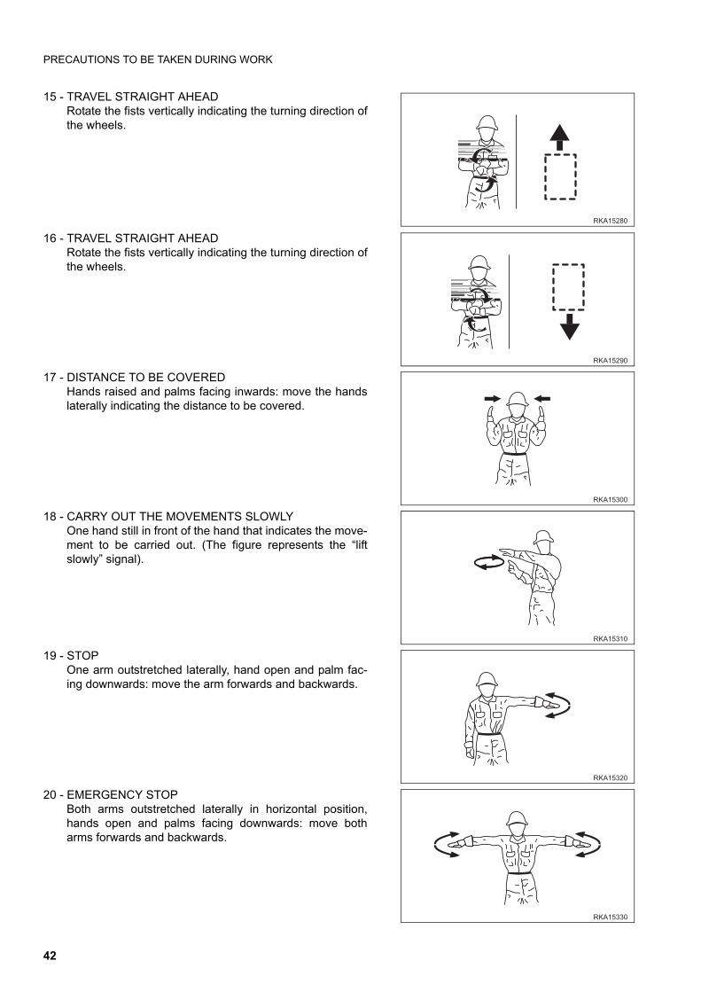
PRECAUTIONS TO BE TAKEN DURING WORK
15 - TRAVEL STRAIGHT AHEADRotate the fists vertically indicating the turning direction ofthe wheels.
16 - TRAVEL STRAIGHT AHEADRotate the fists vertically indicating the turning direction ofthe wheels.
17 - DISTANCE TO BE COVEREDHands raised and palms facing inwards: move the handslaterally indicating the distance to be covered.
18 - CARRY OUT THE MOVEMENTS SLOWLYOne hand still in front of the hand that indicates the move-ment to be carried out. (The figure represents the “liftslowly” signal).
19 - STOPOne arm outstretched laterally, hand open and palm fac-ing downwards: move the arm forwards and backwards.
20 - EMERGENCY STOPBoth arms outstretched laterally in horizontal position,hands open and palms facing downwards: move botharms forwards and backwards.
��� ��
��� ���
��� ���
��� ��
��� ���
��� ���
42
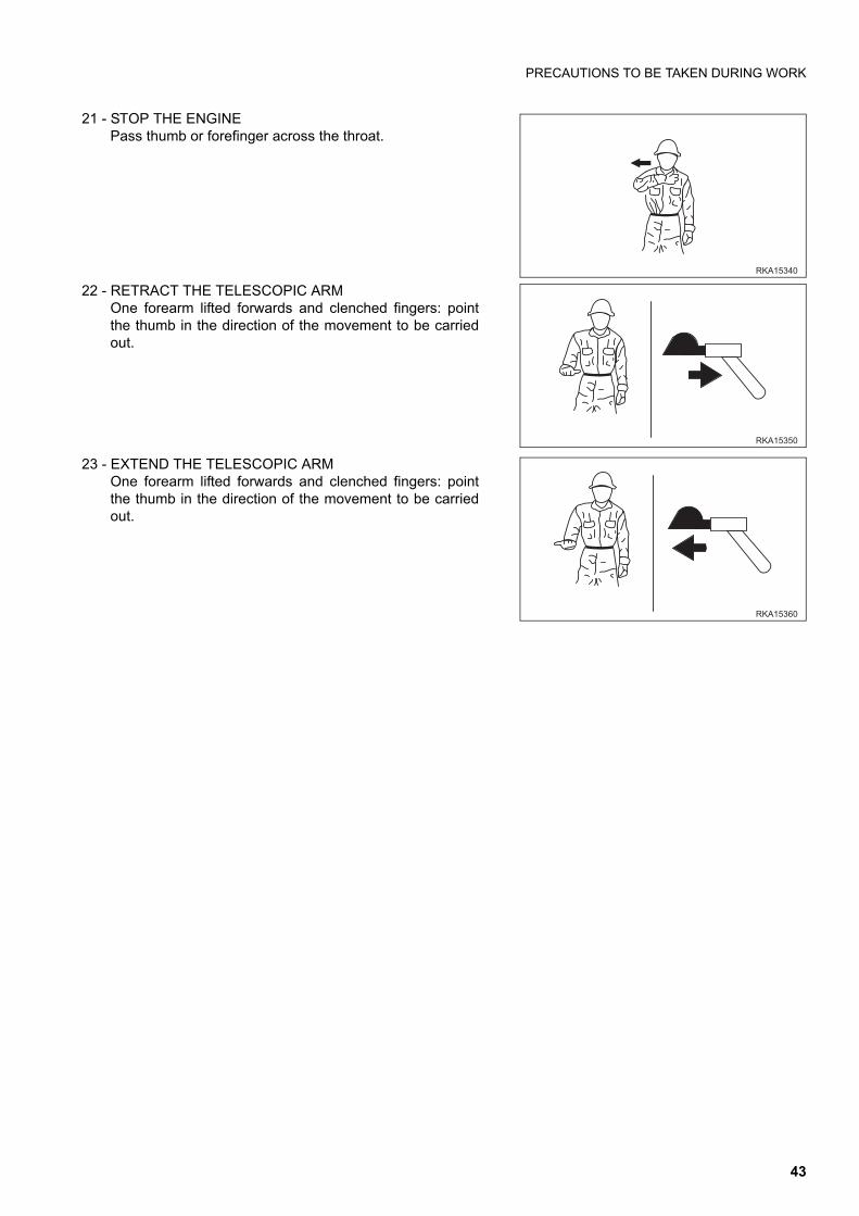
PRECAUTIONS TO BE TAKEN DURING WORK
21 - STOP THE ENGINEPass thumb or forefinger across the throat.
22 - RETRACT THE TELESCOPIC ARMOne forearm lifted forwards and clenched fingers: pointthe thumb in the direction of the movement to be carriedout.
23 - EXTEND THE TELESCOPIC ARMOne forearm lifted forwards and clenched fingers: pointthe thumb in the direction of the movement to be carriedout.
��� ���
��� � �
��� ���
43
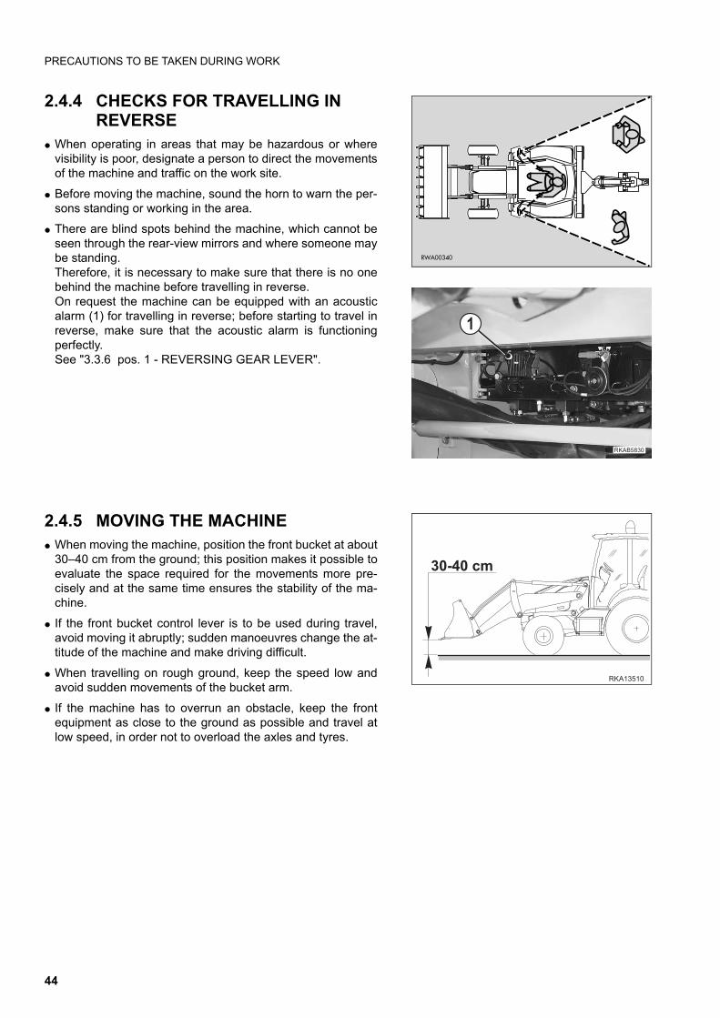
PRECAUTIONS TO BE TAKEN DURING WORK
2.4.4 CHECKS FOR TRAVELLING IN REVERSE
q When operating in areas that may be hazardous or wherevisibility is poor, designate a person to direct the movementsof the machine and traffic on the work site.
q Before moving the machine, sound the horn to warn the per-sons standing or working in the area.
q There are blind spots behind the machine, which cannot beseen through the rear-view mirrors and where someone maybe standing.Therefore, it is necessary to make sure that there is no onebehind the machine before travelling in reverse.On request the machine can be equipped with an acousticalarm (1) for travelling in reverse; before starting to travel inreverse, make sure that the acoustic alarm is functioningperfectly.See "3.3.6 pos. 1 - REVERSING GEAR LEVER".
2.4.5 MOVING THE MACHINEq When moving the machine, position the front bucket at about
30–40 cm from the ground; this position makes it possible toevaluate the space required for the movements more pre-cisely and at the same time ensures the stability of the ma-chine.
q If the front bucket control lever is to be used during travel,avoid moving it abruptly; sudden manoeuvres change the at-titude of the machine and make driving difficult.
q When travelling on rough ground, keep the speed low andavoid sudden movements of the bucket arm.
q If the machine has to overrun an obstacle, keep the frontequipment as close to the ground as possible and travel atlow speed, in order not to overload the axles and tyres.
RWA00340
���� ��
�
�������
���� �
44
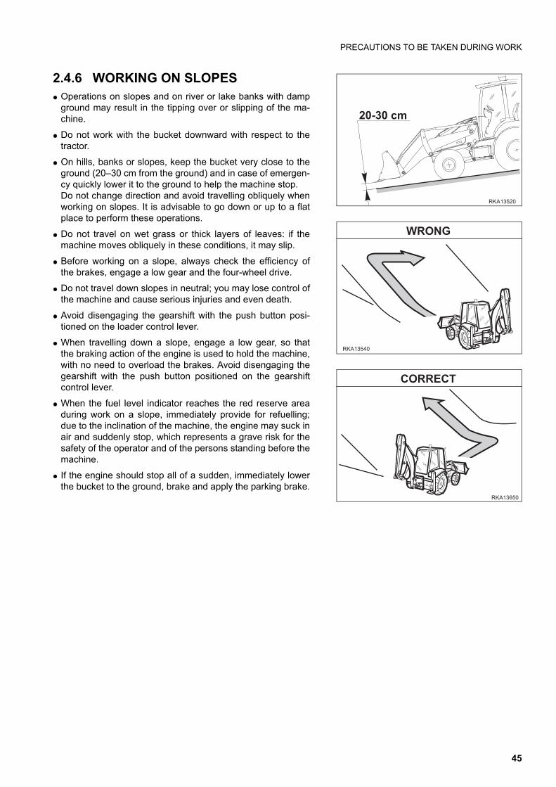
PRECAUTIONS TO BE TAKEN DURING WORK
2.4.6 WORKING ON SLOPES q Operations on slopes and on river or lake banks with damp
ground may result in the tipping over or slipping of the ma-chine.
q Do not work with the bucket downward with respect to thetractor.
q On hills, banks or slopes, keep the bucket very close to theground (20–30 cm from the ground) and in case of emergen-cy quickly lower it to the ground to help the machine stop.Do not change direction and avoid travelling obliquely whenworking on slopes. It is advisable to go down or up to a flatplace to perform these operations.
q Do not travel on wet grass or thick layers of leaves: if themachine moves obliquely in these conditions, it may slip.
q Before working on a slope, always check the efficiency ofthe brakes, engage a low gear and the four-wheel drive.
q Do not travel down slopes in neutral; you may lose control ofthe machine and cause serious injuries and even death.
q Avoid disengaging the gearshift with the push button posi-tioned on the loader control lever.
q When travelling down a slope, engage a low gear, so thatthe braking action of the engine is used to hold the machine,with no need to overload the brakes. Avoid disengaging thegearshift with the push button positioned on the gearshiftcontrol lever.
q When the fuel level indicator reaches the red reserve areaduring work on a slope, immediately provide for refuelling;due to the inclination of the machine, the engine may suck inair and suddenly stop, which represents a grave risk for thesafety of the operator and of the persons standing before themachine.
q If the engine should stop all of a sudden, immediately lowerthe bucket to the ground, brake and apply the parking brake.
�������
���� ��
���� ��
�����
����� �
���� �
45
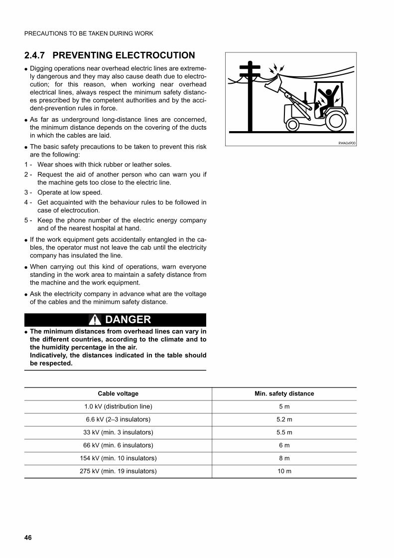
PRECAUTIONS TO BE TAKEN DURING WORK
2.4.7 PREVENTING ELECTROCUTION q Digging operations near overhead electric lines are extreme-
ly dangerous and they may also cause death due to electro-cution; for this reason, when working near overheadelectrical lines, always respect the minimum safety distanc-es prescribed by the competent authorities and by the acci-dent-prevention rules in force.
q As far as underground long-distance lines are concerned,the minimum distance depends on the covering of the ductsin which the cables are laid.
q The basic safety precautions to be taken to prevent this riskare the following:
1 - Wear shoes with thick rubber or leather soles.
2 - Request the aid of another person who can warn you ifthe machine gets too close to the electric line.
3 - Operate at low speed.
4 - Get acquainted with the behaviour rules to be followed incase of electrocution.
5 - Keep the phone number of the electric energy companyand of the nearest hospital at hand.
q If the work equipment gets accidentally entangled in the ca-bles, the operator must not leave the cab until the electricitycompany has insulated the line.
q When carrying out this kind of operations, warn everyonestanding in the work area to maintain a safety distance fromthe machine and the work equipment.
q Ask the electricity company in advance what are the voltageof the cables and the minimum safety distance.
DANGERq The minimum distances from overhead lines can vary in
the different countries, according to the climate and tothe humidity percentage in the air.Indicatively, the distances indicated in the table shouldbe respected.
RWA04900
Cable voltage Min. safety distance
1.0 kV (distribution line) 5 m
6.6 kV (2–3 insulators) 5.2 m
33 kV (min. 3 insulators) 5.5 m
66 kV (min. 6 insulators) 6 m
154 kV (min. 10 insulators) 8 m
275 kV (min. 19 insulators) 10 m
46
PRECAUTIONS TO BE TAKEN DURING WORK
2.4.8 VISIBILITYq Switch on the headlights or the work lights as soon as visibility decreases.
q If visibility decreases due to mist, smoke or heavy rain, stop the machine in a safe position and wait for theweather to improve until visibility becomes acceptable.
2.4.9 WORKING ON ICY OR SNOW-COVERED SURFACESq If the ground is icy or covered with snow, the response of the machine to the movements of the steering wheel
may not be precise.To reduce the risks connected with poor manoeuvrability, proceed as follows:
1 - Engage the four-wheel drive.
2 - Travel using the accelerator smoothly and gradually.
3 - Brake smoothly and only after having slowed down by using the engine deceleration as much as possible.
4 - Absolutely avoid any sudden braking, abrupt acceleration and sudden steering with short steering radius.
q If the machine is used to clear snow or as snowplough on roads (installing the specific optional equipment andeven chains, if necessary), be careful to the road shoulders and to any object/obstacle buried in the snow (way-side posts, milestones, signs just above the asphalt, etc.).
2.4.10 PREVENTING DAMAGE CAUSED BY THE WORK EQUIPMENTq When working in tunnels, galleries, under electric cables or other ducts (air, telephone lines) and wherever the
height is limited, proceed with the greatest care to prevent the bucket or arms and the backhoe bucket fromcausing any damage.
2.4.11 WORKING ON LOOSE GROUNDq Avoid operating the machine too close to the edge of cliffs, overhangs and deep ditches.
These areas may collapse, making the machine fall down or tip over and this could result in serious injury oreven death.Remember that after heavy rain or earthquakes these dangerous conditions usually get worse.
q The earth laid near ditches is loose and can easily collapse due to the weight or vibrations of the machine.Be extremely careful: always close the cab doors and fasten the safety belt.
47
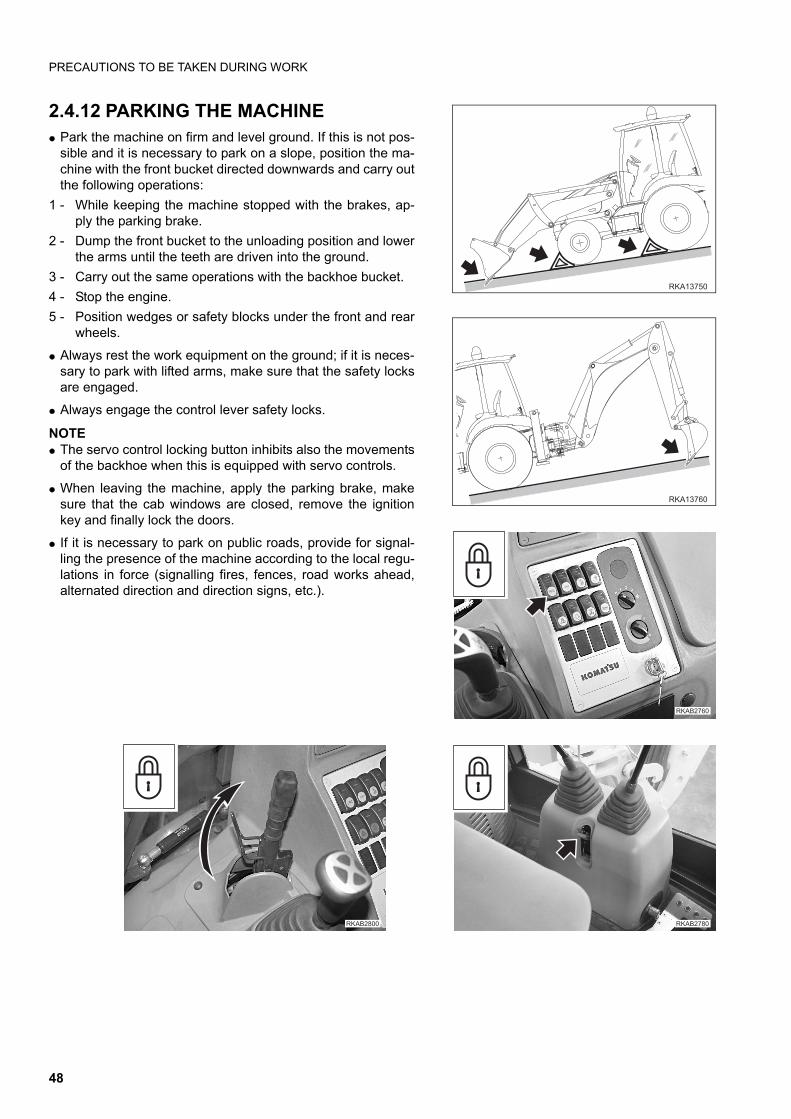
PRECAUTIONS TO BE TAKEN DURING WORK
2.4.12 PARKING THE MACHINEq Park the machine on firm and level ground. If this is not pos-
sible and it is necessary to park on a slope, position the ma-chine with the front bucket directed downwards and carry outthe following operations:
1 - While keeping the machine stopped with the brakes, ap-ply the parking brake.
2 - Dump the front bucket to the unloading position and lowerthe arms until the teeth are driven into the ground.
3 - Carry out the same operations with the backhoe bucket.
4 - Stop the engine.
5 - Position wedges or safety blocks under the front and rearwheels.
q Always rest the work equipment on the ground; if it is neces-sary to park with lifted arms, make sure that the safety locksare engaged.
q Always engage the control lever safety locks.
NOTEq The servo control locking button inhibits also the movements
of the backhoe when this is equipped with servo controls.
q When leaving the machine, apply the parking brake, makesure that the cab windows are closed, remove the ignitionkey and finally lock the doors.
q If it is necessary to park on public roads, provide for signal-ling the presence of the machine according to the local regu-lations in force (signalling fires, fences, road works ahead,alternated direction and direction signs, etc.).
����� �
�������
��������
��������������
48
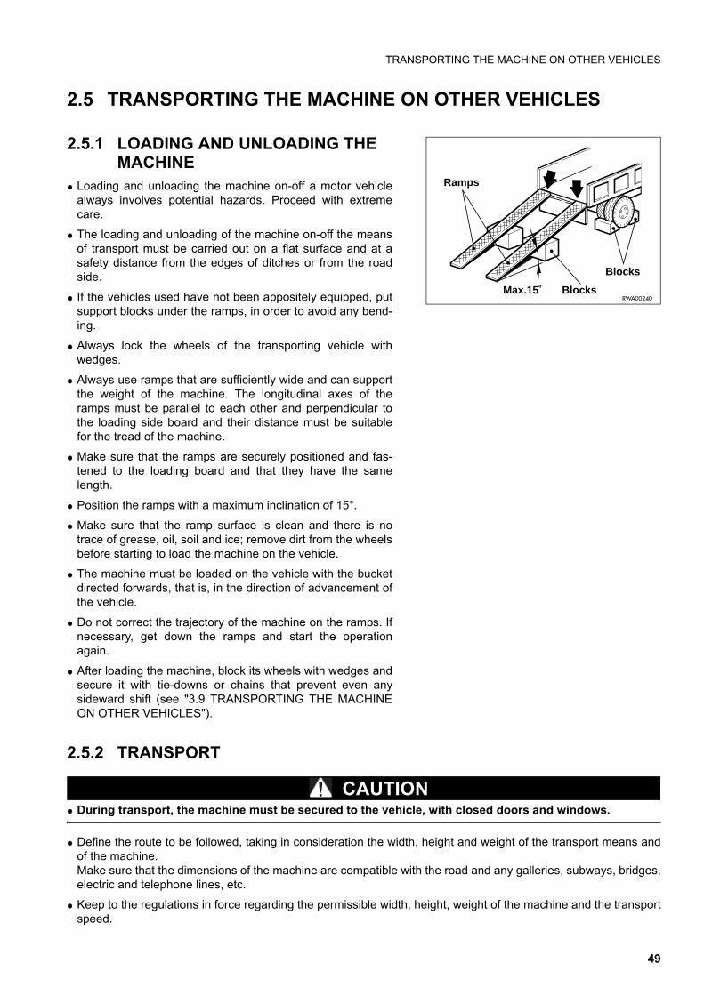
TRANSPORTING THE MACHINE ON OTHER VEHICLES
2.5 TRANSPORTING THE MACHINE ON OTHER VEHICLES
2.5.1 LOADING AND UNLOADING THE MACHINE
q Loading and unloading the machine on-off a motor vehiclealways involves potential hazards. Proceed with extremecare.
q The loading and unloading of the machine on-off the meansof transport must be carried out on a flat surface and at asafety distance from the edges of ditches or from the roadside.
q If the vehicles used have not been appositely equipped, putsupport blocks under the ramps, in order to avoid any bend-ing.
q Always lock the wheels of the transporting vehicle withwedges.
q Always use ramps that are sufficiently wide and can supportthe weight of the machine. The longitudinal axes of theramps must be parallel to each other and perpendicular tothe loading side board and their distance must be suitablefor the tread of the machine.
q Make sure that the ramps are securely positioned and fas-tened to the loading board and that they have the samelength.
q Position the ramps with a maximum inclination of 15°.
q Make sure that the ramp surface is clean and there is notrace of grease, oil, soil and ice; remove dirt from the wheelsbefore starting to load the machine on the vehicle.
q The machine must be loaded on the vehicle with the bucketdirected forwards, that is, in the direction of advancement ofthe vehicle.
q Do not correct the trajectory of the machine on the ramps. Ifnecessary, get down the ramps and start the operationagain.
q After loading the machine, block its wheels with wedges andsecure it with tie-downs or chains that prevent even anysideward shift (see "3.9 TRANSPORTING THE MACHINEON OTHER VEHICLES").
2.5.2 TRANSPORT
CAUTIONq During transport, the machine must be secured to the vehicle, with closed doors and windows.
q Define the route to be followed, taking in consideration the width, height and weight of the transport means andof the machine.Make sure that the dimensions of the machine are compatible with the road and any galleries, subways, bridges,electric and telephone lines, etc.
q Keep to the regulations in force regarding the permissible width, height, weight of the machine and the transportspeed.
Ramps
Blocks
Blocks
RWA00240Max.15˚
49
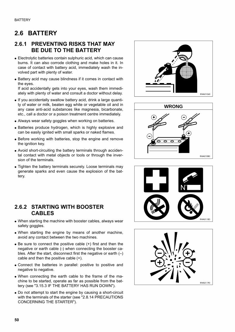
BATTERY
2.6 BATTERY
2.6.1 PREVENTING RISKS THAT MAY BE DUE TO THE BATTERY
q Electrolytic batteries contain sulphuric acid, which can causeburns. It can also corrode clothing and make holes in it. Incase of contact with battery acid, immediately wash the in-volved part with plenty of water.
q Battery acid may cause blindness if it comes in contact withthe eyes.If acid accidentally gets into your eyes, wash them immedi-ately with plenty of water and consult a doctor without delay.
q If you accidentally swallow battery acid, drink a large quanti-ty of water or milk, beaten egg white or vegetable oil and inany case anti-acid substances like magnesia, bicarbonate,etc., call a doctor or a poison treatment centre immediately.
q Always wear safety goggles when working on batteries.
q Batteries produce hydrogen, which is highly explosive andcan be easily ignited with small sparks or naked flames.
q Before working with batteries, stop the engine and removethe ignition key.
q Avoid short-circuiting the battery terminals through acciden-tal contact with metal objects or tools or through the inver-sion of the terminals.
q Tighten the battery terminals securely. Loose terminals maygenerate sparks and even cause the explosion of the bat-tery.
2.6.2 STARTING WITH BOOSTER CABLES
q When starting the machine with booster cables, always wearsafety goggles.
q When starting the engine by means of another machine,avoid any contact between the two machines.
q Be sure to connect the positive cable (+) first and then thenegative or earth cable (-) when connecting the booster ca-bles. After the start, disconnect first the negative or earth (–)cable and then the positive cable (+).
q Connect the batteries in parallel: positive to positive andnegative to negative.
q When connecting the earth cable to the frame of the ma-chine to be started, operate as far as possible from the bat-tery (see "3.15.3 IF THE BATTERY HAS RUN DOWN").
q Do not attempt to start the engine by causing a short-circuitwith the terminals of the starter (see "2.8.14 PRECAUTIONSCONCERNING THE STARTER").
RWA01060
RWA01080
WRONG
RWA01180
RWA01190
50
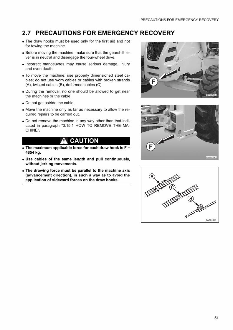
PRECAUTIONS FOR EMERGENCY RECOVERY
2.7 PRECAUTIONS FOR EMERGENCY RECOVERYq The draw hooks must be used only for the first aid and not
for towing the machine.
q Before moving the machine, make sure that the gearshift le-ver is in neutral and disengage the four-wheel drive.
q Incorrect manoeuvres may cause serious damage, injuryand even death.
q To move the machine, use properly dimensioned steel ca-bles; do not use worn cables or cables with broken strands(A), twisted cables (B), deformed cables (C).
q During the removal, no one should be allowed to get nearthe machines or the cable.
q Do not get astride the cable.
q Move the machine only as far as necessary to allow the re-quired repairs to be carried out.
q Do not remove the machine in any way other than that indi-cated in paragraph "3.15.1 HOW TO REMOVE THE MA-CHINE".
CAUTIONq The maximum applicable force for each draw hook is F =
4854 kg.
q Use cables of the same length and pull continuously,without jerking movements.
q The drawing force must be parallel to the machine axis(advancement direction), in such a way as to avoid theapplication of sideward forces on the draw hooks.
�������
�
�������
�
RWA05380
51
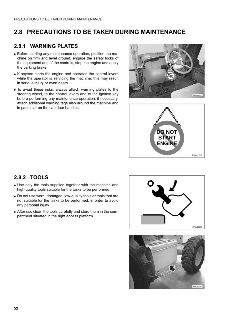
PRECAUTIONS TO BE TAKEN DURING MAINTENANCE
2.8 PRECAUTIONS TO BE TAKEN DURING MAINTENANCE
2.8.1 WARNING PLATESq Before starting any maintenance operation, position the ma-
chine on firm and level ground, engage the safety locks ofthe equipment and of the controls, stop the engine and applythe parking brake.
q If anyone starts the engine and operates the control leverswhile the operator is servicing the machine, this may resultin serious injury or even death.
q To avoid these risks, always attach warning plates to thesteering wheel, to the control levers and to the ignition keybefore performing any maintenance operation; if necessary,attach additional warning tags also around the machine andin particular on the cab door handles.
2.8.2 TOOLS q Use only the tools supplied together with the machine and
high-quality tools suitable for the tasks to be performed.
q Do not use worn, damaged, low-quality tools or tools that arenot suitable for the tasks to be performed, in order to avoidany personal injury.
q After use clean the tools carefully and store them in the com-partment situated in the right access platform.
�������
DO NOTSTART
ENGINE
RWA01210
RWA01310
��������
52
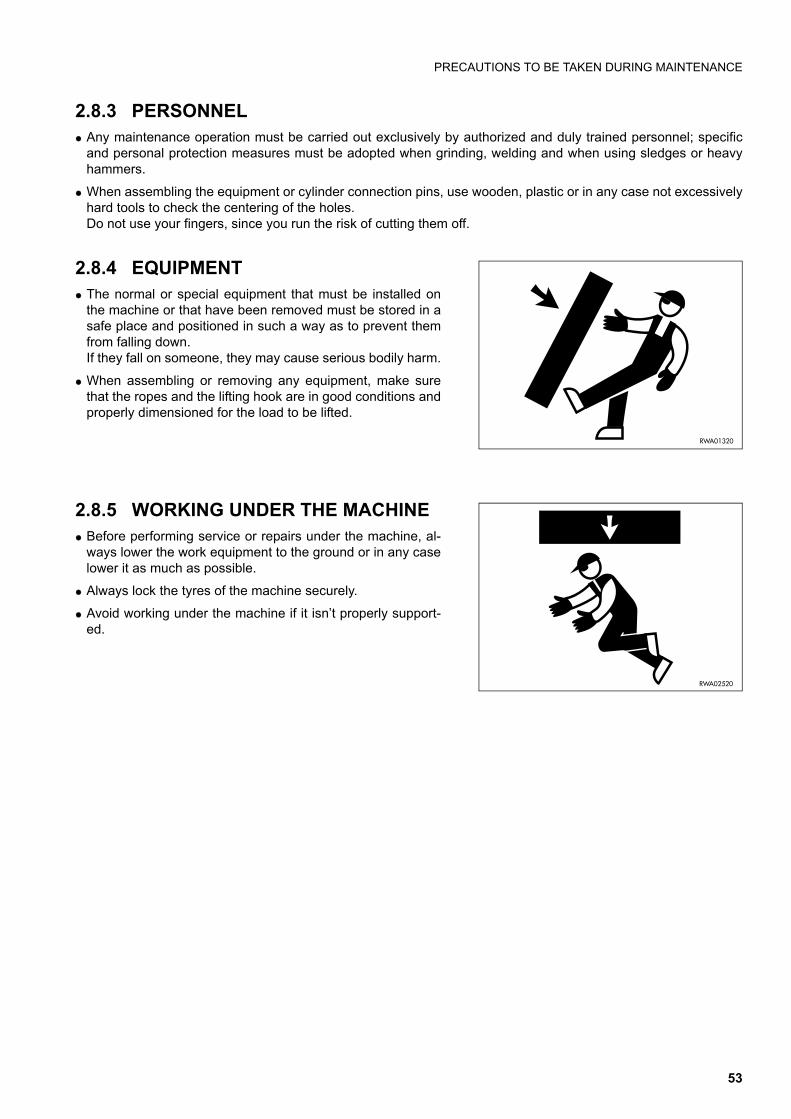
PRECAUTIONS TO BE TAKEN DURING MAINTENANCE
2.8.3 PERSONNELq Any maintenance operation must be carried out exclusively by authorized and duly trained personnel; specific
and personal protection measures must be adopted when grinding, welding and when using sledges or heavyhammers.
q When assembling the equipment or cylinder connection pins, use wooden, plastic or in any case not excessivelyhard tools to check the centering of the holes.Do not use your fingers, since you run the risk of cutting them off.
2.8.4 EQUIPMENT q The normal or special equipment that must be installed on
the machine or that have been removed must be stored in asafe place and positioned in such a way as to prevent themfrom falling down.If they fall on someone, they may cause serious bodily harm.
q When assembling or removing any equipment, make surethat the ropes and the lifting hook are in good conditions andproperly dimensioned for the load to be lifted.
2.8.5 WORKING UNDER THE MACHINE q Before performing service or repairs under the machine, al-
ways lower the work equipment to the ground or in any caselower it as much as possible.
q Always lock the tyres of the machine securely.
q Avoid working under the machine if it isn’t properly support-ed.
RWA01320
RWA02520
53
PRECAUTIONS TO BE TAKEN DURING MAINTENANCE
2.8.6 KEEPING THE MACHINE CLEAN q Spilled oil or grease, scattered tools or broken pieces are
dangerous, because they may cause someone to slip or trip.Always keep the machine and the worksite clean and tidy.
q To clean the machine, use a pressurized jet of warm water orsteam and the specific detergents available on the market.Do not use diesel oil, oil or solvents, since the former leavean oily coat that favours the sticking of dust, while the latter(even if weak) damage the painted surfaces and thereforefacilitate rusting.
q While cleaning the machine, keep the pressurized jet at aminimum distance of approx. 60 cm, in order to avoid dam-aging the warning plates and the pictograms.If the plates are damaged, request Komatsu or your Komat-su Dealer to send you spare plates and change them.
q Water into the electric system provokes the oxidation of thecontacts and may hinder the start of the machine or evenmake it start suddenly and abruptly. For this reason, avoidusing water or steam jets to clean sensors, connectors orthe inside of the operator's cab.
2.8.7 USE OF THE ENGINE DURING MAINTENANCEq During maintenance operations, run the engine only when indispensable. If the engine must be running (for ex-
ample, when checking the functionality of the alternator), it is advisable that someone remains seated in the driv-ing position, so that the engine can be stopped whenever necessary.
q During maintenance operations with running engine, neither move the control locking devices from the “lock” po-sition, nor change the position of the gearshift lever.Service personnel must not move any control lever.
q When carrying out maintenance operations, do not touch the moving parts of the machine and avoid wearinglarge and loose clothes.
2.8.8 PERIODICAL CHANGE OF THE SAFETY RELATED PARTSq Periodically change the following components, which are important for safety and fire prevention:
Fuel system: fuel delivery and return pipes.Hydraulic system: main delivery pipes of the hydraulic pump.Hydraulic system: work circuit pipes from the distributor to the hydraulic cylinders.Safety belt.
q Even if they seem to be in good conditions, these components must be periodically changed with new ones.In fact, these components tend to deteriorate over time.
q If one of these parts is defective, change or repair it even if the prescribed change interval has not elapsed yet.(See "4.6 PERIODICAL CHANGE OF THE SAFETY RELATED COMPONENTS").
RWA01330
54

PRECAUTIONS TO BE TAKEN DURING MAINTENANCE
2.8.9 STOP THE ENGINE BEFORE CAR-RYING OUT ANY MAINTENANCE OPERATION OR INSPECTION
q Stop the machine only on firm and level ground and stop theengine before carrying out any maintenance operation or in-spection.
q If it is necessary to have the engine running during mainte-nance, engage the safety LOCKS of the equipment controllevers, apply the parking brake and carry out any mainte-nance operation with the help of another person; an operatormust remain on board and the words to be used during theoperation must be agreed upon.
NOTEq The servo control locking button inhibits also the movements
of the backhoe when this is equipped with servo controls.
q The maintenance personnel must be very careful not totouch any moving part of the engine.
RWA02000
��������
�������
�������
55
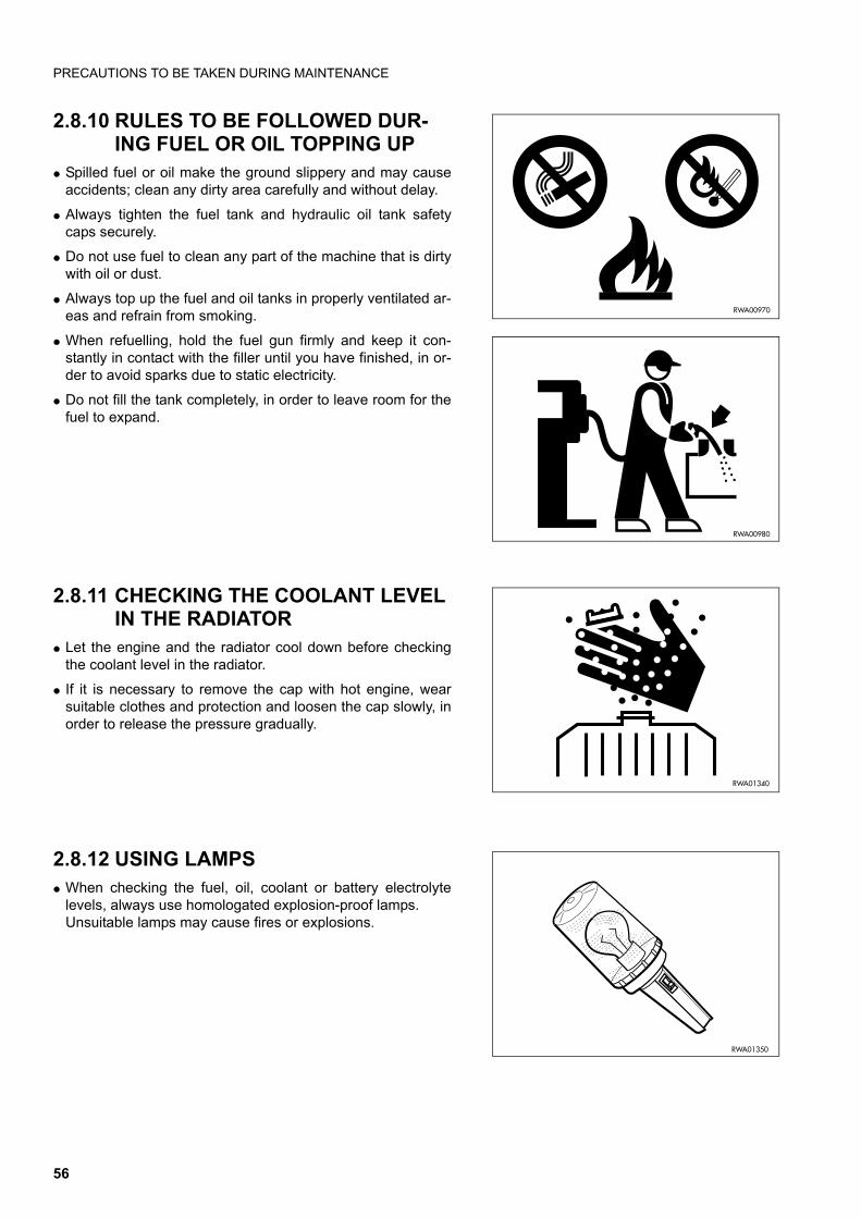
PRECAUTIONS TO BE TAKEN DURING MAINTENANCE
2.8.10 RULES TO BE FOLLOWED DUR-ING FUEL OR OIL TOPPING UP
q Spilled fuel or oil make the ground slippery and may causeaccidents; clean any dirty area carefully and without delay.
q Always tighten the fuel tank and hydraulic oil tank safetycaps securely.
q Do not use fuel to clean any part of the machine that is dirtywith oil or dust.
q Always top up the fuel and oil tanks in properly ventilated ar-eas and refrain from smoking.
q When refuelling, hold the fuel gun firmly and keep it con-stantly in contact with the filler until you have finished, in or-der to avoid sparks due to static electricity.
q Do not fill the tank completely, in order to leave room for thefuel to expand.
2.8.11 CHECKING THE COOLANT LEVEL IN THE RADIATOR
q Let the engine and the radiator cool down before checkingthe coolant level in the radiator.
q If it is necessary to remove the cap with hot engine, wearsuitable clothes and protection and loosen the cap slowly, inorder to release the pressure gradually.
2.8.12 USING LAMPSq When checking the fuel, oil, coolant or battery electrolyte
levels, always use homologated explosion-proof lamps.Unsuitable lamps may cause fires or explosions.
RWA00970
RWA00980
RWA01340
RWA01350
56
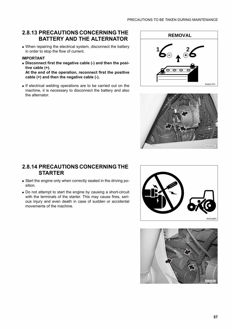
PRECAUTIONS TO BE TAKEN DURING MAINTENANCE
2.8.13 PRECAUTIONS CONCERNING THE BATTERY AND THE ALTERNATOR
q When repairing the electrical system, disconnect the batteryin order to stop the flow of current.
IMPORTANTq Disconnect first the negative cable (-) and then the posi-
tive cable (+).At the end of the operation, reconnect first the positivecable (+) and then the negative cable (-).
q If electrical welding operations are to be carried out on themachine, it is necessary to disconnect the battery and alsothe alternator.
2.8.14 PRECAUTIONS CONCERNING THE STARTER
q Start the engine only when correctly seated in the driving po-sition.
q Do not attempt to start the engine by causing a short-circuitwith the terminals of the starter. This may cause fires, seri-ous injury and even death in case of sudden or accidentalmovements of the machine.
1 2
RWA01370
REMOVAL
����� �
RWA04890
�������
57
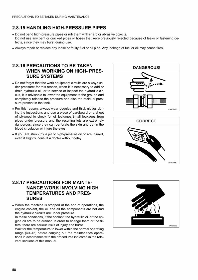
PRECAUTIONS TO BE TAKEN DURING MAINTENANCE
2.8.15 HANDLING HIGH-PRESSURE PIPESq Do not bend high-pressure pipes or rub them with sharp or abrasive objects.
Do not use any bent or cracked pipes or hoses that were previously rejected because of leaks or fastening de-fects, since they may burst during use.
q Always repair or replace any loose or faulty fuel or oil pipe. Any leakage of fuel or oil may cause fires.
2.8.16 PRECAUTIONS TO BE TAKEN WHEN WORKING ON HIGH- PRES-SURE SYSTEMS
q Do not forget that the work equipment circuits are always un-der pressure; for this reason, when it is necessary to add ordrain hydraulic oil, or to service or inspect the hydraulic cir-cuit, it is advisable to lower the equipment to the ground andcompletely release the pressure and also the residual pres-sure present in the tank.
q For this reason, always wear goggles and thick gloves dur-ing the inspections and use a piece of cardboard or a sheetof plywood to check for oil leakages.Small leakages frompipes under pressure and the resulting jets are extremelydangerous, since they can perforate the skin and get in theblood circulation or injure the eyes.
q If you are struck by a jet of high-pressure oil or are injured,even if slightly, consult a doctor without delay.
2.8.17 PRECAUTIONS FOR MAINTE-NANCE WORK INVOLVING HIGH TEMPERATURES AND PRES-SURES
q When the machine is stopped at the end of operations, theengine coolant, the oil and all the components are hot andthe hydraulic circuits are under pressure.In these conditions, if the coolant, the hydraulic oil or the en-gine oil are to be drained in order to change them or the fil-ters, there are serious risks of injury and burns.Wait for the temperature to lower within the normal operatingrange (40–45) before carrying out the maintenance opera-tions in accordance with the procedures indicated in the rele-vant sections of this manual.
RWA01480
DANGEROUS!
RWA01580
CORRECT
RWA00990
58
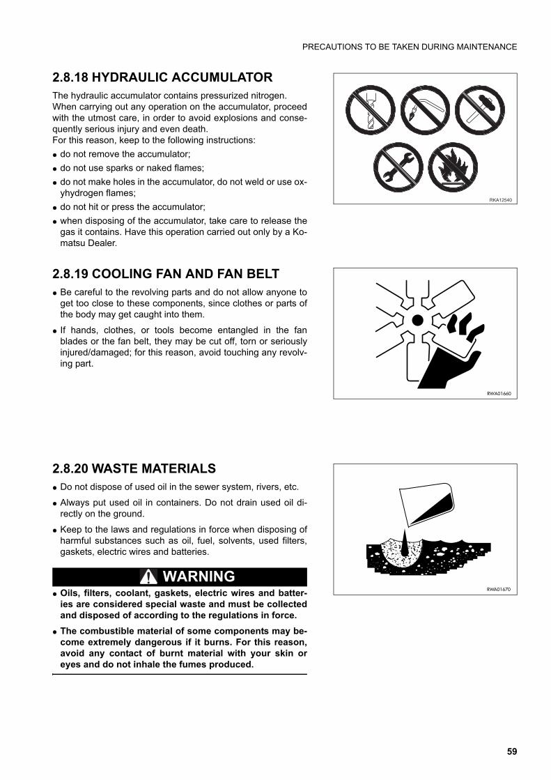
PRECAUTIONS TO BE TAKEN DURING MAINTENANCE
2.8.18 HYDRAULIC ACCUMULATORThe hydraulic accumulator contains pressurized nitrogen.When carrying out any operation on the accumulator, proceedwith the utmost care, in order to avoid explosions and conse-quently serious injury and even death. For this reason, keep to the following instructions:
q do not remove the accumulator;
q do not use sparks or naked flames;
q do not make holes in the accumulator, do not weld or use ox-yhydrogen flames;
q do not hit or press the accumulator;
q when disposing of the accumulator, take care to release thegas it contains. Have this operation carried out only by a Ko-matsu Dealer.
2.8.19 COOLING FAN AND FAN BELTq Be careful to the revolving parts and do not allow anyone to
get too close to these components, since clothes or parts ofthe body may get caught into them.
q If hands, clothes, or tools become entangled in the fanblades or the fan belt, they may be cut off, torn or seriouslyinjured/damaged; for this reason, avoid touching any revolv-ing part.
2.8.20 WASTE MATERIALSq Do not dispose of used oil in the sewer system, rivers, etc.
q Always put used oil in containers. Do not drain used oil di-rectly on the ground.
q Keep to the laws and regulations in force when disposing ofharmful substances such as oil, fuel, solvents, used filters,gaskets, electric wires and batteries.
WARNINGq Oils, filters, coolant, gaskets, electric wires and batter-
ies are considered special waste and must be collectedand disposed of according to the regulations in force.
q The combustible material of some components may be-come extremely dangerous if it burns. For this reason,avoid any contact of burnt material with your skin oreyes and do not inhale the fumes produced.
���� ��
RWA01660
RWA01670
59
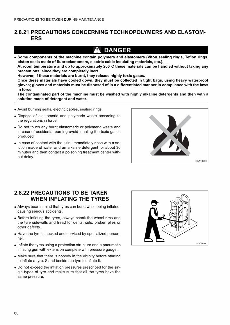
PRECAUTIONS TO BE TAKEN DURING MAINTENANCE
2.8.21 PRECAUTIONS CONCERNING TECHNOPOLYMERS AND ELASTOM-ERS
DANGERq Some components of the machine contain polymers and elastomers (Viton sealing rings, Teflon rings,
piston seals made of fluoroelastomers, electric cable insulating materials, etc.).At room temperature and up to approximately 200°C these materials can be handled without taking anyprecautions, since they are completely inert.However, if these materials are burnt, they release highly toxic gases.Once these materials have cooled down, they must be collected in tight bags, using heavy waterproofgloves; gloves and materials must be disposed of in a differentiated manner in compliance with the lawsin force.The contaminated part of the machine must be washed with highly alkaline detergents and then with asolution made of detergent and water.
q Avoid burning seals, electric cables, sealing rings.
q Dispose of elastomeric and polymeric waste according tothe regulations in force.
q Do not touch any burnt elastomeric or polymeric waste andin case of accidental burning avoid inhaling the toxic gasesproduced.
q In case of contact with the skin, immediately rinse with a so-lution made of water and an alkaline detergent for about 30minutes and then contact a poisoning treatment center with-out delay.
2.8.22 PRECAUTIONS TO BE TAKEN WHEN INFLATING THE TYRES
q Always bear in mind that tyres can burst while being inflated,causing serious accidents.
q Before inflating the tyres, always check the wheel rims andthe tyre sidewalls and tread for dents, cuts, broken plies orother defects.
q Have the tyres checked and serviced by specialized person-nel.
q Inflate the tyres using a protection structure and a pneumaticinflating gun with extension complete with pressure gauge.
q Make sure that there is nobody in the vicinity before startingto inflate a tyre. Stand beside the tyre to inflate it.
q Do not exceed the inflation pressures prescribed for the sin-gle types of tyre and make sure that all the tyres have thesame pressure.
RKA13780
RWA01680
60

PRECAUTIONS TO BE TAKEN DURING MAINTENANCE
2.8.23 PRECAUTIONS FOR THE INSTAL-LATION OF THE EXHAUST SYS-TEM TAILPIPE
q When the machine is stopped at the end of work, the ex-haust pipe (1) and the tailpipe (2) are very hot. In these con-ditions, if any maintenance operation has to be carried out,the operator runs the risk of being burned or injured.Carry out any maintenance operation only when these partshave cooled down and in any case always use thick gloves.
q Pay the utmost attention when installing the tailpipe (2) onthe exhaust pipe (1), since the former must be positionedcorrectly with the outlet of the exhaust gases directed towardthe front part of the machine and inclined 60° outwards.This position serves to prevent the exhaust gases from be-ing directed towards the cab and therefore towards the oper-ator.
2.8.24 PRECAUTIONS TO BE TAKEN WHEN USING SYNTHETIC BIODE-GRADABLE OIL TYPE «HEES»
q It is not possible to mix the synthetic biodegradable oil type HEES with ordinary hydraulic oils, since when thetemperature increases insoluble compounds are generated, which are deposited on the filters and clog them(the maximum concentration of ordinary oil must not exceed 1% of the total quantity of oil).
q Biodegradable oil can be used only in the hydraulic system; it cannot be used for the engine, the transmissions,the braking system, etc.
q Before introducing synthetic biodegradable oil in the hydraulic system, empty the system completely, discon-necting the cylinders and all the parts that may contain ordinary oil, and replace the drain filter with a new one.Start the engine and let it idle without using the work equipment, wait until the oil reaches a temperature of atleast 40°C, then start moving the equipment, so that all the parts of the system are filled with oil. Stop the engineand check the oil level (see "4.8.6.a CHECKING THE HYDRAULIC OIL LEVEL").
�������
�
�
61

THIS PAGE WAS INTENTIONALLY LEFT EMPTY
62

����� ��������������������
63
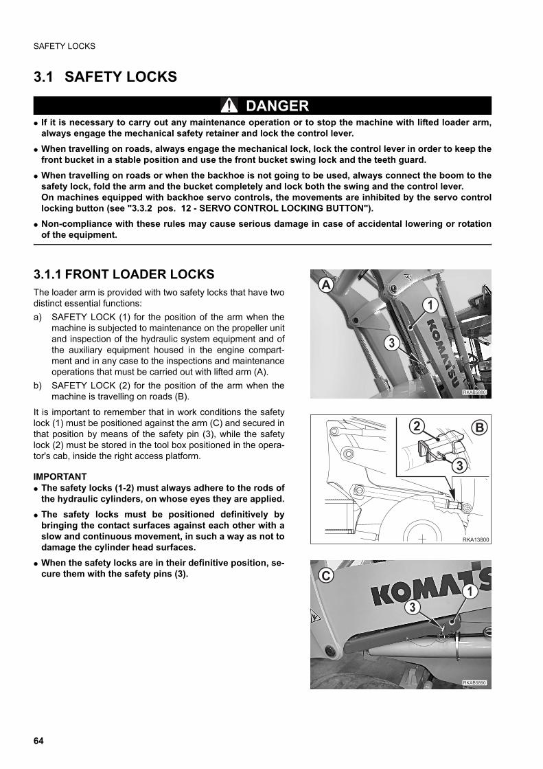
SAFETY LOCKS
3.1 SAFETY LOCKS
DANGERq If it is necessary to carry out any maintenance operation or to stop the machine with lifted loader arm,
always engage the mechanical safety retainer and lock the control lever.
q When travelling on roads, always engage the mechanical lock, lock the control lever in order to keep thefront bucket in a stable position and use the front bucket swing lock and the teeth guard.
q When travelling on roads or when the backhoe is not going to be used, always connect the boom to thesafety lock, fold the arm and the bucket completely and lock both the swing and the control lever.On machines equipped with backhoe servo controls, the movements are inhibited by the servo controllocking button (see "3.3.2 pos. 12 - SERVO CONTROL LOCKING BUTTON").
q Non-compliance with these rules may cause serious damage in case of accidental lowering or rotationof the equipment.
3.1.1 FRONT LOADER LOCKSThe loader arm is provided with two safety locks that have twodistinct essential functions:
a) SAFETY LOCK (1) for the position of the arm when themachine is subjected to maintenance on the propeller unitand inspection of the hydraulic system equipment and ofthe auxiliary equipment housed in the engine compart-ment and in any case to the inspections and maintenanceoperations that must be carried out with lifted arm (A).
b) SAFETY LOCK (2) for the position of the arm when themachine is travelling on roads (B).
It is important to remember that in work conditions the safetylock (1) must be positioned against the arm (C) and secured inthat position by means of the safety pin (3), while the safetylock (2) must be stored in the tool box positioned in the opera-tor's cab, inside the right access platform.
IMPORTANTq The safety locks (1-2) must always adhere to the rods of
the hydraulic cylinders, on whose eyes they are applied.
q The safety locks must be positioned definitively bybringing the contact surfaces against each other with aslow and continuous movement, in such a way as not todamage the cylinder head surfaces.
q When the safety locks are in their definitive position, se-cure them with the safety pins (3).
���� �
�
�
�
������
�
� �
���� ��
�
�
64
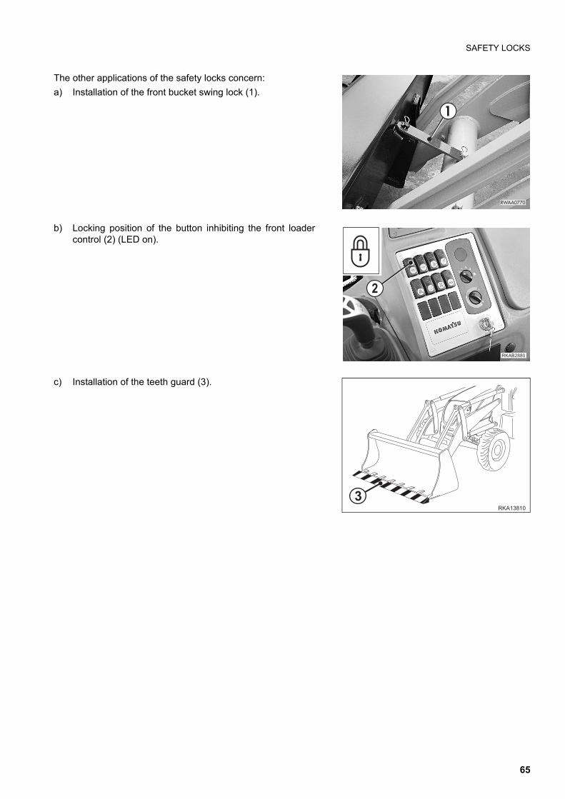
SAFETY LOCKS
The other applications of the safety locks concern:
a) Installation of the front bucket swing lock (1).
b) Locking position of the button inhibiting the front loadercontrol (2) (LED on).
c) Installation of the teeth guard (3).
������
�
#
�����
�����
�
65
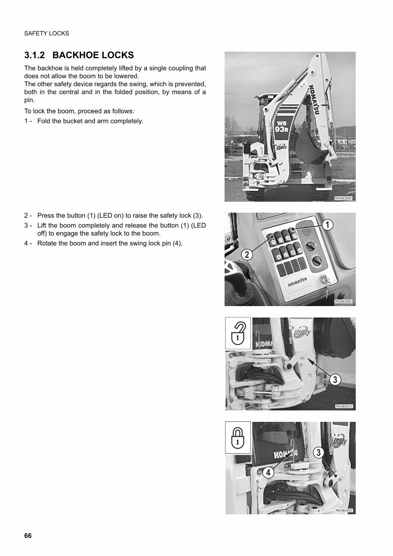
SAFETY LOCKS
3.1.2 BACKHOE LOCKSThe backhoe is held completely lifted by a single coupling thatdoes not allow the boom to be lowered.The other safety device regards the swing, which is prevented,both in the central and in the folded position, by means of apin.
To lock the boom, proceed as follows:
1 - Fold the bucket and arm completely.
2 - Press the button (1) (LED on) to raise the safety lock (3).
3 - Lift the boom completely and release the button (1) (LEDoff) to engage the safety lock to the boom.
4 - Rotate the boom and insert the swing lock pin (4).
��������
�������
�
�
�������
�
��������
�
�
66
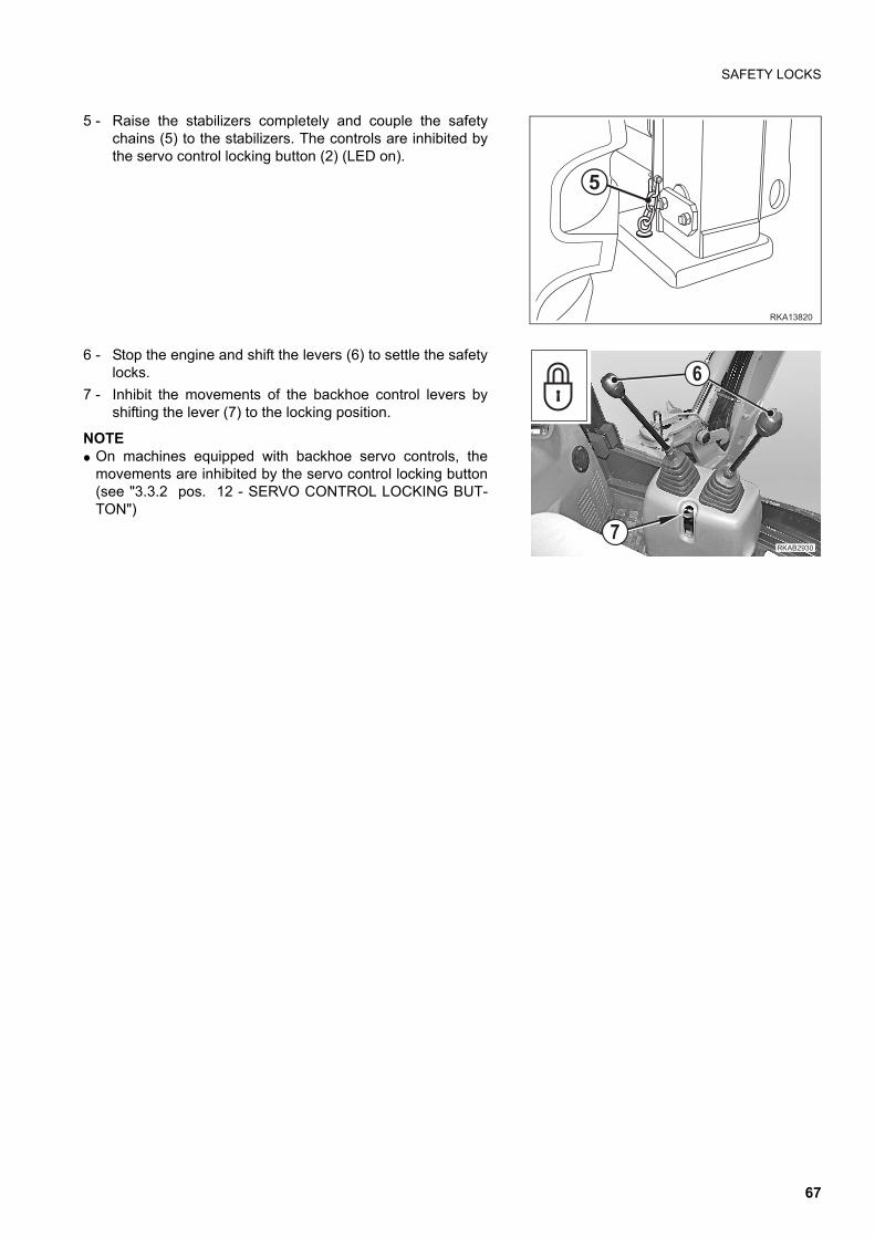
SAFETY LOCKS
5 - Raise the stabilizers completely and couple the safetychains (5) to the stabilizers. The controls are inhibited bythe servo control locking button (2) (LED on).
6 - Stop the engine and shift the levers (6) to settle the safetylocks.
7 - Inhibit the movements of the backhoe control levers byshifting the lever (7) to the locking position.
NOTEq On machines equipped with backhoe servo controls, the
movements are inhibited by the servo control locking button(see "3.3.2 pos. 12 - SERVO CONTROL LOCKING BUT-TON")
������
�
��������
�
67
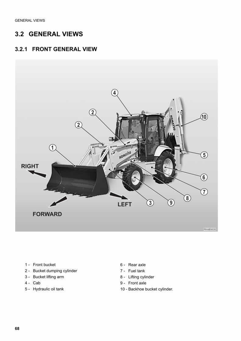
GENERAL VIEWS
3.2 GENERAL VIEWS
3.2.1 FRONT GENERAL VIEW
1 - Front bucket
2 - Bucket dumping cylinder
3 - Bucket lifting arm
4 - Cab
5 - Hydraulic oil tank
6 - Rear axle
7 - Fuel tank
8 - Lifting cylinder
9 - Front axle
10 - Backhoe bucket cylinder.
���� ���
� !"
�
��
�
�
�
�
�
�����
�������
����
68
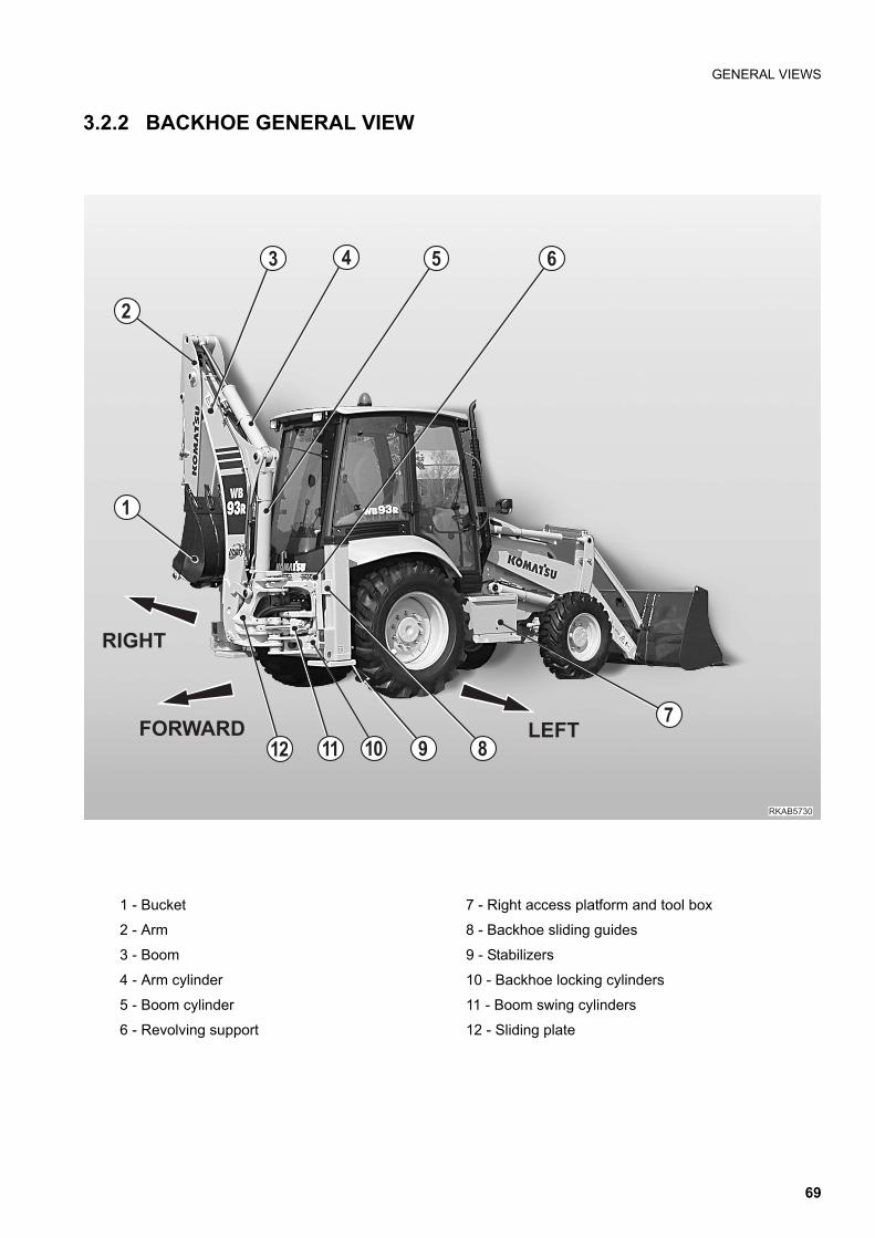
GENERAL VIEWS
3.2.2 BACKHOE GENERAL VIEW
1 - Bucket
2 - Arm
3 - Boom
4 - Arm cylinder
5 - Boom cylinder
6 - Revolving support
7 - Right access platform and tool box
8 - Backhoe sliding guides
9 - Stabilizers
10 - Backhoe locking cylinders
11 - Boom swing cylinders
12 - Sliding plate
�����
������� ����
���� ���
�
�
�
� � �
! "����
��
69
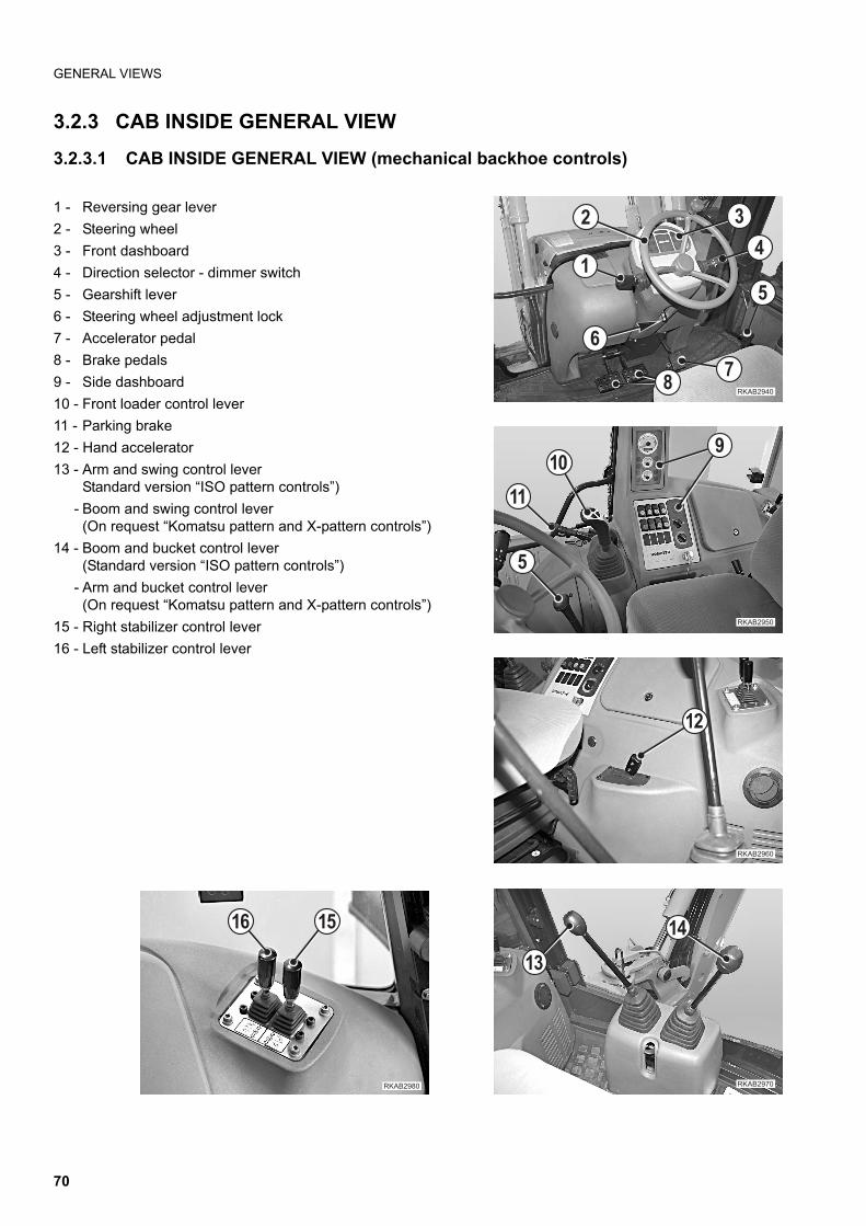
GENERAL VIEWS
3.2.3 CAB INSIDE GENERAL VIEW
3.2.3.1 CAB INSIDE GENERAL VIEW (mechanical backhoe controls)
1 - Reversing gear lever
2 - Steering wheel
3 - Front dashboard
4 - Direction selector - dimmer switch
5 - Gearshift lever
6 - Steering wheel adjustment lock
7 - Accelerator pedal
8 - Brake pedals
9 - Side dashboard
10 - Front loader control lever
11 - Parking brake
12 - Hand accelerator
13 - Arm and swing control lever Standard version “ISO pattern controls”)
- Boom and swing control lever (On request “Komatsu pattern and X-pattern controls”)
14 - Boom and bucket control lever(Standard version “ISO pattern controls”)
- Arm and bucket control lever(On request “Komatsu pattern and X-pattern controls”)
15 - Right stabilizer control lever
16 - Left stabilizer control lever
��������
�
� �
�
�
�"
������ �
�
��!
��
��������
��
��
��������
��
�������
� ��
70
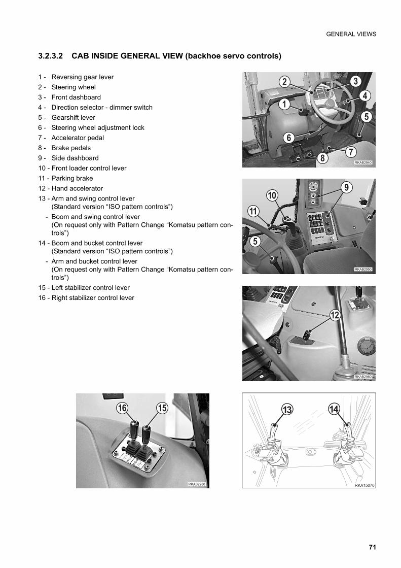
GENERAL VIEWS
3.2.3.2 CAB INSIDE GENERAL VIEW (backhoe servo controls)
1 - Reversing gear lever
2 - Steering wheel
3 - Front dashboard
4 - Direction selector - dimmer switch
5 - Gearshift lever
6 - Steering wheel adjustment lock
7 - Accelerator pedal
8 - Brake pedals
9 - Side dashboard
10 - Front loader control lever
11 - Parking brake
12 - Hand accelerator
13 - Arm and swing control lever (Standard version “ISO pattern controls”)
- Boom and swing control lever (On request only with Pattern Change “Komatsu pattern con-trols”)
14 - Boom and bucket control lever(Standard version “ISO pattern controls”)
- Arm and bucket control lever(On request only with Pattern Change “Komatsu pattern con-trols”)
15 - Left stabilizer control lever
16 - Right stabilizer control lever
��������
�
� �
�
�
�"
������ �
�
��!
��
��� �
�� ��
��������
��
�������
� ��
71
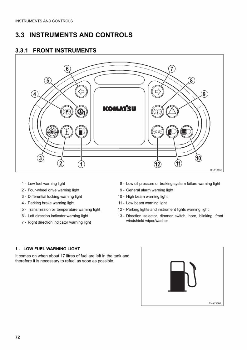
INSTRUMENTS AND CONTROLS
3.3 INSTRUMENTS AND CONTROLS
3.3.1 FRONT INSTRUMENTS
1 - LOW FUEL WARNING LIGHT
It comes on when about 17 litres of fuel are left in the tank andtherefore it is necessary to refuel as soon as possible.
1 - Low fuel warning light 8 - Low oil pressure or braking system failure warning light
2 - Four-wheel drive warning light 9 - General alarm warning light
3 - Differential locking warning light 10 - High beam warning light
4 - Parking brake warning light 11 - Low beam warning light
5 - Transmission oil temperature warning light 12 - Parking lights and instrument lights warning light
6 - Left direction indicator warning light 13 - Direction selector, dimmer switch, horn, blinking, frontwindshield wiper/washer7 - Right direction indicator warning light
���
�� ����
�
�
!
"
�
���� �
������
72
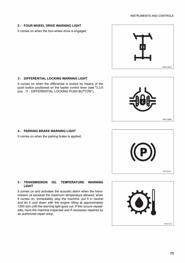
INSTRUMENTS AND CONTROLS
2 - FOUR-WHEEL DRIVE WARNING LIGHT
It comes on when the four-wheel drive is engaged.
3 - DIFFERENTIAL LOCKING WARNING LIGHT
It comes on when the differential is locked by means of thepush button positioned on the loader control lever (see "3.3.6pos. 11 - DIFFERENTIAL LOCKING PUSH BUTTON").
4 - PARKING BRAKE WARNING LIGHT
It comes on when the parking brake is applied.
5 - TRANSMISSION OIL TEMPERATURE WARNINGLIGHT
It comes on and activates the acoustic alarm when the trans-mission oil exceeds the maximum temperature allowed; whenit comes on, immediately stop the machine, put it in neutraland let it cool down with the engine idling at approximately1200 rpm until the warning light goes out. If this occurs repeat-edly, have the machine inspected and if necessary repaired byan authorized repair shop.
������
�����
�����
�
�����
73
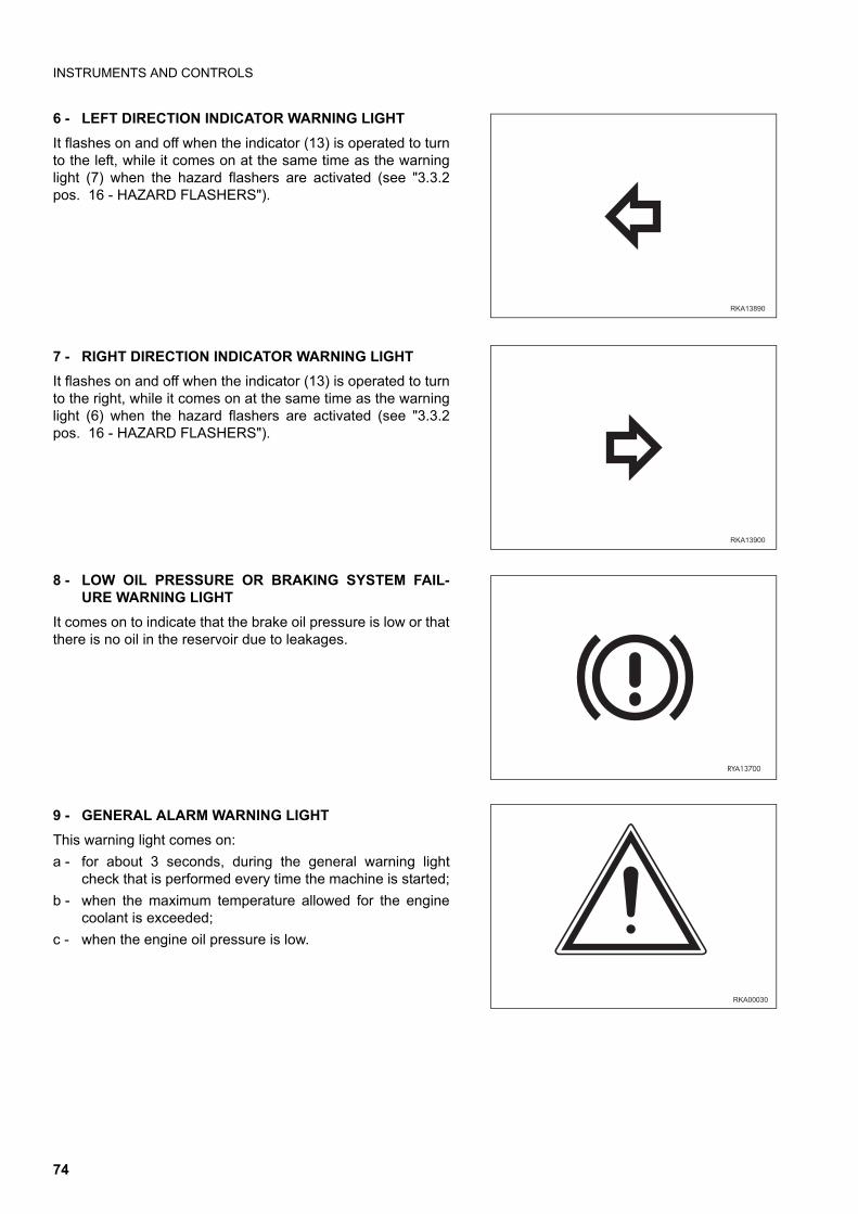
INSTRUMENTS AND CONTROLS
6 - LEFT DIRECTION INDICATOR WARNING LIGHT
It flashes on and off when the indicator (13) is operated to turnto the left, while it comes on at the same time as the warninglight (7) when the hazard flashers are activated (see "3.3.2pos. 16 - HAZARD FLASHERS").
7 - RIGHT DIRECTION INDICATOR WARNING LIGHT
It flashes on and off when the indicator (13) is operated to turnto the right, while it comes on at the same time as the warninglight (6) when the hazard flashers are activated (see "3.3.2pos. 16 - HAZARD FLASHERS").
8 - LOW OIL PRESSURE OR BRAKING SYSTEM FAIL-URE WARNING LIGHT
It comes on to indicate that the brake oil pressure is low or thatthere is no oil in the reservoir due to leakages.
9 - GENERAL ALARM WARNING LIGHT
This warning light comes on:
a - for about 3 seconds, during the general warning lightcheck that is performed every time the machine is started;
b - when the maximum temperature allowed for the enginecoolant is exceeded;
c - when the engine oil pressure is low.
������
�������
����
��������
74
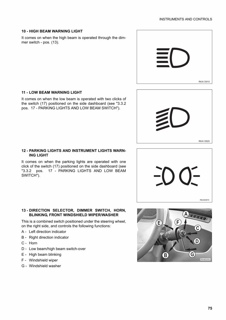
INSTRUMENTS AND CONTROLS
10 - HIGH BEAM WARNING LIGHT
It comes on when the high beam is operated through the dim-mer switch - pos. (13).
11 - LOW BEAM WARNING LIGHT
It comes on when the low beam is operated with two clicks ofthe switch (17) positioned on the side dashboard (see "3.3.2pos. 17 - PARKING LIGHTS AND LOW BEAM SWITCH").
12 - PARKING LIGHTS AND INSTRUMENT LIGHTS WARN-ING LIGHT
It comes on when the parking lights are operated with oneclick of the switch (17) positioned on the side dashboard (see"3.3.2 pos. 17 - PARKING LIGHTS AND LOW BEAMSWITCH").
13 - DIRECTION SELECTOR, DIMMER SWITCH, HORN,BLINKING, FRONT WINDSHIELD WIPER/WASHER
This is a combined switch positioned under the steering wheel,on the right side, and controls the following functions:
A - Left direction indicator
B - Right direction indicator
C - Horn
D - Low beam/high beam switch-over
E - High beam blinking
F - Windshield wiper
G - Windshield washer
������
�������
��������
��������
�
�
�
�
�
�
75
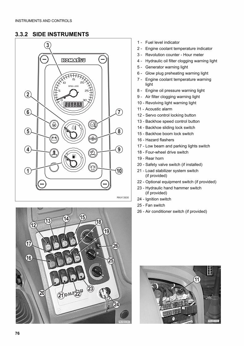
INSTRUMENTS AND CONTROLS
3.3.2 SIDE INSTRUMENTS
�������
�
�
�
�
�
!
��
"
�
1 - Fuel level indicator
2 - Engine coolant temperature indicator
3 - Revolution counter - Hour meter
4 - Hydraulic oil filter clogging warning light
5 - Generator warning light
6 - Glow plug preheating warning light
7 - Engine coolant temperature warninglight
8 - Engine oil pressure warning light
9 - Air filter clogging warning light
10 - Revolving light warning light
11 - Acoustic alarm
12 - Servo control locking button
13 - Backhoe speed control button
14 - Backhoe sliding lock switch
15 - Backhoe boom lock switch
16 - Hazard flashers
17 - Low beam and parking lights switch
18 - Four-wheel drive switch
19 - Rear horn
20 - Safety valve switch (if installed)
21 - Load stabilizer system switch(if provided)
22 - Optional equipment switch (if provided)
23 - Hydraulic hand hammer switch(if provided)
24 - Ignition switch
25 - Fan switch
26 - Air conditioner switch (if provided)
��������
�!
��
�
�� ����
��
��
� ��
�"��
������
��������
��
76
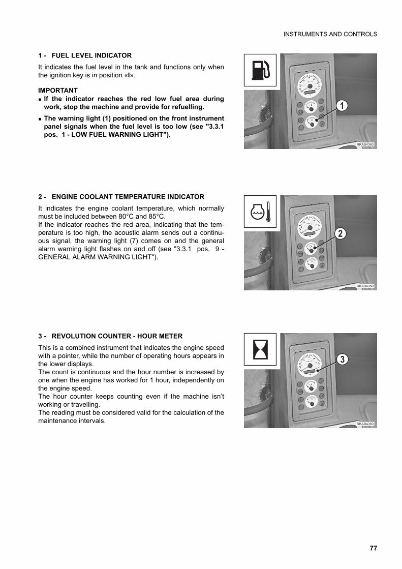
INSTRUMENTS AND CONTROLS
1 - FUEL LEVEL INDICATOR
It indicates the fuel level in the tank and functions only whenthe ignition key is in position «I».
IMPORTANTq If the indicator reaches the red low fuel area during
work, stop the machine and provide for refuelling.
q The warning light (1) positioned on the front instrumentpanel signals when the fuel level is too low (see "3.3.1pos. 1 - LOW FUEL WARNING LIGHT").
2 - ENGINE COOLANT TEMPERATURE INDICATOR
It indicates the engine coolant temperature, which normallymust be included between 80°C and 85°C.If the indicator reaches the red area, indicating that the tem-perature is too high, the acoustic alarm sends out a continu-ous signal, the warning light (7) comes on and the generalalarm warning light flashes on and off (see "3.3.1 pos. 9 -GENERAL ALARM WARNING LIGHT").
3 - REVOLUTION COUNTER - HOUR METER
This is a combined instrument that indicates the engine speedwith a pointer, while the number of operating hours appears inthe lower displays. The count is continuous and the hour number is increased byone when the engine has worked for 1 hour, independently onthe engine speed. The hour counter keeps counting even if the machine isn’tworking or travelling.The reading must be considered valid for the calculation of themaintenance intervals.
��������
�
������ �
�
��������
�
77
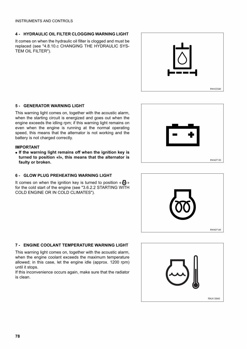
INSTRUMENTS AND CONTROLS
4 - HYDRAULIC OIL FILTER CLOGGING WARNING LIGHT
It comes on when the hydraulic oil filter is clogged and must bereplaced (see "4.8.10.c CHANGING THE HYDRAULIC SYS-TEM OIL FILTER").
5 - GENERATOR WARNING LIGHT
This warning light comes on, together with the acoustic alarm,when the starting circuit is energized and goes out when theengine exceeds the idling rpm; if this warning light remains oneven when the engine is running at the normal operatingspeed, this means that the alternator is not working and thebattery is not charged correctly.
IMPORTANTq If the warning light remains off when the ignition key is
turned to position «I», this means that the alternator isfaulty or broken.
6 - GLOW PLUG PREHEATING WARNING LIGHT
It comes on when the ignition key is turned to position « »for the cold start of the engine (see "3.6.2.2 STARTING WITHCOLD ENGINE OR IN COLD CLIMATES").
7 - ENGINE COOLANT TEMPERATURE WARNING LIGHT
This warning light comes on, together with the acoustic alarm,when the engine coolant exceeds the maximum temperatureallowed; in this case, let the engine idle (approx. 1200 rpm)until it stops.If this inconvenience occurs again, make sure that the radiatoris clean.
RWA22340
RWA07150
RWA07160
�������
78
INSTRUMENTS AND CONTROLS
8 - ENGINE OIL PRESSURE WARNING LIGHT
This warning light comes on, together with the acoustic alarm,when the engine is not running and the starting circuit is oper-ated and goes out as soon as the engine lubrication circuit ispressurized.If it does not go out or comes on when the engine is running,stop the machine immediately and try to find the cause of thefailure.
9 - AIR FILTER CLOGGING WARNING LIGHT
It comes one when the engine air filter needs cleaning (see"4.8.1.a CHECKING, CLEANING OR CHANGING THE EN-GINE AIR FILTERS").
10 - REVOLVING LIGHT WARNING LIGHT
It comes on when the revolving light is operated by means ofthe switch positioned on the upper right side of the cab (see"3.3.5 pos. 2 - REVOLVING LIGHT SWITH").
11 - ACOUSTIC ALARM
The acoustic alarm starts when the circuits are energized withthe ignition key (turned to position « ») and stops automatical-ly after the automatic check on the warning lights.The sounding of the alarm when the machine is working sig-nals the following anomalies:• Insufficient engine oil pressure• Overheating of the engine cooling circuit• Overheating of the transmission oil• Faulty alternator or worn belt• Incorrect position of the seat while the machine is moving
RWA07130
RWA31710
RKA01800
RKA01070
79
INSTRUMENTS AND CONTROLS
12 - SERVO CONTROL LOCKING BUTTON
WARNINGq When travelling on roads, always engage the servo con-
trol locking device.
This button has the function to inhibit the servo controls andmust be used when the machine travels on roads and as safe-ty lock when leaving the driver’s seat or parking the machine.To lock the servo controls, press the button (12) (LED on).Press the button again (LED off) to release the controls.
NOTEq Whenever the machine is started, the controls are locked
automatically (LED on); press the button (LED off) to use thecontrols.
q For safety reasons, the servo controls are locked automati-cally (LED on) when the seat is rotated by the operator tochange driving position. The servo controls are automaticallyreleased (LED off) when the rotation has been completedand the seat is fixed in the correct driving position (front orrear).
q In the version with backhoe servo controls, this buttonserves to lock the backhoe controls, too.
13 - BACKHOE SPEED CONTROL BUTTON
This button allows the quantity of oil delivered by the hydraulicpump to be selected. Whenever restarted, the machine auto-matically selects the POWER mode (LED on), even if when itstopped the selected mode was ECONOMY. This positionmakes it possible to use the maximum oil delivery and is indis-pensable for a correct use of the backhoe. When the button ispressed (LED off), the ECONOMY operating mode is selected.To return to the POWER mode (LED on), press the buttonagain. The machine passes automatically from POWER toECONOMY mode when the forward or the reverse gear areengaged (reversing gear lever forward or backward). To returnto the POWER mode, shift the lever back to the neutral posi-tion.
14 - BACKHOE SLIDING LOCK SWITCH
This switch has the function to release the backhoe unit fromthe sliding guides, in such a way as to make it possible tochange the position of the backhoe with respect to the ma-chine. The backhoe unit is generally fixed on the guides andthe switch is not operated (LED off). When pressed, the switchcomes on and releases the unit from the guides, thus allowingthe backhoe to slide; once the desired position has beenreached, press the switch again to fix the backhoe unit (LEDoff).
��������
��
�������
��
�����
������
80
INSTRUMENTS AND CONTROLS
15 - BACKHOE BOOM LOCKING BUTTON
This is a button that automatically returns to position OFF andis used to couple the safety lock to the boom when the back-hoe is not going to be used or when the machine travels onroads.Press the button (LED on) to lift the safety lock; this is indis-pensable to position the boom correctly before the couplingoperation.Release the button (LED off) to lower the lock and couple it tothe boom. For the use of this button, see "3.6.1.1 pos. 8 - BACKHOEBOOM LOCKING BUTTON".
16 - HAZARD FLASHERS
This button operates both direction indicators at the same timeand must be used whenever, while travelling on roads, the ma-chine is temporarily parked/stopped on the roadway or in anycase in anomalous position.
17 - PARKING LIGHTS AND LOW BEAM SWITCH
This is a two-position switch; with one click it switches on theparking lights and instruments, with two clicks it switches onthe low beam. The parking lights can be switched on even withthe machine at rest.
18 - FOUR-WHEEL DRIVE SWITCH
When pressed (LED on), this switch engages the four-wheeldrive. When the switch is pressed, also the warning light pos.(2) on the front instrument panel comes on (see "3.3.1 pos. 2- FOUR-WHEEL DRIVE WARNING LIGHT").When pressed again (LED off), it disengages the four-wheeldrive.
IMPORTANTq When travelling at high speed and on roads, disengage
the four-wheel drive.
q The four-wheel drive is automatically engaged when thebrake pedals are pressed, and only with the 4th gear en-gaged.
�������
RWA20210
������
������
81
INSTRUMENTS AND CONTROLS
19 - REAR HORN
It serves to warn the persons in the surrounding area beforestarting work and in case of danger when working with thebackhoe.
20 - ELECTRIC SAFETY VALVE SWITCH (if installed)
When pressed (LED on), this switch deactivates the safetyvalves installed on the front loader cylinders.When pressed again (LED off), it reactivates the safety valves.
IMPORTANTq Always deactivate the electric safety valves when the
load stabilizer system “LSS” is operated.For further information regarding the “LSS”, see "6.11LOAD STABILIZER SYSTEM (LSS) (Optional)".
21 - LOAD STABILIZER SYSTEM SWITCH “LSS”(if provided)
Pressing the switch (LED on) enables the load stabilizer sys-tem LSS. When the switch is in this position the battery can be re-charged and the pressure is kept constant.For further information on the LSS system, see "6.11 LOADSTABILIZER SYSTEM (LSS) (Optional)".Press the switch again (LED off) to disable the load stabilizersystem.
22 - OPTIONAL EQUIPMENT SWITCH (if provided)
������
�������
�������
82
INSTRUMENTS AND CONTROLS
23 - HYDRAULIC HAND HAMMER SWITCH (if provided)
When pressed (LED on), this switch enables the hydraulic cir-cuit of the hand hammer. When pressed again (LED off), it dis-ables the circuit.
24 - IGNITION SWITCH
The ignition switch is a rotary key switch with four positionsmarked with the following symbols « » - (OFF) - « » -« » (START).For further details on the use of this switch, see "3.6.2 START-ING THE ENGINE").
25 - FAN SWITCH
It is a three-speed switch and operates the fan motor. Turn the switch clockwise to increase the fan speed.If operated after opening the cock installed on the heater, it en-sures the circulation of warm air and serves as heating switch(see "3.5.3 VENTILATION AND HEATING").The temperature of the air delivered by the heater can be ad-justed through the knob positioned under the switch. Turn theknob clockwise to increase the temperature and counterclock-wise to reduce it.If the machine is provided with air conditioning system, thesame knob can be used to adjust the air flow and therefore thetemperature inside the cab. For further information, see "3.5.4AIR CONDITIONER (if installed)".
26 - AIR CONDITIONER SWITCH (if provided)
Press the switch (LED on) to start the compressor of the airconditioner.For further information on the operation of the air conditioningsystem, see "3.5.4 AIR CONDITIONER (if installed)".Press the switch again (LED off) to stop the air conditioner.
IMPORTANTq It is advisable to start the air conditioner only with low
engine rpm and not during acceleration, to avoid dam-aging the system or breaking the compressor drive belt.
�������
RWA23290
RWA07170
RYA13780
83
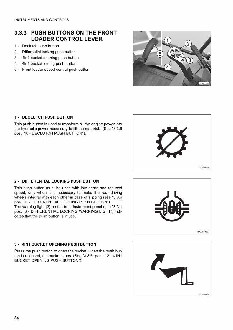
INSTRUMENTS AND CONTROLS
3.3.3 PUSH BUTTONS ON THE FRONT LOADER CONTROL LEVER
1 - Declutch push button
2 - Differential locking push button
3 - 4in1 bucket opening push button
4 - 4in1 bucket folding push button
5 - Front loader speed control push button
1 - DECLUTCH PUSH BUTTON
This push button is used to transform all the engine power intothe hydraulic power necessary to lift the material. (See "3.3.6pos. 10 - DECLUTCH PUSH BUTTON").
2 - DIFFERENTIAL LOCKING PUSH BUTTON
This push button must be used with low gears and reducedspeed, only when it is necessary to make the rear drivingwheels integral with each other in case of slipping (see "3.3.6pos. 11 - DIFFERENTIAL LOCKING PUSH BUTTON").The warning light (3) on the front instrument panel (see "3.3.1pos. 3 - DIFFERENTIAL LOCKING WARNING LIGHT") indi-cates that the push button is in use.
3 - 4IN1 BUCKET OPENING PUSH BUTTON
Press the push button to open the bucket; when the push but-ton is released, the bucket stops. (See "3.3.6 pos. 12 - 4 IN1BUCKET OPENING PUSH BUTTON").
���� ��
�
�
��
�
�������
�����
����� �
84
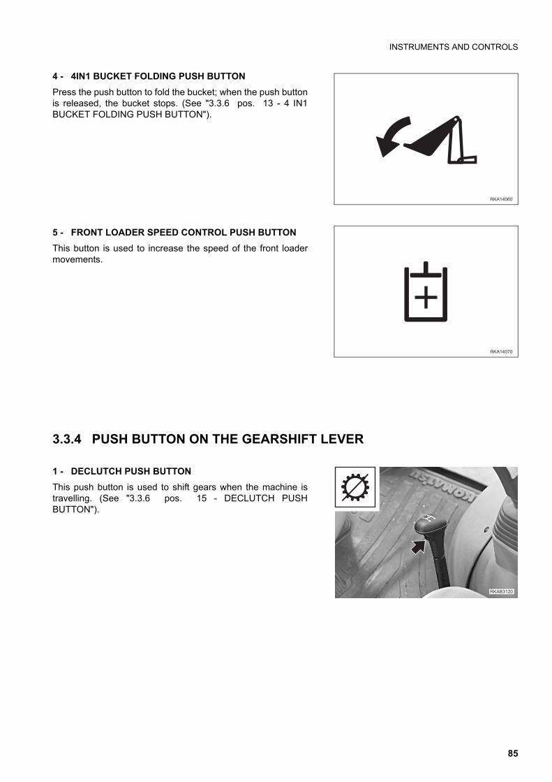
INSTRUMENTS AND CONTROLS
4 - 4IN1 BUCKET FOLDING PUSH BUTTON
Press the push button to fold the bucket; when the push buttonis released, the bucket stops. (See "3.3.6 pos. 13 - 4 IN1BUCKET FOLDING PUSH BUTTON").
5 - FRONT LOADER SPEED CONTROL PUSH BUTTON
This button is used to increase the speed of the front loadermovements.
3.3.4 PUSH BUTTON ON THE GEARSHIFT LEVER
1 - DECLUTCH PUSH BUTTON
This push button is used to shift gears when the machine istravelling. (See "3.3.6 pos. 15 - DECLUTCH PUSHBUTTON").
�������
�������
�������
85
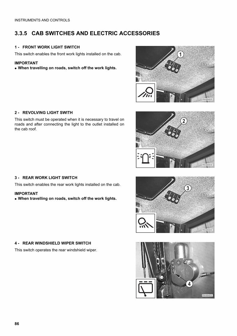
INSTRUMENTS AND CONTROLS
3.3.5 CAB SWITCHES AND ELECTRIC ACCESSORIES
1 - FRONT WORK LIGHT SWITCH
This switch enables the front work lights installed on the cab.
IMPORTANTq When travelling on roads, switch off the work lights.
2 - REVOLVING LIGHT SWITH
This switch must be operated when it is necessary to travel onroads and after connecting the light to the outlet installed onthe cab roof.
3 - REAR WORK LIGHT SWITCH
This switch enables the rear work lights installed on the cab.
IMPORTANTq When travelling on roads, switch off the work lights.
4 - REAR WINDSHIELD WIPER SWITCH
This switch operates the rear windshield wiper.
��������
�
��������
�
��������
�
������ �
�
86
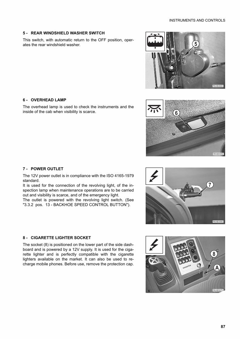
INSTRUMENTS AND CONTROLS
5 - REAR WINDSHIELD WASHER SWITCH
This switch, with automatic return to the OFF position, oper-ates the rear windshield washer.
6 - OVERHEAD LAMP
The overhead lamp is used to check the instruments and theinside of the cab when visibility is scarce.
7 - POWER OUTLET
The 12V power outlet is in compliance with the ISO 4165-1979standard.It is used for the connection of the revolving light, of the in-spection lamp when maintenance operations are to be carriedout and visibility is scarce, and of the emergency light.The outlet is powered with the revolving light switch. (See"3.3.2 pos. 13 - BACKHOE SPEED CONTROL BUTTON").
8 - CIGARETTE LIGHTER SOCKET
The socket (8) is positioned on the lower part of the side dash-board and is powered by a 12V supply. It is used for the ciga-rette lighter and is perfectly compatible with the cigarettelighters available on the market. It can also be used to re-charge mobile phones. Before use, remove the protection cap.
��������
�
������ �
��������
�
��������
�
"
87
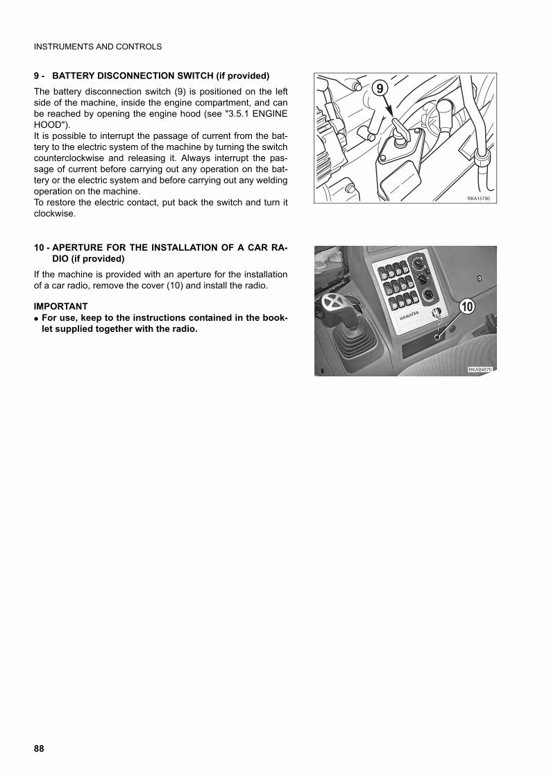
INSTRUMENTS AND CONTROLS
9 - BATTERY DISCONNECTION SWITCH (if provided)
The battery disconnection switch (9) is positioned on the leftside of the machine, inside the engine compartment, and canbe reached by opening the engine hood (see "3.5.1 ENGINEHOOD").It is possible to interrupt the passage of current from the bat-tery to the electric system of the machine by turning the switchcounterclockwise and releasing it. Always interrupt the pas-sage of current before carrying out any operation on the bat-tery or the electric system and before carrying out any weldingoperation on the machine.To restore the electric contact, put back the switch and turn itclockwise.
10 - APERTURE FOR THE INSTALLATION OF A CAR RA-DIO (if provided)
If the machine is provided with an aperture for the installationof a car radio, remove the cover (10) and install the radio.
IMPORTANTq For use, keep to the instructions contained in the book-
let supplied together with the radio.
��� ���
!
��������
��
88
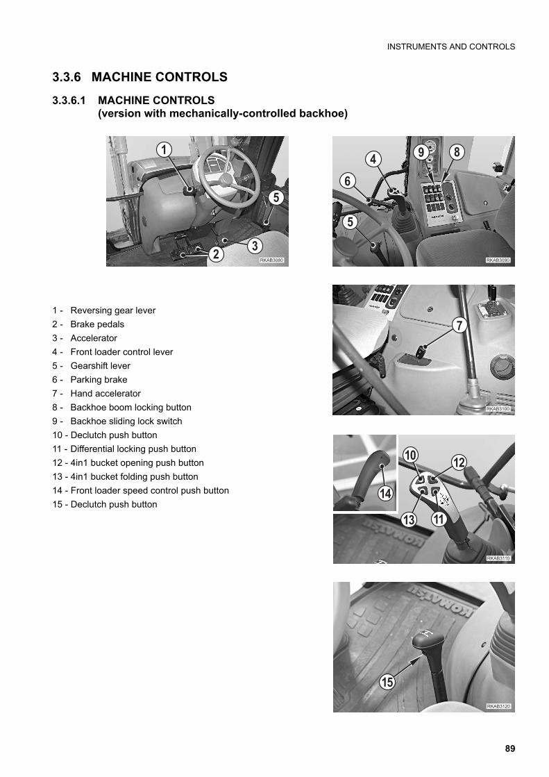
INSTRUMENTS AND CONTROLS
3.3.6 MACHINE CONTROLS
3.3.6.1 MACHINE CONTROLS (version with mechanically-controlled backhoe)
1 - Reversing gear lever
2 - Brake pedals
3 - Accelerator
4 - Front loader control lever
5 - Gearshift lever
6 - Parking brake
7 - Hand accelerator
8 - Backhoe boom locking button
9 - Backhoe sliding lock switch
10 - Declutch push button
11 - Differential locking push button
12 - 4in1 bucket opening push button
13 - 4in1 bucket folding push button
14 - Front loader speed control push button
15 - Declutch push button
��������
�
� !
"
�������
�
�������
�
�
��
������
��
����
����
�������
��
89
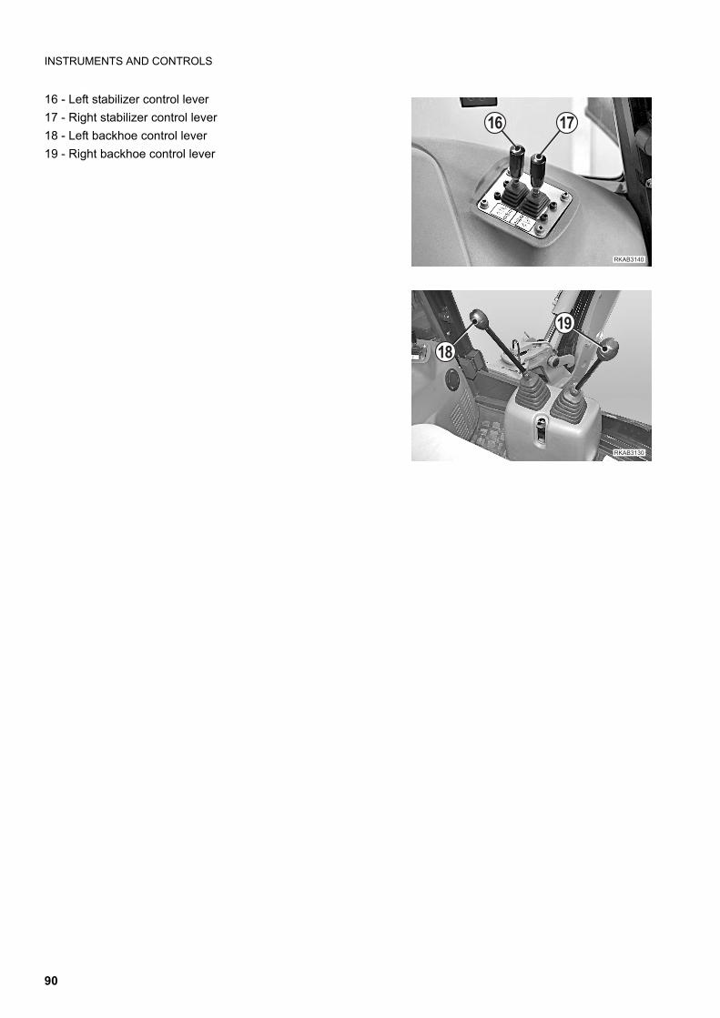
INSTRUMENTS AND CONTROLS
16 - Left stabilizer control lever
17 - Right stabilizer control lever
18 - Left backhoe control lever
19 - Right backhoe control lever
�������
�!
�"
�������
� ��
90
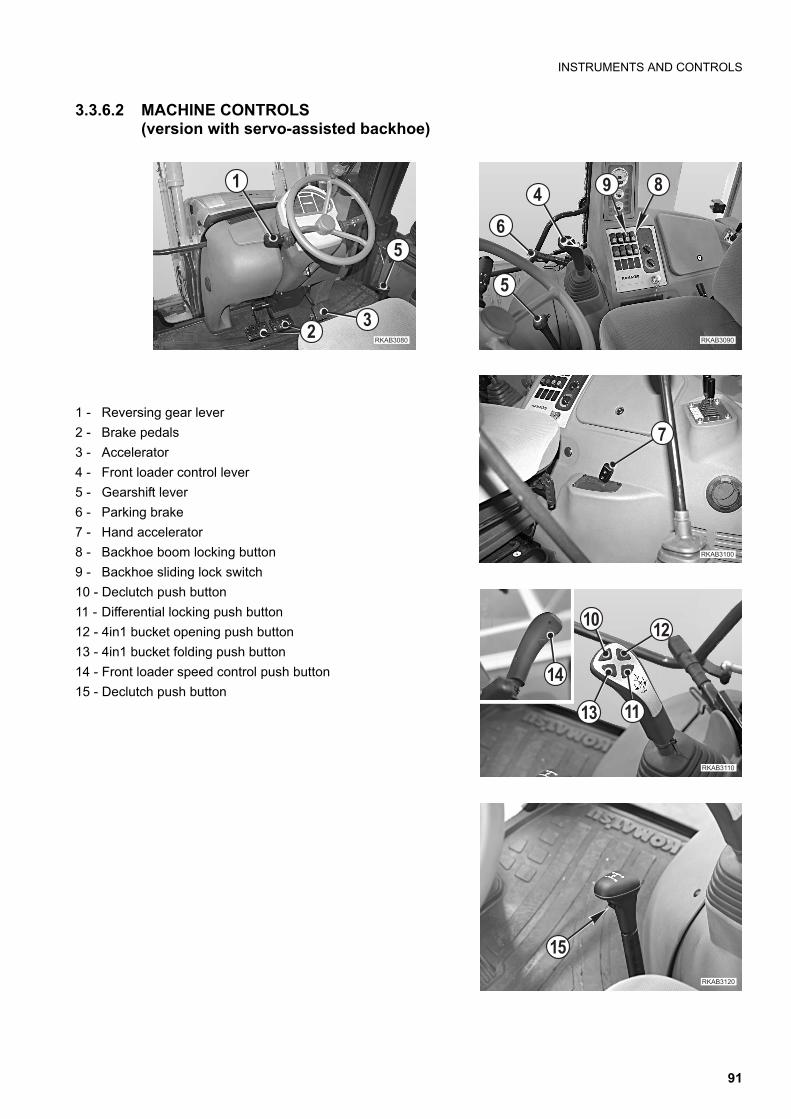
INSTRUMENTS AND CONTROLS
3.3.6.2 MACHINE CONTROLS(version with servo-assisted backhoe)
1 - Reversing gear lever
2 - Brake pedals
3 - Accelerator
4 - Front loader control lever
5 - Gearshift lever
6 - Parking brake
7 - Hand accelerator
8 - Backhoe boom locking button
9 - Backhoe sliding lock switch
10 - Declutch push button
11 - Differential locking push button
12 - 4in1 bucket opening push button
13 - 4in1 bucket folding push button
14 - Front loader speed control push button
15 - Declutch push button
��������
�
� !
"
�������
�
�������
�
�
��
������
��
����
����
�������
��
91

INSTRUMENTS AND CONTROLS
16 - Left stabilizer control switch
17 - Right stabilizer control switch
18 - Left backhoe control lever
19 - Right backhoe control lever
20 - Pattern change control lever (if provided and only for theversion with servo-assisted backhoe)
�������
� ��
��� �
�" �!��
92
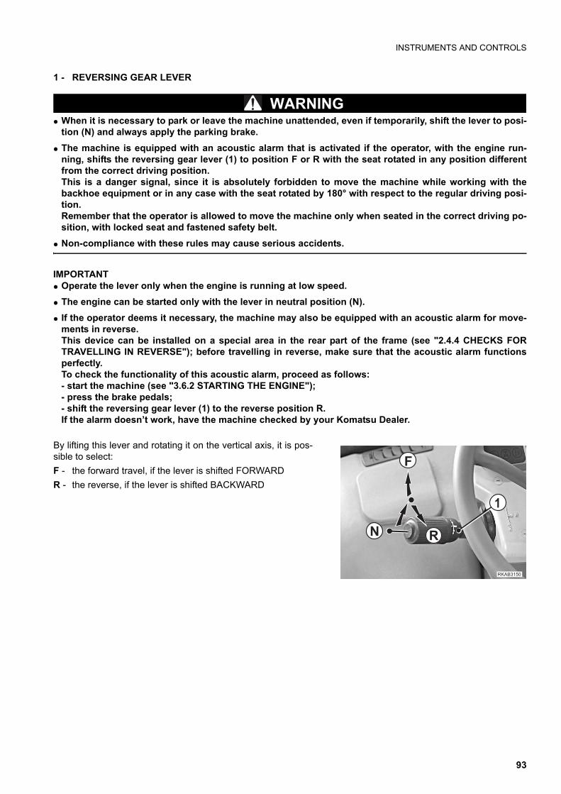
INSTRUMENTS AND CONTROLS
1 - REVERSING GEAR LEVER
WARNINGq When it is necessary to park or leave the machine unattended, even if temporarily, shift the lever to posi-
tion (N) and always apply the parking brake.
q The machine is equipped with an acoustic alarm that is activated if the operator, with the engine run-ning, shifts the reversing gear lever (1) to position F or R with the seat rotated in any position differentfrom the correct driving position.This is a danger signal, since it is absolutely forbidden to move the machine while working with thebackhoe equipment or in any case with the seat rotated by 180° with respect to the regular driving posi-tion. Remember that the operator is allowed to move the machine only when seated in the correct driving po-sition, with locked seat and fastened safety belt.
q Non-compliance with these rules may cause serious accidents.
IMPORTANTq Operate the lever only when the engine is running at low speed.
q The engine can be started only with the lever in neutral position (N).
q If the operator deems it necessary, the machine may also be equipped with an acoustic alarm for move-ments in reverse.This device can be installed on a special area in the rear part of the frame (see "2.4.4 CHECKS FORTRAVELLING IN REVERSE"); before travelling in reverse, make sure that the acoustic alarm functionsperfectly.To check the functionality of this acoustic alarm, proceed as follows:- start the machine (see "3.6.2 STARTING THE ENGINE");- press the brake pedals;- shift the reversing gear lever (1) to the reverse position R.If the alarm doesn’t work, have the machine checked by your Komatsu Dealer.
By lifting this lever and rotating it on the vertical axis, it is pos-sible to select:
F - the forward travel, if the lever is shifted FORWARD
R - the reverse, if the lever is shifted BACKWARD
�
�
��
����� �
93
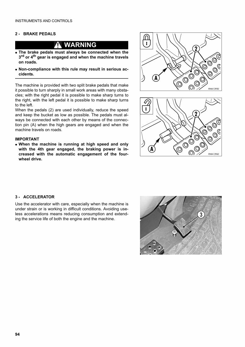
INSTRUMENTS AND CONTROLS
2 - BRAKE PEDALS
WARNINGq The brake pedals must always be connected when the
3rd or 4th gear is engaged and when the machine travelson roads.
q Non-compliance with this rule may result in serious ac-cidents.
The machine is provided with two split brake pedals that makeit possible to turn sharply in small work areas with many obsta-cles; with the right pedal it is possible to make sharp turns tothe right, with the left pedal it is possible to make sharp turnsto the left.When the pedals (2) are used individually, reduce the speedand keep the bucket as low as possible. The pedals must al-ways be connected with each other by means of the connec-tion pin (A) when the high gears are engaged and when themachine travels on roads.
IMPORTANTq When the machine is running at high speed and only
with the 4th gear engaged, the braking power is in-creased with the automatic engagement of the four-wheel drive.
3 - ACCELERATOR
Use the accelerator with care, especially when the machine isunder strain or is working in difficult conditions. Avoiding use-less accelerations means reducing consumption and extend-ing the service life of both the engine and the machine.
RWA13950
2
A
RWA13960
2
A
�
94
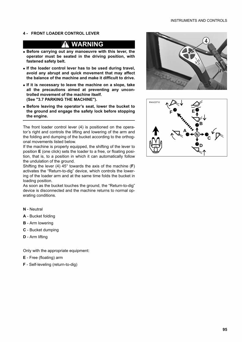
INSTRUMENTS AND CONTROLS
4 - FRONT LOADER CONTROL LEVER
WARNINGq Before carrying out any manoeuvre with this lever, the
operator must be seated in the driving position, withfastened safety belt.
q If the loader control lever has to be used during travel,avoid any abrupt and quick movement that may affectthe balance of the machine and make it difficult to drive.
q If it is necessary to leave the machine on a slope, takeall the precautions aimed at preventing any uncon-trolled movement of the machine itself.(See "3.7 PARKING THE MACHINE").
q Before leaving the operator’s seat, lower the bucket tothe ground and engage the safety lock before stoppingthe engine.
The front loader control lever (4) is positioned on the opera-tor’s right and controls the lifting and lowering of the arm andthe folding and dumping of the bucket according to the orthog-onal movements listed below.If the machine is properly equipped, the shifting of the lever toposition E (one click) sets the loader to a free, or floating posi-tion, that is, to a position in which it can automatically followthe undulation of the ground.Shifting the lever (4) 45° towards the axis of the machine (F)activates the “Return-to-dig” device, which controls the lower-ing of the loader arm and at the same time folds the bucket inloading position.As soon as the bucket touches the ground, the “Return-to-dig”device is disconnected and the machine returns to normal op-erating conditions.
N - Neutral
A - Bucket folding
B - Arm lowering
C - Bucket dumping
D - Arm lifting
Only with the appropriate equipment:
E - Free (floating) arm
F - Self-leveling (return-to-dig)
�
A
B
C
D
N
E
RWA33710
F
95
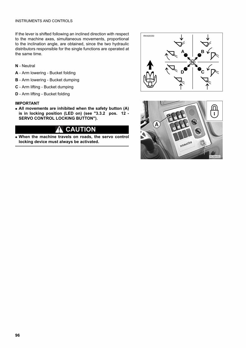
INSTRUMENTS AND CONTROLS
If the lever is shifted following an inclined direction with respectto the machine axes, simultaneous movements, proportionalto the inclination angle, are obtained, since the two hydraulicdistributors responsible for the single functions are operated atthe same time.
N - Neutral
A - Arm lowering - Bucket folding
B - Arm lowering - Bucket dumping
C - Arm lifting - Bucket dumping
D - Arm lifting - Bucket folding
IMPORTANTq All movements are inhibited when the safety button (A)
is in locking position (LED on) (see "3.3.2 pos. 12 -SERVO CONTROL LOCKING BUTTON").
CAUTIONq When the machine travels on roads, the servo control
locking device must always be activated.
D
A B
C
N
RWA00550
������ �
�
96

INSTRUMENTS AND CONTROLS
5 - GEARSHIFT LEVER
WARNINGq Since no mechanical connection is provided between
the gearbox and the engine, if the machine is parked ona slope it can move freely even with engaged gears; forthis reason, always apply the parking brake, in order toavoid any damage.
q Engage the gears only with the engine running at lowspeed.
q Avoid shifting up when using the machine for heavy-du-ty applications.
q Always shift the lever to the neutral position (N) whenparking or leaving the machine unattended, even if tem-porarily.
By means of the lever (5) it is possible to engage one of thefour available gears, which are arranged according to the dia-gram.The choice of the gear to be engaged is up to the operator; it isadvisable to use the low gears for heavy-duty applications andto use the high gears for movements on flat surfaces or to trav-el at high speed.This precaution serves to protect the converter unit from dan-gerous overheatings.
IMPORTANTq During normal travel, the gears can be shifted up or
down with the declutch push button (15) pressed.(See "3.3.6 pos. 15 - DECLUTCH PUSH BUTTON").
q Before shifting down, decelerate by putting on thebrakes.
������
�
��
1
2
3
4
N
RWA03270
97
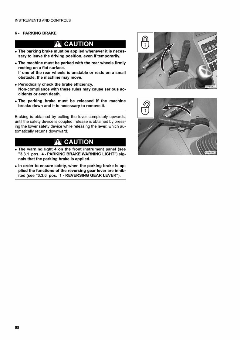
INSTRUMENTS AND CONTROLS
6 - PARKING BRAKE
CAUTIONq The parking brake must be applied whenever it is neces-
sary to leave the driving position, even if temporarily.
q The machine must be parked with the rear wheels firmlyresting on a flat surface.If one of the rear wheels is unstable or rests on a smallobstacle, the machine may move.
q Periodically check the brake efficiency.Non-compliance with these rules may cause serious ac-cidents or even death.
q The parking brake must be released if the machinebreaks down and it is necessary to remove it.
Braking is obtained by pulling the lever completely upwards,until the safety device is coupled; release is obtained by press-ing the lower safety device while releasing the lever, which au-tomatically returns downward.
CAUTIONq The warning light 4 on the front instrument panel (see
"3.3.1 pos. 4 - PARKING BRAKE WARNING LIGHT") sig-nals that the parking brake is applied.
q In order to ensure safety, when the parking brake is ap-plied the functions of the reversing gear lever are inhib-ited (see "3.3.6 pos. 1 - REVERSING GEAR LEVER").
�������
������
98
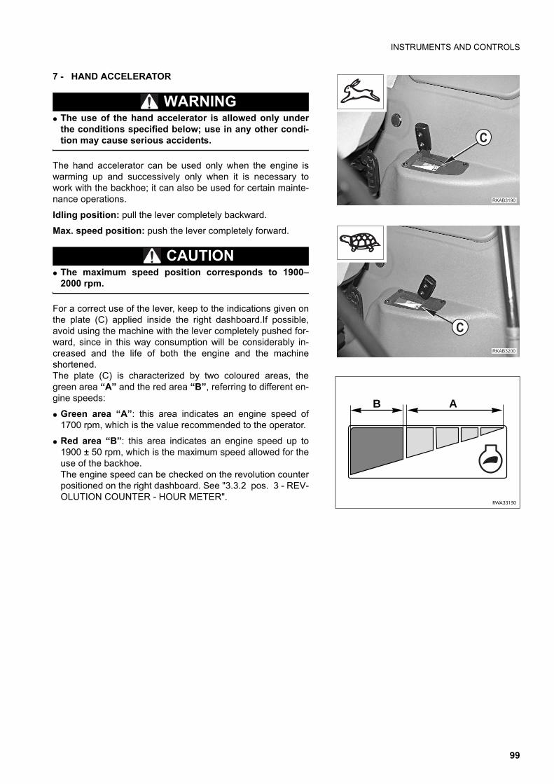
INSTRUMENTS AND CONTROLS
7 - HAND ACCELERATOR
WARNINGq The use of the hand accelerator is allowed only under
the conditions specified below; use in any other condi-tion may cause serious accidents.
The hand accelerator can be used only when the engine iswarming up and successively only when it is necessary towork with the backhoe; it can also be used for certain mainte-nance operations.
Idling position: pull the lever completely backward.
Max. speed position: push the lever completely forward.
CAUTIONq The maximum speed position corresponds to 1900–
2000 rpm.
For a correct use of the lever, keep to the indications given onthe plate (C) applied inside the right dashboard.If possible,avoid using the machine with the lever completely pushed for-ward, since in this way consumption will be considerably in-creased and the life of both the engine and the machineshortened.The plate (C) is characterized by two coloured areas, thegreen area “A” and the red area “B”, referring to different en-gine speeds:
q Green area “A”: this area indicates an engine speed of1700 rpm, which is the value recommended to the operator.
q Red area “B”: this area indicates an engine speed up to1900 ± 50 rpm, which is the maximum speed allowed for theuse of the backhoe.The engine speed can be checked on the revolution counterpositioned on the right dashboard. See "3.3.2 pos. 3 - REV-OLUTION COUNTER - HOUR METER".
�������
��������
AB
RWA33150
99
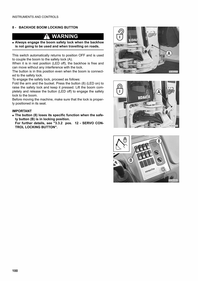
INSTRUMENTS AND CONTROLS
8 - BACKHOE BOOM LOCKING BUTTON
WARNINGq Always engage the boom safety lock when the backhoe
is not going to be used and when travelling on roads.
This switch automatically returns to position OFF and is usedto couple the boom to the safety lock (A).When it is in rest position (LED off), the backhoe is free andcan move without any interference with the lock.The button is in this position even when the boom is connect-ed to the safety lock.To engage the safety lock, proceed as follows:Fold the arm and the bucket. Press the button (8) (LED on) toraise the safety lock and keep it pressed. Lift the boom com-pletely and release the button (LED off) to engage the safetylock to the boom.Before moving the machine, make sure that the lock is proper-ly positioned in its seat.
IMPORTANTq The button (8) loses its specific function when the safe-
ty button (B) is in locking position.For further details, see "3.3.2 pos. 12 - SERVO CON-TROL LOCKING BUTTON".
��������
�
"
�������
�
��������
�
100
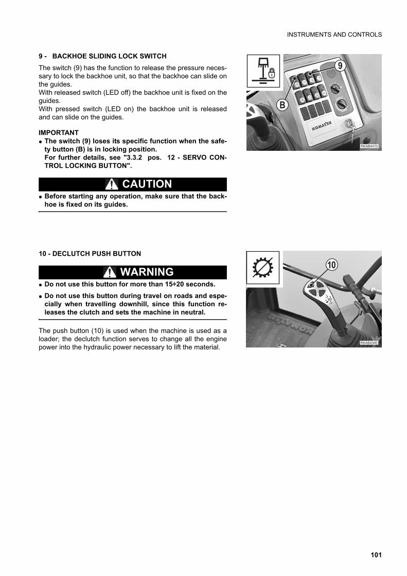
INSTRUMENTS AND CONTROLS
9 - BACKHOE SLIDING LOCK SWITCH
The switch (9) has the function to release the pressure neces-sary to lock the backhoe unit, so that the backhoe can slide onthe guides.With released switch (LED off) the backhoe unit is fixed on theguides. With pressed switch (LED on) the backhoe unit is releasedand can slide on the guides.
IMPORTANTq The switch (9) loses its specific function when the safe-
ty button (B) is in locking position.For further details, see "3.3.2 pos. 12 - SERVO CON-TROL LOCKING BUTTON".
CAUTIONq Before starting any operation, make sure that the back-
hoe is fixed on its guides.
10 - DECLUTCH PUSH BUTTON
WARNINGq Do not use this button for more than 15÷20 seconds.
q Do not use this button during travel on roads and espe-cially when travelling downhill, since this function re-leases the clutch and sets the machine in neutral.
The push button (10) is used when the machine is used as aloader; the declutch function serves to change all the enginepower into the hydraulic power necessary to lift the material.
��������
�
!
��������
��
101
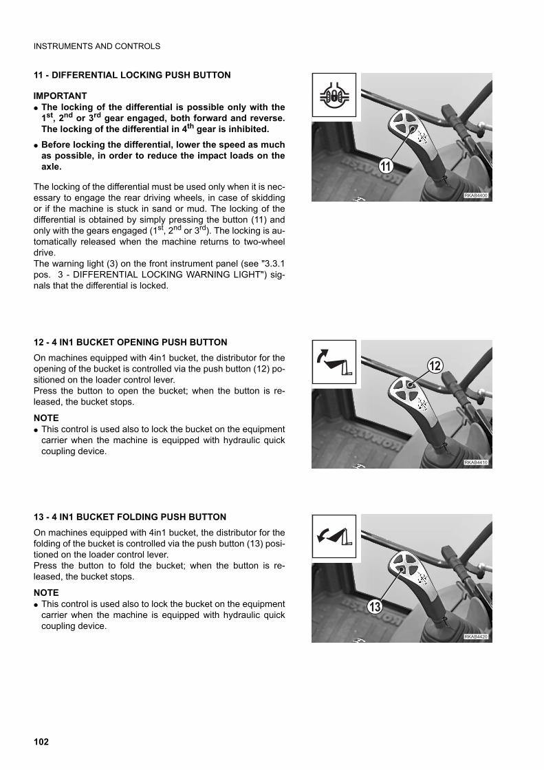
INSTRUMENTS AND CONTROLS
11 - DIFFERENTIAL LOCKING PUSH BUTTON
IMPORTANTq The locking of the differential is possible only with the
1st, 2nd or 3rd gear engaged, both forward and reverse.The locking of the differential in 4th gear is inhibited.
q Before locking the differential, lower the speed as muchas possible, in order to reduce the impact loads on theaxle.
The locking of the differential must be used only when it is nec-essary to engage the rear driving wheels, in case of skiddingor if the machine is stuck in sand or mud. The locking of thedifferential is obtained by simply pressing the button (11) andonly with the gears engaged (1st, 2nd or 3rd). The locking is au-tomatically released when the machine returns to two-wheeldrive.The warning light (3) on the front instrument panel (see "3.3.1pos. 3 - DIFFERENTIAL LOCKING WARNING LIGHT") sig-nals that the differential is locked.
12 - 4 IN1 BUCKET OPENING PUSH BUTTON
On machines equipped with 4in1 bucket, the distributor for theopening of the bucket is controlled via the push button (12) po-sitioned on the loader control lever.Press the button to open the bucket; when the button is re-leased, the bucket stops.
NOTEq This control is used also to lock the bucket on the equipment
carrier when the machine is equipped with hydraulic quickcoupling device.
13 - 4 IN1 BUCKET FOLDING PUSH BUTTON
On machines equipped with 4in1 bucket, the distributor for thefolding of the bucket is controlled via the push button (13) posi-tioned on the loader control lever.Press the button to fold the bucket; when the button is re-leased, the bucket stops.
NOTEq This control is used also to lock the bucket on the equipment
carrier when the machine is equipped with hydraulic quickcoupling device.
��������
��
�������
��
��������
��
102
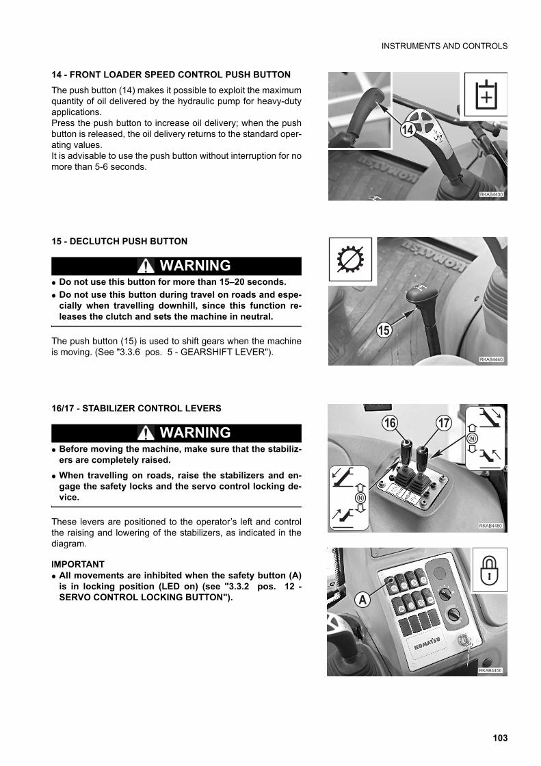
INSTRUMENTS AND CONTROLS
14 - FRONT LOADER SPEED CONTROL PUSH BUTTON
The push button (14) makes it possible to exploit the maximumquantity of oil delivered by the hydraulic pump for heavy-dutyapplications.Press the push button to increase oil delivery; when the pushbutton is released, the oil delivery returns to the standard oper-ating values.It is advisable to use the push button without interruption for nomore than 5-6 seconds.
15 - DECLUTCH PUSH BUTTON
WARNINGq Do not use this button for more than 15–20 seconds.
q Do not use this button during travel on roads and espe-cially when travelling downhill, since this function re-leases the clutch and sets the machine in neutral.
The push button (15) is used to shift gears when the machineis moving. (See "3.3.6 pos. 5 - GEARSHIFT LEVER").
16/17 - STABILIZER CONTROL LEVERS
WARNINGq Before moving the machine, make sure that the stabiliz-
ers are completely raised.
q When travelling on roads, raise the stabilizers and en-gage the safety locks and the servo control locking de-vice.
These levers are positioned to the operator’s left and controlthe raising and lowering of the stabilizers, as indicated in thediagram.
IMPORTANTq All movements are inhibited when the safety button (A)
is in locking position (LED on) (see "3.3.2 pos. 12 -SERVO CONTROL LOCKING BUTTON").
��������
��
��������
��
�������
�
�
� ��
������ �
�
103
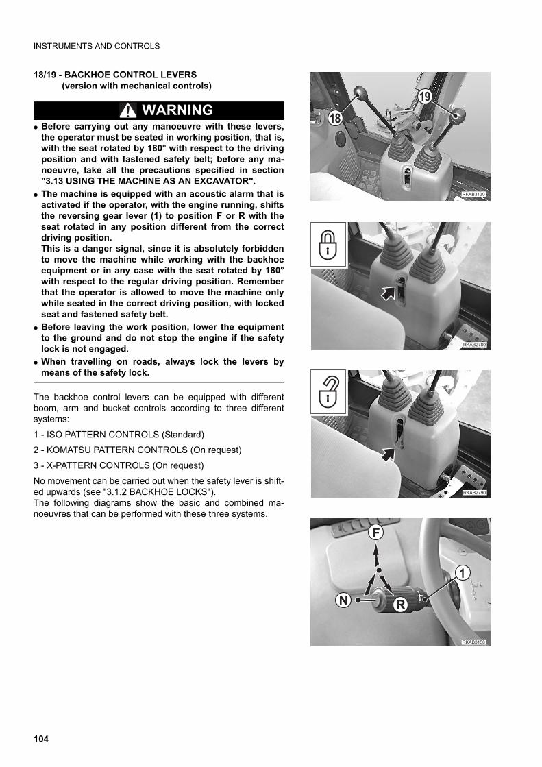
INSTRUMENTS AND CONTROLS
18/19 - BACKHOE CONTROL LEVERS(version with mechanical controls)
WARNINGq Before carrying out any manoeuvre with these levers,
the operator must be seated in working position, that is,with the seat rotated by 180° with respect to the drivingposition and with fastened safety belt; before any ma-noeuvre, take all the precautions specified in section"3.13 USING THE MACHINE AS AN EXCAVATOR".
q The machine is equipped with an acoustic alarm that isactivated if the operator, with the engine running, shiftsthe reversing gear lever (1) to position F or R with theseat rotated in any position different from the correctdriving position.This is a danger signal, since it is absolutely forbiddento move the machine while working with the backhoeequipment or in any case with the seat rotated by 180°with respect to the regular driving position. Rememberthat the operator is allowed to move the machine onlywhile seated in the correct driving position, with lockedseat and fastened safety belt.
q Before leaving the work position, lower the equipmentto the ground and do not stop the engine if the safetylock is not engaged.
q When travelling on roads, always lock the levers bymeans of the safety lock.
The backhoe control levers can be equipped with differentboom, arm and bucket controls according to three differentsystems:
1 - ISO PATTERN CONTROLS (Standard)
2 - KOMATSU PATTERN CONTROLS (On request)
3 - X-PATTERN CONTROLS (On request)
No movement can be carried out when the safety lever is shift-ed upwards (see "3.1.2 BACKHOE LOCKS"). The following diagrams show the basic and combined ma-noeuvres that can be performed with these three systems.
�������
�!
�"
�������
��������
�
�
��
����� �
104
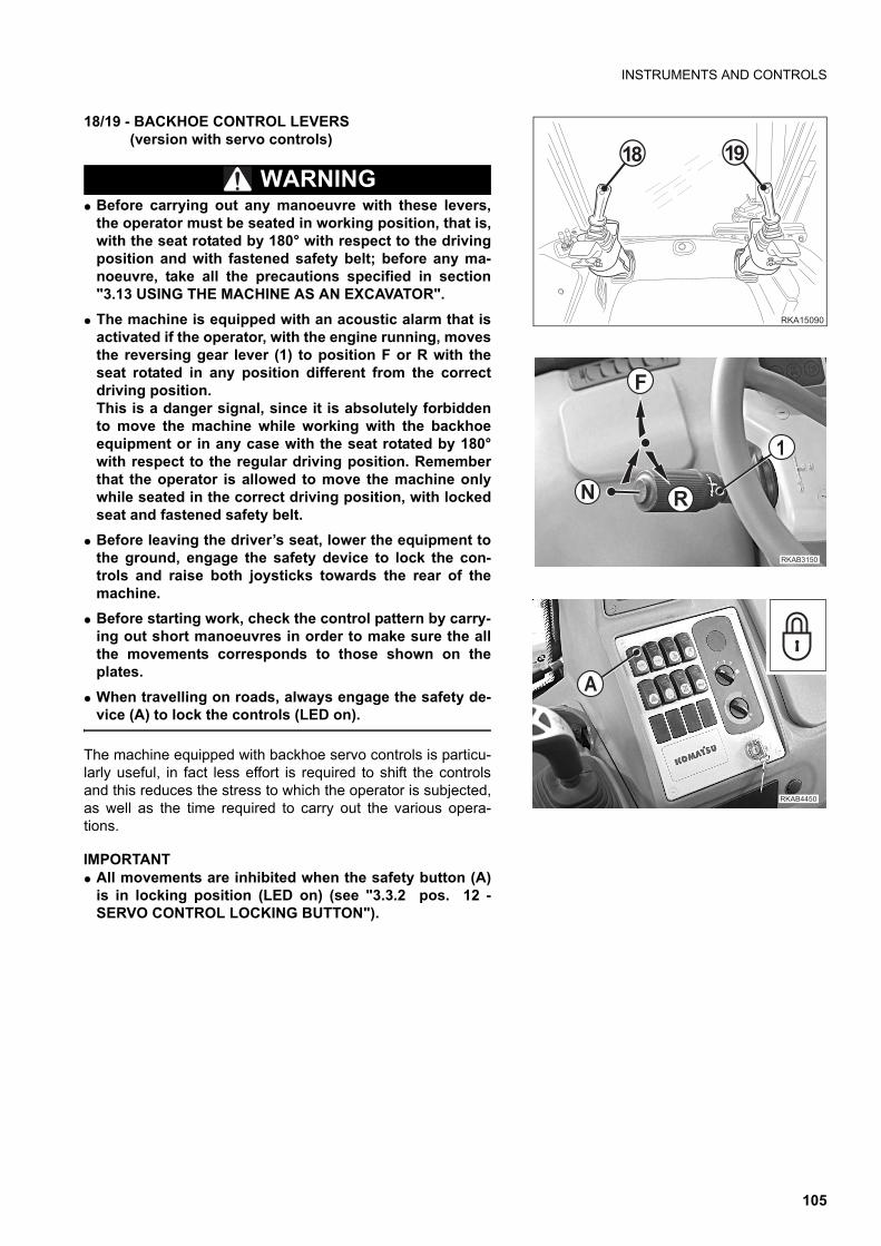
INSTRUMENTS AND CONTROLS
18/19 - BACKHOE CONTROL LEVERS (version with servo controls)
WARNINGq Before carrying out any manoeuvre with these levers,
the operator must be seated in working position, that is,with the seat rotated by 180° with respect to the drivingposition and with fastened safety belt; before any ma-noeuvre, take all the precautions specified in section"3.13 USING THE MACHINE AS AN EXCAVATOR".
q The machine is equipped with an acoustic alarm that isactivated if the operator, with the engine running, movesthe reversing gear lever (1) to position F or R with theseat rotated in any position different from the correctdriving position.This is a danger signal, since it is absolutely forbiddento move the machine while working with the backhoeequipment or in any case with the seat rotated by 180°with respect to the regular driving position. Rememberthat the operator is allowed to move the machine onlywhile seated in the correct driving position, with lockedseat and fastened safety belt.
q Before leaving the driver’s seat, lower the equipment tothe ground, engage the safety device to lock the con-trols and raise both joysticks towards the rear of themachine.
q Before starting work, check the control pattern by carry-ing out short manoeuvres in order to make sure the allthe movements corresponds to those shown on theplates.
q When travelling on roads, always engage the safety de-vice (A) to lock the controls (LED on).
The machine equipped with backhoe servo controls is particu-larly useful, in fact less effort is required to shift the controlsand this reduces the stress to which the operator is subjected,as well as the time required to carry out the various opera-tions.
IMPORTANTq All movements are inhibited when the safety button (A)
is in locking position (LED on) (see "3.3.2 pos. 12 -SERVO CONTROL LOCKING BUTTON").
��� �
�" �!
�
�
��
����� �
������ �
�
105
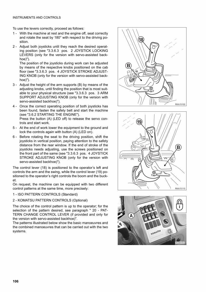
INSTRUMENTS AND CONTROLS
To use the levers correctly, proceed as follows:
1 - With the machine at rest and the engine off, seat correctlyand rotate the seat by 180° with respect to the driving po-sition.
2 - Adjust both joysticks until they reach the desired operat-ing position (see "3.3.6.3 pos. 2 JOYSTICK LOCKINGLEVERS (only for the version with servo-assisted back-hoe)").The position of the joysticks during work can be adjustedby means of the respective knobs positioned on the cabfloor (see "3.3.6.3 pos. 4 JOYSTICK STROKE ADJUST-ING KNOB (only for the version with servo-assisted back-hoe)").
3 - Adjust the height of the arm supports (B) by means of theadjusting knobs, until finding the position that is most suit-able to your physical structure (see "3.3.6.3 pos. 3 ARMSUPPORT ADJUSTING KNOB (only for the version withservo-assisted backhoe)").
4 - Once the correct operating position of both joysticks hasbeen found, fasten the safety belt and start the machine(see "3.6.2 STARTING THE ENGINE").Press the button (A) (LED off) to release the servo con-trols and start work.
5 - At the end of work lower the equipment to the ground andlock the controls again with button (A) (LED on).
6 - Before rotating the seat to the driving position, shift thejoysticks in vertical position, paying attention to the safetydistance from the rear window. If the end of stroke of thejoysticks needs adjusting, use the screws positioned onthe front part of the same (see "3.3.6.3 pos. 4 JOYSTICKSTROKE ADJUSTING KNOB (only for the version withservo-assisted backhoe)").
The control lever (18) is positioned to the operator’s left andcontrols the arm and the swing, while the control lever (19) po-sitioned to the operator’s right controls the boom and the buck-et.On request, the machine can be equipped with two differentcontrol patterns at the same time, more precisely:
1 - ISO PATTERN CONTROLS (Standard)
2 - KOMATSU PATTERN CONTROLS (Optional)
The choice of the control pattern is up to the operator; for theselection of the pattern desired, see paragraph " 20 - PAT-TERN CHANGE CONTROL LEVER (if provided and only forthe version with servo-assisted backhoe)".The patterns illustrated below show the basic manoeuvres andthe combined manoeuvres that can be carried out with the twosystems.
��� �
�"
�
��� ��
�!
�
������ �
�
106
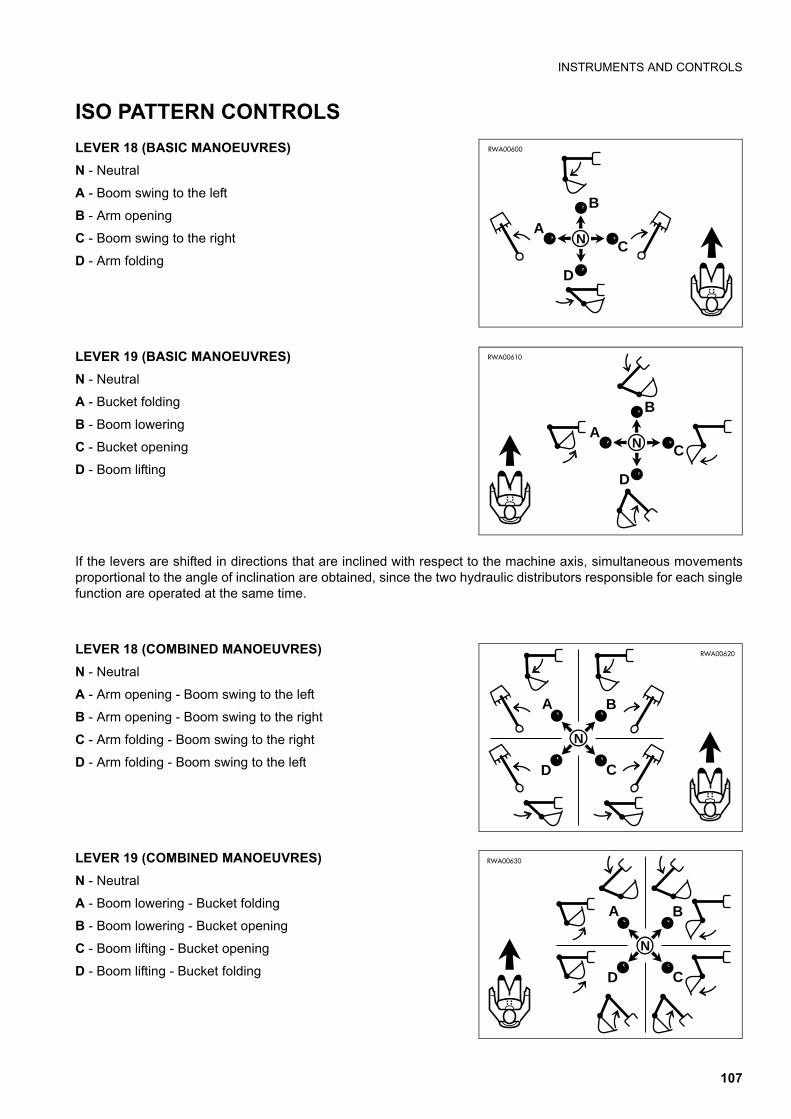
INSTRUMENTS AND CONTROLS
ISO PATTERN CONTROLS
LEVER 18 (BASIC MANOEUVRES)
N - Neutral
A - Boom swing to the left
B - Arm opening
C - Boom swing to the right
D - Arm folding
LEVER 19 (BASIC MANOEUVRES)
N - Neutral
A - Bucket folding
B - Boom lowering
C - Bucket opening
D - Boom lifting
If the levers are shifted in directions that are inclined with respect to the machine axis, simultaneous movementsproportional to the angle of inclination are obtained, since the two hydraulic distributors responsible for each singlefunction are operated at the same time.
LEVER 18 (COMBINED MANOEUVRES)
N - Neutral
A - Arm opening - Boom swing to the left
B - Arm opening - Boom swing to the right
C - Arm folding - Boom swing to the right
D - Arm folding - Boom swing to the left
LEVER 19 (COMBINED MANOEUVRES)
N - Neutral
A - Boom lowering - Bucket folding
B - Boom lowering - Bucket opening
C - Boom lifting - Bucket opening
D - Boom lifting - Bucket folding
A
B
C
D
N
RWA00600
A
B
C
D
N
RWA00610
RWA00620
D
A B
C
N
RWA00630
N
D
A B
C
107

INSTRUMENTS AND CONTROLS
KOMATSU PATTERN CONTROLS
LEVER 18 (BASIC MANOEUVRES)
N - Neutral
A - Boom swing to the left
B - Boom lowering
C - Boom swing to the right
D - Boom lifting
LEVER 19 (BASIC MANOEUVRES)
N - Neutral
A - Bucket folding
B - Arm opening
C - Bucket opening
D - Arm folding
If the levers are shifted in directions that are inclined with respect to the machine axis, simultaneous movementsproportional to the angle of inclination are obtained, since the two hydraulic distributors responsible for each singlefunction are operated at the same time.
LEVER 18 (COMBINED MANOEUVRES)
N - Neutral
A - Boom lowering and swing to the left
B - Boom lowering and swing to the right
C - Boom lifting and swing to the right
D - Boom lifting and swing to the left
LEVER 19 (COMBINED MANOEUVRES)
N - Neutral
A - Arm opening - bucket folding
B - Arm opening - bucket opening
C - Arm folding - bucket opening
D - Arm folding - bucket folding
A
B
C
D
N
RWA00560
A
B
C
D
N
RWA00570
RWA00580
D
A B
C
N
RWA00590
N
D
A B
C
108
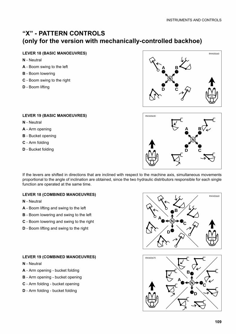
INSTRUMENTS AND CONTROLS
“X” - PATTERN CONTROLS (only for the version with mechanically-controlled backhoe)
LEVER 18 (BASIC MANOEUVRES)
N - Neutral
A - Boom swing to the left
B - Boom lowering
C - Boom swing to the right
D - Boom lifting
LEVER 19 (BASIC MANOEUVRES)
N - Neutral
A - Arm opening
B - Bucket opening
C - Arm folding
D - Bucket folding
If the levers are shifted in directions that are inclined with respect to the machine axis, simultaneous movementsproportional to the angle of inclination are obtained, since the two hydraulic distributors responsible for each singlefunction are operated at the same time.
LEVER 18 (COMBINED MANOEUVRES)
N - Neutral
A - Boom lifting and swing to the left
B - Boom lowering and swing to the left
C - Boom lowering and swing to the right
D - Boom lifting and swing to the right
LEVER 19 (COMBINED MANOEUVRES)
N - Neutral
A - Arm opening - bucket folding
B - Arm opening - bucket opening
C - Arm folding - bucket opening
D - Arm folding - bucket folding
RWA00640
D
A B
C
N
RWA00650
D
A B
C
N
RWA00660
A
B
C
D
N
RWA00670
A
B
C
D
N
109
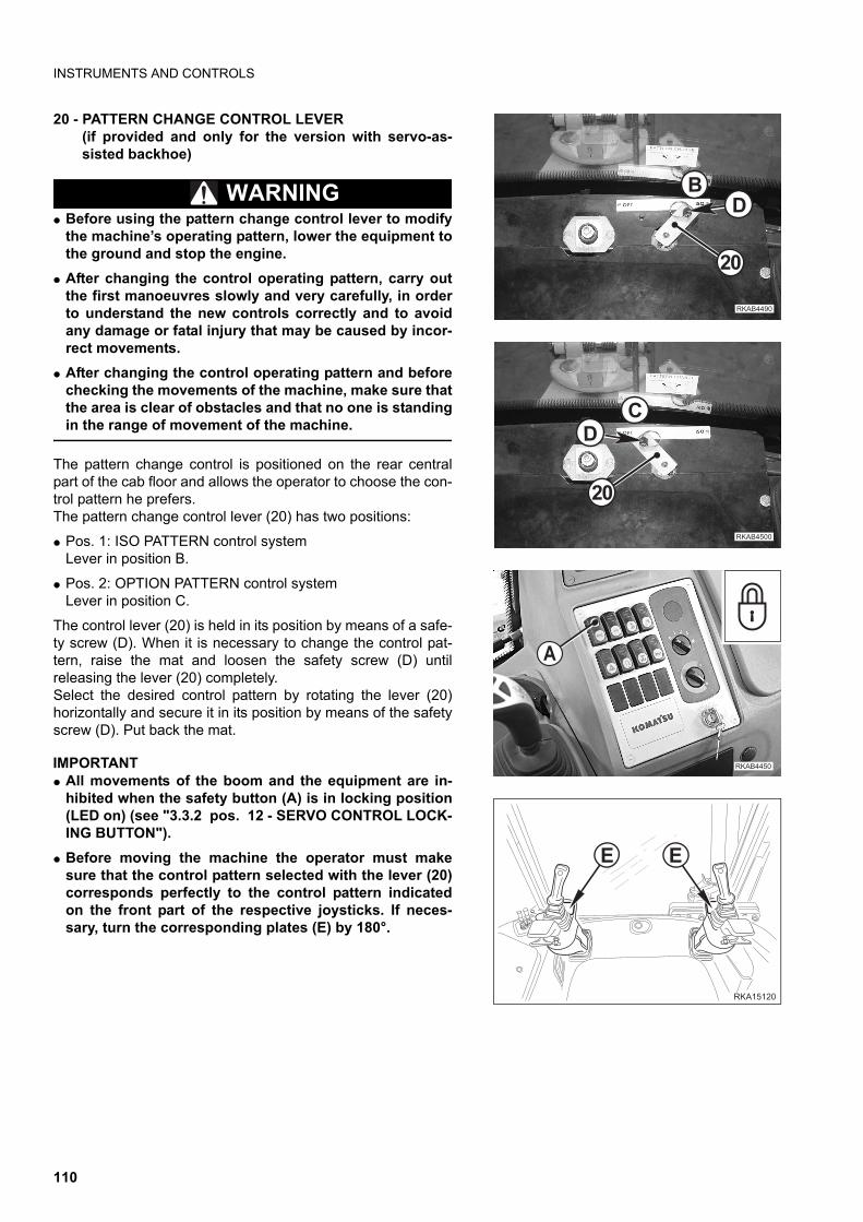
INSTRUMENTS AND CONTROLS
20 - PATTERN CHANGE CONTROL LEVER (if provided and only for the version with servo-as-sisted backhoe)
WARNINGq Before using the pattern change control lever to modify
the machine’s operating pattern, lower the equipment tothe ground and stop the engine.
q After changing the control operating pattern, carry outthe first manoeuvres slowly and very carefully, in orderto understand the new controls correctly and to avoidany damage or fatal injury that may be caused by incor-rect movements.
q After changing the control operating pattern and beforechecking the movements of the machine, make sure thatthe area is clear of obstacles and that no one is standingin the range of movement of the machine.
The pattern change control is positioned on the rear centralpart of the cab floor and allows the operator to choose the con-trol pattern he prefers.The pattern change control lever (20) has two positions:
q Pos. 1: ISO PATTERN control systemLever in position B.
q Pos. 2: OPTION PATTERN control systemLever in position C.
The control lever (20) is held in its position by means of a safe-ty screw (D). When it is necessary to change the control pat-tern, raise the mat and loosen the safety screw (D) untilreleasing the lever (20) completely.Select the desired control pattern by rotating the lever (20)horizontally and secure it in its position by means of the safetyscrew (D). Put back the mat.
IMPORTANTq All movements of the boom and the equipment are in-
hibited when the safety button (A) is in locking position(LED on) (see "3.3.2 pos. 12 - SERVO CONTROL LOCK-ING BUTTON").
q Before moving the machine the operator must makesure that the control pattern selected with the lever (20)corresponds perfectly to the control pattern indicatedon the front part of the respective joysticks. If neces-sary, turn the corresponding plates (E) by 180°.
��
��
��������
��
�
����� ��
������ �
�
��� ��
��
110
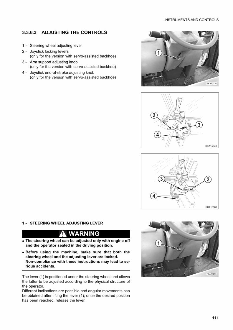
INSTRUMENTS AND CONTROLS
3.3.6.3 ADJUSTING THE CONTROLS
1 - Steering wheel adjusting lever
2 - Joystick locking levers(only for the version with servo-assisted backhoe)
3 - Arm support adjusting knob(only for the version with servo-assisted backhoe)
4 - Joystick end-of-stroke adjusting knob(only for the version with servo-assisted backhoe)
1 - STEERING WHEEL ADJUSTING LEVER
WARNINGq The steering wheel can be adjusted only with engine off
and the operator seated in the driving position.
q Before using the machine, make sure that both thesteering wheel and the adjusting lever are locked.Non-compliance with these instructions may lead to se-rious accidents.
The lever (1) is positioned under the steering wheel and allowsthe latter to be adjusted according to the physical structure ofthe operator.Different inclinations are possible and angular movements canbe obtained after lifting the lever (1); once the desired positionhas been reached, release the lever.
��������
�
��� ��
�
�
�
��� ��
��
�
��������
�
111
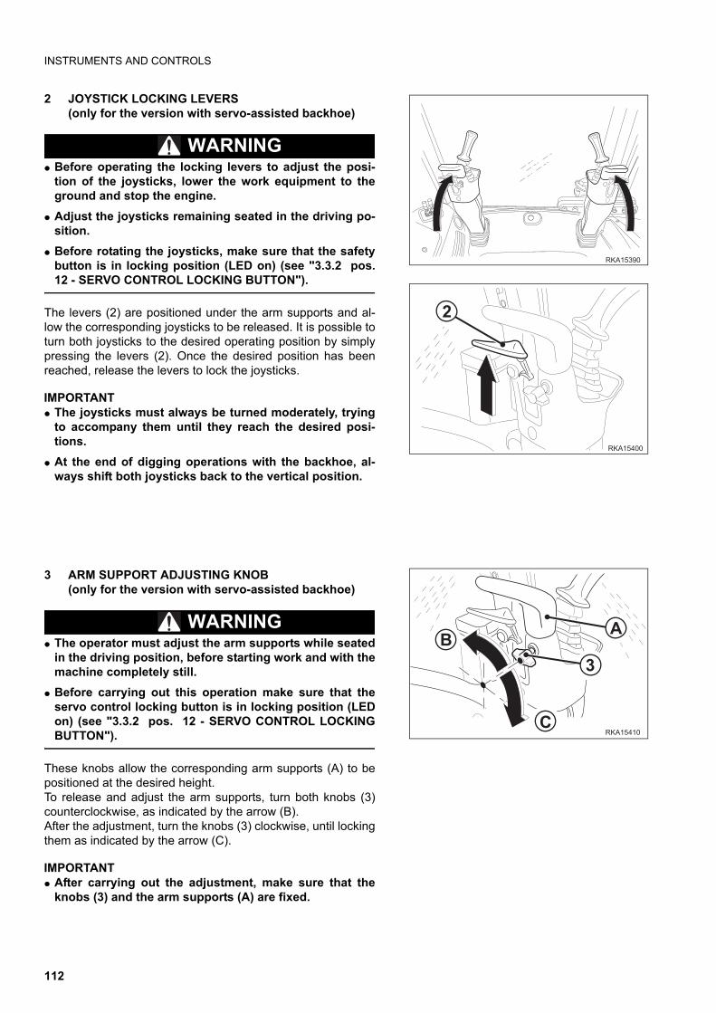
INSTRUMENTS AND CONTROLS
2 JOYSTICK LOCKING LEVERS(only for the version with servo-assisted backhoe)
WARNINGq Before operating the locking levers to adjust the posi-
tion of the joysticks, lower the work equipment to theground and stop the engine.
q Adjust the joysticks remaining seated in the driving po-sition.
q Before rotating the joysticks, make sure that the safetybutton is in locking position (LED on) (see "3.3.2 pos.12 - SERVO CONTROL LOCKING BUTTON").
The levers (2) are positioned under the arm supports and al-low the corresponding joysticks to be released. It is possible toturn both joysticks to the desired operating position by simplypressing the levers (2). Once the desired position has beenreached, release the levers to lock the joysticks.
IMPORTANTq The joysticks must always be turned moderately, trying
to accompany them until they reach the desired posi-tions.
q At the end of digging operations with the backhoe, al-ways shift both joysticks back to the vertical position.
3 ARM SUPPORT ADJUSTING KNOB(only for the version with servo-assisted backhoe)
WARNINGq The operator must adjust the arm supports while seated
in the driving position, before starting work and with themachine completely still.
q Before carrying out this operation make sure that theservo control locking button is in locking position (LEDon) (see "3.3.2 pos. 12 - SERVO CONTROL LOCKINGBUTTON").
These knobs allow the corresponding arm supports (A) to bepositioned at the desired height.To release and adjust the arm supports, turn both knobs (3)counterclockwise, as indicated by the arrow (B). After the adjustment, turn the knobs (3) clockwise, until lockingthem as indicated by the arrow (C).
IMPORTANTq After carrying out the adjustment, make sure that the
knobs (3) and the arm supports (A) are fixed.
��� ��
�
��� ���
�
��� ��
�
�
112
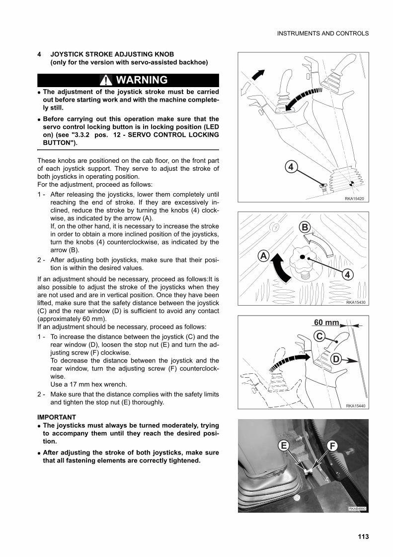
INSTRUMENTS AND CONTROLS
4 JOYSTICK STROKE ADJUSTING KNOB(only for the version with servo-assisted backhoe)
WARNINGq The adjustment of the joystick stroke must be carried
out before starting work and with the machine complete-ly still.
q Before carrying out this operation make sure that theservo control locking button is in locking position (LEDon) (see "3.3.2 pos. 12 - SERVO CONTROL LOCKINGBUTTON").
These knobs are positioned on the cab floor, on the front partof each joystick support. They serve to adjust the stroke ofboth joysticks in operating position.For the adjustment, proceed as follows:
1 - After releasing the joysticks, lower them completely untilreaching the end of stroke. If they are excessively in-clined, reduce the stroke by turning the knobs (4) clock-wise, as indicated by the arrow (A).If, on the other hand, it is necessary to increase the strokein order to obtain a more inclined position of the joysticks,turn the knobs (4) counterclockwise, as indicated by thearrow (B).
2 - After adjusting both joysticks, make sure that their posi-tion is within the desired values.
If an adjustment should be necessary, proceed as follows:It isalso possible to adjust the stroke of the joysticks when theyare not used and are in vertical position. Once they have beenlifted, make sure that the safety distance between the joystick(C) and the rear window (D) is sufficient to avoid any contact(approximately 60 mm).If an adjustment should be necessary, proceed as follows:
1 - To increase the distance between the joystick (C) and therear window (D), loosen the stop nut (E) and turn the ad-justing screw (F) clockwise.To decrease the distance between the joystick and therear window, turn the adjusting screw (F) counterclock-wise.Use a 17 mm hex wrench.
2 - Make sure that the distance complies with the safety limitsand tighten the stop nut (E) thoroughly.
IMPORTANTq The joysticks must always be turned moderately, trying
to accompany them until they reach the desired posi-tion.
q After adjusting the stroke of both joysticks, make surethat all fastening elements are correctly tightened.
��� ���
�
�
�
�
��� ���
�
��� ���
���
�
�������
� �
113
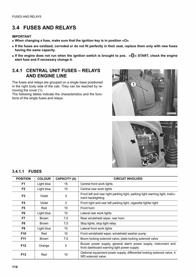
FUSES AND RELAYS
3.4 FUSES AND RELAYS
IMPORTANTq When changing a fuse, make sure that the ignition key is in position « ».
q If the fuses are oxidized, corroded or do not fit perfectly in their seat, replace them only with new fuseshaving the same capacity.
q If the engine does not run when the ignition switch is brought to pos. « » START, check the enginestart fuse and if necessary change it.
3.4.1 CENTRAL UNIT FUSES – RELAYS AND ENGINE LINE
The fuses and relays are grouped on a single base positionedin the right body side of the cab. They can be reached by re-moving the cover (1).The following tables indicate the characteristics and the func-tions of the single fuses and relays.
3.4.1.1 FUSES
��������
�
������ �
POSITION COLOUR CAPACITY (A) CIRCUIT INVOLVED
F1 Light blue 15 Central front work lights
F2 Light blue 15 Central rear work lights
F3 Violet 3Front left and rear right parking light, parking light warning light, instru-ment backlighting
F4 Violet 3 Front right and rear left parking light, cigarette lighter light
F5 Red 10 Front horn
F6 Light blue 15 Lateral rear work lights
F7 Brown 7,5 Rear windshield wiper, rear horn
F8 Brown 7,5 Stop lights, stop light relay
F9 Light blue 15 Lateral front work lights
F10 Red 10 Front windshield wiper, windshield washer pump
F11 Brown 7,5 Boom locking solenoid valve, plate locking solenoid valve
F12 Orange 5Buzzer power supply, general alarm power supply, instrument andfront dashboard warning light power supply
F13 Red 10Optional equipment power supply, differential locking solenoid valve, 4WD solenoid valve
114
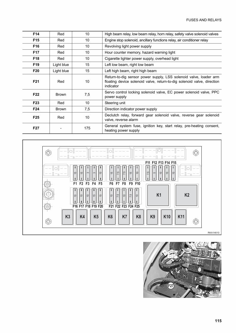
FUSES AND RELAYS
F14 Red 10 High beam relay, low beam relay, horn relay, safety valve solenoid valves
F15 Red 10 Engine stop solenoid, ancillary functions relay, air conditioner relay
F16 Red 10 Revolving light power supply
F17 Red 10 Hour counter memory, hazard warning light
F18 Red 10 Cigarette lighter power supply, overhead light
F19 Light blue 15 Left low beam, right low beam
F20 Light blue 15 Left high beam, right high beam
F21 Red 10Return-to-dig sensor power supply, LSS solenoid valve, loader armfloating device solenoid valve, return-to-dig solenoid valve, directionindicator
F22 Brown 7,5Servo control locking solenoid valve, EC power solenoid valve, PPCpower supply
F23 Red 10 Steering unit
F24 Brown 7,5 Direction indicator power supply
F25 Red 10Declutch relay, forward gear solenoid valve, reverse gear solenoidvalve, reverse alarm
F27 - 175General system fuse, ignition key, start relay, pre-heating consent,heating power supply
�� �� �� �� �� � �� �" �! ���
���
�� ��� ��" ��! ��� ��� ��� ��� ��� ���
��� ��� ��� ���
� � � �
� � � � �
� � �!
�!
�!
� �!
�!
�
#� #� #� # #� #" #!
#� #�
#�� #��
�
������
��������
���
115
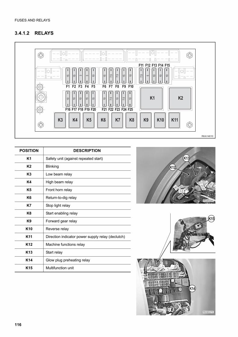
FUSES AND RELAYS
3.4.1.2 RELAYS
�� �� �� �� �� � �� �" �! ���
���
�� ��� ��" ��! ��� ��� ��� ��� ��� ���
��� ��� ��� ���� � � �
� � � � �
� � �!
�!
�!
� �!
�!
�
#� #� #� # #� #" #!
#� #�
#�� #��
�
������
��������
#��
#��
�������
#��
#��
POSITION DESCRIPTION
K1 Safety unit (against repeated start)
K2 Blinking
K3 Low beam relay
K4 High beam relay
K5 Front horn relay
K6 Return-to-dig relay
K7 Stop light relay
K8 Start enabling relay
K9 Forward gear relay
K10 Reverse relay
K11 Direction indicator power supply relay (declutch)
K12 Machine functions relay
K13 Start relay
K14 Glow plug preheating relay
K15 Multifunction unit
116
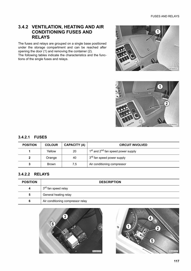
FUSES AND RELAYS
3.4.2 VENTILATION, HEATING AND AIR CONDITIONING FUSES AND RELAYS
The fuses and relays are grouped on a single base positionedunder the storage compartment and can be reached afteropening the door (1) and removing the container (2).The following tables indicate the characteristics and the func-tions of the single fuses and relays.
3.4.2.1 FUSES
3.4.2.2 RELAYS
�
�������
�
�������
�
POSITION COLOUR CAPACITY (A) CIRCUIT INVOLVED
1 Yellow 20 1st and 2nd fan speed power supply
2 Orange 40 3rd fan speed power supply
3 Brown 7,5 Air conditioning compressor
POSITION DESCRIPTION
4 3rd fan speed relay
5 General heating relay
6 Air conditioning compressor relay
��������
�
�
�
�
��������
�
117
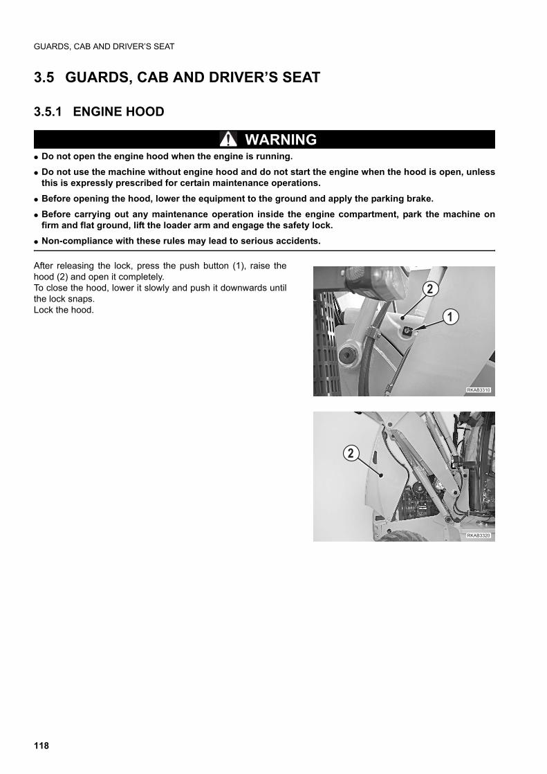
GUARDS, CAB AND DRIVER’S SEAT
3.5 GUARDS, CAB AND DRIVER’S SEAT
3.5.1 ENGINE HOOD
WARNINGq Do not open the engine hood when the engine is running.
q Do not use the machine without engine hood and do not start the engine when the hood is open, unlessthis is expressly prescribed for certain maintenance operations.
q Before opening the hood, lower the equipment to the ground and apply the parking brake.
q Before carrying out any maintenance operation inside the engine compartment, park the machine onfirm and flat ground, lift the loader arm and engage the safety lock.
q Non-compliance with these rules may lead to serious accidents.
After releasing the lock, press the push button (1), raise thehood (2) and open it completely.To close the hood, lower it slowly and push it downwards untilthe lock snaps.Lock the hood.
�������
�
�
��������
�
118
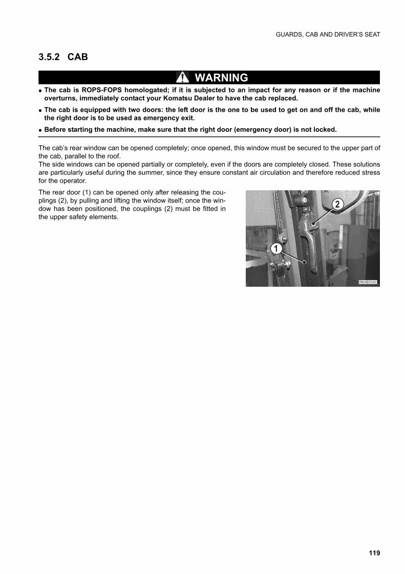
GUARDS, CAB AND DRIVER’S SEAT
3.5.2 CAB
WARNINGq The cab is ROPS-FOPS homologated; if it is subjected to an impact for any reason or if the machine
overturns, immediately contact your Komatsu Dealer to have the cab replaced.
q The cab is equipped with two doors: the left door is the one to be used to get on and off the cab, whilethe right door is to be used as emergency exit.
q Before starting the machine, make sure that the right door (emergency door) is not locked.
The cab’s rear window can be opened completely; once opened, this window must be secured to the upper part ofthe cab, parallel to the roof.The side windows can be opened partially or completely, even if the doors are completely closed. These solutionsare particularly useful during the summer, since they ensure constant air circulation and therefore reduced stressfor the operator.
The rear door (1) can be opened only after releasing the cou-plings (2), by pulling and lifting the window itself; once the win-dow has been positioned, the couplings (2) must be fitted inthe upper safety elements.
��������
�
�
119
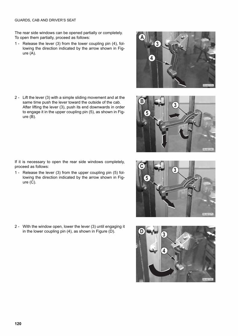
GUARDS, CAB AND DRIVER’S SEAT
The rear side windows can be opened partially or completely.To open them partially, proceed as follows:
1 - Release the lever (3) from the lower coupling pin (4), fol-lowing the direction indicated by the arrow shown in Fig-ure (A).
2 - Lift the lever (3) with a simple sliding movement and at thesame time push the lever toward the outside of the cab.After lifting the lever (3), push its end downwards in orderto engage it in the upper coupling pin (5), as shown in Fig-ure (B).
If it is necessary to open the rear side windows completely,proceed as follows:
1 - Release the lever (3) from the upper coupling pin (5) fol-lowing the direction indicated by the arrow shown in Fig-ure (C).
2 - With the window open, lower the lever (3) until engaging itin the lower coupling pin (4), as shown in Figure (D).
������ �
�
��
��������
��
�
��������
��
�������
�
��
120
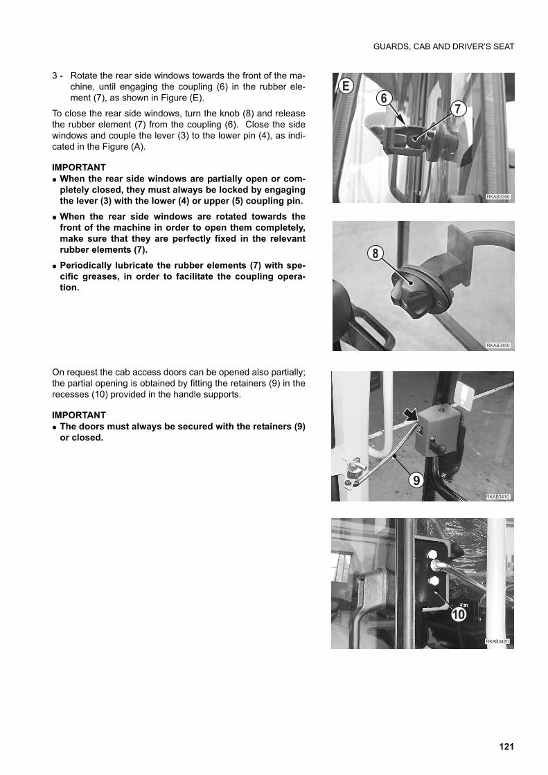
GUARDS, CAB AND DRIVER’S SEAT
3 - Rotate the rear side windows towards the front of the ma-chine, until engaging the coupling (6) in the rubber ele-ment (7), as shown in Figure (E).
To close the rear side windows, turn the knob (8) and releasethe rubber element (7) from the coupling (6). Close the sidewindows and couple the lever (3) to the lower pin (4), as indi-cated in the Figure (A).
IMPORTANTq When the rear side windows are partially open or com-
pletely closed, they must always be locked by engagingthe lever (3) with the lower (4) or upper (5) coupling pin.
q When the rear side windows are rotated towards thefront of the machine in order to open them completely,make sure that they are perfectly fixed in the relevantrubber elements (7).
q Periodically lubricate the rubber elements (7) with spe-cific greases, in order to facilitate the coupling opera-tion.
On request the cab access doors can be opened also partially;the partial opening is obtained by fitting the retainers (9) in therecesses (10) provided in the handle supports.
IMPORTANTq The doors must always be secured with the retainers (9)
or closed.
��������
�
�
��������
"
�������
!
��������
��
121
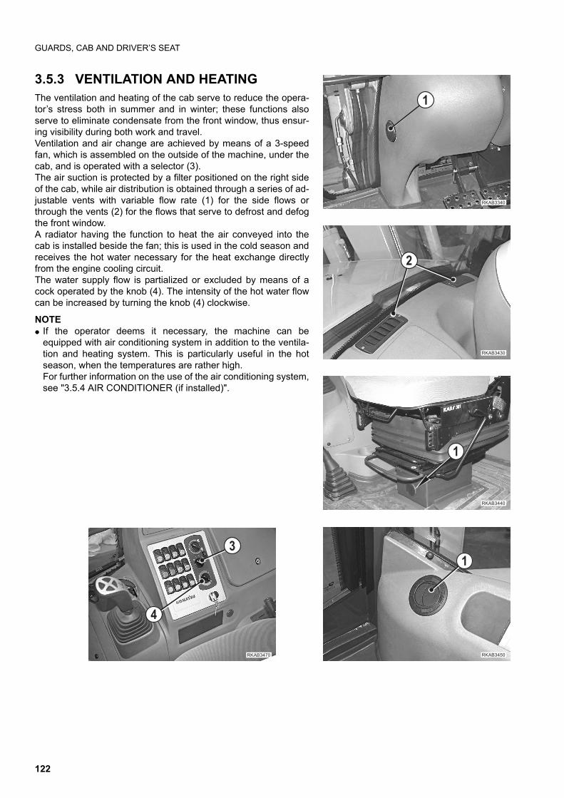
GUARDS, CAB AND DRIVER’S SEAT
3.5.3 VENTILATION AND HEATINGThe ventilation and heating of the cab serve to reduce the opera-tor’s stress both in summer and in winter; these functions alsoserve to eliminate condensate from the front window, thus ensur-ing visibility during both work and travel.Ventilation and air change are achieved by means of a 3-speedfan, which is assembled on the outside of the machine, under thecab, and is operated with a selector (3).The air suction is protected by a filter positioned on the right sideof the cab, while air distribution is obtained through a series of ad-justable vents with variable flow rate (1) for the side flows orthrough the vents (2) for the flows that serve to defrost and defogthe front window.A radiator having the function to heat the air conveyed into thecab is installed beside the fan; this is used in the cold season andreceives the hot water necessary for the heat exchange directlyfrom the engine cooling circuit.The water supply flow is partialized or excluded by means of acock operated by the knob (4). The intensity of the hot water flowcan be increased by turning the knob (4) clockwise.
NOTEq If the operator deems it necessary, the machine can be
equipped with air conditioning system in addition to the ventila-tion and heating system. This is particularly useful in the hotseason, when the temperatures are rather high.For further information on the use of the air conditioning system,see "3.5.4 AIR CONDITIONER (if installed)".
��������
�
��������
�
��������
�
������ �
�
��������
�
�
122
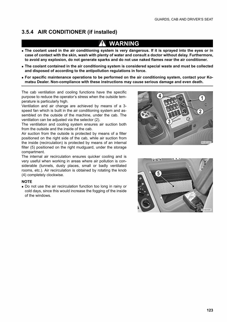
GUARDS, CAB AND DRIVER’S SEAT
3.5.4 AIR CONDITIONER (if installed)
WARNINGq The coolant used in the air conditioning system is very dangerous. If it is sprayed into the eyes or in
case of contact with the skin, wash with plenty of water and consult a doctor without delay. Furthermore,to avoid any explosion, do not generate sparks and do not use naked flames near the air conditioner.
q The coolant contained in the air conditioning system is considered special waste and must be collectedand disposed of according to the antipollution regulations in force.
q For specific maintenance operations to be performed on the air conditioning system, contact your Ko-matsu Dealer. Non-compliance with these instructions may cause serious damage and even death.
The cab ventilation and cooling functions have the specificpurpose to reduce the operator’s stress when the outside tem-perature is particularly high.Ventilation and air change are achieved by means of a 3-speed fan which is built in the air conditioning system and as-sembled on the outside of the machine, under the cab. Theventilation can be adjusted via the selector (2).The ventilation and cooling system ensures air suction bothfrom the outside and the inside of the cab.Air suction from the outside is protected by means of a filterpositioned on the right side of the cab, while air suction fromthe inside (recirculation) is protected by means of an internalfilter (5) positioned on the right mudguard, under the storagecompartment.The internal air recirculation ensures quicker cooling and isvery useful when working in areas where air pollution is con-siderable (tunnels, dusty places, small or badly ventilatedrooms, etc.). Air recirculation is obtained by rotating the knob(4) completely clockwise.
NOTEq Do not use the air recirculation function too long in rainy or
cold days, since this would increase the fogging of the insideof the windows.
������
�
�������
�
�
�
�
123
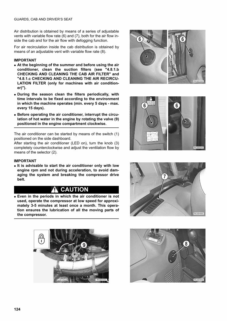
GUARDS, CAB AND DRIVER’S SEAT
Air distribution is obtained by means of a series of adjustablevents with variable flow rate (6) and (7), both for the air flow in-side the cab and for the air flow with defogging function.
For air recirculation inside the cab distribution is obtained bymeans of an adjustable vent with variable flow rate (8).
IMPORTANTq At the beginning of the summer and before using the air
conditioner, clean the suction filters (see "4.8.1.bCHECKING AND CLEANING THE CAB AIR FILTER" and"4.8.1.c CHECKING AND CLEANING THE AIR RECIRCU-LATION FILTER (only for machines with air condition-er)").
q During the season clean the filters periodically, withtime intervals to be fixed according to the environmentin which the machine operates (min. every 5 days - max.every 15 days).
q Before operating the air conditioner, interrupt the circu-lation of hot water in the engine by rotating the valve (9)positioned in the engine compartment clockwise.
The air conditioner can be started by means of the switch (1)positioned on the side dashboard.After starting the air conditioner (LED on), turn the knob (3)completely counterclockwise and adjust the ventilation flow bymeans of the selector (2).
IMPORTANTq It is advisable to start the air conditioner only with low
engine rpm and not during acceleration, to avoid dam-aging the system and breaking the compressor drivebelt.
CAUTIONq Even in the periods in which the air conditioner is not
used, operate the compressor at low speed for approxi-mately 3-5 minutes at least once a month. This opera-tion ensures the lubrication of all the moving parts ofthe compressor.
����� ��
����� �
"
�������
�
��������
����� ��
!
124
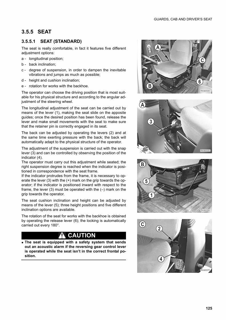
GUARDS, CAB AND DRIVER’S SEAT
3.5.5 SEAT
3.5.5.1 SEAT (STANDARD)
The seat is really comfortable, in fact it features five differentadjustment options:
a - longitudinal position;
b - back inclination;
c - degree of suspension, in order to dampen the inevitablevibrations and jumps as much as possible;
d - height and cushion inclination;
e - rotation for works with the backhoe.
The operator can choose the driving position that is most suit-able for his physical structure and according to the angular ad-justment of the steering wheel.
The longitudinal adjustment of the seat can be carried out bymeans of the lever (1), making the seat slide on the appositeguides; once the desired position has been found, release thelever and make small movements with the seat to make surethat the retainer pin is correctly engaged in its seat.
The back can be adjusted by operating the levers (2) and atthe same time exerting pressure with the back; the back willautomatically adapt to the physical structure of the operator.
The adjustment of the suspension is carried out with the snaplever (3) and can be controlled by observing the position of theindicator (4).The operator must carry out this adjustment while seated; theright suspension degree is reached when the indicator is posi-tioned in correspondence with the seat frame.If the indicator protrudes from the frame, it is necessary to op-erate the lever (3) with the (+) mark on the grip towards the op-erator; if the indicator is positioned inward with respect to theframe, the lever (3) must be operated with the (–) mark on thegrip towards the operator.
The seat cushion inclination and height can be adjusted bymeans of the lever (5); three height positions and five differentinclination options are available.
The rotation of the seat for works with the backhoe is obtainedby operating the release lever (6); the locking is automaticallycarried out every 180°.
CAUTIONq The seat is equipped with a safety system that sends
out an acoustic alarm if the reversing gear control leveris operated while the seat isn’t in the correct frontal po-sition.
����� ��
�
�
����� ��
�
�
�
����� �
�
�
����� ��
�
�
125
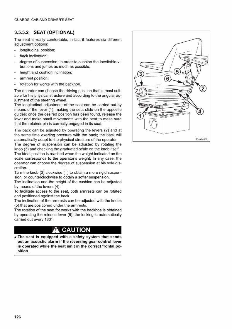
GUARDS, CAB AND DRIVER’S SEAT
3.5.5.2 SEAT (OPTIONAL)
The seat is really comfortable, in fact it features six differentadjustment options:
- longitudinal position;
- back inclination;
- degree of suspension, in order to cushion the inevitable vi-brations and jumps as much as possible;
- height and cushion inclination;
- armrest position;
- rotation for works with the backhoe.
The operator can choose the driving position that is most suit-able for his physical structure and according to the angular ad-justment of the steering wheel.The longitudinal adjustment of the seat can be carried out bymeans of the lever (1), making the seat slide on the appositeguides; once the desired position has been found, release thelever and make small movements with the seat to make surethat the retainer pin is correctly engaged in its seat.
The back can be adjusted by operating the levers (2) and atthe same time exerting pressure with the back; the back willautomatically adapt to the physical structure of the operator.The degree of suspension can be adjusted by rotating theknob (3) and checking the graduated scale on the knob itself.The ideal position is reached when the weight indicated on thescale corresponds to the operator’s weight. In any case, theoperator can choose the degree of suspension at his sole dis-cretion.Turn the knob (3) clockwise ( ) to obtain a more rigid suspen-sion, or counterclockwise to obtain a softer suspension.The inclination and the height of the cushion can be adjustedby means of the levers (4).To facilitate access to the seat, both armrests can be rotatedand positioned against the back.The inclination of the armrests can be adjusted with the knobs(5) that are positioned under the armrests.The rotation of the seat for works with the backhoe is obtainedby operating the release lever (6); the locking is automaticallycarried out every 180°.
CAUTIONq The seat is equipped with a safety system that sends
out an acoustic alarm if the reversing gear control leveris operated while the seat isn’t in the correct frontal po-sition.
�
� �
�
�
����
126
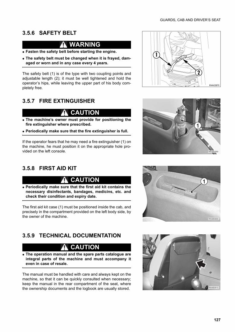
GUARDS, CAB AND DRIVER’S SEAT
3.5.6 SAFETY BELT
WARNINGq Fasten the safety belt before starting the engine.
q The safety belt must be changed when it is frayed, dam-aged or worn and in any case every 4 years.
The safety belt (1) is of the type with two coupling points andadjustable length (2); it must be well tightened and hold theoperator’s hips, while leaving the upper part of his body com-pletely free.
3.5.7 FIRE EXTINGUISHER
CAUTIONq The machine’s owner must provide for positioning the
fire extinguisher where prescribed.
q Periodically make sure that the fire extinguisher is full.
If the operator fears that he may need a fire extinguisher (1) onthe machine, he must position it on the appropriate hole pro-vided on the left console.
3.5.8 FIRST AID KIT
CAUTIONq Periodically make sure that the first aid kit contains the
necessary disinfectants, bandages, medicins, etc. andcheck their condition and expiry date.
The first aid kit case (1) must be positioned inside the cab, andprecisely in the compartment provided on the left body side, bythe owner of the machine.
3.5.9 TECHNICAL DOCUMENTATION
CAUTIONq The operation manual and the spare parts catalogue are
integral parts of the machine and must accompany iteven in case of resale.
The manual must be handled with care and always kept on themachine, so that it can be quickly consulted when necessary;keep the manual in the rear compartment of the seat, wherethe ownership documents and the logbook are usually stored.
2
1
RWA02870
����� ��
�
��������
�
�������
127
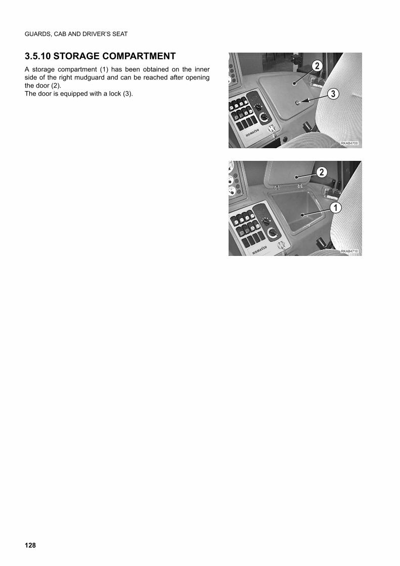
GUARDS, CAB AND DRIVER’S SEAT
3.5.10 STORAGE COMPARTMENT A storage compartment (1) has been obtained on the innerside of the right mudguard and can be reached after openingthe door (2). The door is equipped with a lock (3).
�
�
��������
�
�������
�
128
USE OF THE MACHINE
3.6 USE OF THE MACHINE
3.6.1 CHECKS TO BE CARRIED OUT BEFORE STARTING THE ENGINE
3.6.1.1 VISUAL CHECKS
WARNINGq Dirt, oil and fuel in the engine compartment near hot parts may damage the machine and even cause
fires.Check frequently and eliminate any leakage; if leakages occur repeatedly, contact your Komatsu Dealer.
Before starting the engine, check around and under the machine to verify:
1 - if there are loose screws or nuts;
2 - if there are oil, fuel or coolant leakages;
3 - the wear of the work equipment;
4 - the fastening of the electrical connections;
5 - the fastening of the engine exhaust pipe and manifold;
6 - the conditions of the rims and the wear of the tyres;
7 - if the safety and warning plates are sufficiently clean;
8 - if the ladders and the handles for the access to the operator’s seat are clean.
Any leak or anomaly must immediately be repaired/eliminated and any trace of oil or grease must be removed.Further visual checks concern:
9 - the condition of the safety belt;
10 - the efficiency of the instruments and of the dashboard;
11 - the condition of the cab windows and the efficiency of lights, work lights and direction indicators.10 - the effi-ciency of the instruments and of the dashboard;
3.6.1.2 DAILY CHECKS
WARNINGq Do not smoke while refuelling and adding oil and avoid using naked flames or non-homologated lighting
means to check the fuel or oil level, in order not to cause fires.
q If some fuel, oil, or lubricant is spilled while filling the tanks, clean the dirty areas immediately.
Before starting any operation, check the engine coolant, engine oil and hydraulic circuit oil levels and lubricate thearticulations (see “4.8.4 MAINTENANCE EVERY 10 HOURS OF OPERATION”).At the end of work, provide for refuelling, in order to avoid the formation of condensate, always checking the fuellevel on the indicator provided on the dashboard.
IMPORTANTq Avoid filling the tank completely, in order to leave room for the gas oil to expand.
q After filling the tank, put back the filler cap, making sure that the bleed hole is completely open.
q Check the engine oil level with the machine in horizontal position and the hydraulic circuit oil level withthe front bucket resting on the ground and the backhoe in transport position.
129
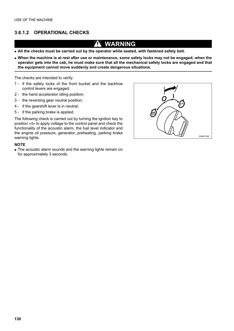
USE OF THE MACHINE
3.6.1.2 OPERATIONAL CHECKS
WARNINGq All the checks must be carried out by the operator while seated, with fastened safety belt.
q When the machine is at rest after use or maintenance, some safety locks may not be engaged; when theoperator gets into the cab, he must make sure that all the mechanical safety locks are engaged and thatthe equipment cannot move suddenly and create dangerous situations.
The checks are intended to verify:
1 - if the safety locks of the front bucket and the backhoecontrol levers are engaged;
2 - the hand accelerator idling position;
3 - the reversing gear neutral position;
4 - if the gearshift lever is in neutral;
5 - if the parking brake is applied.
The following check is carried out by turning the ignition key toposition « » to apply voltage to the control panel and check thefunctionality of the acoustic alarm, the fuel level indicator andthe engine oil pressure, generator, preheating, parking brakewarning lights.
NOTEq The acoustic alarm sounds and the warning lights remain on
for approximately 3 seconds.
RWA01960
130
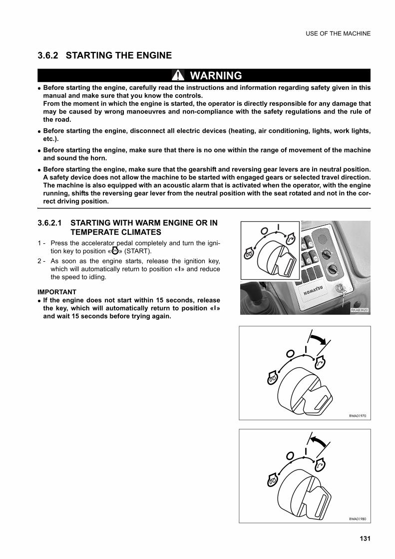
USE OF THE MACHINE
3.6.2 STARTING THE ENGINE
WARNINGq Before starting the engine, carefully read the instructions and information regarding safety given in this
manual and make sure that you know the controls.From the moment in which the engine is started, the operator is directly responsible for any damage thatmay be caused by wrong manoeuvres and non-compliance with the safety regulations and the rule ofthe road.
q Before starting the engine, disconnect all electric devices (heating, air conditioning, lights, work lights,etc.).
q Before starting the engine, make sure that there is no one within the range of movement of the machineand sound the horn.
q Before starting the engine, make sure that the gearshift and reversing gear levers are in neutral position.A safety device does not allow the machine to be started with engaged gears or selected travel direction.The machine is also equipped with an acoustic alarm that is activated when the operator, with the enginerunning, shifts the reversing gear lever from the neutral position with the seat rotated and not in the cor-rect driving position.
3.6.2.1 STARTING WITH WARM ENGINE OR IN TEMPERATE CLIMATES
1 - Press the accelerator pedal completely and turn the igni-tion key to position « » (START).
2 - As soon as the engine starts, release the ignition key,which will automatically return to position « » and reducethe speed to idling.
IMPORTANTq If the engine does not start within 15 seconds, release
the key, which will automatically return to position « »and wait 15 seconds before trying again.
��������
RWA01970
RWA01980
131
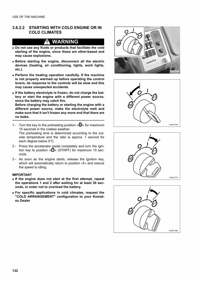
USE OF THE MACHINE
3.6.2.2 STARTING WITH COLD ENGINE OR IN COLD CLIMATES
WARNINGq Do not use any fluids or products that facilitate the cold
starting of the engine, since these are ether-based andmay cause explosions.
q Before starting the engine, disconnect all the electricdevices (heating, air conditioning, lights, work lights,etc.).
q Perform the heating operation carefully. If the machineis not properly warmed up before operating the controllevers, its response to the controls will be slow and thismay cause unexpected accidents.
q If the battery electrolyte is frozen, do not charge the bat-tery or start the engine with a different power source,since the battery may catch fire.Before charging the battery or starting the engine with adifferent power source, make the electrolyte melt andmake sure that it isn't frozen any more and that there areno leaks.
1 - Turn the key to the preheating position « » for maximum15 seconds in the coldest weather.The preheating time is determined according to the out-side temperature and the ratio is approx. 1 second foreach degree below 0°C.
2 - Press the accelerator pedal completely and turn the igni-tion key to position « » (START) for maximum 15 sec-onds.
3 - As soon as the engine starts, release the ignition key,which will automatically return to position « » and reducethe speed to idling.
IMPORTANTq If the engine does not start at the first attempt, repeat
the operations 1 and 2 after waiting for at least 30 sec-onds, in order not to overload the battery.
q For specific applications in cold climates, request the"COLD ARRANGEMENT" configuration to your Komat-su Dealer
��������
RWA01990
RWA01970
RWA01980
132
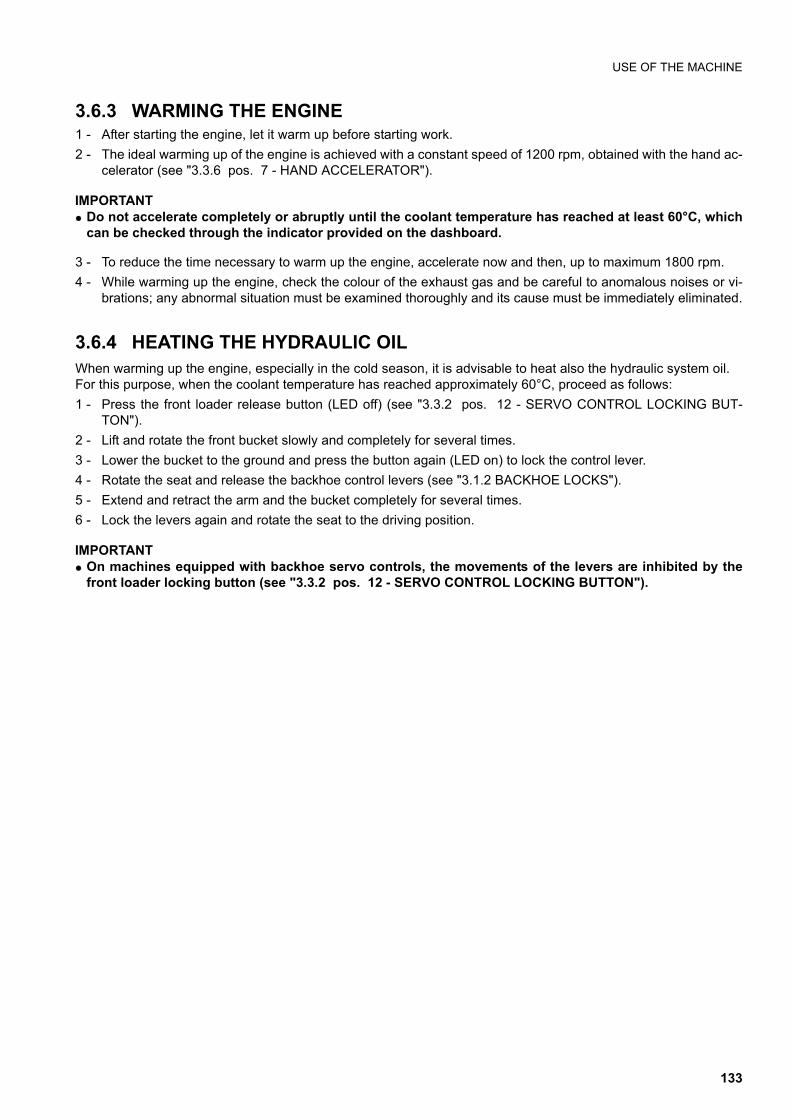
USE OF THE MACHINE
3.6.3 WARMING THE ENGINE1 - After starting the engine, let it warm up before starting work.
2 - The ideal warming up of the engine is achieved with a constant speed of 1200 rpm, obtained with the hand ac-celerator (see "3.3.6 pos. 7 - HAND ACCELERATOR").
IMPORTANTq Do not accelerate completely or abruptly until the coolant temperature has reached at least 60°C, which
can be checked through the indicator provided on the dashboard.
3 - To reduce the time necessary to warm up the engine, accelerate now and then, up to maximum 1800 rpm.
4 - While warming up the engine, check the colour of the exhaust gas and be careful to anomalous noises or vi-brations; any abnormal situation must be examined thoroughly and its cause must be immediately eliminated.
3.6.4 HEATING THE HYDRAULIC OILWhen warming up the engine, especially in the cold season, it is advisable to heat also the hydraulic system oil.For this purpose, when the coolant temperature has reached approximately 60°C, proceed as follows:
1 - Press the front loader release button (LED off) (see "3.3.2 pos. 12 - SERVO CONTROL LOCKING BUT-TON").
2 - Lift and rotate the front bucket slowly and completely for several times.
3 - Lower the bucket to the ground and press the button again (LED on) to lock the control lever.
4 - Rotate the seat and release the backhoe control levers (see "3.1.2 BACKHOE LOCKS").
5 - Extend and retract the arm and the bucket completely for several times.
6 - Lock the levers again and rotate the seat to the driving position.
IMPORTANTq On machines equipped with backhoe servo controls, the movements of the levers are inhibited by the
front loader locking button (see "3.3.2 pos. 12 - SERVO CONTROL LOCKING BUTTON").
133
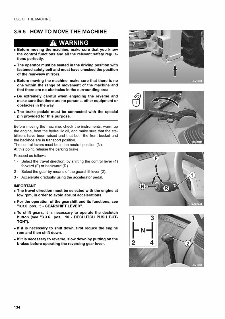
USE OF THE MACHINE
3.6.5 HOW TO MOVE THE MACHINE
WARNINGq Before moving the machine, make sure that you know
the control functions and all the relevant safety regula-tions perfectly.
q The operator must be seated in the driving position withfastened safety belt and must have checked the positionof the rear-view mirrors.
q Before moving the machine, make sure that there is noone within the range of movement of the machine andthat there are no obstacles in the surrounding area.
q Be extremely careful when engaging the reverse andmake sure that there are no persons, other equipment orobstacles in the way.
q The brake pedals must be connected with the specialpin provided for this purpose.
Before moving the machine, check the instruments, warm upthe engine, heat the hydraulic oil, and make sure that the sta-bilizers have been raised and that both the front bucket andthe backhoe are in transport position.The control levers must be in the neutral position (N).At this point, release the parking brake.
Proceed as follows:
1 - Select the travel direction, by shifting the control lever (1)forward (F) or backward (R).
2 - Select the gear by means of the gearshift lever (2).
3 - Accelerate gradually using the accelerator pedal.
IMPORTANTq The travel direction must be selected with the engine at
low rpm, in order to avoid abrupt accelerations.
q For the operation of the gearshift and its functions, see"3.3.6 pos. 5 - GEARSHIFT LEVER".
q To shift gears, it is necessary to operate the declutchbutton (see "3.3.6 pos. 10 - DECLUTCH PUSH BUT-TON").
q If it is necessary to shift down, first reduce the enginerpm and then shift down.
q If it is necessary to reverse, slow down by putting on thebrakes before operating the reversing gear lever.
��������
������
�
�
��
����� �
��������
�
�
�
�
�
�
134
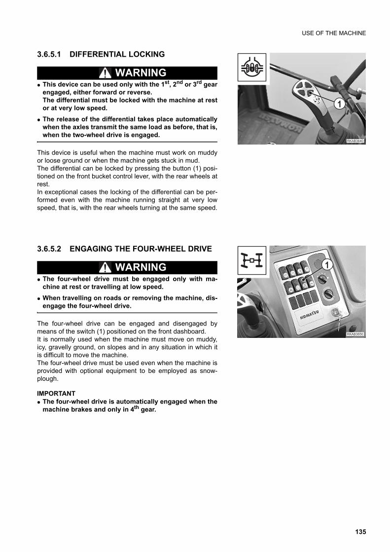
USE OF THE MACHINE
3.6.5.1 DIFFERENTIAL LOCKING
WARNINGq This device can be used only with the 1st, 2nd or 3rd gear
engaged, either forward or reverse.The differential must be locked with the machine at restor at very low speed.
q The release of the differential takes place automaticallywhen the axles transmit the same load as before, that is,when the two-wheel drive is engaged.
This device is useful when the machine must work on muddyor loose ground or when the machine gets stuck in mud. The differential can be locked by pressing the button (1) posi-tioned on the front bucket control lever, with the rear wheels atrest.In exceptional cases the locking of the differential can be per-formed even with the machine running straight at very lowspeed, that is, with the rear wheels turning at the same speed.
3.6.5.2 ENGAGING THE FOUR-WHEEL DRIVE
WARNINGq The four-wheel drive must be engaged only with ma-
chine at rest or travelling at low speed.
q When travelling on roads or removing the machine, dis-engage the four-wheel drive.
The four-wheel drive can be engaged and disengaged bymeans of the switch (1) positioned on the front dashboard.It is normally used when the machine must move on muddy,icy, gravelly ground, on slopes and in any situation in which itis difficult to move the machine.The four-wheel drive must be used even when the machine isprovided with optional equipment to be employed as snow-plough.
IMPORTANTq The four-wheel drive is automatically engaged when the
machine brakes and only in 4th gear.
��������
�
������ �
�
135
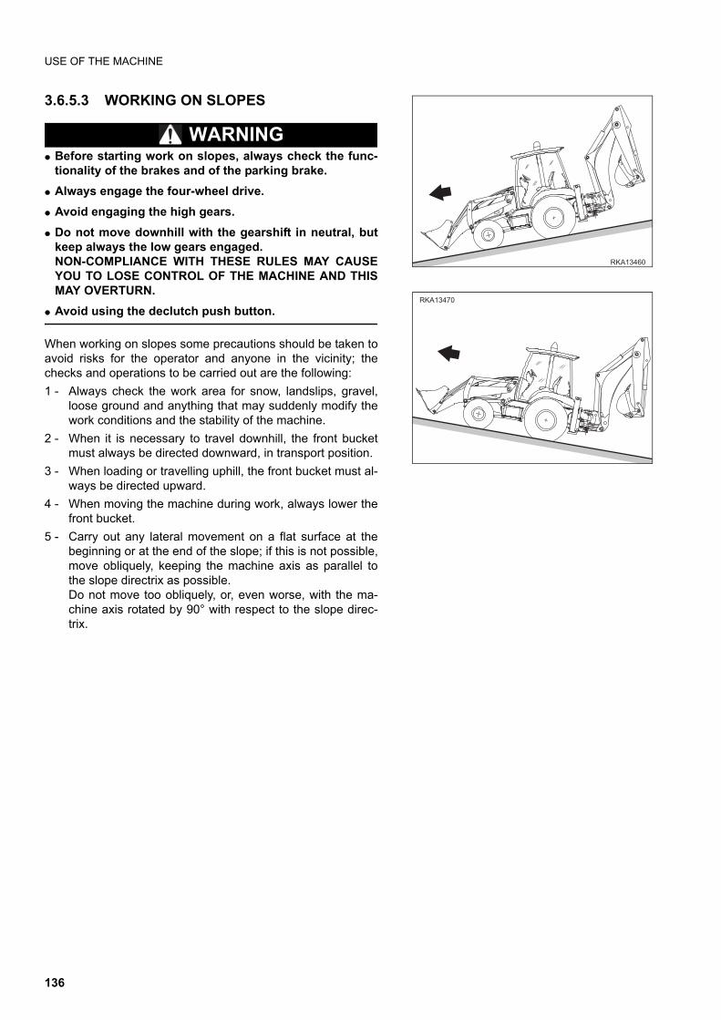
USE OF THE MACHINE
3.6.5.3 WORKING ON SLOPES
WARNINGq Before starting work on slopes, always check the func-
tionality of the brakes and of the parking brake.
q Always engage the four-wheel drive.
q Avoid engaging the high gears.
q Do not move downhill with the gearshift in neutral, butkeep always the low gears engaged.NON-COMPLIANCE WITH THESE RULES MAY CAUSEYOU TO LOSE CONTROL OF THE MACHINE AND THISMAY OVERTURN.
q Avoid using the declutch push button.
When working on slopes some precautions should be taken toavoid risks for the operator and anyone in the vicinity; thechecks and operations to be carried out are the following:
1 - Always check the work area for snow, landslips, gravel,loose ground and anything that may suddenly modify thework conditions and the stability of the machine.
2 - When it is necessary to travel downhill, the front bucketmust always be directed downward, in transport position.
3 - When loading or travelling uphill, the front bucket must al-ways be directed upward.
4 - When moving the machine during work, always lower thefront bucket.
5 - Carry out any lateral movement on a flat surface at thebeginning or at the end of the slope; if this is not possible,move obliquely, keeping the machine axis as parallel tothe slope directrix as possible.Do not move too obliquely, or, even worse, with the ma-chine axis rotated by 90° with respect to the slope direc-trix.
������
������
136
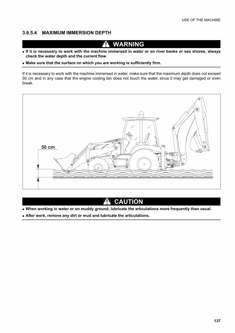
USE OF THE MACHINE
3.6.5.4 MAXIMUM IMMERSION DEPTH
WARNINGq If it is necessary to work with the machine immersed in water or on river banks or sea shores, always
check the water depth and the current flow.
q Make sure that the surface on which you are working is sufficiently firm.
If it is necessary to work with the machine immersed in water, make sure that the maximum depth does not exceed50 cm and in any case that the engine cooling fan does not touch the water, since it may get damaged or evenbreak.
CAUTIONq When working in water or on muddy ground, lubricate the articulations more frequently than usual.
q After work, remove any dirt or mud and lubricate the articulations.
����
137
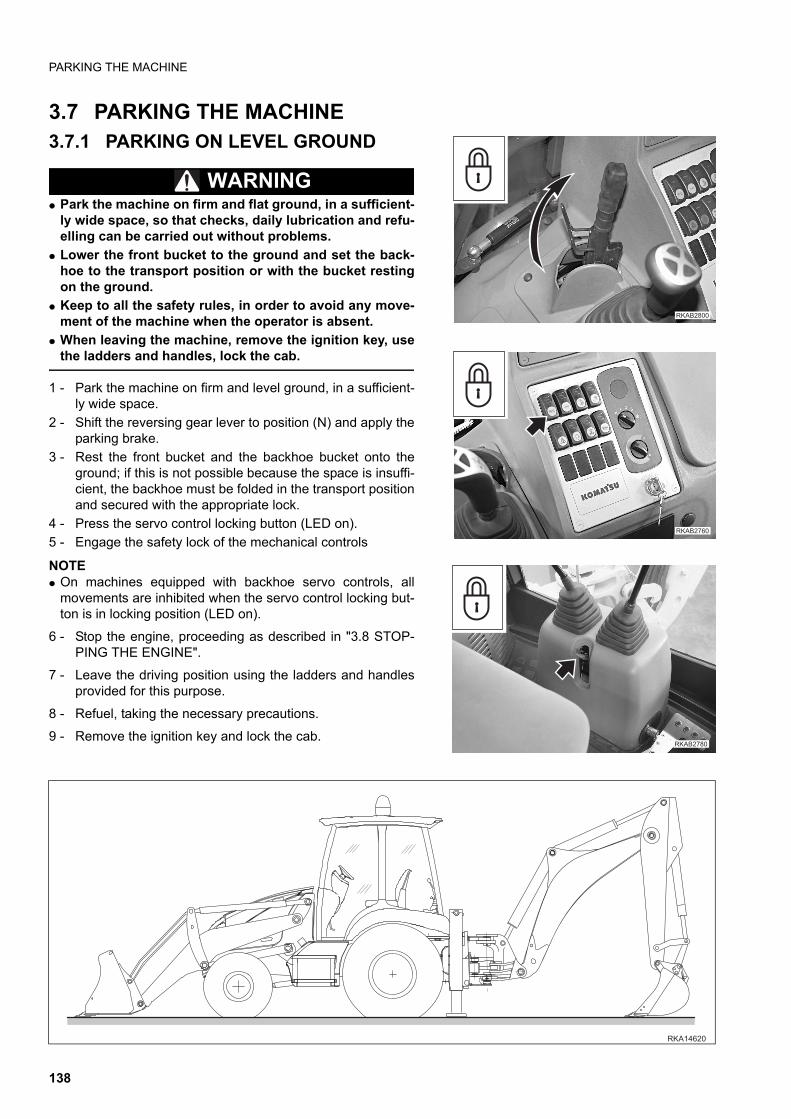
PARKING THE MACHINE
3.7 PARKING THE MACHINE3.7.1 PARKING ON LEVEL GROUND
WARNINGq Park the machine on firm and flat ground, in a sufficient-
ly wide space, so that checks, daily lubrication and refu-elling can be carried out without problems.
q Lower the front bucket to the ground and set the back-hoe to the transport position or with the bucket restingon the ground.
q Keep to all the safety rules, in order to avoid any move-ment of the machine when the operator is absent.
q When leaving the machine, remove the ignition key, usethe ladders and handles, lock the cab.
1 - Park the machine on firm and level ground, in a sufficient-ly wide space.
2 - Shift the reversing gear lever to position (N) and apply theparking brake.
3 - Rest the front bucket and the backhoe bucket onto theground; if this is not possible because the space is insuffi-cient, the backhoe must be folded in the transport positionand secured with the appropriate lock.
4 - Press the servo control locking button (LED on).
5 - Engage the safety lock of the mechanical controls
NOTEq On machines equipped with backhoe servo controls, all
movements are inhibited when the servo control locking but-ton is in locking position (LED on).
6 - Stop the engine, proceeding as described in "3.8 STOP-PING THE ENGINE".
7 - Leave the driving position using the ladders and handlesprovided for this purpose.
8 - Refuel, taking the necessary precautions.
9 - Remove the ignition key and lock the cab.
�������
��������
�������
������
138
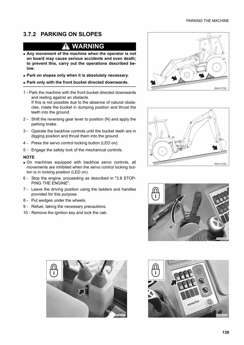
PARKING THE MACHINE
3.7.2 PARKING ON SLOPES
WARNINGq Any movement of the machine when the operator is not
on board may cause serious accidents and even death;to prevent this, carry out the operations described be-low.
q Park on slopes only when it is absolutely necessary.
q Park only with the front bucket directed downwards.
1 - Park the machine with the front bucket directed downwardsand resting against an obstacle.If this is not possible due to the absence of natural obsta-cles, rotate the bucket in dumping position and thrust theteeth into the ground.
2 - Shift the reversing gear lever to position (N) and apply theparking brake.
3 - Operate the backhoe controls until the bucket teeth are indigging position and thrust them into the ground.
4 - Press the servo control locking button (LED on).
5 - Engage the safety lock of the mechanical controls.
NOTEq On machines equipped with backhoe servo controls, all
movements are inhibited when the servo control locking but-ton is in locking position (LED on).
6 - Stop the engine, proceeding as described in "3.8 STOP-PING THE ENGINE".
7 - Leave the driving position using the ladders and handlesprovided for this purpose.
8 - Put wedges under the wheels.
9 - Refuel, taking the necessary precautions.
10 - Remove the ignition key and lock the cab.
����� �
�������
�������
���������������
139
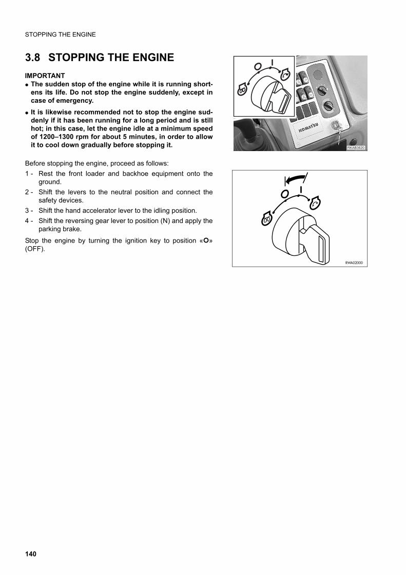
STOPPING THE ENGINE
3.8 STOPPING THE ENGINE
IMPORTANTq The sudden stop of the engine while it is running short-
ens its life. Do not stop the engine suddenly, except incase of emergency.
q It is likewise recommended not to stop the engine sud-denly if it has been running for a long period and is stillhot; in this case, let the engine idle at a minimum speedof 1200–1300 rpm for about 5 minutes, in order to allowit to cool down gradually before stopping it.
Before stopping the engine, proceed as follows:
1 - Rest the front loader and backhoe equipment onto theground.
2 - Shift the levers to the neutral position and connect thesafety devices.
3 - Shift the hand accelerator lever to the idling position.
4 - Shift the reversing gear lever to position (N) and apply theparking brake.
Stop the engine by turning the ignition key to position « »(OFF).
��������
RWA02000
140

TRANSPORTING THE MACHINE ON OTHER VEHICLES
3.9 TRANSPORTING THE MACHINE ON OTHER VEHICLES
3.9.1 LOADING AND UNLOADING THE MACHINE
WARNINGq The loading and unloading of the machine on-off the means of transport must be carried out on a flat
surface and at a safety distance from the edges of ditches or from the roadside.
q Block the means of transport by positioning wedges before and behind each wheel.
q Make sure that the ramps are sufficiently strong; if necessary, reinforce them with blocks, in order toprevent any dangerous bending.
q Make sure that the ramps have the same length, are firmly anchored to the vehicle, are parallel to eachother and perpendicular to the loading board; the distance between the ramps must be suitable for thewheel gauge of the machine.
q Position the ramps with a maximum inclination of 15°.
q Remove any trace of oil, grease or ice from the ramps and the loading board.
q Do not change direction when the machine is already on the ramps; if necessary, go down and find thecorrect direction.
1 - The machine must get on the ramps with the front bucket (1) directed forward and lifted from the ground.
2 - After loading the machine on the truck, lower the front bucket to the ground, shift the gears into NEUTRAL andapply the parking brake.
3 - Lower the backhoe bucket (2) onto the vehicle, lower the stabilizers (3), lock the loader control and the back-hoe control levers.
IMPORTANTq On machines equipped with backhoe servo controls, the movements of the levers are inhibited by the
front loader locking button (see "3.3.2 pos. 12 - SERVO CONTROL LOCKING BUTTON").
4 - Stop the engine and remove the ignition key.
5 - Secure the machine in the correct position by putting wedges (4) before and behind each wheel.
�$%&��'
������
�
�
� � � �
�
�
�
141
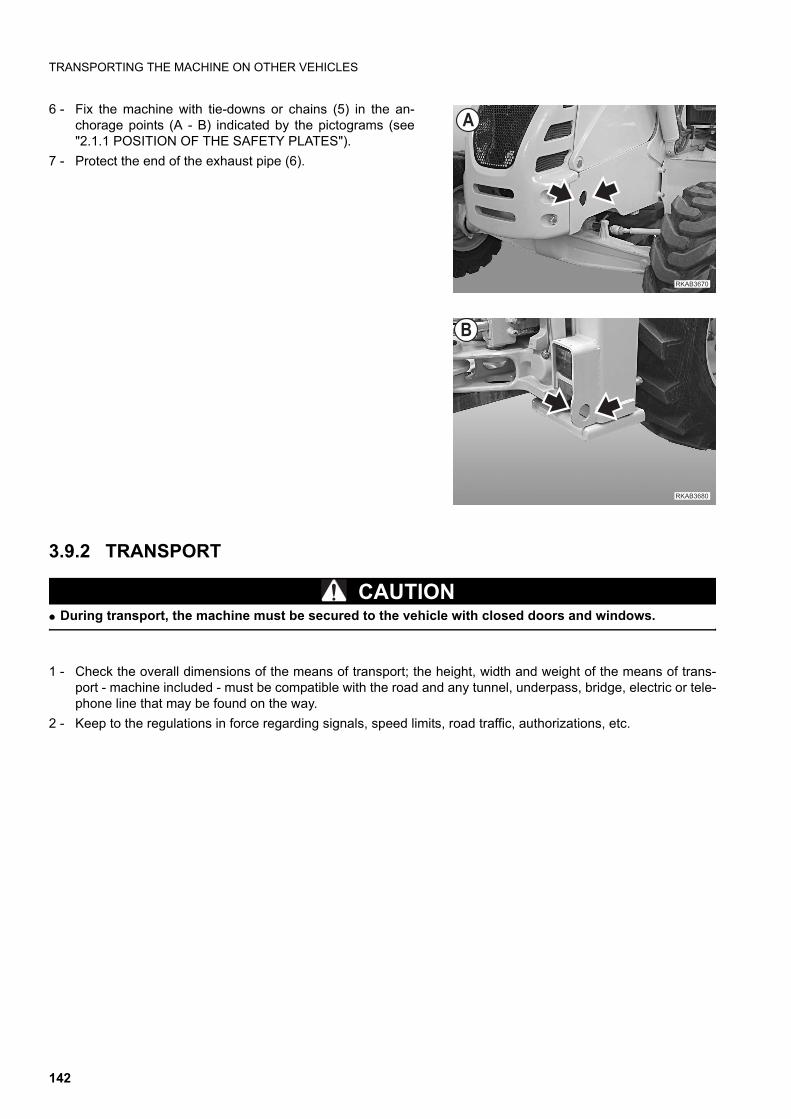
TRANSPORTING THE MACHINE ON OTHER VEHICLES
6 - Fix the machine with tie-downs or chains (5) in the an-chorage points (A - B) indicated by the pictograms (see"2.1.1 POSITION OF THE SAFETY PLATES").
7 - Protect the end of the exhaust pipe (6).
3.9.2 TRANSPORT
CAUTIONq During transport, the machine must be secured to the vehicle with closed doors and windows.
1 - Check the overall dimensions of the means of transport; the height, width and weight of the means of trans-port - machine included - must be compatible with the road and any tunnel, underpass, bridge, electric or tele-phone line that may be found on the way.
2 - Keep to the regulations in force regarding signals, speed limits, road traffic, authorizations, etc.
��������
�
�������
�
142
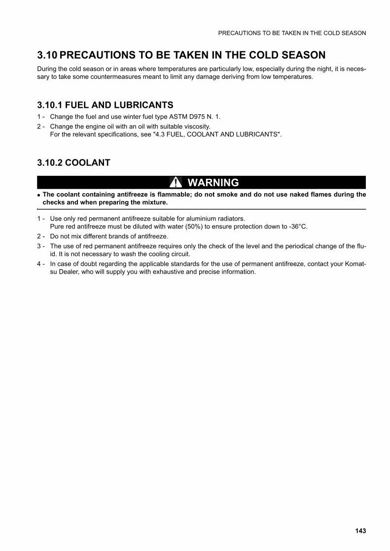
PRECAUTIONS TO BE TAKEN IN THE COLD SEASON
3.10 PRECAUTIONS TO BE TAKEN IN THE COLD SEASONDuring the cold season or in areas where temperatures are particularly low, especially during the night, it is neces-sary to take some countermeasures meant to limit any damage deriving from low temperatures.
3.10.1 FUEL AND LUBRICANTS1 - Change the fuel and use winter fuel type ASTM D975 N. 1.
2 - Change the engine oil with an oil with suitable viscosity.For the relevant specifications, see "4.3 FUEL, COOLANT AND LUBRICANTS".
3.10.2 COOLANT
WARNINGq The coolant containing antifreeze is flammable; do not smoke and do not use naked flames during the
checks and when preparing the mixture.
1 - Use only red permanent antifreeze suitable for aluminium radiators.Pure red antifreeze must be diluted with water (50%) to ensure protection down to -36°C.
2 - Do not mix different brands of antifreeze.
3 - The use of red permanent antifreeze requires only the check of the level and the periodical change of the flu-id. It is not necessary to wash the cooling circuit.
4 - In case of doubt regarding the applicable standards for the use of permanent antifreeze, contact your Komat-su Dealer, who will supply you with exhaustive and precise information.
143
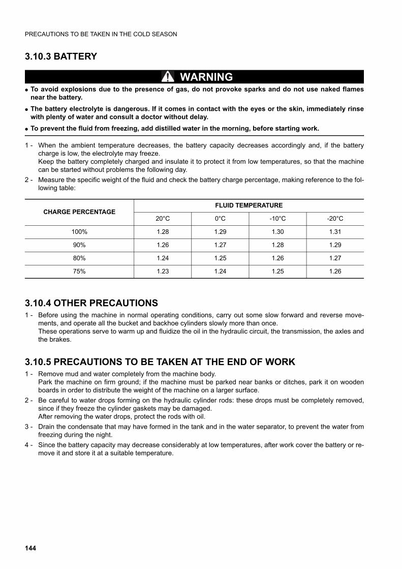
PRECAUTIONS TO BE TAKEN IN THE COLD SEASON
3.10.3 BATTERY
WARNINGq To avoid explosions due to the presence of gas, do not provoke sparks and do not use naked flames
near the battery.
q The battery electrolyte is dangerous. If it comes in contact with the eyes or the skin, immediately rinsewith plenty of water and consult a doctor without delay.
q To prevent the fluid from freezing, add distilled water in the morning, before starting work.
1 - When the ambient temperature decreases, the battery capacity decreases accordingly and, if the batterycharge is low, the electrolyte may freeze.Keep the battery completely charged and insulate it to protect it from low temperatures, so that the machinecan be started without problems the following day.
2 - Measure the specific weight of the fluid and check the battery charge percentage, making reference to the fol-lowing table:
3.10.4 OTHER PRECAUTIONS1 - Before using the machine in normal operating conditions, carry out some slow forward and reverse move-
ments, and operate all the bucket and backhoe cylinders slowly more than once.These operations serve to warm up and fluidize the oil in the hydraulic circuit, the transmission, the axles andthe brakes.
3.10.5 PRECAUTIONS TO BE TAKEN AT THE END OF WORK1 - Remove mud and water completely from the machine body.
Park the machine on firm ground; if the machine must be parked near banks or ditches, park it on woodenboards in order to distribute the weight of the machine on a larger surface.
2 - Be careful to water drops forming on the hydraulic cylinder rods: these drops must be completely removed,since if they freeze the cylinder gaskets may be damaged.After removing the water drops, protect the rods with oil.
3 - Drain the condensate that may have formed in the tank and in the water separator, to prevent the water fromfreezing during the night.
4 - Since the battery capacity may decrease considerably at low temperatures, after work cover the battery or re-move it and store it at a suitable temperature.
CHARGE PERCENTAGEFLUID TEMPERATURE
20°C 0°C -10°C -20°C
100% 1.28 1.29 1.30 1.31
90% 1.26 1.27 1.28 1.29
80% 1.24 1.25 1.26 1.27
75% 1.23 1.24 1.25 1.26
144

PRECAUTIONS TO BE TAKEN AT THE END OF THE WINTER
3.11 PRECAUTIONS TO BE TAKEN AT THE END OF THE WINTER1 - At the end of the cold season, change lubricants and fuel.
IMPORTANTq The use of permanent antifreeze requires only the check of the level and the periodical change of the flu-
id.For the relevant specifications, see "4.3 FUEL, COOLANT AND LUBRICANTS"”.
2 - Make sure that the cooling fan belt is in good conditions.
3 - Make sure that the fins of the radiator and of the heat exchanger are clean.
4 - Check the radiator cap gasket and spring; in case of doubt regarding tightness and setting, change the cap.
145
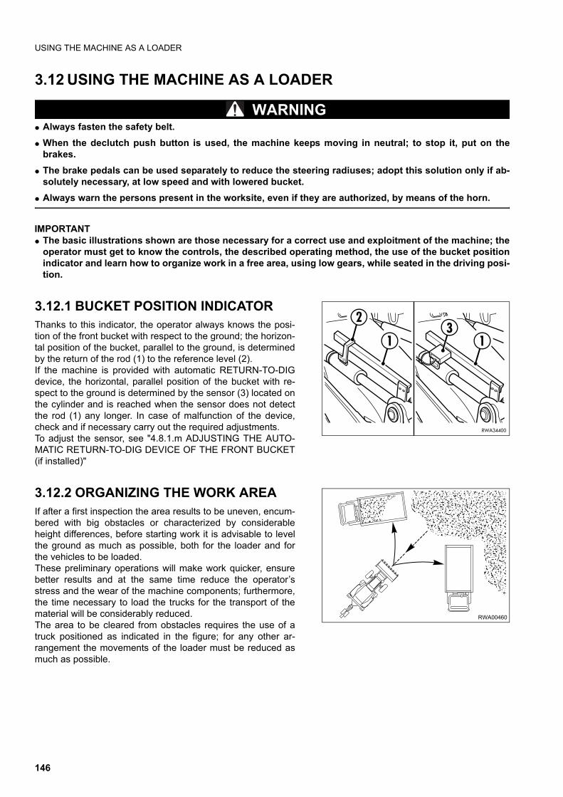
USING THE MACHINE AS A LOADER
3.12 USING THE MACHINE AS A LOADER
WARNINGq Always fasten the safety belt.
q When the declutch push button is used, the machine keeps moving in neutral; to stop it, put on thebrakes.
q The brake pedals can be used separately to reduce the steering radiuses; adopt this solution only if ab-solutely necessary, at low speed and with lowered bucket.
q Always warn the persons present in the worksite, even if they are authorized, by means of the horn.
IMPORTANTq The basic illustrations shown are those necessary for a correct use and exploitment of the machine; the
operator must get to know the controls, the described operating method, the use of the bucket positionindicator and learn how to organize work in a free area, using low gears, while seated in the driving posi-tion.
3.12.1 BUCKET POSITION INDICATORThanks to this indicator, the operator always knows the posi-tion of the front bucket with respect to the ground; the horizon-tal position of the bucket, parallel to the ground, is determinedby the return of the rod (1) to the reference level (2).If the machine is provided with automatic RETURN-TO-DIGdevice, the horizontal, parallel position of the bucket with re-spect to the ground is determined by the sensor (3) located onthe cylinder and is reached when the sensor does not detectthe rod (1) any longer. In case of malfunction of the device,check and if necessary carry out the required adjustments.To adjust the sensor, see "4.8.1.m ADJUSTING THE AUTO-MATIC RETURN-TO-DIG DEVICE OF THE FRONT BUCKET(if installed)"
3.12.2 ORGANIZING THE WORK AREAIf after a first inspection the area results to be uneven, encum-bered with big obstacles or characterized by considerableheight differences, before starting work it is advisable to levelthe ground as much as possible, both for the loader and forthe vehicles to be loaded. These preliminary operations will make work quicker, ensurebetter results and at the same time reduce the operator’sstress and the wear of the machine components; furthermore,the time necessary to load the trucks for the transport of thematerial will be considerably reduced.The area to be cleared from obstacles requires the use of atruck positioned as indicated in the figure; for any other ar-rangement the movements of the loader must be reduced asmuch as possible.
RWA34400
11
23
RWA00460
146
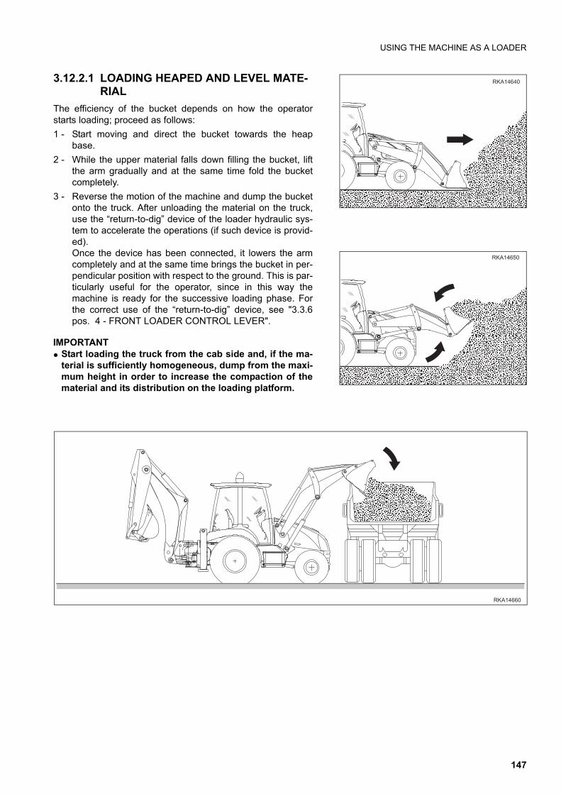
USING THE MACHINE AS A LOADER
3.12.2.1 LOADING HEAPED AND LEVEL MATE-RIAL
The efficiency of the bucket depends on how the operatorstarts loading; proceed as follows:
1 - Start moving and direct the bucket towards the heapbase.
2 - While the upper material falls down filling the bucket, liftthe arm gradually and at the same time fold the bucketcompletely.
3 - Reverse the motion of the machine and dump the bucketonto the truck. After unloading the material on the truck,use the “return-to-dig” device of the loader hydraulic sys-tem to accelerate the operations (if such device is provid-ed).Once the device has been connected, it lowers the armcompletely and at the same time brings the bucket in per-pendicular position with respect to the ground. This is par-ticularly useful for the operator, since in this way themachine is ready for the successive loading phase. Forthe correct use of the “return-to-dig” device, see "3.3.6pos. 4 - FRONT LOADER CONTROL LEVER".
IMPORTANTq Start loading the truck from the cab side and, if the ma-
terial is sufficiently homogeneous, dump from the maxi-mum height in order to increase the compaction of thematerial and its distribution on the loading platform.
������
�����
������
147
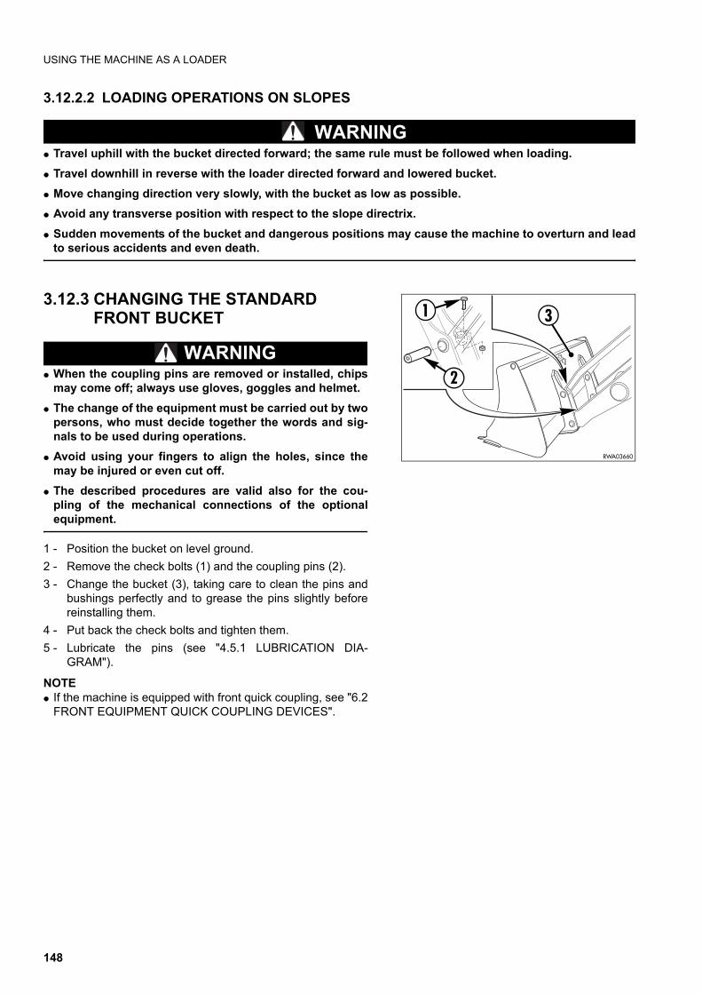
USING THE MACHINE AS A LOADER
3.12.2.2 LOADING OPERATIONS ON SLOPES
WARNINGq Travel uphill with the bucket directed forward; the same rule must be followed when loading.
q Travel downhill in reverse with the loader directed forward and lowered bucket.
q Move changing direction very slowly, with the bucket as low as possible.
q Avoid any transverse position with respect to the slope directrix.
q Sudden movements of the bucket and dangerous positions may cause the machine to overturn and leadto serious accidents and even death.
3.12.3 CHANGING THE STANDARD FRONT BUCKET
WARNINGq When the coupling pins are removed or installed, chips
may come off; always use gloves, goggles and helmet.
q The change of the equipment must be carried out by twopersons, who must decide together the words and sig-nals to be used during operations.
q Avoid using your fingers to align the holes, since themay be injured or even cut off.
q The described procedures are valid also for the cou-pling of the mechanical connections of the optionalequipment.
1 - Position the bucket on level ground.
2 - Remove the check bolts (1) and the coupling pins (2).
3 - Change the bucket (3), taking care to clean the pins andbushings perfectly and to grease the pins slightly beforereinstalling them.
4 - Put back the check bolts and tighten them.
5 - Lubricate the pins (see "4.5.1 LUBRICATION DIA-GRAM").
NOTEq If the machine is equipped with front quick coupling, see "6.2
FRONT EQUIPMENT QUICK COUPLING DEVICES".
1
2
RWA03660
3
148
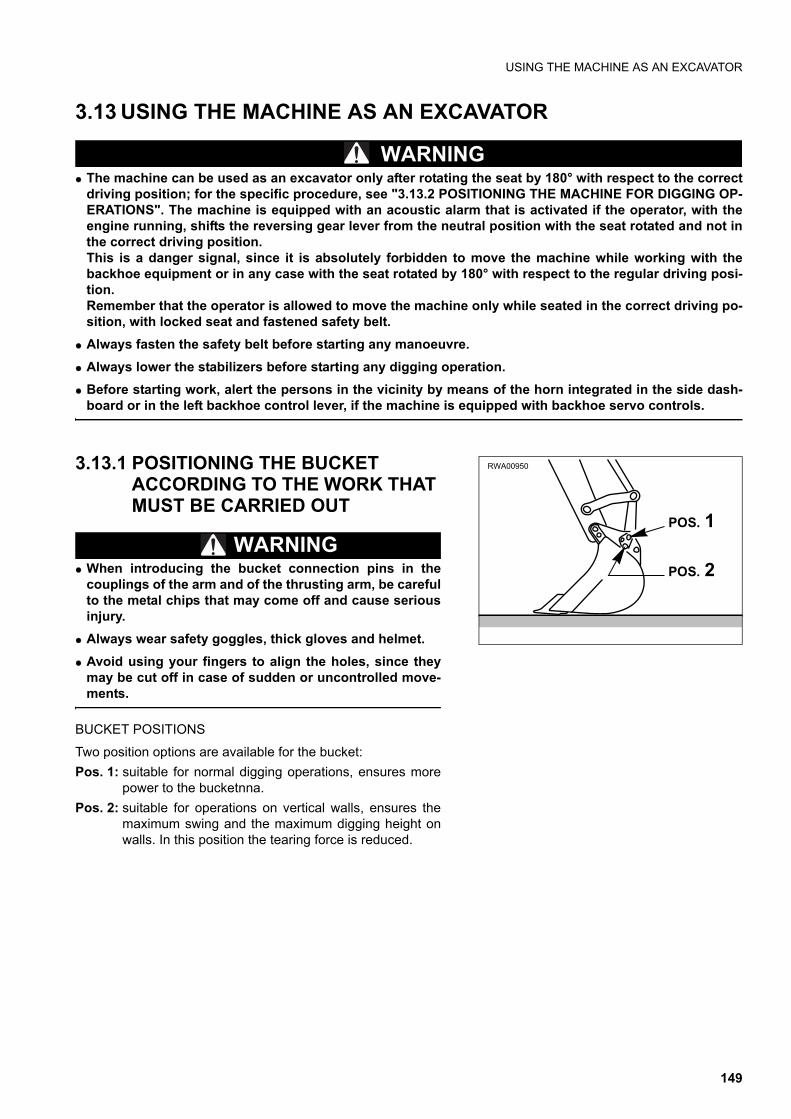
USING THE MACHINE AS AN EXCAVATOR
3.13 USING THE MACHINE AS AN EXCAVATOR
WARNINGq The machine can be used as an excavator only after rotating the seat by 180° with respect to the correct
driving position; for the specific procedure, see "3.13.2 POSITIONING THE MACHINE FOR DIGGING OP-ERATIONS". The machine is equipped with an acoustic alarm that is activated if the operator, with theengine running, shifts the reversing gear lever from the neutral position with the seat rotated and not inthe correct driving position.This is a danger signal, since it is absolutely forbidden to move the machine while working with thebackhoe equipment or in any case with the seat rotated by 180° with respect to the regular driving posi-tion.Remember that the operator is allowed to move the machine only while seated in the correct driving po-sition, with locked seat and fastened safety belt.
q Always fasten the safety belt before starting any manoeuvre.
q Always lower the stabilizers before starting any digging operation.
q Before starting work, alert the persons in the vicinity by means of the horn integrated in the side dash-board or in the left backhoe control lever, if the machine is equipped with backhoe servo controls.
3.13.1 POSITIONING THE BUCKET ACCORDING TO THE WORK THAT MUST BE CARRIED OUT
WARNINGq When introducing the bucket connection pins in the
couplings of the arm and of the thrusting arm, be carefulto the metal chips that may come off and cause seriousinjury.
q Always wear safety goggles, thick gloves and helmet.
q Avoid using your fingers to align the holes, since theymay be cut off in case of sudden or uncontrolled move-ments.
BUCKET POSITIONS
Two position options are available for the bucket:
Pos. 1: suitable for normal digging operations, ensures morepower to the bucketnna.
Pos. 2: suitable for operations on vertical walls, ensures themaximum swing and the maximum digging height onwalls. In this position the tearing force is reduced.
RWA00950
POS. 1
POS. 2
149
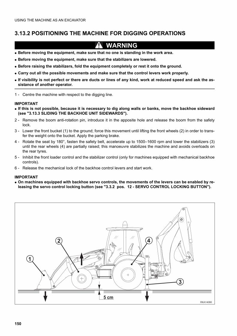
USING THE MACHINE AS AN EXCAVATOR
3.13.2 POSITIONING THE MACHINE FOR DIGGING OPERATIONS
WARNINGq Before moving the equipment, make sure that no one is standing in the work area.
q Before moving the equipment, make sure that the stabilizers are lowered.
q Before raising the stabilizers, fold the equipment completely or rest it onto the ground.
q Carry out all the possible movements and make sure that the control levers work properly.
q If visibility is not perfect or there are ducts or lines of any kind, work at reduced speed and ask the as-sistance of another operator.
1 - Centre the machine with respect to the digging line.
IMPORTANTq If this is not possible, because it is necessary to dig along walls or banks, move the backhoe sideward
(see "3.13.3 SLIDING THE BACKHOE UNIT SIDEWARDS").
2 - Remove the boom anti-rotation pin, introduce it in the apposite hole and release the boom from the safetylock.
3 - Lower the front bucket (1) to the ground; force this movement until lifting the front wheels (2) in order to trans-fer the weight onto the bucket. Apply the parking brake.
4 - Rotate the seat by 180°, fasten the safety belt, accelerate up to 1500–1600 rpm and lower the stabilizers (3)until the rear wheels (4) are partially raised; this manoeuvre stabilizes the machine and avoids overloads onthe rear tyres.
5 - Inhibit the front loader control and the stabilizer control (only for machines equipped with mechanical backhoecontrols).
6 - Release the mechanical lock of the backhoe control levers and start work.
IMPORTANTq On machines equipped with backhoe servo controls, the movements of the levers can be enabled by re-
leasing the servo control locking button (see "3.3.2 pos. 12 - SERVO CONTROL LOCKING BUTTON").
�����
���
�
� �
�
150
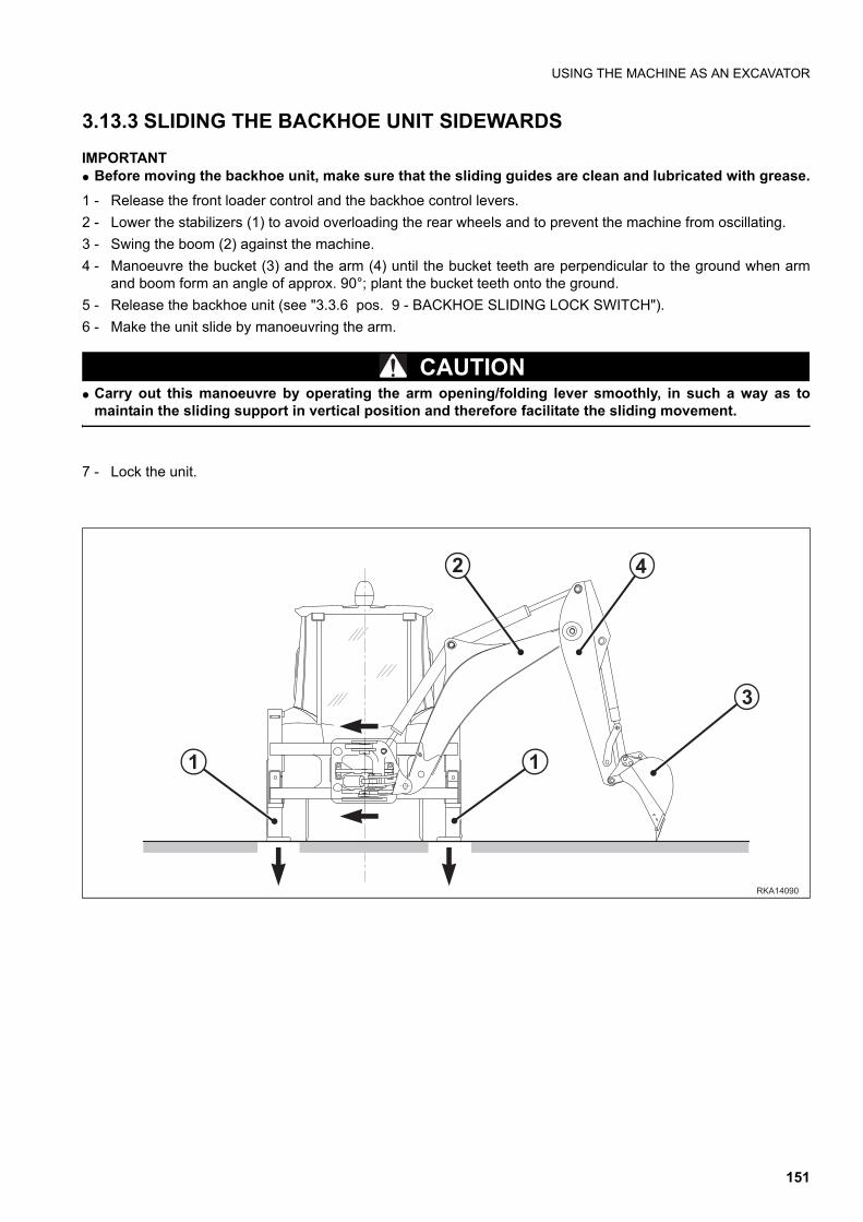
USING THE MACHINE AS AN EXCAVATOR
3.13.3 SLIDING THE BACKHOE UNIT SIDEWARDS
IMPORTANTq Before moving the backhoe unit, make sure that the sliding guides are clean and lubricated with grease.
1 - Release the front loader control and the backhoe control levers.
2 - Lower the stabilizers (1) to avoid overloading the rear wheels and to prevent the machine from oscillating.
3 - Swing the boom (2) against the machine.
4 - Manoeuvre the bucket (3) and the arm (4) until the bucket teeth are perpendicular to the ground when armand boom form an angle of approx. 90°; plant the bucket teeth onto the ground.
5 - Release the backhoe unit (see "3.3.6 pos. 9 - BACKHOE SLIDING LOCK SWITCH").
6 - Make the unit slide by manoeuvring the arm.
CAUTIONq Carry out this manoeuvre by operating the arm opening/folding lever smoothly, in such a way as to
maintain the sliding support in vertical position and therefore facilitate the sliding movement.
7 - Lock the unit.
�����
�
�
�
�
�
151
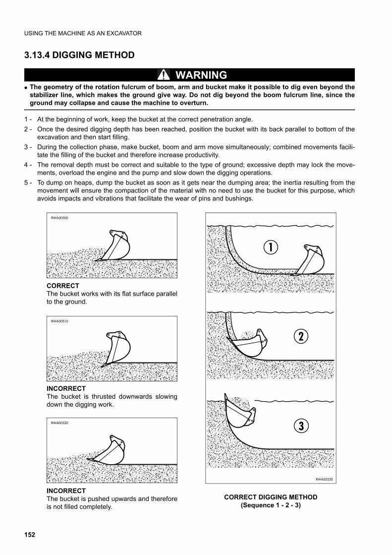
USING THE MACHINE AS AN EXCAVATOR
3.13.4 DIGGING METHOD
WARNINGq The geometry of the rotation fulcrum of boom, arm and bucket make it possible to dig even beyond the
stabilizer line, which makes the ground give way. Do not dig beyond the boom fulcrum line, since theground may collapse and cause the machine to overturn.
1 - At the beginning of work, keep the bucket at the correct penetration angle.
2 - Once the desired digging depth has been reached, position the bucket with its back parallel to bottom of theexcavation and then start filling.
3 - During the collection phase, make bucket, boom and arm move simultaneously; combined movements facili-tate the filling of the bucket and therefore increase productivity.
4 - The removal depth must be correct and suitable to the type of ground; excessive depth may lock the move-ments, overload the engine and the pump and slow down the digging operations.
5 - To dump on heaps, dump the bucket as soon as it gets near the dumping area; the inertia resulting from themovement will ensure the compaction of the material with no need to use the bucket for this purpose, whichavoids impacts and vibrations that facilitate the wear of pins and bushings.
RWA00530
3
2
1
CORRECT DIGGING METHOD(Sequence 1 - 2 - 3)
RWA00500
CORRECTThe bucket works with its flat surface parallelto the ground.
RWA00510
INCORRECTThe bucket is thrusted downwards slowingdown the digging work.
RWA00520
INCORRECTThe bucket is pushed upwards and thereforeis not filled completely.
152
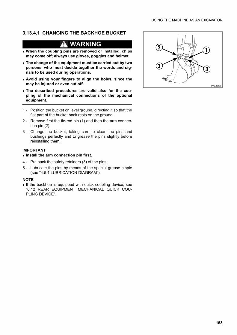
USING THE MACHINE AS AN EXCAVATOR
3.13.4.1 CHANGING THE BACKHOE BUCKET
WARNINGq When the coupling pins are removed or installed, chips
may come off; always use gloves, goggles and helmet.
q The change of the equipment must be carried out by twopersons, who must decide together the words and sig-nals to be used during operations.
q Avoid using your fingers to align the holes, since themay be injured or even cut off.
q The described procedures are valid also for the cou-pling of the mechanical connections of the optionalequipment.
1 - Position the bucket on level ground, directing it so that theflat part of the bucket back rests on the ground.
2 - Remove first the tie-rod pin (1) and then the arm connec-tion pin (2).
3 - Change the bucket, taking care to clean the pins andbushings perfectly and to grease the pins slightly beforereinstalling them.
IMPORTANTq Install the arm connection pin first.
4 - Put back the safety retainers (3) of the pins.
5 - Lubricate the pins by means of the special grease nipple(see "4.5.1 LUBRICATION DIAGRAM").
NOTEq If the backhoe is equipped with quick coupling device, see
"6.12 REAR EQUIPMENT MECHANICAL QUICK COU-PLING DEVICE".
RWA03670
2
3 3
1
153
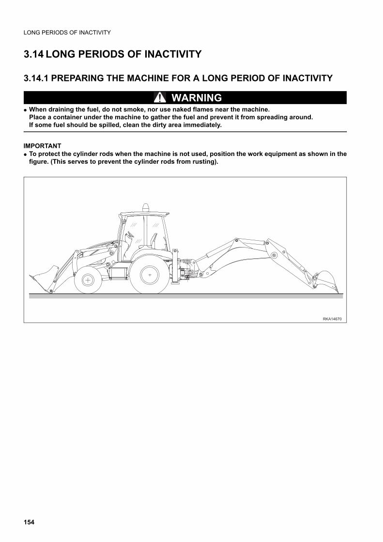
LONG PERIODS OF INACTIVITY
3.14 LONG PERIODS OF INACTIVITY
3.14.1 PREPARING THE MACHINE FOR A LONG PERIOD OF INACTIVITY
WARNINGq When draining the fuel, do not smoke, nor use naked flames near the machine.
Place a container under the machine to gather the fuel and prevent it from spreading around.If some fuel should be spilled, clean the dirty area immediately.
IMPORTANTq To protect the cylinder rods when the machine is not used, position the work equipment as shown in the
figure. (This serves to prevent the cylinder rods from rusting).
������
154

LONG PERIODS OF INACTIVITY
NOTEq This preliminary operations must be carried out when the machine is going to remain unused for approximately 1
month; if the period of inactivity is expected to be longer, see also "3.14.2 PREPARING THE ENGINE FOR ALONG PERIOD OF INACTIVITY".
If the machine is going to remain unused for a long period, to keep its components in good conditions it is advisa-ble to store it in a sheltered place and to take the following measures:
1 - Clean the inside and the outside of the machine completely and very carefully, retouching any scratch on thepaintwork in order to avoid oxidation.
2 - Drain and change all the fluids of the hydraulic circuits and the lubricants (axles, reduction gears, converter),following the indications given in the maintenance instructions.
3 - Change all the filtering elements (air filter, engine oil filter, hydraulic circuit filters, fuel filter).
4 - To prevent the deformation of the tyre sidewalls, insert supports or blocks under the axles, to nullify the weightof the machine.
5 - Grease the exposed rods of the hydraulic cylinders and the equipment joints.
6 - Shift the machine controls to the neutral position and engage the safety locks.
7 - Seal the end of the exhaust pipe and the engine breather outlets.
8 - Refuel completely.
9 - Remove the battery, check the electrolyte level and make sure that the battery is charged.Place the battery in a room with suitable temperature and recharge it periodically.
10 - Lock the cab doors, the filler cap and the engine hood.
11 - Seal the filler cap.
155
LONG PERIODS OF INACTIVITY
3.14.2 PREPARING THE ENGINE FOR A LONG PERIOD OF INACTIVITYNOTEq These operations must be carried out only if the engine is going to remain unused for more than 1 month.
q The first two operations must be carried out only on engines that have already run for more than 200 hours.
1 - Drain the oil from the oil pan and fill it with washing oil FIAT L35.
2 - Start the engine and let it idle for 15 minutes.Stop the engine and drain the oil.
3 - Fill the oil pan to the MIN. level with SAE 30 oil or with oil corresponding to the MIL - 2160B – type 2 specifica-tions.
4 - Empty the fuel filters, disconnect the fuel pump intake pipe and connect it to an outside tank filled with CBF(ISO 4113) oil.
5 - Start the engine and let it run at 800–1000 rpm for 15 minutes.At this point, use a syringe to slowly spray 40 g of SAE30 oil or of an oil corresponding to the MIL - 2160B -type 2 specifications into the suction manifold (taking approximately 10 seconds).
6 - Stop the engine and drain the oil from the oil pan.
NOTEq Recovered oil can be used again, for other two or three times, when preparing the engine for a long period of in-
activity.
7 - Loosen the alternator, fan and coolant pump belts.
8 - Reconnect the fuel pump intake pipe to the fuel tank.
9 - Seal the exhaust pipe and all the intake and breather openings with adhesive tape and vynil bags.
10 - Position a sign with the clear writing “NO ENGINE OIL” on the steering wheel and on the engine.
IMPORTANTq These operations must be repeated every 6 months.
3.14.3 MAINTENANCE DURING A PERIOD OF INACTIVITYNOTEq These operations must be carried out once a month.
1 - Recharge the battery and install it on the machine.
2 - Remove the seals from tank, exhaust pipe and breather outlets.
3 - Check the tyre pressure and remove the support blocks from under the machine.
4 - Start the engine and let it idle for 15 minutes.
5 - While warming the engine, remove the protection grease from the exposed rods of the hydraulic cylinders.
6 - Before moving the machine, make sure that the instruments, warning lights, lights, direction indicators, wind-shield wipers and stop lights function correctly.
7 - As soon as possible, warm the hydraulic cylinders by slowly lifting and extending all the equipment more thanonce.
8 - Travel for short distances at low speed, applying the brakes every now and then to allow the braking surfacesto settle down.
156
LONG PERIODS OF INACTIVITY
3.14.4 RESTARTING THE ENGINENOTEq These operations must be carried out if the machine has been prepared for a period of inactivity longer than 1
month.
1 - Remove the seals from the exhaust pipe and the filler cap.
2 - Open the engine hood and the cab.
3 - Remove the seals from the intake and breather openings.
4 - Drain the oil contained in the injection pump.
5 - Fill the engine with the oil prescribed, suitable for the ambient temperature.
6 - Tighten the alternator, fan and coolant pump belts.
7 - Check all the fluid levels (coolant, windshield detergent, fuel, oil in the gearbox and axle hydraulic circuits).
8 - Check the battery charge and install it.
9 - Start the engine by proceeding as indicated in paragraph "3.6.2 STARTING THE ENGINE" and make surethat the engine oil pressure warning light goes out when the starter has run for approx. 5 seconds.
10 - After starting the engine, let it idle for 15 minutes.
11 - Warm up the hydraulic cylinders by slowly lifting and extending all the equipment more than once.
3.14.5 AFTER THE PERIOD OF INACTIVITYConsidering that different periods of inactivity can have different durations, the functions of the machine can be re-stored according to two different procedures:
1 - If the period of inactivity lasted for more than one month, follow the instructions given in paragraphs "3.14.4RESTARTING THE ENGINE" and "3.14.3 MAINTENANCE DURING A PERIOD OF INACTIVITY".
2 - If the period of inactivity has lasted for less than one month, follow the indications given in paragraph "3.14.3MAINTENANCE DURING A PERIOD OF INACTIVITY".
157
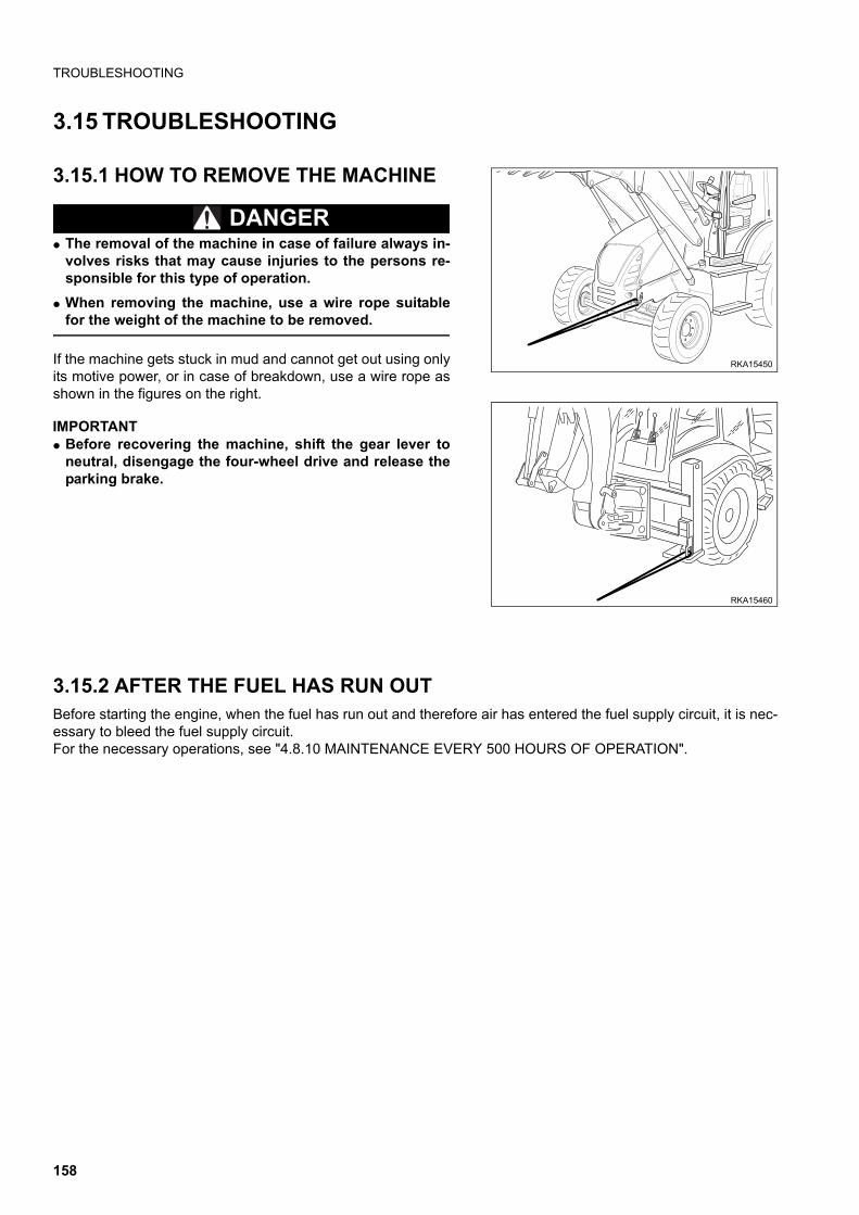
TROUBLESHOOTING
3.15 TROUBLESHOOTING
3.15.1 HOW TO REMOVE THE MACHINE
DANGERq The removal of the machine in case of failure always in-
volves risks that may cause injuries to the persons re-sponsible for this type of operation.
q When removing the machine, use a wire rope suitablefor the weight of the machine to be removed.
If the machine gets stuck in mud and cannot get out using onlyits motive power, or in case of breakdown, use a wire rope asshown in the figures on the right.
IMPORTANTq Before recovering the machine, shift the gear lever to
neutral, disengage the four-wheel drive and release theparking brake.
3.15.2 AFTER THE FUEL HAS RUN OUTBefore starting the engine, when the fuel has run out and therefore air has entered the fuel supply circuit, it is nec-essary to bleed the fuel supply circuit.For the necessary operations, see "4.8.10 MAINTENANCE EVERY 500 HOURS OF OPERATION".
RKA15450
RKA15460
158
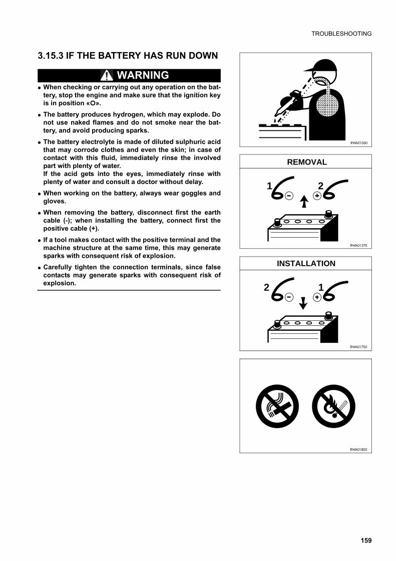
TROUBLESHOOTING
3.15.3 IF THE BATTERY HAS RUN DOWN
WARNINGq When checking or carrying out any operation on the bat-
tery, stop the engine and make sure that the ignition keyis in position « ».
q The battery produces hydrogen, which may explode. Donot use naked flames and do not smoke near the bat-tery, and avoid producing sparks.
q The battery electrolyte is made of diluted sulphuric acidthat may corrode clothes and even the skin; in case ofcontact with this fluid, immediately rinse the involvedpart with plenty of water.If the acid gets into the eyes, immediately rinse withplenty of water and consult a doctor without delay.
q When working on the battery, always wear goggles andgloves.
q When removing the battery, disconnect first the earthcable (-); when installing the battery, connect first thepositive cable (+).
q If a tool makes contact with the positive terminal and themachine structure at the same time, this may generatesparks with consequent risk of explosion.
q Carefully tighten the connection terminals, since falsecontacts may generate sparks with consequent risk ofexplosion.
RWA01060
1 2
RWA01370
REMOVAL
RWA01800
2 1
RWA01700
INSTALLATION
159
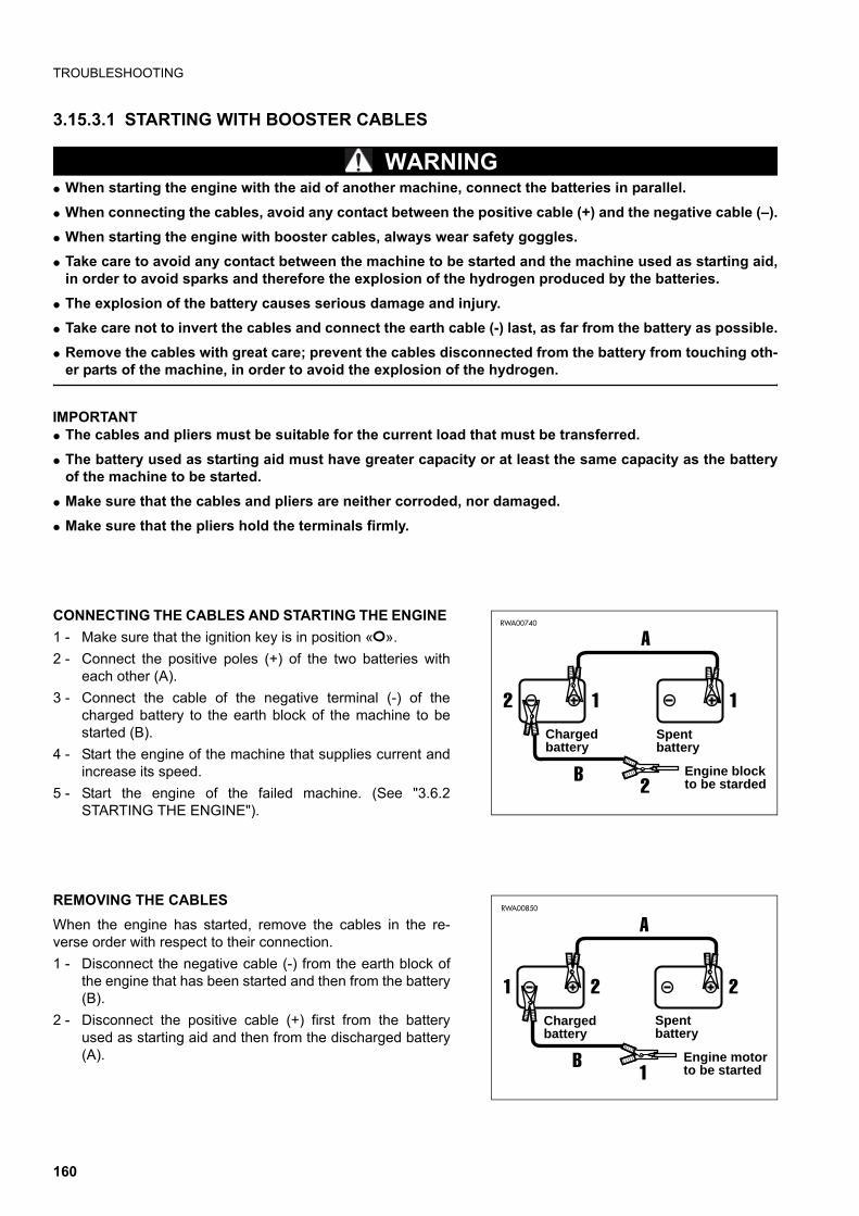
TROUBLESHOOTING
3.15.3.1 STARTING WITH BOOSTER CABLES
WARNINGq When starting the engine with the aid of another machine, connect the batteries in parallel.
q When connecting the cables, avoid any contact between the positive cable (+) and the negative cable (–).
q When starting the engine with booster cables, always wear safety goggles.
q Take care to avoid any contact between the machine to be started and the machine used as starting aid,in order to avoid sparks and therefore the explosion of the hydrogen produced by the batteries.
q The explosion of the battery causes serious damage and injury.
q Take care not to invert the cables and connect the earth cable (-) last, as far from the battery as possible.
q Remove the cables with great care; prevent the cables disconnected from the battery from touching oth-er parts of the machine, in order to avoid the explosion of the hydrogen.
IMPORTANTq The cables and pliers must be suitable for the current load that must be transferred.
q The battery used as starting aid must have greater capacity or at least the same capacity as the batteryof the machine to be started.
q Make sure that the cables and pliers are neither corroded, nor damaged.
q Make sure that the pliers hold the terminals firmly.
CONNECTING THE CABLES AND STARTING THE ENGINE
1 - Make sure that the ignition key is in position « ».
2 - Connect the positive poles (+) of the two batteries witheach other (A).
3 - Connect the cable of the negative terminal (-) of thecharged battery to the earth block of the machine to bestarted (B).
4 - Start the engine of the machine that supplies current andincrease its speed.
5 - Start the engine of the failed machine. (See "3.6.2STARTING THE ENGINE").
REMOVING THE CABLES
When the engine has started, remove the cables in the re-verse order with respect to their connection.
1 - Disconnect the negative cable (-) from the earth block ofthe engine that has been started and then from the battery(B).
2 - Disconnect the positive cable (+) first from the batteryused as starting aid and then from the discharged battery(A).
A
B
2 1
2
RWA00740
1Spentbattery
Chargedbattery
Engine blockto be starded
A
B
1 2
1
RWA00850
2Spentbattery
Chargedbattery
Engine motorto be started
160

TROUBLESHOOTING
3.15.4 OTHER TROUBLES(•) Always contact your Komatsu Dealer when you have to carry out this operation.
• If the anomaly or its cause is not included in the table below, contact your Komatsu Dealer for the necessaryrepair.
3.15.4.1 ELECTRICAL CIRCUIT
3.15.4.2 HYDRAULIC SYSTEM
TROUBLE CAUSE REMEDY
Lights do not work satisfactorily evenwith engine running at high speed:
• Faulty cables.
• Faulty fan belt tension.
(•) Check and repair any loose terminal and connection.
• Adjust fan tension (see “EVERY 250 HOURS).
Lights come on intermittently with en-gine running:
Alternator charge warning light does notgo out with engine running and increas-ing speed:
• Faulty alternator.
• Faulty cables.
(•) Change.
(•) Check and repair.
Alternator emits an abnormal noise: • Faulty alternator. (•) Change.
Starter does not turn with key in STARTposition:
• Faulty cables.
• Battery charge insufficient.
• Faulty engine start fuse.
(•) Check and repair.
• Charge battery.
• Change.
Starter pinion engages and then disen-gages:
• Battery charge insufficient. • Charge battery.
Starter makes engine run slowly:• Battery charge insufficient.
• Faulty starter.
• Charge battery.
(•) Change.
Starter disengages before engine hasstarted:
• Faulty cables.
• Battery charge insufficient.
(•) Check and repair.
• Charge battery.
Engine oil pressure warning light doesnot come on when engine is stopped(ignition key in position « »):
• Faulty bulb.
• Faulty pressure sensor.
(•) Change.
(•) Change.
Alternator charge warning light does notcome on when engine is stopped (igni-tion key in position « »):
• Faulty bulb.
• Faulty cables.
(•) Change.
(•) Check and repair.
TROUBLE CAUSE REMEDY
Pump emits an abnormal noise:
• No oil in the tank.
• Faulty pump.
• Hydraulic oil unsuitable for the tem-perature.
• Top up.
(•) Repair or change.
• Change.
Equipment control levers do not returnautomatically to neutral position:
• Broken return spring or seized ele-ment.
(•) Change spring or distributor ele-ment.
Equipment moves only at low speed:
• Faulty pump.
• Max. pressure valves out of rating, or not closed due to impurities.
• Dirty drain filter.
(•) Repair or change.
(•) Calibrate or change.
• Change.
161
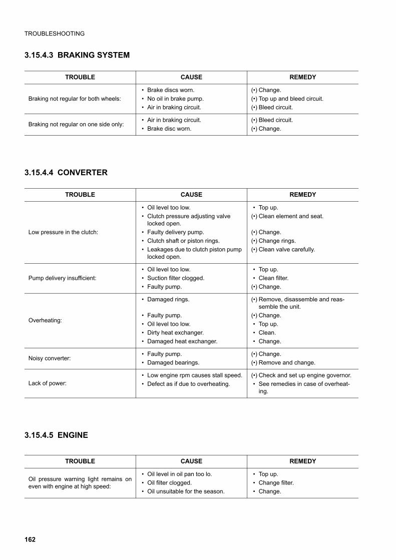
TROUBLESHOOTING
3.15.4.3 BRAKING SYSTEM
3.15.4.4 CONVERTER
3.15.4.5 ENGINE
TROUBLE CAUSE REMEDY
Braking not regular for both wheels:
• Brake discs worn.
• No oil in brake pump.
• Air in braking circuit.
(•) Change.
(•) Top up and bleed circuit.
(•) Bleed circuit.
Braking not regular on one side only:• Air in braking circuit.
• Brake disc worn.
(•) Bleed circuit.
(•) Change.
TROUBLE CAUSE REMEDY
Low pressure in the clutch:
• Oil level too low.
• Clutch pressure adjusting valve locked open.
• Faulty delivery pump.
• Clutch shaft or piston rings.
• Leakages due to clutch piston pump locked open.
• Top up.
(•) Clean element and seat.
(•) Change.
(•) Change rings.
(•) Clean valve carefully.
Pump delivery insufficient:
• Oil level too low.
• Suction filter clogged.
• Faulty pump.
• Top up.
• Clean filter.
(•) Change.
Overheating:
• Damaged rings.
• Faulty pump.
• Oil level too low.
• Dirty heat exchanger.
• Damaged heat exchanger.
(•) Remove, disassemble and reas-semble the unit.
(•) Change.
• Top up.
• Clean.
• Change.
Noisy converter:• Faulty pump.
• Damaged bearings.
(•) Change.
(•) Remove and change.
Lack of power:• Low engine rpm causes stall speed.
• Defect as if due to overheating.
(•) Check and set up engine governor.
• See remedies in case of overheat-ing.
TROUBLE CAUSE REMEDY
Oil pressure warning light remains oneven with engine at high speed:
• Oil level in oil pan too lo.
• Oil filter clogged.
• Oil unsuitable for the season.
• Top up.
• Change filter.
• Change.
162
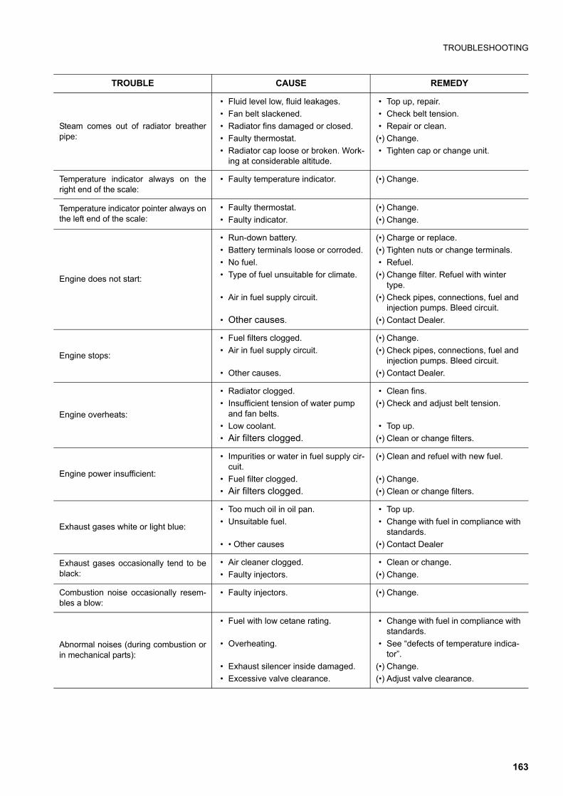
TROUBLESHOOTING
Steam comes out of radiator breatherpipe:
• Fluid level low, fluid leakages.
• Fan belt slackened.
• Radiator fins damaged or closed.
• Faulty thermostat.
• Radiator cap loose or broken. Work-ing at considerable altitude.
• Top up, repair.
• Check belt tension.
• Repair or clean.
(•) Change.
• Tighten cap or change unit.
Temperature indicator always on theright end of the scale:
• Faulty temperature indicator. (•) Change.
Temperature indicator pointer always onthe left end of the scale:
• Faulty thermostat.
• Faulty indicator.
(•) Change.
(•) Change.
Engine does not start:
• Run-down battery.
• Battery terminals loose or corroded.
• No fuel.
• Type of fuel unsuitable for climate.
• Air in fuel supply circuit.
• Other causes.
(•) Charge or replace.
(•) Tighten nuts or change terminals.
• Refuel.
(•) Change filter. Refuel with winter type.
(•) Check pipes, connections, fuel and injection pumps. Bleed circuit.
(•) Contact Dealer.
Engine stops:
• Fuel filters clogged.
• Air in fuel supply circuit.
• Other causes.
(•) Change.
(•) Check pipes, connections, fuel and injection pumps. Bleed circuit.
(•) Contact Dealer.
Engine overheats:
• Radiator clogged.
• Insufficient tension of water pump and fan belts.
• Low coolant.
• Air filters clogged.
• Clean fins.
(•) Check and adjust belt tension.
• Top up.
(•) Clean or change filters.
Engine power insufficient:
• Impurities or water in fuel supply cir-cuit.
• Fuel filter clogged.
• Air filters clogged.
(•) Clean and refuel with new fuel.
(•) Change.
(•) Clean or change filters.
Exhaust gases white or light blue:
• Too much oil in oil pan.
• Unsuitable fuel.
• • Other causes
• Top up.
• Change with fuel in compliance with standards.
(•) Contact Dealer
Exhaust gases occasionally tend to beblack:
• Air cleaner clogged.
• Faulty injectors.
• Clean or change.
(•) Change.
Combustion noise occasionally resem-bles a blow:
• Faulty injectors. (•) Change.
Abnormal noises (during combustion orin mechanical parts):
• Fuel with low cetane rating.
• Overheating.
• Exhaust silencer inside damaged.
• Excessive valve clearance.
• Change with fuel in compliance with standards.
• See “defects of temperature indica-tor”.
(•) Change.
(•) Adjust valve clearance.
TROUBLE CAUSE REMEDY
163

THIS PAGE WAS INTENTIONALLY LEFT EMPTY
164

��������� �
165
GUIDE TO MAINTENANCE
4.1 GUIDE TO MAINTENANCEq Before opening the engine hood, engage the safety locks of both the front loader and the backhoe.
q If it is necessary to check the hydraulic oil level in the tank, set the machine in transport position (see "3.1 SAFE-TY LOCKS").
q Carry out any maintenance operation on firm and level ground, after applying the parking brake.
q Use Komatsu genuine oils and greases; choose oils suitable for the ambient temperature.
q Use clean oils and greases. Keep the oil and grease containers clean and prevent any foreign matter from get-ting into them.
q Always keep the machine clean: this makes it easier to locate any failed part.In particular, clean the grease nipples, the breathers and the areas near the openings for the level checks, toprevent any impurities from getting into/on them.
q Draining hot oil or coolant immediately after stopping the engine is hazardous. Wait for the engine to cool downuntil reaching a temperature of at least 40–50° C.
q When changing the oil or the filters, check for metal particles. If you find large quantities of metal particles, con-tact your Komatsu Dealer.
q Check and change the oil in a clean place and prevent any impurities from getting into the tank.
q Before carrying out any maintenance operation, hang warning plates on the ignition switch, the control leversand the cab doors, to prevent anyone from starting the engine.
q When performing maintenance operations, always take the precautions indicated on the safety plates applied tothe machine.
q Instructions for arc welding:
1 - Turn the ignition key to position «O».
2 - Disconnect the battery (first the negative pole and then the positive pole).
3 - Disconnect the alternator.
4 - Do not apply more than 200V continuously.
5 - Connect the earth cable within 1 m from the point where the welding operation must be carried out.
6 - Avoid placing gaskets and bearings between the welding area and the earth cable.
q Do not use flammable fluids to clean any parts of the machine. Keep naked flames away from these fluids andavoid smoking.
q When O rings and gaskets are removed, clean the sealing surfaces thoroughly and replace the O rings and gas-kets with new ones. Fit the O rings and gaskets correctly when reassembling.
q Avoid keeping loose objects or tools in your pockets: they may fall out and drop into the machine, especiallywhen you open covers and work on the machine while bending over it.
q When washing the machine, do not direct the high-pressure water jet onto the radiator and the heat exchanger.
q When washing the machine, protect the electric system connectors and avoid wetting the ignition switch.
q Before starting work in mud, under the rain, on seashores or river banks, provide for lubrication where required.Wash the machine immediately after work to protect the components from rust. Lubricate the equipment jointsmore frequently than usual.
q When the worksite is particularly dusty, proceed as follows:
1 - Check the air filter for any clogging and clean it more frequently than usual.
2 - Clean the radiator and the heat exchanger frequently, to avoid any clogging of the fins.
3 - Change the diesel oil filter more frequently than usual.
4 - Clean the electrical components, especially the starter and the alternator, to avoid any accumulation of dust.
166

GUIDE TO MAINTENANCE
q Never mix oils of different brands.Do not top up with any oil different from those used in the machine. If necessary, drain the tanks and fill themwith the oil of the new brand.
WARNINGq Oils, filters, coolant, gaskets, electric wires and batteries are considered special waste and must be col-
lected and disposed of according to the regulations in force.
q The combustible material of some components may become extremely dangerous if it burns. For thisreason, avoid any contact of burnt material with your skin or eyes and do not inhale the fumes (see "2.8PRECAUTIONS TO BE TAKEN DURING MAINTENANCE").
167
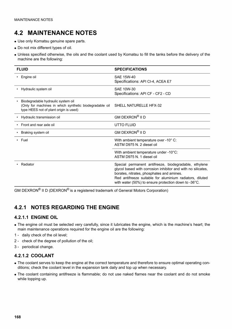
MAINTENANCE NOTES
4.2 MAINTENANCE NOTESq Use only Komatsu genuine spare parts.
q Do not mix different types of oil.
q Unless specified otherwise, the oils and the coolant used by Komatsu to fill the tanks before the delivery of themachine are the following:
GM DEXRON® II D (DEXRON® is a registered trademark of General Motors Corporation)
4.2.1 NOTES REGARDING THE ENGINE
4.2.1.1 ENGINE OIL
q The engine oil must be selected very carefully, since it lubricates the engine, which is the machine’s heart; themain maintenance operations required for the engine oil are the following:
1 - daily check of the oil level;
2 - check of the degree of pollution of the oil;
3 - periodical change.
4.2.1.2 COOLANT
q The coolant serves to keep the engine at the correct temperature and therefore to ensure optimal operating con-ditions; check the coolant level in the expansion tank daily and top up when necessary.
q The coolant containing antifreeze is flammable; do not use naked flames near the coolant and do not smokewhile topping up.
FLUID SPECIFICATIONS
• Engine oil SAE 15W-40Specifications: API CI-4, ACEA E7
• Hydraulic system oil SAE 10W-30Specifications: API CF - CF2 - CD
• Biodegradable hydraulic system oil(Only for machines in which synthetic biodegradable oiltype HEES not of plant origin is used)
SHELL NATURELLE HFX-32
• Hydraulic transmission oil GM DEXRON® II D
• Front and rear axle oil UTTO FLUID
• Braking system oil GM DEXRON® II D
• Fuel With ambient temperature over -10° C:ASTM D975 N. 2 diesel oil
With ambient temperature under -10°C:ASTM D975 N. 1 diesel oil
• Radiator Special permanent antifreeze, biodegradable, ethyleneglycol based with corrosion inhibitor and with no silicates,borates, nitrates, phosphates and amines.Red antifreeze suitable for aluminium radiators, dilutedwith water (50%) to ensure protection down to -36°C.
168
MAINTENANCE NOTES
q Use only red permanent ethylene glycol based antifreeze, with corrosion inhibitors and antifoam products, suita-ble for aluminium radiators. If pure, dilute with water (50%).
q The use of permanent antifreeze requires only the check of the level and the periodical change of the fluid. It isnot necessary to wash the cooling circuit.
q Use drinkable water and in any case soft water.
q Do not use corrosion inhibitors containing soluble oil, since they damage the rubber couplings.
q In case of doubt regarding the applicable standards for the use of antifreeze, contact your Komatsu Dealer, whowill supply you with exhaustive and precise information.
4.2.1.3 FUEL
q Always use fuel suitable for the engine. Other fuels with different specifications may damage the engine or re-duce its power.
q Always refuel at the end of work.
q When refuelling, make sure that there is no water on the fuel drum cover and take care not to draw condensatefrom the drum bottom.
q If fuel runs out, or if the fuel filter has been replaced, it is necessary to bleed the circuit.
4.2.2 NOTES REGARDING THE HYDRAULIC SYSTEMq Be extremely careful when performing maintenance operations on the hydraulic system, since soon after work
the oil is very hot.The circuit is pressurized not only during work, but also at the end of work.
q The maintenance operations required for the hydraulic system are the following:
1 - daily check of the oil level in the tank;
2 - periodical change of the oil filter;
3 - periodical change of the oil and cleaning of the intake filter.
q Always bleed the circuit after changing the oil filter or the oil.
q When a component is removed from the circuit, check the gaskets and O rings and change them if they are dam-aged.
q When a cylinder or a component of the hydraulic circuit is removed, after reassembly bleed the circuit by pro-ceeding as follows:
1 - start the engine and let it idle;
2 - extend all the cylinders 4-5 times, stopping them at approx. 100 mm from the end of stroke;
3 - slowly make all the cylinders reach the end of stroke for 3-4 times.
169
MAINTENANCE NOTES
4.2.3 NOTES REGARDING THE ELECTRIC SYSTEMq If the cables are wet or their insulating material is damaged, the electric system leaks and this may result in mal-
functions of the machine.
q The maintenance operations required for the electric system are the following:
1 - check of the alternator belt for damage or breakages;
2 - check of the battery electrolyte level.
q Do not remove or eliminate any electric component installed on the machine and do not install any electric com-ponent with characteristics different from those specified and approved by Komatsu.
q Keep the electric system dry.
q When working on seashores or river or lake banks, protect the jack plugs from corrosion.
q Do not connect any optional device to the fuses, ignition switch, battery, relays, etc.; for the installation of any op-tional equipment, contact your Komatsu Dealer.
q If any electric welding operation has to be carried out, disconnect the battery and the alternator.
4.2.4 NOTES REGARDING LUBRICATIONq Lubrication makes the operations carried out with the machine and work equipment smoother, while preventing
wear and the noise that may be produced if the joints are dry.
q Lubrication is to be carried out with grease or oil.
q The maintenance operations required for the components that need lubricating are the following:
1 - check of the levels;
2 - oil change;
3 - injection of grease through the grease nipples;
4 - grease lubrication with a brush.
q Use only the specified lubricants, according to the ambient temperature.
q Always clean the grease nipples before injecting grease and remove any excess grease after lubrication; thiscleaning operation must be performed with extreme care on the revolving parts.
q Check that the lubricant levels are correct, avoiding excessive or insufficient quantities.
170

MAINTENANCE NOTES
4.2.5 PARTS SUBJECT TO WEAR THAT PERIODICALLY NEED CHANGINGThe parts subject to wear such as filters, bucket teeth, etc. must be replaced according to the periodic mainte-nance intervals prescribed or when they reach the wear limit.The timely change of these parts ensures an economic use of the machine.Use only Komatsu genuine parts, which alone can guarantee excellent quality and interchangeability.
ITEM CODE DESCRIPTION Q.ty CHANGE INTERVAL
Hydraulic oil drain filter 42N-62-15470 Cartridge 1
EVERY 500 HOURSOF OPERATION
Engine oil filter EA504074043 Cartridge 1
Fuel filter EA504073234 Cartridge 1
Converter oil filter CA0040952 Cartridge 1EVERY 1000 HOURS
OF OPERATION
Air filter848101189
848101190
Main cartridge
Safety cartridge
1
1
WHEN REQUIRED
WHEN REQUIRED
Front bucket
312204054
801580085
801703012
Tooth
Screw
Nut
AR
AR
AR
—
—
—
Backhoe bucket
312204054
801580085
801703012
312204052
312204053
801580085
801014184
801703012
Central tooth
Screw
Nut
Right tooth
Left tooth
Screw
Side screw
Nut
AR
AR
AR
1
1
AR
4
AR
—
—
—
—
—
—
—
—
171
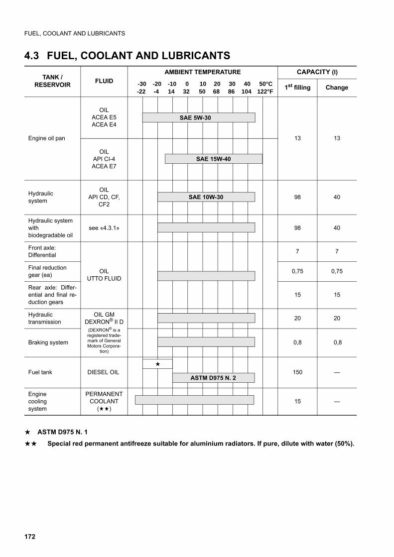
FUEL, COOLANT AND LUBRICANTS
4.3 FUEL, COOLANT AND LUBRICANTS
a ASTM D975 N. 1
aa Special red permanent antifreeze suitable for aluminium radiators. If pure, dilute with water (50%).
TANK /RESERVOIR
FLUID
AMBIENT TEMPERATURE CAPACITY (l)
1st filling Change
Engine oil pan
OILACEA E5ACEA E4
13 13
OILAPI CI-4ACEA E7
Hydraulic system
OILAPI CD, CF,
CF298 40
Hydraulic systemwith biodegradable oil
see «4.3.1» 98 40
Front axle: Differential
OILUTTO FLUID
7 7
Final reductiongear (ea)
0,75 0,75
Rear axle: Differ-ential and final re-duction gears
15 15
Hydraulic transmission
OIL GM DEXRON® II D
(DEXRON® is a registered trade-mark of General Motors Corpora-
tion)
20 20
Braking system 0,8 0,8
Fuel tank DIESEL OIL 150 —
Engine cooling system
PERMANENT COOLANT
(aa)15 —
SAE 15W-40
SAE 5W-30
a
ASTM D975 N. 2
SAE 10W-30
-30 -20 -10 0 10 20 30 40 50°C-22 -4 14 32 50 68 86 104 122°F
172
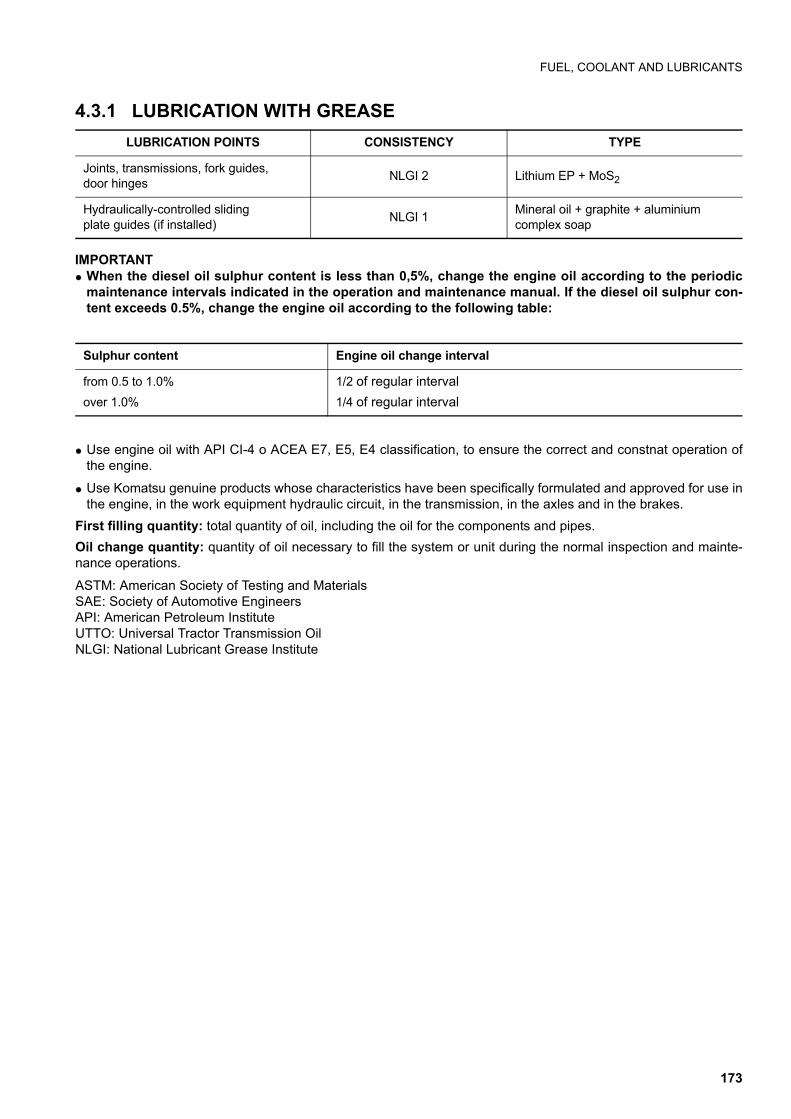
FUEL, COOLANT AND LUBRICANTS
4.3.1 LUBRICATION WITH GREASE
IMPORTANTq When the diesel oil sulphur content is less than 0,5%, change the engine oil according to the periodic
maintenance intervals indicated in the operation and maintenance manual. If the diesel oil sulphur con-tent exceeds 0.5%, change the engine oil according to the following table:
q Use engine oil with API CI-4 o ACEA E7, E5, E4 classification, to ensure the correct and constnat operation ofthe engine.
q Use Komatsu genuine products whose characteristics have been specifically formulated and approved for use inthe engine, in the work equipment hydraulic circuit, in the transmission, in the axles and in the brakes.
First filling quantity: total quantity of oil, including the oil for the components and pipes.
Oil change quantity: quantity of oil necessary to fill the system or unit during the normal inspection and mainte-nance operations.
ASTM: American Society of Testing and MaterialsSAE: Society of Automotive EngineersAPI: American Petroleum InstituteUTTO: Universal Tractor Transmission OilNLGI: National Lubricant Grease Institute
LUBRICATION POINTS CONSISTENCY TYPE
Joints, transmissions, fork guides,door hinges
NLGI 2 Lithium EP + MoS2
Hydraulically-controlled sliding plate guides (if installed)
NLGI 1Mineral oil + graphite + aluminiumcomplex soap
Sulphur content Engine oil change interval
from 0.5 to 1.0%
over 1.0%
1/2 of regular interval
1/4 of regular interval
173

FUEL, COOLANT AND LUBRICANTS
4.3.2 HOMOLOGATED SYNTHETIC BIODEGRADABLE LUBRICANTS “HEES”
Komatsu machines can be filled with synthetic biodegradable hydraulic oil type HEES not of plant origin and there-fore the use of the oils indicated in the following table is authorized and recommended: .
CAUTIONq It is not possible to mix the synthetic biodegradable oil type HEES with ordinary hydraulic oils, since
when the temperature increases insoluble compounds are generated, which are deposited on the filtersand clog them (the maximum concentration of ordinary oil must not exceed 1% of the total quantity ofoil).
q Biodegradable oil can be used only in the hydraulic system; it cannot be used for the engine, the trans-mission, the braking system, etc.
q Before introducing biodegradable oil in the hydraulic system, empty the system completely, disconnect-ing the cylinders and all the parts that may contain conventional oil, and replace the drain filter with anew one.
q Start the engine and let it idle without using the work equipment, wait until the oil reaches a temperatureof at least 40°C, then start moving the equipment, so that all the parts of the system are filled with oil.
q Stop the engine and check the oil level (see "4.8.6.a CHECKING THE HYDRAULIC OIL LEVEL").
SUPPLIER SYNTHETIC BIODEGRADABLE OIL “HEES”
KOMATSU BO 46 G4 (KES 07.872)
AGIP —
ARAL —
AVIA —
BP —
CONDAT CONDAT D 46 K
ELF —
ESSO —
FINA BIOHYDRAN SE 46
FUCHS —
KENDALL —
KUWAIT PETROLEUM K8 —
MOBIL EAL SYNDRAULIC
MOBIL (USA) —
PAKELO —
PANOLIN HLP SYNTH 46
SHELL NATURELLE HFX-32
TAMOIL —
TEXACO —
TOTAL HYDROBIO 46
VALVOLINE —
174
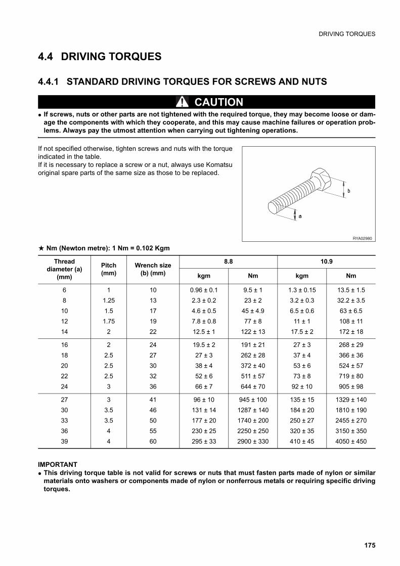
DRIVING TORQUES
4.4 DRIVING TORQUES
4.4.1 STANDARD DRIVING TORQUES FOR SCREWS AND NUTS
CAUTIONq If screws, nuts or other parts are not tightened with the required torque, they may become loose or dam-
age the components with which they cooperate, and this may cause machine failures or operation prob-lems. Always pay the utmost attention when carrying out tightening operations.
If not specified otherwise, tighten screws and nuts with the torqueindicated in the table.If it is necessary to replace a screw or a nut, always use Komatsuoriginal spare parts of the same size as those to be replaced.
a Nm (Newton metre): 1 Nm = 0.102 Kgm
IMPORTANTq This driving torque table is not valid for screws or nuts that must fasten parts made of nylon or similar
materials onto washers or components made of nylon or nonferrous metals or requiring specific drivingtorques.
��������
Threaddiameter (a)
(mm)
Pitch(mm)
Wrench size (b) (mm)
8.8 10.9
kgm Nm kgm Nm
6
8
10
12
14
1
1.25
1.5
1.75
2
10
13
17
19
22
0.96 ± 0.1
2.3 ± 0.2
4.6 ± 0.5
7.8 ± 0.8
12.5 ± 1
9.5 ± 1
23 ± 2
45 ± 4.9
77 ± 8
122 ± 13
1.3 ± 0.15
3.2 ± 0.3
6.5 ± 0.6
11 ± 1
17.5 ± 2
13.5 ± 1.5
32.2 ± 3.5
63 ± 6.5
108 ± 11
172 ± 18
16
18
20
22
24
2
2.5
2.5
2.5
3
24
27
30
32
36
19.5 ± 2
27 ± 3
38 ± 4
52 ± 6
66 ± 7
191 ± 21
262 ± 28
372 ± 40
511 ± 57
644 ± 70
27 ± 3
37 ± 4
53 ± 6
73 ± 8
92 ± 10
268 ± 29
366 ± 36
524 ± 57
719 ± 80
905 ± 98
27
30
33
36
39
3
3.5
3.5
4
4
41
46
50
55
60
96 ± 10
131 ± 14
177 ± 20
230 ± 25
295 ± 33
945 ± 100
1287 ± 140
1740 ± 200
2250 ± 250
2900 ± 330
135 ± 15
184 ± 20
250 ± 27
320 ± 35
410 ± 45
1329 ± 140
1810 ± 190
2455 ± 270
3150 ± 350
4050 ± 450
175
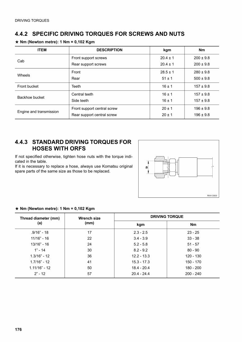
DRIVING TORQUES
4.4.2 SPECIFIC DRIVING TORQUES FOR SCREWS AND NUTSa Nm (Newton metre): 1 Nm = 0,102 Kgm
4.4.3 STANDARD DRIVING TORQUES FOR HOSES WITH ORFS
If not specified otherwise, tighten hose nuts with the torque indi-cated in the table.If it is necessary to replace a hose, always use Komatsu originalspare parts of the same size as those to be replaced.
a Nm (Newton metre): 1 Nm = 0,102 Kgm
ITEM DESCRIPTION kgm Nm
CabFront support screws
Rear support screws
20.4 ± 1
20.4 ± 1
200 ± 9.8
200 ± 9.8
WheelsFront
Rear
28.5 ± 1
51 ± 1
280 ± 9.8
500 ± 9.8
Front bucket Teeth 16 ± 1 157 ± 9.8
Backhoe bucketCentral teeth
Side teeth
16 ± 1
16 ± 1
157 ± 9.8
157 ± 9.8
Engine and transmissionFront support central screw
Rear support central screw
20 ± 1
20 ± 1
196 ± 9.8
196 ± 9.8
�������
$
Thread diameter (mm)(a)
Wrench size(mm)
DRIVING TORQUE
kgm Nm
.9/16” - 18
11/16” - 16
13/16” - 16
1” - 14
1.3/16” - 12
1.7/16” - 12
1.11/16” - 12
2” - 12
17
22
24
30
36
41
50
57
2.3 - 2.5
3.4 - 3.9
5.2 - 5.8
8.2 - 9.2
12.2 - 13.3
15.3 - 17.3
18.4 - 20.4
20.4 - 24.4
23 - 25
33 - 38
51 - 57
80 - 90
120 - 130
150 - 170
180 - 200
200 - 240
176
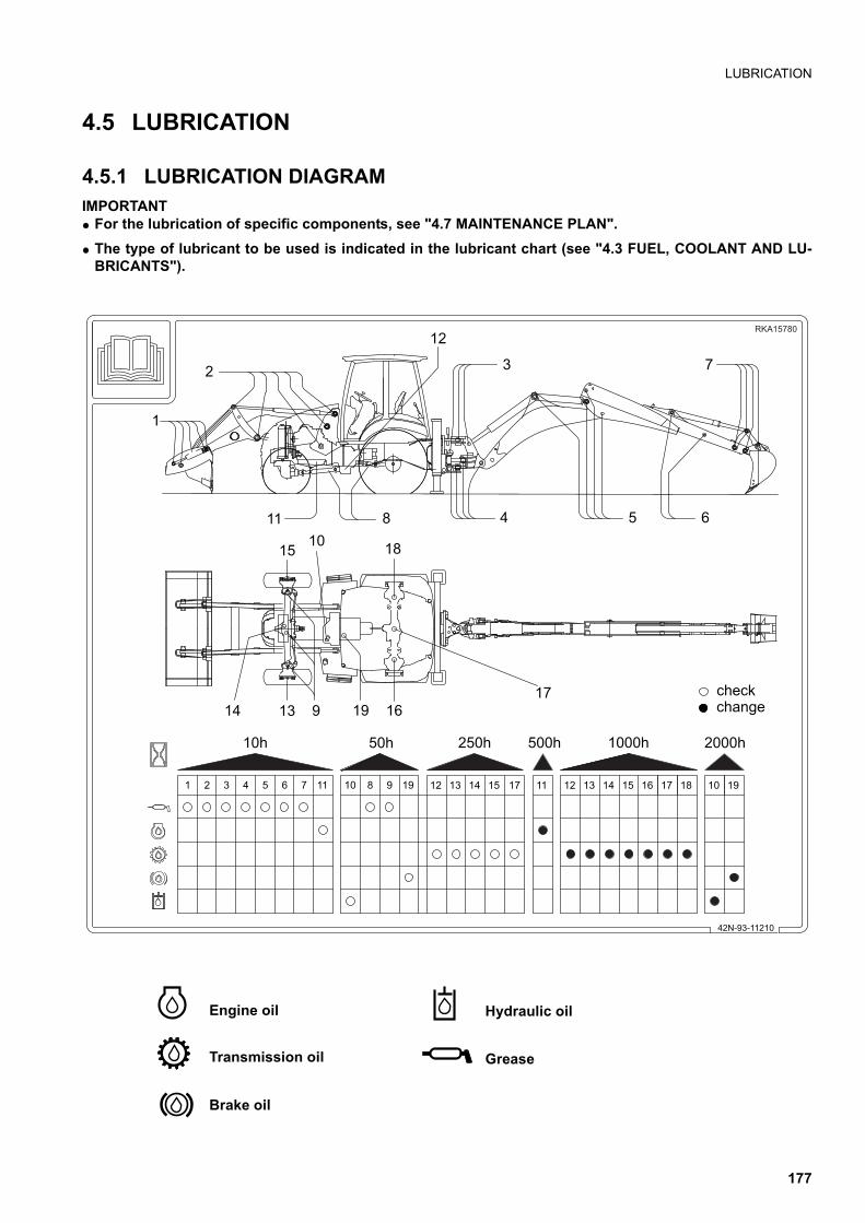
LUBRICATION
4.5 LUBRICATION
4.5.1 LUBRICATION DIAGRAMIMPORTANTq For the lubrication of specific components, see "4.7 MAINTENANCE PLAN".
q The type of lubricant to be used is indicated in the lubricant chart (see "4.3 FUEL, COOLANT AND LU-BRICANTS").
� � � � � � � �� � � � � � � � � � �
��"
#"$#%#"&'($
�
�
�
�
� �
�
� � �
�
��
�" �" � �" ���" ����"
���������
��� ��
Hydraulic oil
Grease
Engine oil
Transmission oil
Brake oil
177
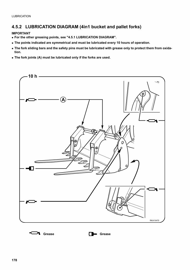
LUBRICATION
4.5.2 LUBRICATION DIAGRAM (4in1 bucket and pallet forks)IMPORTANTq For the other greasing points, see "4.5.1 LUBRICATION DIAGRAM".
q The points indicated are symmetrical and must be lubricated every 10 hours of operation.
q The fork sliding bars and the safety pins must be lubricated with grease only to protect them from oxida-tion.
q The fork joints (A) must be lubricated only if the forks are used.
10 h
A
RKA15470
Grease Grease
178
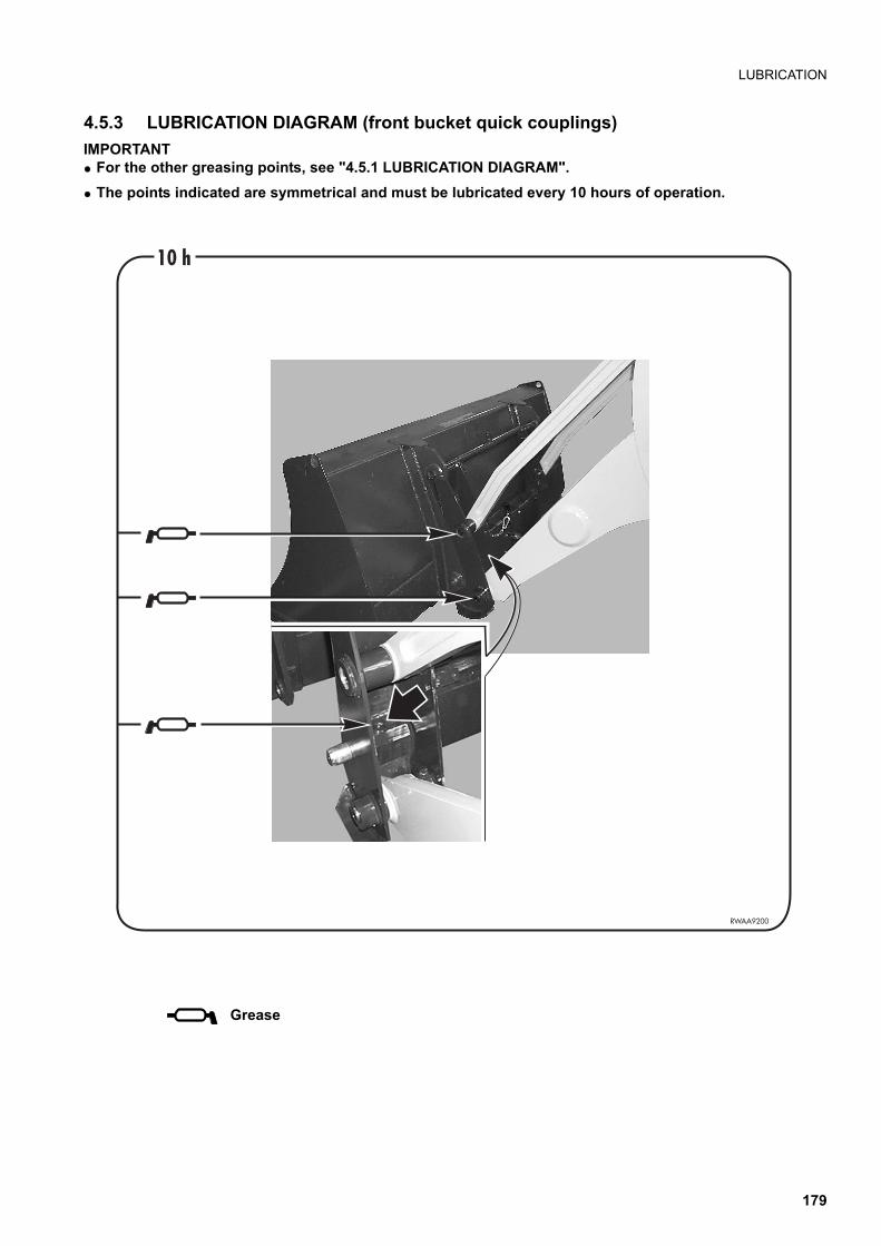
LUBRICATION
4.5.3 LUBRICATION DIAGRAM (front bucket quick couplings)
IMPORTANTq For the other greasing points, see "4.5.1 LUBRICATION DIAGRAM".
q The points indicated are symmetrical and must be lubricated every 10 hours of operation.
�����
#��$
Grease
179
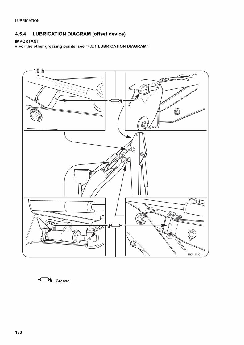
LUBRICATION
4.5.4 LUBRICATION DIAGRAM (offset device)
IMPORTANTq For the other greasing points, see "4.5.1 LUBRICATION DIAGRAM".
������
��(
Grease
180
PERIODICAL CHANGE OF THE SAFETY RELATED COMPONENTS
4.6 PERIODICAL CHANGE OF THE SAFETY RELATED COMPO-NENTS
To ensure safety at any moment while driving and using the machine, the operator must carry out all the routinemaintenance operations prescribed. Furthermore, the operator must periodically change the components indicat-ed in the table in the following page, which are especially related to safety and fire-prevention rules. These compo-nents are subject to wear and since it is particularly difficult to evaluate their conditions through simple routinemaintenance, after a certain time interval it is advisable to change them independently of their state, in order tokeep them efficient over time. Repair or replace these components immediately in case of failures or anomalies,even if the time interval prescribed for their change has not elapsed yet.
If the pipe clamps show signs of deterioration, like deformations or cracks, change them together with the pipes.
In addition to the periodical change of the components listed in the following page, the inspections described herebelow are to be carried out on the hydraulic pipes. In case of anomalies, carry out the necessary adjustments andchanges, or adopt any other measure required.
Type of check Items to be checked
Before starting the engine Leakages from joints, hydraulic pipes or fuel pipes
Periodically (monthly)Leakages from joints, hydraulic pipes or fuel pipes. Damaged hydraulic orfuel pipes (cracks, wear and tear)
Periodically (yearly)Leakages from joints, hydraulic pipes or fuel pipes. Deteriorated, twisted,damaged hydraulic or fuel pipes (cracks, wear and tear) or pipes in con-tact with other parts of the machine
181
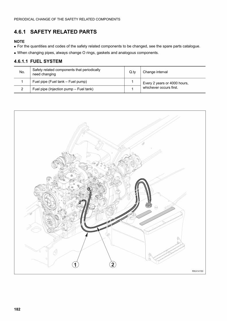
PERIODICAL CHANGE OF THE SAFETY RELATED COMPONENTS
4.6.1 SAFETY RELATED PARTS
NOTEq For the quantities and codes of the safety related components to be changed, see the spare parts catalogue.
q When changing pipes, always change O rings, gaskets and analogous components.
4.6.1.1 FUEL SYSTEM
No.Safety related components that periodically need changing
Q.ty Change interval
1 Fuel pipe (Fuel tank – Fuel pump) 1 Every 2 years or 4000 hours, whichever occurs first.2 Fuel pipe (Injection pump – Fuel tank) 1
RKA14150
21
182
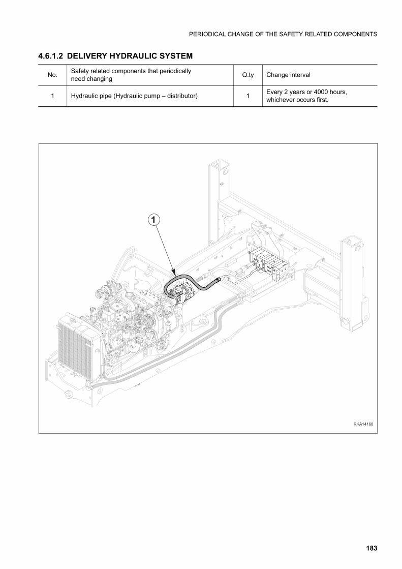
PERIODICAL CHANGE OF THE SAFETY RELATED COMPONENTS
4.6.1.2 DELIVERY HYDRAULIC SYSTEM
No.Safety related components that periodically need changing
Q.ty Change interval
1 Hydraulic pipe (Hydraulic pump – distributor) 1Every 2 years or 4000 hours, whichever occurs first.
RKA14160
1
183
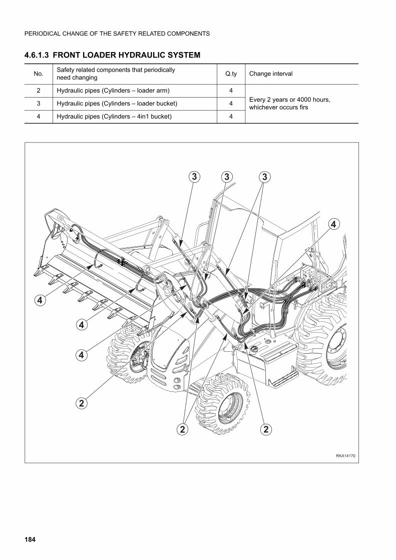
PERIODICAL CHANGE OF THE SAFETY RELATED COMPONENTS
4.6.1.3 FRONT LOADER HYDRAULIC SYSTEM
No.Safety related components that periodically need changing
Q.ty Change interval
2 Hydraulic pipes (Cylinders – loader arm) 4
Every 2 years or 4000 hours,whichever occurs firs
3 Hydraulic pipes (Cylinders – loader bucket) 4
4 Hydraulic pipes (Cylinders – 4in1 bucket) 4
RKA14170
4
4
4
2
2 2
3
4
33
184
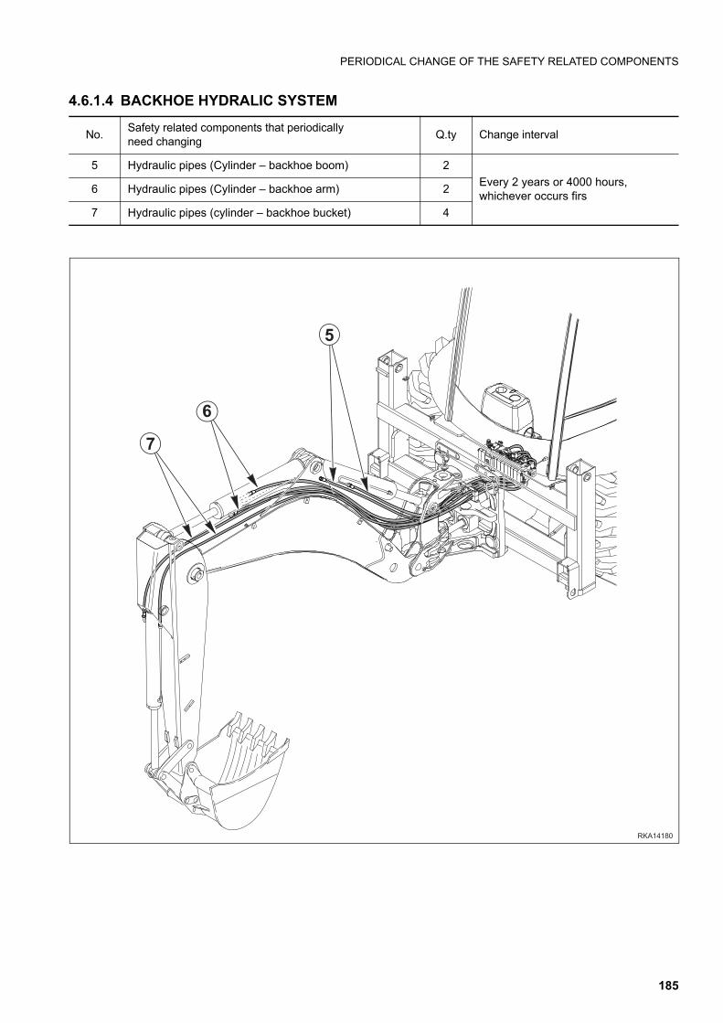
PERIODICAL CHANGE OF THE SAFETY RELATED COMPONENTS
4.6.1.4 BACKHOE HYDRALIC SYSTEM
No.Safety related components that periodically need changing
Q.ty Change interval
5 Hydraulic pipes (Cylinder – backhoe boom) 2
Every 2 years or 4000 hours, whichever occurs firs
6 Hydraulic pipes (Cylinder – backhoe arm) 2
7 Hydraulic pipes (cylinder – backhoe bucket) 4
RKA14180
7
6
5
185
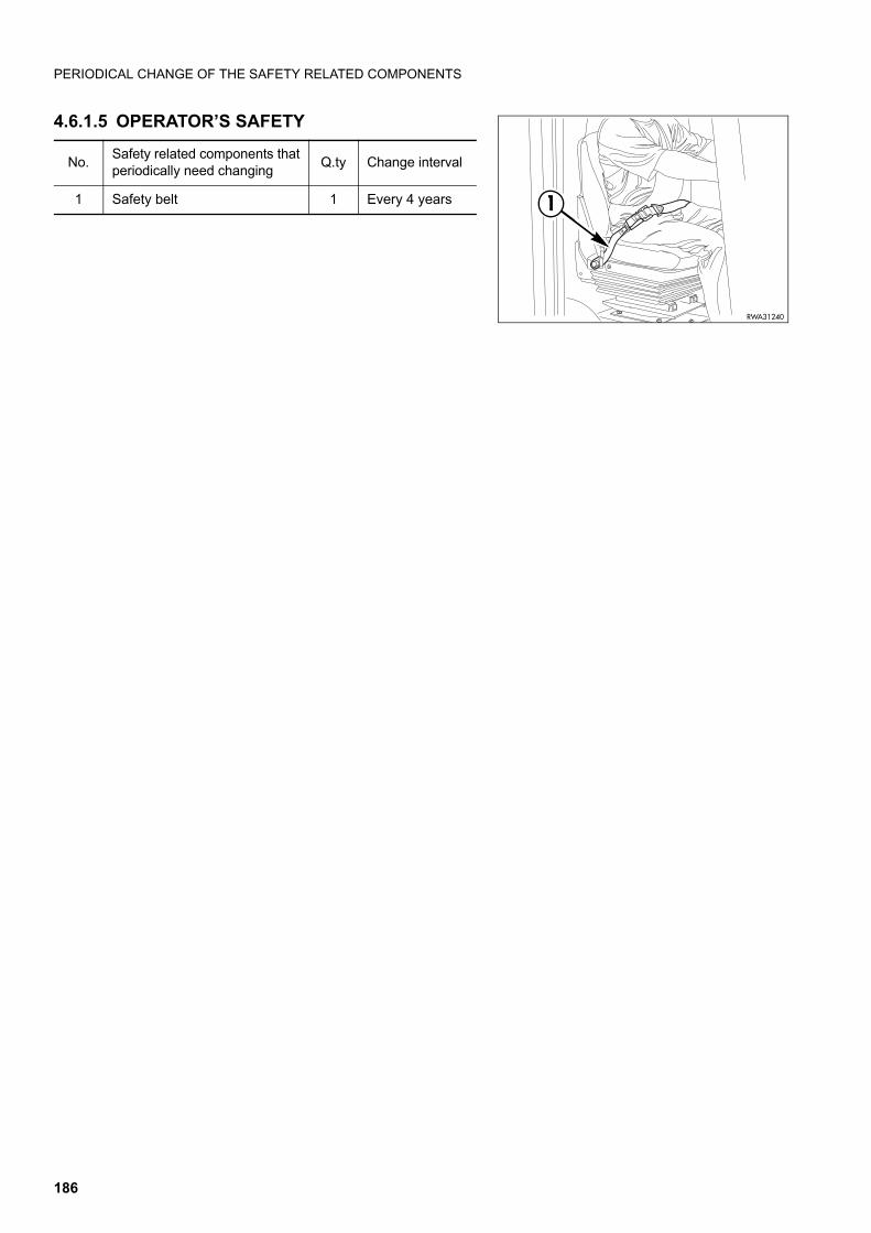
PERIODICAL CHANGE OF THE SAFETY RELATED COMPONENTS
4.6.1.5 OPERATOR’S SAFETY
No.Safety related components thatperiodically need changing
Q.ty Change interval
1 Safety belt 1 Every 4 years 1
RWA31240
186
MAINTENANCE PLAN
4.7 MAINTENANCE PLAN
WHEN REQUIREDa. CHECKING, CLEANING OR CHANGING THE ENGINE AIR FILTERS.......................................................................... 189
b. CHECKING AND CLEANING THE CAB AIR FILTER ..................................................................................................... 190
c. CHECKING AND CLEANING THE AIR RECIRCULATION FILTER (only for machines with air conditioner) ................. 191
d. CHECKING THE DETERGENT LEVEL IN THE WINDSHIELD WASHER RESERVOIR ............................................... 191
e. CHECKING THE WINDSHIELD WIPER BLADES .......................................................................................................... 192
f. LUBRICATING THE CAB DOOR HINGES...................................................................................................................... 192
g. FUSES AND RELAYS – CHECK AND CHANGE............................................................................................................ 192
h. BLEEDING THE BRAKING CIRCUIT.............................................................................................................................. 193
i. CHECKING AND ADJUSTING THE FRONT WHEEL TOE-IN........................................................................................ 194
j. CHECKING THE BRAKING EFFICIENCY........................................................................................................................ 194
k. CHECKING AND ADJUSTING THE PARKING BRAKE.................................................................................................. 195
l. CHECKING AND ADJUSTING THE BRAKE PEDAL STROKE ...................................................................................... 196
m. ADJUSTING THE AUTOMATIC RETURN-TO-DIG DEVICE OF THE FRONT BUCKET (if installed) ............................... 196
n. CHECKING AND ADJUSTING THE STABILIZER SLACK.............................................................................................. 197
MAINTENANCE INTERVALS IN CASE OF USE OF THE DEMOLITION HAMMERa. CHANGING THE HYDRAULIC OIL FILTER.................................................................................................................... 198
b. CHANGING THE HYDRAULIC OIL................................................................................................................................. 198
CHECKS TO BE CARRIED OUT BEFORE STARTING THE ENGINEa. VARIOUS CHECKS ......................................................................................................................................................... 199
b. CHECKING THE COOLANT LEVEL ............................................................................................................................... 199
c. CHECKING THE FUEL LEVEL ....................................................................................................................................... 200
d. CHECKING THE ENGINE OIL LEVEL ............................................................................................................................ 200
MAINTENANCE EVERY 10 HOURS OF OPERATIONa. LUBRICATING THE JOINTS ........................................................................................................................................... 201
MAINTENANCE AFTER THE FIRST 50 HOURS OF OPERATION (Only for machines in which synthetic biodegradable oil type HEES is used) (Operations to be
carried out together with those prescribed at point “4.8.6 MAINTENANCE EVERY 50 HOURS OF
OPERATION”)a. CHANGING THE HYDRAULIC SYSTEM OIL FILTER.................................................................................................... 214
MAINTENANCE EVERY 50 HOURS OF OPERATIONa. CHECKING THE HYDRAULIC OIL LEVEL ..................................................................................................................... 203
b. CHECKING THE FLUID LEVEL IN THE RADIATOR ...................................................................................................... 204
c. CHECKING THE BRAKING SYSTEM OIL LEVEL.......................................................................................................... 204
d. LUBRICATING THE PROPELLER SHAFTS ................................................................................................................... 205
e. LUBRICATING THE FRONT AXLE JOINTS AND CENTRAL COUPLING ..................................................................... 206
f. CHECKING THE TYRE PRESSURE .............................................................................................................................. 206
g. DRAINING THE WATER SEPARATOR ........................................................................................................................... 207
187
MAINTENANCE PLAN
MAINTENANCE AFTER THE FIRST 250 HOURS OF OPERATION (Operations to be carried out together with those prescribed at point "4.8.8 MAINTE-NANCE EVERY 250 HOURS OF OPERATION")a. CHANGING THE FRONT AXLE OIL ............................................................................................................................... 222
b. CHANGING THE REAR AXLE OIL ................................................................................................................................. 223
c. CHANGING THE HYDRAULIC TRANSMISSION OIL .................................................................................................... 224
d. CHANGING THE HYDRAULIC TRANSMISSION OIL FILTER ....................................................................................... 225
e. CHANGING THE HYDRAULIC SYSTEM OIL FILTER.................................................................................................... 214
MAINTENANCE EVERY 250 HOURS OF OPERATIONa. CHECKING THE ALTERNATOR-FAN BELT ................................................................................................................... 208
b. CHECKING AND ADJUSTING THE A/C COMPRESSOR BELT TENSION (only for machines with air conditioner)..... 209
c. CHECKING THE BATTERY ELECTROLYTE LEVEL...................................................................................................... 210
d. CHECKING THE FRONT AXLE OIL LEVELS................................................................................................................. 211
e. CHECKING THE REAR AXLE OIL LEVEL...................................................................................................................... 211
f. CHECKING THE HYDRAULIC TRANSMISSION OIL LEVEL......................................................................................... 212
g. CHECKING THE WHEEL NUT DRIVING TORQUE ....................................................................................................... 212
MAINTENANCE AFTER THE FIRST 500 HOURS OF OPERATION (Only for machines in which synthetic biodegradable oil type HEES is used) (Operations to be carried out together with those prescribed at point “4.8.10 MAINTE-NANCE EVERY 500 HOURS OF OPERATION”)a. CHANGING THE HYDRAULIC OIL AND CLEANING THE INTAKE FILTER.................................................................. 226
MAINTENANCE EVERY 500 HOURS OF OPERATIONa. CHANGING THE ENGINE OIL........................................................................................................................................ 213
b. CHANGING THE ENGINE OIL FILTER........................................................................................................................... 214
c. CHANGING THE HYDRAULIC SYSTEM OIL FILTER.................................................................................................... 214
d. CHANGING THE FUEL FILTER ...................................................................................................................................... 217
e. DRAINING THE FUEL TANK........................................................................................................................................... 218
f. DRAINING THE HYDRAULIC OIL TANK (only for machines in which synthetic biodegradable oil type HEES is used).... 219
g. CLEANING THE OUTSIDE OF THE RADIATOR............................................................................................................ 220
h. CLEANING THE OUTSIDE OF THE A/C CONDENSER (only for machines with air conditioner).................................. 221
MAINTENANCE EVERY 1000 HOURS OF OPERATIONa. CHANGING THE FRONT AXLE OIL ............................................................................................................................... 222
b. CHANGING THE REAR AXLE OIL ................................................................................................................................. 223
c. CHANGING THE HYDRAULIC TRANSMISSION OIL .................................................................................................... 224
d. CHANGING THE HYDRAULIC TRANSMISSION OIL FILTER ....................................................................................... 225
MAINTENANCE EVERY 2000 HOURS OF OPERATIONa. CHANGING THE HYDRAULIC OIL AND CLEANING THE INTAKE FILTER.................................................................. 226
b. CHANGING THE COOLANT........................................................................................................................................... 228
c. CHANGING THE BRAKING SYSTEM OIL...................................................................................................................... 229
d. CHECKING THE ALTERNATOR AND THE STARTER................................................................................................... 230
e. CHANGING THE ALTERNATOR BELT ........................................................................................................................... 230
f. CHECKING THE A/C COOLING GAS QUANTITY (only for machines with air conditioner)........................................... 230
MAINTENANCE EVERY 3000 HOURS OF OPERATIONa. CHECKING THE ENGINE RETAINING SCREWS AND DAMPING ELEMENTS ........................................................... 231
b. CHECKING AND ADJUSTING THE ENGINE VALVE CLEARANCE AND THE INJECTION TIMING ADVANCE ......... 231
MAINTENANCE EVERY 4000 HOURS OF OPERATIONa. CHANGING THE A/C DEWATERING FILTER (Only for machines with air conditioner) ................................................. 232
b. CHECKING THE OPERATING CONDITIONS OF THE A/C COMPRESSOR (Only for machines with air conditioner). 232
c. CHANGING THE ENGINE THERMOSTATIC VALVE...................................................................................................... 232
188
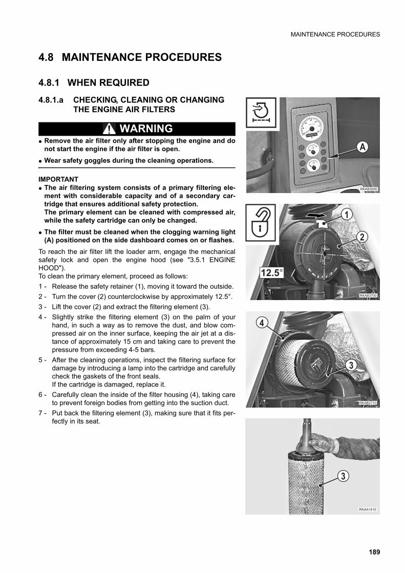
MAINTENANCE PROCEDURES
4.8 MAINTENANCE PROCEDURES
4.8.1 WHEN REQUIRED
4.8.1.a CHECKING, CLEANING OR CHANGING THE ENGINE AIR FILTERS
WARNINGq Remove the air filter only after stopping the engine and do
not start the engine if the air filter is open.
q Wear safety goggles during the cleaning operations.
IMPORTANTq The air filtering system consists of a primary filtering ele-
ment with considerable capacity and of a secondary car-tridge that ensures additional safety protection.The primary element can be cleaned with compressed air,while the safety cartridge can only be changed.
q The filter must be cleaned when the clogging warning light(A) positioned on the side dashboard comes on or flashes.
To reach the air filter lift the loader arm, engage the mechanicalsafety lock and open the engine hood (see "3.5.1 ENGINEHOOD").To clean the primary element, proceed as follows:
1 - Release the safety retainer (1), moving it toward the outside.
2 - Turn the cover (2) counterclockwise by approximately 12.5°.
3 - Lift the cover (2) and extract the filtering element (3).
4 - Slightly strike the filtering element (3) on the palm of yourhand, in such a way as to remove the dust, and blow com-pressed air on the inner surface, keeping the air jet at a dis-tance of approximately 15 cm and taking care to prevent thepressure from exceeding 4-5 bars.
5 - After the cleaning operations, inspect the filtering surface fordamage by introducing a lamp into the cartridge and carefullycheck the gaskets of the front seals.If the cartridge is damaged, replace it.
6 - Carefully clean the inside of the filter housing (4), taking careto prevent foreign bodies from getting into the suction duct.
7 - Put back the filtering element (3), making sure that it fits per-fectly in its seat.
��������
�
��������
��&�)
�
�
�������
�
�
������
�
189
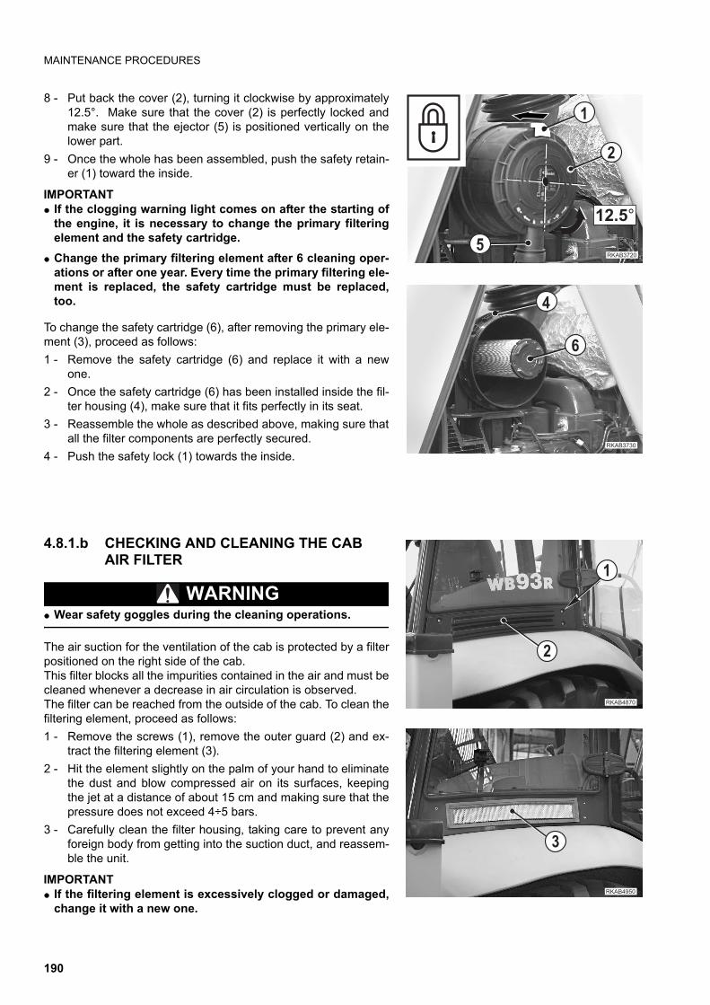
MAINTENANCE PROCEDURES
8 - Put back the cover (2), turning it clockwise by approximately12.5°. Make sure that the cover (2) is perfectly locked andmake sure that the ejector (5) is positioned vertically on thelower part.
9 - Once the whole has been assembled, push the safety retain-er (1) toward the inside.
IMPORTANTq If the clogging warning light comes on after the starting of
the engine, it is necessary to change the primary filteringelement and the safety cartridge.
q Change the primary filtering element after 6 cleaning oper-ations or after one year. Every time the primary filtering ele-ment is replaced, the safety cartridge must be replaced,too.
To change the safety cartridge (6), after removing the primary ele-ment (3), proceed as follows:
1 - Remove the safety cartridge (6) and replace it with a newone.
2 - Once the safety cartridge (6) has been installed inside the fil-ter housing (4), make sure that it fits perfectly in its seat.
3 - Reassemble the whole as described above, making sure thatall the filter components are perfectly secured.
4 - Push the safety lock (1) towards the inside.
4.8.1.b CHECKING AND CLEANING THE CAB AIR FILTER
WARNINGq Wear safety goggles during the cleaning operations.
The air suction for the ventilation of the cab is protected by a filterpositioned on the right side of the cab.This filter blocks all the impurities contained in the air and must becleaned whenever a decrease in air circulation is observed.The filter can be reached from the outside of the cab. To clean thefiltering element, proceed as follows:
1 - Remove the screws (1), remove the outer guard (2) and ex-tract the filtering element (3).
2 - Hit the element slightly on the palm of your hand to eliminatethe dust and blow compressed air on its surfaces, keepingthe jet at a distance of about 15 cm and making sure that thepressure does not exceed 4÷5 bars.
3 - Carefully clean the filter housing, taking care to prevent anyforeign body from getting into the suction duct, and reassem-ble the unit.
IMPORTANTq If the filtering element is excessively clogged or damaged,
change it with a new one.
��������
��&�)
�
�
�
��������
�
�������
�
�
�
������ �
190
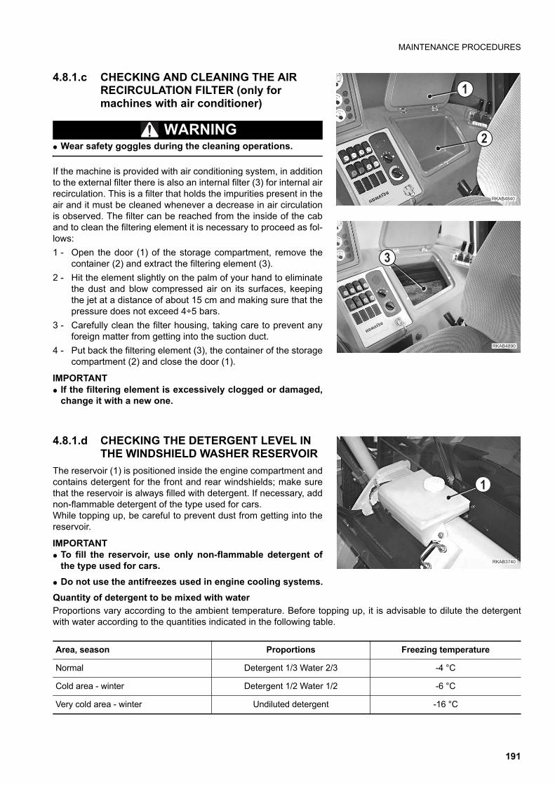
MAINTENANCE PROCEDURES
4.8.1.c CHECKING AND CLEANING THE AIR RECIRCULATION FILTER (only for machines with air conditioner)
WARNINGq Wear safety goggles during the cleaning operations.
If the machine is provided with air conditioning system, in additionto the external filter there is also an internal filter (3) for internal airrecirculation. This is a filter that holds the impurities present in theair and it must be cleaned whenever a decrease in air circulationis observed. The filter can be reached from the inside of the caband to clean the filtering element it is necessary to proceed as fol-lows:
1 - Open the door (1) of the storage compartment, remove thecontainer (2) and extract the filtering element (3).
2 - Hit the element slightly on the palm of your hand to eliminatethe dust and blow compressed air on its surfaces, keepingthe jet at a distance of about 15 cm and making sure that thepressure does not exceed 4÷5 bars.
3 - Carefully clean the filter housing, taking care to prevent anyforeign matter from getting into the suction duct.
4 - Put back the filtering element (3), the container of the storagecompartment (2) and close the door (1).
IMPORTANTq If the filtering element is excessively clogged or damaged,
change it with a new one.
4.8.1.d CHECKING THE DETERGENT LEVEL IN THE WINDSHIELD WASHER RESERVOIR
The reservoir (1) is positioned inside the engine compartment andcontains detergent for the front and rear windshields; make surethat the reservoir is always filled with detergent. If necessary, addnon-flammable detergent of the type used for cars.While topping up, be careful to prevent dust from getting into thereservoir.
IMPORTANTq To fill the reservoir, use only non-flammable detergent of
the type used for cars.
q Do not use the antifreezes used in engine cooling systems.
Quantity of detergent to be mixed with water
Proportions vary according to the ambient temperature. Before topping up, it is advisable to dilute the detergentwith water according to the quantities indicated in the following table.
�
�������
�
�������
�
��������
�
Area, season Proportions Freezing temperature
Normal Detergent 1/3 Water 2/3 -4 °C
Cold area - winter Detergent 1/2 Water 1/2 -6 °C
Very cold area - winter Undiluted detergent -16 °C
191
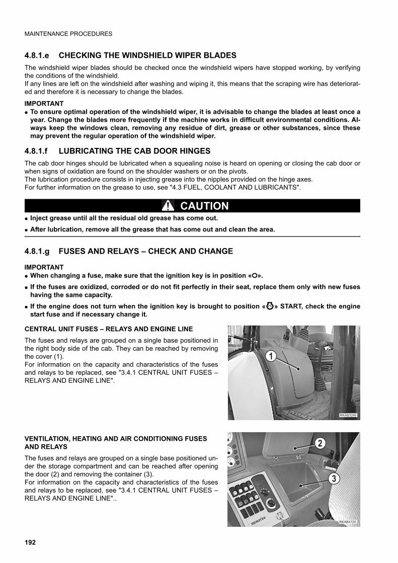
MAINTENANCE PROCEDURES
4.8.1.e CHECKING THE WINDSHIELD WIPER BLADES
The windshield wiper blades should be checked once the windshield wipers have stopped working, by verifyingthe conditions of the windshield.If any lines are left on the windshield after washing and wiping it, this means that the scraping wire has deteriorat-ed and therefore it is necessary to change the blades.
IMPORTANTq To ensure optimal operation of the windshield wiper, it is advisable to change the blades at least once a
year. Change the blades more frequently if the machine works in difficult environmental conditions. Al-ways keep the windows clean, removing any residue of dirt, grease or other substances, since thesemay prevent the regular operation of the windshield wiper.
4.8.1.f LUBRICATING THE CAB DOOR HINGES
The cab door hinges should be lubricated when a squealing noise is heard on opening or closing the cab door orwhen signs of oxidation are found on the shoulder washers or on the pivots.The lubrication procedure consists in injecting grease into the nipples provided on the hinge axes.For further information on the grease to use, see "4.3 FUEL, COOLANT AND LUBRICANTS".
CAUTIONq Inject grease until all the residual old grease has come out.
q After lubrication, remove all the grease that has come out and clean the area.
4.8.1.g FUSES AND RELAYS – CHECK AND CHANGE
IMPORTANTq When changing a fuse, make sure that the ignition key is in position « ».
q If the fuses are oxidized, corroded or do not fit perfectly in their seat, replace them only with new fuseshaving the same capacity.
q If the engine does not turn when the ignition key is brought to position « » START, check the enginestart fuse and if necessary change it.
CENTRAL UNIT FUSES – RELAYS AND ENGINE LINE
The fuses and relays are grouped on a single base positioned inthe right body side of the cab. They can be reached by removingthe cover (1).For information on the capacity and characteristics of the fusesand relays to be replaced, see "3.4.1 CENTRAL UNIT FUSES –RELAYS AND ENGINE LINE".
VENTILATION, HEATING AND AIR CONDITIONING FUSES AND RELAYS
The fuses and relays are grouped on a single base positioned un-der the storage compartment and can be reached after openingthe door (2) and removing the container (3).For information on the capacity and characteristics of the fusesand relays to be replaced, see "3.4.1 CENTRAL UNIT FUSES –RELAYS AND ENGINE LINE"..
��������
�
�
��������
�
192
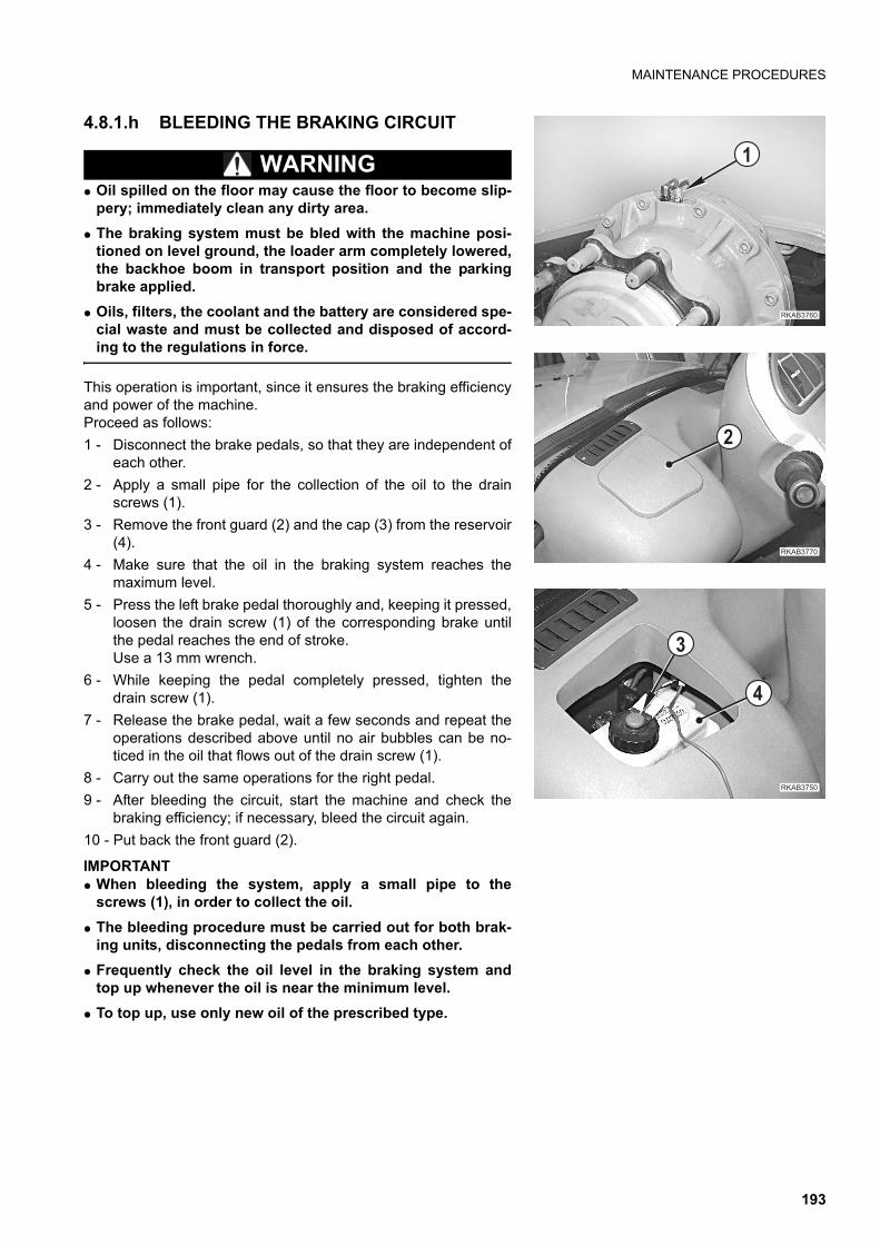
MAINTENANCE PROCEDURES
4.8.1.h BLEEDING THE BRAKING CIRCUIT
WARNINGq Oil spilled on the floor may cause the floor to become slip-
pery; immediately clean any dirty area.
q The braking system must be bled with the machine posi-tioned on level ground, the loader arm completely lowered,the backhoe boom in transport position and the parkingbrake applied.
q Oils, filters, the coolant and the battery are considered spe-cial waste and must be collected and disposed of accord-ing to the regulations in force.
This operation is important, since it ensures the braking efficiencyand power of the machine. Proceed as follows:
1 - Disconnect the brake pedals, so that they are independent ofeach other.
2 - Apply a small pipe for the collection of the oil to the drainscrews (1).
3 - Remove the front guard (2) and the cap (3) from the reservoir(4).
4 - Make sure that the oil in the braking system reaches themaximum level.
5 - Press the left brake pedal thoroughly and, keeping it pressed,loosen the drain screw (1) of the corresponding brake untilthe pedal reaches the end of stroke. Use a 13 mm wrench.
6 - While keeping the pedal completely pressed, tighten thedrain screw (1).
7 - Release the brake pedal, wait a few seconds and repeat theoperations described above until no air bubbles can be no-ticed in the oil that flows out of the drain screw (1).
8 - Carry out the same operations for the right pedal.
9 - After bleeding the circuit, start the machine and check thebraking efficiency; if necessary, bleed the circuit again.
10 - Put back the front guard (2).
IMPORTANTq When bleeding the system, apply a small pipe to the
screws (1), in order to collect the oil.
q The bleeding procedure must be carried out for both brak-ing units, disconnecting the pedals from each other.
q Frequently check the oil level in the braking system andtop up whenever the oil is near the minimum level.
q To top up, use only new oil of the prescribed type.
��������
�
��������
�
������ �
�
�
193
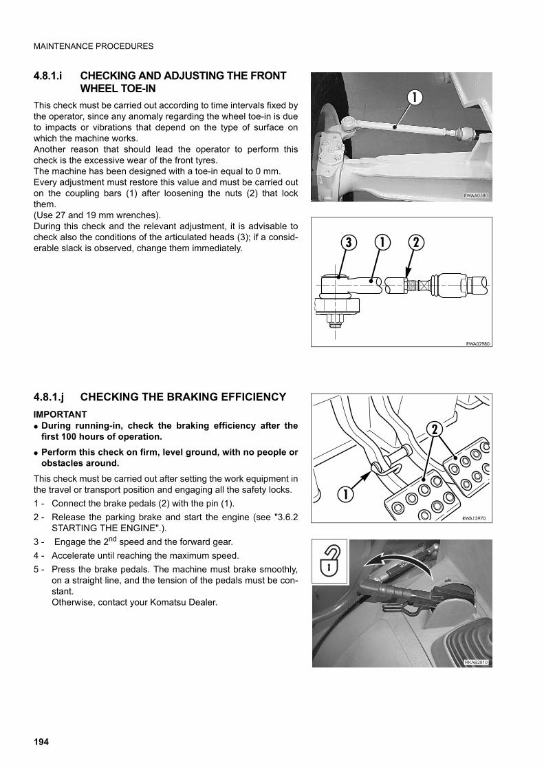
MAINTENANCE PROCEDURES
4.8.1.i CHECKING AND ADJUSTING THE FRONT WHEEL TOE-IN
This check must be carried out according to time intervals fixed bythe operator, since any anomaly regarding the wheel toe-in is dueto impacts or vibrations that depend on the type of surface onwhich the machine works.Another reason that should lead the operator to perform thischeck is the excessive wear of the front tyres.The machine has been designed with a toe-in equal to 0 mm.Every adjustment must restore this value and must be carried outon the coupling bars (1) after loosening the nuts (2) that lockthem. (Use 27 and 19 mm wrenches).During this check and the relevant adjustment, it is advisable tocheck also the conditions of the articulated heads (3); if a consid-erable slack is observed, change them immediately.
4.8.1.j CHECKING THE BRAKING EFFICIENCY
IMPORTANTq During running-in, check the braking efficiency after the
first 100 hours of operation.
q Perform this check on firm, level ground, with no people orobstacles around.
This check must be carried out after setting the work equipment inthe travel or transport position and engaging all the safety locks.
1 - Connect the brake pedals (2) with the pin (1).
2 - Release the parking brake and start the engine (see "3.6.2STARTING THE ENGINE".).
3 - Engage the 2nd speed and the forward gear.
4 - Accelerate until reaching the maximum speed.
5 - Press the brake pedals. The machine must brake smoothly,on a straight line, and the tension of the pedals must be con-stant.Otherwise, contact your Komatsu Dealer.
�����
#
RWA02980
3 1 2
RWA13970
2
1
������
194
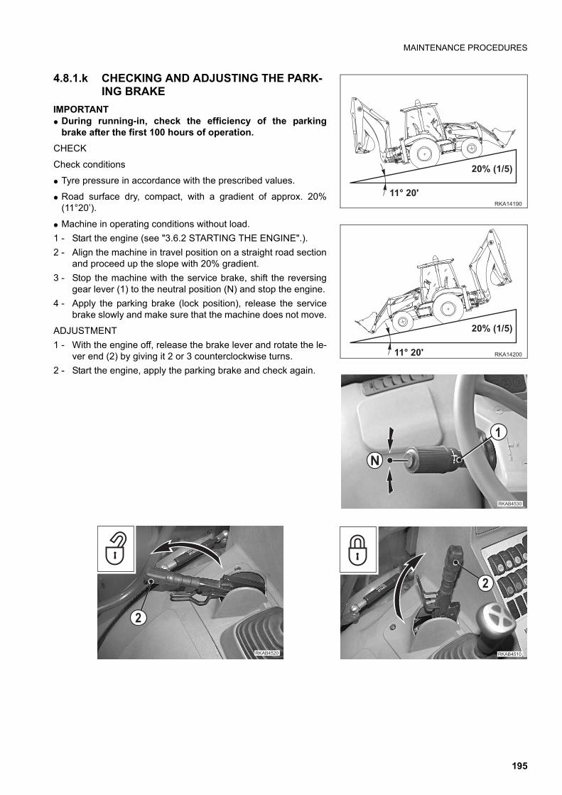
MAINTENANCE PROCEDURES
4.8.1.k CHECKING AND ADJUSTING THE PARK-ING BRAKE
IMPORTANTq During running-in, check the efficiency of the parking
brake after the first 100 hours of operation.
CHECK
Check conditions
q Tyre pressure in accordance with the prescribed values.
q Road surface dry, compact, with a gradient of approx. 20%(11°20’).
q Machine in operating conditions without load.
1 - Start the engine (see "3.6.2 STARTING THE ENGINE".).
2 - Align the machine in travel position on a straight road sectionand proceed up the slope with 20% gradient.
3 - Stop the machine with the service brake, shift the reversinggear lever (1) to the neutral position (N) and stop the engine.
4 - Apply the parking brake (lock position), release the servicebrake slowly and make sure that the machine does not move.
ADJUSTMENT
1 - With the engine off, release the brake lever and rotate the le-ver end (2) by giving it 2 or 3 counterclockwise turns.
2 - Start the engine, apply the parking brake and check again.
�������'��)
��*+�,�-
������
��'��)
��*+�,�-
�
�
����� ��
����� �
�
����� ��
�
195
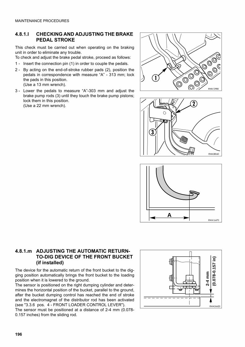
MAINTENANCE PROCEDURES
4.8.1.l CHECKING AND ADJUSTING THE BRAKE PEDAL STROKE
This check must be carried out when operating on the brakingunit in order to eliminate any trouble.To check and adjust the brake pedal stroke, proceed as follows:
1 - Insert the connection pin (1) in order to couple the pedals.
2 - By acting on the end-of-stroke rubber pads (2), position thepedals in correspondence with measure “A” - 313 mm; lockthe pads in this position.(Use a 13 mm wrench).
3 - Lower the pedals to measure “A”-303 mm and adjust thebrake pump rods (3) until they touch the brake pump pistons;lock them in this position.(Use a 22 mm wrench).
4.8.1.m ADJUSTING THE AUTOMATIC RETURN-TO-DIG DEVICE OF THE FRONT BUCKET (if installed)
The device for the automatic return of the front bucket to the dig-ging position automatically brings the front bucket to the loadingposition when it is lowered to the ground. The sensor is positioned on the right dumping cylinder and deter-mines the horizontal position of the bucket, parallel to the ground,after the bucket dumping control has reached the end of strokeand the electromagnet of the distributor rod has been activated(see "3.3.6 pos. 4 - FRONT LOADER CONTROL LEVER"). The sensor must be positioned at a distance of 2-4 mm (0.078-0.157 inches) from the sliding rod.
RWA13980
1
2
3
RWA38040
ARWA16470
2-4
mm
(0.0
78-0
.157
in)
RWA34420
196
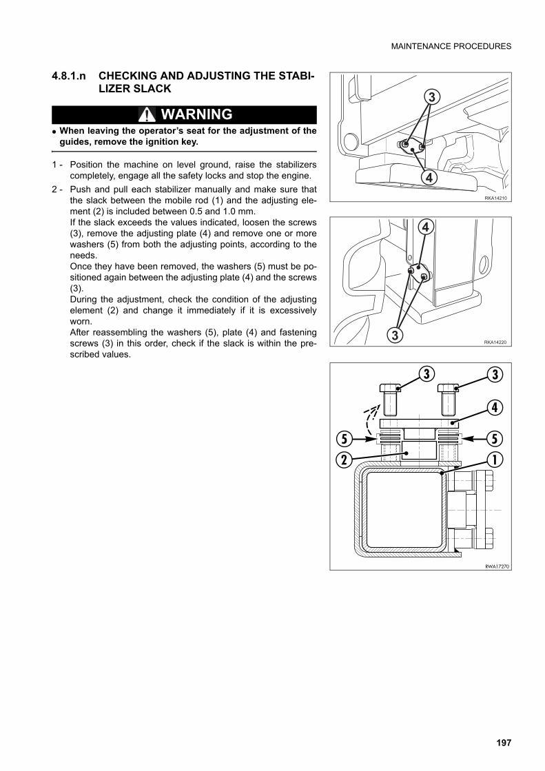
MAINTENANCE PROCEDURES
4.8.1.n CHECKING AND ADJUSTING THE STABI-LIZER SLACK
WARNINGq When leaving the operator’s seat for the adjustment of the
guides, remove the ignition key.
1 - Position the machine on level ground, raise the stabilizerscompletely, engage all the safety locks and stop the engine.
2 - Push and pull each stabilizer manually and make sure thatthe slack between the mobile rod (1) and the adjusting ele-ment (2) is included between 0.5 and 1.0 mm.If the slack exceeds the values indicated, loosen the screws(3), remove the adjusting plate (4) and remove one or morewashers (5) from both the adjusting points, according to theneeds.Once they have been removed, the washers (5) must be po-sitioned again between the adjusting plate (4) and the screws(3).During the adjustment, check the condition of the adjustingelement (2) and change it immediately if it is excessivelyworn.After reassembling the washers (5), plate (4) and fasteningscrews (3) in this order, check if the slack is within the pre-scribed values.
������
�
�
������
�
�
RWA17270
55
3
4
1
3
2
197
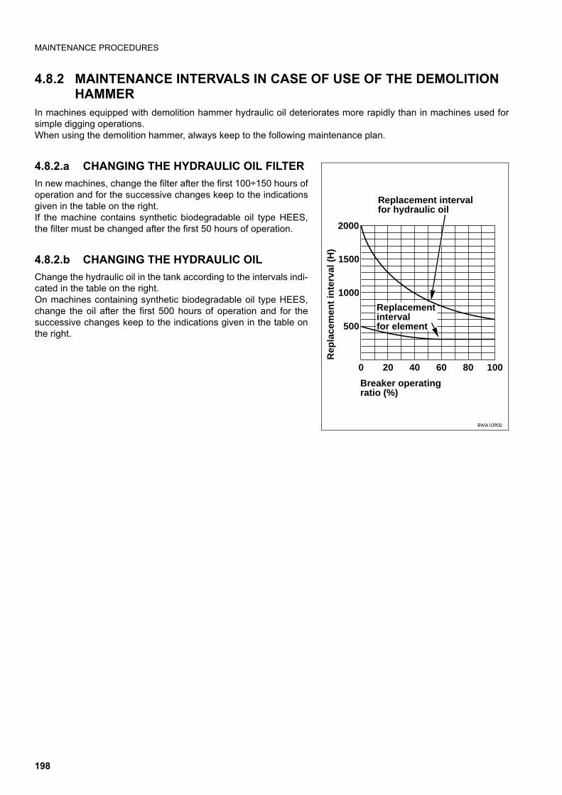
MAINTENANCE PROCEDURES
4.8.2 MAINTENANCE INTERVALS IN CASE OF USE OF THE DEMOLITION HAMMER
In machines equipped with demolition hammer hydraulic oil deteriorates more rapidly than in machines used forsimple digging operations.When using the demolition hammer, always keep to the following maintenance plan.
4.8.2.a CHANGING THE HYDRAULIC OIL FILTER
In new machines, change the filter after the first 100÷150 hours ofoperation and for the successive changes keep to the indicationsgiven in the table on the right.If the machine contains synthetic biodegradable oil type HEES,the filter must be changed after the first 50 hours of operation.
4.8.2.b CHANGING THE HYDRAULIC OIL
Change the hydraulic oil in the tank according to the intervals indi-cated in the table on the right.On machines containing synthetic biodegradable oil type HEES,change the oil after the first 500 hours of operation and for thesuccessive changes keep to the indications given in the table onthe right.
0 20 40 60 80 100
500
2000
Breaker operating ratio (%)
Rep
lace
men
t in
terv
al (
H)
Replacement interval for hydraulic oil
RWA10900
1500
1000
Replacementinterval for element
198
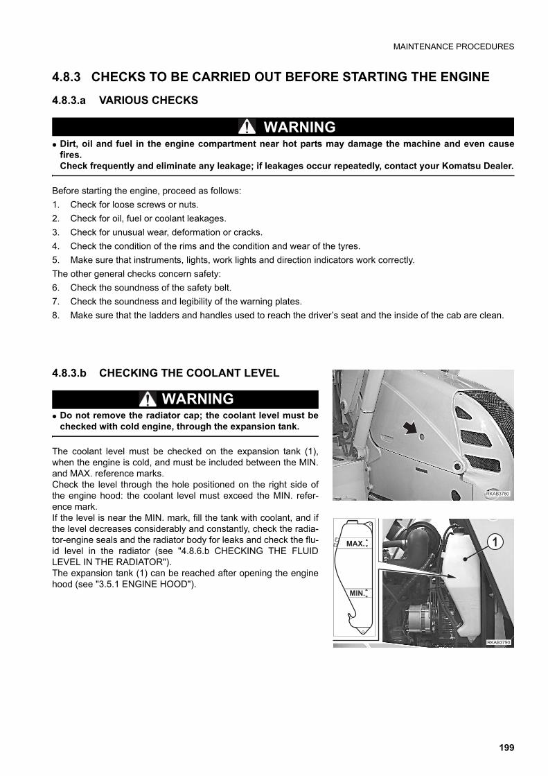
MAINTENANCE PROCEDURES
4.8.3 CHECKS TO BE CARRIED OUT BEFORE STARTING THE ENGINE
4.8.3.a VARIOUS CHECKS
WARNINGq Dirt, oil and fuel in the engine compartment near hot parts may damage the machine and even cause
fires.Check frequently and eliminate any leakage; if leakages occur repeatedly, contact your Komatsu Dealer.
Before starting the engine, proceed as follows:
1. Check for loose screws or nuts.
2. Check for oil, fuel or coolant leakages.
3. Check for unusual wear, deformation or cracks.
4. Check the condition of the rims and the condition and wear of the tyres.
5. Make sure that instruments, lights, work lights and direction indicators work correctly.
The other general checks concern safety:
6. Check the soundness of the safety belt.
7. Check the soundness and legibility of the warning plates.
8. Make sure that the ladders and handles used to reach the driver’s seat and the inside of the cab are clean.
4.8.3.b CHECKING THE COOLANT LEVEL
WARNINGq Do not remove the radiator cap; the coolant level must be
checked with cold engine, through the expansion tank.
The coolant level must be checked on the expansion tank (1),when the engine is cold, and must be included between the MIN.and MAX. reference marks. Check the level through the hole positioned on the right side ofthe engine hood: the coolant level must exceed the MIN. refer-ence mark.If the level is near the MIN. mark, fill the tank with coolant, and ifthe level decreases considerably and constantly, check the radia-tor-engine seals and the radiator body for leaks and check the flu-id level in the radiator (see "4.8.6.b CHECKING THE FLUIDLEVEL IN THE RADIATOR").The expansion tank (1) can be reached after opening the enginehood (see "3.5.1 ENGINE HOOD").
�������
��������
���.&
���&
199
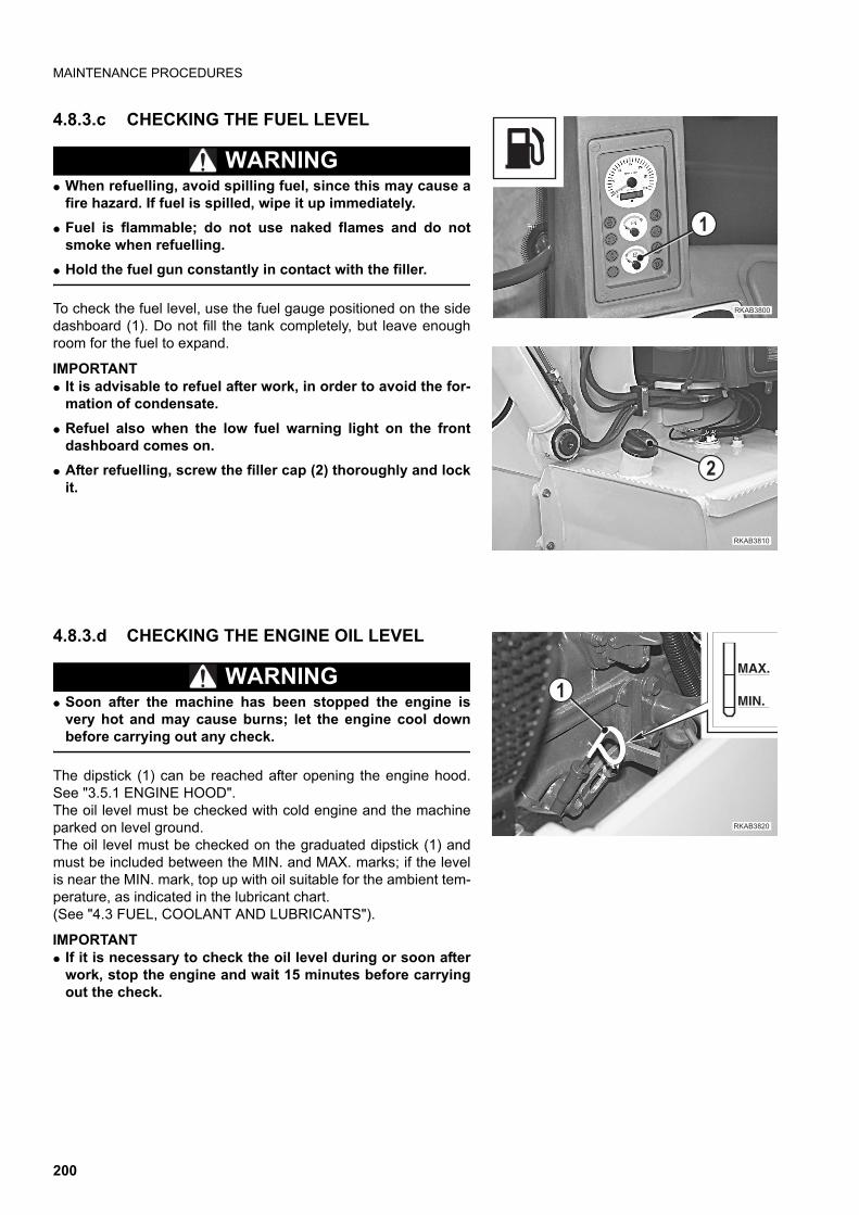
MAINTENANCE PROCEDURES
4.8.3.c CHECKING THE FUEL LEVEL
WARNINGq When refuelling, avoid spilling fuel, since this may cause a
fire hazard. If fuel is spilled, wipe it up immediately.
q Fuel is flammable; do not use naked flames and do notsmoke when refuelling.
q Hold the fuel gun constantly in contact with the filler.
To check the fuel level, use the fuel gauge positioned on the sidedashboard (1). Do not fill the tank completely, but leave enoughroom for the fuel to expand.
IMPORTANTq It is advisable to refuel after work, in order to avoid the for-
mation of condensate.
q Refuel also when the low fuel warning light on the frontdashboard comes on.
q After refuelling, screw the filler cap (2) thoroughly and lockit.
4.8.3.d CHECKING THE ENGINE OIL LEVEL
WARNINGq Soon after the machine has been stopped the engine is
very hot and may cause burns; let the engine cool downbefore carrying out any check.
The dipstick (1) can be reached after opening the engine hood.See "3.5.1 ENGINE HOOD".The oil level must be checked with cold engine and the machineparked on level ground.The oil level must be checked on the graduated dipstick (1) andmust be included between the MIN. and MAX. marks; if the levelis near the MIN. mark, top up with oil suitable for the ambient tem-perature, as indicated in the lubricant chart.(See "4.3 FUEL, COOLANT AND LUBRICANTS").
IMPORTANTq If it is necessary to check the oil level during or soon after
work, stop the engine and wait 15 minutes before carryingout the check.
�������
�
������
�
�������
����
��
200
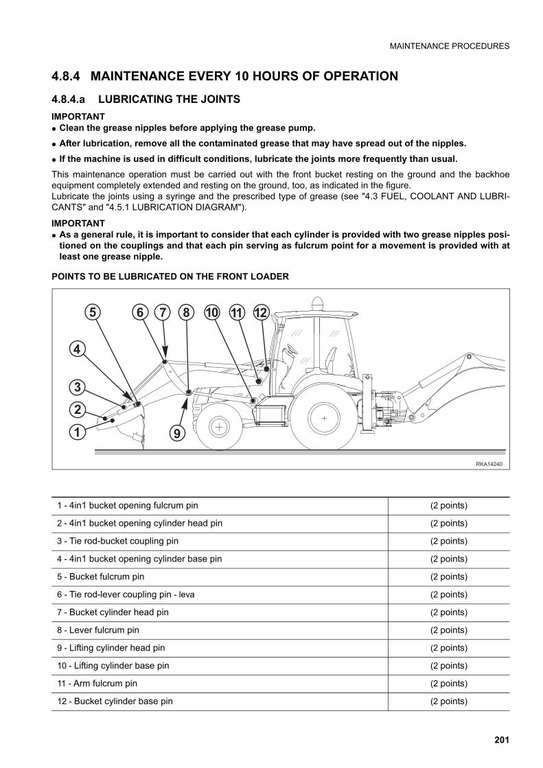
MAINTENANCE PROCEDURES
4.8.4 MAINTENANCE EVERY 10 HOURS OF OPERATION
4.8.4.a LUBRICATING THE JOINTS
IMPORTANTq Clean the grease nipples before applying the grease pump.
q After lubrication, remove all the contaminated grease that may have spread out of the nipples.
q If the machine is used in difficult conditions, lubricate the joints more frequently than usual.
This maintenance operation must be carried out with the front bucket resting on the ground and the backhoeequipment completely extended and resting on the ground, too, as indicated in the figure.Lubricate the joints using a syringe and the prescribed type of grease (see "4.3 FUEL, COOLANT AND LUBRI-CANTS" and "4.5.1 LUBRICATION DIAGRAM").
IMPORTANTq As a general rule, it is important to consider that each cylinder is provided with two grease nipples posi-
tioned on the couplings and that each pin serving as fulcrum point for a movement is provided with atleast one grease nipple.
POINTS TO BE LUBRICATED ON THE FRONT LOADER
������
�
�
!
" ������
�
�
�
�
1 - 4in1 bucket opening fulcrum pin (2 points)
2 - 4in1 bucket opening cylinder head pin (2 points)
3 - Tie rod-bucket coupling pin (2 points)
4 - 4in1 bucket opening cylinder base pin (2 points)
5 - Bucket fulcrum pin (2 points)
6 - Tie rod-lever coupling pin - leva (2 points)
7 - Bucket cylinder head pin (2 points)
8 - Lever fulcrum pin (2 points)
9 - Lifting cylinder head pin (2 points)
10 - Lifting cylinder base pin (2 points)
11 - Arm fulcrum pin (2 points)
12 - Bucket cylinder base pin (2 points)
201
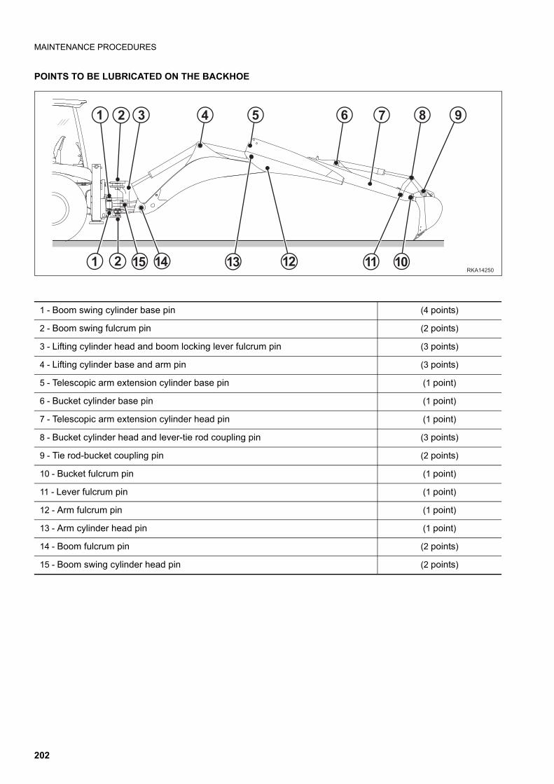
MAINTENANCE PROCEDURES
POINTS TO BE LUBRICATED ON THE BACKHOE
1 - Boom swing cylinder base pin (4 points)
2 - Boom swing fulcrum pin (2 points)
3 - Lifting cylinder head and boom locking lever fulcrum pin (3 points)
4 - Lifting cylinder base and arm pin (3 points)
5 - Telescopic arm extension cylinder base pin (1 point)
6 - Bucket cylinder base pin (1 point)
7 - Telescopic arm extension cylinder head pin (1 point)
8 - Bucket cylinder head and lever-tie rod coupling pin (3 points)
9 - Tie rod-bucket coupling pin (2 points)
10 - Bucket fulcrum pin (1 point)
11 - Lever fulcrum pin (1 point)
12 - Arm fulcrum pin (1 point)
13 - Arm cylinder head pin (1 point)
14 - Boom fulcrum pin (2 points)
15 - Boom swing cylinder head pin (2 points)
����� �
� � � � � " !
�� ���
�
� �� ������
202
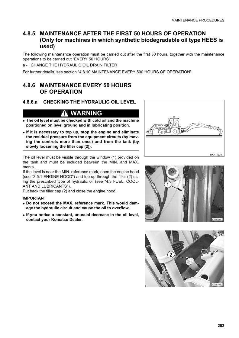
MAINTENANCE PROCEDURES
4.8.5 MAINTENANCE AFTER THE FIRST 50 HOURS OF OPERATION (Only for machines in which synthetic biodegradable oil type HEES is used)
The following maintenance operation must be carried out after the first 50 hours, together with the maintenanceoperations to be carried out “EVERY 50 HOURS”.
a - CHANGE THE HYDRAULIC OIL DRAIN FILTER
For further details, see section "4.8.10 MAINTENANCE EVERY 500 HOURS OF OPERATION".
4.8.6 MAINTENANCE EVERY 50 HOURS OF OPERATION
4.8.6.a CHECKING THE HYDRAULIC OIL LEVEL
WARNINGq The oil level must be checked with cold oil and the machine
positioned on level ground and in lubricating position.
q If it is necessary to top up, stop the engine and eliminatethe residual pressure from the equipment circuits (by mov-ing the controls more than once) and from the tank (byslowly loosening the filler cap (2)).
The oil level must be visible through the window (1) provided onthe tank and must be included between the MIN. and MAX.marks.If the level is near the MIN. reference mark, open the engine hood(see "3.5.1 ENGINE HOOD") and top up through the filler (2) us-ing the prescribed type of hydraulic oil (see "4.3 FUEL, COOL-ANT AND LUBRICANTS").Put back the filler cap (2) and close the engine hood.
IMPORTANTq Do not exceed the MAX. reference mark. This would dam-
age the hydraulic circuit and cause the oil to overflow.
q If you notice a constant, unusual decrease in the oil level,contact your Komatsu Dealer.
������
�������
�
�������
�
203
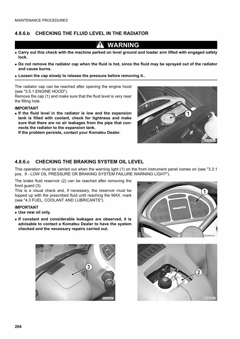
MAINTENANCE PROCEDURES
4.8.6.b CHECKING THE FLUID LEVEL IN THE RADIATOR
WARNINGq Carry out this check with the machine parked on level ground and loader arm lifted with engaged safety
lock.
q Do not remove the radiator cap when the fluid is hot, since the fluid may be sprayed out of the radiatorand cause burns.
q Loosen the cap slowly to release the pressure before removing it..
The radiator cap can be reached after opening the engine hood(see "3.5.1 ENGINE HOOD").Remove the cap (1) and make sure that the fluid level is very nearthe filling hole.
IMPORTANTq If the fluid level in the radiator is low and the expansion
tank is filled with coolant, check for tightness and makesure that there are no air leakages from the pipe that con-nects the radiator to the expansion tank.If the problem persists, contact your Komatsu Dealer.
4.8.6.c CHECKING THE BRAKING SYSTEM OIL LEVEL
This operation must be carried out when the warning light (1) on the front instrument panel comes on (see "3.3.1pos. 8 - LOW OIL PRESSURE OR BRAKING SYSTEM FAILURE WARNING LIGHT").
The brake fluid reservoir (2) can be reached after removing thefront guard (3).This is a visual check and, if necessary, the reservoir must betopped up with the prescribed fluid until reaching the MAX. mark(see "4.3 FUEL, COOLANT AND LUBRICANTS").
IMPORTANTq Use new oil only.
q If constant and considerable leakages are observed, it isadvisable to contact a Komatsu Dealer to have the systemchecked and the necessary repairs carried out.
�������
�
����� ��
�
�������
�
������
�
204
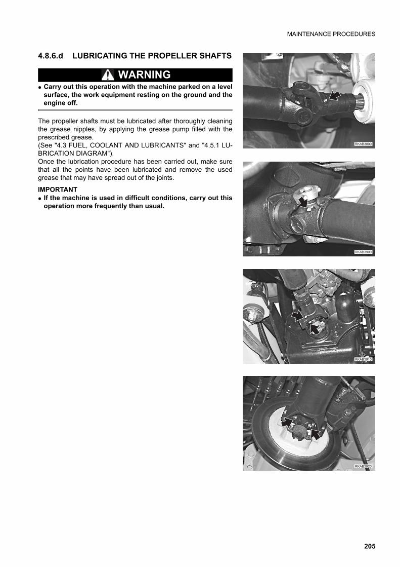
MAINTENANCE PROCEDURES
4.8.6.d LUBRICATING THE PROPELLER SHAFTS
WARNINGq Carry out this operation with the machine parked on a level
surface, the work equipment resting on the ground and theengine off.
The propeller shafts must be lubricated after thoroughly cleaningthe grease nipples, by applying the grease pump filled with theprescribed grease.(See "4.3 FUEL, COOLANT AND LUBRICANTS" and "4.5.1 LU-BRICATION DIAGRAM").Once the lubrication procedure has been carried out, make surethat all the points have been lubricated and remove the usedgrease that may have spread out of the joints.
IMPORTANTq If the machine is used in difficult conditions, carry out this
operation more frequently than usual.
�������
��������
�������
��������
205
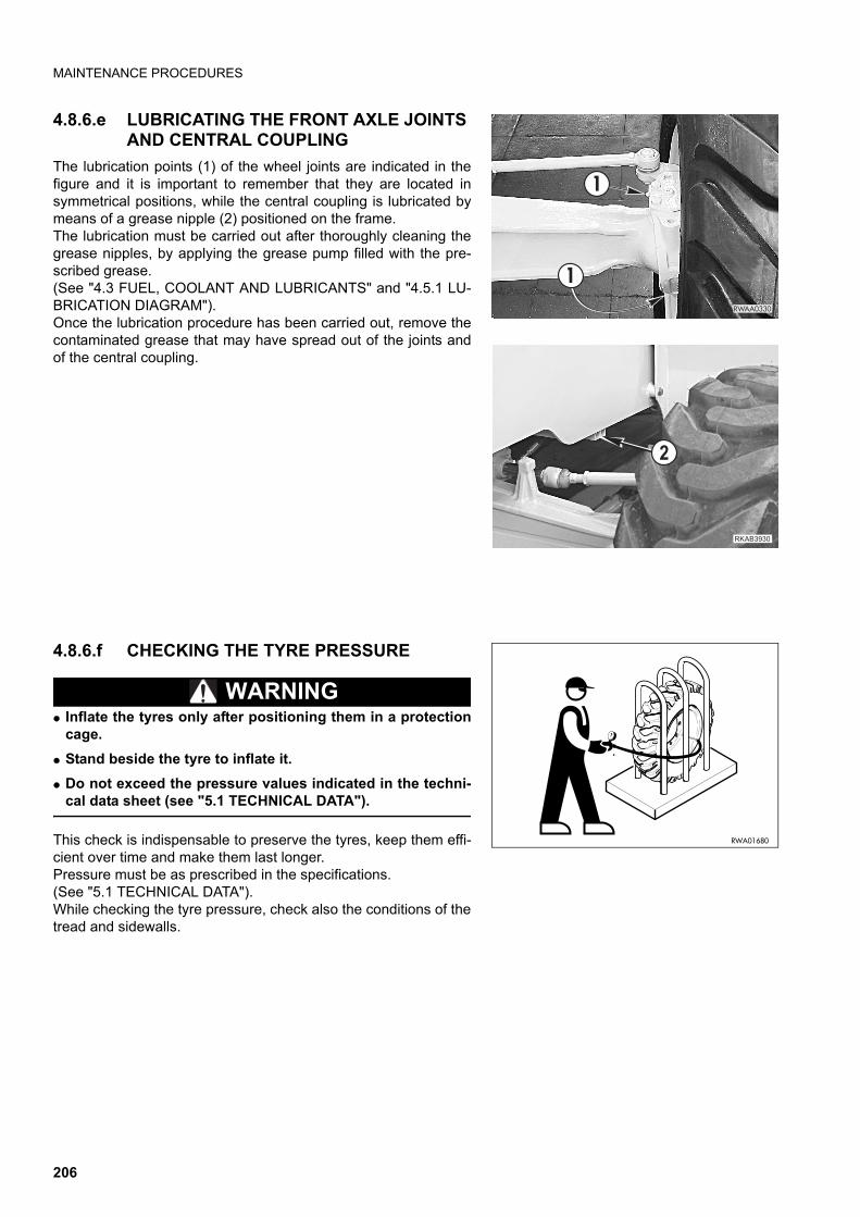
MAINTENANCE PROCEDURES
4.8.6.e LUBRICATING THE FRONT AXLE JOINTS AND CENTRAL COUPLING
The lubrication points (1) of the wheel joints are indicated in thefigure and it is important to remember that they are located insymmetrical positions, while the central coupling is lubricated bymeans of a grease nipple (2) positioned on the frame.The lubrication must be carried out after thoroughly cleaning thegrease nipples, by applying the grease pump filled with the pre-scribed grease.(See "4.3 FUEL, COOLANT AND LUBRICANTS" and "4.5.1 LU-BRICATION DIAGRAM").Once the lubrication procedure has been carried out, remove thecontaminated grease that may have spread out of the joints andof the central coupling.
4.8.6.f CHECKING THE TYRE PRESSURE
WARNINGq Inflate the tyres only after positioning them in a protection
cage.
q Stand beside the tyre to inflate it.
q Do not exceed the pressure values indicated in the techni-cal data sheet (see "5.1 TECHNICAL DATA").
This check is indispensable to preserve the tyres, keep them effi-cient over time and make them last longer.Pressure must be as prescribed in the specifications. (See "5.1 TECHNICAL DATA").While checking the tyre pressure, check also the conditions of thetread and sidewalls.
�����
#
#
��������
�
RWA01680
206
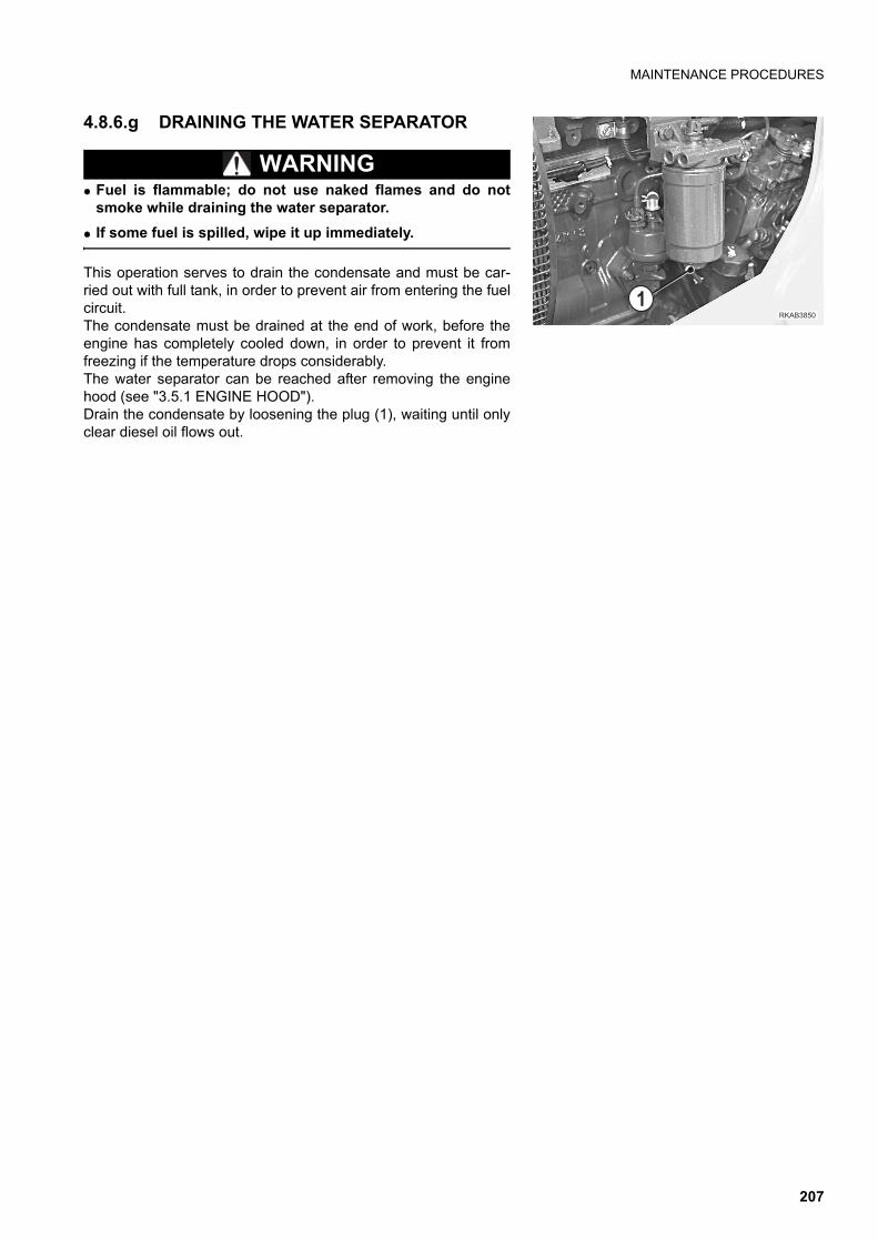
MAINTENANCE PROCEDURES
4.8.6.g DRAINING THE WATER SEPARATOR
WARNINGq Fuel is flammable; do not use naked flames and do not
smoke while draining the water separator.
q If some fuel is spilled, wipe it up immediately.
This operation serves to drain the condensate and must be car-ried out with full tank, in order to prevent air from entering the fuelcircuit.The condensate must be drained at the end of work, before theengine has completely cooled down, in order to prevent it fromfreezing if the temperature drops considerably.The water separator can be reached after removing the enginehood (see "3.5.1 ENGINE HOOD").Drain the condensate by loosening the plug (1), waiting until onlyclear diesel oil flows out.
����� �
�
207
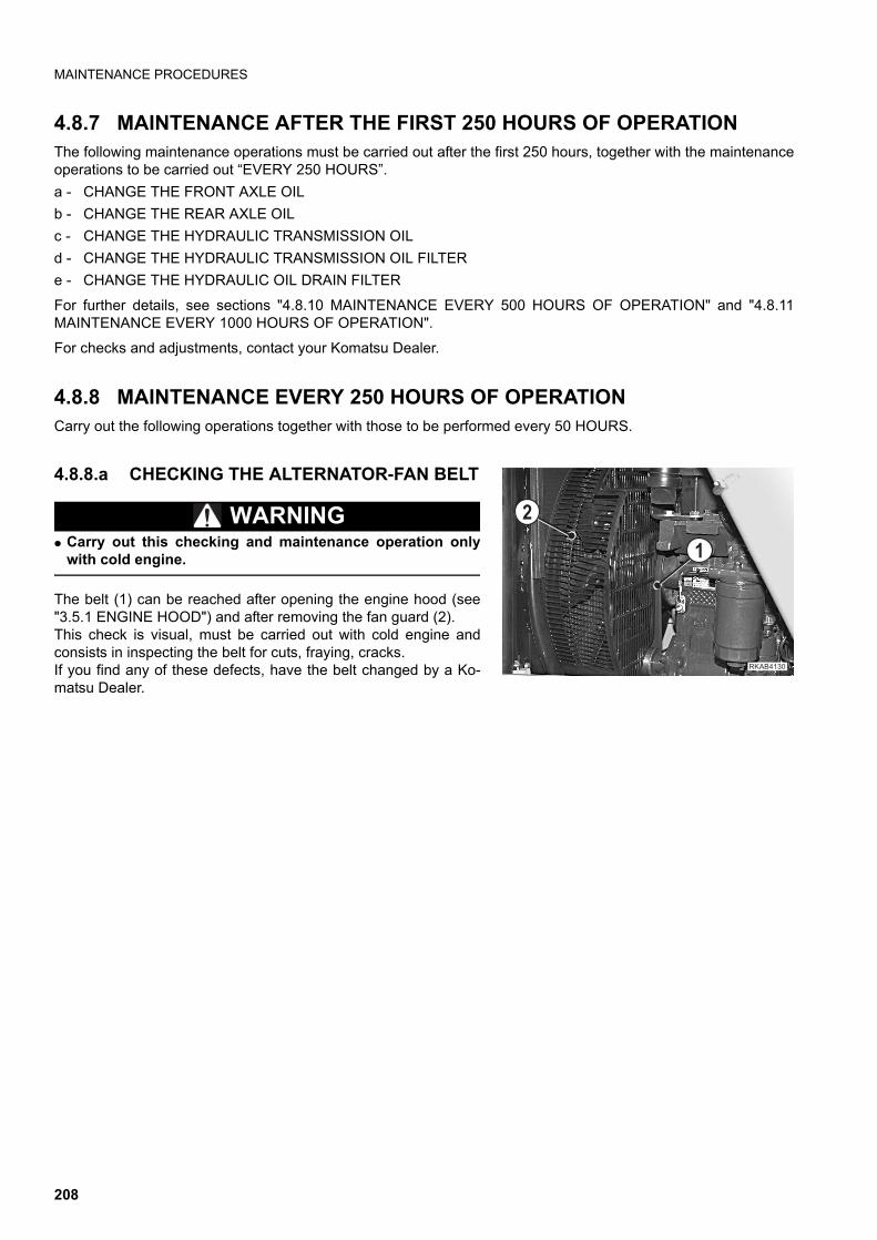
MAINTENANCE PROCEDURES
4.8.7 MAINTENANCE AFTER THE FIRST 250 HOURS OF OPERATIONThe following maintenance operations must be carried out after the first 250 hours, together with the maintenanceoperations to be carried out “EVERY 250 HOURS”.
a - CHANGE THE FRONT AXLE OIL
b - CHANGE THE REAR AXLE OIL
c - CHANGE THE HYDRAULIC TRANSMISSION OIL
d - CHANGE THE HYDRAULIC TRANSMISSION OIL FILTER
e - CHANGE THE HYDRAULIC OIL DRAIN FILTER
For further details, see sections "4.8.10 MAINTENANCE EVERY 500 HOURS OF OPERATION" and "4.8.11MAINTENANCE EVERY 1000 HOURS OF OPERATION".
For checks and adjustments, contact your Komatsu Dealer.
4.8.8 MAINTENANCE EVERY 250 HOURS OF OPERATIONCarry out the following operations together with those to be performed every 50 HOURS.
4.8.8.a CHECKING THE ALTERNATOR-FAN BELT
WARNINGq Carry out this checking and maintenance operation only
with cold engine.
The belt (1) can be reached after opening the engine hood (see"3.5.1 ENGINE HOOD") and after removing the fan guard (2).This check is visual, must be carried out with cold engine andconsists in inspecting the belt for cuts, fraying, cracks.If you find any of these defects, have the belt changed by a Ko-matsu Dealer.
�������
�
�
208
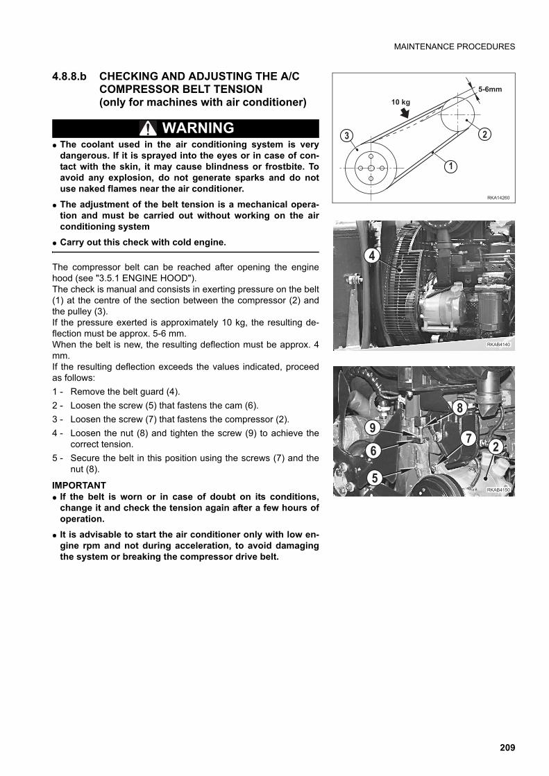
MAINTENANCE PROCEDURES
4.8.8.b CHECKING AND ADJUSTING THE A/C COMPRESSOR BELT TENSION (only for machines with air conditioner)
WARNINGq The coolant used in the air conditioning system is very
dangerous. If it is sprayed into the eyes or in case of con-tact with the skin, it may cause blindness or frostbite. Toavoid any explosion, do not generate sparks and do notuse naked flames near the air conditioner.
q The adjustment of the belt tension is a mechanical opera-tion and must be carried out without working on the airconditioning system
q Carry out this check with cold engine.
The compressor belt can be reached after opening the enginehood (see "3.5.1 ENGINE HOOD").The check is manual and consists in exerting pressure on the belt(1) at the centre of the section between the compressor (2) andthe pulley (3).If the pressure exerted is approximately 10 kg, the resulting de-flection must be approx. 5-6 mm.When the belt is new, the resulting deflection must be approx. 4mm.If the resulting deflection exceeds the values indicated, proceedas follows:
1 - Remove the belt guard (4).
2 - Loosen the screw (5) that fastens the cam (6).
3 - Loosen the screw (7) that fastens the compressor (2).
4 - Loosen the nut (8) and tighten the screw (9) to achieve thecorrect tension.
5 - Secure the belt in this position using the screws (7) and thenut (8).
IMPORTANTq If the belt is worn or in case of doubt on its conditions,
change it and check the tension again after a few hours ofoperation.
q It is advisable to start the air conditioner only with low en-gine rpm and not during acceleration, to avoid damagingthe system or breaking the compressor drive belt.
�������
��/0
�� ��
� �
�
����� �
�
�
!
"
�
�������
�
209
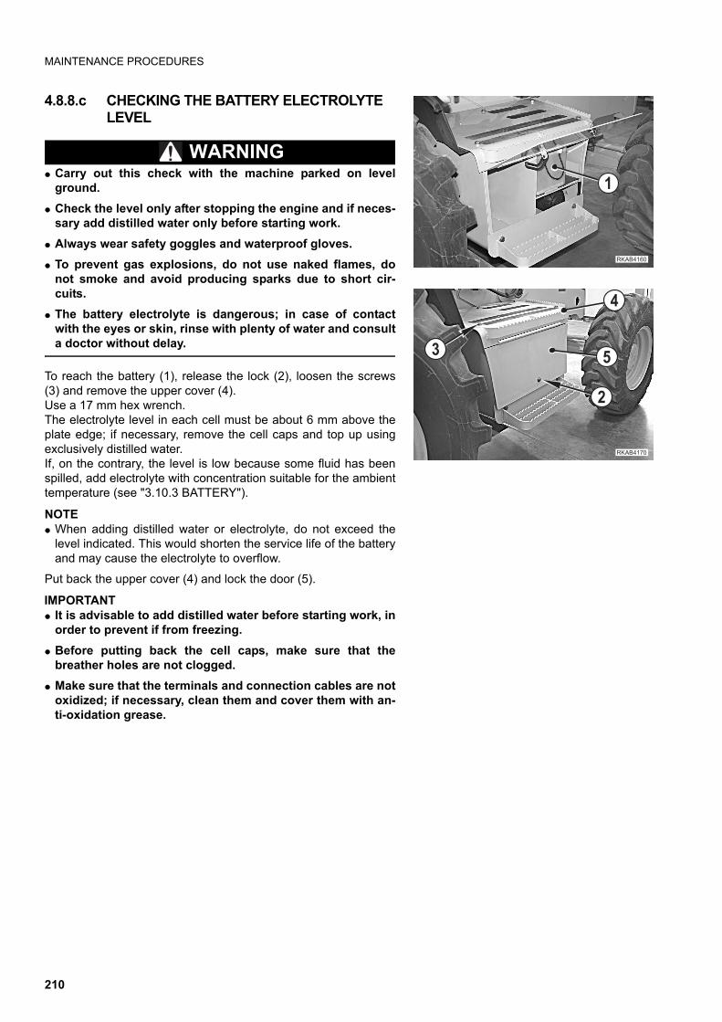
MAINTENANCE PROCEDURES
4.8.8.c CHECKING THE BATTERY ELECTROLYTE LEVEL
WARNINGq Carry out this check with the machine parked on level
ground.
q Check the level only after stopping the engine and if neces-sary add distilled water only before starting work.
q Always wear safety goggles and waterproof gloves.
q To prevent gas explosions, do not use naked flames, donot smoke and avoid producing sparks due to short cir-cuits.
q The battery electrolyte is dangerous; in case of contactwith the eyes or skin, rinse with plenty of water and consulta doctor without delay.
To reach the battery (1), release the lock (2), loosen the screws(3) and remove the upper cover (4).Use a 17 mm hex wrench.The electrolyte level in each cell must be about 6 mm above theplate edge; if necessary, remove the cell caps and top up usingexclusively distilled water.If, on the contrary, the level is low because some fluid has beenspilled, add electrolyte with concentration suitable for the ambienttemperature (see "3.10.3 BATTERY").
NOTEq When adding distilled water or electrolyte, do not exceed the
level indicated. This would shorten the service life of the batteryand may cause the electrolyte to overflow.
Put back the upper cover (4) and lock the door (5).
IMPORTANTq It is advisable to add distilled water before starting work, in
order to prevent if from freezing.
q Before putting back the cell caps, make sure that thebreather holes are not clogged.
q Make sure that the terminals and connection cables are notoxidized; if necessary, clean them and cover them with an-ti-oxidation grease.
�������
�
�������
�
�
�
�
210
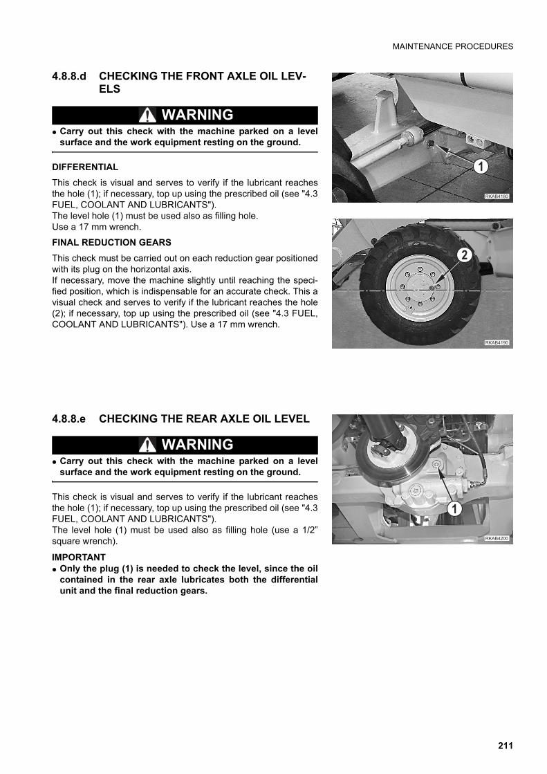
MAINTENANCE PROCEDURES
4.8.8.d CHECKING THE FRONT AXLE OIL LEV-ELS
WARNINGq Carry out this check with the machine parked on a level
surface and the work equipment resting on the ground.
DIFFERENTIAL
This check is visual and serves to verify if the lubricant reachesthe hole (1); if necessary, top up using the prescribed oil (see "4.3FUEL, COOLANT AND LUBRICANTS").The level hole (1) must be used also as filling hole.Use a 17 mm wrench.
FINAL REDUCTION GEARS
This check must be carried out on each reduction gear positionedwith its plug on the horizontal axis.If necessary, move the machine slightly until reaching the speci-fied position, which is indispensable for an accurate check. This avisual check and serves to verify if the lubricant reaches the hole(2); if necessary, top up using the prescribed oil (see "4.3 FUEL,COOLANT AND LUBRICANTS"). Use a 17 mm wrench.
4.8.8.e CHECKING THE REAR AXLE OIL LEVEL
WARNINGq Carry out this check with the machine parked on a level
surface and the work equipment resting on the ground.
This check is visual and serves to verify if the lubricant reachesthe hole (1); if necessary, top up using the prescribed oil (see "4.3FUEL, COOLANT AND LUBRICANTS").The level hole (1) must be used also as filling hole (use a 1/2”square wrench).
IMPORTANTq Only the plug (1) is needed to check the level, since the oil
contained in the rear axle lubricates both the differentialunit and the final reduction gears.
������
�
�������
�
��������
�
211
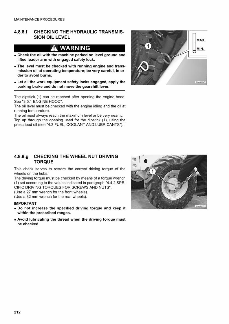
MAINTENANCE PROCEDURES
4.8.8.f CHECKING THE HYDRAULIC TRANSMIS-SION OIL LEVEL
WARNINGq Check the oil with the machine parked on level ground and
lifted loader arm with engaged safety lock.
q The level must be checked with running engine and trans-mission oil at operating temperature; be very careful, in or-der to avoid burns.
q Let all the work equipment safety locks engaged, apply theparking brake and do not move the gearshift lever.
The dipstick (1) can be reached after opening the engine hood.See "3.5.1 ENGINE HOOD".The oil level must be checked with the engine idling and the oil atrunning temperature.The oil must always reach the maximum level or be very near it.Top up through the opening used for the dipstick (1), using theprescribed oil (see "4.3 FUEL, COOLANT AND LUBRICANTS").
4.8.8.g CHECKING THE WHEEL NUT DRIVING TORQUE
This check serves to restore the correct driving torque of thewheels on the hubs.The driving torque must be checked by means of a torque wrench(1) set according to the values indicated in paragraph "4.4.2 SPE-CIFIC DRIVING TORQUES FOR SCREWS AND NUTS".(Use a 27 mm wrench for the front wheels).(Use a 32 mm wrench for the rear wheels).
IMPORTANTq Do not increase the specified driving torque and keep it
within the prescribed ranges.
q Avoid lubricating the thread when the driving torque mustbe checked.
��������
����
��
������ �
�
212
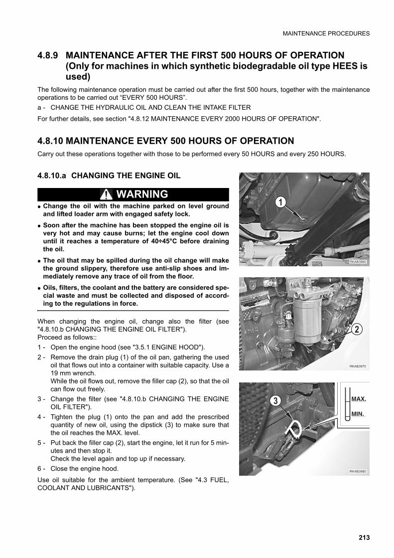
MAINTENANCE PROCEDURES
4.8.9 MAINTENANCE AFTER THE FIRST 500 HOURS OF OPERATION(Only for machines in which synthetic biodegradable oil type HEES is used)
The following maintenance operation must be carried out after the first 500 hours, together with the maintenanceoperations to be carried out “EVERY 500 HOURS”.
a - CHANGE THE HYDRAULIC OIL AND CLEAN THE INTAKE FILTER
For further details, see section "4.8.12 MAINTENANCE EVERY 2000 HOURS OF OPERATION".
4.8.10 MAINTENANCE EVERY 500 HOURS OF OPERATIONCarry out these operations together with those to be performed every 50 HOURS and every 250 HOURS.
4.8.10.a CHANGING THE ENGINE OIL
WARNINGq Change the oil with the machine parked on level ground
and lifted loader arm with engaged safety lock.
q Soon after the machine has been stopped the engine oil isvery hot and may cause burns; let the engine cool downuntil it reaches a temperature of 40÷45°C before drainingthe oil.
q The oil that may be spilled during the oil change will makethe ground slippery, therefore use anti-slip shoes and im-mediately remove any trace of oil from the floor.
q Oils, filters, the coolant and the battery are considered spe-cial waste and must be collected and disposed of accord-ing to the regulations in force.
When changing the engine oil, change also the filter (see"4.8.10.b CHANGING THE ENGINE OIL FILTER").Proceed as follows::
1 - Open the engine hood (see "3.5.1 ENGINE HOOD").
2 - Remove the drain plug (1) of the oil pan, gathering the usedoil that flows out into a container with suitable capacity. Use a19 mm wrench.While the oil flows out, remove the filler cap (2), so that the oilcan flow out freely.
3 - Change the filter (see "4.8.10.b CHANGING THE ENGINEOIL FILTER").
4 - Tighten the plug (1) onto the pan and add the prescribedquantity of new oil, using the dipstick (3) to make sure thatthe oil reaches the MAX. level.
5 - Put back the filler cap (2), start the engine, let it run for 5 min-utes and then stop it.Check the level again and top up if necessary.
6 - Close the engine hood.
Use oil suitable for the ambient temperature. (See "4.3 FUEL,COOLANT AND LUBRICANTS").
��������
�
��������
�
�������
� ���
��
213
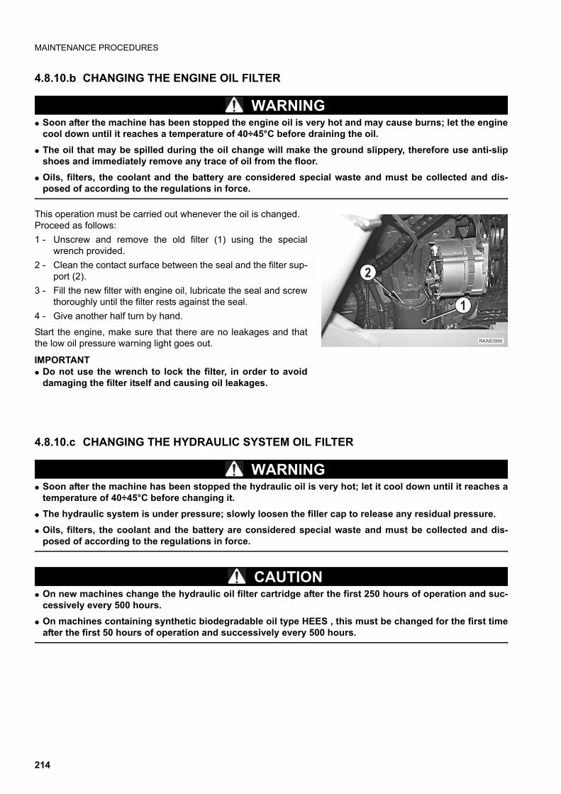
MAINTENANCE PROCEDURES
4.8.10.b CHANGING THE ENGINE OIL FILTER
WARNINGq Soon after the machine has been stopped the engine oil is very hot and may cause burns; let the engine
cool down until it reaches a temperature of 40÷45°C before draining the oil.
q The oil that may be spilled during the oil change will make the ground slippery, therefore use anti-slipshoes and immediately remove any trace of oil from the floor.
q Oils, filters, the coolant and the battery are considered special waste and must be collected and dis-posed of according to the regulations in force.
This operation must be carried out whenever the oil is changed.Proceed as follows:
1 - Unscrew and remove the old filter (1) using the specialwrench provided.
2 - Clean the contact surface between the seal and the filter sup-port (2).
3 - Fill the new filter with engine oil, lubricate the seal and screwthoroughly until the filter rests against the seal.
4 - Give another half turn by hand.
Start the engine, make sure that there are no leakages and thatthe low oil pressure warning light goes out.
IMPORTANTq Do not use the wrench to lock the filter, in order to avoid
damaging the filter itself and causing oil leakages.
4.8.10.c CHANGING THE HYDRAULIC SYSTEM OIL FILTER
WARNINGq Soon after the machine has been stopped the hydraulic oil is very hot; let it cool down until it reaches a
temperature of 40÷45°C before changing it.
q The hydraulic system is under pressure; slowly loosen the filler cap to release any residual pressure.
q Oils, filters, the coolant and the battery are considered special waste and must be collected and dis-posed of according to the regulations in force.
CAUTIONq On new machines change the hydraulic oil filter cartridge after the first 250 hours of operation and suc-
cessively every 500 hours.
q On machines containing synthetic biodegradable oil type HEES , this must be changed for the first timeafter the first 50 hours of operation and successively every 500 hours.
��������
�
�
214
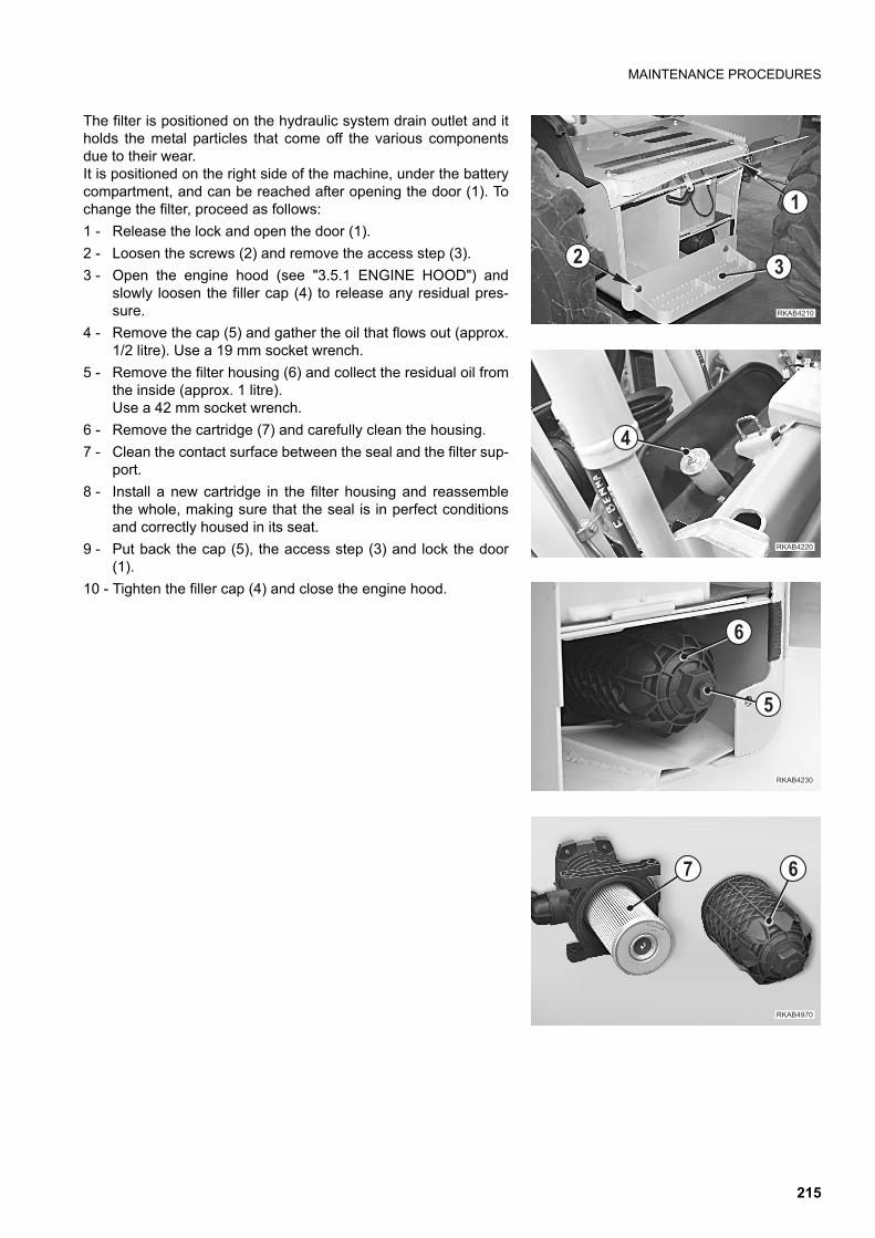
MAINTENANCE PROCEDURES
The filter is positioned on the hydraulic system drain outlet and itholds the metal particles that come off the various componentsdue to their wear.It is positioned on the right side of the machine, under the batterycompartment, and can be reached after opening the door (1). Tochange the filter, proceed as follows:
1 - Release the lock and open the door (1).
2 - Loosen the screws (2) and remove the access step (3).
3 - Open the engine hood (see "3.5.1 ENGINE HOOD") andslowly loosen the filler cap (4) to release any residual pres-sure.
4 - Remove the cap (5) and gather the oil that flows out (approx.1/2 litre). Use a 19 mm socket wrench.
5 - Remove the filter housing (6) and collect the residual oil fromthe inside (approx. 1 litre). Use a 42 mm socket wrench.
6 - Remove the cartridge (7) and carefully clean the housing.
7 - Clean the contact surface between the seal and the filter sup-port.
8 - Install a new cartridge in the filter housing and reassemblethe whole, making sure that the seal is in perfect conditionsand correctly housed in its seat.
9 - Put back the cap (5), the access step (3) and lock the door(1).
10 - Tighten the filler cap (4) and close the engine hood.
�������
�
� �
��������
�
��������
�
��������
�
215

MAINTENANCE PROCEDURES
IMPORTANTq In machines equipped with demolition hammer hydraulic
oil deteriorates more rapidly than in machines used forsimple digging operations.On new machines, change the filter after the first 100-150hours of operation and for the successive changes keep tothe indications given in the table on the right.
0 20 40 60 80 100
500
100
800
Breaker operating ratio (%)
Rep
lace
men
t in
terv
al (
H)
Replacement interval for element
RWA10710
216
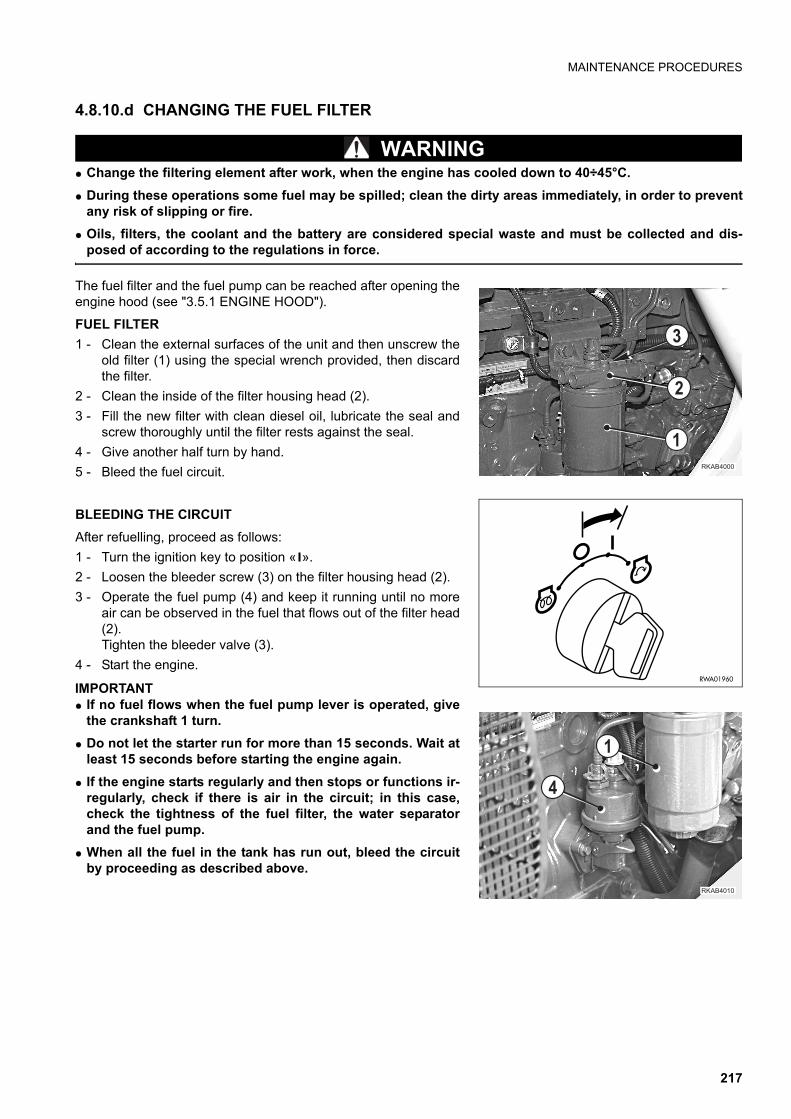
MAINTENANCE PROCEDURES
4.8.10.d CHANGING THE FUEL FILTER
WARNINGq Change the filtering element after work, when the engine has cooled down to 40÷45°C.
q During these operations some fuel may be spilled; clean the dirty areas immediately, in order to preventany risk of slipping or fire.
q Oils, filters, the coolant and the battery are considered special waste and must be collected and dis-posed of according to the regulations in force.
The fuel filter and the fuel pump can be reached after opening theengine hood (see "3.5.1 ENGINE HOOD").
FUEL FILTER
1 - Clean the external surfaces of the unit and then unscrew theold filter (1) using the special wrench provided, then discardthe filter.
2 - Clean the inside of the filter housing head (2).
3 - Fill the new filter with clean diesel oil, lubricate the seal andscrew thoroughly until the filter rests against the seal.
4 - Give another half turn by hand.
5 - Bleed the fuel circuit.
BLEEDING THE CIRCUIT
After refuelling, proceed as follows:
1 - Turn the ignition key to position « ».
2 - Loosen the bleeder screw (3) on the filter housing head (2).
3 - Operate the fuel pump (4) and keep it running until no moreair can be observed in the fuel that flows out of the filter head(2). Tighten the bleeder valve (3).
4 - Start the engine.
IMPORTANTq If no fuel flows when the fuel pump lever is operated, give
the crankshaft 1 turn.
q Do not let the starter run for more than 15 seconds. Wait atleast 15 seconds before starting the engine again.
q If the engine starts regularly and then stops or functions ir-regularly, check if there is air in the circuit; in this case,check the tightness of the fuel filter, the water separatorand the fuel pump.
q When all the fuel in the tank has run out, bleed the circuitby proceeding as described above.
��������
�
�
�
RWA01960
�������
�
�
217
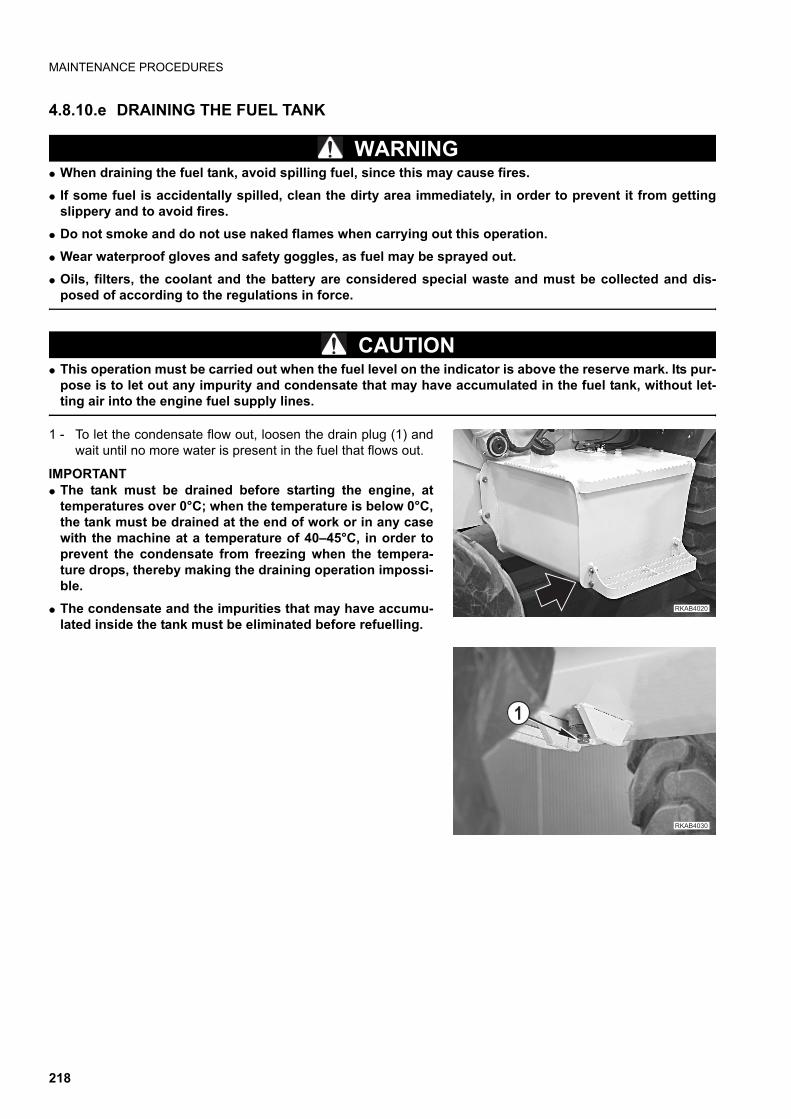
MAINTENANCE PROCEDURES
4.8.10.e DRAINING THE FUEL TANK
WARNINGq When draining the fuel tank, avoid spilling fuel, since this may cause fires.
q If some fuel is accidentally spilled, clean the dirty area immediately, in order to prevent it from gettingslippery and to avoid fires.
q Do not smoke and do not use naked flames when carrying out this operation.
q Wear waterproof gloves and safety goggles, as fuel may be sprayed out.
q Oils, filters, the coolant and the battery are considered special waste and must be collected and dis-posed of according to the regulations in force.
CAUTIONq This operation must be carried out when the fuel level on the indicator is above the reserve mark. Its pur-
pose is to let out any impurity and condensate that may have accumulated in the fuel tank, without let-ting air into the engine fuel supply lines.
1 - To let the condensate flow out, loosen the drain plug (1) andwait until no more water is present in the fuel that flows out.
IMPORTANTq The tank must be drained before starting the engine, at
temperatures over 0°C; when the temperature is below 0°C,the tank must be drained at the end of work or in any casewith the machine at a temperature of 40–45°C, in order toprevent the condensate from freezing when the tempera-ture drops, thereby making the draining operation impossi-ble.
q The condensate and the impurities that may have accumu-lated inside the tank must be eliminated before refuelling.
��������
��������
�
218
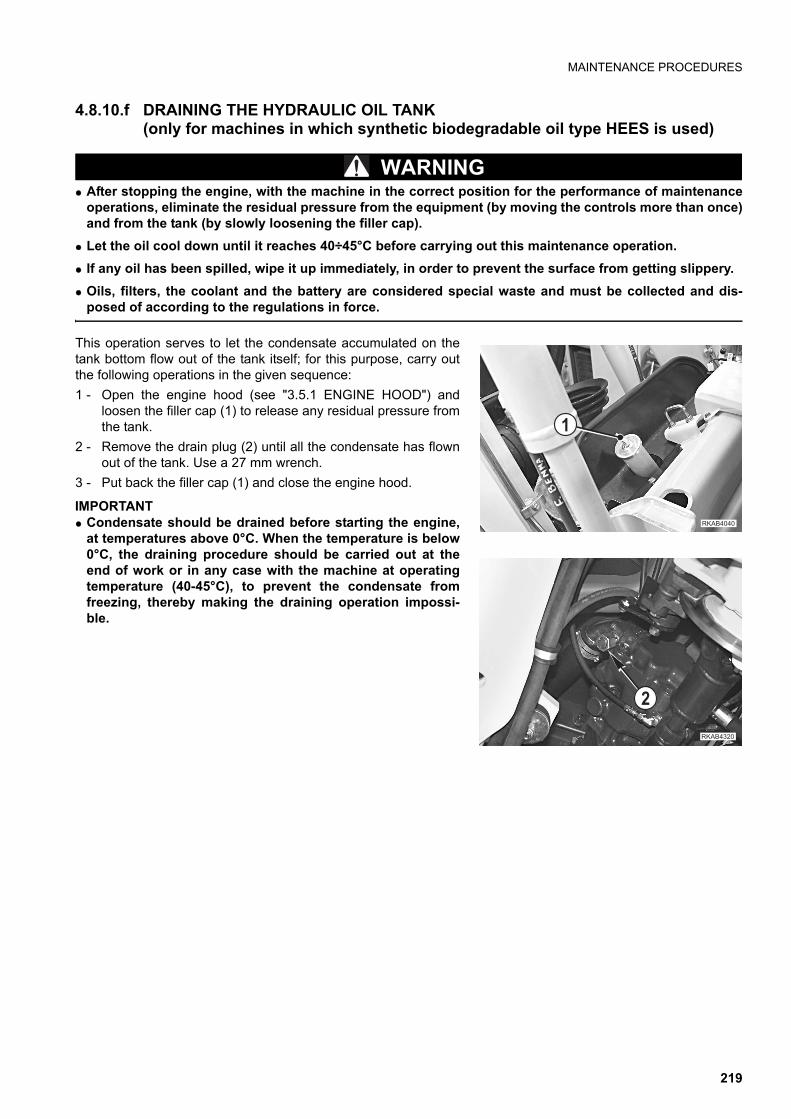
MAINTENANCE PROCEDURES
4.8.10.f DRAINING THE HYDRAULIC OIL TANK(only for machines in which synthetic biodegradable oil type HEES is used)
WARNINGq After stopping the engine, with the machine in the correct position for the performance of maintenance
operations, eliminate the residual pressure from the equipment (by moving the controls more than once)and from the tank (by slowly loosening the filler cap).
q Let the oil cool down until it reaches 40÷45°C before carrying out this maintenance operation.
q If any oil has been spilled, wipe it up immediately, in order to prevent the surface from getting slippery.
q Oils, filters, the coolant and the battery are considered special waste and must be collected and dis-posed of according to the regulations in force.
This operation serves to let the condensate accumulated on thetank bottom flow out of the tank itself; for this purpose, carry outthe following operations in the given sequence:
1 - Open the engine hood (see "3.5.1 ENGINE HOOD") andloosen the filler cap (1) to release any residual pressure fromthe tank.
2 - Remove the drain plug (2) until all the condensate has flownout of the tank. Use a 27 mm wrench.
3 - Put back the filler cap (1) and close the engine hood.
IMPORTANTq Condensate should be drained before starting the engine,
at temperatures above 0°C. When the temperature is below0°C, the draining procedure should be carried out at theend of work or in any case with the machine at operatingtemperature (40-45°C), to prevent the condensate fromfreezing, thereby making the draining operation impossi-ble.
��������
�
��������
�
219
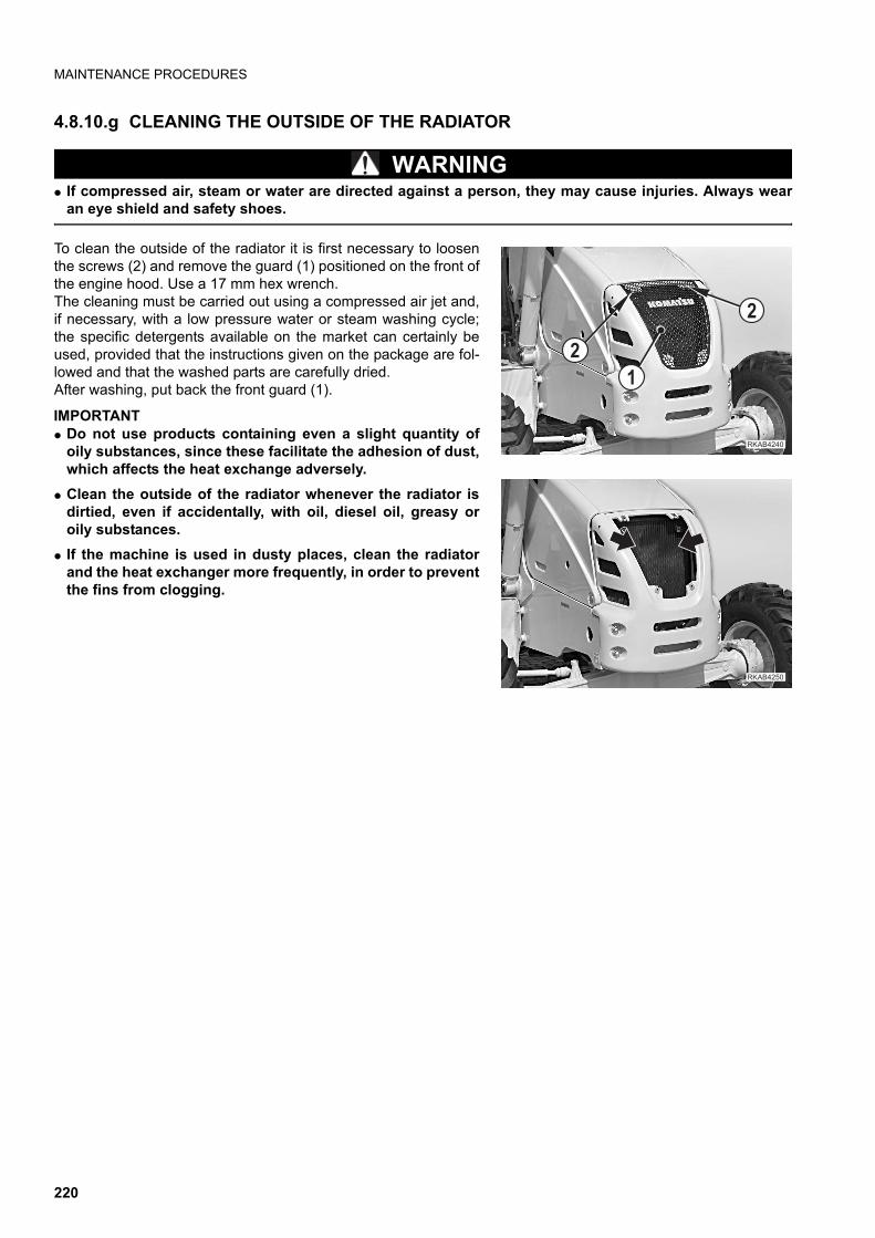
MAINTENANCE PROCEDURES
4.8.10.g CLEANING THE OUTSIDE OF THE RADIATOR
WARNINGq If compressed air, steam or water are directed against a person, they may cause injuries. Always wear
an eye shield and safety shoes.
To clean the outside of the radiator it is first necessary to loosenthe screws (2) and remove the guard (1) positioned on the front ofthe engine hood. Use a 17 mm hex wrench.The cleaning must be carried out using a compressed air jet and,if necessary, with a low pressure water or steam washing cycle;the specific detergents available on the market can certainly beused, provided that the instructions given on the package are fol-lowed and that the washed parts are carefully dried.After washing, put back the front guard (1).
IMPORTANTq Do not use products containing even a slight quantity of
oily substances, since these facilitate the adhesion of dust,which affects the heat exchange adversely.
q Clean the outside of the radiator whenever the radiator isdirtied, even if accidentally, with oil, diesel oil, greasy oroily substances.
q If the machine is used in dusty places, clean the radiatorand the heat exchanger more frequently, in order to preventthe fins from clogging.
��������
�
�
�
������ �
220
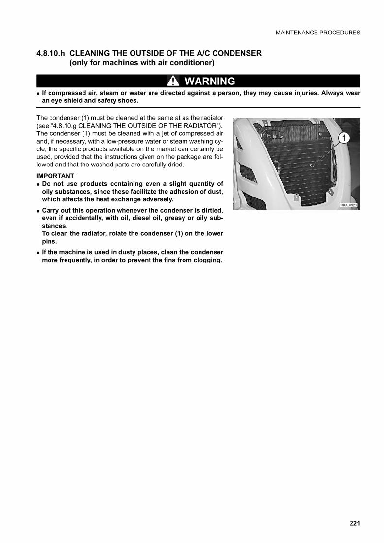
MAINTENANCE PROCEDURES
4.8.10.h CLEANING THE OUTSIDE OF THE A/C CONDENSER (only for machines with air conditioner)
WARNINGq If compressed air, steam or water are directed against a person, they may cause injuries. Always wear
an eye shield and safety shoes.
The condenser (1) must be cleaned at the same at as the radiator(see "4.8.10.g CLEANING THE OUTSIDE OF THE RADIATOR").The condenser (1) must be cleaned with a jet of compressed airand, if necessary, with a low-pressure water or steam washing cy-cle; the specific products available on the market can certainly beused, provided that the instructions given on the package are fol-lowed and that the washed parts are carefully dried.
IMPORTANTq Do not use products containing even a slight quantity of
oily substances, since these facilitate the adhesion of dust,which affects the heat exchange adversely.
q Carry out this operation whenever the condenser is dirtied,even if accidentally, with oil, diesel oil, greasy or oily sub-stances.To clean the radiator, rotate the condenser (1) on the lowerpins.
q If the machine is used in dusty places, clean the condensermore frequently, in order to prevent the fins from clogging.
��������
�
221
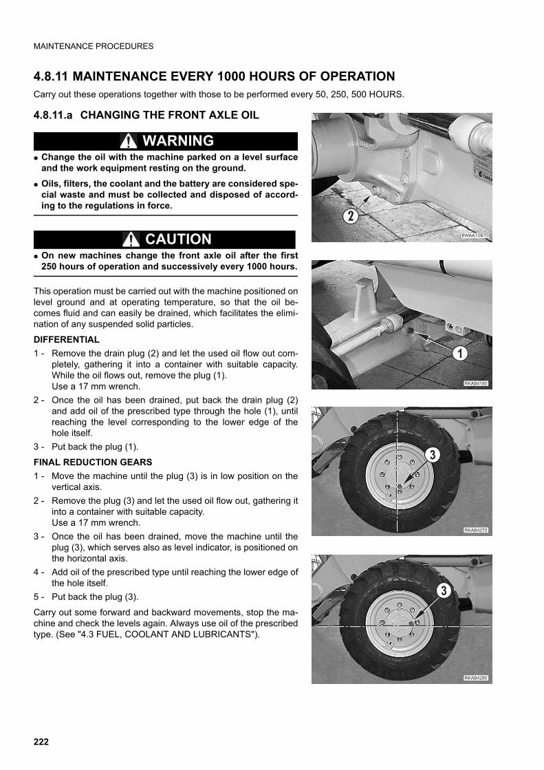
MAINTENANCE PROCEDURES
4.8.11 MAINTENANCE EVERY 1000 HOURS OF OPERATIONCarry out these operations together with those to be performed every 50, 250, 500 HOURS.
4.8.11.a CHANGING THE FRONT AXLE OIL
WARNINGq Change the oil with the machine parked on a level surface
and the work equipment resting on the ground.
q Oils, filters, the coolant and the battery are considered spe-cial waste and must be collected and disposed of accord-ing to the regulations in force.
CAUTIONq On new machines change the front axle oil after the first
250 hours of operation and successively every 1000 hours.
This operation must be carried out with the machine positioned onlevel ground and at operating temperature, so that the oil be-comes fluid and can easily be drained, which facilitates the elimi-nation of any suspended solid particles.
DIFFERENTIAL
1 - Remove the drain plug (2) and let the used oil flow out com-pletely, gathering it into a container with suitable capacity.While the oil flows out, remove the plug (1).Use a 17 mm wrench.
2 - Once the oil has been drained, put back the drain plug (2)and add oil of the prescribed type through the hole (1), untilreaching the level corresponding to the lower edge of thehole itself.
3 - Put back the plug (1).
FINAL REDUCTION GEARS
1 - Move the machine until the plug (3) is in low position on thevertical axis.
2 - Remove the plug (3) and let the used oil flow out, gathering itinto a container with suitable capacity.Use a 17 mm wrench.
3 - Once the oil has been drained, move the machine until theplug (3), which serves also as level indicator, is positioned onthe horizontal axis.
4 - Add oil of the prescribed type until reaching the lower edge ofthe hole itself.
5 - Put back the plug (3).
Carry out some forward and backward movements, stop the ma-chine and check the levels again. Always use oil of the prescribedtype. (See "4.3 FUEL, COOLANT AND LUBRICANTS").
�������
������
�
��������
�
�������
�
222
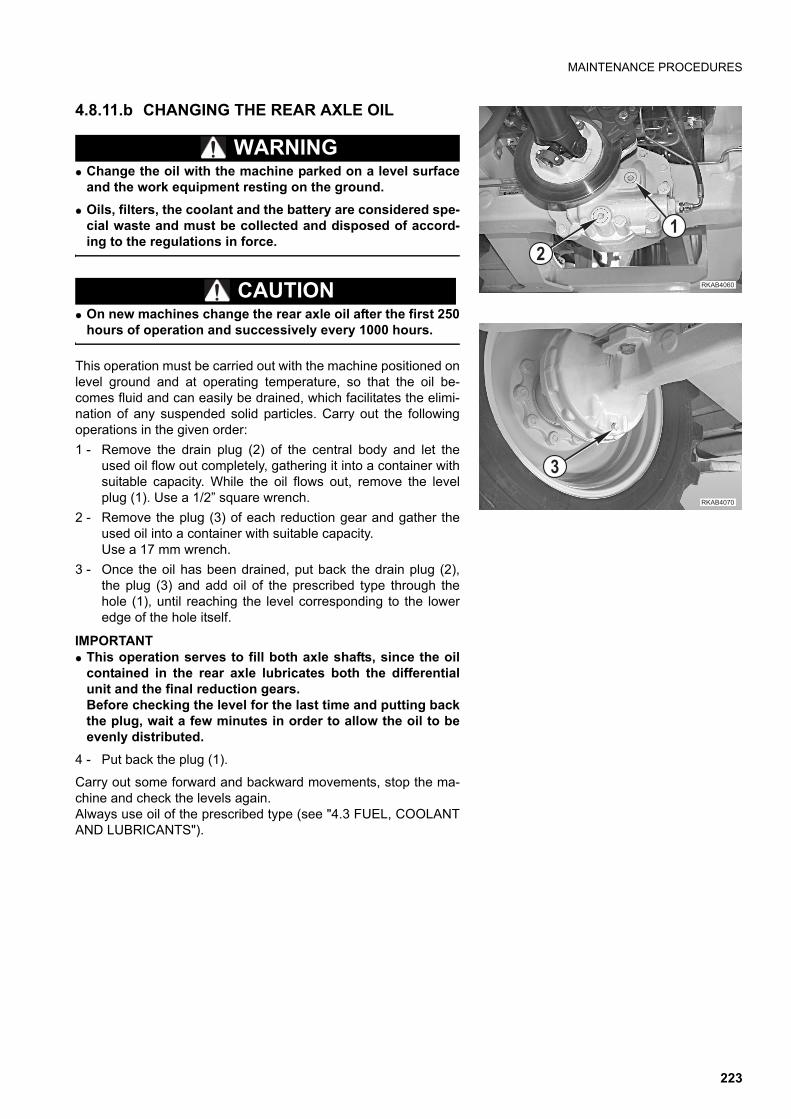
MAINTENANCE PROCEDURES
4.8.11.b CHANGING THE REAR AXLE OIL
WARNINGq Change the oil with the machine parked on a level surface
and the work equipment resting on the ground.
q Oils, filters, the coolant and the battery are considered spe-cial waste and must be collected and disposed of accord-ing to the regulations in force.
CAUTIONq On new machines change the rear axle oil after the first 250
hours of operation and successively every 1000 hours.
This operation must be carried out with the machine positioned onlevel ground and at operating temperature, so that the oil be-comes fluid and can easily be drained, which facilitates the elimi-nation of any suspended solid particles. Carry out the followingoperations in the given order:
1 - Remove the drain plug (2) of the central body and let theused oil flow out completely, gathering it into a container withsuitable capacity. While the oil flows out, remove the levelplug (1). Use a 1/2” square wrench.
2 - Remove the plug (3) of each reduction gear and gather theused oil into a container with suitable capacity.Use a 17 mm wrench.
3 - Once the oil has been drained, put back the drain plug (2),the plug (3) and add oil of the prescribed type through thehole (1), until reaching the level corresponding to the loweredge of the hole itself.
IMPORTANTq This operation serves to fill both axle shafts, since the oil
contained in the rear axle lubricates both the differentialunit and the final reduction gears. Before checking the level for the last time and putting backthe plug, wait a few minutes in order to allow the oil to beevenly distributed.
4 - Put back the plug (1).
Carry out some forward and backward movements, stop the ma-chine and check the levels again.Always use oil of the prescribed type (see "4.3 FUEL, COOLANTAND LUBRICANTS").
��������
��
��������
�
223
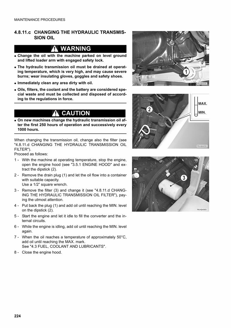
MAINTENANCE PROCEDURES
4.8.11.c CHANGING THE HYDRAULIC TRANSMIS-SION OIL
WARNINGq Change the oil with the machine parked on level ground
and lifted loader arm with engaged safety lock.
q The hydraulic transmission oil must be drained at operat-ing temperature, which is very high, and may cause severeburns; wear insulating gloves, goggles and safety shoes.
q Immediately clean any area dirty with oil.
q Oils, filters, the coolant and the battery are considered spe-cial waste and must be collected and disposed of accord-ing to the regulations in force.
CAUTIONq On new machines change the hydraulic transmission oil af-
ter the first 250 hours of operation and successively every1000 hours.
When changing the transmission oil, change also the filter (see"4.8.11.d CHANGING THE HYDRAULIC TRANSMISSION OILFILTER").Proceed as follows:
1 - With the machine at operating temperature, stop the engine,open the engine hood (see "3.5.1 ENGINE HOOD" and ex-tract the dipstick (2).
2 - Remove the drain plug (1) and let the oil flow into a containerwith suitable capacity.Use a 1/2” square wrench.
3 - Remove the filter (3) and change it (see "4.8.11.d CHANG-ING THE HYDRAULIC TRANSMISSION OIL FILTER"), pay-ing the utmost attention.
4 - Put back the plug (1) and add oil until reaching the MIN. levelon the dipstick (2).
5 - Start the engine and let it idle to fill the converter and the in-ternal circuits.
6 - While the engine is idling, add oil until reaching the MIN. levelagain.
7 - When the oil reaches a temperature of approximately 50°C,add oil until reaching the MAX. mark.See "4.3 FUEL, COOLANT AND LUBRICANTS".
8 - Close the engine hood.
�������
�
��������
����
��
�
��������
224
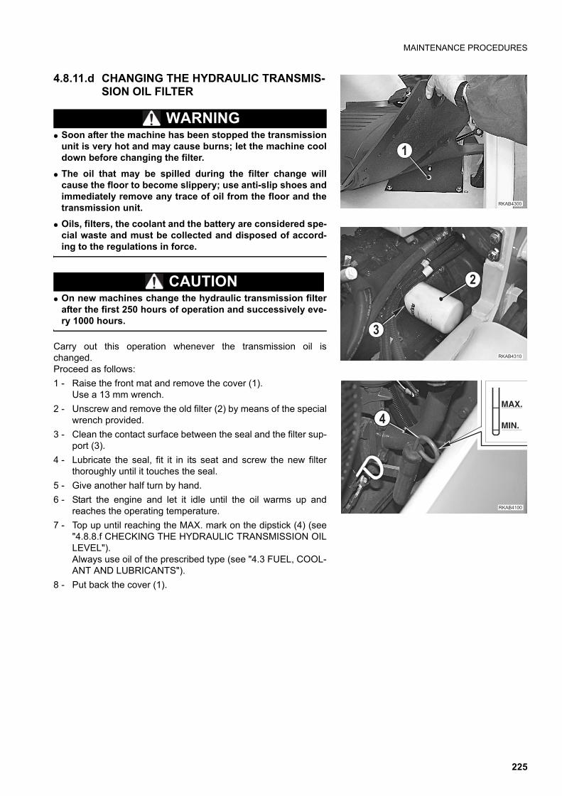
MAINTENANCE PROCEDURES
4.8.11.d CHANGING THE HYDRAULIC TRANSMIS-SION OIL FILTER
WARNINGq Soon after the machine has been stopped the transmission
unit is very hot and may cause burns; let the machine cooldown before changing the filter.
q The oil that may be spilled during the filter change willcause the floor to become slippery; use anti-slip shoes andimmediately remove any trace of oil from the floor and thetransmission unit.
q Oils, filters, the coolant and the battery are considered spe-cial waste and must be collected and disposed of accord-ing to the regulations in force.
CAUTIONq On new machines change the hydraulic transmission filter
after the first 250 hours of operation and successively eve-ry 1000 hours.
Carry out this operation whenever the transmission oil ischanged.Proceed as follows:
1 - Raise the front mat and remove the cover (1).Use a 13 mm wrench.
2 - Unscrew and remove the old filter (2) by means of the specialwrench provided.
3 - Clean the contact surface between the seal and the filter sup-port (3).
4 - Lubricate the seal, fit it in its seat and screw the new filterthoroughly until it touches the seal.
5 - Give another half turn by hand.
6 - Start the engine and let it idle until the oil warms up andreaches the operating temperature.
7 - Top up until reaching the MAX. mark on the dipstick (4) (see"4.8.8.f CHECKING THE HYDRAULIC TRANSMISSION OILLEVEL").Always use oil of the prescribed type (see "4.3 FUEL, COOL-ANT AND LUBRICANTS").
8 - Put back the cover (1).
�
��������
�
�������
�
�������
����
��
225
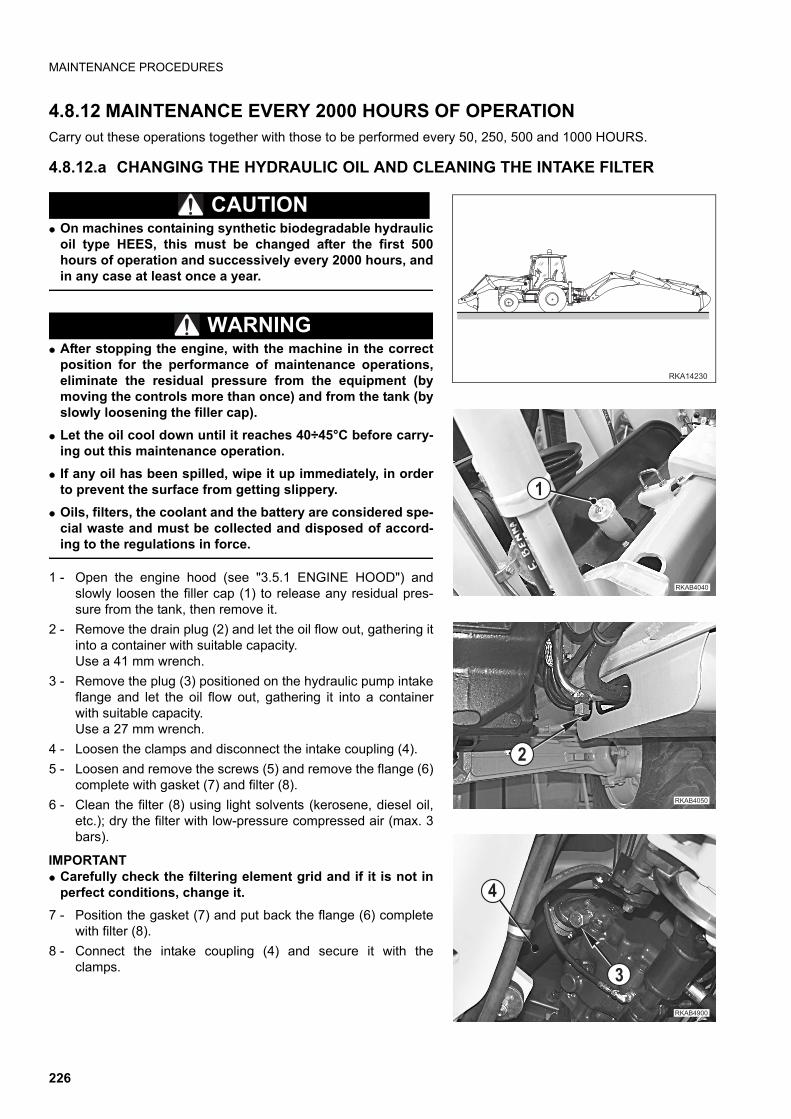
MAINTENANCE PROCEDURES
4.8.12 MAINTENANCE EVERY 2000 HOURS OF OPERATIONCarry out these operations together with those to be performed every 50, 250, 500 and 1000 HOURS.
4.8.12.a CHANGING THE HYDRAULIC OIL AND CLEANING THE INTAKE FILTER
CAUTIONq On machines containing synthetic biodegradable hydraulic
oil type HEES, this must be changed after the first 500hours of operation and successively every 2000 hours, andin any case at least once a year.
WARNINGq After stopping the engine, with the machine in the correct
position for the performance of maintenance operations,eliminate the residual pressure from the equipment (bymoving the controls more than once) and from the tank (byslowly loosening the filler cap).
q Let the oil cool down until it reaches 40÷45°C before carry-ing out this maintenance operation.
q If any oil has been spilled, wipe it up immediately, in orderto prevent the surface from getting slippery.
q Oils, filters, the coolant and the battery are considered spe-cial waste and must be collected and disposed of accord-ing to the regulations in force.
1 - Open the engine hood (see "3.5.1 ENGINE HOOD") andslowly loosen the filler cap (1) to release any residual pres-sure from the tank, then remove it.
2 - Remove the drain plug (2) and let the oil flow out, gathering itinto a container with suitable capacity.Use a 41 mm wrench.
3 - Remove the plug (3) positioned on the hydraulic pump intakeflange and let the oil flow out, gathering it into a containerwith suitable capacity.Use a 27 mm wrench.
4 - Loosen the clamps and disconnect the intake coupling (4).
5 - Loosen and remove the screws (5) and remove the flange (6)complete with gasket (7) and filter (8).
6 - Clean the filter (8) using light solvents (kerosene, diesel oil,etc.); dry the filter with low-pressure compressed air (max. 3bars).
IMPORTANTq Carefully check the filtering element grid and if it is not in
perfect conditions, change it.
7 - Position the gasket (7) and put back the flange (6) completewith filter (8).
8 - Connect the intake coupling (4) and secure it with theclamps.
��������
�
������
��������
�
�
������ �
�
226
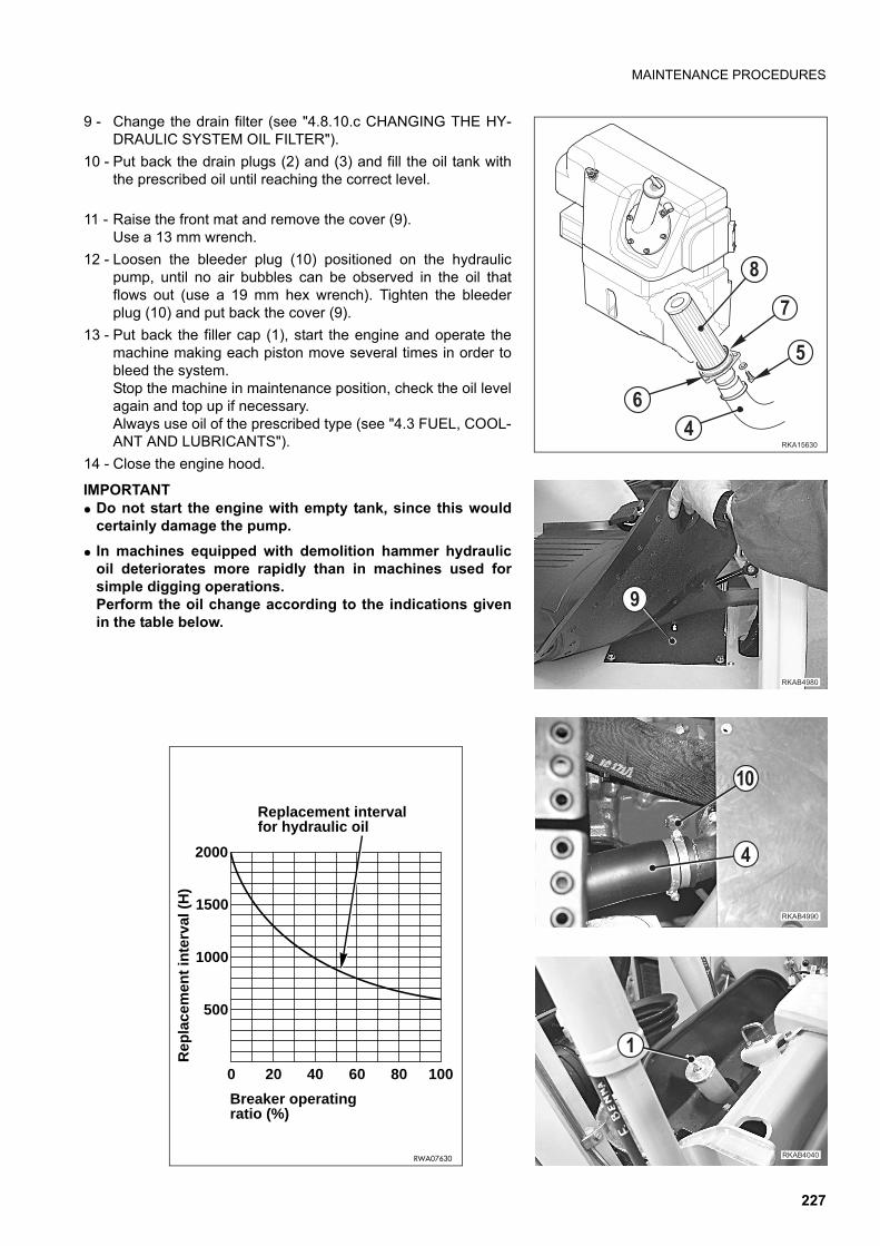
MAINTENANCE PROCEDURES
9 - Change the drain filter (see "4.8.10.c CHANGING THE HY-DRAULIC SYSTEM OIL FILTER").
10 - Put back the drain plugs (2) and (3) and fill the oil tank withthe prescribed oil until reaching the correct level.
11 - Raise the front mat and remove the cover (9).Use a 13 mm wrench.
12 - Loosen the bleeder plug (10) positioned on the hydraulicpump, until no air bubbles can be observed in the oil thatflows out (use a 19 mm hex wrench). Tighten the bleederplug (10) and put back the cover (9).
13 - Put back the filler cap (1), start the engine and operate themachine making each piston move several times in order tobleed the system.Stop the machine in maintenance position, check the oil levelagain and top up if necessary.Always use oil of the prescribed type (see "4.3 FUEL, COOL-ANT AND LUBRICANTS").
14 - Close the engine hood.
IMPORTANTq Do not start the engine with empty tank, since this would
certainly damage the pump.
q In machines equipped with demolition hammer hydraulicoil deteriorates more rapidly than in machines used forsimple digging operations.Perform the oil change according to the indications givenin the table below.
��� ���
"
�
�
�
!
�������
��
�
��������
��������
�0 20 40 60 80 100
500
2000
Breaker operating ratio (%)
Rep
lace
men
t in
terv
al (
H)
Replacement interval for hydraulic oil
RWA07630
1500
1000
227
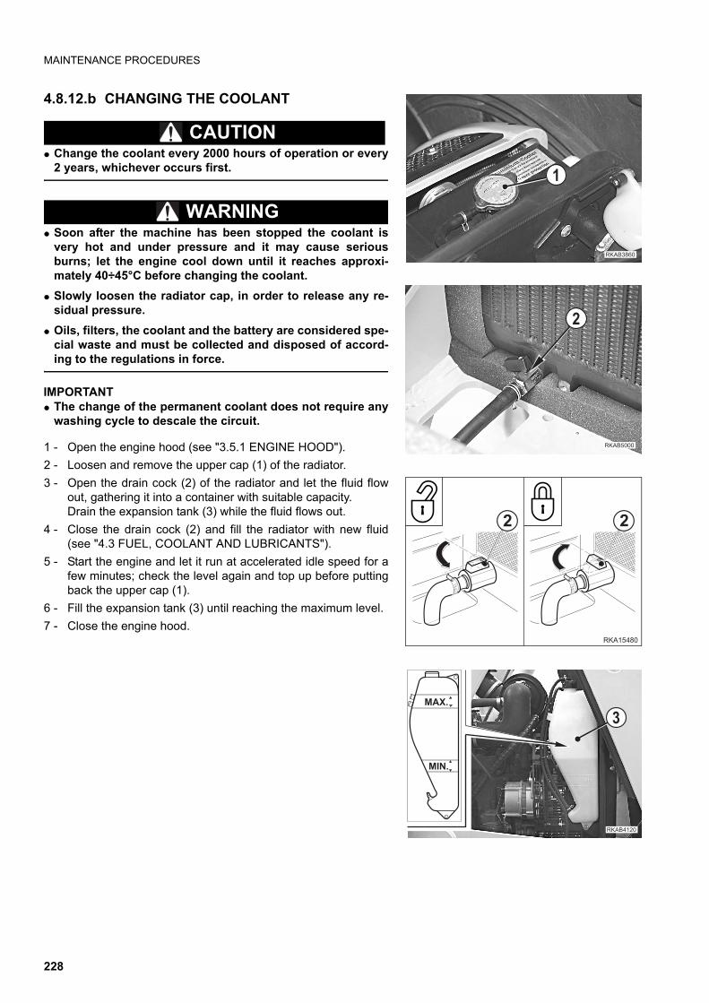
MAINTENANCE PROCEDURES
4.8.12.b CHANGING THE COOLANT
CAUTIONq Change the coolant every 2000 hours of operation or every
2 years, whichever occurs first.
WARNINGq Soon after the machine has been stopped the coolant is
very hot and under pressure and it may cause seriousburns; let the engine cool down until it reaches approxi-mately 40÷45°C before changing the coolant.
q Slowly loosen the radiator cap, in order to release any re-sidual pressure.
q Oils, filters, the coolant and the battery are considered spe-cial waste and must be collected and disposed of accord-ing to the regulations in force.
IMPORTANTq The change of the permanent coolant does not require any
washing cycle to descale the circuit.
1 - Open the engine hood (see "3.5.1 ENGINE HOOD").
2 - Loosen and remove the upper cap (1) of the radiator.
3 - Open the drain cock (2) of the radiator and let the fluid flowout, gathering it into a container with suitable capacity.Drain the expansion tank (3) while the fluid flows out.
4 - Close the drain cock (2) and fill the radiator with new fluid(see "4.3 FUEL, COOLANT AND LUBRICANTS").
5 - Start the engine and let it run at accelerated idle speed for afew minutes; check the level again and top up before puttingback the upper cap (1).
6 - Fill the expansion tank (3) until reaching the maximum level.
7 - Close the engine hood.
�������
�
�
���� ���
2
RKA15480
2
�������
���.&
���&
228
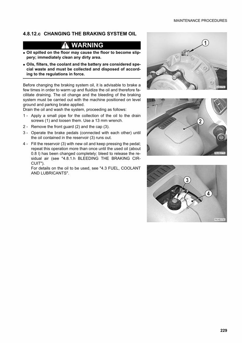
MAINTENANCE PROCEDURES
4.8.12.c CHANGING THE BRAKING SYSTEM OIL
WARNINGq Oil spilled on the floor may cause the floor to become slip-
pery; immediately clean any dirty area.
q Oils, filters, the coolant and the battery are considered spe-cial waste and must be collected and disposed of accord-ing to the regulations in force.
Before changing the braking system oil, it is advisable to brake afew times in order to warm up and fluidize the oil and therefore fa-cilitate draining. The oil change and the bleeding of the brakingsystem must be carried out with the machine positioned on levelground and parking brake applied. Drain the oil and wash the system, proceeding as follows:
1 - Apply a small pipe for the collection of the oil to the drainscrews (1) and loosen them. Use a 13 mm wrench.
2 - Remove the front guard (2) and the cap (3).
3 - Operate the brake pedals (connected with each other) untilthe oil contained in the reservoir (3) runs out.
4 - Fill the reservoir (3) with new oil and keep pressing the pedal;repeat this operation more than once until the used oil (about0.8 l) has been changed completely; bleed to release the re-sidual air (see "4.8.1.h BLEEDING THE BRAKING CIR-CUIT").For details on the oil to be used, see "4.3 FUEL, COOLANTAND LUBRICANTS".
��������
�
��������
�
������ �
�
�
229
MAINTENANCE PROCEDURES
4.8.12.d CHECKING THE ALTERNATOR AND THE STARTER
This procedure must be carried out by qualified personnel. Have this operation performed by your Komatsu Deal-er.
4.8.12.e CHANGING THE ALTERNATOR BELT
This procedure must be carried out by qualified personnel. Have this operation performed by your Komatsu Deal-er.
4.8.12.f CHECKING THE A/C COOLING GAS QUANTITY (only for machines with air conditioner)
WARNINGq The coolant used in the air conditioning system is very dangerous. If it is sprayed into the eyes or in
case of contact with the skin, it may cause blindness or frostbite. To avoid any explosion, do not gener-ate sparks and do not use naked flames near the air conditioner.
q Oils, filters, the coolant and the battery are considered special waste and must be collected and dis-posed of according to the regulations in force.
q Maintenance on the air conditioning system must be carried out exclusively by specialized personnel.
Specific equipment is required to check the coolant; have this maintenance operation carried out only by special-ized personnel and for this purpose contact your Komatsu Dealer.
230

MAINTENANCE PROCEDURES
4.8.13 MAINTENANCE EVERY 3000 HOURS OF OPERATIONCarry out these operations together with those to be performed every 50, 250, 500 and 1000 HOURS.
4.8.13.a CHECKING THE ENGINE RETAINING SCREWS AND DAMPING ELEMENTS
This procedure must be carried out by qualified personnel. Have this operation performed by your Komatsu Deal-er.
4.8.13.b CHECKING AND ADJUSTING THE ENGINE VALVE CLEARANCE AND THE INJECTION TIMING ADVANCE
Since these checks and adjustment operations require the use of special tools, have these operations carried outby qualified personnel supplied by your Komatsu Dealer.
231
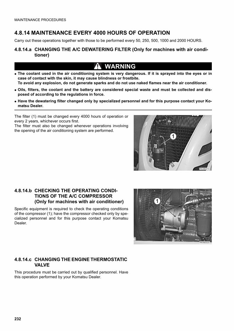
MAINTENANCE PROCEDURES
4.8.14 MAINTENANCE EVERY 4000 HOURS OF OPERATIONCarry out these operations together with those to be performed every 50, 250, 500, 1000 and 2000 HOURS.
4.8.14.a CHANGING THE A/C DEWATERING FILTER (Only for machines with air condi-tioner)
WARNINGq The coolant used in the air conditioning system is very dangerous. If it is sprayed into the eyes or in
case of contact with the skin, it may cause blindness or frostbite.To avoid any explosion, do not generate sparks and do not use naked flames near the air conditioner.
q Oils, filters, the coolant and the battery are considered special waste and must be collected and dis-posed of according to the regulations in force.
q Have the dewatering filter changed only by specialized personnel and for this purpose contact your Ko-matsu Dealer.
The filter (1) must be changed every 4000 hours of operation orevery 2 years, whichever occurs first.The filter must also be changed whenever operations involvingthe opening of the air conditioning system are performed.
4.8.14.b CHECKING THE OPERATING CONDI-TIONS OF THE A/C COMPRESSOR(Only for machines with air conditioner)
Specific equipment is required to check the operating conditionsof the compressor (1); have the compressor checked only by spe-cialized personnel and for this purpose contact your KomatsuDealer.
4.8.14.c CHANGING THE ENGINE THERMOSTATIC VALVE
This procedure must be carried out by qualified personnel. Havethis operation performed by your Komatsu Dealer.
�
���� ��
�
���� ���
232

�� ��� ����� ��� ������
233
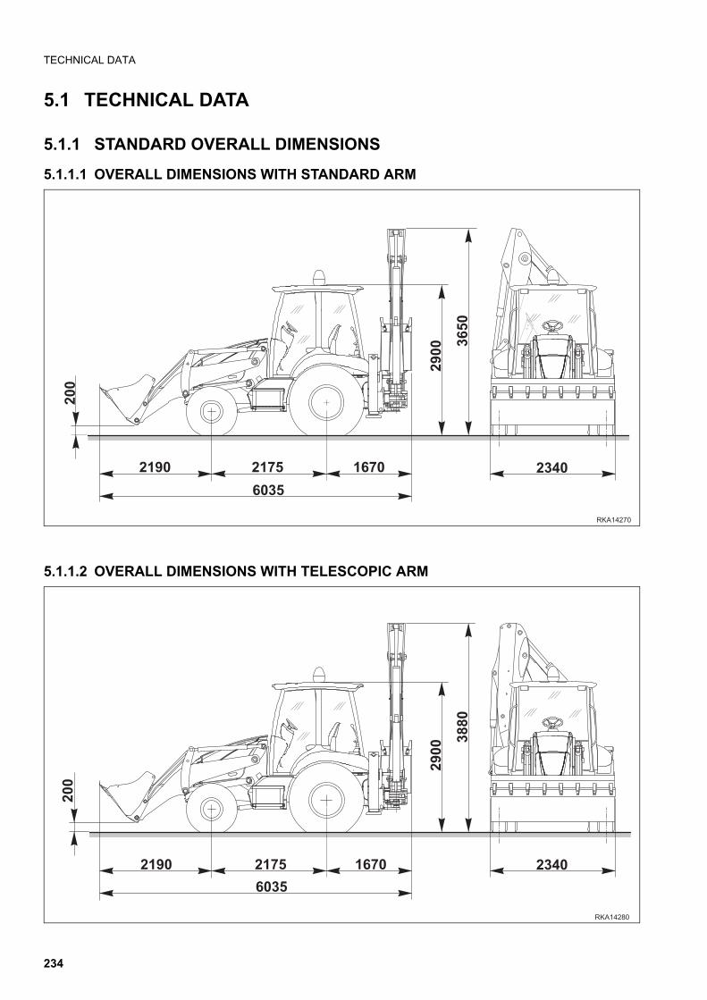
TECHNICAL DATA
5.1 TECHNICAL DATA
5.1.1 STANDARD OVERALL DIMENSIONS
5.1.1.1 OVERALL DIMENSIONS WITH STANDARD ARM
5.1.1.2 OVERALL DIMENSIONS WITH TELESCOPIC ARM
��!� ����
���
� ��
�!��
���
� ��
����
������
����
���
�!��
�""�
������
��!� ���� � ��
���
234
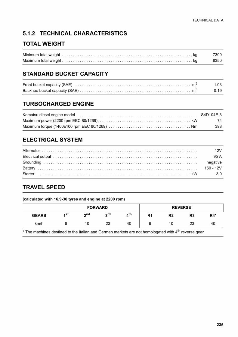
TECHNICAL DATA
5.1.2 TECHNICAL CHARACTERISTICS
TOTAL WEIGHT
Minimum total weight . . . . . . . . . . . . . . . . . . . . . . . . . . . . . . . . . . . . . . . . . . . . . . . . . . . . . . . . . . . kg 7300
Maximum total weight . . . . . . . . . . . . . . . . . . . . . . . . . . . . . . . . . . . . . . . . . . . . . . . . . . . . . . . . . . . kg 8350
STANDARD BUCKET CAPACITY
Front bucket capacity (SAE) . . . . . . . . . . . . . . . . . . . . . . . . . . . . . . . . . . . . . . . . . . . . . . . . . . . . m3 1.03
Backhoe bucket capacity (SAE) . . . . . . . . . . . . . . . . . . . . . . . . . . . . . . . . . . . . . . . . . . . . . . . . . . m3 0.19
TURBOCHARGED ENGINE
Komatsu diesel engine model . . . . . . . . . . . . . . . . . . . . . . . . . . . . . . . . . . . . . . . . . . . . . . . . . . . . . . . S4D104E-3
Maximum power (2200 rpm EEC 80/1269). . . . . . . . . . . . . . . . . . . . . . . . . . . . . . . . . . . . . . . . . . kW 74
Maximum torque (1400±100 rpm EEC 80/1269) . . . . . . . . . . . . . . . . . . . . . . . . . . . . . . . . . . . . . Nm 398
ELECTRICAL SYSTEM
Alternator . . . . . . . . . . . . . . . . . . . . . . . . . . . . . . . . . . . . . . . . . . . . . . . . . . . . . . . . . . . . . . . . . . . . . . 12V
Electrical output . . . . . . . . . . . . . . . . . . . . . . . . . . . . . . . . . . . . . . . . . . . . . . . . . . . . . . . . . . . . . . . . . 95 A
Grounding . . . . . . . . . . . . . . . . . . . . . . . . . . . . . . . . . . . . . . . . . . . . . . . . . . . . . . . . . . . . . . . . . . . . . negative
Battery . . . . . . . . . . . . . . . . . . . . . . . . . . . . . . . . . . . . . . . . . . . . . . . . . . . . . . . . . . . . . . . . . . . . . . . . 160 - 12V
Starter . . . . . . . . . . . . . . . . . . . . . . . . . . . . . . . . . . . . . . . . . . . . . . . . . . . . . . . . . . . . . . . . . . . . . . kW 3.0
TRAVEL SPEED
(calculated with 16.9-30 tyres and engine at 2200 rpm)
* The machines destined to the Italian and German markets are not homologated with 4th reverse gear.
FORWARD REVERSE
GEARS 1st 2nd 3rd 4th R1 R2 R3 R4*
km/h 6 10 23 40 6 10 23 40
235
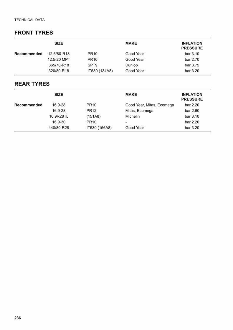
TECHNICAL DATA
FRONT TYRES
SIZE MAKE INFLATIONPRESSURE
Recommended 12.5/80-R18 PR10 Good Year bar 3.10
12.5-20 MPT PR10 Good Year bar 2.70
365/70-R18 SPT9 Dunlop bar 3.75
320/80-R18 IT530 (134A8) Good Year bar 3.20
REAR TYRES
SIZE MAKE INFLATION PRESSURE
Recommended 16.9-28 PR10 Good Year, Mitas, Ecomega bar 2.20
16.9-28 PR12 Mitas, Ecomega bar 2.60
16.9R28TL (151A8) Michelin bar 3.10
16.9-30 PR10 - bar 2.20
440/80-R28 IT530 (156A8) Good Year bar 3.20
236
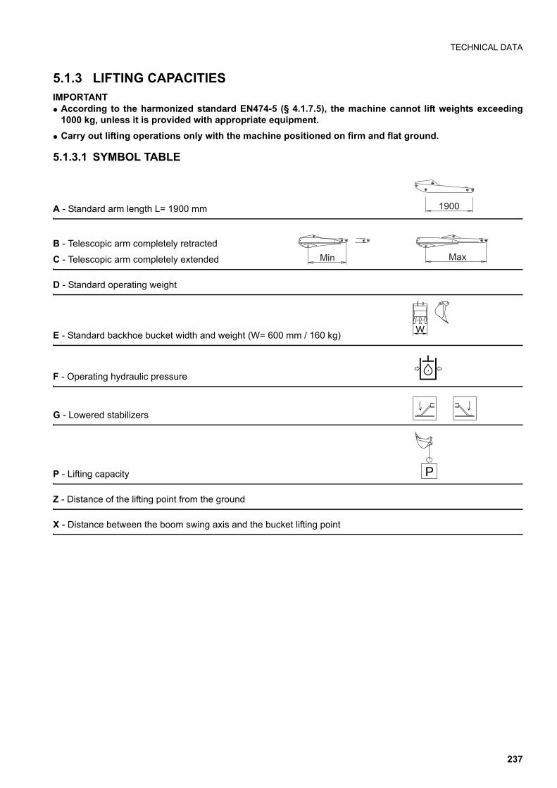
TECHNICAL DATA
5.1.3 LIFTING CAPACITIESIMPORTANTq According to the harmonized standard EN474-5 (§ 4.1.7.5), the machine cannot lift weights exceeding
1000 kg, unless it is provided with appropriate equipment.
q Carry out lifting operations only with the machine positioned on firm and flat ground.
5.1.3.1 SYMBOL TABLE
A - Standard arm length L= 1900 mm
B - Telescopic arm completely retracted
C - Telescopic arm completely extended
D - Standard operating weight
E - Standard backhoe bucket width and weight (W= 600 mm / 160 kg)
F - Operating hydraulic pressure
G - Lowered stabilizers
P - Lifting capacity
Z - Distance of the lifting point from the ground
X - Distance between the boom swing axis and the bucket lifting point
1900
Min Max
W
P
237
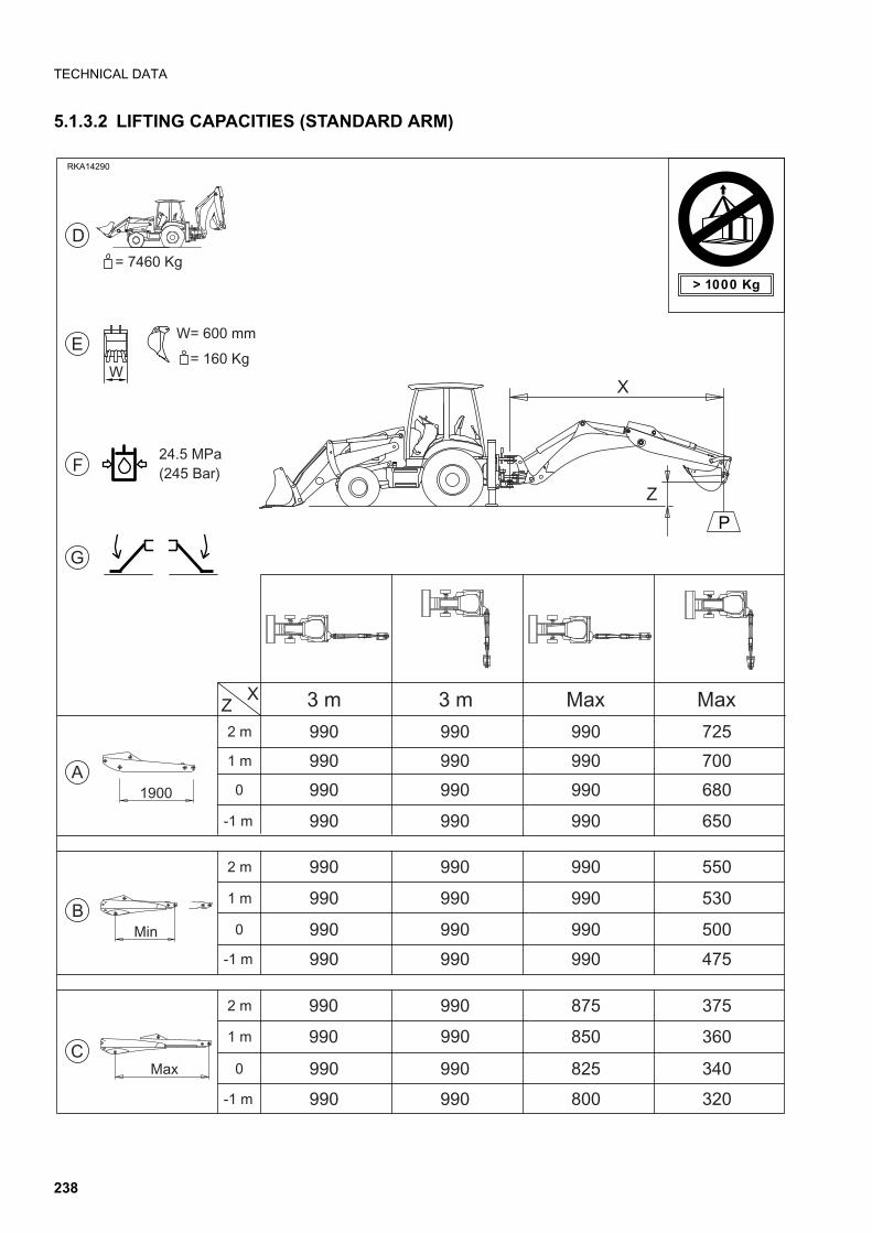
TECHNICAL DATA
5.1.3.2 LIFTING CAPACITIES (STANDARD ARM)
XZ2 m
1 m
0
-1 m
3 m 3 m Max Max
2 m
1 m
0
-1 m
2 m
1 m
0
-1 m
24.5 MPa(245 Bar)
W= 600 mm
= 160 Kg
= 7460 Kg
D
F
E
G
A
B
C
W
990 990 990 725
990 990 990 700
990 990 990 680
990 990 990 650
990 990 990 550
990 990 990 530
990 990 990 500
990 990 990 475
990 990 875 375
990 990 850 360
990 990 825 340
990 990 800 320
> 1000 Kg
RKA14290
Z
X
P
1900
Min
Max
238

TECHNICAL DATA
5.1.3.3 LIFTING CAPACITIES (TELESCOPIC ARM)
239

THIS PAGE WAS INTENTIONALLY LEFT EMPTY
240

�1�����������������21������
241
AUTHORIZED OPTIONAL EQUIPMENT
6.1 AUTHORIZED OPTIONAL EQUIPMENT
CAUTIONq Komatsu machines can be provided with optional equipment in addition to the standard equipment; if
optional equipment is installed and used, carefully read the relevant operation manual and keep to theinstructions given therein.
q Use only optional or special equipment recommended and approved by Komatsu and in compliancewith the requirements indicated in the table. (See "6.1.2 PRECAUTIONS REGARDING THE INSTALLA-TION OF EQUIPMENT").
q Komatsu cannot be held liable for any injury, accident or product failure resulting from the installationand use of unauthorized equipment.
6.1.1 PRECAUTIONS REGARDING SAFETYThe installation of optional accessories and equipment other than those authorized by Komatsu shortens the life ofthe machine and may also cause safety problems.It is advisable to contact a Komatsu Dealer before installing any accessory that is not mentioned in this operationand maintenance manual.In case of failure to comply with these instructions, Komatsu declines any responsibility for accidents or damage.
WARNINGq When removing or installing any equipment, take the following precautions and be careful to ensure that
operations are carried out in total safety.
q Carry out installation and removal on a firm and flat surface.
q When the operations are carried out by two or more operators, decide the communication signals in ad-vance and respect them during work.
q Use a crane to handle objects weighing more than 25 kg.
q Always support any heavy part before removing it. When lifting heavy parts, be always careful to the po-sition of the centre of gravity of the object being handled.
q It is dangerous to carry out any operation with suspended loads. Always position the load on a suitablesupport and make sure that it is stable.
q When installing or removing any equipment, make sure that it is stable and cannot fall down.
q Never stand under loads being lifted by a crane.Take care to choose a safe position, where you do not run any risk in case the load should fall down.
IMPORTANTq Specialized personnel is required to operate cranes. Do not allow unskilled personnel to use cranes.
For further details regarding installation and removal operations, contact your Komatsu Dealer.
242

AUTHORIZED OPTIONAL EQUIPMENT
6.1.2 PRECAUTIONS REGARDING THE INSTALLATION OF EQUIPMENT
WARNINGq The installation of long work equipment reduces the stability of the machine.
If it is necessary to travel up or down a slope, proceed very carefully, since the machine may lose its bal-ance and overturn.
q When work equipment with overall dimensions exceeding those of the standard equipment is installed,be particularly careful, since more space is necessary for the movements of the equipment and of themachine.
243
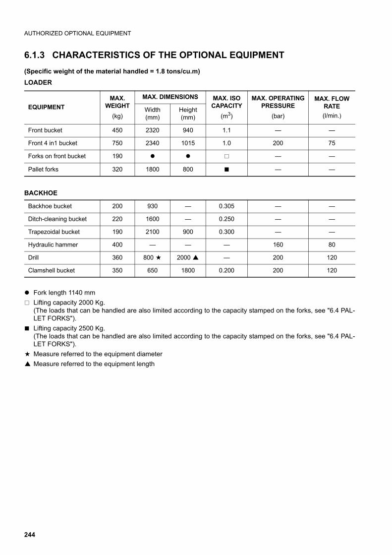
AUTHORIZED OPTIONAL EQUIPMENT
6.1.3 CHARACTERISTICS OF THE OPTIONAL EQUIPMENT
(Specific weight of the material handled = 1.8 tons/cu.m)
LOADER
BACKHOE
q Fork length 1140 mm
T Lifting capacity 2000 Kg.(The loads that can be handled are also limited according to the capacity stamped on the forks, see "6.4 PAL-LET FORKS").
t Lifting capacity 2500 Kg.(The loads that can be handled are also limited according to the capacity stamped on the forks, see "6.4 PAL-LET FORKS").
a Measure referred to the equipment diameter
e Measure referred to the equipment length
EQUIPMENT
MAX. WEIGHT
(kg)
MAX. DIMENSIONS MAX. ISO CAPACITY
(m3)
MAX. OPERATINGPRESSURE
(bar)
MAX. FLOWRATE
(l/min.)Width(mm)
Height(mm)
Front bucket 450 2320 940 1.1 — —
Front 4 in1 bucket 750 2340 1015 1.0 200 75
Forks on front bucket 190 q q T — —
Pallet forks 320 1800 800 t — —
Backhoe bucket 200 930 — 0.305 — —
Ditch-cleaning bucket 220 1600 — 0.250 — —
Trapezoidal bucket 190 2100 900 0.300 — —
Hydraulic hammer 400 — — — 160 80
Drill 360 800 a 2000 e — 200 120
Clamshell bucket 350 650 1800 0.200 200 120
244
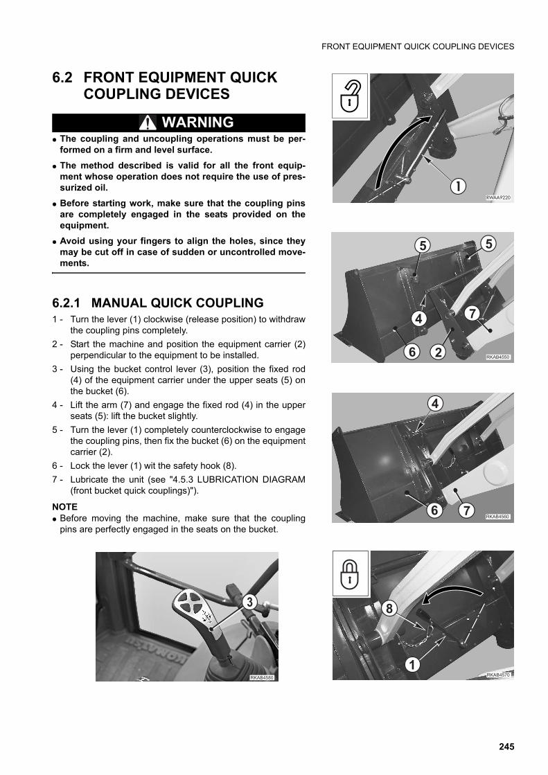
FRONT EQUIPMENT QUICK COUPLING DEVICES
6.2 FRONT EQUIPMENT QUICK COUPLING DEVICES
WARNINGq The coupling and uncoupling operations must be per-
formed on a firm and level surface.
q The method described is valid for all the front equip-ment whose operation does not require the use of pres-surized oil.
q Before starting work, make sure that the coupling pinsare completely engaged in the seats provided on theequipment.
q Avoid using your fingers to align the holes, since theymay be cut off in case of sudden or uncontrolled move-ments.
6.2.1 MANUAL QUICK COUPLING1 - Turn the lever (1) clockwise (release position) to withdraw
the coupling pins completely.
2 - Start the machine and position the equipment carrier (2)perpendicular to the equipment to be installed.
3 - Using the bucket control lever (3), position the fixed rod(4) of the equipment carrier under the upper seats (5) onthe bucket (6).
4 - Lift the arm (7) and engage the fixed rod (4) in the upperseats (5): lift the bucket slightly.
5 - Turn the lever (1) completely counterclockwise to engagethe coupling pins, then fix the bucket (6) on the equipmentcarrier (2).
6 - Lock the lever (1) wit the safety hook (8).
7 - Lubricate the unit (see "4.5.3 LUBRICATION DIAGRAM(front bucket quick couplings)").
NOTEq Before moving the machine, make sure that the coupling
pins are perfectly engaged in the seats on the bucket.
������
#
����� ��
�
"
����� �
��
��
�
����� �� �
�
����� �
�
245
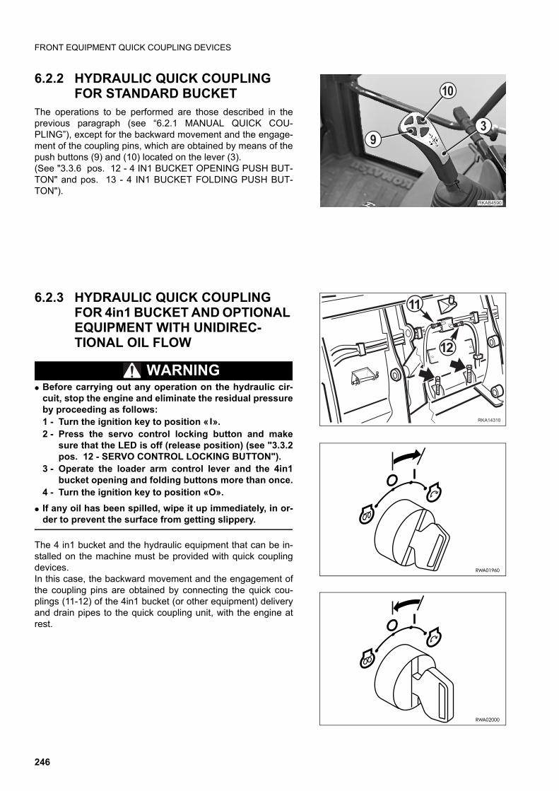
FRONT EQUIPMENT QUICK COUPLING DEVICES
6.2.2 HYDRAULIC QUICK COUPLING FOR STANDARD BUCKET
The operations to be performed are those described in theprevious paragraph (see “6.2.1 MANUAL QUICK COU-PLING”), except for the backward movement and the engage-ment of the coupling pins, which are obtained by means of thepush buttons (9) and (10) located on the lever (3). (See "3.3.6 pos. 12 - 4 IN1 BUCKET OPENING PUSH BUT-TON" and pos. 13 - 4 IN1 BUCKET FOLDING PUSH BUT-TON").
6.2.3 HYDRAULIC QUICK COUPLING FOR 4in1 BUCKET AND OPTIONAL EQUIPMENT WITH UNIDIREC-TIONAL OIL FLOW
WARNINGq Before carrying out any operation on the hydraulic cir-
cuit, stop the engine and eliminate the residual pressureby proceeding as follows:1 - Turn the ignition key to position « ».2 - Press the servo control locking button and make
sure that the LED is off (release position) (see "3.3.2pos. 12 - SERVO CONTROL LOCKING BUTTON").
3 - Operate the loader arm control lever and the 4in1bucket opening and folding buttons more than once.
4 - Turn the ignition key to position «O».
q If any oil has been spilled, wipe it up immediately, in or-der to prevent the surface from getting slippery.
The 4 in1 bucket and the hydraulic equipment that can be in-stalled on the machine must be provided with quick couplingdevices.In this case, the backward movement and the engagement ofthe coupling pins are obtained by connecting the quick cou-plings (11-12) of the 4in1 bucket (or other equipment) deliveryand drain pipes to the quick coupling unit, with the engine atrest.
����� ��
�
��
!
������
��
��
RWA02000
RWA01960
246
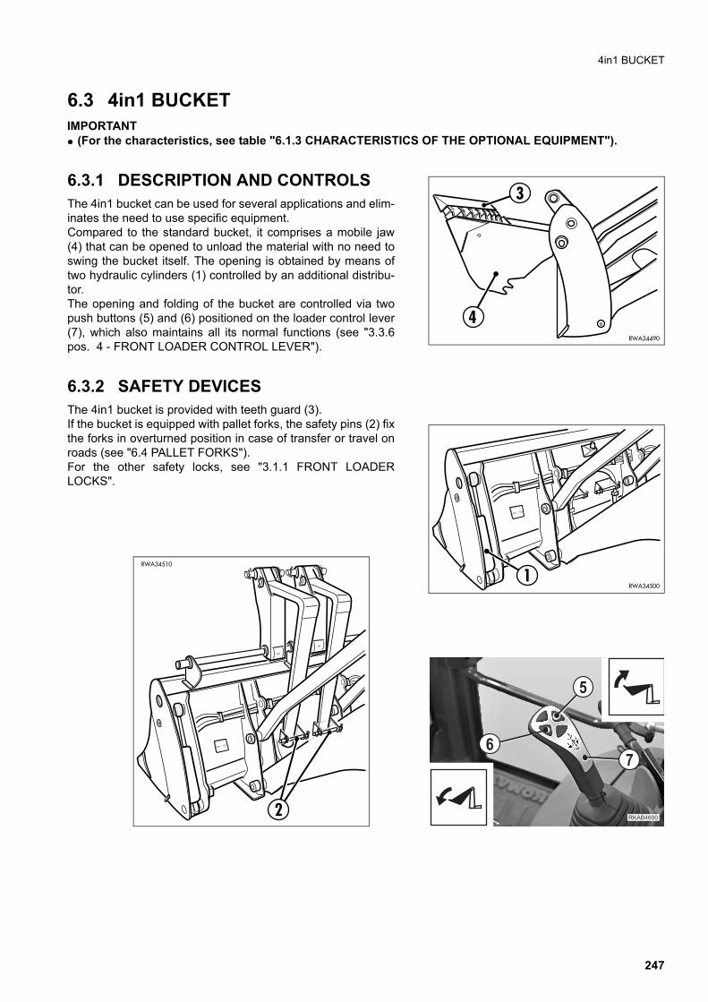
4in1 BUCKET
6.3 4in1 BUCKETIMPORTANTq (For the characteristics, see table "6.1.3 CHARACTERISTICS OF THE OPTIONAL EQUIPMENT").
6.3.1 DESCRIPTION AND CONTROLS The 4in1 bucket can be used for several applications and elim-inates the need to use specific equipment.Compared to the standard bucket, it comprises a mobile jaw(4) that can be opened to unload the material with no need toswing the bucket itself. The opening is obtained by means oftwo hydraulic cylinders (1) controlled by an additional distribu-tor.The opening and folding of the bucket are controlled via twopush buttons (5) and (6) positioned on the loader control lever(7), which also maintains all its normal functions (see "3.3.6pos. 4 - FRONT LOADER CONTROL LEVER").
6.3.2 SAFETY DEVICES The 4in1 bucket is provided with teeth guard (3).If the bucket is equipped with pallet forks, the safety pins (2) fixthe forks in overturned position in case of transfer or travel onroads (see "6.4 PALLET FORKS").For the other safety locks, see "3.1.1 FRONT LOADERLOCKS".
3
4RWA34490
RWA345001
��������
�
�
RWA34510
2
247
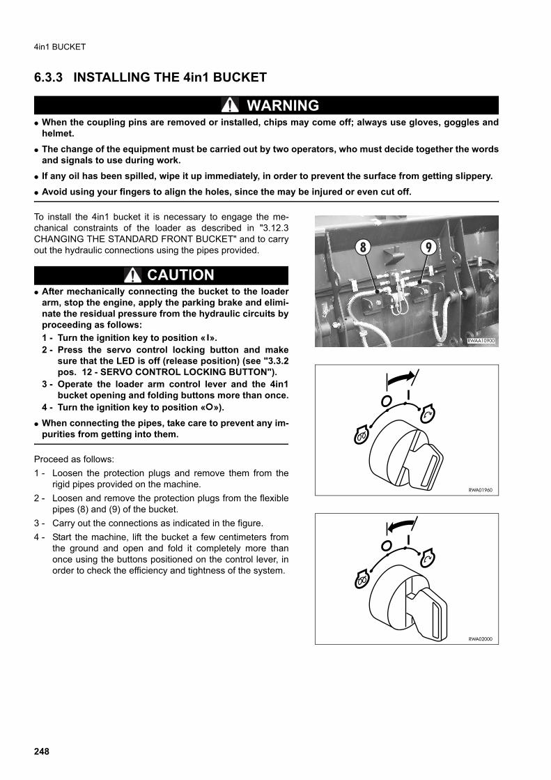
4in1 BUCKET
6.3.3 INSTALLING THE 4in1 BUCKET
WARNINGq When the coupling pins are removed or installed, chips may come off; always use gloves, goggles and
helmet.
q The change of the equipment must be carried out by two operators, who must decide together the wordsand signals to use during work.
q If any oil has been spilled, wipe it up immediately, in order to prevent the surface from getting slippery.
q Avoid using your fingers to align the holes, since the may be injured or even cut off.
To install the 4in1 bucket it is necessary to engage the me-chanical constraints of the loader as described in "3.12.3CHANGING THE STANDARD FRONT BUCKET" and to carryout the hydraulic connections using the pipes provided.
CAUTIONq After mechanically connecting the bucket to the loader
arm, stop the engine, apply the parking brake and elimi-nate the residual pressure from the hydraulic circuits byproceeding as follows:
1 - Turn the ignition key to position « ».2 - Press the servo control locking button and make
sure that the LED is off (release position) (see "3.3.2pos. 12 - SERVO CONTROL LOCKING BUTTON").
3 - Operate the loader arm control lever and the 4in1bucket opening and folding buttons more than once.
4 - Turn the ignition key to position « »).
q When connecting the pipes, take care to prevent any im-purities from getting into them.
Proceed as follows:
1 - Loosen the protection plugs and remove them from therigid pipes provided on the machine.
2 - Loosen and remove the protection plugs from the flexiblepipes (8) and (9) of the bucket.
3 - Carry out the connections as indicated in the figure.
4 - Start the machine, lift the bucket a few centimeters fromthe ground and open and fold it completely more thanonce using the buttons positioned on the control lever, inorder to check the efficiency and tightness of the system.
�����
%&
RWA02000
RWA01960
248
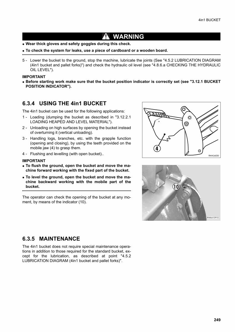
4in1 BUCKET
WARNINGq Wear thick gloves and safety goggles during this check.
q To check the system for leaks, use a piece of cardboard or a wooden board.
5 - Lower the bucket to the ground, stop the machine, lubricate the joints (See "4.5.2 LUBRICATION DIAGRAM(4in1 bucket and pallet forks)") and check the hydraulic oil level (see "4.8.6.a CHECKING THE HYDRAULICOIL LEVEL").
IMPORTANTq Before starting work make sure that the bucket position indicator is correctly set (see "3.12.1 BUCKET
POSITION INDICATOR").
6.3.4 USING THE 4in1 BUCKET The 4in1 bucket can be used for the following applications:
1 - Loading (dumping the bucket as described in "3.12.2.1LOADING HEAPED AND LEVEL MATERIAL").
2 - Unloading on high surfaces by opening the bucket insteadof overturning it (vertical unloading).
3 - Handling logs, branches, etc. with the grapple function(opening and closing), by using the teeth provided on themobile jaw (4) to grasp them.
4 - Flushing and levelling (with open bucket)..
IMPORTANTq To flush the ground, open the bucket and move the ma-
chine forward working with the fixed part of the bucket.
q To level the ground, open the bucket and move the ma-chine backward working with the mobile part of thebucket.
The operator can check the opening of the bucket at any mo-ment, by means of the indicator (10).
6.3.5 MAINTENANCEThe 4in1 bucket does not require special maintenance opera-tions in addition to those required for the standard bucket, ex-cept for the lubrication, as described at point "4.5.2LUBRICATION DIAGRAM (4in1 bucket and pallet forks)".
4RWA34520
������
#�
249
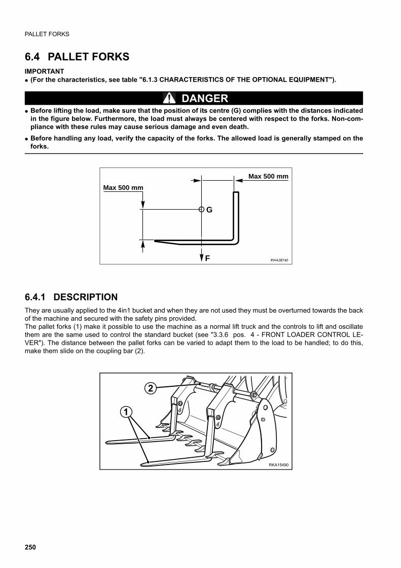
PALLET FORKS
6.4 PALLET FORKSIMPORTANTq (For the characteristics, see table "6.1.3 CHARACTERISTICS OF THE OPTIONAL EQUIPMENT").
DANGERq Before lifting the load, make sure that the position of its centre (G) complies with the distances indicated
in the figure below. Furthermore, the load must always be centered with respect to the forks. Non-com-pliance with these rules may cause serious damage and even death.
q Before handling any load, verify the capacity of the forks. The allowed load is generally stamped on theforks.
6.4.1 DESCRIPTIONThey are usually applied to the 4in1 bucket and when they are not used they must be overturned towards the backof the machine and secured with the safety pins provided.The pallet forks (1) make it possible to use the machine as a normal lift truck and the controls to lift and oscillatethem are the same used to control the standard bucket (see "3.3.6 pos. 4 - FRONT LOADER CONTROL LE-VER"). The distance between the pallet forks can be varied to adapt them to the load to be handled; to do this,make them slide on the coupling bar (2).
RWA38740
Max 500 mm
Max 500 mm
G
F
RKA15490
1
2
250
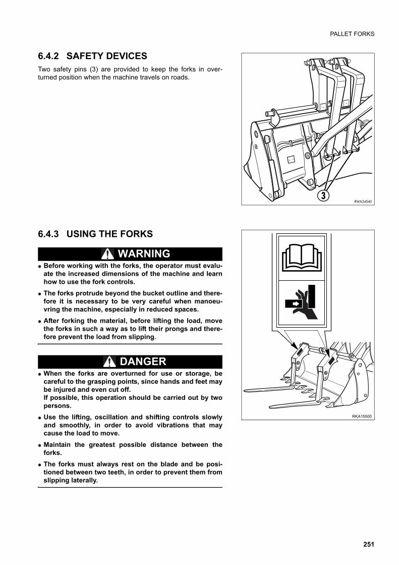
PALLET FORKS
6.4.2 SAFETY DEVICES Two safety pins (3) are provided to keep the forks in over-turned position when the machine travels on roads.
6.4.3 USING THE FORKS
WARNINGq Before working with the forks, the operator must evalu-
ate the increased dimensions of the machine and learnhow to use the fork controls.
q The forks protrude beyond the bucket outline and there-fore it is necessary to be very careful when manoeu-vring the machine, especially in reduced spaces.
q After forking the material, before lifting the load, movethe forks in such a way as to lift their prongs and there-fore prevent the load from slipping.
DANGERq When the forks are overturned for use or storage, be
careful to the grasping points, since hands and feet maybe injured and even cut off.If possible, this operation should be carried out by twopersons.
q Use the lifting, oscillation and shifting controls slowlyand smoothly, in order to avoid vibrations that maycause the load to move.
q Maintain the greatest possible distance between theforks.
q The forks must always rest on the blade and be posi-tioned between two teeth, in order to prevent them fromslipping laterally.
RWA345403
RKA15500
251
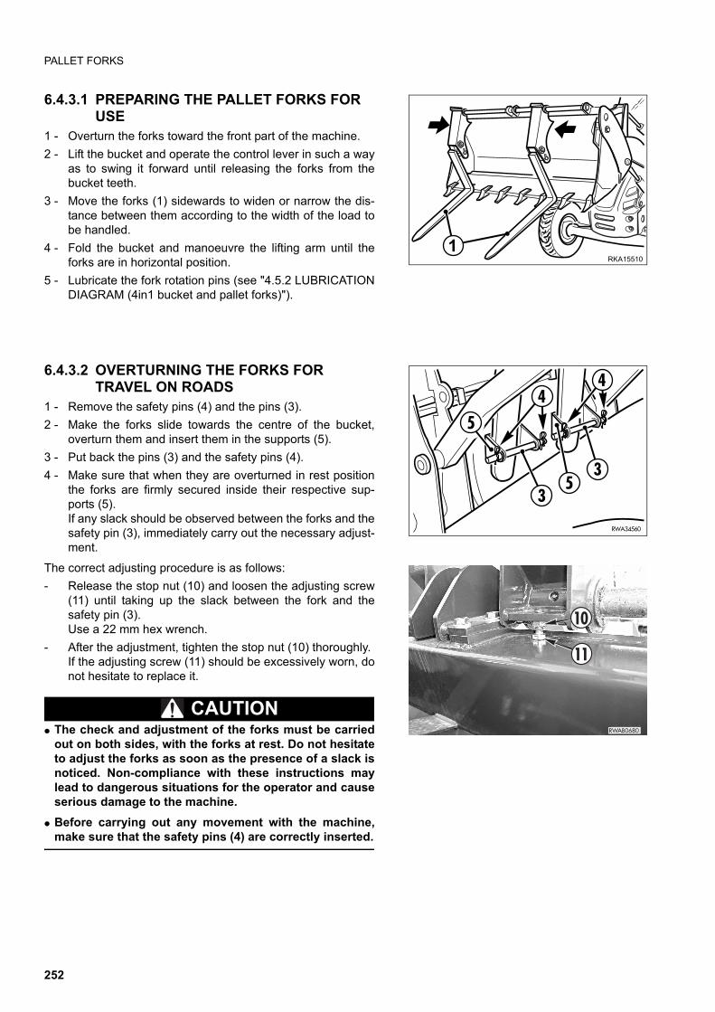
PALLET FORKS
6.4.3.1 PREPARING THE PALLET FORKS FOR USE
1 - Overturn the forks toward the front part of the machine.
2 - Lift the bucket and operate the control lever in such a wayas to swing it forward until releasing the forks from thebucket teeth.
3 - Move the forks (1) sidewards to widen or narrow the dis-tance between them according to the width of the load tobe handled.
4 - Fold the bucket and manoeuvre the lifting arm until theforks are in horizontal position.
5 - Lubricate the fork rotation pins (see "4.5.2 LUBRICATIONDIAGRAM (4in1 bucket and pallet forks)").
6.4.3.2 OVERTURNING THE FORKS FOR TRAVEL ON ROADS
1 - Remove the safety pins (4) and the pins (3).
2 - Make the forks slide towards the centre of the bucket,overturn them and insert them in the supports (5).
3 - Put back the pins (3) and the safety pins (4).
4 - Make sure that when they are overturned in rest positionthe forks are firmly secured inside their respective sup-ports (5).If any slack should be observed between the forks and thesafety pin (3), immediately carry out the necessary adjust-ment.
The correct adjusting procedure is as follows:
- Release the stop nut (10) and loosen the adjusting screw(11) until taking up the slack between the fork and thesafety pin (3).Use a 22 mm hex wrench.
- After the adjustment, tighten the stop nut (10) thoroughly.If the adjusting screw (11) should be excessively worn, donot hesitate to replace it.
CAUTIONq The check and adjustment of the forks must be carried
out on both sides, with the forks at rest. Do not hesitateto adjust the forks as soon as the presence of a slack isnoticed. Non-compliance with these instructions maylead to dangerous situations for the operator and causeserious damage to the machine.
q Before carrying out any movement with the machine,make sure that the safety pins (4) are correctly inserted.
RKA155101
RWA34560
44
3
35
5
RWAB0680
11
10
252
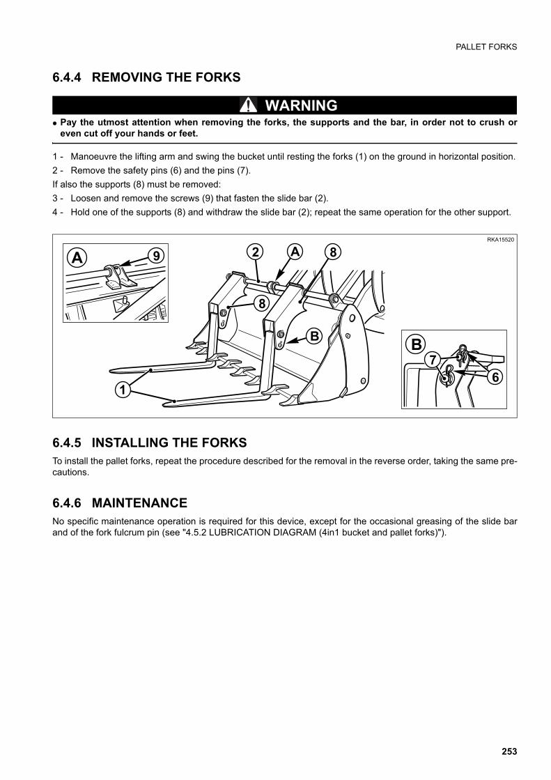
PALLET FORKS
6.4.4 REMOVING THE FORKS
WARNINGq Pay the utmost attention when removing the forks, the supports and the bar, in order not to crush or
even cut off your hands or feet.
1 - Manoeuvre the lifting arm and swing the bucket until resting the forks (1) on the ground in horizontal position.
2 - Remove the safety pins (6) and the pins (7).
If also the supports (8) must be removed:
3 - Loosen and remove the screws (9) that fasten the slide bar (2).
4 - Hold one of the supports (8) and withdraw the slide bar (2); repeat the same operation for the other support.
6.4.5 INSTALLING THE FORKSTo install the pallet forks, repeat the procedure described for the removal in the reverse order, taking the same pre-cautions.
6.4.6 MAINTENANCENo specific maintenance operation is required for this device, except for the occasional greasing of the slide barand of the fork fulcrum pin (see "4.5.2 LUBRICATION DIAGRAM (4in1 bucket and pallet forks)").
RKA15520
A 9
B7
6
A 8
B
2
8
1
253
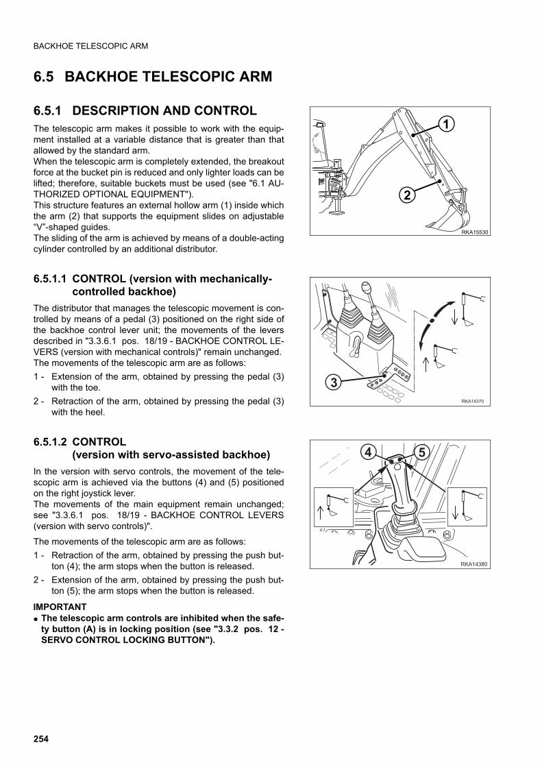
BACKHOE TELESCOPIC ARM
6.5 BACKHOE TELESCOPIC ARM
6.5.1 DESCRIPTION AND CONTROLThe telescopic arm makes it possible to work with the equip-ment installed at a variable distance that is greater than thatallowed by the standard arm.When the telescopic arm is completely extended, the breakoutforce at the bucket pin is reduced and only lighter loads can belifted; therefore, suitable buckets must be used (see "6.1 AU-THORIZED OPTIONAL EQUIPMENT").This structure features an external hollow arm (1) inside whichthe arm (2) that supports the equipment slides on adjustable“V”-shaped guides.The sliding of the arm is achieved by means of a double-actingcylinder controlled by an additional distributor.
6.5.1.1 CONTROL (version with mechanically-controlled backhoe)
The distributor that manages the telescopic movement is con-trolled by means of a pedal (3) positioned on the right side ofthe backhoe control lever unit; the movements of the leversdescribed in "3.3.6.1 pos. 18/19 - BACKHOE CONTROL LE-VERS (version with mechanical controls)" remain unchanged.The movements of the telescopic arm are as follows:
1 - Extension of the arm, obtained by pressing the pedal (3)with the toe.
2 - Retraction of the arm, obtained by pressing the pedal (3)with the heel.
6.5.1.2 CONTROL(version with servo-assisted backhoe)
In the version with servo controls, the movement of the tele-scopic arm is achieved via the buttons (4) and (5) positionedon the right joystick lever.The movements of the main equipment remain unchanged;see "3.3.6.1 pos. 18/19 - BACKHOE CONTROL LEVERS(version with servo controls)".
The movements of the telescopic arm are as follows:
1 - Retraction of the arm, obtained by pressing the push but-ton (4); the arm stops when the button is released.
2 - Extension of the arm, obtained by pressing the push but-ton (5); the arm stops when the button is released.
IMPORTANTq The telescopic arm controls are inhibited when the safe-
ty button (A) is in locking position (see "3.3.2 pos. 12 -SERVO CONTROL LOCKING BUTTON").
1
RKA15530
2
�������
�
������
� �
254
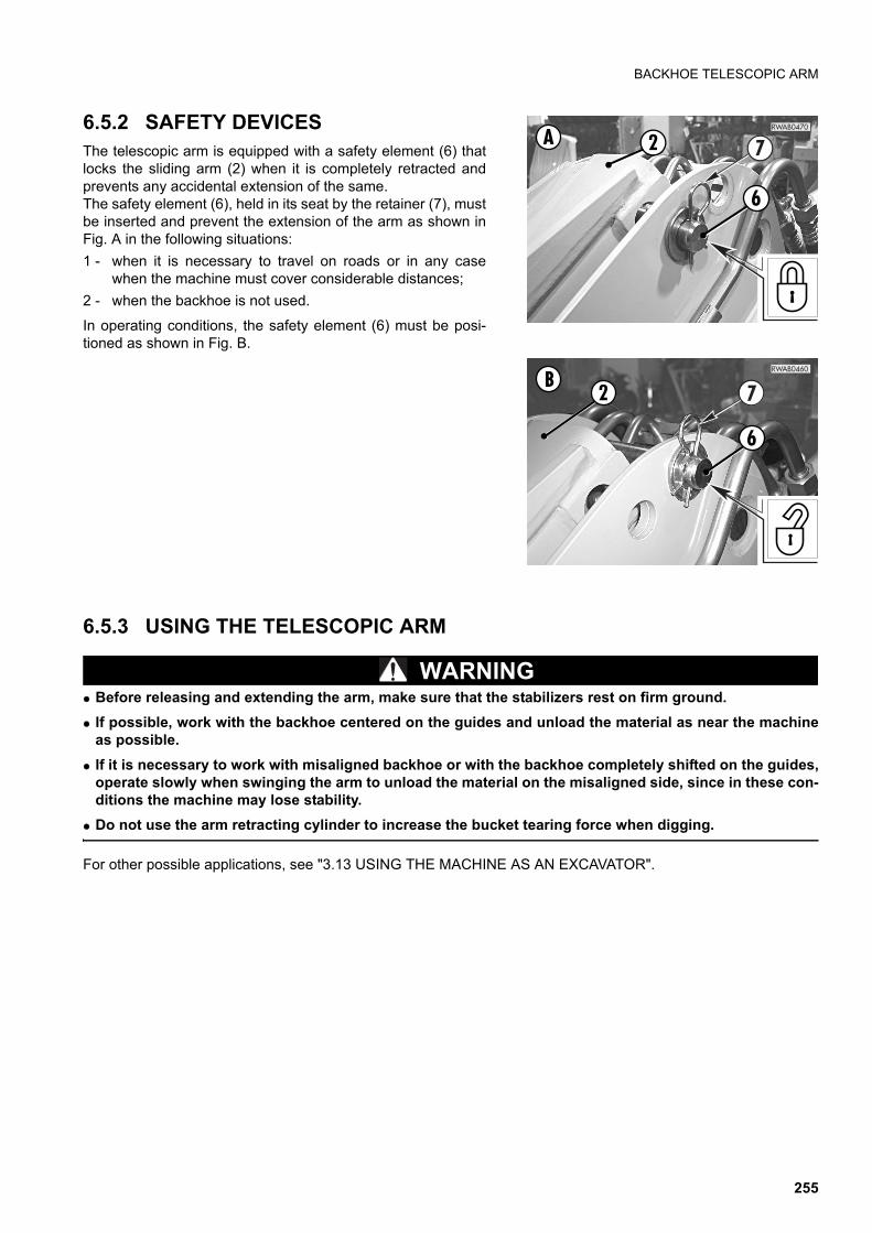
BACKHOE TELESCOPIC ARM
6.5.2 SAFETY DEVICESThe telescopic arm is equipped with a safety element (6) thatlocks the sliding arm (2) when it is completely retracted andprevents any accidental extension of the same.The safety element (6), held in its seat by the retainer (7), mustbe inserted and prevent the extension of the arm as shown inFig. A in the following situations:
1 - when it is necessary to travel on roads or in any casewhen the machine must cover considerable distances;
2 - when the backhoe is not used.
In operating conditions, the safety element (6) must be posi-tioned as shown in Fig. B.
6.5.3 USING THE TELESCOPIC ARM
WARNINGq Before releasing and extending the arm, make sure that the stabilizers rest on firm ground.
q If possible, work with the backhoe centered on the guides and unload the material as near the machineas possible.
q If it is necessary to work with misaligned backhoe or with the backhoe completely shifted on the guides,operate slowly when swinging the arm to unload the material on the misaligned side, since in these con-ditions the machine may lose stability.
q Do not use the arm retracting cylinder to increase the bucket tearing force when digging.
For other possible applications, see "3.13 USING THE MACHINE AS AN EXCAVATOR".
RWAB0470
7
6
A 2
RWAB0460
7
6
B2
255
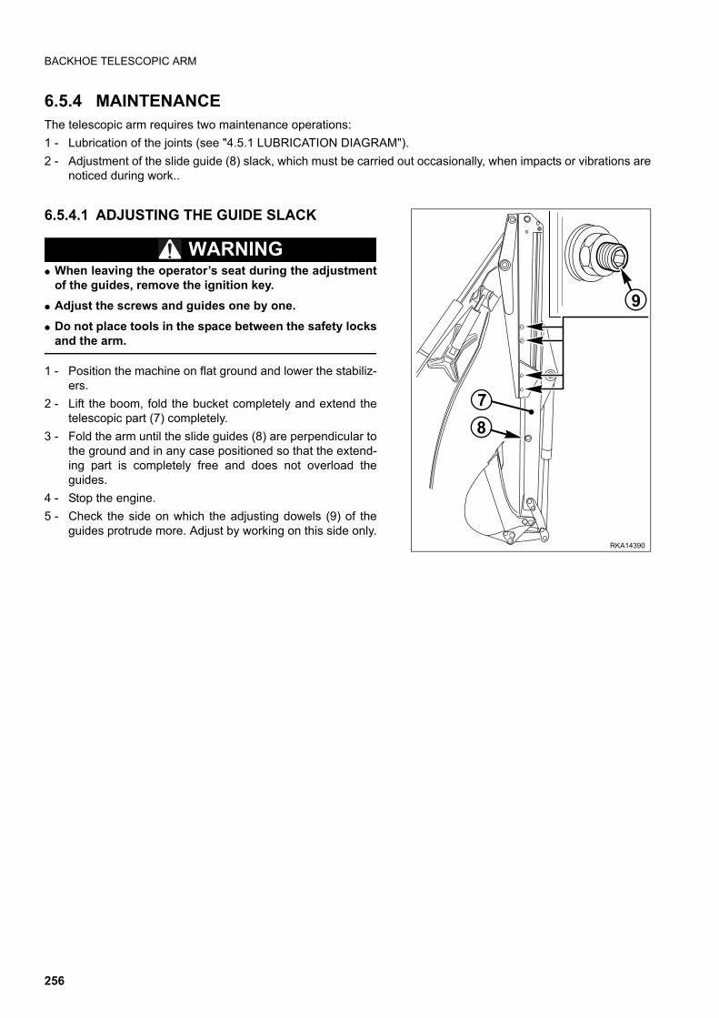
BACKHOE TELESCOPIC ARM
6.5.4 MAINTENANCEThe telescopic arm requires two maintenance operations:
1 - Lubrication of the joints (see "4.5.1 LUBRICATION DIAGRAM").
2 - Adjustment of the slide guide (8) slack, which must be carried out occasionally, when impacts or vibrations arenoticed during work..
6.5.4.1 ADJUSTING THE GUIDE SLACK
WARNINGq When leaving the operator’s seat during the adjustment
of the guides, remove the ignition key.
q Adjust the screws and guides one by one.
q Do not place tools in the space between the safety locksand the arm.
1 - Position the machine on flat ground and lower the stabiliz-ers.
2 - Lift the boom, fold the bucket completely and extend thetelescopic part (7) completely.
3 - Fold the arm until the slide guides (8) are perpendicular tothe ground and in any case positioned so that the extend-ing part is completely free and does not overload theguides.
4 - Stop the engine.
5 - Check the side on which the adjusting dowels (9) of theguides protrude more. Adjust by working on this side only.
RKA14390
7
8
9
256
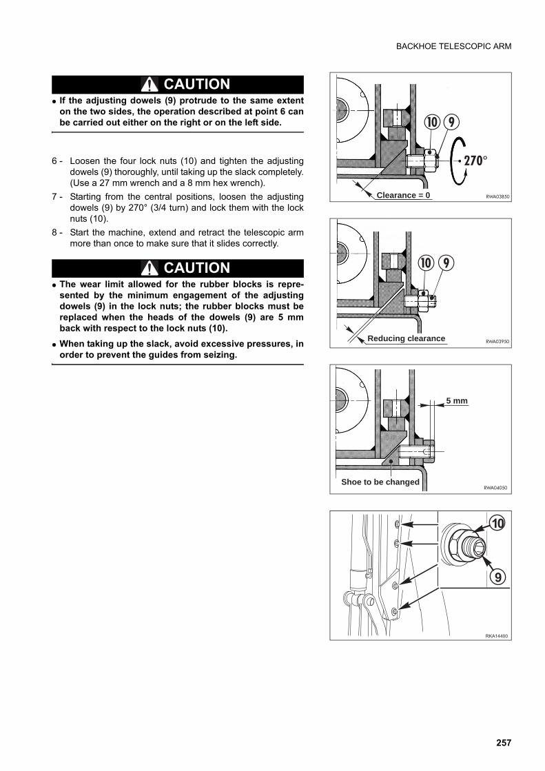
BACKHOE TELESCOPIC ARM
CAUTIONq If the adjusting dowels (9) protrude to the same extent
on the two sides, the operation described at point 6 canbe carried out either on the right or on the left side.
6 - Loosen the four lock nuts (10) and tighten the adjustingdowels (9) thoroughly, until taking up the slack completely.(Use a 27 mm wrench and a 8 mm hex wrench).
7 - Starting from the central positions, loosen the adjustingdowels (9) by 270° (3/4 turn) and lock them with the locknuts (10).
8 - Start the machine, extend and retract the telescopic armmore than once to make sure that it slides correctly.
CAUTIONq The wear limit allowed for the rubber blocks is repre-
sented by the minimum engagement of the adjustingdowels (9) in the lock nuts; the rubber blocks must bereplaced when the heads of the dowels (9) are 5 mmback with respect to the lock nuts (10).
q When taking up the slack, avoid excessive pressures, inorder to prevent the guides from seizing.
�������
!
��
RWA04050Shoe to be changed
5 mm
10
RWA03950
9
Reducing clearance
RWA03850
10 9
270°
Clearance = 0
257
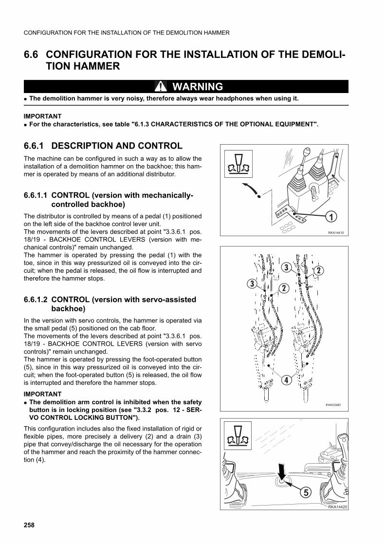
CONFIGURATION FOR THE INSTALLATION OF THE DEMOLITION HAMMER
6.6 CONFIGURATION FOR THE INSTALLATION OF THE DEMOLI-TION HAMMER
WARNINGq The demolition hammer is very noisy, therefore always wear headphones when using it.
IMPORTANTq For the characteristics, see table "6.1.3 CHARACTERISTICS OF THE OPTIONAL EQUIPMENT".
6.6.1 DESCRIPTION AND CONTROLThe machine can be configured in such a way as to allow theinstallation of a demolition hammer on the backhoe; this ham-mer is operated by means of an additional distributor.
6.6.1.1 CONTROL (version with mechanically-controlled backhoe)
The distributor is controlled by means of a pedal (1) positionedon the left side of the backhoe control lever unit.The movements of the levers described at point "3.3.6.1 pos.18/19 - BACKHOE CONTROL LEVERS (version with me-chanical controls)" remain unchanged. The hammer is operated by pressing the pedal (1) with thetoe, since in this way pressurized oil is conveyed into the cir-cuit; when the pedal is released, the oil flow is interrupted andtherefore the hammer stops.
6.6.1.2 CONTROL (version with servo-assisted backhoe)
In the version with servo controls, the hammer is operated viathe small pedal (5) positioned on the cab floor.The movements of the levers described at point "3.3.6.1 pos.18/19 - BACKHOE CONTROL LEVERS (version with servocontrols)" remain unchanged.The hammer is operated by pressing the foot-operated button(5), since in this way pressurized oil is conveyed into the cir-cuit; when the foot-operated button (5) is released, the oil flowis interrupted and therefore the hammer stops.
IMPORTANTq The demolition arm control is inhibited when the safety
button is in locking position (see "3.3.2 pos. 12 - SER-VO CONTROL LOCKING BUTTON").
This configuration includes also the fixed installation of rigid orflexible pipes, more precisely a delivery (2) and a drain (3)pipe that convey/discharge the oil necessary for the operationof the hammer and reach the proximity of the hammer connec-tion (4).
������
�
������
�
RWA03680
23
23
4
258
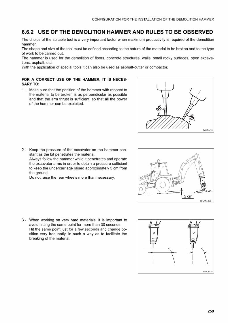
CONFIGURATION FOR THE INSTALLATION OF THE DEMOLITION HAMMER
6.6.2 USE OF THE DEMOLITION HAMMER AND RULES TO BE OBSERVEDThe choice of the suitable tool is a very important factor when maximum productivity is required of the demolitionhammer.The shape and size of the tool must be defined according to the nature of the material to be broken and to the typeof work to be carried out.The hammer is used for the demolition of floors, concrete structures, walls, small rocky surfaces, open excava-tions, asphalt, etc.With the application of special tools it can also be used as asphalt-cutter or compactor.
FOR A CORRECT USE OF THE HAMMER, IT IS NECES-SARY TO:
1 - Make sure that the position of the hammer with respect tothe material to be broken is as perpendicular as possibleand that the arm thrust is sufficient, so that all the powerof the hammer can be exploited.
2 - Keep the pressure of the excavator on the hammer con-stant as the bit penetrates the material.Always follow the hammer while it penetrates and operatethe excavator arms in order to obtain a pressure sufficientto keep the undercarriage raised approximately 5 cm fromthe ground.Do not raise the rear wheels more than necessary.
3 - When working on very hard materials, it is important toavoid hitting the same point for more than 30 seconds.Hit the same point just for a few seconds and change po-sition very frequently, in such a way as to facilitate thebreaking of the material.
RWA06410
90°
90 °
RWA06430
������
���
259
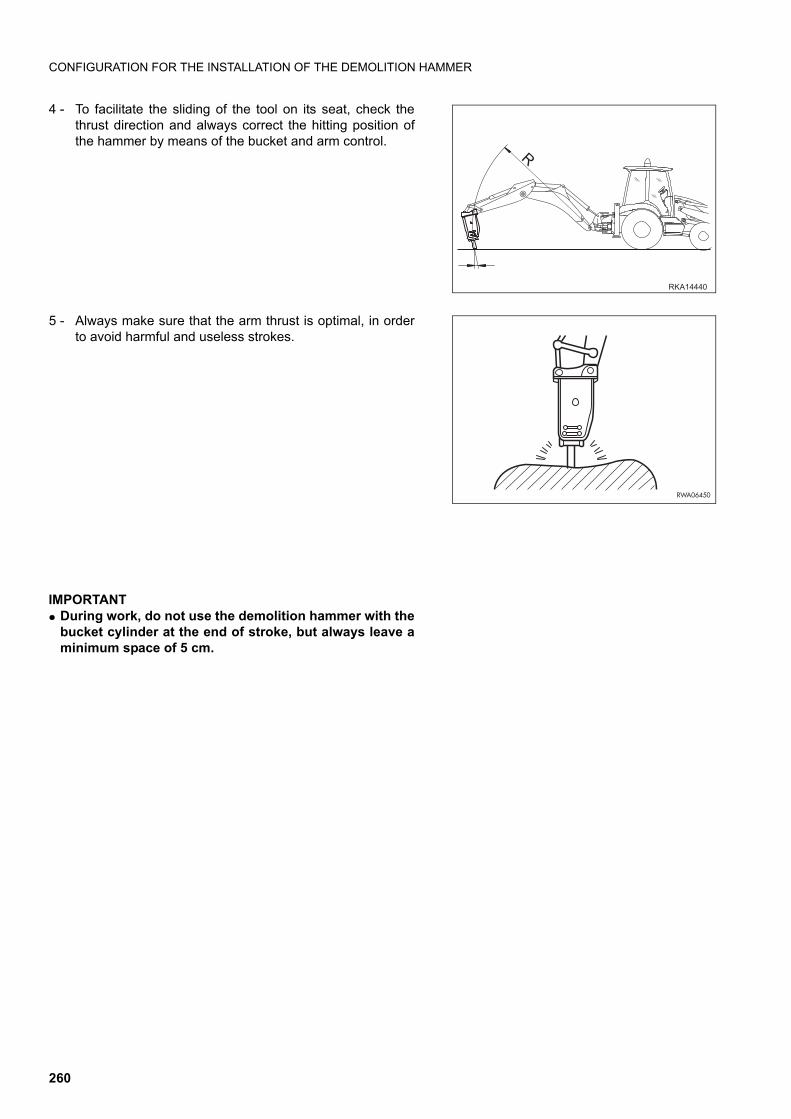
CONFIGURATION FOR THE INSTALLATION OF THE DEMOLITION HAMMER
4 - To facilitate the sliding of the tool on its seat, check thethrust direction and always correct the hitting position ofthe hammer by means of the bucket and arm control.
5 - Always make sure that the arm thrust is optimal, in orderto avoid harmful and useless strokes.
IMPORTANTq During work, do not use the demolition hammer with the
bucket cylinder at the end of stroke, but always leave aminimum space of 5 cm.
RWA06450
������
260
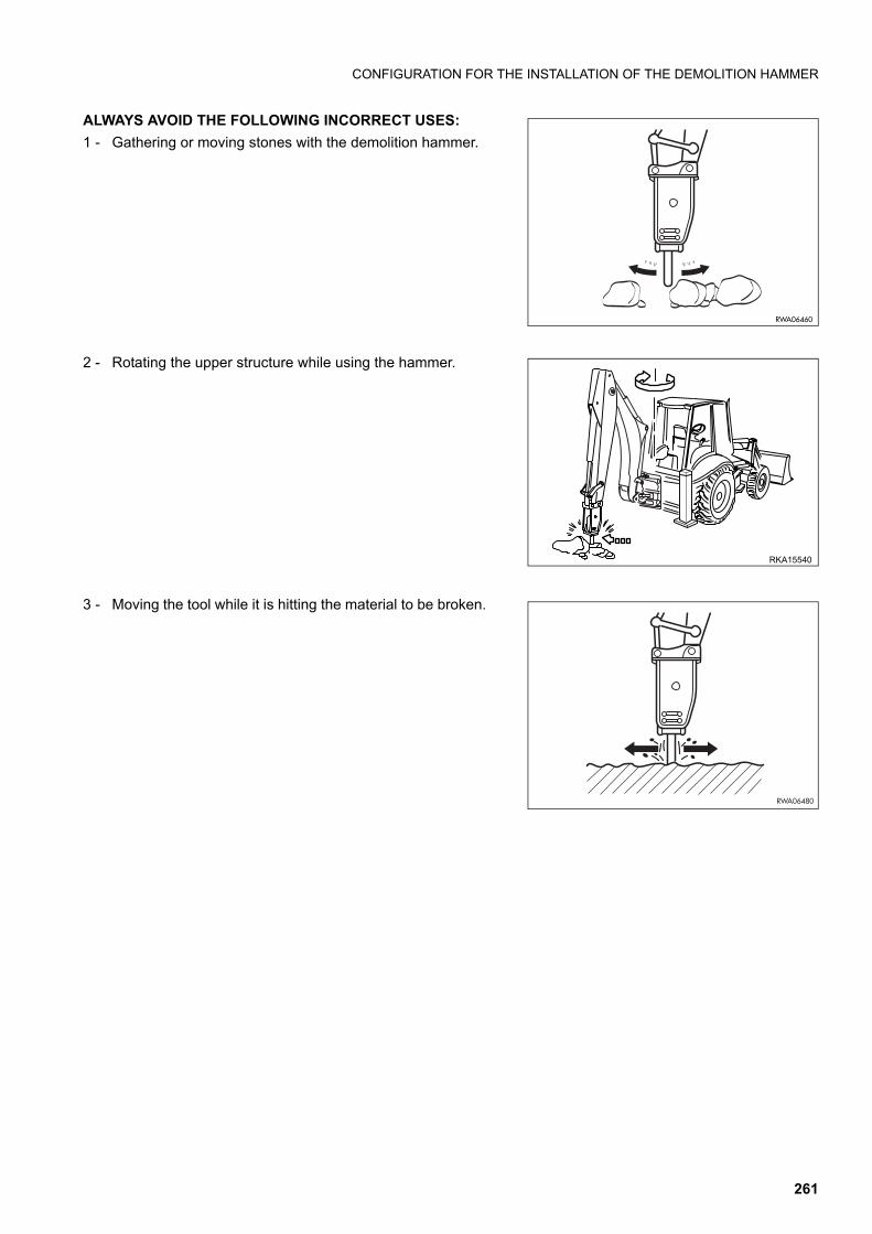
CONFIGURATION FOR THE INSTALLATION OF THE DEMOLITION HAMMER
ALWAYS AVOID THE FOLLOWING INCORRECT USES:
1 - Gathering or moving stones with the demolition hammer.
2 - Rotating the upper structure while using the hammer.
3 - Moving the tool while it is hitting the material to be broken.
RWA06460
RWA06480
RKA15540
261
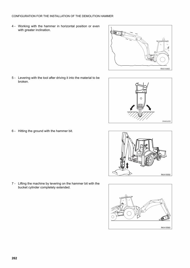
CONFIGURATION FOR THE INSTALLATION OF THE DEMOLITION HAMMER
4 - Working with the hammer in horizontal position or evenwith greater inclination.
5 - Levering with the tool after driving it into the material to bebroken.
6 - Hitting the ground with the hammer bit.
7 - Lifting the machine by levering on the hammer bit with thebucket cylinder completely extended.
RKA15560
RKA15550
RWA06500
������
262
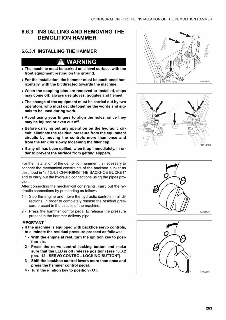
CONFIGURATION FOR THE INSTALLATION OF THE DEMOLITION HAMMER
6.6.3 INSTALLING AND REMOVING THE DEMOLITION HAMMER
6.6.3.1 INSTALLING THE HAMMER
WARNINGq The machine must be parked on a level surface, with the
front equipment resting on the ground.
q For the installation, the hammer must be positioned hor-izontally, with the bit directed towards the machine.
q When the coupling pins are removed or installed, chipsmay come off; always use gloves, goggles and helmet.
q The change of the equipment must be carried out by twooperators, who must decide together the words and sig-nals to be used during work.
q Avoid using your fingers to align the holes, since theymay be injured or even cut off.
q Before carrying out any operation on the hydraulic cir-cuit, eliminate the residual pressure from the equipmentcircuits by moving the controls more than once andfrom the tank by slowly loosening the filler cap.
q If any oil has been spilled, wipe it up immediately, in or-der to prevent the surface from getting slippery.
For the installation of the demolition hammer it is necessary toconnect the mechanical constraints of the backhoe bucket asdescribed in "3.13.4.1 CHANGING THE BACKHOE BUCKET"and to carry out the hydraulic connections using the pipes pro-vided.After connecting the mechanical constraints, carry out the hy-draulic connections by proceeding as follows
1 - Stop the engine and move the hydraulic controls in all di-rections, in order to completely release the residual pres-sure present in the circuits of the machine.
2 - Press the hammer control pedal to release the pressurepresent in the hammer delivery pipe.
IMPORTANTq If the machine is equipped with backhoe servo controls,
to eliminate the residual pressure proceed as follows:
1 - With the engine at rest, turn the ignition key to posi-tion « ».
2 - Press the servo control locking button and makesure that the LED is off (release position) (see "3.3.2pos. 12 - SERVO CONTROL LOCKING BUTTON").
3 - Shift the backhoe control levers more than once andpress the hammer control pedal.
4 - Turn the ignition key to position « ».
�������
����
RWA02000
RWA01960
263
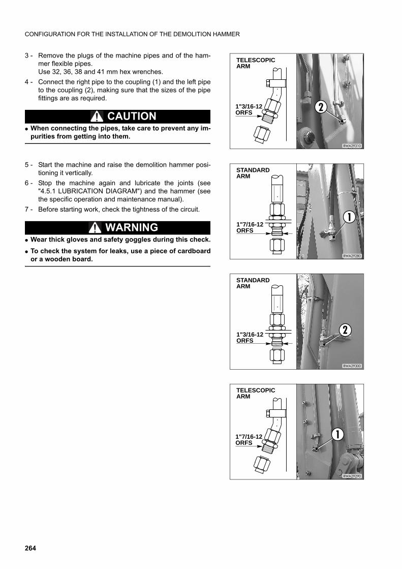
CONFIGURATION FOR THE INSTALLATION OF THE DEMOLITION HAMMER
3 - Remove the plugs of the machine pipes and of the ham-mer flexible pipes.Use 32, 36, 38 and 41 mm hex wrenches.
4 - Connect the right pipe to the coupling (1) and the left pipeto the coupling (2), making sure that the sizes of the pipefittings are as required.
CAUTIONq When connecting the pipes, take care to prevent any im-
purities from getting into them.
5 - Start the machine and raise the demolition hammer posi-tioning it vertically.
6 - Stop the machine again and lubricate the joints (see"4.5.1 LUBRICATION DIAGRAM") and the hammer (seethe specific operation and maintenance manual).
7 - Before starting work, check the tightness of the circuit.
WARNINGq Wear thick gloves and safety goggles during this check.
q To check the system for leaks, use a piece of cardboardor a wooden board.
1"7/16-12 ORFS
1
RWA29290
TELESCOPIC ARM
1"3/16-12 ORFS
2
RWA29300
STANDARD ARM
1"7/16-12 ORFS
1
RWA29280
STANDARD ARM
1"3/16-12 ORFS 2
RWA29310
TELESCOPIC ARM
264
CONFIGURATION FOR THE INSTALLATION OF THE DEMOLITION HAMMER
6.6.3.2 REMOVING THE HAMMER
To remove the hammer, proceed as follows:
1 - Stop the engine and move the hydraulic controls in all directions, in order to completely release the residualpressure present in the circuits of the machine.
2 - Press the hammer control pedal to release the pressure present in the hammer delivery pipe.
IMPORTANTq If the machine is equipped with backhoe servo controls, to release the residual pressure from the cir-
cuits, follow the procedure indicated in the previous paragraph "6.6.3.1 INSTALLING THE HAMMER".
3 - Disconnect the hammer delivery and return pipes.Use 32, 36, 38 and 41 mm hex wrenches.
4 - Fit the pipe sealing plugs complete with the relevant gaskets.
WARNINGq Make sure that the plugs are properly tightened and that there are no leakages; if the circuit is inadvert-
ently pressurized, small leakages can be turned into thin jets that may perforate the skin or injure theeyes.
q Always wear thick gloves and safety goggles to carry out this check.
q To check the system for leaks, use a piece of cardboard or a wooden board.
5 - Disconnect the hammer from the mechanical constraints, as described in "3.13.4.1 CHANGING THE BACK-HOE BUCKET".
6.6.4 USING THE HAMMERSee the specific manual.
OPERATIONS WITH HAND HYDRAULIC HAMMER AND COMPACTING TOOLS
CAUTIONq If the machine is provided with telescopic arm, this must be kept only folded.
6.6.5 MAINTENANCEThe hydraulic system does not require any maintenance operation and inspection other than those prescribed forthe machine.Regarding the maintenance operations required for the hammer, see the specific operation manual.
265
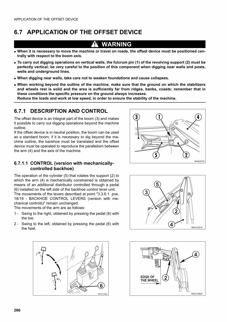
APPLICATION OF THE OFFSET DEVICE
6.7 APPLICATION OF THE OFFSET DEVICE
WARNINGq When it is necessary to move the machine or travel on roads, the offset device must be positioned cen-
trally with respect to the boom axis.
q To carry out digging operations on vertical walls, the fulcrum pin (1) of the revolving support (2) must beperfectly vertical; be very careful to the position of this component when digging near walls and posts,wells and underground lines.
q When digging near walls, take care not to weaken foundations and cause collapses.
q When working beyond the outline of the machine, make sure that the ground on which the stabilizersand wheels rest is solid and the area is sufficiently far from ridges, banks, coasts: remember that inthese conditions the specific pressure on the ground always increases.Reduce the loads and work at low speed, in order to ensure the stability of the machine.
6.7.1 DESCRIPTION AND CONTROL The offset device is an integral part of the boom (3) and makesit possible to carry out digging operations beyond the machineoutline.If the offset device is in neutral position, the boom can be usedas a standard boom; if it is necessary to dig beyond the ma-chine outline, the backhoe must be translated and the offsetdevice must be operated to reproduce the parallelism betweenthe arm (4) and the axis of the machine.
6.7.1.1 CONTROL (version with mechanically-controlled backhoe)
The operation of the cylinder (5) that rotates the support (2) towhich the arm (4) is mechanically constrained is obtained bymeans of an additional distributor controlled through a pedal(6) installed on the left side of the backhoe control lever unit.The movements of the levers described at point "3.3.6.1 pos.18/19 - BACKHOE CONTROL LEVERS (version with me-chanical controls)" remain unchanged. The movements of the arm are as follows:
1 - Swing to the right, obtained by pressing the pedal (6) withthe toe.
2 - Swing to the left, obtained by pressing the pedal (6) withthe heel.
1 4
25
3
RWA03750
���� ��
�
��
���� ��
��� ��
�
��� �������������
266
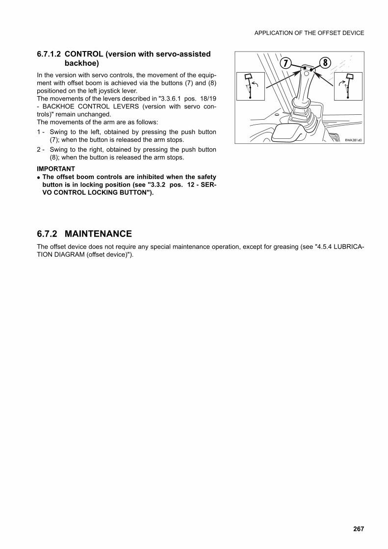
APPLICATION OF THE OFFSET DEVICE
6.7.1.2 CONTROL (version with servo-assisted backhoe)
In the version with servo controls, the movement of the equip-ment with offset boom is achieved via the buttons (7) and (8)positioned on the left joystick lever.The movements of the levers described in "3.3.6.1 pos. 18/19- BACKHOE CONTROL LEVERS (version with servo con-trols)" remain unchanged.The movements of the arm are as follows:
1 - Swing to the left, obtained by pressing the push button(7); when the button is released the arm stops.
2 - Swing to the right, obtained by pressing the push button(8); when the button is released the arm stops.
IMPORTANTq The offset boom controls are inhibited when the safety
button is in locking position (see "3.3.2 pos. 12 - SER-VO CONTROL LOCKING BUTTON").
6.7.2 MAINTENANCEThe offset device does not require any special maintenance operation, except for greasing (see "4.5.4 LUBRICA-TION DIAGRAM (offset device)").
7
RWA38140
8
267
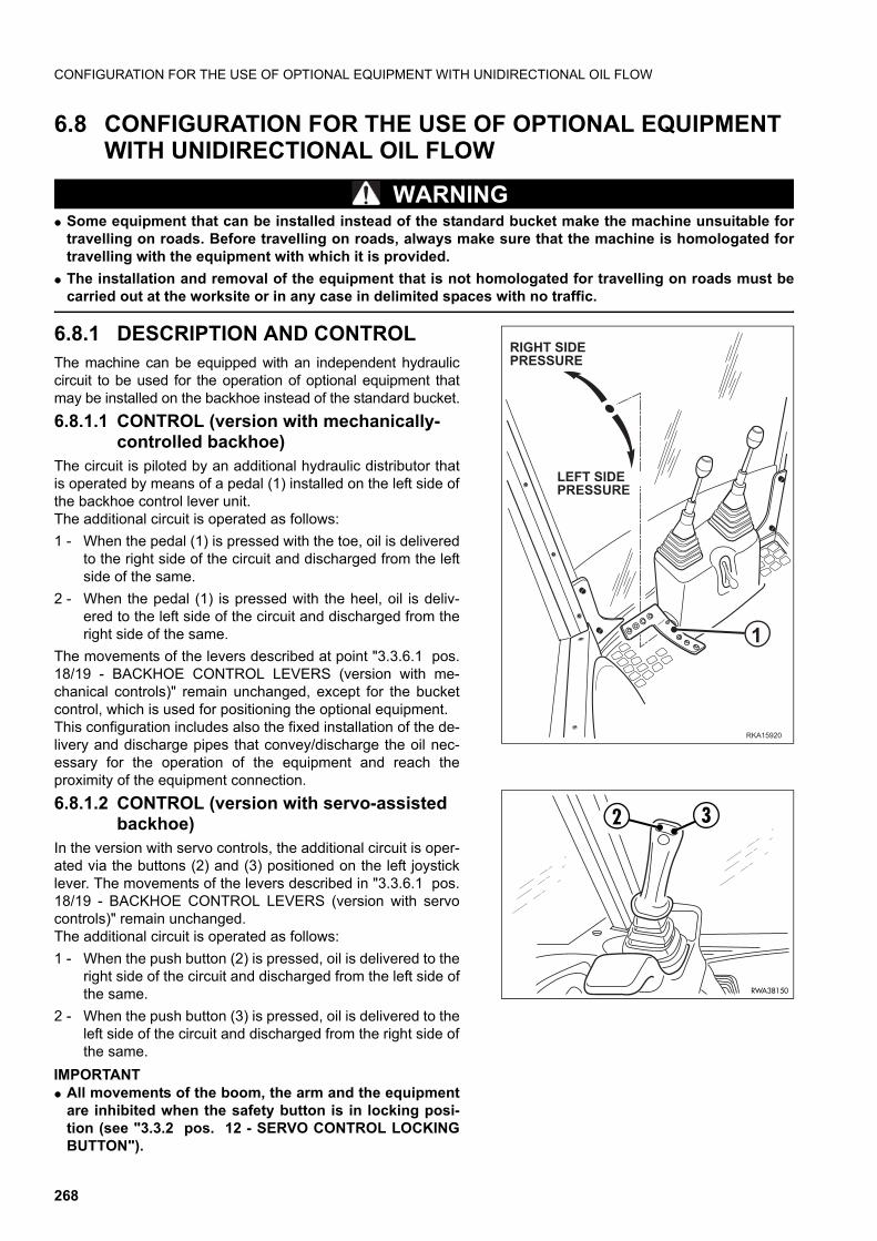
CONFIGURATION FOR THE USE OF OPTIONAL EQUIPMENT WITH UNIDIRECTIONAL OIL FLOW
6.8 CONFIGURATION FOR THE USE OF OPTIONAL EQUIPMENT WITH UNIDIRECTIONAL OIL FLOW
WARNINGq Some equipment that can be installed instead of the standard bucket make the machine unsuitable for
travelling on roads. Before travelling on roads, always make sure that the machine is homologated fortravelling with the equipment with which it is provided.
q The installation and removal of the equipment that is not homologated for travelling on roads must becarried out at the worksite or in any case in delimited spaces with no traffic.
6.8.1 DESCRIPTION AND CONTROL The machine can be equipped with an independent hydrauliccircuit to be used for the operation of optional equipment thatmay be installed on the backhoe instead of the standard bucket.
6.8.1.1 CONTROL (version with mechanically-controlled backhoe)
The circuit is piloted by an additional hydraulic distributor thatis operated by means of a pedal (1) installed on the left side ofthe backhoe control lever unit.The additional circuit is operated as follows:
1 - When the pedal (1) is pressed with the toe, oil is deliveredto the right side of the circuit and discharged from the leftside of the same.
2 - When the pedal (1) is pressed with the heel, oil is deliv-ered to the left side of the circuit and discharged from theright side of the same.
The movements of the levers described at point "3.3.6.1 pos.18/19 - BACKHOE CONTROL LEVERS (version with me-chanical controls)" remain unchanged, except for the bucketcontrol, which is used for positioning the optional equipment. This configuration includes also the fixed installation of the de-livery and discharge pipes that convey/discharge the oil nec-essary for the operation of the equipment and reach theproximity of the equipment connection.
6.8.1.2 CONTROL (version with servo-assisted backhoe)
In the version with servo controls, the additional circuit is oper-ated via the buttons (2) and (3) positioned on the left joysticklever. The movements of the levers described in "3.3.6.1 pos.18/19 - BACKHOE CONTROL LEVERS (version with servocontrols)" remain unchanged.The additional circuit is operated as follows:
1 - When the push button (2) is pressed, oil is delivered to theright side of the circuit and discharged from the left side ofthe same.
2 - When the push button (3) is pressed, oil is delivered to theleft side of the circuit and discharged from the right side ofthe same.
IMPORTANTq All movements of the boom, the arm and the equipment
are inhibited when the safety button is in locking posi-tion (see "3.3.2 pos. 12 - SERVO CONTROL LOCKINGBUTTON").
��� ���
�
��������������1��
�������������1��
2
RWA38150
3
268
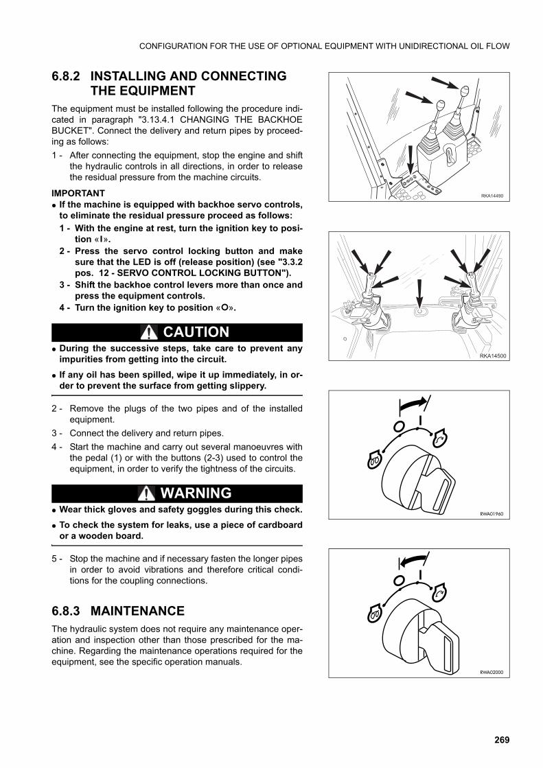
CONFIGURATION FOR THE USE OF OPTIONAL EQUIPMENT WITH UNIDIRECTIONAL OIL FLOW
6.8.2 INSTALLING AND CONNECTING THE EQUIPMENT
The equipment must be installed following the procedure indi-cated in paragraph "3.13.4.1 CHANGING THE BACKHOEBUCKET". Connect the delivery and return pipes by proceed-ing as follows:
1 - After connecting the equipment, stop the engine and shiftthe hydraulic controls in all directions, in order to releasethe residual pressure from the machine circuits.
IMPORTANTq If the machine is equipped with backhoe servo controls,
to eliminate the residual pressure proceed as follows:
1 - With the engine at rest, turn the ignition key to posi-tion « ».
2 - Press the servo control locking button and makesure that the LED is off (release position) (see "3.3.2pos. 12 - SERVO CONTROL LOCKING BUTTON").
3 - Shift the backhoe control levers more than once andpress the equipment controls.
4 - Turn the ignition key to position « ».
CAUTIONq During the successive steps, take care to prevent any
impurities from getting into the circuit.
q If any oil has been spilled, wipe it up immediately, in or-der to prevent the surface from getting slippery.
2 - Remove the plugs of the two pipes and of the installedequipment.
3 - Connect the delivery and return pipes.
4 - Start the machine and carry out several manoeuvres withthe pedal (1) or with the buttons (2-3) used to control theequipment, in order to verify the tightness of the circuits.
WARNINGq Wear thick gloves and safety goggles during this check.
q To check the system for leaks, use a piece of cardboardor a wooden board.
5 - Stop the machine and if necessary fasten the longer pipesin order to avoid vibrations and therefore critical condi-tions for the coupling connections.
6.8.3 MAINTENANCEThe hydraulic system does not require any maintenance oper-ation and inspection other than those prescribed for the ma-chine. Regarding the maintenance operations required for theequipment, see the specific operation manuals.
�������
����
RWA01960
RWA02000
269
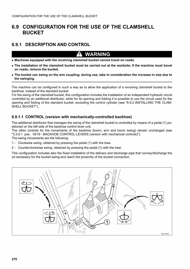
CONFIGURATION FOR THE USE OF THE CLAMSHELL BUCKET
6.9 CONFIGURATION FOR THE USE OF THE CLAMSHELL BUCKET
6.9.1 DESCRIPTION AND CONTROL
WARNINGq Machines equipped with the revolving clamshell bucket cannot travel on roads.
q The installation of the clamshell bucket must be carried out at the worksite; if the machine must travelon roads, remove the bucket.
q The bucket can swing on the arm coupling; during use, take in consideration the increase in size due tothe swinging.
The machine can be configured in such a way as to allow the application of a revolving clamshell bucket to thebackhoe, instead of the standard bucket.For the swing of the clamshell bucket, this configuration includes the installation of an independent hydraulic circuitcontrolled by an additional distributor, while for its opening and folding it is possible to use the circuit used for theopening and folding of the standard bucket, excluding the control cylinder (see "6.9.2 INSTALLING THE CLAM-SHELL BUCKET").
6.9.1.1 CONTROL (version with mechanically-controlled backhoe)
The additional distributor that manages the swing of the clamshell bucket is controlled by means of a pedal (1) po-sitioned on the left side of the backhoe control lever unit.The other controls for the movements of the backhoe (boom, arm and boom swing) remain unchanged (see"3.3.6.1 pos. 18/19 - BACKHOE CONTROL LEVERS (version with mechanical controls)").The swing movements are the following:
1 - Clockwise swing, obtained by pressing the pedal (1) with the toes.
2 - Counterclockwise swing, obtained by pressing the pedal (1) with the heel.
This configuration includes also the fixed installation of the delivery and discharge pipe that convey/discharge theoil necessary for the bucket swing and reach the proximity of the bucket connection.
���� ��
�
270
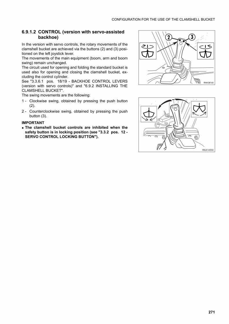
CONFIGURATION FOR THE USE OF THE CLAMSHELL BUCKET
6.9.1.2 CONTROL (version with servo-assisted backhoe)
In the version with servo controls, the rotary movements of theclamshell bucket are achieved via the buttons (2) and (3) posi-tioned on the left joystick lever.The movements of the main equipment (boom, arm and boomswing) remain unchanged.The circuit used for opening and folding the standard bucket isused also for opening and closing the clamshell bucket, ex-cluding the control cylinder.See "3.3.6.1 pos. 18/19 - BACKHOE CONTROL LEVERS(version with servo controls)" and "6.9.2 INSTALLING THECLAMSHELL BUCKET".The swing movements are the following:
1 - Clockwise swing, obtained by pressing the push button(2).
2 - Counterclockwise swing, obtained by pressing the pushbutton (3).
IMPORTANTq The clamshell bucket controls are inhibited when the
safety button is in locking position (see "3.3.2 pos. 12 -SERVO CONTROL LOCKING BUTTON").
2
RWA38160
3
����
271
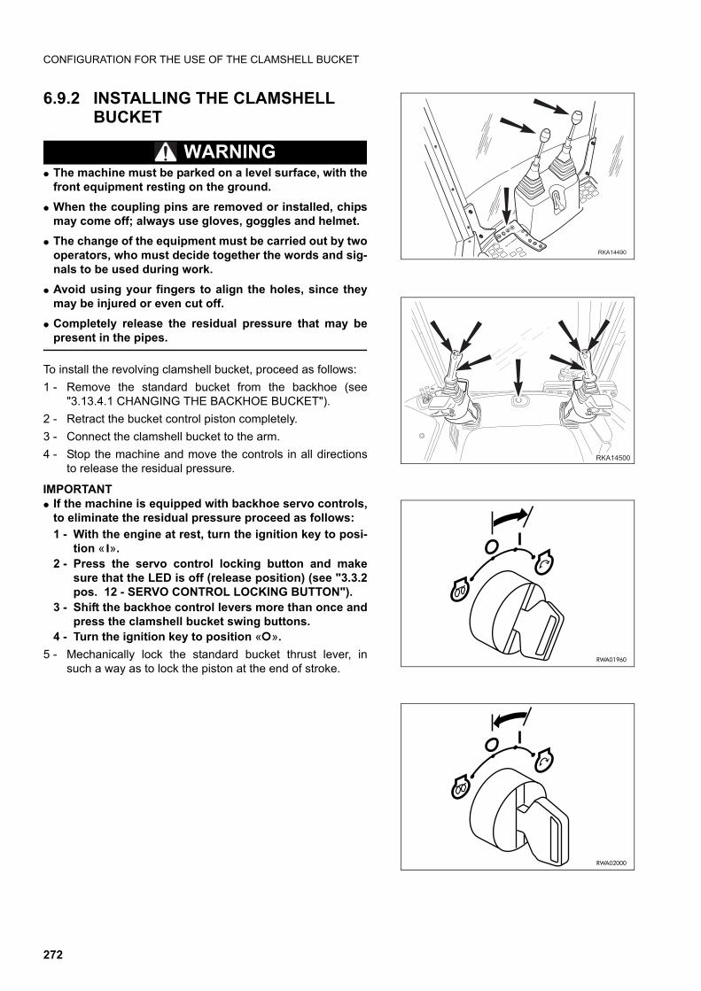
CONFIGURATION FOR THE USE OF THE CLAMSHELL BUCKET
6.9.2 INSTALLING THE CLAMSHELL BUCKET
WARNINGq The machine must be parked on a level surface, with the
front equipment resting on the ground.
q When the coupling pins are removed or installed, chipsmay come off; always use gloves, goggles and helmet.
q The change of the equipment must be carried out by twooperators, who must decide together the words and sig-nals to be used during work.
q Avoid using your fingers to align the holes, since theymay be injured or even cut off.
q Completely release the residual pressure that may bepresent in the pipes.
To install the revolving clamshell bucket, proceed as follows:
1 - Remove the standard bucket from the backhoe (see"3.13.4.1 CHANGING THE BACKHOE BUCKET").
2 - Retract the bucket control piston completely.
3 - Connect the clamshell bucket to the arm.
4 - Stop the machine and move the controls in all directionsto release the residual pressure.
IMPORTANTq If the machine is equipped with backhoe servo controls,
to eliminate the residual pressure proceed as follows:
1 - With the engine at rest, turn the ignition key to posi-tion « ».
2 - Press the servo control locking button and makesure that the LED is off (release position) (see "3.3.2pos. 12 - SERVO CONTROL LOCKING BUTTON").
3 - Shift the backhoe control levers more than once andpress the clamshell bucket swing buttons.
4 - Turn the ignition key to position « ».
5 - Mechanically lock the standard bucket thrust lever, insuch a way as to lock the piston at the end of stroke.
�������
����
RWA01960
RWA02000
272
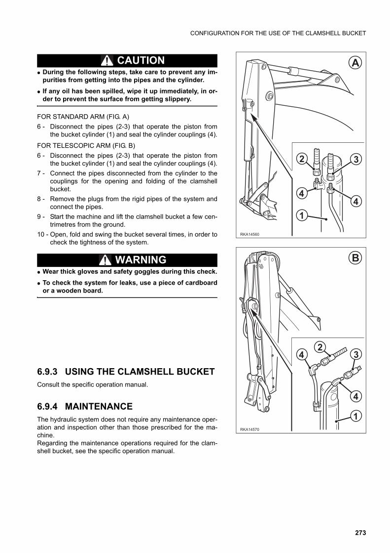
CONFIGURATION FOR THE USE OF THE CLAMSHELL BUCKET
CAUTIONq During the following steps, take care to prevent any im-
purities from getting into the pipes and the cylinder.
q If any oil has been spilled, wipe it up immediately, in or-der to prevent the surface from getting slippery.
FOR STANDARD ARM (FIG. A)
6 - Disconnect the pipes (2-3) that operate the piston fromthe bucket cylinder (1) and seal the cylinder couplings (4).
FOR TELESCOPIC ARM (FIG. B)
6 - Disconnect the pipes (2-3) that operate the piston fromthe bucket cylinder (1) and seal the cylinder couplings (4).
7 - Connect the pipes disconnected from the cylinder to thecouplings for the opening and folding of the clamshellbucket.
8 - Remove the plugs from the rigid pipes of the system andconnect the pipes.
9 - Start the machine and lift the clamshell bucket a few cen-trimetres from the ground.
10 - Open, fold and swing the bucket several times, in order tocheck the tightness of the system.
WARNINGq Wear thick gloves and safety goggles during this check.
q To check the system for leaks, use a piece of cardboardor a wooden board.
6.9.3 USING THE CLAMSHELL BUCKETConsult the specific operation manual.
6.9.4 MAINTENANCEThe hydraulic system does not require any maintenance oper-ation and inspection other than those prescribed for the ma-chine.Regarding the maintenance operations required for the clam-shell bucket, see the specific operation manual.
���� �
�
�
�
� �
�
�
��
�
�
���� �
�
273
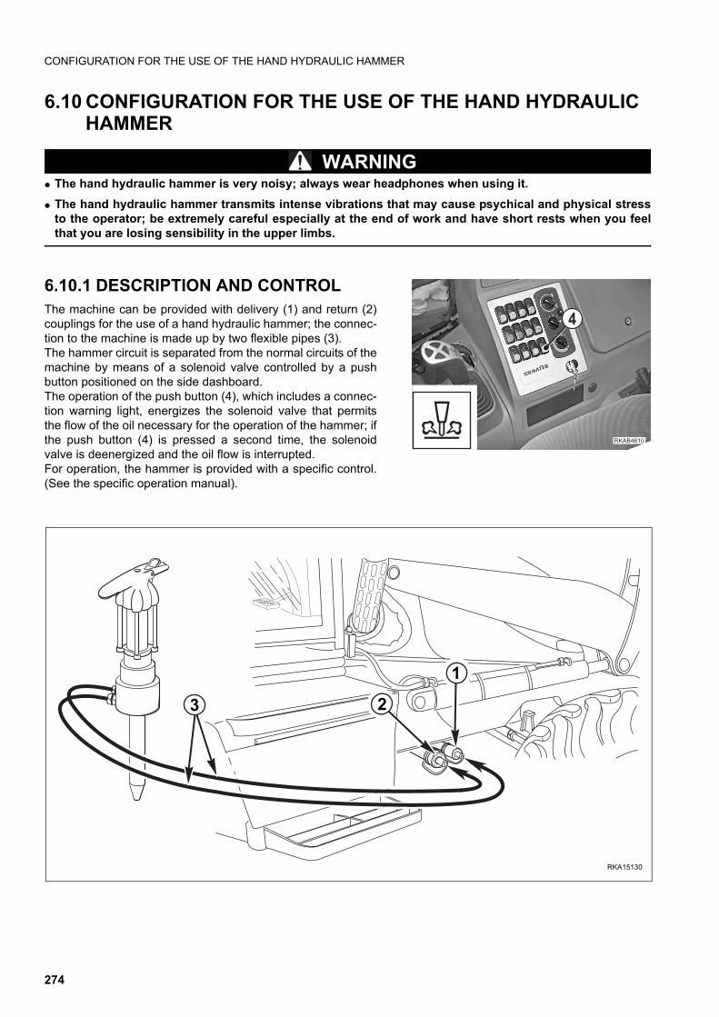
CONFIGURATION FOR THE USE OF THE HAND HYDRAULIC HAMMER
6.10 CONFIGURATION FOR THE USE OF THE HAND HYDRAULIC HAMMER
WARNINGq The hand hydraulic hammer is very noisy; always wear headphones when using it.q The hand hydraulic hammer transmits intense vibrations that may cause psychical and physical stress
to the operator; be extremely careful especially at the end of work and have short rests when you feelthat you are losing sensibility in the upper limbs.
6.10.1 DESCRIPTION AND CONTROLThe machine can be provided with delivery (1) and return (2)couplings for the use of a hand hydraulic hammer; the connec-tion to the machine is made up by two flexible pipes (3).The hammer circuit is separated from the normal circuits of themachine by means of a solenoid valve controlled by a pushbutton positioned on the side dashboard.The operation of the push button (4), which includes a connec-tion warning light, energizes the solenoid valve that permitsthe flow of the oil necessary for the operation of the hammer; ifthe push button (4) is pressed a second time, the solenoidvalve is deenergized and the oil flow is interrupted.For operation, the hammer is provided with a specific control.(See the specific operation manual).
��������
�
RKA15130
1
23
274
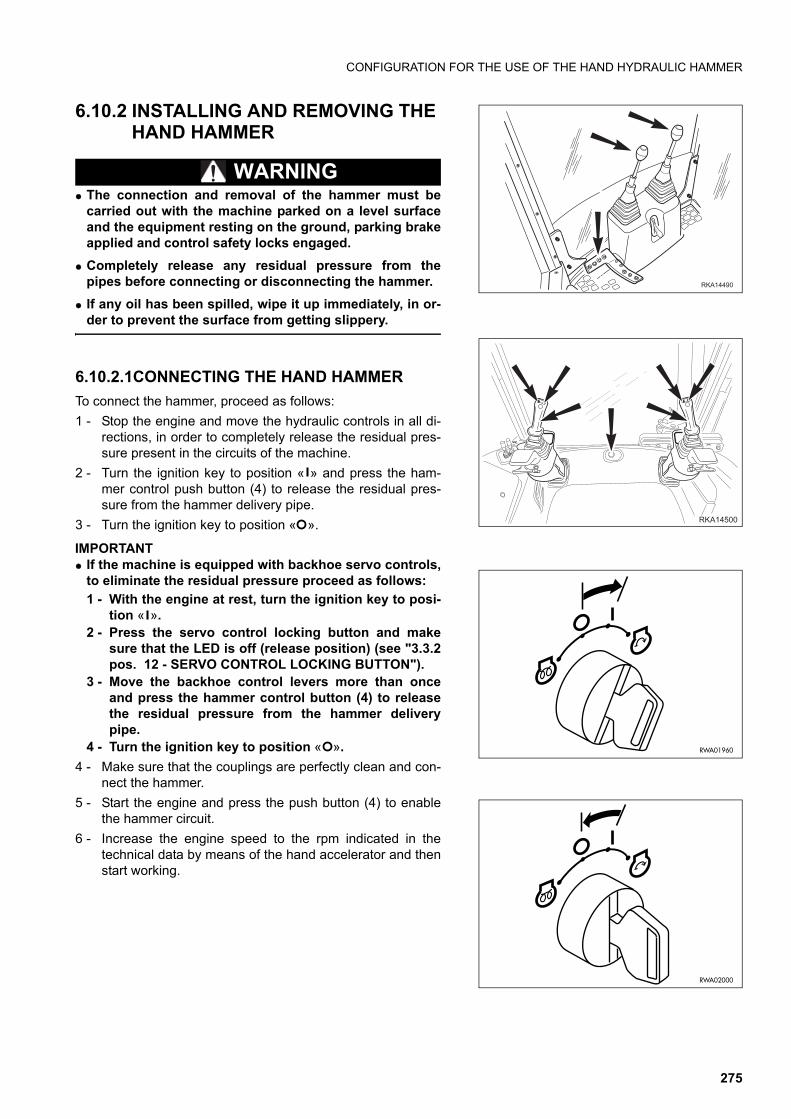
CONFIGURATION FOR THE USE OF THE HAND HYDRAULIC HAMMER
6.10.2 INSTALLING AND REMOVING THE HAND HAMMER
WARNINGq The connection and removal of the hammer must be
carried out with the machine parked on a level surfaceand the equipment resting on the ground, parking brakeapplied and control safety locks engaged.
q Completely release any residual pressure from thepipes before connecting or disconnecting the hammer.
q If any oil has been spilled, wipe it up immediately, in or-der to prevent the surface from getting slippery.
6.10.2.1CONNECTING THE HAND HAMMER
To connect the hammer, proceed as follows:
1 - Stop the engine and move the hydraulic controls in all di-rections, in order to completely release the residual pres-sure present in the circuits of the machine.
2 - Turn the ignition key to position « » and press the ham-mer control push button (4) to release the residual pres-sure from the hammer delivery pipe.
3 - Turn the ignition key to position « ».
IMPORTANTq If the machine is equipped with backhoe servo controls,
to eliminate the residual pressure proceed as follows:
1 - With the engine at rest, turn the ignition key to posi-tion « ».
2 - Press the servo control locking button and makesure that the LED is off (release position) (see "3.3.2pos. 12 - SERVO CONTROL LOCKING BUTTON").
3 - Move the backhoe control levers more than onceand press the hammer control button (4) to releasethe residual pressure from the hammer deliverypipe.
4 - Turn the ignition key to position « ».
4 - Make sure that the couplings are perfectly clean and con-nect the hammer.
5 - Start the engine and press the push button (4) to enablethe hammer circuit.
6 - Increase the engine speed to the rpm indicated in thetechnical data by means of the hand accelerator and thenstart working.
�������
����
RWA01960
RWA02000
275
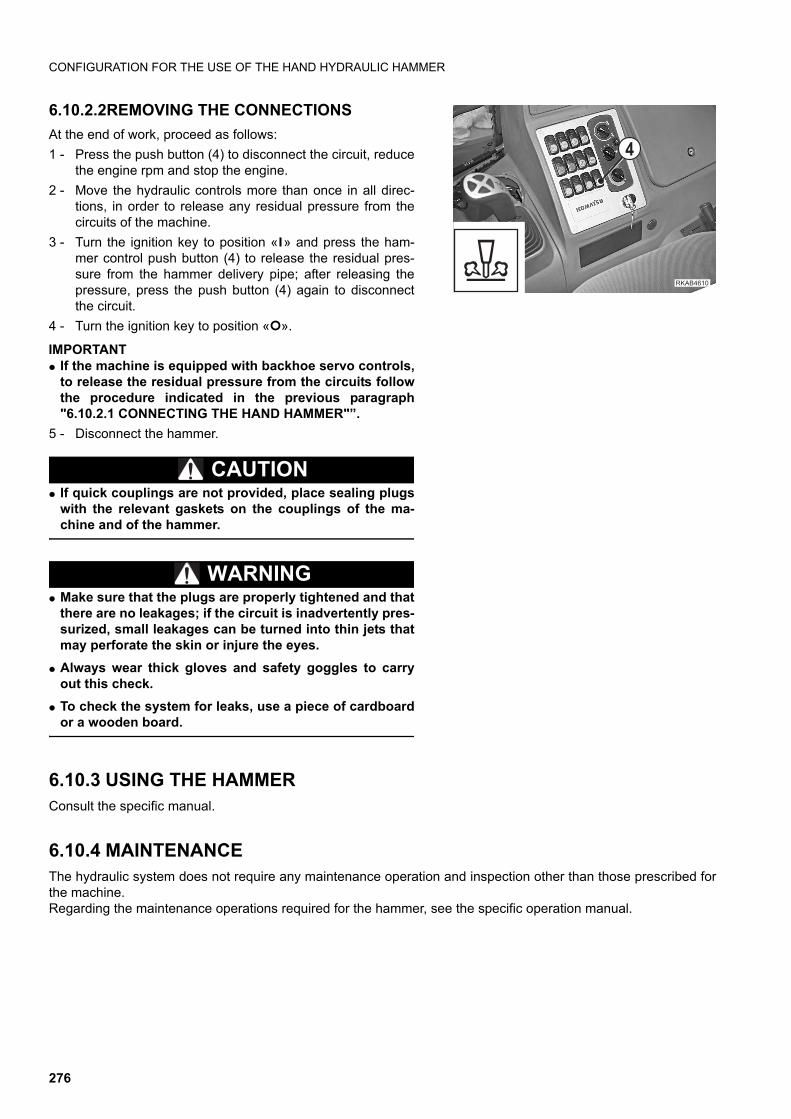
CONFIGURATION FOR THE USE OF THE HAND HYDRAULIC HAMMER
6.10.2.2REMOVING THE CONNECTIONS
At the end of work, proceed as follows:
1 - Press the push button (4) to disconnect the circuit, reducethe engine rpm and stop the engine.
2 - Move the hydraulic controls more than once in all direc-tions, in order to release any residual pressure from thecircuits of the machine.
3 - Turn the ignition key to position « » and press the ham-mer control push button (4) to release the residual pres-sure from the hammer delivery pipe; after releasing thepressure, press the push button (4) again to disconnectthe circuit.
4 - Turn the ignition key to position « ».
IMPORTANTq If the machine is equipped with backhoe servo controls,
to release the residual pressure from the circuits followthe procedure indicated in the previous paragraph"6.10.2.1 CONNECTING THE HAND HAMMER"”.
5 - Disconnect the hammer.
CAUTIONq If quick couplings are not provided, place sealing plugs
with the relevant gaskets on the couplings of the ma-chine and of the hammer.
WARNINGq Make sure that the plugs are properly tightened and that
there are no leakages; if the circuit is inadvertently pres-surized, small leakages can be turned into thin jets thatmay perforate the skin or injure the eyes.
q Always wear thick gloves and safety goggles to carryout this check.
q To check the system for leaks, use a piece of cardboardor a wooden board.
6.10.3 USING THE HAMMERConsult the specific manual.
6.10.4 MAINTENANCEThe hydraulic system does not require any maintenance operation and inspection other than those prescribed forthe machine.Regarding the maintenance operations required for the hammer, see the specific operation manual.
�������
�
276
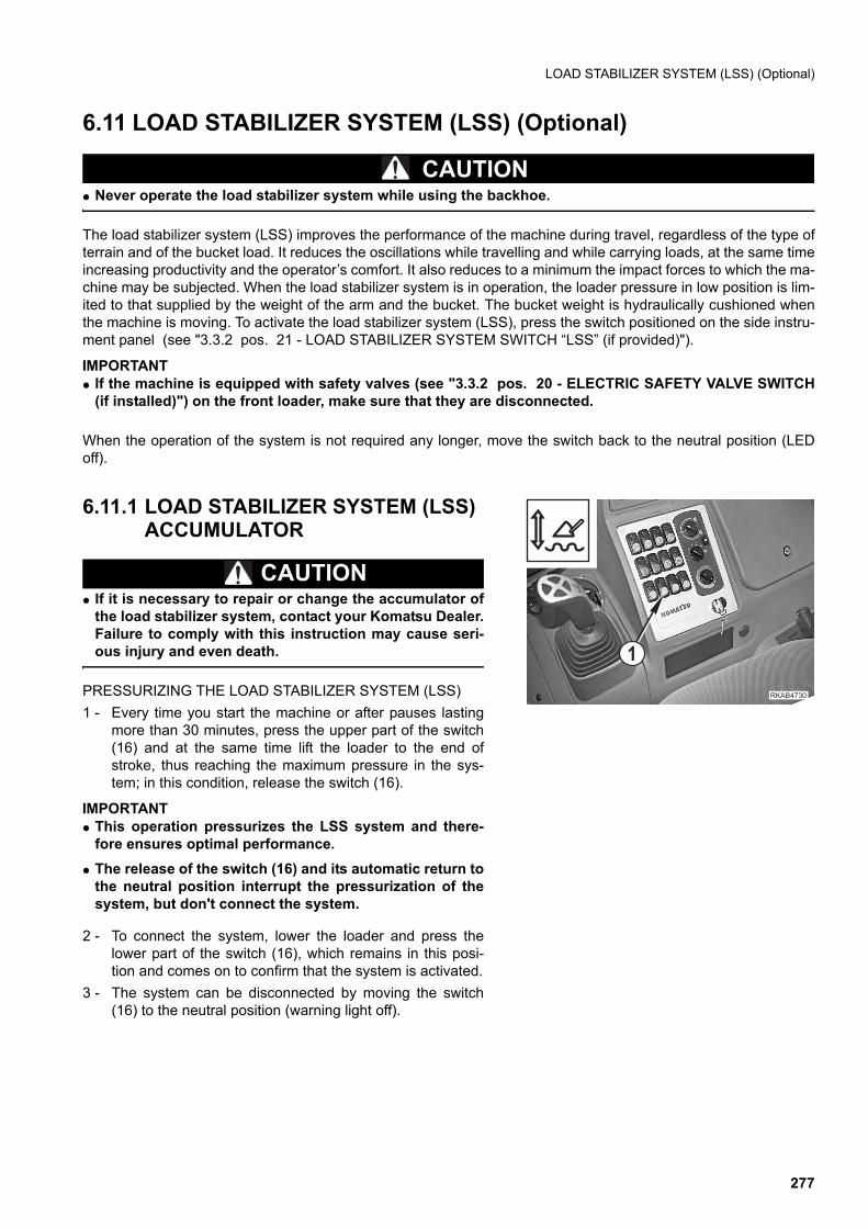
LOAD STABILIZER SYSTEM (LSS) (Optional)
6.11 LOAD STABILIZER SYSTEM (LSS) (Optional)
CAUTIONq Never operate the load stabilizer system while using the backhoe.
The load stabilizer system (LSS) improves the performance of the machine during travel, regardless of the type ofterrain and of the bucket load. It reduces the oscillations while travelling and while carrying loads, at the same timeincreasing productivity and the operator’s comfort. It also reduces to a minimum the impact forces to which the ma-chine may be subjected. When the load stabilizer system is in operation, the loader pressure in low position is lim-ited to that supplied by the weight of the arm and the bucket. The bucket weight is hydraulically cushioned whenthe machine is moving. To activate the load stabilizer system (LSS), press the switch positioned on the side instru-ment panel (see "3.3.2 pos. 21 - LOAD STABILIZER SYSTEM SWITCH “LSS” (if provided)").
IMPORTANTq If the machine is equipped with safety valves (see "3.3.2 pos. 20 - ELECTRIC SAFETY VALVE SWITCH
(if installed)") on the front loader, make sure that they are disconnected.
When the operation of the system is not required any longer, move the switch back to the neutral position (LEDoff).
6.11.1 LOAD STABILIZER SYSTEM (LSS) ACCUMULATOR
CAUTIONq If it is necessary to repair or change the accumulator of
the load stabilizer system, contact your Komatsu Dealer.Failure to comply with this instruction may cause seri-ous injury and even death.
PRESSURIZING THE LOAD STABILIZER SYSTEM (LSS)
1 - Every time you start the machine or after pauses lastingmore than 30 minutes, press the upper part of the switch(16) and at the same time lift the loader to the end ofstroke, thus reaching the maximum pressure in the sys-tem; in this condition, release the switch (16).
IMPORTANTq This operation pressurizes the LSS system and there-
fore ensures optimal performance.
q The release of the switch (16) and its automatic return tothe neutral position interrupt the pressurization of thesystem, but don't connect the system.
2 - To connect the system, lower the loader and press thelower part of the switch (16), which remains in this posi-tion and comes on to confirm that the system is activated.
3 - The system can be disconnected by moving the switch(16) to the neutral position (warning light off).
��������
�
277
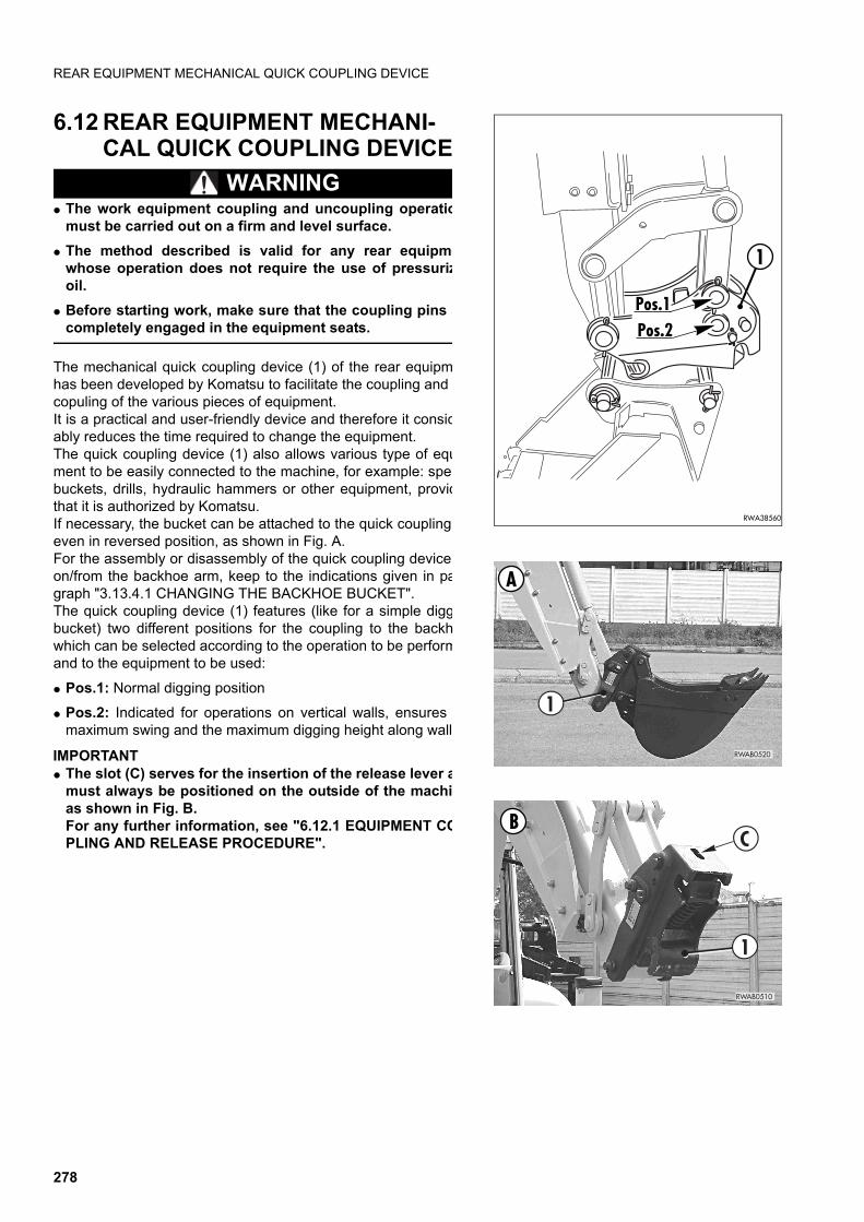
REAR EQUIPMENT MECHANICAL QUICK COUPLING DEVICE
6.12 REAR EQUIPMENT MECHANI-CAL QUICK COUPLING DEVICE
WARNINGq The work equipment coupling and uncoupling operatio
must be carried out on a firm and level surface.
q The method described is valid for any rear equipmewhose operation does not require the use of pressurizoil.
q Before starting work, make sure that the coupling pins acompletely engaged in the equipment seats.
The mechanical quick coupling device (1) of the rear equipmhas been developed by Komatsu to facilitate the coupling and copuling of the various pieces of equipment.It is a practical and user-friendly device and therefore it considably reduces the time required to change the equipment.The quick coupling device (1) also allows various type of equment to be easily connected to the machine, for example: specbuckets, drills, hydraulic hammers or other equipment, providthat it is authorized by Komatsu.If necessary, the bucket can be attached to the quick coupling even in reversed position, as shown in Fig. A.For the assembly or disassembly of the quick coupling device on/from the backhoe arm, keep to the indications given in pagraph "3.13.4.1 CHANGING THE BACKHOE BUCKET".The quick coupling device (1) features (like for a simple diggbucket) two different positions for the coupling to the backhwhich can be selected according to the operation to be performand to the equipment to be used:
q Pos.1: Normal digging position
q Pos.2: Indicated for operations on vertical walls, ensures maximum swing and the maximum digging height along walls
IMPORTANTq The slot (C) serves for the insertion of the release lever a
must always be positioned on the outside of the machias shown in Fig. B.For any further information, see "6.12.1 EQUIPMENT COPLING AND RELEASE PROCEDURE".
RWA38560
1
Pos.2Pos.1
RWAB0520
A
1
RWAB0510
BC
1
278
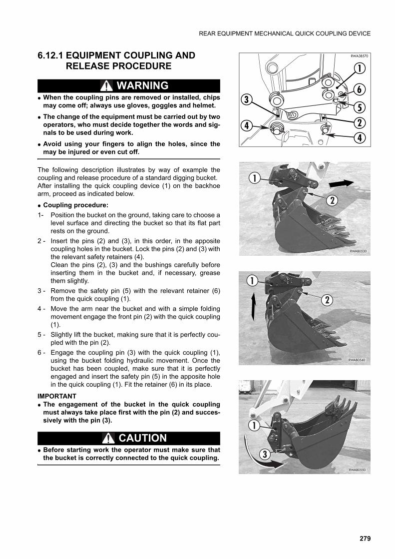
REAR EQUIPMENT MECHANICAL QUICK COUPLING DEVICE
6.12.1 EQUIPMENT COUPLING AND RELEASE PROCEDURE
WARNINGq When the coupling pins are removed or installed, chips
may come off; always use gloves, goggles and helmet.
q The change of the equipment must be carried out by twooperators, who must decide together the words and sig-nals to be used during work.
q Avoid using your fingers to align the holes, since themay be injured or even cut off.
The following description illustrates by way of example thecoupling and release procedure of a standard digging bucket.After installing the quick coupling device (1) on the backhoearm, proceed as indicated below.
q Coupling procedure:
1- Position the bucket on the ground, taking care to choose alevel surface and directing the bucket so that its flat partrests on the ground.
2 - Insert the pins (2) and (3), in this order, in the appositecoupling holes in the bucket. Lock the pins (2) and (3) withthe relevant safety retainers (4).Clean the pins (2), (3) and the bushings carefully beforeinserting them in the bucket and, if necessary, greasethem slightly.
3 - Remove the safety pin (5) with the relevant retainer (6)from the quick coupling (1).
4 - Move the arm near the bucket and with a simple foldingmovement engage the front pin (2) with the quick coupling(1).
5 - Slightly lift the bucket, making sure that it is perfectly cou-pled with the pin (2).
6 - Engage the coupling pin (3) with the quick coupling (1),using the bucket folding hydraulic movement. Once thebucket has been coupled, make sure that it is perfectlyengaged and insert the safety pin (5) in the apposite holein the quick coupling (1). Fit the retainer (6) in its place.
IMPORTANTq The engagement of the bucket in the quick coupling
must always take place first with the pin (2) and succes-sively with the pin (3).
CAUTIONq Before starting work the operator must make sure that
the bucket is correctly connected to the quick coupling.
RWA38570
2
3
1
44
5
6
RWAB0530
2
1
RWAB0540
2
1
RWAB0550
3
1
279
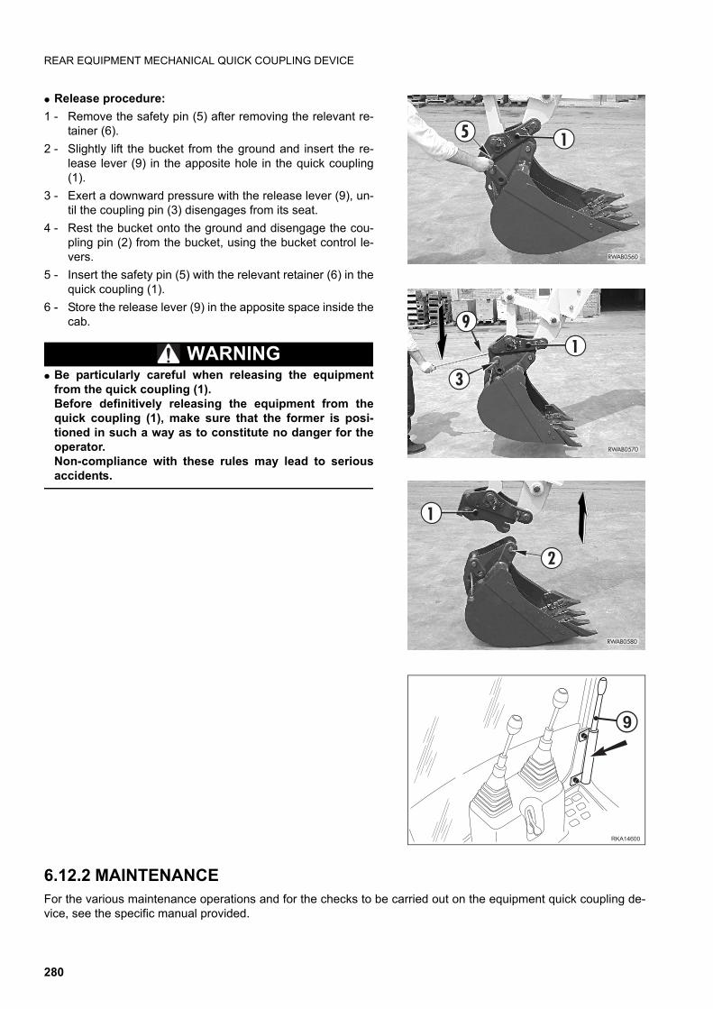
REAR EQUIPMENT MECHANICAL QUICK COUPLING DEVICE
q Release procedure:
1 - Remove the safety pin (5) after removing the relevant re-tainer (6).
2 - Slightly lift the bucket from the ground and insert the re-lease lever (9) in the apposite hole in the quick coupling(1).
3 - Exert a downward pressure with the release lever (9), un-til the coupling pin (3) disengages from its seat.
4 - Rest the bucket onto the ground and disengage the cou-pling pin (2) from the bucket, using the bucket control le-vers.
5 - Insert the safety pin (5) with the relevant retainer (6) in thequick coupling (1).
6 - Store the release lever (9) in the apposite space inside thecab.
WARNINGq Be particularly careful when releasing the equipment
from the quick coupling (1). Before definitively releasing the equipment from thequick coupling (1), make sure that the former is posi-tioned in such a way as to constitute no danger for theoperator.Non-compliance with these rules may lead to seriousaccidents.
6.12.2 MAINTENANCEFor the various maintenance operations and for the checks to be carried out on the equipment quick coupling de-vice, see the specific manual provided.
RWAB0560
5 1
RWAB0570
91
3
RWAB0580
1
2
�������
!
280


�������������� � �������������������������������������������� �!��