operation / installation manual - rinnai
TRANSCRIPT
To Suit Models:
Infinity XR 32
Infinity XR26 Plus
Infinity XR26
Infinity XR24
Infinity XR20 Plus
Infinity XR20
Infinity XR18
Infinity XR16
Infinity XR26i
Infinity HD250
Infinity HD250i
Infinity HD200
Infinity HD200i
Efficiency24
Operation / Installation
Manual
How to use and install Rinnai continuous flow water heaters
This appliance shall be installed in accordance with:
• Manufacturer’s Installation Instructions
• Current AS/NZS 3000, AS/NZS 3500 & NZS 5261
• Local Regulations and Municipal Building Codes
This appliance must be installed, serviced and removed by an Authorised Person.
Rinnai New Zealand i Operation Manual
REGULATORY INFORMATION..................................................................................1
WARNING ABOUT HOT WATER ...............................................................................1
FEATURES AND BENEFITS ......................................................................................2
IMPORTANT INFORMATION .....................................................................................3
OPERATION WITHOUT CONTROLLERS..................................................................5
GENERAL WATER CONTROL INFORMATION ........................................................6
UNIVERSAL WATER CONTROLLERS......................................................................7
ABOUT THE UNIVERSAL WATER CONTROLLER (MC-91-2A) ................................................................ 7
TURNING ON THE CONTROLLER............................................................................................................. 7
ADJUSTING TEMPERATURE..................................................................................................................... 7
HOW TO USE TWO OR MORE UNIVERSAL WATER CONTROLLERS ................................................... 8
TRANSFERING PRIORITY.......................................................................................................................... 8
ADJUSTING TEMPERATURE..................................................................................................................... 8
DELUXE KITCHEN WATER CONTROLLERS ...........................................................9
ABOUT THE DELUXE KITCHEN WATER CONTROLLER (MC-70-2A/MC-100V) ..................................... 9
HOW TO USE A SINGLE DELUXE WATER CONTROLLER...................................................................... 9
TURNING ON THE CONTROLLER............................................................................................................. 9
SETTING THE CLOCK ................................................................................................................................ 9
SETTING THE SOUND VOLUME ............................................................................................................. 10
ADJUSTING TEMPERATURE................................................................................................................... 10
DELUXE BATHROOM WATER CONTROLLERS....................................................11
ABOUT THE DELUXE BATHROOM WATER CONTROLLER (BC-70-2A/BC-100V) ............................... 11
HOW TO USE TWO OR MORE DELUXE WATER CONTROLLERS ....................................................... 12
TURNING ON THE CONTROLLERS ........................................................................................................ 12
SETTING THE CLOCK (SEE PAGE 9 TO 10 FOR DETAILS ON HOW TO SET THE CLOCK) .............. 12
SETTING THE SOUND VOLUME ............................................................................................................. 12
ADJUSTING TEMPERATURE................................................................................................................... 12
OPERATING THE SHOWER SAVER / BATH FILL FUNCTION ............................................................... 13
COMBINING UNIVERSAL AND DELUXE CONTROLLERS ..................................................................... 14
TROUBLESHOOTING...............................................................................................15
WARRANTY STATEMENT - HOT WATER PRODUCTS .........................................16
WARRANTY CONDITIONS.......................................................................................17
INSTALLATION MANUAL ........................................................................................18
ACCESSORIES ........................................................................................................32
CONTACT INFORMATION ......................................................................................33
OPERATION MANUAL
Rinnai New Zealand 1 Operation Manual
Your Rinnai Continuous Flow water heater complies with NZS5262. A declaration to this effect can befound on the Energy Safety Service website; www.ess.govt.nz.
This Appliance must be installed correctly by an authorised person. The installation of gas, water, andelectricity must conform to local regulations.
The installation must also comply with the instructions supplied by Rinnai.
All dimensions referred to in these instructions are in millimetres, unless otherwise specified.
Please keep this instruction booklet in a safe place for future reference.
Excessively hot water is dangerous, especially for youngchildren and the infirm. Rinnai Continuous Flow waterheaters allow you to control the temperature of hot water tosafe levels.
Water temperatures above 55°C can cause severe burnsinstantly and may even result in death. Those most at risk arechildren, disabled, elderly and the infirm. Hot water at 65°C (avery common hot water temperature in New Zealand ) canseverely burn a child in less than half a second. At 55°C ittakes half a minute.
ALWAYS......
Test the temperature of the water with your elbow beforeplacing your child in the bath, also carefully feel water beforebathing or showering yourself.
Supervise children whenever they are in the bathroom.
Make sure that the hot water tap is turned off tightly.
CONSIDER.....
Installing child proof tap covers or child resistant taps (bothapproaches will prevent a small hand being able to turn onthe tap).
Setting your appliance at a maximum temperature of 55°C(Contact Rinnai New Zealand).
NEVER…..
Leave a toddler in the care of another child. They may notunderstand the need to have the water temperature set at asafe level.
REGULATORY INFORMATION
WARNING ABOUT HOT WATER
Rinnai New Zealand 2 Operation Manual
FEATURES AND BENEFITS
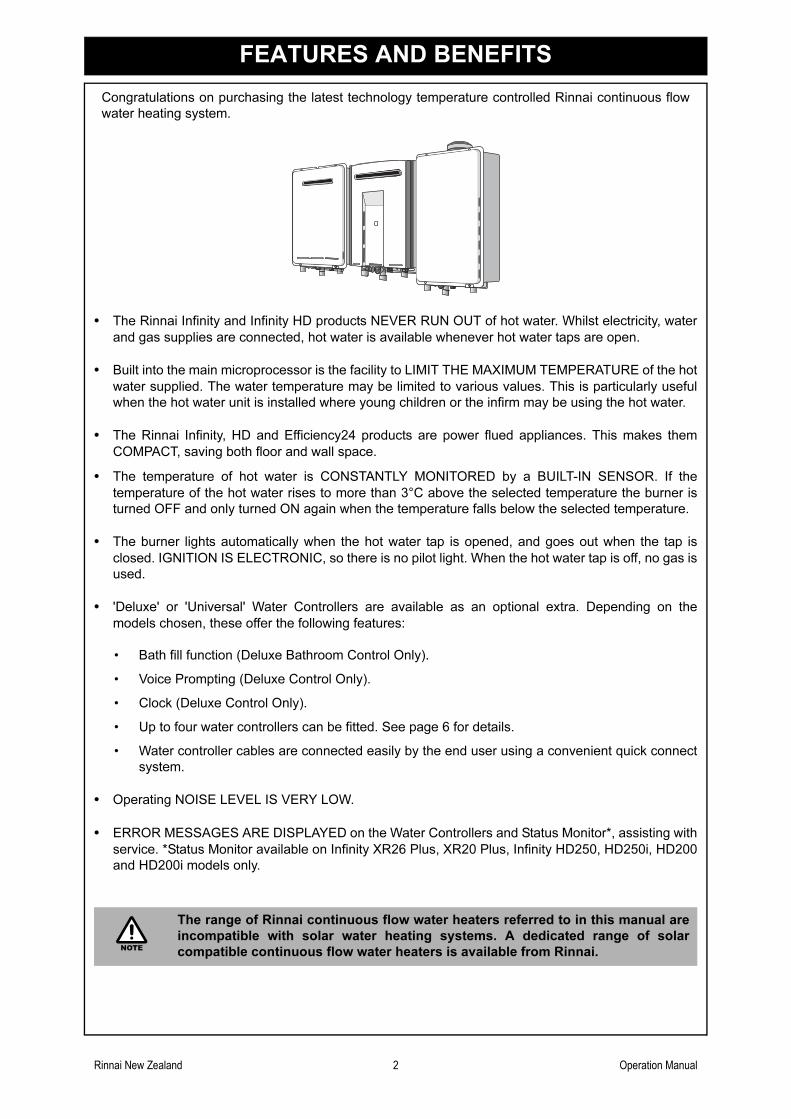
Congratulations on purchasing the latest technology temperature controlled Rinnai continuous flow
water heating system.
• The Rinnai Infinity and Infinity HD products NEVER RUN OUT of hot water. Whilst electricity, water
and gas supplies are connected, hot water is available whenever hot water taps are open.
• Built into the main microprocessor is the facility to LIMIT THE MAXIMUM TEMPERATURE of the hot
water supplied. The water temperature may be limited to various values. This is particularly useful
when the hot water unit is installed where young children or the infirm may be using the hot water.
• The Rinnai Infinity, HD and Efficiency24 products are power flued appliances. This makes them
COMPACT, saving both floor and wall space.
• The temperature of hot water is CONSTANTLY MONITORED by a BUILT-IN SENSOR. If the
temperature of the hot water rises to more than 3°C above the selected temperature the burner is
turned OFF and only turned ON again when the temperature falls below the selected temperature.
• The burner lights automatically when the hot water tap is opened, and goes out when the tap is
closed. IGNITION IS ELECTRONIC, so there is no pilot light. When the hot water tap is off, no gas is
used.
• 'Deluxe' or 'Universal' Water Controllers are available as an optional extra. Depending on the
models chosen, these offer the following features:
• Bath fill function (Deluxe Bathroom Control Only).
• Voice Prompting (Deluxe Control Only).
• Clock (Deluxe Control Only).
• Up to four water controllers can be fitted. See page 6 for details.
• Water controller cables are connected easily by the end user using a convenient quick connect
system.
• Operating NOISE LEVEL IS VERY LOW.
• ERROR MESSAGES ARE DISPLAYED on the Water Controllers and Status Monitor*, assisting with
service. *Status Monitor available on Infinity XR26 Plus, XR20 Plus, Infinity HD250, HD250i, HD200
and HD200i models only.
The range of Rinnai continuous flow water heaters referred to in this manual are
incompatible with solar water heating systems. A dedicated range of solar
compatible continuous flow water heaters is available from Rinnai.NOTE
Rinnai New Zealand 3 Operation Manual
IMPORTANT INFORMATION
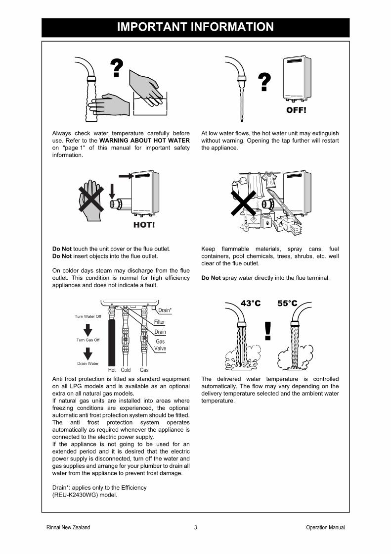
Always check water temperature carefully before
use. Refer to the WARNING ABOUT HOT WATER
on "page 1" of this manual for important safety
information.
At low water flows, the hot water unit may extinguish
without warning. Opening the tap further will restart
the appliance.
Do Not touch the unit cover or the flue outlet.
Do Not insert objects into the flue outlet.
On colder days steam may discharge from the flue
outlet. This condition is normal for high efficiency
appliances and does not indicate a fault.
Keep flammable materials, spray cans, fuel
containers, pool chemicals, trees, shrubs, etc. well
clear of the flue outlet.
Do Not spray water directly into the flue terminal.
Anti frost protection is fitted as standard equipment
on all LPG models and is available as an optional
extra on all natural gas models.
If natural gas units are installed into areas where
freezing conditions are experienced, the optional
automatic anti frost protection system should be fitted.
The anti frost protection system operates
automatically as required whenever the appliance is
connected to the electric power supply.
If the appliance is not going to be used for an
extended period and it is desired that the electric
power supply is disconnected, turn off the water and
gas supplies and arrange for your plumber to drain all
water from the appliance to prevent frost damage.
Drain*: applies only to the Efficiency
(REU-K2430WG) model.
The delivered water temperature is controlled
automatically. The flow may vary depending on the
delivery temperature selected and the ambient water
temperature.
OFF!
HOT!
Filter
Drain
Drain*
Gas
Valve
GasColdHot
Turn Water Off
Turn Gas Off
Drain Water
43°C 55°C
Rinnai New Zealand 4 Operation Manual
IMPORTANT INFORMATION
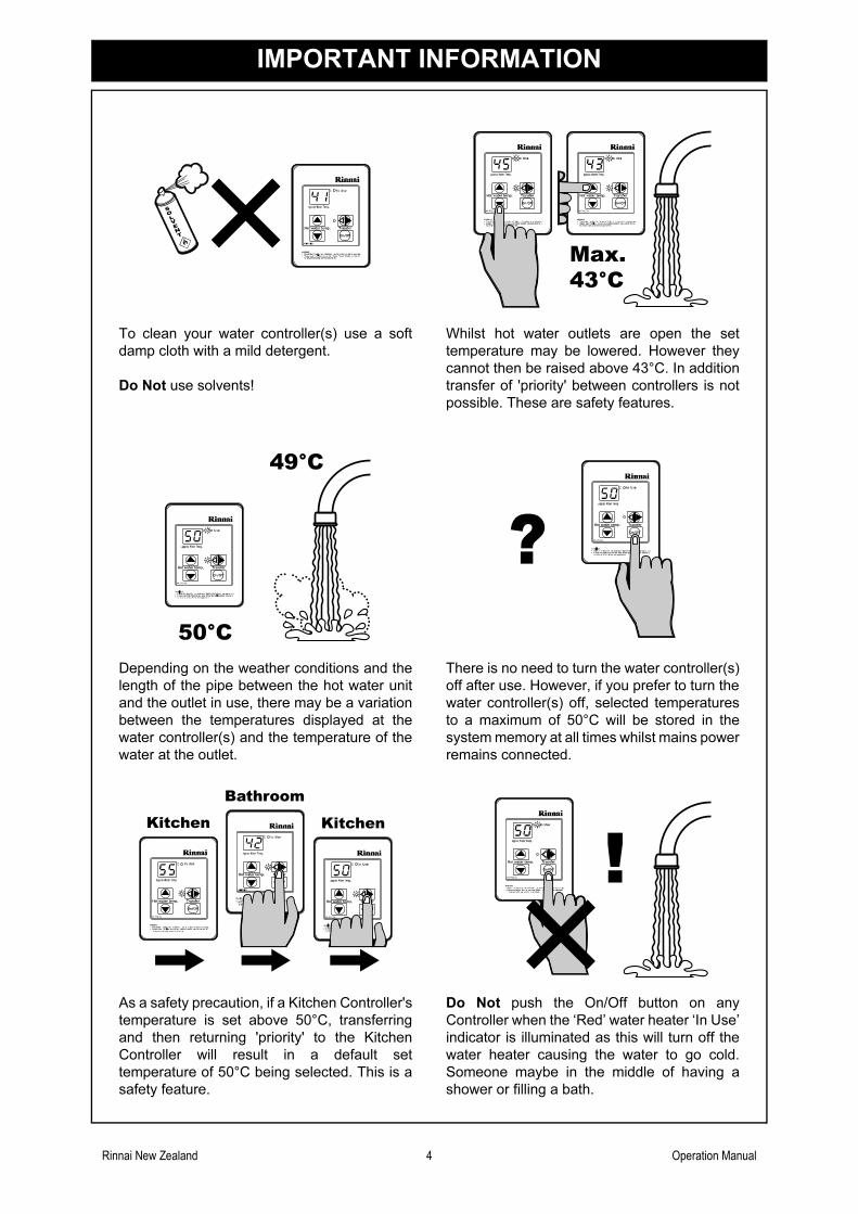
To clean your water controller(s) use a soft
damp cloth with a mild detergent.
Do Not use solvents!
Whilst hot water outlets are open the set
temperature may be lowered. However they
cannot then be raised above 43°C. In addition
transfer of 'priority' between controllers is not
possible. These are safety features.
Depending on the weather conditions and the
length of the pipe between the hot water unit
and the outlet in use, there may be a variation
between the temperatures displayed at the
water controller(s) and the temperature of the
water at the outlet.
There is no need to turn the water controller(s)
off after use. However, if you prefer to turn the
water controller(s) off, selected temperatures
to a maximum of 50°C will be stored in the
system memory at all times whilst mains power
remains connected.
As a safety precaution, if a Kitchen Controller's
temperature is set above 50°C, transferring
and then returning 'priority' to the Kitchen
Controller will result in a default set
temperature of 50°C being selected. This is a
safety feature.
Do Not push the On/Off button on any
Controller when the ‘Red’ water heater ‘In Use’
indicator is illuminated as this will turn off the
water heater causing the water to go cold.
Someone maybe in the middle of having a
shower or filling a bath.
SOLVENT
Max.43°C
49°C
50°C
Kitchen Kitchen
Bathroom
Rinnai New Zealand 5 Operation Manual
OPERATION WITHOUT CONTROLLERS
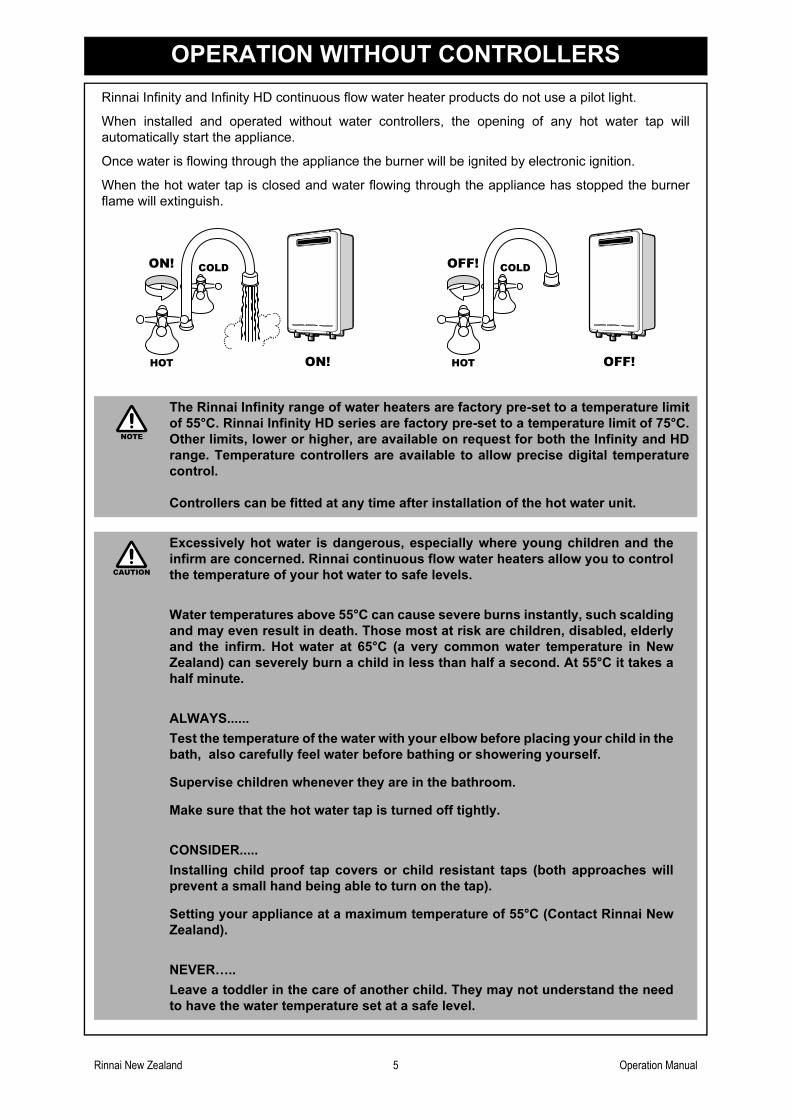
Rinnai Infinity and Infinity HD continuous flow water heater products do not use a pilot light.
When installed and operated without water controllers, the opening of any hot water tap will
automatically start the appliance.
Once water is flowing through the appliance the burner will be ignited by electronic ignition.
When the hot water tap is closed and water flowing through the appliance has stopped the burner
flame will extinguish.
The Rinnai Infinity range of water heaters are factory pre-set to a temperature limit
of 55°C. Rinnai Infinity HD series are factory pre-set to a temperature limit of 75°C.
Other limits, lower or higher, are available on request for both the Infinity and HD
range. Temperature controllers are available to allow precise digital temperature
control.
Controllers can be fitted at any time after installation of the hot water unit.
Excessively hot water is dangerous, especially where young children and the
infirm are concerned. Rinnai continuous flow water heaters allow you to control
the temperature of your hot water to safe levels.
Water temperatures above 55°C can cause severe burns instantly, such scalding
and may even result in death. Those most at risk are children, disabled, elderly
and the infirm. Hot water at 65°C (a very common water temperature in New
Zealand) can severely burn a child in less than half a second. At 55°C it takes a
half minute.
ALWAYS......
Test the temperature of the water with your elbow before placing your child in the
bath, also carefully feel water before bathing or showering yourself.
Supervise children whenever they are in the bathroom.
Make sure that the hot water tap is turned off tightly.
CONSIDER.....
Installing child proof tap covers or child resistant taps (both approaches will
prevent a small hand being able to turn on the tap).
Setting your appliance at a maximum temperature of 55°C (Contact Rinnai New
Zealand).
NEVER…..
Leave a toddler in the care of another child. They may not understand the need
to have the water temperature set at a safe level.
HOTHOT
COLDCOLDON!ON!
ON!ON! HOTHOT
COLDCOLDOFF!OFF!
OFF!OFF!
NOTE
CAUTION
Rinnai New Zealand 6 Operation Manual
GENERAL WATER CONTROL INFORMATION
Remote water controllers allow precise temperature control by the user. When used correctly, the hot
water unit will deliver the selected temperature, even when the water flow is varied, or more than one
tap is in use. Each water controller can be individually programmed, however the water heater can
only deliver one set temperature at any time. The available temperatures (°C) are as follows:
Kitchen Controller:
37, 38, 39, 40, 41, 42, 43, 44, 45, 46, 48, 50, 55°C* ( 60, 65, 75°C Infinity HD models only )
Bathroom Controller:
Hot Water Delivery: 37, 38, 39, 40, 41, 42, 43, 44, 45, 46, 48, 50°C
Bath fill Delivery: 37, 38, 39, 40, 41, 42, 43, 44, 45, 46, 47, 48°C
Whilst hot water outlets are open the set temperature may be lowered. However the set temperature
cannot then be raised above 43°C. In addition, transfer of 'priority' between water controllers is not
possible. These are safety features.
Suggested temperatures are:
Kitchen 50°C ~ 55°C* Shower 37°C ~ 43°C, Bath fill 39°C ~ 45°C
* Temperature may not be available on all installations. Rinnai water heaters can be programmed to deliver higher temperatures
via the kitchen water controller. Contact Rinnai for more details.
These temperatures are suggestions only. You may find higher or lower temperatures more
comfortable. Maintaining lower temperatures helps save energy. To obtain water temperatures lower
than 37°C simply add cold water.
Water controllers are an optional extra. 'Universal', 'Deluxe', and ‘Wireless’ water controllers can be
fitted. Universal water controllers allow temperature selection only. Deluxe water controllers allow
temperature selection, shower saver / bath fill, voice prompting and have a clock function.
Water controllers allow the water temperature to be set from the various locations where they are
installed. The temperature selected will be available to all outlets.
Universal (MC-91-2A), Deluxe (MC/BC-70-2A and MC/BC-100V) and Wireless Water Controllers
- available configurations:
Wired and
Wireless
Installations
A maximum of 4 water controllers can be fitted. Any combination of deluxe, universal
and wireless controllers can be used with the following limitations:
Only ONE master controller can be installed. This can be a MC-70V/MC-100V, a
MC-91 (when programmed as a master controller) or a MC502S (wireless) water
controller.
Up to TWO BC-70V/BC-100V water controllers can be installed.
The FOURTH water controller in any installation MUST BE a MC502S (wireless)
or a MC-91.
Rinnai New Zealand 7 Operation Manual
UNIVERSAL WATER CONTROLLERS
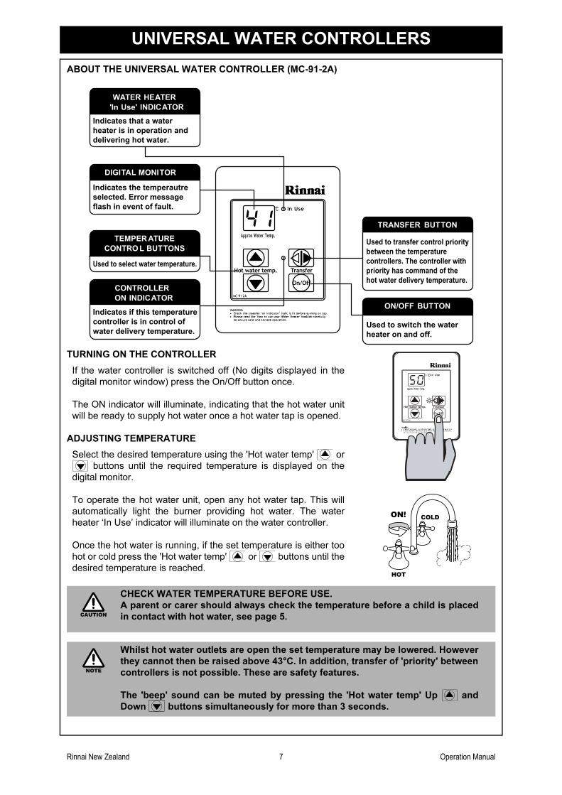
ABOUT THE UNIVERSAL WATER CONTROLLER (MC-91-2A)
TURNING ON THE CONTROLLER
If the water controller is switched off (No digits displayed in the
digital monitor window) press the On/Off button once.
The ON indicator will illuminate, indicating that the hot water unit
will be ready to supply hot water once a hot water tap is opened.
ADJUSTING TEMPERATURE
Select the desired temperature using the 'Hot water temp' or
buttons until the required temperature is displayed on the
digital monitor.
To operate the hot water unit, open any hot water tap. This will
automatically light the burner providing hot water. The water
heater ‘In Use’ indicator will illuminate on the water controller.
Once the hot water is running, if the set temperature is either too
hot or cold press the 'Hot water temp' or buttons until the
desired temperature is reached.
CHECK WATER TEMPERATURE BEFORE USE.
A parent or carer should always check the temperature before a child is placed
in contact with hot water, see page 5.
Whilst hot water outlets are open the set temperature may be lowered. However
they cannot then be raised above 43°C. In addition, transfer of 'priority' between
controllers is not possible. These are safety features.
The 'beep' sound can be muted by pressing the 'Hot water temp' Up and
Down buttons simultaneously for more than 3 seconds.
WATER HEATER
'In Use' INDICATOR
DIGITAL MONITOR
TEMPERATURE
CONTROL BUTTONS
CONTROLLER
ON INDICATOR
TRANSFER BUTTON
ON/OFF BUTTON
Indicates that a water
heater is in operation and
delivering hot water.
Indicates the temperautre
selected. Error message
flash in event of fault.
Used to select water temperature.
Indicates if this temperature
controller is in control of
water delivery temperature.
Used to transfer control priority
between the temperature
controllers. The controller with
priority has command of the
hot water delivery temperature.
Used to switch the water
heater on and off.
HOTHOT
COLDCOLDON!ON!
CAUTION
NOTE
Rinnai New Zealand 8 Operation Manual
UNIVERSAL WATER CONTROLLERS
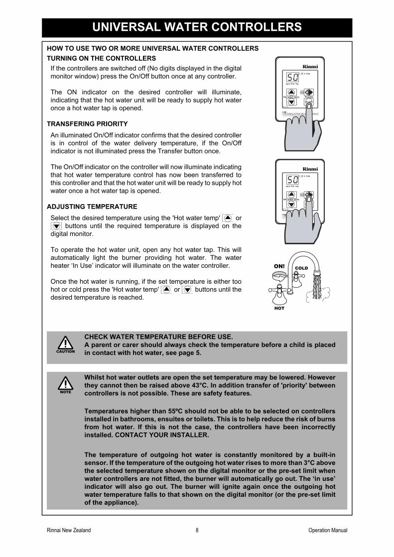
HOW TO USE TWO OR MORE UNIVERSAL WATER CONTROLLERS
TURNING ON THE CONTROLLERS
If the controllers are switched off (No digits displayed in the digital
monitor window) press the On/Off button once at any controller.
The ON indicator on the desired controller will illuminate,
indicating that the hot water unit will be ready to supply hot water
once a hot water tap is opened.
TRANSFERING PRIORITY
An illuminated On/Off indicator confirms that the desired controller
is in control of the water delivery temperature, if the On/Off
indicator is not illuminated press the Transfer button once.
The On/Off indicator on the controller will now illuminate indicating
that hot water temperature control has now been transferred to
this controller and that the hot water unit will be ready to supply hot
water once a hot water tap is opened.
ADJUSTING TEMPERATURE
Select the desired temperature using the 'Hot water temp' or
buttons until the required temperature is displayed on the
digital monitor.
To operate the hot water unit, open any hot water tap. This will
automatically light the burner providing hot water. The water
heater ‘In Use’ indicator will illuminate on the water controller.
Once the hot water is running, if the set temperature is either too
hot or cold press the 'Hot water temp' or buttons until the
desired temperature is reached.
CHECK WATER TEMPERATURE BEFORE USE.
A parent or carer should always check the temperature before a child is placed
in contact with hot water, see page 5.
Whilst hot water outlets are open the set temperature may be lowered. However
they cannot then be raised above 43°C. In addition transfer of 'priority' between
controllers is not possible. These are safety features.
Temperatures higher than 55ºC should not be able to be selected on controllers
installed in bathrooms, ensuites or toilets. This is to help reduce the risk of burns
from hot water. If this is not the case, the controllers have been incorrectly
installed. CONTACT YOUR INSTALLER.
The temperature of outgoing hot water is constantly monitored by a built-in
sensor. If the temperature of the outgoing hot water rises to more than 3°C above
the selected temperature shown on the digital monitor or the pre-set limit when
water controllers are not fitted, the burner will automatically go out. The ‘in use’
indicator will also go out. The burner will ignite again once the outgoing hot
water temperature falls to that shown on the digital monitor (or the pre-set limit
of the appliance).
HOTHOT
COLDCOLDON!ON!
CAUTION
NOTE
Rinnai New Zealand 9 Operation Manual
DELUXE KITCHEN WATER CONTROLLERS
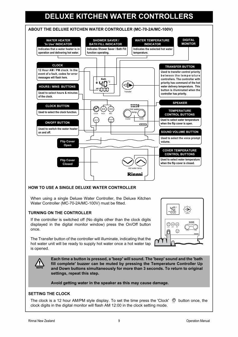
ABOUT THE DELUXE KITCHEN WATER CONTROLLER (MC-70-2A/MC-100V)
HOW TO USE A SINGLE DELUXE WATER CONTROLLER
SETTING THE CLOCK
The clock is a 12 hour AM/PM style display. To set the time press the 'Clock' button once, the
clock digits in the digital monitor will flash AM 12:00 in the clock setting mode.
When using a single Deluxe Water Controller, the Deluxe Kitchen
Water Controller (MC-70-2A/MC-100V) must be fitted.
TURNING ON THE CONTROLLER
If the controller is switched off (No digits other than the clock digits
displayed in the digital monitor window) press the On/Off button
once.
The Transfer button of the controller will illuminate, indicating that the
hot water unit will be ready to supply hot water once a hot water tap
is opened.
Each time a button is pressed, a 'beep' will sound. The 'beep' sound and the 'bath
fill complete' buzzer can be muted by pressing the Temperature Controller Up
and Down buttons simultaneously for more than 3 seconds. To return to original
settings, repeat this step.
Avoid getting water in the speaker as this may cause damage.
Clock Hour Min.
Vol.
Hot water
temp.
00 00
ON/OFF
MC-70 -1A
Transfer
Sound Cooler Hotter
Bath
Hot water temp.
Used to switch the water heater
on and off.
Used to transfer control priority
b e t w e e n t h e t e m p e r a t u r e
controllers. The controller with
priority has command of the hot
water delivery temperature. This
button is illuminated when the
controller has priority.
TRANSFER BUTTON
ON/OFF BUTTON
Used to select hours & minutes
of the clock.
HOURS / MINS BUTTONS
Used to select the clock function.
CLOCK BUTTON
DIGITAL
MONITOR
Indicates that a water heater is in
operation and delivering hot water.
WATER HEATER
'In Use' INDICATOR
12 Hour AM / PM clock. In the
event of a fault, codes for error
messages will flash here.
CLOCK
Indicates Shower Saver / Bath Fill
function operating.
SHOWER SAVER /
BATH FILL INDICATOR
SPEAKER
Used to select water temperature
when the flip cover is open.
TEMPERATURE
CONTROL BUTTONS
Used to select water temperature
when the flip cover is closed.
COVER TEMPERATURE
CONTROL BUTTONS
Used to select the voice prompt
volume.
SOUND VOLUME BUTTON
Indicates the selected hot water
temperature.
WATER TEMPERATURE
INDICATOR
Flip Cover
Open
Flip Cover
Closed
Clock Hour Min.
Vol.
Hot water temp.
00 00
ON/OFF
MC -70 -1A
Transfer
Sound Cooler Hotter
BATH
NOTE
Clock
Rinnai New Zealand 10 Operation Manual
DELUXE KITCHEN WATER CONTROLLERS
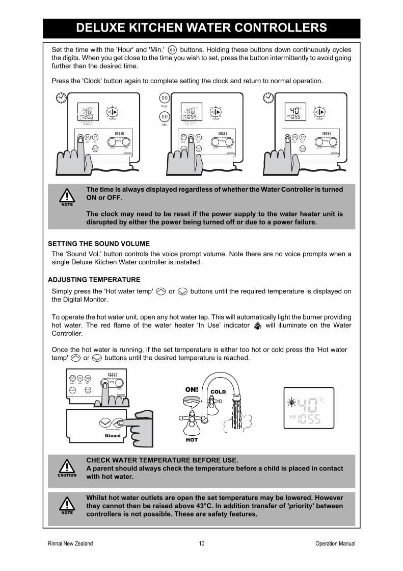
Set the time with the 'Hour' and 'Min.' buttons. Holding these buttons down continuously cycles
the digits. When you get close to the time you wish to set, press the button intermittently to avoid going
further than the desired time.
SETTING THE SOUND VOLUME
Press the 'Clock' button again to complete setting the clock and return to normal operation.
The time is always displayed regardless of whether the Water Controller is turned
ON or OFF.
The clock may need to be reset if the power supply to the water heater unit is
disrupted by either the power being turned off or due to a power failure.
The 'Sound Vol.' button controls the voice prompt volume. Note there are no voice prompts when a
single Deluxe Kitchen Water controller is installed.
ADJUSTING TEMPERATURE
Simply press the 'Hot water temp' or buttons until the required temperature is displayed on
the Digital Monitor.
To operate the hot water unit, open any hot water tap. This will automatically light the burner providing
hot water. The red flame of the water heater ‘In Use’ indicator will illuminate on the Water
Controller.
Once the hot water is running, if the set temperature is either too hot or cold press the 'Hot water
temp' or buttons until the desired temperature is reached.
CHECK WATER TEMPERATURE BEFORE USE.
A parent should always check the temperature before a child is placed in contact
with hot water.
Whilst hot water outlets are open the set temperature may be lowered. However
they cannot then be raised above 43°C. In addition transfer of 'priority' between
controllers is not possible. These are safety features.
00
Clock Hour Min.
Vol.
Hot water temp.
00 00
ON/OFF
MC -70 -1A
Transfer
Sound Cooler Hotter
BATH
Clock Hour Min.
Vol.
Hot water temp.
00 00
ON/OFF
MC -70 -1A
Transfer
Sound Cooler Hotter
BATHHour
Min.
00
00
Clock Hour Min.
Vol.
Hot water temp.
00 00
ON/OFF
MC -70 -1A
Transfer
Sound Cooler Hotter
NOTE
Clock Hour Min.
Vol.
Hot water temp.
00 00
ON/OFF
MC -70 -1A
Sound Cooler Hotter
Hot water temp.
HOTHOT
COLDCOLDON!ON!
CAUTION
NOTE
Rinnai New Zealand 11 Operation Manual
DELUXE BATHROOM WATER CONTROLLERS
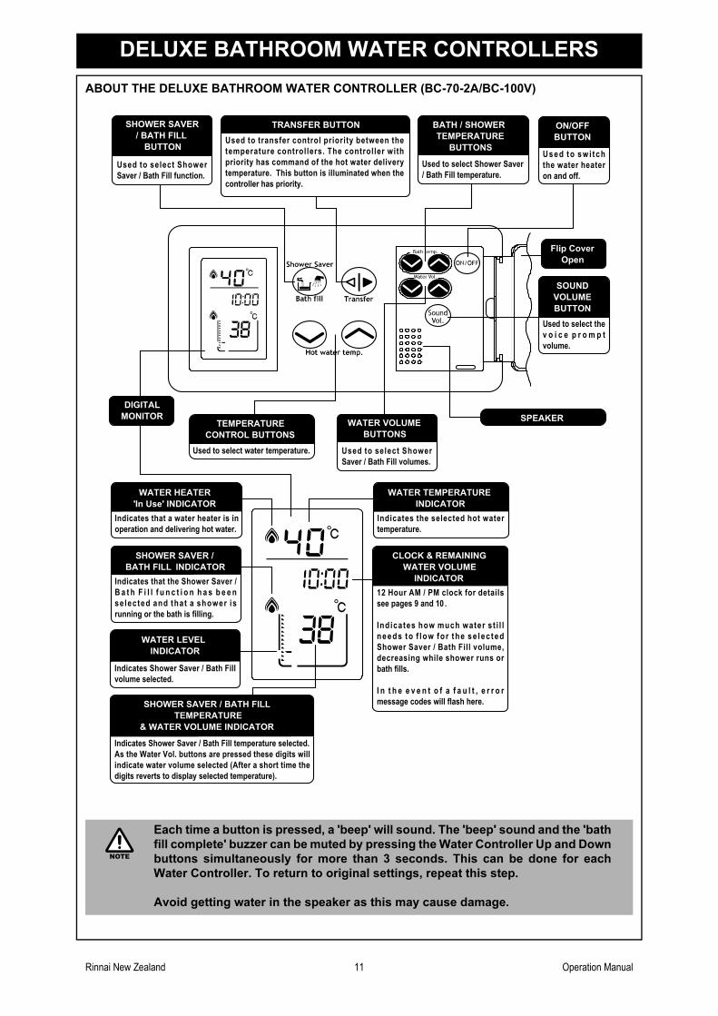
ABOUT THE DELUXE BATHROOM WATER CONTROLLER (BC-70-2A/BC-100V)
Each time a button is pressed, a 'beep' will sound. The 'beep' sound and the 'bath
fill complete' buzzer can be muted by pressing the Water Controller Up and Down
buttons simultaneously for more than 3 seconds. This can be done for each
Water Controller. To return to original settings, repeat this step.
Avoid getting water in the speaker as this may cause damage.
Used to select Shower Saver
/ Bath Fill temperature.
BATH / SHOWER
TEMPERATURE
BUTTONS
TRANSFER BUTTON
Used to transfer control priority between the
temperature controllers. The controller with
priority has command of the hot water delivery
temperature. This button is illuminated when the
controller has priority.
Used to select Shower
Saver / Bath Fill volumes.
WATER VOLUME
BUTTONS
Used to swi tch
the water heater
on and off.
ON/OFF
BUTTON
Used to select the
v o i c e p r o m p t
volume.
SOUND
VOLUME
BUTTON
SPEAKER
Used to select water temperature.
TEMPERATURE
CONTROL BUTTONS
Used to select Shower
Saver / Bath Fill function.
SHOWER SAVER
/ BATH FILL
BUTTON
Indicates the selected hot water
temperature.
WATER TEMPERATURE
INDICATOR
Indicates that a water heater is in
operation and delivering hot water.
WATER HEATER
'In Use' INDICATOR
Indicates that the Shower Saver /
B a t h F i l l f u n c t i o n h a s b e e n
selected and that a shower is
running or the bath is filling.
SHOWER SAVER /
BATH FILL INDICATOR
12 Hour AM / PM clock for details
see pages 9 and 10 .
Indicates how much water st i l l
needs to f low for the se lec ted
Shower Saver / Bath Fill volume,
decreasing while shower runs or
bath fills.
I n t h e e v e n t o f a f a u l t , e r r o r
message codes will flash here.
CLOCK & REMAINING
WATER VOLUME
INDICATOR
Indicates Shower Saver / Bath Fill temperature selected.
As the Water Vol. buttons are pressed these digits will
indicate water volume selected (After a short time the
digits reverts to display selected temperature).
SHOWER SAVER / BATH FILL
TEMPERATURE
& WATER VOLUME INDICATOR
Indicates Shower Saver / Bath Fill
volume selected.
WATER LEVEL
INDICATOR
DIGITAL
MONITOR
Flip Cover
Open
NOTE
Rinnai New Zealand 12 Operation Manual
DELUXE BATHROOM WATER CONTROLLERS
HOW TO USE TWO OR MORE DELUXE WATER CONTROLLERS
SETTING THE CLOCK (SEE PAGE 9 TO 10 FOR DETAILS ON HOW TO SET THE CLOCK)
ADJUSTING TEMPERATURE
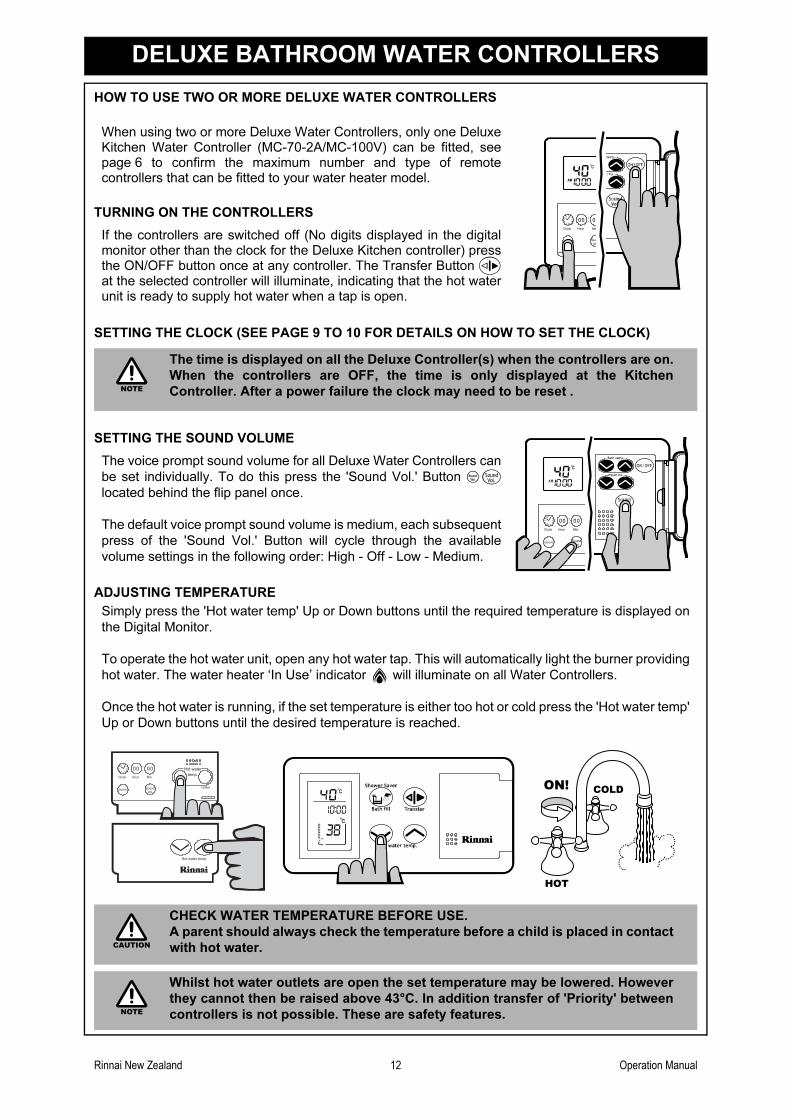
When using two or more Deluxe Water Controllers, only one DeluxeKitchen Water Controller (MC-70-2A/MC-100V) can be fitted, seepage 6 to confirm the maximum number and type of remotecontrollers that can be fitted to your water heater model.
TURNING ON THE CONTROLLERS
If the controllers are switched off (No digits displayed in the digitalmonitor other than the clock for the Deluxe Kitchen controller) pressthe ON/OFF button once at any controller. The Transfer Button at the selected controller will illuminate, indicating that the hot waterunit is ready to supply hot water when a tap is open.
The time is displayed on all the Deluxe Controller(s) when the controllers are on.
When the controllers are OFF, the time is only displayed at the Kitchen
Controller. After a power failure the clock may need to be reset .
SETTING THE SOUND VOLUME
The voice prompt sound volume for all Deluxe Water Controllers can
be set individually. To do this press the 'Sound Vol.' Button
located behind the flip panel once.
The default voice prompt sound volume is medium, each subsequent
press of the 'Sound Vol.' Button will cycle through the available
volume settings in the following order: High - Off - Low - Medium.
Simply press the 'Hot water temp' Up or Down buttons until the required temperature is displayed on
the Digital Monitor.
To operate the hot water unit, open any hot water tap. This will automatically light the burner providing
hot water. The water heater ‘In Use’ indicator will illuminate on all Water Controllers.
Once the hot water is running, if the set temperature is either too hot or cold press the 'Hot water temp'
Up or Down buttons until the desired temperature is reached.
CHECK WATER TEMPERATURE BEFORE USE.
A parent should always check the temperature before a child is placed in contact
with hot water.
Whilst hot water outlets are open the set temperature may be lowered. However
they cannot then be raised above 43°C. In addition transfer of 'Priority' between
controllers is not possible. These are safety features.
Clock Hour Min
Vo
00 00
ON/OFFSou
BATH
NOTE
Vol.
Sound
Clock Hour Min.
Vol.
00 00
ON/OFFSound
BATH
Clock Hour Min.
Vol.
Hot water temp.
00 00
ON/OFF
MC -70 -1A
Sound Cooler Hotter
Hot water temp.
HOTHOT
COLDCOLDON!ON!
CAUTION
NOTE
Rinnai New Zealand 13 Operation Manual
DELUXE BATHROOM WATER CONTROLLERS
OPERATING THE SHOWER SAVER / BATH FILL FUNCTION
Programming Shower / Bath volume and Temperature
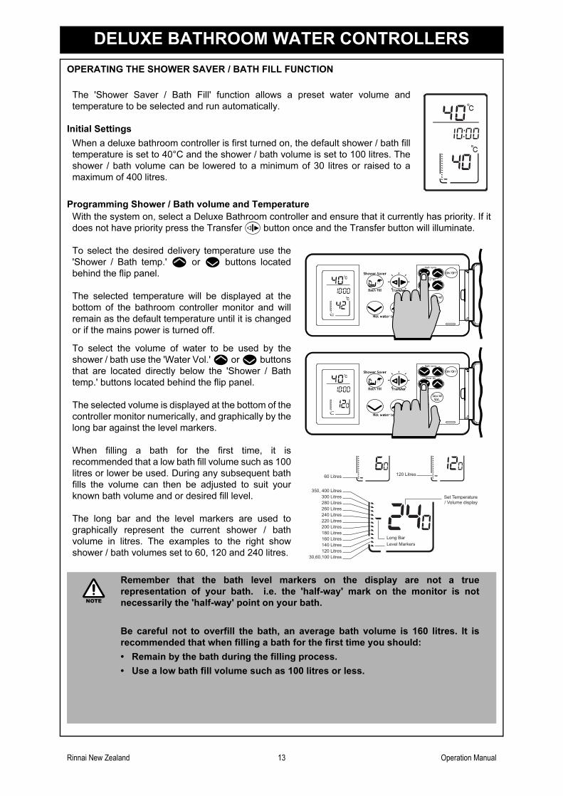
The 'Shower Saver / Bath Fill' function allows a preset water volume and
temperature to be selected and run automatically.
Initial Settings
When a deluxe bathroom controller is first turned on, the default shower / bath fill
temperature is set to 40°C and the shower / bath volume is set to 100 litres. The
shower / bath volume can be lowered to a minimum of 30 litres or raised to a
maximum of 400 litres.
With the system on, select a Deluxe Bathroom controller and ensure that it currently has priority. If it
does not have priority press the Transfer button once and the Transfer button will illuminate.
To select the desired delivery temperature use the
'Shower / Bath temp.' or buttons located
behind the flip panel.
The selected temperature will be displayed at the
bottom of the bathroom controller monitor and will
remain as the default temperature until it is changed
or if the mains power is turned off.
To select the volume of water to be used by the
shower / bath use the 'Water Vol.' or buttons
that are located directly below the 'Shower / Bath
temp.' buttons located behind the flip panel.
The selected volume is displayed at the bottom of the
controller monitor numerically, and graphically by the
long bar against the level markers.
When filling a bath for the first time, it is
recommended that a low bath fill volume such as 100
litres or lower be used. During any subsequent bath
fills the volume can then be adjusted to suit your
known bath volume and or desired fill level.
The long bar and the level markers are used to
graphically represent the current shower / bath
volume in litres. The examples to the right show
shower / bath volumes set to 60, 120 and 240 litres.
Remember that the bath level markers on the display are not a true
representation of your bath. i.e. the 'half-way' mark on the monitor is not
necessarily the 'half-way' point on your bath.
Be careful not to overfill the bath, an average bath volume is 160 litres. It is
recommended that when filling a bath for the first time you should:
• Remain by the bath during the filling process.
• Use a low bath fill volume such as 100 litres or less.
30,60,100 Litres
60 Litres 120 Litres
120 Litres
Long BarLevel Markers140 Litres
160 Litres 180 Litres 200 Litres 220 Litres 240 Litres 260 Litres 280 Litres 300 Litres
350, 400 Litres Set Temperature/ Volume display
NOTE
Rinnai New Zealand 14 Operation Manual
DELUXE BATHROOM WATER CONTROLLERS
Using Shower Saver / Bath Fill
COMBINING UNIVERSAL AND DELUXE CONTROLLERS
Universal and Deluxe Controllers can be combined and will function as described in other sections of
this manual. Refer to the table on page 6 to confirm the maximum number and combination of
controllers that can be fitted to your Water Heater model.
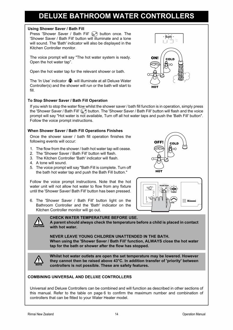
Press 'Shower Saver / Bath Fill' button once. The
'Shower Saver / Bath Fill' button will illuminate and a tone
will sound. The 'Bath' indicator will also be displayed in the
Kitchen Controller monitor.
The voice prompt will say "The hot water system is ready.
Open the hot water tap”.
Open the hot water tap for the relevant shower or bath.
The ‘In Use’ indicator will illuminate at all Deluxe Water
Controller(s) and the shower will run or the bath will start to
fill.
To Stop Shower Saver / Bath Fill Operation
If you wish to stop the water flow whilst the shower saver / bath fill function is in operation, simply press
the 'Shower Saver / Bath Fill' button. The 'Shower Saver / Bath Fill' button will flash and the voice
prompt will say "Hot water is not available, Turn off all hot water taps and push the 'Bath Fill' button".
Follow the voice prompt instructions.
When Shower Saver / Bath Fill Operations Finishes
Once the shower saver / bath fill operation finishes the
following events will occur:
1. The flow from the shower / bath hot water tap will cease.
2. The 'Shower Saver / Bath Fill' button will flash.
3. The Kitchen Controller 'Bath' indicator will flash.
4. A tone will sound.
5. The voice prompt will say "Bath Fill is complete. Turn off
the bath hot water tap and push the Bath Fill button."
Follow the voice prompt instructions. Note that the hot
water unit will not allow hot water to flow from any fixture
until the 'Shower Saver/ Bath Fill' button has been pressed.
6. The 'Shower Saver / Bath Fill' button light on the
Bathroom Controller and the 'Bath' indicator on the
Kitchen Controller monitor will go out.
CHECK WATER TEMPERATURE BEFORE USE.
A parent should always check the temperature before a child is placed in contact
with hot water.
NEVER LEAVE YOUNG CHILDREN UNATTENDED IN THE BATH.
When using the 'Shower Saver / Bath Fill' function, ALWAYS close the hot water
tap for the bath or shower after the flow has stopped.
Whilst hot water outlets are open the set temperature may be lowered. However
they cannot then be raised above 43°C. In addition transfer of 'priority' between
controllers is not possible. These are safety features.
Bath
HOTHOT
COLDCOLDON!ON!
HOTHOT
COLDCOLDOFF!OFF!
CAUTION
NOTE
Rinnai New Zealand 15 Operation Manual
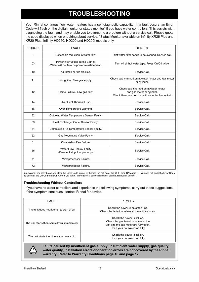
TROUBLESHOOTING
Your Rinnai continous flow water heaters has a self diagnostic capability. If a fault occurs, an Error
Code will flash on the digital monitor or status monitor* if you have water controllers. This assists with
diagnosing the fault, and may enable you to overcome a problem without a service call. Please quote
the code displayed when enquiring about service. *Status Monitor available on Infinity XR26 Plus and
XR20 Plus, Infinity HD250, HD200 and HD200i models only.
In all cases, you may be able to clear the Error Code simply by turning the hot water tap OFF, then ON again. If this does not clear the Error Code,try pushing the On/Off button OFF, then ON again. If the Error Code still remains, contact Rinnai for advice.
Troubleshooting Without Controllers
If you have no water controllers and experience the following symptoms, carry out these suggestions.
If the symptom continues, contact Rinnai for advice.
ERROR FAULT REMEDY
- Noticeable reduction in water flow. Inlet water filter needs to be cleaned. Service call.
03Power interruption during Bath fill
(Water will not flow on power reinstatement).Turn off all hot water taps. Press On/Off twice.
10 Air intake or flue blocked. Service Call.
11 No ignition / No gas supply.Check gas is turned on at water heater and gas meter
or cylinder.
12 Flame Failure / Low gas flow.
Check gas is turned on at water heater
and gas meter or cylinder.
Check there are no obstructions to the flue outlet.
14 Over Heat Thermal Fuse. Service Call.
16 Over Temperature Warning. Service Call.
32 Outgoing Water Temperature Sensor Faulty. Service Call.
33 Heat Exchanger Outlet Sensor Faulty. Service Call.
34 Combustion Air Temperature Sensor Faulty. Service Call.
52 Gas Modulating Valve Faulty. Service Call.
61 Combustion Fan Failure. Service Call.
65Water Flow Control Faulty
(Does not stop flow properly).Service Call.
71 Microprocessor Failure. Service Call.
72 Microprocessor Failure. Service Call.
FAULT REMEDY
The unit does not attempt to start at all.Check the power is on at the unit.
Check the isolation valves at the unit are open.
The unit starts then shuts down immediately.
Check the power is still on.
Check the gas isolation valves at the
unit and the gas meter are fully open.
Open your hot water tap fully.
The unit starts then the water goes cold.Check the power is still on.
Open your hot water tap fully.
Faults caused by insufficient gas supply, insufficient water supply, gas quality,
water quality, installation errors or operation errors are not covered by the Rinnai
warranty. Refer to Warranty Conditions page 16 and page 17.NOTE
Rinnai New Zealand 16 Operation Manual
WARRANTY STATEMENT - HOT WATER PRODUCTS
RINNAI BRINGS YOU PEACE OF MIND WITH A 3 YEAR MINIMUM WARRANTY
Rinnai Infinity 3 Year Warranty - Terms and Conditions
1. During the 36 month period from date of purchase and subject to clauses 2 and 3 below, Rinnai New
Zealand Limited ("Rinnai") will, at its own discretion, either replace or repair any defective product at no
charge to the customer.
2. This warranty covers manufacturing defects only. This warranty will not apply if (for example) the product
has been improperly installed or is otherwise installed contrary to manufacturer's recommendations, has
been damaged during installation, has not been operated in accordance with operating instructions, or has
been subjected to damage or abuse beyond that expected from conditions of normal use.
3. Warranty claims may be invalid if not accompanied by details of the installing or supervising gas fitter's
registration number and the gas fitting certification number.
4. This warranty commences from the date of purchase. Proof of purchase is required at the time of any
warranty claim.
5. Servicing of the product is to be carried out by a Rinnai authorised service centre.
Extended Warranty for Rinnai Infinity Heat Exchanger
The warranty on heat exchangers in Rinnai infinity in domestic use is 10 years pro rata (i.e. in the 4th
year, 70% of the value of the part is covered and 40% in the 7th year).
For Rinnai infinity units installed for commercial use the warranty for the heat exchanger is 5 years
pro rata (i.e. in the 4th year, 40% of the value of the part is covered and 20% in the 5th year).
This warranty is subject to Terms and Conditions 2 to 5 above.
All other parts and labour for the product are covered for 3 years in accordance with the Terms and
Conditions above.
Water Quality
Water quality outside the maximum recommended limits as set down in the customer's handbook will
void this warranty. Proof of purchase may be required for a warranty claim to be valid. [Water quality]
tests will be carried out at the customer's own cost but Rinnai will reimburse the customer for those
costs if the product is found to be defective.
All Rinnai appliances meet or exceed the safety standards required by New Zealand gas and electrical
regulations. Rinnai is constantly improving its products and as such specifications are subject to
change or variation without notice.
Rinnai New Zealand 17 Operation Manual
WARRANTY CONDITIONS
WARRANTY CONDITIONS
1. Dated proof of purchase is required to be shown to the attending service technician prior to the
commencement of any warranty work.
2. All Rinnai water heaters must be installed in accordance with the Manufacturer's Installation Instructions,
current AS/NZS3000, AS/NZS3500 and NZS5261, local regulations and municipal building codes.
3. All Rinnai water heaters must only be installed, commissioned and removed by persons Authorised by local
regulations to do so. All Rinnai water heaters must only be serviced and repaired by a Rinnai approved
service technician.
4. Where the water heater has not been sited in accordance with the Installation Instructions or installed such
that normal service access is difficult , a service charge may apply. At the discretion of the attending service
technician, if access is deemed dangerous service will be refused.
5. Where a failed component is replaced under warranty, the balance of the original appliance warranty will
remain effective.
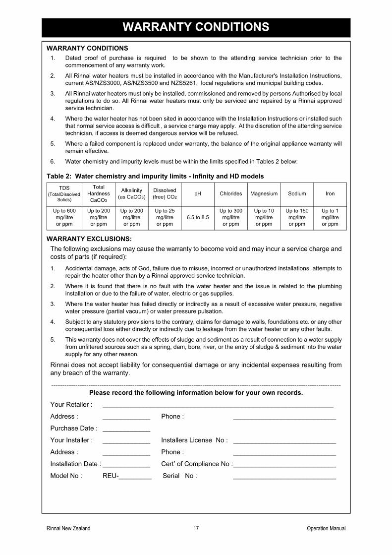
6. Water chemistry and impurity levels must be within the limits specified in Tables 2 below:
Table 2: Water chemistry and impurity limits - Infinity and HD models
WARRANTY EXCLUSIONS:
The following exclusions may cause the warranty to become void and may incur a service charge and
costs of parts (if required):
1. Accidental damage, acts of God, failure due to misuse, incorrect or unauthorized installations, attempts to
repair the heater other than by a Rinnai approved service technician.
2. Where it is found that there is no fault with the water heater and the issue is related to the plumbing
installation or due to the failure of water, electric or gas supplies.
3. Where the water heater has failed directly or indirectly as a result of excessive water pressure, negative
water pressure (partial vacuum) or water pressure pulsation.
4. Subject to any statutory provisions to the contrary, claims for damage to walls, foundations etc. or any other
consequential loss either directly or indirectly due to leakage from the water heater or any other faults.
5. This warranty does not cover the effects of sludge and sediment as a result of connection to a water supply
from unfiltered sources such as a spring, dam, bore, river, or the entry of sludge & sediment into the water
supply for any other reason.
Rinnai does not accept liability for consequential damage or any incidental expenses resulting from
any breach of the warranty.
------------------------------------------------------------------------------------------------------------------------------------
Please record the following information below for your own records.
Your Retailer : _______________________________________________________________
Address : _____________ Phone : ____________________________
Purchase Date : _____________
Your Installer : _____________ Installers License No : ____________________________
Address : _____________ Phone : ____________________________
Installation Date : _____________ Cert’ of Compliance No :____________________________
Model No : REU-_________ Serial No : ____________________________
TDS(Total Dissolved
Solids)
Total
Hardness
CaCO3
Alkalinity
(as CaCO3)
Dissolved
(free) CO2pH Chlorides Magnesium Sodium Iron
Up to 600
mg/litre
or ppm
Up to 200
mg/litre
or ppm
Up to 200
mg/litre
or ppm
Up to 25
mg/litre
or ppm
6.5 to 8.5
Up to 300
mg/litre
or ppm
Up to 10
mg/litre
or ppm
Up to 150
mg/litre
or ppm
Up to 1
mg/litre
or ppm
Rinnai New Zealand 18 Installation Manual
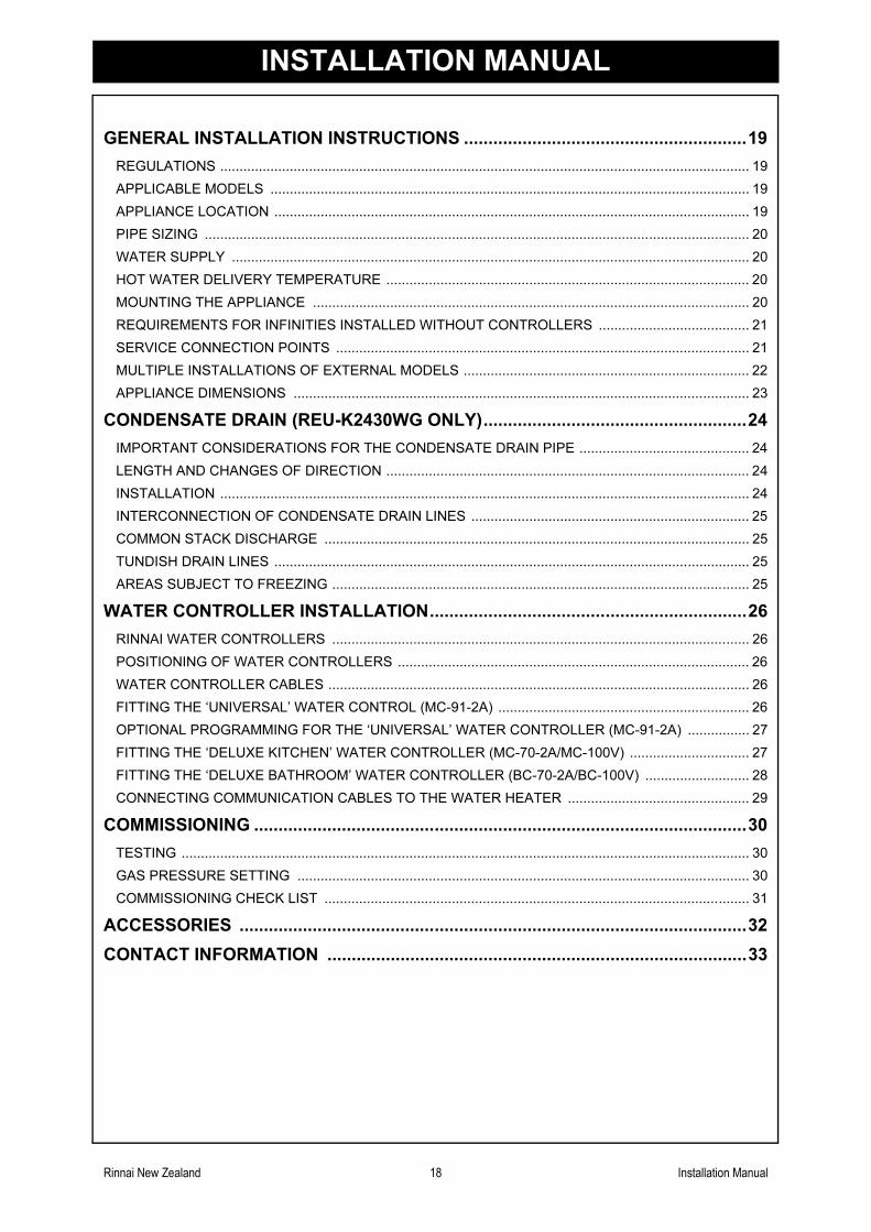
GENERAL INSTALLATION INSTRUCTIONS ..........................................................19
REGULATIONS ......................................................................................................................................... 19
APPLICABLE MODELS ............................................................................................................................ 19
APPLIANCE LOCATION ........................................................................................................................... 19
PIPE SIZING ............................................................................................................................................. 20
WATER SUPPLY ...................................................................................................................................... 20
HOT WATER DELIVERY TEMPERATURE .............................................................................................. 20
MOUNTING THE APPLIANCE ................................................................................................................. 20
REQUIREMENTS FOR INFINITIES INSTALLED WITHOUT CONTROLLERS ....................................... 21
SERVICE CONNECTION POINTS ........................................................................................................... 21
MULTIPLE INSTALLATIONS OF EXTERNAL MODELS .......................................................................... 22
APPLIANCE DIMENSIONS ...................................................................................................................... 23
CONDENSATE DRAIN (REU-K2430WG ONLY)......................................................24
IMPORTANT CONSIDERATIONS FOR THE CONDENSATE DRAIN PIPE ............................................ 24
LENGTH AND CHANGES OF DIRECTION .............................................................................................. 24
INSTALLATION ......................................................................................................................................... 24
INTERCONNECTION OF CONDENSATE DRAIN LINES ........................................................................ 25
COMMON STACK DISCHARGE .............................................................................................................. 25
TUNDISH DRAIN LINES ........................................................................................................................... 25
AREAS SUBJECT TO FREEZING ............................................................................................................ 25
WATER CONTROLLER INSTALLATION.................................................................26
RINNAI WATER CONTROLLERS ............................................................................................................ 26
POSITIONING OF WATER CONTROLLERS ........................................................................................... 26
WATER CONTROLLER CABLES ............................................................................................................. 26
FITTING THE ‘UNIVERSAL’ WATER CONTROL (MC-91-2A) ................................................................. 26
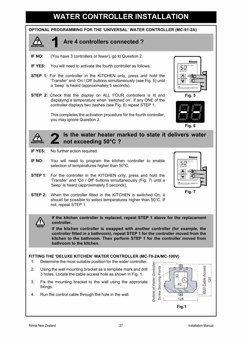
OPTIONAL PROGRAMMING FOR THE ‘UNIVERSAL’ WATER CONTROLLER (MC-91-2A) ................ 27
FITTING THE ‘DELUXE KITCHEN’ WATER CONTROLLER (MC-70-2A/MC-100V) ............................... 27
FITTING THE ‘DELUXE BATHROOM’ WATER CONTROLLER (BC-70-2A/BC-100V) ........................... 28
CONNECTING COMMUNICATION CABLES TO THE WATER HEATER ............................................... 29
COMMISSIONING .....................................................................................................30
TESTING ................................................................................................................................................... 30
GAS PRESSURE SETTING ..................................................................................................................... 30
COMMISSIONING CHECK LIST .............................................................................................................. 31
ACCESSORIES ........................................................................................................32
CONTACT INFORMATION ......................................................................................33
INSTALLATION MANUAL
Rinnai New Zealand 19 Installation Manual
GENERAL INSTALLATION INSTRUCTIONS
REGULATIONS
This appliance must be installed in accordance with:
• Current AS/NZS3000, AS/NZS3500 and NZS5261
• Rinnai Installation Instructions
• Local regulations and municipal building codes
Installation, Service and Removal MUST BE by an Authorised Person only.
APPLICABLE MODELS
These Installation Instructions apply to the following Rinnai continuous flow water heater models:
APPLIANCE LOCATION
(External Models)
This appliance is designed for ‘Outdoor’ Installation only. As such, it must be located in an above
ground open air situation with natural ventilation, without stagnant areas, where gas leakage and
products of combustion are rapidly dispersed by wind and natural convection.
This appliance must be mounted on a vertical structure with the water and gas connections on the
underside pointing downwards. For appliances installed on elevated structures or under floors specific
requirements apply. Refer to NZS5261 for details.
This appliance must not be used as a domestic spa or swimming pool heater.
Location of the appliance flue terminal must be in accordance with NZS5261 Section 2.6.11, 2.6.12
and 2.6.13. Figure 3 is reproduced in the ‘Horizonal Flue Terminal Clearances’ section of these
instructions. Note that NZS5261-2003 was current at the time of printing but may have been
superseded. It is the installers’ responsibility to ensure current requirements are met.
(Internal Models)
This appliance is designed for ‘Indoor’ installation only. It may be installed ‘Outdoors’ in an enclosure
if the requirements of NZS5261 are satisfied. An enclosure is defined as a compartment, enclosed
area or partitioned off space primarily used for the installing of the appliance. If installed in an
enclosure, either Internally or Externally, the location should be ventilated to allow gas to dissipate
and provision must be made for the safe disposal of any leaking water to an exposed location.
This appliance must be mounted on a vertical structure with the water and gas connections on the
underside pointing downwards. For appliances installed in roof spaces or elevated structures specific
requirements apply. Refer to NZS5261 Section 1.6 for details.
This appliance must not be used as a domestic spa or swimming pool heater.
This appliance MUST be used with the Rinnai Infinity flueing system only. The use of a non Rinnai
flueing system may result in a dangerous situation and violates regulations.
This appliance must be located so that the flue terminal exits the building at a suitable point. Figure 3
is reproduced under “MINIMUM CLEARANCES REQUIRED FOR FLUE TERMINALS (Extract from
NZS5261-2003)” on page 22.
REU-V1620WG
REU-V1818WG
REU-V2024WG
REU-V2426WG
REU-K2430WG
REU-V2630WG
REU-V3237WG
REU-VM2024WD
REU-VM2630WD
REU-VM2630WC
REU-VM3237WC
REU-V2632FFUG
REU-VM2632FFUC
REU-VM3237FFUC
NZS5261-2003 was current at the time of printing but may have been superseded. It
is the installer’s responsibility to ensure current requirements are met.
Flue Dip-Switch, if flue length exceeds 2m, dip-switch 1 of SW1 is to be switched to
the 'OFF' position.
NOTE
NOTE
Rinnai New Zealand 20 Installation Manual
GENERAL INSTALLATION INSTRUCTIONS
(All Models)
This appliance must be placed as close as practicable to the most frequently used hot water outlet or
outlets to minimise the delay time for hot water delivery. For installations where the distance between
the water heater and the outlets is considerable, a flow and return system can be used to minimize
the waiting time for hot water delivery. Alternatively, multiple appliances can be strategically placed to
serve outlets with minimal delay time. Contact Rinnai for further information.
An AC230V, 10 Amp, earthed power point must be provided adjacent to the appliance. For outdoor
installations this power point must be weather proof. It must be clear of the gas and water connections
to the appliance and also the flue exhaust and water pressure relief valve. The power cord of the
appliance is 1.5 Metres long.
All appliances must be installed to ensure access can be gained without hazard or undue difficulty for
inspection, repair, renewal or operational purposes. Sufficient clearances shall allow access to, and
removal of, all serviceable components. Appliances should not be mounted higher than 3.5 metres
above the ground or floor level unless the customer can arrange permanent and safe access or can
provide another means of access, for example, by means of scissor or boom lifts.
PIPE SIZING
See Table 1 page 21 for appliance gas consumption. If the gas pipe sizing is insufficient the customer
will not get the full performance benefit. Gas pipe sizing must consider the gas input to this appliance
as well as all the other gas appliances in the premises. The gas meter and regulator must be specified
for this gas rate. An approved sizing chart such as the one in NZS5261 should be used.
Water pipe sizing and layout should be performed in accordance with AS/NZS3500. All hot water pipe-
work should be insulated to optimise performance and energy efficiency.
WATER SUPPLY
See Table 1, page 21 for applicable water pressures. Approved pressure limiting valves may be
required if the ‘Maximum’ rated water supply pressures in Table 1 are exceeded. To achieve the rated
flow, the ‘Minimum’ water supply pressures in Table 1 must be supplied. The water heaters will
operate at lower pressures but will not achieve the rated flow. Contact Rinnai for ‘gravity fed’ or ‘low
pressure’ installations.
Water chemistry and impurity limits are detailed under ‘Warranty Conditions’. Most metropolitan water
supplies fall within the requirements. If you are unsure about your local water quality, contact your
water authority. If sludge or foreign matter is present in the water supply, a suitable filter or strainer
should be incorporated in the water supply to the water heater.
HOT WATER DELIVERY TEMPERATURE
Local regulations and or the requirements of AS/NZS 3500.4 must be considered regarding the
temperature limitations of hot water supplied to areas used primarily for personal hygiene. The
temperature of water to these areas may be limited to 55º C or less. To ensure these regulations and
or requirements are met the system MUST be installed in accordance with the 'Water Heater and
Controller Installation Configurations' section of these instructions.
MOUNTING THE APPLIANCE
See Table 1, page 21 for individual appliance weights. The wall or structure on which the units are to
be mounted must be capable of supporting these weights and the associated pipe-work.
Rinnai New Zealand 21 Installation Manual
GENERAL INSTALLATION INSTRUCTIONS
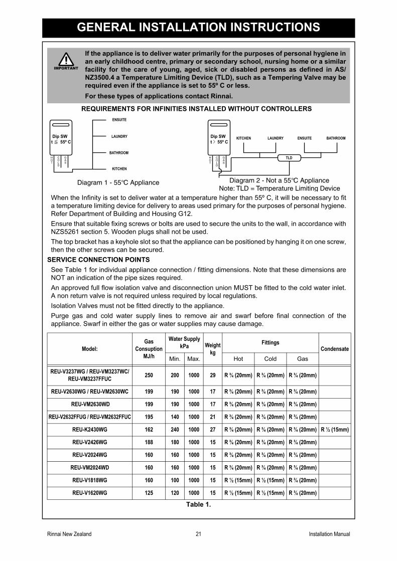
When the Infinity is set to deliver water at a temperature higher than 55º C, it will be necessary to fit
a temperature limiting device for delivery to areas used primary for the purposes of personal hygiene.
Refer Department of Building and Housing G12.
Ensure that suitable fixing screws or bolts are used to secure the units to the wall, in accordance with
NZS5261 section 5. Wooden plugs shall not be used.
The top bracket has a keyhole slot so that the appliance can be positioned by hanging it on one screw,
then the other screws can be secured.
SERVICE CONNECTION POINTS
See Table 1 for individual appliance connection / fitting dimensions. Note that these dimensions are
NOT an indication of the pipe sizes required.
An approved full flow isolation valve and disconnection union MUST be fitted to the cold water inlet.
A non return valve is not required unless required by local regulations.
Isolation Valves must not be fitted directly to the appliance.
Purge gas and cold water supply lines to remove air and swarf before final connection of the
appliance. Swarf in either the gas or water supplies may cause damage.
Table 1.
If the appliance is to deliver water primarily for the purposes of personal hygiene in
an early childhood centre, primary or secondary school, nursing home or a similar
facility for the care of young, aged, sick or disabled persons as defined in AS/
NZ3500.4 a Temperature Limiting Device (TLD), such as a Tempering Valve may be
required even if the appliance is set to 55º C or less.
For these types of applications contact Rinnai.
REQUIREMENTS FOR INFINITIES INSTALLED WITHOUT CONTROLLERS
Model:
Gas
Consuption
MJ/h
Water Supply
kPa Weight
kg
FittingsCondensate
Min. Max. Hot Cold Gas
REU-V3237WG / REU-VM3237WC/
REU-VM3237FFUC250 200 1000 29 R ¾ (20mm) R ¾ (20mm) R ¾ (20mm)
REU-V2630WG / REU-VM2630WC 199 190 1000 17 R ¾ (20mm) R ¾ (20mm) R ¾ (20mm)
REU-VM2630WD 199 190 1000 17 R ¾ (20mm) R ¾ (20mm) R ¾ (20mm)
REU-V2632FFUG / REU-VM2632FFUC 195 140 1000 21 R ¾ (20mm) R ¾ (20mm) R ¾ (20mm)
REU-K2430WG 162 240 1000 27 R ¾ (20mm) R ¾ (20mm) R ¾ (20mm) R ½ (15mm)
REU-V2426WG 188 180 1000 15 R ¾ (20mm) R ¾ (20mm) R ¾ (20mm)
REU-V2024WG 160 160 1000 15 R ¾ (20mm) R ¾ (20mm) R ¾ (20mm)
REU-VM2024WD 160 160 1000 15 R ¾ (20mm) R ¾ (20mm) R ¾ (20mm)
REU-V1818WG 160 100 1000 15 R ½ (15mm) R ½ (15mm) R ¾ (20mm)
REU-V1620WG 125 120 1000 15 R ½ (15mm) R ½ (15mm) R ¾ (20mm)
IMPORTANT
Dip SW
t 55º C
KITCHEN
LAUNDRY
BATHROOM
ENSUITE
H
O
T
C
O
L
D
G
A
S
KITCHEN LAUNDRY BATHROOMENSUITE
TLDH
O
T
C
O
L
D
G
A
S
Diagram 1 - 55°C Appliance Diagram 2 - Not a 55°C ApplianceNote: TLD = Temperature Limiting Device
Dip SW
t 55º C
Rinnai New Zealand 22 Installation Manual
GENERAL INSTALLATION INSTRUCTIONS
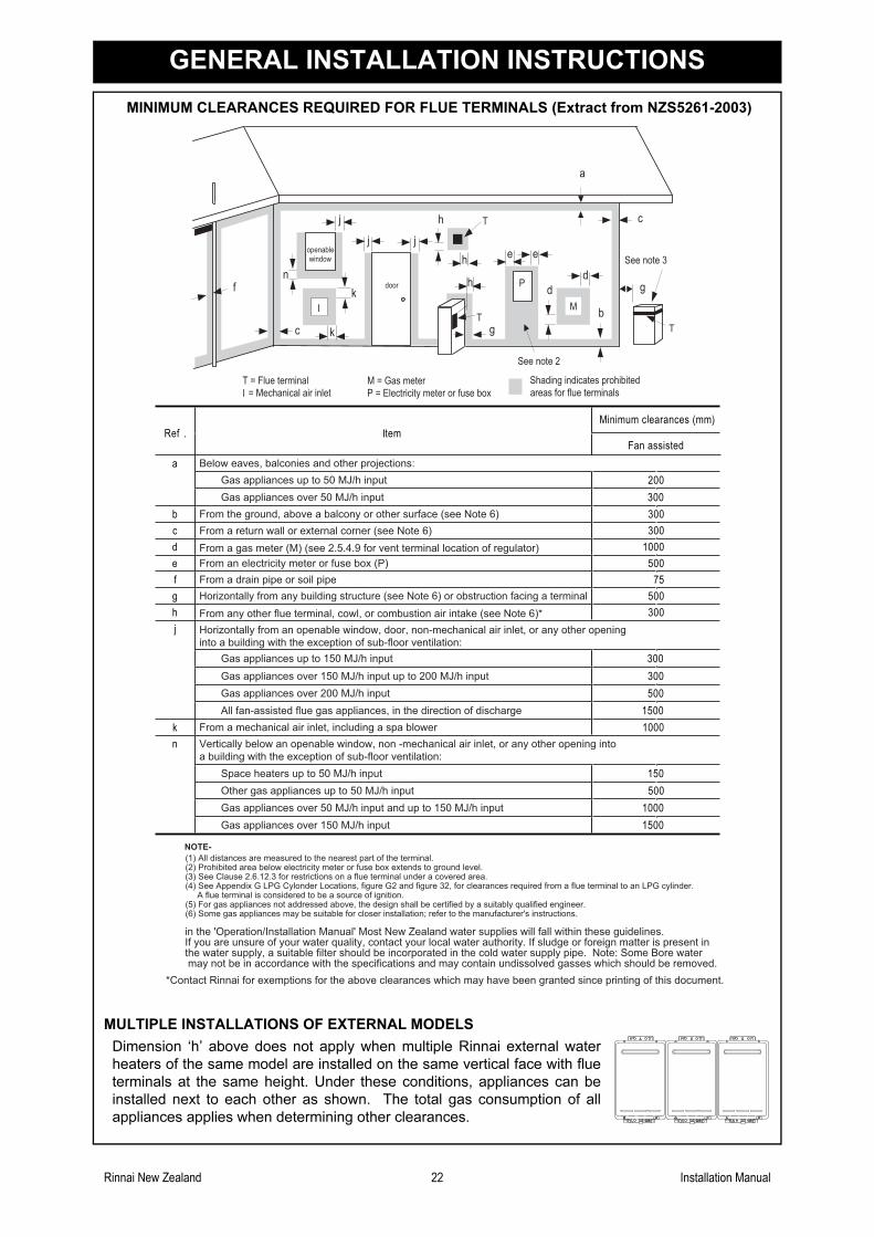
MINIMUM CLEARANCES REQUIRED FOR FLUE TERMINALS (Extract from NZS5261-2003)
MULTIPLE INSTALLATIONS OF EXTERNAL MODELS
Dimension ‘h’ above does not apply when multiple Rinnai external water
heaters of the same model are installed on the same vertical face with flue
terminals at the same height. Under these conditions, appliances can be
installed next to each other as shown. The total gas consumption of all
appliances applies when determining other clearances.
Below eaves, balconies and other projections:
Gas appliances up to 50 MJ/h input
Gas appliances over 50 MJ/h input
From the ground, above a balcony or other surface (see Note 6)
From a gas meter (M) (see 2.5.4.9 for vent terminal location of regulator)
From an electricity meter or fuse box (P)
From a drain pipe or soil pipe
Horizontally from any building structure (see Note 6) or obstruction facing a terminal
From any other flue terminal, cowl, or combustion air intake (see Note 6)*
Horizontally from an openable window, door, non-mechanical air inlet, or any other opening
into a building with the exception of sub-floor ventilation:
From a return wall or external corner (see Note 6)
Gas appliances up to 150 MJ/h input
Gas appliances over 150 MJ/h input up to 200 MJ/h input
Gas appliances over 200 MJ/h input
All fan-assisted flue gas appliances, in the direction of discharge
From a mechanical air inlet, including a spa blower
Vertically below an openable window, non -mechanical air inlet, or any other opening into
a building with the exception of sub-floor ventilation:
Space heaters up to 50 MJ/h input
Other gas appliances up to 50 MJ/h input
Gas appliances over 50 MJ/h input and up to 150 MJ/h input
Gas appliances over 150 MJ/h input
NOTE-
(1) All distances are measured to the nearest part of the terminal.(2) Prohibited area below electricity meter or fuse box extends to ground level.(3) See Clause 2.6.12.3 for restrictions on a flue terminal under a covered area.(4) See Appendix G LPG Cylonder Locations, figure G2 and figure 32, for clearances required from a flue terminal to an LPG cylinder.A flue terminal is considered to be a source of ignition.
(5) For gas appliances not addressed above, the design shall be certified by a suitably qualified engineer.(6) Some gas appliances may be suitable for closer installation; refer to the manufacturer's instructions.
in the 'Operation/Installation Manual' Most New Zealand water supplies will fall within these guidelines.If you are unsure of your water quality, contact your local water authority. If sludge or foreign matter is present inthe water supply, a suitable filter should be incorporated in the cold water supply pipe. Note: Some Bore watermay not be in accordance with the specifications and may contain undissolved gasses which should be removed.
*Contact Rinnai for exemptions for the above clearances which may have been granted since printing of this document.
g
openablewindow
door
M
P g
See note 3
T
b
d
d
ee
See note 2
h
h
a
h
jj
j
n
k
k
c
c
f
T = Flue terminal
I = Mechanical air inlet areas for flue terminals
T
TI
Shading indicates prohibitedM = Gas meter
P = Electricity meter or fuse box
Rinnai New Zealand 23 Installation Manual
GENERAL INSTALLATION INSTRUCTIONS
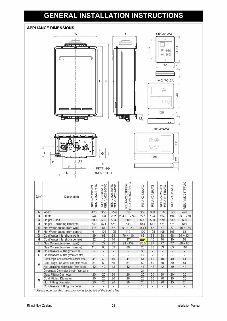
APPLIANCE DIMENSIONS
Dim' Description
RE
U-V
32
37
WG
RE
U-V
M3
23
7W
C
RE
U-V
26
30
WG
RE
U-V
M2
63
0W
C
RE
U-V
26
32
FF
UG
RE
U-V
M2
63
2F
FU
C
A Width 470 350 350
B Depth 244 194 234.5 ~ 274.5
C Height - Unit 600 530 600
D Height - Including Brackets 640 571 641
E Hot Water outlet (from wall) 115 87 91 ~ 131
F Hot Water outlet (from centre) 61 105 110
G Cold Water inlet (from wall) 99 68 70 ~ 110
H Cold Water inlet (from centre) 52 10 27*
I Gas Connection (from wall) 61 77 99 ~139
J Gas Connection (from centre) 110 83 89
Gas: Length Gas Connection (from base) 41 40 41
Cold: Length Cold Water inlet (from base) 51 50 51
Hot: Length Hot Water outlet (from base) 42 42 42
Gas: Fitting Diameter 20 20 20
Cold: Fitting Diameter 20 20 20
Hot: Fitting Diameter 20 20 20
M
N
RE
U-V
M2
63
0W
D
RE
U-V
M2
02
4W
D
BC-70-2A
MC-70-2A
MC-91-2A
90
12
0
83
20
20
B
DC
M
355.6
202
503
571
87
105
68
10
77
83
40
50
42
20
20
20
RE
U-V
24
26
WG
350
194
530
571
87
105
68
10
77
83
40
50
42
20
20
20
RE
U-K
24
30
WG
350
277
600
644
164.5
100
83
53
70.5
25
51
62
41
20
20
20
RE
U-V
16
20
WG
RE
U-V
20
24
WG
RE
U-V
18
18
WG
350
194
530
571
87
105
68
10
77
83
40
50
39
20
15
15
350
194
530
571
87
105
68
10
77
83
K Condensate outlet (from wall) - - -- -33 --
L Condensate outlet (from centre) - - -- -132 --
40
50
42
Condensate Connection Length (from base) - - -- -24 --
20
20
20
Condensate: Fitting Diameter - - -- -15 -
RE
U-V
M3
23
7F
FU
C
470
230 ~270
600
640
110 ~ 150
61
94 ~ 134
52
56 ~ 96
110
41
51
42
20
20
20
-
-
-
--
A
N
FITTING
DIAMETER
* Please note that this measurement is to the left of the centre line.
E
F J
L
H
G I
K
12
0
128
97
195
22
Rinnai New Zealand 24 Installation Manual
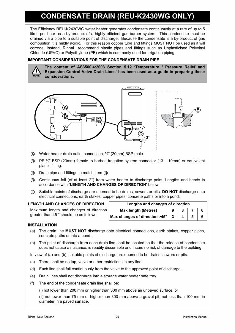
CONDENSATE DRAIN (REU-K2430WG ONLY)
The Efficiency REU-K2430WG water heater generates condensate continuously at a rate of up to 5
litres per hour as a by-product of a highly efficient gas burner system. This condensate must be
drained via a pipe to a suitable point of discharge. Because the condensate is a by-product of gas
combustion it is mildly acidic. For this reason copper tube and fittings MUST NOT be used as it will
corrode. Instead, Rinnai recommend plastic pipes and fittings such as Unplasticised Polyvinyl
Chloride (UPVC) or Polyethylene (PE) which is commonly used for irrigation piping.
IMPORTANT CONSIDERATIONS FOR THE CONDENSATE DRAIN PIPE
Water heater drain outlet connection, ½” (20mm) BSP male.
PE ½” BSP (20mm) female to barbed irrigation system connector (13 – 19mm) or equivalent
plastic fitting.
Drain pipe and fittings to match item .
Continuous fall (of at least 2°) from water heater to discharge point. Lengths and bends in
accordance with ‘LENGTH AND CHANGES OF DIRECTION’ below.
Suitable points of discharge are deemed to be drains, sewers or pits. DO NOT discharge onto
electrical connections, earth stakes, copper pipes, concrete paths or into a pond.
INSTALLATION
(a) The drain line MUST NOT discharge onto electrical connections, earth stakes, copper pipes,
concrete paths or into a pond.
(b) The point of discharge from each drain line shall be located so that the release of condensate
does not cause a nuisance, is readily discernible and incurs no risk of damage to the building.
In view of (a) and (b), suitable points of discharge are deemed to be drains, sewers or pits.
(c) There shall be no tap, valve or other restrictions in any line.
(d) Each line shall fall continuously from the valve to the approved point of discharge.
(e) Drain lines shall not discharge into a storage water heater safe tray.
(f) The end of the condensate drain line shall be:
(i) not lower than 200 mm or higher than 300 mm above an unpaved surface; or
(ii) not lower than 75 mm or higher than 300 mm above a gravel pit, not less than 100 mm in
diameter in a paved surface.
The content of AS3500.4:2003 Section 5.12 ‘Temperature / Pressure Relief and
Expansion Control Valve Drain Lines’ has been used as a guide in preparing these
considerations.
LENGTH AND CHANGES OF DIRECTION
Maximum length and changes of direction
greater than 45 ° should be as follows:
Lengths and changes of direction
Max length (Metres) 9 8 7 6
Max changes of direction >45° 3 4 5 6
NOTE
A
B
C B
D
E
Rinnai New Zealand 25 Installation Manual
CONDENSATE DRAIN (REU-K2430WG ONLY)
(g) Where discharging over a tundish or gully trap, drain lines shall have an air gap of a size at least
twice the diameter of the drain line.
INTERCONNECTION OF CONDENSATE DRAIN LINES
Condensate drain lines from multiple water heaters may be joined together provided they conform
with the ‘INSTALLATION’ requirements on page 25.
COMMON STACK DISCHARGE
Where individual water heaters are installed in a multistorey building, the condensate drain lines may
discharge into a common stack, subject to the following:
(a) The discharge from the common stack is to a tundish, having a discharge line, that is not less
than the size of the common stack, directly connected to a fixture trap, and installed in connection
with any adjacent soil or waste stack.
(b) The discharge point of the common stack is such that any discharge is readily visible and not
cause any nuisance.
(c) The common stack is vented by extending the pipe upwards, above the roof level.
TUNDISH DRAIN LINES
The drain line from any tundish shall be not less than DN 20 or less than one size larger than that of
the largest drain line discharging into the tundish. Tundish drain lines shall comply with the
‘INSTALLATION’ requirements on page 25.
AREAS SUBJECT TO FREEZING
In areas where water pipes are prone to freezing, the drain pipe from any valve shall be insulated and
not exceed 300 mm in length. It shall discharge into a tundish through an air gap of not less than 75
mm and not more than 150 mm measured from the outlet of the drain pipe to the rim of the tundish.
Rinnai New Zealand 26 Installation Manual
WATER CONTROLLER INSTALLATION
RINNAI WATER CONTROLLERS
Water Controllers are available as an optional extra. Universal, Deluxe, and Wireless Controllers can
be used together and will function as described in the Operation Section of this manual. Please refer
to the table on page 6 to confirm the maximum number and combination of controllers that can be
fitted. This section refers to wired controllers, for details on installation of Wireless Controllers, pleaserefer to separate instructions.
POSITIONING OF WATER CONTROLLERS
Controllers must be installed in shaded and clean locations. They should be fitted out of reach of
children (suggested height from floor to be at least 1500mm). Controllers are water resistant,
however, durability is improved when positioned outside the shower recess or at least 400mm above
the highest part of a sink, basin or bath.
WATER CONTROLLER CABLES
Water controls operate at extra low voltage (12 Volts DC) which is supplied from the water heater.
Controllers come supplied with 15 m of electrical cable. The appliance end of the controller cables are
fitted with spade terminals. Extension cabling is available from Rinnai.
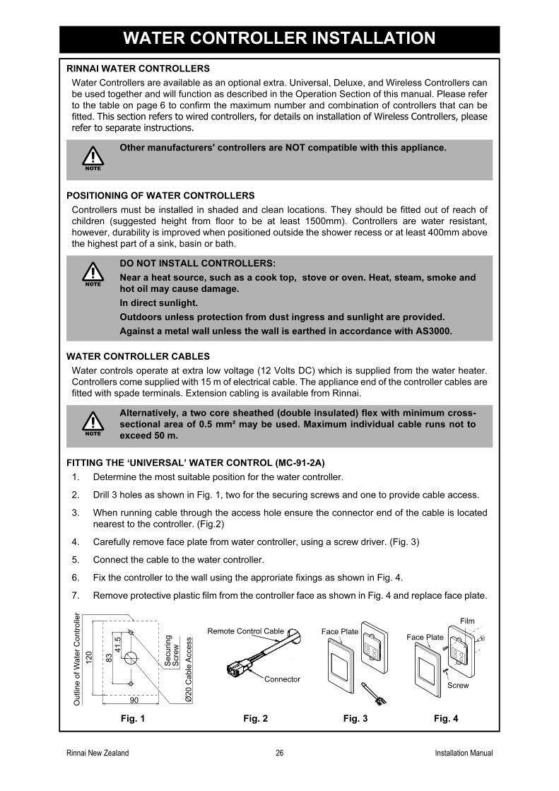
FITTING THE ‘UNIVERSAL’ WATER CONTROL (MC-91-2A)
1. Determine the most suitable position for the water controller.
2. Drill 3 holes as shown in Fig. 1, two for the securing screws and one to provide cable access.
3. When running cable through the access hole ensure the connector end of the cable is located
nearest to the controller. (Fig.2)
4. Carefully remove face plate from water controller, using a screw driver. (Fig. 3)
5. Connect the cable to the water controller.
6. Fix the controller to the wall using the approriate fixings as shown in Fig. 4.
7. Remove protective plastic film from the controller face as shown in Fig. 4 and replace face plate.
Other manufacturers' controllers are NOT compatible with this appliance.
DO NOT INSTALL CONTROLLERS:
Near a heat source, such as a cook top, stove or oven. Heat, steam, smoke and
hot oil may cause damage.
In direct sunlight.
Outdoors unless protection from dust ingress and sunlight are provided.
Against a metal wall unless the wall is earthed in accordance with AS3000.
Alternatively, a two core sheathed (double insulated) flex with minimum cross-
sectional area of 0.5 mm² may be used. Maximum individual cable runs not to
exceed 50 m.
Fig. 1 Fig. 2 Fig. 3 Fig. 4
NOTE
NOTE
NOTE
83
41.5
120
Outlin
e o
f W
ate
r C
ontr
olle
r
90
Securing
Scre
w
Ø20
Cable
Access
Remote Control Cable
Connector
Face PlateFace Plate
Screw
Film
Rinnai New Zealand 27 Installation Manual
WATER CONTROLLER INSTALLATION
OPTIONAL PROGRAMMING FOR THE ‘UNIVERSAL’ WATER CONTROLLER (MC-91-2A)
FITTING THE ‘DELUXE KITCHEN’ WATER CONTROLLER (MC-70-2A/MC-100V)
Are 4 controllers connected ?
IF NO: (You have 3 controllers or fewer), go to Question 2.
IF YES: You will need to activate the fourth controller as follows:
STEP 1: For the controller in the KITCHEN only, press and hold the
‘Transfer’ and ‘On / Off’ buttons simultaneously (see Fig. 5) until
a ‘beep’ is heard (approximately 5 seconds).
STEP 2: Check that the display on ALL FOUR controllers is lit and
displaying a temperature when ‘switched on’. If any ONE of the
controller displays two dashes (see Fig. 6) repeat STEP 1.
This completes the activation procedure for the fourth controller,
you may ignore Question 2.
Fig. 5
Fig. 6
Is the water heater marked to state it delivers water
not exceeding 50°C ?
IF YES: No further action required.
IF NO: You will need to program the kitchen controller to enable
selection of temperatures higher than 50°C.
STEP 1: For the controller in the KITCHEN only, press and hold the
‘Transfer’ and ‘On / Off’ buttons simultaneously (Fig. 7) until a
‘beep’ is heard (approximately 5 seconds).
STEP 2: When the controller fitted in the KITCHEN is switched On, it
should be possible to select temperatures higher than 50°C. If
not, repeat STEP 1.
Fig. 7
If the kitchen controller is replaced, repeat STEP 1 above for the replacement
controller.
If the kitchen controller is swapped with another controller (for example, the
controller fitted in a bathroom), repeat STEP 1 for the controller moved from the
kitchen to the bathroom. Then perform STEP 1 for the controller moved from
bathroom to the kitchen.
1. Determine the most suitable position for the water controller.
2. Using the wall mounting bracket as a template mark and drill
3 holes. Locate the cable access hole as shown in Fig. 1.
3. Fix the mounting bracket to the wall using the approriate
fixings.
4. Run the control cable through the hole in the wall.
Fig.1
QUESTION
QUESTION
NOTE
120
128
Ø2
0C
ab
le A
cce
ss
Scre
w S
ecuring P
oin
ts
30
40
Outlin
e o
f W
ate
r C
ontr
olle
r
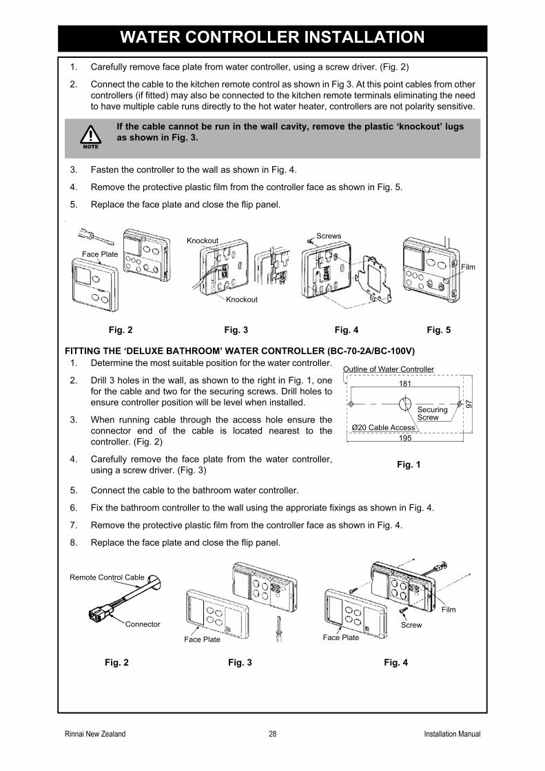
Rinnai New Zealand 28 Installation Manual
WATER CONTROLLER INSTALLATION
1. Carefully remove face plate from water controller, using a screw driver. (Fig. 2)
2. Connect the cable to the kitchen remote control as shown in Fig 3. At this point cables from other
controllers (if fitted) may also be connected to the kitchen remote terminals eliminating the need
to have multiple cable runs directly to the hot water heater, controllers are not polarity sensitive.
3. Fasten the controller to the wall as shown in Fig. 4.
4. Remove the protective plastic film from the controller face as shown in Fig. 5.
5. Replace the face plate and close the flip panel.
.
FITTING THE ‘DELUXE BATHROOM’ WATER CONTROLLER (BC-70-2A/BC-100V)
5. Connect the cable to the bathroom water controller.
6. Fix the bathroom controller to the wall using the approriate fixings as shown in Fig. 4.
7. Remove the protective plastic film from the controller face as shown in Fig. 4.
8. Replace the face plate and close the flip panel.
If the cable cannot be run in the wall cavity, remove the plastic ‘knockout’ lugs
as shown in Fig. 3.
Fig. 2 Fig. 3 Fig. 4 Fig. 5
1. Determine the most suitable position for the water controller.
2. Drill 3 holes in the wall, as shown to the right in Fig. 1, one
for the cable and two for the securing screws. Drill holes to
ensure controller position will be level when installed.
3. When running cable through the access hole ensure the
connector end of the cable is located nearest to the
controller. (Fig. 2)
4. Carefully remove the face plate from the water controller,
using a screw driver. (Fig. 3)Fig. 1
Fig. 2 Fig. 3 Fig. 4
NOTE
Face Plate
Knockout
Knockout
Screws
Film
181
195
Outline of Water Controller
97
SecuringScrew
Ø20 Cable Access
Remote Control Cable
Connector
Face Plate Face Plate
Screw
Film
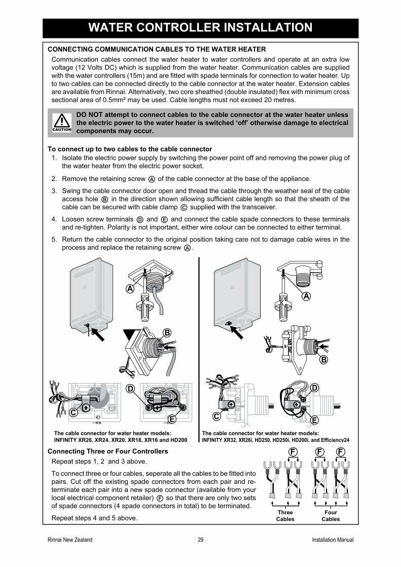
Rinnai New Zealand 29 Installation Manual
WATER CONTROLLER INSTALLATION
CONNECTING COMMUNICATION CABLES TO THE WATER HEATER
Communication cables connect the water heater to water controllers and operate at an extra low
voltage (12 Volts DC) which is supplied from the water heater. Communication cables are supplied
with the water controllers (15m) and are fitted with spade terminals for connection to water heater. Up
to two cables can be connected directly to the cable connector at the water heater. Extension cables
are available from Rinnai. Alternatively, two core sheathed (double insulated) flex with minimum cross
sectional area of 0.5mm² may be used. Cable lengths must not exceed 20 metres.
To connect up to two cables to the cable connector
DO NOT attempt to connect cables to the cable connector at the water heater unless
the electric power to the water heater is switched ‘off’ otherwise damage to electrical
components may occur.
1. Isolate the electric power supply by switching the power point off and removing the power plug of
the water heater from the electric power socket.
2. Remove the retaining screw of the cable connector at the base of the appliance.
3. Swing the cable connector door open and thread the cable through the weather seal of the cable
access hole in the direction shown allowing sufficient cable length so that the sheath of the
cable can be secured with cable clamp supplied with the transceiver.
4. Loosen screw terminals and and connect the cable spade connectors to these terminals
and re-tighten. Polarity is not important, either wire colour can be connected to either terminal.
5. Return the cable connector to the original position taking care not to damage cable wires in the
process and replace the retaining screw .
Connecting Three or Four Controllers
Repeat steps 1, 2 and 3 above.
To connect three or four cables, seperate all the cables to be fitted into
pairs. Cut off the existing spade connectors from each pair and re-
terminate each pair into a new spade connector (available from your
local electrical component retailer) so that there are only two sets
of spade connectors (4 spade connectors in total) to be terminated.
Repeat steps 4 and 5 above.
CAUTION
A
B
C
D E
A
A
B
A
CE
D
B
The cable connector for water heater models:The cable connector for water heater models:
INFINITY XR26, XR24, XR20, XR18, XR16 and HD200 INFINITY XR32, XR26i, HD250, HD250i, HD200i, and Efficiency24
F
Three
Cables
Four
Cables
F F F
Rinnai New Zealand 30 Installation Manual
COMMISSIONING
TESTING
1. Before final connection of the water heater purge gas, hot water and cold water supply lines.
Swarf in either the gas or water supplies may cause damage.
2. Turn on gas and cold water supplies.
3. Test for water leaks and gas escapes near the unit.
4. Isolate gas supply. Remove test point screw located on the gas inlet connection and attach
pressure gauge.
5. Turn the power 'on' at the power point socket and turn on gas.
6. If water controllers are fitted, turn ensure they are controller 'ON', select the maximum delivery
temperature and open ALL available hot water taps including the shower. If remote controllers
are not fitted, simply open all available hot water taps. (CAUTION: Ensure building occupants do
not have access to hot water outlets during this procedure.)
7. Operate ALL other gas appliances at their maximum gas rate, in accordance with manufacturers
instructions.
8. With all gas appliances in operation at maximum gas rate, the pressure should read between
1.0 - 3.5 kPa on Natural Gas. On LPG the pressure should be 2.75 - 3.5 kPa. If the pressure is
lower, the gas supply is inadequate and the appliance will not operate to specification. It is the
Installers responsibility to check the gas meter, service regulator and pipe work for correct
operation/sizing and rectify as required. Note that the gas regulator on the appliance is
electronically controlled and factory pre-set. Under normal circumstances it DOES NOT need
adjustment during installation.
9. Close hot water taps including the shower.
10. Inspect and clean the strainer located on the cold water inlet connection. This procedure may
need to be repeated to ensure the strainer remains clear, especially on new installations.
11. If water controllers are fitted, it is necessary to test their operation through the complete range of
functions (refer to the Operation sections of this manual).
12. Confirm the hot water delivery temperature(s) using a thermometer. If controllers are fitted,
ensure temperatures exceeding 55º C cannot be selected on bathroom or ensuite controllers.
13. After testing is completed, explain to the householder the functions and operation of the water
heater and temperature controllers (if fitted). Ensure the 'Customer Record' on page 17 of this
manual is filled in and that the booklet is handed to the customer.
GAS PRESSURE SETTING
The regulator is electronically controlled and factory pre-set. Under normal circumstances it does not
require adjustment during installation.
Make adjustments only if the unit is not operating correctly and all other possible causes for incorrect
operation have been eliminated.
Instructions for Gas Pressure Setting are to be found in the instruction pocket located inside the
appliance front cover.
COMMISSIONING CHECK LIST
A commissioning check list is provided to enable the installer to step through the correct
commissioning procedure when installing a Rinnai continuous flow water heater.
The check list can also assist the installer to identify potential installation errors that may prevent the
appliance from operating correctly.
For your convenience a copy of the commissioning check list has been provided on the following
page.
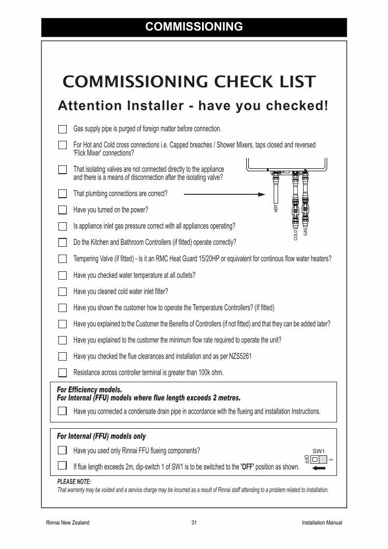
Rinnai New Zealand 31 Installation Manual
COMMISSIONING
Gas supply pipe is purged of foreign matter before connection.
For Hot and Cold cross connections i.e. Capped breaches / Shower Mixers, taps closed and reversed'Flick Mixer' connections?
That isolating valves are not connected directly to the applianceand there is a means of disconnection after the isolating valve?
That plumbing connections are correct?
Have you turned on the power?
Is appliance inlet gas pressure correct with all appliances operating?
Do the Kitchen and Bathroom Controllers (if fitted) operate correctly?
Tempering Valve (if fitted) - Is it an RMC Heat Guard 15/20HP or equivalent for continous flow water heaters?
Have you checked water temperature at all outlets?
Have you cleaned cold water inlet filter?
Have you shown the customer how to operate the Temperature Controllers? (If fitted)
Have you explained to the Customer the Benefits of Controllers (if not fitted) and that they can be added later?
Have you explained to the customer the minimum flow rate required to operate the unit?
Have you checked the flue clearances and installation and as per NZS5261
Have you used only Rinnai FFU flueing components?
If flue length exceeds 2m, dip-switch 1 of SW1 is to be switched to the 'OFF' position as shown.
Attention Installer - have you checked!
COMMISSIONING CHECK LIST
1OFF
SW1
For Internal (FFU) models only
PLEASE NOTE:
That warranty may be voided and a service charge may be incurred as a result of Rinnai staff attending to a problem related to installation.
Resistance across controller terminal is greater than 100k ohm.
For Efficiency models.For Internal (FFU) models where flue length exceeds 2 metres.
Have you connected a condensate drain pipe in accordance with the flueing and installation Instructions.
Rinnai New Zealand 32 Installation Manual
ACCESSORIES
Recess Box:
When installing an Rinnai continuous flow hot water heater in a new home or renovation, it is a great
idea to allow for a recess box to be included at the construction stage. These boxes allow you to
literally recess the appliance into the cavity of the wall saving precious space. In addition they virtually
hide your hot water system altogether.
All boxes and covers are suitable for painting to blend in with the exterior of your home.
Pipe Cover:
Where a recess box is not used, pipe covers are recommended as the finishing touch to an Rinnai
continuous flow hot water heater installation. Basically the covers are designed to hide the plumbing
pipework and valves. These are particularly popular in installations where the unit is permanently
visible to the occupants of the house. The cover can be easily attached to the appliance and two pipe
covers can be joined together for longer pipework if necessary.
Security Bracket:
Prevent theft by securing your Rinnai continuous flow hot water heater with our custom security
bracket, easily installed it covers the lower mounting bracket of the appliance to create a tamper proof
installation.
Flue Diverters
Designed to redirect flue products when the water heater is installed on a balcony, patio etc. this
product is available for selected models only.
Contact Rinnai for further information about our accessory range and model suitability details.
U283-932x02(00)
2007.10
Consumer Enquiries: 0800 746624 (0800 RINNAI)
Installer Enquiries: 0800 86746624 (0800 TORINNAI)
Customer Contacts
PO Box 24068 Royal Oak, Auckland
Email: [email protected]
www.rinnai.co.nz
691 Mt. Albert Road,
Rinnai New Zealand Limited
CONTACT INFORMATION