operating instructions gas engine - scdc
TRANSCRIPT
Operating InstructionsGas engine12V4000L32F16V4000L32F
MS150104/03E
Engine model kW/cyl. Application group12V4000L32F 100 kW/cyl. 3A, continuous power, unrestricted
16V4000L32F 100 kW/cyl. 3A, continuous power, unrestricted
Table 1: Applicability
© 2017 Copyright MTU Friedrichshafen GmbH
This publication is protected by copyright and may not be used in any way, whether in whole or in part, without the prior writ-ten consent of MTU Friedrichshafen GmbH. This particularly applies to its reproduction, distribution, editing, translation, micro-filming and storage or processing in electronic systems including databases and online services.
All information in this publication was the latest information available at the time of going to print. MTU Friedrichshafen GmbHreserves the right to change, delete or supplement the information provided as and when required.
Table of Contents1 Safety
1.1 Important provisions for all products 51.2 Correct use of all products 71.3 Personnel and organizational requirements 81.4 Initial start-up and operation – Safety
regulations 91.5 Safety regulations for startup and operation,
specific information for gaseous fuel or dualfuel supply applications 11
1.6 Assembly, maintenance, and repair work –Safety regulations 13
1.7 Safety regulations for assembly,maintenance and repair work, specificinformation for gaseous fuel and dual fuelsupply or applications 17
1.8 Fire and environmental protection, fluidsand lubricants 18
1.9 Fire prevention and environmentalprotection, fluids and lubricants, auxiliarymaterials, specific information for gaseousfuel supply in gaseous-fuel or dual-fuelapplications 20
1.10 Standards for warning notices in the textand highlighted information 21
2 Transport
2.1 Transport 22
3 Product Summary
3.1 Engine layout 233.2 Engine side and cylinder designations 253.3 Engine – Main dimensions 263.4 Firing order 273.5 Technical Data 28
3.5.1 12V4000L32F, 16V4000L32F engine data, fuel-optimized (TA-Luft) 28
3.5.2 Engine data 12V4000L32F, 16V4000L32F,emissions-optimized (1/2 TA-Luft) 32
3.6 Monitoring, Control and RegulationEquipment 363.6.1 Gas engine phase 4 system – Overview 363.6.2 Purpose of the units 38
4 Operation
4.1 Runtimes at partial load 404.2 Putting the engine into operation after
extended out-of-service periods (>3 months) 41
4.3 Putting the engine into operation afterscheduled out-of-service-period 42
4.4 Control, starting and stopping sequences 434.5 Engine – Start 454.6 Operational checks 464.7 Emission values – Check 474.8 Engine – Shutdown 494.9 Engine – Emergency shutdown 50
4.10 After stopping the engine – Engine remainsready for operation 52
4.11 After stopping the engine – Putting theengine out of operation 53
5 Maintenance
5.1 50-hours check 545.2 Maintenance task reference table [QL1] 55
6 Troubleshooting
6.1 Fault messages - Key 566.2 Fault messages in genset control system log 586.3 Engine governor – Fault messages 123
7 Task Description
7.1 Engine 1637.1.1 Engine – Barring manually 1637.1.2 Machine room – Check for smell of gas 164
7.2 Crankcase Breather 1657.2.1 Oil separator – Filter replacement 165
7.3 Ignition System 1677.3.1 Spark plug – Replacement 1677.3.2 Spark plug – Removal 1687.3.3 Spark plug – Installation 1697.3.4 Spark plug connector – Replacement 1717.3.5 Spark plug connector – Removal 1727.3.6 Spark plug connector – Cleaning and check 1737.3.7 Spark plug connector – Installation 1747.3.8 Ignition system – Ignition timing check 176
7.4 Valve Drive 1777.4.1 Valve protrusion – Measurement 1777.4.2 Valve clearance – Check and adjustment 1807.4.3 Valve gear – Lubrication 1827.4.4 Cylinder head cover ‒ Removal 1837.4.5 Cylinder head cover ‒ Installation 184
7.5 Gas System 1857.5.1 Gas supply - Checking gas lines for leaks 185
7.6 Air Filter 1867.6.1 Air filter – Replacement 186
MS150104/03E 2017-09 | Table of Contents | 3
DCL-
ID: 0
0000
2754
7 - 0
04
7.6.2 Air filter – Removal and installation 187
7.7 Lube Oil System, Lube Oil Circuit 1887.7.1 Engine oil level – Check 1887.7.2 Engine oil – Change 1897.7.3 Engine oil – Sample extraction and analysis 190
7.8 Oil Filtration / Cooling 1917.8.1 Engine oil filter – Replacement 191
7.9 Coolant Circuit, General, High-TemperatureCircuit 1927.9.1 Engine coolant – Level check 1927.9.2 Engine coolant – Change 1937.9.3 Engine coolant – Draining 1947.9.4 Engine coolant – Filling 1967.9.5 Vent line of engine coolant circuit –
Replacement 197
7.10 Low-Temperature Circuit 1987.10.1 Mixture coolant level – Check 198
7.10.2 Mixture coolant – Change 1997.10.3 Mixture coolant – Draining 2007.10.4 Mixture coolant – Filling 201
7.11 Wiring (General) for Engine/Gearbox/Unit 2027.11.1 Engine cabling – Check 2027.11.2 Sensors – Overview 2037.11.3 Sensors – Removal 2077.11.4 Sensors – Installation 209
8 Appendix A
8.1 Abbreviations 2108.2 MTU Onsite Energy contact person / service
partner 212
9 Appendix B
9.1 Special Tools 2139.2 Index 217
4 | Table of Contents | MS150104/03E 2017-09
DCL-
ID: 0
0000
2754
7 - 0
04
1 Safety
1.1 Important provisions for all products
General informationThis product may pose a risk of injury or damage in the following cases:• Incorrect use• Operation, maintenance and repair by unqualified personnel• Changes or modifications which are neither made nor authorized by the manufacturer• Noncompliance with the safety instructions and warning notices
NameplatesThe product is identified by nameplate, model designation or serial number and must match with the infor-mation on the title page of this manual.
Nameplates, model designation or serial number can be found on the product.
All EU-certified engines delivered by MTU come with a second nameplate. When operating the machine in theEU: The second nameplate must be affixed in a prominent position as described in the accompanying specifi-cations.
Emission regulations and emission labels
Responsibility for compliance with emission regulationsModification or removal of any mechanical/electronic components or the installation of additional compo-nents including the execution of calibration processes that might affect the emission characteristics of theproduct are prohibited by emission regulations. Emission-related components must only be serviced, ex-changed or repaired if the components used for this purpose are approved by the manufacturer.
Noncompliance with these specifications will invalidate the design type approval or certification issued bythe emissions regulation authorities. The manufacturer does not accept any liability for violations of theemission regulations.
The product must be operated over its entire life cycle according to the conditions defined as "Intended use"(→ Page 7).
Emission certification applicable to engines with EPA Nonroad Tier 4 emissioncertification in accordance with 40 CFR 1039Extract from the standard:
Failing to follow these instructions when installing a certified engine in a piece of nonroad equipment violatesfederal law (40 CFR 1068.105(b)), subject to fines or other penalties as described in the Clean Air Act.
Extract from the standard:
If you install the engine in a way that makes the engine's emission control information label hard to readduring normal engine maintenance, you must place a duplicate label on the equipment, as described in 40CFR 1068.105.
When fitting the second label, the requirements of 40 CFR 1068.105(c) must be followed and observed. Thisparagraph described the process for requesting and fitting the label, the documentation obligations and stor-age obligations for the required documents.
Replacing components with emission labelsOn all MTU engines fitted with emission labels, these labels must remain on the engine throughout its opera-tional life.
MS150104/03E 2017-09 | Safety | 5
TIM
-ID: 0
0000
4053
0 - 0
11
Exception: Engines used exclusively in land-based, military applications other than by US government agen-cies.
Please note the following when replacing components with emission labels:• The relevant emission labels must be affixed to the spare part.• Emission labels shall not be transferred from the replaced part to the spare part.• The emission labels must be removed from the replaced part and destroyed.
6 | Safety | MS150104/03E 2017-09
TIM
-ID: 0
0000
4053
0 - 0
11
1.2 Correct use of all products
Correct useThe product is intended for use in accordance with its contractually-defined purpose as described in the rele-vant technical documents only.
Intended use entails operation:• Within the permissible operating parameters in accordance with the (→ Technical data)• With fluids and lubricants approved by the manufacturer in accordance with the (→ Fluids and Lubricants
Specifications of the manufacturer)• With preservation approved by the manufacturer in accordance with the (→ Preservation and Represerva-
tion Specifications of the manufacturer)• With spare parts approved by the manufacturer in accordance with the (→ Spare Parts Catalog/MTU con-
tact/Service partner)• In the original as-delivered configuration or in a configuration approved by the manufacturer in writing (al-
so applies to engine control/parameters)• In compliance with all safety regulations and in adherence with all warning notices in this manual• In compliance with the maintenance work and intervals specified in the (→ Maintenance Schedule)
throughout the useful life of the product• In compliance with the maintenance and repair instructions contained in this manual, in particular with
regard to the specified tightening torques• With the exclusive use of technical personnel trained in commissioning, operation, maintenance and re-
pair
The product must not be operated in explosive atmospheres unless the engine fulfills the conditions for suchuse and approval has been granted.
Any other use, particularly misuse, is considered as being contrary to the intended purpose. Such improperuse increases the risk of injury and damage when working with the product. The manufacturer shall not beheld liable for any damage resulting from improper, non-intended use.
The specifications of the manufacturer will be amended or supplemented as necessary. Prior to operation,make sure that the latest version is used. The latest version can be found on the websites:• For drive systems: http://www.mtu-online.com• For power generation: http://www.mtuonsiteenergy.com
Modifications or conversionsUnauthorized changes to the product represent a contravention of its intended use and compromise safety.
Changes or modifications shall only be considered to comply with the intended use when expressly author-ized by the manufacturer. The manufacturer shall not be held liable for any damage resulting from unauthor-ized changes or modifications.
MS150104/03E 2017-09 | Safety | 7
TIM
-ID: 0
0000
6567
1 - 0
05
1.3 Personnel and organizational requirements
Organizational measures of the user/manufacturerThis manual must be issued to all personnel involved in operation, maintenance, repair, assembly, installa-tion, or transportation.
Keep this manual handy in the vicinity of the product such that it is accessible to operating, maintenance,repair, assembly, installation, and transport personnel at all times.
Personnel must receive instruction on product handling and repair based on this manual. In particular, per-sonnel must have read and understood the safety requirements and warnings before starting work.
This is important in the case of personnel who only occasionally perform work on or around the product.Such personnel must be instructed repeatedly.
Personnel requirementsAll work on the product must be carried out by trained, instructed and qualified personnel only:• Training at the Training Center of the manufacturer• Qualified personnel from the areas mechanical engineering, plant construction, and electrical engineering
The operator must define the responsibilities of the personnel involved in operation, maintenance, repair, as-sembly, installation, and transport in writing.
Personnel shall not report for duty under the influence of alcohol, drugs or strong medication.
Clothing and personal protective equipmentAlways wear appropriate personal protective equipment, e.g. safety shoes, ear protectors, protective gloves,goggles, breathing mask. Follow the instructions concerning personal protective equipment in the descrip-tions of the individual activities.
Safe handling of Substances of Very High Concern pursuant to the REACH regulation (Registration, Evalua-tion, Authorisation and restriction of CHemicals): We recommend wearing protective gloves at all times inorder to reduce risk when working.
8 | Safety | MS150104/03E 2017-09
TIM
-ID: 0
0000
4053
1 - 0
11
1.4 Initial start-up and operation – Safety regulations
Safety regulations for initial start-upInstall the product correctly and carry out acceptance in accordance with the manufacturer's specificationsbefore putting the product into service. All necessary approvals must be granted by the relevant authoritiesand all requirements for initial startup must be fulfilled.
Whenever the product is subsequently taken into operation ensure that:• All personnel is clear of the danger zone surrounding moving parts of the machine.
Electrically-actuated linkages may be set in motion when the Engine Control Unit (governor) is switchedon.
• All maintenance and repair work has been completed.• All loose parts have been removed from rotating machine components.• All safety equipment is in place.• All components must be properly grounded. Ground separately by means of a grounding stake as neces-
sary.• No persons wearing pacemakers or any other technical body aids are present.• The service room is adequately ventilated.• In the first few hours of operation, the product emits gases as a result of smoldering e.g. lacquers or oil.
These gases may be hazardous to health. Always wear respiratory protection in the operating room duringthis period.
• The exhaust system is leak-tight and that the gases are vented to atmosphere.• The product must be free of any damage, this applies in particular to lines and cabling.• Protect battery terminals, generator terminals or cables against accidental contact.• Check that all connections have been correctly allocated e.g. +/- polarity, fuel line/reduction agent line,
supply/return.
Immediately after putting the product into operation, make sure that all control and display instruments aswell as the monitoring, signaling and alarm systems work properly.
Smoking is prohibited in the area of the product.
Safety regulations during operationThe operator must be familiar with the control and display elements.
The operator must be familiar with the consequences of any operations performed.
During operation, the display instruments and monitoring units must be permanently observed with regard topresent operating status, violation of limit values and warning or alarm messages.
Malfunctions and emergency stopPractice emergency procedures, especially emergency stopping, at regular intervals.
Take the following steps if any system malfunctions are detected or signaled by the system:• inform supervisor(s) in charge,• analyze the message,• respond by taking any necessary emergency action, e.g. emergency stop.
Contact Service if the root cause of the malfunction cannot be clearly identified.
OperationDo not remain in the operating room when the product is running unless absolutely necessary. Keep yourstay as short as possible.
Keep a safe distance away from the product if possible. Do not touch the product unless expressly instructedto do so following a written procedure.
Do not inhale the exhaust gases of the product.
MS150104/03E 2017-09 | Safety | 9
TIM
-ID: 0
0000
4053
3 - 0
18
The following requirements must be fulfilled before the product is started:• Wear ear protectors.• Mop up any leaked or spilled fluids and lubricants immediately or soak up with a suitable binding agent.
Operation of electrical equipmentWhen electrical equipment is in operation, certain components of these appliances are electrically live.
Follow the applicable operating and safety instructions when operating the devices and heed warnings at alltimes.
10 | Safety | MS150104/03E 2017-09
TIM
-ID: 0
0000
4053
3 - 0
18
1.5 Safety regulations for startup and operation, specificinformation for gaseous fuel or dual fuel supply applications
General safety regulationsImportant informationThe fuel supplied to the gas engine is exclusively fuel gas.The fuel supply for dual fuel application is diesel with different shares of fuel gas.
Requirement for the user: Check the gas train every time the product is started.
The temperature of the gas during operation must not fall below 5 °C in any section.
Gas system, general requirementsThe plant manufacturer/user shall establish the connection to the gas supply in accordance with the applica-ble statutory requirements, e.g. DVGW, G490/I, G491/I, DIN EN 12186, NFPA37.
Gas supply shutoff: The plant manufacturer/user shall ensure that the gas shutoff device complies with localregulations.
The pressure regulator shall be equipped with an approved safety shutoff valve and a safety exhaust valve tohandle the situation where the pressure at the outlet of the gas pressure regulator is too high. The gas mustbe vented to a hazard-free zone (atmosphere).
The gas train shall be equipped with a temperature-monitored flame arrester if the gas supply system is con-nected to a vessel or if oxygen-containing gases are used.
The gas shutoff valves are activated via two different paths from the control system, with one path assignedto each of the gas shutoff valves.
The gas train shall feature minimum pressure monitoring.
Additional equipment may be necessary in the gas train, e.g. maximum pressure monitoring, if• gas supply pressure exceeds 100 mbar• gas volume flow exceeds 200 m³/h• fuel efficiency exceeds 600 KW
Safety regulations for initial startup in gas mixture/dual fuel applicationsWhenever the product is put into service, ensure that:• Mobile application: The product shall only be used outdoors.• Stationary application: The product shall only be used with adequate ventilation.
Gas system, requirements for gas operationThe plant manufacturer/user shall use tested gas trains for the fuel supply of the product and connection tothe gas supply network. The manufacturer shall be consulted on matters related to connection conditionsand dimensions.
Gas trains have the following components fitted in the flow direction:• a manual shutoff valve• a gas filter• two gas shutoff valves• a pressure regulating device
The gas train shall feature automatic leak monitoring.
The plant manufacturer/user shall ensure that the gas train is positioned directly in front of the engine, butno more than 3 meters upstream of the engine interface. The interface is the flange of the gas flow controlleror the connection of the gas/air mixer of the engine.
Series 400: The gas train must be positioned directly before the engine but no more than 2 meters upstreamof the engine interface.
MS150104/03E 2017-09 | Safety | 11
TIM
-ID: 0
0000
4055
0 - 0
09
Freedom of movement of the flexible line connection must be guaranteed in accordance with the installationinstructions.
Gas system, requirements for dual fuel applicationsGas trains feature the following components in the direction of flow (plant manufacturer/user scope of sup-ply):• a manual shutoff valve• a gas filter
Gas trains feature the following components in the direction of flow (MTU scope of supply):• two gas shutoff valves (automatic)• a pressure regulating device• a manual shutoff valve
12 | Safety | MS150104/03E 2017-09
TIM
-ID: 0
0000
4055
0 - 0
09
1.6 Assembly, maintenance, and repair work – Safety regulations
Safety regulations for work prior to assembly, maintenance, and repairHave assembly, maintenance, or repair work carried out by qualified and authorized personnel only.
Allow the product to cool down to less than 50 °C (risk of explosion for oil vapors, fluids and lubricants, riskof burning).
Relieve pressure in fluid and lubricant systems and compressed-air lines which are to be opened. Use suita-ble containers of adequate capacity to catch fluids and lubricants.
Release residual pressure before removing or replacing a component in the supply line. To depressurize pres-surized lines, shut off the lines first, then release the residual pressure.
When changing the oil or working on the fuel system, ensure that the service room is adequately ventilated.
Never carry out assembly, maintenance, or repair work with the product in operation, unless:• It is expressly permitted to do so following a written procedure.
Lock-out the product to preclude undesired starting, e.g.• Start interlock• Key switch• Close supply line for hydraulic starting.
Attach “Do not operate” sign in the operating area or to control equipment.
Disconnect the battery cables or actuate the battery isolating switch, if fitted. Lock circuit breakers.
Before starting work on CaPoS, if used:• Switch off the charging system (DC/DC converter).• Discharge the UltraCap modules using the appropriate discharger.• Short-circuit the UltraCap modules with a suitable wire jumper.
Close the main valve on the compressed-air system and vent the compressed-air line when pneumatic start-ers are fitted.
Before working on the exhaust aftertreatment system, close the shutoff valve on the reducing agent tank.Note that the reducing agent pumps continue to run for a certain period when the engine is stopped.
Disconnect the control equipment from the product.
Use the recommended special tools or suitable equivalents when instructed to do so.
Safety regulations when performing assembly, maintenance, and repair work
Special tools and lifting equipmentUse only proper and calibrated tools. Observe the specified tightening torques during assembly or disassem-bly.
Setting down, lifting and climbingCarry out work only on assemblies or plants which are properly secured.
Use appropriate lifting equipment for all components. Use all specified attachment points and observe thecenter of gravity.
Never work on engines or components when they are held in place by lifting equipment.
Make sure components or assemblies are placed on stable surfaces. Adopt suitable measures to preventcomponents/tools from falling down.
Assume a safe standing position when performing assembly work.
Never use the product as a climbing aid.
When working high on the equipment, always use suitable ladders and work platforms. Special instructionsfor outdoor areas: There must be no risk of slipping e.g. due to icing.
MS150104/03E 2017-09 | Safety | 13
TIM
-ID: 0
0000
4053
5 - 0
19
Removing, installing and cleanlinessPay particular attention to cleanliness at all times.
Take special care when removing ventilation or plug screws from the product.
Ensure that O-rings are not installed in a slanted/twisted condition.
Carry out appropriate cleaning procedures to clean and inspect components requiring special cleanness(e.g. components carrying oil, fuel, or air).
Note cooling time for components which are heated for installation or removal (risk of burning).
Ensure that all mounts and dampers are installed correctly.
Remove any accumulation of condensate after assembling chilled components. Coat the components with asuitable corrosion inhibitor as necessary.
LinesEnsure that lines for all fluids and lubricants and their connections are clean.
Always seal connections with caps or covers if a line is removed or opened.
Fit new seals when re-installing lines.
Never bend lines and avoid damaging lines, particularly the fuel lines.
Ensure that all fuel injection and pressurized oil lines are installed with enough clearance to prevent contactwith other components. Do not place fuel or oil lines near hot components.
MiscellaneousWear a breathing mask offering protection against soot, dust, and mineral fibers (filter class P3) when work-ing on exhaust components. Wear protective gloves and goggles for protection against acidic condensate.
Do not touch elastomeric seals (e.g. Viton sealing rings) with your bare hands if they have a carbonized orresinous appearance.
Elastomer components (e.g. engine mounts, damping elements, couplings and V-belts) must not be painted.Only install them after painting the engine or mask them prior to painting.
The following applies to starters with copper-beryllium alloy pinions:• Wear a respirator mask (filter class P3). Do not blow out the interior of the flywheel housing or the starter
with compressed air. Clean the flywheel housing inside with a class H dust extraction device.• Observe the safety data sheet.
Safety regulations after performing assembly, maintenance, and repair workBefore barring the engine, make sure that nobody is standing in the danger zone of the product.
Check that all access ports/apertures which have been opened to facilitate working are closed again.
Check that all safety equipment has been installed and that all tools and loose parts have been removed(especially the barring tool).
Ensure that no unattached parts have been left in/on the product (e.g. including rags and cable straps).
Ensure that the grounding system is properly connected.
Welding workWelding operations on the product or mounted units are not permitted. Cover the product when welding inits vicinity.
Before starting welding work:• Switch off the power supply master switch.• Disconnect the battery cables or actuate the battery isolating switch.• Separate the electrical ground of electronic equipment from the ground of the unit.
14 | Safety | MS150104/03E 2017-09
TIM
-ID: 0
0000
4053
5 - 0
19
No other assembly, maintenance, or repair work must be carried out in the vicinity of the product while weld-ing is in progress. There is a risk of explosion or fire due to oil vapors or highly flammable fluids and lubri-cants.
Do not use product as ground terminal.
Never position the welding power supply cable adjacent to, or crossing wiring harnesses of the product. Thewelding current can induce interfering voltages in the wiring harnesses which may damage the electrical sys-tem.
Remove components (e.g. exhaust pipe) from the product before performing necessary welding work.
Hydraulic installation and removalCheck the function and safe operating condition of tools and fixtures to be used. Use only the specified devi-ces for hydraulic removal/installation procedures.
Observe the max. permissible push-on pressure specified for the equipment.
Do not attempt to bend or apply force to lines which are under pressure.
Before starting work, pay attention to the following:• Vent the installation/removal device, the pumps and the pipework at the relevant designated points.• For hydraulic installation, screw on the tool with the piston retracted.• For hydraulic removal, screw on the tool with the piston extended.
For a hydraulic installation/removal device with central expansion pressure supply, screw spindle into shaftend until correct sealing is established.
During hydraulic installation and removal, ensure that nobody is standing in the immediate vicinity of thecomponent to be installed/removed.
Working with batteriesObserve the safety instructions of the manufacturer when working on batteries.
Gases released from the battery are explosive. Avoid sparks and naked flames.
Do not allow battery acids to come into contact with skin or clothing.
Wear protective clothing, goggles and protective gloves.
Do not place objects on the battery.
Before connecting the cable to the battery, check the battery polarity. The battery may explode and sprayacid if the battery terminals are connected incorrectly.
Working on electrical and electronic assembliesAlways obtain the permission of the person in charge before commencing assembly, maintenance, and repairwork or switching off any part of the electronic system required to do so.
De-energize the appropriate areas prior to working on assemblies.
ESD: Work on electrostatically endangered components which could be damaged by electrostatic discharge(ESD) must always be carried out with appropriate equipment. Appropriate equipment is e.g. electrically con-ductive work surfaces or antistatic wristbands.
Do not damage wiring during removal work. When reconnecting, ensure that cabling cannot be damaged dur-ing operation by:• Contact with sharp edges• Chafing on components• Contact with hot surfaces.
Do not secure cables on lines carrying fluids.
Do not use cable ties to secure lines.
Always use connector pliers to tighten union nuts on connectors.
MS150104/03E 2017-09 | Safety | 15
TIM
-ID: 0
0000
4053
5 - 0
19
Subject the device as well as the product to functional testing on completion of all repair work. The emergen-cy stop function must be tested in particular. The functional check of the emergency stop, during which thevoltage supply of the ECU is switched off, must only be carried out when the product is cold.
Store spare parts properly prior to replacement, i.e. protect them against moisture in particular. Packagefaulty electronic components or assemblies properly before dispatching for repair:• Moisture-proof• Shock-proof• Wrapped in antistatic foil (as necessary)
Working with laser equipmentWork with laser devices shall be carried out by trained and qualified personnel only. Follow the safety in-structions in the manufacturer's user manual when working with laser equipment.
Wear special laser safety glasses when working with laser equipment (danger of concentrated radiation).
Laser equipment must be fitted with the protective devices necessary for safe operation according to typeand application.
Measuring component dimensionsWorkpieces, components and measuring equipment lie in the specified tolerance range at a reference tem-perature of 20 °C.
16 | Safety | MS150104/03E 2017-09
TIM
-ID: 0
0000
4053
5 - 0
19
1.7 Safety regulations for assembly, maintenance and repairwork, specific information for gaseous fuel and dual fuelsupply or applications
Safety regulations for work prior to assembly, maintenance, and repairAssembly work shall be performed by specially trained/qualified and authorized personnel only.
The gas supply shall be connected by trained/qualified and authorized personnel only.
Work on the gas-bearing parts of the product shall be performed by specially trained/qualified and author-ized personnel only.
Ensure adequate – possibly increased – ventilation before opening the gas system.
Shut down the gas supply to the product by closing the manual shutoff valve.
Lock-out / tag-out the drive unit to prevent starting.
MS150104/03E 2017-09 | Safety | 17
TIM
-ID: 0
0000
4054
9 - 0
08
1.8 Fire and environmental protection, fluids and lubricants
Fire prevention and fireFire, naked light and smoking are prohibited.
The product has hot surfaces that can ignite combustible gases and other substances in the immediate area.The operating company must install and operate the product a safe distance away from danger sources andobserve any relevant safety regulations or recommendations. Products that comply with the SOLAS Conven-tion do not constitute such as danger.
After working with combustible fluids and lubricants (e.g. cleaning agents), ensure the area is well ventilated.The resultant steam/air mixture must be sufficiently diluted to prevent a potentially explosive atmosphere.
Rectify any fuel or oil leaks immediately. Fuel or oil on hot components can cause fires – therefore alwayskeep the product in a clean condition. Do not leave rags saturated with fluids and lubricants on the product.Do not store combustible materials near the product.
Before welding, clean the area to be welded with a nonflammable fluid. Do not carry out welding work onpipes and components carrying oil or fuel.
When starting the engine with an external power source, connect the ground lead last and remove it first. Toavoid sparks in the vicinity of the battery, connect the ground cable from the external power source to theground cable of the engine or to the ground terminal of the starter.
Ensure that suitable extinguishing agents (fire extinguishers) are always available and that staff are familiarwith their correct handling.
A fire can result in the creation of toxic substances. Always wear protective gloves when handling compo-nents and wear additional personal protective equipment is necessary.
NoiseWear ear protectors in workplaces with a sound pressure level in excess of 85 dB (A).
Noise can lead to an increased risk of accidents if acoustic signals, warning shouts or sounds indicating dan-ger are compromised.
Environmental protection and disposalDispose of used fluids, lubricants and components in accordance with local regulations.
Within the EU, batteries can be returned free of charge to the manufacturer where they will be properly recy-cled.
Operating fluids and auxiliary materials (process materials)Process materials can also be or contain hazardous or toxic substances. When using process materials andother chemical substances, observe the associated safety data sheet. The safety data sheet may be obtainedfrom the relevant manufacturer or from MTU.
Only process materials approved by the manufacturer in accordance with the Fluids and Lubricants Specifi-cations must be used. The most recent respective version must be requested from the manufacturer.
Contamination of process materials with reducing agent (e.g. AdBlue®, DEF): Store process materials in sep-arate containers and their own drip trays. Even extremely small amounts of reducing agent contaminationcan result in malfunctions in sensors and other components.
Used oil contains combustion residues that are harmful to health.
When handling used oil, protective gloves must be used.
Wash relevant areas after contact with used oil.
18 | Safety | MS150104/03E 2017-09
TIM
-ID: 0
0000
4053
6 - 0
16
Registration, evaluation, approval and restriction of chemicals (REACHordinance)Particularly hazardous substances used with our products are named in a list:
www.mtu-online.com/mtu/technische-info → SVHC as per REACH in MTU products
Compressed air• Unauthorized use of compressed air, e.g. forcing flammable liquids (hazard class AI, AII and B) out of con-
tainers, risks causing an explosion.• Wear goggles when blowing dirt off workpieces or blowing away chips.• Blowing compressed air into thin-walled containers (e.g. containers made of sheet metal, plastic or glass)
for drying purposes or to check for leaks risks bursting them.• Pay special attention to the pressure in the compressed air system or pressure vessel.• Assemblies or products which are to be connected must be designed to withstand this pressure. Install
pressure-reducing or safety valves set to the admissible pressure if this is not the case.• Hose couplings and connections must be securely attached.• Provide the snout of the air nozzle with a protective disk (e.g. rubber disk).• Release residual pressure before removing a compressed air device from the supply line. To depressurize
compressed-air lines, shut off the lines first, then release the residual pressure.• Carry out a leak test in the specified manner.
Painting• Observe the relevant safety data sheet for all materials.• When carrying out painting work outside the spray stands provided with fume extraction systems, ensure
that the area is well ventilated. Make sure that neighboring work areas are not adversely affected.• There must be no naked flames in the vicinity.• No smoking.• Observe fire-prevention regulations.• Always wear a mask providing protection against paint and solvent vapors.
Liquid nitrogen• Observe the relevant safety data sheet for all materials.• Work with liquid nitrogen may be carried out only by qualified personnel.• Store liquid nitrogen only in small quantities and always in specified containers without fixed covers.• Avoid body contact (eyes, hands).• Wear protective clothing, protective gloves, closed shoes and safety goggles.• Make sure that the working area is well ventilated.• Avoid knocking or jolting the containers, valves and fittings or workpieces in any way.
Acids/alkalines/reducing agents (e.g. AdBlue®, DEF)• Observe the relevant safety data sheet for all materials.• When working with acids and alkaline solutions, wear goggles or face mask, gloves and protective cloth-
ing.• Do not inhale vapors.• If reducing agent is swallowed, rinse out mouth and drink plenty of water.• Remove any wet clothing immediately.• After skin contact, wash affected body areas with plenty of water.• Rinse eyes immediately with eyedrops or clean mains water. Consult a doctor as soon as possible.
Contamination of reducing agent with other process materials: Store reducing agent in separate contain-ers and use separate drip trays. Even extremely slight contamination can lead to malfunctions in the ex-haust aftertreatment system.
MS150104/03E 2017-09 | Safety | 19
TIM
-ID: 0
0000
4053
6 - 0
16
1.9 Fire prevention and environmental protection, fluids andlubricants, auxiliary materials, specific information forgaseous fuel supply in gaseous-fuel or dual-fuel applications
General notes on gasObserve the information contained in the safety data sheet of the gas used. Consult with gas supplier/utility.
The gas used must comply with the (→ Fluids and Lubricants Specifications of the manufacturer).
Risk of poisoning due to hazardous impurities. The ingestion of even small quantities of hydrogen sulfide orammonia can be fatal.
Inhaling certain gases can be dangerous to life depending on concentration. Furthermore some gases can nolonger be detected by smell in higher concentrations.
Conduct in case of escaping gases:• If safe to do so: Shut off main gas supply.• If safe to do so: Execute an emergency stop.• Cordon off danger zone.• Ensure sufficient ventilation.• Do not enter the hazard zone until it has been established (via measurement of the gas concentration with
a suitable gas detector) that the atmosphere is no longer hazardous.
Check all gas conveying lines for tightness prior to initial operation and at regular intervals during operation.
Natural gas (pipeline quality)Highly flammable gas; forms an explosive mixture with air/oxygen.
Weakly narcotic gas; risk of suffocation at high concentrations.
Biogenic gases from fermentation processesHighly flammable gas; forms an explosive mixture with air/oxygen.
Risk of poisoning due to hydrogen sulfide from the fermentation process. The ingestion of even small quanti-ties of hydrogen sulfide can be fatal.
Weakly narcotic gas; risk of suffocation at high concentrations.
Biogenic gases have a tendency to segregate. In low-lying areas of the plant, carbon dioxide enrichment ispossible.
20 | Safety | MS150104/03E 2017-09
TIM
-ID: 0
0000
4053
7 - 0
05
1.10 Standards for warning notices in the text and highlightedinformation
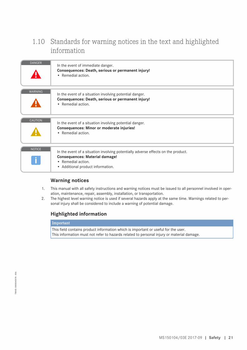
DANGERIn the event of immediate danger.Consequences: Death, serious or permanent injury!• Remedial action.
WARNINGIn the event of a situation involving potential danger.Consequences: Death, serious or permanent injury!• Remedial action.
CAUTIONIn the event of a situation involving potential danger.Consequences: Minor or moderate injuries!• Remedial action.
NOTICEIn the event of a situation involving potentially adverse effects on the product.Consequences: Material damage!• Remedial action.• Additional product information.
Warning notices1. This manual with all safety instructions and warning notices must be issued to all personnel involved in oper-
ation, maintenance, repair, assembly, installation, or transportation.2. The highest level warning notice is used if several hazards apply at the same time. Warnings related to per-
sonal injury shall be considered to include a warning of potential damage.
Highlighted informationImportantThis field contains product information which is important or useful for the user.This information must not refer to hazards related to personal injury or material damage.
MS150104/03E 2017-09 | Safety | 21
TIM
-ID: 0
0000
4057
8 - 0
06
2 Transport
2.1 TransportTaking the engine's center of gravity into accountFor information regarding the center of gravity of the engine, refer to the installation/arrangement drawingof the engine/genset/system.
Transport• Lift the engine/genset/system only with the lifting eyes provided.• Only use transport and lifting devices approved by MTU.• The engine/genset/system must only be transported in installation position.• Max. permissible diagonal pull 10°.• If the engine/genset/system is supplied with special aluminum foil packing, lift it at the lifting eyes of the
trestle or use a means of transportation which is appropriate for the given weight (forklift truck).• Prior to transporting the engine/genset/system, it is imperative to install the transport locking device for
the crankshaft.• Prior to transporting the engine/genset/system, it is imperative to install the transport locks for the en-
gine mounts.• Secure the engine/genset/system such as to preclude tipping during transport.• Secure the engine/system/genset as to preclude slipping and tipping when driving up or down inclines
and ramps.
Setting the engine down after transport• Make sure that the consistency and load-bearing capacity of the ground or support surface is adequate.• Never set an engine/genset/system down on the oil pan unless expressively authorized to do so by MTU
on a case-to-case basis.• Place the engine/genset/system on a firm, flat surface only.
22 | Transport | MS150104/03E 2017-09
TIM
-ID: 0
0000
0261
4 - 0
05
3 Product Summary
3.1 Engine layout
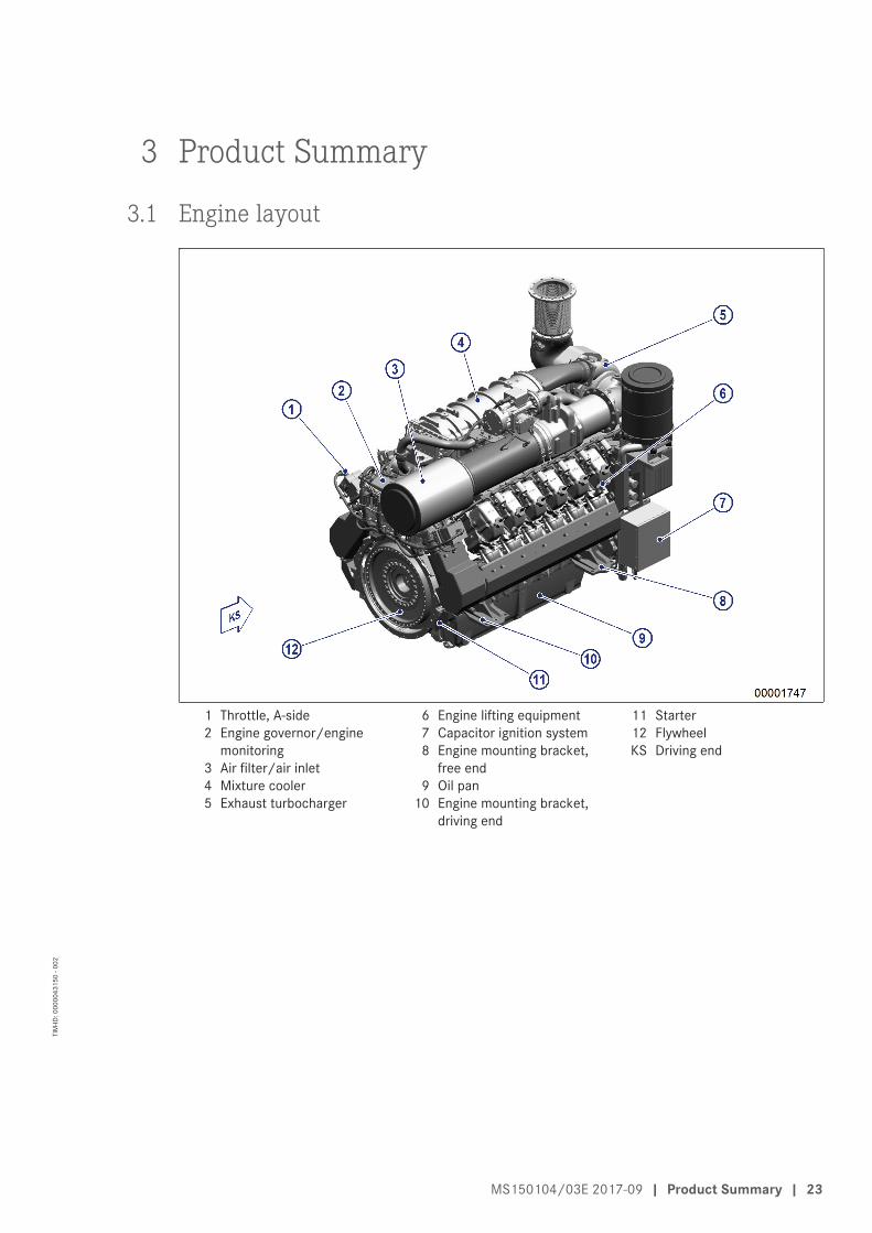
1 Throttle, A-side2 Engine governor/engine
monitoring3 Air filter/air inlet4 Mixture cooler5 Exhaust turbocharger
6 Engine lifting equipment7 Capacitor ignition system8 Engine mounting bracket,
free end9 Oil pan
10 Engine mounting bracket,driving end
11 Starter12 FlywheelKS Driving end
MS150104/03E 2017-09 | Product Summary | 23
TIM
-ID: 0
0000
4315
0 - 0
02
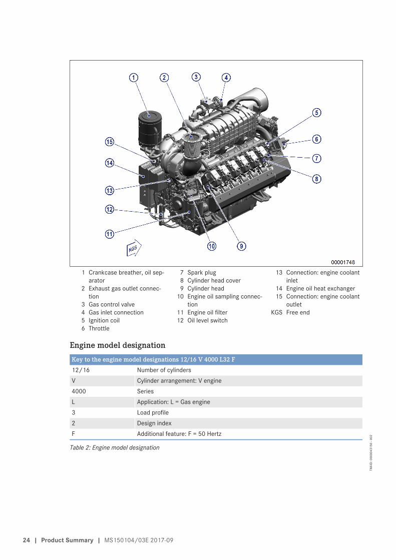
1 Crankcase breather, oil sep-arator
2 Exhaust gas outlet connec-tion
3 Gas control valve4 Gas inlet connection5 Ignition coil6 Throttle
7 Spark plug8 Cylinder head cover9 Cylinder head
10 Engine oil sampling connec-tion
11 Engine oil filter12 Oil level switch
13 Connection: engine coolantinlet
14 Engine oil heat exchanger15 Connection: engine coolant
outletKGS Free end
Engine model designationKey to the engine model designations 12/16 V 4000 L32 F12/16 Number of cylindersV Cylinder arrangement: V engine4000 SeriesL Application: L = Gas engine3 Load profile2 Design indexF Additional feature: F = 50 Hertz
Table 2: Engine model designation
24 | Product Summary | MS150104/03E 2017-09
TIM
-ID: 0
0000
4315
0 - 0
02
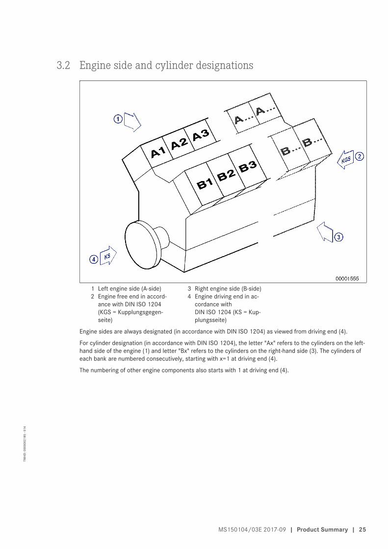
3.2 Engine side and cylinder designations
1 Left engine side (A-side)2 Engine free end in accord-
ance with DIN ISO 1204(KGS = Kupplungsgegen-seite)
3 Right engine side (B-side)4 Engine driving end in ac-
cordance withDIN ISO 1204 (KS = Kup-plungsseite)
Engine sides are always designated (in accordance with DIN ISO 1204) as viewed from driving end (4).
For cylinder designation (in accordance with DIN ISO 1204), the letter "Ax" refers to the cylinders on the left-hand side of the engine (1) and letter "Bx" refers to the cylinders on the right-hand side (3). The cylinders ofeach bank are numbered consecutively, starting with x=1 at driving end (4).
The numbering of other engine components also starts with 1 at driving end (4).
MS150104/03E 2017-09 | Product Summary | 25
TIM
-ID: 0
0000
0218
5 - 0
14
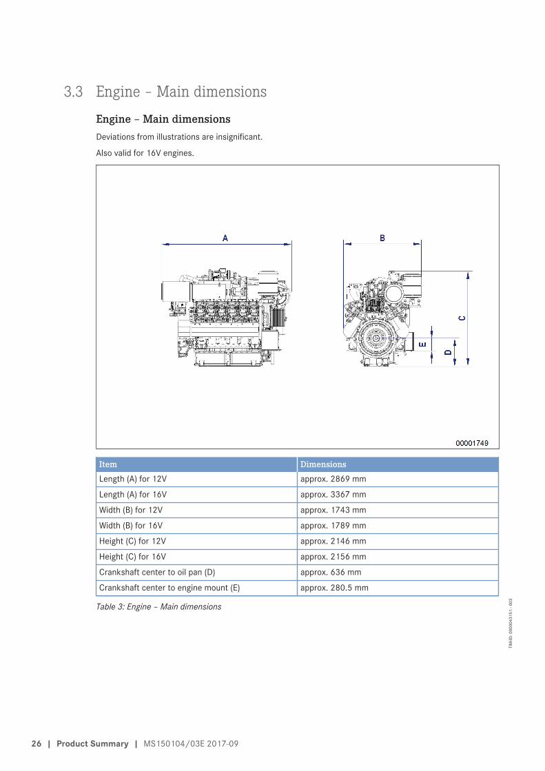
3.3 Engine – Main dimensions
Engine – Main dimensionsDeviations from illustrations are insignificant.
Also valid for 16V engines.
Item DimensionsLength (A) for 12V approx. 2869 mm
Length (A) for 16V approx. 3367 mm
Width (B) for 12V approx. 1743 mm
Width (B) for 16V approx. 1789 mm
Height (C) for 12V approx. 2146 mm
Height (C) for 16V approx. 2156 mm
Crankshaft center to oil pan (D) approx. 636 mm
Crankshaft center to engine mount (E) approx. 280.5 mm
Table 3: Engine – Main dimensions
26 | Product Summary | MS150104/03E 2017-09
TIM
-ID: 0
0000
4315
1 - 0
03
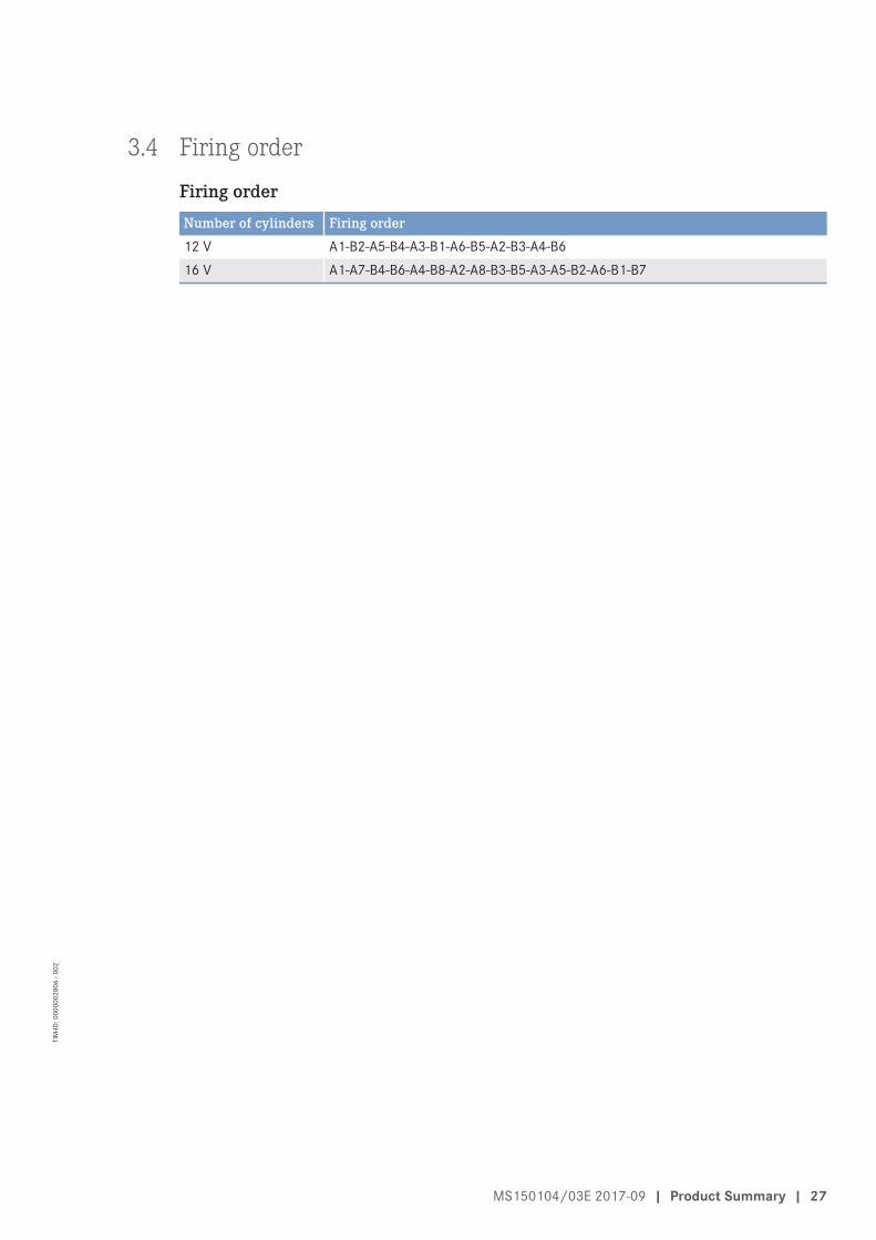
3.4 Firing order
Firing orderNumber of cylinders Firing order12 V A1-B2-A5-B4-A3-B1-A6-B5-A2-B3-A4-B616 V A1-A7-B4-B6-A4-B8-A2-A8-B3-B5-A3-A5-B2-A6-B1-B7
MS150104/03E 2017-09 | Product Summary | 27
TIM
-ID: 0
0000
0280
6 - 0
02
3.5 Technical Data
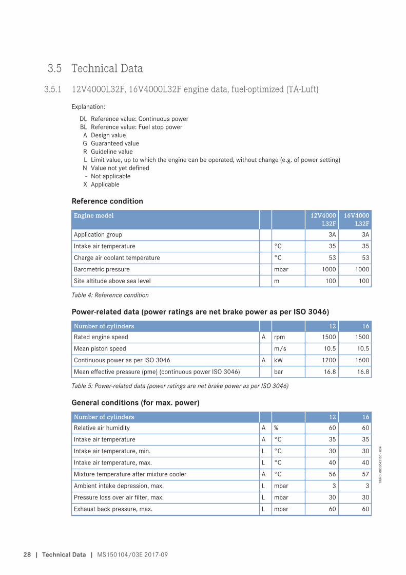
3.5.1 12V4000L32F, 16V4000L32F engine data, fuel-optimized (TA-Luft)
Explanation:
DL Reference value: Continuous powerBL Reference value: Fuel stop powerA Design valueG Guaranteed valueR Guideline valueL Limit value, up to which the engine can be operated, without change (e.g. of power setting)N Value not yet defined- Not applicable
X Applicable
Reference conditionEngine model 12V4000
L32F16V4000
L32FApplication group 3A 3A
Intake air temperature °C 35 35
Charge air coolant temperature °C 53 53
Barometric pressure mbar 1000 1000
Site altitude above sea level m 100 100
Table 4: Reference condition
Power-related data (power ratings are net brake power as per ISO 3046)Number of cylinders 12 16Rated engine speed A rpm 1500 1500
Mean piston speed m/s 10.5 10.5
Continuous power as per ISO 3046 A kW 1200 1600
Mean effective pressure (pme) (continuous power ISO 3046) bar 16.8 16.8
Table 5: Power-related data (power ratings are net brake power as per ISO 3046)
General conditions (for max. power)Number of cylinders 12 16Relative air humidity A % 60 60
Intake air temperature A °C 35 35
Intake air temperature, min. L °C 30 30
Intake air temperature, max. L °C 40 40
Mixture temperature after mixture cooler A °C 56 57
Ambient intake depression, max. L mbar 3 3
Pressure loss over air filter, max. L mbar 30 30
Exhaust back pressure, max. L mbar 60 60
28 | Technical Data | MS150104/03E 2017-09
TIM
-ID: 0
0000
4315
3 - 0
04
Number of cylinders 12 16Gas type: natural gas X X
Methane number, min. L 80 80
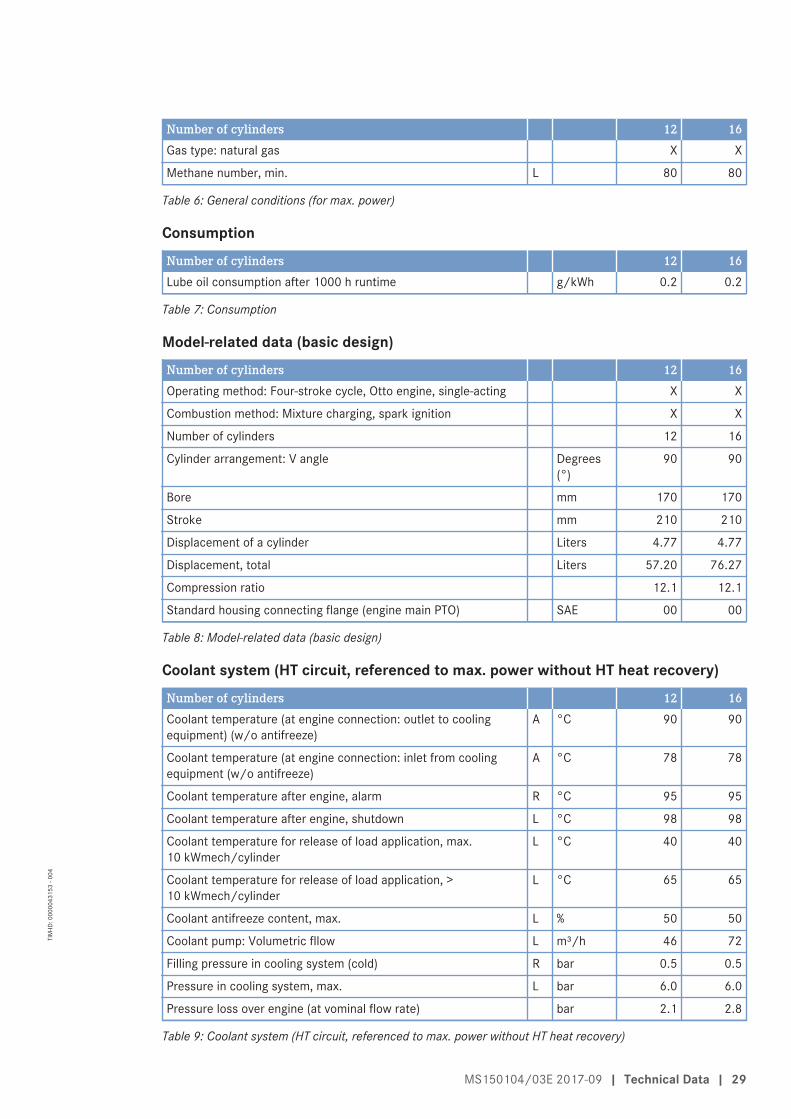
Table 6: General conditions (for max. power)
ConsumptionNumber of cylinders 12 16Lube oil consumption after 1000 h runtime g/kWh 0.2 0.2
Table 7: Consumption
Model-related data (basic design)Number of cylinders 12 16Operating method: Four-stroke cycle, Otto engine, single-acting X X
Combustion method: Mixture charging, spark ignition X X
Number of cylinders 12 16
Cylinder arrangement: V angle Degrees(°)
90 90
Bore mm 170 170
Stroke mm 210 210
Displacement of a cylinder Liters 4.77 4.77
Displacement, total Liters 57.20 76.27
Compression ratio 12.1 12.1
Standard housing connecting flange (engine main PTO) SAE 00 00
Table 8: Model-related data (basic design)
Coolant system (HT circuit, referenced to max. power without HT heat recovery)Number of cylinders 12 16Coolant temperature (at engine connection: outlet to coolingequipment) (w/o antifreeze)
A °C 90 90
Coolant temperature (at engine connection: inlet from coolingequipment (w/o antifreeze)
A °C 78 78
Coolant temperature after engine, alarm R °C 95 95
Coolant temperature after engine, shutdown L °C 98 98
Coolant temperature for release of load application, max.10 kWmech/cylinder
L °C 40 40
Coolant temperature for release of load application, >10 kWmech/cylinder
L °C 65 65
Coolant antifreeze content, max. L % 50 50
Coolant pump: Volumetric fllow L m³/h 46 72
Filling pressure in cooling system (cold) R bar 0.5 0.5
Pressure in cooling system, max. L bar 6.0 6.0
Pressure loss over engine (at vominal flow rate) bar 2.1 2.8
Table 9: Coolant system (HT circuit, referenced to max. power without HT heat recovery)
MS150104/03E 2017-09 | Technical Data | 29
TIM
-ID: 0
0000
4315
3 - 0
04

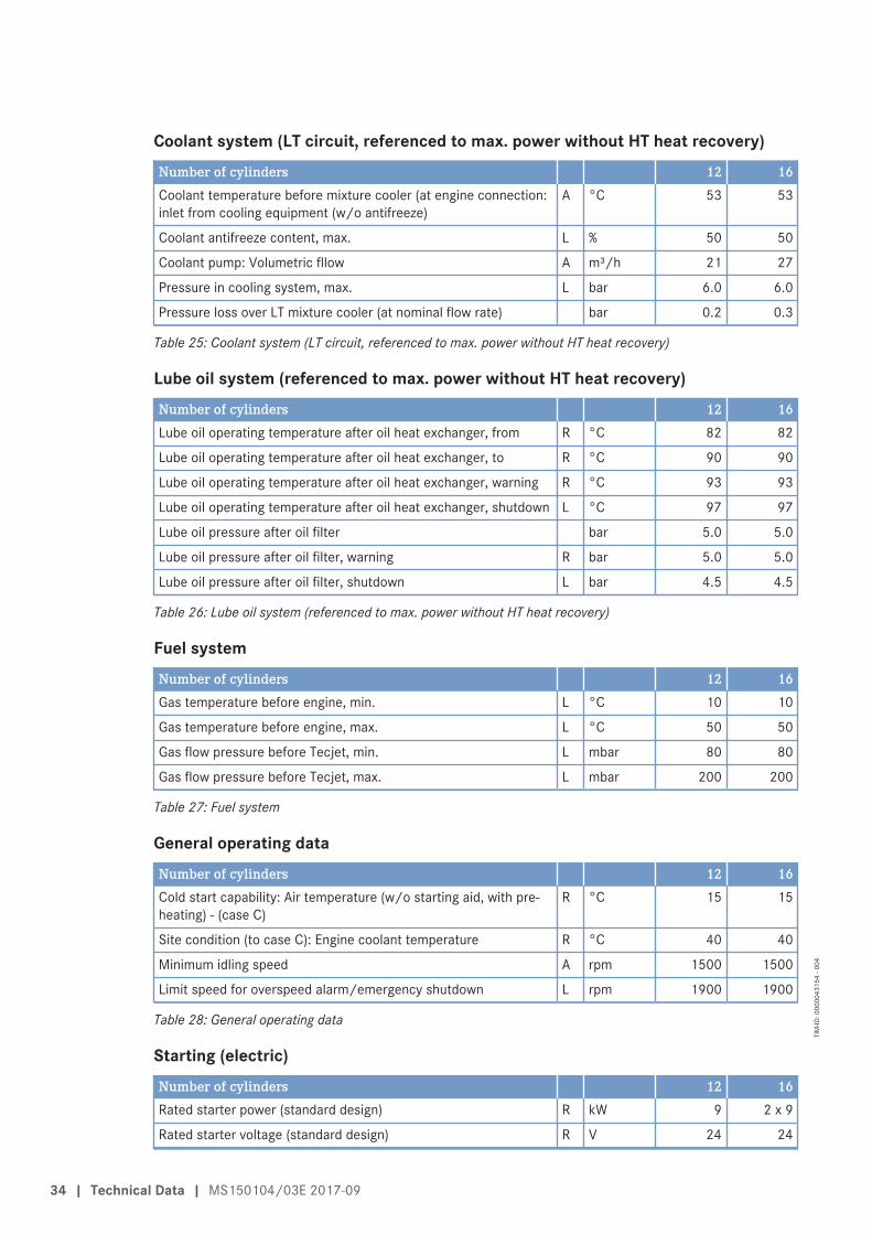
Coolant system (LT circuit, referenced to max. power without HT heat recovery)Number of cylinders 12 16Coolant temperature before mixture cooler (at engine connection:inlet from cooling equipment (w/o antifreeze)
A °C 53 53
Coolant antifreeze content, max. L % 50 50
Coolant pump: Volumetric fllow A m³/h 21 27
Pressure in cooling system, max. L bar 6.0 6.0
Pressure loss over LT mixture cooler (at nominal flow rate) bar 0.2 0.3
Table 10: Coolant system (LT circuit, referenced to max. power without HT heat recovery)
Lube oil system (referenced to max. power without HT heat recovery)Number of cylinders 12 16Lube oil operating temperature after oil heat exchanger, from R °C 82 82
Lube oil operating temperature after oil heat exchanger, to R °C 90 90
Lube oil operating temperature after oil heat exchanger, warning R °C 93 93
Lube oil operating temperature after oil heat exchanger, shutdown L °C 97 97
Lube oil pressure after oil filter bar 5.0 5.0
Lube oil pressure after oil filter, warning R bar 5.0 5.0
Lube oil pressure after oil filter, shutdown L bar 4.5 4.5
Table 11: Lube oil system (referenced to max. power without HT heat recovery)
Fuel systemNumber of cylinders 12 16Gas temperature before engine, min. L °C 10 10
Gas temperature before engine, max. L °C 50 50
Gas flow pressure before Tecjet, min. L mbar 80 80
Gas flow pressure before Tecjet, max. L mbar 200 200
Table 12: Fuel system
General operating dataNumber of cylinders 12 16Cold start capability: Air temperature (w/o starting aid, with pre-heating) - (case C)
R °C 15 15
Site condition (to case C): Engine coolant temperature R °C 40 40
Minimum idling speed A rpm 1500 1500
Limit speed for overspeed alarm/emergency shutdown L rpm 1900 1900
Table 13: General operating data
Starting (electric)Number of cylinders 12 16Rated starter power (standard design) R kW 9 2 x 9
Rated starter voltage (standard design) R V 24 24
30 | Technical Data | MS150104/03E 2017-09
TIM
-ID: 0
0000
4315
3 - 0
04
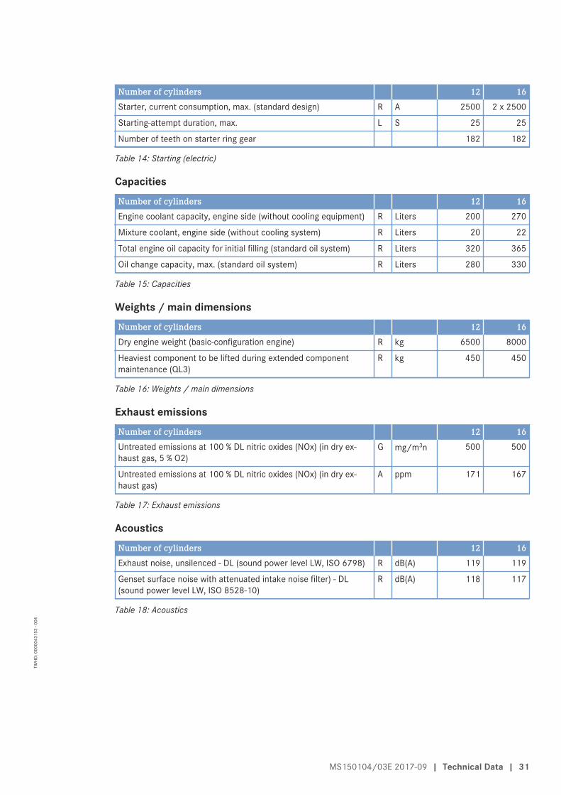
Number of cylinders 12 16Starter, current consumption, max. (standard design) R A 2500 2 x 2500
Starting-attempt duration, max. L S 25 25
Number of teeth on starter ring gear 182 182
Table 14: Starting (electric)
CapacitiesNumber of cylinders 12 16Engine coolant capacity, engine side (without cooling equipment) R Liters 200 270
Mixture coolant, engine side (without cooling system) R Liters 20 22
Total engine oil capacity for initial filling (standard oil system) R Liters 320 365
Oil change capacity, max. (standard oil system) R Liters 280 330
Table 15: Capacities
Weights / main dimensionsNumber of cylinders 12 16Dry engine weight (basic-configuration engine) R kg 6500 8000
Heaviest component to be lifted during extended componentmaintenance (QL3)
R kg 450 450
Table 16: Weights / main dimensions
Exhaust emissionsNumber of cylinders 12 16Untreated emissions at 100 % DL nitric oxides (NOx) (in dry ex-haust gas, 5 % O2)
G mg/m3n 500 500
Untreated emissions at 100 % DL nitric oxides (NOx) (in dry ex-haust gas)
A ppm 171 167
Table 17: Exhaust emissions
AcousticsNumber of cylinders 12 16Exhaust noise, unsilenced - DL (sound power level LW, ISO 6798) R dB(A) 119 119
Genset surface noise with attenuated intake noise filter) - DL(sound power level LW, ISO 8528-10)
R dB(A) 118 117
Table 18: Acoustics
MS150104/03E 2017-09 | Technical Data | 31
TIM
-ID: 0
0000
4315
3 - 0
04
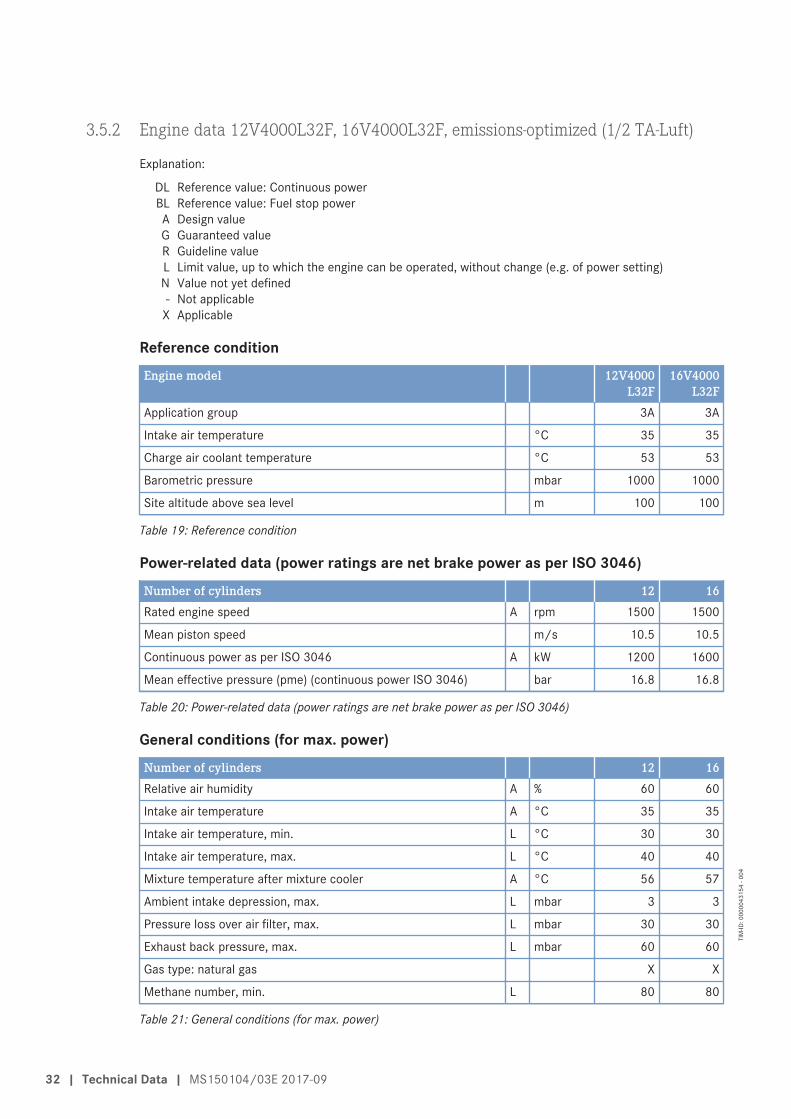
3.5.2 Engine data 12V4000L32F, 16V4000L32F, emissions-optimized (1/2 TA-Luft)
Explanation:
DL Reference value: Continuous powerBL Reference value: Fuel stop powerA Design valueG Guaranteed valueR Guideline valueL Limit value, up to which the engine can be operated, without change (e.g. of power setting)N Value not yet defined- Not applicable
X Applicable
Reference conditionEngine model 12V4000
L32F16V4000
L32FApplication group 3A 3A
Intake air temperature °C 35 35
Charge air coolant temperature °C 53 53
Barometric pressure mbar 1000 1000
Site altitude above sea level m 100 100
Table 19: Reference condition
Power-related data (power ratings are net brake power as per ISO 3046)Number of cylinders 12 16Rated engine speed A rpm 1500 1500
Mean piston speed m/s 10.5 10.5
Continuous power as per ISO 3046 A kW 1200 1600
Mean effective pressure (pme) (continuous power ISO 3046) bar 16.8 16.8
Table 20: Power-related data (power ratings are net brake power as per ISO 3046)
General conditions (for max. power)Number of cylinders 12 16Relative air humidity A % 60 60
Intake air temperature A °C 35 35
Intake air temperature, min. L °C 30 30
Intake air temperature, max. L °C 40 40
Mixture temperature after mixture cooler A °C 56 57
Ambient intake depression, max. L mbar 3 3
Pressure loss over air filter, max. L mbar 30 30
Exhaust back pressure, max. L mbar 60 60
Gas type: natural gas X X
Methane number, min. L 80 80
Table 21: General conditions (for max. power)
32 | Technical Data | MS150104/03E 2017-09
TIM
-ID: 0
0000
4315
4 - 0
04
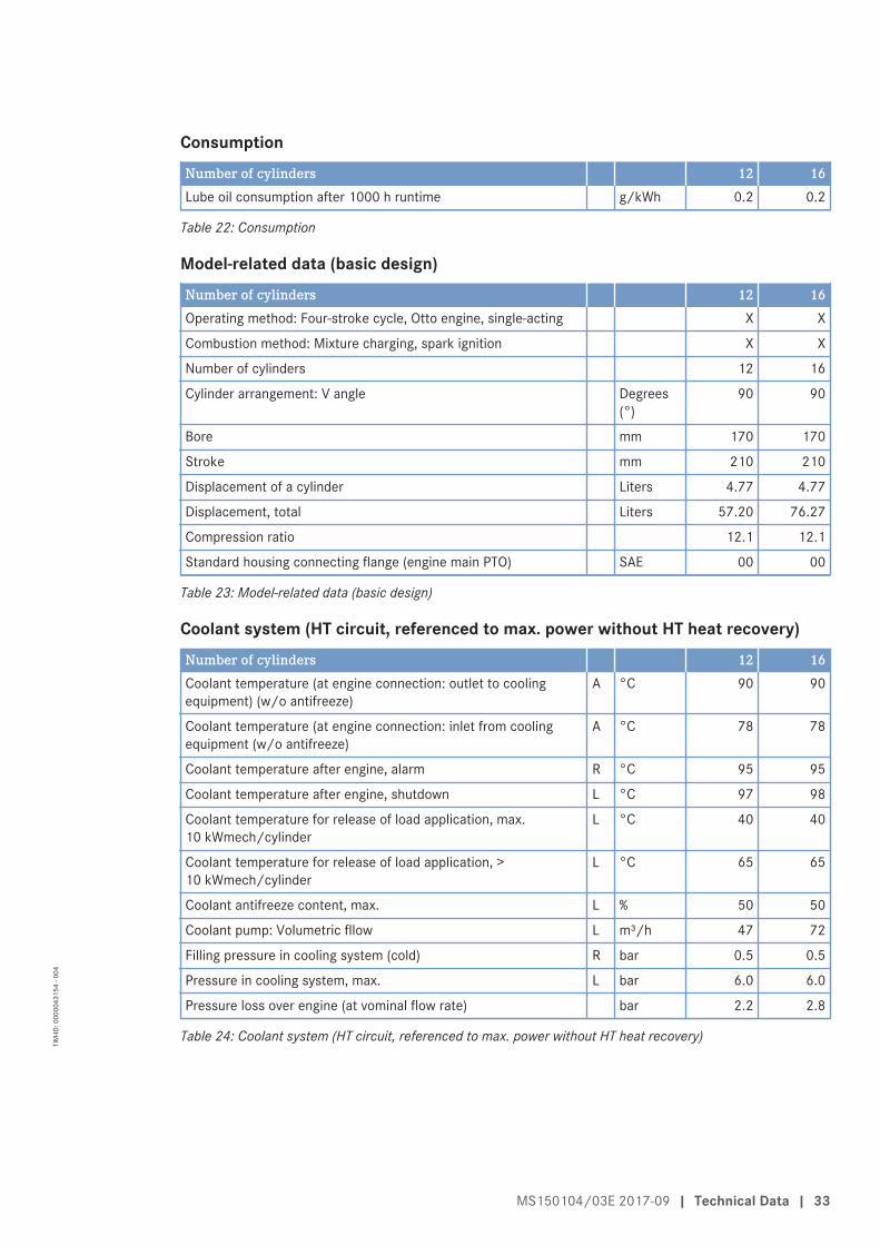
ConsumptionNumber of cylinders 12 16Lube oil consumption after 1000 h runtime g/kWh 0.2 0.2
Table 22: Consumption
Model-related data (basic design)Number of cylinders 12 16Operating method: Four-stroke cycle, Otto engine, single-acting X X
Combustion method: Mixture charging, spark ignition X X
Number of cylinders 12 16
Cylinder arrangement: V angle Degrees(°)
90 90
Bore mm 170 170
Stroke mm 210 210
Displacement of a cylinder Liters 4.77 4.77
Displacement, total Liters 57.20 76.27
Compression ratio 12.1 12.1
Standard housing connecting flange (engine main PTO) SAE 00 00
Table 23: Model-related data (basic design)
Coolant system (HT circuit, referenced to max. power without HT heat recovery)Number of cylinders 12 16Coolant temperature (at engine connection: outlet to coolingequipment) (w/o antifreeze)
A °C 90 90
Coolant temperature (at engine connection: inlet from coolingequipment (w/o antifreeze)
A °C 78 78
Coolant temperature after engine, alarm R °C 95 95
Coolant temperature after engine, shutdown L °C 97 98
Coolant temperature for release of load application, max.10 kWmech/cylinder
L °C 40 40
Coolant temperature for release of load application, >10 kWmech/cylinder
L °C 65 65
Coolant antifreeze content, max. L % 50 50
Coolant pump: Volumetric fllow L m³/h 47 72
Filling pressure in cooling system (cold) R bar 0.5 0.5
Pressure in cooling system, max. L bar 6.0 6.0
Pressure loss over engine (at vominal flow rate) bar 2.2 2.8
Table 24: Coolant system (HT circuit, referenced to max. power without HT heat recovery)
MS150104/03E 2017-09 | Technical Data | 33
TIM
-ID: 0
0000
4315
4 - 0
04
Coolant system (LT circuit, referenced to max. power without HT heat recovery)Number of cylinders 12 16Coolant temperature before mixture cooler (at engine connection:inlet from cooling equipment (w/o antifreeze)
A °C 53 53
Coolant antifreeze content, max. L % 50 50
Coolant pump: Volumetric fllow A m³/h 21 27
Pressure in cooling system, max. L bar 6.0 6.0
Pressure loss over LT mixture cooler (at nominal flow rate) bar 0.2 0.3
Table 25: Coolant system (LT circuit, referenced to max. power without HT heat recovery)
Lube oil system (referenced to max. power without HT heat recovery)Number of cylinders 12 16Lube oil operating temperature after oil heat exchanger, from R °C 82 82
Lube oil operating temperature after oil heat exchanger, to R °C 90 90
Lube oil operating temperature after oil heat exchanger, warning R °C 93 93
Lube oil operating temperature after oil heat exchanger, shutdown L °C 97 97
Lube oil pressure after oil filter bar 5.0 5.0
Lube oil pressure after oil filter, warning R bar 5.0 5.0
Lube oil pressure after oil filter, shutdown L bar 4.5 4.5
Table 26: Lube oil system (referenced to max. power without HT heat recovery)
Fuel systemNumber of cylinders 12 16Gas temperature before engine, min. L °C 10 10
Gas temperature before engine, max. L °C 50 50
Gas flow pressure before Tecjet, min. L mbar 80 80
Gas flow pressure before Tecjet, max. L mbar 200 200
Table 27: Fuel system
General operating dataNumber of cylinders 12 16Cold start capability: Air temperature (w/o starting aid, with pre-heating) - (case C)
R °C 15 15
Site condition (to case C): Engine coolant temperature R °C 40 40
Minimum idling speed A rpm 1500 1500
Limit speed for overspeed alarm/emergency shutdown L rpm 1900 1900
Table 28: General operating data
Starting (electric)Number of cylinders 12 16Rated starter power (standard design) R kW 9 2 x 9
Rated starter voltage (standard design) R V 24 24
34 | Technical Data | MS150104/03E 2017-09
TIM
-ID: 0
0000
4315
4 - 0
04

Number of cylinders 12 16Starter, current consumption, max. (standard design) R A 2500 2 x 2500
Starting-attempt duration, max. L S 25 25
Number of teeth on starter ring gear 182 182
Table 29: Starting (electric)
CapacitiesNumber of cylinders 12 16Engine coolant capacity, engine side (without cooling equipment) R Liters 200 270
Mixture coolant, engine side (without cooling system) R Liters 20 22
Total engine oil capacity for initial filling (standard oil system) R Liters 320 365
Oil change capacity, max. (standard oil system) R Liters 280 330
Table 30: Capacities
Weights / main dimensionsNumber of cylinders 12 16Dry engine weight (basic-configuration engine) R kg 6500 8000
Heaviest component to be lifted during extended componentmaintenance (QL3)
R kg 450 450
Table 31: Weights / main dimensions
Exhaust emissionsNumber of cylinders 12 16Untreated emissions at 100 % DL nitric oxides (NOx) (in dry ex-haust gas, 5 % O2)
G mg/m3n 250 250
Untreated emissions at 100 % DL nitric oxides (NOx) (in dry ex-haust gas)
A ppm 84 83
Table 32: Exhaust emissions
AcousticsNumber of cylinders 12 16Exhaust noise, unsilenced - DL (sound power level LW, ISO 6798) R dB(A) 121 119
Genset surface noise with attenuated intake noise filter) - DL(sound power level LW, ISO 8528-10)
R dB(A) 121 120
Table 33: Acoustics
MS150104/03E 2017-09 | Technical Data | 35
TIM
-ID: 0
0000
4315
4 - 0
04
3.6 Monitoring, Control and Regulation Equipment
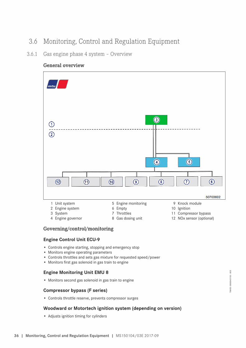
3.6.1 Gas engine phase 4 system – Overview
General overview
1 Unit system2 Engine system3 System4 Engine governor
5 Engine monitoring6 Empty7 Throttles8 Gas dosing unit
9 Knock module10 Ignition11 Compressor bypass12 NOx sensor (optional)
Governing/control/monitoring
Engine Control Unit ECU-9• Controls engine starting, stopping and emergency stop• Monitors engine operating parameters• Controls throttles and sets gas mixture for requested speed/power• Monitors first gas solenoid in gas train to engine
Engine Monitoring Unit EMU 8• Monitors second gas solenoid in gas train to engine
Compressor bypass (F series)• Controls throttle reserve, prevents compressor surges
Woodward or Motortech ignition system (depending on version)• Adjusts ignition timing for cylinders
36 | Monitoring, Control and Regulation Equipment | MS150104/03E 2017-09
TIM
-ID: 0
0000
4315
5 - 0
03
Anti-knock control AKR• Controls monitored cylinders re. knock characteristics. If knocking is found, the ignition timing is retarded
on the cylinder in question. If this does not result in an improvement, the power is reduced.
Gas control valve TecJet52• Controls the required amount of gas
Mixture throttles (P Series)• The mixture throttles in the mixture lines which are controlled by the engine governor
MS150104/03E 2017-09 | Monitoring, Control and Regulation Equipment | 37
TIM
-ID: 0
0000
4315
5 - 0
03
3.6.2 Purpose of the units
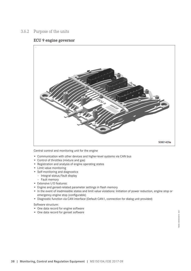
ECU 9 engine governor
Central control and monitoring unit for the engine
• Communication with other devices and higher-level systems via CAN bus• Control of throttles (mixture and gas)• Registration and analysis of engine operating states• Limit value monitoring• Self-monitoring and diagnostics
– Integral status/fault display– Fault memory
• Extensive I/O features:• Engine and genset-related parameter settings in flash memory• In the event of inadmissible states and limit value violations: Initiation of power reduction, engine stop or
emergency engine stop (configurable)• Diagnostic function via CAN interface (Default CAN1, connection for dialog unit provided)
Software structure:• One data record for engine software• One data record for genset software
38 | Monitoring, Control and Regulation Equipment | MS150104/03E 2017-09
TIM
-ID: 0
0000
4081
8 - 0
02
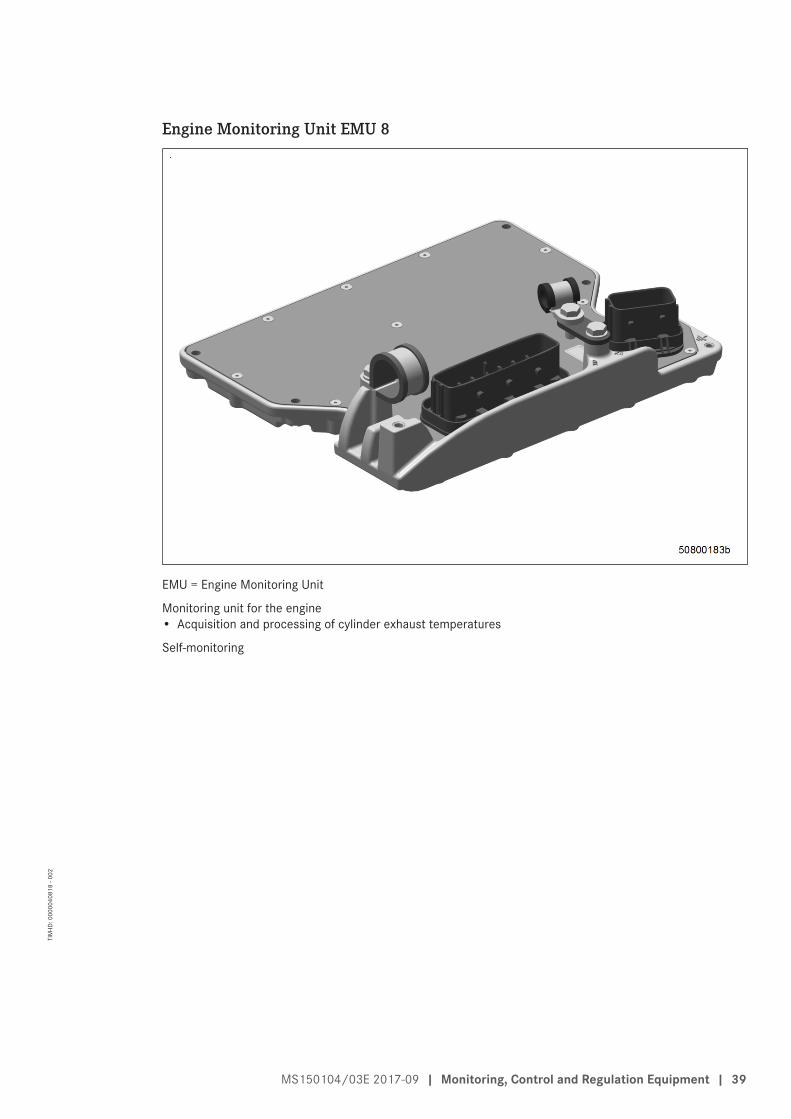
Engine Monitoring Unit EMU 8
EMU = Engine Monitoring Unit
Monitoring unit for the engine• Acquisition and processing of cylinder exhaust temperatures
Self-monitoring
MS150104/03E 2017-09 | Monitoring, Control and Regulation Equipment | 39
TIM
-ID: 0
0000
4081
8 - 0
02
4 Operation
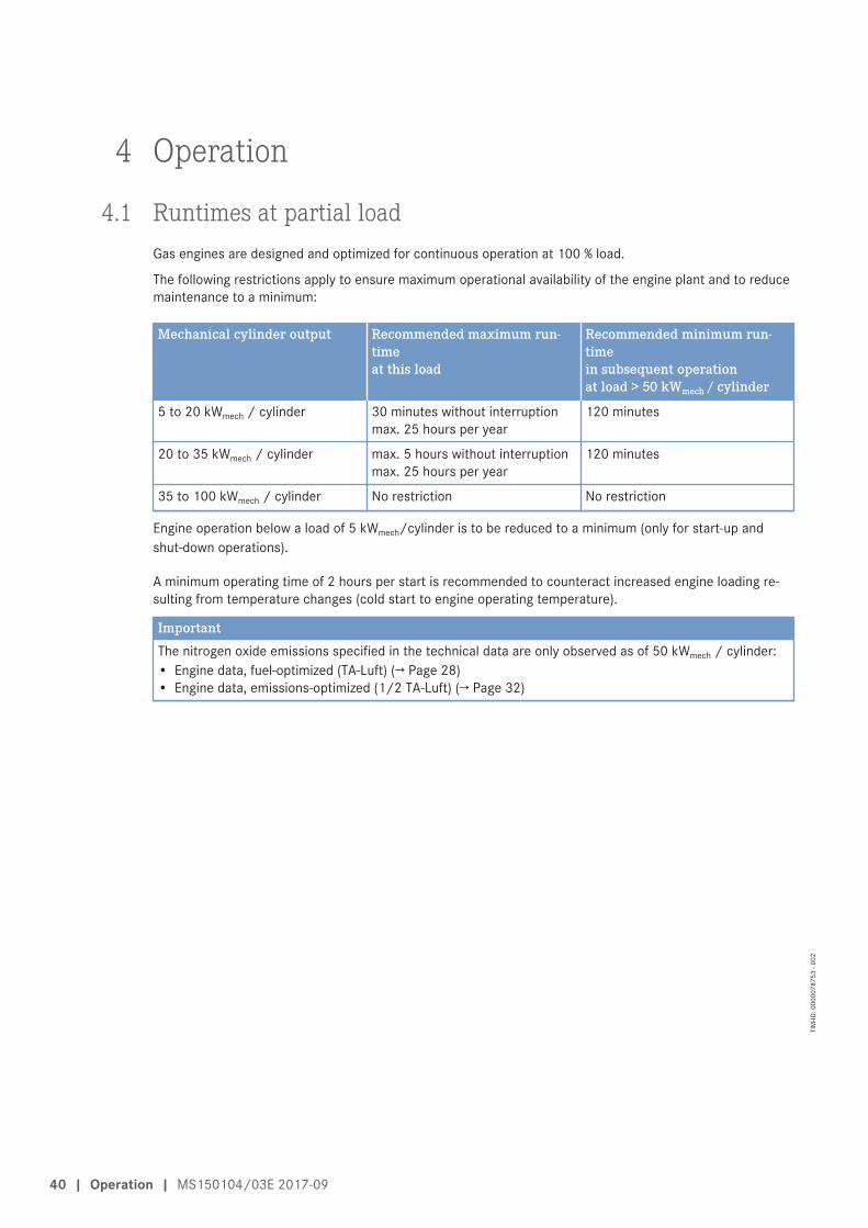
4.1 Runtimes at partial loadGas engines are designed and optimized for continuous operation at 100 % load.
The following restrictions apply to ensure maximum operational availability of the engine plant and to reducemaintenance to a minimum:
Mechanical cylinder output Recommended maximum run-timeat this load
Recommended minimum run-timein subsequent operationat load > 50 kWmech / cylinder
5 to 20 kWmech / cylinder 30 minutes without interruptionmax. 25 hours per year
120 minutes
20 to 35 kWmech / cylinder max. 5 hours without interruptionmax. 25 hours per year
120 minutes
35 to 100 kWmech / cylinder No restriction No restriction
Engine operation below a load of 5 kWmech/cylinder is to be reduced to a minimum (only for start-up andshut-down operations).
A minimum operating time of 2 hours per start is recommended to counteract increased engine loading re-sulting from temperature changes (cold start to engine operating temperature).
ImportantThe nitrogen oxide emissions specified in the technical data are only observed as of 50 kWmech / cylinder:• Engine data, fuel-optimized (TA-Luft) (→ Page 28)• Engine data, emissions-optimized (1/2 TA-Luft) (→ Page 32)
40 | Operation | MS150104/03E 2017-09
TIM
-ID: 0
0000
7875
3 - 0
02
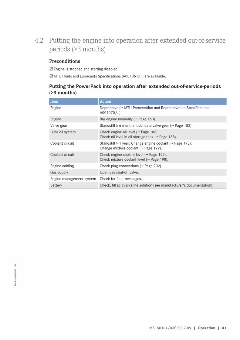
4.2 Putting the engine into operation after extended out-of-serviceperiods (>3 months)
Preconditions☑Engine is stopped and starting disabled.
☑MTU Fluids and Lubricants Specifications (A001061/..) are available.
Putting the PowerPack into operation after extended out-of-service-periods(>3 months)Item ActionEngine Depreserve (→ MTU Preservation and Represervation Specifications
A001070/..).Engine Bar engine manually (→ Page 163).Valve gear Standstill ≥ 6 months: Lubricate valve gear (→ Page 182).Lube oil system Check engine oil level (→ Page 188);
Check oil level in oil storage tank (→ Page 188).Coolant circuit Standstill > 1 year: Change engine coolant (→ Page 193);
Change mixture coolant (→ Page 199).Coolant circuit Check engine coolant level (→ Page 192);
Check mixture coolant level (→ Page 198).Engine cabling Check plug connections (→ Page 202).Gas supply Open gas shut-off valve.Engine management system Check for fault messages.Battery Check, fill acid/alkaline solution (see manufacturer's documentation).
MS150104/03E 2017-09 | Operation | 41
TIM
-ID: 0
0000
1010
2 - 0
02
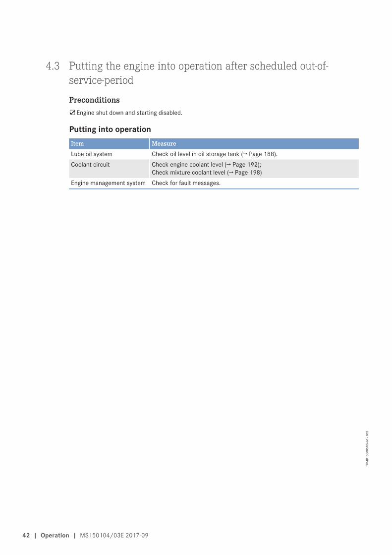
4.3 Putting the engine into operation after scheduled out-of-service-period
Preconditions☑Engine shut down and starting disabled.
Putting into operationItem MeasureLube oil system Check oil level in oil storage tank (→ Page 188).Coolant circuit Check engine coolant level (→ Page 192);
Check mixture coolant level (→ Page 198)Engine management system Check for fault messages.
42 | Operation | MS150104/03E 2017-09
TIM
-ID: 0
0000
1066
0 - 0
02
4.4 Control, starting and stopping sequencesNOTICE
Risk of engine damage due to incorrect action.Risk of severe damage to property!• Ensure engine is ready for operation before starting. See engine documentation.
Starting and stopping sequencesThe starting sequence is software-controlled and depends on the place of start command input.
To ensure that no mixture is in the engine when ignition is switched on or off, which is a specific requirementfor gas engines, special procedures for engine start / stop are specified.
The maximum number of attempted starts is limited to three. After this, an extended scavenging phase isinitiated with the gas shut-off valves closed and the ignition off in order to purge the intake duct, engine cyl-inders and exhaust duct (up to the exhaust turbine outlet elbow) with air. The operator shall ensure by meansof structural safeguards that flammable gases or vapors do not arise in hazardous quantities or concentra-tions in the surroundings of the installation (gas pipework up to gas control valve and exhaust gas systemafter turbine). A contact is designated to initiate such safety measures.
Starting sequenceThe following steps are performed automatically when a start command is activated with the engine at stand-still:
1. Setting start counter2. Priming (optional)3. Checking gas supply solenoid valves for leaks4. Activating starter5. Waiting for starting speed6. Scavenging the engine7. Ignition8. Opening gas supply solenoid valves9. Waiting for starter disengagement speed
10. Disengaging starter11. Waiting for idling speed12. Ramping-up to rated speed
Start termination1. The maximum number of attempted starts is limited to three following start termination2. An alarm is then signaled3. Requesting external ventilation by contact4. A new engine start request is only possible following fault acknowledgment
Stopping sequenceThe following steps are performed automatically when a stop command is activated:
1. Closing gas supply solenoid valves2. Opening mixture throttles, scavenging residual gas3. Engine running down to standstill4. Deactivating ignition5. Closing mixture throttles
MS150104/03E 2017-09 | Operation | 43
TIM
-ID: 0
0000
4315
7 - 0
02
Emergency stopping sequenceIf an emergency stop command is activated, the following steps are carried out automatically:
1. Closing gas supply solenoid valves2. Closing mixture throttles3. Engine running down to standstill4. Deactivating ignition5. Requesting external ventilation by contact
Restarting after emergency stopA scavenging phase and a request for external ventilation by contact ensue following a start request afteremergency shutdown.
1. Requesting external ventilation by contact2. Activating starter3. Waiting for starting speed4. Scavenging the engine5. Disengaging starter6. Engine running down to standstill7. Resetting start counter8. Awaiting start request
Oil refill sequence1. Waiting for engine running2. Engine running for a minimum (programmed) time period3. Oil refilling enabled4. When oil refill request is received5. Refilling oil (automatically)6. When oil refill request is canceled7. Stopping oil refilling (automatically)
44 | Operation | MS150104/03E 2017-09
TIM
-ID: 0
0000
4315
7 - 0
02
4.5 Engine – Start
Preconditions☑Generator is not connected to network.
☑Start interlock is not active.
DANGERRotating and moving engine parts.Risk of crushing, danger of parts of the body being caught or pulled in!• Before cranking the engine with starter system, make sure that there are no persons in the engine's
danger zone.
WARNINGHigh level of engine noise when the engine is running.Risk of damage to hearing!• Wear ear protectors.
Starting the engineNote: A max. of 5 engine starting attempts are permitted at a max. fuel supply opening time of 15 seconds respec-
tively. After a max. of 5 unsuccessful start attempts, the fuel supply must be locked. Before attempting tostart the engine again, allow time for sufficient inertization of the exhaust section.
u Initiate specified engine starting sequence (→ Page 43).
MS150104/03E 2017-09 | Operation | 45
TIM
-ID: 0
0000
4271
9 - 0
02
4.6 Operational checksDANGER
Components are moving or rotating.Risk of crushing, danger of parts of the body being caught or pulled in!• Operate the engine at low load only. Keep clear of the danger zone of the engine.
WARNINGHigh level of engine noise when the engine is running.Risk of damage to hearing!• Wear ear protectors.
Operational checksItem MeasureMachine room Check machine room for smell of gas (→ Page 164).ECU Check for fault messages;
If fault messages are displayed: Determine the cause, rectify the fault.Check indicated operating parameters (speed, temperatures, pressures)
Operation log (if provided) Document operating parameters.• This is especially useful for fault localization and fast remedial action.
Engine under load,engine at nominal speed
Check engine/plant and all pipework visually for leaks, rectify any leaks withthe engine stopped;Check for abnormal running noises and vibration.
46 | Operation | MS150104/03E 2017-09
TIM
-ID: 0
0000
4315
8 - 0
02
4.7 Emission values – Check
Special tools, Material, Spare partsDesignation / Use Part No. Qty.
Gas detection and alarm unit (not stocked by MTU)
WARNINGEngine operation at high load/speed when measuring emissions.Risk of injury!• Conduct measuring in a room which offers safe protection from the engine if at all possible. If this is
not feasible, keep the greatest possible distance away when measuring, e.g. using wireless datatransmission or long cables.
WARNINGInstalling/removing measuring equipment – exhaust gases are hot and pressurized.Risk of injury and burning!• Only install/remove measuring equipment when the engine is at standstill.• Wear protective clothing, protective gloves and goggles/safety mask.
WARNINGHigh level of engine noise when the engine is running.Risk of damage to hearing!• Wear ear protectors.
WARNINGExhaust gases are harmful to health and may cause cancer.Risk of poisoning and suffocation!• Keep the engine room well-ventilated at all times.• Repair leaking exhaust pipework immediately.
NOTICEStopping the engine when it is running at full load subjects it to extreme thermal and mechanical stress-es.Overheating of and, therefore, damage to components is possible!• Before shutting down the engine, allow it to idle until the engine temperatures decrease and constant
levels are indicated.
NOTICENon-compliance with exhaust emission limits.Emission agencies may revoke the operating license!• Adjust the exhaust emissions such as to ensure compliance with statutory limits.• Use tested measuring equipment only.• Exhaust emissions shall be checked and adjusted at the intervals specified in the Maintenance
Schedule.
MS150104/03E 2017-09 | Operation | 47
TIM
-ID: 0
0000
6350
8 - 0
03
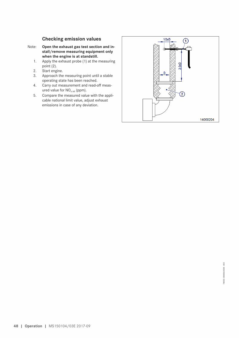
Checking emission valuesNote: Open the exhaust gas test section and in-
stall/remove measuring equipment onlywhen the engine is at standstill.
1. Apply the exhaust probe (1) at the measuringpoint (2).
2. Start engine.3. Approach the measuring point until a stable
operating state has been reached.4. Carry out measurement and read-off meas-
ured value for NOx rel (ppm).5. Compare the measured value with the appli-
cable national limit value, adjust exhaustemissions in case of any deviation.
48 | Operation | MS150104/03E 2017-09
TIM
-ID: 0
0000
6350
8 - 0
03
4.8 Engine – Shutdown
Preconditions☑Generator is not connected to network.
NOTICEStopping the engine when it is running at full load subjects it to extreme thermal and mechanical stress-es.Overheating of and, therefore, damage to components is possible!• Before shutting down the engine, allow it to idle until the engine temperatures decrease and constant
levels are indicated.
Shutting down engineu Shut down engine in accordance with stopping sequence specifications (→ Page 43).
MS150104/03E 2017-09 | Operation | 49
TIM
-ID: 0
0000
4272
0 - 0
01
4.9 Engine – Emergency shutdownWARNING
Escaping residual gas may create an explosive atmosphere in case of emergency stop.Explosion hazard!• Ensure that any escaping residual gas is routed out by means of appropriate facility ventilation and
use of an SBV (safety blow-off valve) to prevent any risk of explosive atmosphere.• Install an SAV (safety shut-off valve) in the gas control system when using gas control systems with
inlet pressures in excess of 0.1 bar.• Install an SAV (safety shut-off valve) and an SBV (safety blow-off valve) in the gas control system
when using single-stage gas control systems with inlet pressures in excess of 1 bar.
NOTICEAn emergency stop subjects the engine system to an extremely high load.Risk of overheating, damage to components!• Trigger an emergency stop only in emergency situations.
Emergency engine shutdownItem MeasureGas shut-off solenoids Two contacts are provided for electrical connection. Close gas shut-off sole-
noids.• engine stop.
Ignition, ignition system In the case of an external EMERGENCY STOP, the ignition remains on untilthe engine has run down to a standstill in order to safely burn off uncombust-ed fuel/air mixture.• The ignition is only switched off in case of an overspeed violation or an
internal ignition fault.Throttle flaps The throttle flaps are always closed in case of EMERGENCY STOP. Closing
the throttle flaps impedes the scavenging of residual gas. External ventilationand inerting systems shall therefore be activated following an emergency en-gine stop.
Room ventilation, facilityventilation
Residual gas may escape from the fuel line in case of EMERGENCY STOP.• A contact is provided to request room and facility ventilation.
Table 34: Emergency engine shutdown
50 | Operation | MS150104/03E 2017-09
TIM
-ID: 0
0000
4315
9 - 0
03
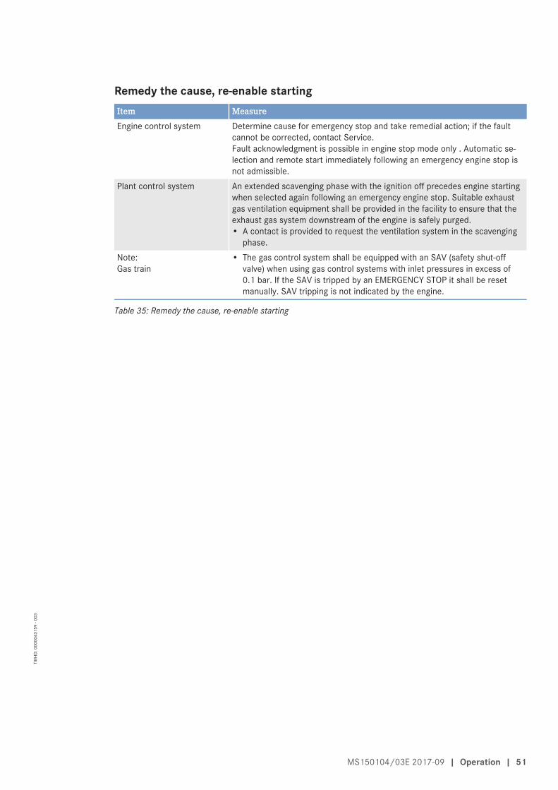
Remedy the cause, re-enable startingItem MeasureEngine control system Determine cause for emergency stop and take remedial action; if the fault
cannot be corrected, contact Service.Fault acknowledgment is possible in engine stop mode only . Automatic se-lection and remote start immediately following an emergency engine stop isnot admissible.
Plant control system An extended scavenging phase with the ignition off precedes engine startingwhen selected again following an emergency engine stop. Suitable exhaustgas ventilation equipment shall be provided in the facility to ensure that theexhaust gas system downstream of the engine is safely purged.• A contact is provided to request the ventilation system in the scavenging
phase.Note:Gas train
• The gas control system shall be equipped with an SAV (safety shut-offvalve) when using gas control systems with inlet pressures in excess of0.1 bar. If the SAV is tripped by an EMERGENCY STOP it shall be resetmanually. SAV tripping is not indicated by the engine.
Table 35: Remedy the cause, re-enable starting
MS150104/03E 2017-09 | Operation | 51
TIM
-ID: 0
0000
4315
9 - 0
03
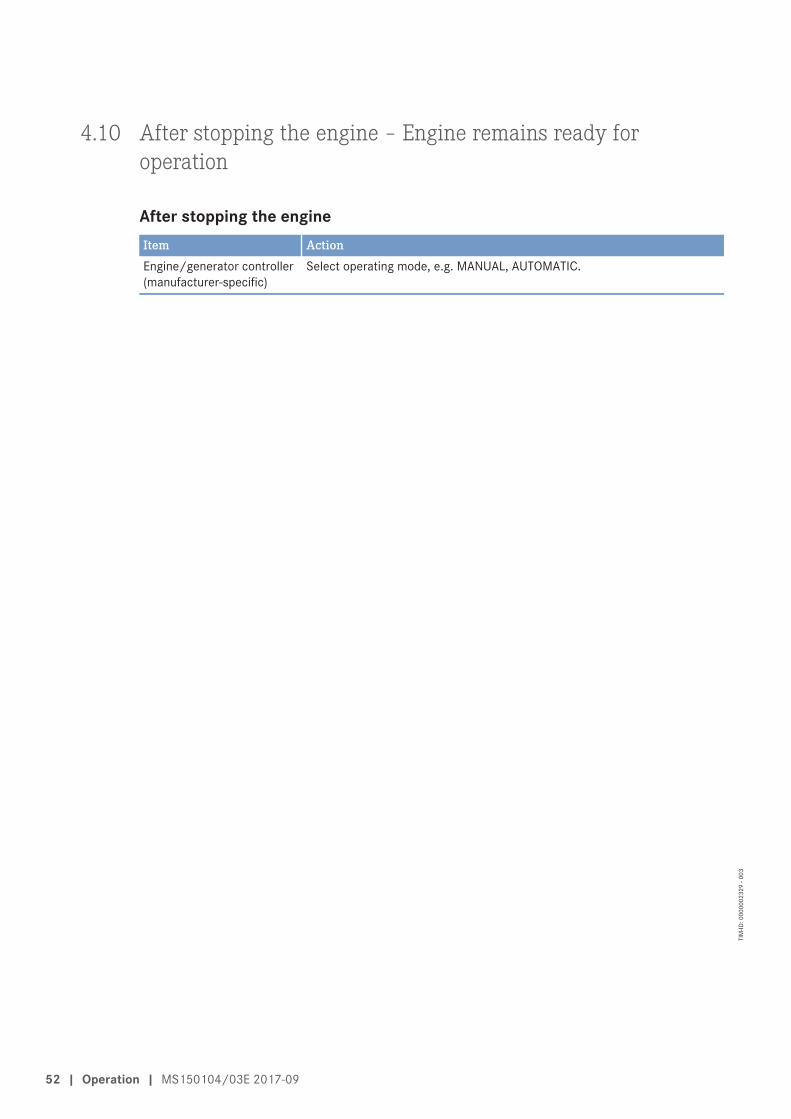
4.10 After stopping the engine – Engine remains ready foroperation
After stopping the engineItem ActionEngine/generator controller(manufacturer-specific)
Select operating mode, e.g. MANUAL, AUTOMATIC.
52 | Operation | MS150104/03E 2017-09
TIM
-ID: 0
0000
0232
9 - 0
03
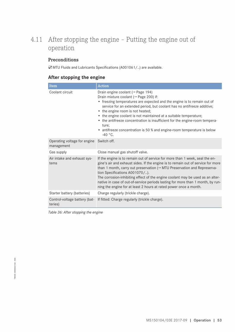
4.11 After stopping the engine – Putting the engine out ofoperation
Preconditions☑MTU Fluids and Lubricants Specifications (A001061/..) are available.
After stopping the engineItem ActionCoolant circuit Drain engine coolant (→ Page 194)
Drain mixture coolant (→ Page 200) if:• freezing temperatures are expected and the engine is to remain out of
service for an extended period, but coolant has no antifreeze additive;• the engine room is not heated;• the engine coolant is not maintained at a suitable temperature;• the antifreeze concentration is insufficient for the engine-room tempera-
ture;• antifreeze concentration is 50 % and engine-room temperature is below
-40 °C.Operating voltage for enginemanagement
Switch off.
Gas supply Close manual gas shutoff valve.Air intake and exhaust sys-tems
If the engine is to remain out of service for more than 1 week, seal the en-gine's air and exhaust sides. If the engine is to remain out of service for morethan 1 month, carry out preservation (→ MTU Preservation and Represerva-tion Specifications A001070/..).The corrosion-inhibiting effect of the engine coolant may be used as an alter-native in case of out-of-service periods lasting for more than 1 month, by run-ning the engine for at least 2 hours at rated power once a month.
Starter battery (batteries) Charge regularly (trickle charge).Control-voltage battery (bat-teries)
If fitted: Charge regularly (trickle charge).
Table 36: After stopping the engine
MS150104/03E 2017-09 | Operation | 53
TIM
-ID: 0
0000
4316
0 - 0
04
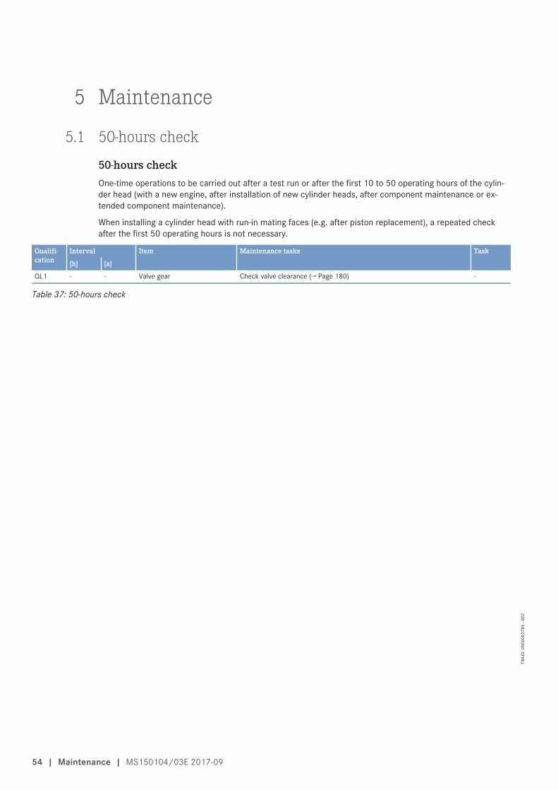
5 Maintenance
5.1 50-hours check
50-hours checkOne-time operations to be carried out after a test run or after the first 10 to 50 operating hours of the cylin-der head (with a new engine, after installation of new cylinder heads, after component maintenance or ex-tended component maintenance).
When installing a cylinder head with run-in mating faces (e.g. after piston replacement), a repeated checkafter the first 50 operating hours is not necessary.
Qualifi-cation
Interval Item Maintenance tasks Task
[h] [a]
QL1 - - Valve gear Check valve clearance (→ Page 180) -
Table 37: 50-hours check
54 | Maintenance | MS150104/03E 2017-09
TIM
-ID: 0
0000
0278
5 - 0
02
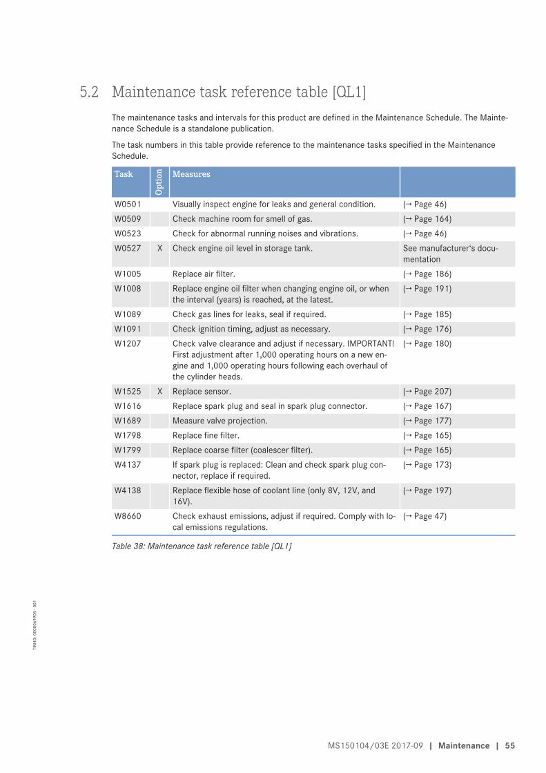
5.2 Maintenance task reference table [QL1]The maintenance tasks and intervals for this product are defined in the Maintenance Schedule. The Mainte-nance Schedule is a standalone publication.
The task numbers in this table provide reference to the maintenance tasks specified in the MaintenanceSchedule.
Task
Opt
ion Measures
W0501 Visually inspect engine for leaks and general condition. (→ Page 46)W0509 Check machine room for smell of gas. (→ Page 164)W0523 Check for abnormal running noises and vibrations. (→ Page 46)W0527 X Check engine oil level in storage tank. See manufacturer‘s docu-
mentationW1005 Replace air filter. (→ Page 186)W1008 Replace engine oil filter when changing engine oil, or when
the interval (years) is reached, at the latest.(→ Page 191)
W1089 Check gas lines for leaks, seal if required. (→ Page 185)W1091 Check ignition timing, adjust as necessary. (→ Page 176)W1207 Check valve clearance and adjust if necessary. IMPORTANT!
First adjustment after 1,000 operating hours on a new en-gine and 1,000 operating hours following each overhaul ofthe cylinder heads.
(→ Page 180)
W1525 X Replace sensor. (→ Page 207)W1616 Replace spark plug and seal in spark plug connector. (→ Page 167)W1689 Measure valve projection. (→ Page 177)W1798 Replace fine filter. (→ Page 165)W1799 Replace coarse filter (coalescer filter). (→ Page 165)W4137 If spark plug is replaced: Clean and check spark plug con-
nector, replace if required.(→ Page 173)
W4138 Replace flexible hose of coolant line (only 8V, 12V, and16V).
(→ Page 197)
W8660 Check exhaust emissions, adjust if required. Comply with lo-cal emissions regulations.
(→ Page 47)
Table 38: Maintenance task reference table [QL1]
MS150104/03E 2017-09 | Maintenance | 55
TIM
-ID: 0
0000
6990
5 - 0
01
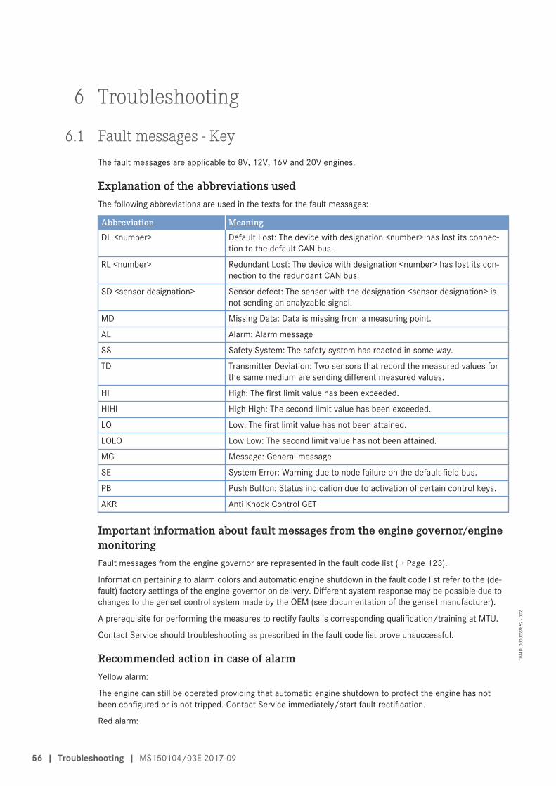
6 Troubleshooting
6.1 Fault messages - KeyThe fault messages are applicable to 8V, 12V, 16V and 20V engines.
Explanation of the abbreviations usedThe following abbreviations are used in the texts for the fault messages:
Abbreviation MeaningDL <number> Default Lost: The device with designation <number> has lost its connec-
tion to the default CAN bus.
RL <number> Redundant Lost: The device with designation <number> has lost its con-nection to the redundant CAN bus.
SD <sensor designation> Sensor defect: The sensor with the designation <sensor designation> isnot sending an analyzable signal.
MD Missing Data: Data is missing from a measuring point.
AL Alarm: Alarm message
SS Safety System: The safety system has reacted in some way.
TD Transmitter Deviation: Two sensors that record the measured values forthe same medium are sending different measured values.
HI High: The first limit value has been exceeded.
HIHI High High: The second limit value has been exceeded.
LO Low: The first limit value has not been attained.
LOLO Low Low: The second limit value has not been attained.
MG Message: General message
SE System Error: Warning due to node failure on the default field bus.
PB Push Button: Status indication due to activation of certain control keys.
AKR Anti Knock Control GET
Important information about fault messages from the engine governor/enginemonitoringFault messages from the engine governor are represented in the fault code list (→ Page 123).
Information pertaining to alarm colors and automatic engine shutdown in the fault code list refer to the (de-fault) factory settings of the engine governor on delivery. Different system response may be possible due tochanges to the genset control system made by the OEM (see documentation of the genset manufacturer).
A prerequisite for performing the measures to rectify faults is corresponding qualification/training at MTU.
Contact Service should troubleshooting as prescribed in the fault code list prove unsuccessful.
Recommended action in case of alarmYellow alarm:
The engine can still be operated providing that automatic engine shutdown to protect the engine has notbeen configured or is not tripped. Contact Service immediately/start fault rectification.
Red alarm:
56 | Troubleshooting | MS150104/03E 2017-09
TIM
-ID: 0
0000
2785
2 - 0
02
Caution, the engine is running at its limits. Shut down manually without further delay if the engine does notshut itself down immediately after a red alarm is signaled.
MS150104/03E 2017-09 | Troubleshooting | 57
TIM
-ID: 0
0000
2785
2 - 0
02
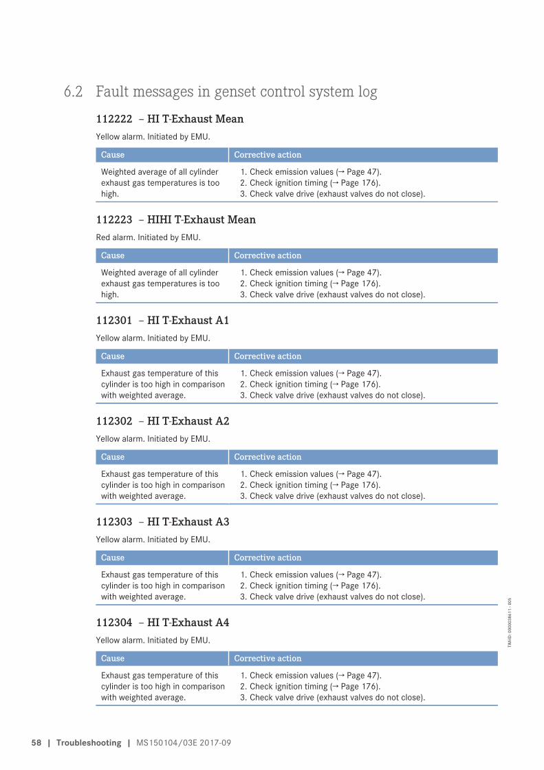
6.2 Fault messages in genset control system log
112222 – HI T-Exhaust MeanYellow alarm. Initiated by EMU.
Cause Corrective action
Weighted average of all cylinderexhaust gas temperatures is toohigh.
1. Check emission values (→ Page 47).2. Check ignition timing (→ Page 176).3. Check valve drive (exhaust valves do not close).
112223 – HIHI T-Exhaust MeanRed alarm. Initiated by EMU.
Cause Corrective action
Weighted average of all cylinderexhaust gas temperatures is toohigh.
1. Check emission values (→ Page 47).2. Check ignition timing (→ Page 176).3. Check valve drive (exhaust valves do not close).
112301 – HI T-Exhaust A1Yellow alarm. Initiated by EMU.
Cause Corrective action
Exhaust gas temperature of thiscylinder is too high in comparisonwith weighted average.
1. Check emission values (→ Page 47).2. Check ignition timing (→ Page 176).3. Check valve drive (exhaust valves do not close).
112302 – HI T-Exhaust A2Yellow alarm. Initiated by EMU.
Cause Corrective action
Exhaust gas temperature of thiscylinder is too high in comparisonwith weighted average.
1. Check emission values (→ Page 47).2. Check ignition timing (→ Page 176).3. Check valve drive (exhaust valves do not close).
112303 – HI T-Exhaust A3Yellow alarm. Initiated by EMU.
Cause Corrective action
Exhaust gas temperature of thiscylinder is too high in comparisonwith weighted average.
1. Check emission values (→ Page 47).2. Check ignition timing (→ Page 176).3. Check valve drive (exhaust valves do not close).
112304 – HI T-Exhaust A4Yellow alarm. Initiated by EMU.
Cause Corrective action
Exhaust gas temperature of thiscylinder is too high in comparisonwith weighted average.
1. Check emission values (→ Page 47).2. Check ignition timing (→ Page 176).3. Check valve drive (exhaust valves do not close).
58 | Troubleshooting | MS150104/03E 2017-09
TIM
-ID: 0
0000
3861
1 - 0
05
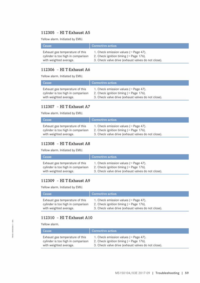
112305 – HI T-Exhaust A5Yellow alarm. Initiated by EMU.
Cause Corrective action
Exhaust gas temperature of thiscylinder is too high in comparisonwith weighted average.
1. Check emission values (→ Page 47).2. Check ignition timing (→ Page 176).3. Check valve drive (exhaust valves do not close).
112306 – HI T-Exhaust A6Yellow alarm. Initiated by EMU.
Cause Corrective action
Exhaust gas temperature of thiscylinder is too high in comparisonwith weighted average.
1. Check emission values (→ Page 47).2. Check ignition timing (→ Page 176).3. Check valve drive (exhaust valves do not close).
112307 – HI T-Exhaust A7Yellow alarm. Initiated by EMU.
Cause Corrective action
Exhaust gas temperature of thiscylinder is too high in comparisonwith weighted average.
1. Check emission values (→ Page 47).2. Check ignition timing (→ Page 176).3. Check valve drive (exhaust valves do not close).
112308 – HI T-Exhaust A8Yellow alarm. Initiated by EMU.
Cause Corrective action
Exhaust gas temperature of thiscylinder is too high in comparisonwith weighted average.
1. Check emission values (→ Page 47).2. Check ignition timing (→ Page 176).3. Check valve drive (exhaust valves do not close).
112309 – HI T-Exhaust A9Yellow alarm. Initiated by EMU.
Cause Corrective action
Exhaust gas temperature of thiscylinder is too high in comparisonwith weighted average.
1. Check emission values (→ Page 47).2. Check ignition timing (→ Page 176).3. Check valve drive (exhaust valves do not close).
112310 – HI T-Exhaust A10Yellow alarm.
Cause Corrective action
Exhaust gas temperature of thiscylinder is too high in comparisonwith weighted average.
1. Check emission values (→ Page 47).2. Check ignition timing (→ Page 176).3. Check valve drive (exhaust valves do not close).
MS150104/03E 2017-09 | Troubleshooting | 59
TIM
-ID: 0
0000
3861
1 - 0
05
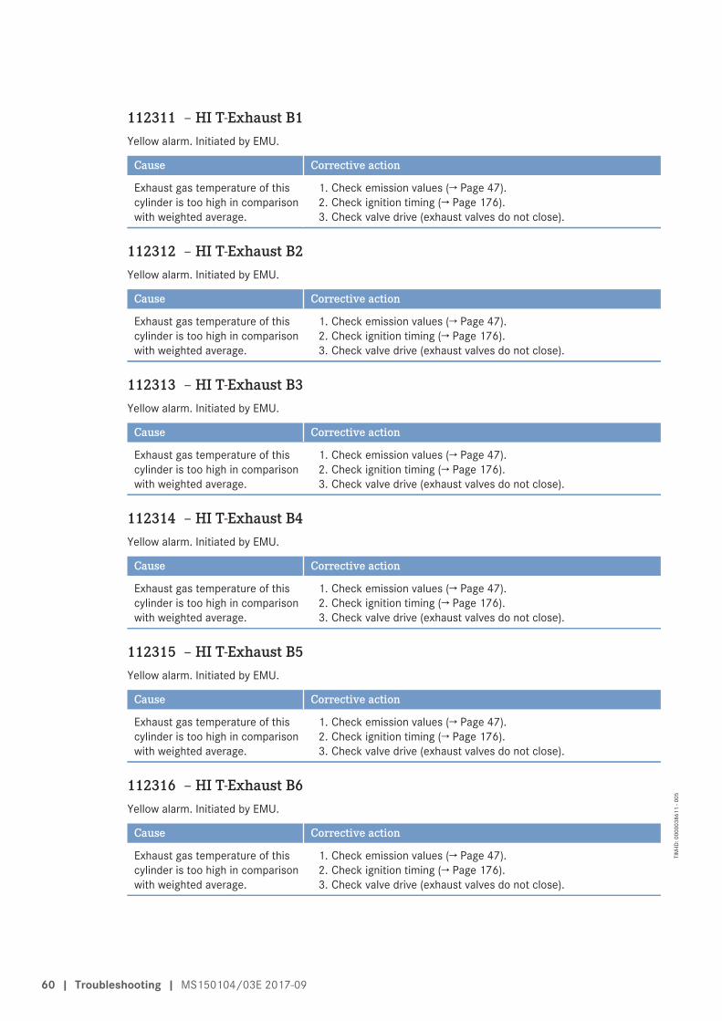
112311 – HI T-Exhaust B1Yellow alarm. Initiated by EMU.
Cause Corrective action
Exhaust gas temperature of thiscylinder is too high in comparisonwith weighted average.
1. Check emission values (→ Page 47).2. Check ignition timing (→ Page 176).3. Check valve drive (exhaust valves do not close).
112312 – HI T-Exhaust B2Yellow alarm. Initiated by EMU.
Cause Corrective action
Exhaust gas temperature of thiscylinder is too high in comparisonwith weighted average.
1. Check emission values (→ Page 47).2. Check ignition timing (→ Page 176).3. Check valve drive (exhaust valves do not close).
112313 – HI T-Exhaust B3Yellow alarm. Initiated by EMU.
Cause Corrective action
Exhaust gas temperature of thiscylinder is too high in comparisonwith weighted average.
1. Check emission values (→ Page 47).2. Check ignition timing (→ Page 176).3. Check valve drive (exhaust valves do not close).
112314 – HI T-Exhaust B4Yellow alarm. Initiated by EMU.
Cause Corrective action
Exhaust gas temperature of thiscylinder is too high in comparisonwith weighted average.
1. Check emission values (→ Page 47).2. Check ignition timing (→ Page 176).3. Check valve drive (exhaust valves do not close).
112315 – HI T-Exhaust B5Yellow alarm. Initiated by EMU.
Cause Corrective action
Exhaust gas temperature of thiscylinder is too high in comparisonwith weighted average.
1. Check emission values (→ Page 47).2. Check ignition timing (→ Page 176).3. Check valve drive (exhaust valves do not close).
112316 – HI T-Exhaust B6Yellow alarm. Initiated by EMU.
Cause Corrective action
Exhaust gas temperature of thiscylinder is too high in comparisonwith weighted average.
1. Check emission values (→ Page 47).2. Check ignition timing (→ Page 176).3. Check valve drive (exhaust valves do not close).
60 | Troubleshooting | MS150104/03E 2017-09
TIM
-ID: 0
0000
3861
1 - 0
05
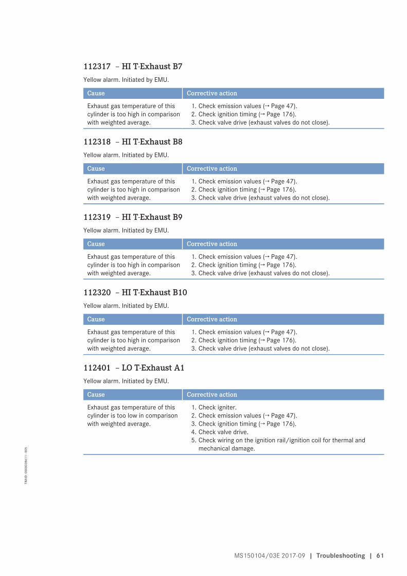
112317 – HI T-Exhaust B7Yellow alarm. Initiated by EMU.
Cause Corrective action
Exhaust gas temperature of thiscylinder is too high in comparisonwith weighted average.
1. Check emission values (→ Page 47).2. Check ignition timing (→ Page 176).3. Check valve drive (exhaust valves do not close).
112318 – HI T-Exhaust B8Yellow alarm. Initiated by EMU.
Cause Corrective action
Exhaust gas temperature of thiscylinder is too high in comparisonwith weighted average.
1. Check emission values (→ Page 47).2. Check ignition timing (→ Page 176).3. Check valve drive (exhaust valves do not close).
112319 – HI T-Exhaust B9Yellow alarm. Initiated by EMU.
Cause Corrective action
Exhaust gas temperature of thiscylinder is too high in comparisonwith weighted average.
1. Check emission values (→ Page 47).2. Check ignition timing (→ Page 176).3. Check valve drive (exhaust valves do not close).
112320 – HI T-Exhaust B10Yellow alarm. Initiated by EMU.
Cause Corrective action
Exhaust gas temperature of thiscylinder is too high in comparisonwith weighted average.
1. Check emission values (→ Page 47).2. Check ignition timing (→ Page 176).3. Check valve drive (exhaust valves do not close).
112401 – LO T-Exhaust A1Yellow alarm. Initiated by EMU.
Cause Corrective action
Exhaust gas temperature of thiscylinder is too low in comparisonwith weighted average.
1. Check igniter.2. Check emission values (→ Page 47).3. Check ignition timing (→ Page 176).4. Check valve drive.5. Check wiring on the ignition rail/ignition coil for thermal and
mechanical damage.
MS150104/03E 2017-09 | Troubleshooting | 61
TIM
-ID: 0
0000
3861
1 - 0
05

112402 – LO T-Exhaust A2Yellow alarm. Initiated by EMU.
Cause Corrective action
Exhaust gas temperature of thiscylinder is too low in comparisonwith weighted average.
1. Check igniter.2. Check emission values (→ Page 47).3. Check ignition timing (→ Page 176).4. Check valve drive.5. Check wiring on the ignition rail/ignition coil for thermal and
mechanical damage.
112403 – LO T-Exhaust A3Yellow alarm. Initiated by EMU.
Cause Corrective action
Exhaust gas temperature of thiscylinder is too low in comparisonwith weighted average.
1. Check igniter.2. Check emission values (→ Page 47).3. Check ignition timing (→ Page 176).4. Check valve drive.5. Check wiring on the ignition rail/ignition coil for thermal and
mechanical damage.
112404 – LO T-Exhaust A4Yellow alarm. Initiated by EMU.
Cause Corrective action
Exhaust gas temperature of thiscylinder is too low in comparisonwith weighted average.
1. Check igniter.2. Check emission values (→ Page 47).3. Check ignition timing (→ Page 176).4. Check valve drive.5. Check wiring on the ignition rail/ignition coil for thermal and
mechanical damage.
112405 – LO T-Exhaust A5Yellow alarm. Initiated by EMU.
Cause Corrective action
Exhaust gas temperature of thiscylinder is too low in comparisonwith weighted average.
1. Check igniter.2. Check emission values (→ Page 47).3. Check ignition timing (→ Page 176).4. Check valve drive.5. Check wiring on the ignition rail/ignition coil for thermal and
mechanical damage.
62 | Troubleshooting | MS150104/03E 2017-09
TIM
-ID: 0
0000
3861
1 - 0
05
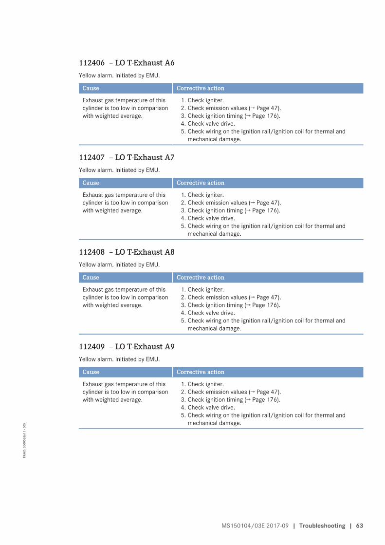
112406 – LO T-Exhaust A6Yellow alarm. Initiated by EMU.
Cause Corrective action
Exhaust gas temperature of thiscylinder is too low in comparisonwith weighted average.
1. Check igniter.2. Check emission values (→ Page 47).3. Check ignition timing (→ Page 176).4. Check valve drive.5. Check wiring on the ignition rail/ignition coil for thermal and
mechanical damage.
112407 – LO T-Exhaust A7Yellow alarm. Initiated by EMU.
Cause Corrective action
Exhaust gas temperature of thiscylinder is too low in comparisonwith weighted average.
1. Check igniter.2. Check emission values (→ Page 47).3. Check ignition timing (→ Page 176).4. Check valve drive.5. Check wiring on the ignition rail/ignition coil for thermal and
mechanical damage.
112408 – LO T-Exhaust A8Yellow alarm. Initiated by EMU.
Cause Corrective action
Exhaust gas temperature of thiscylinder is too low in comparisonwith weighted average.
1. Check igniter.2. Check emission values (→ Page 47).3. Check ignition timing (→ Page 176).4. Check valve drive.5. Check wiring on the ignition rail/ignition coil for thermal and
mechanical damage.
112409 – LO T-Exhaust A9Yellow alarm. Initiated by EMU.
Cause Corrective action
Exhaust gas temperature of thiscylinder is too low in comparisonwith weighted average.
1. Check igniter.2. Check emission values (→ Page 47).3. Check ignition timing (→ Page 176).4. Check valve drive.5. Check wiring on the ignition rail/ignition coil for thermal and
mechanical damage.
MS150104/03E 2017-09 | Troubleshooting | 63
TIM
-ID: 0
0000
3861
1 - 0
05

112410 – LO T-Exhaust A10Yellow alarm. Initiated by EMU.
Cause Corrective action
Exhaust gas temperature of thiscylinder is too low in comparisonwith weighted average.
1. Check igniter.2. Check emission values (→ Page 47).3. Check ignition timing (→ Page 176).4. Check valve drive.5. Check wiring on the ignition rail/ignition coil for thermal and
mechanical damage.
112411 – LO T-Exhaust B1Yellow alarm. Initiated by EMU.
Cause Corrective action
Exhaust gas temperature of thiscylinder is too low in comparisonwith weighted average.
1. Check igniter.2. Check emission values (→ Page 47).3. Check ignition timing (→ Page 176).4. Check valve drive.5. Check wiring on the ignition rail/ignition coil for thermal and
mechanical damage.
112412 – LO T-Exhaust B2Yellow alarm. Initiated by EMU.
Cause Corrective action
Exhaust gas temperature of thiscylinder is too low in comparisonwith weighted average.
1. Check igniter.2. Check emission values (→ Page 47).3. Check ignition timing (→ Page 176).4. Check valve drive.5. Check wiring on the ignition rail/ignition coil for thermal and
mechanical damage.
112413 – LO T-Exhaust B3Yellow alarm. Initiated by EMU.
Cause Corrective action
Exhaust gas temperature of thiscylinder is too low in comparisonwith weighted average.
1. Check igniter.2. Check emission values (→ Page 47).3. Check ignition timing (→ Page 176).4. Check valve drive.5. Check wiring on the ignition rail/ignition coil for thermal and
mechanical damage.
64 | Troubleshooting | MS150104/03E 2017-09
TIM
-ID: 0
0000
3861
1 - 0
05
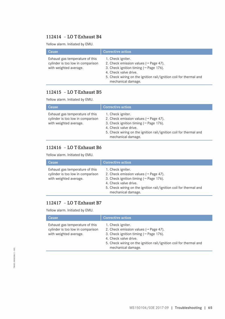
112414 – LO T-Exhaust B4Yellow alarm. Initiated by EMU.
Cause Corrective action
Exhaust gas temperature of thiscylinder is too low in comparisonwith weighted average.
1. Check igniter.2. Check emission values (→ Page 47).3. Check ignition timing (→ Page 176).4. Check valve drive.5. Check wiring on the ignition rail/ignition coil for thermal and
mechanical damage.
112415 – LO T-Exhaust B5Yellow alarm. Initiated by EMU.
Cause Corrective action
Exhaust gas temperature of thiscylinder is too low in comparisonwith weighted average.
1. Check igniter.2. Check emission values (→ Page 47).3. Check ignition timing (→ Page 176).4. Check valve drive.5. Check wiring on the ignition rail/ignition coil for thermal and
mechanical damage.
112416 – LO T-Exhaust B6Yellow alarm. Initiated by EMU.
Cause Corrective action
Exhaust gas temperature of thiscylinder is too low in comparisonwith weighted average.
1. Check igniter.2. Check emission values (→ Page 47).3. Check ignition timing (→ Page 176).4. Check valve drive.5. Check wiring on the ignition rail/ignition coil for thermal and
mechanical damage.
112417 – LO T-Exhaust B7Yellow alarm. Initiated by EMU.
Cause Corrective action
Exhaust gas temperature of thiscylinder is too low in comparisonwith weighted average.
1. Check igniter.2. Check emission values (→ Page 47).3. Check ignition timing (→ Page 176).4. Check valve drive.5. Check wiring on the ignition rail/ignition coil for thermal and
mechanical damage.
MS150104/03E 2017-09 | Troubleshooting | 65
TIM
-ID: 0
0000
3861
1 - 0
05
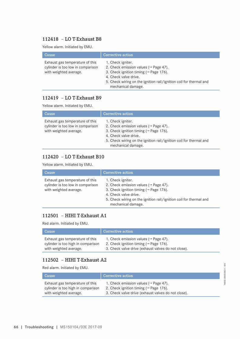
112418 – LO T-Exhaust B8Yellow alarm. Initiated by EMU.
Cause Corrective action
Exhaust gas temperature of thiscylinder is too low in comparisonwith weighted average.
1. Check igniter.2. Check emission values (→ Page 47).3. Check ignition timing (→ Page 176).4. Check valve drive.5. Check wiring on the ignition rail/ignition coil for thermal and
mechanical damage.
112419 – LO T-Exhaust B9Yellow alarm. Initiated by EMU.
Cause Corrective action
Exhaust gas temperature of thiscylinder is too low in comparisonwith weighted average.
1. Check igniter.2. Check emission values (→ Page 47).3. Check ignition timing (→ Page 176).4. Check valve drive.5. Check wiring on the ignition rail/ignition coil for thermal and
mechanical damage.
112420 – LO T-Exhaust B10Yellow alarm. Initiated by EMU.
Cause Corrective action
Exhaust gas temperature of thiscylinder is too low in comparisonwith weighted average.
1. Check igniter.2. Check emission values (→ Page 47).3. Check ignition timing (→ Page 176).4. Check valve drive.5. Check wiring on the ignition rail/ignition coil for thermal and
mechanical damage.
112501 – HIHI T-Exhaust A1Red alarm. Initiated by EMU.
Cause Corrective action
Exhaust gas temperature of thiscylinder is too high in comparisonwith weighted average.
1. Check emission values (→ Page 47).2. Check ignition timing (→ Page 176).3. Check valve drive (exhaust valves do not close).
112502 – HIHI T-Exhaust A2Red alarm. Initiated by EMU.
Cause Corrective action
Exhaust gas temperature of thiscylinder is too high in comparisonwith weighted average.
1. Check emission values (→ Page 47).2. Check ignition timing (→ Page 176).3. Check valve drive (exhaust valves do not close).
66 | Troubleshooting | MS150104/03E 2017-09
TIM
-ID: 0
0000
3861
1 - 0
05
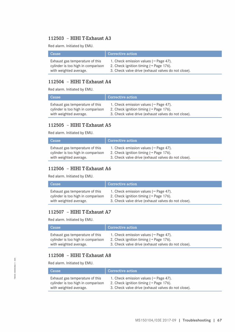
112503 – HIHI T-Exhaust A3Red alarm. Initiated by EMU.
Cause Corrective action
Exhaust gas temperature of thiscylinder is too high in comparisonwith weighted average.
1. Check emission values (→ Page 47).2. Check ignition timing (→ Page 176).3. Check valve drive (exhaust valves do not close).
112504 – HIHI T-Exhaust A4Red alarm. Initiated by EMU.
Cause Corrective action
Exhaust gas temperature of thiscylinder is too high in comparisonwith weighted average.
1. Check emission values (→ Page 47).2. Check ignition timing (→ Page 176).3. Check valve drive (exhaust valves do not close).
112505 – HIHI T-Exhaust A5Red alarm. Initiated by EMU.
Cause Corrective action
Exhaust gas temperature of thiscylinder is too high in comparisonwith weighted average.
1. Check emission values (→ Page 47).2. Check ignition timing (→ Page 176).3. Check valve drive (exhaust valves do not close).
112506 – HIHI T-Exhaust A6Red alarm. Initiated by EMU.
Cause Corrective action
Exhaust gas temperature of thiscylinder is too high in comparisonwith weighted average.
1. Check emission values (→ Page 47).2. Check ignition timing (→ Page 176).3. Check valve drive (exhaust valves do not close).
112507 – HIHI T-Exhaust A7Red alarm. Initiated by EMU.
Cause Corrective action
Exhaust gas temperature of thiscylinder is too high in comparisonwith weighted average.
1. Check emission values (→ Page 47).2. Check ignition timing (→ Page 176).3. Check valve drive (exhaust valves do not close).
112508 – HIHI T-Exhaust A8Red alarm. Initiated by EMU.
Cause Corrective action
Exhaust gas temperature of thiscylinder is too high in comparisonwith weighted average.
1. Check emission values (→ Page 47).2. Check ignition timing (→ Page 176).3. Check valve drive (exhaust valves do not close).
MS150104/03E 2017-09 | Troubleshooting | 67
TIM
-ID: 0
0000
3861
1 - 0
05
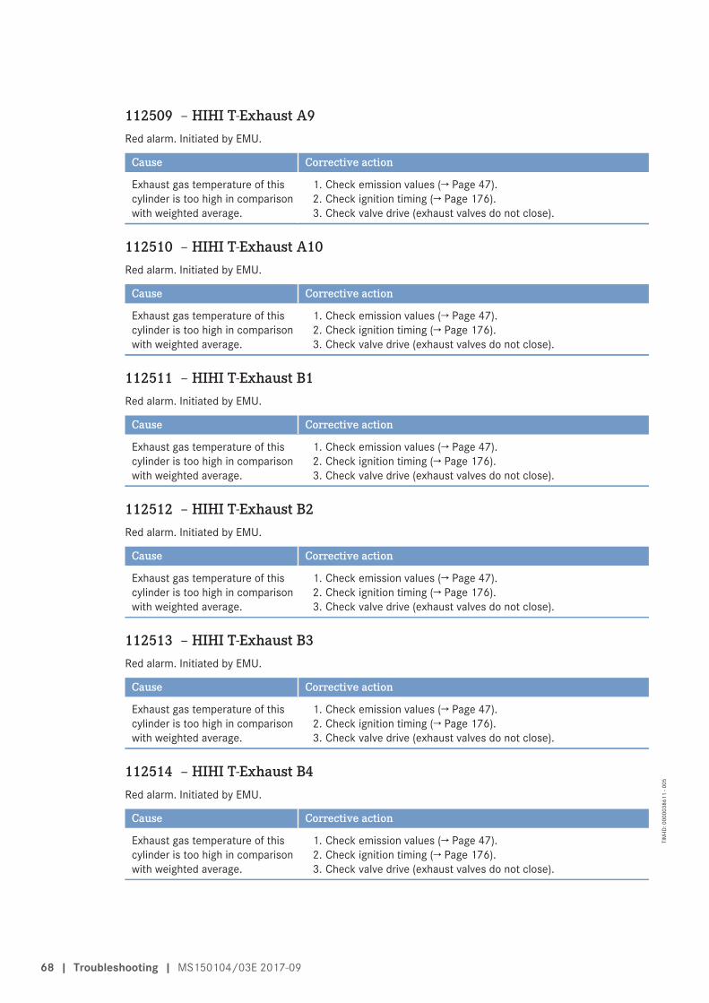
112509 – HIHI T-Exhaust A9Red alarm. Initiated by EMU.
Cause Corrective action
Exhaust gas temperature of thiscylinder is too high in comparisonwith weighted average.
1. Check emission values (→ Page 47).2. Check ignition timing (→ Page 176).3. Check valve drive (exhaust valves do not close).
112510 – HIHI T-Exhaust A10Red alarm. Initiated by EMU.
Cause Corrective action
Exhaust gas temperature of thiscylinder is too high in comparisonwith weighted average.
1. Check emission values (→ Page 47).2. Check ignition timing (→ Page 176).3. Check valve drive (exhaust valves do not close).
112511 – HIHI T-Exhaust B1Red alarm. Initiated by EMU.
Cause Corrective action
Exhaust gas temperature of thiscylinder is too high in comparisonwith weighted average.
1. Check emission values (→ Page 47).2. Check ignition timing (→ Page 176).3. Check valve drive (exhaust valves do not close).
112512 – HIHI T-Exhaust B2Red alarm. Initiated by EMU.
Cause Corrective action
Exhaust gas temperature of thiscylinder is too high in comparisonwith weighted average.
1. Check emission values (→ Page 47).2. Check ignition timing (→ Page 176).3. Check valve drive (exhaust valves do not close).
112513 – HIHI T-Exhaust B3Red alarm. Initiated by EMU.
Cause Corrective action
Exhaust gas temperature of thiscylinder is too high in comparisonwith weighted average.
1. Check emission values (→ Page 47).2. Check ignition timing (→ Page 176).3. Check valve drive (exhaust valves do not close).
112514 – HIHI T-Exhaust B4Red alarm. Initiated by EMU.
Cause Corrective action
Exhaust gas temperature of thiscylinder is too high in comparisonwith weighted average.
1. Check emission values (→ Page 47).2. Check ignition timing (→ Page 176).3. Check valve drive (exhaust valves do not close).
68 | Troubleshooting | MS150104/03E 2017-09
TIM
-ID: 0
0000
3861
1 - 0
05

112515 – HIHI T-Exhaust B5Red alarm. Initiated by EMU.
Cause Corrective action
Exhaust gas temperature of thiscylinder is too high in comparisonwith weighted average.
1. Check emission values (→ Page 47).2. Check ignition timing (→ Page 176).3. Check valve drive (exhaust valves do not close).
112516 – HIHI T-Exhaust B6Red alarm. Initiated by EMU.
Cause Corrective action
Exhaust gas temperature of thiscylinder is too high in comparisonwith weighted average.
1. Check emission values(→ Page 47).2. Check ignition timing (→ Page 176).3. Check valve drive (exhaust valves do not close).
112517 – HIHI T-Exhaust B7Red alarm. Initiated by EMU.
Cause Corrective action
Exhaust gas temperature of thiscylinder is too high in comparisonwith weighted average.
1. Check emission values (→ Page 47).2. Check ignition timing (→ Page 176).3. Check valve drive (exhaust valves do not close).
112518 – HIHI T-Exhaust B8Red alarm. Initiated by EMU.
Cause Corrective action
Exhaust gas temperature of thiscylinder is too high in comparisonwith weighted average.
1. Check emission values (→ Page 47).2. Check ignition timing (→ Page 176).3. Check valve drive (exhaust valves do not close).
112519 – HIHI T-Exhaust B9Red alarm. Initiated by EMU.
Cause Corrective action
Exhaust gas temperature of thiscylinder is too high in comparisonwith weighted average.
1. Check emission values (→ Page 47).2. Check ignition timing (→ Page 176).3. Check valve drive (exhaust valves do not close).
112520 – HIHI T-Exhaust B10Red alarm. Initiated by EMU.
Cause Corrective action
Exhaust gas temperature of thiscylinder is too high in comparisonwith weighted average.
1. Check emission values (→ Page 47).2. Check ignition timing (→ Page 176).3. Check valve drive (exhaust valves do not close).
MS150104/03E 2017-09 | Troubleshooting | 69
TIM
-ID: 0
0000
3861
1 - 0
05
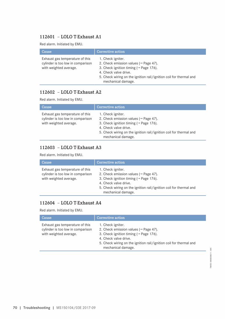
112601 – LOLO T-Exhaust A1Red alarm. Initiated by EMU.
Cause Corrective action
Exhaust gas temperature of thiscylinder is too low in comparisonwith weighted average.
1. Check igniter.2. Check emission values (→ Page 47).3. Check ignition timing (→ Page 176).4. Check valve drive.5. Check wiring on the ignition rail/ignition coil for thermal and
mechanical damage.
112602 – LOLO T-Exhaust A2Red alarm. Initiated by EMU.
Cause Corrective action
Exhaust gas temperature of thiscylinder is too low in comparisonwith weighted average.
1. Check igniter.2. Check emission values (→ Page 47).3. Check ignition timing (→ Page 176).4. Check valve drive.5. Check wiring on the ignition rail/ignition coil for thermal and
mechanical damage.
112603 – LOLO T-Exhaust A3Red alarm. Initiated by EMU.
Cause Corrective action
Exhaust gas temperature of thiscylinder is too low in comparisonwith weighted average.
1. Check igniter.2. Check emission values (→ Page 47).3. Check ignition timing (→ Page 176).4. Check valve drive.5. Check wiring on the ignition rail/ignition coil for thermal and
mechanical damage.
112604 – LOLO T-Exhaust A4Red alarm. Initiated by EMU.
Cause Corrective action
Exhaust gas temperature of thiscylinder is too low in comparisonwith weighted average.
1. Check igniter.2. Check emission values (→ Page 47).3. Check ignition timing (→ Page 176).4. Check valve drive.5. Check wiring on the ignition rail/ignition coil for thermal and
mechanical damage.
70 | Troubleshooting | MS150104/03E 2017-09
TIM
-ID: 0
0000
3861
1 - 0
05
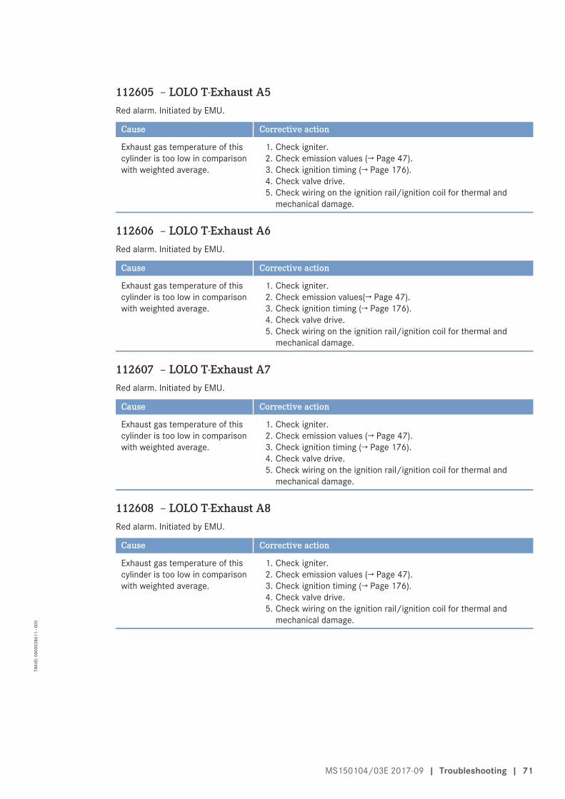
112605 – LOLO T-Exhaust A5Red alarm. Initiated by EMU.
Cause Corrective action
Exhaust gas temperature of thiscylinder is too low in comparisonwith weighted average.
1. Check igniter.2. Check emission values (→ Page 47).3. Check ignition timing (→ Page 176).4. Check valve drive.5. Check wiring on the ignition rail/ignition coil for thermal and
mechanical damage.
112606 – LOLO T-Exhaust A6Red alarm. Initiated by EMU.
Cause Corrective action
Exhaust gas temperature of thiscylinder is too low in comparisonwith weighted average.
1. Check igniter.2. Check emission values(→ Page 47).3. Check ignition timing (→ Page 176).4. Check valve drive.5. Check wiring on the ignition rail/ignition coil for thermal and
mechanical damage.
112607 – LOLO T-Exhaust A7Red alarm. Initiated by EMU.
Cause Corrective action
Exhaust gas temperature of thiscylinder is too low in comparisonwith weighted average.
1. Check igniter.2. Check emission values (→ Page 47).3. Check ignition timing (→ Page 176).4. Check valve drive.5. Check wiring on the ignition rail/ignition coil for thermal and
mechanical damage.
112608 – LOLO T-Exhaust A8Red alarm. Initiated by EMU.
Cause Corrective action
Exhaust gas temperature of thiscylinder is too low in comparisonwith weighted average.
1. Check igniter.2. Check emission values (→ Page 47).3. Check ignition timing (→ Page 176).4. Check valve drive.5. Check wiring on the ignition rail/ignition coil for thermal and
mechanical damage.
MS150104/03E 2017-09 | Troubleshooting | 71
TIM
-ID: 0
0000
3861
1 - 0
05
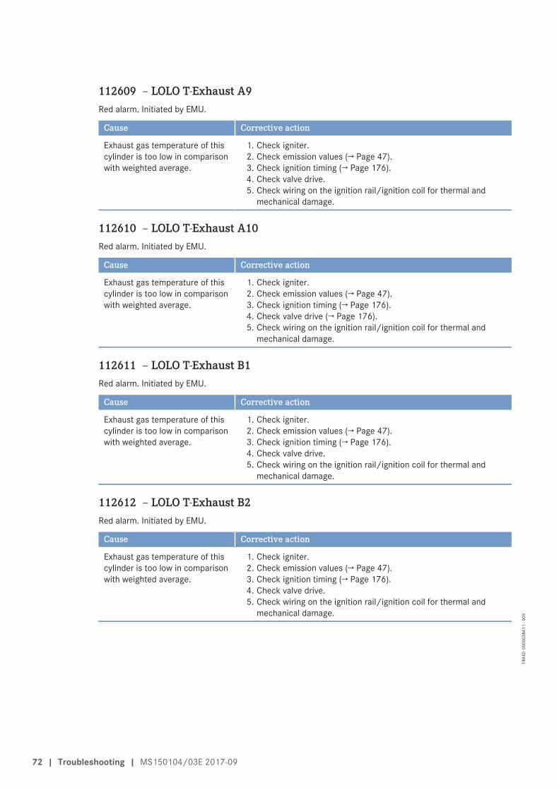
112609 – LOLO T-Exhaust A9Red alarm. Initiated by EMU.
Cause Corrective action
Exhaust gas temperature of thiscylinder is too low in comparisonwith weighted average.
1. Check igniter.2. Check emission values (→ Page 47).3. Check ignition timing (→ Page 176).4. Check valve drive.5. Check wiring on the ignition rail/ignition coil for thermal and
mechanical damage.
112610 – LOLO T-Exhaust A10Red alarm. Initiated by EMU.
Cause Corrective action
Exhaust gas temperature of thiscylinder is too low in comparisonwith weighted average.
1. Check igniter.2. Check emission values (→ Page 47).3. Check ignition timing (→ Page 176).4. Check valve drive (→ Page 176).5. Check wiring on the ignition rail/ignition coil for thermal and
mechanical damage.
112611 – LOLO T-Exhaust B1Red alarm. Initiated by EMU.
Cause Corrective action
Exhaust gas temperature of thiscylinder is too low in comparisonwith weighted average.
1. Check igniter.2. Check emission values (→ Page 47).3. Check ignition timing (→ Page 176).4. Check valve drive.5. Check wiring on the ignition rail/ignition coil for thermal and
mechanical damage.
112612 – LOLO T-Exhaust B2Red alarm. Initiated by EMU.
Cause Corrective action
Exhaust gas temperature of thiscylinder is too low in comparisonwith weighted average.
1. Check igniter.2. Check emission values (→ Page 47).3. Check ignition timing (→ Page 176).4. Check valve drive.5. Check wiring on the ignition rail/ignition coil for thermal and
mechanical damage.
72 | Troubleshooting | MS150104/03E 2017-09
TIM
-ID: 0
0000
3861
1 - 0
05

112613 – LOLO T-Exhaust B3Red alarm. Initiated by EMU.
Cause Corrective action
Exhaust gas temperature of thiscylinder is too low in comparisonwith weighted average.
1. Check igniter.2. Check emission values (→ Page 47).3. Check ignition timing (→ Page 176).4. Check valve drive.5. Check wiring on the ignition rail/ignition coil for thermal and
mechanical damage.
112614 – LOLO T-Exhaust B4Red alarm. Initiated by EMU.
Cause Corrective action
Exhaust gas temperature of thiscylinder is too low in comparisonwith weighted average.
1. Check igniter.2. Check emission values (→ Page 47).3. Check ignition timing (→ Page 176).4. Check valve drive.5. Check wiring on the ignition rail/ignition coil for thermal and
mechanical damage.
112615 – LOLO T-Exhaust B5Red alarm. Initiated by EMU.
Cause Corrective action
Exhaust gas temperature of thiscylinder is too low in comparisonwith weighted average.
1. Check igniter.2. Check emission values (→ Page 47).3. Check ignition timing (→ Page 176).4. Check valve drive.5. Check wiring on the ignition rail/ignition coil for thermal and
mechanical damage.
112616 – LOLO T-Exhaust B6Red alarm. Initiated by EMU.
Cause Corrective action
Exhaust gas temperature of thiscylinder is too low in comparisonwith weighted average.
1. Check igniter.2. Check emission values (→ Page 47).3. Check ignition timing (→ Page 176).4. Check valve drive.5. Check wiring on the ignition rail/ignition coil for thermal and
mechanical damage.
MS150104/03E 2017-09 | Troubleshooting | 73
TIM
-ID: 0
0000
3861
1 - 0
05
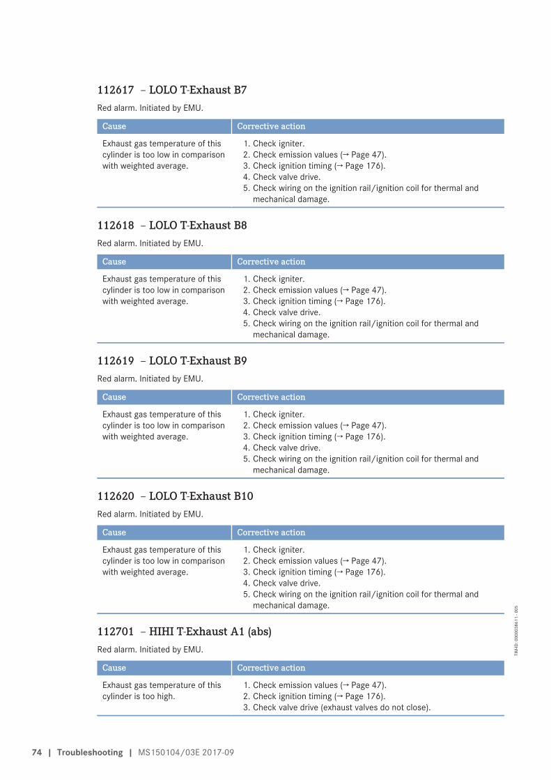
112617 – LOLO T-Exhaust B7Red alarm. Initiated by EMU.
Cause Corrective action
Exhaust gas temperature of thiscylinder is too low in comparisonwith weighted average.
1. Check igniter.2. Check emission values (→ Page 47).3. Check ignition timing (→ Page 176).4. Check valve drive.5. Check wiring on the ignition rail/ignition coil for thermal and
mechanical damage.
112618 – LOLO T-Exhaust B8Red alarm. Initiated by EMU.
Cause Corrective action
Exhaust gas temperature of thiscylinder is too low in comparisonwith weighted average.
1. Check igniter.2. Check emission values (→ Page 47).3. Check ignition timing (→ Page 176).4. Check valve drive.5. Check wiring on the ignition rail/ignition coil for thermal and
mechanical damage.
112619 – LOLO T-Exhaust B9Red alarm. Initiated by EMU.
Cause Corrective action
Exhaust gas temperature of thiscylinder is too low in comparisonwith weighted average.
1. Check igniter.2. Check emission values (→ Page 47).3. Check ignition timing (→ Page 176).4. Check valve drive.5. Check wiring on the ignition rail/ignition coil for thermal and
mechanical damage.
112620 – LOLO T-Exhaust B10Red alarm. Initiated by EMU.
Cause Corrective action
Exhaust gas temperature of thiscylinder is too low in comparisonwith weighted average.
1. Check igniter.2. Check emission values (→ Page 47).3. Check ignition timing (→ Page 176).4. Check valve drive.5. Check wiring on the ignition rail/ignition coil for thermal and
mechanical damage.
112701 – HIHI T-Exhaust A1 (abs)Red alarm. Initiated by EMU.
Cause Corrective action
Exhaust gas temperature of thiscylinder is too high.
1. Check emission values (→ Page 47).2. Check ignition timing (→ Page 176).3. Check valve drive (exhaust valves do not close).
74 | Troubleshooting | MS150104/03E 2017-09
TIM
-ID: 0
0000
3861
1 - 0
05
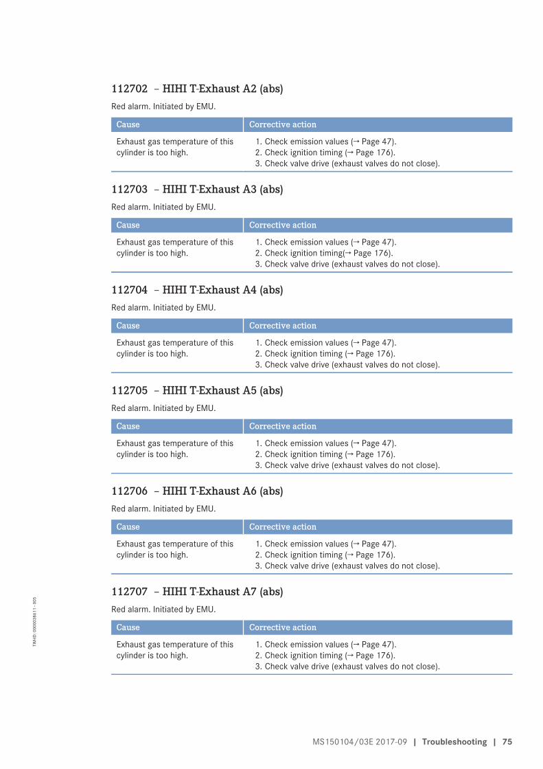
112702 – HIHI T-Exhaust A2 (abs)Red alarm. Initiated by EMU.
Cause Corrective action
Exhaust gas temperature of thiscylinder is too high.
1. Check emission values (→ Page 47).2. Check ignition timing (→ Page 176).3. Check valve drive (exhaust valves do not close).
112703 – HIHI T-Exhaust A3 (abs)Red alarm. Initiated by EMU.
Cause Corrective action
Exhaust gas temperature of thiscylinder is too high.
1. Check emission values (→ Page 47).2. Check ignition timing(→ Page 176).3. Check valve drive (exhaust valves do not close).
112704 – HIHI T-Exhaust A4 (abs)Red alarm. Initiated by EMU.
Cause Corrective action
Exhaust gas temperature of thiscylinder is too high.
1. Check emission values (→ Page 47).2. Check ignition timing (→ Page 176).3. Check valve drive (exhaust valves do not close).
112705 – HIHI T-Exhaust A5 (abs)Red alarm. Initiated by EMU.
Cause Corrective action
Exhaust gas temperature of thiscylinder is too high.
1. Check emission values (→ Page 47).2. Check ignition timing (→ Page 176).3. Check valve drive (exhaust valves do not close).
112706 – HIHI T-Exhaust A6 (abs)Red alarm. Initiated by EMU.
Cause Corrective action
Exhaust gas temperature of thiscylinder is too high.
1. Check emission values (→ Page 47).2. Check ignition timing (→ Page 176).3. Check valve drive (exhaust valves do not close).
112707 – HIHI T-Exhaust A7 (abs)Red alarm. Initiated by EMU.
Cause Corrective action
Exhaust gas temperature of thiscylinder is too high.
1. Check emission values (→ Page 47).2. Check ignition timing (→ Page 176).3. Check valve drive (exhaust valves do not close).
MS150104/03E 2017-09 | Troubleshooting | 75
TIM
-ID: 0
0000
3861
1 - 0
05
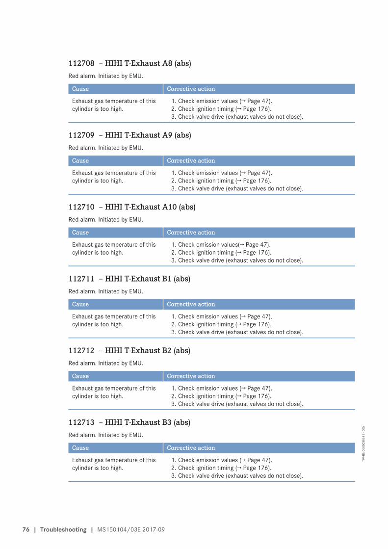
112708 – HIHI T-Exhaust A8 (abs)Red alarm. Initiated by EMU.
Cause Corrective action
Exhaust gas temperature of thiscylinder is too high.
1. Check emission values (→ Page 47).2. Check ignition timing (→ Page 176).3. Check valve drive (exhaust valves do not close).
112709 – HIHI T-Exhaust A9 (abs)Red alarm. Initiated by EMU.
Cause Corrective action
Exhaust gas temperature of thiscylinder is too high.
1. Check emission values (→ Page 47).2. Check ignition timing (→ Page 176).3. Check valve drive (exhaust valves do not close).
112710 – HIHI T-Exhaust A10 (abs)Red alarm. Initiated by EMU.
Cause Corrective action
Exhaust gas temperature of thiscylinder is too high.
1. Check emission values(→ Page 47).2. Check ignition timing (→ Page 176).3. Check valve drive (exhaust valves do not close).
112711 – HIHI T-Exhaust B1 (abs)Red alarm. Initiated by EMU.
Cause Corrective action
Exhaust gas temperature of thiscylinder is too high.
1. Check emission values (→ Page 47).2. Check ignition timing (→ Page 176).3. Check valve drive (exhaust valves do not close).
112712 – HIHI T-Exhaust B2 (abs)Red alarm. Initiated by EMU.
Cause Corrective action
Exhaust gas temperature of thiscylinder is too high.
1. Check emission values (→ Page 47).2. Check ignition timing (→ Page 176).3. Check valve drive (exhaust valves do not close).
112713 – HIHI T-Exhaust B3 (abs)Red alarm. Initiated by EMU.
Cause Corrective action
Exhaust gas temperature of thiscylinder is too high.
1. Check emission values (→ Page 47).2. Check ignition timing (→ Page 176).3. Check valve drive (exhaust valves do not close).
76 | Troubleshooting | MS150104/03E 2017-09
TIM
-ID: 0
0000
3861
1 - 0
05
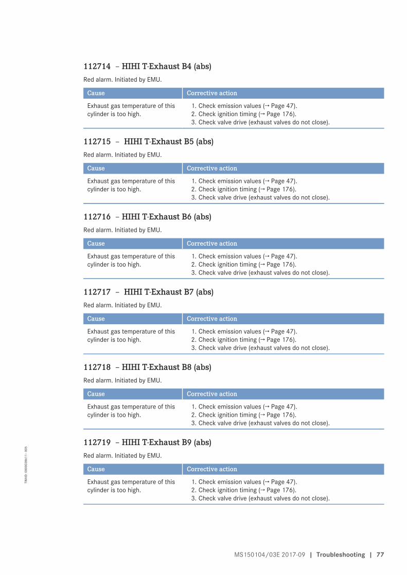
112714 – HIHI T-Exhaust B4 (abs)Red alarm. Initiated by EMU.
Cause Corrective action
Exhaust gas temperature of thiscylinder is too high.
1. Check emission values (→ Page 47).2. Check ignition timing (→ Page 176).3. Check valve drive (exhaust valves do not close).
112715 – HIHI T-Exhaust B5 (abs)Red alarm. Initiated by EMU.
Cause Corrective action
Exhaust gas temperature of thiscylinder is too high.
1. Check emission values (→ Page 47).2. Check ignition timing (→ Page 176).3. Check valve drive (exhaust valves do not close).
112716 – HIHI T-Exhaust B6 (abs)Red alarm. Initiated by EMU.
Cause Corrective action
Exhaust gas temperature of thiscylinder is too high.
1. Check emission values (→ Page 47).2. Check ignition timing (→ Page 176).3. Check valve drive (exhaust valves do not close).
112717 – HIHI T-Exhaust B7 (abs)Red alarm. Initiated by EMU.
Cause Corrective action
Exhaust gas temperature of thiscylinder is too high.
1. Check emission values (→ Page 47).2. Check ignition timing (→ Page 176).3. Check valve drive (exhaust valves do not close).
112718 – HIHI T-Exhaust B8 (abs)Red alarm. Initiated by EMU.
Cause Corrective action
Exhaust gas temperature of thiscylinder is too high.
1. Check emission values (→ Page 47).2. Check ignition timing (→ Page 176).3. Check valve drive (exhaust valves do not close).
112719 – HIHI T-Exhaust B9 (abs)Red alarm. Initiated by EMU.
Cause Corrective action
Exhaust gas temperature of thiscylinder is too high.
1. Check emission values (→ Page 47).2. Check ignition timing (→ Page 176).3. Check valve drive (exhaust valves do not close).
MS150104/03E 2017-09 | Troubleshooting | 77
TIM
-ID: 0
0000
3861
1 - 0
05
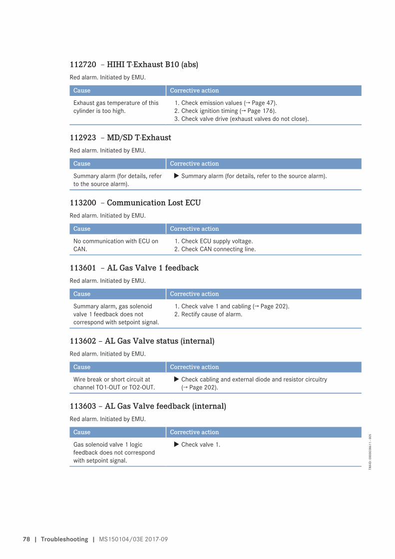
112720 – HIHI T-Exhaust B10 (abs)Red alarm. Initiated by EMU.
Cause Corrective action
Exhaust gas temperature of thiscylinder is too high.
1. Check emission values (→ Page 47).2. Check ignition timing (→ Page 176).3. Check valve drive (exhaust valves do not close).
112923 – MD/SD T-ExhaustRed alarm. Initiated by EMU.
Cause Corrective action
Summary alarm (for details, referto the source alarm).
u Summary alarm (for details, refer to the source alarm).
113200 – Communication Lost ECURed alarm. Initiated by EMU.
Cause Corrective action
No communication with ECU onCAN.
1. Check ECU supply voltage.2. Check CAN connecting line.
113601 – AL Gas Valve 1 feedbackRed alarm. Initiated by EMU.
Cause Corrective action
Summary alarm, gas solenoidvalve 1 feedback does notcorrespond with setpoint signal.
1. Check valve 1 and cabling (→ Page 202).2. Rectify cause of alarm.
113602 – AL Gas Valve status (internal)Red alarm. Initiated by EMU.
Cause Corrective action
Wire break or short circuit atchannel TO1-OUT or TO2-OUT.
u Check cabling and external diode and resistor circuitry(→ Page 202).
113603 – AL Gas Valve feedback (internal)Red alarm. Initiated by EMU.
Cause Corrective action
Gas solenoid valve 1 logicfeedback does not correspondwith setpoint signal.
u Check valve 1.
78 | Troubleshooting | MS150104/03E 2017-09
TIM
-ID: 0
0000
3861
1 - 0
05
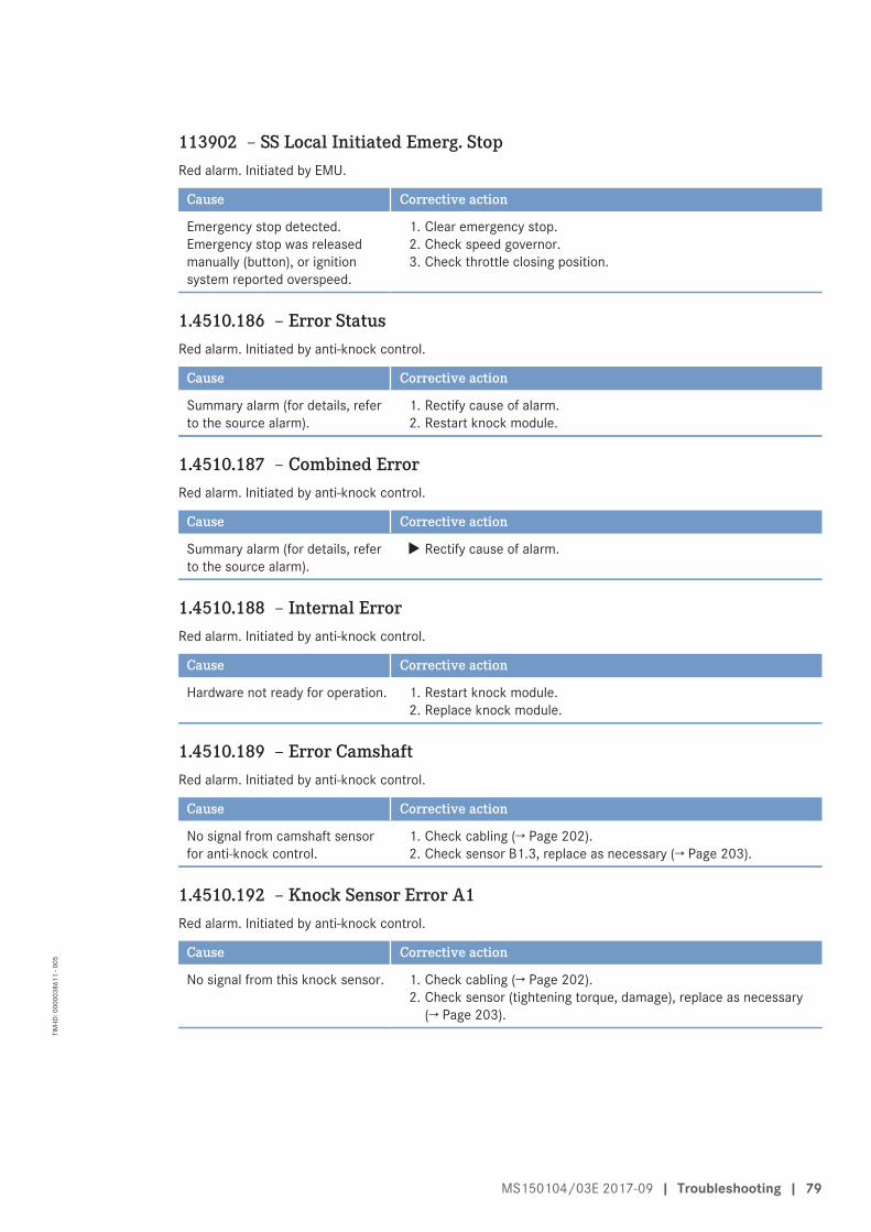
113902 – SS Local Initiated Emerg. StopRed alarm. Initiated by EMU.
Cause Corrective action
Emergency stop detected.Emergency stop was releasedmanually (button), or ignitionsystem reported overspeed.
1. Clear emergency stop.2. Check speed governor.3. Check throttle closing position.
1.4510.186 – Error StatusRed alarm. Initiated by anti-knock control.
Cause Corrective action
Summary alarm (for details, referto the source alarm).
1. Rectify cause of alarm.2. Restart knock module.
1.4510.187 – Combined ErrorRed alarm. Initiated by anti-knock control.
Cause Corrective action
Summary alarm (for details, referto the source alarm).
u Rectify cause of alarm.
1.4510.188 – Internal ErrorRed alarm. Initiated by anti-knock control.
Cause Corrective action
Hardware not ready for operation. 1. Restart knock module.2. Replace knock module.
1.4510.189 – Error CamshaftRed alarm. Initiated by anti-knock control.
Cause Corrective action
No signal from camshaft sensorfor anti-knock control.
1. Check cabling (→ Page 202).2. Check sensor B1.3, replace as necessary (→ Page 203).
1.4510.192 – Knock Sensor Error A1Red alarm. Initiated by anti-knock control.
Cause Corrective action
No signal from this knock sensor. 1. Check cabling (→ Page 202).2. Check sensor (tightening torque, damage), replace as necessary
(→ Page 203).
MS150104/03E 2017-09 | Troubleshooting | 79
TIM
-ID: 0
0000
3861
1 - 0
05
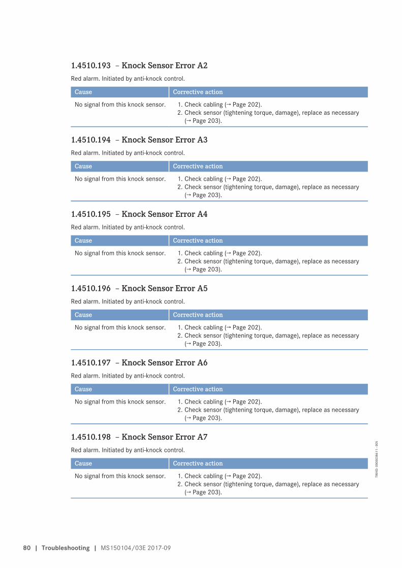
1.4510.193 – Knock Sensor Error A2Red alarm. Initiated by anti-knock control.
Cause Corrective action
No signal from this knock sensor. 1. Check cabling (→ Page 202).2. Check sensor (tightening torque, damage), replace as necessary
(→ Page 203).
1.4510.194 – Knock Sensor Error A3Red alarm. Initiated by anti-knock control.
Cause Corrective action
No signal from this knock sensor. 1. Check cabling (→ Page 202).2. Check sensor (tightening torque, damage), replace as necessary
(→ Page 203).
1.4510.195 – Knock Sensor Error A4Red alarm. Initiated by anti-knock control.
Cause Corrective action
No signal from this knock sensor. 1. Check cabling (→ Page 202).2. Check sensor (tightening torque, damage), replace as necessary
(→ Page 203).
1.4510.196 – Knock Sensor Error A5Red alarm. Initiated by anti-knock control.
Cause Corrective action
No signal from this knock sensor. 1. Check cabling (→ Page 202).2. Check sensor (tightening torque, damage), replace as necessary
(→ Page 203).
1.4510.197 – Knock Sensor Error A6Red alarm. Initiated by anti-knock control.
Cause Corrective action
No signal from this knock sensor. 1. Check cabling (→ Page 202).2. Check sensor (tightening torque, damage), replace as necessary
(→ Page 203).
1.4510.198 – Knock Sensor Error A7Red alarm. Initiated by anti-knock control.
Cause Corrective action
No signal from this knock sensor. 1. Check cabling (→ Page 202).2. Check sensor (tightening torque, damage), replace as necessary
(→ Page 203).
80 | Troubleshooting | MS150104/03E 2017-09
TIM
-ID: 0
0000
3861
1 - 0
05
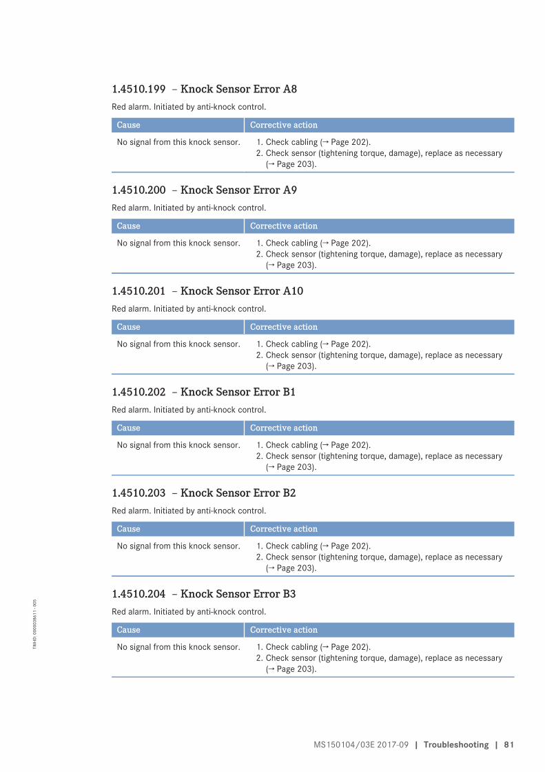
1.4510.199 – Knock Sensor Error A8Red alarm. Initiated by anti-knock control.
Cause Corrective action
No signal from this knock sensor. 1. Check cabling (→ Page 202).2. Check sensor (tightening torque, damage), replace as necessary
(→ Page 203).
1.4510.200 – Knock Sensor Error A9Red alarm. Initiated by anti-knock control.
Cause Corrective action
No signal from this knock sensor. 1. Check cabling (→ Page 202).2. Check sensor (tightening torque, damage), replace as necessary
(→ Page 203).
1.4510.201 – Knock Sensor Error A10Red alarm. Initiated by anti-knock control.
Cause Corrective action
No signal from this knock sensor. 1. Check cabling (→ Page 202).2. Check sensor (tightening torque, damage), replace as necessary
(→ Page 203).
1.4510.202 – Knock Sensor Error B1Red alarm. Initiated by anti-knock control.
Cause Corrective action
No signal from this knock sensor. 1. Check cabling (→ Page 202).2. Check sensor (tightening torque, damage), replace as necessary
(→ Page 203).
1.4510.203 – Knock Sensor Error B2Red alarm. Initiated by anti-knock control.
Cause Corrective action
No signal from this knock sensor. 1. Check cabling (→ Page 202).2. Check sensor (tightening torque, damage), replace as necessary
(→ Page 203).
1.4510.204 – Knock Sensor Error B3Red alarm. Initiated by anti-knock control.
Cause Corrective action
No signal from this knock sensor. 1. Check cabling (→ Page 202).2. Check sensor (tightening torque, damage), replace as necessary
(→ Page 203).
MS150104/03E 2017-09 | Troubleshooting | 81
TIM
-ID: 0
0000
3861
1 - 0
05
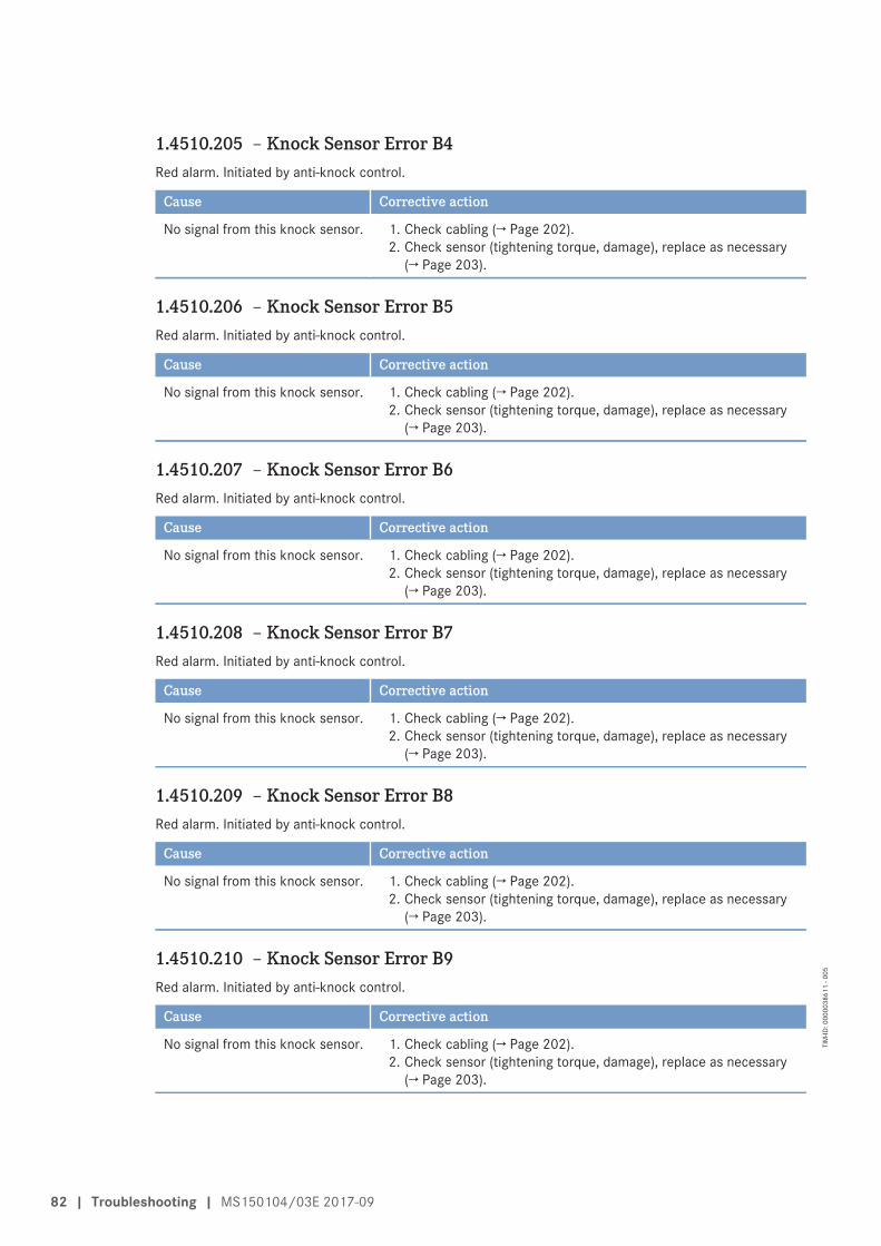
1.4510.205 – Knock Sensor Error B4Red alarm. Initiated by anti-knock control.
Cause Corrective action
No signal from this knock sensor. 1. Check cabling (→ Page 202).2. Check sensor (tightening torque, damage), replace as necessary
(→ Page 203).
1.4510.206 – Knock Sensor Error B5Red alarm. Initiated by anti-knock control.
Cause Corrective action
No signal from this knock sensor. 1. Check cabling (→ Page 202).2. Check sensor (tightening torque, damage), replace as necessary
(→ Page 203).
1.4510.207 – Knock Sensor Error B6Red alarm. Initiated by anti-knock control.
Cause Corrective action
No signal from this knock sensor. 1. Check cabling (→ Page 202).2. Check sensor (tightening torque, damage), replace as necessary
(→ Page 203).
1.4510.208 – Knock Sensor Error B7Red alarm. Initiated by anti-knock control.
Cause Corrective action
No signal from this knock sensor. 1. Check cabling (→ Page 202).2. Check sensor (tightening torque, damage), replace as necessary
(→ Page 203).
1.4510.209 – Knock Sensor Error B8Red alarm. Initiated by anti-knock control.
Cause Corrective action
No signal from this knock sensor. 1. Check cabling (→ Page 202).2. Check sensor (tightening torque, damage), replace as necessary
(→ Page 203).
1.4510.210 – Knock Sensor Error B9Red alarm. Initiated by anti-knock control.
Cause Corrective action
No signal from this knock sensor. 1. Check cabling (→ Page 202).2. Check sensor (tightening torque, damage), replace as necessary
(→ Page 203).
82 | Troubleshooting | MS150104/03E 2017-09
TIM
-ID: 0
0000
3861
1 - 0
05
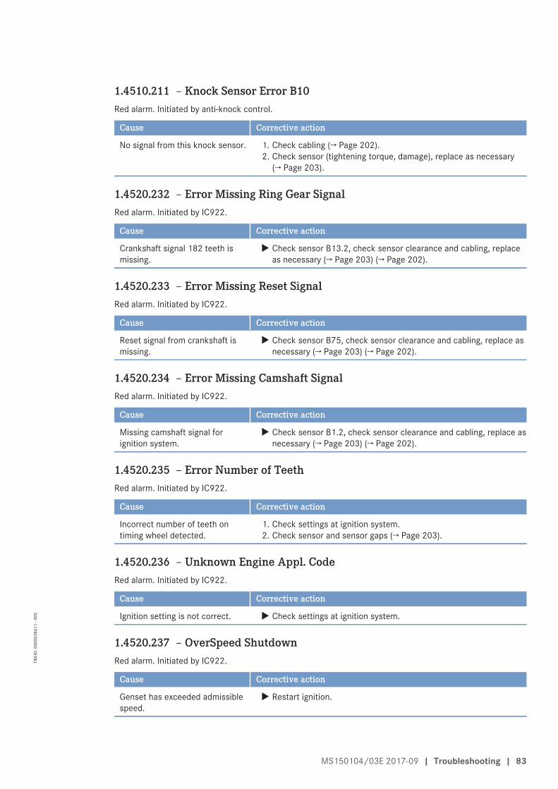
1.4510.211 – Knock Sensor Error B10Red alarm. Initiated by anti-knock control.
Cause Corrective action
No signal from this knock sensor. 1. Check cabling (→ Page 202).2. Check sensor (tightening torque, damage), replace as necessary
(→ Page 203).
1.4520.232 – Error Missing Ring Gear SignalRed alarm. Initiated by IC922.
Cause Corrective action
Crankshaft signal 182 teeth ismissing.
u Check sensor B13.2, check sensor clearance and cabling, replaceas necessary (→ Page 203) (→ Page 202).
1.4520.233 – Error Missing Reset SignalRed alarm. Initiated by IC922.
Cause Corrective action
Reset signal from crankshaft ismissing.
u Check sensor B75, check sensor clearance and cabling, replace asnecessary (→ Page 203) (→ Page 202).
1.4520.234 – Error Missing Camshaft SignalRed alarm. Initiated by IC922.
Cause Corrective action
Missing camshaft signal forignition system.
u Check sensor B1.2, check sensor clearance and cabling, replace asnecessary (→ Page 203) (→ Page 202).
1.4520.235 – Error Number of TeethRed alarm. Initiated by IC922.
Cause Corrective action
Incorrect number of teeth ontiming wheel detected.
1. Check settings at ignition system.2. Check sensor and sensor gaps (→ Page 203).
1.4520.236 – Unknown Engine Appl. CodeRed alarm. Initiated by IC922.
Cause Corrective action
Ignition setting is not correct. u Check settings at ignition system.
1.4520.237 – OverSpeed ShutdownRed alarm. Initiated by IC922.
Cause Corrective action
Genset has exceeded admissiblespeed.
u Restart ignition.
MS150104/03E 2017-09 | Troubleshooting | 83
TIM
-ID: 0
0000
3861
1 - 0
05
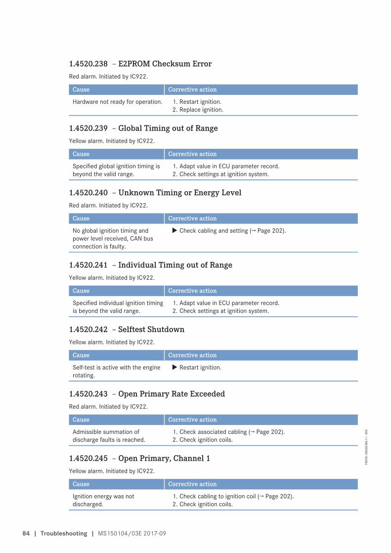
1.4520.238 – E2PROM Checksum ErrorRed alarm. Initiated by IC922.
Cause Corrective action
Hardware not ready for operation. 1. Restart ignition.2. Replace ignition.
1.4520.239 – Global Timing out of RangeYellow alarm. Initiated by IC922.
Cause Corrective action
Specified global ignition timing isbeyond the valid range.
1. Adapt value in ECU parameter record.2. Check settings at ignition system.
1.4520.240 – Unknown Timing or Energy LevelRed alarm. Initiated by IC922.
Cause Corrective action
No global ignition timing andpower level received, CAN busconnection is faulty.
u Check cabling and setting (→ Page 202).
1.4520.241 – Individual Timing out of RangeYellow alarm. Initiated by IC922.
Cause Corrective action
Specified individual ignition timingis beyond the valid range.
1. Adapt value in ECU parameter record.2. Check settings at ignition system.
1.4520.242 – Selftest ShutdownYellow alarm. Initiated by IC922.
Cause Corrective action
Self-test is active with the enginerotating.
u Restart ignition.
1.4520.243 – Open Primary Rate ExceededRed alarm. Initiated by IC922.
Cause Corrective action
Admissible summation ofdischarge faults is reached.
1. Check associated cabling (→ Page 202).2. Check ignition coils.
1.4520.245 – Open Primary, Channel 1Yellow alarm. Initiated by IC922.
Cause Corrective action
Ignition energy was notdischarged.
1. Check cabling to ignition coil (→ Page 202).2. Check ignition coils.
84 | Troubleshooting | MS150104/03E 2017-09
TIM
-ID: 0
0000
3861
1 - 0
05
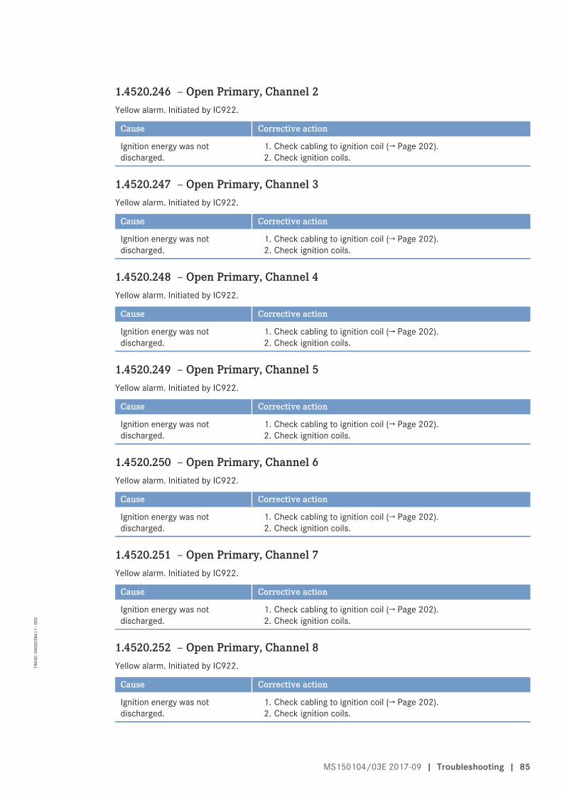
1.4520.246 – Open Primary, Channel 2Yellow alarm. Initiated by IC922.
Cause Corrective action
Ignition energy was notdischarged.
1. Check cabling to ignition coil (→ Page 202).2. Check ignition coils.
1.4520.247 – Open Primary, Channel 3Yellow alarm. Initiated by IC922.
Cause Corrective action
Ignition energy was notdischarged.
1. Check cabling to ignition coil (→ Page 202).2. Check ignition coils.
1.4520.248 – Open Primary, Channel 4Yellow alarm. Initiated by IC922.
Cause Corrective action
Ignition energy was notdischarged.
1. Check cabling to ignition coil (→ Page 202).2. Check ignition coils.
1.4520.249 – Open Primary, Channel 5Yellow alarm. Initiated by IC922.
Cause Corrective action
Ignition energy was notdischarged.
1. Check cabling to ignition coil (→ Page 202).2. Check ignition coils.
1.4520.250 – Open Primary, Channel 6Yellow alarm. Initiated by IC922.
Cause Corrective action
Ignition energy was notdischarged.
1. Check cabling to ignition coil (→ Page 202).2. Check ignition coils.
1.4520.251 – Open Primary, Channel 7Yellow alarm. Initiated by IC922.
Cause Corrective action
Ignition energy was notdischarged.
1. Check cabling to ignition coil (→ Page 202).2. Check ignition coils.
1.4520.252 – Open Primary, Channel 8Yellow alarm. Initiated by IC922.
Cause Corrective action
Ignition energy was notdischarged.
1. Check cabling to ignition coil (→ Page 202).2. Check ignition coils.
MS150104/03E 2017-09 | Troubleshooting | 85
TIM
-ID: 0
0000
3861
1 - 0
05
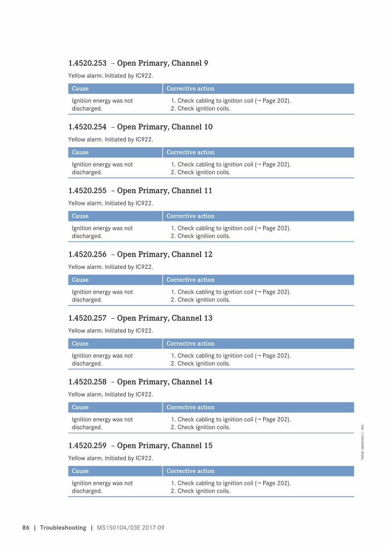
1.4520.253 – Open Primary, Channel 9Yellow alarm. Initiated by IC922.
Cause Corrective action
Ignition energy was notdischarged.
1. Check cabling to ignition coil (→ Page 202).2. Check ignition coils.
1.4520.254 – Open Primary, Channel 10Yellow alarm. Initiated by IC922.
Cause Corrective action
Ignition energy was notdischarged.
1. Check cabling to ignition coil (→ Page 202).2. Check ignition coils.
1.4520.255 – Open Primary, Channel 11Yellow alarm. Initiated by IC922.
Cause Corrective action
Ignition energy was notdischarged.
1. Check cabling to ignition coil (→ Page 202).2. Check ignition coils.
1.4520.256 – Open Primary, Channel 12Yellow alarm. Initiated by IC922.
Cause Corrective action
Ignition energy was notdischarged.
1. Check cabling to ignition coil (→ Page 202).2. Check ignition coils.
1.4520.257 – Open Primary, Channel 13Yellow alarm. Initiated by IC922.
Cause Corrective action
Ignition energy was notdischarged.
1. Check cabling to ignition coil (→ Page 202).2. Check ignition coils.
1.4520.258 – Open Primary, Channel 14Yellow alarm. Initiated by IC922.
Cause Corrective action
Ignition energy was notdischarged.
1. Check cabling to ignition coil (→ Page 202).2. Check ignition coils.
1.4520.259 – Open Primary, Channel 15Yellow alarm. Initiated by IC922.
Cause Corrective action
Ignition energy was notdischarged.
1. Check cabling to ignition coil (→ Page 202).2. Check ignition coils.
86 | Troubleshooting | MS150104/03E 2017-09
TIM
-ID: 0
0000
3861
1 - 0
05
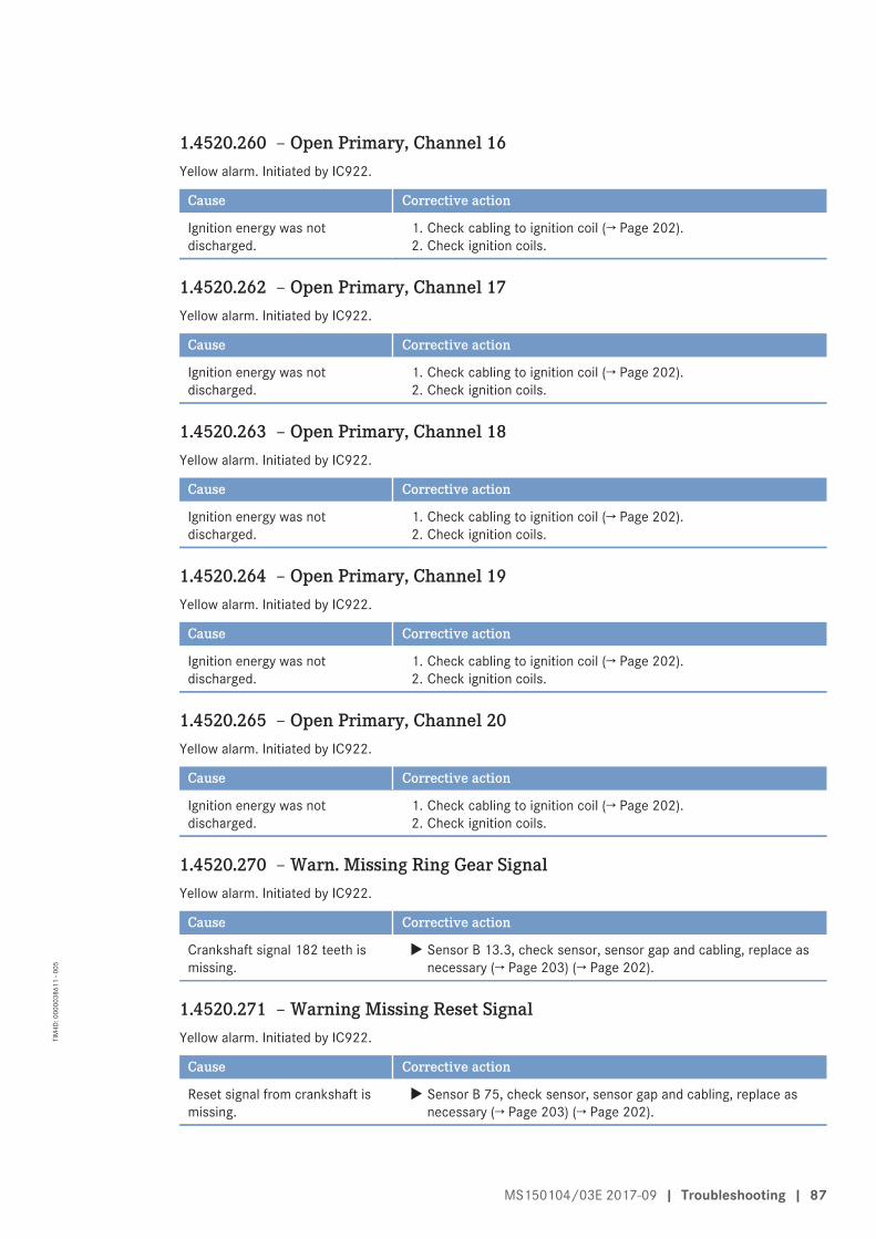
1.4520.260 – Open Primary, Channel 16Yellow alarm. Initiated by IC922.
Cause Corrective action
Ignition energy was notdischarged.
1. Check cabling to ignition coil (→ Page 202).2. Check ignition coils.
1.4520.262 – Open Primary, Channel 17Yellow alarm. Initiated by IC922.
Cause Corrective action
Ignition energy was notdischarged.
1. Check cabling to ignition coil (→ Page 202).2. Check ignition coils.
1.4520.263 – Open Primary, Channel 18Yellow alarm. Initiated by IC922.
Cause Corrective action
Ignition energy was notdischarged.
1. Check cabling to ignition coil (→ Page 202).2. Check ignition coils.
1.4520.264 – Open Primary, Channel 19Yellow alarm. Initiated by IC922.
Cause Corrective action
Ignition energy was notdischarged.
1. Check cabling to ignition coil (→ Page 202).2. Check ignition coils.
1.4520.265 – Open Primary, Channel 20Yellow alarm. Initiated by IC922.
Cause Corrective action
Ignition energy was notdischarged.
1. Check cabling to ignition coil (→ Page 202).2. Check ignition coils.
1.4520.270 – Warn. Missing Ring Gear SignalYellow alarm. Initiated by IC922.
Cause Corrective action
Crankshaft signal 182 teeth ismissing.
u Sensor B 13.3, check sensor, sensor gap and cabling, replace asnecessary (→ Page 203) (→ Page 202).
1.4520.271 – Warning Missing Reset SignalYellow alarm. Initiated by IC922.
Cause Corrective action
Reset signal from crankshaft ismissing.
u Sensor B 75, check sensor, sensor gap and cabling, replace asnecessary (→ Page 203) (→ Page 202).
MS150104/03E 2017-09 | Troubleshooting | 87
TIM
-ID: 0
0000
3861
1 - 0
05
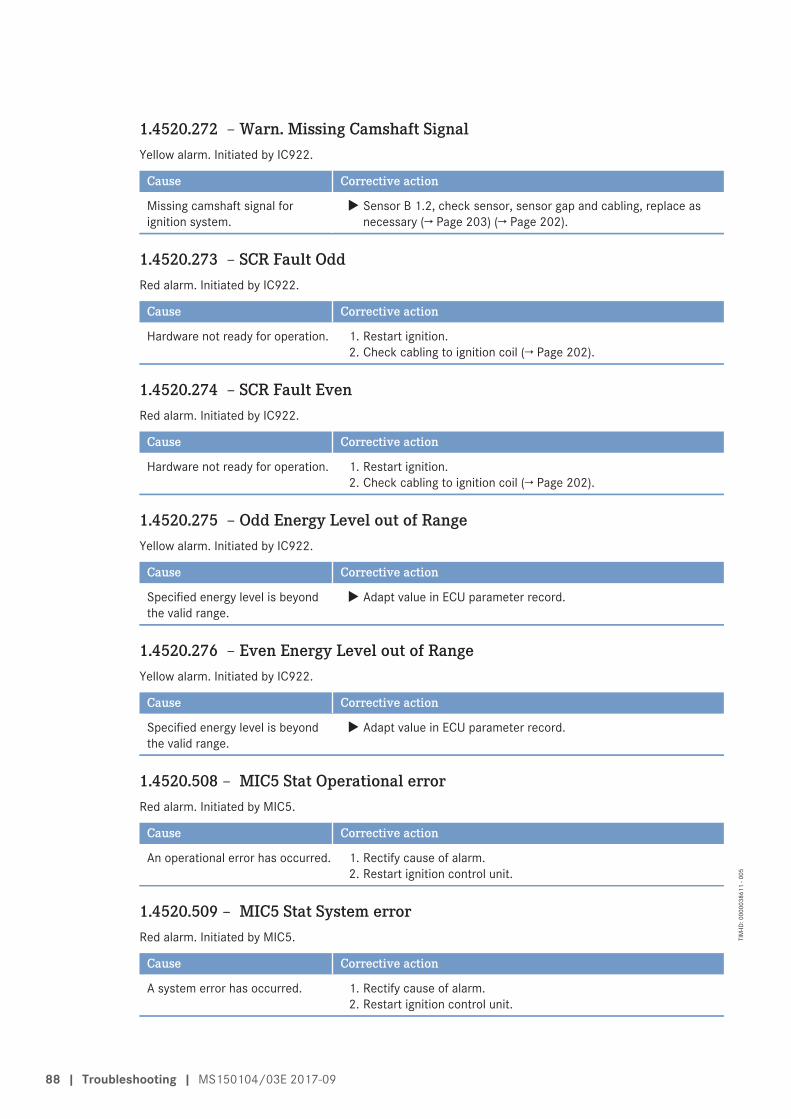
1.4520.272 – Warn. Missing Camshaft SignalYellow alarm. Initiated by IC922.
Cause Corrective action
Missing camshaft signal forignition system.
u Sensor B 1.2, check sensor, sensor gap and cabling, replace asnecessary (→ Page 203) (→ Page 202).
1.4520.273 – SCR Fault OddRed alarm. Initiated by IC922.
Cause Corrective action
Hardware not ready for operation. 1. Restart ignition.2. Check cabling to ignition coil (→ Page 202).
1.4520.274 – SCR Fault EvenRed alarm. Initiated by IC922.
Cause Corrective action
Hardware not ready for operation. 1. Restart ignition.2. Check cabling to ignition coil (→ Page 202).
1.4520.275 – Odd Energy Level out of RangeYellow alarm. Initiated by IC922.
Cause Corrective action
Specified energy level is beyondthe valid range.
u Adapt value in ECU parameter record.
1.4520.276 – Even Energy Level out of RangeYellow alarm. Initiated by IC922.
Cause Corrective action
Specified energy level is beyondthe valid range.
u Adapt value in ECU parameter record.
1.4520.508 – MIC5 Stat Operational errorRed alarm. Initiated by MIC5.
Cause Corrective action
An operational error has occurred. 1. Rectify cause of alarm.2. Restart ignition control unit.
1.4520.509 – MIC5 Stat System errorRed alarm. Initiated by MIC5.
Cause Corrective action
A system error has occurred. 1. Rectify cause of alarm.2. Restart ignition control unit.
88 | Troubleshooting | MS150104/03E 2017-09
TIM
-ID: 0
0000
3861
1 - 0
05
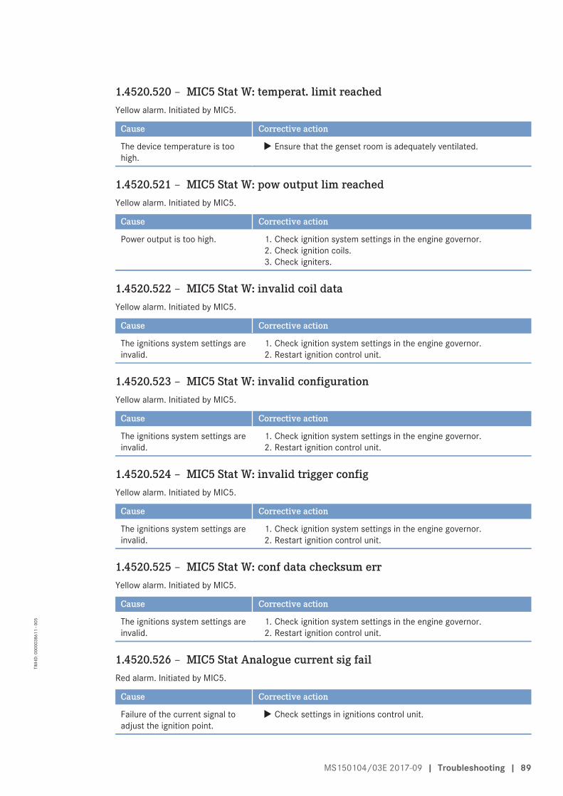
1.4520.520 – MIC5 Stat W: temperat. limit reachedYellow alarm. Initiated by MIC5.
Cause Corrective action
The device temperature is toohigh.
u Ensure that the genset room is adequately ventilated.
1.4520.521 – MIC5 Stat W: pow output lim reachedYellow alarm. Initiated by MIC5.
Cause Corrective action
Power output is too high. 1. Check ignition system settings in the engine governor.2. Check ignition coils.3. Check igniters.
1.4520.522 – MIC5 Stat W: invalid coil dataYellow alarm. Initiated by MIC5.
Cause Corrective action
The ignitions system settings areinvalid.
1. Check ignition system settings in the engine governor.2. Restart ignition control unit.
1.4520.523 – MIC5 Stat W: invalid configurationYellow alarm. Initiated by MIC5.
Cause Corrective action
The ignitions system settings areinvalid.
1. Check ignition system settings in the engine governor.2. Restart ignition control unit.
1.4520.524 – MIC5 Stat W: invalid trigger configYellow alarm. Initiated by MIC5.
Cause Corrective action
The ignitions system settings areinvalid.
1. Check ignition system settings in the engine governor.2. Restart ignition control unit.
1.4520.525 – MIC5 Stat W: conf data checksum errYellow alarm. Initiated by MIC5.
Cause Corrective action
The ignitions system settings areinvalid.
1. Check ignition system settings in the engine governor.2. Restart ignition control unit.
1.4520.526 – MIC5 Stat Analogue current sig failRed alarm. Initiated by MIC5.
Cause Corrective action
Failure of the current signal toadjust the ignition point.
u Check settings in ignitions control unit.
MS150104/03E 2017-09 | Troubleshooting | 89
TIM
-ID: 0
0000
3861
1 - 0
05
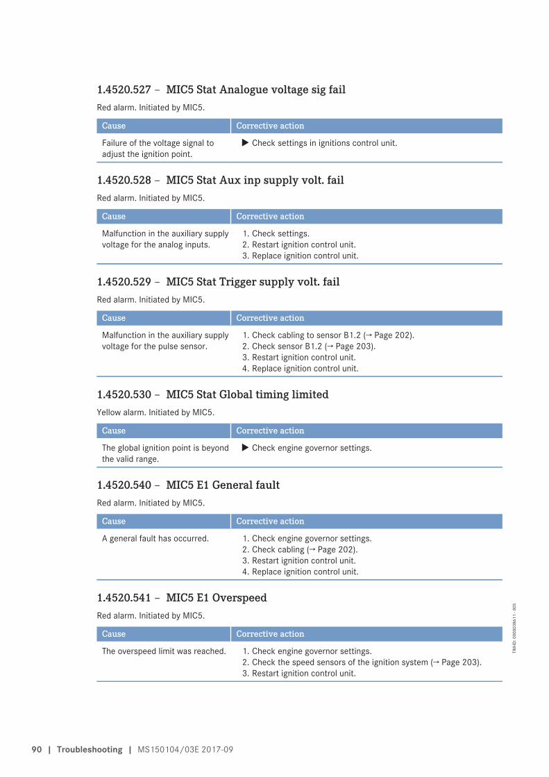
1.4520.527 – MIC5 Stat Analogue voltage sig failRed alarm. Initiated by MIC5.
Cause Corrective action
Failure of the voltage signal toadjust the ignition point.
u Check settings in ignitions control unit.
1.4520.528 – MIC5 Stat Aux inp supply volt. failRed alarm. Initiated by MIC5.
Cause Corrective action
Malfunction in the auxiliary supplyvoltage for the analog inputs.
1. Check settings.2. Restart ignition control unit.3. Replace ignition control unit.
1.4520.529 – MIC5 Stat Trigger supply volt. failRed alarm. Initiated by MIC5.
Cause Corrective action
Malfunction in the auxiliary supplyvoltage for the pulse sensor.
1. Check cabling to sensor B1.2 (→ Page 202).2. Check sensor B1.2 (→ Page 203).3. Restart ignition control unit.4. Replace ignition control unit.
1.4520.530 – MIC5 Stat Global timing limitedYellow alarm. Initiated by MIC5.
Cause Corrective action
The global ignition point is beyondthe valid range.
u Check engine governor settings.
1.4520.540 – MIC5 E1 General faultRed alarm. Initiated by MIC5.
Cause Corrective action
A general fault has occurred. 1. Check engine governor settings.2. Check cabling (→ Page 202).3. Restart ignition control unit.4. Replace ignition control unit.
1.4520.541 – MIC5 E1 OverspeedRed alarm. Initiated by MIC5.
Cause Corrective action
The overspeed limit was reached. 1. Check engine governor settings.2. Check the speed sensors of the ignition system (→ Page 203).3. Restart ignition control unit.
90 | Troubleshooting | MS150104/03E 2017-09
TIM
-ID: 0
0000
3861
1 - 0
05
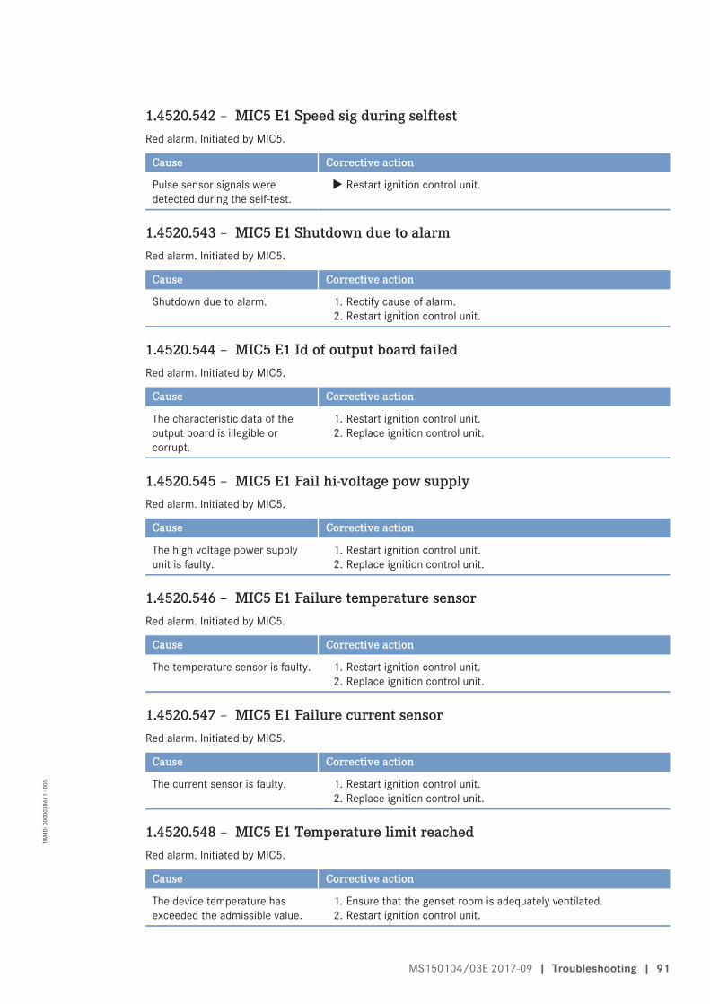
1.4520.542 – MIC5 E1 Speed sig during selftestRed alarm. Initiated by MIC5.
Cause Corrective action
Pulse sensor signals weredetected during the self-test.
u Restart ignition control unit.
1.4520.543 – MIC5 E1 Shutdown due to alarmRed alarm. Initiated by MIC5.
Cause Corrective action
Shutdown due to alarm. 1. Rectify cause of alarm.2. Restart ignition control unit.
1.4520.544 – MIC5 E1 Id of output board failedRed alarm. Initiated by MIC5.
Cause Corrective action
The characteristic data of theoutput board is illegible orcorrupt.
1. Restart ignition control unit.2. Replace ignition control unit.
1.4520.545 – MIC5 E1 Fail hi-voltage pow supplyRed alarm. Initiated by MIC5.
Cause Corrective action
The high voltage power supplyunit is faulty.
1. Restart ignition control unit.2. Replace ignition control unit.
1.4520.546 – MIC5 E1 Failure temperature sensorRed alarm. Initiated by MIC5.
Cause Corrective action
The temperature sensor is faulty. 1. Restart ignition control unit.2. Replace ignition control unit.
1.4520.547 – MIC5 E1 Failure current sensorRed alarm. Initiated by MIC5.
Cause Corrective action
The current sensor is faulty. 1. Restart ignition control unit.2. Replace ignition control unit.
1.4520.548 – MIC5 E1 Temperature limit reachedRed alarm. Initiated by MIC5.
Cause Corrective action
The device temperature hasexceeded the admissible value.
1. Ensure that the genset room is adequately ventilated.2. Restart ignition control unit.
MS150104/03E 2017-09 | Troubleshooting | 91
TIM
-ID: 0
0000
3861
1 - 0
05
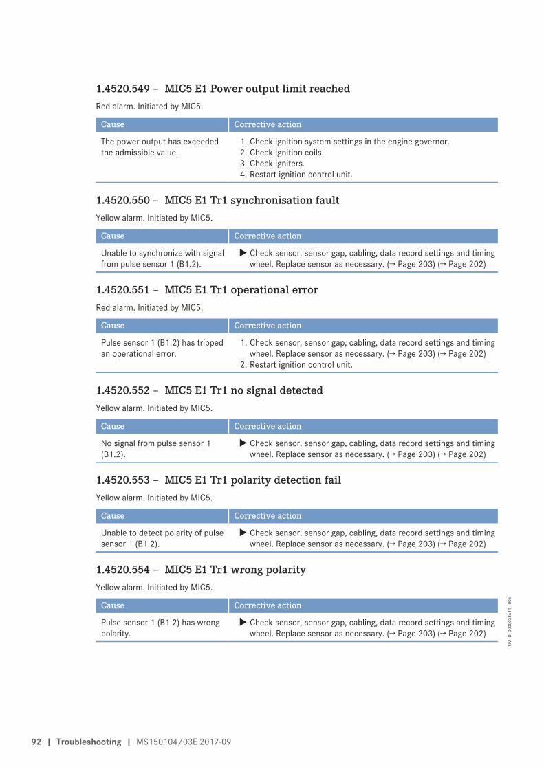
1.4520.549 – MIC5 E1 Power output limit reachedRed alarm. Initiated by MIC5.
Cause Corrective action
The power output has exceededthe admissible value.
1. Check ignition system settings in the engine governor.2. Check ignition coils.3. Check igniters.4. Restart ignition control unit.
1.4520.550 – MIC5 E1 Tr1 synchronisation faultYellow alarm. Initiated by MIC5.
Cause Corrective action
Unable to synchronize with signalfrom pulse sensor 1 (B1.2).
u Check sensor, sensor gap, cabling, data record settings and timingwheel. Replace sensor as necessary. (→ Page 203) (→ Page 202)
1.4520.551 – MIC5 E1 Tr1 operational errorRed alarm. Initiated by MIC5.
Cause Corrective action
Pulse sensor 1 (B1.2) has trippedan operational error.
1. Check sensor, sensor gap, cabling, data record settings and timingwheel. Replace sensor as necessary. (→ Page 203) (→ Page 202)
2. Restart ignition control unit.
1.4520.552 – MIC5 E1 Tr1 no signal detectedYellow alarm. Initiated by MIC5.
Cause Corrective action
No signal from pulse sensor 1(B1.2).
u Check sensor, sensor gap, cabling, data record settings and timingwheel. Replace sensor as necessary. (→ Page 203) (→ Page 202)
1.4520.553 – MIC5 E1 Tr1 polarity detection failYellow alarm. Initiated by MIC5.
Cause Corrective action
Unable to detect polarity of pulsesensor 1 (B1.2).
u Check sensor, sensor gap, cabling, data record settings and timingwheel. Replace sensor as necessary. (→ Page 203) (→ Page 202)
1.4520.554 – MIC5 E1 Tr1 wrong polarityYellow alarm. Initiated by MIC5.
Cause Corrective action
Pulse sensor 1 (B1.2) has wrongpolarity.
u Check sensor, sensor gap, cabling, data record settings and timingwheel. Replace sensor as necessary. (→ Page 203) (→ Page 202)
92 | Troubleshooting | MS150104/03E 2017-09
TIM
-ID: 0
0000
3861
1 - 0
05
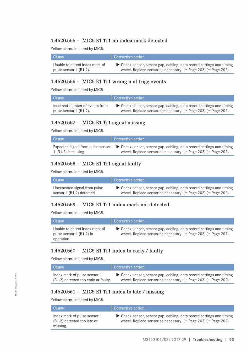
1.4520.555 – MIC5 E1 Tr1 no index mark detectedYellow alarm. Initiated by MIC5.
Cause Corrective action
Unable to detect index mark ofpulse sensor 1 (B1.2).
u Check sensor, sensor gap, cabling, data record settings and timingwheel. Replace sensor as necessary. (→ Page 203) (→ Page 202)
1.4520.556 – MIC5 E1 Tr1 wrong n of trigg eventsYellow alarm. Initiated by MIC5.
Cause Corrective action
Incorrect number of events frompulse sensor 1 (B1.2).
u Check sensor, sensor gap, cabling, data record settings and timingwheel. Replace sensor as necessary. (→ Page 203) (→ Page 202)
1.4520.557 – MIC5 E1 Tr1 signal missingYellow alarm. Initiated by MIC5.
Cause Corrective action
Expected signal from pulse sensor1 (B1.2) is missing.
u Check sensor, sensor gap, cabling, data record settings and timingwheel. Replace sensor as necessary. (→ Page 203) (→ Page 202)
1.4520.558 – MIC5 E1 Tr1 signal faultyYellow alarm. Initiated by MIC5.
Cause Corrective action
Unexpected signal from pulsesensor 1 (B1.2) detected.
u Check sensor, sensor gap, cabling, data record settings and timingwheel. Replace sensor as necessary. (→ Page 203) (→ Page 202)
1.4520.559 – MIC5 E1 Tr1 index mark not detectedYellow alarm. Initiated by MIC5.
Cause Corrective action
Unable to detect index mark ofpulse sensor 1 (B1.2) inoperation.
u Check sensor, sensor gap, cabling, data record settings and timingwheel. Replace sensor as necessary. (→ Page 203) (→ Page 202)
1.4520.560 – MIC5 E1 Tr1 index to early / faultyYellow alarm. Initiated by MIC5.
Cause Corrective action
Index mark of pulse sensor 1(B1.2) detected too early or faulty.
u Check sensor, sensor gap, cabling, data record settings and timingwheel. Replace sensor as necessary. (→ Page 203) (→ Page 202)
1.4520.561 – MIC5 E1 Tr1 index to late / missingYellow alarm. Initiated by MIC5.
Cause Corrective action
Index mark of pulse sensor 1(B1.2) detected too late ormissing.
u Check sensor, sensor gap, cabling, data record settings and timingwheel. Replace sensor as necessary. (→ Page 203) (→ Page 202)
MS150104/03E 2017-09 | Troubleshooting | 93
TIM
-ID: 0
0000
3861
1 - 0
05
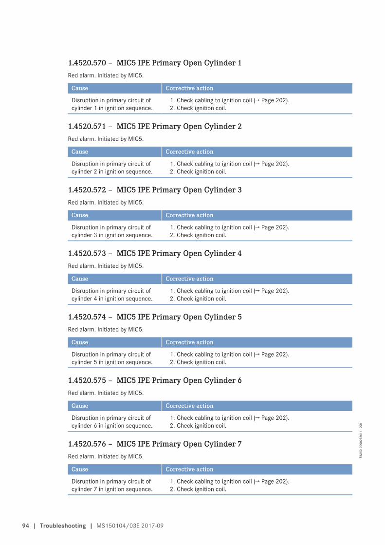
1.4520.570 – MIC5 IPE Primary Open Cylinder 1Red alarm. Initiated by MIC5.
Cause Corrective action
Disruption in primary circuit ofcylinder 1 in ignition sequence.
1. Check cabling to ignition coil (→ Page 202).2. Check ignition coil.
1.4520.571 – MIC5 IPE Primary Open Cylinder 2Red alarm. Initiated by MIC5.
Cause Corrective action
Disruption in primary circuit ofcylinder 2 in ignition sequence.
1. Check cabling to ignition coil (→ Page 202).2. Check ignition coil.
1.4520.572 – MIC5 IPE Primary Open Cylinder 3Red alarm. Initiated by MIC5.
Cause Corrective action
Disruption in primary circuit ofcylinder 3 in ignition sequence.
1. Check cabling to ignition coil (→ Page 202).2. Check ignition coil.
1.4520.573 – MIC5 IPE Primary Open Cylinder 4Red alarm. Initiated by MIC5.
Cause Corrective action
Disruption in primary circuit ofcylinder 4 in ignition sequence.
1. Check cabling to ignition coil (→ Page 202).2. Check ignition coil.
1.4520.574 – MIC5 IPE Primary Open Cylinder 5Red alarm. Initiated by MIC5.
Cause Corrective action
Disruption in primary circuit ofcylinder 5 in ignition sequence.
1. Check cabling to ignition coil (→ Page 202).2. Check ignition coil.
1.4520.575 – MIC5 IPE Primary Open Cylinder 6Red alarm. Initiated by MIC5.
Cause Corrective action
Disruption in primary circuit ofcylinder 6 in ignition sequence.
1. Check cabling to ignition coil (→ Page 202).2. Check ignition coil.
1.4520.576 – MIC5 IPE Primary Open Cylinder 7Red alarm. Initiated by MIC5.
Cause Corrective action
Disruption in primary circuit ofcylinder 7 in ignition sequence.
1. Check cabling to ignition coil (→ Page 202).2. Check ignition coil.
94 | Troubleshooting | MS150104/03E 2017-09
TIM
-ID: 0
0000
3861
1 - 0
05

1.4520.577 – MIC5 IPE Primary Open Cylinder 8Red alarm. Initiated by MIC5.
Cause Corrective action
Disruption in primary circuit ofcylinder 8 in ignition sequence.
1. Check cabling to ignition coil (→ Page 202).2. Check ignition coil.
1.4520.578 – MIC5 IPE Primary Open Cylinder 9Red alarm. Initiated by MIC5.
Cause Corrective action
Disruption in primary circuit ofcylinder 9 in ignition sequence.
1. Check cabling to ignition coil (→ Page 202).2. Check ignition coil.
1.4520.579 – MIC5 IPE Primary Open Cylinder 10Red alarm. Initiated by MIC5.
Cause Corrective action
Disruption in primary circuit ofcylinder 10 in ignition sequence.
1. Check cabling to ignition coil (→ Page 202).2. Check ignition coil.
1.4520.580 – MIC5 IPE Primary Open Cylinder 11Red alarm. Initiated by MIC5.
Cause Corrective action
Disruption in primary circuit ofcylinder 11 in ignition sequence.
1. Check cabling to ignition coil (→ Page 202).2. Check ignition coil.
1.4520.581 – MIC5 IPE Primary Open Cylinder 12Red alarm. Initiated by MIC5.
Cause Corrective action
Disruption in primary circuit ofcylinder 12 in ignition sequence.
1. Check cabling to ignition coil (→ Page 202).2. Check ignition coil.
1.4520.582 – MIC5 IPE Primary Open Cylinder 13Red alarm. Initiated by MIC5.
Cause Corrective action
Disruption in primary circuit ofcylinder 13 in ignition sequence.
1. Check cabling to ignition coil (→ Page 202).2. Check ignition coil.
1.4520.583 – MIC5 IPE Primary Open Cylinder 14Red alarm. Initiated by MIC5.
Cause Corrective action
Disruption in primary circuit ofcylinder 14 in ignition sequence.
1. Check cabling to ignition coil (→ Page 202).2. Check ignition coil.
MS150104/03E 2017-09 | Troubleshooting | 95
TIM
-ID: 0
0000
3861
1 - 0
05
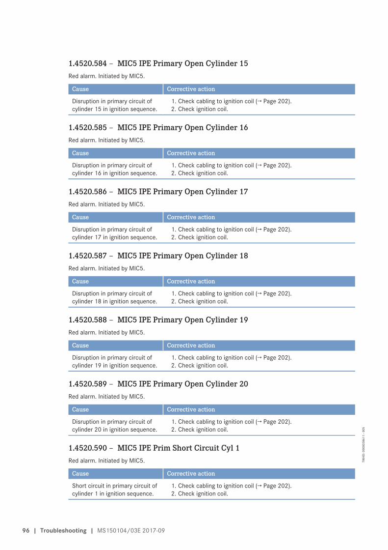
1.4520.584 – MIC5 IPE Primary Open Cylinder 15Red alarm. Initiated by MIC5.
Cause Corrective action
Disruption in primary circuit ofcylinder 15 in ignition sequence.
1. Check cabling to ignition coil (→ Page 202).2. Check ignition coil.
1.4520.585 – MIC5 IPE Primary Open Cylinder 16Red alarm. Initiated by MIC5.
Cause Corrective action
Disruption in primary circuit ofcylinder 16 in ignition sequence.
1. Check cabling to ignition coil (→ Page 202).2. Check ignition coil.
1.4520.586 – MIC5 IPE Primary Open Cylinder 17Red alarm. Initiated by MIC5.
Cause Corrective action
Disruption in primary circuit ofcylinder 17 in ignition sequence.
1. Check cabling to ignition coil (→ Page 202).2. Check ignition coil.
1.4520.587 – MIC5 IPE Primary Open Cylinder 18Red alarm. Initiated by MIC5.
Cause Corrective action
Disruption in primary circuit ofcylinder 18 in ignition sequence.
1. Check cabling to ignition coil (→ Page 202).2. Check ignition coil.
1.4520.588 – MIC5 IPE Primary Open Cylinder 19Red alarm. Initiated by MIC5.
Cause Corrective action
Disruption in primary circuit ofcylinder 19 in ignition sequence.
1. Check cabling to ignition coil (→ Page 202).2. Check ignition coil.
1.4520.589 – MIC5 IPE Primary Open Cylinder 20Red alarm. Initiated by MIC5.
Cause Corrective action
Disruption in primary circuit ofcylinder 20 in ignition sequence.
1. Check cabling to ignition coil (→ Page 202).2. Check ignition coil.
1.4520.590 – MIC5 IPE Prim Short Circuit Cyl 1Red alarm. Initiated by MIC5.
Cause Corrective action
Short circuit in primary circuit ofcylinder 1 in ignition sequence.
1. Check cabling to ignition coil (→ Page 202).2. Check ignition coil.
96 | Troubleshooting | MS150104/03E 2017-09
TIM
-ID: 0
0000
3861
1 - 0
05

1.4520.591 – MIC5 IPE Prim Short Circuit Cyl 2Red alarm. Initiated by MIC5.
Cause Corrective action
Short circuit in primary circuit ofcylinder 2 in ignition sequence.
1. Check cabling to ignition coil (→ Page 202).2. Check ignition coil.
1.4520.592 – MIC5 IPE Prim Short Circuit Cyl 3Red alarm. Initiated by MIC5.
Cause Corrective action
Short circuit in primary circuit ofcylinder 3 in ignition sequence.
1. Check cabling to ignition coil (→ Page 202).2. Check ignition coil.
1.4520.593 – MIC5 IPE Prim Short Circuit Cyl 4Red alarm. Initiated by MIC5.
Cause Corrective action
Short circuit in primary circuit ofcylinder 4 in ignition sequence.
1. Check cabling to ignition coil (→ Page 202).2. Check ignition coil.
1.4520.594 – MIC5 IPE Prim Short Circuit Cyl 5Red alarm. Initiated by MIC5.
Cause Corrective action
Short circuit in primary circuit ofcylinder 5 in ignition sequence.
1. Check cabling to ignition coil (→ Page 202).2. Check ignition coil.
1.4520.595 – MIC5 IPE Prim Short Circuit Cyl 6Red alarm. Initiated by MIC5.
Cause Corrective action
Short circuit in primary circuit ofcylinder 6 in ignition sequence.
1. Check cabling to ignition coil (→ Page 202).2. Check ignition coil.
1.4520.596 – MIC5 IPE Prim Short Circuit Cyl 7Red alarm. Initiated by MIC5.
Cause Corrective action
Short circuit in primary circuit ofcylinder 7 in ignition sequence.
1. Check cabling to ignition coil (→ Page 202).2. Check ignition coil.
1.4520.597 – MIC5 IPE Prim Short Circuit Cyl 8Red alarm. Initiated by MIC5.
Cause Corrective action
Short circuit in primary circuit ofcylinder 8 in ignition sequence.
1. Check cabling to ignition coil (→ Page 202).2. Check ignition coil.
MS150104/03E 2017-09 | Troubleshooting | 97
TIM
-ID: 0
0000
3861
1 - 0
05
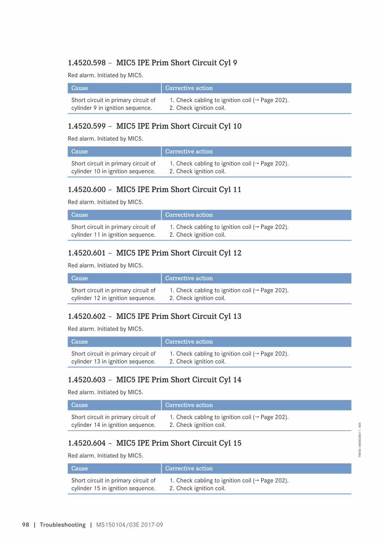
1.4520.598 – MIC5 IPE Prim Short Circuit Cyl 9Red alarm. Initiated by MIC5.
Cause Corrective action
Short circuit in primary circuit ofcylinder 9 in ignition sequence.
1. Check cabling to ignition coil (→ Page 202).2. Check ignition coil.
1.4520.599 – MIC5 IPE Prim Short Circuit Cyl 10Red alarm. Initiated by MIC5.
Cause Corrective action
Short circuit in primary circuit ofcylinder 10 in ignition sequence.
1. Check cabling to ignition coil (→ Page 202).2. Check ignition coil.
1.4520.600 – MIC5 IPE Prim Short Circuit Cyl 11Red alarm. Initiated by MIC5.
Cause Corrective action
Short circuit in primary circuit ofcylinder 11 in ignition sequence.
1. Check cabling to ignition coil (→ Page 202).2. Check ignition coil.
1.4520.601 – MIC5 IPE Prim Short Circuit Cyl 12Red alarm. Initiated by MIC5.
Cause Corrective action
Short circuit in primary circuit ofcylinder 12 in ignition sequence.
1. Check cabling to ignition coil (→ Page 202).2. Check ignition coil.
1.4520.602 – MIC5 IPE Prim Short Circuit Cyl 13Red alarm. Initiated by MIC5.
Cause Corrective action
Short circuit in primary circuit ofcylinder 13 in ignition sequence.
1. Check cabling to ignition coil (→ Page 202).2. Check ignition coil.
1.4520.603 – MIC5 IPE Prim Short Circuit Cyl 14Red alarm. Initiated by MIC5.
Cause Corrective action
Short circuit in primary circuit ofcylinder 14 in ignition sequence.
1. Check cabling to ignition coil (→ Page 202).2. Check ignition coil.
1.4520.604 – MIC5 IPE Prim Short Circuit Cyl 15Red alarm. Initiated by MIC5.
Cause Corrective action
Short circuit in primary circuit ofcylinder 15 in ignition sequence.
1. Check cabling to ignition coil (→ Page 202).2. Check ignition coil.
98 | Troubleshooting | MS150104/03E 2017-09
TIM
-ID: 0
0000
3861
1 - 0
05
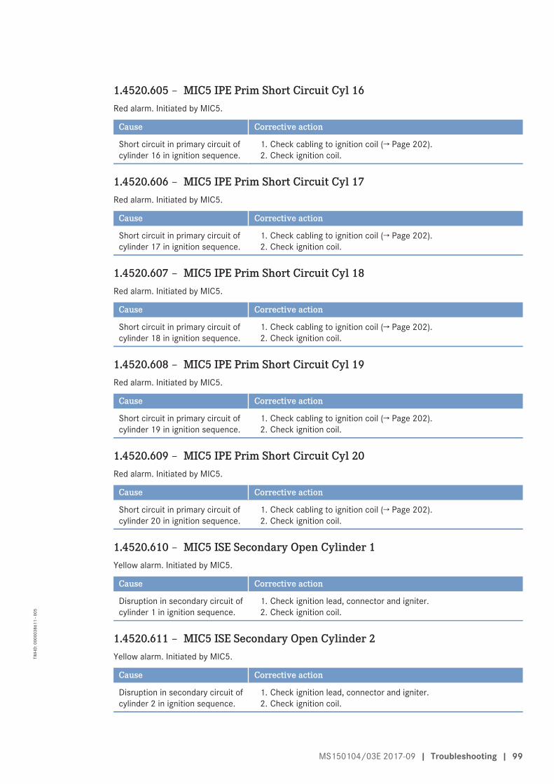
1.4520.605 – MIC5 IPE Prim Short Circuit Cyl 16Red alarm. Initiated by MIC5.
Cause Corrective action
Short circuit in primary circuit ofcylinder 16 in ignition sequence.
1. Check cabling to ignition coil (→ Page 202).2. Check ignition coil.
1.4520.606 – MIC5 IPE Prim Short Circuit Cyl 17Red alarm. Initiated by MIC5.
Cause Corrective action
Short circuit in primary circuit ofcylinder 17 in ignition sequence.
1. Check cabling to ignition coil (→ Page 202).2. Check ignition coil.
1.4520.607 – MIC5 IPE Prim Short Circuit Cyl 18Red alarm. Initiated by MIC5.
Cause Corrective action
Short circuit in primary circuit ofcylinder 18 in ignition sequence.
1. Check cabling to ignition coil (→ Page 202).2. Check ignition coil.
1.4520.608 – MIC5 IPE Prim Short Circuit Cyl 19Red alarm. Initiated by MIC5.
Cause Corrective action
Short circuit in primary circuit ofcylinder 19 in ignition sequence.
1. Check cabling to ignition coil (→ Page 202).2. Check ignition coil.
1.4520.609 – MIC5 IPE Prim Short Circuit Cyl 20Red alarm. Initiated by MIC5.
Cause Corrective action
Short circuit in primary circuit ofcylinder 20 in ignition sequence.
1. Check cabling to ignition coil (→ Page 202).2. Check ignition coil.
1.4520.610 – MIC5 ISE Secondary Open Cylinder 1Yellow alarm. Initiated by MIC5.
Cause Corrective action
Disruption in secondary circuit ofcylinder 1 in ignition sequence.
1. Check ignition lead, connector and igniter.2. Check ignition coil.
1.4520.611 – MIC5 ISE Secondary Open Cylinder 2Yellow alarm. Initiated by MIC5.
Cause Corrective action
Disruption in secondary circuit ofcylinder 2 in ignition sequence.
1. Check ignition lead, connector and igniter.2. Check ignition coil.
MS150104/03E 2017-09 | Troubleshooting | 99
TIM
-ID: 0
0000
3861
1 - 0
05
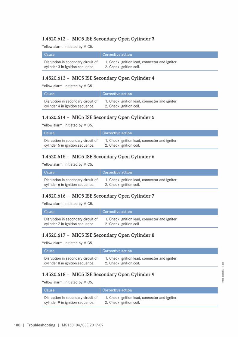
1.4520.612 – MIC5 ISE Secondary Open Cylinder 3Yellow alarm. Initiated by MIC5.
Cause Corrective action
Disruption in secondary circuit ofcylinder 3 in ignition sequence.
1. Check ignition lead, connector and igniter.2. Check ignition coil.
1.4520.613 – MIC5 ISE Secondary Open Cylinder 4Yellow alarm. Initiated by MIC5.
Cause Corrective action
Disruption in secondary circuit ofcylinder 4 in ignition sequence.
1. Check ignition lead, connector and igniter.2. Check ignition coil.
1.4520.614 – MIC5 ISE Secondary Open Cylinder 5Yellow alarm. Initiated by MIC5.
Cause Corrective action
Disruption in secondary circuit ofcylinder 5 in ignition sequence.
1. Check ignition lead, connector and igniter.2. Check ignition coil.
1.4520.615 – MIC5 ISE Secondary Open Cylinder 6Yellow alarm. Initiated by MIC5.
Cause Corrective action
Disruption in secondary circuit ofcylinder 6 in ignition sequence.
1. Check ignition lead, connector and igniter.2. Check ignition coil.
1.4520.616 – MIC5 ISE Secondary Open Cylinder 7Yellow alarm. Initiated by MIC5.
Cause Corrective action
Disruption in secondary circuit ofcylinder 7 in ignition sequence.
1. Check ignition lead, connector and igniter.2. Check ignition coil.
1.4520.617 – MIC5 ISE Secondary Open Cylinder 8Yellow alarm. Initiated by MIC5.
Cause Corrective action
Disruption in secondary circuit ofcylinder 8 in ignition sequence.
1. Check ignition lead, connector and igniter.2. Check ignition coil.
1.4520.618 – MIC5 ISE Secondary Open Cylinder 9Yellow alarm. Initiated by MIC5.
Cause Corrective action
Disruption in secondary circuit ofcylinder 9 in ignition sequence.
1. Check ignition lead, connector and igniter.2. Check ignition coil.
100 | Troubleshooting | MS150104/03E 2017-09
TIM
-ID: 0
0000
3861
1 - 0
05

1.4520.619 – MIC5 ISE Secondary Open Cylinder 10Yellow alarm. Initiated by MIC5.
Cause Corrective action
Disruption in secondary circuit ofcylinder 10 in ignition sequence.
1. Check ignition lead, connector and igniter.2. Check ignition coil.
1.4520.620 – MIC5 ISE Secondary Open Cylinder 11Yellow alarm. Initiated by MIC5.
Cause Corrective action
Disruption in secondary circuit ofcylinder 11 in ignition sequence.
1. Check ignition lead, connector and igniter.2. Check ignition coil.
1.4520.621 – MIC5 ISE Secondary Open Cylinder 12Yellow alarm. Initiated by MIC5.
Cause Corrective action
Disruption in secondary circuit ofcylinder 12 in ignition sequence.
1. Check ignition lead, connector and igniter.2. Check ignition coil.
1.4520.622 – MIC5 ISE Secondary Open Cylinder 13Yellow alarm. Initiated by MIC5.
Cause Corrective action
Disruption in secondary circuit ofcylinder 13 in ignition sequence.
1. Check ignition lead, connector and igniter.2. Check ignition coil.
1.4520.623 – MIC5 ISE Secondary Open Cylinder 14Yellow alarm. Initiated by MIC5.
Cause Corrective action
Disruption in secondary circuit ofcylinder 14 in ignition sequence.
1. Check ignition lead, connector and igniter.2. Check ignition coil.
1.4520.624 – MIC5 ISE Secondary Open Cylinder 15Yellow alarm. Initiated by MIC5.
Cause Corrective action
Disruption in secondary circuit ofcylinder 15 in ignition sequence.
1. Check ignition lead, connector and igniter.2. Check ignition coil.
1.4520.625 – MIC5 ISE Secondary Open Cylinder 16Yellow alarm. Initiated by MIC5.
Cause Corrective action
Disruption in secondary circuit ofcylinder 16 in ignition sequence.
1. Check ignition lead, connector and igniter.2. Check ignition coil.
MS150104/03E 2017-09 | Troubleshooting | 101
TIM
-ID: 0
0000
3861
1 - 0
05
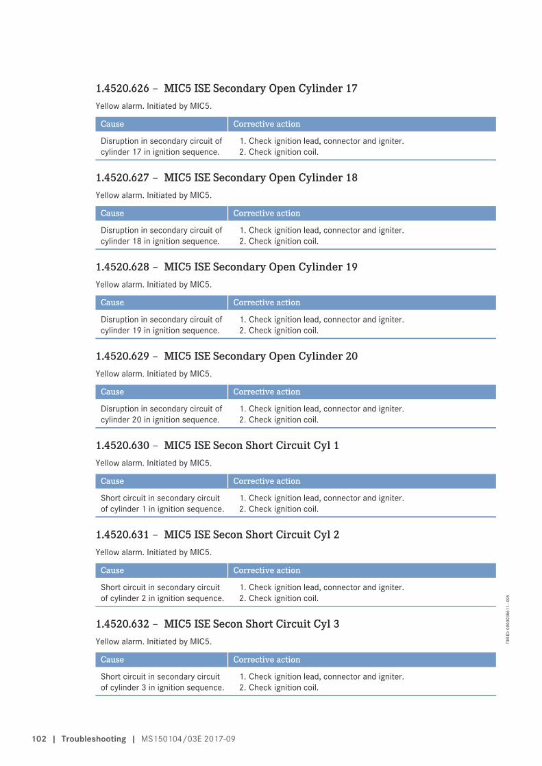
1.4520.626 – MIC5 ISE Secondary Open Cylinder 17Yellow alarm. Initiated by MIC5.
Cause Corrective action
Disruption in secondary circuit ofcylinder 17 in ignition sequence.
1. Check ignition lead, connector and igniter.2. Check ignition coil.
1.4520.627 – MIC5 ISE Secondary Open Cylinder 18Yellow alarm. Initiated by MIC5.
Cause Corrective action
Disruption in secondary circuit ofcylinder 18 in ignition sequence.
1. Check ignition lead, connector and igniter.2. Check ignition coil.
1.4520.628 – MIC5 ISE Secondary Open Cylinder 19Yellow alarm. Initiated by MIC5.
Cause Corrective action
Disruption in secondary circuit ofcylinder 19 in ignition sequence.
1. Check ignition lead, connector and igniter.2. Check ignition coil.
1.4520.629 – MIC5 ISE Secondary Open Cylinder 20Yellow alarm. Initiated by MIC5.
Cause Corrective action
Disruption in secondary circuit ofcylinder 20 in ignition sequence.
1. Check ignition lead, connector and igniter.2. Check ignition coil.
1.4520.630 – MIC5 ISE Secon Short Circuit Cyl 1Yellow alarm. Initiated by MIC5.
Cause Corrective action
Short circuit in secondary circuitof cylinder 1 in ignition sequence.
1. Check ignition lead, connector and igniter.2. Check ignition coil.
1.4520.631 – MIC5 ISE Secon Short Circuit Cyl 2Yellow alarm. Initiated by MIC5.
Cause Corrective action
Short circuit in secondary circuitof cylinder 2 in ignition sequence.
1. Check ignition lead, connector and igniter.2. Check ignition coil.
1.4520.632 – MIC5 ISE Secon Short Circuit Cyl 3Yellow alarm. Initiated by MIC5.
Cause Corrective action
Short circuit in secondary circuitof cylinder 3 in ignition sequence.
1. Check ignition lead, connector and igniter.2. Check ignition coil.
102 | Troubleshooting | MS150104/03E 2017-09
TIM
-ID: 0
0000
3861
1 - 0
05
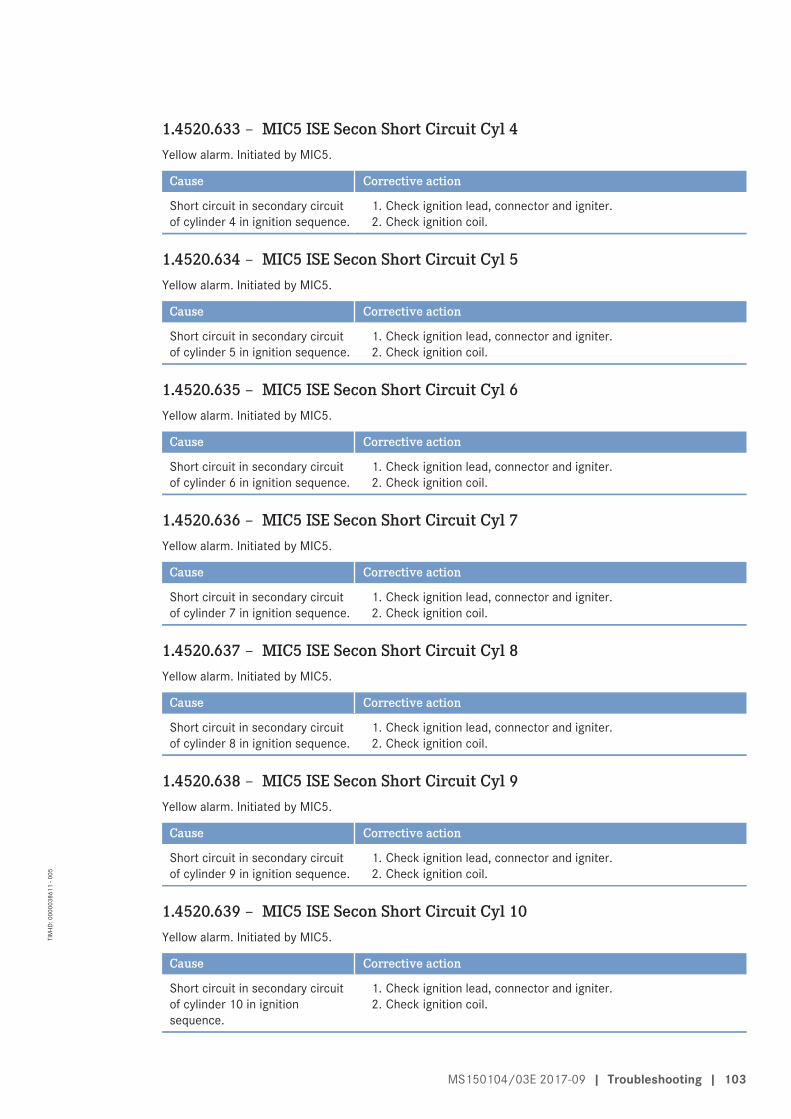
1.4520.633 – MIC5 ISE Secon Short Circuit Cyl 4Yellow alarm. Initiated by MIC5.
Cause Corrective action
Short circuit in secondary circuitof cylinder 4 in ignition sequence.
1. Check ignition lead, connector and igniter.2. Check ignition coil.
1.4520.634 – MIC5 ISE Secon Short Circuit Cyl 5Yellow alarm. Initiated by MIC5.
Cause Corrective action
Short circuit in secondary circuitof cylinder 5 in ignition sequence.
1. Check ignition lead, connector and igniter.2. Check ignition coil.
1.4520.635 – MIC5 ISE Secon Short Circuit Cyl 6Yellow alarm. Initiated by MIC5.
Cause Corrective action
Short circuit in secondary circuitof cylinder 6 in ignition sequence.
1. Check ignition lead, connector and igniter.2. Check ignition coil.
1.4520.636 – MIC5 ISE Secon Short Circuit Cyl 7Yellow alarm. Initiated by MIC5.
Cause Corrective action
Short circuit in secondary circuitof cylinder 7 in ignition sequence.
1. Check ignition lead, connector and igniter.2. Check ignition coil.
1.4520.637 – MIC5 ISE Secon Short Circuit Cyl 8Yellow alarm. Initiated by MIC5.
Cause Corrective action
Short circuit in secondary circuitof cylinder 8 in ignition sequence.
1. Check ignition lead, connector and igniter.2. Check ignition coil.
1.4520.638 – MIC5 ISE Secon Short Circuit Cyl 9Yellow alarm. Initiated by MIC5.
Cause Corrective action
Short circuit in secondary circuitof cylinder 9 in ignition sequence.
1. Check ignition lead, connector and igniter.2. Check ignition coil.
1.4520.639 – MIC5 ISE Secon Short Circuit Cyl 10Yellow alarm. Initiated by MIC5.
Cause Corrective action
Short circuit in secondary circuitof cylinder 10 in ignitionsequence.
1. Check ignition lead, connector and igniter.2. Check ignition coil.
MS150104/03E 2017-09 | Troubleshooting | 103
TIM
-ID: 0
0000
3861
1 - 0
05
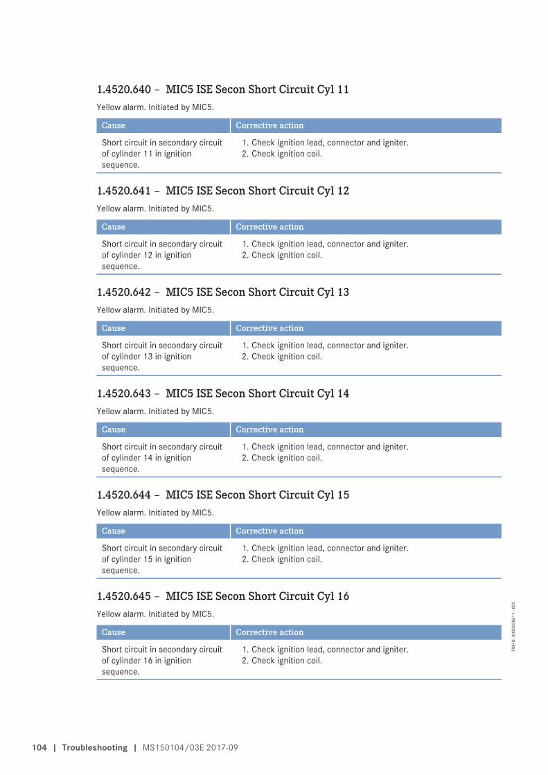
1.4520.640 – MIC5 ISE Secon Short Circuit Cyl 11Yellow alarm. Initiated by MIC5.
Cause Corrective action
Short circuit in secondary circuitof cylinder 11 in ignitionsequence.
1. Check ignition lead, connector and igniter.2. Check ignition coil.
1.4520.641 – MIC5 ISE Secon Short Circuit Cyl 12Yellow alarm. Initiated by MIC5.
Cause Corrective action
Short circuit in secondary circuitof cylinder 12 in ignitionsequence.
1. Check ignition lead, connector and igniter.2. Check ignition coil.
1.4520.642 – MIC5 ISE Secon Short Circuit Cyl 13Yellow alarm. Initiated by MIC5.
Cause Corrective action
Short circuit in secondary circuitof cylinder 13 in ignitionsequence.
1. Check ignition lead, connector and igniter.2. Check ignition coil.
1.4520.643 – MIC5 ISE Secon Short Circuit Cyl 14Yellow alarm. Initiated by MIC5.
Cause Corrective action
Short circuit in secondary circuitof cylinder 14 in ignitionsequence.
1. Check ignition lead, connector and igniter.2. Check ignition coil.
1.4520.644 – MIC5 ISE Secon Short Circuit Cyl 15Yellow alarm. Initiated by MIC5.
Cause Corrective action
Short circuit in secondary circuitof cylinder 15 in ignitionsequence.
1. Check ignition lead, connector and igniter.2. Check ignition coil.
1.4520.645 – MIC5 ISE Secon Short Circuit Cyl 16Yellow alarm. Initiated by MIC5.
Cause Corrective action
Short circuit in secondary circuitof cylinder 16 in ignitionsequence.
1. Check ignition lead, connector and igniter.2. Check ignition coil.
104 | Troubleshooting | MS150104/03E 2017-09
TIM
-ID: 0
0000
3861
1 - 0
05
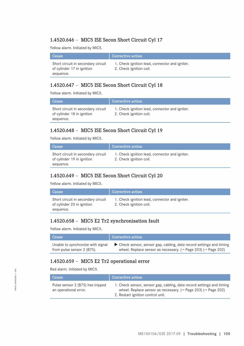
1.4520.646 – MIC5 ISE Secon Short Circuit Cyl 17Yellow alarm. Initiated by MIC5.
Cause Corrective action
Short circuit in secondary circuitof cylinder 17 in ignitionsequence.
1. Check ignition lead, connector and igniter.2. Check ignition coil.
1.4520.647 – MIC5 ISE Secon Short Circuit Cyl 18Yellow alarm. Initiated by MIC5.
Cause Corrective action
Short circuit in secondary circuitof cylinder 18 in ignitionsequence.
1. Check ignition lead, connector and igniter.2. Check ignition coil.
1.4520.648 – MIC5 ISE Secon Short Circuit Cyl 19Yellow alarm. Initiated by MIC5.
Cause Corrective action
Short circuit in secondary circuitof cylinder 19 in ignitionsequence.
1. Check ignition lead, connector and igniter.2. Check ignition coil.
1.4520.649 – MIC5 ISE Secon Short Circuit Cyl 20Yellow alarm. Initiated by MIC5.
Cause Corrective action
Short circuit in secondary circuitof cylinder 20 in ignitionsequence.
1. Check ignition lead, connector and igniter.2. Check ignition coil.
1.4520.658 – MIC5 E2 Tr2 synchronisation faultYellow alarm. Initiated by MIC5.
Cause Corrective action
Unable to synchronize with signalfrom pulse sensor 2 (B75).
u Check sensor, sensor gap, cabling, data record settings and timingwheel. Replace sensor as necessary. (→ Page 203) (→ Page 202)
1.4520.659 – MIC5 E2 Tr2 operational errorRed alarm. Initiated by MIC5.
Cause Corrective action
Pulse sensor 2 (B75) has trippedan operational error.
1. Check sensor, sensor gap, cabling, data record settings and timingwheel. Replace sensor as necessary. (→ Page 203) (→ Page 202)
2. Restart ignition control unit.
MS150104/03E 2017-09 | Troubleshooting | 105
TIM
-ID: 0
0000
3861
1 - 0
05
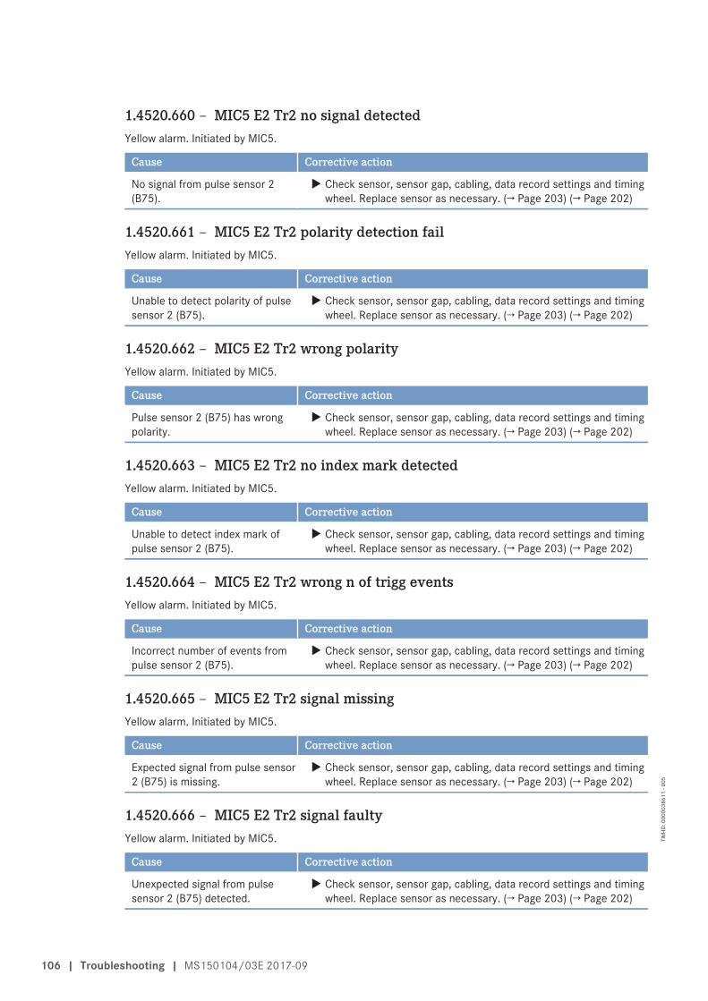
1.4520.660 – MIC5 E2 Tr2 no signal detectedYellow alarm. Initiated by MIC5.
Cause Corrective action
No signal from pulse sensor 2(B75).
u Check sensor, sensor gap, cabling, data record settings and timingwheel. Replace sensor as necessary. (→ Page 203) (→ Page 202)
1.4520.661 – MIC5 E2 Tr2 polarity detection failYellow alarm. Initiated by MIC5.
Cause Corrective action
Unable to detect polarity of pulsesensor 2 (B75).
u Check sensor, sensor gap, cabling, data record settings and timingwheel. Replace sensor as necessary. (→ Page 203) (→ Page 202)
1.4520.662 – MIC5 E2 Tr2 wrong polarityYellow alarm. Initiated by MIC5.
Cause Corrective action
Pulse sensor 2 (B75) has wrongpolarity.
u Check sensor, sensor gap, cabling, data record settings and timingwheel. Replace sensor as necessary. (→ Page 203) (→ Page 202)
1.4520.663 – MIC5 E2 Tr2 no index mark detectedYellow alarm. Initiated by MIC5.
Cause Corrective action
Unable to detect index mark ofpulse sensor 2 (B75).
u Check sensor, sensor gap, cabling, data record settings and timingwheel. Replace sensor as necessary. (→ Page 203) (→ Page 202)
1.4520.664 – MIC5 E2 Tr2 wrong n of trigg eventsYellow alarm. Initiated by MIC5.
Cause Corrective action
Incorrect number of events frompulse sensor 2 (B75).
u Check sensor, sensor gap, cabling, data record settings and timingwheel. Replace sensor as necessary. (→ Page 203) (→ Page 202)
1.4520.665 – MIC5 E2 Tr2 signal missingYellow alarm. Initiated by MIC5.
Cause Corrective action
Expected signal from pulse sensor2 (B75) is missing.
u Check sensor, sensor gap, cabling, data record settings and timingwheel. Replace sensor as necessary. (→ Page 203) (→ Page 202)
1.4520.666 – MIC5 E2 Tr2 signal faultyYellow alarm. Initiated by MIC5.
Cause Corrective action
Unexpected signal from pulsesensor 2 (B75) detected.
u Check sensor, sensor gap, cabling, data record settings and timingwheel. Replace sensor as necessary. (→ Page 203) (→ Page 202)
106 | Troubleshooting | MS150104/03E 2017-09
TIM
-ID: 0
0000
3861
1 - 0
05
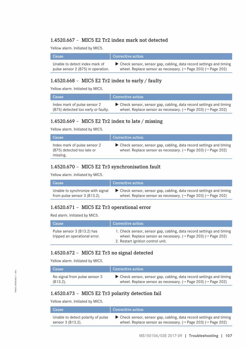
1.4520.667 – MIC5 E2 Tr2 index mark not detectedYellow alarm. Initiated by MIC5.
Cause Corrective action
Unable to detect index mark ofpulse sensor 2 (B75) in operation.
u Check sensor, sensor gap, cabling, data record settings and timingwheel. Replace sensor as necessary. (→ Page 203) (→ Page 202)
1.4520.668 – MIC5 E2 Tr2 index to early / faultyYellow alarm. Initiated by MIC5.
Cause Corrective action
Index mark of pulse sensor 2(B75) detected too early or faulty.
u Check sensor, sensor gap, cabling, data record settings and timingwheel. Replace sensor as necessary. (→ Page 203) (→ Page 202)
1.4520.669 – MIC5 E2 Tr2 index to late / missingYellow alarm. Initiated by MIC5.
Cause Corrective action
Index mark of pulse sensor 2(B75) detected too late ormissing.
u Check sensor, sensor gap, cabling, data record settings and timingwheel. Replace sensor as necessary. (→ Page 203) (→ Page 202)
1.4520.670 – MIC5 E2 Tr3 synchronisation faultYellow alarm. Initiated by MIC5.
Cause Corrective action
Unable to synchronize with signalfrom pulse sensor 3 (B13.2).
u Check sensor, sensor gap, cabling, data record settings and timingwheel. Replace sensor as necessary. (→ Page 203) (→ Page 202)
1.4520.671 – MIC5 E2 Tr3 operational errorRed alarm. Initiated by MIC5.
Cause Corrective action
Pulse sensor 3 (B13.2) hastripped an operational error.
1. Check sensor, sensor gap, cabling, data record settings and timingwheel. Replace sensor as necessary. (→ Page 203) (→ Page 202)
2. Restart ignition control unit.
1.4520.672 – MIC5 E2 Tr3 no signal detectedYellow alarm. Initiated by MIC5.
Cause Corrective action
No signal from pulse sensor 3(B13.2).
u Check sensor, sensor gap, cabling, data record settings and timingwheel. Replace sensor as necessary. (→ Page 203) (→ Page 202)
1.4520.673 – MIC5 E2 Tr3 polarity detection failYellow alarm. Initiated by MIC5.
Cause Corrective action
Unable to detect polarity of pulsesensor 3 (B13.2).
u Check sensor, sensor gap, cabling, data record settings and timingwheel. Replace sensor as necessary. (→ Page 203) (→ Page 202)
MS150104/03E 2017-09 | Troubleshooting | 107
TIM
-ID: 0
0000
3861
1 - 0
05
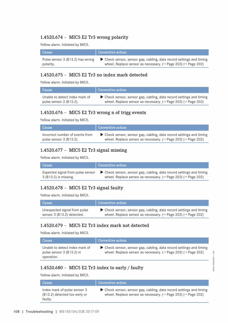
1.4520.674 – MIC5 E2 Tr3 wrong polarityYellow alarm. Initiated by MIC5.
Cause Corrective action
Pulse sensor 3 (B13.2) has wrongpolarity.
u Check sensor, sensor gap, cabling, data record settings and timingwheel. Replace sensor as necessary. (→ Page 203) (→ Page 202)
1.4520.675 – MIC5 E2 Tr3 no index mark detectedYellow alarm. Initiated by MIC5.
Cause Corrective action
Unable to detect index mark ofpulse sensor 3 (B13.2).
u Check sensor, sensor gap, cabling, data record settings and timingwheel. Replace sensor as necessary. (→ Page 203) (→ Page 202)
1.4520.676 – MIC5 E2 Tr3 wrong n of trigg eventsYellow alarm. Initiated by MIC5.
Cause Corrective action
Incorrect number of events frompulse sensor 3 (B13.2).
u Check sensor, sensor gap, cabling, data record settings and timingwheel. Replace sensor as necessary. (→ Page 203) (→ Page 202)
1.4520.677 – MIC5 E2 Tr3 signal missingYellow alarm. Initiated by MIC5.
Cause Corrective action
Expected signal from pulse sensor3 (B13.2) is missing.
u Check sensor, sensor gap, cabling, data record settings and timingwheel. Replace sensor as necessary. (→ Page 203) (→ Page 202)
1.4520.678 – MIC5 E2 Tr3 signal faultyYellow alarm. Initiated by MIC5.
Cause Corrective action
Unexpected signal from pulsesensor 3 (B13.2) detected.
u Check sensor, sensor gap, cabling, data record settings and timingwheel. Replace sensor as necessary. (→ Page 203) (→ Page 202)
1.4520.679 – MIC5 E2 Tr3 index mark not detectedYellow alarm. Initiated by MIC5.
Cause Corrective action
Unable to detect index mark ofpulse sensor 3 (B13.2) inoperation.
u Check sensor, sensor gap, cabling, data record settings and timingwheel. Replace sensor as necessary. (→ Page 203) (→ Page 202)
1.4520.680 – MIC5 E2 Tr3 index to early / faultyYellow alarm. Initiated by MIC5.
Cause Corrective action
Index mark of pulse sensor 3(B13.2) detected too early orfaulty.
u Check sensor, sensor gap, cabling, data record settings and timingwheel. Replace sensor as necessary. (→ Page 203) (→ Page 202)
108 | Troubleshooting | MS150104/03E 2017-09
TIM
-ID: 0
0000
3861
1 - 0
05
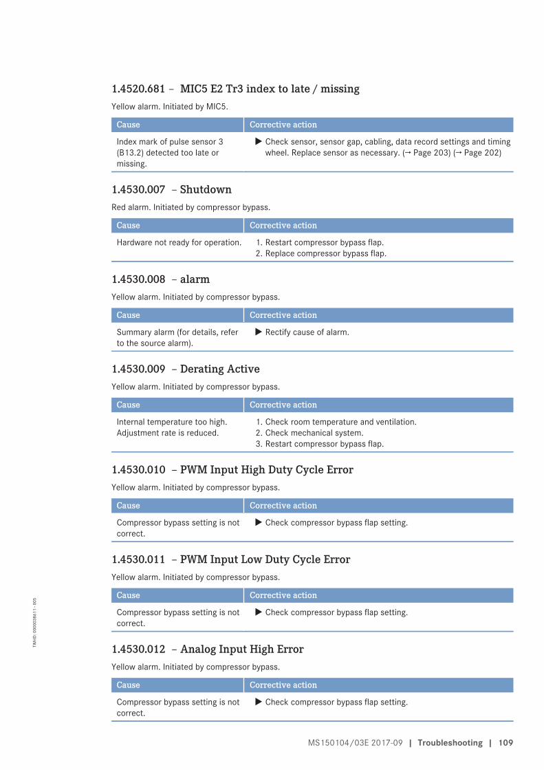
1.4520.681 – MIC5 E2 Tr3 index to late / missingYellow alarm. Initiated by MIC5.
Cause Corrective action
Index mark of pulse sensor 3(B13.2) detected too late ormissing.
u Check sensor, sensor gap, cabling, data record settings and timingwheel. Replace sensor as necessary. (→ Page 203) (→ Page 202)
1.4530.007 – ShutdownRed alarm. Initiated by compressor bypass.
Cause Corrective action
Hardware not ready for operation. 1. Restart compressor bypass flap.2. Replace compressor bypass flap.
1.4530.008 – alarmYellow alarm. Initiated by compressor bypass.
Cause Corrective action
Summary alarm (for details, referto the source alarm).
u Rectify cause of alarm.
1.4530.009 – Derating ActiveYellow alarm. Initiated by compressor bypass.
Cause Corrective action
Internal temperature too high.Adjustment rate is reduced.
1. Check room temperature and ventilation.2. Check mechanical system.3. Restart compressor bypass flap.
1.4530.010 – PWM Input High Duty Cycle ErrorYellow alarm. Initiated by compressor bypass.
Cause Corrective action
Compressor bypass setting is notcorrect.
u Check compressor bypass flap setting.
1.4530.011 – PWM Input Low Duty Cycle ErrorYellow alarm. Initiated by compressor bypass.
Cause Corrective action
Compressor bypass setting is notcorrect.
u Check compressor bypass flap setting.
1.4530.012 – Analog Input High ErrorYellow alarm. Initiated by compressor bypass.
Cause Corrective action
Compressor bypass setting is notcorrect.
u Check compressor bypass flap setting.
MS150104/03E 2017-09 | Troubleshooting | 109
TIM
-ID: 0
0000
3861
1 - 0
05
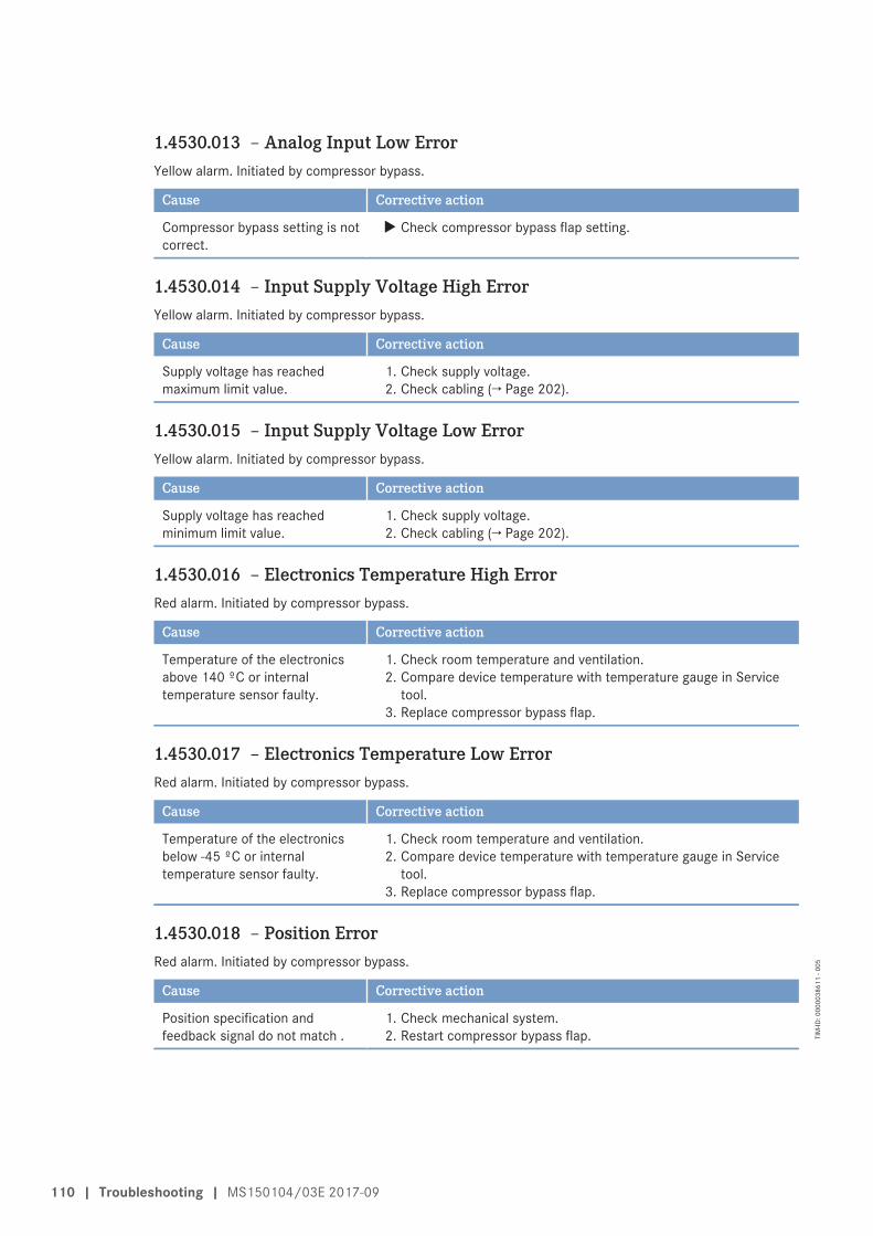
1.4530.013 – Analog Input Low ErrorYellow alarm. Initiated by compressor bypass.
Cause Corrective action
Compressor bypass setting is notcorrect.
u Check compressor bypass flap setting.
1.4530.014 – Input Supply Voltage High ErrorYellow alarm. Initiated by compressor bypass.
Cause Corrective action
Supply voltage has reachedmaximum limit value.
1. Check supply voltage.2. Check cabling (→ Page 202).
1.4530.015 – Input Supply Voltage Low ErrorYellow alarm. Initiated by compressor bypass.
Cause Corrective action
Supply voltage has reachedminimum limit value.
1. Check supply voltage.2. Check cabling (→ Page 202).
1.4530.016 – Electronics Temperature High ErrorRed alarm. Initiated by compressor bypass.
Cause Corrective action
Temperature of the electronicsabove 140 ºC or internaltemperature sensor faulty.
1. Check room temperature and ventilation.2. Compare device temperature with temperature gauge in Service
tool.3. Replace compressor bypass flap.
1.4530.017 – Electronics Temperature Low ErrorRed alarm. Initiated by compressor bypass.
Cause Corrective action
Temperature of the electronicsbelow -45 ºC or internaltemperature sensor faulty.
1. Check room temperature and ventilation.2. Compare device temperature with temperature gauge in Service
tool.3. Replace compressor bypass flap.
1.4530.018 – Position ErrorRed alarm. Initiated by compressor bypass.
Cause Corrective action
Position specification andfeedback signal do not match .
1. Check mechanical system.2. Restart compressor bypass flap.
110 | Troubleshooting | MS150104/03E 2017-09
TIM
-ID: 0
0000
3861
1 - 0
05
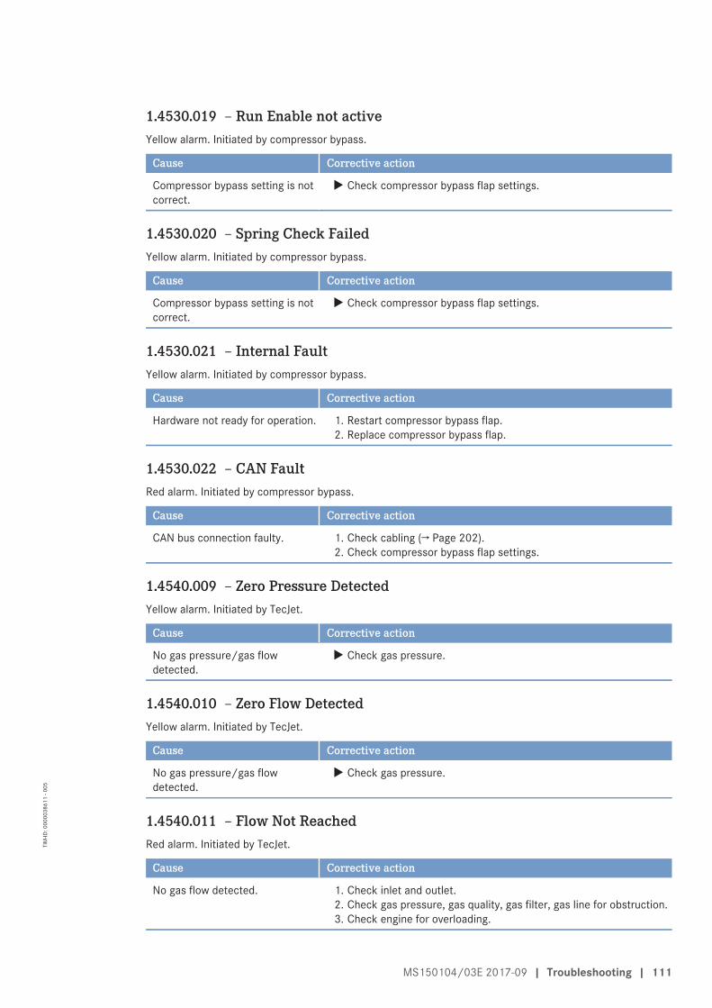
1.4530.019 – Run Enable not activeYellow alarm. Initiated by compressor bypass.
Cause Corrective action
Compressor bypass setting is notcorrect.
u Check compressor bypass flap settings.
1.4530.020 – Spring Check FailedYellow alarm. Initiated by compressor bypass.
Cause Corrective action
Compressor bypass setting is notcorrect.
u Check compressor bypass flap settings.
1.4530.021 – Internal FaultYellow alarm. Initiated by compressor bypass.
Cause Corrective action
Hardware not ready for operation. 1. Restart compressor bypass flap.2. Replace compressor bypass flap.
1.4530.022 – CAN FaultRed alarm. Initiated by compressor bypass.
Cause Corrective action
CAN bus connection faulty. 1. Check cabling (→ Page 202).2. Check compressor bypass flap settings.
1.4540.009 – Zero Pressure DetectedYellow alarm. Initiated by TecJet.
Cause Corrective action
No gas pressure/gas flowdetected.
u Check gas pressure.
1.4540.010 – Zero Flow DetectedYellow alarm. Initiated by TecJet.
Cause Corrective action
No gas pressure/gas flowdetected.
u Check gas pressure.
1.4540.011 – Flow Not ReachedRed alarm. Initiated by TecJet.
Cause Corrective action
No gas flow detected. 1. Check inlet and outlet.2. Check gas pressure, gas quality, gas filter, gas line for obstruction.3. Check engine for overloading.
MS150104/03E 2017-09 | Troubleshooting | 111
TIM
-ID: 0
0000
3861
1 - 0
05
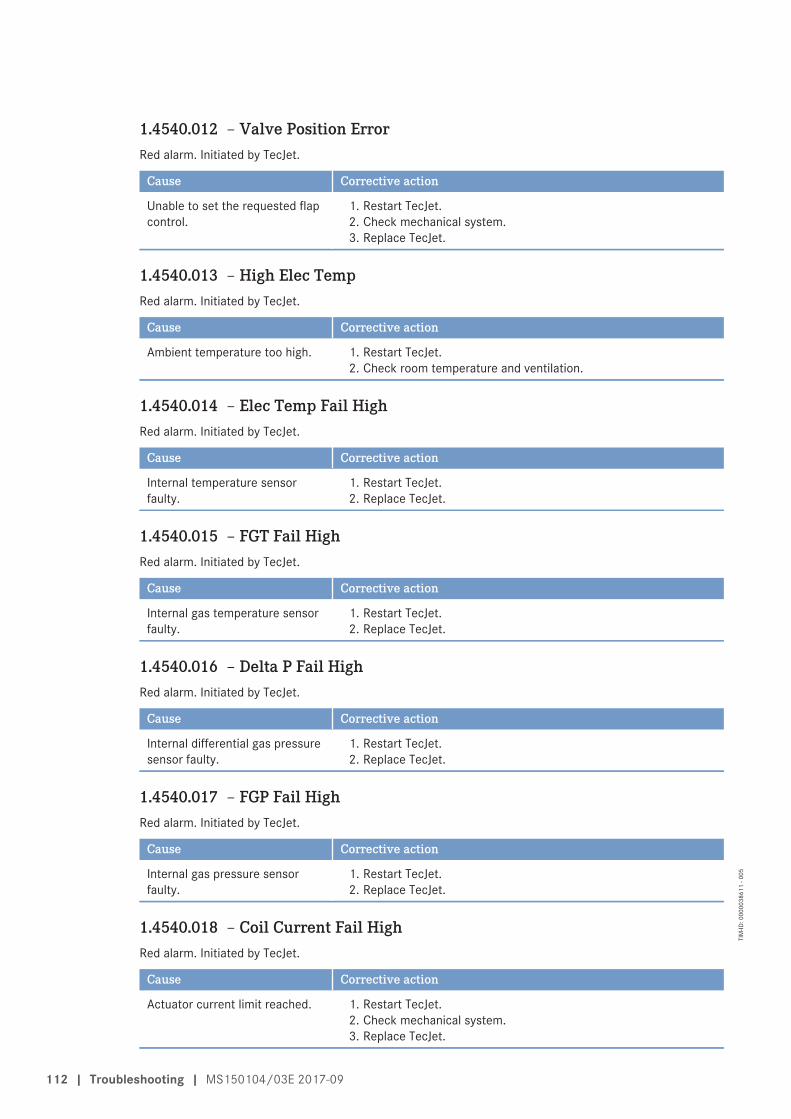
1.4540.012 – Valve Position ErrorRed alarm. Initiated by TecJet.
Cause Corrective action
Unable to set the requested flapcontrol.
1. Restart TecJet.2. Check mechanical system.3. Replace TecJet.
1.4540.013 – High Elec TempRed alarm. Initiated by TecJet.
Cause Corrective action
Ambient temperature too high. 1. Restart TecJet.2. Check room temperature and ventilation.
1.4540.014 – Elec Temp Fail HighRed alarm. Initiated by TecJet.
Cause Corrective action
Internal temperature sensorfaulty.
1. Restart TecJet.2. Replace TecJet.
1.4540.015 – FGT Fail HighRed alarm. Initiated by TecJet.
Cause Corrective action
Internal gas temperature sensorfaulty.
1. Restart TecJet.2. Replace TecJet.
1.4540.016 – Delta P Fail HighRed alarm. Initiated by TecJet.
Cause Corrective action
Internal differential gas pressuresensor faulty.
1. Restart TecJet.2. Replace TecJet.
1.4540.017 – FGP Fail HighRed alarm. Initiated by TecJet.
Cause Corrective action
Internal gas pressure sensorfaulty.
1. Restart TecJet.2. Replace TecJet.
1.4540.018 – Coil Current Fail HighRed alarm. Initiated by TecJet.
Cause Corrective action
Actuator current limit reached. 1. Restart TecJet.2. Check mechanical system.3. Replace TecJet.
112 | Troubleshooting | MS150104/03E 2017-09
TIM
-ID: 0
0000
3861
1 - 0
05
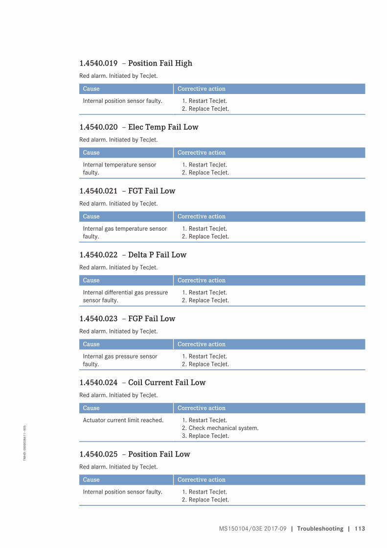
1.4540.019 – Position Fail HighRed alarm. Initiated by TecJet.
Cause Corrective action
Internal position sensor faulty. 1. Restart TecJet.2. Replace TecJet.
1.4540.020 – Elec Temp Fail LowRed alarm. Initiated by TecJet.
Cause Corrective action
Internal temperature sensorfaulty.
1. Restart TecJet.2. Replace TecJet.
1.4540.021 – FGT Fail LowRed alarm. Initiated by TecJet.
Cause Corrective action
Internal gas temperature sensorfaulty.
1. Restart TecJet.2. Replace TecJet.
1.4540.022 – Delta P Fail LowRed alarm. Initiated by TecJet.
Cause Corrective action
Internal differential gas pressuresensor faulty.
1. Restart TecJet.2. Replace TecJet.
1.4540.023 – FGP Fail LowRed alarm. Initiated by TecJet.
Cause Corrective action
Internal gas pressure sensorfaulty.
1. Restart TecJet.2. Replace TecJet.
1.4540.024 – Coil Current Fail LowRed alarm. Initiated by TecJet.
Cause Corrective action
Actuator current limit reached. 1. Restart TecJet.2. Check mechanical system.3. Replace TecJet.
1.4540.025 – Position Fail LowRed alarm. Initiated by TecJet.
Cause Corrective action
Internal position sensor faulty. 1. Restart TecJet.2. Replace TecJet.
MS150104/03E 2017-09 | Troubleshooting | 113
TIM
-ID: 0
0000
3861
1 - 0
05
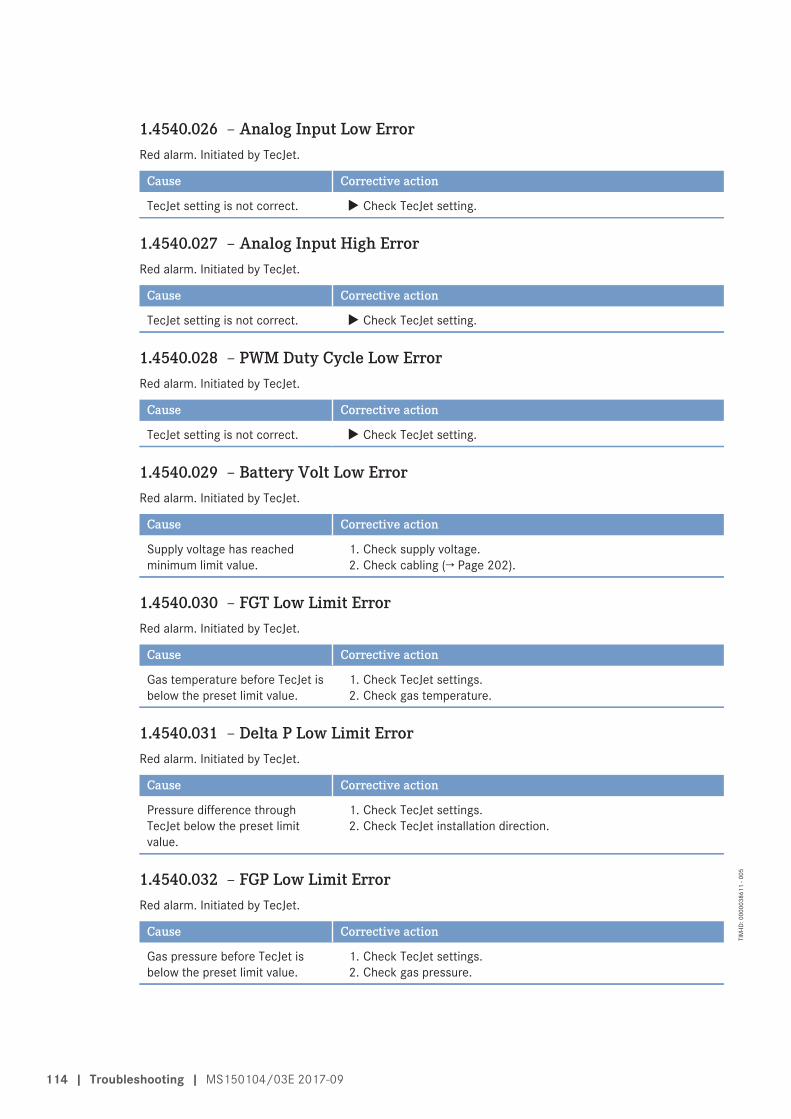
1.4540.026 – Analog Input Low ErrorRed alarm. Initiated by TecJet.
Cause Corrective action
TecJet setting is not correct. u Check TecJet setting.
1.4540.027 – Analog Input High ErrorRed alarm. Initiated by TecJet.
Cause Corrective action
TecJet setting is not correct. u Check TecJet setting.
1.4540.028 – PWM Duty Cycle Low ErrorRed alarm. Initiated by TecJet.
Cause Corrective action
TecJet setting is not correct. u Check TecJet setting.
1.4540.029 – Battery Volt Low ErrorRed alarm. Initiated by TecJet.
Cause Corrective action
Supply voltage has reachedminimum limit value.
1. Check supply voltage.2. Check cabling (→ Page 202).
1.4540.030 – FGT Low Limit ErrorRed alarm. Initiated by TecJet.
Cause Corrective action
Gas temperature before TecJet isbelow the preset limit value.
1. Check TecJet settings.2. Check gas temperature.
1.4540.031 – Delta P Low Limit ErrorRed alarm. Initiated by TecJet.
Cause Corrective action
Pressure difference throughTecJet below the preset limitvalue.
1. Check TecJet settings.2. Check TecJet installation direction.
1.4540.032 – FGP Low Limit ErrorRed alarm. Initiated by TecJet.
Cause Corrective action
Gas pressure before TecJet isbelow the preset limit value.
1. Check TecJet settings.2. Check gas pressure.
114 | Troubleshooting | MS150104/03E 2017-09
TIM
-ID: 0
0000
3861
1 - 0
05
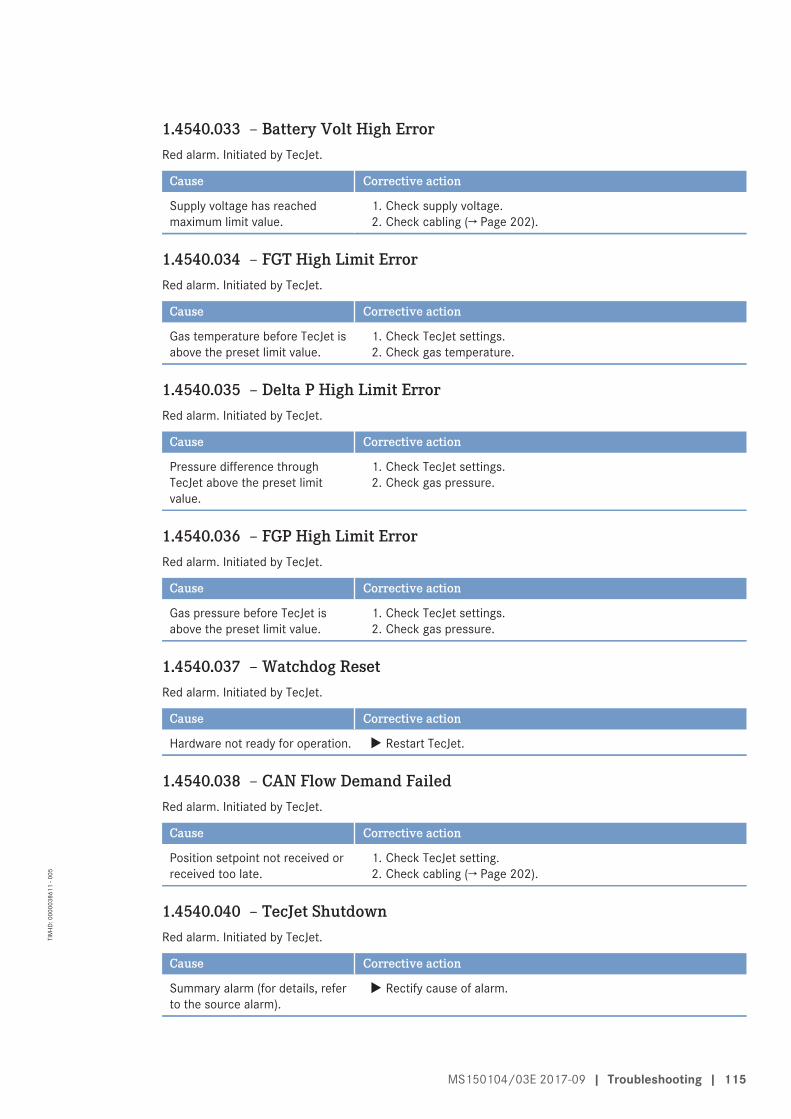
1.4540.033 – Battery Volt High ErrorRed alarm. Initiated by TecJet.
Cause Corrective action
Supply voltage has reachedmaximum limit value.
1. Check supply voltage.2. Check cabling (→ Page 202).
1.4540.034 – FGT High Limit ErrorRed alarm. Initiated by TecJet.
Cause Corrective action
Gas temperature before TecJet isabove the preset limit value.
1. Check TecJet settings.2. Check gas temperature.
1.4540.035 – Delta P High Limit ErrorRed alarm. Initiated by TecJet.
Cause Corrective action
Pressure difference throughTecJet above the preset limitvalue.
1. Check TecJet settings.2. Check gas pressure.
1.4540.036 – FGP High Limit ErrorRed alarm. Initiated by TecJet.
Cause Corrective action
Gas pressure before TecJet isabove the preset limit value.
1. Check TecJet settings.2. Check gas pressure.
1.4540.037 – Watchdog ResetRed alarm. Initiated by TecJet.
Cause Corrective action
Hardware not ready for operation. u Restart TecJet.
1.4540.038 – CAN Flow Demand FailedRed alarm. Initiated by TecJet.
Cause Corrective action
Position setpoint not received orreceived too late.
1. Check TecJet setting.2. Check cabling (→ Page 202).
1.4540.040 – TecJet ShutdownRed alarm. Initiated by TecJet.
Cause Corrective action
Summary alarm (for details, referto the source alarm).
u Rectify cause of alarm.
MS150104/03E 2017-09 | Troubleshooting | 115
TIM
-ID: 0
0000
3861
1 - 0
05
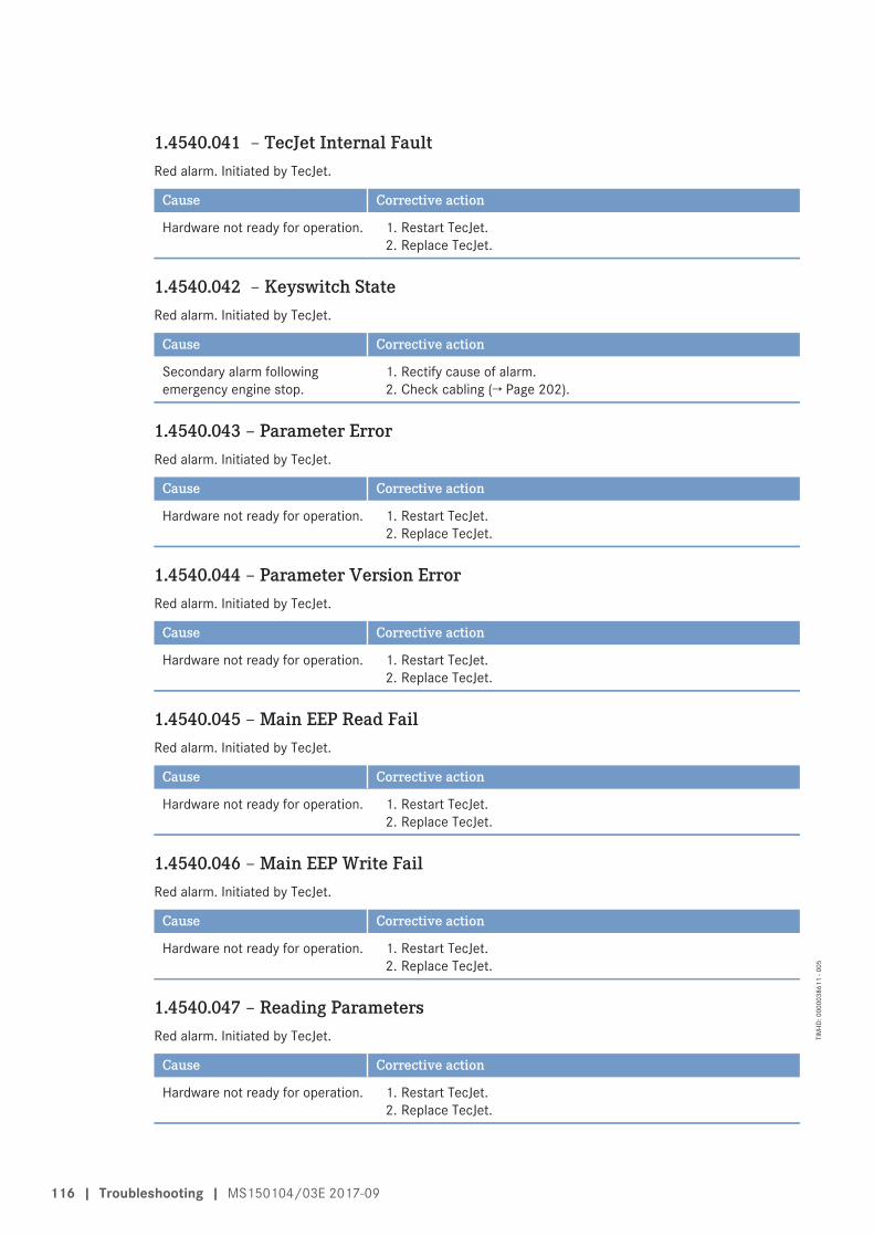
1.4540.041 – TecJet Internal FaultRed alarm. Initiated by TecJet.
Cause Corrective action
Hardware not ready for operation. 1. Restart TecJet.2. Replace TecJet.
1.4540.042 – Keyswitch StateRed alarm. Initiated by TecJet.
Cause Corrective action
Secondary alarm followingemergency engine stop.
1. Rectify cause of alarm.2. Check cabling (→ Page 202).
1.4540.043 – Parameter ErrorRed alarm. Initiated by TecJet.
Cause Corrective action
Hardware not ready for operation. 1. Restart TecJet.2. Replace TecJet.
1.4540.044 – Parameter Version ErrorRed alarm. Initiated by TecJet.
Cause Corrective action
Hardware not ready for operation. 1. Restart TecJet.2. Replace TecJet.
1.4540.045 – Main EEP Read FailRed alarm. Initiated by TecJet.
Cause Corrective action
Hardware not ready for operation. 1. Restart TecJet.2. Replace TecJet.
1.4540.046 – Main EEP Write FailRed alarm. Initiated by TecJet.
Cause Corrective action
Hardware not ready for operation. 1. Restart TecJet.2. Replace TecJet.
1.4540.047 – Reading ParametersRed alarm. Initiated by TecJet.
Cause Corrective action
Hardware not ready for operation. 1. Restart TecJet.2. Replace TecJet.
116 | Troubleshooting | MS150104/03E 2017-09
TIM
-ID: 0
0000
3861
1 - 0
05
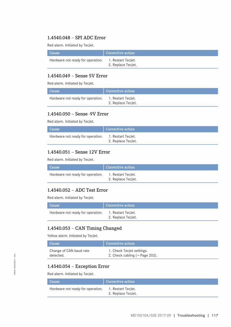
1.4540.048 – SPI ADC ErrorRed alarm. Initiated by TecJet.
Cause Corrective action
Hardware not ready for operation. 1. Restart TecJet.2. Replace TecJet.
1.4540.049 – Sense 5V ErrorRed alarm. Initiated by TecJet.
Cause Corrective action
Hardware not ready for operation. 1. Restart TecJet.2. Replace TecJet.
1.4540.050 – Sense -9V ErrorRed alarm. Initiated by TecJet.
Cause Corrective action
Hardware not ready for operation. 1. Restart TecJet.2. Replace TecJet.
1.4540.051 – Sense 12V ErrorRed alarm. Initiated by TecJet.
Cause Corrective action
Hardware not ready for operation. 1. Restart TecJet.2. Replace TecJet.
1.4540.052 – ADC Test ErrorRed alarm. Initiated by TecJet.
Cause Corrective action
Hardware not ready for operation. 1. Restart TecJet.2. Replace TecJet.
1.4540.053 – CAN Timing ChangedYellow alarm. Initiated by TecJet.
Cause Corrective action
Change of CAN baud ratedetected.
1. Check TecJet settings.2. Check cabling (→ Page 202).
1.4540.054 – Exception ErrorRed alarm. Initiated by TecJet.
Cause Corrective action
Hardware not ready for operation. 1. Restart TecJet.2. Replace TecJet.
MS150104/03E 2017-09 | Troubleshooting | 117
TIM
-ID: 0
0000
3861
1 - 0
05
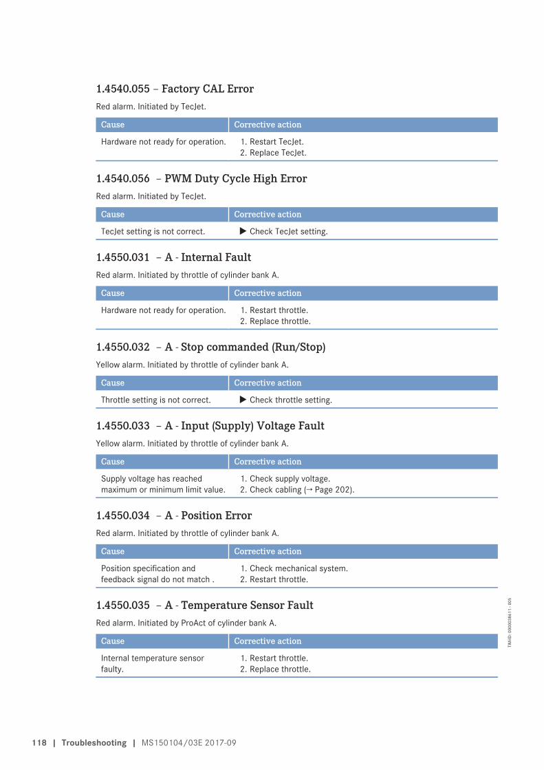
1.4540.055 – Factory CAL ErrorRed alarm. Initiated by TecJet.
Cause Corrective action
Hardware not ready for operation. 1. Restart TecJet.2. Replace TecJet.
1.4540.056 – PWM Duty Cycle High ErrorRed alarm. Initiated by TecJet.
Cause Corrective action
TecJet setting is not correct. u Check TecJet setting.
1.4550.031 – A - Internal FaultRed alarm. Initiated by throttle of cylinder bank A.
Cause Corrective action
Hardware not ready for operation. 1. Restart throttle.2. Replace throttle.
1.4550.032 – A - Stop commanded (Run/Stop)Yellow alarm. Initiated by throttle of cylinder bank A.
Cause Corrective action
Throttle setting is not correct. u Check throttle setting.
1.4550.033 – A - Input (Supply) Voltage FaultYellow alarm. Initiated by throttle of cylinder bank A.
Cause Corrective action
Supply voltage has reachedmaximum or minimum limit value.
1. Check supply voltage.2. Check cabling (→ Page 202).
1.4550.034 – A - Position ErrorRed alarm. Initiated by throttle of cylinder bank A.
Cause Corrective action
Position specification andfeedback signal do not match .
1. Check mechanical system.2. Restart throttle.
1.4550.035 – A - Temperature Sensor FaultRed alarm. Initiated by ProAct of cylinder bank A.
Cause Corrective action
Internal temperature sensorfaulty.
1. Restart throttle.2. Replace throttle.
118 | Troubleshooting | MS150104/03E 2017-09
TIM
-ID: 0
0000
3861
1 - 0
05
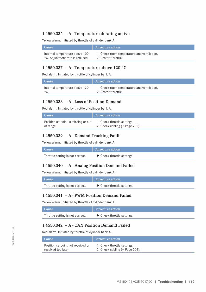
1.4550.036 – A - Temperature derating activeYellow alarm. Initiated by throttle of cylinder bank A.
Cause Corrective action
Internal temperature above 100ºC. Adjustment rate is reduced.
1. Check room temperature and ventilation.2. Restart throttle.
1.4550.037 – A - Temperature above 120 °CRed alarm. Initiated by throttle of cylinder bank A.
Cause Corrective action
Internal temperature above 120ºC.
1. Check room temperature and ventilation.2. Restart throttle.
1.4550.038 – A - Loss of Position DemandRed alarm. Initiated by throttle of cylinder bank A.
Cause Corrective action
Position setpoint is missing or outof range.
1. Check throttle settings.2. Check cabling (→ Page 202).
1.4550.039 – A - Demand Tracking FaultYellow alarm. Initiated by throttle of cylinder bank A.
Cause Corrective action
Throttle setting is not correct. u Check throttle settings.
1.4550.040 – A - Analog Position Demand FailedYellow alarm. Initiated by throttle of cylinder bank A.
Cause Corrective action
Throttle setting is not correct. u Check throttle settings.
1.4550.041 – A - PWM Position Demand FailedYellow alarm. Initiated by throttle of cylinder bank A.
Cause Corrective action
Throttle setting is not correct. u Check throttle settings.
1.4550.042 – A - CAN Position Demand FailedRed alarm. Initiated by throttle of cylinder bank A.
Cause Corrective action
Position setpoint not received orreceived too late.
1. Check throttle settings.2. Check cabling (→ Page 202).
MS150104/03E 2017-09 | Troubleshooting | 119
TIM
-ID: 0
0000
3861
1 - 0
05
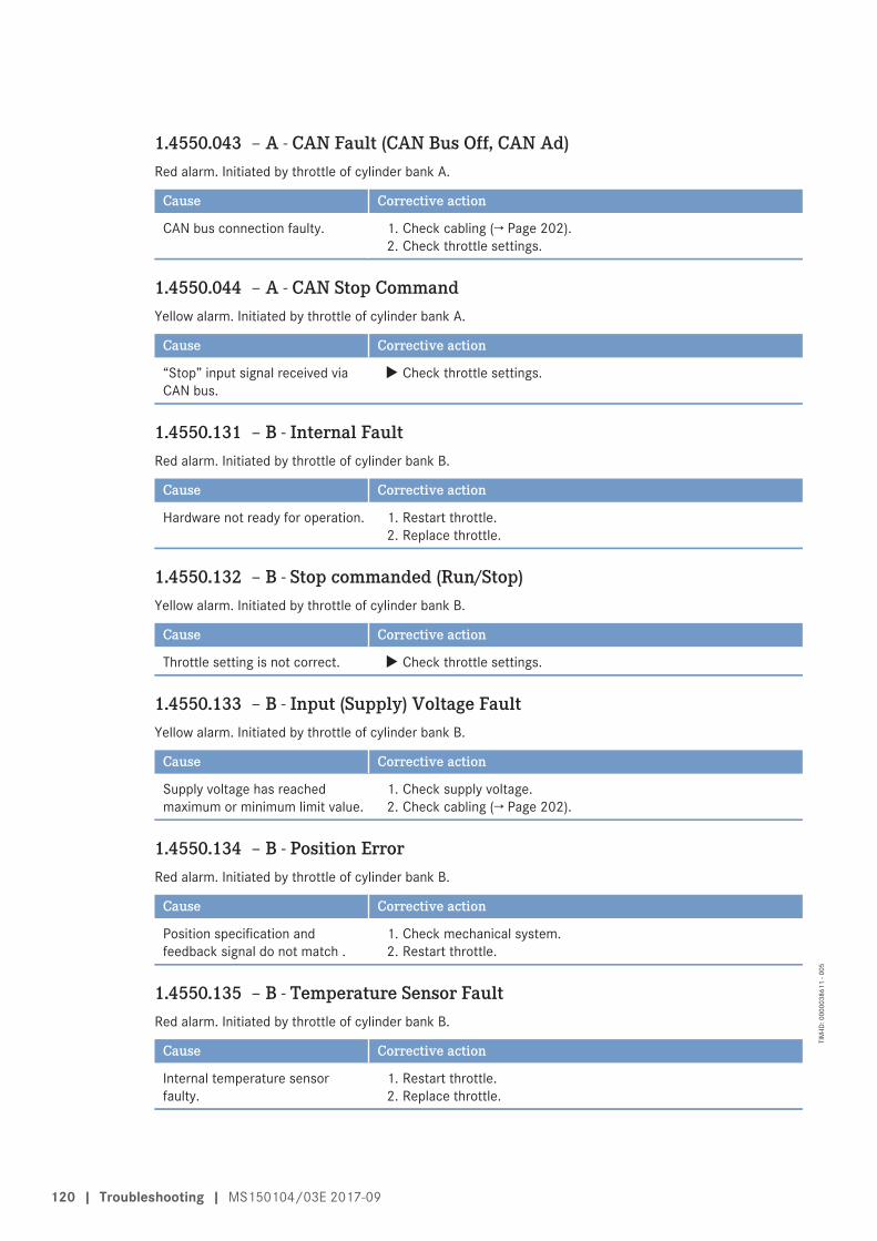
1.4550.043 – A - CAN Fault (CAN Bus Off, CAN Ad)Red alarm. Initiated by throttle of cylinder bank A.
Cause Corrective action
CAN bus connection faulty. 1. Check cabling (→ Page 202).2. Check throttle settings.
1.4550.044 – A - CAN Stop CommandYellow alarm. Initiated by throttle of cylinder bank A.
Cause Corrective action
“Stop” input signal received viaCAN bus.
u Check throttle settings.
1.4550.131 – B - Internal FaultRed alarm. Initiated by throttle of cylinder bank B.
Cause Corrective action
Hardware not ready for operation. 1. Restart throttle.2. Replace throttle.
1.4550.132 – B - Stop commanded (Run/Stop)Yellow alarm. Initiated by throttle of cylinder bank B.
Cause Corrective action
Throttle setting is not correct. u Check throttle settings.
1.4550.133 – B - Input (Supply) Voltage FaultYellow alarm. Initiated by throttle of cylinder bank B.
Cause Corrective action
Supply voltage has reachedmaximum or minimum limit value.
1. Check supply voltage.2. Check cabling (→ Page 202).
1.4550.134 – B - Position ErrorRed alarm. Initiated by throttle of cylinder bank B.
Cause Corrective action
Position specification andfeedback signal do not match .
1. Check mechanical system.2. Restart throttle.
1.4550.135 – B - Temperature Sensor FaultRed alarm. Initiated by throttle of cylinder bank B.
Cause Corrective action
Internal temperature sensorfaulty.
1. Restart throttle.2. Replace throttle.
120 | Troubleshooting | MS150104/03E 2017-09
TIM
-ID: 0
0000
3861
1 - 0
05
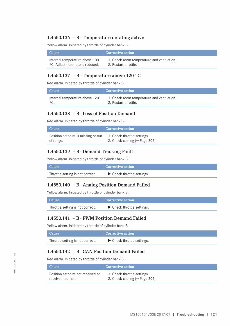
1.4550.136 – B - Temperature derating activeYellow alarm. Initiated by throttle of cylinder bank B.
Cause Corrective action
Internal temperature above 100ºC. Adjustment rate is reduced.
1. Check room temperature and ventilation.2. Restart throttle.
1.4550.137 – B - Temperature above 120 °CRed alarm. Initiated by throttle of cylinder bank B.
Cause Corrective action
Internal temperature above 120ºC.
1. Check room temperature and ventilation.2. Restart throttle.
1.4550.138 – B - Loss of Position DemandRed alarm. Initiated by throttle of cylinder bank B.
Cause Corrective action
Position setpoint is missing or outof range.
1. Check throttle settings.2. Check cabling (→ Page 202).
1.4550.139 – B - Demand Tracking FaultYellow alarm. Initiated by throttle of cylinder bank B.
Cause Corrective action
Throttle setting is not correct. u Check throttle settings.
1.4550.140 – B - Analog Position Demand FailedYellow alarm. Initiated by throttle of cylinder bank B.
Cause Corrective action
Throttle setting is not correct. u Check throttle settings.
1.4550.141 – B - PWM Position Demand FailedYellow alarm. Initiated by throttle of cylinder bank B.
Cause Corrective action
Throttle setting is not correct. u Check throttle settings.
1.4550.142 – B - CAN Position Demand FailedRed alarm. Initiated by throttle of cylinder bank B.
Cause Corrective action
Position setpoint not received orreceived too late.
1. Check throttle settings.2. Check cabling (→ Page 202).
MS150104/03E 2017-09 | Troubleshooting | 121
TIM
-ID: 0
0000
3861
1 - 0
05
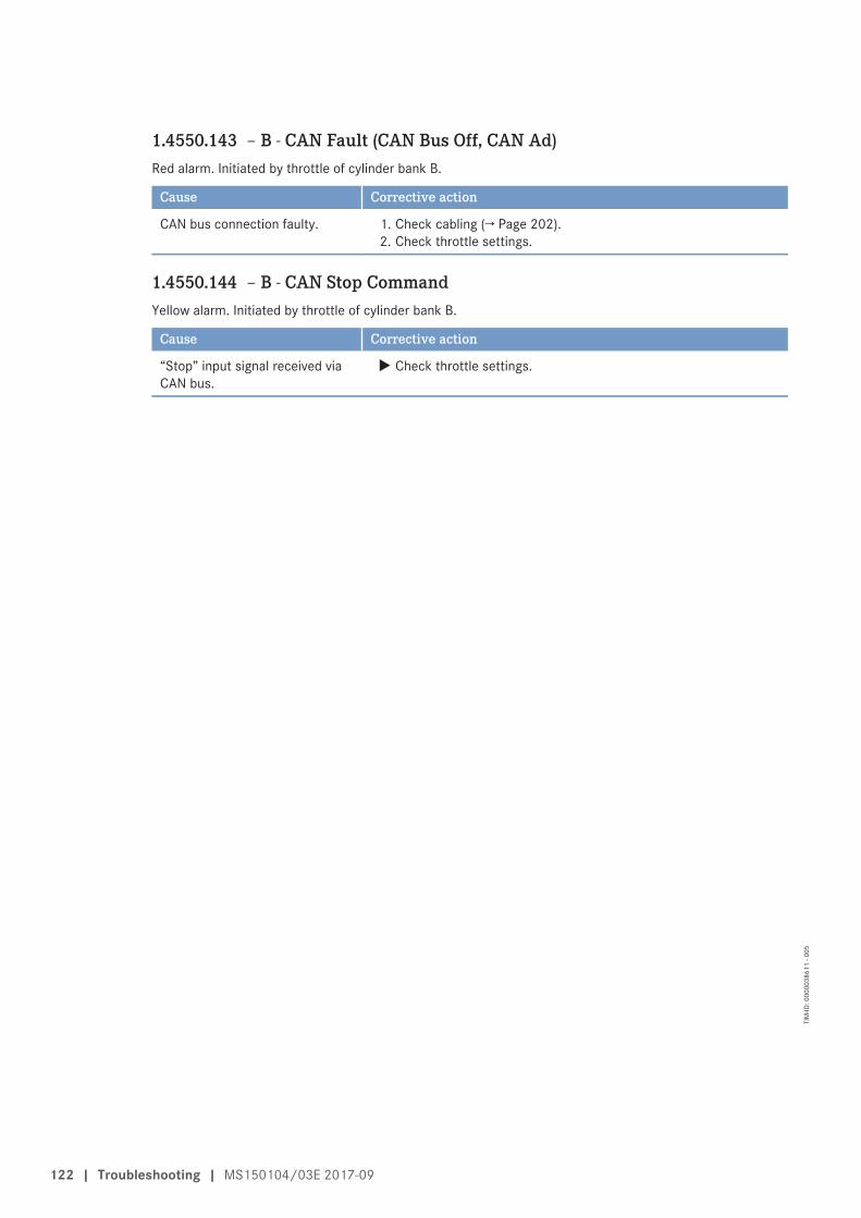
1.4550.143 – B - CAN Fault (CAN Bus Off, CAN Ad)Red alarm. Initiated by throttle of cylinder bank B.
Cause Corrective action
CAN bus connection faulty. 1. Check cabling (→ Page 202).2. Check throttle settings.
1.4550.144 – B - CAN Stop CommandYellow alarm. Initiated by throttle of cylinder bank B.
Cause Corrective action
“Stop” input signal received viaCAN bus.
u Check throttle settings.
122 | Troubleshooting | MS150104/03E 2017-09
TIM
-ID: 0
0000
3861
1 - 0
05
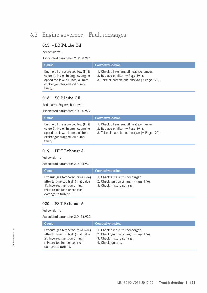
6.3 Engine governor – Fault messages
015 – LO P-Lube OilYellow alarm.
Associated parameter 2.0100.921
Cause Corrective action
Engine oil pressure too low (limitvalue 1). No oil in engine, enginespeed too low, oil lines, oil heatexchanger clogged, oil pumpfaulty.
1. Check oil system, oil heat exchanger.2. Replace oil filter (→ Page 191).3. Take oil sample and analyze (→ Page 190).
016 – SS P-Lube OilRed alarm. Engine shutdown.
Associated parameter 2.0100.922
Cause Corrective action
Engine oil pressure too low (limitvalue 2). No oil in engine, enginespeed too low, oil lines, oil heatexchanger clogged, oil pumpfaulty.
1. Check oil system, oil heat exchanger.2. Replace oil filter (→ Page 191).3. Take oil sample and analyze (→ Page 190).
019 – HI T-Exhaust AYellow alarm.
Associated parameter 2.0126.931
Cause Corrective action
Exhaust gas temperature (A side)after turbine too high (limit value1). Incorrect ignition timing,mixture too lean or too rich,damage to turbine.
1. Check exhaust turbocharger.2. Check ignition timing (→ Page 176).3. Check mixture setting.
020 – SS T-Exhaust AYellow alarm.
Associated parameter 2.0126.932
Cause Corrective action
Exhaust gas temperature (A side)after turbine too high (limit value2). Incorrect ignition timing,mixture too lean or too rich,damage to turbine.
1. Check exhaust turbocharger.2. Check ignition timing (→ Page 176).3. Check mixture setting.4. Check igniters.
MS150104/03E 2017-09 | Troubleshooting | 123
TIM
-ID: 0
0000
3861
2 - 0
03
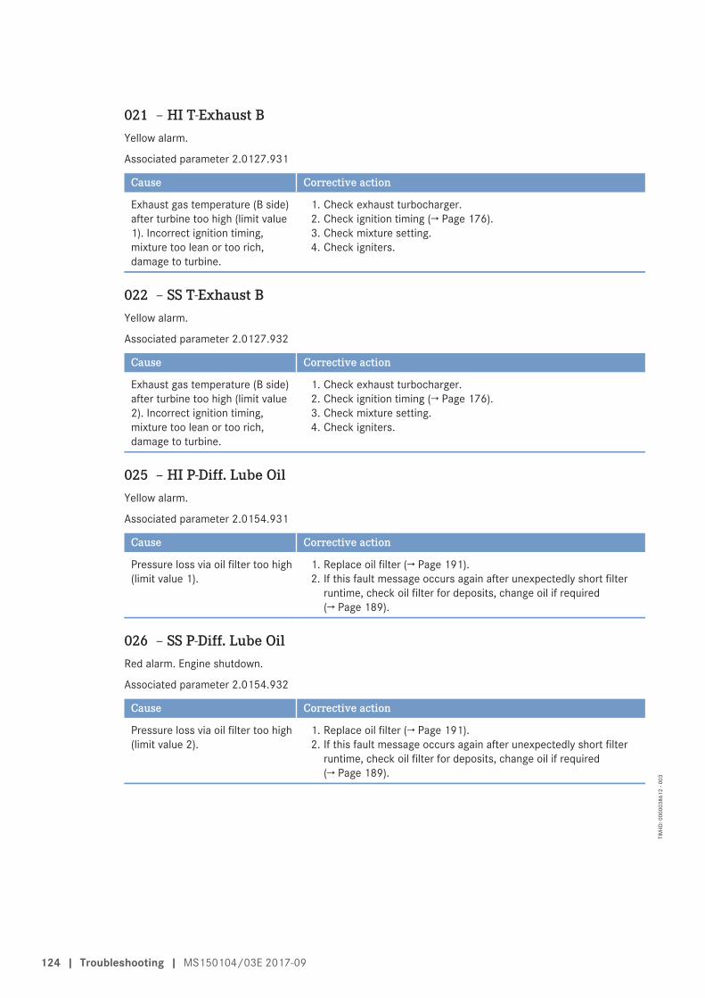
021 – HI T-Exhaust BYellow alarm.
Associated parameter 2.0127.931
Cause Corrective action
Exhaust gas temperature (B side)after turbine too high (limit value1). Incorrect ignition timing,mixture too lean or too rich,damage to turbine.
1. Check exhaust turbocharger.2. Check ignition timing (→ Page 176).3. Check mixture setting.4. Check igniters.
022 – SS T-Exhaust BYellow alarm.
Associated parameter 2.0127.932
Cause Corrective action
Exhaust gas temperature (B side)after turbine too high (limit value2). Incorrect ignition timing,mixture too lean or too rich,damage to turbine.
1. Check exhaust turbocharger.2. Check ignition timing (→ Page 176).3. Check mixture setting.4. Check igniters.
025 – HI P-Diff. Lube OilYellow alarm.
Associated parameter 2.0154.931
Cause Corrective action
Pressure loss via oil filter too high(limit value 1).
1. Replace oil filter (→ Page 191).2. If this fault message occurs again after unexpectedly short filter
runtime, check oil filter for deposits, change oil if required(→ Page 189).
026 – SS P-Diff. Lube OilRed alarm. Engine shutdown.
Associated parameter 2.0154.932
Cause Corrective action
Pressure loss via oil filter too high(limit value 2).
1. Replace oil filter (→ Page 191).2. If this fault message occurs again after unexpectedly short filter
runtime, check oil filter for deposits, change oil if required(→ Page 189).
124 | Troubleshooting | MS150104/03E 2017-09
TIM
-ID: 0
0000
3861
2 - 0
03
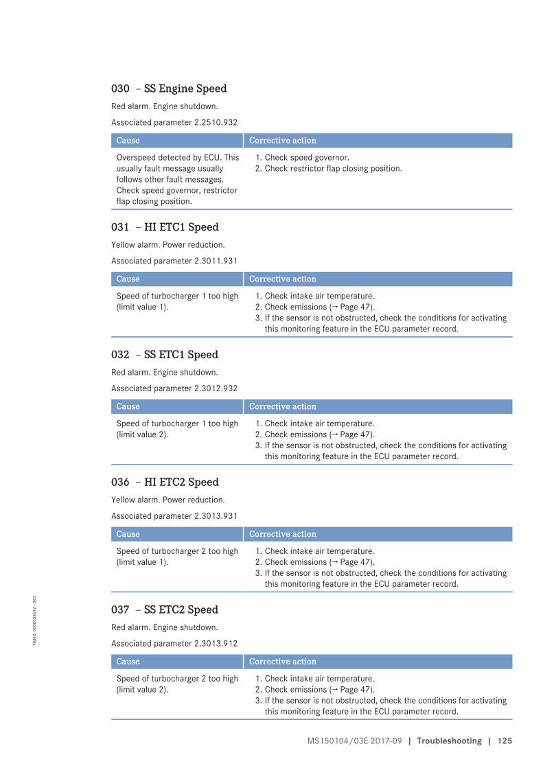
030 – SS Engine SpeedRed alarm. Engine shutdown.
Associated parameter 2.2510.932
Cause Corrective action
Overspeed detected by ECU. Thisusually fault message usuallyfollows other fault messages.Check speed governor, restrictorflap closing position.
1. Check speed governor.2. Check restrictor flap closing position.
031 – HI ETC1 SpeedYellow alarm. Power reduction.
Associated parameter 2.3011.931
Cause Corrective action
Speed of turbocharger 1 too high(limit value 1).
1. Check intake air temperature.2. Check emissions (→ Page 47).3. If the sensor is not obstructed, check the conditions for activating
this monitoring feature in the ECU parameter record.
032 – SS ETC1 SpeedRed alarm. Engine shutdown.
Associated parameter 2.3012.932
Cause Corrective action
Speed of turbocharger 1 too high(limit value 2).
1. Check intake air temperature.2. Check emissions (→ Page 47).3. If the sensor is not obstructed, check the conditions for activating
this monitoring feature in the ECU parameter record.
036 – HI ETC2 SpeedYellow alarm. Power reduction.
Associated parameter 2.3013.931
Cause Corrective action
Speed of turbocharger 2 too high(limit value 1).
1. Check intake air temperature.2. Check emissions (→ Page 47).3. If the sensor is not obstructed, check the conditions for activating
this monitoring feature in the ECU parameter record.
037 – SS ETC2 SpeedRed alarm. Engine shutdown.
Associated parameter 2.3013.912
Cause Corrective action
Speed of turbocharger 2 too high(limit value 2).
1. Check intake air temperature.2. Check emissions (→ Page 47).3. If the sensor is not obstructed, check the conditions for activating
this monitoring feature in the ECU parameter record.
MS150104/03E 2017-09 | Troubleshooting | 125
TIM
-ID: 0
0000
3861
2 - 0
03
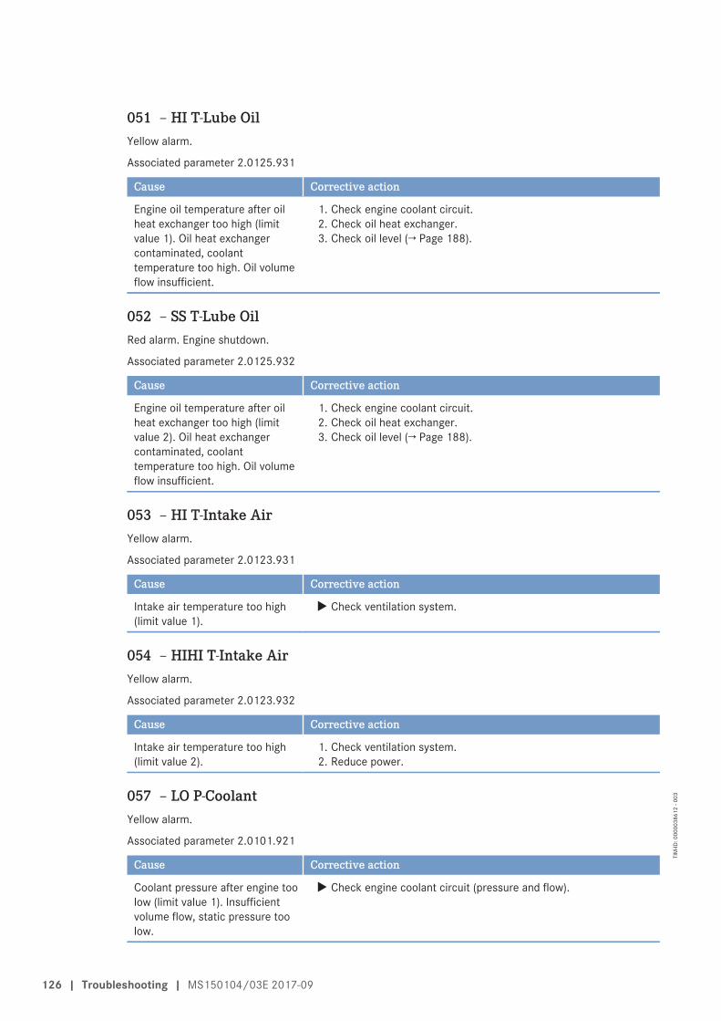
051 – HI T-Lube OilYellow alarm.
Associated parameter 2.0125.931
Cause Corrective action
Engine oil temperature after oilheat exchanger too high (limitvalue 1). Oil heat exchangercontaminated, coolanttemperature too high. Oil volumeflow insufficient.
1. Check engine coolant circuit.2. Check oil heat exchanger.3. Check oil level (→ Page 188).
052 – SS T-Lube OilRed alarm. Engine shutdown.
Associated parameter 2.0125.932
Cause Corrective action
Engine oil temperature after oilheat exchanger too high (limitvalue 2). Oil heat exchangercontaminated, coolanttemperature too high. Oil volumeflow insufficient.
1. Check engine coolant circuit.2. Check oil heat exchanger.3. Check oil level (→ Page 188).
053 – HI T-Intake AirYellow alarm.
Associated parameter 2.0123.931
Cause Corrective action
Intake air temperature too high(limit value 1).
u Check ventilation system.
054 – HIHI T-Intake AirYellow alarm.
Associated parameter 2.0123.932
Cause Corrective action
Intake air temperature too high(limit value 2).
1. Check ventilation system.2. Reduce power.
057 – LO P-CoolantYellow alarm.
Associated parameter 2.0101.921
Cause Corrective action
Coolant pressure after engine toolow (limit value 1). Insufficientvolume flow, static pressure toolow.
u Check engine coolant circuit (pressure and flow).
126 | Troubleshooting | MS150104/03E 2017-09
TIM
-ID: 0
0000
3861
2 - 0
03
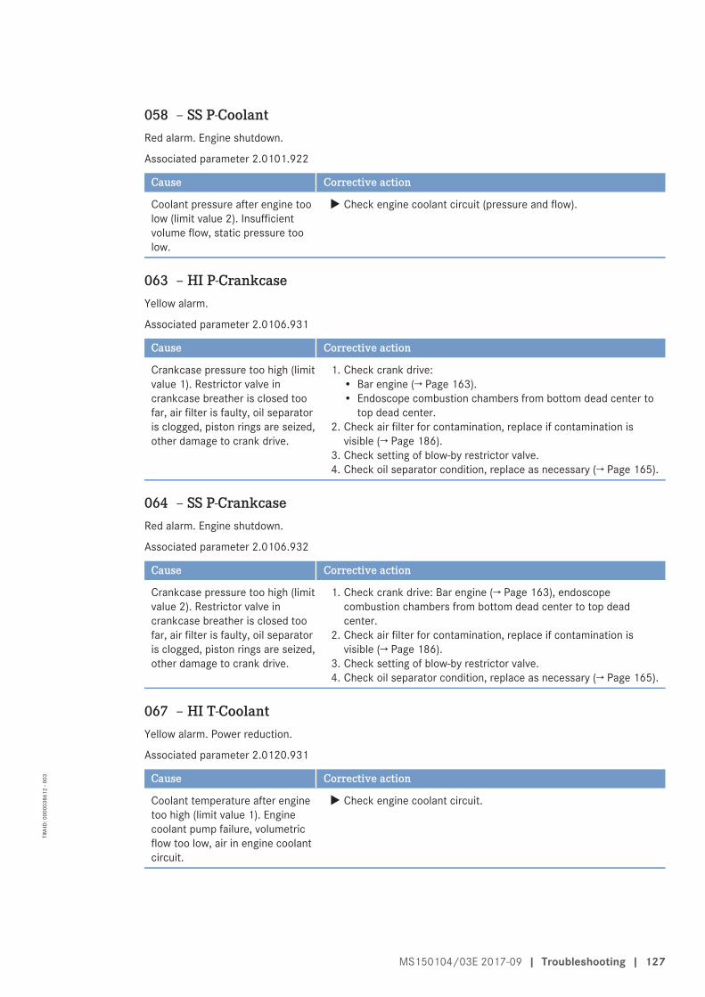
058 – SS P-CoolantRed alarm. Engine shutdown.
Associated parameter 2.0101.922
Cause Corrective action
Coolant pressure after engine toolow (limit value 2). Insufficientvolume flow, static pressure toolow.
u Check engine coolant circuit (pressure and flow).
063 – HI P-CrankcaseYellow alarm.
Associated parameter 2.0106.931
Cause Corrective action
Crankcase pressure too high (limitvalue 1). Restrictor valve incrankcase breather is closed toofar, air filter is faulty, oil separatoris clogged, piston rings are seized,other damage to crank drive.
1. Check crank drive:• Bar engine (→ Page 163).• Endoscope combustion chambers from bottom dead center to
top dead center.2. Check air filter for contamination, replace if contamination is
visible (→ Page 186).3. Check setting of blow-by restrictor valve.4. Check oil separator condition, replace as necessary (→ Page 165).
064 – SS P-CrankcaseRed alarm. Engine shutdown.
Associated parameter 2.0106.932
Cause Corrective action
Crankcase pressure too high (limitvalue 2). Restrictor valve incrankcase breather is closed toofar, air filter is faulty, oil separatoris clogged, piston rings are seized,other damage to crank drive.
1. Check crank drive: Bar engine (→ Page 163), endoscopecombustion chambers from bottom dead center to top deadcenter.
2. Check air filter for contamination, replace if contamination isvisible (→ Page 186).
3. Check setting of blow-by restrictor valve.4. Check oil separator condition, replace as necessary (→ Page 165).
067 – HI T-CoolantYellow alarm. Power reduction.
Associated parameter 2.0120.931
Cause Corrective action
Coolant temperature after enginetoo high (limit value 1). Enginecoolant pump failure, volumetricflow too low, air in engine coolantcircuit.
u Check engine coolant circuit.
MS150104/03E 2017-09 | Troubleshooting | 127
TIM
-ID: 0
0000
3861
2 - 0
03
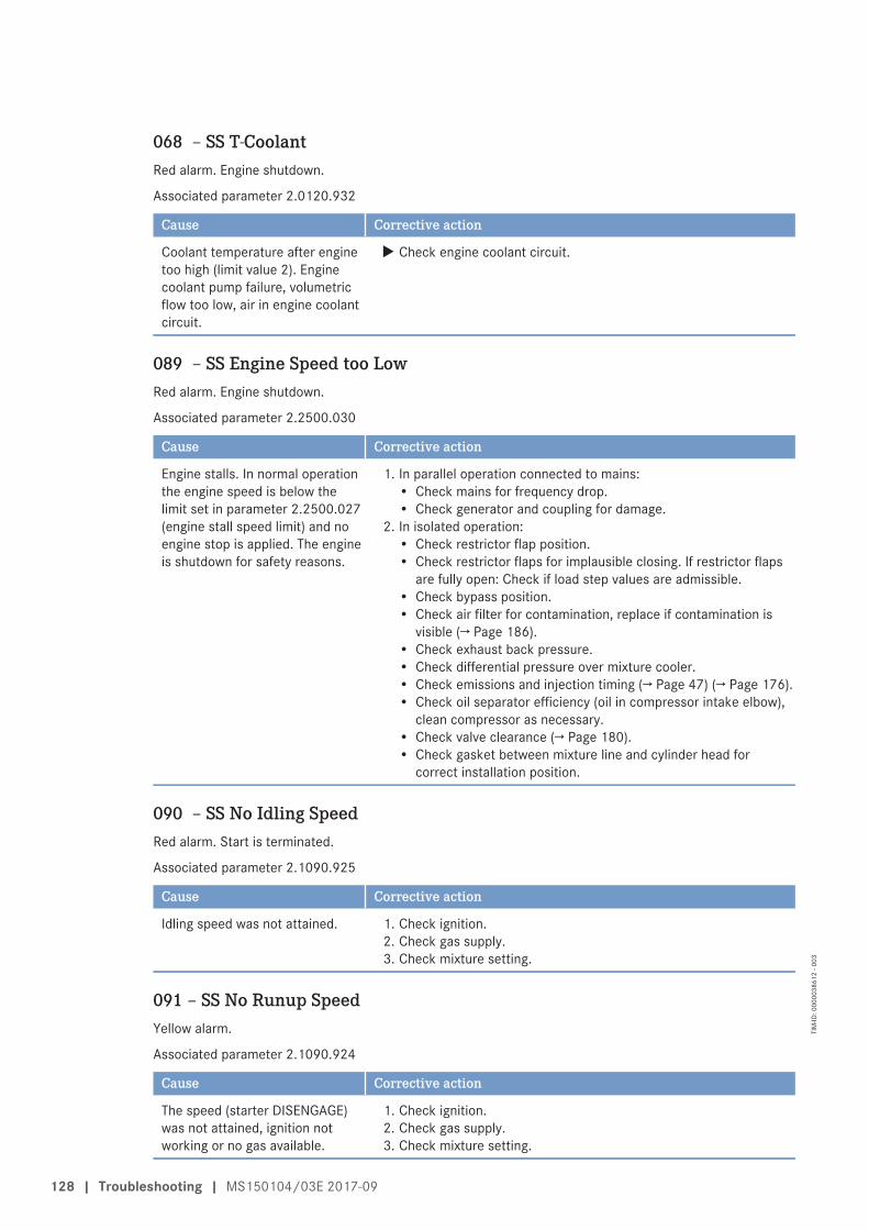
068 – SS T-CoolantRed alarm. Engine shutdown.
Associated parameter 2.0120.932
Cause Corrective action
Coolant temperature after enginetoo high (limit value 2). Enginecoolant pump failure, volumetricflow too low, air in engine coolantcircuit.
u Check engine coolant circuit.
089 – SS Engine Speed too LowRed alarm. Engine shutdown.
Associated parameter 2.2500.030
Cause Corrective action
Engine stalls. In normal operationthe engine speed is below thelimit set in parameter 2.2500.027(engine stall speed limit) and noengine stop is applied. The engineis shutdown for safety reasons.
1. In parallel operation connected to mains:• Check mains for frequency drop.• Check generator and coupling for damage.
2. In isolated operation:• Check restrictor flap position.• Check restrictor flaps for implausible closing. If restrictor flaps
are fully open: Check if load step values are admissible.• Check bypass position.• Check air filter for contamination, replace if contamination is
visible (→ Page 186).• Check exhaust back pressure.• Check differential pressure over mixture cooler.• Check emissions and injection timing (→ Page 47) (→ Page 176).• Check oil separator efficiency (oil in compressor intake elbow),
clean compressor as necessary.• Check valve clearance (→ Page 180).• Check gasket between mixture line and cylinder head for
correct installation position.
090 – SS No Idling SpeedRed alarm. Start is terminated.
Associated parameter 2.1090.925
Cause Corrective action
Idling speed was not attained. 1. Check ignition.2. Check gas supply.3. Check mixture setting.
091 – SS No Runup SpeedYellow alarm.
Associated parameter 2.1090.924
Cause Corrective action
The speed (starter DISENGAGE)was not attained, ignition notworking or no gas available.
1. Check ignition.2. Check gas supply.3. Check mixture setting.
128 | Troubleshooting | MS150104/03E 2017-09
TIM
-ID: 0
0000
3861
2 - 0
03
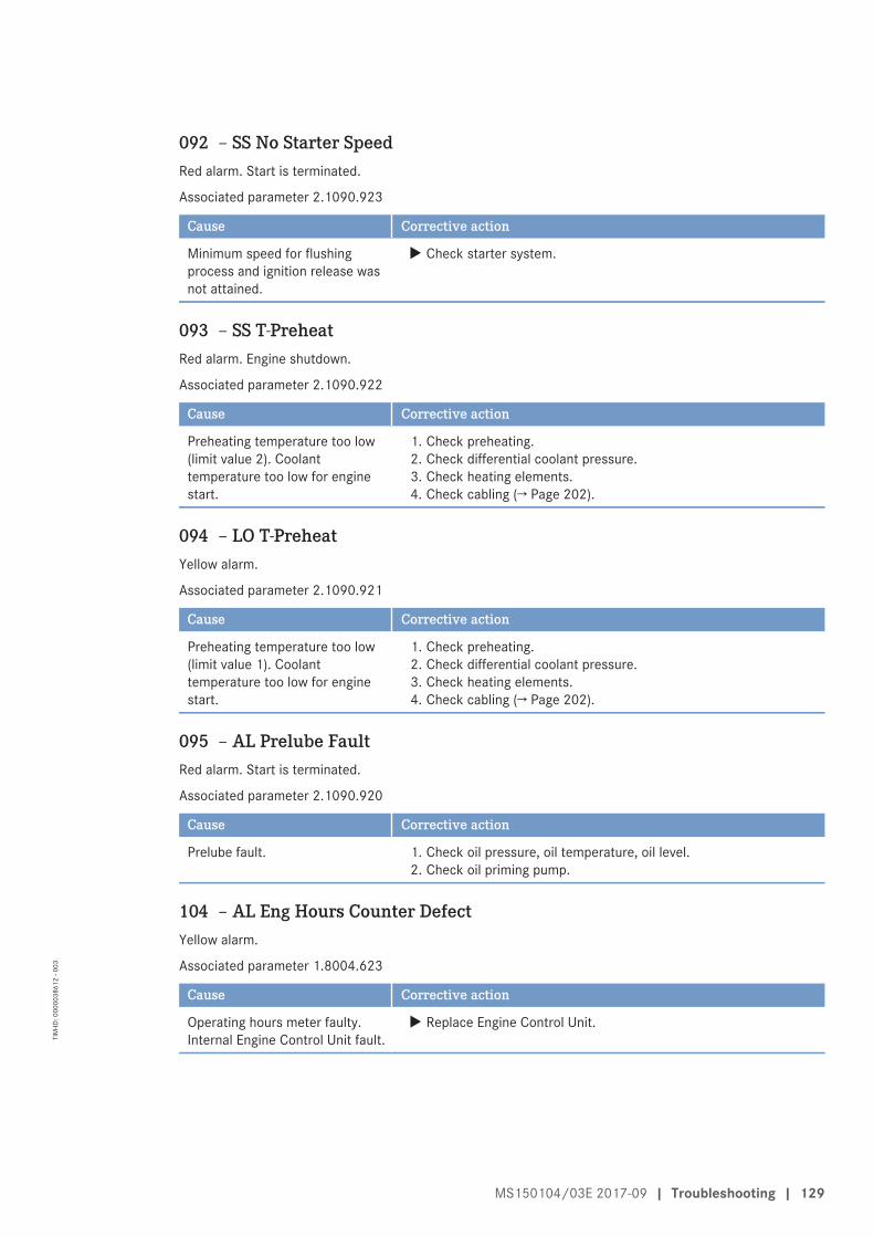
092 – SS No Starter SpeedRed alarm. Start is terminated.
Associated parameter 2.1090.923
Cause Corrective action
Minimum speed for flushingprocess and ignition release wasnot attained.
u Check starter system.
093 – SS T-PreheatRed alarm. Engine shutdown.
Associated parameter 2.1090.922
Cause Corrective action
Preheating temperature too low(limit value 2). Coolanttemperature too low for enginestart.
1. Check preheating.2. Check differential coolant pressure.3. Check heating elements.4. Check cabling (→ Page 202).
094 – LO T-PreheatYellow alarm.
Associated parameter 2.1090.921
Cause Corrective action
Preheating temperature too low(limit value 1). Coolanttemperature too low for enginestart.
1. Check preheating.2. Check differential coolant pressure.3. Check heating elements.4. Check cabling (→ Page 202).
095 – AL Prelube FaultRed alarm. Start is terminated.
Associated parameter 2.1090.920
Cause Corrective action
Prelube fault. 1. Check oil pressure, oil temperature, oil level.2. Check oil priming pump.
104 – AL Eng Hours Counter DefectYellow alarm.
Associated parameter 1.8004.623
Cause Corrective action
Operating hours meter faulty.Internal Engine Control Unit fault.
u Replace Engine Control Unit.
MS150104/03E 2017-09 | Troubleshooting | 129
TIM
-ID: 0
0000
3861
2 - 0
03
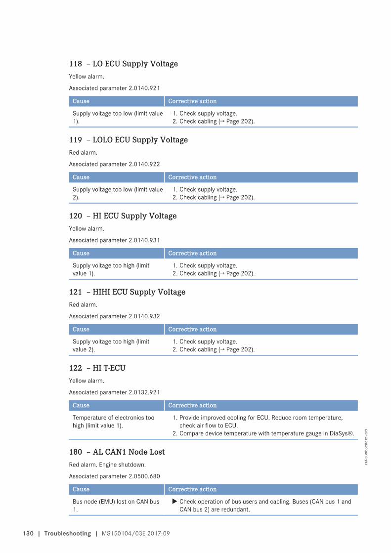
118 – LO ECU Supply VoltageYellow alarm.
Associated parameter 2.0140.921
Cause Corrective action
Supply voltage too low (limit value1).
1. Check supply voltage.2. Check cabling (→ Page 202).
119 – LOLO ECU Supply VoltageRed alarm.
Associated parameter 2.0140.922
Cause Corrective action
Supply voltage too low (limit value2).
1. Check supply voltage.2. Check cabling (→ Page 202).
120 – HI ECU Supply VoltageYellow alarm.
Associated parameter 2.0140.931
Cause Corrective action
Supply voltage too high (limitvalue 1).
1. Check supply voltage.2. Check cabling (→ Page 202).
121 – HIHI ECU Supply VoltageRed alarm.
Associated parameter 2.0140.932
Cause Corrective action
Supply voltage too high (limitvalue 2).
1. Check supply voltage.2. Check cabling (→ Page 202).
122 – HI T-ECUYellow alarm.
Associated parameter 2.0132.921
Cause Corrective action
Temperature of electronics toohigh (limit value 1).
1. Provide improved cooling for ECU. Reduce room temperature,check air flow to ECU.
2. Compare device temperature with temperature gauge in DiaSys®.
180 – AL CAN1 Node LostRed alarm. Engine shutdown.
Associated parameter 2.0500.680
Cause Corrective action
Bus node (EMU) lost on CAN bus1.
u Check operation of bus users and cabling. Buses (CAN bus 1 andCAN bus 2) are redundant.
130 | Troubleshooting | MS150104/03E 2017-09
TIM
-ID: 0
0000
3861
2 - 0
03
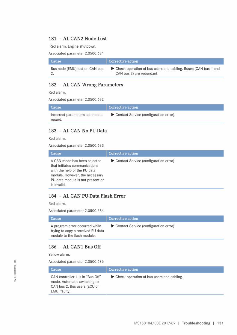
181 – AL CAN2 Node Lost Red alarm. Engine shutdown.
Associated parameter 2.0500.681
Cause Corrective action
Bus node (EMU) lost on CAN bus2.
u Check operation of bus users and cabling. Buses (CAN bus 1 andCAN bus 2) are redundant.
182 – AL CAN Wrong ParametersRed alarm.
Associated parameter 2.0500.682
Cause Corrective action
Incorrect parameters set in datarecord.
u Contact Service (configuration error).
183 – AL CAN No PU-DataRed alarm.
Associated parameter 2.0500.683
Cause Corrective action
A CAN mode has been selectedthat initiates communicationswith the help of the PU datamodule. However, the necessaryPU data module is not present oris invalid.
u Contact Service (configuration error).
184 – AL CAN PU-Data Flash ErrorRed alarm.
Associated parameter 2.0500.684
Cause Corrective action
A program error occurred whiletrying to copy a received PU datamodule to the flash module.
u Contact Service (configuration error).
186 – AL CAN1 Bus OffYellow alarm.
Associated parameter 2.0500.686
Cause Corrective action
CAN controller 1 is in “Bus-Off”mode. Automatic switching toCAN bus 2. Bus users (ECU orEMU) faulty.
u Check operation of bus users and cabling.
MS150104/03E 2017-09 | Troubleshooting | 131
TIM
-ID: 0
0000
3861
2 - 0
03
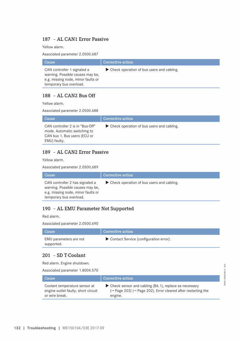
187 – AL CAN1 Error PassiveYellow alarm.
Associated parameter 2.0500.687
Cause Corrective action
CAN controller 1 signaled awarning. Possible causes may be,e.g. missing node, minor faults ortemporary bus overload.
u Check operation of bus users and cabling.
188 – AL CAN2 Bus OffYellow alarm.
Associated parameter 2.0500.688
Cause Corrective action
CAN controller 2 is in “Bus-Off”mode. Automatic switching toCAN bus 1. Bus users (ECU orEMU) faulty.
u Check operation of bus users and cabling.
189 – AL CAN2 Error PassiveYellow alarm.
Associated parameter 2.0500.689
Cause Corrective action
CAN controller 2 has signaled awarning. Possible causes may be,e.g. missing node, minor faults ortemporary bus overload.
u Check operation of bus users and cabling.
190 – AL EMU Parameter Not SupportedRed alarm.
Associated parameter 2.0500.690
Cause Corrective action
EMU parameters are notsupported.
u Contact Service (configuration error).
201 – SD T-CoolantRed alarm. Engine shutdown.
Associated parameter 1.8004.570
Cause Corrective action
Coolant temperature sensor atengine outlet faulty, short circuitor wire break.
u Check sensor and cabling (B6.1), replace as necessary(→ Page 203) (→ Page 202). Error cleared after restarting theengine.
132 | Troubleshooting | MS150104/03E 2017-09
TIM
-ID: 0
0000
3861
2 - 0
03
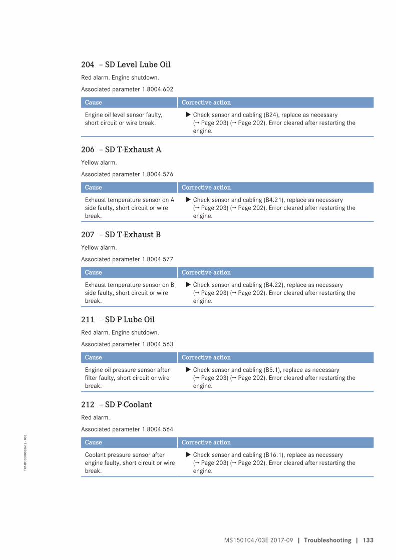
204 – SD Level Lube OilRed alarm. Engine shutdown.
Associated parameter 1.8004.602
Cause Corrective action
Engine oil level sensor faulty,short circuit or wire break.
u Check sensor and cabling (B24), replace as necessary(→ Page 203) (→ Page 202). Error cleared after restarting theengine.
206 – SD T-Exhaust AYellow alarm.
Associated parameter 1.8004.576
Cause Corrective action
Exhaust temperature sensor on Aside faulty, short circuit or wirebreak.
u Check sensor and cabling (B4.21), replace as necessary(→ Page 203) (→ Page 202). Error cleared after restarting theengine.
207 – SD T-Exhaust BYellow alarm.
Associated parameter 1.8004.577
Cause Corrective action
Exhaust temperature sensor on Bside faulty, short circuit or wirebreak.
u Check sensor and cabling (B4.22), replace as necessary(→ Page 203) (→ Page 202). Error cleared after restarting theengine.
211 – SD P-Lube OilRed alarm. Engine shutdown.
Associated parameter 1.8004.563
Cause Corrective action
Engine oil pressure sensor afterfilter faulty, short circuit or wirebreak.
u Check sensor and cabling (B5.1), replace as necessary(→ Page 203) (→ Page 202). Error cleared after restarting theengine.
212 – SD P-CoolantRed alarm.
Associated parameter 1.8004.564
Cause Corrective action
Coolant pressure sensor afterengine faulty, short circuit or wirebreak.
u Check sensor and cabling (B16.1), replace as necessary(→ Page 203) (→ Page 202). Error cleared after restarting theengine.
MS150104/03E 2017-09 | Troubleshooting | 133
TIM
-ID: 0
0000
3861
2 - 0
03
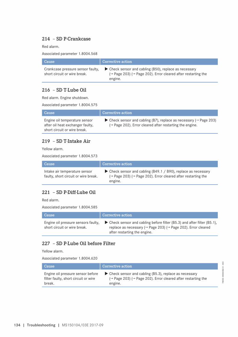
214 – SD P-CrankcaseRed alarm.
Associated parameter 1.8004.568
Cause Corrective action
Crankcase pressure sensor faulty,short circuit or wire break.
u Check sensor and cabling (B50), replace as necessary(→ Page 203) (→ Page 202). Error cleared after restarting theengine.
216 – SD T-Lube OilRed alarm. Engine shutdown.
Associated parameter 1.8004.575
Cause Corrective action
Engine oil temperature sensorafter oil heat exchanger faulty,short circuit or wire break.
u Check sensor and cabling (B7), replace as necessary (→ Page 203)(→ Page 202). Error cleared after restarting the engine.
219 – SD T-Intake AirYellow alarm.
Associated parameter 1.8004.573
Cause Corrective action
Intake air temperature sensorfaulty, short circuit or wire break.
u Check sensor and cabling (B49.1 / B90), replace as necessary(→ Page 203) (→ Page 202). Error cleared after restarting theengine.
221 – SD P-Diff-Lube OilRed alarm.
Associated parameter 1.8004.585
Cause Corrective action
Engine oil pressure sensors faulty,short circuit or wire break.
u Check sensor and cabling before filter (B5.3) and after filter (B5.1),replace as necessary (→ Page 203) (→ Page 202). Error clearedafter restarting the engine.
227 – SD P-Lube Oil before FilterYellow alarm.
Associated parameter 1.8004.620
Cause Corrective action
Engine oil pressure sensor beforefilter faulty, short circuit or wirebreak.
u Check sensor and cabling (B5.3), replace as necessary(→ Page 203) (→ Page 202). Error cleared after restarting theengine.
134 | Troubleshooting | MS150104/03E 2017-09
TIM
-ID: 0
0000
3861
2 - 0
03
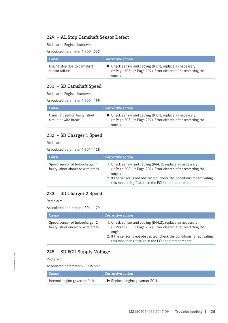
229 – AL Stop Camshaft Sensor DefectRed alarm. Engine shutdown.
Associated parameter 1.8004.562
Cause Corrective action
Engine stop due to camshaftsensor failure.
u Check sensor and cabling (B1.1), replace as necessary(→ Page 203) (→ Page 202). Error cleared after restarting theengine.
231 – SD Camshaft SpeedRed alarm. Engine shutdown.
Associated parameter 1.8004.499
Cause Corrective action
Camshaft sensor faulty, shortcircuit or wire break.
u Check sensor and cabling (B1.1), replace as necessary(→ Page 203) (→ Page 202). Error cleared after restarting theengine.
232 – SD Charger 1 SpeedRed alarm.
Associated parameter 1.3011.128
Cause Corrective action
Speed sensor of turbocharger 1faulty, short circuit or wire break.
1. Check sensor and cabling (B44.1), replace as necessary(→ Page 203) (→ Page 202). Error cleared after restarting theengine.
2. If the sensor is not obstructed, check the conditions for activatingthis monitoring feature in the ECU parameter record.
233 – SD Charger 2 SpeedRed alarm.
Associated parameter 1.3011.129
Cause Corrective action
Speed sensor of turbocharger 2faulty, short circuit or wire break.
1. Check sensor and cabling (B44.2), replace as necessary(→ Page 203) (→ Page 202). Error cleared after restarting theengine.
2. If the sensor is not obstructed, check the conditions for activatingthis monitoring feature in the ECU parameter record.
245 – SD ECU Supply VoltageRed alarm.
Associated parameter 2.8006.589
Cause Corrective action
Internal engine governor fault. u Replace engine governor ECU.
MS150104/03E 2017-09 | Troubleshooting | 135
TIM
-ID: 0
0000
3861
2 - 0
03
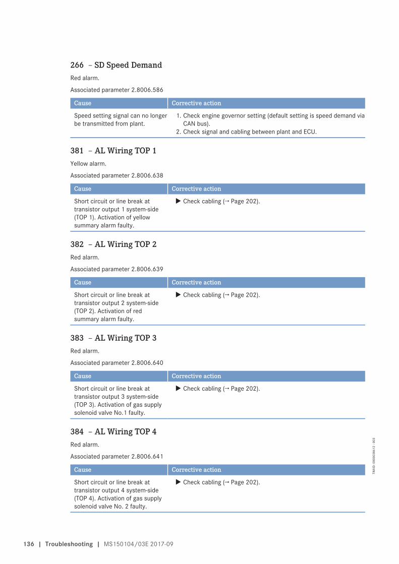
266 – SD Speed DemandRed alarm.
Associated parameter 2.8006.586
Cause Corrective action
Speed setting signal can no longerbe transmitted from plant.
1. Check engine governor setting (default setting is speed demand viaCAN bus).
2. Check signal and cabling between plant and ECU.
381 – AL Wiring TOP 1Yellow alarm.
Associated parameter 2.8006.638
Cause Corrective action
Short circuit or line break attransistor output 1 system-side(TOP 1). Activation of yellowsummary alarm faulty.
u Check cabling (→ Page 202).
382 – AL Wiring TOP 2Red alarm.
Associated parameter 2.8006.639
Cause Corrective action
Short circuit or line break attransistor output 2 system-side(TOP 2). Activation of redsummary alarm faulty.
u Check cabling (→ Page 202).
383 – AL Wiring TOP 3Red alarm.
Associated parameter 2.8006.640
Cause Corrective action
Short circuit or line break attransistor output 3 system-side(TOP 3). Activation of gas supplysolenoid valve No.1 faulty.
u Check cabling (→ Page 202).
384 – AL Wiring TOP 4Red alarm.
Associated parameter 2.8006.641
Cause Corrective action
Short circuit or line break attransistor output 4 system-side(TOP 4). Activation of gas supplysolenoid valve No. 2 faulty.
u Check cabling (→ Page 202).
136 | Troubleshooting | MS150104/03E 2017-09
TIM
-ID: 0
0000
3861
2 - 0
03
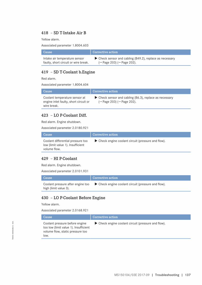
418 – SD T-Intake Air BYellow alarm.
Associated parameter 1.8004.603
Cause Corrective action
Intake air temperature sensorfaulty, short circuit or wire break.
u Check sensor and cabling (B49.2), replace as necessary(→ Page 203) (→ Page 202).
419 – SD T-Coolant b.EngineRed alarm.
Associated parameter 1.8004.604
Cause Corrective action
Coolant temperature sensor atengine inlet faulty, short circuit orwire break.
u Check sensor and cabling (B6.3), replace as necessary(→ Page 203) (→ Page 202).
423 – LO P-Coolant Diff.Red alarm. Engine shutdown.
Associated parameter 2.0180.921
Cause Corrective action
Coolant differential pressure toolow (limit value 1). Insufficientvolume flow.
u Check engine coolant circuit (pressure and flow).
429 – HI P-CoolantRed alarm. Engine shutdown.
Associated parameter 2.0101.931
Cause Corrective action
Coolant pressure after engine toohigh (limit value 3).
u Check engine coolant circuit (pressure and flow).
430 – LO P-Coolant Before EngineYellow alarm.
Associated parameter 2.0168.921
Cause Corrective action
Coolant pressure before enginetoo low (limit value 1). Insufficientvolume flow, static pressure toolow.
u Check engine coolant circuit (pressure and flow).
MS150104/03E 2017-09 | Troubleshooting | 137
TIM
-ID: 0
0000
3861
2 - 0
03
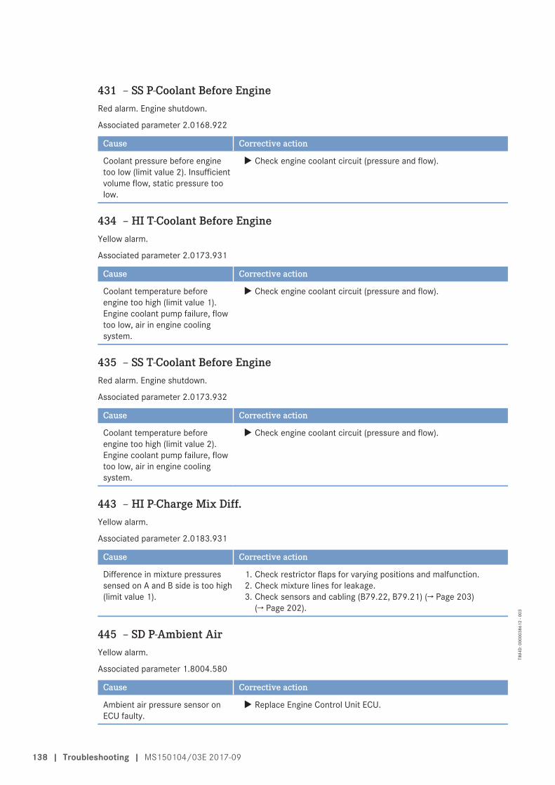
431 – SS P-Coolant Before EngineRed alarm. Engine shutdown.
Associated parameter 2.0168.922
Cause Corrective action
Coolant pressure before enginetoo low (limit value 2). Insufficientvolume flow, static pressure toolow.
u Check engine coolant circuit (pressure and flow).
434 – HI T-Coolant Before EngineYellow alarm.
Associated parameter 2.0173.931
Cause Corrective action
Coolant temperature beforeengine too high (limit value 1).Engine coolant pump failure, flowtoo low, air in engine coolingsystem.
u Check engine coolant circuit (pressure and flow).
435 – SS T-Coolant Before EngineRed alarm. Engine shutdown.
Associated parameter 2.0173.932
Cause Corrective action
Coolant temperature beforeengine too high (limit value 2).Engine coolant pump failure, flowtoo low, air in engine coolingsystem.
u Check engine coolant circuit (pressure and flow).
443 – HI P-Charge Mix Diff.Yellow alarm.
Associated parameter 2.0183.931
Cause Corrective action
Difference in mixture pressuressensed on A and B side is too high(limit value 1).
1. Check restrictor flaps for varying positions and malfunction.2. Check mixture lines for leakage.3. Check sensors and cabling (B79.22, B79.21) (→ Page 203)
(→ Page 202).
445 – SD P-Ambient AirYellow alarm.
Associated parameter 1.8004.580
Cause Corrective action
Ambient air pressure sensor onECU faulty.
u Replace Engine Control Unit ECU.
138 | Troubleshooting | MS150104/03E 2017-09
TIM
-ID: 0
0000
3861
2 - 0
03
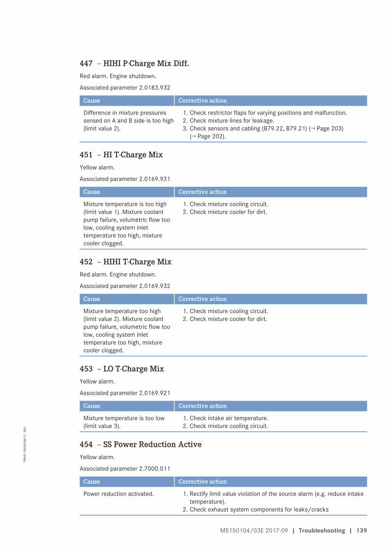
447 – HIHI P-Charge Mix Diff.Red alarm. Engine shutdown.
Associated parameter 2.0183.932
Cause Corrective action
Difference in mixture pressuressensed on A and B side is too high(limit value 2).
1. Check restrictor flaps for varying positions and malfunction.2. Check mixture lines for leakage.3. Check sensors and cabling (B79.22, B79.21) (→ Page 203)
(→ Page 202).
451 – HI T-Charge MixYellow alarm.
Associated parameter 2.0169.931
Cause Corrective action
Mixture temperature is too high(limit value 1). Mixture coolantpump failure, volumetric flow toolow, cooling system inlettemperature too high, mixturecooler clogged.
1. Check mixture cooling circuit.2. Check mixture cooler for dirt.
452 – HIHI T-Charge MixRed alarm. Engine shutdown.
Associated parameter 2.0169.932
Cause Corrective action
Mixture temperature too high(limit value 2). Mixture coolantpump failure, volumetric flow toolow, cooling system inlettemperature too high, mixturecooler clogged.
1. Check mixture cooling circuit.2. Check mixture cooler for dirt.
453 – LO T-Charge MixYellow alarm.
Associated parameter 2.0169.921
Cause Corrective action
Mixture temperature is too low(limit value 3).
1. Check intake air temperature.2. Check mixture cooling circuit.
454 – SS Power Reduction ActiveYellow alarm.
Associated parameter 2.7000.011
Cause Corrective action
Power reduction activated. 1. Rectify limit value violation of the source alarm (e.g. reduce intaketemperature).
2. Check exhaust system components for leaks/cracks
MS150104/03E 2017-09 | Troubleshooting | 139
TIM
-ID: 0
0000
3861
2 - 0
03
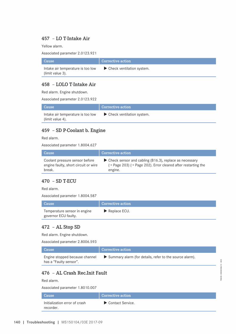
457 – LO T-Intake AirYellow alarm.
Associated parameter 2.0123.921
Cause Corrective action
Intake air temperature is too low(limit value 3).
u Check ventilation system.
458 – LOLO T-Intake AirRed alarm. Engine shutdown.
Associated parameter 2.0123.922
Cause Corrective action
Intake air temperature is too low(limit value 4).
u Check ventilation system.
459 – SD P-Coolant b. EngineRed alarm.
Associated parameter 1.8004.627
Cause Corrective action
Coolant pressure sensor beforeengine faulty, short circuit or wirebreak.
u Check sensor and cabling (B16.3), replace as necessary(→ Page 203) (→ Page 202). Error cleared after restarting theengine.
470 – SD T-ECURed alarm.
Associated parameter 1.8004.587
Cause Corrective action
Temperature sensor in enginegovernor ECU faulty.
u Replace ECU.
472 – AL Stop SDRed alarm. Engine shutdown.
Associated parameter 2.8006.593
Cause Corrective action
Engine stopped because channelhas a “Faulty sensor”.
u Summary alarm (for details, refer to the source alarm).
476 – AL Crash Rec.Init FaultRed alarm.
Associated parameter 1.8010.007
Cause Corrective action
Initialization error of crashrecorder.
u Contact Service.
140 | Troubleshooting | MS150104/03E 2017-09
TIM
-ID: 0
0000
3861
2 - 0
03
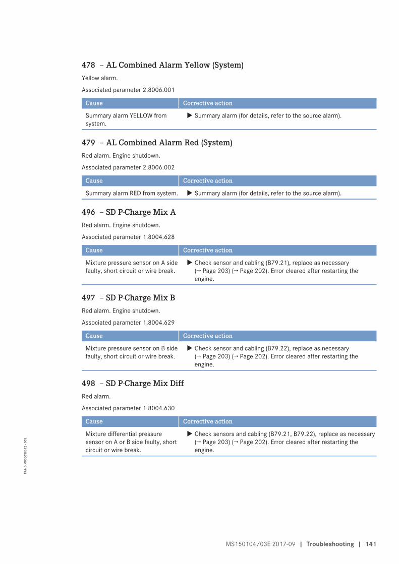
478 – AL Combined Alarm Yellow (System)Yellow alarm.
Associated parameter 2.8006.001
Cause Corrective action
Summary alarm YELLOW fromsystem.
u Summary alarm (for details, refer to the source alarm).
479 – AL Combined Alarm Red (System)Red alarm. Engine shutdown.
Associated parameter 2.8006.002
Cause Corrective action
Summary alarm RED from system. u Summary alarm (for details, refer to the source alarm).
496 – SD P-Charge Mix ARed alarm. Engine shutdown.
Associated parameter 1.8004.628
Cause Corrective action
Mixture pressure sensor on A sidefaulty, short circuit or wire break.
u Check sensor and cabling (B79.21), replace as necessary(→ Page 203) (→ Page 202). Error cleared after restarting theengine.
497 – SD P-Charge Mix BRed alarm. Engine shutdown.
Associated parameter 1.8004.629
Cause Corrective action
Mixture pressure sensor on B sidefaulty, short circuit or wire break.
u Check sensor and cabling (B79.22), replace as necessary(→ Page 203) (→ Page 202). Error cleared after restarting theengine.
498 – SD P-Charge Mix DiffRed alarm.
Associated parameter 1.8004.630
Cause Corrective action
Mixture differential pressuresensor on A or B side faulty, shortcircuit or wire break.
u Check sensors and cabling (B79.21, B79.22), replace as necessary(→ Page 203) (→ Page 202). Error cleared after restarting theengine.
MS150104/03E 2017-09 | Troubleshooting | 141
TIM
-ID: 0
0000
3861
2 - 0
03
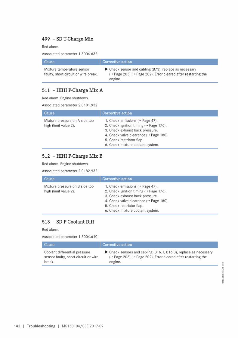
499 – SD T-Charge MixRed alarm.
Associated parameter 1.8004.632
Cause Corrective action
Mixture temperature sensorfaulty, short circuit or wire break.
u Check sensor and cabling (B73), replace as necessary(→ Page 203) (→ Page 202). Error cleared after restarting theengine.
511 – HIHI P-Charge Mix ARed alarm. Engine shutdown.
Associated parameter 2.0181.932
Cause Corrective action
Mixture pressure on A side toohigh (limit value 2).
1. Check emissions (→ Page 47).2. Check ignition timing (→ Page 176).3. Check exhaust back pressure.4. Check valve clearance (→ Page 180).5. Check restrictor flap.6. Check mixture coolant system.
512 – HIHI P-Charge Mix BRed alarm. Engine shutdown.
Associated parameter 2.0182.932
Cause Corrective action
Mixture pressure on B side toohigh (limit value 2).
1. Check emissions (→ Page 47).2. Check ignition timing (→ Page 176).3. Check exhaust back pressure.4. Check valve clearance (→ Page 180).5. Check restrictor flap.6. Check mixture coolant system.
513 – SD P-Coolant DiffRed alarm.
Associated parameter 1.8004.610
Cause Corrective action
Coolant differential pressuresensor faulty, short circuit or wirebreak.
u Check sensors and cabling (B16.1, B16.3), replace as necessary(→ Page 203) (→ Page 202). Error cleared after restarting theengine.
142 | Troubleshooting | MS150104/03E 2017-09
TIM
-ID: 0
0000
3861
2 - 0
03
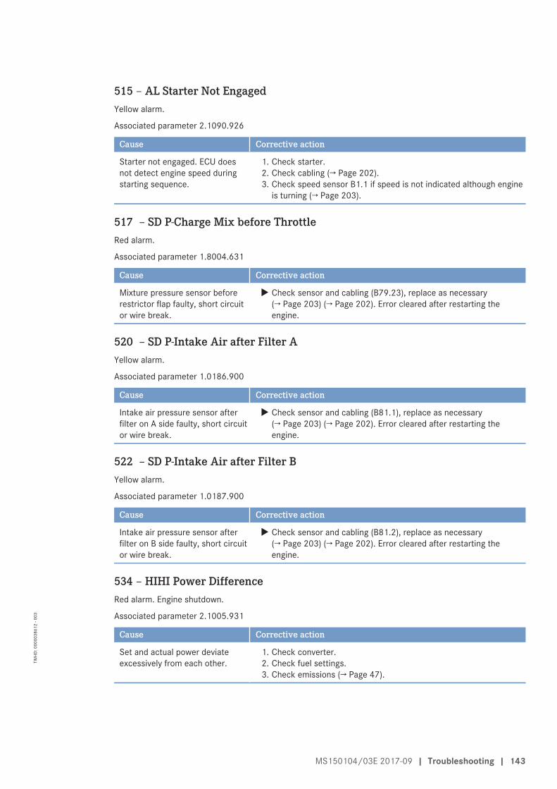
515 – AL Starter Not EngagedYellow alarm.
Associated parameter 2.1090.926
Cause Corrective action
Starter not engaged. ECU doesnot detect engine speed duringstarting sequence.
1. Check starter.2. Check cabling (→ Page 202).3. Check speed sensor B1.1 if speed is not indicated although engine
is turning (→ Page 203).
517 – SD P-Charge Mix before ThrottleRed alarm.
Associated parameter 1.8004.631
Cause Corrective action
Mixture pressure sensor beforerestrictor flap faulty, short circuitor wire break.
u Check sensor and cabling (B79.23), replace as necessary(→ Page 203) (→ Page 202). Error cleared after restarting theengine.
520 – SD P-Intake Air after Filter AYellow alarm.
Associated parameter 1.0186.900
Cause Corrective action
Intake air pressure sensor afterfilter on A side faulty, short circuitor wire break.
u Check sensor and cabling (B81.1), replace as necessary(→ Page 203) (→ Page 202). Error cleared after restarting theengine.
522 – SD P-Intake Air after Filter BYellow alarm.
Associated parameter 1.0187.900
Cause Corrective action
Intake air pressure sensor afterfilter on B side faulty, short circuitor wire break.
u Check sensor and cabling (B81.2), replace as necessary(→ Page 203) (→ Page 202). Error cleared after restarting theengine.
534 – HIHI Power DifferenceRed alarm. Engine shutdown.
Associated parameter 2.1005.931
Cause Corrective action
Set and actual power deviateexcessively from each other.
1. Check converter.2. Check fuel settings.3. Check emissions (→ Page 47).
MS150104/03E 2017-09 | Troubleshooting | 143
TIM
-ID: 0
0000
3861
2 - 0
03
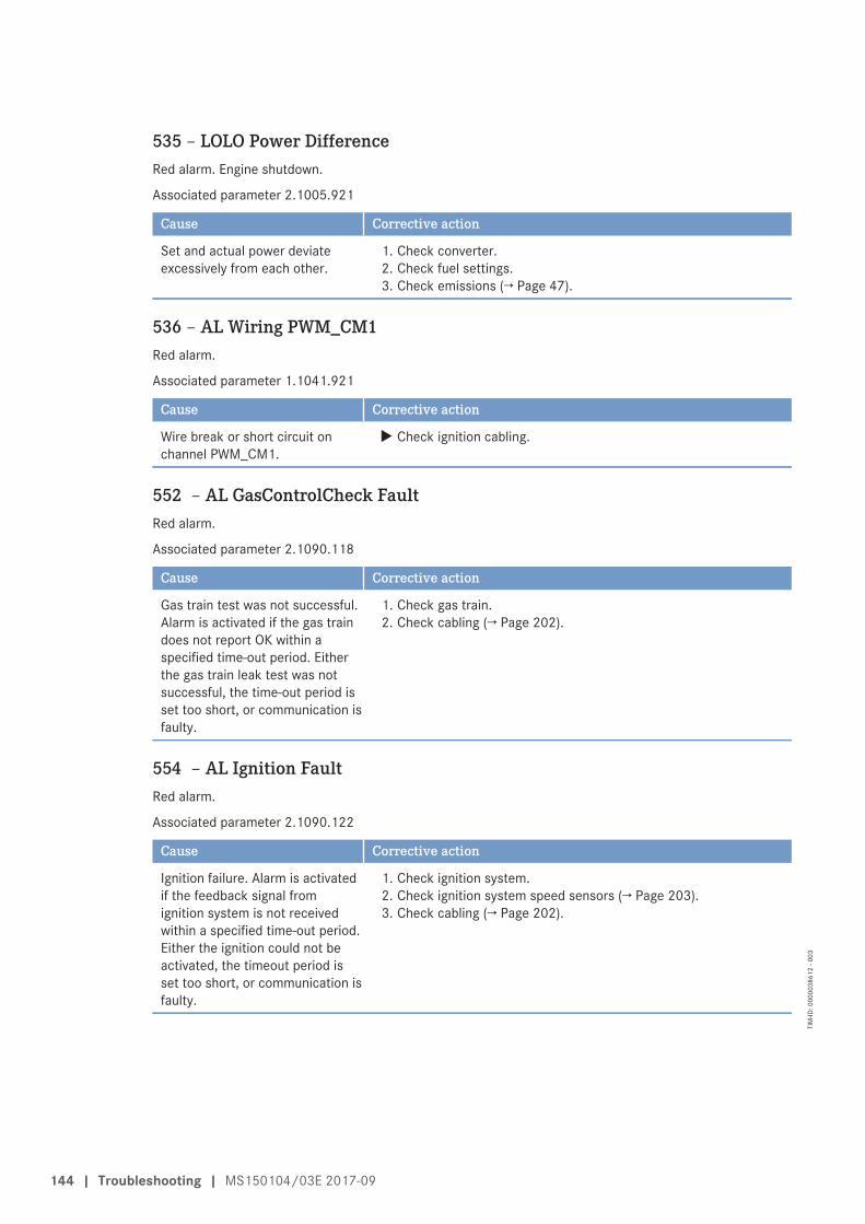
535 – LOLO Power DifferenceRed alarm. Engine shutdown.
Associated parameter 2.1005.921
Cause Corrective action
Set and actual power deviateexcessively from each other.
1. Check converter.2. Check fuel settings.3. Check emissions (→ Page 47).
536 – AL Wiring PWM_CM1Red alarm.
Associated parameter 1.1041.921
Cause Corrective action
Wire break or short circuit onchannel PWM_CM1.
u Check ignition cabling.
552 – AL GasControlCheck FaultRed alarm.
Associated parameter 2.1090.118
Cause Corrective action
Gas train test was not successful.Alarm is activated if the gas traindoes not report OK within aspecified time-out period. Eitherthe gas train leak test was notsuccessful, the time-out period isset too short, or communication isfaulty.
1. Check gas train.2. Check cabling (→ Page 202).
554 – AL Ignition FaultRed alarm.
Associated parameter 2.1090.122
Cause Corrective action
Ignition failure. Alarm is activatedif the feedback signal fromignition system is not receivedwithin a specified time-out period.Either the ignition could not beactivated, the timeout period isset too short, or communication isfaulty.
1. Check ignition system.2. Check ignition system speed sensors (→ Page 203).3. Check cabling (→ Page 202).
144 | Troubleshooting | MS150104/03E 2017-09
TIM
-ID: 0
0000
3861
2 - 0
03
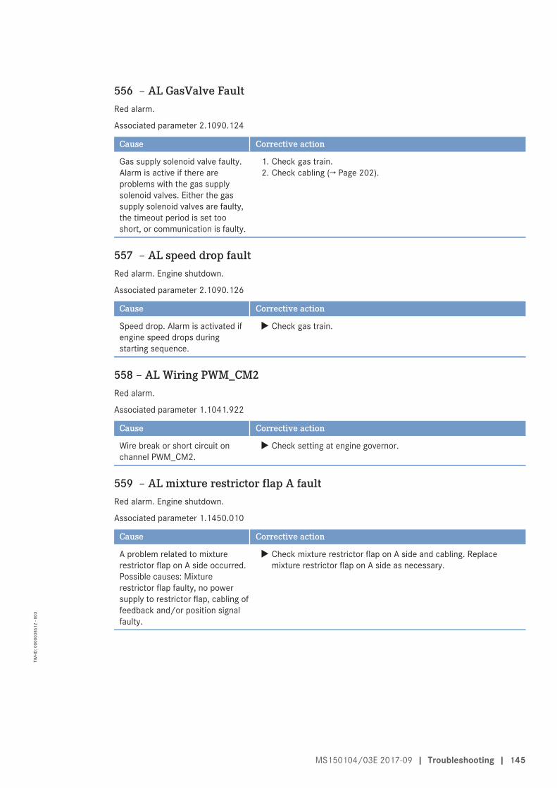
556 – AL GasValve FaultRed alarm.
Associated parameter 2.1090.124
Cause Corrective action
Gas supply solenoid valve faulty.Alarm is active if there areproblems with the gas supplysolenoid valves. Either the gassupply solenoid valves are faulty,the timeout period is set tooshort, or communication is faulty.
1. Check gas train.2. Check cabling (→ Page 202).
557 – AL speed drop faultRed alarm. Engine shutdown.
Associated parameter 2.1090.126
Cause Corrective action
Speed drop. Alarm is activated ifengine speed drops duringstarting sequence.
u Check gas train.
558 – AL Wiring PWM_CM2Red alarm.
Associated parameter 1.1041.922
Cause Corrective action
Wire break or short circuit onchannel PWM_CM2.
u Check setting at engine governor.
559 – AL mixture restrictor flap A faultRed alarm. Engine shutdown.
Associated parameter 1.1450.010
Cause Corrective action
A problem related to mixturerestrictor flap on A side occurred.Possible causes: Mixturerestrictor flap faulty, no powersupply to restrictor flap, cabling offeedback and/or position signalfaulty.
u Check mixture restrictor flap on A side and cabling. Replacemixture restrictor flap on A side as necessary.
MS150104/03E 2017-09 | Troubleshooting | 145
TIM
-ID: 0
0000
3861
2 - 0
03
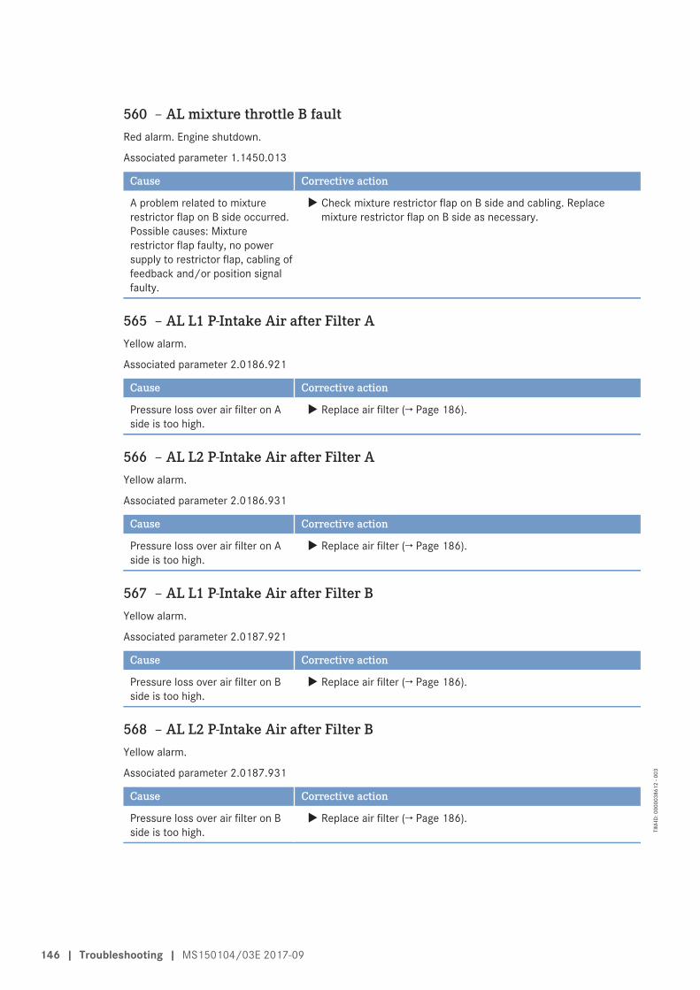
560 – AL mixture throttle B faultRed alarm. Engine shutdown.
Associated parameter 1.1450.013
Cause Corrective action
A problem related to mixturerestrictor flap on B side occurred.Possible causes: Mixturerestrictor flap faulty, no powersupply to restrictor flap, cabling offeedback and/or position signalfaulty.
u Check mixture restrictor flap on B side and cabling. Replacemixture restrictor flap on B side as necessary.
565 – AL L1 P-Intake Air after Filter AYellow alarm.
Associated parameter 2.0186.921
Cause Corrective action
Pressure loss over air filter on Aside is too high.
u Replace air filter (→ Page 186).
566 – AL L2 P-Intake Air after Filter AYellow alarm.
Associated parameter 2.0186.931
Cause Corrective action
Pressure loss over air filter on Aside is too high.
u Replace air filter (→ Page 186).
567 – AL L1 P-Intake Air after Filter BYellow alarm.
Associated parameter 2.0187.921
Cause Corrective action
Pressure loss over air filter on Bside is too high.
u Replace air filter (→ Page 186).
568 – AL L2 P-Intake Air after Filter BYellow alarm.
Associated parameter 2.0187.931
Cause Corrective action
Pressure loss over air filter on Bside is too high.
u Replace air filter (→ Page 186).
146 | Troubleshooting | MS150104/03E 2017-09
TIM
-ID: 0
0000
3861
2 - 0
03
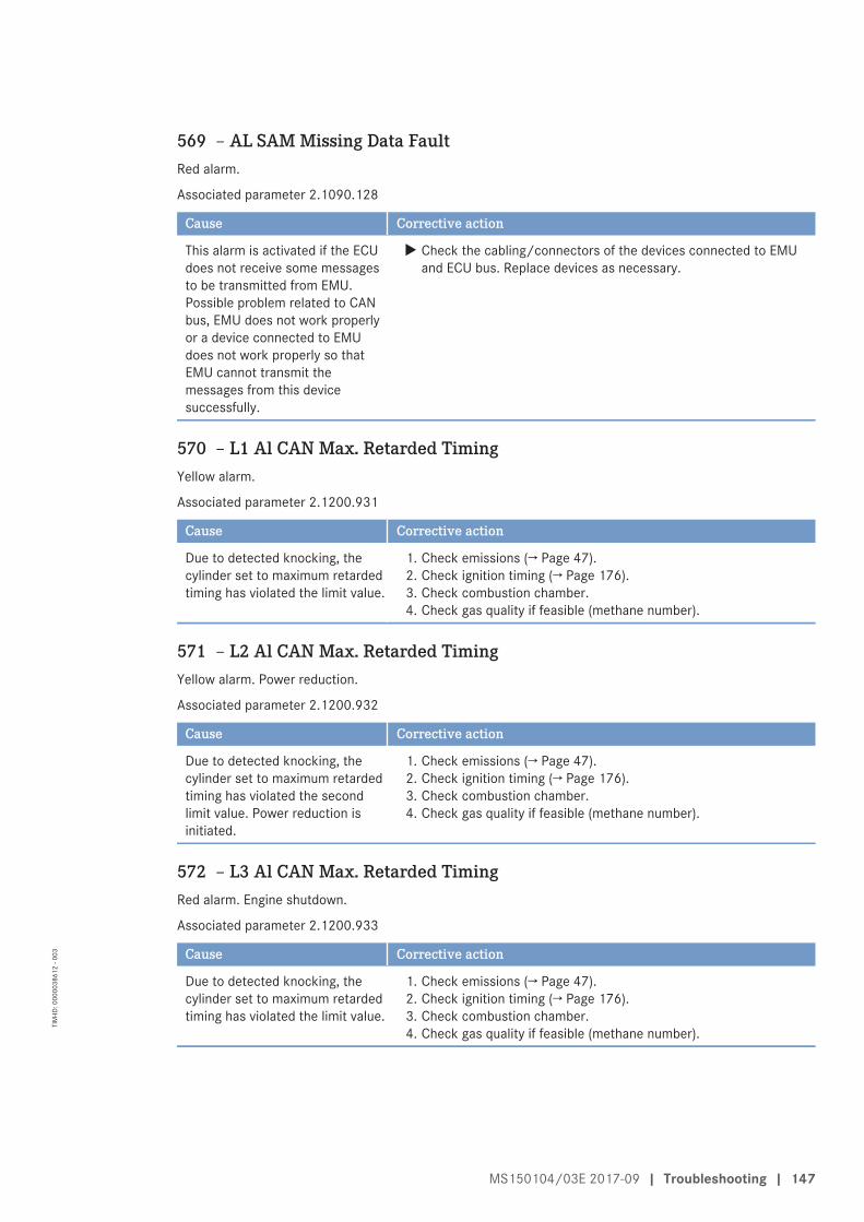
569 – AL SAM Missing Data FaultRed alarm.
Associated parameter 2.1090.128
Cause Corrective action
This alarm is activated if the ECUdoes not receive some messagesto be transmitted from EMU.Possible problem related to CANbus, EMU does not work properlyor a device connected to EMUdoes not work properly so thatEMU cannot transmit themessages from this devicesuccessfully.
u Check the cabling/connectors of the devices connected to EMUand ECU bus. Replace devices as necessary.
570 – L1 Al CAN Max. Retarded TimingYellow alarm.
Associated parameter 2.1200.931
Cause Corrective action
Due to detected knocking, thecylinder set to maximum retardedtiming has violated the limit value.
1. Check emissions (→ Page 47).2. Check ignition timing (→ Page 176).3. Check combustion chamber.4. Check gas quality if feasible (methane number).
571 – L2 Al CAN Max. Retarded TimingYellow alarm. Power reduction.
Associated parameter 2.1200.932
Cause Corrective action
Due to detected knocking, thecylinder set to maximum retardedtiming has violated the secondlimit value. Power reduction isinitiated.
1. Check emissions (→ Page 47).2. Check ignition timing (→ Page 176).3. Check combustion chamber.4. Check gas quality if feasible (methane number).
572 – L3 Al CAN Max. Retarded TimingRed alarm. Engine shutdown.
Associated parameter 2.1200.933
Cause Corrective action
Due to detected knocking, thecylinder set to maximum retardedtiming has violated the limit value.
1. Check emissions (→ Page 47).2. Check ignition timing (→ Page 176).3. Check combustion chamber.4. Check gas quality if feasible (methane number).
MS150104/03E 2017-09 | Troubleshooting | 147
TIM
-ID: 0
0000
3861
2 - 0
03
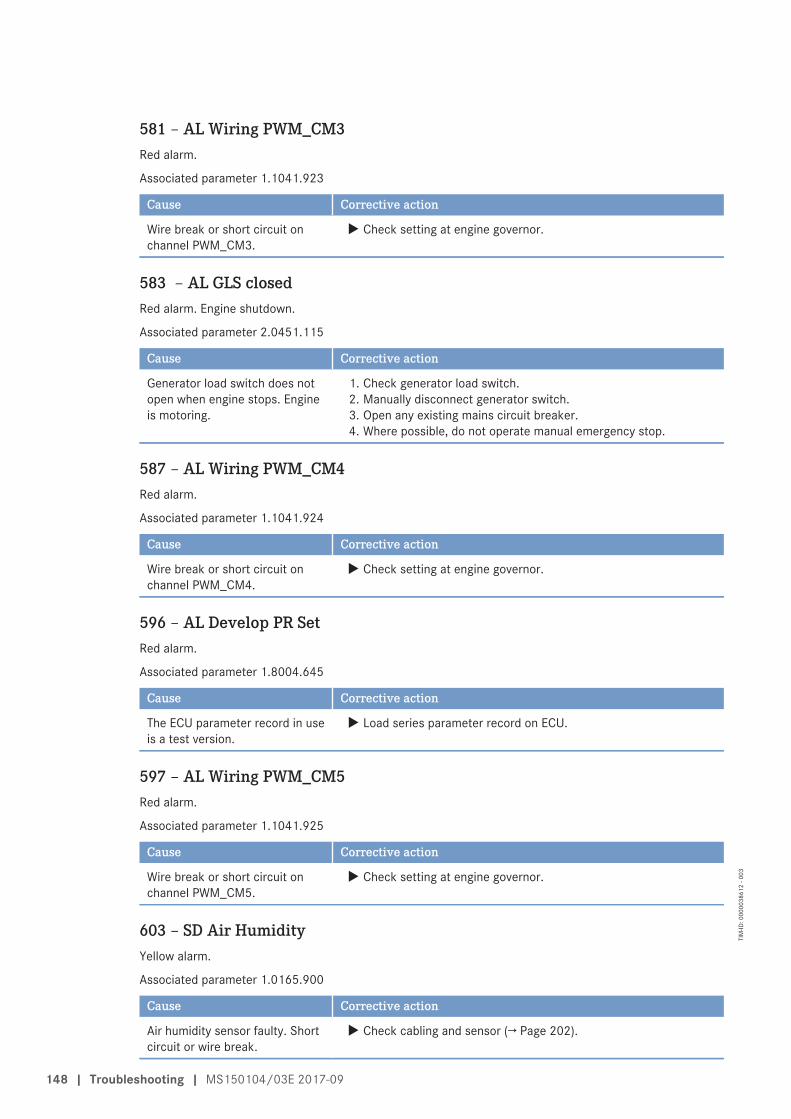
581 – AL Wiring PWM_CM3Red alarm.
Associated parameter 1.1041.923
Cause Corrective action
Wire break or short circuit onchannel PWM_CM3.
u Check setting at engine governor.
583 – AL GLS closedRed alarm. Engine shutdown.
Associated parameter 2.0451.115
Cause Corrective action
Generator load switch does notopen when engine stops. Engineis motoring.
1. Check generator load switch.2. Manually disconnect generator switch.3. Open any existing mains circuit breaker.4. Where possible, do not operate manual emergency stop.
587 – AL Wiring PWM_CM4Red alarm.
Associated parameter 1.1041.924
Cause Corrective action
Wire break or short circuit onchannel PWM_CM4.
u Check setting at engine governor.
596 – AL Develop PR SetRed alarm.
Associated parameter 1.8004.645
Cause Corrective action
The ECU parameter record in useis a test version.
u Load series parameter record on ECU.
597 – AL Wiring PWM_CM5Red alarm.
Associated parameter 1.1041.925
Cause Corrective action
Wire break or short circuit onchannel PWM_CM5.
u Check setting at engine governor.
603 – SD Air HumidityYellow alarm.
Associated parameter 1.0165.900
Cause Corrective action
Air humidity sensor faulty. Shortcircuit or wire break.
u Check cabling and sensor (→ Page 202).
148 | Troubleshooting | MS150104/03E 2017-09
TIM
-ID: 0
0000
3861
2 - 0
03
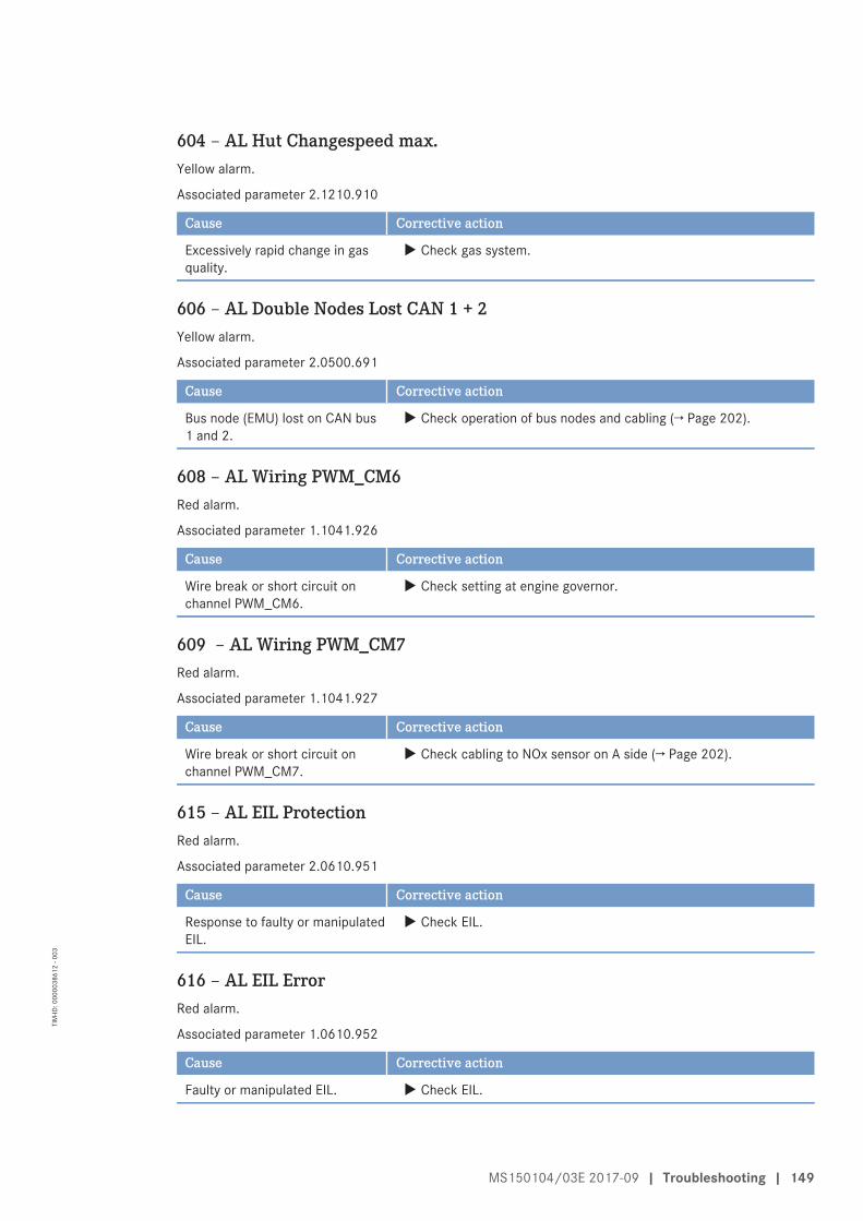
604 – AL Hut Changespeed max.Yellow alarm.
Associated parameter 2.1210.910
Cause Corrective action
Excessively rapid change in gasquality.
u Check gas system.
606 – AL Double Nodes Lost CAN 1 + 2Yellow alarm.
Associated parameter 2.0500.691
Cause Corrective action
Bus node (EMU) lost on CAN bus1 and 2.
u Check operation of bus nodes and cabling (→ Page 202).
608 – AL Wiring PWM_CM6Red alarm.
Associated parameter 1.1041.926
Cause Corrective action
Wire break or short circuit onchannel PWM_CM6.
u Check setting at engine governor.
609 – AL Wiring PWM_CM7Red alarm.
Associated parameter 1.1041.927
Cause Corrective action
Wire break or short circuit onchannel PWM_CM7.
u Check cabling to NOx sensor on A side (→ Page 202).
615 – AL EIL ProtectionRed alarm.
Associated parameter 2.0610.951
Cause Corrective action
Response to faulty or manipulatedEIL.
u Check EIL.
616 – AL EIL ErrorRed alarm.
Associated parameter 1.0610.952
Cause Corrective action
Faulty or manipulated EIL. u Check EIL.
MS150104/03E 2017-09 | Troubleshooting | 149
TIM
-ID: 0
0000
3861
2 - 0
03
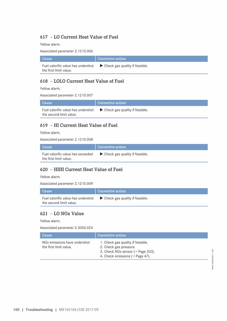
617 – LO Current Heat Value of FuelYellow alarm.
Associated parameter 2.1210.006
Cause Corrective action
Fuel calorific value has undershotthe first limit value.
u Check gas quality if feasible.
618 – LOLO Current Heat Value of FuelYellow alarm.
Associated parameter 2.1210.007
Cause Corrective action
Fuel calorific value has undershotthe second limit value.
u Check gas quality if feasible.
619 – HI Current Heat Value of FuelYellow alarm.
Associated parameter 2.1210.008
Cause Corrective action
Fuel calorific value has exceededthe first limit value.
u Check gas quality if feasible.
620 – HIHI Current Heat Value of FuelYellow alarm.
Associated parameter 2.1210.009
Cause Corrective action
Fuel calorific value has undershotthe second limit value.
u Check gas quality if feasible.
621 – LO NOx ValueYellow alarm.
Associated parameter 2.3050.024
Cause Corrective action
NOx emissions have undershotthe first limit value.
1. Check gas quality if feasible.2. Check gas pressure.3. Check NOx sensor (→ Page 203).4. Check emissions (→ Page 47).
150 | Troubleshooting | MS150104/03E 2017-09
TIM
-ID: 0
0000
3861
2 - 0
03
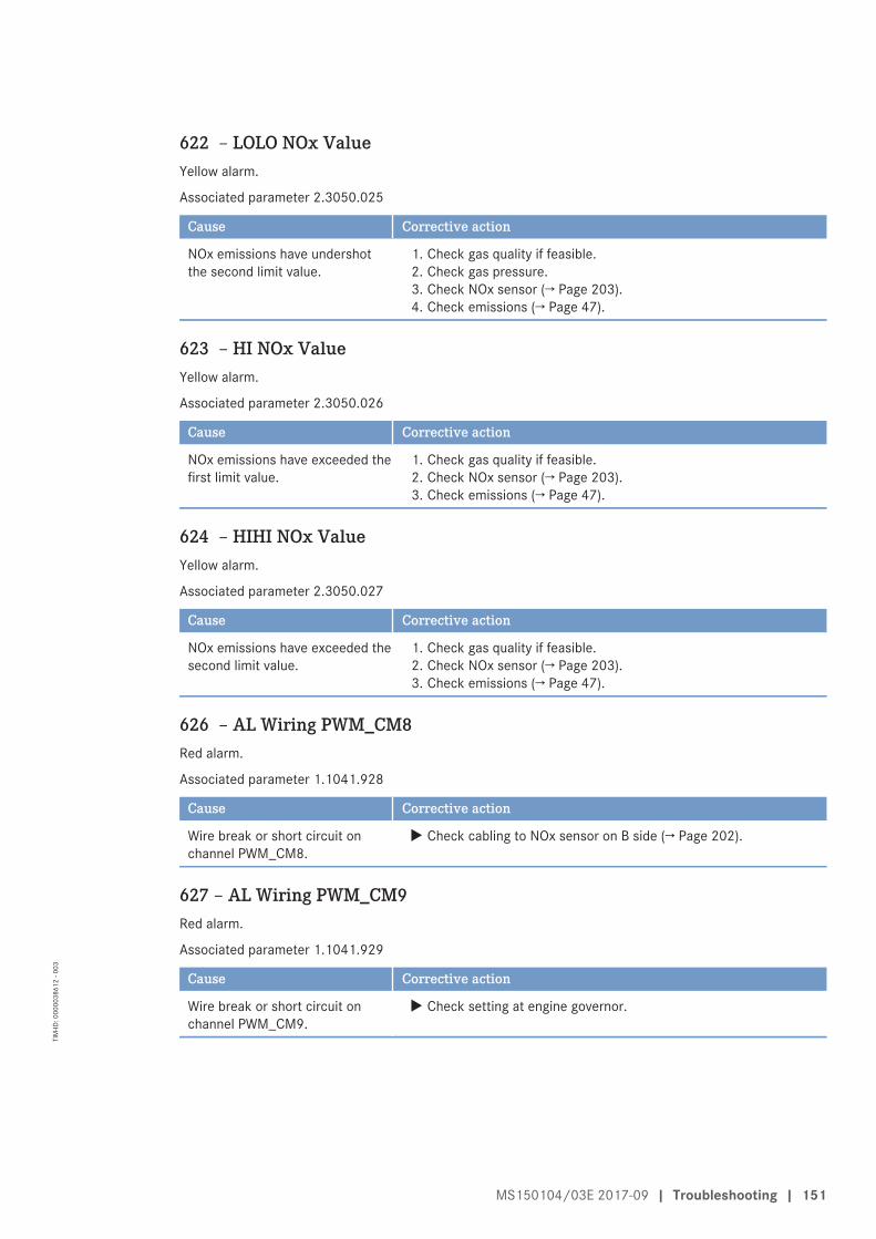
622 – LOLO NOx ValueYellow alarm.
Associated parameter 2.3050.025
Cause Corrective action
NOx emissions have undershotthe second limit value.
1. Check gas quality if feasible.2. Check gas pressure.3. Check NOx sensor (→ Page 203).4. Check emissions (→ Page 47).
623 – HI NOx ValueYellow alarm.
Associated parameter 2.3050.026
Cause Corrective action
NOx emissions have exceeded thefirst limit value.
1. Check gas quality if feasible.2. Check NOx sensor (→ Page 203).3. Check emissions (→ Page 47).
624 – HIHI NOx ValueYellow alarm.
Associated parameter 2.3050.027
Cause Corrective action
NOx emissions have exceeded thesecond limit value.
1. Check gas quality if feasible.2. Check NOx sensor (→ Page 203).3. Check emissions (→ Page 47).
626 – AL Wiring PWM_CM8Red alarm.
Associated parameter 1.1041.928
Cause Corrective action
Wire break or short circuit onchannel PWM_CM8.
u Check cabling to NOx sensor on B side (→ Page 202).
627 – AL Wiring PWM_CM9Red alarm.
Associated parameter 1.1041.929
Cause Corrective action
Wire break or short circuit onchannel PWM_CM9.
u Check setting at engine governor.
MS150104/03E 2017-09 | Troubleshooting | 151
TIM
-ID: 0
0000
3861
2 - 0
03
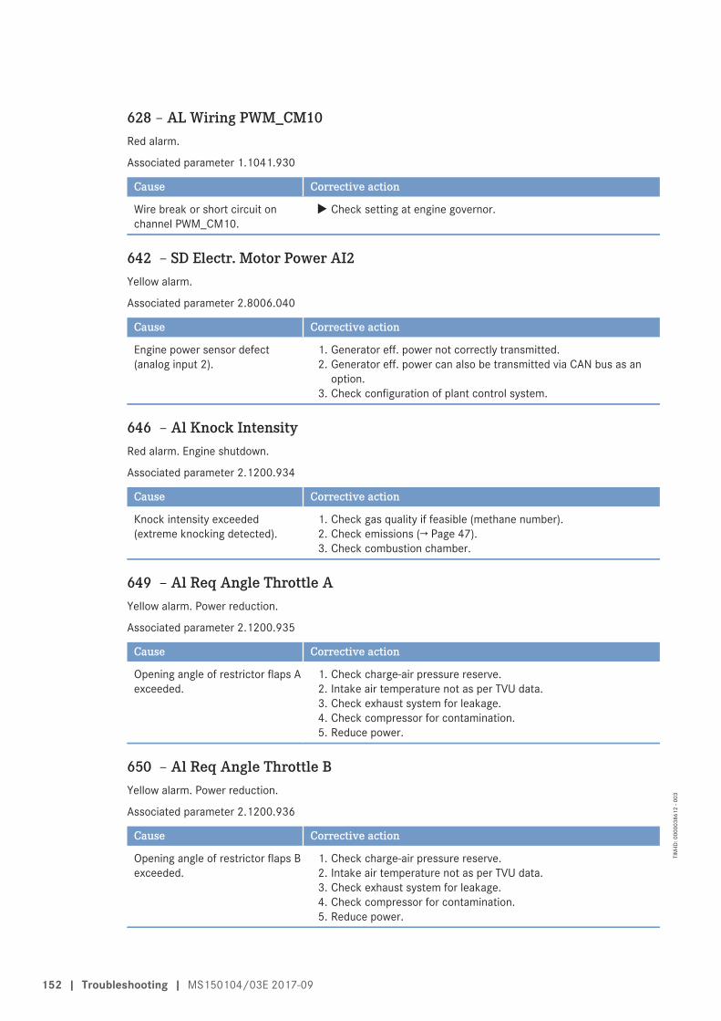
628 – AL Wiring PWM_CM10Red alarm.
Associated parameter 1.1041.930
Cause Corrective action
Wire break or short circuit onchannel PWM_CM10.
u Check setting at engine governor.
642 – SD Electr. Motor Power AI2Yellow alarm.
Associated parameter 2.8006.040
Cause Corrective action
Engine power sensor defect(analog input 2).
1. Generator eff. power not correctly transmitted.2. Generator eff. power can also be transmitted via CAN bus as an
option.3. Check configuration of plant control system.
646 – Al Knock IntensityRed alarm. Engine shutdown.
Associated parameter 2.1200.934
Cause Corrective action
Knock intensity exceeded(extreme knocking detected).
1. Check gas quality if feasible (methane number).2. Check emissions (→ Page 47).3. Check combustion chamber.
649 – Al Req Angle Throttle AYellow alarm. Power reduction.
Associated parameter 2.1200.935
Cause Corrective action
Opening angle of restrictor flaps Aexceeded.
1. Check charge-air pressure reserve.2. Intake air temperature not as per TVU data.3. Check exhaust system for leakage.4. Check compressor for contamination.5. Reduce power.
650 – Al Req Angle Throttle BYellow alarm. Power reduction.
Associated parameter 2.1200.936
Cause Corrective action
Opening angle of restrictor flaps Bexceeded.
1. Check charge-air pressure reserve.2. Intake air temperature not as per TVU data.3. Check exhaust system for leakage.4. Check compressor for contamination.5. Reduce power.
152 | Troubleshooting | MS150104/03E 2017-09
TIM
-ID: 0
0000
3861
2 - 0
03
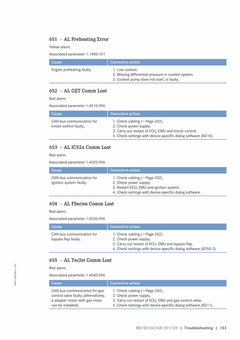
651 – AL Preheating ErrorYellow alarm.
Associated parameter 1.1480.101
Cause Corrective action
Engine preheating faulty. 1. Low coolant.2. Missing differential pressure in coolant system.3. Coolant pump does not start, is faulty.
652 – AL GET Comm LostRed alarm.
Associated parameter 1.4510.996
Cause Corrective action
CAN bus communication forknock control faulty.
1. Check cabling (→ Page 202).2. Check power supply.3. Carry out restart of ECU, EMU and knock control.4. Check settings with device-specific dialog software (XD10).
653 – AL IC92x Comm LostRed alarm.
Associated parameter 1.4520.996
Cause Corrective action
CAN bus communication forignition system faulty.
1. Check cabling (→ Page 202).2. Check power supply.3. Restart ECU, EMU and ignition system.4. Check settings with device-specific dialog software.
654 – AL FSeries Comm LostRed alarm.
Associated parameter 1.4530.996
Cause Corrective action
CAN bus communication forbypass flap faulty.
1. Check cabling (→ Page 202).2. Check power supply.3. Carry out restart of ECU, EMU and bypass flap.4. Check settings with device-specific dialog software (XD50.3).
655 – AL TecJet Comm LostRed alarm.
Associated parameter 1.4540.996
Cause Corrective action
CAN bus communication for gascontrol valve faulty (alternatively,a stepper motor with gas mixercan be installed).
1. Check cabling (→ Page 202).2. Check power supply.3. Carry out restart of ECU, EMU and gas control valve.4. Check settings with device-specific dialog software (XD11).
MS150104/03E 2017-09 | Troubleshooting | 153
TIM
-ID: 0
0000
3861
2 - 0
03
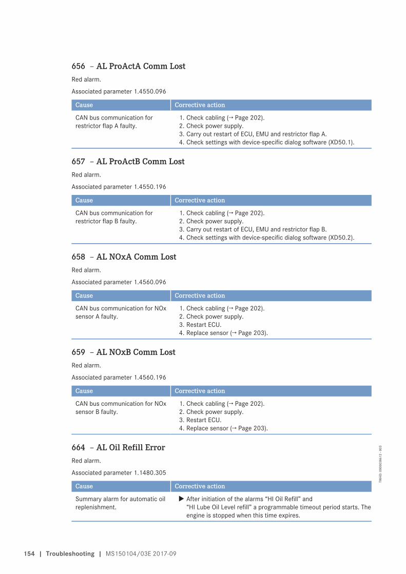
656 – AL ProActA Comm LostRed alarm.
Associated parameter 1.4550.096
Cause Corrective action
CAN bus communication forrestrictor flap A faulty.
1. Check cabling (→ Page 202).2. Check power supply.3. Carry out restart of ECU, EMU and restrictor flap A.4. Check settings with device-specific dialog software (XD50.1).
657 – AL ProActB Comm LostRed alarm.
Associated parameter 1.4550.196
Cause Corrective action
CAN bus communication forrestrictor flap B faulty.
1. Check cabling (→ Page 202).2. Check power supply.3. Carry out restart of ECU, EMU and restrictor flap B.4. Check settings with device-specific dialog software (XD50.2).
658 – AL NOxA Comm LostRed alarm.
Associated parameter 1.4560.096
Cause Corrective action
CAN bus communication for NOxsensor A faulty.
1. Check cabling (→ Page 202).2. Check power supply.3. Restart ECU.4. Replace sensor (→ Page 203).
659 – AL NOxB Comm LostRed alarm.
Associated parameter 1.4560.196
Cause Corrective action
CAN bus communication for NOxsensor B faulty.
1. Check cabling (→ Page 202).2. Check power supply.3. Restart ECU.4. Replace sensor (→ Page 203).
664 – AL Oil Refill ErrorRed alarm.
Associated parameter 1.1480.305
Cause Corrective action
Summary alarm for automatic oilreplenishment.
u After initiation of the alarms “HI Oil Refill” and“HI Lube Oil Level refill” a programmable timeout period starts. Theengine is stopped when this time expires.
154 | Troubleshooting | MS150104/03E 2017-09
TIM
-ID: 0
0000
3861
2 - 0
03
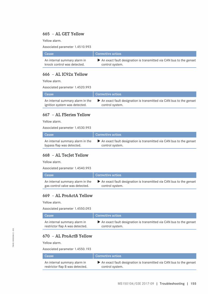
665 – AL GET YellowYellow alarm.
Associated parameter 1.4510.993
Cause Corrective action
An internal summary alarm inknock control was detected.
u An exact fault designation is transmitted via CAN bus to the gensetcontrol system.
666 – AL IC92x YellowYellow alarm.
Associated parameter 1.4520.993
Cause Corrective action
An internal summary alarm in theignition system was detected.
u An exact fault designation is transmitted via CAN bus to the gensetcontrol system.
667 – AL FSeries YellowYellow alarm.
Associated parameter 1.4530.993
Cause Corrective action
An internal summary alarm in thebypass flap was detected.
u An exact fault designation is transmitted via CAN bus to the gensetcontrol system.
668 – AL TecJet YellowYellow alarm.
Associated parameter 1.4540.993
Cause Corrective action
An internal summary alarm in thegas control valve was detected.
u An exact fault designation is transmitted via CAN bus to the gensetcontrol system.
669 – AL ProActA YellowYellow alarm.
Associated parameter 1.4550.093
Cause Corrective action
An internal summary alarm inrestrictor flap A was detected.
u An exact fault designation is transmitted via CAN bus to the gensetcontrol system.
670 – AL ProActB YellowYellow alarm.
Associated parameter 1.4550.193
Cause Corrective action
An internal summary alarm inrestrictor flap B was detected.
u An exact fault designation is transmitted via CAN bus to the gensetcontrol system.
MS150104/03E 2017-09 | Troubleshooting | 155
TIM
-ID: 0
0000
3861
2 - 0
03
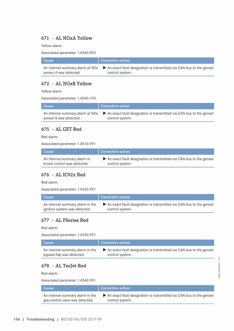
671 – AL NOxA YellowYellow alarm.
Associated parameter 1.4560.093
Cause Corrective action
An internal summary alarm at NOxsensor A was detected.
u An exact fault designation is transmitted via CAN bus to the gensetcontrol system.
672 – AL NOxB YellowYellow alarm.
Associated parameter 1.4560.193
Cause Corrective action
An internal summary alarm at NOxsensor B was detected.
u An exact fault designation is transmitted via CAN bus to the gensetcontrol system.
675 – AL GET RedRed alarm.
Associated parameter 1.4510.991
Cause Corrective action
An internal summary alarm inknock control was detected.
u An exact fault designation is transmitted via CAN bus to the gensetcontrol system.
676 – AL IC92x RedRed alarm.
Associated parameter 1.4520.991
Cause Corrective action
An internal summary alarm in theignition system was detected.
u An exact fault designation is transmitted via CAN bus to the gensetcontrol system.
677 – AL FSeries RedRed alarm.
Associated parameter 1.4530.991
Cause Corrective action
An internal summary alarm in thebypass flap was detected.
u An exact fault designation is transmitted via CAN bus to the gensetcontrol system.
678 – AL TecJet RedRed alarm.
Associated parameter 1.4540.991
Cause Corrective action
An internal summary alarm in thegas control valve was detected.
u An exact fault designation is transmitted via CAN bus to the gensetcontrol system.
156 | Troubleshooting | MS150104/03E 2017-09
TIM
-ID: 0
0000
3861
2 - 0
03
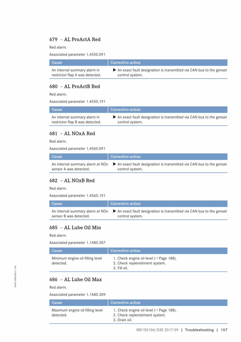
679 – AL ProActA RedRed alarm.
Associated parameter 1.4550.091
Cause Corrective action
An internal summary alarm inrestrictor flap A was detected.
u An exact fault designation is transmitted via CAN bus to the gensetcontrol system.
680 – AL ProActB RedRed alarm.
Associated parameter 1.4550.191
Cause Corrective action
An internal summary alarm inrestrictor flap B was detected.
u An exact fault designation is transmitted via CAN bus to the gensetcontrol system.
681 – AL NOxA RedRed alarm.
Associated parameter 1.4560.091
Cause Corrective action
An internal summary alarm at NOxsensor A was detected.
u An exact fault designation is transmitted via CAN bus to the gensetcontrol system.
682 – AL NOxB RedRed alarm.
Associated parameter 1.4560.191
Cause Corrective action
An internal summary alarm at NOxsensor B was detected.
u An exact fault designation is transmitted via CAN bus to the gensetcontrol system.
685 – AL Lube Oil MinRed alarm.
Associated parameter 1.1480.307
Cause Corrective action
Minimum engine oil filling leveldetected.
1. Check engine oil level (→ Page 188).2. Check replenishment system.3. Fill oil.
686 – AL Lube Oil MaxRed alarm.
Associated parameter 1.1480.309
Cause Corrective action
Maximum engine oil filling leveldetected.
1. Check engine oil level (→ Page 188).2. Check replenishment system.3. Drain oil.
MS150104/03E 2017-09 | Troubleshooting | 157
TIM
-ID: 0
0000
3861
2 - 0
03
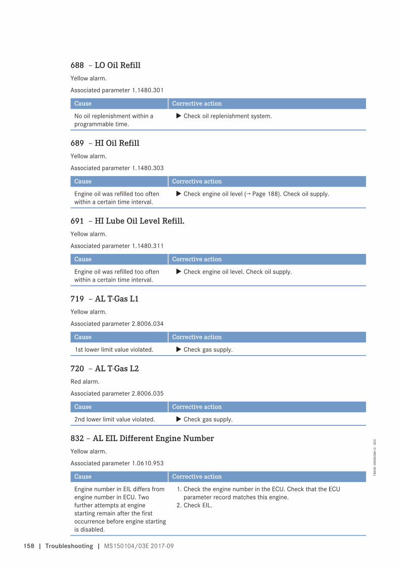
688 – LO Oil RefillYellow alarm.
Associated parameter 1.1480.301
Cause Corrective action
No oil replenishment within aprogrammable time.
u Check oil replenishment system.
689 – HI Oil RefillYellow alarm.
Associated parameter 1.1480.303
Cause Corrective action
Engine oil was refilled too oftenwithin a certain time interval.
u Check engine oil level (→ Page 188). Check oil supply.
691 – HI Lube Oil Level Refill.Yellow alarm.
Associated parameter 1.1480.311
Cause Corrective action
Engine oil was refilled too oftenwithin a certain time interval.
u Check engine oil level. Check oil supply.
719 – AL T-Gas L1Yellow alarm.
Associated parameter 2.8006.034
Cause Corrective action
1st lower limit value violated. u Check gas supply.
720 – AL T-Gas L2Red alarm.
Associated parameter 2.8006.035
Cause Corrective action
2nd lower limit value violated. u Check gas supply.
832 – AL EIL Different Engine NumberYellow alarm.
Associated parameter 1.0610.953
Cause Corrective action
Engine number in EIL differs fromengine number in ECU. Twofurther attempts at enginestarting remain after the firstoccurrence before engine startingis disabled.
1. Check the engine number in the ECU. Check that the ECUparameter record matches this engine.
2. Check EIL.
158 | Troubleshooting | MS150104/03E 2017-09
TIM
-ID: 0
0000
3861
2 - 0
03
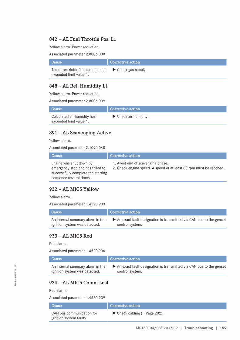
842 – AL Fuel Throttle Pos. L1Yellow alarm. Power reduction.
Associated parameter 2.8006.038
Cause Corrective action
TecJet restrictor flap position hasexceeded limit value 1.
u Check gas supply.
848 – AL Rel. Humidity L1Yellow alarm. Power reduction.
Associated parameter 2.8006.039
Cause Corrective action
Calculated air humidity hasexceeded limit value 1.
u Check air humidity.
891 – AL Scavenging ActiveYellow alarm.
Associated parameter 2.1090.048
Cause Corrective action
Engine was shut down byemergency stop and has failed tosuccessfully complete the startingsequence several times.
1. Await end of scavenging phase.2. Check engine speed. A speed of at least 80 rpm must be reached.
932 – AL MIC5 YellowYellow alarm.
Associated parameter 1.4520.933
Cause Corrective action
An internal summary alarm in theignition system was detected.
u An exact fault designation is transmitted via CAN bus to the gensetcontrol system.
933 – AL MIC5 RedRed alarm.
Associated parameter 1.4520.936
Cause Corrective action
An internal summary alarm in theignition system was detected.
u An exact fault designation is transmitted via CAN bus to the gensetcontrol system.
934 – AL MIC5 Comm LostRed alarm.
Associated parameter 1.4520.939
Cause Corrective action
CAN bus communication forignition system faulty.
u Check cabling (→ Page 202).
MS150104/03E 2017-09 | Troubleshooting | 159
TIM
-ID: 0
0000
3861
2 - 0
03
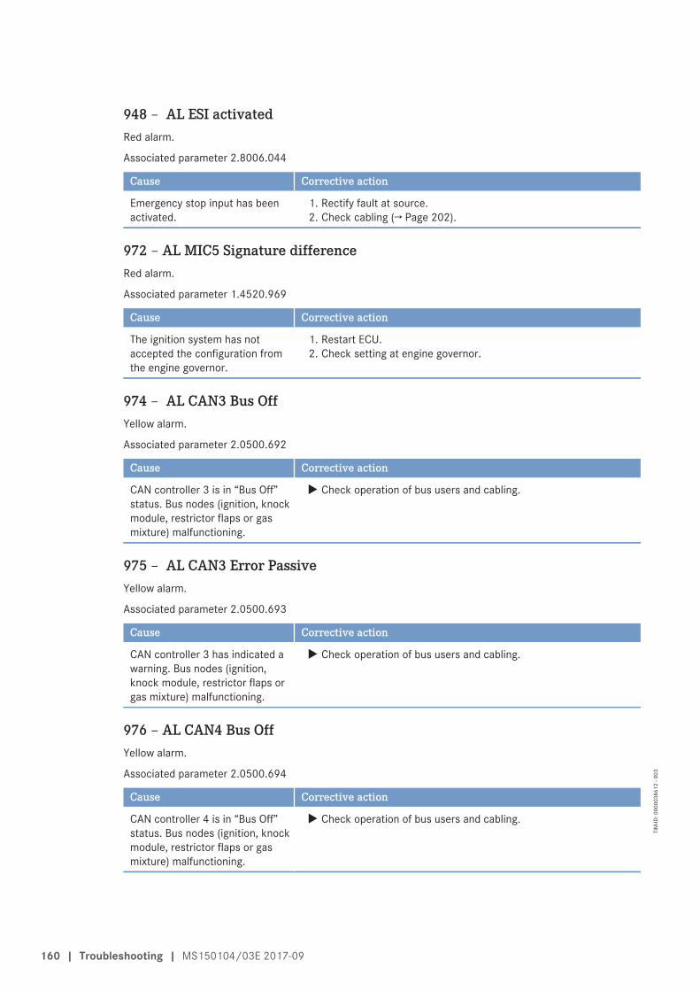
948 – AL ESI activatedRed alarm.
Associated parameter 2.8006.044
Cause Corrective action
Emergency stop input has beenactivated.
1. Rectify fault at source.2. Check cabling (→ Page 202).
972 – AL MIC5 Signature differenceRed alarm.
Associated parameter 1.4520.969
Cause Corrective action
The ignition system has notaccepted the configuration fromthe engine governor.
1. Restart ECU.2. Check setting at engine governor.
974 – AL CAN3 Bus OffYellow alarm.
Associated parameter 2.0500.692
Cause Corrective action
CAN controller 3 is in “Bus Off”status. Bus nodes (ignition, knockmodule, restrictor flaps or gasmixture) malfunctioning.
u Check operation of bus users and cabling.
975 – AL CAN3 Error PassiveYellow alarm.
Associated parameter 2.0500.693
Cause Corrective action
CAN controller 3 has indicated awarning. Bus nodes (ignition,knock module, restrictor flaps orgas mixture) malfunctioning.
u Check operation of bus users and cabling.
976 – AL CAN4 Bus OffYellow alarm.
Associated parameter 2.0500.694
Cause Corrective action
CAN controller 4 is in “Bus Off”status. Bus nodes (ignition, knockmodule, restrictor flaps or gasmixture) malfunctioning.
u Check operation of bus users and cabling.
160 | Troubleshooting | MS150104/03E 2017-09
TIM
-ID: 0
0000
3861
2 - 0
03
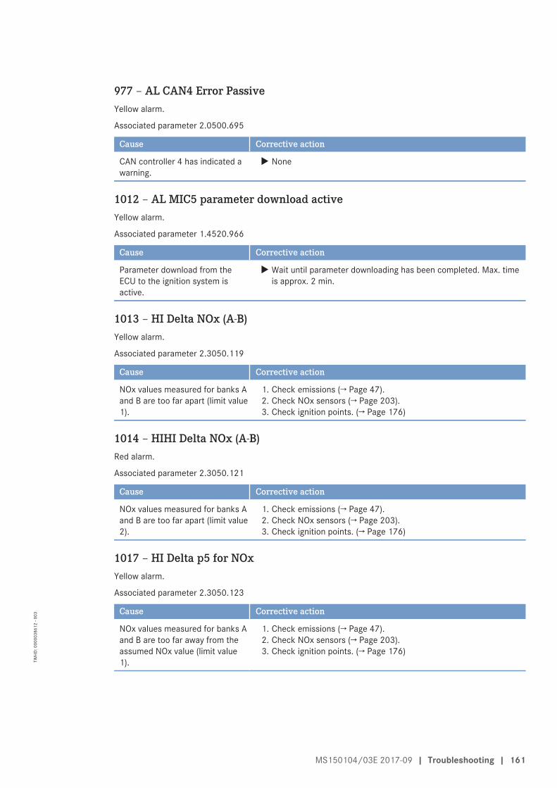
977 – AL CAN4 Error PassiveYellow alarm.
Associated parameter 2.0500.695
Cause Corrective action
CAN controller 4 has indicated awarning.
u None
1012 – AL MIC5 parameter download activeYellow alarm.
Associated parameter 1.4520.966
Cause Corrective action
Parameter download from theECU to the ignition system isactive.
u Wait until parameter downloading has been completed. Max. timeis approx. 2 min.
1013 – HI Delta NOx (A-B)Yellow alarm.
Associated parameter 2.3050.119
Cause Corrective action
NOx values measured for banks Aand B are too far apart (limit value1).
1. Check emissions (→ Page 47).2. Check NOx sensors (→ Page 203).3. Check ignition points. (→ Page 176)
1014 – HIHI Delta NOx (A-B)Red alarm.
Associated parameter 2.3050.121
Cause Corrective action
NOx values measured for banks Aand B are too far apart (limit value2).
1. Check emissions (→ Page 47).2. Check NOx sensors (→ Page 203).3. Check ignition points. (→ Page 176)
1017 – HI Delta p5 for NOxYellow alarm.
Associated parameter 2.3050.123
Cause Corrective action
NOx values measured for banks Aand B are too far away from theassumed NOx value (limit value1).
1. Check emissions (→ Page 47).2. Check NOx sensors (→ Page 203).3. Check ignition points. (→ Page 176)
MS150104/03E 2017-09 | Troubleshooting | 161
TIM
-ID: 0
0000
3861
2 - 0
03
1030 – LO P-Crank CaseYellow alarm.
Associated parameter 2.0106.935
Cause Corrective action
Crankcase pressure too low (limitvalue 1). Restrictor valve incrankcase breather too widelyopen, faulty air filter.
1. Check air filter for damage, replace if damage is visible .2. Check setting of blow-by restrictor valve.
1031 – LOLO P-Crank CaseRed alarm. Engine shutdown.
Associated parameter 2.0106.936
Cause Corrective action
Crankcase pressure too low (limitvalue 2). Restrictor valve incrankcase breather too widelyopen, faulty air filter.
1. Check air filter for damage, replace if damage is visible .2. Check setting of blow-by restrictor valve.
162 | Troubleshooting | MS150104/03E 2017-09
TIM
-ID: 0
0000
3861
2 - 0
03
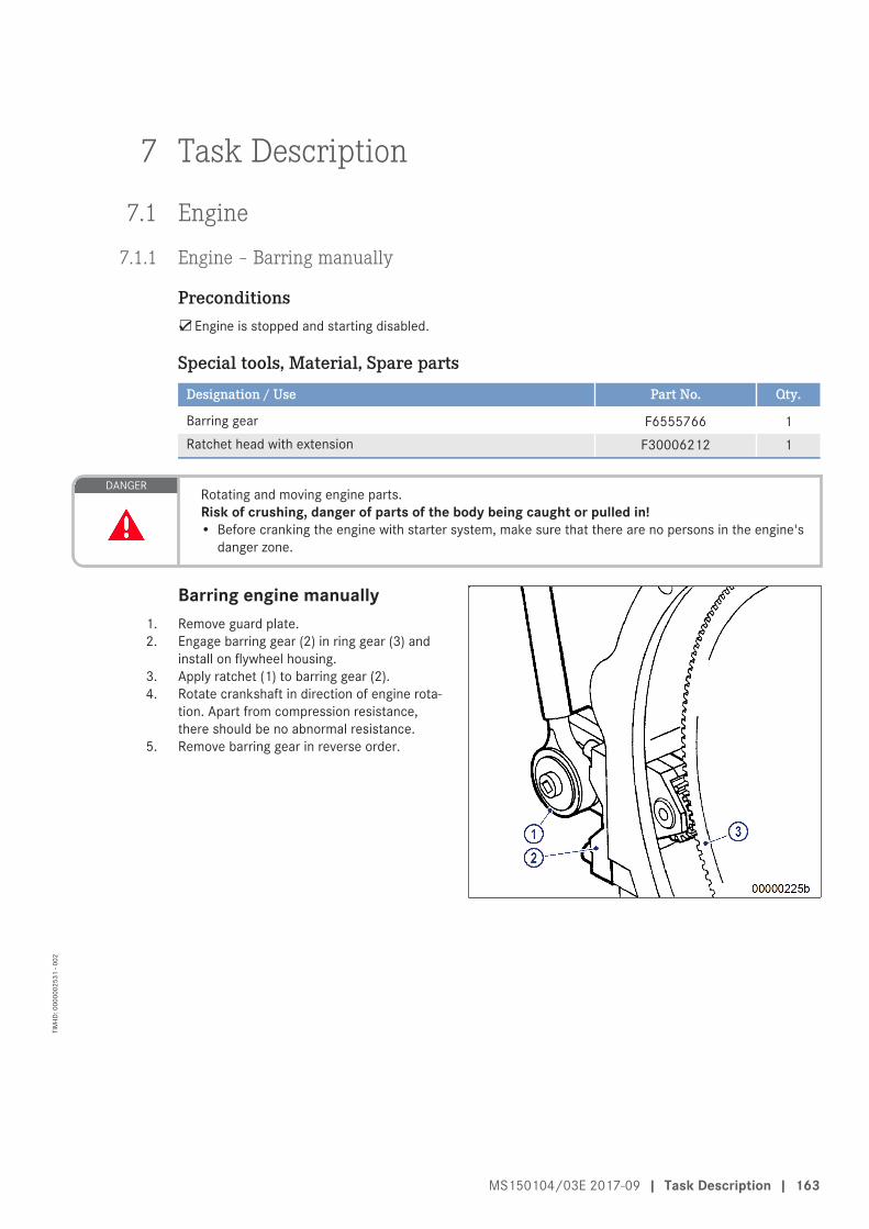
7 Task Description
7.1 Engine
7.1.1 Engine – Barring manually
Preconditions☑Engine is stopped and starting disabled.
Special tools, Material, Spare partsDesignation / Use Part No. Qty.
Barring gear F6555766 1Ratchet head with extension F30006212 1
DANGERRotating and moving engine parts.Risk of crushing, danger of parts of the body being caught or pulled in!• Before cranking the engine with starter system, make sure that there are no persons in the engine's
danger zone.
Barring engine manually1. Remove guard plate.2. Engage barring gear (2) in ring gear (3) and
install on flywheel housing.3. Apply ratchet (1) to barring gear (2).4. Rotate crankshaft in direction of engine rota-
tion. Apart from compression resistance,there should be no abnormal resistance.
5. Remove barring gear in reverse order.
MS150104/03E 2017-09 | Task Description | 163
TIM
-ID: 0
0000
0253
1 - 0
02
7.1.2 Machine room – Check for smell of gas
Special tools, Material, Spare partsDesignation / Use Part No. Qty.
Gas detection and alarm unit (not stocked by MTU)
WARNINGGaseous fuels are combustible/explosive.Risk of fire and explosion!• Avoid open flames, electrical sparks and ignition sources.• Carry gas-warning unit (part of the personal safety equipment).• Do not smoke.
Checking machine room for smell of gas1. Check machine room for smell of gas or localize gas supply leaks using gas detection and alarm unit.2. If smell of gas is detected or the gas detection and alarm unit is triggered:
• Avoid naked flames!• Avoid sparks! Do not use electrical appliances (including switches, connectors/sockets, telephone, bell).• Do not smoke!• Close main gas shutoff device!• Open windows and doors!• Warn residents and leave building!• Call gas supplier from outside the building!
164 | Engine | MS150104/03E 2017-09
TIM
-ID: 0
0000
0253
3 - 0
03
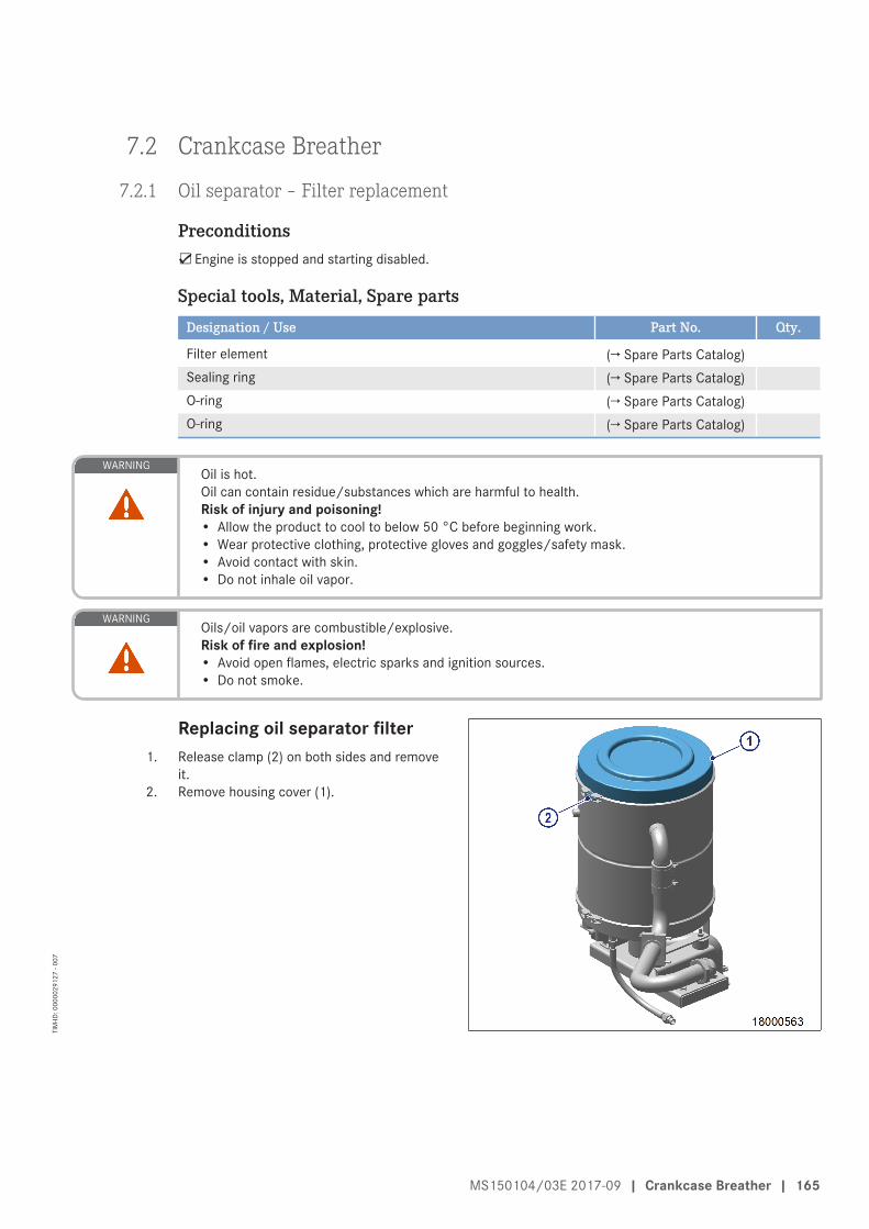
7.2 Crankcase Breather
7.2.1 Oil separator – Filter replacement
Preconditions☑Engine is stopped and starting disabled.
Special tools, Material, Spare partsDesignation / Use Part No. Qty.
Filter element (→ Spare Parts Catalog)Sealing ring (→ Spare Parts Catalog)O-ring (→ Spare Parts Catalog)O-ring (→ Spare Parts Catalog)
WARNINGOil is hot.Oil can contain residue/substances which are harmful to health.Risk of injury and poisoning!• Allow the product to cool to below 50 °C before beginning work.• Wear protective clothing, protective gloves and goggles/safety mask.• Avoid contact with skin.• Do not inhale oil vapor.
WARNINGOils/oil vapors are combustible/explosive.Risk of fire and explosion!• Avoid open flames, electric sparks and ignition sources.• Do not smoke.
Replacing oil separator filter1. Release clamp (2) on both sides and remove
it.2. Remove housing cover (1).
MS150104/03E 2017-09 | Crankcase Breather | 165
TIM
-ID: 0
0000
2912
7 - 0
07
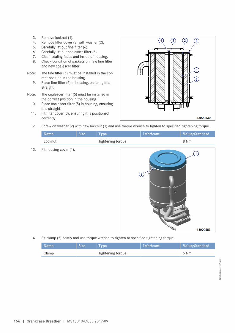
3. Remove locknut (1).4. Remove filter cover (3) with washer (2).5. Carefully lift out fine filter (6).6. Carefully lift out coalescer filter (5).7. Clean sealing faces and inside of housing.8. Check condition of gaskets on new fine filter
and new coalescer filter.
Note: The fine filter (6) must be installed in the cor-rect position in the housing.
9. Place fine filter (6) in housing, ensuring it isstraight.
Note: The coalescer filter (5) must be installed inthe correct position in the housing.
10. Place coalescer filter (5) in housing, ensuringit is straight.
11. Fit filter cover (3), ensuring it is positionedcorrectly.
12. Screw on washer (2) with new locknut (1) and use torque wrench to tighten to specified tightening torque.
Name Size Type Lubricant Value/Standard
Locknut Tightening torque 8 Nm
13. Fit housing cover (1).
14. Fit clamp (2) neatly and use torque wrench to tighten to specified tightening torque.
Name Size Type Lubricant Value/Standard
Clamp Tightening torque 5 Nm
166 | Crankcase Breather | MS150104/03E 2017-09
TIM
-ID: 0
0000
2912
7 - 0
07
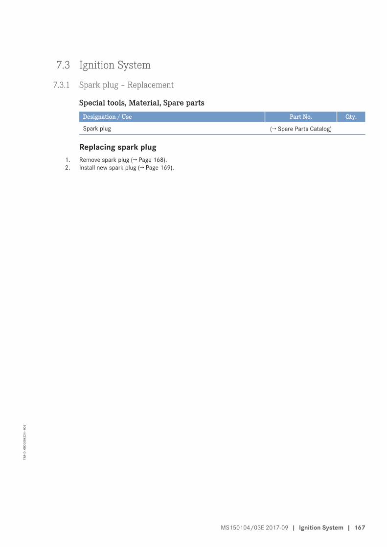
7.3 Ignition System
7.3.1 Spark plug – Replacement
Special tools, Material, Spare partsDesignation / Use Part No. Qty.
Spark plug (→ Spare Parts Catalog)
Replacing spark plug1. Remove spark plug (→ Page 168).2. Install new spark plug (→ Page 169).
MS150104/03E 2017-09 | Ignition System | 167
TIM
-ID: 0
0000
0422
4 - 0
02
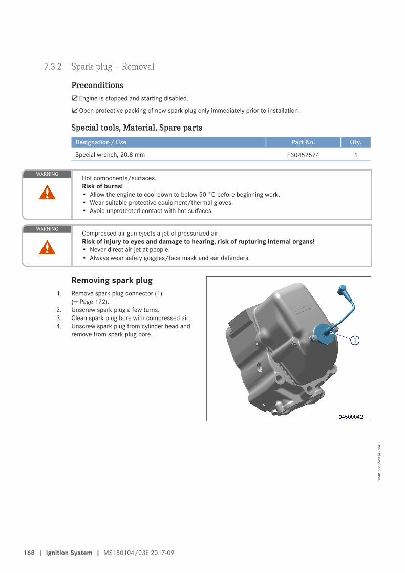
7.3.2 Spark plug – Removal
Preconditions☑Engine is stopped and starting disabled.
☑Open protective packing of new spark plug only immediately prior to installation.
Special tools, Material, Spare partsDesignation / Use Part No. Qty.
Special wrench, 20.8 mm F30452574 1
WARNINGHot components/surfaces.Risk of burns!• Allow the engine to cool down to below 50 °C before beginning work.• Wear suitable protective equipment/thermal gloves.• Avoid unprotected contact with hot surfaces.
WARNINGCompressed air gun ejects a jet of pressurized air.Risk of injury to eyes and damage to hearing, risk of rupturing internal organs!• Never direct air jet at people.• Always wear safety goggles/face mask and ear defenders.
Removing spark plug1. Remove spark plug connector (1)
(→ Page 172).2. Unscrew spark plug a few turns.3. Clean spark plug bore with compressed air.4. Unscrew spark plug from cylinder head and
remove from spark plug bore.
168 | Ignition System | MS150104/03E 2017-09
TIM
-ID: 0
0000
4342
4 - 0
04
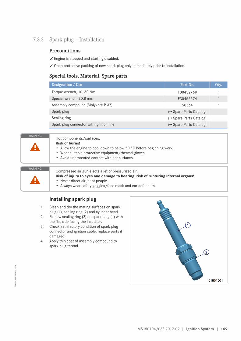
7.3.3 Spark plug – Installation
Preconditions☑Engine is stopped and starting disabled.
☑Open protective packing of new spark plug only immediately prior to installation.
Special tools, Material, Spare partsDesignation / Use Part No. Qty.
Torque wrench, 10–60 Nm F30452769 1Special wrench, 20.8 mm F30452574 1Assembly compound (Molykote P 37) 50564 1Spark plug (→ Spare Parts Catalog)Sealing ring (→ Spare Parts Catalog)Spark plug connector with ignition line (→ Spare Parts Catalog)
WARNINGHot components/surfaces.Risk of burns!• Allow the engine to cool down to below 50 °C before beginning work.• Wear suitable protective equipment/thermal gloves.• Avoid unprotected contact with hot surfaces.
WARNINGCompressed air gun ejects a jet of pressurized air.Risk of injury to eyes and damage to hearing, risk of rupturing internal organs!• Never direct air jet at people.• Always wear safety goggles/face mask and ear defenders.
Installing spark plug1. Clean and dry the mating surfaces on spark
plug (1), sealing ring (2) and cylinder head.2. Fit new sealing ring (2) on spark plug (1) with
the flat side facing the insulator.3. Check satisfactory condition of spark plug
connector and ignition cable, replace parts ifdamaged.
4. Apply thin coat of assembly compound tospark plug thread.
MS150104/03E 2017-09 | Ignition System | 169
TIM
-ID: 0
0000
4342
5 - 0
04
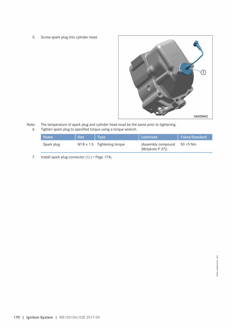
5. Screw spark plug into cylinder head.
Note: The temperature of spark plug and cylinder head must be the same prior to tightening.6. Tighten spark plug to specified torque using a torque wrench.
Name Size Type Lubricant Value/Standard
Spark plug M18 x 1.5 Tightening torque (Assembly compound(Molykote P 37))
50 +5 Nm
7. Install spark plug connector (1) (→ Page 174).
170 | Ignition System | MS150104/03E 2017-09
TIM
-ID: 0
0000
4342
5 - 0
04
7.3.4 Spark plug connector – Replacement
Special tools, Material, Spare partsDesignation / Use Part No. Qty.
Spark plug connector (→ Spare Parts Catalog)
Replacing spark plug connector1. Remove spark plug connector (→ Page 172).2. Install spark plug connector (→ Page 174).
MS150104/03E 2017-09 | Ignition System | 171
TIM
-ID: 0
0000
3589
7 - 0
04
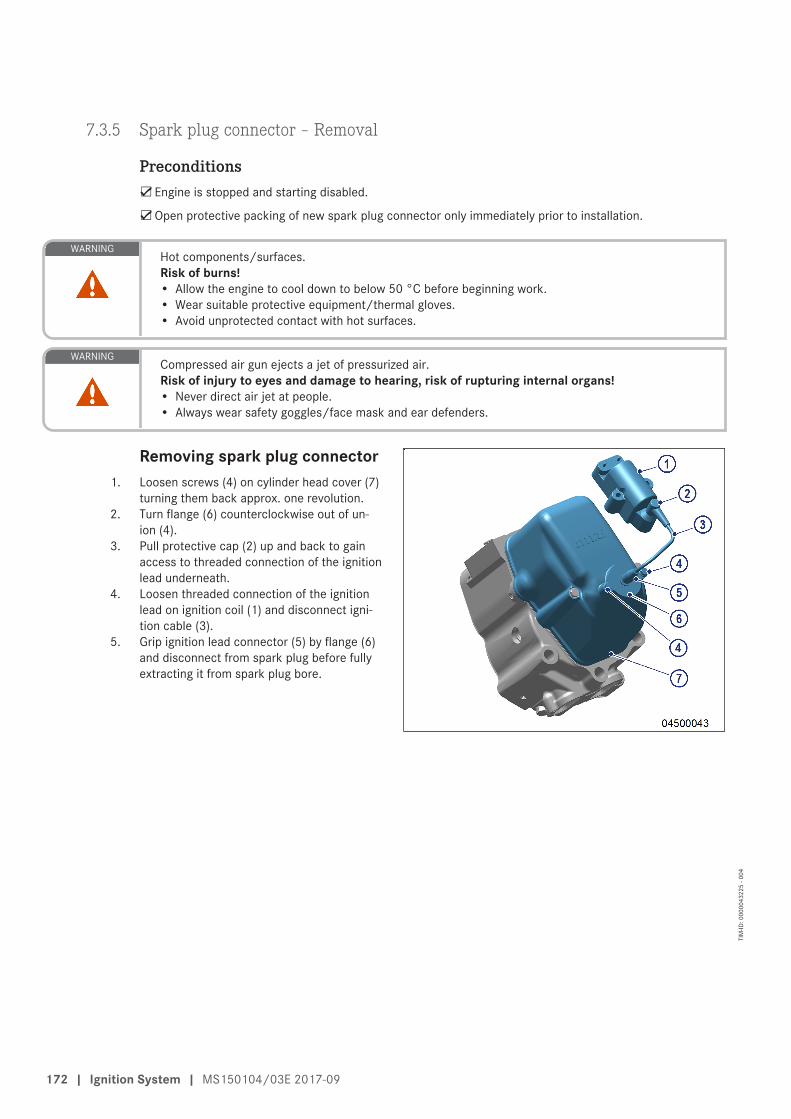
7.3.5 Spark plug connector – Removal
Preconditions☑Engine is stopped and starting disabled.
☑Open protective packing of new spark plug connector only immediately prior to installation.
WARNINGHot components/surfaces.Risk of burns!• Allow the engine to cool down to below 50 °C before beginning work.• Wear suitable protective equipment/thermal gloves.• Avoid unprotected contact with hot surfaces.
WARNINGCompressed air gun ejects a jet of pressurized air.Risk of injury to eyes and damage to hearing, risk of rupturing internal organs!• Never direct air jet at people.• Always wear safety goggles/face mask and ear defenders.
Removing spark plug connector1. Loosen screws (4) on cylinder head cover (7)
turning them back approx. one revolution.2. Turn flange (6) counterclockwise out of un-
ion (4).3. Pull protective cap (2) up and back to gain
access to threaded connection of the ignitionlead underneath.
4. Loosen threaded connection of the ignitionlead on ignition coil (1) and disconnect igni-tion cable (3).
5. Grip ignition lead connector (5) by flange (6)and disconnect from spark plug before fullyextracting it from spark plug bore.
172 | Ignition System | MS150104/03E 2017-09
TIM
-ID: 0
0000
4322
5 - 0
04
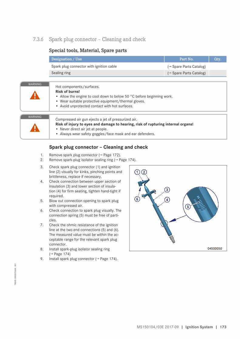
7.3.6 Spark plug connector – Cleaning and check
Special tools, Material, Spare partsDesignation / Use Part No. Qty.
Spark plug connector with ignition cable (→ Spare Parts Catalog)Sealing ring (→ Spare Parts Catalog)
WARNINGHot components/surfaces.Risk of burns!• Allow the engine to cool down to below 50 °C before beginning work.• Wear suitable protective equipment/thermal gloves.• Avoid unprotected contact with hot surfaces.
WARNINGCompressed air gun ejects a jet of pressurized air.Risk of injury to eyes and damage to hearing, risk of rupturing internal organs!• Never direct air jet at people.• Always wear safety goggles/face mask and ear defenders.
Spark plug connector – Cleaning and check1. Remove spark plug connector (→ Page 172).2. Remove spark-plug isolator sealing ring (→ Page 174).
3. Check spark plug connector (1) and ignitionline (2) visually for kinks, pinching points andbrittleness, replace if necessary.
4. Check connection between upper section ofinsulation (3) and lower section of insula-tion (4) for firm seating, tighten hand-tight ifrequired.
5. Blow out connection opening to spark plugwith compressed air.
6. Check connection to spark plug visually. Theconnection spring (5) must be free of parti-cles.
7. Check the ohmic resistance of the ignitionline at the two end connections (5) and (6).The measured value must be within the ac-ceptable range for the relevant spark plugconnector.
8. Install spark-plug isolator sealing ring(→ Page 174)
9. Install spark plug connector (→ Page 174).
MS150104/03E 2017-09 | Ignition System | 173
TIM
-ID: 0
0000
7044
8 - 0
01
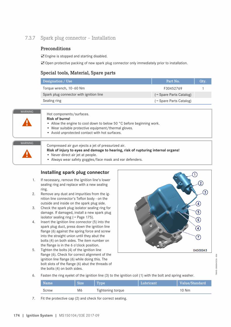
7.3.7 Spark plug connector – Installation
Preconditions☑Engine is stopped and starting disabled.
☑Open protective packing of new spark plug connector only immediately prior to installation.
Special tools, Material, Spare partsDesignation / Use Part No. Qty.
Torque wrench, 10–60 Nm F30452769 1Spark plug connector with ignition line (→ Spare Parts Catalog)Sealing ring (→ Spare Parts Catalog)
WARNINGHot components/surfaces.Risk of burns!• Allow the engine to cool down to below 50 °C before beginning work.• Wear suitable protective equipment/thermal gloves.• Avoid unprotected contact with hot surfaces.
WARNINGCompressed air gun ejects a jet of pressurized air.Risk of injury to eyes and damage to hearing, risk of rupturing internal organs!• Never direct air jet at people.• Always wear safety goggles/face mask and ear defenders.
Installing spark plug connector1. If necessary, remove the ignition line's lower
sealing ring and replace with a new sealingring.
2. Remove any dust and impurities from the ig-nition line connector's Teflon body - on theoutside and inside on the spark plug side.
3. Check the spark plug isolator sealing ring fordamage. If damaged, install a new spark plugisolator sealing ring (→ Page 175).
4. Insert the ignition line connector (5) into thespark plug duct, press down the ignition lineflange (6) against the spring force and screwinto the straight union until they abut thebolts (4) on both sides. The item number onthe flange is in the 6 o'clock position.
5. Tighten the bolts (4) of the ignition lineflange (6). Check for correct alignment of theignition line flange (6) while doing this. Thebolt slots of the flange (6) abut the threads ofthe bolts (4) on both sides.
6. Fasten the ring eyelet of the ignition line (3) to the ignition coil (1) with the bolt and spring washer.
Name Size Type Lubricant Value/Standard
Screw M6 Tightening torque 10 Nm
7. Fit the protective cap (2) and check for correct seating.
174 | Ignition System | MS150104/03E 2017-09
TIM
-ID: 0
0000
4322
6 - 0
06
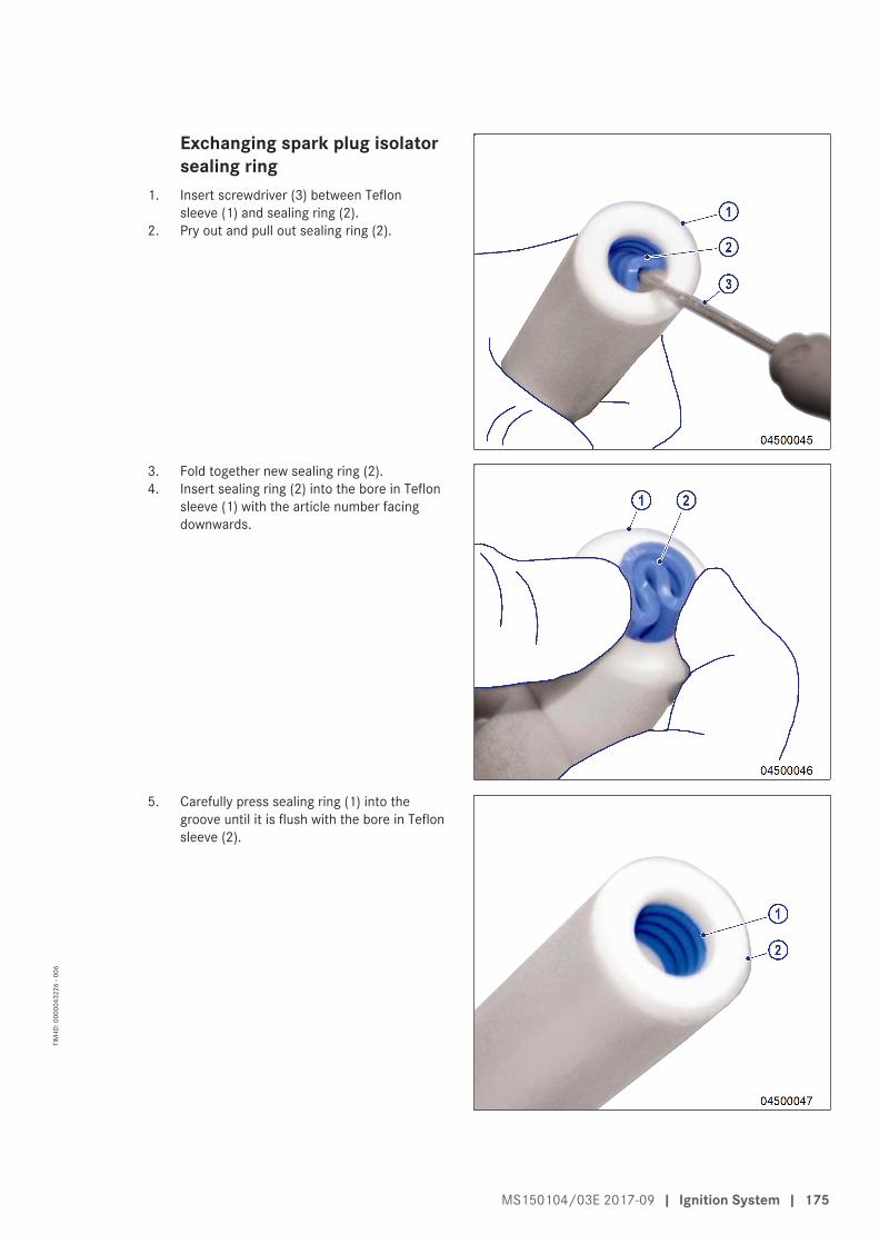
Exchanging spark plug isolatorsealing ring
1. Insert screwdriver (3) between Teflonsleeve (1) and sealing ring (2).
2. Pry out and pull out sealing ring (2).
3. Fold together new sealing ring (2).4. Insert sealing ring (2) into the bore in Teflon
sleeve (1) with the article number facingdownwards.
5. Carefully press sealing ring (1) into thegroove until it is flush with the bore in Teflonsleeve (2).
MS150104/03E 2017-09 | Ignition System | 175
TIM
-ID: 0
0000
4322
6 - 0
06
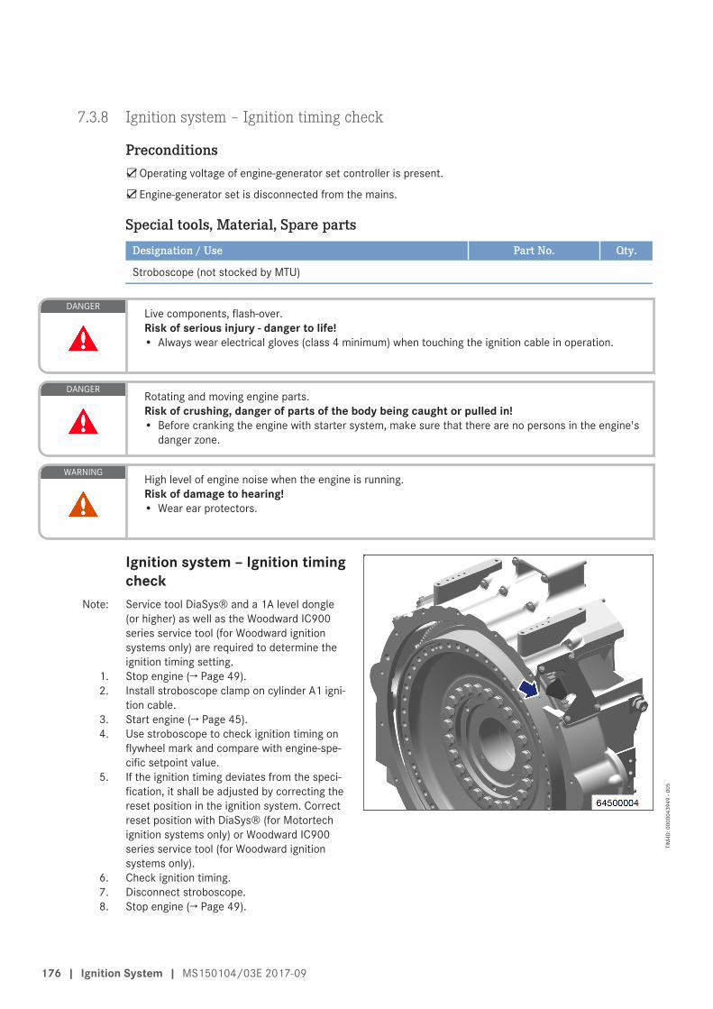
7.3.8 Ignition system – Ignition timing check
Preconditions☑Operating voltage of engine-generator set controller is present.
☑Engine-generator set is disconnected from the mains.
Special tools, Material, Spare partsDesignation / Use Part No. Qty.
Stroboscope (not stocked by MTU)
DANGERLive components, flash-over.Risk of serious injury - danger to life!• Always wear electrical gloves (class 4 minimum) when touching the ignition cable in operation.
DANGERRotating and moving engine parts.Risk of crushing, danger of parts of the body being caught or pulled in!• Before cranking the engine with starter system, make sure that there are no persons in the engine's
danger zone.
WARNINGHigh level of engine noise when the engine is running.Risk of damage to hearing!• Wear ear protectors.
Ignition system – Ignition timingcheck
Note: Service tool DiaSys® and a 1A level dongle(or higher) as well as the Woodward IC900series service tool (for Woodward ignitionsystems only) are required to determine theignition timing setting.
1. Stop engine (→ Page 49).2. Install stroboscope clamp on cylinder A1 igni-
tion cable.3. Start engine (→ Page 45).4. Use stroboscope to check ignition timing on
flywheel mark and compare with engine-spe-cific setpoint value.
5. If the ignition timing deviates from the speci-fication, it shall be adjusted by correcting thereset position in the ignition system. Correctreset position with DiaSys® (for Motortechignition systems only) or Woodward IC900series service tool (for Woodward ignitionsystems only).
6. Check ignition timing.7. Disconnect stroboscope.8. Stop engine (→ Page 49).
176 | Ignition System | MS150104/03E 2017-09
TIM
-ID: 0
0000
4394
9 - 0
05
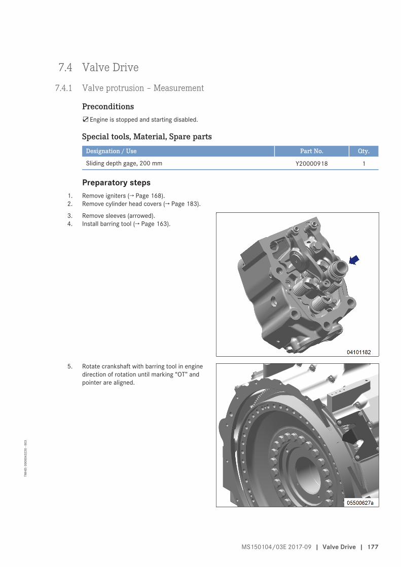
7.4 Valve Drive
7.4.1 Valve protrusion – Measurement
Preconditions☑Engine is stopped and starting disabled.
Special tools, Material, Spare partsDesignation / Use Part No. Qty.
Sliding depth gage, 200 mm Y20000918 1
Preparatory steps1. Remove igniters (→ Page 168).2. Remove cylinder head covers (→ Page 183).
3. Remove sleeves (arrowed).4. Install barring tool (→ Page 163).
5. Rotate crankshaft with barring tool in enginedirection of rotation until marking “OT” andpointer are aligned.
MS150104/03E 2017-09 | Valve Drive | 177
TIM
-ID: 0
0000
4322
0 - 0
03
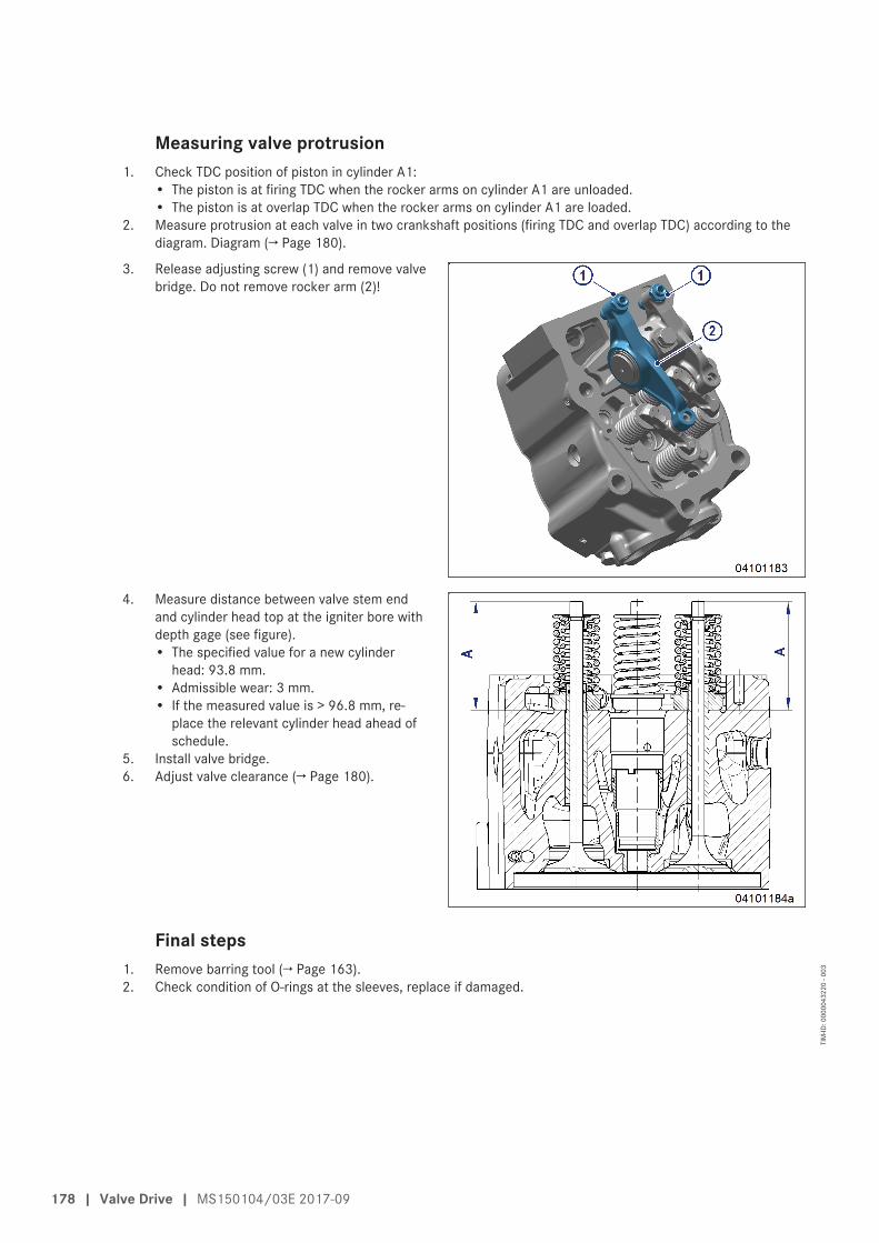
Measuring valve protrusion1. Check TDC position of piston in cylinder A1:
• The piston is at firing TDC when the rocker arms on cylinder A1 are unloaded.• The piston is at overlap TDC when the rocker arms on cylinder A1 are loaded.
2. Measure protrusion at each valve in two crankshaft positions (firing TDC and overlap TDC) according to thediagram. Diagram (→ Page 180).
3. Release adjusting screw (1) and remove valvebridge. Do not remove rocker arm (2)!
4. Measure distance between valve stem endand cylinder head top at the igniter bore withdepth gage (see figure).• The specified value for a new cylinder
head: 93.8 mm.• Admissible wear: 3 mm.• If the measured value is > 96.8 mm, re-
place the relevant cylinder head ahead ofschedule.
5. Install valve bridge.6. Adjust valve clearance (→ Page 180).
Final steps1. Remove barring tool (→ Page 163).2. Check condition of O-rings at the sleeves, replace if damaged.
178 | Valve Drive | MS150104/03E 2017-09
TIM
-ID: 0
0000
4322
0 - 0
03
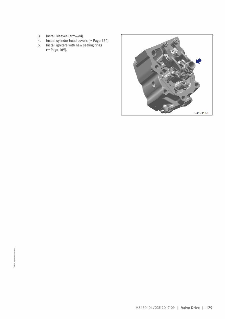
3. Install sleeves (arrowed).4. Install cylinder head covers (→ Page 184).5. Install igniters with new sealing rings
(→ Page 169).
MS150104/03E 2017-09 | Valve Drive | 179
TIM
-ID: 0
0000
4322
0 - 0
03
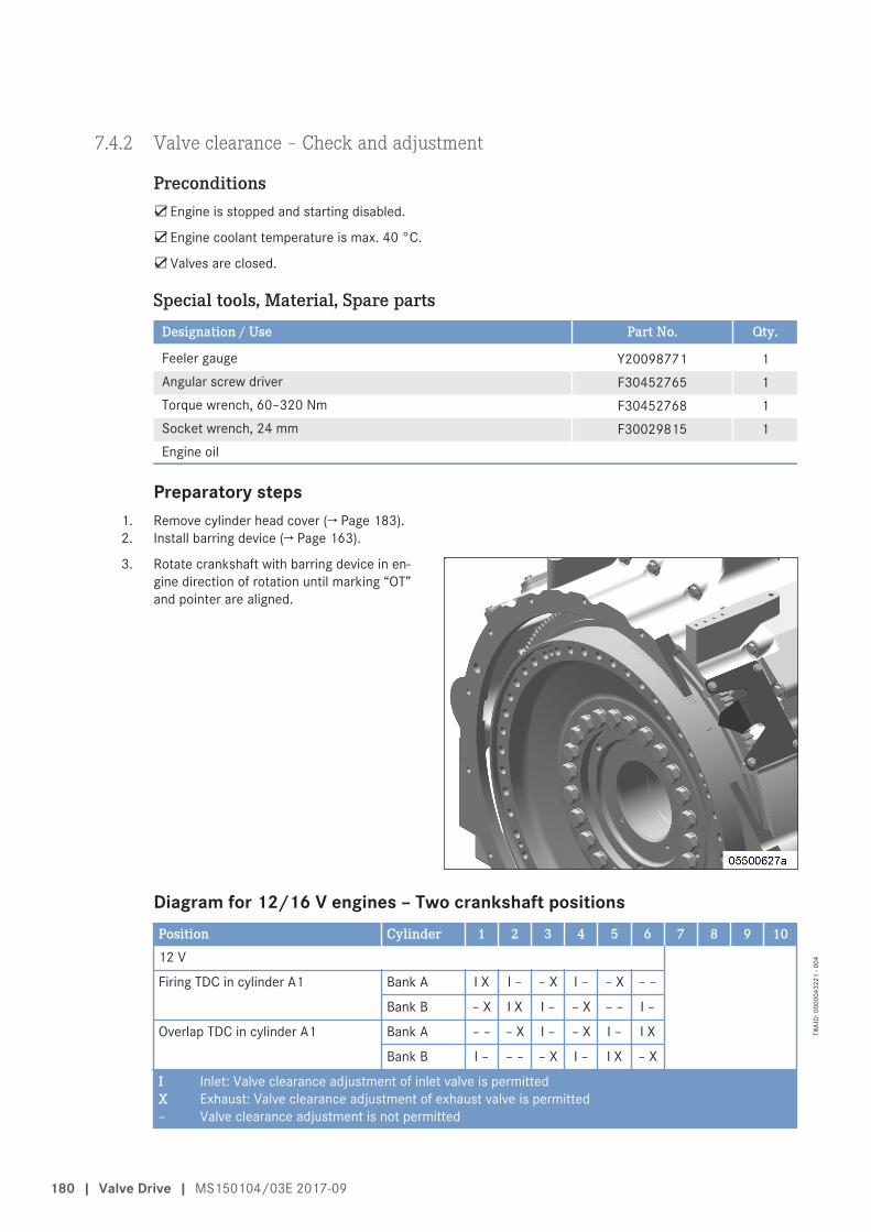
7.4.2 Valve clearance – Check and adjustment
Preconditions☑Engine is stopped and starting disabled.
☑Engine coolant temperature is max. 40 °C.
☑Valves are closed.
Special tools, Material, Spare partsDesignation / Use Part No. Qty.
Feeler gauge Y20098771 1Angular screw driver F30452765 1Torque wrench, 60–320 Nm F30452768 1Socket wrench, 24 mm F30029815 1Engine oil
Preparatory steps1. Remove cylinder head cover (→ Page 183).2. Install barring device (→ Page 163).
3. Rotate crankshaft with barring device in en-gine direction of rotation until marking “OT”and pointer are aligned.
Diagram for 12/16 V engines – Two crankshaft positionsPosition Cylinder 1 2 3 4 5 6 7 8 9 1012 V
Firing TDC in cylinder A1 Bank A I X I – – X I – – X – –
Bank B – X I X I – – X – – I –
Overlap TDC in cylinder A1 Bank A – – – X I – – X I – I X
Bank B I – – – – X I – I X – X
I Inlet: Valve clearance adjustment of inlet valve is permittedX Exhaust: Valve clearance adjustment of exhaust valve is permitted– Valve clearance adjustment is not permitted
180 | Valve Drive | MS150104/03E 2017-09
TIM
-ID: 0
0000
4322
1 - 0
04
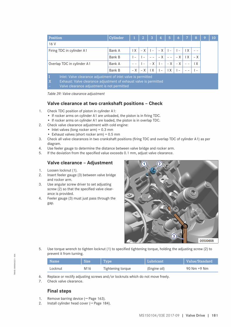
Position Cylinder 1 2 3 4 5 6 7 8 9 1016 V
Firing TDC in cylinder A1 Bank A I X – X I – – X I – I – I X – –
Bank B I – I – – – – X – – – X I X – X
Overlap TDC in cylinder A1 Bank A – – I – – X I – – X – X – – I X
Bank B – X – X I X I – I X I – – – I –
I Inlet: Valve clearance adjustment of inlet valve is permittedX Exhaust: Valve clearance adjustment of exhaust valve is permitted– Valve clearance adjustment is not permitted
Table 39: Valve clearance adjustment
Valve clearance at two crankshaft positions – Check1. Check TDC position of piston in cylinder A1:
• If rocker arms on cylinder A1 are unloaded, the piston is in firing TDC.• If rocker arms on cylinder A1 are loaded, the piston is in overlap TDC.
2. Check valve clearance adjustment with cold engine:• Inlet valves (long rocker arm) = 0.3 mm• Exhaust valves (short rocker arm) = 0.5 mm
3. Check all valve clearances in two crankshaft positions (firing TDC and overlap TDC of cylinder A1) as perdiagram.
4. Use feeler gauge to determine the distance between valve bridge and rocker arm.5. If the deviation from the specified value exceeds 0.1 mm, adjust valve clearance.
Valve clearance – Adjustment1. Loosen locknut (1).2. Insert feeler gauge (3) between valve bridge
and rocker arm.3. Use angular screw driver to set adjusting
screw (2) so that the specified valve clear-ance is provided.
4. Feeler gauge (3) must just pass through thegap.
5. Use torque wrench to tighten locknut (1) to specified tightening torque, holding the adjusting screw (2) toprevent it from turning.
Name Size Type Lubricant Value/Standard
Locknut M16 Tightening torque (Engine oil) 90 Nm +9 Nm
6. Replace or rectify adjusting screws and/or locknuts which do not move freely.7. Check valve clearance.
Final steps1. Remove barring device (→ Page 163).2. Install cylinder head cover (→ Page 184).
MS150104/03E 2017-09 | Valve Drive | 181
TIM
-ID: 0
0000
4322
1 - 0
04
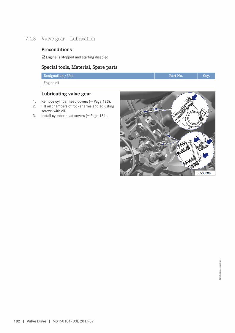
7.4.3 Valve gear – Lubrication
Preconditions☑Engine is stopped and starting disabled.
Special tools, Material, Spare partsDesignation / Use Part No. Qty.
Engine oil
Lubricating valve gear1. Remove cylinder head covers (→ Page 183).2. Fill oil chambers of rocker arms and adjusting
screws with oil.3. Install cylinder head covers (→ Page 184).
182 | Valve Drive | MS150104/03E 2017-09
TIM
-ID: 0
0000
4335
2 - 0
01
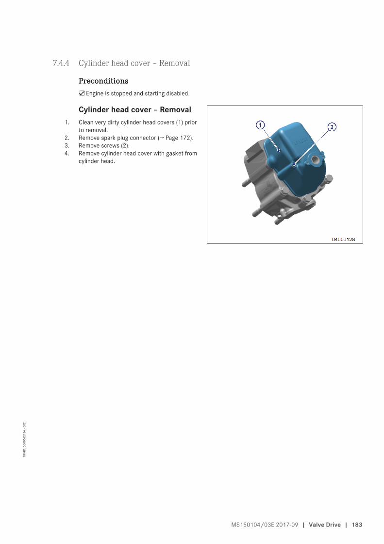
7.4.4 Cylinder head cover ‒ Removal
Preconditions☑Engine is stopped and starting disabled.
Cylinder head cover ‒ Removal1. Clean very dirty cylinder head covers (1) prior
to removal.2. Remove spark plug connector (→ Page 172).3. Remove screws (2).4. Remove cylinder head cover with gasket from
cylinder head.
MS150104/03E 2017-09 | Valve Drive | 183
TIM
-ID: 0
0000
4213
6 - 0
02
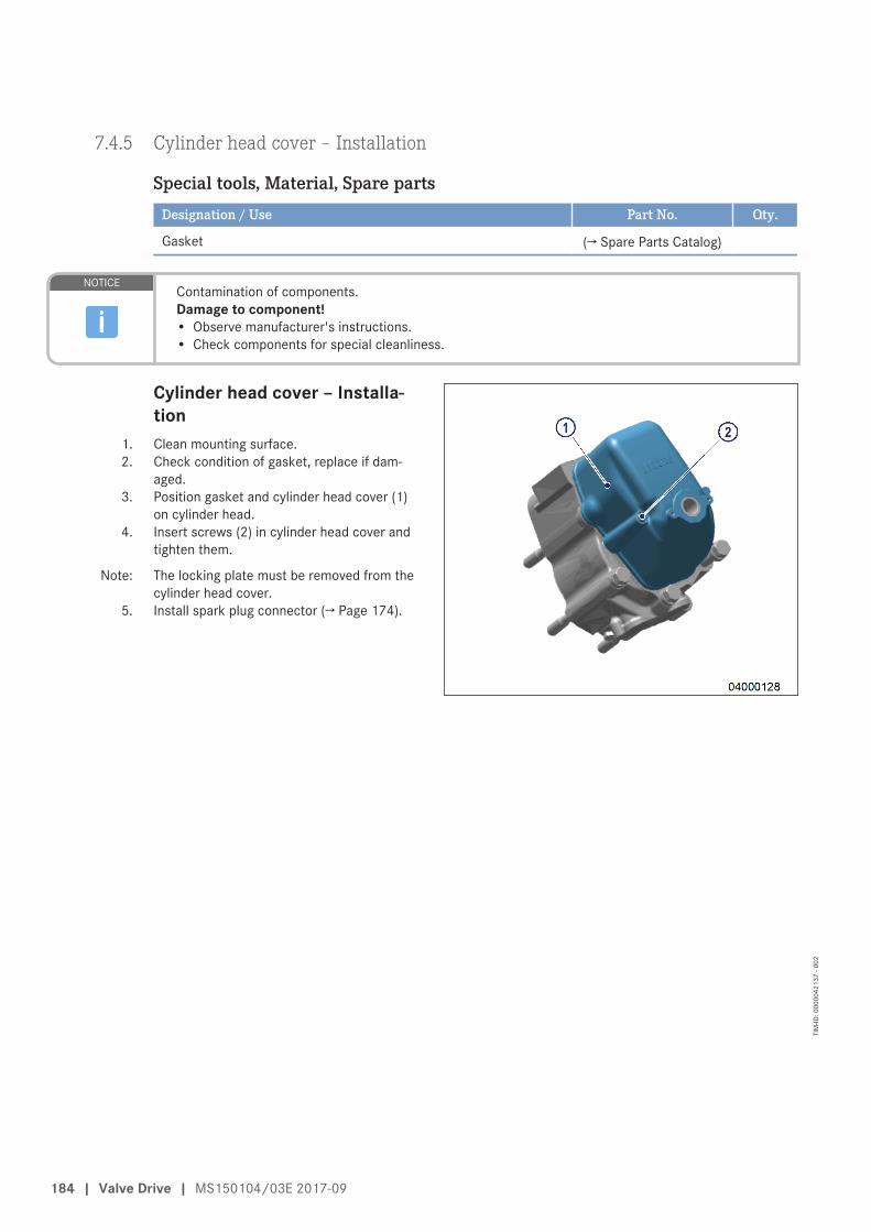
7.4.5 Cylinder head cover ‒ Installation
Special tools, Material, Spare partsDesignation / Use Part No. Qty.
Gasket (→ Spare Parts Catalog)
NOTICEContamination of components.Damage to component!• Observe manufacturer's instructions.• Check components for special cleanliness.
Cylinder head cover ‒ Installa-tion
1. Clean mounting surface.2. Check condition of gasket, replace if dam-
aged.3. Position gasket and cylinder head cover (1)
on cylinder head.4. Insert screws (2) in cylinder head cover and
tighten them.
Note: The locking plate must be removed from thecylinder head cover.
5. Install spark plug connector (→ Page 174).
184 | Valve Drive | MS150104/03E 2017-09
TIM
-ID: 0
0000
4213
7 - 0
02
7.5 Gas System
7.5.1 Gas supply - Checking gas lines for leaks
Preconditions☑Engine is stopped and starting disabled.
Special tools, Material, Spare partsDesignation / Use Part No. Qty.
Leak identification spraySoap suds
WARNINGGaseous fuels are combustible/explosive.Risk of fire and explosion!• Avoid open flames, electrical sparks and ignition sources.• Carry gas-warning unit (part of the personal safety equipment).• Do not smoke.
WARNINGHot components/surfaces.Risk of burns!• Allow the engine to cool down to below 50 °C before beginning work.• Wear suitable protective equipment/thermal gloves.• Avoid unprotected contact with hot surfaces.
Gas supply - Checking gas lines for leaks1. Coat all connections of the gas supply line with soap solution or spray with leakage detection spray from a
distance of 30 to 50 cm.• Leaks are indicated by the formation of bubbles or foam.
2. Replace leaking parts.
MS150104/03E 2017-09 | Gas System | 185
TIM
-ID: 0
0000
0499
6 - 0
03
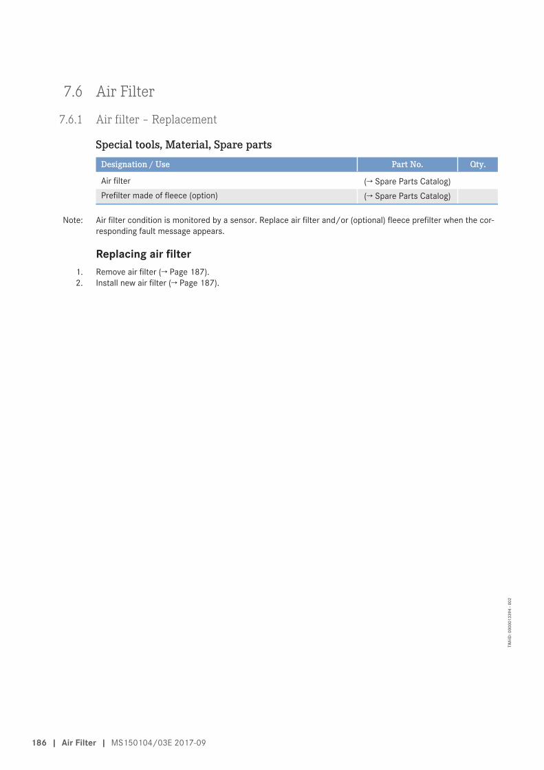
7.6 Air Filter
7.6.1 Air filter – Replacement
Special tools, Material, Spare partsDesignation / Use Part No. Qty.
Air filter (→ Spare Parts Catalog)Prefilter made of fleece (option) (→ Spare Parts Catalog)
Note: Air filter condition is monitored by a sensor. Replace air filter and/or (optional) fleece prefilter when the cor-responding fault message appears.
Replacing air filter1. Remove air filter (→ Page 187).2. Install new air filter (→ Page 187).
186 | Air Filter | MS150104/03E 2017-09
TIM
-ID: 0
0000
1339
4 - 0
02
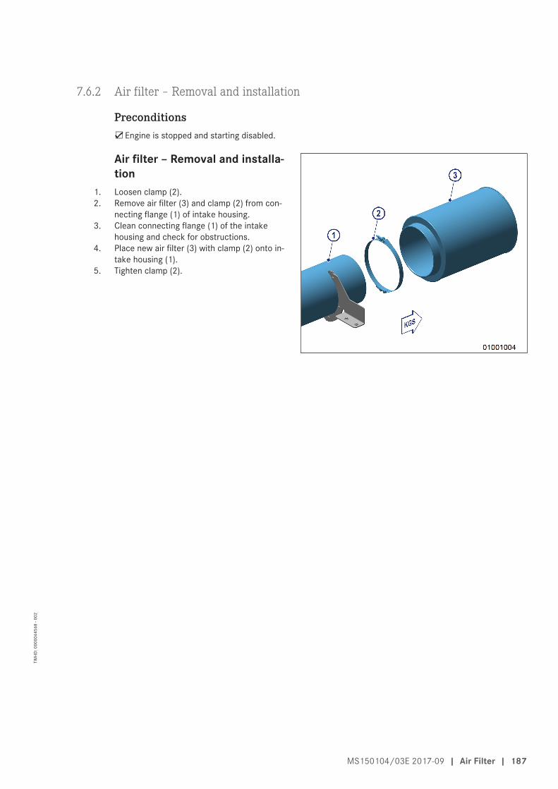
7.6.2 Air filter – Removal and installation
Preconditions☑Engine is stopped and starting disabled.
Air filter – Removal and installa-tion
1. Loosen clamp (2).2. Remove air filter (3) and clamp (2) from con-
necting flange (1) of intake housing.3. Clean connecting flange (1) of the intake
housing and check for obstructions.4. Place new air filter (3) with clamp (2) onto in-
take housing (1).5. Tighten clamp (2).
MS150104/03E 2017-09 | Air Filter | 187
TIM
-ID: 0
0000
4456
8 - 0
02
7.7 Lube Oil System, Lube Oil Circuit
7.7.1 Engine oil level – Check
Preconditions☑Engine is stopped and starting disabled.
WARNINGOil is hot.Oil can contain residue/substances which are harmful to health.Risk of injury and poisoning!• Allow the product to cool to below 50 °C before beginning work.• Wear protective clothing, protective gloves and goggles/safety mask.• Avoid contact with skin.• Do not inhale oil vapor.
WARNINGOils/oil vapors are combustible/explosive.Risk of fire and explosion!• Avoid open flames, electric sparks and ignition sources.• Do not smoke.
Checking oil level prior to en-gine start
1. Pull out dipstick from guide tube and wipe it.2. Insert dipstick into guide tube up to the stop,
withdraw after approx. 10 seconds and checkoil level.
Note: After extended standstill, the oil level may ex-ceed the mark (1) by up to 2 cm. The causeof this may be that oil, e.g. from the oil filterand oil heat exchanger flows back into the oilpan.
3. The oil level must reach the mark (2) or ex-ceed the mark (1) by up to 2 cm.
Note: Topping up oil manually is not required. Theoil level check is only intended to confirmthat the automatic oil replenishment featureworks properly.
4. Insert oil dipstick into guide tube up to thestop.
Checking oil level after the engine is stopped1. 5 minutes after stopping the engine, remove oil dipstick from the guide tube and wipe it.2. Insert dipstick into guide tube up to the stop, withdraw after approx. 10 seconds and check oil level.
Note: Topping up oil manually is not required. The oil level check is only intended to confirm that the automatic oilreplenishment feature works properly.
3. Oil level must be between marks (1) and (2).4. Insert oil dipstick into guide tube up to the stop.
188 | Lube Oil System, Lube Oil Circuit | MS150104/03E 2017-09
TIM
-ID: 0
0000
0616
9 - 0
06
7.7.2 Engine oil – Change
Preconditions☑Engine is stopped and starting disabled.
☑Engine is at operating temperature.
☑MTU Fluids and Lubricants Specifications (A001061/..) are available.
Special tools, Material, Spare partsDesignation / Use Part No. Qty.
Engine oil
WARNINGOil is hot.Oil can contain residue/substances which are harmful to health.Risk of injury and poisoning!• Allow the product to cool to below 50 °C before beginning work.• Wear protective clothing, protective gloves and goggles/safety mask.• Avoid contact with skin.• Do not inhale oil vapor.
WARNINGOils/oil vapors are combustible/explosive.Risk of fire and explosion!• Avoid open flames, electric sparks and ignition sources.• Do not smoke.
Extracting engine oil1. Open shutoff valve(s) in extraction line from engine and waste-oil tank.2. Extract all oil from oil pan using the electric pump.3. Close shutoff valve(s).
Filling with new engine oil1. Determine oil change quantity for fuel optimized (→ Page 28) or emissions-optimized (→ Page 32) engine ver-
sion.2. Use electric pump to fill engine with oil from new-oil tank until the "max." mark on the oil dipstick is reached.3. Check engine oil level (→ Page 188).
MS150104/03E 2017-09 | Lube Oil System, Lube Oil Circuit | 189
TIM
-ID: 0
0000
2913
7 - 0
04
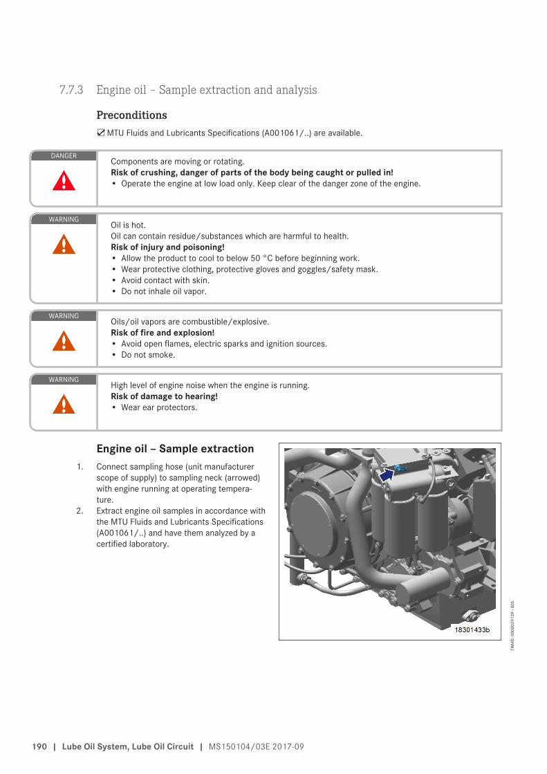
7.7.3 Engine oil – Sample extraction and analysis
Preconditions☑MTU Fluids and Lubricants Specifications (A001061/..) are available.
DANGERComponents are moving or rotating.Risk of crushing, danger of parts of the body being caught or pulled in!• Operate the engine at low load only. Keep clear of the danger zone of the engine.
WARNINGOil is hot.Oil can contain residue/substances which are harmful to health.Risk of injury and poisoning!• Allow the product to cool to below 50 °C before beginning work.• Wear protective clothing, protective gloves and goggles/safety mask.• Avoid contact with skin.• Do not inhale oil vapor.
WARNINGOils/oil vapors are combustible/explosive.Risk of fire and explosion!• Avoid open flames, electric sparks and ignition sources.• Do not smoke.
WARNINGHigh level of engine noise when the engine is running.Risk of damage to hearing!• Wear ear protectors.
Engine oil – Sample extraction1. Connect sampling hose (unit manufacturer
scope of supply) to sampling neck (arrowed)with engine running at operating tempera-ture.
2. Extract engine oil samples in accordance withthe MTU Fluids and Lubricants Specifications(A001061/..) and have them analyzed by acertified laboratory.
190 | Lube Oil System, Lube Oil Circuit | MS150104/03E 2017-09
TIM
-ID: 0
0000
2913
9 - 0
05
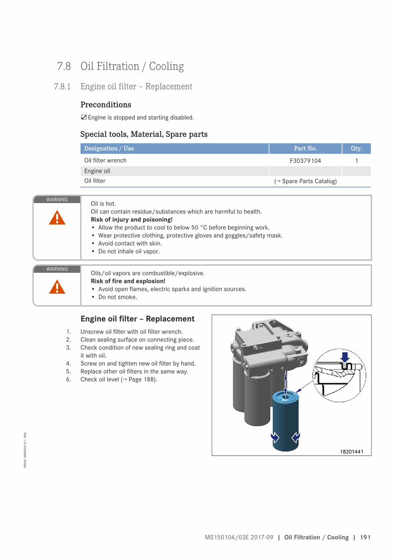
7.8 Oil Filtration / Cooling
7.8.1 Engine oil filter – Replacement
Preconditions☑Engine is stopped and starting disabled.
Special tools, Material, Spare partsDesignation / Use Part No. Qty.
Oil filter wrench F30379104 1Engine oilOil filter (→ Spare Parts Catalog)
WARNINGOil is hot.Oil can contain residue/substances which are harmful to health.Risk of injury and poisoning!• Allow the product to cool to below 50 °C before beginning work.• Wear protective clothing, protective gloves and goggles/safety mask.• Avoid contact with skin.• Do not inhale oil vapor.
WARNINGOils/oil vapors are combustible/explosive.Risk of fire and explosion!• Avoid open flames, electric sparks and ignition sources.• Do not smoke.
Engine oil filter – Replacement1. Unscrew oil filter with oil filter wrench.2. Clean sealing surface on connecting piece.3. Check condition of new sealing ring and coat
it with oil.4. Screw on and tighten new oil filter by hand.5. Replace other oil filters in the same way.6. Check oil level (→ Page 188).
MS150104/03E 2017-09 | Oil Filtration / Cooling | 191
TIM
-ID: 0
0000
2914
1 - 0
06
7.9 Coolant Circuit, General, High-Temperature Circuit
7.9.1 Engine coolant – Level check
Preconditions☑Engine is stopped and starting disabled.
☑MTU Fluids and Lubricants Specifications (A001061/..) are available.
WARNINGCoolant is hot and under pressure.Risk of injury and scalding!• Let the engine cool down.• Wear protective clothing, gloves, and goggles / safety mask.
Checking engine coolant level1. Read off fuel-optimized (→ Page 28) or emissions-optimized (→ Page 32) system filling pressure at pressure
gage.2. Top up with treated coolant as necessary (→ Page 196).
192 | Coolant Circuit, General, High-Temperature Circuit | MS150104/03E 2017-09
TIM
-ID: 0
0000
0676
8 - 0
02
7.9.2 Engine coolant – Change
Special tools, Material, Spare partsDesignation / Use Part No. Qty.
Coolant
Engine coolant change1. Drain engine coolant (→ Page 194).2. Fill with engine coolant (→ Page 196).
MS150104/03E 2017-09 | Coolant Circuit, General, High-Temperature Circuit | 193
TIM
-ID: 0
0000
0003
6 - 0
31
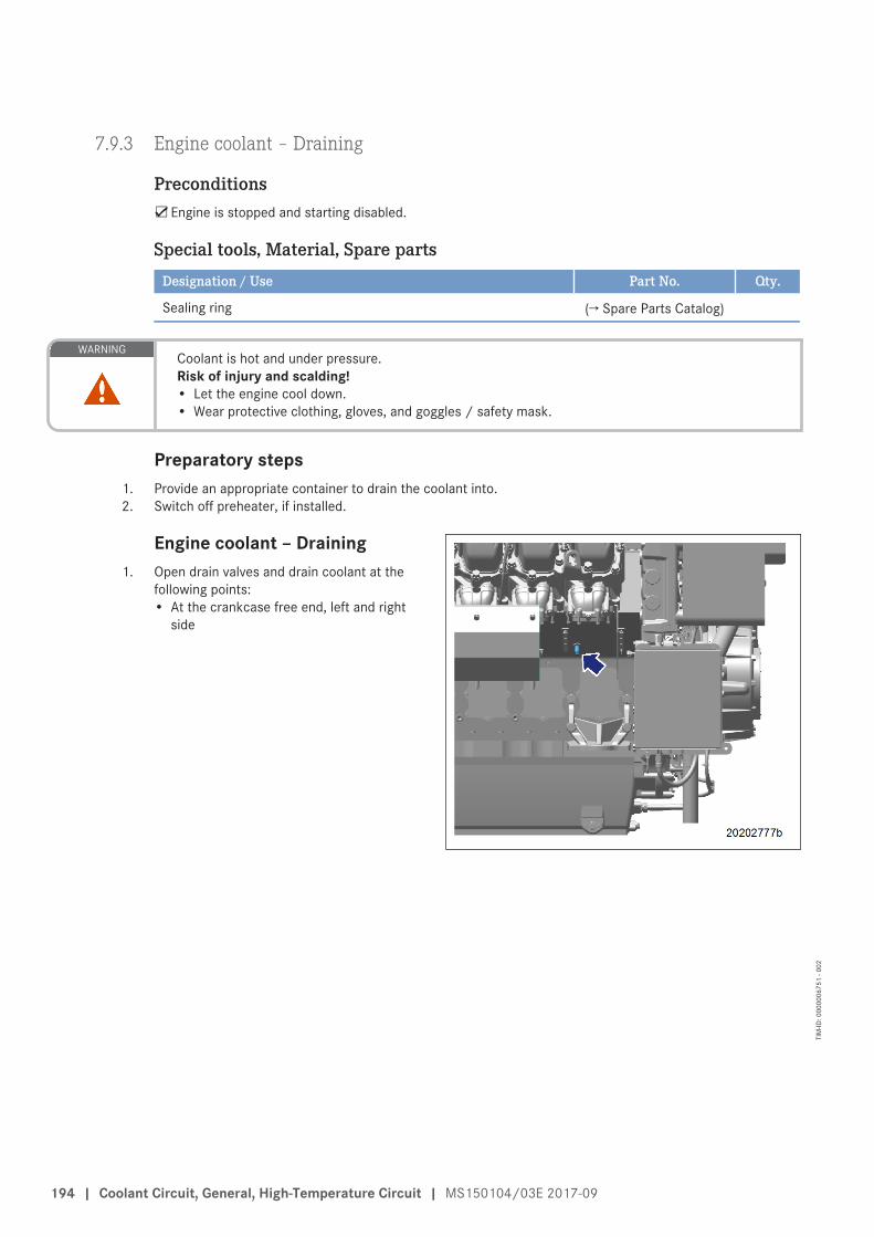
7.9.3 Engine coolant – Draining
Preconditions☑Engine is stopped and starting disabled.
Special tools, Material, Spare partsDesignation / Use Part No. Qty.
Sealing ring (→ Spare Parts Catalog)
WARNINGCoolant is hot and under pressure.Risk of injury and scalding!• Let the engine cool down.• Wear protective clothing, gloves, and goggles / safety mask.
Preparatory steps1. Provide an appropriate container to drain the coolant into.2. Switch off preheater, if installed.
Engine coolant – Draining1. Open drain valves and drain coolant at the
following points:• At the crankcase free end, left and right
side
194 | Coolant Circuit, General, High-Temperature Circuit | MS150104/03E 2017-09
TIM
-ID: 0
0000
0675
1 - 0
02
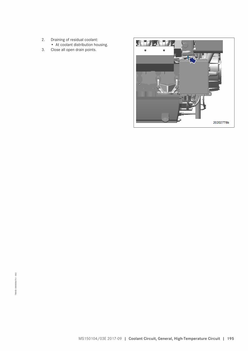
2. Draining of residual coolant:• At coolant distribution housing.
3. Close all open drain points.
MS150104/03E 2017-09 | Coolant Circuit, General, High-Temperature Circuit | 195
TIM
-ID: 0
0000
0675
1 - 0
02
7.9.4 Engine coolant – Filling
Preconditions☑Engine is stopped and starting disabled.
☑MTU Fluids and Lubricants Specifications (A001061/..) are available.
Special tools, Material, Spare partsDesignation / Use Part No. Qty.
Engine coolant
WARNINGCoolant is hot and under pressure.Risk of injury and scalding!• Let the engine cool down.• Wear protective clothing, gloves, and goggles / safety mask.
NOTICECold coolant in hot engine can cause thermal stress.Possible formation of cracks in the engine!• Fill / top up coolant only into cold engine.
Filling with coolant1. Fill with treated coolant using a pressure pump until the fuel-optimized (→ Page 28) or emissions-optimized
(→ Page 32) system filling pressure has been reached.2. Vent engine coolant circuit at vent line.3. Start engine and run at idle speed for a few minutes.4. Check coolant level (→ Page 192).
196 | Coolant Circuit, General, High-Temperature Circuit | MS150104/03E 2017-09
TIM
-ID: 0
0000
4277
3 - 0
01
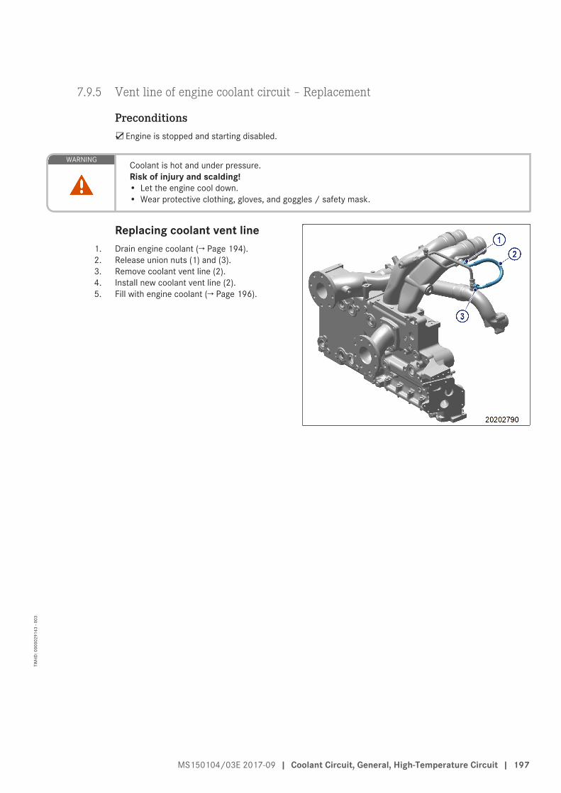
7.9.5 Vent line of engine coolant circuit – Replacement
Preconditions☑Engine is stopped and starting disabled.
WARNINGCoolant is hot and under pressure.Risk of injury and scalding!• Let the engine cool down.• Wear protective clothing, gloves, and goggles / safety mask.
Replacing coolant vent line1. Drain engine coolant (→ Page 194).2. Release union nuts (1) and (3).3. Remove coolant vent line (2).4. Install new coolant vent line (2).5. Fill with engine coolant (→ Page 196).
MS150104/03E 2017-09 | Coolant Circuit, General, High-Temperature Circuit | 197
TIM
-ID: 0
0000
2914
3 - 0
03
7.10 Low-Temperature Circuit
7.10.1 Mixture coolant level – Check
Preconditions☑Engine is stopped and starting disabled.
☑MTU Fluids and Lubricants Specifications (A001061/..) are available.
WARNINGCoolant is hot and under pressure.Risk of injury and scalding!• Let the engine cool down.• Wear protective clothing, gloves, and goggles / safety mask.
Mixture coolant level – Check1. Read off system filling pressure, fuel-optimized (→ Page 28) or emissions-optimized (→ Page 32) at pressure
gauge.2. Top up with treated coolant as necessary (→ Page 201).
198 | Low-Temperature Circuit | MS150104/03E 2017-09
TIM
-ID: 0
0000
0703
2 - 0
03
7.10.2 Mixture coolant – Change
Special tools, Material, Spare partsDesignation / Use Part No. Qty.
Mixture coolant
Mixture coolant – Change1. Drain mixture coolant (→ Page 200).2. Fill with fresh mixture coolant (→ Page 201).
MS150104/03E 2017-09 | Low-Temperature Circuit | 199
TIM
-ID: 0
0000
0702
7 - 0
04
7.10.3 Mixture coolant – Draining
Preconditions☑Engine is stopped and starting disabled.
WARNINGCoolant is hot and under pressure.Risk of injury and scalding!• Let the engine cool down.• Wear protective clothing, gloves, and goggles / safety mask.
Draining mixture coolant1. Provide a suitable receptacle to catch the coolant.2. Open drain valve at drain point in coolant line to mixture coolant cooler and drain coolant.
200 | Low-Temperature Circuit | MS150104/03E 2017-09
TIM
-ID: 0
0000
4277
4 - 0
01
7.10.4 Mixture coolant – Filling
Preconditions☑Engine is stopped and starting disabled.
☑MTU Fluids and Lubricants Specifications (A001061/..) are available.
Special tools, Material, Spare partsDesignation / Use Part No. Qty.
Mixture coolant
WARNINGCoolant is hot and under pressure.Risk of injury and scalding!• Let the engine cool down.• Wear protective clothing, gloves, and goggles / safety mask.
NOTICECold coolant in hot engine can cause thermal stress.Possible formation of cracks in the engine!• Fill / top up coolant only into cold engine.
Filling with coolant1. Fill with treated coolant until the fuel-optimized (→ Page 28) or emissions-optimized (→ Page 32) system fill-
ing pressure has been reached.2. Vent mixture coolant circuit via system.3. Start engine and run at idle speed for a few minutes.4. Check coolant level (→ Page 198).
MS150104/03E 2017-09 | Low-Temperature Circuit | 201
TIM
-ID: 0
0000
4277
5 - 0
01
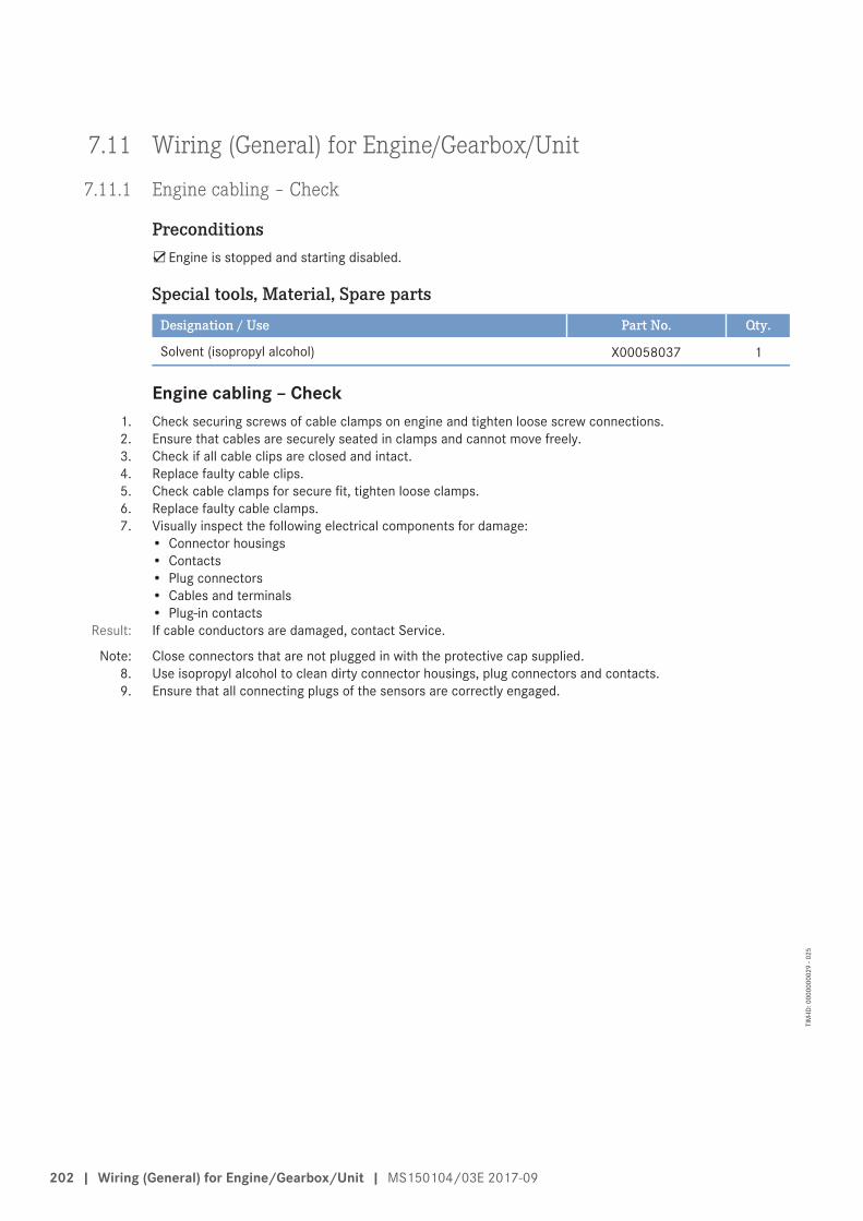
7.11 Wiring (General) for Engine/Gearbox/Unit
7.11.1 Engine cabling – Check
Preconditions☑Engine is stopped and starting disabled.
Special tools, Material, Spare partsDesignation / Use Part No. Qty.
Solvent (isopropyl alcohol) X00058037 1
Engine cabling – Check1. Check securing screws of cable clamps on engine and tighten loose screw connections.2. Ensure that cables are securely seated in clamps and cannot move freely.3. Check if all cable clips are closed and intact.4. Replace faulty cable clips.5. Check cable clamps for secure fit, tighten loose clamps.6. Replace faulty cable clamps.7. Visually inspect the following electrical components for damage:
• Connector housings• Contacts• Plug connectors• Cables and terminals• Plug-in contacts
Result: If cable conductors are damaged, contact Service.
Note: Close connectors that are not plugged in with the protective cap supplied.8. Use isopropyl alcohol to clean dirty connector housings, plug connectors and contacts.9. Ensure that all connecting plugs of the sensors are correctly engaged.
202 | Wiring (General) for Engine/Gearbox/Unit | MS150104/03E 2017-09
TIM
-ID: 0
0000
0002
9 - 0
25
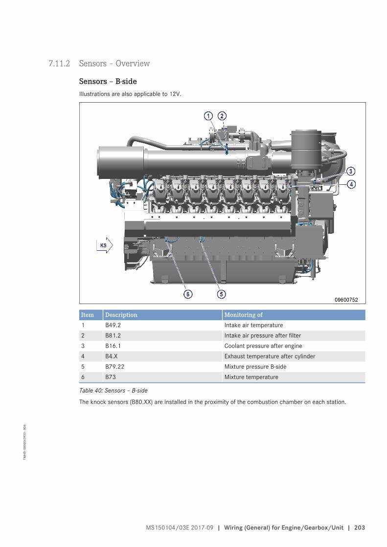
7.11.2 Sensors – Overview
Sensors – B-sideIllustrations are also applicable to 12V.
Item Description Monitoring of1 B49.2 Intake air temperature2 B81.2 Intake air pressure after filter3 B16.1 Coolant pressure after engine4 B4.X Exhaust temperature after cylinder5 B79.22 Mixture pressure B-side6 B73 Mixture temperature
Table 40: Sensors – B-side
The knock sensors (B80.XX) are installed in the proximity of the combustion chamber on each station.
MS150104/03E 2017-09 | Wiring (General) for Engine/Gearbox/Unit | 203
TIM
-ID: 0
0000
4393
3 - 0
06
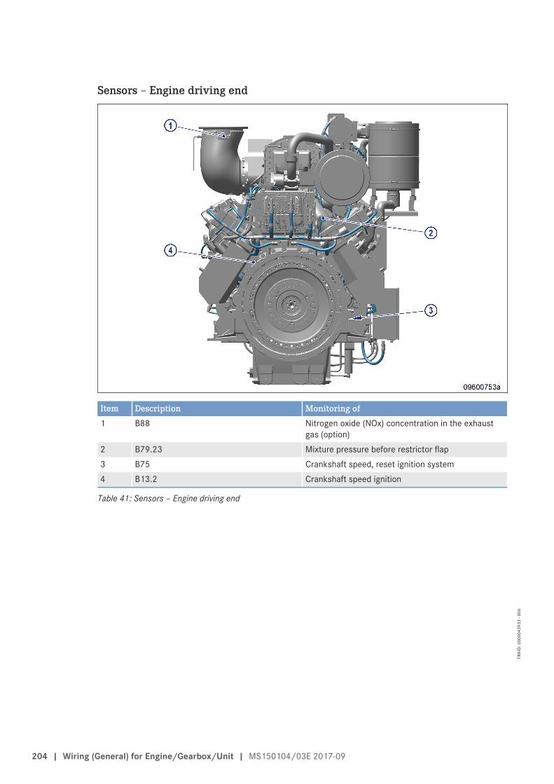
Sensors – Engine driving end
Item Description Monitoring of1 B88 Nitrogen oxide (NOx) concentration in the exhaust
gas (option)2 B79.23 Mixture pressure before restrictor flap3 B75 Crankshaft speed, reset ignition system4 B13.2 Crankshaft speed ignition
Table 41: Sensors – Engine driving end
204 | Wiring (General) for Engine/Gearbox/Unit | MS150104/03E 2017-09
TIM
-ID: 0
0000
4393
3 - 0
06
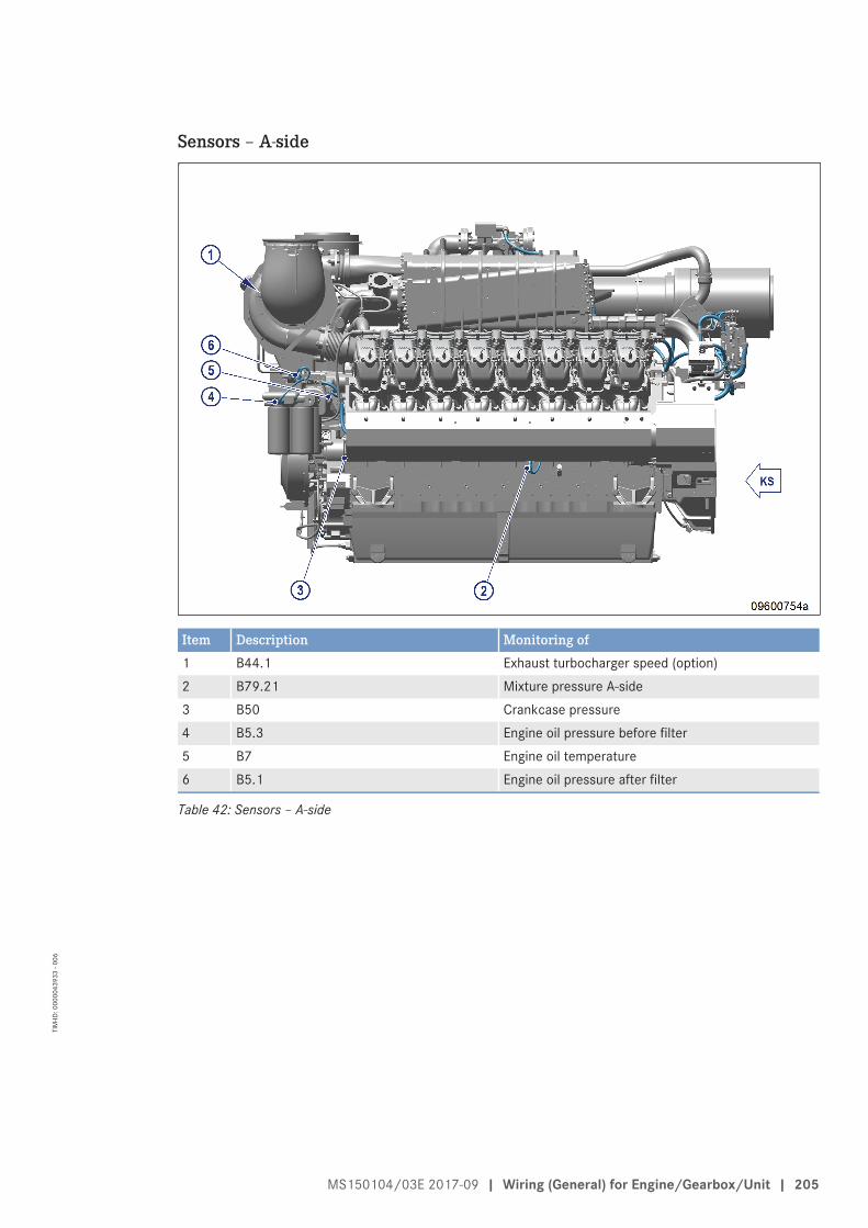
Sensors – A-side
Item Description Monitoring of1 B44.1 Exhaust turbocharger speed (option)2 B79.21 Mixture pressure A-side3 B50 Crankcase pressure4 B5.3 Engine oil pressure before filter5 B7 Engine oil temperature6 B5.1 Engine oil pressure after filter
Table 42: Sensors – A-side
MS150104/03E 2017-09 | Wiring (General) for Engine/Gearbox/Unit | 205
TIM
-ID: 0
0000
4393
3 - 0
06
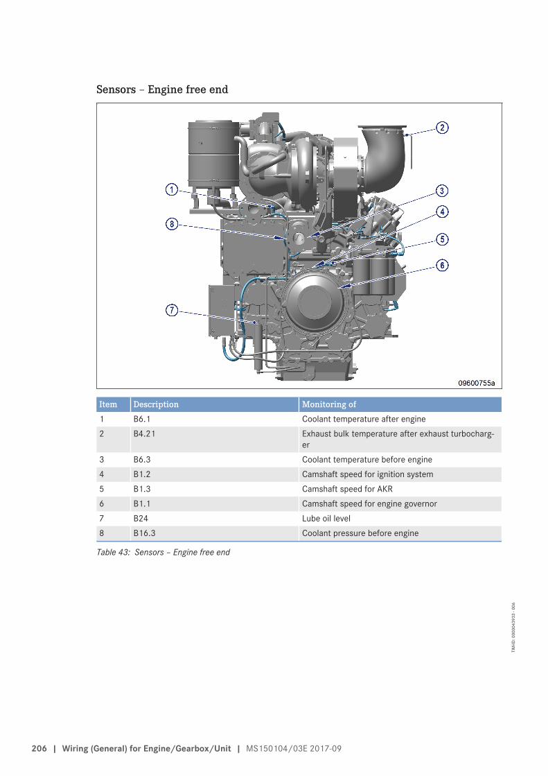
Sensors – Engine free end
Item Description Monitoring of1 B6.1 Coolant temperature after engine2 B4.21 Exhaust bulk temperature after exhaust turbocharg-
er3 B6.3 Coolant temperature before engine4 B1.2 Camshaft speed for ignition system5 B1.3 Camshaft speed for AKR6 B1.1 Camshaft speed for engine governor7 B24 Lube oil level8 B16.3 Coolant pressure before engine
Table 43: Sensors – Engine free end
206 | Wiring (General) for Engine/Gearbox/Unit | MS150104/03E 2017-09
TIM
-ID: 0
0000
4393
3 - 0
06
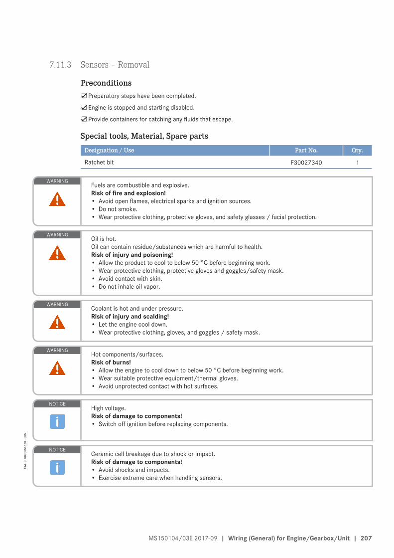
7.11.3 Sensors – Removal
Preconditions☑Preparatory steps have been completed.
☑Engine is stopped and starting disabled.
☑Provide containers for catching any fluids that escape.
Special tools, Material, Spare partsDesignation / Use Part No. Qty.
Ratchet bit F30027340 1
WARNINGFuels are combustible and explosive.Risk of fire and explosion!• Avoid open flames, electrical sparks and ignition sources.• Do not smoke.• Wear protective clothing, protective gloves, and safety glasses / facial protection.
WARNINGOil is hot.Oil can contain residue/substances which are harmful to health.Risk of injury and poisoning!• Allow the product to cool to below 50 °C before beginning work.• Wear protective clothing, protective gloves and goggles/safety mask.• Avoid contact with skin.• Do not inhale oil vapor.
WARNINGCoolant is hot and under pressure.Risk of injury and scalding!• Let the engine cool down.• Wear protective clothing, gloves, and goggles / safety mask.
WARNINGHot components/surfaces.Risk of burns!• Allow the engine to cool down to below 50 °C before beginning work.• Wear suitable protective equipment/thermal gloves.• Avoid unprotected contact with hot surfaces.
NOTICEHigh voltage.Risk of damage to components!• Switch off ignition before replacing components.
NOTICECeramic cell breakage due to shock or impact.Risk of damage to components!• Avoid shocks and impacts.• Exercise extreme care when handling sensors.
MS150104/03E 2017-09 | Wiring (General) for Engine/Gearbox/Unit | 207
TIM
-ID: 0
0000
5458
8 - 0
05
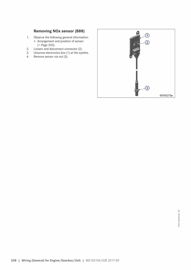
Removing NOx sensor (B88)1. Observe the following general information:
• Arrangement and position of sensor(→ Page 203).
2. Loosen and disconnect connector (2).3. Unscrew electronics box (1) at the eyelets.4. Remove sensor via nut (3).
208 | Wiring (General) for Engine/Gearbox/Unit | MS150104/03E 2017-09
TIM
-ID: 0
0000
5458
8 - 0
05
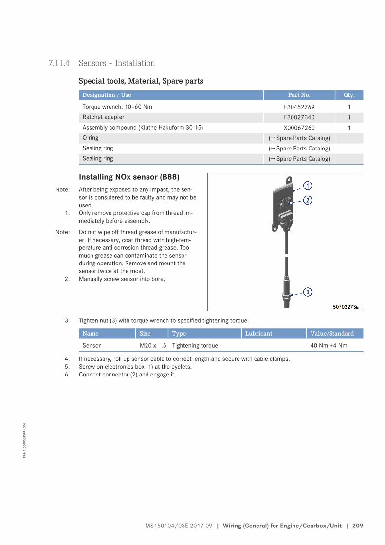
7.11.4 Sensors – Installation
Special tools, Material, Spare partsDesignation / Use Part No. Qty.
Torque wrench, 10–60 Nm F30452769 1Ratchet adapter F30027340 1Assembly compound (Kluthe Hakuform 30-15) X00067260 1O-ring (→ Spare Parts Catalog)Sealing ring (→ Spare Parts Catalog)Sealing ring (→ Spare Parts Catalog)
Installing NOx sensor (B88)Note: After being exposed to any impact, the sen-
sor is considered to be faulty and may not beused.
1. Only remove protective cap from thread im-mediately before assembly.
Note: Do not wipe off thread grease of manufactur-er. If necessary, coat thread with high-tem-perature anti-corrosion thread grease. Toomuch grease can contaminate the sensorduring operation. Remove and mount thesensor twice at the most.
2. Manually screw sensor into bore.
3. Tighten nut (3) with torque wrench to specified tightening torque.
Name Size Type Lubricant Value/Standard
Sensor M20 x 1.5 Tightening torque 40 Nm +4 Nm
4. If necessary, roll up sensor cable to correct length and secure with cable clamps.5. Screw on electronics box (1) at the eyelets.6. Connect connector (2) and engage it.
MS150104/03E 2017-09 | Wiring (General) for Engine/Gearbox/Unit | 209
TIM
-ID: 0
0000
5458
9 - 0
04
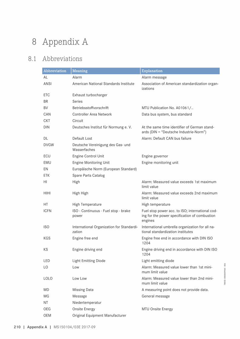
8 Appendix A
8.1 AbbreviationsAbbreviation Meaning ExplanationAL Alarm Alarm messageANSI American National Standards Institute Association of American standardization organ-
izationsETC Exhaust turbochargerBR SeriesBV Betriebsstoffvorschrift MTU Publication No. A01061/..CAN Controller Area Network Data bus system, bus standardCKT CircuitDIN Deutsches Institut für Normung e. V. At the same time identifier of German stand-
ards (DIN = “Deutsche Industrie-Norm”)DL Default Lost Alarm: Default CAN bus failureDVGW Deutsche Vereinigung des Gas- und
WasserfachesECU Engine Control Unit Engine governorEMU Engine Monitoring Unit Engine monitoring unitEN Europäische Norm (European Standard)ETK Spare Parts CatalogHI High Alarm: Measured value exceeds 1st maximum
limit valueHIHI High High Alarm: Measured value exceeds 2nd maximum
limit valueHT High Temperature High temperatureICFN ISO - Continuous - Fuel stop - brake
powerFuel stop power acc. to ISO; international cod-ing for the power specification of combustionengines
ISO International Organization for Standardi-zation
International umbrella organization for all na-tional standardization institutes
KGS Engine free end Engine free end in accordance with DIN ISO1204
KS Engine driving end Engine driving end in accordance with DIN ISO1204
LED Light Emitting Diode Light emitting diodeLO Low Alarm: Measured value lower than 1st mini-
mum limit valueLOLO Low Low Alarm: Measured value lower than 2nd mini-
mum limit valueMD Missing Data A measuring point does not provide data.MG Message General messageNT NiedertemperaturOEG Onsite Energy MTU Onsite EnergyOEM Original Equipment Manufacturer
210 | Appendix A | MS150104/03E 2017-09
TIM
-ID: 0
0000
0996
0 - 0
06
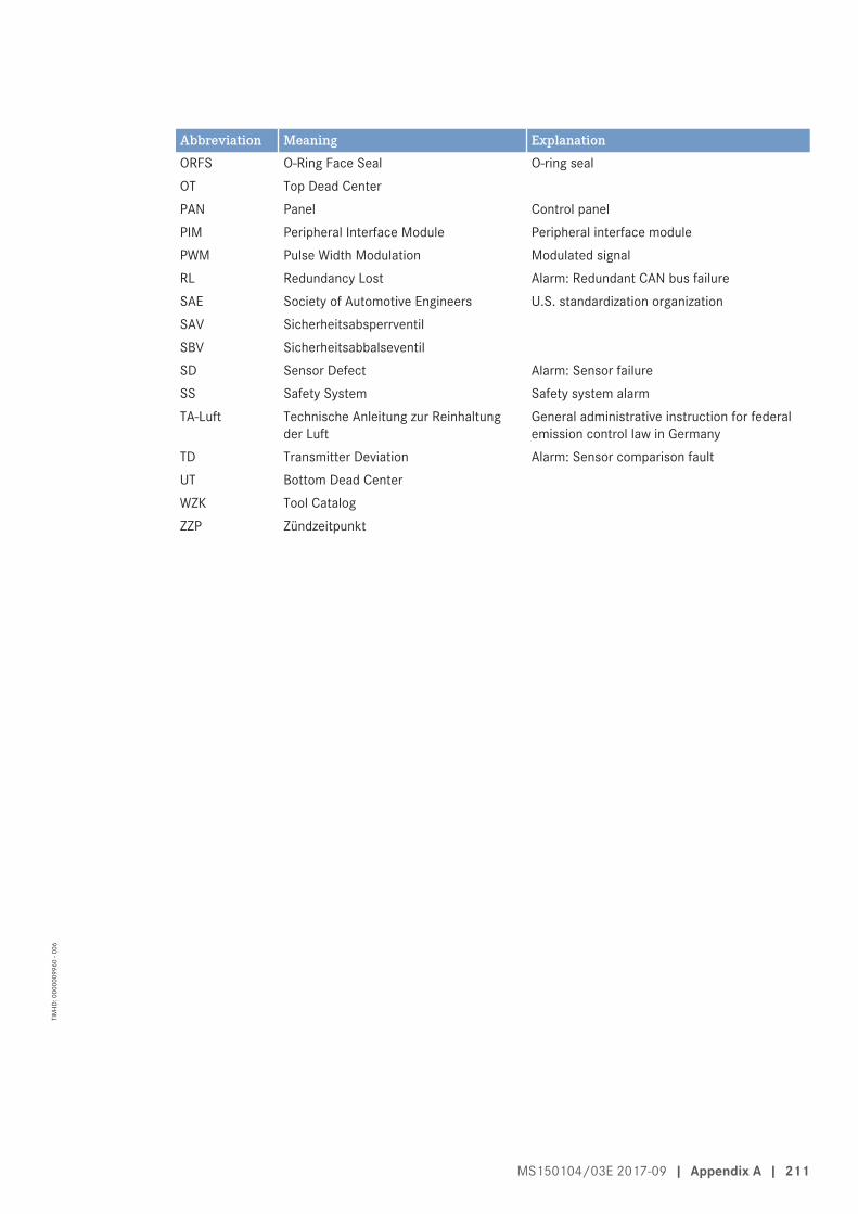
Abbreviation Meaning ExplanationORFS O-Ring Face Seal O-ring sealOT Top Dead CenterPAN Panel Control panelPIM Peripheral Interface Module Peripheral interface modulePWM Pulse Width Modulation Modulated signalRL Redundancy Lost Alarm: Redundant CAN bus failureSAE Society of Automotive Engineers U.S. standardization organizationSAV SicherheitsabsperrventilSBV SicherheitsabbalseventilSD Sensor Defect Alarm: Sensor failureSS Safety System Safety system alarmTA-Luft Technische Anleitung zur Reinhaltung
der LuftGeneral administrative instruction for federalemission control law in Germany
TD Transmitter Deviation Alarm: Sensor comparison faultUT Bottom Dead CenterWZK Tool CatalogZZP Zündzeitpunkt
MS150104/03E 2017-09 | Appendix A | 211
TIM
-ID: 0
0000
0996
0 - 0
06
8.2 MTU Onsite Energy contact person / service partner
ServiceThe worldwide network of the sales organization with subsidiaries, sales offices, representatives and custom-er service centers ensure fast and direct support on site and ensure the high availability of our products.
Local SupportExperienced and qualified specialists place their knowledge and expertise at your disposal.
For our locally available support, go to MTU's Internet site:• http://www.mtuonsiteenergy.com/haendlersuche/index.de.html
24-h HotlineWith our 24-h hotline and the flexibility of our service staff, we are always ready to assist you - either duringoperation, for preventive maintenance, corrective work in case of malfunction or changed operating condi-tions, or for spare parts supply.
For our locally available support, go to MTU's Internet site:• http://www.mtuonsiteenergy.com/haendlersuche/index.de.html
Your contact at Headquarters:• [email protected]
Spare Parts ServiceQuick, easy and correct identification of the spare part required for your system. The right spare part at theright time at the right place.
With this aim in mind, we can call on a globally networked spares logistics system.
Your contact at Headquarters:
Germany:• Tel.: +49 821 74800• Fax: +49 821 74802289• E-mail: [email protected]
Worldwide:• Tel.: +49 7541 908555• Fax: +49 7541 908121• E-mail: [email protected]
212 | Appendix A | MS150104/03E 2017-09
TIM
-ID: 0
0000
0262
4 - 0
06
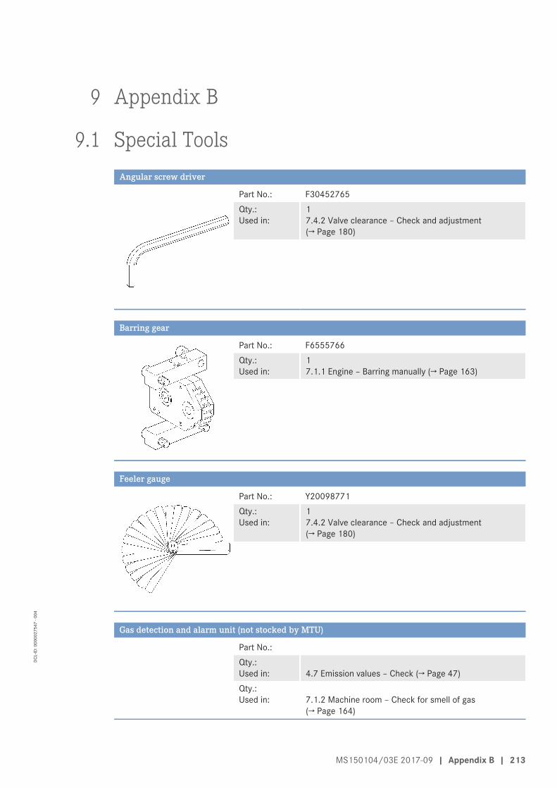
9 Appendix B
9.1 Special ToolsAngular screw driver
Part No.: F30452765Qty.:Used in:
1 7.4.2 Valve clearance – Check and adjustment(→ Page 180)
Barring gear
Part No.: F6555766Qty.:Used in:
1 7.1.1 Engine – Barring manually (→ Page 163)
Feeler gauge
Part No.: Y20098771Qty.:Used in:
1 7.4.2 Valve clearance – Check and adjustment(→ Page 180)
Gas detection and alarm unit (not stocked by MTU)
Part No.: Qty.:Used in:
4.7 Emission values – Check (→ Page 47)
Qty.:Used in:
7.1.2 Machine room – Check for smell of gas(→ Page 164)
MS150104/03E 2017-09 | Appendix B | 213
DCL-
ID: 0
0000
2754
7 - 0
04
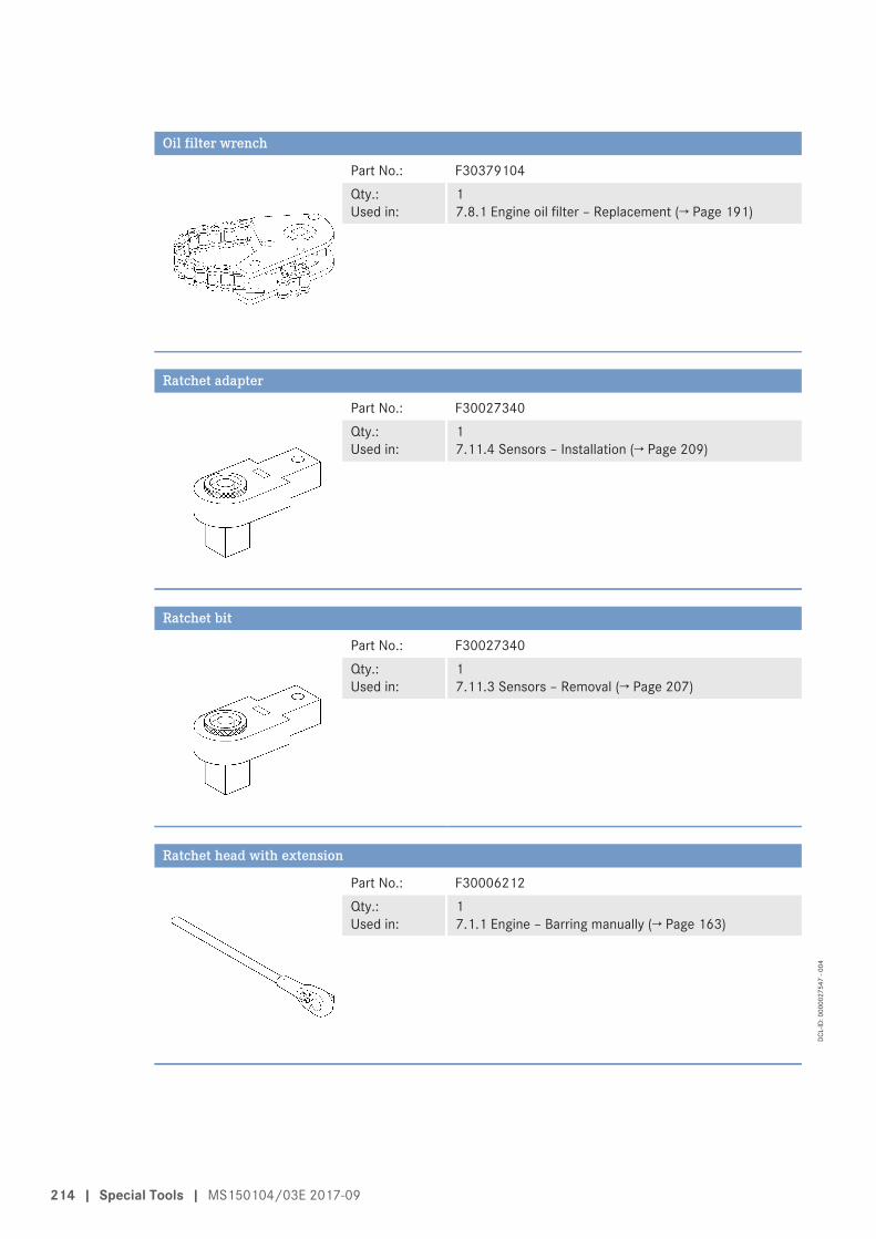
Oil filter wrench
Part No.: F30379104Qty.:Used in:
1 7.8.1 Engine oil filter – Replacement (→ Page 191)
Ratchet adapter
Part No.: F30027340Qty.:Used in:
1 7.11.4 Sensors – Installation (→ Page 209)
Ratchet bit
Part No.: F30027340Qty.:Used in:
1 7.11.3 Sensors – Removal (→ Page 207)
Ratchet head with extension
Part No.: F30006212Qty.:Used in:
1 7.1.1 Engine – Barring manually (→ Page 163)
214 | Special Tools | MS150104/03E 2017-09
DCL-
ID: 0
0000
2754
7 - 0
04
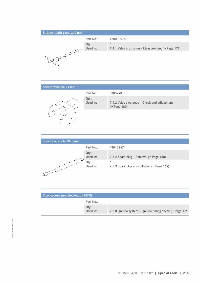
Sliding depth gage, 200 mm
Part No.: Y20000918Qty.:Used in:
1 7.4.1 Valve protrusion – Measurement (→ Page 177)
Socket wrench, 24 mm
Part No.: F30029815Qty.:Used in:
1 7.4.2 Valve clearance – Check and adjustment(→ Page 180)
Special wrench, 20.8 mm
Part No.: F30452574Qty.:Used in:
1 7.3.2 Spark plug – Removal (→ Page 168)
Qty.:Used in:
1 7.3.3 Spark plug – Installation (→ Page 169)
Stroboscope (not stocked by MTU)
Part No.: Qty.:Used in:
7.3.8 Ignition system – Ignition timing check (→ Page 176)
MS150104/03E 2017-09 | Special Tools | 215
DCL-
ID: 0
0000
2754
7 - 0
04
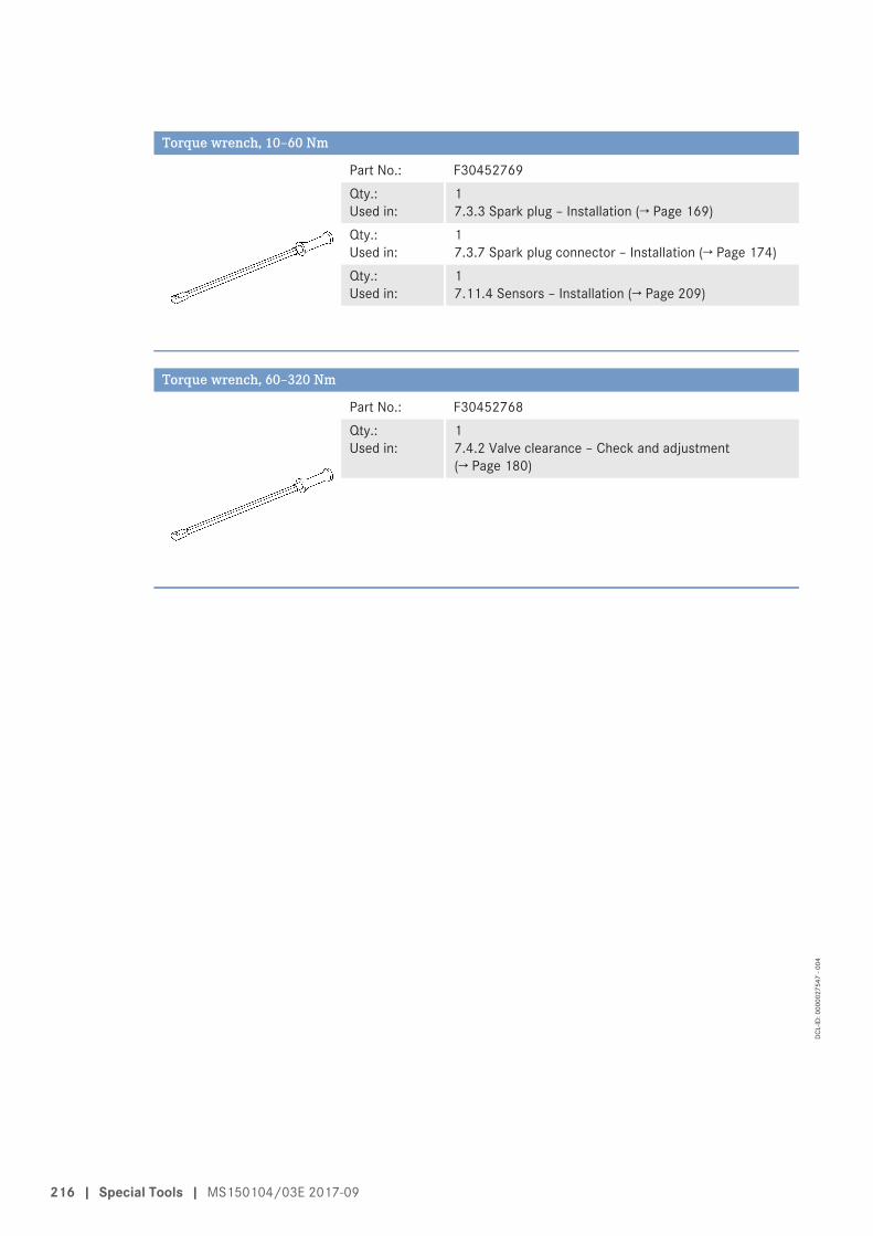
Torque wrench, 10–60 Nm
Part No.: F30452769Qty.:Used in:
1 7.3.3 Spark plug – Installation (→ Page 169)
Qty.:Used in:
1 7.3.7 Spark plug connector – Installation (→ Page 174)
Qty.:Used in:
1 7.11.4 Sensors – Installation (→ Page 209)
Torque wrench, 60–320 Nm
Part No.: F30452768Qty.:Used in:
1 7.4.2 Valve clearance – Check and adjustment(→ Page 180)
216 | Special Tools | MS150104/03E 2017-09
DCL-
ID: 0
0000
2754
7 - 0
04
9.2 IndexNumerics
50-hours check 54
A
Abbreviations 210After extended out-of-service periods (>3 months) – Putting the engine into operation 41After stopping the engine – Engine remains ready for operation 52– Putting the engine out of operation 53Air filter – Installation 187– Removal 187– Replacement 186
C
Cabling – Check
– On engine 202Contact person – MTU Onsite Energy 212Control 43Coolant – Change 193Cylinder – Designation 25Cylinder head cover – Installation 184– Removal 183
E
Emergency stop – Engine 50Emission values – Check 47Engine – After stopping
– Putting out of operation 53– Barring manually 163– Emergency shutdown 50– Main dimensions 26– Shutdown 49– Start 45Engine cabling – Check 202Engine coolant – Change 193– Draining 194– Filling 196– Level check 192Engine data 12V4000L32 – Emissions-optimized (1/2 TA-Luft) 32Engine data 12V4000L32F – Fuel-optimized (TA-Luft) 28
Engine data 16V4000L32 – Emissions-optimized (1/2 TA-Luft) 32Engine data 16V4000L32F – Fuel-optimized (TA-Luft) 28Engine driving end – Definition 25Engine free end – Definition 25Engine layout 23Engine oil – Change 189– Sample extraction and analysis 190Engine oil filter – Replacement 191Engine oil level – Check 188Engine sides – Designation 25
F
Fault messages – Engine governor 123– Genset control system log 58– Key 56Firing order 27
G
Gas engine phase 4 system – Overview 36Gas supply – Check
– Gas lines for leaks 185
I
Ignition system – Ignition timing check 176
M
Machine room – Check for smell of gas 164Main dimensions – Engine 26Maintenance Schedule – Maintenance task reference table [QL1] 55Mixture coolant – Change 199– Draining 200– Filling 201Mixture coolant level – Check 198MTU Onsite Energy – Contact person 212– Service partner 212
MS150104/03E 2017-09 | Index | 217
DCL-
ID: 0
0000
2754
7 - 0
04
O
Oil separator – Filter replacement 165Operational checks 46Overview – Engine 23– Sensors 203
P
Purpose of the units 38Putting the engine into operation – After extended out-of-service periods (>3 months) 41Putting the engine into operation after scheduled out-of-
service-period 42
R
Runtimes at partial load 40
S
Safety regulations – Assembly work 13– Assembly work, specific information for dual fuel sup-
ply applications 17– Assembly work, specific information for gaseous fuel
supply applications 17– Auxiliary materials 18– Auxiliary materials, specific information for dual fuel
applications 20– Auxiliary materials, specific information for gaseous
fuel supply applications 20– Environmental protection 18– Environmental protection, specific information for dual
fuel applications 20– Environmental protection, specific information for gas-
eous fuel supply applications 20– Fire prevention 18– Fire prevention, specific information for dual fuel ap-
plications 20– Fire prevention, specific information for gaseous fuel
supply applications 20– Fluids and lubricants 18– Fluids and lubricants, specific information for dual fuel
applications 20– Fluids and lubricants, specific information for gaseous
fuel supply applications 20– Important provisions 5, 7– Initial start-up 9– Maintenance work 13– Maintenance work, specific information for dual fuel
supply applications 17– Maintenance work, specific information for gaseous
fuel supply applications 17– Operation 9– Operation, specific information for dual fuel supply ap-
plications 11– Operation, specific information for gaseous fuel supply
applications 11– Organizational requirements 8– Personnel requirements 8– Repair work 13– Repair work, specific information for dual fuel supply
applications 17– Repair work, specific information for gaseous fuel sup-
ply applications 17– Startup, specific information for dual fuel supply appli-
cations 11– Startup, specific information for gaseous fuel supply
applications 11Safety requirements – Warning notices, standards 21Sensors – Installation 209– Overview 203– Removal 207Service partner – MTU Onsite Energy 212
218 | Index | MS150104/03E 2017-09
DCL-
ID: 0
0000
2754
7 - 0
04
Spark plug – Installation 169– Removal 168– Replacement 167Spark plug connector – Check 173– Cleaning 173– Installation 174– Removal 172– Replacement 171Starting sequence 43Stopping sequence 43
T
transport 22
V
Valve clearance – Adjustment 180– Check 180Valve gear – Lubrication 182Valve protrusion – Measurement 177Vent line of engine coolant circuit – Replacement 197
W
Warning notices, standards 21
MS150104/03E 2017-09 | Index | 219
DCL-
ID: 0
0000
2754
7 - 0
04