ontology driven certification of pressure equipments
TRANSCRIPT
Ontology Driven Certificationof Pressure EquipmentsElena Camossi,a Franca Giannini,b Marina Monti,b Paolo Bragatto,c Paolo Pittiglio,c and Silvia Ansaldica School of Computer Science and Informatics, UCD, Irelandb Istituto di Matematica Applicata e Tecnologie Informatiche, CNR, Genova, Italy; [email protected] (for correspondence)c Istituto Superiore per la Prevenzione e la Sicurezza del Laroro, DIPIA, Monteporzio (RM), Italy
Published online 28 October 2008 in Wiley InterScience (www.interscience.wiley.com). DOI 10.1002/prs.10277
Standards and engineering codes rule design, con-struction and operation of chemical plant equipmentsto ensure reliability and safety. In this article, weexploit knowledge-based methodologies and technolo-gies to guarantee safety rules compliance of pressureequipments. Specifically, we describe a knowledge-based tool defined on top of a knowledge-based com-puter-aided design system, which can serve inspectionbodies, i.e., for certification purposes, and pressureequipment designers for the verification of the appro-priate safety normative (i.e., the pressure equipmentdirective). The article focuses on the knowledge baseof the tool, which has been formalized through thePED&I (Pressure Equipment Design and Inspection)ontology. The ontology has been enriched by logicalaxioms, which ensure the consistency of the knowledgebase, and by reasoning rules, which enable to infer newrelationships among the class instances stored in the on-tology.� 2008 American Institute of Chemical EngineersProcess Saf Prog 27: 313–322, 2008
Keywords: safety rules compliance; risk analysis;pressure equipments; ontology; knowledge manage-ment; knowledge-based CAD
INTRODUCTIONSafety plays a very important role all through the
life cycle of a process plant, from the process designphase to engineering, construction, operation, main-tenance and revamping phases. Incorporating reliabil-ity and inherent safety principles into a plant designrequires thorough attention to design details, includ-ing the systematic review by a multidisciplinary teamof process and equipment experts [1]. In particular,the increasing awareness of safety and economical
issues strengthens the needs of more secure and reli-able engineering equipments, which may cause prob-lems because of different reasons, such as incorrectdesign or realization, improper installation or use, orinadequate maintenance. Consequently the design,manufacturing and installation of plant equipmentsand machineries are subjected to laws to warranteethey are safe and will not affect people’s health.
Indeed, equipments, such as pressure vessels,tanks, reactors, boilers, pumps, and valves have tomeet complex safety requirements and criteria, whichmay be quite difficult to assess in the design phase.To this aim, in the past decades professional institu-tions and trade associations developed engineeringcodes and standards, which cover the design, theconstruction, the maintenance and the inspection of awide range of equipments. Codes are widely appliedin process industry to realize safe plant componentsand to meet the overall plant safety criteria. Theadoption of appropriate standards and codes for theemployment and the maintenance of plant equip-ments, which operate in a major hazard establish-ment, is a crucial issue for the assessment of thesafety, as required by the ‘‘Seveso II Directive’’1.
Decisions taken at the beginning, i.e., during thedetailed plant design, influence reliability and safety,and may imply later plant changes, such as addingexternal safety measures. Therefore, in current prac-tice designers have to comply with the safety criteriasince the very first design phases, to avoid errors andwaste of time in the subsequent design and approvalphases. Then, as required by National and Interna-tional regulations, technical bodies have to verify thesafety criteria adherence as soon as they receive thedrawings, to speed up the approval process.
Nowadays, computer-aided design (CAD) systemssupport designers in every phase of the process plant
1COMAH Safety Report assessment manual—Level III Technical aspects.Web page: http://www.hse.gov.uk/comah/sragtech (Accessed February2008).
This work was supported by European Commission (IST 506766); AIM@SHAPE Network of Excellence (AIM@SHAPE) and Irish Research Council forScience, Engineering, and Technology.
� 2008 American Institute of Chemical Engineers
Process Safety Progress (Vol.27, No.4) December 2008 313
development. Initially developed to handle just geo-metries, they have become sophisticated tools, ableto manage all the aspects of engineering design:shapes, geometric features, functions, constraints,relationships and standards. In particular, commercialsystems offer workbenches and functionalities forknowledge-based engineering (KBE). KBE offers anenhanced support for the description and processingof product models in the whole product lifecycle, andenable to computerize several types of knowledge: geo-metric data, technical specifications, normative andstandards, and best practice guidelines deriving frompast experience. Knowledge-based CAD systems (KB-CAD) allow users to define and manage rules, whichmay assure that the designed parts automatically adhereto a priori defined rules. Furthermore, a KB-CAD mayhandle parts previously designed, and may verify thecompliance with the rules defined also a posteriori,highlighting possible incoherencies. The ability to com-puterize geometric rules results in faster and higherquality design. However, a KB-CAD is able to manageonly detailed and well-defined geometrical rules, but itcannot handle indirect criteria. Thus, KB-CAD are notsufficient to provide a thorough support for the verifica-tion of the safety compliance of CAD models, e.g., ofchemical plants and equipments.
The objective of the research presented in this arti-cle is the definition of a knowledge-based (KB)design system supporting on the one hand designersin the application of safety rules for plant compo-nents since the first design stages, and on the otherhand inspectors which verify the normative compli-ance of pressure equipments models. Hazard situa-tions deriving from safety rules violations can beavoided, thus providing a fundamental capability tosupport organizations that perform plant safety certifi-cations. To formalize the expert knowledge related tothis domain, we designed a Pressure EquipmentDesign and Inspection (PED&I) ontology. We focusin particular on the formalization of the appropriatesafety normative pressure equipments have to complywith. Specifically, the application supports the safetyrules of vessels for the storage of under-pressure flu-ids according to the pressure equipment directive 97/23/EC,2 as they are applied in Italy, where they areencoded in the VSR collection.
The addressed application may benefit from theontology we propose in different aspects. First of all,ontologies are used to formalize a shared conceptual-ization on a domain, then the PED&I ontology easesthe communication among the different actorsinvolved in the design and the normative verificationon pressure equipments. The terminology and thedesign details we formalize are trustworthy, becausethey have been formalized in strict collaboration withexperts in this field. The PED&I ontology has beenwritten in OWL (Web Ontology Language3), whichsyntax and semantics have been formalized and are
available to public. Then, the interaction of softwaremodules with the tool we propose via the PED&I on-tology is straightforward.
In the tool described in this article, once a pres-sure equipment model is represented in the PED&Iontology, its compliance with the VSR normative canbe checked. This operation can be performed bothduring the design phase, thus assisting the designer,and, once the model is released, during safety inspec-tions. In both cases, given the equipment model, thenorms applicable to it are retrieved from the ontol-ogy, then geometric and functional constraints can beverified through the KBE module of the CAD system.The check is performed in a semi-automatic envi-ronment, that is, the system highlights the possibleviolations to the user, which decides on the requiredinterventions.
The selection of the correct normative is obtainedthrough the formalization of the logical constraintsthat relate each equipment to the corresponding setof safety rules. This is realized through the specifica-tion of the ontology classes that represent the con-ceptual entities of the domain (e.g., pressure equip-ments, safety rules) and the corresponding logicalaxioms, that must be verified by the entities of theseclasses; the relationships among these entities; andthe logical rules, written in SWRL (Semantic Web RuleLanguage4), that enable to infer new logical relation-ships among the class instances. In particular, thelogic rules execution makes explicit whether a set ofnorms applies to a given equipment.
The ontology can be extended to support differentequipments and rules related to the domain of pres-sure vessels and component. Furthermore, the meth-odology we apply for the KB tool design can beapplied to any well formalized domain requiring theverification of rules and constraints.
The article is organized as follows. In Section 2 theresearch background and an overview of relatedworks are illustrated. In Section 3 we introduce thegeneral architecture of the KB system, whereas inSection 4 we discuss the design of the knowledgebase of the system, i.e. the PED&I ontology. In Sec-tion 5 we introduce the developed prototype throughan application example to illustrate how the definedontology supports the certification of safety rules forpressure equipments. Finally, benefits and limitationsof the approach are discussed in Section 6, whichconcludes the article.
BACKGROUND AND RELATED WORKSThe set of safety rules we represent in the tool
knowledge base is the VSR code [2], developed inItaly in the early seventies by constructors and publicbodies and enforced by the law for pressure vesselsverification. The VSR code is analogous to othercodes developed by main industrialized countries,such as BS5500 in UK, ASME VIII-div.1 in USAand AD-MERKBLATT in Germany. For 20 years,
4SWRL: A Semantic Web Rule Language, Combining OWL and RuleML.W3C Member Submission 21 May 2004. Web site: http://www.w3.org/Submission/SWRL/ (Accessed February 2008).
2Pressure equipment directive (PED) 97/23/EC, 1997. Web page: http://europa.eu.int/comm/enterprise/pressure_equipment/ped/index_en.html (Accessed February 2008).
3OWL, Web Ontology Language Reference. W3C Recommendation 10 Feb-ruary 2004. World Wide Web Consortium. Web site: http://www.w3.org/TR/owl-ref/ (Accessed February 2008).
314 December 2008 Published on behalf of the AIChE DOI 10.1002/prs Process Safety Progress (Vol.27, No.4)
I.S.P.E.S.L.5 has been in charge to manage and updatethe VSR code in Italy. In 1997, the European Commis-sion issued the PED directive 97/23/CE/to allow thefree trade of pressure equipments across the Euro-pean Union. The Directive does not enforce anynational code, but defines only general criteria,named Essential Safety Requirements, which have tobe verified to approve pressure equipments. VSRcode has been harmonized with PED directive, andnowadays it is widely used in Italy for pressureequipments design and approval.
The development of computer-aided tools forenhancing plant safety has been recognized as an im-portant issue and several researches address the vari-ous aspects of the problem. In Gabbar et al. [3] inves-tigate limitations and issues in managing safetyrelated activities throughout the plant lifecycle andpropose a framework for computer-aided plant safetymanagement systems.
To assess the compliance to safety conditions, inthe recent past, the verification of process plants hasbeen improved through the application of KB tech-nologies. In two works [4,5], both originated from theresearch carried out in the European project HIDA[6], the authors apply KB technologies to the assess-ment of cracks in plant components, underlining thebenefits deriving from the incorporation of defectchecking code into a KB system. In the projectTTF 2,6 which is supported by the European PressureEquipment Research Council and is aimed at promot-ing the use of High Strength Steels, the integration ofa new analysis method with appropriate material datainto a KB system is proposed. The system is intendedto be used by both pressure vessel designers andstandardization bodies, who are responsible foraccepting new materials into design standards and fordetermining the material values.
More recently, KBE tools rely on ontologies, whichare recognized as an effective technological supportfor the formalization of knowledge rich modelsincluding sophisticated logical relationships and con-straints. An ontology is a ‘‘specification of a conceptu-alization’’ [7], i.e., a representation of the knowledgeof a domain of interest, which is associated with asemantic network structure [8]. Ontology and othersemantic web technologies differ from traditionalDBMS because they provide effective reasoningcapabilities: for instance, through the check of logicalaxioms and the application of reasoning rules, it ispossible to infer new knowledge from data alreadystored.
Ontologies in engineering have been used mainlyfor sharing and reusing both domain and functionalknowledge [9]. In [10], ontologies have been appliedto the semantics-driven simplification of CAD models,aimed at the visualization and the design review oflarge plant models. In [11] an ontology-based toolfor the support of the structural design process ispresented.
Similarly to [3,5,6,10], in this article we provide aformalization of expert’s knowledge aiming at theverification of the safety of process plants. However,differently from those works, we propose a KB toolfor the automatic check of pressure equipment safetyrules encoded in ontologies. Moreover, differentlyfrom other KBE works which apply ontologies, weexploit their potentialities not only for the representa-tion of the domain knowledge; rather we investigatethe application of the reasoning capability they pro-vide, through the specification of the relationshipsamong classes and of axioms that check the belong-ing of instances to domain classes and their participa-tion to relationships.
The research presented in this article relies andextends the work presented in [12]; herein the knowl-edge base have been expanded and effective reason-ing capabilities have been added. The application oflogical rules introduces a significant novelty in themethodology applied, because implicit knowledgecan be inferred whenever a new instance is insertedin the ontology, improving the clearness of the for-malization of the domain knowledge and enabling itscomplete representation.
A KNOWLEDGE-BASED SYSTEM FOR PRESSURE EQUIPMENT SAFETYThe KB environment we propose to support both
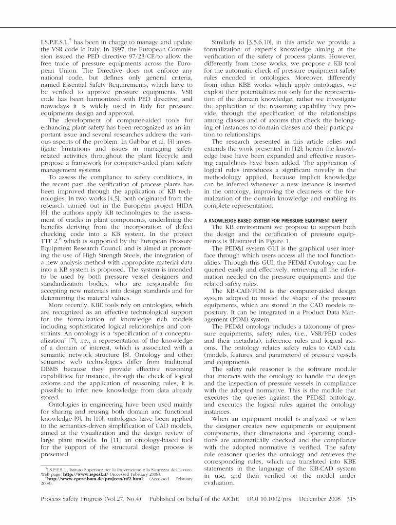
the design and the certification of pressure equip-ments is illustrated in Figure 1.
The PED&I system GUI is the graphical user inter-face through which users access all the tool function-alities. Through this GUI, the PED&I Ontology can bequeried easily and effectively, retrieving all the infor-mation needed on the pressure equipments and therelated safety rules.
The KB-CAD/PDM is the computer-aided designsystem adopted to model the shape of the pressureequipments, which are stored in the CAD models re-pository. It can be integrated in a Product Data Man-agement (PDM) system.
The PED&I ontology includes a taxonomy of pres-sure equipments, safety rules, (i.e., VSR/PED codesand their metadata), inference rules and logical axi-oms. The ontology relates safety rules to CAD data(models, features, and parameters) of pressure vesselsand equipments.
The safety rule reasoner is the software modulethat interacts with the ontology to handle the designand the inspection of pressure vessels in compliancewith the adopted normative. This is the module thatexecutes the queries against the PED&I ontology,and executes the logical rules against the ontologyinstances.
When an equipment model is analyzed or whenthe designer creates new equipments or equipmentcomponents, their dimensions and operating condi-tions are automatically checked and the compliancewith the adopted normative is verified. The safetyrule reasoner queries the ontology and retrieves thecorresponding rules, which are translated into KBEstatements in the language of the KB-CAD systemin use, and then verified on the model underevaluation.
5I.S.P.E.S.L., Istituto Superiore per la Prevenzione e la Sicurezza del Lavoro.Web page: http://www.ispesl.it/ (Accessed February 2008).
6http://www.eperc.bam.de/projects/ttf2.html (Accessed February2008).
Process Safety Progress (Vol.27, No.4) Published on behalf of the AIChE DOI 10.1002/prs December 2008 315
For the pressure vessel designer, rules correspondto a set of design directives to follow and dimen-sional parameter dependences to satisfy to obtainsafe components. By contrast, from the inspectionpoint of view, once the user has specified the data ofthe equipment to be certified, the system firstlyrebuilds a synthetic digital representation of the equip-ment to provide a simplified but meaningful CADmodel. Then, the translated safety rules can be auto-matically verified on the rebuilt digital representation.
THE PRESSURE EQUIPMENT DESIGN ANDINSPECTION KNOWLEDGE BASE
In this section, we present the design of thePED&I ontology, which has been defined following abottom-up approach, relying on the analysis of theVSR rules collection, and in collaboration withexperts in the field, to guarantee the adequacy of theterminology and equipment parameterization. Theontology has been specified in OWL-DL, the descrip-tion logic sublanguage of OWL. Inference rules havebeen defined in SWRL, the W3C’s proposal for asemantic rule web language.
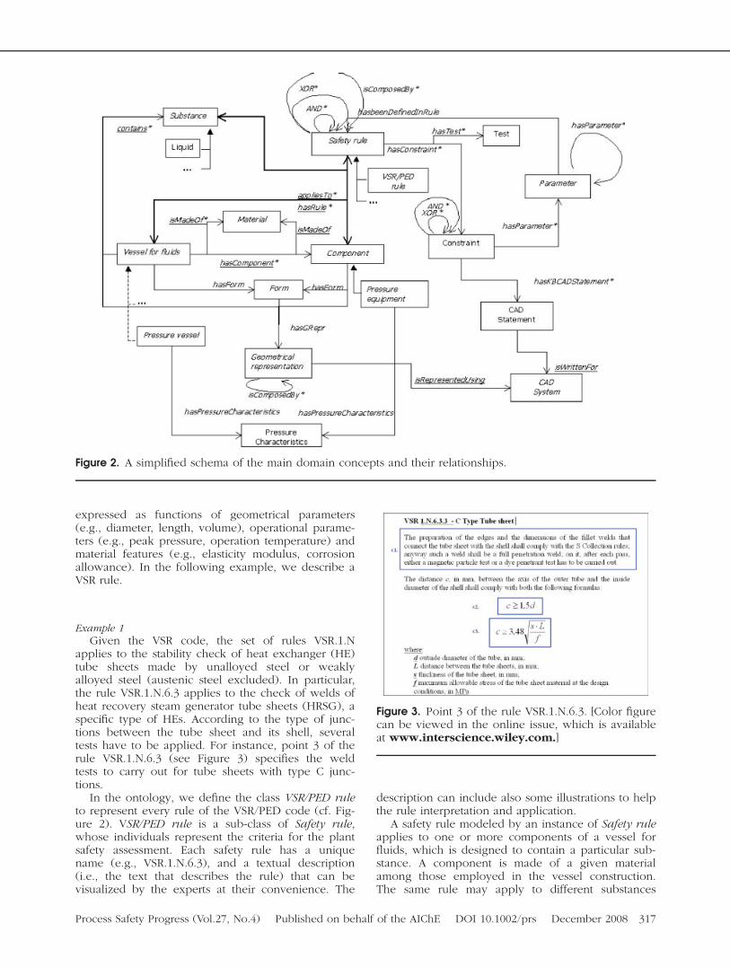
The PED&I ontology represents the conceptual enti-ties, with their relationships, involved in the domain ofpressure equipments (e.g., vessel for fluids, vessel com-ponents and materials, safety rules). A simplifiedschema, reporting the main concepts, is shown in Fig-ure 2. For the sake of readability, we report classes andrelationships, disregarding class attributes.
In Figure 2 rectangles are ontology classes, whichrepresent the domain concepts. The enclosed labelsindicate the class names.7 Classes with labels in italic
are abstract, i.e., no instances will be created forthose classes; they are used to model common con-cepts. Unlabelled arrows with a thick tip representthe relationship is-a. For example, Junction is-a (spe-cific type of) Component. is-a enables property in-heritance among the classes involved, and throughthis relationship the ontology concepts are classifiedand organized in taxonomies. Moreover, relationshipshave a direction, and those with a starred label (rel*)have multiple target. For example, the relationshiphascomponent, holding from Vessel for fluids to Com-ponent, enables to represent a vessel for fluids ascomposed of more than one element (e.g., its shell,two ends, several openings). Finally, relationshipswith underlined labels (rel) are mandatory. A Vesselfor fluids, for example, is made of at least one vesselComponent.
In the following, first we focus on the formaliza-tion of the safety rules through illustrative examples,then we give an overview of the axioms whichensure ontology consistency.
Safety RulesThe code VSR/PED [2] represents the core of the
PED&I ontology. The VSR code is organized in chap-ters, according to the different pressure equipments.It rules the whole pressure equipment lifecycle,including rules for construction, testing, inspectionalong operation time, repair and modification. More-over, VSR/PED defines the operative technical specifi-cations for the verification of the stability of pressurevessels, giving the safety conditions on pressure ves-sels and components (e.g., shells, ends, plates),equipments, and every model detail (e.g., stiffeningrings, openings), like, for instance, the minimalthickness of vessel components. Safety conditions are
7For the sake of comprehension, composite class names are strings with-out spaces. Note that spaces are omitted, or substituted by underscores (_)in the OWL file, where a class name is a string without spaces.
Figure 1. KB system for pressure vessel design and inspection. [Color figure can be viewed in the online issue,which is available at www.interscience.wiley.com.]
316 December 2008 Published on behalf of the AIChE DOI 10.1002/prs Process Safety Progress (Vol.27, No.4)
expressed as functions of geometrical parameters(e.g., diameter, length, volume), operational parame-ters (e.g., peak pressure, operation temperature) andmaterial features (e.g., elasticity modulus, corrosionallowance). In the following example, we describe aVSR rule.
Example 1Given the VSR code, the set of rules VSR.1.N
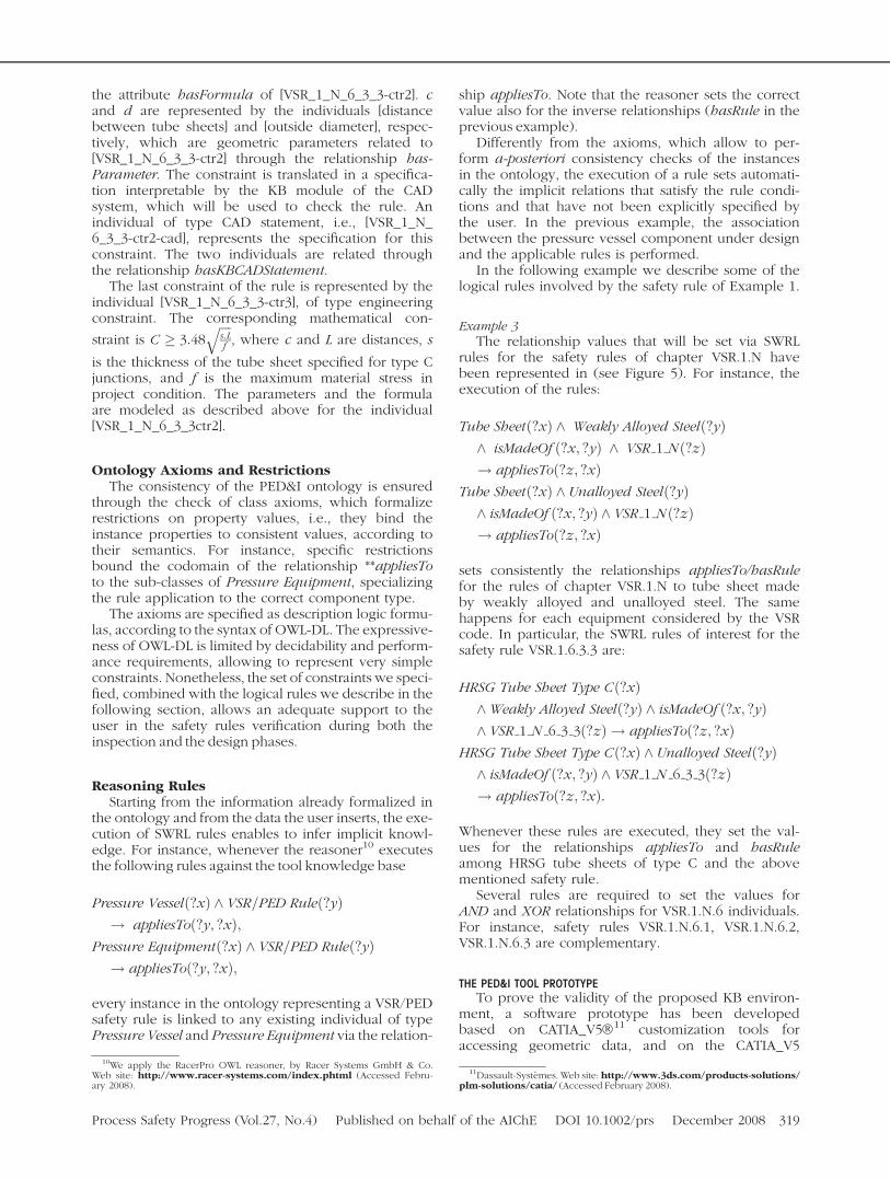
applies to the stability check of heat exchanger (HE)tube sheets made by unalloyed steel or weaklyalloyed steel (austenic steel excluded). In particular,the rule VSR.1.N.6.3 applies to the check of welds ofheat recovery steam generator tube sheets (HRSG), aspecific type of HEs. According to the type of junc-tions between the tube sheet and its shell, severaltests have to be applied. For instance, point 3 of therule VSR.1.N.6.3 (see Figure 3) specifies the weldtests to carry out for tube sheets with type C junc-tions.
In the ontology, we define the class VSR/PED ruleto represent every rule of the VSR/PED code (cf. Fig-ure 2). VSR/PED rule is a sub-class of Safety rule,whose individuals represent the criteria for the plantsafety assessment. Each safety rule has a uniquename (e.g., VSR.1.N.6.3), and a textual description(i.e., the text that describes the rule) that can bevisualized by the experts at their convenience. The
description can include also some illustrations to helpthe rule interpretation and application.
A safety rule modeled by an instance of Safety ruleapplies to one or more components of a vessel forfluids, which is designed to contain a particular sub-stance. A component is made of a given materialamong those employed in the vessel construction.The same rule may apply to different substances
Figure 2. A simplified schema of the main domain concepts and their relationships.
Figure 3. Point 3 of the rule VSR.1.N.6.3. [Color figurecan be viewed in the online issue, which is availableat www.interscience.wiley.com.]
Process Safety Progress (Vol.27, No.4) Published on behalf of the AIChE DOI 10.1002/prs December 2008 317
among those the vessel has been designed to contain,and to the (set of) material(s) employed for the man-ufacturing of the vessel and its components.
A rule can be subdivided into sub-rules, whichmay be complementary, or in alternative to a differ-ent set of rules. Each rule may specify one or moreconstraints, either geometrical, operational, or func-tional. Analogously to rules, a constraint may be com-plementary or in alternative to other constraints. Ageometric and functional constraint is usually speci-fied as a computation that involves a set of parame-ters. A parameter may be geometric (e.g., length,area, distance, thickness, etc.) or functional (e.g.,pressure, temperature, etc.). Often a parameter isdefined as a function of other parameters.
The check of a safety rule or constraint is per-formed according to safety tests, which are executedon the equipment the rule applies to. To link therules’ checks to the CAD models, geometric con-straints and parameter extraction procedures arelinked to the corresponding procedures of the spe-cific KB-CAD system in use. Following these domainrequirements, in the following example we illustratehow the safety rules of Example 1 have been mod-eled in the ontology. Instance names in the ontologyrecall the real rules names, being a key code for peo-ple familiar with the VSR norms.
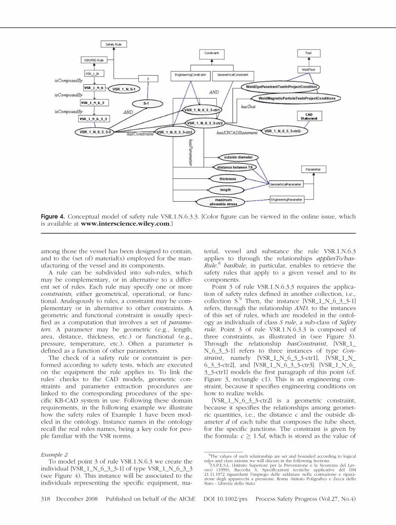
Example 2To model point 3 of rule VSR.1.N.6.3 we create the
individual [VSR_1_N_6_3_3-1] of type VSR_1_N_6_3_3(see Figure 4). This instance will be associated to theindividuals representing the specific equipment, ma-
terial, vessel and substance the rule VSR.1.N.6.3applies to through the relationships appliesTo/has-Rule.8 hasRule, in particular, enables to retrieve thesafety rules that apply to a given vessel and to itscomponents.
Point 3 of rule VSR.1.N.6.3.3 requires the applica-tion of safety rules defined in another collection, i.e.,collection S.9 Then, the instance [VSR_1_N_6_3_3-1]refers, through the relationship AND, to the instancesof this set of rules, which are modeled in the ontol-ogy as individuals of class S rule, a sub-class of Safetyrule. Point 3 of rule VSR.1.N.6.3.3 is composed ofthree constraints, as illustrated in (see Figure 3).Through the relationship hasConstraint, [VSR_1_N_6_3_3-1] refers to three instances of type Con-straint, namely [VSR_1_N_6_3_3-ctr1], [VSR_1_N_6_3_3-ctr2], and [VSR_1_N_6_3_3-ctr3]. [VSR_1_N_6_3_3-ctr1] models the first paragraph of this point (cf.Figure 3, rectangle c1). This is an engineering con-straint, because it specifies engineering conditions onhow to realize welds.
[VSR_1_N_6_3_3-ctr2] is a geometric constraint,because it specifies the relationships among geomet-ric quantities, i.e., the distance c and the outside di-ameter d of each tube that composes the tube sheet,for the specific junctions. The constraint is given bythe formula: c � 1.5d, which is stored as the value of
Figure 4. Conceptual model of safety rule VSR.1.N.6.3.3. [Color figure can be viewed in the online issue, whichis available at www.interscience.wiley.com.]
8The values of such relationship are set and bounded according to logicalrules and class axioms we will discuss in the following Sections.
9I.S.P.E.S.L. (Istituto Superiore per la Prevenzione e la Sicurezza del Lav-oro) (1999), Raccolta S, Specificazioni tecniche applicative del DM21.11.1972 riguardanti l’impiego delle saldature nella costruzione e ripara-zione degli apparecchi a pressione. Roma -Istituto Poligrafico e Zecca delloStato - Libreria dello Stato.
318 December 2008 Published on behalf of the AIChE DOI 10.1002/prs Process Safety Progress (Vol.27, No.4)
the attribute hasFormula of [VSR_1_N_6_3_3-ctr2]. cand d are represented by the individuals [distancebetween tube sheets] and [outside diameter], respec-tively, which are geometric parameters related to[VSR_1_N_6_3_3-ctr2] through the relationship has-Parameter. The constraint is translated in a specifica-tion interpretable by the KB module of the CADsystem, which will be used to check the rule. Anindividual of type CAD statement, i.e., [VSR_1_N_6_3_3-ctr2-cad], represents the specification for thisconstraint. The two individuals are related throughthe relationship hasKBCADStatement.
The last constraint of the rule is represented by theindividual [VSR_1_N_6_3_3-ctr3], of type engineeringconstraint. The corresponding mathematical con-
straint is C � 3:48ffiffiffiffis:Lf
q, where c and L are distances, s
is the thickness of the tube sheet specified for type Cjunctions, and f is the maximum material stress inproject condition. The parameters and the formulaare modeled as described above for the individual[VSR_1_N_6_3_3ctr2].
Ontology Axioms and RestrictionsThe consistency of the PED&I ontology is ensured
through the check of class axioms, which formalizerestrictions on property values, i.e., they bind theinstance properties to consistent values, according totheir semantics. For instance, specific restrictionsbound the codomain of the relationship **appliesToto the sub-classes of Pressure Equipment, specializingthe rule application to the correct component type.
The axioms are specified as description logic formu-las, according to the syntax of OWL-DL. The expressive-ness of OWL-DL is limited by decidability and perform-ance requirements, allowing to represent very simpleconstraints. Nonetheless, the set of constraints we speci-fied, combined with the logical rules we describe in thefollowing section, allows an adequate support to theuser in the safety rules verification during both theinspection and the design phases.
Reasoning RulesStarting from the information already formalized in
the ontology and from the data the user inserts, the exe-cution of SWRL rules enables to infer implicit knowl-edge. For instance, whenever the reasoner10 executesthe following rules against the tool knowledge base
Pressure Vesselð?xÞ ^ VSR=PED Ruleð?yÞ! appliesToð?y; ?xÞ;
Pressure Equipmentð?xÞ ^ VSR=PED Ruleð?yÞ! appliesToð?y; ?xÞ;
every instance in the ontology representing a VSR/PEDsafety rule is linked to any existing individual of typePressure Vessel and Pressure Equipment via the relation-
ship appliesTo. Note that the reasoner sets the correctvalue also for the inverse relationships (hasRule in theprevious example).
Differently from the axioms, which allow to per-form a-posteriori consistency checks of the instancesin the ontology, the execution of a rule sets automati-cally the implicit relations that satisfy the rule condi-tions and that have not been explicitly specified bythe user. In the previous example, the associationbetween the pressure vessel component under designand the applicable rules is performed.
In the following example we describe some of thelogical rules involved by the safety rule of Example 1.
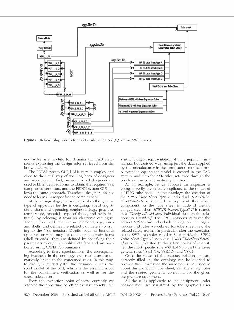
Example 3The relationship values that will be set via SWRL
rules for the safety rules of chapter VSR.1.N havebeen represented in (see Figure 5). For instance, theexecution of the rules:
Tube Sheetð?xÞ ^ Weakly Alloyed Steelð?yÞ^ isMadeOf ð?x; ?yÞ ^ VSR 1 N ð?zÞ! appliesToð?z; ?xÞ
Tube Sheetð?xÞ ^ Unalloyed Steelð?yÞ^ isMadeOf ð?x; ?yÞ ^ VSR 1 N ð?zÞ! appliesToð?z; ?xÞ
sets consistently the relationships appliesTo/hasRulefor the rules of chapter VSR.1.N to tube sheet madeby weakly alloyed and unalloyed steel. The samehappens for each equipment considered by the VSRcode. In particular, the SWRL rules of interest for thesafety rule VSR.1.6.3.3 are:
HRSG Tube Sheet Type Cð?xÞ^Weakly Alloyed Steelð?yÞ ^ isMadeOf ð?x; ?yÞ^ VSR 1 N 6 3 3ð?zÞ ! appliesToð?z; ?xÞ
HRSG Tube Sheet Type Cð?xÞ ^ Unalloyed Steelð?yÞ^ isMadeOf ð?x; ?yÞ ^ VSR 1 N 6 3 3ð?zÞ! appliesToð?z; ?xÞ:
Whenever these rules are executed, they set the val-ues for the relationships appliesTo and hasRuleamong HRSG tube sheets of type C and the abovementioned safety rule.
Several rules are required to set the values forAND and XOR relationships for VSR.1.N.6 individuals.For instance, safety rules VSR.1.N.6.1, VSR.1.N.6.2,VSR.1.N.6.3 are complementary.
THE PED&I TOOL PROTOTYPETo prove the validity of the proposed KB environ-
ment, a software prototype has been developedbased on CATIA_V5�11 customization tools foraccessing geometric data, and on the CATIA_V5
10We apply the RacerPro OWL reasoner, by Racer Systems GmbH & Co.Web site: http://www.racer-systems.com/index.phtml (Accessed Febru-ary 2008).
11Dassault-Systemes. Web site: http://www.3ds.com/products-solutions/plm-solutions/catia/ (Accessed February 2008).
Process Safety Progress (Vol.27, No.4) Published on behalf of the AIChE DOI 10.1002/prs December 2008 319
knowledgeware module for defining the CAD state-ments expressing the design rules retrieved from theknowledge base.
The PED&I system GUI, [13] is easy to employ andclose to the usual way of working both of designersand inspectors. In fact, pressure vessel designers areused to fill in detailed forms to obtain the required VSRcompliance certificate, and the PED&I system GUI fol-lows the same approach. Therefore, designers do notneed to learn a new specific and complex tool.
At the design stage, the user describes the generaltype of apparatus he/she is designing, specifying itsdimensions and operating conditions (e.g., pressure,temperature, materials, type of fluids, and main fea-tures), by selecting it from an electronic catalogue.Then, he/she adds the various elements, e.g., endsand shells, and defines the related parameters accord-ing to the VSR notation. Details, such as branchesopenings or nips, may be added on the main items(shell or ends); they are defined by specifying theirparameters through a VSR-like interface and are posi-tioned using CATIA V5 commands.
According to these specifications, the correspond-ing instances in the ontology are created and auto-matically linked to the concerned rules. In this way,following a guided path, the designer creates thesolid model of the part, which is the essential inputfor the containment verification as well as for thestress calculations.
From the inspection point of view, currently weadopted the procedure of letting the user to rebuild a
synthetic digital representation of the equipment, in amanual but assisted way, using just the data suppliedby the manufacturer in the certification request form.A synthetic equipment model is created in the CADsystem, and then the VSR rules, retrieved through theontology, can be automatically checked.
As an example, let us suppose an inspector isgoing to verify the safety compliance of the model ofa HRSG tube sheet. In the ontology the creation ofthe HRSG Tube Sheet Type C individual [HRSGTube-SheetTypeC-1] is required to represent this vesselcomponent. As the tube sheet is made of weaklyalloyed steel, then [HRSGTubeSheetTypeC-1] is relatedto a Weakly alloyed steel individual through the rela-tionship isMadeOf. The OWL reasoner retrieves thecorrect Safety rule individuals relying on the logicalaxioms and rules we defined for tube sheets and therelated safety norms. In particular, after the executionof the SWRL rules described in Section 4.3, the HRSGTube Sheet Type C individual [HRSGTubeSheetTypeC-1] is correctly related to the safety norms of interest,i.e., the most specific rule VSR.1.N.6.3.3 and the moregeneral rules VSR.1.N.6, VSR.1.N, and VSR.1.
Once the values of the instance relationships arecorrectly filled in, the ontology can be queried toprovide the information the inspector is interested inabout this particular tube sheet, i.e., the safety rulesand the related geometric constraints for the giventhe pressure equipment.
All the rules applicable to the equipment underconsideration are visualized by the graphical user
Figure 5. Relationship values for safety rule VSR.1.N.6.3.3 set via SWRL rules.
320 December 2008 Published on behalf of the AIChE DOI 10.1002/prs Process Safety Progress (Vol.27, No.4)
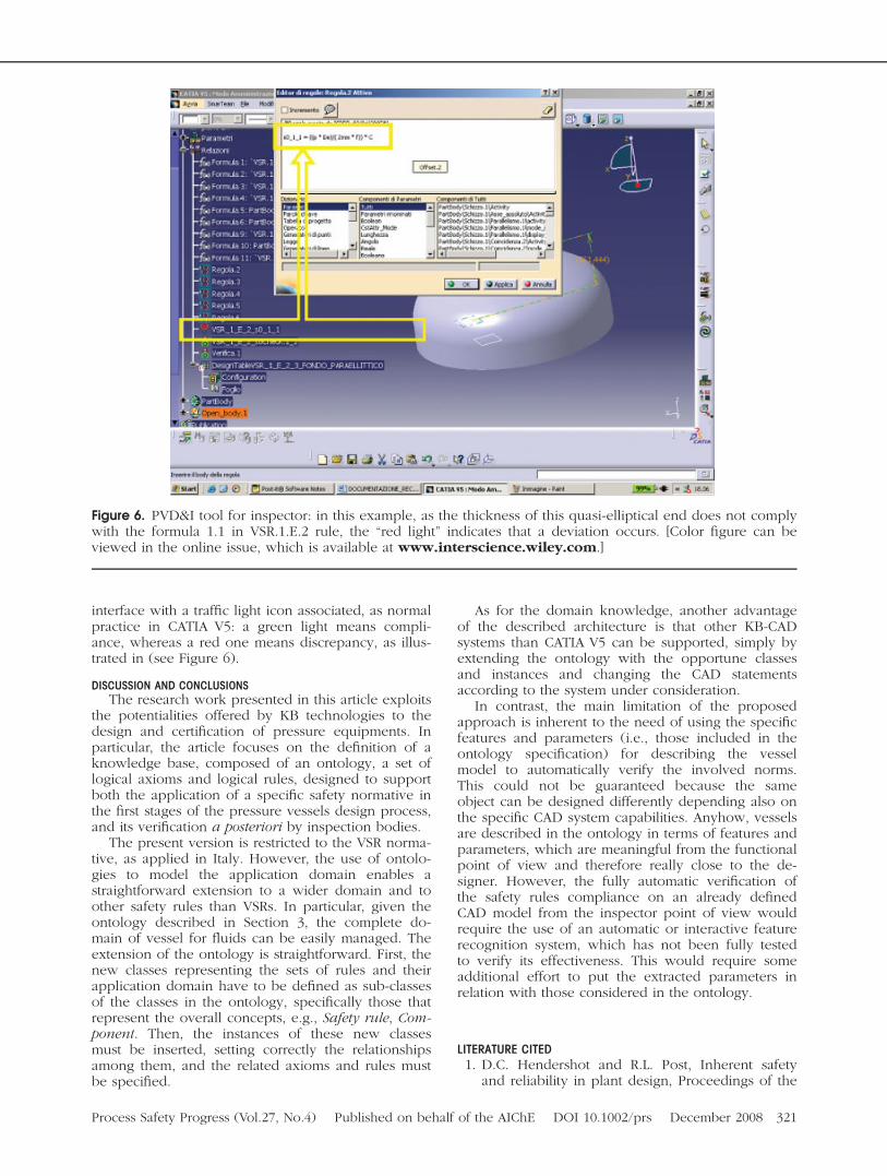
interface with a traffic light icon associated, as normalpractice in CATIA V5: a green light means compli-ance, whereas a red one means discrepancy, as illus-trated in (see Figure 6).
DISCUSSION AND CONCLUSIONSThe research work presented in this article exploits
the potentialities offered by KB technologies to thedesign and certification of pressure equipments. Inparticular, the article focuses on the definition of aknowledge base, composed of an ontology, a set oflogical axioms and logical rules, designed to supportboth the application of a specific safety normative inthe first stages of the pressure vessels design process,and its verification a posteriori by inspection bodies.
The present version is restricted to the VSR norma-tive, as applied in Italy. However, the use of ontolo-gies to model the application domain enables astraightforward extension to a wider domain and toother safety rules than VSRs. In particular, given theontology described in Section 3, the complete do-main of vessel for fluids can be easily managed. Theextension of the ontology is straightforward. First, thenew classes representing the sets of rules and theirapplication domain have to be defined as sub-classesof the classes in the ontology, specifically those thatrepresent the overall concepts, e.g., Safety rule, Com-ponent. Then, the instances of these new classesmust be inserted, setting correctly the relationshipsamong them, and the related axioms and rules mustbe specified.
As for the domain knowledge, another advantageof the described architecture is that other KB-CADsystems than CATIA V5 can be supported, simply byextending the ontology with the opportune classesand instances and changing the CAD statementsaccording to the system under consideration.
In contrast, the main limitation of the proposedapproach is inherent to the need of using the specificfeatures and parameters (i.e., those included in theontology specification) for describing the vesselmodel to automatically verify the involved norms.This could not be guaranteed because the sameobject can be designed differently depending also onthe specific CAD system capabilities. Anyhow, vesselsare described in the ontology in terms of features andparameters, which are meaningful from the functionalpoint of view and therefore really close to the de-signer. However, the fully automatic verification ofthe safety rules compliance on an already definedCAD model from the inspector point of view wouldrequire the use of an automatic or interactive featurerecognition system, which has not been fully testedto verify its effectiveness. This would require someadditional effort to put the extracted parameters inrelation with those considered in the ontology.
LITERATURE CITED1. D.C. Hendershot and R.L. Post, Inherent safety
and reliability in plant design, Proceedings of the
Figure 6. PVD&I tool for inspector: in this example, as the thickness of this quasi-elliptical end does not complywith the formula 1.1 in VSR.1.E.2 rule, the ‘‘red light’’ indicates that a deviation occurs. [Color figure can beviewed in the online issue, which is available at www.interscience.wiley.com.]
Process Safety Progress (Vol.27, No.4) Published on behalf of the AIChE DOI 10.1002/prs December 2008 321
2000 Mary Kay O’Connor process safety centersymposium, (2000), 268–281.
2. I.S.P.E.S.L. (Istituto Superiore per la Prevenzione ela Sicurezza del Lavoro) (1999), Raccolta VSR,Revisione 1995: Specificazioni Tecniche Applica-tive del Decreto Ministeriale 21 Novembre 1972per la Verifica della Stabilita dei Recipientiin Pressione. Roma -Istituto Poligrafico e Zeccadello Stato - Libreria dello Stato.
3. H.A. Gabbar, P.W.H. Chung, Y. Shimada, and K.Suzuki, Computer-aided plant enterprise safetymanagement system (CAPE-SAFE)—design frame-work, Syst Eng 5 (2002), 109–122.
4. K. Nikbin, A unified approach to high tempera-ture defect assessment code and its incorporationin a knowledge-based system, Int J Pres Ves Pip78 (2001), 929–935.
5. A. Jovanovic, K. Maile, G. Wagemann, N. Le Mat-Hamata, U. Gampe, P. Andersson, P. Segle, andGelineau O, Assesment of cracks in power plantcomponents by means of the HIDA knowledge-based system (KBS), Int J Pres Ves Pip 78 (2001),1053–1069.
6. I.A. Shibli, Overview of the HIDA project. Int JPres Ves Piping 78 (2001), 729–735.
7. T.R. Gruber, A translation approach to portableontology specification. Knowl Acquis 5 (1995),199–220.
8. N.F. Noy and D.L. McGuinnes, Ontology develop-ment 101: A guide to creating your first ontology,Stanford knowledge systems laboratory, Tech-nical report KSL-01–05, T.R.SMI-2001–0880,(2001).
9. Y. Kitamura and R. Mizoguchi, Ontology-basedsystematization of functional knowledge. J EngDes 15 (2004), 327–351.
10. J. Posada, C. Toro, S. Wundrak, and A. Stork, On-tology supported semantic simplification of largedata sets of industrial plant cad models for designreview visualization, Proceedings of knowledge-based intelligent information and engineering sys-tems, Lecture notes in computer science 3683,Springer Verlag, (2005), 184–190.
11. C. Toro, J. Posada, M. Termenon, J. Oyarzun, andJ. Falcon, Knowledge based tools to supportstructural design process. KES 2006, Part I, LNAI4251, Springer Verlag, (2006), 679–686.
12. S. Ansaldi, P. Bragatto, E. Camossi, F. Giannini, M.Monti, and P. Pittiglio, A knowledge-based toolfor risk prevention on pressure equipments. Com-put Aided Des Appl 3 (2006), 99–108.
13. P. Bragatto, P. Pittiglio, and S. Ansaldi, Knowledgebased tools for stability verification during pres-sure equipment life cycle, Proceedings of the So-ciety for Risk Analysis conference, Como -Italy(2005).
322 December 2008 Published on behalf of the AIChE DOI 10.1002/prs Process Safety Progress (Vol.27, No.4)